Project Manual - Maine.gov
626
Project Manual Downeast Correctional Facility Men’s Reentry Center Machiasport, Maine Issued for Construction Volume One Submitted by: SMRT Architects and Engineers August 14, 2020 Project # 19176‐00 smrƟnc.com
-
Upload
khangminh22 -
Category
Documents
-
view
0 -
download
0
Transcript of Project Manual - Maine.gov

Project Manual Downeast Correctional Facility
Men’s Reentry Center Machiasport, Maine
Issued for Construction
Volume One
Submitted by: SMRT Architects and Engineers
August 14, 2020
Project # 19176‐00
smr nc.com

DCF MEN'S REENTRY FACILITY AUGUST 14, 2020 MACHIASPORT, MAINE ISSUE FOR CONTRUCTION
19176-00 TABLE OF CONTENTS TOC - 1
TABLE OF CONTENTS VOLUME ONE
DIVISION 00 - PROCUREMENT AND CONTRACTING REQUIREMENTS 001113 NOTICE TO CONTRACTORS 13 MAY 2020 002113 INSTRUCTIONS TO BIDDERS 003119 EXISTING CONDITION INFORMATION 003132 GEOTECHNICAL DATA 004113 CONTRACTOR BID FORM 005213 CONTRACT AGREEMENT SAMPLE 01 MAY 2020 006113.13 CONTRACTOR PERFORMANCE BOND 13 DEC 2020 006113.16 CONTRACTOR PERFORMANCE BOND SAMPLE 13 DEC 2018 007100 DEFINITIONS 01 MAY 2020 007213 GENERAL CONDITIONS 01 MAY 2020 007346 WAGE DETERMINATION SCHEDULE 01 MAY 2020
DIVISION 01 - GENERAL REQUIREMENTS 011000 SUMMARY 011140 PROJECT COORDINATION DRAWINGS 012300 ALTERNATES 012600 CONTRACT MODIFICATION PROCEDURES 012900 PAYMENT PROCEDURES 013100 PROJECT MANAGEMENT AND COORDINATION 013200 CONSTRUCTION PROGRESS DOCUMENTATION 013300 SUBMITTAL PROCEDURES 014000 QUALITY REQUIREMENTS 014100 SPECIAL INSPECTIONS 014200 REFERENCES 015000 TEMPORARY FACILITIES AND CONTROLS 016000 PRODUCT REQUIREMENTS 017000 TESTING, ADJUSTING, AND BALANCING 017300 EXECUTION 017329 CUTTING AND PATCHING 017419 CONSTRUCTION WASTE MANAGEMENT AND DISPOSAL 017700 CLOSEOUT PROCEDURES 017823 OPERATION AND MAINTENANCE DATA 017839 PROJECT RECORD DOCUMENTS 017900 DEMONSTRATION AND TRAINING
DIVISION 02 - EXISTING CONDITIONS 024113 SELECTIVE SITE DEMOLITION 024119 SELECTIVE DEMOLITION
DIVISION 03 - CONCRETE 033000 CAST-IN-PLACE CONCRETE
DIVISION 05 - METALS 055000 METAL FABRICATIONS

DCF MEN'S REENTRY FACILITY AUGUST 14, 2020 MACHIASPORT, MAINE ISSUE FOR CONTRUCTION
19176-00 TABLE OF CONTENTS TOC - 2
TABLE OF CONTENTS VOLUME ONE
DIVISION 06 – WOOD, PLASTICS AND COMPOSITES 061000 ROUGH CARPENTRY 061610 STRUCTURAL SHEATHING 064116 PLASTIC-LAMINATE-FACED-ARCHITECTURAL CABINETS 066400 PLASTIC PANELING
DIVISION 07 - THERMAL AND MOISTURE PROTECTION 072100 THERMAL INSULATION 072500 WEATHER BARRIERS 074113.16 STANDING-SEAM METAL ROOF PANELS 074643 COMPOSITION SIDING 076200 SHEET METAL FLASHING AND TRIM 078413 PENETRATION FIRESTOPPING 079200 JOINT SEALANTS 079219 ACOUSTICAL JOINT SEALANTS
DIVISION 08 - OPENINGS 081113 HOLLOW METAL DOORS AND FRAMES 081416 FLUSH WOOD DOORS 083113 ACCESS DOORS AND FRAMES 083313 COILING COUNTER DOORS 084113 ALUMINUM-FRAMED ENTRANCES AND STOREFRONTS 085313 VINYL WINDOWS 087111 DOOR HARDWARE (DESCRIPTIVE SPECIFICATION) 088000 GLAZING
DIVISION 09 - FINISHES 092900 GYPSUM BOARD 093013 CERAMIC TILING 095123 ACOUSTICAL TILE CEILINGS 096513 RESILIENT BASE AND ACCESSORIES 096516 RESILIENT SHEET FLOORING 096519 RESILIENT TILE FLOORING 096723 RESINOUS FLOORING 096813 TILE CARPETING 099113 EXTERIOR PAINTING 099123 INTERIOR PAINTING
DIVISION 10 - SPECIALTIES 102113.19 PLASTIC TOILET COMPARTMENTS 102800 TOILET, BATH, AND LAUNDRY ACCESSORIES 104413 FIRE PROTECTION CABINETS 104416 FIRE EXTINGUISHERS 105113 METAL LOCKERS

DCF MEN'S REENTRY FACILITY AUGUST 14, 2020 MACHIASPORT, MAINE ISSUE FOR CONTRUCTION
19176-00 TABLE OF CONTENTS TOC - 3
TABLE OF CONTENTS VOLUME ONE
DIVISION 11 - EQUIPMENT 111100 LAUNDRY EQUIPMENT 114000 FOODSERVICE EQUIPMENT
DIVISION 12 - FURNISHINGS 122113 HORIZONTAL LOUVER BLINDS 123661.16 SOLID SURFACING COUNTERTOPS 129300 SITE FURNISHINGS

DCF MEN'S REENTRY FACILITY AUGUST 14, 2020 MACHIASPORT, MAINE ISSUE FOR CONTRUCTION
19176-00 TABLE OF CONTENTS TOC - 4
TABLE OF CONTENTS VOLUME TWO
DIVISION 21 - FIRE SUPPRESSION 210000 BASIC FIRE PROTECTION MATERIALS AND METHODS 211000 FIRE SUPPRESSION SPRINKLER SYSTEM 211023 WET CHEMICAL EXTINGUISHING SYSTEMS 213000 FIRE PUMPS
DIVISION 22 - PLUMBING 220000 BASIC PLUMBING REQUIREMENTS 220500 BASIC PLUMBING MATERIALS AND METHODS 220516 PIPE EXPANSION FITTINGS AND LOOPS 220519 METERS AND GAUGES 220529 HANGERS AND SUPPORTS 220548 MECHANICAL VIBRATION AND SEISMIC CONTROLS 220553 PLUMBING IDENTIFICATION 220701 PIPE INSULATION 221116 PLUMBING PIPING 221119 PLUMBING SPECIALTIES 221343.14 FUJI CLEAN TREAMENTS SYSTEM 221343.16 E-ONE PUMP STATION AND CONTROLS 223300 ELECTRIC DOMESTIC WATER HEATERS 224000 PLUMBING FIXTURES
DIVISION 23 - HEATING, VENTILATING, AND AIR CONDITIONING (HVAC) 230000 BASIC MECHANICAL REQUIREMENTS 230523.12 BALL VALVES FOR HVAC PIPING 230553 MECHANICAL IDENTIFICATION 230713 DUCT INSULATION 230900 HVAC INSTRUMENTATION AND CONTROLS 232113 HYDRONIC PIPING 232116 HYDRONIC PIPING SPECIALTIES 232123 HYDRONIC PUMPS 233113 METAL DUCTS 233300 AIR DUCT ACCESSORIES 233416 CENTRIFUGAL FANS 233713 DIFFUSERS, REGISTERS, AND GRILLES 235239 BOILER PLANT 237223.23 PACKAGED, OUTDOOR, HEAT WHEEL ENERGY RECOVERY UNITS 237333 INDIRECT-FIRED MAKE-UP AIR UNIT 238239 CABINET UNIT HEATERS 238239.16 PROPELLER UNIT HEATERS 238316 RADIANT-HEATING HYDRONIC PIPING
DIVISION 26 - ELECTRICAL 260100 BASIC ELECTRICAL REQUIREMENTS 260500 COMMON WORK RESULTS FOR ELECTRICAL

DCF MEN'S REENTRY FACILITY AUGUST 14, 2020 MACHIASPORT, MAINE ISSUE FOR CONTRUCTION
19176-00 TABLE OF CONTENTS TOC - 5
TABLE OF CONTENTS VOLUME TWO
260513 MEDIUM VOLTAGE CABLES 260519 LOW-VOLTAGE ELETRICAL POWER CONDUCTORS AND CABLES 260526 GROUNDING AND BONDING FOR ELECTRICAL SYSTEMS 260529 HANGERS AND SUPPORTS FOR ELECTRICAL SYSTEMS 260533 RACEWAYS AND BOXES FOR ELECTRICAL SYSTEMS 260543 UNDERGROUND DUCTS AND RACEWAYS FOR ELECTRICAL SYSTEMS 260553 IDENTIFICATION FOR ELECTRICAL SYSTEMS 260573.13 SHORT-CIRCUIT STUDIES 260573.16 COORDINATION STUDIES 260573.19 ARC-FLASH HAZARD ANALYSIS 260923 LIGHTING CONTROL DEVICES 261219 PAD-MOUNTED, LIQUID-FILLED, MEDIUM-VOLTAGE TRANSFORMERS 262416 PANELBOARDS 262726 WIRING DEVICES 262813 FUSES 262816 ENCLOSED SWITCHES AND CIRCUIT BREAKERS 262913.03 MANUAL AND MAGNETIC MOTOR CONTROLLERS 262923 VARIABLE-FREQUENCY MOTOR CONTROLLERS 262913.14 DIESEL ENGINE GENERATORS 263600 TRANSFER SWITCHES 264113 LIGHTING PROTECTION FOR STRUCTURES 265119 LED INTERIOR LIGHTING 265619 LED EXTERIOR LIGHTING
DIVISION 28 - ELECTRONIC SAFETY AND SECURITY 283111 DIGITAL, ADDRESSABLE FIRE ALARM SYSTEM
DIVISION 31 - EARTHWORK 311000 SITE CLEARING
312000 EATH MOVING
312319 DEWATERING
312500 EROSION AND SEDIMENTATION CONTROL
313700 RIP RAP
315000 EXCAVATION SUPPORT AND PROTECTION

DCF MEN'S REENTRY FACILITY AUGUST 14, 2020 MACHIASPORT, MAINE ISSUE FOR CONTRUCTION
19176-00 TABLE OF CONTENTS TOC - 6
TABLE OF CONTENTS VOLUME TWO
DIVISION 32 – EXTERIOR IMPROVEMENTS 321216 ASPHALT PAVING 321313 CONCRETE PAVING 321723 PAVEMENT MARKINGS
329200 TURF AND GRASSES
DIVISION 33 – UTILITIES 330513 MANHOLES, CATCH BASINS AND PRECAST CONCRETE 331100 WATER UTILITY DISTRIBUTION PIPING
333100 SANITARY UTILITY SEWERAGE PIPING
334100 STORM UTILITY DRAINAGE PIPING
334600 SUBDRAINAGE
END OF TABLE OF CONTENTS
13 May 2020 00 11 13 Notice to Contractors
001113 Notice to Contractors for Email Bid.2020.07.22 dfs Page 1 of 2 00 11 13
Downeeast Correctional Facility - Men's Reentry Center BGS 3082
This new investment by the State of Maine will provide necessary accommodations for the transitional housing of 48 male inmates under the custody of the Maine Department of Corrections. This 9, 600 s.f., single-story facility will serve as housing for 48 Men classified as ‘Minimum/ Community Release’ status. The residents of the facility will receive educational and support services on site and will leave daily for work within the Washington County community. The appearance of this facility will reinforce the investment into the rehabilitation of the residents as well as the community of Washington County with a respectable civic/ residential design aesthetic.project The cost of the work is approximately $ 5,631,080. The work to be performed under this contract shall be completed on or before the Final Completion date of 1 September 2021. 1. Submit bids on a completed Contractor Bid Form, plus bid security when required, all scanned and
included as an attachment to an email with the subject line marked "Bid for Downeast Correctional Facility - Men's Reentry Center" and addressed to the Bid Administrator at: [email protected], so as to be received no later than 2:00:00 p.m. on September 9, 2020. Bid submissions will be opened and read aloud at the time and date noted above at the Bureau of General Services office, accessible as a video conference call. Those who wish to participate in the call must submit a request for access to [email protected]. Any bid received after the noted time will not be considered a valid bid and will remain unopened. Any bid submitted by any other means will not be considered a valid bid. The Bid Administrator may require the Bidder to surrender a valid paper copy of the bid form or the bid security document in certain circumstances. Questions on the bid opening process shall be addressed to the Bid Administrator: Joseph H. Ostwald, Director, Division of Planning, Design & Construction, Bureau of General Services, 77 State House Station, Augusta, Maine 04333-0077, [email protected].
2. The bid shall be submitted on the Contractor Bid Form (section 00 41 13) provided in the Bid Documents. The Owner reserves the right to accept or reject any or all bids as may best serve the interest of the Owner.
3. Bid security is required on this project. If noted above as required, the Bidder shall include a satisfactory Bid Bond (section 00 43 13) or a certified or cashier's check for 5% of the bid amount with the completed bid form submitted to the Owner. The Bid Bond form is available on the BGS website.
4. Performance and Payment Bonds are required on this project. If noted above as required, the selected Contractor shall furnish a 100% contract Performance Bond (section 00 61 13.13) and a 100% contract Payment Bond (section 00 61 13.16) in the contract amount to cover the execution of the Work. Bond forms are available on the BGS website.
5. Filed Sub-bids are not required on this project.
13 May 2020 00 11 13 Notice to Contractors
001113 Notice to Contractors for Email Bid.2020.07.22 dfs Page 2 of 2 00 11 13
6. There are no Pre-qualified General Contractors on this project. If Pre-qualified General Contractors are identified for this project, the name of each company, with their city and state, are listed below.
7. An on-site pre-bid conference will be conducted for this project. If a pre-bid conference is scheduled, it is mandatory for General Contractors and optional for Subcontractors and suppliers. Contractors who arrive late or leave early for a mandatory meeting may be prohibited from participating in this meeting and bidding. Pre-bid conference will be held on-site on Monday, August 24, 2020, Pre-bid conference time is 11:00 a.m. to 1:00 p.m.
8. Property Insurance for this construction contract, described in the Insurance Requirements section of the General Conditions of the contract, shall be New construction insured by Contractor.
9. Bid Documents - full sets only - will be available on or about August 18, 2020 and may be obtained at
no cost" from: Electronic files from Jessica Johnson at SMRT [email protected] Bid documents will also be posted on the BGS website at: https://www.maine.gov/dafs/brem/business-opportunities
10. Bid Documents may be examined at:
AGC Maine Construction Summary 188 Whitten Road 734 Chestnut Street Augusta, ME 04332 Manchester, NH 03104 Phone 207-622-4741 Fax 207-622-1625 Phone 603-627-8856 Fax 603-627-4524

01 May 2020 00 21 13 Instructions to Bidders
002113 Instructions to Bidders 01 May 2020 Page 1 of 3 00 21 13
1. Bidder Requirements 1.1 A bidder is a Contractor who is qualified, or has been specifically pre-qualified by the Bureau of
General Services, to bid on the proposed project described in the Bid Documents.
1.2 Contractors and Subcontractors bidding on projects that utilize Filed Sub-bids shall follow the requirements outlined in these Bid Documents for such projects. See Section 00 22 13 for additional information.
1.3 Contractors and Subcontractors are not eligible to bid on the project when their access to project design documents prior to the bid period distribution of documents creates an unfair bidding advantage. Prohibited access includes consultation with the Owner or with design professionals engaged by the Owner regarding cost estimating, constructability review, or project scheduling. This prohibition to bid applies to open, competitive bidding or pre-qualified contractor bidding or Filed Sub-bidding. The Bureau may require additional information to determine if the activities of a Contractor constitute an unfair bidding advantage.
1.4 Each bidder is responsible for becoming thoroughly familiar with the Bid Documents prior to submitting a bid. The failure of a bidder to review evident site conditions, to attend available pre-bid conferences, or to receive, examine, or act on addenda to the Bid Documents shall not relieve that bidder from any obligation with respect to their bid or the execution of the work as a Contractor.
1.5 Prior to the award of the contract, General Contractor bidders or Filed Sub-bidders may be required to provide documented evidence to the Owner or the Bureau showing compliance with the provisions of this section, their business experience, financial capability, or performance on previous projects.
1.6 The selected General Contractor bidder will be required to provide proof of insurance before a contract can be executed.
1.7 Contracts developed from this bid shall not be assigned, sublet or transferred without the written consent of the Owner.
1.8 By submitting a bid the Contractor attests that it has not been declared ineligible to bid on State of Maine projects. The Director of the Bureau of General Services may disallow award of this contract to any Contractor if there is evidence that the Contractor or any of its Subcontractors, through their own fault, have been terminated, suspended for cause, debarred from bidding, agreed to refrain from bidding as part of a settlement, have defaulted on a contract, or had a contract completed by another party.
1.9 The Contractor attests that it is not presently indicted for or otherwise criminally or civilly charged by a Federal, State or local government entity with commission of any of the following offenses and has not within a three-year period preceding this bid been convicted of or had a civil judgment rendered against them for commission of fraud or a criminal offense in connection with obtaining, attempting to obtain, or performing a public (Federal, State or local) transaction, or contract under a public transaction, violation of Federal or State anti-trust statutes or commission of embezzlement, theft, forgery, bribery, falsification or destruction of records, making false statements, or receiving stolen property.

01 May 2020 00 21 13 Instructions to Bidders
002113 Instructions to Bidders 01 May 2020 Page 2 of 3 00 21 13
1.10 The Contractor shall not make any award or permit any award (subgrant or contract) at any tier to any party which is debarred or suspended or is otherwise excluded from or ineligible for participation in Federal assistance programs or State of Maine projects.
2. Authority of Owner 2.1 The Owner reserves the right to accept or reject any or all bids as may best serve the interest of
the Owner.
2.2 Subject to the Owner’s stated right to accept or reject any or all bids, the Contractor shall be selected on the basis of the lowest sum of an acceptable Base Bid plus any Alternate Bids the Owner elects to include. An acceptable bid is one from a responsive and responsible bidder.
3. Submitting Bids and Bid Requirements 3.1 Each bid shall be submitted on the forms provided in the Bid Documents.
3.2 Each bid shall be valid for a period of thirty calendar days following the Project bid closing date
and time.
3.3 A bid that contains any escalation clause is considered invalid.
3.4 Bidders shall include a Bid Bond or other approved bid security with the bid form submitted to the Owner when the bid form indicates such bid security is required. The bond value shall be 5% of the bid amount. The form of bond is shown in section 00 43 13.
3.5 Bidders shall include the cost of Performance and Payment Bonds in the bid amount if the bid amount will result in a construction contract value over $125,000, inclusive of alternate bids that may be awarded in the contract. Pursuant to 14 M.R.S.A., Section 871, Public Works Contractors' Surety Bond Law of 1971, subsection 3, the selected Contractor is required to provide these bonds before a contract can be executed. The form of bonds are shown in section 00 61 13.13 and 00 61 13.16.
3.6 Bidders may modify bids in writing, by the same means as the original bid submission, prior to the bid closing time. Such written amendments shall not disclose the amount of the initial bid. If so disclosed, the entire bid is considered invalid.
3.7 Bidders shall acknowledge on the bid form all Addenda issued in a timely manner. The Consultant shall not issue Addenda affecting the content of the bid less than 72 hours prior to the bid closing time. Addenda shall be issued to all companies who are registered holders of Bid Documents.
3.8 A bid may be withdrawn without penalty if a written request by the bidder is presented to the Owner prior to the bid closing time. Such written withdrawal requests are subject to verification as required by the Bureau. After the bid closing time, such written withdrawal requests may be allowed in consideration of the bid bond or, without utilizing a bid bond, if the Contractor

01 May 2020 00 21 13 Instructions to Bidders
002113 Instructions to Bidders 01 May 2020 Page 3 of 3 00 21 13
provides documented evidence to the satisfaction of the Bureau that factual errors had been made on the bid form.
3.9 In the event State of Maine Offices unexpectedly close on the published date of a public bid opening in the location of that bid opening, prior to the time of the scheduled deadline, the new deadline for the public bid opening will be the following business day at the originally scheduled hour of the day, at the original location. Official closings are posted on the State of Maine government website.
3.10 The Owner may require, in a Notice of Intent to Award letter to the apparent low bidder, a Schedule of Values, Project Schedule, and List of Subcontractors and Suppliers as both a demonstration of capability of the Bidder and as a condition of award.
3.11 Projects which require a State of Maine wage determination will include that schedule as part of the Bid Documents. See section 00 73 46, if such rates are required.
3.12 Projects which require compliance with the Davis-Bacon Act are subject to the regulations contained the Code for Federal Regulations and the federal wage determination which is made a part of the Bid Documents. See section 00 73 46, if such rates are required.
3.13 The Owner is exempt from the payment of Maine State sales and use taxes as provided in 36 M.R.S. §1760 (1). The Contractor and Subcontractors shall not include taxes on exempt items in the construction contract.

DOWNEAST CORRECTIONAL FACILITY JUNE 25, 2020 MACHIASPORT, MAINE DESIGN DEVELOPMENT
19176
THIS PAGE INTENTIONALLY LEFT BLANK

DCF MEN’S REENTRY FACILITY AUGUST 14, 2020 MACHIASPORT, MAINE ISSUED FOR CONSTRUCTION
19176-01 EXISTING CONDITION INFORMATION 003119 - 1
DOCUMENT 003119
EXISTING CONDITION INFORMATION
1.1 EXISTING CONDITION INFORMATION
A. This Document with its referenced attachments is part of the Procurement and Contracting Requirements for Project. They provide Owner's information for Bidders' convenience and are intended to supplement rather than serve in lieu of the Bidders' own investigations. They are made available for Bidders' convenience and information, but are not a warranty of existing conditions. This Document and its attachments are not part of the Contract Documents.
B. Survey information that includes information on existing conditions, prepared by SEBAGO TECHNICS, SOUTH PORTLAND, MAINE, entitled 'EXISTING CONDITIONS PLAN OF THE DOWNEAST CORRECTIONAL FACILITY, MACHIASPORT, MAINE and dated 12-19-2019 (see note #12) is available for viewing as part of Drawings.
C. Related Requirements:
1. Document 002113 "Instructions to Bidders" for the Bidder's responsibilities for examination of Project site and existing conditions.
2. Document 003132 "Geotechnical Data" for reports and soil-boring data from geotechnical investigations that are made available to bidders.
END OF DOCUMENT 003119
NOT TO SCALE

DCF MEN’S REENTRY FACILITY AUGUST 14, 2020 MACHIASPORT, MAINE ISSUED FOR CONSTRUCTION
19176-01 GEOTECHNICAL DATA 003132 - 1
DOCUMENT 003132
GEOTECHNICAL DATA
1.1 GEOTECHNICAL DATA
A. This Document with its referenced attachments is part of the Procurement and Contracting Requirements for Project. They provide Owner's information for Bidders' convenience and are intended to supplement rather than serve in lieu of Bidders' own investigations. They are made available for Bidders' convenience and information, but are not a warranty of existing conditions. This Document and its attachments are not part of the Contract Documents.
B. A geotechnical investigation report for Project, prepared by S.W. Cole Engineering, Inc., dated June 19, 2020, is available for viewing as appended to this Document.
C. Related Requirements:
1. Document 002113 "Instructions to Bidders" for the Bidder's responsibilities for examination of Project site and existing conditions.
2. Document 003119 "Existing Condition Information" for information about existing conditions that is made available to bidders.
END OF DOCUMENT 003132

REPORT
19-1670 S June 19, 2020
Geotechnical Engineering Services
Proposed Re-Entry Building Downeast Correctional Facility 64 Base Road Machiasport, Maine
PREPARED FOR: SMRT, Inc. Attention: Dennis Morin, AIA 144 Fore Street Portland, Maine 04104 PREPARED BY: S. W. Cole Engineering, Inc. 37 Liberty Drive Bangor, ME 04401 Tel: (207) 848-5714

TABLE OF CONTENTS
1.0 INTRODUCTION ....................................................................................................... 1
1.1 Scope and Purpose ............................................................................................... 1
1.2 Site and Proposed Construction ............................................................................ 1
2.0 EXPLORATION AND TESTING ................................................................................ 2
2.1 Explorations ........................................................................................................... 2
2.2 Testing ................................................................................................................... 2
3.0 SUBSURFACE CONDITIONS .................................................................................. 2
3.1 Soil and Bedrock ................................................................................................... 3
3.2 Groundwater .......................................................................................................... 4
4.0 EVALUATION AND RECOMMENDATIONS ............................................................. 4
4.1 General Findings ................................................................................................... 4
4.2 Site and Subgrade Preparation ............................................................................. 5
4.3 Excavation and Dewatering ................................................................................... 6
4.4 Foundations ........................................................................................................... 6
4.5 Foundation Drainage ............................................................................................. 7
4.6 Slab-On-Grade ...................................................................................................... 7
4.7 Entrance Slabs, Sidewalks and Exterior Slabs ...................................................... 8
4.8 Backfill and Compaction ........................................................................................ 8
4.9 Weather Considerations ........................................................................................ 9
4.10 Design Review and Construction Testing .......................................................... 10
5.0 CLOSURE ............................................................................................................... 10
Appendix A Limitations
Appendix B Figures
Appendix C Exploration Logs & Key
Appendix D Laboratory Test Results

1
19-1670 S
June 19, 2020
SMRT, Inc. Attention: Dennis Morin, AIA 144 Fore Street Portland, Maine 04104 Subject: Geotechnical Engineering Services
Proposed Re-Entry Building Downeast Correctional Facility 64 Base Road Machiasport, Maine
Dear Dennis: In accordance with our Agreement, dated November 13, 2019, we have observed
subsurface explorations for the subject project. This report summarizes our findings and
geotechnical recommendations and its contents are subject to the limitations set forth in
Appendix A.
1.0 INTRODUCTION
1.1 Scope and Purpose
The purpose of our services was to obtain subsurface information at the site in order to
develop geotechnical recommendations relative to foundations and earthwork associated
with the proposed construction. Our scope of services included observation of eleven
test pit explorations, soils laboratory testing, a geotechnical analysis of the subsurface
findings and preparation of this report.
1.2 Site and Proposed Construction
The site is located at the existing Downeast Correctional Facility on Base Road in
Machiasport, Maine. We understand the facility was operational until about February
2018. The site includes about eight existing structures within the secured (gated) portion
of the facility. The remainder of the site primarily consists of surficial bituminous

19-1670 S June 19, 2020
2
pavement or landscaped areas. Based on the provided survey information from Sebago
Technics, Inc., we understand the overall site generally slopes downward from southwest
to northeast from about elevation 190 to 175 feet (project datum). We understand the
ground surface within the proposed building footprint generally slopes downward from
west to east from about elevation 186 to 183. We understand several of the existing
buildings will be demolished in favor of the proposed construction. Based on information
provided by the Maine Department of Corrections, we understand previously blasted
utility trenches may exist within the proposed building footprint.
We understand redevelopment plans call for construction of a new re-entry building
located within the central portion of the site, currently occupied by paved parking and
landscaped areas. We understand the proposed building will be lightly loaded, wood-
framed, on-grade construction with a footprint approaching 10,000 SF. We understand
the building is proposed at a Finish Floor Elevation (FFE) of 184 feet requiring cuts and
fills approaching 2 feet. Proposed structural loading information is not available at this
time. Existing and proposed site features are shown on the “Exploration Location Plan”
attached in Appendix B.
2.0 EXPLORATION AND TESTING
2.1 Explorations
Eleven test pit explorations (TP-1 through TP-11) were made at the site on November 26,
2019, by Maine Department of Corrections’ resources. The exploration locations were
selected in the field by S. W. Cole Engineering, Inc. (S.W.COLE) and subsequently
located using a mapping grade GPS. The approximate exploration locations are shown
on the “Exploration Location Plan” attached in Appendix B. Logs of the explorations and
a key to the notes and symbols used on the logs are attached in Appendix C.
2.2 Testing
Soil samples were visually classified in the field at the time of the explorations. Several
samples from the explorations were returned to our laboratory for further classification
and testing. The results of two grain size analyses tests are attached in Appendix D.
3.0 SUBSURFACE CONDITIONS

19-1670 S June 19, 2020
3
3.1 Soil and Bedrock
The explorations encountered a soils profile generally consisting of surficial topsoil or
pavement overlying fill overlying glacial till mantling bedrock. Underlying the fill soils, test pit
TP-1 encountered a probable thin veneer of glacial till soils. The subsurface findings are
summarized below; refer to the attached logs for more detailed subsurface information.
Topsoil: Test pits TP-1, TP-2, TP-5, TP-6 and TP-9 through TP-11 encountered about 0.2
to 0.5 feet of surficial topsoil, generally consisting of loose silty sand with organics.
Pavement: Test pits TP-4, TP-7 and TP-8 encountered about 2.5 inches of surficial
bituminous pavement.
Fill: Underlying the topsoil or pavement, the explorations encountered fill soils generally
consisting of sand with varying portions of silt, gravel and cobbles with occasional organics.
Test pit TP-5 encountered pavement and metal debris with the fill. The fill were generally
encountered to depths ranging from about 1.6 to 4.8 feet. Test pits TP-8 and TP-11 were
terminated in the fills at depths of 4.7 and 7.4 feet, respectively, due to unknown,
abandoned, water lines.
Test pit TP-3 was performed adjacent to a foundation wall, which was observed from depths
of 0.5 to 4.8 feet below the existing ground surface. The footing appeared to bear on
bedrock.
Glacial Till: Underlying the fill soils, test pit TP-1 encountered a thin veneer of probable
glacial till generally consisting of sand and silt with some gravel and cobbles.
Refusal Surfaces: Excluding TP-8 and TP-11, the explorations were terminated on refusal
surfaces (probable bedrock) at depths ranging from 1.6 to 4.8 feet. Probable surficial
bedrock outcrops were observed within the northwestern portion of the proposed building
envelope.
Not all the strata were encountered at each exploration; refer to the attached logs for more
detailed subsurface information.

19-1670 S June 19, 2020
4
3.2 Groundwater
Groundwater seepage was observed in test pits TP-1 through TP-6 at depths ranging from
about 1.5 to 4.5 feet. Groundwater likely becomes perched on the relatively impervious
bedrock encountered at the explorations. Long term groundwater information is not
available. It should be anticipated that groundwater levels will fluctuate, particularly in
response to periods of snowmelt and precipitation, as well as changes in site use.
4.0 EVALUATION AND RECOMMENDATIONS
4.1 General Findings
Based on the subsurface findings, the proposed construction is feasible from a geotechnical
standpoint. The principle geotechnical considerations include:
• Fill soils extending to depths of about 2 to 5 feet were encountered within the
proposed building footprint. Additionally, we understand previously blasted utility
trenches may exist within the building footprint (TP-8 and TP-11) extending to depths
greater than 7.4 feet. All fills and utilities must be removed within the building footprint
and replaced with compacted Structural Fill.
• The site is underlain by uncontrolled fills overlying shallow bedrock. We anticipate
bedrock removal by blasting will likely be required for on-grade slabs and shallow
foundations within the western portion of the building area as well as for deeper
excavations for utilities or bedrock knobs that rise within the building footprint.
• Spread footing foundations and slab-on-grade floors bearing on properly prepared
subgrades appear suitable for the proposed building. Spread footings bearing on
sound, intact bedrock should be have at least 2.5 feet of soil cover and be pinned to
bedrock if shallower than design frost depth. Spread footings bearing on soil should
be underlain by at least 3-inches of Crushed Stone overlying properly prepared
subgrades. On-grade floor slabs should bear on at least 6 inches of compacted
Crushed Stone overlying properly prepared subgrades.
• Earthwork, grading and foundation construction activities should occur during drier,
non-freezing weather of Spring, Summer and Fall.
• Groundwater was observed near the bedrock surface at the exploration locations.
The contractor should anticipate the need to dewater excavations.

19-1670 S June 19, 2020
5
• Perimeter foundation underdrains are recommended for the proposed building.
• Imported Granular Borrow, Structural Fill and Crushed Stone will be needed for
construction. The existing silty fill soils are unsuitable for reuse within the proposed
building, but may be suitable for reuse in landscape and paved areas, provided they
are at a compactable moisture content at the time of reuse and organic and debris
are removed.
4.2 Site and Subgrade Preparation
We recommend site preparation begin with the construction of an erosion control system to
protect adjacent drainage ways and areas outside the construction limits. Surficial topsoil,
pavement, existing fills, abandoned utilities and relic foundations should be completely
removed from areas of proposed construction. As much vegetation as possible should
remain outside the construction areas to lessen the potential for erosion and site
disturbance.
Building Pad and Footings: We recommend the existing fills, relic foundations and utilities
be removed within the building footprint. We anticipate previously blasted utility trenches
may be encountered within the building footprint. The extent of removal should extend 1
foot laterally outward from outside edge of perimeter footings for every 1-foot of excavation
depth (1H:1V bearing splay). The over-excavated area should be backfilled with compacted
Structural Fill.
In general, native subgrades will consist of bedrock. We anticipate compacted fills will be
required to achieve proposed foundations subgrades within the northeast portion of the
building. We anticipate bedrock removal by blasting will be required for the on-grade slabs
and shallow foundations within the western portion of the building area as well as for deeper
excavations for utilities or bedrock knobs that rise within the building footprint. We
recommend footings be founded on intact, competent bedrock, native glacial till soils or new
compacted Structural Fill underlain by bedrock or native glacial till soils. Footings founded
directly on bedrock should have a minimum foundation wall height of 2.5 feet and be pinned
if shallower than design frost depth. For interior footings not exposed to freezing
temperatures, we recommend footings be cast on compacted Structural Fill overlying
properly prepared subgrades or 3-inches of Crushed Stone working into the bedrock
surface. On-grade floor slabs should be underlain with at least 6 inches of compacted
Crushed Stone.
19-1670 S June 19, 2020
6
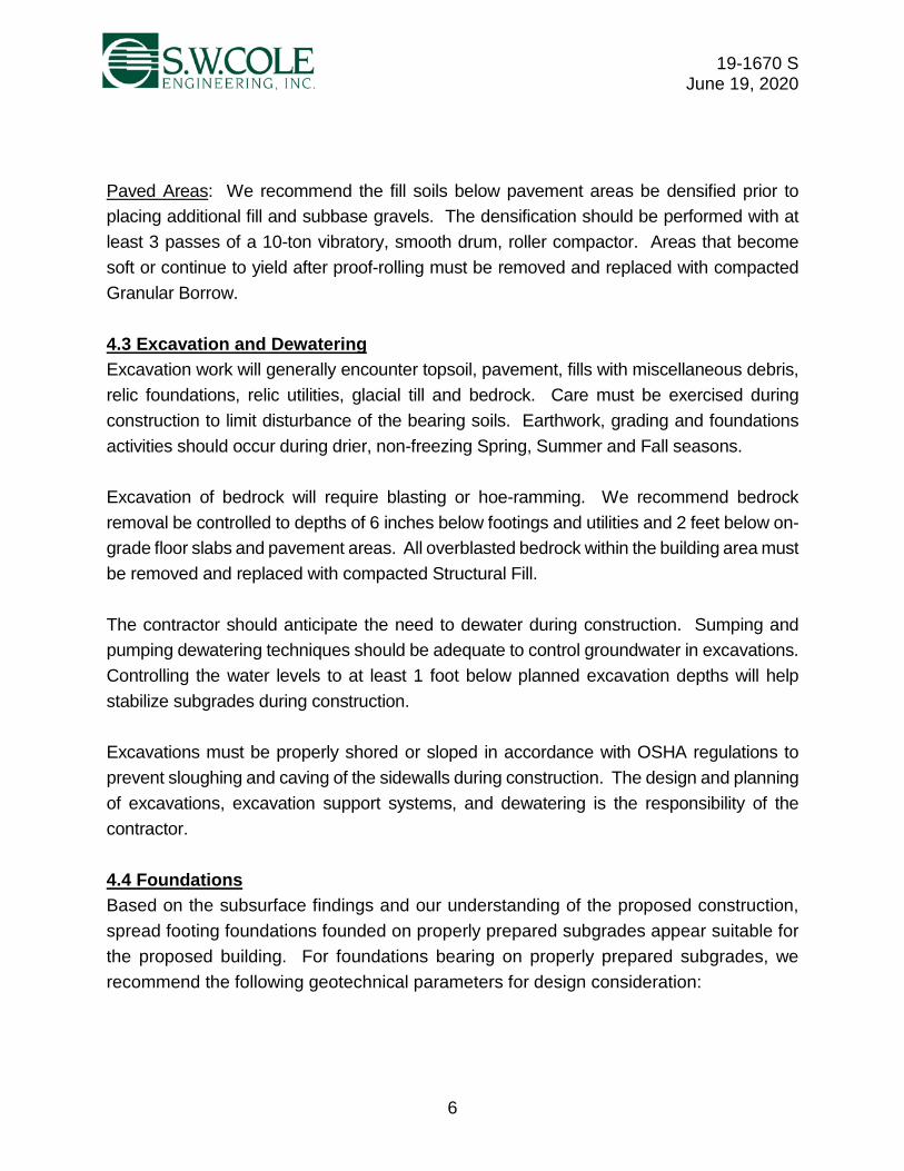
Paved Areas: We recommend the fill soils below pavement areas be densified prior to
placing additional fill and subbase gravels. The densification should be performed with at
least 3 passes of a 10-ton vibratory, smooth drum, roller compactor. Areas that become
soft or continue to yield after proof-rolling must be removed and replaced with compacted
Granular Borrow.
4.3 Excavation and Dewatering
Excavation work will generally encounter topsoil, pavement, fills with miscellaneous debris,
relic foundations, relic utilities, glacial till and bedrock. Care must be exercised during
construction to limit disturbance of the bearing soils. Earthwork, grading and foundations
activities should occur during drier, non-freezing Spring, Summer and Fall seasons.
Excavation of bedrock will require blasting or hoe-ramming. We recommend bedrock
removal be controlled to depths of 6 inches below footings and utilities and 2 feet below on-
grade floor slabs and pavement areas. All overblasted bedrock within the building area must
be removed and replaced with compacted Structural Fill.
The contractor should anticipate the need to dewater during construction. Sumping and
pumping dewatering techniques should be adequate to control groundwater in excavations.
Controlling the water levels to at least 1 foot below planned excavation depths will help
stabilize subgrades during construction.
Excavations must be properly shored or sloped in accordance with OSHA regulations to
prevent sloughing and caving of the sidewalls during construction. The design and planning
of excavations, excavation support systems, and dewatering is the responsibility of the
contractor.
4.4 Foundations
Based on the subsurface findings and our understanding of the proposed construction,
spread footing foundations founded on properly prepared subgrades appear suitable for
the proposed building. For foundations bearing on properly prepared subgrades, we
recommend the following geotechnical parameters for design consideration:

19-1670 S June 19, 2020
7
Geotechnical Parameters for Spread Footings and Foundation Walls
Design Frost Depth
4.5 feet (Soil)
2.5 feet (Bedrock)
Net Allowable Soil Bearing Pressure 4.0 ksf
Net Allowable Bedrock Bearing Pressure 8.0 ksf
Base Friction Factor 0.40
Total Unit Weight of Backfill (compacted Structural Fill) 130 pcf
Internal Friction Angle of Backfill 30°
At-Rest Lateral Earth Pressure Coefficient 0.5
Seismic Soil Site Class (2015 IBC) C
Based on the subsurface findings, we recommend design consider post-construction
settlements of 1 inch total and ½ inch differential over 40 feet.
4.5 Foundation Drainage
We recommend an underdrain system be installed on the outside edge of perimeter
footings. The underdrain pipe should consist of 4-inch diameter, perforated SDR-35
foundation drain pipe bedded in Crushed Stone and wrapped in non-woven geotextile fabric
such as Mirafi 180N or equivalent. The underdrain pipe must have a positive gravity outlet
protected from freezing, clogging and backflow. Surface grades should be sloped away
from the building for positive surface water drainage. A general foundation detail sketch is
attached in Appendix B.
4.6 Slab-On-Grade
On-grade floor slabs in heated areas may be designed using a subgrade reaction
modulus of 100 pci (pounds per cubic inch) provided the slab is underlain by at least 6
inches of compacted Crushed Stone over properly prepared subgrades. The structural
engineer or concrete consultant must design steel reinforcing and joint spacing
appropriate to slab thickness and function.
Considering shallow bedrock was encountered beneath the proposed building area, we
recommend a sub-slab radon venting system be installed beneath on-grade floor slabs.
Additionally, we recommend a sub-slab vapor retarder be installed beneath on-grade floor
slabs. The vapor retarder must have a permeance that is less than the floor cover or
surface treatment that is applied to the slab. To protect the vapor retarder from puncture
from the Crushed Stone slab base material, we recommend a layer of rigid foundation

19-1670 S June 19, 2020
8
insulation between the vapor retarder and Crushed Stone. The vapor retarder material
should be placed according to the manufacturer’s recommended method, including the
taping and lapping of all joints and wall connections. The architect and/or flooring
consultant should select the vapor retarder products compatible with flooring and
adhesive materials.
The floor slab should be appropriately cured using moisture retention methods after
casting. Typical floor slab curing methods should be used for at least 7 days. The
architect or flooring consultant should assign curing methods consistent with current
applicable American Concrete Institute (ACI) procedures with consideration of curing
method compatibility to proposed surface treatments, flooring and adhesive materials.
4.7 Entrance Slabs, Sidewalks and Exterior Slabs
Entrance slabs, sidewalks and exterior slabs must be designed to reduce the effects of
differential frost action between adjacent pavement, doorways, and entrances. We
recommend that non-frost susceptible Structural Fill be provided to a depth of at least 4.5
feet below the top of entrance slabs, sidewalks, and exterior slabs. This thickness of
Structural Fill should extend the full width of the entrance slab, sidewalk and exterior slabs
or outward at least 4.5 feet, whichever is greater, thereafter transitioning up to the bottom
of the adjacent sidewalk or pavement gravels at a 3H:1V or flatter slope. General details
of this frost transition zone are attached in Appendix B.
4.8 Backfill and Compaction
We recommend the following fill and backfill materials: recycled products must also be
tested in accordance with applicable environmental regulations and approved by a
qualified environmental consultant.
Common Borrow: Fill to raise grades in landscape areas should be non-organic
compactable earth meeting the requirements of 2014 Maine Department of
Transportation (MaineDOT) Standard Specification 703.18 Common Borrow.
Granular Borrow: Fill to raise grade, backfill for over-excavations and trench backfill in
paved areas should consist of sand, silty sand or sand and gravel meeting the
requirements of 2014 MaineDOT Standard Specification 703.19 Granular Borrow.

19-1670 S June 19, 2020
9
Structural Fill: Fill to raise grades, backfill for over-excavations, backfill for foundations,
and material below exterior entrances slabs should be clean, non-frost susceptible sand
and gravel meeting the gradation requirements for Structural Fill as given below:
Structural Fill
Sieve Size Percent Finer by Weight
4 inch 100
3 inch 90 to 100
¼ inch 25 to 90
#40 0 to 30
#200 0 to 6
Crushed Stone: Crushed Stone, used beneath foundations, for underdrain aggregate
and slab base material should meet the requirements of 2014 MaineDOT Standard
Specification 703.22 Type C Underdrain Aggregate.
Reuse of Site Soils: The silty fill and native soils are unsuitable for reuse as fill in the
building footprint, but may be suitable for reuse as Common Borrow in landscape areas
or Granular Borrow in paved areas, provided they are at a compactable moisture content
at the time of reuse and organics and debris are removed for reuse beneath paved areas.
Placement and Compaction: Fill should be placed in horizontal lifts and compacted such
that the desired density is achieved throughout the lift thickness with 3 to 5 passes of the
compaction equipment. Loose lift thicknesses for grading fill, and backfill activities should
not exceed 12 inches. We recommend that fill and backfill be compacted to at least 95
percent of its maximum dry density as determined by ASTM D-1557. Crushed Stone
should be compacted with 3 to 5 passes of a vibratory plate compactor having a static
weight of at least 500 pounds.
4.9 Weather Considerations
The site soils are moisture-sensitive; therefore, construction activity should be limited during
wet and freezing weather and the site soils may require drying before construction activities
may continue. The contractor should anticipate the need for water to temper fills in order to
facilitate compaction during dry weather. If construction takes place during cold weather,
subgrades, foundations and floor slabs must be protected during freezing conditions.
Concrete and fill must not be placed on frozen soil; and once placed, the concrete and soil
beneath the structure must be protected from freezing.

19-1670 S June 19, 2020
10
4.10 Design Review and Construction Testing
S.W.COLE should be retained to review the construction documents prior to bidding to
determine that our earthwork and foundation recommendations have been properly
interpreted and implemented.
A soils and concrete testing program should be implemented during construction to observe
compliance with the design concepts, plans, and specifications. S.W.COLE is available to
observe earthwork activities, the preparation of foundation bearing surfaces and pavement
subgrades, as well as to provide testing and IBC Special Inspection services for soils,
concrete, steel, spray-applied fireproofing, structural masonry and asphalt construction
materials.
5.0 CLOSURE
It has been a pleasure to be of assistance to you with this phase of your project. We look
forward to working with you during the design phase as the project progresses.
Sincerely, S. W. Cole Engineering, Inc. Nathan D. Strout, P.E. Geotechnical Engineer NDS:tjb
nstrout
Stamp
nstrout
NDS

Appendix A
Limitations
This report has been prepared for the exclusive use of SMRT, Inc. for specific application
to the proposed Re-Entry Building at the Downeast Correctional Facility at 64 Base Road
in Machiasport, Maine. S. W. Cole Engineering, Inc. (S.W.COLE) has endeavored to
conduct our services in accordance with generally accepted soil and foundation
engineering practices. No warranty, expressed or implied, is made.
The soil profiles described in the report are intended to convey general trends in
subsurface conditions. The boundaries between strata are approximate and are based
upon interpretation of exploration data and samples.
The analyses performed during this investigation and recommendations presented in this
report are based in part upon the data obtained from subsurface explorations made at the
site. Variations in subsurface conditions may occur between explorations and may not
become evident until construction. If variations in subsurface conditions become evident
after submission of this report, it will be necessary to evaluate their nature and to review
the recommendations of this report.
Observations have been made during exploration work to assess site groundwater levels.
Fluctuations in water levels will occur due to variations in rainfall, temperature, and other
factors.
S.W.COLE’s scope of services has not included the investigation, detection, or prevention
of any Biological Pollutants at the project site or in any existing or proposed structure at the
site. The term “Biological Pollutants” includes, but is not limited to, molds, fungi, spores,
bacteria, and viruses, and the byproducts of any such biological organisms.
Recommendations contained in this report are based substantially upon information
provided by others regarding the proposed project. In the event that any changes are
made in the design, nature, or location of the proposed project, S.W.COLE should review
such changes as they relate to analyses associated with this report. Recommendations
contained in this report shall not be considered valid unless the changes are reviewed by
S.W.COLE.

APPENDIX B
Figures

UGE UGE
UGEUGEUGEUGEUGE
UG
EU
GE
UG
E
UGE UGE UGE
UG
E
UGE
UG
E
UGE
UGE
SSSS S S S
S
SS
SS
S
S
S
S
UGU
UG
UU
GU
UGU
UGU
WW
W
W
W
W
W
W
W
W
W
W
W
WW
WW
WW
W
T
H
H
S
S
S
FFE=
184.
00
184.
00
183.
80
181.
29
181.
30
183.
80
183.
65 183.
43
184.
00
184.
00
184.
00
184.
00
184.
00
183.
50
FFE=
182.
97
181.
75
181.
40
183.
78
183.
78
SD
SD
SD
SD
182.
46
S
S
S
S
S
S
S
S
S
S
S
SS
SS
SS
S
S
SS
SS
SS
WW
WW
WW
W
W
W
W
W
WW
W
W
LIM
IT O
F D
ISTU
RBA
NC
E
W
W
W
W
W
W
W
182.
26
W
W
W
2" W
ATER
LIN
E
NEW
6" W
ATER
MAI
N B
Y O
THER
S,SE
E AC
OE
DES
IGN
PLA
NS
PRO
POSE
D W
ATER
SER
VIC
E TO
DO
WN
EAST
CO
RR
ECTI
ON
AL F
ACIL
ITY
Out
crop
Out
crop
SM
RT,
INC
.
PR
OP
OS
ED
RE
-EN
TRY
BU
ILD
ING
DO
WN
EA
ST
CO
RR
EC
TIO
NA
L FA
CIL
ITY
64 B
AS
E R
OA
DM
AC
HIA
SP
OR
T, M
AIN
E
EX
PLO
RA
TIO
N L
OC
ATI
ON
PLA
N
Job
No.
:D
ate
:19
-167
006
/05/
2020
Sca
le:
She
et:
NTS
1
LEG
EN
D:
AP
PR
OX
IMA
TE T
ES
T P
IT L
OC
ATI
ON
AP
PR
OX
IMA
TE L
OC
ATI
ON
OF
OB
SE
RV
ED
BE
DR
OC
KO
UTC
RO
P
NO
TES
:
1.E
XP
LOR
ATI
ON
LO
CA
TIO
N P
LAN
WA
S P
RE
PA
RE
D F
RO
M A
1"=
20' S
CA
LE P
LAN
OF
THE
SIT
E E
NTI
TLE
D "S
CH
EM
ATI
CG
RA
DIN
G A
ND
UTI
LITY
PLA
N,"
PR
EP
AR
ED
BY
SE
BA
GO
TEC
HN
ICS
, IN
C. (
STI
), D
ATE
D 5
/19/
2020
.
2.TH
E T
ES
T P
ITS
WE
RE
LO
CA
TED
IN T
HE
FIE
LD B
Y S
UR
VE
YB
Y S
TI A
ND
PR
OV
IDE
D O
N T
HE
AB
OV
E R
EFE
RE
NC
ED
PLA
N.
3.TH
E O
BS
ER
VE
D B
ED
RO
CK
OU
TCR
OP
S W
ER
E L
OC
ATE
D IN
THE
FIE
LD B
Y G
PS
SU
RV
EY
BY
S. W
. CO
LE E
NG
INE
ER
ING
,IN
C. U
SIN
G A
MA
PP
ING
GR
AD
E T
RIM
BLE
GP
S R
EC
EIV
ER
.
4.TH
IS P
LAN
SH
OU
LD B
E U
SE
D IN
CO
NJU
NC
TIO
N W
ITH
TH
EA
SS
OC
IATE
D S
. W. C
OLE
EN
GIN
EE
RIN
G, I
NC
.G
EO
TEC
HN
ICA
L R
EP
OR
T.
5.TH
E P
UR
PO
SE
OF
THIS
PLA
N IS
ON
LY T
O D
EP
ICT
THE
LOC
ATI
ON
OF
THE
EX
PLO
RA
TIO
NS
IN R
ELA
TIO
N T
O T
HE
EX
ISTI
NG
CO
ND
ITIO
NS
AN
D P
RO
PO
SE
D C
ON
STR
UC
TIO
NA
ND
IS N
OT
TO B
E U
SE
D F
OR
CO
NS
TRU
CTI
ON
.
Feet
020
40
012
/06/
2019
DR
AFT
RE
PO
RT
SU
BM
ISS
ION
CE
M
106
/19/
2020
FIN
AL
RE
PO
RT
SU
BM
ISS
ION
CE
M
R:\2019\19-1670\CAD\Drawings\19-1670 ELP_Rev1.dwg, 6/19/2020 1:03:31 PM, 1:1, CEM, S. W. Cole Engineering, Inc.

3
1
6"M
IN.
STRUCTURALFILL
HEATED SPACEEXTERIOR
FOUNDATION WALL
ENTRANCE SLABOR SIDEWALK
PAVEMENT SECTION(BY OTHERS)
VAPOR RETARDER
FLOOR SLAB
RIGID INSULATION (TYP)
THERMAL BREAK
CRUSHED STONE
? ?
UNDISTURBED NATIVESOILS OR BEDROCK
COMPACTEDSTRUCTURAL FILL
RADON VENTING (BY OTHERS)
4" PERFORATED UNDERDRAINPIPE BEDDED IN 3/4" CRUSHED
STONE WRAPPED IN GEOTEXTILEFILTER FABRIC (PERFORATIONS
ORIENTED DOWNWARDS)
PROPERLY PREPARED SUBGRADE
2.5'
MIN
. PIN
NE
D T
O B
ED
RO
CK
4.5'
MIN
. FO
OTI
NG
ON
SO
IL
NOTE:
1. UNDERDRAIN INSTALLATION
AND MATERIAL GRADATION
RECOMMENDATIONS ARE
CONTAINED WITHIN THIS
REPORT.
2. DETAIL IS PROVIDED FOR
ILLUSTRATIVE PURPOSES ONLY,
NOT FOR CONSTRUCTION. Job No.:Date :
Scale:Sheet:
S.W.COLEE N G I N E E R I N G , I N C .
FOUNDATION DETAIL SKETCH
Not to Scale2
SMRT, INC.
PROPOSED RE-ENTRY BUILDINGDOWNEAST CORRECTIONAL FACILITY
64 BASE ROADMACHIASPORT, MAINE
19-167012/09/2019
0 12/09/2019 DRAFT REPORT SUBMITTAL CEM
1 06/19/2020 FINAL REPORT SUBMITTAL CEM
R:\2
019\
19-1
670\
CA
D\D
raw
ings
\19-
1670
FD
S Re
v1.d
wg,
6/1
9/20
20 1
:01:
50 P
M, 1
:1, C
EM, S
. W. C
ole
Engi
neer
ing,
Inc.
AutoCAD SHX Text
NO.
AutoCAD SHX Text
DATE
AutoCAD SHX Text
DESCRIPTION
AutoCAD SHX Text
BY

APPENDIX C
Exploration Logs and Key

3.5
TopsoilBrown Silty Gravelly SAND with cobbles (Fill)
Brown SAND and SILT, some gravel with cobbles (Probable Glacial Till)
Refusal at 3.7 feet(Probable Bedrock)
Water Level qp = Pocket Penetrometer Strength, kips/sq.ft.
At Completion of DiggingAfter Digging
At time of Digging
H20Depth T
ype
Gra
phic
Log
Stratum DescriptionField / LabTest Data
SampleNo.
SampleDepth
(ft)
Depth(feet)
KEY TO NOTESAND SYMBOLS:
TEST PIT TP -1COMPLETION DEPTH (FT): 3.7DATE: 11/26/2019 SURFACE ELEVATION (FT): 183.6' +/-LOCATION: See Exploration Location Plan
REMARKS:WATER LEVEL DEPTHS (FT): 3.5 ft Moderate seepage at 3.5'
TEST PIT LOGSLOGGED BY: Nate Strout
Stratification lines represent approximate boundary betweensoil types, transitions may be gradual. Water level readingshave been made at times and under conditions stated.Fluctuations of groundwater may occur due to other factorsthan those present at the time measurements were made.
CONTRACTOR: ME Dept. of CorrectionsEQUIPMENT: CAT 430D IT
PROJECT NO.: 19-1670T
ES
T P
IT 1
9-1
670
.GP
J S
WC
E T
EM
PLA
TE
.GD
T 6
/17
/20
CLIENT: SMRT, Inc.PROJECT: Proposed Re-Entry BuildingLOCATION: 64 Base Road, Machiasport, Maine
1.5
TopsoilBrown Silty Gravelly SAND with cobbles and boulders (Fill)
Refusal at 1.6 feet(Probable Bedrock)
H20Depth T
ype
Gra
phic
Log
Stratum DescriptionField / LabTest Data
SampleNo.
SampleDepth
(ft)
Depth(feet)
TEST PIT TP -2COMPLETION DEPTH (FT): 1.6DATE: 11/26/2019 SURFACE ELEVATION (FT): 182.5' +/-LOCATION: See Exploration Location Plan
REMARKS:WATER LEVEL DEPTHS (FT): 1.5 ft Heavy seepage at 1.5'
0.4
2.1
0.4

4
Brown SAND and GRAVEL, some silt with concrete, cobbles andboulders (Fill)
Refusal at 4.8 feet(Probable Bedrock)
S-1 1-2
Water Level qp = Pocket Penetrometer Strength, kips/sq.ft.
At Completion of DiggingAfter Digging
At time of Digging
H20Depth T
ype
Gra
phic
Log
Stratum DescriptionField / LabTest Data
SampleNo.
SampleDepth
(ft)
Depth(feet)
KEY TO NOTESAND SYMBOLS:
TEST PIT TP -3COMPLETION DEPTH (FT): 4.8DATE: 11/26/2019 SURFACE ELEVATION (FT): 182.8' +/-LOCATION: See Exploration Location Plan
REMARKS: Foundation wall in sidewall from 6" below ground surface to 4.8'WATER LEVEL DEPTHS (FT): 4 ft Heavy seepage at 4.0'
TEST PIT LOGSLOGGED BY: Nate Strout
Stratification lines represent approximate boundary betweensoil types, transitions may be gradual. Water level readingshave been made at times and under conditions stated.Fluctuations of groundwater may occur due to other factorsthan those present at the time measurements were made.
CONTRACTOR: ME Dept. of CorrectionsEQUIPMENT: CAT 430D IT
PROJECT NO.: 19-1670T
ES
T P
IT 1
9-1
670
.GP
J S
WC
E T
EM
PLA
TE
.GD
T 6
/17
/20
CLIENT: SMRT, Inc.PROJECT: Proposed Re-Entry BuildingLOCATION: 64 Base Road, Machiasport, Maine
4
Bituminous Pavement (2.5")Brown Gravelly SAND, some silt with cobbles (Fill)
Brown Silty Gravelly SAND with cobbles (Fill)
Refusal at 4.0 feet(Probable Bedrock)
H20Depth T
ype
Gra
phic
Log
Stratum DescriptionField / LabTest Data
SampleNo.
SampleDepth
(ft)
Depth(feet)
TEST PIT TP -4COMPLETION DEPTH (FT): 4.0DATE: 11/26/2019 SURFACE ELEVATION (FT): 180.7' +/-LOCATION: See Exploration Location Plan
REMARKS:WATER LEVEL DEPTHS (FT): 4 ft Light seepage at 4.0'
0.2
2.8

2.4
Topsoil
Brown and red-brown Silty GRAVEL and SAND with cobbles, organics,pavement and metal debris (Fill)
Refusal at 2.4 feet(Probable Bedrock)
S-1 1-2
Water Level qp = Pocket Penetrometer Strength, kips/sq.ft.
At Completion of DiggingAfter Digging
At time of Digging
H20Depth T
ype
Gra
phic
Log
Stratum DescriptionField / LabTest Data
SampleNo.
SampleDepth
(ft)
Depth(feet)
KEY TO NOTESAND SYMBOLS:
TEST PIT TP -5COMPLETION DEPTH (FT): 2.4DATE: 11/26/2019 SURFACE ELEVATION (FT): 186' +/-LOCATION: See Exploration Location Plan
REMARKS:WATER LEVEL DEPTHS (FT): 2.4 ft Moderate seepage at 2.4'
TEST PIT LOGSLOGGED BY: Nate Strout
Stratification lines represent approximate boundary betweensoil types, transitions may be gradual. Water level readingshave been made at times and under conditions stated.Fluctuations of groundwater may occur due to other factorsthan those present at the time measurements were made.
CONTRACTOR: ME Dept. of CorrectionsEQUIPMENT: CAT 430D IT
PROJECT NO.: 19-1670T
ES
T P
IT 1
9-1
670
.GP
J S
WC
E T
EM
PLA
TE
.GD
T 6
/17
/20
CLIENT: SMRT, Inc.PROJECT: Proposed Re-Entry BuildingLOCATION: 64 Base Road, Machiasport, Maine
4.5
TopsoilBrown Gravelly SAND, some silt (Fill)
Brown Silty SAND, some gravel (Fill)
Black Gravelly SAND, some silt (Fill)
Refusal at 4.6 feet(Probable Bedrock)
H20Depth T
ype
Gra
phic
Log
Stratum DescriptionField / LabTest Data
SampleNo.
SampleDepth
(ft)
Depth(feet)
TEST PIT TP -6COMPLETION DEPTH (FT): 4.6DATE: 11/26/2019 SURFACE ELEVATION (FT): 185' +/-LOCATION: See Exploration Location Plan
REMARKS:WATER LEVEL DEPTHS (FT): 4.5 ft Moderate seepage at 4.5'
0.5
0.4
2.1
4.0

Bituminous Pavement (2.5")Light brown Gravelly SAND, some silt with cobbles (Fill)
Red-brown Silty Gravelly SAND with cobbles (Fill)
Refusal at 3.3 feet(Probable Bedrock)
Water Level qp = Pocket Penetrometer Strength, kips/sq.ft.
At Completion of DiggingAfter Digging
At time of Digging
H20Depth T
ype
Gra
phic
Log
Stratum DescriptionField / LabTest Data
SampleNo.
SampleDepth
(ft)
Depth(feet)
KEY TO NOTESAND SYMBOLS:
TEST PIT TP -7COMPLETION DEPTH (FT): 3.3DATE: 11/26/2019 SURFACE ELEVATION (FT): 183.3' +/-LOCATION: See Exploration Location Plan
REMARKS:WATER LEVEL DEPTHS (FT): No free water observed
TEST PIT LOGSLOGGED BY: Nate Strout
Stratification lines represent approximate boundary betweensoil types, transitions may be gradual. Water level readingshave been made at times and under conditions stated.Fluctuations of groundwater may occur due to other factorsthan those present at the time measurements were made.
CONTRACTOR: ME Dept. of CorrectionsEQUIPMENT: CAT 430D IT
PROJECT NO.: 19-1670T
ES
T P
IT 1
9-1
670
.GP
J S
WC
E T
EM
PLA
TE
.GD
T 6
/17
/20
CLIENT: SMRT, Inc.PROJECT: Proposed Re-Entry BuildingLOCATION: 64 Base Road, Machiasport, Maine
Bituminous Pavement (2.5")Light brown Gravelly SAND, some silt with cobbles (Fill)
Brown Silty Gravelly SAND with cobbles (Fill)
Bottom of Exploration at 4.7 feet(Test pit terminated due to abandoned water line)
S-1 1.5-2.5
H20Depth T
ype
Gra
phic
Log
Stratum DescriptionField / LabTest Data
SampleNo.
SampleDepth
(ft)
Depth(feet)
TEST PIT TP -8COMPLETION DEPTH (FT): 4.7DATE: 11/26/2019 SURFACE ELEVATION (FT): 182.4' +/-LOCATION: See Exploration Location Plan
REMARKS:WATER LEVEL DEPTHS (FT): No free water observed
0.2
1.0
0.2
1.0

TopsoilBrown Silty SAND, some gravel (Fill)
Refusal at 2.3 feet(Probable Bedrock)
Water Level qp = Pocket Penetrometer Strength, kips/sq.ft.
At Completion of DiggingAfter Digging
At time of Digging
H20Depth T
ype
Gra
phic
Log
Stratum DescriptionField / LabTest Data
SampleNo.
SampleDepth
(ft)
Depth(feet)
KEY TO NOTESAND SYMBOLS:
TEST PIT TP -9COMPLETION DEPTH (FT): 2.3DATE: 11/26/2019 SURFACE ELEVATION (FT): 188.8' +/-LOCATION: See Exploration Location Plan
REMARKS:WATER LEVEL DEPTHS (FT): No free water observed
TEST PIT LOGSLOGGED BY: Nate Strout
Stratification lines represent approximate boundary betweensoil types, transitions may be gradual. Water level readingshave been made at times and under conditions stated.Fluctuations of groundwater may occur due to other factorsthan those present at the time measurements were made.
CONTRACTOR: ME Dept. of CorrectionsEQUIPMENT: CAT 430D IT
PROJECT NO.: 19-1670T
ES
T P
IT 1
9-1
670
.GP
J S
WC
E T
EM
PLA
TE
.GD
T 6
/17
/20
CLIENT: SMRT, Inc.PROJECT: Proposed Re-Entry BuildingLOCATION: 64 Base Road, Machiasport, Maine
TopsoilRed-brown SAND, some silt and gravel (Fill)
with trace fine rootlets
Refusal at 3.6 feet(Probable Bedrock)
H20Depth T
ype
Gra
phic
Log
Stratum DescriptionField / LabTest Data
SampleNo.
SampleDepth
(ft)
Depth(feet)
TEST PIT TP-10COMPLETION DEPTH (FT): 3.6DATE: 11/26/2019 SURFACE ELEVATION (FT): 186' +/-LOCATION: See Exploration Location Plan
REMARKS:WATER LEVEL DEPTHS (FT): No free water observed
0.2
0.3

TopsoilBrown Gravelly SAND, some silt with occcasional cobbles (Fill)
Red-brown Gravelly Silty SAND with trace organics (Fill)
Bottom of Exploration at 7.4 feet(Test pit terminated due to abandoned water line)
Water Level qp = Pocket Penetrometer Strength, kips/sq.ft.
At Completion of DiggingAfter Digging
At time of Digging
H20Depth T
ype
Gra
phic
Log
Stratum DescriptionField / LabTest Data
SampleNo.
SampleDepth
(ft)
Depth(feet)
5
KEY TO NOTESAND SYMBOLS:
TEST PIT TP-11COMPLETION DEPTH (FT): 7.4DATE: 11/26/2019 SURFACE ELEVATION (FT): 183.8' +/-LOCATION: See Exploration Location Plan
REMARKS:WATER LEVEL DEPTHS (FT): No free water observed
TEST PIT LOGSLOGGED BY: Nate Strout
Stratification lines represent approximate boundary betweensoil types, transitions may be gradual. Water level readingshave been made at times and under conditions stated.Fluctuations of groundwater may occur due to other factorsthan those present at the time measurements were made.
CONTRACTOR: ME Dept. of CorrectionsEQUIPMENT: CAT 430D IT
PROJECT NO.: 19-1670T
ES
T P
IT 1
9-1
670
.GP
J S
WC
E T
EM
PLA
TE
.GD
T 6
/17
/20
CLIENT: SMRT, Inc.PROJECT: Proposed Re-Entry BuildingLOCATION: 64 Base Road, Machiasport, Maine
0.4
4.9

KEY TO THE NOTES & SYMBOLS Test Boring and Test Pit Explorations
All stratification lines represent the approximate boundary between soil types and the transition
may be gradual.
Key to Symbols Used:
w - water content, percent (dry weight basis)
qu - unconfined compressive strength, kips/sq. ft. - laboratory test
Sv - field vane shear strength, kips/sq. ft.
Lv - lab vane shear strength, kips/sq. ft.
qp - unconfined compressive strength, kips/sq. ft. – pocket penetrometer test
O - organic content, percent (dry weight basis)
WL - liquid limit - Atterberg test
WP - plastic limit - Atterberg test
WOH - advance by weight of hammer
WOM - advance by weight of man
WOR - advance by weight of rods
HYD - advance by force of hydraulic piston on drill
RQD - Rock Quality Designator - an index of the quality of a rock mass.
γT - total soil weight
γB - buoyant soil weight
Description of Proportions: Description of Stratified Soils
Parting: 0 to 1/16” thickness
Trace: 0 to 5% Seam: 1/16” to 1/2” thickness
Some: 5 to 12% Layer: ½” to 12” thickness
“Y” 12 to 35% Varved: Alternating seams or layers
And 35+% Occasional: one or less per foot of thickness
With Undifferentiated Frequent: more than one per foot of thickness
REFUSAL: Test Boring Explorations - Refusal depth indicates that depth at which, in the drill
foreman's opinion, sufficient resistance to the advance of the casing, auger, probe rod or sampler
was encountered to render further advance impossible or impracticable by the procedures and
equipment being used.
REFUSAL: Test Pit Explorations - Refusal depth indicates that depth at which sufficient
resistance to the advance of the backhoe bucket was encountered to render further advance
impossible or impracticable by the procedures and equipment being used.
Although refusal may indicate the encountering of the bedrock surface, it may indicate the striking
of large cobbles, boulders, very dense or cemented soil, or other buried natural or man-made
objects or it may indicate the encountering of a harder zone after penetrating a considerable
depth through a weathered or disintegrated zone of the bedrock.

APPENDIX D
Laboratory Test Results

Project Name MACHIASPORT ME - DOWNEAST CORRECTIONAL FACILITY - GEOTECHNICAL ENGINEERING SERVICES
Project Number 19-1670
Lab ID 25476B
Material Source TP-3, 1-2'Date Completed 12/6/2019
Tested By THOMAS HIGGINS
Date Received 12/5/2019
ASTM C-117 & C-136
Client SMRT, INC.
Exploration S-1
Report of Gradation
0%
10%
20%
30%
40%
50%
60%
70%
80%
90%
100%
0.00100.01000.10001.000010.0000100.0000
SIEVE SIZE - mm
AM
OU
NT
PA
SS
ING
.
3" 2" 1" #10 #20 #40 #100 #2001/2" 1/4"
SIEVE SIZE AMOUNT PASSING (%)STANDARD
DESIGNATION (mm/µm)
6" 100150
5" 100125
4" 100100
3" 10075
2" 10050
1-1/2" 9638.1
1" 8825.0
3/4" 8319.0
1/2" 7412.5
1/4" 646.3
No. 4 40.4% Gravel604.75
No. 10 452.00
No. 20 29850
No. 40 54.4% Sand17425
No. 60 11250
No. 100 7150
No. 200 5.2% Fines5.275
Comments:

Project Name MACHIASPORT ME - DOWNEAST CORRECTIONAL FACILITY - GEOTECHNICAL ENGINEERING SERVICES
Project Number 19-1670
Lab ID 25477B
Material Source TP-5, 1-2'Date Completed 12/6/2019
Tested By THOMAS HIGGINS
Date Received 12/5/2019
ASTM C-117 & C-136
Client SMRT, INC.
Exploration S-1
Report of Gradation
0%
10%
20%
30%
40%
50%
60%
70%
80%
90%
100%
0.00100.01000.10001.000010.0000100.0000
SIEVE SIZE - mm
AM
OU
NT
PA
SS
ING
.
3" 2" 1" #10 #20 #40 #100 #2001/2" 1/4"
SIEVE SIZE AMOUNT PASSING (%)STANDARD
DESIGNATION (mm/µm)
6" 100150
5" 100125
4" 100100
3" 10075
2" 9550
1-1/2" 8838.1
1" 8325.0
3/4" 7919.0
1/2" 7412.5
1/4" 636.3
No. 4 40.1% Gravel604.75
No. 10 512.00
No. 20 42850
No. 40 37.8% Sand33425
No. 60 28250
No. 100 25150
No. 200 22.1% Fines22.175
Comments:

13 May 2020 00 41 13 Contractor Bid Form
004113 Contractor Bid Form.2020.07.22 dfs Page 1 of 2 00 41 13
Downeast Correctional Facility - Men's Reentry Center 3082
Bid Form submitted by: email only to email address below Bid Administrator:
David Schoenherr [email protected] Bureau of General Services 111 Sewall Street, Cross State Office Building, 4th floor 77 State House Station Augusta, Maine 04333-0077
Bidder:
Signature: _______________________________________________________________
Printed name and title: _______________________________________________________________
Company name: _______________________________________________________________
Mailing address: _______________________________________________________________
City, state, zip code: _______________________________________________________________
Phone number: _______________________________________________________________
Email address: _______________________________________________________________
State of incorporation,
if a corporation: _______________________________________________________________
List of all partners, if a partnership: _______________________________________________________________
The Bidder agrees, if the Owner offers to award the contract, to provide any and all bonds and certificates of insurance, as well as Schedule of Values, Project Schedule, and List of Subcontractors and Suppliers if required by the Owner, and to sign the designated Construction Contract within twelve calendar days after the date of notification of such acceptance, except if the twelfth day falls on a State of Maine government holiday or other closure day, or a Saturday, or a Sunday, in which case the aforementioned documents must be received before 12:00 noon on the first available business day following the holiday, other closure day, Saturday, or Sunday. As a guarantee thereof, the Bidder submits, together with this bid, a bid bond or other acceptable instrument as and if required by the Bid Documents.

13 May 2020 00 41 13 Contractor Bid Form
004113 Contractor Bid Form.2020.07.22 dfs Page 2 of 2 00 41 13
1. The Bidder, having carefully examined the form of contract, general conditions, specifications and drawings dated August 14, 2020, prepared by SMRT, Inc. for Downeast Correctional Facility - Men's Reentry Center, as well as the premises and conditions relating to the work, proposes to furnish all labor, equipment and materials necessary for and reasonably incidental to the construction and completion of this project for the Base Bid amount of: $ _______________________ .00
2. Allowances are not included on this project.
No Allowances insert brief name of Allowance $ 0.00 insert brief name of Allowance $ 0.00
3. Alternate Bids are included on this project. Alternate Bids are as shown below Any dollar amount line below that is left blank by the Bidder shall be read as a bid of $0.00.
1 Add Alternate #1 - Ductless split system AC units. $____________________ .00
2 Add Alternate #2 - New dual-compartment walk-in freezer $____________________ .00
3 Add Alternate #3 - Lightening Protection at Reentry Center $____________________ .00
4 not used $____________________ .00
4. The Bidder acknowledges receipt of the following addenda to the specifications and drawings:
Addendum No. ____ Dated: ________ Addendum No. ____ Dated: ________
Addendum No. ____ Dated: ________ Addendum No. ____ Dated: ________
Addendum No. ____ Dated: ________ Addendum No. ____ Dated: ________
Addendum No. ____ Dated: ________ Addendum No. ____ Dated: ________
5. Bid security is required on this project.
If noted above as required, the Bidder shall include a satisfactory Bid Bond (section 00 43 13) or a certified or cashier's check for 5% of the bid amount with this completed bid form submitted to the Owner.
6. Filed Sub-bids are not required on this project.
01 May 2020 00 52 13
[Fillable contract forms may be downloaded from the Bureau of General Services website.] 005213 Contract Agreement SAMPLE 01 May 2020 Page 1 of 4 00 52 13
AdvantageME CT#
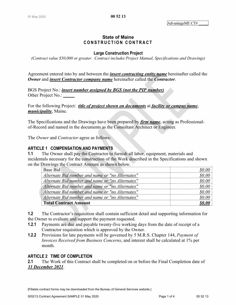
State of Maine C O N S T R U C T I O N C O N T R A C T
Large Construction Project
(Contract value $50,000 or greater. Contract includes Project Manual, Specifications and Drawings)
Agreement entered into by and between the insert contracting entity name hereinafter called the Owner and insert Contractor company name hereinafter called the Contractor. BGS Project No.: insert number assigned by BGS (not the PIP number) Other Project No.: For the following Project: title of project shown on documents at facility or campus name, municipality, Maine. The Specifications and the Drawings have been prepared by firm name, acting as Professional-of-Record and named in the documents as the Consultant Architect or Engineer. The Owner and Contractor agree as follows: ARTICLE 1 COMPENSATION AND PAYMENTS 1.1 The Owner shall pay the Contractor to furnish all labor, equipment, materials and incidentals necessary for the construction of the Work described in the Specifications and shown on the Drawings the Contract Amount as shown below.
Base Bid $0.00 Alternate Bid number and name or "no Alternates" $0.00 Alternate Bid number and name or "no Alternates" $0.00 Alternate Bid number and name or "no Alternates" $0.00 Alternate Bid number and name or "no Alternates" $0.00 Alternate Bid number and name or "no Alternates" $0.00 Total Contract Amount $0.00
1.2 The Contractor’s requisition shall contain sufficient detail and supporting information for the Owner to evaluate and support the payment requested. 1.2.1 Payments are due and payable twenty-five working days from the date of receipt of a
Contractor requisition which is approved by the Owner. 1.2.2 Provisions for late payments will be governed by 5 M.R.S. Chapter 144, Payment of
Invoices Received from Business Concerns, and interest shall be calculated at 1% per month.
ARTICLE 2 TIME OF COMPLETION 2.1 The Work of this Contract shall be completed on or before the Final Completion date of 31 December 2021.

01 May 2020 00 52 13
[Fillable contract forms may be downloaded from the Bureau of General Services website.] 005213 Contract Agreement SAMPLE 01 May 2020 Page 2 of 4 00 52 13
The following abbreviated definitions are for reference only, see Section 00 71 00 Definitions for actual definitions. Substantial Completion: date of first beneficial use by the Owner. Final Completion: the Contractor’s final completion deadline. Contract Expiration: the Owner’s deadline for management of contract accounts.
ARTICLE 3 INELIGIBLE BIDDER 3.1 By signing this contract the Contractor attests that it has not been declared ineligible to bid on State of Maine projects. The Bureau of General Services may disallow award of this contract to any Contractor if there is evidence that the Contractor or any of its Subcontractors, through their own fault, have been terminated, suspended for cause, debarred from bidding, agreed to refrain from bidding as part of a settlement, have defaulted on a contract, or had a contract completed by another party. 3.2 By signing this contract the Contractor attests that it is not presently indicted for or otherwise criminally or civilly charged by a Federal, State or local government entity with commission of any of the following offenses and has not within a three-year period preceding this bid been convicted of or had a civil judgment rendered against them for commission of fraud or a criminal offense in connection with obtaining, attempting to obtain, or performing a public (Federal, State or local) transaction, or contract under a public transaction, violation of Federal or State anti-trust statutes or commission of embezzlement, theft, forgery, bribery, falsification or destruction of records, making false statements, or receiving stolen property. 3.3 The Contractor shall not make any award or permit any award (subgrant or contract) at any tier to any party which is debarred or suspended or is otherwise excluded from or ineligible for participation in Federal assistance programs or State of Maine projects. ARTICLE 4 CONTRACTOR’S RESPONSIBILITIES 4.1 On this project, the Contractor shall furnish the Owner the appropriate contract bonds in the amount of 100% of the Contract Sum. Contract bonds are mandated if the Contract Sum exceeds $125,000, or if bonds are specifically required by the Contract Documents. 4.2 The Owner has verified the appropriate coverage with the State of Maine Division of Risk Management, and selected the proper option as follows. Property Insurance for this construction contract, described in the Insurance Requirements section of the General Conditions of the contract, shall be Non-standard project insured by Contractor. 4.3 The Contractor shall comply with all laws, codes and regulations applicable to the Work. 4.4 The Contractor shall acquire all permits and third-party approvals applicable to the Work not specifically identified as provided by the Owner. Costs for Contractor-provided permits and third-party approvals shall be included in the Contract Sum identified in Section 1.1 above. 4.5 The Contractor shall remain an independent agent for the duration of this Contract, shall not become an employee of the State of Maine, and shall assure that no State employee will be compensated by, or otherwise benefit from, this Contract.

01 May 2020 00 52 13
[Fillable contract forms may be downloaded from the Bureau of General Services website.] 005213 Contract Agreement SAMPLE 01 May 2020 Page 3 of 4 00 52 13
4.6 The Contractor shall be responsible for any design cost, construction cost, or other cost incurred on the Project to the extent caused by the negligent acts, errors or omissions of the Contractor or their Subcontractors in the performance of Work under this Contract. ARTICLE 5 OWNER'S RESPONSIBILITIES 5.1 The Owner shall provide full information about the objectives, schedule, constraints and existing conditions of the project. The Owner has established a budget with reasonable contingencies that meets the project requirements. 5.2 By signing this contract, the Owner attests that all State of Maine procurement requirements for this contract have been met, including the solicitation of competitive bids. ARTICLE 6 INSTRUMENTS OF SERVICE 6.1 The Contractor’s use of the drawings, specifications and other documents known as the Consultant’s Instruments of Service is limited to the execution of the Contractor’s scope of work of this project unless the Contractor receives the written consent of the Owner and Consultant for use elsewhere. ARTICLE 7 MISCELLANEOUS PROVISIONS 7.1 This Contract shall be governed by the laws of the State of Maine. 7.2 The Owner and Contractor, respectively, bind themselves, their partners, successors, assigns and legal representatives to this Contract. Neither party to this Contract shall assign the Contract as a whole without written consent of the other party, which consent the Owner may withhold without cause. 7.3 Notwithstanding any other provision of this Agreement, if the Owner does not receive sufficient funds to fund this Agreement or funds are de-appropriated, or if the Owner does not receive legal authority from the Maine State Legislature or Maine Courts to expend funds intended for this Agreement, then the Owner is not obligated to make payment under this Agreement; provided, however, the Owner shall be obligated to pay for services satisfactorily performed prior to any such non-appropriation in accordance with the termination provisions of this agreement. The Owner shall timely notify the Consultant of any non-appropriation and the effective date of the non-appropriation. ARTICLE 8 CONTRACT DOCUMENTS 8.1 The General Conditions of the contract, instructions to bidders, bid form, Special Provisions, the written specifications and the drawings, and any Addenda, together with this agreement, form the contract. Each element is as fully a part of the Contract as if hereto attached or herein repeated. 8.2 Specifications: indicate date of issuance of project manual 8.3 Drawings: note each sheet number and title 8.4 Addenda: note each addenda number and date, or "none"

01 May 2020 00 52 13
[Fillable contract forms may be downloaded from the Bureau of General Services website.] 005213 Contract Agreement SAMPLE 01 May 2020 Page 4 of 4 00 52 13
BGS Project No.: The Agreement is effective as of the date executed by the approval authority. OWNER CONTRACTOR
(Signature) (Date) (Signature) (Date) name and title name and title name of contracting entity name of contractor company address address telephone telephone email address email address Vendor Number
(Indicate names of the review and approval individuals appropriate to the approval authority.)
select proper approval authority Reviewed by: Approved by:
(Signature) (Date) (Signature) (Date) insert name Joseph H. Ostwald Project Manager/ Contract Administrator Director, Planning, Design & Construction

13 December 2018 00 61 13.13
Contractor Performance Bond
[Fillable bond forms may be downloaded from the Bureau of Real Estate Management website.] 006113.13 Contractor Performance Bond SAMPLE 13 Dec 2018 Page 1 of 2 00 61 13.13
Bond No.: insert bond number
We, the undersigned, insert company name of Contractor, select type of entity of insert name of
municipality in the State of insert name of state as principal, and insert name of surety as Surety, are
hereby held and firmly bound unto select title of obligee in the penal sum of the Contract Price $ insert
the Contract Price in numbers for the payment of which, well and truly to be made, we hereby jointly
and severally bind ourselves, our heirs, executors, administrators, successors and assigns.
The condition of the above obligation is such that if the principal shall promptly and faithfully
perform the contract entered into this insert date, i.e.: 8th day of select month, select year, which is the
same date as that of the notice of intent to award letter, or in the absence of such a letter, not later than the
date the Owner signs the construction contract, for the construction of insert name of project as
designated in the contract documents, then this obligation shall be null and void.
Otherwise, the same shall remain in force and effect- it being expressly understood and agreed
that the liability of the Surety for any and all claims hereunder shall, in no event, exceed the penal amount
of this obligation as herein stated.
The Surety, for value received hereby stipulates and agrees that the obligation of said Surety and
its bonds shall be in no way impaired or affected by any extension of the time which the Obligee may
accept during the performance of the contract and said Surety does hereby waive notice of any such
extension.

13 December 2018 00 61 13.13
Contractor Performance Bond
[Fillable bond forms may be downloaded from the Bureau of Real Estate Management website.] 006113.13 Contractor Performance Bond SAMPLE 13 Dec 2018 Page 2 of 2 00 61 13.13
In witness whereof, the principal and the Surety have hereunto set their hands and seals, and such
of them as are corporations have caused their corporate seals to be hereto affixed and these presents to be
signed by their proper officers, the day and year first set above.
Signed and sealed this insert date, i.e.: 8th day of select month, select year, which is the same
date as that of the notice of intent to award letter, or in the absence of such a letter, not later than the date
the Owner signs the construction contract.
Contractor
(Signature) insert name and title
insert company name
insert address
insert city state zip code
Surety
(Signature) insert name and title
insert company name
insert address
insert city state zip code
If Contractor is a partnership, all partners shall execute the bond. A power of attorney document
indicating that it still is in full force and effect shall be provided by the person executing this bond.

13 December 2018 00 61 13.16
Contractor Payment Bond
[Fillable bond forms may be downloaded from the Bureau of Real Estate Management website.] 006113.16 Contractor Payment Bond SAMPLE 13 Dec 2018 Page 1 of 2 00 61 13.16
Bond No.: insert bond number
We, the undersigned, insert company name of Contractor, select type of entity of insert name of
municipality in the State of insert name of state as principal, and insert name of surety as Surety, are
hereby held and firmly bound unto select title of obligee in the penal sum of the Contract Price $ insert
the Contract Price in numbers for the use and benefit of claimants, defined as an entity having a contract
with the principal or with a subcontractor of the principal for labor, materials, or both labor and materials,
used or reasonably required for use in the performance of the contract, for the payment of which, well and
truly to be made, we hereby jointly and severally bind ourselves, our heirs, executors, administrators,
successors and assigns.
The condition of the above obligation is such that if the principal shall promptly satisfy all claims
and demands incurred for all labor and materials, used or required by the principal in connection with the
work described in the contract entered into this insert date, i.e.: 8th day of select month, select year,
which is the same date as that of the notice of intent to award letter, or in the absence of such a letter, not
later than the date the Owner signs the construction contract, for the construction of insert name of
project as designated in the contract documents, and shall fully reimburse the oblige for all outlay and
expense with said oblige may incur in making good any default of said principal, then this obligation shall
be null and void.
Otherwise, the same shall remain in force and effect- it being expressly understood and agreed
that the liability of the Surety for any and all claims hereunder shall, in no event, exceed the penal amount
of this obligation as herein stated.
The Surety, for value received hereby stipulates and agrees that the obligation of said Surety and
its bonds shall be in no way impaired or affected by any extension of the time which the Obligee may
accept during the performance of the contract and said Surety does hereby waive notice of any such
extension.

13 December 2018 00 61 13.16
Contractor Payment Bond
[Fillable bond forms may be downloaded from the Bureau of Real Estate Management website.] 006113.16 Contractor Payment Bond SAMPLE 13 Dec 2018 Page 2 of 2 00 61 13.16
In witness whereof, the principal and the Surety have hereunto set their hands and seals, and such
of them as are corporations have caused their corporate seals to be hereto affixed and these presents to be
signed by their proper officers, the day and year first set above.
Signed and sealed this insert date, i.e.: 8th day of select month, select year, which is the same
date as that of the notice of intent to award letter, or in the absence of such a letter, not later than the date
the Owner signs the construction contract.
Contractor
(Signature) insert name and title
insert company name
insert address
insert city state zip code
Surety
(Signature) insert name and title
insert company name
insert address
insert city state zip code
If Contractor is a partnership, all partners shall execute the bond. A power of attorney document
indicating that it still is in full force and effect shall be provided by the person executing this bond.
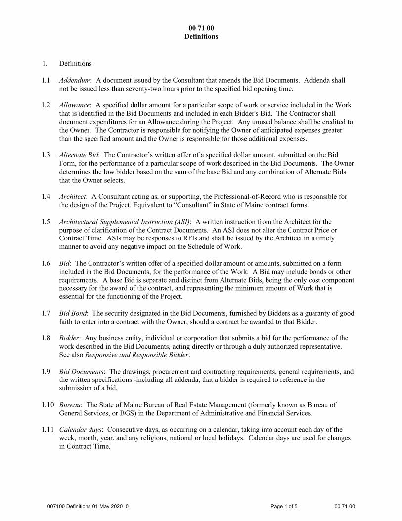
00 71 00 Definitions
007100 Definitions 01 May 2020_0 Page 1 of 5 00 71 00
1. Definitions
1.1 Addendum: A document issued by the Consultant that amends the Bid Documents. Addenda shall not be issued less than seventy-two hours prior to the specified bid opening time.
1.2 Allowance: A specified dollar amount for a particular scope of work or service included in the Work
that is identified in the Bid Documents and included in each Bidder's Bid. The Contractor shall document expenditures for an Allowance during the Project. Any unused balance shall be credited to the Owner. The Contractor is responsible for notifying the Owner of anticipated expenses greater than the specified amount and the Owner is responsible for those additional expenses.
1.3 Alternate Bid: The Contractor’s written offer of a specified dollar amount, submitted on the Bid
Form, for the performance of a particular scope of work described in the Bid Documents. The Owner determines the low bidder based on the sum of the base Bid and any combination of Alternate Bids that the Owner selects.
1.4 Architect: A Consultant acting as, or supporting, the Professional-of-Record who is responsible for
the design of the Project. Equivalent to “Consultant” in State of Maine contract forms.
1.5 Architectural Supplemental Instruction (ASI): A written instruction from the Architect for the purpose of clarification of the Contract Documents. An ASI does not alter the Contract Price or Contract Time. ASIs may be responses to RFIs and shall be issued by the Architect in a timely manner to avoid any negative impact on the Schedule of Work.
1.6 Bid: The Contractor’s written offer of a specified dollar amount or amounts, submitted on a form
included in the Bid Documents, for the performance of the Work. A Bid may include bonds or other requirements. A base Bid is separate and distinct from Alternate Bids, being the only cost component necessary for the award of the contract, and representing the minimum amount of Work that is essential for the functioning of the Project.
1.7 Bid Bond: The security designated in the Bid Documents, furnished by Bidders as a guaranty of good
faith to enter into a contract with the Owner, should a contract be awarded to that Bidder.
1.8 Bidder: Any business entity, individual or corporation that submits a bid for the performance of the work described in the Bid Documents, acting directly or through a duly authorized representative. See also Responsive and Responsible Bidder.
1.9 Bid Documents: The drawings, procurement and contracting requirements, general requirements, and
the written specifications -including all addenda, that a bidder is required to reference in the submission of a bid.
1.10 Bureau: The State of Maine Bureau of Real Estate Management (formerly known as Bureau of
General Services, or BGS) in the Department of Administrative and Financial Services.
1.11 Calendar days: Consecutive days, as occurring on a calendar, taking into account each day of the week, month, year, and any religious, national or local holidays. Calendar days are used for changes in Contract Time.

00 71 00 Definitions
007100 Definitions 01 May 2020_0 Page 2 of 5 00 71 00
1.12 Certificate of Substantial Completion: A document developed by the Consultant that describes the final status of the Work and establishes the date that the Owner may use the facility for its intended purpose. The Certificate of Substantial Completion may also include a provisional list of items - a "punch list" - remaining to be completed by the Contractor. The Certificate of Substantial Completion identifies the date from which the project warranty period commences.
1.13 Certificate of Occupancy: A document developed by a local jurisdiction such as the Code
Enforcement Officer that grants permission to the Owner to occupy a building.
1.14 Change Order (CO): A document that modifies the contract and establishes the basis of a specific adjustment to the Contract Price or the Contract Time, or both. Change Orders may address correction of omissions, errors, and document discrepancies, or additional requirements. Change Orders should include all labor, materials and incidentals required to complete the work described. A Change Order is not valid until signed by the Contractor, Owner and Consultant and approved by the Bureau.
1.15 Change Order Proposal (COP) (see also Proposal): Contract change proposed by the Contractor
regarding the contract amount, requirements, or time. The Contractor implements the work of a COP after it is accepted by all parties. Accepted COPs are incorporated into the contract by Change Order.
1.16 Clerk of the Works: The authorized representative of the Consultant on the job site. Clerk of the
Works is sometimes called the Architect's representative. 1.17 Construction Change Directive (CCD): A written order prepared by the Consultant and signed by the
Owner and Consultant, directing a change in the Work prior to final agreement with the Contractor on adjustment, if any, in the Contract Price or Contract Time, or both.
1.18 Contract: A written agreement between the Owner and the successful bidder which obligates the
Contractor to perform the work specified in the Contract Documents and obligates the Owner to compensate the Contractor at the mutually accepted sum, rates or prices.
1.19 Contract Bonds (also known as Payment and Performance Bonds): The approved forms of security,
furnished by the Contractor and their surety, which guarantee the faithful performance of all the terms of the contract and the payment of all bills for labor, materials and equipment by the Contractor.
1.20 Contract Documents: The drawings and written specifications (including all addenda), Standard
General Conditions, and the contract (including all Change Orders subsequently incorporated in the documents).
1.21 Contract Price: The dollar amount of the construction contract, also called Contract Sum.
1.22 Contract Time: The designated duration of time to execute the Work of the contract, with a specific
date for completion. 1.23 Contractor: Also called the "General Contractor" or "GC" the individual or entity undertaking the
execution of the general contract work under the terms of the contract with the Owner, acting directly or through a duly authorized representative. The Contractor is responsible for the means, methods and materials utilized in the execution and completion of the Work.

00 71 00 Definitions
007100 Definitions 01 May 2020_0 Page 3 of 5 00 71 00
1.24 Consultant: The Architect or Engineer acting as Professional-of-Record for the Project. The Consultant is responsible for the design of the Project.
1.25 Drawings: The graphic and pictorial portion of the Contract Documents showing the design, location
and dimensions of the Work, generally including plans, elevations, sections, details, schedules, and diagrams.
1.26 Engineer: A Consultant acting as, or supporting, the Professional-of-Record who is responsible for
the design of the Project. Equivalent to “Consultant” in State of Maine contract forms. 1.27 Filed Sub-bid: The designated major Subcontractor's (or, in some cases, Contractor’s) written offer
of a specified dollar amount or amounts, submitted on a form included in the Bid Documents, for the performance of a particular portion of the Work. A Filed Sub-bid may include bonds or other requirements.
1.28 Final Completion: Project status establishing the date when the Work is fully completed in
compliance with the Contract Documents, as certified by the Consultant. Final payment to the Contractor is due upon Final Completion of the Project.
1.29 General Requirements: The on-site overhead expense items the Contractor provides for the Project,
typically including, but not limited to, building permits, construction supervision, Contract Bonds, insurance, field office, temporary utilities, rubbish removal, and site fencing. Overhead expenses of the Contractor's general operation are not included. Sometimes referred to as the Contractor's General Conditions.
1.30 Owner: The State agency which is represented by duly authorized individuals. The Owner is
responsible for defining the scope of the Project and compensation to the Consultant and Contractor. 1.31 Owner’s Representative: The individual or entity contracted by the Owner to be an advisor and
information conduit regarding the Project.
1.32 Overhead: General and administrative expenses of the Contractor’s principal and branch offices, including payroll costs and other compensation of Contractor employees, deductibles paid on any insurance policy, charges against the Contractor for delinquent payments, and costs related to the correction of defective work, and the Contractor’s capital expenses, including interest on capital used for the work.
1.33 Performance and Payment Bonds (also known as Contract Bonds): The approved forms of security, furnished by the Contractor and their surety, which guarantee the faithful performance of all the terms of the contract and the payment of all bills for labor, materials and equipment by the Contractor.
1.34 Post-Bid Addendum: Document issued by the Consultant that defines a potential Change Order prior
to signing of the construction contract. The Post-Bid Addendum allows the Owner to negotiate contract changes with the Bidder submitting the lowest valid bid, only if the negotiated changes to the Bid Documents result in no change or no increase in the bid price. A Post-Bid Addendum may also be issued after a competitive construction Bid opening to those Bidders who submitted a Bid initially, for the purpose of rebidding the Project work without re-advertising.

00 71 00 Definitions
007100 Definitions 01 May 2020_0 Page 4 of 5 00 71 00
1.35 Project: The construction project proposed by the Owner to be constructed according to the Contract
Documents. The Project, a public improvement, may be tied logistically to other public improvements and other activities conducted by the Owner or other contractors.
1.36 Proposal (see also Change Order Proposal): The Contractor’s written offer submitted to the Owner
for consideration containing a specified dollar amount or rate, for a specific scope of work, and including a schedule impact, if any. A proposal shall include all costs for overhead and profit. The Contractor implements the work of a Proposal after it is accepted by all parties. Accepted Proposals are incorporated into the contract by Change Order.
1.37 Proposal Request (PR): An Owner's written request to the Contractor for a Change Order Proposal.
1.38 Punch List: A document that identifies the items of work remaining to be done by the Contractor at
the Close Out of a Project. The Punch List is created as a result of a final inspection of the work only after the Contractor attests that all of the Work is in its complete and permanent status.
1.39 Request For Information (RFI): A Contractor’s written request to the Consultant for clarification,
definition or description of the Work. RFIs shall be presented by the Contractor in a timely manner to avoid any negative impact on the Schedule of Work.
1.40 Request For Proposal (RFP): An Owner's written request to the Contractor for a Change Order
Proposal.
1.41 Requisition for Payment: The document in which the Contractor certifies that the Work described is, to the best of the Contractor's knowledge, information and belief, complete and that all previous payments have been paid by the Contractor to Subcontractors and suppliers, and that the current requested payment is now due. See Schedule of Values.
1.42 Responsive and Responsible Bidder: A bidder who complies, on a given project, with the following
responsive standards, as required by the bid documents: provided specific qualifications to bid the project, if required; attended mandatory pre-bid conferences, if required; provided a bid prior to the close of the bid period; submitted a complete bid form; submitted other materials and information, such as bid security, as required;
and, meets the following minimums regarding these responsible standards: sustains a satisfactory record of project performance; maintains a permanent place of business in a known physical location; possesses the financial means for short- and long-term operations; possesses the appropriate technical experience; employs adequate personnel and subcontractor resources; maintains the equipment needed to perform the work; complies with the proposed implementation schedule; complies with the insurance and bonding requirements; can provide post-construction warranty coverage; and other criteria which can be considered relevant to the contract.

00 71 00 Definitions
007100 Definitions 01 May 2020_0 Page 5 of 5 00 71 00
1.43 Retainage: The amount, calculated at five percent (5%) of the contract value or a scheduled value, that the Owner shall withhold from the Contractor until the work or portion of work is declared substantially complete or otherwise accepted by the Owner. The Owner may, if requested, reduce the amount withheld if the Owner deems it desirable and prudent to do so. (See Title 5 M.R.S.A., Section 1746.)
1.44 Sample: A physical example provided by the Contractor which illustrates materials, equipment or
workmanship and establishes standards by which the Work will be judged. 1.45 Schedule of the Work: The document prepared by the Contractor and approved by the Owner that
specifies the dates on which the Contractor plans to begin and complete various parts of the Work, including dates on which information and approvals are required from the Owner.
1.46 Schedule of Values: The document prepared by the Contractor and approved by the Owner before the
commencement of the Work that specifies the dollar values of discrete portions of the Work equal in sum to the contract amount. The Schedule of Values is used to document progress payments of the Work in regular (usually monthly) requisitions for payment. See Requisition for Payment.
1.47 Shop Drawings: The drawings, diagrams, schedules and other data specially prepared for the Work
by the Contractor or a Subcontractor, manufacturer, supplier or distributor to illustrate some portion of the Work.
1.48 Specifications: The portion of the Contract Documents consisting of the written requirements of the
Work for materials, equipment, systems, standards, workmanship, and performance of related services.
1.49 Subcontractor: An individual or entity undertaking the execution of any part of the Work by virtue of
a written agreement with the Contractor or any other Subcontractor. Also, an individual or entity retained by the Contractor or any other Subcontractor as an independent contractor to provide the labor, materials, equipment or services necessary to complete a specific portion of the Work.
1.50 Substantial Completion: Project status indicating when the Work or a designated portion of the Work
is sufficiently complete in compliance with the Contract Documents so that the Owner can occupy or utilize the Work for its intended purpose without unscheduled disruption. Substantial Completion is documented by the date of the Certificate of Substantial Completion signed by the Owner and the Contractor.
1.51 Superintendent: The representative of the Contractor on the job site, authorized by the Contractor to
receive and fulfill instructions from the Consultant. 1.52 Surety: The individual or entity that is legally bound with the Contractor and Subcontractor to insure
the faithful performance of the contract and for the payment of the bills for labor, materials and equipment by the Contractor and Subcontractors.
1.53 Work: The construction and services, whether completed or partially completed, including all labor,
materials, equipment and services provided or to be provided by the Contractor and Subcontractors to fulfill the requirements of the Project as described in the Contract Documents.
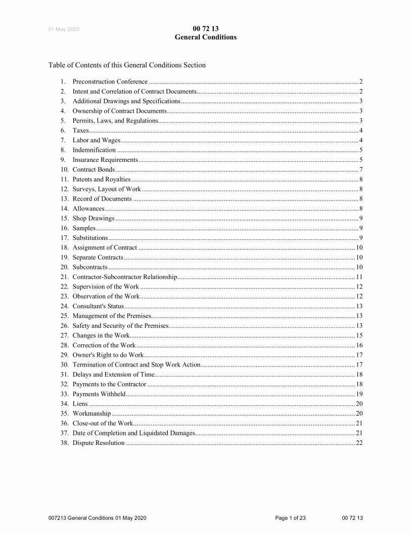
01 May 2020 00 72 13 General Conditions
007213 General Conditions 01 May 2020 Page 1 of 23 00 72 13
Table of Contents of this General Conditions Section
1. Preconstruction Conference ...................................................................................................................... 2 2. Intent and Correlation of Contract Documents ........................................................................................... 2 3. Additional Drawings and Specifications .................................................................................................... 3 4. Ownership of Contract Documents ............................................................................................................ 3 5. Permits, Laws, and Regulations................................................................................................................. 3 6. Taxes ........................................................................................................................................................ 4 7. Labor and Wages ...................................................................................................................................... 4 8. Indemnification ........................................................................................................................................ 5 9. Insurance Requirements ............................................................................................................................ 5 10. Contract Bonds ......................................................................................................................................... 7 11. Patents and Royalties ................................................................................................................................ 8 12. Surveys, Layout of Work .......................................................................................................................... 8 13. Record of Documents ............................................................................................................................... 8 14. Allowances ............................................................................................................................................... 8 15. Shop Drawings ......................................................................................................................................... 9 16. Samples .................................................................................................................................................... 9 17. Substitutions ............................................................................................................................................. 9 18. Assignment of Contract .......................................................................................................................... 10 19. Separate Contracts .................................................................................................................................. 10 20. Subcontracts ........................................................................................................................................... 10 21. Contractor-Subcontractor Relationship .................................................................................................... 11 22. Supervision of the Work ......................................................................................................................... 12 23. Observation of the Work ......................................................................................................................... 12 24. Consultant's Status .................................................................................................................................. 13 25. Management of the Premises................................................................................................................... 13 26. Safety and Security of the Premises ......................................................................................................... 13 27. Changes in the Work............................................................................................................................... 15 28. Correction of the Work ........................................................................................................................... 16 29. Owner's Right to do Work ....................................................................................................................... 17 30. Termination of Contract and Stop Work Action ....................................................................................... 17 31. Delays and Extension of Time................................................................................................................. 18 32. Payments to the Contractor ..................................................................................................................... 18 33. Payments Withheld ................................................................................................................................. 19 34. Liens ...................................................................................................................................................... 20 35. Workmanship ......................................................................................................................................... 20 36. Close-out of the Work ............................................................................................................................. 21 37. Date of Completion and Liquidated Damages .......................................................................................... 21 38. Dispute Resolution ................................................................................................................................. 22

01 May 2020 00 72 13 General Conditions
007213 General Conditions 01 May 2020 Page 2 of 23 00 72 13
1. Preconstruction Conference 1.1 The Contractor shall, upon acceptance of a contract and prior to commencing work, schedule a
preconstruction conference with the Owner and Consultant. The purpose of this conference is as follows.
1.1.1 Introduce all parties who have a significant role in the Project, including: Owner (State agency or other contracting entity)
Owner's Representative Consultant (Architect or Engineer)
Subconsultants Clerk-of-the-works
Contractor (GC) Superintendent Subcontractors Other State agencies Construction testing company Commissioning agent Special Inspections agent Bureau of General Services (BGS); 1.1.2 Review the responsibilities of each party; 1.1.3 Review any previously-identified special provisions of the Project; 1.1.4 Review the Schedule of the Work calendar submitted by the Contractor to be approved by the
Owner and Consultant; 1.1.5 Review the Schedule of Values form submitted by the Contractor to be approved by the Owner
and Consultant; 1.1.6 Establish routines for Shop Drawing approval, contract changes, requisitions, et cetera; 1.1.7 discuss jobsite issues; 1.1.8 Discuss Project close-out procedures; 1.1.9 Provide an opportunity for clarification of Contract Documents before work begins; and 1.1.10 Schedule regular meetings at appropriate intervals for the review of the progress of the Work.
2. Intent and Correlation of Contract Documents 2.1 The intent of the Contract Documents is to describe the complete Project. The Contract
Documents consist of various components; each component complements the others. What is shown as a requirement by any one component shall be inferred as a requirement on all corresponding components.
2.2 The Contractor shall furnish all labor, equipment and materials, tools, transportation, insurance, services, supplies, operations and methods necessary for, and reasonably incidental to, the construction and completion of the Project. Any work that deviates from the Contract Documents which appears to be required by the exigencies of construction or by inconsistencies in the Contract Documents, will be determined by the Consultant and authorized in writing by the Consultant, Owner and the Bureau prior to execution. The Contractor shall be responsible for requesting clarifying information where the intent of the Contract Documents is uncertain.
2.3 The Contractor shall not utilize any apparent error or omission in the Contract Documents to the disadvantage of the Owner. The Contractor shall promptly notify the Consultant in writing of such errors or omissions. The Consultant shall make any corrections or clarifications necessary in such a situation to document the true intent of the Contract Documents.

01 May 2020 00 72 13 General Conditions
007213 General Conditions 01 May 2020 Page 3 of 23 00 72 13
3. Additional Drawings and Specifications 3.1 Upon the written request of the Contractor, the Owner shall provide, at no expense to the
Contractor, up to five sets of printed Drawings and Specifications for the execution of the Work.
3.2 The Consultant shall promptly furnish to the Contractor revised Drawings and Specifications, for the area of the documents where those revisions apply, when corrections or clarifications are made by the Consultant. All such information shall be consistent with, and reasonably inferred from, the Contract Documents. The Contractor shall do no work without the proper Drawings and Specifications.
4. Ownership of Contract Documents 4.1 The designs represented on the Contract Documents are the property of the Consultant. The
Drawings and Specifications shall not be used on other work without consent of the Consultant.
5. Permits, Laws, and Regulations 5.1 The Owner is responsible for obtaining any zoning approvals or other similar local project
approvals necessary to complete the Work, unless otherwise specified in the Contract Documents.
5.2 The Owner is responsible for obtaining Maine Department of Environmental Protection, Maine Department of Transportation, or other similar state government project approvals necessary to complete the Work, unless otherwise indicated in the Contract Documents.
5.3 The Owner is responsible for obtaining any federal agency project approvals necessary to complete the Work, unless otherwise indicated in the Contract Documents.
5.4 The Owner is responsible for obtaining all easements for permanent structures or permanent changes in existing facilities.
5.5 The Contractor is responsible for obtaining and paying for all permits and licenses necessary for the implementation of the Work. The Contractor shall notify the Owner of any delays, variance or restrictions that may result from the issuing of permits and licenses.
5.6 The Contractor shall comply with all ordinances, laws, rules and regulations and make all required notices bearing on the implementation of the Work. In the event the Contractor observes disagreement between the Drawings and Specifications and any ordinances, laws, rules and regulations, the Contractor shall promptly notify the Consultant in writing. Any necessary changes shall be made as provided in the contract for changes in the work. The Contractor shall not perform any work knowing it to be contrary to such ordinances, laws, rules and regulations.
5.7 The Contractor shall comply with local, state and federal regulations regarding construction safety and all other aspects of the Work.
5.8 The Contractor shall comply with the Maine Code of Fair Practices and Affirmative Action, 5 M.R.S. §784 (2).

01 May 2020 00 72 13 General Conditions
007213 General Conditions 01 May 2020 Page 4 of 23 00 72 13
6. Taxes 6.1 The Owner is exempt from the payment of Maine State sales and use taxes as provided in 36
M.R.S. §1760 (1). The Contractor and Subcontractors shall not include taxes on exempt items in the construction contract.
6.2 Section 1760 further provides in subsection 61 that sales to a construction contractor or its subcontractor of tangible personal property that is to be physically incorporated in, and become a permanent part of, real property for sale to or owned by the Owner, are exempt from Maine State sales and use taxes. Tangible personal property is defined in 36 M.R.S. §1752 (17).
6.3 The Contractor may contact Maine Revenue Services, 24 State House Station, Augusta, Maine 04333 for guidance on tax exempt regulations authorized by 36 M.R.S. §1760 and detailed in Rule 302 (18-125 CMR 302).
7. Labor and Wages 7.1 The Contractor shall conform to the labor laws of the State of Maine, and all other laws,
ordinances, and legal requirements affecting the work in Maine.
7.2 The Consultant shall include a wage determination document prepared by the Maine Department of Labor in the Contract Documents for state-funded contracts in excess of $50,000. The document shows the minimum wages required to be paid to each category of labor employed on the project.
7.3 On projects requiring a Maine wage determination, the Contractor shall submit monthly payroll records to the Owner ("the contracting agency") showing the name and occupation of all workers and all independent contractors employed on the project. The monthly submission must also include the Contractor's company name, the title of the project, hours worked, hourly rate or other method of remuneration, and the actual wages or other compensation paid to each person.
7.4 The Contractor shall not reveal, in the payroll records submitted to the Owner, personal information regarding workers and independent contractors, other than the information described above. Such information shall not include Social Security number, employee identification number, or employee address or phone number, for example.
7.5 The Contractor shall conform to Maine statute (39-A M.R.S. §105-A (6)) by providing to the Workers’ Compensation Board a list of all subcontractors and independent contractors on the job site and a record of the entity to whom that subcontractor or independent contractor is directly contracted and by whom that subcontractor or independent contractor is insured for workers' compensation purposes.
7.6 The Contractor shall enforce strict discipline and good order among their employees at all times, and shall not employ any person unfit or unskilled to do the work assigned to them.
7.7 The Contractor shall promptly pay all employees when their compensation is due, shall promptly pay all others who have billed and are due for materials, supplies and services used in the Work, and shall promptly pay all others who have billed and are due for insurance, workers compensation coverage, federal and state unemployment compensation, and Social Security

01 May 2020 00 72 13 General Conditions
007213 General Conditions 01 May 2020 Page 5 of 23 00 72 13
charges pertaining to this Project. Before final payments are made, the Contractor shall furnish to the Owner affidavits that all such payments described above have been made.
7.8 The Contractor may contact the Maine Department of Labor, 54 State House Station, Augusta, Maine 04333 for guidance on labor issues.
7.9 The Contractor may contact the Maine Workers’ Compensation Board, 27 State House Station, Augusta, Maine 04333 for guidance on workers' compensation issues.
8. Indemnification 8.1 The Contractor shall indemnify and hold harmless the Owner and its officers and employees from
and against any and all damages, liabilities, and costs, including reasonable attorney’s fees, and defense costs, for any and all injuries to persons or property, including claims for violation of intellectual property rights, to the extent caused by the negligent acts or omissions of the Contractor, its employees, agents, officers or subcontractors in the performance of work under this Agreement. The Contractor shall not be liable for claims to the extent caused by the negligent acts or omissions of the Owner or for actions taken in reasonable reliance on written instructions of the Owner.
8.2 The Contractor shall notify the Owner promptly of all claims arising out of the performance of
work under this Agreement by the Contractor, its employees or agents, officers or subcontractors.
8.3 This indemnity provision shall survive the termination of the Agreement, completion of the project or the expiration of the term of the Agreement.
9. Insurance Requirements 9.1 The Contractor shall provide, with each original of the signed Contract, an insurance certificate or
certificates acceptable to the Owner and BGS. The Contractor shall submit insurance certificates to the Owner and BGS at the commencement of this Contract and at policy renewal or revision dates. The certificates shall identify the project name and BGS project number, and shall name the Owner as certificate holder and as additional insured for general liability and automobile liability coverages. The submitted forms shall contain a provision that coverage afforded under the insurance policies will not be canceled or materially changed unless at least ten days prior written notice by registered letter has been given to the Owner and BGS.
9.2 The Owner does not warrant or represent that the insurance required herein constitutes an insurance portfolio which adequately addresses all risks faced by the Contractor or its Subcontractors. The Contractor is responsible for the existence, extent and adequacy of insurance prior to commencement of work. The Contractor shall not allow any Subcontractor to commence work until all similar insurance required of the Subcontractor has been confirmed by the Contractor.
9.3 The Contractor shall procure and maintain primary insurance for the duration of the Project and, if written on a Claims-Made basis, shall also procure and maintain Extended Reporting Period (ERP) insurance for the period of time that any claims could be brought. The Contractor shall ensure that all Subcontractors they engage or employ will procure and maintain similar insurance

01 May 2020 00 72 13 General Conditions
007213 General Conditions 01 May 2020 Page 6 of 23 00 72 13
in form and amount acceptable to the Owner and BGS. At a minimum, the insurance shall be of the types and limits set forth herein protecting the Contractor from claims which may result from the Contractor’s execution of the Work, whether such execution be by the Contractor or by those employed by the Contractor or by those for whose acts they may be liable. All required insurance coverages shall be placed with carriers authorized to conduct business in the State of Maine by the Maine Bureau of Insurance.
9.3.1 The Contractor shall have Workers’ Compensation insurance for all employees on the Project site in accordance with the requirements of the Workers’ Compensation law of the State of Maine. Minimum acceptable limits for Employer’s Liability are:
Bodily Injury by Accident........................................ $500,000 Bodily Injury by Disease ......................................... $500,000 Each Employee Bodily Injury by Disease ......................................... $500,000 Policy Limit
9.3.2 The Contractor shall have Commercial General Liability insurance providing coverage for bodily injury and property damage liability for all hazards of the Project including premise and operations, products and completed operations, contractual, and personal injury liabilities. The policy shall include collapse and underground coverage as well as explosion coverage if explosion hazards exist. Aggregate limits shall apply on a location or project basis. Minimum acceptable limits are:
General aggregate limit ............................................ $2,000,000 Products and completed operations aggregate ........... $1,000,000 Each occurrence limit .............................................. $1,000,000 Personal injury aggregate ......................................... $1,000,000
9.3.3 The Contractor shall have Automobile Liability insurance against claims for bodily injury, death or property damage resulting from the maintenance, ownership or use of all owned, non-owned and hired automobiles, trucks and trailers. Minimum acceptable limit is:
Any one accident or loss .......................................... $500,000
9.3.4 The Contractor shall have Owner’s Protective Liability insurance for contract values $50,000 and above, naming the Owner as the Named Insured. Minimum acceptable limits are:
General aggregate limit ............................................ $2,000,000 Each occurrence limit .............................................. $1,000,000
9.4 The Owner has determined the appropriate coverage for this particular project, verified the coverage with the State of Maine Division of Risk Management, and selected the proper option on the contract form. Property Insurance for this construction contract shall be one of the options described below.
9.4.1 Non-standard project insured by the Contractor – Projects of this type include, but are not limited to, site improvements such as parking lots, boat launches, utility runs, and free-standing mechanical or electrical equipment, and do not necessarily include buildings. The Contractor shall procure and maintain an appropriate level of property insurance naming the Owner, Contractor and any Subcontractors as insureds as their interest may appear. Covered cause of loss form shall be all Risks of Direct Physical Loss, endorsed to include flood, earthquake, transit and sprinkler leakage where sprinkler coverage is applicable. Unless specifically authorized in writing by the Owner, the limit of insurance shall not be less than the initial contract amount and coverage shall apply during the entire contract period until the Certificate of Substantial Completion is accepted by the Owner.
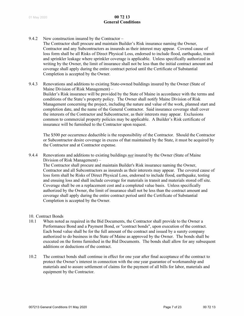
01 May 2020 00 72 13 General Conditions
007213 General Conditions 01 May 2020 Page 7 of 23 00 72 13
9.4.2 New construction insured by the Contractor – The Contractor shall procure and maintain Builder’s Risk insurance naming the Owner, Contractor and any Subcontractors as insureds as their interest may appear. Covered cause of loss form shall be all Risks of Direct Physical Loss, endorsed to include flood, earthquake, transit and sprinkler leakage where sprinkler coverage is applicable. Unless specifically authorized in writing by the Owner, the limit of insurance shall not be less than the initial contract amount and coverage shall apply during the entire contract period until the Certificate of Substantial Completion is accepted by the Owner.
9.4.3 Renovations and additions to existing State-owned buildings insured by the Owner (State of Maine Division of Risk Management) – Builder’s Risk insurance will be provided by the State of Maine in accordance with the terms and conditions of the State’s property policy. The Owner shall notify Maine Division of Risk Management concerning the project, including the nature and value of the work, planned start and completion date, and the name of the General Contractor. Said insurance coverage shall cover the interests of the Contractor and Subcontractor, as their interests may appear. Exclusions common to commercial property policies may be applicable. A Builder’s Risk certificate of insurance will be furnished to the Contractor upon request. The $500 per occurrence deductible is the responsibility of the Contractor. Should the Contractor or Subcontractor desire coverage in excess of that maintained by the State, it must be acquired by the Contractor and at Contractor expense.
9.4.4 Renovations and additions to existing buildings not insured by the Owner (State of Maine Division of Risk Management) – The Contractor shall procure and maintain Builder's Risk insurance naming the Owner, Contractor and all Subcontractors as insureds as their interests may appear. The covered cause of loss form shall be Risks of Direct Physical Loss, endorsed to include flood, earthquake, testing and ensuing loss and shall include coverage for materials in transit and materials stored off site. Coverage shall be on a replacement cost and a completed value basis. Unless specifically authorized by the Owner, the limit of insurance shall not be less than the contract amount and coverage shall apply during the entire contract period until the Certificate of Substantial Completion is accepted by the Owner.
10. Contract Bonds 10.1 When noted as required in the Bid Documents, the Contractor shall provide to the Owner a
Performance Bond and a Payment Bond, or "contract bonds", upon execution of the contract. Each bond value shall be for the full amount of the contract and issued by a surety company authorized to do business in the State of Maine as approved by the Owner. The bonds shall be executed on the forms furnished in the Bid Documents. The bonds shall allow for any subsequent additions or deductions of the contract.
10.2 The contract bonds shall continue in effect for one year after final acceptance of the contract to protect the Owner’s interest in connection with the one year guarantee of workmanship and materials and to assure settlement of claims for the payment of all bills for labor, materials and equipment by the Contractor.

01 May 2020 00 72 13 General Conditions
007213 General Conditions 01 May 2020 Page 8 of 23 00 72 13
11. Patents and Royalties 11.1 The Contractor shall, for all time, secure for the Owner the free and undisputed right to the use of
any patented articles or methods used in the Work. The expense of defending any suits for infringement or alleged infringement of such patents shall be borne by the Contractor. Awards made regarding patent suits shall be paid by the Contractor. The Contractor shall hold the Owner harmless regarding patent suits that may arise due to installations made by the Contractor, and to any awards made as a result of such suits.
11.2 Any royalty payments related to the work done by the Contractor for the Project shall be borne by the Contractor. The Contractor shall hold the Owner harmless regarding any royalty payments that may arise due to installations made by the Contractor.
12. Surveys, Layout of Work 12.1 The Owner shall furnish all property surveys unless otherwise specified.
12.2 The Contractor is responsible for correctly staking out the Work on the site. The Contractor shall
employ a competent surveyor to position all construction on the site. The surveyor shall run the axis lines, establish correct datum points and check each line and point on the site to insure their accuracy. All such lines and points shall be carefully preserved throughout the construction.
12.3 The Contractor shall lay out all work from dimensions given on the Drawings. The Contractor shall take measurements and verify dimensions of any existing work that affects the Work or to which the Work is to be fitted. The Contractor is solely responsible for the accuracy of all measurements. The Contractor shall verify all grades, lines, levels, elevations and dimensions shown on the Drawings and report any errors or inconsistencies to the Consultant prior to commencing work.
13. Record of Documents 13.1 The Contractor shall maintain one complete set of Contract Documents on the jobsite, in good
order and current status, for access by the Owner and Consultant.
13.2 The Contractor shall maintain, continuously updated, complete records of Requests for Information, Architectural Supplemental Instructions (or equivalent), Information Bulletins, supplemental sketches, Change Order Proposals, Change Orders, Shop Drawings, testing reports, et cetera, for access by the Owner and Consultant.
14. Allowances 14.1 The Contract Price shall include all allowances described in the Contract Documents. The
Contractor shall include all overhead and profit necessary to implement each allowance in their Contract Price.
14.2 The Contractor shall not be required to employ parties for allowance work against whom the Contractor has a reasonable objection. In such a case, the Contractor shall notify the Owner in writing of their position and shall propose an alternative party to complete the work of the allowance.

01 May 2020 00 72 13 General Conditions
007213 General Conditions 01 May 2020 Page 9 of 23 00 72 13
15. Shop Drawings 15.1 The Contractor shall administer Shop Drawings prepared by the Contractor, Subcontractors,
suppliers or others to conform to the approved Schedule of the Work. The Contractor shall verify all field measurements, check and authorize all Shop Drawings and schedules required by the Work. The Contractor is the responsible party and contact for the Contractor's work as well as that of Subcontractors, suppliers or others who provide Shop Drawings.
15.2 The Consultant shall review and acknowledge Shop Drawings, with reasonable promptness, for general conformity with the design concept of the project and compliance with the information provided in the Contract Documents.
15.3 The Contractor shall provide monthly updated logs containing: requests for information, information bulletins, supplemental instructions, supplemental sketches, change order proposals, change orders, submittals, testing and deficiencies.
15.4 The Contractor shall make any corrections required by the Consultant, and shall submit a quantity of corrected copies as may be needed. The acceptance of Shop Drawings or schedules by the Consultant shall not relieve the Contractor from responsibility for deviations from Drawings and Specifications, unless the Contractor has called such deviations to the attention of the Consultant at the time of submission and secured the Consultant’s written approval. The acceptance of Shop Drawings or schedules by the Consultant does not relieve the Contractor from responsibility for errors in Shop Drawings or schedules.
16. Samples 16.1 The Contractor shall furnish for approval, with reasonable promptness, all samples as directed by
the Consultant. The Consultant shall review and approve such samples, with reasonable promptness, for general conformity with the design concept of the project and compliance with the information provided in the Contract Documents. The subsequent work shall be in accord with the approved samples.
17. Substitutions 17.1 The Contractor shall furnish items and materials described in the Contract Documents. If the
item or material specified describes a proprietary product, or uses the name of a manufacturer, the term “or approved equal” shall be implied, if it is not included in the text. The specific item or material specified establishes a minimum standard for the general design, level of quality, type, function, durability, efficiency, reliability, compatibility, warranty coverage, installation factors and required maintenance. The Drawing or written Specification shall not be construed to exclude other manufacturers products of comparable design, quality, and efficiency.
17.2 The Contractor may submit detailed information about a proposed substitution to the Consultant for consideration. Particular models of items and particular materials which the Contractor asserts to be equal to the items and materials identified in the Contract Documents shall be allowed only with written approval by the Consultant. The request for substitution shall include a cost comparison and a reason or reasons for the substitution.
17.3 The Consultant may request additional information about the proposed substitution. The approval or rejection of a proposed substitution may be based on timeliness of the request, source

01 May 2020 00 72 13 General Conditions
007213 General Conditions 01 May 2020 Page 10 of 23 00 72 13
of the information, the considerations of minimum standards described above, or other considerations. The Consultant should briefly state the rationale for the decision. The decision shall be considered final.
17.4 The duration of a substitution review process can not be the basis for a claim for delay in the Schedule of the Work.
18. Assignment of Contract 18.1 The Contractor shall not assign or sublet the contract as a whole without the written consent of
the Owner. The Contractor shall not assign any money due to the Contractor without the written consent of the Owner.
19. Separate Contracts 19.1 The Owner reserves the right to create other contracts in connection with this Project using
similar General Conditions. The Contractor shall allow the Owner's other contractors reasonable opportunity for the delivery and storage of materials and the execution of their work. The Contractor shall coordinate and properly connect the Work of all contractors.
19.2 The Contractor shall promptly report to the Consultant and Owner any apparent deficiencies in work of the Owner's other contractors that impacts the proper execution or results of the Contractor. The Contractor’s failure to observe or report any deficiencies constitutes an acceptance of the Owner's other contractors work as suitable for the interface of the Contractor’s work, except for latent deficiencies in the Owner's other contractors work.
19.3 Similarly, the Contractor shall promptly report to the Consultant and Owner any apparent deficiencies in their own work that would impact the proper execution or results of the Owner's other contractors.
19.4 The Contractor shall report to the Consultant and Owner any conflicts or claims for damages with the Owner's other contractors and settle such conflicts or claims for damages by mutual agreement or arbitration, if necessary, at no expense to the Owner.
19.5 In the event the Owner's other contractors sue the Owner regarding any damage alleged to have been caused by the Contractor, the Owner shall notify the Contractor, who shall defend such proceedings at the Contractor's expense. The Contractor shall pay or satisfy any judgment that may arise against the Owner, and pay all other costs incurred.
20. Subcontracts 20.1 The Contractor shall not subcontract any part of this contract without the written permission of
the Owner.
20.2 The Contractor shall submit a complete list of named Subcontractors and material suppliers to the Consultant and Owner for approval by the Owner prior to commencing work. The Subcontractors named shall be reputable companies of recognized standing with a record of satisfactory work.

01 May 2020 00 72 13 General Conditions
007213 General Conditions 01 May 2020 Page 11 of 23 00 72 13
20.3 The Contractor shall not employ any Subcontractor or use any material until they have been approved, or where there is reason to believe the resulting work will not comply with the Contract Documents.
20.4 The Contractor, not the Owner, is as fully responsible for the acts and omissions of Subcontractors and of persons employed by them, as the Contractor is for the acts and omissions of persons directly or indirectly employed by the Contractor.
20.5 Neither the Contract Documents nor any Contractor-Subcontractor contract shall indicate, infer or create any direct contractual relationship between any Subcontractor and the Owner.
21. Contractor-Subcontractor Relationship 21.1 The Contractor shall be bound to the Subcontractor by all the obligations in the Contract
Documents that bind the Contractor to the Owner.
21.2 The Contractor shall pay the Subcontractor, in proportion to the dollar value of the work completed and requisitioned by the Subcontractor, the approved dollar amount allowed to the Contractor no more than seven days after receipt of payment from the Owner.
21.3 The Contractor shall pay the Subcontractor accordingly if the Contract Documents or the subcontract provide for earlier or larger payments than described in the provision above.
21.4 The Contractor shall pay the Subcontractor for completed and requisitioned subcontract work, less retainage, no more than seven days after receipt of payment from the Owner for the Contractor's approved Requisition for Payment, even if the Consultant fails to certify a portion of the Requisition for Payment for a cause not the fault of the Subcontractor.
21.5 The Contractor shall not make a claim for liquidated damages or penalty for delay in any amount in excess of amounts that are specified by the subcontract.
21.6 The Contractor shall not make a claim for services rendered or materials furnished by the Subcontractor unless written notice is given by the Contractor to the Subcontractor within ten calendar days of the day in which the claim originated.
21.7 The Contractor shall give the Subcontractor an opportunity to present and to submit evidence in any progress conference or disputes involving subcontract work.
21.8 The Contractor shall pay the Subcontractor a just share of any fire insurance payment received by the Contractor.
21.9 The Subcontractor shall be bound to the Contractor by the terms of the Contract Documents and assumes toward the Contractor all the obligations and responsibilities that the Contractor, by those documents, assumes toward the Owner.
21.10 The Subcontractor shall submit applications for payment to the Contractor in such reasonable time as to enable the Contractor to apply for payment as specified.

01 May 2020 00 72 13 General Conditions
007213 General Conditions 01 May 2020 Page 12 of 23 00 72 13
21.11 The Subcontractor shall make any claims for extra cost, extensions of time or damages, to the Contractor in the manner provided in these General Conditions for like claims by the Contractor to the Owner, except that the time for the Subcontractor to make claims for extra cost is seven calendar days after the receipt of Consultant's instructions.
22. Supervision of the Work 22.1 During all stages of the Work the Contractor shall have a competent superintendent, with any
necessary assistant superintendents, overseeing the project. The superintendent shall not be reassigned without the consent of the Owner unless a superintendent ceases to be employed by the Contractor due to unsatisfactory performance.
22.2 The superintendent represents the Contractor on the jobsite. Directives given by the Consultant or Owner to the superintendent shall be as binding as if given directly to the Contractor's main office. All important directives shall be confirmed in writing to the Contractor. The Consultant and Owner are not responsible for the acts or omissions of the superintendent or assistant superintendents.
22.3 The Contractor shall provide supervision of the Work equal to the industry's highest standard of care. The superintendent shall carefully study and compare all Contract Documents and promptly report any error, inconsistency or omission discovered to the Consultant. The Contractor may not necessarily be held liable for damages resulting directly from any error, inconsistency or omission in the Contract Documents or other instructions by the Consultant that was not revealed by the superintendent in a timely way.
23. Observation of the Work 23.1 The Contractor shall allow the Owner, the Consultant and the Bureau continuous access to the
site for the purpose of observation of the progress of the work. All necessary safeguards and accommodations for such observations shall be provided by the Contractor.
23.2 The Contractor shall coordinate all required testing, approval or demonstration of the Work. The Contractor shall give sufficient notice to the appropriate parties of readiness for testing, inspection or examination.
23.3 The Contractor shall schedule inspections and obtain all required certificates of inspection for inspections by a party other than the Consultant.
23.4 The Consultant shall make all scheduled observations promptly, prior to the work being concealed or buried by the Contractor. If approval of the Work is required of the Consultant, the Contractor shall notify the Consultant of the construction schedule in this regard. Work concealed or buried prior to the Consultant's approval may need to be uncovered at the Contractor’s expense.
23.5 The Consultant may order reexamination of questioned work, and, if so ordered, the work must be uncovered by the Contractor. If the work is found to conform to the Contract Documents, the Owner shall pay the expense of the reexamination and remedial work. If the work is found to not conform to the Contract Documents, the Contractor shall pay the expense, unless the defect in the

01 May 2020 00 72 13 General Conditions
007213 General Conditions 01 May 2020 Page 13 of 23 00 72 13
work was caused by the Owner's Contractor, whose responsibility the reexamination expense becomes.
23.6 The Bureau shall periodically observe the Work during the course of construction and make recommendations to the Contractor or Consultant as necessary. Such recommendations shall be considered and implemented through the usual means for changes to the Work.
24. Consultant's Status 24.1 The Consultant represents the Owner during the construction period, and observes the work in
progress on behalf of the Owner. The Consultant has authority to act on behalf of the Owner only to the extent expressly provided by the Contract Documents or otherwise demonstrated to the Contractor. The Consultant has authority to stop the work whenever such an action is necessary, in the Consultant's reasonable opinion, to ensure the proper execution of the contract.
24.2 The Consultant is the interpreter of the conditions of the contract and the judge of its performance. The Consultant shall favor neither the Owner nor the Contractor, but shall use the Consultant’s powers under the contract to enforce faithful performance by both parties.
24.3 In the event of the termination of the Consultant's employment on the project prior to completion of the work, the Owner shall appoint a capable and reputable replacement. The status of the new Consultant relative to this contract shall be that of the former Consultant.
25. Management of the Premises 25.1 The Contractor shall place equipment and materials, and conduct activities on the premises in a
manner that does not unreasonably hinder site circulation, environmental stability, or any long term effect. Likewise, the Consultant's directions shall not cause the use of premises to be impeded for the Contractor or Owner.
25.2 The Contractor shall not use the premises for any purpose other than that which is directly related to the scope of work. The Owner shall not use the premises for any purpose incompatible with the proposed work simultaneous to the work of the Contractor.
25.3 The Contractor shall enforce the Consultant’s instructions regarding information posted on the premises such as signage and advertisements, as well as activities conducted on the premises such as fires, and smoking.
25.4 The Owner may occupy any part of the Project that is completed with the written consent of the Contractor, and without prejudice to any of the rights of the Owner or Contractor. Such use or occupancy shall not, in and of itself, be construed as a final acceptance of any work or materials.
26. Safety and Security of the Premises 26.1 The Contractor shall designate, and make known to the Consultant and the Owner, a safety
officer whose duty is the prevention of accidents on the site.

01 May 2020 00 72 13 General Conditions
007213 General Conditions 01 May 2020 Page 14 of 23 00 72 13
26.2 The Contractor shall continuously maintain security on the premises and protect from unreasonable occasion of injury all people authorized to be on the job site. The Contractor shall also effectively protect the property and adjacent properties from damage or loss.
26.3 The Contractor shall take all necessary precautions to ensure the safety of workers and others on and adjacent to the site, abiding by applicable local, state and federal safety regulations. The Contractor shall erect and continuously maintain safeguards for the protection of workers and others, and shall post signs and other warnings regarding hazards associated with the construction process, such as protruding fasteners, moving equipment, trenches and holes, scaffolding, window, door or stair openings, and falling materials.
26.4 The Contractor shall restore the premises to conditions that existed prior to the start of the project at areas not intended to be altered according to the Contract Documents.
26.5 The Contractor shall protect existing utilities and exercise care working in the vicinity of utilities shown in the Drawings and Specifications or otherwise located by the Contractor.
26.6 The Contractor shall protect from damage existing trees and other significant plantings and landscape features of the site which will remain a permanent part of the site. If necessary or indicated in the Contract Documents, tree trunks shall be boxed and barriers erected to prevent damage to tree branches or roots.
26.7 The Contractor shall repair or replace damage to the Work caused by the Contractor’s or Subcontractor’s forces, including that which is reasonably protected, at the expense of the responsible party.
26.8 The Contractor shall not load, or allow to be loaded, any part of the Project with a force which imperils personal or structural safety. The Consultant may consult with the Contractor on such means and methods of construction, however, the ultimate responsibility lies with the Contractor.
26.9 The Contractor shall not jeopardize any work in place with subsequent construction activities such as blasting, drilling, excavating, cutting, patching or altering work. The Consultant must approve altering any structural components of the project. The Contractor shall supervise all construction activities carried out by others on site to ensure that the work is neatly done and in a manner that will not endanger the structure or the component parts.
26.10 The Contractor may act with their sole discretion in emergency situations that potentially effect health, life or serious damage to the premises or adjacent properties, to prevent such potential loss or injury. The Contractor may negotiate with the Owner for compensation for expenses due to such emergency work.
26.11 The Contractor and Subcontractors shall have no responsibility for the identification, discovery, presence, handling, removal or disposal of, or exposure of persons to, hazardous materials in any form at the project site. The Contractor shall avoid disruption of any hazardous materials or toxic substances at the project site and promptly notify the Owner in writing on the occasion of such a discovery.

01 May 2020 00 72 13 General Conditions
007213 General Conditions 01 May 2020 Page 15 of 23 00 72 13
26.12 The Contractor shall keep the premises free of any unsafe accumulation of waste materials caused by the work. The Contractor shall regularly keep the spaces “broom clean”. See the Close-out of the Work provisions of this section regarding cleaning at the completion of the project.
27. Changes in the Work 27.1 The Contractor shall not proceed with extra work without an approved Change Order or
Construction Change Directive. A Change Order which has been properly signed by all parties shall become a part of the contract.
27.2 A Change Order is the usual document for directing changes in the Work. In certain circumstances, however, the Owner may utilize a Construction Change Directive to direct the Contractor to perform changes in the Work that are generally consistent with the scope of the project. The Owner shall use a Construction Change Directive only when the normal process for approving changes to the Work has failed to the detriment of the Project, or when agreement on the terms of a Change Order cannot be met, or when an urgent situation requires, in the Owner's judgment, prompt action by the Contractor.
27.3 The Consultant shall prepare the Construction Change Directive representing a complete scope of work, with proposed Contract Price and Contract Time revisions, if any, clearly stated.
27.4 The Contractor shall promptly carry out a Construction Change Directive which has been signed by the Owner and the Consultant. Work thus completed by the Contractor constitutes the basis for a Change Order. Changes in the Contract Price and Contract Time shall be as defined in the Construction Change Directive unless subsequently negotiated with some other terms.
27.5 The method of determining the dollar value of extra work shall be by: .1 an estimate of the Contractor accepted by Owner as a lump sum, or .2 unit prices named in the contract or subsequently agreed upon, or .3 cost plus a designated percentage, or .4 cost plus a fixed fee.
27.6 The Contractor shall determine the dollar value of the extra work for both the lump sum and cost plus designated percentage methods so as not to exceed the following rates. The rates include all overhead and profit expenses. .1 Contractor - for any work performed by the Contractor’s own forces, up to 20% of the cost; .2 Subcontractor - for work performed by Subcontractor’s own forces, up to 20% of the cost; .3 Contractor - for work performed by Contractor’s Subcontractor, up to 10% of the amount due
the Subcontractor.
27.7 The Contractor shall keep and provide records as needed or directed for the cost plus designated percentage method. The Consultant shall review and certify the appropriate amount which includes the Contractor's overhead and profit. The Owner shall make payments based on the Consultant’s certificate.
27.8 Cost reflected in Change Orders shall be limited to the following: cost of materials, cost of delivery, cost of labor (including Social Security, pension, Workers' Compensation insurance, and unemployment insurance), and cost of rental of power tools and equipment. Labor cost may

01 May 2020 00 72 13 General Conditions
007213 General Conditions 01 May 2020 Page 16 of 23 00 72 13
include a pro-ratio share of a foreman’s time only in the case of an extension of contract time granted due to the Change Order.
27.9 Overhead reflected in Change Orders shall be limited to the following: bond premium, supervision, wages of clerks, time keepers, and watchmen, small tools, incidental expenses, general office expenses, and all other overhead expenses directly related to the Change Order.
27.10 The Contractor shall provide credit to the Owner for labor, materials, equipment and other costs but not overhead and profit expenses for those Change Order items that result in a net value of credit to the contract.
27.11 The Owner may change the scope of work of the Project without invalidating the contract. The Owner shall notify the Contractor of a change of the scope of work for the Owner's Contractors, which may affect the work of this Contractor, without invalidating the contract. Change Orders for extension of the time caused by such changes shall be developed at the time of directing the change in scope of work.
27.12 The Consultant may order minor changes in the Work, not involving extra cost, which is consistent with the intent of the design or project.
27.13 The Contractor shall immediately give written notification to the Consultant of latent conditions discovered at the site which materially differ from those represented in the Drawings or Specifications, and which may eventually result in a change in the scope of work. The Contractor shall suspend work until receiving direction from the Consultant. The Consultant shall promptly investigate the conditions and respond to the Contractor's notice with direction that avoids any unnecessary delay of the Work. The Consultant shall determine if the discovered conditions warrant a Change Order.
27.14 The Contractor shall, within ten calendar days of receipt of the information, give written notification to the Consultant if the Contractor claims that instructions by the Consultant will constitute extra cost not accounted for by Change Order or otherwise under the contract. The Consultant shall promptly respond to the Contractor's notice with direction that avoids any unnecessary delay of the Work. The Consultant shall determine if the Contractor's claim warrants a Change Order.
28. Correction of the Work 28.1 The Contractor shall promptly remove from the premises all work the Consultant declares is non-
conforming to the contract. The Contractor shall replace the work properly at no expense to the Owner. The Contractor is also responsible for the expenses of others whose work was damaged or destroyed by such remedial work.
28.2 The Owner may elect to remove non-conforming work if it is not removed by the Contractor within a reasonable time, that time defined in a written notice from the Consultant. The Owner may elect to store removed non-conforming work not removed by the Contractor at the Contractor's expense. The Owner may, with ten days written notice, dispose of materials which the Contractor does not remove. The Owner may sell the materials and apply the net proceeds, after deducting all expenses, to the costs that should have been borne by the Contractor.
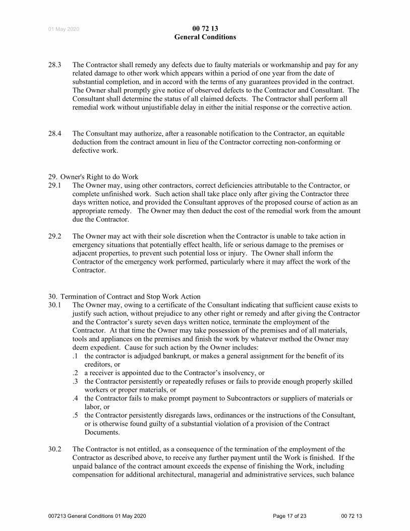
01 May 2020 00 72 13 General Conditions
007213 General Conditions 01 May 2020 Page 17 of 23 00 72 13
28.3 The Contractor shall remedy any defects due to faulty materials or workmanship and pay for any related damage to other work which appears within a period of one year from the date of substantial completion, and in accord with the terms of any guarantees provided in the contract. The Owner shall promptly give notice of observed defects to the Contractor and Consultant. The Consultant shall determine the status of all claimed defects. The Contractor shall perform all remedial work without unjustifiable delay in either the initial response or the corrective action.
28.4 The Consultant may authorize, after a reasonable notification to the Contractor, an equitable
deduction from the contract amount in lieu of the Contractor correcting non-conforming or defective work.
29. Owner's Right to do Work 29.1 The Owner may, using other contractors, correct deficiencies attributable to the Contractor, or
complete unfinished work. Such action shall take place only after giving the Contractor three days written notice, and provided the Consultant approves of the proposed course of action as an appropriate remedy. The Owner may then deduct the cost of the remedial work from the amount due the Contractor.
29.2 The Owner may act with their sole discretion when the Contractor is unable to take action in emergency situations that potentially effect health, life or serious damage to the premises or adjacent properties, to prevent such potential loss or injury. The Owner shall inform the Contractor of the emergency work performed, particularly where it may affect the work of the Contractor.
30. Termination of Contract and Stop Work Action 30.1 The Owner may, owing to a certificate of the Consultant indicating that sufficient cause exists to
justify such action, without prejudice to any other right or remedy and after giving the Contractor and the Contractor’s surety seven days written notice, terminate the employment of the Contractor. At that time the Owner may take possession of the premises and of all materials, tools and appliances on the premises and finish the work by whatever method the Owner may deem expedient. Cause for such action by the Owner includes: .1 the contractor is adjudged bankrupt, or makes a general assignment for the benefit of its
creditors, or .2 a receiver is appointed due to the Contractor’s insolvency, or .3 the Contractor persistently or repeatedly refuses or fails to provide enough properly skilled
workers or proper materials, or .4 the Contractor fails to make prompt payment to Subcontractors or suppliers of materials or
labor, or .5 the Contractor persistently disregards laws, ordinances or the instructions of the Consultant,
or is otherwise found guilty of a substantial violation of a provision of the Contract Documents.
30.2 The Contractor is not entitled, as a consequence of the termination of the employment of the
Contractor as described above, to receive any further payment until the Work is finished. If the unpaid balance of the contract amount exceeds the expense of finishing the Work, including compensation for additional architectural, managerial and administrative services, such balance

01 May 2020 00 72 13 General Conditions
007213 General Conditions 01 May 2020 Page 18 of 23 00 72 13
shall be paid to the Contractor. If the expense of finishing the Work exceeds the unpaid balance, the Contractor shall pay the difference to the Owner. The Consultant shall certify the expense incurred by the Contractor’s default. This obligation for payment shall continue to exist after termination of the contract.
30.3 The Contractor may, if the Work is stopped by order of any court or other public authority for a period of thirty consecutive days, and through no act or fault of the Contractor or of anyone employed by the Contractor, with seven days written notice to the Owner and the Consultant, terminate this contract. The Contractor may then recover from the Owner payment for all work executed, any proven loss and reasonable profit and damage.
30.4 The Contractor may, if the Consultant fails to issue a certificate for payment within seven days after the Contractor's formal request for payment, through no fault of the Contractor, or if the Owner fails to pay to the Contractor within 30 days after submission of any sum certified by the Consultant, with seven days written notice to the Owner and the Consultant, stop the Work or terminate this Contract.
31. Delays and Extension of Time 31.1 The completion date of the contract shall be extended if the work is delayed by changes ordered
in the work which have approved time extensions, or by an act or neglect of the Owner, the Consultant, or the Owner's Contractor, or by strikes, lockouts, fire, flooding, unusual delay in transportation, unavoidable casualties, or by other causes beyond the Contractor’s control. The Consultant shall determine the status of all claimed causes.
31.2 The contract shall not be extended for delay occurring more than seven calendar days before the Contractor's claim made in writing to the Consultant. In case of a continuing cause of delay, only one claim is necessary.
31.3 The contract shall not be extended due to failure of the Consultant to furnish drawings if no schedule or agreement is made between the Contractor and the Consultant indicating the dates which drawings shall be furnished and fourteen calendar days has passed after said date for such drawings.
31.4 This article does not exclude the recovery of damages for delay by either party under other provisions in the Contract Document.
32. Payments to the Contractor 32.1 As noted under Preconstruction Conference in this section, the Contractor shall submit a
Schedule of Values form, before the first application for payment, for approval by the Owner and Consultant. The Consultant may direct the Contractor to provide evidence that supports the correctness of the form. The approved Schedule of Values shall be used as a basis for payments.
32.2 The Contractor shall submit an application for each payment (“Requisition for Payment”) on a form approved by the Owner and Consultant. The Consultant may require receipts or other documents showing the Contractor's payments for materials and labor, including payments to Subcontractors.
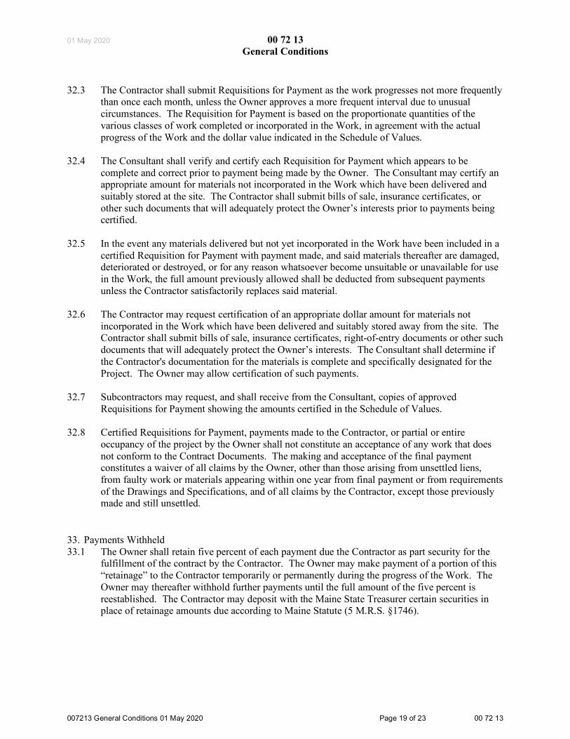
01 May 2020 00 72 13 General Conditions
007213 General Conditions 01 May 2020 Page 19 of 23 00 72 13
32.3 The Contractor shall submit Requisitions for Payment as the work progresses not more frequently than once each month, unless the Owner approves a more frequent interval due to unusual circumstances. The Requisition for Payment is based on the proportionate quantities of the various classes of work completed or incorporated in the Work, in agreement with the actual progress of the Work and the dollar value indicated in the Schedule of Values.
32.4 The Consultant shall verify and certify each Requisition for Payment which appears to be complete and correct prior to payment being made by the Owner. The Consultant may certify an appropriate amount for materials not incorporated in the Work which have been delivered and suitably stored at the site. The Contractor shall submit bills of sale, insurance certificates, or other such documents that will adequately protect the Owner’s interests prior to payments being certified.
32.5 In the event any materials delivered but not yet incorporated in the Work have been included in a certified Requisition for Payment with payment made, and said materials thereafter are damaged, deteriorated or destroyed, or for any reason whatsoever become unsuitable or unavailable for use in the Work, the full amount previously allowed shall be deducted from subsequent payments unless the Contractor satisfactorily replaces said material.
32.6 The Contractor may request certification of an appropriate dollar amount for materials not incorporated in the Work which have been delivered and suitably stored away from the site. The Contractor shall submit bills of sale, insurance certificates, right-of-entry documents or other such documents that will adequately protect the Owner’s interests. The Consultant shall determine if the Contractor's documentation for the materials is complete and specifically designated for the Project. The Owner may allow certification of such payments.
32.7 Subcontractors may request, and shall receive from the Consultant, copies of approved Requisitions for Payment showing the amounts certified in the Schedule of Values.
32.8 Certified Requisitions for Payment, payments made to the Contractor, or partial or entire occupancy of the project by the Owner shall not constitute an acceptance of any work that does not conform to the Contract Documents. The making and acceptance of the final payment constitutes a waiver of all claims by the Owner, other than those arising from unsettled liens, from faulty work or materials appearing within one year from final payment or from requirements of the Drawings and Specifications, and of all claims by the Contractor, except those previously made and still unsettled.
33. Payments Withheld 33.1 The Owner shall retain five percent of each payment due the Contractor as part security for the
fulfillment of the contract by the Contractor. The Owner may make payment of a portion of this “retainage” to the Contractor temporarily or permanently during the progress of the Work. The Owner may thereafter withhold further payments until the full amount of the five percent is reestablished. The Contractor may deposit with the Maine State Treasurer certain securities in place of retainage amounts due according to Maine Statute (5 M.R.S. §1746).

01 May 2020 00 72 13 General Conditions
007213 General Conditions 01 May 2020 Page 20 of 23 00 72 13
33.2 The Consultant may withhold or nullify the whole or a portion of any Requisitions for Payment submitted by the Contractor in the amount that may be necessary, in his reasonable opinion, to protect the Owner from loss due to any of the following: .1 defective work not remedied; .2 claims filed or reasonable evidence indicating probable filing of claims; .3 failure to make payments properly to Subcontractors or suppliers; .4 a reasonable doubt that the contract can be completed for the balance then unpaid; .5 liability for damage to another contractor.
The Owner shall make payment to the Contractor, in the amount withheld, when the above circumstances are removed.
34. Liens 34.1 The Contractor shall deliver to the Owner a complete release of all liens arising out of this
contract before the final payment or any part of the retainage payment is released. The Contractor shall provide with the release of liens an affidavit asserting each release includes all labor and materials for which a lien could be filed. Alternately, the Contractor, in the event any Subcontractor or supplier refuses to furnish a release of lien in full, may furnish a bond satisfactory to the Owner, to indemnify the Owner against any lien.
34.2 In the event any lien remains unsatisfied after all payments to the Contractor are made by the Owner, the Contractor shall refund to the Owner all money that the latter may be compelled to pay in discharging such lien, including all cost and reasonable attorney’s fees.
35. Workmanship 35.1 The Contractor shall provide materials, equipment, and installed work equal to or better than the
quality specified in the Contract Documents and approved in submittal and sample. The installation methods shall be of the highest standards, and the best obtainable from the respective trades. The Consultant’s decision on the quality of work shall be final.
35.2 The Contractor shall know local labor conditions for skilled and unskilled labor in order to apply the labor appropriately to the Work. All labor shall be performed by individuals well skilled in their respective trades.
35.3 The Contractor shall perform all cutting, fitting, patching and placing of work in such a manner to allow subsequent work to fit properly, whether that be by the Contractor, the Owner's Contractors or others. The Owner and Consultant may advise the Contractor regarding such subsequent work. Notwithstanding the notification or knowledge of such subsequent work, the Contractor may be directed to comply with this standard of compatible construction by the Consultant at the Contractor's expense.
35.4 The Contractor shall request clarification or revision of any design work by the Consultant, prior to commencing that work, in a circumstance where the Contractor believes the work cannot feasibly be completed at the highest quality, or as indicated in the Contract Documents. The Consultant shall respond to such requests in a timely way, providing clarifying information, a feasible revision, or instruction allowing a reduced quality of work. The Contractor shall follow the direction of the Consultant regarding the required request for information.

01 May 2020 00 72 13 General Conditions
007213 General Conditions 01 May 2020 Page 21 of 23 00 72 13
35.5 The Contractor shall guarantee the Work against any defects in workmanship and materials for a
period of one year commencing with the date of the Certificate of Substantial Completion, unless specified otherwise for specific elements of the project. The Work may also be subdivided in mutually agreed upon components, each defined by a separate Certificate of Substantial Completion.
36. Close-out of the Work 36.1 The Contractor shall remove from the premises all waste materials caused by the work. The
Contractor shall make the spaces “broom clean” unless a more thorough cleaning is specified. The Contractor shall clean all windows and glass immediately prior to the final inspection, unless otherwise directed.
36.2 The Owner may conduct the cleaning of the premises where the Contractor, duly notified by the Consultant, fails to adequately complete the task. The expense of this cleaning may be deducted from the sum due to the Contractor.
36.3 The Contractor shall participate in all final inspections and acknowledge the documentation of unsatisfactory work, customarily called the "punch list", to be corrected by the Contractor. The Consultant shall document the successful completion of the Work in a dated Certificate of Substantial Completion, to be signed by Owner, Consultant, and Contractor.
36.4 The Contractor shall not call for final inspection of any portion of the Work that is not completely and permanently installed. The Contractor may be found liable for the expenses of individuals called to final inspection meetings prematurely.
36.5 The Contractor and all major Subcontractors shall participate in the end-of-warranty-period conference, typically scheduled close to one year after the Substantial Completion date.
37. Date of Completion and Liquidated Damages 37.1 The Contractor may make a written request to the Owner for an extension or reduction of time, if
necessary. The request shall include the reasons the Contractor believes justifies the proposed completion date. The Owner may grant the revision of the contract completion date if the Work was delayed due to conditions beyond the control and the responsibility of the Contractor. The Contractor shall not conduct unauthorized accelerated work or file delay claims to recover alleged damages for unauthorized early completion.
37.2 The Contractor shall vigorously pursue the completion of the Work and notify the Owner of any factors that have, may, or will affect the approved Schedule of the Work. The Contractor may be found responsible for expenses of the Owner or Consultant if the Contractor fails to make notification of project delays.
37.3 The Project is planned to be done in an orderly fashion which allows for an iterative submittal review process, construction administration including minor changes in the Work and some bad weather. The Contractor shall not file delay claims to recover alleged damages on work the Consultant determines has followed the expected rate of progress.

01 May 2020 00 72 13 General Conditions
007213 General Conditions 01 May 2020 Page 22 of 23 00 72 13
37.4 The Consultant shall prepare the Certificate of Substantial Completion which, when signed by the Owner and the Contractor, documents the date of Substantial Completion of the Work or a designated portion of the Work. The Owner shall not consider the issuance of a Certificate of Occupancy by an outside authority a prerequisite for Substantial Completion if the Certificate of Occupancy cannot be obtained due to factors beyond the Contractor’s control.
37.5 Liquidated Damages may be deducted from the sum due to the Contractor for each calendar day that the Work remains uncompleted after the completion date specified in the Contract or an approved amended completion date. The dollar amount per day shall be calculated using the Schedule of Liquidated Damages table shown below.
If the original contract amount is: The per day Liquidated Damages shall be: Less than $100,000 $250 $100,000 to less than $2,000,000 $750 $2,000,000 to less than $10,000,000 $1,500 $10,000,000 and greater $1,500 plus $250 for
each $2,000,000 over $10,000,000
38. Dispute Resolution38.1 Mediation
38.1.1 A dispute between the parties which arises under this Contract which cannot be resolved through informal negotiation, shall be submitted to a neutral mediator jointly selected by the parties.
38.1.2 Either party may file suit before or during mediation if the party, in good faith, deems it to be necessary to avoid losing the right to sue due to a statute of limitations. If suit is filed before good faith mediation efforts are completed, the party filing suit shall agree to stay all proceedings in the lawsuit pending completion of the mediation process, provided such stay is without prejudice.
38.1.3 In any mediation between the Owner and the Consultant, the Owner has the right to consolidate related claims between Owner and Contractor.
38.2 Arbitration
38.2.1 If the dispute is not resolved through mediation, the dispute shall be settled by arbitration. The arbitration shall be conducted before a panel of three arbitrators. Each party shall select one arbitrator; the third arbitrator shall be appointed by the arbitrators selected by the parties. The arbitration shall be conducted in accordance with the Maine Uniform Arbitration Act (MUAA), except as otherwise provided in this section.
38.2.2 The decision of the arbitrators shall be final and binding upon all parties. The decision may be entered in court as provided in the MUAA.
38.2.3 The costs of the arbitration, including the arbitrators’ fees shall be borne equally by the parties to the arbitration, unless the arbitrator orders otherwise.

01 May 2020 00 72 13 General Conditions
007213 General Conditions 01 May 2020 Page 23 of 23 00 72 13
38.2.4 In any arbitration between the Owner and the Consultant, the Owner has the right to consolidate related claims between Owner and Contractor.

01 May 2020 00 73 46 Wage Determination Schedule
007346 Wage Determination Schedule 01 May 2020 Page 1 of 2 00 73 46
PART 1- GENERAL
1.1 Related Documents A. Drawings and general provisions of the Contract, including General and Supplementary
Conditions and other Division 01 Specifications Sections, apply to this Section.
1.2 SummaryA. This Section includes the wage determination requirements for Contractors as issued by the State
of Maine Department of Labor Bureau of Labor Standards or the United States Department ofLabor.
1.3 RequirementsA. Conform to the wage determination schedule for this project which is shown on the following
page.
PART 2 - PRODUCTS (not used)
PART 3 - EXECUTION (not used)

01 May 2020 00 73 46 Wage Determination Schedule
007346 Wage Determination Schedule 01 May 2020 Page 2 of 2 00 73 46
End of Section 00 73 46


DOWNEAST CORRECTIONAL FACILITY JUNE 25, 2020 MACHIASPORT, MAINE DESIGN DEVELOPMENT
19176
THIS PAGE INTENTIONALLY LEFT BLANK

DCF MEN'S REENTRY FACILITY AUGUST 14, 2020
MACHIASPORT, MAINE ISSUE FOR CONSTRUCTION
19176-01 SUMMARY 011000 - 1
SECTION 011000
SUMMARY
PART 1 - GENERAL
1.1 RELATED DOCUMENTS
A. Drawings, general provisions of the Contract and other Division 01 Specification Sections,apply to this Section.
1.2 SUMMARY
A. This Section includes the following:
1) Use of premises.
2) Owner's occupancy requirements.3) Work restrictions.
4) Specification formats and conventions.
B. Related Sections include the following:
1) Division 01 Section "Temporary Facilities and Controls" for limitations and procedures
governing temporary use of Owner's facilities.
1.3 USE OF PREMISES
A. General: Project site is a secured non-operating correctional facility. The Owner's use of the
facilities will not continue without interruption during all phases of the project. The contractor
shall have limited use of the premises for construction operations, including use of the Projectsite, during the construction period.
B. Site and building security will be maintained before, during and after construction, at all times
of the day or night. To accommodate the work, the Contractor shall establish operating
temporary control and work stations for facility operations. Switch-over periods during whichcontrol systems are fully inoperative shall be strictly limited. The contractor shall plan and
coordinate a security plan and schedule with the owner prior to start of construction, and once
approved not deviate from the approved plan and schedule without written approval of anychange not less than 72 hours prior to any change. The owner has the right to modify or reject
the plan at the owner’s discretion.

DCF MEN'S REENTRY FACILITY AUGUST 14, 2020
MACHIASPORT, MAINE ISSUE FOR CONSTRUCTION
19176-01 SUMMARY 011000 - 2
C. The limits of Work shall be proposed and approved in writing prior to start. Confine operationsto areas within agreed-upon limits the Work. Work and access to the existing building outside
the limits of Work will be strictly prohibited without advanced consent of the owner. The owner
has the right to require any access to these areas to be ‘Escorted Access’ by the owner’s staff.
Should any work be required outside the limits of Work, the area is to be maintained in anoccupiable condition throughout the construction period. Repair damage caused by construction
operations. Take all precautions necessary to protect the building and its occupants during the
construction period.
D. Site Access. The contractor’s access shall be coordinated with the owner and shall not be
considered as ‘Free Access’. The contractor shall provide a securable material storage
trailer/container for placement outside of the secure fence area. Location of storage
container/trailer shall be as directed by the owner.
1) Keep driveways, loading areas, entrances, etc. serving premises clear and available to
Owner, Owner's employees, and emergency vehicles at all times. Do not use these areas
for parking or storage of materials.
E. Vehicle Parking. Contractor vehicle parking will be in designated areas only. Vehicle access
within the perimeter fence will be limited and shall be coordinated with the owner. Any vehicle
within the secure perimeter shall be turned-off and locked with all windows tightly closed andkeys removed when not occupied. All materials, tools, or other loose items shall be secured
when unattended. Vehicles, materials, tools, or loose items not meeting these requirements will
be removed at the owner’s expense.
F. Dumpsters. The contractor is responsible for providing his own dumpsters, placed where
directed. The contractor shall schedule all dumpster removal times with the owner. Search of
dumpsters may be done at any time at the discretion of the owner.
G. Smoking anywhere on site is strictly prohibited.
H. Lost Items. Any missing items including tools, phones, pagers, keys, etc. shall be reported to
the owner immediately. The contractor shall not depart the facility until efforts are made to
locate the misplaced or lost item.
I. Phones. The contractor shall provide cell phones for their personnel’s use. A land line will not
be provided by the owner. Any cell phone on the premises must be documented with the
owner. Information required will include the name of person with phone, phone number and
phone carrier name. Any lost phone must be reported immediately to the owner.
J. Facility Radio. The owner will assign a contact employee from the facility for the Contractor.
One radio will be provided to the Contractor’s designated person for communications. Use of
and restrictions related to this radio will be outlined at the Security Orientation.
K. Contractor Office. A typical contractor trailer will be allowed where directed by the Owner,
outside of the secured facility perimeter. The contractor is to provide any desired furniture such
as plan tables, chairs, file cabinets, etc. as needed. The contractor office shall be furnished toaccommodate project meetings.

DCF MEN'S REENTRY FACILITY AUGUST 14, 2020
MACHIASPORT, MAINE ISSUE FOR CONSTRUCTION
19176-01 SUMMARY 011000 - 3
L. Sanitary Facilities. The owner will designate restrooms for use at no cost to the contractor. Contractor shall clean restrooms professionally, and shall have them cleaned prior to returning
to owner use.
M. Electric Power Service. The owner will allow connection to circuits within the facility at no
cost to the contractor. Where power is required, such as at the contractor’s office, and available connection points are limited to utility owned systems, the contractor shall arrange and pay for
his own temporary electric power service.
N. Space Conditioning Utilities. The Owner will heat or cool interior work areas at no cost to the contractor. The contractor shall maintain existing heating and cooling devices in operational
condition as needed to provide heating and cooling, or shall provide equipment as needed to
provide heating and cooling.
O. Lighting: Provide temporary lighting with local switching that provides adequate illumination
for construction operations, observations, inspections, and traffic conditions.
P. Fire Extinguishers. The contractor shall provide portable, UL rated; with class and
extinguishing agent as required by locations and classes of fire exposures.
Q. Data Services. The contractor shall provide any desired data access within their contractor’s
office. The owner will not allow access of any kind to their system. Any wireless system used
shall be secured.
R. Isolation of Work Area: Prevent dust, fumes, and odors from entering occupied areas.
1) Maintain dust partitions during the Work. Use vacuum collection attachments on dust-
producing equipment. Isolate limited work within occupied areas using portable dust-containment devices.
S. Perform daily construction cleanup and final cleanup using approved, HEPA-filter-equipped
vacuum equipment.
T. Snow removal will be performed by the owner.
1.4 OWNER'S OCCUPANCY REQUIREMENTS
A. Owner Occupancy of Completed Areas of Construction: Owner reserves the right to occupy
and to place and install equipment in completed areas of building before Substantial Completion, provided such occupancy does not interfere with completion of the Work. Such
placement of equipment and partial occupancy shall not constitute acceptance of the total Work.
1.5 WORK RESTRICTIONS
A. Construction operations shall be limited to the hours between 7 AM and 5 PM weekdays. Weekend or holiday work shall be by written authorization from the Owner’s representative in
advance.

DCF MEN'S REENTRY FACILITY AUGUST 14, 2020
MACHIASPORT, MAINE ISSUE FOR CONSTRUCTION
19176-01 SUMMARY 011000 - 4
1) Permission may be granted for after-hour, weekend, or holiday construction operations if submitted in advance and approved. Submit requests for authorization no less than 72
hours prior to the requested period or more.
1.6 SPECIFICATION FORMATS AND CONVENTIONS
A. Specification Format: The Specifications are organized into Divisions and Sections using the
34-division format and CSI/CSC's "MasterFormat" numbering system.
1) Division 01: Sections in Division 01 govern the execution of the Work of all Sections in
the Specifications.
B. Specification Content: The Specifications use certain conventions for the style of language and
the intended meaning of certain terms, words, and phrases when used in particular situations.
These conventions are as follows:
1) Abbreviated Language: Language used in the Specifications and other Contract
Documents is abbreviated. Words and meanings shall be interpreted as appropriate.
Words implied, but not stated, shall be inferred as the sense requires. Singular words
shall be interpreted as plural, and plural words shall be interpreted as singular where applicable as the context of the Contract Documents indicates.
2) Imperative mood and streamlined language are generally used in the Specifications.
Requirements expressed in the imperative mood are to be performed by Contractor. Occasionally, the indicative or subjunctive mood may be used in the Section Text for
clarity to describe responsibilities that must be fulfilled indirectly by Contractor or by
others when so noted.
a. The words "shall," "shall be," or "shall comply with," depending on the context,
are implied where a colon (:) is used within a sentence or phrase.
PART 2 - PRODUCTS (Not Used)
PART 3 - EXECUTION (Not Used)
END OF SECTION 011000

DCF MEN'S REENTRY FACILITY AUGUST 14, 2020 MACHIASPORT, MAINE ISSUE FOR CONSTRUCTION
19176-01 PROJECT CORRDINATION DRAWINGS 011140 - 1
SECTION 011140
PROJECT COORDINATION DRAWINGS
PART 1 - GENERAL
1.1 RELATED DOCUMENTS
A. Drawings and general provisions of the Contract, including General and Supplementary Conditions
and Division 1 Specification Sections, apply to this Section.
B. This section contains general information that applies to all work performed under the Contract and
is inherently made a part of each specification section.
1.2 PROJECT COORDINATION AND COORDINATION DRAWINGS
A. Coordination: Be fully responsible for coordination of all trades, coordinating construction
sequences and schedules, and coordinating the actual installed location and interface of all work.
Engineering drawings are diagrammatic by nature, permitting trade contractors flexibility to fit
components in coordination with other trade contractors. Coordination Drawings are the method
and record of that coordination effort. Coordinate the locations and routing of pipe, ductwork,
conduit, and other systems, utilities, services, equipment and work with respect to structural
members, architectural finishes, headroom conditions, door swings, door and window openings,
shafts and chases, and other features of the project.
B. Sequencing and Scheduling of the Work: Plan ahead and anticipate later work. Schedule, deliver
and install items of work in the optimum sequence to ensure the complete and correct interface of
all work, and to avoid cutting and patching. Ensure that all blocking, anchors, sleeves, inserts,
clips, brackets, braces, hangers, bolts, supports, conduits, pipes and other items are correctly
located in sequence and prior to completing, enclosing or concealing work.
C. Coordinate Modifications to the Work: Fully and completely coordinate all modifications to the
work including without limitation: 1) changes which affect Contract Price, 2) changes which do
not affect Contract Price, 3) substitutions, 4) Contractor’s selection when given optional choices,
and 5) other modifications and changes. Coordinate and provide all other work required to
implement the modification at no subsequent additional cost to the Owner by claim.
D. Coordination Drawings: Before materials are fabricated or the work begun, the General Contractor
shall supervise and direct the creation of complete Coordination Drawings showing the complete
three dimensional coordination and integration of all work of this project, including, but not limited
to, structural, architectural, fire protection, HVAC, plumbing and electrical disciplines.
1. Intent: Coordination Drawings are intended to assist the General Contractor during
construction to avoid and prevent conflicts and to verify that adequate equipment movement
paths are available for both installation and future equipment repair or replacement. Do not
attempt to use Coordination Drawings to substitute for other required “shop drawings”,
“record drawings”, or any other required submittal. Coordination Drawings are to be
produced to show all components fit within the space available, with irreconcilable conflicts
identified for A/E assistance in finding resolution.
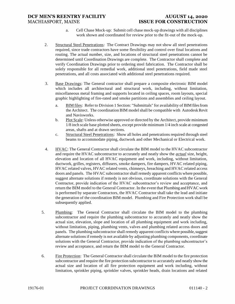
DCF MEN'S REENTRY FACILITY AUGUST 14, 2020 MACHIASPORT, MAINE ISSUE FOR CONSTRUCTION
19176-01 PROJECT CORRDINATION DRAWINGS 011140 - 2
a. Cell Chase Mock-up: Submit cell chase mock-up drawings with all disciplines
work shown and coordinated for review prior to the fit-out of the mock-up.
2. Structural Steel Penetrations: The Contract Drawings may not show all steel penetrations
required, since trade contractors have some flexibility and control over final locations and
routing. The actual number, size, and locations of structural steel penetrations cannot be
determined until Coordination Drawings are complete. The Contractor shall complete and
verify Coordination Drawings prior to ordering steel fabrication. The Contractor shall be
solely responsible for all remedial work, additional steel penetrations, field made steel
penetrations, and all costs associated with additional steel penetrations required.
3. Base Drawings: The General contractor shall prepare a composite electronic BIM model
which includes all architectural and structural work, including, without limitation,
miscellaneous metal framing and supports located in ceiling spaces, room layouts, special
graphic highlighting of fire-rated and smoke partitions and assemblies and ceiling layout.
a. BIM files: Refer to Division 1 Section: "Submittals" for availability of BIM files from
the Architect. The coordination BIM model shall be compatible with Autodesk Revit
and Navisworks.
b. Plot Scale: Unless otherwise approved or directed by the Architect, provide minimum
1/8 inch scale base plotted sheets, except provide minimum 1/4 inch scale at congested
areas, shafts and at drawn sections.
c. Structural Steel Penetrations: Show all holes and penetrations required through steel
beams to accommodate piping, ductwork and other Mechanical or Electrical work.
4. HVAC: The General Contractor shall circulate the BIM model to the HVAC subcontractor
and require the HVAC subcontractor to accurately and neatly show the actual size, height,
elevation and location of all HVAC equipment and work, including, without limitation,
ductwork, grilles, registers, diffusers, smoke dampers, fire dampers, HVAC related piping,
HVAC related valves, HVAC related vents, chimneys, breaching and HVAC related access
doors and panels. The HVAC subcontractor shall remedy apparent conflicts where possible,
suggest alternate solutions if remedy is not obvious, coordinate solutions with the General
Contractor, provide indication of the HVAC subcontractor’s review and acceptance, and
return the BIM model to the General Contractor. In the event that Plumbing and HVAC work
is performed by separate Contractors, the HVAC Contractor shall take the lead and initiate
the generation of the coordination BIM model. Plumbing and Fire Protection work shall be
subsequently applied.
5. Plumbing: The General Contractor shall circulate the BIM model to the plumbing
subcontractor and require the plumbing subcontractor to accurately and neatly show the
actual size, elevation, slope and location of all plumbing equipment and work including,
without limitation, piping, plumbing vents, valves and plumbing related access doors and
panels. The plumbing subcontractor shall remedy apparent conflicts where possible, suggest
alternate solutions if remedy is not available by adjusting plumbing components, coordinate
solutions with the General Contractor, provide indication of the plumbing subcontractor’s
review and acceptance, and return the BIM model to the General Contractor.
6. Fire Protection: The General Contractor shall circulate the BIM model to the fire protection
subcontractor and require the fire protection subcontractor to accurately and neatly show the
actual size and location of all fire protection equipment and work including, without
limitation, sprinkler piping, sprinkler valves, sprinkler heads, drain locations and related
DCF MEN'S REENTRY FACILITY AUGUST 14, 2020 MACHIASPORT, MAINE ISSUE FOR CONSTRUCTION
19176-01 PROJECT CORRDINATION DRAWINGS 011140 - 3
access doors and panels. The fire protection subcontractor shall remedy apparent conflicts
where possible, suggest alternate solutions if remedy is not available by adjusting fire
protection components, coordinate solutions with the General Contractor, provide indication
of the fire protection subcontractor’s review and acceptance, and return the BIM model to the
General Contractor.
7. Electrical: The General Contractor shall circulate the BIM model to the electrical
subcontractor and require the electrical subcontractor to accurately and neatly show the
actual size and location of all electrical equipment and work including, without limitation,
electrical panelboards, major conduits, racks of branch conduit, feeders, light fixtures, other
significant electrical systems, and electrical related access doors and panels. The electrical
subcontractor shall remedy apparent conflicts where possible, suggest alternate solutions if
remedy is not available by adjusting electrical, coordinate solutions with the General
Contractor, provide indication of the electrical subcontractor’s review and acceptance, and
return the BIM model to the General Contractor.
8. Other Subcontractors: The General Contractor shall circulate the BIM model to other
subcontractors whose work might conflict with other work and require these subcontractors
to accurately and neatly show the actual size and location of all their equipment and work,
including special access doors and panels. These subcontractors shall remedy apparent
conflicts where possible, suggest alternate solutions if remedy is not available by adjusting
their trade components, coordinate solutions with the General Contractor, provide indication
of the subcontractor's review and acceptance, and return the BIM model to the General
Contractor.
9. General Contractor Review and Submission: The General Contractor shall carefully review,
modify and approve the BIM model in cooperation with the subcontractors to assure that
conflicts, if any, are resolved before work in the field is begun and to ensure that the location
of work exposed to view is as indicated and as approved by the Architect. Submittal to the
Architect shall include highlighting of any adjustments recommended which affect the
design, and of any conflicts not resolved by the construction team. The General Contractor
shall plot, stamp, sign and submit the BIM model and resulting coordination drawings to the
Architect for review, in compliance with Section 001330.
10. Architect Notification and Authorization Required: If at any time during the coordination
process, the General Contractor cannot resolve a conflict without changing ceiling heights,
wall locations, or other indicated relationships and dimensions, the General Contractor shall
immediately notify the Architect and request instructions. The General Contractor shall not
move or adjust any dimension, location or relationship indicated on the Contract Documents
without first having received the Architect’s written authorization.
11. General Contractor’s Responsibilities: As part of the General Contractor’s responsibility to
coordinate and conduct the work, the General Contractor shall be solely responsible for
commencing, diligently pursuing and completing the coordination drawing process prior to
the start of installation. The General Contractor and each subcontractor shall provide
ongoing coordination services throughout the project and shall resolve conflicts prior to
installation. The General Contractor shall be solely responsible for subsequently required
modifications to make components fit, defects in the installation resulting from the lack of
coordination, and delays resulting from missed coordination prior to installation. The
Architect’s review of coordination drawings shall not relieve the General Contractor or its
subcontractors from their responsibility for coordinating the fit of all work performed under

DCF MEN'S REENTRY FACILITY AUGUST 14, 2020 MACHIASPORT, MAINE ISSUE FOR CONSTRUCTION
19176-01 PROJECT CORRDINATION DRAWINGS 011140 - 4
the contract.
1.02 RELATED SECTIONS
A. Division 21 – Fire Suppression
B. Division 22 - Plumbing.
C. Division 23 – Heating Ventilation and Air Conditioning
D. Division 26 - Electrical: For electrical requirements.
E. Division 27 - Communications
F. Division 28 – Electronic Safety and Security
1.03 SUBMITTALS
A. General: Submit in accordance with Division 1 Section: “Submittals”.
B. Shop Drawings: Submit copies of all Coordination Drawings with all subcontractor’s signatures
and stamps.
PART 2 - PRODUCTS (Not Used)
PART 3 - EXECUTION (Not Used)
END OF SECTION
DCF MEN'S REENTRY FACILITY AUGUST 14, 2020
MACHIASPORT, MAINE ISSUE FOR CONSTRUCTION
19176-01 ALTERNATES 012300 - 1
SECTION 012300
ALTERNATES
PART 1 - GENERAL
1.1 RELATED DOCUMENTS
A. Drawings and general provisions of the Contract, including General and Supplementary Conditions and other Division 01 Specification Sections, apply to this Section.
1.2 SUMMARY
A. Section includes administrative and procedural requirements for alternates.
1.3 DEFINITIONS
A. Alternate: An amount proposed by bidders and stated on the Bid Form for certain work defined
in the bidding requirements that may be added to or deducted from the base bid amount if the Owner decides to accept a corresponding change either in the amount of construction to be
completed or in the products, materials, equipment, systems, or installation methods described
in the Contract Documents.
1. Alternates described in this Section are part of the Work only if enumerated in the Agreement.
2. The cost or credit for each alternate is the net addition to or deduction from the Contract
Sum to incorporate alternates into the Work. No other adjustments are made to the Contract Sum.
1.4 PROCEDURES
A. Coordination: Revise or adjust affected adjacent work as necessary to completely integrate work of the alternate into Project.
1. Include, as part of each alternate, miscellaneous devices, accessory objects, and similar
items incidental to or required for a complete installation, whether or not indicated as part
of alternate.
B. Execute accepted alternates under the same conditions as other Work of the Contract.
C. Schedule: A Part 3 "Schedule of Alternates" Article is included at the end of this Section.
Specification Sections referenced in schedule contain requirements for materials necessary to achieve the work described under each alternate.

DCF MEN'S REENTRY FACILITY AUGUST 14, 2020
MACHIASPORT, MAINE ISSUE FOR CONSTRUCTION
19176-01 ALTERNATES 012300 - 2
PART 2 - PRODUCTS (Not Used)
PART 3 - EXECUTION
3.1 SCHEDULE OF ALTERNATES
A. Add Alternate No. 1: Ductless split system air conditioning units at Fitness Room 122 and
Multipurpose Room 121. See Mechanical Drawings.
B. Add Alternate No. 2: New commercial kitchen dual compartment walk-in freezer and cooler.
See Kitchen Design Drawings – Reentry Center.
C. Add Alternate No. 3: Lightening Protection at Reentry Center building.
END OF SECTION 012300

DCF MEN'S REENTRY FACILITY AUGUST 14, 2020
MACHIASPORT, MAINE ISSUE FOR CONSTRUCTION
19176-01 CONTRACT MODIFICATION PROCEDURES 012600 - 1
SECTION 012600
CONTRACT MODIFICATION PROCEDURES
PART 1 - GENERAL
1.1 RELATED DOCUMENTS
A. Drawings and general provisions of the Contract, including General and Supplementary Conditions and other Division 1 Specification Sections, apply to this Section.
1.2 SUMMARY
A. This Section specifies administrative and procedural requirements for handling and processing Contract modifications.
B. Related Sections include the following:
1. Division 1 Section "Allowances" for procedural requirements for handling and processing allowances as applicable.
2. Division 1 Section “Alternates” for procedural requirements for handling and processing
alternate items as applicable.
3. Division 1 Section "Product Requirements" for administrative procedures for handling requests for substitutions made after Contract award.
1.3 MINOR CHANGES IN THE WORK
A. Architect will issue supplemental instructions authorizing Minor Changes in the Work, not involving adjustment to the Contract Sum or the Contract Time.
1.4 PROPOSAL REQUESTS
A. Owner-Initiated Proposal Requests: Architect will issue a detailed description of proposed changes in the Work that may require adjustment to the Contract Sum or the Contract Time as a
proposal request. If necessary, the description will include supplemental or revised Drawings
and Specifications.
1. Proposal Requests issued by Architect are issued only as information necessary to describe a change being considered. They are not a direction to modify the Contract or to
proceed with the work as described. Do not consider them instructions either to stop
work in progress or to execute the proposed change. Upon receipt, consider the schedule implications of the proposed change and immediately advise the Architect through the
Contractor of any coordination necessary between proposed work and work in-progress.
If the Owner selects to proceed with the work prior to execution of a Change Order, a
written authorization will be issued.
DCF MEN'S REENTRY FACILITY AUGUST 14, 2020
MACHIASPORT, MAINE ISSUE FOR CONSTRUCTION
19176-01 CONTRACT MODIFICATION PROCEDURES 012600 - 2
2. Within time specified in Proposal Request (20 days if not specified) after receipt of Proposal Request, submit a Contractor Proposal estimating cost adjustments to the
Contract Sum and the Contract Time necessary to execute the change.
a. Include a list of quantities of products required or eliminated and unit costs, with
total amount of purchases and credits to be made. If requested, furnish survey data to substantiate quantities.
b. Indicate applicable taxes, delivery charges, equipment rental, and amounts of trade
discounts. c. Include costs of labor and supervision directly attributable to the change.
d. Include an updated Contractor's Construction Schedule that indicates the effect of
the change, including, but not limited to, changes in activity duration, start and finish times, and activity relationship. Use available total float before requesting
an extension of the Contract Time.
B. Contractor-Initiated Proposals/Claims: If an Architect issued document or if latent or
unforeseen conditions require modifications to the Contract, the Contractor may propose changes by submitting a proposal for a change to the Architect through the Construction
Manager.
1. Include a statement outlining reasons for the change and the effect of the change on the Work. Provide a complete description of the proposed change. Indicate the effect of the
proposed change on the Contract Sum and the Contract Time.
2. Include a list of quantities of products required or eliminated and unit costs, with total amount of purchases and credits to be made. If requested, furnish survey data to
substantiate quantities.
3. Indicate applicable taxes, delivery charges, equipment rental, and amounts of trade
discounts. 4. Include costs of labor and supervision directly attributable to the change.
5. Include an updated Contractor's Construction Schedule that indicates the effect of the
change, including, but not limited to, changes in activity duration, start and finish times, and activity relationship. Use available total float before requesting an extension of the
Contract Time.
6. Comply with requirements in Division 1 Section "Product Requirements" if the proposed
change requires substitution of one product or system for product or system specified.
C. Proposal Request Form: SMRT form. The form used is a combined Supplemental Instruction/
Proposal Request Form. Proceed as indicated on form. One form is used for both needs in
order that the two may be tracked together.
1. If a Supplemental Instruction has an impact on project cost or project schedule, proceed
as indicated for a Proposal Request.
D. Contractor (and Sub-Contractor) Expenses and Profit: Contractor costs permitted to be charged against a change shall be limited to those items specifically attributable to the change including
actual payments for materials, equipment rentals, expendable items, wages and benefits to
workmen and supervisors, insurance, bonds, and other probable direct costs, but not including
any administrative, accounting, or other indirect or overhead costs, or any wages or benefits of supervisory personnel not assigned full time to the site. Supervisory personnel time shall not
exceed 10% of the summed time of those being supervised. Contractor overhead and profit and

DCF MEN'S REENTRY FACILITY AUGUST 14, 2020
MACHIASPORT, MAINE ISSUE FOR CONSTRUCTION
19176-01 CONTRACT MODIFICATION PROCEDURES 012600 - 3
any other expense not included as a cost identified above shall be determined per 00 72 13 General Conditions Section 27.
1.5 ALLOWANCES (AS APPLICABLE)
A. Allowance Adjustment: To adjust allowance amounts, base each Change Order proposal on the
difference between purchase amount and the allowance amount, multiplied by final measurement of work-in-place. If applicable, include reasonable allowances for cutting losses,
tolerances, mixing wastes, normal product imperfections, and similar margins.
1. Include installation costs in purchase amount only where indicated as part of the allowance. If not indicated, installation is not to be accounted for within the allowance
value.
2. Unless indicated otherwise, the allowance sum is the cost of the product delivered to the site, or if temporarily stored off-site then to that warehouse. If requested, prepare
explanation and documentation to substantiate distribution of additional costs and other
margins claimed.
3. Submit substantiation of a change in scope of work, if any, claimed in Change Orders related to unit-cost allowances.
4. Owner reserves the right to establish the quantity of work-in-place by independent
quantity survey, measure, or count.
B. Submit claims for increased costs because of a change in scope or nature of the allowance
described in the Contract Documents. Submit claims within 21 days subsequent to recognition
of increase. Failure to submit claim prior to material purchase may be cause for rejection of the claim.
1. Do not include Contractor's or subcontractor's indirect expense in the Change Order cost
amount unless it is clearly shown that the nature or extent of work has changed from what
could have been foreseen from information in the Contract Documents. 2. No change to Contractor's indirect expense is permitted for selection of higher- or lower-
priced materials or systems of the same scope and nature as originally indicated. Only
the direct cost change will be paid.
1.6 UNIT COSTS (AS APPLICABLE)
A. Submit accounting for unit cost expenses as described in the specification for the unit cost.
Provide documentation for quantities provided as unit cost material co-signed by the
Construction Manager on the day material was delivered or placed.
1.7 CHANGE ORDER PROCEDURES
A. Upon Owner's written approval of a Contractor Proposal, Architect will issue a Change Order
for signatures of Owner, Construction Manager and Contractor on AIA Document G701.
1. When so indicated by the Owner, written approval of a Contractor Proposal shall be
notice to proceed with a change.

DCF MEN'S REENTRY FACILITY AUGUST 14, 2020
MACHIASPORT, MAINE ISSUE FOR CONSTRUCTION
19176-01 CONTRACT MODIFICATION PROCEDURES 012600 - 4
2. Payment for costs accrued shall be applied for only when the associated Change Order is endorsed by all parties, and the change documented in the monthly Application for
Payment.
1.8 CONSTRUCTION CHANGE DIRECTIVE
A. Construction Change Directive: Architect may issue a Construction Change Directive on AIA Document G714. A Construction Change Directive instructs the Contractor to proceed with a
change in the Work, for subsequent inclusion in a Change Order. Proceed with work as directed
when authorized by a Construction Change Directive.
1. Construction Change Directive contains a complete description of change in the Work. It
also designates method to be followed to determine change in the Contract Sum or the
Contract Time. 2. Payment for costs accrued may be applied for based upon an authorized Construction
Change Directive, provided that costs are fully accounted for.
B. Documentation: Maintain detailed records on a time and material basis of work required by the
Construction Change Directive.
C. After completion of change, submit an itemized account and supporting data necessary to
substantiate cost and time adjustments to the Contract for inclusion in a Change Order.
PART 2 - PRODUCTS (Not Used)
PART 3 - EXECUTION (Not Used)
END OF SECTION 012600

DCF MEN'S REENTRY FACILITY AUGUST 14, 2020
MACHIASPORT, MAINE ISSUE FOR CONSTRUCTION
19176-01 PAYMENT PROCEDURES 012900 - 1
SECTION 012900
PAYMENT PROCEDURES
PART 1 - GENERAL
1.1 RELATED DOCUMENTS
A. Drawings and general provisions of the Contract, including General and Supplementary Conditions and other Division 1 Specification Sections, apply to this Section.
1.2 SUMMARY
A. This Section specifies administrative and procedural requirements necessary to prepare and process Applications for Payment.
B. Related Sections include the following:
1. Division 1 Section “Special Project Requirements”. 2. Division 1 Section "Unit Prices" for administrative requirements governing use of unit
prices as applicable.
3. Division 1 Section "Allowances" for procedural requirements governing handling and
processing of allowances as applicable. 4. Division 1 Section "Contract Modification Procedures" for administrative procedures for
handling changes to the Contract.
5. Division 1 Section "Construction Progress Documentation" for administrative requirements governing preparation and submittal of Contractor's Construction Schedule,
Submittals Schedule, and reports.
1.3 DEFINITIONS
A. Schedule of Values: A statement furnished by Contractor allocating portions of the Contract
Sum to various portions of the Work and used as the basis for reviewing Contractor's
Applications for Payment.
1.4 SCHEDULE OF VALUES
A. Coordination: Coordinate preparation of the Schedule of Values with preparation of
Contractor's Construction Schedule.
1. Correlate line items in the Schedule of Values with other required administrative forms
and schedules, including the following:
a. Application for Payment forms with Continuation Sheets.
DCF MEN'S REENTRY FACILITY AUGUST 14, 2020
MACHIASPORT, MAINE ISSUE FOR CONSTRUCTION
19176-01 PAYMENT PROCEDURES 012900 - 2
2. Submit the Schedule of Values to Architect at earliest possible date but no later than
seven days before the date scheduled for submittal of initial Applications for Payment.
B. Format and Content: Use the Project Manual table of contents as a guide to establish line items
for the Schedule of Values. Provide at least one line item for each Specification Section.
1. Use form AIA G703.
2. Provide a breakdown of the Contract Sum in enough detail to facilitate continued
evaluation of Applications for Payment and progress reports. Provide several line items
for principal subcontract amounts, where appropriate.
a. For major work items and sub-contracts, provide separate line items for material
and labor.
b. Within all trades scheduled for commissioning, identify a line item for commissioning equal to eight percent (8%) of the value of the work for each
commissioned trade. This value will be paid as a percentage completed as
commissioning progresses with not less than two percent (2%) of the value of the
work held as retainage against post-occupancy commissioning. c. Within trades which provide programmed electronic controls system, including but
not limited to fire alarm, mechanical building management or controls, and
security electronic controls systems, identify a line item for system acceptance testing equal to fifteen percent (15%) of the value of the work for each trade.
3. Round amounts to nearest whole dollar; total shall equal the Contract Sum.
4. Allowances: Provide a separate line item in the Schedule of Values for each allowance. Show line-item value of unit-cost allowances, as a product of the unit cost, multiplied by
measured quantity. Use information indicated in the Contract Documents to determine
quantities.
5. Include a separate line item in the Schedule of Values for submittals. Refer to Division 1 Section “Special Project Requirements”.
6. Each item in the Schedule of Values and Applications for Payment shall be complete.
Include total cost and proportionate share of general overhead and profit for each item
within each.
a. Temporary facilities and other major cost items that are not direct cost of actual
work-in-place may be shown either as separate line items in the Schedule of
Values or distributed as general overhead expense, at Contractor's option.
7. Schedule Updating: Update and resubmit the Schedule of Values before the next
Application for Payment when Change Orders or Construction Change Directives result
in a change in the Contract Sum. Enter all changes as new line items at the end of the Schedule of Values. Do not revise scheduled values for items of work subsequent to the
initial pay application, except to further break-down a scheduled value if needed to
provide more clarity.

DCF MEN'S REENTRY FACILITY AUGUST 14, 2020
MACHIASPORT, MAINE ISSUE FOR CONSTRUCTION
19176-01 PAYMENT PROCEDURES 012900 - 3
1.5 APPLICATIONS FOR PAYMENT
A. Each Application for Payment shall be consistent with previous applications and payments as
certified and paid for by Owner.
1. Initial Application for Payment, Application for Payment at time of Substantial
Completion, and final Application for Payment involve additional requirements.
B. Payment Application Times: The date for progress payment review meetings shall be the same
for each month, and shall coincide with semi-monthly site meetings to permit review of the
work in-place. The period of construction Work covered by each Application for Payment is the period indicated in the Agreement.
C. Payment Application Forms: Use AIA Document G702 and AIA Document G703 Continuation
Sheets or Contractor’s computerized form as approved by the Owner as form for Applications for Payment, modified to additionally provide a certification signature for the Contractor.
Submit quantity of certified copies of application as directed by Contractor.
D. Application Preparation: Complete every entry on form. Notarize and execute by a person
authorized to sign legal documents on behalf of Contractor. Incomplete applications will be returned for completion prior to action is taken on the application.
1. Entries shall match data on the Schedule of Values and Construction Schedule. Use
updated schedules if revisions were made. 2. Include amounts of Change Orders issued before last day of construction period covered
by application.
3. Refer to Division 1 Section “Special Project Requirements” for payment retainage requirements.
E. Preliminary Application: Not less than two days prior to each monthly progress meeting,
submit electronic copies of the Payment Application for review and for comparison against the
progress of the Work apparent on-site. The Architect will review the application against work in place and advise of necessary corrections necessary for the final application.
1. Plan submission of Material Location Reports to coincide with draft Payment Application
submissions. 2. Plan submission of updated Project Schedules to coincide with draft Payment Application
submissions.
F. Stored Materials: Include in Application for Payment amounts applied for materials or
equipment purchased or fabricated and stored, but not yet installed. Differentiate between items stored on-site and items stored off-site.
1. Refer to Division 1 Section “Special Project Requirements” for limitations on payment
for stored materials. 2. Provide certificate of insurance, evidence of transfer of title to Owner, and consent of
surety to payment for stored materials.
3. Provide supporting documentation that verifies amount requested, such as paid invoices. 4. Provide summary documentation for stored materials indicating the following:
a. Value of materials previously stored and remaining stored as of date of previous
Applications for Payment.

DCF MEN'S REENTRY FACILITY AUGUST 14, 2020
MACHIASPORT, MAINE ISSUE FOR CONSTRUCTION
19176-01 PAYMENT PROCEDURES 012900 - 4
b. Value of previously stored materials removed from storage (installed) after date of previous Application for Payment and on or before date of current Application for
Payment.
c. Value of materials stored since date of previous Application for Payment and
remaining stored as of date of current Application for Payment.
G. Waivers of Mechanic's Lien: With each Application for Payment, submit waivers of mechanic's
liens from subcontractors, sub-subcontractors, and suppliers for construction period covered by
the previous application.
1. Submit partial waivers on each item for amount requested before deduction for retainage,
on each item.
2. When an application shows completion of an item, submit final or full waivers. 3. Owner reserves the right to designate which entities involved in the Work must submit
waivers.
4. Waiver Delays: Submit each Application for Payment with Contractor's waiver of
mechanic's lien for the construction period preceding the current application.
a. Submit final Application for Payment with or preceded by final waivers from
every entity on the list of subcontractors, principal suppliers and fabricators.
Submit the list for Owner’s approval.
5. Waiver Forms: Submit waivers of lien on forms acceptable to the Owner.
6. Maintain a complete list of all subcontractors on the project and distribute to the
Architect and Construction Manager.
H. Initial Application for Payment: Administrative actions and submittals that must precede or
coincide with submittal of first Application for Payment include the following:
1. List of subcontractors.
2. Schedule of Values. 3. Schedule of unit prices (if applicable).
4. Schedule of allowances (if applicable).
5. Proposed Preliminary Construction Schedule 6. Products list.
7. LEED submittal for project materials cost data as applicable.
8. Submittals Schedule (preliminary if not final).
9. List of Contractor's staff assignments. 10. Copy of building permit.
11. Copies of authorizations and licenses from authorities having jurisdiction for
performance of the Work. 12. Certificates of insurance and insurance policies.
13. Performance and payment bonds.
14. Data needed to acquire Owner's insurance.
I. Application for Payment at Substantial Completion: After issuing the Certificate of Substantial
Completion, submit an Application for Payment showing 100 percent completion for portion of
the Work claimed as substantially complete.
1. Include documentation supporting claim that the Work is substantially complete and a statement showing an accounting of changes to the Contract Sum.

DCF MEN'S REENTRY FACILITY AUGUST 14, 2020
MACHIASPORT, MAINE ISSUE FOR CONSTRUCTION
19176-01 PAYMENT PROCEDURES 012900 - 5
2. This application shall reflect Certificates of Partial Substantial Completion issued previously for Owner occupancy of designated portions of the Work.
J. Final Payment Application: Submit final Application for Payment with releases and supporting
documentation not previously submitted and accepted, including, but not limited, to the
following:
1. Evidence of completion of Project closeout requirements.
2. Insurance certificates for products and completed operations where required and proof
that taxes, fees, and similar obligations were paid. 3. Updated final statement, accounting for final changes to the Contract Sum.
4. AIA Document G706, "Contractor's Affidavit of Payment of Debts and Claims."
5. AIA Document G706A, "Contractor's Affidavit of Release of Liens." 6. AIA Document G707, "Consent of Surety to Final Payment."
7. Lien waivers from lower tier suppliers and subcontractors.
8. Evidence that claims have been settled.
9. Final meter readings for utilities, a measured record of stored fuel, and similar data as of date of Substantial Completion or when Owner took possession of and assumed
responsibility for corresponding elements of the Work.
PART 2 - PRODUCTS (Not Used)
PART 3 - EXECUTION (Not Used)
END OF SECTION 012900

DCF MEN'S REENTRY FACILITY AUGUST 14, 2020
MACHIASPORT, MAINE ISSUE FOR CONSTRUCTION
19176-01 PAYMENT PROCEDURES 012900 - 6
THIS PAGE INTENTIONALLY LEFT BLANK

DCF MEN'S REENTRY FACILITY AUGUST 14, 2020
MACHIASPORT, MAINE ISSUE FOR CONSTRUCTION
19176-01 PROJECT MANAGEMENT AND COORDINATION 013100 - 1
SECTION 013100
PROJECT MANAGEMENT AND COORDINATION
PART 1 - GENERAL
1.1 RELATED DOCUMENTS
A. Drawings and general provisions of the Contract, including General and Supplementary Conditions and other Division 01 Specification Sections, apply to this Section.
1.2 SUMMARY
A. This Section includes administrative provisions for coordinating construction operations on Project including, but not limited to, the following:
1. General project coordination procedures.
2. Administrative and supervisory personnel. 3. Project meetings.
4. Requests for Interpretation (RFIs).
B. Each contractor shall participate in coordination requirements.
C. Related Sections include the following:
1. Division 01 Section "Summary of Work" for a description of the Work of the contract.
2. Division 01 Section “Special Project Requirements” for additional requirements for
coordination, project meetings, RFIs, and digital project management. 3. Division 01 Section “Project Coordination Drawings” for preparing and submitting
coordination drawings.
4. Division 01 Section "Construction Progress Documentation" for preparing and submitting Contractors’ Construction Schedule.
5. Division 01 Section "Execution Requirements" for procedures for coordinating general
installation and field-engineering services, including establishment of benchmarks and
control points. 6. Division 01 Section "Closeout Procedures" for coordinating closeout of the Contract.
1.3 DEFINITIONS
A. RFI: Request from Contractor seeking interpretation or clarification of the Contract Documents.

DCF MEN'S REENTRY FACILITY AUGUST 14, 2020
MACHIASPORT, MAINE ISSUE FOR CONSTRUCTION
19176-01 PROJECT MANAGEMENT AND COORDINATION 013100 - 2
1.4 COORDINATION
A. Coordination: General Contractor will manage multiple contractor construction operations
included in different Sections of the Specifications to ensure efficient and orderly installation of
each part of the Work. Construction Manager will manage construction operations included in
different Sections that depend on each other for proper installation, connection, and operation. Coordination includes the following tasks:
1. Schedule construction operations in sequence required to obtain the best results where
installation of one part of the Work depends on installation of other components, before or after its own installation.
2. Coordinate installation of different components with other contractors to ensure
maximum accessibility for required maintenance, service, and repair. 3. Make adequate provisions to accommodate items scheduled for later installation.
4. Where availability of space is limited, coordinate installation of different components to
ensure maximum performance and accessibility for required maintenance, service, and
repair of all components, including mechanical and electrical.
B. Administrative Procedures: General Contractor will coordinate scheduling and timing of
required administrative procedures with other construction activities and activities of other
contractors to avoid conflicts and to ensure orderly progress of the Work. Such administrative activities include, but are not limited to, the following:
1. Preparation of Contractors’ Construction Schedule.
2. Preparation of the Schedule of Values. 3. Installation and removal of temporary facilities and controls.
4. Delivery and processing of submittals.
5. Progress meetings.
6. Pre-installation conferences. 7. Project closeout activities.
8. Commissioning, startup and adjustment of systems.
9. Project closeout activities.
C. Conservation: Construction activities shall be coordinated to ensure that operations are carried
out with consideration given to conservation of energy, water, and materials.
1.5 SUBMITTALS
A. Subcontract List: General Contractor will prepare a written summary identifying individuals or firms proposed for each portion of the Work, including those who are to furnish products or
equipment fabricated to a special design. Include the following information in tabular form:
1. Name, address, telephone number, and email address of entity performing subcontract or supplying products.
2. Number and title of related Specification Section(s) covered by subcontract.
3. Drawing number and detail references, as appropriate, covered by subcontract.

DCF MEN'S REENTRY FACILITY AUGUST 14, 2020
MACHIASPORT, MAINE ISSUE FOR CONSTRUCTION
19176-01 PROJECT MANAGEMENT AND COORDINATION 013100 - 3
B. Key Personnel Names: Within 15 days of starting construction operations, submit a list of key personnel assignments, including superintendent and other personnel in attendance at Project
site. Identify individuals and their duties and responsibilities; list mailing and e mail addresses
and telephone numbers including cell phone, home and office telephone numbers. Provide
names, addresses, and telephone numbers of individuals assigned as standbys in the absence of individuals assigned to Project.
1. Post copies of list in Project meeting room, in temporary field office, and by each
temporary telephone. Keep list current at all times.
1.6 PROJECT MEETINGS
A. General: General Contractor will schedule and conduct meetings and conferences at Project
site, unless otherwise indicated.
1. Attendees: Inform participants and others involved, and individuals whose presence is
required, of date and time of each meeting. Notify Owner and Architect of scheduled
meeting dates and times.
2. Agenda: Prepare the meeting agenda. Distribute the agenda to all invited attendees. 3. Minutes: Record significant discussions and agreements achieved. Distribute the
meeting minutes to everyone concerned, including Owner and Architect, within three
days of the meeting.
B. Pre-construction Conference: General Contractor will schedule a pre-construction conference
before starting construction, at a time convenient to Owner and Architect, but no later than 15
days after execution of the Agreement. Hold the conference at Project site or another convenient location. Conduct the meeting to review responsibilities and personnel assignments.
1. Attendees: General Contractor, authorized representatives of Owner, Architect and their
consultants; Contractors and its superintendents; major subcontractors; suppliers; and
other concerned parties shall attend the conference. All participants at the conference shall be familiar with Project and authorized to conclude matters relating to the Work.
2. Agenda: Discuss items of significance that could affect progress, including the
following:
a. Tentative construction schedule.
b. Phasing.
c. Critical work sequencing and long-lead items.
d. Designation of key personnel and their duties. e. Lines of communication and authority.
f. Use of web-based Project software.
g. Procedures for processing field decisions and Change Orders. h. Procedures for RFIs.
i. Procedures for testing and inspecting.
j. Procedures for processing Applications for Payment. k. Distribution of the Contract Documents.
l. Submittal procedures.
m. Preparation of Record Documents.
n. Use of the premises. o. Work hours and restrictions.

DCF MEN'S REENTRY FACILITY AUGUST 14, 2020
MACHIASPORT, MAINE ISSUE FOR CONSTRUCTION
19176-01 PROJECT MANAGEMENT AND COORDINATION 013100 - 4
p. Owner's occupancy requirements when applicable. q. Responsibility for temporary facilities and controls.
r. Procedures for moisture and mold control.
s. Construction waste management and recycling.
t. Parking availability. u. Office, work, and storage areas.
v. Equipment deliveries and priorities.
w. First aid. x. Security.
y. Progress cleaning.
3. Minutes: General Contractor will record and distribute meeting minutes.
C. Pre-installation Conferences: Conduct a pre-installation conference at Project site before each
construction activity that requires coordination with other construction.
1. Attendees: Installer and representatives of manufacturers and fabricators involved in or
affected by the installation and its coordination or integration with other materials and installations that have preceded or will follow, shall attend the meeting. Advise Architect
of scheduled meeting dates.
2. Pre-installation conferences shall be required for the following areas of the project at a minimum:
a. Site work: Earthwork, installation of utilities, site paving and concrete
b. Building foundations c. Underground utilities within the building
d. Concrete slabs: on-grade and elevated
e. Masonry and installation of hollow metal frames
f. Roofing g. Metal Siding
h. MEP Rough In
i. Security Systems j. Detention Doors, Frames, Furniture and Hardware
3. Agenda: Review progress of other construction activities and preparations for the
particular activity under consideration, including requirements for the following:
a. The Contract Documents.
b. Options.
c. Related RFIs. d. Related Change Orders.
e. Purchases.
f. Deliveries. g. Submittals.
h. Review of mockups.
i. Possible conflicts.
j. Compatibility problems. k. Time schedules.
l. Weather limitations.
m. Manufacturer's written recommendations. n. Warranty requirements.

DCF MEN'S REENTRY FACILITY AUGUST 14, 2020
MACHIASPORT, MAINE ISSUE FOR CONSTRUCTION
19176-01 PROJECT MANAGEMENT AND COORDINATION 013100 - 5
o. Compatibility of materials. p. Acceptability of substrates.
q. Temporary facilities and controls.
r. Space and access limitations.
s. Regulations of authorities having jurisdiction. t. Testing and inspecting requirements.
u. Installation procedures.
v. Coordination with other work. w. Required performance results.
x. Protection of adjacent work.
y. Protection of construction and personnel.
4. Record significant conference discussions, agreements, and disagreements, including
required corrective measures and actions.
5. Reporting: General Contractor shall record and distribute minutes of the meeting to each
party present and to parties who should have been present. 6. Do not proceed with installation if the conference cannot be successfully concluded.
Initiate whatever actions are necessary to resolve impediments to performance of the
Work and reconvene the conference at earliest feasible date.
D. Progress Meetings: General Contractor will conduct progress meetings on a biweekly basis, or
at intervals as agreed among all parties. Coordinate dates of meetings with preparation of
payment requests.
1. Attendees: In addition to General Contractor, representatives of Owner and Architect,
each Contractor, major subcontractor, supplier, and other entity concerned with current
progress or involved in planning, coordination, or performance of future activities shall
be represented at these meetings. All participants at the conference shall be familiar with Project and authorized to conclude matters relating to the Work.
2. Agenda: Review and correct or approve minutes of previous progress meeting. Review
other items of significance that could affect progress. Include topics for discussion as appropriate to status of Project.
a. Contractors’ Construction Schedule: An updated Construction Schedule shall be
presented by the General Contractor reviewing progress since the last meeting.
Determine whether each activity is on time, ahead of schedule, or behind schedule, in relation to Contractors’ Construction Schedule. Determine how construction
behind schedule will be expedited; secure commitments from parties involved to
do so. Discuss whether schedule revisions are required to ensure that current and subsequent activities will be completed within the Contract Time.
1) Review schedule for next period.
b. Review present and future needs of each entity present, including the following:
1) Interface requirements.
2) Sequence of operations.
3) Status of submittals.
4) Deliveries. 5) Off-site fabrication.
6) Access.

DCF MEN'S REENTRY FACILITY AUGUST 14, 2020
MACHIASPORT, MAINE ISSUE FOR CONSTRUCTION
19176-01 PROJECT MANAGEMENT AND COORDINATION 013100 - 6
7) Site utilization. 8) Temporary facilities and controls.
9) Work hours.
10) Hazards and risks.
11) Progress cleaning. 12) Quality and work standards.
13) Status of correction of deficient items.
14) Field observations. 15) RFIs.
16) Status of proposal requests.
17) Pending changes. 18) Status of Change Orders.
19) Pending claims and disputes.
20) Documentation of information for payment requests.
3. Minutes: General Contractor will record and distribute the meeting minutes. 4. Reporting: Distribute minutes of the meeting to each party present and to parties who
should have been present.
a. Schedule Updating: Revise Contractors’ Construction Schedule after each progress meeting where revisions to the schedule have been made or recognized.
Issue revised schedule concurrently with the report of each meeting.
E. Coordination Meetings: General Contractor shall conduct Contractor project coordination meetings at biweekly intervals or as agreed among all parties. Project subcontractor
coordination meetings are in addition to specific meetings held for other purposes, such as
progress meetings and pre-installation conferences.
1. Attendees: In addition to General Contractor, representatives of Contractor, major subcontractors, supplier, and other entity concerned with current progress or involved in
planning, coordination, or performance of future activities shall be represented at these
meetings. All participants at the conference shall be familiar with Project and authorized to conclude matters relating to the Work.
2. Agenda: Review and correct or approve minutes of the previous coordination meeting.
Review other items of significance that could affect progress. Include topics for
discussion as appropriate to status of Project.
a. Combined Contractors’ Construction Schedule: Review progress since the last
coordination meeting. Determine whether each contract is on time, ahead of
schedule, or behind schedule, in relation to Combined Contractors’ Construction Schedule. Determine how construction behind schedule will be expedited; secure
commitments from parties involved to do so. Discuss whether schedule revisions
are required to ensure that current and subsequent activities will be completed within the Contract Time.
b. Schedule Updating: Revise Combined Contractors’ Construction Schedule after
each coordination meeting where revisions to the schedule have been made or
recognized. Issue revised schedule concurrently with report of each meeting. c. Review present and future needs of each contractor present, including the
following:
1) Interface requirements.

DCF MEN'S REENTRY FACILITY AUGUST 14, 2020
MACHIASPORT, MAINE ISSUE FOR CONSTRUCTION
19176-01 PROJECT MANAGEMENT AND COORDINATION 013100 - 7
2) Sequence of operations. 3) Resolution of coordination conflicts.
4) Status of submittals.
5) Deliveries.
6) Off-site fabrication. 7) Access.
8) Site utilization.
9) Temporary facilities and controls. 10) Work hours.
11) Safety.
12) Progress cleaning. 13) Quality and work standards
14) RFIs.
15) Change Orders.
3. Reporting: Record meeting results and distribute copies to everyone in attendance and to others affected by decisions or actions resulting from each meeting.
F. Project Closeout Conference: General Contractor will schedule and Conduct a Project closeout
conference, at a time convenient to Owner and Architect, but no later than 90 days prior to the scheduled date of Substantial Completion.
1. Conduct the conference to review requirements and responsibilities related to Project
closeout. 2. Attendees:General Contractor, authorized representatives of Owner, Owner's
Commissioning Authority, Architect, and their consultants; Contractor and its
superintendent; major subcontractors; suppliers; and other concerned parties shall attend
the meeting. Participants at the meeting shall be familiar with Project and authorized to conclude matters relating to the Work.
3. Agenda: Discuss items of significance that could affect or delay Project closeout,
including the following:
a. Preparation of record documents.
b. Procedures required prior to inspection for Substantial Completion and for final
inspection for acceptance.
c. Procedures for completing and archiving we-based Project software data files. d. Submittal of written warranties.
e. Requirements for preparing sustainable design documentation where required.
f. Requirements for preparing operations and maintenance data. g. Requirements for delivery of maintenance stock, spare parts, and tools.
h. Requirements for demonstration and training.
i. Preparation of Contractors’ punch list. j. Procedures for processing Applications for Payment at Substantial Completion and
for final payment.
k. Submittal procedures.
l. Coordination of separate contracts. m. Owner's partial occupancy requirements.
n. Installation of Owner's furniture, fixtures, and equipment.
o. Responsibility for removing temporary facilities and controls.
4. Minutes: Entity conducting meeting will record and distribute meeting minutes.

DCF MEN'S REENTRY FACILITY AUGUST 14, 2020
MACHIASPORT, MAINE ISSUE FOR CONSTRUCTION
19176-01 PROJECT MANAGEMENT AND COORDINATION 013100 - 8
1.7 REQUESTS FOR INFORMATION/ INTERPRETATION (RFIs)
A. Procedure: Immediately on discovery of the need for interpretation of the Contract Documents,
and if not possible to request interpretation at Project meeting, prepare and submit an RFI in the
form specified.
1. RFIs shall originate with General Contractor. RFIs submitted by entities other than a Contract will be returned with no response. All RFIs shall be submitted through the
Contractor for review, logging and distribution. Upon receipt, the Architect will review
and respond to all RFIs. Responses shall be in writing and will be distributed to the Contractor and Owner by the Architect. The Contractor will distribute responses to Sub-
Contractors.
2. RFIs submitted directly to the Architect or Owner by a sub-contractor or supplier will be returned to the Contractor with no response.
3. Coordinate and submit RFIs in a prompt manner so as to avoid delays in your work or
that of others.
B. Content of the RFI: Include a detailed, legible description of item needing interpretation and the following:
1. Project name.
2. Date. 3. Name of General Contractor.
4. Name of Sub-Contractor.
5. Name of Architect. 6. Contractor’s RFI number, numbered sequentially.
7. Specification Section number and title and related paragraphs, as appropriate.
8. Drawing number and detail references, as appropriate.
9. Field dimensions and conditions, as appropriate. 10. Contractor's suggested solution(s). If Contractor's solution(s) impact the Contract Time
or the Contract Sum, Contractor shall state impact in the RFI.
11. Contractor's signature. 12. Attachments: Include drawings, descriptions, measurements, photos, Product Data, Shop
Drawings, and other information necessary to fully describe items needing interpretation.
a. Supplementary drawings prepared by Contractor shall include dimensions,
thicknesses, structural grid references, and details of affected materials, assemblies, and attachments.
C. RFIs shall be submitted electronically.
1. Hard-Copy RFIs: Identify each page of attachments with the RFI number and sequential page number. Convert to PDF format for transmission.
2. Software-Generated RFIs: Software-generated form with substantially the same content
as indicated above. Attachments shall be electronic files in Adobe Acrobat PDF format.
D. Architect's Action: Architect will review each RFI, determine action required, and return it.
Allow five working days for Architect's response for each RFI. RFIs received after 1:00 p.m.
will be considered as received the following working day. RFI responses will be provided as
soon as reasonably possible, which will be dependent upon the research required.
1. The following RFIs will be returned without action:

DCF MEN'S REENTRY FACILITY AUGUST 14, 2020
MACHIASPORT, MAINE ISSUE FOR CONSTRUCTION
19176-01 PROJECT MANAGEMENT AND COORDINATION 013100 - 9
a. Requests for approval of submittals. b. Requests for approval of substitutions.
c. Requests for coordination information already indicated in the Contract
Documents.
d. Requests for adjustments in the Contract Time or the Contract Sum. e. Requests for interpretation of Architect's actions on submittals.
f. Incomplete, incoherent, or unnecessary RFIs, frivolous RFIs, or RFIs with
numerous errors.
2. Architect's action may include a request for additional information, in which case
Architect's time for response will start again.
3. Architect's action on RFIs that may result in a change to the Contract Time or the Contract Sum may be eligible for Contractor to submit Change Proposal according to
Division 01 Section "Contract Modification Procedures."
a. If Contractor believes the RFI response warrants change in the Contract Time or
the Contract Sum, notify Architect in writing within 10 days of receipt of the RFI response.
E. On receipt of Architect's action, General Contractor will update the RFI log and immediately
distribute the RFI response to affected parties. Contractors shall review response and notify General Contractor within seven days if Contractor disagrees with response.
F. RFI Log: General Contractor will prepare, maintain, and submit a tabular log of RFIs organized
by the RFI number. The log will include the following:
1. Project name.
2. Name of General Contractor.
3. Name of Contractor.
4. Name of Architect. 5. Contractor’s RFI number.
6. Construction Manager’s RFI number including RFIs that were dropped and not
submitted. 7. RFI description.
8. Date the RFI was submitted.
9. Date Architect's response was received.
10. Identification of related Minor Change in the Work, Construction Change Directive, and Proposal Request, as appropriate.
1.8 DIGITAL PROJECT MANAGEMENT
A. Web-Based Project Software: General Contractor will provide, administer, and use web-based Project software site for purposes of hosting and managing Project communication and
documentation until Final Completion.
1. Web-based Project software site includes, at a minimum, the following features:
a. Compilation of Project data, including General Contractor, Contractors,
subcontractors, Architect, architect's consultants, Owner, and other entities
involved in Project. Include names of individuals and contact information.

DCF MEN'S REENTRY FACILITY AUGUST 14, 2020
MACHIASPORT, MAINE ISSUE FOR CONSTRUCTION
19176-01 PROJECT MANAGEMENT AND COORDINATION 013100 - 10
b. Access control for each entity for each workflow process, to determine entity's digital rights to create, modify, view, and print documents.
c. Document workflow planning, allowing customization of workflow between
project entities.
d. Creation, logging, tracking, and notification for Project communications required in other Specification Sections, including, but not limited to, RFIs, submittals,
Minor Changes in the Work, Construction Change Directives, and Change Orders.
e. Track status of each Project communication in real time, and log time and date when responses are provided.
f. Procedures for handling PDFs or similar file formats, allowing markups by each
entity. Provide security features to lock markups against changes once submitted. g. Processing and tracking of payment applications.
h. Processing and tracking of contract modifications.
i. Creating and distributing meeting minutes.
j. Document management for Drawings, Specifications, and coordination drawings, including revision control.
k. Management of construction progress photographs.
l. Mobile device compatibility, including smartphones and tablets.
2. Provide web-based Project software user licenses for Contractors plus Owner,
Commissioning Authority, Architect, and Architect's consultants.
3. At completion of Project, provide digital archive in format that is readable by common desktop software applications in format acceptable to Architect. Provide data in locked
format to prevent further changes.
PART 2 - PRODUCTS (Not Used)
PART 3 - EXECUTION (Not Used)
END OF SECTION 013100

DCF MEN'S REENTRY FACILITY AUGUST 14, 2020
MACHIASPORT, MAINE ISSUE FOR CONSTRUCTION
19176-01 CONSTRUCTION PROGRESS DOCUMENTATION 013200 - 1
SECTION 013200
CONSTRUCTION PROGRESS DOCUMENTATION
PART 1 - GENERAL
1.1 RELATED DOCUMENTS
A. Drawings and general provisions of the Contract, including General and Supplementary Conditions and other Division 1 Specification Sections, apply to this Section.
1.2 SUMMARY
A. This Section includes administrative and procedural requirements for documenting the progress of construction during performance of the Work, including the following:
1. Contractor's Construction Schedule.
2. Submittals Schedule.
B. Related Sections include the following:
1. Division 1 Section "Payment Procedures" for submitting the Schedule of Values.
2. Division 1 Section "Project Management and Coordination" for submitting and
distributing meeting and conference minutes. 3. Division 1 Section "Submittal Procedures" for submitting schedules and reports.
4. Division 1 Section "Quality Requirements" for submitting a schedule of tests and
inspections. 5. Division 1 Section "Closeout Procedures" for submitting photographic negatives as
Project Record Documents at Project closeout.
1.3 DEFINITIONS
A. Activity: A discrete part of a project that can be identified for planning, scheduling, monitoring,
and controlling the construction project. Activities included in a construction schedule consume
time and resources.
1. Critical activities are activities on the critical path. They must start and finish on the planned early start and finish times.
2. Predecessor activity is an activity that must be completed before a given activity can be
started.
B. CPM: Critical Path Method, which is a method of planning and scheduling a construction
project where activities are arranged based on activity relationships. Network calculations
determine when activities can be performed and the critical path of Project.
C. Critical Path: The longest continuous chain of activities through the network schedule that establishes the minimum overall Project duration and contains no float.

DCF MEN'S REENTRY FACILITY AUGUST 14, 2020
MACHIASPORT, MAINE ISSUE FOR CONSTRUCTION
19176-01 CONSTRUCTION PROGRESS DOCUMENTATION 013200 - 2
D. Event: The starting or ending point of an activity.
E. Float: The measure of leeway in starting and completing an activity.
1. Float time is not for the exclusive use or benefit of either Owner or Contractor, but is a
jointly owned, expiring Project resource available to both parties as needed to meet
schedule milestones and Contract completion date. 2. Free float is the amount of time an activity can be delayed without adversely affecting the
early start of the following activity.
3. Total float is the measure of leeway in starting or completing an activity without adversely affecting the planned Project completion date.
F. Fragnet: A partial or fragmentary network that breaks down activities into smaller activities for
greater detail.
G. Major Area: A story of construction, a separate building, or a similar significant construction
element.
H. Milestone: A key or critical point in time for reference or measurement.
I. Network Diagram: A graphic diagram of a network schedule, showing activities and activity relationships.
1.4 SUBMITTALS
A. Submittals Schedule: Submit three copies of schedule. Arrange the following information in a graphic or spreadsheet format:
1. Scheduled date for first submittal.
2. Specification section numbers with title of submittals. 3. Submittal category (action or informational).
4. Name of subcontractor.
5. Description of the Work covered.
6. Scheduled date for Architect's final release or approval. 7. Critical path date for final release and approval.
B. Contractors’ Construction Schedule: Submit two printed copies of initial schedule, one a
reproducible print and one a blue- or black-line print, large enough to show entire schedule for entire construction period.
1.5 QUALITY ASSURANCE
A. Pre-scheduling Conference: Contractor will conduct a conference at Project site following start
of the Work to discuss the overall project schedule and to identify critical shop drawing submittals required from the DEC..
1. Review software limitations, content, and format for submissions.
2. Discuss phasing, staging of the Work, interim milestone dates, and dates for Owner occupancy.

DCF MEN'S REENTRY FACILITY AUGUST 14, 2020
MACHIASPORT, MAINE ISSUE FOR CONSTRUCTION
19176-01 CONSTRUCTION PROGRESS DOCUMENTATION 013200 - 3
3. Review time required for production of submittals, submittal requirements and procedures, review of schedule impacts from re-submittals.
4. Review time required for completion and equipment startup and commissioning
procedures.
5. Review and finalize list of construction activities to be included in schedule. 6. Review schedule for work of separate contracts, including work by Owner.
7. Review procedures for updating schedule.
1.6 COORDINATION
A. Coordinate preparation and processing of schedules and reports with performance of
construction activities and with scheduling and reporting of separate contractors.
PART 2 - PRODUCTS
2.1 SCHEDULE FORMAT
A. Submit required schedules as PDF electronic files.
2.2 SUBMITTALS SCHEDULE
A. Preparation: Submit a schedule of submittals arranged in chronological order by dates required correlating with construction schedule. Include time required for review, resubmittal and
second review, ordering, manufacturing, fabrication, and delivery when establishing dates.
1. Coordinate Submittals Schedule with list of contractors, subcontractors, the Schedule of Values, and Contractors’ Construction Schedule.
2. Identify priority submittals and schedule submission first to permit processing so as to
keep pace with the construction schedule. 3. Group related products within a specification division that require simultaneous review.
4. Group other related products within a specification division when possible.
5. Distribute dates for return of submittals to match actual need, and to reasonably distribute
review work load. Show float where available to permit prioritization of returns. 6. Initial Submittal: Submit within three weeks of notice to proceed and prior to first
submittal. Show schedule for submittals required during the first 60 days of construction.
List those required to maintain orderly progress of the Work and those required early because of long lead time for manufacture or fabrication.
7. Final Submittal: Submit concurrently with the first complete submittal of Contractor's
Construction Schedule.
2.3 CONTRACTOR'S CONSTRUCTION SCHEDULE, GENERAL
A. Procedures: Comply with procedures contained in AGC's "Construction Planning &
Scheduling."
B. Time Frame: Extend schedule from date established for commencement of the Work to date of Substantial Completion.

DCF MEN'S REENTRY FACILITY AUGUST 14, 2020
MACHIASPORT, MAINE ISSUE FOR CONSTRUCTION
19176-01 CONSTRUCTION PROGRESS DOCUMENTATION 013200 - 4
1. Contract completion date shall not be changed by submission of a schedule that shows an early completion date, unless specifically authorized by Change Order.
C. Activities: Treat each building area as a separate numbered activity for each principal element
of the Work.
1. Activity Duration: Define activities so that no activity is longer than 30 days. 2. Procurement: Include procurement process activities for long lead items and major
equipment. Include submittals/resubmittals, purchasing, fabrication, delivery.
3. Startup and Testing: Include realistic schedule period for start-up and testing. 4. Indoor Air Quality Venting: If specified, include facility ventilation period prior to
occupancy consistent with LEED EQ Credit 3.2 criteria (14,000 cubic feet/square foot
floor area).
D. Constraints: Include constraints and work restrictions indicated in the Contract Documents and
as follows in schedule, and show how the sequence of the Work is affected.
1. Phasing: Arrange list of activities on schedule by phase.
2. Work under More Than One Contract: Include a separate activity for each contract. 3. Work by Owner: Include a separate activity for each portion of the Work performed by
Owner.
E. Milestones: Include milestones indicated in the Contract Documents in schedule, including, but not limited to, the Notice to Proceed, Partial Occupancy, Substantial Completion, and Final
Completion.
F. Upcoming Work Summary: Prepare summary report indicating activities scheduled to occur or commence within the next three weeks. Identify issues that need immediate resolution. Prepare
for presentation at regular construction meetings.
G. Computer Software: Prepare schedules using a program that has been developed specifically to
manage construction schedules.
PART 3 - EXECUTION
3.1 CONTRACTOR'S CONSTRUCTION SCHEDULE
A. CPM Schedule: Prepare Contractor’s construction schedule using a time-scaled CPM network analysis diagram for the Work.
1. Develop network so that it can be accepted no later than the submission of the second
Application for Payment.
2. Prepare a list of all activities required to complete the Work.
a. Indicate the estimated time duration, sequence requirements, and relationships of
each activity in relation to other activities. Include time frames for submittals,
mobilization, materials purchase, fabrication, delivery, installation, testing and commissioning, punch list inspection.
DCF MEN'S REENTRY FACILITY AUGUST 14, 2020
MACHIASPORT, MAINE ISSUE FOR CONSTRUCTION
19176-01 CONSTRUCTION PROGRESS DOCUMENTATION 013200 - 5
3. Critical Path Activities: Identify critical path activities including those for interim completion dates.
4. Process data to produce a computer drawn time scaled network of activities. Revise and
reorganize as often as necessary to produce a schedule compliant with the Contract Time.
Scheduled start and completion dates shall be consistent with the Contract dates. 5. Format: Locate the critical path for the project and clearly mark on the schedule,
indicating which activities are on the critical path. Sub-networks for activities that are off
of the critical path may be on separate pages. Indicate float for each scheduled activity at front and back of each. Highlight any activity which has zero float.
B. Contractor's Construction Schedule Updating: At monthly intervals, update schedule to reflect
actual construction progress and activities. Issue schedule one week before each regularly
scheduled progress meeting.
1. Revise schedule immediately after each meeting or other activity where revisions have
been recognized or made. Issue updated schedule concurrently with the report of each
such meeting. 2. As the Work progresses, indicate Actual Completion percentage for each activity.
C. Distribution: Distribute copies of approved schedule to Architect, Owner, separate contractors,
testing and inspecting agencies, and other parties identified by Contractor with a need-to-know
schedule responsibility.
1. Post copies in Project meeting rooms and temporary field offices.
2. When revisions are made, distribute updated schedules to the same parties and post in the same locations. Delete parties from distribution when they have completed their assigned
portion of the Work and are no longer involved in performance of construction activities.
END OF SECTION 013200

DCF MEN'S REENTRY FACILITY AUGUST 14, 2020
MACHIASPORT, MAINE ISSUE FOR CONSTRUCTION
19176-01 CONSTRUCTION PROGRESS DOCUMENTATION 013200 - 6
THIS PAGE INTENTIONALLY LEFT BLANK

DCF MEN'S REENTRY FACILITY AUGUST 14, 2020
MACHIASPORT, MAINE ISSUE FOR CONSTRUCTION
19176-01 SUBMITTAL PROCEDURES 013300-1
SECTION 013300
SUBMITTAL PROCEDURES
PART 1 - GENERAL
1.1 RELATED DOCUMENTS
A. Drawings and general provisions of the Contract, including General and Supplementary Conditions and other Division 01 Specification Sections, apply to this Section.
1.2 SUMMARY
A. Section Includes:
1. Submittal schedule requirements.
2. Administrative and procedural requirements for submittals.
B. Related Requirements:
1. Section 012900 "Payment Procedures" for submitting Applications for Payment and the
schedule of values.
2. Section 013100 "Project Management and Coordination" for submitting coordination
drawings and subcontract list and for requirements for web-based Project software. 3. Section 013200 "Construction Progress Documentation" for submitting schedules and
reports, including Contractor's construction schedule.
4. Section 014000 "Quality Requirements" for submitting test and inspection reports, and schedule of tests and inspections.
5. Section 017700 "Closeout Procedures" for submitting closeout submittals and
maintenance material submittals. 6. Section 017823 "Operation and Maintenance Data" for submitting operation and
maintenance manuals.
7. Section 017839 "Project Record Documents" for submitting record Drawings, record
Specifications, and record Product Data. 8. Section 017900 "Demonstration and Training" for submitting video recordings of
demonstration of equipment and training of Owner's personnel.
1.3 DEFINITIONS
A. Action Submittals: Written and graphic information and physical samples that require
Architect's responsive action. Action submittals are those submittals indicated in individual
Specification Sections as "action submittals."
B. Informational Submittals: Written and graphic information and physical samples that do not require Architect's responsive action. Submittals may be rejected for not complying with
requirements. Informational submittals are those submittals indicated in individual Specification
Sections as "informational submittals."
DCF MEN'S REENTRY FACILITY AUGUST 14, 2020
MACHIASPORT, MAINE ISSUE FOR CONSTRUCTION
19176-01 SUBMITTAL PROCEDURES 013300-2
1.4 SUBMITTAL SCHEDULE
A. Submittal Schedule: Submit, as an action submittal, a list of submittals, arranged in
chronological order by dates required by construction schedule. Include time required for
review, ordering, manufacturing, fabrication, and delivery when establishing dates. Include
additional time required for making corrections or revisions to submittals noted by Architect and additional time for handling and reviewing submittals required by those corrections.
1. Coordinate submittal schedule with list of subcontracts, the schedule of values, and
Contractor's construction schedule. 2. Initial Submittal Schedule: Submit concurrently with startup construction schedule.
Include submittals required during the first 60 days of construction. List those submittals
required to maintain orderly progress of the Work and those required early because of long lead time for manufacture or fabrication.
3. Final Submittal Schedule: Submit concurrently with the first complete submittal of
Contractor's construction schedule.
a. Submit revised submittal schedule as required to reflect changes in current status and timing for submittals.
4. Format: Arrange the following information in a tabular format:
a. Scheduled date for first submittal. b. Specification Section number and title.
c. Submittal Category: Action; informational.
d. Name of subcontractor. e. Description of the Work covered.
f. Scheduled date for Architect's final release or approval.
g. Scheduled dates for purchasing.
h. Scheduled date of fabrication. i. Scheduled dates for installation.
j. Activity or event number.
1.5 SUBMITTAL FORMATS
A. Submittal Information: Include the following information in each submittal:
1. Project name.
2. Date.
3. Name of Architect. 4. Name of General Contractor.
5. Name of firm or entity that prepared submittal.
6. Names of subcontractor, manufacturer, and supplier. 7. Unique submittal number, including revision identifier. Include Specification Section
number with sequential alphanumeric identifier and alphanumeric suffix for resubmittals.
8. Category and type of submittal. 9. Submittal purpose and description.
10. Number and title of Specification Section, with paragraph number and generic name for
each of multiple items.
11. Drawing number and detail references, as appropriate.

DCF MEN'S REENTRY FACILITY AUGUST 14, 2020
MACHIASPORT, MAINE ISSUE FOR CONSTRUCTION
19176-01 SUBMITTAL PROCEDURES 013300-3
12. Indication of full or partial submittal. 13. Location(s) where product is to be installed, as appropriate.
14. Other necessary identification.
15. Remarks.
16. Signature of transmitter.
B. Options: Identify options requiring selection by Architect.
C. Deviations and Additional Information: On each submittal, clearly indicate deviations from
requirements in the Contract Documents, including minor variations and limitations; include relevant additional information and revisions, other than those requested by Architect on
previous submittals. Indicate by highlighting on each submittal or noting on attached separate
sheet.
D. Submittals Utilizing Web-Based Project Software: Prepare submittals as PDF files or other
format indicated by Project management software.
1. Contact [email protected] for additional email and process requirements.
1.6 SUBMITTAL PROCEDURES
A. Prepare and submit submittals required by individual Specification Sections. Types of
submittals are indicated in individual Specification Sections.
1. Web-Based Project Management Software: Prepare submittals in PDF form, and upload to web-based Project management software website. Enter required data in web-based
software site to fully identify submittal.
B. Coordination: Coordinate preparation and processing of submittals with performance of construction activities.
1. Coordinate each submittal with fabrication, purchasing, testing, delivery, other
submittals, and related activities that require sequential activity.
2. Submit all submittal items required for each Specification Section concurrently unless partial submittals for portions of the Work are indicated on approved submittal schedule.
3. Submit action submittals and informational submittals required by the same Specification
Section as separate packages under separate transmittals. 4. Coordinate transmittal of submittals for related parts of the Work specified in different
Sections, so processing will not be delayed because of need to review submittals
concurrently for coordination.
a. Architect reserves the right to withhold action on a submittal requiring coordination with other submittals until related submittals are received.
C. Processing Time: Allow time for submittal review, including time for resubmittals, as follows.
Time for review shall commence on Architect's receipt of submittal. No extension of the Contract Time will be authorized because of failure to transmit submittals enough in advance of
the Work to permit processing, including resubmittals.

DCF MEN'S REENTRY FACILITY AUGUST 14, 2020
MACHIASPORT, MAINE ISSUE FOR CONSTRUCTION
19176-01 SUBMITTAL PROCEDURES 013300-4
1. Initial Review: Allow 15 days for initial review of each submittal. Allow additional time if coordination with subsequent submittals is required. Architect will advise Contractor
when a submittal being processed must be delayed for coordination.
2. Intermediate Review: If intermediate submittal is necessary, process it in same manner as
initial submittal. 3. Resubmittal Review: Allow 15 days for review of each resubmittal.
4. Concurrent Consultant Review: Where the Contract Documents indicate that submittals
may be transmitted simultaneously to Architect and to Architect's consultants, allow 15 days for review of each submittal. Submittal will be returned to Architect before being
returned to Contractor.
D. Resubmittals: Make resubmittals in same form and number of copies as initial submittal.
1. Note date and content of previous submittal.
2. Note date and content of revision in label or title block, and clearly indicate extent of
revision.
3. Resubmit submittals until they are marked with approval notation from Architect's action stamp.
E. Distribution: Furnish copies of final submittals to manufacturers, subcontractors, suppliers,
fabricators, installers, authorities having jurisdiction, and others as necessary for performance of construction activities. Show distribution on transmittal forms.
F. Use for Construction: Retain complete copies of submittals on Project site. Use only final action
submittals that are marked with approval notation from Architect's action stamp.
1.7 SUBMITTAL REQUIREMENTS
A. Product Data: Collect information into a single submittal for each element of construction and
type of product or equipment.
1. If information must be specially prepared for submittal because standard published data are unsuitable for use, submit as Shop Drawings, not as Product Data.
2. Mark each copy of each submittal to show which products and options are applicable.
3. Include the following information, as applicable:
a. Manufacturer's catalog cuts.
b. Manufacturer's product specifications.
c. Standard color charts.
d. Statement of compliance with specified referenced standards. e. Testing by recognized testing agency.
f. Application of testing agency labels and seals.
g. Notation of coordination requirements. h. Availability and delivery time information.
4. For equipment, include the following in addition to the above, as applicable:
a. Wiring diagrams that show factory-installed wiring. b. Printed performance curves.
c. Operational range diagrams.

DCF MEN'S REENTRY FACILITY AUGUST 14, 2020
MACHIASPORT, MAINE ISSUE FOR CONSTRUCTION
19176-01 SUBMITTAL PROCEDURES 013300-5
d. Clearances required to other construction, if not indicated on accompanying Shop Drawings.
5. Submit Product Data before Shop Drawings, and before or concurrently with Samples.
B. Shop Drawings: Prepare Project-specific information, drawn accurately to scale. Do not base
Shop Drawings on reproductions of the Contract Documents or standard printed data unless submittal based on Architect's digital data drawing files is otherwise permitted.
1. Preparation: Fully illustrate requirements in the Contract Documents. Include the
following information, as applicable:
a. Identification of products.
b. Schedules.
c. Compliance with specified standards. d. Notation of coordination requirements.
e. Notation of dimensions established by field measurement.
f. Relationship and attachment to adjoining construction clearly indicated.
g. Seal and signature of professional engineer if specified.
C. Samples: Submit Samples for review of type, color, pattern, and texture for a check of these
characteristics with other materials.
1. Transmit Samples that contain multiple, related components, such as accessories together in one submittal package.
2. Identification: Permanently attach label on unexposed side of Samples that includes the
following:
a. Project name and submittal number.
b. Generic description of Sample.
c. Product name and name of manufacturer.
d. Sample source. e. Number and title of applicable Specification Section.
f. Specification paragraph number and generic name of each item.
3. Web-Based Project Management Software: Prepare submittals in PDF form, and upload to web-based Project software website. Enter required data in web-based software site to
fully identify submittal.
4. Disposition: Maintain sets of approved Samples at Project site, available for quality-
control comparisons throughout the course of construction activity. Sample sets may be used to determine final acceptance of construction associated with each set.
5. Samples for Initial Selection: Submit manufacturer's color charts consisting of units or
sections of units, showing the full range of colors, textures, and patterns available.
a. Number of Samples: Submit one full set(s) of available choices where color,
pattern, texture, or similar characteristics are required to be selected from
manufacturer's product line. Architect will return submittal with options selected.
6. Samples for Verification: Submit full-size units or Samples of size indicated, prepared
from same material to be used for the Work, cured and finished in manner specified, and
physically identical with material or product proposed for use, and that show full range of
DCF MEN'S REENTRY FACILITY AUGUST 14, 2020
MACHIASPORT, MAINE ISSUE FOR CONSTRUCTION
19176-01 SUBMITTAL PROCEDURES 013300-6
color and texture variations expected. Samples include, but are not limited to, the following: partial sections of manufactured or fabricated components; small cuts or
containers of materials; complete units of repetitively used materials; swatches showing
color, texture, and pattern; color range sets; and components used for independent testing
and inspection.
a. Number of Samples: Submit three sets of Samples. Architect will retain one
Sample sets; remainder will be returned.
1) Submit a single Sample where assembly details, workmanship, fabrication techniques, connections, operation, and other similar characteristics are to
be demonstrated.
2) If variation in color, pattern, texture, or other characteristic is inherent in material or product represented by a Sample, submit at least three sets of
paired units that show approximate limits of variations.
D. Product Schedule: As required in individual Specification Sections, prepare a written summary
indicating types of products required for the Work and their intended location. Include the following information in tabular form:
1. Type of product. Include unique identifier for each product indicated in the Contract
Documents or assigned by Contractor if none is indicated. 2. Manufacturer and product name, and model number if applicable.
3. Number and name of room or space.
4. Location within room or space.
E. Qualification Data: Prepare written information that demonstrates capabilities and experience of
firm or person. Include lists of completed projects with project names and addresses, contact
information of architects and owners, and other information specified.
F. Design Data: Prepare and submit written and graphic information indicating compliance with indicated performance and design criteria in individual Specification Sections. Include list of
assumptions and summary of loads. Include load diagrams if applicable. Provide name and
version of software, if any, used for calculations. Number each page of submittal.
G. Certificates:
1. Certificates and Certifications Submittals: Submit a statement that includes signature of
entity responsible for preparing certification. Certificates and certifications shall be
signed by an officer or other individual authorized to sign documents on behalf of that entity. Provide a notarized signature where indicated.
2. Installer Certificates: Submit written statements on manufacturer's letterhead, certifying
that Installer complies with requirements in the Contract Documents and, where required, is authorized by manufacturer for this specific Project.
3. Manufacturer Certificates: Submit written statements on manufacturer's letterhead,
certifying that manufacturer complies with requirements in the Contract Documents. Include evidence of manufacturing experience where required.
4. Material Certificates: Submit written statements on manufacturer's letterhead, certifying
that material complies with requirements in the Contract Documents.
5. Product Certificates: Submit written statements on manufacturer's letterhead, certifying that product complies with requirements in the Contract Documents.
DCF MEN'S REENTRY FACILITY AUGUST 14, 2020
MACHIASPORT, MAINE ISSUE FOR CONSTRUCTION
19176-01 SUBMITTAL PROCEDURES 013300-7
6. Welding Certificates: Prepare written certification that welding procedures and personnel comply with requirements in the Contract Documents. Submit record of AWS
B2.1/B2.1M on AWS forms. Include names of firms and personnel certified.
H. Test and Research Reports:
1. Compatibility Test Reports: Submit reports written by a qualified testing agency, on testing agency's standard form, indicating and interpreting results of compatibility tests
performed before installation of product. Include written recommendations for substrate
preparation and primers required. 2. Field Test Reports: Submit written reports indicating and interpreting results of field tests
performed either during installation of product or after product is installed in its final
location, for compliance with requirements in the Contract Documents. 3. Material Test Reports: Submit reports written by a qualified testing agency, on testing
agency's standard form, indicating and interpreting test results of material for compliance
with requirements in the Contract Documents.
4. Preconstruction Test Reports: Submit reports written by a qualified testing agency, on testing agency's standard form, indicating and interpreting results of tests performed
before installation of product, for compliance with performance requirements in the
Contract Documents. 5. Product Test Reports: Submit written reports indicating that current product produced by
manufacturer complies with requirements in the Contract Documents. Base reports on
evaluation of tests performed by manufacturer and witnessed by a qualified testing agency, or on comprehensive tests performed by a qualified testing agency.
1.8 DELEGATED-DESIGN SERVICES
A. Performance and Design Criteria: Where professional design services or certifications by a
design professional are specifically required of Contractor by the Contract Documents, provide products and systems complying with specific performance and design criteria indicated.
1. If criteria indicated are insufficient to perform services or certification required, submit a
written request for additional information to Architect.
B. Delegated-Design Services Certification: In addition to Shop Drawings, Product Data, and other
required submittals, submit digitally signed PDF file paper copies of certificate, signed and
sealed by the responsible design professional, for each product and system specifically assigned
to Contractor to be designed or certified by a design professional.
1. Indicate that products and systems comply with performance and design criteria in the
Contract Documents. Include list of codes, loads, and other factors used in performing
these services.
1.9 CONTRACTOR'S REVIEW
A. Action Submittals and Informational Submittals: Review each submittal and check for
coordination with other Work of the Contract and for compliance with the Contract Documents. Note corrections and field dimensions. Mark with approval stamp before submitting to
Architect.

DCF MEN'S REENTRY FACILITY AUGUST 14, 2020
MACHIASPORT, MAINE ISSUE FOR CONSTRUCTION
19176-01 SUBMITTAL PROCEDURES 013300-8
B. Contractor's Approval: Indicate Contractor's approval for each submittal with indication in web-based Project management software. Include name of reviewer, date of Contractor's approval,
and statement certifying that submittal has been reviewed, checked, and approved for
compliance with the Contract Documents.
1. Architect will not review submittals received from Contractor that do not have Contractor's review and approval.
1.10 ARCHITECT'S REVIEW
A. Action Submittals: Architect will review each submittal, indicate corrections or revisions required, and return.
1. Submittals by Web-Based Project Management Software: Architect will indicate, on
Project management software website, the appropriate action.
B. Informational Submittals: Architect will review each submittal and will not return it, or will
return it if it does not comply with requirements. Architect will forward each submittal to
appropriate party.
C. Partial submittals prepared for a portion of the Work will be reviewed when use of partial submittals has received prior approval from Architect.
D. Incomplete submittals are unacceptable, will be considered nonresponsive, and will be returned
for resubmittal without review.
E. Architect will return without review submittals received from sources other than Contractor.
F. Submittals not required by the Contract Documents will be returned by Architect without
action.
PART 2 - PRODUCTS (Not Used)
PART 3 - EXECUTION (Not Used)
END OF SECTION 013300

DCF MEN'S REENTRY FACILITY AUGUST 14, 2020
MACHIASPORT, MAINE ISSUE FOR CONSTRUCTION
19176-01 QUALITY REQUIREMENTS 014000 - 1
SECTION 014000
QUALITY REQUIREMENTS
PART 1 - GENERAL
1.1 RELATED DOCUMENTS
A. Drawings and general provisions of the Contract, including General and Supplementary Conditions and other Division 1 Specification Sections, apply to this Section.
1.2 SUMMARY
A. This Section includes administrative and procedural requirements for quality assurance and quality control.
B. Testing and inspecting services are required to verify compliance with requirements specified or
indicated. These services do not relieve Contractors of responsibility for compliance with the Contract Document requirements.
1. Specific quality-control requirements for individual construction activities are specified
in the Sections that specify those activities. Requirements in those Sections may also
cover production of standard products. 2. Specified tests, inspections, and related actions do not limit Contractors’ quality-control
procedures that facilitate compliance with the Contract Document requirements.
3. Requirements for Contractors to provide quality-control services required by General Contractor, Architect, Owner, or authorities having jurisdiction are not limited by
provisions of this Section.
C. Related Sections include the following:
1. Division 1 Section "Construction Progress Documentation" for developing a schedule of
required tests and inspections.
2. Division 1 Section "Cutting and Patching" for repair and restoration of construction
disturbed by testing and inspecting activities. 3. Divisions 2 through 38 Sections for specific delegated design, and test and inspection
requirements.
1.3 DEFINITIONS
A. Quality-Assurance Services: Activities, actions, and procedures performed before and during
execution of the Work to guard against defects and deficiencies and ensure that proposed
construction complies with requirements.

DCF MEN'S REENTRY FACILITY AUGUST 14, 2020
MACHIASPORT, MAINE ISSUE FOR CONSTRUCTION
19176-01 QUALITY REQUIREMENTS 014000 - 2
B. Quality-Control Services: Tests, inspections, procedures, and related actions during and after execution of the Work to evaluate whether completed construction complies with requirements.
Services do not include contract enforcement activities performed by the General Contractor
and Architect.
C. Mockups: Full-size, physical example assemblies to illustrate finishes and materials. Mockups are used to verify selections made under Sample submittals, to demonstrate aesthetic effects
and, where indicated, qualities of materials and execution, and to review construction,
coordination, testing, or operation. Mockups establish the standard by which the Work will be judged. Refer to Division 1 Section “Submittal Procedures” for requirements.
D. Testing Agency: An entity engaged to perform specific tests, inspections, or both. Testing
laboratory shall mean the same as testing agency.
1.4 DELEGATED DESIGN
A. Performance and Design Criteria: Where professional design services or certifications by a
design professional are specifically required of a Contractor by the Contract Documents,
provide products and systems complying with specific performance and design criteria indicated.
1. If criteria indicated are not sufficient to perform services or certification required, submit
a written request for additional information to Architect.
1.5 CONFLICTING REQUIREMENTS
A. Conflicting Standards and Other Requirements: If compliance with two or more standards or
requirements are specified and the standards or requirements establish different or conflicting requirements for minimum quantities or quality levels, comply with the most stringent
requirement. Refer conflicting requirements that are different, but apparently equal, to Architect
for direction before proceeding.
B. Minimum Quantity or Quality Levels: The quantity or quality level shown or specified shall be the minimum provided or performed. The actual installation may comply exactly with the
minimum quantity or quality specified, or it may exceed the minimum within reasonable limits.
To comply with these requirements, indicated numeric values are minimum or maximum, as appropriate, for the context of requirements. Refer uncertainties to Architect for a decision
before proceeding.
1.6 SUBMITTALS
A. Contractor's Quality-Control Plan: For quality-assurance and quality-control activities and responsibilities.
B. Qualification Data: For testing agencies specified in "Quality Assurance" Article to
demonstrate their capabilities and experience. Include proof of qualifications in the form of a recent report on the inspection of the testing agency by a recognized authority.

DCF MEN'S REENTRY FACILITY AUGUST 14, 2020
MACHIASPORT, MAINE ISSUE FOR CONSTRUCTION
19176-01 QUALITY REQUIREMENTS 014000 - 3
C. Delegated-Design Submittal: In addition to Shop Drawings, Product Data, and other required submittals, submit a statement, signed and sealed by the responsible design professional
licensed in the project jurisdiction, for each product and system specifically assigned to a
Contractor to be designed or certified by a design professional, indicating that the products and
systems are in compliance with performance and design criteria indicated. Include list of codes, loads, and other factors used in performing these services.
D. Schedule of Tests and Inspections: Prepare in tabular form and submit a schedule of tests and
inspections. Include the following:
1. Specification Section number and title.
2. Description of test and inspection.
3. Identification of applicable standards. 4. Identification of test and inspection methods.
5. Number of tests and inspections required.
6. Time schedule or time span for tests and inspections.
7. Entity responsible for performing tests and inspections. 8. Requirements for obtaining samples.
9. Unique characteristics of each quality-control service.
E. Reports: Prepare and submit certified written reports that include the following:
1. Date of issue.
2. Project title and number.
3. Name, address, and telephone number of testing agency. 4. Dates and locations of samples and tests or inspections.
5. Names of individuals making tests and inspections.
6. Description of the Work and test and inspection method.
7. Identification of product and Specification Section. 8. Complete test or inspection data.
9. Test and inspection results and an interpretation of test results.
10. Ambient conditions at time of sample taking and testing and inspecting. 11. Comments or professional opinion on whether tested or inspected Work complies with
the Contract Document requirements.
12. Name and signature of laboratory inspector.
13. Recommendations on retesting and reinspecting.
F. Permits, Licenses, and Certificates: For Owner's records, submit copies of permits, licenses,
certifications, inspection reports, releases, jurisdictional settlements, notices, receipts for fee
payments, judgments, correspondence, records, and similar documents, established for compliance with standards and regulations bearing on performance of the Work.
1.7 CONTRACTOR'S QUALITY-CONTROL PLAN
A. Quality-Control Plan, General: Submit quality-control plan within 10 days of Notice to Proceed, and not less than five days prior to preconstruction conference. Submit in format acceptable to
Architect. Identify personnel, procedures, controls, instructions, tests, records, and forms to be
used to carry out Contractor's quality-assurance and quality-control responsibilities. Coordinate
with Contractor's Construction Schedule.

DCF MEN'S REENTRY FACILITY AUGUST 14, 2020
MACHIASPORT, MAINE ISSUE FOR CONSTRUCTION
19176-01 QUALITY REQUIREMENTS 014000 - 4
B. Quality-Control Personnel Qualifications: Engage qualified personnel trained and experienced in managing and executing quality-assurance and quality-control procedures similar in nature
and extent to those required for Project.
C. Submittal Procedure: Describe procedures for ensuring compliance with requirements through
review and management of submittal process. Indicate qualifications of personnel responsible for submittal review.
D. Testing and Inspection: In quality-control plan, include a comprehensive schedule of Work
requiring testing or inspection, including the following:
1. Contractor-performed tests and inspections including Subcontractor-performed tests and
inspections. Include required tests and inspections and Contractor-elected tests and
inspections. Distinguish source quality-control tests and inspections from field quality-control tests and inspections.
2. Special inspections required by authorities having jurisdiction and indicated on the
Statement of Special Inspections.
3. Owner-performed tests and inspections indicated in the Contract Documents.
E. Continuous Inspection of Workmanship: Describe process for continuous inspection during
construction to identify and correct deficiencies in workmanship in addition to testing and
inspection specified. Indicate types of corrective actions to be required to bring work into compliance with standards of workmanship established by Contract requirements and approved
mockups.
F. Monitoring and Documentation: Maintain testing and inspection reports including log of approved and rejected results. Include work General Contractor or Architect has indicated as
nonconforming or defective. Indicate corrective actions taken to bring nonconforming work into
compliance with requirements. Comply with requirements of authorities having jurisdiction.
1.8 QUALITY ASSURANCE
A. Fabricator Qualifications: A firm experienced in producing products similar to those indicated
for this Project and with a record of successful in-service performance, as well as sufficient
production capacity to produce required units.
B. Factory-Authorized Service Representative Qualifications: An authorized representative of
manufacturer who is trained and approved by manufacturer to inspect installation of
manufacturer's products that are similar in material, design, and extent to those indicated for this
Project.
C. Installer Qualifications: A firm or individual experienced in installing, erecting, or assembling
work similar in material, design, and extent to that indicated for this Project, whose work has
resulted in construction with a record of successful in-service performance.
D. Manufacturer Qualifications: A firm experienced in manufacturing products or systems similar
to those indicated for this Project and with a record of successful in-service performance.

DCF MEN'S REENTRY FACILITY AUGUST 14, 2020
MACHIASPORT, MAINE ISSUE FOR CONSTRUCTION
19176-01 QUALITY REQUIREMENTS 014000 - 5
E. Professional Engineer Qualifications: A professional engineer who is legally qualified to practice in jurisdiction where Project is located and who is experienced in providing
engineering services of the kind indicated. Engineering services are defined as those performed
for installations of the system, assembly, or product that is similar to those indicated for this
Project in material, design, and extent.
F. Specialists: Certain sections of the Specifications require that specific construction activities
shall be performed by entities who are recognized experts in those operations. Specialists shall
satisfy qualification requirements indicated and shall be engaged for the activities indicated.
1. Requirement for specialists shall not supersede building codes and similar regulations
governing the Work, nor interfere with local trade-union jurisdictional settlements and
similar conventions.
G. Testing Agency Qualifications: An agency with the experience and capability to conduct
testing and inspecting indicated, as documented by ASTM E 548, and that specializes in types
of tests and inspections to be performed.
H. Product Tests: Tests and inspections that are performed by a nationally recognized testing laboratory (NRTL) according to 29 CFR 1910.7, by a testing agency accredited according to
NIST's National Voluntary Laboratory Accreditation Program (NVLAP), or by a testing agency
qualified to conduct product testing and acceptable to authorities having jurisdiction, to establish product performance and compliance with specified requirements.
I. Source Quality-Control Tests: Tests and inspections that are performed at the source; for
example, plant, mill, factory, or shop.
J. Pre-construction Testing: Testing agency shall perform pre-construction testing for compliance
with specified requirements for performance and test methods.
1. Contractor responsibilities include the following:
a. Provide test specimens and assemblies representative of proposed materials and construction. Provide sizes and configurations of assemblies to adequately
demonstrate capability of product to comply with performance requirements.
b. Submit specimens in a timely manner with sufficient time for testing and analyzing results to prevent delaying the Work.
c. Fabricate and install test assemblies using installers who will perform the same
tasks for Project.
d. When testing is complete, remove assemblies; do not reuse materials on Project.
2. Testing Agency Responsibilities: Submit a certified written report of each test,
inspection, and similar quality-assurance service to General Contractor and Architect
with copy to Contractor. Interpret tests and inspections and state in each report whether tested and inspected work complies with or deviates from the Contract Documents.
K. Mockups: Before installing portions of the Work requiring mockups, build mockups for each
form of construction and finish required to comply with the following requirements, using materials indicated for the completed Work:

DCF MEN'S REENTRY FACILITY AUGUST 14, 2020
MACHIASPORT, MAINE ISSUE FOR CONSTRUCTION
19176-01 QUALITY REQUIREMENTS 014000 - 6
1. Build mockups in location and of size indicated or, if not indicated, as directed by General Contractor.
2. Notify General Contractor and Architect not less than seven days in advance of dates and
times when mockups will be constructed by submitting a transmittal for the mock-up as a
product sample submittal. 3. Demonstrate the proposed range of aesthetic effects and workmanship.
4. Obtain Architect's and General Contractor’s approval of mockups before starting work,
fabrication, or construction. Approval will be recorded as a return submittal. 5. Maintain mockups during construction in an undisturbed condition as a standard for
judging the completed Work.
6. Demolish and remove mockups when directed, unless otherwise indicated.
1.9 QUALITY CONTROL
A. Owner Responsibilities:
1. Owner will engage a qualified independent testing agency to perform testing services.
2. Payment for these services will be made by Owner through the General Contractor. 3. Costs for retesting and reinspecting construction that replaces or is necessitated by work
that failed to comply with the Contract Documents will be charged to responsible
Contractor without reimbursement.
B. Contractor Responsibilities:
1. For tests and inspections specified as the responsibility of the Contractor, provide these
services. Engage a qualified testing agency to perform these quality-control services.
a. Contractor shall not employ the same entity engaged by Owner, unless agreed to in
writing by Owner.
b. Payment for these services will be made by the Contractor.
2. For all required tests, notify General Contractor and testing agency at least 24 hours in advance of time when Work that requires testing or inspecting will be performed.
3. Where quality-control services are indicated as Contractor's responsibility, submit a
certified written report, in duplicate, of each quality-control service. 4. Testing and inspecting requested by Contractor and not required by the Contract
Documents are Contractor's responsibility.
5. Submit additional copies of each written report directly to authorities having jurisdiction,
when they so direct.
C. Special Tests and Inspections: Owner will engage testing agency to conduct special tests and
inspections required by authorities having jurisdiction as the responsibility of Owner.
1. Testing agency will notify General Contractor and Contractor promptly of irregularities and deficiencies observed in the Work during performance of its services.
2. Testing agency will submit a certified written report of each test, inspection, and similar
quality-control service to General Contractor with copy to Architect, Contractor, and to authorities having jurisdiction.
3. Testing agency will submit a final report of special tests and inspections at Substantial
Completion, which includes a list of unresolved deficiencies.

DCF MEN'S REENTRY FACILITY AUGUST 14, 2020
MACHIASPORT, MAINE ISSUE FOR CONSTRUCTION
19176-01 QUALITY REQUIREMENTS 014000 - 7
4. Testing agency will interpret tests and inspections and state in each report whether tested and inspected work complies with or deviates from the Contract Documents.
5. Testing agency will retest and reinspect corrected work.
D. Manufacturer's Field Services: Where indicated, engage a factory-authorized service
representative to inspect field-assembled components and equipment installation, including service connections. Report results in writing.
E. Manufacturer's Technical Services: Where indicated, engage a manufacturer's technical
representative to observe and inspect the Work. Manufacturer's technical representative's services include participation in pre-installation conferences, examination of substrates and
conditions, verification of materials, observation of Installer activities, inspection of completed
portions of the Work, and submittal of written reports.
F. Retesting/Re-inspecting: Regardless of whether original tests or inspections were Contractor's
responsibility, provide quality-control services, including retesting and reinspecting, for
construction that revised or replaced Work that failed to comply with requirements established
by the Contract Documents.
G. Testing Agency Responsibilities: Cooperate with General Contractor and Contractor in
performance of duties. Provide qualified personnel to perform required tests and inspections.
1. Notify General Contractor and Contractor promptly of irregularities or deficiencies observed in the Work during performance of its services.
2. Interpret tests and inspections and state in each report whether tested and inspected work
complies with or deviates from requirements. 3. Submit a certified written report, in triplicate, of each test, inspection, and similar quality-
control service.
4. Do not release, revoke, alter, or increase requirements of the Contract Documents or
approve or accept any portion of the Work. 5. Do not perform any duties of Contractor.
H. Associated Services: Cooperate with agencies performing required tests, inspections, and
similar quality-control services, and provide reasonable auxiliary services as requested. Notify testing agency to permit coordination with the testing agency sufficiently in advance of
operations to permit assignment of personnel. Provide the following:
1. Access to the Work.
2. Incidental labor and facilities necessary to facilitate tests and inspections. 3. Adequate quantities of representative samples of materials that require testing and
inspecting. Assist agency in obtaining samples.
4. Facilities for storage and field-curing of test samples. 5. Preliminary design mix proposed for use for material mixes that require control by testing
agency.
6. Security and protection for samples and for testing and inspecting equipment at Project site.
I. Coordination: Coordinate sequence of activities to accommodate required quality-assurance
and quality-control services with a minimum of delay and to avoid necessity of removing and
replacing construction to accommodate testing and inspecting.

DCF MEN'S REENTRY FACILITY AUGUST 14, 2020
MACHIASPORT, MAINE ISSUE FOR CONSTRUCTION
19176-01 QUALITY REQUIREMENTS 014000 - 8
1. Schedule times for tests, inspections, obtaining samples, and similar activities.
J. Schedule of Tests and Inspections: Assist in the General Contractor’s preparation of a
preliminary schedule of tests, inspections, and similar quality-control services required by the
Contract Documents. Cooperate with the testing agent to finalize scheduled testing
requirements. Submit schedule within 30 days of date established for commencement of the
Work.
1. Distribution: General Contractor will distribute schedule to Owner, testing agencies,
Contractor and each other party involved in performance of portions of the Work where tests and inspections are required.
PART 2 - PRODUCTS (Not Used)
PART 3 - EXECUTION
3.1 REPAIR AND PROTECTION
A. General: On completion of testing, inspecting, sample taking, and similar services, repair
damaged construction and restore substrates and finishes.
1. Provide materials and comply with installation requirements specified in other Sections of these Specifications. Restore patched areas and extend restoration into adjoining areas
in a manner that eliminates evidence of patching.
2. Comply with the Contract Document requirements for Division 1 Section "Cutting and Patching."
B. Protect construction exposed by or for quality-control service activities.
C. Repair and protection are Contractor's responsibility, regardless of the assignment of responsibility for quality-control services.
END OF SECTION 014000

DCF MEN'S REENTRY FACILITY AUGUST 14, 2020
MACHIASPORT, MAINE ISSUE FOR CONSTRUCTION
19176-01 SPECIAL INSPECTIONS 014100 - 1
SECTION 014100
SPECIAL INSPECTIONS
PART 1 - GENERAL
1.1 RELATED DOCUMENTS
A. Drawings and general provisions of the Contract, including General and Supplementary Conditions and other Division 1 Specification Sections, apply to this Section.
1.2 GENERAL REQUIREMENTS
A. Special Inspections and Structural Testing shall be in accordance with Chapter 17 of the International Building Code (2015) as referenced by the Maine Uniform Building and Energy
Code (MUBEC).
B. The program of Special Inspection and Structural Testing is a Quality Assurance program intended to ensure that the work is performed in accordance with the Contract Documents.
C. This specification section is intended to inform the General Contractor of the Owner’s quality
assurance program and the extent of the General Contractor’s responsibilities. This specification
section is also intended to notify the Special Inspector, Testing Laboratory, and other Agents of the Special Inspector of their requirements and responsibilities.
1.3 DEFINITIONS
A. Registered Design Professional: Licensed Professional Engineer or Registered Architect whose seal appears in the Construction Drawings. Unless noted otherwise, references to the
Registered Design Professional in this section refer to the Structural Engineer of Record (SER).
B. Code Enforcement Official: Officer or other designated authority charged with administration and enforcement of the MUBEC.
C. Special Inspector: A Professional Engineer retained by the Owner to perform structural
inspections and coordinate and oversee the work of the other Agents. The Special Inspector
shall be licensed in the state where the project is located and shall have building design experience.
D. Testing/Inspecting Agency: Agent retained by Special Inspector or Owner and coordinated by
Special Inspector to perform some inspection services on behalf of Special Inspector. A Geotechnical Engineer is an example of an Inspecting Agent.
E. Statement of Special Inspections: Documents prepared by the Registered Design Professional
and filed with and approved by the Code Enforcement Official, listing materials and work
requiring Special Inspections. The Statement of Special Inspections is located in Attachment A.

DCF MEN'S REENTRY FACILITY AUGUST 14, 2020
MACHIASPORT, MAINE ISSUE FOR CONSTRUCTION
19176-01 SPECIAL INSPECTIONS 014100 - 2
F. Schedule of Special Inspections: An itemized list of inspections, verifications, and tests (including frequency) required for the project and individuals, agencies, or firms who will be
retained to perform these services. The Schedule of Special Inspections is located in Attachment
A.
G. Continuous Special Inspection: Full-time observation of work by the Special Inspector or Testing Agency while the work is being performed.
H. Periodic Special Inspections: Part-time or intermittent observation of work by the Special
Inspector or Testing Agency for work that has been or is being performed and at completion of the work.
1.4 QUALIFICATIONS
A. The Special Inspector shall be a licensed Professional Engineer or Structural Engineer who is approved by the Registered Design Professional for Structural Engineer of Record and Code
Enforcement Official.
B. The Testing Laboratory and individual technicians shall be approved by the Structural Engineer
of Record (SER).
C. The Testing Laboratory shall maintain a full time licensed Professional Engineer on staff who
shall certify all test reports. The Engineer shall be responsible for the training of the testing
technicians and shall be in responsible charge of the field and laboratory testing operations.
D. Special Inspections shall be performed by inspectors who are either licensed Professional
Engineers (P.E.), Engineer-Intern (E.I.) with an education and background in structural
engineering except as indicated below.
E. Comply with the following specific requirements:
1. Special Inspections of soils and foundations may be performed by inspectors with an
education and background in geotechnical engineering in lieu of a background in
structural engineering. 2. Technicians performing sampling and testing of concrete shall be ACI certified Concrete
Field Testing Technicians – Grade 1.
3. Inspectors performing inspections of concrete work such as inspections of concrete placement, batching, reinforcing placement, curing and protection, may be ACI certified
Concrete Construction Inspectors or ICC certified Reinforced Concrete Special Inspector
in lieu of being a licensed P.E, S.E. or EIT.
4. Technicians performing visual inspection of welding shall be AWS Certified Welding Inspectors or ICC certified Structural Steel and Welding Special Inspectors, technicians
performing non-destructive testing such as ultrasonic testing, radiographic testing,
magnetic particle testing, or dye-penetrant testing shall be certified as an ASNT-TC Level II or Level III technician.
5. Inspectors performing inspections of spray fireproofing may be ICC certified Spray-
Applied Fireproofing Special Inspector.

DCF MEN'S REENTRY FACILITY AUGUST 14, 2020
MACHIASPORT, MAINE ISSUE FOR CONSTRUCTION
19176-01 SPECIAL INSPECTIONS 014100 - 3
6. Technicians performing standard tests described by specific ASTM Standards shall have training in the performance of such tests and must be able to demonstrate either by oral or
written examination competence for the test to be conducted. They shall be under the
supervision of a licensed Professional Engineer and shall not be permitted to
independently evaluate test results.
1.5 SUBMITTALS
A. The Special Inspector and Testing Laboratory shall submit to the Registered Design
Professional for Structural Engineer of Record (SER) and Code Enforcement Official for review a copy of their qualifications which shall include the names and qualifications of each of the
individual inspectors and technicians who will be performing inspections or tests.
B. The Special Inspector and Testing Laboratory shall disclose any past or present business relationship or potential conflict of interest with the General Contractor or any of the
Subcontractors whose work will be inspected or tested.
1.6 PAYMENT
The Owner will engage and pay for services of Special Inspector and Testing/Inspecting Agency.
A. If materials requiring Special Inspections are fabricated in a plant not within 100 miles of the
project site, General Contractor shall be responsible for travel expenses of Special Inspector or
Testing/Inspecting Agency.
B. The General Contractor shall be responsible for cost of retesting or reinspection of work failing
to comply with requirements of Contract Documents.
C. The General Contractor will provide Special Inspector with complete set of Contract Documents sealed by the Registered Design Professional and approved by the Code
Enforcement Official.
1.7 GENERAL CONTRACTOR RESPONSIBILITIES
A. The General Contractor shall cooperate with the Special Inspector and his agents so that the Special Inspections and testing may be performed without hindrance.
B. The General Contractor shall review the Statement of Special Inspections and shall be
responsible for coordinating and scheduling inspections and tests. The General Contractor shall notify the Special Inspector or Testing Laboratory at least 24 hours in advance of a required
inspection or test. Uninspected work that required inspection may be rejected solely on that
basis.
C. The General Contractor shall provide incidental labor and facilities to provide access to the work to be inspected or tested, to obtain and handle samples at the site or at source of products
to be tested, to facilitate tests and inspections, storage and curing of test samples.

DCF MEN'S REENTRY FACILITY AUGUST 14, 2020
MACHIASPORT, MAINE ISSUE FOR CONSTRUCTION
19176-01 SPECIAL INSPECTIONS 014100 - 4
D. The General Contractor shall keep at the project site the latest set of construction drawings, field sketches, approved shop drawings, and specifications for use by the inspectors and testing
technicians.
E. The Special Inspection program shall in no way relieve the General Contractor of his obligation
to perform work in accordance with the requirements of the Contract Documents or from implementing an effective Quality Control program. All work that is to be subjected to Special
Inspections shall first be reviewed by the General Contractor’s quality control personnel.
F. The General Contractor shall be solely responsible for construction site safety.
1.8 LIMITS ON AUTHORITY
A. The Special Inspector or Testing/Inspecting Agencies may not release, revoke, alter, or enlarge
on the requirements of the Contract Documents.
B. The Special Inspector or Testing/Inspecting Agencies will not have control over the General
Contractor’s means and methods of construction.
C. The Special Inspector or Testing/Inspecting Agencies shall not be responsible for construction
site safety.
D. The Special Inspector or Testing/Inspecting Agencies have no authority to stop the work.
1.9 STATEMENT OF SPECIAL INSPECTIONS
A. The attached Statement of Special Inspections (Attachment A), prepared by the Registered Design Professional for Structural Engineer of Record (SER), shall be submitted with the
application for Building Permit.
1.10 RECORDS AND REPORTS
A. Detailed daily reports shall be prepared of each inspection or test and submitted to the Special
Inspector. Reports shall include:
1. Date of test or inspection.
2. Name of inspector or technician. 3. Location of specific areas tested or inspected.
4. Description of test or inspection and results.
5. Applicable ASTM standard. 6. Weather conditions.
7. Engineer’s signature and license number.
B. The Special Inspector shall submit interim reports to the Code Enforcement Official at the end
of each week that include all inspections and test reports received that week. Copies shall be sent to the SER, Architect, and Contractor.
C. Any discrepancies from the Contract Documents found during a Special Inspection shall be
immediately reported to the General Contractor. If the discrepancies are not corrected, the

DCF MEN'S REENTRY FACILITY AUGUST 14, 2020
MACHIASPORT, MAINE ISSUE FOR CONSTRUCTION
19176-01 SPECIAL INSPECTIONS 014100 - 5
Special Inspector shall notify the SER and Code Enforcement Official. Reports shall document all discrepancies identified and the corrective action taken.
D. The Testing Laboratory shall immediately notify the Special Inspector and the SER by
telephone and email of any test results that fail to comply with the requirements of the Contract
Documents. Notification shall be made within 3 days of test showing deficiency.
E. Reports shall be submitted to the Special Inspector within 7 days of the inspection or test. Hand
written reports may be submitted if final typed copies are not available.
F. At the completion of the work requiring Special Inspections, each inspection agency and testing laboratory shall provide a statement to the Special Inspector that all work was completed in
substantial conformance with the Contract Documents and that all appropriate inspections and
tests were performed.
1.11 COMMUNICATION
A. Testing/Inspecting Agency shall immediately notify General Contractor, Special Inspector, and
Registered Design Professional by telephone, fax, or e-mail of test results failing to comply with
requirements of Contract Documents.
B. Special Inspector shall immediately notify General Contractor of work found to be in
nonconformance with Contract Documents during inspections. If nonconforming work is not
corrected while Special Inspector is on-site, Special Inspector shall notify Registered Design Professional within 24 hours (one business day) and issue a nonconformance report. Special
Inspector may use Special Inspection Non-Conformance Report form at end of this section or
other similar form.
C. If nonconforming work is not corrected at time of substantial completion of structure or other
appropriate time, Special Inspector shall notify Code Enforcement Official.
1.12 DISTRIBUTION OF REPORTS
A. Testing/Inspecting Agency shall submit reports to Special Inspector and Registered Design Professional within 7 days of inspection or test. Legible handwritten reports may be submitted
if final typed copies are not available.
B. Special Inspector shall submit reports to Registered Design Professional within 7 days of inspections. Legible handwritten reports may be submitted if final typed copies are not
available.
C. If requested by the Code Enforcement Official, Special Inspector shall submit interim reports
that include inspections and tests performed since beginning of construction or since previous interim report. Interim reports shall be addressed to the Code Enforcement Official with copies
sent to the Registered Design Professionals (Structural Engineer and Architect) and General
Contractor. Interim reports shall be signed by Agent performing inspections.

DCF MEN'S REENTRY FACILITY AUGUST 14, 2020
MACHIASPORT, MAINE ISSUE FOR CONSTRUCTION
19176-01 SPECIAL INSPECTIONS 014100 - 6
1.13 FINAL REPORT OF SPECIAL INSPECTIONS
A. At completion of work, each Testing/Inspecting Agency shall submit Agent’s Final Report of
Special Inspections to Special Inspector stating work was completed in substantial conformance
with Contract Documents and appropriate inspections and tests were performed.
Testing/Inspecting Agency may use Agent’s Final Report of Special Inspections form provided at end of this section or other similar form.
B. At completion of work, Special Inspector shall compile inspection and test reports generated by
each Agent into a Final Report of Special Inspections. Final Report of Special Inspections shall state required inspections have been performed and itemize nonconforming work not corrected
or resolved.
C. Special Inspector may use Final Report of Special Inspections form provided (Attachment A) or other similar form.
D. Special Inspector shall submit Final Report of Special Inspections to Registered Design
Professional and Code Enforcement Official prior to issuance of a Certificate of Use and
Occupancy.
END OF SECTION 014100

DCF MEN'S REENTRY FACILITY AUGUST 14, 2020
MACHIASPORT, MAINE ISSUE FOR CONSTRUCTION
19176-01 SPECIAL INSPECTIONS 014100 - 7
ATTACHMENT A
Special Inspections Schedules

DCF MEN'S REENTRY FACILITY AUGUST 14, 2020
MACHIASPORT, MAINE ISSUE FOR CONSTRUCTION
19176-01 SPECIAL INSPECTIONS 014100 - 8

DCF MEN'S REENTRY FACILITY AUGUST 14, 2020
MACHIASPORT, MAINE ISSUE FOR CONSTRUCTION
19176-01 SPECIAL INSPECTIONS SCHEDULES 014100-A - 1
ATTACHMENT A
Structural Statement of Special Inspections Project: Downeast Correctional Facility – Men’s Reentry Facility
Location: 6 Base Road, Machiasport, Maine
Owner: Bureau of General Services
This Statement of Special Inspections encompass the following discipline: Structural
This Statement of Special Inspections is submitted as a condition for permit issuance in accordance with the Special
Inspection and Structural Testing requirements of the Building Code. It includes a schedule of Special Inspection
services applicable to this project as well as the name of the Structural Special Inspection Coordinator (SSIC) and the
identity of other approved agencies to be retained for conducting these inspections and tests. The Structural Special Inspection Coordinator shall keep records of all Structural inspections and shall furnish
inspection reports to the Building Code Official (BCO) and the Structural Registered Design Professional in
Responsible Charge (SRDP). Discovered discrepancies shall be brought to the immediate attention of the Contractor
for correction. If such discrepancies are not corrected, the discrepancies shall be brought to the attention of the
Building Official and the Structural Registered Design Professional in Responsible Charge. The Special Inspection
program does not relieve the Contractor of his or her responsibilities. Interim reports shall be submitted to the Building Official and the Structural Registered Design Professional in
Responsible Charge at an interval determined by the SSIC and the BCO. A Final Report of Special Inspections documenting completion of all required Special Inspections, testing and
correction of any discrepancies noted in the inspections shall be submitted to the BCO prior to issuance of a
Certificate of Use and Occupancy. Job site safety and means and methods of construction are solely the responsibility of the Contractor. Interim Report Frequency: Upon request of Building Official ________ or per attached schedule.
Prepared by:
Design Professional Seal
Brian Steele, P.E.
(type or print name of the Structural Registered Design Professional in Responsible Charge)
08/14/2020
Signature Date
Owner’s Authorization:
Building Code Official’s Acceptance:
Signature Date Signature Date

DCF MEN'S REENTRY FACILITY AUGUST 14, 2020
MACHIASPORT, MAINE ISSUE FOR CONSTRUCTION
19176-01 SPECIAL INSPECTIONS SCHEDULES 014100-A - 2
ATTACHMENT A
Structural Statement of Special Inspections (Continued)
List of Agents
Project: Downeast Correctional Facility – Men’s Reentry Facility
Location: 6 Base Road, Machiasport, Maine
Owner: Bureau of General Services
This Statement of Special Inspections encompass the following discipline: Structural
(Note: Statement of Special Inspections for other disciplines may be included under a separate cover)
This Statement of Special Inspections / Quality Assurance Plan includes the following building systems:
Soils and Foundations Cast-in-Place Concrete Precast Concrete System Masonry Systems Structural Steel Wood Construction Special Cases
Special Inspection Agencies Firm Address, Telephone, e-mail
1. STRUCTURAL Special Inspections Coordinator (SSIC)
TBD
2. Special Inspector (SI 1) TBD
3. Special Inspector (SI 2) TBD
4. Testing Agency (TA 1) TBD
5. Testing Agency (TA 2) TBD
6. Other (O1) TBD
Note: The inspectors and testing agencies shall be engaged by the Owner or the Owner’s Agent, and not by the Contractor or Subcontractor whose work is to be inspected or tested. Any conflict of interest must be disclosed to the Building Official, prior to commencing work.

DCF MEN'S REENTRY FACILITY AUGUST 14, 2020
MACHIASPORT, MAINE ISSUE FOR CONSTRUCTION
19176-01 SPECIAL INSPECTIONS SCHEDULES 014100-A - 3
ATTACHMENT A
Structural Statement of Special Inspections (Continued)
Final Report of Special Inspections (SSIC/SI 1) [To be completed by the Structural Special Inspections Coordinator (SSIC/SI 1). Note that all Agent’s Final Reports must be received prior to issuance.] Project: Downeast Correctional Facility – Men’s Reentry Facility
Location: 6 Base Road, Machiasport, Maine Owner: Bureau of General Services Owner’s Address: Division of Planning, Design & Construction, 77 State House Station, Augusta, Maine, 04333-0077
Architect of Record: Jessica Johnson SMRT
(name) (firm) Structural Registered Design Professional in Responsible Charge:
Brian T. Steele SMRT
(name) (firm) To the best of my information, knowledge and belief, the Special Inspections required for this project, and itemized in the Statement of Special Inspections submitted for permit, have been performed and all discovered discrepancies have been reported and resolved. Interim reports submitted prior to this final report form a basis for and are to be considered an integral part of this final report.
Respectfully submitted,
Structural Special Inspection Coordinator
(Type or print name)
(Firm Name)
Signature Date
Licensed Professional Seal
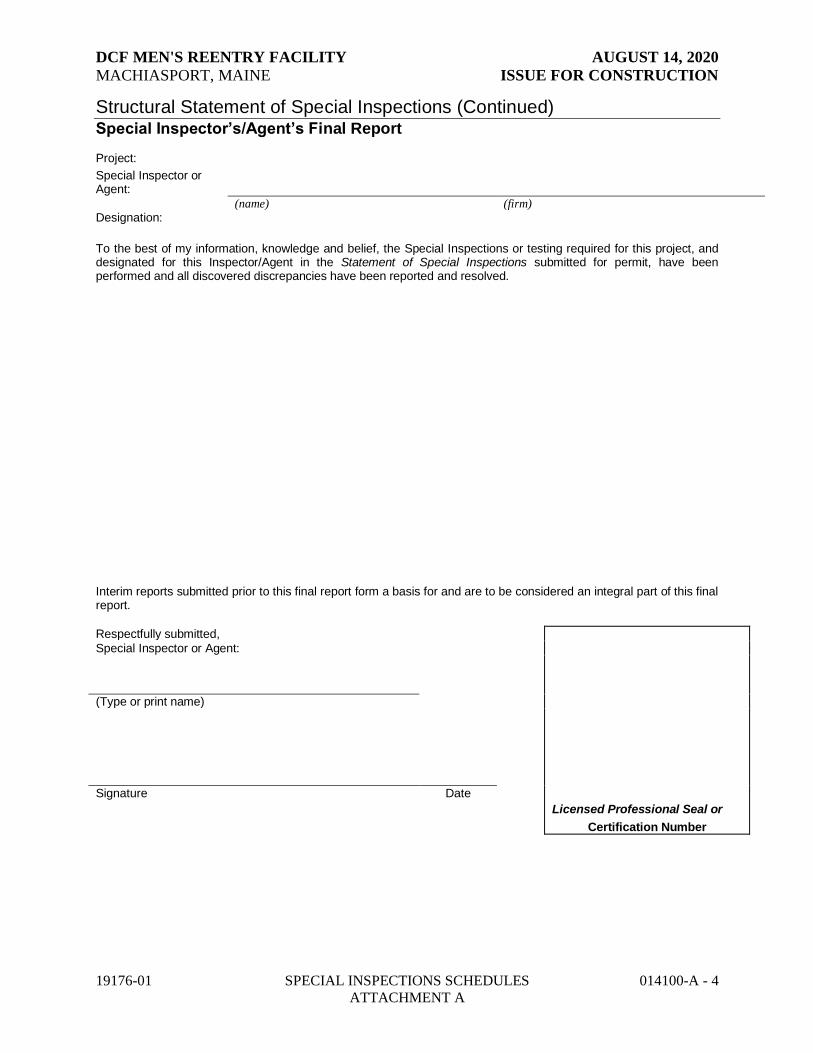
DCF MEN'S REENTRY FACILITY AUGUST 14, 2020
MACHIASPORT, MAINE ISSUE FOR CONSTRUCTION
19176-01 SPECIAL INSPECTIONS SCHEDULES 014100-A - 4
ATTACHMENT A
Structural Statement of Special Inspections (Continued) Special Inspector’s/Agent’s Final Report Project:
Special Inspector or Agent:
(name) (firm)
Designation:
To the best of my information, knowledge and belief, the Special Inspections or testing required for this project, and designated for this Inspector/Agent in the Statement of Special Inspections submitted for permit, have been performed and all discovered discrepancies have been reported and resolved.
Interim reports submitted prior to this final report form a basis for and are to be considered an integral part of this final report.
Respectfully submitted,
Special Inspector or Agent:
(Type or print name)
Signature Date
Licensed Professional Seal or
Certification Number

DCF MEN'S REENTRY FACILITY AUGUST 14, 2020
MACHIASPORT, MAINE ISSUE FOR CONSTRUCTION
19176-01 SPECIAL INSPECTIONS SCHEDULES 014100-A - 5
ATTACHMENT A
Structural Schedule of Special Inspections
Qualifications of Inspectors and Testing Technicians The qualifications of all personnel performing Special Inspection and testing activities are subject to the approval of the Building Official. The credentials of all Inspectors and testing technicians shall be provided to the Special Inspector for their records. NOTE VERIFICATION THAT QUALIFIED INDIVIDUALS ARE AVAILABLE TO PERFORM STIPULATED TESTING AND/OR INSPECTION SHOULD BE PROVIDED PRIOR TO SUBMITTING STATEMENT. AGENT QUALIFICATIONS IN SCHEDULE ARE SUGGESTIONS ONLY; FINAL QUALIFICATIONS ARE SUBJECT TO THE DISCRETION OF THE REGISTERED DESIGN PROFESSIONAL PREPARING THE SCHEDULE. Key for Minimum Qualifications of Inspection Agents: When the Registered Design Professional in Responsible Charge or Special Inspector of Record deems it appropriate that the individual performing a stipulated test or inspection have a specific certification, license or experience as indicated below, such requirement shall be listed below and shall be clearly identified within the schedule under the Agent Qualification Designation. PE/SE Structural Engineer – a licensed SE or PE specializing in the design of building structures PE/GE Geotechnical Engineer – a licensed PE specializing in soil mechanics and foundations EIT Engineer-In-Training – a graduate engineer who has passed the Fundamentals of Engineering
examination Experienced Testing Technician ETT Experienced Testing Technician – An Experienced Testing Technician with a minimum 5 years
experience with the stipulated test or inspection American Concrete Institute (ACI) Certification ACI-CFTT Concrete Field Testing Technician – Grade 1 ACI-CCI Concrete Construction Inspector ACI-LTT Laboratory Testing Technician – Grade 1&2 ACI-STT Strength Testing Technician American Welding Society (AWS) Certification AWS-CWI Certified Welding Inspector AWS/AISC-SSI Certified Structural Steel Inspector American Society of Non-Destructive Testing (ASNT) Certification ASNT Non-Destructive Testing Technician – Level II or III. International Code Council (ICC) Certification ICC-SMSI Structural Masonry Special Inspector ICC-SWSI Structural Steel and Welding Special Inspector ICC-SFSI Spray-Applied Fireproofing Special Inspector ICC-PCSI Prestressed Concrete Special Inspector ICC-RCSI Reinforced Concrete Special Inspector National Institute for Certification in Engineering Technologies (NICET) NICET-CT Concrete Technician – Levels I, II, III & IV NICET-ST Soils Technician - Levels I, II, III & IV NICET-GET Geotechnical Engineering Technician - Levels I, II, III & IV
Other
Qualified inspector with minimum of 20 years of experience in structural work

DCF MEN'S REENTRY FACILITY AUGUST 14, 2020
MACHIASPORT, MAINE ISSUE FOR CONSTRUCTION
19176-01 SPECIAL INSPECTIONS SCHEDULES 014100-A - 6 ATTACHMENT A
Structural Schedule of Special Inspections
SOILS & FOUNDATION CONSTRUCTION
VERIFICATION AND INSPECTION
IBC Section 1705.6, 1705.7
Y/N EXTENT: CONTINUOUS,
PERIODIC,
SUBMITTAL, OR NONE
COMMENTS AGENT AGENT QUALIFICATION
TASK COMPLETED
1. Verify existing soil conditions, fill placement and load
bearing requirements
a. Prior to placement of prepared fill, determine that
the site has been prepared in accordance with the
approved soils report.
Y P IBC 1705.6 PE/GE, EIT or ETT
b. During placement and compaction of fill material,
verify material being used and maximum lift
thickness comply with the approved soils report.
Y C IBC 1705.6 PE/GE, EIT or ETT
c. Test in-place dry density of compacted fill
complies with the approved soils report. Y p IBC 1704.7.2 PE/GE, EIT or ETT
2. Pile foundations:
a. Observe and record procedures for static load
testing of piles. C IBC 1705.7 PE/GE, EIT or ETT
b. Observe and record procedures for dynamic load
testing of piles. C PE/GE, EIT or ETT
c. Record installation of each pile and results of load
test. Include cutoff and tip elevations of each pile
relative to permanent reference.
C PE/GE, EIT or ETT
d. Test welded splices of steel piles C AWS D1.1 AWS-CWI
3. Pier foundations: Verify installation of pier foundations for
buildings assigned to Seismic Design Category C, D, E or F. N C IBC 1705.7 PE/GE, EIT or ETT
a. Verify pier diameter and length N C PE/GE, EIT or ETT
b. Verify pier embedment (socket) into bedrock N C PE/GE, EIT or ETT
c. Verify suitability of end bearing strata N C PE/GE, EIT or ETT

DCF MEN'S REENTRY FACILITY AUGUST 14, 2020
MACHIASPORT, MAINE ISSUE FOR CONSTRUCTION
19176-01 SPECIAL INSPECTIONS SCHEDULES 014100-A - 7 ATTACHMENT A
Structural Schedule of Special Inspections CONCRETE CONSTRUCTION
VERIFICATION AND INSPECTION
IBC Section 1705.7
Y/N EXTENT:
CONTINUOUS, PERIODIC,
SUBMITTAL,
OR NONE
COMMENTS AGENT AGENT
QUALIFICATION
TASK
COMPLETED
1. Inspection of reinforcing steel, including prestressing
tendons, and verify placement Y P
ACI 318: CH.
20, 25.2, 25.3,
26.1-26.5.3
PE/SE or EIT
2. Reinforcing bar welding:
a. verify weldability of reinforcing bars other than
ASTM A706
b. Inspect single-pass fillet welds, maximum 5/16”
c. Inspect all other weld
N
P
P
C
Welding of
Reinf Not
Allowed
AWS D1.4,
ACI 318: 56.5.4
3. Inspect anchors cast in concrete Y P ACI 318 17.8.2 PE/SE or EIT
4. Inspect anchors post-installed in hardened concrete
members.
a. Adhesive anchors installed in horizontally or
upwardly inclined orientations to resist sustained
tension loads
b. Mechanical anchors and adhesive anchors not
defined in 4.a.
Y
Y
C
P
ACI 318:
17.8.2.4
ACI: 17.8.2
5. Verifying use of required design mix Y P
ACI 318: Ch 19,
26.4.3, 26.4.4 PE/SE or EIT
6. Prior to concrete placement, fabricate specimens for
strength test, perform slump and air content test, and
determine the temperature of concrete Y C
ASTM C 172
ASTM C 31
ACI 318: 26.4.5,
26.12
ACI-CFTT or
ACI-STT
7. Inspection of concrete and shotcrete placement for
proper application techniques Y C ACI 318: 26.4.5 PE/SE or EIT
8. verify maintenance of specified curing temperature
and techniques Y P ACI 318: 26.4.7-
26.4.9 PE/SE or EIT
9. Inspection of Prestressed Concrete
a. Application of prestressing force. N C ACI 318: 18.20 PE/SE or EIT
b. Grouting of bonded prestressing tendons N C
ACI 318:
18.18.4 PE/SE or EIT
10. Inspect erection of precast concrete members N P
ACI 318: Ch
26.8 PE/SE or EIT
11. Verification of in-situ concrete strength, prior to
stressing of tendons in post-tensioned concrete and prior
to removal of shores and forms from beans and structural
slabs
N P ACI 318:
26.10.2 ACI-STT
12. Inspect formwork for shape, location and dimensions
of concrete member being formed. Y P ACI 319:
26.10.1 (b) PE/SE or EIT

DCF MEN'S REENTRY FACILITY AUGUST 14, 2020
MACHIASPORT, MAINE ISSUE FOR CONSTRUCTION
19176-01 SPECIAL INSPECTIONS SCHEDULES 014100-A - 8 ATTACHMENT A
Structural Schedule of Special Inspections MASONRY CONSTRUCTION
VERIFICATION AND INSPECTION
IBC Section 1705.4
Y/N
EXTENT:
CONTINUOUS,
PERIODIC,
SUBMITTAL,
OR NONE
COMMENTS
AGENT AGENT
QUALIFICATION
TASK COMPLETED
1. As masonry construction begins, the following shall be verified
to ensure compliance:
INSPECTION
ONLY
REQUIRED FOR
BEARING
MASONRY
a. Proportions of site-prepared mortar. N P ACI530.1, 2.6A PE/SE or EIT
b. Construction of mortar joints. N P ACI530.1, 3.3B PE/SE or EIT
c. Location of reinforcement and connectors. N P ACI530.1, 3.4, 3.6A PE/SE or EIT
d. Prestressing technique. N P ACI530.1, 3.6B PE/SE or EIT
e. Grade and size of prestressing tendons and
anchorages. N P
ACI530.1, 2.4B,
2.4H PE/SE or EIT
2. The inspection program shall verify:
a. Size and location of structural elements. N P ACI530.1, 3.3G PE/SE or EIT
b. Type, size and location of anchors, including
other details of anchorage of masonry to
structural members, frames or other construction.
N P ACI530, 1.2.2(e),
2.1.4, 3.1.6 PE/SE or EIT
c. Specified size, grade and type of reinforcement. N P
ACI530, 1.12,
ACI530.1, 2.4,
3.4
PE/SE or EIT
d. Welding of reinforcing bars. N C AC530, 2.1.10.6.2,
3.2..4 (b) AWS-CWI
e. Protection of masonry during cold weather
(temperature below 40°F) or hot weather
(temperature above 90°F).
N P
IBC 2104.3,
2104.4; ACI530.1,
1.8C,
1.8D
PE/SE or EIT
f. Application and measurement of prestressing force. N P ACI530.1, 3.6B PE/SE or EIT
3. Prior to grouting, the following shall be verified to
ensure compliance: NO CMU AT THIS TIME
a. Grout space is clean. N P ACI530.1, 3.2D PE/SE or EIT
b. Placement of reinforcement and connectors and
prestressing tendons and anchorages. N P
ACI530, 1.12,
ACI530.1, 3.4 PE/SE or EIT
c. Proportions of site-prepared grout and prestressing
grout for bonded tendons. N P ACI530.1, 2.6B PE/SE or EIT
d. Construction of mortar joints. N P ACI530.1, 3.3B PE/SE or EIT
4. Grout placement shall be verified to ensure compliance
with code and construction document provisions. N C ACI530.1, 3.5 PE/SE or EIT
a. Grouting of prestressing bonded tendons. N C ACI530.1, 3.6C PE/SE or EIT
5. Preparation of any required grout specimens, mortar
specimens and/or prisms shall be observed. N C
IBC 2105.2.2,
2105.3; ACI530.1, l.4 PE/SE or EIT
6. Compliance with required inspection provisions of the
construction documents and the approved submittals
shall be verified.
N P ACI530.1, 1.5 PE/SE or EIT

DCF MEN'S REENTRY FACILITY AUGUST 14, 2020
MACHIASPORT, MAINE ISSUE FOR CONSTRUCTION
19176-01 SPECIAL INSPECTIONS SCHEDULES 014100-A - 9 ATTACHMENT A
Structural Schedule of Special Inspections - STEEL CONSTRUCTION VERIFICATION AND INSPECTION
IBC Section 1705.2
Y/N
EXTENT: CONTINUOUS,
PERIODIC, SUBMITTAL, OR
NONE
COMMENTS AGENT AGENT QUALIFICATION
TASK COMPLETED
1. Material verification of high-strength bolts, nuts
and washers:
a. Identification markings to conform to ASTM standards
specified in the approved construction documents.
N S
Applicable
ASTM
material
specifications;
AISC 360-10,
Section N5.6
PE/SE or EIT
b. Manufacturer's certificate of compliance required. N S PE/SE or EIT
2. Inspection of high-strength bolting
a. Bearing-type connections. N P AISC 360-10,
Section N5.6
IBC Sect
1705.12
AWS/AISC-SSI
b. Slip-critical connections. N
C or P
(method dependent) AWS/AISC-SSI
3. Material verification of structural steel (IBC Sect 1708.4):
a. Identification markings to conform to ASTM
standards specified in the approved construction
documents. N S
ASTM A 6 or
ASTM A 568
IBC Sect
1705.12
PE/SE or EIT
b. Manufacturers' certified mill test reports.
N S
ASTM A 6 or
ASTM A 568
IBC Sect
1705.12
PE/SE or EIT
4. Material verification of weld filler materials:
a. Identification markings to conform to AWS
specification in the approved construction
documents.
N S AISC 360-10,
Section N5.6 PE/SE or EIT
b. Manufacturer's certificate of compliance required. N S PE/SE or EIT
5. Submit current AWS D1.1 welder certificate for all field welders
who will be welding on this project. N S AWS D1.1 PE/SE or EIT
6. Inspection of welding (IBC 1704.3.1):
a. Structural steel:
1) Complete and partial penetration groove welds. N C
AWS D1.1
AWS-CWI
2) Multipass fillet welds. N C AWS-CWI
3) Single-pass fillet welds> 5/16” N C AWS-CWI
4) Single-pass fillet welds< 5/16” N P AWS-CWI
5) Floor deck shear studs N
6) Floor and roof deck welds N P AWS D1.3 AWS-CWI
b. Reinforcing steel (IBC Sect 1903.5.2):
1) Verification of weldability of reinforcing steel other
than ASTM A706.
ONLY BY
PERMISSION
OF SER
2) Reinforcing steel-resisting flexural and axial forces in
intermediate and special moment frames, and boundary
elements of special reinforced concrete shear walls and
shear reinforcement.
N C AWS D1.4
ACI 318: 3.5.2
AWS-CWI
3) Shear reinforcement. N C AWS-CWI
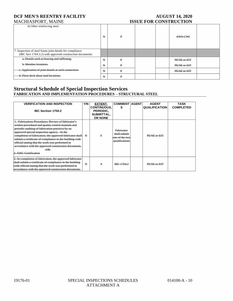
DCF MEN'S REENTRY FACILITY AUGUST 14, 2020
MACHIASPORT, MAINE ISSUE FOR CONSTRUCTION
19176-01 SPECIAL INSPECTIONS SCHEDULES 014100-A - 10 ATTACHMENT A
4) Other reinforcing steel.
N P AWS-CWI
7. Inspection of steel frame joint details for compliance
(IBC Sect 1704.3.2) with approved construction documents:
a. Details such as bracing and stiffening. N P
PE/SE or EIT
b. Member locations. N P PE/SE or EIT
c. Application of joint details at each connection. N P PE/SE or EIT
d. Floor deck shear stud locations. N P
Structural Schedule of Special Inspection Services FABRICATION AND IMPLEMENTATION PROCEDURES – STRUCTURAL STEEL
VERIFICATION AND INSPECTION
IBC Section 1704.2
Y/N EXTENT:
CONTINUOUS, PERIODIC,
SUBMITTAL,
OR NONE
COMMENT
S
AGENT AGENT
QUALIFICATION
TASK
COMPLETED
1. Fabrications Procedures: Review of fabricator’s
written procedural and quality control manuals and
periodic auditing of fabrication practices by an
approved special inspection agency. At the
completion of fabrication, the approved fabricator shall
submit a certificate of compliance to the building code
official stating that the work was performed in
accordance with the approved construction documents.
-OR-
N S
Fabricator
shall submit
one of the two
qualifications
PE/SE or EIT
2. AISC Certification
3. At completion of fabrication, the approved fabricator
shall submit a certificate of compliance to the building
code official stating that the work was performed in
accordance with the approved construction documents.
N S IBC 1704.2 PE/SE or EIT
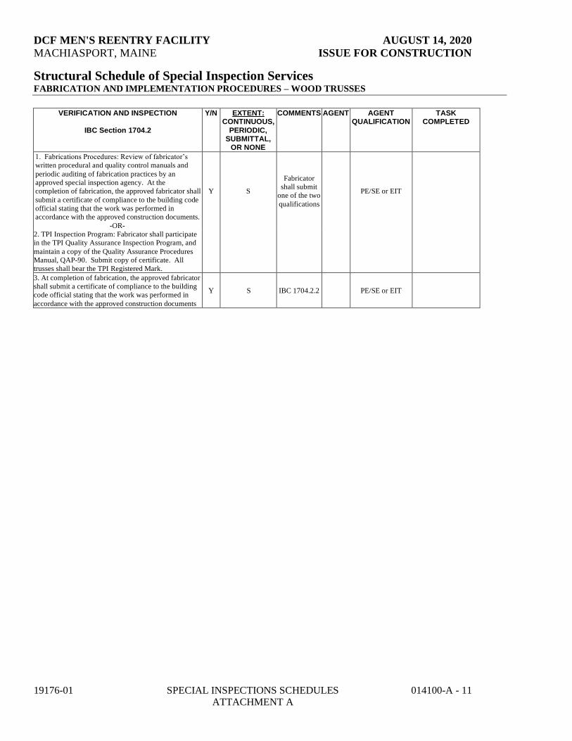
DCF MEN'S REENTRY FACILITY AUGUST 14, 2020
MACHIASPORT, MAINE ISSUE FOR CONSTRUCTION
19176-01 SPECIAL INSPECTIONS SCHEDULES 014100-A - 11 ATTACHMENT A
Structural Schedule of Special Inspection Services FABRICATION AND IMPLEMENTATION PROCEDURES – WOOD TRUSSES
VERIFICATION AND INSPECTION
IBC Section 1704.2
Y/N EXTENT: CONTINUOUS,
PERIODIC, SUBMITTAL,
OR NONE
COMMENTS AGENT AGENT QUALIFICATION
TASK COMPLETED
1. Fabrications Procedures: Review of fabricator’s
written procedural and quality control manuals and
periodic auditing of fabrication practices by an
approved special inspection agency. At the
completion of fabrication, the approved fabricator shall
submit a certificate of compliance to the building code
official stating that the work was performed in
accordance with the approved construction documents.
-OR-
Y S
Fabricator
shall submit
one of the two
qualifications
PE/SE or EIT
2. TPI Inspection Program: Fabricator shall participate
in the TPI Quality Assurance Inspection Program, and
maintain a copy of the Quality Assurance Procedures
Manual, QAP-90. Submit copy of certificate. All
trusses shall bear the TPI Registered Mark.
3. At completion of fabrication, the approved fabricator
shall submit a certificate of compliance to the building
code official stating that the work was performed in
accordance with the approved construction documents
Y S IBC 1704.2.2 PE/SE or EIT

DCF MEN'S REENTRY FACILITY AUGUST 14, 2020
MACHIASPORT, MAINE ISSUE FOR CONSTRUCTION
19176-01 SPECIAL INSPECTIONS SCHEDULES 014100-A - 12 ATTACHMENT A
Structural Schedule of Special Inspections
WOOD CONSTRUCTION
VERIFICATION AND INSPECTION
IBC Section 1705.11.1
Y/N EXTENT:
CONTINUOUS, PERIODIC,
SUBMITTAL,
OR NONE
COMMENTS AGENT AGENT
QUALIFICATION
TASK
COMPLETED
1. Fabrication of diaphragms
a. Verify wood structural panel sheathing for
grade and thickness Y P IBC 1705.11.1 PE/SE or EIT
b. Verify the nominal size of framing members
at adjoining panel edges Y P IBC 1705.11.1 PE/SE or EIT
c. Verify the nail diameter and length Y P IBC 1705.11.1 PE/SE or EIT
d. Verify the locations and installation of drag
struts, bracing and hold-downs. Y P IBC 1705.11.1 PE/SE or EIT
e. Verify the spacing between fasteners in each
line and at edge margins Y P IBC 1705.11.1 PE/SE or EIT

DCF MEN'S REENTRY FACILITY AUGUST 14, 2020
MACHIASPORT, MAINE ISSUE FOR CONSTRUCTION
19176-01 SPECIAL INSPECTIONS SCHEDULES 014100-A - 13 ATTACHMENT A
Structural Schedule of Special Inspections
SPRAYED FIRE-RESISTANT MATERIALS
VERIFICATION AND INSPECTION
Y/N
EXTENT:
COMMENTS AGENT AGENT
QUALIFICATION
TASK
IBC Section 1704.14
CONTINUOUS,
PERIODIC,
SUBMITTAL,
OR NONE
COMPLETED
Submit copies of approved manufacturer's instructions for
preparation, application and curing N S
1. Prior to application of sprayed fire-resistant materials,
surface preparation shall be observed to verify compliance
with maufacturer's written instructions.
N C IBC 1704.10.1 ICC-SFSI
2. Substrate shall have a minimum ambient temerature
before and after application as specified in the approved
manufacturer's written instructions.
N IBC 1704.10.2 ICC-SFSI
Proper ventilation of area shall be maintained as requried
by the approved manufacturer's written instructions. N P IBC 1704.10.2 ICC-SFSI
Thickness of applied fire-resistant materials applied to
structural elements shall be measured to verify minimums
as required by the approved fire-resistant design.
N
Thickness
shall be
determined in
accordance
with ASTM
E605.
ICC-SFSI
Individually meassured thickness which exceeds the
design thickness specified by 1/4" or more shall be
recorded as the thickness specified +1/4"; for design
thicknesses 1" or greater the minimum allowable
individual thickness shall be the design thickness minus
1/4"; for design thickness less than 1", the minimum
allowable individual thickness shall be the design
thickness minus 25%:
1.Floor, roof and wall assemblies N P
average of not
less than 4
measurements
for each 1,000
sq. ft. of
sprayed area
ICC-SFSI
2. Structural framing members N P
test a
minimum of
25% of
framing
members on
each floor
ICC-SFSI
Density of sprayed fire-resistant material shall be not less
than specified, test in accordance with ASTM E 605 N P ICC-SFSI
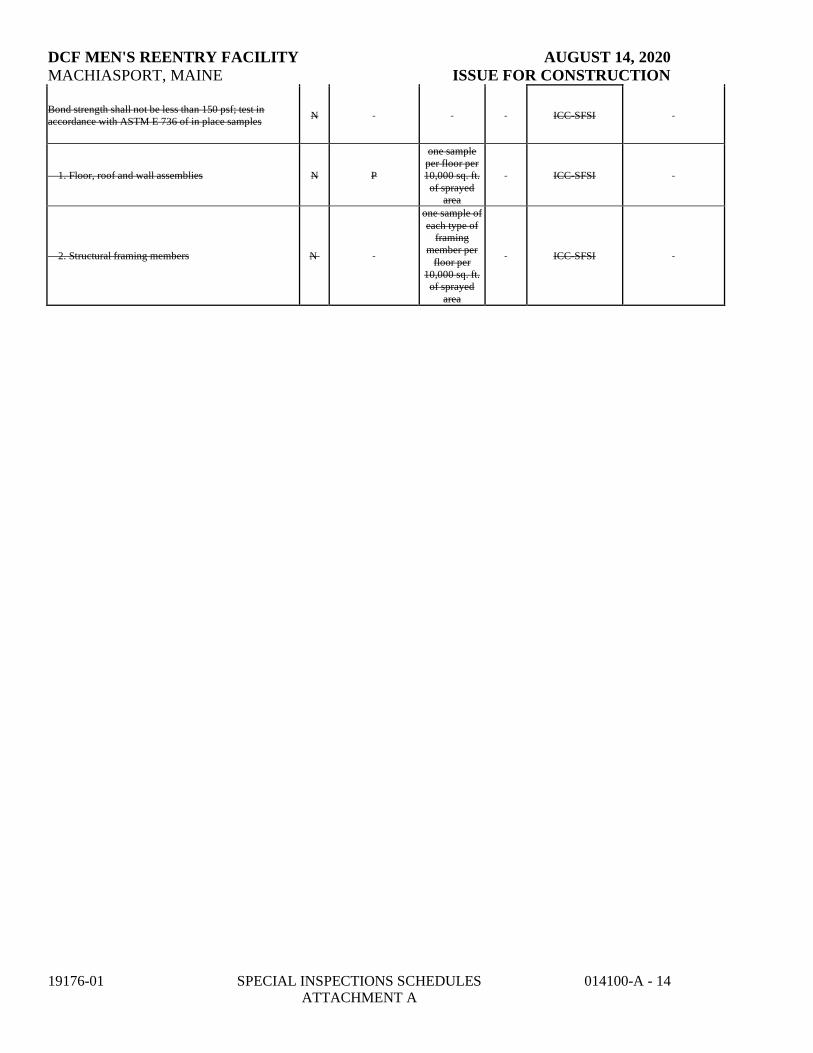
DCF MEN'S REENTRY FACILITY AUGUST 14, 2020
MACHIASPORT, MAINE ISSUE FOR CONSTRUCTION
19176-01 SPECIAL INSPECTIONS SCHEDULES 014100-A - 14 ATTACHMENT A
Bond strength shall not be less than 150 psf; test in
accordance with ASTM E 736 of in place samples N ICC-SFSI
1. Floor, roof and wall assemblies N P
one sample
per floor per
10,000 sq. ft.
of sprayed
area
ICC-SFSI
2. Structural framing members N
one sample of
each type of
framing
member per
floor per
10,000 sq. ft.
of sprayed
area
ICC-SFSI

DCF MEN'S REENTRY FACILITY AUGUST 14, 2020
MACHIASPORT, MAINE ISSUE FOR CONSTRUCTION
19176-01 SPECIAL INSPECTIONS SCHEDULES 014100-A - 15 ATTACHMENT A
Structural Schedule of Special Inspections SEISMIC RESISTANCE - STRUCTURAL
VERIFICATION AND INSPECTION
IBC Section 1707
Y/N EXTENT:
CONTINUOUS,
PERIODIC,
SUBMITTAL, OR NONE
COMMENTS AGENT AGENT
QUALIFICATION
TASK
COMPLETED
1. Special inspections for seismic resistance.
Special inspection as specified in this section
is required for the following:
Seismic Design Category: B
a. The seismic-force-resisting
systems in structures assigned to
Seismic Design Category C, D, E or
F
N P IBC 1705.12.2 PE/SE or EIT
2. Structural steel: Continuous special
inspection for structural welding in accordance
with AISC 341.
N P IBC 1705.13 AWS-CWI
3. Structural wood:
a. Continuous special inspection
during field gluing operations of
elements of the seismic-force-resist-
ing system.
N C IBC 1705.12.2 PE/SE or EIT
b. Periodic special inspections for
nailing, bolting, anchoring and
other fastening of components
within the seismic-force-resisting
system, including drag struts,
braces and hold-downs
N P IBC 1705.12.2 PE/SE or EIT
4. Cold-formed steel framing: Periodic special
inspections during welding operations of
elements of the seismic-force-resisting system.
Periodic special inspections for screw
attachment, bolting, anchoring and other
fastening of components within the seismic-
force-resisting system, including struts, braces,
and hold-downs
N N IBC 1705.11.2
4. Seismic isolation system. Provide periodic
special inspection during the fabrication and
installation of isolator units and energy
dissipation devices if used as part of the
seismic isolation system
N N
CURRENTLY NOT IN
PROJECT
IBC 1705

DCF MEN'S REENTRY FACILITY AUGUST 14, 2020
MACHIASPORT, MAINE ISSUE FOR CONSTRUCTION
19176-01 SPECIAL INSPECTIONS SCHEDULES 014100-A - 16 ATTACHMENT A
Quality Assurance Plan – Seismic and Wind
QUALITY ASSURANCE FOR SEISMIC RESISTANCE CHECK LIST [IBC 1705.12]
Seismic Design Category B
QUALITY ASSURANCE FOR WIND RESISTANCE CHECK LIST [IBC 1706]
Wind Exposure Category B
FOR SEISMIC DESIGN CATEGORY C OR HIGHER:
Structural:
The seismic-force-resisting systems
Steel Braced Frames and associated connections/anchorage
Steel Moment Frames and associated connections
Shear walls: CMU Wood Concrete Diaphragms: Floor Roof
Other:
RE
QU
IRE
D
NO
T
RE
QU
IRE
D
NO
T
AP
PL
ICA
BL
E
QUALITY ASSURANCE PLAN REQUIREMENTS
(A Quality Assurance Plan is required where indicated below)
In wind exposure Categories B, where 3-second-gust basic wind speed is 120 miles per hour or
greater.
In wind exposure Categories C and D, where 3-second-gust basic wind speed is 120 miles per hour or greater.
Prepared by:
Building Code Official’s Acceptance:
Signature Date Signature Date

DCF MEN'S REENTRY FACILITY AUGUST 14, 2020
MACHIASPORT, MAINE ISSUE FOR CONSTRUCTION
19176-01 SPECIAL INSPECTIONS SCHEDULES 014100-A - 17 ATTACHMENT A
Contractor’s Statement of Responsibility
Each contractor responsible for the construction or fabrication of a system or component designated in the Quality Assurance Plan must submit a Statement of Responsibility. The Statement of Responsibility is required for Seismic Design Category C or higher. Make additional copies of this form as required. Project: Downeast Correctional Facility – Men’s Reentry Facility Contractor’s Name: Address: License No.: Description of designated building systems and components included in the Statement of Responsibility:
Contractor’s Acknowledgment of Special Requirements I hereby acknowledge that I have received, read, and understand the Quality Assurance Plan and Special Inspection program. I hereby acknowledge that control will be exercised to obtain conformance with the construction documents approved by the Building Official. ________________________________ _______________ Signature Date
Contractor’s Provisions for Quality Control Procedures for exercising control within the contractor’s organization, the method and frequency of reporting and the distribution of reports is attached to this Statement. Identification and qualifications of the person(s) exercising such control and their position(s) in the organization are attached to this Statement.

DOWNEAST CORRECTIONAL FACILITY JUNE 25, 2020 MACHIASPORT, MAINE DESIGN DEVELOPMENT
19176
THIS PAGE INTENTIONALLY LEFT BLANK

DCF MEN'S REENTRY FACILITY AUGUST 14, 2020
MACHIASPORT, MAINE ISSUE FOR CONSTRUCTION
19176-01 REFERENCES 014200 - 1
SECTION 014200
REFERENCES
PART 1 - GENERAL
1.1 RELATED DOCUMENTS
A. Drawings and general provisions of the Contract, including General and Supplementary Conditions and other Division 01 Specification Sections, apply to this Section.
1.2 DEFINITIONS
A. General: Basic Contract definitions are included in the Conditions of the Contract.
B. "Approved": When used to convey Architect's action on Contractor's submittals, applications,
and requests, "approved" is limited to Architect's duties and responsibilities as stated in the
Conditions of the Contract.
C. "Directed": A command or instruction by Architect. Other terms including "requested,"
"authorized," "selected," "required," and "permitted" have the same meaning as "directed."
D. "Indicated": Requirements expressed by graphic representations or in written form on
Drawings, in Specifications, and in other Contract Documents. Other terms including "shown," "noted," "scheduled," and "specified" have the same meaning as "indicated."
E. "Regulations": Laws, ordinances, statutes, and lawful orders issued by authorities having
jurisdiction, and rules, conventions, and agreements within the construction industry that control performance of the Work.
F. "Furnish": Supply and deliver to Project site, ready for unloading, unpacking, assembly,
installation, and similar operations.
G. "Install": Operations at Project site including unloading, temporarily storing, unpacking,
assembling, erecting, placing, anchoring, applying, working to dimension, finishing, curing,
protecting, cleaning, and similar operations.
H. "Provide": Furnish and install, complete and ready for the intended use.
I. "Project Site": Space available for performing construction activities. The extent of Project site
is shown on Drawings and may or may not be identical with the description of the land on
which Project is to be built.
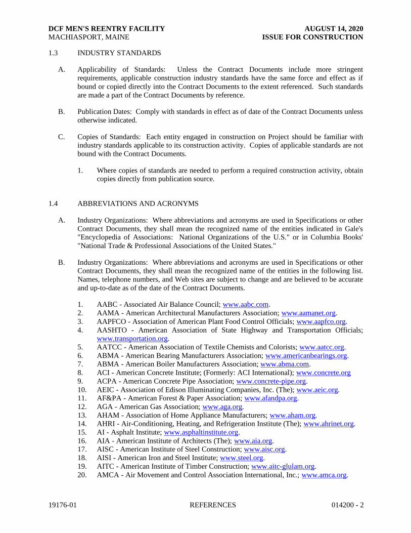
DCF MEN'S REENTRY FACILITY AUGUST 14, 2020
MACHIASPORT, MAINE ISSUE FOR CONSTRUCTION
19176-01 REFERENCES 014200 - 2
1.3 INDUSTRY STANDARDS
A. Applicability of Standards: Unless the Contract Documents include more stringent
requirements, applicable construction industry standards have the same force and effect as if
bound or copied directly into the Contract Documents to the extent referenced. Such standards
are made a part of the Contract Documents by reference.
B. Publication Dates: Comply with standards in effect as of date of the Contract Documents unless
otherwise indicated.
C. Copies of Standards: Each entity engaged in construction on Project should be familiar with industry standards applicable to its construction activity. Copies of applicable standards are not
bound with the Contract Documents.
1. Where copies of standards are needed to perform a required construction activity, obtain copies directly from publication source.
1.4 ABBREVIATIONS AND ACRONYMS
A. Industry Organizations: Where abbreviations and acronyms are used in Specifications or other
Contract Documents, they shall mean the recognized name of the entities indicated in Gale's "Encyclopedia of Associations: National Organizations of the U.S." or in Columbia Books'
"National Trade & Professional Associations of the United States."
B. Industry Organizations: Where abbreviations and acronyms are used in Specifications or other Contract Documents, they shall mean the recognized name of the entities in the following list.
Names, telephone numbers, and Web sites are subject to change and are believed to be accurate
and up-to-date as of the date of the Contract Documents.
1. AABC - Associated Air Balance Council; www.aabc.com.
2. AAMA - American Architectural Manufacturers Association; www.aamanet.org.
3. AAPFCO - Association of American Plant Food Control Officials; www.aapfco.org.
4. AASHTO - American Association of State Highway and Transportation Officials; www.transportation.org.
5. AATCC - American Association of Textile Chemists and Colorists; www.aatcc.org.
6. ABMA - American Bearing Manufacturers Association; www.americanbearings.org. 7. ABMA - American Boiler Manufacturers Association; www.abma.com.
8. ACI - American Concrete Institute; (Formerly: ACI International); www.concrete.org
9. ACPA - American Concrete Pipe Association; www.concrete-pipe.org.
10. AEIC - Association of Edison Illuminating Companies, Inc. (The); www.aeic.org. 11. AF&PA - American Forest & Paper Association; www.afandpa.org.
12. AGA - American Gas Association; www.aga.org.
13. AHAM - Association of Home Appliance Manufacturers; www.aham.org. 14. AHRI - Air-Conditioning, Heating, and Refrigeration Institute (The); www.ahrinet.org.
15. AI - Asphalt Institute; www.asphaltinstitute.org.
16. AIA - American Institute of Architects (The); www.aia.org. 17. AISC - American Institute of Steel Construction; www.aisc.org.
18. AISI - American Iron and Steel Institute; www.steel.org.
19. AITC - American Institute of Timber Construction; www.aitc-glulam.org.
20. AMCA - Air Movement and Control Association International, Inc.; www.amca.org.

DCF MEN'S REENTRY FACILITY AUGUST 14, 2020
MACHIASPORT, MAINE ISSUE FOR CONSTRUCTION
19176-01 REFERENCES 014200 - 3
21. ANSI - American National Standards Institute; www.ansi.org. 22. AOSA - Association of Official Seed Analysts, Inc.; www.aosaseed.com.
23. APA - APA - The Engineered Wood Association; www.apawood.org.
24. APA - Architectural Precast Association; www.archprecast.org.
25. API - American Petroleum Institute; www.api.org. 26. ARI - Air-Conditioning & Refrigeration Institute; (See AHRI).
27. ARI - American Refrigeration Institute; (See AHRI).
28. ARMA - Asphalt Roofing Manufacturers Association; www.asphaltroofing.org. 29. ASCE - American Society of Civil Engineers; www.asce.org.
30. ASCE/SEI - American Society of Civil Engineers/Structural Engineering Institute; (See
ASCE). 31. ASHRAE - American Society of Heating, Refrigerating and Air-Conditioning Engineers;
www.ashrae.org.
32. ASME - ASME International; (American Society of Mechanical Engineers);
www.asme.org. 33. ASSE - American Society of Safety Engineers (The); www.asse.org.
34. ASSE - American Society of Sanitary Engineering; www.asse-plumbing.org.
35. ASTM - ASTM International; www.astm.org. 36. ATIS - Alliance for Telecommunications Industry Solutions; www.atis.org.
37. AWEA - American Wind Energy Association; www.awea.org.
38. AWI - Architectural Woodwork Institute; www.awinet.org. 39. AWMAC - Architectural Woodwork Manufacturers Association of Canada;
www.awmac.com.
40. AWPA - American Wood Protection Association; www.awpa.com.
41. AWS - American Welding Society; www.aws.org. 42. AWWA - American Water Works Association; www.awwa.org.
43. BHMA - Builders Hardware Manufacturers Association; www.buildershardware.com.
44. BIA - Brick Industry Association (The); www.gobrick.com. 45. BICSI - BICSI, Inc.; www.bicsi.org.
46. BIFMA - BIFMA International; (Business and Institutional Furniture Manufacturer's
Association); www.bifma.org.
47. BISSC - Baking Industry Sanitation Standards Committee; www.bissc.org. 48. BWF - Badminton World Federation; (Formerly: International Badminton Federation);
www.bissc.org.
49. CDA - Copper Development Association; www.copper.org. 50. CE - Conformite Europeenne; http://ec.europa.eu/growth/single-market/ce-marking/
51. CEA - Canadian Electricity Association; www.electricity.ca.
52. CEA - Consumer Electronics Association; www.ce.org. 53. CFFA - Chemical Fabrics and Film Association, Inc.; www.chemicalfabricsandfilm.com.
54. CFSEI - Cold-Formed Steel Engineers Institute; www.cfsei.org.
55. CGA - Compressed Gas Association; www.cganet.com.
56. CIMA - Cellulose Insulation Manufacturers Association; www.cellulose.org. 57. CISCA - Ceilings & Interior Systems Construction Association; www.cisca.org.
58. CISPI - Cast Iron Soil Pipe Institute; www.cispi.org.
59. CLFMI - Chain Link Fence Manufacturers Institute; www.chainlinkinfo.org. 60. CPA - Composite Panel Association; www.pbmdf.com.
61. CRI - Carpet and Rug Institute (The); www.carpet-rug.org.
62. CRRC - Cool Roof Rating Council; www.coolroofs.org. 63. CRSI - Concrete Reinforcing Steel Institute; www.crsi.org.
64. CSA - Canadian Standards Association; www.csa.ca.

DCF MEN'S REENTRY FACILITY AUGUST 14, 2020
MACHIASPORT, MAINE ISSUE FOR CONSTRUCTION
19176-01 REFERENCES 014200 - 4
65. CSA - CSA International; (Formerly: IAS - International Approval Services); www.csa-international.org.
66. CSI - Construction Specifications Institute (The); www.csinet.org.
67. CSSB - Cedar Shake & Shingle Bureau; www.cedarbureau.org.
68. CTI - Cooling Technology Institute; (Formerly: Cooling Tower Institute); www.cti.org. 69. CWC - Composite Wood Council; (See CPA).
70. DASMA - Door and Access Systems Manufacturers Association; www.dasma.com.
71. DHI - Door and Hardware Institute; www.dhi.org. 72. ECA - Electronic Components Association; (See ECIA).
73. ECAMA - Electronic Components Assemblies & Materials Association; (See ECIA).
74. ECIA - Electronic Components Industry Association; www.eciaonline.org. 75. EIA - Electronic Industries Alliance; (See TIA).
76. EIMA - EIFS Industry Members Association; www.eima.com.
77. EJMA - Expansion Joint Manufacturers Association, Inc.; www.ejma.org.
78. ESD - ESD Association; (Electrostatic Discharge Association); www.esda.org . 79. ESTA - Entertainment Services and Technology Association; (See PLASA).
80. ETL - Intertek (See Intertek); www.intertek.com.
81. EVO - Efficiency Valuation Organization; www.evo-world.org. 82. FCI - Fluid Controls Institute; www.fluidcontrolsinstitute.org.
83. FIBA - Federation Internationale de Basketball; (The International Basketball
Federation); www.fiba.com. 84. FIVB - Federation Internationale de Volleyball; (The International Volleyball
Federation); www.fivb.org.
85. FM Approvals - FM Approvals LLC; www.fmglobal.com.
86. FM Global - FM Global; (Formerly: FMG - FM Global); www.fmglobal.com. 87. FRSA - Florida Roofing, Sheet Metal & Air Conditioning Contractors Association, Inc.;
www.floridaroof.com.
88. FSA - Fluid Sealing Association; www.fluidsealing.com. 89. FSC - Forest Stewardship Council U.S.; www.fscus.org.
90. GA - Gypsum Association; www.gypsum.org.
91. GANA - Glass Association of North America; www.glasswebsite.com.
92. GS - Green Seal; www.greenseal.org. 93. HI - Hydraulic Institute; www.pumps.org.
94. HI/GAMA - Hydronics Institute/Gas Appliance Manufacturers Association; (See AHRI).
95. HMMA - Hollow Metal Manufacturers Association; (See NAAMM). 96. HPVA - Hardwood Plywood & Veneer Association; www.hpva.org.
97. HPW - H. P. White Laboratory, Inc.; www.hpwhite.com.
98. IAPSC - International Association of Professional Security Consultants; www.iapsc.org. 99. IAS - International Accreditation Service; www.iasonline.org.
100. IAS - International Approval Services; (See CSA).
101. ICBO - International Conference of Building Officials; (See ICC).
102. ICC - International Code Council; www.iccsafe.org. 103. ICEA - Insulated Cable Engineers Association, Inc.; www.icea.net.
104. ICPA - International Cast Polymer Alliance; www.icpa-hq.org.
105. ICRI - International Concrete Repair Institute, Inc.; www.icri.org. 106. IEC - International Electrotechnical Commission; www.iec.ch.
107. IEEE - Institute of Electrical and Electronics Engineers, Inc. (The); www.ieee.org.
108. IES - Illuminating Engineering Society; (Formerly: Illuminating Engineering Society of North America); www.ies.org.
109. IESNA - Illuminating Engineering Society of North America; (See IES).
110. IEST - Institute of Environmental Sciences and Technology; www.iest.org.

DCF MEN'S REENTRY FACILITY AUGUST 14, 2020
MACHIASPORT, MAINE ISSUE FOR CONSTRUCTION
19176-01 REFERENCES 014200 - 5
111. IGMA - Insulating Glass Manufacturers Alliance; www.igmaonline.org. 112. IGSHPA - International Ground Source Heat Pump Association;
www.igshpa.okstate.edu.
113. ILI - Indiana Limestone Institute of America, Inc.; www.iliai.com.
114. Intertek - Intertek Group; (Formerly: ETL SEMCO; Intertek Testing Service NA); www.intertek.com.
115. ISA - International Society of Automation (The); (Formerly: Instrumentation, Systems,
and Automation Society); www.isa.org. 116. ISAS - Instrumentation, Systems, and Automation Society (The); (See ISA).
117. ISFA - International Surface Fabricators Association; (Formerly: International Solid
Surface Fabricators Association); www.isfanow.org. 118. ISO - International Organization for Standardization; www.iso.org.
119. ISSFA - International Solid Surface Fabricators Association; (See ISFA).
120. ITU - International Telecommunication Union; www.itu.int/home.
121. KCMA - Kitchen Cabinet Manufacturers Association; www.kcma.org. 122. LMA - Laminating Materials Association; (See CPA).
123. LPI - Lightning Protection Institute; www.lightning.org.
124. MBMA - Metal Building Manufacturers Association; www.mbma.com. 125. MCA - Metal Construction Association; www.metalconstruction.org.
126. MFMA - Maple Flooring Manufacturers Association, Inc.; www.maplefloor.org.
127. MFMA - Metal Framing Manufacturers Association, Inc.; www.metalframingmfg.org. 128. MHIA - Material Handling Industry of America; www.mhia.org.
129. MIA - Marble Institute of America; www.marble-institute.com.
130. MMPA - Moulding & Millwork Producers Association; www.wmmpa.com.
131. MPI - Master Painters Institute; www.paintinfo.com. 132. MSS - Manufacturers Standardization Society of The Valve and Fittings Industry Inc.;
www.mss-hq.org.
133. NAAMM - National Association of Architectural Metal Manufacturers; www.naamm.org.
134. NACE - NACE International; (National Association of Corrosion Engineers
International); www.nace.org.
135. NADCA - National Air Duct Cleaners Association; www.nadca.com. 136. NAIMA - North American Insulation Manufacturers Association; www.naima.org.
137. NBGQA - National Building Granite Quarries Association, Inc.; www.nbgqa.com.
138. NBI - New Buildings Institute; www.newbuildings.org. 139. NCAA - National Collegiate Athletic Association (The); www.ncaa.org.
140. NCMA - National Concrete Masonry Association; www.ncma.org.
141. NEBB - National Environmental Balancing Bureau; www.nebb.org. 142. NECA - National Electrical Contractors Association; www.necanet.org.
143. NeLMA - Northeastern Lumber Manufacturers Association; www.nelma.org.
144. NEMA - National Electrical Manufacturers Association; www.nema.org.
145. NETA - InterNational Electrical Testing Association; www.netaworld.org. 146. NFHS - National Federation of State High School Associations; www.nfhs.org.
147. NFPA - National Fire Protection Association; www.nfpa.org.
148. NFPA - NFPA International; (See NFPA). 149. NFRC - National Fenestration Rating Council; www.nfrc.org.
150. NHLA - National Hardwood Lumber Association; www.nhla.com.
151. NLGA - National Lumber Grades Authority; www.nlga.org. 152. NOFMA - National Oak Flooring Manufacturers Association; (See NWFA).
153. NOMMA - National Ornamental & Miscellaneous Metals Association; www.nomma.org.
154. NRCA - National Roofing Contractors Association; www.nrca.net.

DCF MEN'S REENTRY FACILITY AUGUST 14, 2020
MACHIASPORT, MAINE ISSUE FOR CONSTRUCTION
19176-01 REFERENCES 014200 - 6
155. NRMCA - National Ready Mixed Concrete Association; www.nrmca.org. 156. NSF - NSF International; www.nsf.org.
157. NSPE - National Society of Professional Engineers; www.nspe.org.
158. NSSGA - National Stone, Sand & Gravel Association; www.nssga.org.
159. NTMA - National Terrazzo & Mosaic Association, Inc. (The); www.ntma.com. 160. NWFA - National Wood Flooring Association; www.nwfa.org.
161. PCI - Precast/Prestressed Concrete Institute; www.pci.org.
162. PDI - Plumbing & Drainage Institute; www.pdionline.org. 163. PLASA - PLASA; (Formerly: ESTA - Entertainment Services and Technology
Association); http://www.plasa.org.
164. RCSC - Research Council on Structural Connections; www.boltcouncil.org. 165. RFCI - Resilient Floor Covering Institute; www.rfci.com.
166. RIS - Redwood Inspection Service; www.redwoodinspection.com.
167. SAE - SAE International; www.sae.org.
168. SCTE - Society of Cable Telecommunications Engineers; www.scte.org. 169. SDI - Steel Deck Institute; www.sdi.org.
170. SDI - Steel Door Institute; www.steeldoor.org.
171. SEFA - Scientific Equipment and Furniture Association (The); www.sefalabs.com. 172. SEI/ASCE - Structural Engineering Institute/American Society of Civil Engineers; (See
ASCE).
173. SIA - Security Industry Association; www.siaonline.org. 174. SJI - Steel Joist Institute; www.steeljoist.org.
175. SMA - Screen Manufacturers Association; www.smainfo.org.
176. SMACNA - Sheet Metal and Air Conditioning Contractors' National Association;
www.smacna.org. 177. SMPTE - Society of Motion Picture and Television Engineers; www.smpte.org.
178. SPFA - Spray Polyurethane Foam Alliance; www.sprayfoam.org.
179. SPIB - Southern Pine Inspection Bureau; www.spib.org. 180. SPRI - Single Ply Roofing Industry; www.spri.org.
181. SRCC - Solar Rating & Certification Corporation; www.solar-rating.org.
182. SSINA - Specialty Steel Industry of North America; www.ssina.com.
183. SSPC - SSPC: The Society for Protective Coatings; www.sspc.org. 184. STI - Steel Tank Institute; www.steeltank.com.
185. SWI - Steel Window Institute; www.steelwindows.com.
186. SWPA - Submersible Wastewater Pump Association; www.swpa.org. 187. TCA - Tilt-Up Concrete Association; www.tilt-up.org.
188. TCNA - Tile Council of North America, Inc.; www.tileusa.com.
189. TEMA - Tubular Exchanger Manufacturers Association, Inc.; www.tema.org. 190. TIA - Telecommunications Industry Association (The); (Formerly: TIA/EIA -
Telecommunications Industry Association/Electronic Industries Alliance);
www.tiaonline.org.
191. TIA/EIA - Telecommunications Industry Association/Electronic Industries Alliance; (See TIA).
192. TMS - The Masonry Society; www.masonrysociety.org.
193. TPI - Truss Plate Institute; www.tpinst.org. 194. TPI - Turfgrass Producers International; www.turfgrasssod.org.
195. TRI - Tile Roofing Institute; www.tileroofing.org.
196. UL - Underwriters Laboratories Inc.; http://www.ul.com. 197. UNI - Uni-Bell PVC Pipe Association; www.uni-bell.org.
198. USAV - USA Volleyball; www.usavolleyball.org.
199. USGBC - U.S. Green Building Council; www.usgbc.org.

DCF MEN'S REENTRY FACILITY AUGUST 14, 2020
MACHIASPORT, MAINE ISSUE FOR CONSTRUCTION
19176-01 REFERENCES 014200 - 7
200. USITT - United States Institute for Theatre Technology, Inc.; www.usitt.org. 201. WASTEC - Waste Equipment Technology Association; www.wastec.org.
202. WCLIB - West Coast Lumber Inspection Bureau; www.wclib.org.
203. WCMA - Window Covering Manufacturers Association; www.wcmanet.org.
204. WDMA - Window & Door Manufacturers Association; www.wdma.com. 205. WI - Woodwork Institute; www.wicnet.org.
206. WSRCA - Western States Roofing Contractors Association; www.wsrca.com.
207. WWPA - Western Wood Products Association; www.wwpa.org.
C. Code Agencies: Where abbreviations and acronyms are used in Specifications or other Contract
Documents, they shall mean the recognized name of the entities in the following list. This
information is believed to be accurate as of the date of the Contract Documents.
1. DIN - Deutsches Institut fur Normung e.V.; www.din.de.
2. IAPMO - International Association of Plumbing and Mechanical Officials;
www.iapmo.org.
3. ICC - International Code Council; www.iccsafe.org. 4. ICC-ES - ICC Evaluation Service, LLC; www.icc-es.org.
D. Federal Government Agencies: Where abbreviations and acronyms are used in Specifications or
other Contract Documents, they shall mean the recognized name of the entities in the following list. Information is subject to change and is up to date as of the date of the Contract Documents.
1. COE - Army Corps of Engineers; www.usace.army.mil.
2. CPSC - Consumer Product Safety Commission; www.cpsc.gov. 3. DOC - Department of Commerce; National Institute of Standards and Technology;
www.nist.gov.
4. DOD - Department of Defense; www.quicksearch.dla.mil.
5. DOE - Department of Energy; www.energy.gov. 6. EPA - Environmental Protection Agency; www.epa.gov.
7. FAA - Federal Aviation Administration; www.faa.gov.
8. FG - Federal Government Publications; www.gpo.gov/fdsys. 9. GSA - General Services Administration; www.gsa.gov.
10. HUD - Department of Housing and Urban Development; www.hud.gov.
11. LBL - Lawrence Berkeley National Laboratory; Environmental Energy Technologies
Division; www.eetd.lbl.gov. 12. OSHA - Occupational Safety & Health Administration; www.osha.gov.
13. SD - Department of State; www.state.gov.
14. TRB - Transportation Research Board; National Cooperative Highway Research Program; The National Academies; www.trb.org.
15. USDA - Department of Agriculture; Agriculture Research Service; U.S. Salinity
Laboratory; www.ars.usda.gov. 16. USDA - Department of Agriculture; Rural Utilities Service; www.usda.gov.
17. USDOJ - Department of Justice; Office of Justice Programs; National Institute of Justice;
www.ojp.usdoj.gov.
18. USP - U.S. Pharmacopeial Convention; www.usp.org. 19. USPS - United States Postal Service; www.usps.com.
E. Standards and Regulations: Where abbreviations and acronyms are used in Specifications or
other Contract Documents, they shall mean the recognized name of the standards and

DCF MEN'S REENTRY FACILITY AUGUST 14, 2020
MACHIASPORT, MAINE ISSUE FOR CONSTRUCTION
19176-01 REFERENCES 014200 - 8
regulations in the following list. This information is subject to change and is believed to be accurate as of the date of the Contract Documents.
1. CFR - Code of Federal Regulations; Available from Government Printing Office;
www.gpo.gov/fdsys.
2. DOD - Department of Defense; Military Specifications and Standards; Available from DLA Document Services; www.quicksearch.dla.mil.
3. DSCC - Defense Supply Center Columbus; (See FS).
4. FED-STD - Federal Standard; (See FS). 5. FS - Federal Specification; Available from DLA Document Services;
www.quicksearch.dla.mil.
a. Available from Defense Standardization Program; www.dsp.dla.mil. b. Available from General Services Administration; www.gsa.gov.
c. Available from National Institute of Building Sciences/Whole Building Design
Guide; www.wbdg.org/ccb.
6. MILSPEC - Military Specification and Standards; (See DOD). 7. USAB - United States Access Board; www.access-board.gov.
8. USATBCB - U.S. Architectural & Transportation Barriers Compliance Board; (See
USAB).
PART 2 - PRODUCTS (Not Used)
PART 3 - EXECUTION (Not Used)
END OF SECTION 014200

DCF MEN'S REENTRY FACILITY AUGUST 14, 2020
MACHIASPORT, MAINE ISSUE FOR CONSTRUCTION
19176-01 TEMPORARY FACILITIES AND CONTROLS 015000 - 1
SECTION 015000
TEMPORARY FACILITIES AND CONTROLS
PART 1 - GENERAL
1.1 RELATED DOCUMENTS
A. Drawings and general provisions of the Contract, including General and Supplementary Conditions and other Division 01 Specification Sections, apply to this Section.
1.2 SUMMARY
A. Section includes requirements for temporary utilities, support facilities, and security and protection facilities.
B. Related Requirements:
1. Section 011000 "Summary" for work restrictions and limitations on utility interruptions.
1.3 USE CHARGES
A. Installation, removal, and use charges for temporary facilities shall be included in the Contract
Sum unless otherwise indicated. Allow other entities engaged in the Project to use temporary
services and facilities without cost, including, but not limited to, Owner's construction forces, Architect, occupants of Project, testing agencies, and authorities having jurisdiction.
B. Sewer Service: Existing sewer is not operational.
C. Water Service: Owner will pay water-service use charges for water used by all entities for construction operations.
D. Electric Power Service: Owner will pay electric-power-service use charges for electricity used
by all entities for construction operations.
E. Water and Service from Existing System: Water from Owner's existing water system is
available for use without metering and without payment of use charges. Provide connections
and extensions of services as required for construction operations.
F. Electric Power Service from Existing System: Electric power from Owner's existing system is available for use. Provide connections and extensions of services as required for construction
operations.
G. Water, and Electric Power Service: Use charges are specified in Section 011200 "Multiple Contract Summary."

DCF MEN'S REENTRY FACILITY AUGUST 14, 2020
MACHIASPORT, MAINE ISSUE FOR CONSTRUCTION
19176-01 TEMPORARY FACILITIES AND CONTROLS 015000 - 2
1.4 INFORMATIONAL SUBMITTALS
A. Site Utilization Plan: Show temporary facilities, temporary utility lines and connections, staging
areas, construction site entrances, vehicle circulation, and parking areas for construction
personnel.
B. Implementation and Termination Schedule: Within 15 days of date established for commencement of the Work, submit schedule indicating implementation and termination dates
of each temporary utility.
C. Project Identification and Temporary Signs: Show fabrication and installation details, including plans, elevations, details, layouts, typestyles, graphic elements, and message content.
D. Fire-Safety Program: Show compliance with requirements of NFPA 241 and authorities having
jurisdiction. Indicate Contractor personnel responsible for management of fire-prevention program.
E. Moisture- and Mold-Protection Plan: Describe procedures and controls for protecting materials
and construction from water absorption and damage and mold. Describe delivery, handling,
storage, installation, and protection provisions for materials subject to water absorption or water damage.
1. Indicate procedures for discarding water-damaged materials, protocols for mitigating
water intrusion into completed Work, and requirements for replacing water-damaged Work.
2. Indicate sequencing of work that requires water, such as sprayed fire-resistive materials,
plastering, and terrazzo grinding, and describe plans for dealing with water from these operations. Show procedures for verifying that wet construction has dried sufficiently to
permit installation of finish materials.
3. Indicate methods to be used to avoid trapping water in finished work.
F. Dust- and HVAC-Control Plan: Submit coordination drawing and narrative that indicates the dust- and HVAC-control measures proposed for use, proposed locations, and proposed time
frame for their operation. Include the following:
1. Locations of dust-control partitions at each phase of work. 2. HVAC system isolation schematic drawing.
3. Location of proposed air-filtration system discharge.
4. Waste-handling procedures.
5. Other dust-control measures.
G. Noise and Vibration Control Plan: Identify construction activities that may impact the
occupancy and use of existing spaces within the building or adjacent existing buildings, whether
occupied by others, or occupied by the Owner. Include the following:
1. Methods used to meet the goals and requirements of the Owner.
2. Concrete cutting method(s) to be used.
3. Location of construction devices on the site. 4. Show compliance with the use and maintenance of quieted construction devices for the
duration of the Project.

DCF MEN'S REENTRY FACILITY AUGUST 14, 2020
MACHIASPORT, MAINE ISSUE FOR CONSTRUCTION
19176-01 TEMPORARY FACILITIES AND CONTROLS 015000 - 3
5. Indicate activities that may disturb building occupants and that are planned to be performed during non-standard working hours as coordinated with the Owner.
6. Indicate locations of sensitive equipment areas or other areas requiring special attention
as identified by Owner. Indicate means for complying with Owner's requirements.
1.5 QUALITY ASSURANCE
A. Electric Service: Comply with NECA, NEMA, and UL standards and regulations for temporary
electric service. Install service to comply with NFPA 70.
B. Tests and Inspections: Arrange for authorities having jurisdiction to test and inspect each temporary utility before use. Obtain required certifications and permits.
C. Accessible Temporary Egress: Comply with applicable provisions in the United States Access
Board's ADA-ABA Accessibility Guidelines and ICC/ANSI A117.1.
1.6 PROJECT CONDITIONS
A. Temporary Use of Permanent Facilities: Engage Installer of each permanent service to assume
responsibility for operation, maintenance, and protection of each permanent service during its
use as a construction facility before Owner's acceptance, regardless of previously assigned responsibilities.
PART 2 - PRODUCTS
2.1 MATERIALS
A. Chain-Link Fencing: Minimum 2-inch (50-mm), 0.148-inch- (3.8-mm-) thick, galvanized-steel,
chain-link fabric fencing; minimum 6 feet (1.8 m) high with galvanized-steel pipe posts;
minimum 2-3/8-inch- (60-mm-) OD line posts and 2-7/8-inch- (73-mm-) OD corner and pull posts, with 1-5/8-inch- (42-mm-) OD top rails.
B. Portable Chain-Link Fencing: Minimum 2-inch (50-mm), 0.148-inch- (3.8-mm-) thick,
galvanized-steel, chain-link fabric fencing; minimum 6 feet (1.8 m) high with galvanized-steel
pipe posts; minimum 2-3/8-inch- (60-mm-) OD line posts and 2-7/8-inch- (73-mm-) OD corner and pull posts, with 1-5/8-inch- (42-mm-) OD top and bottom rails. Provide galvanized-steel
bases for supporting posts.
C. Fencing Windscreen Privacy Screen: Polyester fabric scrim with grommets for attachment to chain-link fence, sized to height of fence, in color selected by Architect from manufacturer's
standard colors.
D. Wood Enclosure Fence: Plywood, 6 feet (1.8 m) high, framed with four 2-by-4-inch (50-by-
100-mm) rails, with preservative-treated wood posts spaced not more than 8 feet (2.4 m) apart.
E. Polyethylene Sheet: Reinforced, fire-resistive sheet, 10-mil (0.25-mm) minimum thickness,
with flame-spread rating of 15 or less in accordance with ASTM E84 and passing NFPA 701
Test Method 2.

DCF MEN'S REENTRY FACILITY AUGUST 14, 2020
MACHIASPORT, MAINE ISSUE FOR CONSTRUCTION
19176-01 TEMPORARY FACILITIES AND CONTROLS 015000 - 4
F. Dust-Control Adhesive-Surface Walk-Off Mats: Provide mats, minimum 36 by 60 inches (914 by 1524 mm).
G. Insulation: Unfaced mineral-fiber blanket, manufactured from glass, slag wool, or rock wool;
with maximum flame-spread and smoke-developed indexes of 25 and 50, respectively.
2.2 TEMPORARY FACILITIES
A. Field Offices: Prefabricated or mobile units with serviceable finishes, temperature controls, and
foundations adequate for normal loading.
B. Field Offices: Owner will provide conditioned interior space for field offices for duration of Project.
C. Common-Use Field Office: Of sufficient size to accommodate needs of Owner,
Architect, General Contractor, and construction personnel office activities and to accommodate Project meetings specified in other Division 01 Sections. Keep office clean and orderly. Furnish
and equip offices as follows:
1. Furniture required for Project-site documents, including file cabinets, plan tables, plan
racks, and bookcases. 2. Conference room of sufficient size to accommodate meetings of 10 individuals. Provide
electrical power service and 120-V ac duplex receptacles, with no fewer than one
receptacle on each wall. Furnish room with conference table, chairs, and 4-foot- (1.2-m-) square tack and marker boards.
3. Drinking water and private toilet.
4. Heating and cooling equipment necessary to maintain a uniform indoor temperature of 68 to 72 deg F (20 to 22 deg C).
5. Lighting fixtures capable of maintaining average illumination of 20 fc (215 lx) at desk
height.
D. Storage and Fabrication Sheds: Provide sheds sized, furnished, and equipped to accommodate materials and equipment for construction operations.
1. Store combustible materials apart from building.
2.3 EQUIPMENT
A. Fire Extinguishers: Portable, UL rated; with class and extinguishing agent as required by
locations and classes of fire exposures.
B. HVAC Equipment: Unless Owner authorizes use of permanent HVAC system, provide vented,
self-contained, liquid-propane-gas or fuel-oil heaters with individual space thermostatic control.
1. Use of gasoline-burning space heaters, open-flame heaters, or salamander-type heating
units is prohibited.
2. Heating, Cooling, and Dehumidifying Units: Listed and labeled for type of fuel being consumed, by a qualified testing agency acceptable to authorities having jurisdiction, and
marked for intended location and application.

DCF MEN'S REENTRY FACILITY AUGUST 14, 2020
MACHIASPORT, MAINE ISSUE FOR CONSTRUCTION
19176-01 TEMPORARY FACILITIES AND CONTROLS 015000 - 5
3. Permanent HVAC System: If Owner authorizes use of permanent HVAC system for temporary use during construction, provide filter with MERV of 8 at each return-air grille
in system and remove at end of construction and clean HVAC system as required in
Section 017700 "Closeout Procedures."
C. Air-Filtration Units: Primary and secondary HEPA-filter-equipped portable units with four-stage filtration. Provide single switch for emergency shutoff. Configure to run continuously.
PART 3 - EXECUTION
3.1 TEMPORARY FACILITIES, GENERAL
A. Conservation: Coordinate construction and use of temporary facilities with consideration given
to conservation of energy, water, and materials. Coordinate use of temporary utilities to
minimize waste.
1. Salvage materials and equipment involved in performance of, but not actually
incorporated into, the Work. See other Sections for disposition of salvaged materials that
are designated as Owner's property.
3.2 INSTALLATION, GENERAL
A. Locate facilities where they will serve Project adequately and result in minimum interference
with performance of the Work. Relocate and modify facilities as required by progress of the
Work.
1. Locate facilities to limit site disturbance as specified in Section 011000 "Summary."
B. Provide each facility ready for use when needed to avoid delay. Do not remove until facilities
are no longer needed or are replaced by authorized use of completed permanent facilities.
C. Isolation of Work Areas in Occupied Facilities: Prevent dust, fumes, and odors from entering
occupied areas.
1. Prior to commencing work, isolate the HVAC system in area where work is to be
performed.
a. Disconnect supply and return ductwork in work area from HVAC systems
servicing occupied areas.
b. Maintain negative air pressure within work area, using HEPA-equipped air-filtration units, starting with commencement of temporary partition construction,
and continuing until removal of temporary partitions is complete.
2. Maintain dust partitions during the Work. Use vacuum collection attachments on dust-
producing equipment. Isolate limited work within occupied areas using portable dust-containment devices.
3. Perform daily construction cleanup and final cleanup using approved, HEPA-filter-
equipped vacuum equipment.

DCF MEN'S REENTRY FACILITY AUGUST 14, 2020
MACHIASPORT, MAINE ISSUE FOR CONSTRUCTION
19176-01 TEMPORARY FACILITIES AND CONTROLS 015000 - 6
3.3 TEMPORARY UTILITY INSTALLATION
A. General: Install temporary service or connect to existing service.
1. Arrange with utility company, Owner, and existing users for time when service can be
interrupted, if necessary, to make connections for temporary services.
B. Sewers and Drainage: Provide temporary utilities to remove effluent lawfully.
1. Connect temporary sewers to private system indicated as directed by authorities having
jurisdiction.
C. Water Service: Install water service and distribution piping in sizes and pressures adequate for construction.
D. Water Service: Connect to Owner's existing water service facilities. Clean and maintain water
service facilities in a condition acceptable to Owner. At Substantial Completion, restore these facilities to condition existing before initial use.
E. Sanitary Facilities: Provide temporary toilets, wash facilities, safety shower and eyewash
facilities, and drinking water for use of construction personnel. Comply with requirements of
authorities having jurisdiction for type, number, location, operation, and maintenance of fixtures and facilities.
1. Use of Permanent Toilets: Use of Owner's existing or new toilet facilities is not
permitted.
F. Temporary Heating and Cooling: Provide temporary heating and cooling required by
construction activities for curing or drying of completed installations or for protecting installed
construction from adverse effects of low temperatures or high humidity. Select equipment that will not have a harmful effect on completed installations or elements being installed.
1. Provide temporary dehumidification systems when required to reduce ambient and
substrate moisture levels to level required to allow installation or application of finishes
and their proper curing or drying.
G. Electric Power Service: Connect to Owner's existing electric power service. Maintain equipment
in a condition acceptable to Owner.
H. Electric Power Service: Provide electric power service and distribution system of sufficient size, capacity, and power characteristics required for construction operations.
1. Connect temporary service to Owner's existing power source, as directed by Owner.
I. Lighting: Provide temporary lighting with local switching that provides adequate illumination
for construction operations, observations, inspections, and traffic conditions.
1. Install and operate temporary lighting that fulfills security and protection requirements
without operating entire system.
DCF MEN'S REENTRY FACILITY AUGUST 14, 2020
MACHIASPORT, MAINE ISSUE FOR CONSTRUCTION
19176-01 TEMPORARY FACILITIES AND CONTROLS 015000 - 7
J. Telephone Service: Provide temporary telephone service in common-use facilities for use by all construction personnel. Install WiFi cell phone access equipment one land-based telephone
line(s) for each field office.
1. Provide additional telephone lines for the following:
a. Provide one telephone line(s) for Owner's use.
2. At each telephone, post a list of important telephone numbers.
a. Police and fire departments.
b. Ambulance service. c. Contractor's home office.
d. Contractor's emergency after-hours telephone number.
e. Architect's office. f. Engineers' offices.
g. Owner's office.
h. Principal subcontractors' field and home offices.
K. Electronic Communication Service: Provide secure WiFi wireless connection to internet with provisions for access by Architect and Owner.
L. Project Computer: Provide a desktop computer in the primary field office adequate for use by
Architect and Owner to access Project electronic documents and maintain electronic communications. Equip computer with not less than the following:
1. Processor: Intel Core i5 or i7.
2. Memory: 16 gigabyte. 3. Disk Storage: 1-terabyte hard-disk drive and combination DVD-RW/CD-RW drive.
4. Display: 24-inch (610-mm) LCD monitor with 256-Mb dedicated video RAM.
5. Full-size keyboard and mouse.
6. Network Connectivity: 10/100BaseT Ethernet. 7. Operating System: Microsoft Windows 10 Professional.
8. Productivity Software:
a. Microsoft Office Professional, 2013 or higher, including Word, Excel, and Outlook.
b. Adobe Reader DC.
c. WinZip 10.0 or higher.
9. Printer: "All-in-one" unit equipped with printer server, combining color printing, photocopying, scanning, and faxing, or separate units for each of these three functions.
10. Internet Service: Broadband modem, router, and ISP, equipped with hardware firewall,
providing minimum 10.0 -Mbps upload and 15-Mbps download speeds at each computer. 11. Internet Security: Integrated software, providing software firewall, virus, spyware,
phishing, and spam protection in a combined application.
12. Backup: External hard drive, minimum 2 terrabytes, with automated backup software providing daily backups.

DCF MEN'S REENTRY FACILITY AUGUST 14, 2020
MACHIASPORT, MAINE ISSUE FOR CONSTRUCTION
19176-01 TEMPORARY FACILITIES AND CONTROLS 015000 - 8
3.4 SUPPORT FACILITIES INSTALLATION
A. Comply with the following:
1. Provide construction for temporary field offices, shops, and sheds located within
construction area or within 30 feet (9 m) of building lines that is noncombustible in
accordance with ASTM E136. Comply with NFPA 241. 2. Utilize designated area within existing building for temporary field offices.
3. Maintain support facilities until Architect schedules Substantial Completion inspection.
Remove before Substantial Completion. Personnel remaining after Substantial Completion will be permitted to use permanent facilities, under conditions acceptable to
Owner.
B. Temporary Roads and Paved Areas: Construct and maintain temporary roads and paved areas adequate for construction operations. Locate temporary roads and paved areas within
construction limits indicated on Drawings.
1. Provide dust-control treatment that is nonpolluting and nontracking. Reapply treatment as
required to minimize dust.
C. Temporary Use of Planned Permanent Roads and Paved Areas: Locate temporary roads and
paved areas in same location as permanent roads and paved areas. Construct and maintain
temporary roads and paved areas adequate for construction operations. Extend temporary roads and paved areas, within construction limits indicated, as necessary for construction operations.
1. Coordinate elevations of temporary roads and paved areas with permanent roads and
paved areas. 2. Prepare subgrade and install subbase and base for temporary roads and paved areas in
accordance with Section 312000 "Earth Moving."
3. Recondition base after temporary use, including removing contaminated material,
regrading, proofrolling, compacting, and testing. 4. Delay installation of final course of permanent hot-mix asphalt pavement until
immediately before Substantial Completion. Repair hot-mix asphalt base-course
pavement before installation of final course in accordance with Section 321216 "Asphalt Paving."
D. Traffic Controls: Comply with requirements of authorities having jurisdiction.
1. Protect existing site improvements to remain, including curbs, pavement, and utilities.
2. Maintain access for fire-fighting equipment and access to fire hydrants.
E. Parking: Use designated areas of Owner's existing parking areas for construction personnel.
F. Storage and Staging: Use designated areas of Project site for storage and staging needs.
G. Dewatering Facilities and Drains: Comply with requirements of authorities having jurisdiction. Maintain Project site, excavations, and construction free of water.
1. Dispose of rainwater in a lawful manner that will not result in flooding Project or
adjoining properties or endanger permanent Work or temporary facilities. 2. Remove snow and ice as required to minimize accumulations.

DCF MEN'S REENTRY FACILITY AUGUST 14, 2020
MACHIASPORT, MAINE ISSUE FOR CONSTRUCTION
19176-01 TEMPORARY FACILITIES AND CONTROLS 015000 - 9
H. Project Signs: Provide Project signs as indicated. Unauthorized signs are not permitted.
1. Identification Signs: Provide Project identification signs as indicated on Drawings.
2. Temporary Signs: Provide other signs as indicated and as required to inform public and
individuals seeking entrance to Project.
a. Provide temporary, directional signs for construction personnel and visitors.
3. Maintain and touch up signs, so they are legible at all times.
I. Waste Disposal Facilities: Comply with requirements specified in Section 017419
"Construction Waste Management and Disposal."
J. Waste Disposal Facilities: Provide waste-collection containers in sizes adequate to handle waste
from construction operations. Comply with requirements of authorities having jurisdiction.
Comply with progress cleaning requirements in Section 017300 "Execution."
K. Lifts and Hoists: Provide facilities necessary for hoisting materials and personnel.
1. Truck cranes and similar devices used for hoisting materials are considered "tools and
equipment" and not temporary facilities.
L. Existing Stair Usage: Use of Owner's existing stairs will be permitted, provided stairs are cleaned and maintained in a condition acceptable to Owner. At Substantial Completion, restore
stairs to condition existing before initial use.
1. Provide protective coverings, barriers, devices, signs, or other procedures to protect stairs and to maintain means of egress. If stairs become damaged, restore damaged areas, so no
evidence remains of correction work.
3.5 SECURITY AND PROTECTION FACILITIES INSTALLATION
A. Protection of Existing Facilities: Protect existing vegetation, equipment, structures, utilities, and
other improvements at Project site and on adjacent properties, except those indicated to be
removed or altered. Repair damage to existing facilities.
1. Where access to adjacent properties is required in order to affect protection of existing facilities, obtain written permission from adjacent property owner to access property for
that purpose.
B. Environmental Protection: Provide protection, operate temporary facilities, and conduct construction as required to comply with environmental regulations and that minimize possible
air, waterway, and subsoil contamination or pollution or other undesirable effects.
1. Comply with work restrictions specified in Section 011000 "Summary."
C. Temporary Erosion and Sedimentation Control: Comply with requirements of EPA Construction General Permit or authorities having jurisdiction, whichever is more stringent and
requirements specified in Section 311000 "Site Clearing."

DCF MEN'S REENTRY FACILITY AUGUST 14, 2020
MACHIASPORT, MAINE ISSUE FOR CONSTRUCTION
19176-01 TEMPORARY FACILITIES AND CONTROLS 015000 - 10
D. Temporary Erosion and Sedimentation Control: Provide measures to prevent soil erosion and discharge of soil-bearing water runoff and airborne dust to undisturbed areas and to adjacent
properties and walkways, according to erosion- and sedimentation-control Drawings]
[requirements of EPA Construction General Permit or authorities having jurisdiction, whichever
is more stringent.
1. Verify that flows of water redirected from construction areas or generated by construction
activity do not enter or cross tree- or plant-protection zones.
2. Inspect, repair, and maintain erosion- and sedimentation-control measures during construction until permanent vegetation has been established.
3. Clean, repair, and restore adjoining properties and roads affected by erosion and
sedimentation from Project site during the course of Project. 4. Remove erosion and sedimentation controls, and restore and stabilize areas disturbed
during removal.
E. Stormwater Control: Comply with requirements of authorities having jurisdiction. Provide
barriers in and around excavations and subgrade construction to prevent flooding by runoff of stormwater from heavy rains.
F. Tree and Plant Protection: Install temporary fencing located as indicated or outside the drip line
of trees to protect vegetation from damage from construction operations. Protect tree root systems from damage, flooding, and erosion.
G. Pest Control: Engage pest-control service to recommend practices to minimize attraction and
harboring of rodents, roaches, and other pests and to perform extermination and control procedures at regular intervals, so Project will be free of pests and their residues at Substantial
Completion. Perform control operations lawfully, using materials approved by authorities
having jurisdiction.
H. Site Enclosure Fence: Before construction operations begin, furnish and install site enclosure fence in a manner that will prevent people from easily entering site except by entrance gates.
1. Extent of Fence: As required to enclose entire Project site or portion determined
sufficient to accommodate construction operations. 2. Maintain security by limiting number of keys and restricting distribution to authorized
personnel. Furnish one set of keys to Owner.
I. Security Enclosure and Lockup: Install temporary enclosure around partially completed areas of
construction. Provide lockable entrances to prevent unauthorized entrance, vandalism, theft, and similar violations of security. Lock entrances at end of each workday.
J. Barricades, Warning Signs, and Lights: Comply with requirements of authorities having
jurisdiction for erecting structurally adequate barricades, including warning signs and lighting.
K. Temporary Egress: Provide temporary egress from existing occupied facilities as indicated and
as required by authorities having jurisdiction. Provide signage directing occupants to temporary
egress.
L. Temporary Enclosures: Provide temporary enclosures for protection of construction, in progress
and completed, from exposure, foul weather, other construction operations, and similar
activities. Provide temporary weathertight enclosure for building exterior.

DCF MEN'S REENTRY FACILITY AUGUST 14, 2020
MACHIASPORT, MAINE ISSUE FOR CONSTRUCTION
19176-01 TEMPORARY FACILITIES AND CONTROLS 015000 - 11
1. Where heating or cooling is needed and permanent enclosure is incomplete, insulate temporary enclosures.
M. Temporary Fire Protection: Install and maintain temporary fire-protection facilities of types
needed to protect against reasonably predictable and controllable fire losses. Comply with
NFPA 241; manage fire-prevention program.
1. Prohibit smoking in construction areas. Comply with additional limits on smoking
specified in other Sections.
2. Supervise welding operations, combustion-type temporary heating units, and similar sources of fire ignition in accordance with requirements of authorities having jurisdiction.
3. Develop and supervise an overall fire-prevention and -protection program for personnel
at Project site. Review needs with local fire department and establish procedures to be followed. Instruct personnel in methods and procedures. Post warnings and information.
4. Provide temporary standpipes and hoses for fire protection. Hang hoses with a warning
sign, stating that hoses are for fire-protection purposes only and are not to be removed.
Match hose size with outlet size and equip with suitable nozzles.
3.6 OPERATION, TERMINATION, AND REMOVAL
A. Supervision: Enforce strict discipline in use of temporary facilities. To minimize waste and
abuse, limit availability of temporary facilities to essential and intended uses.
B. Maintenance: Maintain facilities in good operating condition until removal.
1. Maintain operation of temporary enclosures, heating, cooling, humidity control,
ventilation, and similar facilities on a 24-hour basis where required to achieve indicated results and to avoid possibility of damage.
C. Temporary Facility Changeover: Do not change over from using temporary security and
protection facilities to permanent facilities until Substantial Completion.
D. Termination and Removal: Remove each temporary facility when need for its service has ended, when it has been replaced by authorized use of a permanent facility, or no later than Substantial
Completion. Complete or, if necessary, restore permanent construction that may have been
delayed because of interference with temporary facility. Repair damaged Work, clean exposed surfaces, and replace construction that cannot be satisfactorily repaired.
1. Materials and facilities that constitute temporary facilities are property of Contractor.
Owner reserves right to take possession of Project identification signs.
2. Remove temporary roads and paved areas not intended for or acceptable for integration into permanent construction. Where area is intended for landscape development, remove
soil and aggregate fill that do not comply with requirements for fill or subsoil. Remove
materials contaminated with road oil, asphalt and other petrochemical compounds, and other substances that might impair growth of plant materials or lawns. Repair or replace
street paving, curbs, and sidewalks at temporary entrances, as required by authorities
having jurisdiction.

DCF MEN'S REENTRY FACILITY AUGUST 14, 2020
MACHIASPORT, MAINE ISSUE FOR CONSTRUCTION
19176-01 TEMPORARY FACILITIES AND CONTROLS 015000 - 12
3. At Substantial Completion, repair, renovate, and clean permanent facilities used during construction period. Comply with final cleaning requirements specified in
Section 017700 "Closeout Procedures."
END OF SECTION 015000

DCF MEN'S REENTRY FACILITY AUGUST 14, 2020
MACHIASPORT, MAINE ISSUE FOR CONSTRUCTION
19176-01 PRODUCT REQUIREMENTS 016000 - 1
SECTION 016000
PRODUCT REQUIREMENTS
PART 1 - GENERAL
1.1 RELATED DOCUMENTS
A. Drawings and general provisions of the Contract, including General and Supplementary Conditions and other Division 01 Specification Sections, apply to this Section.
1.2 SUMMARY
A. This Section includes administrative and procedural requirements for selection of products for use in Project; product delivery, storage, and handling; manufacturers' standard warranties on
products; special warranties; product substitutions; and comparable products.
B. Related Sections include the following:
1. Division 01 Section "References" for applicable industry standards for products
specified.
2. Division 01 Section "Closeout Procedures" for submitting warranties for Contract
closeout. 3. Divisions 02 through 33 Sections for specific requirements for warranties on products
and installations specified to be warranted. (ON DRAWINGS)
1.3 DEFINITIONS
A. Products: Items purchased for incorporating into the Work, whether purchased for Project or
taken from previously purchased stock. The term "product" includes the terms "material,"
"equipment," "system," and terms of similar intent.
1. Named Products: Items identified by manufacturer's product name, including make or
model number or other designation shown or listed in manufacturer's published product
literature, that is current as of date of the Contract Documents.
2. New Products: Items that have not previously been incorporated into another project or facility, except that products consisting of recycled-content materials are allowed, unless
explicitly stated otherwise. Products salvaged or recycled from other projects are not
considered new products. 3. Comparable Product: Product that is demonstrated and approved through submittal
process, or where indicated as a product substitution, to have the indicated qualities
related to type, function, dimension, in-service performance, physical properties,
appearance, and other characteristics that equal or exceed those of specified product.
B. Substitutions: Changes in products, materials, equipment, and methods of construction from
those required by the Contract Documents and proposed by Contractor.

DCF MEN'S REENTRY FACILITY AUGUST 14, 2020
MACHIASPORT, MAINE ISSUE FOR CONSTRUCTION
19176-01 PRODUCT REQUIREMENTS 016000 - 2
C. Basis-of-Design Product Specification: Where a specific manufacturer's product is named and accompanied by the words "basis of design," including make or model number or other
designation, to establish the significant qualities related to type, function, dimension, in-service
performance, physical properties, appearance, and other characteristics for purposes of
evaluating comparable products of other named manufacturers.
1.4 SUBMITTALS
A. Substitution Requests: Submit three copies of each request for consideration. Identify product
or fabrication or installation method to be replaced. Include Specification Section number and title and Drawing numbers and titles. No substitution will be allowed if timeframe for decision
causes delay in project schedule.
1. Substitution Request Form: Use facsimile of form provided at end of Section. 2. Documentation: Show compliance with requirements for substitutions and the following,
as applicable:
a. Statement indicating why specified material or product cannot be provided.
b. Coordination information, including a list of changes or modifications needed to other parts of the Work and to construction performed by Owner and separate
contractors, that will be necessary to accommodate proposed substitution.
c. Detailed comparison of significant qualities of proposed substitution with those of the Work specified. Significant qualities may include attributes such as
performance, weight, size, durability, visual effect, and specific features and
requirements indicated. d. Product Data, including drawings and descriptions of products and fabrication and
installation procedures.
e. Samples, where applicable or requested.
f. List of similar installations for completed projects with project names and addresses and names and addresses of architects and owners.
g. Material test reports from a qualified testing agency indicating and interpreting test
results for compliance with requirements indicated. h. Research/evaluation reports evidencing compliance with building code in effect for
Project, from a model code organization acceptable to authorities having
jurisdiction.
i. Detailed comparison of Contractor's Construction Schedule using proposed substitution with products specified for the Work, including effect on the overall
Contract Time. If specified product or method of construction cannot be provided
within the Contract Time, include letter from manufacturer, on manufacturer's letterhead, stating lack of availability or delays in delivery.
j. Cost information, including a proposal of change, if any, in the Contract Sum.
k. Contractor's certification that proposed substitution complies with requirements in the Contract Documents and is appropriate for applications indicated.
l. Contractor's waiver of rights to additional payment or time that may subsequently
become necessary because of failure of proposed substitution to produce indicated
results.
3. Architect's Action: If necessary, Architect will request additional information or
documentation for evaluation within 7 days of receipt of a request for substitution.
Architect will notify Contractor of acceptance or rejection of proposed substitution within

DCF MEN'S REENTRY FACILITY AUGUST 14, 2020
MACHIASPORT, MAINE ISSUE FOR CONSTRUCTION
19176-01 PRODUCT REQUIREMENTS 016000 - 3
15 days of receipt of request, or 7 days of receipt of additional information or documentation, whichever is later.
a. Form of Acceptance: Change Order.
b. Use product specified if Architect cannot make a decision on use of a proposed
substitution within time allocated.
B. Basis-of-Design Product Specification Submittal: Comply with requirements in Division 01
Section "Submittal Procedures." Show compliance with requirements.
1.5 QUALITY ASSURANCE
A. Compatibility of Options: If Contractor is given option of selecting between two or more
products for use on Project, product selected shall be compatible with products previously
selected, even if previously selected products were also options.
1. Each contractor is responsible for providing products and construction methods
compatible with products and construction methods of other contractors.
2. If a dispute arises between contractors over concurrently selectable but incompatible
products, Architect will determine which products shall be used.
B. Products with asbestos: Asbestos containing materials are not to be purchased or installed in
this project.
1.6 PRODUCT DELIVERY, STORAGE, AND HANDLING
A. Deliver, store, and handle products using means and methods that will prevent damage,
deterioration, and loss, including theft. Comply with manufacturer's written instructions.
B. Delivery and Handling:
1. Deliver product to job site only, not to main hospital loading dock.
2. Schedule delivery to minimize long-term storage at Project site and to prevent
overcrowding of construction spaces.
3. Coordinate delivery with installation time to ensure minimum holding time for items that are flammable, hazardous, easily damaged, or sensitive to deterioration, theft, and other
losses.
4. Deliver products to Project site in an undamaged condition in manufacturer's original sealed container or other packaging system, complete with labels and instructions for
handling, storing, unpacking, protecting, and installing.
5. Inspect products on delivery to ensure compliance with the Contract Documents and to
ensure that products are undamaged and properly protected.
C. Storage:
1. Store products to allow for inspection and measurement of quantity or counting of units.
2. Store materials in a manner that will not endanger Project structure. 3. Store products that are subject to damage by the elements, under cover in a weathertight
enclosure above ground, with ventilation adequate to prevent condensation.

DCF MEN'S REENTRY FACILITY AUGUST 14, 2020
MACHIASPORT, MAINE ISSUE FOR CONSTRUCTION
19176-01 PRODUCT REQUIREMENTS 016000 - 4
4. Store cementitious products and materials on elevated platforms. 5. Store foam plastic from exposure to sunlight, except to extent necessary for period of
installation and concealment.
6. Comply with product manufacturer's written instructions for temperature, humidity,
ventilation, and weather-protection requirements for storage. 7. Protect stored products from damage and liquids from freezing.
8. Provide a secure location and enclosure at Project site for storage of materials and
equipment by Owner's construction forces. Coordinate location with Owner.
1.7 PRODUCT WARRANTIES
A. Warranties specified in other Sections shall be in addition to, and run concurrent with, other
warranties required by the Contract Documents. Manufacturer's disclaimers and limitations on product warranties do not relieve Contractor of obligations under requirements of the Contract
Documents.
1. Manufacturer's Warranty: Preprinted written warranty published by individual
manufacturer for a particular product and specifically endorsed by manufacturer to Owner.
2. Special Warranty: Written warranty required by or incorporated into the Contract
Documents, either to extend time limit provided by manufacturer's warranty or to provide more rights for Owner.
B. Special Warranties: Prepare a written document that contains appropriate terms and
identification, ready for execution. Submit a draft for approval before final execution.
1. Manufacturer's Standard Form: Modified to include Project-specific information and
properly executed.
2. Specified Form: When specified forms are included with the Specifications, prepare a
written document using appropriate form properly executed. 3. Refer to Divisions 02 through 49 Sections for specific content requirements and
particular requirements for submitting special warranties.
C. Submittal Time: Comply with requirements in Division 01 Section "Closeout Procedures."
PART 2 - PRODUCTS
2.1 PRODUCT SELECTION PROCEDURES
A. General Product Requirements: Provide products that comply with the Contract Documents,
that are undamaged and, unless otherwise indicated, that are new at time of installation.
1. Provide products complete with accessories, trim, finish, fasteners, and other items
needed for a complete installation and indicated use and effect.
2. Standard Products: If available, and unless custom products or nonstandard options are specified, provide standard products of types that have been produced and used
successfully in similar situations on other projects.

DCF MEN'S REENTRY FACILITY AUGUST 14, 2020
MACHIASPORT, MAINE ISSUE FOR CONSTRUCTION
19176-01 PRODUCT REQUIREMENTS 016000 - 5
3. Owner reserves the right to limit selection to products with warranties not in conflict with requirements of the Contract Documents.
4. Where products are accompanied by the term "as selected," Architect will make
selection.
5. Where products are accompanied by the term "match sample," sample to be matched is Architect's.
6. Descriptive, performance, and reference standard requirements in the Specifications
establish "salient characteristics" of products. 7. Or Equal: Where products are specified by name and accompanied by the term "or
equal" or "or approved equal" or “or approved substitute" or approved," comply with
provisions in "Product Substitutions" Article to obtain approval for use of an unnamed product.
B. Product Selection Procedures:
1. Product: Where Specifications name a single product and manufacturer, provide the
named product that complies with requirements. 2. Manufacturer/Source: Where Specifications name a single manufacturer or source,
provide a product by the named manufacturer or source that complies with requirements.
3. Products: Where Specifications include a list of names of both products and manufacturers, provide one of the products listed that complies with requirements.
4. Manufacturers: Where Specifications include a list of manufacturers' names, provide a
product by one of the manufacturers listed that complies with requirements. 5. Available Products: Where Specifications include a list of names of both products and
manufacturers, provide one of the products listed, or an unnamed product, that complies
with requirements. Comply with provisions in "Product Substitutions" Article to obtain
approval for use of an unnamed product. 6. Available Manufacturers: Where Specifications include a list of manufacturers, provide a
product by one of the manufacturers listed, or an unnamed manufacturer, that complies
with requirements. Comply with provisions in "Product Substitutions" Article to obtain approval for use of an unnamed product.
7. Product Options: Where Specifications indicate that sizes, profiles, and dimensional
requirements on Drawings are based on a specific product or system, provide the
specified product or system. Comply with provisions in Part 2 "Product Substitutions" Article for consideration of an unnamed product or system.
8. Basis-of-Design Products: Where Specifications name a product and include a list of
manufacturers, provide the specified product or a comparable product by one of the other named manufacturers. Drawings and Specifications indicate sizes, profiles, dimensions,
and other characteristics that are based on the product named. Comply with provisions in
"Product Substitutions" Article to obtain approval for use of an unnamed product. 9. Visual Matching Specification: Where Specifications require matching an established
Sample, select a product that complies with requirements and matches Architect's sample.
Architect's decision will be final on whether a proposed product matches.
a. If no product available within specified category matches and complies with other specified requirements, comply with provisions in Part 2 "Product Substitutions"
Article for proposal of product.
10. Visual Selection Specification: Where Specifications include the phrase "as selected from manufacturer's colors, patterns, textures" or a similar phrase, select a product that
complies with other specified requirements.

DCF MEN'S REENTRY FACILITY AUGUST 14, 2020
MACHIASPORT, MAINE ISSUE FOR CONSTRUCTION
19176-01 PRODUCT REQUIREMENTS 016000 - 6
a. Standard Range: Where Specifications include the phrase "standard range of colors, patterns, textures" or similar phrase, Architect will select color, pattern,
density, or texture from manufacturer's product line that does not include premium
items.
b. Full Range: Where Specifications include the phrase "full range of colors, patterns, textures" or similar phrase, Architect will select color, pattern, density, or
texture from manufacturer's product line that includes both standard and premium
items.
2.2 PRODUCT SUBSTITUTIONS
A. Timing: Architect will consider requests for substitution if received within 60 days after
commencement of the Work. Requests received after that time may be considered or rejected at discretion of Architect.
B. Conditions: Architect will consider Contractor's request for substitution when the following
conditions are satisfied. If the following conditions are not satisfied, Architect will return
requests without action, except to record noncompliance with these requirements:
1. Requested substitution offers Owner a substantial advantage in cost, time, energy
conservation, or other considerations, after deducting additional responsibilities Owner
must assume. Owner's additional responsibilities may include compensation to Architect for redesign and evaluation services, increased cost of other construction by Owner, and
similar considerations.
2. Requested substitution does not require extensive revisions to the Contract Documents. 3. Requested substitution is consistent with the Contract Documents and will produce
indicated results.
4. Substitution request is fully documented and properly submitted.
5. Requested substitution will not adversely affect Contractor's Construction Schedule. 6. Requested substitution has received necessary approvals of authorities having
jurisdiction.
7. Requested substitution is compatible with other portions of the Work. 8. Requested substitution has been coordinated with other portions of the Work.
9. Requested substitution provides specified warranty.
10. If requested substitution involves more than one contractor, requested substitution has
been coordinated with other portions of the Work, is uniform and consistent, is compatible with other products, and is acceptable to all contractors involved.
PART 3 - EXECUTION (Not Used)

DCF MEN'S REENTRY FACILITY AUGUST 14, 2020
MACHIASPORT, MAINE ISSUE FOR CONSTRUCTION
19176-01 PRODUCT REQUIREMENTS 016000 - 7
SUBSTITUTION REQUEST FORM
Project: Substitution Request Number: .
To: From: . Re: Date: .
Specification Title: Description: .
Section: Page: Article/Paragraph: .
Proposed Substitution: .
Manufacturer: Address: Phone: .
Trade Name: Model No. .
Attached data includes product description, specifications, drawings, and performance and test data adequate for
evaluation of the request: applicable portions of the data are clearly identified.
Attached data also includes a description of changes to the Contract Documents that the proposed substitutions will
require for its proper installation.
The Undersigned certifies:
1. Has investigated proposed Product and determined that it meets or exceeds the quality level of the specified
product.
2. Will provide the same warranty for the Substitution as for the specified Product.
3. Will provide no additional cost to the Owner. 4. Will coordinate installation and make changes to other Work that may be required for the Work to be com-
plete with no additional cost to Owner.
5. Waive claims for additional costs or time extension that may subsequently become apparent.
6. Will reimburse Owner and Architect/Engineer for review or redesign services associated with substitution.
Submitted By: .
Signed By: .
Firm: .
Address: .
Telephone: Fax: .
A/E’s REVIEW AND ACTION
Submission approved - Make submittals in accordance with Specification Section 01330.
Submission approved as noted - Make submittals in accordance with Specification Section 01330.
Submission rejected - Use specified materials.
Submission request received too late - Use specified materials.
Signed by: Date: .
Supporting Data Attached: Drawings Product Data Samples Tests Reports
Other .
END OF SECTION 016000

DCF MEN'S REENTRY FACILITY AUGUST 14, 2020
MACHIASPORT, MAINE ISSUE FOR CONSTRUCTION
19176-01 PRODUCT REQUIREMENTS 016000 - 8
INTENTIONALLY LEFT BLANK

DCF MEN'S REENTRY FACILITY AUGUST 14, 2020
MACHIASPORT, MAINE ISSUE FOR CONSTRUCTION
19176-01 TESTING, ADJUSTING, AND BALANCING 017000 - 1
SECTION 017000
TESTING, ADJUSTING, AND BALANCING
PART 1 - GENERAL
1.1 RELATED DOCUMENTS
A. Drawings and general provisions of the Contract, including General and Supplementary Conditions and Division 1 Specification Sections, apply to this Section.
B. The requirements of Section 230000, “Basic Mechanical Requirements”, Section 230500,
“Basic Mechanical Materials and Methods” and Section 220000, “Basic Plumbing Requirements” apply to work defined by this Section.
1.2 SUMMARY
A. This Section includes TAB to produce design objectives for the following:
1. Air Systems:
a. Variable-air-volume systems.
2. Hydronic Piping Systems:
a. Constant-flow systems. b. Variable-flow systems.
c. Primary-secondary systems.
3. HVAC equipment quantitative-performance settings. 4. Verifying that automatic control devices are functioning properly.
5. Reporting results of activities and procedures specified in this Section.
1.3 DEFINITIONS
A. Adjust: To regulate fluid flow rate and air patterns at the terminal equipment, such as to reduce
fan speed or adjust a damper.
B. Balance: To proportion flows within the distribution system, including submains, branches, and
terminals, according to indicated quantities.
C. Barrier or Boundary: Construction, either vertical or horizontal, such as walls, floors, and
ceilings that are designed and constructed to restrict the movement of airflow, smoke, odors,
and other pollutants.

DCF MEN'S REENTRY FACILITY AUGUST 14, 2020
MACHIASPORT, MAINE ISSUE FOR CONSTRUCTION
19176-01 TESTING, ADJUSTING, AND BALANCING 017000 - 2
D. Draft: A current of air, when referring to localized effect caused by one or more factors of high air velocity, low ambient temperature, or direction of airflow, whereby more heat is withdrawn
from a person's skin than is normally dissipated.
E. NC: Noise criteria.
F. Procedure: An approach to and execution of a sequence of work operations to yield repeatable results.
G. RC: Room criteria.
H. Report Forms: Test data sheets for recording test data in logical order.
I. Static Head: The pressure due to the weight of the fluid above the point of measurement. In a
closed system, static head is equal on both sides of the pump.
J. Suction Head: The height of fluid surface above the centerline of the pump on the suction side.
K. System Effect: A phenomenon that can create undesired or unpredicted conditions that cause
reduced capacities in all or part of a system.
L. System Effect Factors: Allowances used to calculate a reduction of the performance ratings of a
fan when installed under conditions different from those presented when the fan was performance tested.
M. TAB: Testing, adjusting, and balancing.
N. Terminal: A point where the controlled medium, such as fluid or energy, enters or leaves the distribution system.
O. Test: A procedure to determine quantitative performance of systems or equipment.
P. Testing, Adjusting, and Balancing (TAB) Firm: The entity responsible for performing and reporting TAB procedures.
1.4 SUBMITTALS
A. Qualification Data: Within 15 days from Contractor's Notice to Proceed, submit 2 copies of
evidence that TAB firm and this Project's TAB team members meet the qualifications specified in "Quality Assurance" Article.
B. Contract Documents Examination Report: Within 30 days from Contractor's Notice to Proceed,
submit 2 copies of the Contract Documents review report as specified in Part 3.
C. Strategies and Procedures Plan: Within 45 days from Contractor's Notice to Proceed, submit 2
copies of TAB strategies and step-by-step procedures as specified in Part 3 "Preparation"
Article. Include a complete set of report forms intended for use on this Project.
D. Certified TAB Reports: Submit two copies of reports prepared, as specified in this Section, on approved forms certified by TAB firm.

DCF MEN'S REENTRY FACILITY AUGUST 14, 2020
MACHIASPORT, MAINE ISSUE FOR CONSTRUCTION
19176-01 TESTING, ADJUSTING, AND BALANCING 017000 - 3
E. Sample Report Forms: Submit two sets of sample TAB report forms.
F. Warranties specified in this Section.
1.5 QUALITY ASSURANCE
A. TAB Firm Qualifications: Engage a TAB firm certified by either AABC or NEBB.
B. TAB Conference: Meet with Owner's and Architect's representatives on approval of TAB strategies and procedures plan to develop a mutual understanding of the details. Ensure the
participation of TAB team members, equipment manufacturers' authorized service
representatives, HVAC controls installers, and other support personnel. Provide seven days' advance notice of scheduled meeting time and location.
1. Agenda Items: Include at least the following:
a. Submittal distribution requirements. b. The Contract Documents examination report.
c. TAB plan.
d. Work schedule and Project-site access requirements.
e. Coordination and cooperation of trades and subcontractors. f. Coordination of documentation and communication flow.
C. Certification of TAB Reports: Certify TAB field data reports. This certification includes the
following:
1. Review field data reports to validate accuracy of data and to prepare certified TAB
reports.
2. Certify that TAB team complied with approved TAB plan and the procedures specified and referenced in this Specification.
D. TAB Report Forms: Use standard forms from AABC's "National Standards for Testing and
Balancing Heating, Ventilating, and Air Conditioning Systems" or NEBB's "Procedural
Standards for Testing, Adjusting, and Balancing of Environmental Systems."
E. Instrumentation Type, Quantity, and Accuracy: As described in AABC's "National Standards
for Testing and Balancing Heating, Ventilating, and Air Conditioning Systems or NEBB's
"Procedural Standards for Testing, Adjusting, and Balancing of Environmental Systems," Section II, "Required Instrumentation for NEBB Certification."
F. Instrumentation Calibration: Calibrate instruments at least every six months or more frequently
if required by instrument manufacturer.
1. Keep an updated record of instrument calibration that indicates date of calibration and the name of party performing instrument calibration.

DCF MEN'S REENTRY FACILITY AUGUST 14, 2020
MACHIASPORT, MAINE ISSUE FOR CONSTRUCTION
19176-01 TESTING, ADJUSTING, AND BALANCING 017000 - 4
1.6 PROJECT CONDITIONS
A. Partial Owner Occupancy: Owner may occupy completed areas of building before Substantial
Completion. Cooperate with Owner during TAB operations to minimize conflicts with Owner's
operations.
1.7 COORDINATION
A. Coordinate the efforts of factory-authorized service representatives for systems and equipment,
HVAC controls installers, and other mechanics to operate HVAC systems and equipment to
support and assist TAB activities.
B. Notice: Provide seven days' advance notice for each test. Include scheduled test dates and
times.
C. Perform TAB after leakage and pressure tests on air and water distribution systems have been satisfactorily completed.
1.8 WARRANTY
A. National Project Performance Guarantee: Provide a guarantee on AABC's "National Standards
for Testing and Balancing Heating, Ventilating, and Air Conditioning Systems" forms stating that AABC will assist in completing requirements of the Contract Documents if TAB firm fails
to comply with the Contract Documents. Guarantee includes the following provisions:
B. Special Guarantee: Provide a guarantee on NEBB forms stating that NEBB will assist in completing requirements of the Contract Documents if TAB firm fails to comply with the
Contract Documents. Guarantee shall include the following provisions:
1. The certified TAB firm has tested and balanced systems according to the Contract Documents.
2. Systems are balanced to optimum performance capabilities within design and installation
limits.
PART 2 - PRODUCTS (Not Applicable)
PART 3 - EXECUTION
3.1 EXAMINATION
A. Examine the Contract Documents to become familiar with Project requirements and to discover conditions in systems' designs that may preclude proper TAB of systems and equipment.
1. Contract Documents are defined in the General and Supplementary Conditions of
Contract.
2. Verify that balancing devices, such as test ports, gage cocks, thermometer wells, flow-control devices, balancing valves and fittings, and manual volume dampers, are required

DCF MEN'S REENTRY FACILITY AUGUST 14, 2020
MACHIASPORT, MAINE ISSUE FOR CONSTRUCTION
19176-01 TESTING, ADJUSTING, AND BALANCING 017000 - 5
by the Contract Documents. Verify that quantities and locations of these balancing devices are accessible and appropriate for effective balancing and for efficient system and
equipment operation.
B. Examine approved submittal data of HVAC systems and equipment.
C. Examine Project Record Documents described in Division 1 Section "Project Record Documents."
D. Examine design data, including HVAC system descriptions, statements of design assumptions
for environmental conditions and systems' output, and statements of philosophies and assumptions about HVAC system and equipment controls.
E. Examine equipment performance data including fan and pump curves. Relate performance data
to Project conditions and requirements, including system effects that can create undesired or unpredicted conditions that cause reduced capacities in all or part of a system. Calculate system
effect factors to reduce performance ratings of HVAC equipment when installed under
conditions different from those presented when the equipment was performance tested at the
factory. To calculate system effects for air systems, use tables and charts found in AMCA 201, "Fans and Systems," Sections 7 through 10; or in SMACNA's "HVAC Systems--Duct Design,"
Sections 5 and 6. Compare this data with the design data and installed conditions.
F. Examine system and equipment installations to verify that they are complete and that testing, cleaning, adjusting, and commissioning specified in individual Sections have been performed.
G. Examine system and equipment test reports.
H. Examine HVAC system and equipment installations to verify that indicated balancing devices, such as test ports, gage cocks, thermometer wells, flow-control devices, balancing valves and
fittings, and manual volume dampers, are properly installed, and that their locations are
accessible and appropriate for effective balancing and for efficient system and equipment
operation.
I. Examine systems for functional deficiencies that cannot be corrected by adjusting and
balancing.
J. Examine HVAC equipment to ensure that clean filters have been installed, bearings are greased, belts are aligned and tight, and equipment with functioning controls is ready for operation.
K. Examine terminal units, such as variable-air-volume boxes, to verify that they are accessible
and their controls are connected and functioning.
L. Examine plenum ceilings used for supply air to verify that they are airtight. Verify that pipe penetrations and other holes are sealed.
M. Examine strainers for clean screens and proper perforations.
N. Examine three-way valves for proper installation for their intended function of diverting or mixing fluid flows.
O. Examine heat-transfer coils for correct piping connections and for clean and straight fins.

DCF MEN'S REENTRY FACILITY AUGUST 14, 2020
MACHIASPORT, MAINE ISSUE FOR CONSTRUCTION
19176-01 TESTING, ADJUSTING, AND BALANCING 017000 - 6
P. Examine system pumps to ensure absence of entrained air in the suction piping.
Q. Examine equipment for installation and for properly operating safety interlocks and controls.
R. Examine automatic temperature system components to verify the following:
1. Dampers, valves, and other controlled devices are operated by the intended controller.
2. Dampers and valves are in the position indicated by the controller. 3. Integrity of valves and dampers for free and full operation and for tightness of fully
closed and fully open positions. This includes dampers in mixing boxes, and variable-
air-volume terminals. 4. Automatic modulating and shutoff valves, including two-way valves and three-way
mixing and diverting valves, are properly connected.
5. Thermostats and humidistats are located to avoid adverse effects of sunlight, drafts, and cold walls.
6. Sensors are located to sense only the intended conditions.
7. Sequence of operation for control modes is according to the Contract Documents.
8. Controller set points are set at indicated values. 9. Interlocked systems are operating.
10. Changeover from heating to cooling mode occurs according to indicated values.
S. Report deficiencies discovered before and during performance of TAB procedures. Observe and record system reactions to changes in conditions. Record default set points if different from
indicated values.
3.2 PREPARATION
A. Prepare a TAB plan that includes strategies and step-by-step procedures.
B. Complete system readiness checks and prepare system readiness reports. Verify the following:
1. Permanent electrical power wiring is complete.
2. Hydronic systems are filled, clean, and free of air. 3. Automatic temperature-control systems are operational.
4. Equipment and duct access doors are securely closed.
5. Balance, smoke, and fire dampers are open. 6. Isolating and balancing valves are open and control valves are operational.
7. Ceilings are installed in critical areas where air-pattern adjustments are required and
access to balancing devices is provided.
8. Windows and doors can be closed so indicated conditions for system operations can be met.
3.3 GENERAL PROCEDURES FOR TESTING AND BALANCING
A. Perform testing and balancing procedures on each system according to the procedures contained in AABC's "National Standards for Testing and Balancing Heating, Ventilating, and Air
Conditioning Systems" or NEBB's "Procedural Standards for Testing, Adjusting, and Balancing
of Environmental Systems" and this Section.

DCF MEN'S REENTRY FACILITY AUGUST 14, 2020
MACHIASPORT, MAINE ISSUE FOR CONSTRUCTION
19176-01 TESTING, ADJUSTING, AND BALANCING 017000 - 7
B. Cut insulation, ducts, pipes, and equipment cabinets for installation of test probes to the minimum extent necessary to allow adequate performance of procedures. After testing and
balancing, close probe holes and patch insulation with new materials identical to those removed.
Restore vapor barrier and finish according to insulation Specifications for this Project.
C. Mark equipment and balancing device settings with paint or other suitable, permanent identification material, including damper-control positions, valve position indicators, fan-speed-
control levers, and similar controls and devices, to show final settings.
D. Take and report testing and balancing measurements in inch-pound (IP) units.
3.4 GENERAL PROCEDURES FOR BALANCING AIR SYSTEMS
A. Prepare test reports for both fans and outlets. Obtain manufacturer's outlet factors and
recommended testing procedures. Crosscheck the summation of required outlet volumes with required fan volumes.
B. Prepare schematic diagrams of systems' "as-built" duct layouts.
C. For variable-air-volume systems, develop a plan to simulate diversity.
D. Determine the best locations in main and branch ducts for accurate duct airflow measurements.
E. Check airflow patterns from the outside-air louvers and dampers and the return- and exhaust-air
dampers, through the supply-fan discharge and mixing dampers.
F. Locate start-stop and disconnect switches, electrical interlocks, and motor starters.
G. Verify that motor starters are equipped with properly sized thermal protection.
H. Check dampers for proper position to achieve desired airflow path.
I. Check for airflow blockages.
J. Check condensate drains for proper connections and functioning.
K. Check for proper sealing of air-handling unit components.
L. Check for proper sealing of air duct system.
3.5 PROCEDURES FOR VARIABLE-AIR-VOLUME SYSTEMS
A. Compensating for Diversity: When the total airflow of all terminal units is more than the
indicated airflow of the fan, place a selected number of terminal units at a maximum set-point
airflow condition until the total airflow of the terminal units equals the indicated airflow of the fan. Select the reduced airflow terminal units so they are distributed evenly among the branch
ducts.
B. Pressure-Independent, Variable-Air-Volume Systems: After the fan systems have been
adjusted, adjust the variable-air-volume systems as follows:

DCF MEN'S REENTRY FACILITY AUGUST 14, 2020
MACHIASPORT, MAINE ISSUE FOR CONSTRUCTION
19176-01 TESTING, ADJUSTING, AND BALANCING 017000 - 8
1. Set outside-air dampers at minimum, and return- and exhaust-air dampers at a position that simulates full-cooling load.
2. Select the terminal unit that is most critical to the supply-fan airflow and static pressure.
Measure static pressure. Adjust system static pressure so the entering static pressure for
the critical terminal unit is not less than the sum of terminal-unit manufacturer's recommended minimum inlet static pressure plus the static pressure needed to overcome
terminal-unit discharge system losses.
3. Measure total system airflow. Adjust to within indicated airflow. 4. Set terminal units at maximum airflow and adjust controller or regulator to deliver the
designed maximum airflow. Use terminal-unit manufacturer's written instructions to
make this adjustment. When total airflow is correct, balance the air outlets downstream from terminal units as described for constant-volume air systems.
5. Set terminal units at minimum airflow and adjust controller or regulator to deliver the
designed minimum airflow. Check air outlets for a proportional reduction in airflow as
described for constant-volume air systems.
a. If air outlets are out of balance at minimum airflow, report the condition but leave
outlets balanced for maximum airflow.
6. Remeasure the return airflow to the fan while operating at maximum return airflow and minimum outside airflow. Adjust the fan and balance the return-air ducts and inlets as
described for constant-volume air systems.
7. Measure static pressure at the most critical terminal unit and adjust the static-pressure controller at the main supply-air sensing station to ensure that adequate static pressure is
maintained at the most critical unit.
8. Record the final fan performance data.
3.6 GENERAL PROCEDURES FOR HYDRONIC SYSTEMS
A. Prepare test reports with pertinent design data and number in sequence starting at pump to end
of system. Check the sum of branch-circuit flows against approved pump flow rate. Correct
variations that exceed plus or minus 5 percent.
B. Prepare schematic diagrams of systems' "as-built" piping layouts.
C. Prepare hydronic systems for testing and balancing according to the following, in addition to the
general preparation procedures specified above:
1. Open all manual valves for maximum flow. 2. Check expansion tank liquid level.
3. Check makeup-water-station pressure gage for adequate pressure for highest vent.
4. Check flow-control valves for specified sequence of operation and set at indicated flow. 5. Set differential-pressure control valves at the specified differential pressure. Do not set at
fully closed position when pump is positive-displacement type unless several terminal
valves are kept open. 6. Set system controls so automatic valves are wide open to heat exchangers.
7. Check pump-motor load. If motor is overloaded, throttle main flow-balancing device so
motor nameplate rating is not exceeded.
8. Check air vents for a forceful liquid flow exiting from vents when manually operated.

DCF MEN'S REENTRY FACILITY AUGUST 14, 2020
MACHIASPORT, MAINE ISSUE FOR CONSTRUCTION
19176-01 TESTING, ADJUSTING, AND BALANCING 017000 - 9
3.7 PROCEDURES FOR HYDRONIC AND DOMESTIC HOT WATER RECIRCULATION SYSTEMS
A. Measure water flow at pumps. Use the following procedures, except for positive-displacement
pumps:
1. Verify impeller size by operating the pump with the discharge valve closed. Read pressure differential across the pump. Convert pressure to head and correct for
differences in gage heights. Note the point on manufacturer's pump curve at zero flow
and verify that the pump has the intended impeller size. 2. Check system resistance. With all valves open, read pressure differential across the
pump and mark pump manufacturer's head-capacity curve. Adjust pump discharge valve
until indicated water flow is achieved. 3. Verify pump-motor brake horsepower. Calculate the intended brake horsepower for the
system based on pump manufacturer's performance data. Compare calculated brake
horsepower with nameplate data on the pump motor. Report conditions where actual
amperage exceeds motor nameplate amperage. 4. Report flow rates that are not within plus or minus 5 percent of design.
B. Set calibrated balancing valves, if installed, at calculated presettings.
C. Measure flow at all stations and adjust, where necessary, to obtain first balance.
1. System components that have Cv rating or an accurately cataloged flow-pressure-drop
relationship may be used as a flow-indicating device.
D. Measure flow at main balancing station and set main balancing device to achieve flow that is 5 percent greater than indicated flow.
E. Adjust balancing stations to within specified tolerances of indicated flow rate as follows:
1. Determine the balancing station with the highest percentage over indicated flow.
2. Adjust each station in turn, beginning with the station with the highest percentage over indicated flow and proceeding to the station with the lowest percentage over indicated
flow.
3. Record settings and mark balancing devices.
F. Measure pump flow rate and make final measurements of pump amperage, voltage, rpm, pump
heads, and systems' pressures and temperatures including outdoor-air temperature.
G. Measure the differential-pressure control valve settings existing at the conclusions of balancing.
3.8 PROCEDURES FOR RADIANT SLAB HEATING SYSTEMS
A. Measure water flow at pumps. Use the following procedures, except for positive-displacement
pumps:
1. Verify impeller size by operating the pump with the discharge valve closed. Read pressure differential across the pump. Convert pressure to head and correct for

DCF MEN'S REENTRY FACILITY AUGUST 14, 2020
MACHIASPORT, MAINE ISSUE FOR CONSTRUCTION
19176-01 TESTING, ADJUSTING, AND BALANCING 017000 - 10
differences in gage heights. Note the point on manufacturer's pump curve at zero flow and verify that the pump has the intended impeller size.
2. Check system resistance. With all valves open, read pressure differential across the
pump and mark pump manufacturer's head-capacity curve. Adjust pump discharge valve
until indicated water flow is achieved. 3. Verify pump-motor brake horsepower. Calculate the intended brake horsepower for the
system based on pump manufacturer's performance data. Compare calculated brake
horsepower with nameplate data on the pump motor. Report conditions where actual amperage exceeds motor nameplate amperage.
4. Report flow rates that are not within plus or minus 5 percent of design.
B. Set calibrated balancing valves, if installed, at calculated presettings.
C. Measure flow at all stations and adjust, where necessary, to obtain first balance.
1. System components that have Cv rating or an accurately cataloged flow-pressure-drop
relationship may be used as a flow-indicating device.
D. Measure flow at main balancing station and set main balancing device to achieve flow that is 5 percent greater than indicated flow.
E. Adjust manifold balancing valves to within specified tolerances of indicated flow rate as
follows:
1. Determine the balancing station with the highest percentage over indicated flow.
2. Adjust each station in turn, beginning with the station with the highest percentage over
indicated flow and proceeding to the station with the lowest percentage over indicated flow.
3. Record settings and mark balancing devices.
F. Measure pump flow rate and make final measurements of pump amperage, voltage, rpm, pump
heads, and systems' pressures and temperatures including outdoor-air temperature.
G. Measure the differential-pressure control valve settings existing at the conclusions of balancing.
3.9 PROCEDURES FOR VARIABLE-FLOW HYDRONIC SYSTEMS
A. Balance systems with automatic two- and three-way control valves by setting systems at maximum flow through heat-exchange terminals and proceed as specified above for hydronic
systems.
3.10 PROCEDURES FOR PRIMARY-SECONDARY-FLOW HYDRONIC SYSTEMS
A. Balance the primary system crossover flow first, then balance the secondary system.
3.11 PROCEDURES FOR HEAT EXCHANGERS
A. Measure water flow through all circuits.

DCF MEN'S REENTRY FACILITY AUGUST 14, 2020
MACHIASPORT, MAINE ISSUE FOR CONSTRUCTION
19176-01 TESTING, ADJUSTING, AND BALANCING 017000 - 11
B. Adjust water flow to within specified tolerances.
C. Measure inlet and outlet water temperatures.
D. Check the setting and operation of safety and relief valves. Record settings.
3.12 PROCEDURES FOR MOTORS
A. Motors, 1/2 HP and Larger: Test at final balanced conditions and record the following data:
1. Manufacturer, model, and serial numbers.
2. Motor horsepower rating.
3. Motor rpm. 4. Efficiency rating.
5. Nameplate and measured voltage, each phase.
6. Nameplate and measured amperage, each phase. 7. Starter thermal-protection-element rating.
B. Motors Driven by Variable-Frequency Controllers: Test for proper operation at speeds varying
from minimum to maximum. Test the manual bypass for the controller to prove proper
operation. Record observations, including controller manufacturer, model and serial numbers, and nameplate data.
3.13 PROCEDURES FOR CHILLERS
A. Balance water flow through each evaporator and condenser to within specified tolerances of indicated flow with all pumps operating. With only one chiller operating in a multiple chiller
installation, do not exceed the flow for the maximum tube velocity recommended by the chiller
manufacturer. Measure and record the following data with each chiller operating at design conditions:
1. Evaporator-water entering and leaving temperatures, pressure drop, and water flow.
2. If water-cooled chillers, condenser-water entering and leaving temperatures, pressure
drop, and water flow. 3. Evaporator and condenser refrigerant temperatures and pressures, using instruments
furnished by chiller manufacturer.
4. Power factor if factory-installed instrumentation is furnished for measuring kilowatt. 5. Kilowatt input if factory-installed instrumentation is furnished for measuring kilowatt.
6. Capacity: Calculate in tons of cooling.
7. If air-cooled chillers, verify condenser-fan rotation and record fan and motor data
including number of fans and entering- and leaving-air temperatures.
3.14 PROCEDURES FOR CONDENSING UNITS
A. Verify proper rotation of fans.
B. Measure entering- and leaving-air temperatures.
C. Record compressor data.

DCF MEN'S REENTRY FACILITY AUGUST 14, 2020
MACHIASPORT, MAINE ISSUE FOR CONSTRUCTION
19176-01 TESTING, ADJUSTING, AND BALANCING 017000 - 12
3.15 PROCEDURES FOR BOILERS
A. If hydronic, measure entering- and leaving-water temperatures and water flow.
B. If steam, measure entering-water temperature and flow and leaving steam pressure, temperature,
and flow.
3.16 PROCEDURES FOR HEAT-TRANSFER COILS
A. Water Coils: Measure the following data for each coil:
1. Entering- and leaving-water temperature.
2. Water flow rate. 3. Water pressure drop.
4. Dry-bulb temperature of entering and leaving air.
5. Wet-bulb temperature of entering and leaving air for cooling coils. 6. Airflow.
7. Air pressure drop.
B. Refrigerant Coils: Measure the following data for each coil:
1. Dry-bulb temperature of entering and leaving air. 2. Wet-bulb temperature of entering and leaving air.
3. Airflow.
4. Air pressure drop. 5. Refrigerant suction pressure and temperature.
3.17 PROCEDURES FOR TEMPERATURE MEASUREMENTS
A. During TAB, report the need for adjustment in temperature regulation within the automatic temperature-control system.
B. Measure indoor wet- and dry-bulb temperatures every other hour for a period of two successive
eight-hour days, in each separately controlled zone, to prove correctness of final temperature
settings. Measure when the building or zone is occupied.
C. Measure outside-air, wet- and dry-bulb temperatures.
3.18 PROCEDURES FOR INDOOR-AIR QUALITY MEASUREMENTS
A. After air balancing is complete and with HVAC systems operating at indicated conditions, perform indoor-air quality testing.
B. Observe and record the following conditions for each HVAC system:
1. The distance between the outside-air intake and the closest exhaust fan discharge, cooling
tower, flue termination, or vent termination. 2. Specified filters are installed. Check for leakage around filters.
3. Cooling coil drain pans have a positive slope to drain.

DCF MEN'S REENTRY FACILITY AUGUST 14, 2020
MACHIASPORT, MAINE ISSUE FOR CONSTRUCTION
19176-01 TESTING, ADJUSTING, AND BALANCING 017000 - 13
4. Cooling coil condensate drain trap maintains an air seal. 5. Evidence of water damage.
6. Insulation in contact with the supply, return, and outside air is dry and clean.
C. Measure and record indoor conditions served by each HVAC system. Make measurements at
multiple locations served by the system if required to satisfy the following:
1. Most remote area.
2. One location per floor.
3. One location for every 5000 sq. ft..
D. Measure and record the following indoor conditions for each location two times at two-hour
intervals, and in accordance with ASHRAE 113:
1. Temperature. 2. Relative humidity.
3. Air velocity.
4. Concentration of carbon dioxide (ppm).
5. Concentration of carbon monoxide (ppm). 6. Nitrogen oxides (ppm).
7. Formaldehyde (ppm).
3.19 TEMPERATURE-CONTROL VERIFICATION
A. Verify that controllers are calibrated and commissioned.
B. Check transmitter and controller locations and note conditions that would adversely affect
control functions.
C. Record controller settings and note variances between set points and actual measurements.
D. Check the operation of limiting controllers (i.e., high- and low-temperature controllers).
E. Check free travel and proper operation of control devices such as damper and valve operators.
F. Check the sequence of operation of control devices. Note air pressures and device positions and correlate with airflow and water flow measurements. Note the speed of response to input
changes.
G. Check the interaction of electrically operated switch transducers.
H. Check the interaction of interlock and lockout systems.
I. Check main control supply-air pressure and observe compressor and dryer operations.
J. Record voltages of power supply and controller output. Determine whether the system operates
on a grounded or nongrounded power supply.
K. Note operation of electric actuators using spring return for proper fail-safe operations.

DCF MEN'S REENTRY FACILITY AUGUST 14, 2020
MACHIASPORT, MAINE ISSUE FOR CONSTRUCTION
19176-01 TESTING, ADJUSTING, AND BALANCING 017000 - 14
3.20 TOLERANCES
A. Set HVAC system airflow and water flow rates within the following tolerances:
1. Supply, Return, and Exhaust Fans and Equipment with Fans: Plus 5 to plus 10 percent.
2. Air Outlets and Inlets: Plus or minus 10 percent.
3. Heating-Water Flow Rate: 0 to plus 10 percent. 4. Cooling-Water Flow Rate: 0 to plus 5 percent.
3.21 REPORTING
A. Initial Construction-Phase Report: Based on examination of the Contract Documents as specified in "Examination" Article, prepare a report on the adequacy of design for systems'
balancing devices. Recommend changes and additions to systems' balancing devices to
facilitate proper performance measuring and balancing. Recommend changes and additions to HVAC systems and general construction to allow access for performance measuring and
balancing devices.
B. Status Reports: As Work progresses, prepare reports to describe completed procedures,
procedures in progress, and scheduled procedures. Include a list of deficiencies and problems found in systems being tested and balanced. Prepare a separate report for each system and each
building floor for systems serving multiple floors.
3.22 FINAL REPORT
A. General: Typewritten, or computer printout in letter-quality font, on standard bond paper, in
three-ring binder, tabulated and divided into sections by tested and balanced systems.
B. Include a certification sheet in front of binder signed and sealed by the certified testing and balancing engineer.
1. Include a list of instruments used for procedures, along with proof of calibration.
C. Final Report Contents: In addition to certified field report data, include the following:
1. Pump curves. 2. Fan curves.
3. Manufacturers' test data.
4. Field test reports prepared by system and equipment installers. 5. Other information relative to equipment performance, but do not include Shop Drawings
and Product Data.
D. General Report Data: In addition to form titles and entries, include the following data in the
final report, as applicable:
1. Title page.
2. Name and address of TAB firm.
3. Project name. 4. Project location.

DCF MEN'S REENTRY FACILITY AUGUST 14, 2020
MACHIASPORT, MAINE ISSUE FOR CONSTRUCTION
19176-01 TESTING, ADJUSTING, AND BALANCING 017000 - 15
5. Architect's name and address. 6. Engineer's name and address.
7. Contractor's name and address.
8. Report date.
9. Signature of TAB firm who certifies the report. 10. Table of Contents with the total number of pages defined for each section of the report.
Number each page in the report.
11. Summary of contents including the following:
a. Indicated versus final performance.
b. Notable characteristics of systems.
c. Description of system operation sequence if it varies from the Contract Documents.
12. Nomenclature sheets for each item of equipment.
13. Data for terminal units, including manufacturer, type size, and fittings.
14. Notes to explain why certain final data in the body of reports varies from indicated values.
15. Test conditions for fans and pump performance forms including the following:
a. Settings for outside-, return-, and exhaust-air dampers. b. Conditions of filters.
c. Cooling coil, wet- and dry-bulb conditions.
d. Face and bypass damper settings at coils. e. Fan drive settings including settings and percentage of maximum pitch diameter.
f. Inlet vane settings for variable-air-volume systems.
g. Settings for supply-air, static-pressure controller.
h. Other system operating conditions that affect performance.
E. System Diagrams: Include schematic layouts of air and hydronic distribution systems. Present
each system with single-line diagram and include the following:
1. Quantities of outside, supply, return, and exhaust airflows. 2. Water and steam flow rates.
3. Duct, outlet, and inlet sizes.
4. Pipe and valve sizes and locations.
5. Terminal units. 6. Balancing stations.
7. Position of balancing devices.
F. Air-Handling Unit Test Reports: For air-handling units with coils, include the following:
1. Unit Data: Include the following:
a. Unit identification.
b. Location. c. Make and type.
d. Model number and unit size.
e. Manufacturer's serial number.
f. Unit arrangement and class. g. Discharge arrangement.

DCF MEN'S REENTRY FACILITY AUGUST 14, 2020
MACHIASPORT, MAINE ISSUE FOR CONSTRUCTION
19176-01 TESTING, ADJUSTING, AND BALANCING 017000 - 16
h. Sheave make, size in inches, and bore. i. Sheave dimensions, center-to-center, and amount of adjustments in inches.
j. Number of belts, make, and size.
k. Number of filters, type, and size.
2. Motor Data:
a. Make and frame type and size.
b. Horsepower and rpm.
c. Volts, phase, and hertz. d. Full-load amperage and service factor.
e. Sheave make, size in inches, and bore.
f. Sheave dimensions, center-to-center, and amount of adjustments in inches.
3. Test Data (Indicated and Actual Values):
a. Total airflow rate in cfm.
b. Total system static pressure in inches wg.
c. Fan rpm. d. Discharge static pressure in inches wg.
e. Filter static-pressure differential in inches wg.
f. Preheat coil static-pressure differential in inches wg. g. Cooling coil static-pressure differential in inches wg.
h. Heating coil static-pressure differential in inches wg.
i. Outside airflow in cfm. j. Return airflow in cfm.
k. Outside-air damper position.
l. Return-air damper position.
m. Vortex damper position.
G. Apparatus-Coil Test Reports:
1. Coil Data:
a. System identification. b. Location.
c. Coil type.
d. Number of rows.
e. Fin spacing in fins per inch o.c. f. Make and model number.
g. Face area in sq. ft..
h. Tube size in NPS. i. Tube and fin materials.
j. Circuiting arrangement.
2. Test Data (Indicated and Actual Values):
a. Airflow rate in cfm.
b. Average face velocity in fpm.
c. Air pressure drop in inches wg.
d. Outside-air, wet- and dry-bulb temperatures in deg F.

DCF MEN'S REENTRY FACILITY AUGUST 14, 2020
MACHIASPORT, MAINE ISSUE FOR CONSTRUCTION
19176-01 TESTING, ADJUSTING, AND BALANCING 017000 - 17
e. Return-air, wet- and dry-bulb temperatures in deg F. f. Entering-air, wet- and dry-bulb temperatures in deg F.
g. Leaving-air, wet- and dry-bulb temperatures in deg F.
h. Water flow rate in gpm.
i. Water pressure differential in feet of head or psig. j. Entering-water temperature in deg F.
k. Leaving-water temperature in deg F.
l. Refrigerant expansion valve and refrigerant types. m. Refrigerant suction pressure in psig.
n. Refrigerant suction temperature in deg F.
o. Inlet steam pressure in psig.
H. Gas- and Oil-Fired Heat Apparatus Test Reports: In addition to manufacturer's factory startup
equipment reports, include the following:
1. Unit Data:
a. System identification. b. Location.
c. Make and type.
d. Model number and unit size. e. Manufacturer's serial number.
f. Fuel type in input data.
g. Output capacity in Btuh. h. Ignition type.
i. Burner-control types.
j. Motor horsepower and rpm.
k. Motor volts, phase, and hertz. l. Motor full-load amperage and service factor.
m. Sheave make, size in inches, and bore.
n. Sheave dimensions, center-to-center, and amount of adjustments in inches.
2. Test Data (Indicated and Actual Values):
a. Total airflow rate in cfm.
b. Entering-air temperature in deg F.
c. Leaving-air temperature in deg F. d. Air temperature differential in deg F.
e. Entering-air static pressure in inches wg.
f. Leaving-air static pressure in inches wg. g. Air static-pressure differential in inches wg.
h. Low-fire fuel input in Btuh.
i. High-fire fuel input in Btuh. j. Manifold pressure in psig.
k. High-temperature-limit setting in deg F.
l. Operating set point in Btuh.
m. Motor voltage at each connection. n. Motor amperage for each phase.
o. Heating value of fuel in Btuh.

DCF MEN'S REENTRY FACILITY AUGUST 14, 2020
MACHIASPORT, MAINE ISSUE FOR CONSTRUCTION
19176-01 TESTING, ADJUSTING, AND BALANCING 017000 - 18
I. Fan Test Reports: For supply, return, and exhaust fans, include the following:
1. Fan Data:
a. System identification.
b. Location.
c. Make and type. d. Model number and size.
e. Manufacturer's serial number.
f. Arrangement and class. g. Sheave make, size in inches, and bore.
h. Sheave dimensions, center-to-center, and amount of adjustments in inches.
2. Motor Data:
a. Make and frame type and size.
b. Horsepower and rpm.
c. Volts, phase, and hertz.
d. Full-load amperage and service factor. e. Sheave make, size in inches, and bore.
f. Sheave dimensions, center-to-center, and amount of adjustments in inches.
g. Number of belts, make, and size.
3. Test Data (Indicated and Actual Values):
a. Total airflow rate in cfm.
b. Total system static pressure in inches wg. c. Fan rpm.
d. Discharge static pressure in inches wg.
e. Suction static pressure in inches wg.
J. Round and Rectangular Duct Traverse Reports: Include a diagram with a grid representing the duct cross-section and record the following:
1. Report Data:
a. System and air-handling unit number. b. Location and zone.
c. Traverse air temperature in deg F.
d. Duct static pressure in inches wg.
e. Duct size in inches. f. Duct area in sq. ft..
g. Indicated airflow rate in cfm.
h. Indicated velocity in fpm. i. Actual airflow rate in cfm.
j. Actual average velocity in fpm.
k. Barometric pressure in psig.
K. Air-Terminal-Device Reports:
1. Unit Data:

DCF MEN'S REENTRY FACILITY AUGUST 14, 2020
MACHIASPORT, MAINE ISSUE FOR CONSTRUCTION
19176-01 TESTING, ADJUSTING, AND BALANCING 017000 - 19
a. System and air-handling unit identification. b. Location and zone.
c. Test apparatus used.
d. Area served.
e. Air-terminal-device make. f. Air-terminal-device number from system diagram.
g. Air-terminal-device type and model number.
h. Air-terminal-device size. i. Air-terminal-device effective area in sq. ft..
2. Test Data (Indicated and Actual Values):
a. Airflow rate in cfm. b. Air velocity in fpm.
c. Preliminary airflow rate as needed in cfm.
d. Preliminary velocity as needed in fpm.
e. Final airflow rate in cfm. f. Final velocity in fpm.
g. Space temperature in deg F.
L. System-Coil Reports: For reheat coils and water coils of terminal units, include the following:
1. Unit Data:
a. System and air-handling unit identification.
b. Location and zone. c. Room or riser served.
d. Coil make and size.
e. Flowmeter type.
2. Test Data (Indicated and Actual Values):
a. Airflow rate in cfm.
b. Entering-water temperature in deg F.
c. Leaving-water temperature in deg F. d. Water pressure drop in feet of head or psig.
e. Entering-air temperature in deg F.
f. Leaving-air temperature in deg F.
M. Packaged Chiller Reports:
1. Unit Data:
a. Unit identification.
b. Make and model number. c. Manufacturer's serial number.
d. Refrigerant type and capacity in gal..
e. Starter type and size. f. Starter thermal protection size.
g. Compressor make and model number.
h. Compressor manufacturer's serial number.

DCF MEN'S REENTRY FACILITY AUGUST 14, 2020
MACHIASPORT, MAINE ISSUE FOR CONSTRUCTION
19176-01 TESTING, ADJUSTING, AND BALANCING 017000 - 20
2. Air-Cooled Condenser Test Data (Indicated and Actual Values):
a. Refrigerant pressure in psig.
b. Refrigerant temperature in deg F.
c. Entering- and leaving-air temperature in deg F.
3. Evaporator Test Reports (Indicated and Actual Values):
a. Refrigerant pressure in psig.
b. Refrigerant temperature in deg F.
c. Entering-water temperature in deg F. d. Leaving-water temperature in deg F.
e. Entering-water pressure in feet of head or psig.
f. Water pressure differential in feet of head or psig.
4. Compressor Test Data (Indicated and Actual Values):
a. Suction pressure in psig.
b. Suction temperature in deg F.
c. Discharge pressure in psig. d. Discharge temperature in deg F.
e. Oil pressure in psig.
f. Oil temperature in deg F. g. Voltage at each connection.
h. Amperage for each phase.
i. Kilowatt input. j. Crankcase heater kilowatt.
k. Chilled-water control set point in deg F.
l. Condenser-water control set point in deg F.
m. Refrigerant low-pressure-cutoff set point in psig. n. Refrigerant high-pressure-cutoff set point in psig.
5. Refrigerant Test Data (Indicated and Actual Values):
a. Oil level. b. Refrigerant level.
c. Relief valve setting in psig.
d. Unloader set points in psig.
e. Percentage of cylinders unloaded. f. Bearing temperatures in deg F.
g. Vane position.
h. Low-temperature-cutoff set point in deg F.
N. Compressor and Condenser Reports: For refrigerant side of unitary systems, stand-alone
refrigerant compressors, air-cooled condensing units, or water-cooled condensing units, include
the following:
1. Unit Data:
a. Unit identification.
b. Location.

DCF MEN'S REENTRY FACILITY AUGUST 14, 2020
MACHIASPORT, MAINE ISSUE FOR CONSTRUCTION
19176-01 TESTING, ADJUSTING, AND BALANCING 017000 - 21
c. Unit make and model number. d. Compressor make.
e. Compressor model and serial numbers.
f. Refrigerant weight in lb.
g. Low ambient temperature cutoff in deg F.
2. Test Data (Indicated and Actual Values):
a. Inlet-duct static pressure in inches wg.
b. Outlet-duct static pressure in inches wg. c. Entering-air, dry-bulb temperature in deg F.
d. Leaving-air, dry-bulb temperature in deg F.
e. Condenser entering-water temperature in deg F. f. Condenser leaving-water temperature in deg F.
g. Condenser-water temperature differential in deg F.
h. Condenser entering-water pressure in feet of head or psig.
i. Condenser leaving-water pressure in feet of head or psig. j. Condenser-water pressure differential in feet of head or psig.
k. Control settings.
l. Unloader set points. m. Low-pressure-cutout set point in psig.
n. High-pressure-cutout set point in psig.
o. Suction pressure in psig. p. Suction temperature in deg F.
q. Condenser refrigerant pressure in psig.
r. Condenser refrigerant temperature in deg F.
s. Oil pressure in psig. t. Oil temperature in deg F.
u. Voltage at each connection.
v. Amperage for each phase. w. Kilowatt input.
x. Crankcase heater kilowatt.
y. Number of fans.
z. Condenser fan rpm. aa. Condenser fan airflow rate in cfm.
bb. Condenser fan motor make, frame size, rpm, and horsepower.
cc. Condenser fan motor voltage at each connection. dd. Condenser fan motor amperage for each phase.
O. Heat-Exchanger/Converter Test Reports: For steam and hot-water heat exchangers, include the
following:
1. Unit Data:
a. Unit identification.
b. Location.
c. Service. d. Make and type.
e. Model and serial numbers.
f. Ratings.

DCF MEN'S REENTRY FACILITY AUGUST 14, 2020
MACHIASPORT, MAINE ISSUE FOR CONSTRUCTION
19176-01 TESTING, ADJUSTING, AND BALANCING 017000 - 22
2. Primary Water Test Data (Indicated and Actual Values):
a. Entering-water temperature in deg F.
b. Leaving-water temperature in deg F.
c. Entering-water pressure in feet of head or psig.
d. Water pressure differential in feet of head or psig. e. Water flow rate in gpm.
3. Secondary Water Test Data (Indicated and Actual Values):
a. Entering-water temperature in deg F. b. Leaving-water temperature in deg F.
c. Entering-water pressure in feet of head or psig.
d. Water pressure differential in feet of head or psig. e. Water flow rate in gpm.
P. Pump Test Reports: Calculate impeller size by plotting the shutoff head on pump curves and
include the following:
1. Unit Data:
a. Unit identification.
b. Location.
c. Service. d. Make and size.
e. Model and serial numbers.
f. Water flow rate in gpm. g. Water pressure differential in feet of head or psig.
h. Required net positive suction head in feet of head or psig.
i. Pump rpm.
j. Impeller diameter in inches. k. Motor make and frame size.
l. Motor horsepower and rpm.
m. Voltage at each connection. n. Amperage for each phase.
o. Full-load amperage and service factor.
p. Seal type.
2. Test Data (Indicated and Actual Values):
a. Static head in feet of head or psig.
b. Pump shutoff pressure in feet of head or psig.
c. Actual impeller size in inches. d. Full-open flow rate in gpm.
e. Full-open pressure in feet of head or psig.
f. Final discharge pressure in feet of head or psig. g. Final suction pressure in feet of head or psig.
h. Final total pressure in feet of head or psig.
i. Final water flow rate in gpm.
j. Voltage at each connection. k. Amperage for each phase.

DCF MEN'S REENTRY FACILITY AUGUST 14, 2020
MACHIASPORT, MAINE ISSUE FOR CONSTRUCTION
19176-01 TESTING, ADJUSTING, AND BALANCING 017000 - 23
Q. Boiler Test Reports:
1. Unit Data:
a. Unit identification.
b. Location.
c. Service. d. Make and type.
e. Model and serial numbers.
f. Fuel type and input in Btuh. g. Number of passes.
h. Ignition type.
i. Burner-control types. j. Voltage at each connection.
k. Amperage for each phase.
2. Test Data (Indicated and Actual Values):
a. Operating pressure in psig. b. Operating temperature in deg F.
c. Entering-water temperature in deg F.
d. Leaving-water temperature in deg F. e. Number of safety valves and sizes in NPS.
f. Safety valve settings in psig.
g. High-limit setting in psig. h. Operating-control setting.
i. High-fire set point.
j. Low-fire set point.
k. Voltage at each connection. l. Amperage for each phase.
m. Draft fan voltage at each connection.
n. Draft fan amperage for each phase. o. Manifold pressure in psig.
R. Indoor-Air Quality Measurement Reports for Each HVAC System:
1. HVAC system designation.
2. Date and time of test. 3. Outdoor temperature, relative humidity, wind speed, and wind direction at start of test.
4. Room number or similar description for each location.
5. Measurements at each location. 6. Observed deficiencies.
S. Instrument Calibration Reports:
1. Report Data:
a. Instrument type and make.
b. Serial number.
c. Application.
d. Dates of use.

DCF MEN'S REENTRY FACILITY AUGUST 14, 2020
MACHIASPORT, MAINE ISSUE FOR CONSTRUCTION
19176-01 TESTING, ADJUSTING, AND BALANCING 017000 - 24
e. Dates of calibration.
3.23 INSPECTIONS
A. Initial Inspection:
1. After testing and balancing are complete, operate each system and randomly check
measurements to verify that the system is operating according to the final test and balance readings documented in the Final Report.
2. Randomly check the following for each system:
a. Measure airflow of at least 10 percent of air outlets. b. Measure water flow of at least 5 percent of terminals.
c. Measure room temperature at each thermostat/temperature sensor. Compare the
reading to the set point. d. Measure sound levels at two locations.
e. Measure space pressure of at least 10 percent of locations.
f. Verify that balancing devices are marked with final balance position.
g. Note deviations to the Contract Documents in the Final Report.
B. Final Inspection:
1. After initial inspection is complete and evidence by random checks verifies that testing
and balancing are complete and accurately documented in the final report, request that a final inspection be made by Architect.
2. TAB firm test and balance engineer shall conduct the inspection in the presence of
Architect. 3. Architect shall randomly select measurements documented in the final report to be
rechecked. The rechecking shall be limited to either 10 percent of the total measurements
recorded, or the extent of measurements that can be accomplished in a normal 8-hour
business day. 4. If the rechecks yield measurements that differ from the measurements documented in the
final report by more than the tolerances allowed, the measurements shall be noted as
"FAILED." 5. If the number of "FAILED" measurements is greater than 10 percent of the total
measurements checked during the final inspection, the testing and balancing shall be
considered incomplete and shall be rejected.
6. TAB firm shall recheck all measurements and make adjustments. Revise the final report and balancing device settings to include all changes and resubmit the final report.
7. Request a second final inspection. If the second final inspection also fails, Owner shall
contract the services of another TAB firm to complete the testing and balancing in accordance with the Contract Documents and deduct the cost of the services from the
final payment.
3.24 ADDITIONAL TESTS
A. Within 90 days of completing TAB, perform additional testing and balancing to verify that
balanced conditions are being maintained throughout and to correct unusual conditions.

DCF MEN'S REENTRY FACILITY AUGUST 14, 2020
MACHIASPORT, MAINE ISSUE FOR CONSTRUCTION
19176-01 TESTING, ADJUSTING, AND BALANCING 017000 - 25
B. Seasonal Periods: If initial TAB procedures were not performed during near-peak summer and winter conditions, perform additional testing, inspecting, and adjusting during near-peak
summer and winter conditions.
END OF SECTION 017000

DOWNEAST CORRECTIONAL FACILITY JUNE 25, 2020 MACHIASPORT, MAINE DESIGN DEVELOPMENT
19176
THIS PAGE INTENTIONALLY LEFT BLANK

DCF MEN'S REENTRY FACILITY AUGUST 14, 2020
MACHIASPORT, MAINE ISSUE FOR CONSTRUCTION
19176-01 EXECUTION 017300 - 1
SECTION 017300
EXECUTION
PART 1 - GENERAL
1.1 RELATED DOCUMENTS
A. Drawings and general provisions of the Contract, including General and Supplementary Conditions and other Division 1 Specification Sections, apply to this Section.
1.2 SUMMARY
A. This Section includes general procedural requirements governing execution of the Work including, but not limited to, the following:
1. Construction layout.
2. Field engineering and surveying. 3. General installation of products.
4. Coordination and support of other contractors hired by the Owner to install specific
systems.
5. Progress cleaning. 6. Starting and adjusting.
7. Protection of installed construction.
8. Correction of the Work.
B. Related Sections include the following:
1. Division 1 Section "Project Management and Coordination" for procedures for
coordinating field engineering with other construction activities. 2. Division 1 Section "Submittal Procedures" for submitting surveys.
3. Division 1 Section "Cutting and Patching" for procedural requirements for cutting and
patching necessary for the installation or performance of other components of the Work.
4. Division 1 Section "Closeout Procedures" for submitting final property survey with Project Record Documents, recording of Owner-accepted deviations from indicated lines
and levels, and final cleaning.
1.3 SUBMITTALS
A. Qualification Data: For professional engineer to demonstrate their capabilities and experience.
Include lists of completed projects with project names and addresses, names and addresses of
architects and owners, and other information specified.
B. Certificates: Submit certificate signed by professional engineer certifying that location and elevation of improvements comply with requirements.

DCF MEN'S REENTRY FACILITY AUGUST 14, 2020
MACHIASPORT, MAINE ISSUE FOR CONSTRUCTION
19176-01 EXECUTION 017300 - 2
1.4 QUALITY ASSURANCE
A. Land Surveyor Qualifications: A professional land surveyor who is legally qualified to practice
in jurisdiction where Project is located and who is experienced in providing land-surveying
services of the kind indicated.
PART 2 - PRODUCTS (Not Used)
PART 3 - EXECUTION
3.1 EXAMINATION
A. Existing Conditions: The existence and location of site improvements, utilities, and other construction indicated as existing are not guaranteed. Before beginning work, investigate and
verify the existence and location of mechanical and electrical systems and other construction
affecting the Work.
1. Before construction, verify the location and points of connection of utility services.
B. Existing Utilities: The existence and location of underground and other utilities and
construction indicated as existing are not guaranteed. Before beginning sitework, investigate
and verify the existence and location of underground utilities and other construction affecting the Work.
1. Before construction, verify the location and invert elevation at points of connection of
sanitary sewer, storm sewer, and water-service piping; and underground electrical services.
2. Furnish location data for work related to Project that must be performed by public
utilities serving Project site.
C. Acceptance of Conditions: Examine substrates, areas, and conditions, with Installer or
Applicator present where indicated, for compliance with requirements for installation tolerances
and other conditions affecting performance. Record observations.
1. Written Report: Where a written report listing conditions detrimental to performance of
the Work is required by other Sections, include the following:
a. Description of the Work.
b. List of detrimental conditions, including substrates. c. List of unacceptable installation tolerances.
d. Recommended corrections.
2. Verify compatibility with and suitability of substrates, including compatibility with
existing finishes or primers. 3. Examine roughing-in for mechanical and electrical systems to verify actual locations of
connections before equipment and fixture installation.
4. Examine walls, floors, and roofs for suitable conditions where products and systems are to be installed.

DCF MEN'S REENTRY FACILITY AUGUST 14, 2020
MACHIASPORT, MAINE ISSUE FOR CONSTRUCTION
19176-01 EXECUTION 017300 - 3
5. Proceed with installation only after unsatisfactory conditions have been corrected. Proceeding with the Work indicates acceptance of surfaces and conditions.
3.2 PREPARATION
A. Field Measurements: Take field measurements as required to fit the Work properly. Recheck
measurements before installing each product. Where portions of the Work are indicated to fit to other construction, verify dimensions of other construction by field measurements before
fabrication. Coordinate fabrication schedule with construction progress to avoid delaying the
Work.
B. Space Requirements: Verify space requirements and dimensions of items shown
diagrammatically on Drawings.
C. Review of Contract Documents and Field Conditions: Immediately on discovery of the need for clarification of the Contract Documents, submit a request for information to Architect through
the General Contractor. Include a detailed description of problem encountered, together with
recommendations for changing the Contract Documents. Submit requests on "Request for
Interpretation/ Information" Form.
3.3 CONSTRUCTION LAYOUT
A. Verification: Before proceeding to layout the Work, verify layout information shown on
Drawings, in relation to the property survey and existing benchmarks. If discrepancies are discovered, notify Architect promptly.
B. General: Engage a professional surveyor to layout the Work using accepted surveying
practices.
1. Establish benchmarks and control points to set lines and levels at each story of
construction and elsewhere as needed to locate each element of Project.
2. Establish dimensions within tolerances indicated. Do not scale Drawings to obtain
required dimensions. 3. Inform installers of lines and levels to which they must comply.
4. Check the location, level and plumb, of every major element as the Work progresses.
5. Notify Architect when deviations from required lines and levels exceed allowable tolerances.
6. Close site surveys with an error of closure equal to or less than the standard established
by authorities having jurisdiction.
C. Site Improvements: Locate and layout site improvements, including pavements, grading, fill and topsoil placement, utility slopes, and invert elevations.
D. Building Lines and Levels: Locate and layout control lines and levels for structures, building
foundations, column grids, and floor levels, including those required for mechanical and electrical work. Transfer survey markings and elevations for use with control lines and levels.
Level foundations and piers from two or more locations.

DCF MEN'S REENTRY FACILITY AUGUST 14, 2020
MACHIASPORT, MAINE ISSUE FOR CONSTRUCTION
19176-01 EXECUTION 017300 - 4
E. Record Log: Maintain a log of layout control work. Record deviations from required lines and levels. Include beginning and ending dates and times of surveys, weather conditions, name and
duty of each survey party member, and types of instruments and tapes used. Make the log
available for reference by Architect.
3.4 FIELD ENGINEERING
A. Identification: Identify existing benchmarks, control points, and property corners.
B. Reference Points: Locate existing permanent benchmarks, control points, and similar reference
points before beginning the Work. Preserve and protect permanent benchmarks and control points during construction operations.
1. Do not change or relocate existing benchmarks or control points without prior written
approval of General Contractor and Architect. Report lost or destroyed permanent benchmarks or control points promptly. Report the need to relocate permanent
benchmarks or control points to Architect before proceeding.
2. Replace lost or destroyed permanent benchmarks and control points promptly. Base
replacements on the original survey control points.
C. Benchmarks: Establish and maintain a minimum of two permanent benchmarks on Project site,
referenced to data established by survey control points. Comply with authorities having
jurisdiction for type and size of benchmark.
1. Record benchmark locations, with horizontal and vertical data, on Project Record
Documents.
2. Where the actual location or elevation of layout points cannot be marked, provide temporary reference points sufficient to locate the Work.
3. Remove temporary reference points when no longer needed. Restore marked
construction to its original condition.
3.5 INSTALLATION
A. General: Locate the Work and components of the Work accurately, in correct alignment and
elevation, as indicated.
1. Make vertical work plumb and make horizontal work level. 2. Where space is limited, install components to maximize space available for maintenance
and ease of removal for replacement.
3. Conceal pipes, ducts, conduit, and wiring in finished areas, unless otherwise indicated.
Obtain written authorization to expose items prior to installation. 4. Maintain minimum headroom clearance of 8 feet (2.4 m) in spaces without a suspended
ceiling. Obtain written authorization to install items below this height.
B. Comply with manufacturer's written instructions and recommendations for installing products in applications indicated.
C. Install products at the time and under conditions that will ensure the best possible results.
Maintain conditions required for product performance until Substantial Completion.

DCF MEN'S REENTRY FACILITY AUGUST 14, 2020
MACHIASPORT, MAINE ISSUE FOR CONSTRUCTION
19176-01 EXECUTION 017300 - 5
D. Conduct construction operations so no part of the Work is subjected to damaging operations or loading in excess of that expected during normal conditions of occupancy.
E. Tools and Equipment: Do not use tools or equipment that produce harmful noise levels.
F. Anchors and Fasteners: Provide anchors and fasteners as required to anchor each component
securely in place, accurately located and aligned with other portions of the Work.
1. Mounting Heights: Where mounting heights are not indicated, mount components at
heights directed by Architect.
2. Allow for building movement, including thermal expansion and contraction.
G. Joints: Make similar joints of uniform width. Where joint locations in exposed work are not
indicated, arrange joints for the best visual effect. Except where sealant or grout joints are
indicated, fit exposed connections together to form hairline joints.
H. Hazardous Materials: Use products, cleaners, and installation materials that are not considered
hazardous.
I. Limiting Exposures: Supervise construction activities to ensure that no part of the construction, completed or in progress, is subject to harmful, dangerous, damaging, or otherwise deleterious
exposure during the construction period. Where applicable, such exposures include, but are not
limited to, the following:
1. Excessive static or dynamic loading.
2. Excessive internal or external pressures. 3. Excessively high or low temperatures.
4. Thermal shock.
5. Excessively high or low humidity.
6. Air contamination or pollution. 7. Water or ice.
8. Solvents.
9. Chemicals. 10. Light.
11. Radiation.
12. Puncture.
13. Abrasion. 14. Heavy traffic.
15. Soiling, staining and corrosion.
16. Bacteria. 17. Rodent and insect infestation.
18. Combustion.
19. Electrical current. 20. High speed operation,
21. Improper lubrication,
22. Unusual wear or other misuse.
23. Contact between incompatible materials. 24. Destructive testing.
25. Misalignment.
26. Excessive weathering. 27. Unprotected storage.

DCF MEN'S REENTRY FACILITY AUGUST 14, 2020
MACHIASPORT, MAINE ISSUE FOR CONSTRUCTION
19176-01 EXECUTION 017300 - 6
28. Improper shipping or handling. 29. Theft.
30. Vandalism.
3.6 PROGRESS CLEANING
A. General: Clean Project site and work areas daily in accordance with OSHA requirements. Coordinate progress cleaning for joint-use areas where more than one installer has worked.
Enforce requirements strictly. Dispose of materials lawfully.
1. Comply with requirements in NFPA 241 for removal of combustible waste materials and debris.
2. Do not hold materials more than 7 days during normal weather or 3 days if the
temperature is expected to rise above 80 deg F (27 deg C). 3. Containerize hazardous and unsanitary waste materials separately from other waste.
Mark containers appropriately and dispose of legally, according to regulations.
B. Site: Maintain Project site free of waste materials and debris.
C. Work Areas: Clean areas where work is in progress to the level of cleanliness necessary for proper execution of the Work.
1. Remove liquid spills promptly.
2. Where dust would impair proper execution of the Work, broom-clean or vacuum the entire work area, as appropriate.
D. Installed Work: Keep installed work clean. Clean installed surfaces according to written
instructions of manufacturer or fabricator of product installed, using only cleaning materials specifically recommended. If specific cleaning materials are not recommended, use cleaning
materials that are not hazardous to health or property and that will not damage exposed surfaces.
E. Concealed Spaces: Remove debris from concealed spaces before enclosing the space.
F. Exposed Surfaces: Clean exposed surfaces and protect as necessary to ensure freedom from damage and deterioration at time of Substantial Completion.
G. Cutting and Patching: Clean areas and spaces where cutting and patching are performed.
Completely remove paint, mortar, oils, putty, and similar materials. 1. Thoroughly clean piping, conduit, and similar features before applying paint or other
finishing materials. Restore damaged pipe covering to its original condition.
H. Waste Disposal: Burying or burning waste materials on-site will not be permitted. Washing
waste materials down sewers or into waterways will not be permitted.
I. During handling and installation, clean and protect construction in progress and adjoining
materials already in place. Apply protective covering where required to ensure protection from
damage or deterioration at Substantial Completion.

DCF MEN'S REENTRY FACILITY AUGUST 14, 2020
MACHIASPORT, MAINE ISSUE FOR CONSTRUCTION
19176-01 EXECUTION 017300 - 7
J. Clean and provide maintenance on completed construction as frequently as necessary through the remainder of the construction period. Adjust and lubricate operable components to ensure
operability without damaging effects.
K. Limiting Exposures: Supervise construction operations to assure that no part of the
construction, completed or in progress, is subject to harmful, dangerous, damaging, or otherwise deleterious exposure during the construction period.
3.7 STARTING AND ADJUSTING
A. Start equipment and operating components to confirm proper operation. Remove malfunctioning units, replace with new units, and retest.
B. Adjust operating components for proper operation without binding. Adjust equipment for
proper operation.
C. Test each piece of equipment to verify proper operation. Test and adjust controls and safeties.
Replace damaged and malfunctioning controls and equipment.
D. Manufacturer's Field Service: If a factory-authorized service representative is required to
inspect field-assembled components and equipment installation, comply with qualification requirements in Division 1 Section "Quality Requirements."
3.8 PROTECTION OF INSTALLED CONSTRUCTION
A. Provide final protection and maintain conditions that ensure installed Work is without damage or deterioration at time of Substantial Completion.
B. Comply with manufacturer's written instructions for temperature and relative humidity.
3.9 CORRECTION OF THE WORK
A. Repair or remove and replace defective construction. Restore damaged substrates and finishes.
Comply with requirements in Division 1 Section "Cutting and Patching."
1. Repairing includes replacing defective parts, refinishing damaged surfaces, touching up
with matching materials, and properly adjusting operating equipment.
B. Restore permanent facilities used during construction to their specified condition.
C. Remove and replace damaged surfaces that are exposed to view if surfaces cannot be repaired
without visible evidence of repair.
D. Repair components that do not operate properly. Remove and replace operating components
that cannot be repaired.

DCF MEN'S REENTRY FACILITY AUGUST 14, 2020
MACHIASPORT, MAINE ISSUE FOR CONSTRUCTION
19176-01 EXECUTION 017300 - 8
E. Remove and replace chipped, scratched, and broken glass or reflective surfaces.
END OF SECTION 017300

DCF MEN'S REENTRY FACILITY AUGUST 14, 2020
MACHIASPORT, MAINE ISSUE FOR CONSTRUCTION
19176-01 EXECUTION 017300 - 9

DOWNEAST CORRECTIONAL FACILITY JUNE 25, 2020 MACHIASPORT, MAINE DESIGN DEVELOPMENT
19176
THIS PAGE INTENTIONALLY LEFT BLANK
DCF MEN'S REENTRY FACILITY AUGUST 14, 2020
MACHIASPORT, MAINE ISSUE FOR CONSTRUCTION
19176-01 CUTTING AND PATCHING 017329 - 1
SECTION 017329
CUTTING AND PATCHING
PART 1 - GENERAL
1.1 RELATED DOCUMENTS
A. Drawings and general provisions of the Contract, including General and Supplementary Conditions and other Division 01 Specification Sections, apply to this Section.
1.2 SUMMARY
A. This Section includes procedural requirements for cutting and patching.
1.3 DEFINITIONS
A. Cutting: Removal of in-place construction necessary to permit installation or performance of
other Work.
B. Patching: Fitting and repair work required to restore surfaces to original conditions after
installation of other Work.
1.4 QUALITY ASSURANCE
A. Structural Elements: Do not cut and patch structural elements in a manner that could change their load-carrying capacity or load-deflection ratio.
B. Miscellaneous Elements: Do not cut and patch miscellaneous elements or related components
in a manner that could change their load-carrying capacity, that results in reducing their capacity to perform as intended, or that results in increased maintenance or decreased
operational life or safety. Miscellaneous elements include the following:
1. Water, moisture, or vapor barriers. 2. Membranes and flashings.
3. Equipment supports.
4. Piping, ductwork, vessels, and equipment.
5. Noise- and vibration-control elements and systems.
C. Visual Requirements: Do not cut and patch construction in a manner that results in visual
evidence of cutting and patching. Do not cut and patch construction exposed on the exterior or
in occupied spaces in a manner that would, in Architect's opinion, reduce the building's aesthetic qualities. Remove and replace construction that has been cut and patched in a visually
unsatisfactory manner.

DCF MEN'S REENTRY FACILITY AUGUST 14, 2020
MACHIASPORT, MAINE ISSUE FOR CONSTRUCTION
19176-01 CUTTING AND PATCHING 017329 - 2
D. Cutting and Patching Conference: Before proceeding, meet at Project site with parties involved in cutting and patching, including mechanical and electrical trades. Review areas of potential
interference and conflict. Coordinate procedures and resolve potential conflicts before
proceeding.
1.5 WARRANTY
A. Existing Warranties: Remove, replace, patch, and repair materials and surfaces cut or damaged
during cutting and patching operations, by methods and with materials so as not to void existing
warranties.
PART 2 - PRODUCTS
2.1 MATERIALS
A. General: Comply with requirements specified in other Sections.
B. In-Place Materials: Use materials identical to in-place materials. For exposed surfaces, use
materials that visually match in-place adjacent surfaces to the fullest extent possible.
1. If identical materials are unavailable or cannot be used, use materials that, when installed,
will match the visual and functional performance of in-place materials.
PART 3 - EXECUTION
3.1 EXAMINATION
A. Examine surfaces to be cut and patched and conditions under which cutting and patching are to be performed.
1. Compatibility: Before patching, verify compatibility with and suitability of substrates,
including compatibility with in-place finishes or primers. 2. Proceed with installation only after unsafe or unsatisfactory conditions have been
corrected.
3.2 PREPARATION
A. Temporary Support: Provide temporary support of Work to be cut.
B. Protection: Protect in-place construction during cutting and patching to prevent damage.
Provide protection from adverse weather conditions for portions of Project that might be
exposed during cutting and patching operations.
C. Adjoining Areas: Avoid interference with use of adjoining areas or interruption of free passage
to adjoining areas.

DCF MEN'S REENTRY FACILITY AUGUST 14, 2020
MACHIASPORT, MAINE ISSUE FOR CONSTRUCTION
19176-01 CUTTING AND PATCHING 017329 - 3
D. Existing Utility Services and Mechanical/Electrical Systems: Where existing services/systems are required to be removed, relocated, or abandoned, bypass such services/systems before
cutting to prevent interruption to occupied areas.
3.3 PERFORMANCE
A. General: Employ skilled workers to perform cutting and patching. Proceed with cutting and patching at the earliest feasible time, and complete without delay.
1. Cut in-place construction to provide for installation of other components or performance
of other construction, and subsequently patch as required to restore surfaces to their original condition.
B. Cutting: Cut in-place construction by sawing, drilling, breaking, chipping, grinding, and similar
operations, including excavation, using methods least likely to damage elements retained or adjoining construction. If possible, review proposed procedures with original Installer; comply
with original Installer's written recommendations.
1. In general, use hand or small power tools designed for sawing and grinding, not
hammering and chopping. Cut holes and slots as small as possible, neatly to size required, and with minimum disturbance of adjacent surfaces. Temporarily cover
openings when not in use.
2. Finished Surfaces: Cut or drill from the exposed or finished side into concealed surfaces. 3. Concrete or Masonry: Cut using a cutting machine, such as an abrasive saw or a
diamond-core drill.
4. Proceed with patching after construction operations requiring cutting are complete.
C. Patching: Patch construction by filling, repairing, refinishing, closing up, and similar operations
following performance of other Work. Patch with durable seams that are as invisible as
possible. Provide materials and comply with installation requirements specified in other
Sections.
1. Inspection: Where feasible, test and inspect patched areas after completion to
demonstrate integrity of installation.
2. Exposed Finishes: Restore exposed finishes of patched areas and extend finish restoration into retained adjoining construction in a manner that will eliminate evidence
of patching and refinishing.
3. Exterior Building Enclosure: Patch components in a manner that restores enclosure to a
weathertight condition.
D. Cleaning: Clean areas and spaces where cutting and patching are performed. Completely
remove paint, mortar, oils, putty, and similar materials.
END OF SECTION 017329

DCF MEN'S REENTRY FACILITY AUGUST 14, 2020
MACHIASPORT, MAINE ISSUE FOR CONSTRUCTION
19176-01 CUTTING AND PATCHING 017329 - 4
INTENTIONALLY LEFT BLANK
DCF MEN'S REENTRY FACILITY AUGUST 14, 2020
MACHIASPORT, MAINE ISSUE FOR CONSTRUCTION
19176-01 CONSTRUCTION WASTE MANAGEMENT AND DISPOSAL 017419 - 1
SECTION 017419
CONSTRUCTION WASTE MANAGEMENT AND DISPOSAL
PART 1 - GENERAL
1.1 RELATED DOCUMENTS
A. Drawings and general provisions of the Contract, including General and Supplementary Conditions and Division 01 Specification Sections, apply to this Section.
1.2 SUMMARY
A. This Section includes administrative and procedural requirements for the following:
1. Salvaging non-hazardous construction waste.
2. Recycling non-hazardous construction waste.
3. Disposing of non-hazardous construction waste.
B. Related Sections include the following:
1. Division 01 Section "Temporary Facilities and Controls" for environmental-protection
measures during construction.
2. Division 04 Section "Unit Masonry" for disposal requirements for masonry waste. 3. Division 31 Section "Site Clearing" for disposition of waste resulting from site clearing
and removal of above- and below-grade improvements.
1.3 DEFINITIONS
A. Construction Waste: Building and site improvement materials and other solid waste resulting
from construction operations. Construction waste includes packaging.
B. Disposal: Removal off-site of demolition and construction waste and subsequent sale, recycling, reuse, or deposit in landfill or incinerator acceptable to authorities having
jurisdiction.
C. Recycle: Recovery of demolition or construction waste for subsequent processing in
preparation for reuse.
D. Salvage: Recovery of construction waste and subsequent sale or reuse in another facility.
E. Salvage and Reuse: Recovery of construction waste and subsequent incorporation into the
Work.

DCF MEN'S REENTRY FACILITY AUGUST 14, 2020
MACHIASPORT, MAINE ISSUE FOR CONSTRUCTION
19176-01 CONSTRUCTION WASTE MANAGEMENT AND DISPOSAL 017419 - 2
1.4 PERFORMANCE GOALS
A. General: Develop waste management plan that results in end-of-Project rates for
salvage/recycling of 50 percent by weight of total waste generated by the Work.
B. Salvage/Recycle Goals: Owner's goal is to salvage and recycle as much nonhazardous
construction waste as possible including the following materials:
1. Construction Waste:
a. Site-clearing waste.
b. Masonry and CMU. c. Lumber.
d. Wood sheet materials.
e. Wood trim. f. Metals.
g. Piping.
h. Electrical conduit.
i. Packaging: Regardless of salvage/recycle goal indicated above, salvage or recycle 100 percent of the following uncontaminated packaging materials:
1) Paper.
2) Cardboard. 3) Boxes.
4) Plastic sheet and film.
5) Polystyrene packaging. 6) Wood crates.
7) Plastic pails.
1.5 SUBMITTALS
A. Waste Management Plan: Submit 3 copies of plan within 30 days of date established for the Notice to Proceed.
B. Waste Reduction Calculations: Before request for Substantial Completion, submit 3 copies of
calculated end-of-Project rates for salvage, recycling, and disposal as a percentage of total waste generated by the Work.
PART 2 - PRODUCTS - (Not Used)
PART 3 - EXECUTION
3.1 PLAN IMPLEMENTATION
A. General: Implement waste management plan. Provide handling, containers, storage, signage,
transportation, and other items as required to implement waste management plan during the
entire duration of the Contract.

DCF MEN'S REENTRY FACILITY AUGUST 14, 2020
MACHIASPORT, MAINE ISSUE FOR CONSTRUCTION
19176-01 CONSTRUCTION WASTE MANAGEMENT AND DISPOSAL 017419 - 3
1. Comply with Division 01 Section "Temporary Facilities and Controls" for operation, termination, and removal requirements.
B. Training: Train workers, subcontractors, and suppliers on proper waste management
procedures, as appropriate for the Work occurring at Project site.
1. Distribute waste management plan to everyone concerned within 3 days of submittal return.
2. Distribute waste management plan to entities when they first begin work on-site. Review
plan procedures and locations established for salvage, recycling, and disposal.
C. Site Access and Temporary Controls: Conduct waste management operations to ensure
minimum interference with roads, streets, walks, walkways, and other adjacent occupied and
used facilities. 1. Comply with Division 01 Section "Temporary Facilities and Controls" for controlling
dust and dirt, environmental protection, and noise control.
3.2 RECYCLING CONSTRUCTION WASTE, GENERAL
A. General: Recycle paper and beverage containers used by on-site workers.
B. Procedures: Separate recyclable waste from other waste materials, trash, and debris. Separate
recyclable waste by type at Project site to the maximum extent practical.
1. Provide appropriately marked containers or bins for controlling recyclable waste until they are removed from Project site. Include list of acceptable and unacceptable materials
at each container and bin.
a. Inspect containers and bins for contamination and remove contaminated materials if found.
2. Stockpile processed materials on-site without intermixing with other materials. Place,
grade, and shape stockpiles to drain surface water. Cover to prevent windblown dust.
3. Stockpile materials away from construction area. Do not store within drip line of remaining trees.
4. Store components off the ground and protect from the weather.
5. Remove recyclable waste off Owner's property and transport to recycling receiver or processor.
3.3 RECYCLING CONSTRUCTION WASTE
A. Packaging:
1. Cardboard and Boxes: Break down packaging into flat sheets. Bundle and store in a dry location.
2. Polystyrene Packaging: Separate and bag materials.
3. Pallets: As much as possible, require deliveries using pallets to remove pallets from Project site. For pallets that remain on-site, break down pallets into component wood
pieces and comply with requirements for recycling wood.

DCF MEN'S REENTRY FACILITY AUGUST 14, 2020
MACHIASPORT, MAINE ISSUE FOR CONSTRUCTION
19176-01 CONSTRUCTION WASTE MANAGEMENT AND DISPOSAL 017419 - 4
4. Crates: Break down crates into component wood pieces and comply with requirements for recycling wood.
B. Site-Clearing Wastes: Chip brush, branches, and trees.
1. Comply with requirements in Division 32 Section "Plants" for use of chipped organic
waste as organic mulch.
C. Wood Materials:
1. Clean Cut-Offs of Lumber: Grind or chip into small pieces.
2. Clean Sawdust: Bag sawdust that does not contain painted or treated wood.
a. Comply with requirements in Division 32 Section "Plants" for use of clean sawdust
as organic mulch.
3.4 DISPOSAL OF WASTE
A. General: Except for items or materials to be salvaged, recycled, or otherwise reused, remove
waste materials from Project site and legally dispose of them in a landfill or incinerator
acceptable to authorities having jurisdiction.
1. Except as otherwise specified, do not allow waste materials that are to be disposed of accumulate on-site.
2. Remove and transport debris in a manner that will prevent spillage on adjacent surfaces
and areas.
B. Burning: Do not burn waste materials.
C. Disposal: Transport waste materials off Owner's property and legally dispose of them.
END OF SECTION 017419

DCF MEN'S REENTRY FACILITY AUGUST 14, 2020
MACHIASPORT, MAINE ISSUE FOR CONSTRUCTION
19176-01 CLOSEOUT PROCEDURES 017700 - 1
SECTION 017700
CLOSEOUT PROCEDURES
PART 1 - GENERAL
1.1 RELATED DOCUMENTS
A. Drawings and general provisions of the Contract, including General and Supplementary Conditions and other Division 01 Specification Sections, apply to this Section.
1.2 SUMMARY
A. Section includes administrative and procedural requirements for Contract closeout, including, but not limited to, the following:
1. Substantial Completion procedures.
2. Final completion procedures.
B. Related Requirements:
1. Section 012900 "Payment Procedures" for requirements for Applications for Payment for
Substantial Completion and Final Completion.
2. Section 017839 "Project Record Documents" for submitting Record Drawings, Record Specifications, and Record Product Data.
1.3 DEFINITIONS
A. List of Incomplete Items: Contractor-prepared list of items to be completed or corrected, prepared for the Architect's use prior to Architect's inspection, to determine if the Work is
substantially complete.
1.4 ACTION SUBMITTALS
A. Contractor's List of Incomplete Items: Initial submittal at Substantial Completion.
B. Certified List of Incomplete Items: Final submittal at Final Completion.
1.5 CLOSEOUT SUBMITTALS
A. Certificates of Release: From authorities having jurisdiction.
B. Certificate of Insurance: For continuing coverage.
C. Field Report: For pest-control inspection.

DCF MEN'S REENTRY FACILITY AUGUST 14, 2020
MACHIASPORT, MAINE ISSUE FOR CONSTRUCTION
19176-01 CLOSEOUT PROCEDURES 017700 - 2
1.6 MAINTENANCE MATERIAL SUBMITTALS
A. Schedule of Maintenance Material Items: For maintenance material submittal items required by
other Sections.
1.7 SUBSTANTIAL COMPLETION PROCEDURES
A. Contractor's List of Incomplete Items: Prepare and submit a list of items to be completed and corrected (Contractor's "punch list"), indicating the value of each item on the list and reasons
why the Work is incomplete.
B. Procedures Prior to Substantial Completion: Complete the following a minimum of 10 days prior to requesting inspection for determining date of Substantial Completion. List items below
that are incomplete at time of request.
1. Advise Owner of pending insurance changeover requirements. 2. Perform preventive maintenance on equipment used prior to Substantial Completion.
3. Instruct Owner's personnel in operation, adjustment, and maintenance of products,
equipment, and systems. Submit demonstration and training video recordings specified in
Section 017900 "Demonstration and Training." 4. Advise Owner of changeover in utility services.
5. Participate with Owner in conducting inspection and walkthrough with local emergency
responders. 6. Terminate and remove temporary facilities from Project site, along with mockups,
construction tools, and similar elements.
7. Complete final cleaning requirements. 8. Touch up paint and otherwise repair and restore marred exposed finishes to eliminate
visual defects.
C. Inspection: Submit a written request for inspection to determine Substantial Completion a
minimum of 10 days prior to date the Work will be completed and ready for final inspection and tests. On receipt of request, Architect will either proceed with inspection or notify Contractor of
unfulfilled requirements. Architect will prepare the Certificate of Substantial Completion after
inspection or will notify Contractor of items, either on Contractor's list or additional items identified by Architect, that must be completed or corrected before certificate will be issued.
1. Request reinspection when the Work identified in previous inspections as incomplete is
completed or corrected.
2. Results of completed inspection will form the basis of requirements for Final Completion.
1.8 FINAL COMPLETION PROCEDURES
A. Submittals Prior to Final Completion: Before requesting final inspection for determining Final Completion, complete the following:
1. Submit a final Application for Payment in accordance with Section 012900 "Payment
Procedures."

DCF MEN'S REENTRY FACILITY AUGUST 14, 2020
MACHIASPORT, MAINE ISSUE FOR CONSTRUCTION
19176-01 CLOSEOUT PROCEDURES 017700 - 3
2. Certified List of Incomplete Items: Submit certified copy of Architect's Substantial Completion inspection list of items to be completed or corrected (punch list), endorsed
and dated by Architect. Certified copy of the list shall state that each item has been
completed or otherwise resolved for acceptance.
3. Certificate of Insurance: Submit evidence of final, continuing insurance coverage complying with insurance requirements.
4. Submit pest-control final inspection report.
5. Submit Final Completion photographic documentation.
B. Inspection: Submit a written request for final inspection to determine acceptance a minimum of
10 days prior to date the Work will be completed and ready for final inspection and tests. On
receipt of request, Architect will either proceed with inspection or notify Contractor of unfulfilled requirements. Architect will prepare a final Certificate for Payment after inspection
or will notify Contractor of construction that must be completed or corrected before certificate
will be issued.
1. Request reinspection when the Work identified in previous inspections as incomplete is completed or corrected.
1.9 LIST OF INCOMPLETE ITEMS
A. Organization of List: Include name and identification of each space and area affected by construction operations for incomplete items and items needing correction including, if
necessary, areas disturbed by Contractor that are outside the limits of construction.
1. Include the following information at the top of each page:
a. Project name.
b. Date.
c. Name of Architect d. Name of Contractor.
e. Page number.
2. Submit list of incomplete items in the following format:
a. PDF Electronic File: Architect will return annotated file.
b. Web-Based Project Software Upload: Utilize software feature for creating and
updating list of incomplete items (punch list).

DCF MEN'S REENTRY FACILITY AUGUST 14, 2020
MACHIASPORT, MAINE ISSUE FOR CONSTRUCTION
19176-01 CLOSEOUT PROCEDURES 017700 - 4
PART 2 - PRODUCTS (NOT USED)
PART 3 - EXECUTION
3.1 FINAL CLEANING
A. General: Perform final cleaning. Conduct cleaning and waste-removal operations to comply
with local laws and ordinances and Federal and local environmental and antipollution regulations.
B. Cleaning: Employ experienced workers or professional cleaners for final cleaning. Clean each
surface or unit to condition expected in an average commercial building cleaning and maintenance program. Comply with manufacturer's written instructions.
1. Complete the following cleaning operations before requesting inspection for certification
of Substantial Completion for entire Project or for a designated portion of Project:
a. Clean Project site of rubbish, waste material, litter, and other foreign substances.
b. Sweep paved areas broom clean. Remove petrochemical spills, stains, and other
foreign deposits.
c. Rake grounds that are not planted, mulched, or paved to a smooth, even-textured surface.
d. Remove tools, construction equipment, machinery, and surplus material from
Project site. e. Remove snow and ice to provide safe access to building.
f. Leave Project clean and ready for occupancy.
C. Pest Control: Comply with pest control requirements in Section 015000 "Temporary Facilities and Controls." Prepare written report.
D. Construction Waste Disposal: Comply with waste-disposal requirements in Section 015000
"Temporary Facilities and Controls." and 017419 "Construction Waste Management and
Disposal."
3.2 REPAIR OF THE WORK
A. Complete repair and restoration operations required by Section 017300 "Execution" before
requesting inspection for determination of Substantial Completion.
END OF SECTION 017700

DCF MEN'S REENTRY FACILITY AUGUST 14, 2020
MACHIASPORT, MAINE ISSUE FOR CONSTRUCTION
19176-01 OPERATION AND MAINTENANCE DATA 017823 - 1
SECTION 017823
OPERATION AND MAINTENANCE DATA
PART 1 - GENERAL
1.1 RELATED DOCUMENTS
A. Drawings and general provisions of the Contract, including General and Supplementary Conditions and other Division 01 Specification Sections, apply to this Section.
1.2 SUMMARY
A. This Section includes administrative and procedural requirements for preparing operation and maintenance manuals, including the following:
1. Operation and maintenance documentation directory.
2. Operation manuals for systems, subsystems, and equipment. 3. Maintenance manuals for the care and maintenance of products, materials, and finishes
systems and equipment. Submit in electronic format.
B. Related Sections include the following:
1. Division 01 Section "Submittal Procedures" for submitting copies of submittals for operation and maintenance manuals.
2. Division 01 Section "Closeout Procedures" for submitting operation and maintenance
manuals. 3. Division 01 Section "Project Record Documents" for preparing Record Drawings for
operation and maintenance manuals.
4. Divisions 02 through 33 Sections for specific operation and maintenance manual requirements for the Work in those Sections. (ON DRAWINGS)
1.3 DEFINITIONS
A. System: An organized collection of parts, equipment, or subsystems united by regular
interaction.
B. Subsystem: A portion of a system with characteristics similar to a system.
1.4 SUBMITTALS
A. Initial Submittal: Submit 2 draft copies of each manual at least 15 days before requesting inspection for Substantial Completion. Include a complete operation and maintenance
directory. Architect will return one copy of draft and mark whether general scope and content
of manual are acceptable.

DCF MEN'S REENTRY FACILITY AUGUST 14, 2020
MACHIASPORT, MAINE ISSUE FOR CONSTRUCTION
19176-01 OPERATION AND MAINTENANCE DATA 017823 - 2
1. Correct or modify each manual to comply with Owner’s and Architect's comments. Submit 3 copies of each corrected manual within 15 days of receipt of Architect's
comments.
B. Final Submittal: Submit one copy of each manual in final form at least 15 days before final
inspection. Architect will return copy with comments within 15 days after final inspection.
1. Correct or modify each manual to comply with Architect's comments. Submit 3 copies of
each corrected manual within 15 days of receipt of Architect's comments.
1.5 COORDINATION
A. Where operation and maintenance documentation includes information on installations by more
than one factory-authorized service representative, assemble and coordinate information
furnished by representatives and prepare manuals.
PART 2 - PRODUCTS
2.1 OPERATION AND MAINTENANCE DOCUMENTATION DIRECTORY
A. Organization: Include a section in the directory for each of the following:
1. List of documents. 2. List of systems.
3. List of equipment.
4. Table of contents.
B. List of Systems and Subsystems: List systems alphabetically. Include references to operation
and maintenance manuals that contain information about each system.
C. List of Equipment: List equipment for each system, organized alphabetically by system. For pieces of equipment not part of system, list alphabetically in separate list.
D. Tables of Contents: Include a table of contents for each emergency, operation, and maintenance
manual.
E. Identification: In the documentation directory and in each operation and maintenance manual, identify each system, subsystem, and piece of equipment with same designation used in the
Contract Documents. If no designation exists, assign a designation according to
ASHRAE Guideline 4, "Preparation of Operating and Maintenance Documentation for Building Systems."
2.2 MANUALS, GENERAL
A. Organization: Unless otherwise indicated, organize each manual into a separate section for each
system and subsystem, and a separate section for each piece of equipment not part of a system. Each manual shall contain the following materials, in the order listed:

DCF MEN'S REENTRY FACILITY AUGUST 14, 2020
MACHIASPORT, MAINE ISSUE FOR CONSTRUCTION
19176-01 OPERATION AND MAINTENANCE DATA 017823 - 3
1. Title page. 2. Table of contents.
3. Manual contents.
B. Title Page: Enclose title page in transparent plastic sleeve. Include the following information:
1. Subject matter included in manual. 2. Name and address of Project.
3. Name and address of Owner.
4. Date of submittal. 5. Name, address, and telephone number of Contractor.
6. Name and address of Architect.
7. Cross-reference to related systems in other operation and maintenance manuals.
C. Table of Contents: List each product included in manual, identified by product name, indexed
to the content of the volume, and cross-referenced to Specification Section number in Project
Manual.
1. If operation or maintenance documentation requires more than one volume to accommodate data, include comprehensive table of contents for all volumes in each
volume of the set.
D. Manual Contents: Organize into sets of manageable size. Arrange contents alphabetically by system, subsystem, and equipment. If possible, assemble instructions for subsystems,
equipment, and components of one system into a single binder. Also furnish an electronic
version.
1. Binders: Heavy-duty, 3-ring, vinyl-covered, loose-leaf binders, in thickness necessary to
accommodate contents, sized to hold 8-1/2-by-11-inch paper; with clear plastic sleeve on
spine to hold label describing contents and with pockets inside covers to hold folded
oversize sheets.
a. If two or more binders are necessary to accommodate data of a system, organize
data in each binder into groupings by subsystem and related components. Cross-
reference other binders if necessary to provide essential information for proper operation or maintenance of equipment or system.
b. Identify each binder on front and spine, with printed title "OPERATION AND
MAINTENANCE MANUAL," Project title or name, and subject matter of
contents. Indicate volume number for multiple-volume sets.
2. Dividers: Heavy-paper dividers with plastic-covered tabs for each section. Mark each
tab to indicate contents. Include typed list of products and major components of
equipment included in the section on each divider, cross-referenced to Specification Section number and title of Project Manual.
3. Protective Plastic Sleeves: Transparent plastic sleeves designed to enclose diagnostic
software diskettes for computerized electronic equipment. 4. Supplementary Text: Prepared on 8-1/2-by-11-inch white bond paper.
5. Drawings: Attach reinforced, punched binder tabs on drawings and bind with text.
a. If oversize drawings are necessary, fold drawings to same size as text pages and
use as foldouts.

DCF MEN'S REENTRY FACILITY AUGUST 14, 2020
MACHIASPORT, MAINE ISSUE FOR CONSTRUCTION
19176-01 OPERATION AND MAINTENANCE DATA 017823 - 4
b. If drawings are too large to be used as foldouts, fold and place drawings in labeled envelopes and bind envelopes in rear of manual. At appropriate locations in
manual, insert typewritten pages indicating drawing titles, descriptions of contents,
and drawing locations.
2.3 OPERATION MANUALS
A. Content: In addition to requirements in this Section, include operation data required in
individual Specification Sections and the following information:
1. System, subsystem, and equipment descriptions. 2. Performance and design criteria if Contractor is delegated design responsibility.
3. Operating standards.
4. Operating procedures. 5. Operating logs.
6. Wiring diagrams.
7. Control diagrams.
8. Piped system diagrams. 9. Precautions against improper use.
10. License requirements including inspection and renewal dates.
B. Descriptions: Include the following:
1. Product name and model number.
2. Manufacturer's name.
3. Equipment identification with serial number of each component. 4. Equipment function.
5. Operating characteristics.
6. Limiting conditions.
7. Performance curves. 8. Engineering data and tests.
9. Complete nomenclature and number of replacement parts.
C. Operating Procedures: Include the following, as applicable:
1. Startup procedures.
2. Equipment or system break-in procedures.
3. Routine and normal operating instructions.
4. Regulation and control procedures. 5. Instructions on stopping.
6. Normal shutdown instructions.
7. Seasonal and weekend operating instructions. 8. Required sequences for electric or electronic systems.
9. Special operating instructions and procedures.
D. Systems and Equipment Controls: Describe the sequence of operation, and diagram controls as installed.
E. Piped Systems: Diagram piping as installed, and identify color-coding where required for
identification.

DCF MEN'S REENTRY FACILITY AUGUST 14, 2020
MACHIASPORT, MAINE ISSUE FOR CONSTRUCTION
19176-01 OPERATION AND MAINTENANCE DATA 017823 - 5
2.4 PRODUCT MAINTENANCE MANUAL
A. Content: Organize manual into a separate section for each product, material, and finish.
Include source information, product information, maintenance procedures, repair materials and
sources, and warranties and bonds, as described below.
B. Source Information: List each product included in manual, identified by product name and arranged to match manual's table of contents. For each product, list name, address, and
telephone number of Installer or supplier and maintenance service agent, and cross-reference
Specification Section number and title in Project Manual.
C. Product Information: Include the following, as applicable:
1. Product name and model number.
2. Manufacturer's name. 3. Color, pattern, and texture.
4. Material and chemical composition.
5. Reordering information for specially manufactured products.
D. Maintenance Procedures: Include manufacturer's written recommendations and the following:
1. Inspection procedures.
2. Types of cleaning agents to be used and methods of cleaning.
3. List of cleaning agents and methods of cleaning detrimental to product. 4. Schedule for routine cleaning and maintenance.
5. Repair instructions.
E. Repair Materials and Sources: Include lists of materials and local sources of materials and related services.
F. Warranties and Bonds: Include copies of warranties and bonds and lists of circumstances and
conditions that would affect validity of warranties or bonds.
1. Include procedures to follow and required notifications for warranty claims.
2.5 SYSTEMS AND EQUIPMENT MAINTENANCE MANUAL
A. Content: For each system, subsystem, and piece of equipment not part of a system, include
source information, manufacturers' maintenance documentation, maintenance procedures, maintenance and service schedules, spare parts list and source information, maintenance service
contracts, and warranty and bond information, as described below.
B. Source Information: List each system, subsystem, and piece of equipment included in manual,
identified by product name and arranged to match manual's table of contents. For each product, list name, address, and telephone number of Installer or supplier and maintenance service agent,
and cross-reference Specification Section number and title in Project Manual.
C. Manufacturers' Maintenance Documentation: Manufacturers' maintenance documentation including the following information for each component part or piece of equipment:

DCF MEN'S REENTRY FACILITY AUGUST 14, 2020
MACHIASPORT, MAINE ISSUE FOR CONSTRUCTION
19176-01 OPERATION AND MAINTENANCE DATA 017823 - 6
1. Standard printed maintenance instructions and bulletins. 2. Drawings, diagrams, and instructions required for maintenance, including disassembly
and component removal, replacement, and assembly.
3. Identification and nomenclature of parts and components.
4. List of items recommended to be stocked as spare parts.
D. Maintenance Procedures: Include the following information and items that detail essential
maintenance procedures:
1. Test and inspection instructions. 2. Troubleshooting guide.
3. Precautions against improper maintenance.
4. Disassembly; component removal, repair, and replacement; and reassembly instructions. 5. Aligning, adjusting, and checking instructions.
6. Demonstration and training videotape, if available.
E. Maintenance and Service Schedules: Include service and lubrication requirements, list of
required lubricants for equipment, and separate schedules for preventive and routine maintenance and service with standard time allotment.
1. Scheduled Maintenance and Service: Tabulate actions for daily, weekly, monthly,
quarterly, semiannual, and annual frequencies. 2. Maintenance and Service Record: Include manufacturers' forms for recording
maintenance.
F. Spare Parts List and Source Information: Include lists of replacement and repair parts, with parts identified and cross-referenced to manufacturers' maintenance documentation and local
sources of maintenance materials and related services.
G. Maintenance Service Contracts: Include copies of maintenance agreements with name and
telephone number of service agent.
H. Warranties and Bonds: Include copies of warranties and bonds and lists of circumstances and
conditions that would affect validity of warranties or bonds.
1. Include procedures to follow and required notifications for warranty claims.
PART 3 - EXECUTION
3.1 MANUAL PREPARATION
A. Operation and Maintenance Documentation Directory: Prepare a separate manual that provides
an organized reference to emergency, operation, and maintenance manuals.
B. Product Maintenance Manual: Assemble a complete set of maintenance data indicating care
and maintenance of each product, material, and finish incorporated into the Work.
DCF MEN'S REENTRY FACILITY AUGUST 14, 2020
MACHIASPORT, MAINE ISSUE FOR CONSTRUCTION
19176-01 OPERATION AND MAINTENANCE DATA 017823 - 7
C. Operation and Maintenance Manuals: Assemble a complete set of operation and maintenance data indicating operation and maintenance of each system, subsystem, and piece of equipment
not part of a system.
1. Engage a factory-authorized service representative to assemble and prepare information
for each system, subsystem, and piece of equipment not part of a system. 2. Prepare a separate manual for each system and subsystem, in the form of an instructional
manual for use by Owner's operating personnel.
D. Manufacturers' Data: Where manuals contain manufacturers' standard printed data, include only sheets pertinent to product or component installed. Mark each sheet to identify each
product or component incorporated into the Work. If data include more than one item in a
tabular format, identify each item using appropriate references from the Contract Documents. Identify data applicable to the Work and delete references to information not applicable.
1. Prepare supplementary text if manufacturers' standard printed data are not available and
where the information is necessary for proper operation and maintenance of equipment or
systems.
E. Drawings: Prepare drawings supplementing manufacturers' printed data to illustrate the
relationship of component parts of equipment and systems and to illustrate control sequence and
flow diagrams. Coordinate these drawings with information contained in Record Drawings to ensure correct illustration of completed installation.
1. Do not use original Project Record Documents as part of operation and maintenance
manuals. 2. Comply with requirements of newly prepared Record Drawings in Division 01 Section
"Project Record Documents."
F. Comply with Division 01 Section "Closeout Procedures" for schedule for submitting operation
and maintenance documentation.
END OF SECTION 017823

DCF MEN'S REENTRY FACILITY AUGUST 14, 2020
MACHIASPORT, MAINE ISSUE FOR CONSTRUCTION
19176-01 OPERATION AND MAINTENANCE DATA 017823 - 8
INTENTIONALLY LEFT BLANK

DCF MEN'S REENTRY FACILITY AUGUST 14, 2020
MACHIASPORT, MAINE ISSUE FOR CONSTRUCTION
19176-01 PROJECT RECORD DOCUMENTS 017839 - 1
SECTION 017839
PROJECT RECORD DOCUMENTS
PART 1 - GENERAL
1.1 RELATED DOCUMENTS
A. Drawings and general provisions of the Contract, including General and Supplementary Conditions and other Division 01 Specification Sections, apply to this Section.
1.2 SUMMARY
A. This Section includes administrative and procedural requirements for Project Record Documents, including the following:
1. Record Drawings.
2. Record Specifications.
B. Related Sections include the following:
1. Division 01 Section "Closeout Procedures" for general closeout procedures.
2. Division 01 Section "Operation and Maintenance Data" for operation and maintenance
manual requirements. 3. Divisions 02 through 33 Sections for specific requirements for Project Record
Documents of the Work in those Sections.
1.3 SUBMITTALS
A. General: Record documents indicated below may be submitted together on USB digital media
provided that three complete drives are provided with complete matching documents.
B. Record Drawings: Comply with the following:
1. Initial Submittal: Submit one set(s) half-size of marked-up Record Drawings. Print each
drawing, whether or not changes and additional information were recorded. Architect will
review and mark whether general scope of changes recorded is acceptable. Architect will
return prints for organizing into sets for printing, binding and final submittal. 2. Final Submittal
a. Reproduce and submit one full size bound set and one half-size bound set of
Record Drawing. Plot and print each Drawing, whether or not changes and additional information were recorded. Bind half size set with a durable front and
back cover and binding. Submit full size set unbound.
3. Submit 3 labeled CD, DVD data discs or USB memory drives with Drawings in Adobe
PDF format and in AutoCAD or Revit 2016. Label PDF files with document Number and Title.
C. Record Specifications:

DCF MEN'S REENTRY FACILITY AUGUST 14, 2020
MACHIASPORT, MAINE ISSUE FOR CONSTRUCTION
19176-01 PROJECT RECORD DOCUMENTS 017839 - 2
1. Submit Project's Specifications, including addenda and contract modifications marked or edited into specs.
2. Submit 3 labeled CD, DVD or USB memory drives with Project's Specifications,
including addenda and contract modifications marked or edited into specs, all in Adobe
PDF format. Label files with specifications by division or section numbers and headings.
D. Record Product Data: Submit each Product Data submittal in Adobe PDF format.
1. Where Record Product Data is required as part of operation and maintenance manuals,
submit marked-up Product Data as an insert in manual instead of submittal as Record Product Data.
2. Submit 3 labeled CD, DVD data discs or USB memory drives with Product Data
documents in Adobe PDF format. Label PDF files with document Number and Title.
E. Record Communications: Submit all Record Communications in Adobe PDF format.
1. Submit 3 labeled CD, DVD data discs or USB memory drives with communications
documents in Adobe PDF format. Provide separate files for different types of
communications and include all attachments. 2. Include Supplemental Instructions/ Proposal Requests, Proposals, Change Orders,
Requests-for-Information, Letters, Claims, Meeting Notes, etc.
PART 2 - PRODUCTS
2.1 RECORD DRAWINGS
A. Record Drawings: Maintain one set of black-line white prints of the Contract Drawings and
Shop Drawings current at the project site to be the project Record Drawings.
1. Architect Issued Drawings: Architect will issue full scale PDF drawing sheets for
Supplemental Instructions. Maintain project Record Drawing set current by inserting or
replacing drawing sheets as issued/approved by Change Order. Transfer site marked
documentation to most current issued drawing sheet at time of insertion into construction Record Drawings set.
2. Preparation: Mark Record Drawings to show the actual installation where installation
varies from that shown originally. Require individual or entity who obtained record data, whether individual or entity is Installer, subcontractor, or similar entity, to prepare the
marked-up Record Drawings.
a. Give particular attention to information on concealed elements that would be
difficult to identify or measure and record later. b. Accurately record information in an understandable drawing technique.
c. Record data as soon as possible after obtaining it. Record and check the markup
before enclosing concealed installations.

DCF MEN'S REENTRY FACILITY AUGUST 14, 2020
MACHIASPORT, MAINE ISSUE FOR CONSTRUCTION
19176-01 PROJECT RECORD DOCUMENTS 017839 - 3
3. Content: Types of items requiring marking include, but are not limited to, the following:
a. Dimensional changes to Drawings.
b. Revisions to details shown on Drawings.
c. Depths of foundations below first floor.
d. Locations and depths of underground utilities. e. Revisions to routing of piping and conduits.
f. Revisions to electrical circuitry.
g. Actual equipment locations. h. Duct size and routing.
i. Locations of concealed internal utilities.
j. Changes made by Change Order or Construction Change Directive. k. Changes made following Architect's written orders.
l. Details not on the original Contract Drawings.
m. Field records for variable and concealed conditions.
n. Record information on the Work that is shown only schematically.
4. Mark the Contract Drawings or Shop Drawings, whichever is most capable of showing
actual physical conditions, completely and accurately. If Shop Drawings are marked,
show cross-reference on the Contract Drawings. 5. Mark record sets with erasable, red-colored pencil. Use other colors to distinguish
between changes for different categories of the Work at same location.
6. Mark important additional information that was either shown schematically or omitted from original Drawings.
7. Note Supplemental Instruction, Construction Change Directive numbers, alternate
numbers, Change Order numbers, and similar identification, where applicable. Where
sketches are issued to illustrate a clarification in the work, it is acceptable to paste applicable drawings onto a blank drawing sheet within the Record Drawings.
B. Format: Identify and date each Record Drawing page; include the designation "PROJECT
RECORD DRAWING" in a prominent location.
1. Record Drawings: Organize Record Drawings into manageable sets. Include
identification on cover sheets.
2. Identification: As follows:
a. Project name. b. Date.
c. Designation "PROJECT RECORD DRAWINGS."
d. Name of Architect and General Contractor where applicable. e. Name of Contractor.
3. Scan drawings to create Adobe Acrobat PDF files for each drawing sheet.
2.2 RECORD SPECIFICATIONS
A. Preparation: Mark Specifications manually or electronically (PDF) to indicate the actual
product installation where installation varies from that indicated in Specifications, addenda, and
contract modifications.

DCF MEN'S REENTRY FACILITY AUGUST 14, 2020
MACHIASPORT, MAINE ISSUE FOR CONSTRUCTION
19176-01 PROJECT RECORD DOCUMENTS 017839 - 4
1. Give particular attention to information on concealed products and installations that cannot be readily identified and recorded later.
2. Mark copy with the proprietary name and model number of products, materials, and
equipment furnished, including substitutions and product options selected. Contractor
option: Markings and revisions may be done within PDF electronic version of specifications provided markings are differentiated from original text.
3. Record the name of manufacturer, supplier, Installer, and other information necessary to
provide a record of selections made. 4. For each principal product, indicate whether Record Product Data has been submitted in
operation and maintenance manuals instead of submitted as Record Product Data by cross
reference. 5. Note related Change Orders and Supplemental Instructions and Record Drawings where
applicable.
6. Scan record specifications to create Adobe Acrobat PDF files for each specification with
file names matching specification titles. Record Specifications marked in PDF format can be submitted directly.
2.3 RECORD PRODUCT DATA (MANUFACTURER PROVIDED) – NOT USED
PART 3 - EXECUTION
3.1 RECORDING AND MAINTENANCE
A. Recording: Maintain one copy of each submittal during the construction period for Project Record Document purposes. Post changes and modifications to Project Record Documents as
they occur; do not wait until the end of Project.
B. Maintenance of Record Documents: Store Record Documents in the field office apart from the
Contract Documents used for construction. Do not use Project Record Documents for construction purposes. Maintain Record Documents in good order and in a clean, dry, legible
condition, protected from deterioration and loss. Provide access to Project Record Documents
for Architect's and General Contractor's reference during normal working hours.
END OF SECTION 017839

DCF MEN'S REENTRY FACILITY AUGUST 14, 2020
MACHIASPORT, MAINE ISSUE FOR CONSTRUCTION
19176-01 DEMONSTRATION AND TRAINING 017900 - 1
SECTION 017900
DEMONSTRATION AND TRAINING
PART 1 - GENERAL
1.1 RELATED DOCUMENTS
A. Drawings and general provisions of the Contract, including General and Supplementary Conditions and other Division 01 Specification Sections, apply to this Section.
1.2 SUMMARY
A. This Section includes administrative and procedural requirements for instructing Owner's personnel, including the following:
1. Demonstration of operation of systems, subsystems, and equipment.
2. Training in operation and maintenance of systems, subsystems, and equipment. 3. Demonstration and training videotapes.
B. Related Sections include the following:
1. Division 01 Section "Project Management and Coordination" for requirements for
preinstruction conferences. 2. Divisions 02 through 33 Sections for specific requirements for demonstration and
training for products in those Sections. (ON DRAWINGS)
1.3 SUBMITTALS
A. Instruction Program: Submit two copies of outline of instructional program for demonstration
and training, including a schedule of proposed dates, times, length of instruction time, and
instructors' names for each training module. Include learning objective and outline for each training module.
1. At completion of training, submit one complete training manual for Owner's use.
B. Qualification Data: For instructor and photographer.
C. Attendance Record: For each training module, submit list of participants and length of instruction time.
D. Evaluations: For each participant and for each training module, submit results and
documentation of performance-based test.

DCF MEN'S REENTRY FACILITY AUGUST 14, 2020
MACHIASPORT, MAINE ISSUE FOR CONSTRUCTION
19176-01 DEMONSTRATION AND TRAINING 017900 - 2
E. Demonstration and Training Videotapes: Submit two copies within seven days of end of each training module.
1. Identification: On each copy, provide an applied label with the following information:
a. Name of Project.
b. Name and address of photographer. c. Name of Architect and General Contractor.
d. Name of Contractor.
e. Date videotape was recorded. f. Description of vantage point, indicating location, direction (by compass point), and
elevation or story of construction.
2. Transcript: Prepared on 8-1/2-by-11-inch paper, punched and bound in heavy-duty, 3-ring, vinyl-covered binders. Mark appropriate identification on front and spine of each
binder. Include a cover sheet with same label information as the corresponding
videotape. Include name of Project and date of videotape on each page.
1.4 QUALITY ASSURANCE
A. Instructor Qualifications: A factory-authorized service representative, complying with
requirements in Division 01 Section "Quality Requirements," experienced in operation and
maintenance procedures and training.
B. Photographer Qualifications: A professional photographer who is experienced photographing
construction projects.
C. Preinstruction Conference: Conduct conference at Project site to comply with requirements in Division 01 Section "Project Management and Coordination." Review methods and procedures
related to demonstration and training including, but not limited to, the following:
1. Inspect and discuss locations and other facilities required for instruction.
2. Review and finalize instruction schedule and verify availability of educational materials, instructors' personnel, audiovisual equipment, and facilities needed to avoid delays.
3. Review required content of instruction.
4. For instruction that must occur outside, review weather and forecasted weather conditions and procedures to follow if conditions are unfavorable.
1.5 COORDINATION
A. Coordinate instruction schedule with Owner's operations. Adjust schedule as required to
minimize disrupting Owner's operations.
B. Coordinate instructors, including providing notification of dates, times, length of instruction
time, and course content.
C. Coordinate content of training modules with content of approved emergency, operation, and maintenance manuals. Do not submit instruction program until operation and maintenance data
has been reviewed and approved by Architect.

DCF MEN'S REENTRY FACILITY AUGUST 14, 2020
MACHIASPORT, MAINE ISSUE FOR CONSTRUCTION
19176-01 DEMONSTRATION AND TRAINING 017900 - 3
PART 2 - PRODUCTS
2.1 INSTRUCTION PROGRAM
A. Program Structure: Develop an instruction program that includes individual training modules
for each system and equipment not part of a system, as required by individual Specification
Sections, and as follows:
1. Motorized doors, including automatic entrance doors.
2. Fire-protection systems, including fire alarm and fire-extinguishing systems.
3. Intrusion detection systems. 4. Conveying systems, including elevators.
5. Medical equipment, including medical gas equipment and piping.
6. Heat generation, including boilers, pumps and water distribution piping. 7. Refrigeration systems, including chillers, cooling towers, condensers, pumps and
distribution piping.
8. HVAC systems, including air-handling equipment, air distribution systems and terminal
equipment and devices. 9. HVAC instrumentation and controls.
10. Electrical service and distribution, including transformers, switchboards, panelboards,
uninterruptible power supplies and motor controls. 11. Packaged engine generators, including transfer switches.
12. Lighting equipment and controls.
13. Communication systems, including intercommunication voice and data equipment.
B. Training Modules: Develop a learning objective and teaching outline for each module. Include
a description of specific skills and knowledge that participant is expected to master. For each
module, include instruction for the following:
1. Basis of System Design, Operational Requirements, and Criteria: Include the following:
a. System, subsystem, and equipment descriptions.
b. Performance and design criteria if Contractor is delegated design responsibility.
c. Operating standards. d. Regulatory requirements.
e. Equipment function.
f. Operating characteristics.
g. Limiting conditions. h. Performance curves.
2. Documentation: Review the following items in detail:
a. Operations manuals. b. Maintenance manuals.
c. Project Record Documents.
d. Identification systems. e. Warranties and bonds.
f. Maintenance service agreements and similar continuing commitments.
3. Emergencies: Include the following, as applicable:

DCF MEN'S REENTRY FACILITY AUGUST 14, 2020
MACHIASPORT, MAINE ISSUE FOR CONSTRUCTION
19176-01 DEMONSTRATION AND TRAINING 017900 - 4
a. Instructions on meaning of warnings, trouble indications, and error messages. b. Instructions on stopping.
c. Shutdown instructions for each type of emergency.
d. Operating instructions for conditions outside of normal operating limits.
e. Sequences for electric or electronic systems. f. Special operating instructions and procedures.
4. Operations: Include the following, as applicable:
a. Startup procedures. b. Equipment or system break-in procedures.
c. Routine and normal operating instructions.
d. Regulation and control procedures. e. Control sequences.
f. Safety procedures.
g. Instructions on stopping.
h. Normal shutdown instructions. i. Operating procedures for emergencies.
j. Operating procedures for system, subsystem, or equipment failure.
k. Seasonal and weekend operating instructions. l. Required sequences for electric or electronic systems.
m. Special operating instructions and procedures.
5. Adjustments: Include the following:
a. Alignments.
b. Checking adjustments.
c. Noise and vibration adjustments.
d. Economy and efficiency adjustments.
6. Troubleshooting: Include the following:
a. Diagnostic instructions.
b. Test and inspection procedures.
7. Maintenance: Include the following:
a. Inspection procedures.
b. Types of cleaning agents to be used and methods of cleaning.
c. List of cleaning agents and methods of cleaning detrimental to product. d. Procedures for routine cleaning
e. Procedures for preventive maintenance.
f. Procedures for routine maintenance. g. Instruction on use of special tools.
8. Repairs: Include the following:
a. Diagnosis instructions. b. Repair instructions.
c. Disassembly; component removal, repair, and replacement; and reassembly
instructions.

DCF MEN'S REENTRY FACILITY AUGUST 14, 2020
MACHIASPORT, MAINE ISSUE FOR CONSTRUCTION
19176-01 DEMONSTRATION AND TRAINING 017900 - 5
d. Instructions for identifying parts and components. e. Review of spare parts needed for operation and maintenance.
PART 3 - EXECUTION
3.1 PREPARATION
A. Assemble educational materials necessary for instruction, including documentation and training module. Assemble training modules into a combined training manual.
B. Set up instructional equipment at instruction location.
3.2 INSTRUCTION
A. Engage qualified instructors to instruct Owner's personnel to adjust, operate, and maintain
systems, subsystems, and equipment not part of a system.
1. Architect will furnish an instructor to describe basis of system design, operational requirements, criteria, and regulatory requirements.
2. Owner will furnish an instructor to describe Owner's operational philosophy.
3. Owner will furnish Contractor with names and positions of participants.
B. Scheduling: Provide instruction at mutually agreed on times. For equipment that requires seasonal operation, provide similar instruction at start of each season.
1. Schedule training with Owner, through Architect, with at least seven days' advance
notice.
C. Evaluation: At conclusion of each training module, assess and document each participant's
mastery of module by use of an oral, a written, or a demonstration performance-based test.
D. Cleanup: Collect used and leftover educational materials and remove from Project site. Remove instructional equipment. Restore systems and equipment to condition existing before
initial training use.
END OF SECTION 017900

DCF MEN'S REENTRY FACILITY AUGUST 14, 2020
MACHIASPORT, MAINE ISSUE FOR CONSTRUCTION
19176-01 DEMONSTRATION AND TRAINING 017900 - 6
INTENTIONALLY LEFT BLANK
DCF MEN'S REENTRY FACILITY AUGUST 14, 2020
MACHIASPORT, MAINE ISSUE FOR CONSTRUCTION
19176-01 SELECTIVE SITE DEMOLITION 024113 - 1
SECTION 024113
SELECTIVE SITE DEMOLITION
PART 1 - GENERAL
1.1 SUMMARY
A. This Section includes the following:
1. Demolition and removal of site improvements, structures and utilities encountered during
excavation work. This work will be incidental to earthwork.
2. Removing below-grade construction. 3. Disconnecting, capping or sealing, and abandoning in-place site utilities as indicated and
as encountered during excavation work.
4. Disconnecting, capping or sealing, and removing site utilities as indicated and as encountered during excavation work.
5. Salvaging items for reuse by Owner.
B. Related Sections include the following:
1. Division 31 Section "Site Clearing" for site clearing and removal of above-grade site improvements not part of site demolition.
1.2 DEFINITIONS
A. Demolish: Completely remove and legally dispose of off-site.
B. Recycle: Recovery of demolition waste for subsequent processing in preparation for reuse.
C. Salvage: Carefully detach from existing construction, in a manner to prevent damage, and
deliver to Owner ready for reuse. Include fasteners or brackets needed for reattachment elsewhere.
1.3 MATERIALS OWNERSHIP
A. Unless otherwise indicated, demolition waste becomes property of Contractor.
B. Historic items, relics, antiques, and similar objects including, but not limited to, cornerstones and their contents, commemorative plaques and tablets, and other items of interest or value to
Owner that may be uncovered during demolition remain the property of Owner.
1. Carefully salvage in a manner to prevent damage and promptly return to Owner.
C. All items indicated on the drawings to be “Salvage” shall remain the property of the Owner and
stored and delivered per direction of Owner’s Representative.

DCF MEN'S REENTRY FACILITY AUGUST 14, 2020
MACHIASPORT, MAINE ISSUE FOR CONSTRUCTION
19176-01 SELECTIVE SITE DEMOLITION 024113 - 2
1.4 SUBMITTALS
A. Schedule of Site Demolition Activities: Indicate the following:
1. Detailed sequence of demolition work, with starting and ending dates for each activity.
2. Temporary interruption of utility services.
3. Shutoff and capping of utility services.
B. Landfill Records: Indicate receipt and acceptance of hazardous wastes by a landfill facility
licensed to accept hazardous wastes.
1.5 QUALITY ASSURANCE
A. Regulatory Requirements: Comply with governing EPA notification regulations before
beginning demolition. Comply with hauling and disposal regulations of authorities having
jurisdiction.
B. Standards: Comply with ANSI A10.6 and NFPA 241.
1.6 PROJECT CONDITIONS
A. Existing utility type, locations and depths within the proposed building and parking areas have
been partially investigated by Sebago Technics and shall be confirmed by contractor prior to start of construction. Given the age of the facility and lack of as-built information, utilities
shown are based solely upon field observations and available record plan information. This
information is expected to be approximate and incomplete. Therefore, the contractor shall engage a utility location company prior to the start of construction and complete a contactor
mapping of the utilities.
Existing utility types may include the main fiber optic and three phase power distribution lines for the campus. Contractor is responsible for protecting utilities until such a time a relocation
plan is designed by a qualified professional. Contractor shall notify and coordinate with State
of Maine, Central Maine Power and the fiber optic provider.
B. Buildings to be demolished will be vacated and their use discontinued before start of the Work. Building demolition will be by others. However, Contractor is responsible for removal of
foundations and below grade structures encountered during construction.
C. Conduct site demolition so operations of adjacent occupied buildings will not be disrupted.
1. Provide not less than 72 hours' notice of activities that will affect operations of adjacent
buildings or facilities.
2. Maintain access to existing walkways, exits, and other facilities used by occupants of
adjacent buildings.
a. Do not close or obstruct walkways, exits, or other facilities used by occupants of
adjacent buildings without written permission from authorities having jurisdiction
and Owner’s Representative.
D. Owner assumes no responsibility for building structures and utilities to be demolished.

DCF MEN'S REENTRY FACILITY AUGUST 14, 2020
MACHIASPORT, MAINE ISSUE FOR CONSTRUCTION
19176-01 SELECTIVE SITE DEMOLITION 024113 - 3
1. Conditions existing at time of inspection for bidding purpose will be maintained by Owner as far as practical.
2. Before site demolition, Owner will remove wanted items.
E. Hazardous Materials: It is not expected that hazardous materials will be encountered in the
Work.
1. If materials suspected of containing hazardous materials are encountered by the
Contractor, do not disturb; immediately notify the Owner’s Representative for review of
situation and development of remedial action required.
F. On-site storage of removed items or materials is not permitted without the permission of the
Owner’s Representative.
PART 2 - PRODUCTS (Not Used)
PART 3 - EXECUTION
3.1 EXAMINATION
A. Verify that utilities have been disconnected and capped before starting demolition operations.
B. Review Project Record Documents of existing construction provided by Owner. Owner does not guarantee that existing conditions are same as those indicated in Project Record Documents.
C. Inventory and record the condition of items to be removed and salvaged. Provide photographs
of conditions that might be misconstrued as damage caused by salvage operations.
D. Verify that hazardous materials have been remediated before proceeding with site demolition
operations.
3.2 PREPARATION
A. Existing Utilities: Locate, identify, disconnect, and seal or cap off indicated utilities serving
buildings, structures, and utilities to be demolished.
1. Owner will arrange to shut off indicated utilities when requested by Contractor.
2. Arrange to shut off indicated utilities with utility companies. 3. If removal, relocation, or abandonment of utility services will affect adjacent occupied
buildings, then provide temporary utilities that bypass buildings and structures to be
demolished and that maintain continuity of service to other buildings and structures. 4. Cut off pipe or conduit a minimum of 24 inches (610 mm) below grade. Cap, valve, or
plug and seal remaining portion of pipe or conduit after bypassing according to
requirements of authorities having jurisdiction.
B. Existing Utilities: Refer to Divisions 22 and 26 Sections for shutting off, disconnecting, removing, and sealing or capping utilities. Do not start demolition work until utility
disconnecting and sealing have been completed and verified in writing.
DCF MEN'S REENTRY FACILITY AUGUST 14, 2020
MACHIASPORT, MAINE ISSUE FOR CONSTRUCTION
19176-01 SELECTIVE SITE DEMOLITION 024113 - 4
C. Salvaged Items: Comply with the following:
1. Clean salvaged items of dirt and demolition debris.
2. Pack or crate items after cleaning. Identify contents of containers.
3. Store items in a secure area until delivery to Owner.
4. Transport items to storage area indicated on Drawings or as directed by the Owner’s Representative.
5. Protect items from damage during transport and storage.
3.3 PROTECTION
A. Existing Facilities: Protect adjacent drives, parking areas, walkways, building entries, and other
building facilities during demolition operations. Maintain exits from existing buildings at all
times.
B. Existing Utilities: Maintain utility services to remain and protect from damage during
demolition operations.
1. Do not interrupt existing utilities serving adjacent occupied or operating facilities unless
authorized in writing by Owner’s Representative and authorities having jurisdiction. 2. Provide temporary services during interruptions to existing utilities, as acceptable to
Owner’s Representative and authorities having jurisdiction.
a. Provide at least 72 hours' notice to occupants of affected buildings if shutdown of service is required during changeover.
C. Temporary Protection: Erect temporary protection, such as walks, fences, railings, canopies,
and covered passageways, where required by authorities having jurisdiction and as indicated. Comply with requirements in Division 01 Section "Temporary Facilities and Controls."
1. Protect adjacent buildings and facilities from damage due to demolition activities.
2. Protect existing site improvements, appurtenances, and landscaping to remain.
3. Erect a plainly visible fence around drip line of individual trees or around perimeter drip line of groups of trees to remain.
4. Provide temporary barricades and other protection required to prevent injury to people
and damage to adjacent buildings and facilities to remain.
D. Remove temporary barriers and protections where hazards no longer exist. Where open
excavations or other hazardous conditions remain, leave temporary barriers and protections in
place.
3.4 DEMOLITION, GENERAL
A. General: Demolish indicated existing site improvements completely or to the limits indicated
on the drawings. Use methods required to complete the Work within limitations of governing
regulations.

DCF MEN'S REENTRY FACILITY AUGUST 14, 2020
MACHIASPORT, MAINE ISSUE FOR CONSTRUCTION
19176-01 SELECTIVE SITE DEMOLITION 024113 - 5
B. Site Access and Temporary Controls: Conduct building demolition and debris-removal operations to ensure minimum interference with roads, streets, walks, walkways, and other
adjacent occupied and used facilities.
1. Do not close or obstruct streets, walks, walkways, or other adjacent occupied or used
facilities without permission from Owner and authorities having jurisdiction. Provide alternate routes around closed or obstructed traffic ways if required by authorities having
jurisdiction.
2. Use water mist and other suitable methods to limit spread of dust and dirt. Comply with governing environmental-protection regulations. Do not use water when it may damage
adjacent construction or create hazardous or objectionable conditions, such as ice,
flooding, and pollution.
C. Explosives: Use of explosives is not permitted.
D. Salvage: Items to be salvaged are indicated on Drawings.
E. Below-Grade Construction: Demolish foundation walls and other below-grade construction that
are within footprint of new construction and extending 5 feet (1.5 m) outside footprint indicated for new construction. Abandon below-grade construction outside this area.
1. Remove below-grade construction, including basements, foundation walls, and footings,
to at least 12 inches below grade. 2. Remove below-grade construction, including basements, foundation walls, and footings,
to depths indicated.
3.5 UTILITIES
A. Excavate for and remove underground utilities indicated to be removed.
3.6 SITE RESTORATION
A. Below-Grade Areas: Completely fill below-grade areas and voids resulting from building
demolition operations with acceptable materials according to backfill requirements in Division 31 Section "Earth Moving."
B. Site Grading: Uniformly rough grade area of demolished construction to a smooth surface, free
from irregular surface changes. Provide a smooth transition between adjacent existing grades and new grades.
3.7 REPAIRS
A. Promptly repair damage to adjacent buildings caused by demolition operations.
3.8 DISPOSAL OF DEMOLISHED MATERIALS
A. Remove demolition waste materials from Project site and legally dispose of them in an EPA-
approved landfill acceptable to authorities having jurisdiction.

DCF MEN'S REENTRY FACILITY AUGUST 14, 2020
MACHIASPORT, MAINE ISSUE FOR CONSTRUCTION
19176-01 SELECTIVE SITE DEMOLITION 024113 - 6
1. Do not allow demolished materials to accumulate on-site. 2. Remove and transport debris in a manner that will prevent spillage on adjacent surfaces
and areas.
B. Do not burn demolished materials.
C. CLEANING 1. Clean adjacent structures and improvements of dust, dirt, and debris caused by building
demolition operations. Return adjacent areas to condition existing before building
demolition operations began.
END OF SECTION 0241113

DCF MEN'S REENTRY FACILITY AUGUST 14, 2020
MACHIASPORT, MAINE ISSUE FOR CONSTRUCTION
19176-01 SELECTIVE DEMOLITION 024119 - 1
SECTION 024119
SELECTIVE DEMOLITION
PART 1 - GENERAL
1.1 RELATED DOCUMENTS
A. Drawings and general provisions of the Contract, including General and Supplementary Conditions and Division 01 Specification Sections, apply to this Section.
1.2 SUMMARY
A. Section Includes:
1. Demolition and removal of selected portions of building or structure.
B. Related Requirements:
1. Section 011000 "Summary" for restrictions on use of the premises, Owner-occupancy requirements, and phasing requirements.
2. Section 017300 "Execution" for cutting and patching procedures.
3. Section 311000 "Site Clearing" for site clearing and removal of above- and below-grade
improvements not part of selective demolition.
1.3 DEFINITIONS
A. Remove: Detach items from existing construction and dispose of them off-site unless indicated
to be salvaged or reinstalled.
B. Remove and Salvage: Detach items from existing construction, in a manner to prevent damage,
and deliver to Owner ready for reuse or store.
C. Remove and Reinstall: Detach items from existing construction, in a manner to prevent damage, prepare for reuse, and reinstall where indicated.
D. Existing to Remain: Leave existing items that are not to be removed and that are not otherwise
indicated to be salvaged or reinstalled.
E. Dismantle: To remove by disassembling or detaching an item from a surface, using gentle methods and equipment to prevent damage to the item and surfaces; disposing of items unless
indicated to be salvaged or reinstalled.
1.4 MATERIALS OWNERSHIP
A. Unless otherwise indicated, demolition waste becomes property of Contractor.

DCF MEN'S REENTRY FACILITY AUGUST 14, 2020
MACHIASPORT, MAINE ISSUE FOR CONSTRUCTION
19176-01 SELECTIVE DEMOLITION 024119 - 2
B. Historic items, relics, antiques, and similar objects including, but not limited to, cornerstones and their contents, commemorative plaques and tablets, and other items of interest or value to
Owner that may be uncovered during demolition remain the property of Owner.
1. Carefully salvage in a manner to prevent damage and promptly return to Owner.
1.5 PREINSTALLATION MEETINGS
A. Predemolition Conference: Conduct conference at Project site.
1. Inspect and discuss condition of construction to be selectively demolished.
2. Review structural load limitations of existing structure. 3. Review and finalize selective demolition schedule and verify availability of materials,
demolition personnel, equipment, and facilities needed to make progress and avoid
delays. 4. Review requirements of work performed by other trades that rely on substrates exposed
by selective demolition operations.
5. Review areas where existing construction is to remain and requires protection.
1.6 INFORMATIONAL SUBMITTALS
A. Engineering Survey: Submit engineering survey of condition of building.
B. Proposed Protection Measures: Submit report, including Drawings, that indicates the measures
proposed for protecting individuals and property, for environmental protection as it relates to hazardous materials scheduled to be abated. Indicate proposed locations and construction of
barriers.
C. Schedule of Selective Demolition Activities: Indicate the following:
1. Detailed sequence of selective demolition and removal work, with starting and ending
dates for each activity.
2. Interruption of utility services. Indicate how long utility services will be interrupted.
3. Coordination for shutoff, capping, and continuation of utility services. 4. Use of stairs.
D. Predemolition Photographs or Video: Show existing conditions of adjoining construction,
including finish surfaces, that might be misconstrued as damage caused by demolition operations. Comply with Section 013233 "Photographic Documentation." Submit before Work
begins.
E. Warranties: Documentation indicating that existing warranties are still in effect after completion
of selective demolition.
1.7 CLOSEOUT SUBMITTALS
A. Inventory: Submit a list of items that have been removed and salvaged.

DCF MEN'S REENTRY FACILITY AUGUST 14, 2020
MACHIASPORT, MAINE ISSUE FOR CONSTRUCTION
19176-01 SELECTIVE DEMOLITION 024119 - 3
1.8 FIELD CONDITIONS
A. Hazardous Materials: Present in buildings and structures to be selectively demolished. A report
on the presence of hazardous materials is on file for review and use. Examine report to become
aware of locations where hazardous materials are present.
1. Hazardous material remediation is specified elsewhere in the Contract Documents. 2. Do not disturb hazardous materials or items suspected of containing hazardous materials
except under procedures specified elsewhere in the Contract Documents.
B. Utility Service: Maintain existing utilities indicated to remain in service and protect them against damage during selective demolition operations.
1.9 COORDINATION
A. Arrange selective demolition schedule to align with abatement contractor’s schedule.
PART 2 - PRODUCTS
2.1 PERFORMANCE REQUIREMENTS
A. Regulatory Requirements: Comply with governing EPA notification regulations before
beginning selective demolition. Comply with hauling and disposal regulations of authorities having jurisdiction.
B. Standards: Comply with ASSE A10.6 and NFPA 241.
PART 3 - EXECUTION
3.1 EXAMINATION
A. Verify that utilities have been disconnected and capped before starting selective demolition
operations.
B. Review Project Record Documents of existing construction or other existing condition and
hazardous material information provided by Owner. Owner does not guarantee that existing
conditions are same as those indicated in Project Record Documents.
C. Perform an engineering survey of condition of building to determine whether removing any element might result in structural deficiency or unplanned collapse of any portion of structure or
adjacent structures during selective building demolition operations.
1. Perform surveys as the Work progresses to detect hazards resulting from selective demolition activities.
D. Verify the hazardous materials that will be remediated before proceeding with selective building
demolition operations.

DCF MEN'S REENTRY FACILITY AUGUST 14, 2020
MACHIASPORT, MAINE ISSUE FOR CONSTRUCTION
19176-01 SELECTIVE DEMOLITION 024119 - 4
E. Survey of Existing Conditions: Record existing conditions by use preconstruction photographs or video.
3.2 UTILITY SERVICES AND MECHANICAL/ELECTRICAL SYSTEMS
A. Existing Services/Systems to Be Removed: Locate, identify, disconnect, and seal or cap off
utility services and mechanical/electrical systems serving areas to be selectively demolished.
1. Owner will arrange to shut off indicated services/systems when requested by Contractor.
2. Arrange to shut off utilities with utility companies.
3. Disconnect, demolish, and remove fire-suppression systems, plumbing, and HVAC systems, equipment, and components indicated on Drawings to be removed.
a. Piping to Be Removed: Remove portion of piping indicated to be removed and cap
or plug remaining piping with same or compatible piping material. b. Equipment to Be Removed: Disconnect and cap services and remove equipment.
c. Equipment to Be Removed and Salvaged: Disconnect and cap services and remove
equipment and deliver to Owner.
d. Ducts to Be Removed: Remove portion of ducts indicated to be removed and plug remaining ducts with same or compatible ductwork material.
3.3 PROTECTION
A. Temporary Protection: Provide temporary barricades and other protection required to prevent injury to people and damage to adjacent buildings and facilities to remain.
1. Provide protection to ensure safe passage of people around selective demolition area and
to and from occupied portions of building. 2. Provide temporary weather protection, during interval between selective demolition of
existing construction on exterior surfaces and new construction, to prevent water leakage
and damage to structure and interior areas.
3. Protect walls, ceilings, floors, and other existing finish work that are to remain or that are exposed during selective demolition operations.
4. Cover and protect furniture, furnishings, and equipment that have not been removed.
5. Comply with requirements for temporary enclosures, dust control, heating, and cooling specified in Section 015000 "Temporary Facilities and Controls."
B. Temporary Shoring: Design, provide, and maintain shoring, bracing, and structural supports as
required to preserve stability and prevent movement, settlement, or collapse of construction and
finishes to remain, and to prevent unexpected or uncontrolled movement or collapse of construction being demolished.
1. Strengthen or add new supports when required during progress of selective demolition.
C. Remove temporary barricades and protections where hazards no longer exist.

DCF MEN'S REENTRY FACILITY AUGUST 14, 2020
MACHIASPORT, MAINE ISSUE FOR CONSTRUCTION
19176-01 SELECTIVE DEMOLITION 024119 - 5
3.4 SELECTIVE DEMOLITION, GENERAL
A. General: Demolish and remove existing construction only to the extent required by hazardous
materials abatement as indicated. Use methods required to complete the Work within limitations
of governing regulations and as follows:
1. Proceed with selective demolition systematically, from higher to lower level. Complete selective demolition operations above each floor or tier before disturbing supporting
members on the next lower level.
2. Neatly cut openings and holes plumb, square, and true to dimensions required. Use cutting methods least likely to damage construction to remain or adjoining construction.
Use hand tools or small power tools designed for sawing or grinding, not hammering and
chopping. Temporarily cover openings to remain. 3. Cut or drill from the exposed or finished side into concealed surfaces to avoid marring
existing finished surfaces.
4. Do not use cutting torches until work area is cleared of flammable materials. At
concealed spaces, such as duct and pipe interiors, verify condition and contents of hidden space before starting flame-cutting operations. Maintain portable fire-suppression devices
during flame-cutting operations.
5. Maintain fire watch during and for at least two hours after flame-cutting operations. 6. Maintain adequate ventilation when using cutting torches.
7. Remove decayed, vermin-infested, or otherwise dangerous or unsuitable materials and
promptly dispose of off-site. 8. Remove structural framing members and lower to ground by method suitable to avoid
free fall and to prevent ground impact or dust generation.
9. Locate selective demolition equipment and remove debris and materials so as not to
impose excessive loads on supporting walls, floors, or framing. 10. Dispose of demolished items and materials promptly. Comply with requirements in
Section 017419 "Construction Waste Management and Disposal."
B. Site Access and Temporary Controls: Conduct selective demolition and debris-removal operations to ensure minimum interference with roads, streets, walks, walkways, and other
adjacent occupied and used facilities.
3.5 DISPOSAL OF DEMOLISHED MATERIALS
A. Remove demolition waste materials from Project site and dispose of them in an EPA-approved construction and demolition waste landfill acceptable to authorities having jurisdiction and
recycle or dispose of them according to Section 017419 "Construction Waste Management and
Disposal."
1. Do not allow demolished materials to accumulate on-site.
2. Remove and transport debris in a manner that will prevent spillage on adjacent surfaces
and areas. 3. Remove debris from elevated portions of building by chute, hoist, or other device that
will convey debris to grade level in a controlled descent.
4. Comply with requirements specified in Section 017419 "Construction Waste
Management and Disposal."
B. Burning: Do not burn demolished materials.
DCF MEN'S REENTRY FACILITY AUGUST 14, 2020
MACHIASPORT, MAINE ISSUE FOR CONSTRUCTION
19176-01 SELECTIVE DEMOLITION 024119 - 6
3.6 SELECTIVE DEMOLITION SCHEDULE
A. Remove: Drywall or plaster ceilings as required to access asbestos containing pipe length or
elbow coverings.
B. Remove: Drywall, plaster or CMU walls as required to access asbestos containing pipe length
or elbow coverings.
C. Remove: CMU exterior walls as required to remove asbestos containing mastic. It is up to the
demolition contractor if they want to remove interior drywall at these locations to access the
mastic or if entire exterior wall can be removed all at once and disposed of in a lined dumpster.
D. Remove: Roofing materials as required to remove asbestos containing roof felt. It is up to the
demolition contractor if entire roof perimeter is removed including the roofing felt and disposed
in a lined dumpster.
END OF SECTION 024119

DCF MEN'S REENTRY FACILITY AUGUST 14, 2020
MACHIASPORT, MAINE ISSUE FOR CONSTRUCTION
19176-01 CAST-IN-PLACE CONCRETE 033000 - 1
SECTION 033000
CAST-IN-PLACE CONCRETE
PART 1 - GENERAL
1.1 RELATED DOCUMENTS
A. Drawings and general provisions of the Contract, including General and Supplementary Conditions and Division 01 Specification Sections, apply to this Section.
1.2 SUMMARY
A. Section includes cast-in-place concrete, including formwork, reinforcement, concrete materials, mixture design, placement procedures, and finishes.
B. Related Requirements:
1. Section 321313 "Concrete Paving" for concrete pavement and walks.
1.3 DEFINITIONS
A. Cementitious Materials: Portland cement alone or in combination with one or more of the following: blended hydraulic cement, fly ash, slag cement, other pozzolans, and silica fume;
materials subject to compliance with requirements.
B. W/C Ratio: The ratio by weight of water to cementitious materials.
1.4 PREINSTALLATION MEETINGS
A. Preinstallation Conference: Conduct conference at Project site.
1. Before submitting design mixtures, review concrete design mixture and examine
procedures for ensuring quality of concrete materials. Require representatives of each entity directly concerned with cast-in-place concrete to attend, including the following:
a. Contractor's superintendent.
b. Independent testing agency responsible for concrete design mixtures. c. Ready-mix concrete manufacturer.
d. Concrete Subcontractor.
e. Special concrete finish Subcontractor.

DCF MEN'S REENTRY FACILITY AUGUST 14, 2020
MACHIASPORT, MAINE ISSUE FOR CONSTRUCTION
19176-01 CAST-IN-PLACE CONCRETE 033000 - 2
2. Review special inspection and testing and inspecting agency procedures for field quality control, concrete finishes and finishing, cold- and hot-weather concreting procedures,
curing procedures, construction contraction and isolation joints, and joint-filler strips,
semirigid joint fillers, forms and form removal limitations, shoring and reshoring
procedures, vapor-retarder installation, anchor rod and anchorage device installation tolerances, steel reinforcement installation, methods for achieving specified floor and slab
flatness and levelness floor and slab flatness and levelness measurement, concrete repair
procedures, and concrete protection.
1.5 ACTION SUBMITTALS
A. Product Data: For each type of product.
B. Design Mixtures: For each concrete mixture. Submit alternate design mixtures when characteristics of materials, Project conditions, weather, test results, or other circumstances
warrant adjustments.
1. Indicate amounts of mixing water to be withheld for later addition at Project site.
C. Steel Reinforcement Shop Drawings: Placing Drawings that detail fabrication, bending, and placement. Include bar sizes, lengths, material, grade, bar schedules, stirrup spacing, bent bar
diagrams, bar arrangement, splices and laps, mechanical connections, tie spacing, hoop spacing,
and supports for concrete reinforcement.
D. Construction Joint Layout: Indicate proposed construction joints required to construct the
structure.
1. Location of construction joints is subject to approval of the Structural Engineer.
1.6 INFORMATIONAL SUBMITTALS
A. Qualification Data: For Installer manufacturer testing agency.
B. Welding certificates.
C. Material Certificates: For each of the following, signed by manufacturers:
1. Cementitious materials.
2. Admixtures.
3. Form materials and form-release agents. 4. Steel reinforcement and accessories.
5. Fiber reinforcement.
6. Waterstops.
7. Curing compounds. 8. Floor and slab treatments.
9. Bonding agents.
10. Adhesives. 11. Vapor retarders.
12. Semirigid joint filler.

DCF MEN'S REENTRY FACILITY AUGUST 14, 2020
MACHIASPORT, MAINE ISSUE FOR CONSTRUCTION
19176-01 CAST-IN-PLACE CONCRETE 033000 - 3
13. Joint-filler strips. 14. Repair materials.
D. Material Test Reports: For the following, from a qualified testing agency:
1. Aggregates: Include service record data indicating absence of deleterious expansion of
concrete due to alkali aggregate reactivity.
E. Floor surface flatness and levelness measurements indicating compliance with specified
tolerances.
F. Field quality-control reports.
G. Minutes of preinstallation conference.
1.7 QUALITY ASSURANCE
A. Installer Qualifications: A qualified installer who employs on Project personnel qualified as ACI-certified Flatwork Technician and Finisher and a supervisor who is an ACI-certified
Concrete Flatwork Technician.
B. Manufacturer Qualifications: A firm experienced in manufacturing ready-mixed concrete
products and that complies with ASTM C94/C94M requirements for production facilities and equipment.
1. Manufacturer certified according to NRMCA's "Certification of Ready Mixed Concrete
Production Facilities."
C. Testing Agency Qualifications: An independent agency, acceptable to authorities having
jurisdiction, qualified according to ASTM C1077 and ASTM E329 for testing indicated.
1. Personnel conducting field tests shall be qualified as ACI Concrete Field Testing Technician, Grade 1, according to ACI CP-1 or an equivalent certification program.
2. Personnel performing laboratory tests shall be ACI-certified Concrete Strength Testing
Technician and Concrete Laboratory Testing Technician, Grade I. Testing agency
laboratory supervisor shall be an ACI-certified Concrete Laboratory Testing Technician, Grade II.
D. Welding Qualifications: Qualify procedures and personnel according to AWS D1.4/D 1.4M.
1.8 PRECONSTRUCTION TESTING
A. Preconstruction Testing Service: Engage a qualified testing agency to perform preconstruction
testing on concrete mixtures.
1.9 DELIVERY, STORAGE, AND HANDLING
A. Steel Reinforcement: Deliver, store, and handle steel reinforcement to prevent bending and damage.

DCF MEN'S REENTRY FACILITY AUGUST 14, 2020
MACHIASPORT, MAINE ISSUE FOR CONSTRUCTION
19176-01 CAST-IN-PLACE CONCRETE 033000 - 4
1.10 FIELD CONDITIONS
A. Cold-Weather Placement: Comply with ACI 306.1 and as follows. Protect concrete work from
physical damage or reduced strength that could be caused by frost, freezing actions, or low
temperatures.
1. When average high and low temperature is expected to fall below 40 deg F (4.4 deg C) for three successive days, maintain delivered concrete mixture temperature within the
temperature range required by ACI 301 (ACI 301M).
2. Do not use frozen materials or materials containing ice or snow. Do not place concrete on frozen subgrade or on subgrade containing frozen materials.
3. Do not use calcium chloride, salt, or other materials containing antifreeze agents or
chemical accelerators unless otherwise specified and approved in mixture designs.
B. Hot-Weather Placement: Comply with ACI 301 (ACI 301M) and ACI 305.1 (ACI 305.1M), and
as follows:
1. Maintain concrete temperature below 90 deg F (32 deg C) at time of placement. Chilled
mixing water or chopped ice may be used to control temperature, provided water equivalent of ice is calculated to total amount of mixing water. Using liquid nitrogen to
cool concrete is Contractor's option.
2. Fog-spray forms, steel reinforcement, and subgrade just before placing concrete. Keep subgrade uniformly moist without standing water, soft spots, or dry areas.
PART 2 - PRODUCTS
2.1 CONCRETE, GENERAL
A. ACI Publications: Comply with the following unless modified by requirements in the Contract
Documents:
1. ACI 301 (ACI 301M).
2. ACI 117 (ACI 117M).
2.2 FORM-FACING MATERIALS
A. Smooth-Formed Finished Concrete: Form-facing panels that provide continuous, true, and
smooth concrete surfaces. Furnish in largest practicable sizes to minimize number of joints.
1. Plywood, metal, or other approved panel materials.
2. Exterior-grade plywood panels, suitable for concrete forms, complying with DOC PS 1,
and as follows:
a. High-density overlay, Class 1 or better. b. Medium-density overlay, Class 1 or better; mill-release agent treated and edge
sealed.
c. Structural 1, B-B or better; mill oiled and edge sealed. d. B-B (Concrete Form), Class 1 or better; mill oiled and edge sealed.

DCF MEN'S REENTRY FACILITY AUGUST 14, 2020
MACHIASPORT, MAINE ISSUE FOR CONSTRUCTION
19176-01 CAST-IN-PLACE CONCRETE 033000 - 5
3. Overlaid Finnish birch plywood.
B. Rough-Formed Finished Concrete: Plywood, lumber, metal, or another approved material.
Provide lumber dressed on at least two edges and one side for tight fit.
C. Chamfer Strips: Wood, metal, PVC, or rubber strips, 3/4 by 3/4 inch (19 by 19 mm), minimum.
D. Form-Release Agent: Commercially formulated form-release agent that does not bond with,
stain, or adversely affect concrete surfaces and does not impair subsequent treatments of
concrete surfaces.
1. Formulate form-release agent with rust inhibitor for steel form-facing materials.
E. Form Ties: Factory-fabricated, removable or snap-off glass-fiber-reinforced plastic or metal
form ties designed to resist lateral pressure of fresh concrete on forms and to prevent spalling of concrete on removal.
1. Furnish units that leave no corrodible metal closer than 1 inch (25 mm) to the plane of
exposed concrete surface.
2. Furnish ties that, when removed, leave holes no larger than 1 inch (25 mm) in diameter in concrete surface.
3. Furnish ties with integral water-barrier plates to walls indicated to receive dampproofing
or waterproofing.
2.3 STEEL REINFORCEMENT
A. Reinforcing Bars: ASTM A615/A615M, Grade 60 (Grade 420), deformed.
B. Plain-Steel Welded-Wire Reinforcement: ASTM A1064/A1064M, plain, fabricated from as-
drawn steel wire into flat sheets.
2.4 REINFORCEMENT ACCESSORIES
A. Joint Dowel Bars: ASTM A615/A615M, Grade 60 (Grade 420), plain-steel bars, cut true to length with ends square and free of burrs.
B. Bar Supports: Bolsters, chairs, spacers, and other devices for spacing, supporting, and fastening
reinforcing bars and welded-wire reinforcement in place. Manufacture bar supports from steel wire, plastic, or precast concrete according to CRSI's "Manual of Standard Practice," of greater
compressive strength than concrete and as follows:
1. For concrete surfaces exposed to view, where legs of wire bar supports contact forms, use
CRSI Class 1 plastic-protected steel wire or CRSI Class 2 stainless-steel bar supports. 2. For epoxy-coated reinforcement, use epoxy-coated or other dielectric-polymer-coated
wire bar supports.

DCF MEN'S REENTRY FACILITY AUGUST 14, 2020
MACHIASPORT, MAINE ISSUE FOR CONSTRUCTION
19176-01 CAST-IN-PLACE CONCRETE 033000 - 6
3. For zinc-coated reinforcement, use galvanized wire or dielectric-polymer-coated wire bar supports.
2.5 CONCRETE MATERIALS
A. Source Limitations: Obtain each type or class of cementitious material of the same brand from
the same manufacturer's plant, obtain aggregate from single source, and obtain admixtures from single source from single manufacturer.
B. Cementitious Materials:
1. Portland Cement: ASTM C150/C150M, Type I/II, gray. 2. Fly Ash: ASTM C618, Class F or C.
3. Slag Cement: ASTM C989/C989M, Grade 100 or 120.
4. Blended Hydraulic Cement: ASTM C595/C595M, Type IS, portland blast-furnace slag cement.
5. Silica Fume: ASTM C1240, amorphous silica.
C. Normal-Weight Aggregates: ASTM C33/C33M, Class 3S coarse aggregate or better, graded.
Provide aggregates from a single source.
1. Maximum Coarse-Aggregate Size: 1-1/2 inches (38 mm) nominal.
2. Fine Aggregate: Free of materials with deleterious reactivity to alkali in cement.
D. Air-Entraining Admixture: ASTM C260/C260M.
E. Chemical Admixtures: Certified by manufacturer to be compatible with other admixtures and
that do not contribute water-soluble chloride ions exceeding those permitted in hardened
concrete. Do not use calcium chloride or admixtures containing calcium chloride.
1. Water-Reducing Admixture: ASTM C494/C494M, Type A.
2. Retarding Admixture: ASTM C494/C494M, Type B.
3. Water-Reducing and Retarding Admixture: ASTM C494/C494M, Type D.
4. High-Range, Water-Reducing Admixture: ASTM C494/C494M, Type F. 5. High-Range, Water-Reducing and Retarding Admixture: ASTM C494/C494M, Type G.
6. Plasticizing and Retarding Admixture: ASTM C1017/C1017M, Type II.
F. Set-Accelerating Corrosion-Inhibiting Admixture: Commercially formulated, anodic inhibitor or mixed cathodic and anodic inhibitor; capable of forming a protective barrier and minimizing
chloride reactions with steel reinforcement in concrete and complying with
ASTM C494/C494M, Type C.
1. Manufacturers: Subject to compliance with requirements, provide products by one of the following:
a. BASF Corporation.
b. Euclid Chemical Company (The); an RPM company. c. GCP Applied Technologies Inc.
d. Sika Corporation.

DCF MEN'S REENTRY FACILITY AUGUST 14, 2020
MACHIASPORT, MAINE ISSUE FOR CONSTRUCTION
19176-01 CAST-IN-PLACE CONCRETE 033000 - 7
G. Non-Set-Accelerating Corrosion-Inhibiting Admixture: Commercially formulated, non-set-accelerating, anodic inhibitor or mixed cathodic and anodic inhibitor; capable of forming a
protective barrier and minimizing chloride reactions with steel reinforcement in concrete.
1. Manufacturers: Subject to compliance with requirements, provide products by one of the
following:
a. BASF Corporation.
b. Cortec Corporation.
c. GCP Applied Technologies Inc. d. Sika Corporation.
H. Water: ASTM C94/C94M and potable.
2.6 VAPOR RETARDERS
A. Sheet Vapor Retarder: ASTM E1745, Class A. Include manufacturer's recommended adhesive
or pressure-sensitive tape.
1. Manufacturers: Subject to compliance with requirements, provide products by one of the
following:
a. Barrier-Bac; Inteplast Group, Ltd.
b. Fortifiber Building Systems Group.
c. ISI Building Products. d. Poly-America, L.P.
e. Raven Industries, Inc.
f. Reef Industries, Inc. g. Stego Industries, LLC.
h. Tex-Trude, LP.
i. W.R. Meadows, Inc.
B. Sheet Vapor Retarder: Polyethylene sheet, ASTM D4397, not less than 10 mils (0.25 mm) thick.
2.7 LIQUID FLOOR TREATMENTS
A. Penetrating Liquid Floor Treatment: Clear, chemically reactive, waterborne solution of inorganic silicate or siliconate materials and proprietary components; odorless; that penetrates,
hardens, and densifies concrete surfaces.
1. Manufacturers: Subject to compliance with requirements, provide products by one of the
following:
a. BASF Corporation.
b. ChemMasters, Inc.
c. ChemTec International. d. Concrete Sealers USA.
e. Curecrete Distribution Inc.
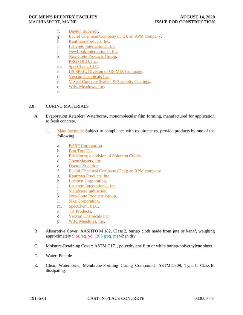
DCF MEN'S REENTRY FACILITY AUGUST 14, 2020
MACHIASPORT, MAINE ISSUE FOR CONSTRUCTION
19176-01 CAST-IN-PLACE CONCRETE 033000 - 8
f. Dayton Superior. g. Euclid Chemical Company (The); an RPM company.
h. Kaufman Products, Inc.
i. Laticrete International, Inc.
j. NewLook International, Inc. k. Nox-Crete Products Group.
l. PROSOCO, Inc.
m. SpecChem, LLC. n. US SPEC, Division of US MIX Company.
o. Vexcon Chemicals Inc.
p. V-Seal Concrete Sealers & Specialty Coatings. q. W.R. Meadows, Inc.
r.
2.8 CURING MATERIALS
A. Evaporation Retarder: Waterborne, monomolecular film forming, manufactured for application to fresh concrete.
1. Manufacturers: Subject to compliance with requirements, provide products by one of the
following:
a. BASF Corporation.
b. Bon Tool Co.
c. Brickform; a division of Solomon Colors. d. ChemMasters, Inc.
e. Dayton Superior.
f. Euclid Chemical Company (The); an RPM company.
g. Kaufman Products, Inc. h. Lambert Corporation.
i. Laticrete International, Inc.
j. Metalcrete Industries. k. Nox-Crete Products Group.
l. Sika Corporation.
m. SpecChem, LLC.
n. TK Products. o. Vexcon Chemicals Inc.
p. W.R. Meadows, Inc.
B. Absorptive Cover: AASHTO M 182, Class 2, burlap cloth made from jute or kenaf, weighing approximately 9 oz./sq. yd. (305 g/sq. m) when dry.
C. Moisture-Retaining Cover: ASTM C171, polyethylene film or white burlap-polyethylene sheet.
D. Water: Potable.
E. Clear, Waterborne, Membrane-Forming Curing Compound: ASTM C309, Type 1, Class B,
dissipating.

DCF MEN'S REENTRY FACILITY AUGUST 14, 2020
MACHIASPORT, MAINE ISSUE FOR CONSTRUCTION
19176-01 CAST-IN-PLACE CONCRETE 033000 - 9
1. Manufacturers: Subject to compliance with requirements, provide products by one of the following:
a. Anti-Hydro International, Inc.
b. ChemMasters, Inc.
c. Dayton Superior. d. Euclid Chemical Company (The); an RPM company.
e. Kaufman Products, Inc.
f. Lambert Corporation. g. Laticrete International, Inc.
h. Nox-Crete Products Group.
i. SpecChem, LLC. j. TK Products.
k. Vexcon Chemicals Inc.
l. W.R. Meadows, Inc.
2.9 RELATED MATERIALS
A. Expansion- and Isolation-Joint-Filler Strips: ASTM D1751, asphalt-saturated cellulosic fiber or
ASTM D1752, cork or self-expanding cork.
B. Semirigid Joint Filler: Two-component, semirigid, 100 percent solids, epoxy resin with a Type A shore durometer hardness of 80 according to ASTM D2240.
C. Bonding Agent: ASTM C1059/C1059M, Type II, nonredispersible, acrylic emulsion or styrene
butadiene.
D. Epoxy Bonding Adhesive: ASTM C881, two-component epoxy resin, capable of humid curing
and bonding to damp surfaces, of class suitable for application temperature and of grade to suit
requirements, and as follows:
1. Types IV and V, load bearing, for bonding hardened or freshly mixed concrete to hardened concrete.
E. Reglets: Fabricate reglets of not less than 0.022-inch- (0.55-mm-) thick, galvanized-steel sheet.
Temporarily fill or cover face opening of reglet to prevent intrusion of concrete or debris.
F. Dovetail Anchor Slots: Hot-dip galvanized-steel sheet, not less than 0.034 inch (0.85 mm) thick,
with bent tab anchors. Temporarily fill or cover face opening of slots to prevent intrusion of
concrete or debris.
2.10 REPAIR MATERIALS
A. Repair Underlayment: Cement-based, polymer-modified, self-leveling product that can be
applied in thicknesses from 1/8 inch (3.2 mm) and that can be feathered at edges to match
adjacent floor elevations.
1. Cement Binder: ASTM C150/C150M, portland cement or hydraulic or blended hydraulic
cement as defined in ASTM C219.

DCF MEN'S REENTRY FACILITY AUGUST 14, 2020
MACHIASPORT, MAINE ISSUE FOR CONSTRUCTION
19176-01 CAST-IN-PLACE CONCRETE 033000 - 10
2. Primer: Product of underlayment manufacturer recommended for substrate, conditions, and application.
3. Aggregate: Well-graded, washed gravel, 1/8 to 1/4 inch (3.2 to 6 mm) or coarse sand as
recommended by underlayment manufacturer.
4. Compressive Strength: Not less than 4100 psi (29 MPa) at 28 days when tested according to ASTM C109/C109M.
B. Repair Overlayment: Cement-based, polymer-modified, self-leveling product that can be
applied in thicknesses from 1/4 inch (6.4 mm) and that can be filled in over a scarified surface to match adjacent floor elevations.
1. Cement Binder: ASTM C150/C150M, portland cement or hydraulic or blended hydraulic
cement as defined in ASTM C219. 2. Primer: Product of topping manufacturer recommended for substrate, conditions, and
application.
3. Aggregate: Well-graded, washed gravel, 1/8 to 1/4 inch (3.2 to 6 mm) or coarse sand as
recommended by topping manufacturer. 4. Compressive Strength: Not less than 5000 psi (34.5 MPa) at 28 days when tested
according to ASTM C109/C109M.
2.11 CONCRETE MIXTURES, GENERAL
A. Prepare design mixtures for each type and strength of concrete, proportioned on the basis of
laboratory trial mixture or field test data, or both, according to ACI 301 (ACI 301M).
1. Use a qualified independent testing agency for preparing and reporting proposed mixture designs based on laboratory trial mixtures.
B. Cementitious Materials: Limit percentage, by weight, of cementitious materials other than
portland cement in concrete as follows:
1. Fly Ash: 25 percent. 2. Combined Fly Ash and Pozzolan: 25 percent.
3. Slag Cement: 50 percent.
4. Combined Fly Ash or Pozzolan and Slag Cement: 50 percent portland cement minimum, with fly ash or pozzolan not exceeding 25 percent.
5. Silica Fume: 10 percent.
6. Combined Fly Ash, Pozzolans, and Silica Fume: 35 percent with fly ash or pozzolans not
exceeding 25 percent and silica fume not exceeding 10 percent. 7. Combined Fly Ash or Pozzolans, Slag Cement, and Silica Fume: 50 percent with fly ash
or pozzolans not exceeding 25 percent and silica fume not exceeding 10 percent.
C. Admixtures: Use admixtures according to manufacturer's written instructions.
1. Use water-reducing high-range water-reducing or plasticizing admixture in concrete, as
required, for placement and workability.
2. Use water-reducing and -retarding admixture when required by high temperatures, low humidity, or other adverse placement conditions.

DCF MEN'S REENTRY FACILITY AUGUST 14, 2020
MACHIASPORT, MAINE ISSUE FOR CONSTRUCTION
19176-01 CAST-IN-PLACE CONCRETE 033000 - 11
3. Use water-reducing admixture in pumped concrete, concrete for heavy-use industrial slabs and parking structure slabs, concrete required to be watertight, and concrete with a
w/c ratio below 0.50.
4. Use corrosion-inhibiting admixture in concrete mixtures where indicated.
2.12 CONCRETE MIXTURES FOR BUILDING ELEMENTS
A. Footings: Normal-weight concrete.
1. Minimum Compressive Strength: As indicated at 28 days.
2. Maximum W/C Ratio: 0.45. 3. Slump Limit: 5 inches (125 mm), plus or minus 1 inch (25 mm).
4. Air Content: 5.5 percent, plus or minus 1.5 percent at point of delivery for 1-1/2-inch
(38-mm) nominal maximum aggregate size.
B. Foundation Walls: Normal-weight concrete.
1. Minimum Compressive Strength: As indicated at 28 days.
2. Maximum W/C Ratio: 0.45.
3. Slump Limit: 5 inches (125 mm), plus or minus 1 inch (25 mm). 4. Air Content: 5.5 percent, plus or minus 1.5 percent at point of delivery for 1-1/2-inch
(38-mm) nominal maximum aggregate size.
C. Slabs-on-Grade: Normal-weight concrete.
1. Minimum Compressive Strength: As indicated at 28 days.
2. Maximum W/C Ratio: 0.45.
3. Slump Limit: 5 inches (125 mm), plus or minus 1 inch (25 mm). 4. Air Content: 5.5 percent, plus or minus 1.5 percent at point of delivery for 1-1/2-inch
(38-mm) nominal maximum aggregate size.
5. Air Content: Do not allow air content of trowel-finished floors to exceed 3 percent.
2.13 FABRICATING REINFORCEMENT
A. Fabricate steel reinforcement according to CRSI's "Manual of Standard Practice."
2.14 CONCRETE MIXING
A. Ready-Mixed Concrete: Measure, batch, mix, and deliver concrete according to ASTM C94/C94M, and furnish batch ticket information.
1. When air temperature is between 85 and 90 deg F (30 and 32 deg C), reduce mixing and
delivery time from 1-1/2 hours to 75 minutes; when air temperature is above 90 deg F (32
deg C), reduce mixing and delivery time to 60 minutes.
B. Project-Site Mixing: Measure, batch, and mix concrete materials and concrete according to
ASTM C94/C94M. Mix concrete materials in appropriate drum-type batch machine mixer.

DCF MEN'S REENTRY FACILITY AUGUST 14, 2020
MACHIASPORT, MAINE ISSUE FOR CONSTRUCTION
19176-01 CAST-IN-PLACE CONCRETE 033000 - 12
1. For mixer capacity of 1 cu. yd. (0.76 cu. m) or smaller, continue mixing at least 1-1/2 minutes, but not more than 5 minutes after ingredients are in mixer, before any part of
batch is released.
2. For mixer capacity larger than 1 cu. yd. (0.76 cu. m), increase mixing time by 15 seconds
for each additional 1 cu. yd. (0.76 cu. m). 3. Provide batch ticket for each batch discharged and used in the Work, indicating Project
identification name and number, date, mixture type, mixture time, quantity, and amount
of water added. Record approximate location of final deposit in structure.
PART 3 - EXECUTION
3.1 FORMWORK INSTALLATION
A. Design, erect, shore, brace, and maintain formwork, according to ACI 301 (ACI 301M), to support vertical, lateral, static, and dynamic loads, and construction loads that might be applied,
until structure can support such loads.
B. Construct formwork so concrete members and structures are of size, shape, alignment,
elevation, and position indicated, within tolerance limits of ACI 117 (ACI 117M).
C. Limit concrete surface irregularities, designated by ACI 347 as abrupt or gradual, as follows:
1. Class B, 1/4 inch (6 mm) for rough-formed finished surfaces.
D. Construct forms tight enough to prevent loss of concrete mortar.
E. Construct forms for easy removal without hammering or prying against concrete surfaces.
Provide crush or wrecking plates where stripping may damage cast-concrete surfaces. Provide
top forms for inclined surfaces steeper than 1.5 horizontal to 1 vertical.
1. Install keyways, reglets, recesses, and the like, for easy removal.
2. Do not use rust-stained steel form-facing material.
F. Set edge forms, bulkheads, and intermediate screed strips for slabs to achieve required
elevations and slopes in finished concrete surfaces. Provide and secure units to support screed strips; use strike-off templates or compacting-type screeds.
G. Provide temporary openings for cleanouts and inspection ports where interior area of formwork
is inaccessible. Close openings with panels tightly fitted to forms and securely braced to prevent loss of concrete mortar. Locate temporary openings in forms at inconspicuous locations.
H. Chamfer exterior corners and edges of permanently exposed concrete.
I. Form openings, chases, offsets, sinkages, keyways, reglets, blocking, screeds, and bulkheads
required in the Work. Determine sizes and locations from trades providing such items.
J. Clean forms and adjacent surfaces to receive concrete. Remove chips, wood, sawdust, dirt, and
other debris just before placing concrete.
K. Retighten forms and bracing before placing concrete, as required, to prevent mortar leaks and maintain proper alignment.

DCF MEN'S REENTRY FACILITY AUGUST 14, 2020
MACHIASPORT, MAINE ISSUE FOR CONSTRUCTION
19176-01 CAST-IN-PLACE CONCRETE 033000 - 13
L. Coat contact surfaces of forms with form-release agent, according to manufacturer's written instructions, before placing reinforcement.
3.2 EMBEDDED ITEM INSTALLATION
A. Place and secure anchorage devices and other embedded items required for adjoining work that
is attached to or supported by cast-in-place concrete. Use setting drawings, templates, diagrams, instructions, and directions furnished with items to be embedded.
1. Install anchor rods, accurately located, to elevations required and complying with
tolerances in Section 7.5 of AISC 303. 2. Install reglets to receive waterproofing and to receive through-wall flashings in outer face
of concrete frame at exterior walls, where flashing is shown at lintels, shelf angles, and
other conditions. 3. Install dovetail anchor slots in concrete structures as indicated.
3.3 REMOVING AND REUSING FORMS
A. General: Formwork for sides of beams, walls, columns, and similar parts of the Work that does
not support weight of concrete may be removed after cumulatively curing at not less than 50 deg F (10 deg C) for 24 hours after placing concrete. Concrete has to be hard enough to not be
damaged by form-removal operations, and curing and protection operations need to be
maintained.
1. Leave formwork for beam soffits, joists, slabs, and other structural elements that support
weight of concrete in place until concrete has achieved at least 70 percent of its 28-day
design compressive strength. 2. Remove forms only if shores have been arranged to permit removal of forms without
loosening or disturbing shores.
B. Clean and repair surfaces of forms to be reused in the Work. Split, frayed, delaminated, or
otherwise damaged form-facing material are not acceptable for exposed surfaces. Apply new form-release agent.
C. When forms are reused, clean surfaces, remove fins and laitance, and tighten to close joints.
Align and secure joints to avoid offsets. Do not use patched forms for exposed concrete surfaces unless approved by Architect.
3.4 SHORING AND RESHORING INSTALLATION
A. Comply with ACI 318 (ACI 318M) and ACI 301 (ACI 301M) for design, installation, and
removal of shoring and reshoring.
1. Do not remove shoring or reshoring until measurement of slab tolerances is complete.
B. In multistory construction, extend shoring or reshoring over a sufficient number of stories to
distribute loads in such a manner that no floor or member will be excessively loaded or will induce tensile stress in concrete members without sufficient steel reinforcement.

DCF MEN'S REENTRY FACILITY AUGUST 14, 2020
MACHIASPORT, MAINE ISSUE FOR CONSTRUCTION
19176-01 CAST-IN-PLACE CONCRETE 033000 - 14
C. Plan sequence of removal of shores and reshore to avoid damage to concrete. Locate and provide adequate reshoring to support construction without excessive stress or deflection.
3.5 VAPOR-RETARDER INSTALLATION
A. Sheet Vapor Retarders: Place, protect, and repair sheet vapor retarder according to
ASTM E1643 and manufacturer's written instructions.
1. Lap joints 6 inches (150 mm) and seal with manufacturer's recommended tape.
B. Bituminous Vapor Retarders: Place, protect, and repair bituminous vapor retarder according to
manufacturer's written instructions.
3.6 STEEL REINFORCEMENT INSTALLATION
A. General: Comply with CRSI's "Manual of Standard Practice" for fabricating, placing, and
supporting reinforcement.
1. Do not cut or puncture vapor retarder. Repair damage and reseal vapor retarder before
placing concrete.
B. Clean reinforcement of loose rust and mill scale, earth, ice, and other foreign materials that
reduce bond to concrete.
C. Accurately position, support, and secure reinforcement against displacement. Locate and
support reinforcement with bar supports to maintain minimum concrete cover. Do not tack weld
crossing reinforcing bars.
1. Weld reinforcing bars according to AWS D1.4/D 1.4M, where indicated.
D. Set wire ties with ends directed into concrete, not toward exposed concrete surfaces.
E. Install welded-wire reinforcement in longest practicable lengths on bar supports spaced to minimize sagging. Lap edges and ends of adjoining sheets at least one mesh spacing. Offset laps
of adjoining sheet widths to prevent continuous laps in either direction. Lace overlaps with wire.
F. Epoxy-Coated Reinforcement: Repair cut and damaged epoxy coatings with epoxy repair
coating according to ASTM D3963/D3963M. Use epoxy-coated steel wire ties to fasten epoxy-coated steel reinforcement.
G. Zinc-Coated Reinforcement: Repair cut and damaged zinc coatings with zinc repair material
according to ASTM A780/A780M. Use galvanized-steel wire ties to fasten zinc-coated steel reinforcement.
3.7 JOINTS
A. General: Construct joints true to line with faces perpendicular to surface plane of concrete.
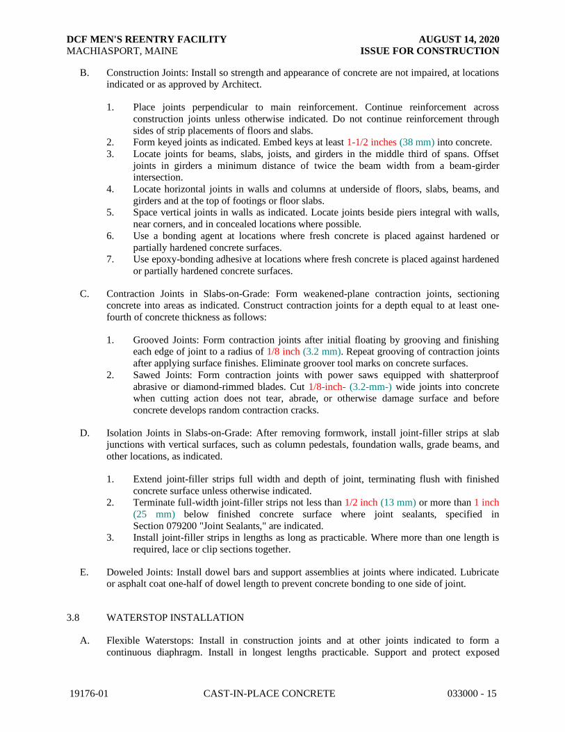
DCF MEN'S REENTRY FACILITY AUGUST 14, 2020
MACHIASPORT, MAINE ISSUE FOR CONSTRUCTION
19176-01 CAST-IN-PLACE CONCRETE 033000 - 15
B. Construction Joints: Install so strength and appearance of concrete are not impaired, at locations indicated or as approved by Architect.
1. Place joints perpendicular to main reinforcement. Continue reinforcement across
construction joints unless otherwise indicated. Do not continue reinforcement through
sides of strip placements of floors and slabs. 2. Form keyed joints as indicated. Embed keys at least 1-1/2 inches (38 mm) into concrete.
3. Locate joints for beams, slabs, joists, and girders in the middle third of spans. Offset
joints in girders a minimum distance of twice the beam width from a beam-girder intersection.
4. Locate horizontal joints in walls and columns at underside of floors, slabs, beams, and
girders and at the top of footings or floor slabs. 5. Space vertical joints in walls as indicated. Locate joints beside piers integral with walls,
near corners, and in concealed locations where possible.
6. Use a bonding agent at locations where fresh concrete is placed against hardened or
partially hardened concrete surfaces. 7. Use epoxy-bonding adhesive at locations where fresh concrete is placed against hardened
or partially hardened concrete surfaces.
C. Contraction Joints in Slabs-on-Grade: Form weakened-plane contraction joints, sectioning concrete into areas as indicated. Construct contraction joints for a depth equal to at least one-
fourth of concrete thickness as follows:
1. Grooved Joints: Form contraction joints after initial floating by grooving and finishing each edge of joint to a radius of 1/8 inch (3.2 mm). Repeat grooving of contraction joints
after applying surface finishes. Eliminate groover tool marks on concrete surfaces.
2. Sawed Joints: Form contraction joints with power saws equipped with shatterproof
abrasive or diamond-rimmed blades. Cut 1/8-inch- (3.2-mm-) wide joints into concrete when cutting action does not tear, abrade, or otherwise damage surface and before
concrete develops random contraction cracks.
D. Isolation Joints in Slabs-on-Grade: After removing formwork, install joint-filler strips at slab junctions with vertical surfaces, such as column pedestals, foundation walls, grade beams, and
other locations, as indicated.
1. Extend joint-filler strips full width and depth of joint, terminating flush with finished
concrete surface unless otherwise indicated. 2. Terminate full-width joint-filler strips not less than 1/2 inch (13 mm) or more than 1 inch
(25 mm) below finished concrete surface where joint sealants, specified in
Section 079200 "Joint Sealants," are indicated. 3. Install joint-filler strips in lengths as long as practicable. Where more than one length is
required, lace or clip sections together.
E. Doweled Joints: Install dowel bars and support assemblies at joints where indicated. Lubricate or asphalt coat one-half of dowel length to prevent concrete bonding to one side of joint.
3.8 WATERSTOP INSTALLATION
A. Flexible Waterstops: Install in construction joints and at other joints indicated to form a
continuous diaphragm. Install in longest lengths practicable. Support and protect exposed

DCF MEN'S REENTRY FACILITY AUGUST 14, 2020
MACHIASPORT, MAINE ISSUE FOR CONSTRUCTION
19176-01 CAST-IN-PLACE CONCRETE 033000 - 16
waterstops during progress of the Work. Field fabricate joints in waterstops according to manufacturer's written instructions.
B. Self-Expanding Strip Waterstops: Install in construction joints and at other locations indicated,
according to manufacturer's written instructions, adhesive bonding, mechanically fastening, and
firmly pressing into place. Install in longest lengths practicable.
3.9 CONCRETE PLACEMENT
A. Before placing concrete, verify that installation of formwork, reinforcement, and embedded
items is complete and that required inspections are completed.
B. Do not add water to concrete during delivery, at Project site, or during placement unless
approved by Architect.
C. Before test sampling and placing concrete, water may be added at Project site, subject to limitations of ACI 301 (ACI 301M).
1. Do not add water to concrete after adding high-range water-reducing admixtures to
mixture.
D. Deposit concrete continuously in one layer or in horizontal layers of such thickness that no new concrete is placed on concrete that has hardened enough to cause seams or planes of weakness.
If a section cannot be placed continuously, provide construction joints as indicated. Deposit
concrete to avoid segregation.
1. Deposit concrete in horizontal layers of depth not to exceed formwork design pressures
and in a manner to avoid inclined construction joints.
2. Consolidate placed concrete with mechanical vibrating equipment according to ACI 301 (ACI 301M).
3. Do not use vibrators to transport concrete inside forms. Insert and withdraw vibrators
vertically at uniformly spaced locations to rapidly penetrate placed layer and at least 6
inches (150 mm) into preceding layer. Do not insert vibrators into lower layers of concrete that have begun to lose plasticity. At each insertion, limit duration of vibration
to time necessary to consolidate concrete and complete embedment of reinforcement and
other embedded items without causing mixture constituents to segregate.
E. Deposit and consolidate concrete for floors and slabs in a continuous operation, within limits of
construction joints, until placement of a panel or section is complete.
1. Consolidate concrete during placement operations, so concrete is thoroughly worked
around reinforcement and other embedded items and into corners. 2. Maintain reinforcement in position on chairs during concrete placement.
3. Screed slab surfaces with a straightedge and strike off to correct elevations.
4. Slope surfaces uniformly to drains where required. 5. Begin initial floating using bull floats or darbies to form a uniform and open-textured
surface plane, before excess bleedwater appears on the surface. Do not further disturb
slab surfaces before starting finishing operations.

DCF MEN'S REENTRY FACILITY AUGUST 14, 2020
MACHIASPORT, MAINE ISSUE FOR CONSTRUCTION
19176-01 CAST-IN-PLACE CONCRETE 033000 - 17
3.10 FINISHING FORMED SURFACES
A. Rough-Formed Finish: As-cast concrete texture imparted by form-facing material with tie holes
and defects repaired and patched. Remove fins and other projections that exceed specified limits
on formed-surface irregularities.
1. Apply to concrete surfaces not exposed to public view.
B. General: Comply with ACI 302.1R recommendations for screeding, restraightening, and
finishing operations for concrete surfaces. Do not wet concrete surfaces.
C. Scratch Finish: While still plastic, texture concrete surface that has been screeded and bull-floated or darbied. Use stiff brushes, brooms, or rakes to produce a profile amplitude of 1/4 inch
(6 mm) in one direction.
1. Apply scratch finish to surfaces indicated.
D. Float Finish: Consolidate surface with power-driven floats or by hand floating if area is small or
inaccessible to power-driven floats. Restraighten, cut down high spots, and fill low spots.
Repeat float passes and restraightening until surface is left with a uniform, smooth, granular
texture.
1. Apply float finish to surfaces to be covered with fluid-applied or sheet waterproofing,
built-up or membrane roofing, or sand-bed terrazzo.
E. Trowel Finish: After applying float finish, apply first troweling and consolidate concrete by hand or power-driven trowel. Continue troweling passes and restraighten until surface is free of
trowel marks and uniform in texture and appearance. Grind smooth any surface defects that
would telegraph through applied coatings or floor coverings.
1. Apply a trowel finish to surfaces exposed to view or to be covered with resilient flooring,
carpet, ceramic or quarry tile set over a cleavage membrane, paint, or another thin-film-
finish coating system.
2. Finish surfaces to the following tolerances, according to ASTM E1155 (ASTM E1155M), for a randomly trafficked floor surface:
a. Specified overall values of flatness, F(F) 25; and of levelness, F(L) 20; with
minimum local values of flatness, F(F) 17; and of levelness, F(L) 15. b. Specified overall values of flatness, F(F) 35; and of levelness, F(L) 25; with
minimum local values of flatness, F(F) 24; and of levelness, F(L) 17; for slabs-on-
grade.
c. Specified overall values of flatness, F(F) 30; and of levelness, F(L) 20; with minimum local values of flatness, F(F) 24; and of levelness, F(L) 15; for
suspended slabs.
d. Specified overall values of flatness, F(F) 45; and of levelness, F(L) 35; with minimum local values of flatness, F(F) 30; and of levelness, F(L) 24.
3. Finish and measure surface, so gap at any point between concrete surface and an
unleveled, freestanding, 10-ft.- (3.05-m-) long straightedge resting on two high spots and placed anywhere on the surface does not exceed 1/4 inch (6 mm).
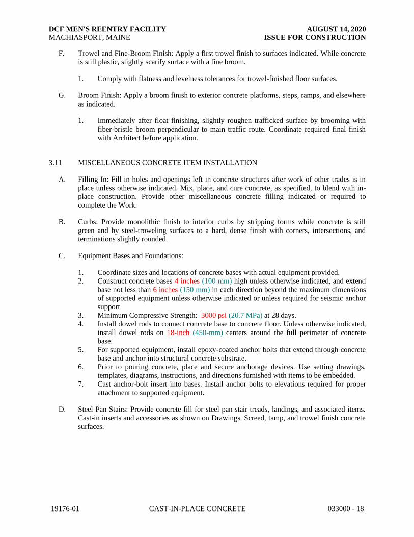
DCF MEN'S REENTRY FACILITY AUGUST 14, 2020
MACHIASPORT, MAINE ISSUE FOR CONSTRUCTION
19176-01 CAST-IN-PLACE CONCRETE 033000 - 18
F. Trowel and Fine-Broom Finish: Apply a first trowel finish to surfaces indicated. While concrete is still plastic, slightly scarify surface with a fine broom.
1. Comply with flatness and levelness tolerances for trowel-finished floor surfaces.
G. Broom Finish: Apply a broom finish to exterior concrete platforms, steps, ramps, and elsewhere
as indicated.
1. Immediately after float finishing, slightly roughen trafficked surface by brooming with
fiber-bristle broom perpendicular to main traffic route. Coordinate required final finish
with Architect before application.
3.11 MISCELLANEOUS CONCRETE ITEM INSTALLATION
A. Filling In: Fill in holes and openings left in concrete structures after work of other trades is in
place unless otherwise indicated. Mix, place, and cure concrete, as specified, to blend with in-place construction. Provide other miscellaneous concrete filling indicated or required to
complete the Work.
B. Curbs: Provide monolithic finish to interior curbs by stripping forms while concrete is still
green and by steel-troweling surfaces to a hard, dense finish with corners, intersections, and terminations slightly rounded.
C. Equipment Bases and Foundations:
1. Coordinate sizes and locations of concrete bases with actual equipment provided. 2. Construct concrete bases 4 inches (100 mm) high unless otherwise indicated, and extend
base not less than 6 inches (150 mm) in each direction beyond the maximum dimensions
of supported equipment unless otherwise indicated or unless required for seismic anchor support.
3. Minimum Compressive Strength: 3000 psi (20.7 MPa) at 28 days.
4. Install dowel rods to connect concrete base to concrete floor. Unless otherwise indicated,
install dowel rods on 18-inch (450-mm) centers around the full perimeter of concrete base.
5. For supported equipment, install epoxy-coated anchor bolts that extend through concrete
base and anchor into structural concrete substrate. 6. Prior to pouring concrete, place and secure anchorage devices. Use setting drawings,
templates, diagrams, instructions, and directions furnished with items to be embedded.
7. Cast anchor-bolt insert into bases. Install anchor bolts to elevations required for proper
attachment to supported equipment.
D. Steel Pan Stairs: Provide concrete fill for steel pan stair treads, landings, and associated items.
Cast-in inserts and accessories as shown on Drawings. Screed, tamp, and trowel finish concrete
surfaces.

DCF MEN'S REENTRY FACILITY AUGUST 14, 2020
MACHIASPORT, MAINE ISSUE FOR CONSTRUCTION
19176-01 CAST-IN-PLACE CONCRETE 033000 - 19
3.12 CONCRETE PROTECTING AND CURING
A. General: Protect freshly placed concrete from premature drying and excessive cold or hot
temperatures. Comply with ACI 306.1 for cold-weather protection and ACI 305.1 (ACI
305.1M) for hot-weather protection during curing.
B. Evaporation Retarder: Apply evaporation retarder to unformed concrete surfaces if hot, dry, or windy conditions cause moisture loss approaching 0.2 lb/sq. ft. x h (1 kg/sq. m x h) before and
during finishing operations. Apply according to manufacturer's written instructions after
placing, screeding, and bull floating or darbying concrete, but before float finishing.
C. Formed Surfaces: Cure formed concrete surfaces, including underside of beams, supported
slabs, and other similar surfaces. If forms remain during curing period, moist cure after
loosening forms. If removing forms before end of curing period, continue curing for remainder of curing period.
D. Unformed Surfaces: Begin curing immediately after finishing concrete. Cure unformed
surfaces, including floors and slabs, concrete floor toppings, and other surfaces.
E. Cure concrete according to ACI 308.1, by one or a combination of the following methods:
1. Moisture Curing: Keep surfaces continuously moist for not less than seven days with the
following materials:
a. Water. b. Continuous water-fog spray.
c. Absorptive cover, water saturated, and kept continuously wet. Cover concrete
surfaces and edges with 12-inch (300-mm) lap over adjacent absorptive covers.
2. Moisture-Retaining-Cover Curing: Cover concrete surfaces with moisture-retaining cover
for curing concrete, placed in widest practicable width, with sides and ends lapped at
least 12 inches (300 mm), and sealed by waterproof tape or adhesive. Cure for not less
than seven days. Immediately repair any holes or tears during curing period, using cover material and waterproof tape.
a. Moisture cure or use moisture-retaining covers to cure concrete surfaces to receive
floor coverings. b. Moisture cure or use moisture-retaining covers to cure concrete surfaces to receive
penetrating liquid floor treatments.
c. Cure concrete surfaces to receive floor coverings with either a moisture-retaining
cover or a curing compound that the manufacturer certifies does not interfere with bonding of floor covering used on Project.
3. Curing Compound: Apply uniformly in continuous operation by power spray or roller
according to manufacturer's written instructions. Recoat areas subjected to heavy rainfall within three hours after initial application. Maintain continuity of coating and repair
damage during curing period.
a. Removal: After curing period has elapsed, remove curing compound without damaging concrete surfaces by method recommended by curing compound

DCF MEN'S REENTRY FACILITY AUGUST 14, 2020
MACHIASPORT, MAINE ISSUE FOR CONSTRUCTION
19176-01 CAST-IN-PLACE CONCRETE 033000 - 20
manufacturer unless manufacturer certifies curing compound does not interfere with bonding of floor covering used on Project.
4. Curing and Sealing Compound: Apply uniformly to floors and slabs indicated in a
continuous operation by power spray or roller according to manufacturer's written
instructions. Recoat areas subjected to heavy rainfall within three hours after initial application. Repeat process 24 hours later and apply a second coat. Maintain continuity
of coating and repair damage during curing period.
3.13 LIQUID FLOOR TREATMENT APPLICATION
A. Penetrating Liquid Floor Treatment: Prepare, apply, and finish penetrating liquid floor treatment
according to manufacturer's written instructions.
1. Remove curing compounds, sealers, oil, dirt, laitance, and other contaminants and complete surface repairs.
2. Do not apply to concrete that is less than manufacturer's written instructions.
3. Apply liquid until surface is saturated, scrubbing into surface until a gel forms; rewet;
and repeat brooming or scrubbing. Rinse with water; remove excess material until surface is dry. Apply a second coat in a similar manner if surface is rough or porous.
B. Sealing Coat: Uniformly apply a continuous sealing coat of curing and sealing compound to
hardened concrete by power spray or roller according to manufacturer's written instructions.
3.14 JOINT FILLING
A. Prepare, clean, and install joint filler according to manufacturer's written instructions.
1. Defer joint filling until concrete has aged at least one month(s). Do not fill joints until construction traffic has permanently ceased.
B. Remove dirt, debris, saw cuttings, curing compounds, and sealers from joints; leave contact
faces of joints clean and dry.
C. Install semirigid joint filler full depth in saw-cut joints and at least 2 inches (50 mm) deep in formed joints. Overfill joint and trim joint filler flush with top of joint after hardening.
3.15 CONCRETE SURFACE REPAIRS
A. Defective Concrete: Repair and patch defective areas when approved by Architect. Remove and replace concrete that cannot be repaired and patched to Architect's approval.
B. Patching Mortar: Mix dry-pack patching mortar, consisting of 1 part portland cement to 2-1/2
parts fine aggregate passing a No. 16 (1.18-mm) sieve, using only enough water for handling
and placing.
C. Repairing Formed Surfaces: Surface defects include color and texture irregularities, cracks,
spalls, air bubbles, honeycombs, rock pockets, fins and other projections on the surface, and
stains and other discolorations that cannot be removed by cleaning.

DCF MEN'S REENTRY FACILITY AUGUST 14, 2020
MACHIASPORT, MAINE ISSUE FOR CONSTRUCTION
19176-01 CAST-IN-PLACE CONCRETE 033000 - 21
1. Immediately after form removal, cut out honeycombs, rock pockets, and voids more than 1/2 inch (13 mm) in any dimension to solid concrete. Limit cut depth to 3/4 inch (19
mm). Make edges of cuts perpendicular to concrete surface. Clean, dampen with water,
and brush-coat holes and voids with bonding agent. Fill and compact with patching
mortar before bonding agent has dried. Fill form-tie voids with patching mortar or cone plugs secured in place with bonding agent.
2. Repair defects on surfaces exposed to view by blending white portland cement and
standard portland cement so that, when dry, patching mortar matches surrounding color. Patch a test area at inconspicuous locations to verify mixture and color match before
proceeding with patching. Compact mortar in place and strike off slightly higher than
surrounding surface. 3. Repair defects on concealed formed surfaces that affect concrete's durability and
structural performance as determined by Architect.
D. Repairing Unformed Surfaces: Test unformed surfaces, such as floors and slabs, for finish and
verify surface tolerances specified for each surface. Correct low and high areas. Test surfaces sloped to drain for trueness of slope and smoothness; use a sloped template.
1. Repair finished surfaces containing defects. Surface defects include spalls, popouts,
honeycombs, rock pockets, crazing and cracks in excess of 0.01 inch (0.25 mm) wide or that penetrate to reinforcement or completely through unreinforced sections regardless of
width, and other objectionable conditions.
2. After concrete has cured at least 14 days, correct high areas by grinding. 3. Correct localized low areas during or immediately after completing surface finishing
operations by cutting out low areas and replacing with patching mortar. Finish repaired
areas to blend into adjacent concrete.
4. Correct other low areas scheduled to receive floor coverings with a repair underlayment. Prepare, mix, and apply repair underlayment and primer according to manufacturer's
written instructions to produce a smooth, uniform, plane, and level surface. Feather edges
to match adjacent floor elevations. 5. Correct other low areas scheduled to remain exposed with a repair topping. Cut out low
areas to ensure a minimum repair topping depth of 1/4 inch (6 mm) to match adjacent
floor elevations. Prepare, mix, and apply repair topping and primer according to
manufacturer's written instructions to produce a smooth, uniform, plane, and level surface.
6. Repair defective areas, except random cracks and single holes 1 inch (25 mm) or less in
diameter, by cutting out and replacing with fresh concrete. Remove defective areas with clean, square cuts and expose steel reinforcement with at least a 3/4-inch (19-mm)
clearance all around. Dampen concrete surfaces in contact with patching concrete and
apply bonding agent. Mix patching concrete of same materials and mixture as original concrete, except without coarse aggregate. Place, compact, and finish to blend with
adjacent finished concrete. Cure in same manner as adjacent concrete.
7. Repair random cracks and single holes 1 inch (25 mm) or less in diameter with patching
mortar. Groove top of cracks and cut out holes to sound concrete and clean off dust, dirt, and loose particles. Dampen cleaned concrete surfaces and apply bonding agent. Place
patching mortar before bonding agent has dried. Compact patching mortar and finish to
match adjacent concrete. Keep patched area continuously moist for at least 72 hours.
E. Perform structural repairs of concrete, subject to Architect's approval, using epoxy adhesive and
patching mortar.

DCF MEN'S REENTRY FACILITY AUGUST 14, 2020
MACHIASPORT, MAINE ISSUE FOR CONSTRUCTION
19176-01 CAST-IN-PLACE CONCRETE 033000 - 22
F. Repair materials and installation not specified above may be used, subject to Architect's approval.
3.16 FIELD QUALITY CONTROL
A. Special Inspections: Owner will engage a special inspector and qualified testing and inspecting
agency to perform field tests and inspections and prepare test reports.
B. Testing Agency: Engage a qualified testing and inspecting agency to perform tests and
inspections and to submit reports.
C. Inspections:
1. Steel reinforcement placement.
2. Steel reinforcement welding.
3. Headed bolts and studs. 4. Verification of use of required design mixture.
5. Concrete placement, including conveying and depositing.
6. Curing procedures and maintenance of curing temperature.
7. Verification of concrete strength before removal of shores and forms from beams and slabs.
D. Concrete Tests: Testing of composite samples of fresh concrete obtained according to
ASTM C172/C172M shall be performed according to the following requirements:
1. Testing Frequency: Obtain one composite sample for each day's pour of each concrete
mixture exceeding 5 cu. yd. (4 cu. m), but less than 25 cu. yd. (19 cu. m), plus one set for
each additional 50 cu. yd. (38 cu. m) or fraction thereof. 2. Testing Frequency: Obtain at least one composite sample for each 100 cu. yd. (76 cu. m)
or fraction thereof of each concrete mixture placed each day.
a. When frequency of testing provides fewer than five compressive-strength tests for
each concrete mixture, testing shall be conducted from at least five randomly selected batches or from each batch if fewer than five are used.
3. Slump: ASTM C143/C143M; one test at point of placement for each composite sample,
but not less than one test for each day's pour of each concrete mixture. Perform additional tests when concrete consistency appears to change.
4. Air Content: ASTM C231/C231M, pressure method, for normal-weight concrete;one test
for each composite sample, but not less than one test for each day's pour of each concrete
mixture. 5. Concrete Temperature: ASTM C1064/C1064M; one test hourly when air temperature is
40 deg F (4.4 deg C) and below or 80 deg F (27 deg C) and above, and one test for each
composite sample. 6. Unit Weight: ASTM C567/C567M, fresh unit weight of structural lightweight concrete;
one test for each composite sample, but not less than one test for each day's pour of each
concrete mixture. 7. Compression Test Specimens: ASTM C31/C31M.

DCF MEN'S REENTRY FACILITY AUGUST 14, 2020
MACHIASPORT, MAINE ISSUE FOR CONSTRUCTION
19176-01 CAST-IN-PLACE CONCRETE 033000 - 23
a. Cast and laboratory cure two sets of two standard cylinder specimens for each composite sample.
b. Cast and field cure two sets of two standard cylinder specimens for each composite
sample.
8. Compressive-Strength Tests: ASTM C39/C39M; test one set of two laboratory-cured specimens at 7 days and one set of two specimens at 28 days.
a. Test one set of two field-cured specimens at 7 days and one set of two specimens
at 28 days. b. A compressive-strength test shall be the average compressive strength from a set of
two specimens obtained from same composite sample and tested at age indicated.
9. When strength of field-cured cylinders is less than 85 percent of companion laboratory-cured cylinders, Contractor shall evaluate operations and provide corrective procedures
for protecting and curing in-place concrete.
10. Strength of each concrete mixture will be satisfactory if every average of any three
consecutive compressive-strength tests equals or exceeds specified compressive strength and no compressive-strength test value falls below specified compressive strength by
more than 500 psi (3.4 MPa).
11. Test results shall be reported in writing to Architect, concrete manufacturer, and Contractor within 48 hours of testing. Reports of compressive-strength tests shall contain
Project identification name and number, date of concrete placement, name of concrete
testing and inspecting agency, location of concrete batch in Work, design compressive strength at 28 days, concrete mixture proportions and materials, compressive breaking
strength, and type of break for both 7- and 28-day tests.
12. Nondestructive Testing: Impact hammer, sonoscope, or other nondestructive device may
be permitted by Architect but will not be used as sole basis for approval or rejection of concrete.
13. Additional Tests: Testing and inspecting agency shall make additional tests of concrete
when test results indicate that slump, air entrainment, compressive strengths, or other requirements have not been met, as directed by Architect. Testing and inspecting agency
may conduct tests to determine adequacy of concrete by cored cylinders complying with
ASTM C42/C42M or by other methods as directed by Architect.
14. Additional testing and inspecting, at Contractor's expense, will be performed to determine compliance of replaced or additional work with specified requirements.
15. Correct deficiencies in the Work that test reports and inspections indicate do not comply
with the Contract Documents.
E. Measure floor and slab flatness and levelness according to ASTM E1155 (ASTM E1155M)
within 24 hours of finishing.
3.17 PROTECTION OF LIQUID FLOOR TREATMENTS
A. Protect liquid floor treatment from damage and wear during the remainder of construction
period. Use protective methods and materials, including temporary covering, recommended in
writing by liquid floor treatments installer.
END OF SECTION 033000

DOWNEAST CORRECTIONAL FACILITY JUNE 25, 2020 MACHIASPORT, MAINE DESIGN DEVELOPMENT
19176
THIS PAGE INTENTIONALLY LEFT BLANK

DCF MEN'S REENTRY FACILITY AUGUST 14, 2020
MACHIASPORT, MAINE ISSUE FOR CONSTRUCTION
19176-01 METAL FABRICATIONS 055000 - 1
SECTION 055000 - METAL FABRICATIONS
PART 1 - GENERAL
1.1 RELATED DOCUMENTS
A. Drawings and general provisions of the Contract, including General and Supplementary
Conditions and Division 01 Specification Sections, apply to this Section.
1.2 SUMMARY
A. Section Includes:
1. Steel tube reinforcement for low partitions. 2. Steel framing and supports for countertops.
3. Steel framing and supports for mechanical and electrical equipment.
4. Steel framing and supports for applications where framing and supports are not specified in other Sections.
1.3 COORDINATION
A. Coordinate selection of shop primers with topcoats to be applied over them. Comply with paint and coating manufacturers' written recommendations to ensure that shop primers and topcoats
are compatible with one another.
B. Coordinate installation of metal fabrications that are anchored to or that receive other work. Furnish setting drawings, templates, and directions for installing anchorages, including sleeves,
concrete inserts, anchor bolts, and items with integral anchors, that are to be embedded in
concrete or masonry. Deliver such items to Project site in time for installation.
1.4 ACTION SUBMITTALS
A. Product Data: For the following:
1. Nonslip aggregates and nonslip-aggregate surface finishes.
2. Paint products. 3. Grout.
B. Shop Drawings: Show fabrication and installation details. Include plans, elevations, sections,
and details of metal fabrications and their connections. Show anchorage and accessory items.]\ Provide Shop Drawings for the following:
1. Steel tube reinforcement for low partitions.
2. Steel framing and supports for mechanical and electrical equipment.

DCF MEN'S REENTRY FACILITY AUGUST 14, 2020
MACHIASPORT, MAINE ISSUE FOR CONSTRUCTION
19176-01 METAL FABRICATIONS 055000 - 2
1.5 INFORMATIONAL SUBMITTALS
A. Qualification Data: For professional engineer.
B. Mill Certificates: Signed by stainless-steel manufacturers, certifying that products furnished
comply with requirements.
C. Welding certificates.
D. Paint Compatibility Certificates: From manufacturers of topcoats applied over shop primers,
certifying that shop primers are compatible with topcoats.
E. Research/Evaluation Reports: For post-installed anchors, from ICC-ES.
1.6 QUALITY ASSURANCE
A. Welding Qualifications: Qualify procedures and personnel according to AWS D1.1/D1.1M,
"Structural Welding Code - Steel."
B. Welding Qualifications: Qualify procedures and personnel according to the following:
1. AWS D1.1/D1.1M, "Structural Welding Code - Steel."
2. AWS D1.2/D1.2M, "Structural Welding Code - Aluminum."
3. AWS D1.6/D1.6M, "Structural Welding Code - Stainless Steel."
1.7 FIELD CONDITIONS
A. Field Measurements: Verify actual locations of walls and other construction contiguous with
metal fabrications by field measurements before fabrication.
PART 2 - PRODUCTS
2.1 PERFORMANCE REQUIREMENTS
A. Thermal Movements: Allow for thermal movements from ambient and surface temperature changes acting on exterior metal fabrications by preventing buckling, opening of joints,
overstressing of components, failure of connections, and other detrimental effects.
1. Temperature Change: 120 deg F (67 deg C), ambient; 180 deg F (100 deg C), material
surfaces.
2.2 METALS
A. Metal Surfaces, General: Provide materials with smooth, flat surfaces unless otherwise
indicated. For metal fabrications exposed to view in the completed Work, provide materials without seam marks, roller marks, rolled trade names, or blemishes.

DCF MEN'S REENTRY FACILITY AUGUST 14, 2020
MACHIASPORT, MAINE ISSUE FOR CONSTRUCTION
19176-01 METAL FABRICATIONS 055000 - 3
B. Steel Plates, Shapes, and Bars: ASTM A36/A36M.
C. Steel Tubing: ASTM A500/A500M, cold-formed steel tubing.
D. Steel Pipe: ASTM A53/A53M, Standard Weight (Schedule 40) unless otherwise indicated.
2.3 FASTENERS
A. General: Unless otherwise indicated, provide Type 304 stainless-steel fasteners for exterior use and zinc-plated fasteners with coating complying with ASTM B633 or ASTM F1941
(ASTM F1941M), Class Fe/Zn 5, at exterior walls. Select fasteners for type, grade, and class
required.
B. Steel Bolts and Nuts: Regular hexagon-head bolts, ASTM A307, Grade A (ASTM F568M,
Property Class 4.6); with hex nuts, ASTM A563 (ASTM A563M); and, where indicated, flat
washers.
C. Stainless-Steel Bolts and Nuts: Regular hexagon-head annealed stainless-steel bolts,
ASTM F593 (ASTM F738M); with hex nuts, ASTM F594 (ASTM F836M); and, where
indicated, flat washers; Alloy Group 1 (A1).
D. Anchor Bolts: ASTM F1554, Grade 36, of dimensions indicated; with nuts, ASTM A563 (ASTM A563M); and, where indicated, flat washers.
1. Hot-dip galvanize or provide mechanically deposited, zinc coating where item being
fastened is indicated to be galvanized.
E. Anchors, General: Anchors capable of sustaining, without failure, a load equal to six times the
load imposed when installed in unit masonry and four times the load imposed when installed in
concrete, as determined by testing according to ASTM E488/E488M, conducted by a qualified independent testing agency.
F. Cast-in-Place Anchors in Concrete: Either threaded type or wedge type unless otherwise
indicated; galvanized ferrous castings, either ASTM A47/A47M malleable iron or
ASTM A27/A27M cast steel. Provide bolts, washers, and shims as needed, all hot-dip galvanized per ASTM F2329.
G. Post-Installed Anchors: Torque-controlled expansion anchors.
1. Material for Interior Locations: Carbon-steel components zinc plated to comply with ASTM B633 or ASTM F1941 (ASTM F1941M), Class Fe/Zn 5, unless otherwise
indicated.
2.4 MISCELLANEOUS MATERIALS
A. Shop Primers: Provide primers that comply with Section 099123 Interior Painting.

DCF MEN'S REENTRY FACILITY AUGUST 14, 2020
MACHIASPORT, MAINE ISSUE FOR CONSTRUCTION
19176-01 METAL FABRICATIONS 055000 - 4
2.5 FABRICATION, GENERAL
A. Shop Assembly: Preassemble items in the shop to greatest extent possible. Disassemble units
only as necessary for shipping and handling limitations. Use connections that maintain
structural value of joined pieces. Clearly mark units for reassembly and coordinated installation.
B. Cut, drill, and punch metals cleanly and accurately. Remove burrs and ease edges to a radius of approximately 1/32 inch (1 mm) unless otherwise indicated. Remove sharp or rough areas on
exposed surfaces.
C. Form bent-metal corners to smallest radius possible without causing grain separation or otherwise impairing work.
D. Form exposed work with accurate angles and surfaces and straight edges.
E. Weld corners and seams continuously to comply with the following:
1. Use materials and methods that minimize distortion and develop strength and corrosion
resistance of base metals.
2. Obtain fusion without undercut or overlap.
3. Remove welding flux immediately. 4. At exposed connections, finish exposed welds and surfaces smooth and blended so no
roughness shows after finishing and contour of welded surface matches that of adjacent
surface.
F. Form exposed connections with hairline joints, flush and smooth, using concealed fasteners or
welds where possible. Where exposed fasteners are required, use Phillips flat-head
(countersunk) fasteners unless otherwise indicated. Locate joints where least conspicuous.
G. Fabricate seams and other connections that are exposed to weather in a manner to exclude
water. Provide weep holes where water may accumulate.
H. Cut, reinforce, drill, and tap metal fabrications as indicated to receive finish hardware, screws,
and similar items.
I. Provide for anchorage of type indicated; coordinate with supporting structure. Space anchoring
devices to secure metal fabrications rigidly in place and to support indicated loads.
2.6 MISCELLANEOUS FRAMING AND SUPPORTS
A. General: Provide steel framing and supports not specified in other Sections as needed to
complete the Work.
B. Fabricate units from steel shapes, plates, and bars of welded construction unless otherwise
indicated. Fabricate to sizes, shapes, and profiles indicated and as necessary to receive adjacent construction.
1. Fabricate units from slotted channel framing where indicated.
2. Furnish inserts for units installed after concrete is placed.
C. Prime miscellaneous framing and supports with zinc-rich primer where indicated.

DCF MEN'S REENTRY FACILITY AUGUST 14, 2020
MACHIASPORT, MAINE ISSUE FOR CONSTRUCTION
19176-01 METAL FABRICATIONS 055000 - 5
2.7 FINISHES, GENERAL
A. Finish metal fabrications after assembly.
B. Finish exposed surfaces to remove tool and die marks and stretch lines, and to blend into
surrounding surface.
2.8 STEEL AND IRON FINISHES
A. Shop prime iron and steel items not indicated to be galvanized unless they are to be embedded
in concrete, sprayed-on fireproofing, or masonry, or unless otherwise indicated.
1. Shop prime with specified in Section 099123 "Interior Painting".
B. Preparation for Shop Priming: Prepare surfaces to comply with SPC-SP 6/NACE No. 3,
"Commercial Blast Cleaning”
C. Retain or revise any of four subparagraphs below to suit Project service conditions of installed work. Insert other exposures and preparation requirements where applicable. See SSPC's
painting manual.
D. Shop Priming: Apply shop primer to comply with SSPC-PA 1, "Paint Application Specification
No. 1: Shop, Field, and Maintenance Painting of Steel," for shop painting.
1. Stripe paint corners, crevices, bolts, welds, and sharp edges.
PART 3 - EXECUTION
3.1 INSTALLATION, GENERAL
A. Cutting, Fitting, and Placement: Perform cutting, drilling, and fitting required for installing
metal fabrications. Set metal fabrications accurately in location, alignment, and elevation; with
edges and surfaces level, plumb, true, and free of rack; and measured from established lines and levels.
B. Fit exposed connections accurately together to form hairline joints. Weld connections that are
not to be left as exposed joints but cannot be shop welded because of shipping size limitations.
Do not weld, cut, or abrade surfaces of exterior units that have been hot-dip galvanized after fabrication and are for bolted or screwed field connections.
C. Field Welding: Comply with the following requirements:
1. Use materials and methods that minimize distortion and develop strength and corrosion resistance of base metals.
2. Obtain fusion without undercut or overlap.
3. Remove welding flux immediately.
4. At exposed connections, finish exposed welds and surfaces smooth and blended so no roughness shows after finishing and contour of welded surface matches that of adjacent
surface.

DCF MEN'S REENTRY FACILITY AUGUST 14, 2020
MACHIASPORT, MAINE ISSUE FOR CONSTRUCTION
19176-01 METAL FABRICATIONS 055000 - 6
D. Fastening to In-Place Construction: Provide anchorage devices and fasteners where metal fabrications are required to be fastened to in-place construction. Provide threaded fasteners for
use with concrete and masonry inserts, toggle bolts, through bolts, lag screws, wood screws, and
other connectors.
3.2 INSTALLING MISCELLANEOUS FRAMING AND SUPPORTS
A. General: Install framing and supports to comply with requirements of items being supported,
including manufacturers' written instructions and requirements indicated on Shop Drawings.
3.3 ADJUSTING AND CLEANING
A. Touchup Painting: Cleaning and touchup painting of field welds, bolted connections, and
abraded areas of shop paint are specified in Section 099123 "Interior Painting."
END OF SECTION 055000
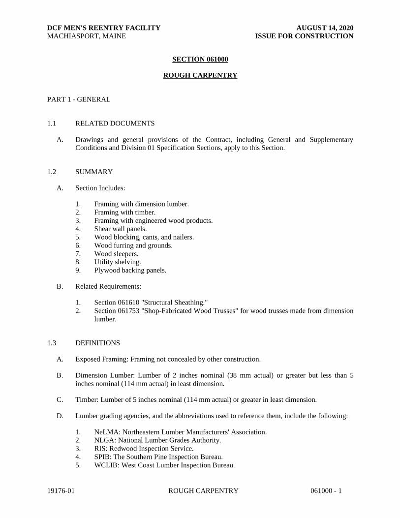
DCF MEN'S REENTRY FACILITY AUGUST 14, 2020
MACHIASPORT, MAINE ISSUE FOR CONSTRUCTION
19176-01 ROUGH CARPENTRY 061000 - 1
SECTION 061000
ROUGH CARPENTRY
PART 1 - GENERAL
1.1 RELATED DOCUMENTS
A. Drawings and general provisions of the Contract, including General and Supplementary Conditions and Division 01 Specification Sections, apply to this Section.
1.2 SUMMARY
A. Section Includes:
1. Framing with dimension lumber.
2. Framing with timber.
3. Framing with engineered wood products. 4. Shear wall panels.
5. Wood blocking, cants, and nailers.
6. Wood furring and grounds.
7. Wood sleepers. 8. Utility shelving.
9. Plywood backing panels.
B. Related Requirements:
1. Section 061610 "Structural Sheathing."
2. Section 061753 "Shop-Fabricated Wood Trusses" for wood trusses made from dimension
lumber.
1.3 DEFINITIONS
A. Exposed Framing: Framing not concealed by other construction.
B. Dimension Lumber: Lumber of 2 inches nominal (38 mm actual) or greater but less than 5
inches nominal (114 mm actual) in least dimension.
C. Timber: Lumber of 5 inches nominal (114 mm actual) or greater in least dimension.
D. Lumber grading agencies, and the abbreviations used to reference them, include the following:
1. NeLMA: Northeastern Lumber Manufacturers' Association. 2. NLGA: National Lumber Grades Authority.
3. RIS: Redwood Inspection Service.
4. SPIB: The Southern Pine Inspection Bureau.
5. WCLIB: West Coast Lumber Inspection Bureau.

DCF MEN'S REENTRY FACILITY AUGUST 14, 2020
MACHIASPORT, MAINE ISSUE FOR CONSTRUCTION
19176-01 ROUGH CARPENTRY 061000 - 2
6. WWPA: Western Wood Products Association.
1.4 ACTION SUBMITTALS
A. Product Data: For each type of process and factory-fabricated product. Indicate component
materials and dimensions and include construction and application details.
1. Include data for wood-preservative treatment from chemical treatment manufacturer and certification by treating plant that treated materials comply with requirements. Indicate
type of preservative used and net amount of preservative retained.
2. For products receiving a waterborne treatment, include statement that moisture content of treated materials was reduced to levels specified before shipment to Project site.
3. Include copies of warranties from chemical treatment manufacturers for each type of
treatment.
B. Fastener Patterns: Full-size templates for fasteners in exposed framing.
1.5 INFORMATIONAL SUBMITTALS
A. Material Certificates: For dimension lumber specified to comply with minimum allowable unit
stresses. Indicate species and grade selected for each use and design values approved by the ALSC Board of Review.
B. Evaluation Reports: For the following, from ICC-ES:
1. Wood-preservative-treated wood. 2. Engineered wood products.
3. Shear panels.
4. Power-driven fasteners. 5. Powder-actuated fasteners.
6. Expansion anchors.
7. Metal framing anchors.
1.6 QUALITY ASSURANCE
A. Testing Agency Qualifications: For testing agency providing classification marking for fire-
retardant treated material, an inspection agency acceptable to authorities having jurisdiction that
periodically performs inspections to verify that the material bearing the classification marking is representative of the material tested.
1.7 DELIVERY, STORAGE, AND HANDLING
A. Stack lumber flat with spacers beneath and between each bundle to provide air circulation.
Protect lumber from weather by covering with waterproof sheeting, securely anchored. Provide for air circulation around stacks and under coverings.

DCF MEN'S REENTRY FACILITY AUGUST 14, 2020
MACHIASPORT, MAINE ISSUE FOR CONSTRUCTION
19176-01 ROUGH CARPENTRY 061000 - 3
PART 2 - PRODUCTS
2.1 WOOD PRODUCTS, GENERAL
A. Certified Wood: Materials shall be produced from wood obtained from forests certified by an
FSC-accredited certification body to comply with FSC STD-01-001, "FSC Principles and
Criteria for Forest Stewardship," for the following:
1. Dimension lumber framing.
2. Timber.
3. Laminated-veneer lumber. 4. Parallel-strand lumber.
5. Rim boards.
6. Miscellaneous lumber.
B. Lumber: DOC PS 20 and applicable rules of grading agencies indicated. If no grading agency is
indicated, provide lumber that complies with the applicable rules of any rules-writing agency
certified by the ALSC Board of Review. Provide lumber graded by an agency certified by the
ALSC Board of Review to inspect and grade lumber under the rules indicated.
1. Factory mark each piece of lumber with grade stamp of grading agency.
2. For exposed lumber indicated to receive a stained or natural finish, mark grade stamp on
end or back of each piece. 3. Where nominal sizes are indicated, provide actual sizes required by DOC PS 20 for
moisture content specified. Where actual sizes are indicated, they are minimum dressed
sizes for dry lumber. 4. Provide dressed lumber, S4S, unless otherwise indicated.
C. Maximum Moisture Content of Lumber: 19 percent
D. Engineered Wood Products: Provide engineered wood products acceptable to authorities having
jurisdiction and for which current model code research or evaluation reports exist that show compliance with building code in effect for Project.
1. Allowable Design Stresses: Provide engineered wood products with allowable design
stresses, as published by manufacturer, that meet or exceed those indicated. Manufacturer's published values shall be determined from empirical data or by rational
engineering analysis and demonstrated by comprehensive testing performed by a
qualified independent testing agency.
2.2 WOOD-PRESERVATIVE-TREATED LUMBER
A. Preservative Treatment by Pressure Process: AWPA U1; Use Category UC2[ for interior
construction not in contact with the ground, Use Category UC3b for exterior construction not in
contact with the ground, and Use Category UC4a for items in contact with the ground].
1. Preservative Chemicals: Acceptable to authorities having jurisdiction and containing no
arsenic or chromium.

DCF MEN'S REENTRY FACILITY AUGUST 14, 2020
MACHIASPORT, MAINE ISSUE FOR CONSTRUCTION
19176-01 ROUGH CARPENTRY 061000 - 4
2. For exposed items indicated to receive a stained or natural finish, use chemical formulations that do not require incising, contain colorants, bleed through, or otherwise
adversely affect finishes.
B. Kiln-dry lumber after treatment to a maximum moisture content of 19 percent. Do not use
material that is warped or that does not comply with requirements for untreated material.
C. Mark lumber with treatment quality mark of an inspection agency approved by the ALSC Board
of Review.
1. For exposed lumber indicated to receive a stained or natural finish, mark end or back of each piece
D. Application: Treat items indicated on Drawings, and the following:
1. Wood cants, nailers, curbs, equipment support bases, blocking, stripping, and similar members in connection with roofing, flashing, vapor barriers, and waterproofing.
2. Wood sills, sleepers, blocking, [furring,] [stripping,] and similar concealed members in
contact with masonry or concrete.
3. Wood framing and furring attached directly to the interior of below-grade exterior masonry or concrete walls.
4. Wood framing members that are less than 18 inches (460 mm) above the ground in
crawlspaces or unexcavated areas. 5. Wood floor plates that are installed over concrete slabs-on-grade.
2.3 DIMENSION LUMBER FRAMING
A. Non-Load-Bearing Interior Partitions: Construction, Stud, or No. 3
1. Application: Interior partitions not indicated as load-bearing.
2. Species:
a. Hem-fir (north); NLGA.
b. Mixed southern pine; SPIB. c. Spruce-pine-fir; NLGA.
d. Hem-fir; WCLIB, or WWPA.
e. Spruce-pine-fir (south); NeLMA, WCLIB, or WWPA. f. Northern species; NLGA.
g. Eastern softwoods; NeLMA.
h. Western woods; WCLIB or WWPA.
B. Load-Bearing Partitions: No. 2 grade.
1. Application: Exterior walls and interior load-bearing partitions.
2. Species:
a. Hem-fir (north); NLGA. b. Southern pine; SPIB.
c. Douglas fir-larch; WCLIB or WWPA.
d. Mixed southern pine; SPIB.

DCF MEN'S REENTRY FACILITY AUGUST 14, 2020
MACHIASPORT, MAINE ISSUE FOR CONSTRUCTION
19176-01 ROUGH CARPENTRY 061000 - 5
e. Spruce-pine-fir; NLGA. f. Douglas fir-south; WWPA.
g. Hem-fir; WCLIB or WWPA.
h. Douglas fir-larch (north); NLGA.
i. Spruce-pine-fir (south); NeLMA, WCLIB, or WWPA.
3. Application: Exterior walls and interior load-bearing partitions.
C. Ceiling Joists: No. 2 grade.
1. Species:
a. Hem-fir (north); NLGA.
b. Southern pine; SPIB.
c. Douglas fir-larch; WCLIB or WWPA. d. Douglas fir-larch (north); NLGA.
e. Mixed southern pine; SPIB.
f. Spruce-pine-fir; NLGA.
g. Hem-fir; WCLIB or WWPA. h. Douglas fir-south; WWPA.
i. Spruce-pine-fir (south); NeLMA, WCLIB, or WWPA.
j. Northern species; NLGA. k. Eastern softwoods; NeLMA.
l. Western woods; WCLIB or WWPA.
D. Joists, Rafters, and Other Framing Not Listed Above: No. 2 grade.
1. Species:
a. Hem-fir (north); NLGA.
b. Southern pine; SPIB.
c. Douglas fir-larch; WCLIB or WWPA. d. Mixed southern pine; SPIB.
e. Spruce-pine-fir; NLGA.
f. Douglas fir-south; WWPA. g. Hem-fir; WCLIB or WWPA.
h. Douglas fir-larch (north); NLGA.
i. Spruce-pine-fir (south); NeLMA, WCLIB, or WWPA.
E. Exposed Framing: Provide material hand-selected for uniformity of appearance and freedom from characteristics, on exposed surfaces and edges, that would impair finish appearance,
including decay, honeycomb, knot-holes, shake, splits, torn grain, and wane.
2.4 TIMBER FRAMING
A. Provide timber framing complying with the following requirements, according to grading rules
of grading agency indicated:
1. Species and Grade: Douglas fir-larch, Douglas fir-larch (north), or Douglas fir-south; No. 1 grade; NLGA, WCLIB, or WWPA.

DCF MEN'S REENTRY FACILITY AUGUST 14, 2020
MACHIASPORT, MAINE ISSUE FOR CONSTRUCTION
19176-01 ROUGH CARPENTRY 061000 - 6
2. Additional Restriction: Free of heart centers.
2.5 ENGINEERED WOOD PRODUCTS
A. Parallel-Strand Lumber: “VersaLam” (VLAM) by Boise Cascade. Structural composite lumber
made from wood strand elements with grain primarily parallel to member lengths, evaluated and
monitored according to ASTM D 5456 and manufactured with an exterior-type adhesive complying with ASTM D 2559.
1. Extreme Fiber Stress in Bending, Edgewise: 3100 psi
2. Modulus of Elasticity, Edgewise: 2,000,000 psi
2.6 SHEAR WALL PANELS
A. Wood-Framed Shear Wall Panels: Prefabricated or field-constructed assembly consisting of
wood perimeter framing, tie downs, and APA rated Exposure I, Structural I plywood or OSB sheathing.
2.7 MISCELLANEOUS LUMBER
A. General: Provide miscellaneous lumber indicated and lumber for support or attachment of other
construction, including the following:
1. Blocking.
2. Nailers.
3. Rooftop equipment bases and support curbs. 4. Cants.
5. Furring.
6. Grounds. 7. Utility shelving.
B. For items of dimension lumber size, provide No. 2 grade lumber and the following species:
1. Hem-fir (north); NLGA.
2. Mixed southern pine; SPIB. 3. Spruce-pine-fir; NLGA.
4. Hem-fir; WCLIB or WWPA.
5. Spruce-pine-fir (south); NeLMA, WCLIB, or WWPA. 6. Western woods; WCLIB or WWPA.
7. Northern species; NLGA.
8. Eastern softwoods; NeLMA.
C. For utility shelving, provide lumber with 19 percent maximum moisture content and the following species and grades:
1. Eastern white pine, Idaho white, lodgepole, ponderosa, or sugar pine; No. 2 grade;
NeLMA, NLGA, WCLIB, or WWPA. 2. Mixed southern pine; No. 2 grade; SPIB.

DCF MEN'S REENTRY FACILITY AUGUST 14, 2020
MACHIASPORT, MAINE ISSUE FOR CONSTRUCTION
19176-01 ROUGH CARPENTRY 061000 - 7
3. Hem-fir or hem-fir (north); No. 2 grade; NLGA, WCLIB, or WWPA. 4. Spruce-pine-fir (south) or spruce-pine-fir; No. 2 grade; NeLMA, NLGA, WCLIB, or
WWPA.
D. For concealed boards, provide lumber with 19 percent maximum moisture content and the
following species and grades:
1. Mixed southern pine; No. 2 grade; SPIB.
2. Hem-fir or hem-fir (north); No. 2 grade; NLGA, WCLIB, or WWPA.
3. Spruce-pine-fir (south) or spruce-pine-fir; No. 2 grade; NeLMA, NLGA, WCLIB, or WWPA.
4. Eastern softwoods; No. 2 Common grade; NeLMA.
5. Northern species; No. 2 Common grade; NLGA. 6. Western woods; No. 2 grade; WCLIB or WWPA.
E. For blocking not used for attachment of other construction, Utility, Stud, or No. 3 grade lumber
of any species may be used provided that it is cut and selected to eliminate defects that will
interfere with its attachment and purpose.
F. For blocking and nailers used for attachment of other construction, select and cut lumber to
eliminate knots and other defects that will interfere with attachment of other work.
G. For furring strips for installing plywood or hardboard paneling, select boards with no knots capable of producing bent-over nails and damage to paneling.
2.8 PLYWOOD BACKING PANELS
A. Equipment Backing Panels: DOC PS 1, Exterior, C-C Plugged in thickness indicated or, if not indicated, not less than 1/2-inch (13-mm) nominal thickness.
2.9 FASTENERS
A. General: Provide fasteners of size and type indicated that comply with requirements specified in
this article for material and manufacture.
1. Where rough carpentry is exposed to weather, in ground contact, pressure-preservative
treated, or in area of high relative humidity, provide fasteners with hot-dip zinc coating
complying with ASTM A 153/A 153M
B. Nails, Brads, and Staples: ASTM F 1667.
C. Power-Driven Fasteners: NES NER-272.
D. Wood Screws: ASME B18.6.1.
E. Lag Bolts: ASME B18.2.1 (ASME B18.2.3.8M).
F. Bolts: Steel bolts complying with ASTM A 307, Grade A (ASTM F 568M, Property Class 4.6);
with ASTM A 563 (ASTM A 563M) hex nuts and, where indicated, flat washers.

DCF MEN'S REENTRY FACILITY AUGUST 14, 2020
MACHIASPORT, MAINE ISSUE FOR CONSTRUCTION
19176-01 ROUGH CARPENTRY 061000 - 8
2.10 METAL FRAMING ANCHORS
A. Manufacturers: Subject to compliance with requirements, provide products by the following:
1. Simpson Strong-Tie Co., Inc.
B. Allowable Design Loads: Manufacturer's published values shall be determined from empirical
data or by rational engineering analysis and demonstrated by comprehensive testing performed by a qualified independent testing agency.
C. Galvanized-Steel Sheet: Hot-dip, zinc-coated steel sheet complying with
ASTM A 653/A 653M, G60 (Z180) coating designation.
1. Use for interior locations unless otherwise indicated.
D. Hot-Dip, Heavy-Galvanized Steel Sheet: ASTM A 653/A 653M; structural steel (SS), high-
strength low-alloy steel Type A (HSLAS Type A), or high-strength low-alloy steel Type B (HSLAS Type B); G185 (Z550) coating designation; and not less than 0.036 inch (0.9 mm)
thick.
1. Use for wood-preservative-treated lumber and where indicated.
E. Stainless-Steel Sheet: ASTM A 666, Type 304 or Type 316.
1. Use for exterior locations and where indicated.
F. Joist Hangers: as specified on structural drawings.
G. Top Flange Hangers: as specified on structural drawings.
H. Bridging: as specified by the truss fabricator.
I. Post Bases: Unless noted otherwise, adjustable-socket type for bolting in place with standoff
plate to raise post 1 inch (25 mm) above base and with 2-inch- (50-mm-) minimum side cover, socket 0.062 inch (1.6 mm) thick, and standoff and adjustment plates 0.108 inch (2.8 mm) thick.
J. Rafter Tie-Downs: as specified on structural drawings.
K. Hold-Downs: as specified on structural drawings.
2.11 MISCELLANEOUS MATERIALS
A. Sill-Sealer Gaskets: Glass-fiber-resilient insulation, fabricated in strip form, for use as a sill
sealer; 1-inch (25-mm) nominal thickness, compressible to 1/32 inch (0.8 mm); selected from
manufacturer's standard widths to suit width of sill members indicated.
B. Sill-Sealer Gaskets: Closed-cell neoprene foam, 1/4 inch (6.4 mm) thick, selected from
manufacturer's standard widths to suit width of sill members indicated.
C. Flexible Flashing: Unless noted otherwise, composite, self-adhesive, flashing product consisting
of a pliable, rubberized-asphalt compound, bonded to a high-density polyethylene film,

DCF MEN'S REENTRY FACILITY AUGUST 14, 2020
MACHIASPORT, MAINE ISSUE FOR CONSTRUCTION
19176-01 ROUGH CARPENTRY 061000 - 9
aluminum foil, or spunbonded polyolefin to produce an overall thickness of not less than 0.025 inch (0.6 mm).
D. Adhesives for Gluing Furring and Sleepers to Concrete or Masonry: Formulation complying
with ASTM D 3498 that is approved for use indicated by adhesive manufacturer.
1. Adhesives shall have a VOC content of 70 g/L or less when calculated according to 40 CFR 59, Subpart D (EPA Method 24).
2. Adhesives shall comply with the testing and product requirements of the California
Department of Health Services' "Standard Practice for the Testing of Volatile Organic Emissions from Various Sources Using Small-Scale Environmental Chambers."
E. Water-Repellent Preservative: NWWDA-tested and -accepted formulation containing 3-iodo-2-
propynyl butyl carbamate, combined with an insecticide containing chloropyrifos as its active ingredient.
PART 3 - EXECUTION
3.1 INSTALLATION, GENERAL
A. Set rough carpentry to required levels and lines, with members plumb, true to line, cut, and fitted. Fit rough carpentry to other construction; scribe and cope as needed for accurate fit.
Locate furring, nailers, blocking, grounds, and similar supports to comply with requirements for
attaching other construction.
B. Framing Standard: Comply with AF&PA's WCD 1, "Details for Conventional Wood Frame
Construction," unless otherwise indicated.
C. Framing with Engineered Wood Products: Install engineered wood products to comply with manufacturer's written instructions.
D. “Microlam” or “LVL” may not be substituted at locations where “Versalam” or “VLAM” are
specified.
E. Provide solid blocking, including tight connections, inside floor cavities underneath columns and jamb studs at sides of wall openings. Cross-sectional area of blocking shall equal or exceed
the bearing area of the column or jamb studs above. An additional post shall be provided inside
the wall underneath the blocking such that continuous support is provided to either the foundation or a supporting beam. Post area and species shall equal (or exceed) that of the
column or jamb studs above.
F. Install plywood backing panels by fastening to studs; coordinate locations with utilities
requiring backing panels. Install fire-retardant treated plywood backing panels with classification marking of testing agency exposed to view.
G. Shear Wall Panels: Install shear wall panels to comply with manufacturer's written instructions.
H. Metal Framing Anchors: Install metal framing anchors to comply with manufacturer's written
instructions. Install fasteners through each fastener hole.

DCF MEN'S REENTRY FACILITY AUGUST 14, 2020
MACHIASPORT, MAINE ISSUE FOR CONSTRUCTION
19176-01 ROUGH CARPENTRY 061000 - 10
1. All 8d nails (8 “penny” nails) shall be 3” long except that Simpson 8d x 1 ½” long nails may be used where specifically indicated on structural details.
I. Install sill sealer gasket to form continuous seal between sill plates and foundation walls.
J. Do not splice structural members between supports.
K. Provide blocking and framing as indicated and as required to support facing materials, fixtures, specialty items, and trim.
1. Provide metal clips for fastening gypsum board or lath at corners and intersections where
framing or blocking does not provide a surface for fastening edges of panels. Space clips not more than 16 inches (406 mm) o.c.
L. Sort and select lumber so that natural characteristics will not interfere with installation or with
fastening other materials to lumber. Do not use materials with defects that interfere with function of member or pieces that are too small to use with minimum number of joints or
optimum joint arrangement.
M. Comply with AWPA M4 for applying field treatment to cut surfaces of preservative-treated
lumber.
1. Use inorganic boron for items that are continuously protected from liquid water.
2. Use copper naphthenate for items not continuously protected from liquid water.
N. Securely attach rough carpentry work to substrate by anchoring and fastening as indicated, complying with the following:
1. NES NER-272 for power-driven fasteners.
2. Table 2304.9.1, "Fastening Schedule," in ICC's International Building Code. 3. Table R602.3(1), "Fastener Schedule for Structural Members," and Table R602.3(2),
"Alternate Attachments," in ICC's International Residential Code for One- and Two-
Family Dwellings.
O. Use steel common nails unless otherwise indicated. Select fasteners of size that will not fully penetrate members where opposite side will be exposed to view or will receive finish materials.
Make tight connections between members. Install fasteners without splitting wood. Drive nails
snug but do not countersink nail heads unless otherwise indicated.
P. For exposed work, arrange fasteners in straight rows parallel with edges of members, with
fasteners evenly spaced, and with adjacent rows staggered.
1. Comply with indicated fastener patterns where applicable. Before fastening, mark
fastener locations, using a template made of sheet metal, plastic, or cardboard. 2. Use finishing nails unless otherwise indicated. Countersink nail heads and fill holes with
wood filler.
3. Use common nails unless otherwise indicated. Drive nails snug but do not countersink nail heads.

DCF MEN'S REENTRY FACILITY AUGUST 14, 2020
MACHIASPORT, MAINE ISSUE FOR CONSTRUCTION
19176-01 ROUGH CARPENTRY 061000 - 11
3.2 WOOD GROUND, SLEEPER, BLOCKING, AND NAILER INSTALLATION
A. Install where indicated and where required for screeding or attaching other work. Form to
shapes indicated and cut as required for true line and level of attached work. Coordinate
locations with other work involved.
B. Attach items to substrates to support applied loading. Recess bolts and nuts flush with surfaces unless otherwise indicated.
C. Where wood-preservative-treated lumber is installed adjacent to metal decking, install
continuous flexible flashing separator between wood and metal decking.
D. Provide permanent grounds of dressed, pressure-preservative-treated, key-beveled lumber not
less than 1-1/2 inches (38 mm) wide and of thickness required to bring face of ground to exact
thickness of finish material. Remove temporary grounds when no longer required.
3.3 WOOD FURRING INSTALLATION
A. Install level and plumb with closure strips at edges and openings. Shim with wood as required
for tolerance of finish work.
B. Furring to Receive Plywood or Hardboard Paneling: Unless noted otherwise, install 1-by-3-inch nominal- (19-by-63-mm actual-) size furring horizontally and vertically at 16 inches o.c.
C. Furring to Receive Gypsum Board : Install 1-by-2-inch nominal- (19-by-38-mm actual-) size
furring vertically at 16 inches o.c.
3.4 WALL AND PARTITION FRAMING INSTALLATION
A. General: Provide single bottom plate and double top plates using members of 2-inch nominal
(38-mm actual) thickness whose widths equal that of studs, except single top plate may be used for non-load-bearing partitions. Fasten plates to supporting construction unless otherwise
indicated.
1. Shearwalls: At walls designated as shearwalls, provide continuous horizontal blocking
between studs supporting horizontal joints for APA rated wall sheathing. Use members of 2-inch nominal (38-mm actual) thickness and of same width as wall or partitions.
B. Construct corners and intersections with three or more studs, except that two studs may be used
for interior non-load-bearing partitions.
C. Provide solid blocking, including tight connections, inside floor cavities underneath columns
and jamb studs at sides of wall openings. Cross-sectional area of blocking shall equal or exceed
the bearing area of the column or jamb studs above. An additional post shall be provided inside
the wall underneath the blocking such that continuous support is provided to either the foundation or a supporting beam. Post area and species shall equal (or exceed) that of the
column or jamb studs above.

DCF MEN'S REENTRY FACILITY AUGUST 14, 2020
MACHIASPORT, MAINE ISSUE FOR CONSTRUCTION
19176-01 ROUGH CARPENTRY 061000 - 12
D. Frame openings with multiple studs and headers. Provide nailed header members of thickness equal to width of studs. Support headers on jamb studs.
1. For non-load-bearing partitions, provide double-jamb studs and headers not less than 4-
inch nominal (89-mm actual) depth for openings 48 inches (1200 mm) and less in width,
6-inch nominal (140-mm actual) depth for openings 48 to 72 inches (1200 to 1800 mm) in width, 8-inch nominal (184-mm actual) depth for openings 72 to 120 inches (1800 to
3000 mm) in width, and not less than 10-inch nominal (235-mm actual) depth for
openings 10 to 12 feet (3 to 3.6 m) in width. 2. For load-bearing walls, provide headers (“lintels”), jack studs and king studs as specified
on structural drawings. Retain paragraph below unless sheathing provides required
bracing. If retaining second option below, indicate locations on Drawings. Change "bracing" to "wind bracing," "seismic bracing," etc., to match term used in code, where
applicable.
3.5 CEILING JOIST AND RAFTER FRAMING INSTALLATION
A. Ceiling Joists: Install ceiling joists with crown edge up and complying with requirements
specified above for floor joists. Face nail to ends of parallel rafters.
1. Where ceiling joists are at right angles to rafters, provide additional short joists parallel to rafters from wall plate to first joist; nail to ends of rafters and to top plate and nail to first
joist or anchor with framing anchors or metal straps. Provide 1-by-8-inch nominal- (19-
by-184-mm actual-) size or 2-by-4-inch nominal- (38-by-89-mm actual-) size stringers spaced 48 inches (1200 mm) o.c. crosswise over main ceiling joists.
B. Provide special framing as indicated for eaves, overhangs, dormers, and similar conditions if
any.
3.6 PROTECTION
A. Protect wood that has been treated with inorganic boron (SBX) from weather. If, despite
protection, inorganic boron-treated wood becomes wet, apply EPA-registered borate treatment.
Apply borate solution by spraying to comply with EPA-registered label.
B. Protect rough carpentry from weather. If, despite protection, rough carpentry becomes [wet]
[sufficiently wet that moisture content exceeds that specified], apply EPA-registered borate
treatment. Apply borate solution by spraying to comply with EPA-registered label.
END OF SECTION 061000

DCF MEN'S REENTRY FACILITY AUGUST 14, 2020
MACHIASPORT, MAINE ISSUE FOR CONSTRUCTION
19176-01 STRUCTURAL SHEATHING 061600 - 1
SECTION 061610
STRUCTURAL SHEATHING
PART 1 - GENERAL
1.1 RELATED DOCUMENTS
A. Drawings and general provisions of the Contract, including General and Supplementary Conditions and Division 01 Specification Sections, apply to this Section.
1.2 SUMMARY
A. Section Includes:
1. Wall sheathing.
2. Roof sheathing.
3. Subflooring. 4. Underlayment.
5. Sheathing joint and penetration treatment.
B. Related Requirements:
1. Section 061000: Rough Carpentry
2. Section 06753: Shop-Fabricated Wood Trusses
1.3 ACTION SUBMITTALS
A. Product Data: For each type of process and factory-fabricated product. Indicate component materials and dimensions and include construction and application details.
1. Include data for wood-preservative treatment from chemical treatment manufacturer and
certification by treating plant that treated plywood complies with requirements. Indicate type of preservative used and net amount of preservative retained.
2. Include data for fire-retardant treatment from chemical treatment manufacturer and
certification by treating plant that treated plywood complies with requirements. Include
physical properties of treated materials. 3. For fire-retardant treatments, include physical properties of treated plywood both before
and after exposure to elevated temperatures, based on testing by a qualified independent
testing agency according to ASTM D 5516. 4. For products receiving a waterborne treatment, include statement that moisture content of
treated materials was reduced to levels specified before shipment to Project site.
5. Include copies of warranties from chemical treatment manufacturers for each type of
treatment.
B. LEED Submittals:

DCF MEN'S REENTRY FACILITY AUGUST 14, 2020
MACHIASPORT, MAINE ISSUE FOR CONSTRUCTION
19176-01 STRUCTURAL SHEATHING 061600 - 2
1. Certificates for Credit MR 6, Credit MR 7: Chain-of-custody certificates indicating that products specified to be made from certified wood comply with forest certification
requirements. Include documentation that manufacturer is certified for chain of custody
by an FSC-accredited certification body. Include statement indicating cost for each
certified wood product. 2. Product Data for Credit IEQ 4.1: For adhesives, documentation including printed
statement of VOC content.
3. Product Data for Credit IEQ 4.4: For composite wood products, documentation indicating that product contains no urea formaldehyde.
4. Laboratory Test Reports for Credit IEQ 4: For adhesives and composite wood products,
documentation indicating that products comply with the testing and product requirements of the California Department of Health Services' "Standard Practice for the Testing of
Volatile Organic Emissions from Various Sources Using Small-Scale Environmental
Chambers."
1.4 INFORMATIONAL SUBMITTALS
A. Evaluation Reports: For following products, from ICC-ES:
1. Preservative-treated plywood.
2. Fire-retardant-treated plywood. 3. Foam-plastic sheathing.
1.5 QUALITY ASSURANCE
A. Testing Agency Qualifications: For testing agency providing classification marking for fire-retardant-treated material, an inspection agency acceptable to authorities having jurisdiction that
periodically performs inspections to verify that the material bearing the classification marking is
representative of the material tested.
1.6 DELIVERY, STORAGE, AND HANDLING
A. Stack panels flat with spacers beneath and between each bundle to provide air circulation.
Protect sheathing from weather by covering with waterproof sheeting, securely anchored.
Provide for air circulation around stacks and under coverings.
PART 2 - PRODUCTS
2.1 WOOD PANEL PRODUCTS
A. Emissions: Products shall meet the testing and product requirements of the California
Department of Health Services' "Standard Practice for the Testing of Volatile Organic Emissions from Various Sources Using Small-Scale Environmental Chambers."
B. Certified Wood: For the following wood products, provide materials produced from wood
obtained from forests certified by an FSC-accredited certification body to comply with FSC STD-01-001, "FSC Principles and Criteria for Forest Stewardship":
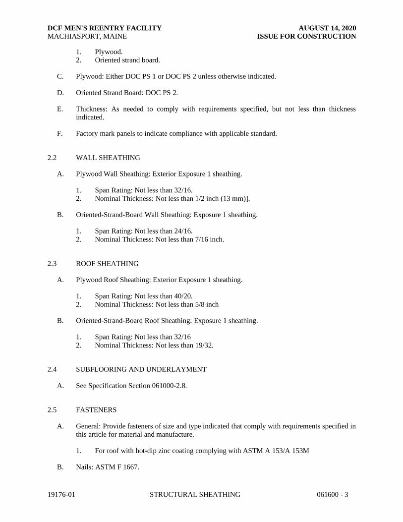
DCF MEN'S REENTRY FACILITY AUGUST 14, 2020
MACHIASPORT, MAINE ISSUE FOR CONSTRUCTION
19176-01 STRUCTURAL SHEATHING 061600 - 3
1. Plywood. 2. Oriented strand board.
C. Plywood: Either DOC PS 1 or DOC PS 2 unless otherwise indicated.
D. Oriented Strand Board: DOC PS 2.
E. Thickness: As needed to comply with requirements specified, but not less than thickness indicated.
F. Factory mark panels to indicate compliance with applicable standard.
2.2 WALL SHEATHING
A. Plywood Wall Sheathing: Exterior Exposure 1 sheathing.
1. Span Rating: Not less than 32/16.
2. Nominal Thickness: Not less than 1/2 inch (13 mm)].
B. Oriented-Strand-Board Wall Sheathing: Exposure 1 sheathing.
1. Span Rating: Not less than 24/16.
2. Nominal Thickness: Not less than 7/16 inch.
2.3 ROOF SHEATHING
A. Plywood Roof Sheathing: Exterior Exposure 1 sheathing.
1. Span Rating: Not less than 40/20.
2. Nominal Thickness: Not less than 5/8 inch
B. Oriented-Strand-Board Roof Sheathing: Exposure 1 sheathing.
1. Span Rating: Not less than 32/16
2. Nominal Thickness: Not less than 19/32.
2.4 SUBFLOORING AND UNDERLAYMENT
A. See Specification Section 061000-2.8.
2.5 FASTENERS
A. General: Provide fasteners of size and type indicated that comply with requirements specified in this article for material and manufacture.
1. For roof with hot-dip zinc coating complying with ASTM A 153/A 153M
B. Nails: ASTM F 1667.

DCF MEN'S REENTRY FACILITY AUGUST 14, 2020
MACHIASPORT, MAINE ISSUE FOR CONSTRUCTION
19176-01 STRUCTURAL SHEATHING 061600 - 4
PART 3 - EXECUTION
3.1 INSTALLATION, GENERAL
A. Do not use materials with defects that impair quality of sheathing or pieces that are too small to
use with minimum number of joints or optimum joint arrangement. Arrange joints so that pieces
do not span between fewer than three support members.
B. Cut panels at penetrations, edges, and other obstructions of work; fit tightly against abutting
construction unless otherwise indicated.
C. Securely attach to substrate by fastening as indicated, complying with the following:
1. NES NER-272 for power-driven fasteners.
2. Table 2304.9.1, "Fastening Schedule," in ICC's "International Building Code."
3. Table R602.3(1), "Fastener Schedule for Structural Members," and Table R602.3(2), "Alternate Attachments," in ICC's "International Residential Code for One- and Two-
Family Dwellings."
D. Use common wire nails unless otherwise indicated. Select fasteners of size that will not fully
penetrate members where opposite side will be exposed to view or will receive finish materials. Make tight connections. Install fasteners without splitting wood.
E. Coordinate wall and roof sheathing installation with flashing and joint-sealant installation so
these materials are installed in sequence and manner that prevent exterior moisture from passing through completed assembly.
F. Do not bridge building expansion joints; cut and space edges of panels to match spacing of
structural support elements.
G. Coordinate sheathing installation with installation of materials installed over sheathing so
sheathing is not exposed to precipitation or left exposed at end of the workday when rain is
forecast.
3.2 WOOD STRUCTURAL PANEL INSTALLATION
A. General: Comply with applicable recommendations in APA Form No. E30, "Engineered Wood
Construction Guide," for types of structural-use panels and applications indicated.
B. Fastening Methods: Fasten panels as indicated below:
1. Combination Subfloor-Underlayment:
a. Glue and nail to wood framing.
2. Subflooring:
a. Glue and nail to wood framing.
3. Wall and Roof Sheathing:

DCF MEN'S REENTRY FACILITY AUGUST 14, 2020
MACHIASPORT, MAINE ISSUE FOR CONSTRUCTION
19176-01 STRUCTURAL SHEATHING 061600 - 5
a. Nail to wood framing. b. Space panels 1/8 inch (3 mm) apart at edges and ends.
4. Underlayment:
a. Nail or staple to subflooring.
b. Space panels 1/32 inch (0.8 mm) apart at edges and ends. c. Fill and sand edge joints of underlayment receiving resilient flooring immediately
before installing flooring.
END OF SECTION 061600

DCF MEN'S REENTRY FACILITY AUGUST 14, 2020
MACHIASPORT, MAINE ISSUE FOR CONSTRUCTION
19176-01 STRUCTURAL SHEATHING 061600 - 6
THIS PAGE INTENTIONALLY LEFT BLANK

DCF MEN'S REENTRY FACILITY AUGUST 14, 2020
MACHIASPORT, MAINE ISSUE FOR CONSTRUCTION
19176-01 SHOP-FABRICATED WOOD TRUSSES 061753 - 1
SECTION 061753
SHOP-FABRICATED WOOD TRUSSES
PART 1 - GENERAL
1.1 RELATED DOCUMENTS
A. Drawings and general provisions of the Contract, including General and Supplementary Conditions and Division 01 Specification Sections, apply to this Section.
1.2 SUMMARY
A. Section Includes
1. Wood roof trusses.
2. Wood floor trusses.
3. Wood girder trusses. 4. Wood truss bracing.
5. Metal truss accessories.
B. Related Requirements:
1. Section 061600 "Sheathing" for roof sheathing and subflooring.
C. Wood truss fabricator to provide bracing plan(s). See 1.4.B.3.
1.3 DEFINITIONS
A. Metal-Plate-Connected Wood Trusses: Planar structural units consisting of metal-plate-connected members fabricated from dimension lumber and cut and assembled before delivery to
Project site.
1.4 ACTION SUBMITTALS
A. Product Data: For metal-plate connectors, metal truss accessories, and fasteners.
1. Include data for wood-preservative treatment from chemical treatment manufacturer and
certification by treating plant that treated materials comply with requirements. Indicate
type of preservative used and net amount of preservative retained. 2. Include data for fire-retardant treatment from chemical treatment manufacturer and
certification by treating plant that treated materials comply with requirements. Include
physical properties of treated materials based on testing by a qualified independent testing agency.

DCF MEN'S REENTRY FACILITY AUGUST 14, 2020
MACHIASPORT, MAINE ISSUE FOR CONSTRUCTION
19176-01 SHOP-FABRICATED WOOD TRUSSES 061753 - 2
3. For fire-retardant treatments, include physical properties of treated lumber both before and after exposure to elevated temperatures, based on testing by a qualified independent
testing agency according to ASTM D 5664.
4. For products receiving a waterborne treatment, include statement that moisture content of
treated materials was reduced to levels specified before shipment to truss fabricator. 5. Include copies of warranties from chemical treatment manufacturers for each type of
treatment.
B. Shop Drawings: Show fabrication and installation details for trusses.
1. Show location, pitch, span, camber, configuration, and spacing for each type of truss
required.
2. Indicate sizes, stress grades, and species of lumber. 3. Indicate locations of permanent bracing required to prevent buckling of individual truss
members due to design loads.
4. Indicate locations, sizes, and materials for permanent bracing required to prevent
buckling of individual truss members due to design loads. 5. Indicate type, size, material, finish, design values, orientation, and location of metal
connector plates.
6. Show splice details and bearing details.
C. Delegated-Design Submittal: For metal-plate-connected wood trusses indicated to comply with
performance requirements and design criteria, including analysis data signed and sealed by the
qualified professional engineer responsible for their preparation.
1.5 INFORMATIONAL SUBMITTALS
A. Qualification Data: For metal connector-plate manufacturer, professional engineer and
fabricator.
B. Material Certificates: For dimension lumber specified to comply with minimum specific gravity. Indicate species and grade selected for each use and specific gravity.
C. Product Certificates: For metal-plate-connected wood trusses, signed by officer of truss
fabricating firm.
D. Evaluation Reports: For the following, from ICC-ES:
1. Metal-plate connectors.
2. Metal truss accessories.
1.6 QUALITY ASSURANCE
A. Metal Connector-Plate Manufacturer Qualifications: A manufacturer that is a member of TPI
and that complies with quality-control procedures in TPI 1 for manufacture of connector plates.
1. Manufacturer's responsibilities include providing professional engineering services needed to assume engineering responsibility.

DCF MEN'S REENTRY FACILITY AUGUST 14, 2020
MACHIASPORT, MAINE ISSUE FOR CONSTRUCTION
19176-01 SHOP-FABRICATED WOOD TRUSSES 061753 - 3
2. Engineering Responsibility: Preparation of Shop Drawings and comprehensive engineering analysis by a qualified professional engineer.
B. Fabricator Qualifications: Shop that participates in a recognized quality-assurance program that
complies with quality-control procedures in TPI 1 and that involves third-party inspection by an
independent testing and inspecting agency acceptable to Architect and authorities having jurisdiction and is certified for chain of custody by an FSC-accredited certification body.
C. Testing Agency Qualifications: For testing agency providing classification marking for fire-
retardant treated material, an inspection agency acceptable to authorities having jurisdiction that periodically performs inspections to verify that the material bearing the classification marking is
representative of the material tested.
1.7 DELIVERY, STORAGE, AND HANDLING
A. Handle and store trusses to comply with recommendations in TPI BCSI, "Building Component
Safety Information: Guide to Good Practice for Handling, Installing, Restraining, & Bracing
Metal Plate Connected Wood Trusses."
1. Store trusses flat, off of ground, and adequately supported to prevent lateral bending. 2. Protect trusses from weather by covering with waterproof sheeting, securely anchored.
3. Provide for air circulation around stacks and under coverings.
B. Inspect trusses showing discoloration, corrosion, or other evidence of deterioration. Discard and replace trusses that are damaged or defective.
PART 2 - PRODUCTS
2.1 PERFORMANCE REQUIREMENTS
A. Delegated Design: Engage a qualified professional engineer, as defined in Section 014000
"Quality Requirements," to design metal-plate-connected wood trusses.
B. Structural Performance: Provide metal-plate-connected wood trusses capable of withstanding
design loads within limits and under conditions indicated. Comply with requirements in TPI 1 unless more stringent requirements are specified below.
1. Design Loads: As indicated.
2. Maximum Deflection Under Design Loads:
a. Roof Trusses: Vertical deflection of 1/240 of span under total load, 1/360 under
snow loads.
C. Comply with applicable requirements and recommendations of the following publications:
1. TPI 1, "National Design Standard for Metal Plate Connected Wood Truss Construction." 2. TPI DSB, "Recommended Design Specification for Temporary Bracing of Metal Plate
Connected Wood Trusses."

DCF MEN'S REENTRY FACILITY AUGUST 14, 2020
MACHIASPORT, MAINE ISSUE FOR CONSTRUCTION
19176-01 SHOP-FABRICATED WOOD TRUSSES 061753 - 4
3. TPI BCSI, "Building Component Safety Information: Guide to Good Practice for Handling, Installing, Restraining, & Bracing Metal Plate Connected Wood Trusses."
D. Wood Structural Design Standard: Comply with applicable requirements in AF&PA's "National
Design Specifications for Wood Construction" and its "Supplement."
2.2 DIMENSION LUMBER
A. Certified Wood: For metal-plate-connected wood trusses and permanent bracing, provide
materials produced from wood obtained from forests certified by an FSC-accredited
certification body to comply with FSC STD-01-001, "FSC Principles and Criteria for Forest Stewardship."
B. Lumber: DOC PS 20 and applicable rules of grading agencies indicated. If no grading agency is
indicated, provide lumber that complies with the applicable rules of any rules writing agency certified by the ALSC Board of Review. Provide lumber graded by an agency certified by the
ALSC Board of Review to inspect and grade lumber under the rules indicated.
1. Factory mark each piece of lumber with grade stamp of grading agency.
2. For exposed lumber indicated to receive a stained or natural finish, omit grade stamp and provide certificates of grade compliance issued by grading agency.
3. Provide dressed lumber, S4S.
4. Provide dry lumber with 19 percent maximum moisture content at time of dressing.
C. Minimum Chord Size for Roof Trusses: 2 by 6 inches nominal for top chords, 2 by 4 inches
nominal for bottom chords
D. Minimum Specific Gravity for Top Chords: 0.5
E. Permanent Bracing: Provide wood bracing that complies with requirements for miscellaneous
lumber in Section 061000 "Rough Carpentry."
2.3 METAL CONNECTOR PLATES
A. Source Limitations: Obtain metal connector plates from single manufacturer.
B. General: Fabricate connector plates to comply with TPI 1.
C. Hot-Dip Galvanized-Steel Sheet: ASTM A 653/A 653M; Structural Steel (SS), high-strength
low-alloy steel Type A (HSLAS Type A), or high-strength low-alloy steel Type B (HSLAS Type B); G60 (Z180) coating designation; and not less than 0.036 inch (0.9 mm) thick.
1. Use for interior locations unless otherwise indicated.
2.4 FASTENERS
A. General: Provide fasteners of size and type indicated that comply with requirements specified in this article for material and manufacture.

DCF MEN'S REENTRY FACILITY AUGUST 14, 2020
MACHIASPORT, MAINE ISSUE FOR CONSTRUCTION
19176-01 SHOP-FABRICATED WOOD TRUSSES 061753 - 5
1. Provide fasteners for use with metal framing anchors that comply with written recommendations of metal framing manufacturer.
B. Nails, Brads, and Staples: ASTM F 1667.
2.5 METAL FRAMING ANCHORS AND ACCESSORIES
A. Allowable Design Loads: Provide products with allowable design loads, as published by manufacturer, that meet or exceed those of products of manufacturers listed. Manufacturer's
published values shall be determined from empirical data or by rational engineering analysis
and demonstrated by comprehensive testing performed by a qualified independent testing agency.
B. Galvanized-Steel Sheet: Hot-dip, zinc-coated steel sheet complying with
ASTM A 653/A 653M, G60 (Z180) coating designation.
1. Use for interior locations unless otherwise indicated.
C. Truss Tie-Downs: See structural drawings
D. Roof Truss Clips: Angle clips for bracing bottom chord of roof trusses at non-load-bearing
walls, 1-1/4 inches (32 mm) wide by 0.050 inch (1.3 mm) thick. Clip is fastened to truss through slotted holes to allow for truss deflection.
E. Roof Truss Bracing/Spacers: U-shaped channels, 1-1/2 inches (38 mm) wide by 1 inch (25 mm)
deep by 0.040 inch (1.0 mm) thick, made to fit between two adjacent trusses and accurately space them apart, and with tabs having metal teeth for fastening to trusses.
2.6 MISCELLANEOUS MATERIALS
A. Galvanizing Repair Paint: SSPC-Paint 20, with dry film containing a minimum of 94 percent zinc dust by weight.
2.7 FABRICATION
A. Cut truss members to accurate lengths, angles, and sizes to produce close-fitting joints.
B. Fabricate metal connector plates to sizes, configurations, thicknesses, and anchorage details required to withstand design loads for types of joint designs indicated.
C. Assemble truss members in design configuration indicated; use jigs or other means to ensure
uniformity and accuracy of assembly with joints closely fitted to comply with tolerances in TPI 1. Position members to produce design camber indicated.
1. Fabricate wood trusses within manufacturing tolerances in TPI 1.
D. Connect truss members by metal connector plates located and securely embedded
simultaneously in both sides of wood members by air or hydraulic press.

DCF MEN'S REENTRY FACILITY AUGUST 14, 2020
MACHIASPORT, MAINE ISSUE FOR CONSTRUCTION
19176-01 SHOP-FABRICATED WOOD TRUSSES 061753 - 6
2.8 SOURCE QUALITY CONTROL
A. Special Inspections: Owner will engage a qualified special inspector to perform special
inspections.
1. Provide special inspector with access to fabricator's documentation of detailed fabrication
and quality-control procedures that provide a basis for inspection control of the workmanship and the fabricator's ability to conform to approved construction documents
and referenced standards.
2. Provide special inspector with access to places where wood trusses are being fabricated to perform inspections.
B. Correct deficiencies in Work that special inspections indicate does not comply with the Contract
Documents.
PART 3 - EXECUTION
3.1 INSTALLATION
A. Install wood trusses only after supporting construction is in place and is braced and secured.
B. If trusses are delivered to Project site in more than one piece, assemble trusses before installing.
C. Hoist trusses in place by lifting equipment suited to sizes and types of trusses required,
exercising care not to damage truss members or joints by out-of-plane bending or other causes.
D. Install and brace trusses according to TPI recommendations and as indicated.
E. Install trusses plumb, square, and true to line and securely fasten to supporting construction.
F. Space trusses 24 inches (610 mm) o.c. unless noted otherwise; adjust and align trusses in
location before permanently fastening.
G. Anchor trusses securely at bearing points; use metal truss tie-downs or floor truss hangers as
applicable. Install fasteners through each fastener hole in metal framing anchors according to
manufacturer's fastening schedules and written instructions.
H. Install and fasten permanent bracing during truss erection and before construction loads are applied. Anchor ends of permanent bracing where terminating at walls or beams.
1. Install bracing to comply with Section 061000 "Rough Carpentry."
2. Install and fasten strongback bracing vertically against vertical web of parallel-chord floor trusses at centers indicated.
I. Install wood trusses within installation tolerances in TPI 1.
J. Do not alter trusses in field. Do not cut, drill, notch, or remove truss members.
K. Replace wood trusses that are damaged or do not meet requirements.

DCF MEN'S REENTRY FACILITY AUGUST 14, 2020
MACHIASPORT, MAINE ISSUE FOR CONSTRUCTION
19176-01 SHOP-FABRICATED WOOD TRUSSES 061753 - 7
1. Damaged trusses may be repaired according to truss repair details signed and sealed by the qualified professional engineer responsible for truss design, when approved by
Architect.
3.2 REPAIRS AND PROTECTION
A. Protect wood that has been treated with inorganic boron (SBX) from weather. If, despite protection, inorganic boron-treated wood becomes wet, apply EPA-registered borate treatment.
Apply borate solution by spraying to comply with EPA-registered label.
B. Protect wood trusses from weather. If, despite protection, wood trusses become wet, apply EPA-registered borate treatment. Apply borate solution by spraying to comply with EPA-
registered label.
C. Repair damaged galvanized coatings on exposed surfaces with galvanized repair paint according to ASTM A 780 and manufacturer's written instructions.
D. Protective Coating: Clean and prepare exposed surfaces of metal connector plates. Brush apply
primer, when part of coating system, and one coat of protective coating.
1. Apply materials to provide minimum dry film thickness recommended by coating system manufacturer.
3.3 FIELD QUALITY CONTROL
A. Special Inspections: Owner will engage a qualified special inspector to perform special inspections to verify that temporary installation restraint/bracing and the permanent individual
truss member restraint/bracing are installed in accordance with the approved truss submittal
package.
END OF SECTION 061753

DCF MEN'S REENTRY FACILITY AUGUST 14, 2020
MACHIASPORT, MAINE ISSUE FOR CONSTRUCTION
19176-01 SHOP-FABRICATED WOOD TRUSSES 061753 - 8
THIS PAGE INTENTIONALLY LEFT BLANK

DCF MEN'S REENTRY FACILITY AUGUST 14, 2020
MACHIASPORT, MAINE ISSUE FOR CONSTRUCTION
19176-01 PLASTIC-LAMINATE-FACED ARCHITECTURAL CABINETS 064116 - 1
SECTION 064116
PLASTIC-LAMINATE-FACED ARCHITECTURAL CABINETS
PART 1 - GENERAL
1.1 RELATED DOCUMENTS
A. Drawings and general provisions of the Contract, including General and Supplementary Conditions and Division 01 Specification Sections, apply to this Section.
1.2 SUMMARY
A. Section Includes:
1. Plastic-laminate-faced architectural cabinets.
2. Wood furring, blocking, shims, and hanging strips for installing plastic-laminate-faced
architectural cabinets unless concealed within other construction before cabinet installation.
1.3 ACTION SUBMITTALS
A. Product Data: For each type of product, including; panel products, high-pressure decorative
laminate, adhesive for bonding plastic laminate, and cabinet hardware and accessories.
B. Shop Drawings: Show location of each item, dimensioned plans and elevations, large-scale
details, attachment devices, and other components.
1. Show locations and sizes of furring, blocking, and hanging strips, including concealed blocking and reinforcement specified in other Sections.
2. Show locations and sizes of cutouts and holes for electrical switches and outlets and other
items installed in architectural plastic-laminate cabinets. 3. Apply AWI Quality Certification Program label to Shop Drawings.
C. Samples for Initial Selection:
1. PVC edge material.
D. Samples for Verification:
1. Plastic laminates, 8 by 10 inches (200 by 250 mm) for each type, color, pattern, and
surface finish.
1.4 INFORMATIONAL SUBMITTALS
A. Qualification Data: For fabricator.

DCF MEN'S REENTRY FACILITY AUGUST 14, 2020
MACHIASPORT, MAINE ISSUE FOR CONSTRUCTION
19176-01 PLASTIC-LAMINATE-FACED ARCHITECTURAL CABINETS 064116 - 2
1.5 QUALITY ASSURANCE
A. Fabricator Qualifications: Shop that employs skilled workers who custom fabricate products
similar to those required for this Project and whose products have a record of successful in-
service performance. Shop is a certified participant in AWI's Quality Certification Program.
B. Installer Qualifications: Fabricator of products.
1.6 DELIVERY, STORAGE, AND HANDLING
A. Do not deliver cabinets until painting and similar operations that could damage woodwork have
been completed in installation areas. If cabinets must be stored in other than installation areas, store only in areas where environmental conditions comply with requirements specified in
"Field Conditions" Article.
1.7 FIELD CONDITIONS
A. Environmental Limitations: Do not deliver or install cabinets until building is enclosed, wet
work is complete, and HVAC system is operating and maintaining temperature and relative
humidity at occupancy levels during the remainder of the construction period.
B. Field Measurements: Where cabinets are indicated to fit to other construction, verify dimensions of other construction by field measurements before fabrication, and indicate
measurements on Shop Drawings. Coordinate fabrication schedule with construction progress to
avoid delaying the Work.
1. Locate concealed framing, blocking, and reinforcements that support cabinets by field
measurements before being enclosed, and indicate measurements on Shop Drawings.
C. Established Dimensions: Where cabinets are indicated to fit to other construction, establish dimensions for areas where cabinets are to fit. Provide allowance for trimming at site, and
coordinate construction to ensure that actual dimensions correspond to established dimensions.
1.8 COORDINATION
A. Coordinate sizes and locations of framing, blocking, furring, reinforcements, and other related units of Work specified in other Sections to ensure that cabinets can be supported and installed
as indicated.
PART 2 - PRODUCTS
2.1 PLASTIC-LAMINATE-FACED ARCHITECTURAL CABINETS
A. Quality Standard: Unless otherwise indicated, comply with the "Architectural Woodwork
Standards" for grades of architectural plastic-laminate cabinets indicated for construction,
finishes, installation, and other requirements.

DCF MEN'S REENTRY FACILITY AUGUST 14, 2020
MACHIASPORT, MAINE ISSUE FOR CONSTRUCTION
19176-01 PLASTIC-LAMINATE-FACED ARCHITECTURAL CABINETS 064116 - 3
1. The Contract Documents contain selections chosen from options in the quality standard and additional requirements beyond those of the quality standard. Comply with those
selections and requirements in addition to the quality standard.
B. Grade: Custom.
C. Type of Construction: Frameless.
D. Cabinet, Door, and Drawer Front Interface Style: Flush overlay.
E. High-Pressure Decorative Laminate: NEMA LD 3, grades as indicated or if not indicated, as
required by woodwork quality standard.
1. Manufacturers: Subject to compliance with requirements, provide products by one of the
following:
a. Wilsonart International Holdings, Inc. b. Formica; A Fletcher Building Company.
c. Pionite; Panolam Surface Systems.
d. Nevamar; Panolam Surface Systems.
F. Laminate Cladding for Exposed Surfaces:
1. Horizontal Surfaces: Grade HGS.
2. Vertical Surfaces: Grade VGS.
3. Edges: PVC tape, 0.018-inch (0.460-mm) minimum thickness, matching laminate in color, pattern, and finish.
4. Pattern Direction: Vertically for drawer fronts, doors, and fixed panels.
G. Materials for Semiexposed Surfaces:
1. Surfaces Other Than Drawer Bodies:
a. Edges of Plastic-Laminate Shelves: PVC edge banding, 0.12 inch (3 mm) thick,
matching laminate in color, pattern, and finish.
b. For semiexposed backs of panels with exposed plastic-laminate surfaces, provide surface of high-pressure decorative laminate, NEMA LD 3, Grade VGS.
2. Drawer Sides and Backs: Solid-hardwood lumber.
3. Drawer Bottoms: Hardwood plywood.
H. Dust Panels: 1/4-inch (6.4-mm) plywood or tempered hardboard above compartments and
drawers unless located directly under tops.
I. Concealed Backs of Panels with Exposed Plastic-Laminate Surfaces: High-pressure decorative
laminate, NEMA LD 3, Grade BKL.
J. Drawer Construction: Fabricate with exposed fronts fastened to subfront with mounting screws
from interior of body.
1. Join subfronts, backs, and sides with glued rabbeted joints supplemented by mechanical fasteners or glued dovetail joints.

DCF MEN'S REENTRY FACILITY AUGUST 14, 2020
MACHIASPORT, MAINE ISSUE FOR CONSTRUCTION
19176-01 PLASTIC-LAMINATE-FACED ARCHITECTURAL CABINETS 064116 - 4
K. Colors, Patterns, and Finishes: Provide materials and products that result in colors and textures of exposed laminate surfaces complying with the following requirements:
1. As indicated in drawings.
2.2 WOOD MATERIALS
A. Wood Products: Provide materials that comply with requirements of referenced quality standard for each type of woodwork and quality grade specified unless otherwise indicated.
1. Wood Moisture Content: 5 to 10 percent.
B. Composite Wood and Agrifiber Products: Provide materials that comply with requirements of referenced quality standard for each type of woodwork and quality grade specified unless
otherwise indicated.
1. Medium-Density Fiberboard: ANSI A208.2, Grade 130. 2. Particleboard: ANSI A208.1, Grade M-2.
2.3 CABINET HARDWARE AND ACCESSORIES
A. General: Provide cabinet hardware and accessory materials associated with architectural
cabinets except for items specified in Section 087111 "Door Hardware (Descriptive Specification)."
B. Frameless Concealed Hinges (European Type): BHMA A156.9, B01602, 135 degrees of
opening, self-closing.
C. Decorative Pulls: Back mounted, solid metal 6-5/16 inches long, 13/32 inch in diameter.
1. Provide Doug Mockett & Co., Rod Pull DP55A in Satin Stainless, or approved equal.
D. Adjustable Shelf Standards and Supports: BHMA A156.9, B04071; with shelf rests, B04081.
1. Basis of Design: Knape and Vogt, 82 Series Standards and 182 Series Brackets.
E. Shelf Rests: BHMA A156.9, B04013; metal.
F. Label Holders: PVC, side loading, c-channel label holders, with changeable copy inserts and
clear plastic insert protectors. Pressure sensitive adhesive backing. 3/4 inch high by 6-inches
wide.
1. Location: Provide one label holder per shelf as indicated in drawings. Provide two inserts
and insert protectors per holder.
G. Support Brackets: Heavy gauge aluminum angle, MIG welded corners, 5/16 inch holes for
mounting, and primed finish for field painting.
1. Countertops: Provide the following type as indicated in drawings.

DCF MEN'S REENTRY FACILITY AUGUST 14, 2020
MACHIASPORT, MAINE ISSUE FOR CONSTRUCTION
19176-01 PLASTIC-LAMINATE-FACED ARCHITECTURAL CABINETS 064116 - 5
a. Provide Rakks Surface-Mounted Counter Support, Model No. EH-1818, or size as required by counter depth, by Ragine Corporation (800-826-6006) or approved
equal.
b. Provide A&M Hardware, Inc.; Extended Concealed Brackets, Model No. EC-18 or
size as required by counter depth or approved equal. c. Provide A&M Hardware, Inc.; Concealed Brackets, Model No. C-18 or size as
required by counter depth or approved equal. Provide at counters mounted on
partial height walls. d. Where countertop brackets are not otherwise indicated, provide concealed type
metal brackets with fasteners for any countertop or shelf span greater than 36".
H. Metal Reveal Strips:
1. Provide Chemetal “#909 Satin Silver Aluminum” (www.chemetal.com); directional satin
finish, or approved equal.
I. Drawer Slides: BHMA A156.9.
1. Grade 1 and Grade 2: Side mounted; full-extension type; zinc-plated steel ball-bearing
slides with polymer rollers.
J. Door Locks: BHMA A156.11, E07121.
K. Drawer Locks: BHMA A156.11, E07041.
L. Door and Drawer Silencers: BHMA A156.16, L03011.
M. Exposed Hardware Finishes: For exposed hardware, provide finish that complies with BHMA A156.18 for BHMA finish number indicated.
1. Satin Stainless Steel: BHMA 630.
N. For concealed hardware, provide manufacturer's standard finish that complies with product class
requirements in BHMA A156.9.
2.4 MISCELLANEOUS MATERIALS
A. Furring, Blocking, Shims, and Hanging Strips: Softwood or hardwood lumber, kiln dried to less
than 15 percent moisture content.
B. Anchors: Select material, type, size, and finish required for each substrate for secure anchorage.
Provide metal expansion sleeves or expansion bolts for post-installed anchors. Use nonferrous-
metal or hot-dip galvanized anchors and inserts at inside face of exterior walls and at floors.
C. Adhesives: Do not use adhesives that contain urea formaldehyde.
D. Adhesive for Bonding Plastic Laminate: Unpigmented contact cement.
1. Adhesive for Bonding Edges: Hot-melt adhesive or adhesive specified above for faces.
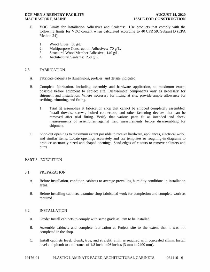
DCF MEN'S REENTRY FACILITY AUGUST 14, 2020
MACHIASPORT, MAINE ISSUE FOR CONSTRUCTION
19176-01 PLASTIC-LAMINATE-FACED ARCHITECTURAL CABINETS 064116 - 6
E. VOC Limits for Installation Adhesives and Sealants: Use products that comply with the following limits for VOC content when calculated according to 40 CFR 59, Subpart D (EPA
Method 24):
1. Wood Glues: 30 g/L.
2. Multipurpose Construction Adhesives: 70 g/L. 3. Structural Wood Member Adhesive: 140 g/L.
4. Architectural Sealants: 250 g/L.
2.5 FABRICATION
A. Fabricate cabinets to dimensions, profiles, and details indicated.
B. Complete fabrication, including assembly and hardware application, to maximum extent
possible before shipment to Project site. Disassemble components only as necessary for shipment and installation. Where necessary for fitting at site, provide ample allowance for
scribing, trimming, and fitting.
1. Trial fit assemblies at fabrication shop that cannot be shipped completely assembled.
Install dowels, screws, bolted connectors, and other fastening devices that can be removed after trial fitting. Verify that various parts fit as intended and check
measurements of assemblies against field measurements before disassembling for
shipment.
C. Shop-cut openings to maximum extent possible to receive hardware, appliances, electrical work,
and similar items. Locate openings accurately and use templates or roughing-in diagrams to
produce accurately sized and shaped openings. Sand edges of cutouts to remove splinters and burrs.
PART 3 - EXECUTION
3.1 PREPARATION
A. Before installation, condition cabinets to average prevailing humidity conditions in installation areas.
B. Before installing cabinets, examine shop-fabricated work for completion and complete work as
required.
3.2 INSTALLATION
A. Grade: Install cabinets to comply with same grade as item to be installed.
B. Assemble cabinets and complete fabrication at Project site to the extent that it was not
completed in the shop.
C. Install cabinets level, plumb, true, and straight. Shim as required with concealed shims. Install
level and plumb to a tolerance of 1/8 inch in 96 inches (3 mm in 2400 mm).

DCF MEN'S REENTRY FACILITY AUGUST 14, 2020
MACHIASPORT, MAINE ISSUE FOR CONSTRUCTION
19176-01 PLASTIC-LAMINATE-FACED ARCHITECTURAL CABINETS 064116 - 7
D. Scribe and cut cabinets to fit adjoining work, refinish cut surfaces, and repair damaged finish at cuts.
E. Anchor cabinets to anchors or blocking built in or directly attached to substrates. Secure with
countersunk, concealed fasteners and blind nailing. Use fine finishing nails or finishing screws
for exposed fastening, countersunk and filled flush with woodwork.
1. Use filler matching finish of items being installed.
F. Cabinets: Install without distortion so doors and drawers fit openings properly and are
accurately aligned. Adjust hardware to center doors and drawers in openings and to provide unencumbered operation. Complete installation of hardware and accessory items as indicated.
1. Install cabinets with no more than 1/8 inch in 96-inch (3 mm in 2400-mm) sag, bow, or
other variation from a straight line. 2. Fasten wall cabinets through back, near top and bottom, and at ends not more than 16
inches (400 mm) o.c. with No. 10 wafer-head screws sized for not less than 1-1/2-inch
(38-mm) penetration into wood framing, blocking, or hanging strips.
3.3 ADJUSTING AND CLEANING
A. Repair damaged and defective cabinets, where possible, to eliminate functional and visual
defects; where not possible to repair, replace woodwork. Adjust joinery for uniform appearance.
B. Clean, lubricate, and adjust hardware.
C. Clean cabinets on exposed and semi exposed surfaces.
END OF SECTION 064116

DCF MEN'S REENTRY FACILITY AUGUST 14, 2020
MACHIASPORT, MAINE ISSUE FOR CONSTRUCTION
19176-01 PLASTIC-LAMINATE-FACED ARCHITECTURAL CABINETS 064116 - 8
THS PAGE INTENTIONALLY LEFT BLANK

DCF MEN'S REENTRY FACILITY AUGUST 14, 2020
MACHIASPORT, MAINE ISSUE FOR CONSTRUCTION
19176-01 PLASTIC PANELING 066400-1
SECTION 066400
PLASTIC PANELING
PART 1 - GENERAL
1.1 RELATED DOCUMENTS
A. Drawings and general provisions of the Contract, including General and Supplementary Conditions and Division 01 Specification Sections, apply to this Section.
1.2 SUMMARY
A. Section Includes:
1. Plastic sheet paneling.
1.3 ACTION SUBMITTALS
A. Product Data: For each type of product.
B. Samples: For plastic paneling and trim accessories, in manufacturer's standard sizes.
1.4 INFORMATIONAL SUBMITTALS
A. Certificates: Submit manufacturer’s certification that materials comply with specified require-
ments and are suitable for intended application.
B. Test and Evaluation Reports: Submit reports showing compliance with specified performance
characteristics and physical properties.
1.5 CLOSEOUT SUBMITTALS
A. Maintenance Data: For plastic sheet paneling to include in maintenance manuals. Include manufacturer’s care and maintenance instructions, including cleaning and repairing instructions.
1.6 QUALITY ASSURANCE
A. Manufacturer’s Qualifications: Manufacturer regularly engaged, for a minimum of 10 years, in the manufacturing of plastic sheet panels of similar type to that specified.
B. Installer's Qualifications: Installer regularly engaged, for a minimum of 5 years, in installation
of FRP panels of similar type to that specified.

DCF MEN'S REENTRY FACILITY AUGUST 14, 2020
MACHIASPORT, MAINE ISSUE FOR CONSTRUCTION
19176-01 PLASTIC PANELING 066400-2
C. Testing Agency: Acceptable to authorities having jurisdiction.
1.7 PROJECT CONDITIONS
A. Environmental Limitations: Do not deliver or install plastic paneling until spaces are enclosed
and weathertight and temporary HVAC system is operating and maintaining ambient
temperature and humidity conditions at occupancy levels during the remainder of the construction period.
PART 2 - PRODUCTS
2.1 MANUFACTURERS
A. Source Limitations: Obtain plastic paneling and trim accessories from single manufacturer.
2.2 PLASTIC SHEET PANELING (FRP-1):
A. Glass-Fiber-Reinforced Plastic Paneling: Gelcoat-finished, glass-fiber-reinforced plastic panels complying with ASTM D5319.
1. Products: Subject to compliance with requirements, available products that may be
incorporated into the Work include, but are not limited to the following:
a. Crane Composites, Inc; GLASBORD Wall Panels with Surfaseal Finish.
2. Surface-Burning Characteristics: As follows when tested by a qualified testing agency
according to ASTM E84. Identify products with appropriate markings of applicable
testing agency.
a. Flame-Spread Index: 25 or less.
b. Smoke-Developed Index: 450 or less.
3. Scratch Resistance: Barcol Hardness 55 when tested in accordance with ASTM D2583. 4. Abrasion Resistance: Weight loss after 25 cycles of no more than 0.038 percent when
tested in accordance with the Taber Abrasion Test, CS-17 abrasive wheels with 1,000 g
weight.
5. Impact Strength: No visible damage on finish side when tested in accordance with ASTM D5420 at 11.0 in-lbs.
6. Nominal Thickness: Not less than 0.075 inch.
7. Surface Finish: Smooth. 8. Color: As indicated on Drawings.
2.3 ACCESSORIES
A. Trim Accessories: Manufacturer's standard one-piece vinyl extrusions designed to retain and
cover edges of panels. Provide inside corners, outside corners, and caps as needed to conceal edges.
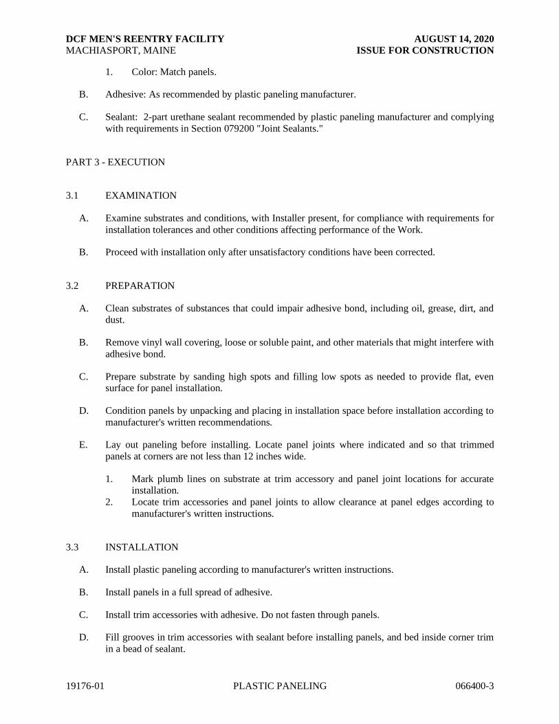
DCF MEN'S REENTRY FACILITY AUGUST 14, 2020
MACHIASPORT, MAINE ISSUE FOR CONSTRUCTION
19176-01 PLASTIC PANELING 066400-3
1. Color: Match panels.
B. Adhesive: As recommended by plastic paneling manufacturer.
C. Sealant: 2-part urethane sealant recommended by plastic paneling manufacturer and complying
with requirements in Section 079200 "Joint Sealants."
PART 3 - EXECUTION
3.1 EXAMINATION
A. Examine substrates and conditions, with Installer present, for compliance with requirements for
installation tolerances and other conditions affecting performance of the Work.
B. Proceed with installation only after unsatisfactory conditions have been corrected.
3.2 PREPARATION
A. Clean substrates of substances that could impair adhesive bond, including oil, grease, dirt, and dust.
B. Remove vinyl wall covering, loose or soluble paint, and other materials that might interfere with
adhesive bond.
C. Prepare substrate by sanding high spots and filling low spots as needed to provide flat, even surface for panel installation.
D. Condition panels by unpacking and placing in installation space before installation according to
manufacturer's written recommendations.
E. Lay out paneling before installing. Locate panel joints where indicated and so that trimmed
panels at corners are not less than 12 inches wide.
1. Mark plumb lines on substrate at trim accessory and panel joint locations for accurate installation.
2. Locate trim accessories and panel joints to allow clearance at panel edges according to
manufacturer's written instructions.
3.3 INSTALLATION
A. Install plastic paneling according to manufacturer's written instructions.
B. Install panels in a full spread of adhesive.
C. Install trim accessories with adhesive. Do not fasten through panels.
D. Fill grooves in trim accessories with sealant before installing panels, and bed inside corner trim
in a bead of sealant.

DCF MEN'S REENTRY FACILITY AUGUST 14, 2020
MACHIASPORT, MAINE ISSUE FOR CONSTRUCTION
19176-01 PLASTIC PANELING 066400-4
E. Maintain uniform space between adjacent panels. Fill space with sealant.
F. Maintain uniform space between panels and wall fixtures. Fill space with sealant.
G. Remove excess sealant and smears as paneling is installed. Clean with solvent recommended by
sealant manufacturer and then wipe with clean dry cloths until no residue remains.
END OF SECTION 066400

DCF MEN'S REENTRY FACILITY AUGUST 14, 2020
MACHIASPORT, MAINE ISSUE FOR CONSTRUCTION
19176-01 THERMAL INSULATION 072100 - 1
SECTION 072100
THERMAL INSULATION
PART 1 - GENERAL
1.1 RELATED DOCUMENTS
A. Drawings and general provisions of the Contract, including General and Supplementary Conditions and Division 01 Specification Sections, apply to this Section.
1.2 SUMMARY
A. Section Includes:
1. Extruded polystyrene foam-plastic board rigid insulation.
2. Spray polyurethane foam insulation.
3. Glass-fiber blanket batt insulation.
B. Related Requirements:
1. Section 092900 "Gypsum Board" for sound attenuation blanket used as acoustic
insulation.
1.3 ACTION SUBMITTALS
A. Product Data: For each type of product indicated.
1.4 INFORMATIONAL SUBMITTALS
A. Product Test Reports: For each product, for tests performed by a qualified testing agency.
B. Research Reports: For foam-plastic insulation, from ICC-ES.
1.5 DELIVERY, STORAGE, AND HANDLING
A. Protect insulation materials from physical damage and from deterioration due to moisture, soiling, and other sources. Store inside and in a dry location. Comply with manufacturer's
written instructions for handling, storing, and protecting during installation.
B. Protect foam-plastic board insulation as follows:
1. Do not expose to sunlight except to necessary extent for period of installation and concealment.
2. Protect against ignition at all times. Do not deliver foam-plastic board materials to Project
site until just before installation time.
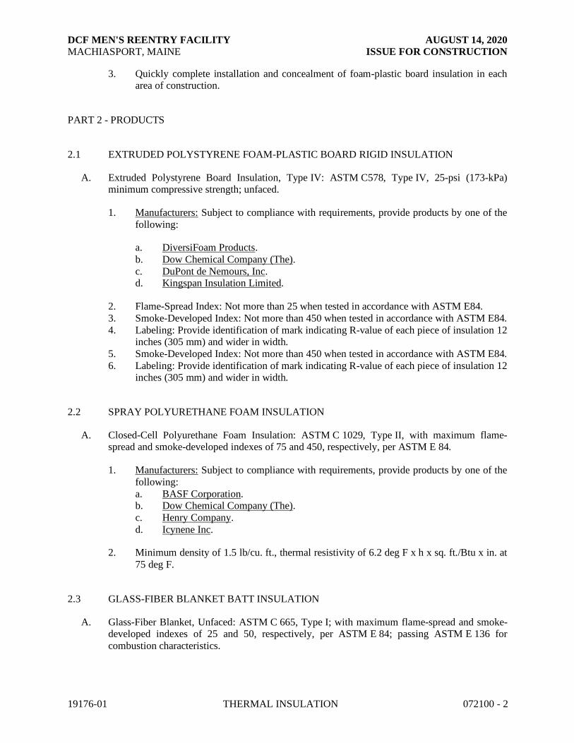
DCF MEN'S REENTRY FACILITY AUGUST 14, 2020
MACHIASPORT, MAINE ISSUE FOR CONSTRUCTION
19176-01 THERMAL INSULATION 072100 - 2
3. Quickly complete installation and concealment of foam-plastic board insulation in each area of construction.
PART 2 - PRODUCTS
2.1 EXTRUDED POLYSTYRENE FOAM-PLASTIC BOARD RIGID INSULATION
A. Extruded Polystyrene Board Insulation, Type IV: ASTM C578, Type IV, 25-psi (173-kPa) minimum compressive strength; unfaced.
1. Manufacturers: Subject to compliance with requirements, provide products by one of the
following:
a. DiversiFoam Products.
b. Dow Chemical Company (The).
c. DuPont de Nemours, Inc. d. Kingspan Insulation Limited.
2. Flame-Spread Index: Not more than 25 when tested in accordance with ASTM E84.
3. Smoke-Developed Index: Not more than 450 when tested in accordance with ASTM E84.
4. Labeling: Provide identification of mark indicating R-value of each piece of insulation 12 inches (305 mm) and wider in width.
5. Smoke-Developed Index: Not more than 450 when tested in accordance with ASTM E84.
6. Labeling: Provide identification of mark indicating R-value of each piece of insulation 12 inches (305 mm) and wider in width.
2.2 SPRAY POLYURETHANE FOAM INSULATION
A. Closed-Cell Polyurethane Foam Insulation: ASTM C 1029, Type II, with maximum flame-spread and smoke-developed indexes of 75 and 450, respectively, per ASTM E 84.
1. Manufacturers: Subject to compliance with requirements, provide products by one of the
following:
a. BASF Corporation. b. Dow Chemical Company (The).
c. Henry Company.
d. Icynene Inc.
2. Minimum density of 1.5 lb/cu. ft., thermal resistivity of 6.2 deg F x h x sq. ft./Btu x in. at
75 deg F.
2.3 GLASS-FIBER BLANKET BATT INSULATION
A. Glass-Fiber Blanket, Unfaced: ASTM C 665, Type I; with maximum flame-spread and smoke-developed indexes of 25 and 50, respectively, per ASTM E 84; passing ASTM E 136 for
combustion characteristics.

DCF MEN'S REENTRY FACILITY AUGUST 14, 2020
MACHIASPORT, MAINE ISSUE FOR CONSTRUCTION
19176-01 THERMAL INSULATION 072100 - 3
B. Manufacturers: Subject to compliance with requirements, provide products by one of the following:
1. CertainTeed Corporation.
2. Johns Manville; a Berkshire Hathaway company.
3. Knauf Insulation.
4. Owens Corning.
2.4 ACCESSORIES
A. Insulation for Miscellaneous Voids: 1. Spray Polyurethane Foam Insulation: ASTM C1029, Type II, closed cell, with maximum
flame-spread and smoke-developed indexes of 75 and 450, respectively, per ASTM E84.
B. Adhesive for Bonding Insulation: Product compatible with insulation and air and water barrier materials, and with demonstrated capability to bond insulation securely to substrates without
damaging insulation and substrates.
C. Eave Ventilation Troughs: Preformed, rigid fiberboard or plastic sheets designed and sized to fit
between roof framing members and to provide ventilation between insulated attic spaces and vented eaves.
D. Sheathing Tape for Foam-Plastic Sheathing: Pressure-sensitive plastic tape recommended by
sheathing manufacturer for sealing joints and penetrations in sheathing.
E. Sub-framing Thermal Spacer:
1. 100% Pultruded glass fiber and thermoset polyester resin insulation clip.
a. Thermal Spacer thickness for top, base and web: 3/16 inches nominal. b. Thermal spacer depth: 4 inches nominal.
1) Depth tolerance: ± 0.005 inches.
c. Basis of Design: Cascadia Windows Inc., Cascadia Clip®, www.cascadiaclip.com
2. Spacer Fasteners: High hex head washer head with sharp twin threaded design of heat treated corrosion resistant coated steel.
3. Fastener for wood framing: ¼” – 10 x 6 inches long with hex head.
a. Acceptable material: Leland Industries Inc., Master Gripper with DT2000 or NZF3000 coating or approved equivalent.

DCF MEN'S REENTRY FACILITY AUGUST 14, 2020
MACHIASPORT, MAINE ISSUE FOR CONSTRUCTION
19176-01 THERMAL INSULATION 072100 - 4
PART 3 - EXECUTION
3.1 PREPARATION
A. Clean substrates of substances that are harmful to insulation, including removing projections
capable of puncturing insulation or vapor retarders, or that interfere with insulation attachment.
3.2 INSTALLATION, GENERAL
A. Comply with insulation manufacturer's written instructions applicable to products and
applications.
B. Install insulation that is undamaged, dry, and unsoiled and that has not been left exposed to ice, rain, or snow at any time.
C. Install insulation with manufacturer's R-value label exposed after insulation is installed.
D. Extend insulation to envelop entire area to be insulated. Fit tightly around obstructions and fill voids with insulation. Remove projections that interfere with placement.
E. Provide sizes to fit applications and selected from manufacturer's standard thicknesses, widths,
and lengths. Apply single layer of insulation units unless multiple layers are otherwise shown or
required to make up total thickness or to achieve R-value.
3.3 INSTALLATION OF BELOW-GRADE INSULATION
A. On vertical slab edge and foundation surfaces, set insulation units using manufacturer's
recommended adhesive according to manufacturer's written instructions.
1. If not otherwise indicated, extend insulation a minimum of 24 inches (610 mm) below
exterior grade line.
B. On horizontal surfaces, loosely lay insulation units according to manufacturer's written instructions. Stagger end joints and tightly abut insulation units.
1. If not otherwise indicated, extend insulation a minimum of 24 inches (610 mm) in from
exterior walls.
3.4 INSTALLATION OF INSULATION IN FRAMED CONSTRUCTION
A. Apply insulation units to substrates by method indicated, complying with the manufacturer’s
written instructions. If no specific method is indicated, bond units to substrate with adhesive or
use mechanical anchorage to provide permanent placement and support of units.
B. Foam-Plastic Board Insulation: Seal joints between units by applying adhesive, mastic, or
sealant to edges of each unit to form a tight seal as units are shoved into place. Fill voids in
completed installation with adhesive, mastic, or sealant as recommended by insulation
manufacturer.

DCF MEN'S REENTRY FACILITY AUGUST 14, 2020
MACHIASPORT, MAINE ISSUE FOR CONSTRUCTION
19176-01 THERMAL INSULATION 072100 - 5
C. Spray-Applied Insulation: Apply spray-applied insulation according to manufacturer's written instructions. Do not apply insulation until installation of pipes, ducts, conduits, wiring, and
electrical outlets in walls is completed and windows, electrical boxes, and other items not
indicated to receive insulation are masked. After insulation is applied, make flush with face of
studs by using method recommended by insulation manufacturer.
D. Miscellaneous Voids: Install insulation in miscellaneous voids and cavity spaces where required
to prevent gaps in insulation using the following materials:
1. Spray Polyurethane Insulation: Apply according to manufacturer's written instructions.
3.5 INSTALLATION OF INSULATION IN CEILINGS FOR SOUND ATTENUATION
A. Where glass-fiber blankets are indicated for sound attenuation above ceilings, install blanket
insulation over entire ceiling area in thicknesses indicated. Extend insulation 48 inches up either side of partitions.
3.6 INSTALLATION OF VAPOR RETARDERS
A. Place vapor retarders on side of construction indicated on Drawings. Extend vapor retarders to
extremities of areas to protect from vapor transmission. Secure vapor retarders in place with adhesives or other anchorage system as indicated. Extend vapor retarders to cover
miscellaneous voids in insulated substrates, including those filled with loose-fiber insulation.
B. Seal vertical joints in vapor retarders over framing by lapping no fewer than two studs.
1. Fasten vapor retarders to wood framing at top, end, and bottom edges; at perimeter of
wall openings; and at lap joints. Space fasteners 16 inches o.c.
C. Seal joints caused by pipes, conduits, electrical boxes, and similar items penetrating vapor retarders with vapor-retarder tape to create an airtight seal between penetrating objects and
vapor retarders.
D. Repair tears or punctures in vapor retarders immediately before concealment by other work.
Cover with vapor-retarder tape or another layer of vapor retarders.
3.7 PROTECTION
A. Protect installed insulation from damage due to harmful weather exposures, physical abuse, and
other causes.
B. Provide temporary coverings or enclosures where insulation is subject to abuse and cannot be
concealed and protected by permanent construction immediately after installation.
END OF SECTION 072100

DOWNEAST CORRECTIONAL FACILITY JUNE 25, 2020 MACHIASPORT, MAINE DESIGN DEVELOPMENT
19176
THIS PAGE INTENTIONALLY LEFT BLANK

DCF MEN'S REENTRY FACILITY AUGUST 14, 2020
MACHIASPORT, MAINE ISSUE FOR CONSTRUCTION
19176-01 WEATHER BARRIERS 072500 - 1
SECTION 072500
WEATHER BARRIERS
PART 1 - GENERAL
1.1 RELATED DOCUMENTS
A. Drawings and general provisions of the Contract, including General and Supplementary Conditions and Division 01 Specification Sections, apply to this Section.
1.2 SUMMARY
A. Section Includes:
1. Building paper.
2. Building wrap.
3. Flexible flashing. 4. Drainage material.
1.3 ACTION SUBMITTALS
A. Product Data: For each type of product.
1. For building wrap, include data on air and water-vapor permeance based on testing according to referenced standards.
B. Shop Drawings: Show details of building [paper] [wrap] at terminations, openings, and
penetrations. Show details of flexible flashing applications.
1.4 INFORMATIONAL SUBMITTALS
A. Evaluation Reports: For water-resistive barrier and flexible flashing, from ICC-ES.
PART 2 - PRODUCTS
2.1 WATER-RESISTIVE BARRIER
A. Building Paper: ASTM D 226, Type 1 (No. 15 asphalt-saturated organic felt), unperforated.
B. Building Paper: Water-vapor-permeable, asphalt-saturated kraft building paper that complies
with ICC-ES AC38, Grade D[; except with water-resistance rating not less than 1 hour].

DCF MEN'S REENTRY FACILITY AUGUST 14, 2020
MACHIASPORT, MAINE ISSUE FOR CONSTRUCTION
19176-01 WEATHER BARRIERS 072500 - 2
C. Building Wrap: ASTM E 1677, Type I air barrier; with flame-spread and smoke-developed indexes of less than 25 and 450, respectively, when tested according to ASTM E 84; UV
stabilized; and acceptable to authorities having jurisdiction.
1. Water-Vapor Permeance: Not less than [75 perms (4300 ng/Pa x s x sq. m)] per
ASTM E 96/E 96M, Desiccant Method (Procedure A). 2. Air Permeance: Not more than 0.004 cfm/sq. ft. at 0.3-inch wg (0.02 L/s x sq. m at 75 Pa)
when tested according to ASTM E 2178.
3. Allowable UV Exposure Time: Not less than three months. 4. Flame Propagation Test: Materials and construction shall be as tested according to
NFPA 285.
D. Building-Wrap Tape: Pressure-sensitive plastic tape recommended by building-wrap manufacturer for sealing joints and penetrations in building wrap.
2.2 FLEXIBLE FLASHING
A. Butyl Rubber Flashing: Composite, self-adhesive, flashing product consisting of a pliable, butyl
rubber compound, bonded to a high-density polyethylene film, aluminum foil, or spunbonded polyolefin to produce an overall thickness of not less than [0.030 inch (0.8 mm)].
1. Flame Propagation Test: Materials and construction shall be as tested according to
NFPA 285.
B. Rubberized-Asphalt Flashing: Composite, self-adhesive, flashing product consisting of a
pliable, rubberized-asphalt compound, bonded to a high-density polyethylene film, aluminum
foil, or spunbonded polyolefin to produce an overall thickness of not less than [0.030 inch (0.8 mm)]
1. Flame Propagation Test: Materials and construction shall be as tested according to
NFPA 285.
C. Primer for Flexible Flashing: Product recommended in writing by flexible flashing manufacturer for substrate.
D. Nails and Staples: Product recommended in writing by flexible flashing manufacturer and
complying with ASTM F 1667.
PART 3 - EXECUTION
3.1 WATER-RESISTIVE BARRIER INSTALLATION
A. Cover exposed exterior surface of sheathing with water-resistive barrier securely fastened to
framing immediately after sheathing is installed.
B. Cover sheathing with water-resistive barrier as follows:
1. Cut back barrier 1/2 inch (13 mm) on each side of the break in supporting members at
expansion- or control-joint locations.

DCF MEN'S REENTRY FACILITY AUGUST 14, 2020
MACHIASPORT, MAINE ISSUE FOR CONSTRUCTION
19176-01 WEATHER BARRIERS 072500 - 3
2. Apply barrier to cover vertical flashing with a minimum 4-inch (100-mm) overlap unless otherwise indicated.
C. Building Paper: Apply horizontally with a 2-inch (50-mm) overlap and a 6-inch (150-mm) end
lap; fasten to sheathing with galvanized staples or roofing nails.
D. Building Wrap: Comply with manufacturer's written instructions and warranty requirements.
1. Seal seams, edges, fasteners, and penetrations with tape.
2. Extend into jambs of openings and seal corners with tape.
3.2 FLEXIBLE FLASHING INSTALLATION
A. Apply flexible flashing where indicated to comply with manufacturer's written instructions.
1. Prime substrates as recommended by flashing manufacturer.
2. Lap seams and junctures with other materials at least 4 inches (100 mm) except that at flashing flanges of other construction, laps need not exceed flange width.
3. Lap flashing over water-resistive barrier at bottom and sides of openings.
4. Lap water-resistive barrier over flashing at heads of openings.
5. After flashing has been applied, roll surfaces with a hard rubber or metal roller to ensure that flashing is completely adhered to substrates.
END OF SECTION 072500

DCF MEN'S REENTRY FACILITY AUGUST 14, 2020
MACHIASPORT, MAINE ISSUE FOR CONSTRUCTION
19176-01 WEATHER BARRIERS 072500 - 4
THIS PAGE INTENTIONALLY LEFT BLANK
DCF MEN'S REENTRY FACILITY AUGUST 14, 2020
MACHIASPORT, MAINE ISSUE FOR CONSTRUCTION
19176-01 STANDING-SEAM METAL ROOF PANELS 074113.16 - 1
SECTION 074113.16
STANDING-SEAM METAL ROOF PANELS
PART 1 - GENERAL
1.1 RELATED DOCUMENTS
A. Drawings and general provisions of the Contract, including General and Supplementary Conditions and Division 01 Specification Sections, apply to this Section.
1.2 SUMMARY
A. Section includes: 1. Standing-seam metal roof panels.
2. Ridge vents
B. Related Sections:
1. Section 07 62 00 “Sheet Metal Flashing and Trim” for flashing at roof edges and
penetrations
1.3 PREINSTALLATION MEETINGS
A. Preinstallation Conference: Conduct conference at Project site.
1. Meet with Owner, Architect, Owner's insurer if applicable, metal panel Installer, metal
panel manufacturer's representative, structural-support Installer, and installers whose
work interfaces with or affects metal panels, including installers of roof accessories and roof-mounted equipment including the photovoltaic (PV) system.
2. Coordinate with requirements for attaching and supporting photovoltaic (PV) system.
3. Review and finalize construction schedule and verify availability of materials, Installer's personnel, equipment, and facilities needed to make progress and avoid delays.
4. Review methods and procedures related to metal panel installation, including
manufacturer's written instructions.
5. Examine support conditions for compliance with requirements, including alignment between and attachment to structural members.
6. Review structural loading limitations of deck during and after roofing.
7. Review flashings, special details, drainage, penetrations, equipment curbs, and condition of other construction that affect metal panels.
8. Review governing regulations and requirements for insurance, certificates, and tests and
inspections if applicable.
9. Review temporary protection requirements for metal panel systems during and after installation.
10. Review procedures for repair of metal panels damaged after installation.
11. Document proceedings, including corrective measures and actions required, and furnish copy of record to each participant.

DCF MEN'S REENTRY FACILITY AUGUST 14, 2020
MACHIASPORT, MAINE ISSUE FOR CONSTRUCTION
19176-01 STANDING-SEAM METAL ROOF PANELS 074113.16 - 2
1.4 ACTION SUBMITTALS
A. Product Data: For each type of product.
1. Include construction details, material descriptions, dimensions of individual components
and profiles, and finishes for each type of panel and accessory.
B. Shop Drawings:
1. Include fabrication and installation layouts of metal panels; details of edge conditions,
joints, panel profiles, corners, anchorages, attachment system, trim, flashings, closures,
and accessories; and special details. 2. Accessories: Include details of the flashing, trim, and anchorage systems, at a scale of not
less than 1-1/2 inches per 12 inches.
C. Samples for Initial Selection: For each type of metal panel indicated with factory-applied color finishes.
1. Include similar Samples of trim and accessories involving color selection.
D. Samples for Verification: For each type of exposed finish required, prepared on Samples of size
indicated below.
1. Metal Panels: 12 inches long by actual panel width. Include clips, fasteners, closures, and
other metal panel accessories.
1.5 INFORMATIONAL SUBMITTALS
A. Qualification Data: For Installer.
B. Product Test Reports: For each product, for tests performed by a qualified testing agency.
C. Field quality-control reports.
D. Sample Warranties: For special warranties.
1.6 CLOSEOUT SUBMITTALS
A. Maintenance Data: For metal panels to include in maintenance manuals.
1.7 QUALITY ASSURANCE
A. Installer Qualifications: An entity that employs installers and supervisors who are trained and
approved by manufacturer.

DCF MEN'S REENTRY FACILITY AUGUST 14, 2020
MACHIASPORT, MAINE ISSUE FOR CONSTRUCTION
19176-01 STANDING-SEAM METAL ROOF PANELS 074113.16 - 3
1.8 DELIVERY, STORAGE, AND HANDLING
A. Deliver components, metal panels, and other manufactured items so as not to be damaged or
deformed. Package metal panels for protection during transportation and handling.
B. Unload, store, and erect metal panels in a manner to prevent bending, warping, twisting, and
surface damage.
C. Stack metal panels horizontally on platforms or pallets, covered with suitable weathertight and
ventilated covering. Store metal panels to ensure dryness, with positive slope for drainage of
water. Do not store metal panels in contact with other materials that might cause staining, denting, or other surface damage.
D. Retain strippable protective covering on metal panels during installation.
1.9 FIELD CONDITIONS
A. Weather Limitations: Proceed with installation only when existing and forecasted weather
conditions permit assembly of metal panels to be performed according to manufacturers' written
instructions and warranty requirements.
1.10 COORDINATION
A. Coordinate sizes and locations of roof curbs, equipment supports, and roof penetrations with
actual equipment provided.
B. Coordinate metal panel installation with rain drainage work, flashing, trim, construction of soffits, and other adjoining work to provide a leakproof, secure, and noncorrosive installation.
1.11 WARRANTY
A. Special Warranty: Manufacturer's standard form in which manufacturer agrees to repair or replace components of metal panel systems that fail in materials or workmanship within
specified warranty period.
1. Failures include, but are not limited to, the following:
a. Structural failures including rupturing, cracking, or puncturing. b. Deterioration of metals and other materials beyond normal weathering.
2. Warranty Period: Two years from date of Substantial Completion.
B. Special Warranty on Panel Finishes: Manufacturer's standard form in which manufacturer agrees to repair finish or replace metal panels that show evidence of deterioration of factory-
applied finishes within specified warranty period.
1. Exposed Panel Finish: Deterioration includes, but is not limited to, the following:
a. Color fading more than 5 Hunter units when tested according to ASTM D 2244.

DCF MEN'S REENTRY FACILITY AUGUST 14, 2020
MACHIASPORT, MAINE ISSUE FOR CONSTRUCTION
19176-01 STANDING-SEAM METAL ROOF PANELS 074113.16 - 4
b. Chalking in excess of a No. 8 rating when tested according to ASTM D 4214. c. Cracking, checking, peeling, or failure of paint to adhere to bare metal.
2. Finish Warranty Period: 20 years from date of Substantial Completion.
PART 2 - PRODUCTS
2.1 PERFORMANCE REQUIREMENTS
A. Structural Performance: Provide metal panel systems capable of withstanding the effects of the
following loads, based on testing according to ASTM E 1592:
1. Wind Loads: As indicated on Drawings. 2. Other Design Loads: As indicated on Drawings.
3. Deflection Limits: For wind loads, no greater than 1/180 of the span.
B. Wind-Uplift Resistance: Provide metal roof panel assemblies that comply with UL 580 for wind-uplift-resistance class indicated.
1. Uplift Rating: UL 90.
C. Thermal Movements: Allow for thermal movements from ambient and surface temperature
changes by preventing buckling, opening of joints, overstressing of components, failure of joint sealants, failure of connections, and other detrimental effects. Base calculations on surface
temperatures of materials due to both solar heat gain and nighttime-sky heat loss.
1. Temperature Change (Range): 120 deg F, ambient; 180 deg F, material surfaces.
2.2 STANDING-SEAM METAL ROOF PANELS
A. General: Provide factory-formed metal roof panels designed to be installed by lapping and
interconnecting raised side edges of adjacent panels with joint type indicated and mechanically attaching panels to supports using concealed clips in side laps. Include clips, cleats, pressure
plates, and accessories required for weathertight installation.
1. Steel Panel Systems: Unless more stringent requirements are indicated, comply with
ASTM E 1514.
B. Vertical-Rib, Seamed-Joint, Standing-Seam Metal Roof Panels: Formed with vertical ribs at
panel edges and a flat pan between ribs; designed for sequential installation by mechanically
attaching panels to supports using concealed clips located under one side of panels, engaging
opposite edge of adjacent panels, and mechanically seaming panels together.
1. Basis-of-Design Product: Subject to compliance with requirements, provide MBCI;
LokSeam or comparable product by one of the following:
a. Architectural Building Components. b. Architectural Metal Systems; a Nucor company.
c. ATAS International, Inc.
d. Berridge Manufacturing Company.

DCF MEN'S REENTRY FACILITY AUGUST 14, 2020
MACHIASPORT, MAINE ISSUE FOR CONSTRUCTION
19176-01 STANDING-SEAM METAL ROOF PANELS 074113.16 - 5
e. CENTRIA Architectural Systems. f. Dimensional Metals, Inc.
g. Englert, Inc.
h. Fabral.
i. Firestone Metal Products, LLC. j. Garland Company, Inc. (The)
k. IMETCO.
l. McElroy Metal, Inc. m. Merchant & Evans.
n. Metal-Fab Manufacturing, LLC.
o. Morin; a Kingspan Group company. p. Petersen Aluminum Corporation.
q. Ryerson, Inc.
r. Ultra Seam, Inc.
2. Metallic-Coated Steel Sheet: Aluminum-zinc alloy-coated steel sheet complying with ASTM A 792/A 792M, Class AZ50 coating designation; structural quality. Prepainted by
the coil-coating process to comply with ASTM A 755/A 755M.
a. Exterior Finish: Two-coat fluoropolymer. b. Color: As selected by Architect from manufacturer's full range.
3. Clips: to accommodate thermal movement.
a. Material: aluminum-zinc alloy-coated steel sheet.
4. Joint Type: As standard with manufacturer.
5. Panel Coverage: 16 inches.
6. Panel Height: 1.75 inches.
2.3 RIDGE VENTS
A. Manufacturer’s standard, rigid-section, high-density, UV-stabilized plastic ridge vent for use
under metal roof.
1. Basis of Design: MBCI or approved equal.
2.4 VENT BAFFLES
A. Manufacturer’s standard, one-piece vent of extruded polystyrene foam (EPS) with lightweight
waterproof air channel and wide stapling flanges for use under metal roof.
1. Basis of Design: ADO Products, Duravent, or approved equal. 2. Size:
a. Width: 22 inches perforated at centerline to fit joist spacing
b. Vent Body Length: 48 inches c. Air Channel Depth: 1.4 inches
d. Net Free Area: 18.7 per square inch.

DCF MEN'S REENTRY FACILITY AUGUST 14, 2020
MACHIASPORT, MAINE ISSUE FOR CONSTRUCTION
19176-01 STANDING-SEAM METAL ROOF PANELS 074113.16 - 6
2.5 UNDERLAYMENT MATERIALS
A. Self-Adhering, High-Temperature Underlayment: Provide self-adhering, cold-applied, sheet
underlayment, a minimum of 30 mils thick, consisting of slip-resistant, polyethylene-film top
surface laminated to a layer of butyl or SBS-modified asphalt adhesive, with release-paper
backing. Provide primer when recommended by underlayment manufacturer.
1. Thermal Stability: Stable after testing at 240 deg F; ASTM D 1970.
2. Low-Temperature Flexibility: Passes after testing at minus 20 deg F; ASTM D 1970.
3. Products: Subject to compliance with requirements, provide one of the following:
a. Carlisle Residential, a division of Carlisle Construction Materials; WIP 300HT.
b. Grace Construction Products, a unit of W. R. Grace & Co.; Grace Ice and Water
Shield HT. c. Henry Company; Blueskin PE200 HT.
d. Kirsch Building Products, LLC; Sharkskin Ultra SA.
e. Metal-Fab Manufacturing, LLC; MetShield.
f. Owens Corning; WeatherLock Metal High Temperature Underlayment.
2.6 MISCELLANEOUS MATERIALS
A. Panel Accessories: Provide components required for a complete, weathertight panel system
including trim, copings, fasciae, mullions, sills, corner units, clips, flashings, sealants, gaskets, fillers, closure strips, and similar items. Match material and finish of metal panels unless
otherwise indicated.
1. Closures: Provide closures at eaves and ridges, fabricated of same metal as metal panels. 2. Backing Plates: Provide metal backing plates at panel end splices, fabricated from
material recommended by manufacturer.
3. Closure Strips: Closed-cell, expanded, cellular, rubber or crosslinked, polyolefin-foam or
closed-cell laminated polyethylene; minimum 1-inch- thick, flexible closure strips; cut or premolded to match metal panel profile. Provide closure strips where indicated or
necessary to ensure weathertight construction.
B. Flashing and Trim: Provide flashing and trim formed from same material as metal panels as required to seal against weather and to provide finished appearance. Locations include, but are
not limited to, eaves, rakes, corners, bases, framed openings, ridges, fasciae, and fillers. Finish
flashing and trim with same finish system as adjacent metal panels.
C. Panel Fasteners: Self-tapping screws designed to withstand design loads.
D. Panel Sealants: Provide sealant type recommended by manufacturer that are compatible with
panel materials, are nonstaining, and do not damage panel finish.
1. Sealant Tape: Pressure-sensitive, 100 percent solids, gray polyisobutylene compound sealant tape with release-paper backing. Provide permanently elastic, nonsag, nontoxic,
nonstaining tape 1/2 inch wide and 1/8 inch thick.
2. Joint Sealant: ASTM C 920; elastomeric polyurethane or silicone sealant; of type, grade, class, and use classifications required to seal joints in metal panels and remain
weathertight; and as recommended in writing by metal panel manufacturer.

DCF MEN'S REENTRY FACILITY AUGUST 14, 2020
MACHIASPORT, MAINE ISSUE FOR CONSTRUCTION
19176-01 STANDING-SEAM METAL ROOF PANELS 074113.16 - 7
3. Butyl-Rubber-Based, Solvent-Release Sealant: ASTM C 1311.
E. Snow Guards
1. Construction:
a. Made of high strength polycarbonate
b. Tested to withstand minus 40 degrees c. U.V. resistance
d. Pre-spotted holes for proper installation
e. Install at walking surface and entry locations.
2.7 FABRICATION
A. General: Fabricate and finish metal panels and accessories at the factory, by manufacturer's standard procedures and processes, as necessary to fulfill indicated performance requirements
demonstrated by laboratory testing. Comply with indicated profiles and with dimensional and
structural requirements.
B. Provide panel profile, including major ribs for full length of panel.
C. Fabricate metal panel joints with factory-installed captive gaskets or separator strips that
provide a weathertight seal and prevent metal-to-metal contact, and that minimize noise from
movements.
D. Sheet Metal Flashing and Trim: Fabricate flashing and trim to comply with manufacturer's
recommendations and recommendations in SMACNA's "Architectural Sheet Metal Manual"
that apply to design, dimensions, metal, and other characteristics of item indicated.
1. Form exposed sheet metal accessories that are without excessive oil canning, buckling,
and tool marks and that are true to line and levels indicated, with exposed edges folded
back to form hems.
2. Seams for Aluminum: Fabricate nonmoving seams with flat-lock seams. Form seams and seal with epoxy seam sealer. Rivet joints for additional strength.
3. Seams for Other Than Aluminum: Fabricate nonmoving seams in accessories with flat-
lock seams. Tin edges to be seamed, form seams, and solder. 4. Sealed Joints: Form nonexpansion, but movable, joints in metal to accommodate sealant
and to comply with SMACNA standards.
5. Conceal fasteners and expansion provisions where possible. Exposed fasteners are not
allowed on faces of accessories exposed to view. 6. Fabricate cleats and attachment devices from same material as accessory being anchored
or from compatible, noncorrosive metal recommended in writing by metal panel
manufacturer.
a. Size: As recommended by SMACNA's "Architectural Sheet Metal Manual" or
metal panel manufacturer for application, but not less than thickness of metal being
secured.

DCF MEN'S REENTRY FACILITY AUGUST 14, 2020
MACHIASPORT, MAINE ISSUE FOR CONSTRUCTION
19176-01 STANDING-SEAM METAL ROOF PANELS 074113.16 - 8
2.8 FINISHES
A. Protect mechanical and painted finishes on exposed surfaces from damage by applying a
strippable, temporary protective covering before shipping.
B. Appearance of Finished Work: Variations in appearance of abutting or adjacent pieces are
acceptable if they are within one-half of the range of approved Samples. Noticeable variations in same piece are unacceptable. Variations in appearance of other components are acceptable if
they are within the range of approved Samples and are assembled or installed to minimize
contrast.
C. Steel Panels and Accessories:
1. Two-Coat Fluoropolymer: AAMA 621. Fluoropolymer finish containing not less than 70
percent PVDF resin by weight in color coat. Prepare, pretreat, and apply coating to exposed metal surfaces to comply with coating and resin manufacturers' written
instructions.
PART 3 - EXECUTION
3.1 EXAMINATION
A. Examine substrates, areas, and conditions, with Installer present, for compliance with
requirements for installation tolerances, metal panel supports, and other conditions affecting
performance of the Work.
1. Examine solid roof sheathing to verify that sheathing joints are supported by framing or
blocking and that installation is within flatness tolerances required by metal roof panel
manufacturer.
a. Verify that air- or water-resistive barriers have been installed over sheathing or
backing substrate to prevent air infiltration or water penetration.
B. Examine roughing-in for components and systems penetrating metal panels to verify actual
locations of penetrations relative to seam locations of metal panels before installation.
C. Proceed with installation only after unsatisfactory conditions have been corrected.
3.2 PREPARATION
A. Miscellaneous Supports: Install subframing, furring, and other miscellaneous panel support members and anchorages according to ASTM C 754 and metal panel manufacturer's written
recommendations.
3.3 UNDERLAYMENT INSTALLATION
A. Self-Adhering Sheet Underlayment: Apply primer if required by manufacturer. Comply with temperature restrictions of underlayment manufacturer for installation. Apply at locations

DCF MEN'S REENTRY FACILITY AUGUST 14, 2020
MACHIASPORT, MAINE ISSUE FOR CONSTRUCTION
19176-01 STANDING-SEAM METAL ROOF PANELS 074113.16 - 9
indicated below, wrinkle free, in shingle fashion to shed water, and with end laps of not less than 6 inches staggered 24 inches between courses. Overlap side edges not less than 3-1/2
inches. Roll laps with roller. Cover underlayment within 14 days.
1. Apply over the roof area indicated below:
a. The entire surface of all roofs.
B. Flashings: Install flashings to cover underlayment to comply with requirements specified in
Section 076200 "Sheet Metal Flashing and Trim."
3.4 METAL PANEL INSTALLATION
A. General: Install metal panels according to manufacturer's written instructions in orientation,
sizes, and locations indicated. Install panels perpendicular to supports unless otherwise
indicated. Anchor metal panels and other components of the Work securely in place, with provisions for thermal and structural movement.
1. Shim or otherwise plumb substrates receiving metal panels.
2. Flash and seal metal panels at perimeter of all openings. Fasten with self-tapping screws.
Do not begin installation until air- or water-resistive barriers and flashings that will be concealed by metal panels are installed.
3. Install screw fasteners in predrilled holes.
4. Locate and space fastenings in uniform vertical and horizontal alignment. 5. Install flashing and trim as metal panel work proceeds.
6. Locate panel splices over, but not attached to, structural supports. Stagger panel splices
and end laps to avoid a four-panel lap splice condition. 7. Align bottoms of metal panels and fasten with blind rivets, bolts, or self-tapping screws.
Fasten flashings and trim around openings and similar elements with self-tapping screws.
8. Provide weathertight escutcheons for pipe- and conduit-penetrating panels.
B. Fasteners:
1. Steel Panels: Use stainless-steel fasteners for surfaces exposed to the exterior; use
galvanized-steel fasteners for surfaces exposed to the interior.
C. Anchor Clips: Anchor metal roof panels and other components of the Work securely in place, using manufacturer's approved fasteners according to manufacturers' written instructions.
D. Metal Protection: Where dissimilar metals contact each other or corrosive substrates, protect
against galvanic action as recommended in writing by metal panel manufacturer.
E. Standing-Seam Metal Roof Panel Installation: Fasten metal roof panels to supports with concealed clips at each standing-seam joint at location, spacing, and with fasteners
recommended in writing by manufacturer.
1. Install clips to supports with self-tapping fasteners. 2. Install pressure plates at locations indicated in manufacturer's written installation
instructions.

DCF MEN'S REENTRY FACILITY AUGUST 14, 2020
MACHIASPORT, MAINE ISSUE FOR CONSTRUCTION
19176-01 STANDING-SEAM METAL ROOF PANELS 074113.16 - 10
3. Seamed Joint: Crimp standing seams with manufacturer-approved, motorized seamer tool so clip, metal roof panel, and factory-applied sealant are completely engaged.
F. Accessory Installation: Install accessories with positive anchorage to building and weathertight
mounting, and provide for thermal expansion. Coordinate installation with flashings and other
components.
1. Install components required for a complete metal panel system including trim, copings,
corners, seam covers, flashings, sealants, gaskets, fillers, closure strips, and similar items.
Provide types indicated by metal roof panel manufacturers; or, if not indicated, types recommended by metal roof panel manufacturer.
G. Flashing and Trim: Comply with performance requirements, manufacturer's written installation
instructions, and SMACNA's "Architectural Sheet Metal Manual." Provide concealed fasteners where possible, and set units true to line and level as indicated. Install work with laps, joints,
and seams that will be permanently watertight and weather resistant.
1. Install exposed flashing and trim that is without buckling and tool marks, and that is true
to line and levels indicated, with exposed edges folded back to form hems. Install sheet metal flashing and trim to fit substrates and achieve waterproof and weather-resistant
performance.
2. Expansion Provisions: Provide for thermal expansion of exposed flashing and trim. Space movement joints at a maximum of 10 feet with no joints allowed within 24 inches of
corner or intersection. Where lapped expansion provisions cannot be used or would not
be sufficiently weather resistant and waterproof, form expansion joints of intermeshing hooked flanges, not less than 1 inch deep, filled with mastic sealant (concealed within
joints).
H. Pipe Flashing: Form flashing around pipe penetration and metal roof panels. Fasten and seal to
metal roof panels as recommended by manufacturer.
CLEANING AND PROTECTION
I. Remove temporary protective coverings and strippable films, if any, as metal panels are installed, unless otherwise indicated in manufacturer's written installation instructions. On
completion of metal panel installation, clean finished surfaces as recommended by metal panel
manufacturer. Maintain in a clean condition during construction.
J. Replace metal panels that have been damaged or have deteriorated beyond successful repair
END OF SECTION 074113.16

DCF MEN'S REENTRY FACILITY AUGUST 14, 2020
MACHIASPORT, MAINE ISSUE FOR CONSTRUCTION
19176-01 COMPOSITION SIDING 074643 - 1
SECTION 074643
COMPOSITION SIDING
PART 1 - GENERAL
1.1 SUMMARY
A. Section Includes:
1. Engineered wood cladding.
2. Soffit panels. 3. Trim and fascia.
4. Sealant.
5. Weather barrier. 6. Flashing.
1.2 COORDINATION
A. Coordinate installation with flashings, weather barriers, and other adjoining construction to
ensure proper sequencing for weathertight performance.
B. Coordinate with finish coat to be applied over primed cladding, soffits, and trim. Comply with
coating manufacturer's written requirements for substrate primer.
1.3 PREINSTALLATION MEETINGS
A. Meet at Project site 3 days before starting installation.
B. Attendees: Contractor, Installer, LP Technical Representative, LP Manufacturer Representative,
and affected trades.
1.4 ACTION SUBMITTALS
A. Product Data:
1. Engineered wood cladding.
2. Soffit panels. 3. Trim and fascia.
4. Sealant.
5. Weather barrier. 6. Flashing.

DCF MEN'S REENTRY FACILITY AUGUST 14, 2020
MACHIASPORT, MAINE ISSUE FOR CONSTRUCTION
19176-01 COMPOSITION SIDING 074643 - 2
B. Shop Drawings:
1. Included details of construction and installation.
C. Samples: For each exposed product and texture specified, 12 inches long.
1.5 INFORMATIONAL SUBMITTALS
A. Manufacturer Certificates: Signed by manufacturer certifying that engineered wood cladding complies with requirements specified in "Performance Requirements" Article.
1. Submit evidence of meeting performance requirements.
B. Product Test Reports: Based on evaluation of comprehensive tests performed by manufacturer
and witnessed by a qualified testing agency, for engineered wood cladding.
C. Research/Evaluation Reports: For each type of engineered wood cladding required, from ICC-
ES.
D. Sample Warranty: For special warranty (Reference 1.11).
1.6 CLOSEOUT SUBMITTALS
A. Maintenance Data: For each type of product.
1.7 MAINTENANCE MATERIAL SUBMITTALS
A. Furnish extra materials that match products installed in packaging acceptable to cladding manufacturer for storage with labels clearly describing contents.
1. Furnish full lengths of engineered wood cladding soffit and trim and fascia including
related accessories, in a quantity equal to 2 percent insert amount of amount installed.
1.8 QUALITY ASSURANCE
A. Installer Qualifications:
B. Mockup: Build mockup for engineered wood cladding soffit and trim and fascia including accessories, to establish quality standards for materials and installation.
1. Build mockup of typical wall area as directed by Architect in size approximately 96
inches long by 120 inches by full thickness.
2. Include one window and flashing. 3. Acceptable mock-ups may remain as part of the Work if undamaged at time of
Substantial Completion.

DCF MEN'S REENTRY FACILITY AUGUST 14, 2020
MACHIASPORT, MAINE ISSUE FOR CONSTRUCTION
19176-01 COMPOSITION SIDING 074643 - 3
1.9 DELIVERY, STORAGE, AND HANDLING
A. Deliver, store and handle materials and products in strict compliance with manufacturer's instructions and recommendations and industry standards.
B. Store products in manufacturer's labeled packaging until ready for installation. Protect from
damage.
C. Store products off the ground, on a flat surface, and under a roof or separate waterproof
covering.
1.10 FIELD CONDITIONS
A. Maintain environmental conditions (temperature, humidity, and ventilation) within limits recommended by manufacturer for optimum results. Do not install products under
environmental conditions outside manufacturer's limits.
1.11 WARRANTY
A. Manufacturer's Standard Warranty: Transferable limited warranty.
1. Warranty Period: Fifty years prorated from date of Substantial Completion.
B. Special Warranty: Manufacturer agrees to repair or replace products that fail in materials or
workmanship within specified warranty period.
1. Failures include, but are not limited to, the following:
a. Structural failures including buckling.
b. Deterioration of materials beyond normal weathering. c. Fungal degradation.
d. Cracking, peeling, separating, chipping, flaking, or rupturing of resin-impregnated
surface overlay. e. Hail damage consisting of a crack, chip, or dent in the surface overlay exceeding
3/8 inch in length or diameter.
2. Warranty Period: Five years from date of Substantial Completion.
PART 2 - PRODUCTS
2.1 MANUFACTURERS
A. Manufacturer: Subject to compliance with requirements, provide LP Building Products; LP
SmartSide or approved equal.
B. Source Limitations: Obtain products, including related accessories, from single source from
single manufacturer.

DCF MEN'S REENTRY FACILITY AUGUST 14, 2020
MACHIASPORT, MAINE ISSUE FOR CONSTRUCTION
19176-01 COMPOSITION SIDING 074643 - 4
2.2 ENGINEERED WOOD CLADDING
A. Strand Lap Siding: 12” Panel Double 6 Profile
1. Description: Exterior-grade phenolic resin-saturated paper overlay laminated to EPA-
registered zinc-borate-preservative-treated engineered wood siding; AWPA compliant;
embossed texture; edges beveled and sealed for moisture resistance; acrylic primed for painting.
2. Fire Rating: 1 hour per ASTM E119; ASTM E 84 Class C flamespread.
3. Texture: Embossed rough-sawn Cedar.
4. Nominal Thickness: 3/8 inch (9.5 mm). 5. SmartLock Cedar Grain Size: Double 6 profile inches nominal width, 0.375 inch (9.5
mm) thickness.
6. Board Width: 12 inches nominal. 7. Board Length: 16 feet (4877 mm).
B. Fiber Cedar Shakes
1. Type: Engineered wood siding with resin and linseed oil impregnated surface, treated
with EPA-registered zinc-borate preservative. 2. Standards Compliance: ANSI A135.6 compliant.
3. Finish: Acrylic latex primer.
4. Thickness: 0.375 inch (10 mm), minimum. 5. Style: Cedar Texture with staggered edge or straight edge.
6. Size: 12 x 48 inches (305 x 1219 mm).
7. Edges: Shiplap Edge.
2.3 SOFFIT
A. Fiber Soffit Panels: Same material as cladding; no grooves, square edges.
1. Fire Rating: 1 hour ASTM E119 assemblies available; ASTM E 84 Class C flamespread.
2. Thickness: 7/16 inch (11 mm) nominal. 3. Style: Smooth grain.
4. Width: 48 inches (1219 mm).
5. Length: 8 feet (2438 mm).
2.4 TRIM AND FASCIA
A. Fiber Trim and Fascia: 540 Series Same material as cladding.
1. Style: Smooth grain. 2. Thickness: 0.910 inch (23 mm).
3. Width: Varies
4. Length: Varies

DCF MEN'S REENTRY FACILITY AUGUST 14, 2020
MACHIASPORT, MAINE ISSUE FOR CONSTRUCTION
19176-01 COMPOSITION SIDING 074643 - 5
2.5 ACCESSORIES
A. Fasteners: ASTM A153, hot-dip galvanized or stainless steel nails with 0.113 inch diameter shank and 0.27 inch diameter head, long enough to achieve 1 1-1/2 inch penetration into
structural sheathing and framing
B. Sealant: ASTM C920, minimum Class 25 sealant.
C. Weather Barrier: ASTM E1677; made from polyolefin fibers.
1. UV Exposure: Minimum three months.
2. Seam Tape: Weather barrier manufacturer's standard product.
D. Drainable Weather Barrier Building Wrap: ASTM E1677; made from polyolefin fibers.
1. Seam Tape: Weather barrier manufacturer's standard product.
E. Flashing: Aluminum at window and door heads and where indicated on Drawings. Refer to
Division 07 Section for sheet metal flashing.
1. Aluminum Flashing Finish: Factory-prime coating.
PART 3 - EXECUTION
3.1 EXAMINATION
A. Verify location of concealed framing for support and anchorage of engineered wood cladding
soffit and trim and fascia.
B. Verify that substrate has been installed to permit proper installation of engineered wood
cladding soffit and trim and fascia.
3.2 PREPARATION
A. Prepare substrates using methods recommended in writing by the cladding manufacturer.
B. Do not proceed with installation until substrates have been properly prepared and deviations from manufacturer's recommended tolerances are corrected.
C. Commencement of installation constitutes acceptance of conditions.
3.3 INSTALLATION
A. Install in accordance with manufacturer's instructions.
1. Install in accordance with conditions stated in ICC-ES ESR-1301.
2. Properly space joints to allow for equilibration.
DCF MEN'S REENTRY FACILITY AUGUST 14, 2020
MACHIASPORT, MAINE ISSUE FOR CONSTRUCTION
19176-01 COMPOSITION SIDING 074643 - 6
B. Do not install to green wood or crooked structural framing. Do not install over rain soaked or
buckled materials. Do not install if excessive moisture is present in the interior, including that from curing concrete and plaster.
C. Do not cut cladding to fabricate trim; use trim components.
D. After installation, seal and flash joints except the overlapping horizontal lap joints. Seal around penetrations. Paint exposed cut edges.
3.4 ADJUSTING AND CLEANING
A. Remove damaged, improperly installed, or otherwise defective materials and replace with new
materials complying with specified requirements.
B. Clean finished surfaces according to manufacturer's written instructions and maintain in a clean
condition during construction.
3.5 PROTECTION
A. Protect installed products until completion of project.
B. Touch-up, repair or replace damaged products.
END OF SECTION 074643

DCF MEN'S REENTRY FACILITY AUGUST 14, 2020
MACHIASPORT, MAINE ISSUE FOR CONSTRUCTION
19176-01 SHEET METAL FLASHING AND TRIM 076200 - 1
SECTION 076200
SHEET METAL FLASHING AND TRIM
PART 1 - GENERAL
1.1 RELATED DOCUMENTS
A. Drawings and general provisions of the Contract, including General and Supplementary Conditions and Division 01 Specification Sections, apply to this Section.
1.2 SUMMARY
A. Section Includes:
1. Formed roof-drainage sheet metal fabrications.
2. Formed low-slope roof sheet metal fabrications.
3. Formed steep-slope roof sheet metal fabrications. 4. Formed wall sheet metal fabrications.
5. Formed equipment support flashing.
B. Related Requirements:
1. Section 061000 "Rough Carpentry" Section 061053 "Miscellaneous Rough Carpentry" for wood nailers, curbs, and blocking.
2. Section 074113.16 "Standing Seam Metal Roof Panels" for materials and installation of
sheet metal flashing and trim integral with roofing. 3. Section 077200 "Roof Accessories" for set-on-type curbs, equipment supports, roof
hatches, vents, and other manufactured roof accessory units.
4. Section 079500 "Expansion Control" for manufactured sheet metal expansion-joint covers.
1.3 COORDINATION
A. Coordinate sheet metal flashing and trim layout and seams with sizes and locations of
penetrations to be flashed, and joints and seams in adjacent materials.
B. Coordinate sheet metal flashing and trim installation with adjoining roofing and wall materials,
joints, and seams to provide leakproof, secure, and noncorrosive installation.
1.4 PREINSTALLATION MEETINGS
A. Preinstallation Conference: Conduct conference at Project site.
1. Review construction schedule. Verify availability of materials, Installer's personnel,
equipment, and facilities needed to make progress and avoid delays.

DCF MEN'S REENTRY FACILITY AUGUST 14, 2020
MACHIASPORT, MAINE ISSUE FOR CONSTRUCTION
19176-01 SHEET METAL FLASHING AND TRIM 076200 - 2
2. Review special roof details, roof drainage, roof-penetration flashing, equipment curbs, and condition of other construction that affect sheet metal flashing and trim.
3. Review requirements for insurance and certificates if applicable.
4. Review sheet metal flashing observation and repair procedures after flashing installation.
1.5 ACTION SUBMITTALS
A. Product Data: For each type of product.
1. Include construction details, material descriptions, dimensions of individual components
and profiles, and finishes for each manufactured product and accessory.
B. Shop Drawings: For sheet metal flashing and trim.
1. Include plans, elevations, sections, and attachment details.
2. Detail fabrication and installation layouts, expansion-joint locations, and keyed details. Distinguish between shop- and field-assembled work.
3. Include identification of material, thickness, weight, and finish for each item and location
in Project.
4. Include details for forming, including profiles, shapes, seams, and dimensions. 5. Include details for joining, supporting, and securing, including layout and spacing of
fasteners, cleats, clips, and other attachments. Include pattern of seams.
6. Include details of termination points and assemblies. 7. Include details of expansion joints and expansion-joint covers, including showing
direction of expansion and contraction from fixed points.
8. Include details of roof-penetration flashing. 9. Include details of edge conditions, including eaves, ridges, valleys, rakes, crickets, and
counterflashings as applicable.
10. Include details of special conditions.
11. Include details of connections to adjoining work. 12. Detail formed flashing and trim at scale of not less than 3 inches per 12 inches (1:5).
C. Samples for Initial Selection: For each type of sheet metal and accessory indicated with factory-
applied finishes.
D. Samples for Verification: For each type of exposed finish.
1. Sheet Metal Flashing: 12 inches (300 mm) long by actual width of unit, including
finished seam and in required profile. Include fasteners, cleats, clips, closures, and other
attachments. 2. Trim, Metal Closures, Expansion Joints, Joint Intersections, and Miscellaneous
Fabrications: 12 inches (300 mm) long and in required profile. Include fasteners and
other exposed accessories. 3. Unit-Type Accessories and Miscellaneous Materials: Full-size Sample.
4. Anodized Aluminum Samples: Samples to show full range to be expected for each color
required.

DCF MEN'S REENTRY FACILITY AUGUST 14, 2020
MACHIASPORT, MAINE ISSUE FOR CONSTRUCTION
19176-01 SHEET METAL FLASHING AND TRIM 076200 - 3
1.6 INFORMATIONAL SUBMITTALS
A. Qualification Data: For fabricator.
B. Product Certificates: For each type of coping and roof edge flashing that is FM Approvals
approved.
C. Product Test Reports: For each product, for tests performed by a qualified testing agency.
D. Sample Warranty: For special warranty.
1.7 CLOSEOUT SUBMITTALS
A. Maintenance Data: For sheet metal flashing and trim, and its accessories, to include in maintenance manuals.
1.8 QUALITY ASSURANCE
A. Fabricator Qualifications: Employs skilled workers who custom fabricate sheet metal flashing and trim similar to that required for this Project and whose products have a record of successful
in-service performance.
1. For copings and roof edge flashings that are FM Approvals approved, shop shall be listed
as able to fabricate required details as tested and approved.
1.9 DELIVERY, STORAGE, AND HANDLING
A. Do not store sheet metal flashing and trim materials in contact with other materials that might
cause staining, denting, or other surface damage. Store sheet metal flashing and trim materials away from uncured concrete and masonry.
B. Protect strippable protective covering on sheet metal flashing and trim from exposure to
sunlight and high humidity, except to extent necessary for period of sheet metal flashing and trim installation.
1.10 WARRANTY
A. Special Warranty on Finishes: Manufacturer agrees to repair finish or replace sheet metal
flashing and trim that shows evidence of deterioration of factory-applied finishes within specified warranty period.
1. Exposed Panel Finish: Deterioration includes, but is not limited to, the following:
a. Color fading more than 5 Hunter units when tested according to ASTM D 2244. b. Chalking in excess of a No. 8 rating when tested according to ASTM D 4214.
c. Cracking, checking, peeling, or failure of paint to adhere to bare metal.
2. Finish Warranty Period: 20 years from date of Substantial Completion.

DCF MEN'S REENTRY FACILITY AUGUST 14, 2020
MACHIASPORT, MAINE ISSUE FOR CONSTRUCTION
19176-01 SHEET METAL FLASHING AND TRIM 076200 - 4
PART 2 - PRODUCTS
2.1 PERFORMANCE REQUIREMENTS
A. General: Sheet metal flashing and trim assemblies shall withstand wind loads, structural
movement, thermally induced movement, and exposure to weather without failure due to
defective manufacture, fabrication, installation, or other defects in construction. Completed sheet metal flashing and trim shall not rattle, leak, or loosen, and shall remain watertight.
B. Sheet Metal Standard for Flashing and Trim: Comply with SMACNA's "Architectural Sheet
Metal Manual" requirements for dimensions and profiles shown unless more stringent requirements are indicated.
C. Sheet Metal Standard for Copper: Comply with CDA's "Copper in Architecture Handbook."
Conform to dimensions and profiles shown unless more stringent requirements are indicated.
D. FM Approvals Listing: Manufacture and install roof edge flashings that are listed in FM
Approvals' "RoofNav" and approved for windstorm classification, Class 1-90. Identify materials
with name of fabricator and design approved by FM Approvals.
E. Thermal Movements: Allow for thermal movements from ambient and surface temperature changes to prevent buckling, opening of joints, overstressing of components, failure of joint
sealants, failure of connections, and other detrimental effects. Base calculations on surface
temperatures of materials due to both solar heat gain and nighttime-sky heat loss.
1. Temperature Change: 120 deg F (67 deg C), ambient; 180 deg F (100 deg C), material
surfaces.
2.2 SHEET METALS
A. General: Protect mechanical and other finishes on exposed surfaces from damage by applying
strippable, temporary protective film before shipping.
B. Aluminum Sheet: ASTM B 209 (ASTM B 209M), alloy as standard with manufacturer for
finish required, with temper as required to suit forming operations and performance required; with smooth, flat surface.
1. Exposed Coil-Coated Finish:
a. Two-Coat Fluoropolymer: AAMA 2605. Fluoropolymer finish containing not less than 70 percent PVDF resin by weight in color coat. Prepare, pretreat, and apply
coating to exposed metal surfaces to comply with coating and resin manufacturers'
written instructions.
2. Color: As selected by Architect from manufacturer's full range. 3. Concealed Finish: Pretreat with manufacturer's standard white or light-colored acrylic or
polyester backer finish, consisting of prime coat and wash coat with minimum total dry
film thickness of 0.5 mil (0.013 mm).

DCF MEN'S REENTRY FACILITY AUGUST 14, 2020
MACHIASPORT, MAINE ISSUE FOR CONSTRUCTION
19176-01 SHEET METAL FLASHING AND TRIM 076200 - 5
C. Metallic-Coated Steel Sheet: Provide zinc-coated (galvanized) steel sheet according to ASTM A 653/A 653M, G90 (Z275) coating designation or aluminum-zinc alloy-coated steel
sheet according to ASTM A 792/A 792M, Class AZ50 (Class AZM150) coating designation,
Grade 40 (Grade 275); prepainted by coil-coating process to comply with
ASTM A 755/A 755M.
1. Exposed Coil-Coated Finish:
a. Two-Coat Fluoropolymer: AAMA 621. Fluoropolymer finish containing not less
than 70 percent PVDF resin by weight in color coat. Prepare, pretreat, and apply coating to exposed metal surfaces to comply with coating and resin manufacturers'
written instructions.
2. Color: As selected by Architect from manufacturer's full range. 3. Concealed Finish: Pretreat with manufacturer's standard white or light-colored acrylic or
polyester backer finish, consisting of prime coat and wash coat with minimum total dry
film thickness of 0.5 mil (0.013 mm).
2.3 UNDERLAYMENT MATERIALS
A. Self-Adhering, High-Temperature Sheet: Minimum 30 mils (0.76 mm) thick, consisting of a
slip-resistant polyethylene- or polypropylene-film top surface laminated to a layer of butyl- or
SBS-modified asphalt adhesive, with release-paper backing; specifically designed to withstand high metal temperatures beneath metal roofing. Provide primer according to written
recommendations of underlayment manufacturer.
1. Thermal Stability: ASTM D 1970; stable after testing at 240 deg F (116 deg C) or higher. 2. Low-Temperature Flexibility: ASTM D 1970; passes after testing at minus 20 deg F (29
deg C) or lower.
B. Slip Sheet: Rosin-sized building paper, 3 lb/100 sq. ft. (0.16 kg/sq. m) minimum.
2.4 MISCELLANEOUS MATERIALS
A. General: Provide materials and types of fasteners, solder, protective coatings, sealants, and other
miscellaneous items as required for complete sheet metal flashing and trim installation and as
recommended by manufacturer of primary sheet metal or manufactured item unless otherwise indicated.
B. Fasteners: Wood screws, annular threaded nails, self-tapping screws, self-locking rivets and
bolts, and other suitable fasteners designed to withstand design loads and recommended by
manufacturer of primary sheet metal or manufactured item.
1. General: Blind fasteners or self-drilling screws, gasketed, with hex-washer head.
a. Exposed Fasteners: Heads matching color of sheet metal using plastic caps or
factory-applied coating. Provide metal-backed EPDM or PVC sealing washers under heads of exposed fasteners bearing on weather side of metal.

DCF MEN'S REENTRY FACILITY AUGUST 14, 2020
MACHIASPORT, MAINE ISSUE FOR CONSTRUCTION
19176-01 SHEET METAL FLASHING AND TRIM 076200 - 6
b. Blind Fasteners: High-strength aluminum or stainless-steel rivets suitable for metal being fastened.
2. Fasteners for Aluminum Sheet: Aluminum or Series 300 stainless steel.
3. Fasteners for Stainless-Steel Sheet: Series 300 stainless steel.
4. Fasteners for Zinc-Tin Alloy-Coated Stainless-Steel Sheet: Series 300 stainless steel. 5. Fasteners for Zinc-Coated (Galvanized) and Aluminum-Zinc Alloy-Coated Steel Sheet:
Series 300 stainless steel or hot-dip galvanized steel according to ASTM A 153/A 153M
or ASTM F 2329.
C. Solder:
1. For Zinc-Coated (Galvanized) Steel: ASTM B 32, with maximum lead content of 0.2
percent.
D. Sealant Tape: Pressure-sensitive, 100 percent solids, polyisobutylene compound sealant tape
with release-paper backing. Provide permanently elastic, nonsag, nontoxic, nonstaining tape 1/2
inch (13 mm) wide and 1/8 inch (3 mm) thick.
E. Elastomeric Sealant: ASTM C 920, elastomeric polyurethane polymer sealant; of type, grade, class, and use classifications required to seal joints in sheet metal flashing and trim and remain
watertight.
2.5 MANUFACTURED SHEET METAL FLASHING AND TRIM
2.6 FABRICATION, GENERAL
A. General: Custom fabricate sheet metal flashing and trim to comply with details shown and
recommendations in cited sheet metal standard that apply to design, dimensions, geometry, metal thickness, and other characteristics of item required. Fabricate sheet metal flashing and
trim in shop to greatest extent possible.
1. Fabricate sheet metal flashing and trim in thickness or weight needed to comply with
performance requirements, but not less than that specified for each application and metal. 2. Obtain field measurements for accurate fit before shop fabrication.
3. Form sheet metal flashing and trim to fit substrates without excessive oil canning,
buckling, and tool marks; true to line, levels, and slopes; and with exposed edges folded back to form hems.
4. Conceal fasteners and expansion provisions where possible. Do not use exposed fasteners
on faces exposed to view.
B. Fabrication Tolerances: Fabricate sheet metal flashing and trim that is capable of installation to a tolerance of 1/4 inch in 20 feet (6 mm in 6 m) on slope and location lines indicated on
Drawings and within 1/8-inch (3-mm) offset of adjoining faces and of alignment of matching
profiles.
C. Fabrication Tolerances: Fabricate sheet metal flashing and trim that is capable of installation to
tolerances specified in MCA's "Guide Specification for Residential Metal Roofing."
D. Expansion Provisions: Form metal for thermal expansion of exposed flashing and trim.

DCF MEN'S REENTRY FACILITY AUGUST 14, 2020
MACHIASPORT, MAINE ISSUE FOR CONSTRUCTION
19176-01 SHEET METAL FLASHING AND TRIM 076200 - 7
1. Form expansion joints of intermeshing hooked flanges, not less than 1 inch (25 mm) deep, filled with butyl sealant concealed within joints.
2. Use lapped expansion joints only where indicated on Drawings.
E. Sealant Joints: Where movable, nonexpansion-type joints are required, form metal to provide
for proper installation of elastomeric sealant according to cited sheet metal standard.
F. Fabricate cleats and attachment devices from same material as accessory being anchored or
from compatible, noncorrosive metal.
G. Fabricate cleats and attachment devices of sizes as recommended by cited sheet metal standard and by FM Global Property Loss Prevention Data Sheet 1-49 for application, but not
less than thickness of metal being secured.
H. Seams: Fabricate nonmoving seams with flat-lock seams. Tin edges to be seamed, form seams, and solder.
I. Seams: Fabricate nonmoving seams with flat-lock seams. Form seams and seal with elastomeric
sealant unless otherwise recommended by sealant manufacturer for intended use. Rivet joints
where necessary for strength.
J. Seams for Aluminum: Fabricate nonmoving seams with flat-lock seams. Form seams and seal
with epoxy seam sealer. Rivet joints where necessary for strength.
K. Do not use graphite pencils to mark metal surfaces.
PART 3 - EXECUTION
3.1 EXAMINATION
A. Examine substrates, areas, and conditions, with Installer present, for compliance with requirements for installation tolerances, substrate, and other conditions affecting performance of
the Work.
1. Verify compliance with requirements for installation tolerances of substrates.
2. Verify that substrate is sound, dry, smooth, clean, sloped for drainage, and securely anchored.
3. Verify that air- or water-resistant barriers have been installed over sheathing or backing
substrate to prevent air infiltration or water penetration.
B. Proceed with installation only after unsatisfactory conditions have been corrected.

DCF MEN'S REENTRY FACILITY AUGUST 14, 2020
MACHIASPORT, MAINE ISSUE FOR CONSTRUCTION
19176-01 SHEET METAL FLASHING AND TRIM 076200 - 8
3.2 UNDERLAYMENT INSTALLATION
A. Self-Adhering Sheet Underlayment: Install self-adhering sheet underlayment, wrinkle free.
Prime substrate if recommended by underlayment manufacturer. Comply with temperature
restrictions of underlayment manufacturer for installation; use primer for installing
underlayment at low temperatures. Apply in shingle fashion to shed water, with end laps of not less than 6 inches (150 mm) staggered 24 inches (600 mm) between courses. Overlap side edges
not less than 3-1/2 inches (90 mm). Roll laps and edges with roller. Cover underlayment within
14 days.
B. Apply slip sheet, wrinkle free, over underlayment before installing sheet metal flashing and
trim.
3.3 INSTALLATION, GENERAL
A. General: Anchor sheet metal flashing and trim and other components of the Work securely in
place, with provisions for thermal and structural movement. Use fasteners, protective coatings,
separators, sealants, and other miscellaneous items as required to complete sheet metal flashing
and trim system.
1. Install sheet metal flashing and trim true to line, levels, and slopes. Provide uniform, neat
seams with minimum exposure of solder, welds, and sealant.
2. Install sheet metal flashing and trim to fit substrates and to result in watertight performance. Verify shapes and dimensions of surfaces to be covered before fabricating
sheet metal.
3. Space cleats not more than 12 inches (300 mm) apart. Attach each cleat with at least two fasteners. Bend tabs over fasteners.
4. Install exposed sheet metal flashing and trim with limited oil canning, and free of
buckling and tool marks.
5. Torch cutting of sheet metal flashing and trim is not permitted. 6. Do not use graphite pencils to mark metal surfaces.
B. Metal Protection: Where dissimilar metals contact each other, or where metal contacts pressure-
treated wood or other corrosive substrates, protect against galvanic action or corrosion by painting contact surfaces with bituminous coating or by other permanent separation as
recommended by sheet metal manufacturer or cited sheet metal standard.
1. Coat concealed side of uncoated-aluminum sheet metal flashing and trim with bituminous
coating where flashing and trim contact wood, ferrous metal, or cementitious construction.
2. Underlayment: Where installing sheet metal flashing and trim directly on cementitious or
wood substrates, install underlayment and cover with slip sheet.
C. Expansion Provisions: Provide for thermal expansion of exposed flashing and trim. Space
movement joints to meet SMACNA standards with no joints within 24 inches (600 mm) of
corner or intersection.
D. Fasteners: Use fastener sizes that penetrate substrate not less than recommended by fastener
manufacturer to achieve maximum pull-out resistance.

DCF MEN'S REENTRY FACILITY AUGUST 14, 2020
MACHIASPORT, MAINE ISSUE FOR CONSTRUCTION
19176-01 SHEET METAL FLASHING AND TRIM 076200 - 9
E. Conceal fasteners and expansion provisions where possible in exposed work and locate to minimize possibility of leakage. Cover and seal fasteners and anchors as required for a tight
installation.
F. Seal joints as required for watertight construction.
3.4 ROOF FLASHING INSTALLATION
A. General: Install sheet metal flashing and trim to comply with performance requirements and
cited sheet metal standard. Provide concealed fasteners where possible, and set units true to line,
levels, and slopes. Install work with laps, joints, and seams that are permanently watertight and weather resistant.
B. Roof Edge Flashing: Anchor to resist uplift and outward forces according to recommendations
in FM Global Property Loss Prevention Data Sheet 1-49 for FM Approvals' listing for required windstorm classification.
C. Roof-Penetration Flashing: Coordinate installation of roof-penetration flashing with installation
of roofing and other items penetrating roof. Seal with elastomeric sealant and clamp flashing to
pipes that penetrate roof.
3.5 WALL FLASHING INSTALLATION
A. General: Install sheet metal wall flashing to intercept and exclude penetrating moisture
according to cited sheet metal standard unless otherwise indicated. Coordinate installation of wall flashing with installation of wall-opening components such as windows, doors, and
louvers.
3.6 ERECTION TOLERANCES
A. Installation Tolerances: Shim and align sheet metal flashing and trim within installed tolerance
of 1/4 inch in 20 feet (6 mm in 6 m) on slope and location lines indicated on Drawings and
within 1/8-inch (3-mm) offset of adjoining faces and of alignment of matching profiles.
B. Installation Tolerances: Shim and align sheet metal flashing and trim within installed tolerances specified in MCA's "Guide Specification for Residential Metal Roofing."
3.7 CLEANING AND PROTECTION
A. Clean exposed metal surfaces of substances that interfere with uniform oxidation and weathering.
B. Clean and neutralize flux materials. Clean off excess solder.
C. Clean off excess sealants.
D. Remove temporary protective coverings and strippable films as sheet metal flashing and trim are installed unless otherwise indicated in manufacturer's written installation instructions. On

DCF MEN'S REENTRY FACILITY AUGUST 14, 2020
MACHIASPORT, MAINE ISSUE FOR CONSTRUCTION
19176-01 SHEET METAL FLASHING AND TRIM 076200 - 10
completion of sheet metal flashing and trim installation, remove unused materials and clean finished surfaces as recommended by sheet metal flashing and trim manufacturer. Maintain
sheet metal flashing and trim in clean condition during construction.
E. Replace sheet metal flashing and trim that have been damaged or that have deteriorated beyond
successful repair by finish touchup or similar minor repair procedures.
END OF SECTION 076200

DCF MEN'S REENTRY FACILITY AUGUST 14, 2020
MACHIASPORT, MAINE ISSUE FOR CONSTRUCTION
19176-01 PENETRATION FIRESTOPPING 078413 - 1
SECTION 078413
PENETRATION FIRESTOPPING
PART 1 - GENERAL
1.1 RELATED DOCUMENTS
A. Drawings and general provisions of the Contract, including General and Supplementary Conditions and Division 01 Specification Sections, apply to this Section.
1.2 SUMMARY
A. Section Includes:
1. Penetrations in fire-resistance-rated walls.
2. Penetrations in horizontal assemblies.
3. Penetrations in smoke barriers.
4. Joints in or between fire-resistance-rated constructions.
5. Joints in smoke barriers.
1.3 ACTION SUBMITTALS
A. Product Data: For each type of product indicated, including MSDS information.
B. Product Schedule: For each penetration firestopping system. Include location and design
designation of qualified testing and inspecting agency.
1. Where Project conditions require modification to a qualified testing and inspecting agency's illustration for a particular penetration firestopping condition, submit
illustration, with modifications marked, approved by penetration firestopping
manufacturer's fire-protection engineer as an engineering judgment or equivalent fire-resistance-rated assembly.
1.4 INFORMATIONAL SUBMITTALS
A. Qualification Data: For qualified Installer.
B. Installer Certificates: From Installer indicating penetration firestopping has been installed in compliance with requirements and manufacturer's written recommendations.
C. Product Test Reports: Based on evaluation of comprehensive tests performed by a qualified
testing agency, for penetration firestopping.

DCF MEN'S REENTRY FACILITY AUGUST 14, 2020
MACHIASPORT, MAINE ISSUE FOR CONSTRUCTION
19176-01 PENETRATION FIRESTOPPING 078413 - 2
1.5 QUALITY ASSURANCE
A. Installer Qualifications:
1. A firm that has been approved by FM Global according to FM Global 4991, "Approval of
Firestop Contractors," or been evaluated by UL and found to comply with its "Qualified
Firestop Contractor Program Requirements."
2. Firm shall be experienced in installing penetration firestopping and fire-resistive joint
systems similar in material, design, and extent to that indicated for this Project, whose
work has resulted in construction with a record of successful performance. Qualifications include having the necessary experience, staff, and training to install manufacturer's
products per specified requirements. Manufacturer's willingness to sell its penetration
firestopping and fire-resistive joint system products to Contractor or to Installer engaged by Contractor does not in itself confer qualification on buyer.
3. Installation Responsibility: installation of through-penetration firestop systems and fire-
resistive joint systems in Project shall be the responsibility of a single sole source firestop
specialty firm. Firm shall manage and perform the complete firestopping and fire-resistive joint system design and installation for the Project, across all disciplines and
trades, ensuring full and complete compliance will all pertinent regulatory agencies and
codes.
B. Fire-Test-Response Characteristics: Penetration firestopping shall comply with the following
requirements:
1. Penetration firestopping and fire-resistive joint system tests are performed by a qualified testing agency acceptable to authorities having jurisdiction.
2. Penetration firestopping and fire-resistive joint systems are identical to those tested per
testing standard referenced in "Penetration Firestopping" Article. Provide rated systems
complying with the following requirements:
a. Penetration firestopping and fire-resistive joint system products bear classification
marking of qualified testing and inspecting agency.
b. Classification markings on penetration firestopping and fire-resistive joint systems
correspond to designations listed by the following:
1) UL in its "Fire Resistance Directory."
2) Intertek ETL SEMKO in its "Directory of Listed Building Products."
3) FM Global in its "Building Materials Approval Guide."
C. Preinstallation Conference: Conduct conference at Project site.
1.6 PROJECT CONDITIONS
A. Environmental Limitations: Do not install penetration firestopping and fire-resistive joint systems when ambient or substrate temperatures are outside limits permitted by penetration
firestopping manufacturers or when substrates are wet because of rain, frost, condensation, or
other causes.

DCF MEN'S REENTRY FACILITY AUGUST 14, 2020
MACHIASPORT, MAINE ISSUE FOR CONSTRUCTION
19176-01 PENETRATION FIRESTOPPING 078413 - 3
B. Install and cure penetration firestopping and fire-resistive joint systems per manufacturer's written instructions using natural means of ventilations or, where this is inadequate, forced-air
circulation.
1.7 COORDINATION
A. Coordinate construction of openings and penetrating items to ensure that penetration firestopping and fire-resistive joint systems are installed according to specified requirements.
B. Coordinate sizing of openings, core-drilled holes, or cut openings to accommodate penetration
firestopping.
C. Notify Owner's testing agency at least seven days in advance of penetration firestopping and
fire-resistive joint systems installations; confirm dates and times on day preceding each series of
installations.
PART 2 - PRODUCTS
2.1 PENETRATION FIRESTOPPING
A. At each applicable instance, provide penetration firestopping that is produced and installed to
resist spread of fire according to requirements indicated, resist passage of smoke and other gases, and maintain original fire-resistance rating of construction penetrated. Penetration
firestopping systems shall be compatible with one another, with the substrates forming
openings, and with penetrating items if any.
B. Penetrations in Fire Resistance Rated Walls: Provide firestopping with ratings determined in
accordance with UL 1479 or ASTM E 814, based on testing at a positive pressure differential of
0.01-inch wg.
1. F-Rating: Not less than the fire-resistance rating of the wall construction being
penetrated.
C. Penetrations in Horizontal Assemblies: Provide firestopping with ratings determined in
accordance with UL 1479 or ASTM E 814, based on testing at a positive pressure differential of 0.01-inch wg.
1. Horizontal assemblies include floors, floor/ceiling assemblies and ceiling membranes of
roof/ceiling assemblies.
2. F-Rating: Minimum of 1-hour rating, but not less than the fire-resistance rating of the
floor construction being penetrated.
3. T-Rating: when penetrant is located outside of a wall cavity, minimum of 1-hour rating,
but not less than the fire-resistance rating of the floor construction being penetrated.
4. W-Rating (if needed): Class 1 rating in accordance with water leakage test per UL 1479.
D. Penetrations in Smoke Barriers: Provide penetration firestopping with ratings determined per
UL 1479.

DCF MEN'S REENTRY FACILITY AUGUST 14, 2020
MACHIASPORT, MAINE ISSUE FOR CONSTRUCTION
19176-01 PENETRATION FIRESTOPPING 078413 - 4
1. L-Rating: Not exceeding 5.0 cfm/sq. ft. of penetration opening at 0.30-inch wg at both ambient and elevated temperatures.
E. W-Rating: Provide penetration firestopping showing no evidence of water leakage when tested
according to UL 1479.
F. Exposed Penetration Firestopping: Provide products with flame-spread and smoke-developed indexes of less than 25 and 450, respectively, as determined per ASTM E 84.
G. Mold Resistance: Provide penetration firestopping with mold and mildew resistance rating of 0
as determined by ASTM G21.
H. VOC Content: Penetration firestopping sealants and sealant primers shall comply with the
following limits for VOC content when calculated according to 40 CFR 59, Subpart D (EPA
Method 24):
1. Sealants: 250 g/L.
2. Sealant Primers for Nonporous Substrates: 250 g/L.
3. Sealant Primers for Porous Substrates: 775 g/L.
I. Low-Emitting Materials: Penetration firestopping sealants and sealant primers shall comply with the testing and product requirements of the California Department of Health Services'
"Standard Practice for the Testing of Volatile Organic Emissions from Various Sources Using
Small-Scale Environmental Chambers."
J. Accessories: Provide components for each penetration firestopping system that are needed to
install fill materials and to maintain ratings required. Use only those components specified by
penetration firestopping manufacturer and approved by qualified testing and inspecting agency for firestopping indicated.
2.2 FIRE-RESISTIVE JOINT SYSTEMS
A. Where required, provide fire-resistive joint systems that are produced and installed to resist
spread of fire according to requirements indicated, resist passage of smoke and other gases, and maintain original fire-resistance rating of assemblies in or between which fire-resistive joint
systems are installed. Fire-resistive joint systems shall accommodate building movements
without impairing their ability to resist the passage of fire and hot gases.
B. Joints in or between Fire-Resistance-Rated Construction: Provide fire-resistive joint systems
with ratings determined per ASTM E 1966 or UL 2079:
1. Joints include those installed in or between fire-resistance-rated walls, floor or
floor/ceiling assemblies, and roofs or roof/ceiling assemblies.
2. Fire-Resistance Rating: Equal to or exceeding the fire-resistance rating of construction
they will join.
C. Joints in Smoke Barriers: Provide fire-resistive joint systems with ratings determined per UL 2079.

DCF MEN'S REENTRY FACILITY AUGUST 14, 2020
MACHIASPORT, MAINE ISSUE FOR CONSTRUCTION
19176-01 PENETRATION FIRESTOPPING 078413 - 5
1. L-Rating: Not exceeding 5.0 cfm/ft of joint at 0.30 inch wg at both ambient and elevated temperatures.
D. Exposed Fire-Resistive Joint Systems: Provide products with flame-spread and smoke-
developed indexes of less than 25 and 450, respectively, as determined per ASTM E 84.
E. Mold Resistance: Provide penetration firestopping with mold and mildew resistance rating of 0 as determined by ASTM G21.
F. VOC Content: Fire-resistive joint system sealants shall comply with the following limits for
VOC content when calculated according to 40 CFR 59, Subpart D (EPA Method 24):
1. Architectural Sealants: 250 g/L.
2. Sealant Primers for Nonporous Substrates: 250 g/L.
3. Sealant Primers for Porous Substrates: 775 g/L.
G. Low-Emitting Materials: Fire-resistive joint system sealants shall comply with the testing and
product requirements of the California Department of Health Services' "Standard Practice for
the Testing of Volatile Organic Emissions from Various Sources Using Small-Scale
Environmental Chambers."
H. Accessories: Provide components of fire-resistive joint systems, including primers and forming
materials, that are needed to install fill materials and to maintain ratings required. Use only
components specified by fire-resistive joint system manufacturer and approved by the qualified testing agency for systems indicated.
2.3 FILL MATERIALS
A. Cast-in-Place Firestop Devices: Factory-assembled devices for use in cast-in-place concrete floors and consisting of an outer metallic sleeve lined with an intumescent strip, a radial
extended flange attached to one end of the sleeve for fastening to concrete formwork, and a
neoprene gasket.
B. Latex Sealants: Single-component latex formulations that do not re-emulsify after cure during exposure to moisture.
C. Firestop Devices: Factory-assembled collars formed from galvanized steel and lined with
intumescent material sized to fit specific diameter of penetrant.
D. Intumescent Composite Sheets: Rigid panels consisting of aluminum-foil-faced elastomeric
sheet bonded to galvanized-steel sheet.
E. Intumescent Putties: Nonhardening dielectric, water-resistant putties containing no solvents,
inorganic fibers, or silicone compounds.
F. Intumescent Wrap Strips: Single-component intumescent elastomeric sheets with aluminum foil
on one side.

DCF MEN'S REENTRY FACILITY AUGUST 14, 2020
MACHIASPORT, MAINE ISSUE FOR CONSTRUCTION
19176-01 PENETRATION FIRESTOPPING 078413 - 6
G. Mortars: Prepackaged dry mixes consisting of a blend of inorganic binders, hydraulic cement, fillers, and lightweight aggregate formulated for mixing with water at Project site to form a
nonshrinking, homogeneous mortar.
H. Pillows/Bags: Reusable heat-expanding pillows/bags consisting of glass-fiber cloth cases filled
with a combination of mineral-fiber, water-insoluble expansion agents, and fire-retardant additives. Where exposed, cover openings with steel-reinforcing wire mesh to protect
pillows/bags from being easily removed.
I. Silicone Foams: Multicomponent, silicone-based liquid elastomers that, when mixed, expand and cure in place to produce a flexible, nonshrinking foam.
J. Silicone Sealants: Single-component, silicone-based, neutral-curing elastomeric sealants of
grade indicated below:
1. Grade: Pourable (self-leveling) formulation for openings in floors and other horizontal
surfaces, and nonsag formulation for openings in vertical and sloped surfaces, unless
indicated firestopping limits use of nonsag grade for both opening conditions.
2.4 MIXING
A. For those products requiring mixing before application, comply with penetration firestopping
manufacturer's written instructions for accurate proportioning of materials, water (if required),
type of mixing equipment, selection of mixer speeds, mixing containers, mixing time, and other items or procedures needed to produce products of uniform quality with optimum performance
characteristics for application indicated.
PART 3 - EXECUTION
3.1 EXAMINATION
A. Examine substrates and conditions, with Installer present, for compliance with requirements for
opening configurations, penetrating items, substrates, and other conditions affecting
performance of the Work.
1. Provide photographic documentation of each penetration or joint before installation of
fire stopping and fire-resistive joint systems. Photographs shall clearly convey the
existing condition and materials. Blurry photographs are not acceptable.
B. Proceed with installation only after unsatisfactory conditions have been corrected.
3.2 PREPARATION
A. Surface Cleaning: Clean out openings immediately before installing penetration firestopping to
comply with manufacturer's written instructions and with the following requirements:
1. Remove from surfaces of opening substrates and from penetrating items foreign materials
that could interfere with adhesion of penetration firestopping.

DCF MEN'S REENTRY FACILITY AUGUST 14, 2020
MACHIASPORT, MAINE ISSUE FOR CONSTRUCTION
19176-01 PENETRATION FIRESTOPPING 078413 - 7
2. Clean opening substrates and penetrating items to produce clean, sound surfaces capable of developing optimum bond with penetration firestopping. Remove loose particles
remaining from cleaning operation.
3. Remove laitance and form-release agents from concrete.
B. Priming: Prime substrates where recommended in writing by manufacturer using that manufacturer's recommended products and methods. Confine primers to areas of bond; do not
allow spillage and migration onto exposed surfaces.
C. Masking Tape: Use masking tape to prevent penetration firestopping from contacting adjoining surfaces that will remain exposed on completion of the Work and that would otherwise be
permanently stained or damaged by such contact or by cleaning methods used to remove stains.
Remove tape as soon as possible without disturbing firestopping's seal with substrates.
3.3 INSTALLATION
A. General: Install penetration firestopping and fire-resistive joint systems to comply with
manufacturer's written installation instructions and published drawings for products and
applications indicated.
B. Install forming materials and other accessories of types required to support fill materials during
their application and in the position needed to produce cross-sectional shapes and depths
required to achieve fire ratings indicated.
1. After installing fill materials and allowing them to fully cure, remove combustible
forming materials and other accessories not indicated as permanent components of
firestopping.
C. Install fill materials for firestopping and fire-resistive joint systems by proven techniques to
produce the following results:
1. Fill voids, cavities and annular spaces formed by openings, forming materials,
accessories, and penetrating items as required to achieve fire-resistance ratings indicated.
2. Apply materials so they contact and adhere to substrates formed by openings and
penetrating items.
3. For fill materials that will remain exposed after completing the Work, finish to produce smooth, uniform surfaces that are flush with adjoining finishes.
D. Upon completion of system installation, provide photographic documentation of firestopping
and fire-resistive joint systems. Blurred photographs are not acceptable.
E. Prepare an informational packet organized in a clear plastic sleeve to be placed above the ceiling at the closest doorway. Penetration and fire-resistive joint information common to a
room or area may be combined into one informational packet. Identify packet location above
ceiling with a blue dot affixed to the occupied side of the ceiling tile below. Provide also a copy of each packet to the Owner. Firestopping and fire-resistive joint system informational package
shall contain the following:
DCF MEN'S REENTRY FACILITY AUGUST 14, 2020
MACHIASPORT, MAINE ISSUE FOR CONSTRUCTION
19176-01 PENETRATION FIRESTOPPING 078413 - 8
1. Title sheet with date of installation, room name and room number.
2. A floor plan highlighted to identify the location of all penetrations and joint systems
included in the informational packet.
3. A list of all penetrations and joints in the packet, each with a unique identifier, and the
corresponding firestopping or fire-resistive joint system used.
4. Manufacturer’s data sheet for each unique penetration or joint system, including ratings
and installation requirements.
5. Photographic documentation of each penetration or joint before installation of fire stopping and fire-resistive joint systems. Photographs shall clearly convey the existing
condition and materials. Blurry photographs are not acceptable.
6. Photographic documentation of firestopping and fire-resistive joint systems. Blurred photographs are not acceptable.
3.4 IDENTIFICATION
A. Identify through-penetration firestop and fire-resistive joint systems with pressure-sensitive,
self-adhesive, preprinted vinyl labels. Attach labels permanently to surfaces of penetrated construction on both sides of each firestop system installation where labels will be visible to
anyone seeking to remove penetrating items or firestop systems. Include the following
information on labels:
1. The words: "DO NOT REMOVE"
2. Contractor's Name, address, and phone number.
3. Through-Penetration firestop or fire-resistive joint system designation of applicable testing and inspecting agency.
4. Date of Installation.
5. Through-Penetration firestop or fire-resistive joint system system manufacturer's name.
6. Installer's Name.
3.5 FIELD QUALITY CONTROL
A. Owner will engage a qualified testing agency to perform tests and inspections.
B. Where deficiencies are found or penetration firestopping is damaged or removed because of testing, repair or replace penetration firestopping to comply with requirements.
C. Proceed with enclosing penetration firestopping with other construction only after inspection
reports are issued and installations comply with requirements.
DCF MEN'S REENTRY FACILITY AUGUST 14, 2020
MACHIASPORT, MAINE ISSUE FOR CONSTRUCTION
19176-01 PENETRATION FIRESTOPPING 078413 - 9
3.6 CLEANING AND PROTECTION
A. Clean off excess fill materials adjacent to openings as the Work progresses by methods and with
cleaning materials that are approved in writing by penetration firestopping manufacturers and
that do not damage materials in which openings occur.
B. Provide final protection and maintain conditions during and after installation that ensure that penetration firestopping is without damage or deterioration at time of Substantial Completion.
If, despite such protection, damage or deterioration occurs, immediately cut out and remove
damaged or deteriorated penetration firestopping and install new materials to produce systems complying with specified requirements.
END OF SECTION 078413

DCF MEN'S REENTRY FACILITY AUGUST 14, 2020
MACHIASPORT, MAINE ISSUE FOR CONSTRUCTION
19176-01 PENETRATION FIRESTOPPING 078413 - 10
THIS PAGE INTENTIONALLY LEFT BLANK

DCF MEN'S REENTRY FACILITY AUGUST 14, 2020
MACHIASPORT, MAINE ISSUE FOR CONSTRUCTION
19176-01 JOINT SEALANTS 079200 - 1
SECTION 079200
JOINT SEALANTS
PART 1 - GENERAL
1.1 RELATED DOCUMENTS
A. Drawings and general provisions of the Contract, including General and Supplementary Conditions and Division 01 Specification Sections, apply to this Section.
1.2 SUMMARY
A. Section Includes:
1. Silicone joint sealants.
2. Urethane joint sealants.
3. Mildew-resistant joint sealants.
4. Latex joint sealants.
B. Related Requirements:
1. Section 079219 "Acoustical Joint Sealants" for sealing joints in sound-rated construction.
2. Section 321373 "Concrete Paving Joint Sealants" for sealing joints in paved roads, parking lots, walkways, and curbing.
1.3 ACTION SUBMITTALS
A. Product Data: For each joint-sealant product.
B. Samples for Selection: Manufacturer's color charts consisting of strips of cured sealants
showing the full range of colors available for each product exposed to view.
C. Joint-Sealant Schedule: Include the following information:
1. Joint-sealant application, joint location, and designation.
2. Joint-sealant manufacturer and product name.
3. Joint-sealant formulation.
4. Joint-sealant color.

DCF MEN'S REENTRY FACILITY AUGUST 14, 2020
MACHIASPORT, MAINE ISSUE FOR CONSTRUCTION
19176-01 JOINT SEALANTS 079200 - 2
1.4 INFORMATIONAL SUBMITTALS
A. Qualification Data: For qualified testing agency.
B. Product Test Reports: For each kind of joint sealant, for tests performed by a qualified testing
agency.
C. Sample Warranties: For special warranties.
1.5 QUALITY ASSURANCE
A. Installer Qualifications: An authorized representative who is trained and approved by
manufacturer.
B. Product Testing: Test joint sealants using a qualified testing agency.
1. Testing Agency Qualifications: Qualified according to ASTM C 1021 to conduct the
testing indicated.
C. Mockups: Install sealant in mockups of assemblies specified in other Sections that are indicated
to receive joint sealants specified in this Section. Use materials and installation methods
specified in this Section.
1.6 FIELD CONDITIONS
A. Do not proceed with installation of joint sealants under the following conditions:
1. When ambient and substrate temperature conditions are outside limits permitted by joint-
sealant manufacturer or are below 40 deg F.
2. When joint substrates are wet.
3. Where joint widths are less than those allowed by joint-sealant manufacturer for
applications indicated.
4. Where contaminants capable of interfering with adhesion have not yet been removed
from joint substrates.
1.7 WARRANTY
A. Special Installer's Warranty: Installer agrees to repair or replace joint sealants that do not comply with performance and other requirements specified in this Section within specified
warranty period.
1. Warranty Period: Two years from date of Substantial Completion.
B. Special Manufacturer's Warranty: Manufacturer agrees to furnish joint sealants to repair or
replace those joint sealants that do not comply with performance and other requirements
specified in this Section within specified warranty period.

DCF MEN'S REENTRY FACILITY AUGUST 14, 2020
MACHIASPORT, MAINE ISSUE FOR CONSTRUCTION
19176-01 JOINT SEALANTS 079200 - 3
1. Warranty Period: Five years from date of Substantial Completion.
C. Special warranties specified in this article exclude deterioration or failure of joint sealants from
the following:
1. Movement of the structure caused by stresses on the sealant exceeding sealant
manufacturer's written specifications for sealant elongation and compression.
2. Disintegration of joint substrates from causes exceeding design specifications.
3. Mechanical damage caused by individuals, tools, or other outside agents.
4. Changes in sealant appearance caused by accumulation of dirt or other atmospheric contaminants.
PART 2 - PRODUCTS
2.1 JOINT SEALANTS, GENERAL
A. Compatibility: Provide joint sealants, backings, and other related materials that are compatible
with one another and with joint substrates under conditions of service and application, as
demonstrated by joint-sealant manufacturer, based on testing and field experience.
B. VOC Content of Interior Sealants: Sealants and sealant primers used inside the weatherproofing system shall comply with the following:
1. Architectural sealants shall have a VOC content of 250 g/L or less.
2. Sealants and sealant primers for nonporous substrates shall have a VOC content of 250 g/L or less.
3. Sealants and sealant primers for nonporous substrates shall have a VOC content of
775 g/L or less.
C. Colors of Exposed Joint Sealants: As selected by Architect from manufacturer's full range.
2.2 SILICONE JOINT SEALANTS
A. Silicone, S, NS, 100/50, NT: Single-component, nonsag, plus 100 percent and minus 50 percent
movement capability, nontraffic-use, neutral-curing silicone joint sealant; ASTM C 920, Type S, Grade NS, Class 100/50, Use NT.
1. Products: Subject to compliance with requirements, available products that may be
incorporated into the Work include, but are not limited to the following:
a. GE Construction Sealants; Momentive Performance Materials Inc.; SCS2700
SilPruf LM.

DCF MEN'S REENTRY FACILITY AUGUST 14, 2020
MACHIASPORT, MAINE ISSUE FOR CONSTRUCTION
19176-01 JOINT SEALANTS 079200 - 4
B. Silicone, S, NS, 100/50, T, NT: Single-component, nonsag, plus 100 percent and minus 50 percent movement capability, traffic- and nontraffic-use, neutral-curing silicone joint sealant;
ASTM C 920, Type S, Grade NS, Class 100/50, Uses T and NT.
1. Products: Subject to compliance with requirements, available products that may be
incorporated into the Work include, but are not limited to the following:
a. Dow Corning Corporation; NS.
2.3 URETHANE JOINT SEALANTS
A. Urethane, M, P, 25, T, NT: Multicomponent, pourable, plus 25 percent and minus 25 percent movement capability, traffic- and nontraffic-use, urethane joint sealant; ASTM C 920, Type M,
Grade P, Class 25, Uses T and NT.
1. Products: Subject to compliance with requirements, available products that may be
incorporated into the Work include, but are not limited to the following:
a. Bostik, Inc; Chem-Calk 555-SL.
b. LymTal International Inc; Iso-Flex 880 GB.
c. Pecora Corporation; Dynatrol II SG. d. Sherwin-Williams Company (The); Stampede-2SL.
2.4 MILDEW-RESISTANT JOINT SEALANTS
A. Mildew-Resistant Joint Sealants: Formulated for prolonged exposure to humidity with fungicide to prevent mold and mildew growth.
B. Silicone, Mildew Resistant, Acid Curing, S, NS, 25, NT: Mildew-resistant, single-component,
nonsag, plus 25 percent and minus 25 percent movement capability, nontraffic-use, acid-curing silicone joint sealant; ASTM C 920, Type S, Grade NS, Class 25, Use NT.
1. Products: Subject to compliance with requirements, available products that may be
incorporated into the Work include, but are not limited to the following:
a. Dow Corning Corporation; 786-M White. b. GE Construction Sealants; Momentive Performance Materials Inc.; SCS1700
Sanitary.
c. May National Associates, Inc.; a subsidiary of Sika Corporation; Bondaflex Sil 100 WF.
d. Soudal USA; RTV GP.
2.5 LATEX JOINT SEALANTS
A. Acrylic Latex: Acrylic latex or siliconized acrylic latex, ASTM C 834, Type OP, Grade NF.
1. Products: Subject to compliance with requirements, available products that may be
incorporated into the Work include, but are not limited to the following:

DCF MEN'S REENTRY FACILITY AUGUST 14, 2020
MACHIASPORT, MAINE ISSUE FOR CONSTRUCTION
19176-01 JOINT SEALANTS 079200 - 5
a. BASF Construction Chemicals - Building Systems; Sonolac. b. May National Associates, Inc.; a subsidiary of Sika Corporation; Bondaflex 600.
c. Pecora Corporation; AC-20.
d. Sherwin-Williams Company (The); 850A Siliconized Acrylic Latex Caulk.
2.6 JOINT-SEALANT BACKING
A. Sealant Backing Material, General: Nonstaining; compatible with joint substrates, sealants,
primers, and other joint fillers; and approved for applications indicated by sealant manufacturer
based on field experience and laboratory testing.
1. Products: Subject to compliance with requirements, available products that may be
incorporated into the Work include, but are not limited to the following:
a. BASF Construction Chemicals - Building Systems. b. Construction Foam Products; a division of Nomaco, Inc.
B. Cylindrical Sealant Backings: ASTM C 1330, Type C (closed-cell material with a surface skin),
and of size and density to control sealant depth and otherwise contribute to producing optimum
sealant performance.
C. Bond-Breaker Tape: Polyethylene tape or other plastic tape recommended by sealant
manufacturer for preventing sealant from adhering to rigid, inflexible joint-filler materials or
joint surfaces at back of joint. Provide self-adhesive tape where applicable.
2.7 MISCELLANEOUS MATERIALS
A. Primer: Material recommended by joint-sealant manufacturer where required for adhesion of
sealant to joint substrates indicated, as determined from preconstruction joint-sealant-substrate tests and field tests.
B. Cleaners for Nonporous Surfaces: Chemical cleaners acceptable to manufacturers of sealants
and sealant backing materials, free of oily residues or other substances capable of staining or
harming joint substrates and adjacent nonporous surfaces in any way, and formulated to promote optimum adhesion of sealants to joint substrates.
C. Masking Tape: Nonstaining, nonabsorbent material compatible with joint sealants and surfaces
adjacent to joints.
PART 3 - EXECUTION
3.1 EXAMINATION
A. Examine joints indicated to receive joint sealants, with Installer present, for compliance with
requirements for joint configuration, installation tolerances, and other conditions affecting performance of the Work.
B. Proceed with installation only after unsatisfactory conditions have been corrected.

DCF MEN'S REENTRY FACILITY AUGUST 14, 2020
MACHIASPORT, MAINE ISSUE FOR CONSTRUCTION
19176-01 JOINT SEALANTS 079200 - 6
3.2 PREPARATION
A. Surface Cleaning of Joints: Clean out joints immediately before installing joint sealants to
comply with joint-sealant manufacturer's written instructions and the following requirements:
1. Remove all foreign material from joint substrates that could interfere with adhesion of
joint sealant, including dust, paints (except for permanent, protective coatings tested and approved for sealant adhesion and compatibility by sealant manufacturer), old joint
sealants, oil, grease, waterproofing, water repellents, water, surface dirt, and frost.
2. Clean porous joint substrate surfaces by brushing, grinding, mechanical abrading, or a combination of these methods to produce a clean, sound substrate capable of developing
optimum bond with joint sealants. Remove loose particles remaining after cleaning
operations above by vacuuming or blowing out joints with oil-free compressed air.
Porous joint substrates include the following:
a. Concrete.
b. Masonry.
c. Unglazed surfaces of ceramic tile. d. Exterior insulation and finish systems.
3. Remove laitance and form-release agents from concrete.
4. Clean nonporous joint substrate surfaces with chemical cleaners or other means that do not stain, harm substrates, or leave residues capable of interfering with adhesion of joint
sealants. Nonporous joint substrates include the following:
a. Metal. b. Glass.
c. Porcelain enamel.
d. Glazed surfaces of ceramic tile.
B. Joint Priming: Prime joint substrates where recommended by joint-sealant manufacturer or as indicated by preconstruction joint-sealant-substrate tests or prior experience. Apply primer to
comply with joint-sealant manufacturer's written instructions. Confine primers to areas of joint-
sealant bond; do not allow spillage or migration onto adjoining surfaces.
C. Masking Tape: Use masking tape where required to prevent contact of sealant or primer with
adjoining surfaces that otherwise would be permanently stained or damaged by such contact or
by cleaning methods required to remove sealant smears. Remove tape immediately after tooling
without disturbing joint seal.
3.3 INSTALLATION OF JOINT SEALANTS
A. General: Comply with joint-sealant manufacturer's written installation instructions for products
and applications indicated, unless more stringent requirements apply.
B. Sealant Installation Standard: Comply with recommendations in ASTM C 1193 for use of joint
sealants as applicable to materials, applications, and conditions indicated.

DCF MEN'S REENTRY FACILITY AUGUST 14, 2020
MACHIASPORT, MAINE ISSUE FOR CONSTRUCTION
19176-01 JOINT SEALANTS 079200 - 7
C. Install sealant backings of kind indicated to support sealants during application and at position required to produce cross-sectional shapes and depths of installed sealants relative to joint
widths that allow optimum sealant movement capability.
1. Do not leave gaps between ends of sealant backings.
2. Do not stretch, twist, puncture, or tear sealant backings.
3. Remove absorbent sealant backings that have become wet before sealant application, and
replace them with dry materials.
D. Install bond-breaker tape behind sealants where sealant backings are not used between sealants and backs of joints.
E. Install sealants using proven techniques that comply with the following and at the same time
backings are installed:
1. Place sealants so they directly contact and fully wet joint substrates.
2. Completely fill recesses in each joint configuration.
3. Produce uniform, cross-sectional shapes and depths relative to joint widths that allow
optimum sealant movement capability.
F. Tooling of Nonsag Sealants: Immediately after sealant application and before skinning or curing
begins, tool sealants according to requirements specified in subparagraphs below to form
smooth, uniform beads of configuration indicated; to eliminate air pockets; and to ensure contact and adhesion of sealant with sides of joint.
1. Remove excess sealant from surfaces adjacent to joints.
2. Use tooling agents that are approved in writing by sealant manufacturer and that do not discolor sealants or adjacent surfaces.
3. Provide concave joint profile per Figure 8A in ASTM C 1193 unless otherwise indicated.
4. Provide flush joint profile according to Figure 8B in ASTM C 1193.
5. Provide recessed joint configuration of recess depth and according to Figure 8C in
ASTM C 1193.
a. Use masking tape to protect surfaces adjacent to recessed tooled joints.
3.4 CLEANING
A. Clean off excess sealant or sealant smears adjacent to joints as the Work progresses by methods
and with cleaning materials approved in writing by manufacturers of joint sealants and of
products in which joints occur.

DCF MEN'S REENTRY FACILITY AUGUST 14, 2020
MACHIASPORT, MAINE ISSUE FOR CONSTRUCTION
19176-01 JOINT SEALANTS 079200 - 8
3.5 PROTECTION
A. Protect joint sealants during and after curing period from contact with contaminating substances
and from damage resulting from construction operations or other causes so sealants are without
deterioration or damage at time of Substantial Completion. If, despite such protection, damage
or deterioration occurs, cut out, remove, and repair damaged or deteriorated joint sealants immediately so installations with repaired areas are indistinguishable from original work.
3.6 JOINT-SEALANT SCHEDULE
A. Joint-Sealant Application: Exterior joints in horizontal traffic surfaces (JS-1).
1. Joint Locations:
a. Isolation and contraction joints in cast-in-place concrete slabs.
2. Joint Sealant: Urethane, M, P, 25, T, NT.
3. Joint-Sealant Color: Color to match mortar.
B. Joint-Sealant Application: Exterior joints in vertical surfaces and horizontal nontraffic
surfaces (JS-2).
1. Joint Locations:
a. Construction joints in cast-in-place concrete.
b. Joints between plant-precast architectural concrete units.
c. Control and expansion joints in unit masonry. d. Joints between different materials listed above.
e. Perimeter joints between materials listed above and frames of doors and windows.
f. Control and expansion joints in ceilings and other overhead surfaces. g. Exterior joints for which no other sealant is indicated.
2. Joint Sealant: Silicone, S, NS, 100/50, NT.
3. Joint-Sealant Color: As selected by Architect from manufacturer's full range of colors.
C. Joint-Sealant Application: Interior joints in horizontal traffic surfaces (JS-3).
1. Joint Locations:
a. Isolation joints in cast-in-place concrete slabs.
2. Joint Sealant: Silicone, S, NS, 100/50, T, NT.
3. Joint-Sealant Color: Color to match mortar.
D. Joint-Sealant Application: Interior joints in vertical surfaces and horizontal nontraffic
surfaces (JS-4).
1. Joint Locations:

DCF MEN'S REENTRY FACILITY AUGUST 14, 2020
MACHIASPORT, MAINE ISSUE FOR CONSTRUCTION
19176-01 JOINT SEALANTS 079200 - 9
a. Control and expansion joints on exposed interior surfaces of exterior walls.
2. Joint Sealant: Silicone, S, NS, 100/50, NT.
3. Joint-Sealant Color: As selected by Architect from manufacturer's full range of colors.
E. Joint-Sealant Application: Interior joints in vertical surfaces and horizontal nontraffic surfaces
not subject to significant movement (JS-5).
1. Joint Locations:
a. Control joints on exposed interior surfaces of exterior walls.
b. Perimeter joints between interior wall surfaces and frames of interior doors, windows, and elevator entrances.
c. Interior joints for which no other sealant is indicated.
2. Joint Sealant: Acrylic latex, Type OP, Grade NF.
3. Joint-Sealant Color: As selected by Architect from manufacturer's full range of colors.
F. Joint-Sealant Application: Mildew-resistant interior joints in vertical surfaces and horizontal
nontraffic surfaces (JS-6).
1. Joint Locations:
a. Joints between plumbing fixtures and adjoining walls, floors, and counters.
2. Joint Sealant: Silicone, mildew resistant, acid curing, S, NS, 25, NT.
3. Joint-Sealant Color: As selected by Architect from manufacturer's full range of colors.
G. Joint-Sealant Application: Concealed mastics (JS-7).
1. Joint Locations:
a. Aluminum thresholds. b. Sill plates.
2. Joint Sealant: Silicone, S, NS, 100/50, NT.
3. Joint-Sealant Color: As indicated by manufacturer's designations.
END OF SECTION 079200

DOWNEAST CORRECTIONAL FACILITY JUNE 25, 2020 MACHIASPORT, MAINE DESIGN DEVELOPMENT
19176
THIS PAGE INTENTIONALLY LEFT BLANK

DCF MEN'S REENTRY FACILITY AUGUST 14, 2020
MACHIASPORT, MAINE ISSUE FOR CONSTRUCTION
19176-01 ACOUSTICAL JOINT SEALANTS 079219 - 1
SECTION 079219
ACOUSTICAL JOINT SEALANTS
PART 1 - GENERAL
1.1 RELATED DOCUMENTS
A. Drawings and general provisions of the Contract, including General and Supplementary
Conditions and Division 01 Specification Sections, apply to this Section.
1.2 SUMMARY
A. Section includes acoustical joint sealants.
B. Related Requirements:
1. Section 079200 "Joint Sealants" for elastomeric, latex, and butyl-rubber-based joint sealants for non-acoustical applications.
1.3 ACTION SUBMITTALS
A. Product Data: For each acoustical joint sealant.
B. Samples for Initial Selection: Manufacturer's color charts consisting of strips of cured sealants
showing the full range of colors available for each product exposed to view.
C. Samples for Verification: For each kind and color of acoustical joint sealant required, provide
Samples with joint sealants in 1/2-inch- wide joints formed between two 6-inch- long strips of material matching the appearance of exposed surfaces adjacent to joint sealants.
D. Acoustical-Joint-Sealant Schedule: Include the following information:
1. Joint-sealant application, joint location, and designation. 2. Joint-sealant manufacturer and product name.
3. Joint-sealant formulation.
4. Joint-sealant color.
1.4 INFORMATIONAL SUBMITTALS
A. Product Test Reports: For each kind of acoustical joint sealant, for tests performed by
manufacturer and witnessed by a qualified testing agency.
B. Sample Warranties: For special warranties.

DCF MEN'S REENTRY FACILITY AUGUST 14, 2020
MACHIASPORT, MAINE ISSUE FOR CONSTRUCTION
19176-01 ACOUSTICAL JOINT SEALANTS 079219 - 2
1.5 WARRANTY
A. Special Installer's Warranty: Installer agrees to repair or replace acoustical joint sealants that do
not comply with performance and other requirements specified in this Section within specified
warranty period.
1. Warranty Period: Two years from date of Substantial Completion.
PART 2 - PRODUCTS
2.1 PERFORMANCE REQUIREMENTS
A. Provide acoustical joint-sealant products that effectively reduce airborne sound transmission through perimeter joints and openings in building construction, as demonstrated by testing
representative assemblies according to ASTM E 90.
2.2 ACOUSTICAL JOINT SEALANTS
A. Acoustical Sealant for Exposed and Concealed Joints: Manufacturer's standard nonsag,
paintable, nonstaining latex acoustical sealant complying with ASTM C 834.
1. Manufacturers: Subject to compliance with requirements, provide products by one of the
following:
a. Accumetric LLC.
b. GE Construction Sealants; Momentive Performance Materials Inc.
c. Grabber Construction Products. d. Hilti, Inc.
e. OSI Sealants; Henkel Corporation.
f. Pecora Corporation. g. Serious Energy Inc.
h. Tremco Incorporated.
2. Colors of Exposed Acoustical Joint Sealants: As selected by Architect from
manufacturer's full range of colors.
2.3 MISCELLANEOUS MATERIALS
A. Primer: Material recommended by acoustical-joint-sealant manufacturer where required for
adhesion of sealant to joint substrates.
B. Cleaners for Nonporous Surfaces: Chemical cleaners acceptable to manufacturers of sealants
and sealant backing materials, free of oily residues or other substances capable of staining or
harming joint substrates and adjacent nonporous surfaces in any way, and formulated to
promote optimum adhesion of sealants to joint substrates.
C. Masking Tape: Nonstaining, nonabsorbent material compatible with joint sealants and surfaces
adjacent to joints.

DCF MEN'S REENTRY FACILITY AUGUST 14, 2020
MACHIASPORT, MAINE ISSUE FOR CONSTRUCTION
19176-01 ACOUSTICAL JOINT SEALANTS 079219 - 3
PART 3 - EXECUTION
3.1 EXAMINATION
A. Examine joints indicated to receive acoustical joint sealants, with Installer present, for
compliance with requirements for joint configuration, installation tolerances, and other
conditions affecting performance of the Work.
B. Proceed with installation only after unsatisfactory conditions have been corrected.
3.2 PREPARATION
A. Surface Cleaning of Joints: Clean out joints immediately before installing acoustical joint sealants to comply with joint-sealant manufacturer's written instructions.
B. Joint Priming: Prime joint substrates where recommended by acoustical-joint-sealant
manufacturer. Apply primer to comply with joint-sealant manufacturer's written instructions. Confine primers to areas of joint-sealant bond; do not allow spillage or migration onto adjoining
surfaces.
C. Masking Tape: Use masking tape where required to prevent contact of sealant or primer with
adjoining surfaces that otherwise would be permanently stained or damaged by such contact or by cleaning methods required to remove sealant smears. Remove tape immediately after tooling
without disturbing joint seal.
3.3 INSTALLATION OF ACOUSTICAL JOINT SEALANTS
A. Comply with acoustical joint-sealant manufacturer's written installation instructions unless more
stringent requirements apply.
B. STC-Rated Assemblies: Seal construction at perimeters, behind control joints, and at openings and penetrations with a continuous bead of acoustical joint sealant. Install acoustical joint
sealants at both faces of partitions, at perimeters, and through penetrations. Comply with
ASTM C 919, ASTM C 1193, and manufacturer's written recommendations for closing off
sound-flanking paths around or through assemblies, including sealing partitions to underside of floor slabs above acoustical ceilings.
C. Acoustical Ceiling Areas: Apply acoustical joint sealant at perimeter edge moldings of
acoustical ceiling areas in a continuous ribbon concealed on back of vertical legs of moldings before they are installed.
3.4 CLEANING
A. Clean off excess sealant or sealant smears adjacent to joints as the Work progresses by methods
and with cleaning materials approved in writing by manufacturers of acoustical joint sealants and of products in which joints occur.
DCF MEN'S REENTRY FACILITY AUGUST 14, 2020
MACHIASPORT, MAINE ISSUE FOR CONSTRUCTION
19176-01 ACOUSTICAL JOINT SEALANTS 079219 - 4
3.5 PROTECTION
A. Protect acoustical joint sealants during and after curing period from contact with contaminating
substances and from damage resulting from construction operations or other causes so sealants
are without deterioration or damage at time of Substantial Completion. If, despite such
protection, damage or deterioration occurs, cut out, remove, and repair damaged or deteriorated acoustical joint sealants immediately so installations with repaired areas are indistinguishable
from original work.
END OF SECTION 079219

DCF MEN'S REENTRY FACILITY AUGUST 14, 2020
MACHIASPORT, MAINE ISSUE FOR CONSTRUCTION
19176-01 HOLLOW METAL DOORS AND FRAMES 081113 - 1
SECTION 081113
HOLLOW METAL DOORS AND FRAMES
PART 1 - GENERAL
1.1 RELATED DOCUMENTS
A. Drawings and general provisions of the Contract, including General and Supplementary Conditions and Division 01 Specification Sections, apply to this Section.
1.2 SUMMARY
A. Section includes hollow-metal work.
B. Related Requirements:
1. Section 087111 "Door Hardware (Descriptive Specification)" for door hardware for
hollow-metal doors.
1.3 DEFINITIONS
A. Minimum Thickness: Minimum thickness of base metal without coatings according to
NAAMM-HMMA 803 or SDI A250.8.
1.4 COORDINATION
A. Coordinate anchorage installation for hollow-metal frames. Furnish setting drawings, templates,
and directions for installing anchorages, including sleeves, concrete inserts, anchor bolts, and
items with integral anchors. Deliver such items to Project site in time for installation.
1.5 PREINSTALLATION MEETINGS
A. Preinstallation Conference: Conduct conference at Project site.
1.6 ACTION SUBMITTALS
A. Product Data: For each type of product.
1. Include construction details, material descriptions, core descriptions and finishes.
B. Shop Drawings: Include the following:
1. Elevations of each door type.

DCF MEN'S REENTRY FACILITY AUGUST 14, 2020
MACHIASPORT, MAINE ISSUE FOR CONSTRUCTION
19176-01 HOLLOW METAL DOORS AND FRAMES 081113 - 2
2. Details of doors, including vertical- and horizontal-edge details and metal thicknesses. 3. Frame details for each frame type, including dimensioned profiles and metal thicknesses.
4. Locations of reinforcement and preparations for hardware.
5. Details of each different wall opening condition.
6. Details of anchorages, joints, field splices, and connections. 7. Details of accessories.
8. Details of moldings, removable stops, and glazing.
9. Details of conduit and preparations for power, signal, and control systems.
C. Schedule: Provide a schedule of hollow-metal work prepared by or under the supervision of
supplier, using same reference numbers for details and openings as those on Drawings.
Coordinate with final Door Hardware Schedule.
1.7 DELIVERY, STORAGE, AND HANDLING
A. Deliver hollow-metal work palletized, packaged, or crated to provide protection during transit
and Project-site storage. Do not use nonvented plastic.
B. Deliver welded frames with two removable spreader bars across bottom of frames, tack welded to jambs and mullions.
C. Store hollow-metal work vertically under cover at Project site with head up. Place on minimum
4-inch- (102-mm-) high wood blocking. Provide minimum 1/4-inch (6-mm) space between each stacked door to permit air circulation.
PART 2 - PRODUCTS
2.1 MANUFACTURERS
A. Manufacturers: Subject to compliance with requirements, provide products by one of the
following:
1. Amweld International, LLC.
2. Ceco Door; ASSA ABLOY. 3. Curries Company; ASSA ABLOY.
4. DE LA FONTAINE.
5. Republic Doors and Frames.
B. Source Limitations: Obtain hollow-metal work from single source from single manufacturer.
2.2 INTERIOR DOORS AND FRAMES
A. Construct interior doors and frames to comply with the standards indicated for materials,
fabrication, hardware locations, hardware reinforcement, tolerances, and clearances, and as specified.
B. Standard-Duty Doors and Frames: SDI A250.8, Level 1.

DCF MEN'S REENTRY FACILITY AUGUST 14, 2020
MACHIASPORT, MAINE ISSUE FOR CONSTRUCTION
19176-01 HOLLOW METAL DOORS AND FRAMES 081113 - 3
1. Physical Performance: Level C according to SDI A250.4. 2. Doors:
a. Type: As indicated in the Door and Frame Schedule.
b. Thickness: 1-3/4 inches (44.5 mm).
c. Face: Metallic-coated, cold-rolled steel sheet, minimum thickness of 0.032 inch (0.8 mm).
d. Edge Construction: Model 1, Full Flush.
e. Core: Manufacturer's standard kraft-paper honeycomb, polystyrene, polyurethane, polyisocyanurate, mineral-board, or vertical steel-stiffener core at manufacturer's
discretion.
3. Frames:
a. Materials: Metallic-coated, cold-rolled steel sheet, minimum thickness of 0.042
inch (1.0 mm).
b. Sidelite Frames: Fabricated from same thickness material as adjacent door frame.
c. Construction: Face welded.
4. Exposed Finish: Prime.
2.3 EXTERIOR HOLLOW-METAL DOORS AND FRAMES
A. Construct exterior doors and frames to comply with the standards indicated for materials, fabrication, hardware locations, hardware reinforcement, tolerances, and clearances, and as
specified.
B. Heavy-Duty Doors and Frames: SDI A250.8, Level 2.
1. Physical Performance: Level B according to SDI A250.4.
2. Doors:
a. Type: As indicated in the Door and Frame Schedule.
b. Thickness: 1-3/4 inches (44.5 mm.) c. Face: Metallic-coated steel sheet, minimum thickness of 0.042 inch (1.0 mm), with
minimum A40 (ZF120) coating.
d. Edge Construction: Model 1, Full Flush. e. Core: Polystyrene, Polyurethane, Polyisocyanurate or Mineral board.
1) Thermal-Rated Doors: Provide doors fabricated with thermal-resistance
value (R-value) of not less than 2.1 deg F x h x sq. ft./Btu (0.370 K x
sq. m/W) when tested according to ASTM C 1363.
3. Frames:
a. Materials: Metallic-coated steel sheet, minimum thickness of 0.053 inch (1.3 mm),
with minimum A40 (ZF120) coating. b. Construction: Full profile welded.
4. Exposed Finish: Prime.
DCF MEN'S REENTRY FACILITY AUGUST 14, 2020
MACHIASPORT, MAINE ISSUE FOR CONSTRUCTION
19176-01 HOLLOW METAL DOORS AND FRAMES 081113 - 4
2.4 BORROWED LITES
A. Hollow-metal frames of metallic-coated steel sheet, minimum thickness of 0.053 inch (1.3 mm).
B. Construction: Face welded.
2.5 FRAME ANCHORS
A. Jamb Anchors:
1. Stud-Wall Type: Designed to engage stud, welded to back of frames; not less than 0.042
inch (1.0 mm) thick.
B. Floor Anchors: Formed from same material as frames, minimum thickness of 0.042 inch (1.0 mm), and as follows:
1. Monolithic Concrete Slabs: Clip-type anchors, with two holes to receive fasteners.
2.6 MATERIALS
A. Cold-Rolled Steel Sheet: ASTM A 1008/A 1008M, Commercial Steel (CS), Type B; suitable
for exposed applications.
B. Hot-Rolled Steel Sheet: ASTM A 1011/A 1011M, Commercial Steel (CS), Type B; free of
scale, pitting, or surface defects; pickled and oiled.
C. Metallic-Coated Steel Sheet: ASTM A 653/A 653M, Commercial Steel (CS), Type B.
D. Frame Anchors: ASTM A 879/A 879M, Commercial Steel (CS), 04Z (12G) coating
designation; mill phosphatized.
1. For anchors built into exterior walls, steel sheet complying with ASTM A 1008/A 1008M
or ASTM A 1011/A 1011M, hot-dip galvanized according to ASTM A 153/A 153M,
Class B.
E. Inserts, Bolts, and Fasteners: Hot-dip galvanized according to ASTM A 153/A 153M.
F. Power-Actuated Fasteners in Concrete: Fastener system of type suitable for application
indicated, fabricated from corrosion-resistant materials, with clips or other accessory devices for
attaching hollow-metal frames of type indicated.
G. Glazing: Comply with requirements in Section 088000 "Glazing."
H. Bituminous Coating: Cold-applied asphalt mastic, compounded for 15-mil (0.4-mm) dry film
thickness per coat. Provide inert-type noncorrosive compound free of asbestos fibers, sulfur components, and other deleterious impurities.

DCF MEN'S REENTRY FACILITY AUGUST 14, 2020
MACHIASPORT, MAINE ISSUE FOR CONSTRUCTION
19176-01 HOLLOW METAL DOORS AND FRAMES 081113 - 5
2.7 FABRICATION
A. Fabricate hollow-metal work to be rigid and free of defects, warp, or buckle. Accurately form
metal to required sizes and profiles, with minimum radius for metal thickness. Where practical,
fit and assemble units in manufacturer's plant. To ensure proper assembly at Project site, clearly
identify work that cannot be permanently factory assembled before shipment.
B. Hollow-Metal Doors:
1. Vertical Edges for Single-Acting Doors: Provide beveled or square edges at
manufacturer's discretion. 2. Top Edge Closures: Close top edges of doors with inverted closures, except provide flush
closures at exterior doors of same material as face sheets.
3. Bottom Edge Closures: Close bottom edges of doors where required for attachment of weather stripping with end closures or channels of same material as face sheets.
4. Exterior Doors: Provide weep-hole openings in bottoms of exterior doors to permit
moisture to escape. Seal joints in top edges of doors against water penetration.
C. Hollow-Metal Frames: Where frames are fabricated in sections due to shipping or handling limitations, provide alignment plates or angles at each joint, fabricated of same thickness metal
as frames.
1. Sidelite Frames: Provide closed tubular members with no visible face seams or joints, fabricated from same material as door frame. Fasten members at crossings and to jambs
by butt welding.
2. Provide countersunk, flat- or oval-head exposed screws and bolts for exposed fasteners unless otherwise indicated.
3. Grout Guards: Weld guards to frame at back of hardware mortises in frames to be
grouted.
4. Floor Anchors: Weld anchors to bottoms of jambs with at least four spot welds per anchor; however, for slip-on drywall frames, provide anchor clips or countersunk holes at
bottoms of jambs.
5. Jamb Anchors: Provide number and spacing of anchors as follows:
a. Stud-Wall Type: Locate anchors not more than 18 inches (457 mm) from top and
bottom of frame. Space anchors not more than 32 inches (813 mm) o.c. and as
follows:
1) Four anchors per jamb from 60 to 90 inches (1524 to 2286 mm) high.
6. Head Anchors: Two anchors per head for frames more than 42 inches (1067 mm) wide
and mounted in metal-stud partitions.
7. Door Silencers: Except on weather-stripped frames, drill stops to receive door silencers as follows. Keep holes clear during construction.
a. Single-Door Frames: Drill stop in strike jamb to receive three door silencers.
b. Double-Door Frames: Drill stop in head jamb to receive two door silencers.
D. Hardware Preparation: Factory prepare hollow-metal work to receive templated mortised
hardware; include cutouts, reinforcement, mortising, drilling, and tapping according to
SDI A250.6, the Door Hardware Schedule, and templates.

DCF MEN'S REENTRY FACILITY AUGUST 14, 2020
MACHIASPORT, MAINE ISSUE FOR CONSTRUCTION
19176-01 HOLLOW METAL DOORS AND FRAMES 081113 - 6
1. Reinforce doors and frames to receive nontemplated, mortised, and surface-mounted door hardware.
2. Comply with applicable requirements in SDI A250.6 and BHMA A156.115 for
preparation of hollow-metal work for hardware.
E. Stops and Moldings: Provide stops and moldings around glazed lites and louvers where indicated. Form corners of stops and moldings with butted or mitered hairline joints.
1. Single Glazed Lites: Provide fixed stops and moldings welded on secure side of hollow-
metal work. 2. Multiple Glazed Lites: Provide fixed and removable stops and moldings so that each
glazed lite is capable of being removed independently.
3. Provide fixed frame moldings on outside of exterior and on secure side of interior doors and frames.
4. Provide loose stops and moldings on inside of hollow-metal work.
5. Coordinate rabbet width between fixed and removable stops with glazing and installation
types indicated.
2.8 STEEL FINISHES
A. Prime Finish: Clean, pretreat, and apply manufacturer's standard primer.
1. Shop Primer: Manufacturer's standard, fast-curing, lead- and chromate-free primer complying with SDI A250.10; recommended by primer manufacturer for substrate;
compatible with substrate and field-applied coatings despite prolonged exposure.
PART 3 - EXECUTION
3.1 EXAMINATION
A. Examine substrates, areas, and conditions, with Installer present, for compliance with
requirements for installation tolerances and other conditions affecting performance of the Work.
B. Examine roughing-in for embedded and built-in anchors to verify actual locations before frame installation.
C. Prepare written report, endorsed by Installer, listing conditions detrimental to performance of
the Work.
D. Proceed with installation only after unsatisfactory conditions have been corrected.
3.2 PREPARATION
A. Remove welded-in shipping spreaders installed at factory. Restore exposed finish by grinding,
filling, and dressing, as required to make repaired area smooth, flush, and invisible on exposed faces.

DCF MEN'S REENTRY FACILITY AUGUST 14, 2020
MACHIASPORT, MAINE ISSUE FOR CONSTRUCTION
19176-01 HOLLOW METAL DOORS AND FRAMES 081113 - 7
B. Drill and tap doors and frames to receive nontemplated, mortised, and surface-mounted door hardware.
3.3 INSTALLATION
A. General: Install hollow-metal work plumb, rigid, properly aligned, and securely fastened in
place. Comply with Drawings and manufacturer's written instructions.
B. Hollow-Metal Frames: Install hollow-metal frames for doors, transoms, sidelites, borrowed
lites, and other openings, of size and profile indicated. Comply with SDI A250.11 or NAAMM-
HMMA 840 as required by standards specified.
1. Set frames accurately in position; plumbed, aligned, and braced securely until permanent
anchors are set. After wall construction is complete, remove temporary braces, leaving
surfaces smooth and undamaged.
a. Where frames are fabricated in sections because of shipping or handling
limitations, field splice at approved locations by welding face joint continuously;
grind, fill, dress, and make splice smooth, flush, and invisible on exposed faces.
b. Install frames with removable stops located on secure side of opening. c. Install door silencers in frames before grouting.
d. Remove temporary braces necessary for installation only after frames have been
properly set and secured. e. Check plumb, square, and twist of frames as walls are constructed. Shim as
necessary to comply with installation tolerances.
2. Floor Anchors: Provide floor anchors for each jamb and mullion that extends to floor, and secure with postinstalled expansion anchors.
a. Floor anchors may be set with power-actuated fasteners instead of postinstalled
expansion anchors if so indicated and approved on Shop Drawings.
3. Metal-Stud Partitions: Solidly pack mineral-fiber insulation inside frames. 4. Installation Tolerances: Adjust hollow-metal door frames for squareness, alignment,
twist, and plumb to the following tolerances:
a. Squareness: Plus or minus 1/16 inch (1.6 mm), measured at door rabbet on a line 90 degrees from jamb perpendicular to frame head.
b. Alignment: Plus or minus 1/16 inch (1.6 mm), measured at jambs on a horizontal
line parallel to plane of wall.
c. Twist: Plus or minus 1/16 inch (1.6 mm), measured at opposite face corners of jambs on parallel lines, and perpendicular to plane of wall.
d. Plumbness: Plus or minus 1/16 inch (1.6 mm), measured at jambs at floor.
C. Hollow-Metal Doors: Fit hollow-metal doors accurately in frames, within clearances specified below. Shim as necessary.
1. Non-Fire-Rated Steel Doors:

DCF MEN'S REENTRY FACILITY AUGUST 14, 2020
MACHIASPORT, MAINE ISSUE FOR CONSTRUCTION
19176-01 HOLLOW METAL DOORS AND FRAMES 081113 - 8
a. Between Door and Frame Jambs and Head: 1/8 inch (3.2 mm) plus or minus 1/32 inch (0.8 mm).
b. Between Edges of Pairs of Doors: 1/8 inch (3.2 mm) to 1/4 inch (6.3 mm) plus or
minus 1/32 inch (0.8 mm).
c. At Bottom of Door: [3/4 inch (19.1 mm)] [5/8 inch (15.8 mm)] plus or minus 1/32 inch (0.8 mm).
d. Between Door Face and Stop: 1/16 inch (1.6 mm) to 1/8 inch (3.2 mm) plus or
minus 1/32 inch (0.8 mm).
D. Glazing: Comply with installation requirements in Section 088000 "Glazing" and with hollow-
metal manufacturer's written instructions.
1. Secure stops with countersunk flat- or oval-head machine screws spaced uniformly not more than 9 inches (230 mm) o.c. and not more than 2 inches (51 mm) o.c. from each
corner.
3.4 ADJUSTING AND CLEANING
A. Final Adjustments: Check and readjust operating hardware items immediately before final inspection. Leave work in complete and proper operating condition. Remove and replace
defective work, including hollow-metal work that is warped, bowed, or otherwise unacceptable.
B. Remove grout and other bonding material from hollow-metal work immediately after installation.
C. Prime-Coat Touchup: Immediately after erection, sand smooth rusted or damaged areas of
prime coat and apply touchup of compatible air-drying, rust-inhibitive primer.
D. Metallic-Coated Surface Touchup: Clean abraded areas and repair with galvanizing repair paint
according to manufacturer's written instructions.
END OF SECTION 081113

DCF MEN'S REENTRY FACILITY AUGUST 14, 2020
MACHIASPORT, MAINE ISSUE FOR CONSTRUCTION
19176-01 FLUSH WOOD DOORS 081416 - 1
SECTION 081416
FLUSH WOOD DOORS
PART 1 - GENERAL
1.1 RELATED DOCUMENTS
A. Drawings and general provisions of the Contract, including General and Supplementary Conditions and Division 01 Specification Sections, apply to this Section.
1.2 SUMMARY
A. Section Includes:
1. Solid-core doors with wood-veneer faces.
2. Factory finishing flush wood doors.
B. Related Requirements: 1. Section 088000 "Glazing" for glass view panels in flush wood doors.
1.3 PREINSTALLATION MEETINGS
A. Preinstallation Conference: Conduct conference at Project site.
1.4 ACTION SUBMITTALS
A. Product Data: For each type of door. Include details of core and edge construction and trim for
openings. Include factory-finishing specifications.
B. Shop Drawings: Indicate location, size, and hand of each door; elevation of each kind of door; construction details not covered in Product Data; and the following:
1. Dimensions and locations of blocking.
2. Dimensions and locations of mortises and holes for hardware. 3. Dimensions and locations of cutouts.
4. Undercuts.
5. Doors to be factory finished and finish requirements.
C. Samples for Initial Selection: For factory-finished doors.

DCF MEN'S REENTRY FACILITY AUGUST 14, 2020
MACHIASPORT, MAINE ISSUE FOR CONSTRUCTION
19176-01 FLUSH WOOD DOORS 081416 - 2
D. Samples for Verification:
1. Factory finishes applied to actual door face materials, approximately 8 by 10 inches (200
by 250 mm), for each material and finish. For each wood species and transparent finish,
provide set of three Samples showing typical range of color and grain to be expected in
finished Work.
1.5 INFORMATIONAL SUBMITTALS
A. Sample Warranty: For special warranty.
1.6 DELIVERY, STORAGE, AND HANDLING
A. Comply with requirements of referenced standard and manufacturer's written instructions.
B. Package doors individually in plastic bags or cardboard cartons.
C. Mark each door on top and bottom rail with opening number used on Shop Drawings.
1.7 FIELD CONDITIONS
A. Environmental Limitations: Do not deliver or install doors until spaces are enclosed and
weathertight, wet work in spaces is complete and dry, and HVAC system is operating and
maintaining temperature between 60 and 90 deg F (16 and 32 deg C) and relative humidity between 25 and 55 percent during remainder of construction period.
1.8 WARRANTY
A. A. Special Warranty: Manufacturer agrees to repair or replace doors that fail in materials or workmanship within specified warranty period.
1. Failures include, but are not limited to, the following:
a. Warping (bow, cup, or twist) more than 1/4 inch (6.4 mm) in a 42-by-84-inch (1067-by-2134-mm) section.
b. Telegraphing of core construction in face veneers exceeding 0.01 inch in a 3-inch
(0.25 mm in a 76.2-mm) span.
2. Warranty shall also include installation and finishing that may be required due to repair or replacement of defective doors.
3. Warranty Period for Solid-Core Interior Doors: Life of installation.

DCF MEN'S REENTRY FACILITY AUGUST 14, 2020
MACHIASPORT, MAINE ISSUE FOR CONSTRUCTION
19176-01 FLUSH WOOD DOORS 081416 - 3
PART 2 - PRODUCTS
2.1 MANUFACTURERS
A. Manufacturers: Subject to compliance with requirements, provide products by one of the
following:
1. Algoma Hardwoods, Inc. 2. Eggers Industries.
3. Graham Wood Doors; ASSA ABLOY Group company.
4. Lambton Doors. 5. Marshfield DoorSystems, Inc.
6. Mohawk Flush Doors, Inc.
B. Source Limitations: Obtain flush wood doors from single manufacturer.
2.2 FLUSH WOOD DOORS, GENERAL
A. Quality Standard: In addition to requirements specified, comply with AWI's, AWMAC's, and
WI's "Architectural Woodwork Standards."
B. WDMA I.S.1-A Performance Grade: Heavy Duty.
C. Structural-Composite-Lumber-Core Doors:
1. Structural Composite Lumber: WDMA I.S.10.
a. Screw Withdrawal, Face: 700 lbf (3100 N). b. Screw Withdrawal, Edge: 400 lbf (1780 N).
2.3 VENEER-FACED DOORS FOR TRANSPARENT FINISH
A. Interior Solid-Core Doors:
1. Grade: Custom (Grade A faces).
2. Species: Select white maple.
3. Cut: Plain sliced (flat sliced).
4. Exposed Vertical Edges: Same species as faces or a compatible species - edge Type A. 5. Core: Either glued or nonglued wood stave or structural composite lumber.
6. Construction: Five or seven plies. Stiles and rails are bonded to core, then entire unit is
abrasive planed before veneering. Faces are bonded to core using a hot press. 7. WDMA I.S.1-A Performance Grade: Heavy Duty.
2.4 LIGHT FRAMES
A. Wood Beads for Light Openings in Wood Doors: Provide manufacturer's standard wood beads
unless otherwise indicated.

DCF MEN'S REENTRY FACILITY AUGUST 14, 2020
MACHIASPORT, MAINE ISSUE FOR CONSTRUCTION
19176-01 FLUSH WOOD DOORS 081416 - 4
1. Wood Species: Same species as door faces. 2. Profile: Flush rectangular beads.
2.5 FABRICATION
A. Factory fit doors to suit frame-opening sizes indicated. Comply with clearance requirements of
referenced quality standard for fitting unless otherwise indicated.
B. Factory machine doors for hardware that is not surface applied. Locate hardware to comply with
DHI-WDHS-3. Comply with final hardware schedules, door frame Shop Drawings, BHMA-
156.115-W, and hardware templates.
1. Coordinate with hardware mortises in metal frames to verify dimensions and alignment
before factory machining.
C. Openings: Factory cut and trim openings through doors.
1. Light Openings: Trim openings with moldings of material and profile indicated.
2. Glazing: Factory install glazing in doors indicated to be factory finished. Comply with
applicable requirements in Section 088000 "Glazing."
2.6 FACTORY FINISHING
A. General: Comply with referenced quality standard for factory finishing. Complete fabrication,
including fitting doors for openings and machining for hardware that is not surface applied,
before finishing.
1. Finish faces, all four edges, edges of cutouts, and mortises. Stains and fillers may be
omitted on top and bottom edges, edges of cutouts, and mortises.
B. Factory finish doors.
C. Transparent Finish:
1. Grade: Custom.
2. Finish: AWI's, AWMAC's, and WI's "Architectural Woodwork Standards" System 5,
conversion varnish. 3. Sheen: Satin.
PART 3 - EXECUTION
3.1 EXAMINATION
A. Examine doors and installed door frames, with Installer present, before hanging doors.
1. Verify that installed frames comply with indicated requirements for type, size, location,
and swing characteristics and have been installed with level heads and plumb jambs.
2. Reject doors with defects.

DCF MEN'S REENTRY FACILITY AUGUST 14, 2020
MACHIASPORT, MAINE ISSUE FOR CONSTRUCTION
19176-01 FLUSH WOOD DOORS 081416 - 5
B. Proceed with installation only after unsatisfactory conditions have been corrected.
3.2 INSTALLATION
A. Hardware: For installation, see Section 087111 "Door Hardware (Descriptive Specification)."
B. Installation Instructions: Install doors to comply with manufacturer's written instructions and
referenced quality standard, and as indicated.
C. Job-Fitted Doors: Align and fit doors in frames with uniform clearances and bevels as indicated
below; do not trim stiles and rails in excess of limits set by manufacturer or permitted for fire-
rated doors. Machine doors for hardware. Seal edges of doors, edges of cutouts, and mortises after fitting and machining.
1. Clearances: Provide 1/8 inch (3.2 mm) at heads, jambs, and between pairs of doors.
Provide 1/8 inch (3.2 mm) from bottom of door to top of decorative floor finish or covering unless otherwise indicated. Where threshold is shown or scheduled, provide1/4
inch (6.4 mm) from bottom of door to top of threshold unless otherwise indicated.
a. Bevel non-fire-rated doors 1/8 inch in 2 inches (3-1/2 degrees) at lock and hinge
edges.
D. Factory-Finished Doors: Restore finish before installation if fitting or machining is required at
Project site.
3.3 ADJUSTING
A. Operation: Rehang or replace doors that do not swing or operate freely.
B. Finished Doors: Replace doors that are damaged or that do not comply with requirements.
Doors may be repaired or refinished if Work complies with requirements and shows no evidence of repair or refinishing.
END OF SECTION 081416

DCF MEN'S REENTRY FACILITY AUGUST 14, 2020
MACHIASPORT, MAINE ISSUE FOR CONSTRUCTION
19176-01 FLUSH WOOD DOORS 081416 - 6
THIS PAGE INTENTIONALLY LEFT BLANK

DCF MEN'S REENTRY FACILITY AUGUST 14, 2020
MACHIASPORT, MAINE ISSUE FOR CONSTRUCTION
19176-01 ACCESS DOORS AND FRAMES 083113 - 1
SECTION 083113
ACCESS DOORS AND FRAMES
PART 1 - GENERAL
1.1 RELATED DOCUMENTS
A. Drawings and general provisions of the Contract, including General and Supplementary Conditions and Division 01 Specification Sections, apply to this Section.
1.2 SUMMARY
A. Section includes access doors and frames for walls and ceilings.
B. Related Requirements:
1. Section 077200 "Roof Accessories" for roof hatches.
1.3 ACTION SUBMITTALS
A. Product Data: For each type of product.
1. Include construction details, material descriptions, dimensions of individual components
and profiles, and finishes.
PART 2 - PRODUCTS
2.1 ACCESS DOORS AND FRAMES
A. Flush Access Doors with Exposed Flanges:
1. Manufacturers: Subject to compliance with requirements, provide products by one of the following:
a. Babcock-Davis.
b. JL Industries, Inc.; a division of the Activar Construction Products Group. c. Karp Associates, Inc.
d. Larsens Manufacturing Company.
e. Milcor; Commercial Products Group of Hart & Cooley, Inc.
f. Nystrom, Inc.
2. Description: Face of door flush with frame, with exposed flange and concealed hinge.
3. Locations: Wall and ceiling.
4. Door Size: As required to access controls or device.

DCF MEN'S REENTRY FACILITY AUGUST 14, 2020
MACHIASPORT, MAINE ISSUE FOR CONSTRUCTION
19176-01 ACCESS DOORS AND FRAMES 083113 - 2
5. Metallic-Coated Steel Sheet for Door: Nominal 0.064 inch (1.63 mm), 16 gage, factory primed.
6. Frame Material: Same material, thickness, and finish as door.
7. Latch and Lock: Cam latch, pinned-hex-head wrench operated.
2.2 MATERIALS
A. Metallic-Coated Steel Sheet: ASTM A 653/A 653M, Commercial Steel (CS), Type B; with
minimum G60 (Z180) or A60 (ZF180) metallic coating.
B. Frame Anchors: Same material as door face.
C. Inserts, Bolts, and Anchor Fasteners: Hot-dip galvanized steel according to
ASTM A 153/A 153M or ASTM F 2329.
2.3 FABRICATION
A. General: Provide access door and frame assemblies manufactured as integral units ready for
installation.
B. Metal Surfaces: For metal surfaces exposed to view in the completed Work, provide materials
with smooth, flat surfaces without blemishes. Do not use materials with exposed pitting, seam marks, roller marks, rolled trade names, or roughness.
C. Doors and Frames: Grind exposed welds smooth and flush with adjacent surfaces. Furnish
mounting holes, attachment devices and fasteners of type required to secure access doors to types of supports indicated.
D. Latch and Lock Hardware:
1. Quantity: Furnish number of latches and locks required to hold doors tightly closed.
2.4 FINISHES
A. Comply with NAAMM's "Metal Finishes Manual for Architectural and Metal Products" for
recommendations for applying and designating finishes.
B. Protect mechanical finishes on exposed surfaces from damage by applying a strippable, temporary protective covering before shipping.
C. Appearance of Finished Work: Noticeable variations in same piece are not acceptable.
Variations in appearance of adjoining components are acceptable if they are within the range of approved Samples and are assembled or installed to minimize contrast.
D. Painted Finishes: Comply with coating manufacturer's written instructions for cleaning,
conversion coating, and applying and baking finish.
1. Factory Primed: Apply manufacturer's standard, lead- and chromate-free, universal primer immediately after surface preparation and pretreatment.

DCF MEN'S REENTRY FACILITY AUGUST 14, 2020
MACHIASPORT, MAINE ISSUE FOR CONSTRUCTION
19176-01 ACCESS DOORS AND FRAMES 083113 - 3
PART 3 - EXECUTION
3.1 COORDINATION
A. Coordinate the installation of services, valves, dampers, etc. with other trade contractors to the
extent possible to combine items requiring service behind common doors.
B. Provide and install access doors where required to access concealed valves, dampers, etc. re-quiring adjustment.
3.2 EXAMINATION
A. Examine substrates for compliance with requirements for installation tolerances and other conditions affecting performance of the Work.
B. Proceed with installation only after unsatisfactory conditions have been corrected.
3.3 INSTALLATION
A. Comply with manufacturer's written instructions for installing access doors and frames.
3.4 ADJUSTING
A. Adjust doors and hardware, after installation, for proper operation.
END OF SECTION 083113

DCF MEN'S REENTRY FACILITY AUGUST 14, 2020
MACHIASPORT, MAINE ISSUE FOR CONSTRUCTION
19176-01 ACCESS DOORS AND FRAMES 083113 - 4

DCF MEN'S REENTRY FACILITY AUGUST 14, 2020
MACHIASPORT, MAINE ISSUE FOR CONSTRUCTION
19176-01 COILING COUNTER DOORS 083313 - 1
SECTION 083313
COILING COUNTER DOORS
PART 1 - GENERAL
1.1 RELATED DOCUMENTS
A. Drawings and general provisions of the Contract, including General and Supplementary Conditions and Division 01 Specification Sections, apply to this Section.
1.2 SUMMARY
A. Section Includes:
1. Counter doors.
B. Related Requirements:
1. Section 055000 "Metal Fabrications" for miscellaneous steel supports.
1.3 ACTION SUBMITTALS
A. Product Data: For each type and size of coiling counter door and accessory.
1. Include construction details, material descriptions, dimensions of individual components,
profiles for slats, and finishes.
B. Shop Drawings: For each installation and for special components not dimensioned or detailed in
manufacturer's product data.
1. Include plans, elevations, sections, and mounting details. 2. Include details of equipment assemblies, and indicate dimensions, required clearances,
method of field assembly, components, and location and size of each field connection.
3. Include points of attachment and their corresponding static and dynamic loads imposed on structure.
1.4 INFORMATIONAL SUBMITTALS
A. Qualification Data: For Installer.
1.5 CLOSEOUT SUBMITTALS
A. Maintenance Data: For coiling counter doors to include in maintenance manuals.

DCF MEN'S REENTRY FACILITY AUGUST 14, 2020
MACHIASPORT, MAINE ISSUE FOR CONSTRUCTION
19176-01 COILING COUNTER DOORS 083313 - 2
1.6 QUALITY ASSURANCE
A. Installer Qualifications: An entity that employs installers and supervisors who are trained and
approved by manufacturer for both installation and maintenance of units required for this
Project.
1. Maintenance Proximity: Not more than two hours' normal travel time from Installer's place of business to Project site.
PART 2 - PRODUCTS
2.1 MANUFACTURERS, GENERAL
A. Source Limitations: Obtain coiling counter doors from single source from single manufacturer.
1. Obtain operators and controls from coiling counter door manufacturer.
2.2 COUNTER DOOR ASSEMBLY
1. Manufacturers: Subject to compliance with requirements, available manufacturers
offering products that may be incorporated into the Work include, but are not limited to
the following:
a. ACME Rolling Doors. b. C.H.I. Overhead Doors, Inc.
c. Overhead Door Corporation.
B. Operation Cycles: Door components and operators capable of operating for not less than 30,000. One operation cycle is complete when a door is opened from the closed position to the
fully open position and returned to the closed position.
C. STC Rating: 26
D. Door Curtain Material Stainless steel.
E. Door Curtain Slats: Flat profile slats of 1-1/2-inch (38-mm) center-to-center height.
1. Gasket Seal. Manufacturer's standard continuous gaskets between slats.
F. Bottom Bar: Manufacturer's standard continuous channel or tubular shape, fabricated stainless steel and finished to match door.
G. Curtain Jamb Guides: Stainless steel with exposed finish matching curtain slats. Provide
continuous integral wear strips to prevent metal-to-metal contact and to minimize operational noise.
H. Hood: Stainless steel
1. Shape: Round or square.
2. Mounting: Face of wall.

DCF MEN'S REENTRY FACILITY AUGUST 14, 2020
MACHIASPORT, MAINE ISSUE FOR CONSTRUCTION
19176-01 COILING COUNTER DOORS 083313 - 3
I. Integral Frame, Hood, and Fascia: Stainless steel.
1. Mounting: Face of wall.
J. Locking Devices: Equip door with locking device assembly
1. Locking Device Assembly: Single-jamb side locking bars, operable from inside with
thumb
K. Manual Door Operator: Push-up operation.
L. Door Finish:
1. Stainless-Steel Finish: No. 2B (bright, cold rolled) 2. Interior Curtain-Slat Facing: Match finish of exterior curtain-slat face
2.3 DOOR CURTAIN MATERIALS AND CONSTRUCTION
A. Door Curtains: Fabricate coiling counter-door curtain of interlocking metal slats in a continuous length for width of door without splices. Unless otherwise indicated, provide slats of thickness
and mechanical properties recommended by door manufacturer for performance, size, and type
of door indicated, and as follows:
1. Stainless-Steel Door Curtain Slats: ASTM A 666, Type 304; sheet thickness of 0.025 inch (0.64 mm); and as required.
B. Curtain Jamb Guides: Manufacturer's standard angles or channels and angles of same material
and finish as curtain slats unless otherwise indicated, with sufficient depth and strength to retain curtain, to allow curtain to operate smoothly, and to withstand loading. Slot bolt holes for guide
adjustment. Provide removable stops on guides to prevent overtravel of curtain.
1. Removable Posts and Jamb Guides: Manufacturer's standard.
2.4 HOODS
A. General: Form sheet metal hood to entirely enclose coiled curtain and operating mechanism at
opening head. Contour to fit end brackets to which hood is attached. Roll and reinforce top and
bottom edges for stiffness. Form closed ends for surface-mounted hoods and fascia for any portion of between-jamb mounting that projects beyond wall face. Equip hood with
intermediate support brackets as required to prevent sagging.
1. Stainless Steel: 0.025-inch- (0.64-mm-) thick stainless-steel sheet, Type 304, complying with ASTM A 666. Item described in "Integral Frame, Hood, and Fascia" Paragraph
below is available from some manufacturers for counter doors or fire-rated counter doors;
sill is optional. Verify availability with manufacturer.
B. Integral Frame, Hood, and Fascia: Welded sheet metal assembly of the following sheet metal(s):
1. Stainless Steel: Type 304, complying with ASTM A 666.

DCF MEN'S REENTRY FACILITY AUGUST 14, 2020
MACHIASPORT, MAINE ISSUE FOR CONSTRUCTION
19176-01 COILING COUNTER DOORS 083313 - 4
2.5 CURTAIN ACCESSORIES
A. Astragal: Equip each door bottom bar with a replaceable, adjustable, continuous, compressible
gasket of flexible vinyl, rubber, or neoprene as a cushion bumper.
B. Push/Pull Handles: Equip each push-up-operated or emergency-operated door with lifting handles on each side of door, finished to match door.
C. Pull-Down Strap: Provide pull-down straps for doors more than 84 inches (2130 mm) high.
2.6 COUNTERBALANCING MECHANISM
A. General: Counterbalance doors by means of manufacturer's standard mechanism with an
adjustable-tension, steel helical torsion spring mounted around a steel shaft and contained in a
spring barrel connected to top of curtain with barrel rings. Use grease-sealed bearings or self-lubricating graphite bearings for rotating members.
B. Counterbalance Barrel: Fabricate spring barrel of manufacturer's standard hot-formed,
structural-quality, seamless or welded carbon-steel pipe, of sufficient diameter and wall
thickness to support rolled-up curtain without distortion of slats and to limit barrel deflection to not more than 0.03 in./ft. (2.5 mm/m) of span under full load.
C. Counterbalance Spring: One or more oil-tempered, heat-treated steel helical torsion springs.
Size springs to counterbalance weight of curtain, with uniform adjustment accessible from outside barrel. Secure ends of springs to barrel and shaft with cast-steel barrel plugs.
D. Torsion Rod for Counterbalance Shaft: Fabricate of manufacturer's standard cold-rolled steel,
sized to hold fixed spring ends and carry torsional load.
E. Brackets: Manufacturer's standard mounting brackets of either cast iron or cold-rolled steel
plate.
2.7 MANUAL DOOR OPERATORS
A. General: Equip door with manual door operator by door manufacturer.
B. Push-up Door Operation: Design counterbalance mechanism so that required lift or pull for door
operation does not exceed 25-lbf (111 N).
2.8 GENERAL FINISH REQUIREMENTS
A. Comply with NAAMM/NOMMA's "Metal Finishes Manual for Architectural and Metal
Products (AMP 500-06)" for recommendations for applying and designating finishes.
B. Appearance of Finished Work: Noticeable variations in same piece are not acceptable.
Variations in appearance of adjoining components are acceptable if they are within the range of approved Samples and are assembled or installed to minimize contrast.

DCF MEN'S REENTRY FACILITY AUGUST 14, 2020
MACHIASPORT, MAINE ISSUE FOR CONSTRUCTION
19176-01 COILING COUNTER DOORS 083313 - 5
2.9 STAINLESS-STEEL FINISHES
A. Surface Preparation: Remove tool and die marks and stretch lines, or blend into finish.
B. Polished Finishes: Grind and polish surfaces to produce uniform finish, free of cross scratches.
1. Run grain of directional finishes with long dimension of each piece.
2. When polishing is completed, passivate and rinse surfaces. Remove embedded foreign matter and leave surfaces chemically clean.
3. Directional Satin Finish: No. 4.
C. Bright, Cold-Rolled, Unpolished Finish: No. 2B.
PART 3 - EXECUTION
3.1 EXAMINATION
A. Examine substrates areas and conditions, with Installer present, for compliance with requirements for substrate construction and other conditions affecting performance of the Work.
B. Proceed with installation only after unsatisfactory conditions have been corrected.
3.2 INSTALLATION
A. Install coiling counter doors and operating equipment complete with necessary hardware, anchors, inserts, hangers, and equipment supports; according to manufacturer's written
instructions and as specified.
B. Install coiling counter doors, hoods, controls, and operators at the mounting locations indicated for each door.
3.3 ADJUSTING
A. Adjust hardware and moving parts to function smoothly so that doors operate easily, free of warp, twist, or distortion.
B. Lubricate bearings and sliding parts as recommended by manufacturer.
C. Adjust seals to provide tight fit around entire perimeter.
END OF SECTION 083313

DCF MEN'S REENTRY FACILITY AUGUST 14, 2020
MACHIASPORT, MAINE ISSUE FOR CONSTRUCTION
19176-01 COILING COUNTER DOORS 083313 - 6
THIS PAGE INTENTIONALLY LEFT BLANK

DCF MEN'S REENTRY FACILITY AUGUST 14, 2020
MACHIASPORT, MAINE ISSUE FOR CONSTRUCTION
19176-01 ALUMINUM-FRAMED ENTRANCES AND STOREFRONTS 084113 - 1
SECTION 084113
ALUMINUM-FRAMED ENTRANCES AND STOREFRONTS
PART 1 - GENERAL
1.1 RELATED DOCUMENTS
A. Drawings and general provisions of the Contract, including General and Supplementary Conditions and Division 01 Specification Sections, apply to this Section.
1.2 SUMMARY
A. Section Includes: 1. Exterior storefront framing.
2. Exterior manual-swing entrance doors and door-frame units.
1.3 PREINSTALLATION MEETINGS
A. Preinstallation Conference: Conduct conference at Project site.
1.4 ACTION SUBMITTALS
A. Product Data: For each type of product.
1. Include construction details, material descriptions, dimensions of individual components and profiles, and finishes.
B. Shop Drawings: For aluminum-framed entrances and storefronts. Include plans, elevations,
sections, full-size details, and attachments to other work.
1. Include details of provisions for assembly expansion and contraction and for draining
moisture occurring within the assembly to the exterior.
2. Include full-size isometric details of each vertical-to-horizontal intersection of aluminum-framed entrances and storefronts, showing the following:
a. Joinery, including concealed welds.
b. Anchorage.
c. Expansion provisions. d. Glazing.
e. Flashing and drainage.
3. Show connection to and continuity with adjacent thermal, weather, air, and vapor barriers.
C. Samples for Initial Selection: For units with factory-applied color finishes.

DCF MEN'S REENTRY FACILITY AUGUST 14, 2020
MACHIASPORT, MAINE ISSUE FOR CONSTRUCTION
19176-01 ALUMINUM-FRAMED ENTRANCES AND STOREFRONTS 084113 - 2
D. Entrance Door Hardware Schedule: Prepared by or under supervision of supplier, detailing fabrication and assembly of entrance door hardware, as well as procedures and diagrams.
Coordinate final entrance door hardware schedule with doors, frames, and related work to
ensure proper size, thickness, hand, function, and finish of entrance door hardware.
1.5 CLOSEOUT SUBMITTALS
A. Maintenance Data: For aluminum-framed entrances and storefronts to include in maintenance
manuals.
1.6 QUALITY ASSURANCE
A. Installer Qualifications: An entity that employs installers and supervisors who are trained and
approved by manufacturer.
B. Product Options: Information on Drawings and in Specifications establishes requirements for aesthetic effects and performance characteristics of assemblies. Aesthetic effects are indicated
by dimensions, arrangements, alignment, and profiles of components and assemblies as they
relate to sightlines, to one another, and to adjoining construction.
1. Do not change intended aesthetic effects, as judged solely by Architect, except with Architect's approval. If changes are proposed, submit comprehensive explanatory data to
Architect for review.
1.7 MOCKUPS
A. Mockups: Build mockups to verify selections made under Sample submittals and to demonstrate
aesthetic effects and set quality standards for fabrication and installation.
1. Build mockup of typical wall area as shown on Drawings. 2. Approval of mockups does not constitute approval of deviations from the Contract
Documents contained in mockups unless Architect specifically approves such deviations
in writing.
1.8 WARRANTY
A. Special Warranty: Manufacturer agrees to repair or replace components of aluminum-framed
entrances and storefronts that do not comply with requirements or that fail in materials or
workmanship within specified warranty period.
1. Failures include, but are not limited to, the following:
a. Structural failures including, but not limited to, excessive deflection.
b. Noise or vibration created by wind and thermal and structural movements.
c. Deterioration of metals, metal finishes, and other materials beyond normal weathering.
d. Water penetration through fixed glazing and framing areas.
e. Failure of operating components.

DCF MEN'S REENTRY FACILITY AUGUST 14, 2020
MACHIASPORT, MAINE ISSUE FOR CONSTRUCTION
19176-01 ALUMINUM-FRAMED ENTRANCES AND STOREFRONTS 084113 - 3
2. Warranty Period: Two years from date of Substantial Completion.
B. Special Finish Warranty: Standard form in which manufacturer agrees to repair finishes or
replace aluminum that shows evidence of deterioration of factory-applied finishes within
specified warranty period.
1. Deterioration includes, but is not limited to, the following:
a. Color fading more than 5 Hunter units when tested according to ASTM D 2244.
b. Chalking in excess of a No. 8 rating when tested according to ASTM D 4214.
c. Cracking, checking, peeling, or failure of paint to adhere to bare metal.
2. Warranty Period: Five years from date of Substantial Completion.
PART 2 - PRODUCTS
2.1 PERFORMANCE REQUIREMENTS
A. General Performance: Comply with performance requirements specified, as determined by
testing of aluminum-framed entrances and storefronts representing those indicated for this
Project without failure due to defective manufacture, fabrication, installation, or other defects in
construction.
1. Aluminum-framed entrances and storefronts shall withstand movements of supporting
structure including, but not limited to, story drift, twist, column shortening, long-term
creep, and deflection from uniformly distributed and concentrated live loads. 2. Failure also includes the following:
a. Thermal stresses transferring to building structure.
b. Glass breakage. c. Noise or vibration created by wind and thermal and structural movements.
d. Loosening or weakening of fasteners, attachments, and other components.
e. Failure of operating units.
B. Structural Loads:
1. Wind Loads: As indicated on Drawings.
C. Deflection of Framing Members: At design wind pressure, as follows:
1. Deflection Normal to Wall Plane: Limited to 1/360 or an amount that restricts edge deflection of individual glazing lites to 3/4 inch (19.1 mm), whichever is less.
2. Deflection Parallel to Glazing Plane: Limited to 1/360 of clear span or 1/8 inch (3.2 mm),
whichever is smaller.
a. Operable Units: Provide a minimum 1/16-inch (1.6-mm) clearance between framing members and operable units.
D. Structural: Test according to ASTM E 330 as follows:

DCF MEN'S REENTRY FACILITY AUGUST 14, 2020
MACHIASPORT, MAINE ISSUE FOR CONSTRUCTION
19176-01 ALUMINUM-FRAMED ENTRANCES AND STOREFRONTS 084113 - 4
1. When tested at positive and negative wind-load design pressures, assemblies do not evidence deflection exceeding specified limits.
2. When tested at 150 percent of positive and negative wind-load design pressures,
assemblies, including anchorage, do not evidence material failures, structural distress, or
permanent deformation of main framing members exceeding 0.2 percent of span. 3. Test Durations: As required by design wind velocity, but not less than 10 seconds.
E. Air Infiltration: Test according to ASTM E 283 for infiltration as follows:
1. Fixed Framing and Glass Area:
a. Maximum air leakage of 0.06 cfm/sq. ft. (0.30 L/s per sq. m) at a static-air-
pressure differential of 1.57 lbf/sq. ft. (75 Pa).
2. Entrance Doors:
a. Single Doors: Maximum air leakage of 0.5 cfm/sq. ft. (2.54 L/s per sq. m) at a
static-air-pressure differential of 1.57 lbf/sq. ft. (75 Pa).
F. Water Penetration under Static Pressure: Test according to ASTM E 331 as follows:
1. No evidence of water penetration through fixed glazing and framing areas when tested according to a minimum static-air-pressure differential of 20 percent of positive wind-
load design pressure, but not less than 6.24 lbf/sq. ft. (300 Pa).
G. Water Penetration under Dynamic Pressure: Test according to AAMA 501.1 as follows:
1. No evidence of water penetration through fixed glazing and framing areas when tested at
dynamic pressure equal to 20 percent of positive wind-load design pressure, but not less
than 6.24 lbf/sq. ft. (300 Pa). 2. Maximum Water Leakage: No uncontrolled water penetrating assemblies or water
appearing on assemblies' normally exposed interior surfaces from sources other than
condensation. Water leakage does not include water controlled by flashing and gutters, or
water that is drained to exterior.
H. Energy Performance: Certify and label energy performance according to NFRC as follows:
1. Thermal Transmittance (U-factor): Fixed glazing and framing areas shall have U-factor
of not more than 0.45 Btu/sq. ft. x h x deg F (2.55 W/sq. m x K) as determined according to NFRC 100.
2. Solar Heat Gain Coefficient: Fixed glazing and framing areas shall have a solar heat gain
coefficient of no greater than 0.35 as determined according to NFRC 200.
3. Condensation Resistance: Fixed glazing and framing areas shall have an NFRC-certified condensation resistance rating of no less than 15 as determined according to NFRC 500.
I. Thermal Movements: Allow for thermal movements resulting from ambient and surface
temperature changes:
1. Temperature Change: 120 deg F (67 deg C), ambient; 180 deg F (100 deg C), material
surfaces.

DCF MEN'S REENTRY FACILITY AUGUST 14, 2020
MACHIASPORT, MAINE ISSUE FOR CONSTRUCTION
19176-01 ALUMINUM-FRAMED ENTRANCES AND STOREFRONTS 084113 - 5
2. Thermal Cycling: No buckling; stress on glass; sealant failure; excess stress on framing, anchors, and fasteners; or reduction of performance when tested according to
AAMA 501.5.
a. High Exterior Ambient-Air Temperature: That which produces an exterior metal-
surface temperature of 180 deg F (82 deg C). b. Low Exterior Ambient-Air Temperature: 0 deg F (minus 18 deg C).
c. Interior Ambient-Air Temperature: 75 deg F (24 deg C).
2.2 MANUFACTURERS
A. Manufacturers: Subject to compliance with requirements, provide products by one of the
following:
1. EFCO Corporation. 2. Kawneer North America; an Alcoa company.
3. Tubelite Inc.
B. Basis of Design: Kawneer Trifab VG 451T.
C. Source Limitations: Obtain all components of aluminum-framed entrance and storefront system, including framing and accessories, from single manufacturer.
2.3 FRAMING
A. Framing Members: Manufacturer's extruded- or formed-aluminum framing members of thickness required and reinforced as required to support imposed loads.
1. Construction: Thermally broken.
2. Glazing System: Retained mechanically with gaskets on four sides. 3. Glazing Plane: Center.
4. Finish: High-performance organic finish.
5. Fabrication Method: Field-fabricated stick system.
B. Backer Plates: Manufacturer's standard, continuous backer plates for framing members, if not integral, where framing abuts adjacent construction.
C. Coverplates: Provide extended aluminum extrusions as detailed on drawings.
D. Brackets and Reinforcements: Manufacturer's standard high-strength aluminum with nonstaining, nonferrous shims for aligning system components.
E. Materials:
1. Aluminum: Alloy and temper recommended by manufacturer for type of use and finish
indicated.
a. Sheet and Plate: ASTM B 209 (ASTM B 209M).
b. Extruded Bars, Rods, Profiles, and Tubes: ASTM B 221 (ASTM B 221M).
c. Extruded Structural Pipe and Tubes: ASTM B 429/B 429M.

DCF MEN'S REENTRY FACILITY AUGUST 14, 2020
MACHIASPORT, MAINE ISSUE FOR CONSTRUCTION
19176-01 ALUMINUM-FRAMED ENTRANCES AND STOREFRONTS 084113 - 6
d. Structural Profiles: ASTM B 308/B 308M.
2. Steel Reinforcement: Manufacturer's standard zinc-rich, corrosion-resistant primer
complying with SSPC-PS Guide No. 12.00; applied immediately after surface preparation
and pretreatment. Select surface preparation methods according to recommendations in
SSPC-SP COM, and prepare surfaces according to applicable SSPC standard.
a. Structural Shapes, Plates, and Bars: ASTM A 36/A 36M.
b. Cold-Rolled Sheet and Strip: ASTM A 1008/A 1008M.
c. Hot-Rolled Sheet and Strip: ASTM A 1011/A 1011M.
2.4 ENTRANCE DOOR SYSTEMS
A. Entrance Doors: Manufacturer's standard glazed entrance doors for manual-swing operation.
1. Door Construction: 1-3/4-inch (44.5-mm) overall thickness, with minimum 0.125-inch- (3.2-mm-) thick, extruded-aluminum tubular rail and stile members. Mechanically fasten
corners with reinforcing brackets that are deeply penetrated and fillet welded or that
incorporate concealed tie rods.
2. Door Design: As indicated. 3. Glazing Stops and Gaskets: Square, snap-on, extruded-aluminum stops and preformed
gaskets.
a. Provide nonremovable glazing stops on outside of door.
2.5 ENTRANCE DOOR HARDWARE
A. General: Provide entrance door hardware and entrance door hardware sets indicated in
"Entrance Door Hardware Sets" Article for each entrance door to comply with requirements in this Section.
1. Entrance Door Hardware Sets: Provide quantity, item, size, finish or color indicated, and
products equivalent in function and comparable in quality to named products.
2. Sequence of Operation: Provide electrified door hardware function, sequence of operation, and interface with other building control systems indicated.
3. Opening-Force Requirements:
a. Egress Doors: Not more than 15 lbf (67 N) to release the latch and not more than 30 lbf (133 N)to set the door in motion and not more than 15 lbf (67 N) to open the
door to its minimum required width.
b. Accessible Interior Doors: Not more than 5 lbf (22.2 N) to fully open door.
B. Designations: Requirements for design, grade, function, finish, size, and other distinctive qualities of each type of entrance door hardware are indicated in "Entrance Door Hardware
Sets" Article. Products are identified by using entrance door hardware designations as follows:
DCF MEN'S REENTRY FACILITY AUGUST 14, 2020
MACHIASPORT, MAINE ISSUE FOR CONSTRUCTION
19176-01 ALUMINUM-FRAMED ENTRANCES AND STOREFRONTS 084113 - 7
1. Named Manufacturers' Products: Manufacturer and product designation are listed for each door hardware type required for the purpose of establishing minimum requirements.
Manufacturers' names are abbreviated in "Entrance Door Hardware Sets" Article.
C. Butt Hinges: BHMA A156.1, Grade 1, radius corner.
1. Nonremovable Pins: Provide set screw in hinge barrel that, when tightened into a groove in hinge pin, prevents removal of pin while entrance door is closed.
2. Exterior Hinges: Stainless steel, with stainless-steel pin.
3. Quantities:
a. For doors up to 87 inches (2210 mm) high, provide three hinges per leaf.
D. Panic Exit Devices: BHMA A156.3, Grade 1, listed and labeled by a testing and inspecting
agency acceptable to authorities having jurisdiction, for panic protection, based on testing according to UL 305.
E. Cylinders: As specified in Section 087111 "Door Hardware (Descriptive Specification).
F. Strikes: Provide strike with black-plastic dust box for each latch or lock bolt; fabricated for
aluminum framing.
G. Operating Trim: BHMA A156.6.
H. Closers: BHMA A156.4, Grade 1, with accessories required for a complete installation, sized as
required by door size, exposure to weather, and anticipated frequency of use; adjustable to comply with field conditions and requirements for opening force.
I. Door Stops: BHMA A156.16, Grade 1, floor or wall mounted, as appropriate for door location
indicated, with integral rubber bumper.
J. Weather Stripping: Manufacturer's standard replaceable components.
1. Compression Type: Made of ASTM D 2000, molded neoprene, or ASTM D 2287,
molded PVC.
2. Sliding Type: AAMA 701/702, made of wool, polypropylene, or nylon woven pile with nylon-fabric or aluminum-strip backing.
K. Weather Sweeps: Manufacturer's standard exterior-door bottom sweep with concealed fasteners
on mounting strip.
L. Silencers: BHMA A156.16, Grade 1.
M. Thresholds: BHMA A156.21, raised thresholds beveled with a slope of not more than 1:2, with
maximum height of 1/2 inch (12.7 mm).
2.6 GLAZING
A. Glazing: Comply with Section 088000 "Glazing."

DCF MEN'S REENTRY FACILITY AUGUST 14, 2020
MACHIASPORT, MAINE ISSUE FOR CONSTRUCTION
19176-01 ALUMINUM-FRAMED ENTRANCES AND STOREFRONTS 084113 - 8
2.7 ACCESSORIES
A. Fasteners and Accessories: Manufacturer's standard corrosion-resistant, nonstaining,
nonbleeding fasteners and accessories compatible with adjacent materials.
1. Use self-locking devices where fasteners are subject to loosening or turning out from
thermal and structural movements, wind loads, or vibration. 2. Reinforce members as required to receive fastener threads.
3. Use exposed fasteners with countersunk Phillips screw heads, finished to match framing
system.
B. Anchors: Three-way adjustable anchors with minimum adjustment of 1 inch (25.4 mm) that
accommodate fabrication and installation tolerances in material and finish compatible with
adjoining materials and recommended by manufacturer.
C. Concealed Flashing: Manufacturer's standard corrosion-resistant, nonstaining, nonbleeding
flashing compatible with adjacent materials.
D. Bituminous Paint: Cold-applied asphalt-mastic paint complying with SSPC-Paint 12
requirements except containing no asbestos, formulated for 30-mil (0.762-mm) thickness per coat.
2.8 FABRICATION
A. Form or extrude aluminum shapes before finishing.
B. Weld in concealed locations to greatest extent possible to minimize distortion or discoloration
of finish. Remove weld spatter and welding oxides from exposed surfaces by descaling or
grinding.
C. Fabricate components that, when assembled, have the following characteristics:
1. Profiles that are sharp, straight, and free of defects or deformations.
2. Accurately fitted joints with ends coped or mitered.
3. Physical and thermal isolation of glazing from framing members. 4. Accommodations for thermal and mechanical movements of glazing and framing to
maintain required glazing edge clearances.
5. Provisions for field replacement of glazing from exterior. 6. Fasteners, anchors, and connection devices that are concealed from view to greatest
extent possible.
D. Mechanically Glazed Framing Members: Fabricate for flush glazing without projecting stops.
E. Storefront Framing: Fabricate components for assembly using shear-block system.
F. Entrance Door Frames: Reinforce as required to support loads imposed by door operation and
for installing entrance door hardware.
1. At exterior doors, provide compression weather stripping at fixed stops.

DCF MEN'S REENTRY FACILITY AUGUST 14, 2020
MACHIASPORT, MAINE ISSUE FOR CONSTRUCTION
19176-01 ALUMINUM-FRAMED ENTRANCES AND STOREFRONTS 084113 - 9
2. At interior doors, provide silencers at stops to prevent metal-to-metal contact. Install three silencers on strike jamb of single-door frames and two silencers on head of frames
for pairs of doors.
G. Entrance Doors: Reinforce doors as required for installing entrance door hardware.
1. At exterior doors, provide weather sweeps applied to door bottoms.
H. Entrance Door Hardware Installation: Factory install entrance door hardware to the greatest
extent possible. Cut, drill, and tap for factory-installed entrance door hardware before applying
finishes.
I. After fabrication, clearly mark components to identify their locations in Project according to
Shop Drawings.
2.9 ALUMINUM FINISHES
A. High-Performance Organic Finish: Two-coat fluoropolymer finish complying with
AAMA 2604 and containing not less than 50 percent PVDF or FEVE resin by weight in color
coat. Prepare, pretreat, and apply coating to exposed metal surfaces to comply with coating and
resin manufacturers' written instructions.
1. Color and Gloss: Two colors as selected by Architect from manufacturer's full range.
Refer to drawings for color distribution.
PART 3 - EXECUTION
3.1 EXAMINATION
A. Examine areas, with Installer present, for compliance with requirements for installation
tolerances and other conditions affecting performance of the Work.
B. Proceed with installation only after unsatisfactory conditions have been corrected.
3.2 PREPARATION
A. Prepare surfaces that are in contact with structural sealant according to sealant manufacturer's
written instructions to ensure compatibility and adhesion. Preparation includes, but is not limited to, cleaning and priming surfaces.
3.3 INSTALLATION
A. General:
1. Comply with manufacturer's written instructions.
2. Do not install damaged components.
3. Fit joints to produce hairline joints free of burrs and distortion.
DCF MEN'S REENTRY FACILITY AUGUST 14, 2020
MACHIASPORT, MAINE ISSUE FOR CONSTRUCTION
19176-01 ALUMINUM-FRAMED ENTRANCES AND STOREFRONTS 084113 - 10
4. Rigidly secure nonmovement joints. 5. Install anchors with separators and isolators to prevent metal corrosion and electrolytic
deterioration and to prevent impeding movement of moving joints.
6. Seal perimeter and other joints watertight unless otherwise indicated.
B. Metal Protection:
1. Where aluminum is in contact with dissimilar metals, protect against galvanic action by
painting contact surfaces with materials recommended by manufacturer for this purpose
or by installing nonconductive spacers. 2. Where aluminum is in contact with concrete or masonry, protect against corrosion by
painting contact surfaces with bituminous paint.
C. Set continuous sill members and flashing in full sealant bed as specified in Section 079200 "Joint Sealants" to produce weathertight installation.
D. Install components plumb and true in alignment with established lines and grades.
E. Install operable units level and plumb, securely anchored, and without distortion. Adjust
weather-stripping contact and hardware movement to produce proper operation.
F. Install glazing as specified in Section 088000 "Glazing."
G. Install weatherseal sealant according to Section 079200 "Joint Sealants" and according to
sealant manufacturer's written instructions to produce weatherproof joints. Install joint filler behind sealant as recommended by sealant manufacturer.
H. Entrance Doors: Install doors to produce smooth operation and tight fit at contact points.
1. Exterior Doors: Install to produce weathertight enclosure and tight fit at weather stripping.
2. Field-Installed Entrance Door Hardware: Install surface-mounted entrance door hardware
according to entrance door hardware manufacturers' written instructions using concealed
fasteners to greatest extent possible.
3.4 ERECTION TOLERANCES
A. Erection Tolerances: Install aluminum-framed entrances and storefronts to comply with the
following maximum tolerances:
1. Plumb: 1/8 inch in 10 feet (3.2 mm in 3 m); 1/4 inch in 40 feet (6.35 mm in 12.2 m).
2. Level: 1/8 inch in 20 feet (3.2 mm in 6 m); 1/4 inch in 40 feet (6.35 mm in 12.2 m).
3. Alignment:
a. Where surfaces abut in line or are separated by reveal or protruding element up to 1/2 inch (12.7 mm) wide, limit offset from true alignment to 1/16 inch (1.6 mm).
b. Where surfaces are separated by reveal or protruding element from 1/2 to 1 inch
(12.7 to 25.4 mm) wide, limit offset from true alignment to 1/8 inch (3.2 mm). c. Where surfaces are separated by reveal or protruding element of 1 inch (25.4 mm)
wide or more, limit offset from true alignment to 1/4 inch (6 mm).
DCF MEN'S REENTRY FACILITY AUGUST 14, 2020
MACHIASPORT, MAINE ISSUE FOR CONSTRUCTION
19176-01 ALUMINUM-FRAMED ENTRANCES AND STOREFRONTS 084113 - 11
4. Location: Limit variation from plane to 1/8 inch in 12 feet (3.2 mm in 3.6 m); 1/2 inch (12.7 mm) over total length.
3.5 MAINTENANCE SERVICE
A. Entrance Door Hardware:
1. Maintenance Tools and Instructions: Furnish a complete set of specialized tools and maintenance instructions as needed for Owner's continued adjustment, maintenance, and
removal and replacement of entrance door hardware.
3.6 ENTRANCE DOOR HARDWARE SETS
A. HWS 1: Each door to receive: Hinges, Closer, Rim Exit Device, Entrance Function with latch
retraction for access control, Stop, Weatherstripping, Threshold.
B. HWS 2: Each door to receive: Hinges, Closer, Rim Exit Device, Push Plate, Stop, Threshold.
C. HWS 3: Each door to receive: Hinges, Closer, Rim Exit Device, Entrance Function,
Weatherstripping, Threshold.
END OF SECTION 084113

DCF MEN'S REENTRY FACILITY AUGUST 14, 2020
MACHIASPORT, MAINE ISSUE FOR CONSTRUCTION
19176-01 ALUMINUM-FRAMED ENTRANCES AND STOREFRONTS 084113 - 12
THIS PAGE INTENTIONALLY LEFT BLANK

DCF MEN'S REENTRY FACILITY AUGUST 14, 2020
MACHIASPORT, MAINE ISSUE FOR CONSTRUCTION
19176-01 VINYL WINDOWS 085313 - 1
SECTION 085313
VINYL WINDOWS
PART 1 - GENERAL
1.1 RELATED DOCUMENTS
A. Drawings and general provisions of the Contract, including General and Supplementary Conditions and Division 01 Specification Sections, apply to this Section.
1.2 SUMMARY
A. Section includes vinyl-framed windows.
1.3 PREINSTALLATION MEETINGS
A. Preinstallation Conference: Conduct conference at Project site.
1. Review and finalize construction schedule and verify availability of materials, Installer's personnel, equipment, and facilities needed to make progress and avoid delays.
2. Review, discuss, and coordinate the interrelationship of vinyl windows with other
exterior wall components. Include provisions for anchoring, flashing, weeping, sealants,
and protecting finishes. 3. Review and discuss the sequence of work required to construct a watertight and
weathertight exterior building envelope.
4. Inspect and discuss the condition of substrate and other preparatory work performed by other trades.
1.4 ACTION SUBMITTALS
A. Product Data: For each type of product.
1. Include construction details, material descriptions, glazing and fabrication methods,
dimensions of individual components and profiles, hardware, and finishes for vinyl
windows.
B. Shop Drawings: Include plans, elevations, sections, hardware, accessories, insect screens, operational clearances, and details of installation, including anchor, flashing, and sealant
installation.
C. Samples: For each exposed product and for each color specified.
D. Samples for Initial Selection: For units with factory-applied color finishes.
1. Include similar Samples of hardware and accessories involving color selection.

DCF MEN'S REENTRY FACILITY AUGUST 14, 2020
MACHIASPORT, MAINE ISSUE FOR CONSTRUCTION
19176-01 VINYL WINDOWS 085313 - 2
E. Product Schedule: For vinyl windows. Use same designations indicated on Drawings.
1.5 INFORMATIONAL SUBMITTALS
A. Qualification Data: For manufacturer and Installer.
B. Product Test Reports: For each type of vinyl window, for tests performed by a qualified testing
agency.
C. Field quality-control reports.
D. Sample Warranties: For manufacturer's warranties.
1.6 QUALITY ASSURANCE
A. Manufacturer Qualifications: A manufacturer capable of fabricating vinyl windows that meet or
exceed performance requirements indicated and of documenting this performance by test
reports and calculations.
B. Installer Qualifications: An installer acceptable to vinyl window manufacturer for installation of
units required for this Project.
1.7 WARRANTY
A. Manufacturer's Warranty: Manufacturer agrees to repair or replace vinyl windows that fail in materials or workmanship within specified warranty period.
1. Failures include, but are not limited to, the following:
a. Failure to meet performance requirements. b. Structural failures including excessive deflection, water leakage, and air
infiltration.
c. Faulty operation of movable sash and hardware. d. Deterioration of materials and finishes beyond normal weathering.
e. Failure of insulating glass.
2. Warranty Period:
a. Window: 20 years from date of Substantial Completion. b. Glazing Units: 20 years from date of Substantial Completion.
PART 2 - PRODUCTS
2.1 MANUFACTURERS
A. Manufacturers: Subject to compliance with requirements, provide products by the following:

DCF MEN'S REENTRY FACILITY AUGUST 14, 2020
MACHIASPORT, MAINE ISSUE FOR CONSTRUCTION
19176-01 VINYL WINDOWS 085313 - 3
1. Mathews Brothers, Clara Starrett, EnergyCore, Double hung and Fixed windows. 2. Substitutions: Approved equal.
B. Source Limitations: Obtain vinyl windows from single source from single manufacturer.
2.2 WINDOW PERFORMANCE REQUIREMENTS
A. Product Standard: Comply with AAMA/WDMA/CSA 101/I.S.2/A440 for definitions and minimum standards of performance, materials, components, accessories, and fabrication unless
more stringent requirements are indicated.
1. Window Certification: WDMA certified with label attached to each window.
B. Performance Class and Grade: AAMA/WDMA/CSA 101/I.S.2/A440 as follows:
1. Minimum Performance Class: LC.
2. Minimum Performance Grade: 30.
C. Thermal Transmittance: NFRC 100 maximum whole-window U-factor of 0.24 Btu/sq. ft. x h x
deg F (1.71 W/sq. m x K).
D. Solar Heat-Gain Coefficient (SHGC): NFRC 200 maximum whole-window SHGC of 0.33.
E. Sound Transmission Class (STC): Rated for not less than 27 STC when tested for laboratory sound transmission loss according to ASTM E 90 and determined by ASTM E 413.
F. Outside-Inside Transmission Class (OITC): Rated for not less than 23 OITC when tested for
laboratory sound transmission loss according to ASTM E 90 and determined by ASTM E 1332.
2.3 VINYL WINDOWS
A. Operating Types: Provide the following operating types in locations indicated on Drawings:
. 1. Double hung.
2. Fixed.
B. Frames and Sashes: Impact-resistant, UV-stabilized PVC complying with
AAMA/WDMA/CSA 101/I.S.2/A440.
1. Finish: Integral color, White
2. Gypsum Board Returns: Provide at interior face of frame.
A. Insulating-Glass Units: ASTM E 2190, certified through IGCC as complying with requirements of IGCC.
1. Glass: ASTM C 1036, Type 1, Class 1, q3.
a. Tint: Clear.
b. Kind: Heat strengthened.

DCF MEN'S REENTRY FACILITY AUGUST 14, 2020
MACHIASPORT, MAINE ISSUE FOR CONSTRUCTION
19176-01 VINYL WINDOWS 085313 - 4
2. Lites: Two. 3. Low-E Coating: Sputtered on second surface.
B. Glazing System: Manufacturer's standard factory-glazing system that produces weathertight
seal.
C. Hardware, General: Provide manufacturer's standard hardware fabricated from aluminum, stainless steel, carbon steel complying with AAMA 907, or other corrosion-resistant material
compatible with adjacent materials; designed to smoothly operate, tightly close, and securely
lock fiberglass windows, and sized to accommodate sash weight and dimensions.
1. Exposed Hardware Color and Finish: As selected by Architect from manufacturer's full
range.
D. Hung Window Hardware:
1. Counterbalancing Mechanism: Complying with AAMA 902, concealed, of size and
capacity to hold sash stationary at any open position.
2. Locks and Latches: Allow unobstructed movement of the sash across adjacent sash in
direction indicated and operated from the inside only. Provide custodial locks. 3. Tilt Hardware: Releasing tilt latch allows sash to pivot about horizontal axis to facilitate
cleaning exterior surfaces from the interior.
E. Weather Stripping: Provide full-perimeter weather stripping for each operable sash unless otherwise indicated.
F. Fasteners: Noncorrosive and compatible with window members, trim, hardware, anchors, and
other components.
1. Exposed Fasteners: Do not use exposed fasteners to the greatest extent possible. For
application of hardware, use fasteners that match finish hardware being fastened.
2.4 INSECT SCREENS
A. General: Fabricate insect screens to integrate with window frame. Provide screen for each
operable exterior sash. Screen wickets are not permitted.
1. Type and Location: Full, outside for double-hung.
B. Aluminum Frames: Manufacturer's standard aluminum alloy complying with SMA 1004 or
SMA 1201. Fabricate frames with mitered or coped joints or corner extrusions, concealed
fasteners, and removable PVC spline/anchor concealing edge of frame.
1. Tubular Framing Sections and Cross Braces: Roll formed from aluminum sheet. 2. Finish for Exterior Screens: Matching color and finish of cladding.
C. Glass-Fiber Mesh Fabric: mesh of PVC-coated, glass-fiber threads; woven and fused to form a
fabric mesh resistant to corrosion, shrinkage, stretch, impact damage, and weather deterioration. Comply with ASTM D 3656.

DCF MEN'S REENTRY FACILITY AUGUST 14, 2020
MACHIASPORT, MAINE ISSUE FOR CONSTRUCTION
19176-01 VINYL WINDOWS 085313 - 5
1. Mesh Color: Manufacturer's standard.
2.5 FABRICATION
A. Fabricate vinyl windows in sizes indicated. Include a complete system for assembling
components and anchoring windows.
B. Glaze vinyl windows in the factory.
C. Weather strip each operable sash to provide weathertight installation.
D. Mullions: Provide mullions and cover plates, compatible with window units, complete with
anchors for support to structure and installation of window units. Allow for erection tolerances and provide for movement of window units due to thermal expansion and building deflections.
Provide mullions and cover plates capable of withstanding design wind loads of window units.
Provide manufacturer's standard finish to match window units.
E. Hardware: Mount hardware through double walls of vinyl extrusions or provide corrosion-
resistant reinforcement.
F. Complete fabrication, assembly, finishing, hardware application, and other work in the factory
to greatest extent possible. Disassemble components only as necessary for shipment and installation. Allow for scribing, trimming, and fitting at Project site.
PART 3 - EXECUTION
3.1 EXAMINATION
A. Examine openings, substrates, structural support, anchorage, and conditions, with Installer
present, for compliance with requirements for installation tolerances and other conditions
affecting performance of the Work.
B. Verify rough opening dimensions, levelness of sill plate, and operational clearances.
C. Examine wall flashings, vapor retarders, water and weather barriers, and other built-in
components to ensure weathertight window installation.
D. Proceed with installation only after unsatisfactory conditions have been corrected.
3.2 INSTALLATION
A. Comply with manufacturer's written instructions for installing windows, hardware, accessories,
and other components. For installation procedures and requirements not addressed in manufacturer's written instructions, comply with installation requirements in ASTM E 2112.
B. Install windows level, plumb, square, true to line, without distortion, anchored securely in place
to structural support, and in proper relation to wall flashing and other adjacent construction to
produce weathertight construction.

DCF MEN'S REENTRY FACILITY AUGUST 14, 2020
MACHIASPORT, MAINE ISSUE FOR CONSTRUCTION
19176-01 VINYL WINDOWS 085313 - 6
3.3 ADJUSTING, CLEANING, AND PROTECTION
A. Adjust operating sashes and hardware for a tight fit at contact points and weather stripping for
smooth operation and weathertight closure.
B. Clean exposed surfaces immediately after installing windows. Remove excess sealants, glazing
materials, dirt, and other substances.
1. Keep protective films and coverings in place until final cleaning.
C. Remove and replace sashes if glass has been broken, chipped, cracked, abraded, or damaged
during construction period.
D. Protect window surfaces from contact with contaminating substances resulting from
construction operations. If contaminating substances do contact window surfaces, remove
contaminants immediately according to manufacturer's written instructions.
END OF SECTION 085313

DCF MEN'S REENTRY FACILITY AUGUST 14, 2020
MACHIASPORT, MAINE ISSUE FOR CONSTRUCTION
19176-01 DOOR HARDWARE 087111 - 1
SECTION 087111
DOOR HARDWARE
PART 1 - GENERAL
1.1 RELATED DOCUMENTS
A. Drawings and general provisions of the Contract, including General and Supplementary Conditions and Division 01 Specification Sections, apply to this Section.
1.2 SUMMARY
A. Section includes:
1. Mechanical door hardware for the following:
a. Swinging doors.
2. Cylinders for door hardware specified in other Sections. 3. Electrified door hardware.
B. Related Sections:
1. Section 081113 "Hollow Metal Doors and Frames" for door silencers provided as part of
hollow-metal frames. 2. Section 084113 "Aluminum-Framed Entrances and Storefronts" for installation of
entrance door hardware, except cylinders.
1.3 ACTION SUBMITTALS
A. Product Data: For each type of product indicated. Include construction and installation details,
material descriptions, dimensions of individual components and profiles, and finishes.
B. Shop Drawings: Details of electrified door hardware, indicating the following:
1. Wiring Diagrams: For power, signal, and control wiring and including the following:
a. Details of interface of electrified door hardware and building safety and security
systems.
b. Schematic diagram of systems that interface with electrified door hardware. c. Point-to-point wiring.
d. Risers.
e. Elevations doors controlled by electrified door hardware.
2. Operation Narrative: Describe the operation of doors controlled by electrified door
hardware.

DCF MEN'S REENTRY FACILITY AUGUST 14, 2020
MACHIASPORT, MAINE ISSUE FOR CONSTRUCTION
19176-01 DOOR HARDWARE 087111 - 2
C. Other Action Submittals:
1. Door Hardware Schedule: Prepared by or under the supervision of Installer, detailing
fabrication and assembly of door hardware, as well as installation procedures and
diagrams. Coordinate final door hardware schedule with doors, frames, and related work
to ensure proper size, thickness, hand, function, and finish of door hardware.
a. Submittal Sequence: Submit door hardware schedule concurrent with submissions
of Product Data, Samples, and Shop Drawings. Coordinate submission of door
hardware schedule with scheduling requirements of other work to facilitate the fabrication of other work that is critical in Project construction schedule.
b. Format: Comply with scheduling sequence and vertical format in DHI's "Sequence
and Format for the Hardware Schedule." Double space entries, and number and date each page.
c. Format: Use same scheduling sequence and format and use same door numbers as
in the Contract Documents.
d. Content: Include the following information:
1) Identification number, location, hand, fire rating, size, and material of each
door and frame.
2) Locations of each door hardware set, cross-referenced to Drawings on floor plans and to door and frame schedule.
3) Complete designations, including name and manufacturer, type, style,
function, size, quantity, function, and finish of each door hardware product. 4) Description of electrified door hardware sequences of operation and
interfaces with other building control systems.
5) Fastenings and other pertinent information.
6) Explanation of abbreviations, symbols, and codes contained in schedule. 7) Mounting locations for door hardware.
8) List of related door devices specified in other Sections for each door and
frame.
2. Keying Schedule: Prepared by or under the supervision of Installer, detailing Owner's
final keying instructions for locks. Include schematic keying diagram and index each key
set to unique door designations that are coordinated with the Contract Documents.
1.4 INFORMATIONAL SUBMITTALS
A. Warranty: Special warranty specified in this Section.
1.5 CLOSEOUT SUBMITTALS
A. Maintenance Data: For each type of door hardware to include in maintenance manuals. Include final hardware and keying schedule.
1.6 QUALITY ASSURANCE
A. Source Limitations: Obtain each type of door hardware from a single manufacturer.

DCF MEN'S REENTRY FACILITY AUGUST 14, 2020
MACHIASPORT, MAINE ISSUE FOR CONSTRUCTION
19176-01 DOOR HARDWARE 087111 - 3
1. Provide electrified door hardware from same manufacturer as mechanical door hardware, unless otherwise indicated. Manufacturers that perform electrical modifications and that
are listed by a testing and inspecting agency acceptable to authorities having jurisdiction
are acceptable.
B. Electrified Door Hardware: Listed and labeled as defined in NFPA 70, Article 100, by a testing agency acceptable to authorities having jurisdiction.
C. Means of Egress Doors: Latches do not require more than 15 lbf (67 N) to release the latch.
Locks do not require use of a key, tool, or special knowledge for operation.
D. Accessibility Requirements: Comply with applicable provisions in the DOJ's 2010 ADA
Standards for Accessible Design for door hardware on doors in an accessible route.
1. Provide operating devices that do not require tight grasping, pinching, or twisting of the wrist and that operate with a force of not more than 5 lbf (22.2 N).
2. Comply with the following maximum opening-force requirements:
a. Interior, Non-Fire-Rated Hinged Doors: 5 lbf (22.2 N) applied perpendicular to
door.
3. Bevel raised thresholds with a slope of not more than 1:2. Provide thresholds not more
than 1/2 inch (13 mm) high.
4. Closers: Adjust door and gate closer sweep periods so that, from an open position of 90 degrees, the time required to move the door to a position of 12 degrees from the latch is 5
seconds minimum.
E. Keying Conference: Conduct conference at Project site to comply with requirements in Section 013100 "Project Management and Coordination." In addition to Owner, Contractor, and
Architect, conference participants shall also include Owner's security personnel. Incorporate
keying conference decisions into final keying schedule after reviewing door hardware keying
system including, but not limited to, the following:
1. Function of building, flow of traffic, purpose of each area, degree of security required,
and plans for future expansion.
2. Preliminary key system schematic diagram. 3. Requirements for key control system.
4. Requirements for access control.
5. Address for delivery of keys.
F. Preinstallation Conference: Conduct conference at Project site.
1. Review and finalize construction schedule and verify availability of materials, Installer's
personnel, equipment, and facilities needed to make progress and avoid delays.
2. Inspect and discuss preparatory work performed by other trades. 3. Inspect and discuss electrical roughing-in for electrified door hardware.
4. Review sequence of operation for each type of electrified door hardware.
DCF MEN'S REENTRY FACILITY AUGUST 14, 2020
MACHIASPORT, MAINE ISSUE FOR CONSTRUCTION
19176-01 DOOR HARDWARE 087111 - 4
1.7 DELIVERY, STORAGE, AND HANDLING
A. Inventory door hardware on receipt and provide secure lock-up for door hardware delivered to
Project site.
B. Tag each item or package separately with identification coordinated with the final door
hardware schedule, and include installation instructions, templates, and necessary fasteners with each item or package.
1.8 COORDINATION
A. Installation Templates: Distribute for doors, frames, and other work specified to be factory prepared. Check Shop Drawings of other work to confirm that adequate provisions are made for
locating and installing door hardware to comply with indicated requirements.
B. Security: Coordinate installation of door hardware, keying, and access control with Owner's security personnel.
C. Electrical System Roughing-In: Coordinate layout and installation of electrified door hardware
with connections to power supplies and building safety and security systems.
1.9 WARRANTY
A. Special Warranty: Manufacturer's standard form in which manufacturer agrees to repair or
replace components of door hardware that fail in materials or workmanship within specified
warranty period.
1. Failures include, but are not limited to, the following:
a. Structural failures including excessive deflection, cracking, or breakage.
b. Faulty operation of doors and door hardware. c. Deterioration of metals, metal finishes, and other materials beyond normal
weathering and use.
2. Warranty Period: Three years from date of Substantial Completion, unless otherwise
indicated. a. Exit Devices: Two years from date of Substantial Completion.
b. Manual Closers: 10 years from date of Substantial Completion.
1.10 MAINTENANCE SERVICE
A. Maintenance Tools and Instructions: Furnish a complete set of specialized tools and
maintenance instructions for Owner's continued adjustment, maintenance, and removal and
replacement of door hardware.

DCF MEN'S REENTRY FACILITY AUGUST 14, 2020
MACHIASPORT, MAINE ISSUE FOR CONSTRUCTION
19176-01 DOOR HARDWARE 087111 - 5
PART 2 - PRODUCTS
2.1 SCHEDULED DOOR HARDWARE
A. Provide door hardware for each door as scheduled in Part 3 "Door Hardware Schedule" Article
and on Drawings to comply with requirements in this Section.
1. Door Hardware Sets: Provide quantity, item, size, finish or color indicated. 2. Sequence of Operation: Provide electrified door hardware function, sequence of
operation, and interface with other building control systems indicated.
B. Designations: Requirements for design, grade, function, finish, size, and other distinctive qualities of each type of door hardware are indicated in Part 3 "Door Hardware Schedule"
Article. Products are identified by descriptive titles corresponding to requirements specified in
Part 2.
2.2 HINGES
A. Hinges: BHMA A156.1. Provide template-produced hinges for hinges installed on hollow-metal
doors and hollow-metal frames.
1. Manufacturers: Subject to compliance with requirements, provide products by one of the following:
a. Hager Companies.
b. McKinney Products Company; an ASSA ABLOY Group company. c. Stanley Commercial Hardware; a division of Stanley Security Solutions.
B. Antifriction-Bearing Hinges:
1. Mounting: Full mortise (butts). 2. Bearing Material: Ball bearing.
3. Grade: Grade 1 (heavy weight).
4. Base and Pin Metal:
a. Exterior Hinges: Stainless steel with stainless-steel pin. b. Interior Hinges: Brass with stainless-steel pin body and brass protruding heads.
5. Pins: Nonremovable.
a. Outswinging Exterior Doors: Maximum security. b. Outswinging Corridor Doors with Locks: Nonremovable.
6. Tips: Flat button.
7. Corners: Square.
C. Electrified Antifriction-Bearing Hinges: Full-mortise mounting.
1. Bearing Material: Ball bearing.
2. Grade: Grade 1 (heavy weight).

DCF MEN'S REENTRY FACILITY AUGUST 14, 2020
MACHIASPORT, MAINE ISSUE FOR CONSTRUCTION
19176-01 DOOR HARDWARE 087111 - 6
3. Base and Pin Metal: a. Interior Hinges: Brass with stainless-steel pin body and brass protruding heads.
4. Pins: Nonremovable.
a. Outswinging Corridor Doors with Locks: Nonremovable.
5. Tips: Flat button. 6. Corners: Square.
7. Electric Option: Concealed electric through wires.
D. Plain-Bearing Hinges: Grade 3 (standard weight).
1. Mounting: Full mortise (butts).
2. Base and Pin Metal: Brass with stainless-steel pin body and brass protruding heads.
3. Pins: Non-rising loose unless otherwise indicated.
a. Outswinging Corridor Doors with Locks: Nonremovable.
4. Tips: Flat button.
5. Corners: Square.
.
2.3 MECHANICAL LOCKS AND LATCHES
A. Lock Functions: As indicated in door hardware schedule.
B. Lock Throw: Comply with testing requirements for length of bolts required for labeled fire doors, and as follows:
1. Mortise Locks: Minimum 3/4-inch (19-mm) latchbolt throw.
2. Deadbolts: Minimum 1-inch (25-mm) bolt throw.
C. Lock Backset: 2-3/4 inches (70 mm), unless otherwise indicated.
D. Lock Trim:
1. Levers: Wrought.
a. Equal to Sargent 8200 Series B style lever. 2. Escutcheons (Roses): Wrought.
3. Operating Device: Lever with escutcheons (roses).
E. Strikes: Provide manufacturer's standard strike for each lock bolt or latchbolt complying with requirements indicated for applicable lock or latch and with strike box and curved lip extended
to protect frame; finished to match lock or latch.Retain applicable subparagraphs below.
F. Mortise Locks: BHMA A156.13; Operational Grade 1; stamped steel case with steel or brass parts; Series 1000.
1. Manufacturers: Subject to compliance with requirements, provide products by one of the
following:

DCF MEN'S REENTRY FACILITY AUGUST 14, 2020
MACHIASPORT, MAINE ISSUE FOR CONSTRUCTION
19176-01 DOOR HARDWARE 087111 - 7
a. Best Access Systems; Stanley Security Solutions, Inc. b. Corbin Russwin, Inc.; an ASSA ABLOY Group company.
c. SARGENT Manufacturing Company; ASSA ABLOY.
d. Schlage; an Allegion brand.
e. Yale Security Inc; an ASSA ABLOY Group company.
2.4 ELECTRIC STRIKES
A. Electric Strikes: BHMA A156.31; Grade 1; with faceplate to suit lock and frame.
1. Manufacturers: Subject to compliance with requirements, provide products by one of the following:
a. Adams Rite Manufacturing Co; an ASSA ABLOY Group company.
b. Folger Adam, a brand of HES; an ASSA ABLOY Group company. c. HES, Inc.; an ASSA ABLOY Group company.
d. Security Door Controls.
e. Von Duprin; an Allegion brand.
2. Material: Stainless steel.
3. Mounting: Mortised.
2.5 MANUAL FLUSH BOLTS
A. Manual Flush Bolts: BHMA A156.16; minimum 3/4-inch (19-mm) throw; designed for mortising into door edge.
1. Manufacturers: Subject to compliance with requirements, provide products by one of the
following:
a. Adams Rite Manufacturing Co; an ASSA ABLOY Group company.
b. Burns Manufacturing Incorporated.
c. Don-Jo Mfg., Inc.
d. Ives; an Allegion brand.
B. Dustproof Strikes: Grade 1, polished wrought brass, with 3/4-inch- (19-mm-) diameter, spring-
tension plunger.
1. Fire Rated: Listed and labeled for use in fire-rated assemblies.
2.6 EXIT DEVICES AND AUXILIARY ITEMS
A. Exit Devices and Auxiliary Items: BHMA A156.3.
1. Manufacturers: Subject to compliance with requirements, provide products by one of the
following:
a. Corbin Russwin, Inc.; an ASSA ABLOY Group company.
b. Door Controls International, Inc.

DCF MEN'S REENTRY FACILITY AUGUST 14, 2020
MACHIASPORT, MAINE ISSUE FOR CONSTRUCTION
19176-01 DOOR HARDWARE 087111 - 8
c. SARGENT Manufacturing Company; ASSA ABLOY. d. Von Duprin; an Allegion brand.
B. Panic Exit Devices: Listed and labeled by a testing and inspecting agency acceptable to
authorities having jurisdiction, for panic protection, based on testing according to UL 305.
C. Rim Exit Devices: Grade 1.
1. Type: Type 1, rim.
2. Grade: Grade 1.
3. Actuating Bar: Cross bar. 4. Material: Brass.
5. Electrified Options:
a. Electric locking and unlocking.
D. Electronic Exit Bars: Nonlatching electronic actuating (releasing) device activated by an
adjustable capacitance sensor and with no moving parts; listed and labeled as panic exit
hardware. Fabricate bar from extruded aluminum, and provide door and frame transfer device
and 16 feet (4.9 m) of cord to route wiring off the door frame.
E. Exit Device Outside Trim: Lever with cylinder; material and finish to match locksets, unless
otherwise indicated.
1. Match design for lock trim, unless otherwise indicated.
F. Through-Bolt Fasteners: For exit devices and trim on metal doors.
2.7 LOCK CYLINDERS
A. Lock Cylinders: Tumbler type, constructed from brass or bronze, stainless steel, or nickel silver.
1. Manufacturers: Subject to compliance with requirements, provide products by one of the
following:
a. Best Access Systems; Stanley Security Solutions, Inc.
b. Corbin Russwin, Inc.; an ASSA ABLOY Group company. c. SARGENT Manufacturing Company; ASSA ABLOY.
d. Schlage; an Allegion brand.
e. Yale Security Inc; an ASSA ABLOY Group company.
B. Standard Lock Cylinders: BHMA A156.5; Grade 1; permanent cores that are removable; face
finished to match lockset.
1. Number of Pins: Five.
2. Type: Mortise type.
C. Construction Master Keys: Provide cylinders with feature that permits voiding of construction
keys without cylinder removal. Provide 10 construction master keys.
D. Construction Cores: Provide construction cores that are replaceable by permanent cores. Provide 10 construction master keys.

DCF MEN'S REENTRY FACILITY AUGUST 14, 2020
MACHIASPORT, MAINE ISSUE FOR CONSTRUCTION
19176-01 DOOR HARDWARE 087111 - 9
2.8 KEYING
A. Keying System: Factory registered, complying with guidelines in BHMA A156.28,
Appendix A. Incorporate decisions made in keying conference.
1. Grand Master Key System: Change keys, a master key, and a grand master key operate
cylinders.
2. Keyed Alike: Key all cylinders to same change key.
B. Keys: Nickel silver.
1. Stamping: Permanently inscribe each key with a visual key control number and include the following notation:
a. Notation: Information to be furnished by Owner.
2. Quantity: In addition to one extra key blank for each lock, provide the following:
a. Cylinder Change Keys: Three.
b. Master Keys: Five.
c. Grand Master Keys: Five.
2.9 KEY CONTROL SYSTEM
A. Key Control Cabinet: BHMA A156.5; metal cabinet with baked-enamel finish; containing key-
holding hooks, labels, 2 sets of key tags with self-locking key holders, key-gathering envelopes,
and temporary and permanent markers; with key capacity of 150 percent of the number of locks.
1. Manufacturers: Subject to compliance with requirements, provide products by one of the
following:
a. American Key Boxes and Cabinets. b. GE Security, Inc.
c. HPC, Inc.
d. Lund Equipment Co., Inc.
e. MMF Industries. f. Oasis International; a Lynn Tilton company.
2. Wall-Mounted Cabinet: Cabinet with hinged-panel door equipped with key-holding
panels and pin-tumbler cylinder door lock.
2.10 OPERATING TRIM
A. Operating Trim: BHMA A156.6; stainless steel, unless otherwise indicated.
1. Manufacturers: Subject to compliance with requirements, provide products by one of the
following:
a. Burns Manufacturing Incorporated.

DCF MEN'S REENTRY FACILITY AUGUST 14, 2020
MACHIASPORT, MAINE ISSUE FOR CONSTRUCTION
19176-01 DOOR HARDWARE 087111 - 10
b. Don-Jo Mfg., Inc. c. Hager Companies.
d. Ives; an Allegion brand.
e. Rockwood Manufacturing Company; an ASSA ABLOY Group company.
f. Trimco.
B. Push-Pull Plates: 1/8 inch (3.2 mm) thick, 3-1/2 inches wide by 15-3/4 inches high (89 mm
wide by 400 mm high) with square corners, beveled edges, and raised integral lip; secured with
exposed screws.
C. Straight Door Pulls: With minimum clearance of 1-1/2 inches (38 mm) from face of door.
1. Type: 3/4-inch (19-mm) constant-diameter pull.
2. Mounting: Surface applied with concealed fasteners. 3. Overall Length: 9 inches (229 mm).
2.11 ACCESSORIES FOR PAIRS OF DOORS
A. Coordinators: BHMA A156.3; consisting of active-leaf, hold-open lever and inactive-leaf
release trigger; fabricated from steel with nylon-coated strike plates; with built-in, adjustable safety release.
2.12 SURFACE CLOSERS
A. Surface Closers: BHMA A156.4; rack-and-pinion hydraulic type with adjustable sweep and latch speeds controlled by key-operated valves and forged-steel main arm. Comply with
manufacturer's written recommendations for size of door closers depending on size of door,
exposure to weather, and anticipated frequency of use. Provide factory-sized closers, adjustable to meet field conditions and requirements for opening force.
1. Manufacturers: Subject to compliance with requirements, provide products by one of the
following:
a. Corbin Russwin, Inc.; an ASSA ABLOY Group company. b. LCN; an Allegion brand.
c. Norton Door Controls; an ASSA ABLOY Group company.
d. Rixson Specialty Door Controls; an ASSA ABLOY Group company. e. SARGENT Manufacturing Company; ASSA ABLOY.
f. Yale Security Inc; an ASSA ABLOY Group company.
B. Surface Closer with Cover: Grade 1; Modern Type with mechanism enclosed in cover.
1. Mounting: Hinge side. 2. Type: Extra Delay Arm.
3. Backcheck: Adjustable, effective between 60 and 85 degrees of door opening.
4. Cover Material: Aluminum. 5. Closing Power Adjustment: At least 50 percent more than minimum tested value.

DCF MEN'S REENTRY FACILITY AUGUST 14, 2020
MACHIASPORT, MAINE ISSUE FOR CONSTRUCTION
19176-01 DOOR HARDWARE 087111 - 11
2.13 MECHANICAL STOPS AND HOLDERS
A. Wall- and Floor-Mounted Stops: BHMA A156.16; polished cast brass, bronze, or aluminum
base metal.
1. Manufacturers: Subject to compliance with requirements, provide products by one of the
following:
a. Burns Manufacturing Incorporated.
b. Don-Jo Mfg., Inc.
c. Hager Companies. d. Ives; an Allegion brand.
e. Rockwood Manufacturing Company; an ASSA ABLOY Group company.
f. Trimco.
B. Dome-Type Floor Stop: Grade 1; with minimum 1-inch- (25-mm-) high bumper for doors
without threshold and 1-3/8-inch- (35-mm-) high bumper for doors with threshold; provide with
extruded aluminum riser for carpet installations.
C. Wall Bumpers: Grade 1; with rubber bumper; 2-1/2-inch (64-mm) diameter, minimum 3/4-inch (19-mm) projection from wall; with backplate for concealed fastener installation; with convex
bumper configuration.
2.14 ELECTROMAGNETIC STOPS AND HOLDERS
A. Electromagnetic Door Holders: BHMA A156.15, Grade 1; wall-mounted electromagnetic single
unit with strike plate attached to swinging door; coordinated with fire detectors and interface
with fire-alarm system for labeled fire-rated door assemblies.
2.15 DOOR GASKETING
A. Door Gasketing: BHMA A156.22; air leakage not to exceed 0.50 cfm per foot (0.000774 cu.
m/s per m) of crack length for gasketing other than for smoke control, as tested according to
ASTM E 283; with resilient or flexible seal strips that are easily replaceable and readily available from stocks maintained by manufacturer.
1. Manufacturers: Subject to compliance with requirements, provide products by one of the
following:
a. M-D Building Products, Inc.
b. National Guard Products, Inc.
c. Reese Enterprises, Inc.
d. Zero International, Inc.
B. Adhesive-Backed Perimeter Gasketing: Neoprene bulb gasket material applied to frame rabbet
with self-adhesive.
C. Door Sweeps: Neoprene gasket material held in place by flat aluminum housing or flange; surface mounted to face of door with screws.

DCF MEN'S REENTRY FACILITY AUGUST 14, 2020
MACHIASPORT, MAINE ISSUE FOR CONSTRUCTION
19176-01 DOOR HARDWARE 087111 - 12
2.16 THRESHOLDS
A. Thresholds: BHMA A156.21; fabricated to full width of opening indicated.
1. Manufacturers: Subject to compliance with requirements, provide products by one of the
following:
a. M-D Building Products, Inc. b. National Guard Products, Inc.
c. Pemko Manufacturing Co.
d. Reese Enterprises, Inc. e. Zero International, Inc.
B. Saddle Thresholds:
1. Type: Thermal break and fluted top, barrier free. 2. Base Metal: Aluminum.
2.17 METAL PROTECTIVE TRIM UNITS
A. Metal Protective Trim Units: BHMA A156.6; fabricated from 0.050-inch- (1.3-mm-) thick
stainless steel; with manufacturer's standard machine or self-tapping screw fasteners.
1. Manufacturers: Subject to compliance with requirements, provide products by one of the
following:
a. Burns Manufacturing Incorporated. b. Don-Jo Mfg., Inc.
c. Ives; an Allegion brand.
d. Rockwood Manufacturing Company; an ASSA ABLOY Group company. e. Trimco.
B. Armor Plates: 36 inches (914 mm) high by door width with allowance for frame stops.
C. Kick Plates: 8 inches (203 mm) high by door width with allowance for frame stops.
2.18 AUXILIARY ELECTRIFIED DOOR HARDWARE
A. Auxiliary Electrified Door Hardware:
1. Manufacturers: Subject to compliance with requirements, provide products by one of the
following:
a. SARGENT Manufacturing Company; ASSA ABLOY.
b. Schlage; an Allegion brand.
c. Securitron Magnalock Corporation; an ASSA ABLOY Group company.
d. Security Door Controls.

DCF MEN'S REENTRY FACILITY AUGUST 14, 2020
MACHIASPORT, MAINE ISSUE FOR CONSTRUCTION
19176-01 DOOR HARDWARE 087111 - 13
B. Boxed Power Supplies: Modular unit in NEMA ICS 6, Type 4 enclosure; filtered and regulated; voltage rating and type matching requirements of door hardware served; listed and labeled for
use with fire alarm systems.
C. Door Position Switches: Magnetically operated reed switch designed for concealed mounting.
D. Door and Frame Transfer Devices: Steel housing for mortise in hinge stile of door, with flexible tube for wiring bundle; accommodating doors that swing open to 120 degrees.
2.19 FABRICATION
A. Manufacturer's Nameplate: Do not provide products that have manufacturer's name or trade name displayed in a visible location except in conjunction with required fire-rated labels and as
otherwise approved by Architect.
1. Manufacturer's identification is permitted on rim of lock cylinders only.
B. Base Metals: Produce door hardware units of base metal indicated, fabricated by forming
method indicated, using manufacturer's standard metal alloy, composition, temper, and
hardness. Furnish metals of a quality equal to or greater than that of specified door hardware
units and BHMA A156.18.
C. Fasteners: Provide door hardware manufactured to comply with published templates prepared
for machine, wood, and sheet metal screws. Provide screws that comply with commercially
recognized industry standards for application intended, except aluminum fasteners are not permitted. Provide Phillips flat-head screws with finished heads to match surface of door
hardware, unless otherwise indicated.
1. Concealed Fasteners: For door hardware units that are exposed when door is closed, except for units already specified with concealed fasteners. Do not use through bolts for
installation where bolt head or nut on opposite face is exposed unless it is the only means
of securely attaching the door hardware. Where through bolts are used on hollow door
and frame construction, provide sleeves for each through bolt.
2. Spacers or Sex Bolts: For through bolting of hollow-metal doors.
3. Fasteners for Wood Doors: Comply with requirements in DHI WDHS.2, "Recommended
Fasteners for Wood Doors." 4. Gasketing Fasteners: Provide noncorrosive fasteners for exterior applications and
elsewhere as indicated.
2.20 FINISHES
A. Provide finishes complying with BHMA A156.18 as indicated in door hardware schedule.
B. Protect mechanical finishes on exposed surfaces from damage by applying a strippable,
temporary protective covering before shipping.
C. Appearance of Finished Work: Variations in appearance of abutting or adjacent pieces are acceptable if they are within one-half of the range of approved Samples. Noticeable variations

DCF MEN'S REENTRY FACILITY AUGUST 14, 2020
MACHIASPORT, MAINE ISSUE FOR CONSTRUCTION
19176-01 DOOR HARDWARE 087111 - 14
in the same piece are not acceptable. Variations in appearance of other components are acceptable if they are within the range of approved Samples and are assembled or installed to
minimize contrast.
PART 3 - EXECUTION
3.1 EXAMINATION
A. Examine doors and frames, with Installer present, for compliance with requirements for
installation tolerances, labeled fire-rated door assembly construction, wall and floor
construction, and other conditions affecting performance.
B. Examine roughing-in for electrical power systems to verify actual locations of wiring
connections before electrified door hardware installation.
C. Proceed with installation only after unsatisfactory conditions have been corrected.
3.2 PREPARATION
A. Steel Doors and Frames: For surface applied door hardware, drill and tap doors and frames
according to ANSI/SDI A250.6.
B. Wood Doors: Comply with DHI WDHS.5 "Recommended Hardware Reinforcement Locations for Mineral Core Wood Flush Doors."
3.3 INSTALLATION
A. Mounting Heights: Mount door hardware units at heights to comply with the following unless otherwise indicated or required to comply with governing regulations.
1. Standard Steel Doors and Frames: ANSI/SDI A250.8.
2. Wood Doors: DHI WDHS.3, "Recommended Locations for Architectural Hardware for Wood Flush Doors."
B. Install each door hardware item to comply with manufacturer's written instructions. Where
cutting and fitting are required to install door hardware onto or into surfaces that are later to be
painted or finished in another way, coordinate removal, storage, and reinstallation of surface protective trim units with finishing work. Do not install surface-mounted items until finishes
have been completed on substrates involved.
1. Set units level, plumb, and true to line and location. Adjust and reinforce attachment substrates as necessary for proper installation and operation.
2. Drill and countersink units that are not factory prepared for anchorage fasteners. Space
fasteners and anchors according to industry standards.
C. Hinges: Install types and in quantities indicated in door hardware schedule but not fewer than the number recommended by manufacturer for application indicated or one hinge for every 30

DCF MEN'S REENTRY FACILITY AUGUST 14, 2020
MACHIASPORT, MAINE ISSUE FOR CONSTRUCTION
19176-01 DOOR HARDWARE 087111 - 15
inches (750 mm) of door height, whichever is more stringent, unless other equivalent means of support for door, such as spring hinges or pivots, are provided.
D. Lock Cylinders: Install construction cores to secure building and areas during construction
period.
1. Replace construction cores with permanent cores as directed by Owner.
E. Key Control System: Tag keys and place them on markers and hooks in key control system
cabinet, as determined by final keying schedule.
F. Boxed Power Supplies: Locate power supplies as indicated or, if not indicated, above accessible ceilings. Verify location with Architect.
1. Configuration: Provide least number of power supplies required to adequately serve
doors with electrified door hardware.
G. Thresholds: Set thresholds for exterior doors and other doors indicated in full bed of sealant
complying with requirements specified in Section 079200 "Joint Sealants."
H. Stops: Provide floor stops for doors unless wall or other type stops are indicated in door
hardware schedule. Do not mount floor stops where they will impede traffic.
I. Perimeter Gasketing: Apply to head and jamb, forming seal between door and frame.
3.4 ADJUSTING
A. Initial Adjustment: Adjust and check each operating item of door hardware and each door to ensure proper operation or function of every unit. Replace units that cannot be adjusted to
operate as intended. Adjust door control devices to compensate for final operation of heating
and ventilating equipment and to comply with referenced accessibility requirements. 1. Electric Strikes: Adjust horizontal and vertical alignment of keeper to properly engage
lock bolt.
2. Door Closers: Adjust sweep period to comply with accessibility requirements and
requirements of authorities having jurisdiction.
3.5 CLEANING AND PROTECTION
A. Clean adjacent surfaces soiled by door hardware installation.
B. Clean operating items as necessary to restore proper function and finish.
C. Provide final protection and maintain conditions that ensure that door hardware is without
damage or deterioration at time of Substantial Completion.
3.6 DOOR HARDWARE SCHEDULE
A. HWS 1, 2 and 3: Refer to Section 084113, “Aluminum Entrances and Storefronts.” Provide lock cylinders for HWS 1 and HWS 3 doors. Doors to have Card Access.

DCF MEN'S REENTRY FACILITY AUGUST 14, 2020
MACHIASPORT, MAINE ISSUE FOR CONSTRUCTION
19176-01 DOOR HARDWARE 087111 - 16
B. HWS 4: Each door to receive: Hinges, (One electrified hinge and electric strike – door has card access), Lockset - Office Function, Closer, Kickplate, Stop as required.
C. HWS 4a: Each door to receive: Hinges, (One electrified hinge and electric strike – door has
card access), Lockset - Office Function, Closer, Kickplate, Stop as required, hold open.
D. HWS 5: Each door to receive: Hinges, Lockset – Privacy Function with Occupied/Unoccupied Indicator and Emergency Release, Closer, Kickplate, Stop as required.
E. HWS 6: Each door to receive: Hinges, Lockset – Storage Function.
F. HWS 6a: Each door to receive: Hinges (One electrified hinge and electric strike – door has card access), Lockset – Storage Function, Closer, Kickplate.
G. HWS 7: Each door to receive: Hinges, Lockset – Office Function, Stop.
H. HWS 8: Each door to receive: Hinges, Passage Set, Kickplate, Stop.
I. HWS 9: Each door to receive: Hinges, Lockset – Privacy Function with Occupied/Unoccupied
Notice, Kickplate, Stop.
J. HWS 10: Each door to receive: Hinges, Lockset – Office Function, Closer, Kickplate, Stop.
K. HWS 11: Each door to receive: Hinges (One electrified hinge and electric strike – door has card access), Lockset – Passage Set with Keyed Deadbolt, Kickplate.
L. HWS 12: Pair of Doors: Active Leaf to receive: Hinges, Concealed Rod Exit Device,
Coordinator, Closer, Stop, Weatherstripping. Inactive Leaf to receive: Hinges, Flushbolt, Stop.
M. HWS 13: Each door to receive: Hinges, Exit Device, Closer, Kickplate, Weatherstripping,
Threshold.
N. HWS 14: Each door to receive: Hinges, Lockset – Storage Function, Closer, Kickplate.
O. HWS 15: Each door to receive: Hinges, Push/Pull, Closer, Kickplate, Stop.
END OF SECTION 087111
DCF MEN'S REENTRY FACILITY AUGUST 14, 2020
MACHIASPORT, MAINE ISSUE FOR CONSTRUCTION
19176-01 GLAZING 088000 - 1
SECTION 088000
GLAZING
PART 1 - GENERAL
1.1 RELATED DOCUMENTS
A. Drawings and general provisions of the Contract, including General and Supplementary Conditions and Division 01 Specification Sections, apply to this Section.
1.2 SUMMARY
A. Section includes:
1. Glass for windows, doors, interior borrowed lites, storefront framing.
2. Glazing sealants and accessories.
3. Hardware for sliding glass counter doors.
B. Related Requirements:
1. Section 057300 "Decorative Metal Railings" for glazing in railings.
1.3 DEFINITIONS
A. Glass Manufacturers: Firms that produce primary glass, fabricated glass, or both, as defined in referenced glazing publications.
B. Glass Thicknesses: Indicated by thickness designations in millimeters according to
ASTM C 1036.
C. IBC: International Building Code.
D. Interspace: Space between lites of an insulating-glass unit.
1.4 COORDINATION
A. Coordinate glazing channel dimensions to provide necessary bite on glass, minimum edge
and face clearances, and adequate sealant thicknesses, with reasonable tolerances.
1.5 PREINSTALLATION MEETINGS
A. Preinstallation Conference: Conduct conference at Project site.

DCF MEN'S REENTRY FACILITY AUGUST 14, 2020
MACHIASPORT, MAINE ISSUE FOR CONSTRUCTION
19176-01 GLAZING 088000 - 2
1. Review and finalize construction schedule and verify availability of materials, Installer's personnel, equipment, and facilities needed to make progress and avoid
delays.
2. Review temporary protection requirements for glazing during and after installation.
1.6 ACTION SUBMITTALS
A. Product Data: For each type of product.
B. Glass Samples: For each type of; 12 inches (300 mm) square.
1. Insulating glass.
1.7 INFORMATIONAL SUBMITTALS
A. Sample Warranties: For special warranties.
1.8 QUALITY ASSURANCE
A. Manufacturer Qualifications for Insulating-Glass Units with Sputter-Coated, Low-E
Coatings: A qualified insulating-glass manufacturer who is approved by coated-glass
manufacturer.
B. Installer Qualifications: A qualified installer who employs glass installers for this Project who are certified under the National Glass Association's Certified Glass Installer Program.
1. Install glazing in mockups specified in Section 084113 "Aluminum-Framed
Entrances and Storefronts" to match glazing systems required for Project, including glazing methods.
1.9 DELIVERY, STORAGE, AND HANDLING
A. Protect glazing materials according to manufacturer's written instructions. Prevent damage to glass and glazing materials from condensation, temperature changes, direct exposure to
sun, or other causes.
B. Comply with insulating-glass manufacturer's written instructions for venting and sealing
units to avoid hermetic seal ruptures due to altitude change.
1.10 FIELD CONDITIONS
A. Environmental Limitations: Do not proceed with glazing when ambient and substrate
temperature conditions are outside limits permitted by glazing material manufacturers and when glazing channel substrates are wet from rain, frost, condensation, or other causes.
1. Do not install glazing sealants when ambient and substrate temperature conditions are
outside limits permitted by sealant manufacturer or are below 40 deg F (4.4 deg C).

DCF MEN'S REENTRY FACILITY AUGUST 14, 2020
MACHIASPORT, MAINE ISSUE FOR CONSTRUCTION
19176-01 GLAZING 088000 - 3
1.11 WARRANTY
A. Manufacturer's Special Warranty for Coated-Glass Products: Manufacturer agrees to replace
coated-glass units that deteriorate within specified warranty period. Deterioration of coated
glass is defined as defects developed from normal use that are not attributed to glass
breakage or to maintaining and cleaning coated glass contrary to manufacturer's written instructions. Defects include peeling, cracking, and other indications of deterioration in
coating.
1. Warranty Period: 10 years from date of Substantial Completion.
B. Manufacturer's Special Warranty for Insulating Glass: Manufacturer agrees to replace
insulating-glass units that deteriorate within specified warranty period. Deterioration of
insulating glass is defined as failure of hermetic seal under normal use that is not attributed to glass breakage or to maintaining and cleaning insulating glass contrary to manufacturer's
written instructions. Evidence of failure is the obstruction of vision by dust, moisture, or
film on interior surfaces of glass.
1. Warranty Period: 10 years from date of Substantial Completion.
PART 2 - PRODUCTS
2.1 MANUFACTURERS
A. Manufacturers: Subject to compliance with requirements, provide products by one of the following:
1. Guardian Industries Corp.; SunGuard.
2. Oldcastle BuildingEnvelope™. 3. Pilkington North America.
4. PPG Industries, Inc.
5. Viracon, Inc.
B. Source Limitations for Glass: Obtain from single source from single manufacturer for each glass type.
1. Obtain tinted glass from single source from single manufacturer.
C. Source Limitations for Glazing Accessories: Obtain from single source from single manufacturer for each product and installation method.
2.2 PERFORMANCE REQUIREMENTS
A. General: Installed glazing systems shall withstand normal thermal movement and wind and
impact loads (where applicable) without failure, including loss or glass breakage attributable to the following: defective manufacture, fabrication, or installation; failure of
sealants or gaskets to remain watertight and airtight; deterioration of glazing materials; or
other defects in construction.

DCF MEN'S REENTRY FACILITY AUGUST 14, 2020
MACHIASPORT, MAINE ISSUE FOR CONSTRUCTION
19176-01 GLAZING 088000 - 4
B. Structural Performance: Glazing shall withstand the following design loads within limits and under conditions indicated determined according to the IBC and ASTM E 1300.
1. Design Wind Pressures: As indicated on Drawings.
2. Design Wind Pressures: Determine design wind pressures applicable to Project
according to ASCE/SEI 7, based on heights above grade indicated on Drawings.
a. Wind Design Data: As indicated on Drawings.
C. Safety Glazing: Where safety glazing is indicated, provide glazing that complies with
16 CFR 1201, Category II.
D. Thermal and Optical Performance Properties: Provide glass with performance properties
specified, as indicated in manufacturer's published test data, based on procedures indicated
below:
1. For monolithic-glass lites, properties are based on units with lites 6 mm thick.
2. For insulating-glass units, properties are based on units of thickness indicated for
overall unit and for each lite.
3. U-Factors: Center-of-glazing values, according to NFRC 100 and based on LBL's WINDOW 5.2 computer program, expressed as Btu/sq. ft. x h x deg F (W/sq. m x K).
4. Solar Heat-Gain Coefficient and Visible Transmittance: Center-of-glazing values,
according to NFRC 200 and based on LBL's WINDOW 5.2 computer program. 5. Visible Reflectance: Center-of-glazing values, according to NFRC 300.
2.3 GLASS PRODUCTS, GENERAL
A. Glazing Publications: Comply with published recommendations of glass product manufacturers and organizations below unless more stringent requirements are indicated.
See these publications for glazing terms not otherwise defined in this Section or in
referenced standards.
1. GANA Publications: "Glazing Manual." 2. IGMA Publication for Insulating Glass: SIGMA TM-3000, "North American Glazing
Guidelines for Sealed Insulating Glass Units for Commercial and Residential Use."
B. Safety Glazing Labeling: Where safety glazing is indicated, permanently mark glazing with certification label. Label shall indicate manufacturer's name, type of glass, thickness, and
safety glazing standard with which glass complies.
C. Insulating-Glass Certification Program: Permanently marked either on spacers or on at least
one component lite of units with appropriate certification label of IgCC.
D. Thickness: Where glass thickness is indicated, it is a minimum. Provide glass that complies
with performance requirements and is not less than the thickness indicated.
1. Minimum Glass Thickness for Exterior Lites: 6 mm. 2. Thickness of Tinted Glass: Provide same thickness for each tint color indicated
throughout Project.

DCF MEN'S REENTRY FACILITY AUGUST 14, 2020
MACHIASPORT, MAINE ISSUE FOR CONSTRUCTION
19176-01 GLAZING 088000 - 5
E. Strength: Where fully tempered float glass is indicated, provide fully tempered float glass.
2.4 GLASS PRODUCTS
A. Fully Tempered Float Glass: ASTM C 1048, Kind FT (fully tempered), Condition A
(uncoated) unless otherwise indicated, Type I, Class 1 (clear) or Class 2 (tinted) as
indicated, Quality-Q3.
1. Fabrication Process: By horizontal (roller-hearth) process with roll-wave distortion
parallel to bottom edge of glass as installed unless otherwise indicated.
B. Ceramic-Coated Vision Glass: ASTM C 1048, Condition C, Type I, Class 1 (clear) or
Class 2 (tinted) as indicated, Quality-Q3; and complying with Specification No. 95-1-31 in
GANA's "Engineering Standards Manual."
1. Basis of Design: PPG Solarban 60 on Solargray.
2.5 INSULATING GLASS
A. Insulating-Glass Units: Factory-assembled units consisting of sealed lites of glass separated
by a dehydrated interspace, qualified according to ASTM E 2190.
1. Sealing System: Dual seal, with manufacturer's standard primary and secondary
sealants.
2. Spacer: Manufacturer's standard spacer material and construction. 3. Desiccant: Molecular sieve or silica gel, or a blend of both.
2.6 GLAZING SEALANTS
A. General:
1. Compatibility: Compatible with one another and with other materials they contact,
including glass products, seals of insulating-glass units, and glazing channel
substrates, under conditions of service and application, as demonstrated by sealant
manufacturer based on testing and field experience. 2. Suitability: Comply with sealant and glass manufacturers' written instructions for
selecting glazing sealants suitable for applications indicated and for conditions
existing at time of installation. 3. Colors of Exposed Glazing Sealants: As selected by Architect from manufacturer's
full range.
B. Glazing Sealant: Neutral-curing silicone glazing sealant complying with ASTM C 920,
Type S, Grade NS, Class 100/50, Use NT.
1. Manufacturers: Subject to compliance with requirements, provide products by one of
the following:

DCF MEN'S REENTRY FACILITY AUGUST 14, 2020
MACHIASPORT, MAINE ISSUE FOR CONSTRUCTION
19176-01 GLAZING 088000 - 6
a. Dow Corning Corporation. b. GE Construction Sealants; Momentive Performance Materials Inc.
c. May National Associates, Inc.; a subsidiary of Sika Corporation.
d. Pecora Corporation.
e. Sika Corporation. f. Tremco Incorporated.
2.7 GLAZING TAPES
A. Back-Bedding Mastic Glazing Tapes: Preformed, butyl-based, 100 percent solids elastomeric tape; nonstaining and nonmigrating in contact with nonporous surfaces; with or
without spacer rod as recommended in writing by tape and glass manufacturers for
application indicated; and complying with ASTM C 1281 and AAMA 800 for products indicated below:
1. AAMA 804.3 tape, where indicated.
2. AAMA 806.3 tape, for glazing applications in which tape is subject to continuous
pressure. 3. AAMA 807.3 tape, for glazing applications in which tape is not subject to continuous
pressure.
B. Expanded Cellular Glazing Tapes: Closed-cell, PVC foam tapes; factory coated with adhesive on both surfaces; and complying with AAMA 800 for the following types:
1. AAMA 810.1, Type 1, for glazing applications in which tape acts as the primary
sealant. 2. AAMA 810.1, Type 2, for glazing applications in which tape is used in combination
with a full bead of liquid sealant.
2.8 MISCELLANEOUS GLAZING MATERIALS
A. General: Provide products of material, size, and shape complying with referenced glazing standard, with requirements of manufacturers of glass and other glazing materials for
application indicated, and with a proven record of compatibility with surfaces contacted in
installation.
B. Cleaners, Primers, and Sealers: Types recommended by sealant or gasket manufacturer.
C. Setting Blocks: Elastomeric material with a Shore, Type A durometer hardness of 85, plus
or minus 5.
D. Spacers: Elastomeric blocks or continuous extrusions of hardness required by glass manufacturer to maintain glass lites in place for installation indicated.
E. Edge Blocks: Elastomeric material of hardness needed to limit glass lateral movement (side
walking).

DCF MEN'S REENTRY FACILITY AUGUST 14, 2020
MACHIASPORT, MAINE ISSUE FOR CONSTRUCTION
19176-01 GLAZING 088000 - 7
F. Cylindrical Glazing Sealant Backing: ASTM C 1330, Type O (open-cell material), of size and density to control glazing sealant depth and otherwise produce optimum glazing sealant
performance.
G. Hardware for Sliding Glass Counter Doors: Provide Roll-Ezy Aluminum Track System
with sliding glass door lock by Knape and Vogt or equal.
2.9 FABRICATION OF GLAZING UNITS
A. Fabricate glazing units in sizes required to fit openings indicated for Project, with edge and
face clearances, edge and surface conditions, and bite complying with written instructions of product manufacturer and referenced glazing publications, to comply with system
performance requirements.
1. Allow for thermal movements from ambient and surface temperature changes acting on glass framing members and glazing components.
a. Temperature Change: 120 deg F (67 deg C), ambient; 180 deg F (100 deg C),
material surfaces.
B. Clean-cut or flat-grind vertical edges of butt-glazed monolithic lites to produce square edges with slight chamfers at junctions of edges and faces.
C. Grind smooth and polish exposed glass edges and corners.
PART 3 - EXECUTION
3.1 EXAMINATION
A. Examine framing, glazing channels, and stops, with Installer present, for compliance with
the following:
1. Manufacturing and installation tolerances, including those for size, squareness, and
offsets at corners.
2. Presence and functioning of weep systems.
3. Minimum required face and edge clearances. 4. Effective sealing between joints of glass-framing members.
B. Proceed with installation only after unsatisfactory conditions have been corrected.
3.2 PREPARATION
A. Clean glazing channels and other framing members receiving glass immediately before
glazing. Remove coatings not firmly bonded to substrates.
B. Examine glazing units to locate exterior and interior surfaces. Label or mark units as needed
so that exterior and interior surfaces are readily identifiable. Do not use materials that leave visible marks in the completed Work.

DCF MEN'S REENTRY FACILITY AUGUST 14, 2020
MACHIASPORT, MAINE ISSUE FOR CONSTRUCTION
19176-01 GLAZING 088000 - 8
3.3 GLAZING, GENERAL
A. Comply with combined written instructions of manufacturers of glass, sealants, gaskets, and
other glazing materials, unless more stringent requirements are indicated, including those in
referenced glazing publications.
B. Protect glass edges from damage during handling and installation. Remove damaged glass from Project site and legally dispose of off Project site. Damaged glass includes glass with
edge damage or other imperfections that, when installed, could weaken glass, impair
performance, or impair appearance.
C. Apply primers to joint surfaces where required for adhesion of sealants, as determined by
preconstruction testing.
D. Install setting blocks in sill rabbets, sized and located to comply with referenced glazing publications, unless otherwise required by glass manufacturer. Set blocks in thin course of
compatible sealant suitable for heel bead.
E. Do not exceed edge pressures stipulated by glass manufacturers for installing glass lites.
F. Provide spacers for glass lites where length plus width is larger than 50 inches (1270 mm).
1. Locate spacers directly opposite each other on both inside and outside faces of glass.
Install correct size and spacing to preserve required face clearances, unless gaskets
and glazing tapes are used that have demonstrated ability to maintain required face clearances and to comply with system performance requirements.
2. Provide 1/8-inch (3-mm) minimum bite of spacers on glass and use thickness equal to
sealant width. With glazing tape, use thickness slightly less than final compressed thickness of tape.
G. Provide edge blocking where indicated or needed to prevent glass lites from moving
sideways in glazing channel, as recommended in writing by glass manufacturer and
according to requirements in referenced glazing publications.
H. Set glass lites in each series with uniform pattern, draw, bow, and similar characteristics.
I. Set glass lites with proper orientation so that coatings face exterior or interior as specified.
J. Where wedge-shaped gaskets are driven into one side of channel to pressurize sealant or gasket on opposite side, provide adequate anchorage so gasket cannot walk out when
installation is subjected to movement.
K. Square cut wedge-shaped gaskets at corners and install gaskets in a manner recommended
by gasket manufacturer to prevent corners from pulling away; seal corner joints and butt joints with sealant recommended by gasket manufacturer.
3.4 TAPE GLAZING
A. Position tapes on fixed stops so that, when compressed by glass, their exposed edges are flush with or protrude slightly above sightline of stops.

DCF MEN'S REENTRY FACILITY AUGUST 14, 2020
MACHIASPORT, MAINE ISSUE FOR CONSTRUCTION
19176-01 GLAZING 088000 - 9
B. Install tapes continuously, but not necessarily in one continuous length. Do not stretch tapes to make them fit opening.
C. Cover vertical framing joints by applying tapes to heads and sills first, then to jambs. Cover
horizontal framing joints by applying tapes to jambs, then to heads and sills.
D. Place joints in tapes at corners of opening with adjoining lengths butted together, not lapped. Seal joints in tapes with compatible sealant approved by tape manufacturer.
E. Do not remove release paper from tape until right before each glazing unit is installed.
F. Apply heel bead of elastomeric sealant.
G. Center glass lites in openings on setting blocks, and press firmly against tape by inserting
dense compression gaskets formed and installed to lock in place against faces of removable
stops. Start gasket applications at corners and work toward centers of openings.
H. Apply cap bead of elastomeric sealant over exposed edge of tape.
3.5 GASKET GLAZING (DRY)
A. Cut compression gaskets to lengths recommended by gasket manufacturer to fit openings
exactly, with allowance for stretch during installation.
B. Insert soft compression gasket between glass and frame or fixed stop so it is securely in
place with joints miter cut and bonded together at corners.
C. Installation with Drive-in Wedge Gaskets: Center glass lites in openings on setting blocks, and press firmly against soft compression gasket by inserting dense compression gaskets
formed and installed to lock in place against faces of removable stops. Start gasket
applications at corners and work toward centers of openings. Compress gaskets to produce a weathertight seal without developing bending stresses in glass. Seal gasket joints with
sealant recommended by gasket manufacturer.
D. Installation with Pressure-Glazing Stops: Center glass lites in openings on setting blocks,
and press firmly against soft compression gasket. Install dense compression gaskets and pressure-glazing stops, applying pressure uniformly to compression gaskets. Compress
gaskets to produce a weathertight seal without developing bending stresses in glass. Seal
gasket joints with sealant recommended by gasket manufacturer.
E. Install gaskets so they protrude past face of glazing stops.
3.6 SEALANT GLAZING (WET)
A. Install continuous spacers, or spacers combined with cylindrical sealant backing, between
glass lites and glazing stops to maintain glass face clearances and to prevent sealant from extruding into glass channel and blocking weep systems until sealants cure. Secure spacers
or spacers and backings in place and in position to control depth of installed sealant relative
to edge clearance for optimum sealant performance.

DCF MEN'S REENTRY FACILITY AUGUST 14, 2020
MACHIASPORT, MAINE ISSUE FOR CONSTRUCTION
19176-01 GLAZING 088000 - 10
B. Force sealants into glazing channels to eliminate voids and to ensure complete wetting or bond of sealant to glass and channel surfaces.
C. Tool exposed surfaces of sealants to provide a substantial wash away from glass.
3.7 CLEANING AND PROTECTION
A. Immediately after installation remove nonpermanent labels and clean surfaces.
B. Protect glass from contact with contaminating substances resulting from construction
operations. Examine glass surfaces adjacent to or below exterior concrete and other
masonry surfaces at frequent intervals during construction, but not less than once a month, for buildup of dirt, scum, alkaline deposits, or stains.
1. If, despite such protection, contaminating substances do come into contact with glass,
remove substances immediately as recommended in writing by glass manufacturer. Remove and replace glass that cannot be cleaned without damage to coatings.
C. Remove and replace glass that is damaged during construction period.
D. Wash glass on both exposed surfaces not more than four days before date scheduled for
inspections that establish date of Substantial Completion. Wash glass as recommended in writing by glass manufacturer.
3.8 MONOLITHIC GLASS SCHEDULE
A. Glass Type: Clear annealed and fully tempered float glass.
1. Minimum Thickness: 6 mm.
2. Safety glazing required.
3.9 INSULATING GLASS SCHEDULE
A. Glass Type: Low-E-coated, tinted insulating glass.
1. Basis-of-Design Product: PPG Solarban 60 on Solargray on Outdoor Lite and
Solarban 60 on Clear for Indoor Lite.
2. Overall Unit Thickness: 1 inch (25 mm). 3. Minimum Thickness of Each Glass Lite: 6 mm.
4. Outdoor Lite: Tinted heat-strengthened or fully tempered float glass.
5. Tint Color: Gray. 6. Interspace Content: Air.

DCF MEN'S REENTRY FACILITY AUGUST 14, 2020
MACHIASPORT, MAINE ISSUE FOR CONSTRUCTION
19176-01 GLAZING 088000 - 11
7. Indoor Lite: Clear heat-strengthened or fully tempered float glass. 8. Winter U-Factor: 0.28 maximum.
9. Visible Light Transmittance: 31 percent minimum.
10. Solar Heat Gain Coefficient: 0.24 maximum.
11. Safety glazing as required.
END OF SECTION 088000

DCF MEN'S REENTRY FACILITY AUGUST 14, 2020
MACHIASPORT, MAINE ISSUE FOR CONSTRUCTION
19176-01 GLAZING 088000 - 12
THIS PAGE INTENTIONALLY LEFT BLANK

DCF MEN'S REENTRY FACILITY AUGUST 14, 2020
MACHIASPORT, MAINE ISSUE FOR CONSTRUCTION
19176-01 GYPSUM BOARD 092900 - 1
SECTION 092900
GYPSUM BOARD
PART 1 - GENERAL
1.1 RELATED DOCUMENTS
A. Drawings and general provisions of the Contract, including General and Supplementary Conditions and Division 01 Specification Sections, apply to this Section.
1.2 SUMMARY
A. Section Includes:
1. Interior gypsum board.
2. Specialty gypsum board
3. Tile backing panels.
B. Related Requirements:
1. Section 092216 "Non-Structural Metal Framing" for non-structural steel framing and
suspension systems that support gypsum board panels.
1.3 ACTION SUBMITTALS
A. Product Data: For each type of product.
1.4 DELIVERY, STORAGE AND HANDLING
A. Store materials inside under cover and keep them dry and protected against weather, condensation, direct sunlight, construction traffic, and other potential causes of damage. Stack
panels flat and supported on risers on a flat platform to prevent sagging.
1.5 FIELD CONDITIONS
A. Environmental Limitations: Comply with ASTM C 840 requirements or gypsum board
manufacturer's written instructions, whichever are more stringent.
B. Do not install paper-faced gypsum panels until installation areas are enclosed and conditioned.
C. Do not install panels that are wet, moisture damaged, and mold damaged.
1. Indications that panels are wet or moisture damaged include, but are not limited to,
discoloration, sagging, or irregular shape.

DCF MEN'S REENTRY FACILITY AUGUST 14, 2020
MACHIASPORT, MAINE ISSUE FOR CONSTRUCTION
19176-01 GYPSUM BOARD 092900 - 2
2. Indications that panels are mold damaged include, but are not limited to, fuzzy or splotchy surface contamination and discoloration.
PART 2 - PRODUCTS
2.1 GYPSUM BOARD, GENERAL
A. Size: Provide maximum lengths and widths available that will minimize joints in each area and that correspond with support system indicated.
2.2 INTERIOR GYPSUM BOARD
A. Gypsum Board, Type X: ASTM C 1396/C 1396M.
1. Manufacturers: Subject to compliance with requirements, provide products by one of the
following:
a. American Gypsum. b. Georgia-Pacific Building Products.
c. National Gypsum Company.
d. Temple-Inland Building Products by Georgia-Pacific.
e. United States Gypsum Company.
2. Thickness: 5/8 inch (15.9 mm).
3. Long Edges: Tapered.
B. Gypsum Ceiling Board: ASTM C1396/C1396M.
1. Manufacturers: Subject to compliance with requirements, provide products by one of the
following:
a. American Gypsum. b. CertainTeed Corporation.
c. Continental Building Products, LLC.
d. Georgia-Pacific Gypsum LLC.
e. National Gypsum Company. f. PABCO Gypsum.
g. USG Corporation.
2. Thickness: 1/2 inch (12.7 mm).
3. Long Edges: Tapered.
C. Abuse-Resistant Gypsum Board: ASTM C 1629/C 1629M.
1. Manufacturers: Subject to compliance with requirements, provide products by one of the following:

DCF MEN'S REENTRY FACILITY AUGUST 14, 2020
MACHIASPORT, MAINE ISSUE FOR CONSTRUCTION
19176-01 GYPSUM BOARD 092900 - 3
a. American Gypsum. b. CertainTeed Corporation.
c. Georgia-Pacific Building Products.
d. National Gypsum Company.
e. Temple-Inland Building Products by Georgia-Pacific. f. United States Gypsum Company.
2. Core: 5/8 inch (15.9 mm), Type X.
3. Surface Abrasion: Meets or exceeds Level 1 requirements. 4. Surface Indentation: Meets or exceeds Level 1 requirements.
5. Single-Drop Soft-Body Impact: Meets or exceeds Level 2 requirements.
6. Long Edges: Tapered. 7. Mold Resistance: ASTM D 3273, score of 10 as rated according to ASTM D 3274.
2.3 SPECIALTY GYPSUM BOARD
A. Acoustically Enhanced Gypsum Board: ASTM C1396/C1396M. Multilayer products
constructed of two layers of gypsum boards sandwiching a viscoelastic sound-absorbing polymer core.
1. Manufacturers: Subject to compliance with requirements, provide products by one of the
following:
a. CertainTeed Corporation; Saint-Gobain North America.
b. National Gypsum Company.
2. Core: 5/8 inch (15.9 mm), Type X 3. Long Edges: Tapered.
2.4 TILE BACKING PANELS
A. Glass-Mat, Water-Resistant Backing Board: ASTM C 1178/C 1178M, with manufacturer's
standard edges.
1. Manufacturers: Subject to compliance with requirements, provide products by one of the
following:
a. American Gypsum. b. Georgia-Pacific Building Products.
c. National Gypsum Company.
d. Temple-Inland Building Products by Georgia-Pacific.
2. Core: 5/8 inch (15.9 mm), Type X.
3. Mold Resistance: ASTM D 3273, score of 10 as rated according to ASTM D 3274.

DCF MEN'S REENTRY FACILITY AUGUST 14, 2020
MACHIASPORT, MAINE ISSUE FOR CONSTRUCTION
19176-01 GYPSUM BOARD 092900 - 4
2.5 TRIM ACCESSORIES
A. Interior Trim: ASTM C 1047.
1. Material: Galvanized or aluminum-coated steel sheet, rolled zinc, plastic, or paper-faced
galvanized-steel sheet.
2. Shapes:
a. Cornerbead.
b. Expansion (control) joint.
2.6 JOINT TREATMENT MATERIALS
A. General: Comply with ASTM C 475/C 475M.
B. Joint Tape:
1. Interior Gypsum Board: Paper. 2. Glass-Mat Gypsum Sheathing Board: 10-by-10 glass mesh.
C. Joint Compound for Interior Gypsum Board: For each coat, use formulation that is compatible
with other compounds applied on previous or for successive coats.
1. Prefilling: At open joints and damaged surface areas, use setting-type taping compound. 2. Embedding and First Coat: For embedding tape and first coat on joints, fasteners, and
trim flanges, use setting-type taping compound.
a. Use setting-type compound for installing paper-faced metal trim accessories.
3. Fill Coat: For second coat, use setting-type, sandable topping compound.
4. Finish Coat: For third coat, use setting-type, sandable topping compound.
D. Joint Compound for Tile Backing Panels:
1. Glass-Mat, Water-Resistant Backing Panel: As recommended by backing panel
manufacturer.
2.7 AUXILIARY MATERIALS
A. General: Provide auxiliary materials that comply with referenced installation standards and manufacturer's written instructions.
B. Steel Drill Screws: ASTM C 1002 unless otherwise indicated.
1. Use screws complying with ASTM C 954 for fastening panels to steel members from 0.033 to 0.112 inch (0.84 to 2.84 mm) thick.
C. Sound-Attenuation Blankets: ASTM C 665, Type I (blankets without membrane facing)
produced by combining thermosetting resins with mineral fibers manufactured from glass, slag
wool, or rock wool.

DCF MEN'S REENTRY FACILITY AUGUST 14, 2020
MACHIASPORT, MAINE ISSUE FOR CONSTRUCTION
19176-01 GYPSUM BOARD 092900 - 5
D. Acoustical Sealant: Manufacturer's standard nonsag, paintable, nonstaining latex sealant complying with ASTM C 834. Product effectively reduces airborne sound transmission through
perimeter joints and openings in building construction as demonstrated by testing representative
assemblies according to ASTM E 90.
1. Manufacturers: Subject to compliance with requirements, provide products by one of the following:
a. Hilti, Inc.
b. Pecora Corporation. c. Specified Technologies, Inc.
d. United States Gypsum Company.
E. Thermal Insulation: As specified in Section 072100 "Thermal Insulation."
PART 3 - EXECUTION
3.1 EXAMINATION
A. Examine areas and substrates including welded hollow-metal frames and support framing, with
Installer present, for compliance with requirements and other conditions affecting performance of the Work.
B. Examine panels before installation. Reject panels that are wet, moisture damaged, and mold
damaged.
C. Proceed with installation only after unsatisfactory conditions have been corrected.
3.2 APPLYING AND FINISHING PANELS, GENERAL
A. Comply with ASTM C 840.
B. Install ceiling panels across framing to minimize the number of abutting end joints and to avoid
abutting end joints in central area of each ceiling. Stagger abutting end joints of adjacent panels
not less than one framing member.
C. Install panels with face side out. Butt panels together for a light contact at edges and ends with not more than 1/16 inch (1.5 mm) of open space between panels. Do not force into place.
D. Locate edge and end joints over supports, except in ceiling applications where intermediate
supports or gypsum board back-blocking is provided behind end joints. Do not place tapered edges against cut edges or ends. Stagger vertical joints on opposite sides of partitions. Do not
make joints other than control joints at corners of framed openings.
E. Form control and expansion joints with space between edges of adjoining gypsum panels.
F. Cover both faces of support framing with gypsum panels in concealed spaces (above ceilings, etc.), except in chases braced internally.

DCF MEN'S REENTRY FACILITY AUGUST 14, 2020
MACHIASPORT, MAINE ISSUE FOR CONSTRUCTION
19176-01 GYPSUM BOARD 092900 - 6
1. Unless concealed application is indicated or required for sound, fire, air, or smoke ratings, coverage may be accomplished with scraps of not less than 8 sq. ft. (0.7 sq. m) in
area.
2. Fit gypsum panels around ducts, pipes, and conduits.
3. Where partitions intersect structural members projecting below underside of floor/roof slabs and decks, cut gypsum panels to fit profile formed by structural members; allow
1/4- to 3/8-inch- (6.4- to 9.5-mm-) wide joints to install sealant.
G. Isolate perimeter of gypsum board applied to non-load-bearing partitions at structural abutments. Provide 1/4- to 1/2-inch- (6.4- to 12.7-mm-) wide spaces at these locations and trim
edges with edge trim where edges of panels are exposed. Seal joints between edges and abutting
structural surfaces with acoustical sealant.
H. Attachment to Steel Framing: Attach panels so leading edge or end of each panel is attached to
open (unsupported) edges of stud flanges first.
I. Install sound attenuation blankets before installing gypsum panels unless blankets are readily
installed after panels have been installed on one side.
3.3 APPLYING INTERIOR GYPSUM BOARD
A. Single-Layer Application:
1. On ceilings, apply gypsum panels before wall/partition board application to greatest extent possible and at right angles to framing unless otherwise indicated.
2. On partitions/walls, apply gypsum panels vertically (parallel to framing) unless otherwise
indicated or required by fire-resistance-rated assembly, and minimize end joints.
a. Stagger abutting end joints not less than one framing member in alternate courses
of panels.
b. At stairwells and other high walls, install panels horizontally unless otherwise
indicated or required by fire-resistance-rated assembly. 3. Fastening Methods: Apply gypsum panels to supports with steel drill screws.
3.4 APPLYING TILE BACKING PANELS
A. Glass-Mat, Water-Resistant Backing Panels: Comply with manufacturer's written installation instructions and install at locations indicated to receive tile. Install with 1/4-inch (6.4-mm) gap
where panels abut other construction or penetrations.
B. Where tile backing panels abut other types of panels in same plane, shim surfaces to produce a
uniform plane across panel surfaces.
3.5 INSTALLING TRIM ACCESSORIES
A. General: For trim with back flanges intended for fasteners, attach to framing with same
fasteners used for panels. Otherwise, attach trim according to manufacturer's written instructions.

DCF MEN'S REENTRY FACILITY AUGUST 14, 2020
MACHIASPORT, MAINE ISSUE FOR CONSTRUCTION
19176-01 GYPSUM BOARD 092900 - 7
B. Control Joints: Install control joints according to ASTM C 840 and in specific locations approved by Architect for visual effect.
C. Interior Trim: Install in the following locations:
1. Cornerbead: Use at outside corners.
3.6 FINISHING GYPSUM BOARD
A. General: Treat gypsum board joints, interior angles, edge trim, control joints, penetrations,
fastener heads, surface defects, and elsewhere as required to prepare gypsum board surfaces for
decoration. Promptly remove residual joint compound from adjacent surfaces.
B. Prefill open joints and damaged surface areas.
C. Apply joint tape over gypsum board joints, except for trim products specifically indicated as not
intended to receive tape.
D. Gypsum Board Finish Levels: Finish panels to levels indicated below and according to
ASTM C 840:
1. Level 1: Ceiling plenum areas, concealed areas, and where indicated.
2. Level 2: Panels that are substrate for tile. 3. Level 4: At panel surfaces that will be exposed to view unless otherwise indicated.
a. Primer and its application to surfaces are specified in Section 099123 "Interior
Painting."
E. Glass-Mat Gypsum Sheathing Board: Finish according to manufacturer's written instructions for
use as exposed soffit board.
3.7 PROTECTION
A. Protect adjacent surfaces from drywall compound and promptly remove from floors and other
non-drywall surfaces. Repair surfaces stained, marred, or otherwise damaged during drywall
application.
B. Protect installed products from damage from weather, condensation, direct sunlight, construction, and other causes during remainder of the construction period.
C. Remove and replace panels that are wet, moisture damaged, and mold damaged.
1. Indications that panels are wet or moisture damaged include, but are not limited to, discoloration, sagging, or irregular shape.
2. Indications that panels are mold damaged include, but are not limited to, fuzzy or
splotchy surface contamination and discoloration.
END OF SECTION 092900

DCF MEN'S REENTRY FACILITY AUGUST 14, 2020
MACHIASPORT, MAINE ISSUE FOR CONSTRUCTION
19176-01 GYPSUM BOARD 092900 - 8
THIS PAGE INTENTIONALLY LEFT BLANK

DCF MEN'S REENTRY FACILITY AUGUST 14, 2020
MACHIASPORT, MAINE ISSUE FOR CONSTRUCTION
19176-01 CERAMIC TILING 093013 - 1
SECTION 093013
CERAMIC TILING
PART 1 - GENERAL
1.1 RELATED DOCUMENTS
A. Drawings and general provisions of the Contract, including General and Supplementary Conditions and Division 01 Specification Sections, apply to this Section.
1.2 SUMMARY
A. Section Includes:
1. Porcelain floor tile.
2. Waterproofing and crack isolation membrane.
3. Metal edge strips.
B. Related Requirements:
1. Section 079200 "Joint Sealants" for sealing of expansion, contraction, control, and
isolation joints in tile surfaces.
2. Section 092900 "Gypsum Board" for glass-mat, water-resistant backer board.
1.3 DEFINITIONS
A. General: Definitions in the ANSI A108 series of tile installation standards and in ANSI A137.1
apply to Work of this Section unless otherwise specified.
B. ANSI A108 Series: ANSI A108.01, ANSI A108.02, ANSI A108.1A, ANSI A108.1B,
ANSI A108.1C, ANSI A108.4, ANSI A108.5, ANSI A108.6, ANSI A108.8, ANSI A108.9,
ANSI A108.10, ANSI A108.11, ANSI A108.12, ANSI A108.13, ANSI A108.14, ANSI A108.15, ANSI A108.16, and ANSI A108.17, which are contained in its "Specifications
for Installation of Ceramic Tile."
C. Module Size: Actual tile size plus joint width indicated.
D. Face Size: Actual tile size, excluding spacer lugs.
1.4 ACTION SUBMITTALS
A. Product Data: For each type of product.

DCF MEN'S REENTRY FACILITY AUGUST 14, 2020
MACHIASPORT, MAINE ISSUE FOR CONSTRUCTION
19176-01 CERAMIC TILING 093013 - 2
B. Shop Drawings: Show locations of each type of tile and tile pattern. Show widths, details, and locations of expansion, contraction, control, and isolation joints in tile substrates and finished
tile surfaces.
C. Samples for Initial Selection: For tile, grout, and accessories involving color selection.
D. Samples for Verification:
1. Full-size units of each type and composition of tile and for each color and finish required.
For ceramic mosaic tile in color blend patterns, provide full sheets of each color blend.
1.5 INFORMATIONAL SUBMITTALS
A. Qualification Data: For Installer.
B. Master Grade Certificates: For each shipment, type, and composition of tile, signed by tile
manufacturer and Installer.
C. Product Certificates: For each type of product.
D. Product Test Reports: For tile-setting and -grouting products.
1.6 MAINTENANCE MATERIAL SUBMITTALS
A. Furnish extra materials that match and are from same production runs as products installed and that are packaged with protective covering for storage and identified with labels describing
contents.
1. Tile and Trim Units: Furnish quantity of full-size units equal to 3 percent of amount installed for each type, composition, color, pattern, and size indicated.
2. Grout: Furnish quantity of grout equal to 3 percent of amount installed for each type,
composition, and color indicated.
1.7 QUALITY ASSURANCE
A. Installer Qualifications:
1. Installer is a five-star member of the National Tile Contractors Association or a Trowel of
Excellence member of the Tile Contractors' Association of America.
1.8 DELIVERY, STORAGE, AND HANDLING
A. Deliver and store packaged materials in original containers with seals unbroken and labels intact
until time of use. Comply with requirements in ANSI A137.1 for labeling tile packages.
B. Store tile and cementitious materials on elevated platforms, under cover, and in a dry location.

DCF MEN'S REENTRY FACILITY AUGUST 14, 2020
MACHIASPORT, MAINE ISSUE FOR CONSTRUCTION
19176-01 CERAMIC TILING 093013 - 3
C. Store aggregates where grading and other required characteristics can be maintained and contamination can be avoided.
D. Store liquid materials in unopened containers and protected from freezing.
1.9 FIELD CONDITIONS
A. Environmental Limitations: Do not install tile until construction in spaces is complete and ambient temperature and humidity conditions are maintained at the levels indicated in
referenced standards and manufacturer's written instructions.
PART 2 - PRODUCTS
2.1 MANUFACTURERS
A. Source Limitations for Tile: Obtain tile of each type, color and finish from single source or
producer.
1. Obtain tile of each type and color or finish from same production run and of consistent
quality in appearance and physical properties for each contiguous area.
B. Source Limitations for Setting and Grouting Materials: Obtain ingredients of a uniform quality
for each mortar, adhesive, and grout component from single manufacturer and each aggregate from single source or producer.
1. Obtain setting and grouting materials, except for unmodified Portland cement and
aggregate, from single manufacturer. 2. Obtain waterproof membrane and crack isolation membrane, from manufacturer of
setting and grouting materials.
2.2 PRODUCTS, GENERAL
A. ANSI Ceramic Tile Standard: Provide tile that complies with ANSI A137.1 for types,
compositions, and other characteristics indicated.
B. ANSI Standards for Tile Installation Materials: Provide materials complying with
ANSI A108.02, ANSI standards referenced in other Part 2 articles, ANSI standards referenced by TCNA installation methods specified in tile installation schedules, and other requirements
specified.
C. Factory Blending: For tile exhibiting color variations within ranges, blend tile in factory and package so tile units taken from one package show same range in colors as those taken from
other packages and match approved Samples.
D. Mounting: For factory-mounted tile, provide back- or edge-mounted tile assemblies as standard
with manufacturer unless otherwise indicated.

DCF MEN'S REENTRY FACILITY AUGUST 14, 2020
MACHIASPORT, MAINE ISSUE FOR CONSTRUCTION
19176-01 CERAMIC TILING 093013 - 4
1. Where tile is indicated for installation in wet areas, do not use back- or edge-mounted tile assemblies unless tile manufacturer specifies in writing that this type of mounting is
suitable for installation indicated and has a record of successful in-service performance.
2.3 TILE PRODUCTS
A. Porcelain Tile Type (CT-1): Unglazed porcelain mosaic tile.
B. Basis-of-Design Product: Subject to compliance with requirements, provide Daltile, Keystones
or equal product by one of the following, as approved by architect:
a. American Olean. b. Royal Mosa.
c. Marazzi, USA.
1. Face Size: 2x2-inch dot mounted in 12x24-inch sheets.
2. Thickness: 1/4 inch (6 mm).
3. Face: Plain with square or cushioned edges.
4. Dynamic Coefficient of Friction: Not less than 0.42. 5. Color: As indicated in Drawings.
6. Grout Color: As selected by Architect from manufacturer's full range.
7. Trim Units: Coordinated with sizes and coursing of adjoining flat tile where applicable and matching characteristics of adjoining flat tile. Provide shapes as follows,
selected from manufacturer's standard shapes:
a. Wall Base (CTB-1): Basis-of-Design Product: Daltile, Keystones Build-up Base MB-5A, or equal product by one of the following, as approved by architect:
1) American Olean.
2) Royal Mosa.
3) Marazzi, USA.
2.4 CRACK ISOLATION AND WATERPROOFING MEMBRANE
A. General: Manufacturer's standard product, selected from the following, that complies with
ANSI A118.10 and ANSI A118.12, and is recommended by the manufacturer for the application indicated. Include reinforcement and accessories recommended by manufacturer.
B. Fluid-Applied Membrane: System consisting of continuous, liquid-latex rubber or elastomeric
polymer.
1. Basis-of-Design Products: Subject to compliance with requirements, provide MAPEI Corporation; Mapelastic Aquadefense (at Toilet/Shower Rooms) and MAPEI
Corporation; Mapelastic CI at all other locations, or equal products by one of the
following as approved by architect:
a. Laticrete International, Inc.
b. Ardex.
c. Bostik, Inc. d. Custom Building Products.

DCF MEN'S REENTRY FACILITY AUGUST 14, 2020
MACHIASPORT, MAINE ISSUE FOR CONSTRUCTION
19176-01 CERAMIC TILING 093013 - 5
2.5 SETTING MATERIALS
A. Latex-Portland Cement Mortar (Thinset): ANSI A118.4.
1. Manufacturers: Subject to compliance with requirements, provide products by one of the
following:
a. Ardex. b. Bostik, Inc.
c. Custom Building Products.
d. Laticrete International, Inc. e. MAPEI Corporation.
2. Provide prepackaged, dry-mortar mix containing dry, redispersible, vinyl acetate or acrylic additive to which only water must be added at Project site.
3. For wall applications, provide mortar that complies with requirements for nonsagging
mortar in addition to the other requirements in ANSI A118.4.
2.6 GROUT MATERIALS
A. Manufacturers: Subject to compliance with requirements, provide products by one of the
following:
a. Ardex. b. Bostik, Inc.
c. Custom Building Products.
d. Laticrete International, Inc. e. MAPEI Corporation.
A. Water-Cleanable Epoxy Grout: ANSI A118.3, with a VOC content of 65 g/L or less.
B. Manufacturers: Subject to compliance with requirements, provide products by one of the
following:
a. Ardex.
b. Bostik, Inc.
c. Custom Building Products. d. Laticrete International, Inc.
e. MAPEI Corporation.
2. Provide product capable of withstanding continuous and intermittent exposure to temperatures of up to 140 and 212 deg F (60 and 100 deg C), respectively, and certified
by manufacturer for intended use.
2.7 ELASTOMERIC SEALANTS
A. General: Provide sealants, primers, backer rods, and other sealant accessories that comply with
the following requirements and with the applicable requirements in Division 07 Section "Joint
Sealants."

DCF MEN'S REENTRY FACILITY AUGUST 14, 2020
MACHIASPORT, MAINE ISSUE FOR CONSTRUCTION
19176-01 CERAMIC TILING 093013 - 6
1. Use sealants that have a VOC content of 250 g/L or less when calculated according to 40 CFR 59, Subpart D (EPA Method 24).
2. Use primers, backer rods, and sealant accessories recommended by sealant manufacturer.
B. Colors: Provide colors of exposed sealants to match colors of grout in tile adjoining sealed
joints unless otherwise indicated.
C. Products: Available products include the following:
1. Keracaulk™ S by Mapei
2. CeramaSeal by Bostik Findley
2.8 MISCELLANEOUS MATERIALS
A. Trowelable Underlayments and Patching Compounds: Latex-modified, portland cement-based
formulation provided or approved by manufacturer of tile-setting materials for installations indicated.
B. Vapor-Retarder Membrane: Polyethylene sheeting, ASTM D 4397, 4.0 mils (0.1 mm) thick.
C. Metal Edge Strips: Angle or L-shaped, height to match tile and setting-bed thickness, metallic,
designed specifically for flooring applications; stainless-steel, ASTM A 666, 300 Series exposed-edge material.
Products: Provide products by Schluter Systems or equal, as approved by architect.
a. Basis of Design: Schluter, Schiene in size required to match tile thickness. Refer to
drawings for flooring transition detail.
D. Tile Cleaner: A neutral cleaner capable of removing soil and residue without harming tile and
grout surfaces, specifically approved for materials and installations indicated by tile and grout
manufacturers.
E. Grout Sealer: Manufacturer's standard product for sealing grout joints and that does not change color or appearance of grout.
1. Products: Subject to compliance with requirements, available manufacturers offering
products that may be incorporated into the Work include, but are not limited to the
following:
a. C-Cure; Penetrating Sealer 978.
b. Custom Building Products; Grout Sealer. c. Jamo Inc.; Penetrating Sealer.
d. MAPEI Corporation; KER 004, Keraseal Penetrating Sealer for Unglazed Grout
and Tile.
e. Summitville Tiles, Inc.; SL-15, Invisible Seal Penetrating Grout and Tile Sealer.

DCF MEN'S REENTRY FACILITY AUGUST 14, 2020
MACHIASPORT, MAINE ISSUE FOR CONSTRUCTION
19176-01 CERAMIC TILING 093013 - 7
2.9 MIXING MORTARS AND GROUT
A. Mix mortars and grouts to comply with referenced standards and mortar and grout
manufacturers' written instructions.
B. Add materials, water, and additives in accurate proportions.
C. Obtain and use type of mixing equipment, mixer speeds, mixing containers, mixing time, and other procedures to produce mortars and grouts of uniform quality with optimum performance
characteristics for installations indicated.
PART 3 - EXECUTION
3.1 EXAMINATION
A. Examine substrates, areas, and conditions where tile will be installed, with Installer present, for
compliance with requirements for installation tolerances and other conditions affecting performance of the Work.
1. Verify that substrates for setting tile are firm; dry; clean; free of coatings that are
incompatible with tile-setting materials, including curing compounds and other
substances that contain soap, wax, oil, or silicone; and comply with flatness tolerances required by ANSI A108.01 for installations indicated.
2. Verify that concrete substrates for tile floors installed with thinset mortar comply with
surface finish requirements in ANSI A108.01 for installations indicated.
a. Verify that surfaces that received a steel trowel finish have been mechanically
scarified.
b. Verify that protrusions, bumps, and ridges have been removed by sanding or grinding.
3. Verify that installation of grounds, anchors, recessed frames, electrical and mechanical
units of work, and similar items located in or behind tile has been completed.
4. Verify that joints and cracks in tile substrates are coordinated with tile joint locations; if not coordinated, adjust joint locations in consultation with Architect.
B. Proceed with installation only after unsatisfactory conditions have been corrected.
3.2 PREPARATION
A. Fill cracks, holes, and depressions in concrete substrates for tile floors installed with thinset
mortar with trowelable leveling and patching compound specifically recommended by tile-
setting material manufacturer.
B. Where indicated, prepare substrates to receive waterproofing by applying a reinforced mortar bed that complies with ANSI A108.1A and is sloped 1/4 inch per foot (1:50) toward drains.
C. Blending: For tile exhibiting color variations, verify that tile has been factory blended and
packaged so tile units taken from one package show same range of colors as those taken from

DCF MEN'S REENTRY FACILITY AUGUST 14, 2020
MACHIASPORT, MAINE ISSUE FOR CONSTRUCTION
19176-01 CERAMIC TILING 093013 - 8
other packages and match approved Samples. If not factory blended, either return to manufacturer or blend tiles at Project site before installing.
3.3 CERAMIC TILE INSTALLATION
A. Comply with TCNA's "Handbook for Ceramic, Glass, and Stone Tile Installation" for TCNA
installation methods specified in tile installation schedules. Comply with parts of the ANSI A108 series "Specifications for Installation of Ceramic Tile" that are referenced in TCNA
installation methods, specified in tile installation schedules, and apply to types of setting and
grouting materials used.
1. For the following installations, follow procedures in the ANSI A108 series of tile
installation standards for providing 95 percent mortar coverage:
a. Tile floors in wet areas.
B. Extend tile work into recesses and under or behind equipment and fixtures to form complete
covering without interruptions unless otherwise indicated. Terminate work neatly at
obstructions, edges, and corners without disrupting pattern or joint alignments.
C. Accurately form intersections and returns. Perform cutting and drilling of tile without marring visible surfaces. Carefully grind cut edges of tile abutting trim, finish, or built-in items for
straight aligned joints. Fit tile closely to electrical outlets, piping, fixtures, and other
penetrations so plates, collars, or covers overlap tile.
D. Provide manufacturer's standard trim shapes where necessary to eliminate exposed tile edges.
E. Where accent tile differs in thickness from field tile, vary setting-bed thickness so that tiles are
flush.
F. Jointing Pattern: Lay tile in grid pattern unless otherwise indicated. Lay out tile work and center
tile fields in both directions in each space or on each wall area. Lay out tile work to minimize
the use of pieces that are less than half of a tile. Provide uniform joint widths unless otherwise
indicated.
1. For tile mounted in sheets, make joints between tile sheets same width as joints within
tile sheets so joints between sheets are not apparent in finished work.
2. Where adjoining tiles on floor, base, walls, or trim are specified or indicated to be same size, align joints.
3. Where tiles are specified or indicated to be whole integer multiples of adjoining tiles on
floor, base, walls, or trim, align joints unless otherwise indicated.
G. Joint Widths: Unless otherwise indicated, install tile with the following joint widths:
1. Ceramic Mosaic Tile: 1/8 inch.
H. Expansion Joints: Provide expansion joints and other sealant-filled joints, including control,
contraction, and isolation joints, where indicated. Form joints during installation of setting materials, mortar beds, and tile. Do not saw-cut joints after installing tiles.

DCF MEN'S REENTRY FACILITY AUGUST 14, 2020
MACHIASPORT, MAINE ISSUE FOR CONSTRUCTION
19176-01 CERAMIC TILING 093013 - 9
1. Where joints occur in concrete substrates, locate joints in tile surfaces directly above them.
I. Metal Edge Strips:
1. Install where exposed edge of tile flooring meets carpet or resilient flooring that finishes
flush with top of tile. 2. Install at exposed top edge of (CTB-1) Cove Base.
J. Grout Sealer: Apply grout sealer to cementitious grout joints according to grout-sealer
manufacturer's written instructions. As soon as grout sealer has penetrated grout joints, remove excess sealer and sealer from tile faces by wiping with soft clot h.
3.4 WATERPROOFING INSTALLATION
A. Install waterproofing to comply with ANSI A108.13 and manufacturer's written instructions to produce waterproof membrane of uniform thickness that is bonded securely to substrate.
B. Allow waterproofing to cure and verify by testing that it is watertight before installing tile or
setting materials over it.
3.5 CRACK ISOLATION MEMBRANE INSTALLATION
A. Install crack isolation membrane to comply with ANSI A108.17 and manufacturer's written
instructions to produce membrane of uniform thickness that is bonded securely to substrate.
B. Allow crack isolation membrane to cure before installing tile or setting materials over it.
3.6 ADJUSTING AND CLEANING
A. Remove and replace tile that is damaged or that does not match adjoining tile. Provide new
matching units, installed as specified and in a manner to eliminate evidence of replacement.
B. Cleaning: On completion of placement and grouting, clean all ceramic tile surfaces so they are
free of foreign matter.
1. Remove grout residue from tile as soon as possible.
2. Clean grout smears and haze from tile according to tile and grout manufacturer's written instructions but no sooner than 10 days after installation. Use only cleaners recommended
by tile and grout manufacturers and only after determining that cleaners are safe to use by
testing on samples of tile and other surfaces to be cleaned. Protect metal surfaces and plumbing fixtures from effects of cleaning. Flush surfaces with clean water before and
after cleaning.
3.7 PROTECTION
A. Protect installed tile work with kraft paper or other heavy covering during construction period to prevent staining, damage, and wear. If recommended by tile manufacturer, apply coat of neutral
protective cleaner to completed tile walls and floors.

DCF MEN'S REENTRY FACILITY AUGUST 14, 2020
MACHIASPORT, MAINE ISSUE FOR CONSTRUCTION
19176-01 CERAMIC TILING 093013 - 10
B. Prohibit foot and wheel traffic from tiled floors for at least seven days after grouting is completed.
C. Before final inspection, remove protective coverings and rinse neutral protective cleaner from
tile surfaces.
3.8 INTERIOR CERAMIC TILE INSTALLATION SCHEDULE
A. Interior Floor Installations, Concrete Subfloor:
1. Ceramic Tile Installation: TCNA F122; thinset mortar on waterproof membrane.
a. Locations: Toilet/Shower Rooms, typical. b. Thinset Mortar: Latex-portland cement mortar.
c. Grout: Water cleanable epoxy grout.
B. Interior Wall Installations, Wood or Metal Studs or Furring:
1. Ceramic Tile Installation: TCNA W243; thinset mortar on gypsum board.
a. Ceramic Tile Type: (CTB-1)
b. Thinset Mortar: Latex-portland cement mortar.
c. Grout: Water cleanable epoxy grout.
END OF SECTION 093013

DCF MEN'S REENTRY FACILITY AUGUST 14, 2020
MACHIASPORT, MAINE ISSUE FOR CONSTRUCTION
19176-01 ACOUSTICAL TILE CEILINGS 095123 - 1
SECTION 095123
ACOUSTICAL TILE CEILINGS
PART 1 - GENERAL
1.1 RELATED DOCUMENTS015
A. Drawings and general provisions of the Contract, including General and Supplementary Conditions and Division 01 Specification Sections, apply to this Section.
1.2 SUMMARY
A. Section Includes:
1. Acoustical tiles for interior ceilings.
2. Exposed suspension systems.
1.3 ACTION SUBMITTALS
A. Product Data: For each type of product.
B. Samples for Verification: For each component indicated.
1. Acoustical Tile: Set of 6x6-inch samples of each type, color, pattern, and texture.
1.4 CLOSEOUT SUBMITTALS
A. Maintenance Data: For finishes to include in maintenance manuals.
1.5 MAINTENANCE MATERIAL SUBMITTALS
A. Furnish extra materials that match products installed and that are packaged with protective covering for storage and identified with labels describing contents.
1. Acoustical Ceiling Units: Full-size tiles equal to 2 percent of quantity installed.
2. Suspension-System Components: Quantity of each exposed grid and exposed component equal to 2 percent of quantity installed.
1.6 QUALITY ASSURANCE
A. Testing Agency Qualifications: Qualified according to the National Voluntary Laboratory
Accreditation Program (NVLAP) for testing indicated.

DCF MEN'S REENTRY FACILITY AUGUST 14, 2020
MACHIASPORT, MAINE ISSUE FOR CONSTRUCTION
19176-01 ACOUSTICAL TILE CEILINGS 095123 - 2
1.7 DELIVERY, STORAGE, AND HANDLING
A. Deliver acoustical tiles, suspension-system components, and accessories to Project site in
original, unopened packages and store them in a fully enclosed, conditioned space where they
will be protected against damage from moisture, humidity, temperature extremes, direct
sunlight, surface contamination, and other causes.
B. Before installing acoustical tiles, permit them to reach room temperature and a stabilized
moisture content.
C. Handle acoustical tiles carefully to avoid chipping edges or damaging units in any way.
1.8 FIELD CONDITIONS
A. Environmental Limitations: Do not install acoustical tile ceilings until spaces are enclosed and
weatherproof, wet work in spaces is complete and dry, work above ceilings is complete, and ambient temperature and humidity conditions are maintained at the levels indicated for Project
when occupied for its intended use.
PART 2 - PRODUCTS
2.1 PERFORMANCE REQUIREMENTS
A. Seismic Performance: Acoustical ceiling shall withstand the effects of earthquake motions
determined according to ASCE/SEI 7.
B. Surface-Burning Characteristics: Comply with ASTM E 84; testing by a qualified testing agency. Identify products with appropriate markings of applicable testing agency.
1. Flame-Spread Index: Comply with ASTM E 1264 for Class A materials.
2. Smoke-Developed Index: 50 or less.
2.2 ACOUSTICAL TILES, GENERAL
A. Source Limitations: Obtain each type of acoustical ceiling tile and supporting suspension
system from single source from single manufacturer.
B. Acoustical Tile Standard: Provide manufacturer's standard tiles of configuration indicated that comply with ASTM E 1264 classifications as designated by types, patterns, acoustical ratings,
and light reflectances unless otherwise indicated.
1. Mounting Method for Measuring NRC: Type E-400; plenum mounting in which face of test specimen is 15-3/4 inches (400 mm) away from test surface according to
ASTM E 795.
C. Acoustical Tile Colors and Patterns: Match appearance characteristics indicated for each
product type.

DCF MEN'S REENTRY FACILITY AUGUST 14, 2020
MACHIASPORT, MAINE ISSUE FOR CONSTRUCTION
19176-01 ACOUSTICAL TILE CEILINGS 095123 - 3
1. Where appearance characteristics of acoustical tiles are indicated by referencing pattern designations in ASTM E 1264 and not manufacturers' proprietary product designations,
provide products selected by Architect from each manufacturer's full range that comply
with requirements indicated for type, pattern, color, light reflectance, acoustical
performance, edge detail, and size.
2.3 ACOUSTICAL TILES (ACT-1)
A. Basis-of-Design Product: Subject to compliance with requirements, provide Armstrong,
Metalworks Vector #6466, M2 Microperforated with acoustical fleece backing, 1/4-inch Reveal with 15/16-inch Vector profile, or equal product by one of the following, as approved by
architect:
1. USG Interiors, Inc.; Subsidiary of USG Corporation. 2. CertainTeed Corp.
A. Classification: Provide fire-resistance-rated tiles complying with ASTM E 1264 for type, form,
and pattern as follows:
1. Type: XX. 2. Pattern: C.
B. Color: As indicated on Drawings.
C. LR: Not less than 0.61.
D. NRC: Not less than 0.70.
E. Edge/Joint Detail: Vector edge.
F. Modular Size: 24 by 24 inches.
G. Broad Spectrum Antimicrobial Fungicide and Bactericide Treatment: Provide acoustical tiles
treated with manufacturer's standard antimicrobial formulation that inhibits fungus, mold,
mildew, and gram-positive and gram-negative bacteria and showing no mold, mildew, or
bacterial growth when tested according to ASTM D 3273 and evaluated according to ASTM D 3274 or ASTM G 21.
2.4 ACOUSTICAL TILES (ACT-2)
A. Basis-of-Design Product: Subject to compliance with requirements, provide Armstrong, Dune 15/16-inch Square Lay-in #1772, or equal product by one of the following, as approved by
architect:
1. CertainTeed Corp.
2. USG Interiors, Inc.; Subsidiary of USG Corporation.
B. Classification: Provide fire-resistance-rated tiles complying with ASTM E 1264 for type, form,
and pattern as follows:
1. Type and Form: Type III, mineral base with painted finish; Form 2, water felted.

DCF MEN'S REENTRY FACILITY AUGUST 14, 2020
MACHIASPORT, MAINE ISSUE FOR CONSTRUCTION
19176-01 ACOUSTICAL TILE CEILINGS 095123 - 4
2. Pattern: C E (perforated, small holes and lightly textured).
C. Color: As indicated on Drawings.
D. LR: Not less than 0.81.
E. NRC: Not less than 0.50.
F. CAC: Not less than 30.
G. Edge/Joint Detail: Square edge.
H. Thickness: 5/8-inch.
I. Modular Size: 24 by 24 inches.
J. Broad Spectrum Antimicrobial Fungicide and Bactericide Treatment: Provide acoustical tiles
treated with manufacturer's standard antimicrobial formulation that inhibits fungus, mold,
mildew, and gram-positive and gram-negative bacteria and showing no mold, mildew, or bacterial growth when tested according to ASTM D 3273 and evaluated according to
ASTM D 3274 or ASTM G 21.
2.5 ACOUSTICAL TILES (ACT-3)
A. Basis-of-Design Product: Subject to compliance with requirements, provide Armstrong, Clean Room FL 15/16-inch Square Lay-in #1715, or equal product by one of the following, as
approved by architect:
1. USG Interiors, Inc.; Subsidiary of USG Corporation. 2. CertainTeed Corp.
B. Classification: Provide fire-resistance-rated tiles complying with ASTM E 1264 for type, form,
and pattern as follows:
1. Type and Form: Type IV, wet-formed mineral fiber; Form 2, water felted.
2. Pattern: G H (Smooth).
C. Color: As indicated on Drawings.
D. LR: Not less than 0.79.
E. NRC: Not less than 0.55.
F. CAC: Not less than 35.
G. Edge/Joint Detail: Square edge.
H. Thickness: 3/4-inch.
I. Modular Size: 24 by 24 inches.

DCF MEN'S REENTRY FACILITY AUGUST 14, 2020
MACHIASPORT, MAINE ISSUE FOR CONSTRUCTION
19176-01 ACOUSTICAL TILE CEILINGS 095123 - 5
J. Broad Spectrum Antimicrobial Fungicide and Bactericide Treatment: Provide acoustical tiles treated with manufacturer's standard antimicrobial formulation that inhibits fungus, mold,
mildew, and gram-positive and gram-negative bacteria and showing no mold, mildew, or
bacterial growth when tested according to ASTM D 3273 and evaluated according to
ASTM D 3274 or ASTM G 21.
K. Clean Room panels must meet guidelines for controlled environments and USDA/FSIS
guidelines for kitchens/food preparation areas.
L. Suspension System: 15/16-inch Prelude Suspension System.
2.6 METAL SUSPENSION SYSTEM (ACT-1, ACT-2, ACT-3)
A. Metal Suspension-System: Provide manufacturer's standard metal suspension systems of types,
structural classifications, and finishes indicated that comply with applicable requirements in ASTM C 635/C635M.
B. Basis-of-Design Product: Subject to compliance with requirements, provide Armstrong, Prelude
15/16” Exposed Tee System (7300 Series) or equal product by one of the following:
1. CertainTeed Corp. 2. USG Interiors, Inc.; Subsidiary of USG Corporation.
C. Direct-Hung, Double-Web Suspension System: Main and cross runners roll formed from and
capped with cold-rolled steel sheet, prepainted, electrolytically zinc coated, or hot-dip galvanized according to ASTM A 653/A 653M, G30 (Z90) coating designation.
1. Structural Classification: Intermediate-duty system.
2. End Condition of Cross Runners: Override (stepped) or butt-edge type. 3. Face Design: Flat, flush.
4. Cap Material: Steel cold-rolled sheet.
5. Cap Finish: Painted white.
6. Accessories: Install adjustable grid spacer clips at locations of recessed, linear light fixtures to equally space main beams to the required extents. Provide Armstrong GSC12
or equal to coordinate with exposed tee system.
2.7 ACCESSORIES
A. Attachment Devices: Size for five times the design load indicated in ASTM C 635/C 635M,
Table 1, "Direct Hung," unless otherwise indicated. Comply with seismic design requirements.
a. Corrosion Protection: Carbon-steel components zinc plated to comply with
ASTM B 633, Class Fe/Zn 5 (0.005 mm) for Class SC 1 service condition.
B. Wire Hangers, Braces, and Ties: Provide wires complying with the following requirements:
1. Zinc-Coated, Carbon-Steel Wire: ASTM A 641/A 641M, Class 1 zinc coating, soft
temper.

DCF MEN'S REENTRY FACILITY AUGUST 14, 2020
MACHIASPORT, MAINE ISSUE FOR CONSTRUCTION
19176-01 ACOUSTICAL TILE CEILINGS 095123 - 6
2. Size: Select wire diameter so its stress at three times hanger design load (ASTM C 635/C 635M, Table 1, "Direct Hung") will be less than yield stress of wire, but
provide not less than 0.106-inch- (2.69-mm-) diameter wire.
C. Hanger Rods or Flat Hangers: Mild steel, zinc coated or protected with rust-inhibitive paint.
D. Angle Hangers: Angles with legs not less than 7/8 inch (22 mm) wide; formed with 0.04-inch- (1-mm-) thick, galvanized-steel sheet complying with ASTM A 653/A 653M, G90 (Z275)
coating designation; with bolted connections and 5/16-inch- (8-mm-) diameter bolts.
2.8 METAL EDGE MOLDINGS AND TRIM
A. Basis-of-Design Product: Subject to compliance with requirements, provide Armstrong to
match ceiling grid system or equal product by one of the following:
1. CertainTeed Corp. 2. USG Interiors, Inc.; Subsidiary of USG Corporation.
B. Roll-Formed, Sheet-Metal Edge Moldings and Trim: Type and profile indicated or, if not
indicated, manufacturer's standard moldings for edges and penetrations complying with seismic
design requirements; formed from sheet metal of same material, finish, and color as that used for exposed flanges of suspension-system runners.
1. Provide manufacturer's standard edge moldings that fit acoustical tile edge details and
suspension systems indicated and that match width and configuration of exposed runners unless otherwise indicated.
2.9 ACOUSTICAL SEALANT
A. Acoustical Sealant for Concealed Joints:
a. Henkel Corporation; OSI Pro-Series SC-175 Acoustical Sound Sealant.
b. Pecora Corporation; AIS-919.
c. Tremco, Inc.; Tremco Acoustical Sealant.
B. Acoustical Sealant: Manufacturer's standard sealant complying with ASTM C 834 and effective in reducing airborne sound transmission through perimeter joints and openings in building
construction as demonstrated by testing representative assemblies according to ASTM E 90.
1. Exposed and Concealed Joints: Nonsag, paintable, nonstaining latex sealant. 2. Concealed Joints: Nondrying, nonhardening, nonskinning, nonstaining, gunnable,
synthetic-rubber sealant.

DCF MEN'S REENTRY FACILITY AUGUST 14, 2020
MACHIASPORT, MAINE ISSUE FOR CONSTRUCTION
19176-01 ACOUSTICAL TILE CEILINGS 095123 - 7
PART 3 - EXECUTION
3.1 EXAMINATION
A. Examine substrates, areas, and conditions, including structural framing and substrates to which
acoustical tile ceilings attach or abut, with Installer present, for compliance with requirements
specified in this and other Sections that affect ceiling installation and anchorage and for compliance with requirements for installation tolerances and other conditions affecting
performance of the Work.
B. Examine acoustical tiles before installation. Reject acoustical tiles that are wet, moisture damaged, or mold damaged.
C. Proceed with installation only after unsatisfactory conditions have been corrected.
3.2 PREPARATION
A. Testing Substrates: Before installing adhesively applied tiles on wet-placed substrates such as
cast-in-place concrete or plaster, test and verify that moisture level is below tile manufacturer's
recommended limits.
B. Measure each ceiling area and establish layout of acoustical tiles to balance border widths at opposite edges of each ceiling. Avoid using less-than-half-width tiles at borders, and comply
with layout shown on reflected ceiling plans.
3.3 INSTALLATION OF SUSPENDED ACOUSTICAL TILE CEILINGS
A. General: Install acoustical panel ceilings to comply with ASTM C 636/C 636M and seismic
design requirements indicated, according to manufacturer's written instructions and CISCA's
"Ceiling Systems Handbook."
B. Suspend ceiling hangers from building's structural members and as follows:
1. Install hangers plumb and free from contact with insulation or other objects within ceiling
plenum that are not part of supporting structure or of ceiling suspension system.
2. Splay hangers only where required to miss obstructions; offset resulting horizontal forces by bracing, countersplaying, or other equally effective means.
3. Where width of ducts and other construction within ceiling plenum produces hanger
spacings that interfere with location of hangers at spacings required to support standard suspension-system members, install supplemental suspension members and hangers in
form of trapezes or equivalent devices.
4. Secure wire hangers to ceiling suspension members and to supports above with a
minimum of three tight turns. Connect hangers directly either to structures or to inserts, eye screws, or other devices that are secure and appropriate for substrate and that will not
deteriorate or otherwise fail due to age, corrosion, or elevated temperatures.
5. Secure flat, angle, channel, and rod hangers to structure, including intermediate framing members, by attaching to inserts, eye screws, or other devices that are secure and
appropriate for both the structure to which hangers are attached and the type of hanger

DCF MEN'S REENTRY FACILITY AUGUST 14, 2020
MACHIASPORT, MAINE ISSUE FOR CONSTRUCTION
19176-01 ACOUSTICAL TILE CEILINGS 095123 - 8
involved. Install hangers in a manner that will not cause them to deteriorate or fail due to age, corrosion, or elevated temperatures.
6. When steel framing does not permit installation of hanger wires at spacing required,
install carrying channels or other supplemental support for attachment of hanger wires.
7. Do not attach hangers to steel deck tabs. 8. Do not attach hangers to steel roof deck. Attach hangers to structural members.
9. Space hangers not more than 48 inches (1200 mm) o.c. along each member supported
directly from hangers unless otherwise indicated; provide hangers not more than 8 inches (200 mm) from ends of each member.
10. Size supplemental suspension members and hangers to support ceiling loads within
performance limits established by referenced standards and publications.
C. Secure bracing wires to ceiling suspension members and to supports with a minimum of four
tight turns. Suspend bracing from building's structural members as required for hangers without
attaching to permanent metal forms, steel deck, or steel deck tabs. Fasten bracing wires into
concrete with cast-in-place or post-installed anchors.
D. Install edge moldings and trim of type indicated at perimeter of acoustical tile ceiling area and
where necessary to conceal edges of acoustical tiles.
1. Apply acoustical sealant in a continuous ribbon concealed on back of vertical legs of moldings before they are installed.
2. Screw attach moldings to substrate at intervals not more than 16 inches (400 mm) o.c.
and not more than 3 inches (75 mm) from ends, leveling with ceiling suspension system to a tolerance of 1/8 inch in 12 feet (3.2 mm in 3.6 m). Miter corners accurately and
connect securely.
3. Do not use exposed fasteners, including pop rivets, on moldings and trim.
E. Install suspension-system runners so they are square and securely interlocked with one another. Remove and replace dented, bent, or kinked members.
F. Arrange directionally patterned acoustical tiles as follows:
1. As indicated on reflected ceiling plans.
G. Install acoustical tiles in coordination with suspension system and exposed moldings and trim.
Place splines or suspension-system flanges into kerfed edges so tile-to-tile joints are closed by
double lap of material.
1. Fit adjoining tile to form flush, tight joints. Scribe and cut tile for accurate fit at borders and around penetrations through tile.
2. Hold tile field in compression by inserting leaf-type, spring-steel spacers between tile and
moldings, spaced 12 inches (305 mm) o.c. 3. Protect lighting fixtures and air ducts to comply with requirements indicated for fire-
resistance-rated assembly.
3.4 ERECTION TOLERANCES
A. Suspended Ceilings: Install main and cross runners level to a tolerance of 1/8 inch in 12 feet
non-cumulative.

DCF MEN'S REENTRY FACILITY AUGUST 14, 2020
MACHIASPORT, MAINE ISSUE FOR CONSTRUCTION
19176-01 ACOUSTICAL TILE CEILINGS 095123 - 9
B. Moldings and Trim: Install moldings and trim to substrate and level with ceiling suspension system to a tolerance of 1/8 inch in 12 feet non-cumulative.
3.5 ADJUSTING
A. Clean exposed surfaces of acoustical tile ceilings, including trim and edge moldings. Comply
with manufacturer's written instructions for cleaning and touchup of minor finish damage.
B. Remove and replace tiles and other ceiling components that cannot be successfully cleaned and
repaired to permanently eliminate evidence of damage.
END OF SECTION 095123

DCF MEN'S REENTRY FACILITY AUGUST 14, 2020
MACHIASPORT, MAINE ISSUE FOR CONSTRUCTION
19176-01 ACOUSTICAL TILE CEILINGS 095123 - 10
THIS PAGE INTENTIONALLY LEFT BLANK

DCF MEN'S REENTRY FACILITY AUGUST 14, 2020
MACHIASPORT, MAINE ISSUE FOR CONSTRUCTION
19176-01 RESILIENT BASE AND ACCESSORIES 096513 - 1
SECTION 096513
RESILIENT BASE AND ACCESSORIES
PART 1 - GENERAL
1.1 RELATED DOCUMENTS
A. Drawings and general provisions of the Contract, including General and Supplementary Conditions and Division 01 Specification Sections, apply to this Section.
1.2 SUMMARY
A. Section Includes:
1. Resilient base.
2. Resilient molding accessories.
1.3 ACTION SUBMITTALS
A. Product Data: For each type of product.
B. Samples for Verification: For each type of product indicated and for each color, texture, and
pattern required in manufacturer's standard-size Samples, but not less than 12 inches (300 mm)
long.
1.4 MAINTENANCE MATERIAL SUBMITTALS
A. Furnish extra materials that match products installed and that are packaged with protective
covering for storage and identified with labels describing contents.
1. Furnish not less than 10 linear feet (3 linear m) for every 500 linear feet (150 linear m) or
fraction thereof, of each type, color, pattern, and size of resilient product installed.
1.5 DELIVERY, STORAGE, AND HANDLING
A. Store resilient products and installation materials in dry spaces protected from the weather, with
ambient temperatures maintained within range recommended by manufacturer, but not less than
50 deg F (10 deg C) or more than 90 deg F (32 deg C).

DCF MEN'S REENTRY FACILITY AUGUST 14, 2020
MACHIASPORT, MAINE ISSUE FOR CONSTRUCTION
19176-01 RESILIENT BASE AND ACCESSORIES 096513 - 2
1.6 FIELD CONDITIONS
A. Maintain ambient temperatures within range recommended by manufacturer, but not less than
70 deg F (21 deg C) or more than 95 deg F (35 deg C), in spaces to receive resilient products
during the following time periods:
1. 48 hours before installation. 2. During installation.
3. 48 hours after installation.
B. After installation and until Substantial Completion, maintain ambient temperatures within range recommended by manufacturer, but not less than 55 deg F (13 deg C) or more than 95 deg F (35
deg C).
C. Install resilient products after other finishing operations, including painting, have been completed.
PART 2 - PRODUCTS
2.1 THERMOSET-RUBBER BASE (RB-1)
A. Basis-of-Design Product: Subject to compliance with requirements, provide Tarkett; BaseWorks Rubber Wall Base with Cove or equal product by one of the following, as approved by
architect:
1. Roppe Corporation.
2. Mannington Commercial.
B. Product Standard: ASTM F 1861, Type TS (rubber, vulcanized thermoset), Group I (solid, homogeneous).
1. Style and Location:
a. Style B, Cove: Locations as indicated in Drawings.
C. Thickness: 0.125 inch (3.2 mm).
D. Height: 4 inches (102 mm).
E. Lengths: Coils in manufacturer's standard length.
F. Outside Corners: Preformed.
G. Inside Corners: Job formed or preformed.
A. Color: As indicated in Drawings.

DCF MEN'S REENTRY FACILITY AUGUST 14, 2020
MACHIASPORT, MAINE ISSUE FOR CONSTRUCTION
19176-01 RESILIENT BASE AND ACCESSORIES 096513 - 3
2.2 VINYL MOLDING ACCESSORY
A. Basis-of-Design: Subject to compliance with requirements, provide Tarkett; Finishing
Accessory Transitions, or equal by one of the following, as approved by architect:
1. Roppe Corporation. 2. Mannington Commercial.
B. Description: Vinyl or Rubber transition strips for floor covering, in compliance with
Accessibility Guidelines (ADA).
C. Profile and Dimensions: As selected from manufacturer’s standard profiles.
D. Locations: Provide vinyl molding accessories at transitions indicated.
E. Colors and Patterns: To be selected from manufacturer’s full range of industry colors.
2.3 INSTALLATION MATERIALS
A. Trowelable Leveling and Patching Compounds: Latex-modified, portland cement based or
blended hydraulic-cement-based formulation provided or approved by resilient-product
manufacturer for applications indicated.
B. Adhesives: Water-resistant type recommended by resilient-product manufacturer for resilient
products and substrate conditions indicated.
C. Metal Edge Strips: Stainless steel, of height required to protect exposed edges of flooring, and in maximum available lengths to minimize running joints.
PART 3 - EXECUTION
3.1 EXAMINATION
A. Examine substrates, with Installer present, for compliance with requirements for maximum
moisture content and other conditions affecting performance of the Work.
1. Verify that finishes of substrates comply with tolerances and other requirements specified
in other Sections and that substrates are free of cracks, ridges, depressions, scale, and foreign deposits that might interfere with adhesion of resilient products.
B. Proceed with installation only after unsatisfactory conditions have been corrected.
1. Installation of resilient products indicates acceptance of surfaces and conditions.
3.2 PREPARATION
A. Prepare substrates according to manufacturer's written instructions to ensure adhesion of
resilient products.

DCF MEN'S REENTRY FACILITY AUGUST 14, 2020
MACHIASPORT, MAINE ISSUE FOR CONSTRUCTION
19176-01 RESILIENT BASE AND ACCESSORIES 096513 - 4
B. Concrete Substrates for Resilient Stair Accessories: Prepare horizontal surfaces according to ASTM F 710.
1. Verify that substrates are dry and free of curing compounds, sealers, and hardeners.
2. Remove substrate coatings and other substances that are incompatible with adhesives and
that contain soap, wax, oil, or silicone, using mechanical methods recommended by manufacturer. Do not use solvents.
3. Alkalinity and Adhesion Testing: Perform tests recommended by manufacturer. Proceed
with installation only after substrate alkalinity falls within range on pH scale recommended by manufacturer in writing, but not less than 5 or more than 9 pH.
4. Moisture Testing: Proceed with installation only after substrates pass testing according to
manufacturer's written recommendations, but not less stringent than the following:
a. Perform anhydrous calcium chloride test according to ASTM F 1869. Proceed with
installation only after substrates have maximum moisture-vapor-emission rate
approved by manufacturer.
b. Perform relative humidity test using in situ probes according to ASTM F 2170. Proceed with installation only after substrate testing is approved by manufacturer.
C. Fill cracks, holes, and depressions in substrates with trowelable leveling and patching
compound; remove bumps and ridges to produce a uniform and smooth substrate.
D. Do not install resilient products until they are the same temperature as the space where they are
to be installed.
1. At least 48 hours in advance of installation, move resilient products and installation materials into spaces where they will be installed.
E. Immediately before installation, sweep and vacuum clean substrates to be covered by resilient
products.
3.3 RESILIENT BASE INSTALLATION
A. Comply with manufacturer's written instructions for installing resilient base.
B. Apply resilient base to walls, columns, pilasters, casework and cabinets in toe spaces, and other
permanent fixtures in rooms and areas where base is required.
C. Install resilient base in lengths as long as practical without gaps at seams and with tops of
adjacent pieces aligned.
D. Tightly adhere resilient base to substrate throughout length of each piece, with base in
continuous contact with horizontal and vertical substrates.
E. Do not stretch resilient base during installation.
F. On masonry surfaces or other similar irregular substrates, fill voids along top edge of resilient
base with manufacturer's recommended adhesive filler material.
G. Preformed Corners: Install preformed corners before installing straight pieces.

DCF MEN'S REENTRY FACILITY AUGUST 14, 2020
MACHIASPORT, MAINE ISSUE FOR CONSTRUCTION
19176-01 RESILIENT BASE AND ACCESSORIES 096513 - 5
H. Job-Formed Corners:
1. RB-1 Outside Corners: Use straight pieces of maximum lengths possible and form with
returns not less than 3 inches (76 mm) in length.
a. Form without producing discoloration (whitening) at bends.
2. Inside Corners, Typical: Use straight pieces of maximum lengths possible and form with returns not less than 3 inches (76 mm) in length.
a. Miter or cope corners to minimize open joints.
3. RB-2 Outside Corners: Use straight pieces of maximum lengths possible and form with returns not less than 3 inches (76 mm) in length.
a. Miter or cope corners to minimize open joints.
3.4 RESILIENT ACCESSORY INSTALLATION
A. Comply with manufacturer's written instructions for installing resilient accessories.
B. Resilient Molding Accessories: Butt to adjacent materials and tightly adhere to substrates
throughout length of each piece. Install reducer transition strips at edges of floor covering that
would otherwise be exposed.
3.5 CLEANING AND PROTECTION
A. Comply with manufacturer's written instructions for cleaning and protecting resilient products.
B. Perform the following operations immediately after completing resilient-product installation:
1. Remove adhesive and other blemishes from exposed surfaces.
2. Sweep and vacuum horizontal surfaces thoroughly.
3. Damp-mop horizontal surfaces to remove marks and soil.
C. Protect resilient products from mars, marks, indentations, and other damage from construction
operations and placement of equipment and fixtures during remainder of construction period.
D. Cover resilient products subject to wear and foot traffic until Substantial Completion.
END OF SECTION 096513

DOWNEAST CORRECTIONAL FACILITY JUNE 25, 2020 MACHIASPORT, MAINE DESIGN DEVELOPMENT
19176
THIS PAGE INTENTIONALLY LEFT BLANK

DCF MEN'S REENTRY FACILITY AUGUST 14, 2020
MACHIASPORT, MAINE ISSUE FOR CONSTRUCTION
19176-01 RESILIENT SHEET FLOORING 096516 - 1
SECTION 096516
RESILIENT SHEET FLOORING
PART 1 - GENERAL
1.1 RELATED DOCUMENTS
A. Drawings and general provisions of the Contract, including General and Supplementary Conditions and Division 01 Specification Sections, apply to this Section.
1.2 SUMMARY
A. Section includes:
1. Vinyl sheet flooring with backing.
1.3 ACTION SUBMITTALS
A. Product Data: For each type of product.
B. Samples for Verification: In manufacturer's standard size, but not less than 6-by-9-inch (150-by-
230-mm) sections of each different color and pattern of resilient sheet flooring required.
1. For heat-welding bead, manufacturer's standard-size Samples, but not less than 9 inches (230 mm) long, of each color required.
1.4 INFORMATIONAL SUBMITTALS
A. Qualification Data: For Installer.
1.5 CLOSEOUT SUBMITTALS
A. Maintenance Data: For each type of resilient sheet flooring to include in maintenance manuals.
1.6 MAINTENANCE MATERIAL SUBMITTALS
A. Furnish extra materials that match products installed and that are packaged with protective
covering for storage and identified with labels describing contents.
1. Resilient Sheet Flooring: Furnish not less than 10 linear feet (3 linear m) for every 500
linear feet (150 linear m) or fraction thereof, in roll form and in full roll width for each type, color, and pattern of flooring installed.

DCF MEN'S REENTRY FACILITY AUGUST 14, 2020
MACHIASPORT, MAINE ISSUE FOR CONSTRUCTION
19176-01 RESILIENT SHEET FLOORING 096516 - 2
1.7 QUALITY ASSURANCE
A. Installer Qualifications: A qualified installer who employs workers for this Project who are
competent in techniques required by manufacturer for resilient sheet flooring installation and
seaming method indicated.
1. Engage an installer who employs workers for this Project who are trained or certified by resilient sheet flooring manufacturer for installation techniques required.
1.8 DELIVERY, STORAGE, AND HANDLING
A. Store resilient sheet flooring and installation materials in dry spaces protected from the weather, with ambient temperatures maintained within range recommended by manufacturer, but not less
than 50 deg F (10 deg C) or more than 90 deg F (32 deg C). Store rolls upright.
1.9 FIELD CONDITIONS
A. Maintain ambient temperatures within range recommended by manufacturer, but not less than
68 deg F (18 deg C) or more than 80 deg F (29 deg C), in spaces to receive resilient sheet
flooring during the following time periods:
1. 48 hours before installation. 2. During installation.
3. 24 hours after installation.
B. After installation and until Substantial Completion, maintain ambient temperatures within range recommended by manufacturer, but not less than 55 deg F (13 deg C) or more than 95 deg F (35
deg C).
C. Close spaces to traffic during resilient sheet flooring installation.
D. Close spaces to traffic for 48 hours after resilient sheet flooring installation.
E. Install resilient sheet flooring after other finishing operations, including painting, have been
completed.
PART 2 - PRODUCTS
2.1 PERFORMANCE REQUIREMENTS
A. Fire-Test-Response Characteristics: For resilient sheet flooring, as determined by testing
identical products according to ASTM E 648 or NFPA 253 by a qualified testing agency.
1. Critical Radiant Flux Classification: Class I, not less than 0.45 W/sq. cm.
B. FloorScore Compliance: Resilient sheet flooring shall comply with requirements of FloorScore
certification.

DCF MEN'S REENTRY FACILITY AUGUST 14, 2020
MACHIASPORT, MAINE ISSUE FOR CONSTRUCTION
19176-01 RESILIENT SHEET FLOORING 096516 - 3
2.2 VINYL SHEET FLOORING WITH BACKING (SV-1)
A. Products: Subject to compliance with requirements, available products that may be incorporated
into the Work include, but are not limited to, the following:
a. Altro; Wood Adhesive-Free, slip-resistant safety flooring.
B. Product Standard: ASTM F1303.
C. Thickness: 0.090 inch (2.4 mm).
D. Backing: Embossed PVC backing.
E. Wearing Surface: Embossed.
F. Sheet Width: 6 ft 7 in (2 m).
G. Seamless-Installation Method: Heat welded.
H. Colors and Patterns: As indicated in drawings.
2.3 INSTALLATION MATERIALS
A. Trowelable Leveling and Patching Compounds: Latex-modified, portland cement based or
blended hydraulic-cement-based formulation provided or approved by resilient sheet flooring
manufacturer for applications indicated.
B. Adhesives: Water-resistant type recommended by flooring and adhesive manufacturers to suit
resilient sheet flooring and substrate conditions indicated.
1. Adhesives shall have a VOC content of 50 g/L or less.
C. Seamless-Installation Accessories:
1. Heat-Welding Bead: Manufacturer's solid-strand product for heat welding seams.
a. Acceptable material: Altro Weldrod.
b. Color: As selected by Architect from manufacturer's full range to match flooring.
D. Floor Polish: Provide protective, liquid floor-polish products recommended by resilient sheet
flooring manufacturer.
PART 3 - EXECUTION
3.1 EXAMINATION
A. Examine substrates, with Installer present, for compliance with requirements for maximum moisture content and other conditions affecting performance of the Work.

DCF MEN'S REENTRY FACILITY AUGUST 14, 2020
MACHIASPORT, MAINE ISSUE FOR CONSTRUCTION
19176-01 RESILIENT SHEET FLOORING 096516 - 4
1. Verify that finishes of substrates comply with tolerances and other requirements specified in other Sections and that substrates are free of cracks, ridges, depressions, scale, and
foreign deposits that might interfere with adhesion of resilient sheet flooring.
B. Proceed with installation only after unsatisfactory conditions have been corrected.
3.2 PREPARATION
A. Prepare substrates according to resilient sheet flooring manufacturer's written instructions to
ensure adhesion of resilient sheet flooring.
B. Concrete Substrates: Prepare according to ASTM F 710.
1. Verify that substrates are dry and free of curing compounds, sealers, and hardeners.
2. Remove substrate coatings and other substances that are incompatible with adhesives and
that contain soap, wax, oil, or silicone, using mechanical methods recommended by resilient sheet flooring manufacturer. Do not use solvents.
3. Alkalinity and Adhesion Testing: Perform tests recommended by resilient sheet flooring
manufacturer. Proceed with installation only after substrate alkalinity falls within range
on pH scale recommended by manufacturer in writing, but not less than 5 or more than 9 pH.
4. Moisture Testing: Proceed with installation only after substrates pass testing according to
resilient sheet flooring manufacturer's written recommendations, but not less stringent than the following:
a. Perform anhydrous calcium chloride test according to ASTM F 1869. Proceed with
installation only after substrates have acceptable moisture condition results as recommended by flooring manufacturer.
b. Perform relative humidity test using in situ probes according to ASTM F 2170.
Proceed with installation only after substrates have acceptable results as
recommended by flooring manufacturer. c. Testing to the levels indicated above, and flooring manufacturer has available an
adhesive that withstands higher levels of substrate moisture, that adhesive must be
used.
C. Fill cracks, holes, and depressions in substrates with trowelable leveling and patching
compound; remove bumps and ridges to produce a uniform and smooth substrate.
D. Do not install resilient sheet flooring until it is the same temperature as the space where it is to
be installed.
1. At least 48 hours in advance of installation, move flooring and installation materials into
spaces where they will be installed.
E. Immediately before installation, sweep and vacuum clean substrates to be covered by resilient sheet flooring.
DCF MEN'S REENTRY FACILITY AUGUST 14, 2020
MACHIASPORT, MAINE ISSUE FOR CONSTRUCTION
19176-01 RESILIENT SHEET FLOORING 096516 - 5
3.3 RESILIENT SHEET FLOORING INSTALLATION
A. Comply with manufacturer's written instructions for installing resilient sheet flooring.
1. Install Altro flooring in accordance with the current posted Altro Installation Practices
and Quick Facts Guide. All Seams shall be heat welded with Altro Weldrod™ only.
B. Unroll resilient sheet flooring and allow it to stabilize before cutting and fitting.
C. Lay out resilient sheet flooring as follows:
1. Maintain uniformity of flooring direction. 2. Minimize number of seams; place seams in inconspicuous and low-traffic areas, at least 6
inches (152 mm) away from parallel joints in flooring substrates.
3. Match edges of flooring for color shading at seams. 4. Avoid cross seams.
D. Scribe and cut resilient sheet flooring to butt neatly and tightly to vertical surfaces, permanent
fixtures, and built-in furniture including cabinets, pipes, outlets, and door frames.
E. Extend resilient sheet flooring into toe spaces, door reveals, closets, and similar openings.
F. Maintain reference markers, holes, and openings that are in place or marked for future cutting
by repeating on resilient sheet flooring as marked on substrates. Use chalk or other
nonpermanent marking device.
G. Install resilient sheet flooring on covers for telephone and electrical ducts and similar items in
installation areas. Maintain overall continuity of color and pattern between pieces of flooring
installed on covers and adjoining flooring. Tightly adhere flooring edges to substrates that abut covers and to cover perimeters.
H. Adhere resilient sheet flooring to substrates using a full spread of adhesive applied to substrate
to produce a completed installation without open cracks, voids, raising and puckering at joints,
telegraphing of adhesive spreader marks, and other surface imperfections.
I. Seamless Installation:
1. Heat-Welded Seams: Comply with ASTM F 1516. Rout joints and heat weld with
welding bead to permanently fuse sections into a seamless flooring. Prepare, weld, and finish seams to produce surfaces flush with adjoining flooring surfaces.
3.4 CLEANING AND PROTECTION
A. Comply with manufacturer's written instructions for cleaning and protecting resilient sheet
flooring.
B. Perform the following operations immediately after completing resilient sheet flooring
installation:
1. Remove adhesive and other blemishes from surfaces. 2. Sweep and vacuum surfaces thoroughly.
DCF MEN'S REENTRY FACILITY AUGUST 14, 2020
MACHIASPORT, MAINE ISSUE FOR CONSTRUCTION
19176-01 RESILIENT SHEET FLOORING 096516 - 6
3. Damp-mop surfaces to remove marks and soil.
C. Protect resilient sheet flooring from mars, marks, indentations, and other damage from
construction operations and placement of equipment and fixtures during remainder of
construction period.
D. Cover resilient sheet flooring until Substantial Completion.
END OF SECTION 096516

DCF MEN'S REENTRY FACILITY AUGUST 14, 2020
MACHIASPORT, MAINE ISSUE FOR CONSTRUCTION
19176-01 RESILIENT TILE FLOORING 096519 - 1
SECTION 096519
RESILIENT TILE FLOORING
PART 1 - GENERAL
1.1 RELATED DOCUMENTS
A. Drawings and general provisions of the Contract, including General and Supplementary Conditions and Division 01 Specification Sections, apply to this Section.
1.2 SUMMARY
A. Section Includes:
1. Rubber floor tile.
2. Vinyl composition floor tile.
1.3 ACTION SUBMITTALS
A. Product Data: For each type of product.
B. Samples for Verification: Full-size units of each color and pattern of floor tile required.
1.4 INFORMATIONAL SUBMITTALS
A. Qualification Data: For Installer.
1.5 CLOSEOUT SUBMITTALS
A. Maintenance Data: For each type of floor tile to include in maintenance manuals.
1.6 MAINTENANCE MATERIAL SUBMITTALS
A. Furnish extra materials that match products installed and that are packaged with protective
covering for storage and identified with labels describing contents.
1. Floor Tile: Furnish one box for every 50 boxes or fraction thereof, of each type, color,
and pattern of floor tile installed.

DCF MEN'S REENTRY FACILITY AUGUST 14, 2020
MACHIASPORT, MAINE ISSUE FOR CONSTRUCTION
19176-01 RESILIENT TILE FLOORING 096519 - 2
1.7 QUALITY ASSURANCE
A. Installer Qualifications: A qualified installer who employs workers for this Project who are
competent in techniques required by manufacturer for floor tile installation and seaming method
indicated.
1. Engage an installer who employs workers for this Project who are trained or certified by floor tile manufacturer for installation techniques required.
1.8 DELIVERY, STORAGE, AND HANDLING
A. Store floor tile and installation materials in dry spaces protected from the weather, with ambient temperatures maintained within range recommended by manufacturer, but not less than 50
deg F (10 deg C) or more than 90 deg F (32 deg C). Store floor tiles on flat surfaces.
1.9 FIELD CONDITIONS
A. Maintain ambient temperatures within range recommended by manufacturer, but not less than
70 deg F (21 deg C) or more than 95 deg F (35 deg C), in spaces to receive floor tile during the
following time periods:
1. 48 hours before installation. 2. During installation.
3. 48 hours after installation.
B. After installation and until Substantial Completion, maintain ambient temperatures within range recommended by manufacturer, but not less than 55 deg F (13 deg C) or more than 95 deg F (35
deg C).
C. Close spaces to traffic during floor tile installation.
D. Close spaces to traffic for 48 hours after floor tile installation.
E. Install floor tile after other finishing operations, including painting, have been completed.
PART 2 - PRODUCTS
2.1 PERFORMANCE REQUIREMENTS
A. Fire-Test-Response Characteristics: For resilient tile flooring, as determined by testing identical
products according to ASTM E 648 or NFPA 253 by a qualified testing agency.
1. Critical Radiant Flux Classification: Class I, not less than 0.45 W/sq. cm.
B. FloorScore Compliance: Resilient sheet flooring shall comply with requirements of FloorScore
certification.

DCF MEN'S REENTRY FACILITY AUGUST 14, 2020
MACHIASPORT, MAINE ISSUE FOR CONSTRUCTION
19176-01 RESILIENT TILE FLOORING 096519 - 3
2.2 RUBBER FLOOR TILE (RUB-1)
A. Basis-of-Design: Subject to compliance with requirements, provide Interface; Nora Systems,
Inc., Norament Grano nTx, Article 3111 or a comparable product by one of the following:
1. Mannington Commercial. 2. Tarkett Commercial.
B. Tile Standard: ASTM F 1344, Class I-B, homogeneous rubber tile, through mottled.
A. Hardness: Grade 2, minimum hardness of 70 measured using Shore, Type A durometer according to ASTM D2240.
B. Wearing Surface: Hammered.
C. Back of Tile: Nora nTx pre-applied adhesive, or equal.
D. Thickness: 0.14 inch (3.5 mm).
E. Size: As indicated in Drawings.
F. Colors and Patterns: As indicated in Drawings.
2.3 VINYL COMPOSITION FLOOR TILE (VCT-1)
A. Basis-of-Design: Subject to compliance with requirements, provide Armstrong Flooring, Inc.;
Standard Excelon Imperial Texture or a comparable product by one of the following:
1. American Biltrite.
2. Johnsonite; a Tarkett company.
B. Tile Standard: ASTM F 1066, Class 2, through-pattern tile.
C. Wearing Surface: Smooth.
D. Thickness: 0.125 inch (3.2 mm).
E. Size: 12 by 12 inches (305 by 305 mm).
F. Color and Patterns: As indicated in Drawings.
2.4 INSTALLATION MATERIALS
A. Trowelable Leveling and Patching Compounds: Latex-modified, portland cement based or
blended hydraulic-cement-based formulation provided or approved by floor tile manufacturer for applications indicated.
B. Adhesives: Water-resistant type recommended by floor tile and adhesive manufacturers to suit
floor tile and substrate conditions indicated.

DCF MEN'S REENTRY FACILITY AUGUST 14, 2020
MACHIASPORT, MAINE ISSUE FOR CONSTRUCTION
19176-01 RESILIENT TILE FLOORING 096519 - 4
a. Vinyl Tile Adhesives: 50 g/L or less.
C. Floor Polish: Provide protective, liquid floor-polish products recommended by floor tile
manufacturer.
PART 3 - EXECUTION
3.1 EXAMINATION
A. Examine substrates, with Installer present, for compliance with requirements for maximum
moisture content and other conditions affecting performance of the Work.
1. Verify that finishes of substrates comply with tolerances and other requirements specified in other Sections and that substrates are free of cracks, ridges, depressions, scale, and
foreign deposits that might interfere with adhesion of floor tile.
B. Proceed with installation only after unsatisfactory conditions have been corrected.
3.2 PREPARATION
A. Prepare substrates according to floor tile manufacturer's written instructions to ensure adhesion
of resilient products.
B. Concrete Substrates: Prepare according to ASTM F710.
1. Verify that substrates are dry and free of curing compounds, sealers, and hardeners.
2. Remove substrate coatings and other substances that are incompatible with adhesives and
that contain soap, wax, oil, or silicone, using mechanical methods recommended by floor tile manufacturer. Do not use solvents.
3. Alkalinity and Adhesion Testing: Perform tests recommended by floor tile manufacturer.
Proceed with installation only after substrate alkalinity falls within range on pH scale recommended by manufacturer in writing, but not less than 7 or more than 9 pH.
4. Moisture Testing: Proceed with installation only after substrates pass testing according to
floor tile manufacturer's written recommendations, but not less stringent than the
following:
a. Perform anhydrous calcium chloride test according to ASTM F 1869. Proceed with
installation only after substrates have maximum moisture-vapor-emission rates
recommended by flooring manufacturer.
b. Perform relative humidity test using in situ probes according to ASTM F 2170.
Proceed with installation only after substrates have relative humidity levels
recommended by flooring manufacturer.
C. Fill cracks, holes, and depressions in substrates with trowelable leveling and patching
compound; remove bumps and ridges to produce a uniform and smooth substrate.
D. Do not install floor tiles until materials are the same temperature as space where they are to be installed.

DCF MEN'S REENTRY FACILITY AUGUST 14, 2020
MACHIASPORT, MAINE ISSUE FOR CONSTRUCTION
19176-01 RESILIENT TILE FLOORING 096519 - 5
1. At least 48 hours in advance of installation, move resilient floor tile and installation materials into spaces where they will be installed.
E. An adhesive bond test should be performed using the actual flooring materials and adhesive to
be installed. The test areas should be a minimum of 36" x 36" and remain in place for at least 72
hours and then evaluated for bond strength to the concrete.
F. Immediately before installation, sweep and vacuum clean substrates to be covered by resilient
floor tile.
3.3 FLOOR TILE INSTALLATION
A. Comply with manufacturer's written instructions for installing floor tile.
1. Follow all requirements in the appropriate Nora nTx Installation Guide.
B. Lay out floor tiles from center marks established with principal walls, discounting minor
offsets, so tiles at opposite edges of room are of equal width. Adjust as necessary to avoid using
cut widths that equal less than one-half tile at perimeter.
1. Lay tiles square with room axis.
C. Match floor tiles for color and pattern by selecting tiles from cartons in the same sequence as
manufactured and packaged, if so numbered. Discard broken, cracked, chipped, or deformed
tiles.
1. Lay tiles as indicated in Drawings.
D. Scribe, cut, and fit floor tiles to butt neatly and tightly to vertical surfaces and permanent
fixtures including built-in furniture, cabinets, pipes, outlets, and door frames.
E. Extend floor tiles into toe spaces, door reveals, closets, and similar openings. Extend floor tiles
to center of door openings.
F. Maintain reference markers, holes, and openings that are in place or marked for future cutting
by repeating on floor tiles as marked on substrates. Use chalk or other nonpermanent marking device.
G. Install floor tiles on covers for telephone and electrical ducts, building expansion-joint covers,
and similar items in finished floor areas. Maintain overall continuity of color and pattern between pieces of tile installed on covers and adjoining tiles. Tightly adhere tile edges to
substrates that abut covers and to cover perimeters.
H. Adhere floor tiles to flooring substrates using a full spread of adhesive applied to substrate to
produce a completed installation without open cracks, voids, raising and puckering at joints, telegraphing of adhesive spreader marks, and other surface imperfections.
3.4 CLEANING AND PROTECTION
A. Comply with manufacturer's written instructions for cleaning and protecting floor tile.

DCF MEN'S REENTRY FACILITY AUGUST 14, 2020
MACHIASPORT, MAINE ISSUE FOR CONSTRUCTION
19176-01 RESILIENT TILE FLOORING 096519 - 6
B. Perform the following operations immediately after completing floor tile installation:
1. Remove adhesive and other blemishes from exposed surfaces.
2. Sweep and vacuum surfaces thoroughly.
3. Damp-mop surfaces to remove marks and soil.
C. Protect floor tile from mars, marks, indentations, and other damage from construction operations and placement of equipment and fixtures during remainder of construction period.
D. Floor Polish: Remove soil, adhesive, and blemishes from floor tile surfaces before applying
liquid floor polish.
1. Apply floor polish only as directed in writing by flooring manufacturer.
E. Cover floor tile until Substantial Completion.
END OF SECTION 096519

DCF MEN'S REENTRY FACILITY AUGUST 14, 2020
MACHIASPORT, MAINE ISSUE FOR CONSTRUCTION
19176-01 RESINOUS FLOORING 096723 - 1
SECTION 096723
RESINOUS FLOORING
PART 1 - GENERAL
1.1 RELATED DOCUMENTS
A. Drawings and general provisions of the Contract, including General and Supplementary Conditions and Division 01 Specification Sections, apply to this Section.
1.2 SUMMARY
A. Section Includes:
1. Resinous flooring.
2. Integral cove base accessories.
1.3 PREINSTALLATION MEETINGS
A. Preinstallation Conference: Conduct conference at Project site before work and mockups begin.
1. Review manufacturer's written instructions for substrate preparation and environmental
conditions affecting resinous flooring installation.
2. Review details of integral cove bases. 3. Review manufacturer's written instructions for installing resinous flooring systems.
4. Review protection measures for adjacent construction and installed flooring, floor
drainage requirements, curbs, base details, and so forth.
1.4 ACTION SUBMITTALS
A. Product Data: For each type of product.
1. Include manufacturer's technical data, installation instructions, and recommendations for each resinous flooring component required.
B. Samples for Verification: Submit one sample of coating, indicating coating applied on
horizontal surfaces. Sample shall illustrate transition from Resinous Flooring system. Provide
sample which is a true representation of proposed field applied finish; not laboratory applied finish. Provide minimum 12 feet by 4 feet field sample color and texture for owner approval as
a mock-up at location designated by General Contractor for review and written approval prior to
installation of any other areas.
C. Product Schedule: For resinous flooring.

DCF MEN'S REENTRY FACILITY AUGUST 14, 2020
MACHIASPORT, MAINE ISSUE FOR CONSTRUCTION
19176-01 RESINOUS FLOORING 096723 - 2
1.5 INFORMATIONAL SUBMITTALS
A. Qualification Data: For Installer.
B. Material Certificates: For each resinous flooring component.
C. Material Test Reports: For each resinous flooring system, by a qualified testing agency.
D. Field quality-control reports.
1.6 CLOSEOUT SUBMITTALS
A. Maintenance Data: For resinous flooring to include in maintenance manuals.
1.7 QUALITY ASSURANCE
A. Installer Qualifications: An authorized representative who is trained and approved by
manufacturer.
1. Engage an installer who is certified in writing by resinous flooring manufacturer as qualified to apply resinous flooring systems indicated.
2. Installer Letter of Certification: Installer to provide letter stating that they have been in
business for at least 10 years and listing 5 projects in the last 2 years of similar scope. For
each project provide: project name, location, date of installation, contact information, size of project, and manufacturer of materials with system information.
3. Installer Experience: Minimum of five years installing resinous flooring systems.
B. Mockups: Apply mockups to verify selections made under sample submittals and to demonstrate aesthetic effects and set quality standards for materials and execution. Do not cover
up mockup area.
1. Apply full-thickness mockups on 16 square foot floor area selected by Architect.
a. Include 96-inch (2400-mm) length of integral cove base with inside corner.
2. Simulate finished lighting conditions for Architect's review of mockups.
3. Approval of mockups does not constitute approval of deviations from the Contract
Documents contained in mockups unless Architect specifically approves such deviations in writing.
4. Subject to compliance with requirements, approved mockups may become part of the
completed Work if undisturbed at time of Substantial Completion. 5. Mockup shall demonstrate desired slip resistance for review and approval by General
Contractor and Architect prior to installing project areas.

DCF MEN'S REENTRY FACILITY AUGUST 14, 2020
MACHIASPORT, MAINE ISSUE FOR CONSTRUCTION
19176-01 RESINOUS FLOORING 096723 - 3
1.8 DELIVERY, STORAGE, AND HANDLING
A. Deliver materials in original packages and containers, with seals unbroken, bearing
manufacturer's labels indicating brand name and directions for storage and mixing with other
components.
1. Maintain containers in clean condition, free of foreign materials and residue. 2. Remove rags and waste from storage areas daily.
1.9 FIELD CONDITIONS
A. Environmental Limitations: Comply with resinous flooring manufacturer's written instructions for substrate temperature, ambient temperature, moisture, ventilation, and other conditions
affecting resinous flooring installation.
B. Lighting: Provide permanent lighting or, if permanent lighting is not in place, simulate permanent lighting conditions during resinous flooring installation.
C. Close spaces to traffic during resinous flooring installation and for 24 hours after installation
unless manufacturer recommends a longer period.
PART 2 - PRODUCTS
2.1 PERFORMANCE REQUIREMENTS
A. Flammability: Self-extinguishing in accordance with ASTM D635.
2.2 RESINOUS FLOORING (EP-1)
A. Resinous Flooring System: Abrasion-, impact-, and chemical-resistant, high performance,
aggregate-filled, resin-based monolithic floor surfacing designed to produce a seamless
floor and integral cove base.
1. Basis-of-Design Product: Subject to compliance with requirements, provide Sherwin-
Williams Company, General Polymers; FasTop Multi Topfloor SL45, 5310-8 Dry Silica
Sand (20-40 Mesh) for broadcast yield 1/4-inch. Topcoat of GP4850 (pigmented) DF
VOC; self-leveling Urethane Slurry Flooring System or a comparable product by one of the following, as approved by architect:
a. Duraflex, Inc.
b. Stonhard, Inc. c. Tnemec Inc.
B. Source Limitations: Obtain primary resinous flooring materials, including primers, resins,
hardening agents, grouting coats, and topcoats, from single source from single manufacturer.
Obtain secondary materials, including patching and fill material, joint sealant, and repair materials, of type and from manufacturer recommended in writing by manufacturer of primary
materials.

DCF MEN'S REENTRY FACILITY AUGUST 14, 2020
MACHIASPORT, MAINE ISSUE FOR CONSTRUCTION
19176-01 RESINOUS FLOORING 096723 - 4
C. System Characteristics:
1. Color and Pattern: As selected from manufacturer’s full range.
2. Wearing Surface: Textured finish for slip resistance.
3. Overall System Thickness: 1/4 inch – 3/8 inch finished system.
D. System Physical Properties: Provide resinous flooring system with the following minimum physical property requirements when tested in accordance with test methods indicated:
1. Compressive Strength: 6,926 psi minimum in accordance with ASTM C579.
2. Tensile Strength: 944 psi minimum in accordance with ASTM C307. 3. Flexural Modulus of Elasticity: 1,909 psi minimum in accordance with ASTM C580.
4. Water Absorption: Karsten Test (Impermeable) – Nil, in accordance with ASTM C413.
5. Shrinkage: Karsten Test (Impermeable) – Nil, in accordance with ASTM C531. 6. Impact Resistance: IR4. No chipping, cracking, or delamination and not more than 1/16-
inch (1.6-mm) permanent indentation in accordance with MIL-D-3134J.
7. Abrasion Resistance: 51 mgs maximum weight loss in accordance with ASTM D4060.
8. Hardness: 83 Shore D in accordance with ASTM D2240. 9. Critical Radiant Flux: 0.45 W/sq. cm or greater in accordance with NFPA 253.
E. System Chemical Resistance: Test specimens of cured resinous flooring system are unaffected
when tested in accordance with manufacturer’s requirements in the following reagents for no fewer than seven days:
F. Primer: Type recommended in writing by resinous flooring manufacturer for substrate and
resinous flooring system indicated.
G. Waterproofing Membrane: Type recommended in writing by resinous flooring manufacturer for
substrate and resinous flooring system indicated.
H. Reinforcing Membrane: Flexible resin formulation that is recommended in writing by resinous
flooring manufacturer for substrate and resinous flooring system indicated and that inhibits substrate cracks from reflecting through resinous flooring.
I. Patching and Fill Material: Resinous product of or approved by resinous flooring manufacturer
and recommended in writing by manufacturer for installation indicated.
J. Body Coats:
1. Products:
a. Sherwin-Williams FasTop Multi Topfloor SL45.
2. Formulation Description: 100 percent solids.
3. Type: Pigmented.
4. Installation Method: Self-leveling slurry with broadcast aggregates. 5. Number of Coats: Apply coats in number indicated for flooring system and at spreading
rates recommended in writing by manufacturer.
6. Thickness of Coats: Manufacturer’s standard. 7. Aggregates: Manufacturer's standard.

DCF MEN'S REENTRY FACILITY AUGUST 14, 2020
MACHIASPORT, MAINE ISSUE FOR CONSTRUCTION
19176-01 RESINOUS FLOORING 096723 - 5
K. Topcoats: Sealing or finish coats.
1. Products:
a. Sherwin-Williams FasTop Multi Topfloor SL45.
2. Resin: Urethane.
3. Formulation Description: 100 percent solids. 4. Type: Clear.
5. Number of Coats: Apply topcoats in number indicated for flooring system and at
spreading rates recommended in writing by manufacturer. 6. Thickness of Coats: 3/16 inch.
7. Finish: Matte.
2.3 INTEGRAL COVE BASE ACCESSORIES
A. Precast, Integral Cove Base: Impact-resistant, polymer-resin, cove base moldings with a grit
profile to promote adhesion of resinous flooring and recommended in writing by resinous
flooring manufacturer.
1. Basis-of-Design Product: Subject to compliance with requirements, provide Sherwin Williams; Epoxy Cove Base System or comparable product, as approved by architect.
2. Radius Cove: Cove molding with approximately 1-inch (25-mm) radius for adhesive
installation at floor-to-wall joint as substrate to receive resinous flooring system to form an integral cove base.
3. Radius Cove Base: 6-inch- (152-mm-) high base molding that provides approximately 1-
inch (25-mm) radius cove at floor-to-wall joint; for adhesive installation as substrate for resinous flooring system to form an integral cove base.
a. Preformed Inside and Outside Corners: Provide manufacturer's standard square
inside and outside corners.
B. Installation Adhesive: As recommended in writing by accessory manufacturer.
PART 3 - EXECUTION
3.1 EXAMINATION
A. Examine substrates, with Installer present, for compliance with requirements for maximum moisture content and other conditions affecting performance of the Work.
1. Verify that finishes of substrates comply with tolerances and other requirements specified
in other Sections and that substrates are free of cracks, ridges, depressions, scale, and
foreign deposits that might interfere with adhesion of resinous flooring systems.
B. Proceed with installation only after unsatisfactory conditions have been corrected.

DCF MEN'S REENTRY FACILITY AUGUST 14, 2020
MACHIASPORT, MAINE ISSUE FOR CONSTRUCTION
19176-01 RESINOUS FLOORING 096723 - 6
3.2 PREPARATION
A. Prepare and clean substrates in accordance with resinous flooring manufacturer's written
instructions for substrate indicated to ensure adhesion.
B. Concrete Substrates: Provide sound concrete surfaces free of laitance, glaze, efflorescence,
curing compounds, form-release agents, dust, dirt, grease, oil, and other contaminants incompatible with resinous flooring.
1. Roughen concrete substrates as follows:
a. Shot-blast surfaces with an apparatus that abrades the concrete surface, contains the dispensed shot within the apparatus, and recirculates the shot by vacuum
pickup.
b. Comply with requirements in SSPC-SP 13/NACE No. 6, with a Concrete Surface Profile of 3 or greater in accordance with ICRI Technical Guideline No. 310.2R,
unless manufacturer's written instructions are more stringent.
2. Repair damaged and deteriorated concrete in accordance with resinous flooring
manufacturer's written instructions. 3. Moisture Testing: Verify that concrete substrates are dry and moisture-vapor emissions
are within acceptable levels according to manufacturer's written instructions by using the
following methods as recommended by the resinous flooring manufacturer. Perform no fewer than three tests in each installation area and with test areas evenly spaced in
installation areas.
a. Anhydrous Calcium Chloride Test: ASTM F1869. Proceed with application of resinous flooring only after substrates have maximum moisture-vapor-emission
rate of 3 lb of water/1000 sq. ft. or that required in manufacturer’s instructions of
slab area in 24 hours.
b. Relative Humidity Test: Using in-situ probes, ASTM F2170. Proceed with installation only after substrates have a percent relative humidity level
measurement as noted acceptable by resinous floor manufacturer.
4. Alkalinity and Adhesion Testing: Perform tests recommended in writing by resinous flooring manufacturer. Proceed with installation only after substrate alkalinity meets
requirements as recommended in writing by flooring manufacturer,
C. Patching and Filling: Use patching and fill material to fill holes and depressions in substrates in
accordance with manufacturer's written instructions.
1. Control Joint Treatment: Treat control joints and other nonmoving substrate cracks to
prevent cracks from reflecting through resinous flooring in accordance with
manufacturer's written instructions.
D. Resinous Materials: Mix components and prepare materials in accordance with resinous
flooring manufacturer's written instructions.

DCF MEN'S REENTRY FACILITY AUGUST 14, 2020
MACHIASPORT, MAINE ISSUE FOR CONSTRUCTION
19176-01 RESINOUS FLOORING 096723 - 7
3.3 INSTALLATION
A. Apply components of resinous flooring system in accordance with manufacturer's written
instructions to produce a uniform, monolithic wearing surface of thickness specified.
1. Coordinate installation of components to provide optimum adhesion of resinous flooring
system to substrate, and optimum intercoat adhesion. 2. Cure resinous flooring components in accordance with manufacturer's written
instructions. Prevent contamination during installation and curing processes.
3. Expansion and Isolation Joint Treatment: Comply with resinous flooring manufacturer's written instructions.
B. Primer: Apply primer over prepared substrate at spreading rate recommended in writing by
manufacturer.
C. Waterproofing Membrane: Apply waterproofing membrane in thickness recommended in
writing by manufacturer.
1. Apply waterproofing membrane to integral cove base substrates.
D. Reinforcing Membrane: Apply reinforcing membrane complying with manufacturer’s recommend method as required.
E. Integral Cove Base Accessories: Adhesively install precast accessories before applying flooring
coats and in accordance with manufacturer's written instructions.
F. Field-Formed Integral Cove Base: Apply cove base mix to wall surfaces before applying
flooring coats. Apply in accordance with manufacturer's written instructions and details,
including those for taping, mixing, priming, troweling, sanding, and topcoating of cove base. Round internal and external corners.
1. Integral Cove Base: 6 inches high.
G. Self-Leveling Body Coats: Apply self-leveling slurry body coats in thickness specified for
flooring system.
1. Aggregates: Broadcast aggregates at rate recommended in writing by manufacturer. After
resin is cured, remove excess aggregates to provide surface texture indicated.
H. Troweled or Screeded Body Coats: Apply troweled or screeded body coats in thickness specified for flooring system. Hand or power trowel and grout to fill voids. When body coats
are cured, remove trowel marks and roughness using method recommended in writing by
manufacturer.
I. Grout Coat: Apply grout coat to fill voids in surface of final body coat.
J. Topcoats: Apply topcoats in number indicated for flooring system specified, at spreading rates
recommended in writing by manufacturer, and to produce wearing surface specified.

DCF MEN'S REENTRY FACILITY AUGUST 14, 2020
MACHIASPORT, MAINE ISSUE FOR CONSTRUCTION
19176-01 RESINOUS FLOORING 096723 - 8
3.4 FIELD QUALITY CONTROL
A. Material Sampling: Owner may, at any time and any number of times during resinous flooring
installation, require material samples for testing for compliance with requirements.
1. Owner will engage an independent testing agency to take samples of materials being used.
Material samples will be taken, identified, sealed, and certified in presence of Contractor. 2. Testing agency will test samples for compliance with requirements, using applicable
referenced testing procedures or, if not referenced, using testing procedures listed in
manufacturer's product data. 3. If test results show applied materials do not comply with specified requirements, pay for
testing, remove noncomplying materials, prepare surfaces coated with unacceptable
materials, and reinstall flooring materials to comply with requirements.
B. Core Sampling: At Owner's direction and at locations designated by Owner, take one core
sample per 1000 sq. ft. (92.9 sq. m) of resinous flooring, or portion of, to verify thickness. For
each sample that fails to comply with requirements, take two additional samples. Repair damage
caused by coring. Correct deficiencies in installed flooring as indicated by testing.
3.5 PROTECTION
A. Cleaning: Upon completion of the Work, clean up and remove from the premises surplus
materials, tools, appliances, empty cans, cartons and rubbish resulting from the Work. Clean off all spatterings and drippings, and all resulting stains.
B. Protect resinous flooring from damage and wear during the remainder of construction period.
Use protective methods and materials, including temporary covering, recommended in writing by resinous flooring manufacturer.
C. Contractor shall insure that coating is protected from any traffic until it is fully cured to the
satisfaction of the coating manufacturer.
END OF SECTION 096723

DCF MEN'S REENTRY FACILITY AUGUST 14, 2020
MACHIASPORT, MAINE ISSUE FOR CONSTRUCTION
19176-01 TILE CARPETING 096813 - 1
SECTION 096813
TILE CARPETING
PART 1 - GENERAL
1.1 RELATED DOCUMENTS
A. Drawings and general provisions of the Contract, including General and Supplementary Conditions and Division 01 Specification Sections, apply to this Section.
1.2 SUMMARY
A. Section includes:
1. Modular carpet tile.
2. Walk-off mat carpet tile.
B. Related Requirements:
1. Section 096513 "Resilient Base and Accessories" for resilient wall base and accessories
installed with carpet tile.
1.3 ACTION SUBMITTALS
A. Product Data: For each type of product.
1. Include manufacturer's written data on physical characteristics, durability, and fade
resistance. 2. Include manufacturer's written installation recommendations for each type of substrate.
B. Shop Drawings: For carpet tile installation, plans showing the following:
1. Columns, doorways, enclosing walls or partitions, built-in cabinets, and locations where cutouts are required in carpet tiles.
2. Carpet tile type, color, and dye lot.
3. Pattern of installation.
4. Pattern type, location, and direction. 5. Type, color, and location of insets and borders.
6. Type, color, and location of edge, transition, and other accessory strips.
7. Transition details to other flooring materials.
C. Samples for Verification: For each of the following products and for each color and texture
required. Label each Sample with manufacturer's name, material description, color, pattern, and
designation indicated on Drawings and in schedules.
1. Carpet Tile: Full-size Sample.

DCF MEN'S REENTRY FACILITY AUGUST 14, 2020
MACHIASPORT, MAINE ISSUE FOR CONSTRUCTION
19176-01 TILE CARPETING 096813 - 2
1.4 INFORMATIONAL SUBMITTALS
A. Qualification Data: For Installer.
B. Product Test Reports: For carpet tile, for tests performed by a qualified testing agency.
C. Sample Warranty: For special warranty.
1.5 CLOSEOUT SUBMITTALS
A. Maintenance Data: For carpet tiles to include in maintenance manuals. Include the following:
1. Methods for maintaining carpet tile, including cleaning and stain-removal products and
procedures and manufacturer's recommended maintenance schedule. 2. Precautions for cleaning materials and methods that could be detrimental to carpet tile.
1.6 MAINTENANCE MATERIAL SUBMITTALS
A. Furnish extra materials, from the same product run, that match products installed and that are packaged with protective covering for storage and identified with labels describing contents.
1. Carpet Tile: Full-size units equal to 5 percent of amount installed for each type indicated,
but not less than 10 sq. yd. (8.3 sq. m).
1.7 QUALITY ASSURANCE
A. Installer Qualifications: An experienced installer who is certified by the International Certified
Floorcovering Installers Association at the Commercial II certification level.
1.8 DELIVERY, STORAGE, AND HANDLING
A. Comply with the Carpet and Rug Institute's CRI 104.
1.9 FIELD CONDITIONS
A. Comply with the Carpet and Rug Institute's CRI 104 for temperature, humidity, and ventilation limitations.
B. Environmental Limitations: Do not deliver or install carpet tiles until spaces are enclosed and
weathertight, wet-work in spaces is complete and dry, and ambient temperature and humidity
conditions are maintained at levels planned for building occupants during the remainder of the construction period.
C. Do not install carpet tiles over concrete slabs until slabs have cured and are sufficiently dry to
bond with adhesive and concrete slabs have pH range recommended by carpet tile manufacturer.

DCF MEN'S REENTRY FACILITY AUGUST 14, 2020
MACHIASPORT, MAINE ISSUE FOR CONSTRUCTION
19176-01 TILE CARPETING 096813 - 3
D. Where demountable partitions or other items are indicated for installation on top of carpet tiles, install carpet tiles before installing these items.
1.10 WARRANTY
A. Special Warranty for Carpet Tiles: Manufacturer agrees to repair or replace components of
carpet tile installation that fail in materials or workmanship within specified warranty period.
1. Warranty does not include deterioration or failure of carpet tile due to unusual traffic,
failure of substrate, vandalism, or abuse.
2. Failures include, but are not limited to, the following:
a. More than 10 percent edge raveling, snags, and runs.
b. Dimensional instability.
c. Excess static discharge. d. Loss of tuft-bind strength.
e. Loss of face fiber.
f. Delamination.
3. Warranty Period: 15 years from date of Substantial Completion.
PART 2 - PRODUCTS
2.1 CARPET TILE (CPT-1)
A. Basis of Design: Subject to compliance with requirements, provide Interface, Driftwood, or a comparable product by one of the following:
1. Mannington Commercial.
2. Tandus Centiva, A Tarkett Company.
B. Color: As indicated in Drawings.
C. Fiber Content: 100 percent solution dyed nylon type 6 or nylon 6,6.
D. Pile Characteristic: Tufted textured loop.
E. Pile Thickness: Minimum: 0.095 in.
F. Stitches: 8.7 stitches per inch.
G. Surface Pile Weight: Minimum 18oz/sq yd.
H. Primary Backing/Backcoating: Synthetic; Manufacturer’s standard GlasBac®RE or equal.
I. Secondary Backing: Manufacturer's standard material.
J. Size: 9.845 in x 39.38 in (25cm x 1m).

DCF MEN'S REENTRY FACILITY AUGUST 14, 2020
MACHIASPORT, MAINE ISSUE FOR CONSTRUCTION
19176-01 TILE CARPETING 096813 - 4
K. Applied Treatments:
1. Soil-Resistance Treatment: Manufacturer's standard treatment.
L. Performance Characteristics:
1. Appearance Retention Rating: Severe traffic, 3.5 minimum according to ASTM D7330.
2. Flooring Radiant Panel (ASTM E-648): Class I. 3. Smoke Density: (ASTM E-662): Less than 450.
4. Dimensional Stability: 0.2 percent or less according to ISO 2551 (Aachen Test).
5. Colorfastness to Light: Not less than 4 after 60 AFU (AATCC fading units) according to AATCC 16, Option E.
6. Electrostatic Propensity: Less than 3.0 kV according to AATCC 134.
2.2 WALK-OFF MAT CARPET TILE (WOM-1)
A. Basis of Design: Subject to compliance with requirements, provide Tarkett; Abrasive Action II
02578 or a comparable product by one of the following:
1. Mannington Commercial.
2. Philadelphia Commercial.
B. Color: As indicated in Drawings.
C. Fiber Content: 100 percent solution dyed nylon 6, 6 or nylon 6.
D. Pile Characteristic: Patterned Loop Pile.
E. Average Pile Height: 0.185 inches (2.92 mm).
F. Stitches/Rows per Inch: 8 per inch.
G. Face Weight: Minimum 24 oz./sq. yd.
H. Primary Backing/Backcoating: Sythetic Non-Woven.
I. Secondary Backing: Manufacturer's standard material.
J. Size: 24 by 24 inches (610 by 610 mm).
K. Applied Treatments:
1. Soil-Resistance Treatment: Manufacturer's standard treatment.
L. Performance Characteristics:
1. Flooring Radiant Panel (ASTM E-648): Class I. 2. Smoke Density: (ASTM E-662): Less than 450.
3. Dimensional Stability: 0.2 percent or less according to ISO 2551 (Aachen Test).
4. Electrostatic Propensity: Less than 3.0 kV according to AATCC 134.
DCF MEN'S REENTRY FACILITY AUGUST 14, 2020
MACHIASPORT, MAINE ISSUE FOR CONSTRUCTION
19176-01 TILE CARPETING 096813 - 5
2.3 INSTALLATION ACCESSORIES
A. Trowelable Leveling and Patching Compounds: Latex-modified, hydraulic-cement-based
formulation provided or recommended by carpet tile manufacturer.
B. Adhesives: Water-resistant, mildew-resistant, non-staining, pressure-sensitive type to suit
products and subfloor conditions indicated, that comply with flammability requirements for installed carpet tile, and are recommended in writing by carpet tile manufacturer for releasable
installation with full warranty of product and installation.
C. Metal Edge/Transition Strips: Extruded aluminum with stainless steel finish of profile and width shown, of height required to protect exposed edge of carpet, and of maximum lengths to
minimize running joints.
PART 3 - EXECUTION
3.1 EXAMINATION
A. Examine substrates, areas, and conditions, with Installer present, for compliance with
requirements for maximum moisture content, alkalinity range, installation tolerances, and other
conditions affecting carpet tile performance.
B. Examine carpet tile for type, color, pattern, and potential defects.
C. Concrete Slabs: Verify that finishes comply with requirements specified in Section 033000
"Cast-in-Place Concrete" and that surfaces are free of cracks, ridges, depressions, scale, and foreign deposits.
1. Moisture Testing: Perform tests so that each test area meets manufacturers’ requirements.
a. Anhydrous Calcium Chloride Test: ASTM F1869. Proceed with installation only after substrates have maximum moisture-vapor-emission rate per manufacturer’s
requirements.
b. Relative Humidity Test: Using in situ probes, ASTM F2170. Proceed with
installation only after substrates have a maximum percent relative humidity level measurement as required by manufacturer or an approved moisture vapor emission
control system has been applied.
c. Perform additional moisture tests recommended in writing by adhesive and carpet tile manufacturers. Proceed with installation only after substrates pass testing.
D. Proceed with installation only after unsatisfactory conditions have been corrected.
E. Comply with tile carpeting manufacturer’s recommended installation method over radiant-
heated flooring.
3.2 PREPARATION
A. General: Comply with CRI's "Carpet Installation Standards" and with carpet tile manufacturer's
written installation instructions for preparing substrates indicated to receive carpet tile.

DCF MEN'S REENTRY FACILITY AUGUST 14, 2020
MACHIASPORT, MAINE ISSUE FOR CONSTRUCTION
19176-01 TILE CARPETING 096813 - 6
B. Use trowelable leveling and patching compounds, according to manufacturer's written instructions, to fill cracks, holes, depressions, and protrusions in substrates. Fill or level cracks,
holes and depressions 1/8 inch (3 mm) wide or wider, and protrusions more than 1/32 inch (0.8
mm) unless more stringent requirements are required by manufacturer's written instructions.
C. Concrete Substrates: Remove coatings, including curing compounds, and other substances that are incompatible with adhesives and that contain soap, wax, oil, or silicone, without using
solvents. Use mechanical methods recommended in writing by adhesive and carpet tile
manufacturers.
D. Broom and vacuum clean substrates to be covered immediately before installing carpet tile.
3.3 INSTALLATION
A. General: Comply with the Carpet and Rug Institute's CRI 104, Section 10, "Carpet Tile," and with carpet tile manufacturer's written installation instructions.
A. Installation Method:
1. (CPT-1): Install tiles “full spread” (every corner) with releasable, pressure-sensitive
adhesive; TacTiles Connectors or equal, as recommended in writing by carpet tile manufacturer.
2. (WOM-1): Glue down; install every tile with full-spread, releasable, pressure-sensitive
adhesive, as recommended in writing by carpet tile manufacturer.
B. Maintain dye-lot integrity. Do not mix dye lots in same area.
C. Cut and fit carpet tile to butt tightly to vertical surfaces, permanent fixtures, and built-in
furniture including cabinets, pipes, outlets, edgings, thresholds, and nosings. Bind or seal cut edges as recommended by carpet tile manufacturer.
D. Extend carpet tile into toe spaces, door reveals, closets, open-bottomed obstructions, removable
flanges, alcoves, and similar openings.
E. Maintain reference markers, holes, and openings that are in place or marked for future cutting by repeating on carpet tile as marked on subfloor. Use nonpermanent, nonstaining marking
device.
F. Install patterns as indicated in drawings.
3.4 CLEANING AND PROTECTION
A. Perform the following operations immediately after installing carpet tile:
1. Remove excess adhesive and other surface blemishes using cleaner recommended by
carpet tile manufacturer. 2. Remove yarns that protrude from carpet tile surface.
3. Vacuum carpet tile using commercial machine with face-beater element.
B. Protect installed carpet tile to comply with the Carpet and Rug Institute's CRI 104, Section 13.7.

DCF MEN'S REENTRY FACILITY AUGUST 14, 2020
MACHIASPORT, MAINE ISSUE FOR CONSTRUCTION
19176-01 TILE CARPETING 096813 - 7
C. Protect carpet tile against damage from construction operations and placement of equipment and fixtures during the remainder of construction period. Use protection methods indicated or
recommended in writing by carpet tile manufacturer.
END OF SECTION 096813
DCF MEN'S REENTRY FACILITY AUGUST 14, 2020
MACHIASPORT, MAINE ISSUE FOR CONSTRUCTION
19176-01 TILE CARPETING 096813 - 8
THIS PAGE INTENTIONALLY LEFT BLANK

DCF MEN'S REENTRY FACILITY AUGUST 14, 2020
MACHIASPORT, MAINE ISSUE FOR CONSTRUCTION
19176-01 EXTERIOR PAINTING 099113 - 1
SECTION 099113
EXTERIOR PAINTING
PART 1 - GENERAL
1.1 RELATED DOCUMENTS
A. Drawings and general provisions of the Contract, including General and Supplementary Conditions and Division 01 Specification Sections, apply to this Section.
1.2 SUMMARY
A. Section includes surface preparation and the application of paint systems on the following
exterior substrates:
1. Steel and iron.
1.3 DEFINITIONS
A. MPI Gloss Level 1: Not more than five units at 60 degrees and 10 units at 85 degrees, according
to ASTM D 523.
B. MPI Gloss Level 3: 10 to 25 units at 60 degrees and 10 to 35 units at 85 degrees, according to
ASTM D 523.
C. MPI Gloss Level 4: 20 to 35 units at 60 degrees and not less than 35 units at 85 degrees,
according to ASTM D 523.
D. MPI Gloss Level 5: 35 to 70 units at 60 degrees, according to ASTM D 523.
E. MPI Gloss Level 6: 70 to 85 units at 60 degrees, according to ASTM D 523.
F. MPI Gloss Level 7: More than 85 units at 60 degrees, according to ASTM D 523.
1.4 ACTION SUBMITTALS
A. Product Data: For each type of product. Include preparation requirements and application
instructions.
1. Include printout of current "MPI Approved Products List" for each product category
specified, with the proposed product highlighted. 2. Indicate VOC content.

DCF MEN'S REENTRY FACILITY AUGUST 14, 2020
MACHIASPORT, MAINE ISSUE FOR CONSTRUCTION
19176-01 EXTERIOR PAINTING 099113 - 2
1.5 DELIVERY, STORAGE, AND HANDLING
A. Store materials not in use in tightly covered containers in well-ventilated areas with ambient
temperatures continuously maintained at not less than 45 deg F (7 deg C).
1. Maintain containers in clean condition, free of foreign materials and residue.
2. Remove rags and waste from storage areas daily.
1.6 FIELD CONDITIONS
A. Apply paints only when temperature of surfaces to be painted and ambient air temperatures are
between 50 and 95 deg F (10 and 35 deg C).
B. Do not apply paints in snow, rain, fog, or mist; when relative humidity exceeds 85 percent; at
temperatures less than 5 deg F (3 deg C) above the dew point; or to damp or wet surfaces.
PART 2 - PRODUCTS
2.1 MANUFACTURERS
A. Manufacturers: Subject to compliance with requirements, provide products by one of the
following:
1. Benjamin Moore & Co. 2. Glidden Professional.
3. PPG Architectural Finishes, Inc.
4. Sherwin-Williams Company (The).
B. Products: Subject to compliance with requirements, provide one of the products listed in the
Exterior Painting Schedule for the paint category indicated.
2.2 PAINT, GENERAL
A. MPI Standards: Products shall comply with MPI standards indicated and shall be listed in its
"MPI Approved Products Lists."
B. Material Compatibility:
1. Materials for use within each paint system shall be compatible with one another and substrates indicated, under conditions of service and application as demonstrated by
manufacturer, based on testing and field experience.
2. For each coat in a paint system, products shall be recommended in writing by topcoat manufacturers for use in paint system and on substrate indicated.
C. Colors: As selected by Architect from manufacturer's full range.

DCF MEN'S REENTRY FACILITY AUGUST 14, 2020
MACHIASPORT, MAINE ISSUE FOR CONSTRUCTION
19176-01 EXTERIOR PAINTING 099113 - 3
PART 3 - EXECUTION
3.1 EXAMINATION
A. Examine substrates and conditions, with Applicator present, for compliance with requirements
for maximum moisture content and other conditions affecting performance of the Work.
B. Verify suitability of substrates, including surface conditions and compatibility, with existing finishes and primers.
C. Proceed with coating application only after unsatisfactory conditions have been corrected.
1. Application of coating indicates acceptance of surfaces and conditions.
3.2 PREPARATION
A. Comply with manufacturer's written instructions and recommendations in "MPI Architectural
Painting Specification Manual" applicable to substrates and paint systems indicated.
B. Remove hardware, covers, plates, and similar items already in place that are removable and are
not to be painted. If removal is impractical or impossible because of size or weight of item,
provide surface-applied protection before surface preparation and painting.
1. After completing painting operations, use workers skilled in the trades involved to reinstall items that were removed. Remove surface-applied protection.
C. Clean substrates of substances that could impair bond of paints, including dust, dirt, oil, grease,
and incompatible paints and encapsulants.
1. Remove incompatible primers and reprime substrate with compatible primers or apply tie
coat as required to produce paint systems indicated.
D. Steel Substrates: Remove rust, loose mill scale, and shop primer if any. Clean using methods recommended in writing by paint manufacturer
E. Shop-Primed Steel Substrates: Clean field welds, bolted connections, and areas where shop
paint is abraded. Paint exposed areas with the same material as used for shop priming to comply
with SSPC-PA 1 for touching up shop-primed surfaces.
3.3 APPLICATION
A. Apply paints according to manufacturer's written instructions and recommendations in "MPI
Architectural Painting Specification Manual."
1. Use applicators and techniques suited for paint and substrate indicated.
2. Paint surfaces behind movable items same as similar exposed surfaces. Before final
installation, paint surfaces behind permanently fixed items with prime coat only.
3. Paint both sides and edges of exterior doors and entire exposed surface of exterior door frames.

DCF MEN'S REENTRY FACILITY AUGUST 14, 2020
MACHIASPORT, MAINE ISSUE FOR CONSTRUCTION
19176-01 EXTERIOR PAINTING 099113 - 4
4. Primers specified in painting schedules may be omitted on items that are factory primed or factory finished if acceptable to topcoat manufacturers.
B. Apply paints to produce surface films without cloudiness, spotting, holidays, laps, brush marks,
roller tracking, runs, sags, ropiness, or other surface imperfections. Cut in sharp lines and color
breaks.
3.4 CLEANING AND PROTECTION
A. At end of each workday, remove rubbish, empty cans, rags, and other discarded materials from
Project site.
B. After completing paint application, clean spattered surfaces. Remove spattered paints by
washing, scraping, or other methods. Do not scratch or damage adjacent finished surfaces.
C. Protect work of other trades against damage from paint application. Correct damage to work of other trades by cleaning, repairing, replacing, and refinishing, as approved by Architect, and
leave in an undamaged condition.
D. At completion of construction activities of other trades, touch up and restore damaged or
defaced painted surfaces.
END OF SECTION 099113

DCF MEN'S REENTRY FACILITY AUGUST 14, 2020
MACHIASPORT, MAINE ISSUE FOR CONSTRUCTION
19176-01 INTERIOR PAINTING 099123 - 1
SECTION 099123
INTERIOR PAINTING
PART 1 - GENERAL
1.1 RELATED DOCUMENTS
A. Drawings and general provisions of the Contract, including General and Supplementary Conditions and Division 01 Specification Sections, apply to this Section.
1.2 SUMMARY
A. Section includes surface preparation and the application of paint systems on the following
interior substrates:
1. Steel.
2. Wood. 3. Gypsum board.
B. This Section includes surface preparation and field painting of exposed interior items and
surfaces.
1. Surface preparation, priming, and finish coats specified in this Section are in addition to shop priming and surface treatment specified in other Sections.
C. This Section includes exposed items and surfaces with low VOC coatings complying with DEP
regulations.
D. Paint exposed surfaces, except where these Specifications indicate that the surface or material is
not to be painted or is to remain natural. If an item or a surface is not specifically mentioned,
paint the item or surface the same as similar adjacent materials or surfaces. If a color of finish is not indicated, Architect will select from standard colors and finishes available.
1. Painting includes field painting of exposed bare and covered pipes and ducts, hangers,
exposed steel and iron supports, and surfaces of mechanical and electrical equipment that
do not have a factory-applied final finish.
E. Do not paint prefinished items, concealed surfaces, finished metal surfaces, operating parts, and
labels.
1. Prefinished items include the following factory-finished components:
a. Architectural woodwork.
b. Toilet enclosures.
c. Finished mechanical and electrical equipment.
d. Light fixtures.

DCF MEN'S REENTRY FACILITY AUGUST 14, 2020
MACHIASPORT, MAINE ISSUE FOR CONSTRUCTION
19176-01 INTERIOR PAINTING 099123 - 2
2. Concealed surfaces include walls or ceilings in the following generally inaccessible
spaces:
a. Furred areas.
b. Ceiling plenums.
3. Finished metal surfaces include the following:
a. Anodized aluminum.
b. Stainless steel.
c. Chromium plate. d. Copper and copper alloys.
e. Bronze and brass.
4. Operating parts include moving parts of operating equipment and the following:
a. Valve and damper operators.
b. Linkages.
c. Sensing devices.
d. Motor and fan shafts.
5. Labels: Do not paint over UL, FMG, or other code-required labels or equipment name,
identification, performance rating, or nomenclature plates.
1.3 DEFINITIONS
A. General: Standard coating terms defined in ASTM D 16 apply to this Section.
1. Flat refers to a lusterless or matte finish with a gloss range below 15 when measured at an
85-degree meter. 2. Eggshell refers to low-sheen finish with a gloss range between 20 and 35 when measured
at a 60-degree meter.
3. Semigloss refers to medium-sheen finish with a gloss range between 35 and 70 when
measured at a 60-degree meter. 4. Full gloss refers to high-sheen finish with a gloss range more than 70 when measured at a
60-degree meter.
1.4 ACTION SUBMITTALS
A. Product Data: For each type of product. Include preparation requirements and application
instructions.
1. Indicate VOC content.
B. Samples for Verification: For each type of paint system and in each color and gloss of topcoat.
1. Submit Samples on rigid backing, 8 inches (200 mm) square.
2. Apply coats on Samples in steps to show each coat required for system.
3. Label each Sample for location and application area.
DCF MEN'S REENTRY FACILITY AUGUST 14, 2020
MACHIASPORT, MAINE ISSUE FOR CONSTRUCTION
19176-01 INTERIOR PAINTING 099123 - 3
C. Product List: Cross-reference to paint system and locations of application areas. Use same designations indicated on Drawings and in schedules. Include color designations.
1.5 MAINTENANCE MATERIAL SUBMITTALS
A. Furnish extra materials, from the same product run, that match products installed and that are
packaged with protective covering for storage and identified with labels describing contents.
1. Paint: 5 percent, but not less than 1 gal. (3.8 L) of each material and color applied.
1.6 QUALITY ASSURANCE
A. Mockups: Apply mockups of each paint system indicated and each color and finish selected to verify preliminary selections made under Sample submittals and to demonstrate aesthetic effects
and set quality standards for materials and execution.
1. Architect will select one surface to represent surfaces and conditions for application of each paint system.
a. Vertical and Horizontal Surfaces: Provide samples of at least 100 sq. ft. (9 sq. m).
b. Other Items: Architect will designate items or areas required.
2. Final approval of color selections will be based on mockups.
a. If preliminary color selections are not approved, apply additional mockups of
additional colors selected by Architect at no added cost to Owner.
3. Approval of mockups does not constitute approval of deviations from the Contract Documents contained in mockups unless Architect specifically approves such deviations
in writing.
4. Subject to compliance with requirements, approved mockups may become part of the completed Work if undisturbed at time of Substantial Completion.
B. Applicator Qualifications: A firm or individual experienced in applying paints and coatings
similar in material, design, and extent to those indicated for this Project, whose work has
resulted in applications with a record of successful in-service performance.
C. Source Limitations: Obtain appropriate primers for each coating system from the same
manufacturer as the finish coats.
1.7 DELIVERY, STORAGE, AND HANDLING
A. Store materials not in use in tightly covered containers in well-ventilated areas with ambient
temperatures continuously maintained at not less than 45 deg F (7 deg C).
1. Maintain containers in clean condition, free of foreign materials and residue.
2. Remove rags and waste from storage areas daily.

DCF MEN'S REENTRY FACILITY AUGUST 14, 2020
MACHIASPORT, MAINE ISSUE FOR CONSTRUCTION
19176-01 INTERIOR PAINTING 099123 - 4
1.8 FIELD CONDITIONS
A. Apply paints only when temperature of surfaces to be painted and ambient air temperatures are
between 50 and 95 deg F (10 and 35 deg C).
B. Do not apply paints when relative humidity exceeds 85 percent; at temperatures less than 5
deg F (3 deg C) above the dew point; or to damp or wet surfaces.
PART 2 - PRODUCTS
2.1 MANUFACTURERS
A. Manufacturers: Subject to compliance with the requirements set forth by the basis of design products included herein, provide products by one of the following:
1. The Sherwin Williams Company. 2. Benjamin Moore & Company.
B. Products: Subject to compliance with requirements, available products that may be incorporated
into the Work include, but are not limited to products listed in other Part 2 articles for the paint
category indicated.
2.2 PAINT PRODUCTS, GENERAL
A. Material Compatibility:
1. Materials for use within each paint system shall be compatible with one another and substrates indicated, under conditions of service and application as demonstrated by
manufacturer, based on testing and field experience.
2. For each coat in a paint system, products shall be recommended in writing by topcoat manufacturers for use in paint system and on substrate indicated.
B. Material Quality: Provide manufacturer's best-quality (commercial line) paint material of the
various coating types specified that are factory formulated and recommended by manufacturer
for application indicated. Paint-material containers not displaying manufacturer's product identification will not be acceptable.
C. Colors: As indicated in Drawings.
D. VOC Content: Products shall comply with VOC limits of authorities having jurisdiction and, for interior paints and coatings applied at Project site, the following VOC limits, exclusive of
colorants added to a tint base, when calculated according to 40 CFR 59, Subpart D (EPA
Method 24).
1. Flat Paints and Coatings: 50 g/L. 2. Nonflat Paints and Coatings: 150 g/L.
3. Primers, Sealers, and Undercoaters: 200 g/L.
4. Anticorrosive and Antirust Paints Applied to Ferrous Metals: 250 g/L. 5. Zinc-Rich Industrial Maintenance Primers: 340 g/L.

DCF MEN'S REENTRY FACILITY AUGUST 14, 2020
MACHIASPORT, MAINE ISSUE FOR CONSTRUCTION
19176-01 INTERIOR PAINTING 099123 - 5
6. Pretreatment Wash Primers: 420 g/L. 7. Floor Coatings: 100 g/L.
8. Shellacs, Clear: 730 g/L.
9. Shellacs, Pigmented: 550 g/L.
E. Chemical Components of Field-Applied Interior Paints and Coatings: Provide topcoat paints and anti-corrosive and anti-rust paints applied to ferrous metals that comply with the following
chemical restrictions; these requirements do not apply to paints and coatings that are applied in
a fabrication or finishing shop:
1. Aromatic Compounds: Paints and coatings shall not contain more than 1.0 percent by
weight of total aromatic compounds (hydrocarbon compounds containing one or more
benzene rings).
2. Restricted Components: Paints and coatings shall not contain any of the following:
a. Acrolein.
b. Acrylonitrile.
c. Antimony. d. Benzene.
e. Butyl benzyl phthalate.
f. Cadmium. g. Di (2-ethylhexyl) phthalate.
h. Di-n-butyl phthalate.
i. Di-n-octyl phthalate. j. 1,2-dichlorobenzene.
k. Diethyl phthalate.
l. Dimethyl phthalate.
m. Ethylbenzene. n. Formaldehyde.
o. Hexavalent chromium.
p. Isophorone. q. Lead.
r. Mercury.
s. Methyl ethyl ketone.
t. Methyl isobutyl ketone. u. Methylene chloride.
v. Naphthalene.
w. Toluene (methylbenzene). x. 1,1,1-trichloroethane.
y. Vinyl chloride.
2.3 INTERIOR PRIMERS
A. Interior Gypsum Board Primer: Factory-formulated latex-based primer for interior application.
1. Basis of Design: Sherwin Williams; ProMar 200 Zero VOC Latex Primer, B28W2600:
Applied at a dry film thickness of not less than 1.5 mils or equal.
B. Interior Ferrous-Metal and Wood Primer: Factory-formulated quick-drying rust-inhibitive metal primer.

DCF MEN'S REENTRY FACILITY AUGUST 14, 2020
MACHIASPORT, MAINE ISSUE FOR CONSTRUCTION
19176-01 INTERIOR PAINTING 099123 - 6
1. Basis of Design: Sherwin Williams; (Interior Ferrous Metal) Pro Industrial Pro-Cryl Universal Primer, B66-310 Series: Applied at a dry film thickness of not less than 2.0
mils or equal.
2. Basis of Design: Sherwin-Williams; (Premium Interior Wall and Wood Primer Wood):
Applied at a dry film thickness of not less than 1.8 mils or equal.
2.4 INTERIOR FINISH COATS
A. Interior Semi-Gloss Latex Enamel: Factory-formulated semi-gloss latex enamel.
1. Basis of Design: Sherwin Williams; ProMar 200 Zero VOC Interior Latex Semi-Gloss, B31-2600 Series: Applied at a dry film thickness of not less than 1.6 mils or equal.
B. Interior Low-Luster Latex Enamel: Factory-formulated latex interior enamel for humid
conditions.
1. Basis of Design: Sherwin Williams; Bath Paint, Interior Latex Satin, A57 Series: Applied
at a dry film thickness of not less than 1.7 mils or equal.
C. Interior Low-Luster Latex Enamel: Factory-formulated low-luster latex enamel.
1. Basis of Design: Sherwin Williams; ProMar 200 Zero VOC Interior Latex Eg-Shel, B20-2600 Series: Applied at a dry film thickness of not less than 1.7 mils or equal.
D. Interior Flat Latex Enamel: Factory-formulated flat latex enamel.
1. Basis of Design: Sherwin Williams; ProMar 200 Zero VOC Interior Latex Flat, B30-2600 Series: Applied at a dry film thickness of not less than 1.7 mils or equal.
E. Interior Semi-Gloss Epoxy Modified Latex Enamel: Factory-formulated, two-component,
semi-gloss finish comprised of water based, polyamine epoxy.
1. Basis of Design: Sherwin Williams; Pro Industrial Pre-Catalyzed Waterbased Epoxy
Semi-Gloss, K46 Series, at 1.5 mils dry, per coat.
2.5 SOURCE QUALITY CONTROL
A. Testing of Paint Materials: Owner reserves the right to invoke the following procedure:
1. Owner will engage the services of a qualified testing agency to sample paint materials.
Contractor will be notified in advance and may be present when samples are taken. If
paint materials have already been delivered to Project site, samples may be taken at Project site. Samples will be identified, sealed, and certified by testing agency.
2. Testing agency will perform tests for compliance with product requirements.
3. Owner may direct Contractor to stop applying paints if test results show materials being
used do not comply with product requirements. Contractor shall remove noncomplying paint materials from Project site, pay for testing, and repaint surfaces painted with
rejected materials. Contractor will be required to remove rejected materials from

DCF MEN'S REENTRY FACILITY AUGUST 14, 2020
MACHIASPORT, MAINE ISSUE FOR CONSTRUCTION
19176-01 INTERIOR PAINTING 099123 - 7
previously painted surfaces if, on repainting with complying materials, the two paints are incompatible.
PART 3 - EXECUTION
3.1 EXAMINATION
A. Examine substrates and conditions, with Applicator present, for compliance with requirements for maximum moisture content and other conditions affecting performance of the Work.
B. Maximum Moisture Content of Substrates: When measured with an electronic moisture meter
as follows:
1. Wood: 15 percent.
2. Gypsum Board: 12 percent.
C. Gypsum Board Substrates: Verify that finishing compound is sanded smooth.
D. Verify suitability of substrates, including surface conditions and compatibility, with existing
finishes and primers.
E. Proceed with coating application only after unsatisfactory conditions have been corrected.
1. Application of coating indicates acceptance of surfaces and conditions.
3.2 PREPARATION
A. Comply with manufacturer's written instructions and recommendations in "MPI Architectural
Painting Specification Manual" applicable to substrates and paint systems indicated.
B. Remove hardware, covers, plates, and similar items already in place that are removable and are
not to be painted. If removal is impractical or impossible because of size or weight of item,
provide surface-applied protection before surface preparation and painting.
1. After completing painting operations, use workers skilled in the trades involved to
reinstall items that were removed. Remove surface-applied protection if any.
C. Clean substrates of substances that could impair bond of paints, including dust, dirt, oil, grease,
and incompatible paints and encapsulants.
1. Remove incompatible primers and reprime substrate with compatible primers or apply tie
coat as required to produce paint systems indicated.
D. Steel Substrates: Remove rust, loose mill scale, and shop primer, if any. Clean using methods recommended in writing by paint manufacturer, but not less than the following:
1. SSPC-SP 2.
2. SSPC-SP 3.
3. SSPC-SP 7/NACE No. 4.

DCF MEN'S REENTRY FACILITY AUGUST 14, 2020
MACHIASPORT, MAINE ISSUE FOR CONSTRUCTION
19176-01 INTERIOR PAINTING 099123 - 8
4. SSPC-SP 11.
E. Shop-Primed Steel Substrates: Clean field welds, bolted connections, and areas where shop
paint is abraded. Paint exposed areas with the same material as used for shop priming to comply
with SSPC-PA 1 for touching up shop-primed surfaces.
F. Wood Substrates:
1. Scrape and clean knots, and apply coat of knot sealer before applying primer.
2. Sand surfaces that will be exposed to view, and dust off.
3. Prime edges, ends, faces, undersides, and backsides of wood. 4. After priming, fill holes and imperfections in the finish surfaces with putty or plastic
wood filler. Sand smooth when dried.
G. Cotton or Canvas Insulation Covering Substrates: Remove dust, dirt, and other foreign material that might impair bond of paints to substrates.
3.3 APPLICATION
A. Apply paints according to manufacturer's written instructions and to recommendations in "MPI
Manual."
1. Use applicators and techniques suited for paint and substrate indicated.
2. Paint surfaces behind movable equipment and furniture same as similar exposed surfaces.
Before final installation, paint surfaces behind permanently fixed equipment or furniture with prime coat only.
3. Paint front and backsides of access panels, removable or hinged covers, and similar
hinged items to match exposed surfaces. 4. Do not paint over labels of independent testing agencies or equipment name,
identification, performance rating, or nomenclature plates.
5. Primers specified in painting schedules may be omitted on items that are factory primed
or factory finished if acceptable to topcoat manufacturers.
B. Tint each undercoat a lighter shade to facilitate identification of each coat if multiple coats of
same material are to be applied. Tint undercoats to match color of topcoat, but provide
sufficient difference in shade of undercoats to distinguish each separate coat.
C. If undercoats or other conditions show through topcoat, apply additional coats until cured film
has a uniform paint finish, color, and appearance.
D. Apply paints to produce surface films without cloudiness, spotting, holidays, laps, brush marks,
roller tracking, runs, sags, ropiness, or other surface imperfections. Cut in sharp lines and color breaks.
E. Painting Fire Suppression, Plumbing, HVAC, Electrical, Communication, and Electronic Safety
and Security Work:
1. Paint the following work where exposed in equipment rooms:
a. Equipment, including panelboards and switch gear.

DCF MEN'S REENTRY FACILITY AUGUST 14, 2020
MACHIASPORT, MAINE ISSUE FOR CONSTRUCTION
19176-01 INTERIOR PAINTING 099123 - 9
b. Uninsulated metal piping. c. Uninsulated plastic piping.
d. Pipe hangers and supports.
e. Metal conduit.
f. Plastic conduit. g. Tanks that do not have factory-applied final finishes.
h. Duct, equipment, and pipe insulation having cotton or canvas insulation covering
or other paintable jacket material.
2. Paint the following work where exposed in occupied spaces:
a. Equipment, including panelboards.
b. Uninsulated metal piping. c. Uninsulated plastic piping.
d. Pipe hangers and supports.
e. Metal conduit.
f. Plastic conduit. g. Duct, equipment, and pipe insulation having cotton or canvas insulation covering
or other paintable jacket material.
h. Other items as directed by Architect.
3. Paint portions of internal surfaces of metal ducts, without liner, behind air inlets and
outlets that are visible from occupied spaces.
3.4 FIELD QUALITY CONTROL
A. Dry Film Thickness Testing: Owner may engage the services of a qualified testing and
inspecting agency to inspect and test paint for dry film thickness.
1. Contractor shall touch up and restore painted surfaces damaged by testing.
2. If test results show that dry film thickness of applied paint does not comply with paint manufacturer's written recommendations, Contractor shall pay for testing and apply
additional coats as needed to provide dry film thickness that complies with paint
manufacturer's written recommendations.
3.5 CLEANING AND PROTECTION
A. At end of each workday, remove rubbish, empty cans, rags, and other discarded materials from
Project site.
B. After completing paint application, clean spattered surfaces. Remove spattered paints by washing, scraping, or other methods. Do not scratch or damage adjacent finished surfaces.
C. Protect work of other trades against damage from paint application. Correct damage to work of
other trades by cleaning, repairing, replacing, and refinishing, as approved by Architect, and leave in an undamaged condition.
D. At completion of construction activities of other trades, touch up and restore damaged or
defaced painted surfaces.

DCF MEN'S REENTRY FACILITY AUGUST 14, 2020
MACHIASPORT, MAINE ISSUE FOR CONSTRUCTION
19176-01 INTERIOR PAINTING 099123 - 10
3.6 INTERIOR PAINTING SCHEDULE
A. Interior Painting Schedule assumes typically two finish coats over a primer, however it is
expected that the Contractor shall provide as many finish coats as required to provide complete
coverage of color with no streaks.
A. Gypsum Board: Provide the following finish systems over interior gypsum board surfaces:
1. Ceilings and Soffits; Flat Latex Enamel Finish: Minimum two finish coats over a primer.
a. Primer: Interior latex based gypsum board primer.
b. Finish Coats: Interior Flat latex enamel.
2. Walls, Typical; Low-Luster Latex Enamel Finish: Minimum two finish coats over a
primer.
a. Primer: Interior latex based gypsum board primer. b. Finish Coats: Interior Eg-Shel latex enamel.
3. Walls in the following locations; Low-Luster Latex Enamel Finish: Minimum two finish
coats over a primer.
1) Toilet/Shower Rooms, typical
b. Primer: Interior latex based gypsum board primer.
c. Finish Coats: Interior Satin latex enamel for humid environments.
4. Gypsum Board Ceilings in the following locations; Semi-Gloss Epoxy Modified Latex
Enamel Finish: Minimum two finish coats over a primer.
1) Staff Toilet/Shower 116.
2) Toilet/Shower 120.
b. Primer: Interior latex based gypsum board primer.
c. Finish Coats: Interior Semi-Gloss Epoxy Modified Latex Enamel
B. Ferrous Metal: Provide the following finish systems over ferrous metal:
1. Semigloss Latex Enamel Finish: Minimum two finish coats over a primer.
a. Primer: Interior ferrous-metal primer.
b. Finish Coats: Interior Semi-Gloss latex enamel.
C. Wood: Provide the following finish systems over wood:
1. Semigloss Latex Enamel Finish: Minimum two finish coats over a primer.
a. Primer: Interior latex based wood primer.
b. Finish Coats: Interior Semi-Gloss latex enamel.
D. Cotton or Canvas Insulation Covering: Provide the following finish systems:

DCF MEN'S REENTRY FACILITY AUGUST 14, 2020
MACHIASPORT, MAINE ISSUE FOR CONSTRUCTION
19176-01 INTERIOR PAINTING 099123 - 11
1. Flat Latex Enamel Finish: Minimum two finish coats over a primer.
a. Primer: Interior latex based wall and wood primer.
b. Finish Coats: Interior Flat latex enamel.
END OF SECTION 099123
DCF MEN'S REENTRY FACILITY AUGUST 14, 2020
MACHIASPORT, MAINE ISSUE FOR CONSTRUCTION
19176-01 INTERIOR PAINTING 099123 - 12
THIS PAGE INTENTIONALLY LEFT BLANK

DCF MEN'S REENTRY FACILITY AUGUST 14, 2020
MACHIASPORT, MAINE ISSUE FOR CONSTRUCTION
19176-01 PLASTIC TOILET COMPARTMENTS 102113.19 - 1
SECTION 102113.19
PLASTIC TOILET COMPARTMENTS
PART 1 - GENERAL
1.1 RELATED DOCUMENTS
A. Drawings and general provisions of the Contract, including General and Supplementary Conditions and Division 01 Specification Sections, apply to this Section.
1.2 SUMMARY
A. Section Includes:
1. Solid-plastic toilet compartments configured as toilet and shower enclosures.
B. Related Requirements:
1. Section 061053 "Miscellaneous Rough Carpentry" for blocking. 2. Section 102800 "Toilet, Bath, and Laundry Accessories" for toilet tissue dispensers, grab
bars, purse shelves, and similar accessories mounted on toilet compartments.
1.3 ACTION SUBMITTALS
A. Product Data: For each type of product.
1. Include construction details, material descriptions, dimensions of individual components
and profiles, and finishes for toilet compartments.
2.
B. Shop Drawings: For toilet compartments.
1. Include plans, elevations, sections, details, and attachment details.
2. Show locations of cutouts for compartment-mounted toilet accessories. 3. Show locations of centerlines of toilet fixtures.
4. Show locations of floor drains.
C. Samples for Initial Selection: For each type of toilet compartment material indicated.
1. Include Samples of hardware and accessories involving material and color selection.
1.4 CLOSEOUT SUBMITTALS
A. Maintenance Data: For toilet compartments to include in maintenance manuals.

DCF MEN'S REENTRY FACILITY AUGUST 14, 2020
MACHIASPORT, MAINE ISSUE FOR CONSTRUCTION
19176-01 PLASTIC TOILET COMPARTMENTS 102113.19 - 2
1.5 PROJECT CONDITIONS
A. Field Measurements: Verify actual locations of toilet fixtures, walls, columns, ceilings, and
other construction contiguous with toilet compartments by field measurements before
fabrication.
PART 2 - PRODUCTS
2.1 PERFORMANCE REQUIREMENTS
A. Surface-Burning Characteristics: Comply with ASTM E 84; testing by a qualified testing
agency. Identify products with appropriate markings of applicable testing agency.
1. Flame-Spread Index: 25 or less.
2. Smoke-Developed Index: 450 or less.
B. Regulatory Requirements: Comply with applicable provisions in the U.S. Architectural & Transportation Barriers Compliance Board's ADA-ABA Accessibility Guidelines for Buildings
and Facilities for toilet compartments designated as accessible.
2.2 SOLID-PLASTIC TOILET AND SHOWER COMPARTMENTS
A. Manufacturers: Subject to compliance with requirements, provide products by one of the following:
1. Bradley Corporation.
2. Global Partitions; ASI Group. 3. Hadrian Manufacturing Inc.
4. Scranton Products.
B. Toilet-Enclosure Style: Overhead braced.
C. Door, Panel and Pilaster Construction: Solid, high-density polyethylene (HDPE) panel material,
not less than 1 inch (25 mm) thick, seamless, with eased edges, no-sightline system, and with
homogenous color and pattern throughout thickness of material.
1. Integral Hinges: Configure doors and pilasters to receive integral hinges. 2. Heat-Sink Strip: Manufacturer's standard continuous, extruded-aluminum or stainless-
steel strip fastened to exposed bottom edges of solid-plastic components to hinder
malicious combustion. 3. Color and Pattern: One color and pattern in each room as selected by Architect from
manufacturer's full range.
D. Pilaster Shoes and Sleeves (Caps): Manufacturer's standard design; polymer or stainless steel.
1. Polymer Color and Pattern: Matching pilaster.
E. Brackets (Fittings):

DCF MEN'S REENTRY FACILITY AUGUST 14, 2020
MACHIASPORT, MAINE ISSUE FOR CONSTRUCTION
19176-01 PLASTIC TOILET COMPARTMENTS 102113.19 - 3
1. Full-Height (Continuous) Type: Manufacturer's standard design; polymer or extruded aluminum.
a. Polymer Color and Pattern: Matching panel.
F. Overhead Cross Bracing for Ceiling-Hung Units: As recommended by manufacturer and
fabricated from solid polymer.
2.3 HARDWARE AND ACCESSORIES
A. Hardware and Accessories: Manufacturer's standard operating hardware and accessories.
1. Material: Chrome-plated zamac. 2. Hinges: Manufacturer's standard integral hinge for solid-plastic doors, allowing
emergency access by lifting door.
3. Latch and Keeper: Manufacturer's standard surface-mounted latch unit designed for emergency access and with combination rubber-faced door strike and keeper. Provide
units that comply with regulatory requirements for accessibility at compartments
designated as accessible.
4. Coat Hook: Manufacturer's standard combination hook and rubber-tipped bumper, sized to prevent in-swinging door from hitting compartment-mounted accessories.
5. Door Bumper: Manufacturer's standard rubber-tipped bumper at out-swinging doors.
6. Door Pull: Manufacturer's standard unit at out-swinging doors that complies with regulatory requirements for accessibility. Provide units on both sides of doors at
compartments designated as accessible.
B. Overhead Bracing: Manufacturer's standard continuous, extruded-aluminum head rail with antigrip profile and in manufacturer's standard finish.
C. Anchorages and Fasteners: Manufacturer's standard exposed fasteners of stainless steel, finished
to match the items they are securing, with theft-resistant-type heads. Provide sex-type bolts for
through-bolt applications. For concealed anchors, use stainless-steel, hot-dip galvanized-steel, or other rust-resistant, protective-coated steel compatible with related materials.
2.4 MATERIALS
A. Aluminum Castings: ASTM B 26/B 26M.
B. Aluminum Extrusions: ASTM B 221 (ASTM B 221M).
C. Brass Castings: ASTM B 584.
D. Brass Extrusions: ASTM B 455.
E. Stainless-Steel Sheet: ASTM A 666, Type 304, stretcher-leveled standard of flatness.
F. Stainless-Steel Castings: ASTM A 743/A 743M.
G. Zamac: ASTM B 86, commercial zinc-alloy die castings.

DCF MEN'S REENTRY FACILITY AUGUST 14, 2020
MACHIASPORT, MAINE ISSUE FOR CONSTRUCTION
19176-01 PLASTIC TOILET COMPARTMENTS 102113.19 - 4
2.5 FABRICATION
A. Fabrication, General: Fabricate toilet compartment components to sizes indicated. Coordinate
requirements and provide cutouts for through-partition toilet accessories where required for
attachment of toilet accessories.
B. Overhead-Braced Units: Provide manufacturer's standard corrosion-resistant supports, leveling mechanism, and anchors at pilasters to suit floor conditions. Provide shoes at pilasters to
conceal supports and leveling mechanism.
C. Door Size and Swings: Unless otherwise indicated, provide 24-inch- (610-mm-) wide, in-swinging doors for standard toilet compartments and 36-inch- (914-mm-) wide, out-swinging
doors with a minimum 32-inch- (813-mm-) wide, clear opening for compartments designated as
accessible.
PART 3 - EXECUTION
3.1 EXAMINATION
A. Examine areas and conditions, with Installer present, for compliance with requirements for
fastening, support, alignment, operating clearances, and other conditions affecting performance of the Work.
1. Confirm location and adequacy of blocking and supports required for installation.
B. Proceed with installation only after unsatisfactory conditions have been corrected.
3.2 INSTALLATION
A. General: Comply with manufacturer's written installation instructions. Install units rigid,
straight, level, and plumb. Secure units in position with manufacturer's recommended anchoring devices.
1. Maximum Clearances:
a. Pilasters and Panels: 1/2 inch (13 mm).
b. Panels and Walls: 1 inch (25 mm).
2. Full-Height (Continuous) Brackets: Secure panels to walls and to pilasters with full-
height brackets.
a. Locate bracket fasteners so holes for wall anchors occur in masonry or tile joints. b. Align brackets at pilasters with brackets at walls.
B. Overhead-Braced Units: Secure pilasters to floor and level, plumb, and tighten. Set pilasters
with anchors penetrating not less than 1-3/4 inches (44 mm) into structural floor unless
otherwise indicated in manufacturer's written instructions. Secure continuous head rail to each pilaster with no fewer than two fasteners. Hang doors to align tops of doors with tops of panels,
and adjust so tops of doors are parallel with overhead brace when doors are in closed position.

DCF MEN'S REENTRY FACILITY AUGUST 14, 2020
MACHIASPORT, MAINE ISSUE FOR CONSTRUCTION
19176-01 PLASTIC TOILET COMPARTMENTS 102113.19 - 5
3.3 ADJUSTING
A. Hardware Adjustment: Adjust and lubricate hardware according to hardware manufacturer's
written instructions for proper operation. Set hinges on in-swinging doors to hold doors open
approximately 30 degrees from closed position when unlatched. Set hinges on out-swinging
doors to return doors to fully closed position.
END OF SECTION 102113.19

DCF MEN'S REENTRY FACILITY AUGUST 14, 2020
MACHIASPORT, MAINE ISSUE FOR CONSTRUCTION
19176-01 PLASTIC TOILET COMPARTMENTS 102113.19 - 6
THIS PAGE INTENTIONALLY LEFT BLANK

DCF MEN'S REENTRY FACILITY AUGUST 14, 2020
MACHIASPORT, MAINE ISSUE FOR CONSTRUCTION
19176-01 TOILET, BATH, AND LAUNDRY ACCESSORIES 102800 - 1
SECTION 102800
TOILET, SHOWER AND JANITOR CLOSET ACCESSORIES
PART 1 - GENERAL
1.1 RELATED DOCUMENTS
A. Drawings and general provisions of the Contract, including General and Supplementary Conditions and Division 01 Specification Sections, apply to this Section.
1.2 SUMMARY
A. Section Includes:
1. Toilet Room accessories
2. Shower accessories
3. Janitor closet accessories.
1.3 SUBMITTALS
A. Product Data: For each type of product indicated. Include the following:
1. Construction details and dimensions.
2. Anchoring and mounting requirements, including requirements for cutouts in other work and substrate preparation.
3. Material and finish descriptions.
4. Features that will be included for Project. 5. Manufacturer's warranty.
B. Product Schedule: Indicating types, quantities, sizes, and installation locations by room of each
accessory required.
1. Identify locations using room designations indicated.
2. Identify products using designations indicated.
C. Maintenance Data: For toilet and bath accessories to include in maintenance manuals.
D. Warranty: Sample of special warranty.
1.4 QUALITY ASSURANCE
A. Source Limitations: For products listed together in the same Part 2 articles, obtain products
from single source from single manufacturer.

DCF MEN'S REENTRY FACILITY AUGUST 14, 2020
MACHIASPORT, MAINE ISSUE FOR CONSTRUCTION
19176-01 TOILET, BATH, AND LAUNDRY ACCESSORIES 102800 - 2
1.5 COORDINATION
A. Coordinate accessory locations with other work to prevent interference with clearances required
for access by people with disabilities, and for proper installation, adjustment, operation,
cleaning, and servicing of accessories.
B. Deliver inserts and anchoring devices set into concrete or masonry as required to prevent delaying the Work.
1.6 WARRANTY
A. Special Mirror Warranty: Manufacturer's standard form in which manufacturer agrees to replace mirrors that develop visible silver spoilage defects and that fail in materials or
workmanship within specified warranty period.
1. Warranty Period: 15 years from date of Substantial Completion.
PART 2 - PRODUCTS
2.1 MATERIALS
A. Stainless Steel: ASTM A 666, Type 304, 0.031-inch (0.8-mm) minimum nominal thickness
unless otherwise indicated.
B. Brass: ASTM B 19, flat products; ASTM B 16/B 16M, rods, shapes, forgings, and flat products
with finished edges; or ASTM B 30, castings.
C. Steel Sheet: ASTM A 1008/A 1008M, Designation CS (cold rolled, commercial steel), 0.036-inch (0.9-mm) minimum nominal thickness.
D. Galvanized-Steel Sheet: ASTM A 653/A 653M, with G60 (Z180) hot-dip zinc coating.
E. Galvanized-Steel Mounting Devices: ASTM A 153/A 153M, hot-dip galvanized after fabrication.
F. Fasteners: Screws, bolts, and other devices of same material as accessory unit and tamper-and-
theft resistant where exposed, and of galvanized steel where concealed.
G. Chrome Plating: ASTM B 456, Service Condition Number SC 2 (moderate service).
H. Mirrors: ASTM C 1503, Mirror Glazing Quality, clear-glass mirrors, nominal 6.0 mm thick.
I. ABS Plastic: Acrylonitrile-butadiene-styrene resin formulation.
2.2 TOILET ROOM ACCESSORIES
A. Basis-of-Design Product: Subject to compliance with requirements, provide product indicated
in specifications or comparable product by one of the following:

DCF MEN'S REENTRY FACILITY AUGUST 14, 2020
MACHIASPORT, MAINE ISSUE FOR CONSTRUCTION
19176-01 TOILET, BATH, AND LAUNDRY ACCESSORIES 102800 - 3
1. American Specialties, Inc. 2. Bradley Corporation.
3. GAMCO Specialty Accessories; a division of Bobrick Washroom Equipment, Inc.
B. Toilet Tissue Dispensers to be furnished by the Owner for installation by the Contractor
(OF/CI). Mark “A.”
C. Paper Towel Dispensers to be furnished by the Owner for installation by the Contractor
(OF/CI). Mark “C.”
D. Liquid-Soap Dispensers to be furnished by the Owner for installation by the Contractor (OF/CI). Mark “B.”
E. Grab Bars : Marks “E, F and G”
1. Basis-of-Design Product: Bobrick B-5806 Series. 2. Mounting: Flanges with concealed fasteners.
3. Material: Stainless steel, 0.05 inch (1.3 mm) thick.
a. Finish: Smooth, No. 4 finish (satin) on ends and slip-resistant texture in grip area.
4. Outside Diameter: 1-1/4 inches (32 mm). 5. Configuration and Length – 18”, 36” and 42” straight.
F. Sanitary-Napkin Disposal Unit: Mark “N”
1. Basis-of-Design Product: Bobrick B-270. 2. Mounting: Surface mounted.
3. Door or Cover: Self-closing, disposal-opening cover.
4. Receptacle: Removable. 5. Material and Finish: Stainless steel, No. 4 finish (satin).
G. Robe Hook: Mark “H”
1. Basis-of-Design Product: Bobrick, B-6727.
2. Description: Double-prong unit. 3. Material and Finish: Stainless steel, No. 4 finish (satin).
H. Mirror : Mark “D”
1. Basis-of-Design Product: Bobrick, B165 24 x 36. 2. Description: ½” x ½” x ½” channel framed with ¼” glass mirror with galvanized back.
3. Size: 24 inches wide by 30 inches high and 24” wide by 60 inches high.
4. Material and Finish: Type 430 stainless steel with bright polish finish.
I. Baby Changing Station: Mark ‘K”
1. Basis-of-Design Product: Koala, KB200-00.
2. Description: Cream-color polypropylene cabinet and bed. 3. Size: 36 inches wide by 22 inches high and 4” deep.

DCF MEN'S REENTRY FACILITY AUGUST 14, 2020
MACHIASPORT, MAINE ISSUE FOR CONSTRUCTION
19176-01 TOILET, BATH, AND LAUNDRY ACCESSORIES 102800 - 4
J. Shower Curtain : Mark “L”
1. Size: Minimum 6 inches (152 mm) wider than opening by 72 inches (1828 mm) high.
2. Material: Vinyl, minimum 0.006 inch (0.15 mm) thick, opaque, matte.
3. Color: As selected from manufacturer's full range. 4. Grommets: Corrosion resistant at minimum 6 inches (152 mm) o.c. through top hem.
5. Shower Curtain Hooks: Chrome-plated or stainless-steel, spring wire curtain hooks with
snap fasteners, sized to accommodate specified curtain rod. Provide one hook per curtain grommet.
K. Mop Rack and Shelf : Mark “M”
1. Basis-of-Design Product: Bobrick; B-239. 2. Description: Unit with shelf, hooks, and holders.
3. Length: 34 inches.
4. Hooks: Four.
5. Mop/Broom Holders: Three, spring-loaded, rubber hat, cam type. 6. Material and Finish: Stainless steel, No. 4 finish (satin).
a. Shelf: Not less than nominal 0.05-inch- thick stainless steel.
2.3 FABRICATION
A. General: Fabricate units with tight seams and joints, and exposed edges rolled. Hang doors and
access panels with full-length, continuous hinges. Equip units for concealed anchorage and
with corrosion-resistant backing plates.
B. Keys: Provide universal keys for internal access to accessories for servicing and resupplying.
Provide minimum of six keys to Owner's representative.
PART 3 - EXECUTION
3.1 INSTALLATION
A. Install accessories according to manufacturers' written instructions, using fasteners appropriate
to substrate indicated and recommended by unit manufacturer. Install units level, plumb, and
firmly anchored in locations and at heights indicated.
B. Grab Bars: Install to withstand a downward load of at least 250 lbf (1112 N), when tested
according to ASTM F 446.
3.2 ADJUSTING AND CLEANING
A. Adjust accessories for unencumbered, smooth operation. Replace damaged or defective items.
B. Remove temporary labels and protective coatings.

DCF MEN'S REENTRY FACILITY AUGUST 14, 2020
MACHIASPORT, MAINE ISSUE FOR CONSTRUCTION
19176-01 TOILET, BATH, AND LAUNDRY ACCESSORIES 102800 - 5
C. Clean and polish exposed surfaces according to manufacturer's written recommendations.
END OF SECTION 102800

DCF MEN'S REENTRY FACILITY AUGUST 14, 2020
MACHIASPORT, MAINE ISSUE FOR CONSTRUCTION
19176-01 TOILET, BATH, AND LAUNDRY ACCESSORIES 102800 - 6
THIS PAGE INTENTIONALLY LEFT BLANK

DCF MEN'S REENTRY FACILITY AUGUST 14, 2020
MACHIASPORT, MAINE ISSUE FOR CONSTRUCTION
19176-01 FIRE PROTECTION CABINETS 104413 - 1
SECTION 104413
FIRE PROTECTION CABINETS
PART 1 - GENERAL
1.1 RELATED DOCUMENTS
A. Drawings and general provisions of the Contract, including General and Supplementary Conditions and Division 01 Specification Sections, apply to this Section.
1.2 SUMMARY
A. Section Includes:
1. Fire-protection cabinets for the following:
a. Portable fire extinguisher.
B. Related Requirements:
1. Section 104416 "Fire Extinguishers" for portable, hand-carried fire extinguishers
accommodated by fire-protection cabinets and fire extinguisher monitoring system and
associated components.
1.3 PREINSTALLATION CONFERENCE
A. Preinstallation Conference: Conduct conference at Project site.
1. Review methods and procedures related to fire-protection cabinets, including, but not
limited to, the following:
a. Schedules and coordination requirements including electronic monitoring.
1.4 ACTION SUBMITTALS
A. Product Data: For each type of product.
1. Show door hardware, cabinet type, trim style, and panel style. Include roughing-in
dimensions and details showing recessed-, semirecessed-, or surface-mounting method
and relationships of box and trim to surrounding construction.
2. Show location of knockouts for fire alarm / monitoring connections.
B. Shop Drawings: For fire-protection cabinets.
1. Include plans, elevations, sections, details, and attachments to other work.

DCF MEN'S REENTRY FACILITY AUGUST 14, 2020
MACHIASPORT, MAINE ISSUE FOR CONSTRUCTION
19176-01 FIRE PROTECTION CABINETS 104413 - 2
C. Samples: For each type of exposed finish required.
D. Product Schedule: For fire-protection cabinets. Indicate whether recessed, semirecessed, or
surface mounted. Coordinate final fire-protection cabinet schedule with fire-extinguisher
schedule to ensure proper fit and function.
1.5 CLOSEOUT SUBMITTALS
A. Maintenance Data: For fire-protection cabinets to include in maintenance manuals.
1.6 COORDINATION
A. Coordinate size of fire-protection cabinets to ensure that type and capacity of fire extinguishers indicated are accommodated.
B. Coordinate sizes, mounting types, and locations of fire-protection cabinets with wall depths.
PART 2 - PRODUCTS
2.1 MANUFACTURERS
A. Source Limitations: Obtain fire-protection cabinets, accessories, and fire extinguishers from
single source from single manufacturer.
2.2 PERFORMANCE REQUIREMENTS
A. Fire-Rated Fire-Protection Cabinets: Listed and labeled to comply with requirements in
ASTM E814 for fire-resistance rating of walls where they are installed.
B. Electrical Components, Devices, and Accessories: Listed and labeled as defined in NFPA 70, by a qualified testing agency, and marked for intended location and application.
2.3 FIRE-PROTECTION CABINET
A. Cabinet Type: Suitable for fire extinguisher.
1. Manufacturers: Subject to compliance with requirements, available manufacturers
offering products that may be incorporated into the Work include, but are not limited to
the following:
a. Babcock-Davis. b. Guardian Fire Equipment, Inc.
c. JL Industries, Inc.; a division of the Activar Construction Products Group.
B. Cabinet Construction: Nonrated.

DCF MEN'S REENTRY FACILITY AUGUST 14, 2020
MACHIASPORT, MAINE ISSUE FOR CONSTRUCTION
19176-01 FIRE PROTECTION CABINETS 104413 - 3
C. Cabinet Material: Cold-rolled steel sheet.
D. Recessed Cabinet:
1. Trimless with Concealed Flange: Surface of surrounding wall finishes flush with exterior
finished surface of cabinet frame and door, without overlapping trim attached to cabinet.
Provide recessed flange, of same material as box, attached to box, to act as drywall bead.
E. Semirecessed Cabinet: One-piece combination trim and perimeter door frame overlapping
surrounding wall surface, with exposed trim face and wall return at outer edge (backbend).
1. Rolled-Edge Trim: 2-1/2-inch backbend depth.
F. Cabinet Trim Material: Steel sheet.
G. Door Material: Steel sheet.
H. Door Style: Vertical duo panel with frame.
I. Door Glazing: Tempered float glass (clear).
J. Door Hardware: Manufacturer's standard door-operating hardware of proper type for cabinet
type, trim style, and door material and style indicated.
1. Provide recessed door pull and friction latch. 2. Provide continuous hinge, of same material and finish as trim,, permitting door to open
180 degrees.
K. Accessories:
1. Mounting Bracket: Manufacturer's standard steel, designed to secure fire extinguisher to
fire-protection cabinet, of sizes required for types and capacities of fire extinguishers
indicated, with plated or baked-enamel finish. 2. Identification: Lettering complying with authorities having jurisdiction for letter style,
size, spacing, and location. Locate as directed by Architect.
a. Identify fire extinguisher in fire-protection cabinet with the words "FIRE
EXTINGUISHER."
1) Location: Applied to cabinet door or cabinet glazing as determined by
Architect
2) Application Process: Silk-screened. 3) Lettering Color: Red.
4) Orientation: Vertical.
L. Materials:
1. Cold-Rolled Steel: ASTM A1008/A1008M, Commercial Steel (CS), Type B.
a. Finish: Baked enamel, TGIC polyester powder coat, HAA polyester powder coat,
epoxy powder coat, or polyester/epoxy hybrid powder coat, complying with
AAMA 2603.

DCF MEN'S REENTRY FACILITY AUGUST 14, 2020
MACHIASPORT, MAINE ISSUE FOR CONSTRUCTION
19176-01 FIRE PROTECTION CABINETS 104413 - 4
b. Prepare, pretreat, and apply coating to exposed metal surfaces to comply with coating and resin manufacturers' written instructions.
c. Color: As selected by Architect from manufacturer's full range.
2. Tempered Float Glass: ASTM C1048, Kind FT, Condition A, Type I, Quality q3, 3 mm
thick, Class 1 (clear).
2.4 FABRICATION
A. Fire-Protection Cabinets: Provide manufacturer's standard box (tub) with trim, frame, door, and
hardware to suit cabinet type, trim style, and door style indicated.
1. Weld joints and grind smooth.
2. Miter corners and grind smooth.
3. Provide factory-drilled mounting holes. 4. Prepare doors and frames to receive locks.
5. Install door locks at factory.
B. Cabinet Doors: Fabricate doors according to manufacturer's standards, from materials indicated
and coordinated with cabinet types and trim styles.
1. Fabricate door frames with tubular stiles and rails and hollow-metal design, minimum 1/2
inch thick.
2. Fabricate door frames of one-piece construction with edges flanged. 3. Miter and weld perimeter door frames and grind smooth.
C. Cabinet Trim: Fabricate cabinet trim in one piece with corners mitered, welded, and ground
smooth.
2.5 GENERAL FINISH REQUIREMENTS
A. Comply with NAAMM's AMP 500, "Metal Finishes Manual for Architectural and Metal
Products," for recommendations for applying and designating finishes.
B. Protect mechanical finishes on exposed surfaces of fire-protection cabinets from damage by applying a strippable, temporary protective covering before shipping.
C. Finish fire-protection cabinets after assembly.
D. Appearance of Finished Work: Noticeable variations in same piece are unacceptable. Variations in appearance of adjoining components are acceptable if they are within the range of approved
Samples and are assembled or installed to minimize contrast.

DCF MEN'S REENTRY FACILITY AUGUST 14, 2020
MACHIASPORT, MAINE ISSUE FOR CONSTRUCTION
19176-01 FIRE PROTECTION CABINETS 104413 - 5
PART 3 - EXECUTION
3.1 EXAMINATION
A. Examine walls and partitions for suitable framing depth and blocking where recessed and
semirecessed cabinets will be installed.
B. Proceed with installation only after unsatisfactory conditions have been corrected.
3.2 PREPARATION
A. Prepare recesses for recessed and semirecessed fire-protection cabinets as required by type and
size of cabinet and trim style.
3.3 INSTALLATION
A. General: Install fire-protection cabinets in locations and at mounting heights indicated or, if not
indicated, at heights acceptable to authorities having jurisdiction.
1. Fire-Protection Cabinets: 42 inches above finished floor to top of fire extinguisher.
B. Fire-Protection Cabinets: Fasten cabinets to structure, square and plumb.
1. Unless otherwise indicated, provide recessed fire-protection cabinets. If wall thickness is
inadequate for recessed cabinets, provide semirecessed fire-protection cabinets. 2. Provide inside latch and lock for break-glass panels.
3. Fasten mounting brackets to inside surface of fire-protection cabinets, square and plumb.
3.4 ADJUSTING AND CLEANING
A. Remove temporary protective coverings and strippable films, if any, as fire-protection cabinets
are installed unless otherwise indicated in manufacturer's written installation instructions.
B. Adjust fire-protection cabinet doors to operate easily without binding. Verify that integral locking devices operate properly.
C. On completion of fire-protection cabinet installation, clean interior and exterior surfaces as
recommended by manufacturer.
D. Touch up marred finishes, or replace fire-protection cabinets that cannot be restored to factory-finished appearance. Use only materials and procedures recommended or furnished by fire-
protection cabinet and mounting bracket manufacturers.
E. Replace fire-protection cabinets that have been damaged or have deteriorated beyond successful repair by finish touchup or similar minor repair procedures.
END OF SECTION 104413

DCF MEN'S REENTRY FACILITY AUGUST 14, 2020
MACHIASPORT, MAINE ISSUE FOR CONSTRUCTION
19176-01 FIRE PROTECTION CABINETS 104413 - 6
THIS PAGE INTENTIONALLY LEFT BLANK

DCF MEN'S REENTRY FACILITY AUGUST 14, 2020
MACHIASPORT, MAINE ISSUE FOR CONSTRUCTION
19176-01 FIRE EXTINGUISHERS 104416 - 1
SECTION 104416
FIRE EXTINGUISHERS
PART 1 - GENERAL
1.1 RELATED DOCUMENTS
A. Drawings and general provisions of the Contract, including General and Supplementary Conditions and Division 01 Specification Sections, apply to this Section.
1.2 SUMMARY
A. Section includes portable, hand-carried fire extinguishers and mounting brackets for fire extinguishers not enclosed in cabinets.
1. Portable fire extinguishers shall be fitted with an en-Gauge enabled pressure gauge that
shall be the appropriate size, type, and rated pressure range for the specific size and type of fire extinguisher.
2. Each fire extinguisher shall be connected to an En-Vision Module (EVM) via a
proprietary tether. The tether shall connect to the fire extinguisher gauge via a “quick
disconnect” type connector located on the back of the pressure gauge case. 3. The system shall have the capability to monitor the hand portable fire extinguisher for
presence, off-normal pressure, loss of EVM power and any obstruction that could
possibly block access to the extinguisher. 4. The EVM shall have the capability to send extinguisher alert or extinguisher trouble
signal to other monitoring systems through the use of two form “C” relay outputs. The
first relay output shall be designated the extinguisher alert output. This relay shall change state if an extinguisher is removed from its designated location. The second relay output
shall be designated the extinguisher trouble output. This relay shall change state if the
EVM senses that the extinguisher has had a pressure loss below a safe operational level,
has had an obstruction continuously blocking access, or the unit’s power source has dropped below a normal operational level. Both EVM output relays shall provide
normally open or normally closed contacts.
5. The fire extinguisher monitoring system shall be interfaced with the building fire alarm system. Refer to Division 28 for the fire alarm system interface requirements.
6. The EVM shall provide fire extinguisher status information locally via two LED’s on the
face of the unit and through the use of an integral sounder. In normal mode, if a fully
pressurized fire extinguisher is present with no obstruction blocking its access, a green LED will illuminate once every 10 seconds. In alert mode, the red LED will illuminate in
different flash patterns to indicate the off-normal condition of the fire extinguisher.
7. Portable fire extinguishers shall be as specified here-in and shall be the appropriate size and type for the potential fire hazard in any given area as dictated by NFPA 10 or local
codes and standards

DCF MEN'S REENTRY FACILITY AUGUST 14, 2020
MACHIASPORT, MAINE ISSUE FOR CONSTRUCTION
19176-01 FIRE EXTINGUISHERS 104416 - 2
B. Related Requirements:
1. Section 104413 "Fire Protection Cabinets."
2. Section 233813 "Commercial-Kitchen Hoods" for fire-extinguishing systems provided as
part of commercial-kitchen exhaust hoods.
3. Section 283000 “Fire Alarm and Emergency Communications Systems”
1.3 ACTION SUBMITTALS
A. Product Data: For each type of product. Include rating and classification, material descriptions,
dimensions of individual components and profiles, and finishes for fire extinguishers, monitoring system components, and mounting brackets.
B. Product data and site drawings shall be submitted and shall include extinguisher location,
extinguisher size and type, extinguisher mounting information (cabinet, bracket, etc), en-Gauge EVM location, EVM mounting information (surface or flush mount and control panel location).
C. Product Schedule: For fire extinguishers. Coordinate final fire-extinguisher schedule with fire-
protection cabinet schedule to ensure proper fit and function. Use same designations indicated
on Drawings.
D. Drawings indicating monitoring system installation including en-Gauge EVM locations and
mounting type.
1.4 INFORMATIONAL SUBMITTALS
A. Warranty: Sample of special warranty.
1.5 CLOSEOUT SUBMITTALS
A. Operation and Maintenance Data: For fire extinguishers and en-Gauge monitoring system to include in maintenance manuals.
1.6 COORDINATION
A. Coordinate type and capacity of fire extinguishers with fire-protection cabinets to ensure fit and
function.
1.7 WARRANTY
A. Special Warranty: Manufacturer's standard form in which manufacturer agrees to repair or
replace components that fail in materials or workmanship within specified warranty period.
1. Failures include, but are not limited to, the following:
a. Failure of hydrostatic test according to NFPA 10.
b. Faulty operation of valves or release levers.
c. Faulty operation of monitoring system
2. Warranty Period: Six years from date of Substantial Completion.

DCF MEN'S REENTRY FACILITY AUGUST 14, 2020
MACHIASPORT, MAINE ISSUE FOR CONSTRUCTION
19176-01 FIRE EXTINGUISHERS 104416 - 3
PART 2 - PRODUCTS
2.1 PERFORMANCE REQUIREMENTS
A. NFPA Compliance: Fabricate and label fire extinguishers to comply with NFPA 10, "Portable
Fire Extinguishers."
B. Fire Extinguishers: Listed and labeled for type, rating, and classification by an independent testing agency acceptable to authorities having jurisdiction.
1. Provide fire extinguishers approved, listed, and labeled by FM Global.
C. The fire extinguisher monitoring technology shall be capable of meeting the NFPA 10 fire extinguisher monthly inspection requirements which include monitoring an extinguisher for its
presence in its designated location, monitoring an extinguisher’s pressure for any off-normal
condition, and monitoring the extinguisher for any potential obstruction that could block access to the device
D. The fire extinguisher monitoring system’s feature s shall include:
1. shall be able to be mounted in a standard plastic single gang electrical box
2. shall signal both locally and remotely immediately after a fire extinguisher has been removed from its designated location
3. shall signal when the internal pressure of the portable fire extinguisher falls below its
normal operating pressure 4. shall signal when an obstruction that blocks access to the fire extinguisher has been
detected over a predetermined amount of time
5. The obstruction detection function shall have the following capabilities that can be
modified for specific applications using on-board dip switches:
a. Factory default Range of 30-36 inches.
b. Ability to adjust the range to approximately 18 inches.
c. Initial obstruction detection timing of once every 15 hours. d. Obstruction verification timing of every 5 hours (after initial 15 hours).
e. Ability to adjust obstruction period to 0-15 hours, 5-20 hours, 15-30 hours or 50-65
hours. f. Factory default obstruction period of 15-30 hours
6. shall be powered by a UL Listed Fire Alarm Control Unit power supply or a remote
power supply providing 12-24 VDC. (Optional power - two 3V lithium batteries in lieu
of hard wired power). 7. shall have the ability to monitor its power and produce a distinct trouble signal when the
power drops below the EVMs operational level
8. shall have on-board red and green LEDs to provide local visible indication of fire extinguisher alert or trouble status
9. shall have an on-board sounder to provide local audible indication or alert or trouble
status

DCF MEN'S REENTRY FACILITY AUGUST 14, 2020
MACHIASPORT, MAINE ISSUE FOR CONSTRUCTION
19176-01 FIRE EXTINGUISHERS 104416 - 4
2.2 PORTABLE, HAND-CARRIED FIRE EXTINGUISHERS
A. Fire Extinguishers: Type, size, and capacity for each fire-protection cabinet and mounting
bracket indicated.
1. Manufacturers: Subject to compliance with requirements, available manufacturers
offering products that may be incorporated into the Work include, but are not limited to the following:
a. Ansul Incorporated; Tyco International.
b. Babcock-Davis. c. Guardian Fire Equipment, Inc.
d. Kidde Residential and Commercial Division.
2. Source Limitations: Obtain fire extinguishers, brackets, fire-protection cabinets, and accessories, from single source from single manufacturer.
3. Valves: en-Gauge enabled.
4. Handles and Levers: Manufacturer's standard.
5. Instruction Labels: Include pictorial marking system complying with NFPA 10, Appendix B, and bar coding for documenting fire-extinguisher location, inspections,
maintenance, and recharging.
2.3 FIRE EXTINGUISHER MONITORING SYSTEM
A. Pressure Gauges, tethers, and other system components required to provide a complete
functioning system
1. Manufacturers: Subject to compliance with requirements, available manufacturers offering products that may be incorporated into the Work include, but are not limited to
the following:
a. En-Gauge, Inc., www.engaugeinc.net
2.4 MOUNTING BRACKETS F.E.-2
A. Mounting Brackets: Manufacturer's standard steel, designed to secure fire extinguisher to wall
or structure, of sizes required for types and capacities of fire extinguishers indicated, with plated
or red baked-enamel finish.
1. Source Limitations: Obtain mounting brackets and fire extinguishers from single source
from single manufacturer.
B. Identification: Lettering complying with authorities having jurisdiction for letter style, size,
spacing, and location. Locate as indicated by Architect.
1. Identify bracket-mounted fire extinguishers with the words "FIRE EXTINGUISHER" in
red letter decals applied to mounting surface.
a. Orientation: Vertical.

DCF MEN'S REENTRY FACILITY AUGUST 14, 2020
MACHIASPORT, MAINE ISSUE FOR CONSTRUCTION
19176-01 FIRE EXTINGUISHERS 104416 - 5
PART 3 - EXECUTION
3.1 EXAMINATION
A. Examine fire extinguishers for proper charging and tagging.
1. Remove and replace damaged, defective, or undercharged fire extinguishers.
B. Proceed with installation only after unsatisfactory conditions have been corrected.
3.2 INSTALLATION
A. General: Install fire extinguishers and mounting brackets in locations indicated and in
compliance with requirements of authorities having jurisdiction.
1. Mounting Brackets: Top of fire extinguisher to be at 42 inches above finished floor.
B. Fire Extinguisher Monitoring System Installation
1. The EVM shall be installed within 30-36 inches of the fire extinguisher gauge. Typically the EVM is mounted below the fire extinguisher and is located 16 to 20 inches off the
floor (similar to AC power receptacles or Data ports)
2. The EVM shall be mounted in a standard plastic single-gang electrical box
3. The EVM shall be flush mounted at stud wall locations 4. The EVM tether shall be anchored to the wall or back of the extinguisher cabinet with the
provided wall grommet
5. The EVM tether shall be run along the wall and anchored utilizing a mountable cable tie in surface mount applications
C. Mounting Brackets: Fasten mounting brackets to surfaces, square and plumb, at locations
indicated.
END OF SECTION 104416

DCF MEN'S REENTRY FACILITY AUGUST 14, 2020
MACHIASPORT, MAINE ISSUE FOR CONSTRUCTION
19176-01 FIRE EXTINGUISHERS 104416 - 6
THIS PAGE INTENTIONALLY LEFT BLANK
DCF MEN'S REENTRY FACILITY AUGUST 14, 2020
MACHIASPORT, MAINE ISSUE FOR CONSTRUCTION
19176-01 METAL LOCKERS 105113 - 1
SECTION 105113
METAL LOCKERS
PART 1 - GENERAL
1.1 RELATED DOCUMENTS
A. Drawings and general provisions of the Contract, including General and Supplementary Conditions and Division 01 Specification Sections, apply to this Section.
1.2 SUMMARY
A. Section Includes:
1. Double-stacked knocked-down corridor lockers.
B. Product Data: For each type of metal locker.
1. Include construction details, material descriptions, dimensions of individual components and profiles, and finishes for each type of metal locker.
C. Shop Drawings: For metal lockers.
1. Include plans, elevations, sections, details, and attachments to other work.
2. Show locker trim and accessories. 3. Include locker identification system and numbering sequence.
D. Samples for Initial Selection: Manufacturer's color charts showing the full range of colors
available.
1.3 DELIVERY, STORAGE, AND HANDLING
A. Do not deliver metal lockers until spaces to receive them are clean, dry, and ready for their
installation.
1.4 FIELD CONDITIONS
A. Field Measurements: Verify actual dimensions of recessed openings by field measurements
before fabrication.
1.5 COORDINATION
A. Coordinate sizes and locations of wood bases for metal lockers.
DCF MEN'S REENTRY FACILITY AUGUST 14, 2020
MACHIASPORT, MAINE ISSUE FOR CONSTRUCTION
19176-01 METAL LOCKERS 105113 - 2
B. Coordinate sizes and locations of framing, blocking, furring, reinforcements, and other related units of work specified in other Sections to ensure that metal lockers can be supported and
installed as indicated.
1.6 WARRANTY
A. Special Warranty: Manufacturer agrees to repair or replace components of metal lockers that fail in materials or workmanship, excluding finish, within specified warranty period.
1. Failures include, but are not limited to, the following:
a. Structural failures. b. Faulty operation of latches and other door hardware.
2. Damage from deliberate destruction and vandalism is excluded.
3. Warranty Period for Knocked-Down Metal Lockers: Two years from date of Substantial Completion.
PART 2 - PRODUCTS
2.1 MANUFACTURERS
A. Source Limitations: Obtain metal lockers and accessories from single source from single locker manufacturer.
2.2 PERFORMANCE REQUIREMENTS
A. Accessibility Requirements: For lockers indicated to be accessible, comply with applicable provisions in the U.S. Architectural & Transportation Barriers Compliance Board's ADA-ABA
Accessibility Guidelines.
2.3 KNOCKED-DOWN CORRIDOR LOCKERS
A. Manufacturers: Subject to compliance with requirements, provide products by one of the
following:
1. DeBourgh Mfg. Co.
2. Hadrian Manufacturing Inc. 3. List Industries Inc.
4. Lyon Workspace Products, LLC.
5. Penco Products, Inc.
B. Doors: One piece; fabricated from 0.060-inch (1.52-mm) nominal-thickness steel sheet; formed
into channel shape with double bend at vertical edges and with right-angle single bend at
horizontal edges.

DCF MEN'S REENTRY FACILITY AUGUST 14, 2020
MACHIASPORT, MAINE ISSUE FOR CONSTRUCTION
19176-01 METAL LOCKERS 105113 - 3
1. Doors less than 12 inches (305 mm) wide may be fabricated from 0.048-inch (1.21-mm) nominal-thickness steel sheet.
2. Doors for box lockers less than 15 inches (381 mm) wide may be fabricated from 0.048-
inch (1.21-mm) nominal-thickness steel sheet.
3. Reinforcement: Manufacturer's standard reinforcing angles, channels, or stiffeners for doors more than 15 inches (381 mm) wide; welded to inner face of doors.
4. Stiffeners: Manufacturer's standard full-height stiffener fabricated from 0.048-inch (1.21-
mm) nominal-thickness steel sheet; welded to inner face of doors. 5. Sound-Dampening Panels: Manufacturer's standard, designed to stiffen doors and reduce
sound levels when doors are closed, of die-formed metal with full perimeter flange and
sound-dampening material; welded to inner face of doors. 6. Door Style: Unperforated panel.
C. Body: Assembled by riveting or bolting body components together. Fabricate from unperforated
steel sheet with thicknesses as follows:
1. Tops, Bottoms, and Intermediate Dividers: 0.024-inch (0.61-mm) nominal thickness, with single bend at sides.
2. Backs and Sides: 0.024-inch (0.61-mm) nominal thickness, with full-height, double-
flanged connections. 3. Shelves: 0.024-inch (0.61-mm) nominal thickness, with double bend at front and single
bend at sides and back.
D. Frames: Channel formed; fabricated from 0.060-inch (1.52-mm) nominal-thickness steel sheet; lapped and factory welded at corners; with top and bottom main frames factory welded into
vertical main frames. Form continuous, integral, full-height door strikes on vertical main
frames.
1. Cross Frames between Tiers: Channel formed and fabricated from same material as main frames; welded to vertical main frames.
2. Frame Vents: Fabricate face frames with vents.
E. Hinges: Welded to door and attached to door frame with no fewer than two factory-installed rivets per hinge that are completely concealed and tamper resistant when door is closed;
fabricated to swing 180 degrees.
1. Hinges: Manufacturer's standard, steel, continuous or knuckle type.
F. Projecting Door Handle and Latch: Finger-lift latch control designed for use with either built-in combination locks or padlocks; positive automatic latching, chromium plated; pry and vandal
resistant.
1. Latch Hooks: Equip doors 48 inches (1219 mm) and higher with three latch hooks and doors less than 48 inches (1219 mm) high with two latch hooks; fabricated from 0.105-
inch (2.66-mm) nominal-thickness steel sheet; welded or riveted to full-height door
strikes; with resilient silencer on each latch hook. 2. Latching Mechanism: Manufacturer's standard, rattle-free latching mechanism and
moving components isolated to prevent metal-to-metal contact, and incorporating a
prelocking device that allows locker door to be locked while door is open and then closed
without unlocking or damaging lock or latching mechanism.

DCF MEN'S REENTRY FACILITY AUGUST 14, 2020
MACHIASPORT, MAINE ISSUE FOR CONSTRUCTION
19176-01 METAL LOCKERS 105113 - 4
G. Locks: Built-in, token-operated locks for Lobby lockers and hasp for user supplied locks in Employee Locker Room.
H. Identification Plates: Manufacturer's standard, etched, embossed, or stamped aluminum plates,
with numbers and letters at least 3/8 inch (9 mm) high.
I. Hooks: Manufacturer's standard ball-pointed type hooks, aluminum or steel; zinc plated.
J. Filler Panels: Fabricated from manufacturer's standard thickness, but not less than 0.036-inch
(0.91-mm) nominal-thickness steel sheet.
K. Finished End Panels: Fabricated from 0.024-inch (0.61-mm) nominal-thickness steel sheet.
L. Materials:
1. Cold-Rolled Steel Sheet: ASTM A 1008/A 1008M, Commercial Steel (CS), Type B,
suitable for exposed applications. 2. Metallic-Coated Steel Sheet: ASTM A 653/A 653M, Commercial Steel (CS), Type B;
with A60 (ZF180) zinc-iron, alloy (galvannealed) coating designation.
M. Finish: Baked enamel or powder coat.
1. Color: As selected by Architect from manufacturer's full range.
2.4 LOCKS
A. Built-in, Token-Operated Locks: Self-contained units mounted on interior of door with
replaceable lock cylinders keyed separately and master keyed. Mount instruction decals on both
door faces. Furnish one change key for each lock and one master key.
1. Fee Type: Token.
2. Coin Box: Manufacturer's standard housing or stainless-steel cash box with stainless-steel flanged cover set into base of lock channel frame. Furnish with removable cylinder and
key, and master code changer key.
2.5 FABRICATION
A. Fabricate metal lockers square, rigid, without warp, and with metal faces flat and free of dents or distortion. Make exposed metal edges safe to touch and free of sharp edges and burrs.
1. Form body panels, doors, shelves, and accessories from one-piece steel sheet unless
otherwise indicated. 2. Provide fasteners, filler plates, supports, clips, and closures as required for complete
installation.
B. Fabricate each metal locker with an individual door and frame; individual top, bottom, and
back; and common intermediate uprights separating compartments. Factory weld frame members of each metal locker together to form a rigid, one-piece assembly.
C. Equipment: Provide each locker with an identification plate and the following equipment:

DCF MEN'S REENTRY FACILITY AUGUST 14, 2020
MACHIASPORT, MAINE ISSUE FOR CONSTRUCTION
19176-01 METAL LOCKERS 105113 - 5
1. Double-Tier Units: One double-prong ceiling hook and two single-prong wall hooks. 2. Triple-Tier Units: One double-prong ceiling hook.
D. Knocked-Down Construction: Fabricate metal lockers using nuts, bolts, screws, or rivets for
nominal assembly at Project site.
E. Accessible Lockers: Fabricate as follows:
1. Locate bottom shelf no lower than 15 inches (381 mm) above the floor.
2. Where hooks, coat rods, or additional shelves are provided, locate no higher than 48
inches (1219 mm) above the floor.
F. Filler Panels: Fabricated in an unequal leg angle shape; finished to match lockers. Provide slip-
joint filler angle formed to receive filler panel.
G. Finished End Panels: Designed for concealing unused penetrations and fasteners, except for perimeter fasteners, at exposed ends of nonrecessed metal lockers; finished to match lockers.
2.6 ACCESSORIES
A. Fasteners: Zinc- or nickel-plated steel, slotless-type, exposed bolt heads; with self-locking nuts
or lock washers for nuts on moving parts.
B. Anchors: Material, type, and size required for secure anchorage to each substrate.
PART 3 - EXECUTION
3.1 EXAMINATION
A. Examine walls, floors, and support bases, with Installer present, for compliance with
requirements for installation tolerances and other conditions affecting performance of the Work.
B. Prepare written report, endorsed by Installer, listing conditions detrimental to performance of the Work.
C. Proceed with installation only after unsatisfactory conditions have been corrected.
3.2 INSTALLATION
A. General: Install lockers level, plumb, and true; shim as required, using concealed shims.
1. Anchor locker runs at ends and at intervals recommended by manufacturer, but not more
than 36 inches (910 mm) o.c. Using concealed fasteners, install anchors through backup
reinforcing plates, channels, or blocking as required to prevent metal distortion. 2. Anchor single rows of metal lockers to walls near top and bottom of lockers.
B. Knocked-Down Lockers: Assemble with standard fasteners, with no exposed fasteners on door
faces or face frames.
DCF MEN'S REENTRY FACILITY AUGUST 14, 2020
MACHIASPORT, MAINE ISSUE FOR CONSTRUCTION
19176-01 METAL LOCKERS 105113 - 6
C. Equipment:
1. Attach hooks with at least two fasteners.
2. Attach door locks on doors using security-type fasteners.
3. Identification Plates: Identify metal lockers with identification indicated on Drawings.
a. Attach plates to each locker door, near top, centered, with at least two aluminum rivets.
D. Trim: Fit exposed connections of trim, fillers, and closures accurately together to form tight,
hairline joints, with concealed fasteners and splice plates.
1. Attach filler panels with concealed fasteners. Locate filler panels where indicated on
Drawings.
2. Attach finished end panels using fasteners only at perimeter to conceal exposed ends of nonrecessed metal lockers.
3.3 ADJUSTING
A. Clean, lubricate, and adjust hardware. Adjust doors and latches to operate easily without
binding. Verify that integral locking devices operate properly.
3.4 PROTECTION
A. Protect metal lockers from damage, abuse, dust, dirt, stain, or paint. Do not permit use during
construction.
B. Touch up marred finishes, or replace metal lockers that cannot be restored to factory-finished
appearance. Use only materials and procedures recommended or furnished by locker
manufacturer.
END OF SECTION 105113

DCF MEN'S REENTRY FACILITY AUGUST 14, 2020
MACHIASPORT, MAINE ISSUE FOR CONSTRUCTION
19176-01 FOOD SERVICE EQUIPMENT 114100 - 1
SECTION 111100
LAUNDRY EQUIPMENT
PART 1 - GENERAL
1.01 SCOPE
A. The work referred to in this section consists of furnishing all labor and material required to
provide and deliver all equipment hereinafter specified into the building, uncrate, assemble,
hang, set in place, level, and completely install, exclusive of final utility connections.
B. Coordinate but do not install (unless specifically directed to do so in the technical
specifications) Owner and Vendor-furnished equipment noted on the drawings or in the
specifications as NILEC. Show on roughing in plans the sizes, utilities, and other requirements as furnished in the Specifications, by Owner or appropriate supplier in submittals
as if the equipment is contractor furnished.
C. Coordinate and show sizes, utilities, and other requirements as determined by physical
inspection for equipment noted as existing to be reused. Include costs for marking, removing,
storing, cleaning, redelivering and installing such equipment. All requirements within the project manual apply to reused equipment except warranty as if contractor furnished including
but not limited to code compliance and accessories necessary to conform with the new
application.
D. Provide a fully functioning ready to operate equipment, provide specified equipment inter
connected. This includes all required ducting for dryers to the lint collection system.
E. Provide all interconnections and equipment a fully functioning turn key for Laundry
Equipment Contractor supplied equipment. This encumbers from the washers, dryers, o-zone
equipment to the booster fans. The Laundry equipment contractor will supply a full set of
drawings detailing the included scope.
1.02 SUBMITTALS
A. Refer to Division 1 Section “Submittal Procedures” for additional information. Upon award
of Contract, furnish the Architect with reproducible copies of the following drawings, in
accordance with the approved project schedule, which shall be made on sheets equal in size and matching the bid set drawing size. Reproduced copies of bid documents will not be
accepted for this purpose in any fashion.
1. Equipment specified for fabrication shall be detailed and fully dimensioned to a minimum scale of 3/4" = 1'-0" (1:20) for plan and elevation views and 1-1/2" = 1'-0" (1:10) for
sections.
2. Prepare separate electrical and mechanical dimensioned rough-in drawings at 1/4" = 1'-0"
( 1:50 ) showing exact point of penetration of floors, walls, and ceilings for all services
required to operate the equipment that the Contractor shall furnish, including the

DCF MEN'S REENTRY FACILITY AUGUST 14, 2020
MACHIASPORT, MAINE ISSUE FOR CONSTRUCTION
19176-01 FOOD SERVICE EQUIPMENT 114100 - 2
requirements for Contractor supplied and installed refrigerant and beverage piping line runs. These drawings shall also show exact locations of final connections to equipment.
Indicate floor drains, floor sinks, receptacles, lights, and other special conditions related to
the equipment known to the Contractor but provided under other Sections.
3. Dimensioned drawings shall be submitted showing the location and size of all bases,
depressions, troughs, special height walls, openings in walls for equipment or operations,
and critical dimensions, etc. Drawings shall be drawn to a scale of not less than 1/4" = 1'-0" (1:50).
B. Manufacturers' Data: Upon award of Contract, submit bound copies of Manufacturers' Illustrations and Technical Data to the Architect for review prior to procurement. Items of
Standard Manufacture shall be submitted, including items purchased to be built into fabricated
equipment. Each illustration shall be marked to describe accurately the item to be furnished as
specified, including voltage, phase, load, accessories, etc.
C. Manufacturers' List: Submit in writing a list of all manufacturers' representatives of the
laundry equipment, and their authorized service agencies' addresses and telephone numbers.
D. Foundation Data: Data and drawings shall be submitted for each item, if any, requiring
special foundations, structures, or supports. Such foundations, structures, or supports will be provided and installed by other appropriate trades in accordance with the drawings and
specifications which shall be provided by the Contractor and reviewed by the Architect.
E. Operation and Maintenance Manuals: Provide three bound copies of operation, maintenance, and parts manuals for all equipment items of standard manufacture including standard
component assemblies built into all custom-fabricated items.
F. Responsibility: Review by the Architect of the drawings and brochures submitted by the
Contractor does not waive the responsibility of the Contractor to furnish each item of
equipment in complete compliance with the specifications and contract drawings.
G. Samples: Samples of materials, products, and fabrication methods shall be submitted for
review at no additional cost, before proceeding with the work.
1.03 QUALITY ASSURANCE
A. Standard Products: Materials, products, and equipment furnished under this contract shall be the standard items of manufacturers regularly engaged in the production of such materials,
products, and equipment and shall be of the manufacturers' latest design that complies with the
specifications.
B. Manufacturers' Qualifications: Manufacturers shall be regularly engaged in the production of
the items furnished and shall have demonstrated the capability to furnish similar equipment
that performs the functions specified or indicated herein.
C. Installation Qualifications: Contractor shall use adequate numbers of skilled workmen who
are thoroughly trained and experienced in the necessary crafts and who are completely familiar with the specified requirements and the methods needed for proper performance of
the work defined in this Section.

DCF MEN'S REENTRY FACILITY AUGUST 14, 2020
MACHIASPORT, MAINE ISSUE FOR CONSTRUCTION
19176-01 FOOD SERVICE EQUIPMENT 114100 - 3
D. Coordination of Work: Coordinate work with the respective trades performing preparatory
work for installation of equipment under this Contract, including, but not limited to:
construction of pits, trenches, receptors; rough-in of supply, waste and vent piping; electrical
connections; and field verification of dimensions.
E. Product Options: Drawings indicate laundry equipment based upon equipment specified
herein. All substitutions shall be in compliance with the requirements in Division 1 (or Section I if appropriate.).
F. Conflict: Where written specifications and drawings conflict or appear to conflict, request clarification. Prior to receiving clarification use the greater quality or greater quantity.
1.04 DELIVERY, STORAGE, AND HANDLING
A. Deliver equipment in containers designed to protect equipment and finish until final
installation. Make arrangements to receive equipment at project site at a time and place
agreed with the General Contractor. If the site is not ready for delivery, then either delay delivery or arrange to hold in a secure and protected warehouse until delivery can be made to
job site.
B. Store equipment in original containers and in location to provide adequate protection to
equipment while not interfering with other construction operations. Coordinate with other
trades so that equipment is not used for scaffolding or as workbenches.
C. Handle equipment carefully to avoid damage to components, enclosures, and finish. Do not
install damaged equipment; replace and return damaged components to equipment
manufacturer.
1.05 APPLICABLE CODES AND STANDARDS
A. Except as otherwise indicated, each item of equipment shall comply with the latest current edition of the following standards as applicable to the manufacture, fabrication, and
installation of the work in this section. Comply with all Federal, State, and Municipal
regulations and notifications which bear on the execution of this work. Call to the attention of the Owner in writing any design conflict with the requirements of the Americans with
Disabilities Act (ADA) during Bid Process so resolution can be affected prior to Contract
Award.
1. NSF Standards: Comply with applicable National Sanitation Foundation standards and
criteria and provide NSF "Seal of Approval" on each manufactured item and on major
items of custom-fabricated work.
2. UL / ETL / CSA Standards: For electrical components and assemblies, provide a
complete index of the components used as selected from the UL / ETL / CSA "Recognized Component Index." For fire extinguishing systems comply with UL 300.
3. ANSI Standards: Comply with applicable ANSI standards for electric-powered and gas-burning equipment; for piping to compressed-gas cylinders; and for plumbing fittings,
including vacuum breakers and air gaps, to prevent siphonage in water piping.

DCF MEN'S REENTRY FACILITY AUGUST 14, 2020
MACHIASPORT, MAINE ISSUE FOR CONSTRUCTION
19176-01 FOOD SERVICE EQUIPMENT 114100 - 4
4. AGA / CGA: All gas-fired equipment shall be AGA / CGA approved, equipped to
operate on the type gas available at the job site, and shall contain 100% automatic safety
shut-off devices.
5. NFPA Standards: Comply with NFPA Bulletin 96 for exhaust systems; with NFPA
Bulletins 13, 17, 17A and 96 for fire extinguishing systems; and with NFPA 54, National
Fuel Gas Code and NFPA 70, National Electrical Code.
6. ASME Code: Comply with ASME boiler code requirements for steam-generating and
steam-heated equipment; provide ASME inspection, stamps, and certification of registration with National Board.
1.06 PROJECT CONDITIONS
A. Visit the job site to field check actual wall dimensions and roughing-in and be responsible for
furnishing, fabricating, and installing the equipment in accordance with the available space
and utility services as they exist on the job site for an accurate fit.
B. Check all door openings, passageways, elevators, etc., to be sure that the equipment can be
conveyed to its proper location within the building and, if necessary, check with the Contractor regarding the possibility of holding wall erection, placement of doorjambs,
windows, etc., for the purpose of moving the equipment to its proper location. Any removal
and rebuilding of walls, partitions, doorjambs, etc., necessary to place the equipment or, if
caused by incorrect information on the Contractor's drawings, shall be done at the expense of the Contractor.
C. Physically check the location and utility size of all "rough-ins" at the job site for compatibility with the equipment being installed before finished floors, walls, and/or ceilings are in place.
D. Check electrical characteristics and water, steam, and gas pressure. Provide pressure-
regulating valves where required for proper operation of equipment.
1.07 GUARANTIES AND WARRANTIES
A. Equipment provided shall include a one-year warranty covering parts and labor, plus any
extended warranties as normally provided by individual manufacturers. Equipment shall be
warranted by the Contractor on the project for one year as indicated in the preceding sentence. The first day of the first year commences upon the issuance of a Certificate of Substantial
Completion for each area, or upon the Owner’s acceptance and use of the equipment. Refer to
Division 1 requirements.
PART 2 - PRODUCTS
2.1 GENERAL
A. The equipment and its component parts shall be new and unused. All items of standard
manufactured equipment shall be current models at the time of delivery. Parts subject to wear,
breakage, or distortion shall be accessible for adjustment, replacement, and repair.

DCF MEN'S REENTRY FACILITY AUGUST 14, 2020
MACHIASPORT, MAINE ISSUE FOR CONSTRUCTION
19176-01 FOOD SERVICE EQUIPMENT 114100 - 5
B. Means shall be provided to ensure adequate lubrication for moving parts. Oil holes, grease
fittings, and filler caps shall be accessible without the use of tools.
C. Plastic nameplates, to identify controls on fabricated equipment and when specified elsewhere, shall be provided of two-ply, 1/16" (2 mm), rigid plastic material which shall be
specifically manufactured for engraving such nameplates. The finished nameplate shall be
machine engraved with white letters on a black background and shall have edges beveled at a 45° angle. Nameplates shall be attached using an adhesive recommended by the manufacturer
of the engraved material.
D. The design of the equipment shall be such as to provide for safe and convenient operation.
Covers or other safety devices shall be provided for all items of equipment presenting safety
hazards. Such guards or safety devices shall not present substantial interference to the
operation of the equipment. Guards shall provide easy access to guarded parts.
2.2 ELECTRICAL AND MECHANICAL REQUIREMENTS
A. Standard UL / ETL / CSA listed materials, devices, and components shall be selected and
installed in accordance with NEMA Standards and recommendations and as required for safe
and efficient use and operation of the equipment without objectionable noise, vibration, and sanitation problems.
1. Provide recognized commercial grade signals, "on-off" pushbuttons or switches, and other
speed and temperature controls as required for operation of each item, complete with pilot lights and permanent engraved, plastic laminate signs and graphics identifying each item.
Provide stainless steel cover plates at controls and signals.
2. Each item requiring electrical power shall be equipped with either a terminal box for
permanent connection or with cord and plug for interruptible connection, as indicated.
Provide NEMA standard grounding type plugs, where used.
3. Provide on, or for, each motor-driven appliance or electrical heating or control unit, a suit-
able control switch or starter of the proper type and rating.
4. Appliances shall be furnished complete with motors, driving mechanism, starters, and
controllers, including but not limited to, master switches, timers, cut-outs, reversing
mechanism, and other electrical equipment if and as applicable. Wiring and connection diagrams shall be furnished with electrically operated machines and for electrically wired
fabricated equipment.
5. Appliances shall be of rigid construction, free from objectionable vibration.
B. Water inlets shall be located above the positive water level wherever possible to prevent
siphoning of liquids into the water supply system. Wherever conditions shall require a submerged inlet, a suitable type of check valve (except in jurisdictions where check valves are
prohibited) and vacuum breaker shall be provided with the fixture to prevent siphoning
2.3 CORRECTIONS PACKAGE

DCF MEN'S REENTRY FACILITY AUGUST 14, 2020
MACHIASPORT, MAINE ISSUE FOR CONSTRUCTION
19176-01 FOOD SERVICE EQUIPMENT 114100 - 6
A. Provide corrections package, as appropriate, on all equipment.
B. In general, furnish standard corrections security packages on all equipment. These packages
are designed to protect equipment from abuse, dis-assembly, unauthorized control
adjustments, removal of parts, storage of contraband, etc. The specifications contain a description of the basic manufacturer’s equipment and a number of acceptable additional
manufacturers. The corrections security package as supplied by the first-named manufacturer
shall be matched by the acceptable additional manufacturers.
C. The following guidelines shall be followed:
1. All shelving and tables shall be fully welded.
2. All controls shall be protected by hinged, sliding, or permanent perforated or louvered
enclosure with locks.
3. All exposed screws shall be security type as specified in Division 13. Specially designed
Torx or other acceptable head design, with special tool, shall be used where occasional access is required. Refer to Division 11 Section “Detention Security Fasteners” for
requirements.
PART 3 - EXECUTION
3.01 INSTALLATION
A. Begin installing the equipment at the time the building is ready to receive the equipment and
in accordance with the schedule.
B. Provide a competent foreman or supervisor for erection of equipment and to coordinate with
other trades regarding connections, installation, and inspection. Coordinate delivery schedule
to ensure adequate openings in the building to receive the equipment.
C. Install and interconnect electrical controls, switches, or other units which are separately
furnished for field installation in or on equipment provided, unless otherwise specified.
D. Coordinate the equipment work with the respective work of other Sections so that electrical
and mechanical components built into the equipment will conform and/or adapt to the type,
materials, and characteristics of the building components.
E. Install heated and motor-driven equipment so as to operate efficiently. Provide additional
vents, guards, deflectors, and other accessories as needed at no additional cost. Note such
additions or modifications on the shop drawings and bring to Architect's attention by special accompanying letter.
3.02 CLEAN-UP

DCF MEN'S REENTRY FACILITY AUGUST 14, 2020
MACHIASPORT, MAINE ISSUE FOR CONSTRUCTION
19176-01 FOOD SERVICE EQUIPMENT 114100 - 7
A. At completion of the installation, clean up, lubricate, and adjust where necessary items of equipment provided and turn them over in first-class condition.
3.03 START-UP, TESTING AND COMMISSIONING
A. Startup Services: Engage factory-authorized service representatives to perform startup
services and to demonstrate and train Owner's maintenance personnel as specified below.
1. Coordinate equipment startup with service-utility testing, balancing, and adjustments.
2. Remove protective coverings and clean and sanitize equipment, both inside and out, and
relamp equipment with integral lighting. Where applicable, comply with manufacturer's
written cleaning instructions.
3. Test each equipment item for proper operation. Repair or replace equipment that is
defective in operation, including units that operate below required capacity or that
operate with excessive noise or vibration.
4. Test and adjust controls and safeties. Replace damaged and malfunctioning controls
and equipment.
5. Test motors and rotating equipment for proper rotation and lubricate moving parts
according to manufacturer's written instructions.
6. Test water, drain, gas, air and liquid-carrying components for leaks. Repair or replace
leaking components.
7. Train Owner's maintenance personnel on procedures and schedules related to startup
and shutdown, troubleshooting, servicing, and preventive maintenance for each
equipment item.
8. Review data in the operation and maintenance manuals. Refer to Division 1 Section
"Closeout Procedures."
9. Review data in the operation and maintenance manuals. Refer to Division 1 Section
"Operation and Maintenance Data."
10. Schedule training with Owner, through Architect, with at least 7 days' advance notice.
PART 4 – ITEM SPECIFICATIONS
The design of the project is based on the following specified equipment. Furnish all equipment in
compliance with these specifications. Substitutions, deviations and alternates must be approved prior to submission for review. All costs associated with re-design, re-engineering and changes to the work shall be
paid by the equipment supplier as required to fit substitutions.
ITEM NO. L1 - SINK, HAND
Eagle Group Model HSAP-14-FW

DCF MEN'S REENTRY FACILITY AUGUST 14, 2020
MACHIASPORT, MAINE ISSUE FOR CONSTRUCTION
19176-01 FOOD SERVICE EQUIPMENT 114100 - 8
Hand Sink, wall model, 16" x 14 “ x 6"D sink bowl, s/s 16 ga. 304 stainless construction, gooseneck spout
faucet, basket drain, deep-drawn seamless design-positive drain, NSF approved Splash-mount gooseneck
spout,P-Trap,Tail piece,, #326015 temperature adjustment valve.
Plumbing components to be shipped loose for installation by Plumber on site
ITEM NO. L2 -SINGEL COMPARTMENT SOAK SINK
Eagle Model 2118-1-16/4
Provide Eagle One-Compartment Utility Sinks. Constructed of type 304 stainless steel with square corners, Euro-Style edging on front, and 8˝ backsplash. All partitions have 5 ⁄8˝ rolled top edge. Faucet holes
punched on 8˝ centers. All outside corners to be bullnosed for clean, safe edges. Stainless steel legs , front ,
tubular legs with adjustable bullet feet. Sink shall be 16 gauge type 304 stainless steel, 13 -3 ⁄8˝ -deep
compartment. Legs shall be stainless, 12-gauge leg gussets welded to a die-cut heavy-gauge
reinforcing plate underneath sink bowl.
Provide loose for pumber to install, faucet and Lever waste with overflow.
ITEM NO. L3 -MOBILE FOLDING TABLE
Eagle Model T3048
Spec-Master® Work Table, 48”length and 30”width as per plan , 14 ga type 304 s/s rolled edge all sides , 16 ga s/s 1-5/8" O.D. legs & 1-1/4" O.D. side & rear cross-rails, 6inch heavy duty casters , 2 swivel , all with
brakes, Provide 14 gauge under shelf on underside of table with additional all welded cross bracing to the
underside of the under shelf. All welded , 14 gauge stainless steel top, stainless steel angle/channel frame, All welded one piece construction,Stainless steel legs, gussets, 5 inch swivel casters with brakes.
ITEM NO. L4 – DRYER 30 LB CAPACITY STAACKED
American Dryer Model AD330 Provide Electric 30-lb. x 2 capacity, 10.1 cu. ft. volume per pocket, 400 cfm airflow per pocket, 100% axial
airflow, Steel door with gasketless glass, 6" diameter vent connection per pocket, 1/2" gas connection per
pocket, Independent electrical connections for each tumbler, Only 43-7/8" deep, Front-serviceable, Fits through a standard 36" door. Stainless steel front, cabinet & basket. Provide S.A.F.E. (Sensor Activated Fire
Extinguishing System)
ITEM NO. L4A – DRYER
Owner supplied and installed
ITEM NO. L5 – IN-LINE LINT COLLECTOR
Clean Cycle Model LL-8-10
Provide self cleaning in line lint collector sized for stacked dryers listed in Item L4. Confirm a manifolded connection. Provide loose for installation into exhaust ducting.
ITEM NO. L6 – WASHER 20LB. CAPACITY
Wascomat Model WLD 720
Provide front load washer with Robust door handle — durable in any environment. Door unlocks
immediately at the end of final cycle. 4compartment supply dispenser

DCF MEN'S REENTRY FACILITY AUGUST 14, 2020
MACHIASPORT, MAINE ISSUE FOR CONSTRUCTION
19176-01 FOOD SERVICE EQUIPMENT 114100 - 9
ITEM NO. L6A – WASHER /EXTRACTOR
Owner provided and installed.
ITEM NO. L7 &7ATROUGH LINT TRAP
Custom fabrication
Provide custom fabricated lint trap as shown on plan.
END OF SECTION 111100

DCF MEN'S REENTRY FACILITY AUGUST 14, 2020
MACHIASPORT, MAINE ISSUE FOR CONSTRUCTION
19176-01 FOOD SERVICE EQUIPMENT 114100 - 10

DCF MEN'S REENTRY FACILITY AUGUST 14, 2020
MACHIASPORT, MAINE ISSUE FOR CONSTRUCTION
19176-01 FOOD SERVICE EQUIPMENT 114000 - 1
SECTION 114000
FOOD SERVICE EQUIPMENT
PART 1 - GENERAL
1.01 SCOPE
A. The work referred to in this section consists of furnishing all labor and material required to provide and deliver all equipment hereinafter specified into the building, uncrate, assemble,
hang, set in place, level, and completely install, exclusive of final utility connections.
B. Coordinate but do not install (unless specifically directed to do so in the technical specifications) Owner and Vendor-supplied equipment noted on the drawings or in the specifications as
NIKEC. Show on roughing in plans the sizes, utilities, and other requirements as furnished in
the Specifications, by Owner or appropriate supplier in submittals as if the equipment is contractor furnished.
C. Coordinate and show sizes, utilities, and other requirements as determined by physical inspection for equipment noted as existing to be reused. Include costs for marking, removing,
storing, cleaning, redelivering and installing such equipment. All requirements within the
project manual apply to reused equipment except warranty as if contractor furnished including
but not limited to code compliance and accessories necessary to conform with the new application.
1.02 SUBMITTALS
A. Refer to Division 1 Section “Submittal Procedures” for additional information. Upon award of
Contract, furnish the Architect with reproducible copies of the following drawings, in accordance with the approved project schedule, which shall be made on sheets equal in size and
matching the bid set drawing size. Reproduced copies of bid documents will not be accepted
for this purpose in any fashion.
1. Equipment specified for fabrication shall be detailed and fully dimensioned to a
minimum scale of 3/4" = 1'-0" (1:20) for plan and elevation views and 1-1/2" = 1'-0" (1:10) for sections.
2. Prepare separate electrical and mechanical dimensioned rough-in drawings at 1/4" =
1'-0" ( 1:50 ) showing exact point of penetration of floors, walls, and ceilings for all services required to operate the equipment that the Contractor shall furnish, including
the requirements for Contractor supplied and installed refrigerant and beverage piping
line runs. These drawings shall also show exact locations of final connections to equip-ment. Indicate floor drains, floor sinks, receptacles, lights, and other special conditions
related to the equipment known to the Contractor but provided under other Sections.
3. Dimensioned drawings shall be submitted showing the location and size of all bases,
depressions, grease interceptors, special height walls, openings in walls for equipment

DCF MEN'S REENTRY FACILITY AUGUST 14, 2020
MACHIASPORT, MAINE ISSUE FOR CONSTRUCTION
19176-01 FOOD SERVICE EQUIPMENT 114000 - 2
or operations, and critical dimensions, etc. Drawings shall be drawn to a scale of not less than 1/4" = 1'-0" (1:50).
B. Manufacturers' Data: Upon award of Contract, submit bound copies of Manufacturers'
Illustrations and Technical Data to the Architect for review prior to procurement. Items of Standard Manufacture shall be submitted, including items purchased to be built into fabricated
equipment. Each illustration shall be marked to describe accurately the item to be furnished as
specified, including voltage, phase, load, accessories, etc.
C. Manufacturers' List: Submit in writing a list of all manufacturers' representatives of the
foodservice equipment, such as convection ovens, ranges, etc., and their authorized service agencies' addresses and telephone numbers.
D. Foundation Data: Data and drawings shall be submitted for each item, if any, requiring special
foundations, structures, or supports. Such foundations, structures, or supports will be provided and installed by other appropriate trades in accordance with the drawings and specifications
which shall be provided by the Contractor and reviewed by the Architect.
E. Operation and Maintenance Manuals: Provide three bound copies of operation, maintenance,
and parts manuals for all equipment items of standard manufacture including standard
component assemblies built into all custom-fabricated items.
F. Responsibility: Review by the Architect of the drawings and brochures submitted by the
Contractor does not waive the responsibility of the Contractor to furnish each item of equipment
in complete compliance with the specifications and contract drawings.
G. Samples: Samples of materials, products, and fabrication methods shall be submitted for
review at no additional cost, before proceeding with the work.
1.03 QUALITY ASSURANCE
A. Standard Products: Materials, products, and equipment furnished under this contract shall be
the standard items of manufacturers regularly engaged in the production of such materials,
products, and equipment and shall be of the manufacturers' latest design that complies with the specifications.
B. Manufacturers' Qualifications: Manufacturers shall be regularly engaged in the production of the items furnished and shall have demonstrated the capability to furnish similar equipment that
performs the functions specified or indicated herein.
C. Installation Qualifications: Contractor shall use adequate numbers of skilled workmen who are thoroughly trained and experienced in the necessary crafts and who are completely familiar with
the specified requirements and the methods needed for proper performance of the work defined
in this Section.
D. Coordination of Work: Coordinate work with the respective trades performing preparatory
work for installation of equipment under this Contract, including, but not limited to: construction of pits, trenches, receptors; rough-in of supply, waste and vent piping; electrical
connections; and field verification of dimensions.

DCF MEN'S REENTRY FACILITY AUGUST 14, 2020
MACHIASPORT, MAINE ISSUE FOR CONSTRUCTION
19176-01 FOOD SERVICE EQUIPMENT 114000 - 3
E. Product Options: Drawings indicate foodservice equipment based upon equipment specified herein. All substitutions shall be in compliance with the requirements in Division 1 ( or Section
I if appropriate.).
F. Conflict: Where written specifications and drawings conflict or appear to conflict, request clarification. Prior to receiving clarification use the greater quality or greater quantity.
1.04 DELIVERY, STORAGE, AND HANDLING
A. Deliver foodservice equipment in containers designed to protect equipment and finish until final
installation. Make arrangements to receive equipment at project site at a time and place agreed with the General Contractor. If the site is not ready for delivery, then either delay delivery or
arrange to hold in a secure and protected warehouse until delivery can be made to job site.
B. Store foodservice equipment in original containers and in location to provide adequate protection to equipment while not interfering with other construction operations. Coordinate
with other trades so that worktables, serving counters and equipment are not used for scaffolding
or as workbenches.
C. Handle foodservice equipment carefully to avoid damage to components, enclosures, and finish.
Do not install damaged foodservice equipment; replace and return damaged components to equipment manufacturer.
1.05 APPLICABLE CODES AND STANDARDS
A. Except as otherwise indicated, each item of equipment shall comply with the latest current
edition of the following standards as applicable to the manufacture, fabrication, and installation of the work in this section. Comply with all Federal, State, and Municipal regulations and
notifications which bear on the execution of this work. Call to the attention of the Owner in
writing any design conflict with the requirements of the Americans with Disabilities Act (ADA)
during Bid Process so resolution can be effected prior to Contract Award.
1. NSF Standards: Comply with applicable National Sanitation Foundation standards and
criteria and provide NSF "Seal of Approval" on each manufactured item and on major items of custom-fabricated work.
2. UL / ETL / CSA Standards: For electrical components and assemblies, provide either UL / ETL / CSA listed products or, where no listing service is available, provide a
complete index of the components used as selected from the UL / ETL / CSA
"Recognized Component Index." For fire extinguishing systems comply with UL 300.
3. ANSI Standards: Comply with applicable ANSI standards for electric-powered and
gas-burning equipment; for piping to compressed-gas cylinders; and for plumbing
fittings, including vacuum breakers and air gaps, to prevent siphonage in water piping.
4. AGA / CGA: All gas-fired equipment shall be AGA / CGA approved, equipped to
operate on the type gas available at the job site, and shall contain 100% automatic safety shut-off devices.

DCF MEN'S REENTRY FACILITY AUGUST 14, 2020
MACHIASPORT, MAINE ISSUE FOR CONSTRUCTION
19176-01 FOOD SERVICE EQUIPMENT 114000 - 4
5. NFPA Standards: Comply with NFPA Bulletin 96 for exhaust systems; with NFPA Bulletins 13, 17, 17A and 96 for fire extinguishing systems; and with NFPA 54,
National Fuel Gas Code and NFPA 70, National Electrical Code.
6. ASME Code: Comply with ASME boiler code requirements for steam-generating and steam-heated equipment; provide ASME inspection, stamps, and certification of
registration with National Board.
7. SMACNA Guidelines: Provide seismic restraints for food service equipment to comply
with the Sheet Metal and Air Conditioning Contractors National Association’s
(SMACNA) “Kitchen Equipment Fabrication Guidelines”, appendix 1, “Guidelines for Seismic Restraints of Kitchen Equipment”, unless otherwise indicated.
8. ASHRAE: Provide mechanical refrigeration systems complying with the American
Society of Heating, Refrigerating and Air Conditioning Engineers’ ASHRAE 15, “Safety Code for Mechanical Refrigeration”.
1.06 PROJECT CONDITIONS
A. Visit the job site to field check actual wall dimensions and roughing-in and be responsible for furnishing, fabricating, and installing the equipment in accordance with the available space and
utility services as they exist on the job site for an accurate fit.
B. Check all door openings, passageways, elevators, etc., to be sure that the equipment can be conveyed to its proper location within the building and, if necessary, check with the Contractor
regarding the possibility of holding wall erection, placement of doorjambs, windows, etc., for
the purpose of moving the equipment to its proper location. Any removal and rebuilding of walls, partitions, doorjambs, etc., necessary to place the equipment or, if caused by incorrect
information on the Contractor's drawings, shall be done at the expense of the Contractor.
C. Physically check the location and utility size of all "rough-ins" at the job site for compatibility with the equipment being installed before finished floors, walls, and/or ceilings are in place.
D. Check electrical characteristics and water, steam, and gas pressure. Provide pressure-regulating valves where required for proper operation of equipment.
1.07 GUARANTIES AND WARRANTIES
A. Self-contained or remote refrigeration systems furnished under this Contract shall be provided
with start-up and a one-year service contract providing free service, 24 hours per day, seven days per week, including parts and labor. Hermetic or semi-hermetic compressors shall be
covered by the manufacturers' factory warranty for an additional four years. Other equipment
provided shall include a one-year warranty covering parts and labor, plus any extended warran-ties as normally provided by individual manufacturers. Equipment including refrigeration
systems both self-contained and remote shall be warranted by the Contractor on the project for
one year as indicated in the preceding sentence. The first day of the first year commences upon the issuance of a certificate of occupancy for each area, or upon the Owner’s acceptance and
use of the equipment.

DCF MEN'S REENTRY FACILITY AUGUST 14, 2020
MACHIASPORT, MAINE ISSUE FOR CONSTRUCTION
19176-01 FOOD SERVICE EQUIPMENT 114000 - 5
PART 2 - PRODUCTS
2.01 GENERAL
A. The equipment and its component parts shall be new and unused. All items of standard
manufactured equipment shall be current models at the time of delivery. Parts subject to wear,
breakage, or distortion shall be accessible for adjustment, replacement, and repair.
B. Means shall be provided to ensure adequate lubrication for moving parts. Oil holes, grease
fittings, and filler caps shall be accessible without the use of tools.
C. Plastic nameplates, to identify controls on fabricated equipment and when specified elsewhere,
shall be provided of two-ply, 1/16" (2 mm), rigid plastic material which shall be specifically
manufactured for engraving such nameplates. The finished nameplate shall be machine engraved with white letters on a black background and shall have edges beveled at a 45°
angle. Nameplates shall be attached using an adhesive recommended by the manufacturer of
the engraved material.
D. The design of the equipment shall be such as to provide for safe and convenient
operation. Covers or other safety devices shall be provided for all items of equipment presenting safety hazards. Such guards or safety devices shall not present substantial interference to the
operation of the equipment. Guards shall provide easy access to guarded parts.
E. Trim shall not be an acceptable substitute for accuracy and neatness. When trim is required and accepted by Architect in lieu of rejection of items of equipment, it shall be the Contractor's
responsibility to provide same at no additional cost.
F. Unless otherwise specified herein, no material lighter than #20 gauge shall be incorporated into
the work. Gauges for sheet iron and sheet steel shall be U.S. Standard Gauges and finished
equipment gauge thickness shall not vary more than 5% plus or minus from the thickness indi-
cated below.
GAUGE THICKNESS GAUGE THICKNESS
#10 0.1406”
(3.0mm) #16 0.0625”
(1.6mm)
#12 0.1094”
(2.5mm)
#18 0.0500”
(1.25mm)
#14 0.0781”
(2.0mm) #20 0.0375”
(1.0mm)
G. Materials or work described in words which have a well-known and accepted technical or trade
meaning shall be held to refer to such accepted meanings.

DCF MEN'S REENTRY FACILITY AUGUST 14, 2020
MACHIASPORT, MAINE ISSUE FOR CONSTRUCTION
19176-01 FOOD SERVICE EQUIPMENT 114000 - 6
2.02 MATERIALS
A. Submit a certified copy of the mill analysis of materials if requested by the Architect.
B. Stainless steel sheets shall conform to American Society for Testing and Materials (ASTM)
specification A240, Type 304 Condition A, 18-8, having a No. 4 finish. A No. 2B finish shall
be acceptable on surfaces of equipment not exposed to view. Sheets shall be uniform throughout in color, finish, and appearance.
C. Stainless steel tubing and pipe shall be Type 304, 18-8, having a No. 4 finish, and shall conform to either ASTM A213 if seamless or ASTM A249 if welded.
D. Rolled shapes shall be of the cold-rolled type conforming to ASTM A36.
E. Galvanized sheet steel shall conform to ASTM A526; where extensive forming to take place,
conform to ASTM A527; conform to ASTM A525, coating designation G115, chemical
treatment.
F. Galvanized steel sheets shall be cold-rolled, stretcher leveled, bonderized, and rerolled to ensure
a smooth surface.
G. Castings shall be corrosion-resisting metal containing not less than 30% nickel. Castings shall
be rough ground, polished, and buffed to bright luster and free from pit marks, runs, checks,
burrs, and other imperfections. In lieu of corrosion- resisting metal castings, die-stamped or cast 18-8 stainless steel will be acceptable.
H. Millwork materials shall be free from defects impairing strength, durability, or appearance; straight and free from warpage; and of the best grade for their particular function. Wood shall
be well seasoned and kiln dried and shall have an average moisture content of 8%, a maximum
of 10%, and a minimum of 5%.
1. Plywood and other woodwork of treatable species, where so required by the code, shall
be fire-retardant treated to result in a flame spread rating of 25 or less with no evidence
of significant progressive combustion when tested for 30 minutes duration under ASTM E84 and shall bear the testing laboratory mark on a surface to be concealed.
2. Concealed softwood or hardwood lumber shall be of poplar, Douglas fir, basswood, red oak, birch, maple, beech, or other stable wood and shall be select or better grade,
unselected for color and grain, surfaced four sides, square-edged, and
straight. Basswood may be used where fire-retardant treated materials are required.
3. Plywood for transparent finish shall conform to U.S. Product Standard PS-51-71, Type
I (fully waterproofed bond), with architectural grade face veneers of species as
specified, free of all pin knots, patches, color streaks and spots, sapwood, and other defects. Plywood designated to have plywood cores shall be of either 5 ply or 7 ply
construction. Plywood so designated on the drawings and plywood not otherwise
shown shall have a particle board core, cross banding of veneers, and face and back veneers. Particle board cores shall have a 45-pound density, except where the fire -
retardant treatment requires cores of lesser density.

DCF MEN'S REENTRY FACILITY AUGUST 14, 2020
MACHIASPORT, MAINE ISSUE FOR CONSTRUCTION
19176-01 FOOD SERVICE EQUIPMENT 114000 - 7
4. Face veneers shall be matched for color and grain to produce balance and continuity of character. Mineral streaks and other discolorations, worm holes, ruptured grain, loose
texture, doze, or shake will not be permitted. Face veneer leaves on each surface shall
be full-length, book matched, center matched, and sequence matched. Surfaces shall
be sequenced and blueprint matched. Veneers not otherwise indicated shall be plain sliced. Backing veneers for concealed surfaces shall be of a species and thickness to
balance the pull of the face veneers.
5. Hardwood plywood for painted surfaces shall conform to U.S. Product Standard
PS-51-71, Type I, and shall have sound birch, maple, or other approved close grain
hardwood faces suitable for a paint finish.
6. Perforated hardboard shall be a tempered hardboard, 1/4" (6 mm) thick, conforming to
Federal Specification LLL-B-810B, Type I, SIS, Finish B (primed), Design B
(perforated), with ¼" (6 mm) diameter holes spaced on 1" (25 mm) centers both ways.
7. Plastic laminate surfaces shall be laminated with thermosetting decorative sheets of the
color, pattern, and style as selected by the Architect. Horizontal surfaces shall be laminated with sheets conforming to Federal Specification L-P-508F, Style D, Type I
(general purpose), Grade HP, Class 1, 1/16" (2 mm) thick, satin finish, with rough
sanded backs. Vertical surfaces shall be laminated with sheets conforming to Federal Specification L-P-598F, Style D, Type II, (vertical surface), Grade HP, Class 1,
non-forming, satin finish, 1/32" (1 mm) thick or heavier. Surfacing for curved surfaces
shall be laminated from sheets conforming to Federal Specification L-P-508F, Style D,
Type III (post-forming), Grade HP, Class 1, satin finish. Balance sheets for backs in concealed locations shall be either reject material of the same type and thickness as the
general purpose grade facing or may be .020" (0.5 mm) thick laminate backing sheets
conforming to Federal Specification L-P-00508E, Style ND, Type V (backing sheet), Grade HP.
8. Adhesive for application of plastic laminate to wood substrates of counter tops shall be
a phenolic, resorcinol, or melamine adhesive conforming to Federal Specification MMM-A-181C and producing a waterproof bond. Adhesive for applying plastic
laminate to vertical surfaces shall be either a waterproof type or a water resistant type
such as a modified urea- formaldehyde resin liquid glue conforming to Federal Specification MMM-A-188C. Contact adhesive will not be acceptable.
9. Plywood for laminate assemblies shown or specified with plywood core shall be of the 5 or 7 ply construction with sanded close-grain hardwood face and back veneers,
laminated with waterproof glue, in thickness shown, conforming to U.S. Product
Standard PS-51-71. Particle board for plastic laminate assemblies shown or specified
with particle board wood core shall conform to U.S. Products Standard CS-236-66, Type 1 or 2, Grade B (45 pound density), Class 2; except where fire-retardant treatment
is required, the density shall conform to the treatment requirements.
I. Sealant: ASTM C 920; type S, Grade NS, Class 25, use, NT. Provide elastomeric sealant, NSF
certified for end use application indicated. Provide sealant that, when cured and washed,
meeting requirements of Food and Drug Administration’s 21 CFR, Section 177.2600 for use in areas that come in contact with food. Dow-Corning #780 or General Electric "Silastic" or
approved equal in either clear or approved color to match surrounding surfaces and applied in
accordance with sealant manufacturers' recommendations for smooth, sealed finish.

DCF MEN'S REENTRY FACILITY AUGUST 14, 2020
MACHIASPORT, MAINE ISSUE FOR CONSTRUCTION
19176-01 FOOD SERVICE EQUIPMENT 114000 - 8
J. Tempered Glass: ASTM C 1048, Kind FT (fully tempered), Condition A (uncoated surfaces),
Type I (transparent), Class 1 (clear), Quality q3 (glazing select). Provide products complying
with ANSI Z97.1, manufactured by horizontal (roller hearth) process and ¼” (6 mm) thick,
unless otherwise indicated. Provide exposed safety edges, if any, seamed before tempering.
K. Sound Dampening: NSF-certified, non-absorbent, hard-drying, sound deadening coating.
Provide coating compounded for permanent adhesion to metal in 1/8” (3 mm) thickness that does not chop, flake, or blister.
2.03 FINISHES
A. Paint and coatings shall be of an NSF approved type suitable for use in conjunction with
foodservice equipment. Such paint or coating shall be durable, non-toxic, non-dusting, non-flaking, and mildew resistant; shall comply with all governing regulations; and shall be
applied in accordance with the recommendations of the manufacturer.
B. Exterior, galvanized parts, exposed members of framework, and wrought steel pipe where
specified to be painted shall be cleaned, properly primed with rust-inhibiting primer, degreased,
and finished with two (2) coats of epoxy-based grey hammertone paint, unless otherwise speci-fied.
C. Stainless steel, where exposed, shall be polished to a #4 commercial finish. Where unexposed,
finish shall be #2B. The grain of polishing shall run in the same direction wherever possible. Where surfaces are disturbed by the fabricating process, such surfaces shall be
finished to match adjacent undisturbed surfaces.
D. Galvanized shelving shall not be painted.
E. Fabricated equipment shall be spray coated with plastic suitable for protecting the equipment
during transport and installation. The coating shall be easily removable and shall be removed after the equipment installation is complete at the work site or, alternatively, when directed by
the Architect.
F. Exposed surfaces on brass, bronze, or steel shall be plated with chromium over nickel in
accordance with Federal Specifications WW-P-541, Paragraph 9.5 and Table 9.4, unless
otherwise specified.
2.04 ELECTRICAL AND MECHANICAL REQUIREMENTS
A. Standard UL / ETL / CSA listed materials, devices, and components shall be selected and
installed in accordance with NEMA Standards and recommendations and as required for safe
and efficient use and operation of the foodservice equipment without objectionable noise, vibration, and sanitation problems.
1. Provide recognized commercial grade signals, "on-off" pushbuttons or switches, and other speed and temperature controls as required for operation of each item, complete
with pilot lights and permanent engraved, plastic laminate signs and graphics identi-
fying each item. Provide stainless steel cover plates at controls and signals.

DCF MEN'S REENTRY FACILITY AUGUST 14, 2020
MACHIASPORT, MAINE ISSUE FOR CONSTRUCTION
19176-01 FOOD SERVICE EQUIPMENT 114000 - 9
2. Each item requiring electrical power shall be equipped with either a terminal box for
permanent connection or with cord and plug for interruptible connection, as
indicated. Provide NEMA standard grounding type plugs, where used.
3. Furnish foodservice equipment completely wired internally using wire and conduit
suitable for a wet location, including a separate grounding wire. Provide electrical
outlets and receptacles required to be mounted on or in fabricated equipment and interconnect to a suitable terminal box (subpanel, starter, or disconnect switch if so
specified) with all wires neatly tagged showing item number, voltage characteristics,
and load information.
4. Receptacles for all wall- and floor-mounted outlets will be provided to be used for
plug-in equipment with characteristics as noted on the drawings. Provide Hubbell
three-wire or four-wire grounding-type connectors and neoprene cords installed on each item of plug-in equipment to match receptacles provided.
5. Electrically heated equipment shall be internally wired to a thermostatic control and an "on-off" red neon light indicator, which shall be mounted in a terminal box on a
removable stainless steel access panel.
6. Only rigid steel zinc-coated conduit shall be used, painted to match adjacent surfaces
where exposed. Wiring shall be run concealed wherever possible.
7. Provide on, or for, each motor-driven appliance or electrical heating or control unit, a suitable control switch or starter of the proper type and rating.
8. Appliances shall be furnished complete with motors, driving mechanism, starters, and controllers, including but not limited to, master switches, timers, cut-outs, reversing
mechanism, and other electrical equipment if and as applicable. Wiring and connection
diagrams shall be furnished with electrically operated machines and for electrically
wired fabricated equipment.
9. Appliances shall be of rigid construction, free from objectionable vibration. Quietness
of operation of all foodservice equipment is a requirement. Remove or repair any equipment producing objectionable noise and/or vibration as directed by the Architect.
10. Motors shall be of the drip-proof, splash-proof, or totally enclosed type, having a con-tinuous duty cycle and ball bearings, except small timing motors which may have sleeve
bearings. Motors shall have windings impregnated to resist moisture. Motors located
where subject to deposits of dust, lint, or other similar matter from the machine on
which installed shall be of the totally enclosed type. Motors shall have ample power to operate the machines for which designated under full load operating conditions without
exceeding their nameplate ratings. Horsepower requirements on driven equipment
shall be determined by the manufacturer based on normal operation at maximum capacity. The nominal rated motor horsepower shall be not less than the horsepower
required for normal operation of the equipment at maximum capacity. Insulation shall
be NEMA Class B, or better.

DCF MEN'S REENTRY FACILITY AUGUST 14, 2020
MACHIASPORT, MAINE ISSUE FOR CONSTRUCTION
19176-01 FOOD SERVICE EQUIPMENT 114000 - 10
11. Cover plates shall be furnished and installed for all electrical outlets, receptacles, switches, etc., to match the material and finish of the equipment to which they will be
fastened.
12. Switches, controls, etc., shall be conspicuously labeled as to use with plastic nameplates secured to the adjacent surface as previously specified in Article 2.01-C. Submit a
sample for approval if requested by Architect.
13. Where specified for custom fabricated equipment, provide compartment with electrical
sub-panel which shall be pre-wired in conduit concealed in cabinet body construction
and connected to all electrical components built into or set upon the counter. Electrical sub-panel shall be UL / ETL / CSA listed, 3-phase, 4-wire circuit breaker type with a
ground buss main breaker and individual breakers for each serviced load. Buss shall
be copper and the circuit breakers shall be the molded case, bolt-on type with
thermomagnetic quick-make, quick-break trip. Multi-pole circuit breakers shall have an internal trip bar. The circuit breakers shall have an interrupting capacity of 10,000
amperes at 120 volts and there shall be a separate breaker for each connected load. Each
breaker shall be sized for 125% of the connected load and a minimum of two (2) extra, single pole, 20 amp circuit breakers shall be provided. The loads shall be connected
through the breakers in a phased sequence to balance the load on each phase.
B. Water inlets shall be located above the positive water level wherever possible to prevent
siphoning of liquids into the water supply system. Wherever conditions shall require a
submerged inlet, a suitable type of check valve (except in jurisdictions where check valves are
prohibited) and vacuum breaker shall be provided with the fixture to prevent siphoning. Where exposed, piping and fittings shall be chrome-plated. Where vacuum breaker piping is through
equipment, provide chrome -plated escutcheon plates to cover holes.
1. Provide and install indirect waste lines from equipment which will discharge into floor
drains or safe wastes, chrome-plated where exposed. Extend to a point at least 1" (25
mm) (or as required by local or state code) above the rim of the floor drain, cut bottom
on 45-degree angle and secure in position.
2. Horizontal piping lines shall be run at the highest possible elevation and not less than
6" (150 mm) above the floor, through equipment where possible.
3. No exposed piping in or around fixtures or in other conspicuous places shall show tool
marks or more than one thread at the fitting.
4. Steam operating valves on or in fabricated and purchased foodservice equipment shall
be provided with composition hand wheels, which shall remain reasonably cool in
service.
5. Provide suitable gas and liquid pressure-reducing valves for equipment with such
components that might reasonably be expected to be affected over a period of time by adverse pressure conditions, including but not limited to dishwashers, booster heaters,
coffee urns, ranges, steam boilers, etc.
C. Provide and install complete refrigeration systems--charged, started, and operating properly--
including, but not limited to compressors, condensers, racks, coils, vibration eliminators, sight
glasses (moisture indicating type), expansion valves, filters, oil separators, thermostats, defrost

DCF MEN'S REENTRY FACILITY AUGUST 14, 2020
MACHIASPORT, MAINE ISSUE FOR CONSTRUCTION
19176-01 FOOD SERVICE EQUIPMENT 114000 - 11
time clocks, all controls and control wiring, liquid line driers, piping, and refrigeration grade copper tubing with all sweat joints using Safety-Silv No. 1200 or approved equal silver solder
(with as few joints as possible)
1. Where specifications call for pre-piped lines (i.e., from a fixture to a valve compartment, etc.), provide such work in strict conformance with other sections of the
specifications which set forth standards for this type of work or in conformity with the
requirements of the ASHRAE Standards or local authorities, whichever is the greater.
2. Mechanically refrigerated cold pans shall have a normally closed liquid line electric
solenoid valve installed before the expansion valve and wired to a silent-type toggle switch complete with an "on-off" red neon light indicator and both mounted in a
terminal box on a removable access panel. This switch shall be fed by a separate control
circuit and shall not to be wired into the compressor circuit so that it shall stop the flow
of refrigerant to the cold pan and not turn off the compressor. The compressor shall then pump down and turn off through the action of the pressure control.
3. Each refrigeration item specification is written to provide minimum specifications and scope of work. Refrigeration equipment shall be designed and installed to maintain the
following general temperatures unless otherwise specified.
a. Walk-In Refrigerators 1.7°C / 35°F
b. Walk-In Freezers -23.3°C / -10°F
c. Reach-In Refrigerators 1.7°C / 35°F
d. Reach-In Freezers -23.3°C / -10°F
e. Undercounter Refrigerators 1.7°C / 35°F
f. Undercounter Freezers -23.3°C / -10°F
g. Cold Pan -17.8°C / 0°F
h. Work Rooms 10°C / 50°F
4. Provide electrical and refrigeration components needed by the completed system and
complete all refrigeration and control connections of and to said components.
5. Provide evaporator coil defrost system on all walk-in refrigerator and freezer rooms
where the refrigeration systems are designed to operate at room temperature of less than 35°F (1.7°C).
6. Verify the requirements of and provide any or all additional refrigeration specialty(s) or component(s) required or recommended by the manufacturer for proper operation
under the specific operating conditions and location of each system specified.
7. Verify and provide manufacturer's certification (or certification by manufacturer's authorized agent) that the equipment selection hereinafter specified for each
refrigeration system is properly sized and shall meet the operating requirements set
forth for each system regarding maintaining specified operating temperature, hours of

DCF MEN'S REENTRY FACILITY AUGUST 14, 2020
MACHIASPORT, MAINE ISSUE FOR CONSTRUCTION
19176-01 FOOD SERVICE EQUIPMENT 114000 - 12
compressor running time, and system pressures and velocities as recommended by the equipment manufacturer(s).
8. During check-out and initial operation, verify that: controls are properly adjusted,
condensers are equipped with an overload protector, a competent service mechanic is on site during the first eight (8) hours of operation, and switches, starters, and controls
are identified as to function.
9. Unless otherwise specified, furnish thermometers for walk-in units mounted above the
exterior entrance door with suitable length armored capillary tubes to allow the sensing
bulbs to be installed in the incoming air stream to the blower coil with runs fastened to the walk-in walls to prevent it from damage. This identical requirement applies to alarm
systems when specified.
2.05 CORRECTIONS PACKAGE
A. Provide corrections package, as appropriate, on all equipment.
B. In general, furnish standard corrections security packages on all foodservice equipment. These
packages are designed to protect equipment from abuse, dis-assembly, unauthorized control adjustments, removal of parts, storage of contraband, etc. The corrections security package as
supplied by the named manufacturer shall be matched by the acceptable additional
manufacturers.
C. The following guidelines shall be followed:
1. All shelving and dunnage racks shall be fully welded. 2. All controls shall be protected by a welded piano hinged locking cover. In the event a
piano hinge cover would restrict the use of the equipment , sliding, or permanent
perforated or louvered enclosure with locks shall be provided.
3. Machinery compartments of refrigerated equipment shall be enclosed with perforated or louvered stainless steel enclosures with locks and security screws.
4. All exposed screws shall be stainless steel security type as specified in Division 1.
Specially designed Torx or other acceptable head design, with special tool, shall be used where occasional access is required.
5. Equipment doors (except walk-ins) shall be secured with removable (by Corrections
Officers only) lockable security bars in addition to standard handle key locks. 6. Angle tray racks and pan racks shall have all slides and components fully welded
together.
7. All waste disposer throats shall be off-set.
8. Sophisticated controls shall be avoided; provide simple, robust mechanical controls. 9. All work tables, tables with sinks, pot and pan sinks, and cooking equipment shall have
flanged feet suitable to securely fasten unit to the floor.
10. All work tables, tables with sinks, and meal assembly tables will have a reinforced stainless steel frame with additional stainless steel cross reinforcement every 30 inches.
This applies to the fabricated top and the undershelves.
PART 3 - EXECUTION

DCF MEN'S REENTRY FACILITY AUGUST 14, 2020
MACHIASPORT, MAINE ISSUE FOR CONSTRUCTION
19176-01 FOOD SERVICE EQUIPMENT 114000 - 13
3.01 INSTALLATION
A. Begin installing the equipment at the time the building is ready to receive the equipment and in
accordance with the schedule.
B. Provide a competent foreman or supervisor for erection of equipment and to coordinate with
other trades regarding connections, installation, and inspection. Coordinate delivery schedule
to ensure adequate openings in the building to receive the equipment.
C. Install refrigeration work in an approved manner, using first quality fittings, controls, valves,
etc. Refrigeration items shall be started up, tested, adjusted, and turned over to the Architect in first-class condition and left operating in accordance with the manufacturer's specifications.
D. Set equipment that rests on masonry bases level onto a bed of silicone rubber sealant.
E. Seal equipment that butts to a wall or against other equipment with silicone rubber sealant. Set
trim strips or other items requiring fasteners in a bed of silicone rubber sealant and fastened with
suitable stainless steel fasteners 48" (1200mm) or less on centers. , surfaces shall be thoroughly cleaned and degreased prior to the application of sealant.
F. Install and interconnect electrical controls, switches, or other units which are separately furnished for field installation in or on equipment provided, unless otherwise specified.
G. Install and wire refrigeration systems in strict conformance with the manufacturers’ instructions
and recommendations. Ensure that all refrigeration condensing units are ventilated properly and are accessible for repair, maintenance, and inspection.
H. Hang evaporator coils per the manufacturer's recommendation at the locations as shown on the drawings. Mount units such that the drain pans are pitched to the drain lines. Hang the coils
using nylon or other approved non-conductive, non-corrosive fasteners Furnish #12 gauge
galvanized steel fish plates of suitable size and shape on the exterior ceiling of the walk-in to
spread the weight of the coils adequately. Connect coils to the condensing unit and install to constitute a complete working system capable of maintaining the interior temperatures specified
regardless of the heavy usage the walk-in units may receive.
I. Furnish and install a copper or PVC drainline painted silver from each coil outlet to a point 1"
(25mm) above the floor drain. Trap drainlines immediately above the floor drain. Provide
continuous electrified heater tape for freezer drainlines, coordinate electrical requirements and wiring with electrical division. Insulate drainline after installation.
J. Refrigeration tubing shall be the Type L, ACR hard drawn degreased, sealed copper and shall
be installed with horizontal runs sloped 1" per 20 feet (1:240) toward the condensing units. Refrigerant piping shall be properly supported by adjustable hangers spaced and adjusted
to the drop required. Where vertical runs of more than 5' (1500mm) occur in the suction line,
trap the risers at the bottom. Install piping so that refrigerant or oil cannot drain back into the coils from the suction line.
K. Insulate suction and refrigerant lines with minimum 1/2" (13mm) Armstrong Armaflex or equal cellular type insulation. Provide metal pipe sleeves where piping passes through a wall, ceiling,
or floor. Fill space around the tubing with mastic insulating compound. Install a permanent
suction line filter in each compressor suction line with pressure fitting ahead of the filter to

DCF MEN'S REENTRY FACILITY AUGUST 14, 2020
MACHIASPORT, MAINE ISSUE FOR CONSTRUCTION
19176-01 FOOD SERVICE EQUIPMENT 114000 - 14
facilitate checking of pressure drop through the filter. Fully insulate and seal penetrations through walk-in cooler or freezer structures to be vapor tight to prevent condensation within any
light fixtures, switch boxes, junction boxes, or any other fittings. Fully seal refrigeration and
drain lines and provide escutcheon plates.
L. Furnish and completely install a thermostat to control the refrigeration temperatures for each
individual compartment.
M. Mount the condensing units on a welded steel rack containing all accessories and components
necessary to form a complete condensing unit package. Provide each condensing unit with a
factory mounted, pre-wired control panel/disconnect switch complete with circuit breakers, contactors, and time clocks as required.
N. Furnish the refrigeration systems with a one-year refrigeration service contract, covering all
parts and labor, with service available seven days per week, 24-hours per day. Provide an option for continuation of the service contract after the first year.. Warrant the refrigeration system for
one year and provide the compressors with the manufacturer's extended five-year warranty.
O. Furnish four (4) copies of complete remote refrigeration system control wiring and piping
diagrams. Frame one (1) copy in Plexiglas and mount at compressor location or inside the
refrigeration system enclosure as appropriate.
P. Coordinate the equipment work with the respective work of other Sections so that electrical and
mechanical components built into the equipment will conform and/or adapt to the type,
materials, and characteristics of the building components.
Q. Install heated and motor-driven equipment so as to operate efficiently. Provide additional vents,
guards, deflectors, and other accessories as needed at no additional cost. Note such additions or modifications on the shop drawings and bring to Architect's attention by special accompany-
ing letter.
3.02 FABRICATION
A. Items of fabricated equipment shall be fabricated in the same factory and shall be similar in
construction details, materials, methods, and appearance to similar types of items so fabricated under this contract.
B. Each fabricated item of equipment shall include necessary reinforcing, bracing, and welding with the proper number and spacing of uprights and cross members for strength. Wherever
standard sheet sizes will permit, the tops of all tables, shelves, exterior panels of cabinet type
fixtures, and doors and drainboards shall be constructed of a single sheet of metal. Except where
required to be removable, flat surfaces shall be secured to vertical and horizontal bracing members by welding or other approved means to eliminate buckle, warp, rattle, and wob-
ble. Equipment not braced in a rigid manner and which is subject to rattle and wobble shall be
unacceptable, and the Contractor shall add additional bracing in an approved manner to achieve acceptance.
C. Suitable pipe slots shall be provided on fabricated equipment to accommodate service and utility lines and mechanical connections. These slots shall be of proper size and shall be neatly made
with turned up edges around to eliminate cutting or defacing of equipment on the job. Cabinet
bases shall be provided with an inner panel duct at the ends or rear of the cabinet allowing

DCF MEN'S REENTRY FACILITY AUGUST 14, 2020
MACHIASPORT, MAINE ISSUE FOR CONSTRUCTION
19176-01 FOOD SERVICE EQUIPMENT 114000 - 15
adequate space to conceal vertical piping. Such work, when performed at the job site, shall be of the same quality as similar work performed in the shop.
D. Exposed surfaces shall be free from bolt and screw heads. When bolts are required, they shall
be of the concealed type and be of similar composition as the metal to which they are applied. Where bolt or screw threads on the interior of fixtures are visible or may come into
contact with hands or wiping cloths, they shall be capped with a stainless steel acorn nut and
stainless steel lock washer.
E. Where screw threads are not visible or readily accessible, they shall be assembled with stainless
steel lock washers and nuts. Wherever bolts or screws are welded to the underside of trim or tops, the reverse side of the weld shall be finished uniformly with the adjoining
surfaces. Depressions at these points shall not be acceptable.
F. Rivets shall not be permitted in any location.
G. Welding shall be the Heli arc method with welding rod of the same composition as the sheets
or parts welded. Welds shall be complete, strong, and ductile with excess metal ground off and joints finished smooth to match adjoining surfaces. Welds shall be free of mechanical
imperfections such as gas holes, pits, cracks, etc., and shall be continuously welded so that the
fixtures shall appear as one piece construction. Butt welds made by spot solder and finished by grinding shall not be acceptable.
1. Spot welds shall have a maximum spacing of 3" (75mm). Tack welds shall be of at
least 1/4" (6mm) length of welding material at a maximum space of 4" (100mm) from center to center. Weld spacing at the ends of the channel battens shall not exceed 2"
(50mm) centers.
2. In no case shall soldering be accepted.
3. Fixtures shall be shop fabricated of one piece and shipped to the job completely
assembled wherever possible. Equipment too large to transport or enter the building as one piece shall be constructed so that the field joints can be welded at the job site.
4. Exposed joints shall be ground flush with adjoining material and finished to harmonize therewith. Whenever material has been depressed by a welding operation, such
depression shall be suitably hammered and peened flush with the adjoining surface and,
if necessary, again ground to eliminate low spots. In all cases, the grain of rough grinding shall be removed by successive fine polishing operations.
5. Unexposed welded joints on under-shelves of tables or counters in stainless steel
construction shall be suitably coated at the factory with an approved metallic-based paint.
6. After galvanized steel members have been welded, welds and areas where galvanizing has been damaged shall have a zinc dust coating applied in conformance with U.S.
Government Military Specification Number MIL-P-26915.
H. Butt joints and contact joints, wherever they occur, shall be close fitting and shall not require a
filler. Wherever break bends occur, they shall be free of undue extrudence and shall not be
flaky, scaly, or cracked in appearance; where such breaks do mar the uniform surface

DCF MEN'S REENTRY FACILITY AUGUST 14, 2020
MACHIASPORT, MAINE ISSUE FOR CONSTRUCTION
19176-01 FOOD SERVICE EQUIPMENT 114000 - 16
appearance of the material, such marks shall be removed by suitable grinding, polishing, and finishing. Wherever sheared edges occur, they shall be free of burrs, fins, and irregular
projections and be finished to obviate danger of cutting or laceration when the hand is drawn
over them. In no case shall overlapping materials be acceptable where miters or bull-nosed
corners occur.
I. The grain of polishing shall run in the same direction on horizontal and on vertical surfaces of
each item of fabricated equipment except in the case where the finish of the horizontal sections of each shall terminate in a mitered edge. Where sinks and adjacent drain-boards are equipped
with backsplash, the grain of polishing shall be consistent in direction throughout the length of
the backsplash and sink compartment.
J. Component parts, whether fabricated by the Contractor or purchased for building into the
fabricated equipment, shall conform to the following: Bolts, screws, nuts, and washers shall be
of steel, except where brass or stainless steel is fastened, in which case they shall be of brass or stainless steel, respectively. Where dissimilar metals are fastened, bolts, screws, nuts, and
washers shall be of the higher grade metal. The spacing and extent of bolts and screws shall be
such as to ensure suitable fastening and prevent buckling of the metals fastened.
3.03 CLEAN-UP
A. At completion of the installation, clean up, lubricate, and adjust where necessary items of
equipment provided and turn them over in first-class condition.
1. Where stainless steel surfaces are disturbed by the installation or fabricating process, such surface shall be finished to match adjoining undisturbed surfaces.
2. At the completion of the installation work, stainless steel shall be gone over with a portable polishing machine and buffed to perfect surfaces. Painted surfaces shall be
carefully gone over and retouched as required.
3.04 START-UP AND TESTING AND COMMISSIONING
A. Startup Services: Engage factory-authorized service representatives to perform startup services and to demonstrate and train Owner's maintenance personnel as specified below.
1. Coordinate food service equipment startup with service-utility testing, balancing, and adjustments. Do not operate steam lines before they have been cleaned and sanitized.
2. Remove protective coverings and clean and sanitize equipment, both inside and out, and relamp equipment with integral lighting. Where applicable, comply with
manufacturer's written cleaning instructions.
3. Test each equipment item for proper operation. Repair or replace equipment that is defective in operation, including units that operate below required capacity or that
operate with excessive noise or vibration.
4. Test refrigeration equipment's ability to maintain specified operating temperature
under heavy-use conditions. Repair or replace equipment that does not maintain
specified operating temperature.

DCF MEN'S REENTRY FACILITY AUGUST 14, 2020
MACHIASPORT, MAINE ISSUE FOR CONSTRUCTION
19176-01 FOOD SERVICE EQUIPMENT 114000 - 17
5. Test and adjust controls and safeties. Replace damaged and malfunctioning controls
and equipment.
6. Test motors and rotating equipment for proper rotation and lubricate moving parts according to manufacturer's written instructions.
7. Test water, drain, gas, steam, oil, refrigerant, and liquid-carrying components for leaks. Repair or replace leaking components.
8. Train Owner's maintenance personnel on procedures and schedules related to startup and shutdown, troubleshooting, servicing, and preventive maintenance for each food
service equipment item.
9. Review data in the operation and maintenance manuals. Refer to Division 1 Section "Contract Closeout."
10. Review data in the operation and maintenance manuals. Refer to Division 1 Section "Operation and Maintenance Data."
11. Schedule training with Owner, through Architect, with at least 7 days' advance notice.
PART 4 – ITEM SPECIFICATIONS
The design of the project is based on the following specified equipment. Furnish all equipment in compliance with these specifications. Substitutions, deviations and alternates must be approved prior to submission for
review. All costs associated with re-design, re-engineering and changes to the work due to the acceptance of
substitutions, deviations and alternates shall be paid by the equipment supplier.
KITCHEN
STORAGE AND REFRIGERATION
NOTE: THE WALK IN COOLER AND FREEZER AND ASSOCIATED SHELVING IS TO BE BID
AS AN ADDITIONAL OPTION ITEMIZING THE COOLER/FREEZER UNIT, AND THE DRY
STORAGE ROOM, THE ASSOCIATED SHELVING AS SEPARATE LINE ITEMS FOR EACH.
ITEM NO. ST1, ST, ST3, ST4, and ST5 - WALK-IN COOLER/FREEZER
Note this item is to be bid as a separate line item as an “Add Alternate” This would include
installation as well as the equipment.
Imperial Bally – Custom
Alternate Manufacturers: Subject to compliance with specifications.
Walk-In Cooler/Freezer
Two Compartment Two compartment cooler/freezer, as per drawing
4” urethane insulation
NSF & UL approved construction Floorless Cooler
Insulated floor in Freezer with ramp
18 gauge stainless steel smooth aluminum finish on interior and exposed exterior

DCF MEN'S REENTRY FACILITY AUGUST 14, 2020
MACHIASPORT, MAINE ISSUE FOR CONSTRUCTION
19176-01 FOOD SERVICE EQUIPMENT 114000 - 18
.032” embossed white aluminum interior ceiling 24 gauge galvalume finish on unexposed exterior
Reinforced one-piece ceiling panels
4” dial thermometer
Pre-wired pilot light and switch One (1) factory installed light per door panel, plus additional light fixtures loose for
installation on site by Electrical Contractor, two (2) each cooler compartment, two (2) in
freezer compartment. Lighting must provide a minumum of 28 foot candles . 120 volt door heater in freezer door frame
48” high 1/8” aluminum tread plate wainscoting full interior all compartments and exposed
exterior, including doors interior and exterior Two (2) 36” x 78” hinged doors with:
14” x 24” vision panels, heated for freezer
Three (3) hinges per door
Security bar on doors exterior with inside release Pressure relief port for freezer
Provide door thresholds ( heated for freezer)
Stainless Steel to adjacent walls NSF approved S/S coved base interior and exterior.
Completely install systems per Plans and specifications
Provide fully charged and tested refigeration system for both units.
ITEM NO. ST6 – SHELVING
New Age Models TB Models as shown on plan Alternate Manufacturers: Subject to compliance with specifications.
Dry Storage Shelving, High tensile extruded Aluminum, Type 6063-T5 Alloy, All heli-arc welded with all seams fully welded and sealed. Shelving Unit, all welded T-bar style, aluminum construction,
weight capacity 1000 lbs. per shelf, NSF, Lifetime rust, corrosion & construction warranty. Provide 5 inch
heavy duty casters, 2 swivel with brakes Provide as per plan shown.
Note: shelving in the kitchen and conforming to the requirements above shall be listed separately in the base bid.
.
SANITATION
ITEM NO. SA1 - SINK, HAND
Eagle Group Model HSA-10 Alternate Manufacturers: Subject to compliance with specifications.
Wall model, 14 3/4" x 18 7/8" x 27 1/8" x 6"D sink, s/s construction, side splashes (both sides) , Marine edge
rim , deck mounted faucet , Wall brackets, gooseneck spout, faucet with wrist handles, basket drain, deep-drawn seamless design-positive drain, NSF approved Splash-mount gooseneck spout,P-Trap,Tail piece,,
#326015 temperature adjustment valve.
Plumbing components to be shipped loose for installation by Plumber on site
ITEM NO. SA2 -MOP SINK
Not in Kitchen Equipment Contract, by Plumbing Contractor
KITCHEN

DCF MEN'S REENTRY FACILITY AUGUST 14, 2020
MACHIASPORT, MAINE ISSUE FOR CONSTRUCTION
19176-01 FOOD SERVICE EQUIPMENT 114000 - 19
ITEM NO. MK1 - REFIGERATOR, REACH-IN
Utility Refrigerator Reach in Refrigerator Model R-75-SS-3S-D
Refrigerated, Reach-in, Three door/section with stainless exterior ( front and sides) , stainless interior, stainless bottom, std. depth cabinet, full-height solid doors, exterior digital thermometer, full length
recessed uni-grip door handle, three hinges per door with extra heavy duty hinges w/"one way" screws,
temperature set point memory that keeps setting when power is off, full height top mounted control housing. Automatic interior light switch concealed in door hinge, Digital temperature control, Condensate heaters
around door openings, Snap-in magnetic door gaskets, Expansion valve refrigeration system, Condensate
evaporator,5 year compressor, 5 year parts, 1 year labor warranty ,Lockable S/S security cover louvered grille and control panels. Provide prison package. Provide 5inch heavy duty casters, all swivel, two with
brakes.
ITEM NO. MK2 FREEZER, REACH-IN
Utility Refrigerator Reach- in Refrigerator Model F-50-SS-2S-D
Freezer, Reach in, Two Door section with stainless exterior ( front and sides) , stainless interior, stainless bottom, std. depth cabinet, full-height doors, exterior digital thermometer, full length recessed uni-grip door
handle, three hinges per door with extra heavy duty hinges w/"one way" screws, temperature set point
memory that keeps setting when power is off, full height top mounted control housing. Automatic interior light switch concealed in door hinge, Digital temperature control, Condensate heaters around door openings,
Snap-in magnetic door gaskets, Expansion valve refrigeration system, Condensate evaporator,5 year
compressor, 5 year parts, 1 year labor warranty ,Lockable S/S security cover louvered grille and control
panels. Provide prison package. Provide 5inch heavy duty casters, all swivel, two with brakes.
ITEM NO. MK3 &MK3A – MOBILE WORK TABLE
Eagle Group Model Custom
Spec-Master® Work Table, as per plan, 14 ga. type 304 s/s top w/ rolled rim edge all sides 16 ga s/s 1-5/8"
O.D. legs &1-1/4" O.D. side & rear crossrails, 5 inch heavy duty casters 2 with breaks . Provide 14 ga.
Stainless under shelf. All welded construction .
ITEM NO. MK4 -SLICER FOOD
Globe Model GC512
Provide Food Slicer, 1/3 Hp. totally enclosed Knife motor lubricated sealed ball bearings, stainless steel construction including blade, knife sharpening system, permanently attached knife ring guard, no voltage
release, Moisture proof, sanitation sealed ON/OFF switch. Provide prison package. 12" diameter gear
driven, high torque knife, 7/8" slice thickness, Includes 6 foot cord and plug, Power indicator light, Non-slip
rubber feet, Stainless steel knife, food chute and slicer table, Stainless steel knife and motor covers, slice deflector, and product receiving tray, Easy-to-clean removable slice deflector and
product tray.
ITEM NO. MK5 – EXHAUST HOOD
Halton Model KVE
Provide Exhaust Hood Dimensions: 1- hood, sections as shown on plans with a typical hanging height of 6'-8" above finished floor. Furnish and install a complete kitchen exhaust canopy. The hood shall be Exhaust

DCF MEN'S REENTRY FACILITY AUGUST 14, 2020
MACHIASPORT, MAINE ISSUE FOR CONSTRUCTION
19176-01 FOOD SERVICE EQUIPMENT 114000 - 20
wall canopy. Halton Model KVE Wall Mounted style as manufactured by the HALTON Company of Scottsville, Kentucky. The canopy shall bear either the ETL or Underwriters Laboratories U.L. label, for
listed range hood without exhaust fire damper per standard 710 and be fabricated in compliance with NFPA-
96-2001 and shall bear the National Sanitation Foundation seal of approval. All exposed surfaces shall be
18-gauge stainless steel with a #4 brushed finish, double shell end walls and face construction. Single wall construction will not be permitted. Hood shall be UL Listed and labeled for “zero clearance” at the end(s) of
the hood as shown on drawings when mounted against a wall. Unexposed surfaces are 18-gauge stainless
steel. The installation shall be in accordance with the manufacturer’s recommendations and conform to NFPA-96 guidelines and all applicable local codes. The hood height shall not exceed 24”H. The overall
lengths of the hoods shall be as indicated on drawings and/or equipment schedule. Use of Capture Walls to
create a seal between cooking equipment and wall shall not be used as they require cooking equipment to be located further from wall reducing isle space. Bottom edge of hood front panels to be square, chamfered
front shall not be allowed as they reduce front overhang and jeopardize capture and containment over tall
cooking equipment. The use of S/S end panels shall not be permitted. Hood to include s/s trim panels from
top of hood to finished ceiling on all open sides.
Seams and joints shall be welded liquid tight in accordance with National Fire Protection Association
(NFPA) bulletin #96. Exposed external welds shall be ground and polished to match original material finish. The hood shall be Underwriters Laboratories (UL) Listed 710. Construction shall conform to the
requirements of National Sanitation Foundation (NSF) standard 2 and the NSF seal shall be displayed on the
front face of the hood. Hanger brackets shall be threaded ½-13 and located on approximately five foot centers.
Hood will include an active internal “Capture-Jet” System on all open sides of the hood that will allow for
Capture and Containment of thermal plume at specified air volumes. The Capture Jet air shall be pulled into a 1” air plenum with the Capture-Jet fan and discharged through Capture-Jet ports that are located along the
inside front, side and bottom edge of the hood at discharge velocity of 1800 FPM. Slot type, passive devices
or “Short-Cycle” discharge is not acceptable.
Each canopy shall have a filter housing of the same material as the canopy liner. The filter housing shall be
equipped with a concealed drip tray the full length of the canopy and with a grease cup for easy removal and
daily cleaning. The hood shall be equipped with Halton KSA (High Efficiency) multi-cyclone Stainless Steel grease extractors. The KSA filters shall be NSF and UL classified. The particulate extraction efficiency is
93% on particulates of 5 microns and 98% on particles with a diameter of 10 microns or larger per ASTM
F2519 method of test. The pressure loss over the extractor shall not exceed 0.50 inches W.C. at flow rates approved by UL for heavy load cooking. Sound levels shall not exceed an NC rating of 55. Baffle,
adjustable or slot type extractors shall not be acceptable.
The airflows through the KSA extractors and the Capture Jet air chamber are to be determined through the integral T.A.B. (Testing and Balancing) ports located on the outside end of the exhaust plenum inside each
hood section. It is the responsibility of the air balancer to adjust the exhaust volumes after installation with a
Magnahelic Gauge or Shortridge Digital Anemometer and the hood TAB ports to match the Pressure vs Air
Flow Curves card provided in each hood section. The exhaust airflow will be calculated based on the convective heat generated by the appliances underneath
each canopy. Submittal shall include convective heat calculations base on the input power of the appliance
served and efficiency of hood system consistent with results of independent test based on ASTM Standards F-1704-05 Capture & Containment and F-2474-05 Heat Gain to Space. Final air volume calculations shall
comply with the hood listing. The use of end panels or rear seals to achieve required airflows, are not
acceptable. Interior of each exhaust hood section shall be supplied with vapor proof, grease proof, and heat proof UL-
listed imbedded LED light fixtures with aluminum heat sink (die cast aluminum junction box with integral
fins) for heat dissipation designed specifically for commercial kitchen hood application. Each fixture shall

DCF MEN'S REENTRY FACILITY AUGUST 14, 2020
MACHIASPORT, MAINE ISSUE FOR CONSTRUCTION
19176-01 FOOD SERVICE EQUIPMENT 114000 - 21
be only 20 watts and be spaced approximately 3'-0" on center to provide 50 foot candles at cooking surface when hood is mounted at 84” A.F.F.. Submitted light fixture must include test data to support 50 foot
candles specification noted and identify if it is an imbedded LED type or standard light fixture with screw-in
type LED bulb. All light fixtures shall be wired in a concealed manner to a junction box on top of the hood
for connection to the light switch. LED light to be Energy Star Rating certified. Fixture shall come complete with integral power supply with an input voltage of 108VAC – 305VAC and input frequency of 50/60 Hz.
Input current rating shall be 0.57A @ 120VAC. Fixture shall contain no mercury or lead. All wiring is in
accordance with the National Electric Code (NFPA 70). Provide Stainless Steel closure panels to finished ceiling, Closure panels shall be removable. Tamperproof
stainlesssteel screws shall be used to affix the removable panels.
ITEM NO. MK6 EXHAUST HOOD FIRE SUPPRESION SYSTEM
Ansul R-102:
The hood shall include factory installed complete Ansul R-102 fire suppression system. System shall
include Ansul test and permit fees. The Ansul system cabinet shall be located on end of hood as shown on
contract drawings. Wiring from Ansul tanks located in cabinet to manual pull stations to be done by E.C. in field.
Ansul R-102 fire extinguishing system shall protect kitchen hood against grease fires by a completely
automatic fire control system of the wet chemical type. Fire detection system shall be capable of detecting
fire in the hood, duct, or surface equipment and shall automatically discharge liquid extinguishing agent into the plenum chamber, exhaust duct collar, and cooking appliances areas to ensure against re-ignition or re-
flash. System components shall include a spring loaded release mechanism, agent tank brass nozzles with
blow off caps and stainless steel (chrome-plated) appliance drops, fusible link detector, wall mounted emergency pull stations, wall mounted Automan and cabinet, and a mechanical gas valve installed in the gas
line serving the cooking equipment (valve provided by fire protections system manufacturer and installed in
gas line by plumber.) System installation shall be made by an authorized representative of the system manufacturer and conform to UL 300 requirements and local codes.
ITEM NO. MK7 – KETTLE , ELECTRIC- TABLE TOP
Cleveland Model KET- 3-T
Provide Electric Table top kettle tilting, 2/3 jacketed, 3 gallon. Water resistant controls splash proof
construction with reinforced rolled rim design at rim, Welded- in heating elements. 50 PSI safety valve, Slash proof element cover with double gasket seal. Self-locking marine tilting mechanism. Provide 316
liner and lift off cover.
ITEM NO. MK8 - RANGE, GAS (Propane), HEAVY DUTY, 36"
Jade Range Model JTRH-4-36C
Provide Titan™ 36" Heavy Duty Range, propane gas, (4) 18" 35,000 BTU open burners, convection oven
base with s/s oven liner, 2 chrome plated oven racks, s/s front, sides. Provide the stainless steel high riser, 6"
high s/s legs, 175,000 BTU. Provide adjustable flanged feet. Provide lockable fully welded piano hinged
control cover. Hinge to be full length of controls. Propane gas, Rear connection. Gas regulator supplied w/range, stainless steel, correctional fastners, stainless steel manifold covers, left and right sides.
ITEM NO. MK9 – DOUBLE DECK CONVECTION OVEN, GAS (Propane)
Montague Model 2-115A -G

DCF MEN'S REENTRY FACILITY AUGUST 14, 2020
MACHIASPORT, MAINE ISSUE FOR CONSTRUCTION
19176-01 FOOD SERVICE EQUIPMENT 114000 - 22
Provide Propane gas with 115,000 BTU/hr output and throttling-type gas 150-500°F (66-260°C) thermostats with burner-on indicator light, Propane gas regulator, automatic fan shutoff, cool-down mode, momentary-
on light switch and 60 minute electric timer; and porcelainized steel oven interiors with: one speed fan, nine
rack positions, five bright nickel racks per cavity with rack stops and no-tip guides standard; ball bearing
mounted 50-50 split doors with double pane viewing windows, and stainless steel 6” (152mm) legs; Porcelainized 16-gauge steel interior, Nine-position bright nickel rack guides, Five bright nickel pan racks,
with rack-stop and no-tip guides , 4” (102mm) of insulation compressed to 2” (51mm) with metal sheathing,
Two covered interior lights.
BURNERS & BLOWER SYSTEMS [EACH DECK]: Indirect-heated “muffled oven” design, Fully welded
dual steel pipe and cast iron burner, 16-gauge stainless steel removable burner baffle , Dependable standing
pilot ignition, Blower with space-saving, 3/4-horsepower single-speed pancake motor.
EXTERIOR CONSTRUCTION FEATURES: Satin finish stainless steel front, Stainless steel top, sides, and
flue deflector, Ball bearing mounted 50-50 split vertical double doors, Double pane thermal viewing
windows,, Single tubular grab handle opens both doors, 6” (152mm) stainless steel legs, with adjustable
bullet feet, 6’ (1829mm) power cord with grounded NEMA 5-15P plug
CONTROL FEATURES [EACH DECK]: Power/fan speed control (single speed fan), Automatic fan cutoff
when door is opened (except in cool-down), Momentary-on interior light switch , 60-minute electric
countdown timer with alarm. NSF approved. Provide corrections package with lockable control cover.
ITEM NO. MK10- WORK TABLE W/SINK Eagle Group Model Custom
Spec-Master® Work Table- All Welded Construction, dimensions as shown on plan, 14 ga type 304 s/s top
w/box Marine edges all sides, 16 ga s/s 1-5/8" O.D. legs & 1-1/4" O.D. side & rear crossrails, adj s/s flanged feet, Sink, 24" x 24" x 12" bowl, for 30"W tables-location and orientation per plan Punch top 8” OC
centered behind sink ,Punch sinks for overflow. Provide 14 gauge undershelf as shown on plan. All
welded construction.
Provide Fisher Model 3311 Faucet, deck-mounted, 8" C.C. mixing valve, 8" swing spout, with 1/2"
inlets. Shipped loose for plumber to install
Provide Fisher Model 29017DrainKing Waste Valve with knob type valve opener, vandal resistant, flat
strainer, 14"x16" overflow tube (cut to fit sink), chrome finish. Furnish loose to plumber to install on site.
ITEM NO. MK10A - CAN OPENER
Edlund Model – S11 Alternate Manufacturers: Subject to compliance with specifications.
Can Opener, NSF listed, stainless steel construction. Provide prison package. Weld mounting plate to table.
ITEM NO. MK11- TABLE TOP MIXER STAND Varimixer Model – V20- mixer stand
Provide vaimixer model -V20- Stainless steel mixer stand with casters.
ITEM NO. MK12- TOP MIXER Varimixer Model – V20
Provide 20 qt. table top mixer with 1 hp motor with variable speed drive with wide agitator speed range
from 100 rpm to 400 rpm. #12 attachment hub with 85 to 330 rpm speed range,stainless steel body, legs,

DCF MEN'S REENTRY FACILITY AUGUST 14, 2020
MACHIASPORT, MAINE ISSUE FOR CONSTRUCTION
19176-01 FOOD SERVICE EQUIPMENT 114000 - 23
planetary cover and bayonet shaft, rubber feet, stainless steel bowl screen, front mounted controls with 15-minute timer, manual bowl lift, high torque transmission. Grease lubricated, anti friction ball bearings.
Permanently lubricated planetary head and attachment hub case. Safety cut-switch automatically turns the
mixer off if bowl screen is open or bowl is lowered. Overload protection and no voltage release, 6 foot cord
and NEMA 5-15P plug. Provide 20 quart bowl constructed of stainless steel, flat beater - stainless steel, spiral dough hook - stainless steel, wire whip - stainless steel wires, bowl scraper in 20 quart size, bowl
screen ingredient chute, Stainless table with legs • Stainless table with castors
ITEM NO. MK13- TOASTER ,CONVERYOR Star Model – QCS1-350
Toaster built with stainless steel construction, heavy-duty motor, drive chain and conveyor speed control.
Conveyor belt tension system for smooth and quiet operation. High performance Quartz Infrared Heaters
.one-piece cover for cleaning and service, furnish with 1” adjustable legs and 4’ cord and a standard NEMA 5-15 plug for plug in installation in a grounded 120V outlet.
Forced convection system ,10” wide belt for up to 2-slices of bread, side-by-side, long lasting, heavy-duty
metal knobs and 1” non-skid heavy-duty rubber feet, Easy-to-use analog controls, power saver switch, extended conveyor belt for easy loading and large warming area for higher production, Safe load-up area
with full width coated front burn guard and cool-to-the-touch exterior, heated holding area,, Hi-limit switch
prevents toaster from overheating protecting critical component parts, Variable speed control for perfect
color and texture of bread.
ITEM NO. MK14- HOT FOOD TABLE with BREATH GUARD Eagle Group Model – SHT4-208
Eagle hot food table, open base design, Top and body are constructed 20 gauge type 430 highly polished
stainless steel. Heat compartments are one-piece deep-drawn type 304 stainless steel, with all corners fully coved, and insulated on all sides with 1˝ fiberglass or equal. 3 ⁄4˝-diameter drain with strainers in each well,
and attached to a common copper manifold. An adjustable heavy gauge type 430 stainless steel undershelf
with gussets, stainless steel 8˝ wide dish shelf, fixed stainless steel tray slide in leu of the standard cutting board. Legs are 15 ⁄8˝ (41mm) diameter, type 304 stainless steel with stainless steel gussets. A Portable units
with 4˝-diameter NSF-approved ball-bearing swivel casters (two with brakes). Controls with individual
infinite controls and offer high and low selections along with eight other temperature settings. Indicator
light remains on continuously while control is in “ON” position. Heat compartments , One-piece deep-drawn 304 stainless steel with all corners fully coved. Heating element—is secured to underside of each
well. 6´cord & plug extends from the bottom right hand side of the unit, stainless steel dish shelf, stainless
steel adjustable undershelf, 15 ⁄8˝ O.D. 16/304 stainless steel tubular legs, stainless steel gussets, drain with strainers is located in each well and attached to a common copper manifold for ease of draining or filling
wells.
Breathguard designed to fully capture the width of the hot well units, with out exceeding the hot well table width, 3/8” Thick lexan Top , 1/4” Thick lexan Front Glass, 1/4” Thick lexan Side Panels ,1” stainless steel
rounded Tubing . Height is 20 inch. Shall not interfere with the roll down door at serving counter. Provide
Concealed mounting hardware
ITEM NO. MK15- ICEMAKER WITH BIN Manitowoc Model – IYF0300A
Provide air cooled ice maker with production capacity of no less than 300 lbs hafe dice cube at 70 degree
ambient room temp. Provide AUCUS self cleaning model. Provide 400 lb capacity bin .

DCF MEN'S REENTRY FACILITY AUGUST 14, 2020
MACHIASPORT, MAINE ISSUE FOR CONSTRUCTION
19176-01 FOOD SERVICE EQUIPMENT 114000 - 24
ITEM NO. MK16 - ICE MAKER WATER FILTRATION SYSTEM Model 3M ICE-165s
Provide single cartridge water filtration systems reducing the effects of particulate, chlorine taste and odor and scale at flow rates up to 3.34 gpm (12.6 lpm). Built-in scale inhibition reduces the ability of calcium and
magnesium to precipitate on the evaporator plates as hard scale. • ICE165-S combines chlorine taste and
odor reduction with particulate reduction from higher turbidity water, while reducing the effects of chlorine corrosion and scale for up to 35,000 gallons (132,489 liters).Purification Water Filter Sys w/Gauge, triple
cartridge 1micron graded density, modified carbon block for sediment, chlorine taste/odor, scale
inhibitor,4.5 gpm (17.01 lpm) flow rate, 30,000 gal. cap, sanitary quick change cartridge system for ice
machine application
ITEM NO. MK17 - MOBILE WORK TABLE
Eagle Group Model Custom
Spec-Master® Work Table, length and width as per plan , 14 ga type 304 s/s rolled edge all sides , 16 ga s/s
1-5/8" O.D. legs & 1-1/4" O.D. side & rear cross-rails, 6inch heavy duty casters , 2 swivel , all with brakes, Provide 14 gauge under shelf on underside of table with additional all welded cross bracing to the underside
of the under shelf.
ITEM NO. MK18 - MOBILE BEVERAGE TABLE
Cambro Model VBRT5110
Provide Cambro VBRT5110 5' Versa food bar, molded-in handles on both sides, as well as four standard with
brakes casters. Overall dimensions: length 69”,width 27”,height36-1/4”. Interior dimensions:52-
9/32”, width 21”.
ITEM NO. MK19 - KNIFE CABINET Perfection Model l –ESC-UT-1-25
Knife Cabinet, 18 gauge stainless steel cabinet body, 14 gauge stainless steel door frame, Full height doors, Removable shadow board. Heavy duty Piano hinge fully welded full length of doors.
DISHWASHING
ITEM NO. DW1 – SOILED DISHTABLE
Eagle Group Model Custom
Provide Spec-Master® Work Table, as per plan, 14 ga. type 304 s/s top w raised rolled rim edge all sides 16
ga s/s 1-5/8" O.D. legs &1-1/4" O.D. side & rear crossrails, Provide scrapping sink as shown on plan .
Provide 14 ga. Stainless under shelf. All welded construction.
ITEM NO. DW1A PRE RINSE SRAYER WALL MOUNT
Fisher Model 2210-WB
Provide a wall mounted pre-spray unit 1.15 GPM, for soiled dish table with 21 inch riser and 36 inch
stainless covered hose. Provide vandal resistant kit.
ITEM NO. DW2 SINGLE TANK DISHMACHINE
Stero Model SD3

DCF MEN'S REENTRY FACILITY AUGUST 14, 2020
MACHIASPORT, MAINE ISSUE FOR CONSTRUCTION
19176-01 FOOD SERVICE EQUIPMENT 114000 - 25
Provide single tank dish machine with built in booster for 70 degree rise, 58 racks per hour, .97 gallons
water per rack. Provide water tempering , single point of connection , high efficiency 2 HP pump,
interchangeable top and lower wash arms, vent control fan, Pressure regulating valve, low water tank heat
protection. Provide a lockable Lexan control cover.
Timed wash cycles for 1, 2 or 4 minutes, Digital control status, 180° final rinse assurance,
Interchangeable upper and lower wash and rinse arms, Automatic tank fill, Door actuated start,
Automatic drain closure, Exhaust fan control and booster activation included, Stainless steel
construction, Error notification, Drain water tempering kit, Electric booster heater, Pressure
reducing valve, Provide 6 dishmachine racks owner to confirm rack configuration.
ITEM NO. DW3 CONDENSATE HOOD
Halton Custom
Provide as shown on Exhaust hood drawings.
ITEM NO. DSW4 – CLEAN DISHTABLE
Eagle Group Model -Custom
Provide Spec-Master® Work Table, as per plan, 14 ga. type 304 s/s top w raised rolled rim edge all sides 16 ga s/s 1-5/8" O.D. legs &1-1/4" O.D. side & rear crossrails. Provide 14 ga. Stainless undershelf. All welded
construction.
ITEM NO. DSW5 POT AND PAN SINK 3 COMPARTMENT
Eagle – Custom
Provide 3 – compartment pot sink , (3) 24" wide x 24" front-to-back x 12" deep comp'ts, as per plan, Crossbrace all legs front-to-back and across the rear. Provide legs every 30” under drain boards.
Provide 16 inch back splash, raised rolled perimeter. 14 gauge stainless steel top, stainless steel
angle/channel frame. All welded one piece construction. Stainless steel legs, gussets, flanged feet and cross-rails. Under shelf on clean end of table. Punch 3.5” waste hole, plus hole for overflow in each sink bowl.
Punch splash 8” on center behind each sink bowl. Note: Field conditions for delivery and set in place of this
unit should be noted. Any modifications required to access and deliver and set in place shall be noted on the
shop drawings.
ITEM NO. DSW5A - FAUCET
Fisher Model 5010
Faucet, splash-mounted, 8" centers, 3" turn down spout, 3/4"inlets. Provide vandal resistant kit. Shipped
loose for plumber to install.
ITEM NO. DSW5B - LEVER/TWIST WASTE
Fisher Model 29017
DrainKing waste valve, vandal resistant, flat strainer, 14"x16" overflow tube, chrome finish (cut tube as
required to fit sink bowls). Provide knob type twist (no lever), Shipped loose for plumber to install.
ITEM NO. DW6 - SHELVING UNIT, TUBULAR
New Age Model 1066TB

DCF MEN'S REENTRY FACILITY AUGUST 14, 2020
MACHIASPORT, MAINE ISSUE FOR CONSTRUCTION
19176-01 FOOD SERVICE EQUIPMENT 114000 - 26
Shelving Unit, all welded T-bar style, 4 shelf unit, aluminum construction, weight capacity 1000 lbs. per
shelf, NSF. Lifetime rust, corrosion & construction warranty. Provide 5 in casters, two swivel, two with
locks, Length/Quantity/Arrangement per Plan.
ITEM NO. DSW7 - STAINLESS STEEL WALL SHEATHING
Provide 18 gauge type 304 stainless steel wall panels, maximum practical size, extending from the top the finished ceiling to finished floor the entire length of wall from the soiled dishtable to the end of the clean
dishtable. Provide Component Hardware J64-1450 divider trim strips and J63-1451 end caps. Pre-punch for
utility stubs (field cutting is to be avoided) and trim with chrome escutcheons.
END OF SECTION 114000

DCF MEN'S REENTRY FACILITY AUGUST 14, 2020
MACHIASPORT, MAINE ISSUE FOR CONSTRUCTION
19176-01 HORIZONTAL LOUVER BLINDS 122113 - 1
SECTION 122113
HORIZONTAL LOUVER BLINDS
PART 1 - GENERAL
1.1 RELATED DOCUMENTS
A. Drawings and general provisions of the Contract, including General and Supplementary Conditions and Division 01 Specification Sections, apply to this Section.
1.2 SUMMARY
A. Section Includes:
1. Horizontal louver blinds with polymer slats, cordless.
B. Related Requirements:
1. Section 061053 "Miscellaneous Rough Carpentry" for wood blocking and grounds for mounting horizontal louver blinds and accessories.
1.3 ACTION SUBMITTALS
A. Product Data: For each type of product.
B. Shop Drawings: For horizontal louver blinds, include fabrication and installation details.
C. Samples: For each exposed product and for each color and texture specified, 12 inches (300
mm) long.
1. Horizontal Louver Blind: Full-size unit, not less than 16 inches (400 mm) wide by 24 inches (600 mm) long.
2. Valance: Full-size unit, not less than 12 inches (300 mm) wide.
D. Product Schedule: For horizontal louver blinds. Use same designations indicated on Drawings.
1.4 INFORMATIONAL SUBMITTALS
A. Product Test Reports: For horizontal louver blinds with polymer slats that have been tested for
compliance with NFPA 701, for tests performed by a qualified testing agency.
1.5 CLOSEOUT SUBMITTALS
A. Maintenance Data: For horizontal louver blinds to include in maintenance manuals.

DCF MEN'S REENTRY FACILITY AUGUST 14, 2020
MACHIASPORT, MAINE ISSUE FOR CONSTRUCTION
19176-01 HORIZONTAL LOUVER BLINDS 122113 - 2
1.6 MAINTENANCE MATERIAL SUBMITTALS
A. Furnish extra materials, that match products installed and that are packaged with protective
covering for storage and identified with labels describing contents.
1. Horizontal Louver Blinds: Full-size units equal to 5 percent of quantity installed for each
size, color, texture, pattern, and gloss indicated, but no fewer than two units.
1.7 QUALITY ASSURANCE
A. Mockups: Build mockups to verify selections made under Sample submittals, to demonstrate
aesthetic effects, and to set quality standards for fabrication and installation.
1. Approval of mockups does not constitute approval of deviations from the Contract
Documents contained in mockups unless Architect specifically approves such deviations
in writing. 2. Subject to compliance with requirements, approved mockups may become part of the
completed Work if undisturbed at time of Substantial Completion.
1.8 DELIVERY, STORAGE, AND HANDLING
A. Deliver horizontal louver blinds in factory packages, marked with manufacturer, product name, and location of installation using same designations indicated on Drawings.
1.9 FIELD CONDITIONS
A. Environmental Limitations: Do not install horizontal louver blinds until construction and wet-work and finish work in spaces, including painting, is complete and dry and ambient
temperature and humidity conditions are maintained at the levels indicated for Project when
occupied for its intended use.
B. Field Measurements: Where horizontal louver blinds are indicated to fit to other construction,
verify dimensions of other construction by field measurements before fabrication and indicate
measurements on Shop Drawings. Allow clearances for operating hardware of operable glazed
units through entire operating range. Notify Architect of installation conditions that vary from Drawings. Coordinate fabrication schedule with construction progress to avoid delaying the
Work.
PART 2 - PRODUCTS
2.1 MANUFACTURERS
A. Source Limitations: Obtain horizontal louver blinds from single source from single
manufacturer.

DCF MEN'S REENTRY FACILITY AUGUST 14, 2020
MACHIASPORT, MAINE ISSUE FOR CONSTRUCTION
19176-01 HORIZONTAL LOUVER BLINDS 122113 - 3
2.2 HORIZONTAL LOUVER BLINDS, POLYMER SLATS
A. Basis-of-Design Product: Subject to compliance with requirements, provide Hunter Douglas
Architectural; FR Faux Wood ShadeSense Blinds or a comparable product by one of the
following, as approved by architect:
1. Levolor. 2. Springs Window Fashions; SWF Contract.
B. Flame-Resistance Rating: Comply with NFPA 701; testing by a qualified testing agency.
Identify products with appropriate markings of applicable testing agency.
C. Slats: Polymers that are lead free, UV stabilized, integrally colored, opaque, and will not crack
or yellow; antistatic, dust-repellent treated.
1. Formulation: Manufacturer's standard engineered polymer. 2. Width: 50mm (+/- 0.5mm) wide.
3. Thickness: 2.8mm (+/- 0.3mm) thick.
4. Spacing: Manufacturer's standard.
5. Profile: Manufacturer's standard.
6. Features:
a. Routless Slat Design: Slats cut without rout holes, reducing light leakage, better
room darkening and more privacy when blinds are closed.
D. Headrail: Formed steel or extruded aluminum; long edges returned or rolled. Headrail fully
encloses operating mechanisms on three sides and ends.
1. Capacity: One blind per headrail unless otherwise indicated.
2. Manual Lift Mechanism:
a. Cordless Lift and Lock: Bottom rail button lifts and lowers blind. Button release
locks blinds in place. Requires a wand or lift cord for tilting.
b. Operator: Extension of lift cord(s) through lift-cord lock mechanism to form cord pull.
3. Manual Tilt Mechanism: Enclosed worm-gear mechanism and linkage rod that adjusts
ladders.
a. Tilt: Full.
b. Tilt: Two-direction.
c. Operator: Manufacturer’s standard.
d. Over-Rotation Protection: Manufacturer's detachable operator or slip clutch to
prevent over rotation of gear.
4. Manual Lift-Operator and Tilt-Operator Locations: Manufacturer's standard unless
otherwise indicated.
E. Bottom Rail: Secures and protects ends of ladders and lift cords.
1. Type: Manufacturer's standard for cordless blind operation.

DCF MEN'S REENTRY FACILITY AUGUST 14, 2020
MACHIASPORT, MAINE ISSUE FOR CONSTRUCTION
19176-01 HORIZONTAL LOUVER BLINDS 122113 - 4
F. Ladders: Evenly spaced across headrail at spacing that prevents long-term slat sag.
1. Type: Braided cord.
G. Valance: Manufacturer's standard with finish to match slats.
H. Mounting Brackets: With spacers and shims required for blind placement and alignment
indicated.
1. Type: Two piece for pocket installation.
2. Intermediate Support: Provide intermediate support brackets to produce support spacing
recommended by blind manufacturer for weight and size of blind.
I. Hold-Down Brackets and Hooks or Pins: Manufacturer's standard.
J. Colors, Textures, Patterns, and Gloss:
1. Slats: As selected by Architect from manufacturer's full range. 2. Components: Provide rails, ladders, and materials exposed to view matching or
coordinating with slat color unless otherwise indicated.
2.3 HORIZONTAL LOUVER BLIND FABRICATION
A. Product Safety Standard: Fabricate horizontal louver blinds to comply with WCMA A 100.1 including requirements for corded, flexible, looped devices; lead content of components; and
warning labels.
B. Unit Sizes: Fabricate units in sizes to fill window and other openings as follows, measured at 74 deg F (23 deg C):
1. Between (Inside) Jamb Installation: Width equal to jamb-to-jamb dimension of opening
in which blind is installed less 1/4 inch (6 mm) per side or 1/2 inch (13 mm) total, plus or minus 1/8 inch (3.1 mm). Length equal to head-to-sill dimension of opening in which
blind is installed less 1/4 inch (6 mm), plus or minus 1/8 inch (3.1 mm).
C. Concealed Components: Noncorrodible or corrosion-resistant-coated materials.
1. Lift-and-Tilt Mechanisms: With permanently lubricated moving parts.
D. Mounting and Intermediate Brackets: Designed for removal and reinstallation of blind without
damaging blind and adjacent surfaces, for supporting blind components, and for bracket
positions and blind placement indicated.
E. Installation Fasteners: No fewer than two fasteners per bracket, fabricated from metal
noncorrosive to brackets and adjoining construction; type designed for securing to supporting
substrate; and supporting blinds and accessories under conditions of normal use.

DCF MEN'S REENTRY FACILITY AUGUST 14, 2020
MACHIASPORT, MAINE ISSUE FOR CONSTRUCTION
19176-01 HORIZONTAL LOUVER BLINDS 122113 - 5
PART 3 - EXECUTION
3.1 EXAMINATION
A. Examine substrates, areas, and conditions, with Installer present, for compliance with
requirements for installation tolerances, operational clearances, and other conditions affecting
performance of the Work.
B. Proceed with installation only after unsatisfactory conditions have been corrected.
3.2 INSTALLATION
A. Install horizontal louver blinds level and plumb, aligned and centered on openings, and aligned with adjacent units according to manufacturer's written instructions.
1. Locate so exterior slat edges are not closer than limit required with manufacturer from
interior faces of glazing frames through full operating ranges of blinds. 2. Install mounting and intermediate brackets to prevent deflection of headrails.
3. Install with clearances that prevent interference with adjacent blinds, adjacent
construction, and operating hardware of glazed openings, other window treatments, and
similar building components and furnishings.
3.3 ADJUSTING
A. Adjust horizontal louver blinds to operate free of binding or malfunction through full operating
ranges.
3.4 CLEANING AND PROTECTION
A. Clean horizontal louver blind surfaces after installation according to manufacturer's written
instructions.
B. Provide final protection and maintain conditions in a manner acceptable to manufacturer and
Installer that ensures that horizontal louver blinds are without damage or deterioration at time of
Substantial Completion.
C. Replace damaged horizontal louver blinds that cannot be repaired in a manner approved by Architect before time of Substantial Completion.
3.5 DEMONSTRATION
A. Demonstrate operation method and instruct owner’s personnel in the proper operation and maintenance of the blinds.

DCF MEN'S REENTRY FACILITY AUGUST 14, 2020
MACHIASPORT, MAINE ISSUE FOR CONSTRUCTION
19176-01 HORIZONTAL LOUVER BLINDS 122113 - 6
3.6 SCHEDULE
A. All exterior windows, excluding Entry Vestibule.
END OF SECTION 122113

DCF MEN'S REENTRY FACILITY AUGUST 14, 2020
MACHIASPORT, MAINE ISSUE FOR CONSTRUCTION
19176-01 SOLID SURFACING COUNTERTOPS 123661.16 - 1
SECTION 123661.16
SOLID SURFACING COUNTERTOPS
PART 1 - GENERAL
1.1 RELATED DOCUMENTS
A. Drawings and general provisions of the Contract, including General and Supplementary Conditions and Division 01 Specification Sections, apply to this Section.
1.2 SUMMARY
A. Section Includes:
1. Solid surface material countertops.
2. Solid surface material backsplashes.
3. Solid surface material end splashes. 4. Solid surface material apron fronts.
5. Solid surface material integral sinks.
B. Related Sections:
1. Section 064116 "Plastic-Laminate-Faced Architectural Cabinets."
1.3 ACTION SUBMITTALS
A. Product Data: For countertop materials.
B. Shop Drawings: For countertops. Show materials, finishes, edge and backsplash profiles, methods of joining, and cutouts for plumbing fixtures.
1. Show locations and details of joints.
2. Show direction of directional pattern, if any.
C. Samples for Verification: For the following products:
1. Countertop material, 6 inches (150 mm) square.
1.4 INFORMATIONAL SUBMITTALS
A. Qualification Data: For fabricator.

DCF MEN'S REENTRY FACILITY AUGUST 14, 2020
MACHIASPORT, MAINE ISSUE FOR CONSTRUCTION
19176-01 SOLID SURFACING COUNTERTOPS 123661.16 - 2
1.5 CLOSEOUT SUBMITTALS
A. Maintenance Data: For solid surface material countertops to include in maintenance manuals.
Include Product Data for care products used or recommended by Installer and names, addresses,
and telephone numbers of local sources for products.
1.6 QUALITY ASSURANCE
A. Fabricator Qualifications: Shop that employs skilled workers who custom-fabricate countertops
similar to that required for this Project, and whose products have a record of successful in-
service performance.
B. Installer Qualifications: Fabricator of countertops.
1.7 FIELD CONDITIONS
A. Field Measurements: Verify dimensions of countertops by field measurements before countertop fabrication is complete.
1.8 COORDINATION
A. Coordinate locations of utilities that will penetrate countertops or backsplashes.
PART 2 - PRODUCTS
2.1 SOLID SURFACE COUNTERTOP MATERIALS
A. Solid Surface Material: Homogeneous-filled plastic resin complying with ICPA SS-1.
1. Manufacturers: Subject to compliance with requirements, provide one of the following:
a. Corian; E. I. du Pont de Nemours and Company.
b. LG Hausys.
c. Aristech Surfaces; Avonite.
2. Type: Provide Standard type unless Special Purpose type is indicated.
3. Colors and Patterns: As indicated in drawings.
B. Particleboard: ANSI A208.1, Grade M-2-Exterior Glue.
C. Integral Sinks:
1. Manufacturer: Corian # 810, ADA compliant. 2. Color: As selected by Owner from manufacturer's full range, refer to finish schedule.

DCF MEN'S REENTRY FACILITY AUGUST 14, 2020
MACHIASPORT, MAINE ISSUE FOR CONSTRUCTION
19176-01 SOLID SURFACING COUNTERTOPS 123661.16 - 3
2.2 COUNTERTOP FABRICATION
A. Fabricate countertops according to solid surface material manufacturer's written instructions and
to the AWI/AWMAC/WI's "Architectural Woodwork Standards."
1. Grade: Custom.
B. Configuration:
1. Front: Straight, slightly eased at top.
2. Backsplash: Straight, slightly eased at corner.
3. End Splash: Matching backsplash.
C. Countertops: 3/4-inch- (19-mm-) thick, solid surface material with front edge built up with same
material.
D. Backsplashes: 1/2-inch- (12.7-mm-) thick, solid surface material.
E. Fabricate tops in one piece with shop-applied edges and backsplashes unless otherwise
indicated. Comply with solid surface material manufacturer's written instructions for adhesives,
sealers, fabrication, and finishing.
F. Joints: Fabricate countertops in sections for joining in field as countertop length requires.
1. Joint Locations: Not within 18 inches (450 mm) of a sink and not where a countertop
section less than 36 inches (900 mm) long would result, unless unavoidable.
G. Cutouts and Holes:
1. Undercounter Plumbing Fixtures: Make cutouts for fixtures in shop using template or
pattern furnished by fixture manufacturer. Form cutouts to smooth, even curves.
a. Provide vertical edges, slightly eased at juncture of cutout edges with top and bottom surfaces of countertop and projecting 3/16 inch (5 mm) into fixture
opening.
2. Counter-Mounted Plumbing Fixtures: Prepare countertops in shop for field cutting
openings for counter-mounted fixtures. Mark tops for cutouts and drill holes at corners of cutout locations. Make corner holes of largest radius practical.
3. Fittings: Drill countertops in shop for plumbing fittings, undercounter soap dispensers,
and similar items. 4. Install integral sink bowls in countertops in shop.
H. Accessories:
1. Grommets: Equal to Doug Mockett and Company Style TG, color to be selected.
2. Hardware Kits for Glass Sliding Doors: Equal to C.R. Laurence Company, Low Profile
Track Assembly.

DCF MEN'S REENTRY FACILITY AUGUST 14, 2020
MACHIASPORT, MAINE ISSUE FOR CONSTRUCTION
19176-01 SOLID SURFACING COUNTERTOPS 123661.16 - 4
2.3 INSTALLATION MATERIALS
A. Adhesive: Product recommended by solid surface material manufacturer.
B. Sealant for Countertops: Comply with applicable requirements in Section 079200 "Joint
Sealants."
PART 3 - EXECUTION
3.1 EXAMINATION
A. Examine substrates to receive solid surface material countertops and conditions under which
countertops will be installed, with Installer present, for compliance with requirements for installation tolerances and other conditions affecting performance of countertops.
B. Proceed with installation only after unsatisfactory conditions have been corrected.
3.2 INSTALLATION
A. Install countertops level to a tolerance of 1/8 inch in 8 feet (3 mm in 2.4 m), 1/4 inch (6 mm)
maximum. Do not exceed 1/64-inch (0.4-mm) difference between planes of adjacent units.
B. Fasten countertops by screwing through corner blocks of base units into underside of
countertop. Predrill holes for screws as recommended by manufacturer. Align adjacent surfaces and, using adhesive in color to match countertop, form seams to comply with manufacturer's
written instructions. Carefully dress joints smooth, remove surface scratches, and clean entire
surface.
C. Fasten subtops to cabinets by screwing through subtops into cornerblocks of base cabinets.
Shim as needed to align subtops in a level plane.
D. Secure countertops to subtops with adhesive according to solid surface material manufacturer's written instructions. Align adjacent surfaces and, using adhesive in color to match countertop,
form seams to comply with manufacturer's written instructions. Carefully dress joints smooth,
remove surface scratches, and clean entire surface.
E. Bond joints with adhesive and draw tight as countertops are set. Mask areas of countertops adjacent to joints to prevent adhesive smears.
1. Clamp units to temporary bracing, supports, or each other to ensure that countertops are
properly aligned and joints are of specified width.
F. Install backsplashes and end splashes by adhering to wall and countertops with adhesive. Mask
areas of countertops and splashes adjacent to joints to prevent adhesive smears.
G. Install aprons to backing and countertops with adhesive. Mask areas of countertops and splashes
adjacent to joints to prevent adhesive smears. Fasten by screwing through backing. Predrill holes for screws as recommended by manufacturer.

DCF MEN'S REENTRY FACILITY AUGUST 14, 2020
MACHIASPORT, MAINE ISSUE FOR CONSTRUCTION
19176-01 SOLID SURFACING COUNTERTOPS 123661.16 - 5
H. Complete cutouts not finished in shop. Mask areas of countertops adjacent to cutouts to prevent damage while cutting. Make cutouts to accurately fit items to be installed, and at right angles to
finished surfaces unless beveling is required for clearance. Ease edges slightly to prevent
snipping.
1. Seal edges of cutouts in particleboard subtops by saturating with varnish.
I. Apply sealant to gaps at walls; comply with Section 079200 "Joint Sealants."
END OF SECTION 123661.16

DCF MEN'S REENTRY FACILITY AUGUST 14, 2020
MACHIASPORT, MAINE ISSUE FOR CONSTRUCTION
19176-01 SOLID SURFACING COUNTERTOPS 123661.16 - 6
THIS PAGE INTENTIONALLY LEFT BLANK

DCF MEN'S REENTRY FACILITY AUGUST 14, 2020
MACHIASPORT, MAINE ISSUE FOR CONSTRUCTION
19176-00 SITE FURNISHINGS 129300 - 1
SECTION 129300
SITE FURNISHINGS
PART 1 - GENERAL
1.1 SUMMARY
A. This Section includes the following:
1. Steel bollards.
1.2 SUBMITTALS
A. Product Data: Include construction details, material descriptions and thicknesses, dimensions,
profiles, fastening and mounting methods, specified options, and finishes for each type of accessory specified.
PART 2 - PRODUCTS
2.1 STEEL BOLLARD
A. Steel Bollard: Heavy duty 6 5/8'' OD schedule 40, primed and painted as indicated on drawings.
B. Available Manufacturers: Subject to compliance with requirements, manufacturers offering
products that may be incorporated into the Work include:
1. TrafficProtectors.com – 877-392-5766 2. Approved Equal
C. Paint Finish: Apply epoxy primer and finish coat as indicated in the drawings.
PART 3 - EXECUTION
3.1 INSTALLATION
A. Install furnishings according to manufacturers' written instructions, using fasteners appropriate to
substrate indicated and recommended by unit manufacturer. Install units level, plumb, and firmly
anchored in locations and at heights indicated.
3.2 INSTALLING METAL BOLLARDS

DCF MEN'S REENTRY FACILITY AUGUST 14, 2020
MACHIASPORT, MAINE ISSUE FOR CONSTRUCTION
19176-00 SITE FURNISHINGS 129300 - 2
A. Anchor bollards in place with concrete and gravel backfill. Place backfill and vibrate or tamp for
consolidation. Support and brace bollards in position.
B. Fill bollards solidly with concrete, mounding top surface to shed water.
3.3 CLEANING
A. Clean surfaces prior to inspection. Replace damaged or defective items.
END OF SECTION 129300