Project Manual for Primary Sewage Treatment Pump Station ...
1070
-
Upload
khangminh22 -
Category
Documents
-
view
1 -
download
0
Transcript of Project Manual for Primary Sewage Treatment Pump Station ...


Project Manual
for
Primary Sewage Treatment Pump Station
Oak Ridge National Laboratory
Oak Ridge, Tennessee
December 2015
Prepared by:
HDR Engineering, Inc. 2517 Sir Barton Way
Lexington, Kentucky 40509 (859) 629-4800

This page intentionally left blank.


This page intentionally left blank.

Revision Log
December 17, 2015:
02642 2.9 G Clarified Material for Slide Gate
16265 2.1 Added additional acceptable manufacturers
January 25, 2016:
ORNL Signature Page
010100 1.1 General Work Requirements

CON00867434 Oak Ridge National Laboratory January 30, 2015 Primary Sewage Treatment Pump Station - For Construction Table of Contents - 1
Table of Contents
LEGEND
For all sections in this document, the following shall apply: Owner = Company Contractor = Seller Engineer = Company Subcontractor = Subcontractor to the Seller
DIVISION 01 - GENERAL REQUIREMENTS
010100 GENERAL WORK REQUIREMENTS 011100 SAFETY AND HEALTH 011500 RADIOLOGICAL PROTECTION 015000 TEMPORARY FACILITIES AND SITE CONTROLS 015500 ENVIRONMENTAL PROTECTION 017419 DEMOLITION WASTE MANAGEMENT AND DISPOSAL 017700 CLOSEOUT PROCEDURES 017823 FACILITY SYSTEMS MANUAL 017839 PROJECT RECORD DOCUMENTS 019113 GENERAL COMMISSIONING REQUIREMENTS 312270 EROSION CONTROL 329219 SEEDING 01010 SUMMARY OF WORK 01035 MODIFICATION PROCEDURES 01040 COORDINATION 01045 CUTTING AND PATCHING 01090 REFERENCES AND ABBREVIATIONS 01200 PROJECT MEETINGS 01300 SUBMITTALS 01400 QUALITY CONTROL 01450 SERVICES OF MANUFACTURER'S REPRESENTATIVE 01510 TEMPORARY UTILITIES 01530 BARRIERS 01535 PROTECTION OF INSTALLED WORK 01540 SECURITY 01550 ACCESS ROADS AND PARKING AREAS 01560 TEMPORARY CONTROLS 01570 TRAFFIC REGULATION 01600 MATERIAL AND EQUIPMENT 01620 STORAGE AND PROTECTION 01640 PRODUCT SUBSTITUTIONS 01700 PROJECT CLOSEOUT 01710 CLEANING 01720 PROJECT RECORD DOCUMENTS 01730 OPERATING AND MAINTENANCE DATA 01740 WARRANTIES AND BONDS
DIVISION 02 - SITE WORK
02000 UNDERGROUND ELECTRICAL SITEWORK 02050 DEMOLITION 02051 DEMOLITION, MODIFICATIONS, AND SALVAGE
OR
NL
Div
isio
n 1
Spec
ific
atio
ns

CON00867434 Oak Ridge National Laboratory January 30, 2015 Primary Sewage Treatment Pump Station - For Construction Table of Contents - 2
02110 SITE CLEARING 02150 SHORING AND BRACING 02200 EARTHWORK 02211 ROUGH GRADING 02221 ROCK REMOVAL 02222 EXCAVATION 02225 EXCAVATING, BACKFILLING, AND COMPACTING FOR UTILITIES 02510 BITUMINOUS PAVEMENT 02512 PAVEMENTS, WALKS, AND CURBS 02515 PRECAST CONCRETE UTILITY STRUCTURES 02605 VALVE AND METER VAULTS 02610 WATER PIPE AND FITTINGS 02640 WATER VALVES AND GATES 02642 SEWAGE VALVES AND GATES 02647 POTABLE YARD HYDRANTS 02720 STORM SEWERAGE 02721 ENGINEERED SURFACE DRAINAGE PRODUCTS 02731 GRAVITY SEWERS 02732 SEWAGE FORCE MAINS 02733 AIR PIPING 02735 MANHOLES AND PRECAST SEWAGE STRUCTURES 02900 LANDSCAPING
DIVISION 03 - CONCRETE
03108 FORMWORK 03208 REINFORCEMENT 03308 CONCRETE, MATERIALS AND PROPORTIONING 03311 CONCRETE MIXING, PLACING, JOINTING, AND CURING 03348 CONCRETE FINISHING AND REPAIR OF SURFACE DEFECTS 03350 CONCRETE TESTING 03431 PRECAST AND PRESTRESSED CONCRETE
DIVISION 04 - MASONRY
04050 COLD AND HOT WEATHER MASONRY CONSTRUCTION 04110 MASONRY MORTAR AND GROUT 04155 MASONRY ACCESSORIES 04200 UNIT MASONRY 04220 CONCRETE MASONRY 04510 MASONRY CLEANING
DIVISION 05 - METALS
05120 STRUCTURAL STEEL 05131 STRUCTURAL ALUMINUM 05500 MISCELLANEOUS METALS, FASTENERS, SPECIAL FINISHES 05505 METAL FABRICATIONS 05522 ALUMINUM RAILINGS
DIVISION 06 - WOOD AND PLASTICS
06100 ROUGH CARPENTRY 06600 FIBERGLASS REINFORCED PLASTIC FABRICATIONS 06611 GLASS FIBER REINFORCED WOOD SUBSTITUTES

CON00867434 Oak Ridge National Laboratory January 30, 2015 Primary Sewage Treatment Pump Station - For Construction Table of Contents - 3
DIVISION 07 - THERMAL AND MOISTURE PROTECTION
07120 FLUID APPLIED WATERPROOFING 07160 BITUMINOUS DAMPROOFING 07180 MASONRY WATER REPELLENT SYSTEM 07200 INSULATION 07530 SINGLE-PLY MEMBRANE ROOFING 07600 FLASHING AND SHEET METAL 07900 JOINT SEALERS
DIVISION 08 - DOORS AND WINDOWS
08222 FIBERGLASS REINFORCED DOORS AND FRAMES 08330 OVERHEAD COILING DOORS 08700 FINISH HARDWARE 08810 GLASS AND GLAZING
DIVISION 09 - FINISHES
09800 SPECIAL COATINGS 09851 CHEMICAL RESISTANT CONCRETE COATING SYSTEM 09900 PAINTING
DIVISION 10 - SPECIALTIES
10200 LOUVERS AND VENTS 10400 IDENTIFICATION DEVICES 10444 DOOR SIGNS 10522 PORTABLE FIRE EXTINGUISHERS
DIVISION 11 - EQUIPMENT
11005 EQUIPMENT: BASIC REQUIREMENTS 11211 CENTRIFUGAL PUMPS 11320 GRIT COLLECTING AND REMOVAL EQUIPMENT 11330 SCREENING 11332 SCREENING PRESS 11371 JET MIXING SYSTEMS 11372 ROTARY BLOWERS 11376 AIR DIFFUSERS 11395 SAMPLERS
DIVISION 13 - SPECIAL CONSTRUCTION
13123 PRECAST CONCRETE BUILDING 13126 PREFABRICATED FRP BUILDING 13215 RESERVOIRS: PRESTRESSED CONCRETE 13400 SUPERVISORY CONTROL AND DATA ACQUISITION (SCADA) SYSTEM 13442 PRIMARY ELEMENTS AND TRANSMITTERS 13443 INSTRUMENT I/O LISTING 13446 CONTROL AUXILIARIES 13448 CONTROL PANELS AND ENCLOSURES 13449 SURGE PROTECTION DEVICES (SPD) FOR INSTRUMENTATION
AND CONTROL EQUIPMENT 13500 PROGRAMMABLE LOGIC CONTROLLER (PLC) CONTROL SYSTEM 13502 COMPUTER NETWORK AND HUMAN MACHINE INTERFACE (HMI) SYSTEM
CON00867434 Oak Ridge National Laboratory January 30, 2015 Primary Sewage Treatment Pump Station - For Construction Table of Contents - 4
DIVISION 15 - MECHANICAL
15060 PIPE AND PIPE FITTINGS: BASIC REQUIREMENTS 15063 PIPE: COPPER 15064 PIPE: PLASTIC 15090 PIPE SUPPORT SYSTEMS 15100 VALVES: BASIC REQUIREMENTS 15101 GATE VALVES 15104 BALL VALVES 15105 GLOBE VALVES 15114 MISCELLANEOUS VALVES 15183 PIPE, DUCT AND EQUIPMENT INSULATION 15440 PLUMBING FIXTURES AND EQUIPMENT 15450 INSTANTANEOUS DOMESTIC WATER HEATERS 15605 HVAC: EQUIPMENT 15890 HVAC: DUCTWORK 15970 INSTRUMENTATION AND CONTROL FOR HVAC SYSTEMS 15990 HVAC SYSTEMS: BALANCING AND TESTING
DIVISION 16 - ELECTRICAL
16010 ELECTRICAL: BASIC REQUIREMENTS 16015 POWER SYSTEM STUDIES 16060 GROUNDING 16080 ACCEPTANCE TESTING 16120 WIRE AND CABLE: 600 VOLT AND BELOW 16130 RACEWAYS AND BOXES 16135 ELECTRICAL: EXTERIOR UNDERGROUND 16140 WIRING DEVICES 16230 ENGINE GENERATOR: DIESEL 16231 RADIATOR MOUNTED RESISTIVE LOAD BANK 16265 VARIABLE FREQUENCY DRIVES: LOW VOLTAGE 16300 POWER DISTRIBUTION BY OTHERS 16410 SAFETY SWITCHES 16411 TRANSFER SWITCHES 16441 PANELBOARDS 16442 MOTOR CONTROL EQUIPMENT 16460 DRY-TYPE TRANSFORMERS 16490 OVERCURRENT AND SHORT CIRCUIT PROTECTIVE DEVICES 16491 LOW VOLTAGE SURGE PROTECTION DEVICES (SPD) 16492 ELECTRICAL METERING DEVICES 16493 CONTROL EQUIPMENT ACCESSORIES 16500 INTERIOR AND EXTERIOR LIGHTING 16721 FIRE PROTECTION AND SIGNALING SYSTEM
APPENDICES
A GEOTECHNICAL REPORT

Primary Sewage Treatment Pump Station January 2016
General Work Requirements 010100 - 1
SECTION 010100 – GENERAL WORK REQUIREMENTS
PART 1 - GENERAL
1.1 SUMMARY OF WORK
A. Work is located at the Oak Ridge National Laboratory (ORNL), a government owned facility, managed by UT-Battelle, LCC, (the Company), for the Department of Energy (DOE), in Oak Ridge, TN.
B. The existing Waste Water Treatment Plant (WWTP) is located at the ORNL (a secure research facility) and is rated at 300,000 gallons per day (gpd). It presently consists of two large lagoons, influent pump stations (PS), package-type WWTP, ozone disinfection, tertiary filtration, waste sludge holding, sludge dewatering with a fan press or drying beds and a sludge dryer. Sludge disposal is shipped to offsite.
C. After project completion, the WWTP will have new supporting facilities and be rated at 400,000 gpd. Estimated flow rating for the Headworks is 0.4 million gallons per day (mgd) average with a peak hour of 1.92 mgd. Peak flow to the existing Davco treatment unit will be approximately 0.5 mgd. Excess flow will be routed to the Environmental Qualification (EQ) Basin.
D. New facilities include:
1. Influent Pump Station (PS), total three pumps: two duty, one emergency standby.
2. New 1800 square foot (s.f.) Headworks Facility foundations and flumes with two mechanical fine screens (6 millimeter [mm]) and respective screening com-pactors.
3. Wet weather pumping station, total two pumps: one duty, one emergency
standby.
4. New 65 foot (ft.) diameter (dia.) X 31 ft. tall Flow Equalization Basin with me-chanical mixing.
5. Flow equalization modulating valve facility.
6. Intermediate PS, total two pumps: one duty, one emergency standby.
7. SCADA improvements to include monitoring/alarms.
January2016
January2016

Primary Sewage Treatment Pump Station January 2016
General Work Requirements 010100 - 2
E. Options: 1. Aerated waste sludge storage with three blowers to provide mixing and aeration:
two duty, one emergency standby.
2. Reroute sewer collection line under Building 2519 and install and terminate un-derground fiber from headworks facility to 2519 control room. Includes paving of White Oak Avenue.
3. Equalization tank crossover catwalk.
4. Second automatic screen to be installed at the headworks.
5. Grit removal equipment to be installed at the headworks.
6. Headworks building: includes deduction for screen canopy, electrical shed and handrail around headworks slab.
7. Paving of Second Street South.
8. Two emergency generators for all new process equipment. One for the new south
facilities and one for the new north facilities.
9. Reroute the potable water pipe in the Second Street South.
F. Perform work in accordance with 29 Code of Federal Regulations (CFR) 1926 and applicable portions of 29 CFR 1910.
G. Work shall be completed in strict accordance with the subcontract documents.
H. The scope of work under this subcontract may involve the risk of public liability for a nuclear incident or precautionary evacuation as these terms are defined by the Atomic Energy Act of 1954, as amended. Therefore, the current version of United States (US) Department of Energy Acquisition Regulation (DEAR) 952.250-70 Nuclear Hazards Indemnity Agreement is incorporated by reference into this subcontract as if included in full text. Violation of DOE nuclear-safety related rules, regulations or orders may subject the Seller to civil penalties.
1.2 COMPANY INTERFACE
A. Communication between the Seller and the Company shall be through the Company’s Technical Project Officer (TPO). The Seller shall communicate issues affecting the contract with a Request for Information (RFI). An RFI form is posted on the Procurement website.
January2016
January2016

Primary Sewage Treatment Pump Station January 2016
General Work Requirements 010100 - 3
1.3 SECURITY
A. Badge and dosimeter requirements.
1. Workers must be badged to enter ORNL. Access points are located on Bethel Valley Road. Submit the badge request form, located on the Procurement website at least seven calendar days, but not more than 14 calendar days, in advance of scheduled plant entrance. Proof of the following current training is a prerequisite for obtaining a badge and for performing work at ORNL:
a. The ORNL Site Access Training (SAT) within the past two years. b. The ORNL Environmental Management System Awareness Training.
2. Request badges only for employees assigned or scheduled to work at the site.
3. Beta-Gamma external radiation dosimeters will be issued to workers if they are
to enter controlled areas, radiological areas, or radioactive material areas. The dosimeters shall be worn with the badge above the waist on outer clothing.
4. Submit temporary badge request forms for one-time visitors at least 48 hours in
advance of scheduled visit using Construction Badge Request Form on the Procurement website.
5. Return all badges and dosimeter upon completion of work. Final payment will
not be processed until badges and dosimeters are returned.
B. Vehicle requirements.
1. Personal vehicles may only be parked in spaces designated for open employee parking. Parking violations may result in termination of employee access to ORNL.
2. Parking and work site access for vehicles used to conduct the subcontract work
shall be coordinated with the TPO.
3. Parking along roads is prohibited. 4. If vehicle access is required to a designated secure area of ORNL (High Flux
Isotope Reactor complex, portions of Spallation Neutron Source, etc.), submit a written list of vehicles needing access to these areas at least 48 hours in advance of required access. Provide the make of vehicle, model, license plate number, and insurance carrier. A Vehicle Access Request Form is located on the Procurement website.
1.4 SUBMITTAL REQUIREMENTS
A. Coordinate submittal information through the Company's TPO, and Procurement representative.
B. Provide the submittal information as stated in the subcontract documents.

Primary Sewage Treatment Pump Station January 2016
General Work Requirements 010100 - 4
C. Identify submittal information with contract number, project title, the Seller's name, and date submitted.
D. Submittals shall be in electronic format, where possible, and will be managed using the ORNL “Submittal Exchange” program. Details and any training for using “Submittal Exchange” will be given to the Seller at the kickoff meeting.
E. Items submitted for review and comment will be returned to the Seller within five business days.
F. Items submitted for approval will be returned within five business days with one of the following comments:
1. Approved as is. 2. Approved with comments, revise and resubmit. 3. Approved with comments, resubmittal not required.
4. Not approved, revise and resubmit. 5. Review not required.
1.5 SPECIFICATION AND DRAWINGS
A. Specification. 1. The specification is written in a streamlined form and directed to the Seller,
unless specifically noted otherwise. 2. The words "shall be" are included by inference where a colon (:) is used within
sentences or phrases.
3. The term "provide" means to furnish and install, complete and ready for intended use.
B. Drawings. 1. Work shall conform to the drawings. 2. Reference drawings are furnished for information only.
1.6 WORKING AND STORAGE AREAS
A. Limit activities and storage to the immediate project site and designated storage areas. Limit travel to the main roads.
B. Store only work-related material and equipment in stockpile areas, storage trailers, and designated storage sites located on government-controlled land.

Primary Sewage Treatment Pump Station January 2016
General Work Requirements 010100 - 5
C. Perform cleanup, trash disposal, and neatly arrange material and equipment on a daily basis.
D. The ORNL has a smoking policy that limits cigarette smoking to certain designated ORNL areas. For work in existing ORNL facilities, the Seller shall only allow its employees, and employees of its lower tier providers, to smoke in the ORNL designated smoking areas. For work on other ORNL construction sites (e.g., outdoor work and/or new facilities) the Seller may request that a site-specific, outdoor smoking area be designated for the Seller’s work; such designated area must be 25’ away from any building entrance or building air intake.
1.7 PROJECT WORK AND PAYMENT SCHEDULE
A. All work shall be complete 30 days after substantial completion is achieved. Substantial completion is when work is sufficiently complete in accordance with the subcontract documents so the company can occupy or utilize the facility/area for its intended use.
B. Within 30 days of award, the subcontractor shall submit a cost-loaded, baseline project schedule with activities and related costs that match the schedule of values. 1. The baseline schedule shall consist of a precedence network diagram using the
critical path method (CPM) to show each individual essential activity in sequence to meet the contract milestones. The schedule shall also show durations and dependencies, including off-jobsite activities such as design, fabrication of equipment, and procurement and delivery of material, as well as total float and free float times. A rolling four-week schedule showing one week actual progress and a three-week look-ahead forecast shall be reviewed and maintained weekly in the Company review meetings. The baseline schedule shall be used for critical path and total float analysis.
C. Submit for approval, within 30 calendar days after the award of contract, a schedule of values (payment schedule) allocated to various portions of the work. The schedule of values shall be in enough detail to verify applications for payment and be traceable to the activities and progress on the schedule. Activities with substantial material values shall be listed separately.
D. Update the project work schedule monthly during design, and bi-weekly during on site work.
1.8 PROJECT COORDINATION
A. Normal construction working hours are 7:00 a.m. to 5:00 p.m., Monday through Thursday. Provide sufficient personnel to complete the project within the specified time. Notify the Company at least 48 hours in advance if performing work at times other than the normal working hours.

Primary Sewage Treatment Pump Station January 2016
General Work Requirements 010100 - 6
B. The Company holidays are New Years Day, Martin Luther King’s Birthday, Good Friday, Memorial Day, Independence Day, Labor Day, Thanksgiving and the day after, and Christmas (two days). Request 72 hours in advance to access the plant on holidays observed by the Company. The Company retains the right to reject requests to work on holidays.
C. A pre-construction meeting will be held at ORNL five calendar days before starting field work. The Seller’s superintendent and key personnel shall attend. The date and time will be mutually agreed upon by the Company and the Seller.
D. A progress and coordination meeting will be held weekly. This meeting will be chaired by the Company’s TPO. The Seller’s superintendent shall attend this meeting and have authority to resolve field problems and make changes in cost and schedule. The project schedule shall be updated prior to the meeting and used as a basis for the discussion.
E. All work shall be coordinated with the Company, to allow integration with the balance of ORNL’s activities, to ensure the mutual safety all work activities. The Seller shall notify the TPO no later than 24 hours in advance of work activities scheduled by the Seller. No work shall take place on any day without explicit approval from the TPO. 1. For all work in or around existing ORNL facilities or infrastructure, protect the
existing ORNL facilities and infrastructure from damage, and protect all personnel from injury resulting from the Seller’s activities.
F. Submit requests for outages a minimum of eight calendar days in advance of need. Hold outages to a minimum in number and duration.
G. Request project specific permits such as hot-work and lockout/tag-out at least 48 hours in advance of need.
H. Provide five-day advance notice before shut down of the sprinkler system to make proper arrangements with the Company’s Fire Protection Department.
I. Provide 48 hours advance notice before shut down of any portion of the Public Address System as may be required for a project.
J. Provide 48 hours advance notice before shut down of any safety systems devices.
1.9 UNUSUAL CONDITIONS
A. The Company interface regarding radiological contamination. Facilities are not expected to contain any radiological contamination, based on surveys performed by the Company (see Statement of Work [SOW] Attachment 2, “Facility-Specific Characterization Information”). Workers do not require Rad Worker training. Radiological Protection support will be provided by the Company to assist the Seller with radiological monitoring during on-site activities. The Company Radiological Protection personnel shall be present during any excavation activity. If radiological contamination is encountered, the Seller shall stop work in that area as directed by the Company Radiological Protection personnel in concert with the TPO. The Company will provide further direction if radiological contamination is encountered.

Primary Sewage Treatment Pump Station January 2016
General Work Requirements 010100 - 7
B. Health Physics (HP) survey requirements. All onsite construction activities will be supported by the Company Radiological Protection personnel. All the Seller equipment brought on site will require survey by the Company Radiological Protection personnel prior to use and prior to removal from the site. The Seller shall provide the Company 24 hours notice in advance of the survey requirement; the Company will direct the Seller as to the location of the survey area.
C. The following have been identified as safety concerns and/or are in close proximity to the work site: identify overhead electrical lines along Central Avenue and the west side of the project site, underground utilities (electrical, communication, water, gas, sewer, storm drains, etc.) and adjacent contamination areas as identified by yellow and magenta chain.
D. Asbestos. No asbestos removal is anticipated but, subcontractor shall have the ability to mobilize an asbestos abatement crew within two workdays.
1. Asbestos containing materials are not expected to be encountered. 2. The Company may elect to remove all asbestos containing material from affected
work surfaces before the Seller initiates work. Provide at least 14 days advance notice to the Company’s TPO for the area(s) requiring asbestos containing material removal.
3. The Seller removal of asbestos material. The Seller shall:
a. Remove identified asbestos material using state-of-the-art work practices
and engineering controls as required in 29 CFR 1926.1101, Appendix A, C, D, E (Mandatory), and Appendix F (Non-Mandatory).
b. Conduct work, in compliance with 40 CFR Part 61 and 40 CFR Part 763. c. Handle waste in compliance with 49 CFR Part 171 and 49 CFR Part 172. d. Shall perform post-abatement visual inspections to confirm that
horizontal and vertical surfaces are free of residual dust and debris. e. Shall perform clearance sampling prior to removal of critical barriers.
Clearance levels shall be 0.01 fibers per cubic centimeter (f/cc) or less, or the background level if this is greater than 0.01f/cc but less than 0.1f/cc. Sample results shall be shared with the Company representative.
4. The Company will issue: Asbestos Work Authorization, Notice of Intent to
demolish or renovate permits, and waste shipping records. 5. Submit copies of training records, as requested, for the Seller’s competent person
and asbestos workers to the Company representative prior to the start of work.
PART 2 - PRODUCTS
2.1 PROPERTY FURNISHED TO THE SELLER
A. The Company will provide no Government Furnished Equipment on this project.

Primary Sewage Treatment Pump Station January 2016
General Work Requirements 010100 - 8
PART 3 - EXECUTION
3.1 PREPARATION
A. Training.
1. Ensure work-specific training is provided before performing work activities. 2. Each worker shall provide proof of current SAT.
3.2 TESTING
A. The Seller shall perform subcontract specified tests in accordance with the following:
1. Provide labor and technical support, annually calibrated (unless more frequent calibration is specified) and properly maintained equipment, and materials required to perform testing. Equipment calibration records shall be submitted upon request.
2. Notify the Company 24 hours before performing tests and inspections, five-days
for fire or sprinkler systems.
3. Perform tests and inspections in a manner that allows observation by the Company.
4. Submit a copy of tests performed within 48 hours after test completion.
3.3 EXCAVATION AND PENETRATION ACTIVITY
A. An excavation/penetration permit will be provided at the pre-construction meeting. A representative of the Seller is required to sign the permit. Ensure the issuance of an approved permit before starting excavation or penetration work. Work covered by the excavation/penetration permit requires an underground survey by the Company before work begins. Contact the Company TPO before digging or penetrating the surfaces.
B. The permit owner (or designee) makes sure that the entity performing work complies with the following: 1. If at any time during the excavation or penetration work the entity performing
work cannot clearly determine where the subsurface utilities or structures are located, based on existing location markings or markings recently disturbed by the work, the work is suspended until utilities or structures in the work area can be relocated and remarked.
2. Ensures that Tennessee One Call markings in an active work area are not older than 15 days from the date on the One Call Ticket received from the Tennessee One Call Center. If they are older than 15 days from the ticket date, the work is

Primary Sewage Treatment Pump Station January 2016
General Work Requirements 010100 - 9
suspended until utilities or structures in the work area can be relocated and remarked.
Note: Details of the Tennessee One Call law can be found on their website.
C. The following special work requirements and precautions are to be followed for excavation activities: 1. When excavating within a distance of 15’ or less from energized electrical power
circuits, the following applicable requirements apply:
a. The energized circuits must be de-energized and grounded or guarded effectively by insulation or other means. See Electrical Work and Lockout/Tagout.
b. Until underground-energized utility structures are exposed, personnel using hand tools (jackhammers, shovels, etc.) must be provided with personal protective equipment (PPE) appropriate to protect them from the hazard associated with contacting the utility structure. Selection of the PPE will be part of the Job Hazard Evaluations.
c. Proper warning signs shall be posted and maintained where underground-energized circuits are suspected but the exact locations are unknown. Personnel shall be advised of such circuits, the hazards involved, and alternative and/or protective measures to be taken.
d. Use of heavy excavation equipment (non-hand-held equipment) in these areas shall be approved and noted. Also, this use shall require compliance with other requirements as deemed appropriate and so noted.
2. When an excavation will cross other potential energy utilities, those utilities should be de-energized, if at all possible. If the utility cannot be de-energized, then the supervisor must establish strict controls to ensure the safety of all personnel; no less than an ORNL Level-3 Manager must approve controls utilized.
a. Hand digging is required with 24” (any direction) to positively identify
the location of any active utility. Adjustments to the depth are required based upon the location of the marked utilities (i.e., begin hand digging at 24” if the slope of the marked utility is not parallel with the ground surface or of unknown slope). Mechanized clearing (toothless bucket if using mechanized machinery such as a backhoe) of soil above the depth of hand-dug clearing is permissible.
b. Once the utility has been exposed and cleared by hand digging below 12” of the utility, mechanized means of digging can commence if supervision determines appropriate.
3. At the discretion of supervision, heavy equipment (i.e., other means than hand excavation) may be used to expose out-of-service utilities so long as reasonable caution is exercised to preclude physical damage to the utility.
4. Flag persons (ground-level observers) shall be required for heavy excavation equipment (non-hand-held equipment) operations in areas of inexactly located energized electrical circuits and other in-service utilities, as well as when the

Primary Sewage Treatment Pump Station January 2016
General Work Requirements 010100 - 10
equipment operator can no longer maintain eye contact with the surface being excavated.
D. The Seller shall obtain approval by the Company before covering existing or newly installed utilities. The Company shall verify that utility locations are recorded before allowing the utilities to be covered.
E. Penetrations less than 2” deep: 1. For penetrating activities (including installation of fasteners less than 2”) where
subsurface elements are unknown, the following requirements will be performed: a. Investigate and/or survey for subsurface elements. b. Use Ground Fault Circuit Interrupters protection or electrically-operated
equipment and tools. c. Connect non-double insulated electrically operated equipment and tools
with an insulated #8 American Wire Gage (AWG) or larger copper conductor. This applies to non-electric coring/cutting machines also.
d. Workers shall wear appropriately rated electrically insulated gloves.
3.4 CONTROL OF MOLD DURING CONSTRUCTION
A. The Company recognizes that mold infestation represents a risk during the construction phase. To reduce the risk of mold infestation the Company requires the following actions by the Seller:
1. Avoid trapping water in finished work. 2. Replace or clean any material that has visible signs of mold.
3. Protect building materials and components from flowing or standing water once
the building roof is installed. 4. Keep interior spaces and materials or components stored in those spaces,
reasonable clean and protected from water damage.
5. Maintain drywall, ceiling tiles, insulation, and other porous materials dry. Replace or properly dry any porous materials that get wet.
6. Do not cover any fireproofing, insulation or other porous materials that are
clearly wet.
7. Maintain appropriate levels of ventilation during construction. Ventilate spaces and storage areas that are enclosed before construction is completed.
3.5 PROJECT SIGN
A. Post identification and emergency notification signs in a conspicuous location at the work site. All points of entry shall have a sign warning of the pre-requisites.

Primary Sewage Treatment Pump Station January 2016
General Work Requirements 010100 - 11
B. Identification signs shall be weatherproof and have the following information:
1. Project title and contract number. 2. Name, address, and phone number of the Seller's business.
3. Name and phone number of person available 24 hours, seven days per week, to
be notified in case of an emergency. Phone number may be pager or cellular phone.
3.6 NEW BURIED UTILITIES
A. Buried underground utilities shall include a tracer wire.
B. Requirements for the tracer wire include:
1. Tracer wire shall be No. 10 or No. 12 AWG copper wire with water resistant thermoplastic (Type TW) insulation.
2. Tracer wire shall be installed on top of the buried utility.
3. Tracer wire shall be positively attached to the buried utilities by plastic wire ties
or similar type of attachment every 10’ for straight utility segments and at all changes of direction.
4. The ends of the tracer wire shall be exposed above finished grade with a 12” coil
of wire at each end. Depending on the circumstances the ends of the tracer wire exposed above finished grade shall be attached to the utility as it leaves the ground or secured in a valve box or junction box.
5. Tracer wire shall be continuous between locations where wire ends come to the
surface. Tracer wire shall be tested for continuity in the presence of a representative of the Company.
3.7 AS-CONSTRUCTED DRAWINGS, MANUALS AND WARRANTY INFORMATION
A. The Seller shall maintain one set of contract documents that reflect the as constructed condition. The as constructed conditions shall be noted in red.
B. The Seller shall submit an Operations and Maintenance (O&M)/warranty package. The package shall be organized and tabbed by construction specification divisions and shall contain at minimum the following information:
1. The O&M manuals for all systems/equipment. 2. Test/Balance reports as required by subcontract documents.
3. List of contacts for service and warranty issues for all equipment.

Primary Sewage Treatment Pump Station January 2016
General Work Requirements 010100 - 12
4. List and summary of warranties (including at minimum the scope of the warranty, term of warranty, and required preventive maintenance to maintain valid warranty).
5. Copies of specific written vendor warranties if required by contract (e.g., roof
warranties).
C. At substantial completion of the project, the Seller shall submit the as constructed documents and the O&M/warranty package to the Company. Final payment will not be made until both submittals are received and approved by the Company.
3.8 MANAGEMENT REPORTING OF ACCIDENTS AND INCIDENTS
A. Notification.
1. If there is any unplanned, unusual work condition that presents an actual or potential hazard or threat to workers or facility infrastructure, it shall be reported to the Company as soon as possible after the event occurs, and in no case longer than 15 minutes after the event occurs unless acute personnel or facility hazards associated with the event prevent subcontractor personnel from contacting the TPO.
B. Preservation of the site following an accident or incident: 1. The Seller shall make every effort to preserve the site following an accident or
near-miss incident. Take pictures of the site. Have all witnesses provide a statement on what they saw or heard.
2. Taking care of any injured personnel takes precedence over preservation of the
accident site.
C. Accident/Incident report:
1. Submit an “Individual Accident/Incident Report” (DOE Form 5484) within two working days of a recordable or lost time injury or illness (Occupational Safety and Health Administration definition). The Company will provide the report form upon request.
2. The Seller must perform a structured accident investigation for any recordable or
lost time injury and/or for any significant non-injury accident/incident that disrupts project operations. An accident investigation report (in addition to the Form 5484, if applicable, discussed in Section C.1 above) containing the following information must be submitted to the Company within three working days:
a. A timeline of critical events before, during, and immediately after the
accident/incident.

Primary Sewage Treatment Pump Station January 2016
General Work Requirements 010100 - 13
b. A causal analysis listing the direct cause, contributing cause(s), and root
cause(s) of the accident/incident; the causes shall also identify in which area of the five core functions of Integrated Safety Management System (ISMS) (see Section 011100, 1.1.A) the cause occurred.
c. A corrective action plan listing actions and completion dates that the Seller has taken or plans to take, to correct any deficient conditions or worker behaviors that led to the accident/incident. The corrective action plan should also consider the applicability of the actions to other projects that the Seller may be performing at ORNL.
END OF SECTION

Primary Sewage Treatment Pump Station November 2014
Safety and Health 011100 - 1
SECTION 011100 – SAFETY AND HEALTH
TABLE OF CONTENTS
PART 1: GENERAL 1.1 SAFETY AND HEALTH PROGRAM 1.2 SAFETY AND HEALTH ENFORCEMENT 1.3 APPLICABLE CODES, REGULATIONS, AND STANDARDS 1.4 HAZARDOUS WORK REQUIREMENTS
A. Airborne Contaminants B. Confined Space C. Demolition D. Electrical E. Excavation/Penetration F. Hazard Communication G. Heat/Cold Stress H. Hoisting and Rigging I. Lockout/Tag-out J. Noise/Hearing Protection K. Respiratory Protection Requirements L. Welding, Cutting, and Hot-work Requirements
1.5 ADDITIONAL SAFETY REQUIREMENTS 1.6 OCCUPATIONAL HEALTH PROTECTION THRESHOLD EXPOSURE LIMITS 1.7 EMERGENCY SERVICES AND EQUIPMENT
1.8 EMERGENCY PREPAREDNESS AND RESPONSE 1.9 EQUIPMENT AND MACHINERY PART 2: EXECUTION 2.1 PREPARATION 2.2 PROTECTION OF WORK AREA 2.3 WORKING AND STORAGE AREAS

Primary Sewage Treatment Pump Station November 2014
Safety and Health 011100 - 2
SECTION 011100 – SAFETY AND HEALTH
PART 1 - GENERAL
1.1 SAFETY AND HEALTH PROGRAM
A. Oak Ridge National Laboratory (ORNL) is committed to accomplishing construction work in a manner that ensures protection of workers, the public, and the environment. In order to meet that commitment, ORNL has implemented an Integrated Safety Management System (ISMS). The objective of ISMS is to WORK SAFELY. By systematically integrating safety into management and work practices at all levels, work is accomplished while protecting the public, the worker, and the environment. Safety management activities can be grouped into five core safety management functions:
1. Define the scope of work. 2. Analyze the hazards.
3. Develop and implement hazard controls.
4. Perform work within controls.
5. Provide feedback and continuous improvement.
These five core safety management functions provide the necessary structure for safely accomplishing any work activity and are applied as a continuous cycle with the degree of rigor appropriate to address the type of work activity and the hazard involved.
B. Submit for approval a written project specific Safety and Health (S&H) Plan 21 calendar days prior to site activities. The plan shall:
1. Address how the Seller will implement the S&H requirements described in the
project subcontract documents, i.e., terms and conditions, technical specifications, and drawings.
2. Designate the individual responsible for on-site implementation of the plan and
who has authority to act on behalf of the Seller, including the qualifications of the designated individual.
3. Provide a list of those project activities for which subsequent hazard analyses are
to be performed.

Primary Sewage Treatment Pump Station November 2014
Safety and Health 011100 - 3
C. Submit for approval a written hazard analysis (HA), addressing project specific hazards, to the Company 21 calendar days prior to site activities. Using ISMS as described in Section 1.1.A, the HA shall identify work tasks anticipated during the construction work, as well as any potential health, safety, and environmental hazards that could reasonably be expected during the work activities, and list specific actions or precautions that will be taken to minimize the risk of such hazards that could cause an accident, injury, illness, or environmental insult. Prior to submission to the Company for approval, the HA shall be approved by a safety manager (or equivalent) and a line manager in the Seller’s work execution team.
The HA shall be revised whenever activities, hazards, or hazard controls change. Minor revisions (not significantly changing the safety risk profile of the job) shall be approved by a competent manager or supervisor of the Seller. In addition, significant revisions to the HA (changes in job scope, the Seller means and methods, etc. from the previously approved HA that result in a significant change in the safety risk profile of the work) shall be submitted to the Company for approval. All final, approved changes to the HA shall be communicated to the affected workers.
The HA shall identify competent persons required for workplace inspections of the construction activity, where required by Occupational Safety and Health Administration (OSHA) standards.
The HA shall provide drawing and/or other documentation of protective measures for which applicable OSHA standards require preparation by a professional engineer or other qualified professional.
The HA shall notify/inform employees that if unsafe conditions have not been addressed, each employee has the right to contact either the ORNL Employee Concern Program by calling 1-888-280-0616, or the Department of Energy Oak Ridge Operations (DOE-ORO) Employee Concerns Hotline at 865-241-3267.
A copy of the HA shall be readily available at the work site in such a way as to make the information readily available to workers in the work area on a continuous basis. Anyone performing hands-on work and anyone requiring unescorted access to the site shall be required to review and sign the HA prior to entering the work area. Each worker shall be briefed on the hazards specific to their work before signing the HA, and shall be re-briefed as often as necessary to ensure their understanding of the HA hazard controls applicable to their daily work activities.
A sample of the Change Summary sheet, HA form and signature sheet are available on the ORNL Procurement web site.
D. The Seller and its lower tier subcontractors shall conduct pre-task briefings, sufficient to ensure job site safety, with affected workers to review hazards and hazard controls for tasks planned that day.
E. The Seller shall confirm that training for their employees and their lower tier subcontractor employees is adequate for the tasks being performed. Documentation of training shall be provided if requested by the Company.

Primary Sewage Treatment Pump Station November 2014
Safety and Health 011100 - 4
F. Submit tabulation of man-hours worked on a monthly basis using the “Tabulation of Work Hours” form provided on the Procurement website. This should include all work hours for both manual and non-manual personnel on the job.
1.2 SAFETY AND HEALTH ENFORCEMENT
A. During all execution of field construction activities, the Seller shall designate the role of a safety officer responsible for the safe conduct of work on the site. The role may be assigned to the designated site superintendent under the following conditions: 1. The site superintendent has the technical competency to identify, understand and
manage all aspects of hazard analysis, hazard mitigation, and safe work control for all work going on at the site at any given time.
2. The site superintendent recognizes assignment of the safety officer role takes
primacy over any other supervision duties.
3. The site superintendent demonstrates competency to meet the Company expectations as a safety officer capable to oversee the conduct of safe work by the Seller in all regards.
B. To the extent the Seller’s site superintendent cannot, or does not meet these expectations for the role of the work’s designated safety officer for all work going on at any given time, the Seller will be expected to appoint another person with sufficient competency and responsibility to meet the Company’s requirements and expectations for the appropriate safety management of the ongoing work as the Seller’s designated safety officer. This designated individual shall have sufficient knowledge and understanding of the work, the Seller’s means and methods, and any applicable regulatory requirements to ensure the work can be prosecuted safely and compliantly. This person shall also have: 1. Minimum 30-hour OSHA construction safety course. 2. Experience and the authority to stop work if the S&H of a worker or the
environment are in danger.
3. Sufficient time and resource to execute the designated S&H responsibilities as a first priority of work. The designated person may have concurrent additional jobsite duties only to the extent those additional duties do not interfere with the ability to perform S&H responsibilities. The S&H shall be the first priority and any other duties shall be immediately suspended if they interfere.
C. The designated S&H person shall have the following responsibilities:
1. Attend a one-hour ORNL Construction Safety Meeting every month. The location and time will be designated.
2. Perform and document daily safety inspections and correct deficiencies
immediately. If deficiencies cannot be corrected, immediately stop related work until correction is completed. Maintain a logbook of inspections, safety meetings, and other project related activities.

Primary Sewage Treatment Pump Station November 2014
Safety and Health 011100 - 5
3. Conduct safety meetings/briefings with workers to discuss precautions, needed improvements, and relevant safety topics for the work being performed prior to beginning new tasks, and as often as necessary thereafter to assure that workers recall the essentials HA elements of the work they are undertaking.
4. Ensure project personnel and unescorted visitors review and sign off as having
reviewed a copy of the project HA before entering the construction site.
5. Revise the HA to reflect changes in the project scope of work, the Seller means and methods, or changes resulting from site conditions. Document additional work tasks, hazards associated with those tasks, and required safety actions in the HA.
6. Serve as the Seller’s point of contact for site S&H concerns.
7. Ensure appropriate industrial hygiene monitoring and safety services are
provided, including instrument calibration and record keeping.
8. Remain on site or ensure a competent, designated alternate remains on site at all times during work activities.
9. Ensure initial and daily inspections of equipment and certification/qualification
of equipment operators are current.
10. Submit documentation for resolution of serious findings identified by the Company.
1.3 APPLICABLE CODES, REGULATIONS, AND STANDARDS
A. Work shall be performed in accordance with the following codes and regulations without limitations:
1. The OSHA 29 Code of Federal Regulations (CFR) 1926 (with the exception of
1926.53 superseded by 10 CFR 835) and applicable sections of 1910 including all referenced codes and standards.
2. The DOE 10 CFR 851. 3. American National Standards Institute, Inc. (ANSI) B30 Series.
4. The ANSI/Site Area Emergency (SAE) J67 (Oct80), Shovel Dipper, Clam
Bucket, and Dragline Bucket Rating (equipment design specification only).
5. The ANSI/Security Industry Association (SIA) A92.2 (1990), American National Standard for Vehicle-Mounted Elevating and Rotating Aerial Devices (equipment design specification only).
6. American Society of Mechanical Engineers (ASME) B56.6 (1993), Rough
Terrain Fork Lift Trucks (equipment design specification only).

Primary Sewage Treatment Pump Station November 2014
Safety and Health 011100 - 6
7. National Safety Council (NSC) A10.31 (1995), Construction and Demolition--Digger Derricks Safety Requirements (equipment design specification only).
8. United States Department of Transportation, (USDOT) Hazardous Materials
Regulations, 40 CFR 106 199 and 49 CFR 325-399.
9. National Fire Protection Association (NFPA) Standards including NFPA 51B-1989, “Fire Prevention in Use of Cutting and Welding Processes”.
10. National Electrical Code Handbook.
11. American Conference of Governmental Industrial Hygienists (ACGIH)
“Threshold Limit Values and Biological Exposure Indices”.
12. The ANSI Z49.1, “Safety in Welding and Cutting”.
13. The ANSI Z88.6, 1984, “For Respiratory Protection - Respirator Use - Physical Qualifications for Personnel” and ANSI Z88.2, “Practices for Respiratory Protection”.
14. The DOE Standard, Hoisting and Rigging, DOE-STD-1090-2007 (available on
the ORNL Procurement web site).
B. In the event of conflicts between the cited regulations, notify the Company for resolution.
1.4 HAZARDOUS WORK REQUIREMENTS
A. Airborne contaminants. 1. Airborne contaminants (chemicals, dust, cutting/grinding debris, etc.) shall be
minimized to the extent reasonably practical, and in no case shall personnel exposures be allowed greater than the accepted standards for airborne contaminants to:
a. Workers without personal protective equipment (PPE) or other protective
measures outside the designated work area;
b. Workers inside the work area, including those utilizing protective measure or equipment.
2. Use appropriate dust-reducing methods such as vacuuming, wetting, enclosures,
air flow control, and PPE during operations that can introduce airborne contaminants.
3. The Company shall be notified of planned activities that produce airborne
contaminants so that it can assess whether appropriate protections are in place to avoid over-exposures outside the job boundary, and/or to avoid plant upset conditions (such as inadvertently triggering a facility smoke alarm).
B. Confined space.

Primary Sewage Treatment Pump Station November 2014
Safety and Health 011100 - 7
1. The ORNL confined spaces are classified as permit-required or non-permit-required.
a. Non-Permit spaces require a job hazard evaluation, work guideline, or a
standard operating procedure approved by the Company.
b. Permit-Required spaces require a confined space permit, which addresses all the elements of 29 CFR 1910.146.
2. Any construction operation involving a confined space entry requires an
evaluation of work by the Seller and the Company’s S&H representative to classify the space as permit-required or non-permit required.
3. Provide retrieval equipment to facilitate non-entry rescue for all permit-required
spaces unless evaluation of the permit-required confined space determines that the use of retrieval equipment creates greater S&H hazards. In this case, rescue services shall be notified that entry into the confined space may require rescue operations.
C. Demolition.
1. An engineering survey of the structure to determine the condition of the framing, floors, and walls, and possibility of unplanned collapse of any portion of the structure shall be performed. The Seller shall provide written evidence that such survey has been performed.
2. The Company shall ensure electric, gas, water, steam, other service lines be shut
off, capped, otherwise controlled outside building line before demolition work is started.
3. The Company shall determine if any type of hazardous chemicals, gases,
explosives, flammable materials, or similarly dangerous substances have been used in any pipes, tanks, or other equipment on the property. When the presence of any such substances is apparent or suspected, testing and purging shall be performed and the hazard eliminated before demolition is started.
D. Electrical.
1. Electrical safety.
a. Conduct electrical installation and maintenance operations in accordance with requirements in 29 CFR 1926 Subpart K, applicable requirements in 29 CFR 1910 Subpart S, NFPA Standard for Electrical Safety in the Workplace (NFPA 70E), and the National Electrical Code.
b. Ensure electrical work is performed by qualified persons as defined in
1910.331-335.
c. Provide a ground fault circuit interrupter for cord sets, receptacles, and electrical tools including plug and cord connections to generators and equipment for employee use.

Primary Sewage Treatment Pump Station November 2014
Safety and Health 011100 - 8
2. The HA is utilized to ensure workers understand their role in the work to be performed, as well as what others involved in that project or task will be doing. Supervisory approval for “working on or near” or “working hot” shall be given in the Electrical Energized Work Permit (available on the ORNL Procurement web site). “Working on or near” or “working hot” requires approval by the subcontractor supervisor, UT-Battelle, LLC (UT-B), Technical Project Officer (TPO), and UT-B Level II Manager. Subcontractor shall follow the guidelines presented in the NFPA 70E tables for determining approach boundaries and PPE.
3. Safety concerns regarding shared neutrals.
The Seller shall be aware that the lockout/tag-out (LO/TO) of individual electrical circuits will not ensure that its associated electrical wiring will be completely de-energized. Disconnected neutrals of circuits which employ shared neutrals can remain energized with normal system voltage, a condition which is prevalent in industry wide 120/240 volt (V), 120/208V and 277/480V building circuitry. For example, in 120/208V lighting circuits, a shared neutral is commonly used for up to three 120V circuits. Three phase wires fed from three circuit breakers (circuits 1, 3 and 5; etc.) and a shared neutral are sent from an electrical panel board to distant light fixtures via a common conduit and junction box system. If one of the circuit breakers is locked out and the other two remain energized, and the shared neutral conductor is disconnected, 120V will routinely be present on the disconnected neutral conductor. In such cases, 120V will be fed from an associated circuit breaker hot phase, through the electrical load (such as the filament of an incandescent bulb), to energize the disconnected neutral conductor with 120V.
When working on circuitry employing shared neutrals, measuring for the presence of voltage on disconnected neutrals is not an adequate safety measure. For example, a light switch on one of the associated circuits may be off, with its circuit breaker still closed (light switches are typically not locked out). A case can result, when zero voltage is measured on a disconnected neutral, due to a light switch being turned off. If one proceeds to work on the disconnected neutral of that circuit, and a light switch is turned on, then 120V will be injected onto the disconnected neutral. Note that a similar situation can exist in facilities where the neutrals are cross-connected between circuits (including circuits from different panels); hence isolating all the circuits in a single panel (using a main breaker or disconnect) may also not ensure that circuit wiring is de-energized and/or isolated.
Due to the above, when work is performed on neutral conductors of any building electrical system, the neutral conductors should be considered as “energized”, regardless of LO/TO actions, and “on or near” electrical safety measures shall be exercised. Appropriate safety precautions to minimize the hazards of “energized” disconnected neutral conductors shall be listed in the project specific HA.
E. Excavation/Penetration.

Primary Sewage Treatment Pump Station November 2014
Safety and Health 011100 - 9
1. The Company will provide the Seller with an excavation/penetration permit, as applicable, prior to the excavation/penetration of surfaces in order to identify the Company utilities and other subsurface company infrastructure. Refer to Section 3.3.A for specifics required, including location of underground or subsurface utilities. The Seller shall utilize Tennessee One Call services in accordance with state law to manage protection of non-company utilities at ORNL. Protect underground or subsurface installations from damage or displacement. The excavation permit and requirements to utilize Tennessee One Call shall be referenced in the HA and be available at the work site.
F. Hazard communication.
1. Demonstrate compliance with a written hazard communication program as required by 29 CFR 1926.59, including employee information and training, provisions for labeling and availability of material safety data sheets (MSDS) as a section of the Seller S&H plan.
2. List all hazardous chemicals/materials brought on site on the form entitled
“Contractor Hazardous Materials Inventory Report” (available via the Procurement web site) before starting on-site work. Provide to the TPO a copy of the MSDS for each chemical/material listed. Update the report monthly and provide a final inventory upon completion of work.
3. The Seller shall maintain the MSDS for hazardous chemicals brought onsite and
shall supply information regarding hazardous chemicals to the Company representative prior to initiation of activities that may potentially expose the Company personnel to a hazard at the job location.
4. The Seller shall remove all unused chemicals or materials brought to the site at
the completion of the job.
G. Heat/Cold stress.
1. Personnel exposed to temperature extremes should be protected in accordance with the ACGIH guidelines by implementing appropriate engineering controls, work rest regimens, and/or PPE. Activities must be evaluated for variables such as air temperature, wind speed, humidity, clothing and/or PPE being worn, and acclimatization status of workers to determine if there is a threat of heat/cold stress. Appropriate work rest regimens are selected based on environmental and/or physiological monitoring.
2. Personnel shall receive proper training on the hazards of working in temperature
extremes. The instruction should include signs and symptoms associated with heat/cold stress, appropriate controls to protect against these hazards, first aid measures, and other factors which may increase a worker's susceptibility to heat/cold injury (e.g., age, weight, consumption of alcohol, taking medications such as diuretics, infection, pre existing medical conditions, etc.).
3. In hot environments, cool liquids shall be made available to workers and workers
shall be encouraged to frequently drink small amounts, e.g., one cup every 15-20 minutes.

Primary Sewage Treatment Pump Station November 2014
Safety and Health 011100 - 10
4. Since prolonged exposure to cold air or to immersion in cold water, at temperatures well above freezing can lead to dangerous hypothermia, whole body protection must be provided. Personnel should be protected by proper clothing and implementing a work/warm-up schedule per the ACGIH guidelines.
H. Hoisting and rigging.
1. General.
a. Perform hoisting and rigging activities in accordance with the DOE Hoisting and Rigging Standard (DOE-STD-1090-2007), and the applicable parts of 29 CFR 1910 Subpart N, 29 CFR 1926 Subparts H and N, and ASME B30 and B56 Series. Provide for review by the Company upon request, documents of certification that the Seller’s hoisting and rigging equipment meets the requirements in these documents. If an inspection certificate expires while the equipment is on site, re-inspect the equipment and update the inspection certificate before continuing work activities. Remove fall protection equipment (harness, lanyard, hooks, self-retracting lifelines) from service when it is found with any damage or when subject to shock loading imposed during a fall arrest.
b. The Seller shall develop an HA content specifically for hoisting and
rigging operations required for the work.
c. Provide load-rating plates attached in a prominent location. When modifications or changes are made to lifting or hoisting equipment or when equipment is modified to permit lifting or hoisting, attach a new manufacturer’s load rating plate. In lieu of a manufacturer’s load rating plate, a certification that the equipment has safely undergone a performance test of at least 125% of the maximum anticipated load may be furnished. This load rating shall then be affixed to the equipment.
d. The Seller’s hoisting and rigging equipment/devices may be inspected by
the Company with the right to suspend operations if found deficient or unsafe.
e. Cranes, boom trucks, and other types of hoisting equipment which do not
have an anti-two-blocking device shall be equipped with a warning feature sufficient to alert the operator before the cable hook assembly is drawn into the top pulley, e.g., cable coating, cable wrapping, alarm device, etc.
f. The use of forklifts, backhoes, and track-hoes for hoisting or rigging
activities is not permitted unless the manufacturer’s written documentation specifies the equipment is designed for that purpose and lifting limits are properly identified.

Primary Sewage Treatment Pump Station November 2014
Safety and Health 011100 - 11
g. Do not operate forklifts within 10’ of any electrical lines without the Company approval. Contact the Company’s TPO for a determination of safety requirements to conduct forklift operations that must be performed within 10’ of electrical lines.
2. Operator qualifications.
a. Equipment operators and riggers, including alternates, shall be qualified to perform their assigned functions. Qualifications shall include physical, knowledge, and skills proficiency based on job function.
b. The Seller, or their lower tier subcontractor, shall maintain a program for
evaluating crane operators. The program shall be available for review by the Company. The program shall include written testing to evaluate operator knowledge and performance testing to evaluate operator skills. Elements of the program shall be consistent with the requirements of DOE hoisting and rigging standard, and include but not be limited to the following:
1) Pre-Use crane inspection.
2) Crane specifications, operator’s manual, load charts,
instrumentation, controls, operator aides, and operating characteristics.
3) Operating procedures under emergency conditions.
4) Setup, shutdown and parking of the crane.
5) Crane attachments.
6) Configurations and loading effects on the crane.
7) Standards, rules and regulations.
8) Rigging practices.
9) Personnel lifting procedures.
3. Ordinary, critical, and pre-engineered lifts.
a. Ordinary lifts less than 5000 pounds (lbs.).
1) The Seller is responsible for ensuring that all lifting meets the
requirements of the regulatory documents noted in this section.
b. Ordinary lifts above 5000 lbs.

Primary Sewage Treatment Pump Station November 2014
Safety and Health 011100 - 12
1) The Seller shall require an appropriate review and approval by the Seller’s field supervisor and hoisting and rigging supervisor in a documented “lift planning” or equivalent format. An example of a lift planning document is available on the Procurement web site.
c. Critical lifts.
1) A lift shall be designated as a critical lift if the requirements
applicable for ordinary lifts do not adequately eliminate or control the likelihood or severity of the following:
a) Personnel injury or significant adverse health impact (on
site or off site). b) Significant release of radioactivity or other hazardous
material or other undesirable conditions. c) Undetectable damage that would jeopardize future
operations or the safety of a facility. d) Damage that would result in delay to schedule or other
significant program impact such as loss of vital data. e) The use of two or more cranes or forklifts or special
hoisting/rigging equipment. f) If the lift exceeds 75% capacity of crane (steel erection
only).
Note: A lift could also be designated as critical if the load requires exceptional care in handling because of size, weight, close-tolerance installation, high susceptibility to damage, or other unusual factors.
2) The Seller shall submit a critical lift plan, using the Critical Lift
Plan form (available on the Procurement web site), to the Company for approval. The plan shall be submitted at least 10 days in advance of the scheduled lift. The lift shall not be made until approval in writing from the Company is received.
a) Include a layout sketch of the crane set up plan that
includes the planned and maximum operating radii for the lift. Also show the item to be lifted. Note: Show set up plans for other lifting machinery [e.g. forklift] if not using a crane.
b) Include proof load tests for slings, shackles, and hooks
used for the hoisting and rigging activities. The same components that were tested must be used for the critical lifting activities.
3) The Seller shall conduct a pre-lift meeting prior to making the
lift. The Company TPO (or designee) and all the Seller personnel involved in the lift shall attend.

Primary Sewage Treatment Pump Station November 2014
Safety and Health 011100 - 13
I. The LO/TO.
1. Hazardous energy sources (electrical, mechanical, etc.) that are present at the work site must be de-energized and locked out before the Seller can begin work involving these hazardous energy sources. The Seller prepared HA shall include identification of hazardous energy sources, methods for performing LO/TO, and a sufficiently detailed LO/TO implementation plan addressing how the Company (if applicable to the work) and all tiers of subcontractors will perform LO/TO on the project in order to ensure a clear understanding of LO/TO coordination between all parties (e.g., will all sub-tier subcontractors use the prime subcontractor’s locks and tags; or will each sub-tier use their own style of locks and tags; etc.)?
2. The Company will perform a LO/TO of applicable company-controlled systems
and equipment. The Seller must provide at least five calendar days advance notice to the Company field representative of systems requiring LO/TO.
3. For work in existing ORNL facilities, the Seller’s work may not proceed until the
Company has conducted a coordination briefing with the Seller to facilitate integration between the Company and the Seller LO/TO activities (including determination of the Company versus the Seller control of applicable systems and equipment).
4. Following any applicable isolation and LO/TO by the Company, a representative
of the Seller shall review and approve the protection provided. In cases where the Company LO/TO permit is issued, the Seller’s representative shall indicate this approval by signing the permit as the “Service Supervisor”. The Seller employees shall verify isolation, and over-lock isolation points (or a lockbox) with their personal locks. These locks shall be identified with the Seller employee's name and a unique employee identification number. The Seller shall, as necessary, provide sub-tier authorized and/or affected employees with a pre-job briefing (approximately one hour). The briefing will cover the scope of work to be performed, the method(s) of energy isolation, and the method(s) for verifying isolation and safe energy conditions.
5. Upon completion of work, the Seller employees shall remove all personal locks
and notify the Company's TPO. The removal of the Company's lock(s) shall not precede the removal of the Seller's lock(s) except in emergency conditions approved by the ORNL Laboratory Shift Superintendent (LSS).
a. Unforeseen circumstances may require the Company to temporarily
suspend the LO/TO and have the Seller to remove the over-lock. If the temporary suspension occurs during the Seller’s off-shift hours, the Company's LSS will contact the Seller for removal of the over-lock. If the Seller cannot be contacted, the LSS will remove the Seller's LO/TO or over-lock device and inform the Seller prior to start of the Seller's next work shift.

Primary Sewage Treatment Pump Station November 2014
Safety and Health 011100 - 14
6. Hazardous energy sources introduced by the Seller must be controlled through the use of the Seller's hazardous energy control procedure contained in the Seller's S&H Program. The Seller shall also provide sub-tier authorized and/or affected employees with a pre-job briefing (approximately one hour). The briefing will cover the scope of work to be performed, the method(s) of energy isolation, and the method(s) for verifying isolation and safe energy conditions.
J. Noise/Hearing protection.
1. When employees are exposed to sound levels exceeding those specified by the ACGIH, “Threshold Limit Values and Biological Exposure Indices,” feasible administrative or engineering controls shall be utilized. If such controls fail to reduce sound levels within those specified by the ACGIH, PPE shall be provided and used to reduce the sound levels.
Note: The more stringent ACGIH criteria are used instead of the OSHA criteria presented in 29 CFR 1926.52.
K. Respiratory protection requirements.
1. The Seller personnel are required to follow all OSHA (29 CFR 1926.103) requirements for respirator use.
2. The Seller personnel will determine which respirator type or class will offer
adequate protection based on:
a. Respiratory hazard(s) to which the worker may be exposed.
b. Workplace and user factors that have the potential to affect respirator performance and reliability.
c. His or her informed professional judgment.
d. Scientific literature.
3. The Seller shall provide respirators in accordance with the following:
a. The Seller employees required to wear negative or positive pressure, tight-fitting respirators shall be medically evaluated per 29 CFR 1926.103. The Seller is responsible for the medical evaluation.
b. Ensure respirator wearers have completed the respirator quantitative or
qualitative fit testing and respirator training.
c. Provide respirators and cartridge type specified to protect worker from exposure to identified or suspected hazards as specified in the Seller prepared HA.

Primary Sewage Treatment Pump Station November 2014
Safety and Health 011100 - 15
d. Provide breathing air, if required. The compressed breathing air quality supplied to the air respiratory protections systems meet the ANSI/Compressed Gas Association (CGA) G7.1, Commodity Specification for Air, requirements.
e. Provide optical corrections for appropriate respirators.
f. All respirators shall be certified by the National Institute for
Occupational Safety and Health (NIOSH). 4. Temporary storage of respirators for reuse shall be in accordance with 29 CFR
1926.103(h) (2).
L. Welding, cutting and hot-work requirements.
1. The Seller shall have a permit system addressing S&H and fire prevention for the following applications when work is conducted in a non designated area; welding and allied processes, grinding, heat treating, thawing pipes with a torch or flame, torch-applied roofing, powder driven fasteners, hot riveting, and similar applications producing a spark or flame. Designated areas are permanent locations designed or approved for hot work operations to be performed regularly. Examples of hot work permits are contained in NFPA 51B.
2. All hot work operations shall be coordinated with the Company to ensure
protection of surrounding work areas, and avoid accidental trips of fire protection alarms.
3. Welders and burners shall wear protective clothing which meets requirements of
ANSI Z49.1. The selected clothing shall be specified in the Seller’s HA for hot-work activities. Protective clothing requirements shall be determined and noted on each hot-work permit issued during this project. Fire watchers who may be exposed to the same hot-work hazards as the welders and burners shall also wear the selected protective clothing.
4. If operations require welding/burning/hot-work where anti-contamination
clothing is required, the Seller personnel shall wear flame-resistant clothing for all layers. Flame resistant clothing shall meet the requirements of NFPA 701. Fire watchers who may be exposed to the same hot-work hazards as the welders and burners shall also wear the selected protective clothing.
5. A fire watch must be designated if any of the following conditions exist:
a. A significant amount of combustible material is closer than 35’ to the
point of operations.
b. A significant amount of combustible material is more than 35’ away, but could be easily ignited by sparks.
c. Hot work is conducted in areas where the employee must wear multiple
layers of clothing and respiratory protection.

Primary Sewage Treatment Pump Station November 2014
Safety and Health 011100 - 16
6. The fire watch shall be instructed to:
a. Remain present in direct line of sight to the work area and perform no other activities other than fire watch duties.
b. Be alert for any condition that could lead to a fire. c. Guard passers-by from welding hazards.
d. Interrupt the work when a hazardous condition develops and deal with
the situation appropriately.
e. Ensure that appropriate fire extinguishing equipment is readily available and know how the equipment is to be used.
f. Remain on the scene for at least 30 minutes after completion of hot work
to detect and report a fire resulting from stored heat.
1.5 ADDITIONAL SAFETY REQUIREMENTS
A. Explosives (other than powder-actuated tools) are prohibited unless written approval is obtained from the Company.
B. The Seller shall not obstruct fire protection equipment, including fire extinguishers and sprinkler systems.
C. Warnings or indications of impending sever weather conditions (heavy rains, strong winds, tornadoes, floods, etc.) shall be monitored and appropriate precautions taken to protect personnel and property from the effects of the severe weather.
1.6 OCCUPATIONAL HEALTH PROTECTION THRESHOLD EXPOSURE LIMITS
A. Exposure to any chemical or physical agent via inhalation, ingestion, skin absorption, or physical contact in excess of the acceptable limits specified in 29 CFR 1926, Subpart Z and/or the ACGIH “Threshold Limit Values and Biological Exposure Indices” shall be prohibited. In the event of conflicts between ACGIH and OSHA criteria, the more stringent shall prevail.
B. The Seller shall be responsible for all monitoring to ensure compliance with the exposure criteria. Approved and calibrated testing devices shall be provided for the measurement of hazardous substances, agents, or environments. Individuals performing testing and monitoring shall be trained in testing and monitoring procedures and hazards. Testing devices shall be used, inspected, and maintained in accordance with the manufacturer’s instructions.
C. Determination of the concentrations of, and hazards from, hazardous substances, agents, and environments shall be made by a qualified industrial hygienist or other competent person during initial start up and as frequently as necessary to ensure the safety and health of the work environment.

Primary Sewage Treatment Pump Station November 2014
Safety and Health 011100 - 17
1.7 EMERGENCY SERVICES AND EQUIPMENT
A. The Seller shall make provisions prior to commencement of the project for prompt medical attention in case of serious injury. If professional medical attention is not available within a reasonable time, the Seller is required to have a person trained in first aid at the work site and have the necessary first aid supplies. The OSHA regulations do not set specific response time requirements for the term “reasonable time”. However, OSHA’s interpretation is that in areas where accidents resulting in suffocation, severe bleeding, or other life threatening or permanently disabling injury or illness are likely, a three to four minute response time, from time of injury to time of administering first aid, is required. In other circumstances, i.e., where a life threatening or permanently disabling injury is an unlikely outcome of an accident, a longer response time, such as 15 minutes, is acceptable.
B. Proper equipment for prompt transportation of the injured person to a physician or hospital, or a communication system for contacting necessary ambulance service shall be provided by the Seller.
C. If a serious or life-threatening injury occurs, the Company will provide emergency ambulance and fire fighting services. The Seller employees must use the Company facility phone to dial 911 or pull a fire alarm box to notify the Company for emergency response. If using a privately owned cell phone, the Seller must call the LSS at 574-6606.
D. The ORNL Health Division will attend any serious life-threatening injury to the level of stabilization. After stabilization, the Seller employee should be transported to the emergency facility of their choice.
E. The Company will provide fire fighting services. The Seller employees must use the Company facility phone to dial 911 or pull a fire alarm box to notify the Company for emergency response. If using a privately owned cell phone, the Seller must call the LSS at 574-6606.
1.8 EMERGENCY PREPAREDNESS AND RESPONSE
A. Observe and participate in notices to evacuate the work area. The evacuation notices may be a drill or actual event.
B. The Seller shall appoint a person to ensure that all the Seller employees are aware of an evacuation alert.
C. Evacuate to the assembly point identified in the HA.
D. Before evacuating the work areas shut down or make safe equipment or processes that could become a safety or fire hazard if left unattended.

Primary Sewage Treatment Pump Station November 2014
Safety and Health 011100 - 18
1.9 EQUIPMENT AND MACHINERY
A. The Seller employees shall be trained in the operation, inspection, and maintenance of the equipment; and the safety features and procedures to be utilized during operation, inspection, and maintenance of the equipment.
B. Before any machinery or mechanized equipment is placed in use, it shall be inspected and tested by a competent person and certified to be in safe operating condition. Inspections and tests shall be in accordance with manufacturer’s recommendations and shall be documented. Records of tests and inspections shall be maintained by the Seller, and shall be made available upon request.
C. All machinery and equipment shall be inspected daily (when in use) to ensure safe operating conditions. The Seller shall designate competent persons to conduct the daily inspections and tests.
D. Whenever any machinery or equipment is found to be unsafe, or whenever a deficiency that affects the safe operation of equipment is observed, the equipment shall be immediately taken out of service and it use prohibited until unsafe conditions have been corrected. A tag indicating that the equipment shall not be operated, and that the tag shall not be removed, shall be placed in a conspicuous location on the equipment.
E. Only designated qualified personnel shall operate machinery and mechanized equipment. Machinery and equipment shall not be operated in a manner that will endanger persons or property nor shall the safe operating speeds or loads be exceeded. Utilize equipment only for the purpose for which it was designed and in accordance with the manufacturer’s instruction and recommendations. Modifications, extensions, replacement parts, or repairs of equipment shall maintain at least the same factor of safety as the original equipment. The manufacturer shall authorize modifications in writing.
PART 2 - EXECUTION
2.1 PREPARATION
A. Before starting on-site work provide the following:
1. Notify the Company in advance of all scheduled on-site activities. 2. Notify the TPO of any of the Seller employees receiving radiopharmaceutical
treatment.
3. Notify the Company of employees who are “Declared Pregnant Workers”.
4. Brief everyone entering the work-site boundaries on identified hazards, control measures, and proper work practices. Maintain documentation of this briefing by signature on HA Log Sheet.
Primary Sewage Treatment Pump Station November 2014
Safety and Health 011100 - 19
2.2 PROTECTION OF WORK AREA
A. Ensure that the work areas and storage areas are conspicuously flagged and barricaded, as needed, prior to initiation of work.
B. Furnish, post, erect, and install safety devices, equipment, signs, barricades, flagging, and any other item necessary to give adequate warning and caution of hazards, and to provide instructions and directions to workers and the public. Signs identifying the Seller shall be posted for the work area and storage areas.
2.3 WORKING AND STORAGE AREAS
A. Limit activities and storage to the immediate project site and designated storage areas. Limit travel to the main roads.
B. Store only work-related material and equipment in stockpile areas, storage trailers, and designated storage sites located on government-controlled land.
C. Perform cleanup, trash disposal, and neatly arrange material/equipment on a daily basis.
END OF SECTION

This page intentionally left blank.
Primary Sewage Treatment Pump Station November 2014
Radiological Protection 011500 - 1
SECTION 011500 – RADIOLOGICAL PROTECTION
TABLE OF CONTENTS
PART 1: INTRODUCTION 1.1 RADIATION PROTECTION PART 2: SELLER RESPONSIBILITIES 2.1 GENERAL 2.2 BIOASSAY MONITORING 2.3 EXTERNAL DOSIMETRY 2.4 FETAL PROTECTION 2.5 POSTING, LABELING, AND CONTROL OF RADIOLOGICAL MATERIAL 2.6 RADIATION GENERATING DEVICES AND SEALED RADIOACTIVE SOURCE
CONTROL 2.7 RADIATION SAFETY TRAINING AND RADIOLOGICAL ENTRY CONTROL 2.8 RADIOLOGICAL DESIGN REQUIREMENTS (AND ALARA) 2.9 RADIOLOGICAL INSTRUMENTATION AND CALIBRATION 2.10 RADIOLOGICAL MONITORING OF INDIVIDUALS AND AREAS 2.11 RADIOLOGICAL RECORDS 2.12 RADIOLOGICAL RELEASE OF MATERIALS 2.13 RADIOLOGICAL WORK PLANNING AND EXECUTION PART 3: PRODUCTS 3.1 SERVICES PROVIDED BY THE COMPANY PART 4: SAFETY PLAN 4.1 RADIOLOGICAL SAFETY PLAN (RSP)

Primary Sewage Treatment Pump Station November 2014
Radiological Protection 011500 - 2
SECTION 011500 – RADIOLOGICAL PROTECTION
PART 1 - INTRODUCTION
1.1 RADIATION PROTECTION
A. To protect workers, the public, and the environment from exposure to radiation or radioactive material, the Company operates under a Radiation Protection Program (RPP) approved by the Department of Energy (DOE) and administered by the Company’s Nuclear and Radiological Protection Division (NRPD). The RPP provides authorization for work with radioactive material under the Atomic Energy Act (AEA) and is the functional equivalent of a Nuclear Regulatory Commission (NRC) Radioactive Material License. All work on this subcontract shall be in accordance with the Company’s RPP.
B. The Seller will be held responsible under this subcontract for any Price-Anderson
Amendments Act (PAAA) reporting and enforcement resulting from the Seller’s acts or omissions in performance of the work.
PART 2 - SELLER RESPONSIBILITIES 2.1 GENERAL
A. The Seller is responsible for conducting all work safely including properly assessing radiological hazards based on the requirements in this subcontract and monitoring results provided by the Company. The Seller’s radiation safety responsibilities are specified in Part 2 and Part 4 of this specification. The radiation services supplied by the Company are described in Section 3.1.
B. The Seller shall be fully responsible for ensuring that its work force, including sub-tier subcontractors, implements and follows radiation protection controls based on the results of surveys and other services provided by the Company.
C. The Seller’s project-specific Safety and Health (S&H) plan (see Specification 011100) shall contain a Radiological Safety Plan (RSP) that specifies task-specific controls and procedures needed to conduct work with radioactive material while maintaining radiation exposures and controlling releases to the environment as low as reasonably achievable (ALARA). Content for the RSP is specified in Part 4 of this specification.
D. The Seller shall notify the Company Technical Project Officer (TPO) 10 days in advance of work shift changes, work schedule changes, or special radiological survey needs that require an increase in the number of the Company’s Radiological Control Technicians (RCTs) assigned to the work.

Primary Sewage Treatment Pump Station November 2014
Radiological Protection 011500 - 3
E. The Seller equipment will be staged in a designated area and surveyed for radiological contamination by the Company RCTs before approval for use on the site and again before removal from the site. A minimum of 24 hours notice to the Company must be provided. If contamination is found the equipment may not be used without specific company approval per Specification 010100. The subcontract terms and conditions regarding the Seller reimbursement for contaminated equipment will apply only when background levels can be accurately determined prior to use of this equipment. Radiological survey measurements and smear samples will be taken and analyzed by the Company Radiological Protection Operations (RPO) RCT personnel.
F. The radiological protection requirements and procedures that implement the Company’s RPP are contained within the Oak Ridge National Laboratory (ORNL) Standards Based Management System (SBMS). Specific requirements from each radiological protection SBMS subject area applicable to this project are contained in the following sections.
2.2 BIOASSAY MONITORING
A. The Seller personnel will be placed on the Company bioassay program administered by NRPD. It is the Seller’s responsibility to assure that bioassay program requirements are completed by all workers, including inspectors and supervisors, performing site activities up to the point that radiological abatement activities are completed for the project. Failure to comply with bioassay program requirements may result in restriction of employees from radiological work. The following bioassay program requirements will apply to the Seller:
1. Baseline bioassay samples and/or whole body counts must be completed before
personnel can work in radiological areas.
2. All workers who are qualified with Radiological II Training shall participate in the bioassay program.
3. Individuals will be selected for routine bioassay sampling in accordance with
requirements specified on Radiation Work Permits (RWPs). Special bioassay samples may be required in the event of an incident involving possible exposure to radioactive material. Special bioassay sampling will typically require the collection of urine and/or fecal samples for at least five days following the suspected acute intake and may also require multiple whole-body counts. At the present time, the Company believes that special bioassay sampling will rarely, if ever, be required due to the stringent intake control measures applicable to this subcontract.
4. Sample collection containers will be provided by the Company. It is the Seller’s
responsibility to ensure that each employee submits bioassay samples as required by this subcontract. The Seller shall notify the Company of any personnel terminations or transfers as soon as possible (preferably five days prior to termination or transfer) so that an exit bioassay sample can be readily obtained. Failure of any of the Seller employee’s to comply with bioassay requirements may result in restriction of the employee from radiological areas and delay of payment to the Seller.

Primary Sewage Treatment Pump Station November 2014
Radiological Protection 011500 - 4
a. Individuals shall pick up a bioassay kit at site distribution points or from the Company RPO representative and shall follow instructions for bioassay samples included in the sample kit.
b. Individuals shall return the sample to the site collection point or to the
project RPO representative.
c. Individuals shall attend whole-body count appointments as scheduled; or inform the RPO (through their supervisor, if necessary) if they are unable to keep an appointment for a whole-body count or submit a bioassay sample within the allotted time frame. Notifications shall be given at least two days prior to the whole-body count appointment date, except in the case of illness or extenuating circumstances. The cost of a whole-body count will be charged to the Seller if an appointment is missed without notification.
5. An exit urine sample or whole body count must also be completed following the
employee’s last day of work within radiological areas. 6. Upon termination, all workers must check out through the Company’s RPO
organization and ensure that all bioassay requirements have been met. Failure of the Seller employee to complete exit dosimetry requirements may result in delay of payment to the Seller. If exit dosimetry requirements are not completed the cost for a dose estimate will be charged to the Seller.
2.3 EXTERNAL DOSIMETRY
A. The Seller personnel who will be entering controlled areas will be placed on the NRPD external dosimetry program and assigned radiation monitoring thermo luminescent dosimeter (TLD) badges. It is the Seller’s responsibility to assure that TLD badges are worn in accordance with the Company’s training and badging requirements. This requirement applies to all personnel, including inspectors and supervisors. Failure to comply with external dosimetry requirements may result in restriction of employees from controlled areas.
B. The following specific external dosimetry program requirements apply to the Seller:
1. The Seller shall complete and submit to the Company’s RPO representative a
previous occupational radiation exposure history (using the ORNL 69 Radiation Dosimeter Assignment Form shown in Attachment 1 or equivalent) for all workers planning to enter controlled areas, prior to starting work.
2. A TLD badge shall only be worn by the person for whom it was issued and only
during the proper quarterly exchange period. 3. Beta-Gamma TLDs shall be worn above the waist and below the neck, on the
outside of clothing, and with the colored label and foil window facing out. 4. The TLDs must not be covered by anything (including other badges) other than
anti-contamination clothing.

Primary Sewage Treatment Pump Station November 2014
Radiological Protection 011500 - 5
5. The TLDs shall not be tampered with or modified.
6. The TLDs should not be stored in areas with extreme temperatures (for example, in direct sunlight in a closed vehicle).
7. Individuals shall return their TLDs to RPO at the beginning of each quarterly
exchange period or upon terminating a project.
8. Individuals who perform radiological work during the same calendar year for multiple employers, other than prime DOE contractors, or visit other DOE sites shall not wear dosimeters issued to them by the Company while performing radiological work for another employer or while visiting a radiological site not managed by the Company. Individuals who perform radiological work elsewhere (such as for another employer or DOE prime contractor) while being monitored for occupational exposure by the Company must notify the RPO.
9. If an individual loses, damages, or contaminates their dosimeter in a radiological
area, they shall place work in a safe condition, immediately exit the area, and notify RPO personnel of the situation. Individuals must not enter any radiological area until the RPO has conducted a review of the lost, damaged or contaminated dosimeter. Approval by the RPO and issuance of a replacement TLD is required prior to re-entry to radiological areas.
10. Individuals should contact RPO prior to exposure of medical radioisotopes, if
possible. Individuals shall contact the RPO upon return to the site following the exposure, and shall not wear their TLD badge or enter radiological areas until cleared by the RPO.
2.4 FETAL PROTECTION
A. The Company manages protection of unborn children from radiological hazards in accordance with the SBMS subject area “Fetal Protection”. The decision to declare pregnancy is entirely voluntary. Declaration of pregnancy and the applicable protective measures are for the purpose of protecting and controlling the embryo/fetus’ exposure to ionizing radiation and other S&H hazards.
B. The following requirements apply to the fetal protection program:
1. If the Seller employee decides to declare her pregnancy, she must do so in writing by completing an ORNL-834, Declaration of Pregnancy form at the Health Division, located in Building 4500N.
2. The Health Division will request a workplace evaluation by the Radiological
Fetal Protection Program Manager and the Heath and Safety Reproductive Health Program Manager.
3. The Seller must restrict the declared pregnant worker from entering radiological
areas until notification of the preliminary dose assessment for the pregnancy to date.

Primary Sewage Treatment Pump Station November 2014
Radiological Protection 011500 - 6
4. The workplace evaluation will include evaluation of data to estimate dose to the embryo/fetus from the time of conception until the time of declaration, and project potential dose for the entire gestation period. A declared pregnant worker will not be allowed to exceed 500 millirem (mrem) doses over the entire term of
her pregnancy, and substantial variation in monthly dose shall be avoided.
5. Following the workplace evaluation the Seller will implement any work restrictions as necessary to ensure protection of the embryo/fetus.
6. Supervisors of declared pregnant workers shall assist in obtaining counseling, if
requested by the declared pregnant worker by contacting a RPO representative. The Supervisor shall cooperate in job hazard evaluations as requested by the Company.
7. Supervisors of declared pregnant workers shall ensure that declarations of
pregnancy are handled as confidential and private and that the rights and privacy of the declared worker are maintained at all times.
8. The declared pregnant worker may withdraw her declaration of pregnancy upon
returning to work after the end of the pregnancy or any time before the end of the pregnancy, by submitting to the Company’s Health Division the ORNL-835, Withdrawal of Pregnancy Declaration form.
2.5 POSTING, LABELING, AND CONTROL OF RADIOLOGICAL MATERIAL
A. The Company RPO will establish and maintain radiological postings, provide RWPs for entry into radiological areas, and label radiological materials as required to ensure compliance with the Company RPP and 10 Code of Federal Regulations (CFR) 835. Radiological work and RWPs are addressed in Section 2.13.
B. The Seller is responsible for providing labor and material to erect and maintain any
radiological barriers, barricades, shielding, warning devices, or locks needed to safely control the work site in accordance with the determinations made by the RPO regarding entry control and posting and labeling requirements. This does not include standard radiological postings, ropes, chains and stanchions which will be handled by the RPO. Radiological area definitions and entry control requirements are provided in Section 2.7 and Attachment 2 of Specification 011500.
2.6 RADIATION GENERATING DEVICES AND SEALED RADIOACTIVE SOURCE
CONTROL
A. The Company maintains a DOE RPP that provides authorization for the possession of radiation generating devices (RGDs) and radioactive sources.
B. The Seller shall not bring onto ORNL property a radioactive source (to include nuclear
density/moisture meters) unless;
1. Authorized by the Company.

Primary Sewage Treatment Pump Station November 2014
Radiological Protection 011500 - 7
2. Authorized through a current license with the NRC or an Agreement State. If the Seller holds a current license with the NRC or Agreement State, then the following requirements are applicable:
a. The Seller or its designee shall supply copies of all licensing and
operator certification regarding use of the source or RGD before bringing the source on site.
b. Sources shall not be left unattended when removed from storage.
c. Sources shall be tested for leakage and/or contamination at intervals not
to exceed six months per the conditions under the NRC materials license. Leak test results shall be provided to RPO prior to bringing the source on site.
d. Radiation dosimetry for personnel using sources or RGDs (where
required) shall be the responsibility of the Seller, in accordance with the provisions of the applicable NRC or Agreement State license and regulations.
e. The subcontract terms and conditions regarding the Seller reimbursement
for contaminated equipment will apply only when background levels can be accurately determined prior to use of this equipment. Swipe samples will be taken and analyzed by RPO RCT personnel.
f. The Company TPO and RPO RCT shall be notified before a source is
brought into the facility so that compliance with the Facility Safety Authorization Basis documents and radioactive material limits may be assured.
C. If the Seller does not possess a NRC or Agreement State license and requires use of a
radioactive source or RGD then the Company RPP provides the regulatory authority for the work and the following provisions apply:
1. If a source must be purchased, the purchase must be made by the Company under
the Company RPP and the following requirements are applicable: a. A Source Custodian will be designated by the Company who must
complete the Company Source Custodian training and pass the Radioactive Source Custodian Exam. The Source Custodian must also have current Radiological Worker II training.
b. The Seller will work with RPO to purchase and register needed sources
in accordance with the Company source control requirements.
2. Only sources listed on the inventory of sources provided to the Company are allowed on site.
3. The Seller must designate a Source User for all sources used by the Seller. The
Seller’s Source User will receive training from the Company RPO.

Primary Sewage Treatment Pump Station November 2014
Radiological Protection 011500 - 8
D. The Seller’s Source Users are responsible for the following:
1. Maintaining a current record of accountable [as defined in 10 CFR 835.2(a)] sealed radioactive sources.
2. Maintaining a log to identify the location of each radioactive source, its removal
requirements, and trained Source Users.
3. Ensuring that a physical inventory is maintained of all sources assigned to the Seller. The inventory of accountable-sources is to be performed at intervals not to exceed six months.
4. Ensuring that source integrity testing (leak testing) is performed on accountable-
sources at intervals not to exceed six months.
5. Ensuring that source storage cabinets or the room containing the cabinets are locked when unattended and that only authorized individuals have access to the sources.
6. Obtaining permission from the Source Custodian and RPO and completing the
custody transfer forms (with assistance from the Source Custodian) prior to relocation of the source to a new permanent storage location or disposal of the source.
7. Ensuring that the Company’s TPO is notified before a source is brought into a
facility so that compliance with the Facility Safety Authorization Basis documents and radioactive material limits may be assured.
8. If source is temporarily removed from its storage location, then complete the
applicable portions of the source log.
9. Notify the Company’s Transportation Management Organization (TMO) and the Source Custodian before source transport over public highways.
10. When use of the source is completed, return the source to the designated storage
area (and the container if applicable) and make the appropriate log entries.
11. When handling high activity sources, implement the requirements that are contained in a technical work document, Hazard Analysis (HA) or in the RWP.
2.7 RADIATION SAFETY TRAINING AND RADIOLOGICAL ENTRY CONTROL
A. General seller-requirements for radiation safety training and entry control are listed below:
1. Radiological areas are defined in 10 CFR 835 and include radiation areas, high radiation areas, very high radiation areas, contamination areas, high contamination areas, and airborne radioactivity areas. Attachment 2 to Specification 011500 provides detailed definitions for these areas.
2. Radiological areas are posted by RPO and entry control is maintained for each
radiological area in accordance with 10 CFR 835.

Primary Sewage Treatment Pump Station November 2014
Radiological Protection 011500 - 9
3. The degree of control is commensurate with the hazards.
4. One or more of the following methods is used to ensure control:
a. Signs and barricades. b. Control devices on entrances. c. Conspicuous visual and/or audible alarms. d. Locked entrance ways. e. Administrative controls.
5. No controls are established that would prevent rapid evacuation of personnel in
emergencies.
6. Attachment 2 to this section provides details on entry control, training, and escort requirements for radiological areas and for other areas controlled for radiological hazards.
B. Written RWPs are used to authorize entry into radiological areas. The Seller employees
may not enter a radiological area without signing in by hand or electronically on an approved RWP. The RWPs must be requested by the Seller and will be issued by the RPO.
C. It is the Seller’s responsibility to request an RWP during their work planning process. To
request an RWP, the Seller must provide a detailed scope of work, an HA, and applicable technical work documents to the RPO at a minimum of five calendar days before the RWP is needed. The HA or other work planning document will specify engineering controls necessary to protect personnel and minimize releases to the environment based on the Seller’s accepted work planning documents, and ALARA principles as defined in Section 2.8.
D. The documents provided by the Seller to the RPO must be adequate to support the
preparation of an RWP. If the documents do not provide an adequate basis for the preparation of an RWP as a result of lack of detail or appropriate information, the Seller must revise and resubmit at its expense.
E. The Seller is responsible for providing labor and material to erect and maintain any
radiological barriers, barricades, shielding, warning devices, or locks needed to safely control the work site in accordance with the determinations made regarding entry control, posting and labeling requirements made by RPO and communicated to the Seller. This does not include standard radiological postings, ropes, chains and stanchions which will be supplied by the RPO.
F. When using RWPs, the Seller’s task supervisor (e.g., foreman, task manager, or other
individual responsible for employees performing the work) is responsible for: 1. Performing a pre-job briefing prior to commencing work controlled by a new or
revised RWP and documenting pre-job briefing attendance.

Primary Sewage Treatment Pump Station November 2014
Radiological Protection 011500 - 10
2. Notifying the RPO and stopping the work being performed after ensuring the job site has been placed in a safe condition if an RWP requires a substantive revision due to changing work scope or additional S&H requirements.
3. Requesting the RCT supervisor or RCT to terminate an RWP when any one of
the following conditions occurs:
a. The job has been completed. b. The job has been discontinued for any reason. c. The last day of work authorized has been reached. d. A new RWP is needed for any other reason.
4. Returning the job site to an acceptable and safe condition. This includes, but is not limited to, the following activities:
a. Cleaning up all waste. b. Bagging used personal protective equipment (PPE) for removal from the
area. c. Removing all tools from the area provided they have been surveyed by
RPO and found to be uncontaminated. d. Assuring that all the Seller personnel have exited the area. e. Removing any copies of the RWPs that the Seller may have placed in
other locations besides the immediate work area.
G. When using the RWPs, the Seller’s workers are responsible for: 1. Verifying that the appropriate RWP for the job has been selected and is still
current.
2. Signing (or acknowledging electronically) the RWP sign-in sheet indicating that the RWP has been read, understood, and that the requirements will be followed.
3. Following the controls identified on the RWP while performing work, and only
performing work within the scope of the RWP.
4. Documenting the results of self-reading dosimeters, when used. H. The RWP infractions may result in loss of a worker’s radiological worker qualifications
and restriction from radiological work.

Primary Sewage Treatment Pump Station November 2014
Radiological Protection 011500 - 11
2.8 RADIOLOGICAL DESIGN REQUIREMENTS (AND ALARA)
A. The Seller shall implement the radiological protection requirements specified in 10 CFR 835 to maintain radiation exposures ALARA during all project work including project or facility design and when planning for significant modification of existing processes and facilities, [including activities such as major maintenance, decontamination and decommissioning (D&D), and environmental restoration]. The ALARA concept applies to radiological dose reduction, contamination control, and waste minimization measures.
B. To minimize radiation exposures, work activities and shift changes shall be scheduled to
prevent idle time in radiation areas, high radiation areas, and very high radiation areas. Work in these areas will also be coordinated with the RPO RCTs to identify locations where lower dose rates exist. These identified locations shall be used for performing all work within these areas to the maximum extent possible and while waiting to perform work. Additionally, work in high radiation areas and very high radiation areas may require the use of the Seller supplied temporary shielding to lower external dose rates.
C. The ORNL general ALARA design requirements shown below are applicable to the Seller.
These design requirements shall be evaluated and results documented as part of the Seller RSP (as further described in Part 4 of Specification 011500). 1. The ORNL general ALARA design requirements.
a. Facilities shall be designed according to ALARA principles to control external and internal radiological hazards.
b. Primary radiation protection shall be provided by physical design
features (e.g., confinement, ventilation, remote handling, and shielding). Administrative controls shall be employed only as supplemental methods or where incorporation of physical design features is impractical.
c. For infrequently occupied areas, the design dose objective shall be that
the dose to the maximally exposed radiological worker does not exceed 20% of the regulatory limits.
d. The ORNL design dose rate objective for areas of continuous
occupational occupancy shall be to maintain dose rates below an average of 0.5 mrem/hour (/h) and shall be ALARA, assuming an individual occupancy of 2000 hours per year.
e. The combination of design features and administrative controls shall
provide that for routine operations, individual annual doses shall be ALARA and shall not exceed the regulatory limits.
f. Components shall be selected that facilitate operations, maintenance,
decontamination, and decommissioning. g. The design objective shall be, under normal conditions, to avoid releases
of airborne radioactive materials to the workplace atmosphere.

Primary Sewage Treatment Pump Station November 2014
Radiological Protection 011500 - 12
h. Each system employing high-efficiency particulate air (HEPA) filters shall be specified to have a minimum removal efficiency of 99.95%.
D. A formal ALARA design review will be required if any of the following conditions is
expected as part of the project:
1. Estimated dose to the maximally exposed worker is 1000 mrem or greater in a year for infrequently occupied areas.
2. Estimated dose rate at worker locations of continuous occupancy is 0.5 mrem/h
or greater. 3. Potential release of airborne radioactivity to work spaces. 4. Radiological modifications that may have adverse effect on systems that already
have an earlier ALARA design review. 5. The radiological hazard is not well understood or cannot be adequately evaluated
during the early design stage.
Note: In estimating doses, do not take credit for any new or modified physical design features or administrative controls described in the design.
E. If a formal ALARA design review or ALARA plan is required it will be performed by an NRPD Project Health Physicist and the Seller shall incorporate results (including required hold points, dose limits, etc.) into the Seller’s RSP.
F. The radiation exposure of the Seller’s workers will be maintained as far below DOE limits
for an occupational worker as is reasonably achievable. The following ALARA goals apply to this subcontract at a minimum:
1. Individual workers are limited to 300 mrem for work associated with a single RWP
unless there is advance written approval (through an ALARA plan).
2. The ORNL ALARA control level is 600 mrem/per year for an individual. The Seller’s workers shall not exceed this level without approval of the applicable ORNL division director through the Company TPO.
3. The ORNL administrative control level of 1,500 mrem will not be exceeded
without the Laboratory Director approval through the Company TPO.
G. The Seller shall include the ALARA goals listed above and a formal commitment to apply ALARA principles on this project as part of the Seller RSP.
2.9 RADIOLOGICAL INSTRUMENTATION AND CALIBRATION
A. All radiological instrumentation used for purposes of demonstrating compliance with requirements in 10 CFR 835 will be provided by the Company NRPD Radiological Protection Instrumentation Source Control organization for use by NRPD RCTs. Radiological protection instruments will be maintained and calibrated in accordance with 10 CFR 835 requirements.

Primary Sewage Treatment Pump Station November 2014
Radiological Protection 011500 - 13
2.10 RADIOLOGICAL MONITORING OF INDIVIDUALS AND AREAS
A. General radiological monitoring.
1. The Seller, with support from the RPO shall establish radiological monitoring requirements in technical work documents (e.g., work plans, RSP, RWPs, health and safety plans, and facility/area surveillance plans) affecting their work and their workplace that are sufficient to:
a. Demonstrate compliance with ORNL radiological protection
requirements. b. Document radiological conditions. c. Detect changes in radiological conditions. d. Detect the gradual buildup of radioactive material. e. Verify the effectiveness of engineering and process controls in
containing radioactive material and reducing radiation exposure. f. Identify and control potential sources of individual exposure to radiation
and/or radioactive material.
B. Contamination control.
1. All the Seller vehicles, heavy equipment, tools, and equipment for use in radiological areas must be surveyed for radiological contamination prior to placement in a radiological area. Surveys will be conducted by RPO RCTs.
2. All vehicles, heavy equipment, tools, and equipment being removed from the Seller’s work area shall be free of gross mud and debris. The Seller shall be responsible for washing their equipment and tools and coordinate with the Company TPO and RPO RCT to minimize potential spread of contamination from washing activities. Upon completion of decontamination operations, the Seller shall notify RPO RCT’s for decontamination screening.
3. Material and equipment exiting controlled areas, buffer areas, and radiological
areas will be surveyed by RPO RCT’s for radioactive contamination and will not be released for unrestricted use until it meets ORNL unrestricted release criteria. The Seller is not permitted to remove potentially contaminated equipment for unrestricted use without written documentation that the equipment has been subjected to radiological survey and has met the appropriate release criteria.
4. Alternatively if the Seller has an appropriate NRC (or State Agreement) license, contaminated equipment may be removed from the site as radioactive material in accordance with applicable Department of Transportation (DOT) and NRC/state license requirements.

Primary Sewage Treatment Pump Station November 2014
Radiological Protection 011500 - 14
5. As part of the Seller’s routine vehicle and equipment maintenance program, air filters, oil filters, or engine oil may require radiological surveys or sampling by RPO RCT’s based on the length of time the equipment has potentially been exposed to radioactive air particles and the measured air concentrations during exposure. This requirement also applies to vehicles and equipment released offsite for unrestricted use. If it is necessary to partially disassemble equipment for measurements and sampling for release then the Seller shall support this operation. If surveys and/or calculations indicate that such materials are not contaminated, it shall be the responsibility of the Seller to properly dispose of them.
6. The Seller shall secure all hoses and cords crossing the boundaries of
contamination, high contamination, and airborne radioactivity areas to help minimize the spread of contamination and safety hazards. Electrical cords and lines that are not under pressure and do not contain radioactive material may be taped in place and tagged near the end to indicate that external surfaces may be contaminated. Hoses containing water under high pressure shall be secured, where possible to prevent whiplash motions caused by loss of operator control. Hoses that may contain radioactive contamination shall be conspicuously labeled “CAUTION-INTERNAL CONTAMINATION”. Radiological labels or markings will be placed by the RPO. Labels and tags will be placed on opposing sides of the hose, where necessary, to ensure that they are clearly visible from all vantage points and hose positions. At a minimum, labels or tags should be placed every 40 feet (ft.) along the length of the hose.
7. Unless otherwise specified by the Company, the Seller shall provide sufficient
tools so that tools frequently required in radiological areas may be solely dedicated for that use. The Seller’s method to control the issuance and use of tools dedicated to these specified areas shall be developed and submitted for review by the Company. In the event that repairs or modifications to tools or equipment are needed, the repairs or changes shall be made, where practicable, in a non-radiological area and/or a portion of the site with low levels of contamination. Items to be removed for repair must first be surveyed by RPO RCTs.
8. All Seller personnel exiting buffer areas, contamination areas, high contamination
areas, and airborne radioactivity areas shall be surveyed for radioactive contamination.
9. These surveys will be conducted by RPO RCTs or by the Seller personnel using
approved company-provided contamination monitors (e.g., Personnel Contamination Monitors [PCMs] or “frisker” instruments) in selected areas as designated by the RPO. Personal, hand-carried articles such as flashlights, clip boards, or hard hats will be surveyed for contamination by RPO RCTs. In the event that contamination is found on the person’s skin or clothing, the individual shall notify RPO RCT’s for decontamination as directed before the individual is permitted to leave the area.

Primary Sewage Treatment Pump Station November 2014
Radiological Protection 011500 - 15
10. An RPO RCT may collect a wipe sample from the interior face-pieces of respirators used in radiological areas to monitor for loose radioactive contamination and to document respirator cleanliness or effectiveness. Positive radioactive contamination results on any wipe sample will require a contamination investigation and cleaning of the respirator before additional use. All the Company issued respirators used for radiological work will be returned to the Company for cleaning before reuse. Return location will be specified by the Company. Positive contamination results caused by a respirator failure may necessitate the initiation of special bioassay monitoring of the affected worker.
C. Air monitoring for radioactivity.
1. At the discretion of the Company, air samples will be taken as necessary by the
RPO for airborne radioactivity. These samples may be taken in the breathing zones of workers, within the work area, and downwind from the work area.
2. The Seller is responsible to assure that the Seller personnel follow the RWP
requirements for wearing personal air sampling (PAS) devices designed to sample radioactive material in the worker breathing zone. These samples will be collected to assess airborne radioactive material concentrations and determine whether an upgrade of respiratory protection is necessary. The PAS sampling may also be used to estimate dose equivalents to workers resulting from inhalation of airborne radioactive material and to identify the need for initiation of special bioassay sampling.
3. In general airborne radioactivity monitoring will be performed in the following
circumstances: a. Where an individual is likely to receive an exposure of 40 or more
derived air concentration (DAC) hours in a year. b. As necessary to characterize the airborne radioactivity hazard where
respiratory protective devices for protection against airborne radionuclides have been prescribed.
c. For work involving isotopes identified during the planning as not having
an approved bioassay protocol. d. When job planning indicates the need to detect and provide warning of
airborne radioactivity concentrations that warrant immediate action to terminate inhalation of airborne radioactive material. This will require real time air monitoring.
4. Area air monitoring deemed necessary will be performed in a location that will
not affect the Seller operations. This sampling will be conducted primarily to ensure that airborne contaminants in the general work area are maintained ALARA and to establish boundaries of airborne radioactivity areas. Monitoring frequency will be at the discretion of NRPD-RPO.

Primary Sewage Treatment Pump Station November 2014
Radiological Protection 011500 - 16
2.11 RADIOLOGICAL RECORDS
A. Radiological records will be generated and controlled by NRPD in accordance with 10 CFR 835 requirements. The Seller employees will receive an annual report documenting radiation doses received while working under the Company RPP.
2.12 RADIOLOGICAL RELEASE OF MATERIALS
A. The general Seller requirements for release of materials from radiologically controlled areas are listed below:
1. Minimize the storage and use of equipment and material inside radiological
areas. 2. Remove packaging to the maximum extent possible prior to transporting
equipment and material into radiological areas. 3. Package radiological-contaminated waste per the Company direction. See
Specification 017419 for general waste packaging requirements. 4. Tools, material, and equipment, including power equipment and temporary
scaffolding shall be surveyed before being brought into radiological areas. Tools, material and equipment will be surveyed by RPO RCTs prior to removal from radiological areas or controlled areas. Contaminated items shall be decontaminated or disposed of as radioactive waste unless managed under current Seller license with NRC or agreement state.
5. The Seller shall provide at least 48 hours notice when requesting a release survey
from the RPO.
2.13 RADIOLOGICAL WORK PLANNING AND EXECUTION A. Radiological work planning.
1. The Seller shall prepare an HA of the work to be done, listing all the hazards and
the steps to be taken to mitigate the hazards. For work involving a potential for significant exposure to radiation or contamination, an ALARA plan may be requested of the Seller in accordance with Section 2.8, to more specifically identify and evaluate radiological hazards, and hazard mitigation methods.
2. As specified in Section 011500 Subsection 2.7, the Seller shall request the
issuance of an RWP at least five calendar days before the scheduled work activity. To request an RWP, the Seller must provide a detailed scope of work, HA and applicable technical work documents to the RPO. The HA or other work planning document will specify engineering controls necessary to protect personnel and minimize releases to the environment based on the Seller’s accepted work planning documents and ALARA principles.
3. As part of the radiological work planning process the Seller will confirm that:
a. Workers have completed all pre-job bioassay examinations as required.

Primary Sewage Treatment Pump Station November 2014
Radiological Protection 011500 - 17
b. Workers have completed the level of radiological training specified on the RWP.
c. Workers are qualified to use respiratory equipment, if required.
d. Workers have obtained the specified dosimetry.
e. Appropriate protective clothing and equipment is on hand, as specified
on the RWP.
f. Contamination areas and airborne radioactivity areas have step-off pads at the exit points.
g. Tools and equipment are checked for operability before being brought
into radiological areas.
h. The HEPA filtered equipment has been tested and certified before being used on site.
i. Receptacles for used protective clothing and waste are placed at the exits
to contamination areas, high contamination areas, and airborne radioactivity areas.
j. Workers understand the work to be performed through participation in
pre-job briefings.
B. Work execution.
1. The following general requirements for radiological work apply to all radiological work operations:
a. Workers review posted radiological survey maps, if available, before
entering the work area or discuss radiological conditions with the RPO RCT.
Note: Workers shall promptly contact RPO RCT whenever problems or events related to radiological protection are discovered. This may include discovery of individuals without required dosimetry, PPE, training, RWP, etc.
b. The Seller shall verify with the RCT the level of coverage (i.e.,
continuous or intermittent) and/or need for an RWP if none has been created for the job.
c. All workers sign in on the appropriate RWP (sign-in sheet or
electronically) prior to radiological area entry or work indicating they have read, understand, and will comply with the radiation safety requirements set forth in the RWP. Electronic Personal Dosimeters (EPDs) may be used to perform this function where they are available.
d. Workers suspend work and obtain guidance if following a procedure and:

Primary Sewage Treatment Pump Station November 2014
Radiological Protection 011500 - 18
1) A written requirement cannot be responsibly followed. 2) Significant work activities exist that are not covered by the
procedure. 3) Required activities deviate from the procedure. 4) The procedure contains outdated guidance.
e. Workers do not smoke, drink, eat, chew, place anything in the mouth, or
touch the face while working in a contamination area, high contamination area, or airborne radioactivity area.
f. Workers place radioactive waste in an appropriately labeled receptacle;
do not place nonradioactive waste into radioactive waste containers.
g. Workers obey any posted, written, or oral requirements issued by the RPO, including exit, evacuate, radiological control hold point, or suspend/stop work orders. Workers report to the RCT and the Seller’s supervisor if:
1) Radiological controls are not adequate. 2) Radiological controls are not implemented. 3) Radiological control hold points are not being satisfied.
Note: If one of the above conditions exists, then the worker has the authority to suspend radiological work.
h. Workers are alert to other activities in the area that may change
radiological conditions.
i. Workers keep the RCTs informed of the status of work activities that affect radiological conditions.
j. Workers contact an RCT immediately if any type of radioactive material
is found outside of a controlled area.
Note: This does not include shipments regulated by the United States (US) DOT.
k. Workers suspend work if they observe unsafe conditions in the work
area. l. Workers follow the guidance provided by the RPO when moving
radioactive material or equipment from radiological areas. m. Line management makes completed RWP sign-in sheets available to the
RPO at least weekly. n. Line management and radiological RPO should periodically review the
RWP requirements to ensure that prescribed radiological controls are being implemented and are adequate based on actual radiological conditions.

Primary Sewage Treatment Pump Station November 2014
Radiological Protection 011500 - 19
Note: An original or revised RWP shall not be issued for more than one year.
2. The following requirements apply to the selection and use of PPE for radioactive
material control:
a. Radiological personal protective apparel shall not be used for non-radiological work.
b. Radiological personal protective apparel is approved for identified tasks
as specified on the RWP. The user is not authorized to deviate from the approved, designated PPE. If changes are needed, then these must be approved through the RWP process.
c. It is the user’s responsibility to inspect each article of PPE before use to
ensure it is not damaged. Damaged items shall be placed in appropriate disposal containers and not returned to storage bins.
d. Appropriate modesty clothing shall be worn under PPE, in accordance
with the Seller’s approved S&H plan (Specification 011100), and will consider environmental conditions and PPE requirements for worker safety.
e. Once a worker enters a radiological area with removable surface
contamination, the worker may not adjust the radiological PPE being worn, except if authorized in the RWP or under the direction and assistance of an RCT.
f. The PPE shall be donned as specified through training, posted
instructions, procedures, or as directed by the RPO or S&H personnel. The PPE shall be worn properly during the course of the work.
g. IF a failure of the personal protective apparel occurs, OR conditions
significantly change while the activity is underway in a radiological area, THEN work should be placed in a safe condition if doing this will not cause immediate harm. Workers should then immediately leave the area, and immediately notify their supervisor and the RPO.
h. Workers shall doff the PPE when leaving the work area as specified
through training, posted instructions, procedures, or as directed by the RPO or S&H personnel.
i. Workers should notify their supervisor and the RPO promptly if any
problems wearing or using the PPE occur.

Primary Sewage Treatment Pump Station November 2014
Radiological Protection 011500 - 20
PART 3 - PRODUCTS
3.1 SERVICES PROVIDED BY THE COMPANY
A. The Company will provide radiological support services, including the services of the RCTs to perform surveys and monitoring, coordinate dose assessments, identify radiological areas, and prepare the RWPs. The Seller’s S&H plan shall contain an RSP that specifies all other site-specific controls and procedures needed to conduct work with radioactive material while maintaining radiation exposures and controlling releases to the environment ALARA.
B. The Company’s radiological support will include the following functions and be performed
according to ORNL procedures (made available to the Seller for review on request):
1. Respirators and cartridges for radiological abatement work only (through the Company’s respirator program per Specifications 010100 and 011100).
a. The Seller personnel shall perform work in areas that are known to be
contaminated or areas that are potentially contaminated with radioactive materials. Therefore, the Company will provide the required respiratory protection equipment for tasks requiring respirators. The Company will provide respirators in accordance with Specifications 010100 and 011100.
b. The Company RCTs will check, appropriately tag, and segregate for
cleaning or disposal, all respirator equipment before it is removed from the area.
2. External dosimetry involving issuing, analyzing, and reporting the results of
TLDs, EPDs, and self-reading dosimeters, as well as any required skin dosimetry.
3. Internal dosimetry, including the specification of monitoring frequency, type of
analyses, provision of sample collection kits, laboratory analyses, and reporting of results.
4. Monitoring in the workplace, including radiation surveys, contamination surveys,
and air monitoring (both personal and area) to determine radiological conditions in the work area and surrounding ambient environment and to verify the effectiveness of the Seller’s protective measures.
5. Entry control, which includes maintaining access control with boundary control
stations, providing and enforcing RWPs, and performing surveys of personnel and tools and equipment.
6. Posting and labeling of the work site as dictated by the results of survey data.
7. Incoming surveys of the Seller vehicles, equipment, and tools.

Primary Sewage Treatment Pump Station November 2014
Radiological Protection 011500 - 21
8. Surveys of vehicles, equipment, tools, and materials released from radiological areas to controlled areas, and unrestricted release surveys of vehicles, equipment, tools, and materials released from controlled areas to uncontrolled areas.
9. Recommendations on methods and procedures for decontaminating personnel.
10. Radiological monitoring instruments.
11. Performing radiological surveys of shipment(s) of radioactive materials to meet
DOE and US DOT shipping requirements. 12. The ALARA plans and design reviews as required by project tasks.
PART 4 - SAFETY PLAN 4.1 RADIOLOGICAL SAFETY PLAN
A. The Seller shall prepare an RSP and submit to the Company for review within 21 days of contract award. The RSP shall be site specific and is expected not to exceed approximately 10 pages. Submittal of existing seller corporate plans or procedures will not fulfill this requirement. The RSP shall be incorporated into the Seller’s S&H plan per Specification 011100. The Seller’s RSP shall address the following as a minimum:
1. The ALARA measures and commitments for the project, including any specific
engineering and administrative controls to maintain radiation exposures and releases to the environment ALARA, with a priority on engineering and administrative controls, when feasible, over the PPE.
2. Requirements for minimizing the amount of material brought into radiological
areas and minimization of waste generated. 3. Requirements for briefing personnel on the RWPs, following the requirements
specified on the RWPs, and other means of communicating radiological controls. 4. Means of limiting releases of radiological material to the environment. 5. Planning and preparation for radiological operations, including radiological hold
points as required. 6. Flow-Down of radiation protection requirements to sub-tier subcontractors. 7. Handling radioactive sources. 8. Controlling the spread of airborne and surface contamination. 9. Proper use of external dosimeters. 10. Participation in the bioassay program, with special emphasis on baseline and
termination samples and timely submission of routine samples.

Primary Sewage Treatment Pump Station November 2014
Radiological Protection 011500 - 22
11. Review of work in progress and evaluation of performance (post-job ALARA review), including lessons learned.
12. Requirements for decontamination of equipment prior to release surveys.
END OF SECTION

Primary Sewage Treatment Pump Station November 2014
Radiological Protection 011500 - 23
Attachment 1
ORNL-69 Radiation Dosimeter Assignment Form

Pri
mar
y S
ewag
e T
reat
men
t Pum
p S
tati
on
Nov
embe
r 20
14
Rad
iolo
gica
l Pro
tect
ion
0115
00 -
24
Att
ach
men
t 2
En
try
Con
trol
, Tra
inin
g, a
nd
Esc
ort
Req
uir
emen
ts f
or R
adio
logi
cal A
reas
R
adio
log
ical
Are
as
Rad
iolo
gica
l are
as h
ave
a sp
ecifi
ed r
egul
ator
y co
nnot
atio
n. T
hese
are
as a
re d
efin
ed in
Titl
e 10
Cod
e of
Fed
eral
Reg
ulat
ions
Par
t 83
5 (1
0 C
FR
835
) an
d ar
e po
sted
in a
ccor
danc
e w
ith
10 C
FR
835
req
uire
men
ts. 1
0 C
FR
835
def
ines
a r
adio
logi
cal a
rea
as a
ny a
rea
with
in a
Con
trolle
d A
rea
defin
ed a
s C
onta
min
atio
n A
rea,
Hig
h C
onta
min
atio
n A
rea,
Airb
orne
R
adio
activ
ity A
rea,
Rad
iatio
n A
rea,
Hig
h R
adia
tion
Are
a, o
r Ver
y H
igh
Rad
iatio
n A
rea.
Oth
er A
reas
Co
ntr
oll
ed F
or
Rad
iolo
gic
al H
azar
ds
Oth
er A
reas
Con
trol
led
for
Rad
iolo
gica
l Haz
ards
are
all
othe
r ar
eas
for
whi
ch r
adio
logi
cal c
ontr
ols
are
requ
ired
and
for
whi
ch a
cces
s is
man
aged
for
the
pur
pose
s or
rad
iolo
gica
l pr
otec
tion.
The
se a
reas
incl
ude
Con
trol
led
Are
as, R
adio
logi
cal B
uffe
r A
reas
, R
adio
activ
e M
ater
ial A
reas
and
Are
as M
arke
d or
Lab
eled
for
Rad
iolo
gica
l Con
trol
.
Are
a D
esig
nat
ion
an
d D
efin
itio
n
En
try
Co
ntr
ol
Req
uir
emen
ts
Tra
inin
g R
equ
irem
ents
E
sco
rtin
g R
equ
irem
ents
All
Rad
iolo
gic
al A
reas
T
he e
ntry
con
trol
req
uire
men
ts a
t rig
ht
appl
y to
all
radi
olog
ical
are
as.
Rad
iolo
gica
l are
as a
re:
• C
onta
min
atio
n A
reas
• H
igh
Con
tam
inat
ion
Are
as
• A
irbor
ne R
adio
activ
ity A
reas
• R
adia
tion
Are
as
• H
igh
Rad
iatio
n A
reas
• V
ery
Hig
h R
adia
tion
Are
as
• R
PO
per
sonn
el a
nd L
ine
Man
agem
ent
ensu
re t
hat
Rad
iolo
gica
l Are
as a
re p
oste
d in
acc
orda
nce
with
P
ostin
g, L
abel
ing
and
Con
trol
of R
adio
activ
e M
ater
ials
.
• R
PO
per
sonn
el a
nd L
ine
Man
agem
ent
ensu
re t
hat
entr
y co
ntro
l is
mai
ntai
ned
for
each
Rad
iolo
gica
l Are
a.
• R
PO
per
sonn
el a
nd L
ine
Man
agem
ent
ensu
re t
hat t
he
degr
ee o
f co
ntro
l is
com
men
sura
te w
ith e
xist
ing
and
pote
ntia
l haz
ards
in th
e ar
ea.
• R
PO
per
sonn
el a
nd L
ine
Man
agem
ent
empl
oy o
ne o
r m
ore
of th
e fo
llow
ing
met
hods
to e
nsur
e en
try
cont
rol:
Sig
ns a
nd
bar
ricad
es
C
ontr
ol d
evic
es o
n en
tran
ces
Con
spic
uous
vis
ual a
nd/o
r au
dibl
e de
vice
s
Lo
cked
ent
ranc
es
A
dmin
istr
ativ
e co
ntro
ls
• S
taff
ensu
res
that
Rad
iolo
gica
l Wor
k P
erm
its a
re u
sed
to c
ontr
ol e
ntry
into
, and
per
form
wor
k in
Rad
iolo
gica
l A
reas
.
• W
orke
rs s
hall
be is
sued
a T
herm
o lu
min
esce
nt
Dos
imet
er (
TLD
) in
acc
orda
nce
with
Ext
erna
l Dos
imet
ry
prio
r to
ent
erin
g R
adio
logi
cal A
reas
.
• R
PO
per
sonn
el a
nd L
ine
Man
agem
ent
ensu
re t
hat
no
cont
rols
are
est
ablis
hed
that
wou
ld im
pede
rap
id
evac
uatio
n of
per
sonn
el in
em
erge
ncie
s
• M
inor
s ar
e no
t pe
rmitt
ed e
ntry
into
any
Rad
iolo
gica
l A
reas
Tra
inin
g re
quire
men
ts m
ay
incl
ude
Site
Acc
ess
Tra
inin
g (S
AT
), R
adio
logi
cal W
orke
r I
Tra
inin
g (R
WI)
, Rad
iolo
gica
l W
orke
r II
Tra
inin
g (R
WII)
im
part
ed in
acc
orda
nce
with
th
e re
quire
men
ts in
Rad
iatio
n S
afet
y T
rain
ing
• S
peci
fic tr
aini
ng
requ
irem
ents
for
each
are
a ar
e de
taile
d be
low
.
See
spe
cific
are
a re
quire
men
ts b
elow

Pri
mar
y S
ewag
e T
reat
men
t Pum
p S
tati
on
Nov
embe
r 20
14
Rad
iolo
gica
l Pro
tect
ion
0115
00 -
25
Co
nta
min
atio
n A
rea
A
ny a
rea
acce
ssib
le t
o in
divi
dual
s w
here
the
rem
ovab
le s
urfa
ce
cont
amin
atio
n le
vels
exc
eed
or a
re
likel
y to
exc
eed
the
rem
ovab
le s
urfa
ce
cont
amin
atio
n va
lues
(sp
ecifi
ed in
A
ppen
dix
D o
f 10
CF
R 8
35)
but
do n
ot
exce
ed 1
00 t
imes
tho
se v
alue
s.
App
endi
x D
leve
ls a
re c
onta
ined
in t
he
Sur
face
Con
tam
inat
ion
Val
ues
Exh
ibit.
• E
ntry
con
trol
req
uire
men
ts a
re d
efin
ed in
“A
ll R
adio
logi
cal A
reas
” ab
ove.
• N
o ad
ditio
nal r
equi
rem
ents
app
ly.
RW
II •
Esc
ort
ing
ma
y b
e p
erm
itte
d if
the
RW
P
expl
icitl
y al
low
s es
cort
ing
and
the
RP
O s
uper
viso
r ap
prov
es.
• E
sco
rts
mus
t hav
e R
WII.
• E
sco
rts
ensu
re t
hat a
ll es
cort
ed p
erso
nnel
com
ply
with
OR
NL’
s ra
diat
ion
prot
ectio
n po
licie
s an
d pr
oced
ures
.
• P
erso
nn
el B
ein
g E
sco
rted
m
ust
have
SA
T.
• Li
ne M
anag
emen
t de
term
ines
the
app
ropr
iate
m
axim
um n
umbe
r of
pe
rson
nel t
hat c
an b
e es
cort
ed b
y a
sing
le
indi
vidu
al.
• N
ote
: C
onsi
der
invo
lvin
g al
l co
gniz
ant
line
orga
niza
tions
(L
ab S
pace
Man
agem
ent,
Fac
ility
Man
agem
ent,
Ope
ratio
ns M
anag
emen
t, et
c.)
in d
eter
min
ing
esco
rtin
g ra
tios.
Hig
h C
on
tam
inat
ion
Are
a
Any
are
a ac
cess
ible
to
indi
vidu
als
whe
re t
he r
emov
able
sur
face
co
ntam
inat
ion
leve
ls e
xcee
d or
are
lik
ely
to e
xcee
d 10
0 tim
es
the
rem
ovab
le s
urfa
ce c
onta
min
atio
n va
lues
(sp
ecifi
ed in
App
endi
x D
of 1
0 C
FR
835
). A
ppen
dix
D le
vels
are
co
ntai
ned
in t
he S
urfa
ce
Con
tam
inat
ion
Val
ues
Exh
ibit.
• E
ntry
con
trol
req
uire
men
ts a
re d
efin
ed in
“A
ll R
adio
logi
cal A
reas
” ab
ove.
• V
isito
rs a
re n
ot p
erm
itted
ent
ry in
to H
igh
Con
tam
inat
ion
Are
as.
RW
II •
Esc
ort
ing
is
no
t p
erm
itte
d
in H
igh
Con
tam
inat
ion
Are
as.
Air
bo
rne
Rad
ioac
tivi
ty A
rea
A
ny a
rea
acce
ssib
le t
o in
divi
dual
s w
here
the
con
cent
ratio
n of
airb
orne
ra
dioa
ctiv
ity, a
bove
nat
ural
ba
ckgr
ound
, exc
eeds
or
is li
kely
to
exce
ed t
he d
eriv
ed a
ir co
ncen
trat
ion
(DA
C)
valu
es (
liste
d in
• E
ntry
con
trol
req
uire
men
ts a
re d
efin
ed in
“A
ll R
adio
logi
cal A
reas
” ab
ove.
• V
isito
rs a
re n
ot p
erm
itted
ent
ry in
to A
irbor
ne
Rad
ioac
tivity
Are
as.
RW
II •
Esc
ort
ing
is
no
t p
erm
itte
d
in A
irbor
ne R
adio
activ
ity
Are
as.

Pri
mar
y S
ewag
e T
reat
men
t Pum
p S
tati
on
Nov
embe
r 20
14
Rad
iolo
gica
l Pro
tect
ion
0115
00 -
26
App
endi
x A
or
App
endi
x C
of
10 C
FR
83
5) o
r an
indi
vidu
al p
rese
nt in
the
ar
ea w
ithou
t re
spira
tory
pro
tect
ion
coul
d re
ceiv
e an
inta
ke e
xcee
ding
12
DA
C h
ours
in a
wee
k.
Rad
iati
on
Are
a
Any
are
a ac
cess
ible
to
indi
vidu
als
in
whi
ch t
he r
adia
tion
leve
ls c
ould
res
ult
in a
n in
divi
dual
rec
eivi
ng a
dee
p do
se
equi
vale
nt in
exc
ess
of 5
mre
m in
one
ho
ur a
t 30
cen
timet
ers
from
the
sour
ce
or f
rom
any
sur
face
that
the
radi
atio
n pe
netr
ates
.
• E
ntry
con
trol
req
uire
men
ts a
re d
efin
ed in
“A
ll R
adio
logi
cal A
reas
” ab
ove.
• N
o ad
ditio
nal r
equi
rem
ents
app
ly.
RW
I •
Esc
ort
ing
ma
y b
e p
erm
itte
d if
the
RW
P
expl
icitl
y al
low
s es
cort
ing
and
the
RP
O s
uper
viso
r ap
prov
es.
• E
sco
rts
mus
t hav
e R
WI.
• E
sco
rts
ensu
re t
hat a
ll es
cort
ed p
erso
nnel
com
ply
with
OR
NL’
s ra
diat
ion
prot
ectio
n po
licie
s an
d pr
oced
ures
.
• P
erso
nn
el B
ein
g E
sco
rted
m
ust
have
SA
T.
• Li
ne M
anag
emen
t de
term
ines
the
app
ropr
iate
m
axim
um n
umbe
r of
pe
rson
nel t
hat c
an b
e es
cort
ed b
y a
sing
le
indi
vidu
al.
• N
ote
: C
onsi
der
invo
lvin
g al
l co
gniz
ant
line
orga
niza
tions
(L
ab S
pace
Man
agem
ent,
Fac
ility
Man
agem
ent,
Ope
ratio
ns M
anag
emen
t, et
c.)
in d
eter
min
ing
esco
rtin
g ra
tios.
Hig
h R
adia
tio
n A
rea
A
ny a
rea
acce
ssib
le t
o in
divi
dual
s in
w
hich
the
rad
iatio
n le
vels
cou
ld r
esul
t in
an
indi
vidu
al r
ecei
ving
a d
eep
dose
eq
uiva
lent
in e
xces
s of
100
mre
m in
on
e ho
ur a
t 30
cen
timet
ers
from
the
radi
atio
n so
urce
or
from
any
sur
face
th
at th
e ra
diat
ion
pene
trat
es.
• In
add
ition
to
the
entr
y co
ntro
l req
uire
men
ts f
or “
All
Rad
iolo
gica
l Are
as”
abov
e:
H
igh
Rad
iatio
n A
reas
are
mon
itore
d by
RP
O
pers
onne
l dur
ing
acce
ss,
In
divi
dual
s en
terin
g H
igh
Rad
iatio
n A
reas
are
m
onito
red
by s
uppl
emen
tal d
osim
etry
in
acco
rdan
ce w
ith U
sing
Sup
plem
enta
l D
osim
eter
s.
• W
here
rad
iatio
n le
vels
exi
st s
uch
that
an
indi
vidu
al
RW
II •
Esc
ort
ing
is
no
t p
erm
itte
d
in H
igh
Rad
iatio
n A
reas
.

Pri
mar
y S
ewag
e T
reat
men
t Pum
p S
tati
on
Nov
embe
r 20
14
Rad
iolo
gica
l Pro
tect
ion
0115
00 -
27
coul
d ex
ceed
100
0 m
rem
in o
ne h
our,
one
or
mor
e of
th
e fo
llow
ing
phys
ical
con
trol
s sh
all b
e in
pla
ce:
A
con
trol
dev
ice
that
pre
vent
s en
try
whe
n hi
gh r
adia
tion
leve
ls e
xist
.
A d
evic
e th
at fu
nctio
ns a
utom
atic
ally
to
prev
ent
use
or o
pera
tion
of r
adia
tion
sour
ce
whi
le in
divi
dual
s ar
e pr
esen
t.
A
con
trol
dev
ice
that
ene
rgiz
es a
vis
ible
or
audi
ble
alar
m.
Li
ne M
anag
emen
t rev
iew
s th
e w
orke
r’s
curr
ent
expo
sure
for
the
cal
enda
r ye
ar b
ased
on
prim
ary
and
supp
lem
enta
l dos
imet
er
read
ings
.
Line
Man
agem
ent c
ondu
cts
a pr
e-jo
b br
iefin
g pr
ior
to b
egin
ning
initi
al w
ork.
• V
isito
rs a
re n
ot p
erm
itted
ent
ry in
to H
igh
Rad
iatio
n A
reas
.
Ver
y H
igh
Rad
iati
on
Are
a
Any
are
a ac
cess
ible
to
indi
vidu
als
in
whi
ch t
he r
adia
tion
leve
ls c
ould
res
ult
in a
n in
divi
dual
rec
eivi
ng a
n ab
sorb
ed
dose
in e
xces
s of
500
rad
s in
one
hou
r at
one
met
er fr
om a
ny s
urfa
ce th
at t
he
radi
atio
n pe
netr
ates
.
• In
add
ition
to
the
entr
y co
ntro
l req
uire
men
ts f
or “
All
Rad
iolo
gica
l Are
as”
and
“Hig
h R
adia
tion
Are
a” a
bove
:
A
dditi
onal
mea
sure
s ar
e im
plem
ente
d by
R
PO
per
sonn
el a
nd L
ine
Man
agem
ent t
o en
sure
tha
t ind
ivid
uals
are
not
abl
e to
gai
n un
auth
oriz
ed o
r in
adve
rten
t ac
cess
.
Ent
ry in
to a
rea
requ
ires
NR
PD
Div
isio
n D
irect
or a
ppro
val.
• V
isito
rs a
re n
ot p
erm
itted
ent
ry in
to V
ery
Hig
h R
adia
tion
Are
as
Spe
cial
ized
tra
inin
g re
quire
d.
Ent
ry N
ot P
erm
itted
Und
er
Nor
mal
Circ
umst
ance
s.
• E
sco
rtin
g i
s n
ot
per
mit
ted
in
Ver
y H
igh
Rad
iatio
n A
reas
.
Oth
er A
reas
Co
ntr
oll
ed F
or
Rad
iolo
gic
al H
azar
ds
Def
init
ion
E
ntr
y C
on
tro
l R
equ
irem
ents
T
rain
ing
R
equ
irem
ents
E
sco
rtin
g R
equ
irem
ents
Co
ntr
oll
ed A
rea
A
ny a
rea
to w
hich
acc
ess
is m
anag
ed b
y or
for
DO
E t
o pr
otec
t ind
ivid
uals
fro
m
exp
osur
e to
rad
iatio
n an
d/or
rad
ioac
tive
mat
eria
l.
• R
PO
per
sonn
el a
nd L
ine
Man
agem
ent
ensu
re t
hat
Con
trol
led
Are
as a
re p
oste
d in
acc
orda
nce
with
P
ostin
g, L
abel
ing
and
Con
trol
of R
adio
activ
e M
ater
ials
.
• In
divi
dual
s en
terin
g C
ontr
olle
d A
reas
sha
ll be
issu
ed
SA
T
• E
sco
rts
mus
t hav
e S
AT
.
• E
sco
rts
ensu
re t
hat a
ll es
cort
ed
pers
onne
l com
ply
with
OR
NL’
s ra
diat
ion
prot
ectio
n po
licie
s an
d pr
oced
ures
.

Pri
mar
y S
ewag
e T
reat
men
t Pum
p S
tati
on
Nov
embe
r 20
14
Rad
iolo
gica
l Pro
tect
ion
0115
00 -
28
a T
herm
o lu
min
esce
nt D
osim
eter
(T
LD)
acco
rdan
ce
with
Ext
erna
l Dos
imet
ry
• R
PO
per
sonn
el a
nd L
ine
Man
agem
ent
ensu
re t
hat
no
cont
rols
are
est
ablis
hed
that
wou
ld im
pede
rap
id
evac
uatio
n of
per
sonn
el in
em
erge
ncie
s
• N
o t
rain
ing
is
req
uir
ed fo
r pe
rson
nel b
eing
esc
orte
d.
• Li
ne M
anag
emen
t det
erm
ines
the
appr
opria
te m
axim
um n
umbe
r of
pe
rson
nel t
hat c
an b
e es
cort
ed b
y a
sing
le in
divi
dual
.
Rad
iolo
gic
al B
uff
er A
rea
A
ny a
rea
inte
nded
to p
rovi
de s
econ
dary
bo
unda
ries
with
in t
he C
ontr
olle
d A
rea
to
min
imiz
e th
e sp
read
of c
onta
min
atio
n an
d to
lim
it do
ses
to g
ener
al e
mpl
oyee
s w
ho h
ave
not
been
tra
ined
as
radi
olog
ical
w
orke
rs.
Rad
iolo
gica
l Buf
fer
Are
as
cont
rolle
d fo
r co
ntam
inat
ion
cont
ain
“Fris
k on
Exi
t” in
the
post
ing.
• R
PO
per
sonn
el a
nd L
ine
Man
agem
ent
ensu
re t
hat
Con
trol
led
Are
as a
re p
oste
d in
acc
orda
nce
with
P
ostin
g, L
abel
ing
and
Con
trol
of R
adio
activ
e M
ater
ials
.
• In
divi
dual
s en
terin
g R
adio
logi
cal B
uffe
r A
reas
co
ntr
olle
d f
or
rad
iati
on
are
issu
ed a
TLD
in
acco
rdan
ce w
ith E
xter
nal D
osim
etry
.
• In
divi
dual
s en
terin
g R
adio
logi
cal B
uffe
r A
reas
co
ntr
olle
d f
or
con
tam
inat
ion
:
S
hall
be is
sued
a T
LD in
acc
orda
nce
with
E
xter
nal D
osim
etry
Sha
ll pe
rfor
m h
and
and
foot
sur
vey
in
acco
rdan
ce w
ith P
erfo
rmin
g H
and
and
Foo
t S
urve
ys.
• R
PO
per
sonn
el a
nd L
ine
Man
agem
ent
ensu
re t
hat
no
cont
rols
are
est
ablis
hed
that
wou
ld im
pede
rap
id
evac
uatio
n of
per
sonn
el in
em
erge
ncie
s.
• M
inor
s ar
e no
t pe
rmitt
ed e
ntry
into
Rad
iolo
gica
l B
uffe
r A
reas
RW
I •
Esc
ort
s m
ust h
ave
RW
I.
• E
sco
rts
ensu
re t
hat a
ll es
cort
ed
pers
onne
l com
ply
with
OR
NL’
s ra
diat
ion
prot
ectio
n po
licie
s an
d pr
oced
ures
.
• N
o t
rain
ing
is
req
uir
ed fo
r pe
rson
nel b
eing
esc
orte
d.
• Li
ne M
anag
emen
t det
erm
ines
the
appr
opria
te m
axim
um n
umbe
r of
pe
rson
nel t
hat c
an b
e es
cort
ed b
y a
sing
le in
divi
dual
.
• N
ote
: C
onsi
der
invo
lvin
g al
l co
gniz
ant
line
orga
niza
tions
(La
b S
pace
Man
agem
ent,
Fac
ility
M
anag
emen
t, O
pera
tions
M
anag
emen
t, et
c.)
in d
eter
min
ing
esco
rtin
g ra
tios.
Rad
ioac
tive
Mat
eria
l A
rea
A
ny a
rea
with
in a
con
trol
led
area
, ac
cess
ible
to in
divi
dual
s, in
whi
ch it
ems
or
cont
aine
rs o
f rad
ioac
tive
mat
eria
l exi
st
and
the
tota
l act
ivity
of
radi
oact
ive
mat
eria
l exc
eeds
the
appl
icab
le v
alue
s pr
ovid
ed in
App
endi
x E
of 1
0 C
FR
835
.
• R
PO
per
sonn
el a
nd L
ine
Man
agem
ent
ensu
re t
hat
Rad
ioac
tive
Mat
eria
l Are
as a
re p
oste
d in
acc
orda
nce
with
Pos
ting,
Lab
elin
g an
d C
ontr
ol o
f R
adio
activ
e M
ater
ials
.
• In
divi
dual
s en
terin
g R
adio
activ
e M
ater
ial A
reas
sha
ll be
issu
ed a
TLD
in a
ccor
danc
e w
ith E
xter
nal
Dos
imet
ry
• R
PO
per
sonn
el a
nd L
ine
Man
agem
ent
ensu
re t
hat
no
cont
rols
are
est
ablis
hed
that
wou
ld im
pede
rap
id
evac
uatio
n of
per
sonn
el in
em
erge
ncie
s
• M
inor
s ar
e no
t pe
rmitt
ed e
ntry
into
Rad
ioac
tive
RW
I •
Esc
ort
s m
ust h
ave
RW
I.
• E
sco
rts
ensu
re t
hat a
ll es
cort
ed
pers
onne
l com
ply
with
OR
NL’
s ra
diat
ion
prot
ectio
n po
licie
s an
d pr
oced
ures
.
• N
o t
rain
ing
is
req
uir
ed fo
r pe
rson
nel b
eing
esc
orte
d.
• Li
ne M
anag
emen
t det
erm
ines
the
appr
opria
te m
axim
um n
umbe
r of
pe
rson
nel t
hat c
an b
e es
cort
ed b
y a
sing
le in
divi
dual
.
• N
ote
: C
onsi
der
invo
lvin
g al
l

Pri
mar
y S
ewag
e T
reat
men
t Pum
p S
tati
on
Nov
embe
r 20
14
Rad
iolo
gica
l Pro
tect
ion
0115
00 -
29
Mat
eria
l Are
as.
cogn
izan
t lin
e or
gani
zatio
ns (
Lab
Spa
ce M
anag
emen
t, F
acili
ty
Man
agem
ent,
Ope
ratio
ns
Man
agem
ent,
etc.
) in
det
erm
inin
g es
cort
ing
ratio
s.
Are
as M
arke
d o
r L
abel
ed f
or
Rad
iolo
gic
al C
on
tro
l A
ny a
rea
with
equ
ipm
ent,
mat
eria
ls,
and/
or s
urfa
ces
that
con
tain
or
pote
ntia
lly
cont
ain
radi
oact
ive
cont
amin
atio
n or
ac
tivat
ion
sour
ces
that
do
not
pose
an
exp
osur
e ha
zard
as
long
as
the
inst
ruct
ions
on
the
labe
l or
mar
king
are
fo
llow
ed.
For
exa
mpl
e, a
reas
with
fixe
d co
ntam
inat
ion
may
be
mar
ked
“Fix
ed
Con
tam
inat
ion,
Con
tact
RC
T P
rior
to
Dis
turb
ing
Sur
face
s.”
• In
divi
dual
s he
ed t
he r
equi
rem
ents
sta
ted
on th
e la
bel
or m
arki
ng
N/A
N
/A
SA
T:
OR
NL
Sit
e A
cces
s T
rain
ing
R
WI:
Rad
iolo
gic
al W
ork
er I
Tra
inin
g
RW
II: R
adio
log
ical
Wo
rker
II T
rain
ing

This page intentionally left blank.

Primary Sewage Treatment Pump Station November 2014
Temporary Facilities and Site Controls 015000 - 1
SECTION 015000 – TEMPORARY FACILITIES AND SITE CONTROLS
PART 1 - GENERAL
1.1 SUMMARY
A. This section provides the requirements for temporary utilities, control of the project area, borrow sites, and dust control.
1.2 REFERENCES
A. American National Standards Institute (ANSI) A225.1, 1987, Manufactured Home Installation.
B. The ANSI/National Fire Protection Association (NFPA) 70-1993, National Electrical Code (NEC).
C. The NFPA 501A, 1992, Manufactured Home Installation, Sites, and Communities.
D. The ANSI D 6.1, “Manual on Uniform Traffic Control Devices for Streets and Highways.”
PART 2 - PRODUCTS
2.1 MATERIALS
A. Barrier Fence: 48” high, orange plastic barrier fence, Vallen Safety Catalog No. FNC-450.
PART 3 - EXECUTION
3.1 INSTALLATION
A. Temporary utilities.
1. Provide temporary lines to use existing plant utilities. Tie-Ins and disconnects to existing systems will be performed by the Company. Provide material and equipment, in place and ready for tie-in. Remove temporary utilities after final disconnect.
2. Electric power, 480 volts (V) is available at the work site. Provide Ground Fault Circuit Interrupters (GFCIs) for temporary electrical lines. Perform temporary electrical work in accordance with ANSI/NFPA 70 NEC requirements.
3. Water is available at the work site. Install reduced-pressure backflow preventers for all temporary water lines.

Primary Sewage Treatment Pump Station November 2014
Temporary Facilities and Site Controls 015000 - 2
4. Telephone service is available through Verizon. The Seller is responsible for providing their telephone service.
5. Provide chemical toilet facilities at the site location. Maintain the toilets in a clean, safe, and sanitary condition for duration of the project.
B. Protection of the work area.
1. Provide and maintain an orange plastic barrier fence around the perimeter of the work site and storage areas.
2. Provide flags and barricades for job site, storage areas, and hazardous work areas.
3. Post a sign providing the Seller’s name, telephone number, project title, and contract number for storage areas not located within the work site.
C. Traffic and pedestrian control.
1. At the kick-off meeting, provide a schedule of plant roads needed to be closed to perform work.
2. A traffic control plan shall be developed to identify required road closures and potential impediments to emergency vehicle traffic. Submit plan, for approval, at least four calendar days before implementation. The plan shall be approved by the Company’s Construction Field Representative (CFR) before implementation.
3. Provide and maintain sufficient traffic control signs, barriers, and flashing warning lights and reflectors when closing lanes.
4. Provide structurally sound temporary crossing walkways for pedestrian traffic over open excavations.
5. Potential traffic interruptions during the project are possible on White Oak Avenue and all Sewage Treatment Plant access roads.
6. Provide traffic control that conforms to ANSI D 6.1, “Manual on Uniform Traffic Control Devices for Streets and Highways”.
7. Provide and maintain pedestrian walkways and building access during the project. The work area shall be flagged with orange plastic barrier fencing and applicable project signs.
8. Provide an adequate number of concrete barricades in front of open trenches adjacent to vehicle traffic.
D. Trailer facility.
1. Provide a trailer that includes a clean eating area and storage. 2. Locate the trailer a minimum of 35’ clear of existing buildings. 3. Provide a platform, stairs, and handrails at each exterior door. Platforms shall be
level with the trailer floor. Platforms and steps shall have a non-skid surface. 4. Anchor and support the trailer to prevent sliding and overturning according to
ANSI A225.1 and NFPA 501A. 5. Outside the trailer, provide a sign containing the company’s name, name and
phone number of supervisor. Provide a listing of phone numbers to reach a responsible individual at all times including off-shift and weekend hours.
E. Dust control.

Primary Sewage Treatment Pump Station November 2014
Temporary Facilities and Site Controls 015000 - 3
1. Control dust emissions during work. Prevent dust from migrating to areas adjacent to the work site. Limit use of water to prevent erosion. Provide hoods, enclosures, and other methods of containment during sandblasting or similar operations.
END OF SECTION

This page intentionally left blank.

Primary Sewage Treatment Pump Station November 2014
Environmental Protection 015500 - 1
SECTION 015500 – ENVIRONMENTAL PROTECTION
PART 1 - GENERAL
1.1 RELATED DOCUMENTS
A. Specification Section 010100, General Work Requirements.
B. Specification Section 011100, Safety and Health.
C. Specification Section 011500, Radiological Protection.
D. Specification Section 015000, Temporary Facilities and Site Controls.
E. Specifications Section 017419, Demolition Waste Management and Disposal.
1.2 ATTACHMENTS
A. Attachment 1, Oak Ridge National Laboratory (ORNL) Environmental Management System (EMS) Awareness Training for Construction and Service Contractors.
B. Attachment 2, Project-Specific Site Wide Prevention Pollution Plan (SWPPP). [To be completed and included at a later date.]
C. Attachment 3, Managing Construction Waste Waters.
D. Attachment 4, Supplemental Construction Site Inspection Form.
1.3 REFERENCES
A. Environmental Protection Agency (EPA) 40 Code of Federal Regulations (CFR) 260 – 280 and Tennessee (TN) Rule 0400-12-01-.01.
B. The EPA, Designation, Reportable Quantities and Notification, 40 CFR 302.
C. Solid Waste Processing and Disposal, TN Rule 0400-11-01.
1.4 DEFINITIONS
A. Environmental protection: the prevention/control of pollution and habitat disruption that may occur to the environment during construction. The control of environmental pollution and damage requires consideration of land, water, and air; biological and cultural resources; and includes management of visual aesthetics; noise, solid, chemical, gaseous, and liquid waste; radiant energy and radioactive material as well as other pollutants.

Primary Sewage Treatment Pump Station November 2014
Environmental Protection 015500 - 2
B. Resource Conservation and Recovery Act (RCRA) hazardous waste: any discarded material that is not excluded by 40 CFR Part 261.4(a) and that is listed in 40 CFR Subpart D or exhibits any of the characteristics identified in 40 CFR 261 Subpart C.
C. Sanitary waste: waste generated by offices, cafeteria, medical facilities and laboratories, and includes textile products (personal protective equipment [PPE], coveralls, cotton items, carpet, etc.).
D. Special waste: wastes that are either difficult or dangerous to manage such as friable or non-friable asbestos, empty aerosol or paint containers, petroleum contaminated soil, bulk product Polychlorinated Biphenyl (PCB) waste, PCB remediation wastes, etc.
1.5 TRAINING
A. All on-site personnel performing work activities with potential to negatively impact the environment shall be provided with environmental awareness training in accordance with requirements of the ORNL EMS. The attached electronic file (Attachment 1) represents the minimum level of EMS Awareness Training to be provided to construction and subcontract workers. The training shall be provided by the Seller as part of the initial employee site orientation and Environment, Safety and Health (ES&H) briefing.
B. The Sellers, their subcontractors and all employees who use hazardous materials and may generate or handle a hazardous waste, must provide evidence of having received RCRA Hazardous Waste Awareness Training and annual refresher training as required by 40 CFR 265.16 and 262.34 prior to starting any work involving these items.
1.6 SUBMITTALS
A. Submit three copies of the Seller signed SWPPP for this project. Include Tennessee Department of Environment and Conservation (TDEC) Level 1 Erosion Prevention & Sediment Control (EP&SC) inspector certification documentation. Must have original seller signatures in blue ink. Must be submitted prior to the start of work.
B. Submit for information only the original signed Supplemental Construction Inspection Forms at project completion.
C. Submit the original signed SWPPP, complete with any revisions, addendums, TDEC Inspection Forms, and supplemental information at project completion.
D. Submit for approval a Treatment and Discharge Plan to address the generation, capture, treatment and disposition of heavily chlorinated or super chlorinated water used to disinfect potable water systems. The Treatment and Discharge Plan shall minimally include but not be limited to specific details such as calculated concentration levels, treatment standards, treatment basin construction, discharge flow rates, and discharge monitoring parameters.
E. Submit for approval, a list of non-storm water/waste water streams that are anticipated to be generated and the treatment and disposal methods for each stream. This must be approved by the Company prior to the start of work.

Primary Sewage Treatment Pump Station November 2014
Environmental Protection 015500 - 3
1.7 REQUIREMENTS TO COMPLY WITH APPLICABLE LAWS AND REGULATIONS
A. The Seller shall provide written proof of registration, licensing, insurance, or other requirements upon request. It is the Seller’s responsibility to ascertain and comply with all applicable federal, state, local and multi-jurisdictional laws, ordinances, and regulations pertaining to the registration, licensing, handling, transportation, packaging, management, processing, resale and disposal of these materials under this contract. These federal, state, and local laws include but are not limited to the Clean Air Act; the Clean Water Act; the Toxic Substances Control Act; the Atomic Energy Act; the Comprehensive Environmental Response, Compensation and Liability Act (CERCLA); the Hazardous Materials Transportation Regulations; the Federal Motor Carrier Safety Regulations; the Tennessee Motor Vehicle Laws Annotated; the Emergency Planning and Community Right-to-Know Act, 40 CFR 279; and TDEC Rule Chapter 0400-40-01.
PART 2 - ENVIRONMENTAL PROTECTION
2.1 PERMITS
A. Conduct all work so as to comply with applicable permits and regulatory requirements. The Company will identify the applicable permits and other regulatory requirements.
B. Conduct all work in accordance with the Tennessee General Permit No. TNR10-0000, “Storm water Discharges from Construction Activities” (hereafter referred to as the General Permit). A copy of the Notice of Coverage will be provided by the Company.
2.2 GENERAL REQUIREMENTS
A. Complete the Supplemental Construction Site Inspection Form every two weeks (form provided in Attachment 4). Thoroughly read the instructions and questions on the form prior to completing each inspection.
B. Placement of fuel or oil storage tanks on-site is not allowed. Fluids needed for construction equipment shall be provided by off-site delivery trucks, as needed.
C. The Seller shall minimize environmental pollution and damage that may occur as the result of demolition, renovation and/or any other construction operations.
D. The Seller shall address environmental issues, potential negative impacts, and appropriate control measures in the Hazards Analysis (per Specification 011100) and discuss these topics during site orientation and pre-job briefings.
E. Conduct all work that generates waste requiring disposal so as to comply with waste acceptance criteria of the disposal facility, in a manner that avoids negative impacts to operational or compliance status of the disposal facility.
F. The Seller’s personnel shall be cognizant of all aspects of environmental protection applicable to the Seller’s work activities, including, but not limited to storm water pollution prevention and control, spill prevention and control, erosion and sediment control, fugitive dust and air emission control, and waste management requirements.

Primary Sewage Treatment Pump Station November 2014
Environmental Protection 015500 - 4
G. Pollution prevention and waste minimization principles shall be incorporated in abatement and demolition activities to ensure the greatest environmental benefits and minimize future liability for the waste that is generated.
H. Comply with all requirements of Section 017419, Demolition Waste Management and Disposal, including but not limited to the implementation of work planning and work practices to facilitate, where feasible, the recycle and/or salvage of at least 50% of non-hazardous construction and demolition debris.
2.3 SPILL PREVENTION
A. Petroleum products stored in quantities greater than or equal to 55 gallons shall be appropriately labeled and have secondary containment capable of preventing any release to a drainage system or the environment. Secondary containment shall be configured so as to capture leaks and spills from both dispensing equipment and/or container(s). Containers 55 gallons or greater that store oil or CERCLA Hazardous Substances (40 CFR 302) must comply with the requirements in the ORNL Spill Prevention Control and Countermeasures (SPCC) Plan.
B. Prior to mobilization to the site, perform an inspection of equipment containing liquid systems including, but not limited to, bulldozers, backhoes, bobcats, drill rigs, trucks, hoists, and cranes, to ensure no leaks exist. Verify hoses, tubing, and hydraulic lines are in good operating condition. Make all necessary repairs before delivery of equipment or vehicles to the construction site.
C. Perform daily inspections to ensure continued good operating condition of equipment and promptly repair all deficiencies. The Seller shall maintain documentation of inspections and provide to the Company upon request.
D. Use due caution when operating oil-bearing equipment near aquatic resources. Where necessary, implement appropriate control measures, including but not limited to the use of physical barriers (plastic or tarps, berms, etc.) and/or absorbent materials to prevent leaks or spills from entering waterways.
E. Use due caution when refueling vehicles or equipment, transferring fuels or other liquids to or from containers; have spill kit on hand for immediate cleanup as necessary. Avoid performing such transfer of fuels near streams or storm water inlets.
2.4 SPILL CONTROL AND CLEAN-UP
A. When on-site, all personnel shall report spills of any hazardous substance and chemical/radiological releases. The Laboratory Shift Superintendent’s (LSS) Office should be called for any spill or other emergency at 574-6606. Specially trained spill response teams clean up all types of spills at ORNL, including oil, hazardous substances, and hazardous waste and are available on shift 24 hours per day, 365 days per year. All spill response personnel have had, at a minimum the initial 24-hour Hazardous Waste Operations (HAZWOPER) Training. The Company will provide initial response; the Seller shall be responsible for all cleanup costs after initial response for activities caused by the Seller.

Primary Sewage Treatment Pump Station November 2014
Environmental Protection 015500 - 5
B. The person discovering a spill should give the following information to the LSS:
1. Type of spill if known (oil, gasoline, acid, base, etc.). 2. Estimated volume of the spilled material. 3. Location of the spill. 4. Extent of the spill. 5. Observer’s location and telephone number.
C. For outside work, provide a spill kit, inspect equipment for leaks, and repair leaking equipment in a timely manner.
D. For inside work, provide a spill kit, prevent spills to floor drains and do not discharge waste into any ORNL systems without the Company approval.
2.5 STORM WATER POLLUTION PREVENTION AND CONTROL
A. Conduct all work activities and maintain site conditions in accordance with the approved
“Project-Specific SWPPP” (Attachment 2).
B. Do not allow liquids, including but not limited to, gasoline, diesel fuel, lubricating oil, or antifreeze to enter the storm sewer systems, waterways, drainage ditches, or the ground.
C. Be aware of storm drain inlets and utilize appropriate control methods and or devices,
and cover or contain debris stored outside. Seal interior drains, roof drains, and nearby area drains prior to demolition activities.
D. Tanks, drums, other containers, pumps and other dispensing units, and any secondary
containment structures shall be located indoors, or under a canopy, or otherwise sheltered from contact with storm water in an appropriate and effective manner.
E. Store all materials indoors or otherwise protected from weather.
F. For outdoor painting operations, minimize overspray, and use tarps/vacuums/enclosures
to contain sandblasting waste and paint chips from paint removal operations.
G. Flushing empty concrete trucks or dumping excess concrete is prohibited. Transport excess concrete back to the batch plant. The truck chute may be washed onsite at a location to be designated by the Company or collected and disposed as approved by the Company. Solidified cement waste from truck chute cleaning is solid waste and shall be cleaned up, and transported to Oak Ridge Reservation (ORR) landfill.
H. Prevent contamination of storm water by appropriate and effective control methods, such
as daily removal of debris to the extent practicable, covering spoil material and debris piles from demolition or other activities, and otherwise diverting storm water from contact with same. Implement other effective controls to detain and filter or collect and treat waste waters generated by storm water contact with radiological or chemical contaminants. Controls shall be sized to handle the 25 year, 24 hour storm event.
I. Minimize the use of deicing compounds and other chemical surface treatments;
application should be performed at the minimum effective rates.

Primary Sewage Treatment Pump Station November 2014
Environmental Protection 015500 - 6
J. Maintain a 60’ minimum buffer zone from streams, be aware of storm drain inlets, and cover or contain debris stored outside.
K. The 90-day accumulation areas shall strictly adhere to requirements provided in Section
017419, “Demolition Waste Management and Disposal”. 2.6 MANAGING WASTE WATER
A. Manage all waste waters in compliance with Attachment 3, “Managing Construction
Waste Waters”.
B. Water used to suppress dust during concrete cutting, demolition, or other activities shall not be discharged directly to storm drains, sanitary sewer, etc. Positive controls shall be used to protect drains from unfiltered discharges of this type. Water generated by demolition activities and decontamination that include Class 1 asbestos containing material (ACM) will require filtration to 10 microns or less for asbestos fibers. This also applies to water from showers provided for asbestos workers. A variance is required for disposal of this wastewater (refer to Attachment 3).
C. Unless otherwise directed by the Company, all chlorinated or treated water shall be
discharged through a treatment/detention basin and monitored for chlorine levels, other contaminants when applicable, and standard water quality indicators. The treatment/detention basin may consist of a field-constructed structure or portable tank per the Seller’s approved water management plan.
D. The Seller shall establish a hold point for the Company inspection of the Seller installed
water diversion and collection system prior to initiation of demolition activities with the potential for release.
E. Storm water accumulated in demolition areas, chlorinated rinse water, and chlorinated
water used to sterilize/flush pipelines shall not be directly discharged, or otherwise allowed to enter the storm systems, waterways, or drainage ditches without written approval from the Company.
F. Notify the Company at least one week prior to any activities that will generate waste water. The Seller’s water management plan identifying the source and composition of the waste water, and describing the control methods to be used for management and disposal shall be approved prior to generating the water. Notify the Company prior to any discharge of water, waste water or other liquid material at least 24 hours in advance, then again immediately prior to initiating discharge.
2.7 EROSION AND SEDIMENT CONTROL
A. Appropriate temporary sediment controls will be in place prior to initiation of site clearing activities. Observe site conditions and inspect sediment controls at least twice weekly, and document the inspections using the “Construction Storm Water Inspection Certification (Twice-weekly Inspections)” Form at http://www.tn.gov/environment/permits/conststrm.shtml.

Primary Sewage Treatment Pump Station November 2014
Environmental Protection 015500 - 7
B. Appropriate effort will be made to avoid and/or mitigate damage to trees and shrubs adjacent to work activities. When it is deemed necessary to prune or remove branches from a tree or shrub (or when other damage occurs), the limb shall be cut off clean with chainsaw or other suitable device, and the wound dressed with an appropriate coating to mitigate future damage from insects or fungi.
C. Manage excavated soil and spoil material in a manner protective of the environment.
Cover stockpiled material to prevent erosion and/or install appropriate sediment controls. Use due caution during excavation or any other soil management in the vicinity of sanitary or storm systems, waterways, or drainage ditches.
D. All erosion prevention measures and sediment controls shall comply with the Tennessee Erosion and Sediment Control Handbook (latest edition).
2.8 FUGITIVE DUST AND AIR EMISSION CONTROL
A. Equipment operation, activities, or processes performed by the Seller shall be in accordance with all federal, state, and local air pollution standards.
B. Asbestos debris shall be kept adequately wet in accordance with 40 CFR 61.
C. Use water mist, temporary enclosures, and other suitable methods to limit spread of dust and dirt.
D. Burning will not be allowed on the project.
E. Manage all equipment containing ozone-depleting substances (e.g. refrigerants) in accordance with the requirements of 40 CFR 82.
PART 3 - WASTE MANAGEMENT
3.1 WASTE MANAGEMENT REQUIREMENTS
A. The Seller shall comply with all waste management instructions provided by the Company, including but not limited to written specifications, drawing notes, waste management plans, policy or procedures, verbal instructions and waste accumulation area postings.
B. Substantive requirements for waste management planning and execution, landfill requirements, salvage and recycling goals and methods are provided within Section 017419, “Demolition Waste Management and Disposal”.
END OF SECTION

ORNL Environmental Management System Awareness Training for Construction and Service Subcontractors
I. POLLUTION Water Pollution: Release of pollutants directly into surface waters, or indirectly via storm water runoff, fuels, oil, chlorine, & other chemical products, uncured cement, erosion & sedimentation, etc. Fish kills, impairment of water quality and aquatic habitat Land pollution: Windblown litter from job sites and/or moving open bed trucks, improper management of chemical products and hazardous wastes Air pollution: Fugitive dust from site grading, sandblasting, demolition, etc. Many construction activities have potential to pollute the environment:
II. CONSEQUENCES
Fines and penalties Suspension of permits
Cost and schedule impacts Work stoppage
Abatement measures Corrective actions
Loss of eligibility to participate in future projects
Potential negative impacts to funding for future projects
Refueling operations
Site clearing, grading and excavation
Spills & leaking equipment
Demolition & other dust-producing activities
Material handling & storage
Concrete finishing, cutting, concrete pumper and/or delivery chute flush out
Paint & coatings applications
Water line disinfection and flushing
ATTACHMENT 1Primary Sewage Treatment Pump Station
November 2014
Environmental Protection 015500 - 8
Environmental Protection 015500-8

III. PREVENTION The ORNL Environmental Management System: Applies to everyone whose work has the potential to impact the environment Requires that all workers be made aware of potential environmental consequences associated with their work activities, and use appropriate control measures Requires notification of construction field representative (CFR) and LSS in response to spills and other environmental incidents or unusual conditions Environmental Requirements are communicated to Subcontractors: To managers and supervisors through technical specifications, plans & drawings, electronic postings, correspondence, etc. To individual workers, during site orientations and Hazards Analysis (HA) review, at ES&H briefings, and whenever assigning specific tasks that could result in a negative environmental impact Environmental Expectations:
Construction and Service Subcontractors are expected to:
Plan, bid, and conduct work in accordance with specifications
Communicate & enforce requirements with employees and with lower tier subcontractors Workers are expected to:
Understand and comply with environmental requirements,
Report unusual conditions and/or environmental incidents, and
Consult supervision with any environmental concerns, questions, or observations
ATTACHMENT 1Primary Sewage Treatment Pump Station
November 2014
Environmental Protection 015500 - 9
Environmental Protection 015500-9

Primary Sewage Treatment Pump Station November 2014
Environmental Protection 015500 - 10
ATTACHMENT 2
Project-Specific Site Wide Prevention Pollution Plan (SWPPP).
[To be completed and included at a later date.]

Att
achm
ent 3
P
rim
ary
Sew
age
Tre
atm
ent P
ump
Sta
tion
N
ovem
ber
2014
Man
agin
g C
onst
ruct
ion
Was
te W
ater
s
Env
iron
men
tal P
rote
ctio
n 01
5500
- 1
1
For
the
purp
oses
of
thes
e gu
idel
ines
, whe
n a
cons
truc
tion
pro
cess
uti
lize
s w
ater
fro
m a
ny s
ourc
e, w
ater
that
is n
ot u
sed
up in
the
proc
ess
(or
lost
by
evap
orat
ion)
sho
uld
be c
onsi
dere
d to
be
was
te w
ater
. T
ypic
al c
onst
ruct
ion
was
te w
ater
s in
clud
e th
ose
list
ed b
elow
, alt
houg
h pa
rtic
ular
cir
cum
stan
ces
and/
or s
ite
spec
ific
con
diti
ons
may
al
ter
the
natu
re o
f th
ese
was
te w
ater
s, o
r re
sult
in th
e ge
nera
tion
of
non-
typi
cal w
aste
wat
ers
not a
ddre
ssed
und
er th
ese
guid
elin
es.
Whe
n pr
ojec
t pla
nner
s de
term
ine
that
non
-typ
ical
was
tew
ater
s m
ay b
e ge
nera
ted
or d
isco
ver
that
they
hav
e be
en, c
onsu
ltat
ion
wit
h an
E
nvir
onm
enta
l Com
plia
nce
Rep
rese
ntat
ive
shou
ld ta
ke p
lace
as
soon
as
prac
tica
ble.
M
ech
anic
al c
onst
ruct
ion
act
ivit
ies:
P
ipel
ine
drai
ning
, flu
shin
g, d
isin
fect
ion,
hyd
rost
atic
test
ing
Civ
il c
onst
ruct
ion
act
ivit
ies:
R
emov
ing
accu
mul
ated
sto
rm w
ater
fro
m tr
ench
es &
oth
er e
xcav
atio
ns o
r st
ruct
ures
Fl
ushi
ng c
oncr
ete
truc
k ch
ute
and/
or c
lean
ing
asso
ciat
ed to
ols
and
equi
pmen
t W
ater
fro
m h
igh
pres
sure
was
hing
and
/or
hosi
ng d
own
surf
aces
D
emol
itio
n a
ctiv
itie
s:
Asb
esto
s w
orke
r sh
ower
fac
ilit
ies
& to
ol d
econ
tam
inat
ion
Con
cret
e cu
ttin
g sy
stem
s (b
lade
coo
lant
/dus
t sup
pres
sion
wat
er)
Gen
eral
dus
t sup
pres
sion
wat
er

Att
achm
ent 3
P
rim
ary
Sew
age
Tre
atm
ent P
ump
Sta
tion
N
ovem
ber
2014
Man
agin
g C
onst
ruct
ion
Was
te W
ater
s
Env
iron
men
tal P
rote
ctio
n 01
5500
- 1
2
Wor
k A
ctiv
ity
Was
te w
ater
des
crip
tion
-p
oten
tial
con
tam
inan
ts
Met
hod
(s)
of d
isp
osal
A
pp
lica
ble
pro
ced
ure
or
per
mit
(s)
Mec
han
ical
Con
stru
ctio
n
D
rain
ing
non-
was
te w
ater
pi
ping
sys
tem
s R
ust p
reve
ntat
ive,
alg
aeci
de,
Chl
orin
e (2
ppm
or
less
), o
ther
ch
emic
al p
rodu
cts,
etc
.
Acc
umul
ate,
cha
ract
eriz
e, a
nd
disp
ose
of a
s li
quid
haz
ardo
us
was
te w
hen
appr
opri
ate
SB
MS
, EM
Sub
ject
Are
a:
Haz
ardo
us a
nd M
ixed
Was
te
Man
agem
ent
Sew
age
Tre
atm
ent P
lant
(S
TP
) or
Pro
cess
Was
te T
reat
men
t C
ompl
ex (
PWT
C)
Var
ianc
e re
quir
ed
SB
MS
, EM
Sub
ject
Are
a:
Was
tew
ater
, Man
agin
g
(wat
ers
exhi
biti
ng h
igh
tem
pera
ture
sha
ll n
ot b
e al
low
ed to
ent
er s
torm
dra
ins
or
surf
ace
wat
er)
or d
isch
arge
to u
plan
d ar
ea in
a
man
ner
that
pre
vent
s er
osio
n (w
hen
appr
oved
by
the
Com
pany
)
Gen
eral
Per
mit
for
Sto
rm
Wat
er D
isch
arge
s fr
om
Con
stru
ctio
n A
ctiv
itie
s (T
NR
10-0
000)
, Pro
ject
Sto
rm
Wat
er P
ollu
tion
Pre
vent
ion
Pla
n
(wat
ers
exhi
biti
ng h
igh
tem
pera
ture
sha
ll n
ot b
e al
low
ed to
ent
er s
torm
dra
ins
or
surf
ace
wat
er)
or, i
f ch
lori
ne is
kno
wn
to b
e th
e on
ly c
onta
min
ant,
disc
harg
e to
sto
rm d
rain
sys
tem
Fiel
d ve
rifi
cati
on o
f su
cces
sful
de
-chl
orin
atio
n is
req
uire
d,
OR
NL
Sit
e W
ide
NP
DE
S
Per
mit
(T
N00
0294
1)
Not
es:
Rus
t pre
vent
ativ
e &
alg
aeci
de a
re c
onsi
dere
d no
n-ha
zard
ous
at ty
pica
l con
cent
rati
ons
util
ized
in c
ooli
ng w
ater
and
oth
er
clos
ed lo
op s
yste
ms.
Neg
ativ
e im
pact
s to
aqu
atic
res
ourc
es a
re p
ossi
ble,
how
ever
, and
car
e sh
all b
e ta
ken
to p
reve
nt r
elea
se to
sur
face
w
ater
s. C
hlor
ine
is ty
pica
lly
abse
nt f
rom
exi
stin
g sy
stem
s ot
her
than
pot
able
or
proc
ess
wat
er (
i.e. c
hill
ed w
ater
, etc
)

Att
achm
ent 3
P
rim
ary
Sew
age
Tre
atm
ent P
ump
Sta
tion
N
ovem
ber
2014
Man
agin
g C
onst
ruct
ion
Was
te W
ater
s
Env
iron
men
tal P
rote
ctio
n 01
5500
- 1
3
Wor
k A
ctiv
ity
Was
te w
ater
des
crip
tion
-p
oten
tial
con
tam
inan
ts
Met
hod
(s)
of d
isp
osal
A
pp
lica
ble
pro
ced
ure
or
per
mit
(s)
Mec
han
ical
Con
stru
ctio
n
Fl
ush
non-
was
te w
ater
pip
ing
syst
ems
Chl
orin
e (2
ppm
or
less
),
nom
inal
sed
imen
t, sc
ale,
etc
. S
TP
or
PW
TC
V
aria
nce
requ
ired
S
BM
S, E
M S
ubje
ct A
rea:
W
aste
wat
er, M
anag
ing
Or
disc
harg
e to
upl
and
area
s in
a
man
ner
that
pre
vent
s er
osio
n –
chem
ical
trea
tmen
t of
disc
harg
e to
rem
ove
chlo
rine
–
filt
rati
on a
s ne
cess
ary
to
rem
ove
sedi
men
t/sc
ale
Gen
eral
Per
mit
for
Sto
rm
Wat
er D
isch
arge
s fr
om
Con
stru
ctio
n A
ctiv
itie
s (T
NR
10-0
000)
, Pro
ject
Sto
rm
Wat
er P
ollu
tion
Pre
vent
ion
Pla
n
or
, if
chlo
rine
is k
now
n to
be
the
only
con
tam
inan
t, di
scha
rge
to s
torm
dra
in s
yste
m
Fiel
d ve
rifi
cati
on o
f su
cces
sful
de
-chl
orin
atio
n is
req
uire
d,
OR
NL
Sit
e W
ide
NP
DE
S
Per
mit
(T
N00
0294
1)
Not
es:

Att
achm
ent 3
P
rim
ary
Sew
age
Tre
atm
ent P
ump
Sta
tion
N
ovem
ber
2014
Man
agin
g C
onst
ruct
ion
Was
te W
ater
s
Env
iron
men
tal P
rote
ctio
n 01
5500
- 1
4
Wor
k A
ctiv
ity
Was
te w
ater
des
crip
tion
-p
oten
tial
con
tam
inan
ts
Met
hod
(s)
of d
isp
osal
A
pp
lica
ble
pro
ced
ure
or
per
mit
(s)
Mec
han
ical
Con
stru
ctio
n
H
ydro
stat
ic te
stin
g C
hlor
ine
(2 p
pm o
r le
ss)
ST
P o
r P
WT
C
Var
ianc
e re
quir
ed
SB
MS
, EM
Sub
ject
Are
a:
Was
tew
ater
, Man
agin
g
or
dis
char
ge to
upl
and
area
s in
a
man
ner
that
pre
vent
s er
osio
n –
chem
ical
trea
tmen
t of
disc
harg
e to
rem
ove
chlo
rine
or, i
f ch
lori
ne is
kno
wn
to b
e th
e on
ly c
onta
min
ant,
disc
harg
e to
sto
rm d
rain
sys
tem
Fiel
d ve
rifi
cati
on o
f su
cces
sful
de
-chl
orin
atio
n is
req
uire
d,
OR
NL
Sit
e W
ide
NP
DE
S
Per
mit
(T
N00
0294
1)
Not
es:

Att
achm
ent 3
P
rim
ary
Sew
age
Tre
atm
ent P
ump
Sta
tion
N
ovem
ber
2014
Man
agin
g C
onst
ruct
ion
Was
te W
ater
s
Env
iron
men
tal P
rote
ctio
n 01
5500
- 1
5
Wor
k A
ctiv
ity
Was
te w
ater
des
crip
tion
-p
oten
tial
con
tam
inan
ts
Met
hod
(s)
of d
isp
osal
A
pp
lica
ble
pro
ced
ure
or
per
mit
(s)
Mec
han
ical
Con
stru
ctio
n
D
isin
fect
pip
ing
syst
ems
Chl
orin
e (5
0 –
200+
ppm
) D
isch
arge
to S
TP
, PW
TC
(C
olle
ctio
n an
d pr
e-tr
eatm
ent
may
be
requ
ired
)
Var
ianc
e re
quir
ed
SB
MS
, EM
Sub
ject
Are
a:
Was
tew
ater
, Man
agin
g
or
to tr
eatm
ent b
asin
via
su
itab
le a
nd e
ffec
tive
de-
chlo
rina
tion
sys
tem
– m
onit
or
disc
harg
e an
d ba
sin
over
flow
fo
r ch
lori
ne, p
H, t
empe
ratu
re,
turb
idit
y, e
tc. a
nd h
alt o
r m
odif
y op
erat
ions
as
need
ed
Fiel
d ve
rifi
cati
on o
f su
cces
sful
de
-chl
orin
atio
n is
req
uire
d,
OR
NL
Sit
e W
ide
NP
DE
S
Per
mit
(T
N00
0294
1)
Not
es:
Hea
vily
chl
orin
ated
wat
er is
ext
rem
ely
toxi
c to
aqu
atic
sys
tem
s; e
xcep
tion
al c
are
shal
l be
take
n to
pre
vent
rel
ease
of
untr
eate
d or
insu
ffic
ient
ly tr
eate
d w
ater
to th
e en
viro
nmen
t. O
verf
low
fro
m tr
eatm
ent b
asin
sha
ll b
e re
leas
ed o
nto
a su
itab
le u
plan
d ar
ea (
or
stor
m d
rain
sys
tem
, if
nece
ssar
y) o
nly
afte
r ve
rifi
cati
on o
f ac
cept
able
de-
chlo
rina
tion
and
oth
er w
ater
qua
lity
par
amet
ers

Att
achm
ent 3
P
rim
ary
Sew
age
Tre
atm
ent P
ump
Sta
tion
N
ovem
ber
2014
Man
agin
g C
onst
ruct
ion
Was
te W
ater
s
Env
iron
men
tal P
rote
ctio
n 01
5500
- 1
6
Wor
k A
ctiv
ity
Was
te w
ater
des
crip
tion
-p
oten
tial
con
tam
inan
ts
Met
hod
(s)
of d
isp
osal
A
pp
lica
ble
pro
ced
ure
or
per
mit
(s)
Civ
il C
onst
ruct
ion
De-
wat
erin
g ex
cava
tion
s S
edim
ent,
susp
ende
d so
lids
, ch
emic
al o
r ra
diol
ogic
al
cont
amin
ants
(pr
evio
usly
ex
isti
ng o
r du
e to
con
stru
ctio
n ac
tivi
ties
)
Filt
rati
on, d
isch
arge
to S
TP
or
PW
TC
V
aria
nce
requ
ired
S
BM
S, E
M S
ubje
ct A
reas
: W
aste
wat
er, M
anag
ing;
H
azar
dous
& M
ixed
Was
te
Man
agem
ent;
Man
agin
g P
CB
W
aste
O
r, F
iltr
atio
n an
d di
scha
rge
to
vege
tate
d up
land
are
as ta
king
ca
re to
ens
ure
that
pum
p in
take
do
es n
ot a
gita
te w
ater
wit
hin
the
exca
vati
on, d
isch
argi
ng to
up
land
are
as th
roug
h fi
ltra
tion
an
d in
a m
anne
r th
at p
reve
nts
eros
ion
By
appr
oval
of
Con
stru
ctio
n Fi
eld
Rep
rese
ntat
ive
and/
or
Env
iron
men
tal P
rote
ctio
n G
ener
al P
erm
it f
or S
torm
W
ater
Dis
char
ges
from
C
onst
ruct
ion
Act
ivit
ies
(TN
R10
-000
0), P
roje
ct S
torm
W
ater
Pol
luti
on P
reve
ntio
n P
lan
Not
es:
Exc
avat
ions
ass
ocia
ted
wit
h co
nstr
ucti
on o
r m
aint
enan
ce o
f po
tabl
e w
ater
line
s or
oth
er li
quid
-car
ryin
g pi
peli
nes
may
pre
sent
w
ith
chlo
rine
or
othe
r po
tent
ial c
onta
min
ants
whi
ch m
ust b
e ad
dres
sed
on a
cas
e by
cas
e ba
sis.
The
pre
senc
e of
reg
ulat
ed
cont
amin
ants
in e
xcav
atio
n w
ater
or
adja
cent
soi
ls r
equi
res
inve
stig
atio
n by
EP
Sta
ff p
rior
to d
ispo
siti
on.

Att
achm
ent 3
P
rim
ary
Sew
age
Tre
atm
ent P
ump
Sta
tion
N
ovem
ber
2014
Man
agin
g C
onst
ruct
ion
Was
te W
ater
s
Env
iron
men
tal P
rote
ctio
n 01
5500
- 1
7
Wor
k A
ctiv
ity
Was
te w
ater
des
crip
tion
-p
oten
tial
con
tam
inan
ts
Met
hod
(s)
of d
isp
osal
A
pp
lica
ble
pro
ced
ure
or
per
mit
(s)
Civ
il C
onst
ruct
ion
Flus
hing
con
cret
e tr
uck
chut
e/cl
eani
ng to
ols
Mod
erat
e al
kali
nity
, Chl
orin
e (2
ppm
or
less
), s
uspe
nded
so
lids
Dis
char
ge to
ST
P, P
WT
C,
Var
ianc
e re
quir
ed
SB
MS
, EM
Sub
ject
Are
a:
Was
tew
ater
, Man
agin
g.
or u
plan
d ar
eas,
fol
low
ed u
p by
re
mov
al o
f cu
red
conc
rete
re
sidu
es
cem
ent-
cont
amin
ated
wat
er
shal
l not
be
rele
ased
into
sto
rm
drai
ns o
r su
rfac
e w
ater
, or
runo
ff o
ther
wis
e al
low
ed
beyo
nd th
e co
nstr
ucti
on s
ite
boun
dari
es
By
appr
oval
of
Con
stru
ctio
n Fi
eld
Rep
rese
ntat
ive
and/
or
Env
iron
men
tal P
rote
ctio
n
Pre
ssur
e w
ashi
ng s
urfa
ces
Chl
orin
e (2
ppm
or
less
),
susp
ende
d so
lids
D
isch
arge
to S
TP
V
aria
nce
requ
ired
S
BM
S, E
M S
ubje
ct A
rea:
W
aste
wat
er, M
anag
ing.
or
upl
and
area
s, c
olle
ct/f
ilte
r pr
ior
to e
nter
ing
aqua
tic
feat
ures
(TN
R10
-000
0), P
roje
ct S
WP
PP
Not
es:
No
det
erge
nt
or o
ther
cle
anin
g ag
ent
allo
wed
wh
ere
run
off
may
rea
ch a
qu
atic
fea
ture
s! C
hlor
ine
typi
call
y ab
sent
fro
m
tank
-sto
red
wat
er a
nd/o
r lo
st d
urin
g us
e du
e to
agi
tati
on, e
xpos
ure
to s
unli
ght a
nd w
ind.
Pre
vent
con
tam
inat
ion
of s
torm
wat
er r
unof
f or
oth
er s
urfa
ce w
ater
sou
rces
due
to c
onta
ct w
ith
uncu
red
cem
ent a
nd/o
r ot
her
susp
ende
d so
lids

Att
achm
ent 3
P
rim
ary
Sew
age
Tre
atm
ent P
ump
Sta
tion
N
ovem
ber
2014
Man
agin
g C
onst
ruct
ion
Was
te W
ater
s
Env
iron
men
tal P
rote
ctio
n 01
5500
- 1
8
Wor
k A
ctiv
ity
Was
te w
ater
des
crip
tion
-p
oten
tial
con
tam
inan
ts
Met
hod
(s)
of d
isp
osal
A
pp
lica
ble
pro
ced
ure
or
per
mit
(s)
Dem
olit
ion
Asb
esto
s w
orke
r sh
ower
s &
to
ol d
econ
tam
inat
ion
Asb
esto
s, C
hlor
ine
(2 p
pm o
r le
ss)
HE
PA
fil
tere
d (5
mic
ron
or
bett
er)
& d
isch
arge
d to
ST
P.
Var
ianc
e re
quir
ed
SB
MS
, EM
Sub
ject
Are
a:
Was
tew
ater
, Man
agin
g.
Not
es:
Dis
char
ge p
erm
itte
d un
der
NE
SH
AP
whe
n H
EP
A f
ilte
red
and
disp
osed
of
to S
ewag
e T
reat
men
t Pla
nt
Gen
eral
dus
t sup
pres
sion
C
hlor
ine
(2 p
pm o
r le
ss)
Dis
char
ge to
upl
and
area
s,
coll
ect/
filt
er p
rior
to e
nter
ing
aqua
tic
feat
ures
Not
es:
Chl
orin
e ty
pica
lly
lost
dur
ing
wat
er u
se d
ue to
agi
tati
on, e
xpos
ure
to s
unli
ght a
nd w
ind,
dep
endi
ng u
pon
volu
mes
and
flo
w
rate
s. M
onit
or r
unof
f an
d tr
eat d
isch
arge
as
nece
ssar
y to
rem
ove
chlo
rine
and
/or
susp
ende
d so
lids
. P
reve
nt r
unof
f to
sto
rm d
rain
s or
su
rfac
e w
ater
if p
H is
det
erm
ined
to b
e ab
ove
8.5
Con
cret
e cu
ttin
g bl
ade
cool
ant/
dust
sup
pres
sion
M
oder
ate
alka
lini
ty, C
hlor
ine
(2 p
pm o
r le
ss),
sus
pend
ed
soli
ds
Dis
char
ge to
ST
P o
r P
WT
C
Var
ianc
e re
quir
ed
SB
MS
, EM
Sub
ject
Are
a:
Was
tew
ater
, Man
agin
g.
or to
upl
and
area
s, c
olle
ct/f
ilte
r pr
ior
to e
nter
ing
aqua
tic
feat
ures
(TN
R10
-000
0), P
roje
ct S
WP
PP
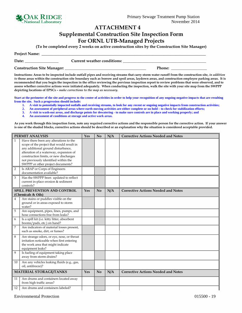
Primary Sewage Treatment Pump Station November 2014
Environmental Protection 015500 - 19
ATTACHMENT 4 Supplemental Construction Site Inspection Form
For ORNL UTB-Managed Projects (To be completed every 2 weeks on active construction sites by the Construction Site Manager)
Project Name: ___________________________________________________________________________________
Date: _________________ Current weather conditions: __________________________________________
Construction Site Manager: _________________________________________ Phone: __________________ Instructions: Areas to be inspected include outfall pipes and receiving streams that carry storm water runoff from the construction site, in addition to those areas within the construction site boundary such as borrow and spoil areas, laydown areas, and construction employee parking areas. It is recommended that you begin the inspection in the office reviewing the pervious inspection report to review problems that were observed, and to assess whether corrective actions were initiated adequately. When conducting the inspection, walk the site with your site map from the SWPPP depicting locations of EPSCs – make corrections to the map as necessary. Start at the perimeter of the site and progress to the center of activities in order to help your recognition of any ongoing negative impacts that are resulting from the site. Such a progression should include:
1. A visit to potentially impacted outfalls and receiving streams, to look for any recent or ongoing negative impacts from construction activities; 2. An assessment of peripheral areas where earth moving activities are either complete or on hold – to check for stabilization efforts; 3. A visit to wash-out areas, and discharge points for dewatering - to make sure controls are in place and working properly; and 4. An assessment of conditions at storage and active work areas.
As you work through this inspection form, note any required corrective actions and the responsible person for the corrective action. If your answer is one of the shaded blocks, corrective actions should be described or an explanation why the situation is considered acceptable provided. PERMIT ANALYSIS Yes No N/A Corrective Actions Needed and Notes 1 Have there been any alterations to the
scope of the project that would result in any additional ground disturbance, alteration of a waterway, expansion of construction limits, or new discharges not previously identified within the SWPPP or other project documents?
2 Is ARAP or Corps of Engineers documentation available?
3 Has the SWPPP been updated to reflect current in-place erosion & sediment controls?
SPILL PREVENTION AND CONTROL (Chemicals & Oils)
Yes No N/A Corrective Actions Needed and Notes
4 Are stains or puddles visible on the ground or in areas exposed to storm water?
5 Are equipment, pipes, lines, pumps, and hose connections free from leaks?
6 Is a spill kit (i.e. kitty litter, absorbent booms/pads, etc.) on hand?
7 Are indicators of material losses present, such as smoke, dirt, or fumes?
8 Are strange odors, or eye, nose, or throat irritation noticeable when first entering the work area that might indicate equipment leaks?
9 Is fueling of equipment taking place away from storm drains?
10 Are any vehicles leaking fluids (e.g., gas, oil, antifreeze)?
MATERIAL STORAGE/TANKS Yes No N/A Corrective Actions Needed and Notes
11 Are drums and containers located away from high traffic areas?
12 Are drums and containers labeled?

Primary Sewage Treatment Pump Station November 2014
Environmental Protection 015500 - 20
13 Are chemical or oil products located on-site secondarily contained (if stored in 55-gal or greater sized volume container)?
14 Are all materials that are potential storm water contaminants protected from storm water?
15 Are containers closed to prevent exposure of contents to storm water?
PAINTING ACTIVITIES Yes No N/A Corrective Actions Needed and Notes
16 Are paint wastes protected from exposure to storm water (e.g., is painting equipment handled/cleaned so as to prevent releases of paint/rinsewater to storm drains or streams)?
LAYDOWN AREAS Yes No N/A Corrective Actions Needed and Notes
17 Is there at least a 60-foot minimum buffer zone between the laydown area and the nearest stream?
STABILIZATION PRACTICES: Yes No N/A Corrective Actions Needed and Notes Includes temporary and permanent seeding, mulching, geotextiles, sod stabilization, vegetative buffer strips, protection of trees,
and preservation of mature vegetation. 18 Are there any occurrences of
uncontrolled concentrated flow or gullying (undermining ground covers/blankets, etc)?
19 Has final stabilization in vegetated areas occurred (at least 70% germination/coverage and no bare spots)?
RUNOFF CONTROL & MANAGEMENT:
Yes No N/A Corrective Actions Needed and Notes
Includes BMPs such as check dams, dewatering treatment practices, diversion, outlet protection, slope drains, & rip rap channels.
20 Are there any signs of scouring around the sides or toe of any control measure?
SEDIMENT CONTROLS: Yes No N/A Corrective Actions Needed and Notes Includes construction exits, sediment basins and traps, silt fences, inlet protection, tubes and wattles, & chemical flocculants.
21 Are there signs of mud being tracked into the streets?
22 Are there any signs of unstable slopes or drainage problems with sediment basins?
23 Are there any signs of scouring or bypassing the sediment basin or trap?
OTHER POLLUTION PREVENTION: Yes No N/A Corrective Actions Needed and Notes Includes concrete washout areas, vehicle maintenance areas, chemical storage, and general housekeeping.
24 Is there any evidence of concrete washout in areas other than what has been designated in the SWPPP and approved by the Company?
25 Are provisions made to de-chlorinate potable or other water used to sterilize or flush pipelines and are these provisions approved by the Company?

Primary Sewage Treatment Pump Station November 2014
Environmental Protection 015500 - 21
STREAM PROTECTION: Yes No N/A Corrective Actions Needed and Notes This includes stream-side buffer zones, stream diversion, and temporary stream crossings to manage work around a stream and
limit/prevent stream damage. 26 Are disturbances to the vegetation
within the buffer zone (except as allowed by ARAP permits and approved project plans) being avoided?
27 Are buffer zones and construction limits clearly marked?
28 Are provisions of all applicable ARAPs being followed?
Additional information and actions taken to replace or repair inadequate control measures or control measures in disrepair:
Based on this inspection, if the site description in the Storm Water Pollution Prevention Plan or any pollution prevention measure identified in the Storm Water Pollution Prevention Plan needs to be revised, the revision to the plan shall be done within 7 days of this inspection, and revisions to control measures shall be implemented within 14 days of this inspection.
End of inspection form

This page intentionally left blank.

Primary Sewage Treatment Pump Station November 2014
Demolition Waste Management and Disposal 017419 - 1
SECTION 017419 – DEMOLITION WASTE MANAGEMENT AND DISPOSAL
PART 1 - GENERAL
1.1 RELATED SECTIONS
A. Specification Section 010100, General Work Requirements.
B. Specification Section 011100, Safety and Health.
C. Specification Section 015500, Environmental Protection.
1.2 ATTACHMENTS
A. Attachment 1, Oak Ridge Reservation Master Profile S-010, Rev 3, Construction/Demolition Waste, Effective 10/01/2012.
B. Attachment 2, Oak Ridge Reservation Master Profile S-050, Rev 3, Spoil Materials, Effective 10/01/2012.
C. Attachment 3, Oak Ridge Reservation Master Profile S-040, Rev 5, Special Waste, Effective .
D. Attachment 4, Special Waste Checklist.
E. Attachment 5, Landfill Prohibited Waste Items.
1.3 REFERENCES
A. Environmental Protection Agency (EPA) 40 CFR 260 – 280 and TN Rule 1200-1-11-.01.
B. The EPA, National Emission Standards, Hazardous Air Pollutants, 40 Code of Federal Regulations (CFR) 61 and Tennessee (TN) Rules 1200-2-8-.01, Fugitive Dust, and 1200-3-11-.02, Asbestos.
C. Solid Waste Processing and Disposal, TN Rule 1200-1-7.
D. The 29 CFR 1926.1101.

Primary Sewage Treatment Pump Station November 2014
Demolition Waste Management and Disposal 017419 - 2
1.4 SUBMITTALS
A. Submit the Hazard Analysis (HA) in accordance with Section 011100. The HA shall include language identifying potential environmental and waste management hazards associated with tasks within the project scope of work and appropriate controls for mitigation of those hazards. Whenever additional tasks and/or hazards are identified within the scope of work, the HA shall be updated to address the new tasks and/or changed conditions.
1.5 DEFINITIONS
A. Resource Conservation and Recovery Act (RCRA) hazardous waste: any discarded material that is not excluded by 40 CFR Part 261.4(a) and that is listed in 40 CFR Subpart D or exhibits any of the characteristics identified in 40 CFR 261 Subpart C.
B. Sanitary waste: waste generated by offices, cafeteria, medical facilities and laboratories, and includes textile products (personal protective equipment [PPE], coveralls, cotton items, carpet, etc.).
C. Special waste: wastes that are either difficult or dangerous to manage such as friable or non-friable asbestos, empty aerosol or paint containers, petroleum contaminated soil, bulk product polychlorintated biphenyl (PCB) waste, PCB remediation wastes, etc.
D. Construction waste: building and site improvement materials and other solid waste resulting from construction, remodeling, renovation, or repair operations. Construction waste includes packaging.
E. Demolition waste: building and site improvement materials resulting from demolition or selective demolition operations.
F. Disposal: removal off-site of demolition and construction waste and subsequent recycling, reuse, or deposit in landfill or incinerator acceptable to authorities having jurisdiction.
G. Recycle: recovery of demolition or construction waste for subsequent processing in preparation for reuse.
H. The PCB waste: waste subject to PCB disposal requirements defined in Toxic Substances Control Act (TSCA) of 1976 as defined in 40 CFR 761.
1.6 TRAINING
A. The Sellers, their subcontractors and all employees who use hazardous materials and may generate or handle a hazardous waste, must provide evidence of having received RCRA Hazardous Waste Awareness Training and annual refresher training as required by 40 CFR 265.16 and 262.34 prior to starting any work involving these items.

Primary Sewage Treatment Pump Station November 2014
Demolition Waste Management and Disposal 017419 - 3
B. Prior to the transport of friable asbestos, truck drivers shall provide evidence of a valid medical card and Class-A Commercial Driver’s License (CDL) with HazMat endorsement.
1.7 REQUIREMENTS TO COMPLY WITH APPLICABLE LAWS AND REGULATIONS
A. The Seller shall provide written proof of registration, licensing, insurance, or other requirements upon request. It is the Seller’s responsibility to ascertain and comply with all applicable federal, state, local and multi-jurisdictional laws, ordinances, and regulations pertaining to the registration, licensing, handling, transportation, packaging, management, processing, resale and disposal of these materials under this contract. These federal, state, and local laws include but are not limited to the Clean Air Act; the TSCA; the Atomic Energy Act; the Comprehensive Environmental Response, Compensation and Liability Act; the Hazardous Materials Transportation Regulations; the Federal Motor Carrier Safety Regulations; the TN Motor Vehicle Laws Annotated; the Emergency Planning and Community Right-to-Know Act, 40 CFR 279; and Tennessee Department of Environment and Conservation (TDEC) Rule Chapter 1200-1-11-.11.
PART 2 - WASTE MANAGEMENT
2.1 WASTE MANAGEMENT REQUIREMENTS
A. The Seller removal of Oak Ridge Reservation (ORR) landfill prohibited wastes must precede all excavation/demolition work.
B. The following items are prohibited from disposal at the ORR landfill and must be removed from the buildings and affected areas prior to excavation/demolition. Instructions for managing the ORR landfill prohibited wastes are provided in Part 2.2 of this section.
1. Radioactive waste.
2. Universal waste.
3. The RCRA hazardous wastes (including but not limited to mercury, lead, lead based paint chips, dust and debris).
4. The all light ballasts (containing PCB and di ethylhexyl phthalate [DEHP])
manufactured prior to 1992. Consult the Company Waste Services Representative prior to removal of ballasts to determine the disposition pathway.
5. Free liquids.
C. The Seller is responsible for gross segregation of all waste items into the following potential categories as shown in Figure 1.

Primary Sewage Treatment Pump Station November 2014
Demolition Waste Management and Disposal 017419 - 4

Primary Sewage Treatment Pump Station November 2014
Demolition Waste Management and Disposal 017419 - 5
1. Special (asbestos and respiratory hazard) waste – special wastes are wastes that are either difficult or dangerous to manage such as friable or non-friable asbestos, respiratory hazards (includes fiberglass with loose fibers), empty aerosol or paint containers, petroleum contaminated soil, etc. Care must be taken to avoid mixing waste type, as some disposal requirements vary from one waste type to another. Coordinate the removal of these materials with the Construction Field Representative (CFR). Attachment 3 provides the ORR landfill waste acceptance criteria for special waste. The Seller’s Supervisor shall personally inspect each load of Special Waste and complete the Special Waste Checklist (Attachment 4) for each load of special waste, and provide the checklist to the driver along with the green tag before the load leaves the project site.
2. Universal wastes – mercury thermostats, batteries, and lamps/bulbs will be
recycled by the Company’s approved vendor. The Company will provide containers and instructions for the Seller accumulation of these items.
3. Scrap metal for recycle – all scrap metal must be collected for the Company’s
approved metal recycle vendor. Both ferrous and nonferrous metals can be collected in the same secure container. Brass, bronze, and lead should be collected separately. Printed circuit boards should be collected in cardboard boxes. Copper wire should be collected separately. The Company will provide scrap metal accumulation containers. INSULATED PIPING CANNOT BE RECYCLED and should be sent to the landfill.
Note: The Seller should not add items with free-flowing oil to the Company’s scrap metal containers. Coordinate the disposal of oily items with the Company.
4. Salvageable materials – all excess property and salvaged materials must be
processed by the Company’s Excess Property Group before leaving the site, and the Company will provide assistance with this process. It is the Seller’s responsibility to protect the property from pilferage and damage until it has been transported to the excess property/salvage area.
5. Radiological-Contaminated wastes streams – all radiological-contaminated
materials excluding Naturally Occurring Radioactive Materials (NORM). All packaging of radiological wastes will be done in the Company-provided containers. Waste packaging will be performed by the Seller under the supervision of the Company.
6. Sanitary waste – sanitary wastes are wastes generated by offices, cafeteria,
medical facilities and laboratories, and include textile products (PPE, coveralls, cotton items, carpet, etc.), and green tagged metals from Radioactive Materials Management Areas (RMMAs). The Seller shall bag garbage and deposit daily in the Company’s dumpster.
Note: Where feasible, collect ALUMINUM CANS, PAPER, and CARDBOARD for RECYCLE. The Company will provide collection containers.
Primary Sewage Treatment Pump Station November 2014
Demolition Waste Management and Disposal 017419 - 6
7. Construction/Demolition debris – these are wastes that result from construction, remodeling, repair and demolition of structures, and from road building or repair. These wastes include lumber, plastic, siding, paneling, flooring, windows, doors, and miscellaneous building demolition materials, brick, concrete, masonry materials, polyvinyl chloride (PVC) material, sheetrock/gypsum board, roofing materials, siding, paneling, flooring, and miscellaneous metals associated with demolition, windows, door, and miscellaneous building demolition materials. Attachment 1 provides the ORR landfill waste acceptance criteria for construction debris.
8. Spoil materials – uncontaminated excavated earth not used for fill, rock, gravel,
road spoils, rebar (embedded in concrete), paving material, and clay material. Spoil materials will be sent to the ORR landfill of Clear Spring Road. Attachment 2 provides the ORR landfill waste acceptance criteria for spoil materials. The general requirements for loading and transportation of spoil materials at the Oak Ridge National Laboratory (ORNL) project site are outlined in Part 2.3 of this section.
9. Prohibited items – special handling requirements for managing prohibited items
is provided in Part 2.2 of this section and a complete list of these items for the ORR landfill is provided in Attachment 5 of this section. The Company will ensure the proper management and disposal of these wastes and should be notified whenever items on the list are generated.
D. The Seller is responsible for ensuring that waste is sized so that it does not get stuck in transportation vehicles. Bulky items, i.e. pipe, concrete foundations, large storage tanks, structural steel, etc., must be less than 8’ in length in order to permit safe handling with ORR landfill equipment.
E. If radiological materials are encountered during demolition, the Company will be responsible for the overall management and direction of the Seller’s packaging operations on radioactive waste. The Company will manifest radioactive wastes, RCRA hazardous, and/or PCB waste. Waste from cleanup of spills may require being managed as a special or a hazardous waste. The Company will make this determination.
F. Waste oils will be recycled through the Company’s off-site contractor unless a condition exists that prevents recycling and/or the used oil must be disposed of as a hazardous waste. The Company will make this determination and will manage the oil appropriately.
G. Instructions for managing ORR landfill eligible waste and the special handling requirements associated with each category of eligible wastes are provided in Part 2.3 of this section.
H. The Company will perform the duties of the generator on behalf of the Seller. The Company’s EPA identification (ID) number will be listed on all manifests and records for any hazardous waste being sent off-site for disposal.
I. Any materials (solvents, paint, etc.) brought on-site by the Seller will be removed by the Seller at the completion of the project INCLUDING EMPTY CONTAINERS, AND PARTIALLY FULL CONTAINERS.

Primary Sewage Treatment Pump Station November 2014
Demolition Waste Management and Disposal 017419 - 7
J. The Company will prepare Special Waste Evaluation Applications; will pay the associated fees; and coordinate the reviews with TDEC, if applicable.
K. The Company will assign and manage an area for interim storage of RCRA/TSCA waste-containing drums, universal waste, and recyclable materials.
L. When a RCRA 90-day area has been established within the project boundary, the Company will be responsible for providing any necessary secondary containment and will provide covers/tarps for all drums within the 90-day area. If roll off or other open top containers are used for RCRA waste, the Company will provide the necessary tarps.
M. When a RCRA 90-day area has been established within the project boundary, the Seller shall ensure that all covers/tarps (with no holes, tears, or rips present) are in place over drums/small containers staged in the area. For roll off or larger open top containers, the Seller shall ensure the tarps are installed properly and any holes/rips in the tarps are repaired in-place. These actions shall be accomplished at the end of each work day and prior to any rain event. The Seller shall also ensure that secondary containment does not contain any liquids. The Seller shall promptly notify the Company of any observations of liquids in secondary containment.
N. The Seller shall provide containers and/or transport vehicles for ORR landfill eligible waste.
O. The Seller shall provide containers and transport vehicles for solid waste generated by activities other than demolition (e.g. trash and garbage). The Seller shall transport waste off government property and dispose of it in compliance with federal, state, and local requirements for solid waste disposal.
P. The Seller shall ensure the provision of respirators and PPE for personnel transporting waste to the ORR landfill.
Q. The Seller shall provide all of the materials (including bulk and non-bulk containers) required for the packaging, labeling, marking, and transportation of non-rad/non-hazardous wastes (including special wastes) to the ORR landfill in conformance with Department of Transportation (DOT) standards.
2.2 RECYCLING CONSTRUCTION/DEMOLITION WASTE
A. No recycle options are available for materials being removed from a radiological area except as defined in Section 2.1.
B. Metals: separate metals by type.
1. Structural steel: stack members according to size, type of member, and length.
2. Remove and dispose of bolts, nuts, washers, and other rough hardware. Recycle if able to be “green-tag surveyed”. No inaccessible surfaces allowed.
C. Packaging: recycle the items below only if used in non-radiological areas.

Primary Sewage Treatment Pump Station November 2014
Demolition Waste Management and Disposal 017419 - 8
1. Cardboard and boxes: break down packaging into flat sheets. Bundle and store in a dry location.
2. Polystyrene packaging: separate and bag materials.
3. Pallets: as much as possible, require deliveries using pallets to remove pallets from the site. For pallets that remain on-site, disposition per the direction of the CFR (e.g. deliver to Excess Property Sales, break down and deliver to burn pile, etc.).
4. Crates: break down crates into component wood pieces and comply with requirements for recycling wood.
2.3 MANAGING ORR LANDFILL PROHIBITED WASTES
A. Landfill prohibited wastes are identified in Attachment 5 of this section.
B. The Seller shall request a radiological survey prior to attaching labels and green tags on all containers.
C. Free liquids.
1. Pumps and motors shall have plugs removed and water and oil drained prior to disposal. Hoses shall be cut and drained. All piping (e.g. fire protection and chilled water systems) shall be drained of free liquids.
2. Collect in containers provided by the Company. Always have 3” to 5” of empty
space above volume of material when using drums for packing.
3. Provide identification of material added to containers (using log sheets) to permit safe opening, storage and handling by the Company.
4. Label each drum to identify the type of waste and the date the drum was filled
and request survey of the container before removing it from the building.
5. Deliver green tagged containers to the Company designated RCRA Accumulation Area.
2.3 CONTROL AND DISPOSAL OF ORR LANDFILL ELIGIBLE WASTE
A. Construction/Demolition (C/D) waste.
1. Remove C/D waste from the buildings and segregate from other wastes whenever possible.
2. The C/D wastes are wastes, typically other than special wastes, resulting from construction, remodeling, repair and demolition of structures, and from road construction and repair including, but not limited to:

Primary Sewage Treatment Pump Station November 2014
Demolition Waste Management and Disposal 017419 - 9
a. Bricks. b. Concrete and other masonry materials. c. Soil. d. Rock. e. Lumber. f. Road spoils. g. Rebar. h. Paving materials. i. Vitrified clay materials (tile, pipe, block, etc.). j. The PVC pipe. k. Polyethylene sheeting. l. Sheetrock/Gypsum board. m. Roofing materials. n. Styrofoam and neoprene insulation materials. o. Building siding materials. p. Paneling. q. Flooring. r. Miscellaneous metals associated with building demolition. s. Window and door glass associated with building demolition.
3. Bulk handling and transport of C/D wastes:
a. Size and load the waste into the waste delivery vehicles in such a manner to prevent the waste from becoming lodged in waste delivery vehicles and containers (i.e., dump truck beds, dump trailers, roll-off containers) during the dumping operations. The Seller shall be responsible for safely removing and clearing lodged materials from the waste delivery vehicles/containers and all associated costs.
b. Waste delivery vehicles shall not be leaking fluids. c. It is recommended that wastes be delivered in vehicles that are self-
dumping/unloading. If it is absolutely necessary to deliver bulky and containerized wastes on flatbed trucks or trailers, the waste generator shall minimize the generation of such containerized and bulky wastes and shall perform advance coordination with the Landfill Operations Manager for the unloading.
d. All containers intended for disposal must be greater than 90% full (less than 10% void) except for 55 gallon or smaller containers, which can be safely compacted with landfill equipment.
4. Refer to Master Waste Profiles S-010 for C/D Waste, Attachment 1.
B. Spoil material waste.
1. Remove spoil material and segregate from other wastes whenever possible.
2. Spoil materials are earthen clean/non-contaminated materials, typically other than special wastes, resulting from construction, and demolition of structures, and from road construction and repair including, but not limited to:
a. Gravel. b. Soil.

Primary Sewage Treatment Pump Station November 2014
Demolition Waste Management and Disposal 017419 - 10
c. Rock. d. Concrete. e. Brick. f. Cinder/Concrete blocks. g. Clay products (tile, pipe, etc.). h. Asphalt pavement.
3. Bulk handling and transport of spoil material wastes:
a. Size and load the waste into the waste delivery vehicles in such a manner to prevent the waste from becoming lodged in waste delivery vehicles and containers (i.e., dump truck beds, dump trailers, roll-off containers) during the dumping operations. The Seller shall be responsible for safely removing and clearing lodged materials from the waste delivery vehicles/containers and all associated costs.
b. Waste delivery vehicles shall not be leaking fluids. c. It is recommended that wastes be delivered in vehicles that are self-
dumping/unloading. If it is absolutely necessary to deliver bulky and containerized wastes on flatbed trucks or trailers, the waste generator shall minimize the generation of such containerized and bulky wastes and shall perform advance coordination with the Landfill Operations Manager for the unloading.
d. All containers intended for disposal must be greater than 90% full (less than 10% void) except for 55 gallon or smaller containers, which can be safely compacted with landfill equipment.
e. Refer to Master Waste Profiles S-050 (Attachment 2) for disposition of spoil material waste at the ORR landfill.
f. Specific instructions dealing with waste identification, transportation and logistics will be provided to subcontractor’s field supervisor and truck drivers in a field briefing prior to start of work.
C. Category I non-friable asbestos (refer to Attachment 3; Master Waste Profile S-040):
1. The prohibited items for C/D waste, with the exception of Category I non-friable asbestos, still apply for this category (see Attachment 5 of this section for a comprehensive listing of landfill prohibited items).
2. Bulk handling and transport of Category I non-friable material (refer to
Attachment 3; Master Waste Profile S-040, Attachment 3-3 for specific packaging instructions) is permissible as follows:
a. Non-Dedicated use dump trucks, inter-modals, roll-off containers, and
similar transport containers requires entire load be wrapped with a single layer (minimum) of 6-mil thick plastic sheeting no later than the end of each work shift.
b. Dedicated use dump trucks, inter-modals, roll-off containers, and similar transport containers do not require plastic sheeting if the containers are dust tight and leak tight via closed gasket doors and closed tarps or metal covers/lids.

Primary Sewage Treatment Pump Station November 2014
Demolition Waste Management and Disposal 017419 - 11
c. Bundled/Stacked transite panels require each bundle to be wrapped, closed, and sealed in a single (minimum) layer of 6-mil thick plastic sheeting no later than the end of each work shift.
d. The label or tag describing the contents of each container must include the following words:
Non-friable Asbestos
DANGER CONTAINS ASBESTOS FIBERS
AVOID CREATING DUST CANCER AND LUNG DISEASE HAZARD
e. The packaged wastes shall be transported to the landfill in such a manner
to prevent airborne releases or the loss of the waste. f. Unloading shall be done carefully to keep the materials in the wrapping
as much as possible and to maintain the non-friability of the asbestos containing material (ACM).
3. Respiratory protection is required when personnel are within 100’ of disposal
activities of these wastes. 4. Provide verbal notification and coordination/concurrence with the ORR Landfill
Operations Manager at 865-574-6905 at least one working day prior to the delivery of these wastes.
5. Return copies of date-stamped Universal Control Number (UCN)-2109 and
original Asbestos Work Authorization (AWA) form to the Asbestos Program Manager (APM).
D. Regulated ACM (RACM) includes friable asbestos: Category I non-friable ACM that has become friable or has become subjected to sanding, grinding, etc.; and Category II non-friable that has a high probability of becoming or has become crumbled, pulverized, or reduced to powder by the forces expected to act on the material in the course of the demolition or renovation operations (refer to Attachment 3; Master Waste Profile S-040, Attachment 3-1 for definitions).
1. Bulk handling and transport of RACM (refer to Attachment 3; Master Waste
Profile S-040, Attachment 3-2 for specific packaging instructions) as follows:
a. Dump trucks, flatbed trucks, roll-bins, or similar vehicles shall be double-lined with 6-mil thick plastic sheets.
b. Place waste in the lined vehicle/container and the loose edges of the plastic sheets shall be lapped over the top of the waste and sealed.
c. Label the containers or wrapped friable ACM with the following warning labels in accordance with 29 CFR 1926.1101:
US DOE, ORNL, Bldg. No.___
DANGER CONTAINS ASBESTOS FIBERS
AVOID CREATING DUST CANCER AND LUNG DISEASE HAZARD

Primary Sewage Treatment Pump Station November 2014
Demolition Waste Management and Disposal 017419 - 12
d. The packaged wastes shall be transported to the landfill in fully enclosed space or fully covered by a secure tarpaulin to prevent airborne releases or the loss of the waste.
e. Unloading shall be done carefully to keep the materials in the wrapping. 2. Respiratory protection is required when personnel are within 100’ of asbestos
containing waste material (ACWM) disposal activities.
3. Return copies of Bill of Lading, Waste Shipment Record (WSR), date-stamped UCN-2109 forms along with original AWA form to the APM.
E. Beryllium-Contaminated waste: Beryllium Oxide (BeO) waste, including wood, paper, clothing, piping, metal, equipment, and demolition material that is contaminated with BeO.
1. Package waste in tightly sealed, double-bagged, 6-mil thick plastic bags, double-
bagged 6-mil thick plastic sheeting, fiber drums, metal drums or plywood boxes.
2. Each package shall be labeled (or equivalent) as shown below [“Danger” is in white on a red oval, which is imposed on a larger white oval on a place rectangle. The text is black on a white background. The border is black.]:
DANGER
CONTAMINATED WITH BERYLLIUM, DO NOT REMOVE DUST BY BLOWING OR
SHAKING CANCER AND LUNG DISEASE HAZARD
3. Waste shipment shall be accompanied by a UCN-2109 form and a
Generator’s/Shipper’s Log for Beryllium Oxide Removal and Disposal, to be completed by the Company for each waste load.
4. If the waste is bagged, it shall be transported in a fully enclosed space or fully
covered by a secured tarpaulin.
5. Respiratory protection is required when personnel are within 100’ of disposal activities of these wastes.
F. Respiratory Hazard (RH) waste includes fiberglass with loose fibers, refractory ceramic fibers, mineral wools, slag wools, rock wools, and other manmade fiber materials and silica. (Refer to Attachment 14 of the Master Waste Profile S-040 Rev. 4.)
1. These materials may be wet down prior to removal activities to reduce
concentration of airborne fibers and materials for the protection of employees. Wastes containing these materials that do not create potential respiratory hazards (for example: solid fiberglass items, wool fibers that are bound in asphalt roofing shingles) will not be subject to the following requirements.
2. These wastes will be packaged and tightly sealed in single bagged 6-mil thick plastic bags, single wrapped in 6-mil thick plastic sheets (piping, equipment, etc.), fiber drums, metal drums, plywood boxes or metal boxes.

Primary Sewage Treatment Pump Station November 2014
Demolition Waste Management and Disposal 017419 - 13
3. No specific labeling requirements for RH waste.
4. The packaged wastes will be transported to the landfill in such a manner to prevent airborne release or loss of the waste.
5. All handling and unloading shall be performed carefully to avoid rupturing of the packaging and shall be the responsibility of the waste generator/transporter. If assistance is needed, such as with the all-terrain fork truck, the generator must verbally coordinate this with the Landfill Operations Manager (865-574-6905) at least one working day in advance of the delivery. The landfill can assist, but must have prior notification from the Company.
2.4 FRIABLE ASBESTOS TRANSPORTATION REQUIREMENTS
A. Notify the CFR no later than 10:00 a.m. each Monday to arrange deliveries of RACM to the ORR landfill.
B. Provide the following information:
1. Intended date of delivery. 2. Number of bulk loads to be delivered.
3. Quantities of each load in cubic feet or cubic meter.
4. Name, address, and phone number of carrier.
5. Names of truck drivers who will deliver the waste.
C. The APM will begin preparation of the WSR which is required for transport on public highway.
G. Notify the APM to complete an inspection of the load while the containers are still at the job-site.
H. The truck driver shall perform the following:
1. Before leaving the job-site, the driver shall have respirator in vehicle. 2. Pick up the containerized load from the job-site. Company Radiation Control
Technician (RCT) or CFR will issue green-tag for each load of waste. After survey, proceed to ORNL Building 7013.
3. Proceed through radiation monitor, if available, following posted instructions.
4. Present green tag to the Company Waste Handler on duty (Room 6).
5. Sign paperwork provided by Company Waste Handler and obtain a date stamped
copy of the UCN-2109 and original green tag.

Primary Sewage Treatment Pump Station November 2014
Demolition Waste Management and Disposal 017419 - 14
6. Sign and copy the WSR as directed by the APM or designee to accept responsibility for the load.
7. Take load and documents (UCN-2109 form, original green tag, signed WSR, and
any other paperwork provided by the Company Waste Handler or APM) to ORNL Building 7001 to initiate DOT inspection. Truck drivers shall provide evidence of a valid medical card and Class-A CDL with hazardous material endorsement.
8. Present paperwork to shipping personnel in the office area of the shipping area.
9. Sign Bill of Lading and obtain driver’s copy.
10. Proceed to Building 9616-11 at the ORR landfill with all documentation obtained
from the Company and follow directions provided by the ORR landfill staff.
11. Return copies of Bill of Lading, WSR, date-stamped UCN-2109 form, along with original AWA form to the APM.
2.5 ORR LANDFILL INFORMATION
A. Disposal at the ORR landfill (formerly known as the Y-12 landfill) will be free of charge to the Seller according to the following schedule for non-hazardous, non-radiological demolition waste and construction debris generated at ORNL facilities: Monday: 07:30 – 10:00 Landfill V 10:00 – 13:00 Landfill VII 13:00 – 15:00 Landfill V Tuesday: No waste receipts. Wednesday: 08:00 – 10:45 Landfill VII 12:00 – 12:15 Landfill VII* 12:15 – 14:30 Landfill V Thursday: 12:00 – 12:15 Landfill VII* 12:15 – 14:30 Landfill V *Landfill VII loads for these periods must be at the Truck Receiving Station by noon and must be scheduled with the ORR Landfill Operations Manager. Loads must be in dump-type trucks and may not be “special cell” wastes.
B. Provide verbal notification and coordination/concurrence with the ORR Landfill Operations Manager at 865-574-6905 at least one working day prior to the delivery of a newly approved special waste or a special waste that is not routinely delivered to the ORR landfill.
Primary Sewage Treatment Pump Station November 2014
Demolition Waste Management and Disposal 017419 - 15
C. Provide verbal notification and coordination/concurrence with the ORR Landfill Operations Manager at 865-574-6905 at least one working day prior to the delivery of friable asbestos waste, non-friable asbestos waste or respiratory hazard waste.
D. Respiratory protection is required when personnel are within 100’ of disposal activities of asbestos, beryllium, and respiratory hazard wastes (including fiberglass and loose fibers).
E. This includes activities such as opening and closing the doors on asbestos roll-offs before
and after dumping, and all manual handling of potentially respirable waste materials.
F. Personnel stationed within a closed-cab vehicle with all doors, windows, and openings closed are not required to wear respirators. Respirators must be present in the cab and available for use by trained personnel should the need arise to exit the vehicle.
G. All personnel on the ground of any active ORR landfill must wear: high visibility apparel (i.e. highly reflective vests); safety glasses; safety shoes; and hard hats. Also, cell phone use is prohibited on the ORR landfill property.
H. Bulky items, i.e. pipe, concrete foundations, large storage tanks, structural steel, etc., must be less than 8’ in length in order to permit safe handling with ORR landfill equipment.
I. The UCN-2109 forms approved by the ORR landfill Operations Office are the primary “ticket” to gain access to the ORR landfill. The Company will complete the required UCN-2109 form set for each waste stream intended for ORR landfill disposal, and initiate the review cycle required by the ORR Landfill Acceptance Manager.
J. The approved UCN-2109 forms will be available at ORNL Building 7013 (the inspection site), and each load of waste intended for ORR landfill disposal must stop at Building 7013 for inspection, monitoring, and collection of forms before leaving ORNL.
K. Each load of waste delivered to the ORR landfill must be accompanied by a RADCON green tag. The Seller field supervision will be responsible for writing the correct UCN-2109 number on each green tag prior to the load leaving the project site. Copies of the approved UCN-2109’s will be proved to the Seller at the field briefing prior to the start of work.
L. All waste material must pass through the Vehicle Portal Monitor (Building 7013) and will be subject to random inspection and RADCON survey.
M. Any waste delivered to the ORR landfill that does not meet the waste acceptance criteria, is not packaged properly, is not labeled properly, or where required notification has not been given, is subject to rejection by the ORR landfill operator. If the delivery is rejected, the Seller shall immediately notify the Company and remain at the ORR landfill for further instructions.
END OF SECTION

ORR WASTE CERTIFICATION PROGRAM DOCUMENT CONTROL SYSTEM
If you print the following document, this page must be attached to the front of the document and you must fill in the information required below. The attached document was printed from a controlled website and is valid until the revision number changes. The user is responsible for checking that the revision number of the printed document matches the revision number of the controlled document on the ORR Waste Certification Program website at http://www-orr.ettp.energy.gov/wastecertification.html. Profile Number: S-010, Construction/Demolition Waste Revision Number: 3 Date Printed: Person Checking Revision Number: NOTE: A hard copy of this document is valid only until the revision number has changed on the
website. The hard copy should be signed and dated the day it is printed. If you continue to work from the hard copy, you should verify its accuracy on the website and record the date(s) the document revision number(s) were checked.
If the document is used again, use the space below to document the date(s) the revision number was checked.
ORR Profile S-010, Rev. 3 Page 1 of 7
ATTACHMENT 1
Primary Sewage Treatment Pump Station
November 2014
Demolition Waste Management and Disposal 017419 - 16

ORR Profile S-010, Rev. 3 Page 2 of 7
Key words: Non-Radioactive, Non-RCRA, Non-TSCA, Construction/Demolition PROFILE NAME: Construction/Demolition Waste Profile No.: S-010 Rev. No. : 3, 10/01/12 Effective Date: 10/15/12 UCOR waste generators shall manage and dispose of Construction/Demolition waste intended for disposal in the ORR Landfills, in accordance with the requirements presented in this profile and following documents:
UCOR Waste Management Program Plan, PPD-WM-2400 URS │CH2M Oak Ridge LLC Waste Certification Program Plan, Oak Ridge, Tennessee, UCOR-
4187 Proper characterization of waste is the responsibility of the generator. Signature of the UCN-2109 form (or equivalent, hereinafter referred to as UCN-2109 or 2109) is certification by the Waste Generator that sufficient controls are in place to mitigate the potential for non-conformances against this profile. This certification includes future generated waste where a blanket UCN-2109 is utilized. A. Material Description Construction/demolition wastes are wastes, other than special wastes, resulting from construction, remodeling, repair and demolition of structures, and from road building or repair. Such wastes include, but are not limited to bricks, concrete and other masonry materials, soil, rock, lumber, road spoils, rebar, and paving materials. Construction/demolition wastes are not radioactive and not regulated under RCRA or TSCA. Acceptable routine wastes include: Brick Concrete Masonry materials Soil Rock Gravel Lumber and pallets Road spoils Rebar (embedded in concrete) Paving materials Vitrified clay materials (tile, pipe, block, etc.) PVC pipe Polyethylene sheeting Sheetrock/gypsum board Roofing materials Insulation materials (fiberglass1, rockwool,
styrofoam) Building siding materials Paneling Flooring Miscellaneous metals associated with building
demolition Window and door glass associated with building
demolition Miscellaneous building demolition materials
Construction/Demolition waste from the demolition of an industrial process or treatment process, or resulting from a CERCLA action may require special waste evaluation and approval by TDEC. Refer to Waste Profile S-040, “Special Waste” for guidance regarding acceptance and disposal of special wastes.
1 Fiberglass with loose fibers that is a respiratory hazard shall be disposed as a special waste (see waste profile S-040).
ATTACHMENT 1
Primary Sewage Treatment Pump Station
November 2014
Demolition Waste Management and Disposal 017419 - 17

ORR Profile S-010, Rev. 3 Page 3 of 7
B. Chemical Constituent Limitations Wastes shall not exhibit characteristics of, or be listed as, hazardous waste as identified in the RCRA regulations, and cannot be subject to any RCRA Land Disposal Restrictions. Wastes shall not be a PCB-detectable waste. PCB concentrations shall be less than 2 ppm. Wastes containing PCBs in concentrations exceeding 2 ppm may be acceptable as a special waste under the provisions of Waste Profile S-040. C. Radiological Constituent Limitations The wastes shall meet the following criteria established with TDEC: 1) Specific activity < 35 picocuries of total uranium per gram of waste, or 2) Material that meets the off-site guidelines established in Figure IV-1 of DOE Order 5400.5, “Radiation
Protection of the Public and the Environment,” or 3) Wastes that are known to be nonradioactive by process knowledge (refer to Appendix A for guidance
concerning the use of process knowledge). Wastes exceeding radiological surface release criteria are prohibited from acceptance under this profile. Reference DOE Order 5400.5, “Radiation Protection of the Public and the Environment,” Figure IV-1, Surface Contamination Guidelines. Radioactive wastes are not acceptable for disposal. Wastes containing residual levels of radionuclides other than uranium may be candidates for landfill disposal under the guidelines of waste profile S-040. D. Physical Parameter Limitations 1) No free liquids2
2) The waste form shall have the consistency to be managed and compacted by landfill heavy equipment.
3) Bulky items, i.e., pipe, concrete foundations, structural steel, etc., should be sized to be less than 8 feet in length
to permit safe handling with landfill equipment. For guidance on bulky wastes, the generator should consult with the Landfill Waste Acceptance Manager or the Landfill FacilityManager.
4) Minimize the mixing of waste across the various waste types, i.e., mixing gravel with lumber and pallets. E. Characterization Parameters and Methodology Process knowledge and/or sampling and analysis may be used for categorizing and characterizing solid waste. Process knowledge may include knowledge and historical information of the areas and buildings from which the waste stream was generated, operations/processes that were performed in the areas/buildings from which the waste stream was generated, materials/contaminants that were used/processed/stored in the areas/buildings from which the waste stream was generated, and whether the waste was stored in radiologically contaminated and/or uncontaminated buildings/areas. Sampling and analysis, if used, must identify and quantify the contaminants that are present in the waste. Analyses may be conducted for TCLP constituents, ignitability, corrosivity, reactivity, PCBs, radiological contaminants, and free liquids. If there are other suspected contaminants in the waste stream, the generator must analyze for these as
2 Any waste material that is determined to contain “free liquids” as defined by Method 9095 (Paint and Filter Liquids Test), as described in “Test Methods for Evaluating Solids Wastes, Physical/Chemical Methods” (Environmental Protection Agency [EPA] pub. No. SW-846).
ATTACHMENT 1
Primary Sewage Treatment Pump Station
November 2014
Demolition Waste Management and Disposal 017419 - 18

ORR Profile S-010, Rev. 3 Page 4 of 7
well. Sampling and analysis of the waste shall conform to the requirements of EPA document SW-846, “Test Methods for Evaluating Solid Waste, Physical/Chemical Methods”, or other nationally recognized standards. In reference to volumetric contamination, uranium is the only radionuclide with volumetric criteria established with TDEC for on-site landfill disposal using this profile. Radionuclide data must be reported in picocuries per gram of waste. (dry weight basis) Quantification of uranium isotopes may be accomplished at a TDEC reviewed NDA facility. In regard to the disposal of waste in the on-site landfills, use of TDEC reviewed NDA facilities for surveying waste is only intended for providing verification that waste believed to meet radiological constituent limitations (see Section C) is suitable for disposal in the on-site landfills. Wastes that are known to be low level radioactive waste or radioactive material through process knowledge, radiological survey, or analytical data must not be sent directly or indirectly (i.e. through a TDEC reviewed NDA facility) to the landfill for disposal. F. Prohibited Items If prohibited materials are observed/detected in wastes delivered to the landfill, the waste generator will be notified so that they can retrieve the materials. Prohibited materials will not be accepted. Items prohibited under this profile include: Classified wastes RCRA Hazardous wastes PCB wastes Radioactive wastes Friable asbestos Liquid wastes Garbage and other putrescible materials Waste containing free liquids Waste contaminated with mercury, beryllium, PCBs, or petroleum products, or other chemicals Tires Lead acid batteries Untreated/treated medical wastes Refrigeration equipment not complying with 40 CFR 82.156 Bulk metals Bulk paper Municipal wastes (All solid waste of or relating to being generated by city or local government, or private
ownership be it business or personal.) Industrial wastes (Solid waste produced in, or generated by, industrial or manufacturing processes. This term
does not include commercial, domestic, mining, or hazardous waste regulated under Subtitle C of RCRA, or oil and gas waste.)
Institutional wastes (All solid waste which are not special waste, emanating from institutions such as, but not limited to, hospitals, health care facilities, nursing homes, laboratories, orphanages, correctional institutions, schools, and universities.)
Unapproved special wastes Wastes that are not generated by DOE activities in the Oak Ridge area Drums Paint and adhesive containers Laboratory chemicals Commercial products manufactured with radioactive materials, i.e., smoke detectors, thoriated welding rods,
etc. Landscaping or land clearing wastes G. Packaging Requirements Packaging and labeling shall comply with the applicable Department of Transportation (49 CFR) requirements. Every waste delivery to the ORR Landfills must be accompanied by a UCN-2109 form, which has been reviewed
ATTACHMENT 1
Primary Sewage Treatment Pump Station
November 2014
Demolition Waste Management and Disposal 017419 - 19

ORR Profile S-010, Rev. 3 Page 5 of 7
and approved by the Landfill Facility Manager or the Waste Acceptance Manager. If waste generators have questions regarding delivery of waste to the landfill, contact the Landfill Waste Acceptance Manager or Landfill Facility Manager. Any dumpsters used to deliver waste to the landfill shall have identification numbers or bar codes, and those identification numbers/bar codes shall be clearly reflected on the corresponding UCN-2109 forms. The waste generator shall contact the Landfill Facility Manager if there are questions regarding personal protective equipment and training requirements for delivery personnel. The waste generator shall size and load the waste into the waste delivery vehicles in such a manner to prevent the waste from becoming lodged in waste delivery vehicles and containers (i.e., dump truck beds, roll-off containers) during the dumping operations. The waste generator/transporter shall be responsible for safely removing and clearing lodged materials from the waste delivery vehicles/containers and all associated costs. Waste delivery vehicles shall not leak fluids. It is highly recommended that waste generators deliver wastes in vehicles that are self-dumping/unloading. If it is necessary to deliver wastes on flatbed trucks or flatbed trailers, the waste will be palletized if possible and the generator shall perform advance coordination with the Landfill Facility Manager to confirm that forklift support will be available. Dump trailers (framed and frameless) are prohibited.
H. Additional Requirements Notification is required at least one working day prior to delivery of new waste streams with new UCN-2109 forms from large construction/demolition projects and prior to non-routine deliveries. Notification must include a UCN-2109 form, associated documentation, and delivery schedules prior to shipping to the landfills. The delivery schedule must be agreed to by the Landfill Operations personnel. All wastes delivered to the landfill must pass through the Vehicle Portal Monitor and will be subject to random inspection and radiological survey. The waste generator should contact the Waste Acceptance Manager or Landfill Facility Manager prior to delivery if the waste has elevated levels of naturally occurring radioactivity. Any waste delivered to the landfill is subject to rejection by the landfill operator. If waste is rejected, the reason for rejection will be furnished to the waste generator. In addition, if advance notification of waste delivery is required for the waste and the notification is not provided to the ORR Landfill staff, the waste will be subject to rejection. If waste is rejected, the reason for rejection will be furnished to the waste generator. The waste generator will be responsible for the cost of retrieval, management, and proper disposition of all prohibited wastes delivered to the landfill. If non-conforming/prohibited waste is dumped into the landfill, the waste generator shall be responsible for removal, packaging, transportation, and disposition of non-conforming/prohibited wastes, and all associated costs. The waste generator shall remove all non-conforming/prohibited waste from the ORR Landfills on the same day the non-conforming/prohibited waste is delivered to the ORR Landfills. I. Required Documentation (as applies) Specific requirements are stated for form UCN-2109, Waste Item Description, and UCOR Form 398, Process Knowledge Documentation. These requirements also apply to the corresponding forms UCN-21941, Request for Landfill Disposal, and UCN-21395, Process Knowledge Documentation, which are used by the Y-12 National Nuclear Security Complex, and the ORR Landfill Shipping Form, which is used by UCOR.
ATTACHMENT 1
Primary Sewage Treatment Pump Station
November 2014
Demolition Waste Management and Disposal 017419 - 20

ORR Profile S-010, Rev. 3 Page 6 of 7
1. Completed and signed form UCN-2109, “Waste Item Description.” Every waste delivery to the ORR Landfills must be accompanied by a UCN-2109 form, which has been reviewed and approved by the Landfill Facility Manager or the Landfill Waste Acceptance Manager. The UCN-2109 form shall comply with the following requirements:
1.1. Information on UCN-2109 forms must accurately represent the waste and must be current, complete, and
correct. 1.2. If there is a change in the generating company, the UCN-2109 form must be modified to identify the
correct company and correct generator information and be re-signed by the waste generator, unless otherwise approved by the Waste Acceptance Manager.
1.3. If a radiological “green tag” is used to support the disposition of waste, the waste generator must provide
the green tag number on the UCN-2109 form when the green tag number becomes available or attach the green tag to the 2109.
1.4. Any Special Handling Instructions must be clearly noted on the UCN-2109 form.
2. Completed Form 398 (or equivalent), “Process Knowledge Documentation”. 3. Radiological “green tag”, or Process Knowledge Documentation Form 398 (or equivalent), or analytical data to
clearly show the waste is not a radiological waste. 4. Sampling plans, laboratory data, statistical evaluation of the data, and/or other information that characterizes the
waste.
ATTACHMENT 1
Primary Sewage Treatment Pump Station
November 2014
Demolition Waste Management and Disposal 017419 - 21

ORR Profile S-010, Rev. 3 Page 7 of 7
APPENDIX A
USE OF PROCESS KNOWLEDGE FOR RADIOLOGICAL RELEASE OF MATERIAL TO U. S. DEPARTMENT OF ENERGY (DOE) LANDFILLS
Process knowledge (PK) is a tool used to aid the characterization of waste generated by DOE activities in the Oak Ridge area. PK is not used as a stand alone process. PK is one input into the evaluation of a material. Only a trained member of the radiological organization with input from trained waste generator can determine if an item is releasable from a radiological perspective. The radiological representative will use the signed PK form as an input to the evaluation for release of the material. The following points emphasize how PK is used in the evaluation for the release of materials to the DOE landfills:
PK is not used for the release of materials to DOE landfills if those materials have been generated, used, or
stored within radiologically contaminated areas. All materials released from contaminated areas are surveyed prior to release. Inaccessible internal surfaces that are physically prevented from coming into contact with radiological contamination—such as the internal surfaces of compressed cylinders or aerosol cans—are not required to be surveyed provided all accessible surfaces are found to meet the release criteria.
Materials released to landfills from within radiologically controlled areas must be appropriately characterized to
demonstrate compliance with applicable release criteria prior to release to the landfills. Radiological surveys and/or sampling are the primary means of characterization even for those materials for which the potential for contamination is known to be very low. However, for those materials not originating from radiological contamination areas and for which the potential for contamination is known to be insignificantly small, PK may be used as the basis for releasing these materials to the DOE landfills.
PK requires an equipment or material owner to certify by signature that equipment or material could not
possibly be contaminated based on personal and specific knowledge about the history of the item including its origin, use, and locations of use.
PK may be used to help the Health Physicist or Radiological Engineer determine if equipment and material may
be potentially contaminated. PK does not relieve the Health Physicist or Radiological Engineer from accountability for assuring the material or equipment meets the release limits.
ATTACHMENT 1
Primary Sewage Treatment Pump Station
November 2014
Demolition Waste Management and Disposal 017419 - 22

ORR WASTE CERTIFICATION PROGRAM DOCUMENT CONTROL SYSTEM
If you print the following document, this page must be attached to the front of the document and you must fill in the information required below. The attached document was printed from a controlled website and is valid until the revision number changes. The user is responsible for checking that the revision number of the printed document matches the revision number of the controlled document on the ORR Waste Certification Program website at http://www-orr.ettp.energy.gov/wastecertification.html Profile Number: S-050, Spoil Materials Revision Number: 3 Date Printed: Person Checking Revision Number: NOTE: A hard copy of this document is valid only until the revision number has changed
on the website. The hard copy should be signed and dated the day it is printed. If you continue to work from the hard copy, you should verify its accuracy on the website and record the date(s) the document revision number(s) were checked.
If the document is used again, use the space below to document the date(s) the revision number was checked.
ORR Profile S-050, Rev. 3 Page 1 of 6
ATTACHMENT 2
Primary Sewage Treatment Pump Station
November 2014
Demolition Waste Management and Disposal 017419 - 23

Keywords: Concrete, Soil, Rock, Gravel, Brick PROFILE NAME: Spoil Materials Profile No.: S-050 Rev. No.: 3, 10/01/12 Effective Date: 10/15/12 UCOR generators shall manage and dispose of Spoil Materials intended for disposal in the ORR Landfills, in accordance with the requirements presented in this profile and following documents:
UCOR Waste Management Program Plan, PPD-WM-2400 URS │CH2M Oak Ridge LLC Waste Certification Program Plan, Oak Ridge, Tennessee,
UCOR-4187 Proper characterization of waste and materials is the responsibility of the generator. Signature of the UCN-2109 form (or equivalent, hereinafter referred to as UCN-2109 or 2109) is certification by the generator that sufficient controls are in place to mitigate the potential for non-conformances against this profile. This certification includes future generated waste/materials where a blanket UCN-2109 is utilized.
A. Material Description The intention of this profile is to identify certain earthen clean/non-contaminated materials that do not have to be deposited in a landfill. Placing this type of material in a “spoil area” will save valuable landfill space. Acceptable Spoil Materials are listed below: Gravel Soil Rock Concrete Brick Cinder/concrete blocks Clay products (tile, pipe,etc.) Asphalt pavement B. Chemical Constituent Limitations: Spoil materials shall be clean, non-contaminated materials. If any chemical contamination is suspected, refer to profiles S-010, S-020, S-030, and/or S-040. C. Radiological Constituent Limitations: Spoil materials shall be clean, non-contaminated materials. If any radioactive contamination is suspected, refer to profiles S-010, S-020, S-030, and/or S-040.
ORR Profile S-050, Rev. 3 Page 2 of 6
ATTACHMENT 2
Primary Sewage Treatment Pump Station
November 2014
Demolition Waste Management and Disposal 017419 - 24

D. Physical Parameter Limitations: 1) No free liquids1 2) Spoil materials should be sized to be less than 8 feet in length to permit safe handling with landfill
equipment. For guidance on bulky materials, consult with the Waste Acceptance Manager or Landfill Facility Manager.
E. Characterization Parameters and Methodology: Process knowledge and/or sampling and analysis may be used for categorizing and characterizing spoil material. Process knowledge may include knowledge and historical information of the areas and buildings from which the material was generated, operations/processes that were performed in the areas/buildings from which the material was generated, materials/contaminants that were used/processed/stored in the areas/buildings from which the material was generated, and whether the material was stored in radiologically contaminated and/or uncontaminated buildings/areas. Refer to Appendix A for guidance concerning the use of process knowledge. Sampling and analysis, if used, must identify and quantify the contaminants that may be present in the spoil material. Analyses may be conducted for TCLP constituents, ignitability, corrosivity, reactivity, PCB’s, radiological contaminants, and free liquids. If there are other suspected contaminants in the spoil material, the generator must analyze for these as well. Sampling and analysis of spoil materials shall conform to the requirements of EPA document SW-846, “Test Methods for Evaluating Solid Waste, Physical/Chemical Methods” or other nationally recognized standards. Sampling, analysis and subsequent data review should appropriately characterize/represent the spoil materials. In reference to volumetric contamination, total uranium and other radionuclides must be reported in picocuries per gram of material. Radioactivity must not be greater than background and enrichment must not substantially deviate from natural (0.711 weight percent). Verification that radioactive isotopes are not greater than background must be performed by process knowledge, analysis of representative samples, or scan at a TDEC reviewed NDA facility. In regard to the disposal of material in the on-site spoil area, use of TDEC reviewed NDA facilities for surveying spoil material is only intended for providing verification that spoil material believed to be non-contaminated is suitable for disposal in the on-site spoil area. Materials that are known to be low level radioactive waste or radioactive material through process knowledge, radiological survey, or analytical data must not be sent directly or indirectly (i.e. through a TDEC reviewed NDA facility) to the spoil area for disposal. F. Prohibited Items If prohibited materials are observed/detected in materials delivered to the spoils area, the generator will be notified so that they can retrieve the materials. Prohibited materials will not be accepted. Items prohibited under this profile include: Classified wastes RCRA Hazardous wastes PCB wastes Radioactive wastes Friable asbestos 1 Any spoil material that is determined to contain “free liquids” as defined by Method 9095 (Paint and Filter Liquids Test), as described in “Test Methods for Evaluating Solids Wastes, Physical/Chemical Methods” (Environmental Protection Agency [EPA] pub. No. SW-846).
ORR Profile S-050, Rev. 3 Page 3 of 6
ATTACHMENT 2
Primary Sewage Treatment Pump Station
November 2014
Demolition Waste Management and Disposal 017419 - 25

Liquid wastes Garbage and other putrescible materials Waste containing free liquids Waste contaminated with mercury, beryllium, PCBs, or petroleum products, or other chemicals Tires Lead acid batteries Untreated/treated medical wastes Refrigeration equipment not complying with 40 CFR 82.156 Bulk metals Bulk paper Municipal wastes (All solid waste of or relating to being generated by city or local government, or
private ownership be it business or personal.) Industrial wastes (Solid waste produced in, or generated by, industrial or manufacturing processes.
This term does not include commercial, domestic, mining, or hazardous waste regulated under Subtitle C of RCRA, or oil and gas waste.)
Institutional wastes (All solid waste which are not special waste, emanating from institutions such as, but not limited to, hospitals, health care facilities, nursing homes, laboratories, orphanages, correctional institutions, schools, and universities.)
Wastes that are not generated by DOE activities in the Oak Ridge area Drums Paint and adhesive containers Laboratory chemicals Commercial products manufactured with radioactive materials, i.e., smoke detectors, thoriated welding
rods, etc. Landscaping or land clearing wastes G. Requirements Packaging Packaging shall comply with the applicable Department of Transportation (49 CFR) requirements. Every spoil material delivery to the ORR Landfills must be accompanied by a UCN-2109 form, which has been reviewed and approved by the Landfill Facility Manager or the Waste Acceptance Manager. If generators have questions regarding delivery of materials to the landfill, contact the Landfill Waste Acceptance Manager or Landfill Facility Manager. The generator shall size and load the material into delivery vehicles in such a manner to prevent the material from becoming lodged in delivery vehicles and containers (i.e., dump truck beds, roll-off containers) during the dumping operations. The generator/transporter shall be responsible for safely removing and clearing lodged materials from the delivery vehicles/containers and all associated costs. Delivery vehicles shall not leak fluids. Dump trailers (framed and frameless) are prohibited. The generator shall contact the Landfill Facility Manager if there are questions regarding personal protective equipment and training requirements for delivery personnel. H. Additional Requirements Notification is required at least one working day prior to delivery of new spoil materials with new UCN-2109 forms from large construction/demolition projects and prior to non-routine deliveries. Notification must include a UCN-2109 form, associated documentation, and delivery schedules prior to shipping to the landfills. The delivery schedule must be agreed to by Landfill Operations personnel.
ORR Profile S-050, Rev. 3 Page 4 of 6
ATTACHMENT 2
Primary Sewage Treatment Pump Station
November 2014
Demolition Waste Management and Disposal 017419 - 26

ORR Profile S-050, Rev. 3 Page 5 of 6
All spoil materials delivered to the landfill must pass through the Vehicle Portal Monitor and will be subject to random inspection and radiological survey. The generator should contact the Waste Acceptance Manager or Landfill Facility Manager prior to delivery if the spoils have elevated levels of naturally occurring radioactivity. Any material delivered to the landfill is subject to rejection by the landfill operator. If material is rejected, the reason for rejection will be furnished to the generator. In addition, if advance notification of delivery is required and the notification is not provided to the ORR Landfill staff, the load will be subject to rejection. If loads are rejected, the reason for rejection will be furnished to the generator. The generator will be responsible for the cost of retrieval, management, and proper disposition of all prohibited materials delivered to the landfill. If non-conforming/prohibited items are disposed in the spoils area, the generator shall be responsible for removal, packaging, transportation, and disposition of non-conforming/prohibited items, and all associated costs. The generator shall remove all non-conforming/prohibited items from the ORR Landfills on the same day the non-conforming/prohibited item is delivered to the ORR Landfills. I. Required Documentation (as applies) Specific requirements are stated for form UCN-2109, Waste Item Description, and UCOR Form 398, Process Knowledge Documentation. These requirements also apply to the corresponding forms UCN-21941, Request for Landfill Disposal, and UCN-21395, Process Knowledge Documentation, which are used by the Y-12 National Nuclear Security Complex, and the ORR Landfill Shipping Form, which is used by UCOR.
1. Completed and signed form UCN-2109, “Waste Item Description.” Every delivery to the ORR Landfills must be accompanied by a UCN-2109 form, which has been reviewed and approved by the Landfill Facility Manager or the Landfill Waste Acceptance Manager. The UCN-2109 form shall comply with the following requirements:
1.1. Information on UCN-2109 forms must accurately represent the spoil material and must be
current, complete, and correct. 1.2. If there is a change in the generating company, the UCN-2109 form must be modified to identify
the correct company and correct generator information and be re-signed by the generator, unless otherwise approved by the Waste Acceptance Manager.
1.3. If a radiological “green tag” is used to support the disposition of material, the generator must
provide the green tag number on the UCN-2109 form when the green tag number becomes available or attach the green tag to the 2109.
2. Completed Form 398 (or equivalent), “Process Knowledge Documentation”. 3. Radiological “green tag”, or Process Knowledge Documentation Form 398 (or equivalent), or
analytical data to clearly show the material is not a radiological waste. 4. Sampling plans, laboratory data, statistical evaluation of the data, and/or other information that
characterizes the material.
ATTACHMENT 2
Primary Sewage Treatment Pump Station
November 2014
Demolition Waste Management and Disposal 017419 - 27

APPENDIX A
USE OF PROCESS KNOWLEDGE FOR RADIOLOGICAL RELEASE OF MATERIAL TO U. S. DEPARTMENT OF ENERGY (DOE) LANDFILLS
Process knowledge (PK) is a tool used to aid the characterization of waste generated by DOE activities in the Oak Ridge area. PK is not used as a stand alone process. PK is one input into the evaluation of a material. Only a trained member of the radiological organization with input from trained waste generator can determine if an item is releasable from a radiological perspective. The radiological representative will use the signed PK form as an input to the evaluation for release of the material. The following points emphasize how PK is used in the evaluation for the release of materials to the DOE landfills:
PK is not used for the release of materials to DOE landfills if those materials have been generated,
used, or stored within radiologically contaminated areas. All materials released from contaminated areas are surveyed prior to release. Inaccessible internal surfaces that are physically prevented from coming into contact with radiological contamination—such as the internal surfaces of compressed cylinders or aerosol cans—are not required to be surveyed provided all accessible surfaces are found to meet the release criteria.
Materials released to landfills from within radiologically controlled areas must be appropriately
characterized to demonstrate compliance with applicable release criteria prior to release to the landfills. Radiological surveys and/or sampling are the primary means of characterization even for those materials for which the potential for contamination is known to be very low. However, for those materials not originating from radiological contamination areas and for which the potential for contamination is known to be insignificantly small, PK may be used as the basis for releasing these materials to the DOE landfills.
PK requires an equipment or material owner to certify by signature that equipment or material could
not possibly be contaminated based on personal and specific knowledge about the history of the item including its origin, use, and locations of use.
PK may be used to help the Health Physicist or Radiological Engineer determine if equipment and
material may be potentially contaminated. PK does not relieve the Health Physicist or Radiological Engineer from accountability for assuring the material or equipment meets the release limits.
ORR Profile S-050, Rev. 3 Page 6 of 6
ATTACHMENT 2
Primary Sewage Treatment Pump Station
November 2014
Demolition Waste Management and Disposal 017419 - 28

ORR WASTE CERTIFICATION PROGRAM DOCUMENT CONTROL SYSTEM
If you print the following document, this page must be attached to the front of the document and you must fill in the information required below. The attached document was printed from a controlled website and is valid until the revision number changes. The user is responsible for checking that the revision number of the printed document matches the revision number of the controlled document on the ORR Waste Certification Program website at http://www-orr.ettp.energy.gov/wastecertification.html Profile Number: S-040, Special Waste Revision Number: 5 Date Printed: Person Checking Revision Number: NOTE: A hard copy of this document is valid only until the revision number has changed on the website. The hard
copy should be signed and dated the day it is printed. If you continue to work from the hard copy, you should verify its accuracy on the website and record the date(s) the document revision number(s) were checked.
If the document is used again, use the space below to document the date(s) the revision number was checked.
ORR Profile S-040, Rev. 5 Page 1 of 44
Attachment 3
Primary Sewage Treatment Pump Station
November 2014
Demolition Waste Management and Disposal 017419 - 29

ORR Profile S-040, Rev. 5 Page 2 of 44
Keywords: Non-Radioactive, Non-RCRA, Non-TSCA PROFILE NAME: Special Waste Profile No.: S-040 Rev. No & Date: 5 7/26/12 Effective Date: 7/30/12 UCOR waste generators shall manage and dispose of waste intended for disposal in the ORR Landfills, in accordance with the requirements presented in this profile and following documents:
UCOR Waste Management Program Plan, PPD-WM-2400 URS │CH2M Oak Ridge LLC Waste Certification Program Plan, Oak Ridge, Tennessee, UCOR-
4187 Proper characterization of waste is the responsibility of the generator. Signature of the UCN-2109 form (or equivalent, hereinafter referred to as UCN-2109 or 2109) is certification by the Waste Generator that sufficient controls are in place to mitigate the potential for non-conformances against this profile. This certification includes future generated waste where a blanket UCN-2109 is utilized. A. Material Description Special wastes are wastes that are either difficult or dangerous to manage and may include sludges, bulky wastes, pesticide wastes, medical wastes, industrial wastes, hazardous wastes that are not subject to regulation under Tennessee Department of Environment and Conservation (TDEC) Rules 1200-1-11-.03 through 1200-1-11.07, liquid wastes, friable asbestos wastes and combustion wastes. Special wastes require review and approval by TDEC prior to disposal in the ORR Landfills. Only TDEC has the authority to determine whether a potential special waste is a special waste. Special Waste is accepted at the Oak Ridge Landfills as authorized in this waste profile. The waste generator must make application to the Landfill Operator (URS CH2M [UCOR]) and to TDEC for review and approval of a special waste request as described in Attachment 1. Certain special wastes have been approved by TDEC on a “blanket” basis for disposal in the ORR Landfills as listed below. The approval/disposal requirements for these particular special wastes are presented in the corresponding attachments. Additional information on “potential special wastes requiring evaluation/approval” and “prohibited items” is provided in Sections F and G. Asbestos (friable and non-friable) (attachment 3) Beryllium oxide (attachment 4) Bird droppings (attachment 15) Dead animals (attachment 5) Empty aerosol cans/empty pressurized gas cylinders (attachment 7) Empty hazardous material containers (attachment 6) Empty paint cans (attachment 12) Empty pesticide containers (attachment 8) Empty herbicide containers Glass (attachment 11) Petroleum product contaminated soil (attachment 10) Treated Medical/Biological Waste (attachment 14) Y-12 Steam plant wastewater treatment facility sludge Y-12 Plant Fly Ash (attachment 9) Y-12 Bottom Ash (attachment 13)
Attachment 3
Primary Sewage Treatment Pump Station
November 2014
Demolition Waste Management and Disposal 017419 - 30

B. Chemical Constituent Limitations Waste shall not exhibit characteristics of, or be listed as, hazardous waste as identified in the RCRA regulations, and cannot be subject to any RCRA Land Disposal Restrictions. Certain PCB wastes may be acceptable for disposal under the PCB regulations provided that it is a TDEC approved special waste. All other PCB wastes will not be acceptable for landfill disposal. C. Radiological Constituent Limitations Wastes proposed for disposal in the ORR Landfills shall meet the following radiological criteria established with DOE and TDEC. Applicability of the criteria is based on the physical composition of the waste and the potential for radiological contamination. It is strongly recommended that generators consult with the Waste Acceptance Manager and cognizant Radiological Engineer or Health Physicist to ensure that the criterion selected is appropriate for the waste. 1) If Surface Contaminated with radioactive isotopes, then waste must meet the off-site surface release
guidelines established in Figure IV-1 of DOE Order 5400.5, “Radiation Protection of the Public and the Environment.”
2) If Volumetrically Contaminated with radioactive isotopes, the waste must comply with the following:
2a) If the waste has a total uranium activity of less than 35 picocuries per gram and no other radionuclides are present, the waste is a candidate for disposal in Industrial Landfill IV, Industrial Landfill V, or Construction/Demolition Landfill VII.
2b) If the waste contains radionuclides other than uranium, the waste must meet volumetric screening
criteria for specific nuclides, in accordance with “Memorandum of Understanding (MOU) Between the Tennessee Division of Radiological Health and the Tennessee Division of Solid Waste Management” (March 25, 2003). The process for complying with the MOU and obtaining approval to dispose of these wastes is described in Attachment 17.
2c) If the waste is volumetrically contaminated with radionuclides that exceed or are not specifically
included in the TDEC MOU volumetric screening criteria, the waste may be a candidate for disposal. It will be necessary for the waste generator to obtain approval to dispose of the waste following the process described in Section 7 of Attachment 17.
3) If nonradioactive waste, then the waste must be documented as such by process knowledge, by radiological
surface survey results, or by volumetric analytical data. Refer to Appendix C of Attachment 17 for guidance concerning the use of process knowledge.
D. Physical Parameter Limitations 1) a. No free liquids1
b. The waste form shall have the consistency to be managed and compacted by landfill heavy equipment 2) Bulky items, i.e., pipe, concrete foundations, large storage tanks, structural steel, etc., must be less than 8
feet in length in order to permit safe handling with landfill equipment. The waste generator is responsible for ensuring that waste is sized so that it does not get stuck in transportation vehicles, which can create unsafe conditions and cause operating delays. For guidance on wastes that are greater than 8 feet, the waste generator should contact the Landfill Waste Acceptance Manager or Landfill Facility Manager.
1 Any waste material that is determined to contain “free liquids” as defined by Method 9095 (Paint and Filter Liquids Test), as described in “Test Methods for Evaluating Solids Wastes, Physical/Chemical Methods” (Environmental Protection Agency [EPA] pub. No. SW-846).
ORR Profile S-040, Rev. 5 Page 3 of 44
Attachment 3
Primary Sewage Treatment Pump Station
November 2014
Demolition Waste Management and Disposal 017419 - 31
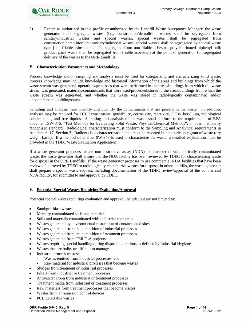
3) Except as authorized in this profile or authorized by the Landfill Waste Acceptance Manager, the waste generator shall segregate wastes (i.e., construction/demolition wastes shall be segregated from sanitary/industrial wastes and special wastes, special wastes shall be segregated from construction/demolition and sanitary/industrial wastes, special wastes shall be segregated by special waste type [i.e., friable asbestos shall be segregated from non-friable asbestos, polychlorinated biphenyl bulk product paint waste shall be segregated from friable asbestos]) at the point of generation for segregated delivery of the wastes to the ORR Landfills.
E. Characterization Parameters and Methodology Process knowledge and/or sampling and analysis must be used for categorizing and characterizing solid waste. Process knowledge may include knowledge and historical information of the areas and buildings from which the waste stream was generated, operations/processes that were performed in the areas/buildings from which the waste stream was generated, materials/contaminants that were used/processed/stored in the areas/buildings from which the waste stream was generated, and whether the waste was stored in radiologically contaminated and/or uncontaminated buildings/areas. Sampling and analysis must identify and quantify the contaminants that are present in the waste. In addition, analyses may be required for TCLP constituents, ignitability, corrosivity, reactivity, PCBs, beryllium, radiological contaminants, and free liquids. Sampling and analysis of the waste shall conform to the requirements of EPA document SW-846, “Test Methods for Evaluating Solid Waste, Physical/Chemical Methods”, or other nationally recognized standard. Radiological characterization must conform to the Sampling and Analytical requirements in Attachment 17, Section 3. Radionuclide characterization data must be reported in picocuries per gram of waste (dry weight basis). If a method other than SW-846 is used to characterize the waste, a detailed explanation must be provided in the TDEC Waste Evaluation Application. If a waste generator proposes to use non-destructive assay (NDA) to characterize volumetrically contaminated waste, the waste generator shall ensure that the NDA facility has been reviewed by TDEC for characterizing waste for disposal in the ORR Landfills. If the waste generator proposes to use commercial NDA facilities that have been reviewed/approved by TDEC to radiologically characterize wastes for disposal in other landfills, the waste generator shall prepare a special waste request, including documentation of the TDEC review/approval of the commercial NDA facility, for submittal to and approval by TDEC. F. Potential Special Wastes Requiring Evaluation/Approval Potential special wastes requiring evaluation and approval include, but are not limited to: Sand/grit blast wastes Mercury contaminated soils and materials Soils and materials contaminated with industrial chemicals Wastes generated by environmental restoration of contaminated sites Wastes generated from the demolition of industrial processes Wastes generated from the demolition of treatment processes Wastes generated from CERCLA projects Wastes requiring special handling during disposal operations as defined by Industrial Hygiene Wastes that are bulky or difficult to manage Industrial process wastes:
- Wastes emitted from industrial processes, and - Raw material for industrial processes that become wastes
Sludges from treatment or industrial processes Filters from industrial or treatment processes Activated carbon from industrial or treatment processes Treatment media from industrial or treatment processes Raw materials from treatment processes that become wastes Wastes from air emission control devices PCB detectable wastes
ORR Profile S-040, Rev. 5 Page 4 of 44
Attachment 3
Primary Sewage Treatment Pump Station
November 2014
Demolition Waste Management and Disposal 017419 - 32

PCB Bulk Product Waste Wastes that present potential respiratory hazards Solid laboratory chemicals Metal turnings, shavings, and dust from industrial processes and machining operations Bulk quantities of non-PCB light ballasts Incinerator ashes Paint chips Untreated Medical/Biological wastes G. Prohibited Items If prohibited materials are observed/detected in wastes delivered to the landfill, the waste generator will be notified so that they can retrieve the materials. Prohibited materials will not be accepted. Items prohibited under this profile include: Waste items listed on a Special Waste Request that have been denied by TDEC RCRA Hazardous Wastes PCB wastes, except those PCB wastes allowable under 40 CFR 761 and approved by TDEC as special waste Radioactive wastes Liquid wastes or waste containing free liquids Tires Lead acid batteries Refrigeration equipment not complying with 40 CFR 82.156 Unapproved special wastes H. Packaging / Transportation Requirements
1. Packaging and labeling shall comply with the applicable Department of Transportation (49 CFR) requirements and the special waste approval requirements. Every waste delivery to the ORR Landfills must be accompanied by a UCN-2109 form, which has been reviewed and approved by the Landfill Facility Manager or the Waste Acceptance Manager. If waste generators have questions regarding delivery of waste to the landfill, contact the Landfill Waste Acceptance Manager or Landfill Facility Manager.
2. Labels, markings, identification, etc. on drums and containers that are not applicable to the drum, container,
or waste in the drum or container must be rendered unidentifiable and the action identified in the accompanying UCN-2109 Waste Description. Any dumpsters used to deliver waste to the landfill shall have identification numbers or bar codes, and those identification numbers/bar codes shall be clearly reflected on the corresponding UCN-2109 forms.
3. The waste generator shall contact the Landfill Facility Manager if there are questions regarding personal
protective equipment and training requirements for delivery personnel.
4. The waste generator shall size and load the waste into the waste delivery vehicles in such a manner to prevent the waste from becoming lodged in waste delivery vehicles and containers (i.e., dump truck beds, roll-off containers) during the dumping operations. The waste generator/transporter shall be responsible for safely removing and clearing lodged materials from the waste delivery vehicles/containers and all associated costs.
5. It is highly recommended that waste generators deliver wastes in vehicles that are self-dumping/unloading.
If it is necessary to deliver wastes on flatbed trucks or flatbed trailers, the waste will be palletized if possible and the generator shall perform advance coordination with the Landfill Facility Manager to confirm that forklift support will be available.
6. For deliveries of large, bulky items that exceed the handling capacity of standard equipment at the landfill,
the waste generator shall make all necessary unloading preparations {i.e., equipment (cranes and large fork trucks), trained personnel, hoisting & rigging plans, work plans, activity hazard assessments, etc.} The waste generator shall be responsible for all costs associated with such unloading activities.
ORR Profile S-040, Rev. 5 Page 5 of 44
Attachment 3
Primary Sewage Treatment Pump Station
November 2014
Demolition Waste Management and Disposal 017419 - 33

7. Waste delivery vehicles shall not leak fluids.
8. Dump trailers (framed and frameless) are prohibited.
9. Void space in containers, except for 55-gallon drums and smaller containers, shall be reduced to the extent
practical. Large (greater than 55-gallon capacity) empty containers shall be size reduced by the waste generator prior to delivery to the landfill.
I. Additional Requirements Disposal plans for special wastes that require TDEC approval prior to disposal must be coordinated with the Waste Acceptance Manager during initial planning activities to allow sufficient time for obtaining TDEC special waste approval. During preparation of proposals and preparation of Waste Management Plans for projects, the waste generator shall communicate with the Landfill Waste Acceptance Manager to discuss the project schedule, projected waste generation/delivery schedule(s), projected waste streams, estimated waste volumes, waste characterization, potential special waste requests, waste segregation, and waste documentation. Waste delivery quantities per day may be limited based on overall ORR waste generation rates. Special Waste that is routinely generated can be represented on a “blanket 2109” which must be renewed annually. The waste generator shall provide notification to and coordinate with the Landfill Facility Manager at least one working day prior to delivery of a newly approved special waste or a special waste that is not routinely delivered to the landfill. The notification must include a UCN-2109 form and associated documentation and address projected materials, volume, contaminants (see Section E), and delivery schedules prior to shipping to the landfills. Landfill Operations personnel must concur with the delivery schedule. The waste generator shall provide verbal notification to and coordinate with the Landfill Facility Manager at least one working day prior to delivery of friable asbestos waste, nonfriable asbestos waste or respiratory hazardous waste to allow sufficient time for preparing for the waste disposal. Landfill Operations personnel must concur with the delivery schedule. All wastes delivered to the landfill, including NDA surveyed wastes, must pass through the Vehicle Portal Monitor and will be subject to random inspection and radiological survey. The waste generator should contact the Landfill Facility Manager prior to delivery if the waste has elevated levels of naturally occurring radioactivity. Any waste delivered to the landfill that does not meet the Waste Acceptance Criteria, is not packaged properly, or is not labeled properly is subject to rejection by the landfill operator. In addition, if advance notification of waste delivery is required for the waste and the notification is not provided to the ORR Landfill staff, the waste will be subject to rejection. If waste is rejected, the reason for rejection will be furnished to the waste generator. The waste generator will be responsible for the cost of retrieval, management, and proper disposition of all prohibited wastes delivered to the landfill. If non-conforming/prohibited waste is dumped into the landfill, the waste generator shall be responsible for removal, packaging, transportation, and disposition of non-conforming/prohibited wastes, and all associated costs. The waste generator shall remove all non-conforming/prohibited waste from the ORR Landfills on the same day the non-conforming/prohibited waste is delivered to the ORR Landfills. J. Required Documentation for Disposal (as applicable) Specific requirements are stated for form UCN-2109, Waste Item Description, and UCOR Form 398, Process Knowledge Documentation. These requirements also apply to the corresponding forms UCN-21941, Request for Landfill Disposal, and UCN-21395, Process Knowledge Documentation, which are used by the Y-12 National Nuclear Security Complex, and the ORR Landfill Shipping Form, which is used by UCOR.
ORR Profile S-040, Rev. 5 Page 6 of 44
Attachment 3
Primary Sewage Treatment Pump Station
November 2014
Demolition Waste Management and Disposal 017419 - 34

1. Completed and signed form UCN-2109, “Waste Item Description.” Every waste delivery to the ORR Landfills must be accompanied by a UCN-2109 form, which has been reviewed and approved by the Landfill Facility Manager or the Landfill Waste Acceptance Manager. The UCN-2109 form shall comply with the following requirements:
1.1. Information on UCN-2109 forms and Process Knowledge Documentation Form 398 (or equivalent) must
accurately represent the waste and must be current, complete, and correct. 1.2. If there is a change in the generating company, the UCN-2109 form must be modified to identify the
correct company and correct generator information and be re-signed by the waste generator, unless otherwise approved by the Waste Acceptance Manager.
1.3. If a radiological “green tag” is used to support the disposition of waste, the waste generator must provide
the green tag number on the UCN-2109 form when the green tag number becomes available or attach the green tag to the 2109.
1.4. The TDEC Special Waste Approval letter number and the disposal landfill specified by TDEC must be
clearly noted on the UCN-2109 form.
1.5. TDEC’s Special Handling Instructions must be clearly noted on the UCN-2109 form. 2. Completed Form 398 (or equivalent), “Process Knowledge Documentation”. 3. Certified Asbestos Waste Shipment Record. (The Asbestos Shipment Record can be obtained at
http://www.state.tn.us/environment/apc/forms/cn1054.pdf) 4. Certified Generator’s/Shipper’s Log for Beryllium/Beryllium Oxide Removal and Disposal (UCOR generators
can obtain a Generator’s/Shipper’s Log for Beryllium Oxide Removal and Disposal at http://www-internal1.bechteljacobs.org/pqa/acm/bjcforms/Form-335.doc), although an equivalent form (such as UCN-21559 for Y-12 generators) may be used.
5. Radiological “green tag”, or Process Knowledge Documentation Form 398 (or equivalent), or analytical data to
clearly show the waste is not a radiological waste. 6. Sampling plans, laboratory data, statistical evaluation of the data, and/or other information that characterizes the
waste. 7. For new special wastes, completed and signed TDEC Division of Solid Waste Management Waste Evaluation
Application and $300 Waste Evaluation Fee for submittal to TDEC, when appropriate. The instructions for applying for a Special Waste Request are in Attachment 1 and the Special Waste Request Form is in Attachment 2. The Waste Evaluation Application and Waste Evaluation Fee Worksheet may be obtained at http://www.state.tn.us/environment/swm/forms/cn1051.pdf
8. Supporting documentation that must accompany the Special Waste Evaluation Application if the waste is
volumetrically contaminated with radionuclides is as follows:
- Sampling and Analytical Summary (Appendix B of Attachment 17), with supporting laboratory data (see Attachment 17, Section 6.1)
- Volumetric screening criteria and compliance calculations (See ORR Waste Certification Website http://www-orr.bechteljacobs.org/DMZ_CM/News/articlefiles/2-ScreeningWorkst.xls for a copy of the spreadsheet “Volumetric Screening Criteria and Compliance Calculations for Industrial Landfill V”) (see Attachment 17, Section 6.2)
- Transmittal letter with the appropriate radiological assurance statement (see Attachment 17, Section 6.3)
9. Information and documentation as described in Section 7 of Attachment 17 for waste containing radionuclides that exceed or are not contained in the radiological volumetric screening criteria.
10. TDEC special waste approval letter
ORR Profile S-040, Rev. 5 Page 7 of 44
Attachment 3
Primary Sewage Treatment Pump Station
November 2014
Demolition Waste Management and Disposal 017419 - 35

ATTACHMENT 1
SPECIAL WASTE EVALUATION REQUEST PROCESS
REGULATORY REQUIREMENTS AND OTHER INFORMATION Tennessee Department of Environment and Conservation (TDEC) Rule 1200-1-7-.01 provides the following definition for special wastes: “Special Wastes” are solid wastes that are either difficult or dangerous to manage and may include sludges, bulky wastes, pesticide wastes, medical wastes, industrial wastes, hazardous wastes which are not subject to regulations under Department Rules 1200-1-11-.03 through 1200-1-11-.07, liquid wastes, friable asbestos wastes, and combustion wastes.
“Industrial Wastes” means solid wastes produced in, or generated by, industrial or manufacturing processes. The term does not include commercial, domestic, mining, or hazardous waste regulated under Subtitle C of RCRA, or oil and gas waste. TDEC Rule 1200-1-7-.01(4)(b) states: “Persons who generate and wish to process or dispose of a special waste must make application to the Commissioner for waste evaluation.” TDEC has also previously indicated that “the unauthorized disposal of solid waste by any person in the State of Tennessee shall be subject to a civil penalty of not less than one hundred ($100) nor more than five thousand dollars ($5000) per day for each day of violation.” TDEC Rule 1200-1-7-.07(2)(b)4 also requires a $300 fee for special waste evaluations. The fee is required for special waste evaluations that include analytical data and/or material safety data sheets (MSDS), and the fee is not required for special waste evaluations that do not include information for review. The TDEC Waste Evaluation Application is presented in Attachment 2. The Oak Ridge Reservation has three solid waste landfills permitted by the Tennessee Department of Environment and Conservation (TDEC) for the disposal of solid wastes generated by Department of Energy activities in the Oak Ridge area. The landfills are Industrial Waste Landfill IV (Permit Number IDL 01-103-0075), Industrial Landfill V (Permit Number IDL 01-103-083), and Construction/Demolition Landfill VII (Permit Number DML 01-103-0045). Through TDEC approved permit documents, these landfills are approved to accept specific industrial wastes, institutional wastes, construction/demolition wastes, and special wastes. Wastes other than those currently approved for disposal by TDEC require special waste evaluation. Refer to Section F of this Profile for a list of potential special wastes requiring evaluation and approval by TDEC. SPECIAL WASTE SUBMITTAL AND APPROVAL PROCESS Based upon the regulatory requirements and guidance from Department of Energy (DOE), the process for handling “potential” special wastes and special wastes generated as a result of DOE activities in the Oak Ridge area is described in the following sections. 2.1 ORO-DOE Project Waste Generator:
2.1.1 The waste generator shall review the Sanitary/Industrial Waste Profiles, and properly characterize and
categorize the waste generator’s waste, including special wastes and “potential” special wastes. (Note: If a waste generator has questions regarding categorization of special wastes or “potential” special wastes, the waste generator should consult with the Landfill Waste Acceptance Manager).
2.1.2 If the waste generator has a special waste or “potential” special waste, the waste generator shall prepare a
draft special waste request package including a transmittal letter, Waste Evaluation Application (see
ORR Profile S-040, Rev. 5 Page 8 of 44
Attachment 3
Primary Sewage Treatment Pump Station
November 2014
Demolition Waste Management and Disposal 017419 - 36
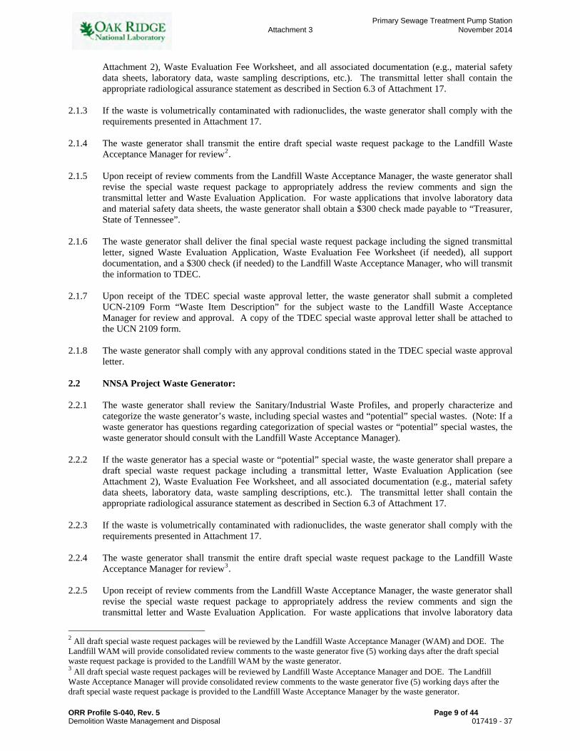
Attachment 2), Waste Evaluation Fee Worksheet, and all associated documentation (e.g., material safety data sheets, laboratory data, waste sampling descriptions, etc.). The transmittal letter shall contain the appropriate radiological assurance statement as described in Section 6.3 of Attachment 17.
2.1.3 If the waste is volumetrically contaminated with radionuclides, the waste generator shall comply with the
requirements presented in Attachment 17. 2.1.4 The waste generator shall transmit the entire draft special waste request package to the Landfill Waste
Acceptance Manager for review2. 2.1.5 Upon receipt of review comments from the Landfill Waste Acceptance Manager, the waste generator shall
revise the special waste request package to appropriately address the review comments and sign the transmittal letter and Waste Evaluation Application. For waste applications that involve laboratory data and material safety data sheets, the waste generator shall obtain a $300 check made payable to “Treasurer, State of Tennessee”.
2.1.6 The waste generator shall deliver the final special waste request package including the signed transmittal
letter, signed Waste Evaluation Application, Waste Evaluation Fee Worksheet (if needed), all support documentation, and a $300 check (if needed) to the Landfill Waste Acceptance Manager, who will transmit the information to TDEC.
2.1.7 Upon receipt of the TDEC special waste approval letter, the waste generator shall submit a completed
UCN-2109 Form “Waste Item Description” for the subject waste to the Landfill Waste Acceptance Manager for review and approval. A copy of the TDEC special waste approval letter shall be attached to the UCN 2109 form.
2.1.8 The waste generator shall comply with any approval conditions stated in the TDEC special waste approval
letter. 2.2 NNSA Project Waste Generator: 2.2.1 The waste generator shall review the Sanitary/Industrial Waste Profiles, and properly characterize and
categorize the waste generator’s waste, including special wastes and “potential” special wastes. (Note: If a waste generator has questions regarding categorization of special wastes or “potential” special wastes, the waste generator should consult with the Landfill Waste Acceptance Manager).
2.2.2 If the waste generator has a special waste or “potential” special waste, the waste generator shall prepare a
draft special waste request package including a transmittal letter, Waste Evaluation Application (see Attachment 2), Waste Evaluation Fee Worksheet, and all associated documentation (e.g., material safety data sheets, laboratory data, waste sampling descriptions, etc.). The transmittal letter shall contain the appropriate radiological assurance statement as described in Section 6.3 of Attachment 17.
2.2.3 If the waste is volumetrically contaminated with radionuclides, the waste generator shall comply with the
requirements presented in Attachment 17. 2.2.4 The waste generator shall transmit the entire draft special waste request package to the Landfill Waste
Acceptance Manager for review3. 2.2.5 Upon receipt of review comments from the Landfill Waste Acceptance Manager, the waste generator shall
revise the special waste request package to appropriately address the review comments and sign the transmittal letter and Waste Evaluation Application. For waste applications that involve laboratory data
2 All draft special waste request packages will be reviewed by the Landfill Waste Acceptance Manager (WAM) and DOE. The Landfill WAM will provide consolidated review comments to the waste generator five (5) working days after the draft special waste request package is provided to the Landfill WAM by the waste generator. 3 All draft special waste request packages will be reviewed by Landfill Waste Acceptance Manager and DOE. The Landfill Waste Acceptance Manager will provide consolidated review comments to the waste generator five (5) working days after the draft special waste request package is provided to the Landfill Waste Acceptance Manager by the waste generator.
ORR Profile S-040, Rev. 5 Page 9 of 44
Attachment 3
Primary Sewage Treatment Pump Station
November 2014
Demolition Waste Management and Disposal 017419 - 37

and material safety data sheets, the waste generator shall obtain a $300 check made payable to “Treasurer, State of Tennessee”.
2.2.6 The waste generator shall transmit the final special waste request package including the signed transmittal
letter, signed Waste Evaluation Application, Waste Evaluation Fee Worksheet (if needed), all support documentation, and a $300 check (if needed) to TDEC for review. In addition, the waste generator shall transmit a copy of the final special waste request package to the Landfill Waste Acceptance Manager.
2.2.7 Upon receipt of the TDEC special waste approval letter, the waste generator shall submit a completed form
UCN-21941, Request for Landfill Disposal, for the subject waste to the Landfill Waste Acceptance Manager for review and approval. A copy of the TDEC special waste approval letter shall be attached to the UCN 21941 form.
2.2.8 The waste generator shall comply with any approval conditions stated in the TDEC special waste approval
letter. 2.2.9 The Landfill Waste Acceptance Manager shall issue an “Agreement to Accept Waste” to the NNSA waste
generator and Y-12 Landfill Coordinator upon resolution of any remaining TDEC and Landfill comments, upon receipt of documentation described in Section 2.2.6, and upon receipt and approval of the completed and signed form UCN-2109 Form, “Waste Item Description.”
2.3 Waste Acceptance Manager: The Landfill Waste Acceptance Manager shall perform the following: 2.3.1 Consult with the waste generators regarding special waste determinations and the special waste handling
process. 2.3.2 Inform appropriate DOE representatives of pending “potential” special waste requests. 2.3.3 Receive for review the draft Waste Evaluation Application and support documentation from the waste
generators. 2.3.4 Perform preliminary review of the draft Waste Evaluation Application package and, if necessary, return to
the waste generators any Waste Evaluation Applications which are not complete, have incorrect information, or do not meet the criteria for special waste.
2.3.5 Distribute the draft Waste Evaluation Application and support documentation to DOE representatives for
review after determining that a draft Waste Evaluation Application is acceptable for review. 2.3.6 Review the draft Waste Evaluation Application and support documentation 2.3.7 Receive and consolidate review comments and transmit the consolidated comments to the waste generator
within five (5) working days after receiving the draft Waste Evaluation Application and support documentation.
2.3.8 Receive the Waste Evaluation Applications from DOE ORO projects and submit them to TDEC with the
Waste Evaluation Fee worksheet and associated fee. 2.3.9 Maintain special waste files including Waste Evaluation Applications, support documentation, and TDEC
response letters (approvals, denials, or requests for additional information). 2.4 U.S. Department of Energy (DOE): 2.4.1 The DOE Landfill Program Manager will review draft Waste Evaluation Applications and provide
comments to the Landfill Waste Acceptance Manager within five (5) working days.
ORR Profile S-040, Rev. 5 Page 10 of 44
Attachment 3
Primary Sewage Treatment Pump Station
November 2014
Demolition Waste Management and Disposal 017419 - 38

Waste Generator Characterizes Waste
End
Generator SubmitsDraft SWR to WAM
with supporting
documentation
WAM Review/Comment
DOE Review/Comment
WAM consolidates DOE comments
and emails to generator
WAM distributes dSWR and supporting
documentation for review
Special Waste Request Submittal Process
continued
No Yes
No
Is SWR necessary per Master
ProfileS-040?
Is draft SWR and support
documentation complete and acceptable for
review?
Yes
ORR Profile S-040, Rev. 5 Page 11 of 44
Attachment 3
Primary Sewage Treatment Pump Station
November 2014
Demolition Waste Management and Disposal 017419 - 39

ORR Profile S-040, Rev. 5 Page 12 of 44
Special Waste Request Submittal Process continued
Generator is Generator is NNSAORO DOE
Generator incorporates comments in SWR
Generator incorporates
comments in SWR
Generator Generator submits final signed SWR and fee
pmt to TDEC and cc: WAM/DOE
WAM submits final signed
SWR and fee pmt to TDEC
Submits “final” SWR and fee
payment to WAM
TDEC reviews
Interim correspondence
between TDEC and generator?
TDEC issues letter of
approval or denial
End
TDEC reviews
Interim correspondence
between generator and TDEC?
NNSA cc: WAM / DOE on
interim correspondence
TDEC issues letter of
approval or denial
End
NNSA CC: WAM / DOE
Generator cc: WAM
Generator cc: WAMon interim
correspondence
WAM cc: DOEon interim
correspondence
Comments incorporated satisfactorily and SWR package complete w/
support documentation?
No
Yes
Yes
Yes
Yes
Yes
No
No
If no issues and LFSWR file is complete.
WAM issues “Agreement to Accept Waste”
Attachment 3
Primary Sewage Treatment Pump Station
November 2014
Demolition Waste Management and Disposal 017419 - 40

ATTACHMENT 2 The Waste Evaluation Application and Waste Evaluation Fee Worksheet may be obtained at http://www.state.tn.us/environment/swm/forms/cn1051.pdf.
ORR Profile S-040, Rev. 5 Page 13 of 44
Attachment 3
Primary Sewage Treatment Pump Station
November 2014
Demolition Waste Management and Disposal 017419 - 41

ATTACHMENT 2 (continued)
ORR Profile S-040, Rev. 5 Page 14 of 44
Attachment 3
Primary Sewage Treatment Pump Station
November 2014
Demolition Waste Management and Disposal 017419 - 42

ATTACHMENT 3
PACKAGING AND TRANSFER REQUIREMENTS FOR SPECIAL WASTE: FRIABLE AND NON-FRIABLE ASBESTOS CONTAINING MATERIAL
1. DEFINITIONS
The following definitions are generally based on Tennessee Department of Environment and Conservation (TDEC) Rule 1200-3-11-.02: “Asbestos containing material” (ACM) means asbestos or any asbestos containing material, which contains more than 1 percent asbestos as determined using Polarized Light Microscopy according to the method specified in Appendix A, Subpart F, 40 Code of Federal Regulations (CFR), Part 763, Section 1, Polarized Light Microscopy, as contained in the 7-1-91 Edition of the CFR. “Category I non-friable ACM” means asbestos containing packings, gaskets, resilient floor covering, and asphalt roofing products, containing more than 1 percent asbestos as determined using polarized light microscopy according to the methods specified in Appendix A, Subpart F, 40 CFR Part 763, Section 1, Polarized Light Microscopy, as contained in the 7-1-91 Edition of the CFR. “Category II non-friable ACM” means any material, excluding Category I non-friable ACM, containing more than 1 percent asbestos as determined using polarized light microscopy according to the methods specified in Appendix A, Subpart F, 40 CFR Part 763, Section 1, Polarized Light Microscopy, as contained in the 7-1-91 Edition of the CFR, that, when dry, cannot be crumbled, pulverized, or reduced to powder by hand pressure. “Friable asbestos material” means any material containing more than 1 percent asbestos as determined using polarized light microscopy according to the methods specified in Appendix A, Subpart F, 40 CFR Part 763, Section 1, Polarized Light Microscopy, as contained in the 7-1-91 Edition of the CFR, that, when dry, can be crumbled, pulverized, or reduced to powder during hand pressure. If the asbestos content is less than 10 percent as determined by a method other than point counting by polarized light microscopy (PLM), verify the asbestos content by point counting using PLM. “In poor condition” means the fibers are readily visible and the material is in a state such that is or may easily become friable (i.e. it can readily be crumbled, pulverized or reduced to powder by simple hand pressure), and the binding of the material is losing its integrity as indicated by peeling, cracking, or crumbling of the material. “Leak-tight” means that solids or liquids cannot escape or spill out. It also means dust-tight. “Regulated asbestos containing material (RACM)” means
1. Friable asbestos material, 2. Category I non-friable ACM that has become friable, 3. Category I non-friable ACM that will be or has become subjected to sanding, grinding, cutting, or
abrading, or 4. Category II non-friable ACM that has a high probably of becoming or has become crumbled,
pulverized, or reduced to powder by the forces expected to act on the material in the course of the demolition or renovation operations regulated by Rule 1200-3-11-.02.
“Visible emissions” means any emissions, which are visually detectable without the aid of instruments, coming from RACM or asbestos containing waste material, or from any asbestos milling, manufacturing, or fabricating operation. This does not include condensed, uncombined water vapor. As previously stated, the above definitions are based on TDEC regulations. Waste generators are responsible for referring to TDEC Rule 1200-3-11-.02 for other regulatory definitions.
ORR Profile S-040, Rev. 5 Page 15 of 44
Attachment 3
Primary Sewage Treatment Pump Station
November 2014
Demolition Waste Management and Disposal 017419 - 43

2. FRIABLE ACM
Friable ACM waste, including insulation, piping, metal, equipment, and clothing that contains or is contaminated with friable asbestos shall be managed as follows: NOTE: Instructions in this section apply only to asbestos waste that meets the criteria established in
Section C of this Profile S-040 “Radiological Constituent Limitations”. a. Shall be packaged and sealed tightly in double-bagged, 6-mil thick plastic bags, double-wrapped
6-mil thick plastic sheeting, fiber drums, metal drums or plywood boxes. b. Shall be labeled (or equivalent) as shown below:
DANGER
CONTAINS ASBESTOS FIBERS AVOID CREATING DUST
CANCER AND LUNG DISEASE HAZARD
c. Shall be transported in a fully enclosed space or fully covered by a secured tarpaulin. d. Shall be accompanied by the following forms to be completed by the waste generator for each load
(i.e., dumpster or truckload):
(1) Waste Shipment Record (2) UCN-2109 Form set; origin, volume, and waste type must be included.
(3) Radiological “green tags”, sample data, NDA documentation, or Form 398 Process
Knowledge Documentation (or equivalent)
e. The generator shall verbally coordinate delivery with the Landfill Facility Manager at least one working day in advance. The waste generator shall have the waste transported to the landfill. The waste generator shall initiate the waste shipment record. If the waste generator transports the waste, he/she shall complete the Transporter’s portion of the Waste Shipment Record and deliver the form to the landfill attendant. The transporter shall exercise extreme care in off-loading the waste to avoid rupturing the package. Unloading is the responsibility of the waste generator/transporter. If assistance is needed, such as with the all-terrain fork truck, the generator must verbally coordinate this with the Landfill Facility Manager one working day in advance of the delivery. The landfill can assist in off-loading, but must have at least one day prior notification from the generator.
f. Shall be accepted for disposal at Industrial Landfill V only on Tuesdays or by special request if the waste meets applicable requirements.
NOTE: Personnel within 100 feet of unloading operations shall, as a minimum, wear a respirator with cartridges for
asbestos protection, unless personnel are inside a totally enclosed cab with all windows, vents, openings, etc. closed. All non-essential personnel shall stay out of the unloading area. Waste generators/transporters shall provide any personal protective equipment they need for the unloading operations.
ORR Profile S-040, Rev. 5 Page 16 of 44
Attachment 3
Primary Sewage Treatment Pump Station
November 2014
Demolition Waste Management and Disposal 017419 - 44

ATTACHMENT 3 (Continued)
3. NONFRIABLE ACM:
(NOTE: Nonfriable ACM waste is normally disposed in Construction/Demolition Landfill VII instead of ILF V.)
Nonfriable ACM is classified as either Category I ACM or Category II ACM. Category I ACM includes asbestos containing gaskets, packings, resilient floor coverings, resilient floor covering mastic, and asphalt roofing products containing more than 1 percent asbestos. Asphalt roofing products which may contain asbestos include built up roofing; asphalt containing single-ply membrane system; asphalt shingles; asphalt containing underlayment felts; asphalt containing roofing coatings and mastics; and asphalt containing base flashings. ACM roofing products that use other bituminous or resinous binders (such as coal tars or pitches) are also considered to be Category I ACM. Category II ACM includes all other nonfriable ACM, for example, asbestos-cement (A/C) tiles, and transite boards or panels more than 1 percent asbestos. The generator must verbally coordinate delivery with the Landfill Facility Manager at least one working day in advance. Non-friable ACM shall be handled under the same requirements defined in Section 2 for friable asbestos, with the following exceptions:
a. The label or tag describing the contents of each container must include the words as follows:
Nonfriable Asbestos
The label/tag must be visible on each waste package.
b. The Waste Shipment Record (as stated in 1.d.1) is NOT required. A UCN-2109 Waste Item
Description form is required. Radiological “green tags”, sample data, NDA documentation, or Form 398 Process Knowledge Documentation (or equivalent) shall be provided with the 2109 form.
c. Respirators shall be worn at the disposal site unless air monitoring results show that they are not
necessary. At a minimum, respirators shall be available for immediate use in case visible emissions are observed. Personnel inside a totally enclosed cab with all windows, vents, openings, etc. closed are not required to wear respirators. All non-essential personnel shall stay out of the unloading area. Waste generators/transporters shall provide any personal protective equipment they need for the unloading operations.
d. For projects that involve handling of nonfriable ACM, appropriate regulatory and industrial hygiene guidance requires that the work be performed in a manner to maintain the nonfriability of the ACM. For nonfriable Category I and II ACM to be classified as nonfriable waste and eligible for handling under the designation of “nonfriable” ACM, the removal operations must conform to the requirements specified in the federal regulations (40 CFR Part 61, Appendix A to Subpart M, “ Interpretive Rule Governing Roof Removal Operations”). Nonfriable Category I and II ACMs that become friable during the removal, loading, and transporting operations shall be managed under the friable ACM handling and disposal requirements described in a previous section of this document.
e. Bulk disposal of Category I non-friable ACM mixed with demolition debris is acceptable as
described below:
1. Prior to demolition of structures and facilities, the waste generators will perform all necessary actions to identify and remove all ACM except for Category I non-friable ACM that is not in poor condition and is not friable prior to demolition. The determination of the category and condition of the ACM shall be made by Asbestos Hazard Emergency Response Act Accredited Asbestos Inspectors using proceduralized processes (i.e., UCOR Procedure PROC-IH-5177, Asbestos and Other Fibrous Materials,
ORR Profile S-040, Rev. 5 Page 17 of 44
Attachment 3
Primary Sewage Treatment Pump Station
November 2014
Demolition Waste Management and Disposal 017419 - 45

or equivalent) incorporating EPA criteria of visual and tactile methods as found in EPA guidance documentation. If it is determined that the Category I non-friable ACM is in poor condition and either friable or will become friable during demolition, it will be considered regulated asbestos containing material (RACM), and it shall be removed from the facility prior to demolition of the facility. The remaining Category I non-friable ACM, which is not in poor condition and is not friable prior to demolition, may be left in the structures/facilities for demolition. In addition, the waste generators shall follow appropriate demolition methods as described in EPA document Demolition Practice Under the Asbestos NESHAP (see http://www.epa.gov/region4/air/asbestos/demolish.htm) to minimize the potential for converting the Category I non-friable ACM to RACM during demolition of structures and facilities, handling of the waste at the demolition site, loading of the waste into waste transport vehicles, and transporting the waste to the ORR Landfills.
2. The resulting Category I non-friable ACM mixed with demolition debris shall be
managed as bulk non-friable ACM as described below.
f. Packaging for bulk handling of non-friable ACM (Category I and II) shall be performed as follows:
1. Bulk Shipment of Non-Friable ACM in Non-Dedicated Use Dump Trucks, Intermodals,
Roll-off Containers, and Similar Transport Containers:
The non-friable ACM shall be kept adequately wet during demolition and loading (without creating free liquids problems).
A single layer (minimum) of 6-mil (minimum) plastic sheeting shall wrap the entire load. Sealed bladder bags or sealed supersacks, which are specifically designed for asbestos containment, may be used in lieu of the plastic sheeting. If plastic sheeting is used, it shall comply with the following: o use oversize plastic sheeting to line the empty transport conveyance, and o after the nonfriable ACM is placed in the lined conveyance, the loose edges of
the plastic sheets shall be lapped over the top of the ACM and sealed. A tarp or metal lid shall cover the entire load and the tailgate/door shall be closed. Asbestos label(s) shall be applied to comply with 29 CFR 1926.1101(k)(8) and shall
include the words “Non-Friable Asbestos”. 2. Bulk Shipment of Non-Friable ACM in Dedicated Use Dump Trucks, Intermodals, Roll-
off Containers, and Similar Transport Containers:
The non-friable ACM shall be kept adequately wet during demolition and loading (without creating free liquids problems).
The containers shall be dust-tight and leak-tight via closed, gasketed doors and closed tarps or metal covers/lids.
No liner or plastic sheeting shall be required. Asbestos label(s) shall be applied to comply with 29 CFR 1926.1101(k)(8) and shall
include the words “Non-Friable Asbestos”, and The containers shall be dedicated to ACM use until the units are decontaminated in
accordance with OSHA regulation 29 CFR 1926.1101 3. Bundled/stacked transite panels:
The non-friable ACM shall be kept adequately wet during demolition and loading (without creating free liquids problems).
Each bundle of transite shall be wrapped, closed, and sealed in a single (minimum) layer of 6-mil (minimum) thick plastic sheeting. Sealed bladder bags or sealed supersacks, which are specifically designed for asbestos containment, may be used in lieu of the plastic sheeting.
ORR Profile S-040, Rev. 5 Page 18 of 44
Attachment 3
Primary Sewage Treatment Pump Station
November 2014
Demolition Waste Management and Disposal 017419 - 46

Asbestos labels shall applied to each bundle to comply with 29 CFR1926.1101(k)(8) and shall include the words “Non-Friable Asbestos”.
g. Unloading shall be done carefully to keep the materials in the wrapping as much as possible and to
maintain the nonfriability of the ACM. Unloading is the responsibility of the waste generator and waste transporter. If assistance is needed, such as with the all-terrain fork truck, the generator must verbally coordinate this need with the Landfill Facility Manager one working day in advance of the delivery. The landfill can assist, but must have the one day prior notification from the generator.
h. The documentation (i.e., Waste Description field in the UCN-2109 Waste Item Description form)
shall identify the material as “Nonfriable Asbestos-Containing Waste Material. Nonfriable ACM is not subject to the National Emissions Standard for Hazardous Air Pollutants for Asbestos unless it is cut, ground, sanded, abraded, crumbled, pulverized, or reduced to powder.”
i. Nonfriable ACM must be secured in transport vehicles in accordance with applicable DOT
requirements.
j. All friable ACM, RACM, and Category I non-friable ACM in poor condition shall be handled separately under the friable ACM handling requirements.
ORR Profile S-040, Rev. 5 Page 19 of 44
Attachment 3
Primary Sewage Treatment Pump Station
November 2014
Demolition Waste Management and Disposal 017419 - 47

ATTACHMENT 4
PACKAGING AND TRANSFER REQUIREMENTS FOR SPECIAL WASTES (BERYLLIUM OXIDE WASTE)
1. Beryllium oxide (BeO) waste, including wood, paper, clothing, piping, metal, equipment, and demolition
material that is contaminated with BeO:
NOTE: Instructions in this section apply only to beryllium oxide waste that meets the criteria established in Section C of this Profile S-040 “Radiological Constituent Limitations”.
a. Shall be packaged and sealed tightly in double-bagged 6-mil-thick plastic bags, double-wrapped 6-
mil-thick plastic sheeting, fiber drums, metal drums or plywood boxes.
b. Shall be labeled (or equivalent) as shown below:
CONTAMINATED WITH BERYLLIUM, DO NOT REMOVE DUST BY BLOWING OR SHAKING,
CANCER AND LUNG DISEASE HAZARD
DANGER
“Danger” is in white letter on a red oval, which is imposed on a larger white oval on a place rectangle. The text is black on a white background. The border is black.
c. Shall be accompanied by a UCN-2109 Formset and a Generator’s/Shipper’s Log for Beryllium
Oxide Removal and Disposal, to be completed by the waste generator for each load of waste (i.e., dumpster pan, truckload, etc.). Radiological “green tags”, sample data, NDA documentation, or Form 398 Process Knowledge Documentation (or equivalent) is required.
d. If the waste is bagged it shall be transported in a fully enclosed space or fully covered by a secured
tarpaulin. Wastes in drums and boxes shall be transported using standard transport vehicles only. e. Shall be transported to the landfill by the waste generator or the waste generator shall have the
waste transported to the landfill. The waste generator shall initiate the Generator’s/Shipper’s Log. If the waste generator transports the waste, he/she shall complete the Transporter’s portion of the log and deliver the form to the Landfill attendant. The transporter shall exercise extreme care in off-loading the waste to avoid rupturing the package.
f. Shall be accepted for disposal at Industrial Landfill V on Tuesdays or by special request.
NOTE: Personnel within 100 feet of unloading operations shall, as a minimum, wear respiratory protection, unless personnel are inside a totally enclosed cab with all windows, vents, openings, etc closed. All non-essential personnel shall stay out of the unloading area. Waste generators/transporters shall provide any personal protective equipment they need for the unloading operations.
ORR Profile S-040, Rev. 5 Page 20 of 44
Attachment 3
Primary Sewage Treatment Pump Station
November 2014
Demolition Waste Management and Disposal 017419 - 48

ATTACHMENT 5
SPECIAL WASTE: DEAD ANIMALS
Occasionally, there is a need to dispose of dead animals from the ORR. These animals may result from incidents such as highway accidents, discovery of dead animals on a plant site, or extermination projects. Consequently, the following guidance is provided for disposal of nonhazardous, nonradioactive dead animals. Dead animals disposed of in Industrial Landfill V will be managed as follows. The following animals are prohibited from disposal in ILF-V: 1. Animals containing and/or contaminated with hazardous materials as defined in 40 CFR Part 261 or
Tennessee Hazardous Waste Management Regulations. 2. Animals containing and/or contaminated with radioactive materials as defined by the Atomic Energy Act of
1954, amended. 3. Animals containing and/or contaminated with carcinogens or suspected carcinogens. 4. Animals containing and/or contaminated with polychlorinated biphenyls (PCBs).
ORR Profile S-040, Rev. 5 Page 21 of 44
Attachment 3
Primary Sewage Treatment Pump Station
November 2014
Demolition Waste Management and Disposal 017419 - 49

ATTACHMENT 6
SPECIAL WASTE: EMPTY HAZARDOUS MATERIAL CONTAINERS
Containers that have contained hazardous materials and that meet the requirements for empty4 containers in Rule 1200-1-11-.02(1)(g) of Rules Governing Hazardous Waste Management in Tennessee may be disposed of in ILF-V. Glass and plastic laboratory chemical containers meeting the definition of empty in the regulations referenced above may be crushed prior to disposal in ILF-V. These materials and a completed UCN- 2109 form should be transported directly to ILF V. The generator must verbally coordinate delivery with the Landfill Facility Manager at least one working day in advance.
4 The referenced hazardous waste regulations indicate that residual quantities of materials can be left in containers; however, wastes containing “free liquids” are prohibited from disposal in the ORR Landfills. Therefore, waste generators shall take appropriate measures (e.g. completely draining the containers, adding absorbent materials, etc.) to ensure that empty containers delivered to the ORR Landfills do not contain residual free liquids.
ORR Profile S-040, Rev. 5 Page 22 of 44
Attachment 3
Primary Sewage Treatment Pump Station
November 2014
Demolition Waste Management and Disposal 017419 - 50

ATTACHMENT 7
SPECIAL WASTE: EMPTY AEROSOL CANS AND PRESSURIZED GAS CYLINDERS
Empty aerosol cans and empty gas cylinders (reference Bureau of Explosives Specification Number 39) shall be considered empty when the pressure in the container is at atmospheric pressure. Cans and cylinders must meet the criteria established in Section C of this Profile S-040 “Radiological Constituent Limitations”. Cans/cylinders shall be packaged in sealed fiber drums, metal drums, or 6-mil-thick plastic bags. Cylinders may be secured to clean pallets. These waste cans/cylinders MUST have a radiological “green tag”. Empty aerosol cans and empty pressurized gas cylinders shall not be placed in bulk solid waste receptacles (dumpsters). The packaged empty aerosol cans and empty gas cylinders shall be transported directly to Industrial Landfill V. The generator must verbally coordinate delivery with the Landfill Facility Manager at least one working day in advance.
ORR Profile S-040, Rev. 5 Page 23 of 44
Attachment 3
Primary Sewage Treatment Pump Station
November 2014
Demolition Waste Management and Disposal 017419 - 51

ATTACHMENT 8
SPECIAL WASTE: EMPTY PESTICIDE CONTAINERS
The following guidance will be used for the disposal of empty pesticide containers. This guidance generally follows the guidelines found in 40 CFR 165.9, Recommended Procedures for the Disposal of Pesticide Containers and Residues. If the container is made of paper, cardboard, or other materials that would deteriorate upon rinsing with water, the container shall be shaken vigorously to remove all residue. The residue will be collected and used along with the bulk of the pesticide. All cardboard boxes will be crushed. The containers will be sealed in plastic bags and will be transported directly to Industrial Landfill V for disposal. If the container is metal, fiber, or other wettable material, it will be rinsed three times. The rinse liquid will be added to the spray mixture. Each rinsing will be done with a volume of water (or other normal dilutent) equal to approximately one-fourth of the container volume. After the final rinse, the container will be punctured and drained prior to disposal. The drained containers will be transported directly to Industrial Landfill V. In the event that the contents of the container included a listed acute hazardous waste (40 CFR 261.33) and if the container is made of paper, cardboard, or other material that would be deteriorated by rinsing with water, this container shall be disposed of as a hazardous waste. If the container can be triple rinsed without deteriorating, the procedure given above for wettable material containers may be used. The following is a list of substances that are used in pesticides and that are classified as acute hazardous wastes upon disposal: SUBSTANCE CHEMICAL ABSTRACTS NO. Acetic acid, fluoro-, sodium salt 62-74-8 Acrolein 107-02-8 Aldicarb 116-06-3 Aldrin 309-00-2 Allyl alcohol 107-18-6 Aluminum phosphide (R,T) 20859-73-8 4-Aminopyridine 504-24-5 Arsenic acid H3AsO4 7778-39-4 Arsenic oxide As203 1327-53-3 Arsenic trioxide 1327-53-3 Calcium cyanide 592-01-8 Calcium cyanide Ca(CN)2 592-01-8 Carbon disulfide 75-15-0 Copper cyanide 544-92-3 Copper cyanide Cu(CN) 544-92-3 Cyanogen chloride 506-77-4 Cyanogen chloride (CN)CI 506-77-4 2-Cyclohexyl-4,6-dinitrophenol 131-89-5 Dieldrin 60-57-1 O,O-Diethyl O-pyrazinyl phosphorothioate 297-97-2 Dimethoate 60-51-5 4,6-Dinitro-o-cresol, & salts 1534-52-1 Dinoseb 88-85-7 Disulfoton 298-04-4 Endosulfan 115-29-7
ORR Profile S-040, Rev. 5 Page 24 of 44
Attachment 3
Primary Sewage Treatment Pump Station
November 2014
Demolition Waste Management and Disposal 017419 - 52

ATTACHMENT 8 (continued) SUBSTANCE CHEMICAL ABSTRACTS NO. Endothall 145-73-3 Endrin 72-20-8 Endrin, & metabolites 72-20-8 Famphur 52-85-7 Fluoroacetamide 640-19-7 Heptachlor 76-44-8 Hydrocyanic acid 74-90-8 Hydrogen cyanide 74-90-8 Hydrogen phosphide 7803-51-2 Isodrin 465-73-6 Methomyl 16752-77-5 Methyl parathion 298-00-0 alpha-Naphtylthiourea 86-88-4 Nicotine, & salts 154-11-5 Parathion 56-38-2 Phenylmercury acetate 62-38-4 Phorate 298-02-2 Phosphine 7803-51-2 2-Propenal 107-02-8 Sodium azide 26628-22-8 Sodium cyanide 143-33-9 Sodium cyanide Na(CN) 143-33-9 Strychnidin-10-one, & salts 157-24-9 Tetraethyl pyrophosphate 107-49-3 Thallium (I) sulfate 7446-18-6 Thiofanox 39196-18-4 Thiourea, 1-naphthalenyl- 86-88-4 Toxaphene 8001-35-2 Warfarin, & salts, when present at concentrations greater than 0.3% 181-81-2 Zinc phosphide Zn3P2, when present at concentrations greater than 10% (R,T) 1314-84-7 These compounds have other names commonly used and included as such in the EPA’s Title III List of Lists. They are listed below along with their chemical abstracts Number. SUBSTANCE CHEMICAL ABSTRACTS NO. Camphechlor 8001-35-2 PMA 62-38-4 TEPP 107-49-3 Thionazin 297-97-2 1CAS Number given for parent compound only.
ORR Profile S-040, Rev. 5 Page 25 of 44
Attachment 3
Primary Sewage Treatment Pump Station
November 2014
Demolition Waste Management and Disposal 017419 - 53

ATTACHMENT 9
SPECIAL WASTE: FLY ASH FROM Y-12 STEAM PLANT
NOTE: Normally, fly ash will be disposed in Construction/Demolition Landfill VII. Pulverized coal is burned in the Y-12 Steam Plant’s industrial boilers to generate steam for process and heating purposes. Fly ash is collected in the high furnace hoppers and baghouses and is pneumatically conveyed to the Dry Ash Handling System for transfer to trucks. Prior to being loaded into trucks, the dry ash will be conditioned with process water to control fugitive dust. Fly ash from this process may be disposed of in Industrial Landfill V, or Construction/Demolition Landfill VII on a daily basis by incorporation with the normal landfill waste (not in a special cell).
ORR Profile S-040, Rev. 5 Page 26 of 44
Attachment 3
Primary Sewage Treatment Pump Station
November 2014
Demolition Waste Management and Disposal 017419 - 54

ATTACHMENT 10
SPECIAL WASTE: PETROLEUM PRODUCT CONTAMINATED SOIL
Occasionally, soil contaminated with petroleum product or spill cleanup residues may be disposed of in ILF-V. In order to safely dispose of the waste, the following procedures will be followed. 1. All free liquid gasoline or other petroleum products must be removed from the soil or spill cleanup residues
before they are taken to the landfill. As much of the petroleum product will be removed from the material as can practically be removed and will be recycled or disposed of in an appropriate manner.
2. The contaminated soil or spill cleanup residues will be tested and must be found to contain less than the
RCRA hazardous waste limits for benzene and lead before they are taken to the landfill. Soil with other chemical or radiological contamination is not included under this special waste approval, and the soil/waste will be subject to separate evaluation as a special waste (See Attachment 2).
3. The landfill technician and the equipment operator shall be notified in advance that the contaminated soil
sand residues could present a fire hazard (flammable materials should not be sent to the landfill) and will act accordingly. There will be no smoking around the waste and minimum contact with sources of heat or sparks from the equipment. Clean soil or cool fly ash will be pushed over the contaminated soil or cleanup residues before it is graded and compacted. Fire extinguishers will be readily available during the disposal operation.
4. Only soil from petroleum product spill cleanups in locations that are not known or believed to be
contaminated with hazardous or radioactive constituents will be accepted. 5. Prior to shipment of the waste to the landfill, the waste generator shall provide the following information to
the Landfill Waste Acceptance Manager. A report will be made to TDEC/DSWM following each petroleum product spill cleanup incident in which the soil or residues are placed in ILF-V in accordance with this approval. This report will contain the following information:
- the location and nature of the spill; - a laboratory analysis of the contaminated soils and residues showing TCLP hazardous waste limits for
benzene and lead are not exceeded; - the date of each disposal, with the estimated quantity of waste disposed.
ORR Profile S-040, Rev. 5 Page 27 of 44
Attachment 3
Primary Sewage Treatment Pump Station
November 2014
Demolition Waste Management and Disposal 017419 - 55

ATTACHMENT 11
OTHER WASTE: GLASS
In general, glass will be crushed by in-plant facilities prior to delivery and disposal at ILF-V. As circumstances arise, disposal of uncrushed glass at the landfill may be allowed at the discretion of the Landfill Waste Acceptance Manager. All glass chemical containers to be disposed of in the landfill shall be empty as defined in Rule 1200-1-11-.02(1)(g) of Rules Governing Hazardous Waste Management in Tennessee. In all cases, the condition of the glass and method of handling the glass will be selected on the basis of ensuring the safety of the equipment operators and other site operating personnel. The glass will be placed on the working face of the refuse cell and compacted along with other daily refuse. If operating experience at the facility dictates, the glass may be spread and covered with 6 in. of compacted soil immediately following each such disposal to promote safe operating conditions for personnel and to minimize damage to delivery vehicles.
ORR Profile S-040, Rev. 5 Page 28 of 44
Attachment 3
Primary Sewage Treatment Pump Station
November 2014
Demolition Waste Management and Disposal 017419 - 56

ATTACHMENT 12
SPECIAL WASTE: EMPTY PAINT CANS
As a result of ongoing construction and maintenance programs, empty paint cans are generated by NNSA operations at Y-12 and DOE contractors in Oak Ridge Operations. Most waste paint cans have a capacity of 5 gallons or less. Empty paint cans containing small amounts of dry paint residue will be disposed of in the Industrial Landfill V. Waste paint cans containing large amounts of dry paint residue will be disposed of as hazardous waste per Rules Governing Hazardous Waste Management in Tennessee and/or screened by TCLP and ignitability tests in the subject hazardous waste management rules. If these tests are conducted, the test results will be considered representative for later disposal of paint residue of the same brand and generic type. Liquid paint will not be allowed in the landfill.
ORR Profile S-040, Rev. 5 Page 29 of 44
Attachment 3
Primary Sewage Treatment Pump Station
November 2014
Demolition Waste Management and Disposal 017419 - 57

ATTACHMENT 13
SPECIAL WASTE: BOTTOM ASH – Y-12 PLANT
Pulverized coal is burned in the Y-12 Steam Plant’s four industrial boilers to generate steam for process and heating purposes. Bottom ash from the operations is sluiced into dewatering bins where it is dewatered and then hauled by truck to Construction/Demolition Landfill VII. Moisture content of the ash is controlled to a range that prevents fugitive dust and allows good handling properties but does not contain free liquids. Bottom ash from this process will be disposed of with normal waste (not in a special cell).
ORR Profile S-040, Rev. 5 Page 30 of 44
Attachment 3
Primary Sewage Treatment Pump Station
November 2014
Demolition Waste Management and Disposal 017419 - 58

ATTACHMENT 14
Special Waste: Treated Biological / Medical Wastes
1. Untreated medical/biological wastes are prohibited from landfill disposal using this blanket approval and require individual review and approval prior to disposal.
2. Liquid biological/medical waste shall not be discarded in the industrial waste receptacles, since all liquid
wastes are prohibited from landfill disposal. 3. Medical / biological wastes must be transported to the landfill separately from other solid wastes in
securely tied plastic bags or other leak-proof containers. In addition, the following criteria shall be met:
a. The waste shall meet the landfill acceptance criteria and shall be consistent with the landfill operating permit requirements.
b. A written description of the treated waste must be provided to the landfill.
c. The wastes shall be packaged and rendered non-infectious prior to disposal (e.g., by autoclaving or
other sterilization process) and the waste package shall be prominently labeled as TREATED MEDICAL WASTE or TREATED BIOLOGICIAL WASTE. The waste package shall be sealed and shall also be prominently labeled with the generator’s name, building number, phone number, and heat-sensitive autoclave tape or other evidence of sterilization treatment used.
d. A written and signed verification must be provided to the landfill that the waste has been rendered
non-infectious.
e. The generator must provide advance notice to the landfill operator prior to delivering medical/biological wastes.
4. Bulk quantities of non-infectious and uncontaminated institutional waste and biological waste (e.g., a
sample freezer cleanout of noncontaminated fish or animal carcasses) are acceptable for disposal at the Y-12 Industrial Landfill V. To arrange for disposal, the generator shall contact the Waste Acceptance Manager or Landfill FacilityOperations Manager and request guidance on waste delivery.
5. Sharps, used and unused, that have been treated and destroyed (i.e., that have been put through a shredder-
grinder, hammermill or other equivalent destructive treatment technology) which are solidified and packaged may be placed in sealed containers, labeled, and shipped directly to the landfill with UCN-2109 forms.
6. Medical/biological sharps, used and unused, that have been treated, but not destroyed (i.e. not put through a
shredder-grinder, hammermill, or other equivalent destructive treatment technology) shall be placed in puncture-proof containers, appropriately labeled, and sent directly to the landfill for disposal. These may, if necessary, be accumulated in a designated locked dumpster prior to separate shipment to the landfill.
ORR Profile S-040, Rev. 5 Page 31 of 44
Attachment 3
Primary Sewage Treatment Pump Station
November 2014
Demolition Waste Management and Disposal 017419 - 59

ATTACHMENT 15
BIRD DROPPINGS
Cleanup of bird droppings occurs at the facilities on the DOE Oak Ridge Reservation. Bird droppings may contain fungi that cause lung diseases. In accordance with communications with TDEC, disposal of bird dropping waste can be accepted for disposal in Industrial Landfill V without a special waste request if the following precautions are taken: the waste shall be managed to prevent airborne releases the waste shall be properly and thoroughly treated with bleach and lime to eliminate the biological hazard (the
waste generator shall obtain detailed disinfection instructions from the generator’s Industrial Hygiene or ES&H representative)
the treated waste shall be packaged in sealed containers (i.e. sealed bucket or drum) the containerized waste should be carefully transported and unloaded to avoid rupturing the container, the waste shall be covered with soil prior to waste compaction No free liquids will be allowed for landfill disposal. Extra lime may be used to prevent free liquids. Due to the potential for generation of gas from the decomposition of the bird droppings, the containers should be promptly disposed of after container sealing is performed. At least one working day advance notice shall be provided to the Landfill Facility Manager prior to shipment of such waste to the landfill. The waste generator shall indicate in the waste description block of the 2109 form “bird droppings that have been treated to eliminate biological hazards”. Bird dropping waste contaminated with chemical contaminants or residual levels of radioactive materials will be subject to the special waste approval process. Management of bird dropping waste that does not comply with the above requirements will require TDEC special waste approval prior to acceptance of the waste at the landfill.
ORR Profile S-040, Rev. 5 Page 32 of 44
Attachment 3
Primary Sewage Treatment Pump Station
November 2014
Demolition Waste Management and Disposal 017419 - 60

ORR Profile S-040, Rev. 5 Page 33 of 44
ATTACHMENT 16
RESERVED
Attachment 3
Primary Sewage Treatment Pump Station
November 2014
Demolition Waste Management and Disposal 017419 - 61

ATTACHMENT 17
SAMPLING, ANALYTICAL, DATA REVIEW, SCREENING, AND DOCUMENTATION REQUIREMENTS FOR WASTES VOLUMETRICALLY CONTAMINATED WITH
RESIDUAL RADIOACTIVE MATERIALS
1. INTRODUCTION The Tennessee Department of Environment and Conservation (TDEC) has developed and established for the Department of Energy the Memorandum of Understanding between the Tennessee Division of Radiological Health and the Tennessee Division of Solid Waste Management (Reference 1) for the disposal of solid wastes volumetrically contaminated with residual radioactive materials in Industrial Landfill V (ILF V) on the Oak Ridge Reservation. This Memorandum of Understanding (MOU) requires that solid wastes be appropriately characterized in accordance with the Sampling and Analytical Summary for Special Waste Permit Request Involving Volumetrically Contaminated Materials (Appendix B and Reference 2) and evaluated in accordance with Volumetric Screening Criteria and Compliance Calculations for Industrial Landfill V (Reference 3). This attachment has been prepared to provide guidance to waste generators for complying with the requirements of these agreements and documents. The radioisotope limitations established in the MOU were developed using RESRAD modeling based on site-specific parameters. 2. APPLICABILITY These requirements are only applicable to solid wastes that meet the requirements for disposal in ILF V and are volumetrically contaminated with radionuclides listed in Table 1. These requirements and the associated screening criteria do not apply to wastes proposed for disposal in any other facility, to surface contaminated wastes, or to wastes volumetrically contaminated with other radionuclides than those listed in Table 1 of this Attachment. This document has been written to address “waste.” The waste generator is responsible for identifying the various wastes/waste streams from a project, process, operation, or activity, and for ensuring that the wastes/waste streams are appropriately identified, segregated as necessary, characterized, and evaluated against the screening criteria. 3. SAMPLING AND ANALYTICAL REQUIREMENTS The waste shall be characterized by sampling and analysis, and the characterization shall be performed in accordance with nationally recognized standards. It is recommended that the characterization be performed in accordance with the requirements of U. S. Environmental Protection Agency (EPA) Document SW-846, Test Methods for Evaluating Solid Waste, Physical/Chemical Methods (Reference 6). A sampling plan shall be developed and implemented for characterizing the waste, and it is recommended that the sampling plan be developed in accordance with Chapter 9, Sampling Plan, of SW-846. The characterization process shall address the following:
A. Physical description of the waste including the approximate volume. B. Explanation of how the waste was generated. Description of the history of the material/waste involved. C. The expected contaminants, the basis for selecting contaminants for analysis, and the basis for excluding
contaminants from analysis. D. Will the waste be sampled and analyzed in accordance with SW-846? If not, a justification will have to be
provided for the use of a different basis for characterizing the waste, the sampling protocol that will be followed, and how the minimum number of required samples was determined.
ORR Profile S-040, Rev. 5 Page 34 of 44
Attachment 3
Primary Sewage Treatment Pump Station
November 2014
Demolition Waste Management and Disposal 017419 - 62

E. Explanation of how the samples will be collected including the sample size and the number of samples to be taken.
F. If samples will be composited, it will be necessary to justify the extent to which samples will be
composited and the basis upon which the compositing will be done (e.g., over what volumes of waste will the samples be composited, etc).
G. Establishment of the detection limits for the contaminants (i.e., minimum detectable activity in picocuries
per gram (pCi/g) on a dry weight basis for radiological contaminants). Note: The detection limit for radiological contaminants shall be less than or equal to the detection limits presented in Table 1.
Sampling and analysis of waste should be performed in accordance with the sampling plan. Any deviations from the plan should be explained/justified and documented. If the generator chooses to characterize their waste using NDA, they will need to obtain TDEC approval of the characterization method before applying the screening numbers or send the Special Waste Request to TDEC Division of Radiological Health.
Table 1.
Radionuclide1, 2 Dose-Based
Screening Criteria4
(pCi/g)
Administrative Limit5
(pCi/g)
Hot-Spot Limit6
(pCi/g) Detection Limit3
(pCi/g) 3H 150 N/A 1500 15.0 14C 62 30 300 3.0
60Co 2 N/A 20 0.2 90Sr 4800 30 300 3.0 99Tc 150 40 400 4.0 137Cs 10 N/A 100 1.0 152Eu 5 N/A 50 0.5 154Eu 5 N/A 50 0.5 226Ra 3 N/A 30 0.3 230Th 5 3 30 0.3 232Th 5 3 30 0.3 234U 120 35 175 3.5 235U 37 35 175 3.5 238U 95 35 175 3.5
Total U 100 35 175 3.5 237Np 5 3 30 0.3 238Pu 40 3 30 0.3 239Pu 37 3 30 0.3
241Am 35 3 30 0.3 1 See Appendix A for additional information on background concentrations and other radionuclides. 2 It is not necessary to analyze for all the listed radionuclides, unless they are expected contaminants. 3 The detection limit is based on ten percent of the lower of the dose-based screening criteria and the administrative limit. 4The dose base limit is based on a future DOE worker at a limit of 1 mrem/year. 5The Administrative Limit was established for some radionuclides to further ensure the safety of the workers. 6 The Hot-Spot Limit is the highest single concentration allowed for each radionuclide listed in a set of data.
4. DATA REVIEW The waste generator should review the laboratory data resulting from the sampling and analysis of the waste to ensure the data are complete, properly identified, reasonable, and meet the requirements of the sampling and analysis plan. The laboratory data should be final approved data that has successfully passed through the laboratory’s quality control/quality assurance program, and any analytical difficulties (i.e., matrix interferences) should be appropriately resolved.
ORR Profile S-040, Rev. 5 Page 35 of 44
Attachment 3
Primary Sewage Treatment Pump Station
November 2014
Demolition Waste Management and Disposal 017419 - 63

5. VOLUMETRIC SCREENING AND COMPLIANCE CALCULATIONS 5.1 Volumetric Screening and Compliance Calculation Spreadsheet DOE and TDEC have developed the Volumetric Screening Criteria and Compliance Calculations for Industrial Landfill V spreadsheet for use in determining whether solid waste volumetrically contaminated with residual radioactive materials are suitable for disposal in ILF V. The spreadsheet includes the dose-based screening criteria, administrative limits, and hot-spot limits; determines if the sample mean exceeds the individual criteria/limit; calculates the ratio of the mean concentration in the waste to the screening criteria for the individual radionuclides; performs the “sum of fraction” calculation and compares the sum of fraction result with unity; and determines if the maximum sample concentration exceeds the hot-spot criteria. In addition, the spreadsheet determines whether or not the sample data passes or fails the individual radionuclide (isotopic) screen, the hot-spot screen, and the sum of fraction screen. The spreadsheet can also perform adjustment calculations for background concentrations of radium226, thorium230, and thorium232, in soil and other wastes, if appropriate supporting information is provided (see Appendix A). The spreadsheet also presents one of the following conclusions “This data set passes screening criteria” or “This data set fails screening criteria.” The spreadsheet does not perform the statistical calculations to calculate the mean and standard deviation for each radionuclide. 5.2 Data Input If the data are complete and justifiable for use, the waste generator should input the data for each radionuclide of concern into the Volumetric Screening Criteria and Compliance Calculations for Industrial Landfill V spreadsheet as described below. A. Input waste specific administrative information such as date, revision number, name of waste stream,
project/activity generating the waste, name of waste generator, plant site, etc.
B. Input the number of samples/detects.
C. Input the minimum concentration in pCi/g.
D. Input the maximum concentration in pCi/g.
E. Calculate (see Note 4) and input the mean concentration in pCi/g.
F. Calculate (see Note 4) and input the standard deviation of the mean in pCi/g. G. If the waste is not soil, change the default background concentrations for radium226, thorium230, and thorium232 to
the number zero (0.0). Use of background concentrations for radium226, thorium230, and thorium232 for wastes other than soil is subject to the justification requirements presented in Appendix A.
Notes:
1. Concentrations should be in pCi/g on a dry weight basis.
2. When data are reported as “less than values” or “not detected”, a concentration equivalent to one half of the
detection limit should be used in the calculation of the mean.
3. When individual sample results are reported as negative numbers, these negative numbers can be included in the calculation of the mean. However, if a negative result is obtained for the calculation of the mean, this value should be entered as a zero in the Volumetric Screening Criteria and Compliance Calculations for Industrial Landfill V spreadsheet.
4. The Volumetric Screening Criteria and Compliance Calculations for Industrial Landfill V spreadsheet will
not calculate the sample mean or standard deviation. Therefore, the waste generator will have to calculate the sample mean and standard deviation using the appropriate statistical formulas based on the statistical basis of the sampling plan. Table 9-1 in Chapter 9 of SW-846 presents statistical formulas for the sample
ORR Profile S-040, Rev. 5 Page 36 of 44
Attachment 3
Primary Sewage Treatment Pump Station
November 2014
Demolition Waste Management and Disposal 017419 - 64

mean and standard deviation, which are dependent on the statistical basis for the sampling (i.e., simple random sampling, systematic random sampling, or stratified random sampling). It is recommended that the waste generator develop a spreadsheet to calculate the sample mean and the standard deviation for the radionuclides of concern. At a minimum, the spreadsheet should present the following information for each radionuclide: sample identification, number of samples, number of detects, analytical results for each sample, one half of the detection limit for each result that is reported as “less than value” or “not detected”, the statistical basis for the sampling, the formulas for calculating the mean and the standard deviation, the calculated mean for each radionuclide, and the calculated standard deviation for each radionuclide. (Note: The Mean and Standard Deviation Calculation spreadsheet can be used for performing these calculations if the statistical basis of the sampling was based on simple random sampling or systematic random sampling in accordance with SW-846. This spreadsheet is a tool. If the data does not fit the parameters established for this spreadsheet, then another method should be used to determine the mean concentration and standard deviation of the mean.)
5. The waste generator should only input data into the Volumetric Screening Criteria and Compliance
Calculations for Industrial Landfill V spreadsheet for the number of samples/detects, minimum concentration, maximum concentration, mean concentration, and standard deviation. The waste generator must not change or tamper with the calculations and evaluation criteria built into the spreadsheet.
5.3 Results of Volumetric Screening The Volumetric Screening Criteria and Compliance Calculations for Industrial Landfill V spreadsheet will perform the necessary calculations to determine whether or not the residual radioactivity in the waste is acceptable for disposal in ILF V. The results of the calculations will be presented adjacent to the “Conclusion,” which is under the table. The conclusion statement “This data set passes screening criteria” indicates the residual radioactivity in the waste is acceptable for disposal in ILF V. The conclusion statement “This data set fails screening criteria” indicates the waste is not acceptable for disposal in ILF V under the screening criteria. Wastes that fail the volumetric screening criteria are not necessarily precluded from disposal in ILF V. Those wastes may be candidates for disposal in ILF V, but they will be subject to rigorous review and evaluation activities including review and evaluation by DOE and TDEC. The waste generator would have to prepare and provide all necessary support information for the special review and evaluation activities. If the waste generator decides to pursue this course of action, the waste generator should contact the Landfill Waste Acceptance Manager for further guidance. 6. DOCUMENTATION If the waste successfully passes the volumetric screening process outlined in Section 5 and receives the conclusion statement “This data set passes screening criteria,” the waste generator shall prepare and submit the following documentation to the Landfill Waste Acceptance Manager. The documentation shall be high quality, well organized and labeled, checked by the waste generator, and suitable for transmission to DOE and TDEC by the Landfill Waste Acceptance Manager. 6.1 Sampling and Analytical Summary (Note: The form in Appendix B may be used for the compilation and presentation of the following information.)
A. Provide administrative information including, but not limited to, the following: date, name of contractor/subcontractor, name of contractor/subcontractor representative, and name of waste stream.
B. Provide a physical description of the waste including the approximate volume. C. Explain how the waste was generated and describe the history of the material/waste. D. State that the waste was sampled in accordance with SW-846. If it was not, provide an explanation of why
SW-846 was not appropriate and describe the sampling protocol that was followed including how the minimum number of samples was determined.
ORR Profile S-040, Rev. 5 Page 37 of 44
Attachment 3
Primary Sewage Treatment Pump Station
November 2014
Demolition Waste Management and Disposal 017419 - 65

E. Explain how the samples were taken including the sample size, and the number of samples taken.
F. Discuss the extent to which samples were composited and provide the basis upon which the compositing
was performed (i.e., over what volumes of waste were samples composited, etc.). G. Identify the radionuclides that were analyzed for and explain the basis upon which these radionuclides were
selected for analysis (e.g., existing data, historical process knowledge, etc.). H. Provide the detection limits (minimum detectable activities in pCi/g dry weight) for the analyses. The
detection limit should be less than or equal to the minimum detection limits presented in Table 1. I. Provide copies of the laboratory data including the definitions of all abbreviations and data qualifiers.
J. Provide justification and supporting documentation for background concentrations of radium and thorium,
if the waste generator decides to use background concentrations of these radionuclides in wastes other than soil. Justification and supporting documentation is not required if the generator’s waste is soil and he/she uses the background concentrations presented in Appendix A for these radionuclides.
6.2 Volumetric Screening Criteria and Compliance Calculations
A. Provide the results of the calculations for the sample mean and standard deviation for the radionuclides of concern using the appropriate statistical formulas based on the statistical basis of the sampling plan. The information should include the following: sample identification, number of samples, number of detects, analytical results for each sample, the statistical basis for the sampling, the formulas for calculating the mean and the standard deviation, the calculated mean for each radionuclide, and the calculated standard deviation for each radionuclide. (Note: The results from the Mean and Standard Deviation Calculation spreadsheet can be used to provide the necessary information.)
B. Provide the results from the Volumetric Screening Criteria and Compliance Calculations for Industrial
Landfill V spreadsheet. 6.3 ASSURANCE STATEMENTS 6.3.1 Wastes Only Subject to Volumetric Contamination If the waste successfully passes the volumetric screening process outlined in Section 5 and receives the conclusion statement “This data set passes screening criteria,” the waste generator shall prepare and sign a transmittal letter containing the following assurance statement. The transmittal letter should be addressed to the Landfill Waste Acceptance Manager.
“This waste complies with applicable authorized limits as provided for in DOE Order 5400.5 for release from radiological control and is appropriate for disposal at the Industrial Landfill V. The waste has been fully characterized and has been shown to meet the agreed upon screening criteria for volumetric contamination as demonstrated in the Sampling and Analytical Summary and the Screening Calculations Worksheet included in this waste request.”
6.3.2 Wastes Only Subject to Surface Contamination This Attachment 17 does not present sampling, analysis, data review, and data assessment requirements for surface contaminated materials/wastes. If a surface contaminated waste successfully passes radiological survey, is characterized, and is shown to meet the applicable surface contamination criteria from Table IV-1 of DOE Order 5400.5 (as amended in November 1995 guidance, the waste generator shall prepare and sign a transmittal letter containing the following assurance statement. The transmittal letter should be addressed to the Landfill Waste Acceptance Manager.
“This waste complies with applicable authorized limits as provided for in DOE Order 5400.5 for release from radiological control and is appropriate for disposal at the Industrial Landfill V. The waste has been
ORR Profile S-040, Rev. 5 Page 38 of 44
Attachment 3
Primary Sewage Treatment Pump Station
November 2014
Demolition Waste Management and Disposal 017419 - 66

fully characterized and has been shown to meet the applicable surface contamination criteria from Table IV-1 of DOE Order 5400.5 (as amended in November 1995 guidance), and the potential for volumetric contamination within the waste has been evaluated and found to be insignificant.”
6.3.3 Wastes Subject to Volumetric and Surface Contamination If the waste successfully passes the volumetric screening process outlined in Section 5 and receives the conclusion statement “This data set passes screening criteria” and if the waste successfully passes radiological survey, is characterized, and is shown to meet the applicable surface contamination criteria from Table IV-1 of DOE Order 5400.5 (as amended in November 1995 guidance, the waste generator shall prepare and sign a transmittal letter containing the following assurance statement. The transmittal letter should be addressed to the Landfill Waste Acceptance Manager.
“This waste complies with applicable authorized limits as provided for in DOE Order 5400.5 for release from radiological control and is appropriate for disposal at the Industrial Landfill V. The waste has been fully characterized, has been shown to meet the applicable surface contamination criteria from Table IV-1 of DOE Order 5400.5 (as amended in November 1995 guidance), and has been shown to meet the agreed upon screening criteria for volumetric contamination as demonstrated in the Sampling and Analytical Summary and the Screening Calculations Worksheet included in this waste request.”
6.3.4 Wastes Evaluated by Process Knowledge If the waste generator uses process knowledge to evaluate and determine the waste is not radiologically contaminated, the waste generator shall prepare and sign a transmittal letter containing the following assurance statement. The basis contained in a TDEC MOU (Reference 8) for performing a process knowledge determination is presented in Appendix C. The transmittal letter should be addressed to the Landfill Waste Acceptance Manager.
“The potential for surface and volumetric contamination of the waste was evaluated and determined to be insignificant based on process knowledge. Process knowledge of the waste was used to determine that the waste is not radiologically contaminated as a result of U. S. Department of Energy operations and that the waste is appropriate for disposal in the Oak Ridge Reservation Landfills. The process knowledge determination is applied only to materials which have not been within radiological contamination areas and is based on the known origin, use, and usage location of the materials. The process knowledge determination is not applied to legacy wastes or other materials for which the origin, use, or usage locations are not well known.
7. OTHER RADIONUCLIDES If a waste is volumetrically contaminated with radionuclides that exceed or are not specifically included in the volumetric screening criteria, the waste generator may pursue disposal of those wastes in the ORR Landfills. The waste generator will be required to perform, or fund the performance of, RESRAD modeling to determine the total effective dose equivalent for the proposed disposal of the waste in the applicable landfill; compare the calculated total effective dose equivalent to allowable effective dose equivalents in accordance with DOE Order 5400.5 and DOE EH-412 Memorandum, Subject: “Application of DOE 5400.5 requirements for release and control of property containing residual radioactive material, dated November 17, 1995; and prepare “authorized limits” justification packages for the proposed disposal of the waste in the appropriate DOE landfill(s). Prior to performance of such activities, the proposed activities and specific requirements of the RESRAD modeling shall be discussed with the Landfill Waste Acceptance Manager and other subject matter experts. The RESRAD modeling results, dose comparisons, and authorized limits justification packages will be submitted to DOE for review and approval. In addition, similar information plus waste characterization data will be submitted via a special waste request to the TDEC Division of Solid Waste Management and Division of Radiological Health for review and concurrence. It should be noted that considerable time and effort will be needed for completing this process.
ORR Profile S-040, Rev. 5 Page 39 of 44
Attachment 3
Primary Sewage Treatment Pump Station
November 2014
Demolition Waste Management and Disposal 017419 - 67

8. REFERENCES 1 Tennessee Department of Environment and Conservation, Memorandum of Understanding between the
Tennessee Division of Radiological Health and the Tennessee Division of Solid Waste Management, March 25, 2003
2 Sampling and Analytical Summary for Special Waste Permit Requests Involving Volumetrically
Contaminated Materials, January 23, 2003
3 Volumetric Screening Criteria and Compliance Calculations for Industrial Landfill V, January 22, 2003
4 U. S. Department of Energy, 1990, Radiation Protection of the Public and the Environment, DOE Order 5400.5, February 8, 1990
5 Memorandum from Raymond F. Pelletier to Distribution, Application of DOE 5400.5 Requirements for
Release and Control of Property Containing Residual Radioactive Material, November 17, 1995
6 U. S. Environmental Protection Agency, 1986, Test Methods for Evaluating Solid Waste, Physical/Chemical Methods, Document SW-846, September 1986
7 Technical Support Document for Derivation of Screening Criteria for Residual Radioactive Material in
Waste for Disposal at Industrial Landfill V at the Y-12 National Security Complex, February 4, 2003.
8 Tennessee Department of Environment and Conservation, Memorandum of Understanding between the Tennessee Division of Radiological Health and the Tennessee Division of Solid Waste Management, October 18, 2005
ORR Profile S-040, Rev. 5 Page 40 of 44
Attachment 3
Primary Sewage Treatment Pump Station
November 2014
Demolition Waste Management and Disposal 017419 - 68

ORR Profile S-040, Rev. 5 Page 41 of 44
APPENDIX A
BACKGROUND CONCENTRATIONS AND OTHER RADIONUCLIDES 1. BACKGROUND CONCENTRATIONS 1.1 Soils With the exception of radium and thorium, background values of radionuclides in soil will not be subtracted from the concentrations of potentially process-related radionuclides measured in the waste for the purpose of demonstrating compliance with the screening criteria. The default background concentrations in the Volumetric Screening Criteria and Compliance Calculation spreadsheet for radium and thorium in soils are as follows: 226Ra 1.1 pCi/g 230Th 1.0 pCi/g 232Th 0.95 pCi/g. These values are based on data collected on the Oak Ridge Reservation and are taken from Myrick, T.E., et al., “Determination of Concentrations of Selected Radionuclides in Surface Soil in the U.S.,” Health Physics, Vol.45, no. 3, pp. 631-642. 1.2 Other Wastes If background subtraction is to be performed for radium or thorium in waste materials other than soils, appropriate background values must be provided with an explanation, including references and supporting documentation, as to how these values were determined and why they are considered representative of the background levels in the waste material. The proposed background concentrations for radium and thorium in non-soil wastes will be subject to TDEC review and concurrence. 2. OTHER RADIONUCLIDES There are two groups of radionuclides for which data may be reported by the laboratory but for which data are not entered in the Volumetric Screening Criteria and Compliance Calculation spreadsheet 2.1.1 Short-lived decay products of uranium, radium and thorium decay series. The potential doses from the short-lived decay products that would be associated with process-related uranium, radium or thorium are addressed within the modeling that was used to calculate screening criteria for the longer-lived members of these decay series. (Similarly, short-lived radioactive decay products of Sr-90, Cs-137, and Np-237 are not considered individually.)
2.1.2 Potassium-40 Potassium-40 is a naturally occurring radioactive nuclide of potassium. It has a half-life of 1.26 billion years. All potassium includes 40K at an isotopic abundance of 0.0118% (i.e., anything that contains potassium will contain 40K). Because potassium is found throughout the environment and because 40K is readily detected by gamma spectroscopy, this radionuclide is commonly reported in radioanalytical data sets. However, because it is not a process-related radionuclide (i.e., there have been no processes utilized at the DOE facilities that would have altered the natural abundance of 40K relative to stable potassium), screening criteria are not needed for this radionuclide.
Attachment 3
Primary Sewage Treatment Pump Station
November 2014
Demolition Waste Management and Disposal 017419 - 69

APPENDIX B
SAMPLING AND ANALYTICAL SUMMARY FOR SPECIAL WASTE PERMIT REQUEST
INVOLVING VOLUMETRICALLY CONTAMINATED MATERIALS
1. Date:
2. Name of Contractor/subcontractor:
3. Name of Contractor/Subcontractor Representative:
4. Name of Waste Stream:
5. Provide the approximate volume of the waste:
6. Provide a physical description of the waste:
7. Describe the history of the material/waste:
8. Explain how the waste was generated:
9. Was the waste sampled in accordance with EPA Document SW-846?
10. If the waste was not sampled in accordance with SW-846, provide an explanation of why SW-846 was not appropriate and describe the sampling protocol that was followed including how the minimum number of samples was determined:
11. How many samples were taken?
12. Explain how the samples were taken including the sample size:
ORR Profile S-040, Rev. 5 Page 42 of 44
Attachment 3
Primary Sewage Treatment Pump Station
November 2014
Demolition Waste Management and Disposal 017419 - 70

ORR Profile S-040, Rev. 5 Page 43 of 44
13. Discuss the extent to which samples were composited and provide the basis upon which the compositing was performed (i.e., over what volumes of waste were samples composited, etc.): Identify the radionuclides that were analyzed for, provide the detection limit1 for the analysis, and explain the basis upon which these radionuclides were selected or excluded from analysis (e.g., existing data, historical process knowledge, etc.) Radionuclide Analyzed
For? Detection Limit pCi/g dry weight
Explain the basis upon which these were selected or excluded from analysis (e.g., existing data, historical
process knowledge, etc.) H3 C14
Co60 Sr90 Tc99 Cs137 Eu152 Eu154 Ra226 Th230 Th232 U234 U235 U238
Total U Np237 Pu238 Pu239
14.
Am241 15. Attach copies of the laboratory data including definitions of abbreviations and data qualifiers.
16. If background concentrations have been used for radium and thorium for wastes other than soil, provide the
justification and supporting references/documentation for the background concentrations:
1 The detection limits must be less than or equal to the minimum detection limits presented in Table 1.
Attachment 3
Primary Sewage Treatment Pump Station
November 2014
Demolition Waste Management and Disposal 017419 - 71

APPENDIX C
USE OF PROCESS KNOWLEDGE FOR RADIOLOGICAL RELEASE OF MATERIAL TO U. S. DEPARTMENT OF ENERGY (DOE) LANDFILLS
Process knowledge (PK) is a tool used to aid the characterization of waste generated by DOE activities in the Oak Ridge area. PK is not used as a stand alone process. PK is one input into the evaluation of a material. Only a trained member of the radiological organization with input from trained waste generator can determine if an item is releasable from a radiological perspective. The radiological representative will use the signed PK form as an input to the evaluation for release of the material. The following points emphasize how PK is used in the evaluation for the release of materials to the DOE landfills:
PK is not used for the release of materials to DOE landfills if those materials have been generated, used, or
stored within radiologically contaminated areas. All materials released from contaminated areas are surveyed prior to release. Inaccessible internal surfaces that are physically prevented from coming into contact with radiological contamination—such as the internal surfaces of compressed cylinders or aerosol cans—are not required to be surveyed provided all accessible surfaces are found to meet the release criteria.
Materials released to landfills from within radiologically controlled areas must be appropriately characterized to
demonstrate compliance with applicable release criteria prior to release to the landfills. Radiological surveys and/or sampling are the primary means of characterization even for those materials for which the potential for contamination is known to be very low. However, for those materials not originating from radiological contamination areas and for which the potential for contamination is known to be insignificantly small, PK may be used as the basis for releasing these materials to the DOE landfills.
PK requires an equipment or material owner to certify by signature that equipment or material could not
possibly be contaminated based on personal and specific knowledge about the history of the item including its origin, use, and locations of use.
PK may be used to help the Health Physicist or Radiological Engineer determine if equipment and material may
be potentially contaminated. PK does not relieve the Project Health Physicist from accountability for assuring the material or equipment meets the release limits.
ORR Profile S-040, Rev. 5 Page 44 of 44
Attachment 3
Primary Sewage Treatment Pump Station
November 2014
Demolition Waste Management and Disposal 017419 - 72

Special Waste Checklist
2109 Number_____________
______ Reviewed “General UT-B and Landfill Requirements” section of Special Waste Checklist Instruction
______ ORR Master Waste Profile S-040, Rev. 5 available for reference
______ Special Waste Packaged and Labeled per Waste Management Instruction and consistent with the ORR Master Waste Profile S-040, Rev. 5
______ Special Waste Transport Requirements to Landfill communicated to Driver per Waste Management Instruction and consistent with the ORR Master Waste Profile S-040, Rev. 5
The following Special Waste Stream Description applies to this Shipment:
Non-friable Asbestos-containing Material Description _______________________________________
Friable Asbestos-containing Material Description ____________________________________________
(Friable ACM Check)
______ Truck Driver obtains and signs Asbestos Waste Shipment Record form for each load prior to arriving at ORNL Transportation
______ Transport vehicle has been correctly placarded by ORNL Transportation
______ Transport vehicle/Truck Driver has obtained Shipping Papers from ORNL Transportation prior to leaving ORNL
Respiratory Hazard Material Description ___________________________________________________
Beryllium-containing Material Description _________________________________________________
Other Special Waste Description _____________________________________________________
Number of Shipments ___________of_____________
I have read and complied with the requirements of the Waste Management Instruction and the ORR Master Waste Profile S-040, Rev. 5:
___________________________________________ _______________________
Subcontractor Superintendent Date
ATTACHMENT 4
Primary Sewage Treatment Pump Station
November 2014
Demolition Waste Management and Disposal 017419 - 73

ATTACHMENT 5
Landfill Prohibited Items
Prohibited Items (DO NOT SEND TO ORR LANDFILL) Commercial products manufactured with radioactive materials, i.e., smoke
detectors, thoriated welding rods, etc. Containerized liquids Electronic equipment with capacitors, mercury switches, ballasts, etc. Fluid filled mechanical equipment (heating, ventilation, and a/c systems,
refrigerators, pumps, motors, appliances, etc. Landscaping or land clearing wastes (straw bales, trees, brush, etc.) Liquid wastes or wastes containing free liquids Metal that can be recycled PCB wastes, except those PCB wastes allowable under 40 CFR 761 and approved
by TDEC as special waste Petroleum product contaminated soil Pressurized gas cylinders Radioactive wastes (wastes known or expected to exceed radiological surface
release criteria) RCRA Hazardous Wastes Refrigeration equipment not complying with 40 CFR 82.156 Unapproved special wastes (listed below) Universal waste (bulbs, batteries, thermostats) Tires Wastes not generated by DOE activities in the Oak Ridge area
Construction/Demolition Debris Prohibited Items
Bulk quantities of clean fill (gravel, soil, rock, concrete, cinder/concrete blocks, clay pipe/tile, asphalt pavement)
General garbage (food waste, packing material) Loose trash or office waste Metals from Radiological Materials Management Areas (RMMAs)
Special Wastes (These Waste Are Subject to Review Prior to Disposal)
Aerosol cans Asbestos debris (friable and non-friable) Beryllium Oxide Bulk quantities of non-PCB light ballasts C/D Debris with PCB Conc. in paint less than 50 ppm Dead animals Empty hazardous materials containers and drums Fiberglass with loose fibers Filters from industrial or treatment processes Industrial process waste Mercury contaminated soils and materials
Demolition Waste Management and Disposal
Primary Sewage Treatment Pump Station November 2014
017419 - 74

ATTACHMENT 5 (Continued)
Landfill Prohibited Items
Metal turnings, shavings, and dust from industrial processes and machining operations
PCB bulk product waste (PCB concentration greater than 50 ppm) PCB items (ballasts, capacitors, or items with detectable PCBs) Paint chips (when not firmly adhered to surfaces) Paint wastes (buckets, cans, brushes, rollers, etc.) Potential respiratory hazards (refractory ceramic fibers, mineral wools, etc.) Sand/grit blast waste Soils and materials contaminated with industrial chemicals Solid laboratory chemicals Treatment media from industrial or treatment processes Wastes that are bulky or difficult to manage (greater than 8’ long)
Demolition Waste Management and Disposal
Primary Sewage Treatment Pump Station November 2014
017419 - 75

This page intentionally left blank.

Primary Sewage Treatment Pump Station November 2014
Closeout Procedures 017700 - 1
SECTION 017700 – CLOSEOUT PROCEDURES
PART 1 - PROJECT REQUIREMENTS
1.1 RELATED DOCUMENTS
A. Drawings and general provisions of the contract, including General and Supplementary Conditions and other Division 01 Specification Sections, apply to this section.
1.2 SUMMARY
A. Section includes administrative and procedural requirements for contract closeout, including, but not limited to, the following: 1. Substantial completion procedures. 2. Final completion procedures. 3. Warranties. 4. Final cleaning.
1.3 SUBSTANTIAL COMPLETION
A. Preliminary procedures: before requesting inspection for determining date of substantial completion, complete the following. List items below that are incomplete with request. 1. Prepare a list of items to be completed and corrected (punch list), the value of
items on the list, and reasons why the work is not complete. 2. Submit specific warranties, workmanship bonds, maintenance service
agreements, final certifications, and similar documents. 3. Complete startup testing of systems. 4. Submit test records. 5. Terminate and remove temporary facilities from project site, along with
construction tools, and similar elements. 6. Complete final cleaning requirements, including touchup painting. 7. Touch up and otherwise repair and restore marred exposed finishes to eliminate
visual defects.

Primary Sewage Treatment Pump Station November 2014
Closeout Procedures 017700 - 2
1.4 FINAL COMPLETION
A. Preliminary procedures – before requesting final inspection for determining final completion, complete the following: 1. Instruct the Company's personnel in operation, adjustment, and maintenance of
products, equipment, and systems.
1.5 LIST OF INCOMPLETE ITEMS (PUNCH LIST)
A. Organization of list: include name and identification of each space and area affected by construction operations for incomplete items and items needing correction including, if necessary, areas disturbed by the Seller that are outside the limits of construction. 1. Include the following information at the top of each page:
a. Project name. b. Date. c. Name of the Seller. d. Page number.
2. Submit list of incomplete items in the following format:
a. Portable document format (PDF) electronic file.
1.6 WARRANTIES
A. Submittal time: submit written warranties on request of the Company for designated portions of the work where commencement of warranties other than date of substantial completion is indicated.
B. Organize warranty documents into an orderly sequence based on the table of contents of the project manual.
C. Provide additional copies of each warranty to include in operation and maintenance manuals.
PART 2 - NOT USED
PART 3 - TECHNICAL REQUIREMENTS
3.1 FINAL CLEANING
A. General: perform final cleaning. Conduct cleaning and waste-removal operations to comply with local laws and ordinances and federal and local environmental and antipollution regulations.

Primary Sewage Treatment Pump Station November 2014
Closeout Procedures 017700 - 3
1. Complete the following cleaning operations before requesting inspection for certification of substantial completion for entire project or for a portion of project:
a. Clean project site, yard, and grounds, in areas disturbed by construction
activities, including landscape development areas, of rubbish, waste material, litter, and other foreign substances.
b. Remove tools, construction equipment, machinery, and surplus material from project site.
c. Leave project clean and ready for occupancy.
B. Construction waste disposal: comply with waste disposal requirements in Section 017419, Demolition Waste Management and Disposal.
END OF SECTION

This page intentionally left blank.

Primary Sewage Treatment Pump Station November 2014
Facility System Manual 017823 - 1
SECTION 017823 – FACILITY SYSTEMS MANUAL
PART 1 - PROJECT REQUIREMENTS
1.1 RELATED DOCUMENTS
A. Drawings and general provisions of the contract, including General and Supplementary Conditions and other Division 01 Specification Sections, apply to this section.
1.2 SUMMARY
A. Section includes administrative and procedural requirements for preparing Facility Systems Manual, including the following: 1. Operation manuals for systems, subsystems, and equipment.
2. Maintenance manuals for the care and maintenance of products, systems and
equipment.
B. Related sections: 1. Division 01 Section "Submittal Procedures" for submitting copies of submittals
for operation and maintenance manuals.
2. Division 01 Section "General Commissioning Requirements" for verification and compilation of data into operation and maintenance manuals.
3. Division Sections 02 through 49 for specific operation and maintenance manual requirements for the work in those sections.
1.3 GENERAL
A. Organization – each manual shall contain the following materials: 1. Title page. 2. Table of contents. 3. Manual contents.
B. Title page – include the following information: 1. Subject matter included in manual. 2. Name and address of project.

Primary Sewage Treatment Pump Station November 2014
Facility System Manual 017823 - 2
3. Date of submittal. 4. Name and contact information for the Seller. 5. Name and contact information for the Company/engineer.
C. Table of contents: list each product included in manual identified by product name and cross-referenced to specification section number in project manual. 1. If operation or maintenance documentation requires more than one volume to
accommodate data, include comprehensive table of contents for all volumes in each volume of the set.
D. Manual contents: organize into sets of manageable size. Arrange contents alphabetically by system, subsystem, and equipment. If possible, assemble instructions for subsystems, equipment, and components of one system into a single binder.
E. Manuals, paper copy: submit manuals in the form of hard copy, bound and labeled volumes. 1. Binders: heavy-duty, three-ring, vinyl-covered, loose-leaf binders, in thickness
necessary to accommodate contents, sized to hold 8½” by 11” paper; with clear plastic sleeve on spine to hold label describing contents and with pockets inside covers to hold folded oversize sheets.
a. If two or more binders are necessary to accommodate data of a system,
organize data in each binder into groupings by subsystem and related components. Cross-Reference other binders if necessary to provide essential information for proper operation or maintenance of equipment or system.
b. Identify each binder on front and spine, with printed title "FACILITY SYSTEMS MANUAL”, project title or name, and subject matter of contents. Indicate volume number for multiple-volume sets.
2. Dividers: heavy-paper dividers with plastic-covered tabs for each section of the
manual. Mark each tab to indicate contents. Include typed list of products and major components of equipment included in the section on each divider, cross-referenced to specification section number and title of project manual.
3. Drawings: attach reinforced, punched binder tabs on drawings and bind with
text.
a. If oversize drawings are necessary, fold drawings to same size as text pages and use as foldouts.
b. If drawings are too large to be used as foldouts, fold and place drawings in labeled envelopes.

Primary Sewage Treatment Pump Station November 2014
Facility System Manual 017823 - 3
1.4 FACILITY SYSTEMS MANUAL
A. Content – in addition to requirements in this section, include operation data required in individual specification sections and the following information: 1. Product name and model number. Use designations for products indicated on
contract documents. 2. Manufacturer's name. 3. Equipment identification with serial number of each component. 4. Performance curves. 5. Engineering data and tests. 6. Operating procedures. 7. Operating logs. 8. Wiring diagrams. 9. Control diagrams. 10. Piped system diagrams. 11. Precautions against improper use. 12. License requirements including inspection and renewal dates.
B. For each system, subsystem, and piece of equipment not part of a system, include source information, manufacturers' maintenance documentation, maintenance procedures, maintenance and service schedules, spare parts list and source information, maintenance service contracts, and warranty and bond information.
C. Systems and equipment controls: describe the sequence of operation, and diagram controls as installed.
1.5 CLOSEOUT SUBMITTALS
A. Manual submittal: submit each manual in final form prior to substantial.
B. Correct or modify each manual to comply with the Company’s comments. Submit copies of each corrected manual within 15 days of receipt of the Company's comments.

Primary Sewage Treatment Pump Station November 2014
Facility System Manual 017823 - 4
PART 2 - PRODUCTS
PART 3 - TECHNICAL REQUIREMENTS
3.1 MANUAL PREPARATION
A. Operation manuals: assemble a complete set of operation data indicating operation and maintenance of each system, subsystem, and piece of equipment not part of a system.
B. Manufacturers' data: where manuals contain manufacturers' standard printed data, include only sheets pertinent to product or component installed. Mark each sheet to identify each product or component incorporated into the work. If data include more than one item in a tabular format, identify each item using appropriate references from the contract documents. Identify data applicable to the work and delete references to information not applicable.
C. Comply with Section 017700, Closeout Procedures for schedule for submitting operation and maintenance documentation.
END OF SECTION

Primary Sewage Treatment Pump Station November 2014
Project Record Documents 017839 - 1
SECTION 017839 – PROJECT RECORD DOCUMENTS
PART 1 - PROJECT REQUIREMENTS
1.1 RELATED DOCUMENTS
A. Drawings and general provisions of the contract, including General and Supplementary Conditions and other Division 01 Specification Sections, apply to this section.
1.2 SUMMARY
A. Section includes administrative and procedural requirements for project record documents, including the following: 1. Record drawings. 2. Revised calculations. 3. Record product data. 4. Miscellaneous record submittals.
B. Related sections: 1. Section 017700, Closeout Procedures for general closeout procedures.
2. Section 017823, Facility System Manual for operation and maintenance manual
requirements.
3. Division Sections 02 through 49 for specific requirements for project record documents of the work in those sections.
1.3 RECORD DRAWINGS
A. Record prints: maintain one set of marked-up paper copies of the contract drawings and shop drawings. 1. Preparation: mark record prints to show the actual installation where installation
varies from that shown originally.
a. Give particular attention to information on concealed elements that would be difficult to identify or measure and record later.
b. Accurately record information. c. Record data as soon as possible after obtaining it.

Primary Sewage Treatment Pump Station November 2014
Project Record Documents 017839 - 2
2. Content – types of items requiring marking include, but are not limited to, the following:
a. Dimensional changes to drawings. b. Revisions to details shown on drawings. c. Locations and depths of underground utilities. d. Revisions to routing of piping and conduits. e. Revisions to electrical circuitry. f. Actual equipment locations. g. Changes made by change order. h. Changes made following the Company's written orders. i. Details not on the original contract drawings.
3. Mark the contract drawings and shop drawings completely and accurately. 4. Mark record sets with erasable, red-colored pencil. 5. Mark important additional information that was either shown preliminarily or
omitted from original drawings. 6. Note change order numbers, and similar identification, where applicable.
B. Format: identify and date each record drawing; include the designation "RECORD DRAWING" in the revision block. 1. Record digital data files: organize digital data information into separate
electronic files that correspond to each sheet of the contract drawings. Name each file with the sheet identification.
1.4 MISCELLANEOUS RECORD SUBMITTALS
A. Assemble miscellaneous records required by other specification sections for miscellaneous record keeping and submittal in connection with actual performance of the work. Bind or file miscellaneous records and identify each, ready for continued use and reference.
B. Format: submit miscellaneous record submittals as paper copy and scanned portable document format (PDF) electronic file(s) of marked up miscellaneous record submittals. 1. Include miscellaneous record submittals directory organized by specification
section number and title, electronically linked to each item of miscellaneous record submittals.
1.5 CLOSEOUT SUBMITTALS
A. Record drawings – comply with the following: 1. Number of copies – submit copies of record drawings as follows:

Primary Sewage Treatment Pump Station November 2014
Project Record Documents 017839 - 3
a. Initial submittal: submit one paper copy set of marked-up record prints and one set of plots from corrected record digital data files. The Company will indicate whether general scope of changes, additional information recorded, and quality of drafting are acceptable.
b. Final submittal: submit one paper copy set of marked-up record prints and one set of record digital data files, computer aided design (CAD) and PDF.
PART 2 - NOT USED
PART 3 - NOT USED
END OF SECTION

This page intentionally left blank.

Primary Sewage Treatment Pump Station November 2014
General Commissioning Requirements 019113 - 1
SECTION 019113 – GENERAL COMMISSIONING REQUIREMENTS
PART 1 - GENERAL
1.1 RELATED DOCUMENTS
A. Drawings and general provisions of the Contract, including General and Supplementary Conditions and Division 01 Specification Sections, apply to this Section.
B. Divisions 02 through 49 Sections for specific closeout and special cleaning requirements for the Work in those Sections.
C. Division 13 for Performance Specification.
1.2 SUMMARY
A. Section includes general requirements that apply to implementation of commissioning without regard to specific systems, assemblies, or components.
1.3 DEFINITIONS
A. Commissioning Plan: A document that outlines the organization, schedule, allocation of resources, and documentation requirements of the commissioning process.
B. CxA: Commissioning Authority.
C. Systems, Subsystems, Equipment, and Components: Where these terms are used together or separately, they shall mean "as-built" systems, subsystems, equipment, and components.
1.4 COMMISSIONING TEAM
A. Members Appointed by Seller(s): Individuals, each having the authority to act on behalf of the entity he or she represents, explicitly organized to implement the commissioning process through coordinated action. The commissioning team shall consist of, but not be limited to, representatives of Seller, including Project superintendent and subcontractors, installers, suppliers, and specialists deemed appropriate by the CxA.
B. Members Appointed by Company:
1. CxA: The designated person, company, or entity that plans, schedules, and coordinates the commissioning team to implement the commissioning process.
2. Representatives of the facility user and operation and maintenance personnel. 3. Company and engineering design professionals.

Primary Sewage Treatment Pump Station November 2014
General Commissioning Requirements 019113 - 2
1.5 COMPANY'S RESPONSIBILITIES
A. Assign operation and maintenance personnel and schedule them to participate in commissioning team activities.
1.6 SELLER'S RESPONSIBILITIES
A. Seller shall assign representatives with expertise and authority to act on its behalf and shall schedule them to participate in and perform commissioning process activities including, but not limited to, the following:
1. Evaluate performance deficiencies identified in test reports and, in collaboration with entity responsible for system and equipment installation, recommend corrective action.
2. Integrate and coordinate commissioning process activities with construction schedule. 3. Review and accept commissioning process test procedures provided by the
Commissioning Authority. 4. Complete commissioning process test procedures.
1.7 CxA'S RESPONSIBILITIES
A. Organize and lead the commissioning team.
B. Provide commissioning plan.
C. Provide Project-specific commissioning process test procedures.
D. Witness systems, assemblies, equipment, and component startup.
E. Compile test data, inspection reports, and certificates; include them in the systems manual and commissioning process report.
PART 2 - PRODUCTS (Not Used)
PART 3 - EXECUTION (Not Used)
END OF SECTION 019113

Primary Sewage Treatment Pump Station November 2014
Erosion Control 312270 - 1
SECTION 312270 – EROSION CONTROL
PART 1 - GENERAL
1.1 RELATED DOCUMENTS
A. Drawings and general provisions of the contract, including General and Supplementary Conditions and Division 01 Specification Sections, apply to this section.
B. Tennessee Erosion and Sediment Control Handbook, Tennessee Department of Environment and Conservation, current edition (http://tnstormwatertraining.org/).
C. Tennessee General Permit No. TNR10-0000 General NPDES Permit for Discharges of Storm Water Associated with Construction Activities, Tennessee Division of Water Pollution Control (http://www.state.tn.us/environment/permits/conststrm.shtml).
1.2 SUMMARY
A. Section includes:
1. Temporary control measures for slope protection, and 2. Controls to reduce erosion, sedimentation, and water pollution through the use of erosion
control devices.
B. Related sections:
1. Section 02200 “Earthwork” for subgrade preparation and fill/backfill requirements. 2. Section 02110 “Clearing” for site clearing and stripping topsoil. 3. Section 32 92 19 “Seeding” for turf and grassing.
1.3 SUBMITTALS
A. Silt fence: submit manufacturer’s data and installation instructions for information.
1.4 QUALITY ASSURANCE
A. Qualifications of competent person – provide at least one person familiar with types of materials being installed during execution of work to:
1. Direct work performed under this section. 2. Direct best methods for installation. 3. Identify defective or damaged materials.

Primary Sewage Treatment Pump Station November 2014
Erosion Control 312270 - 2
B. Inspector: provide qualified inspector to inspect sediment and erosion control features during construction and operation. Inspector shall have completed the Tennessee Department of Environment and Conservation’s “Fundamentals of Erosion Prevention and Sediment Control Level I” course within the past three years.
1.5 PROJECT CONDITIONS
A. Coordinate temporary pollution control provisions with permanent erosion control features to assure economical, effective, and continuous erosion control throughout construction and post construction periods.
PART 2 - PRODUCTS
2.1 MATERIALS
A. Silt fences.
1. Type A per Tennessee Erosion and Sediment Control Handbook. 2. Type C per Tennessee Erosion and Sediment Control Handbook, Silt-Saver® Belted Silt
Retention Fence – Type C, or approved equal. 3. Wire Fence: Minimum 36 in. height, minimum 14-gage and maximum mesh spacing of
6”. Use wire fence reinforcement with Type C silt fence per Tennessee Erosion and Sediment Control Handbook. Wire fence is not required for Silt-Saver® Belted Silt Retention Fence – Type C.
B. Mulching material.
1. Air-dry, clean, mildew- and seed-free salt hay or thrashed straw of wheat, rye, oats, or barley. Hay or chopped cornstalks are not acceptable.
C. Staples.
1. Minimum 11-gage, “U” shaped length of legs – minimum 6”, crown width – 1”, thickness – sufficient for soil penetration without undue distortion.
D. Jute mesh.
1. Nontoxic to the growth of plants and germination of seeds, average weight of 0.9 lb/yd2 ± 5%.
E. Excelsior matting.

Primary Sewage Treatment Pump Station November 2014
Erosion Control 312270 - 3
1. Machine-product blanket of 100% curled wood excelsior with 80% of the fibers 6”. or
longer. Consistent thickness with the fiber evenly distributed over the entire area of the blanket. Smolder resistant and marked to show which side is the top. The top shall be covered with a photodegradable plastic mesh, have a mesh size 1” X 1” (± ¼”), 48” wide with a minimum thickness of 3/8”, and a minimum dry weight of 0.8 lb/yd2.
F. Straw matting.
1. Machine-Product blanket of clean, wood-free straw from agricultural crops, consistent thickness with straw evenly distributed over the blanket. Top side of blanket shall be covered with a photodegradable plastic mesh, have a mesh size of 9/16” X 9/16” (± 3/16”), sewn lengthwise to the blanket at a maximum 2” apart using biodegradable thread, 48” wide with a minimum thickness of 3/8”, and minimum dry weight of 0.5 lb/yd2.
G. Straw bales.
1. Baled hay or straw containing 5’ 3 or more of material. Securely bind bales with wire or nylon.
PART 3 - PRODUCTS
3.1 PREPARATION
A. Coordinate general preparation with requirements on drawings.
B. Site preparation: prepare site in accordance with good engineering practices for installation of surface erosion control features. Compact surface and remove and replace pockets of soft soil with compacted earth material to provide a consistently uniform and stable surface in accordance with Division 31 Section “Earth Moving”.
3.2 INSTALLATION/APPLICATION/ERECTION
A. General.
1. Utilize the Tennessee Erosion and Sediment Control Handbook for requirements on installation and erection. If there is conflict with information in this Section and the Tennessee Erosion and Sediment Control Handbook, the Tennessee Erosion and Sediment Control Handbook shall take precedence. Follow manufacturer’s instruction when applicable.
2. Control surface water runoff on-site and provide temporary soil stabilization measures as required to prevent removal of soil by action of either water or wind, more commonly known as erosion. Protect land areas adjacent to work site from sedimentation by installation of erosion and sediment control measures. Provide, as a first step in construction operation, sediment basins and traps, perimeter barriers, and other measures intended to deter erosion and transport of sediment associated with construction activities before upslope land disturbance takes place.

Primary Sewage Treatment Pump Station November 2014
Erosion Control 312270 - 4
3. Seed and mulch within 14 d of installation of earthen structures, such as dams, berms,
and diversions.
B. Silt fences.
1. Type and locations of silt fences shall be as shown on the drawings.
C. Excelsior matting.
1. Install excelsior matting at locations shown on the plans. 2. Shape area to be protected to required shape and grade and thoroughly compact after
seedbed preparation. Remove rocks or clods over 1 ½ in. in diameter and sticks and other material that will prevent contact of excelsior matting with soil surface. Complete seeding and fertilizing activities in accordance with Section 32 92 19 “Seeding”, prior to installing the excelsior matting.
3. Unroll excelsior matting in the direction of the flow of water with edges and ends butted snugly against each other. When unrolled, the netting shall be on top and the fibers in contact with the soil. The mats shall be anchored firmly to the soil with staples driven vertically into the ground and flush with the surface of the mats. On slopes flatter than 4H: 1V, staples shall be spaced no more than 5 ft apart on all edges and 1’ apart at all joints and ends. On all slopes 4H: 1V or steeper or in depressions defined by the grading plans, three rows of staples spaced 2½ to 3’ apart shall be placed and staples shall be spaced not more than 6” apart at all joints and ends. The spacing of staples may be modified to fit conditions as directed by the Company.
D. Jute mesh.
1. Install jute mesh as required. 2. After seeding and mulching is complete, install mesh and secure with staples or twine
and peg in accordance with manufacturer’s recommendations.
E. Diversion dikes.
1. Prepare the base of diversion dike so that a good bond is obtained between original ground and placed fill. Remove vegetation and thoroughly disk base before placement of fill.
2. Minimum constructed cross section shall meet design requirements. Top of constructed dike shall not be lower than design elevation.
3. Machine compact all dikes and have positive drainage to an outlet. 4. Convey diverted clean runoff from a protected or stabilized area directly to undisturbed
stabilized area or to grade stabilization structure. 5. Convey diverted sediment laden runoff from disturbed or exposed upland areas to
sediment basin or to protected area. 6. Stabilization shall be as indicated on plans. Lining shall extend upslope on dike for a
height of 8” (measured vertically from the upslope toe) and extend at least 7’ upslope from the upslope toes.
F. Diversion swales.

Primary Sewage Treatment Pump Station November 2014
Erosion Control 312270 - 5
1. Remove trees, brush, stumps, obstructions, and other objectionable material and dispose
of so as not to interfere with proper functioning of swale. 2. Excavate swale or shape to line, grade, and cross section as shown on drawings and free
of bank projections or other irregularities which will impede normal flow. 3. Compact fills as needed to prevent settlement that would cause damage in completed
swale. 4. Spread or dispose of earth removed and not needed in construction so that it will not
interfere with functioning of swale. 5. Perimeter swales shall have a minimum grade of 1%. Bottom shall be level. 6. Convey diverted clean runoff from a protected or stabilized area directly to an
undisturbed stabilized area or to grade stabilization structure. 7. Convey diverted sediment laden runoff from disturbed or exposed upland area to
sediment basin or to protected area. 8. Stabilization shall be as indicated on plans. Extend lining across bottom and up both
sides of channel a height of at least 8” vertically above bottom.
3.3 MAINTENANCE
A. Inspection.
1. Inspect erosion and sediment control measures prior to expected storm events (or series of storm events such as intermittent showers over one or more days), within 24 hours after every rainfall that exceeds 0.5 in. of precipitation in 24 hours, and at least twice every calendar week and at least 72 hours apart, in accordance with Tennessee General Permit No. TNR10-0000.
2. Document each inspection using the form referenced in Specification Section 01 55 00-Environmental Protection, Paragraph 2.7(A). This is a link to the TN website where form CN-1173 is located for download.
B. Repair/Replace.
1. Repair or replace inadequate sediment and erosion control measures or sediment and erosion control measures in disrepair before the next rain event, but no later than seven days after the need is identified.
C. Removal of temporary sediment and erosion control measures.
1. Maintain silt fences and straw bale barriers until upslope soils are permanently stabilized. 2. Obtain approval from Company prior to removal of temporary sediment and erosion
control measures. Sediment shall be returned to project site, at locations directed by the Company.
END OF SECTION

This page intentionally left blank.

Primary Sewage Treatment Pump Station November 2014
Seeding 329219 - 1
SECTION 329219 – SEEDING
PART 1 - GENERAL
1.1 RELATED DOCUMENTS
A. Drawings and general provisions of the contract, including General and Supplementary Conditions and Division 01 Specification Sections, apply to this section.
B. Refer to other sections for items affecting seeding. Coordinate this work with that specified by other sections for timely execution.
1.2 SUMMARY
A. This specification applies to seeding, mulching, fertilizing, and liming.
B. This work shall be performed in all disturbed areas not receiving such site improvements as buildings, roads, walks, sod, planting, etc., and shall include, but not necessarily be limited to, all seed bed preparation; the supplying and placing of soil additives, seed, and mulch wherever required by the drawings or directed by the Company; and maintenance.
1.3 SUBMITIALS
A. Submit product data for all materials specified in this section in accordance with the requirements of Division 1.
B. Submit manufacturer’s data and installation instructions for all materials to be used as a part of the project installation.
C. Submit certified laboratory report from accredited commercial seed laboratory showing the analysis of the seed furnished.
1.4 QUALITY ASSURANCE
A. Provide seed mixture in containers showing percentage of seed mix, year of production, net weight, date of packaging, and location of packaging.
B. All seeding operations must include fertilizer.
1.5 REFERENCES
A. Tennessee Department of Transportation (TDOT), Bureau of Highways, Standard Specification for Road and Bridge Construction, March 1, 2006.
B. Tennessee Department of Agriculture.

Primary Sewage Treatment Pump Station November 2014
Seeding 329219 - 2
C. Native Warm-Season Grasses: Identification, Establishment and Management for Wildlife and Forage Production in the Mid-South, PB1752.
1.6 DELIVERY, STORAGE AND HANDLING
A. Deliver grass seed mixture in sealed containers. Seed shall be be furnished in new bags or bags that are sound and not mended;
B. "Below standard" seed shall not be accepted.
C. Deliver fertilizer in waterproof bags showing weight, chemical analysis, and name of manufacturer.
1.7 DEFINITIONS
A. Pounds per acre of live seed. Determine the amount of live seed in container by the following formula: net weight of seed in the container multiplied by the purity percentage multiplied by the germination percentage (e.g. if seed is 96% pure and test 80% germination then a 100 ounce container would contain 76.8 ounces of live seed).
PART 2 - PRODUCTS
2.1 MATERIALS
A. Grass seed. 1. Grass seed: turf type Fescue.
a. Rebel 3 or approved substitute.
2. Grass seed: native grass mix, individual seed rate (lbs/acre of live seed).
a. Big Bluestem (variety: Kaw)- 2.25; Little Bluestem (variety: Camper)-
2.25; Indian grass (variety: Rumsey) - 3.0; Switch grass (variety: Blackwell) -2.25; Partridge Pea - 0.25; Annual Ryegrass - 5.0
b. Provide required native grass seed to the Company if the area is temporarily seeded with annual ryegrass as directed by the CFR.
3. Grass seed: annual Ryegrass (e.g., Lolium multiflorum).
a. Temporary seeding is not to include any crown vetch or sericea
lespedeza.
B. Mulching material.
1. Stalks of rye, oats, wheat, or other approved grain crops properly cured prior to baling, air dried.

Primary Sewage Treatment Pump Station November 2014
Seeding 329219 - 3
2. Bales should weight 100 lbs., minimum. Coverage rates may vary with lighter bales.
3. Free of noxious weeds and weed seeds or other material detrimental to plant
growth. 4. Hay or chopped cornstalks are not acceptable. 5. Straw shall be suitable for spreading with standard mulch blower equipment.
C. Fertilizer. 1. Fescue and temporary seeding.
a. Standard commercial fertilizer conforming to requirements of TDOT
Specification Subsection 918.15 with guarantee of analysis conforming to a 10-10-10 formula.
b. Fertilizer shall be uniform in composition, free flowing, and suitable for application with approved equipment.
2. Native grass mix.
a. Apply slow-release organic fertilizers such as Biosol Mix, Biosol, Gro-Power, Osmocote, or approved equal to minimize deficiencies of the topsoil.
b. Micronizing fertilizer is acceptable for use in the spring and summer months.
D. Agricultural limestone. 1. Agricultural limestone shall contain not less than 85% of calcium carbonate and
magnesium carbonate combined.
2. Crushed so that at least 85% will pass No. 10 mesh sieve and 50% will pass through a No. 40 mesh sieve.
E. Water: clean, fresh, and free of substances or matter which could inhibit vigorous growth of grass. Erosion control matting: shall meet requirements of following TDOT subsections of Division III, Materials: Material Subsection Jute Mesh 918.19 Excelsior Matting 918.28 Erosion Control Fabric 918.29 Staples 918.19

Primary Sewage Treatment Pump Station November 2014
Seeding 329219 - 4
PART 3 - EXECUTION
3.1 PREPARATION
A. Unless otherwise approved in writing by the Company, seeding operations for native grasses shall be limited to Spring planting February 15 through May 31 or Fall planting September 15 through November 15 periods.
B. Unless otherwise approved in writing by the Company, seeding operations for fescue grasses shall be limited to Spring planting March 1 through April 30 or Fall planting September 1 through October 30 periods.
C. Seeding operations for temporary grasses can be used at any time it is not appropriate for other grass types or as specified by the CFR.
D. Verify that prepared soil base is ready to receive work of this section and that final dressing is within reasonably close conformity to lines, grades, and cross-sections.
E. Perform all seeding and related work as a continuous operation. Sow seed as soon as the seed bed has been prepared, and perform subsequent work in a continuous manner.
F. Before beginning seeding operations in any area, complete the placing of topsoil and final grading, and have the work approved by the Company.
G. Scarify, disk, harrow, rake, or otherwise work each area to be seeded until the soil has been loosened and pulverized to a depth of not less than 2”. Perform this work only when the soil is in a tillable and workable condition.
3.2 INSTALLATION/APPLICATION/ERECTION
A. Fertilizing and liming. 1. Fescue/Temporary seeding.
a. Apply commercial Grade 10-10-10 fertilizer at a rate of not less than 20
lb. / 1000 sf. b. Apply agricultural limestone at a rate of not less than 75 lb. / 1000 sf. c. Uniformly incorporate into soil for a depth of approximately ½”.
2. Native grass mix.
a. Apply fertilizer uniformly over the seed bed at 200 lbs. / acre using
commercially manufactured Grade 6-12-12. b. If pH is unknown or less than 5.5, apply 2000 lbs. / acre agricultural
limestone. c. Lightly harrow, rake, or otherwise incorporate them into the soil for a
depth of approximately 1”. 3. Apply after smooth raking of topsoil.

Primary Sewage Treatment Pump Station November 2014
Seeding 329219 - 5
4. Do not apply fertilizer at same time or with same machine used to apply seed. 5. Lightly water to aid the dissipation of fertilizer.
B. Seeding. 1. Sow seed uniformly with a rotary seeder, wheelbarrow seeder, no-till drill or
hydraulic equipment or by other satisfactory means. 2. Perform no seeding during windy weather or when the ground surface is frozen,
wet, or otherwise un-tillable. 3. Fescue.
a. Apply seed at a rate of 8 lbs. / 1000 sf. evenly in two intersecting
directions. b. Rake in lightly. c. Do not seed area in excess of that which can be mulched on same day.
4. Native grass mix.
a. Apply seed at a rate of 10-12 lbs PLS per acre. b. Seed must not be deeper than ¼”-½”. c. Area is not to be disked after seed is applied. d. Apply with equipment that has an agitator or picker wheels in seed box
to lift Indian grass and bluestem seed up for distribution. 5. Temporary seeding.
a. Apply seed at rate of 3 lbs. / 1000 sf. (120 lbs. / acre). b. Rake in lightly. c. Do not seed area in excess of that which can be mulched on same day.
6. Roll seeded area with an approved roller.
C. Mulching. 1. Immediately following seeding and rolling. 2. Fescue.
a. Apply mulch at a rate of 100 lb/1000 sf.
3. Native grass mix.
a. Apply mulch at a rate of 55 bales per acre blown or 72 bales per acre
hand spread. b. The mulch rate may be varied by the Company, depending on the texture
and condition of the mulch material and the characteristics of the area seeded.

Primary Sewage Treatment Pump Station November 2014
Seeding 329219 - 6
4. Maintain clear of shrubs and trees. 5. Apply water with a fine spray immediately after each area has been mulched or
received erosion control matting. Saturate to 2” of soil. 6. Cover all portions of the seeded areas with a uniform layer of mulch so that
approximately 25% of the ground is visible.
D. Seed protection. 1. Cover seeded slopes where grade is 3:1 or greater or other areas at locations
shown on plans with excelsior matting. 2. Place and secure excelsior matting on previously shaped and seeded channels,
slopes, or other areas and locations shown on plans or as required by the Company in accordance with construction requirements of TDOT Section 805.
E. Maintenance. 1. Maintain newly seeded areas until final acceptance. 2. Restore areas showing settlement to specified grades. 3. Newly seeded areas shall be watered as necessary or reseeded at the Seller’s
expense until an acceptable stand of grass has been achieved. 4. An acceptable stand of grass is defined as:
a. No bare spots larger than 3 sf. b. No more than 10% of total area with bare spots larger than 1 sf. c. No more than 15% of total area with bare spots larger than 6 in2.
END OF SECTION

CON00867434 Oak Ridge National Laboratory January 30, 2015 Primary Sewage Treatment Pump Station - For Construction SUMMARY OF WORK 01010 - 1
SECTION 01010
SUMMARY OF WORK
PART 1 - GENERAL
1.1 WORK INCLUDED
A. Installation/construction of Improvements to the Oak Ridge National Laboratory WWTP located in Oak Ridge , Tennessee. The project title is, Primary Sewage Treatment Pump Station.
B. The Contractor shall provide all materials, labor and equipment necessary for completion of the Project. The Contract Documents are intended to provide the basis for proper completion of the work suitable for the intended use of the Company. Anything not expressly set forth but which is reasonably implied or necessary for proper performance of the Project shall be included.
C. Continuous Operations: The existing system must be maintained in continuous operation in such a manner that it meets all local, state, and federal requirements. The Contractor is responsible not to deactivate, demolish, or interfere with any system component required for the continuous operation until a new or temporary permanent-like system has been installed and is operational. The Contractor is responsible for payment of all fines resulting from any action or inaction on his part or the part of his subcontractors during performance of the Work that causes the facility/facilities to operate in an illegal manner or fail to operate in a legal manner.
D. The following major Work items are included in the Contract, but are not exclusive to the project : 1. Influent Pumping Station 2. Headwork Facility with fine mechanical screening and grit removal 3. Wet Weather Pumping Station 4. Wet Weather Flow Equalization Basin 5. Flow Equalization Basin Modulating Valve Facility 6. Influent Flow Measurement Structure 7. Intermediate Pumping Station 8. Aerated Waste Sludge Holding Basin 9. Miscellaneous Piping and Valves 10. Electrical 11. Instrumentation 12. Emergency Generators .
1.2 PERMITS
A. The Contractor shall obtain any permits related to or required by, the Work in this Contract.
1.3 CODES
A. Comply with applicable codes and regulations of authorities having jurisdiction. Submit copies of inspection reports, notices, citations and similar communications, to the Company.
1.4 EXISTING CONDITIONS AND DIMENSIONS
A. The Work in this Contract will primarily be performed in or around existing facilities of which a portion must remain functional. The Contractor must maintain the required items and/or systems functional without additional effort by the Company's personnel and at no extra costs to the Company.
B. The Contractor is responsible for verifying all existing conditions, elevations, dimensions, etc., and providing his finished work to facilitate existing conditions.

CON00867434 Oak Ridge National Laboratory January 30, 2015 Primary Sewage Treatment Pump Station - For Construction SUMMARY OF WORK 01010 - 2
PART 2 - PRODUCTS (NOT USED)
PART 3 - EXECUTION (NOT USED)
END OF SECTION

CON00867434 Oak Ridge National Laboratory January 30, 2015 Primary Sewage Treatment Pump Station - For Construction MODIFICATION PROCEDURES 01035 - 1
SECTION 01035
MODIFICATION PROCEDURES
PART 1 - GENERAL
1.1 CHANGE ORDER PROCEDURE
A. Change Orders shall be prepared by the Engineer for handling contract changes that affect Contract Price or Contract Times or both. Changes that have been initiated by a Work Change Directive must be incorporated into a subsequent Change Order if they affect Price or Times.
B. Where Contract Milestones are listed in the Agreement, any effect of a Change Order thereon shall be addressed in the Change Order.
C. Engineer will initiate the process, including a description of the changes involved and attachments, based upon documents and proposals submitted by the Contractor, or requests by the Company, or both.
D. When the Engineer has completed and signed the Change Order form, all copies will be sent to the Contractor for signature. After approval by the Contractor, all copies will be sent to the Company for signature. Engineer shall make distribution of fully signed copies following approval and signature by both parties.
E. Should a change order only apply to Contract Price or to Contract Times, the Engineer shall cross out the part of the tabulation that does not apply.
1.2 CHANGE ORDER FORM
A. The Change Order form is illustrated on the following page.
PART 2 - EXECUTION (NOT USED)
PART 3 - EXECUTION (NOT USED)

CON0086734/090814 PRIMARY SEWAGE TREATMENT PUMP STATIONJanuary 30, 2015 OAK RIDGE NATIONAL LABORATORYFor Construction
MODIFICATION PROCEDURES
01035 - 2
CHANGE ORDER No. CONTRACTOR DATE OF ISSUANCE: PROJECT: COMPANY’S PROJECT NO. CONTRACT FOR ENGINEER: HDR Engineering, Inc.
2517 Sir Barton Way Lexington, Kentucky 40509
ENGINEER=S PROJECT NO. COMPANY
You are directed to make the following changes in the Contract Documents. Purpose of Change Order:
Attachments:
CHANGE IN CONTRACT PRICE: CHANGE IN CONTRACT TIME Original Contract Price Original Contract Time (Days/Date) days ( ) Previous Change Orders No. - thru No. - Net Change from previous Change Orders (Days) $0.00 Contract Price prior to this Change Order Contract Time prior to this Change Order (Days/Date) $0.00 ( ) Net Increase of this Change Order Net increase of this Change Order (Days) days Contract Price with all approved Change Orders Contract time with all approved Change Orders (Days/Date) $0.00 days ( )
ACCEPTED: RECOMMENDED: APPROVED: by by by
DATE DATE DATE
END OF SECTION

CON00867434 Oak Ridge National Laboratory January 30, 2015 Primary Sewage Treatment Pump Station - For Construction COORDINATION 01040 - 1
SECTION 01040
COORDINATION
PART 1 - GENERAL (see also Company Specification Section 010100)
1.1 WORK INCLUDED
A. The Contractor shall coordinate the Work of all crafts, trades and subcontractors engaged on the Work, and he shall have final responsibility in regards to the schedule, workmanship and completeness of each and all parts of the Work.
B. The Contractor shall be prepared to guarantee to each of his subcontractors the dimensions which they may require for the fitting of their work to the surrounding work.
C. All crafts, trades and subcontractors shall be made to cooperate with each other and with others as they may be involved in the installation of work which adjoins, incorporates, precedes or follows the work of another. It shall be the Contractor's responsibility to point out areas of cooperation prior to execution of subcontract agreements and the assignment of the parts of the Work. Each craft, trade and subcontractor shall be made responsible to the Contractor, for furnishing embedded items, giving directions for doing all cutting and fitting, making all provisions for accommodating the Work, and for protecting, patching, repairing and cleaning as required to satisfactorily perform the Work.
D. The Contractor shall be responsible for all cutting, digging and other actions of his subcontractors and workmen. Where such action impairs the safety or function of any structure or component of the Project, the Contractor shall make such repairs, alterations and additions as will, in the opinion of the Company, bring said structure or component back to its original design condition at no additional cost to the Company.
E. Each subcontractor is expected to be familiar with the General Requirements and all Sections of the Detailed Specifications for all other trades and to study all Drawings applicable to his work to the end that complete coordination between the trades will be affected. Each subcontractor shall consult with the Contractor, who shall advise the Company if conflicts exist on the Drawings.
F. No extra compensation will be allowed to cover the cost of removing piping, conduits, etc., or equipment found encroaching on space required by others.
PART 2 - PRODUCTS (NOT USED)
PART 3 - EXECUTION (NOT USED)
END OF SECTION

This page intentionally left blank.

CON00867434 Oak Ridge National Laboratory January 30, 2015 Primary Sewage Treatment Pump Station - For Construction CUTTING AND PATCHING 01045 - 1
SECTION 01045
CUTTING AND PATCHING
PART 1 - GENERAL (see also Company Specification Section 010100)
1.1 SUMMARY
A. Provide cutting and patching work to properly complete the work of the project, complying with requirements for connection to existing lines and structures.
B. Do not cut and patch in a manner that would result in a failure of the work to perform as intended, decreased energy efficiency, increased maintenance, reduced operational life, or decreased safety.
PART 2 - PRODUCTS
2.1 MATERIALS
A. Match existing materials with new materials conforming to project requirements when performing cutting and patching work.
PART 3 - EXECUTION
3.1 INSTALLATION
A. Inspect conditions prior to work to identify scope and type of work required. Protect adjacent work. Notify Company of work requiring interruption to building services or the Company's operations.
B. Perform work with workmen skilled in the trades involved. Prepare sample area of each type of work for approval.
C. Cutting: Use cutting tools, not chopping tools. Make neat holes. Minimize damage to adjacent work. Check for concealed utilities and structure before cutting.
D. Patching: Make patches, seams, and joints durable and inconspicuous. Comply with tolerances for new work.
E. Clean work area and areas affected by cutting and patching operations.
END OF SECTION

This page intentionally left blank.

CON00867434 Oak Ridge National Laboratory January 30, 2015 Primary Sewage Treatment Pump Station - For Construction REFERENCES AND ABBREVIATIONS 01090 - 1
SECTION 01090
REFERENCES AND ABBREVIATIONS
PART 1 - GENERAL
1.1 REQUIREMENTS INCLUDED
A. Where any of the following abbreviations are used in the Contract Documents, they shall have the meaning set forth as follows:
ACI American Concrete Institute AFBMA Anti-Friction Bearing Manufacturers Association AGMA American Gear Manufacturers Association AISC American Institute of Steel Construction ANS American National Standard ANSI American National Standards Institute API American Petroleum Institute ASCE American Society of Civil Engineers ASHRAE American Society of Heating, Refrigerating and Air Conditioning Engineers ASME American Society of Mechanical Engineers ASTM American Society for Testing and Materials AWG American or Brown and Sharpe Wire Gage AWPA American Wood-Preservers' Association AWWA American Water Works Association Fed. Spec. Federal Specifications issued by the Federal Supply Service of the General
Services Administration, Washington, DC IBR Institute of Boiler and Radiator Manufacturers IEEE Institute of Electrical and Electronics Engineers, Inc. IPS Iron Pipe Size NBS National Bureau of Standards NEC National Electrical Code; latest edition NEMA National Electrical Manufacturers Association NFPA National Fire Protection Association NPT National Pipe Thread SMACNA Sheet Metal and Air Conditioning Contractors National Association, Inc. Stl. WG U.S. Steel Wire, Washburn and Moen, American Steel and Wire or Roebling
Gage 125-lb. ANS; American National Standard for Cast-Iron Pipe Flanges and 250-lb. ANS Flanged Fittings, Designation B16.1-1975, for the appropriate class UL Underwriters' Laboratories
B. Reference Standards: 1. For products or workmanship specified by association, trade or federal standards, comply
with requirements of the standard, except when more rigid requirements are specified or are required by applicable codes.
2. The date of the standard is that in effect as of the Bid date, or the date of the Company Agreement when there are no bids, unless a certain date is indicated for the standard in the Contract Documents.
3. When required by an individual Specification section, the Prime Contractor shall obtain a copy of the standard. Maintain the copy at the job site, available for review by Company, Engineer, and other appropriate parties until Substantial Completion.

CON00867434 Oak Ridge National Laboratory January 30, 2015 Primary Sewage Treatment Pump Station - For Construction REFERENCES AND ABBREVIATIONS 01090 - 2
PART 2 - PRODUCTS (NOT USED)
PART 3 - EXECUTION (NOT USED)
END OF SECTION

CON00867434 Oak Ridge National Laboratory January 30, 2015 Primary Sewage Treatment Pump Station - For Construction PROJECT MEETINGS 01200 - 1
SECTION 01200
PROJECT MEETINGS
PART 1 - GENERAL (See also Company Specification Section 010100)
1.1 PRECONSTRUCTION CONFERENCES
A. Prior to commencing the work, a preconstruction conference will be held at the job site and representatives of the following organizations shall have at least one representative in attendance: 1. Company. 2. Engineer. 3. Contractor. 4. Major subcontractors as the Contractor may direct, or the Company may require upon
sufficient notice.
B. The preconstruction conference will be for the purpose of reviewing procedures to be followed concerning the orderly flow of required paperwork; coordination of the various parties involved with the project, review of Shop Drawing submittals, Contract time, payment estimates, Change Orders, and other items of interest to the parties involved.
1.2 PROGRESS MEETINGS
A. With the express purpose of expediting construction and providing the opportunity for cooperation of affected parties, weekly meetings shall be called which shall be attended by representatives of (a) Company, (b) the Company, (c) the Contractor, (d) all Subcontractors. A location on or near the site will be designated where such meetings will be held.
PART 2 - PRODUCTS
PART 3 - EXECUTION
END OF SECTION

This page intentionally left blank.

CON00867434 Oak Ridge National Laboratory January 30, 2015 Primary Sewage Treatment Pump Station - For Construction SUBMITTALS 01300 - 1
SECTION 01300
SUBMITTALS
PART 1 – GENERAL (See also Company Specification Section 010100)
1.1 WORK INCLUDED
A. Shop drawings, descriptive literature, project data and samples (when samples are specifically requested) for all manufactured or fabricated items shall be submitted by the Contractor to the Company for examination and review in the form and in the manner required by the Company. All submittals shall be furnished in electronic format, where possible, and will be managed using the Company “Submittal Exchange” program. and shall be checked and reviewed by the Contractor before submission to the Company. The review of the submittal by the Company shall not be construed as a complete check, but will indicate only that the general method of construction and detailing is satisfactory. Review of such submittal will not relieve the Contractor of the responsibility for any errors which may exist as the Contractor shall be responsible for the dimensions and design of adequate connections, details, and satisfactory construction of all work.
1.2 RELATED REQUIREMENTS
A. Section 01720 - Project Record Documents.
1.3 DEFINITIONS
A. The term "submittals" shall mean shop drawings, manufacturer's drawings, catalog sheets, brochures, descriptive literature, diagrams, schedules, calculations, material lists, performance charts, test reports, office and field samples, and items of similar nature which are normally submitted for the Company's review for conformance with the design concept and compliance with the Contract Documents.
1.4 CONTRACTOR’S ULTIMATE RESPONSIBILITY
A. Review by the Company of shop drawings or submittals of material and equipment shall not relieve the Contractor from the responsibilities of furnishing same of proper dimension, size, quantity, materials and all performance characteristics to efficiently perform the requirements and intent of the Contract Documents. Review shall not relieve the Contractor from responsibility for errors of any kind on the shop drawings. Review is intended only to assure conformance with the design concept of the Project and compliance with the information given in the Contract Documents. Review of shop drawings shall not be construed as releasing the Contractor from the responsibility of complying with the Specifications.
1.5 GENERAL REQUIREMENTS FOR SUBMITTALS
A. Shop drawings shall be prepared by a qualified detailer. Details shall be identified by reference to sheet and detail numbers shown on Contract Documents. Where applicable, show fabrication, layout, setting and erection details. Shop drawings are defined as original drawings prepared by the Contractor, subcontractors, suppliers, or distributors performing work under this Contract. Shop drawings illustrate some portion of the work and show fabrication, layout, setting or erection details of equipment, materials and components. The Contractor shall, upload all submittals onto the Company Submittal Exchange.
B. Project data shall include manufacturer's standard schematic drawings modified to delete information which is not applicable to the Project, and shall be supplemented to provide additional information applicable to the Project. Each copy of descriptive literature shall be clearly marked to identify pertinent information as it applies to the Project.

CON00867434 Oak Ridge National Laboratory January 30, 2015 Primary Sewage Treatment Pump Station - For Construction SUBMITTALS 01300 - 2
C. Where samples are required, they shall be adequate to illustrate materials, equipment or workmanship, and to establish standards by which completed work is judged. Provide sufficient size and quantity to clearly illustrate functional characteristics of product and material, with integrally related parts and attachment devices, along with a full range of color samples.
D. All submittals shall be referenced to the applicable item, section and division of the Specifications, and to the applicable Drawing(s) or Drawing schedule(s) and shall be accompanied by transmittal forms in the format provided by the Company.
E. The Contractor shall review and check submittals, and indicate his review by initials and date.
F. If the submittals deviate from the Contract Drawings and/or Specifications, the Contractor shall advise the Company, in letter of transmittal of the deviation and the reasons therefor. All changes shall be clearly marked on the submittal with a bold mark other than red. Any additional costs for modifications shall be borne by the Contractor.
G. In the event the Company does not specifically reject the use of material or equipment at variance to that which is shown on the Drawings or specified, the Contractor shall, at no additional expense to the Company, and using methods reviewed by the Company, make any changes to structures, piping, controls, electrical work, mechanical work, etc., that may be necessary to accommodate this equipment or material. Should equipment other than that on which design drawings are based be accepted by the Company, shop drawings shall be submitted detailing all modification work and equipment changes made necessary by the substituted item.
H. Additional information on particular items, such as special drawings, schedules, calculations, performance curves, and material details, shall be provided when specifically requested in the technical Specifications.
I. Submittals for all electrically operated items (including instrumentation and controls) shall include complete wiring diagrams showing lead, runs, number of wires, wire size, color coding, all terminations and connections, and coordination with related equipment.
J. Equipment shop drawings shall indicate all factory or shop paint coatings applied by suppliers, manufacturers and fabricators; the Contractor shall be responsible for insuring the compatibility of such coatings with the field-applied paint products and systems.
K. Fastener specifications of manufacturer shall be indicated on equipment shop drawings.
L. Where manufacturer's brand names are given in the Specifications for building and construction materials and products, such as grout, bonding compounds, curing compounds, masonry cleaners, waterproofing solutions and similar products, the Contractor shall submit names and descriptive literature of such materials and products he proposes to use in this Contract.
M. No material shall be fabricated or shipped unless the applicable drawings or submittals have been reviewed by the Company and returned to the Contractor.
N. All bulletins, brochures, instructions, parts lists, and warranties packaged with and accompanying materials and products delivered to and installed in the Project shall be saved and transmitted to the Company through the Submittal Exchange.
O. Color charts shall be provided.
P. Samples shall be provided for doors, door frames, window frames, roll-up doors and masonry.
1.6 CONTRACTOR RESPONSIBILITIES
A. Verify field measurements, field construction criteria, catalog numbers and similar data.
B. Coordinate each submittal with requirements of Work and Contact Documents.
C. Notify Company, in writing at time of submission, of deviations in submittals from requirements of Contract Documents.

CON00867434 Oak Ridge National Laboratory January 30, 2015 Primary Sewage Treatment Pump Station - For Construction SUBMITTALS 01300 - 3
D. Begin no work, and have no material or products fabricated or shipped which required submittals until return of submittals with Company's stamp and initials or signature indicating review.
PART 2 - PRODUCTS (NOT USED)
PART 3 - EXECUTION (NOT USED)
END OF SECTION

This page intentionally left blank.

CON00867434 Oak Ridge National Laboratory January 30, 2015 Primary Sewage Treatment Pump Station - For Construction QUALITY CONTROL 01400 - 1
SECTION 01400
QUALITY CONTROL
PART 1 - GENERAL
1.1 WORK INCLUDED
A. Work of all crafts and trades shall be laid out to lines and elevations as established by the Contractor from the Drawings or from instructions by the Engineer.
B. Unless otherwise shown, all work shall be plumb and level, in straight lines and true planes, parallel or square to the established lines and levels. The Work shall be accurately measured and fitted to tolerance as established by the best practices of the crafts and trades involved, and shall be as required to fit all parts of the Work carefully and neatly together.
C. All equipment, materials and articles incorporated into the Work shall be new and of comparable quality to that specified. All workmanship shall be first-class and shall be performed by mechanics skilled at, and regularly employed in, their respective trades.
D. The Contractor shall determine that the equipment he proposes to furnish can be brought into the facility and installed in the space available. Equipment shall be installed so that all parts are readily accessible for inspection and maintenance.
1.2 WORKMANSHIP
A. Comply with industry standards except when more restrictive tolerances or specified requirements indicate more rigid standards or more precise workmanship.
1.3 MANUFACTURERS INSTRUCTIONS
A. Comply with manufacturer’s instructions in full detail as to shipping, handling, storing, installing, start-up and operation.
1.4 MANUFACTURERS FIELD SERVICES
A. The Contractor shall arrange for the services of qualified service representatives from the companies manufacturing or supplying each type of equipment required in the Specification sections and/or in Section 01450.
B. The manufacturer or supplier shall provide sufficient engineering and technician manhours to satisfactorily complete Supervision of Installation, Equipment Check-out, Field Acceptance Tests, Pre-startup Operator Training, and Post-startup Services (see Section 01450).
1.5 TESTING SERVICES
A. Tests, inspections and certifications of materials, of equipment, of subcontractors work, or of completed work shall be provided by the Contractor, as required by the various sections of the Specifications, and all costs for such tests, inspections and certifications shall be included in the Contract Price.
B. The Contractor shall submit the name of testing laboratory proposed for use on the Project to the Company, for approval.
C. The Contractor shall deliver written notice to the Engineer at least two (2) work days in advance of any inspections or tests to be made at the Project site. All inspections or tests to be conducted in the field shall be done in the presence of the Company or his representative.
D. Certifications by independent testing laboratories may be by properly attested copies of the data including scientific procedures and results of tests.

CON00867434 Oak Ridge National Laboratory January 30, 2015 Primary Sewage Treatment Pump Station - For Construction QUALITY CONTROL 01400 - 2
E. Contractor shall schedule and provide site visit services by the same firm which provided geotechnical investigations utilized in the structural design of the foundations for the project. Said visits shall be for the sole purpose of confirming that the conditions described in the geotechnical report are present over the foundation areas extending beyond the investigational borings. The actual cost of providing the described services is included in the bid. The Engineer or his representative may waive site visits which are intended to evaluate sub-grade conditions which, in the Engineer’s opinion, are substantially identical to adjacent conditions which have been exposed and evaluated.
END OF SECTION

CON00867434 Oak Ridge National Laboratory January 30, 2015 Primary Sewage Treatment Pump Station - For Construction SERVICES OF MANUFACTURER'S REPRESENTATIVE 01450 - 1
SECTION 01450
SERVICES OF MANUFACTURER'S REPRESENTATIVE
PART 1 - GENERAL
1.1 WORK INCLUDED
A. General: The Contractor shall provide a qualified service representative from each company manufacturing or supplying certain equipment to perform the duties herein described and as required by the various sections of the Specifications. All costs shall be included in the Contract price. 1. The service representative shall notify the Engineer and Company each time he intends to
be at the project site, and define the purpose of this visit. There will be no acknowledgment by the Company of on-site visits by service representatives unless such visits are properly logged by the Engineer and Company.
B. Supervision of Installation: Where indicated in the Specifications, the manufacturer’s representative shall provide supervision of the workers and advice to the Company to insure that proper procedures are followed during equipment installation.
C. Equipment Check-out: 1. After installation of the listed equipment has been completed and the equipment is
presumably ready for operation but before it is operated by others, the representative shall inspect, operate, test and adjust the equipment. The inspection shall include but shall not be limited to, the following points as applicable: a. Soundness (without cracked or otherwise damaged parts). b. Completeness in all details as specified. c. Correctness of setting, alignment and relative arrangement of various parts. d. Adequacy and correctness of packing, sealing and lubricants.
2. The operation, testing and adjustment shall be as required to prove that the equipment has been installed properly and is capable of satisfactory operation under the conditions specified. On completion of his work, the manufacturer's or supplier's representative shall submit in triplicate to the Company a complete signed report of the result of his inspection, operation, adjustments and tests. The report shall include detailed descriptions of the points inspected, tests and adjustments made, quantitative results obtained, if such are specified, and suggestions for precautions to be taken to ensure proper maintenance. The report also shall include a certificate that the equipment conforms to the requirements of the Contract and is ready for permanent operation and that nothing in the installation will render the manufacturer's warranty null and void.
D. Field Acceptance Tests: After the Company has reviewed the reports from the manufacturer's representatives, the Contractor shall make arrangements to have the manufacturer's representatives present when the field acceptance tests are made.
E. Pre-startup Operator Training: Provision of classroom and hands-on training to maintenance personnel in the operation and maintenance of the equipment prior to placing the equipment in full operation.
F. Post-startup Services: Provision of assistance to the Company in the calibration, tuning and troubleshooting, plus any additional training which may be required during the year after the equipment is accepted by the Company.
G. The estimated number of on-site manhours required for pre-startup operator training and for post-startup services are listed in Table A.

CON00867434 Oak Ridge National Laboratory January 30, 2015 Primary Sewage Treatment Pump Station - For Construction SERVICES OF MANUFACTURER'S REPRESENTATIVE 01450 - 2
Table A
TASKS AND MANHOURS
SPECIFICATION SECTION
PRE-STARTUP OPERATOR TRAINING
POST-STARTUP SERVICES
11211 - Submersible Sewage Pumps and Storm Water Pumps 8 8
11330 – Mechanical Fine Screen 8 8
11332 – Screening Compactor 8 8
11320 – Grit Handling Equipment 8 8
11371 - EQ Mixing Equipment 8 8
11372 - Aerated Sludge Holding Blowers 8 8
16000 - General Instrumentation and Control System 16 16
16000 - Motor Controls and VFDs 16 16
16000 – Emergency Generator 8 8
PART 2 - PRODUCTS (NOT USED)
PART 3 - EXECUTION (NOT USED)
END OF SECTION

CON00867434 Oak Ridge National Laboratory January 30, 2015 Primary Sewage Treatment Pump Station - For Construction TEMPORARY UTILITIES 01510 - 1
SECTION 01510
TEMPORARY UTILITIES
PART 1 - GENERAL
1.1 WORK INCLUDED
A. The Contractor shall maintain strict supervision of use of temporary utility services: 1. Enforce compliance with applicable standards. 2. Enforce safety practices. 3. Prevent abuse of services.
1.2 REQUIREMENTS OF REGULATORY AGENCIES
A. Obtain and pay for all permits as required by governing authorities.
B. Obtain and pay for temporary easements required across property other than that of Company.
C. Comply with applicable codes.
1.3 REMOVAL
A. Completely remove temporary materials, equipment, and miscellaneous items upon completion of construction and approval of the Engineer.
B. Repair damage caused by installation and restore to specified or original condition.
1.4 TEMPORARY ELECTRICITY
A. Electrical services for construction needs and for lighting and heating the work area will be provided by the Contractor.
1.5 TEMPORARY LIGHTING
A. Furnish and install temporary lighting required for: 1. Construction needs. 2. Safe and adequate working conditions. 3. Public Safety 4. Security lighting. 5. Temporary office and storage area lighting.
B. Service periods: 1. Security lighting: All hours of darkness. 2. Safety lighting:
a. Within construction area: All times that authorized personnel are present. b. Public areas: At all times.
C. Costs of Installation and Preparation: Contractor shall pay all installation, maintenance and removal costs of temporary lighting.
D. Maintenance of temporary lighting service (replacement of bulbs, etc.) shall be the sole responsibility of the Contractor.
1.6 INTERNET SERVICE (FOR CONTRACTOR AND RESIDENT PROJECT REPRESENATIVE)
A. Furnish and install temporary internet services for construction needs throughout construction periods.
B. Pay costs for temporary internet services, including installation, maintenance and removal.

CON00867434 Oak Ridge National Laboratory January 30, 2015 Primary Sewage Treatment Pump Station - For Construction TEMPORARY UTILITIES 01510 - 2
C. Pay costs for all local internet services.
1.7 TEMPORARY WATER
A. Water necessary for construction, testing shall be provided at the Contractor’s expense.
END OF SECTION

CON00867434 Oak Ridge National Laboratory January 30, 2015 Primary Sewage Treatment Pump Station - For Construction BARRIERS 01530 - 1
SECTION 01530
BARRIERS
PART 1 - GENERAL
1.1 WORK INCLUDED
A. The Contractor shall provide all temporary barriers in conformance with local, state, federal and Company codes.
PART 2 - PRODUCTS (NOT USED)
PART 3 - EXECUTION (NOT USED)
END OF SECTION

This page intentionally left blank.

CON00867434 Oak Ridge National Laboratory January 30, 2015 Primary Sewage Treatment Pump Station - For Construction PROTECTION OF INSTALLED WORK 01535 - 1
SECTION 01535
PROTECTION OF INSTALLED WORK
PART 1 - GENERAL
1.1 WORK INCLUDED
A. Protection for products, including Company-provided products, after installation.
1.2 RELATED REQUIREMENTS
A. Division 1 - General Requirements.
PART 2 - PRODUCTS (NOT USED)
PART 3 - EXECUTION
3.1 PROTECTION AFTER INSTALLATION
A. Protect installed products and control traffic in immediate area to prevent damage from subsequent operations.
B. Restrict traffic of any kind across planted lawn and landscape areas.
END OF SECTION

This page intentionally left blank.

CON00867434 Oak Ridge National Laboratory January 30, 2015 Primary Sewage Treatment Pump Station - For Construction SECURITY 01540 - 1
SECTION 01540
SECURITY
PART 1 - GENERAL
1.1 WORK INCLUDED
A. The Project area has to remain safely accessible to Company's personnel; however, the Contractor will provide any non-interfering security he deems necessary to protect his work, equipment, etc.
B. Provide an adequate system to secure the Project area at all times, especially during non-construction periods; the Contractor shall be solely responsible for taking proper security measures.
C. For both security and safety purposes, cranes, vehicles and other equipment left on-site by the Contractor shall be locked at the end of each working day.
1.2 COSTS
A. Contractor shall pay for all costs for protection and security systems.
PART 2 - PRODUCTS (NOT USED)
PART 3 - EXECUTION (NOT USED)
END OF SECTION

This page intentionally left blank.

CON00867434 Oak Ridge National Laboratory January 30, 2015 Primary Sewage Treatment Pump Station - For Construction ACCESS ROADS AND PARKING AREAS 01550 - 1
SECTION 01550
ACCESS ROADS AND PARKING AREAS
PART 1 - GENERAL
1.1 WORK INCLUDED
A. Access roads.
B. Temporary parking.
C. Existing pavements and parking areas.
D. Permanent pavements and parking areas.
E. Maintenance.
F. Removal and repair.
1.2 RELATED REQUIREMENTS
A. Section 01045 - Cutting and Patching.
B. Section 01510 - Temporary Utilities.
PART 2 - PART 2 - PRODUCTS
2.1 MATERIALS
A. For temporary construction: Contractor's option must be approved by the Company.
PART 3 - PART 3 - EXECUTION
3.1 PREPARATION
A. Clear areas, provide proper surface and storm drainage of premises and adjacent areas. Install erosion protection.
3.2 ACCESS ROADS
A. Construct temporary all-weather access roads from public thoroughfares to serve construction area, of a width and load-bearing capacity to provide unimpeded traffic for construction purposes.
B. Construct temporary bridges and/or culverts to span low areas and allow unimpeded drainage.
C. Extend and relocate as work progress requires, and provide detours as necessary for unimpeded traffic flow.
D. Locate temporary access roads as approved by the Company and/or the Engineer.
E. Provide and maintain access to all Company facilities.
F. A potion of White Oak Avenue must remain open to the width that an emergency vehicle can travel through the area.

CON00867434 Oak Ridge National Laboratory January 30, 2015 Primary Sewage Treatment Pump Station - For Construction ACCESS ROADS AND PARKING AREAS 01550 - 2
3.3 TEMPORARY PARKING
A. Construct temporary parking areas to accommodate use of construction personnel in an area acceptable to the Company and/or the Engineer. The Contractor shall enforce the requirement that all Project employees and subcontractors park only in the designated areas. Pay all costs relating to temporary parking. The Company must approve of all temporary parking and storage areas.
3.4 MAINTENANCE
A. Maintain traffic and parking areas in a sound condition, free of excavated material, construction equipment, products, mud, snow and ice. Use whatever dust control measures required to prevent airborne particles.
B. Maintain existing paved areas used for construction; promptly repair breaks, potholes, low areas, standing water and other deficiencies to maintain paving and drainage in original and/or specified condition.
3.5 REMOVAL AND REPAIR
A. Remove temporary materials and construction when permanent facilities are usable as directed by the Engineer.
B. Remove underground work and compacted materials to a depth of two (2) feet; fill and grade site as specified.
C. Repair existing permanent facilities damaged by usage to original and/or specified condition.
END OF SECTION

CON00867434 Oak Ridge National Laboratory January 30, 2015 Primary Sewage Treatment Pump Station - For Construction TEMPORARY CONTROLS 01560 - 1
SECTION 01560
TEMPORARY CONTROLS
PART 1 – GENERAL (See also Company Specification Section 010100)
1.1 WORK INCLUDED
A. Dust control.
B. Erosion and sediment control.
1.2 RELATED REQUIREMENTS
A. Section 01510 - Temporary Utilities.
PART 2 - PART 2 - PRODUCTS (NOT USED)
PART 3 - PART 3 - EXECUTION
3.1 DUST CONTROL
A. Execute work by methods to minimize raising dust from construction operations.
B. Provide positive means to minimize construction or traffic generated dust from dispersing into atmosphere.
C. Provide spraying of construction traffic areas with water to hold dust leaving the construction site to the minimum amounts allowed by regulations.
3.2 EROSION AND SEDIMENT CONTROL
A. Plan and execute construction by methods to control surface drainage from cuts and fills, from borrow and waste disposal areas. Prevent erosion and sedimentation.
B. Minimize amount of bare soil exposed at one time.
C. Provide temporary measures such as berms, dikes, drains, hay bales, gabions, etc., as directed by the Company so as to minimize siltation due to runoff. See also Company Specification Section 312270, Erosion Control.
D. Construct fill and waste areas by selective placement to avoid erosive exposed surface of silts or clays.
E. Periodically inspect earthwork to detect evidence of erosion and sedimentation; promptly apply corrective measures.
END OF SECTION

This page intentionally left blank.

CON00867434 Oak Ridge National Laboratory January 30, 2015 Primary Sewage Treatment Pump Station - For Construction TRAFFIC REGULATION 01570 - 1
SECTION 01570
TRAFFIC REGULATION
PART 1 – GENERAL (See also Company Specification Section 010100)
1.1 WORK INCLUDED
A. Construction parking control.
B. Flagmen.
C. Flares and lights.
D. Haul routes.
E. Removal of controls.
1.2 RELATED REQUIREMENTS
A. Section 01530 - Barriers.
PART 2 - PRODUCTS
2.1 SIGNS AND DEVICES
A. Traffic Cones and Drums, Flares and Lights: As approved by local jurisdictions.
B. Flagman Equipment: As required by local jurisdictions.
PART 3 - EXECUTION
3.1 CONSTRUCTION PARKING CONTROL
A. Control vehicular parking to prevent interference with public traffic and parking, access by emergency vehicles and Company's operations.
B. Monitor parking of construction personnel's vehicles in existing facilities. Maintain vehicular access to and through parking areas.
C. Prevent parking on or adjacent to access roads or in non-designated areas.
3.2 TRAFFIC CONTROL
A. Whenever and wherever, in the Company's opinion, traffic is sufficiently congested or public safety is endangered, Contractor shall furnish uniformed officers to direct traffic and to keep traffic off any highway area affected by construction operations.
B. Contractor shall abide by county and state regulations governing utility construction work.
C. Traffic control shall be provided according to the TDEC Manual on Uniform Traffic Control Devices for Streets and Highways.
3.3 FLAGMEN
A. Provide trained and equipped flagmen to regulate traffic when construction operations or traffic encroach on public traffic lanes.

CON00867434 Oak Ridge National Laboratory January 30, 2015 Primary Sewage Treatment Pump Station - For Construction TRAFFIC REGULATION 01570 - 2
3.4 FLARES AND LIGHTS
A. Use flares and lights during hours of low visibility to delineate traffic lanes and to guide traffic.
3.5 HAUL ROUTES
A. Consult with the Company to establish public thoroughfares to be used for haul routes and site access.
B. Confine construction traffic to designated haul routes.
C. Provide traffic control at critical areas of haul routes to regulate traffic and minimize interference with public traffic.
3.6 REMOVAL OF CONTROLS
A. Remove equipment and devices when no longer required.
END OF SECTION
CON00867434 Oak Ridge National Laboratory January 30, 2015 Primary Sewage Treatment Pump Station - For Construction MATERIAL AND EQUIPMENT 01600 - 1
SECTION 01600
MATERIAL AND EQUIPMENT
PART 1 – GENERAL (See also Company Specification Sections 010100 and 017419)
1.1 STORAGE OF MATERIALS AND EQUIPMENT
A. All excavated spoil, all materials and all equipment to be incorporated in the Work shall be placed so as not to injure any part of the Work or existing facilities and so that free access can be had at all times to all parts of the Work and to all public utility installations in the vicinity of the Work. Materials and equipment shall be kept neatly piled and compactly stored in such locations as will cause a minimum of inconvenience to public travel and adjoining owners, tenants and occupants.
1.2 HANDLING AND DISTRIBUTION
A. The Contractor shall handle, haul, and distribute all materials and all surplus materials on the different portions of the Work, as necessary or required; shall provide suitable and adequate storage room for materials and equipment during the progress of the Work, and be responsible for the protection, loss of, or damage to materials and equipment furnished by him, until final completion and acceptance of the Work.
B. Storage and demurrage charges by transportation companies and vendors shall be borne by the Contractor.
1.3 MATERIALS, SAMPLES, INSPECTION
A. Unless otherwise expressly provided on the Drawings or in any of the other Contract Documents, only new materials and equipment shall be incorporated in the Work. All materials and equipment furnished by the Contractor to be incorporated in the Work shall be subject to the inspection of the Company. No material shall be processed or fabricated for the Work or delivered to the Work site without prior concurrence of the Company.
B. Facilities and labor for the storage, handling, and inspection of all materials and equipment shall be furnished by the Contractor. Defective materials and equipment shall be removed immediately from the site of the Work.
C. If the Company so requires, either prior to or after commencement of the Work, the Contractor shall submit samples of materials for such special tests as the Company deems necessary to demonstrate that they conform to the Specifications. Such samples, including concrete test cylinders, shall be furnished, taken, stored, packed, and shipped by the Contractor as directed. The Contractor shall furnish suitable molds for and make the concrete test cylinders. Except as otherwise expressly specified, the Contractor shall make arrangements for, and pay for, the tests.
D. All samples shall be packed so as to reach their destination in good condition, and shall be labeled to indicate the material represented, the name of the building or work and location for which the material is intended, and the name of the Contractor submitting the sample. To ensure consideration of samples, the Contractor shall notify the Company by letter that the samples have been shipped and shall properly describe the samples in the letter. The letter of notification shall be sent separate from and should not be enclosed with the samples.
E. The Contractor shall submit data and samples, or place his orders, sufficiently early to permit consideration, inspection and testing before the materials and equipment are needed for incorporation in the Work. The consequences of his failure to do so shall be the Contractor's sole responsibility.

CON00867434 Oak Ridge National Laboratory January 30, 2015 Primary Sewage Treatment Pump Station - For Construction MATERIAL AND EQUIPMENT 01600 - 2
F. In order to demonstrate the proficiency of workmen, or to facilitate the choice among several textures, types, finishes, surfaces, etc., the Contractor shall provide such samples of workmanship of wall, floor, finish, etc., as may be required.
G. When required, the Contractor shall furnish to the Company triplicate sworn copies of manufacturer's shop or mill tests (or reports from independent testing laboratories) relative to materials, equipment performance ratings, and concrete data.
H. After review of the samples, data, etc., the materials and equipment used on the Work shall in all respects conform therewith.
PART 2 - PRODUCTS (NOT USED)
PART 3 - EXECUTION (NOT USED)
END OF SECTION

CON00867434 Oak Ridge National Laboratory January 30, 2015 Primary Sewage Treatment Pump Station - For Construction STORAGE AND PROTECTION 01620 - 1
SECTION 01620
STORAGE AND PROTECTION
PART 1 – GENERAL (See also Company Specification Section 010100)
1.1 WORK INCLUDED
A. General storage.
B. Enclosed storage.
C. Exterior storage.
D. Maintenance of storage.
1.2 RELATED REQUIREMENTS
A. Division 1 - General Requirements.
PART 2 - PRODUCTS (NOT USED)
PART 3 - EXECUTION
3.1 GENERAL STORAGE
A. Store products, immediately on delivery, in accordance with manufacturer's instructions, with seals and labels intact. Protect until installed.
B. Arrange storage in a manner to provide access for maintenance of stored items and for inspection.
C. PVC pipe and PVC materials are to be covered for UV protection.
3.2 ENCLOSED STORAGE
A. Store products, subject to damage by the elements, in substantial weather tight enclosures.
B. Maintain temperature and humidity within ranges stated in manufacturer's instructions.
C. Provide humidity control and ventilation for sensitive products as required by manufacturer's instructions.
D. Store unpacked and loose products on shelves, in bins, or in neat groups of like items.
3.3 EXTERIOR STORAGE
A. Provide substantial platforms, blocking, or skids, to support fabricated products above ground; slope to provide drainage. Protect products from soiling and staining.
B. For products subject to discoloration or deterioration from exposure to the elements, cover with impervious sheet material. Provide ventilation to avoid condensation.
C. Store loose granular materials on clean, solid surfaces such pavement, or on rigid sheet materials, to prevent mixing with foreign matter.
D. Provide surface drainage to prevent erosion and ponding of water.
E. Prevent mixing of refuse or chemically injurious materials.

CON00867434 Oak Ridge National Laboratory January 30, 2015 Primary Sewage Treatment Pump Station - For Construction STORAGE AND PROTECTION 01620 - 2
3.4 MAINTENANCE OF STORAGE
A. Periodically, inspect stored products on a scheduled basis. Maintain a log of inspections, make available to Engineer on request.
B. Verify that storage facilities comply with manufacturer's product storage requirements.
C. Verify that manufacturer required environmental conditions are maintained continually.
D. Verify that surfaces of products exposed to the elements are not adversely affected; that any weathering of finishes in acceptable under requirements of Contract Documents.
3.5 MAINTENANCE OF EQUIPMENT STORAGE
A. For mechanical and electrical equipment in long-term storage, provide manufacturer's service instructions to accompany each item, with notice of enclosed instructions shown on exterior of package.
B. Service equipment on a regularly scheduled basis, in accordance with the manufacturer's recommendations, maintaining a log of services; submit as a record document.
END OF SECTION

CON00867434 Oak Ridge National Laboratory January 30, 2015 Primary Sewage Treatment Pump Station - For Construction PRODUCT SUBSTITUTIONS 01640 - 1
SECTION 01640
PRODUCT SUBSTITUTIONS
PART 1 - GENERAL (See also Company Specification Section 010100)
1.1 SUMMARY
A. Section Includes: 1. The procedure for requesting the approval of substitution of a product that is not equivalent
to a product which is specified by descriptive or performance criteria or defined by reference to one or more of the following: a. Name of manufacturer. b. Name of vendor. c. Trade name. d. Catalog number.
2. Substitutions are not "or-equals." 3. This Specification Section does not address substitutions for major equipment.
B. Related Specification Sections include but are not necessarily limited to: 1. Division 01
C. Request for Substitution - General: 1. Base all bids on materials, equipment, and procedures specified. 2. Certain types of equipment and kinds of material are described in specifications by means of
references to names of manufacturers and vendors, trade names, or catalog numbers. a. When this method of specifying is used, it is not intended to exclude from consideration
other products bearing other manufacturer's or vendor's names, trade names, or catalog numbers, provided said products are "or-equals," as determined by Engineer.
3. Other types of equipment and kinds of material may be acceptable substitutions under the following conditions: a. Or-equals are unavailable due to strike, discontinued production of products meeting
specified requirements, or other factors beyond control of Contractor; or, b. Contractor proposes a cost and/or time reduction incentive to the Company.
1.2 QUALITY ASSURANCE
A. In making request for substitution or in using an approved product, Contractor represents Contractor: 1. Has investigated proposed product, and has determined that it is adequate or superior in all
respects to that specified, and that it will perform function for which it is intended. 2. Will provide same guarantee for substitute item as for product specified. 3. Will coordinate installation of accepted substitution into Work, to include building
modifications if necessary, making such changes as may be required for Work to be complete in all respects.
4. Waives all claims for additional costs related to substitution which subsequently arise.
1.3 DEFINITIONS
A. Product: Manufactured material or equipment.
1.4 PROCEDURE FOR REQUESTING SUBSTITUTION
A. Substitution shall be considered only: 1. After Award of Contract. 2. Under the conditions stated herein.
B. Written request through Contractor only.

CON00867434 Oak Ridge National Laboratory January 30, 2015 Primary Sewage Treatment Pump Station - For Construction PRODUCT SUBSTITUTIONS 01640 - 2
C. Transmittal Mechanics: 1. Follow the transmittal mechanics prescribed for Shop Drawings in Specification Section
01300. a. Product substitution will be treated in a manner similar to "deviations," as described in
Specification Section 01640. b. List the letter describing the deviation and justifications on the transmittal form in the
space provided under the column with the heading DESCRIPTION. 1) Include in the transmittal letter, either directly or as a clearly marked attachment,
the items listed in Paragraph D below.
D. Transmittal Contents: 1. Product identification:
a. Manufacturer's name. b. Telephone number and representative contact name. c. Specification Section or Drawing reference of originally specified product, including
discrete name or tag number assigned to original product in the Contract Documents. 2. Manufacturer's literature clearly marked to show compliance of proposed product with
Contract Documents. 3. Itemized comparison of original and proposed product addressing product characteristics
including but not necessarily limited to: a. Size. b. Composition or materials of construction. c. Weight. d. Electrical or mechanical requirements.
4. Product experience: a. Location of past projects utilizing product. b. Name and telephone number of persons associated with referenced projects
knowledgeable concerning proposed product. c. Available field data and reports associated with proposed product.
5. Data relating to changes in construction schedule. 6. Data relating to changes in cost. 7. Samples:
a. At request of Engineer. b. Full size if requested by Engineer. c. Held until substantial completion. d. Engineer not responsible for loss or damage to samples.
1.5 APPROVAL OR REJECTION
A. Written approval or rejection of substitution given by the Engineer.
B. Engineer reserves the right to require proposed product to comply with color and pattern of specified product if necessary to secure design intent.
C. In the event the substitution is approved, the resulting cost and/or time reduction will be documented by Change Order in accordance with the General Conditions.
D. Substitution will be rejected if: 1. Submittal is not through the Contractor with his stamp of approval. 2. Request is not made in accordance with this Specification Section. 3. In the Engineer's opinion, acceptance will require substantial revision of the original design. 4. In the Engineer's opinion, substitution will not perform adequately the function consistent
with the design intent.
E. Contractor shall reimburse Company for the cost of Engineer's evaluation whether or not substitution is approved.

CON00867434 Oak Ridge National Laboratory January 30, 2015 Primary Sewage Treatment Pump Station - For Construction PRODUCT SUBSTITUTIONS 01640 - 3
PART 2 - PRODUCTS - (NOT APPLICABLE TO THIS SPECIFICATION SECTION)
PART 3 - EXECUTION - (NOT APPLICABLE TO THIS SPECIFICATION SECTION)
END OF SECTION

CON00867434 Oak Ridge National Laboratory January 30, 2015 Primary Sewage Treatment Pump Station - For Construction PRODUCT SUBSTITUTIONS 01640 - 4
EXHIBIT A Substitution Request Form (One Item per each Form)
Project: Date:
Substitution Requestor:
Contractor:
Specification Section No: Paragraph No. (i.e. 2.1.A.1.c): Specified Item:
Proposed Substitution:
Provide Product Data Sheets, Manufacturer’s written installation instructions, drawings, diagrams, or any other information as an attached to this Form that will demonstrate the proposed substitution is an Approved Equal.
In the lines provided state differences between proposed substitutions and specified item. Differences include but are not limited to interrelationship with other items; materials, equipment, function, utility, life cycle costs, applied finished, appearances, and quality. ____________________________________________________________________________________________ ____________________________________________________________________________________________ ____________________________________________________________________________________________
In the lines provided demonstrate how the proposed substitution is compatible with or modifies other systems, parts, equipment or components of the Project and Work under the Contract : ____________________________________________________________________________________________ ____________________________________________________________________________________________ ____________________________________________________________________________________________
In the lines provided, describe what effect the proposed substitution has on dimensions indicated on the Drawings and previously reviewed Shop Drawings? ____________________________________________________________________________________________ ____________________________________________________________________________________________ ____________________________________________________________________________________________
In the lines provided, describe what effect the proposed substitution has on the Construction Schedule and Contract Time. ____________________________________________________________________________________________ ____________________________________________________________________________________________ ____________________________________________________________________________________________
In the lines provided, describe what effect the proposed substitution has on the Contract Price. This includes all direct, indirect, impact and delay costs. ____________________________________________________________________________________________ ____________________________________________________________________________________________ ____________________________________________________________________________________________
Manufacturer’s guarantees of the proposed and specified items are:
☐ Same ☐ Different (explain on attachment)
The undersigned state that the function, utility, life cycle costs, applied finishes, appearance and quality of the proposed substitution are equal or superior to those of the specified item.
For use by Project Representative: ______________________________________________ ☐ Accepted ☐ Accepted as Noted (Contractor’s Signature)
☐ Not Accepted ☐ Received Too Late ______________________________________________ (Contractor’s Firm)
__________________ ______________________________________________ (Date) (Firms Address)
__________________ ______________________________________________ (Telephone)
Comments:
Copyright 2014 HDR Engineering, Inc.

CON00867434 Oak Ridge National Laboratory January 30, 2015 Primary Sewage Treatment Pump Station - For Construction PROJECT CLOSEOUT 01700 - 1
SECTION 01700
PROJECT CLOSEOUT
PART 1 – GENERAL (See also Company Specification Sections 17700 and 19113)
1.1 RELATED REQUIREMENTS
A. Section 01710 - Cleaning.
B. Section 01720 - Project Record Documents.
1.2 SUBSTANTIAL COMPLETION
A. Contractor: 1. Submit written certification to Engineer that project is substantially complete. 2. Submit list of major items to be completed or corrected.
B. Engineer will make an inspection within seven days after receipt of certification, together with the Company's representative.
C. Should Engineer consider that work is substantially complete: 1. Contractor shall prepare, and submit to Engineer, a list of the items to be completed or
corrected, as determined by on-site observation. 2. Engineer will prepare and issue a Certificate of Substantial Completion, containing:
a. Date of Substantial Completion. b. Contractor's list of items to be completed or corrected, verified and amended by
Engineer. c. The time within which Contractor shall complete or correct work of listed items. d. Time and date Company will assume possession of work or designated portion thereof. e. Responsibilities of Company and Contractor for:
1) Insurance. 2) Utilities. 3) Operation of mechanical, electrical and other systems. 4) Maintenance and cleaning. 5) Security.
f. Signatures of: 1) Engineer. 2) Contractor. 3) Company.
3. Contractor: Complete work listed for completion or correction, within designated time.
D. Should Engineer consider that work is not substantially complete: 1. He shall immediately notify Contractor, in writing, stating reasons. 2. Contractor: Complete work, and send second written notice to Engineer, certifying that
Project, or designated portion of project is substantially complete. 3. Engineer will re-review work.
1.3 FINAL INSPECTION
A. Contractor shall submit written certification that: 1. Contract Documents have been reviewed. 2. Project has been inspected for compliance with Contract Documents and commissioning to
complete. 3. Work has been completed in accordance with Contract Documents. 4. Equipment and systems have been tested in presence of Company's representative and are
operational. 5. Project is completed and ready for final inspection.

CON00867434 Oak Ridge National Laboratory January 30, 2015 Primary Sewage Treatment Pump Station - For Construction PROJECT CLOSEOUT 01700 - 2
B. Engineer will make final on-site observation/review within seven (7) days after receipt of certification.
C. Should Engineer consider that work is finally complete in accordance with requirements of Contract Documents, he shall request Contractor to make Project Closeout submittals.
D. Should Engineer consider that work is not finally complete: 1. He shall notify Contractor, in writing, stating reasons. 2. Contractor shall take immediate steps to remedy the stated deficiencies, and send second
written notice to Engineer certifying that work is complete. 3. Engineer will re-review the work.
1.4 FINAL CLEANING UP
A. The work will not be considered as completed and final payment made until all final cleaning up has been done by the Contractor in a manner satisfactory to the Engineer. See Section 01710 for detailed requirements.
1.5 CLOSEOUT SUBMITTALS
A. Project Record Documents: to requirements of Section 01720.
B. Operation and Maintenance Data: to requirements of particular technical specifications and Section 01730.
C. Warranties and Bonds: to requirements of particular technical specifications and Section 01740.
1.6 INSTRUCTION
A. Instruct Company's personnel in operation of all systems, mechanical, electrical and other equipment.
1.7 FINAL APPLICATION FOR PAYMENT
A. Contractor shall submit final applications in accordance with requirements of General Conditions.
1.8 FINAL CERTIFICATE FOR PAYMENT
A. Engineer will issue final certificate in accordance with provisions of General Conditions.
B. Should final completion be materially delayed through no fault of Contractor, Engineer may issue a Semi-final Certificate for payment.
PART 2 - PRODUCTS (NOT USED)
PART 3 - EXECUTION (NOT USED)
END OF SECTION
CON00867434 Oak Ridge National Laboratory January 30, 2015 Primary Sewage Treatment Pump Station - For Construction CLEANING 01710 - 1
SECTION 01710
CLEANING
Part 1 - GENERAL (See also Company Specification Section 010100)
1.1 WORK INCLUDED
A. On a continuous basis, maintain premises free from accumulations of waste, debris, and rubbish, caused by operations.
B. At completion of Work, remove waste materials, rubbish, tools, equipment, machinery and surplus materials, and clean all sight-exposed surfaces; leave Project clean and ready for occupancy.
1.2 RELATED REQUIREMENTS
A. Section 01045 - Cutting and Patching.
B. Section 01700 - Project Closeout.
C. Cleaning for Specific Products or Work: Specification Section for that work.
1.3 SAFETY REQUIREMENTS
A. Hazards control: 1. Store volatile wastes in covered metal containers, and remove from premises daily. 2. Prevent accumulation of wastes which create hazardous conditions. 3. Provide adequate ventilation during use of volatile or noxious substances.
B. Conduct cleaning and disposal operations to comply with local ordinances and anti-pollution laws. 1. Do not burn or bury rubbish and waste materials on Project site without written permission
from the Company. 2. Do not dispose of volatile wastes such as mineral spirits, oil, or paint thinner in storm or
sanitary drains. 3. Do not dispose of wastes into streams or waterways.
PART 2 - PART 2 - PRODUCTS
2.1 MATERIALS
A. Use only cleaning materials recommended by manufacturer of surface to be cleaned.
B. Use cleaning materials only on surfaces recommended by cleaning material manufacturer.
PART 3 - EXECUTION
3.1 DURING CONSTRUCTION
A. Execute cleaning to ensure that building, grounds and public properties are maintained free from accumulations of waste materials, trash, and rubbish.
B. Wet down dry materials and rubbish to allay dust and prevent blowing dust.
C. At reasonable intervals during progress of Work, clean site and public properties. Provide on-site containers for collection of waste materials, debris, trash, and rubbish.

CON00867434 Oak Ridge National Laboratory January 30, 2015 Primary Sewage Treatment Pump Station - For Construction CLEANING 01710 - 2
D. Remove waste materials, debris, trash, and rubbish from site when containers are full, or when directed by the Engineer or Company’s representative, but not less often than once weekly. Legally dispose of all waste materials, debris, trash, and rubbish at dumping areas off of Project site.
E. Handle materials in a controlled manner with as few handlings as possible; do not drop or throw materials from heights.
F. The Contractor shall thoroughly clean all materials and equipment installed.
3.2 FINAL CLEANING
A. Employ experienced workmen, or professional cleaners, for final cleaning.
B. In preparation for substantial completion, conduct final inspection of sight-exposed interior and exterior surface, and of concealed spaces.
C. Repair, patch and touch up marred surfaces to specified finish, to match adjacent surfaces.
D. Broom clean paved surfaces; rake clean other surfaces of grounds.
E. Maintain cleaning until Project, or portion thereof, is occupied by Company.
F. The Contractor shall restore or replace existing property or structures as promptly and practicable as work progresses.
END OF SECTION

CON00867434 Oak Ridge National Laboratory January 30, 2015 Primary Sewage Treatment Pump Station - For Construction PROJECT RECORD DOCUMENTS 01720 - 1
SECTION 01720
PROJECT RECORD DOCUMENTS
PART 1 - GENERAL (See also Company Specification Sections 010100 and 17839)
1.1 RELATED REQUIREMENTS
A. Section 01300 - Submittals.
1.2 MAINTENANCE OF DOCUMENTS
A. Maintain at job site, one copy of: 1. Contract Drawings. 2. Specifications. 3. Addenda. 4. Reviewed Shop Drawings. 5. Change Orders. 6. Other Modifications to Contract.
B. Store documents in approved location, apart from documents used for construction.
C. Provide files and racks for storage of documents.
D. Maintain documents in clean, dry legible condition.
E. Do not use record documents for construction purposes.
F. Make documents available at all times for inspection by Engineer and Company.
1.3 MARKING DEVICES
A. Provide colored pencil or felt-tip marking pen for all marking.
1.4 RECORDING
A. Label each document "RECORD DRAWING" in 2-inch high printed letters.
B. Keep record documents current.
C. Do not permanently conceal any work until required information has been recorded.
D. Contract Drawings: Legibly mark to record actual construction: 1. Horizontal and vertical location of underground utilities and appurtenances referenced to
permanent surface improvements. 2. Location of internal utilities and appurtenances concealed in construction referenced to
visible and accessible features of structure. 3. Field changes of dimension and detail. 4. Changes made by Change Order or Field Order. 5. Details not on original Contract Drawings.
E. Specifications and Addenda: Legibly mark up each Section to record: 1. Manufacturer, trade name, catalog number, and Supplier of each product and item of
equipment actually installed. 2. Changes made by Change Order or Field Order. 3. Other matters not originally specified.
F. Shop Drawings: Maintain as record documents; legibly annotate Shop Drawings to record changes made after review.

CON00867434 Oak Ridge National Laboratory January 30, 2015 Primary Sewage Treatment Pump Station - For Construction PROJECT RECORD DOCUMENTS 01720 - 2
1.5 SUBMITTAL
A. At completion of project, deliver record documents to Engineer.
B. Accompany submittal with transmittal letter, in duplicate, containing: 1. Date. 2. Project title and number. 3. Contractor's name and address. 4. Title and number of each record document. 5. Certification that each document as submitted is complete and accurate. 6. Signature of Contractor or his authorized representative.
PART 2 - PRODUCTS (NOT USED)
PART 3 - EXECUTION (NOT USED)
END OF SECTION
CON00867434 Oak Ridge National Laboratory January 30, 2015 Primary Sewage Treatment Pump Station - For Construction OPERATING AND MAINTENANCE DATA 01730 - 1
SECTION 01730
OPERATING AND MAINTENANCE DATA
PART 1 - GENERAL (See also Company Specification Sections 010100 and 17832)
1.1 WORK INCLUDED
A. Compile product data and related information appropriate for Company's maintenance and operation of equipment furnished under the contract. Prepare operating and maintenance data as specified.
B. Instruct Company's personnel in the maintenance and operation of equipment and systems as outlined herein.
C. In addition to maintenance and operations data, the manufacturer's printed recommended installation practice shall also be included. If not part of the operations and maintenance manual, separate written installation instructions shall be provided, serving to assist the Contractor in equipment installation.
1.2 RELATED REQUIREMENTS
A. Section 01300 - Submittals.
B. Section 01720 - Project Record Documents.
C. Section 01740 - Warranties and Bonds.
1.3 MAINTENANCE AND OPERATIONS MANUAL
A. Every piece of equipment furnished and installed shall be provided with the following maintenance and operations manuals: 1. One (1) copy in electronic format, on compact disk, furnished for the Company’s review as
to adequacy and completeness. Preferred electronic format is .pdf file. Following review, the Contractor shall cause any changes required to be made , and shall store all manuals until the completion of the project or until requested by the Company. The manuals will be stored and delivered to the Company, organized as described in this specification.
2. Two (2) final copies, with all required changes, in print format, furnished to the Company. 3. Two (2) final copies, with all required changes, on compact disk. One (1) copies furnished
to Company, one (1) copy furnished to Company. Format shall be .pdf file.
B. The final form of the manuals shall be utilized in instructions of the Company's personnel.
1.4 FORM OF SUBMITTALS
A. Prepare data in the form of an instructional manual for use by Company's personnel.
B. Format for hard copies: 1. Size: 8-1/2 x 11 in. 2. Paper: 20 pound minimum, white, for typed pages. 3. Text: Manufacturer's printed data, or neatly typewritten. 4. Drawings:
a. Provide reinforced punched binder tab, bind with text. b. Fold large drawings to the size of the text pages where feasible. c. For all drawings included within manuals, furnish a 8 mil mylar copy in standard size
drawings 36" x 24", 8" x 16" or 8-1/2" x 11". d. For flow or piping diagrams that cannot be detailed on the standard size drawings, a
larger, appropriate size drawing may be submitted. 5. Provide fly-leaf for each separate product, or each piece of operating equipment.

CON00867434 Oak Ridge National Laboratory January 30, 2015 Primary Sewage Treatment Pump Station - For Construction OPERATING AND MAINTENANCE DATA 01730 - 2
a. Provide typed description of product, and major component parts of equipment. b. Provide indexed tabs.
6. Cover: Identify each volume with types or printed title "OPERATING AND MAINTENANCE INSTRUCTIONS". List: a. Title of Project. b. Identity of separate structure as applicable. c. Identity of general subject matter covered in the manual.
C. Binders: 1. Commercial quality, durable and cleanable, 3-hole, 3" or 4" post type binders, with oil and
moisture resistant hard covers. 2. When multiple binders are used, correlate the data into related consistent grouping. 3. Labeled on the front cover and side of each binder shall be the name of the Contract, the
Contract Number and Volume Number.
1.5 CONTENT OF MANUAL
A. Neatly typewritten table of contents for each volume, arranged in systematic order. 1. Contractor, name of responsible principal, address and telephone number. 2. A list of each product required to be included, indexed to the content of the volume. 3. List, with each product, the name, address and telephone number of:
a. Subcontractor or installer. b. Maintenance contractor, as appropriate. c. Identify the area of responsibility of each. d. Local source of supply for parts and replacement.
4. Identify each product by product name and other identifying symbols as set forth in Contract Documents.
B. Product Data: 1. Include only those sheets which are pertinent to the specific product. References to other
sizes and types or models of similar equipment shall be deleted or lined out. 2. Annotate each sheet to:
a. Clearly identify the specific product or part installed. b. Clearly identify the data applicable to the installation. c. Provide a parts list for all new equipment items, with catalog numbers and other data
necessary for ordering replacement parts. d. Delete references to inapplicable information.
3. Clear and concise instructions for the operation, adjustment, lubrication, and other maintenance of the equipment including a lubrication chart.
C. Drawings: 1. Supplement product data with drawings as necessary to clearly illustrate:
a. Relations of component parts of equipment and systems. b. Control and flow diagrams.
2. Coordinate drawings with information in Project Record Documents to assure correct illustration of completed installation.
3. Do not use Project Record Documents as maintenance drawings.
D. Written text, as required to supplement product data for the particular installation: 1. Organize in a consistent format under separate headings for different procedures. 2. Provide a logical sequence of instructions for each procedure.
E. Copy of each warranty, bond and service contract issued: Provide information sheet for Company's personnel. 1. Proper procedures in the event of failure. 2. Instances which might affect the validity of warranties or bonds.

CON00867434 Oak Ridge National Laboratory January 30, 2015 Primary Sewage Treatment Pump Station - For Construction OPERATING AND MAINTENANCE DATA 01730 - 3
F. The electronic copies of the manuals shall be submitted to the Company for review at the same time that the equipment to which it pertains is delivered at the site. The manuals must be approved by the Company before final payment on the equipment is made.
PART 2 - PRODUCTS (NOT USED)
PART 3 - EXECUTION (NOT USED)
END OF SECTION

This page intentionally left blank.

CON00867434 Oak Ridge National Laboratory January 30, 2015 Primary Sewage Treatment Pump Station - For Construction WARRANTIES AND BONDS 01740 - 1
SECTION 01740
WARRANTIES AND BONDS
PART 1 – GENERAL (See also Company General Terms and Conditions and Specification Section 17700)
1.1 WORK INCLUDED
A. Compile specified warranties and bonds.
B. Compile specified service and maintenance contracts.
C. Co-execute submittals when required.
D. Review submittals to verify compliance with Contract Documents.
1.2 RELATED REQUIREMENTS
A. Performance and Payment Bonds.
B. Guaranty.
C. General Warranty of Construction.
D. Warranties and Bonds required for specific products: As listed in other Specification sections.
1.3 WARRANTY BONDS OR CORPORATE GUARANTEES IN LIEU OF EXPERIENCE RECORD
A. When specifically requested in the products and installation general provisions of a Specification section for a particular piece of equipment or product, a record of five (5) years of successful full-scale operation shall be required from the equipment manufacturer. This record of full-scale operation shall be from existing facilities utilizing the equipment or product specified, in an application similar to the application intended for this Project.
B. The manufacturer shall certify in writing to the Contractor that it has the required record of successful full-scale operation. This certification shall be submitted by the Contractor with his construction materials and/or equipment data list. In the event the manufacturer cannot provide the five (5) year certification of experience to the Contractor, the Contractor shall furnish within thirty (30) days after the Notice of Award, a Warranty Bond or Corporation Guarantee from the equipment manufacturer written in the name of the Contractor and acceptable to the Company. The Warranty Bond or Corporate Guarantee shall be kept in force for five (5) years from the Date of Substantial Completion of the Contract less the number of years of experience the manufacturer may be able to certify to the Company. As a minimum, the Bond or Guarantee shall be in force for one (1) year after the Date of Substantial Completion of the Contract. The Warranty Bond shall be written in an amount equivalent to the manufacturer's quotation, the Contractor's installation cost plus 100 percent (100%). The Warranty Bond or Corporate Guarantee will assure the Company that, if in the judgment of the Company, the equipment does not perform its specified function, the Contractor shall remove the equipment and install equipment that will perform the specified function and the work by the Contractor shall be paid for by the Warranty Bond or Corporate Guarantee.
1.4 SUBMITTALS REQUIREMENTS
A. Assemble warranties, bonds and service and maintenance contracts, executed by each of the respective manufacturers, suppliers and subcontractors.
B. Furnish two (2) original signed copies.

CON00867434 Oak Ridge National Laboratory January 30, 2015 Primary Sewage Treatment Pump Station - For Construction WARRANTIES AND BONDS 01740 - 2
C. Table of Contents: Neatly typed, in orderly sequence. Provide complete information for each item. 1. Product, equipment or work item. 2. Firm name, address and telephone number. 3. Scope. 4. Date of beginning of warranty, bond or service and maintenance contract. 5. Duration of warranty, bond or service and maintenance contract. 6. Provide information for Company's personnel:
a. Proper procedure in case of failure. b. Instances which might affect the validity of warranty or bond.
7. Contractor name, address and telephone number.
1.5 FORM OF SUBMITTALS
A. Prepare in duplicate packets.
B. Format: 1. Size 8 1/2-inch x 11 inches, punch sheets for 3-ring binder: Fold larger sheets to fit into
binders. 2. Cover: Identify each packet with typed or printed title "WARRANTIES AND BONDS".
List: a. Title of Project. b. Name of Contractor.
C. Binders: Commercial quality, three-ring, with durable and cleanable plastic covers.
1.6 TIME OF SUBMITTALS
A. For equipment or component parts of equipment put into service during progress of construction: Submit documents within ten (10) days after inspection and acceptance.
B. Otherwise, make submittals within ten (10) days after date of substantial completion, prior to final request for payment.
C. For items of work, where acceptance is delayed materially beyond the Date of Substantial Completion, provide updated submittal within 10 days after acceptance, listing the date of acceptance as the start of the warranty period.
1.7 SUBMITTALS REQUIRED
A. Submit warranties, bonds, service and maintenance contracts as specified in the respective sections of the Specifications. Additionally, the Contractor shall warrant the entire contract, including all concrete, paving, building, plumbing, HVAC, mechanical and electrical equipment to be free from defects in design and installation for one (1) year from the date of startup. In the event a component fails to perform as specified or is proven defective in service during the warranty period, the Contractor shall repair the defect without cost to the Company.
PART 2 - PRODUCTS (NOT USED)
PART 3 - EXECUTION (NOT USED)
END OF SECTION

CON00867434 Oak Ridge National Laboratory January 30, 2015 Primary Sewage Treatment Pump Station - For Construction UNDERGROUND ELECTRICAL SITEWORK 02000 - 1
SECTION 02000
UNDERGROUND ELECTRICAL SITEWORK
PART 1 - GENERAL
1.1 WORK INCLUDED
A. This section covers the materials and insulation for the Work in existing manholes, new handholes, underground ductbank and concrete encasement of ductbank where required on the Drawings.
B. The Contractor shall furnish all material and labor required in the repair of streets, roads, drives, fences, lawns, shrubbery, trees, water mains, pipes, pipelines and contents, underground power and telephone facilities, and any other incidental property damaged during the installation of the underground conduit.
C. The Contractor shall furnish all labor and materials including conduit jointing, conduit seals or plugs, trenching, shoring, backfilling, tamping, and disposal of water and excess or unusable material.
D. All construction and installation work shall be done in a thorough and workmanlike manner in accordance with the Contract Documents and shall be subject to acceptance by the Company.
E. All material to be used in construction of the project shall be stored so as to be protected from deteriorating effects of the elements. The Contractor shall bear in mind the weather conditions that may prevail prior to the time the material is incorporated into the plant. If metallic items or material are to be stored longer than a few months and outdoor storage cannot be avoided, they shall be stacked on boards or timbers well above the ground line and effectively protected from the elements by a roof or tarpaulin. For brief periods only (not over 30 days) these metallic materials may be stored in the open, exposed to the elements, provided they do not come into contact with the ground.
F. The underground conduit and handhole system shall be constructed in accordance with the instructions given herein unless otherwise specified by the Engineer or unless state or local requirements are more stringent, in which case the latter requirements will govern.
G. All parties associated with excavations for the conduit and manhole system shall follow well-established safety rules and regulations to safeguard the public and workmen.
H. The Contractor shall notify utilities, local authorities, regulatory bodies and others when construction is to commence. When conflicts are encountered involving the relocation of handholes, conduits or ducts, the Engineer shall be notified.
I. Where deviations from the Drawings are necessary or desirable, such construction shall proceed only with approval by the Engineer.
1.2 SUBMITTALS
A. Complete shop drawings for handholes and ductbank.
PART 2 - PRODUCTS
2.1 ACCEPTABLE MANUFACTURERS
A. Conduit and fittings: 1. PVC and ABS plastic utility duct for underground installation shall be “Carlon” or equal.
B. Duct spacers and fittings:

CON00867434 Oak Ridge National Laboratory January 30, 2015 Primary Sewage Treatment Pump Station - For Construction UNDERGROUND ELECTRICAL SITEWORK 02000 - 2
1. Duct spacers and fittings shall be “Carlon” or equal.
C. Handholes: 1. Handholes shall be as manufactured by Cloud Concrete Products or equal. 2. Handhole tops shall be Neenah R-1640 or equal. 3. Pulling irons shall be Hubbard No. 9120 or equal. 4. Cable racks shall be McGraw-Edison Co., or equal.
D. Innerduct and couplers: Innerducts and couplers shall be as manufactured by AT&T, George-Ingraham Corporation or equal.
2.2 MATERIALS
A. Conduit: Underground duct lines shall be PVC or ABS plastic utility duct, Type EB for encased burial in concrete and Type DB for direct burial without encasement.
B. Duct spacers: Spacers shall be made from high density polyethylene, and shall be double wall construction. They shall consist of interlocking modules, i.e. bases, intermediates and caps. Base pads shall be used to assure specified dimensions between trench floor and bottom of first tier of ducts. The interlocking modules shall include an internal vertical channel on both side edges of the spacers. The interlocking modules spacers shall provide independent support for each duct, and 3-inch separation between ducts.
C. Handholes: 1. This Contractor shall furnish and install all materials and labor required to construct
handholes as detailed on the Drawings and as specified herein. 2. The size of the tops and frames shall be as shown on the Drawings. 3. Pulling irons shall be located on all walls opposite all conduit entrances, including stub-
outs. Irons shall be located 6 inches lower than the lowest conduit on the opposite duct bank.
4. Water stop shall be standard 6 inches flat neoprene dumbbell type. 5. All duct entering or leaving handholes shall have bell ends.
D. Innerduct and couplers: 1. Innerduct shall be corrugated high-density polyethylene pipe. The inside diameter shall be
1.0 inches and the wall thickness shall be 0.1875 inches. 2. Innerduct couplers shall be an aluminum tube with internal threads on each end. The length
shall be approximately 3 inches with an outside diameter of 1.5 inches. 3. Duct sealer shall be used to create a permanent, watertight and gastight seal between
innerducts and to seal the space between a cable and an innerduct.
PART 3 - EXECUTION
3.1 INSTALLATION
A. General: 1. Gas and oil mains shall be given special attention and precaution shall be taken to guard
against the fire hazards they present. Excavations in public streets should always be checked for gas leakage, even though gas mains or sewer are not directly encountered. No flame of any sort shall be permitted around excavations when the odor of gas is detected. Workmen shall not be allowed to smoke; and precautions shall be taken to prevent pedestrians from throwing lighted cigars, cigarettes, or burning matches into such excavations. The owning company shall be notified when excavation involving such structures is undertaken so that a representative may be present if desired.
2. Accessibility of fire hydrants and driveways shall be maintained using temporary bridges over trench(s) as required.
3. The Contractor shall employ dust control methods and materials at all times using sprinklered water or other approved means. Do not use oil or similar penetrants.

CON00867434 Oak Ridge National Laboratory January 30, 2015 Primary Sewage Treatment Pump Station - For Construction UNDERGROUND ELECTRICAL SITEWORK 02000 - 3
B. Duct: The duct system shall consist of single or multiple round-bore conduit for the telecommunications system. The number and size of the ducts shall be as indicated on the Contract Drawings. Duct lines shall be laid to a minimum grade of 4 inches per 100 feet. Changes in direction of runs exceeding a total of 10 degrees, either vertical or horizontal, shall be accomplished by long sweep bends having a minimum radius of curvature of 25 feet, except that manufactured bends may be used at the ends of the run. The long sweep bends may be made up of one or more curved or straight sections and/or combinations thereof. Manufactured bends shall have a minimum radius of 18 inches for use with ducts of less than 3 inches in diameter and a minimum radius of 36 inches for ducts of 3 in end bells where duct line enter handholes. Conduit shall be thoroughly cleaned before using or laying. During construction after duct line is completed, the ends of the conduit shall be plugged to prevent water washing mud into the conduits or handholes. Particular care shall be taken to keep the conduits clean of concrete, dirt, or any other substance during the course of construction.
C. Handholes: 1. Furnishing of all labor and material to provide and install the necessary excavation and
material (including pea gravel) necessary to make an appropriate installation. Handhole units also include all material and labor required in the repair and/or replacement of streets, roads, drives, fences, lawns, shrubbery, water mains, pipes, pipelines and contents, underground power and telephone facilities, buried sewerage and drainage facilities and any other property damaged during the construction of the handhole assembly unit. Backfilling shall include compaction, removal of excess materials and site clearing.
2. The underground handholes shall be installed in accordance with the instructions given unless state or local requirements are more stringent, in which case the latter requirements will govern.
3. Pea gravel shall be placed inside the handhole to minimize rodent and condensation problems.
4. Each concrete handhole shall be provided with hardware and equipment as specified and/or as shown in the Drawings.
5. Handholes shall be provided with cable racks as required for racking cable plus 50 percent spare.
6. At the option of the Contractor, the handhole proper may be constructed on-site or be of precast concrete.
D. Excavation: 1. This Contractor shall do all excavation and backfill in connection with his work.
Excavations shall be held a safe distance from foundations and footings so as not to undermine them. Trench excavation width shall be held to a minimum. Contractor shall attempt to locate all underground facilities a safe distance from existing trees so as not to cause damage to the trees.
2. All excavation shall be “UNCLASSIFIED.” Where rock is encountered, it shall be removed by the Contractor at no additional cost to the Company. Rock shall be removed to a depth of 4 inches below the conduit and filled to subgrade with approved backfill material. Soundings have not been made. If the Bidder wishes, he shall, at his own expense, make whatever soundings he deems necessary before submitted his bid.
3. Information regarding location and sizes for existing underground utilities has been shown on the Drawings. In areas where underground utilities are likely to be encountered, the Contractor shall make every effort to minimize the interruption of the utility lines. The Contractor shall notify the Company whenever these utility lines are encountered and shall make a record of the size, location and service of the utility for inclusion on the record drawings.
4. All backfill material shall be free from rock, bricks, and stones greater than 2 inches in diameter and all debris. All backfill shall be thoroughly tamped in 6-inch layers with a mechanical tamp. Minimum encasement must meet the NEC requirements.
5. After backfilling has been completed, the disturbed areas shall be returned to their original condition and shall match the adjoining area, or in areas to be covered under site work, the area shall be finished as directed by the Company/Engineer.

CON00867434 Oak Ridge National Laboratory January 30, 2015 Primary Sewage Treatment Pump Station - For Construction UNDERGROUND ELECTRICAL SITEWORK 02000 - 4
6. Sheeting, shoring and bracing of excavations as may be required. 7. Where sand encasement or fine earth is required, Contractor shall provide all labor and
materials to encase the conduit in sand or fine earth. (Encasement shall consist of a 4-inch cover over the conduit(s), a minimum of 1½ inches at the sides and a minimum of 3 inches for the base.)
8. The depth of trench shall be as follows unless otherwise noted on the plans and approved by the Engineer: a. Minimum depth in soil - 24 inches. b. Minimum depth at ditch crossings - 36 inches. c. Minimum depth in rock - 6 inches.
9. The trench route and handhole locations will be clearly marked by the Contractor before excavation is started.
10. Upon completion of conduit sections, a test mandrel 1/4-inch smaller in diameter than the inside diameter of the conduit shall be pulled through all single duct conduit and through two diagonally opposite ducts in multiduct conduit formations to ensure proper alignment. In addition, all conduits shall be cleaned of loose materials such as concrete, mud, dirt, stones, etc. A flexible non-corrosive, non-deteriorating pull wire shall be placed in all single and multiduct conduit(s), new and existing. The ends of the conduit shall b e sealed to prevent the entrance of foreign matter and to protect against water or gas from entering manholes or building. All conduit entering buildings shall be kept plugged at all times. If the Work extends over several days, the conduits shall be plugged at night temporarily, and permanently upon completion of the Work.
11. Contractor shall perform any rough grading and subgrade preparation necessary to match existing grading and structures. This includes the furnishing of additional fill if required.
12. All excavated material shall be removed from site.
E. Grades and lines: 1. Contractor shall verify dimensions and elevations of site and report difficulties to Engineer
immediately upon discovery. 2. All lines and grade work shall be laid out by the Contractor in accordance with Drawings
and Specifications. Maintain all established bounds and benchmarks and replace as directed any which are destroyed or disturbed.
3. The Drawings do not indicate the alignment and finished grade elevations of sewer, drain, water, underground electric, existing conduit and/or other buried facilities.
F. Protection: 1. All rules and regulations governing the respective utilities shall be observed in executing all
work. All work shall be executed in such a manner as to prevent any damage to existing buildings, streets, curbs, paving, service utility lines, structures and adjoining property.
2. The installation, maintenance and removal of sheet piling, shoring, and bracing required for the protection of all items of the project affected by the Work of this section shall be included by the Contractor.
3. The furnishing of all facilities and materials necessary to prevent the earth at the bottom of excavation from becoming frozen or unsuitable to receive footing or other load bearing units shall be included by the Contractor.
4. The Contractor shall remove by pumping, draining, bailing or otherwise any water which may accumulate or b found in the trenches and other excavations made under this Contract and shall form all pump wells, sumps, dams, flumes or other work necessary to keep the trenches and other excavations entirely clear of water during the installation of the conduit and handhole system.
5. The Contractor shall comply with state and local regulations, or, in absence thereof, with provisions of the “Manual of Accident Prevention in Construction: of the Associated General Contractors of America, Inc. and the applicable provisions of the Federal Occupations Safety and Health Act of 1970.
G. Clearing and grubbing: 1. Planting in areas of new construction shall be cleared from site.

CON00867434 Oak Ridge National Laboratory January 30, 2015 Primary Sewage Treatment Pump Station - For Construction UNDERGROUND ELECTRICAL SITEWORK 02000 - 5
2. Stumps and roots shall be completely removed.
H. Shoring, sheeting and bracing: Shore, sheet or brace excavations and trenches as required to maintain them secure and to protect adjacent existing structure and utilities. Any such shoring, sheeting or bracing shall be at no additional cost. Comply with all applicable state and local regulations.
I. Filling and grading: 1. Provide sufficient compaction equipment units of suitable types to spread, level and
compact fills promptly upon delivery of materials. 2. Notify Engineer when excavations are ready for inspection. Filling and backfilling shall not
be started until conditions have been approved by the Company or its representative. 3. No fill shall be placed on frozen material and no fill containing ice or frozen lumps shall be
used. 4. Before backfilling against walls, the permanent structures must be completed and
sufficiently aged to attain strength required to resist backfill pressures without damage. Temporary bracing will not be permitted except by written permission from the Engineer. Correct any damage to the structure caused by backfilling operations at no cost to Company. Place no stones closer than 18 inches to wall surface.
5. Backfill trenches only after conduit has been inspected, tested and locations of pipes and appurtenances have been recorded.
6. Each conduit section shall be laid on a graded bed; bed shall be shaped by means of hand shovels to give full and continuous support. Backfill by hand for a depth of 12 inches above the concrete; use sand or graded gravel and tamp firmly in layers not exceeding 8 inches in thickness, taking care not to disturb the pipe. Compact the remainder of the backfill thoroughly with a rammer of suitable weight or with an approved mechanical tamper to achieve the compaction specified below for various fill conditions.
J. Replacing concrete and bituminous pavement: 1. All concrete areas destroyed by the installation of underground conduit shall be replaced.
Concrete shall be removed by sawing at the nearest scored joint. New concrete shall be scored with the same dimensional pattern as the existing, and shall have a broom finish.
2. All bituminous paving taken up during construction shall be replaced with like material. Backfill shall be allowed to completely settle before new pavement is applied. For a period of six months after the pavement is reapplied, this Contractor shall be responsible for the maintenance of the new pavement and if it should settle so as to hinder safe and comfortable driving, this Contractor shall repave it to a smooth over surface.
3. All curbs destroyed during the installation of this line shall be replaced to match the existing curb.
K. Landscape: All existing landscaping including trees, shrubs, bushes, etc., destroyed by the installation of underground conduit shall be replaced.
3.2 INNERDUCT INSTALLATION
A. Innerducts shall be installed in 4-inch conduits.
B. Refer to the Drawings for location of innerduct.
3.3 EXTERIOR CONDUIT - BURIED
A. PVC or GRS conduit may be used for direct burial at depths required by NEC Articles 300 and 710, unless noted otherwise.
B. Provide bituminous asphaltic coating for all ferrous conduit installed directly in earth. Apply two (2) coats after completely assembled. Conduit with factory applied protective coating may be considered in lieu of asphalt, providing suitable touch-up materials are used for final sealing of couplings and other injuries to the factory applied coat.
C. Provide GRS or concrete encased PVC conduit within 5 feet of the perimeter of the building.

CON00867434 Oak Ridge National Laboratory January 30, 2015 Primary Sewage Treatment Pump Station - For Construction UNDERGROUND ELECTRICAL SITEWORK 02000 - 6
D. Provide GRS elbows.
3.4 EXTERIOR CONDUIT - EXPOSED
A. Provide only GRS conduit within 10 feet AFG unless otherwise noted. PVC or GRS conduit may be used at heights greater than 10 feet AFG.
3.5 CONCRETE ENCASED CONDUIT
A. Provide GRS or PVC conduit buried in concrete. Utilize GRS elbows only. The outside diameter of any conduit buried in concrete shall not exceed one-third of the thickness of the structural slab, wall, or beam in which it is placed. The conduit shall be located entirely within the middle third of the member. Lateral spacing of conduits buried in concrete slabs shall be not less than three diameters, except where Drawings definitely indicate that the concrete slab has been specially designed to accommodate a closer spacing of conduits entering wire closets, panelboards, etc.
END OF SECTION

CON00867434 Oak Ridge National Laboratory January 30, 2015 Primary Sewage Treatment Pump Station - For Construction DEMOLITION 02050 - 1
SECTION 02050 DEMOLITION
PART 1 - GENERAL
1.1 GENERAL PROVISIONS
A. Demolition work shall be included in the Contract.
B. Prior to demolition of structures the following procedures shall be accomplished. 1. Company release of such structure. 2. All electrical and mechanical services rerouted or shut off outside the area of demolition. 3. Coordinate sequencing with Subcontractors. 4. Survey and record the condition of existing facilities to remain in place that may be affected
by the demolition operations. After demolition operations are completed, survey the conditions again and restore existing facilities to the pre-demolition condition, at no additional cost to the Company.
C. Demolition work shall include all items indicated on the Drawings.
1.2 SCHEDULE
A. Perform demolition and removal work at such a time and in such a manner, so as not to interfere with the Company's operations, the work of other trades and other Contracts. Follow the Progress Schedule as agreed to and worked out with the Company.
B. Coordinate demolition and removal work with the work of other Contractors, so that the new construction work installed before, during and after the work of this Section may commence without undue delay.
1.3 PROTECTION
A. Do not close or obstruct streets, walks, and other facilities occupied and used by the Company and the public, without prior written permission from the Company and local authorities having jurisdiction.
B. The structural stability of structures adjacent to, or affected by the work of this Contract will be the responsibility of the Contractor. Provide temporary shoring, and bracing where required.
C. Provide all necessary shielding of existing materials and equipment, which are to remain, within or adjacent to work areas.
D. Maintain in service and protect from damage the existing utilities that are indicated to remain.
1.4 UTILITIES
A. Notify all utilities in sufficient time prior to razing operations to permit them to disconnect and remove and/or relocate the respective utility.
1.5 SEWER SEALING
A. Plug and seal, using concrete, piping as shown on the drawings or as directed by the Engineer.
1.6 SALVAGEABLE MATERIALS
A. The Company shall have first right to salvage material.
B. Salvage material and equipment to be retained by the Company shall be located as directed by the Engineer.

CON00867434 Oak Ridge National Laboratory January 30, 2015 Primary Sewage Treatment Pump Station - For Construction DEMOLITION 02050 - 2
1.7 DEMOLITION OPERATIONS
A. Demolition of existing structures shall be conducted to one of the following standards: 1. As shown on the Contract Drawings, or if not detailed on the Contract Drawings, 2. Removed to a minimum of 36 inches below the finished grade, or 3. Removed to 36 inches below the location of a new structure.
B. Remove existing concrete using an abrasive saw to make initial cuts not less than 2 inches deep, between areas to be removed and areas to remain, providing a smooth, straight joint or cut line. Make cut lines in floor slabs parallel with walls.
C. If existing abandoned utility lines extend into the area of construction being removed, remove abandoned lines to elevations shown on the drawings, or as directed by the Engineer outside of demolition area and plug permanently with steel cap or concrete.
D. Adequate drainage of all structures demolished shall be provided by providing openings in the floors and walls of the portion of the structures remaining in place. The Contractor shall notify the Engineer, prior to backfilling the structures remaining in place, in order for him to inspect the drainage provision provided.
E. Provide all temporary shoring and bracing as required to transfer loads of existing construction to remain from construction being removed. Remove and dispose of temporary support measures when new construction has been installed by other contractors.
PART 2 - PRODUCTS
PART 3 - EXECUTION
END OF SECTION

CON00867434 Oak Ridge National Laboratory January 30, 2015 Primary Sewage Treatment Pump Station - For Construction DEMOLITION, MODIFICATIONS, AND SALVAGE 02051 - 1
SECTION 02051 DEMOLITION, MODIFICATIONS, AND SALVAGE
PART 1 - GENERAL
1.1 SCOPE OF WORK
A. Furnish all labor, materials, equipment and incidentals required and demolish, modify, remove and dispose of work shown on the Drawings and as specified herein.
B. Included, but not limited to, are demolition, modifications and removal of existing materials, equipment or work necessary to install the new work as shown on the Drawings and as specified herein and to connect with existing work in approved manner.
C. Demolition, modifications and removals which may be specified under other Sections shall conform to requirements of this Section.
D. Comply with applicable laws, codes, ordinances and regulations. Obtain and pay for necessary permits.
E. Remove from site and legally dispose of dismantled materials, trash, debris, etc., except any items specifically indicated to be re-used or salvaged as described below.
F. The Contractor shall visit the sites of the work and examine the premises so as to fully understand all of the existing conditions relative to the work. Contractor must acquire security clearance from the Company before visiting the site. The Company contact person is Jeff Harrison @ (865) 241-3884 (cell phone 865-919-3888 .No increase in cost or extension of performance time will be considered for failure to know the conditions of the site and structures.
G. Contractor shall also comply with the Demolition Notes on the plans.
1.2 RELATED WORK
A. Summary of Work is included in Section 01010.
B. Section 02110: Site Clearing.
C. Submittals are included in Section 01300.
D. Environmental Protection is included in Company Section 01 55 00.
1.3 SUBMITTALS
A. Contractor shall coordinate respective selective demolition work between trades.
B. Submit to the Engineer, in accordance with Section 01300, six copies of proposed methods and operations of demolition of the structures and modifications prior to the start of work. Include in the schedule the coordination of shutoff, capping and continuation of utility service as required.
C. Furnish a detailed sequence of demolition and removal work to ensure the uninterrupted progress of the Company’s operations.
D. Before commencing demolition work, all modifications necessary to bypass the affected structure shall be completed. Actual work shall not begin until the Engineer has inspected and approved the modifications and authorized commencement of the demolition work in writing.
E. The Contractor shall prepare a plan for the demolition work prior to commencing demolition work of this Contract and submit this sequence and schedule for demolition, indicate which items of equipment or facilities must be maintained in service and indicate also all items of equipment and materials which are to be salvaged for reuse. Demolition work plan shall identify related demolition and salvage work by other trades to avoid conflicts.

CON00867434 Oak Ridge National Laboratory January 30, 2015 Primary Sewage Treatment Pump Station - For Construction DEMOLITION, MODIFICATIONS, AND SALVAGE 02051 - 2
1.4 JOB CONDITIONS
A. Protection: 1. The Contractor is cautioned to exercise great care in protecting existing structures and
property of the Company while proceeding with work of this Section and the entire Contract. All damage shall be repaired at once to the satisfaction of the Engineer. All such repairs shall be at the expense of the Contractor and no claims for additional payment will be accepted.
2. Execute the demolition and removal work to prevent damage or injury to structures, occupants thereof and adjacent features which might result from falling debris or other causes, and so as not to interfere with the use, and free and safe passage to and from adjacent structures.
3. Closing or obstructing of roadways, sidewalks and passageways adjacent to the work by the placement or storage of materials will not be permitted and all operations shall be conducted with a minimum interference to traffic on these ways.
4. Erect and maintain barriers, lights, sidewalk sheds and other required protective devices.
B. Scheduling: Carry out operations so as to avoid interference with operations and work in the existing facilities.
C. Notification: At least 7 days prior to commencement of a demolition or removal, notify the Engineer in writing of proposed schedule therefor. No removals shall be started without the permission of the Engineer.
D. Conditions of Structures: 1. The Company and the Engineer assume no responsibility for the actual condition of the
structures to be demolished or modified. 2. Conditions existing at the time of inspection for bidding purposes will be maintained by the
Company insofar as practical. However, variations within a structure may occur prior to the start of demolition work.
E. Repairs to Damage: Promptly repair damage caused to adjacent facilities by demolition operation when directed by Engineer and at no cost to the Company. Repairs shall be made to a condition at least equal to that which existed prior to construction.
F. Traffic Access: 1. Conduct demolition and modification operations and the removal of equipment and debris
to ensure minimum interference with roads, streets, walks both onsite and offsite and to ensure minimum interference with occupied or used facilities.
2. Special attention is directed towards maintaining safe and convenient access to the existing facilities by Company’s personnel and vehicles.
3. Do not close or obstruct streets, walks or other occupied or used facilities without permission from the Engineer. Furnish alternate routes around closed or obstructed traffic in access ways.
1.5 SALVAGEABLE MATERIALS
A. All equipment shall be demolished (non-salvaged) unless listed below in Paragraph B. for salvage. Salvaged equipment shall be carefully removed by the Contractor without damage and shall be properly transported by the Contractor to a Company designated storage area(s). The Company reserves the right to salvage other equipment. as coordinated with the Contractor(s). The Contractor shall properly dispose of all demolished (non-salvaged) equipment and materials off-site.
B. Equipment to be salvaged by General Contractor includes but is not limited to the following: 1. N/A
C. Equipment to be salvaged by Electrical Contractor includes but is not limited to the following: 1. N/A

CON00867434 Oak Ridge National Laboratory January 30, 2015 Primary Sewage Treatment Pump Station - For Construction DEMOLITION, MODIFICATIONS, AND SALVAGE 02051 - 3
D. The Electrical Contractor shall demolish (remove and dispose) all wire, conduit, boxes, switches, and ancillary electrical equipment for any removed/replaced equipment, both demolished and salvaged.
END OF SECTION

This page intentionally left blank.

CON00867434 Oak Ridge National Laboratory January 30, 2015 Primary Sewage Treatment Pump Station - For Construction SITE CLEARING 02110 - 1
SECTION 02110
SITE CLEARING
PART 1 - GENERAL
1.1 WORK INCLUDED
A. Clear site within construction limits of plant life and grass.
B. Remove root system of trees and shrubs.
C. Remove surface debris.
1.2 REGULATORY REQUIREMENTS
A. Conform to applicable local and Company codes and ordinances for disposal of debris.
PART 2 - PRODUCTS (NOT USED)
PART 3 - EXECUTION
3.1 EXISTING TREES AND OTHER VEGETATION
A. The Contractor shall not cut or injure any trees or other vegetation outside right-of-way or easement lines and outside areas to be cleared, as indicated on the Drawings, without written permission from the Engineer. The Contractor shall be responsible for all damage done outside these lines.
B. The Engineer shall designate which trees are to be removed within permanent and temporary easement lines or right-of-way lines.
3.2 CLEARING
A. From areas to be cleared, the Contractor shall cut or otherwise remove all trees, brush, and other vegetable matter such as snags, bark and refuse. The ground shall be cleared to the width of the permanent easement or right-of-way unless otherwise directed by the Engineer.
B. Except where clearing is done by uprooting with machinery, trees, stumps, and stubs to be cleared shall be cut as close to the ground surface as practicable, but no more than 6 inches above the ground surface for small trees and 12 inches for larger trees.
C. Elm bark shall be either buried at least 1 foot deep or burned in suitable incinerators off site with satisfactory antipollution controls and fire prevention controls, to prevent the spread of Dutch Elm disease and as required by applicable laws.
3.3 GRUBBING
A. From areas to be grubbed, the Contractor shall remove completely all stumps, remove to a depth of 12 inches all roots larger than 3-inch diameter, and remove to a depth of 6 inches all roots larger than 1/2-inch diameter. Such depths shall be measured from the existing ground surface or the proposed finished grade, whichever is lower.
3.4 STRIPPING OF TOPSOIL
A. Prior to starting general excavation, strip topsoil to a depth of 6 inches or to depths required by the Engineer. Do not strip topsoil in a muddy condition and avoid mixture of subsoil. Stockpile the stripped topsoil within easement or right-of-way lines for use in finish grading and site

CON00867434 Oak Ridge National Laboratory January 30, 2015 Primary Sewage Treatment Pump Station - For Construction SITE CLEARING 02110 - 2
restoration. Topsoil stockpiled shall be free from trash, brush, stones over 2 inches in diameter and other extraneous material.
3.5 PROTECTION
A. Protect plant growth and features remaining as final landscaping.
B. Protect bench marks and existing work from damage or displacement.
C. Maintain designated site access for vehicle and pedestrian traffic.
3.6 REMOVAL
A. All material resulting from clearing and grubbing and not scheduled for reuse shall become the property of the Contractor and shall be suitably disposed of off-site, unless otherwise directed by the Engineer, in accordance with all applicable laws, ordinances, rules and regulations.
B. Such disposal shall be performed as soon as possible after removal of the material and shall not be left until the final period of cleaning up.
END OF SECTION

CON00867434 Oak Ridge National Laboratory January 30, 2015 Primary Sewage Treatment Pump Station - For Construction SHORING AND BRACING 02150 - 1
SECTION 02150
SHORING AND BRACING
PART 1 - GENERAL
1.1 SUMMARY
A. Shore and brace sidewalls as needed in excavations with steel sheet piles with wale systems or soldier piles with timber lagging and tie back system as required to protect existing buildings, utilities, roadways, and improvements.
B. Maintain shoring and bracing during construction activities, and remove shoring and bracing if practical when construction and filling is complete.
C. Geotechnical investigation borings, if applicable, were drilled for this project where indicated on the drawings in the report. The geotechnical report was not prepared for purposes of bid development and the accuracy of the report is limited. The Contractor should confer with a geotechnical engineer and/or conduct additional study in the area to obtain the specific type of geotechnical information required for construction and for preparation of bids.
1.2 SUBMITTALS
A. Provide copies of information on methods of the shoring and bracing system proposed for the work, design basis, calculations where applicable, and copies of shop drawings for inclusion in the project and job-site record files.
1.3 QUALITY ASSURANCE
A. Comply with governing codes and regulations. Deliver, handle, and store materials in accordance with manufacturer’s instructions.
B. Shoring and bracing system design shall be prepared and sealed by a registered professional engineer or structural engineer. The system design shall provide the sequence and method of installation and removal. Shoring and bracing system design shall be in accordance with Occupational Safety and Health Administration (OSHA) requirements 29 CFR Section 1926.652.
PART 2 - PRODUCTS
2.1 MATERIALS
A. Steel Sheet Piles: Heavy-gauge steel sheet.
B. Soldier Piles: Steel H-beams.
C. Timber Lagging: Heavy timber. Pressure treated with wood preservative for use below water table for extended time period.
PART 3 - EXECUTION
3.1 INSTALLATION
A. Install in proper relation with adjacent construction. Coordinate with work of other sections.
B. Locate shoring and bracing to avoid permanent construction. Anchor and brace to prevent collapse.
END OF SECTION

This page intentionally left blank.

CON00867434 Oak Ridge National Laboratory January 30, 2015 Primary Sewage Treatment Pump Station - For Construction EARTHWORK 02200 - 1
SECTION 02200
EARTHWORK
PART 1 - GENERAL
1.1 WORK INCLUDED
A. This section includes all excavating, filling, grading, and related items required to complete the work as shown on the Drawings and specified herein.
B. This section does not include the following related items: 1. Clearing and grubbing. 2. Storm drainage and utilities, including excavation and backfill. 3. Lawns and planting work, including placement of topsoil and finish grading.
1.2 SUBSURFACE SOIL DATA
A. Subsurface investigations have not been performed specifically for this Project with the exception of the Influent Pumping Station. Investigations performed by S&ME in 1988 may be available for review with consent of the Company. Information is primarily for use in determining depth to rock, but the Contractor may draw his own conclusions from it.
1.3 BENCH MARKS AND MONUMENTS
A. Maintain carefully all bench marks, monuments and other reference points. If disturbed or destroyed, replace as directed.
1.4 FINISHED GRADES AND REQUIRED SUBGRADES
A. The words "Finished Grades" as used herein mean the required final grade elevations indicated on the Drawings. Any conflict in finish grade between spot elevation and cross sections shall be brought to the attention of the Engineer who will determine which elevations shall govern. Where not otherwise indicated, project site areas outside of pavements within the limits of grading shall be given uniform slopes between points for finished grades which are shown, or between such points and existing grade, except that vertical curves or roundings shall be provided at abrupt changes in slope.
B. The words "Required Subgrades" as used herein mean the required subgrade elevations as fixed by the surface improvements to be placed thereon as shown on the Drawings. Required subgrades shall be true planes, parallel to finished grades, of depths as follows: 1. Below lawn areas - 4 inches. 2. Below other surfacing - as fixed by depth of surfacing shown or scheduled on the Drawings.
1.5 SOIL REMOVAL
A. The Company must be notified and grant consent before any soil is removed off site.
PART 2 - PRODUCTS (NOT USED)
PART 3 - EXECUTION
3.1 STRIPPING OF TOPSOIL
A. Prior to starting general excavation strip topsoil from areas within limits of grading to depth or depths specified hereunder, do not strip topsoil in a muddy condition, and avoid admixture of

CON00867434 Oak Ridge National Laboratory January 30, 2015 Primary Sewage Treatment Pump Station - For Construction EARTHWORK 02200 - 2
subsoil. Strip no soil from areas shown as not to be disturbed or from areas where only a slight change, if any, in existing grades is required. Stock the stripped topsoil within the site at locations shown on the Drawings or as approved by the Engineer. Do not stockpile topsoil on steep slopes or on the uphill side of cut areas. Topsoil stockpiled shall be free from trash, brush, stones over 2 inches in diameter and other extraneous material. Stockpiled material in excess of that required for lawns may be used in general filling operations outside of paved areas, provided it is well mixed with other approved fill materials, and provided the specified degree of compaction for lawn areas (85 percent) can be achieved. 1. Strip topsoil to a depth not exceeding 6 inches, or to such depth or depths as the Engineer
may require. 2. Remove all topsoil from areas to be occupied by drives, walks, or parking area paving.
3.2 EXCAVATING
A. Grades - Dimensions. Excavate to elevations and dimensions indicated, plus ample space for construction operations. Fill any excess cut under pavements in accordance with Article 3.03 of this section.
B. Obstructions. Within the project site, remove to a minimum depth of 2 feet below finish grade all existing walls, floors, curbs, drainage structures, pavements and other improvements, unless shown to be retained in the Project. Clean out any existing dug wells, cisterns, abandoned manholes, catch basins, septic tanks, sink holes and other similar structures and fill with granular material firmly compacted. Plug with concrete or masonry the open ends of abandoned sewers encountered in any excavation; plug in the same manner sewer openings in abandoned manholes and catch basins. Break up masonry or concrete bottoms of existing structures to permit drainage.
C. Unclassified Excavation. Materials to be excavated shall be unclassified, and shall include the removal of earth, rock, or other materials encountered in the excavating to the depth and extent shown or indicated on the Drawings. 1. The term "rock" as used herein is defined to be hard material as found in nature, over 1/2
cubic yard in volume, that cannot be dislodged from its bed and removed therefrom without drilling or blasting; anything other is "earth" insofar as removal of the material to be excavated is concerned, including paving and paving foundations.
2. Excavate rock encountered in grading to depth as follows: under surfaced areas - to 6 inches below the required subgrade for such areas; under lawn areas - 12 inches below finished grade, provided that boulders or rock outcrops shall be left undisturbed if the Drawings so indicate or the Engineer so directs. Such areas of rock excavation shall be backfilled to subgrade level with suitable earth (all topsoil in lawn areas) thoroughly compacted in place.
3. Blasting will not be permitted.
D. Shore, sheet and/or brace excavations as required to maintain them secure, remove shoring as the backfilling progresses, but only when banks are safe against caving. Such shoring shall not constitute a condition for which any increase may be made in the Contract sum, except that when sheeting is left in place on written order of the Engineer, the Contract sum will be adjusted.
E. Drainage. Keep excavations free from water. Do not discharge water from excavations onto privately owned property, nor where harmful erosion will result. Presence of ground water in the soil shall not constitute a condition for which any increase may be made in the Contract sum.
F. Frost Protection. Make no excavation to the full depth indicated when freezing temperatures may be expected unless the concrete slabs can be poured immediately after the excavation has been completed. Protect the bottom so excavated from frost if placing of concrete is delayed.
G. Disposal. Remove from the site and dispose of all debris and all excavated material not suitable for fill. Excess excavated material suitable for fill may be disposed of on site with special permission and as directed by the Company.

CON00867434 Oak Ridge National Laboratory January 30, 2015 Primary Sewage Treatment Pump Station - For Construction EARTHWORK 02200 - 3
H. Unsanitary conditions encountered shall be corrected or removed entirely.
3.3 BACKFILLING, FILLING, AND GRADING
A. Grades. Do all cutting, filling, backfilling, and grading as required to bring areas within the limits of grading to required subgrades specified under Article 1.04, paragraph B of this section.
B. Earth fills: 1. Preparation of Fill Areas. Strip vegetation from areas to be filled not otherwise prepared,
and remove all debris subject to termite attack, rot or corrosion. Fill holes and minor depressions and compact each filling thoroughly.
2. Existing soils in areas to be filled, shall be reasonable dry, and shall be pre-compacted by making a minimum of three overlapping runs, one being in the cross direction with a ten-ton vibrating roller or other equipment approved by the Engineer. Drain any low site areas holding water and allow to dry out thoroughly before commencing fill operations hereunder. Any areas which deflect excessively shall be undercut to stable material or stabilized as directed by the Engineer.
3. Fill material shall be free of all organic matter, debris and refuse and shall be of uniform character. Fill material shall include no stones larger than 6 inches maximum dimension. Rock or broken masonry shall be well-distributed in earth, or other fine material with interstices filled, and shall not be placed within two feet of finished grades.
4. Compaction. Fill material at optimum moisture content shall be placed in uniform horizontal layers not more than 6 inches thick measured loose, over the fill areas involved. Compact each layer fully and uniformly at optimum moisture content to a minimum density in percentage of Standard Proctor Maximum as determined by ASTM D-698 or AASHO Standard Method T-99: a. Fill under surfaced areas such as drives, walks, parking bays, curbs, etc., 95 percent. b. Fill under future parking and building areas, 95 percent. c. Fill under lawn areas 85 percent.
5. Fill material shall be allowed to air dry to proper moisture content as each layer is placed, if necessary, prior to compaction.
6. For the guidance of the Contractor, the following method is suggested as procedure for achieving the specified degree of compaction. Compact each layer of fill material fully and uniformly by making continuous runs over material with a sheeps foot roller containing teeth not less than 7 inches long and having an end area of not less than 5 square inches each. The sheeps foot roller weight should impose a load upon each tooth between 1,000 and 2,200 pounds. Sheeps foot rollers should be made of not less than two sections, operated side by side and mounted in such a manner that each section may oscillate, independently of the other. Continue rolling until the teeth of the roller penetrates a maximum of 3/4 inches over the entire surface of each lift. The moisture content of the fill material must be rigidly controlled during compaction by additional wetting to obtain a ratio to within 2 percent of the optimum as determined by field tests. Material containing excessive moisture must be permitted to dry to proper moisture content before being rolled. If soil classification is proper for its use, a 10 ton vibrating type roller may be used for compaction of fill to obtain required degree of compaction, subject to approval by the Engineer of such equipment.
7. Tests. Fills shall be tested as directed by the Engineer by a testing laboratory selected by the Contractor and approved by the Company. Cost of initial tests and if fills fail to meet the specifications, additional corrective work and retesting shall be at the expense of the Contractor. No construction shall be placed on fills until fills are approved by the Engineer. Field density tests on compacted fills shall be made in accordance with ASTM D-2167, ASTM D-1556, or ASTM D-2922 on each 6-inch layer after compaction, or more often as determined by the Engineer. One density test per 10,000 square feet of fill in parking areas and one density test per 200 linear feet of roadway or part thereof shall be required. Report of density test results shall be submitted to the Engineer.

CON00867434 Oak Ridge National Laboratory January 30, 2015 Primary Sewage Treatment Pump Station - For Construction EARTHWORK 02200 - 4
8. No fill material shall be placed, spread, or rolled when it is frozen, thawing, or during excessively wet weather conditions. When work is interrupted by excessively wet weather, fill operations shall not be resumed until the moisture content and density of previously placed fill are as specified.
C. Backfilling. Remove from spaces to be filled all unsuitable material, including all rubbish, trash, and other debris. Place no backfill until foundations are braced and have cured sufficiently to develop adequate strength to withstand pressures of backfilling operations. Trenches shall not remain open for extended periods of time during wet weather. Secure approval of the Engineer prior to commencing this work. Material for backfill shall be clean and unfrozen, free from substance subject to rot, corrosion, or termite attack and rock larger than 6 inches in dimension. If fill is required on both sides of a wall, it shall be brought up simultaneously and evenly on both sides. Backfilling around piping shall be by hand and for a depth of one foot above the pipe, taking care not to disturb the pipe or injure the pipe coating. Deposit backfill in horizontal layers not to exceed 6 inches depth, measured loose, compacting each layer thoroughly by approved mechanical devices. Work shall be at once discontinued if damage to waterproofing, piping, or other construction occurs, and such damage shall be satisfactorily repaired before work is resumed. Bring all backfill to required subgrades.
D. Deficiency of Fill Material. Provide clean, suitable earth for required additional fill if a sufficient quantity is not available from the required excavation on the site.
E. Correction of Subgrade. Bring to the required subgrades any areas where settlement, erosion or other grade changes occur.
3.4 DISPOSITION OF UTILITIES
A. Rules and regulations governing the respective utilities shall be observed in executing all work under this heading.
B. Active utilities shown on the Drawings shall be protected from damage and removed or relocated only as indicated or specified.
C. Active utilities not shown on the Drawings shall be protected or relocated in accordance with written instructions of the Engineer.
D. Inactive and abandoned utilities encountered in excavating and grading operations shall be removed, plugged, or capped. In absence of specified requirements, plug or cap such utility lines at least three feet outside of new ditch lines or as required by the local regulations.
3.5 BORROW AREAS
A. Additional borrow earth may be obtained from the locality at the Contractor's option, from off-site sources, or from on-site areas outside the limits of grading provided such areas of borrow and soil composition are approved by the Engineer. The Contractor shall do all necessary cleaning, grubbing, grading, drainage and seeding of borrow areas to the satisfaction of the Company, and any claims arising form this operation shall be borne by the Contractor.
3.6 COMPLETION
A. Complete the grading operations after pavements have been installed, site improvements constructed, and all materials, rubbish, and debris removed from the site. Leave subgrades for lawn areas clean and at required grades.
END OF SECTION

CON00867434 Oak Ridge National Laboratory January 30, 2015 Primary Sewage Treatment Pump Station - For Construction ROUGH GRADING 02211 - 1
SECTION 02211
ROUGH GRADING
PART 1 - GENERAL
1.1 WORK INCLUDED
A. Remove topsoil and stockpile for later reuse.
B. Excavate subsoil and stockpile for later reuse as directed.
C. Grade and rough contour site.
1.2 RELATED REQUIREMENTS
A. Section 02221 - Rock Removal.
B. Section 02222 - Excavation.
C. Section 02225 - Excavation, Backfilling and Compacting for Utilities.
1.3 PROJECT RECORD DOCUMENTS
A. Submit documents under provisions of Section 01720.
B. Accurately record location of utilities remaining, rerouted utilities, new utilities by horizontal dimensions, elevations or inverts, and slope gradients.
1.4 PROTECTION
A. Protect trees and other features remaining as portion of final landscaping.
B. Protect bench marks, existing structures, fences, roads, sidewalks and other features not designated for demolition.
C. Protect above or below grade utilities which are to remain.
D. Contractor shall be responsible for repairing any damage to those items not designated for demolition or removal in a manner satisfactory to the Company at no additional cost to the Company.
PART 2 - PRODUCTS
2.1 MATERIALS
A. Topsoil: Excavated material, graded free of roots, rocks larger than 1 inch, subsoil, debris, and large weeds.
B. Subsoil: Excavated material, graded free of lumps larger than 12 inches, rocks larger than 12 inches, and debris.
PART 3 - EXECUTION
3.1 PREPARATION
A. Notify the Company of any areas where dirt will be disturbed other than what is indicated on the drawings.
B. Identify required lines, levels, contours, and datum.

CON00867434 Oak Ridge National Laboratory January 30, 2015 Primary Sewage Treatment Pump Station - For Construction ROUGH GRADING 02211 - 2
C. Identify known below grade utilities. Stake and flag locations.
D. Identify and flag above grade utilities.
E. Maintain and protect existing utilities remaining which pass through work area.
F. Upon discovery of unknown utility or concealed conditions, discontinue affected work; notify Engineer.
3.2 TOPSOIL EXCAVATION
A. Excavate topsoil from areas to be further excavated, and stockpile in area designated on site by the Engineer.
B. Do not excavate wet topsoil.
C. Stockpile topsoil to depth not exceeding 8 feet.
3.3 SUBSOIL EXCAVATION
A. Excavate subsoil from indicated areas and stockpile in area designated on site. Excess subsoil may be reused.
B. Do not excavate wet subsoil.
C. Stockpile subsoil to depth not exceeding 8 feet.
D. When excavation through roots is necessary, perform work by hand and cut roots with a sharp axe.
3.4 TOLERANCES
A. Top Surface of Subgrade: Plus or minus 3 inches.
END OF SECTION

CON00867434 Oak Ridge National Laboratory January 30, 2015 Primary Sewage Treatment Pump Station - For Construction ROCK REMOVAL 02221 - 1
SECTION 02221
ROCK REMOVAL
PART 1 - GENERAL
1.1 WORK INCLUDED
A. The Contractor shall excavate rock, if encountered, as required to perform the required work, and shall dispose of the excavated material, and shall furnish acceptable material for backfill in place of the excavated rock.
B. In general, rock in pipe trenches shall be excavated so as to be not less than 6 inches from the pipe after it has been laid.
C. No blasting is allowed for this project.
PART 2 - PRODUCTS
2.1 MATERIALS
A. Rock definition: Solid mineral material that cannot be removed with a power shovel.
PART 3 - EXECUTION
3.1 BLASTING PRECAUTIONS
A. No explosives shall be used.
3.2 PAYMENT
A. Rock excavation shall be bid as unclassified and will not be paid for separately
END OF SECTION

This page intentionally left blank.

CON00867434 Oak Ridge National Laboratory January 30, 2015 Primary Sewage Treatment Pump Station - For Construction EXCAVATION 02222 - 1
SECTION 02222
EXCAVATION
PART 1 - GENERAL
1.1 WORK INCLUDED
A. Structure excavation.
B. Shoring excavations.
1.2 RELATED REQUIREMENTS
A. Section 02221 - Rock Removal.
B. Section 02225 - Excavating, Backfilling and Compacting for Utilities.
1.3 PROTECTION
A. Protect excavations by shoring, bracing, sheet piling, underpinning, or other methods required to prevent cave-in or loose soil from falling into excavation.
B. Underpin adjacent structures which may be damaged by excavation work, including service utilities and pipe chases.
C. Notify Engineer of unexpected subsurface conditions and discontinue affected work in area until notified to resume work.
D. Protect bottom of excavations and soil adjacent to and beneath foundations from frost.
E. Grade excavation top perimeter to prevent surface water run-off into excavation.
F. Contractor shall provide ample means and devices with which to intercept any water entering the excavation area.
PART 2 - PRODUCTS
2.1 MATERIALS
A. Subsoil: Excavated material, graded free of lumps larger than 12 inches, rocks larger than 12 inches, and debris.
B. Pea Gravel: Mineral aggregate graded 1/4 inch to 5/8 inch, free of soil, subsoil, clay, shale, or foreign matter.
PART 3 - EXECUTION
3.1 PREPARATION
A. Identify required lines, levels, contours, and datum.
3.2 EXCAVATION
A. Excavate subsoil required for structure foundations, construction operations, and other work.
B. Contractor is responsible to adequately brace open cuts and protect workmen and equipment from cave-in.
C. Remove lumped subsoil, boulders, and rock up to 1/3 cu. yd., measured by volume.

CON00867434 Oak Ridge National Laboratory January 30, 2015 Primary Sewage Treatment Pump Station - For Construction EXCAVATION 02222 - 2
D. Correct unauthorized excavation at no cost to Company.
E. Fill over-excavated areas under structure bearing surfaces in accordance with direction by Engineer.
F. Stockpile excavated material in area designated on site.
3.3 EXCAVATION FOR STRUCTURES
A. For structures, excavate to elevations and dimensions indicated, plus ample space for construction operations and inspection of foundations.
B. Excavate for foundation bearing a minimum of 24 inches below existing grade.
C. Structure foundations shall bear entirely in original subsoil, entirely on rock, or entirely on compacted earth or granular fill unless otherwise directed by the geotechnical representative inspecting the excavation as required by Section 01400 - Quality Control. 1. Where structures are to be soil-bearing and rock is encountered, undercut rock 24 inches and
backfill with compacted earth material. 2. Where structures are to be rock bearing, rock surface shall be inspected to verify that
material is bedrock and has sufficient strength to support the structure. 3. Prior to placement of any granular fill, forms, reinforcing steel, or concrete, schedule and
provide site visit services by the same firm which provided geotechnical investigations utilized in the structural design of the foundations for the project, as per Section 01400, Quality Control. Said visits shall be for the sole purpose of confirming that the conditions described in the geotechnical report are present over the foundation areas extending beyond the investigational borings.
4. If material unsuitable for foundation (in the opinion of the geotechnical Engineer) is found at or below the grade to which excavation would normally be carried in accordance with the Drawings and/or Specifications, the Contractor shall remove such material to the required width and depth and replace it with thoroughly compacted, screened gravel, select bank-run gravel, fine aggregate or concrete as directed, in order to provide a suitable bearing for the foundation.
5. Structure foundations shall be installed immediately after excavation is completed, or if this cannot be done, the last 4 to 6 inches of material should not be removed until preparations for installing the foundation are complete. In no case should foundations be installed in excavations which contain water. Any soft, saturated areas in the bottom of excavations shall be removed or stabilized using granular material.
6. Make no excavation to the full depth indicated when freezing temperatures may be expected unless foundations can be installed after the excavation has been completed. Protect the bottom so excavated from frost if foundation installation is delayed.
3.4 REMOVAL OF WATER
A. The Contractor, at his own expense, shall provide adequate facilities for promptly and continuously removing water from all excavation.
B. To ensure proper conditions at all times during construction, the Contractor shall provide and maintain ample means and devices (including spare units kept ready for immediate use in case of breakdowns) with which to remove promptly and dispose properly of all water entering trenches and other excavations. Such excavation shall be kept dry until the structures, pipes, and appurtenances to be built therein have been completed to such extent that they will not be floated or otherwise damaged.
C. All water pumped or drained from the Work shall be disposed of in a suitable manner without undue interference with other work, damage to pavements, other surfaces, or property. Suitable temporary pipes, flumes, or channels shall be provided for water that may flow along or across the site of the Work.

CON00867434 Oak Ridge National Laboratory January 30, 2015 Primary Sewage Treatment Pump Station - For Construction EXCAVATION 02222 - 3
D. If necessary, the Contractor shall dewater the excavations by means of an efficient drainage wellpoint system which will drain the soil and prevent saturated soil from flowing into the excavation. The wellpoints shall be designed especially for this type of service. The pumping unit shall be designed for use with the wellpoints, and shall be capable of maintaining a high vacuum and of handling large volumes of air and water at the same time.
E. The installation of the wellpoints and pump shall be done under the supervision of a competent representative of the manufacturer. The Contractor shall do all special work such as surrounding the wellpoints with sand or gravel or other work which is necessary for the wellpoint system to operate for the successful dewatering of the excavation.
3.5 UNAUTHORIZED EXCAVATION
A. If the bottom of any excavation is taken out beyond the limits indicated or prescribed, the resulting void shall be backfilled at the Contractor's expense with thoroughly compacted granular material or with 3,000 psi concrete, if the excavation was for a structure, unless otherwise directed by the geotechnical representative inspecting the excavation.
3.6 EXCESS MATERIAL
A. No excavated materials shall be removed from the site of the work or disposed of by the Contractor except as directed or permitted.
B. Surplus excavated materials suitable for backfill shall be used to backfill normal excavations in rock or to replace other materials unacceptable for use as backfill; shall be neatly deposited and graded so as to make or widen fills, flatten side slopes, or fill depressions. All work shall be as directed or permitted and without additional compensation.
C. Surplus excavated materials not needed as specified above shall be disposed of by the Contractor, who shall obtain all permits and make all arrangements required.
3.7 EXISTING UTILITIES AND OTHER OBSTRUCTIONS
A. Prior to the commencement of construction on the project, the Contractor shall contact the Company utility group whose lines, above and below ground, may be affected during construction and verify the locations of the utilities as shown on the Contract Drawings. The Contractor shall ascertain from said utility group if he will be allowed to displace or alter, by necessity, those lines encountered or replace those lines disturbed by accident during construction, or if the companies themselves are only permitted by policy to perform such work. If the Contractor is permitted to perform such work, he shall leave the lines in as good condition as were originally encountered and complete the Work as quickly as possible. All such lines or underground structures damaged or molested in the construction shall be replaced at the Contractor's expense, unless in the opinion of the Engineer, such damage was caused through no fault of the Contractor.
3.8 FIELD QUALITY CONTROL
A. Provide for visual inspection of rock surfaces and foundation sub-grades under provisions of Section 01400.
END OF SECTION

This page intentionally left blank.

CON00867434 Oak Ridge National Laboratory January 30, 2015 Primary Sewage Treatment Pump Station - For Construction EXCAVATING, BACKFILLING, AND COMPACTING FOR UTILITIES 02225 - 1
SECTION 02225
EXCAVATING, BACKFILLING, AND COMPACTING FOR UTILITIES
PART 1 - GENERAL
1.1 WORK INCLUDED
A. The Contractor shall make excavations in such widths and depths as will give suitable room for below grade vaults, pump stations, etc., laying pipe to the lines, grades and elevations, furnish, place and compact all backfill materials specified herein or denoted on the Drawings. The materials, equipment, labor, etc., required herein are to be considered as part of the requirements and costs for installing the various pipes, structures and other items they are incidental to.
1.2 RELATED WORK
A. Section 02221 - Rock Removal.
B. Section 02610 - Water Pipe and Fittings.
C. Section 02731 - Gravity Sewers.
D. Section 02732 - Force Mains.
PART 2 - PRODUCTS
2.1 MATERIALS
A. Crushed stone material shall conform with the requirements of the applicable sections of the Tennessee Bureau of Highways Standard Specifications and shall consist of clean, hard, and durable particles or fragments, free from dirt, vegetation or objectionable materials.
B. Two classes of crushed stone material are used in this Section. The type of material in each class is as follows: 1. Class I - No. 9 Aggregate. 2. Class II - Dense Graded Aggregate (DGA).
PART 3 - EXECUTION
3.1 EXCAVATION OF TRENCHES
A. Unless otherwise directed by the Engineer, trenches are to be excavated in open cuts. 1. Where pipe is to be laid in gravel bedding or concrete cradle, the trench may be excavated
by machinery to, or just below, the designated subgrade, provided that the material remaining at the bottom of the trench is no more than slightly disturbed.
2. Where pipe is to be laid directly on the trench bottom, the lower part of trenches in earth shall not be excavated to subgrade by machinery. However, just before the pipe is to be placed, the last of the material to be excavated shall be removed by means of hand tools to form a flat or shaped bottom, true to grade, so that the pipe will have a uniform and continuous bearing and support on firm and undisturbed material between joints except for limited areas where the use of pipe slings may have disturbed the bottom.
B. Trenches shall be sufficient width to provide working space on each side of the pipe and to permit proper backfilling around the pipe.

CON00867434 Oak Ridge National Laboratory January 30, 2015 Primary Sewage Treatment Pump Station - For Construction EXCAVATING, BACKFILLING, AND COMPACTING FOR UTILITIES 02225 - 2
1. The Contractor shall remove only as much of any existing pavement as is necessary for the prosecution of the Work. The pavement shall be cut with pneumatic tools, without extra compensation to the Contractor, to prevent damage to the remaining road surface. Where pavement is removed in large pieces, it shall be disposed of before proceeding with the excavation.
C. All excavated materials shall be placed a safe distance back from the edge of the trench.
D. Unless specifically directed otherwise by the Engineer, not more than 500 feet of trench shall be opened ahead of the pipe laying work of any one crew, and not more than 500 feet of open ditch shall be left behind the pipe laying work of any one crew. Watchmen or barricades, lanterns and other such signs and signals as may be necessary to warn the public of the dangers in connection with open trenches, excavations and other obstructions, shall be provided by and at the expense of the Contractor.
E. When so required, or when directed by the Engineer, only one-half of street crossings and road crossings shall be excavated before placing temporary bridges over the side excavated, for the convenience of the traveling public. All backfilled ditches shall be maintained in such manner that they will offer no hazard to the passage of traffic. The convenience of the traveling public and the property owners abutting the improvements shall be taken into consideration. All public or private drives shall be promptly backfilled or bridged at the direction of the Engineer.
F. Trench excavation shall include the removal of earth, rock, or other materials encountered in the excavating to the depth and extent shown or indicated on the Drawings.
3.2 WATER PIPE BEDDING
A. Piping for water mains shall be supported as follows: 1. The trench bottom for water main piping shall be stable, continuous, relatively smooth and
free of frozen material, clumped dirt, foreign material and rock or granular material larger than 1/2 inch in diameter. The foundation for water main piping shall be prepared so that the entire load of the backfill on top of the pipe will be carried uniformly on the barrel of the pipe. Any uneven areas in the trench bottom shall be shaved-off or filled-in with Class I granular bedding. When the trench is made through rock, the bottom shall be lowered to provide 6 inches of clearance around the pipe. Class I granular bedding shall be used to bring the trench bottom to grade.
B. After each pipe has been brought to grade, aligned, and placed in final position, earth material for water main piping in areas not subject to vehicular traffic and Class I material for water mains in paved areas, shall be deposited and densified under the pipe haunches and on each side of the pipe up to the spring line of the pipe to prevent lateral displacement and hold the pipe in proper position during subsequent pipe jointing, bedding, and backfilling operations.
C. In wet, yielding and mucky locations where pipe is in danger of sinking below grade or floating out of grade or line, or where backfill materials are of such a fluid nature that such movements of pipe might take place during the placing of the backfill, the pipe must be weighted or secured permanently in place by such means as will prove effective.
D. Where an unstable (i.e., water, mud, etc.) trench bottom is encountered, stabilization of the trench bottom is required. This is to be accomplished by undercutting the trench depth and replacing to grade with a foundation of crushed stone aggregate.
E. The depth of the foundation is dependent upon the severity of the trench bottom. The size of stone aggregate used in the foundation will be determined by the condition of the unstable material. Once the trench bottom has been stabilized, the required Class I bedding material can be placed.
F. It should be noted that no pipe shall be laid on solid or blasted rock.
G. Pipe bedding as required in Paragraphs A, B, C, and D of this Section is not considered a separate pay item.

CON00867434 Oak Ridge National Laboratory January 30, 2015 Primary Sewage Treatment Pump Station - For Construction EXCAVATING, BACKFILLING, AND COMPACTING FOR UTILITIES 02225 - 3
3.3 WATER PIPE BACKFILLING
A. Initial Backfill: 1. This backfill is defined as that material which is placed over the pipe from the spring line to
a point 6 inches above the top of the pipe. For water main piping in areas not subject to vehicular traffic, initial backfill material shall be earth material free of rocks, acceptable to the Engineer or with Class I material when a condition exists mentioned in Paragraph A, 3. below. For water main piping in paved areas, initial backfill shall be Class I material.
2. Material used, whether earth or Class I, in the initial backfilling is not a separate pay item. Payment for the material is included in the unit price per linear foot of water main.
3. In areas where large quantities of rock are excavated and the available excavated earth in the immediate vicinity is insufficient for placing the required amount of backfill over the top of the pipe as set forth in Paragraph A.1, the Contractor shall either haul in earth or order Class I material for backfilling over the pipe. Neither the hauling and placement of earth nor the ordering and placement of Class I material to fulfill the backfill requirements set forth herein is considered a separate pay item.
B. Final Backfill: 1. There are two cases where the method of final backfilling varies. The various cases and
their trench situations are as follows: a. Case I - Areas not subject to vehicular traffic. b. Case II - Paved areas including streets, drives, parking areas, and walks.
2. In all cases, walking or working on the completed pipelines, except as may be necessary in backfilling, will not be permitted until the trench has been backfilled to a point 6 inches above the top of the pipe. The method of final backfilling for each of the above cases is as follows: a. Case I - The trench shall be backfilled from a point 6 inches above the top of the pipe to
a point 8 inches below the surface of the ground with earth material free from large rock (greater than 6 inches in the longest dimension), acceptable to the Engineer. The remainder of the trench shall be backfilled with earth material reasonably free of any rocks.
b. Case II - The trench shall be backfilled from a point 6 inches above the top of the pipe to a point 12 inches below the existing pavement surface with Class I (No. 9 crushed stone aggregate) material. The backfill shall be mechanically tamped in approximately 6-inch layers to obtain the maximum possible compaction. The remaining backfill shall be as follows:
c. For gravel surfaces - Class II (dense graded aggregate) material mechanically tamped to maximum possible compaction. The trench may be left with a slight mound if permitted by the Engineer.
d. For bituminous and concrete surfaces - Bituminous and concrete pavement sections as detailed on the Drawings and as specified for Bituminous Pavement Replacement and Concrete Pavement Replacement.
3. Earth and Class I material used in final backfill is not a separate pay item. Payment shall be included in the price of water main.
4. Class II material used in final backfill shall be included in the unit price of the pipe.
C. A sufficient amount of Class II material shall be stockpiled to insure immediate replacement by the Contractor of any settled areas. No extra payment will be made for the filling in of settled or washed areas by the Contractor.
D. Excavated materials from trenches, in excess of quantity required for trench backfill, shall be disposed of by the Contractor. It shall be the responsibility of the Contractor to obtain location or permits for its disposal, unless specific waste areas have been designated on the Drawings or noted in these Specifications. The cost of disposal of excess excavated materials, as set forth herein, no additional compensation being allowed for hauling or overhaul. The Company must be contacted and seek permission prior to the disposal of any excess material.

CON00867434 Oak Ridge National Laboratory January 30, 2015 Primary Sewage Treatment Pump Station - For Construction EXCAVATING, BACKFILLING, AND COMPACTING FOR UTILITIES 02225 - 4
3.4 GRAVITY SEWER AND FORCE MAIN PIPE BEDDING
A. Piping for gravity sewers and force mains shall be supported as follows: All gravity sewer and force main piping shall be laid on a bed of granular material except when a concrete encasement situation occurs. All pipe bedding material shall be Class I (No. 9 crushed stone aggregate) and shall be placed to a depth of 4 inches in an earth trench and 6 inches in a rock trench. Aggregate bedding shall be graded to provide for a uniform and continuous support beneath the pipe at all points.
B. After each pipe has been brought to grade, aligned, and placed in final position, Class I material for gravity sewer piping and earth material for force main piping in areas not subject to vehicular traffic and Class I material for force mains in paved areas, shall be deposited and densified under the pipe haunches and on each side of the pipe up to the spring line of the pipe to prevent lateral displacement and hold the pipe in proper position during subsequent pipe jointing, bedding, and backfilling operations.
C. In wet, yielding and mucky locations where pipe is in danger of sinking below grade or floating out of grade or line, or where backfill materials are of such a fluid nature that such movements of pipe might take place during the placing of the backfill, the pipe must be weighted or secured permanently in place by such means as will prove effective.
D. Where an unstable (i.e., water, mud, etc.) trench bottom is encountered, stabilization of the trench bottom is required. This is to be accomplished by undercutting the trench depth and replacing to grade with a foundation of crushed stone aggregate.
E. The depth of the foundation is dependent upon the severity of the trench bottom. The size of stone aggregate used in the foundation will be determined by the condition of the unstable material. Once the trench bottom has been stabilized, the required Class I bedding material can be placed.
F. It should be noted that no pipe shall be laid on solid or blasted rock.
G. Pipe bedding, as required in Paragraphs A, B, C, and D of this Section, is not considered a separate pay item.
3.5 GRAVITY SEWER AND FORCE MAIN BACKFILL
A. Initial Backfill: 1. This backfill is defined as that material which is placed over the pipe from the spring line to
a point 6 inches above the top of the pipe. For gravity sewer piping the material shall be Class I (No. 9 crushed stone aggregate) and may be machine placed without compaction. Uneven places in the backfill shall be leveled by hand. For force main piping in areas not subject to vehicular traffic, initial backfill material shall be earth material free of rocks, acceptable to the Engineer or with Class I material when a condition exists mentioned in Paragraph A, 3. below. For force main piping in paved areas, initial backfill shall be Class I material.
2. Material used, whether earth or Class I, in the initial backfilling is not a separate pay item. Payment for the material is included in the unit price per linear foot of gravity sewer or force main.
3. In areas where large quantities of rock are excavated and the available excavated earth in the immediate vicinity is insufficient for placing the required amount of backfill over the top of the pipe as set forth in Paragraph A.1, the Contractor shall either haul in earth or order Class I material for backfilling over the pipe. Neither the hauling and placement of earth nor the ordering and placement of Class I material to fulfill the backfill requirements set forth herein is considered a separate pay item.
B. Final Backfill: 1. There are two cases where the method of final backfilling varies. The various cases and
their trench situations are as follows: a. Case I - Areas not subject to vehicular traffic.
CON00867434 Oak Ridge National Laboratory January 30, 2015 Primary Sewage Treatment Pump Station - For Construction EXCAVATING, BACKFILLING, AND COMPACTING FOR UTILITIES 02225 - 5
b. Case II - Paved areas including streets, drives, parking areas, and walks. 2. In all cases, walking or working on the completed pipelines, except as may be necessary in
backfilling, will not be permitted until the trench has been backfilled to a point 6 inches above the top of the pipe. The method of final backfilling for each of the above cases is as follows: a. Case I - The trench shall be backfilled from a point 6 inches above the top of the pipe to
a point 8 inches below the surface of the ground with earth material free from large rock (greater than 6 inches in the longest dimension), acceptable to the Engineer. The remainder of the trench shall be backfilled with earth material reasonably free of any rocks.
b. Case II - The trench shall be backfilled from a point 6 inches above the top of the pipe to a point 12 inches below the existing pavement surface with Class I (No. 9 crushed stone aggregate) material. The backfill shall be mechanically tamped in approximately 6-inch layers to obtain maximum possible compaction. The remaining backfill shall be as follows:
c. For gravel surfaces - Class II (dense graded aggregate) material mechanically tamped to maximum possible compaction. The trench may be left with a slight mound if permitted by the Engineer.
d. For bituminous and concrete surfaces - Bituminous and concrete pavement sections as detailed on the Drawings and as specified for Bituminous Pavement Replacement and Concrete Pavement Replacement.
3. Earth and Class I material used in final backfill is not a separate pay item. Payment shall be included in the price of gravity sewer and force main.
4. Class II material used in final backfill shall be included in the unit price for gravity sewer and force main.
C. A sufficient amount of Class II material shall be stockpiled to insure immediate replacement by the Contractor of any settled areas. No extra payment will be made for the filling in of settled or washed areas by the Contractor.
D. Excavated materials from trenches, in excess of quantity required for trench backfill, shall be disposed of by the Contractor. It shall be the responsibility of the Contractor to obtain location or permits for its disposal, unless specific waste areas have been designated on the Drawings or noted in these Specifications. The cost of disposal of excess excavated materials, as set forth herein, no additional compensation being allowed for hauling or overhaul.
3.6 PLACEMENT OF IDENTIFICATION TAPE
A. Detectable underground marking tape shall be placed over all utility lines. Care shall be taken to insure that the buried marking tape is not broken when installed and shall be Lineguard brand encased aluminum foil, Type III. The identification tape is manufactured by Lineguard, Inc., P.O. Box 426, Wheaton, IL 60187.
B. The identification tape shall bear the printed identification of the utility line below it, such as "Caution - Buried Below". Tape shall be reverse printed; surface printing will not be acceptable. The tape shall be visible in all types and colors of soil and provide maximum color contrast to the soil. The tape shall meet the APWA color code, and shall be 2 inches in width. Colors are: yellow - gas, green - sewer, red - electric, blue - water, orange - telephone, brown - force main.
C. The tape shall be the last equipment installed in the trench so as to be first out. The tape shall be buried 4 to 6 inches below top of grade. After trench backfilling, the tape shall be placed in the backfill and allowed to settle into place with the backfill. The tape may be plowed in after final settlement, installed with a tool during the trench backfilling process, unrolled before final restoration or installed in any other way acceptable to the Company or Engineer.
3.7 PLACEMENT OF LOCATION WIRE
A. Detectable underground location wire shall be placed above all non-metallic water mains and force mains. Care shall be taken to insure that the buried wire is not broken.

CON00867434 Oak Ridge National Laboratory January 30, 2015 Primary Sewage Treatment Pump Station - For Construction EXCAVATING, BACKFILLING, AND COMPACTING FOR UTILITIES 02225 - 6
B. The location wire shall be no smaller than #10 AWG solid copper-coated steel wire with minimum 550 lb. tensile strength or #12 AWG stranded wire, either copper-coated steel or solid copper with minimum 300 lb. tensile strength; each with HDPE insulating jacket. Wire requirements are based on electrical resistance per 1000 foot length. Copper-coated steel wire is preferred to reduce the likelihood of vandalism theft.
C. The location wire shall be continuous from valve box to valve box and shall be terminated (unconnected) with a wire nut and enough “loose” wire to extend 24 inches outside the valve box.
END OF SECTION

CON00867434 Oak Ridge National Laboratory January 30, 2015 Primary Sewage Treatment Pump Station - For Construction BITUMINOUS PAVEMENT 02510 - 1
SECTION 02510
BITUMINOUS PAVEMENT
PART 1 - GENERAL
1.1 SUMMARY
A. Provide bituminous pavement for following applications, with prepared subbase and compacted base. 1. Roads. 2. Parking areas. 3. Driveways.
B. Provide striping for parking, roadway, and handicapped markings.
1.2 SUBMITTALS
A. Submit for approval product data, test reports.
1.3 QUALITY ASSURANCE
A. Comply with governing codes and regulations. Provide products of acceptable manufacturers which have been in satisfactory use in similar service. Use experienced installers. Deliver, handle, and store materials in accordance with manufacturer's instructions.
PART 2 - PRODUCTS
2.1 MATERIALS
A. Prime coat: Cut-back asphalt.
B. Tack coat: Emulsified asphalt.
C. Asphaltic cement: AASHTO M226 and as required by local authorities.
D. Aggregate: Crushed stone or crushed gravel.
E. Traffic paint: Quick-drying chlorinated-rubber alkyd type, color as approved.
F. Wheel-stops: Precast concrete of uniform color and texture with steel stakes.
PART 3 - EXECUTION
3.1 NEW PAVEMENT INSTALLATION
A. Asphalt/aggregate Mixture: Comply with local DPW Standard Specifications for Highways and Bridges. Class as required by loading and use.
B. Remove loose material from compacted subbase. Proof roll and check for areas requiring additional compaction. Report unsatisfactory conditions in writing.] Beginning of work means acceptance of compacted subbase.
C. Apply prime coat to prepared surface. Apply tack coat to previous laid work and adjacent in-place concrete surfaces.
D. Place bituminous concrete at minimum temperature of 225 degrees F in strips not less than 10' wide overlapping joints in previous courses. Complete entire base course thickness before beginning surface course.
E. Construct curbs, where required, to dimensions indicated or if not indicated to standard shapes. Provide tack coat between curb and pavement.
CON00867434 Oak Ridge National Laboratory January 30, 2015 Primary Sewage Treatment Pump Station - For Construction BITUMINOUS PAVEMENT 02510 - 2
F. Begin rolling when pavement can withstand weight of roller. Roll while still hot to obtain maximum density and to eliminate roller marks.
G. Provide 4" lane and striping paint in uniform, straight lines. Provide wheelstops where indicated and securely dowel into pavement. Protect work from traffic and damage.
H. Test in-place asphalt work for thickness and smoothness. Remove and replace defective work and patch to eliminate evidence of patching. Provide the following minimum thickness and smoothness unless otherwise greater thickness is required on the Drawings: 1. Subbase course: 8” - inch DGA. 2. Base course: 3” -inch. 3. Surface course: 1.5 -inch plus or minus 1/4-inch at drives and parking. 4. Surface course smoothness: Plus or minus 1/8-inch in 10 feet. No ponding of water is
acceptable.
I. Thickness of bituminous surface and base shall be determined by coring of the newly constructed pavement in accordance with Tennessee Method 64-420-04, Paragraphs 1.2, 1.3, 2, and 3, with the following exceptions: 1. Coring frequency shall be 500 feet. 2. Exploratory cores for a deficiency shall be spaced at 100 foot intervals. 3. Excess thickness will be considered as included in the Contract price per unit. 4. Deficient thickness between ½-inch and 3/4-inch will require a deduction from the unit price
in the proportion of the actual thickness to the design thickness for the area of the deficiency as determined in accordance with the stipulated method. Deficient thickness of greater than 3/4-inch will require an additional 1-inch layer of surface to be overlaid over the area of the deficiency.
3.2 TRENCH WIDTH PAVEMENT REPLACEMENT
A. Sections of pavement shall be replaced as required to install the pipelines. Disturbed pavement shall be reconstructed to original lines and grades with bituminous binder as detailed on the Drawings and in such manner as to leave all such surfaces in fully as good or better condition than that which existed prior to these operations.
B. Prior to trenching, the pavement shall be scored or cut to straight edges along each side of the proposed trench to avoid unnecessary damage to the remainder of the paving. Edges of the existing pavement shall be recut and trimmed as necessary to square, straight edges after the pipe has been installed and prior to placement of the binder course or concrete.
C. Backfilling of trenches shall be in accordance with the applicable portions of Section 02225.
CHOOSE ONE OF THE FOLLOWING ITEMS, DEPENDING ON BITUMINOUS FINISH REQUIREMENTS.
EITHER:
Bituminous surface shall be one course construction of an appropriate surface JMF prepared and installed in accordance with the requirements of the Tennessee Department of Highways. 1. Placement and compaction of surface course shall be in accordance with the Tennessee
Department of Highways Standard Specifications. Minimum thickness after compaction shall be as detailed on the Drawings.
D. Concrete base, as detailed on the Drawings, shall be 4,000 psi conforming to the applicable requirements of Division 3.
F. Bituminous pavement replacement is a separate pay item.
END OF SECTION

CON00867434 Oak Ridge National Laboratory January 30, 2015 Primary Sewage Treatment Pump Station - For Construction PAVEMENTS, WALKS, AND CURBS 02512 - 1
SECTION 02512
PAVEMENTS, WALKS, AND CURBS
PART 1 - GENERAL
1.1 WORK INCLUDED
A. This Section includes all labor, materials, equipment and related items required to complete the work of pavements, walks, and curbs shown on the Drawings and specified herein.
B. This Section does not include the following related items: 1. Clearing and grubbing. 2. Earthwork, including establishing of subgrades for pavements, walks, and curbs. 3. Site improvements, excluding pavements, walks, and curbs. 4. Storm drainage and utilities. 5. Concrete work in connection with storm drainage.
1.2 COORDINATION
A. Coordinate carefully the Work specified in this Section with storm drainage and utility installations specified under other Sections of these Specifications. Notify the Engineer promptly of any conflict between work of this Section and that of other trades.
1.3 STATE SPECIFICATIONS
A. Where the words "State Specifications" are used herein, they shall be understood to refer to the Standard Specifications of the Tennessee Department of Highways. Reference to State Specifications is solely for the purpose of specifying kind and quality of materials and methods of construction. Where, in such specifications, the word "Engineer" or the title of any other State Official or employee appears, it shall for the purpose just stated and be understood to mean the duly authorized representative of the Company.
PART 2 - PRODUCTS (NOT USED)
PART 3 - PART 3 - EXECUTION
3.1 SUBGRADES FOR PAVEMENTS, WALKS, AND CURBS
A. Grading. Do any necessary grading in addition to that performed in accordance with Section 02200 - Earthwork to bring subgrades after final compaction to the required grades and sections for pavements and curbs.
B. Preparation of Subgrades. Loosen exceptionally hard spots and recompact. Remove spongy and otherwise unsuitable material and replace it with stable material. Fill and tamp traces of storm drain trenches.
C. Compaction of Subgrade. Compact the subgrades of all surface areas with appropriate compacting equipment or by other means to such degree as will ensure against settlement of the superimposed work. Refer to Section 02200 for compaction requirements for subgrades.
D. Checking Subgrade. Maintain all subgrade in satisfactory condition, protected against traffic and properly drained until the surface improvements are placed. Immediately in advance of concreting, check subgrade levels with templates riding the forms, correct irregularities and compact thoroughly any added fill material. On areas to receive concrete pavement, place grade

CON00867434 Oak Ridge National Laboratory January 30, 2015 Primary Sewage Treatment Pump Station - For Construction PAVEMENTS, WALKS, AND CURBS 02512 - 2
stakes spaced sufficiently to afford facility for checking subgrade levels. Correct irregularities, compacting thoroughly any fill material.
E. Drainage Structures. Check for correct elevation and position all manhole covers, grates, and similar structures located within areas to be paved and make, or have made, any necessary adjustments in such structures.
3.2 CONCRETE WORK
A. General. Concrete and concrete materials for work of this Section shall conform to applicable requirements of Division 03, and, in addition the following: 1. Concrete used in all work of this Section shall be Class A and shall have a minimum 28-day
allowable compressive strength of 4,000 pounds per square inch, shall contain not less than six (6) sacks of cement per cubic yard, and shall be an air entrained type, with 4 percent to 6 percent total air content, by use of an approved air entraining agent as specified under Division 03.
B. Requirements for forms, reinforcement, mixing, placing, finishing and curing shall be generally as specified for other concrete work under Division 03, as modified hereinafter under particular item specification.
3.3 CONCRETE CURBS
A. General. Concrete curb and gutter and header curb shall be constructed in accordance with State Specifications at locations shown and to details shown on the Drawings. Curved forms shall be used where curbs are curved to a radius of 100 feet or less. 1. The Contractor may, at his option, install extruded section curb and gutter and header curb.
If used, the section, equipment, jointing provisions, etc., shall be reviewed by the Engineer and approved prior to installation.
B. Contraction Joints. Construct concrete curbs in sections 6 to 10 feet long by use of 1/8-inch steel division plates. Such plates shall be of size and shape conforming to cross sections of the concrete and shall not be bent or otherwise deformed.
C. Expansion Joints. Provide expansion joints with premolded filler cut to shape of cross section as follows: (1) at ends of all the returns, (2) at not more than 50 feet intervals. Expansion joints shall be at least ½-inch wide, and if adjoining pavement is concrete, of the same width and at same locations as expansion joints in the pavement.
D. Finish. Tamp and screed concrete as soon a placed. Remove division plates and face forms as soon as practicable; fill any honeycombed places with 1:2 mortar and give exposed surfaces a smooth, wood-float finish without plastering. Finish square corners to 1/4-inch radius and other corners to radius shown.
E. Height. Curb height shall be as detailed on the Drawings. Transition height at handicap ramp locations to meet level of drive and walk pavement.
F. Protection. Remove no forms (except face forms) for 24 hours after placing concrete. Barricade against vehicular traffic 14 days and against pedestrian for 3 days. Compact thoroughly the backfill behind the curb.
3.4 CONCRETE WALKS AND PAVING
A. General. Walks in City streets or in streets to be dedicated shall be constructed in accordance with City Specifications or in the absence of same, in accordance with the following specifications for all other concrete walks.
B. Concrete walks shall be one course construction, reinforced concrete nominally 5-inches thick, but in no case less than 4 ½ inches actual thickness, of widths shown on the Drawings. Edges of walks shall be formed adequately and braced to maintain alignment. Use flexible or curved forms for all curves in walks.
CON00867434 Oak Ridge National Laboratory January 30, 2015 Primary Sewage Treatment Pump Station - For Construction PAVEMENTS, WALKS, AND CURBS 02512 - 3
1. Provide integral turn-down at walk edges where abutting bituminous paving as detailed. 2. Slopes. Provide grade stakes not more than 25 feet apart for all walk construction. Check
tops of forms for grade before pacing concrete. Introduce short vertical curves in all walks as shown on the Drawings, or at points where change in walk grade exceeds 2%. For a distance of 2 feet from top and bottom of steps, walk slopes shall not exceed ½ inch per foot. Provide 1/4 inch per foot cross slope in the direction of natural drainage, and make slight adjustments in slopes at walk intersections as necessary or directed to provide proper drainage.
3. Finish. Tamp and screed the concrete true to grade and section bringing sufficient mortar to the surface for finishing and give a wood or carpet-float finish, providing that where the walk grade exceeds 5%, the surface shall be given a belted or broomed finish as directed by the Engineer. Round all edges, including those along expansion joints and scored joints to a 1/4 inch radius. Where walks terminate at curbs, finish the walk 1/4 inch above the curb providing a neat bevel.
4. Expansion Joints. Provide ½ inch transverse expansion joints with premolded filler not more than 50 feet apart, also at walk junctions and intersections, at top and bottom of steps and where walks abut curb returns, buildings, platforms, or other fixed structures, or terminate at curbs. Such expansion joints are not required (except for curb returns) between walks and contiguous parallel curbs. At walk junctions and intersections, the required expansion joints shall be located at the end of each rounding or fillet. Expansion joints shall be at right angles to the slab and extend the full depth thereof; the premolded filler shall extend to within 1/4 inch of the walk surface. Locate expansion joints in all walks as nearly as practicable opposite those in abutting curbs.
5. Scored Joints. Between expansion joints, cut grooves 1/8 inch to 1/4 inch wide, at least 3/4 inch deep, and with a spacing approximately equal to the walk width but not greater than 6 feet on centers.
C. Handicap Ramp. Provide ramped sections for handicapped access where shown and as detailed. Ramp surface shall be given a uniform medium broomed finish at right angles to ramp pitch. Install tactile warning strip of width shown in Cobble II pattern as manufactured by Paverlock, Inc., of Cincinnati, Ohio.
D. Other concrete paving at exterior areas shall conform to requirements shown on the Drawings. 1. Provide reinforced concrete entrance area paving at Auditorium Building where shown.
Thickness and dimensions shall be as detailed. Surface shall match grade of adjacent existing paving and finish spot grades as shown on the Drawings. The pad shall be given a uniformly textured finish to match existing paving.
E. Protection. Remove no forms for 24 hours after pouring concrete. Protect concrete walks and paving form pedestrian traffic for a period of 3 days after pouring, and against vehicular traffic for a period of 14 days.
3.5 CONCRETE STEPS
A. Concrete steps shall be constructed under work of this Section where shown and as detailed on the Drawings. Verify elevations at top and bottom landings prior to laying out formwork, excavation or preparation of subgrade.
B. Excavation and Preparation of Subgrade. Excavate for corner posts to dimensions shown, and trim subgrade of concrete to required shape and slope. Footing excavations and subgrades shall be in a firm, moist condition, prior to placing any concrete, clean and free from loose material.
C. Build forms to details shown on the Drawings, and so as to permit their removal without damage to the concrete. Place reinforcement as detailed, properly supported to maintain it in position during placing of concrete.
D. Finish. Place concrete, and thoroughly compact it in the forms by means of spading, rodding, tamping or vibrating so as to thoroughly work into all corners and around reinforcement. All treads shall be pitched as detailed to drain, and shall be given a uniformly textured wood or

CON00867434 Oak Ridge National Laboratory January 30, 2015 Primary Sewage Treatment Pump Station - For Construction PAVEMENTS, WALKS, AND CURBS 02512 - 4
carpet float finish. Exposed edges of treads shall be rounded smoothly to ½-inch radius. Remove face forms as soon as practicable, patch any surface voids with 1:2 mortar to match color of concrete, and rub with carborundum stone and water to a uniformly textured finish. Plastering of concrete surfaces will not be permitted.
E. Protection. Do not open steps for use for seven days after concrete is placed.
3.6 BITUMINOUS PAVING
A. General. All roadway and parking area pavement designated as bituminous shall consist of a crushed stone and dense graded aggregate base, and bituminous surface course. Refer to the Drawings for thickness of base, and surfacing, and total paving thickness.
B. Subgrades shall be in accordance with applicable provisions of State Specifications. The subgrades shall be shaped to conform to the lines, grades, and cross sections indicated on the Drawings. All high areas shall be removed and all low areas shall be filled with approved material and compacted. Areas of yielding or unstable material shall be excavated and backfilled with approved material as directed by the Engineer. Compaction shall be to a uniform density throughout and in accordance with Article 3.03, Subparagraph B of Section 02200.
C. Bituminous Surface 1. Surfacing shall be one-course bituminous concrete construction and in accordance with
applicable provisions of the TDEC Standard Specifications, Section 402. The surface course shall contain no aggregate larger than ½-inch. The surface mixture shall contain natural sand in the proportions of no less than 25 percent of the total combined fine and course aggregates.
2. Surface course shall be of minimum thickness after compaction as shown on the Drawings. 3. Thickness of bituminous surface and base shall be determined by coring of the newly
constructed pavement in accordance with TDEC Method 64-420-04, Paragraphs 1.2, 1.3, 2, and 3, with the following exceptions: a. Coring frequency shall be 500 feet. b. Exploratory cores for a deficiency shall be spaced at 100 foot intervals. c. Excess thickness will be considered as included in the Contract price per square yard. d. Deficient thickness between ½-inch and 3/4-inch will require a deduction from the unit
price per square yard in the proportion of the actual thickness to the design thickness for the area of the deficiency as determined in accordance with the stipulated method. Deficient thickness of greater than 3/4-inch will require an additional 1-inch layer of surface to be overlaid over the area of the deficiency.
D. Dense Graded Aggregate Base 1. Dense graded aggregate base shall be one-course construction and shall conform to the
applicable provisions of the TDEC Standard Specifications, Section 303. The base shall consist of graded aggregate no larger than 1 inch and water sufficient to provide the mixture with a satisfactory moisture content for compaction to a density of not less than 84 percent of the solid volume.
2. Dense graded aggregate base shall be of minimum thickness after compaction as shown on the Drawings.
E. Crushed Stone Base 1. Crushed stone base shall be one-course construction of No. 2 aggregate and shall conform to
the applicable provisions of the TDEC Standard Specifications, Section 302 for Gravel Base Type 1. The crushed stone shall consist of graded aggregate no larger than 3 inches and compacted to a minimum thickness as shown on the Drawings.
F. A cut-back asphalt emulsion primer shall be applied to the dense graded aggregate base course prior to placing the bituminous surface course. Primer-L shall conform to the applicable provisions of the TDEC Standard Specifications, Section 407 for materials and application.
G. Compact the subgrade of all pavement areas and place and compact crushed stone base, dense graded aggregate base, and bituminous surface course in conformance with applicable sections

CON00867434 Oak Ridge National Laboratory January 30, 2015 Primary Sewage Treatment Pump Station - For Construction PAVEMENTS, WALKS, AND CURBS 02512 - 5
of the TDEC Standard Specifications to the lines, grades and cross-sections shown on the Drawings.
H. Signing: Construct signs for traffic control in areas as shown on the Drawings in accordance with the MUTCD, latest edition.
I. Striping: Lay off and stripe parking areas and service road as indicated on the Drawings and in accordance with the MUTCD, latest edition. Provide cross-hatching, stop bars, and centerline stripes for roadway to limits shown on the Drawings. Cross-hatching and stripes shall be approximately 4 inches wide, stop bars shall be 24-inches wide, of lengths indicated. Paint materials shall be as recommended in State Specifications. Color shall be white. 1. Provide painted lettering for "Stop" in location shown on the Drawings. Color shall be
white and material shall be as specified above.
END OF SECTION

This page intentionally left blank.

CON00867434 Oak Ridge National Laboratory January 30, 2015 Primary Sewage Treatment Pump Station - For Construction PRECAST CONCRETE UTILITY STRUCTURES 02515 - 1
SECTION 02515
PRECAST CONCRETE UTILITY STRUCTURES
PART 1 - GENERAL
1.1 SUMMARY
A. Section Includes: 1. Precast concrete vaults, manholes, wetwells, pump stations, and appurtenant items. 2. Leak testing completed structures.
B. Related Sections include but are not necessarily limited to: 1. Division 1 - General Requirements. 2. Section 02200 - Earthwork. 3. Section 02221 - Trenching, Backfilling, and Compacting for Utilities. 4. Section 03308 - Concrete, Materials, and Proportioning. 5. Section 07900 – Sealants.
1.2 QUALITY
A. Referenced Standards: 1. American Association of State Highway and Transportation Officials (AASHTO):
a. M198, Standard Specification for Asbestos-Cement Underdrain Pipe. b. Standard Specification for Highway Bridges.
2. American Society for Testing and Materials (ASTM): a. A48, Standard Specification for Gray Iron Castings. b. A615, Standard Specification for Reinforcing Steel. c. C478, Standard Specification for Precast Reinforced Concrete Manhole Section. d. C890, Standard Practice for Minimum Structural Design Loading for Monolithic or
Sectional Precast Concrete Water and Wastewater Structures. e. C923, Standard Specification for Resilient Connectors Between Reinforced Concrete
Manhole Structures, Pipes, and Laterals. f. ASTM C990, D1227, Standard Specification for Emulsified Asphalt Used as a
Protective Coating for Roofing. g. D4022, Standard Specification for Coal Tar Roof Cement, Asbestos Containing.
3. Building Code: International Building Code, 2009 Edition, including local amendments. 4. Occupational, Health and Safety Administration (OSHA):
a. Standard 1926.74, Requirements for Precast Concrete. 5. Tennessee Department of Transportation Standard Specifications and Details.
B. Qualifications: 1. Product Supplier:
a. At least 10 years successful experience in design and construction of precast concrete utility structures.
2. Professional Engineer in charge of structural design: a. Licensed to practice engineering in Tennessee.
1.3 SUBMITTALS
A. See Specification Section 01300 for requirements for the mechanics and administration of the submittal process.
B. Shop Drawings: 1. Product technical data including:
a. Acknowledgement that products submitted meet requirements of standards referenced. b. Manufacturer's installation instructions.
2. Fabrication and/or Layout Drawings: a. Include detailed plan and section drawing showing typical components and dimensions
for each type of structure.

CON00867434 Oak Ridge National Laboratory January 30, 2015 Primary Sewage Treatment Pump Station - For Construction PRECAST CONCRETE UTILITY STRUCTURES 02515 - 2
b. Itemize, on separate schedule, sectional breakdown of each structure with all components and refer to drawing identification number or notation.
c. Indicate knockout elevations and pipe sizes for all piping entering each structure. d. Buoyancy uplift and structural calculations per Building Code and pertinent state
requirements. Calculations to be signed and sealed by a professional engineer in the state of Tennessee.
e. Drawings shall be signed and sealed by a professional engineer registered in the state of Tennessee.
1.4 SITE CONDITIONS
A. The project’s established 100 year flood elevation shall be as shown on the Drawings.
PART 2 - PRODUCTS
2.1 ACCEPTABLE MANUFACTURERS
A. Subject to compliance with the Contract Documents, the following manufacturers are acceptable: 1. Manhole, rings, covers and frames:
a. Must be made in the United States of America. 1) US Foundry. 2) East Jordan IronWorks.
2. Black mastic joint compound: a. Kalktite 340. b. Tufflex. c. Plastico.
3. Premolded joint compound: a. Kent Seal. b. Ram Nec. c. Conseal.
4. Fibered asphalt compound: a. Sonneborn Hydrocide 700B Semi-Mastic.
B. Submit request for substitutions in accordance with Division 01.
2.2 UTILITY STRUCTURE COMPONENTS
A. Structure Components: 1. Precast concrete. 2. Reinforcement: ASTM C478 or A615 grade 60. 3. Minimum base thickness: 12 IN for cast-in-place base, 6 IN for precast base.
a. Verify flotation stability. 4. Provide the following components for each structure:
a. Base (precast or cast-in-place). Sanitary structures shall be precast base only. b. Precast bottom section(s). c. Precast barrel section(s). d. Precast eccentric transition section. e. Precast adjuster ring(s). f. Precast concrete transition section. g. Precast or cast-in-place flat top. h. Pipe penetration seals.
5. Unless dimensioned or specifically noted on Drawings, provide structure with minimum 48 IN inside dimensions. a. Where 5 FT DIA or larger bases are used, a flat top section shall be used to transition to
a 4 FT DIA riser section. 6. Manhole Steps
B. Nonpressure Type Frames and Cover:

CON00867434 Oak Ridge National Laboratory January 30, 2015 Primary Sewage Treatment Pump Station - For Construction PRECAST CONCRETE UTILITY STRUCTURES 02515 - 3
1. Furnish and install frame and cover for all process drains and sanitary manholes. Materials must meet requirements for frames and covers in paved areas.
2. Furnish and install frame and cover for all storm drain manholes. Materials must meet requirements for frames and covers in paved areas. a. When used on area inlets and precast junction boxes, provide the ring type necessary to
accommodate the structure.
C. Pressure Type Frame and Cover: 1. Provide covers meeting the requirements of Paragraph 2.2B and as modified below. 2. Furnish frame and bolted cover of heavy-duty construction. Equip unit with six stainless
steel countersunk 3/8 IN DIA by 1-1/2 IN long bolts with stainless steel washers. 3. Provide solid lid and minimum 1/8 IN thick x 1/2 IN wide continuous strip neoprene gasket. 4. Furnish unit with a minimum of six anchorage holes and six 6 IN long x 3/4 IN DIA
stainless steel anchor bolts.
D. Special Coatings and Joint Treatment: 1. Joints of precast sections:
a. Seal joints with butyl rubber sealant and polyolefin backed exterior joint wrap meeting ASTM C990 requirements.
2. Reference Contract Documents for special lining or coating requirements.
E. Concrete: 1. Constructed with Portland ASTM C150, Type I / II cement with a tricalcium aluminate
content not to exceed 8 percent. 2. Mix aggregate shall be a minimum of 50 percent crushed limestone. 3. Provide 3000 psi non-shrink grout.
PART 3 - EXECUTION
3.1 DESIGN
A. Design all precast components to resist all loadings required by the Building Code and the Contract Documents for the Project application, including but not limited to soil, surcharge, hydrostatic, vertical live load, and seismic forces, as applicable.
B. Buoyancy Uplift: 1. Units with integral precast base sections shall be designed by the supplier to resist flotation,
as required. Provide calculations with shop drawing submittal. 2. Use 100 year flood elevation specified on the Contract Documents for flotation calculation. 3. Factor of safety against flotation shall be 1.25 (minimum) or as approved by authority
having jurisdiction.
C. Structural Loading: 1. Manholes or vaults constructed in paved areas shall be designed to support AASHTO HS-20
loadings. (Reference ASTM C890 for loading application). 2. Manholes or vaults constructed in unpaved areas shall be designed to also support a
minimum uniform live load surcharge of 100 pounds per square foot (PSF). 3. Design walls and foundations for soil loads per Project’s geotechnical recommendations. 4. See Contract Drawings for additional loading requirements, as applicable.
3.2 CONSTRUCTION
A. General: 1. Both cast-in-place and precast base slabs shall be permitted.
a. The Contractor shall coordinate any deviations from the design shown in the Contract Drawings, such as uplift design requirements as a result of a change from cast-in-place to precast construction.
2. On all straight runs, lay pipe through structure or vault and cut out top half of pipe. See detail on Drawings. If pipes deflect at structure or vault, shape as specified herein.

CON00867434 Oak Ridge National Laboratory January 30, 2015 Primary Sewage Treatment Pump Station - For Construction PRECAST CONCRETE UTILITY STRUCTURES 02515 - 4
3. Make inverts with a semi-circular bottom conforming to the inside contour of the adjacent sections.
4. Shape inverts accurately and steel trowel finish. For changes in direction of the sewer and entering branches into the structure, make a circular curve in the structure invert using as large a radius as structure inside diameter will permit.
5. Pour base slab integral with bottom barrel section.
B. Build each structure or vault to dimensions shown on plans and at such elevation that pipe sections built into wall of structure or vault will be true extensions of line of pipe. 1. For horizontal joints, install a resilient O-ring type gaskets in addition to premolded joint
compound.
C. For all horizontal mating surfaces between concrete and concrete or concrete and metal, above established high groundwater elevation shown, provide premolded joint compound .
D. For horizontal joints that fall below established high groundwater elevation shown, install a resilient O-ring type gasket or pre-molded joint compound.
E. Seal all pipe penetrations in structure or vault. Form pipe openings smooth and well shaped. After installation, seal cracks with non shrink grout. After grout cures, wire brush smooth and apply two coats emulsified fibered asphalt compound to minimum wet thickness of 1/8 IN to ensure complete seal.
F. Set and adjust frame and cover final 6 IN (minimum) to 18 IN (maximum) to match finished pavement or finished grade elevation using precast adjuster rings.
3.3 INSTALLATION/ERECTION
A. Structures: 1. Install in a minimum 12 IN level bed of washed #57 stone bedding below the base of the
structure. 2. Concrete shall be placed around the structure in the annular space between the outside
surface and the excavation to the dimensions shown on the Drawings. 3. Install plumb and to grade for entering and exiting piping. 4. Exercise care to protect entering and exiting piping.
B. Pipe: 1. Install as indicated on the Drawings. 2. Install to line and grade as indicated. 3. Connection of pipe and fittings to be in accordance with the pipe specifications and
Drawings.
END OF SECTION

CON00867434 Oak Ridge National Laboratory January 30, 2015 Primary Sewage Treatment Pump Station - For Construction VALVE AND METER VAULTS 02605 - 1
SECTION 02605
VALVE AND METER VAULTS
PART 1 - GENERAL
1.1 WORK INCLUDED
A. The Contractor shall provide all materials and labor to install a valve and meter vaults as shown on the Drawings and specified herein.
1.2 RELATED WORK
A. Section 02225 - Excavating, Backfilling, and Compacting for Utilities.
B. Section 02610 - Water Pipe and Fittings.
C. Section 02640 - Water Valves and Gates.
PART 2 - PRODUCTS
2.1 VALVE VAULT
A. Concrete Manholes - General: 1. Manholes shall conform in shape, size, dimensions, materials, and other respects to the
details indicated on the Drawings or bound in the Specifications. 2. All concrete manholes shall have precast reinforced concrete developed bases. No other
type of base will be allowed. Invert channels shall be factory constructed when the base is made. Sloping invert channels shall be constructed whenever the difference between the inlet and outlet elevation is 2 feet or less.
3. The concrete manhole walls (barrels and cones) shall be precast concrete sections. The top of the cone shall be built of reinforced concrete adjustment rings to permit adjustment of the frame to meet the finished surface. Minimum strength of the concrete for the precast sections shall be 4,000 psi at the time of shipment.
4. For concrete manholes, the inverts of the developed bases shall conform accurately to the size of the adjoining pipes. Side inverts shall be curved and main inverts (where direction changes) shall be laid out in smooth curves of the longest possible radius which is tangent, within the manhole, to the centerlines of adjoining pipelines.
5. For concrete manholes, the cast-iron frames and covers shall be the standard frame and cover as indicated on the Drawings and specified hereinafter in this Section.
B. Precast Concrete Sections: 1. Precast concrete sections and appurtenances shall conform to the ASTM Standard
Specifications for Precast Reinforced Concrete Manhole Sections, Designation C478, latest revision, with the following exceptions and additional requirements.
2. The base section shall be monolithic for 4-foot diameter manholes. Manholes with diameter of 5 feet or larger shall have base slab.
3. The wall sections shall be not less than 5 inches thick. 4. Type II cement shall be used except as otherwise permitted. 5. Joints between sections shall be made watertight through the use of rubber 0-ring gaskets or
rubber profile gaskets such as Forsheda 138. Gaskets shall conform to the ASTM Standard C-443, latest revision. Rope mastic or butyl mastic sealant will not be allowed except as noted in Article 2.01 B.6.
6. Butyl mastic sealant shall be installed between the cone section, any adjusting sections or rings, and casting.

CON00867434 Oak Ridge National Laboratory January 30, 2015 Primary Sewage Treatment Pump Station - For Construction VALVE AND METER VAULTS 02605 - 2
C. Concrete Manhole Frames and Covers: 1. The Contractor shall furnish all cast-iron manhole frames and covers conforming to the
details shown on the Drawings, or as hereinbefore specified. 2. The castings shall be of good quality, strong, tough, evengrained cast iron, smooth, free
from scale, lumps, blisters, sandholes, and defects of every nature which would render them unfit for the service for which they are intended. Contact surfaces of covers and frame seats shall be machined to prevent rocking of covers.
3. All castings shall be thoroughly cleaned and subject to a careful hammer inspection. 4. Castings shall be at least Class 25 conforming to the ASTM Standard Specifications for
Gray Iron Casting, Designation A48, latest revision. 5. Unless otherwise specified, manhole covers shall be 22-3/4 inches in diameter, weighing not
less than 350 pounds per frame and cover. Manhole covers shall set neatly in the rings, with contact edges machined for even bearings and tops flush with ring edge. They shall have sufficient corrugations to prevent slipperiness. The covers shall have two (2) pick holes about 1-1/4 inches wide and 1/2 inches deep with 3/8 inch undercut all around. Covers shall not be perforated. Frames and covers shall be J.R. Hoe and Sons, Mc-350, or approved equal.
6. All covers shall be marked in large letters "WATER" in the center.
D. Pre-molded Elastomeric-sealed Joints: All holes for pipe connections in concrete barrels and bases shall have a factory-installed flexible rubber gasket to prevent infiltration. The manhole boots shall conform to the latest revision of ASTM-C973. The boots shall be Contour Seal or Kor-N-Seal made by National Pollution Control Systems, Inc., Nashua, NH; A-Lok Manhole Pipe Seal made by A-Lok Corporation, Trenton, NJ; or an approved equal.
2.2 PRV/PSV AND METER VAULT
A. General: A pre-cast concrete valve vault shall be furnished and installed in accordance with the details and dimensions as shown on the Plans. Concrete for the vault shall be Type I, 4,500 psi at 28 days, and shall conform to the applicable requirements of ACI 301-72 in all respects. Reinforcement shall conform to the requirements of ASTM A-615, A-616, or A-617. Minimum yield strength of the reinforcement shall be 60,000 psi.
B. Access Hatch: Access hatch assemblies shall be installed in the top slab of the valve pit at the location shown on the Drawings. Frames and covers shall be fabricated of aluminum. Frame shall be securely mounted over the valves. Covers shall be provided with lifting handle and safety latch to hold the cover in the 90 degrees open position. Locking hasps shall be provided. Covers shall be of the checkered plate design. Access frame and cover shall be sized in accordance with the Drawings. Access frame and cover shall be Model KD-2 as manufactured by the Bilco Company, New Haven, CT, or approved equal.
2.3 VALVES
A. Valves are specified in Section 02640.
PART 3 - EXECUTION
3.1 FABRICATION - PRECAST SECTIONS
A. Manhole sections shall contain manhole steps accurately positioned and embedded in the concrete when the section is cast.
B. Sections shall be cured in an enclosed curing area and shall attain a strength of 4,000 psi prior to shipment.
C. No more than two (2) lift holes or inserts may be cast or drilled in each section.
D. Flat slab tops shall have a minimum thickness of 6 inches and reinforcement in accordance with ASTM C478.

CON00867434 Oak Ridge National Laboratory January 30, 2015 Primary Sewage Treatment Pump Station - For Construction VALVE AND METER VAULTS 02605 - 3
E. The date of manufacture and the name or trademark of the manufacturer shall be clearly marked on the precast sections.
F. Acceptance of the sections will be on the basis of material tests and inspection of the completed product and test cylinders if requested by the Engineer.
G. Cones shall be precast sections of similar construction.
3.2 SETTING PRECAST MANHOLE SECTIONS
A. Precast-reinforced concrete manhole sections shall be set so as to be vertical and with sections and steps in true alignment.
B. Rubber gaskets shall be installed in all manhole joints in accordance with the manufacturer's recommendations.
C. All holes in sections used for their handling shall be thoroughly plugged with rubber plugs made specifically for this purpose.
3.3 ADJUSTING MANHOLE FRAMES AND COVERS TO GRADE
A. Unless otherwise shown on the Drawings, the top of the precast concrete eccentric cone of a standard manhole or the top of the flat slab of a shallow manhole shall terminate not less than 4 inches below existing grade in an unpaved non-traffic area (except in a residential yard) and not less than 13 inches below existing grade in a paved or unpaved traffic area and in a residential yard. The frame and lid shall be adjusted to the required final grade as described hereinafter.
B. Only clean adjusting sections shall be used. Each adjusting section shall be laid in a bead of butyl mastic sealant and shall be thoroughly bonded.
C. When a manhole is located in an unpaved non-traffic area (other than a residential yard), the frame and cover shall be adjusted to a final elevation of 3 inches to 5 inches above the existing grade at the center of the cover. If field changes have resulted in the installed manhole invert elevation being lower than the invert elevation shown on the Drawings, the adjustment to the required final elevation of 3 inches to 5 inches above existing grade shall be accomplished by the use of precast concrete adjusting rings. If field changes have resulted in the completed manhole invert being higher than the invert shown on the Drawings and the top of the frame and cover being higher than 5 inches above the existing grade, then the Contractor shall substitute, at no additional cost to the Company, a shorter barrel section on the manhole so that the frame and lid may be adjusted to the proper final elevation through the use of precast concrete adjusting rings. 1. When a manhole is located in a bituminous, concrete, or crushed stone traffic area, or in a
residential yard, the frame and cover shall be adjusted to the grade of the surrounding area by the use of precast concrete rings. The adjusted frame and lid shall conform to the elevation and slope of the surrounding area. If field changes have resulted in the completed manhole invert being higher than the invert shown on the Drawings and the top of the eccentric cone, when used, or the top of the flat shab, when used, being less than the height of the frame and lid below the grade of the surrounding area, then the Contractor shall substitute, at no additional cost to the Company, a shorter barrel section on the manhole so that the frame and lid may be adjusted to the proper final elevation through the use of precast concrete adjusting rings.
2. The Contractor shall coordinate elevations of manhole covers in paved streets with the Company. If resurfacing of the street in which sewers are laid is expected within twelve (12) months, covers shall be set 1-1/2 inches above the existing pavement surface in anticipation of the resurfacing operations.
3.4 ADJUSTING SECTIONS
A. Only clean adjusting sections shall be used. Each adjusting section shall be laid in a bead butyl mastic sealant and shall be thoroughly bonded.

CON00867434 Oak Ridge National Laboratory January 30, 2015 Primary Sewage Treatment Pump Station - For Construction VALVE AND METER VAULTS 02605 - 4
3.5 SETTING MANHOLE FRAMES AND COVERS
A. Manhole frames shall be set with the tops conforming to the required elevations set forth hereinbefore. Frames shall be set concentric with the top of the concrete and in a full bead of butyl mastic sealant so that the space between the top of the masonry and the bottom flange of the frame shall be completely watertight.
B. Only clean adjusting sections shall be used. Each adjusting section shall be laid in a bead butyl mastic sealant and shall be thoroughly bonded.
C. Manhole covers shall be left in place in the frames on completion of other work at the manholes.
END OF SECTION

CON00867434 Oak Ridge National Laboratory January 30, 2015 Primary Sewage Treatment Pump Station - For Construction WATER PIPE AND FITTINGS 02610 - 1
SECTION 02610
WATER PIPE AND FITTINGS
PART 1 - GENERAL
1.1 WORK INCLUDED
A. The Contractor shall furnish all labor, material, and equipment necessary to install water main piping together with all appurtenances as shown and detailed on the Drawings and specified herein.
1.2 RELATED WORK
A. Section 02222 - Excavation.
B. Section 02225 - Excavating, Backfilling and Compacting for Utilities.
C. Section 02640 - Water Valves and Gates.
PART 2 - PRODUCTS
2.1 DUCTILE IRON PIPE (DIP) AND FITTINGS
A. Ductile iron pipe (DIP) shall conform to ANSI/AWWA C150/A21.50, ANSI/AWWA C151/A21.51 Standard. The pipe shall conform to pressure class 350 minimum unless noted otherwise. All fittings and joints should be capable of accommodating pressure of not less than 250 psi.
B. Fittings shall be ductile iron in accordance with AWWA C153 and have a body thickness and radii of curvature conforming to ANSI A21.10 or ANSI A21.53 for compact fittings and shall conform to the details and dimensions shown therein. Fittings shall have rubber gasket joints meeting the requirements of AWWA C111. Fittings shall be cement-mortar lined and bituminous coated to conform to the latest revision of ANSI/AWWA standards.
C. Ductile iron flanged joint pipe shall conform to ANSI/AWWA C115/A 21.15 Standard and have a thickness Class of 53. The pipe shall have a rated working pressure of 250 psi with Class 125 flanges. Gaskets shall be ring gaskets with a thickness of 1/8 inch. Flange bolts shall conform to ANSI B 16.1.
D. Flanged fittings shall meet all requirements of ANSI/AWWA C110/A21.10 (or A21.53 for compact fittings) and have Class 125 flanges. Fittings shall accommodate a working pressure up to 250 psi and be supplied with all accessories.
E. Ductile iron mechanical joint fittings shall be in accordance with AWWA C153 and have a body thickness and radii of curvature conforming to ANSI A21.10 (or A21.53 for compact fittings) and have joints in accordance with ANSI/AWWA C111/A21.11. Fittings and joints shall be supplied with all accessories.
F. Restrained joint pipe and fittings shall be a boltless system equal to "Field- Lok" restraining gaskets or "TRFLEX Joint" as manufactured by US Pipe & Foundry Company. A Mega lug system shall be used to restrain the pipe joints.
G. Ball and socket restrained joint pipe and fittings shall be a boltless system equivalent to USIFLEX manufactured by U.S. Pipe and Foundry Company or FLEX-LOK manufactured by American Pipe Company. Pipe shall have a working pressure rating of 250 psi and have a maximum joint deflection of 15 degrees. Nominal laying lengths shall be in the range of 18-feet 6-inches to 20-feet 6-inches.
CON00867434 Oak Ridge National Laboratory January 30, 2015 Primary Sewage Treatment Pump Station - For Construction WATER PIPE AND FITTINGS 02610 - 2
H. All ductile fittings shall be rated at 250 psi water working pressure plus water hammer. Ductile iron fittings shall be ductile cast-iron grade 70-50-05 per ASTM Specification A339-55.
I. Cement mortar lining and seal coating for pipe and fittings, where applicable shall be in accordance with ANSI/AWWA C104/A21.4. Bituminous outside coating shall be in accordance with ANSI/AWWA C151/A21.51 for pipe and ANSI/AWWA C110/A21.10 for fittings.
J. Where indicated, high-density, cross-laminated polyethylene film shall be provided for encasement of ductile iron pipe. The film shall meet the requirements of AWWA C105.
K. No separate pay item has been established for fittings and no determination of the number of fittings required on the job has been made. The Contractor, during the bidding phase, shall determine the number of fittings required on the job and include the cost of the fittings and installation in the unit price for pipe.
L. Ductile iron pipe and fittings shall be as manufactured by U.S. Pipe & Foundry Company, American Cast Iron Pipe Company, or approved equivalent.
2.2 POLYVINYL CHLORIDE (PVC) PIPE AND FITTINGS
A. Polyvinyl chloride (PVC) pipe for water mains shall be Class 200 (SDR 21) or Class 250 (SDR 17) PVC pressure rated pipe with either twin gasket joints or integral bell joints with rubber O-ring seals. All class 200 pipe shall meet the requirements of SDR 21 and all class 250 pipe shall meet the requirement of SDR 17.
B. All PVC pipe shall conform to the latest revisions of ASTM D-1784 (PVC Compounds), ASTM D-2241 (PVC Plastic Pipe, SDR), and ASTM D-2672 (Bell-end PVC Pipe). PVC pipe shall have a minimum cell classification of 12454B or 12454C as defined in ASTM D-1784. Rubber gasketed joints shall conform to ASTM D-3139. The gaskets for the PVC pipe joint shall conform to ASTM F-477 and D-1869.
C. Fittings for all lines 4 inches in diameter or larger shall be ductile iron and in accordance with AWWA C153 and have a body thickness and radii of curvature conforming to ANSI A21.10 or ANSI A21.53 for compact fittings. Cement mortar lining and seal coating shall be in accordance with ANSI/AWWA C104/A21.4. Bituminous outside coating shall be in accordance with ANSI/AWWA C110/A21.10. All fittings shall be rated at 250 psi water working pressure plus water hammer and be ductile cast-iron grade 70-50-05 per ASTM Specification A339.
D. Fittings for all lines less than 4 inches in diameter shall be PVC gasketed push-on type or socket glue-type manufactured specifically for the pipe class being utilized. All socket-glue type connections shall be joined with PVC solvent cement conforming to ASTM D2564. Product and viscosity shall be as recommended by the pipe and fitting manufacturer to assure compatibility. Solvent cement joints shall be made up in accordance with the requirements of ASTM D2855. Appropriate thrust blocks shall be provided for the fittings.
E. No separate pay item has been established for fittings and no determination of the number of fittings required on the job has been made. The Contractor during the bidding phase shall determine the number of fittings required and include the cost of the fittings and installation in the unit price for pipe.
F. Rubber gasket joints shall provide adequate expansion to allow for a 50 degree change in temperature on one length of pipe. Lubrication for rubber connected couplings shall be water soluble, non-toxic, be non-objectionable in taste and odor and have no deteriorating affect on the PVC or rubber gaskets and shall be as supplied by the pipe manufacturer.
G. All pipe and couplings shall bear identification markings that will remain legible during normal handling, storage and installation, which have been applied in a manner what will not reduce the strength of the pipe or the coupling or otherwise damage them. Pipe and coupling markings shall include the nominal size and OD base, material code designation, dimension ratio number, ASTM Pressure Class, ASTM designation number for this standard, manufacturer's name or trademark, seal (mark) of the testing agency that verified the suitability of the pipe material for

CON00867434 Oak Ridge National Laboratory January 30, 2015 Primary Sewage Treatment Pump Station - For Construction WATER PIPE AND FITTINGS 02610 - 3
potable-water service. Each marking shall be applied at intervals of not more than 5 feet for the pipe and shall be marked on each coupling.
2.3 POLYVINYL CHLORIDE (PVC) WATER PIPE - C.I. PIPE SIZE
A. This pipe shall meet the requirements of AWWA C900-75 for Polyvinyl Chloride (PVC) Pressure Pipe. The pipe shall be PVC 1120 pipe with cast iron pipe equivalent ODs. All Class 150 pipe shall meet the requirements of DR 18 and Class 200 meet the requirements of DR 14.
B. Provisions must be made for expansion and contraction at each joint with a rubber ring. The bell shall consist of an integral wall section with a solid cross-section rubber ring which meets the laboratory performance of ASTM D3139. The bell section shall be designed to be at least as strong as the pipe wall.
C. Standard laying lengths shall be 20 feet + for all sizes. At least 85 percent of the total footage of pipe of any class and size shall be furnished in standard lengths, the remaining 15% in random lengths. Random lengths shall not be less than 10 feet long. Each standard and random length of pipe shall be tested to four times the class pressure of the pipe for a minimum of 5 seconds. The integral bell shall be tested with the pipe.
D. Fittings for all lines 4 inches in diameter or larger shall be ductile iron and in accordance with AWWA C153 and have a body thickness and radii of curvature conforming to ANSI A21.10 or ANSI A21.53 for compact fittings. Cement mortar lining and seal coating shall be in accordance with ANSI/AWWA C104/A21.4. Bituminous outside coating shall be in accordance with ANSI/AWWA C110/A21.10. All fittings shall be rated at 250 psi water working pressure plus water hammer and be ductile cast-iron grade 70-50-05 per ASTM Specification A339.
E. Fittings for all lines less than 4 inches in diameter shall be PVC gasketed push-on type or socket glue-type manufactured specifically for the pipe class being utilized. All socket-glue type connections shall be joined with PVC solvent cement conforming to ASTM D2564. Product and viscosity shall be as recommended by the pipe and fitting manufacturer to assure compatibility. Solvent cement joints shall be made up in accordance with the requirements of ASTM D2855. Appropriate thrust blocks shall be provided for the fittings.
F. No separate pay item has been established for fittings and no determination of the number of fittings required on the job has been made. The Contractor during the bidding phase shall determine the number of fittings required and include the cost of the fittings and installation in the unit price for pipe.
2.4 POLYVINYL CHLORIDE (PVC) FLANGED PIPE AND FITTINGS
A. Polyvinyl chloride (PVC) pipe for exposed installation shall be Schedule 80, Type IV, Grade 1, conforming to ASTM D1785.
B. PVC fittings shall be Schedule 80 conforming to the requirements of ASTM D2467 for socket type and ASTM D2464 for threaded type.
C. Joints shall be socket-weld, except where connecting to unions, valves, and equipment with threaded or flanged connections that require future disassembly.
D. Where required, flanges shall be 125-pound standard drilling. Gaskets shall be full-faced 1/8-inch thick, fabricated from neoprene. When mating flange has a raised face, use flat ring gasket and provide filler gasket between OD of raised face and flange OD to protect flange from bolting moment. Bolts, nuts and washers for flange connections shall be stainless steel.
E. All socket-weld connections shall be joined with PVC solvent cement conforming to ASTM D2564. Product and viscosity shall be as recommended by the pipe and fitting manufacturer to assure compatibility.
F. Solvent cement joints shall be made up in accordance with the requirements of ASTM D2855.
G. Thread lubricant for threaded fittings shall be teflon tape.

CON00867434 Oak Ridge National Laboratory January 30, 2015 Primary Sewage Treatment Pump Station - For Construction WATER PIPE AND FITTINGS 02610 - 4
PART 3 - EXECUTION
3.1 LAYING DEPTHS
A. In general, water mains shall be laid with a minimum cover of 30 inches, except as otherwise indicated on the Drawings.
3.2 SEWER/CONTAMINANT PIPE CROSSING CONCRETE ENCASEMENT
A. At locations shown on the Drawings, required by the Specifications, or as directed by the Engineer, concrete encasement shall be used when the clearance between the proposed water pipe and any existing sewer or contaminant carrying pipe is 18 inches or less. Contaminant carrying pipe includes underground petroleum, slurry, food processing, and other pipe as determined by the Engineer.
B. Whether the proposed water pipe is above or below the existing sewer/contaminant pipe, the concrete shall fully encase the sewer/contaminant pipe and extend to the spring line of the water pipe. Encasement shall extend in each direction along the sewer/contaminant pipe until the encased sewer/contaminant pipe is 10 feet from the proposed water main, measured perpendicular to the water main.
C. Concrete shall be 3,000 psi and shall be mixed sufficiently wet to permit it to flow between and under the pipes to form a continuous bridge. In tamping the concrete, care shall be taken not to disturb the grade or line of either pipe or damage the joints.
D. Concrete for this Work is not a separate pay item and will be considered incidental to water pipe installation.
3.3 PIPE LAYING
A. Slip Jointed and Heat-Fusion Welded Pipe: 1. All pipe shall be laid with ends abutting and true to the lines and grades indicated on the
plans. Pipe shall be fitted and matched so that when laid in the Work, it will provide a smooth and uniform invert. Supporting of pipe shall be as set out in Section 02225 and in no case shall the supporting of pipe on blocks be permitted.
2. Before each piece of pipe is lowered into the trench, it shall be thoroughly swabbed out to insure it being clean. Any piece of pipe or fitting which is known to be defective shall not be laid or placed in the lines. If any defective pipe or fittings shall be discovered after the pipe is laid, it shall be removed and replaced with a satisfactory pipe or fitting without additional charge. In case a length of pipe is cut to fit in a line, it shall be so cut as to leave a smooth end at right angles to the longitudinal axis of the pipe. Bevel can be made with hand or power tools.
3. The interior of the pipe, as the Work progresses, shall be cleaned of dirt, jointing materials, and superfluous materials of every description. When laying of pipe is stopped for any reason, the exposed end of such pipe shall be closed with a plywood plug fitted so as to exclude earth or other material and precautions taken to prevent floatation of pipe by runoff into trench.
4. Anchorage of Bends: a. At all tees, plugs, caps and bends of 11-1/4 degrees and over, and at reducers or in
fittings where changes in pipe diameter occur, movement shall be prevented by using suitable harness, thrust blocks or ballast. Thrust blocks shall be as shown on the Drawings, with sufficient volumes of concrete being provided; however, care shall be taken to leave weep holes unobstructed and allow for future tightening of all nearby joints. Unless otherwise directed by the Engineer, thrust blocks shall be placed so that pipe and fitting joints will be accessible for repair.
b. Bridles, harness or pipe ballasting shall meet with the approval of the Engineer. Steel rods and clamps shall be galvanized or otherwise rust-proofed or painted.

CON00867434 Oak Ridge National Laboratory January 30, 2015 Primary Sewage Treatment Pump Station - For Construction WATER PIPE AND FITTINGS 02610 - 5
c. No extra pay shall be allowed for work on proper anchorage of pipe, fittings or other appurtenances. Such items shall be included in the price bid for the supported item.
5. No backfilling (except for securing pipe in place) over pipe will be allowed until the Engineer has the opportunity to make an inspection of the joints, alignment and grade in the section laid, but such inspection shall not relieve the Contractor of further liability in case of defective joints, misalignment caused by backfilling and other such deficiencies that are noted later.
6. All joint surfaces shall be cleaned immediately before jointing the pipe. The joint shall be lubricated in accordance with the pipe manufacturer's recommendations. Each pipe unit shall then be carefully pushed into place without damage to pipe or gasket. All pipe shall be provided with home marks to insure proper gasket seating. Details of gasket installation and joint assembly shall follow the manufacturer's direction for the joint type and material of the pipe. The resulting joints shall be watertight and flexible.
B. Solvent Welded Pipe: 1. All rigid plastic pipe shall be cut, made up, and installed in accordance with the pipe
manufacturer’s recommendations. When installed exposed, the pipe shall be supported or hung in accordance with the manufacturer’s recommendations.
2. Containers of solvent cement shall be completely closed except when cement is being applied to pipe components. Should the solvent cement become lumpy or thickened, it shall be discarded, and a new container opened.
3. Schedule 80 threaded adapters shall be used where necessary to connect to a threaded valve or fitting.
4. Only strap wrenches shall be used for tightening threaded plastic joints, and care shall be taken not to overtighten those joints.
5. Solvent welded pipe shall not be laid or installed when the ambient temperature is below 40 degrees F, nor above 90 degrees F when exposed to direct sunlight. Ends to be joined shall be shielded from direct sunlight prior to and during the laying operation.
6. Provide adequate ventilation when working with pipe joint solvent cement.
3.4 TESTING OF WATER PIPE
A. The completed work shall comply with the provisions listed herein, or similar requirements which will insure equal or better results. Suitable test plugs, water pump or other equipment and apparatus, and all labor required to properly conduct the tests shall be furnished by the Contractor at no expense to the Company.
B. Water main piping shall be pressure tested to 250 percent of the normal system operating pressure or to 100 percent of the rated working pressure of the pipe, whichever is less. At no time shall the test pressure exceed 100 percent of the pipe's rated working pressure. A pipe section shall be accepted if the test pressure does not fall more than 5 psi during the minimum 2-hour test period. The pipe shall be tested for allowable leakage according to AWWA C-600 or C-605, as applicable, concurrently with the pressure test.
C. Where practicable, pipelines shall be tested between line valves or plugs in lengths of not more than 6,000 feet. Testing shall proceed from the source of water toward the termination of the line. The line shall be tested upon the completion of the first 6,000 feet. After the completion of two (2) consecutive tests without failure, the Contractor, at his option and with the Engineer's approval, may discontinue testing until the system is complete.
D. All pipe, fittings and other materials found to be defective under test shall be removed and replaced at the Contractor's expense.
E. Before applying the specified test pressure, air shall be expelled completely from the pipe, valves and hydrants. If permanent air vents are not located at high points within the test section, the Contractor shall install corporation cocks at such points so that the air can be expelled as the line is filled with water.

CON00867434 Oak Ridge National Laboratory January 30, 2015 Primary Sewage Treatment Pump Station - For Construction WATER PIPE AND FITTINGS 02610 - 6
F. All piping shall be tested for leakage at a pressure no less than that specified for the pressure test. The leakage shall be defined as the quantity of water that must be supplied to the tested section to maintain pressure within 5 psi of the specified test pressure after the air in the pipeline has been expelled and the pipe has been filled with water. The leakage shall be less than an allowable amount determined by the following equation:
L = SD (P)½
133,200
Where: L = allowable leakage (gallons/hour) S = length of pipe tested, in feet D = nominal diameter of pipe (inches) P = test pressure (psig)
G. Should the sections under test fail to meet the requirements, the Contractor shall do all work of locating and repairing the leaks and retesting as the Engineer may require without additional compensation. All visible leaks are to be repaired regardless of the amount of leakage.
H. If in the judgment of the Engineer, it is impracticable to follow the foregoing procedures for any reason, modifications in the procedures shall be made as required and as acceptable to the Engineer, but in any event, the Contractor shall be responsible for the ultimate tightness of the line within the above test requirements.
3.5 PLACEMENT OF IDENTIFICATION TAPE
A. The placement of detectable underground marking tape shall be installed over all water mains as specified in Section 02225.
3.6 PLACEMENT OF LOCATION WIRE
A. The placement of detectable underground location wire shall be installed above all non-metallic water main as specified in Section 02225.
END OF SECTION

CON00867434 Oak Ridge National Laboratory January 30, 2015 Primary Sewage Treatment Pump Station - For Construction WATER VALVES AND GATES 02640 - 1
SECTION 02640
WATER VALVES AND GATES
PART 1 - GENERAL
1.1 WORK INCLUDED
A. The Contractor shall furnish all labor, material, and equipment necessary to install valves together with all appurtenances as shown and detailed on the Drawings and specified herein.
1.2 1RELATED WORK
A. Section 02225 - Excavating, Backfilling and Compacting for Utilities.
B. Section 02610 - Water Pipe and Fittings.
C. Section 02647 – Potable Yard Hydrants.
1.3 SUBMITTALS
A. Complete shop drawings of all valves and appurtenances shall be submitted to the Engineer in accordance with the requirements of Section 01300.
B. The manufacturer shall furnish the Engineer two (2) copies of an affidavit stating that the valve and all materials used in its construction conform to the applicable requirements of the latest revision of the applicable AWWA Standard, and that all tests specified therein have been performed and that all test requirements have been met.
C. The Engineer shall be furnished two (2) copies of an affidavit that the "Valve Protection Testing" has been done and that all test requirements have been met.
D. The Engineer shall be furnished with two (2) copies of an affidavit that inspection, testing and rejection are in accordance with the latest revision of the applicable AWWA Standard.
PART 2 - PRODUCTS
2.1 GATE VALVES
A. All gate valves shall be of the resilient seat type in accordance with the latest revision of AWWA C509 Standard. The valve body, bonnet and gate castings shall be ductile iron or cast iron. The valve shall have a non-rising stem (NRS), fully bronze mounted or stainless steel with o-ring seals. Valve body and bonnet, inside and out, shall be fully coated with fusion bonded epoxy coating in accordance with AWWA C550 Standard. Valves shall have a rated working pressure of 200 psi.
B. Gate valves for buried service shall be furnished with mechanical joint end connections, unless otherwise shown on the Drawings or specified herein. The end connection shall be suitable to receive ductile iron or PVC pipe.
C. Gate valves for meter pits, pump stations, or other installations as shown on the Drawings shall be furnished with flanged joint and connections, outside screw and yoke and handwheel operator. The gate valve shall have the direction of opening cast on the rim of the handwheel and provided with chain and lock.
D. All gate valves shall have the name or monogram of the manufacturer, the year the valve casting was made, the size of the valve, and the working pressure cast on the body of the valve.

CON00867434 Oak Ridge National Laboratory January 30, 2015 Primary Sewage Treatment Pump Station - For Construction WATER VALVES AND GATES 02640 - 2
E. Buried service gate valves shall be provided with a 2-inch square operating nut and shall be opened by turning to the left (counterclockwise).
F. Buried service gate valves shall be installed in a vertical position with valve box as detailed on the Drawings. They shall be set vertically and properly adjusted so that the cover will be in the same plane as the finished surface of the ground or street.
G. Valves shall be those manufactured by Mueller, or approved equivalent.
2.2 TAPPING VALVES
A. All tapping valves shall be of the resilient seat, gate valve type in accordance with the latest revision of AWWA C509 Standard. The valve body, bonnet and gate castings shall be cast iron. The valve shall have a non-rising stem (NRS), fully bronze mounted with o-ring seals. Valve body and bonnet, inside and out, shall be fully coated with fusion bonded epoxy coating in accordance with AWWA C550 Standard. Valves shall have a rated working pressure of 200 psi.
B. Valve shall be furnished with ANSI B16.1 flanged end with centering ring on tapping side. Outlet side shall be mechanical joint. All valves through 12 inches shall mate all sleeves through 12-inch outlet regardless of manufacturer.
C. All cast iron shall conform to ASTM A126, Class B. Castings shall be clean and sound without defects that will impair their service. No plugging or welding of such defects will be allowed. Bolts shall be electric-zinc plated steel with hex heads and hex nuts in accordance with ASTM A-307 and A-563.
D. Stems shall be manganese bronze having a minimum tensile strength of 60,000 psi, a minimum yield of 20,000 psi. NRS stem collars shall be cast integral with them and machined to size. The housing for the valve stem collar shall be machined. All thrust bearing shall be incorporated as required, to optimize operating torques. NRS valves shall be furnished with two (2) o-ring stem seals located above the thrust collar and one (1) below. O-rings shall be set in grooves in the stem. The o-ring grooves shall not be less than the root diameter of the stem threads.
E. Gates for valve shall be totally encapsulated in rubber, be field replaceable, and provide a dual seal on the mating body seat. Valve shall be capable of installation in any position with rated sealing in both directions. Rubber sets of specially compounded SBR materials shall be utilized and be capable of sealing even under conditions of normal wear. The valve body shall have integral guide engaging lugs in the gate in a tongue-and-groove manner, supporting the gate throughout the entire open/close travel.
F. Tapping valves shall be capable of making taps by using a cutter not less than 1/4-inch smaller than nominal pipe size.
G. All tapping valves shall have the name or monogram of the manufacturer, the year the valve casting was made, the size of the valve, and the working pressure cast on the body of the valve.
H. Tapping valves shall be provided with a 2-inch square operating nut and shall be opened by turning to the left counterclockwise).
I. Tapping valves shall be installed in a vertical position with valve box as detailed on the Drawings. They shall be set vertically and properly adjusted so that the cover will be in the same plane as the finished surface of the ground or street.
J. Valves shall be those manufactured by Mueller, M & H Valve Company, American or approved equivalent.
2.3 TAPPING SLEEVES
A. Tapping sleeves shall be cast iron and capable of containing pressure within the full volume of the sleeve. Sleeve shall be mechanical joint suitable for use with ductile iron or PVC pipe.
B. Sleeve shall be rated at 200 psi working pressure through 12-inch size and 150 psi for sleeves 14-inch through 24-inch.

CON00867434 Oak Ridge National Laboratory January 30, 2015 Primary Sewage Treatment Pump Station - For Construction WATER VALVES AND GATES 02640 - 3
C. Flanged throat section of mechanical joint sleeves through 12-inch size shall conform to MSS SP60 Standard. For throat sections larger than 12 inches, flanged section shall mate valves of same manufacture as sleeves.
D. All cast iron shall conform to ASTM A126, Class B. Castings shall be cleaned and sound without defects that will impair their service. No plugging or welding of such defects will be allowed. Bolts, nuts, and gaskets shall be in accordance with mechanical joint requirements of AWWA C111.
E. Tapping sleeves shall be capable of withstanding their rated pressure without leakage past the side gaskets and end gaskets of the sleeve. Sleeves shall be supplied with split end gaskets and two-piece glands. Side flange rubber gaskets shall butt against the rubber end gaskets to make a watertight seal. Side and end bolts shall be of a T-head design. The throat flange shall be designed to center the tapping valve to the sleeve. Tapping sleeve shall be equipped with a test plug.
F. Tapping sleeves shall be fully coated with fusion bonded epoxy coating in accordance with AWWA C550 Standard.
G. Sleeves shall be marked with the name of the manufacturer and size (run x branch).
H. Tapping sleeve shall be manufactured by Mueller, M & H Valve Company, or approved equivalent.
2.4 CHECK VALVES
A. General: Check valves shall be all iron body, bronze mounted, full opening swing type. Valve clapper shall swing completely clear of the waterway when valve is full open, permitting a "full flow" through the valve equivalent to the nominal pipe diameter. They shall comply with AWWA Standard C-508 latest revision. The valves shall be M & H Valve Company, Anniston, AL, Valve Type 159-Lever Weight, or approved equivalent.
B. Rating: Check valves shall be rated at 175 psi water working pressure, 350 psi hydrostatic test for structural soundness (2-inch through 12-inch) and 150 psi water working pressure and 300 psi hydrostatic test (sizes 14-inch through 30-inch). Seat tightness at rated working pressure shall be in accordance with valves shown in AWWA Standard C-500 for gate valves and fully conform to AWWA C508.
C. End Configurations: Check valves shall be furnished with 125-pound ANSI flanges ends with accessories.
D. Materials: All cast iron shall conform to ASTM-A-126 Class B. Castings shall be clean and sound without defects that will impair their service. No plugging or welding of such defects will be allowed. Clappers shall be all bronze for sizes through 4-inch and cast iron, neoprene faced for sizes 6-inch and larger. Hinge pins shall be 18-8 stainless steel rotating in bronze plugs. Bolts shall be electro-zinc plated steel with hex heads and hex nuts in accordance with ASTM A-307 and A-563, respectively.
E. Design: Check valves shall be constructed to permit top entry for complete removal of internal components without removing the valve from the line. Glands shall be o-rings, 2-inch to 12-inch sizes and conventional in 14-inch to 30-inch sizes. Check valves shall be equipped with adjustable outside lever and weight to accomplish faster closing and to minimize slamming effect. All valves 14-inch and larger shall have extended hinge pins for future addition of levers and springs required. Valves shall be suitable for installation in either horizontal or vertical position.
F. Painting: The inside and outside of all valves, together with the working parts except bronze and machined surfaces, shall be coated in accordance with the latest revision of AWWA C550 Standard.
CON00867434 Oak Ridge National Laboratory January 30, 2015 Primary Sewage Treatment Pump Station - For Construction WATER VALVES AND GATES 02640 - 4
G. Marking: Marking shall be in accordance with AWWA C-508 and shall include size, working pressure, and cast arrow to indicate direction of flow, name of manufacturer, and year of manufacture.
PRESSURE REDUCING VALVE (PRV)
H. The valve shall automatically reduce a higher inlet pressure to a steady lower downstream pressure regardless of changing flow rate and/or varying inlet pressure. The main valve and pilot valve shall close drip-tight when downstream pressure exceeds the pressure setting of the control pilot.
I. The valve shall include a check feature that will close the valve when pressure reversal occurs. The closing of valve shall be accomplished by transmitting downstream pressure to the main valve cover chamber.
J. The valve shall be a hydraulically operated, diaphragm-actuated, globe pattern valve. It shall contain a resilient, synthetic rubber disc, having a rectangular cross-section, contained on three and one-half sides by a disc retainer and forming a tight seal against a single renewable seat. The diaphragm assembly containing a valve stem shall be fully guided at both ends by a bearing in the valve cover and an integral bearing in the valve seat. This diaphragm assembly shall be the only moving part and shall form a sealed chamber in the upper portion of the valve, separating operating pressure from line pressure. The diaphragm shall consist of nylon fabric bonded with synthetic rubber and shall not be used as a seating surface. Packing glands and/or stuffing boxes are not permitted, and there shall be no pistons operating the valve or pilot controls. All necessary repairs shall be possible without removing valve from the line.
K. The pressure reducing pilot control shall be a direct-acting, adjustable, spring-loaded, normally open diaphragm valve, which closes when downstream pressure exceeds the spring setting.
L. Valve shall have a cast iron body with bronze trim.
M. Upstream adjustment range shall be 20 psi to 200 psi and downstream adjustment range 30 psi to 300 psi.
N. The valve shall be similar to a Model 90G-01 Pressure Reducing Valve (globe style) as manufactured by Cla-Val Co., or approved equivalent.
2.5 REDUCED PRESSURE ZONE BACKFLOW PREVENTOR
A. Backflow preventors shall have FDA approved epoxy coated cast iron check valve bodies with bronze seats, and FDA approved epoxy coated cast iron relief valve with stainless steel trim. Test cocks shall be bronze body ball valves. Features shall include replaceable bronze seats, non-rising stem resilient wedge gate valve shut-offs, epoxy coated check and relief valves (inside and out), and stainless steel internal parts.
B. Backflow preventors shall be suitable for continuous use for water supply pressure to 175 psi and water temperature up to 110 degrees Fahrenheit. They shall comply with the latest revision of AWWA C-511.
C. Markings shall be in accordance with AWWA C-508 and include size, working pressure, and cast arrow to indicate direction of flow, name of manufacturer, and year of manufacturer.
D. End configurations shall be furnished with 125 pound ANSI flanged ends with accessories.
E. Painting the inside and outside of all valves, together with the working parts except bronze and machined surfaces, shall be coated in accordance with the latest revision of AWWA C-550.
F. The backflow preventor shall be Series 909 Reduced Pressure Zone Backflow Preventor as manufactured by WATTS Regulator, or an acceptable equivalent product.
G. Backflow Preventors shall be approved by the California cross connection control.

CON00867434 Oak Ridge National Laboratory January 30, 2015 Primary Sewage Treatment Pump Station - For Construction WATER VALVES AND GATES 02640 - 5
2.6 BALL VALVES
A. Ball valves shall have double union ends to permit removal of the valve without disconnecting the pipeline and shall be of the type which will not leak when the downstream union end is disconnected.
B. Viton "O" ring seals shall be used with teflon seats. Ball valves shall be installed with the flow arrow pointed in the direction of flow to permit disconnection of downstream piping.
C. During installation, the valve handle shall be oriented for ease of operation by rotating the valve body about its axis prior to tightening the ends.
D. Where indicated on the Drawings, the valve shall be equipped with a pointer and scale plate which will indicate the position of the valve at all times.
2.7 ELASTOMER CHECK VALVES
A. Elastomer check valves shall be of single piece construction, with no independently moving parts. The valves shall be designed to open under head pressures of 10-inches or less, and when closed shall seal around particles and debris. The method of mounting shall be as approved by the Engineer.
B. The elastomer check valves shall be Tideflex Series TF-2, as manufactured by Red Valve Company, Inc., or approved equivalvent.
2.8 VALVE BOXES
A. Each buried stop and valve shall be provided with a suitable valve box. Boxes shall be of the adjustable, telescoping, heavy-pattern type with the lower part of cast iron and the upper part of steel or cast iron. They shall be so designed and constructed as to prevent the direct transmission of traffic loads to the pipe or valve.
B. The upper or sliding section of the box shall be provided with a flange having sufficient bearing area to prevent undue settlement. The lower section of the box shall be designed to enclose the operating nut and stuffing box of the valve and rest on the valve bonnet.
C. The boxes shall be adjustable through at least 6 inches vertically without reduction of the lap between sections to less than 4 inches.
D. The inside diameter of boxes for valves shall be at least 4-1/2 inches, and the lengths shall be as necessary for the depths of the valves or stops with which the boxes are to be used.
E. Covers for valves shall be close fitting and substantially dirt-tight.
F. The top of the cover shall be flush with the top of the box rim. An arrow and the word OPEN to indicate the direction of turning to open the valve shall be cast in the top of the valve covers.
2.9 COUPLING ADAPTER
A. The pipe couplings shall be of a gasketed, sleeve-type with diameter to properly fit the pipe. Each coupling shall consist of one (1) steel middle ring, of thickness and length specified, two (2) steel followers, two (2) rubber-compounded wedge section gaskets and sufficient track-head steel bolts to properly compress the gaskets. Field joints shall be made with this type of coupling. The middle ring and followers of the coupling shall be true circular sections free from irregularities, flat spots, or surface defects. They shall be formed from mill sections with the follower-ring section of such design as to provide confinement of the gasket. After welding, they shall be tested by cold expanding a minimum of 1 percent beyond the yield point. The coupling bolts shall be of the elliptic-neck, track-head design with rolled threads. The manufacturer shall supply information as to the recommended torque to which the bolts shall be tightened. All bolt holes in the followers shall be oval for greater strength. The gaskets of the coupling shall be composed of a crude or synthetic rubber base compounded with other products to produce a material which will not deteriorate from age, from heat, or exposure to air under

CON00867434 Oak Ridge National Laboratory January 30, 2015 Primary Sewage Treatment Pump Station - For Construction WATER VALVES AND GATES 02640 - 6
normal storage conditions. It shall also possess the quality of resilience and ability to resist cold flow of the material so that the joint will remain sealed and tight indefinitely when subjected to shock, vibration, pulsation and temperature or other adjustments of the pipe line. The couplings shall be assembled on the job in a manner to insure permanently tight joints under all reasonable conditions of expansion, contraction, shifting and settlement, unavoidable variations in trench gradient, etc.
B. Nuts and bolts shall be in accordance with AWWA C111.
C. Couplings shall be shop primed and field painted in accordance with Division 9 (or one coat of coal tar epoxy if not specified in Division 9).
D. Compression couplings shall be equivalent to Style 38 manufactured by Dresser. Flanged couplings shall have flanges in accordance with AWWA C207 and be equivalent to Style 128 manufactured by Dresser.
2.10 PRESSURE GAUGES
A. Pressure gauges shall have cast brass cases with bourdon tubes and precision rotary movements of bronze, nickel, or other material suitable to the environment in which they will be located. Dials shall be 6 inches in diameter with a pressure range of 0 to 100 psi. Provide female quick coupler for connection to corporation stop. Each gauge shall be provided with snuffer.
B. Corporation stops shall be similar to Ford Products and shall have iron pipe threads with pack joint connection outlets. Provide male quick coupler for attachment of pressure gauge.
C. Pressure gauges shall be of the large face type, 4” and installed so they can be viewed from the ground level.
PART 3 - EXECUTION
3.1 INSTALLATION
A. Valves shall be installed as nearly as possible in the positions indicated on the Drawings consistent with conveniences of operating the handwheel or wrench. All valves shall be carefully erected and supported in their respective positions free from all distortion and strain on appurtenances during handling and installation.
B. All material shall be carefully inspected for defects in workmanship and material, all debris and foreign material cleaned out of valve openings and seats, all operating mechanisms operated to check their proper functioning, and all nuts and bolts checked for tightness.
C. Valves and other equipment which do not operate easily or are otherwise defective shall be repaired or replaced at the Contractor's expense.
D. Valves shall not be installed with stems below the horizontal.
E. Valves shall be set plumb and supported adequately in conformance with the instructions of the manufacturer. Valves mounted on the face of concrete shall be shimmed vertically and grouted in place. Valves in the control piping shall be installed so as to be easily accessible.
F. Where chain wheels are provided for remote operation of valves, two (2) S-shaped hooks shall be provided for each valve to enable the chains to be hooked so as not to interfere with personnel traffic.
G. Valves shall be provided with extension stems where required for convenience of operation. Extension stems shall be provided for valves installed underground and elsewhere so that the operating wrench does not exceed 6 feet in length.
H. A permanent type gasket of uniform thickness shall be provided between flanges of valves and sluice gates and their wall thimble.

CON00867434 Oak Ridge National Laboratory January 30, 2015 Primary Sewage Treatment Pump Station - For Construction WATER VALVES AND GATES 02640 - 7
I. Wall thimbles shall be accurately set in the concrete walls so that the gates can be mounted in their respective positions without distortion or strain.
J. Floorstand operators and stem guides shall be set so that the stems shall run smoothly in true alignment. Guides shall be anchored firmly to the walls. Distances from the centerlines of gates to the operating level or base of floorstand shall be checked by the Contractor and adjusted if necessary to suit the actual conditions of installation.
3.2 PAINTING
A. Valves shall be factory primed and fully coated, inside and out, with fusion bonded epoxy in accordance with the latest revision of AWWA C550 Standard.
B. Other painting is specified in Division 9.
END OF SECTION

This page intentionally left blank.

CON00867434 Oak Ridge National Laboratory January 30, 2015 Primary Sewage Treatment Pump Station - For Construction SEWAGE VALVES AND GATES 02642 - 1
SECTION 02642
SEWAGE VALVES AND GATES
PART 1 - GENERAL
1.1 WORK INCLUDED
A. The Contractor shall furnish and install valves, gates, and miscellaneous piping appurtenances, as indicated on the Drawings and as herein specified.
B. The Drawings and Specifications direct attention to certain features of the equipment, but do not purport to cover all the details of their design. The equipment furnished shall be designed and constructed equal to the high quality equipment manufactured by such firms as are mentioned hereinafter, or as permitted by the Engineer. The Contractor shall furnish and install the equipment complete in all details and ready for operation.
C. Electrical work and equipment specified herein shall conform to the requirements of the applicable electrical sections.
D. Enclosures shall be of a suitable type for the atmospheres in which they are installed.
E. Sizes and capacities not specified herein are indicated on the Drawings.
1.2 RELATED WORK
A. Section 02225 - Excavating, Backfilling and Compacting for Utilities.
B. Section 02731 - Gravity Sewers
C. Section 02732 - Sewage Force Mains.
1.3 SUBMITTALS
A. Complete shop drawings of all valves and appurtenances shall be submitted to the Engineer in accordance with the requirements of Section 01300.
B. The manufacturer shall furnish the Engineer two (2) copies of an affidavit stating that the valve and all materials used in its construction conform to the applicable requirements of ANSI/AWWA valve, and that all tests specified therein have been performed and that all test requirements have been met.
C. The Engineer shall be furnished two (2) copies of affidavit that the "valve protection testing" has been done and that all test requirements have been met.
D. The Engineer shall be furnished with two (2) copies of affidavit that inspection, testing and rejection are in accordance with AWWA Standard.
PART 2 - PRODUCTS
2.1 CHECK VALVES
A. Check valves 3 inches and larger shall be iron body, bronze mounted, full opening, swing type check valves with bolted covers and flanged ends. Flanges shall be faced and drilled in accordance with the 125-pound AN Standard. Valves shall comply with AWWA Standard C508 latest revision.
B. Valves shall be equipped with outside levers and weights.
C. Valves shall be designed for working pressures as follows:

CON00867434 Oak Ridge National Laboratory January 30, 2015 Primary Sewage Treatment Pump Station - For Construction SEWAGE VALVES AND GATES 02642 - 2
Valve Size (Diameter) Pressure 3 to 12 inches 175 psi 14 to 24 inches 150 psi 30 inches and larger 120 psi
D. Check valves smaller than 3 inches in size shall be 200-pound WOG minimum bronze or all brass swing check valves. Valves shall have screw-on cap and renewable composition disks. Valve body shall be as herein specified for gate valves.
E. Check valves in pipelines carrying sewage or sludge shall be installed horizontally.
2.2 PLUG VALVES
A. Plug valves shall conform to the latest revision of AWWA C507 and shall be of the nonlubricated eccentric type with resilient plugs faced with natural or synthetic rubber suitable for service in sewage and sludge piping.
B. Port areas shall be unobstructed when open and have smoothly shaped waterways of not less than 80 percent (80%) of full pipe area except that valves 30 in. and larger shall have only 70 percent (70%) area.
C. Bodies shall be of semisteel, suitable for 125-pound working water pressure and shall have raised seats.
D. Valves 3 inches and larger shall have seats of a welded in overlay of not less than 90 percent (90%) pure nickel or other acceptable material.
E. Valves less than 3 inches shall have plastic-covered seats.
F. Valves shall have permanently lubricated upper and lower stainless steel bushings on plug journal ends.
G. Valves shall have bolted bonnets. Valves 4 inches and larger shall be designed so that they can be repacked under line pressure without removing the bonnet from the valve. Packing shall be adjustable.
H. Valves 6 inches and larger shall be gear-operated with handwheels and valves smaller than 6 inches shall be wrench operated, except as hereinafter specified or indicated on the Drawings.
I. Where there is a lack of space for the valve wrench to operate gear operators, handwheels shall be provided in lieu of the wrench.
J. Chain operators, consisting of sprocket wheels, chain guides and operating chains shall be provided for all valves with operator centerlines located more than 6 feet 6 inches above the operating level. Operating chain shall be galvanized and shall extend within 3 feet of the operating level.
K. Gear operators shall be totally enclosed, worm gear type, permanently lubricated, and shall be watertight and dusttight.
L. Gear operators shall be provided with adjustable stops for the open and closed position to prevent overtravel, and shall have a valve disk position indicator.
M. A suitable lever or wrench shall be provided for each six wrench operated valves but at least one wrench for each operating station. Wrenches or wheels and chains shall be of suitable size and sufficient length for easy operation of the valves at their rated working pressure.
N. Plug valves 2-1/2 inches and smaller shall have screwed ends.
O. Plug valves 3 inches and larger shall have mechanical joint or flanged ends faced and drilled in accordance with 125-pound ANSI Standard.
P. Plug valves shall be those manufactured by DeZurik, Clow, or approved equal.

CON00867434 Oak Ridge National Laboratory January 30, 2015 Primary Sewage Treatment Pump Station - For Construction SEWAGE VALVES AND GATES 02642 - 3
2.3 GATE VALVES
A. All gate valves shall be of the double disc, parallel seat type, iron body, non-rising stem, fully bronze mounted with O-ring seals. Valves shall be of standard manufacture and of the highest quality both as to materials and workmanship and shall conform to the latest revisions of AWWA Specification C-509. Valves shall have a rated working pressure of 200 psi.
B. Gate valves for buried service shall be furnished with mechanical joint end connections, unless otherwise shown on the Drawings or specified herein. The end connection shall be suitable to receive ductile iron or PVC pipe.
C. Gate valves for meter pits, pump stations, or other installations as shown on the Drawings shall be furnished with flanged joint and connections, outside screw and yoke and handwheel operator. The gate valve shall have the direction of opening cast on the rim of the handwheel and provided with chain and lock.
D. All gate valves shall have the name or monogram of the manufacturer, the year the valve casting was made, the size of the valve, and the working pressure cast on the body of the valve.
E. Buried service gate valves shall be provided with a 2-inch square operating nut and shall be opened by turning to the left (counterclockwise).
F. Buried service gate valves shall be installed in a vertical position with valve box as detailed on the Drawings. They shall be set vertically and properly adjusted so that the cover will be in the same plane as the finished surface of the ground or paved surface (concrete, bituminous, etc.).
G. Valves shall be those manufactured by Mueller, M & H Valve Company, American, or approved equal.
2.4 MODULATING VALVE
A. Eccentric plug valve. 1. Plugs shall be solid one piece, cast of ASTM A536 ductile iron. The plug shall have a
cylindrical seating surface eccentrically offset from the center of the shaft. Plug shall not contact the seat prior to 90% closed. Plug facing shall be Chloroprene (CR), or other resilient facing suitable for the application.
2. Bodies shall be of ASTM A126 Class B cast iron. Port shall be rectangular. Port area shall be 100% of Standard class pipe area. Bearings shall be sleeve type and made of sintered, oil-impregnated permanently lubricated type 316 stainless steel per ASTM A743 Grade CF8M.
3. Seats shall be 1/8" thick welded overlay of not less than 95% pure nickel. Seat shall be at least 1/2” wide and raised. The raised surface shall be completely covered with nickel to insure that the resilient plug face contacts only the nickel seat.
4. Adjustable Packing shall be of the multiple V-ring type, with a packing gland follower. Shaft seals shall permit inspection, adjustment or complete replacement of packing without disturbing any part of the valve or actuator assembly except the packing gland follower.
5. Grit Excluders made of PTFE shall be provided to prevent the entry of grit and solids into the bearing areas.
6. Pressure ratings shall be bi-directional and 175 psi (1,207 kPa) on sizes 3”-12" (80-300mm) and 150 psi (1,034 kPa) for 14"-36" (350-900mm). Every valve shall be given a certified hydrostatic and seat test, with test reports being available upon request.
7. Worm gear actuators shall be provided on all valves six inches and larger. Actuators shall be enclosed in a cast iron housing, with outboard seals to protect the bearings and other internal components. The actuator shaft and gear quadrant shall be supported on permanently lubricated bronze bearings.
8. Actuator mounting brackets shall be totally enclosed. 9. Eccentric plug valves and actuators shall meet or exceed the latest revisions of AWWA
C517 and other applicable standards. Flanged ends shall be per ANSI B16.1 and mechanical joint ends per AWWA C111.

CON00867434 Oak Ridge National Laboratory January 30, 2015 Primary Sewage Treatment Pump Station - For Construction SEWAGE VALVES AND GATES 02642 - 4
10. Eccentric plug valves and actuators shall be model PEF as manufactured by DeZURIK Water Controls, Or approved equal.
B. Electric Valve Actuator 1. All electric actuators shall conform to the requirements of AWWA Standard C540-93. 2. Actuators shall contain motor, gearing, manual over-ride, limit switches, torque switches,
drive coupling, integral motor controls, position feedback transmitter (where required) and mechanical dial position indicator.
3. The motor shall be specifically designed for actuator service. The motor will be of the indication type with class F insulation and protected by means of thermal switches imbedded in the motor windings. Motor enclosure will be totally enclosed, non-ventilated.
4. Motors will be capable of operating on 120-volt/1PH/60 hertz power. 5. Actuator enclosure shall be NEMA 4 (watertight). All external fasteners on the electric
actuator will be stainless steel. Fasteners on limit switch and terminal compartments shall be captured to prevent loss while covers are removed.
6. All gearing shall be grease lubricated and designed to withstand the full stall torque of the motor.
7. Manual over-ride shall be by handwheel. Manual operation will be via power gearing to minimize required rimpull and facilitate easy changeover from motor to manual operation when actuator is under load. Return from manual to electric mode of operation will be automatic upon motor operation. A seized or inoperable motor shall not prevent manual operation.
8. Limit switches shall be furnished at each end of travel. Limit switch adjustment shall not be altered by manual operation. Limit switch drive shall be by countergear. Limit switches must be capable of quick adjustment requiring no more than five (5) turns of the limit switch adjustment spindle. A minimum of twelve (12) heavy-duty contacts shall be provided for each actuator. Contacts shall be of silver and capable of reliably switching low voltage DC source from the control system furnished by others.
9. Mechanically operated torque switches shall be furnished at each end of travel. Torque switches will trip when the valve load exceeds the torque switch setting. The torque switch adjustment device must be calibrated directly in engineering units of torque.
10. Wiring shall be terminated at a plug and socket connector. 11. Quarterturn actuators will be furnished with mechanical stops that restrict the valve/actuator
travel. 12. Actuator must be capable of the following valve closing times/operating speeds: quarterturn
valves – 60 seconds closing time, gate valves and sluice gates – 12 inches per minute operating speed.
13. Actuators will be capable of operating in an ambient temperature range of –20 to +175 degrees F (without motor controls) and –20 to +160 degrees F (with motor controls).
14. All actuators in open/close service will be furnished with integral motor controls consisting of reversing starters, control transformer, phase discriminator, monitor relay (to signal fault conditions such as thermal switch trip, torque switch tripped in mid-travel, wrong phase sequence or phase failure), “open-stop-close” pushbuttons, “local-off-remote” selector switch in addition to red and green indicating lights. An interface with the control system must be furnished with optical isolators to separate incoming voltage signals from the internal motor controls.
15. Actuators in modulating service will be selected such that the required dynamic valve torque is no more than 60% of the electric’s actuator’s maximum rated breakaway torque. Power gearing in modulating actuators shall have zero backlash between the motor and actuator output.

CON00867434 Oak Ridge National Laboratory January 30, 2015 Primary Sewage Treatment Pump Station - For Construction SEWAGE VALVES AND GATES 02642 - 5
16. All actuators in modulating service will be furnished with a 4-20mA feedback signal in addition to the following motor controls: reversing starters, control transformer, phase discriminator, monitor relay, positioner, “open-stop-close” pushbuttons, “local-off-remote” selector switch in addition to red and green indicating lights. The positioner shall be capable of accepting a 4-20 mADC command signal and positioning the valve by comparing the command signal with the present valve position as indicated by the feedback potentiometer mounted inside the actuator. The positioner shall be field adjustable to fail to the “open”, “closed”, or “last position” on loss of 4-20 mADC command signal.
17. All pushbuttons, selector switch and indicating lights are to be furnished in a separate NEMA 4 enclosure for remote mounting for each valve (if required).
18. All terminal connections for the customer use shall be located in a sealed terminal compartment that is separated from controls components by means of a double watertight seal.
19. All actuators shall be manufactured by AUMA Actuators, Inc. or approved equal.
2.5 TAPPING SLEEVES AND VALVES
A. Tapping sleeves and valves shall consist of a split cast iron sleeve tee with mechanical joint ends on the main and a flange on the branch, and a tapping type gate valve with one flange end and one mechanical joint end.
B. The valve shall, in general, conform to the requirements hereinbefore specified for gate valves and shall be furnished with a 2-inch square operating nut.
C. The Contractor shall be responsible for verifying the outside diameter of the pipe to be correct. Sleeves and valves shall be manufactured by M&H Valve & Fittings, Div. of Dresser, Inc., Anniston, AL; Clow Corporation, Chicago, IL; Traverse City Iron Works, Traverse City, MI; or an acceptable equivalent product.
2.6 MUD VALVES
A. Mud valves shall be located and sized as indicated on the Drawings and as specified herein. Mud valves shall be designed for basin drain applications, and shall be of the nonrising stem type. The valve body shall be constructed of cast iron with the stem, stem nut, disc ring, and seat ring of bronze. All bolts and nuts shall be rustproofed steel.
B. The valves shall be furnished with operating nuts to be located at the positions shown on the Drawings. They shall also be furnished with extension stems, stem guides if required, and bench stands.
C. The mud valves shall be as manufactured by Clow Corporation, or an approved equivalent product.
2.7 TELESCOPING VALVES
A. Telescoping valves shall be equipped with handwheel operated floorstands and shall be sized as indicated on the Drawings. Valves shall be as manufactured by Keene Corporation, Aurora, IL, or an approved equivalent product.
2.8 COMBINATION AIR VALVES (SEWAGE)
A. The valves shall be of the type that automatically exhausts large quantities of air during the filling of a system and allows air to re-enter during draining or when a vacuum occurs. The valves shall also release small pockets of air as they may accumulate within the piping system under operating pressure. The overall height shall not exceed 21 inches. Valves shall be constructed of high strength plastic, stainless steel, and other non-corrosion materials.
The valves shall be rated for not less than 150 psi operating pressure.
B. On sewage or sludge lines, the combination air/vacuum valve shall be Series 440 SCAV manufactured by APCO, or an acceptable equivalent.

CON00867434 Oak Ridge National Laboratory January 30, 2015 Primary Sewage Treatment Pump Station - For Construction SEWAGE VALVES AND GATES 02642 - 6
2.9 SLIDE GATES
A. Self-contained slide gates shall be rising stem, fabricated gates complete with frames and anchor rods, plate disk, stem, and bench stand. All metal parts except the stem and bench stand shall be of aluminum. Stems shall be made of stainless steel. Bench stands are described hereinafter.
B. Side frame shall be made of extruded aluminum members having a slot in which the disk shall be guided. The bottom frame members shall be an aluminum tee or an angle to serve as a flat seat for the rubber seat on the bottom edge of the disk.
C. The disk shall be reinforced as necessary to prevent buckling and to support the attachment for the stem.
D. The top frame member or concrete structure shall support the bench stand as indicated on the Drawings.
E. The slide gates shall be flush bottom fabricated metal gates made by Rodney-Hunt Machine Co., Orange, MA; Waterman Industries, Inc., Lubbock, TX; Hydro-Gate Corporation, Commerce City, CO; or be acceptable equivalent products.
F. Manually lifted slide gates shall have embedded or surface mounted frames and shall be as indicated on the Drawings and as herein specified.
G. Disk and frame shall be 6061-T6 aluminum alloy and temper designation of the Aluminum Association. Disk shall be formed from aluminum plate and frames for the disk shall be of extruded aluminum. The handle shall be of the same material as the gates.
H. Frame shall be set into the concrete as the concrete is being placed. The frame shall be straight and true, and shall permit the gates to be moved easily and to seat tight without binding.
2.10 VALVE BOXES
A. Each buried stop and valve shall be provided with a suitable valve box. Boxes shall be of the adjustable, telescoping, heavy-pattern type with the lower part of cast iron and the upper part of steel or cast iron. They shall be so designed and constructed as to prevent the direct transmission of traffic loads to the pipe or valve.
B. The upper or sliding section of the box shall be provided with a flange having sufficient bearing area to prevent undue settlement. The lower section of the box shall be designed to enclose the operating nut and stuffing box of the valve and rest on the valve bonnet.
C. The boxes shall be adjustable through at least 6 inches vertically without reduction of the lap between sections to less than 4 inches.
D. The inside diameter of boxes for valves shall be at least 4-1/2 inches, and the lengths shall be as necessary for the depths of the valves or stops with which the boxes are to be used.
E. Covers for valves shall be close fitting and substantially dirt-tight.
F. The top of the cover shall be flush with the top of the box rim. An arrow and the word OPEN to indicate the direction of turning to open the valve shall be cast in the top of the valve covers.
2.11 FLOORSTANDS
A. Floorstands shall be handwheel or crank operated as indicated on the Drawings or as required to suit the application.

CON00867434 Oak Ridge National Laboratory January 30, 2015 Primary Sewage Treatment Pump Station - For Construction SEWAGE VALVES AND GATES 02642 - 7
B. Handwheel operated type shall be without gear reduction and crank-operated type will have either single or double gear reduction depending upon the lifting capacity required. Each type shall be provided with a threaded cast bronze lift nut to engage the operating stem. Tapered roller bearings shall be provided above and below a flange on the operating nut to support both opening and closing thrusts. Floorstands shall develop their maximum capacity with not greater than a 40-pound pull on the crank or handwheel. Gears, where required, shall be steel with machined cut teeth designed for smooth operation. The pinion shafts on crank-operated floorstands, either single or double ratio, shall be supported on tapered roller bearings or other approved bearings. All components shall be totally enclosed in a cast iron case and cover. Positive mechanical seals will be provided on the operating nut and the pinion shafts to exclude moisture and dirt and prevent leakage of lubricant out of the hoist. Lubricating fittings shall be provided for the lubrication of all gears and bearings. Floorstands shall include a cast iron pedestal with the input shaft or handwheel approximately 36 in. above the operating floor. An arrow with the word OPEN shall be cast on the floorstand or handwheel indicating the direction of rotation to open.
C. Floorstands for rising stem sluice gates shall have clear, transparent, rigid, plastic stem covers.
D. Floorstands for nonrising stem sluice gates shall have stem indicators.
E. Floorstands shall be provided by the valve or gate manufacturer with each valve or gate requiring floorstands.
2.12 T-HANDLE OPERATING WRENCHES
A. T-handle operating wrenches shall be provided in the number and lengths necessary to permit operation of all valves by operators of average height working in normal positions.
2.13 FLOOR BOXES
A. The floor boxes shall be cast iron with a bronze bushing of the size necessary to accommodate the extension stem. The boxes shall be suitable for installation in a concrete floor of the thickness indicated on the Drawings.
B. They shall be similar to those made by Mueller Co., Decatur, IL; Clow Corporation, Chicago, IL; Coldwell-Wilcox Co., Fairfield, CT; or be acceptable equivalent products.
2.14 PRESSURE GAUGES
A. Pressure gauges shall have cast brass cases with bourdon tubes and precision rotary movements of bronze, nickel, or other material suitable to the environment in which they will be located. Dials shall be 6 inches in diameter with a pressure range of 0 to 100 psi. Provide female quick coupler for connection to corporation stop.
B. Corporation stops shall be similar to Ford Products and shall have iron pipe threads with pack joint connection outlets. Provide male quick coupler for attachment of pressure gauge.
C. Pressure gauges shall have a snubber to prevent shock damage to gauges.
D. Pressure gauges shall be of the large face type, 4” and installed so they can be viewed from teh ground area.
PART 3 - EXECUTION
3.1 INSTALLATION
A. Valves shall be installed as nearly as possible in the positions indicated on the Drawings consistent with conveniences of operating the handwheel or wrench. All valves shall be carefully erected and supported in their respective positions free from all distortion and strain on appurtenances during handling and installation.

CON00867434 Oak Ridge National Laboratory January 30, 2015 Primary Sewage Treatment Pump Station - For Construction SEWAGE VALVES AND GATES 02642 - 8
B. All material shall be carefully inspected for defects in workmanship and material, all debris and foreign material cleaned out of valve openings and seats, all operating mechanisms operated to check their proper functioning, and all nuts and bolts checked for tightness.
C. Valves and other equipment which do not operate easily or are otherwise defective shall be repaired or replaced at the Contractor's expense.
D. Valves shall not be installed with stems below the horizontal.
E. Valves shall be set plumb and supported adequately in conformance with the instructions of the manufacturer. Valves mounted on the face of concrete shall be shimmed vertically and grouted in place. Valves in the control piping shall be installed so as to be easily accessible.
F. Where chain wheels are provided for remote operation of valves, two S-shaped hooks shall be provided for each valve to enable the chains to be hooked so as not to interfere with personnel traffic.
G. Valves shall be provided with extension stems where required for convenience of operation. Extension stems shall be provided for valves installed underground and elsewhere so that the operating wrench does not exceed 6 feet in length.
H. A permanent type gasket of uniform thickness shall be provided between flanges of valves and sluice gates and their wall thimble.
I. Wall thimbles shall be accurately set in the concrete walls so that the gates can be mounted in their respective positions without distortion or strain.
J. Plug valves in horizontal sewage and sludge piping shall be installed with the shaft horizontal such that when in the open position, the plug is located in the upper part of the valve body. Valves shall be oriented so that in the closed position, the plug is at the upstream end of the valve.
K. Floorstand operators and stem guides shall be set so that the stems shall run smoothly in true alignment. Guides shall be anchored firmly to the walls. Distances from the centerlines of gates to the operating level or base of floorstand shall be checked by the Contractor and adjusted if necessary to suit the actual conditions of installation.
3.2 PAINTING
A. Valves shall be factory primed and fully coated, inside and out, with fusion bonded epoxy in accordance with the latest revision of AWWA C550 Standard.
B. Other painting is specified in Division 9.
END OF SECTION

CON00867434 Oak Ridge National Laboratory January 30, 2015 Primary Sewage Treatment Pump Station - For Construction POTABLE YARD HYDRANTS 02647 - 1
SECTION 02647
POTABLE YARD HYDRANTS
PART 1 - GENERAL
1.1 WORK INCLUDED
A. The Contractor shall furnish and install, where indicated on the Drawings, and as herein specified, the following equipment.
1.2 RELATED WORK
A. Section 02610 - Water Pipe and Fittings.
B. Division 2 - Site Work.
PART 2 - PRODUCTS
2.1 YARD HYDRANTS
A. Yard hydrants shall be installed where described on the Drawings or directed by the Engineer in accordance with the details shown. Hydrants shall be of the freeze-proof, compression type with all working parts removable without digging up the hydrants. Hydrants shall be equipped with hose connections and bottom connection for two-inch water line. Hydrants shall be Model M-150 Murdock Manufacturing and Supply Company, Zurn, Josam, or an acceptable equivalent product.
B. All hydrants shall be backfilled to the ground surface with crushed stone.
C. Exposed portions of hydrants shall be factory painted with an enamel finish. Color charts shall be furnished with shop drawings for color selection by the Engineer. Below-ground portions shall have a factory applied pitch tar varnish finish.
D. Provide 250 ft. of 1-1/2 inch rubber hose with a nylon reinforcing and two nozzles to match existing hoses. The hoses shall be in 25 foot sections and shall be equipped with quick disconnects. Nozzles shall have an on-off capability.
E. Provide and install hose racks at each hydrant. The hose rack shall be stainless steel.
END OF SECTION

This page intentionally left blank.

CON00867434 Oak Ridge National Laboratory January 30, 2015 Primary Sewage Treatment Pump Station - For Construction STORM SEWERAGE 02720 - 1
SECTION 02720
STORM SEWERAGE
PART 1 - GENERAL
1.1 WORK INCLUDED
A. This Section includes all labor, materials, equipment and related items required to complete the work of storm drainage shown on the Drawings and specified herein.
B. This Section does not include the following related items: 1. Clearing and grubbing. 2. Earthwork. 3. Pavements and curbs. 4. Site Utilities. 5. Electrical Work.
1.2 PERMITS AND CODES
A. The intent of this Section of the Specifications is that the Contractor's bid on the Work covered herein shall be based upon the Drawings and Specifications, but that the Work shall comply with all applicable codes and regulations as amended by any waivers.
1.3 LOCAL STANDARDS
A. The term "local standards" as used herein means the standards of design and construction of the Kentucky Department of Highways.
PART 2 - PRODUCTS
2.1 CIRCULAR REINFORCED CONCRETE PIPE
A. Pipe materials shall conform to the requirements of the Kentucky Department of Highways.
B. Reinforced concrete pipe shall meet ASTM C76 AASHTO M170, and shall be in the diameter on the Drawings and Class III unless noted otherwise.
C. Pipe joints shall be bell and spigot construction in accordance with ASTM C443.
D. Rubber gaskets shall be Forsheda 138 gaskets in accordance with ASTM C 443 or approved equal.
E. Pipe shall be as manufactured by Independent Concrete Pipe Co. or approve equal.
2.2 CORRUGATED METAL PIPE
A. Corrugated metal pipe shall conform to the requirements of the Kentucky Department of Highways.
B. Corrugated aluminum pipe shall meet AASHTO M196, Type I and AASHTO M190 Type C.
C. Corrugated steel pipe shall meet AASHTO M36, Type I and AASHTO M190, Type C.
D. Pipe joints shall be the band coupler type, not less than five (5) corrugations wide as supplied by the pipe manufacturer.

CON00867434 Oak Ridge National Laboratory January 30, 2015 Primary Sewage Treatment Pump Station - For Construction STORM SEWERAGE 02720 - 2
2.3 CORRUGATED WALL PVC PIPE WITH SMOOTH INTERIOR
A. Corrugated PVC pipe and fittings shall conform to the requirements of ASTM F-949. Pipe and fittings shall have a minimum cell classification of 12454B or 12454C as defined in ASTM D-1784.
B. Joints shall be push-on bell and spigot type using elastomeric ring gaskets conforming to ASTM D 3212 and F 477. The gaskets shall be securely fixed into place in the bells so that they cannot be dislodged during joint assembly. The gaskets shall be of a composition and texture which is resistant to common ingredients of sewage and industrial waste, including oils and groundwater, and which will endure permanently under the conditions of the proposed use.
C. Corrugated PVC pipe shall be furnished in lengths of not more than 13 feet. The centerline of each pipe section shall not deviate from a straight line drawn between the centers of the openings at the ends by more than 1/16 inch per foot of length.
D. Corrugated PVC pipe shall have a smooth interior.
E. PVC pipe shall not have a filler content greater than ten percent (10%) by weight relative to PVC resin in the compound.
F. Corrugated PVC pipe shall be clearly marked at intervals of 5 feet or less with the manufacturer's name or trademark, nominal pipe size, PVC cell classification, the plastic "PVC", the designation "ASTM F-949", and extrusion code, including date and location of manufacture. Fittings shall be clearly marked with the manufacturer's name or trademark, nominal size, the material designation "PVC", and the designation "ASTM F-949."
G. Corrugated PVC pipe shall have a minimum stiffness of 50 psi when measured
H. at 5 percent vertical ring deflection (tested in accordance with ASTM D-2412), as defined in ASTM F-949.
I. Five (5) copies of directions for handling and installing the pipe shall be furnished to the Contractor by the manufacturer at the first delivery of pipe to the job. PVC pipe installation shall conform to ASTM D-2321 latest revision.
J. Corrugated PVC pipe shall be A-2000 as manufactured by Contech Construction Products, Inc. or approved equal.
2.4 PRECAST CONCRETE BOX CULVERTS
A. Precast reinforced concrete box culverts shall meet ASTM C789 and/or ASTM C850 and shall be in the size shown on the Drawings and Class III unless noted otherwise.
B. Joints shall be tongue and groove construction and shall be filled with butyl mastic sealant during installation as recommended by culvert manufacturer.
C. Precast reinforced concrete box culverts shall be as manufactured by Independent Concrete Pipe Co. or approved equal.
2.5 PRECAST CONCRETE MANHOLES
A. Manholes, frames, and covers shall be in accordance with Section 02735.
2.6 PRECAST CONCRETE INLET/OUTLET TREATMENTS
A. Precast concrete inlet/outlet treatments shall meet the requirements of the Kentucky Department of Highways and of the type and size shown on the Drawings.
B. Castings shall be cast iron as manufactured by Neenah, Hoe, McKinley, Flockhart or approved equal.

CON00867434 Oak Ridge National Laboratory January 30, 2015 Primary Sewage Treatment Pump Station - For Construction STORM SEWERAGE 02720 - 3
PART 3 - EXECUTION
3.1 EXISTING IMPROVEMENTS
A. Maintain in operating condition all active drains and other utilities encountered in the Project area. Repair to the satisfaction of the Engineer any surface or subsurface improvement damaged during the course of the Work (unless such improvement is shown to be abandoned or removed), whether or not such improvement is shown on the Drawings.
3.2 PROTECTION OF PIPING LAID IN AREAS OF FILL
A. Underground drains specified in this Section shall not be laid in areas of fill prior to the actual performance of the grading operation, unless the depth of the cover over such utilities below existing ground surface is at least 30 inches. Such depth of cover requirement may be reduced provided the pipe is protected by concrete cradling, encasement or other manner satisfactory to the Engineer.
3.3 TRENCHING AND BACKFILLING
A. General: Unless otherwise directed by the Engineer, trenches in which storm drainage lines are to be laid shall be excavated in open cut to the depths shown on the Drawings. In general, this shall be interpreted to mean that machine excavation in earth shall extend to an elevation permitting minimum depth of bedding material below.
B. Width of Trench: Excavate trenches of sufficient width to provide free working space on each side of the pipe and to permit proper backfilling around the pipe. 1. Pipe trenches shall be made as narrow as practicable and shall not be widened by scraping
or loosening material from the sides. Every effort shall be made to keep the sides of the trenches firm and undisturbed until backfilling has been completed and consolidated.
2. Trenches shall be excavated with approximately vertical sides between the elevation of the center of the pipe and an elevation 1 foot above the top of the pipe.
C. Sheeting and Bracing: Sheet and brace trenches as necessary to protect workmen and adjacent structures. Comply with local regulations, or, in the absence thereof, with the "Manual of Accident Prevention in Construction", of the Associated General Contractors of America, Inc. Do not remove sheeting until trench is backfilled sufficiently to protect pipe and prevent injurious caving.
D. Water Removal: Keep trenches free from water while construction therein is in progress. Under no circumstances lay pipe or appurtenances in water. Pump or bail water from bell hole to permit proper jointing of pipes. Conduct the discharge from trench dewatering to sediment controlled areas as specified.
E. Disposition of Existing Utilities: Rules and regulations governing the respective utilities shall be observed in executing all work under this heading. Active utilities not shown on the Drawings shall be protected or relocated in accordance with written instructions of the Engineer and the Contract sum will be adjusted for such additional work. Inactive and abandoned utilities encountered in trenching operation shall be removed, plugged, or capped. In absence of specific requirements, plug or cap such utility lines at least 3 feet from new ditch line or as required by the local regulations.
F. Unclassified Excavation: Materials to be excavated shall be unclassified, and shall include the removal of earth, rock, or other materials encountered in the excavating to the depth and extent shown or indicated on the Drawings. In the case of any change in the excavation, ordered in writing by the Engineer, the resulting changes in quantities shall be accurately computed, its value shall be determined in accordance with applicable Unit Prices agreed upon between the Company and Contractor or subcontractors, and the Contract sum shall be adjusted accordingly.

CON00867434 Oak Ridge National Laboratory January 30, 2015 Primary Sewage Treatment Pump Station - For Construction STORM SEWERAGE 02720 - 4
1. Blasting: Obtain written approval of method from the Engineer before proceeding with rock excavation. Cover blasts with heavy timbers or mats. Set off no blasts within 25 feet of pipe already laid in trench. Protect earth backfill pipe already laid. Explosives shall be stored, handled and employed in accordance with the provisions of the "Manual of Accident Prevention in Construction" of the Associated General Contractors of America, Inc.
G. Pipe Bedding: Storm drainage pipe shall be laid on a bed of granular material except when a concrete encasement situations occurs. All pipe bedding material shall be Class I select granular material approved by the Engineer and shall be placed to a depth of 4 inches in an earth trench and 6 inches in a rock trench. Granular bedding shall be graded to provide for a uniform and continuous support beneath the pipe at all points. Bell holes shall be provided so that after placement, only the barrel of the pipe receives bearing pressure from the supporting material. 1. After each pipe has been aligned, and placed in final position, granular material as shown
on the Drawings, shall be deposited and densified under the pipe haunches and on each side of the pipe up to the spring line of the pipe to prevent lateral displacement and hold the pipe in proper position during subsequent pipe jointing, bedding, and backfilling operations.
2. In wet, yielding and mucky locations where the pipe is in danger of sinking below grade, the pipe must be weighted or secured permanently in place by such means as will prove effective. In areas where a high water table exists, extreme care shall be taken in the placement of the backfill material to prevent flotation of the pipe at any time.
3. Where an unstable (i.e. water, mud, etc.) trench bottom is encountered, stabilization of the trench bottom is required. This is to be accomplished by undercutting the trench depth and replacing to grade with a foundation of aggregate material. The depth of the foundation is dependent upon the severity of the trench bottom. The size of aggregate used in the foundation will be determined by the condition of the unstable material. Once the trench bottom has been stabilized, the required Class I bedding can be placed.
H. Special Supports: Whenever, in the opinion of the Engineer, the soil at or below the requisite pipe grade is unsuitable for supporting pipe and appurtenances specified in this Section after stabilization as herein before described, special supports shall be provided as the Engineer may direct, and the Contract sum will be adjusted.
I. Backfilling: Backfill trenches only after pipe has been inspected, and locations of pipe lines and appurtenances, and rock excavation, if any, have been recorded. Pipes shall be backfilled as herein specified or as otherwise shown on the Drawings. 1. Initial Backfill: This backfill is defined as that material which is placed over the pipe from
the spring line of the pipe, to a point 12 inches above the top of the pipe. The backfill shall be Class I aggregate material as detailed on the Drawings.
2. Final Backfill: The trench shall be backfilled from a point 12 inches above the top of the pipe to subgrade with earth material reasonably free of any rocks. Compaction shall meet the requirements for the adjacent embankment.
3. Walking or working on the completed pipelines, except as may be necessary in backfilling, will not be permitted until the trench has been backfilled to a point 6 inches above the top of the pipe.
4. The Class I aggregate material used in backfilling shall be No. 9 crushed stone or clean sand meeting the requirements of the Kentucky Department of Highways.
3.4 TESTING
A. After the piping system has been brought to completion, and prior to final inspection, the Contractor shall rod out the entire system by pushing through each individual line in the system appropriate tools for the removal from the lines of any and all dirt, debris, and trash.
B. During the final inspection, the Engineer will inspect each individual line, either by use of lights, television or other means at his disposal to determine whether the completed lines are true to line and grade as laid out or as shown on the Drawings.

CON00867434 Oak Ridge National Laboratory January 30, 2015 Primary Sewage Treatment Pump Station - For Construction STORM SEWERAGE 02720 - 5
1. The Engineer may require that the Contractor pass through the system under its own momentum a wooden ball of a diameter 1 inch less than the minimal diameter of the pipe, except that no ball larger than 8 inches in diameter shall be used.
2. All lines or sections of line that are found to be laid improperly with respect to line or grade, that are found to contain broken or leaking sections of pipe, or are obstructed in such a manner that they cannot be satisfactorily corrected otherwise, shall be removed and replaced at the Contractor's expense.
3.5 FINAL INSPECTION
A. At the time of final inspection of the Work performed under the Contract, the storm drainage system covered by this Section shall be complete in every respect and in perfect operating condition. All surplus materials of every character resulting from the Work of this Section shall have been removed. Pipes shall be free from sand, silt, or other obstructions. Any defects discovered in the storm drainage subsequent to this inspection shall have been corrected.
3.6 CERTIFICATES
A. Furnish to the Engineer affidavits from the manufacturers of pipe, furnished and installed under this Section, certifying that such materials delivered to the Project conform to the requirements of this Section.
END OF SECTION

This page intentionally left blank.

CON00867434 Oak Ridge National Laboratory January 30, 2015 Primary Sewage Treatment Pump Station - For Construction ENGINEERED SURFACE DRAINAGE PRODUCTS 02721 - 1
SECTION 02721
ENGINEERED SURFACE DRAINAGE PRODUCTS
PART 1 - GENERAL
1.1 WORK INCLUDED
A. Contractor shall furnish and install PVC Drain Basins for sanitary sewers where shown on the drawings, including frames and lids, together with all appurtenances as shown and detailed on the Drawings or specified herein. PVC surface drainage inlets shall include the drain basin type as indicated on the contract drawing and referenced within the contract specifications. The ductile iron grates for each of these fittings are to be considered an integral part of the surface drainage inlet and shall be furnished by the same manufacturer. The surface drainage inlets shall be as manufactured by Nyloplast a division of Advanced Drainage Systems, Inc., or approved equal.
1.2 RELATED WORK
A. Section 02731 - Gravity Sewers.
B. Division 3 - Concrete.
1.3 REFERENCES
A. The following standards shall apply to materials and design for PVC Drain Basins: 1. ASTM D-3212: Standard Specification for Joints for Drain and Sewer Plastic Pipes Using
Flexible Elastomeric Seals. 2. ASTM F-477: Standard Specification for Elastomeric Seals (Gaskets) for Joining Plastic
Pipe. 3. ASTM D-1784: Standard Specification For Rigid Poly(Vinyl Chloride) (PVC) Compounds
and Chlorinated Poly(Vinyl Chloride) (CPVC) Compounds. 4. ASTM A-536: Standard Specification for Ductile Iron Castings 5. ASTM D-2321: Standard Practice for Underground Installation of Thermoplastic Pipe for
Sewers and Other Gravity-Flow Applications 6. AASHTO H-20: Axial Loading.
1.4 DEFINITIONS
A. Standard Manhole: Any manhole that is greater than 4 feet in depth, as measured from the invert of the manhole base at its center to the bottom of the manhole frame. A standard manhole will terminate with a manhole cone with ring and lid.
B. Shallow Manhole: Any manhole that is 4 feet or less in depth, as measured in the preceding sentence. A shallow manhole will terminate in a flat top with ring and lid.
C. Manhole Chimney: The cylindrical variable height portion of a manhole structure used to support and adjust the finished grade of the manhole frame. The chimney extends from the top of the cone to the base of the manhole frame.
D. Manhole Cone: That portion of a manhole structure which slopes upward and inward from the barrel of the manhole to the required chimney or frame diameter.
1.5 SUBMITTALS
A. Manufacturer shall submit a certification that the PVC Drain Basins are manufactured in strict accordance with ASTM D-1784 " Standard Specification For Rigid Poly(Vinyl Chloride) (PVC) Compounds and Chlorinated Poly(Vinyl Chloride) (CPVC) Compounds ".

CON00867434 Oak Ridge National Laboratory January 30, 2015 Primary Sewage Treatment Pump Station - For Construction ENGINEERED SURFACE DRAINAGE PRODUCTS 02721 - 2
B. Layout drawings, showing pipe sizes for entrance and exit pipes, configuration of inverts, and details of any drop connections shall be submitted for review prior to any fabrication of manholes.
C. Upon Company or Engineer’s request, a copy of the manufacturer’s test report or a statement by the supplier, accompanied by a copy of the test results, that the manhole has been sampled, tested, and inspected in accordance with the provisions of ASTM 1784 and this specification, and meets all requirements shall be provided for each unit. An authorized agent of the supplier or manufacturer shall sign each certification so furnished.
PART 2 - PRODUCTS
2.1 DRAIN BASINS
A. Manufacturers: Drain Basins shall be as manufactured by Nyloplast a division of Advanced Drainage Systems, Inc., or approved equal.
B. Materials: 1. The drain basins required for this contract shall be manufactured from PVC pipe stock,
utilizing a thermoforming process to reform the pipe stock to the specified configuration. The drainage pipe connection stubs shall be manufactured from PVC pipe stock and formed to provide a watertight connection with the specified pipe system. This joint tightness shall conform to ASTM D3212 for joints for drain and sewer plastic pipe using flexible elastomeric seals. The flexible elastomeric seals shall conform to ASTM F477. The pipe bell spigot shall be joined to the main body of the drain basin or catch basin. The raw material used to manufacture the pipe stock that is used to manufacture the main body and pipe stubs of the surface drainage inlets shall conform to ASTM D1784 cell class 12454.
2. The grates and frames furnished for all surface drainage inlets shall be ductile iron for sizes 8”, 10”, 12”, 15”, 18”, 24” and 30” and shall be made specifically for each basin so as to provide a round bottom flange that closely matches the diameter of the surface drainage inlet. Grates for drain basins shall be capable of supporting various wheel loads as specified by Nyloplast. 12” and 15” square grates will be hinged to the frame using pins. Ductile iron used in the manufacture of the castings shall conform to ASTM A536 grade 70-50-05. Grates and covers shall be provided painted black.
PART 3 - EXECUTION
3.1 INSTALLATION METHODS
A. General: The drain basin installation should strictly follow the manufacturers recommended installation procedures and instructions. In addition to these instructions, local codes may apply and should be consulted as applicable in manhole installation. Correct manhole installation requires proper concrete foundation, good backfill and proper handling to prevent manhole damage and insure long-term corrosion resistant service.
3.2 INSTALLATION PROCEDURES
A. The specified PVC surface drainage inlet shall be installed using conventional flexible pipe backfill materials and procedures. The backfill material shall be crushed stone or other granular material meeting the requirements of class 1 or class 2 material as defined in ASTM D2321. Bedding and backfill for surface drainage inlets shall be well placed and compacted uniformly in accordance with ASTM D2321. The drain basin body will be cut at the time of the final grade. No brick, stone or concrete block will be required to set the grate to the final grade height. For load rated installations, a concrete slab shall be poured under and around the grate and frame. The concrete slab must be designed taking into consideration local soil conditions, traffic loading, and other applicable design factors.
END OF SECTION

CON0086734/090814 PRIMARY SEWAGE TREATMENT PUMP STATION January 30, 2015 OAK RIDGE NATIONAL LABORATORYFor ConstructionFor Construction GRAVITY SEWERS 02731 - 1
SECTION 02731
GRAVITY SEWERS
PART 1 - GENERAL
1.1 WORK INCLUDED
A. The Contractor shall furnish all labor, material, and equipment necessary to install gravity sewer piping together with all appurtenances as shown and detailed on the Drawings and specified herein.
1.2 RELATED WORK
A. Section 02225 - Excavating, Backfilling, and Compacting for Utilities.
B. Section 02735 - Manholes and Precast Sewage Structures.
PART 2 - PRODUCTS
2.1 DUCTILE IRON PIPE (DIP) AND FITTINGS
A. Ductile iron pipe (DIP) shall conform to ANSI/AWWA C150/A21.50, ANSI/AWWA C151/A21.51 Standard (latest). The pipe shall conform to pressure class 350 unless noted otherwise. All fittings shall be capable of accommodating pressure up to 250 psi.
B. Fittings shall be ductile iron in accordance with AWWA C153 and have a body thickness and radii of curvature conforming to ANSI A21.10 or ANSI A21.53 for compact fittings and shall conform to the details and dimensions shown therein. Fittings shall have rubber gasket joints meeting the requirements of AWWA C111. Fittings shall be cement-mortar lined and bituminous coated to conform to the latest revision of ANSI/AWWA standards.
C. Ductile iron flanged joint pipe shall conform to ANSI/AWWA C115/A 21.15 Standard and have a thickness Class of 53. The pipe shall have a rated working pressure of 250 psi with Class 125 flanges. Gaskets shall be ring gaskets with a thickness of 1/8 inch. Flange bolts shall conform to ANSI B 16.1.
D. Flanged fittings shall meet all requirements of ANSI/AWWA C110/A21.10 and have Class 125 flanges. Fittings shall accommodate a working pressure up to 250 psi and be supplied with all accessories.
E. Restrained joint pipe and fittings shall be a boltless system equivalent to "Field Lok" restraining gaskets or "TRFLEX Joint" as manufactured by U.S. Pipe & Foundry Company.
F. Ball and socket restrained joint pipe and fittings shall be a boltless system equivalent to USIFLEX manufactured by U.S. Pipe and Foundry Company or FLEX-LOK manufactured by American Pipe Company. Pipe shall have a maximum joint deflection of 15 degrees. Nominal laying lengths shall be in the range of 18-feet 6-inches to 20-feet 6-inches.
G. All ductile fittings shall be rated at 250 psi water working pressure plus water hammer. Ductile iron fittings shall be ductile cast-iron grade 70-50-05 per ASTM Specification A339.
H. Cement mortar lining and seal coating for pipe and fittings, where applicable, shall be in accordance with ANSI/AWWA C104/A21.4. Bituminous outside coating shall be in accordance with ANSI/AWWA C151/A21.51 for pipe and ANSI/AWWA C110/A21.10 for fittings.
I. Where indicated, high-density, cross-laminated polyethylene film shall be provided for encasement of ductile iron pipe. The film shall meet the requirements of AWWA C105.

CON0086734/090814 PRIMARY SEWAGE TREATMENT PUMP STATION January 30, 2015 OAK RIDGE NATIONAL LABORATORYFor ConstructionFor Construction GRAVITY SEWERS 02731 - 2
J. No separate pay item has been established for fittings and no determination of the number of fittings required on the job has been made. The Contractor, during the bidding phase, shall determine the number of fittings required on the job and include the cost of the fittings and installation in the Contract unit price.
2.2 POLYVINYL CHLORIDE (PVC) FORCE MAIN PIPE
A. Polyvinyl chloride (PVC) pipe for force mains shall be PVC pressure rated pipe with integral bell joints with rubber O-ring seals, of the pressure class and dimension ration shown on the Drawings.
B. All PVC pipe shall conform to the latest revisions of ASTM D-1784 (PVC Compounds), ASTM D-2241 (PVC Plastic Pipe, SDR) and ASTM D-2672 (Bell - End PVC Pipe). PVC pipe shall have a minimum cell classification of 12454B or 12454C ad defined in ASTM D-1784. Rubber gasketed joints shall conform to ASTM D-3139. The gaskets for the PVC pipe joint shall conform to ASTM F-477 and D-1869.
C. Fittings for all lines 4 inches in diameter or larger shall be ductile iron and in accordance with AWWA C153 and have a body thickness and radii of curvature conforming to ANSI A21.10 or ANSI A21.53 for compact fittings. Cement mortar lining and seal coating shall be in accordance with ANSI/AWWA C104/A21.4. Bituminous outside coating shall be in accordance with ANSI/AWWA C110/A21.10. All fittings shall be rated at 250 psi water working pressure plus water hammer and be ductile cast-iron grade 70-50-05 per ASTM Specification A339.
D. Fittings for all lines less than 4 inches in diameter shall be PVC gasketed push-on type or socket glue-type manufactured specifically for the pipe class being utilized. All socket-glue type connections shall be joined with PVC solvent cement conforming to ASTM D2564. Product and viscosity shall be as recommended by the pipe and fitting manufacturer to assure compatibility. Solvent cement joints shall be made up in accordance with the requirements of ASTM D2855. Appropriate thrust blocks shall be provided for the fittings.
E. No separate pay item has been established for fittings and no determination of the number of fittings required on the job has been made. The Contractor during the bidding phase shall determine the number of fittings required and include the cost of the fittings and installation in the unit price for pipe.
F. Rubber gasket joints shall provide adequate expansion to allow for a 50 degree change in temperature on one length of pipe. Lubrication for rubber connected couplings shall be water soluble, non-toxic, be non-objectionable in taste and odor and have no deteriorating affect on the PVC or rubber gaskets and shall be as supplied by the pipe manufacturer.
G. All pipe and couplings shall bear identification markings that will remain legible during normal handling, storage and installation, which have been applied in a manner what will not reduce the strength of the pipe or the coupling or otherwise damage them. Pipe and coupling markings shall include the nominal size and OD base, material code designation, dimension ratio number, ASTM Pressure Class, ASTM designation number for this standard, manufacturer's name or trademark, seal (mark) of the testing agency that verified the suitability of the pipe material for sanitary sewer service. Each marking shall be applied at intervals of not more than 5 feet for the pipe and shall be marked on each coupling.
2.3 POLYVINYL CHLORIDE (PVC) FLANGED PIPE AND FITTINGS
A. Polyvinyl chloride (PVC) pipe for exposed installation shall be Schedule 80, Type IV, Grade 1, conforming to ASTM D1785.
B. PVC fittings shall be Schedule 80 conforming to the requirements of ASTM D2467 for socket type and ASTM D2464 for threaded type.
C. Joints shall be socket-weld, except where connecting to unions, valves, and equipment with threaded or flanged connections that require future disassembly.

CON0086734/090814 PRIMARY SEWAGE TREATMENT PUMP STATION January 30, 2015 OAK RIDGE NATIONAL LABORATORYFor ConstructionFor Construction GRAVITY SEWERS 02731 - 3
D. Where required, flanges shall be 125-pound standard drilling. Gaskets shall be full-faced 1/8-inch thick, fabricated from neoprene. When mating flange has a raised face, use flat ring gasket and provide filler gasket between OD of raised face and flange OD to protect flange from bolting moment. Bolts, nuts and washers for flange connections shall be stainless steel.
E. All socket-weld connections shall be joined with PVC solvent cement conforming to ASTM D2564. Product and viscosity shall be as recommended by the pipe and fitting manufacturer to assure compatibility.
F. Solvent cement joints shall be made up in accordance with the requirements of ASTM D2855.
G. Thread lubricant for threaded fittings shall be teflon tape.
PART 3 - EXECUTION
3.1 PIPE LAYING
A. All pipe shall be laid with ends abutting and true to the lines and grades indicated on the Drawings. The pipe shall be laid straight between changes in alignment and at uniform grade between changes in grade. Pipe shall be fitted and matched so that when laid in the trench, it will provide a smooth and uniform invert. Supporting of pipe shall be as set out in Section 02225 and in no case shall the supporting of pipe on blocks be permitted.
B. Before each piece of pipe is lowered into the trench, it shall be thoroughly swabbed out to insure its being clean. Any piece of pipe or fitting which is known to be defective shall not be laid or placed in the lines. If any defective pipe or fitting shall be discovered after the pipe is laid, it shall be removed and replaced with a satisfactory pipe or fitting without additional charge. In case a length of pipe is cut to fit in a line, it shall be so cut as to leave a smooth end at right angles to the longitudinal axis of the pipe and beveled to match the factory bevel for insertion into gasketed joints. Bevel can be made with hand or power tools.
C. The interior of the pipe, as the work progresses, shall be cleaned of dirt, jointing materials, and superfluous materials of every description. When laying of pipe is stopped for any reason, the exposed end of such pipe shall be closed with a plywood plug fitted into the pipe bell so as to exclude earth or other material and precautions taken to prevent flotation of pipe by runoff into trench.
D. All pipe shall be laid starting at the lowest point and installed so that the spigot ends point in the direction of flow.
3.2 JOINTING
A. All joint surfaces shall be cleaned immediately before jointing the pipe. The bell or groove shall be lubricated in accordance with the manufacturer's recommendation. Each pipe unit shall then be carefully pushed into place without damage to pipe or gasket. All pipe shall be provided with home marks to insure proper gasket seating. Details of gasket installation and joint assembly shall follow the direction of the manufacturer's of the joint material and of the pipe. The resulting joints shall be watertight and flexible. NO SOLVENT CEMENT JOINTS SHALL BE ALLOWED.
3.3 TESTING OF GRAVITY SEWER LINES
A. After the gravity piping system has been brought to completion, and prior to final inspection, the Contractor shall rod out the entire system by pushing through each individual line in the system, from manhole to manhole, appropriate tools for the removal from the line of any and all dirt, debris, and trash. If necessary during the process of rodding the system, water shall be turned into the system in such quantities to carry off the dirt, debris and trash.

CON0086734/090814 PRIMARY SEWAGE TREATMENT PUMP STATION January 30, 2015 OAK RIDGE NATIONAL LABORATORYFor ConstructionFor Construction GRAVITY SEWERS 02731 - 4
B. During the final inspection, the Engineer will require all flexible sanitary sewer pipe to be mandrel deflection tested after installation. 1. The mandrel (go/no-go) device shall be cylindrical in shape and constructed with nine (9)
evenly spaced arms of prongs. The mandrel dimension shall be 95 percent of the flexible pipe's published ASTM average inside diameter. Allowances for pipe wall thickness tolerances of ovality (from shipment, heat, shipping loads, poor production, etc.) shall not be deducted from the ASTM average inside diameter, but shall be counted as part of the 5 percent allowance. The contact length of the mandrel's arms shall equivalent or exceed the nominal diameter of the sewer to be inspected. Critical mandrel dimensions shall carry a tolerance ± 0.001 inch.
2. The mandrel inspection shall be conducted no earlier than 30 days after reaching final trench backfill grade provided, in the opinion of the Engineer, sufficient water densification or rainfall has occurred to thoroughly settle the soil throughout the entire trench depth. Short-term (tested 30 days after installation) deflection shall not exceed 5 percent of the pipe's average inside diameter. The mandrel shall be hand pulled by the contractor through all sewer lines. Any sections of the sewer not passing the mandrel test shall be uncovered and the Contractor shall replace and recompact the embedment backfill material to the satisfaction of the Engineer. These repaired sections shall be retested with the go/no-go mandrel until passing.
3. The Engineer shall be responsible for approving the mandrel. Proving rings may be used to assist in this. Drawings of the mandrel with complete dimensioning shall be furnished by the Contractor to the Engineer for each diameter and type of flexible pipe.
C. The pipe line shall be made as nearly watertight as practicable, and leakage tests and measurements shall be made. All apparatus and equipment required for testing shall be furnished by the Contractor and the cost shall be included in the unit price bid for pipe and manholes. 1. The Engineer may require the Contractor to smoke test the first section (manhole to
manhole) of each size of pipe and type of joint prior to backfilling, to establish and check laying and jointing procedures. The test shall consist of smoke blown into closed-off sections of sewer under pressure and observing any smoke coming from the pipe line indicating the presence of leaks. Other supplementary smoke tests prior to backfilling may be performed by the Contractor at his option; however, any such tests shall not supplant the final tests of the completed work unless such final tests are waived by the Engineer.
2. Where the groundwater level is more than 1 foot above the top of the pipe at its upper end, the Contractor shall conduct either infiltration tests or low pressure air tests on the completed pipeline.
3. Where the groundwater level is less than 1 foot above the top of the pipe at its upper end, the Contractor shall conduct either exfiltration tests or low pressure air tests on the completed pipeline.
D. Low pressure air tests shall be made using equipment specifically designed and manufactured for the purpose of testing sewer lines using low pressure air. The equipment shall be provided with an air regulator valve or air safety valve so set that the internal pressure in the pipeline cannot exceed 8 psig. 1. The test shall be made on each manhole-to-manhole section of pipeline after placement of
the backfill. The Engineer or his designated representative must be present to witness each satisfactory air test before it will be accepted as fulfilling the requirements of these Specifications.
2. Pneumatic plugs shall have a sealing length equivalent to or greater than the diameter of the pipe to be tested. Pneumatic plugs shall resist internal test pressures without requiring external bracing or blocking.
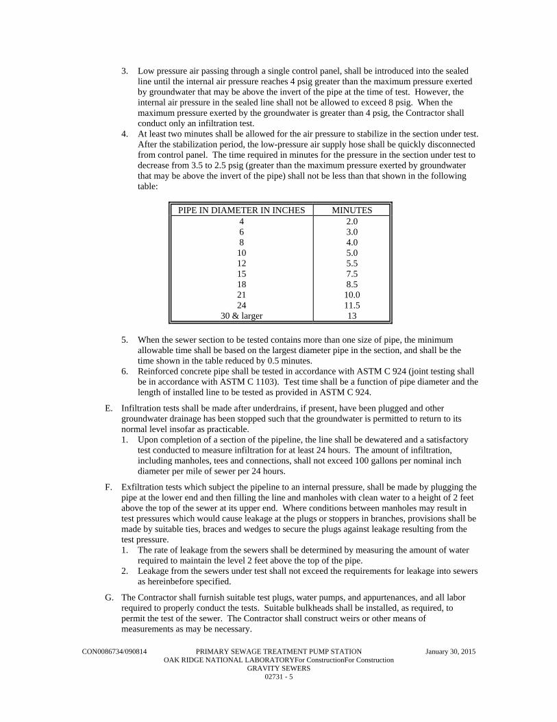
CON0086734/090814 PRIMARY SEWAGE TREATMENT PUMP STATION January 30, 2015 OAK RIDGE NATIONAL LABORATORYFor ConstructionFor Construction GRAVITY SEWERS 02731 - 5
3. Low pressure air passing through a single control panel, shall be introduced into the sealed line until the internal air pressure reaches 4 psig greater than the maximum pressure exerted by groundwater that may be above the invert of the pipe at the time of test. However, the internal air pressure in the sealed line shall not be allowed to exceed 8 psig. When the maximum pressure exerted by the groundwater is greater than 4 psig, the Contractor shall conduct only an infiltration test.
4. At least two minutes shall be allowed for the air pressure to stabilize in the section under test. After the stabilization period, the low-pressure air supply hose shall be quickly disconnected from control panel. The time required in minutes for the pressure in the section under test to decrease from 3.5 to 2.5 psig (greater than the maximum pressure exerted by groundwater that may be above the invert of the pipe) shall not be less than that shown in the following table:
PIPE IN DIAMETER IN INCHES MINUTES 4 6 8
10 12 15 18 21 24
30 & larger
2.0 3.0 4.0 5.0 5.5 7.5 8.5
10.0 11.5 13
5. When the sewer section to be tested contains more than one size of pipe, the minimum
allowable time shall be based on the largest diameter pipe in the section, and shall be the time shown in the table reduced by 0.5 minutes.
6. Reinforced concrete pipe shall be tested in accordance with ASTM C 924 (joint testing shall be in accordance with ASTM C 1103). Test time shall be a function of pipe diameter and the length of installed line to be tested as provided in ASTM C 924.
E. Infiltration tests shall be made after underdrains, if present, have been plugged and other groundwater drainage has been stopped such that the groundwater is permitted to return to its normal level insofar as practicable. 1. Upon completion of a section of the pipeline, the line shall be dewatered and a satisfactory
test conducted to measure infiltration for at least 24 hours. The amount of infiltration, including manholes, tees and connections, shall not exceed 100 gallons per nominal inch diameter per mile of sewer per 24 hours.
F. Exfiltration tests which subject the pipeline to an internal pressure, shall be made by plugging the pipe at the lower end and then filling the line and manholes with clean water to a height of 2 feet above the top of the sewer at its upper end. Where conditions between manholes may result in test pressures which would cause leakage at the plugs or stoppers in branches, provisions shall be made by suitable ties, braces and wedges to secure the plugs against leakage resulting from the test pressure. 1. The rate of leakage from the sewers shall be determined by measuring the amount of water
required to maintain the level 2 feet above the top of the pipe. 2. Leakage from the sewers under test shall not exceed the requirements for leakage into sewers
as hereinbefore specified.
G. The Contractor shall furnish suitable test plugs, water pumps, and appurtenances, and all labor required to properly conduct the tests. Suitable bulkheads shall be installed, as required, to permit the test of the sewer. The Contractor shall construct weirs or other means of measurements as may be necessary.

CON0086734/090814 PRIMARY SEWAGE TREATMENT PUMP STATION January 30, 2015 OAK RIDGE NATIONAL LABORATORYFor ConstructionFor Construction GRAVITY SEWERS 02731 - 6
H. Should the sections under test fail to meet the requirements, the Contractor shall do all work of locating and repairing the leaks and retesting as the Engineer may require without additional compensation.
I. If in the judgment of the Engineer, it is impracticable to follow the foregoing procedures for any reason, modifications in the procedures shall be made as required and as acceptable to the Engineer, but in any event, the Contractor shall be responsible for the ultimate tightness of the line within the above test requirements.
END OF SECTION

CON0086734/090814 PRIMARY SEWAGE TREATMENT PUMP STATION January 30, 2015 OAK RIDGE NATIONAL LABORATORYFor ConstructionFor Construction SEWAGE FORCE MAINS 02732 - 1
SECTION 02732
SEWAGE FORCE MAINS
PART 1 - GENERAL
1.1 WORK INCLUDED
A. The Contractor shall furnish all labor, material, and equipment necessary to install force main piping together with all appurtenances as shown and detailed on the Drawings and specified herein.
1.2 RELATED WORK
A. Section 02225 - Excavating, Backfilling, and Compacting for Utilities.
PART 2 - PRODUCTS
2.1 DUCTILE IRON PIPE (DIP) AND FITTINGS
A. Ductile iron pipe (DIP) shall conform to ANSI/AWWA C150/A21.50, ANSI/AWWA C151/A21.51 Standard (latest). The pipe shall conform to pressure class 350 unless noted otherwise. All fittings shall be capable of accommodating pressure up to 250 psi.
B. Fittings shall be ductile iron in accordance with AWWA C153 and have a body thickness and radii of curvature conforming to ANSI A21.10 or ANSI A21.53 for compact fittings and shall conform to the details and dimensions shown therein. Fittings shall have rubber gasket joints meeting the requirements of AWWA C111. Fittings shall be cement-mortar lined and bituminous coated to conform to the latest revision of ANSI/AWWA standards.
C. Ductile iron flanged joint pipe shall conform to ANSI/AWWA C115/A 21.15 Standard and have a thickness Class of 53. The pipe shall have a rated working pressure of 250 psi with Class 125 flanges. Gaskets shall be ring gaskets with a thickness of 1/8 inch. Flange bolts shall conform to ANSI B 16.1.
D. Flanged fittings shall meet all requirements of ANSI/AWWA C110/A21.10 and have Class 125 flanges. Fittings shall accommodate a working pressure up to 250 psi and be supplied with all accessories.
E. Restrained joint pipe and fittings shall be a boltless system equivalent to "Field Lok" restraining gaskets or "TRFLEX Joint" as manufactured by U.S. Pipe & Foundry Company.
F. Ball and socket restrained joint pipe and fittings shall be a boltless system equivalent to USIFLEX manufactured by U.S. Pipe and Foundry Company or FLEX-LOK manufactured by American Pipe Company. Pipe shall have a maximum joint deflection of 15 degrees. Nominal laying lengths shall be in the range of 18-feet 6-inches to 20-feet 6-inches.
G. All ductile fittings shall be rated at 250 psi water working pressure plus water hammer. Ductile iron fittings shall be ductile cast-iron grade 70-50-05 per ASTM Specification A339.
H. Cement mortar lining and seal coating for pipe and fittings, where applicable, shall be in accordance with ANSI/AWWA C104/A21.4. Bituminous outside coating shall be in accordance with ANSI/AWWA C151/A21.51 for pipe and ANSI/AWWA C110/A21.10 for fittings.
I. Where indicated, high-density, cross-laminated polyethylene film shall be provided for encasement of ductile iron pipe. The film shall meet the requirements of AWWA C105.

CON0086734/090814 PRIMARY SEWAGE TREATMENT PUMP STATION January 30, 2015 OAK RIDGE NATIONAL LABORATORYFor ConstructionFor Construction SEWAGE FORCE MAINS 02732 - 2
J. No separate pay item has been established for fittings and no determination of the number of fittings required on the job has been made. The Contractor, during the bidding phase, shall determine the number of fittings required on the job and include the cost of the fittings and installation in the Contract unit price.
2.2 POLYVINYL CHLORIDE (PVC) FORCE MAIN PIPE
A. Polyvinyl chloride (PVC) pipe for force mains shall be PVC pressure rated pipe with integral bell joints with rubber O-ring seals, of the pressure class and dimension ration shown on the Drawings.
B. All PVC pipe shall conform to the latest revisions of ASTM D-1784 (PVC Compounds), ASTM D-2241 (PVC Plastic Pipe, SDR) and ASTM D-2672 (Bell - End PVC Pipe). PVC pipe shall have a minimum cell classification of 12454B or 12454C ad defined in ASTM D-1784. Rubber gasketed joints shall conform to ASTM D-3139. The gaskets for the PVC pipe joint shall conform to ASTM F-477 and D-1869.
C. Fittings for all lines 4 inches in diameter or larger shall be ductile iron and in accordance with AWWA C153 and have a body thickness and radii of curvature conforming to ANSI A21.10 or ANSI A21.53 for compact fittings. Cement mortar lining and seal coating shall be in accordance with ANSI/AWWA C104/A21.4. Bituminous outside coating shall be in accordance with ANSI/AWWA C110/A21.10. All fittings shall be rated at 250 psi water working pressure plus water hammer and be ductile cast-iron grade 70-50-05 per ASTM Specification A339.
D. Fittings for all lines less than 4 inches in diameter shall be PVC gasketed push-on type or socket glue-type manufactured specifically for the pipe class being utilized. All socket-glue type connections shall be joined with PVC solvent cement conforming to ASTM D2564. Product and viscosity shall be as recommended by the pipe and fitting manufacturer to assure compatibility. Solvent cement joints shall be made up in accordance with the requirements of ASTM D2855. Appropriate thrust blocks shall be provided for the fittings.
E. No separate pay item has been established for fittings and no determination of the number of fittings required on the job has been made. The Contractor during the bidding phase shall determine the number of fittings required and include the cost of the fittings and installation in the unit price for pipe.
F. Rubber gasket joints shall provide adequate expansion to allow for a 50 degree change in temperature on one length of pipe. Lubrication for rubber connected couplings shall be water soluble, non-toxic, be non-objectionable in taste and odor and have no deteriorating affect on the PVC or rubber gaskets and shall be as supplied by the pipe manufacturer.
G. All pipe and couplings shall bear identification markings that will remain legible during normal handling, storage and installation, which have been applied in a manner what will not reduce the strength of the pipe or the coupling or otherwise damage them. Pipe and coupling markings shall include the nominal size and OD base, material code designation, dimension ratio number, ASTM Pressure Class, ASTM designation number for this standard, manufacturer's name or trademark, seal (mark) of the testing agency that verified the suitability of the pipe material for sanitary sewer service. Each marking shall be applied at intervals of not more than 5 feet for the pipe and shall be marked on each coupling.
2.3 POLYVINYL CHLORIDE (PVC) FLANGED PIPE AND FITTINGS
A. Polyvinyl chloride (PVC) pipe for exposed installation shall be Schedule 80, Type IV, Grade 1, conforming to ASTM D1785.
B. PVC fittings shall be Schedule 80 conforming to the requirements of ASTM D2467 for socket type and ASTM D2464 for threaded type.
C. Joints shall be socket-weld, except where connecting to unions, valves, and equipment with threaded or flanged connections that require future disassembly.

CON0086734/090814 PRIMARY SEWAGE TREATMENT PUMP STATION January 30, 2015 OAK RIDGE NATIONAL LABORATORYFor ConstructionFor Construction SEWAGE FORCE MAINS 02732 - 3
D. Where required, flanges shall be 125-pound standard drilling. Gaskets shall be full-faced 1/8-inch thick, fabricated from neoprene. When mating flange has a raised face, use flat ring gasket and provide filler gasket between OD of raised face and flange OD to protect flange from bolting moment. Bolts, nuts and washers for flange connections shall be stainless steel.
E. All socket-weld connections shall be joined with PVC solvent cement conforming to ASTM D2564. Product and viscosity shall be as recommended by the pipe and fitting manufacturer to assure compatibility.
F. Solvent cement joints shall be made up in accordance with the requirements of ASTM D2855.
G. Thread lubricant for threaded fittings shall be teflon tape.
PART 3 - EXECUTION
3.1 LAYING DEPTHS
A. In general, force mains shall be laid with a minimum cover of 30 inches, except as otherwise indicated on the Drawings.
3.2 PIPE LAYING
A. All pipe shall be laid with ends abutting and true to the lines and grades indicated on the Drawings. Pipe shall be fitted and matched so that when laid in the Work, it will provide a smooth and uniform invert. Supporting of pipe shall be as set out in Section 02225 and in no case shall the supporting of pipe on blocks be permitted.
B. Before each piece of pipe is lowered into the trench, it shall be thoroughly swabbed out to insure it being clean. Any piece of pipe or fitting which is known to be defective shall not be laid or placed in the lines. If any defective pipe or fittings shall be discovered after the pipe is laid, it shall be removed and replaced with a satisfactory pipe or fitting without additional charge. In case a length of pipe is cut to fit in a line, it shall be so cut as to leave a smooth end at right angles to the longitudinal axis of the pipe. Bevel can be made with hand or power tools.
C. The interior of the pipe, as the Work progresses, shall be cleaned of dirt, jointing materials, and superfluous materials of every description. When laying of pipe is stopped for any reason, the exposed end of such pipe shall be closed with a plywood plug fitted so as to exclude earth or other material and precautions taken to prevent floatation of pipe by runoff into trench.
D. Anchorage of Bends: 1. At all tees, plugs, caps and bends of 11-1/4 degrees and over, and at reducers or in fittings
where changes in pipe diameter occur, movement shall be prevented by using suitable harness, thrust blocks or ballast. Thrust blocks shall be as shown on the Drawings, with sufficient volumes of concrete being provided; however care shall be taken to leave weep holes unobstructed and allow for future tightening of all nearby joints. Unless otherwise directed by the Engineer, thrust blocks shall be placed so that pipe and fitting joints will be accessible for repair.
2. Bridles, harness or pipe ballasting shall meet with the approval of the Engineer. Steel rods and clamps shall be galvanized or otherwise rust-proofed or painted.
3. No extra pay shall be allowed for work on proper anchorage of pipe, fittings or other appurtenances. Such items shall be included in the price bid for the supported item.
3.3 POLYETHYLENE ENCASEMENT
A. Polyethylene encasement shall be installed on ductile iron pipe where indicated on the Contract Drawings. Installation shall be in accordance with Method ‘B’ as described in AWWA C-105.
3.4 JOINTING
A. Slip Jointed and Heat-Fusion Welded Pipe:

CON0086734/090814 PRIMARY SEWAGE TREATMENT PUMP STATION January 30, 2015 OAK RIDGE NATIONAL LABORATORYFor ConstructionFor Construction SEWAGE FORCE MAINS 02732 - 4
1. All pipe shall be laid with ends abutting and true to the lines and grades indicated on the plans. Pipe shall be fitted and matched so that when laid in the Work, it will provide a smooth and uniform invert. Supporting of pipe shall be as set out in Section 02225 and in no case shall the supporting of pipe on blocks be permitted.
2. Before each piece of pipe is lowered into the trench, it shall be thoroughly swabbed out to insure it being clean. Any piece of pipe or fitting which is known to be defective shall not be laid or placed in the lines. If any defective pipe or fittings shall be discovered after the pipe is laid, it shall be removed and replaced with a satisfactory pipe or fitting without additional charge. In case a length of pipe is cut to fit in a line, it shall be so cut as to leave a smooth end at right angles to the longitudinal axis of the pipe. Bevel can be made with hand or power tools.
3. The interior of the pipe, as the Work progresses, shall be cleaned of dirt, jointing materials, and superfluous materials of every description. When laying of pipe is stopped for any reason, the exposed end of such pipe shall be closed with a plywood plug fitted so as to exclude earth or other material and precautions taken to prevent floatation of pipe by runoff into trench.
4. Anchorage of Bends: a. At all tees, plugs, caps and bends of 11-1/4 degrees and over, and at reducers or in
fittings where changes in pipe diameter occur, movement shall be prevented by using suitable harness, thrust blocks or ballast. Thrust blocks shall be as shown on the Drawings, with sufficient volumes of concrete being provided; however, care shall be taken to leave weep holes unobstructed and allow for future tightening of all nearby joints. Unless otherwise directed by the Engineer, thrust blocks shall be placed so that pipe and fitting joints will be accessible for repair.
b. Bridles, harness or pipe ballasting shall meet with the approval of the Engineer. Steel rods and clamps shall be galvanized or otherwise rust-proofed or painted.
c. No extra pay shall be allowed for work on proper anchorage of pipe, fittings or other appurtenances. Such items shall be included in the price bid for the supported item.
B. No backfilling (except for securing pipe in place) over pipe will be allowed until the Engineer has the opportunity to make an inspection of the joints, alignment and grade in the section laid, but such inspection shall not relieve the Contractor of further liability in case of defective joints, misalignment caused by backfilling and other such deficiencies that are noted later.
C. All joint surfaces shall be cleaned immediately before jointing the pipe. The joint shall be lubricated in accordance with the pipe manufacturer's recommendations. Each pipe unit shall then be carefully pushed into place without damage to pipe or gasket. All pipe shall be provided with home marks to insure proper gasket seating. Details of gasket installation and joint assembly shall follow the manufacturer's direction for the joint type and material of the pipe. The resulting joints shall be watertight and flexible.
D. Solvent Welded Pipe: 1. All rigid plastic pipe shall be cut, made up, and installed in accordance with the pipe
manufacturer’s recommendations. When installed exposed, the pipe shall be supported or hung in accordance with the manufacturer’s recommendations.
2. Containers of solvent cement shall be completely closed except when cement is being applied to pipe components. Should the solvent cement become lumpy or thickened, it shall be discarded, and a new container opened.
3. Schedule 80 threaded adapters shall be used where necessary to connect to a threaded valve or fitting.
4. Only strap wrenches shall be used for tightening threaded plastic joints, and care shall be taken not to overtighten those joints.
5. Solvent welded pipe shall not be laid or installed when the ambient temperature is below 40 degrees F, nor above 90 degrees F when exposed to direct sunlight. Ends to be joined shall be shielded from direct sunlight prior to and during the laying operation.
6. Provide adequate ventilation when working with pipe joint solvent cement.

CON0086734/090814 PRIMARY SEWAGE TREATMENT PUMP STATION January 30, 2015 OAK RIDGE NATIONAL LABORATORYFor ConstructionFor Construction SEWAGE FORCE MAINS 02732 - 5
3.5 TESTING OF FORCE MAINS
A. The completed work shall comply with the provisions listed herein, or similar requirements which will insure equal or better results. Suitable test plugs, water pump or other equipment and apparatus, and all labor required to properly conduct the tests shall be furnished by the Contractor at no expense to the Company.
B. Force main piping shall be pressure tested to 250 percent of the normal system operating pressure or to 100 percent of the rated pressure of the pipe, whichever is less. At no time shall the test pressure exceed 100 percent of the pipe's rated pressure. A pipe section shall be accepted if the test pressure does not fall more than 5 percent during the 4-hour period.
C. All piping shall be tested for leakage at a pressure no less than that specified for the pressure test. The leakage shall be less than an allowable amount determined by the following equation:
L ND (P)½
7,400
Where: L = allowable leakage (gallon/hour) N = number of joints in length of pipeline tested D = nominal diameter of pipe (inches) P = test pressure (psig)
D. Should the sections under test fail to meet the requirements, the Contractor shall do all work locating and repairing the leaks and retesting as the Engineer may require without additional compensation.
E. If in the judgment of the Engineer, it is impracticable to follow the foregoing procedures for any reason, modifications in the procedures shall be made as required and as acceptable to the Engineer, but in any event, the Contractor shall be responsible for the ultimate tightness of the line within the above test requirements.
END OF SECTION

This page intentionally left blank.

CON00867434 Oak Ridge National Laboratory January 30, 2015 Primary Sewage Treatment Pump Station - For Construction AIR PIPING 02733 - 1
SECTION 02733
AIR PIPING
PART 1 - GENERAL
1.1 WORK INCLUDED
A. The Contractor shall furnish all labor, material, and equipment necessary to install air piping together with all appurtenances as shown and detailed on the Drawings and specified herein.
PART 2 - PRODUCTS
2.1 UNLINED STEEL PIPING
A. Unlined steel piping shall conform to the requirements of ASTM A139, Standard Specification for Electric Fusion (Arc) Welded Steel Pipe (NPS 4 and Over), latest revision.
B. Fittings for unlined steel piping shall conform to the requirements of ANSI B16.9, Factory Made Wrought Steel Buttwelding Fittings.
C. The exposed components of air piping shall be provided with flat faced, carbon steel, or alloy Class 125 flanges at points which will allow the component portions of the system to be disassembled into manageable units. Higher pressure rated flanges shall be provided as required to mate with equipment when the equipment flange is of a higher pressure rating than required for piping. Fittings shall have high temperature gaskets of EPDM or Viton with a minimum thickness of 1/8-inch.
2.2 DUCTILE IRON PIPE (DIP) AND FITTINGS
A. Ductile iron pipe (DIP) shall conform to ANSI/AWWA C150/A21.50, ANSI/AWWA C151/A21.51 Standard (latest). The pipe shall conform to pressure class 350 unless noted otherwise. All pipe, fittings and joints should be capable of accommodating pressure up to 350 psi. The ductile iron pipe shall be as manufactured by Clow Corporation, U.S. Pipe & Foundry Company, American Cast Iron Pipe Company, or approved equal.
B. Mechanical joint fittings shall be ductile iron in accordance with AWWA C153 and have a body thickness and radii of curvature conforming to ANSI A21.10 or ANSI A21.53 for compact fittings and shall conform to the details and dimensions shown therein. Fittings shall have EPDM high temperature gasket joints meeting the latest requirements. Fittings shall be bituminous coated to conform to the latest revision of ANSI/AWWA standards.
C. Ductile iron flanged joint pipe shall conform to ANSI/AWWA C115/A 21.15 Standard and have a thickness Class of 53. The pipe shall have a rated working pressure of 350 psi with Class 125 flanges. Gaskets shall be high temperature gaskets with a thickness of 1/8 inch consisting of organic fibers (Kevlar) and neoprene binder.
D. Flanged fittings shall meet all requirements of ANSI/AWWA C110/A21.10 and have Class 125 flanges. Fittings shall accommodate a working pressure up to 250 psi and be supplied with all accessories.
E. All ductile iron pipe and fittings shall have the manufacturer's outside asphaltic coating and no interior lining.
F. Bituminous outside coating shall be in accordance with ANSI/AWWA C151/A21.51 for pipe and ANSI/AWWA C110/A21.10 for fittings.

CON00867434 Oak Ridge National Laboratory January 30, 2015 Primary Sewage Treatment Pump Station - For Construction AIR PIPING 02733 - 2
G. All ductile fittings shall be rated at 250 psi water working pressure plus water hammer. Ductile iron fittings shall be ductile cast-iron grade 70-50-05 per ASTM Specification A339.
H. No separate pay item has been established for fittings and no determination of the number of fittings required on the job has been made. The Contractor, during the bidding phase, shall determine the number of fittings required on the job and include the cost of the fittings and installation in the Contract unit price.
PART 3 - EXECUTION
3.1 PIPE INSTALLATION, GENERAL
A. In general, buried pipe lines shall be laid with a minimum cover of 30 inches, except as otherwise indicated on the Drawings. Exposed pipe lines shall be installed as indicated on the Drawings, unless the manufacturer’s requirements dictate otherwise.
3.2 AIR PIPING INSTALLATION
A. Welded Steel Pipe: 1. Preparation: Notify Engineer at least 2 weeks prior to field fabrication of pipe or fittings.
Prior to beginning fabrication, verify size, material, joint types, elevation, and horizontal location of existing pipelines to be connected to new pipelines or new equipment. Verify proper grade and type of welding electrodes are present at site, free of moisture and dampness, and coating is undamaged.
2. Fabrication: a. Join pipe and fittings in accordance with manufacturer's instructions, unless otherwise
shown or specified. b. Remove foreign objects prior to assembly and installation. c. For flanged connectors:
1) Install perpendicular to pipe centerline. Bolt holes shall straddle vertical centerlines, align with connecting equipment flanges, or as shown on the Drawings.
2) Use torque limiting wrenches to ensure uniform bearing and proper bolt tightness. 3) Raised Face Flanges: Use flat face flange when joining with flat faced ductile or
cast iron flange. 4) For installation of exposed piping, piping runs shall be parallel to building or
column lines and perpendicular or parallel to floor, unless shown otherwise. 5) Piping upstream and downstream of flow measuring devices shall provide straight
lengths as required for accurate flow measurement. 6) Install piping so that no load or movement in excess of that stipulated by
equipment manufacturer will be imposed upon equipment connection; install to allow for contraction and expansion without stressing pipe, joints, or connected equipment.
3. Piping clearance, unless otherwise shown: a. Over Walkways and Stairs: Minimum of 7 feet 6 inches, measured from walking
surface or stair tread to lowest extremity of piping system including flanges, valve bodies or mechanisms, insulation, or hanger/support systems.
b. Between Equipment or Equipment Piping and Adjacent Piping: Minimum 3 feet-0 inch(es), measured from equipment extremity and extremity of piping system including flanges, valve bodies or mechanisms, insulation, or hanger/support systems.
c. From Adjacent Work: Minimum 1inch from nearest extremity of completed piping system including flanges, valve bodies or mechanisms, insulation, or hanger/support systems.
d. Do not route piping in front of or to interfere with access ways, ladders, stairs, platforms, walkways, openings, doors, or windows.

CON00867434 Oak Ridge National Laboratory January 30, 2015 Primary Sewage Treatment Pump Station - For Construction AIR PIPING 02733 - 3
e. Headroom in front of openings, doors, and windows shall not be less than the top of the opening.
f. Do not route piping over, around, in front of, in back of, or below electrical equipment including controls, panels, switches, terminals, boxes, or other similar electrical work.
4. Perform welding in accordance with Section IX, ASME Boiler and Pressure Vessel Code and ASME B31.1 for Pressure Piping. a. Weld Identification: Mark each weld with symbol identifying welder performing the
work. b. Pipe End Preparation:
1) Machine shaping is preferred. 2) Oxygen or Arc Cutting shall be smooth to touch, true, and slag removed by
chipping or grinding. 3) Beveled Ends for Butt Welding shall conform to ANSI B16.25.
c. Surfaces: 1) Clean and free of paint, oil, rust, scale, slag, or other material detrimental to
welding. 2) Clean stainless steel joints with stainless steel wire brushes or stainless steel wool
prior to welding. 3) Thoroughly clean each layer of deposited weld metal, including final pass, prior to
deposition of each additional layer of weld metal with a power driven wire brush. d. Alignment and Spacing:
1) Align ends to be joined within existing commercial tolerances on diameters, wall thicknesses, and out of roundness.
2) Root Opening of Joint: As stated in qualified welding procedure. 3) Minimum Spacing of Circumferential Butt Welds: Minimum four times pipe wall
thickness or 1 inch, whichever is greater. e. Climatic Conditions:
1) Do not perform welding if there is impingement of any rain, snow, sleet, or high wind on the weld area, or if the ambient temperature is below 32 degrees F.
2) Stainless Steel and Alloy Piping: If the ambient is less than 32 degrees F, local preheating to a temperature warm to the hand is required.
f. Tack Welds shall be performed by qualified welder using same procedure as for completed weld, made with electrode similar or equivalent to electrode to be used for first weld pass, and not defective. Remove those not meeting requirements prior to commencing welding procedures.
g. Surface Defects: Chip or grind out those affecting soundness of weld. h. Weld Passes: As required in welding procedure. i. Weld Quality: Free of cracks, incomplete penetration, weld undercutting, excessive
weld reinforcement, porosity slag inclusions, and other defects in excess of limits shown in applicable piping code.
5. Pipe Corrosion Protection and Finishing a. Notify Engineer at least 3 days prior to start of any surface preparation or coating
application work. b. Provide the following coating and identification systems for Carbon Steel Pipe:
1) Exposed: As specified in Section 09900, Painting. 2) Submerged or Embedded: Shop coat with coal tar epoxy as specified in Section
09900, Painting. If in potable water service, use NSF 61 approved epoxy. 3) Piping Identification shall be as specified in Section 09900, Painting.
6. Cleaning a. Blow Air Piping clean of loose debris prior to making final connections to diffusers or
injectors. Blow clean with compressed air at 4,000 fpm; do not flush with water.

CON00867434 Oak Ridge National Laboratory January 30, 2015 Primary Sewage Treatment Pump Station - For Construction AIR PIPING 02733 - 4
B. Slip Jointed Pipe: 1. All pipe shall be laid with ends abutting and true to the lines and grades indicated on the
plans. Pipe shall be fitted and matched so that when laid in the Work, it will provide a smooth and uniform invert. Supporting of pipe shall be as set out in Section 02225 and in no case shall the supporting of pipe on blocks be permitted.
2. Before each piece of pipe is lowered into the trench, it shall be thoroughly swabbed out to insure it being clean. Any piece of pipe or fitting which is known to be defective shall not be laid or placed in the lines. If any defective pipe or fittings shall be discovered after the pipe is laid, it shall be removed and replaced with a satisfactory pipe or fitting without additional charge. In case a length of pipe is cut to fit in a line, it shall be so cut as to leave a smooth end at right angles to the longitudinal axis of the pipe. Bevel can be made with hand or power tools.
3. The interior of the pipe, as the Work progresses, shall be cleaned of dirt, jointing materials, and superfluous materials of every description. When laying of pipe is stopped for any reason, the exposed end of such pipe shall be closed with a plywood plug fitted so as to exclude earth or other material and precautions taken to prevent floatation of pipe by runoff into trench.
4. Anchorage of Bends: a. At all tees, plugs, caps and bends of 11-1/4 degrees and over, and at reducers or in
fittings where changes in pipe diameter occur, movement shall be prevented by using suitable harness, thrust blocks or ballast. Thrust blocks shall be as shown on the Drawings, with sufficient volumes of concrete being provided; however, care shall be taken to leave weep holes unobstructed and allow for future tightening of all nearby joints. Unless otherwise directed by the Engineer, thrust blocks shall be placed so that pipe and fitting joints will be accessible for repair.
b. Bridles, harness or pipe ballasting shall meet with the approval of the Engineer. Steel rods and clamps shall be galvanized or otherwise rust-proofed or painted.
c. No extra pay shall be allowed for work on proper anchorage of pipe, fittings or other appurtenances. Such items shall be included in the price bid for the supported item.
5. No backfilling (except for securing pipe in place) over pipe will be allowed until the Engineer has the opportunity to make an inspection of the joints, alignment and grade in the section laid, but such inspection shall not relieve the Contractor of further liability in case of defective joints, misalignment caused by backfilling and other such deficiencies that are noted later.All joint surfaces shall be cleaned immediately before jointing the pipe. The bell or groove shall be lubricated in accordance with the pipe manufacturer's recommendations. Each pipe unit shall then be carefully pushed into place without damage to pipe or gasket. All pipe shall be provided with home marks to insure proper gasket seating. Details of gasket installation and joint assembly shall follow the direction of the manufacturer's of the joint material and of the pipe. The resulting joints shall be watertight and flexible.
C. Solvent Welded Pipe: 1. All rigid CPVC pipe shall be cut, made up, and installed in accordance with the pipe
manufacturer’s recommendations. Where laid in a trench, the plastic pipe shall be laid by snaking it from one side of the trench to the other. When installed exposed, the pipe shall be supported or hung in accordance with the manufacturer’s recommendations.
2. Containers of solvent cement shall be completely closed except when cement is being applied to pipe components. Should the solvent cement become lumpy or thickened, it shall be discarded, and a new container opened.
3. Schedule 80 threaded adapters shall be used where necessary to connect to a threaded valve or fitting.
4. Only strap wrenches shall be used for tightening threaded plastic joints, and care shall be taken not to over-tighten those joints.
5. Solvent welded pipe shall not be laid or installed when the ambient temperature is below 40 degrees F, nor above 90 degrees F when exposed to direct sunlight. Ends to be joined shall be shielded from direct sunlight prior to and during the laying operation.
6. Provide adequate ventilation when working with pipe joint solvent cement.

CON00867434 Oak Ridge National Laboratory January 30, 2015 Primary Sewage Treatment Pump Station - For Construction AIR PIPING 02733 - 5
3.3 TESTING OF LOW PRESSURE AIR LINES
A. The completed work shall comply with the provisions listed herein, or similar requirements which will insure equal or better results. Suitable test plugs or caps, air pumps, compressors, or other equipment and apparatus, and all labor required to properly conduct the tests shall be furnished by the Contractor at no expense to the Company.
B. Low pressure air tests shall be made using equipment specifically designed and manufactured for the purpose of testing piping using low pressure air. The equipment shall be provided with an air regulator valve or air safety valve so set that the internal pressure in the pipeline cannot exceed psig. 1. The test shall be made on isolatable sections of pipe after erection or placement of the
backfill. The Engineer or his designated representative must be present to witness each satisfactory air test before it will be accepted as fulfilling the requirements of these Specifications.
2. Pneumatic plugs shall have a sealing length equal to or greater than the diameter of the pipe to be tested. Pneumatic plugs shall resist internal test pressures without requiring external bracing or blocking. If caps are used, they shall be removable following the testing without damaging the piping.
3. Low pressure air passing through a single control panel, shall be introduced into the sealed line until the internal air pressure the previously specified pressure.
4. At least two minutes shall be allowed for the air pressure to stabilize in the section under test. (Note: Where the piping is exposed to full sunlight, the testing should be conducted in the very early morning, or in darkness.) After the stabilization period, the low-pressure air supply hose shall be quickly disconnected from control panel. The time required in minutes for the pressure in the section under test to decrease by 1 psig shall not be less than that shown in the following table:
C.
Pipe in Diameter in Inches
Minutes
4 or less 6 8 10 12 15 18 21 24 30 & larger
2.0 3.0 4.0 5.0 5.5 7.5 8.5 10.0 11.5 13.5
1. When the air piping section to be tested contains more than one size of pipe, the minimum allowable time shall be based on the largest diameter pipe in the section, and shall be the time shown in the table reduced by 0.5 minutes.
D. Should the sections under test fail to meet the requirements, the Contractor shall do all work locating and repairing the leaks and retesting as the Engineer may require without additional compensation.
E. If in the judgment of the Engineer, it is impracticable to follow the foregoing procedures for any reason, modifications in the procedures shall be made as required and as acceptable to the Engineer, but in any event, the Contractor shall be responsible for the ultimate tightness of the line within the above test requirements.
END OF SECTION

This page intentionally left blank.

CON00867434 Oak Ridge National Laboratory January 30, 2015 Primary Sewage Treatment Pump Station - For Construction MANHOLES AND PRECAST SEWAGE STRUCTURES 02735 - 1
SECTION 02735
MANHOLES AND PRECAST SEWAGE STRUCTURES
PART 1 - GENERAL
1.1 WORK INCLUDED
A. The Contractor shall furnish all labor, material, and equipment necessary to construct manholes for sanitary sewers, including steps, frames and covers, together with all appurtenances as shown and detailed on the Drawings and specified herein. Manhole materials shall be precast concrete as detailed on the Contract Drawings. An internal flexible rubber frame seal and where necessary, an interlocking extension or extensions, shall be used to seal the entire chimney of all sanitary manholes. The seal and extension or extensions shall extend from the frame down to the top of the cone.
B. When and where detailed or specified, the Contractor shall furnish all labor, material, and equipment necessary to construct wetwells and valve vaults for sanitary sewer collection system or sewage treatment pump stations, including steps, cast-in place hatches, and all appurtenances as shown and detailed on the Drawings and specified herein. Wetwell and valve vault materials shall be precast concrete as detailed on the Contract Drawings.
1.2 RELATED WORK
A. Section 02731 - Gravity Sewers.
B. Section 02732 - Sewage Force Mains
C. Division 3 - Concrete.
1.3 DEFINITIONS
A. Standard Manhole: Any manhole that is greater than 4 feet in depth, as measured from the invert of the manhole base at its center to the bottom of the manhole frame. A standard manhole will terminate with a manhole cone with ring and lid.
B. Shallow Manhole: Any manhole that is 4 feet or less in depth, as measured in the preceding sentence. A shallow manhole will terminate in a flat top with ring and lid.
C. Manhole Chimney: The cylindrical variable height portion of a manhole structure used to support and adjust the finished grade of the manhole frame. The chimney extends from the top of the cone to the base of the manhole frame.
D. Manhole Cone: That portion of a manhole structure which slopes upward and inward from the barrel of the manhole to the required chimney or frame diameter.
E. Wetwell: A pump station sewage containing structure constructed of pre-cast concrete components which could be used for large diameter manholes. A wetwell will terminate in a flat top with a hatch and lid cast into the cover.
F. Valve vault: A pump station valve protection structure constructed of pre-cast concrete components which could be used for manholes. A valve vault will terminate in a flat top with a hatch and lid cast into the cover.

CON00867434 Oak Ridge National Laboratory January 30, 2015 Primary Sewage Treatment Pump Station - For Construction MANHOLES AND PRECAST SEWAGE STRUCTURES 02735 - 2
PART 2 - PRODUCTS
2.1 CONCRETE MANHOLES - GENERAL
A. Manholes shall conform, in shape, size, dimensions, materials, and other respects, to the details indicated on the Drawings. 1. All 4-foot diameter concrete manholes shall have precast reinforced concrete developed
bases. Invert channels shall be factory constructed when the base is made. Sloping invert channels shall be constructed whenever the difference between the inlet and outlet elevation is 2 feet or less. The inverts of the developed bases shall conform accurately to the size of the adjoining pipes. Side inverts shall be curved and main inverts (where direction changes) shall be laid out in smooth curves of the longest possible radius which is tangent, within the manhole, to the centerlines of adjoining pipelines. Concrete Manholes with diameters greater than 4 feet shall have cast-in-place or plastic formed inverts which shall be installed after construction of the manhole.
2. The concrete manhole walls (barrels and cones) shall be precast concrete sections. The top of the cone shall be built of reinforced concrete adjustment rings to permit adjustment of the frame to meet the finished surface. Minimum strength of the concrete for the precast sections shall be 4,000 psi at the time of shipment.
3. The base section shall be monolithic for 4-foot diameter manholes. Manholes with a diameter of 5 feet or larger shall have a base slab.
4. Manhole frames and covers shall be the standard frame and cover as indicated on the Drawings and specified hereinafter in this Section.
B. Manholes shall be manufactured by Sherman Dixie Concrete Industries, or approved equivalent.
2.2 CONCRETE WETWELLS AND VALVE VAULTS - GENERAL
A. Wetwells and valve vaults shall conform, in shape, size, dimensions, materials, and other respects, to the details indicated on the Drawings. 1. Concrete wetwells shall have cast-in-place inverts. Invert slopes shall be as depicted on the
drawings or as required by the pump manufacturer. 2. The concrete wetwell and valve vault walls (barrels) shall be precast concrete sections. The
tops of both structures shall be flat, with frames and hatches cast into the slab sections. Minimum strength of the concrete for the precast sections shall be 4,000 psi at the time of shipment.
3. The base section shall be monolithic for 4-foot diameter wetwells and valve vault structures. Wetwells and valve vault structures with diameters of 5 feet or larger shall have a base slab.
B. Precast components for wetwells and valve vaults shall be manufactured by Sherman Dixie Concrete Industries, or approved equivalent.
2.3 PRECAST CONCRETE SECTIONS
A. Precast concrete sections and appurtenances shall conform to the ASTM Standard Specifications for Precast Reinforced Concrete Manhole Sections, Designation C478, latest revision, with the following exceptions and additional requirements. 1. The wall sections shall be not less than 5 inches thick. 2. Only Type II cement shall be used except as otherwise specified.
B. Joints between sections shall be made watertight through the use of rubber O-ring gaskets or rubber profile gaskets such as Forsheda 138. Gaskets shall conform to the ASTM Standard C-443, latest revision. Rope mastic or butyl mastic sealant shall not be allowed except as sealant between the cone section, any adjusting sections or rings, and the frame casting.
2.4 MANHOLES FRAMES AND COVERS
A. The Contractor shall furnish all cast-iron manhole frames and covers conforming to the details shown on the Drawings, or as specified.

CON00867434 Oak Ridge National Laboratory January 30, 2015 Primary Sewage Treatment Pump Station - For Construction MANHOLES AND PRECAST SEWAGE STRUCTURES 02735 - 3
1. The castings shall be of good quality, strong, tough, evengrained cast iron, smooth, free from scale, lumps, blisters, sandholes, and defects of every nature which would render them unfit for the service for which they are intended. Contact surfaces of covers and frame seats shall be machined to prevent rocking of covers.
2. All castings shall be thoroughly cleaned and subject to a careful hammer inspection. 3. Castings shall be at least Class 25 conforming to the ASTM Standard Specifications for
Gray Iron Casting, Designation A48, latest revision. 4. Unless otherwise specified or detailed, manhole covers shall be 22-3/4 inches in diameter,
weighing not less than 350 pounds per frame and cover. Manhole covers shall set neatly in the rings, with contact edges machined for even bearing and tops flush with ring edge. They shall have sufficient corrugations to prevent slipperiness. The covers shall have two (2) pick holes about 1-1/4 inches wide and 2 inches deep with 3/8-inch undercut all around. Covers shall not be perforated.
5. All covers shall be marked in large letters "SANITARY SEWER" in the center.
B. Frames and covers shall be J.R. Hoe and Sons, Mc-350, or approved equivalent.
2.5 MANHOLE STEPS (CONCRETE MANHOLES)
A. Manholes steps shall be the polypropylene plastic type reinforced with a deformed steel rod. The steps shall be of the size and configuration as shown on the Drawings. Steps shall line up over the downstream invert of the manhole. The steps shall be embedded into the manhole wall a minimum of 3-3/8 inches. Steps shall be uniformly spaced at 12-inch to 16-inch intervals.
2.6 PIPE CONNECTOR SYSTEM
A. All holes for pipe connections in manhole and wetwell barrels and bases shall have a factory-installed flexible rubber pipe connector system to prevent infiltration. The pipe connector system shall conform to the latest revision of ASTM-C923.
B. For manholes of 12 feet or less in depth, without the presence of ground water, the pipe connector system shall be A-Lok Manhole Pipe Seal as manufactured by A-Lok Corporation, Trenton, NJ; Contour Seal or Kor-N-Seal as manufactured by National Pollution Control Systems, Inc., Nashua, NH; PSX as manufactured by Press-Seal Gasket Corporation, or an approved equivalent.
C. For manholes of 12 feet or greater in depth, or when ground water is present, the pipe connector system shall be A-Lok Manhole Pipe Seal as manufactured by A-Lok Corporation, Trenton, NJ, or an approved equivalent.
2.7 POLYETHYLENE DIAPHRAGM MANHOLE FRAME INSERTS
A. Polyethylene diaphragm manhole frame inserts shall be installed in all manholes. 1. Polyethylene diaphragm manhole frame inserts shall be manufactured from corrosion-proof
material suitable for atmospheres containing hydrogen sulfide and diluted sulfuric acid. 2. The body of the manhole insert shall be made of high density polyethylene copolymer
material meeting ASTM Specification D 1248, Class A, Category 5, Type III (the insert shall have a minimum impact brittleness temperature of -180 degrees Fahrenheit). The thickness shall be a uniform 1/8 inch or greater. The manhole frame insert shall be manufactured to dimensions as shown on the Drawings to allow easy installation within the manhole frame.
3. Insert gaskets shall be made of closed cell neoprene. The gasket shall have a pressure sensitive adhesive on one side and shall be placed under the weight bearing surface of the insert by the manufacturer. The adhesive shall be compatible with the manhole insert material so as to form a long-lasting bond in either wet or dry conditions.
4. A lift strap shall be attached to the rising edge of the bowl insert. The lift strap shall be made of 1 inch wide woven polypropylene web and shall be seared on all cut ends to prevent unraveling. The lift strap shall be attached to the manhole insert by means of a stainless steel rivet. Placement of the lift strap shall provide easy visual location.

CON00867434 Oak Ridge National Laboratory January 30, 2015 Primary Sewage Treatment Pump Station - For Construction MANHOLES AND PRECAST SEWAGE STRUCTURES 02735 - 4
5. Standard ventilation shall be by means of vent hole on the side wall of the manhole frame insert approximately 3/4-inches below the lip. The vent hole will allow a maximum release of 10 gallons per 24 hours when the insert is full.
6. The manhole frame insert shall be manufactured to fit the manhole frame rim upon which the manhole cover rests. The Contractor is responsible for obtaining specific measurements of each manhole cover to insure a proper fit. The manhole frame shall be cleaned of all dirt, scale and debris before placing the manhole frame insert on the rim.
B. The polyethylene diaphragm manhole inserts shall be as provided by any manufacturer approved by the Engineer.
2.8 MANHOLE FRAME SEAL
A. Manhole frame seals shall consist of a flexible internal rubber sleeve and extension and stainless steel compression bands, all conforming to the following requirements: 1. Rubber Sleeve and Extension - The flexible rubber sleeve, extensions and wedge strips shall
be extruded or molded from a high grade rubber compound conforming to the applicable requirements of ASTM C-923, with a minimum 1500 psi tensile strength, maximum 18% compression set and a hardness (durometer) of 48 5.
2. The sleeve shall be either double or triple pleated, with a minimum unexpanded vertical height of 8 inches and 10 inches respectively and a minimum thickness of 3/16 inches. The top and bottom section of the sleeve shall contain an integrally formed expansion band recess and multiple sealing fins.
3. The top section of the extension shall have a minimum thickness of 3/32 inches and shall be shaped to fit into the bottom band recess of the sleeve under the bottom chimney seal band and the remainder of the extension shall have a minimum thickness of 3/16 inches. The bottom section of the extension shall contain an integrally formed expansion band recess and multiple sealing fins matching that of the rubber sleeve.
4. Any splice used to fabricate the sleeve and extension shall be hot vulcanized and have a strength such that the sleeve shall withstand a 180 degree bend with no visible separation.
5. The continuous wedge strip used to adapt the rubber sleeve to sloping surfaces shall have the slope differential needed to provide a vertical band recess surface, be shaped to fit into the band recess and have an integral band restraint. The length of the wedge strip shall be such that, when its ends are butted together, it will cover the entire inside circumference of that band recess needing slope adjustment.
6. The expansion bands used to compress the sleeve against the manhole shall be integrally formed from 16 gauge stainless steel conforming to ASTM A-240 Type 304, with no welded attachments and shall have a minimum width of 1: inches.The bands shall have a minimum adjustment range of 2 diameter inches and the mechanism used to expand the band shall have the capacity to develop the pressures necessary to make a watertight seal. The band shall be permanently held in this expanded position with a positive locking mechanism, any studs and nuts used for this mechanism shall be stainless steel conforming to ASTM F-923 and 594, Type 304.
B. Manhole frame seals shall be manufactured by Cretex Specialty Products or approved equivalent.
2.9 CLEANOUTS
A. Cleanouts shall be extended to finish grade and capped with a clean-out plug in accordance with details and at locations shown on the Drawings. 1. Pipe shall be the same as the gravity sewer line in which the cleanout is located. 2. A 4-inch thick concrete pad, 2 feet 0-inches square, with the cleanout lid section, shall be
provided around each cleanout.
2.10 DROP CONNECTIONS
A. Drop connections shall be installed in the manhole as shown on the Drawings.

CON00867434 Oak Ridge National Laboratory January 30, 2015 Primary Sewage Treatment Pump Station - For Construction MANHOLES AND PRECAST SEWAGE STRUCTURES 02735 - 5
PART 3 - EXECUTION
3.1 FABRICATION - PRECAST SECTIONS
A. Manhole and valve vault sections shall contain manhole steps accurately positioned and embedded in the concrete when the section is cast. Wet well sections shall contain no manhole steps.
B. Sections shall be cured in an enclosed curing area and shall attain a strength of 4,000 psi prior to shipment.
C. No more than two (2) lift holes or inserts may be cast or drilled in each section.
D. Flat slab tops shall have a minimum thickness of 6 inches and reinforcement in accordance with ASTM C478.
E. The date of manufacture and the name or trademark of the manufacturer shall be clearly marked on the precast sections.
F. Acceptance of the sections will be on the basis of material tests and inspection of the completed product and test cylinders if requested by the Engineer.
G. Cones shall be precast sections of similar construction.
3.2 SETTING PRECAST SECTIONS
A. Precast reinforced concrete sections shall be set so as to be vertical and with sections and steps, where required, in true alignment.
B. Rubber gaskets shall be installed in all section joints in accordance with the manufacturer's recommendations.
C. All holes in sections used for their handling shall be thoroughly plugged with rubber plugs made specifically for this purpose.
3.3 SETTING MANHOLE FRAMES AND COVERS
A. Manhole frames shall be set with the tops conforming to the required elevations set forth hereinbefore. Frames shall be set concentric with the top of the concrete and in a full bead of butyl mastic sealant so that the space between the top of the manhole and the bottom flange of the frame shall be completely watertight.
B. Manhole covers shall be left in place in the frames on completion of other work at the manholes.
3.4 INSTALLATION OF MANHOLE FRAME SEAL
A. The Contractor shall measure the manhole to determine the information required on the manufacturer’s “Sizing and Ordering” procedure. 1. All sealing surfaces shall be reasonably smooth, clean and free of any form offsets or
excessive honeycomb. The top internal portions of the cone shall have a minimum 3-inch high vertical surface. The preparation of this vertical surface when none exists shall be in accordance with the frame seal manufacturer’s instructions.
2. The internal frame seals and extensions shall be installed in accordance with the manufacturer’s instructions. The Contractor shall have a manufacturer’s recommended expansion tool and all other equipment/tools necessary to install the frame seals.
3. Manhole frame seals shall be visually inspected after installation to ensure that the seal is properly positioned, tight against the manhole and frame surfaces, that no voids or leakage points exist and that the bands are securely locked in place. Any seals failing this inspection shall be reworked as necessary and reinspected at no additional cost to the Company.

CON00867434 Oak Ridge National Laboratory January 30, 2015 Primary Sewage Treatment Pump Station - For Construction MANHOLES AND PRECAST SEWAGE STRUCTURES 02735 - 6
3.5 ADJUSTING MANHOLE FRAMES AND COVERS TO GRADE
A. Unless otherwise shown on the Drawings, the top of the precast concrete eccentric cone of a standard manhole or the top of the flat slab of a shallow manhole shall terminate not less than 4 inches below existing grade in an unpaved non-traffic area (except in a residential yard) and not less than 13 inches below existing grade in a paved or unpaved traffic area and in a residential yard. The frame and lid shall be adjusted to the required final grade as described hereinafter.
B. Only clean adjusting sections shall be used. Each adjusting section shall be laid in a bead of butyl mastic sealant and shall be thoroughly bonded.
C. When a manhole is located in an unpaved non-traffic area (other than a residential yard), the frame and cover shall be adjusted to a final elevation of 3 inches to 5 inches above the existing grade at the center of the cover. If field changes have resulted in the installed manhole invert elevation being lower than the invert elevation shown on the Drawings, the adjustment to the required final elevation of 3 inches to 5 inches above existing grade shall be accomplished by the use of precast concrete adjusting rings. If field changes have resulted in the completed manhole invert being higher than the invert shown on the Drawings and the top of the frame and cover being higher than 5 inches above the existing grade, then the Contractor shall substitute, at no additional cost to the Company, a shorter barrel section on the manhole so that the frame and lid may be adjusted to the proper final elevation through the use of precast concrete adjusting rings.
D. When a manhole is located in a bituminous, concrete, or crushed stone traffic area, or in a residential yard, the frame and cover shall be adjusted to the grade of the surrounding area by the use of precast concrete rings. The adjusted frame and lid shall conform to the elevation and slope of the surrounding area. If field changes have resulted in the completed manhole invert being higher than the invert shown on the Drawings and the top of the eccentric cone, when used, or the top of the flat shab, when used, being less than the height of the frame and lid below the grade of the surrounding area, then the Contractor shall substitute, at no additional cost to the Company, a shorter barrel section on the manhole so that the frame and lid may be adjusted to the proper final elevation through the use of precast concrete adjusting rings.
E. The Contractor shall coordinate elevations of manhole covers in paved streets with the Company. If resurfacing of the street in which sewers are laid is expected within twelve (12) months, covers shall be set 1-1/2 inches above the existing pavement surface in anticipation of the resurfacing operations.
3.6 VACUUM TESTING OF MANHOLES AND PRECAST SEWAGE STRUCTURES
A. Manholes shall be tested in accordance with ASTM 1244, after installation with all connections in place. The vacuum test method is intended to demonstrate the condition of manholes prior to backfill. It may also be used to test manholes after backfilling; however, testing should be correlated with the connector supplier.
B. Where groundwater is present in the excavation and trenches, the Contractor shall take any necessary steps (including construction of a piezometric tube adjacent to the manhole) to determine the depth of groundwater above the invert of the manhole at the time of testing, at no additional cost to the Company. Information concerning groundwater levels above the invert shall be used to determine the amount of vacuum applied during the test.
C. A vacuum test for manholes shall include testing of the joint seal between the cast iron frame and the concrete cone, top slab, and any grade rings. Where a hatch and cover are provided in the top of a precast sewage structure, the Contractor shall provide a means of establishing a seal over the hatch, unless the Drawings and notes indicate that the hatch is to be tested for vacuum.
D. Prior to the test, the following items shall be complete: 1. Lift holes, if any, shall be plugged with an approved, non-shrink grout prior to testing. 2. Drop connections, if any, shall be installed prior to testing.
E. Testing Procedure:

CON00867434 Oak Ridge National Laboratory January 30, 2015 Primary Sewage Treatment Pump Station - For Construction MANHOLES AND PRECAST SEWAGE STRUCTURES 02735 - 7
1. Temporarily plug, with the plugs being braced to prevent the plugs or pipes from being drawn into the manhole, all pipes entering the manhole at least eight inches into the sewer pipe(s). The plug must be inflated at a location past the manhole/pipe gasket.
2. The test head shall be placed on the top of the conical, over the manway opening in a flat top, or (in the case of a wetwell or valve vault) over such adapter as may be required, and inflated in accordance with the manufacturer's recommendations.
3. A vacuum of 10 inches of mercury shall be drawn on the manhole, or such lesser amount of vacuum that the combined vacuum and positive external head pressure from groundwater does not exceed the recommended pressure ratings for the pipe connector system. The vacuum shall be measured by a test gauge which shall be liquid filled, having a 3.5 inch diameter face, reading from zero to thirty inches of mercury.
4. The indicated vacuum (as determined under the preceding paragraph) shall be drawn on the manhole, the valve on the vacuum line of the test head closed, and the vacuum pump shut off. The time shall be measured for the vacuum to drop 1 inch of mercury.
5. The manhole shall be considered to pass the vacuum test if the time for the vacuum reading to drop 1 inch of mercury meets or exceeds the values indicated in the following table:
Minimum Test times for Various Manhole Diameters (seconds) Depth Diameter (inches)
(ft.) 30 33 36 42 48 54 60 66 72
8 11 12 14 17 20 23 26 29 33 10 14 15 18 21 25 29 33 36 41 12 17 18 21 25 30 35 39 43 49 14 20 21 25 30 35 41 46 51 57 16 22 24 28 34 40 46 52 58 67 18 25 27 32 38 45 52 59 65 73 20 28 30 35 42 50 58 65 72 81 22 31 33 39 46 55 64 72 79 89 24 33 36 42 51 59 69 78 87 97 26 36 39 46 55 64 75 85 94 105 28 39 42 49 59 69 81 91 101 113 30 42 45 53 63 74 87 98 108 121
6. If a manhole fails the vacuum test, the manhole shall be repaired with a non-shrinkable grout or other suitable material based on the material of which the manhole is constructed and retested, as stated above.
7. Failure of this vacuum test shall not preclude acceptance by appropriate water infiltration or exfiltration testing, or such other means as may be accepted by the Engineer.
8. All temporary plugs and braces shall be removed after each test.
END OF SECTION

This page intentionally left blank.

CON00867434 Oak Ridge National Laboratory January 30, 2015 Primary Sewage Treatment Pump Station - For Construction LANDSCAPING 02900 - 1
SECTION 02900
LANDSCAPING
PART 1 - GENERAL
1.1 RELATED DOCUMENTS
A. Drawings and general provisions of the Contract, including General Conditions and Division 1 Specification Sections, apply to work of this Section.
B. Drawings indicate an area for landscaping with an allowance dedicated to the Seller with selection of landscaping by the Company.
1.2 DESCRIPTION OF WORK
A. This section includes furnishing labor, materials, equipment and related items required to complete all landscape plantings as indicated on the Drawings and Specifications as specified, including but not limited to the following: 1. Spreading of topsoil. 2. Seeding and sodding. 3. Furnishing and planting trees and shrubs. 4. Turf and planting maintenance.
B. Refer to Division 2, Section 02200 Earthwork for topsoil stripping, excavation, filling and subgrade preparation.
1.3 QUALITY ASSURANCE
A. Subcontract landscape work to a single firm specializing in landscape plantings and having completed at least five (5) similar projects in the past three (3) years. The landscape subcontractor shall furnish evidence of his experience upon request.
B. General: Ship landscape materials with certificates of inspection required by governing authorities. Comply with regulations applicable to landscape materials.
C. Substitutions: Substitutions will be permitted after Award of Contract only upon submission of proof in writing that a plant is not obtainable and authorization by the Company for use of the nearest equivalent obtainable size or variety of plant having the same essential characteristics.
D. Analysis and Standards: Packaged products shall bear manufacturer's certified analysis. For other materials, provide analysis by recognized laboratory made in accordance with methods established by the Association of Official Agriculture Chemists, wherever applicable.
E. Sources: Notice of sources of plant materials shall accompany the bid for this project and be listed on the Unit Price Sheet under Sources of Materials. All plant materials for this project must come from nurseries located in Zones 5a to 6a as established in the most recent United States Department of Agriculture (USDA) Plant Hardiness Zone Chart.
F. Topsoil: The Contractor shall be required to take representative soil samples from the area from which topsoil shall be stripped for this project. Samples shall be taken over the entire area in a manner as recommended by the testing agency or laboratory. Samples shall be forwarded to the Engineer office for evaluation. Additional samples will be forwarded for testing by a State or commercial soil testing laboratory using methods approved by the Association of Official Agricultural Chemist or the State Agricultural Experiment Station. The Contractor shall include this in his bid and shall pay for all tests required.
G. Inspection of Plants: The Engineer may inspect trees and shrubs either at place of growth or at landscape contractor's nursery before the plants are delivered to the site for compliance with

CON00867434 Oak Ridge National Laboratory January 30, 2015 Primary Sewage Treatment Pump Station - For Construction LANDSCAPING 02900 - 2
requirements for genus, species, variety, size and quality. The Engineer retains right to further inspect trees and shrubs for size and condition of balls and root systems, insects, injuries and latent defects and to reject unsatisfactory or defective material at any time during progress of work.
1.4 SUBMITTALS
A. Certification. Submit certificates of inspection as required by governmental authorities. Submit manufacturer's or vendors certified analysis for soil amendments and fertilizer materials. Submit other data substantiating that materials comply with specified requirements. 1. Submit seed vendor's certified statement for each grass seed mixture required, stating
botanical and common name, percentage by weight and percentages of purity, germination and weed seed for each grass seed species.
B. Maintenance Instructions: Submit three (3) sets of typewritten instructions recommending procedures to be established by Company for maintenance of landscape work for one (1) full year. Submit prior to final acceptance.
1.5 DELIVERY, STORAGE AND HANDLING
A. Packaged Materials: Deliver packaged materials in containers showing weight, analysis and name of manufacturer. Protect materials from deterioration during delivery and while stored at site.
B. Burlap: Synthetic or treated burlap shall not be used on any tree or shrub scheduled for installation on this project. Any plant ball found to be covered with such burlap shall be removed from the site and replaced with acceptable material.
C. Sod: Time delivery so that sod will be placed within 24 hours after stripping. Protect sod against drying and breaking of roller strips.
D. Trees and Shrubs: Provide freshly dug trees and shrubs. Do not prune prior to delivery unless otherwise approved by Company. Do not bend or bind-tie trees or shrubs in such manner as to damage bark, break branches or destroy natural shape. Provide protective covering during delivery. Do not drop balled and burlapped stock during delivery.
E. Deliver trees and shrubs after preparations for planting have been completed and plant immediately. If planting is delayed more than 6 hours after delivery, set trees and shrubs in shade, protect from weather and mechanical damage and keep roots moist by covering with mulch, burlap or other acceptable means of retaining moisture.
1.6 JOB CONDITIONS
A. Proceed with and complete landscape work as rapidly as portions of site become available, working within seasonal limitations for each kind of landscape work required.
B. Utilities: Determine location of underground utilities and perform work in a manner which will avoid possible damage. Hand excavate as required. Maintain grade stakes set by others until removal is mutually agreed upon by parties concerned.
C. Excavation: When conditions detrimental to plant growth are encountered, such as rubble fill, adverse drainage conditions or obstructions, notify Company before planting. Refer to planting notes and Part 3, Execution for more restrictive requirements.
D. Time of Planting: Planting operations shall be conducted under favorable weather conditions during the planting season extending from October 1 to December 15 or March 1 to May 15. At the option of and with full responsibility for the plantings, the Contractor may conduct limited planting operations under unseasonable weather conditions without additional compensation or any waiver of the guarantee if requested in writing by the Contractor and approved by the Company.

CON00867434 Oak Ridge National Laboratory January 30, 2015 Primary Sewage Treatment Pump Station - For Construction LANDSCAPING 02900 - 3
E. Time of Seeding: Seeding operations shall be conducted under favorable weather conditions during the season extending from August 15 to October 15 or March 1 to May 1. At the option of and with full responsibility for the seeding, the Contractor may work under unseasonable weather conditions without additional compensation.
F. Time of Sodding: Sodding operation shall be conducted any time when weather conditions are suitable and the ground is dry enough and not frozen.
G. Coordination with Lawns: Plant trees and shrubs after final grades are established and prior to planting of lawns unless otherwise acceptable to the Company. If planting of trees and shrubs occurs after lawn work, protect lawn areas and promptly repair damage to lawns resulting from planting operations.
1.7 PLANT GUARANTEE AND REPLACEMENT
A. Guarantee: Plants shall be guaranteed for the duration of one (1) full year after the formal acceptance of the planting by the Company and shall be alive and in satisfactory growth at the end of the guarantee period. The Company shall be responsible for all maintenance necessary to keep the plants alive and healthy between the time the plantings are accepted and the end of the guarantee period. The basic needs of the plants during this period are for adequate water and protection from insects and other similar pests.
B. Seeded or sodded lawn areas are not subject to a one (1) year guarantee, but new lawns shall be alive, vigorous and healthy at time of final acceptance.
C. The Contractor shall check the plantings regularly. Should the Contractor find the plant material is not receiving the proper maintenance at any time prior to the end of the guarantee period, he should advise the Company immediately in writing so corrective measures may be initiated.
D. Replacement: At the end of the guarantee period, inspection will be made by the Company upon receipt of written or verbal notice requesting such inspection submitted by the Contractor at least ten (10) days prior to the anticipated date. Any plant required under this Contract that is dead or not satisfactory in growth as determined by the Company shall be removed from the site. These, and any plants missing due to the Contractor's negligence, shall be replaced as soon as conditions permit but during the normal planting season.
E. Any plant that has die-back or otherwise loses over 30 percent or more of its branches, excluding branches removed by trimming required under "Pruning and Repair", as existing and living prior to removal from the nursery field shall be rejected.
F. The Contractor shall be responsible for removing dead or diseased plants from the site during the guarantee period when notified by the Company of dead materials. Replacements shall be made only at the end of the guarantee period as described herein.
G. Material and Operations: All replacements shall be plants of the same kind and size as specified in the Plant List. They shall be furnished and planted as specified under "New Planting", the cost of which shall be borne by the Contractor.
H. Replaced plants are not subject to a full one (1) year guarantee, but replacements must be alive and vigorous when inspected after planting and must leaf out fully in the spring if replacements are made while the plant is dormant.
I. Cost of Plant Replacement: A sum sufficient to cover the estimated cost of possible replacements, including materials and labor, shall be retained by the Company and paid to the Contractor at the end of the guarantee period after all replacements have been made and approved. The minimum retainage shall be seven (7) percent of the total cost of planting. A larger percentage shall be withheld if the condition of the plantings indicate the potential value of replacements will exceed the minimum retainage.

CON00867434 Oak Ridge National Laboratory January 30, 2015 Primary Sewage Treatment Pump Station - For Construction LANDSCAPING 02900 - 4
PART 2 - PRODUCTS
2.1 MATERIALS
A. Existing topsoil shall be stripped and stockpiled under Section 02200, Earthwork. Should an adequate amount of topsoil not be available within the stockpile to complete the specified work, the Contractor shall furnish at his own expense sufficient topsoil of the quality described herein to complete the work. 1. The Contractor shall furnish a soil analysis and reports as performed by the Agricultural
Extension Service or commercial testing laboratory for any areas from which topsoil is to be stripped or used for this project. The soil shall be tested for nutritional content, organic matter and texture. The Contractor shall incorporate necessary additives in proper quantities as recommended in the soil analysis, or as necessary to bring the soils up to acceptable standards.
2. Topsoil shall be original surface loam obtained from well-drained areas from which topsoil has not been removed previously, either by erosion, clearing and removal of trees or mechanical means. It shall not contain subsoil material and shall be clean and free of clay lumps, roots, stones or similar substances more than 1 inch in diameter, debris, discarded fragments of building materials or weeds and weed seeds. Topsoil shall be classified as a loam, silt loam, clay loam or a combination thereof, as determined from the Bureau of Plant Industry, Soils and Agricultural Engineering, U.S.D.A. Triangular soil texture chart. It shall be rich, friable loam containing not less than 3 percent, nor more than 10 percent, by weight of organic matter as determined by loss on ignition of oven dried samples. The ignition test shall be performed on samples which have been thoroughly oven dried at a temperature of 221 degrees fahrenheit.
B. Commercial fertilizer shall be complete fertilizer, 10-10-10, or as specified and shall conform to the applicable state fertilizer laws. Fertilizer shall be uniform in composition, dry and free-flowing and shall be delivered to the site in the original, unopened containers, each bearing the manufacturer's guaranteed analysis. Any fertilizer which becomes caked or otherwise damaged will not be accepted.
C. Herbicide shall be an approved commercial grade pre-emergent herbicide used in soil preparation. The particular type of herbicide shall be certified safe for the plants specified in the Plant List or for the plants around which the herbicide shall be used.
D. Lime shall be ground limestone (Dolomite) containing not less than 85 percent of total carbonates and shall be ground to a fineness that 50 percent will pass through a 100-mesh sieve and 90 percent will pass through a 20-mesh sieve. Coarser material shall be acceptable provided that specified rates of application are increased proportionally on the basis of quantities passing the 100-mesh sieve.
E. Peat shall be a domestic product consisting of partially decomposed vegetable matter of natural occurrence. It shall be brown, clean, low in content of mineral and woody materials, mildly acid and granulated or shredded.
F. Aluminum sulfate shall be a commercially available agricultural chemical and shall be furnished under the manufacturer's guaranteed statement of analysis giving percentage of active ingredients.
G. Ammonium nitrate shall be a commercially available agricultural chemical and shall be furnished under the manufacturer's guaranteed statement of analysis giving percentage of active ingredients.
H. Bark mulch shall be an approved, clean, sterilized pine or fir bark, chipped to a uniform size not to exceed a length of 2 inches or a thickness of 1/2-inch. It shall be decay and fire resistant, non-toxic to plant material and shall have a maximum water content of 18 percent and an average weight of 17 to 20 pounds per cubic foot. The bark shall be screened to remove sawdust and fine shavings and shall contain no hardwood or sapwood.

CON00867434 Oak Ridge National Laboratory January 30, 2015 Primary Sewage Treatment Pump Station - For Construction LANDSCAPING 02900 - 5
I. Water: The Contractor shall provide, at no additional expense, an adequate supply of water to meet the needs of this Contract. The Contractor shall furnish all necessary hoses, equipment, attachments and accessories for the adequate irrigation of planted areas as may be required to complete the work as specified.
J. Watering plants to be installed in tree planting pits shall be perforated PVC and ADS corrugated pipe in individual lengths as required for the specific ball sizes as detailed in the Plant List.
K. French drain shall be polyethylene perforated drain pipe 4 inches diameter, corrugated and wrapped with high-modulus geotextile filter fabric meeting or exceeding ASTM D1248 with Class C pigments with a minimum of 4 percent black color concentrate for ultraviolet protection.
L. Materials for Staking, Guying and Wrapping: 1. Stakes shall be 7 feet to 8 feet long, heavy duty "T" section fence posts, painted a dark
brown. 2. Wire for fastening trees to stakes shall be No. 10 gauge pliable, galvanized iron. 3. Hose to encase wire used for fastening trees to stakes shall be new or used two-ply reinforced
rubber garden hose, black or green in color. Only one color shall be used throughout the project.
M. Lawn Materials: 1. Sod shall be well-rooted, nursery grown on a mat, 100 percent Rebel Fescue or approved mix
of similar fescues (KY 31 not acceptable) completely free of noxious weeds and grasses. It shall be mowed to a height not to exceed 2" before lifting and shall be of uniform thickness, with not over 1-1/4 inches or less than 1-inch of soil and shall be approved by the Company before planting.
2. Seed shall be mixed and guaranteed by the dealer to be as follows:
Common Name Proportion by Weight Percent of Purity Percent of
Germination Rebel Fescue (or approved equal) 100% 98% 90%
N. Plant Materials (See Plant List): 1. Nomenclature: The names of plants required under this Contract conform to those given in
Standardized Plant Names, 1942 Edition, prepared by the American Joint Committee on Horticultural Nomenclature. Names of varieties not included therein conform generally with names accepted in the nursery trade.
2. Quantities: Quantities necessary to complete the planting as shown on the Drawings and located thereon shall be furnished.
3. Quality and Size: Plants shall have a habit of growth that is normal for the species and shall be sound, healthy, vigorous stock, grown in a recognized nursery in accordance with good horticultural practice and free of disease, insects, eggs, larvae and defects such as knots, sun-scald, injuries, abrasions or disfigurement. All plants shall equal or exceed the measurements specified in the Plant List which are minimum acceptable sizes. They shall be measured before pruning with branches in normal position. Any necessary pruning shall be done at the time of planting (see "Pruning and Repairs") requirements for the measurement, branching, grading, quality, balling and burlapping of plants in the Plant List generally follow or exceed the Code of Standards currently recommended by the American Association of Nurserymen, Inc. in the American Standard for Nursery Stock ANSI Z60.1.
4. Type of Protection to Roots:

CON00867434 Oak Ridge National Laboratory January 30, 2015 Primary Sewage Treatment Pump Station - For Construction LANDSCAPING 02900 - 6
a. Balled and Burlapped Plants: Plants shall be balled and burlapped unless otherwise noted on the Drawings. They shall be dug with firm, natural balls of earth of sufficient diameter and depth to encompass the fibrous and feeding roots system necessary for full recovery of the plant and of minimum sizes shown on the Plant List. Balls shall be firmly wrapped with untreated burlap or similar material and bound with twine, cord or wire mesh. Where necessary to prevent breaking or cracking of the ball during the process of planting, the ball may be secured to a platform.
b. Container-grown Plants: Designated for "containers" in the Plant List shall have been grown in containers such as pots, cans, tubs or boxes and have sufficient roots to hold earth together intact after removal without being rootbound. Container size shall be in proportion to plant size and in accordance with the AAN Standards. The Company shall have the option to reject container-grown material if the growing media is too porous to hold adequate water for the plant's survival without watering more than once a week.
c. Protection after Delivery: The balls of plants which cannot be planted immediately upon delivery shall be covered with moist soil or mulch or provided with other protection from drying winds and sun. All plants shall be watered as necessary until planted.
O. Anti-Desiccant: Emulsion type, film-forming agent designed to permit transpiration but retard excessive loss of moisture from plants. Deliver in manufacturer's fully identified containers and mix in accordance with manufacturer's instructions.
PART 3 - EXECUTION
3.1 PREPARATION
A. Lay out individual tree and shrub locations and areas for multiple plantings. Stake locations and outline areas and secure Company's acceptance before start of planting work. Make minor adjustments as may be requested.
3.2 OBSTRUCTION BELOW GROUND OR OVERHEAD
A. It is not contemplated that planting shall be done where the depth of soil over underground construction, obstructions or rock is insufficient to accommodate the roots or where pockets in rock or impervious soil will require drainage. Where such conditions are encountered in excavation of planting areas and where the stone, boulders or other obstructions cannot be broken and removed by hand methods in the course of digging plant pits of the usual size and where trees to be planted are found to be under overhead wires, other locations for the planting may be designated by the Company.
B. Removal of rock or other underground obstruction, relocation of construction and provisions of drainage for planting areas shall be done only as approved by the Company.
C. Should the landscape contractor encounter unsatisfactory surface or subsurface drainage conditions, soil depth, latent soils, hard pan, steam or other utility lines or any other conditions that will jeopardize the health and vigor of the plantings, he must advise the Company in writing of the conditions prior to installing the plants. Otherwise, the landscape contractor warrants that the planting areas are suitable for proper growth and development of the plants to be installed.
3.3 PREPARATION FOR PLANTING LAWNS
A. All areas disturbed by the Contractor's operation, not scheduled for other improvements, shall be seeded or sodded. See Drawings for more detailed requirements.

CON00867434 Oak Ridge National Laboratory January 30, 2015 Primary Sewage Treatment Pump Station - For Construction LANDSCAPING 02900 - 7
B. Preparation of Subgrade: All areas to be planted in lawn, except as specified below, shall be subsoiled by disking, harrowing or tilling. The term "subsoiling" as used herein means the mechanical cleavage of the subsoil without major displacement or inversion of the existing soil horizon. It is the purpose of this operation to rupture the subsoil, creating cracks and fissures to a depth of 6 inches, except where rock or other equally resistant material is encountered. All subgrades for lawns shall be subsoiled on slopes of 3:1 or less, lawn areas with slopes greater than 3:1 shall not be subsoiled. When subsoiling operation is complete, all stones over 1-inch in size, sticks and rubbish shall be removed, and the surface graded and lightly compacted so that it will be parallel to the proposed finish grade. No heavy objects, except lawn rollers, shall be moved over lawn areas after the subgrade soil has been prepared, unless the subgrade soil is again graded and loosened as specified above before topsoil is spread.
C. Topsoil Placement and Finish Grading: After the subgrade soil has been prepared, topsoil shall be spread evenly thereon and lightly compacted. No topsoil shall be spread in a frozen or muddy condition. Topsoil shall be spread to a minimum depth of 6 inches on all areas to be seeded or sodded and shall be graded to lines, grades and/or contours shown on the Drawings and/or specified. The finish surface shall be smooth and free of bumps, depressions or other irregularities or foreign materials. In areas where the original existing topsoil is still in place and relatively undisturbed, except for compaction, additional topsoil will not be required. 1. Allowance for settlement shall be made. 2. Areas where the topsoil has not been removed shall be scarified, smoothed and sticks, stones
and rubbish shall be removed.
D. Soil Preparation: Soil used in planting shall be topsoil as previously specified and shall be amended in accord with the soil test results. Newly prepared topsoil backfill will be required in all planting areas unless specifically exempted by notes on the Drawings. 1. Topsoil shall be spread to a minimum depth of 6" inches in all lawn areas.
E. Soil Improvements: Fertilizer shall be applied at the rate of 20 pounds of 10-10-10 per 1,000 square feet or as recommended by the testing laboratory. Limestone shall be thoroughly mixed into the topsoil and as far ahead of seeding as will not interfere with other grading operations. If areas to be sodded have been heavily compacted, they shall be disked, rolled and drug to prepare a suitable growing media.
F. Seeding of Lawns: 1. Sowing of Seed: Immediately before any seed is to be sown, the ground shall be scarified as
necessary and shall be raked until the surface is smooth, friable and of uniformly fine texture. Lawn areas shall be seeded evenly with a mechanical drilling seeder at the rate of 7 pounds per 1,000 square feet of area, lightly raked and rolled with a 200-pound roller and watered with a fine spray. The method of seeding may be varied at the discretion of the Contractor, on his own responsibility to establish a smooth, uniform turf composed of the grasses specified. The sowing of seed shall be done only within the seasons extending from March 1 to May 1 and from August 15 to October 15 unless other seasons may be approved by the Company.
2. Mulching: All seeded areas having a slope of 4 to 1 or greater shall be mulched with a straw and asphalt mat or with a spray mulch of an approved latex-type material.
3. Straw and asphalt mat shall be applied at the rate of 1-1/2 tons of straw per acre (70 pounds per 1,000 square feet), and 480 gallons of asphalt per acre (11 gallons per 1,000 square feet). Asphalt shall either be emulsified RS-1 grade or cutback RC-1 grade. The method of application may be: (1) by spreading the straw evenly over the seeded area after which the asphalt tie-down is sprayed over the straw in a solid pattern, or (2) by applying the mat in one operation by a jet-type mulch spreader in which the straw and asphalt are sprayed in mixture evenly over the area.
4. Spray mulch of a latex-type material shall be applied by hydrojet method at the rate of 75 gallons of concentrate mixed in 1,000 gallons of water per acre (23 gallons per 1,000 square feet).
G. Laying of Sod:

CON00867434 Oak Ridge National Laboratory January 30, 2015 Primary Sewage Treatment Pump Station - For Construction LANDSCAPING 02900 - 8
1. Before any sod is laid, all soft spots and inequalities in grade shall be corrected. Fertilizer spread shall be raked in. Sod shall be laid so that no voids occur, tamped or rolled and then watered thoroughly. The complete sodded surface shall be true to finished grade, even and firm at all points.
2. Sod on slopes steeper than 2 ½ to 1 shall be held in place by wooden pins about 1 inch square and about 6 inches long, driven through the sod into the soil until they are flush with the top of the sod or by other Company approved methods for holding the sod in place. Stakes shall be spaced along the centerline of a strip of sod at intervals of approximately 3 feet.
3. During dry periods, sod must be watered as it is laid. 4. The Contractor shall sod all lawn areas as shown on the Drawings.
3.4 NEW PLANTING
A. Layout: New planting shall be located where shown on the Drawings except where obstructions below ground or overhead are encountered or where changes have been made in the construction. Necessary adjustments shall be made only after approval by the Company. No planting, with the exception of ground cover, espalier plants and hedge, shall be placed closer than 2 feet to pavement or structures. The landscape contractor shall be responsible for staking and layout of plantings on this project. The Company shall be advised when stakes are in place and ready for inspection on various planting areas. All layout work shall be inspected and approved by the Company prior to opening any plant pits.
B. Planting Pits: Reasonable care shall be exercised to have pits dug and soil prepared prior to moving plants to their respective locations for planting to insure that they will not be unnecessarily exposed to drying elements or to physical damage. However, no open holes shall be left overnight or unmarked or unattended. 1. Before planting any area, fill a representative sample of the excavated planting pits and beds
with water to a depth of 6 inches or more as required to verify if the subsoil is permeable enough to percolate satisfactorily and drain adequately after plants are installed. Advise the Company in writing if any problems are anticipated regarding excessive ground water or unsuitable percolation.
C. Soil Preparation: 1. Soil use in planting shall be topsoil as previously specified and shall be amended in accord
with the soil test results. Newly prepared topsoil backfill will be required in all planting areas unless specifically exempted by notes on the Drawings.
2. Topsoil shall be spread to a minimum depth of 15 inches in all shrub planting beds and ground cover beds.
3. Width of shrub beds shall be equal to three (3) times the width of the root ball. 4. Fertilizer shall be placed in each tree or shrub planting pit at a depth of 6 inches to 8 inches
when the plant is set in place. The exact quantity and distribution shall be in strict accordance with the soil test results.
5. Additional fertilization may be required prior to acceptance of plantings or individual plants that are visibly in a weakened or stressful condition.
D. Excess excavated soil shall be disposed of by the Contractor.
E. Setting Plants: Unless otherwise specified, all plants shall be planted in pits, centered and set to such depth that the finished grade level at the plant after settlement will be the same as that at which the plant was grown. 1. Prior to setting container-grown plants, make four to five cuts 1/2-inch to 1 inch deep, top to
bottom on rootbound mass to loosen roots. 2. Plants shall be planted upright and faced to give the best appearance or relationship to
adjacent structures. 3. All cords and bindings shall be cut from plants prior to planting. The top one-third of burlap
shall be removed from the root ball prior to backfilling. All broken or frayed roots shall be cut off cleanly.

CON00867434 Oak Ridge National Laboratory January 30, 2015 Primary Sewage Treatment Pump Station - For Construction LANDSCAPING 02900 - 9
4. Topsoil shall be placed and compacted carefully to avoid injury to roots and to fill all voids. When the hole is nearly filled, add water as necessary to allow it to soak away. Fill the hole to finished grade. After the ground settles, additional soil shall be filled in, to the level of the finished grade.
F. Watering pipes, as shown on the Details, shall be set adjacent to each tree ball the time of planting (pipes not required with shrubs) and backfilled with washed river gravel 1/4-inch to 3/8-inch diameter.
G. Guying and Staking: Trees shall be supported immediately after planting. All trees shall be staked as detailed and shown on the Drawings. Wires shall be encased in hose to prevent direct contact with the bark of the tree and shall be placed around the trunk in a single loop. Wires shall be tightened and kept taut by the use of turnbuckles. Stakes shall be equally spaced about each tree and shall be driven vertically into the ground to a depth of about 2 feet in such a manner as not to injure the ball or roots. Trees shall be fastened to each stake at a height of about 5 feet by means of two (2) strands of wire. Stakes shall be uniform in length and placed according to the type, the type, size and location of the tree as follows: 1. Shade trees up to 1-3/4 inches in caliper shall be anchored with one (1) 7 foot or 8 foot
diagonal stake and guy wires per Planting Detail. 2. Shade trees 2 inches in caliper and larger shall anchored with two (2) equally spaced 7 feet or
8 feet stake and guy wires per Planting. 3. Ornamental trees (conifers) to 6 feet in height, anchor with one (1) 7 foot or 8 foot diagonal
stake per Planting Detail. 4. Ornamental trees (conifers) over 6 feet in height, anchor with two (2) equally spaced 7 foot
or 8 foot stakes and guy wires per Planting Detail. 5. Ornamental trees (deciduous and broadleaf evergreen) to 2-1/2 inches in caliper, anchor with
one (1) 7 foot or 8 foot diagonal stake per Planting Detail.
H. The Contractor shall remove the stakes and wires one (1) year after the trees have been planted, unless otherwise directed by the Company.
I. Wrapping: Promptly after planting, the trunks of all trees, except conifers, shall be wrapped spirally from the groundline to the height of the second branches. Overlap half of each spiral to form a double wrapping. All wrapping shall be neat and snug, and the material shall be held in place by a suitable cord.
J. Herbicide Treatment: All tree saucers and ground cover beds shall be treated after plants have been installed with an approved pre-emergent herbicide material applied in strict conformance with rates and methods recommend by the manufacturer. Plants installed during the fall planting seasons shall be treated with the approved herbicide during the first week of April of the following year. Plants installed in the spring shall be treated with the approved herbicide immediately after installation. Herbicide shall be cleared by the manufacturer as safe for use around plants itemized in the Plant List.
K. Mulching: Tree and shrub beds shall be mulched as noted in the Planting Details or as shown on the Drawings. This mulch shall cover the entire bed area and shall have a neat and well-defined edge between lawn area and shrub bed. Trees in lawn areas with individual saucers shall be mulched with 2 inches of bark mulch.
L. Pruning and Repair: All pruning and repair work must be completed within a ten (10) day period after planting. The amount of pruning included under the work of this Section shall be limited to the minimum necessary to remove dead or injured twigs and branches and to compensate for the loss of roots as a result of transplanting operations. 1. Trees and some shrubs will be pruned back after planting to maintain a balance between the
reduced root system and the branches. Care will be taken in this work to insure that the plants preserve their natural form. Branches shall be pruned to reduce total leaf area by 20 percent on all trees 3 inch in caliper and larger and on all deciduous and broadleaf evergreen shrubs 36 inches in height or spread or larger.

CON00867434 Oak Ridge National Laboratory January 30, 2015 Primary Sewage Treatment Pump Station - For Construction LANDSCAPING 02900 - 10
2. The natural form of newly planted trees and shrubs will be preserved in pruning by the removal of branches and/or part of branches at different lengths in accord with standard horticulture practices and as directed by the Company. Pruning will always be done with a clean cut in living wood without bruising or tearing of bark and without leaving any stubs which would prevent the wound from healing over. Horizontal cuts may cause rot and will be avoided. Larger cuts, 3/4-inch or more in diameter, will be painted with two (2) coats of orange shellac.
3.5 CLEAN-UP
A. Clean-up: Any soil, bark, peat or similar material which has been brought onto paved areas within or outside the construction area by hauling operations or otherwise shall be removed promptly, keeping these areas clean at all times. Upon completion of the planting, all excess soil, stones and debris which have not been cleaned up shall be removed from the site or disposed of as directed by the Company. All planting areas shall be prepared for final inspection.
B. Other Work: The Contractor shall be responsible for the repair of any damage caused by his activities or those of his subcontractors within or outside the construction area such as the storage of topsoil or other materials, operation of equipment and other usages. Such repair operations shall include any regarding, sodding or other work necessary to restore damaged work or areas to a condition acceptable to the Company.
3.6 MAINTENANCE
A. Maintenance shall begin immediately following the last operation of installation for each portion of lawn and for each plant and shall continue until installation of planting is complete and the planting is formally accepted by the Company. Maintenance shall include mowing, watering, weeding, cultivating, mulching, removal of dead material, resetting plants to proper grades or upright position and restoration of the planting saucer and other necessary operations. Any damage resulting from planting operations shall be repaired promptly.
B. Seeded areas shall be protected and maintained by watering, regular mowing and replanting as may be necessary to produce a uniform stand of grass. Maintenance shall continue until a dense, uniform turf is established composed of the grass specified, and shall include repair of damage caused by erosion until acceptance. For the purpose of an acceptable standard, scattered bare spots, none of which is larger than one square foot, will be allowed up to a maximum of 3 percent of any lawn area.
C. Sodded areas shall be watered and mowed regularly and replanted until all sod is in place and ready for inspection. Maintenance shall continue until acceptance of the project and for at least thirty (30) days after installation of the sod.
D. The Company shall be responsible for all required maintenance after the planting is formally accepted.
3.7 INSPECTION FOR ACCEPTANCE
A. Inspection of the work of this Section to determine completion of the Contractor's work, exclusive of the possible guarantee replacement of plants, shall be made by the Company upon receipt of written notice requesting such inspection submitted by the Contractor at least ten (10) days prior to the anticipated date of inspection.
B. Acceptance: After inspection, the Contractor will be notified in writing by the Company of acceptance of all work of this Section, exclusive of the possible replacement of plants subject to guarantee or the Contractor will be notified in writing if there are any deficiencies from the requirements for completion of the work. Replacement, maintenance and repair work remaining to be done shall be subject to reinspection before acceptance. All seeded and sodded areas and all plants shall be alive and in a healthy and vigorous condition at the time of the final inspection.
END OF SECTION

CON00867434 Oak Ridge National Laboratory January 30, 2015 Primary Sewage Treatment Pump Station - For Construction FORMWORK 03108 - 1
SECTION 03108
FORMWORK
PART 1 - GENERAL
1.1 SUMMARY
A. Section Includes: 1. Formwork requirements for concrete construction.
B. Related Sections include but are not necessarily limited to: 1. Division 0 - Bidding Requirements, Contract Forms, and Conditions of the Contract. 2. Division 1 - General Requirements. 3. Section 03311 - Concrete Mixing, Placing, Jointing, and Curing. 4. Section 03348 - Concrete Finishing.
1.2 QUALITY ASSURANCE
A. Referenced Standards: 1. American Concrete Institute (ACI):
a. 116R, Cement and Concrete Terminology. b. 318, Building Code Requirements for Structural Concrete. c. 347R, Recommended Practice for Concrete Formwork.
2. Building Code: International Building Code, 2009 Edition including local amendments referred to herein as Building Code.
B. Qualifications: 1. Formwork, shoring and reshoring (as applicable) to be designed by a professional structural
engineer currently registered in the state where the Project is located and having minimum of 3 years of experience in this type of design work.
C. Design Requirements: 1. Design and engineering of formwork, shoring and reshoring as well as its construction is the
responsibility of the Contractor. 2. Design formwork for loads, lateral pressures and allowable stresses outlined in ACI 347R
and for design considerations, wind loads, allowable stresses and other applicable requirements of the controlling local building code. Where conflicts occur between the above two standards, the more stringent requirements shall govern.
3. Design formwork to limit maximum deflection of form facing materials reflected in concrete surfaces exposed to view to 1/240 of span between structural members.
4. Minimize the size of form ties and carefully select spacing to minimize potential for development of shrinkage induced cracks.
D. Formwork Removal: 1. The removal of formwork for columns, walls, and suspended beams, shall comply with ACI
318 and ACI 347R. 2. Develop a procedure and schedule for removal of shores and installation of reshores and for
calculating the loads transferred to the structure during this process. a. Perform structural calculations as required to prove that all portions of the structure in
combination with remaining forming and shoring system has sufficient strength to safely support its own weight plus the loads placed thereon.
b. When developing procedure, schedule, and structural calculations, consider the following at each stage of construction. 1) The structural system that exists. 2) Effects of all loads during construction. 3) Strength of concrete.

CON00867434 Oak Ridge National Laboratory January 30, 2015 Primary Sewage Treatment Pump Station - For Construction FORMWORK 03108 - 2
4) The influence of deformations of the structure and shoring system on the distribution of dead loads and construction loads.
5) The strength and spacing of shores and shoring systems used, as well as the method of shoring, bracing, shore removal, and reshoring, including the minimum time intervals between the various operations.
6) Any other loading or condition that affects the safety of serviceability of the structure during construction.
1.3 DEFINITIONS
A. Words and terms used in these Specifications are defined ACI 116R.
B. Rustication: Finished surface treatment/architectural linework elements as described herein paragraph 2.2, Section 03348, and on Contract Drawings.
1.4 SUBMITTALS
A. Shop Drawings: 1. See Section 01300 for requirements for the mechanics and administration of the submittal
process 2. Product technical data including:
a. Acknowledgement that products submitted meet requirements of standards referenced. b. Manufacturer's installation instructions. c. Manufacturer and type of proposed form materials. d. Manufacturer and type of proposed form ties. e. Manufacturer and type of proposed form coating material. f. Manufacturer and type of void forms including compressive strength.
3. Formwork and shoring removal procedure and schedule incorporating impact of mix designs and ambient conditions to be expected; reference Quality Assurance paragraph.
4. If requested, submit structural analysis and concrete strength data used in planning and implementing form removal and shoring.
5. Formwork drawings shall be submitted for all circular wall forming systems. 6. Formwork designer qualifications for all formwork supporting elevated concrete
construction, including walls and columns over 15 FT tall and elevated slabs and floor systems.
PART 2 - PRODUCTS
2.1 MATERIALS
A. Forms for Surfaces Exposed to View: 1. Void forms:
a. SureVoid Products, Inc. b. Deslauriers, Inc. c. Or approved equal.
2. Wood forms: a. New 5/8 or 3/4 IN 5-ply structural plywood of concrete form grade. b. Built-in-place or prefabricated type panel. c. 4 x 8 FT sheets for built-in-place type except where small pieces will cover entire area. d. When approved, plywood my be reused.
3. Metal forms: a. Metal forms excluding aluminum may be used. b. Forms to be tight to prevent leakage, free of rust and straight without dents to provide
members of uniform thickness.

CON00867434 Oak Ridge National Laboratory January 30, 2015 Primary Sewage Treatment Pump Station - For Construction FORMWORK 03108 - 3
B. Forms for Surfaces Not Exposed to View: 1. Wood or metal sufficiently tight to prevent leakage. Do not use aluminum forms where the
aluminum will be in contact with fresh concrete.
C. Lumber: Straight, uniform width and thickness; and free from knots, offsets, holes, dents, and other surface defects.
D. Chamfer Strips: Clear white pine, surface against concrete planed.
E. Form Release: Nonstaining and shall not prevent bonding of future finishes to concrete surface.
F. Prefabricated forms: 1. Simplex “Industrial Steel Frame Forms.” 2. Symons “Steel Ply.” 3. Universal “Uniform.”
2.2 ACCESSORIES
A. Form Ties: 1. Commercially fabricated for use in form construction. Do not use wire ties intended for
securing rebar. 2. Constructed so that ends or end fasteners can be removed without causing spalling at
surfaces of the concrete. 3. 3/4 IN minimum to 1 IN maximum diameter cones on both ends. 4. Embedded portion of ties to be not less than 1-1/2 IN from face of concrete after ends have
been removed. 5. Provide ties with built-in waterstops in all walls that will be in contact with:
a. Process liquid during facility operation. b. Exterior below grade walls of all structures.
6. Through-wall ties designed to be entirely removed are not allowed in any wall that is required to be watertight. a. Taper ties shall not be used for concrete construction required to be watertight.
B. Void Forms: 1. Continuous void forms. 2. Specially designed and manufactured for the purpose of creating a void area directly under
concrete members which will allow a space for soil vertical upward movement. 3. Able to support the weight of concrete and construction loads to be placed thereon with no
decrease in required void form depth. 4. Constructed from double faced corrugated cardboard or fiberboard which is wax
impregnated and laminated with moisture-resistant adhesive. 5. Capable of resisting moisture with no loss of load carrying strength or change in depth or
configuration.
C. Architectural Form Liners and Inserts 1. Include items in formwork to create rustication patterns to match existing finish at adjacent
structures of similar type of process or function. 2. Reference structural notes drawing as well as individual design drawings for additional
requirements. 3. Unless otherwise specified, size, location, spacing, profile, and pattern shall match existing
treatments.
PART 3 - EXECUTION
3.1 PREPARATION
A. Form Surface Treatment:

CON00867434 Oak Ridge National Laboratory January 30, 2015 Primary Sewage Treatment Pump Station - For Construction FORMWORK 03108 - 4
1. Before placing of either reinforcing steel or concrete, cover surfaces of forms with an approved coating material that will effectively prevent absorption of moisture and prevent bond with concrete, will not stain concrete or prevent bonding of future finishes. A field applied form release agent or sealer of approved type or a factory applied nonabsorptive liner may be used.
2. For water treatment plants, provide form oil which will not be toxic after 30 days after application.
3. Do not allow excess form coating material to stand in puddles in forms nor in contact with hardened concrete against which fresh concrete is to be placed.
B. Provide temporary openings at base of column and wall forms and at other points where necessary to facilitate cleaning and observation immediately before concrete is placed, and to limit height of free fall of concrete to prevent aggregate segregation. Temporary openings to limit height of free fall of concrete shall be spaced no more than 8 FT apart.
C. Clean surfaces of forms, reinforcing steel and other embedded materials of any accumulated mortar or grout from previous concreting and of all other foreign material before concrete is placed.
3.2 ERECTION
A. Install products in accordance with manufacturer's instructions.
B. Tolerances: 1. Variation from plumb:
a. In lines and surfaces of columns, piers, walls, and in risers. 1) Maximum in any 10 FT of height: 1/4 IN. 2) Maximum for entire height: 1/2 IN.
b. For exposed corner columns, control-joint grooves, and other exposed to view lines: 1) Maximum in any 20 FT length: 1/4 IN. 2) Maximum for entire length: 1/2 IN.
2. Variation from level or from grades specified: a. In slab soffits, ceilings, beam soffits and in arises, measured before removal of
supporting shores. 1) Maximum in any 10 FT of length: 1/4 IN. 2) Maximum in any bay or in any 20 FT length: 3/8 IN. 3) Maximum for entire length: 3/4 IN.
b. In exposed lintels, sills, parapets, horizontal grooves, and other exposed to view lines: 1) Maximum in any bay or in 20 FT length: 1/4 IN. 2) Maximum for entire length: 1/2 IN.
3. Variation of linear structure lines from established position in plan and related position of columns, walls, and partitions: a. Maximum in any bay: 1/2 IN. b. Maximum in any 20 FT of length: 1/2 IN. c. Maximum for entire length: 1 IN.
4. Variation in sizes and location of sleeves, floor openings, and wall openings: Maximum of +1/2 IN.
5. Variation in horizontal plan location of beam, column and wall centerlines from required location: Maximum of +1/2 IN.
6. Variation in cross sectional dimensions of columns and beams and in thickness of slabs and walls: Maximum of -1/4 IN, +1/2 IN.
7. Footings and foundations: a. Variations in concrete dimensions in plan: -1/2 IN, +2 IN. b. Misplacement or eccentricity:
1) 2 percent of footing width in direction of misplacement but not more than 2 IN. c. Thickness:
1) Decrease in specified thickness: 5 percent.

CON00867434 Oak Ridge National Laboratory January 30, 2015 Primary Sewage Treatment Pump Station - For Construction FORMWORK 03108 - 5
2) Increase in specified thickness: No limit except that which may interfere with other construction.
8. Variation in steps: a. In a flight of stairs:
1) Rise: +1/8 IN. 2) Tread: +1/4 IN.
b. In consecutive steps: 1) Rise: +1/16 IN. 2) Tread: +1/8 IN.
9. Establish and maintain in an undisturbed condition and until final completion and acceptance of Project, sufficient control points and bench marks to be used for reference purposes to check tolerances.
10. Regardless of tolerances listed allow no portion of structure to extend beyond legal boundary of Project.
11. To maintain specified tolerances, camber formwork as required to compensate for anticipated deflections in formwork prior to hardening of concrete.
12. Where specific, more restrictive tolerances are called out on the Drawings, these specific tolerances shall govern.
C. Make forms sufficiently tight to prevent loss of mortar from concrete.
D. Place 3/4 IN chamfer strips in permanently exposed to view edges and corners of forms to produce 3/4 IN wide beveled edges.
E. At construction joints, overlap contact surface of form sheathing for flush surfaces exposed to view over hardened concrete in previous placement by at least 1 IN. Hold forms against hardened concrete to prevent offsets or loss of mortar at construction joint and to maintain a true surface. Where possible, locate juncture of built in-place wood or metal forms at architectural lines, contraction joint, or construction joints.
F. Construct wood forms for wall openings to facilitate loosening, if necessary, to counteract swelling.
G. Anchor formwork to shores or other supporting surfaces or members so that movement of any part of formwork system is prevented during concrete placement.
H. Provide runways for moving equipment with struts or legs, supported directly on grade, formwork, or structural member without resting on reinforcing steel.
I. Provide positive means of adjustment (wedges or jacks) of shores and struts and take up all settlement during concrete placing operation. Securely brace forms against lateral deflection. Fasten wedges used for final adjustment of forms prior to concrete placement in position after final check.
J. After void forms are in place and before concrete is placed thereon, cover joints between abutting form sections and cover ends of forms to prevent intrusion of soil, concrete or any other materials. 1. Install void forms in accordance with manufacturer’s instructions.
3.3 REMOVAL OF FORMS
A. No construction loads shall be supported on, nor any shoring removed from, any part of the structure under construction except when that portion of the structure in combination with remaining forming and shoring system has sufficient strength to safely support its weight and loads placed thereon. Wall forms may not be removed until 48 hours after pour.
B. When required for concrete curing in hot weather, for repair of surface defects, or when finishing is required at an early age, remove forms as soon as concrete has hardened sufficiently to resist damage from removal operations or lack of support. See Paragraph 1.2D for additional requirements.

CON00867434 Oak Ridge National Laboratory January 30, 2015 Primary Sewage Treatment Pump Station - For Construction FORMWORK 03108 - 6
C. Remove top forms on sloping surfaces of concrete as soon as concrete has attained sufficient stiffness to prevent sagging. Perform any needed repairs or treatment required on such sloping surfaces at once, followed by curing specified in Section 03311.
D. Loosen wood forms for wall openings as soon as this can be accomplished without damage to concrete.
E. Where no reshoring is planned, leave forms and shoring used to support weight of concrete in place until concrete has attained its specified 28-day compressive strength. Where a reshoring procedure is planned, supporting formwork may be removed when concrete has reached the concrete strength required by the formwork designer's structural calculations.
F. When shores and other vertical supports are so arranged that non-load-carrying form facing material may be removed without loosening or disturbing shores and supports, facing material may be removed when concrete has sufficiently hardened to resist damage from removal.
3.4 RESHORING
A. No construction loads shall be supported on, nor any shoring removed from, any part of the structure under construction except when that portion of the structure in combination with remaining forming and shoring system has sufficient strength to safely support its weight and loads placed thereon.
B. While reshoring is underway, no superimposed dead or live loads shall be permitted on the new construction.
C. During reshoring do not subject concrete in structural members to combined dead and construction loads in excess of loads that structural members can adequately support.
D. Place reshores as soon as practicable after stripping operations are complete but in no case later then end of working day on which stripping occurs.
E. Tighten reshores to carry their required loads without overstressing.
F. Where no reshoring is planned, leave forms and shoring used to support weight of concrete in place until concrete has attained its specified 28-day compressive strength. Where a reshoring procedure is planned, supporting formwork may be removed when concrete has reached the concrete strength required by the formwork designer’s structural calculations.
G. For floors supporting shores under newly placed concrete leave original supporting shores in place or reshore. Reshoring system shall have a capacity sufficient to resist anticipated loads. Locate reshores directly under a shore position above.
END OF SECTION

CON00867434 Oak Ridge National Laboratory January 30, 2015 Primary Sewage Treatment Pump Station - For Construction REINFORCEMENT 03208 - 1
SECTION 03208
REINFORCEMENT
PART 1 - GENERAL
1.1 SUMMARY
A. Section Includes: 1. Reinforcing bar requirements for concrete construction.
B. Related Sections include but are not necessarily limited to: 1. Division 0 - Bidding Requirements, Contract Forms, and Conditions of the Contract. 2. Division 1 - General Requirements. 3. Section 05505 - Metal Fabrications.
1.2 QUALITY ASSURANCE
A. Referenced Standards: 1. American Concrete Institute (ACI):
a. SP-66, ACI Detailing Manual. b. 318, Building Code Requirements for Structural Concrete.
2. ASTM International (ASTM): a. A615, Standard Specification for Deformed and Plain Billet-Steel Bars for Concrete
Reinforcement (Including Supplementary Requirements S1). b. A706, Standard Specification for Low-Alloy Steel Deformed and Plain Bars for
Concrete Reinforcement. c. A1064, Standard Specification for Steel Wire and Welded Wire Reinforcement, Plain
and Deformed, for Concrete 3. American Welding Society (AWS):
a. D1.4, Structural Welding Code Reinforcing Steel. 4. Concrete Reinforcing Steel Institute (CRSI):
a. Manual of Standard Practice.
B. Qualifications: 1. Welding operators, processes and procedures to be qualified in accordance with AWS D1.4. 2. Welding operators to have been qualified during the previous 12 months prior to
commencement of welding.
1.3 SUBMITTALS
A. Shop Drawings: 1. See Section 01300 for requirements for the mechanics and administration of the submittal
process. 2. Product technical data including:
a. Acknowledgement that products submitted meet requirements of standards referenced. b. Manufacturer's installation instructions. c. Mill certificates for all reinforcing. d. Manufacture and type of proprietary rebar mechanical splices. e. Manufacturer and type of rebar adhesive anchor including installation instructions.
3. Qualifications of welding operators, welding processes and procedures. 4. Rebar number, sizes, spacing, dimensions, configurations, locations, mark numbers, lap
splice lengths and locations, concrete cover and rebar supports. 5. Sufficient rebar details to permit installation of reinforcing. 6. Rebar details in accordance with ACI SP-66. 7. Locations where proprietary rebar mechanical splices and connectors are required or
proposed for use.
CON00867434 Oak Ridge National Laboratory January 30, 2015 Primary Sewage Treatment Pump Station - For Construction REINFORCEMENT 03208 - 2
8. Shop Drawings shall be in sufficient detail to permit installation of reinforcing without reference to Contract Drawings. a. Shop Drawings shall not be prepared by reproducing the plans and details indicated on
the Contract Drawings but shall consist of completely redrawn plans and details as necessary to indicate complete fabrication and installation of all reinforcing steel.
1.4 DELIVERY, STORAGE, AND HANDLING
A. Support and store all reinforcing above ground.
B. Ship to jobsite with attached plastic or metal tags with permanent mark numbers which match the shop drawing mark numbers.
PART 2 - PRODUCTS
2.1 ACCEPTABLE MANUFACTURES
A. Subject to compliance with the Contract Documents, the following manufacturers are acceptable: 1. Rebar adhesive anchors:
a. See Specification Section 05505. 2. Rebar mechanical splices:
a. Lenton Rebar Splicing by Erico, Inc. b. Richmond dowel bar splicer system by Dayton/Richmond Screw and Anchor Co., Inc. c. Bar-Grip Systems by Barsplice Products, Inc. d. Approved equal.
2.2 MATERIALS
A. Reinforcing Bars: ASTM A615, grade 60, deformed.
B. Proprietary Mechanical Connectors: Taper threaded couplers specifically designed for developing full bar tension and meet Building Code requirements.
C. Proprietary Rebar Mechanical Splices: To develop in tension and compression a minimum of 125 percent of the yield strength of the rebars being spliced.
D. Reinforcing Bars to be Welded: 1. ASTM A706. 2. All instances of welding to be approved by Engineer.
E. Welded Wire Fabric: ASTM A1064.
F. Smooth Dowel Bars: ASTM A276, Type 316 (Stainless Steel).
G. Welding Electrodes: E90 meeting requirements of AWS D1.4.
H. Rebar Adhesive Anchors: See Specification Section 05505.
2.3 ACCESSORIES
A. Metal Chairs, Runners, Bolsters, Spacers, Hangers, and Other Rebar Supports: 1. Plastic-coated tips in contact with forms. 2. Plastic coating meeting requirements of CRSI Manual of Standard Practice.
B. Protective plastic caps at mechanical splices.

CON00867434 Oak Ridge National Laboratory January 30, 2015 Primary Sewage Treatment Pump Station - For Construction REINFORCEMENT 03208 - 3
2.4 FABRICATION
A. Tolerances: 1. Sheared lengths: +1 IN. 2. Overall dimensions of stirrups, ties and spirals: +1/2 IN. 3. All other bends: +0 IN, -1/2 IN.
B. Minimum diameter of bends measured on the inside of the rebar to be as indicated in ACI 318 Paragraph 7.2.
C. Ship rebars to jobsite with attached plastic or metal tags. 1. Place on each tag the mark number of the rebar corresponding to the mark number indicated
on the Shop Drawing. 2. Mark numbers on tags to be so placed that the numbers cannot be removed.
PART 3 - EXECUTION
3.1 INSTALLATION
A. Tolerances: 1. Rebar placement:
a. Clear distance to formed surfaces: +1/4 IN. b. Minimum spacing between bars: -1/4 IN. c. Top bars in slabs and beams:
1) Members 8 IN deep or less: +1/4 IN. 2) Members between 8 IN and 2 FT deep: -1/4 IN, +1/2 IN. 3) Members more than 2 FT deep: -1/4 IN, +1 IN.
d. Crosswise of members: Spaced evenly within +1 IN. e. Lengthwise of members: +2 IN.
2. Minimum clear distances between rebars: a. Beams, walls and slabs: Distance equal to rebar diameter or 1 IN, whichever is greater. b. Columns: Distance equal to 1-1/2 times the rebar diameter or 1-1/2 IN, whichever is
greater. c. Beam and slab rebars shall be threaded through the column vertical rebars without
displacing the column vertical rebars and still maintaining the clear distances required for the beam and slab rebars.
B. Minimum concrete protective covering for reinforcement: As shown on Drawings.
C. Unless indicated otherwise on Drawings, provide splice lengths for reinforcing as follows: 1. For rebars: Class B splice meeting the requirements of Paragraph 12.15 of ACI 318. 2. For welded wire fabric:
a. Splice lap length measured between outermost cross wires of each fabric sheet shall not be less than 1 spacing of cross wires plus 2 IN, nor less than 1.5 x development length nor less than 6 IN.
b. Development length shall be as required for the yield strength of the welded wire fabric in accordance with Paragraph 12.8 of ACI 318.
3. Provide splices of reinforcing not specifically indicated or specified subject to approval of Engineer. a. Mechanical proprietary splice connectors may only be used when approved or indicated
on the Contract Drawings.
D. Welding: 1. Obtain written approval by the Engineer prior to welding reinforcing. 2. Perform welding of rebars in accordance with requirements of AWS D1.4. 3. Have each welder place an approved identifying mark near each completed weld.

CON00867434 Oak Ridge National Laboratory January 30, 2015 Primary Sewage Treatment Pump Station - For Construction REINFORCEMENT 03208 - 4
E. Placing Rebars: 1. Assure that reinforcement at time concrete is placed is free of mud, oil or other materials
that may affect or reduce bond. 2. Reinforcement with rust, mill scale or a combination of both will be accepted as being
satisfactory without cleaning or brushing provided dimensions and weights including heights of deformations on a cleaned sample is not less than required by applicable ASTM specification that governs for the rebar supplied.
3. Rebar support: a. Support rebars and fasten together to prevent displacement by construction loads or
placing of concrete. b. On ground, provide supporting concrete blocks or metal bar supports with bottom plate.
1) Do not use concrete blocks, bricks, etc. to support slab-on-grade reinforcing where the slab on grade is 6 IN or less in thickness.
2) Do not use concrete blocks, bricks, etc. to support reinforcing in foundations that are pile or caisson supported.
c. Set tie wires with ends directed into concrete, away from exposed concrete surfaces. d. Over formwork, provide plastic-coated metal chairs, runners, bolsters, spacers, hangers
and other rebar support. 1) Only tips in contact with the forms need to be plastic coated.
4. Support rebars over cardboard void forms by means of concrete supports which will not puncture or damage the void forms during construction nor impair the strength of the concrete members in any way.
5. Where parallel horizontal reinforcement in beams is indicated to be placed in two or more layers, rebars in the upper layers shall be placed directly above rebars in the bottom layer with clear distance between layers to be 1 IN. a. Place spacer rebars at 3 FT maximum centers to maintain the required 1 IN clear
distance between layers. 6. Extend reinforcement to within 2 IN of concrete perimeter edges.
a. If perimeter edge is formed by earth, extend reinforcement to within 3 IN of the edge. 7. To assure proper placement, furnish templates for all column vertical bars and dowels. 8. Do not bend reinforcement after embedding in hardened concrete unless approved by
Engineer. a. Do not bend reinforcing by means of heat or pounding.
9. Do not tack weld reinforcing. 10. Embed rebars into hardened concrete utilizing adhesive anchor system specifically
manufactured for such installation: a. Drill hole in concrete with diameter and depth as required to develop the full yield
strength of the bar according to manufacturer's requirements. b. Clean hole per manufacturer’s requirements. c. Place adhesive in drilled hole. d. Insert rebar into hole and adhesive in accordance with manufacturer's instructions.
3.2 FIELD QUALITY CONTROL
A. Reinforcement Congestion and Interferences: 1. Notify Engineer whenever the specified clearances between rebars cannot be met. 2. Do not place any concrete until the Engineer submits a solution to rebar congestion
problem. 3. Rebars may be moved as necessary to avoid interference with other reinforcing steel,
conduits, or embedded items. 4. If rebars are moved more than one bar diameter, obtain Engineer's approval of resulting
arrangement of rebars. 5. No cutting of rebars shall be done without written approval of Engineer.
B. Company may employ a testing laboratory to perform and report following:

CON00867434 Oak Ridge National Laboratory January 30, 2015 Primary Sewage Treatment Pump Station - For Construction REINFORCEMENT 03208 - 5
1. Review and approve Contractor proposed welding procedures and processes for conformance with AWS D1.4.
2. Test three samples of each bar size and each type of weld in accord with AWS D1.4. a. The tensile strength of each test shall be not less than 125 percent of the required yield
strength of the rebar tested. b. Conduct nondestructive field tests (radiographic or magnetic particle) on not less than
one random sample for each 10 welds. c. In addition if any welds are found defective, test five previous welds performed by
same welder. 3. Visually inspect each weld for presence of cracks, undercuts, inadequate size and other
visible defects.
C. The Contractor shall ensure that all welders are qualified in accordance with AWS D1.4.
END OF SECTION

This page intentionally left blank.

CON00867434 Oak Ridge National Laboratory January 30, 2015 Primary Sewage Treatment Pump Station - For Construction CONCRETE, MATERIALS AND PROPORTIONING 03308 - 1
SECTION 03308
CONCRETE, MATERIALS AND PROPORTIONING
PART 1 - GENERAL
1.1 SUMMARY
A. Section Includes: 1. Concrete materials, strengths and proportioning for concrete work. 2. Grouting:
a. Base plates for columns and equipment. b. Dowels and anchors into concrete. c. Patching cavities in concrete. d. As specified and indicated in the Contract Document.
B. Related Specification Sections include but are not necessarily limited to: 1. Division 0 - Bidding Requirements, Contract Forms, and Conditions of the Contract. 2. Division 1 - General Requirements. 3. Section 03108 – Formwork. 4. Section 03311 – Concrete Mixing, Placing, Jointing, and Curing. 5. Section 03348 – Concrete Finishing and Repair of Surface Defects. 6. Section 03350 - ConcreteTesting.
1.2 QUALITY ASSURANCE
A. Referenced Standards: 1. American Concrete Institute (ACI):
a. 116R, Cement and Concrete Terminology. b. 117, Standard Specifications for Tolerances for Concrete Construction and Materials. c. 211.1, Standard Practice for Selecting Proportions for Normal, Heavyweight, and Mass
Concrete. d. 212.3R, Chemical Admixtures for Concrete. e. 226.3R, Use of Fly Ash in Concrete. f. 301, Specifications for Structural Concrete. g. 318, Building Code Requirements for Structural Concrete. h. 350, Code Requirements for Environmental Engineering Concrete Structures.
2. American Society for Testing and Materials (ASTM): a. C33, Standard Specification for Concrete Aggregates. b. C39, Standard Test Method for Compressive Strength of Cylindrical Concrete
Specimens. c. C94, Standard Specification for Ready-Mixed Concrete. d. C138, Standard Test Method for Density (Unit Weight), Yield, and Air Content
(Gravimetric) of Concrete. e. C143, Standard Test Method for Slump of Hydraulic-Cement Concrete. f. C150, Standard Specification for Portland Cement. g. C157, Standard Test Method for Length Change of Hardened Hydraulic-Cement,
Mortar, and Concrete. h. C171, Standard Specification for Sheet Materials for Curing Concrete. i. C173, Standard Test Method for Air Content of Freshly Mixed Concrete by the
Volumetric Method. j. C192, Standard Practice for Making and Curing Concrete Test Specimens in the
Laboratory. k. C231, Standard Test Method for Air Content of Freshly Mixed Concrete by the
Pressure Method.

CON00867434 Oak Ridge National Laboratory January 30, 2015 Primary Sewage Treatment Pump Station - For Construction CONCRETE, MATERIALS AND PROPORTIONING 03308 - 2
l. C260, Standard Specification for Air-Entraining Admixtures for Concrete. m. C494, Standard Specification for Chemical Admixtures for Concrete. n. C618, Standard Specification for Coal Fly Ash and Raw or Calcined Natural Pozzolan
for Use in Concrete. o. C1116, Standard Specification for Fiber – Reinforced Concrete and Shotcrete. p. C1260, Standard Test Method for Potential Alkali Reactivity of Aggregates (Mortar-
Bar Method). q. C1567, Standard Test Method for Determining the Potential Alkali-Silica Reactivity of
Combinations of Cementitious Materials and Aggregate (Accelerated Mortar-Bar Method).
3. Corps of Engineers Specification: a. CRD-C621, Specification for NonShrink Grout.
1.3 DEFINITIONS
A. Words and terms used in these Specifications are defined in Cement and Concrete Terminology ACI 116R.
B. Exterior Concrete: Concrete exposed to the outside atmosphere in its completed construction state.
C. Water-Bearing Concrete: Any concrete surface to be in contact with process fluids during normal operation of the facility, including, but not limited to, tanks, channels, wet wells and distribution chambers.
D. Foundation: Any horizontally-oriented base concrete in contact with earth, intended to support a structure, including, but not limited to, spread footings, grade beams, and foundation mats. Does not include concrete in contact with process fluids during normal operation.
E. Grout: Sand-cement grout per paragraph 2.2.
F. Concrete Fill and Lean Concrete: Non-structural, lower strength concrete mix, as defined in this Section.
1.4 SUBMITTALS
A. See Division 01 for requirements for the mechanics and administration of the submittal process.
B. Shop Drawings: 1. Product technical data including:
a. Acknowledgement that products submitted meet requirements of standards referenced. b. Manufacturer's instructions. c. Concrete mix designs as required by Specification Section 03350.
1) Manufacturer and type of proposed admixtures. 2) Manufacturer and type of proposed nonshrink grout and grout cure/seal compound.
2. Certifications: a. Standard deviation value in psi for ready mix plant supplying the concrete. b. That the pozzolan meets the quality requirements stated in this Section, and supplier's
certified test reports for each shipment of pozzolan delivered to concrete supplier. c. That the class of coarse aggregate meets the requirements of ASTM C33 for type and
location of concrete construction. d. Of aggregate gradation. e. Of corase aggregate impurities as relates to Alkali-Silica Reactivity f. Shrinkage test results.
3. Test reports: a. Cement and pozzolan mill reports for all cement to be supplied. b. Provide test results for Alkali-Silica reactive impurities on coarse aggregates per
referenced ASTM standards.

CON00867434 Oak Ridge National Laboratory January 30, 2015 Primary Sewage Treatment Pump Station - For Construction CONCRETE, MATERIALS AND PROPORTIONING 03308 - 3
1.5 DELIVERY, STORAGE AND HANDLING
A. Storage of Materials: 1. Store cement and pozzolan in weathertight buildings, bins, or silos which will exclude
moisture and contaminants. 2. Arrange aggregate stockpiles and use in a manner to avoid excessive segregation and to
prevent contamination with other materials or with other sizes of like aggregates. a. Wash coarse aggregates as required herein.
3. Allow sand to drain until it has reached a relatively uniform moisture content before use. 4. Do not use frozen or partially frozen aggregates. 5. Do not use bottom 6 IN layer of stockpiled material in contact with ground. 6. Store admixtures in such a manner as to avoid contamination, evaporation, or damage.
a. For those used in form of suspensions or non-stable solutions, provide agitating equipment to assure thorough distribution of ingredients.
b. Protect liquid admixtures from freezing and temperature changes which would adversely affect their characteristics and performance.
PART 2 - PRODUCTS
2.1 ACCEPTABLE MANUFACTURERS
A. Subject to compliance with the Contract Documents, the following manufacturers are acceptable. 1. Non-shrink grout:
a. BASF. b. Euclid Chemical Company. c. Five Star Products, Inc. d. Sika Corporation. e. L&M Construction Chemicals. f. Or approved equal.
2. Epoxy grout: a. Ceilcote. b. ITW Polymer Technologies. c. Sika Corporation. d. Five Star Products, Inc. e. Or approved equal.
3. Synthetic fibers: a. Fibermesh. b. Grace Construction Products. c. PGI Performance Concrete Fibers. d. Euclid Chemical. e. Or approved equal.
2.2 MATERIALS
A. Cement: 1. ASTM C150, Type I/II or type II for cast-in-place concrete. 2. ASTM C150, Type III for precast concrete.
B. Pozzolans: 1. Fly ash ASTM C618, Class F. 2. Non-staining. 3. Suited to provide hardened concrete of uniform light gray color. 4. Fly ash maximum loss on ignition: 6 percent. 5. Compatible with other concrete ingredients and having no deleterious effects on the
hardened concrete.

CON00867434 Oak Ridge National Laboratory January 30, 2015 Primary Sewage Treatment Pump Station - For Construction CONCRETE, MATERIALS AND PROPORTIONING 03308 - 4
6. Produced by source approved by Tennessee DOT for use in concrete for bridges. 7. Cement and pozzolan type used shall correspond to that upon which selection of concrete
proportions was based in the mix design.
C. Admixtures: 1. Air entraining: ASTM C260. 2. Water reducing, retarding, and accelerating: Conform to ASTM C494, Types A through E,
and provisions of ACI 212.3R. 3. High range water reducers (superplasticizers):
a. Conform to ASTM C494, Types F or G. 4. All concrete mixes require the use of water reducers to maintain the specified water-to-
cement ratios without additional cement. 5. Pozzolan: per above. 6. Admixtures to be chloride free. Do not use calcium chloride. 7. Provide admixtures of same type, manufacturer and quantity as used in establishing required
concrete proportions in the mix design.
D. Water: 1. Potable, containing less than 50 ppm of chlorides. 2. Clean and free from deleterious substances. 3. Free of oils, acids and organic matter.
E. Aggregates for Normal Weight Concrete: 1. ASTM C33. 2. Fine and coarse aggregates to be regarded as separate ingredients. 3. Provide aggregates approved for bridge construction by the NC DOT. 4. Coarse aggregate:
a. For all concrete of 3000 psi strength: ASTM C33, size number 67 (maximum ¾ IN). b. For all other concrete: ASTM C33, size number 57 (maximum 1 IN). c. Use only washed aggregates.
5. Fine aggregates to be natural, not manufactured. 6. Do not use coarse aggregates that may be deleteriously reactive when combined with alkalis
in cement. 7. Pozzolan or other additives shall not be used to compensate for alkali reactivity of
aggregates.
F. Maximum total chloride ion content for concrete mix including all ingredients measured as a weight percent of cement: 1. 0.10 for cast-in-place concrete. 2. 0.06 for precast concrete. 3. Do not use calcium chloride.
G. Sand Cement Grout (referred to as “Grout” on the Drawings): 1. Approximately three (3) parts sand, one (1) part Portland cement, 6 +1 percent entrained air
and water to produce a slump which allows grout to completely fill required areas and surround adjacent reinforcing. a. Provide sand in accordance with requirements for fine aggregate for concrete.
2. Minimum 28 day compressive strength: 3000 psi minimum, but shall be at least strength of parent concrete when used at construction joints.
H. Nonshrink Grout: 1. Nonmetallic, noncorrosive, and nonstaining. 2. Premixed with only water to be added in accordance with manufacturer's instructions at
jobsite. 3. Grout to produce a positive but controlled expansion. Mass expansion shall not be created
by gas liberation or by other means. 4. Minimum 28 day compressive strength: 6500 psi. 5. In accordance with USACE’s CRD-C621.

CON00867434 Oak Ridge National Laboratory January 30, 2015 Primary Sewage Treatment Pump Station - For Construction CONCRETE, MATERIALS AND PROPORTIONING 03308 - 5
I. Epoxy Grout: 1. Three-component epoxy resin system:
a. Two (2) liquid epoxy components. b. One (1) inert aggregate filler component.
2. Adhesive: a. BASF “Masterflow 648 CP”. b. ITW Polymer Technologies “Escoweld 7505E” c. Sika "Sikadur 42, Grout-Pak." d. Five Star Products, Inc. “Five Star HP Epoxy Grout”. e. Or equal.
3. Aggregate: a. BASF “Masterflow 648 CP”. b. ITW Polymer Technologies “Escoweld 7530”. c. Sika “Sikadur 42, Grout-Pak” with aggregate. d. Five Star Products with aggregate. e. Or equal.
4. Aggregate manufacturer shall be the same as the adhesive manufacturer. 5. The aggregate shall be compatible with the adhesive. 6. Each component furnished in separate package for mixing at jobsite.
J. See Section 03311 for Grout Schedule of use.
K. Synthetic Microfiber Reinforcing: 1. 100% virgin polypropylene, fibrillated fibers containing no reprocessed olefin materials and
specifically manufactured for use in concrete. 2. Physical Characteristics:
a. Specific gravity: 0.91. b. Fiber length: ¾ IN.
3. Use for all cast-in-place concrete unless otherwise noted. a. Columns do not require fibers.
4. Mix shall contain 1.5 LBS of fiber per cubic yard.
2.3 MIXES
A. General: 1. Provide concrete capable of being placed without aggregate segregation and, when cured, of
developing all properties specified. 2. All concrete to be normal weight concrete, weighing approximately 145 to 150 LBS per
cubic foot at 28 days after placement, unless noted otherwise.
B. Minimum 28 Day Compressive Strengths: 1. Pavement, curbs, sidewalks, concrete fill, and lean concrete 3,000 psi 2. All Precast concrete 5,000 psi 3. All other cast-in-place concrete 4,500 psi
C. Air Entrainment: 1. Provide air entrainment in all concrete resulting in a total air content percent by volume as
follows: a. 1 IN and ¾ IN maximum aggregate size: 6 +/- 1/1.2 percent total air content. b. 1/2 IN maximum aggregate size: 6-1/2 +/- 1/1.2 percent total air content.
D. Slump: 1. Measure slump at point of discharge into concrete construction members. 2. 4 IN maximum, 1 IN minimum measured at point of discharge for all concrete mixes
without superplacticizer. 3. 8 IN maximum after addition of superplacticizer (reference “Proportioning” paragraph). 4. Concrete of lower than minimum slump may be used provided it can be properly placed and
consolidated to provide desired quality without repairs.

CON00867434 Oak Ridge National Laboratory January 30, 2015 Primary Sewage Treatment Pump Station - For Construction CONCRETE, MATERIALS AND PROPORTIONING 03308 - 6
5. Provide additional water or water reducing admixture at ready mix plant for concrete that is to be pumped to allow for slump loss due to pumping. Provide only enough additional water so that slump of concrete at discharge end of pump hose does not exceed maximum slump specified and the maximum specified water-cement ratio is not exceeded.
6. Slump tolerances shall comply with the requirements of ACI 117.
E. Proportioning: 1. General:
a. Proportion ingredients to produce a mixture which will work readily into corners and angles of forms and around reinforcement by methods of placement and consolidation employed without permitting materials to segregate or excessive free water to collect on surface.
b. Proportion ingredients to produce proper placability, durability, strength and other required properties.
2. Normal weight concrete cement* content and maximum water cement ratios: *Cement in following table shall be defined as all cementitous material (i.e. cement plus pozzolans).
SPECIFIED STRENGTH (PSI) at 28 Days
Target * Cement
(Lbs/CY) (+/- 5%)
MAXIMUM WATER CEMENT RATIO BY
WEIGHT 5,000 (for precast concrete only) 611 0.40
4,500 564 0.42 3,000 517 0.48
* Cement content’s intent is to provide a crackfree, durable finished product, not one with
excessive strength.
3. Pozzolan: a. Fly Ash: for cast-in-place concrete only, 20 to 25 percent by weight of Portland cement
content per cubic yard may be replaced with fly ash at a rate of 1 LB fly ash for 1 LB cement.
4. Water reducing, retarding, and accelerating admixtures: a. Use in accordance with manufacturer's instructions. b. Add to mix at batching plant. c. Water reducers are required to maintain specified maximum water to cement ratios.
5. High range water reducers (superplasticizers): a. Use required for all concrete to be pumped. b. Use required for all non-pumped concrete except slabs on grade and foundations. c. Maximum concrete slump before addition of admixture to be 3 IN. maximum slump
after addition to be 8 IN. d. Reference Section 03311 “Placing of Concrete” for additional requirements.
6. Concrete mix proportioning methods for normal weight concrete: a. Method 1:
1) Used when combination of materials proposed is to be evaluated and proportions selected to be on a basis of trial mixes.
2) Produce mixes having suitable proportions and consistencies based on ACI 211.1, using at least three (3) different water cement ratios or cement contents which will produce a range of compressive strengths encompassing the required average strength.
3) Design trial mixes to produce a slump within 0.75 IN of maximum specified, and for air entrained concrete, air content within 0.5 percent specified.
4) For each water cement ratio or cement content, make at least three (3) compression test cylinders for specified test age, and cure in accordance with ASTM C192. a) Test for strength at 28 days in accordance with ASTM C39.

CON00867434 Oak Ridge National Laboratory January 30, 2015 Primary Sewage Treatment Pump Station - For Construction CONCRETE, MATERIALS AND PROPORTIONING 03308 - 7
5) From results of these tests, plot a curve showing relationship between water cement ratio or cement content and compressive strength.
6) From this curve select water cement ratio or cement content to be used to produce required average strength.
7) Use cement content and mixture proportions such that maximum water cement ratio is not exceeded when slump is maximum specified.
8) Base field control on maintenance of proper cement content, slump, air content and water cement ratio.
9) See paragraph hereafter for definition of required average strength. b. Method 2:
1) In lieu of trial mixes, field test records for concrete made with similar ingredients may be used.
2) Use of proposed concrete mix proportions based on field test records subject to approval by Engineer based on information contained in field test records and demonstrated ability to provide the required average strength.
3) Field test records to represent materials, proportions and conditions similar to those specified. a) Changes in the materials, proportions and conditions within the test records
shall have not been more restricted than those for the proposed concrete mix. b) Field test records shall meet the requirements of ACI 318 (or ACI 350 as
applicable) Paragraph 5.3.1. 4) Required concrete proportions may be established by interpolation between the
strengths and proportions of two (2) or more test records each of which meets the requirements of this Specification Section.
7. Required average strength to exceed the specified 28 day compressive strength by the amount determined or calculated in accordance with Paragraph 5.3 of ACI 318 and ACI 350 using the standard deviation of the proposed concrete production facility as described in Paragraphs 5.3.1 and 2 of ACI 318 and ACI 350.
F. Allowable Shrinkage: 0.048 percent per ASTM C157.
G. Flowable Fill: 1. Flowable fill shall be of cement, fly ash, fine sand, water and air having consistency which
will flow under a very low head. 2. Approximate quantities of each component per cubic yard of mixed material:
a. Cement (Type I or Type II): 50 LBS. b. Fly Ash: 200 LBS. c. Fine sand: 2700 LBS. d. Water (approximate): 420 LBS. e. Air content (approximate): 10 percent.
3. Actual quantities shall be adjusted to provide a yield of 1 CY with the materials used. 4. Fine sand shall be an evenly graded material having not less than 95 percent passing the No.
4 sieve and not more than 5 percent passing the No. 200 sieve.
2.4 SOURCE QUALITY CONTROL
A. To assure stockpiles are not contaminated or materials are segregated, perform any test for determining conformance to requirements for cleanness and grading on samples secured from aggregates at point of batching.
B. Do not use frozen or partially frozen aggregates.

CON00867434 Oak Ridge National Laboratory January 30, 2015 Primary Sewage Treatment Pump Station - For Construction CONCRETE, MATERIALS AND PROPORTIONING 03308 - 8
PART 3 - EXECUTION
3.1 FIELD QUALITY CONTROL
A. Perform concrete tests per Specification Section 03350. The contractor is responsible for all concrete testing.
B. Perform strength test on any concrete to which water has been added at the jobsite.
C. Reference Section 03311 for grout use schedule.
END OF SECTION

CON00867434 Oak Ridge National Laboratory January 30, 2015 Primary Sewage Treatment Pump Station - For Construction CONCRETE MIXING, PLACING, JOINTING, AND CURING 03311 - 1
SECTION 03311
CONCRETE MIXING, PLACING, JOINTING, AND CURING
PART 1 - GENERAL
1.1 SUMMARY
A. Section Includes: 1. Mixing, placing, jointing, and curing of concrete construction.
B. Related Sections include but are not necessarily limited to: 1. Division 0 – Bidding Requirements, Contract Forms, and Conditions of the Contract. 2. Division 1 – General Requirements. 3. Section 03108 - Formwork. 4. Section 03208 - Reinforcement. 5. Section 03308 - Concrete, Materials and Proportioning. 6. Section 03348 - Concrete Finishing and Repair of Surface Defects. 7. Section 03350 - Testing. 8. Section 07900 - Joint Sealants.
1.2 QUALITY ASSURANCE
A. Referenced Standards: 1. American Concrete Institute (ACI):
a. 116R, Cement and Concrete Terminology. b. 304R, Guide for Measuring, Mixing, Transporting and Placing Concrete. c. 304.2R, Placing Concrete by Pumping Methods. d. 305R, Hot Weather Concreting. e. 306R, Cold Weather Concreting. f. 308, Standard Practice for Curing Concrete. g. 309R, Guide for Consolidation of Concrete. h. 350, Environmental Engineering of Concrete Structures i. 350.5, Specifications for Environmental Concrete Structures
2. American Society for Testing and Materials (ASTM): a. A36, Standard Specification for Carbon Structural Steel. b. C94, Standard Specification for Ready-Mixed Concrete. c. C171, Standard Specification for Sheet Materials for Curing Concrete. d. C309, Standard Specification for Liquid Membrane-Forming Compounds for Curing
Concrete. e. D994, Standard Specification for Preformed Expansion Joint Filler for Concrete
(Bituminous Type). f. D1056, Standard Specification for Flexible Cellular Materials Sponge or Expanded
Rubber. g. D1751, Standard Specification for Preformed Expansion Joint Filler for Concrete
Paving and Structural Construction (Non-Extruding and Resilient Bituminous Types). 3. National Ready Mixed Concrete Association (NRMCA):
a. Check List for Certification of Ready Mixed Concrete Production Facilities. 4. Corps of Engineers
a. CRD – C572, Standard Specification for Polyvinyl Waterstops.
B. Qualifications: 1. Ready Mixed Concrete Batch Plant: Certified by NRMCA.

CON00867434 Oak Ridge National Laboratory January 30, 2015 Primary Sewage Treatment Pump Station - For Construction CONCRETE MIXING, PLACING, JOINTING, AND CURING 03311 - 2
C. Concrete Conference: 1. A meeting to review the detailed requirements of the Contractor’s proposed concrete design
mixes, to determine the procedures for producing proper concrete construction, and to clarify the roles of the parties involved shall be held no later than 30 days after the notice to proceed.
2. All parties involved in the concrete work shall attend the conference, including: a. Contractor’s representative. b. Testing laboratory representative/inspectors. c. Concrete subcontractor. d. Reinforcing steel subcontractor and detailer. e. Concrete supplier. f. Admixture manufacturer’s representative. g. Company. h. Design Engineer. i. Resident Engineer.
3. The conference shall be held at a mutually agreed upon time and place. The Engineer shall be notified no less than seven days prior to the date of the conference.
4. The agenda shall include but not be limited to the following. a. Scheduling, sequence and notification of concrete placements. b. Delivery time from batch plant and maximum waiting period prior to placing concrete. c. Review of approved design mix including the limits of water that can be added and who
is authorized to add water. d. Authority of testing agency. e. Curing procedures. f. Temperature/weather issues. g. Test cylinder storage and protection. h. Approval and rejection of work. i. Mock-up panels as the standard.
1.3 DEFINITIONS
A. Words and terms used in this Specification are defined in ACI 116R.
1.4 SUBMITTALS
A. Shop Drawings: 1. See Division 01. 2. Product technical data including:
a. Acknowledgement that products submitted meet requirements of standards referenced. b. Manufacturer's installation instructions.
1) Procedure for adding high-range water reducer at the jobsite. c. Scaled (minimum 1/8 IN per foot) drawings showing proposed locations of
construction joints and joint keyway dimensions. d. Manufacturers and types:
1) Joint fillers. 2) Curing compound. 3) Construction joint bonding adhesive. 4) Waterstops.
e. Sample of each prefabricated waterstop joint type to be used in project. 3. Certifications:
a. Ready mix concrete plant certification.
B. Miscellaneous: 1. Copies of concrete delivery tickets. 2. Description of proposed curing methods.

CON00867434 Oak Ridge National Laboratory January 30, 2015 Primary Sewage Treatment Pump Station - For Construction CONCRETE MIXING, PLACING, JOINTING, AND CURING 03311 - 3
1.5 PROJECT CONDITIONS
A. Adjust concrete mix design when material characteristics, job conditions, weather, strength test results or other circumstances warrant. 1. Do not use revised concrete mixes until submitted to and approved by Engineer.
1.6 DELIVERY, STORAGE AND HANDLING
A. Delivery: 1. Concrete:
a. Prepare a delivery ticket for each load of ready mixed concrete. b. Truck operator shall hand ticket to Contractor at the time of delivery. c. Ticket to show:
1) Mix identification. 2) Quantity delivered. 3) Amount of material in each batch. 4) Outdoor temperature in the shade. 5) Time at which cement was added 6) Time of delivery. 7) Time of discharge. 8) Amount of water added and withheld at the batch plant, and amount of approved
water added at the job site (if any).
1.7 SEQUENCING AND SCHEDULING
A. Do not begin concrete production until proposed concrete mix design has been approved by Engineer. 1. Approved of concrete mix design does not relieve Contractor of his responsibility to provide
concrete that meets the requirements of this Specification.
PART 2 - PRODUCTS
2.1 COMPONENTS
A. Neoprene Expansion Joint Fillers: 1. Manufacturers:
a. Permaglaze. b. Rubatex. c. Williams Products.
2. Materials: a. Closed cell expanded rubber. b. ASTM D1056, Type 2, Class A, Grade 1.
B. Asphalt Expansion Joint Fillers: 1. Manufacturers:
a. W R Meadows. b. J and P Petroleum Products.
2. Materials: ASTM D994.
C. Fiber Expansion Joint Fillers: 1. Materials: ASTM D1751.
D. Waterstops, PVC: 1. Manufacturers:
a. Greenstreak Plastics Products. b. W R Meadows. c. Vinylex Corp. d. Or equal.

CON00867434 Oak Ridge National Laboratory January 30, 2015 Primary Sewage Treatment Pump Station - For Construction CONCRETE MIXING, PLACING, JOINTING, AND CURING 03311 - 4
2. Cast-in-place type: Corp of Engineer’s Specification CRD-572. 3. Materials: Virgin PVC compound not containing any scrap or reclaimed materials or
pigment. 4. Thickness: 3/8 IN, unless otherwise noted. 5. Approved profiles as listed, unless otherwise specified.
a. Ribbed: 3/8 IN x 6 IN for use in construction (non-movement) joints only. b. Center bulb: 1/4 x 3/8 x 9 IN, with center bulb 3/4 IN ID, 1 ¼ OD, similar to
Greenstreak Plastic Products Style #718 for expansion joints only. c. Split Rib: 3/8 IN x 6 IN, similar to Greenstreak Plastic Products Style #724, or 3/8 IN x
4 IN, similar to Greenstreak Plastic Products Style #721. d. Tear web: 9 IN x 1/8 IN with minimum ¾ IN web height, similar to Greenstreak Plastic
Products Style #699. e. Base Seal: Style #771 by Greenstreak Plastic Products, or approved equal.
6. Factory fabricated intersection fittings, to be field butt spliced onto straight runs. 7. Factory prepunched (12 IN centers, each edge) for wire supports. 8. See Drawings for application and other requirements.
E. Waterstops, Preformed – Strip Type: 1. Manufacturers:
a. Greenstreak (Hydrotite). b. Adeka Ultra Seal (MC-2010MN). c. De Neef (Swellseal Plus).
2. Nonbentonite composition, hydrophilic. 3. Manufactured solely for the purpose of preventing water from traveling through
construction joints. 4. Volumetric expansion limited to 3 times maximum. 5. See Drawings for application and other requirements.
F. Water Swelling Sealant: 1. Compatible with strip-type waterstop. 2. Single component, gun applied. 3. Moisture cured. 4. Minimum 70% volumetric expansion swelling capability.
G. Waterstops, Metal: 1. Carbon steel: 6 IN x 10 gage (minimum). 2. Lap joints: 4 IN minimum.
H. Membrane Curing Compound: 1. Comply with ASTM C309. 2. High solids. 3. Shall not prevent the bonding of future coverings, coatings, or finishes.
I. Vapor Barrier: see Specification 07190.
J. Sand cement grout, non-shrink grout and epoxy grout: See Section 03308.
K. Epoxy Bonding Agent 1. “Corr-Bond” by Euclid. 2. Sika Armatec 110” by Sika Corp. 3. “CR 246” by STO.
2.2 SOURCE QUALITY CONTROL
A. The central concrete plant shall conform to the check list for certification of Ready Mixed Concrete Production Facilities of the NRMCA.

CON00867434 Oak Ridge National Laboratory January 30, 2015 Primary Sewage Treatment Pump Station - For Construction CONCRETE MIXING, PLACING, JOINTING, AND CURING 03311 - 5
PART 3 - EXECUTION
3.1 PREPARATION
A. General: 1. Complete formwork.
a. See Section 03108. 2. Remove earth, snow, ice, water, and other foreign materials from areas that will receive
concrete. 3. Secure reinforcement in place.
a. See Section 03208. 4. Position expansion joint material, anchors and other embedded items. 5. Obtain approval of reinforcement erection and placement prior to placing concrete. 6. Do not place concrete during rain, sleet, or snow, unless adequate protection is provided and
approval is obtained. a. Plan size of crews with due regard for effects of concrete temperature and atmospheric
conditions on rate of hardening of concrete as required to obtain good surfaces and avoid unplanned cold joints.
b. Do not allow rainwater to increase mixing water nor to damage surface finish. 7. Remove hardened concrete and foreign materials from inner surfaces of conveying
equipment and formwork. 8. Provide slabs and beams of minimum indicated required depth when sloping structural
foundation base slabs and elevated slabs to drains. For floor slabs on grade, slope top of subgrade to provide slab of required uniform thickness.
B. Preparation of Subgrade for Slabs on Ground: 1. Subgrade drained and of adequate and uniform load-bearing nature. 2. Obtain approval of subgrade compaction density prior to placing slabs on ground. 3. Maintain subgrade at a temperature above 32 DegF before concrete placing begins for a
sufficient amount of time to remove frost. 4. Moisten subgrade to eliminate absorption. Keep subgrade moist at time of concreting.
Allow no free-standing water on subgrade or soft or muddy spots when concrete is placed.
C. Edge Forms and Screeds: 1. Set accurately to produce designated elevations and contours of finished surface. 2. Sufficiently strong to support vibrating screeds or roller pipe screeds, if required. 3. Use strike off templates, or approved vibrating type screeds, to align concrete surfaces to
contours of screed strips.
3.2 CONCRETE MIXING
A. General: 1. Provide all concrete from a central plant conforming to Check List for Certification of
Ready Mixed Concrete Production Facilities of the NRMCA. 2. Batch, mix, and transport in accordance with ASTM C94.
B. Control of Admixtures: 1. Charge admixtures into mixer as solutions.
a. Measure by means of an approved mechanical dispensing device. b. Liquid considered a part of mixing water. c. Admixtures that cannot be added in solution may be weighed or measured by volume if
so recommended by manufacturer. 2. Add separately, when two or more admixtures are used in concrete, to avoid possible
interaction that might interfere with efficiency of either admixture, or adversely affect concrete.

CON00867434 Oak Ridge National Laboratory January 30, 2015 Primary Sewage Treatment Pump Station - For Construction CONCRETE MIXING, PLACING, JOINTING, AND CURING 03311 - 6
3. Complete addition of retarding admixtures within one minute after addition of water to cement has been completed, or prior to beginning of last three quarters of required mixing, whichever occurs first.
C. Tempering and Control of Mixing Water: 1. Mix concrete only in quantities for immediate use. 2. Discard concrete which has set. 3. Discharge concrete from ready mix trucks within time limit and drum revolutions stated in
ASTM C94. 4. Addition of water at the jobsite:
a. See Section 03308 for specified water cement ratio and slump. b. Do not exceed maximum specified water cement ratio or slump. c. Incorporate water by additional mixing equal to at least half of total mixing required. d. Perform strength test on any concrete to which water has been added at the jobsite. See
Section 03350.
D. Mixes with Silica Fume: 1. When silica fume in dry compacted form is used:
a. Reduce the batch size to 80 percent of maximum per ASTM C94 requirements. b. Increase the mixing time 40 percent over the minimum per ASTM C94 requirements.
3.3 PLACING OF CONCRETE
A. General: 1. Place concrete at such a rate that concrete, which is being integrated with fresh concrete, is
still workable. a. Serious consideration shall be given to using concrete pumps in order to assure timely
delivery of concrete into forms to avoid cold joints and placement issues. b. Contractor may choose to submit an equivalent self-consolidating concrete mix in order
to reduce consolidation and placement issues. c. Tyned rakes are prohibited as a means of conveying fiber reinforced concrete.
2. Comply with ACI 304R and 304.2R. 3. Do not begin placing concrete during rain, sleet, or snow. Protect fresh concrete from
ensuing inclement weather. 4. Do not deposit concrete which has partially hardened or has been contaminated by foreign
materials. 5. Begin work only when work of other trades affecting concrete is complete. 6. Deposit concrete:
a. Continuously to avoid cold joints. b. In layers of 12 to 18 IN.
7. Locate construction joints at locations specified or approved by Engineer. a. Plan size of crews with due regard for effects of concrete temperature and atmosphere
conditions to avoid unplanned cold joints. 8. Do not deposit concrete which has partially hardened or has been contaminated by foreign
materials. 9. Spreaders:
a. Temporary: 1) Remove as soon as concrete placing renders their function unnecessary.
b. Embedded: 1) Obtain approval of Engineer. 2) Materials: Concrete or metal. 3) Ends of metal spreaders coated with plastic coating 2 IN from each end.
10. Do not begin placing of concrete in supported elements until concrete previously placed in supporting members is no longer plastic and has been in place at least a minimum of 2 HRS.
11. Deposit concrete as nearly as practicable in its final position to avoid segregation. a. Maximum free fall: 4 FT.

CON00867434 Oak Ridge National Laboratory January 30, 2015 Primary Sewage Treatment Pump Station - For Construction CONCRETE MIXING, PLACING, JOINTING, AND CURING 03311 - 7
b. Free fall exceeding 4 FT: 1) Place concrete by means of hopper, elephant trunk or tremie pipe extending down to within 4 FT of surface placed upon.
12. Perform the following operations before bleeding water has an opportunity to collect on surface: a. Spread. b. Consolidate. c. Straightedge. d. Darby or bull float.
13. No water shall be added to the concrete surface to ease finishing operation.
B. High-Range Water Reducers (Superplasticizers): 1. Add superplasticizer to the concrete at the concrete batch plant. 2. Perform concrete slump test at the plant both prior to and after addition of the admixture to
the concrete. 3. Reference paragraph “Field Quality Control” and Section 03350 for additional required
testing in field.
C. Cold Weather Concrete Placement: 1. Comply with ACI 306R. 2. Do not place concrete on substrates that are below 32 DegF or contain frozen material. 3. Maintain all materials, forms, reinforcement, subgrade and any other items which concrete
will come in contact with free of frost, ice or snow at time of concrete placement. 4. Temperature of concrete when discharged at site:
AIR TEMPERATURE DEG F
MINIMUM CONCRETE TEMPERATURE, DEG F FOR SECTIONS WITH LEAST DIMENSION LESS THAN 12 IN
MINIMUM CONCRETE TEMPERATURE, DEG F FOR SECTIONS WITH LEAST DIMENSION 12 IN OR GREATER
30 to 45 60 55 0 to 30 65 55 below 0 70 60
5. Heat subgrade, forms, and reinforcement so the temperature of the subgrade, forms, and
reinforcement will be between 45 and 70 DegF, when temperature of surrounding air is 40 DegF or below at time concrete is placed. Remove all frost from subgrade, forms and reinforcement before concrete is placed.
6. Combine water with aggregate in mixer before cement is added, if water or aggregate is heated above 90 DegF.
7. Do not mix cement with water or with mixtures of water and aggregate having a temperature greater than 90 DegF.
8. Do not place slabs on ground if temperature is below 40 DegF or if temperature surrounding the slab will be below 40 DegF before structure is enclosed and heated.
D. Hot Weather Concrete Placement: 1. Comply with ACI 305R. 2. Cool ingredients before mixing, or add flake ice or well crushed ice of a size that will melt
completely during mixing for all or part of mixing water if high temperature, low slump, flash set, cold joints, or shrinkage cracks are encountered.
3. Temperature of concrete when placed: a. Not to exceed 90 DegF. b. Not so high as to cause:
1) Shrinkage cracks. 2) Difficulty in placement due to loss of slump. 3) Flash set.
4. Temperature of forms and reinforcing when placing concrete: a. Not to exceed 90 DegF.

CON00867434 Oak Ridge National Laboratory January 30, 2015 Primary Sewage Treatment Pump Station - For Construction CONCRETE MIXING, PLACING, JOINTING, AND CURING 03311 - 8
b. May be reduced by spraying with water to cool below 90 DegF. 1) Leave no standing water to contact concrete being placed.
5. Prevent plastic shrinkage cracking and/or slab curling due to evaporation.
E. Consolidating: 1. Consolidate in accordance with ACI 309R except as modified herein. 2. Consolidate by vibration so that concrete is thoroughly worked around reinforcement,
embedded items and into corners of forms. a. Eliminate:
1) Air or stone pockets. 2) Honeycombing or pitting. 3) Planes of weakness.
3. Internal vibrators: a. Minimum frequency of 8000 vibrations per minute. b. Insert and withdraw at points approximately 18 IN apart.
1) Allow sufficient duration at each insertion to consolidate concrete but not sufficient to cause segregation.
c. Use in: 1) Beams and girders of framed slabs. 2) Columns and walls. 3) Vibrating concrete around all waterstops.
d. Size of vibrators shall be in accordance with Table 5.1.5 of ACI 309R. 4. Obtain consolidation of slabs with internal vibrators, vibrating screeds, roller pipe screeds,
or other approved means. 5. Do not use vibrators to transport concrete within forms. 6. Do not excessively vibrate concrete that contains “traprock” aggregate. 7. Provide spare vibrators on jobsite during all concrete placing operations. 8. Bring a full surface of mortar against form by vibration supplemented if necessary by
spading to work coarse aggregate back from formed surface, where concrete is to have an as-cast finish.
9. Use suitable form vibrators located just below top surface of concrete, where internal vibrators cannot be used in areas of congested reinforcing.
10. Prevent construction equipment, construction operations, and personnel from introducing vibrations into freshly placed concrete after the concrete has been placed and consolidated.
F. Handle concrete from mixer to place of final deposit by methods which will prevent segregation or loss of ingredients and in a manner which will assure that required quality of concrete is maintained. 1. Use truck mixers, agitators, and non-agitating units in accordance with ASTM C94. 2. Horizontal belt conveyors:
a. Mount at a slope which will not cause segregation or loss of ingredients. b. Protect concrete against undue drying or rise in temperature. c. Use an arrangement at discharge end to prevent segregation. d. Do not allow mortar to adhere to return length of belt. e. Discharge conveyor runs into equipment specially designed for spreading concrete.
3. Metal or metal lined chutes: a. Slope not exceeding 1 vertical to 2 horizontal and not less than 1 vertical to 3
horizontal. b. Chutes more than 20 FT long and chutes not meeting slope requirements may be used
provided they discharge into a hopper before distribution. c. Provide end of each chute with a device to prevent segregation.
4. Pumping or pneumatic conveying equipment: a. Designed for concrete application and having adequate pumping capacity. b. Control pneumatic placement so segregation is avoided in discharged concrete. c. Loss of slump in pumping or pneumatic conveying equipment shall not exceed 1-1/2
IN.

CON00867434 Oak Ridge National Laboratory January 30, 2015 Primary Sewage Treatment Pump Station - For Construction CONCRETE MIXING, PLACING, JOINTING, AND CURING 03311 - 9
d. Do not convey concrete through pipe made of aluminum or aluminum alloy. e. Provide pumping equipment without Y sections.
3.4 JOINTS AND EMBEDDED ITEMS
A. General - Construction Joints: 1. Locate joints as indicated on Contract Drawings or as clearly shown on approved shop
drawings. a. See paragraphs below for additional information.
2. Unplanned construction joints will not be allowed. If concrete cannot be completely placed between planned construction joints, then it must be removed.
3. Allow a minimum of 72 hours before placement of adjoining concrete construction. 4. In general, locate joints near third point of spans of slabs, beams and girders unless a beam
intersects a girder at this point, in which case, offset joint a distance equal to twice the width of the beam.
5. Locate joints in walls and columns at underside of floors, slabs, beams, or girders, and at tops of foundations or floor slabs, unless shown otherwise. a. At Contractor's option, beam pockets may be formed into concrete walls. Size pockets
to allow beam reinforcing to be placed as detailed on Drawings. 6. Place beams, girders, column capitals and drop panels at same time as slabs. 7. Make joints perpendicular to main reinforcement with all reinforcement continuous across
joints. 8. Provide roughened construction joints at all construction joints except vertically-oriented
beam and wall joints (at bulkheads) and unless indicated otherwise on Drawings. a. Clean the previously hardened concrete interface and remove all laitance. b. Intentionally roughen the interface to a full amplitude of ¼ IN.
9. Provide continuous keyways only where indicated on Drawings. Construction joint keyways shall have the following dimensions, unless shown otherwise on Drawings or directed otherwise by Engineer. a. Wall keys:
1) Keyway width, not less than 1/3 and not more than 1/2 the wall thickness measured perpendicular to wall faces.
2) Keyway depth to be not less than 1-1/2 IN. 3) Place keyway in wall center unless shown otherwise on Drawings.
b. Keyways in footings, foundations, base slabs, and structural or elevated slabs: 1) Keyway height not less than 1/3 and not more than 1/2 the footing or slab
thickness. 2) Keyway depth not less than 1-1/2 IN. 3) Keyway in footing or slab center unless shown otherwise on Drawings.
c. Beam Keyways: 1) Full width of beam 2) Keyway height not less than 5-1/2 IN. 3) Keyway depth not less than 1-1/2 IN. 4) Keyway located in initial beam pour , directly above the bottom reinforcing,
unless shown otherwise on Drawings.
B. Construction Joints – Spacing unless otherwise specified: 1. Structures not intended to contain liquid:
a. Wall vertical construction joints: 1) 50 FT maximum centers. 2) At wall intersections, 10 FT maximum from corner.
b. Base slab, floor, and roof slab construction joints: 1) Placements to be approximately square and not to exceed 2500 SF. 2) Maximum side dimension of a slab pour to be 50 FT.
2. Water retaining structures: a. Wall and slab joint spacing 30 FT maximum unless otherwise noted.

CON00867434 Oak Ridge National Laboratory January 30, 2015 Primary Sewage Treatment Pump Station - For Construction CONCRETE MIXING, PLACING, JOINTING, AND CURING 03311 - 10
C. Bonding at Construction Joints: 1. Obtain bond between concrete pours at construction joints by thoroughly cleaning and
removing all laitance from construction joints. 2. Before new concrete is placed, all construction joints shall be coated with cement grout or
dampened, as outlined below: a. At tanks, and structures designed to contain liquids:
1) Cover the hardened concrete of horizontal joints with a coat of cement grout of similar proportions to the concrete, except substitute fine aggregate for coarse aggregate.
2) Place grout as thick as possible on vertical surfaces. 3) Place 2 IN layer of grout in bottoms of wall or column lifts immediately before
placing concrete and at least 1/2 IN thick on other horizontal surfaces. 4) Vibrate grout and first layer of concrete simultaneously. 5) Place fresh concrete before the grout has attained its initial set.
b. At other locations: 1) At non-keyed joints, roughen the surface of the concrete to expose the aggregate
uniformly. 2) Remove laitance, loosened particles of aggregate or damaged concrete at the
surface, or at the Contractor's option, use an approved chemical retarder which delays but does not prevent setting of the surface of the mortar in accordance with the manufacturer's recommendations. a) Retarded mortar shall be removed within 24 HRS after placing to produce a
clean exposed aggregate bonding surface. 3) Dampen the hardened concrete (but do not saturate) immediately prior to placing
of fresh concrete or grout.
D. Locate control joints in members as indicated on Drawings. 1. Time cutting properly with set of concrete, if saw cut joints are required or permitted.
a. Start cutting as soon as concrete has hardened sufficiently to prevent aggregates being dislodged by saw.
b. Complete before shrinkage stresses become sufficient to produce cracking.
E. Expansion Joints: 1. Do not permit reinforcement or other embedded metal items bonded to concrete (except
smooth dowels bonded on only one side of joint) to extend continuously through an expansion joint.
2. Use neoprene expansion joint fillers, unless noted otherwise on Drawings. 3. Seal expansion joints as shown on Drawings. See Section 07900 for requirements.
F. Waterstops, General: 1. Lap all types of waterstop to create continuous water tight joints. 2. Do not mix different types of waterstop materials in the same structure without specific
approval from the Engineer. 3. Contractor is responsible for waterstop selection and installation to provide leak-tight joints,
to the minimum standard shown in the Contract Documents. 4. Base selection on anticipated differential movement of mating surfaces. 5. Waterstop manufacturer’s representative shall provide on-site training of waterstop
installation, splicing, welding and inspection procedures prior to construction, and at no additional cost.
G. Preformed Strip Type: 1. Install in a bed of swelling sealant on smooth surface of hardened concrete by use of nails,
screws or other means as recommended by manufacturer to prevent movement of waterstop during placement of new concrete.
2. Roughened joints shall be especially prepared during concrete placement to provide smooth surface for proper waterstop installation.

CON00867434 Oak Ridge National Laboratory January 30, 2015 Primary Sewage Treatment Pump Station - For Construction CONCRETE MIXING, PLACING, JOINTING, AND CURING 03311 - 11
3. Unless otherwise noted, use in joints against existing concrete and where indicated on Drawings.
H. PVC Waterstops: 1. Position waterstop accurately in joints, with adequate clearance from all reinforcing. 2. Secure waterstops in correct position using hog rings or grommets spaced 12 IN maximum
along the length and passed through the edge of the waterstops. Tie wire to adjacent reinforcing.
3. Hold horizontal waterstops in place with continuous supports. 4. Install according to manufacturer’s instructions. Do not displace reinforcement from
required location. 5. Splice ends and intersections with perpendicular butt splice using electrical splicing iron in
accordance with manufacturer’s instructions. a. Use factory fabricated “T” and corner intersection fittings. b. Field splice straight runs of material.
I. Other Embedded Items: 1. Place sleeves, inserts, anchors, and embedded items required for adjoining work or for its
support, prior to initiating concreting. a. Give Contractor whose work is related or integral to concrete, or supported by it, ample
notice and opportunity to furnish and install items before concreting. 2. Do not place electrical conduit, drains, or pipes in or thru concrete slabs, walls, columns,
foundations, beams or other structural members unless approved by Engineer.
J. Placing Embedded Items: 1. Position expansion joint material, waterstops, and other embedded items accurately. 2. Support against displacement. 3. Fill voids in sleeves, inserts and anchor slots temporarily with readily removable material to
prevent entry of concrete into voids. 4. Provide adequate means for anchoring waterstop in concrete.
a. Provide means to prevent waterstops in the forms from being displaced by the concrete. b. Work concrete under the waterstops by hand, so as to avoid the formation of air and
rock pockets, when placing concrete around waterstops.
3.5 FINISHING
A. See Section 03348. 1. Coordinate mixing and placing with finishing.
3.6 INSTALLATION OF GROUT
A. Grout Schedule of Use: 1. Sand cement grout:
a. Construction joint bedding. b. General use.
2. Non-shrinking non-metallic grout: a. Filling form tie holes. b. Under column and beam base plates. c. Other uses indicated on the Drawings.
3. Epoxy grout: a. Patching cavities in concrete. b. Grouting of dowels and anchor bolts into existing concrete. c. Grouting of equipment base plates where driving motor is 500 HP and above. d. Other uses indicated on the Drawings.
B. Grout Installation: 1. Sand cement grout:
a. Consolidate grout by rodding or by other effective means to assure complete filling of keyways.

CON00867434 Oak Ridge National Laboratory January 30, 2015 Primary Sewage Treatment Pump Station - For Construction CONCRETE MIXING, PLACING, JOINTING, AND CURING 03311 - 12
b. Cure grout by one of methods specified. 2. Non-shrink non-metallic grout:
a. Clean concrete surface to receive grout. b. Saturate concrete with water for 24 HRS prior to grouting. c. Mix in a mechanical mixer. d. Use no more water than necessary to produce flowable grout. e. Place in accordance with manufacturer's instructions. f. Provide under beam, column, and equipment base plates, in joints between precast
concrete filter slabs, and in other locations indicated on the Drawings. g. Completely fill all spaces and cavities below the top of base plates. h. Provide forms where base plates and bed plates do not confine grout. i. Where exposed to view, finish grout edges smooth. j. Except where a slope is indicated on the Drawings, finish edges flush at the base plate,
bed plate, member or piece of equipment. k. Coat exposed edges of grout with cure or seal compound recommended by the grout
manufacturer. 3. Epoxy grout:
a. Mix and place in accordance with manufacturer's instructions. b. Apply only to clean, dry, sound surface. c. Completely fill all cavities and spaces around dowels and anchors without voids. d. Grout base and bed plates as specified for non-shrinking, non-metallic grout. e. Obtain manufacturer's field technical assistance as required to assure proper placement.
3.7 CURING AND PROTECTION
A. Protect concrete from premature drying, excessively hot or cold temperatures, and mechanical injury immediately after placement, and maintain with minimal moisture loss at relatively constant temperature for period necessary for hydration of cement, hardening, and compressive strength gain. Follow recommendations of ACI 318 except as modified herein. All traffic shall be kept from the surface for the first 48 hours of curing.
B. For surfaces of non-water bearing structures, apply one of the following curing procedures immediately after completion of placement and finishing (surfaces not in contact with forms): 1. Ponding or continuous wetting. 2. Application of absorptive mats or fabric kept continuously wet. 3. Application of sand kept continuously wet. 4. Continuous application of steam (not exceeding 150 DegF) or mist spray. 5. Application of waterproof sheet materials, conforming to ASTM C171. 6. Application of other moisture retaining covering as approved.
C. For surfaces of water bearing structures not in contact with forms, apply the following procedure: 1. Surfaces shall be covered with a double layer of burlap, wetted before placing, and
overlapped at least 6 IN. Keep burlap continuously wet, with intimate concrete contact and covered with waterproofing sheeting a minimum of 4 mils thick.
D. Surfaces in Contact with Forms: 1. Minimize moisture loss from and temperature gain of concrete placed in forms exposed to
heating by sun by keeping forms wet and cool until they can be safely removed. 2. After form removal, cure concrete until end of time prescribed.
a. Use one of methods 1 through 4 listed in 3.7.B. b. Or curing compound conforming to ASTM C309 as outlined below:
1) Curing compound may only be used on vertical wall surfaces of non-water bearing structures.
2) Apply curing compound in accordance with manufacturer’s recommendations. 3) Do not use on any surface against which additional concrete or other material is to
be bonded unless it is proven that curing compound will not prevent pond.

CON00867434 Oak Ridge National Laboratory January 30, 2015 Primary Sewage Treatment Pump Station - For Construction CONCRETE MIXING, PLACING, JOINTING, AND CURING 03311 - 13
4) Vertical surfaces cured with a curing compound shall be covered with a minimum of two coats of the curing compound. Vertical surfaces are defined as any surface steeper than 1 vertical to 4 horizontal. a) Apply the first coat of curing compound to a vertical surface immediately after
form removal. b) The vertical concrete surface at the time of receiving the first coat shall be
damp with no free water on the surface. c) Allow the preceding coat to completely dry prior to applying the next coat.
E. Water used during curing process shall not be more than 20 DegF colder than the temperature of the concrete.
F. Continue curing for at least 7 days. If one of curing procedures indicated above is used initially, it may be replaced by one of other procedures indicated any time after concrete is 1 day old, provided concrete is not permitted to become surface dry during transition.
G. Cold Weather: 1. Follow recommendations of ACI 306R. 2. Maintain temperature of concrete between 50 and 70 DegF for required curing period, when
outdoor temperature is 40 DegF, or less. 3. Use heating, covering, insulating, or housing of the concrete work to maintain required
temperature without injury due to concentration of heat. 4. Do not use combustion heaters unless precautions are taken to prevent exposure of concrete
to exhaust gases which contain carbon dioxide. 5. Interior slabs in areas intended to be heated shall be adequately protected so that frost does
not develop in the supporting subgrade.
H. Hot Weather: 1. Follow recommendations of ACI 305R. 2. Make provision for cooling forms, reinforcement and concrete, windbreaks, shading, fog
spraying, sprinkling, ponding, or wet covering with a light colored material. 3. Provide protective measures as quickly as concrete hardening and finishing operations will
allow.
I. Rate of Temperature Change: 1. Keep changes in temperature of air immediately adjacent to concrete as uniform as possible,
during and immediately following curing period. 2. Do not exceed a temperature change of 5 DegF in any 1 HR or 50 DegF in any 24 HR
period.
J. Protection from Mechanical Injury: 1. Protect concrete from damaging mechanical disturbances, such as load stresses, heavy
shock, and excessive vibration. 2. Protect finished concrete surfaces from damage by construction equipment, materials, or
methods, and by rain or running water. 3. Do not load self supporting structures in such a way as to overstress concrete.
3.8 FIELD QUALITY CONTROL
A. Tests in accordance with Section 03350. 1. Perform a strength test on all concrete to which excess water or superplasticizer, above the
amount stated in the approved concrete mix design, has been added at the jobsite. a. Perform sampling after water or superplasticizer has been added and additional mixing
has been performed. 2. The contractor is responsible for all concrete testing.
END OF SECTION

This page intentionally left blank.

CON00867434 Oak Ridge National Laboratory January 30, 2015 Primary Sewage Treatment Pump Station - For Construction CONCRETE FINISHING AND REPAIR OF SURFACE DEFECTS 03348 - 1
SECTION 03348
CONCRETE FINISHING AND REPAIR OF SURFACE DEFECTS
PART 1 - GENERAL
1.1 SUMMARY
A. Section Includes: 1. Concrete finishing and repair of surface defects.
B. Related Specification Sections include but are not necessarily limited to: 1. Division 0 - Bidding Requirements, Contract Forms, and Conditions of the Contract. 2. Division 1 - General Requirements. 3. Section 03108 - Formwork. 4. Section 03308 - Concrete, Materials and Proportioning. 5. Section 03311 - Concrete Mixing, Placing, Jointing and Curing.
1.2 QUALITY ASSURANCE
A. Referenced Standards: 1. American Concrete Institute (ACI):
a. 116R, Cement and Concrete Terminology. 2. ASTM International (ASTM):
a. C150, Standard Specification for Portland Cement. b. D4258, Standard Practice for Surface Cleaning Concrete for Coating. c. D4259, Standard Practice for Abrading Concrete.
3. Society for Protective Coatings/NACE International (SSPC/NACE): a. SP 13/NACE No. 6, Surface Preparation of Concrete.
B. Qualifications: 1. Applicator of acrylic and epoxy surfacer/filler must be approved, in writing, by
manufacturer. 2. Manufacturer of acrylic and epoxy surfacer/filler shall have minimum of five (5) years
experience in manufacturing of same with documented performance history for similar installations.
3. Installer/applicator of acrylic and epoxy surfacer/filler shall have minimum of three (3) years experience installing similar coatings and shall be licensed or approved in writing by manufacturer to install/apply this product.
4. Applicator of concrete sealer shall be factory trained and approved, in writing, by the manufacturer to apply the product. a. Applicator shall have a minimum of five (5) years experience successfully applying
materials specified.
C. Mock-Ups: 1. Construct mock-up for each type of wall finish specified for review and acceptance by
Engineer. a. Construct additional mock-ups as required until accepted. b. Mock-up constitutes minimum standard of quality for actual construction. c. Maintain mock-up during construction. d. Remove when directed by Engineer. e. Mock-up shall include:
1) Minimum 4 x 4 FT area of each different wall finish specified. 2) Sample of patched tie hole. 3) Sample of all jointery being used in the walls.

CON00867434 Oak Ridge National Laboratory January 30, 2015 Primary Sewage Treatment Pump Station - For Construction CONCRETE FINISHING AND REPAIR OF SURFACE DEFECTS 03348 - 2
4) Include mock-up of wall having acrylic and epoxy surfacer/filler coating after all preparatory work has been completed per manufacturer's recommendations.
2. Construct mock-up floor slab incorporating each different type of floor finish specified for review and acceptance by Engineer. a. Minimum 4 x 4 FT area for each different slab finish. b. Mock-up constitutes minimum standard of quality for actual construction. c. Construct additional mock-up slabs as required until accepted by Engineer. d. Maintain mock-up slab during construction. e. Remove when directed by Engineer.
1.3 DEFINITIONS
A. Vertical Surface Defects: 1. Any void in the face of the concrete deeper than 1/8 IN, such as:
a. Tie holes. b. Air pockets (bug holes). c. Honeycombs. d. Rock holes.
2. Scabbing: a. Scabbing is defect in which parts of the form face, including release agent, adhere to
concrete. 3. Foreign material embedded in face of concrete. 4. Fins 1/16 IN or more in height.
B. Installer or Applicator: 1. Installer or applicator is the person actually installing or applying the product in the field at
the Project site. 2. Installer and applicator are synonymous.
C. Other words and terms used in this Specification Section are defined in ACI 116R.
1.4 SUBMITTALS
A. Shop Drawings: 1. See Specification Section 01300 for requirements for the mechanics and administration of
the submittal process. 2. Product technical data including:
a. Acknowledgement that products submitted meet requirements of standards referenced. b. Product data sheet for every component specified in this Section. c. Manufacturer's installation instructions.
3. Certifications: a. Certification of aggregate gradation. b. Certification that products being used will not interfere with bonding of future floor or
wall finishes. c. Manufacturer's written approval of applicators.
4. Certification of manufacturer experience qualifications for acrylic and epoxy surfacer/filler and performance history.
5. Certification of installer qualifications for application of acrylic and epoxy surfacer/filler, and concrete sealer.
B. Miscellaneous Submittals: 1. See Specification Section 01300 for requirements for the mechanics and administration of
the submittal process. 2. Schedule of concrete structures indicating finishes of concrete surfaces.
1.5 DELIVERY, STORAGE, AND HANDLING
A. Comply with manufacturer's recommendations and requirements for materials used.
CON00867434 Oak Ridge National Laboratory January 30, 2015 Primary Sewage Treatment Pump Station - For Construction CONCRETE FINISHING AND REPAIR OF SURFACE DEFECTS 03348 - 3
1.6 WARRANTY
A. Provide warranty equal to specified manufacturer's standard warranty for all products used.
PART 2 - PRODUCTS
2.1 ACCEPTABLE MANUFACTURERS
A. Subject to compliance with the Contract Documents, the following manufacturers are acceptable: 1. Chemical floor sealer (CS-3):
a. L & M Construction Chemicals, Inc. b. Euclid Chemical Co. c. Dayton Superior.
2. Bonding agents: a. Euclid Chemical Co. b. BASF Admixtures, Inc. c. L & M Construction Chemicals, Inc.
3. Acrylic and Epoxy Surfacer/filler: a. Tnemec. b. Sherwin Williams.
2.2 MATERIALS
A. Chemical Floor Sealer (CS-3): 1. Clear, penetrating, 100 percent reactive waterborne silane-siloxane micro emulsion. 2. VOC compliant, odorless. 3. Non-flammable. 4. Similar to L&M Construction Chemicals "AQUAPEL+PLUS”.
B. Bonding Agent: 1. For use only on concrete surfaces not receiving liquid water repellent coating:
a. High solids acrylic latex base liquid for interior or exterior application as a bonding agent to improve adhesion and mechanical properties of concrete patching mortars.
b. Euclid Chemical Co. "Flex-Con”. c. BASF Admixtures, Inc. "Acryl-Set”. d. L & M Construction Chemicals, Inc. "Everbond”. e. Thoro System Products "Acryl 60”.
2. For use only on concrete surface receiving liquid water repellent: a. Non-acrylic base liquid for interior or exterior application as a bonding agent to
improve adhesion and mechanical properties of concrete patching mortars.
C. Cement: 1. ASTM C150, Type II Portland for areas exposed to sewage. 2. ASTM C150, Type I or III Portland elsewhere.
D. Aggregate: 1. Sand: Maximum size #30 mesh sieve. 2. For exposed aggregate finish surfaces: Same as surrounding wall.
E. Water: Potable.
F. Non-Shrink Grout: See Specification Section 03308 and Specification Section 03311.
G. Acrylic Surfacer/Filler: 1. Fast curing, aggregate reinforced acrylic modified cement. 2. Volume solids: 75 percent ±2 percent. 3. VOC = 0 LBS/GAL. 4. Color: Plaster white.

CON00867434 Oak Ridge National Laboratory January 30, 2015 Primary Sewage Treatment Pump Station - For Construction CONCRETE FINISHING AND REPAIR OF SURFACE DEFECTS 03348 - 4
5. At Contractors option epoxy surfacer/filler may be used in lieu of acrylic.
2.3 MIXES
A. Bonding Grout: One (1) part cement to one (1) part aggregate.
B. Patching Mortar: 1. One (1) part cement to two and one-half (2-1/2) parts aggregate by damp loose volume.
a. Substitute white Portland cement for a part of gray Portland cement to produce color matching surrounding concrete.
PART 3 - EXECUTION
3.1 PREPARATION
A. For methods of curing, see Specification Section 03311.
B. Preparation of Bonding Grout Mixture: 1. Mix cement and aggregate. 2. Mix bonding agent and water together in separate container in accordance with
manufacturer's instructions. 3. Add bonding agent/water mixture to cement/aggregate mixture. 4. Mix to consistency of thick cream. 5. Bonding agent itself may be used as bonding grout if approved by manufacturer and
Engineer.
C. Preparation of Patching Mortar Mixture: 1. Mix cement and aggregate. 2. Mix bonding agent and water together in separate container in accordance with
manufacturer's instructions. 3. Add only enough bonding agent/water mixture to cement/aggregate mixture to allow
handling and placing. 4. Let stand with frequent manipulation with a trowel, until mix has reached stiffest
consistency to allow placement.
D. Clean surfaces in accordance with ASTM D4258 to remove dust, dirt, form oil, grease, or other contaminants prior to abrasive blasting, chipping, grinding or wire brushing. 1. Abrasive blast surfaces in accordance with ASTM D4259 and SSPC SP13/NACE No. 6 to
completely open defects down to sound concrete and remove laitance. a. If additional chipping or wire brushing is necessary, make edges perpendicular to
surface or slightly undercut. b. No featheredges will be permitted.
2. Rinse surface with clean water and allow surface water to evaporate prior to repairing surface defects.
E. Repairing Surface Defects: 1. This method of repairing surface defects is to be used only on vertical concrete surfaces, in
tanks containing water, surfaces to receive liquid water repellent and exterior surfaces. 2. Fill and repair using patching mortar mix specified in Article 2.3.
a. Use non-shrink grout to fill tieholes as outlined in this Specification Section. 3. If required by bonding agent manufacturer, etch surfaces with a muriatic acid solution
followed by a thorough rinse with clean water. a. Test concrete to determine pH level and continue flushing with clean water until
surface pH is within acceptable limits. 4. Dampen area to be patched and an area at least 6 IN wide surrounding it prior to application
of bonding grout. 5. Brush bonding grout into the surface after the surface water has evaporated.

CON00867434 Oak Ridge National Laboratory January 30, 2015 Primary Sewage Treatment Pump Station - For Construction CONCRETE FINISHING AND REPAIR OF SURFACE DEFECTS 03348 - 5
6. Allow bonding grout to set for period of time required by bonding agent manufacturer before applying premixed patching mortar.
7. Fill tie holes with non-shrink non-metallic grout. a. Where exposed to view and scheduled to receive concrete Finish #2 or #5, hold grout
below surface of concrete and fill with patching mortar to match surrounding concrete. 8. Fill all other defects with patching mortar.
a. Match color of surrounding wall. b. Do not use acrylic bonding agent in patching mortar for filling defects in surfaces to be
treated with liquid water repellent. 9. Consolidate grout or mortar into place and strike off so as to leave patch slightly higher than
surrounding surface. 10. Leave undisturbed for at least 60 minutes before finishing level with surrounding surface.
a. Do not use metal tools in finishing a patch in a formed wall which will be exposed or coated with other materials.
11. Keep areas damp in accordance with grout manufacturer or bonding agent manufacturer's directions.
F. Repairing Surface Defects - Interior Concrete Surfaces Only: 1. Does not include exterior concrete surfaces, surfaces exposed to water, or surfaces to
receive liquid water repellent. 2. Clean surfaces in accordance with ASTM D4258 to remove dirt, dust, form oil, grease or
other contaminants prior to abrasive blasting, chipping, grinding or wire brushing. 3. Abrasive blast concrete in accordance with ASTM D4259 and SSPC SP13/NACE No. 6 to
completely open defects down to sound concrete and remove laitance. 4. If additional chipping or wire brushing is necessary, make edges perpendicular to surface or
slightly undercut. 5. No feather edges will be permitted. 6. Rinse surface with clean water and allow surface water to evaporate prior to repairing
surface defects. 7. Fill tie holes with non-shrink, non-metallic grout.
G. Preparation - Surfacer/Filler: 1. Allow concrete to cure for minimum 28 days.
a. Verify that surfaces have been cleaned in accordance with ASTM D4258 to remove dust, dirt, form oil, grease and other contaminants, and that surface has been abrasive blasted to completely open all defects down to sound concrete and remove all laitance.
b. Bring surface within manufacturer's recommended moisture content. 1) Test as recommended by surfacer/filler manufacturer.
2. Blend and mix individual components of prepackaged surfacer/filler system in strict accordance with manufacturer's instructions.
3. Provide primer when required by conditions and/or as recommended by manufacturer or as specified.
4. Apply by trowel or hydraulic pumping equipment. a. If applied by hydraulic pumping equipment, material shall be finished by hand
troweling. b. Force material into all voids and surface irregularities. c. Provide a uniform, continuous, void free, smooth film surface.
5. Thickness: a. Minimum: 1/16 IN. b. Maximum: 1/8 IN. c. Uniform.
6. Remove all trowel marks and leave ready for topcoats of high performance industrial coatings.
7. Install concrete slab toppings within tolerances indicated in Article 3.2. a. Clean surfaces in accordance with ASTM D4258 to remove form oils, grease, dirt,
laitance, and other contaminants which will affect finish or topping material.

CON00867434 Oak Ridge National Laboratory January 30, 2015 Primary Sewage Treatment Pump Station - For Construction CONCRETE FINISHING AND REPAIR OF SURFACE DEFECTS 03348 - 6
3.2 INSTALLATION AND APPLICATION
A. Do not repair surface defects or apply wall or floor finishes when temperature is or is expected to be below 50 DegF. 1. If necessary, enclose and heat area to between 50 and 70 DegF during repair of surface
defects and curing of patching material. a. Use only clean fuel, indirect fired heating apparatus.
B. Chemical Floor Sealer (CS-3) Application: 1. Apply to floor areas indicated on the Drawings in accordance with manufacturer's
recommendations. 2. Apply at rate recommended by manufacturer. 3. After final coat of material is applied, remove surplus in accordance with manufacturer's
recommendations.
C. Concrete Finishes for Vertical Wall Surfaces: 1. General: Give concrete surfaces finish as specified below after removal of formwork and
repair of surface defects. 2. Finish #1 - As cast rough form finish:
a. Selected forming materials are not required. b. Prepare surface in accordance with Article 3.1 and repair the following surface defects:
1) Tie holes. 2) Honeycombs deeper than 1/4 IN. 3) Air pockets deeper than 1/4 IN. 4) Rock holes deeper than 1/4 IN.
c. Chip or rub off fins exceeding 1/4 IN in height. d. Use at unexposed surfaces such as foundations and backfilled surfaces of walls not to
be waterproofed. 3. Finish #2 - As cast form finish:
a. Form facing material shall produce a smooth, hard, uniform texture. 1) Use forms specified for surfaces exposed to view in accordance with Specification
Section 03108. b. Prepare surface in accordance with Article 3.1 and repair the following surface defects:
1) Tie holes. 2) Honeycombs deeper than 1/8 IN or larger than 1/8 IN DIA. 3) Air pockets deeper than 1/8 IN or larger than 1/8 IN DIA. 4) Rock holes deeper than 1/8 IN or larger than 1/8 IN DIA. 5) Scabbing.
c. Chip or rub off fins exceeding 1/8 IN in height. 1) Finish shall provide uniform color and texture.
d. Provide this finish for: 1) All exposed exterior cast-in-place concrete surfaces that will not be receiving any
additional coatings. 2) All cast-in-place concrete surfaces not specified to receive another finish.
4. Finish #5 - Smooth form finish: a. Form facing material shall produce a smooth, hard, uniform texture.
1) Use forms specified for surfaces exposed to view in accordance with Specification Section 03108.
b. Prepare surface in accordance with Article 3.1 and repair the following surface defects: 1) Tie holes. 2) Honeycombs, air pockets, rock holes and other holes deeper than 1/16 IN or larger
than 1/16 IN DIA. 3) Scabbing.
c. Chip or rub off fins exceeding 1/16 IN in height. d. Provide this finish for:

CON00867434 Oak Ridge National Laboratory January 30, 2015 Primary Sewage Treatment Pump Station - For Construction CONCRETE FINISHING AND REPAIR OF SURFACE DEFECTS 03348 - 7
1) All interior exposed cast-in-place concrete surfaces and surfaces receiving additional coatings.
e. Construct mock-up per Article 1.2.
D. Related Unformed Surfaces (Except Slabs): 1. Strike smooth and level tops of walls or buttresses, horizontal offsets, and similar unformed
surfaces occurring adjacent to formed surfaces after concrete is placed. 2. Float surface to a texture consistent with that of formed surfaces.
a. If more than one (1) finish occurs immediately adjacent to unformed surface, provide surface with most stringent formed surface requirement.
3. Continue treatment uniformly across unformed surfaces.
E. Concrete Finishes for Horizontal Slab Surfaces: 1. General:
a. Tamp concrete to force coarse aggregate down from surface. b. Screed with straightedge, eliminate high and low places, bring surface to required finish
elevations; slope uniformly to drains. c. Dusting of surface with dry cement or sand during finishing processes not permitted.
2. Unspecified slab finish: a. When type of finish is not indicated, use following finishes as applicable:
1) Surfaces intended to receive bonded applied cementitious applications: Scratched finish.
2) Surfaces intended to receive roofing or waterproofing membranes: Floated finish. 3) Floors: Troweled finish. 4) Garage floors and ramps: Broom or belt finish. 5) Exterior slabs, sidewalks, platforms, steps and landings, and ramps, not covered by
other finish materials: Broom or belt finish. 6) All slabs to receive a floated finish before final finishing.
3. Scratched slab finish: After concrete has been placed, consolidated, struck off, and leveled to a Class B tolerance, roughen surface with stiff brushes or rakes before final set.
4. Floated finish: a. After concrete has been placed, consolidated, struck off, and leveled, do no further
work until ready for floating. b. Begin floating when water sheen has disappeared and surface has stiffened sufficiently
to permit operations. 1) Use wood or cork float.
c. During or after first floating, check planeness of entire surface with a 10 FT straightedge applied at not less than two (2) different angles.
d. Cut down all high spots and fill all low spots to produce a surface with Class B tolerance throughout.
e. Refloat slab immediately to a uniform texture. 5. Troweled finish:
a. Float finish surface to true, even plane. b. Power trowel, and finally hand trowel. c. First troweling after power troweling shall produce a smooth surface which is relatively
free of defects, but which may still show some trowel marks. d. Perform additional trowelings by hand after surface has hardened sufficiently. e. Final trowel when a ringing sound is produced as trowel is moved over surface. f. Thoroughly consolidate surface by hand troweling. g. Leave finished surface essentially free of trowel marks, uniform in texture and
appearance and plane to a Class A tolerance. h. On surfaces intended to support floor coverings, remove any defects that would show
through floor covering by grinding. 6. Broom or belt finish: Immediately after concrete has received a float finish as specified,
give it a transverse scored texture by drawing a broom or burlap belt across surface. 7. Underside of concrete slab finish:
a. Match finish as specified for adjacent vertical surfaces.

CON00867434 Oak Ridge National Laboratory January 30, 2015 Primary Sewage Treatment Pump Station - For Construction CONCRETE FINISHING AND REPAIR OF SURFACE DEFECTS 03348 - 8
b. If more than one (1) finish occurs immediately adjacent to underside of slab surface, provide surface with most stringent formed surface requirement.
3.3 FIELD QUALITY CONTROL
A. Horizontal slab finishes will be accepted provided: 1. Applicable specification requirements are satisfied. 2. Water does not pond in areas sloped to drain. 3. Gap between a 10 FT straightedge placed anywhere and the finished surface does not
exceed: a. Class A tolerance: 1/8 IN. b. Class B tolerance: 1/4 IN. c. Class C tolerance: 1/2 IN.
4. Accumulated deviation from intended true plane of finished surface does not exceed 1/2 IN. 5. Accuracy of floor finish does not adversely affect installation and operation of movable
equipment, floor supported items, or items fitted to floor (doors, tracks, etc.).
B. Unacceptable finishes shall be replaced or, if approved in writing by Engineer, may be corrected provided strength and appearance are not adversely affected. 1. High spots to be removed by grinding and/or low spots filled with a patching compound or
other remedial measures to match adjacent surfaces.
3.4 PROTECTION
A. All horizontal slab surfaces receiving chemical floor sealer shall be kept free of traffic and loads for minimum of 72 HRS following installation of sealer.
END OF SECTION

CON00867434 Oak Ridge National Laboratory January 30, 2015 Primary Sewage Treatment Pump Station - For Construction CONCRETE TESTING 03350 - 1
SECTION 03350
CONCRETE TESTING
PART 1 - GENERAL
1.1 SUMMARY
A. Section Includes: 1. Materials and concrete testing as required to establish cementitious mix designs. 2. Testing of concrete materials and operations during construction for compliance with
Contract Documents. 3. In-place testing of concrete, if required. 4. Mortar, masonry grout, and concrete masonry unit testing, per Division 4.
B. Related Sections include but are not necessarily limited to: 1. Division 0 - Bidding Requirements, Contract Forms, and Conditions of the Contract. 2. Division 1 - General Requirements. 3. Section 03208 - Reinforcement. 4. Section 03308 - Concrete, Materials, and Proportioning. 5. Section 03311 - Concrete Mixing, Placing, Jointing, and Curing. 6. Section 04110 - Cement and Lime Mortar. 7. Section 04220 - Concrete Masonry.
1.2 RESPONSIBILITY AND PAYMENT
A. Company will hire an independent Testing Agency/Special Inspector to perform the following testing and inspection and provide test results to the Engineer and Contractor. 1. Testing and inspection of concrete and grout produced for incorporation into the work
during the construction of the Project for compliance with the Contract Documents. 2. Additional testing or retesting of materials occasioned by their failure, by test or inspection,
to meet requirements of the Contract Documents. 3. Strength testing on concrete required by the Engineer or Special Inspector when the water-
cement ratio exceeds the water-cement ratio of the typical test cylinders. 4. In-place testing of concrete as may be required by Engineer when strength of structure is
considered potentially deficient. 5. Other testing services needed or required by Contractor such as field curing of test
specimens and testing of additional specimens for determining when forms, form shoring, or reshoring may be removed.
6. Company will pay for services defined in Paragraph 1.2A.1.
B. Contractor shall hire a qualified testing agency to perform the following testing and provide test result to the Engineer. 1. Testing of materials and mixes proposed by the Contractor for compliance with the Contract
Documents and retesting in the event of changes. 2. Additional testing and inspection required because of changes in materials of proportions
requested by Contractor. 3. Contractor shall pay for services defined in Paragraphs 1.2B.1 and 1.2B.2. 4. Contractor shall pay for testing services defined in Paragraphs 1.2A.2., 1.2A.3., 1.2A.4 and
1.2A.5.
C. Testing Agency/Special Inspector Authority: 1. Testing Agency/Special Inspector and their representatives retained by Contractor or
Company are not authorized to revoke, alter, relax, enlarge, or release any requirement of Contract Documents, nor to reject, approve or accept any portion of the Work.
CON00867434 Oak Ridge National Laboratory January 30, 2015 Primary Sewage Treatment Pump Station - For Construction CONCRETE TESTING 03350 - 2
2. Testing Agency/Special Inspector shall inform the Contractor and Engineer regarding acceptability of or deficiencies in the work including materials furnished and work performed by Contractor that fails to fulfill requirements of the Contract Documents.
3. Company retains the responsibility for ultimate rejection or approval of any portion of the Work.
1.3 QUALITY ASSURANCE
A. Referenced Standards: 1. American Association of State Highway and Transportation Officials (AASHTO):
a. T260, Standard Method of Sampling and Testing for Total Chloride Ion in Concrete and Concrete Raw Materials.
2. American Concrete Institute (ACI): a. 318, Building Code Requirements for Structural Concrete. b. 350, Code Requirements for Environmental Engineering Concrete Structures. c. 350.5, Specifications for Environmental Concrete Structures
3. American Society for Testing and Materials (ASTM): a. C31, Standard Method of Making and Curing Concrete Test Specimens in the Field. b. C39, Standard Method of Test for Compressive Strength of Cylindrical Concrete
Specimens. c. C42, Standard Method of Obtaining and Testing Drilled Cores and Sawed Beams of
Concrete. d. C94, Standard Specifications for Ready Mixed Concrete. e. C138, Standard Method of Test for Unit Weight, Yield, and Air Content (Gravimetric)
of Concrete. f. C143, Standard Method of Test for Slump of Portland Cement. g. C172, Standard Method of Sampling Fresh Concrete. h. C173, Standard Method of Test for Air Content of Freshly Mixed Concrete by the
Volumetric Method. i. C192, Standard Method for Making and Curing Concrete Test Specimens in
Laboratory. j. C231, Standard Method of Test for Air Content of Freshly Mixed Concrete by the
Pressure Method. k. C496 Standard Method of Test for Splitting Tensile Strength of Cylindrical Concrete
Specimens. l. C780, Standard Test Method for Preconstruction and Construction Evaluation of
Mortars for Plain and Reinforced Unit Masonry. m. C1019, Standard Test Method for Sampling and Testing Grout. n. C1314, Standard Test Method for Compressive Strength of Masonry Prisms. o. E329, Standard Recommended Practice for Inspection and Testing Agencies for
Concrete, Steel, and Bituminous Materials as Used in Construction.
B. Building Code: International Building Code, 2009 Edition.
C. Qualifications: 1. Testing Agency:
a. Meeting requirements of ASTM E329 and ASTM C94 and be approved by Engineer. b. Provide evidence of recent inspection by Cement and Concrete Reference Laboratory
of National Bureau of Standards, and correction of deficiencies noted.
1.4 DEFINITIONS
A. Testing Agency: An independent professional testing firm or service hired by Contractor or by Company to perform testing and analysis services on materials, mixes, structures, procedures, and other items as directed, and as provided in the Contract Documents. 1. The Special Inspector (SI) may at times be the same entity as the Testing Agency. 2. Contractor selected agency must be approved in writing by Company and Engineer. 3. Testing Agencies employed by Contractor and Company need not be same firm.

CON00867434 Oak Ridge National Laboratory January 30, 2015 Primary Sewage Treatment Pump Station - For Construction CONCRETE TESTING 03350 - 3
1.5 SUBMITTALS
A. Shop Drawings: 1. See Division 01 for requirements for the mechanics and administration of the submittal
process. 2. Product technical data including:
a. Concrete materials and concrete mix designs proposed for use. Include results of all testing performed to qualify materials and to establish mix designs. Place no concrete until approval of mix designs has been received in writing. Submittal for each concrete mix design to include: 1) Sieve analysis and source of fine and coarse aggregates. 2) Test for aggregate organic impurities. 3) Proportioning of all materials. 4) Type of cement with mill certificate. 5) Brand, class, and certificate of conformance, of pozzolan proposed for use along
with other submittal data as required by Section 03308. 6) Slump and unit weight. 7) Brand, type and quantity of air entrainment and any other proposed admixtures. 8) Total chloride ion content per cubic yard of concrete determined in accordance
with AASHTO T260. 9) 28-day compression test results and any other data required by Section 03308 to
establish concrete mix design. 10) Shrinkage test results.
3. Certifications: a. Testing Agency qualifications.
4. Test results: a. Strength test results on concrete placed during construction including dates cast and
tested, mix design, project description, slump, air content, atmospheric and concrete temperatures, and unit weights.
b. Strength test results on concrete core samples of in-place construction if required. c. Results of load testing in-place concrete, if required.
PART 2 - PRODUCTS (NOT APPLICABLE TO THIS SECTION)
PART 3 - EXECUTION
3.1 TESTING AGENCY SERVICES
A. Review and test Contractor's proposed materials for compliance with the Contract Documents, including Building Code Special Inspection requirements.
B. Review and test Contractor's proposed cementitious mix design(s).
C. Conduct tests on concrete, grout, mortar, and other cement-containing products produced by or for Contractor for incorporation into the work during the construction of the Project for compliance with the Contract Documents. 1. Strength tests using the following procedures:
a. Secure concrete samples in accordance with ASTM C172. Obtain each sample from a different batch of concrete on a random basis, avoiding selection of test batch other than by a number selected at random before commencement of concrete placement.
b. For each strength test mold and cure 5 (five) cylinders from each sample in accordance with ASTM C31. Record any deviations from requirements on test report.
c. Field cure one cylinder for the 7-day test. Laboratory cure the remaining.
CON00867434 Oak Ridge National Laboratory January 30, 2015 Primary Sewage Treatment Pump Station - For Construction CONCRETE TESTING 03350 - 4
d. Test cylinders in accordance with ASTM C39. Test two cylinders at 28 days for strength test result and field-cured sample at 7 days for information. Hold remaining 2 cylinder in reserve. If 4 IN DIA x 8 IN high cylinders are approved, test three cylinders at 28 days, Hold remaining cylinder in reserve. 1) Strength test result: Average of strengths of two cylinders from the same sample
tested at 28 days. If one or more cylinders in a test manifest evidence of improper sampling, molding, handling, curing, or testing, discard and test reserve cylinder; average strength of remaining cylinders shall be considered strength test result. Should all cylinders in a test show any of above defects, discard entire test.
2. Frequency shall be as follows: a. Concrete sand cement grout; one strength test consisting of 3 IN DIA x 6 IN high
cylinders for each 4 HR period of grout placement or fraction thereof. b. Concrete topping, concrete fill and lean concrete; one strength test consisting of
cylinders for each 10 CY of each type of concrete or fraction thereof placed. c. Fiber reinforced concrete; one strength test not less than every 4 HR not less than once
for each 50 CY or fraction thereof, for each mix type. d. All other concrete; one strength test to be taken not less than once a day, nor less than
once for each 60 CY or fraction thereof for each mix type placed in any 1 day. 1) If total volume of concrete on project is such that frequency of testing required in
above paragraph will provide less than five strength tests, tests shall then be made from at least five randomly selected batches or from each batch if fewer than five batches are provided.
D. Determine slump of concrete sample for each load of concrete. Take sample as specified in ASTM C94. Determine slump in accordance with ASTM C143.
E. Determine air content of concrete sample for each strength test in accordance with either ASTM C231, ASTM C173, or ASTM C138. Take sample as specified in ASTM C94.
F. Determine temperature of concrete sample for each strength test.
3.2 OTHER AS-NEEDED TESTING SERVICES
A. Following services to be performed by Testing Agency when necessary and paid for by Contractor at his own expense: 1. Additional testing and inspection required because of changes in materials or proportions
requested by Contractor. 2. Additional testing of materials or concrete occasioned by their failure, by test or inspection,
to meet Specification requirements. 3. Perform strength test on any concrete to which water has been added at the jobsite. 4. Other testing services needed or required by Contractor, such as field cured test specimens
for determining when forms, form shoring, or reshoring may be removed. a. An extra strength test is required for concrete subject to either live load or shore
removal prior to 28 days after placing concrete.
3.3 DUTIES AND AUTHORITIES OF TESTING AGENCY
A. Testing Agency to inspect, sample and test materials and production of concrete as required by these Contract Documents and by Engineer. When it appears that any material furnished or work performed by Contractor fails to fulfill requirements of the Contract Documents, Testing Agency to report such deficiency to Engineer and Contractor.
B. Testing Agency to report all test and inspection results to Engineer and Contractor immediately after they are performed. All test reports to include exact location in the work at which batch represented by a test was deposited. Reports of strength tests to include detailed information on storage and curing of specimens prior to testing.

CON00867434 Oak Ridge National Laboratory January 30, 2015 Primary Sewage Treatment Pump Station - For Construction CONCRETE TESTING 03350 - 5
3.4 RESPONSIBILITIES AND DUTIES OF CONTRACTOR
A. Provide and fund all necessary testing services for qualification of proposed materials and establishment of concrete mix designs.
B. Use of Testing Agency and approval by Engineer of proposed concrete mix design shall in no way relieve Contractor of responsibility to furnish materials and construction in full compliance with Contract Documents.
C. To facilitate testing and inspection, perform the following: 1. Furnish any necessary labor to assist Testing Agency in obtaining and handling samples at
site or other sources of materials. 2. Provide and maintain for sole use of Testing Agency adequate facilities for safe storage and
proper curing of concrete test specimens on site as required by ASTM C31.
D. Notify Engineer and Testing Agency sufficiently in advance of operations (minimum of 24 HRS) to allow for completion of quality tests and for assignment of personnel.
3.5 EVALUATION OF TEST RESULTS
A. Test results for standard molded and cured test cylinders to be evaluated separately for each mix design. Such evaluation shall be valid only if tests have been conducted in accordance with specified quality standards. For evaluation of potential strength and uniformity, each mix design shall be represented by at least three strength tests. A strength test shall be the average of at least two cylinders from the same sample tested at 28 days.
B. Acceptance: 1. Strength level of each specified compressive strength shall be considered satisfactory if both
of the following requirements are met: a. Average of all sets of three consecutive strength tests equal or exceed the required
specified 28-day compressive strength. b. No individual strength test falls below the required specified 28-day compressive
strength by more than 500 psi. 2. Field cured cylinders shall have compressive strengths of at least 85% of that obtained from
a corresponding laboratory cured specimen at same age. If this strength cannot be met, Engineer shall have the right to direct additional field curing methods and/or other corrective measures.
3.6 TESTING OF CONCRETE-IN-PLACE
A. In-place testing of concrete may be required by Engineer when strength of structure is considered potentially deficient as specified in paragraph 3.7 D.
B. Testing by impact hammer, sonoscope, or other nondestructive device may be permitted by Engineer to determine relative strengths at various locations in structure or for selecting areas to be cored. Such tests shall not be used as the basis for acceptance or rejection.
C. Core Tests: 1. Where required, obtain and test cores in accordance with ACI 318 and ASTM C42. If
concrete in structure will be dry under service conditions, air dry cores (temperature 60 to 80 DegF, relative humidity less than 60 percent) for 7 days before test and test dry. If concrete in structure will be wet or subjected to high moisture atmosphere under service conditions, test cores after immersion in water for at least 40 HRS and test wet. Testing wet or dry to be determined by Engineer.
2. Take three representative cores from each member or area of concrete in place that is considered potentially deficient. Location of cores shall be determined by Engineer so as to least impair strength of structure. If, before testing, one or more of cores shows evidence of having been damaged subsequent to or during removal from structure, damaged core shall be replaced.

CON00867434 Oak Ridge National Laboratory January 30, 2015 Primary Sewage Treatment Pump Station - For Construction CONCRETE TESTING 03350 - 6
3. Concrete in area represented by a core test will be considered adequate if average strength of three cores is equal to at least 85 percent of specified strength and no single core is less than 75 percent of specified strength.
4. Fill core holes with nonshrink grout. Finish to match surrounding surface when exposed in a finished area.
3.7 ACCEPTANCE
A. Completed concrete work which meets applicable requirements will be accepted without qualification. 1. Completed concrete work which fails to meet one or more requirements but which has been
repaired to bring it into compliance will be accepted without qualification. 2. Completed concrete work which fails to meet one or more requirements and which cannot
be brought into compliance may be accepted or rejected as provided in these Contract Documents. In this event, modifications may be required to assure that concrete work complies with requirements. Modifications, as directed by Engineer, to be made at no additional cost to Company.
B. Dimensional Tolerances: 1. Formed surfaces resulting in concrete outlines smaller than permitted by tolerances shall be
considered potentially deficient in strength and subject to modifications required by Engineer.
2. Formed surfaces resulting in concrete outlines larger than permitted by tolerances may be rejected and excess material subject to removal. If removal of excess material is permitted, accomplish in such a manner as to maintain strength of section and to meet all other applicable requirements of function and appearance.
3. Concrete members cast in wrong location may be rejected if strength, appearance or function of structure is adversely affected or misplaced items interfere with other construction.
4. Inaccurately formed concrete surfaces exceeding limits of tolerances and which are exposed to view, may be rejected. Repair or remove and replace if required.
5. Finished slabs exceeding tolerances may be required to be repaired provided that strength or appearance is not adversely affected. High spots may be removed with a grinder, low spots filled with a patching compound, or other remedial measures performed as permitted or required.
C. Appearance: 1. Concrete surfaces exposed to view with defects which, in opinion of Engineer, adversely
affect appearance as required by specified finish shall be repaired by approved methods. 2. Concrete not exposed to view is not subject to rejection for defective appearance unless, in
the opinion of the Engineer, the defects impair the strength or function of the member.
D. Strength: 1. Strength of structure in-place will be considered potentially deficient if it fails to comply
with any requirements which control strength of structure, including but not necessarily limited to following: a. Low concrete strength as specified in Article 3.5. b. Reinforcing steel size, configuration, quantity, strength, position, or arrangement at
variance with requirements in Section 03208 or requirements of the Contract Drawings or approved shop drawings.
c. Concrete which differs from required dimensions or location in such a manner as to reduce strength.
d. Curing time and procedure not meeting requirements of these Specifications. e. Inadequate protection of concrete from extremes of temperature during early stages of
hardening and strength development. f. Mechanical injury, construction fires, accidents or premature removal of formwork
likely to result in deficient strength.
CON00867434 Oak Ridge National Laboratory January 30, 2015 Primary Sewage Treatment Pump Station - For Construction CONCRETE TESTING 03350 - 7
g. Concrete defects such as voids, honeycomb, cold joints, spalling, cracking, etc., likely to result in deficient strength.
2. Structural analysis and/or additional testing may be required when strength of structure is considered potentially deficient.
3. Core tests may be required when strength of concrete in place is considered potentially deficient.
4. If core tests are inconclusive or impractical to obtain or if structural analysis does not confirm safety of structure, load tests may be required and their results evaluated in accordance with Chapter 20 of ACI 318.
5. Correct or replace concrete work judged inadequate by structural analysis or by results of core tests or load tests with additional construction, as directed by Engineer, at Contractor's expense.
6. Contractor to pay all costs incurred in providing additional testing and/or structural analysis required.
END OF SECTION

This page intentionally left blank.
CON00867434 Oak Ridge National Laboratory January 30, 2015 Primary Sewage Treatment Pump Station - For Construction PRECAST AND PRESTRESSED CONCRETE 03431 - 1
SECTION 03431
PRECAST AND PRESTRESSED CONCRETE
PART 1 - GENERAL
1.1 SUMMARY
A. Section Includes: 1. Precast and prestressed concrete. 2. Building system engineering analysis and design.
B. Related Specification Sections include but are not necessarily limited to: 1. Division 00 - Bidding Requirements, Contract Forms, and Conditions of the Contract. 2. Division 01 - General Requirements. 3. Section 03208 - Reinforcement. 4. Section 03308 - Concrete, Materials and Proportioning. 5. Section 03348 – Concrete Finishing and Repair of Surface Defects. 6. Section 03350 - Testing. 7. Section 05505 – Metal Fabrications. 8. Section 07900 – Joints Sealants
1.2 QUALITY ASSURANCE
A. Referenced Standards: 1. American Concrete Institute (ACI):
a. 318, Building Code Requirements for Structural Concrete. 2. ASTM International (ASTM):
a. A36, Standard Specification for Carbon Structural Steel. b. A108, Standard Specification for Steel Bar, Carbon and Alloy, Cold-Finished. c. A276, Standard Specification for Stainless Steel Bars and Shapes. d. A416, Standard Specification for Steel Strand, Uncoated Seven-Wire for Prestressed
Concrete. e. A496, Standard Specification for Steel Wire, Deformed, for Concrete Reinforcement. f. A666, Standard Specification for Stainless Steel Sheet, Strip, Plate, and Flat Bar. g. C33, Standard Specification for Concrete Aggregates. h. C150, Standard Specification for Portland Cement. i. C330, Standard Specification for Lightweight Aggregates for Structural Concrete. j. D2240, Standard Test Method for Rubber Property-Durometer Hardness. k. E329, Standard Specification for Agencies Engaged in Construction Inspection and/or
Testing. l. F593, Standard Specification for Stainless Steel Bolts, Hex Cap Screws and Studs.
3. American Welding Society (AWS): a. A5.1, Specification for Carbon Steel Electrodes for Shielded Metal Arc Welding. b. A5.5, Specification for Low-Alloy Steel Electrodes for Shielded Metal Arc Welding. c. D1.1, Structural Welding Code - Steel. d. D1.4, Structural Welding Code - Reinforcing Steel. e. D1.6, Structural Welding Code – Stainless Steel.
4. Occupational Safety and Health Administration (OSHA). 5. Precast/Prestressed Concrete Institute (PCI):
a. MNL 116, Manual for Quality Control for Plants and Production of Precast and Prestressed Concrete Products.
b. PCI Design Handbook Precast and Prestressed Concrete. 6. Building code:
a. International Code Council (ICC):

CON00867434 Oak Ridge National Laboratory January 30, 2015 Primary Sewage Treatment Pump Station - For Construction PRECAST AND PRESTRESSED CONCRETE 03431 - 2
1) International Building Code 2009 Edition, referred to herein as Building Code.
B. Qualifications: 1. Provide precast and prestressed concrete units produced by an active member of PCI.
a. Precaster shall have current certification for Group “C2" as defined by the PCI Plant Certification Program.
2. Precast plant quality control and inspection program shall be of such caliber that will meet the requirements of the ICC and/or be approved by the project’s governing authority to self perform the Code’s Special Inspections.
3. Manufacturer’s testing facilities meet requirements of PCI MNL-116 and PCI MNL-117, as applicable.
4. Provide units manufactured by plant which has regularly and continuously engaged in manufacture of units of same type as those required for a minimum of 3 years.
5. Assure manufacturer's testing facilities meet requirements of ASTM E329. 6. Welding operators and processes to be qualified in accordance with:
a. AWS D1.1 for welding steel shapes and plates. b. AWS D1.4 for welding reinforcing bars. c. AWS D1.6 for welding stainless steel.
7. Welding operators to have passed qualification tests for type of welding required during the previous 12 months prior to commencement of welding.
8. Precast design engineer shall be a registered PE in the state of Tennessee and have a minimum 5 years experience in design of precast and prestressed members and buildings systems with scope similar to the project.
9. Precast erector shall be fully qualified by the Precast/Prestressed Concrete Institute prior to beginning any work. a. The erector shall submit a Letter of Qualifications as furnished by the PCI. b. The erector shall be qualified in Structure Category S2.
1.3 SUBMITTALS
A. Shop Drawings: 1. See Division 01 for requirements for the mechanics and administration of the submittal
process. 2. Product technical data including:
a. Acknowledgement that products submitted meet requirements of standards referenced. b. Manufacturer's installation instructions. c. Sizes, types and manufacturer of bearing pads. d. Hardware to be utilized to support suspended appurtenances. e. Product data sheets on insulation proposed for use in the panels. f. Final mix design including color pigment amounts and identification if appropriate.
3. General: a. Prior to submittal to the Engineer for review and action, all Shop Drawings shall be
processed by the Contractor, the electrical subcontract tor, and any other subcontractor who has work that impacts the construction of the precast members. 1) Provide certification letter as cover sheet to each submittal confirming that all
impacted trades have reviewed the submittal and coordinated any work associated with the precast construction.
b. All Drawings, erection Drawings, and calculations shall be sealed by a professional engineer registered in the state of Tennessee. 1) Provide a summary document, separate from the submitted calculations, as part of
the above certification listing the design criteria used for precast design including: a) Appropriate codes and standards. b) Snow loads. c) Live loads. d) Service and collateral loads. e) Wind loads. f) Seismic loads.
CON00867434 Oak Ridge National Laboratory January 30, 2015 Primary Sewage Treatment Pump Station - For Construction PRECAST AND PRESTRESSED CONCRETE 03431 - 3
g) Equipment loads. 2) Such summary of document shall be part of the erection plans. 3) Provide tables or summaries of wind and/or seismic loads to be resisted by cast-in-
place concrete designed by Engineer. a) Such information shall be used by Engineer to verify foundation designs as
depicted on Bid Document. 4. Shop Drawings and erection plans for precast units, their connections and supports showing:
a. Member size and location. b. Size, configuration, location and quantity of reinforcing bars and prestressing strands. c. Initial prestress forces. d. Size and location of openings verified by Contractor. e. Size, number, and locations of embedded metal items and connections. f. Required concrete strengths. g. Identification of each unit using same standard marking numbers as used to mark actual
units. 5. Calculations for members and connections designed by fabricator.
a. Calculations to be sealed by a professional engineer registered in the state of Tennessee. b. Perform calculations using the dead load of the members plus the superimposed
uniform and concentrated loads shown on the Drawings and indicated in this Specification Section.
c. Indicate the following: 1) Design for maximum moment, maximum shear and maximum torsion. 2) Final top and bottom flexural stresses resulting from the stresses due to maximum
moment and prestress force. 3) Ultimate moment capacity. 4) Final top and bottom flexural stresses, ultimate moment capacity, and ultimate
shear capacity, if affected, for members with reduced cross sections due to openings or penetrations.
5) When required on Drawings, a check for no tension in top and bottom of members due to prestress force and member dead load plus superimposed loads indicated on Drawings and in this Specification Section.
6) Column design and load bearing panel design for maximum axial load and maximum moment.
7) Connection design for each support point for each precast member. a) Include design for all items through the connection load path including
embedded portion in precast member, embedded portion in supporting structure and any connection bolts, welds, or other miscellaneous pieces required for proper design but not shown on the Drawings.
8) Design of overall building systems for lateral loadings in combination with gravity loads.
6. Concrete mix design(s) including submittal information defined in Section 03350. 7. Copies of source and construction/erection quality control tests. 8. Certification and qualifications.
a. Of manufacturer’s testing facility qualifications (Special Inspections). b. That Precaster is an active member of PCI. c. Precaster maintains current certification for Group “C2” as defined by the PCI Plant
Certification Program. d. Erector qualifications. e. Welding Operator qualifications and process qualifications. f. Precast design engineer qualifications.
B. Submit in writing any requests for modifications to Contract Documents. Submitting Shop Drawings for review does not constitute “in writing” unless it is brought to the attention of the Engineer that specific changes are being requested.
C. Inspection Reports: All Code required Special Inspections.

CON00867434 Oak Ridge National Laboratory January 30, 2015 Primary Sewage Treatment Pump Station - For Construction PRECAST AND PRESTRESSED CONCRETE 03431 - 4
D. Samples: 1. Preliminary samples:
a. Provide two (2) 12x12x2 IN samples showing color, finish texture (on both front and back face of panel) and all rustication joints, feature strips, or any other special detailing required by the Project, for Engineer’s review for each color selected. 1) Company may select up to three (3) different combinations of color and finish
texture. b. After color and finish texture has been selected from preliminary samples, provide one
(1) full size panel in color and finish texture selected and ship to site for final approval. 2. Final sample:
a. Contractor shall erect the full size panel at the site in a location agreed upon by the Contractor and the Company. Once this panel is accepted by the Company for color and finish texture, it will become the Final Sample and shall be used as a comparison panel for all other precast wall panels having the same finish and color. 1) Subsequent panels not meeting the same color and/or finish texture, as determined
by the Engineer, will be identified on the face of the panel as not acceptable and will be removed from the project site immediately.
1.4 PROJECT CONDITIONS
A. Contractor shall verify and submit field measurements to the precaster prior to fabrication.
B. If field measurements indicate supporting work is out of tolerance, submit actual dimensions, elevations along with proposed modification to supporting work or precast for Engineer’s review. Do not proceed with changes until Engineer approved modifications.
PART 2 - PRODUCTS
2.1 ACCEPTABLE MANUFACTURERS
A. Subject to compliance with the Contract Documents, the following manufacturers are acceptable: 1. Headed studs and deformed bar anchors:
a. Nelson Stud Welding Div., TRW, Inc. b. KSM Division, Omark Industries. c. Or approved equal.
2.2 MATERIALS
A. Embedded Steel Plates, Bars, and Shapes: Unless otherwise noted, ASTM A666 or A276 Stainless Steel Type 304 or 316.
B. Bearing Pads: 1. Random, fiber-reinforced elastomeric pads. 2. Preformed, randomly oriented synthetic fibers set in elastomer. 3. Capable of supporting a compressive stress of 3000 psi with no cracking, splitting or
delaminating in the internal portions of the pad. 4. Masticord as manufactured by JVI, Inc.
C. Cement: Comply with ASTM C150, Type I or III.
D. Sand cement grout in keyways between hollow core or other slabs: see Section 03308.
E. Aggregates for Normal Weight Concrete: 1. ASTM C33 with coarse aggregate meeting the gradation for Size 67 as stated in ASTM
C33. 2. Provide aggregates approved for bridge construction by the State Highway Department in
the state where the precast units are fabricated or in the state where the Project is located. 3. All fine aggregate to be natural not manufactured.

CON00867434 Oak Ridge National Laboratory January 30, 2015 Primary Sewage Treatment Pump Station - For Construction PRECAST AND PRESTRESSED CONCRETE 03431 - 5
F. Water: 1. Potable, clean. 2. Free of oils, acids, and organic matter.
G. Maximum total chloride ion content contributed from all ingredients of concrete including water, aggregates, cement and admixtures measured as a weight percent of cement to not exceed 0.06 for prestressed concrete and 0.10 for all other precast concrete.
H. Prestressing Strands: 1. Either 250K or 270K high tensile strength uncoated seven (7) wire strand. 2. Manufacture and test strands in accordance with ASTM A416.
I. Reinforcing Steel and Welded Wire Reinforcement: See Section 03208.
J. Headed Studs: ASTM A108.
K. Deformed Bar Anchors: ASTM A496.
L. Electrodes: 1. E70 series conforming to AWS A5.1/A5.1M or AWS A5.5/A5.5M for welding steel shapes
and plates. 2. E90 series conforming to AWS A5.5/A5.5M for welding rebar. 3. For stainless steel use proper material for alloy being welded.
M. Trapeze Channels: 1. Stainless steel. 2. Install at bottom of all double tee stems, unless noted otherwise. 3. To be used to hang light loads, such as HVAC duct and light fixtures.
2.3 MIXES
A. See Section 03308: 1. Minimum compressive strength: 5000 psi. 2. Use no pozzolans in mix.
B. Do not begin fabrication of units until concrete mix design(s) have been reviewed by Engineer.
2.4 DESIGN
A. General Design Requirements: 1. Design units and connections in strict accordance with the Building Code, ACI 318 and the
PCI Design Handbook Precast and Prestressed Concrete. a. Precast building systems shall be designed by the supplier to support all vertical and
lateral loadings defined by the Building Code, and comply with all integrity/tie requirements. Reference balance of Contract Documents for additional information.
b. Notify Engineer when sizes and precast members shown on Drawings cannot be designed or fabricated. Any increase in precast member size must be evaluated for impact to the cast-in-place concrete and masonry that support precast.
c. Increase in precast member sizes should be such that intended spaces are not reduced in size.
2. Design loads: a. Roof dead load, live load, and snow load: Design units for the super-imposed loads as
required by the Building Code. b. Equipment loads:
1) See Drawings for major equipment loads. 2) Design members for concentrated loads placed in their actual locations. 3) Verify weights and locations of concentrated loads.
c. Wind load: See Drawings for wind load criteria. d. Seismic load: See Drawings for seismic load criteria. e. Service and collateral loads:

CON00867434 Oak Ridge National Laboratory January 30, 2015 Primary Sewage Treatment Pump Station - For Construction PRECAST AND PRESTRESSED CONCRETE 03431 - 6
1) Contractor to coordinate, establish, verify, and account for magnitude of mechanical, electrical, fire protection, or architectural features supported from roof or floor slab systems.
2) Provide for no less than 5 psf. 3. Design units taking into account reduced cross section at openings and penetrations. 4. Provide all reinforcing in units as indicated.
a. Where not indicated, design and provide all reinforcing and prestressing strands subject to approval of Engineer.
5. Due to presence of corrosive atmosphere, design prestressed members where indicated on Drawings for no tension in top and bottom of members resulting from loads indicated on Drawings and in this Specification Section.
B. Specific Design Requirements: 1. Roof framing members:
a. Roof panels shall be designed, installed, and connected to limit differential deflection between panels to 3/16-IN.
b. Roof system to act as a rigid diaphragm to distribute lateral loads to the shear walls indicated on the Drawings.
2. Connections: a. Precast connections shown on the Drawings are diagrammatic only showing possible
connection concepts. 1) Other connections may be acceptable subject to approval of the Engineer.
b. Design and provide all connection pieces necessary to connect all precast members to the supporting structure.
c. For connection details to cast-in-place concrete work or concrete masonry work that are not fully detailed on the Drawings, design and detail connections in cast-in-place work or concrete masonry work to provide fully compatible and workable connection.
2.5 FABRICATION
A. Do not fabricate units until: 1. Support locations and penetrations have been verified by Contractor. 2. Shop Drawings have been reviewed by Engineer.
B. Manufacture, quality, dimensional and erection tolerances of all units to be in accordance with both PCI MNL 116 and PCI Design Handbook Precast and Prestressed Concrete. 1. Architectural panels to meet PCI MNL-117 and PCI Design Handbook Precast and
Prestressed Concrete.
C. Cast all members in smooth rigid forms which will provide straight, true members of uniform thickness and uniform color and finish.
D. Use sand cement grout mixture to fill all air pockets, keyways, and voids, and to repair chipped edges. Finish all repairs smooth to match adjacent surface texture and color.
E. Where units are to receive concrete topping, provide units having heavy broom finish on top surface for bond. 1. Roughness of top surface to provide bond with topping and design for horizontal shear at
interface in accordance with requirements of paragraph 17.5 ACI 318. 2. Make all other surfaces smooth, with finishes as specified in Section 03348..
F. Incorporate embedded plates, angles, and flange welding strips into members at time of manufacture. 1. Provide embedded items as specified herein, as shown on the Drawings and/or required by
the precaster’s design. 2. Provide flange welding strips provided such welding strips are approved by Engineer and
designed by the supplier for required loadings. 3. Provide welding strips on all edges of all double tee flanged and flat panels. 4. Space strips as required by analysis.

CON00867434 Oak Ridge National Laboratory January 30, 2015 Primary Sewage Treatment Pump Station - For Construction PRECAST AND PRESTRESSED CONCRETE 03431 - 7
5. Cast lifting devices into units at or near support points. a. Remove protruding lifting devices after units are erected. b. Grout any remaining voids flush with adjacent surfaces.
G. Cast openings larger than 6 IN SQ or 6 IN DIA in units at time of manufacture. 1. Make smaller openings by neat cutting or neat drilling by trades requiring them. 2. Coordinate sizes and locations of all openings:
a. Before fabrication of units. b. With all member reinforcing to avoid damage thereto.
H. Make provisions for support of suspended ceilings, lighting fixtures, ducts, piping, conduits and other suspended work. 1. Use embedded stainless steel concrete inserts and channels for all connections to precast
unless otherwise approved. Reference Drawings for suggested details that reduce the need for field installation.
2. Drilled expansion, adhesive, or powder driven fasteners in slabs shall be installed only with written approval by precast supplier. a. Anchors must be coordinated with reinforcing locations to avoid jeopardizing long-term
integrity of members. b. Damage to strands by post-installed anchors shall be grounds for Engineer rejection of
precast units. c. Repair any damage caused by such installation. d. Submit certification from precast manufacturer that each field-drilled hole will not
damage precast member or its reinforcing. 3. Install powder-driven fasteners by means of a low velocity powder-actuated tool complying
with requirements of OSHA. 4. Assure that the load to be supported by each in-place drilled-in bolt or powder-driven
fastener does not exceed the maximum allowable load recommended by its manufacturer for the concrete strength encountered and for the type, size and embedment length of fastener installed.
I. Automatically weld headed studs and deformed bar anchors to members to provide full penetration weld.
J. Weld steel shapes and plates per AWS D1.1 or AWS D1.6 and reinforcing steel per AWS D1.4.
K. Minimum concrete compressive strength at time of strand release: 3500 psi or higher as required by precast designer analysis. 1. During detensioning, avoid shock, overloading, or unbalanced loading..
L. Mark each unit as indicated on the erection plans. 1. Place mark on non-exposed-to-view surface.
M. Coat or finish ends of exposed prestressing strands to prevent corrosion.
N. Tolerances: Per PCI MNL-117 and PCI MNL-117, as applicable.
2.6 SOURCE QUALITY CONTROL
A. During production of precast concrete units, conduct strength tests of concrete placed in units as required in Specification Section 03350 for concrete placed during fabrication. 1. Results of strength tests to be sent immediately to Engineer, Contractor and Company. 2. Test reports to indicate units they represent.
B. When approved by Engineer, strength tests may be made by precast manufacturer after he has submitted certification that his testing facilities meet the requirements of ASTM E329.
C. Reference requirements for Building Code required Special Inspections.

CON00867434 Oak Ridge National Laboratory January 30, 2015 Primary Sewage Treatment Pump Station - For Construction PRECAST AND PRESTRESSED CONCRETE 03431 - 8
PART 3 - EXECUTION
3.1 PREPARATION
A. Verify acceptability and location of supports to receive units. 1. Check bearing surfaces to determine that they are level and uniform.
B. Verify compressive strengths of concrete and masonry supports. 1. Do not start erection of units until supports have reached their 28 day required compressive
strengths.
3.2 ERECTION
A. Sequence erection to provide a balance of loads across walls.
B. Give consideration to possible lack of stability or capacity of partially completed frame or structure.
C. Contractor to be responsible for guying, shoring, and bracing of frame, walls and individual members as necessary to resist forces due to wind, erection, or any other source that may occur before structure is completed.
D. Use only erection equipment adequate for placing units at lines and elevations indicated on Drawings. 1. Do not damage units or existing construction during erection. 2. Erect units using lifting handles cast into the units.
E. Place floor and roof slabs on continuous ¼ IN minimum thick bearing pad unless otherwise specified so that width equals bearing length minus 1 IN.
F. After erection, verify that there is no direct contact between bottom of units and supporting members. 1. Where direct contact occurs, install additional layers of bearing material to raise units off
supports.
G. Weld steel shapes and plates per AWS D1.1 or AWS D1.6 (as appropriate) and reinforcing steel per AWS D1.4.
H. Fill all keyways between hollow core slabs with concrete sand cement grout. 1. See Specification Section 03308.
I. Calk all precast work joints as specified in Section 07900 and as indicated on Drawings.
J. Erect units within the following tolerance limits: 1. Clearances between precast and structural frame: 1 IN minimum. 2. Joints:
a. Face width: Plus or minus 3/16 IN. b. Taper in any length: (1 in 500) to maximum 1/4 IN. c. Step-in face: 1/8 IN (includes alignment between parallel mating surfaces, double tee
camber, etc.). d. Jog in alignment of edge: 1/4 IN.
3.3 FIELD QUALITY CONTROL
A. Causes for rejection of units include, but are not necessarily limited to the following: 1. Cracked units. 2. Chipped, broken, or spalled edges. 3. Units not within allowable casting tolerances. 4. Voids or air pockets which, in opinion of Engineer, are too numerous or too large. 5. Non-uniform finish or appearance. 6. Low concrete strength. 7. Improperly placed embedded items and/or openings.

CON00867434 Oak Ridge National Laboratory January 30, 2015 Primary Sewage Treatment Pump Station - For Construction PRECAST AND PRESTRESSED CONCRETE 03431 - 9
8. Exposed wire mesh, reinforcing or prestressing strands. 9. Unacceptable differential deflection between panels. 10. Damage to precast construction by other trades that would impair structural capacity and/or
long-term serviceability. 11. Inadequate or unacceptable Special Inspection documentation as determined by Engineer
and Building Official.
END OF SECTION

This page intentionally left blank.

CON00867434 Oak Ridge National Laboratory January 30, 2015 Primary Sewage Treatment Pump Station - For Construction COLD AND HOT WEATHER MASONRY CONSTRUCTION 04050 - 1
SECTION 04050
COLD AND HOT WEATHER MASONRY CONSTRUCTION
PART 1 - GENERAL
1.1 SUMMARY
A. Section Includes: 1. Cold weather protection. 2. Hot weather protection.
B. Related Specification Sections include but are not necessarily limited to: 1. Division 0 - Bidding Requirements, Contract Forms, and Conditions of the Contract. 2. Division 1 - General Requirements.
1.2 QUALITY ASSURANCE
A. Referenced Standards: 1. American Concrete Institute/American Society of Civil Engineers/The Masonry Society
(ACI/ASCE/TMS): a. ACI 530.1/ASCE 6/TMS 602, Specification for Masonry Structures.
2. International Masonry Industry All-Weather Council (IMIAWC): a. Recommended Practices and Guide Specifications for Masonry Construction.
3. National Concrete Masonry Association (NCMA). a. TEK 3-1C, All Weather Concrete Masonry Construction.
1.3 DEFINITIONS
A. Hot Weather Construction: Per ACI 530.1/ASCE 6/TMS 602, hot weather construction is defined as occurring when ambient temperatures exceed 100 DegF or 90 DegF when the wind velocity is greater than 8 mph.
B. Cold Weather Construction: Per ACI 530.1/ASCE 6/TMS 602, cold weather construction is defined as occurring when ambient temperature falls below 40 DegF or when the temperature of the masonry units is below 40 DegF.
PART 2 - PRODUCTS - (NOT APPLICABLE TO THIS SECTION)
PART 3 - EXECUTION
3.1 ERECTION AND APPLICATION
A. General: 1. Comply with NCMA TEK 3-1C recommendations and practices. 2. Do not use frozen or ice coated materials. 3. At end of each day or at shutdown, cover tops of all walls not enclosed or sheltered with
clear polyethylene minimum 6 mil thick. a. Extend down each side of wall minimum of 16 IN and secure.
B. Temporary Facilities: 1. Construct and maintain temporary protection required to permit continuous and orderly
progress of work. 2. Provide and maintain heat sufficient to assure temperature above 32 DegF within protected
areas.

CON00867434 Oak Ridge National Laboratory January 30, 2015 Primary Sewage Treatment Pump Station - For Construction COLD AND HOT WEATHER MASONRY CONSTRUCTION 04050 - 2
3. Remove all temporary facilities after completion of work.
C. Cold Weather Construction and Protection Requirements: 1. Prior to and during installation:
a. Air temperature 32 to 40 DegF: Heat mixing water or aggregate to produce mortar temperatures between 40 and 120 DegF.
b. Air temperature 25 to 32 DegF: 1) Heat mixing water or aggregate to produce mortar temperatures between 40 and
120 DegF. 2) Maintain mortar temperatures above freezing until used.
c. Air temperature below 25 DegF: 1) Heat mixing water and aggregate to produce mortar temperatures between 40 and
120 DegF. 2) Maintain mortar temperatures above freezing until used. 3) Maintain temperature of units until laid at not less than 40 DegF. 4) Provide heat on both sides of walls under construction to maintain air temperature
above freezing. 5) Provide windbreaks or shelters when wind is in excess of 15 mph.
a) Wind breaks or shelters shall be translucent. 2. After installation:
a. Air temperature 32 to 40 DegF: Protect from rain or snow for not less than 24 HRS by covering with weather-resistive translucent membrane.
b. Air temperature 25 to 32 DegF: Completely cover with translucent weather-resistive membrane for not less than 24 HRS.
c. Air temperature 20 to 25 DegF: Completely protect with insulating blankets for not less than 24 HRS or provide other protection approved by Engineer.
d. Air temperature below 20 DegF: 1) Provide enclosed translucent shelters and heating to maintain air temperature on
each side of wall above 32 DegF for 24 HRS. 2) Do not allow rapid drop in temperature after removal of heat.
e. Promptly repair all tears, holes, etc., to translucent membrane and shelter using compatible patching material and tape as recommended by membrane manufacturer.
D. Hot Weather Construction and Protection Requirements: 1. Comply with requirements of IMIAWC, NCMA and ACI/ASCE/TMS. 2. Storage and preparation of materials.
a. Cover or shade masonry units and mortar materials from direct sun. b. Maintain sand in a damp loose condition.
1) Sand moisture shall be maintained at minimum 8 percent. 2) Sprinkle with cool water as required to maintain moisture content.
c. Use cool water for mixing mortars. d. Avoid using tools and equipment that have been sitting in the sun.
1) Sprinkle mortar boards, mortar pans, wheel barrows, mixers, etc., with cool water. e. Wet brick units having high initial rates of absorption. f. Do not wet concrete masonry units prior to use.
3. Installation: a. Place masonry units within one minute of the spreading of the mortar.
1) Mortar beds shall not be spread more than 4 FT ahead of the masonry unit being placed.
b. Provide wind screens and shading partitions as required to eliminate direct sunlight exposure.
c. Wet installed units using fog spray of clean water. d. Cover installed work immediately after installation to slow rate of loss of moisture from
units. e. Fog-spray new masonry work until damp.
1) Repeat fog spraying minimum of three (3) times per day until masonry work has cured for 72 HRS.

CON00867434 Oak Ridge National Laboratory January 30, 2015 Primary Sewage Treatment Pump Station - For Construction COLD AND HOT WEATHER MASONRY CONSTRUCTION 04050 - 3
2) In high humidity conditions, Engineer reserves the right to discontinue fog spraying if operation is found to be introducing excessive amounts of moisture into the Work.
END OF SECTION

This page intentionally left blank.

CON00867434 Oak Ridge National Laboratory January 30, 2015 Primary Sewage Treatment Pump Station - For Construction MASONRY MORTAR AND GROUT 04110 - 1
SECTION 04110
MASONRY MORTAR AND GROUT
PART 1 - GENERAL
1.1 SUMMARY
A. Section Includes: 1. Masonry mortar. 2. Masonry grout. 3. Integral water repellent admixture.
B. Related Specification Sections include but are not necessarily limited to: 1. Division 0 - Bidding Requirements, Contract Forms, and Conditions of the Contract. 2. Division 1 - General Requirements. 3. Section 04220 - Concrete Masonry.
1.2 QUALITY ASSURANCE
A. Referenced Standards: 1. American Concrete Institute/American Society of Civil Engineers/The Masonry Society
(ACI/ASCE/TMS). a. ACI 530.1/ASCE 6/TMS 602, Specification for Masonry Structures.
2. ASTM International (ASTM): a. C143, Standard Test Method for Slump of Hydraulic-Cement Concrete. b. C144, Standard Specification for Aggregate for Masonry Mortar. c. C150, Standard Specification for Portland Cement. d. C207, Standard Specification for Hydrated Lime for Masonry Purposes. e. C270, Standard Specification for Mortar for Unit Masonry. f. C404, Standard Specification for Aggregates for Masonry Grout. g. C476, Standard Specification for Grout for Masonry. h. C1019, Standard Test Method for Sampling and Testing Grout. i. C1093, Standard Practice for Accreditation of Testing Agencies for Masonry. j. C1384, Standard Specification for Admixtures for Masonry Mortars.
3. Building code: a. International Code Council (ICC):
1) International Building Code and associated standards, 2009 Edition including all amendments, referred to herein as Building Code.
B. Qualifications: 1. Testing Laboratory shall be an independent agency qualified in accordance with
ASTM C1093 for performing the testing indicated. a. Testing Laboratory shall have a minimum of 10 years experience in the testing of
mortar and grout. 2. Technician conducting tests shall have minimum of five (5) years experience in the testing
of mortar and grout.
C. Mock-Ups: 1. Provide mortar and pointing grout for mock-up panels specified in Specification Section
04220.
1.3 DEFINITIONS
A. Coarse grout and fine grout are defined by the aggregate size used in accordance with ASTM C476.
B. Coarse aggregate and fine aggregate are defined in ASTM C404, Table 1.

CON00867434 Oak Ridge National Laboratory January 30, 2015 Primary Sewage Treatment Pump Station - For Construction MASONRY MORTAR AND GROUT 04110 - 2
1.4 SUBMITTALS
A. Shop Drawings: 1. See Specification Section 01300 for requirements for the mechanics and administration of
the submittal process. 2. Product technical data including:
a. Acknowledgement that products submitted meet requirements of standards referenced. b. Proposed mortar mix design, including proposed preblended, prepackaged dry mortar
mixes. 1) Proposed mortar mix for fire rated construction. 2) Proposed mortar mix design to include brand, type and manufacturer of all
cementitious materials and source or producer of aggregate. 3) Provide integral water repellent manufacturer's certified recommended dosage rate
for mortar batched each day during masonry construction. c. Proposed masonry grout mix design.
3. Test results: a. Preconstruction mortar test results. b. Preconstruction masonry grout test results. c. Strength test results for all pointing grout, mortar and masonry grout (both coarse and
fine grout) placed during construction. d. Slump test results of all masonry grout placed during construction.
B. Samples: 1. Actual colored mortar samples for color selection by Engineer.
a. Color card and plastic simulations are not acceptable.
C. Miscellaneous Submittals: 1. See Specification Section 01300 for requirements for the mechanics and administration of
the submittal process. 2. Qualifications of testing lab and technician.
1.5 DELIVERY, STORAGE, AND HANDLING
A. Store cementitious materials on elevated platforms, under cover, and in a dry location. 1. Do not use cementitious materials that have become damp.
B. Store aggregates where grading and other required characteristics can be maintained and contamination avoided.
C. Deliver preblended, dry mortar mix in moisture-resistant containers designed for lifting and emptying into dispensing silo. 1. Store preblended, dry mortar mix in delivery containers on elevated platforms, under cover,
and in a dry location or in a metal dispensing silo with weatherproof cover.
PART 2 - PRODUCTS
2.1 MATERIALS
A. Portland Cement: 1. ASTM C150, Type I or II. 2. Natural color. 3. Maximum percent of alkalis: 0.60 in accordance with ASTM C150, Table 1A.
B. Hydrated Lime: 1. ASTM C207, Type S. 2. Type SA not acceptable. 3. Lime substitutes are not acceptable.
C. Mortar Aggregate: ASTM C144, free of gypsum.
CON00867434 Oak Ridge National Laboratory January 30, 2015 Primary Sewage Treatment Pump Station - For Construction MASONRY MORTAR AND GROUT 04110 - 3
D. Masonry Grout: 1. ASTM C476. 2. No admixtures allowed.
E. Grout Aggregate: ASTM C404.
F. Water: Potable.
G. Mortar Pigments: 1. Commercial colorants suitably compounded for use in mortar mixes. 2. Do not exceed manufacturer's recommended pigment-to-cement ratios.
H. Integral Water Repellent Admixture: 1. Liquid polymeric admixture: ASTM C1384. 2. Verify compatibility with liquid water repellent admixture being used in the fabrication of
concrete masonry units. 3. Do not use integral water repellent admixture in mortar for brick.
2.2 MIXES
A. Type "S" mortar shall be used: 1. Wherever a fire-resistance classification or rating is shown for unit masonry construction
provide mortar of type which has been tested and listed for construction indicated. 2. Comply with ASTM C270, Table No. 1. 3. Do not use masonry cement. 4. Mix materials minimum of three (3) minutes and maximum of five (5) minutes. 5. Adjust consistency to satisfaction of mason. 6. Do not use admixtures unless otherwise indicated. 7. Provide integral water repellent admixture in all mortar used for both interior and exterior
masonry work.
B. Masonry Grout: 1. Comply with ASTM C476. 2. Use no anti-freeze additives. 3. No fly ash additives will be accepted. 4. No air entrainment. 5. Mix 5 minutes minimum. 6. Slump: 8 to 11 IN. 7. Do not add integral water repellent admixture to masonry grout mix. 8. At Contractor's option, manufactured grout meeting the above minimum requirements may
be used. 9. Minimum 28-day compressive strength: 2,000 psi.
2.3 SOURCE QUALITY CONTROL
A. Perform preconstruction laboratory tests on proposed masonry grout mix prior to start of masonry work. 1. Perform tests far enough in advance so that any necessary retesting can be accomplished
before masonry construction begins. a. Test grout per ASTM C1019.
B. Source Limitations for Mortar Materials: 1. Obtain mortar ingredients of a uniform quality, including color for exposed masonry, from a
single manufacturer for each cementitious component and from one (1) source or producer for each aggregate.

CON00867434 Oak Ridge National Laboratory January 30, 2015 Primary Sewage Treatment Pump Station - For Construction MASONRY MORTAR AND GROUT 04110 - 4
PART 3 - EXECUTION
3.1 INSTALLATION
A. Install products in accordance with manufacturer's instructions and ACI 530.1/ASCE 6/TMS 602.
B. Use coarse grout in spaces with least dimension over 2 IN.
C. Consolidate all grout while installing. 1. Consolidate grout pours 12 IN or less in height by mechanical vibration or by puddling. 2. Consolidate grout pours exceeding 12 IN in height by mechanical vibration and
reconsolidate by mechanical vibration after initial water loss and settlement has occurred.
D. Use colored mortar for all masonry veneer as indicated on the drawings unless noted otherwise.
3.2 FIELD QUALITY CONTROL
A. Mortar: 1. If standard gray mortar begins to stiffen, it may be retempered by adding water and
remixing unless prohibited by water repellent admixture manufacturer. a. Standard gray mortar shall not be retempered more than one (1) time. b. Pointing grout shall not be retempered.
2. Colored mortar shall not be retempered. 3. All mortar and pointing grout must be used within 2-1/2 HRS maximum after initial mixing
per ACI 530.1/ASCE 6/TMS 602.
B. Engineer reserves right to alter mix design based on initial rate of absorption of masonry units.
C. Masonry Grout: 1. Use grout within 1-1/2 HRS maximum after initial mixing. 2. Use no grout after it has begun to set. 3. Do not retemper grout after initial mixing. 4. Place grout in lifts not exceeding 4 FT.
D. Masonry Grout Testing: 1. Testing and inspection services will be provided by the Company's special masonry
inspector. a. Do not include in the bid price the cost of these services.
2. Conduct compressive strength tests and slump tests on all masonry grout used during masonry construction.
3. Perform all compressive strength test sampling, testing and reporting per ASTM C1019. 4. Perform all slump test sampling, testing, and reporting per ASTM C143. 5. Frequency of sampling: One (1) sample (three (3) specimens) collected each grouting
operation during masonry construction. 6. Compressive strength testing:
a. One (1) strength test shall be the average of three (3) specimens from the same sample, tested at 28 days.
E. Verify all exterior joints on the finished face of masonry units have been raked out to required depth.
END OF SECTION

CON00867434 Oak Ridge National Laboratory January 30, 2015 Primary Sewage Treatment Pump Station - For Construction MASONRY ACCESSORIES 04155 - 1
SECTION 04155
MASONRY ACCESSORIES
PART 1 - GENERAL
1.1 SUMMARY
A. Section Includes: 1. Masonry accessories.
B. Related Specification Sections include but are not necessarily limited to: 1. Division 0 - Bidding Requirements, Contract Forms, and Conditions of the Contract. 2. Division 1 - General Requirements. 3. Section 04220 - Concrete Masonry. 4. Section 05505 - Metal Fabrications.
1.2 QUALITY ASSURANCE
A. Referenced Standards: 1. ASTM International (ASTM):
a. A82, Standard Specification for Steel Wire, Plain, for Concrete Reinforcement. b. A153, Standard Specification for Zinc Coating (Hot-Dip) on Iron and Steel Hardware. c. A167, Standard Specification for Stainless and Heat-Resisting Chromium-Nickel Steel
Plate, Sheet, and Strip. d. A580, Standard Specification for Stainless Steel Wire. e. A951, Standard Specification for Steel Wire for Masonry Joint Reinforcement. f. A1008, Standard Specification for Steel, Sheet, Cold-Rolled, Carbon, Structural, High-
Strength Low-Alloy, High-Strength Low-Alloy with Improved Formability, Solution Hardened, and Bake Hardenable.
g. D624, Standard Test Method for Tear Strength of Conventional Vulcanized Rubber and Thermoplastic Elastomers.
h. D2287, Standard Specification for Nonrigid Vinyl Chloride Polymer and Copolymer Molding and Extrusion Compounds.
2. Building code: 1) International Building Code, 2009 Edition and local amendments.
B. Mock-Ups: 1. Provide specified products for inclusion into mock-up panels required by Specification
Section 04220. 2. Coordinate with built-in items and veneer coursing.
1.3 SUBMITTALS
A. Shop Drawings: 1. See Specification Section 01300 for requirements for the mechanics and administration of
the submittal process. 2. Product technical data including:
a. Acknowledgement that products submitted meet requirements of standards referenced. b. Manufacturer's installation instructions. c. Detailed drawings of all factory or field formed stainless steel thru wall flashing. d. Tear resistance of flashing material. e. Manufacturer's recommendations for flashing adhesive. f. Manufacturer's data sheet on each product.

CON00867434 Oak Ridge National Laboratory January 30, 2015 Primary Sewage Treatment Pump Station - For Construction MASONRY ACCESSORIES 04155 - 2
PART 2 - PRODUCTS
2.1 ACCEPTABLE MANUFACTURERS
A. Subject to compliance with the Contract Documents, the following manufacturers are acceptable: 1. Weep vents for cavity wall construction:
a. Dur-O-Wal Inc. b. Heckman Building Products Inc. c. Hohmann & Barnard, Inc. d. Wire Bond. e. Mortar Net USA, Ltd.
2. Reglets: a. Hohmann & Barnard, Inc. b. W. P. Hickman Co. c. Superior Concrete Accessories, Inc.
3. Masonry anchors, horizontal joint reinforcing, veneer anchorage system, random coursing veneer anchorage system and miscellaneous anchors: a. Dur-O-Wal. b. Heckman. c. Hohmann & Barnard, Inc. d. Wire Bond.
4. Thru wall flashing: a. EPDM:
1) Carlisle Syntech Systems, Inc. 2) Firestone Building Products Co.
b. Stainless steel: 1) Heckman Building Products. 2) Hohmann & Barnard, Inc.
5. Weep joint mortar protection system: a. Mortar Net USA, Ltd. b. Hohmann & Barnard, Inc. c. Wire Bond.
6. Preformed control joint inserts: a. Dur-O-Wal. b. Hohmann & Barnard, Inc.
7. Grout screen: a. Wire Bond. b. Dur-O-Wal. c. Heckman Building Products. d. Hohmann & Barnard, Inc.
B. Submit request for substitution in accordance with Specification Section 01640.
2.2 MANUFACTURED UNITS
A. Thru Wall Flashing and Stainless Steel Drip: 1. 40 mil EPDM manufactured specifically for thru wall flashing.
a. Tear resistance: ASTM D624, 150 LB/IN minimum. b. Width as required.
1) Provide single piece full width, no horizontal joints will be allowed unless approved in writing by Engineer.
c. Factory precut wherever possible. d. Factory fabricated inside and outside corners when available.
B. Flashing Adhesive: As recommended by flashing manufacturer for sealing laps, sealing to vertical masonry and concrete surfaces and sealing to stainless steel surfaces.

CON00867434 Oak Ridge National Laboratory January 30, 2015 Primary Sewage Treatment Pump Station - For Construction MASONRY ACCESSORIES 04155 - 3
C. Weep Vent: 1. 90 percent open mesh vent designed to be placed in vertical mortar joint. 2. Mortar Net USA, Ltd. "Mortar Net Weep Vents." 3. Color: Gray.
D. Reglets: 1. Products specified are manufactured by Hohmann & Barnard, Inc. 2. For masonry construction: Type #MR - Masonry Reglet. 3. For concrete construction: Type #CR - Concrete Reglet.
E. Veneer Anchorage System for New Concrete Back-up: 1. Anchors, dovetail:
a. Stainless steel, Type 304 or 316, ASTM A167. b. 16 GA corrugated steel with dovetail.
1) 1 IN wide x 5 1/2 IN long minimum or as required by Project conditions. a) Provide minimum 2 IN embedment into veneer mortar joint.
2. Dovetail slots: a. Stainless steel, Type 304 or 316, ASTM A167. b. 22 GA steel. c. 1 IN wide, 1 IN deep, nominal 5/8 IN throat with filler.
F. Veneer Anchorage System for Existing Concrete and or Concrete Masonry Back-up: 1. Adjustable pintle and plate:
a. Conform to ASTM A951. b. Cold drawn stainless steel wire pintle, ASTM A580, Type 304. c. 14 GA stainless steel plate, ASTM A167, Type 304. d. Galvanized, ASTM A153, Class B2. e. 3/16 IN DIA wire x length required to embed pintle minimum 2 IN into veneer mortar
joint. f. Dur-O-Wal #D/A 213.
G. Horizontal Joint Reinforcing: 1. General:
a. Conform to ASTM A951. b. Stainless steel, ASTM A580, Type 304 or 316. c. 9 GA side rods. d. 9 GA cross rods. e. Hot-dipped galvanized, ASTM A153. f. Prefabricated corner and tee sections with minimum length of 30 IN from point of
intersection. 2. Single wythe wall joint reinforcing:
a. Ladder design at walls with vertical reinforcing. b. Truss design at walls without vertical reinforcing.
3. Composite wall joint reinforcing: Ladder design with double side rod. 4. Cavity wall joint reinforcing with masonry back-up:
a. Ladder design horizontal joint reinforcing. b. Wire eyes welded to horizontal joint reinforcing.
1) Length as required to project through rigid insulation into airspace. c. 3/16 IN DIA adjustable pintle veneer anchors.
1) Length as required to provide minimum 2 IN embed into veneer mortar joint. d. Dur-O-Wal "LADUR-EYE."
H. Anchors at Intersecting Load-Bearing Walls (Rigid Steel Masonry Anchors): 1 x 1/4 x 24 IN (or length as shown on Drawings or as required by wall condition) stainless steel, ASTM A167, Type 304 or 316, with ends turned up 2 IN.
I. Grout Screen: 1. Polypropylene monofilament.

CON00867434 Oak Ridge National Laboratory January 30, 2015 Primary Sewage Treatment Pump Station - For Construction MASONRY ACCESSORIES 04155 - 4
2. 1/4 x 1/4 IN mesh. 3. Width of grout screen to be 2 IN less than nominal width of CMU.
J. Weep Joint Mortar Protection System: 1. 100 percent recycled polyester. 2. 90 percent minimum open weave mesh. 3. Minimum 10 IN high by full width of air cavity.
K. Preformed Control Joint Inserts: 1. ASTM D2287. 2. Hardness: 85 durometer. 3. Shear strength: Minimum 2831 LBS/per/FT/joint. 4. Dur-O-Wal #D/A 2002 or Hohmann & Barnard #VS Series.
PART 3 - EXECUTION
3.1 INSTALLATION
A. Install products in accordance with manufacturer's instructions.
B. Thru Wall Flashing and Stainless Steel Drip: 1. Install to provide positive drainage of cavity moisture. 2. Extend flashing horizontally beyond each edge of lintel or sills to next vertical mortar joint
but not less than 4 IN and turn up edge one (1) full veneer course. a. Seal all joints.
3. Where thru wall flashing and stainless steel drip steps up or down in the wall, provide end dam at step. a. End dam shall extend up or down to tie into thru wall flashing step. b. Seal all joints for continuous watertight barrier.
4. At concrete back-up, secure upper edge of flashing with adhesive and seal. 5. Adhere vertical surface of flashing to back-up wall with adhesive recommended by flashing
manufacturer. 6. Extend flashing minimum of 6 IN above top of weep joint mortar protection system when
possible. 7. Lap and seal flashing at all inside and outside corners to provide continuous uninterrupted
barrier.
C. Weeps: 1. Provide open weep joints at maximum 32 IN OC in head joint of first course of veneer
immediately above thru wall flashing. a. Omit mortar bed on top of thru wall flashing at each open weep joint location to allow
moisture an unobstructed path to the exterior. b. Weep joints shall be not more than 4 IN high.
2. Provide weep vents maximum 32 IN OC in top of head joint of top course of veneer or as indicated on Drawings. a. Do not use weep vents in weep joints at the bottom of the wall. b. Set weep vents back away from face of veneer slightly so the front edge of the vent is
contained within the mortar joint.
D. Weep Joint Mortar Protection System: 1. Install continuous row(s) of material. 2. Provide multiple thicknesses of material compressed as required to completely fill the entire
air cavity. a. Thickness to be at least 10 percent wider than air cavity being filled.
3. Set material directly on top of thru wall flashing.
E. Butt joints of preformed control joint inserts tightly together and secure with adhesive or sealant acceptable to insert manufacturer.

CON00867434 Oak Ridge National Laboratory January 30, 2015 Primary Sewage Treatment Pump Station - For Construction MASONRY ACCESSORIES 04155 - 5
F. Anchoring Veneer: 1. Veneer with concrete block back-up:
a. Anchor veneer to new construction using horizontal joint reinforcing and adjustable pintle veneer anchors .
2. Veneer with concrete back-up: a. Anchor veneer to new construction using dovetail anchors and slots. b. Anchor veneer to existing construction using adjustable pintle and plate. c. Provide veneer anchorage at not more than 16 IN OC vertically and 16 IN OC
horizontally.
G. Reinforcing Masonry: 1. General:
a. Provide continuous horizontal joint reinforcing in all concrete masonry wall construction. 1) Embed longitudinal side rods in mortar for entire length with minimum cover of
5/8 IN on exterior side of walls and 1/2 IN at other locations. a) For interior partitions, the "exterior" side of the wall is considered the side
having the most corrosive atmosphere or the corridor side of the wall. 2) Lap reinforcement minimum of 12 IN at ends.
a) Remove cross wires on one (1) side of the lap splice and bend the side rods slightly so the lap is provided with 12 IN of uninterrupted wire lap occurring in the same plane.
3) Do not bridge control joints with horizontal joint reinforcing. 4) Do not bridge expansion joints with horizontal joint reinforcing. 5) At corners and wall intersections use prefabricated "L" and "T" horizontal joint
reinforcing sections. 6) Cut and bend as required.
b. Install reinforcing at 16 IN OC vertically unless noted otherwise on Drawings. c. Install reinforcing 8 IN OC vertically for a minimum of 24 IN at starter courses.
1) Do not install horizontal joint reinforcing in veneer mortar joint having through-wall flashing.
d. In concrete masonry back-up construction, install horizontal joint reinforcing and adjustable pintle veneer anchors at 8 IN OC in parapets. 1) Parapets begin at the course immediately above the top of the roof structural
member or top of concrete topping slab on precast roof structure. e. In concrete masonry back-up construction, install additional horizontal joint reinforcing
and adjustable pintle veneer anchors 16 IN OC in courses on each side of vertical control joints and on each jamb of openings for full height of joint or opening. 1) Alternate with normal wall horizontal joint reinforcing. 2) Extend reinforcing minimum 32 IN beyond joint or jambs of opening.
f. In concrete masonry back-up construction, reinforce masonry openings over 12 IN wide with horizontal joint reinforcing and adjustable pintle veneer anchors placed in three (3) horizontal joints above lintel and two (2) horizontal joints below sill. 1) Extend minimum of 32 IN beyond jambs of opening.
2. Reinforcing concrete masonry: a. At intersecting (interior/exterior or interior/interior) load-bearing walls, provide rigid
steel anchors 16 IN OC vertically, embed ends in grout filled cores. 1) Alternate rigid steel anchors with horizontal joint reinforcing.
b. At intersecting non-load bearing walls or at intersecting (interior/exterior or interior/interior) load bearing/non-load bearing walls provide grout screen in mortar joint at 16 IN OC vertically. 1) Extend minimum 6 IN into each wall. 2) Alternate grout screen with horizontal joint reinforcing.
c. Install vertical reinforcing bars where indicated on Drawings. 1) Provide means necessary to ensure position of vertical steel reinforcing meets
requirements of Building Code.

CON00867434 Oak Ridge National Laboratory January 30, 2015 Primary Sewage Treatment Pump Station - For Construction MASONRY ACCESSORIES 04155 - 6
d. Anchor intersecting concrete masonry (regardless of load bearing capacity) to intersecting concrete or concrete back-up using dovetail slots and anchors. 1) Provide dovetail anchors at 16 IN OC or as noted on Drawings.
3. Repair all galvanized coatings damaged as a result of welding. a. See Specification Section 05505 for galvanizing repair system.
4. Reinforcing veneer: a. Reinforce veneer with joint reinforcement placed in veneer mortar joints:
1) In new masonry back-up construction alternate veneer horizontal joint reinforcing with horizontal joint reinforcing and adjustable pintle veneer anchors or, composite wall horizontal joint reinforcing where indicated on drawings.
2) In new concrete back-up construction alternate veneer horizontal joint reinforcing with dovetail anchors.
H. Install reglets as walls are being constructed. 1. Set reglets true with wall, plumb and at consistent depth.
I. Remove all excess mortar and grout from reglets as walls are being constructed and protect reglet openings from filling with mortar, grout and other construction debris.
END OF SECTION

CON00867434 Oak Ridge National Laboratory January 30, 2015 Primary Sewage Treatment Pump Station - For Construction UNIT MASONRY 04200 - 1
SECTION 04200
UNIT MASONRY
PART 1 - GENERAL
1.1 SUMMARY
A. Provide unit masonry for walls and partitions: 1. Brick veneer on steel stud back-up. 2. Brick and block cavity walls. 3. Concrete masonry bearing walls and non-bearing partitions. 4. Building in of precast or stone lintels and sills. 5. Freestanding masonry walls (garden walls, site walls) and retaining walls. 6. Repair and remodeling at existing construction.
1.2 SUBMITTALS
A. Submit for approval samples, product data, 4 foot by 4 foot mock-ups, test reports.
1.3 QUALITY ASSURANCE
A. Comply with governing codes and regulations. Provide products of acceptable manufacturers which have been in satisfactory use in similar service. Use experienced installers. Deliver, handle, and store materials in accordance with manufacturer's instructions.
PART 2 - PRODUCTS
2.1 MATERIALS
A. Brick: Standard modular, 2-1/4-inch by 3-3/4-inch by 7-5/8-inch. ASTM C 216, Grade SW, Type FBS. Special shapes as required by building configuration.
B. Face Brick: Standard modular size per manufacturer, ASTM C73, Grade SW. Special shapes as required.
C. Concrete Building Brick: Normal weight, ASTM C55, Type 1, Grade N, standard modular size. Special shapes as required.
D. Concrete Block: Normal weight, ASTM C 140 and C 90, Type 1; 7-5/8-inch by 15-5/8-inch face size. Special shapes as required.
E. Facing Block: Normal weight, low-absorption concrete block; Foster Masonry Products or approved equivalent. Style, color, and surface texture as selected.
F. Precast Concrete Coping, Wall Caps and Sills: 4,000 psi; light sandblast finish.
G. Mortar: ASTM C 270, portland cement-lime mortar using Type S cement ASTM C91 above grade and Type M cement ASTM C91 below grade; other types as required by application. Inorganic oxide mortar pigments, color as selected; Davis, Solomon Grind-Chem or approved equivalent.
H. Reinforcing: 1. Ties and Reinforcing: Hot-dipped galvanized, ASTM A 153. 2. Horizontal Reinforcing: Welded truss type, 9 gage wire with deformed side rods. 3. Brick to Concrete Masonry Ties: Two piece horizontal reinforcing with 3/16-inch diameter,
tab-type, adjustable drop ties. 4. Masonry to Concrete Ties: 24 gage steel dovetail slots, fillers, and 1 inch wide, 16 gage
corrugated galvanized steel anchors, length as required.

CON00867434 Oak Ridge National Laboratory January 30, 2015 Primary Sewage Treatment Pump Station - For Construction UNIT MASONRY 04200 - 2
5. Masonry to Steel Ties: 3/16-inch diameter, 2 piece steel wire ties for lateral restraint, and horizontal and vertical movement.
6. Brick to Metal Stud Ties: 3/16-inch diameter vee ties with drip, 12 gage wall slot; Hohmann & Barnard DW-10 or approved equivalent.
7. Reinforcing Bars: Deformed bars, ASTM A 615, Grade 60.
I. Through-wall Flashing: Plastic membrane "Plasta Seal" manufactured by Phoenix Building Products or approved equivalent; 0.030-inch thick; joints of plastic membrane sheeting shall be in accordance with manufacturer's recommendations.
J. Waterproofing: Two (2) 10.0 mil coats of coal tar for a minimum DFT of 20.0 mils; coal tar shall be surface prepared and applied in accordance with manufacturer's recommendations; coal tar shall be equivalent to Tnemec Hi-Build Tnemecol (46-465) or Kop-coat Bitumastic Super Service Black.
K. Miscellaneous Materials: 1. Weep baffle at base of cavity: Clean, rounded gravel. 2. Drainage: Open head joints or rope wicks as indicated.
PART 3 - EXECUTION
3.1 INSTALLATION
A. Comply with PCA "Recommended Practices for Laying Concrete Block" and BIA Tech Notes 11, 11A, 11B, 11C, 11D, and 11E, and NCMA TEK Bulletins.
B. Weather Protection: Cold weather; heat mortar water and sand, enclose walls and provide temporary heat as recommended by BIA Tech Notes 1, 1A, 1B, and 1C. Hot weather; use mortar within 1-1/2 hours after mixing for ambient 80 degrees F or above.
C. Tolerances: From dimensions and locations in Contract Documents for plumb, level and alignment, plus or minus 1/8-inch in 20 feet.
D. Fire Rating: Where indicated, provide assemblies identical to tested assemblies and accepted by authorities having jurisdiction.
E. Bond: Lay exposed face brick in running bond except at areas of special coursing, patterns and bonding as indicated on Drawings.
F. Joints: Maintain uniform width; tool concave. Provide full bed, head and collar joints except at weepholes; keep cavity clean at cavity walls.
G. Weepholes: Provide fully open head joints at 24 inches o.c. for brick at 32 inches o.c. for block above all ledges, flashings and lintels. Fill cavity 8 inches high with weep baffle material.
H. Through-wall Flashing: Install flashing membrane at the base of each wall and at lintels.
I. Waterproofing: Apply waterproofing on the exterior side of interior block.
J. Install steel lintels and provide reinforced masonry lintels where indicated.
K. Coordinate installation of flashings; prepare masonry surfaces smooth and bed flashings in mortar.
L. Ties and Horizontal Reinforcing: Comply with codes; space ties not more than 24 inch o.c. vertically and horizontally.
M. Provide expansion joints no greater than 30 feet o.c. at approved locations.
N. Remove and replace damaged units. Enlarge holes in mortar and re-point. Prepare joints to receive sealants. Clean brick using bucket and brush method; comply with BIA Tech Note 20. Clean concrete masonry by dry brushing; comply with NCMA TEK No. 28.
END OF SECTION

CON00867434 Oak Ridge National Laboratory January 30, 2015 Primary Sewage Treatment Pump Station - For Construction CONCRETE MASONRY 04220 - 1
SECTION 04220
CONCRETE MASONRY
PART 1 - GENERAL
1.1 SUMMARY
A. Section Includes: 1. Concrete masonry construction (CMU) including all standard concrete masonry, precast
concrete sills, split face, ground face, and pre-colored units. 2. Integral water repellent admixture.
B. Related Specification Sections include but are not necessarily limited to: 1. Division 0 - Bidding Requirements, Contract Forms, and Conditions of the Contract. 2. Division 1 - General Requirements. 3. Section 03208 - Reinforcement. 4. Section 03348 - Concrete Finishing and Repair of Surface Defects. 5. Section 04050 - Cold and Hot Weather Masonry Construction. 6. Section 04110 - Cement and Lime Mortars. 7. Section 04155 - Masonry Accessories. 8. Section 04510 - Masonry Cleaning. 9. Section 07180 - Masonry Water Repellent System. 10. Section 07200 - Insulation. 11. Section 07900 - Joint Sealants.
1.2 QUALITY ASSURANCE
A. Referenced Standards: 1. American Concrete Institute (ACI)/American Society of Civil Engineers (ASCE)/The
Masonry Society (TMS): a. ACI 530.1/ASCE 6/TMS 602, Specification for Masonry Structures.
2. ASTM International (ASTM): a. C33, Standard Specification for Concrete Aggregates. b. C90, Standard Specification for Loadbearing Concrete Masonry Units.
3. National Concrete Masonry Association (NCMA): a. TEK 2-3A, Architectural Concrete Masonry Units. b. TEK 3-4B, Bracing Concrete Masonry Walls During Construction. c. TEK 8-2A,Removal of Stains from Concrete Masonry. d. TEK 8-3A, Control and Removal of Efflorescence.
4. Building code: 1) International Building Code, 2009 Edition and local amendments.
B. Qualifications: 1. Concrete masonry unit manufacturer shall be licensed or qualified, in writing, by
manufacturer of integral water repellent admixture to produce masonry units containing manufacturer's admixture.
2. Concrete masonry unit manufacturer shall have a minimum of five (5) years experience producing masonry units containing manufacturer's admixture.
3. Testing laboratory shall have a minimum of 10 years experience in the testing of concrete masonry units using the method(s) specified.
4. Technician conducting tests shall have a minimum of five (5) years experience in the testing of concrete masonry units using the method(s) specified.
C. Mock-Ups: 1. Prior to permanent wall construction, construct mock-up.

CON00867434 Oak Ridge National Laboratory January 30, 2015 Primary Sewage Treatment Pump Station - For Construction CONCRETE MASONRY 04220 - 2
a. Mock-up shall be as large as required to properly display all components required by the building masonry construction; however, the mock-up shall be a minimum 4 FT high x 8 FT long.
b. Utilize all specified components for Engineer review and acceptance. 2. Mock-up shall constitute minimum standard of quality for actual construction.
a. Maintain mock-up during construction. 3. If not acceptable, construct additional mock-ups as required. 4. Remove when directed by Engineer. 5. Mock-up to include all special corners and other special CMU detailing including split
faced, ground face, pre-colored, and standard masonry units. a. Step construction of mock-up to allow observation of all specified components. b. Mock-up shall include, as a minimum, all types of masonry, all special shapes, reglet
installation, dovetail anchors, cavity insulation, vertical wall reinforcing with grouted cell, all types of horizontal joint reinforcing, veneer anchorage system, thru wall flashing, weep joints and weep vents, colored mortar, pointing grout, typical control joint construction, and typical bond beam construction, and liquid water repellent. 1) Mock-up shall include inside and outside corner showing thru wall flashing
lapping, jointing and sealing. 2) Mock-up shall include example of flashing condition at bearing end of lintels as
outlined in Specification Section 04155. 3) Cavity wall flood test:
a) Engineer shall witness demonstration. b) Dam mock-up cavity at each end and plug all weep joints. c) Flood cavity with a minimum 8 IN depth of water. d) Remove weep joint plugs and allow cavity to drain to demonstrate
effectiveness of weep joints. e) Test will be considered acceptable if no standing water remains in cavity after
a period of 15 minutes. f) Correct deficiencies identified by Engineer and retest until acceptable to
Engineer.
D. All masonry units of any one (1) particular type, color or face style shall be from the same production run. 1. Special shapes shall be factory fabricated unless noted otherwise.
1.3 DEFINITIONS
A. For purposes of manufacturing concrete masonry units using integral water repellent admixture, all concrete masonry units are considered to be installed in an exterior environment.
B. Definitions to be in accordance with Standard Unit Nomenclature Table 1, NCMA TEK 2-3A.
1.4 SUBMITTALS
A. Shop Drawings: 1. See Specification Section 01300 for requirements for the mechanics and administration of
the submittal process. 2. Product technical data including:
a. Manufacturer's information on aggregate and cement type used in manufacture. 3. Certifications:
a. Certification that concrete masonry units meet or exceed requirements of standards referenced.
b. Certification that integral water repellent admixture will not affect the use of coloring processes or alter the actual colors of factory colored masonry units.
c. Data sheets on integral water repellent admixture being used in masonry unit manufacturing.
d. Technical bulletins on cleaning masonry containing integral water repellent.

CON00867434 Oak Ridge National Laboratory January 30, 2015 Primary Sewage Treatment Pump Station - For Construction CONCRETE MASONRY 04220 - 3
e. Certification of integral water repellent admixture dosage rates from concrete masonry unit producer.
f. Concrete masonry producer shall certify that integral liquid water repellent admixture has been provided at dosage rate recommended by admixture manufacturer for use in exterior wall construction.
g. Certification that concrete masonry units meet all requirements for strength, absorption, density, moisture content and dimensions when tested according to ASTM C140.
h. Submit test results prior to shipping masonry units to the job site. 4. Qualifications of testing lab and technician. 5. Test results for all masonry testing.
a. Manufacturer's installation and cleaning instructions for type of masonry units used for this project.
B. Samples: 1. Manufacturer's full line of colors, including premium/designer colors, for ground faced
masonry and split-face masonry and pre-colored units for Engineer's color selection. a. Provide actual masonry samples.
1) Color cards are not acceptable. 2. Dimensional data on all masonry units used for this project.
a. Provide complete data on thickness of prefacing material, depth of facing on jamb and special use units for all prefaced masonry.
3. Minimum two (2) 2 x 8 x 8 IN samples of all masonry veneer units of each color selected or specified. a. Samples shall show color range and texture range to be expected in the Project.
C. Miscellaneous Submittals: 1. See Specification Section 01300 for requirements for the mechanics and administration of
the submittal process.
1.5 DELIVERY, STORAGE, AND HANDLING
A. Deliver units on pallets with tight covers or deliver in cubes and store on dunnage.
B. Protect units from damage.
C. Inspect units upon delivery for damage, to assure color match with mock-up or approved samples, dimensional quality, and trueness of unit. 1. Remove damaged or otherwise unacceptable units from the Project Site.
D. Store units in accordance with manufacturer's recommendations.
PART 2 - PRODUCTS
2.1 ACCEPTABLE MANUFACTURERS
A. Subject to compliance with the Contract Documents, the following manufacturers are acceptable: 1. Split-face masonry units:
a. Trenwyth Industries Incorporated. b. Spectra Development Corporation.
2. Ground face masonry units: a. Concrete Materials. b. Clayton Concrete Block. c. Dillon and Co. d. Oldcastle. e. Trenwyth Industries, Inc.
3. Integral water repellent admixture: a. Grace Construction Products.
CON00867434 Oak Ridge National Laboratory January 30, 2015 Primary Sewage Treatment Pump Station - For Construction CONCRETE MASONRY 04220 - 4
b. ACM Chemistries, Inc.
B. Submit request for substitution in accordance with Specification Section 01640.
2.2 MATERIALS
A. Concrete Masonry Units: 1. Modular units, ASTM C90.
a. Provide aggregate in accordance with ASTM C33. b. Total linear drying shrinkage: ASTM C90. c. Weight: Minimum of 125 LB/CF. d. Medium weight or light weight units are not acceptable.
2. Face shell and web thickness: ASTM C90, Table 1. 3. Water absorption: ASTM C90 Table 2. 4. Concrete bricks of same material, texture and quality. 5. Compressive strength: ASTM C90, Table 2. 6. Dimensional tolerance: ASTM C90. 7. Manufacture all standard masonry units using integral water repellent admixture.
B. Ground Face Masonry Units (GFMU): 1. ASTM C90. 2. Total linear drying shrinkage: ASTM C90. 3. Weight: Minimum of 125 LB/CF. 4. Face shell and web thickness prior to face grinding: ASTM C90, Table 1. 5. Manufacture all ground face masonry units using integral water repellent admixture.
C. Reinforcing Bars: Refer to Specification Section 03208 and as indicated on Drawings.
D. Mortar: Refer to Specification Section 04110.
E. Masonry Grout: Refer to Specification Section 04110.
F. Masonry Accessories: Refer to Specification Section 04155.
G. Sealants: Refer to Specification Section 07900.
H. Integral Concrete Masonry Water Repellent: 1. Liquid polymeric admixture. 2. Water permeance of masonry: Capable of achieving a Class E Rating when evaluated using
ASTM E514 with the test extended to 72 HRS, using the rating criteria specified in ASTM E514.
3. Flexural bond strength of masonry: An increase of 10 percent, minimum, in masonry flexural bond strength shall occur as a result of adding integral water-repellent concrete masonry and mortar admixtures when compared to a control (containing no admixtures) concrete masonry and mortar tested in accordance with ASTM C1357.
4. Compressive strength of masonry prisms: Maximum 5 percent decrease in compressive strength of prisms shall occur as a result of adding integral water-repellent concrete masonry and mortar admixtures when compared to a control (containing no mortar admixtures) concrete masonry and mortar when tested in accordance with ASTM C1314.
5. Drying shrinkage of masonry: Maximum 5 percent increase in drying shrinkage of the concrete masonry units shall occur as a result of adding integral water repellent concrete masonry admixture when compared to a control (containing no admixtures) concrete masonry when tested in accordance with ASTM C426.
6. Grout shear bond strength: Maximum 5 percent decrease in grout shear bond strength shall occur as a result of adding integral water repellent admixture to the concrete masonry units when compared to a control (containing no admixtures).
2.3 FABRICATION
A. Concrete Masonry Units: 1. Color:

CON00867434 Oak Ridge National Laboratory January 30, 2015 Primary Sewage Treatment Pump Station - For Construction CONCRETE MASONRY 04220 - 5
a. Colors to be selected by Engineer or match existing masonry as indicated on drawings. b. Interior units: Size as indicated on drawings. c. Exposed exterior units: Size as indicated on drawings.
2. Design compressive strength: f'm=1,500 psi minimum. a. Determine in accordance with unit strength method per ACI 530.1/ASCE 6/TMS 602.
3. Fire resistive units: Fabricate to meet the Building Code. 4. Fabricated in the manufacturing plant. 5. Provide square corners. 6. Special shapes and faces:
a. Split face. b. Slump block. c. Scored face with joints at 8 IN OC. or as noted on drawings. d. Field cutting scored joints is not allowed. e. Other special shapes as noted on Drawings.
B. Ground Face Masonry Units (GFMU): 1. Factory ground faces on modular concrete block. 2. Manufacturer's standard factory applied clear sealer. 3. Provide single or double face units as noted on Drawings with special lintels, corners, caps,
jamb returns sloped top units and scored units as indicated on the Drawings or as required for wall conditions.
4. Provide square corners. 5. Sizes as indicated on the Drawings. 6. Color: To be selected by Engineer.
PART 3 - EXECUTION
3.1 PREPARATION
A. Verify that anchors and flashings are correct.
B. Lay out walls in advance for uniform and accurate spacing of bond patterns and joints. 1. Properly locate openings, movement type joints, returns, and offsets weep joints and weep
vents.
3.2 INSTALLATION
A. Install products in accordance with manufacturer's instructions.
B. General: 1. Build cavity walls to thickness indicated on Drawings. 2. Build composite walls to thickness indicated on Drawings. 3. Build in flashing, reinforcing, reglets, weeps, weep vent and related accessory items.
a. See Specification Section 04155 for installation of accessory items. 4. Perform all cutting with masonry saws using saw blades as recommended by masonry unit
manufacturer. 5. Drill holes with power drill using drill bits as recommended by masonry unit manufacturer. 6. Holes made by chipping unit will not be accepted. 7. Install field units in running bond.
a. Provide special coursing where indicated on the Drawings. 8. Install masonry units in running bond as shown on Drawings. 9. Cut as required to maintain bond pattern. 10. Use solid units where cutting or laying would expose holes and as noted on Drawings. 11. Avoid use of less than half size units, whenever possible. 12. Do not use chipped, cracked, spalled, stained or imperfect units exposed in finish work. 13. Do not wet concrete masonry units. 14. Build chases and recesses as indicated and required for work of other trades.

CON00867434 Oak Ridge National Laboratory January 30, 2015 Primary Sewage Treatment Pump Station - For Construction CONCRETE MASONRY 04220 - 6
a. Provide not less than 8 IN of masonry between chase or recess and jamb of openings, and between adjacent chases and recesses unless detailed otherwise on the Drawings.
15. In fire rated wall construction, install fire resistive units in accordance with the Building Code.
16. At all electrical light fixture locations, outlet boxes, other electrical device boxes and equipment, wall hydrants, hose bibbs, fire department sprinkler connections or any other device, box, etc., which must be sealed to the face of the exterior masonry, provide smooth face concrete block, of the same color as surrounding block, at the device or box location. a. Verify the area of smooth face required and center the device or box in the area unless
noted otherwise on the Drawings. b. Verify location of all smooth face masonry units prior to installation.
C. Concrete Masonry Units: 1. Install grouted hollow units under lintel bearing points.
a. Refer to Specification Section 04110 for grouting.
D. Laying and Tooling: 1. Lay masonry units with completely filled bed and head joints.
a. Provide full mortar bed on all block cross webs and completely fill head joints. 1) Do not slush head joints. 2) Protect cells requiring grout fill from mortar droppings. 3) Omit mortar from head joint at weep joint opening.
b. In cavity wall construction, taper mortar on inside edge of veneer and outside edge of masonry back-up to prevent mortar from falling into cavity.
c. Protect cavity during laying of masonry as required to prevent mortar droppings from filling cavity.
d. Install weep joint mortar protection system in cavity per Specification Section 04155. 2. Maintain nominal 3/8 IN joint widths.
a. Cut joints flush where concealed and where EIFS is required. b. Tool exposed joints concave. c. Compress mortar in below ground joints and in joints concealed by insulation in cavity
wall construction. d. Provide wider joints where noted on Drawings.
1) In no case shall any mortar joint be more than 3/4 IN wide. e. Where masonry sits on top of steel support omit the mortar joint on top of the support
and sit masonry directly on top of the thru wall flashing or the steel support member unless a mortar joint is required to maintain coursing.
3. During tooling of joints, enlarge any voids or holes except weeps, and completely fill with mortar.
4. Point-up all joints at corners, openings, and adjacent work to provide neat, uniform appearance.
5. Remove masonry disturbed after laying. a. Clean and relay in fresh mortar. b. Do not pound units to fit. c. If adjustments are required, remove units, clean, and reset in fresh mortar.
6. Where work is stopped and later resumed, rack back 1/2 masonry unit length in each course. a. Remove loose units and mortar prior to laying fresh masonry.
7. As work progresses, build in items indicated on Drawings and specified. a. Fill in solidly with mortar around built-in items. b. Where built-in items are to be embedded in cores of hollow masonry units, place grout
screen in joint below and fill core solid with mortar. 8. In composite wall construction, fill all collar joints solid with grout unless noted otherwise
on the Drawings. a. Ensure that grout in collar joint is free of air pockets and voids. b. Do not allow grout in collar joint to bridge control joint.
E. Control Joints and Sealants:

CON00867434 Oak Ridge National Laboratory January 30, 2015 Primary Sewage Treatment Pump Station - For Construction CONCRETE MASONRY 04220 - 7
1. Provide vertical expansion, control and isolation joints where indicated on Drawings. a. Where not indicated on Drawings, provide control joints at maximum 24 FT OC or at
natural point of weakness. b. Provide at all T intersections. c. Rake out mortar in joint.
1) Exercise care not to damage thru wall flashing when cleaning mortar from vertical joints.
2. Refer to Specification Section 07900 for sealant installation requirements. a. Seal control and expansion joints.
F. Tolerances: 1. Maximum variation from plumb in vertical lines and surfaces of columns, walls, and arises:
a. 1/4 IN in 10 FT. b. 3/8 IN in a story height not to exceed 20 FT. c. 1/2 IN in 40 FT or more.
2. Maximum variation from plumb for external corners, expansion joints, and other conspicuous lines: a. 1/4 IN in any story or 20 FT maximum. b. 1/2 IN in 40 FT or more.
3. Maximum variation from level of grades for exposed lintels, sills, parapets, horizontal grooves, and other conspicuous lines: a. 1/4 IN in any bay or 20 FT. b. 1/2 IN in 40 FT or more.
4. Maximum variation from plan location of related portions of columns, walls, and partitions: a. 1/2 IN in any bay or 20 FT. b. 3/4 IN in 40 FT or more.
5. Maximum variation in cross-sectional dimensions of columns and thicknesses of walls from dimensions shown on Drawings: a. Minus 1/4 IN. b. Plus 1/2 IN.
6. Maximum variation in mortar joint width: a. Bed joints: 3/32 IN in 10 FT. b. Head joints:
1) Minus 1/8 IN. 2) Plus 1/8 IN.
G. Protect against weather when work is not in progress. 1. During inclement weather conditions, cover top of walls with translucent waterproof
membrane. 2. See Specification Section 04050.
H. Protect against cold/hot weather as specified in Specification Section 04050.
3.3 FIELD QUALITY CONTROL
A. Bracing Concrete Masonry Walls During Construction: 1. At a minimum, provide bracing in accordance with NCMA TEK 3-4B. 2. Contractor is responsible for adequately bracing all masonry during construction.
B. Remove and replace loose, stained, damaged and other unacceptable units as directed by Engineer. 1. Provide new units to match. 2. Install in fresh mortar. 3. Point to eliminate evidence of replacement.
C. Special Masonry Inspection: 1. Masonry inspection services will be provided during the following construction activities:
a. Cost of masonry inspection services will be paid by the Company. b. During laying of units:

CON00867434 Oak Ridge National Laboratory January 30, 2015 Primary Sewage Treatment Pump Station - For Construction CONCRETE MASONRY 04220 - 8
1) During the first day of the masonry construction, inspect proportions of site prepared mortar, construction of mortar joints, location of all reinforcing and connectors, size and location of structural elements, type, size and location of anchors, protection of masonry during cold weather.
2) Inspection to be continuous the first full day of masonry construction which requires special inspection. a) Thereafter, a minimum of 3 HRS every third day of construction until the
concrete masonry work is complete. 3) Inspection while laying masonry units may be made concurrently with other
inspection duties provided all inspection duties are adequately performed. 4) When deficiencies are found, additional inspection shall be provided as required
until deficiencies have been corrected. 5) If masonry crews change, an additional full day of inspection is required during the
first day the new crew is on-site. c. Placement of reinforcing steel:
1) Verification of all reinforcing including size, grade, lap lengths, and type. 2) Inspection may be periodic as required to verify all reinforcing. 3) Inspector to be present during the concrete pour in which any dowels connecting
concrete to masonry are cast to verify proper location of dowels. d. Prior to each grouting operation, verify that grout space is clean, reinforcing is clean
and connectors are properly placed, proportions of site-prepared grout are correct and mortar joints have been properly constructed. 1) Inspection may be periodic as required to verify proper grout space.
e. Verify compliance with Building Code and Specifications continuously during all grouting operations.
f. Provide special inspection in accordance with the Building Code Table 1704.5.1 including observation of masonry work for conformance to the Contract Documents: 1) Provide inspection reports to the Engineer, Building Official and Company.
a) Notify Contractor of discrepancies for correction. b) Notify Engineer, Building Official and Company, in writing, when
discrepancies have been satisfactorily corrected. 2) Submit final signed report stating that work requiring special inspection was, to the
best of the inspector's knowledge, in conformance to the Contract Documents and the applicable workmanship previsions of the Building Code.
3.4 CLEANING
A. Clean concrete masonry as the wall is being constructed using fiber brushes, wooden paddles and scrapers. 1. No acid-based cleaning solutions shall be used unless approved in writing by Engineer.
B. Clean ground faced and pre-colored masonry units as wall is being constructed using fiber brushes, wooden paddles and scrapers. 1. DO NOT USE METAL TOOLS FOR CLEANING WALL. 2. Remove primary efflorescence from masonry walls constructed with water repellent
admixture, in accordance with the unit manufacturer's recommendations and NCMA TEK 8-3A.
3. Remove dirt and stains from masonry in accordance with manufacturer's recommendations and NCMA TEK 8-2A.
4. After wall construction has been completed, completely clean wall using detergent recommended by ground face unit manufacturer. a. Remove manufacturer's clear surface sealer in preparation for application of liquid
water repellent specified in Specification Section 07180. 5. See Specification Section 04510.
C. Ground Face:

CON00867434 Oak Ridge National Laboratory January 30, 2015 Primary Sewage Treatment Pump Station - For Construction CONCRETE MASONRY 04220 - 9
1. Maintain walls clean during installation, remove all mortar splatters immediately using soft damp rag.
2. Do not allow excess mortar to harden on faces.
END OF SECTION

This page intentionally left blank.

CON00867434 Oak Ridge National Laboratory January 30, 2015 Primary Sewage Treatment Pump Station - For Construction MASONRY CLEANING 04510 - 1
SECTION 04510
MASONRY CLEANING
PART 1 - GENERAL
1.1 SUMMARY
A. Section Includes: 1. Masonry cleaning.
B. Related Sections include but are not necessarily limited to: 1. Division 00 - Bidding Requirements, Contract Forms, and Conditions of the Contract. 2. Division 01 - General Requirements.
1.2 QUALITY ASSURANCE
A. Qualifications: 1. Use experienced workmen familiar with product and its application.
1.3 SUBMITTALS
A. Shop Drawings: 1. See Specification Section 01300 for requirements for the mechanics and administration of
the submittal process. 2. Product technical data including:
a. Manufacturer's application instructions. b. Manufacturer's dilution recommendations. c. Manufacturer's recommendations on neutralizing rinse.
B. Certifications: 1. Certification that Contractor is experienced in this type of masonry cleaning.
PART 2 - PRODUCTS
2.1 ACCEPTABLE MANUFACTURERS
A. Subject to compliance with the Contract Documents, the following manufacturers are acceptable: 1. Cleaning solution: Detergent type.
a. Pro So Co. b. Diedrich Technologies, Inc.
2. Cleaning solution for manganese or vanadium stained masonry: a. Pro So Co. b. Diedrich Technologies, Inc.
B. Submit request for substitution in accordance with Specification Section 01640.
2.2 MATERIALS
A. Detergent-Type Cleaning Solution: Pro So Co. "Sure Clean #600" detergent masonry cleaner.
B. Manganese or Vanadium-Stained Masonry: Pro So Co. "Vanatrol."
C. Water: Potable.
D. Neutralizing rinse as required by manufacturer.

CON00867434 Oak Ridge National Laboratory January 30, 2015 Primary Sewage Treatment Pump Station - For Construction MASONRY CLEANING 04510 - 2
2.3 MIXES
A. Dilute cleaning solution with potable water at rate which will provide for the weakest solution allowable for cleaning wall.
B. If project conditions require solution of greater than 5 percent acid, obtain permission from Engineer in writing prior to applying solution to wall surface.
PART 3 - EXECUTION
3.1 PREPARATION
A. Allow {7} {28} days after completion of masonry work before start of cleaning.
B. Remove excess mortar using wooden paddles and scrapers.
C. Protect adjacent surfaces not to be cleaned.
3.2 APPLICATION
A. Protect adjacent surfaces subject to potential damage by cleaning solution.
B. Apply masonry cleaner to exposed-to-view masonry surfaces. 1. Do not use wire brushes. 2. Use only tools free of rust. 3. Apply solution using fibered wall-washing brush.
C. Thoroughly rinse and pre-soak walls.
D. Flush all loose mortar and dirt from surface.
E. Wet to prevent "run-off" streaking.
F. Scrape off mortar and reapply cleaning solution.
G. After scrubbing, clean thoroughly with pressurized water.
H. Apply neutralizing rinse as recommended by manufacturer.
END OF SECTION

CON00867434 Oak Ridge National Laboratory January 30, 2015 Primary Sewage Treatment Pump Station - For Construction STRUCTURAL STEEL 05120 - 1
SECTION 05120
STRUCTURAL STEEL
PART 1 - GENERAL
1.1 SUMMARY
A. Provide structural steel for building construction including sub-framing units which are part of the general framing system. Include anchors, bases, bearing plates, bracing, lintels when part of structural framing, and detail fittings.
B. Modify existing structural steel systems and components to accommodate remodeling and new work.
1.2 SUBMITTALS
A. Submit for approval shop drawings, product data, test reports.
1.3 QUALITY ASSURANCE
A. Comply with governing codes and regulations. Provide products of acceptable manufacturers. Use experienced installers. Deliver, handle, and store materials in accordance with manufacturer's instructions.
PART 2 - PRODUCTS
2.1 MATERIALS
A. Steel shapes, plates and bars: ASTM A 36, or ASTM A 572, Grade 50.
B. Steel pipe: ASTM A 53.
C. Anchor bolts: ASTM A 307.
D. High strength threaded fasteners: ASTM A 325.
E. Non-metallic shrinkage resistant grout; Euclid Euco NS, L&M Crystex, Sonneborn Sonnegrout or approved equal. Compressive strength suited for project requirements.
F. Shop finish for structural steel in accordance to Section 09800.
G. Galvanized shapes, including lintels: Hot dip galvanized ASTM A 123.
H. Welding: AWS D1.1.
PART 3 - EXECUTION
3.1 INSTALLATION
A. Comply with AISC codes and specifications, and with AWS "Structural Welding Code".
B. Employ a registered engineer to check elevations and plumb and level tolerances; certify that installed work is within AISC Standards. Company may engage testing/inspection agency to inspect welded and bolted connections.
CON00867434 Oak Ridge National Laboratory January 30, 2015 Primary Sewage Treatment Pump Station - For Construction STRUCTURAL STEEL 05120 - 2
C. Architecturally exposed steel: Fabricate with special care using materials carefully selected for best appearance. Store materials off ground and keep clean. Cut, fit and assemble work with surfaces smooth, square and with complete contact at joints. Set all cambers up. Weld all work continuously; grind smooth and flush to make seams invisible after priming. Prepare surfaces to comply with SSPC-SP6; apply prime coat within 24 hours after cleaning.
D. Touch-up field welds and abraded areas in accordance with Section 09800.
END OF SECTION

CON00867434 Oak Ridge National Laboratory January 30, 2015 Primary Sewage Treatment Pump Station - For Construction STRUCTURAL ALUMINUM 05131 - 1
SECTION 05131
STRUCTURAL ALUMINUM
PART 1 - GENERAL
1.1 SUMMARY
A. Section Includes: 1. Structural aluminum including the fabrication and erection of framing and bracing
members, including connection design.
B. Related Sections include but are not necessarily limited to: 1. Division 0 - Bidding Requirements, Contract Forms, and Conditions of the Contract. 2. Division 1 - General Requirements. 3. Section 05505 - Metal Fabrications.
1.2 QUALITY ASSURANCE
A. Referenced Standards: 1. Aluminum Association (AA):
a. ADM-1, Aluminum Design Manual, current edition. 2. American Institute of Steel Construction (AISC):
a. Manual of Steel Construction. 3. ASTM International (ASTM):
a. B209, Standard Specification for Aluminum and Aluminum-Alloy Sheet and Plate. b. B210, Standard Specification for Aluminum-Alloy Drawn Seamless Tubes. c. B221, Standard Specification for Aluminum-Alloy Extruded Bars, Rods, Wire, Shapes,
and Tubes. d. B247, Standard Specification for Aluminum-Alloy Die Forgings, Hand Forgings, and
Rolled Ring Forgings. e. B308, Standard Specification for Aluminum-Alloy 6061-T6 Standard Structural
Shapes. f. F467, Standard Specification for Nonferrous Nuts for General Use. g. F468, Standard Specification for Nonferrous Bolts, Hex Cap Screws, and Studs for
General Use. h. F593, Standard Specification for Stainless Steel Bolts, Hex Cap Screws, and Studs. i. F594, Standard Specification for Stainless Steel Nuts.
4. American Welding Society (AWS): a. D1.2, Structural Welding Code Aluminum.
5. Building code: 1) International Building Code, 2006 Edition, with local amendments.
B. Qualifications: 1. For welding aluminum: Qualify welding procedures and welding operators in accordance
with AWS D1.2. Welding operators to have been qualified during the 12-month period prior to commencement of welding.
2. Connections and members not detailed on the Drawings shall be designed by a professional engineer registered in the state of Tennessee.
1.3 SUBMITTALS
A. Shop Drawings: 1. See Section 01300 for requirements for the mechanics and administration of the submittal
process.
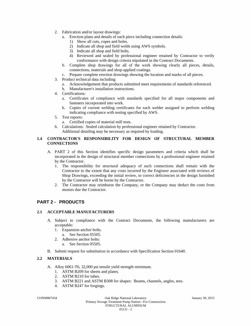
CON00867434 Oak Ridge National Laboratory January 30, 2015 Primary Sewage Treatment Pump Station - For Construction STRUCTURAL ALUMINUM 05131 - 2
2. Fabrication and/or layout drawings: a. Erection plans and details of each piece including connection details:
1) Show all cuts, copes and holes. 2) Indicate all shop and field welds using AWS symbols. 3) Indicate all shop and field bolts. 4) Reviewed and sealed by professional engineer retained by Contractor to verify
conformance with design criteria stipulated in the Contract Documents. b. Complete shop drawings for all of the work showing clearly all pieces, details,
connections, materials and shop-applied coatings. c. Prepare complete erection drawings showing the location and marks of all pieces.
3. Product technical data including: a. Acknowledgement that products submitted meet requirements of standards referenced. b. Manufacturer's installation instructions.
4. Certifications: a. Certificates of compliance with standards specified for all major components and
fasteners incorporated into work. b. Copies of current welding certificates for each welder assigned to perform welding
indicating compliance with testing specified by AWS. 5. Test reports:
a. Certified copies of material mill tests. 6. Calculations: Sealed calculation by professional engineer retained by Contractor.
Additional detailing may be necessary as required by loading.
1.4 CONTRACTOR'S RESPONSIBILITY FOR DESIGN OF STRUCTURAL MEMBER CONNECTIONS
A. PART 2 of this Section identifies specific design parameters and criteria which shall be incorporated in the design of structural member connections by a professional engineer retained by the Contractor. 1. The responsibility for structural adequacy of such connections shall remain with the
Contractor to the extent that any costs incurred by the Engineer associated with reviews of Shop Drawings, exceeding the initial review, to correct deficiencies in the design furnished by the Contractor will be borne by the Contractor.
2. The Contractor may reimburse the Company, or the Company may deduct the costs from monies due the Contractor.
PART 2 - PRODUCTS
2.1 ACCEPTABLE MANUFACTURERS
A. Subject to compliance with the Contract Documents, the following manufacturers are acceptable: 1. Expansion anchor bolts.
a. See Section 05505. 2. Adhesive anchor bolts:
a. See Section 05505.
B. Submit request for substitution in accordance with Specification Section 01640.
2.2 MATERIALS
A. Alloy 6061-T6, 32,000 psi tensile yield strength minimum. 1. ASTM B209 for sheets and plates. 2. ASTM B210 for tubes. 3. ASTM B221 and ASTM B308 for shapes: Beams, channels, angles, tees. 4. ASTM B247 for forgings.

CON00867434 Oak Ridge National Laboratory January 30, 2015 Primary Sewage Treatment Pump Station - For Construction STRUCTURAL ALUMINUM 05131 - 3
B. Nonferrous Bolts and Nuts: ASTM F467 and ASTM F468 of alloy 2024-T4 (60,000 psi tensile strength minimum).
C. Stainless Steel Bolts and Nuts for Fastening Aluminum: Minimum yield strength of 30,000 psi and a minimum tensile strength of 75,000 psi. 1. All locations: ASTM F593 and F594, Type 304 or 316.
D. Washers: Same material and alloy as found in bolts and nuts with which the washers are to be used.
E. Electrodes for Welding Aluminum: AWS D1.2 filler alloy 5356.
F. Expansion Anchor Bolts and Adhesive Anchor Bolts for Fastening to Concrete: See Section 05505.
2.3 DESIGN
A. All design shall consider effect of welds on material properties. 1. Minimize or eliminate the use of field welding. 2. Observe locations of any specified shop splice welds.
B. Where final design of connections for any portion of structure is not indicated, perform final design of such connections in accordance with the Building Code.
C. Final designs of connections shall conform to AA ADM-1 and to details and requirements shown on Drawings. 1. Design loads for connections to be designed by the Contractor shall be as shown on the
Drawings. 2. Where design loads are not specified, connections shall be detailed to develop the full
capacity of the member. 3. Additional detailing may be necessary as required by loading.
2.4 FABRICATION
A. Fabrication of bolted and welded connections of aluminum work shall be in accordance with AA ADM-1.
B. Contractor to be solely responsible for correctness of all shop and field fabrication and fit. Verify field conditions and dimensions prior to fabrication.
C. Fabricate aluminum work and assemble in shop to greatest extent possible. Make splices only where indicated or approved by Engineer.
D. Provide connections as indicated. Where not indicated, design and provide connections in accordance with requirements of this Section. One-sided or other types of eccentric connections are not acceptable unless indicated on Contract Drawings or approved on shop drawings.
E. Drill or punch holes at right angles to surface of metal. Do not make or enlarge holes by burning. Provide holes clean and free of torn or ragged edges. Use tools which will make a 1/16 IN bevel to remove outside burrs resulting from drilling or punching operations. 1. Punch or drill for field connections and for attachment of work by other trades.
F. Cope at 45 degrees corners of stiffener plates at junction of member flanges with webs.
G. Welding: Weld connections to members in shop and bolt connections in field. Perform welding using electrodes of filler alloy 5356. Perform welding in accordance with AWS D1.2. Use only welding procedures and welding operators qualified in accordance with requirements of paragraph 1.2 B "Qualifications".
H. All full penetration welds shall be tested by liquid penetrant or ultrasonic methods per AWS standards.
I. Form to shapes indicated with straight lines, true angles and smooth curves. Grind smooth all rough welds and sharp edges.

CON00867434 Oak Ridge National Laboratory January 30, 2015 Primary Sewage Treatment Pump Station - For Construction STRUCTURAL ALUMINUM 05131 - 4
1. Round all corners to approximately 1/8 IN radius.
J. Finish: Mill finish as fabricated.
PART 3 - EXECUTION
3.1 ERECTION
A. Contractor is solely responsible for safety. Construction means and methods and sequencing of work are prerogative of the Contractor. Take into consideration that full structural capacity of many structural members is not realized until structural assembly is complete; e.g. until decks and diagonal bracing or rigid moment connections are installed. 1. Partially complete structural members shall not be loaded without an investigation by the
Contractor. 2. Until all elements of the permanent structure and lateral bracing system are complete,
provide temporary bracing designed, furnished and installed by the Contractor.
B. Bolting: 1. Protect bolt threads from damage. 2. Rest bolt heads and nuts squarely against surfaces. 3. Where bolt heads or nuts rest on beveled surfaces having slope greater that 1 in 20 with
plane normal to bolt axis, use beveled washers to provide full bearing to head and nut. 4. Correct poor matching of holes by drilling to next larger size and use larger diameter bolt 5. Unless otherwise specified, connect aluminum members to:
a. Aluminum members using 3/4 IN DIA nonferrous bolts of alloy 2024-T4 or stainless steel bolts per F593.
b. Carbon and low alloy steel using 3/4 IN DIA stainless steel bolts per F593. Provide dissimilar materials protection.
c. Concrete or masonry using stainless steel expansion anchor bolts or adhesive anchor bolts unless shown otherwise. Provide dissimilar materials protection.
C. Welding: Field welding of aluminum is not allowed unless indicated on Drawings.
D. Correct fabrication errors and damaged members in shop. Do not use cutting torch in shop or in field to cut any members, to correct fabrication errors, or to cut openings.
E. Provide templates for anchors, bolts, and other items to be installed in other work.
F. Field Assembly: 1. Tolerances shall comply with AISC Manual of Steel Construction and the ADM-1. 2. Before members are assembled, thoroughly clean all bearing surfaces and surfaces that will
be in permanent contact. a. After assembly, carefully align all members of each frame or assembly and accurately
adjust until final, correct and true location is achieved. As work progresses, securely fasten in place.
3. Provide full length members without splices. 4. Securely tighten and leave in place all erection bolts used in welded construction, unless
removal is required.
G. Set beam and column baseplates accurately, as indicated on nonshrink grout, in accordance with Division 3. 1. If not indicated, provide minimum of 1 IN grout thickness under base plates. 2. Set and anchor each base plate to proper line and elevation.
a. Use aluminum wedges, shims, or setting nuts for leveling and plumbing columns and beams. Tighten anchor bolts.
b. Fill space between bearing surface and bottom of base plate with nonshrink grout. Fill space until voids are completely filled and base plates are fully bedded on wedges, shims, and grout.

CON00867434 Oak Ridge National Laboratory January 30, 2015 Primary Sewage Treatment Pump Station - For Construction STRUCTURAL ALUMINUM 05131 - 5
c. Do not remove wedges or shims and where they protrude, cut off flush with edge of base plate.
H. Temporary Protection: Suitably protect aluminum surfaces against lime mortar stains, discoloration, surface abrasion and other construction abuses. Remove protection.
I. Contact with Dissimilar Materials: Where aluminum surfaces will be embedded in concrete, built into masonry, or in contact with steel, concrete, grout, masonry, or other dissimilar materials, coat the aluminum surfaces.
END OF SECTION

This page intentionally left blank.

CON00867434 Oak Ridge National Laboratory January 30, 2015 Primary Sewage Treatment Pump Station - For Construction MISCELLANEOUS METALS, FASTENERS, SPECIAL FINISHES 05500 - 1
SECTION 05500
MISCELLANEOUS METALS, FASTENERS, SPECIAL FINISHES
PART 1 - GENERAL
1.1 WORK INCLUDED
A. Provide all labor, materials, equipment and service necessary for fabrication and erection of structural steel and aluminum and for fabrication and installation of miscellaneous non-ferrous metals as shown on the Drawings and not specifically included under other sections of these Specifications. 1. Erection. 2. Shop and Erection Drawings. 3. Shop Painting. 4. Galvanizing. 5. Aluminum Work Protection. 6. Cleaning Aluminum Work. 7. Miscellaneous Items. 8. Loose Lintels. 9. Sleeves and Inserts. 10. Aluminum Pipe Railing. 11. Aluminum Stairs. 12. Ladders. 13. Ship Ladders. 14. Plate Covers and Frames. 15. Guard Chains. 16. Lifting Hooks. 17. Sand Trap Grating and Frame. 18. Cast Iron Wheel Guard. 19. Cast Aluminum Nosings. 20. Floor Hatches and Frames. 21. Access Doors.
1.2 RELATED WORK
A. Section 04200 - Unit Masonry.
1.3 REFERENCES
A. All work under this Section shall be governed by: 1. Specifications for the design, fabrication and erection of structural steel for buildings -
American Institute of Steel Construction, current edition. 2. Aluminum Construction Manual, Section 1, Specifications for Aluminum Structures - the
Aluminum Association. 3. All welding shall conform to the latest code of the American Welding Society. 4. ASTM A-276. 5. ASTM A-325. 6. ASTM F-593, 294. 7. Federal Specification FF-S-325. 8. ASTM A-48. 9. Federal Specification TT-V-51F. 10. ANSI B94.12. 11. ASTM A-12, A-153, A-384, A-563 and A-780. 12. SSPC SP-1, SP-2, SP3, SP-7.

CON00867434 Oak Ridge National Laboratory January 30, 2015 Primary Sewage Treatment Pump Station - For Construction MISCELLANEOUS METALS, FASTENERS, SPECIAL FINISHES 05500 - 2
1.4 SUBMITTALS
A. As required by the Specifications, the Contractor shall submit for review completely detailed and certified shop and erection drawings of the miscellaneous metal work. All coatings or other protection against corrosion to be applied at the shop or in the field shall be indicated on these drawings. The shop drawings for aluminum work shall show the alloys and tempers to be used, and the finish, if any to be applied.
B. Shop drawings, giving complete information necessary for fabrication, layout and installation of metal work shall be submitted to the Engineer for review prior to fabrication.
C. Preparation of shop drawings for fabricated metal items shall coordinated by the Contractor with the manufacturers of various equipment in order to comply with details, locations, openings, and arrangements required by the manufacturers.
D. Field measurements shall be made to verify all dimensions in the field which may affect installation of work before shop drawings are made and/or fabrication is performed.
1.5 QUALITY ASSURANCE
A. The design, detail and workmanship of steel plates and structural steel shall conform to the AISC Specification for the Design, Fabrication, and Erection of Structural Steel for Buildings.
B. Where welding is permitted or required, it shall conform to the current requirements of the American Welding Society for the type of work in question.
C. Aluminum work shall be fabricated in a shop where the quality of work is in accordance with the highest standards for work of this type. All work shall be executed by mechanics skilled in the fabrication of aluminum, and shall be true to detail with sharp, clean profiles, fitted with proper joints and intersections and with finishes as specified.
D. All miscellaneous metal work shall be formed to shape and size with sharp lines and angles. Shearing and punching shall leave clean true lines and surfaces.
1.6 RESPONSIBILITY FOR DIMENSIONS
A. The general design and dimensions of the miscellaneous metal work are indicated on the Drawings, but the Contractor shall be responsible for the correctness of the details and dimensions of the finished articles. He shall verify conditions at the job before fabrication and coordinate the work with that of all other trades to prevent interference.
PART 2 - PRODUCTS
2.1 MATERIALS
A. Steel plates and structural steel shapes shall conform to ASTM Standard Specification for Structural Steel, Designation A36.
B. Sheet steel shall be cold rolled or hot rolled carbon sheet steel conforming to ASTM Standard Specification for Steel, Carbon, Cold Rolled Sheet, Commercial Quality, Designation A36 or AST ASTM Standard Specification for Steel, Carbon (0.15 maximum, percent), Hot Rolled Sheet and Strip, Commercial Quality, Designation A569, as appropriate.
C. Steel pipe shall conform to ASTM Standard Specifications for Pipe, Steel, Black and Hot Dipped, Zinc Coated, Welded and Seamless, Designation A53.
D. Stainless steel shall be Type 304 unless otherwise indicated or specified.
E. Aluminum work shall be fabricated of plates, rolled or extruded shapes, sheets or casting conforming (unless otherwise permitted or indicated) to the following alloy and temper designations of the Aluminum Association:

CON00867434 Oak Ridge National Laboratory January 30, 2015 Primary Sewage Treatment Pump Station - For Construction MISCELLANEOUS METALS, FASTENERS, SPECIAL FINISHES 05500 - 3
1. Structural rolled or extruded shapes 6061-T6. 2. Extruded shapes 6063-T5. 3. Plates 6061-T6. 4. Gratings (bearing bars) 6061-T6 (crimp bars) 6063-T6. 5. Castings 214. 6. Sheets 3003-F. 7. Bolts and nuts 2024-T4. 8. Pipe Railing 6063-T6.
F. The Contractor shall furnish the Engineer with mill certificates and a signed statement from the fabricator that all aluminum work furnished is of the proper alloys, as specified above.
2.2 STEEL
A. Structural steel shall conform to the requirements of ASTM A-36. Structural tubing, where used, shall conform to the requirements of ASTM A-500, Grade B, and the ends of the tubing shall be properly sealed to protect the internal surfaces. Steel anchor bolts shall be ASTM A-36 hot rolled threaded rod or bar stock, except where stainless steel is indicated on the Drawings.
B. Structural steel members as required shall conform to ASTM Standard shapes.
C. Base and bearing plates shall be provided where necessary to provide maximum bearing value of not more than 200 psi on solid concrete masonry units not more than 750 psi on concrete and shall be grouted in place.
D. Steel lintels shall be provided for all square head openings in masonry where shown and where other lintels are not indicated on the Drawings. Lengths of bearing at each end of lintels shall be not less than 1 inch per foot of span, but in no case less than 8 inches shall be increased or the lintels shall be fitted with bearing plates as required to provide unit pressures in pounds per square inch of not more that 200 on solid concrete masonry units and 625 on concrete. All new steel lintels shall be hot-dipped galvanized. Finish coats are specified in Division 9 - Finishes.
2.3 SHOP PAINTING
A. Painting of miscellaneous ferrous metal work is specified under Division 9.
2.4 GALVANIZING
A. Items of miscellaneous iron work and steel work indicated on the Drawings or specified to be galvanized shall be zinc coated by the hot dip process in conformity with ASTM Standard Specification for Zinc (hot galvanized) Coatings on Products Fabricated from Rolled, Pressed, and Forged Steel Shapes, Plates, Bars, and Strip, Designation A123-78; or ASTM Standard Specifications for Zinc Coating (hot-dip) on Iron and Steel Hardware, Designation A153-78, as appropriate. Galvanizing is specified under Article 3.04, "Hot-Dip Galvanizing".
2.5 ALUMINUM
A. All structural and miscellaneous aluminum shall be Alloy 6061 (Alloy 6063 for extrusions), Temper T6, unless otherwise noted, indicated or accepted by the Engineer. Where welding is necessary in fabrication, it shall be done in conformance with Section 7 "Welded Construction" of Specification for Aluminum Structures, referenced hereinbefore.
2.6 ALUMINUM WORK PROTECTION
A. Aluminum surfaces which after erection would otherwise be in contact with concrete or brick masonry or with mortar, shall be protected from contact therewith by a coat of bitumastic super service black manufactured by the Koppers Company, Inc., Pittsburgh, PA; Tarmastic 100 manufactured by Porter Coating Division, Porter Paint Company, Louisville, KY; 450 Heavy Tnemecol manufactured by Tnemec Company, North Kansas City, MO; or an acceptable equivalent product. Areas where the paint has been damaged by abrasion or other cause shall be cleaned and repainted as directed so that the aluminum will have a complete protective paint

CON00867434 Oak Ridge National Laboratory January 30, 2015 Primary Sewage Treatment Pump Station - For Construction MISCELLANEOUS METALS, FASTENERS, SPECIAL FINISHES 05500 - 4
film when brought into contact with the material against which it is being protected. Before application of coating, the surface shall be cleaned of all dirt, heavy deposits of grease or oil, and other foreign substances and shall be immersed in or swabbed with an acceptable solvent. Next the surfaces shall be rinsed with clear water and thoroughly dried.
B. The Contractor's attention is directed to the requirements of the Specifications in regard to protection against electrolysis where aluminum is to be used in conjunction with dissimilar metals.
C. Where a shop coating of methacrylate lacquer has been specified on aluminum work to protect the surface from stain, the protective coating of lacquer worn off during handling or erection shall be replaced in the field by a new coating of lacquer of the same type.
D. During construction, care shall be taken to prevent damage to the aluminum work from splashing or the accumulation of paint, concrete, mortar, or other similar materials.
2.7 STAINLESS STEEL
A. Stainless steel shapes shall be ANSI Type 304 or 316 in accordance with ASTM A-276. Miscellaneous bar stock products such as pipe straps shall be 400 Series stainless steel. Anchor bolts, nuts and washers shall be ANSI Series 300 stainless steel.
2.8 FASTENERS
A. Bolts, Nuts and Washers: 1. Structural bolts shall be high strength ASTM A-325, Type 1, galvanized and galvanized
ASTM A-325 hardened flat washers and galvanized ASTM A-325 hex nuts. Galvanized bolts, nuts and washers shall be centrifugally spun after galvanizing. Nuts shall have threads tapped oversize after galvanizing. All stainless steel bolts, nuts and washers shall be ANSI Type 300 Series stainless steel in accordance with ASTM F-593, with ASTM F-594 nuts. All bolts shall have hexagonal heads.
2. Anchors and bolts including nuts and washers shall be provided where necessary for securing the work in place. Sizes, types and spacings of anchors and bolts not indicated or specified otherwise shall be as necessary for their purposes. Anchor bolts and anchors for the erection of structural steel shall be galvanized. Anchored bolts, nuts, and washers for all other uses including, but not limited to, underwater use and for the installation of equipment, piping, pumps and motors shall be stainless steel Type 304.
B. Expansion Anchors (In Concrete): 1. Expansion anchors shall be of two (2) types:
a. Stainless steel wedge type. b. Self drilling plated type with stainless steel bolt and stainless steel washer.
2. Type of expansion anchor desired shall be noted on Drawings. 3. Stainless steel wedge type anchors shall be ITW Ramset/Red Head or approved equal of
Type 303 stainless steel. Anchors shall meet or exceed latest Government GSA Federal Specifications FF-S-325, Group II, Type 4, Class 1. Anchor shall be used with 300 series stainless steel bolt and washer.
4. Self drilling plated anchors shall be ITW Ramset/Red Head or approved equal. Anchors shall meet or exceed latest Government GSA Federal Specification FF-S-325, Group III, Type 1. Self-drilling anchors shall be electro-deposited zinc plated and chromate dipped, to meet or exceed the requirements of the latest Federal Specification QQ-Z-325, Type II, Class 3. Cutting teeth shall have minimum hardness of 82 Rockwell A scale.
5. Stainless steel expansion anchors shall be installed in accordance with manufacturer's recommendations.
6. Self-drilling expansion anchors shall be installed in accordance with manufacturer's recommendations. To insure full development strength, all self-drilling expansion anchors shall be expanded over the plug in the final set, by using a bolt screwed into the female threads and impacted by hand with a suitable hammer. The final set shall not be accomplished by using the drilling tool.

CON00867434 Oak Ridge National Laboratory January 30, 2015 Primary Sewage Treatment Pump Station - For Construction MISCELLANEOUS METALS, FASTENERS, SPECIAL FINISHES 05500 - 5
7. After installation, pull-out tests by the anchor manufacturer's representative may be requested by the Engineer. If so, the Engineer's Resident Representative will stipulate the number and location of the tests.
2.9 ALUMINUM LADDERS
A. Aluminum ladders shall be furnished and installed at the locations shown on the Contract Drawings.
B. The ladders shall be constructed with side rails of 2-1/2 inches by 1/2-inch flat bar and brackets of 3 inches by 1/2-inch flat bar with rungs of 1 inch diameter bars, shouldered, driven through the side rails and peened. Maximum bracket support spacing shall be 5 feet - 0 inches on centers. The brackets shall be welded to the side rails. Rung spacing shall be 12 inches on centers. In general, the ladders shall extend to within 6 inches of the access opening. Ladders shall be constructed of 6061-T6 aluminum. Wedge type expansion anchors shall be used to attach aluminum ladders to walls as indicated on Contract Drawings.
2.10 MISCELLANEOUS ITEMS
A. Items of miscellaneous metal work not particularly specified hereinafter shall be of the shape, size, material and details indicated on the Drawings or suitable for the purpose intended.
2.11 LOOSE LINTELS
A. The Contractor shall furnish all loose lintels as indicated on the Drawings or required by the work. The loose lintels shall be fabricated from structural steel shapes and plates. All loose lintels shall be hot-dip galvanized after fabrication.
2.12 SLEEVES AND INSERTS
A. The Contractor's attention is directed to the requirements of the Specifications regarding sleeves and inserts.
2.13 ALUMINUM PIPE RAILING
A. The aluminum pipe railing shall be the product of company normally engaged in the manufacture of pipe railing. Railing shall be shop assembled in lengths not to exceed 24 feet for field erection.
B. Handrails and stair rails shall be designed to withstand a 200-pound concentrated load applied in any direction at any point on the top rail. Handrails and stair rails shall also be designed to withstand a load of 50 lbs/ft. applied horizontally to the top rail. The 200-pound load will not be applied simultaneously with the 50 lbs/ft. load. In addition, the handrails shall be designed to withstand a load of 100 lbs/ft. applied vertically downward to the top rail and simultaneously with the 50 lbs/ft. horizontal load. The 100 lbs/ft. vertical load does not apply to stair rails.
C. The manufacturer shall submit calculations to the Engineer for approval. Testing of base castings or base extrusions by an independent lab or manufacturer's lab (if manufacturer's lab meets the requirements of the Aluminum Association) will be an acceptable substitute for calculations. Calculations will be required for approval of all other design aspects.
D. Post spacing shall be a maximum of 6 feet 0 inches. Posts and railings shall be a minimum of 1-1/2 inches Schedule 40 aluminum pipe alloy 6063-T6, ASTM-B-429 or ASTM-B-221. The handrail manufacturer shall show that their posts are of adequate strength to meet the loading requirements. If the manufacturer's posts are not of adequate strength, the manufacturer may reduce the post spacing or add reinforcing dowels or may do both in order to meet loading requirements.

CON00867434 Oak Ridge National Laboratory January 30, 2015 Primary Sewage Treatment Pump Station - For Construction MISCELLANEOUS METALS, FASTENERS, SPECIAL FINISHES 05500 - 6
E. The handrail shall be made of pipes joined together with component fittings. Samples of all components, bases, toe plate and pipe must be submitted for approval. Components that are glued or pop riveted at the joints will not be acceptable. All components must be mechanically fastened with stainless steel hardware. Handrail and components shall be Thompson Fabricating Company or approved equal.
F. Posts shall not interrupt the continuation of the top rail at any point along the railing, including corners and end terminations. The top surface of the top railing shall be smooth and shall not be interrupted by projecting fittings.
G. The midrail at a corner return shall be able to withstand a 200-pound load without loosening.
H. Expansion bolts shall be spaced 10 diameters apart and 5-diameter edge distance for no reduction in pullout strength. A safety factor of four shall be used on expansion bolt pullout values published by the manufacturer. Expansion bolts shall be stainless steel type 303 wedge bolts.
I. Toe plate shall conform to OSHA standards. Toe plate shall be a minimum of 4 inches high and shall be an extrusion that attaches to the posts with clamps which will allow for expansion and contraction between posts. Toe plates shall be set 1/4-inch above the walking surface. Toe plates shall be provided on handrails as required by OSHA and/or as shown on Drawings. Toe plates shall be shipped loose in stock lengths with pre-manufactured corners for field installation.
J. Openings in the railing shall be guarded by a self-closing gate. Safety chains shall not be used unless specifically shown on the Drawings.
K. Finish shall be Aluminum Association M10-C22-A41 (215-R1). The pipe shall be plastic wrapped. The plastic wrap is to be removed after erection.
L. Aluminum surfaces in contact with concrete, grout or dissimilar metals will be protected with a coat of bituminous paint, mylar isolators or other approved material.
2.14 ALUMINUM STAIRS
A. The aluminum stairs shall have structural aluminum channel stringers and supports, aluminum tread plate treads and platforms and sheet aluminum risers as indicated on the Drawings and in the details.
B. The treads shall be aluminum grating. The treads shall be supported by and attached to 1-1/4 inch by 3/16 inch aluminum carrier angles bolted to the stringers. The treads shall be the widths indicated.
C. All platforms shall be fabricated of 1/4-inches thick aluminum tread plate and shall be supported on the edges by structural aluminum angles and at the mid-spans by structural aluminum tees.
D. The aluminum tread plate for treads and platforms shall have an acceptable nonskid pattern surface.
E. The Contractor shall provide all structural aluminum angle hangers, struts, rod hangers, closure plates and brackets indicated or necessary to complete the stairs as indicated.
2.15 SHIP LADDERS
A. Ship ladders as located on the Drawings shall have structural aluminum channel stringers, aluminum pipe handrails and aluminum riveted grating treads. The treads shall be Type K manufactured by Borden Metal Products Company, Elizabeth, NJ; Reticuline Type M manufactured by IKG Industries, Long Island City, NY; Type KM manufactured by Kerrigan Iron Works, Inc., Nashville, TN; or an acceptable equivalent product. The bearing bars of the treads shall be 3/16 inches thick by 1-1/4 inches deep and shall be fabricated of 6061-T6 aluminum alloy. Crimp bars shall be fabricated of 6063-T5 aluminum alloy riveted on 7-inch centers, and raised slightly above the bearing bars and serrated. The treads shall have integral

CON00867434 Oak Ridge National Laboratory January 30, 2015 Primary Sewage Treatment Pump Station - For Construction MISCELLANEOUS METALS, FASTENERS, SPECIAL FINISHES 05500 - 7
slotted and punched end plates for attaching to the stringers. All treads shall be provided with 1-1/4-inch abrasive or extruded aluminum corrugated nosing.
B. The handrails shall be fabricated of 1-1/2 inch IPS, Schedule 40 aluminum pipe with flush welded joints ground smooth. The rails shall be secured to the stringers as indicated. The handrails shall be given an Aluminum Association Standard Anodic finish, Designation C22A31 followed by a shop coat of methacrylate lacquer.
C. The Contractor shall provide all structural aluminum clip angles, brackets and fasteners required to complete the ship ladders as indicated. All fasteners shall be stainless steel.
2.16 PLATE COVERS AND FRAMES
A. The plate covers and frames shall be of the sizes indicated on the Drawings. The frames shall be aluminum angles of the sizes indicated with welded strap anchors for securing the frames in the concrete. The frames shall have mitered corners with welded joints ground smooth where exposed.
B. The covers shall be 1/4-inch thick aluminum tread plate having an acceptable nonskid surface and reinforced with aluminum bars welded to the underside of the cover in accordance with the details. Plate covers shall be capable of supporting a uniform superimposed load of 100 psf for the span with a deflection of less than 1/4-inch based on an allowable fiber stress of 16,000 psi. The covers shall be made to fit neatly and accurately in the frames.
C. Hinged covers shall be furnished with heavy duty stainless steel, plain bearing hinges with stainless steel pins. The hinges shall be fastened to the covers and frames with stainless steel machine screws. The hinged covers shall be provided with flush lift handles fabricated from 1/2-inch diameter aluminum rod, alloy 6061-T6511.
D. A single leaf of hinged plate covers shall be no greater than 3 feet square in size.
E. Removable plate covers shall have 1-inch diameter finger holes to facilitate removal. All edges of holes cut in the plate covers shall be ground smooth.
F. Removable plate covers shall be no greater than 14 square feet in size with the longer dimension no greater than 7 feet.
G. Gasket plate covers shall have continuous compressible neoprene seals between the cover and frame at the perimeter. The covers shall be secured to the frames with countersunk, flathead, stainless steel machine screws spaced approximately 6 inches on centers.
H. The aluminum plate covers shall be flush mounted with the floor, eliminating a tripping hazard.
2.17 GUARD CHAINS
A. Removable guard chains at openings in aluminum pipe railings shall be fabricated from wrought, non-welded aluminum chain having 12 links per foot. The chains shall be secured to aluminum eyes bolted or welded to pipe stanchion at one end of the opening. The free ends of the chains shall be provided with hooks formed from 1/4-inch diameter solid aluminum rod for attaching to similar eyes in the pipe stanchion at the opposite end of the opening.
2.18 LIFTING HOOKS
A. Lifting hooks in concrete shall be fabricated from 3/4-inch diameter steel rod bent in a U-shape and threaded at the ends to receive nuts. The lifting hook shall be fastened to a 1/2-inch by 4-inch by 8-inch steel anchor plate and the assembly placed in the formwork before the concrete is placed. Lifting hook assemblies shall be hot-dip galvanized after fabrication.
B. Lifting hooks supported from steel shall be fabricated 3/4 inch diameter steel rod bent in a U-shape and threaded at both ends to receive nuts. The lifting hooks shall be placed in punched holes in the bottom flange of steel beams and secured in place by nuts as indicated. Lifting hooks and appurtenances shall be hot-dip galvanized.

CON00867434 Oak Ridge National Laboratory January 30, 2015 Primary Sewage Treatment Pump Station - For Construction MISCELLANEOUS METALS, FASTENERS, SPECIAL FINISHES 05500 - 8
2.19 SAND TRAP GRATING AND FRAME
A. The sand trap grating and frames in the building shall be “heavy-duty” weight constructed of high strength gray iron.
2.20 CAST IRON WHEEL GUARDS
A. Wheel guards where indicated on the Drawings shall be cast iron guards of the sizes and types indicated on the Drawings and as herein specified and shall be manufactured by Neenah Foundry Company, Neenah, WI; Flockhart Foundry Company, Neward, NJ; McKinley Iron Works, Fort Worth, TX; or an acceptable equivalent product. Wheel guards shall be given one shop coat of rust inhibitive paint before shipment.
B. Wheel guards shall be heavy duty concrete fill type, cast iron wheel guards, No. R-4983-C manufactured by Neenah Foundry Company; Type 706A manufactured by Flockhart Foundry Company; or an acceptable equivalent product. The guards shall be set 2 inches into the pavement and shall be bolted to the masonry walls. The guards shall be filled with Class A concrete and the top of the fill sloped at a 15 degree angle from the building.
2.21 CAST ALUMINUM NOSINGS
A. The cast aluminum nosing shall be abrasive cast aluminum nosings securely fastened with stainless steel, flat head bolts and wing anchors set into the fresh concrete. The nosings shall be the products of Wooster Products, Inc., Wooster, OH; American Abrasive Metals Company, Irvington, NJ; Andco Building Specialties, Division of Andco Industries Corporation, Greensboro, NC; or acceptable equivalent products.
B. Cast aluminum nosings for concrete steps and platforms shall be of the widths indicated and shall be Type 101 made by Wooster Products, Inc.; Style A made by American Abrasive Metals Company; Style 801 made by Andco Building Specialties, or acceptable equivalent products.
2.22 FLOOR HATCHES AND FRAMES
A. The floor hatches and frames shall be flush floor hatches manufactured by the Bilco Company, New Haven, CT; Babcock-Davis Associates, Inc., Arlington, MA; or acceptable equivalent product. The hatches shall be double leaf gutter type and of the sizes indicated on the Drawings. The hatches shall be factory assembled and shipped complete with frame for installation on the job. The hatches shall be furnished with hinges, hold open safety lock bars, and flush lift handles. Gutter type hatches shall have a 1-1/2 inch drainage coupling located in on corner of the channel frame.
B. The floor hatches and frames shall be fabricated from aluminum with 1/4-inch extruded aluminum frames and 1/4-inch diamond checkered aluminum plate covers. The covers shall be reinforced to be capable of withstanding a uniform live load of 300 psf.
2.23 ACCESS DOORS
A. Doors shall be flush panel access doors as manufactured Inryco Inc., Milwaukee , WI; Karp Associates, Inc., Maspeth, NY; BOICO, Birmingham, AL; or approved equal. Doors and frames to be galvanized steel with concealed hinge and flush screw driver operated locks.
2.24 SAFETY CHAIN
A. Safety chain shall be 3/8-inch trade size, proof coil, welded, polyester coated, low carbon steel in OSHA safety yellow designed for barrier chain application as manufactured by Campbell Chain Company, York, PA.

CON00867434 Oak Ridge National Laboratory January 30, 2015 Primary Sewage Treatment Pump Station - For Construction MISCELLANEOUS METALS, FASTENERS, SPECIAL FINISHES 05500 - 9
2.25 CASTINGS
A. All miscellaneous iron casting shall be of best quality materials free from flaws and unsightly defects. Gray cast iron shall be ASTM A-48 Class 35 (35,000 psi tensile strength). Furnish and install in the locations indicated casting of the type and size shown on the Drawings.
2.26 CARPENTER'S IRON WORK
A. Furnish bent or otherwise custom fabricated bolts, plates, anchors, hangers, dowels and other miscellaneous steel and iron shapes as required for framing and supporting woodwork and for anchoring or securing woodwork to concrete or other structures. Manufacture or fabricate items of sizes, shapes, and dimensions required. Furnish malleable iron washers for heads and nuts which bear on wood structural connections, elsewhere, furnish steel washers.
2.27 MISCELLANEOUS FRAMING AND SUPPORTS
A. Provide miscellaneous steel framing and supports as required to complete the work. Fabricate miscellaneous units to the sizes, shapes, and profiles shown or if not shown, of the required dimensions to receive adjacent grating plates, louvers, vents, grilles, screens or other work to be retained by the framing. Except as otherwise shown, fabricate from structural steel shapes and plates and steel bars of all welded construction using mitered corners, welded brackets and splice plates and a minimum number of joints for field connection. Cut, drill and tap units to receive hardware and similar items to be anchored to the work.
PART 3 - EXECUTION
3.1 ANCHORAGE ITEMS
A. The Contractor shall furnish all bolts, nuts, shims, pins, screws, straps, nails and other anchors which may be required by the Drawings or job conditions to secure all items permanently in place whether or not specifically called for or shown on the Drawings.
3.2 FABRICATION AND INSTALLATION OF METAL WORK
A. General: All metal items shall be accurately fabricated and erected with exposed joints close fitting. All joints shall be of such character and so assembled that they will be as strong and rigid as adjoining sections. Joints shall be located where least conspicuous. Items shall have smooth finished surfaces except where otherwise shown or specified.
B. Built-in Items: Members or parts to be built-in with masonry or concrete shall be in a form affording a suitable anchorage or shall be provided with approved anchors, expansion shields or other approved means of securing members.
C. Dissimilar Metals: Ferrous and non-ferrous metals shall be insulated at all contacts with felt washer, strips or sheets, bitumastic paints, or other acceptable means. All aluminum surfaces in contact with concrete shall be coated with two (2) coats of Federal Specification TT-V51F Asphalt Varnish, or approved equal.
D. Connections: 1. All required anchors, couplings, bolts, and nuts required to support miscellaneous metal
work shall be furnished and installed as required. 2. Weights of connections and accessories shall be adequate to safely sustain and withstand
stresses and strains to which they will be normally subjected. 3. Connections shall be bolted except where welding is called for in the Drawings. Bolts shall
be 3/4-inch diameter unless noted or required otherwise.
E. Expansion Anchors:
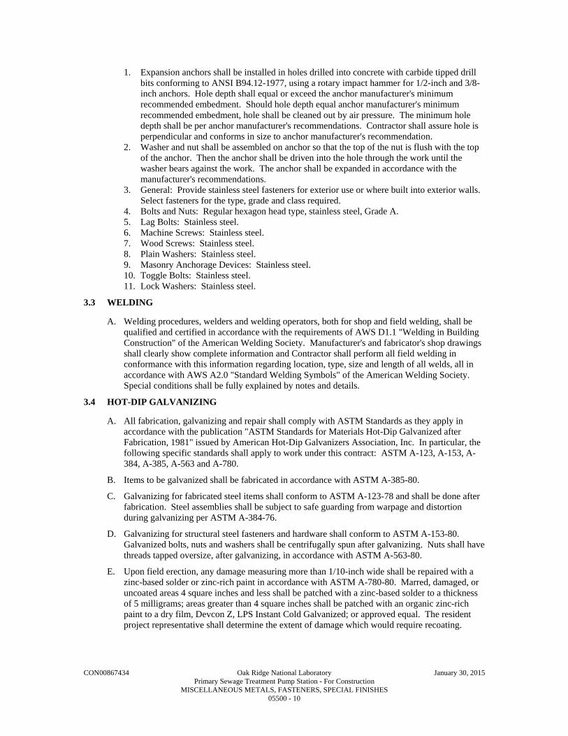
CON00867434 Oak Ridge National Laboratory January 30, 2015 Primary Sewage Treatment Pump Station - For Construction MISCELLANEOUS METALS, FASTENERS, SPECIAL FINISHES 05500 - 10
1. Expansion anchors shall be installed in holes drilled into concrete with carbide tipped drill bits conforming to ANSI B94.12-1977, using a rotary impact hammer for 1/2-inch and 3/8-inch anchors. Hole depth shall equal or exceed the anchor manufacturer's minimum recommended embedment. Should hole depth equal anchor manufacturer's minimum recommended embedment, hole shall be cleaned out by air pressure. The minimum hole depth shall be per anchor manufacturer's recommendations. Contractor shall assure hole is perpendicular and conforms in size to anchor manufacturer's recommendation.
2. Washer and nut shall be assembled on anchor so that the top of the nut is flush with the top of the anchor. Then the anchor shall be driven into the hole through the work until the washer bears against the work. The anchor shall be expanded in accordance with the manufacturer's recommendations.
3. General: Provide stainless steel fasteners for exterior use or where built into exterior walls. Select fasteners for the type, grade and class required.
4. Bolts and Nuts: Regular hexagon head type, stainless steel, Grade A. 5. Lag Bolts: Stainless steel. 6. Machine Screws: Stainless steel. 7. Wood Screws: Stainless steel. 8. Plain Washers: Stainless steel. 9. Masonry Anchorage Devices: Stainless steel. 10. Toggle Bolts: Stainless steel. 11. Lock Washers: Stainless steel.
3.3 WELDING
A. Welding procedures, welders and welding operators, both for shop and field welding, shall be qualified and certified in accordance with the requirements of AWS D1.1 "Welding in Building Construction" of the American Welding Society. Manufacturer's and fabricator's shop drawings shall clearly show complete information and Contractor shall perform all field welding in conformance with this information regarding location, type, size and length of all welds, all in accordance with AWS A2.0 "Standard Welding Symbols" of the American Welding Society. Special conditions shall be fully explained by notes and details.
3.4 HOT-DIP GALVANIZING
A. All fabrication, galvanizing and repair shall comply with ASTM Standards as they apply in accordance with the publication "ASTM Standards for Materials Hot-Dip Galvanized after Fabrication, 1981" issued by American Hot-Dip Galvanizers Association, Inc. In particular, the following specific standards shall apply to work under this contract: ASTM A-123, A-153, A-384, A-385, A-563 and A-780.
B. Items to be galvanized shall be fabricated in accordance with ASTM A-385-80.
C. Galvanizing for fabricated steel items shall conform to ASTM A-123-78 and shall be done after fabrication. Steel assemblies shall be subject to safe guarding from warpage and distortion during galvanizing per ASTM A-384-76.
D. Galvanizing for structural steel fasteners and hardware shall conform to ASTM A-153-80. Galvanized bolts, nuts and washers shall be centrifugally spun after galvanizing. Nuts shall have threads tapped oversize, after galvanizing, in accordance with ASTM A-563-80.
E. Upon field erection, any damage measuring more than 1/10-inch wide shall be repaired with a zinc-based solder or zinc-rich paint in accordance with ASTM A-780-80. Marred, damaged, or uncoated areas 4 square inches and less shall be patched with a zinc-based solder to a thickness of 5 milligrams; areas greater than 4 square inches shall be patched with an organic zinc-rich paint to a dry film, Devcon Z, LPS Instant Cold Galvanized; or approved equal. The resident project representative shall determine the extent of damage which would require recoating.
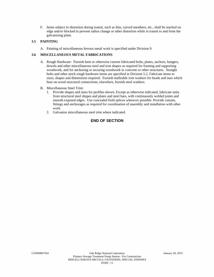
CON00867434 Oak Ridge National Laboratory January 30, 2015 Primary Sewage Treatment Pump Station - For Construction MISCELLANEOUS METALS, FASTENERS, SPECIAL FINISHES 05500 - 11
F. Items subject to distortion during transit, such as thin, curved members, etc., shall be stacked on edge and/or blocked to prevent radius change or other distortion while in transit to and from the galvanizing plant.
3.5 PAINTING
A. Painting of miscellaneous ferrous metal work is specified under Division 9.
3.6 MISCELLANEOUS METAL FABRICATIONS
A. Rough Hardware: Furnish bent or otherwise custom fabricated bolts, plates, anchors, hangers, dowels and other miscellaneous steel and iron shapes as required for framing and supporting woodwork, and for anchoring or securing woodwork to concrete or other structures. Straight bolts and other stock rough hardware items are specified in Division 5.2. Fabricate items to sizes, shapes and dimensions required. Furnish malleable iron washers for heads and nuts which bear on wood structural connections; elsewhere, furnish steel washers.
B. Miscellaneous Steel Trim: 1. Provide shapes and sizes for profiles shown. Except as otherwise indicated, fabricate units
from structural steel shapes and plates and steel bars, with continuously welded joints and smooth exposed edges. Use concealed field splices wherever possible. Provide cutouts, fittings and anchorages as required for coordination of assembly and installation with other work.
2. Galvanize miscellaneous steel trim where indicated.
END OF SECTION

This page intentionally left blank.

CON00867434 Oak Ridge National Laboratory January 30, 2015 Primary Sewage Treatment Pump Station - For Construction METAL FABRICATIONS 05505 - 1
SECTION 05505
METAL FABRICATIONS
PART 1 - GENERAL
1.1 SUMMARY
A. Section Includes: 1. Custom fabricated metal items and certain manufactured units not otherwise indicated to be
supplied under work of other Specification Sections. 2. Design of all temporary bracing not indicated on Drawings. 3. Design of systems and components, including but not limited to:
a. Stairs. b. Landings. c. Ladders. d. Modular framing system.
B. Related Specification Sections include but are not necessarily limited to: 1. Division 00 - Bidding Requirements, Contract Forms, and Conditions of the Contract. 2. Division 01 - General Requirements. 3. Division 03 - Concrete. 4. Section 05522 - Aluminum Railings.
1.2 QUALITY ASSURANCE
A. Referenced Standards: 1. Aluminum Association (AA):
a. ADM 1, Aluminum Design Manual. 2. American Association of State Highway and Transportation Officials (AASHTO):
a. HB, Standard Specifications for Highway Bridges. 3. American Institute of Steel Construction (AISC):
a. 325, Manual of Steel Construction - Allowable Stress Design (ASD). b. 360, Specifications for Structural Steel Buildings (referred to herein as AISC
Specification). 4. American National Standards Institute (ANSI):
a. A14.3, Ladders - Fixed - Safety Requirements. 5. American Society of Civil Engineers (ASCE):
a. 7, Minimum Design Loads for Buildings and Other Structures. 6. ASTM International (ASTM):
a. A6, Standard Specification for General Requirements for Rolled Structural Steel Bars, Plates, Shapes, and Sheet Piling.
b. A36, Standard Specification for Carbon Structural Steel. c. A47, Standard Specification for Ferritic Malleable Iron Castings. d. A48, Standard Specification for Gray Iron Castings. e. A53, Standard Specification for Pipe, Steel, Black and Hot-Dipped, Zinc-Coated,
Welded and Seamless. f. A108, Standard Specification for Steel Bar, Carbon and Alloy, Cold Finished. g. A123/A123M, Standard Specification for Zinc (Hot-Dip Galvanized) Coatings on Iron
and Steel Products. h. A153/A153M, Standard Specification for Zinc Coating (Hot-Dip) on Iron and Steel
Hardware. i. A197, Standard Specification for Cupola Malleable Iron. j. A269, Standard Specification for Seamless and Welded Austenitic Stainless Steel
Tubing for General Service. k. A276, Standard Specification for Stainless Steel Bars and Shapes.

CON00867434 Oak Ridge National Laboratory January 30, 2015 Primary Sewage Treatment Pump Station - For Construction METAL FABRICATIONS 05505 - 2
l. A307, Standard Specification for Carbon Steel Bolts and Studs, 60,000 PSI Tensile Strength.
m. A312, Standard Specification for Seamless, Welded, and Heavily Cold Worked Austenitic Stainless Steel Pipes.
n. A325, Standard Specification for Structural Bolts, Steel, Heat Treated, 120/105 ksi Minimum Tensile Strength.
o. A380, Standard Practice for Cleaning, Descaling, and Passivation of Stainless Steel Parts, Equipment, and Systems.
p. A496, Standard Specification for Steel Wire, Deformed, for Concrete Reinforcement. q. A500, Standard Specification for Cold-Formed Welded and Seamless Carbon Steel
Structural Tubing in Rounds and Shapes. r. A501, Standard Specification for Hot-Formed Welded and Seamless Carbon Steel
Structural Tubing. s. A536, Standard Specification for Ductile Iron Castings. t. A554, Standard Specification for Welded Stainless Steel Mechanical Tubing. u. A572, Standard Specification for High-Strength Low-Alloy Columbium-Vanadium
Structural Steel. v. A666, Standard Specification for Annealed or Cold-Worked Austenitic Stainless Steel
Sheet, Strip, Plate, and Flat Bar. w. A668, Standard Specification for Steel Forgings, Carbon and Alloy, for General
Industrial Use. x. A780, Standard Practice for Repair of Damaged and Uncoated Areas of Hot-Dip
Galvanized Coatings. y. A786, Standard Specification for Hot-Rolled Carbon, Low-Alloy, High-Strength Low-
Alloy, and Alloy Steel Floor Plates. z. A992, Standard Specification for Steel for Structural Shapes. aa. A1064, Standard Specification for Steel Wire and Welded Wire Reinforcement, Plain
and Deformed, for Concrete. bb. B26, Standard Specification for Aluminum-Alloy Sand Castings. cc. B209, Standard Specification for Aluminum and Aluminum-Alloy Sheet and Plate. dd. B221, Standard Specification for Aluminum and Aluminum-Alloy Extruded Bars,
Rods, Wire, Profiles, and Tubes. ee. B308, Standard Specification for Aluminum-Alloy 6061-T6 Standard Structural
Profiles. ff. B429, Standard Specification for Aluminum-Alloy Extruded Structural Pipe and Tube. gg. B632, Standard Specification for Aluminum-Alloy Rolled Tread Plate. hh. F467, Standard Specification for Nonferrous Nuts for General Use. ii. F468, Standard Specification for Nonferrous Bolts, Hex Cap Screws, and Studs for
General Use. jj. F593, Standard Specification for Stainless Steel Bolts, Hex Cap Screws, and Studs. kk. F835, Standard Specification for Alloy Steel Socket Button and Flat Countersunk Head
Cap Screws. ll. F879, Standard Specification for Stainless Steel Socket Button and Flat Countersunk
Head Cap Screws. mm. F1554, Standard Specification for Anchor Bolts, Steel, 36, 55, and 105-ksi Yield
Strength. nn. F1789, Standard Terminology for F16 Mechanical Fasteners.
7. American Welding Society (AWS): a. A5.1/A5.1M, Specification for Carbon Steel Electrodes for Shielded Metal Arc
Welding. b. D1.1, Structural Welding Code - Steel. c. D1.2, Structural Welding Code - Aluminum. d. D1.6/D1.6M, Structural Welding Code - Stainless Steel.
8. National Association of Architectural Metal Manufacturers (NAAMM): a. AMP 510, Metal Stairs Manual.

CON00867434 Oak Ridge National Laboratory January 30, 2015 Primary Sewage Treatment Pump Station - For Construction METAL FABRICATIONS 05505 - 3
b. AMP 555, Code of Standard Practice for the Architectural Metal Industry (Including Miscellaneous Iron).
c. MBG 531, Metal Bar Grating Manual. 9. NACE International (NACE). 10. Nickel Development Institute (NiDI):
a. Publication 11 007, Guidelines for the welded fabrication of nickel-containing stainless steels for corrosion resistant services.
11. Occupational Safety and Health Administration (OSHA): a. 29 CFR 1910, Occupational Safety and Health Standards, referred to herein as OSHA
Standards. 12. Building code:
a. International Code Council (ICC): 1) International Building Code 2009 Edition including all local amendments, referred
to herein as Building Code.
B. Qualifications: 1. Qualify welding procedures and welding operators in accordance with AWS. 2. Fabricator shall have minimum of 10 years experience in fabrication of metal items
specified. 3. Engineer for contractor-designed systems and components: Professional structural engineer
licensed in the state of Tennessee. 4. NACE certified inspector shall have minimum of two (2) years experience performing
inspections as indicated. a. Have a current Level III coating inspector certification.
1.3 DEFINITIONS
A. Fasteners: As defined in ASTM F1789.
B. Galvanizing: Hot-dip galvanizing per ASTM A123/A123M or ASTM A153/A153M with minimum coating of 2.0 OZ of zinc per square foot of metal (average of specimens) unless noted otherwise or dictated by standard.
C. Hardware: As defined in ASTM A153/A153M.
D. Installer or Applicator: 1. Installer or applicator is the person actually installing or applying the product in the field at
the Project site. 2. Installer and applicator are synonymous.
1.4 SUBMITTALS
A. Shop Drawings: 1. See Specification Section 01300 for requirements for the mechanics and administration of
the submittal process. 2. Fabrication and/or layout drawings and details:
a. Submit drawings for all fabrications and assemblies. 1) Include erection drawings, plans, sections, details and connection details.
b. Identify materials of construction, shop coatings and third party accessories. 3. Product technical data including:
a. Acknowledgement that products submitted meet requirements of standards referenced. b. Manufacturer's installation instructions. c. Provide manufacturer's standard allowable load tables for the following:
1) Grating and checkered plate. 2) Expansion anchor bolts. 3) Adhesive anchor bolts. 4) Castings, trench covers and accessories. 5) Modular framing systems.

CON00867434 Oak Ridge National Laboratory January 30, 2015 Primary Sewage Treatment Pump Station - For Construction METAL FABRICATIONS 05505 - 4
4. Contractor designed systems and components, including but not limited to, stairs, landings and ladders: a. Certification that manufactured units meet all design loads specified. b. Shop Drawings and engineering design calculations:
1) Indicate design live loads. 2) Sealed by a professional structural engineer. 3) Engineer will review for general compliance with Contract Documents.
B. Informational Submittals: 1. See Specification Section 01300 for requirements for the mechanics and administration of
the submittal process. 2. Certification of welders and welding processes.
a. Indicate compliance with AWS. 3. NACE inspector qualifications. 4. NACE certification of surface preparation. 5. NACE certification of paint application.
1.5 DELIVERY, STORAGE, AND HANDLING
A. Deliver and handle fabrications to avoid damage.
B. Store above ground on skids or other supports to keep items free of dirt and other foreign debris and to protect against corrosion.
PART 2 - PRODUCTS
2.1 ACCEPTABLE MANUFACTURERS
A. Subject to compliance with the Contract Documents, the following manufacturers are acceptable: 1. Headed studs and deformed bar anchors:
a. Nelson Stud Welding Div., TRW Inc. b. Stud Welding Products, Inc.
2. Expansion anchor bolts: a. Hilti Inc. b. Simpson Strong-Tie.
3. Epoxy adhesive anchor bolts: a. Hilti Inc. b. Simpson Strong-Tie.
4. Self-tapping concrete anchors: a. ITW Buildex. b. Powers Fasteners.
5. Castings, trench covers and accessories: a. Neenah Foundry Co. b. Deeter Foundry Co. c. Barry Craft Construction Casting Co. d. McKinley Iron Works.
6. Aluminum ladders: a. Any manufacturer capable of meeting the requirements of this Specification Section.
7. Galvanizing repair paint: a. Clearco Products Co., Inc. b. ZRC Products.
8. Modular framing system: a. Unistrut Building Systems. b. B-Line Systems. c. Kindorf. d. Superstrut.

CON00867434 Oak Ridge National Laboratory January 30, 2015 Primary Sewage Treatment Pump Station - For Construction METAL FABRICATIONS 05505 - 5
B. Submit request for substitution in accordance with Specification Section 01640.
2.2 MATERIALS
A. Steel: 1. Structural:
a. W-shapes and WT-shapes: ASTM A992, Grade 50. b. All other plates and rolled sections: ASTM A36.
2. Pipe: ASTM A53, Types E or S, Grade B or ASTM A501. 3. Structural tubing:
a. ASTM A500, Grade B (46 ksi minimum yield). 4. Bolts, nuts and washers, high strength:
a. ASTM A325. b. Provide two (2) washers with all bolts.
5. Bolts and nuts: a. ASTM A307, Grade A.
6. Welding electrodes: AWS D1.1, E70 Series. 7. Steel forgings: ASTM A668. 8.
B. Stainless Steel: 1. Stainless steel in welded applications: Low carbon 'L' type. 2. Minimum yield strength of 30,000 psi and minimum tensile strength of 75,000 psi.
a. Bars, shapes: ASTM A276, Type 304. b. Tubing and pipe: ASTM A269, ASTM A312 or ASTM A554, Type 304 or 316. c. Strip, plate and flat bars: ASTM A666, Type 304 or 316. d. Bolts and nuts: ASTM F593, Type 303, 304 or 316.
3. Minimum yield strength of 25,000 psi and minimum tensile strength of 70,000 psi. a. Strip, plate and flat bar for welded connections, ASTM A666, Type 304L or 316L.
4. Welding electrodes: In accordance with AWS for metal alloy being welded.
C. Aluminum: 1. Alloy 6061-T6, 32,000 psi tensile yield strength minimum.
a. ASTM B221 and ASTM B308 for shapes including beams, channels, angles, tees and zees.
b. Weir plates, baffles and deflector plates, ASTM B209. 2. Alloy 6063-T5 or T6, 15,000 psi tensile yield strength minimum.
a. ASTM B221 and ASTM B429 for bars, rods, wires, pipes and tubes. 3. ASTM B26 for castings. 4. ASTM F468, alloy 2024 T4 for bolts. 5. ASTM F467, alloy 2024 T4 for nuts. 6. Electrodes for welding aluminum: AWS D1.2, filler alloy 4043 or 5356.
D. Washers: Same material and alloy as found in accompanying bolts and nuts.
E. Embedded Anchor Bolts: 1. Building anchor bolts:
a. ASTM F1554, Grade 55 with weldability supplement S1 or ASTM A36 for threaded rods galvanized.
b. ASTM A307, Grade A for headed bolts galvanized. 2. All other anchor bolts: Type 304 or 316 stainless steel with matching nut and washer.
F. Expansion Anchor Bolts and Adhesive Anchor Bolts: 1. Stainless steel, Type 304, 314 or 316. 2. Provide minimum edge distance cover and spacing as recommended by manufacturer, or as
indicated on Drawings whichever is larger. a. Minimum embedment as recommended by manufacturer or eight (8) diameters of bolt,
whichever is larger.

CON00867434 Oak Ridge National Laboratory January 30, 2015 Primary Sewage Treatment Pump Station - For Construction METAL FABRICATIONS 05505 - 6
b. Notify Engineer if required depth of embedment cannot be achieved at a particular anchor bolt location.
c. Follow manufacturer's recommendations for installation and torque. 3. Submit manufacturer's load test data to verify at least the anchor bolt capacities at the
following embedment depths: a. Data must be based on actual tests performed in unreinforced mass of concrete of not
more than 4000 psi compressive strength. b. Capacity must be at a concrete temperature of at least 130 DegF.
ANCHOR BOLT DIAMETER (IN)
EMBEDMENT (IN)
MINIMUM ULTIMATE TENSION CAPACITY (KIP)*, **
3/8 3 4.8 1/2 4 8.1 5/8 5 11.4 3/4 6 15.4 7/8 7 20.0 1 8 24.7
1-1/4 10 34.3 * Data must be based on actual tests preformed in unreinforced mass concrete of not more than 4000 psi
compressive strength. ** Capacity must be at a concrete temperature of at least 130 DegF.
4. Expansion anchor bolts: a. Kwik Bolt by Hilti, Inc. b. Trubolt by ITW Ramset/Red Head. c. Wedge-All by Simpson Strong-Tie.
5. Adhesive anchor bolts: a. HVA Adhesive Anchor System by Hilti. b. HIT HY 200 Adhesive Anchor by Hilti. c. Hit RE-500-50 Adhesive Anchor by Hilti. d. EPCON Ceramic 6 Epoxy by ITW Ramset/Red Head. e. Acrylic-Tie by Simpson Strong-Tie.
6. Self-tapping concrete anchors: a. Tapcon by ITW Buildex. b. 410 stainless steel. c. 1/4 IN DIA with 5/16 IN hex head.
1) Minimum embedment as recommended by manufacturer.
G. Headed Studs: ASTM A108 with a minimum yield strength of 50,000 psi and a minimum tensile strength of 60,000 psi.
H. Deformed Bar Anchors: ASTM A496 or ASTM A1064 with a minimum yield strength of 70,000 psi and a minimum tensile strength of 80,000 psi.
I. Iron and Steel Hardware: Galvanized in accordance with ASTM A153/A153M when required to be galvanized.
J. Galvanizing Repair Paint: 1. High zinc dust content paint for regalvanizing welds and abrasions. 2. ASTM A780. 3. Zinc content: Minimum 92 percent in dry film. 4. ZRC "ZRC Cold Galvanizing" or Clearco "High Performance Zinc Spray."
2.3 MANUFACTURED UNITS
A. Ladders: 1. General:
a. Fully welded type.

CON00867434 Oak Ridge National Laboratory January 30, 2015 Primary Sewage Treatment Pump Station - For Construction METAL FABRICATIONS 05505 - 7
1) All welds to be full penetration welds. b. All ladders of a particular material shall have consistent construction and material
shapes and sizes unless detailed otherwise on the Drawings. c. Design ladder in accordance with OSHA Standards, ANSI A14.3, ASCE 7 and
applicable Building Codes. d. Ladders shall be designed to support a minimum concentrated live load of 300 LBS at
any point to produce the maximum stress in the member being designed. 1) Apply additional 300 LB loads for each section of ladder exceeding 10 FT.
e. Maximum allowable stresses per AA ADM 1. f. Maximum lateral deflection: Side rail span/240 when lateral load of 100 LBS is
applied at any location. 2. Material:
a. Aluminum. b. Finish:
1) Mill. 3. Rails:
a. Round pipe or rectangular tubing: 1) Round pipe:
a) 1-1/2 IN nominal diameter. b) Schedule 80.
2) Rectangular tubing: a) Cross-section: 3 by 2 IN maximum. b) Thickness: 0.125 IN minimum.
b. Spacing: 1) Minimum clear distance between rails to be 18 IN. 2) Step-through ladder extensions: 24 IN, centerline to centerline.
c. Provide cap at exposed top and bottom of side rails. 1) Provide weep holes as necessary to prevent the accumulation of moisture within
hollow members. d. Extend side rails of step-through ladders a minimum of 42 IN above the landing.
4. Rungs: a. Minimum 1 IN DIA or 1 IN square solid bar.
1) Integral non-slip finish on all sides. a) Non-slip finish: Coarse knurling or extruded serrations. b) Shop or field-applied grit tape and cap type non-slip finish is not acceptable.
b. Rungs shall penetrate inside wall of side rails. 1) Do not extend rungs beyond the outside face of the side rail. 2) Provide full-penetration weld all around rung.
c. Rung spacing: 1) Uniform, 12 IN. 2) Top rung shall be level with landing or platform.
a) Where top of ladder terminates at grating cover, floor access door, roof hatch or similar condition; locate top rung as close as practicable to, but not more than 6 IN below, adjacent walking surface.
3) Spacing of bottom rung from grade or platform may vary but shall not exceed 14 IN.
5. Brackets: a. Angle or bent plate brackets welded to side rails:
1) 3/8 IN by 2-1/2 IN by length required. 2) Provide punched holes for 3/4 IN bolts or anchors. 3) Minimum distance from centerline of rung to wall or any obstruction: 7 IN. 4) Maximum spacing: 4 FT OC.
b. For floor supported ladders, provide 3/8 by 2-1/2 by 4 IN rectangular bracket or 3/8 by 6 by 6 IN square plate welded to rails with punched holes for 3/4 IN bolts. 1) Provide wall brackets on floor supported units if vertical run is over 4 FT.
6. Provide ladder cage where shown on the Drawings.

CON00867434 Oak Ridge National Laboratory January 30, 2015 Primary Sewage Treatment Pump Station - For Construction METAL FABRICATIONS 05505 - 8
a. Cage construction shall meet all requirements of OSHA Standards and this Specification Section: 1) Hoops: Minimum 1/4 by 2 IN bar at 48 IN OC spacing. 2) Vertical bars: Minimum 1/4 by 1-1/2 IN bar. 3) Weld all connections. 4) Construct cage of same materials as the ladder on which it is mounted. 5) Mount cage on ladder by welding.
7. Landings: a. Construct landing, railing and all supports of same material as the ladder. b. Design landing platform and supporting structure for not less than 100 psf plus a
concentrated load of 300 LBS with a maximum deflection of 1/300 of span under a superimposed live load of 100 psi.
c. Grating: 1) Minimum 1-1/2 IN non-slip grating per this Specification Section. 2) Attach grating using stainless steel clips and bolts at 24 IN OC maximum spacing.
d. Structural support: Channel or tubular sections with bracing, plates, angles, etc., to support guardrail and grating and to support landing off the side of the structures. 1) Weld or bolt all connections using stainless steel bolts, nuts and washers.
e. Guardrails: 1) Match ladder side rails.
a) Space intermediate rails equally between top rail and top of kickplate. 2) Provide 4 IN high x 3/8 IN thick toeboard each side of landing.
8. Gates: a. Constructed of same material and sizes as the ladder system. b. Hinges:
1) Stainless steel. 2) Heavy-duty, self-closing.
c. Gate stop: 1) Aluminum. 2) Positive self-latching.
9. Ladder safety extension post: a. Telescoping tubular aluminum section that automatically locks into place when fully
extended. b. Non-ferrous corrosion-resistant spring and hardware. c. Factory assembled with all hardware necessary for mounting to ladder. d. Bilco "LadderUp" safety post.
B. Bollards: 1. 8 IN DIA extra strength steel pipe, ASTM A53.
a. Galvanized. b.
C. Metal Stairs: 1. Fabricated as indicated. 2. Treads: Grating as specified.
a. Provide integral corrugated non-slip nosing. 3. Risers:
a. Grating treads: Solid plate attached to trailing edge of tread as shown on Drawings. 4. Landings:
a. Grating as specified. b. Provide integral corrugated non-slip nosing at edge acting as stair tread/nosing.
5. Fabricate and design stair, platforms and landings, and all connections to support a 100 psf uniform live load or a concentrated load of 1000 LBS, whichever requires the stronger component.
6. Design, fabricate, and install in compliance with NAAMM and applicable codes. a. NAAMM AMP 510:

CON00867434 Oak Ridge National Laboratory January 30, 2015 Primary Sewage Treatment Pump Station - For Construction METAL FABRICATIONS 05505 - 9
1) Exterior at site structures and equipment: Industrial Class. 2) Interior or exterior at buildings: Service Class.
7. Handrails and guardrails: Refer to Specification Section 05522 8. Material:
a. Aluminum.
D. Aluminum Checkered Plate: 1. Conform to ASTM B632.
a. Diamond pattern: Use one (1) pattern throughout Project. b. Material: Type 6061-T6.
2. Design live load: a. 100 psf, uniform load. b. 300 LBS concentrated load on 4 IN square area. c. All components to be adequate for the uniform load or the concentrated load, whichever
requires the stronger component. d. Maximum deflection: 1/300 of span under a superimposed live load of 50 psf.
3. Reinforce as necessary with aluminum angles. 4. Plate sections:
a. Maximum 3 FT wide. b. Minimum 1/4 IN thick. c. Maximum 100 LBS per section if required to be removable.
5. Provide joints at center of all openings unless shown otherwise. a. Reinforce joints and openings with additional angles to provide required load carrying
capacity. 6. Unless shown otherwise, frame for openings with aluminum checkered plate cover:
a. Aluminum support angles: 1) 3 by 2 by 1/4 IN minimum size with long leg vertical. 2) 5/8 IN DIA adhesive anchor bolts spaced at maximum of 24 IN OC along each side
with not less than two (2) anchor bolts per side. b. Aluminum concrete insert seats:
1) 2 by 2 by 1/4 IN minimum size. 2) Auto-welded studs or strap anchors at 18 IN OC with not less than two (2) studs or
anchored per side. c. Drill and tap frame to receive 3/8 IN DIA fasteners at not more than 24 IN OC with not
less than two (2) fasteners per side. 1) Fasteners: Stainless steel flat countersunk cap screws: ASTM F879.
E. Aluminum Grating: 1. NAAMM MBG 531. 2. Bearing bars: Rectangular, 1-1/2 by 3/16 IN at 1-3/16 IN OC spacing OR I-bar, 1-1/2 IN
deep with minimum 1/16 IN thick bar and minimum 1/4 IN flange width at 1-3/16 IN OC spacing.
3. Cross bars: a. Welded, swaged or pressure locked to bearing bars: b. Maximum 4 IN/OC spacing.
4. Top edges of bars: Grooved or serrated. 5. Finish: Mill. 6. Clips and bolts: Stainless steel. 7. Seat angles: Aluminum.
F. Heavy-Duty Castings, Trench Covers, and Accessories: 1. Prefabricated, cast aluminum ASTM B26. 2. Design load: AASHTO HS-20 wheel loading for indicated span. 3. Machine horizontal mating surfaces.
G. Access Cover: 1. Tank type manhole frame and solid lid: ASTM A48 or ASTM A536, cast iron.
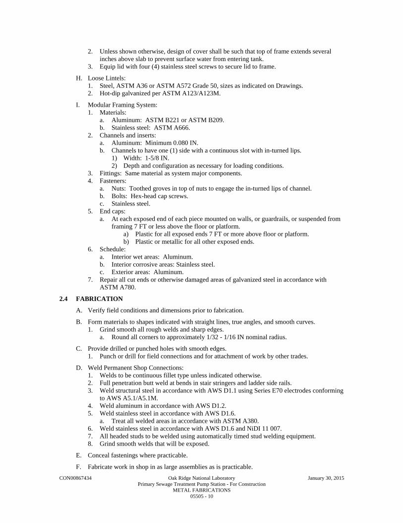
CON00867434 Oak Ridge National Laboratory January 30, 2015 Primary Sewage Treatment Pump Station - For Construction METAL FABRICATIONS 05505 - 10
2. Unless shown otherwise, design of cover shall be such that top of frame extends several inches above slab to prevent surface water from entering tank.
3. Equip lid with four (4) stainless steel screws to secure lid to frame.
H. Loose Lintels: 1. Steel, ASTM A36 or ASTM A572 Grade 50, sizes as indicated on Drawings. 2. Hot-dip galvanized per ASTM A123/A123M.
I. Modular Framing System: 1. Materials:
a. Aluminum: ASTM B221 or ASTM B209. b. Stainless steel: ASTM A666.
2. Channels and inserts: a. Aluminum: Minimum 0.080 IN. b. Channels to have one (1) side with a continuous slot with in-turned lips.
1) Width: 1-5/8 IN. 2) Depth and configuration as necessary for loading conditions.
3. Fittings: Same material as system major components. 4. Fasteners:
a. Nuts: Toothed groves in top of nuts to engage the in-turned lips of channel. b. Bolts: Hex-head cap screws. c. Stainless steel.
5. End caps: a. At each exposed end of each piece mounted on walls, or guardrails, or suspended from
framing 7 FT or less above the floor or platform. a) Plastic for all exposed ends 7 FT or more above floor or platform. b) Plastic or metallic for all other exposed ends.
6. Schedule: a. Interior wet areas: Aluminum. b. Interior corrosive areas: Stainless steel. c. Exterior areas: Aluminum.
7. Repair all cut ends or otherwise damaged areas of galvanized steel in accordance with ASTM A780.
2.4 FABRICATION
A. Verify field conditions and dimensions prior to fabrication.
B. Form materials to shapes indicated with straight lines, true angles, and smooth curves. 1. Grind smooth all rough welds and sharp edges.
a. Round all corners to approximately 1/32 - 1/16 IN nominal radius.
C. Provide drilled or punched holes with smooth edges. 1. Punch or drill for field connections and for attachment of work by other trades.
D. Weld Permanent Shop Connections: 1. Welds to be continuous fillet type unless indicated otherwise. 2. Full penetration butt weld at bends in stair stringers and ladder side rails. 3. Weld structural steel in accordance with AWS D1.1 using Series E70 electrodes conforming
to AWS A5.1/A5.1M. 4. Weld aluminum in accordance with AWS D1.2. 5. Weld stainless steel in accordance with AWS D1.6.
a. Treat all welded areas in accordance with ASTM A380. 6. Weld stainless steel in accordance with AWS D1.6 and NiDI 11 007. 7. All headed studs to be welded using automatically timed stud welding equipment. 8. Grind smooth welds that will be exposed.
E. Conceal fastenings where practicable.
F. Fabricate work in shop in as large assemblies as is practicable.

CON00867434 Oak Ridge National Laboratory January 30, 2015 Primary Sewage Treatment Pump Station - For Construction METAL FABRICATIONS 05505 - 11
G. Tolerances: 1. Rolling:
a. ASTM A6. b. When material received from the mill does not satisfy ASTM A6 tolerances for camber,
profile, flatness, or sweep, the Contractor is permitted to perform corrective work by the use of controlled heating and mechanical straightening, subject to the limitations of the AISC Specification.
2. Fabrication tolerance: a. Member length:
1) Both ends finished for contact bearing: 1/32 IN. 2) Framed members:
a) 30 FT or less: 1/16 IN. b) Over 30 FT: 1/8 IN.
b. Member straightness: 1) Compression members: 1/1000 of axial length between points laterally supported. 2) Non-compression members: ASTM A6 tolerance for wide flange shapes.
c. Specified member camber (except compression members): 1) 50 FT or less: Minus 0/plus 1/2 IN. 2) Over 50 FT: Minus 0/plus 1/2 IN (plus 1/8 IN per 10 FT over 50 FT). 3) Members received from mill with 75 percent of specified camber require no further
cambering. 4) Beams/trusses without specified camber shall be fabricated so after erection,
camber is upward. 5) Camber shall be measured in fabrication shop in unstressed condition.
d. At bolted splices, depth deviation shall be taken up by filler plates. 1) At welded joints, adjust weld profile to conform to variation in depth. 2) Slope weld surface per AWS requirements.
e. Finished members shall be free from twists, bends and open joints. 1) Sharp kinks, bends and deviation from above tolerances are cause for rejection of
material.
H. Fabricate grating, checkered plate, stairs, ladders and accessories using aluminum unless shown otherwise on Drawings. 1. Finish:
a. Mill, unless noted otherwise. b. Coat surfaces in contact with dissimilar materials.
I. Fabricate grating in accordance with NAAMM MBG 531. 1. Maximum tolerance for difference in depth between grating depth and seat or support angle
depth: 1/8 IN. 2. Distance between edge of grating and face of embedded seat angle or face of wall or other
structural member: 1/4 IN. a. Tolerance: NAAMM MBG 531.
3. Removable sections: Not wider than 3 FT and not more than 100 LBS. 4. Ends and perimeter edges: Banded.
a. Provide full depth banding unless noted otherwise. b. Banding at trenches and sumps to be 1/4 IN less than grating depth to allow for
drainage. 5. Openings through grating: Reinforced to provide required load carrying capacity and
banded with 4 IN high toe plate. 6. Provide joints at openings between individual grating sections. 7. Fabricate grating so that bearing bars and cross bars in adjacent sections are aligned.
J. Fabricate checkered plate and miscellaneous metals in accordance with NAAMM AMP 555. 1. Workmanship: Class 2 unless noted otherwise.

CON00867434 Oak Ridge National Laboratory January 30, 2015 Primary Sewage Treatment Pump Station - For Construction METAL FABRICATIONS 05505 - 12
K. Passivate stainless steel items and stainless steel welds after they have been ground smooth, where indicated on Drawings. 1. ASTM A380.
2.5 SOURCE QUALITY CONTROL
A. Surface Preparation: 1. All miscellaneous metal fabrication item surfaces shall be inspected and approved by NACE
certified coatings inspector prior to application of shop-applied paint coating. a. Inspection shall be performed to determine depth of blast profile and cleanliness of
surface. b. Fabricator shall reblast and or re-clean surfaces as required until acceptable.
B. Shop Applied Paint Coating Application: 1. After surface has been accepted in writing by NACE certified coatings inspector, fabricator
may proceed with application of paint coatings. 2. Application of paint coatings shall be observed and certified by NACE certified coatings
inspector.
C. COMPANY Pays for Field Inspection and Testing: 1. Company will employ and pay for services of an independent testing agency to inspect and
test structural metal shop and field work for compliance with this Specification Section. 2. Contractor responsible for testing to qualify shop and field welders and as needed for
Contractor's own quality control to ensure compliance with Contract Documents. 3. Contractor provides sufficient notification and access so inspection and testing can be
accomplished. 4. Contractor pays for retesting of failed tests and for additional testing required when defects
are discovered.
D. CONTRACTOR Pays for Shop Inspection and Testing: 1. Employ and pay for the services of a qualified independent testing agency to inspect and test
all structural steel work for compliance with Contract Documents. 2. Independent testing agency shall have a minimum of five (5) years performing similar work
and shall be subject to Company's approval.
E. Responsibilities of Testing Agency: 1. Inspect shop and field welding in accordance with AWS Code including the following non-
destructive testing: a. Visually inspect all welds. b. In addition to visual inspection, test 50 percent of full penetration welds and 20 percent
of fillet welds with liquid dye penetrant. c. Test 20 percent of liquid dye penetrant tested full penetration welds with ultrasonic or
radiographic testing. 2. Inspect high-strength bolting in accordance with the RCSC Specification for Structural
Joints Using High-Strength Bolts, Section 9. a. Verify direct tension indicator gaps.
3. Inspect structural metal which has been erected. 4. Inspect stud welding in accordance with AWS Code. 5. Prepare and submit inspection and test reports to Engineer.
a. Assist Engineer to determine corrective measures necessary for defective work.
PART 3 - EXECUTION
3.1 PREPARATION
A. Provide items to be built into other construction in time to allow their installation. 1. If such items are not provided in time for installation, cut in and install.
B. Prior to installation, inspect and verify condition of substrate.

CON00867434 Oak Ridge National Laboratory January 30, 2015 Primary Sewage Treatment Pump Station - For Construction METAL FABRICATIONS 05505 - 13
C. Correct surface defects or conditions which may interfere with or prevent a satisfactory installation. 1. Field welding aluminum is not permitted unless approved in writing by Engineer.
3.2 INSTALLATION
A. Set metal work level, true to line, plumb. 1. Shim and grout as necessary.
B. Contractor is solely responsible for safety. 1. Construction means and methods and sequencing of work is the prerogative of the
Contractor. 2. Take into consideration that full structural capacity of many structural members is not
realized until structural assembly is complete; e.g., until slabs, decks, and diagonal bracing or rigid connections are installed.
3. Partially complete structural members shall not be loaded without an investigation by the Contractor.
4. Until all elements of the permanent structure and lateral bracing system are complete, temporary bracing for the partially complete structure will be required.
C. Adequate temporary bracing to provide safety, stability and to resist all loads to which the partially complete structure may be subjected, including construction activities and operation of equipment is the responsibility of the Contractor. 1. Plumb, align, and set structural steel members to specified tolerances. 2. Use temporary guys, braces, shoring, connections, etc., necessary to maintain the structural
framing plumb and in proper alignment until permanent connections are made, the succeeding work is in place, and temporary work is no longer necessary.
3. Use temporary guys, bracing, shoring, and other work to prevent injury or damage to adjacent work or construction from stresses due to erection procedures and operation of erection equipment, construction loads, and wind.
4. Contractor shall be responsible for the design of the temporary bracing system and must consider the sequence and schedule of placement of such elements and effects of loads imposed on the structural metal members by partially or completely installed work, including work of all other trades. a. If not obvious from experience or from the Drawings, the Contractor shall confer with
the Engineer to identify those structural steel elements that must be complete before the temporary bracing system is removed.
5. Remove and dispose of all temporary work and facilities off-site.
D. Examine work-in-place on which specified work is in any way dependent to ensure that conditions are satisfactory for the installation of the work. 1. Report defects in work-in-place which may influence satisfactory completion of the work. 2. Absence of such notification will be construed as acceptance of work-in-place.
E. Field Measurement: 1. Take field measurements as necessary to verify or supplement dimensions indicated on the
Drawings. 2. Contractor responsible for the accurate fit of the work.
F. Check the elevations of all finished footings or foundations and the location and alignment of all anchor bolts before starting erection. 1. Use surveyor's level. 2. Notify Engineer of any errors or deviations found by such checking.
G. Framing member location tolerances after erection shall not exceed the frame tolerances listed in the FIELD QUALITY CONTROL Article in PART 3 of this Specification Section.
H. Erect plumb and level; introduce temporary bracing required to support erection loads.
I. Use light drifting necessary to draw holes together.

CON00867434 Oak Ridge National Laboratory January 30, 2015 Primary Sewage Treatment Pump Station - For Construction METAL FABRICATIONS 05505 - 14
1. Drifting to match unfair holes is not allowed.
J. Welding: 1. Conform to AWS D1.1 and requirements of the FABRICATION Article in PART 2 of this
Specification Section. 2. When joining two (2) sections of steel of different ASTM designations, welding techniques
shall be in accordance with a qualified AWS D1.1 procedure.
K. Shore existing members when unbolting of common connections is required. 1. Use new bolts for rebolting connections.
L. Clean stored material of all foreign matter accumulated during erection period.
M. Bolt Field Connections: Where practicable, conceal fastenings.
N. Field Welding: 1. Follow AWS procedures. 2. Grind welds smooth where field welding is required.
O. Field cutting grating or checkered plate to correct fabrication errors is not acceptable. 1. Replace entire section.
P. Remove all burrs and radius all sharp edges and corners of miscellaneous plates, angles, framing system elements, etc.
Q. Unless noted or specified otherwise: 1. Connect steel members to steel members with 3/4 IN DIA ASTM A325 high strength bolts. 2. Connect aluminum to aluminum with 3/4 IN DIA stainless steel bolts. 3. Connect aluminum to structural steel using 3/4 IN DIA stainless steel bolts.
a. Provide dissimilar metals protection. 4. Connect aluminum and steel members to concrete and masonry using stainless steel
expansion anchor bolts or adhesive anchor bolts unless shown otherwise. a. Provide dissimilar materials protection.
5. Provide washers for all bolted connections. 6. Where exposed, bolts shall extend a maximum of 3/4 IN and a minimum of 1/2 IN above
the top nut. a. If bolts are cut off to required maximum height, threads must be dressed to allow nuts
to be removed without damage to the bolt or the nuts.
R. Install and tighten ASTM A325 high-strength bolts in accordance with the AISC 325, Allowable Stress Design (ASD). 1. Provide hardened washers for all ASTM A325 bolts.
a. Provide the hardened washer under the element (nut or bolt head) turned in tightening.
S. After bolts are tightened, upset threads of ASTM A307 unfinished bolts or anchor bolts to prevent nuts from backing off.
T. Secure metal to wood with lag screws of adequate size with appropriate washers.
U. Do not field splice fabricated items unless said items exceed standard shipping length or change of direction requires splicing. 1. Provide full penetration welded splices where continuity is required.
V. Provide each fabricated item complete with attachment devices as indicated or required to install.
W. Anchor such that work will not be distorted nor fasteners overstressed from expansion and contraction.
X. Set beam and column base plates accurately on nonshrink grout as indicated on Drawings. 1. See Division 03 Specification Sections for non-shrink grout. 2. Set and anchor each base plate to proper line and elevation.

CON00867434 Oak Ridge National Laboratory January 30, 2015 Primary Sewage Treatment Pump Station - For Construction METAL FABRICATIONS 05505 - 15
a. Use metal wedges, shims, or setting nuts for leveling and plumbing columns and beams. 1) Wedges, shims and setting nuts to be of same metal as base plate they support. 2) Tighten nuts on anchor bolts.
b. Fill space between bearing surface and bottom of base plate with nonshrink grout. 1) Fill space until voids are completely filled and base plates are fully bedded on
wedges, shims, and grout. c. Do not remove wedges or shims.
1) Where they protrude, cut off flush with edge of base plate. d. Fill sleeves around anchor bolts solid with non-shrink grout.
Y. Tie anchor bolts in position to embedded reinforcing steel using wire. 1. Tack welding prohibited.
a. Coat bolt threads and nuts with heavy coat of clean grease. 2. Anchor bolt location tolerance:
a. 1/16 IN. b. Provide steel templates for all column anchor bolts.
Z. Install bollards in concrete as detailed. 1. 48 IN projection above ground. 2. 48 IN embedment in concrete, unless detailed otherwise on Drawings. 3. Fill pipe with concrete and round off at top.
AA. Accurately locate and place frames for openings before casting into floor slab so top of plate is flush with surface of finished floor. 1. Keep screw holes clean and ready to receive screws.
BB. Attach grating to end and intermediate supports with grating saddle clips and bolts. 1. Maximum spacing: 2 FT OC with minimum of two (2) per side. 2. Attach individual units of aluminum grating together with clips at 2 FT OC maximum with
a minimum of two (2) clips per side.
CC. Repair damaged galvanized surfaces in accordance with ASTM A780. 1. Prepare damaged surfaces by abrasive blasting or power sanding. 2. Apply galvanizing repair paint to minimum 6 mils DFT in accordance with manufacturer's
instructions.
DD. Anchor ladder to concrete structure with minimum 3/4 IN stainless steel anchor bolts with minimum 6 IN embedment.
EE. Anchor ladder to masonry structure with minimum 3/4 IN stainless steel anchor bolts with minimum 6 IN embedment. 1. When anchoring into masonry, fill masonry cores with grout at anchor locations and each
masonry core within 8 IN of anchor 2. When anchoring into cavity wall construction, provide minimum 6 IN embedment into
concrete or masonry back-up wall. a. At each anchor location, provide sleeve between back face of veneer and cavity face of
concrete or masonry back-up wall. b. Cut cavity insulation as required and seal around sleeve.
1) Sleeve to be 1 IN DIA schedule 40 stainless steel tubing, TP-304L, ASTM A269. a) Minimum wall thickness to be .065 IN.
2) Continuously weld 4 by 4 by 1/4 IN Type 304 stainless steel, ASTM A666 flange onto each end of pipe. a) Drill 1 IN hole in flange to match pipe. b) Attach sleeve to concrete or masonry back-up with 1/4 IN self-tapping
concrete anchors. 3) Grout solid, area around bolt where bolt penetrates veneer. 4) Accurately locate sleeves to align with bolt locations on ladder.

CON00867434 Oak Ridge National Laboratory January 30, 2015 Primary Sewage Treatment Pump Station - For Construction METAL FABRICATIONS 05505 - 16
FF. Anchor ladder to metal stud walls using minimum 1/2 IN stainless steel bolts, nuts and washers. 1. Verify that stud wall has been provided with adequate backing to accept ladder anchors.
GG. Install ladder safety extension post in accordance with manufacturer's instructions. 1. Mount device opposite the climbing side. 2. Provide ladder safety extension device for all ladders unless noted otherwise.
HH. Mount ladder fall protection system with rail offset from ladder side rail approximately 3 IN.
II. Install factory pre-fabricated stairs in location indicated in the Contract Documents.
3.3 FIELD QUALITY CONTROL
A. Tolerances shall meet structural requirements of Specification Section 05120 for erecting items of structural nature.
B. Tolerances (unless otherwise noted on the Drawings): 1. Frame placement, after assembly and before welding or tightening.
a. Deviation from plumb, level and alignment: 1 in 500, maximum. b. Displacement of centerlines of columns: 1/2 IN maximum, each side of centerline
location shown on Drawings.
3.4 CLEANING
A. After fabrication, erection, installation or application, clean all miscellaneous metal fabrication surfaces of all dirt, weld slag and other foreign matter.
B. All stainless steel products in addition to Paragraph A. above: 1. Remove all heat tint, rusting, discoloration by passivation, ASTM A380, or other acceptable
means as listed in NiDI 11 007 as approved by the Engineer.
END OF SECTION

CON00867434 Oak Ridge National Laboratory January 30, 2015 Primary Sewage Treatment Pump Station - For Construction ALUMINUM RAILINGS 05522 - 1
SECTION 05522
ALUMINUM RAILINGS
PART 1 - GENERAL
1.1 SUMMARY
A. Section Includes: 1. Aluminum handrail, stair rail and guardrail. 2. Aluminum guardrail gates.
B. Related Specification Sections include but are not necessarily limited to: 1. Division 0 - Bidding Requirements, Contract Forms, and Conditions of the Contract. 2. Division 1 - General Requirements. 3. Section 05505 - Metal Fabrications.
1.2 QUALITY ASSURANCE
A. Referenced Standards: 1. Aluminum Association (AA):
a. ADM-1, Aluminum Design Manual. b. 45, Designation System for Aluminum Finishes.
2. American Society of Mechanical Engineer (ASME): a. Section IX, Qualification Standard for Welding and Brazing Procedures, Welders,
Brazers, and Welding and Brazing Operators. 3. ASTM International (ASTM):
a. B108, Standard Specification for Aluminum-Alloy Permanent Mold Castings. b. B209, Standard Specification for Aluminum and Aluminum-Alloy Sheet and Plate. c. B221, Standard Specification for Aluminum and Aluminum-Alloy Extruded Bars,
Rods, Wire, Shapes and Tubes. d. B247, Standard Specification for Aluminum and Aluminum-Alloy Die Forgings, Hand
Forgings, and Rolled Ring Forgings. e. B308, Standard Specification for Aluminum-Alloy 6061-T6 Standard Structural
Profiles. f. B429, Standard Specification for Aluminum-Alloy Extruded Structural Pipe and Tube.
4. American Welding Society (AWS): a. C5.5, Recommended Practices for Gas Tungsten Arc Welding. b. D1.2, Structural Welding Code Aluminum.
5. National Association of Architectural Metal Manufacturers (NAAMM): a. AMP 521, Pipe Railing Systems Manual.
6. Occupational Safety and Health Administration (OSHA): a. 29 CFR 1910, Occupational Safety and Health Standards, referred to herein as OSHA
Standards. 7. Building code:
a. International Building Code, 2009 Edition including all amendments, referred to herein as Building Code.
B. Qualifications: 1. Qualify welding procedures and welding operators in accordance with AWS and
ASME Section IX.

CON00867434 Oak Ridge National Laboratory January 30, 2015 Primary Sewage Treatment Pump Station - For Construction ALUMINUM RAILINGS 05522 - 2
1.3 DEFINITIONS
A. Guardrail: A system of building components located near the open sides of elevated walking surfaces for the purpose of minimizing the possibility of an accidental fall from the walking surface to the lower level. Guardrails shall not have openings that allow the passage of a 21inch (533 mm) diameter sphere. An intermediate rail is required.
B. Handrail: A railing provided for grasping with the hand for support.
C. Railing: A generic term referring to guardrail, handrail and/or stair rails.
D. Stair Rail: A guardrail, installed at the open side of stairways with either a handrail mounted to the inside face of the guardrail, or where allowed by applicable codes, with the top rail mounted at handrail height and serving the function of a handrail. Stair rails shall not have openings that allow the passage of a 21inch (533 mm) diameter sphere. An intermediate rail is required.
1.4 SUBMITTALS
A. Shop Drawings: 1. See Specification Section 01300 for requirements for the mechanics and administration of
the submittal process. 2. Fabrication and/or layout drawings:
a. Drawings showing profile, location, sections and fabrication details including all welding information of each railing.
b. Type and details of anchorage. c. Location and type of expansion joints. d. Materials of construction, shop coatings and all third-party accessories.
3. Product technical data including: a. Acknowledgement that products submitted meet requirements of standards referenced. b. Manufacturer's installation details.
4. Certification that railings have been designed and fabricated to meet the loading requirements specified.
5. Calculations for all proposed systems in compliance with this Specification. a. Calculations shall be performed, sealed, signed and dated by a registered professional
structural engineer licensed in the State of Tennessee. b. Calculations shall be specific to this Project and shall include all assumptions,
references and design interpretations used to achieve the results obtained by the Engineer.
c. Reduction in load criteria is not acceptable as reason for deviation from sizes indicated in the Specification.
B. Miscellaneous Submittals: 1. See Specification Section 01300 for requirements for the mechanics and administration of
the submittal process. 2. Certification of welders and welding procedures indicating compliance with AWS
requirements. 3. Qualifications of engineer performing design and stamping and sealing calculations and
shop drawings.
1.5 DELIVERY, STORAGE AND HANDLING
A. Deliver and handle railings to preclude damage.
B. Store railings on skids, keep free of dirt and other foreign matter which will damage railings or finish and protect against corrosion.

CON00867434 Oak Ridge National Laboratory January 30, 2015 Primary Sewage Treatment Pump Station - For Construction ALUMINUM RAILINGS 05522 - 3
PART 2 - PRODUCTS
2.1 ACCEPTABLE MANUFACTURERS
A. Subject to compliance with the Contract Documents, the following manufacturers are acceptable:
1. Welded railing systems: a. Any manufacturer meeting this Specification Section.
2.2 MATERIALS
A. Alloy 6061-T6, 35,000 psi tensile yield strength minimum. 1. ASTM B209 for sheets and plates. 2. ASTM B308 for shapes - beams, channels, angles, tees, and zees. 3. ASTM B247 for forgings. 4. ASTM B221 for vertical railing posts only.
B. Alloy 6063-T5 or T6, 15,000 psi tensile yield strength minimum. 1. ASTM B221 and ASTM B429 for bars, rods, wires, all other pipes and tubes.
C. Cast Fittings: Aluminum, ASTM B108.
D. Shims: Aluminum of same alloy as component being shimmed.
E. Fasteners: See Specification Section 05505.
F. Expansion and Adhesive Anchors: See Specification Section 05505.
G. Electrodes for Welding: 1. Aluminum: AWS D1.2. 2. Filler alloy 5356 or 4043.
2.3 FABRICATION
A. General: 1. Verify field conditions and dimensions prior to fabrication. 2. For fabrication of items which will be exposed to view, use only materials which are smooth
and free of surface blemishes including pitting, seam marks, roller marks, rolled trade names and roughness. a. Remove blemishes by grinding and buffing or by welding and grinding, prior to
cleaning, treating and application of surface finishes. 3. Form exposed work with smooth, short radius bends, accurate angles and straight edges.
a. Ease exposed edges to a radius of approximately 1/32 IN. b. Form bent-metal corners to smallest radius possible without causing grain separation or
otherwise impairing work. c. Drill or punch holes with smooth edges.
4. Form exposed connections with flush, smooth, hairline joints, using stainless steel or aluminum splice locks to splice sections together. a. Ease the edges of top rail splices and expansion joints and remove all burrs left from
cutting. 5. Provide for anchorage of type indicated on Drawings or as required by field conditions.
a. Drill or punch holes with smooth edges. 6. Design railings and anchorage system in accordance with NAAMM AMP 521 to resist
loading as required by Building Code. 7. Custom fabricate railings to minimum dimensions and profiles indicated. Provide signed
and sealed calculations for design of railing system. a. Fabricate handrail mounted to wall or to guardrail vertical posts using minimum
1-1/4 IN nominal diameter Schedule 40 pipe. b. Fabricate all guardrail top rails using minimum 2 IN nominal diameter Schedule 40
pipe.

CON00867434 Oak Ridge National Laboratory January 30, 2015 Primary Sewage Treatment Pump Station - For Construction ALUMINUM RAILINGS 05522 - 4
c. Fabricate all guardrail vertical posts using minimum 2 IN nominal diameter Schedule 40 pipe.
d. All intermediate rails shall be fabricated using minimum 1-1/2 IN nominal diameter Schedule 40 pipe. 1) Where details are not indicated, set horizontal rails to requirements of the Building
Code or OSHA Standards, whichever requires the more restrictive design. e. Space vertical posts as required by loading requirements. f. Space handrail brackets as required by loading requirements. g. Base plate for vertical guardrail posts mounted to top of concrete surface:
1) 1/2 x 6 x 6 IN square plate. 2) Predrilled to accept four (4) anchors.
h. Base plate for vertical guardrail post mounted to flange of metal structure: 1) 1/2 x 3 x 8 1/2 IN plate. 2) Predrilled to accept two (2) fasteners.
i. Mounting bracket for vertical guardrail post mounted to vertical concrete surface or web of metal structural member: 1) Pair of 3/8 IN angles or bent plates. 2) Predrilled to accept two (2) fasteners each. 3) Weld angles or bent plates to vertical posts.
j. Removable railing section base assembly: 1) Base plate for vertical posts mounted to concrete surface:
a) 1/2 x 6 x 6 IN square plate. b) Predrilled to accept four (4) anchors.
2) Base plate for vertical posts mounted to flange of metal structure: a) 1/2 x 3 x 8 1/2 IN plate. b) Predrilled to accept two (2) anchors.
3) Provide 2 IN DIA x 8 IN long solid aluminum rod welded to the base plate. 4) Provide 2 IN long pipe section to match vertical post.
a) Fit pipe over solid aluminum rod and weld to base plate. b) Do not weld pipe section to solid aluminum rod.
5) Guardrail vertical post shall fit over solid rod and rest on pipe section. a) Provide two (2) drilled and tapped holes in vertical guardrail post to accept set
screws. b) Set screws: 1/4 IN stainless steel.
6) Completed assembly shall be designed to withstand the loading capacity specified. k. Removable railing section having posts fitted into sleeves cast into concrete slab. l. Provide 3/8 IN x 4 IN flat bar toeboards or 1/4 IN minimum thickness x 4 IN high
extruded toeboard with stiffener ribs on back side at all elevated walkways, platforms and stair landings, and where indicated on the Drawings or required by OSHA Standards.
m. Guardrail gates: 1) Constructed of same material and sizes as the guardrail system. 2) Width of gates as shown on Drawings. 3) Hinges:
a) Size as recommended by hinge manufacturer. (1) Rated for Heavy Duty usage. (2) Minimum thickness: 0.32 IN.
b) Welded to gate and jamb post. c) Full surface type. d) Permanently lubricated ball bearing. e) Same material as guardrail system.
4) Stop plate: a) Provide stop plate at top and bottom of the gate. b) Same material as guardrail system.
(1) Provide .125 IN DIA, 0.0625 IN thick EPDM silencer pads adhesive applied at each corner of each stationary plate.

CON00867434 Oak Ridge National Laboratory January 30, 2015 Primary Sewage Treatment Pump Station - For Construction ALUMINUM RAILINGS 05522 - 5
c) Minimum thickness: 0.25 IN. d) Welded to gate vertical post. e) Sized to extend from centerline of gate vertical post to centerline of jamb
vertical post. 8. Fit exposed ends of guardrails and handrails with solid terminations.
a. Return ends of handrail to wall, but do not attach to wall. b. Where guardrail terminates at a wall, provide a vertical post located 4 IN off the wall to
center of post. 9. Preassemble items in shop to greatest extent possible to minimize field splicing and
assembly of units at project site.
B. Finish: Mill per AA 45.
C. Railing Fabrication: 1. All railings are to be welded systems. 2. Use wire welding for all joints. 3. All welding to be continuous in accordance with AWS C5.5 and AWS D1.2.
a. All welded railing joints shall have full penetration welds unless noted otherwise. 4. All exposed welds to be ground smooth and flush to match and blend with adjoining
surfaces. a. NAAMM AMP 521, Type 2.
5. No ragged edges, surface defects, or undercutting of adjoining surfaces will be accepted. 6. Finishing joints with filler is not acceptable. 7. Provide flush weld fittings using locking weld connectors or coped drive-on connectors.
D. Install weeps to drain water from hollow sections of railing at exterior and high humidity conditions.
1. Drill 1/4 IN weep hole in railings closed at bottom: a. 1 IN above walkway surface at bottom of posts set in concrete. b. 1 IN above solid aluminum rod at posts having base plate. c. At low point of intermediate rails. d. Do not drill weep holes:
1) In bottom of base plate.
E. Expansion Joints: 1. Joints to be designed to allow expansion and contraction of railing and still meet design
loads required. a. Top rail splices and expansion joints shall be located within 8 IN of post or other
support. b. Where railings span building or tank expansion joints; provide a railing expansion joint
in the span crossing the building or tank expansion joint. 2. Provide expansion joints in any continuous run exceeding 20 FT in length.
a. Space expansion joints at not more than 40 FT OC. 3. Provide minimum 0.10 IN of expansion joint for each 20 FT length of top rail for each
25 DegF differential between installation temperature and maximum design temperature. a. Maximum expansion joint width at time of installation shall not exceed 3/8 IN.
1) Provide additional expansion joints as required to limit expansion joint width. 4. Provide slip-joint with internal sleeve.
a. Extend slip joint min 2 IN beyond joint at maximum design width. b. Fasten internal sleeve securely to one side
1) Provide allen-head set screw located in bottom of rail. 2) Rivets or exposed screw heads are not acceptable.

CON00867434 Oak Ridge National Laboratory January 30, 2015 Primary Sewage Treatment Pump Station - For Construction ALUMINUM RAILINGS 05522 - 6
PART 3 - EXECUTION
3.1 PREPARATION
A. Prior to installation, inspect and verify condition of substrate. 1. Installation of product constitutes installer's acceptance of substrate condition for product
compatibility.
B. Correct surface defects or conditions which may interfere with or prevent a satisfactory installation.
1. Field welding aluminum is not permitted unless approved in writing by Engineer.
3.2 INSTALLATION
A. Install gate, handrails and guardrails to meet loading requirements of the Building Code.
B. Install products in accordance with manufacturer's instructions.
C. Set work accurately in location, alignment and elevation; plumb, level and true. 1. Measure from established lines and items which are to be built into concrete, masonry or
similar construction.
D. Align railings prior to securing in place to assure proper matching at butting and expansion joints and correct alignment throughout their length.
1. Provide shims as required.
E. Install proper sized expansion joints based on temperature at time of installation and differential coefficient of expansion of materials in all railings as recommended by manufacturer.
1. Lubricate expansion joint splice bar for smooth movement of railing sections.
F. Provide removable railing sections where indicated on Drawings.
G. Attach handrails to walls or guardrail with brackets designed for condition: 1. Provide brackets which provide a minimum 1-1/2 IN clearance between handrail and
nearest obstruction. a. Handrails shall not project more than 3-1/2 IN into required stairway width.
2. Anchor handrail brackets to concrete or masonry walls with 1/2 IN stainless steel adhesive anchors with stainless steel hex head bolts.
H. Anchor railings to concrete with minimum 1/2 IN stainless steel adhesive anchors with stainless steel bolts, nuts and washers unless noted otherwise in the Contract Documents.
1. Where exposed, bolts shall extend minimum 1/2 IN and maximum 3/4 IN above the top nut. a. If bolts are cut off to required height, threads must be dressed to allow nuts to be
removed without damage to the bolt or the nut. b. Bevel the top of the bolt after cutting to provide a smooth surface.
I. Anchor railings to metal structure with stainless steel bolts, nuts and washers. 1. Where connection uses only 2 bolts, use 3/4 IN DIA. 2. Where connection uses 4 bolts, use 1/2 IN DIA.
J. Install toeboards to fit tight to the walking surface. 1. Notch toeboards at base plates or other obstructions. 2. Bottom of toeboard shall not exceed 1/4 IN above walking surface.
K. Provide railings as required for stair construction identified in Specification Section 05505.
L. Install guardrail gate plumb and level in location shown on Drawings. 1. Center gate in opening. 2. Top of gate to match top of guardrail.
END OF SECTION
CON00867434 Oak Ridge National Laboratory January 30, 2015 Primary Sewage Treatment Pump Station - For Construction ROUGH CARPENTRY 06100 - 1
SECTION 06100
ROUGH CARPENTRY
PART 1 - GENERAL
1.1 WORK INCLUDED
A. Provide rough carpentry work, as necessary for: 1. Backing panels for utilities. 2. Nailers, blocking, furring, and sleepers.
1.2 SUBMITTALS
A. Submit for approval product data.
1.3 QUALITY ASSURANCE
A. Comply with governing codes and regulations. Provide products of acceptable manufacturers which have been in satisfactory use in similar service. Use experienced installers. Deliver, handle, and store materials in accordance with manufacturer's instructions.
1.4 DELIVERY, STORAGE, AND HANDLING
A. Delivery and Storage: Keep materials under cover and dry. Protect against exposure to weather and contact with damp or wet surfaces. Stack lumber as well as plywood and other panels; provide for air circulation within and around stacks and under temporary coverings including polyethylene and similar materials. 1. For lumber and plywood pressure treated with waterborne chemicals, place spacers between
each bundle to provide air circulation.
PART 2 - PRODUCTS
2.1 LUMBER, GENERAL
A. Lumber Standards: Furnish lumber manufactured to comply with PS 20 "American Softwood Lumber Standard" and with applicable grading rules of inspection agencies certified by American Lumber Standards Committee's (ALSC) Board of Review.
B. Nominal sizes are indicated, except as shown by detail dimensions. Provide actual sizes as required by PS 20, for moisture content specified for each use. 1. Provide dressed lumber, S4S, unless otherwise indicated. 2. Provide seasoned lumber with 19 percent maximum moisture content at time of dressing
and shipment for sizes 2 inches or less in nominal thickness, unless otherwise indicated.
2.2 MISCELLANEOUS LUMBER
A. General: Provide lumber for support or attachment of other construction including rooftop equipment curbs and support bases, cant strips, bucks, nailers, blocking, furring, grounds, stripping, and similar members.
B. Fabricate miscellaneous lumber from dimension lumber of sizes indicated and into shapes shown.
C. Moisture content: 19 percent maximum for lumber items not specified to receive wood preservative treatment.

CON00867434 Oak Ridge National Laboratory January 30, 2015 Primary Sewage Treatment Pump Station - For Construction ROUGH CARPENTRY 06100 - 2
D. Grade: "Standard" grade light-framing-size lumber of any species or board-size lumber as required. "No. 3 Common" or "Standard" grade boards per WCLIB or WWPA rules or "No. 2 Boards" per SPIB rules.
2.3 FASTENERS
A. General: Provide fasteners of size and type indicated that comply with requirements specified in this article for material and manufacture. 1. Where rough carpentry is exposed to weather, in ground contact, or in area of high relative
humidity, provide fasteners with a hot-dip zinc coating per ASTM A 153 or of AISI Type 304 stainless steel.
B. Nails, Wire, Brads, and Staples: FS FF-N-105.
C. Power Driven Fasteners: National Evaluation Report NER-272.
D. Wood Screws: ANSI B18.6.1.
E. Lag Bolts: ANSI B18.2.1.
F. Bolts: Steel bolts complying with ASTM A 307, Grade A; with ASTM A 563 hex nuts and where indicated, flat washers.
2.4 PRESERVATIVE WOOD TREATMENT BY PRESSURE PROCESS
A. General: Where lumber or plywood is indicated as preservative-treated wood or is specified herein to be treated, comply with applicable requirements of AWPA Standards C2 (Lumber) and C9 (Plywood). Mark each treated item with the AWPB or SPIB Quality Mark Requirements.
B. Pressure-treat above-ground items with water-borne preservatives to a minimum retention of 0.25 pcf. For interior uses, after treatment, kiln-dry lumber and plywood to a maximum moisture content, respectively, of 19 percent and 15 percent. Treat indicated items and the following: 1. Wood cants, nailers, curbs, equipment support bases, blocking, stripping, and similar
members in connection with roofing, flashing, vapor barriers, and waterproofing. 2. Wood sills, sleepers, blocking, furring, stripping, and similar concealed members in contact
with masonry or concrete. 3. Wood framing members less than 18 inches above grade. 4. Wood floor plates installed over concrete slabs directly in contact with earth.
C. Pressure-treat wood members in contact with the ground or fresh water with water-borne preservatives to a minimum retention of 0.40 pcf.
D. Complete fabrication of treated items prior to treatment, where possible. If cut after treatment, coat cut surfaces to comply with AWPA M4. Inspect each piece of lumber or plywood after drying and discard damaged or defective pieces.
PART 3 - EXECUTION
3.1 INSTALLATION, GENERAL
A. Discard units of material with defects that impair quality of rough carpentry construction and that are too small to use in fabricating rough carpentry with minimum joints or optimum joint arrangement.
B. Set rough carpentry to required levels and lines, with members plumb and true to line and cut and fitted.
C. Fit rough carpentry to other construction; scribe and cope as required for accurate fit. Correlate location of furring, nailers, blocking, grounds, and similar supports to allow attachment of other construction.

CON00867434 Oak Ridge National Laboratory January 30, 2015 Primary Sewage Treatment Pump Station - For Construction ROUGH CARPENTRY 06100 - 3
D. Securely attach rough carpentry work to substrate by anchoring and fastening as indicated.
E. Countersink nail heads on exposed carpentry work and fill holes.
F. Use common wire nails, unless otherwise indicated. Use finishing nails for finish work. Select fasteners of size that will not penetrate members where opposite side will be exposed to view or will receive finish materials. Make tight connections between members. Install fasteners without splitting of wood; predrill as required.
3.2 WOOD GROUNDS, NAILERS, BLOCKING, AND SLEEPERS
A. Install wood grounds, nailers, blocking, and sleepers where shown and where required for screeding or attachment of other work. Form to shapes as shown and cut as required for true line and level of work to be attached. Coordinate location with other work involved.
B. Attach to substrates as required to support applied loading. Countersink bolts and nuts flush with surfaces, unless otherwise indicated. Build into masonry during installation of masonry work. Where possible, anchor to formwork before concrete placement.
C. Install permanent grounds of dressed, preservative treated, key-bevelled lumber not less than 1-1/2 inches wide and of thickness required to bring face of ground to exact thickness of finish material involved. Remove temporary grounds when no longer required.
END OF SECTION

This page intentionally left blank.

CON00867434 Oak Ridge National Laboratory January 30, 2015 Primary Sewage Treatment Pump Station - For Construction FIBERGLASS REINFORCED PLASTIC FABRICATIONS 06600 - 1
SECTION 06600
FIBERGLASS REINFORCED PLASTIC FABRICATIONS
PART 1 - GENERAL
1.1 WORK INCLUDED
A. Provide all labor, materials, equipment and services required or necessary to furnish and install fiberglass reinforced plastic (FRP) [grating], [handrails], [stairs], [ladders & cages], [and] [structural shapes] where shown on the drawings and as specified herein.
1.2 RELATED DOCUMENTS
A. Contract drawings, including general drawings and addenda drawings.
B. Division 1 Specification sections.
C. Section 05500 - Miscellaneous Metals and Fasteners
1.3 SUMMARY
A. This section includes specifications for the following fiberglass reinforced plastic items, assemblies, and fabrications: 1. Grating and stair treads. 2. Grating embed frames. 3. Structural fabrications. 4. Stair assemblies. 5. Handrail and toeboard assemblies. 6. Ladders and cages.
1.4 QUALITY ASSURANCE
A. All FRP products and fabrications shall be supplied by an experienced firm who has continually engaged in the manufacture and fabrication of fiberglass reinforced plastic. All suppliers must document a minimum of five years experience with similar projects with equal scope or design.
B. The installing contractor shall: assure that all field dimensions are taken accurately and communicated properly to the FRP fabricator, that other trades will not affect a proper installation of the FRP, and that all manufacturer's instructions and recommendations are followed.
C. No substitution of materials will be allowed unless they are submitted for review as alternates, and the Engineer approves their use.
1.5 DESIGN REQUIREMENTS
A. OSHA - 29 CFR as it pertains to worker safety and walking-working surfaces for stairs, ladders, handrail, and platforms
B. FRP grating shall designed to support 100 lbs. per square foot uniform load. Deflection shall not exceed .25 inch.
C. FRP Structural Shapes shall be designed into structures that will support all applicable loads. Deflection shall not exceed L/D of 180.
1.6 SUBMITTALS
A. Submit complete shop drawings and engineering data for all FRP materials and fabrications as required by this scope of work.

CON00867434 Oak Ridge National Laboratory January 30, 2015 Primary Sewage Treatment Pump Station - For Construction FIBERGLASS REINFORCED PLASTIC FABRICATIONS 06600 - 2
B. Product data:
C. Manufacturer’s catalog data with load charts for all FRP gratings. 1. Manufacturer’s catalog data for all FRP structural shapes.
D. Shop drawings: 1. Shop drawings shall indicate all FRP materials required and include all dimensions,
connections, fasteners, tolerances, assembly and installation details as required. 2. Coordination with equipment suppliers shall be indicated on the shop drawings where
openings for such equipment is required.
PART 2 - PRODUCTS
2.1 GENERAL
A. All FRP materials shall be manufactured with (select either Isophthalic-Polyester or Vinylester) resins.
B. All pultruded grating and structural shapes shall be constructed of strand roving, transverse mat, and a synthetic surface veil including ultraviolet (UV) light inhibitors.
C. All pultruded grating and structural shapes shall be flame retardant per ASTM E-84 Class I (flame spread of less than 25).
D. After fabrication of FRP, all cuts, holes, and abrasion shall be sealed to prevent corrosion.
E. The FRP materials of the types required shall be the product of one manufacturer, and shall be as manufactured by Seasafe Inc., Lafayette LA, (800-326-8842) or approved equivalent.
2.2 2FRP GRATING AND STAIR TREADS
A. FRP grating to be [Isophthalic-Polyester] [Vinylester] pultruded and shall meet ASTM E-84 Class I (flame spread of less than 25) and ASTM D-635 (self-extinguishing).
B. Grating shall be GatorDeck [select part number from catalog] with bearing bars centers spaced at [select corresponding bearing bar spacing from catalog].
C. Color shall be [safety yellow] [gray].
D. Grating and stair treads shall be made from pultruded bearing bars and cross rods.
E. Grating shall be assembled using a locking cross-rod design that makes a permanent connection between the cross-rod and bearing bar, and shall be completely bonded into a one-piece panel.
F. Stair Treads shall have a square tube nosing.
G. Grating shall have a slip resistant epoxy grit surface.
H. Grating clips shall be 316 stainless steel. Grating clips shall be installed on not more than six foot (6') centers, with not less than 4 clips per panel.
2.3 FRP GRATING EMBED FRAMES
A. All FRP grating set in concrete openings shall have a FRP embed angle frame.
B. Embed angle frame to be EBA-10, EBA-15, or EBA-20 as required for the grating specified above.
C. Embed angle have continuous integral anchor.
D. FRP embed angle frames shall be fabricated with Vinylester resin.

CON00867434 Oak Ridge National Laboratory January 30, 2015 Primary Sewage Treatment Pump Station - For Construction FIBERGLASS REINFORCED PLASTIC FABRICATIONS 06600 - 3
2.4 2FRP STRUCTURAL FABRICATIONS
A. FRP structural shapes shall be [Isophthalic-Polyester] [Vinylester] pultruded fiberglass shapes. All shapes shall meet ASTM E-84 Class I (Flame spread of less than 25) and ASTM D-635 (Self-extinguishing).
B. The minimum physical properties shall be:
Property ASTMLongitudinal
Direction Transverse Direction
Tensile Stress D-638 30,000 psi 7,000 psi
Tensile Modulus D-638 2.5 x 10⁶ psi 0.8 x 10⁶ psi
Compressive Stress D-695 30,000 psi 15,000 psi
Compressive Modulus D-695 2.5 x 10⁶ psi 1.0 x 10⁶ psi
Flexural Stress D-790 30,000 psi 10,000 psi
Flexural Modulus D-790 1.8 x 10⁶ psi 0.8 x 10⁶ psi
Modulus of Elasticity, E Full Section 2. 8 x 10⁶ psi
C. All structural shapes shall be fabricated per the drawings with good workmanship, closely fitted joints, and finished true to line and in accurate position to permit installation and proper joining of parts in the field
D. Bolts and washers used to assemble or connect to FRP structural fabrications shall be 316 stainless steel.
E. All joint surfaces to be bonded shall be abraded to remove surface gloss and be free of burrs or other foreign materials that would prevent proper adhesion.
F. Bonded surfaces shall use high-strength epoxy adhesives designed for FRP use and mechanical fasteners.
G. All pieces of an assembly shall have easily identified part numbers or piece marks.
H. For multiple unit assemblies, shop assemble pieces into the largest practical assembly suitable for shipping.
2.5 FRP STAIRS
A. Fabricate stair structural components from FRP structural shapes as described in section 2.04.
B. Use OSHA standards for rise and run
C. Use stair treads as specified in section 2.02.
D. Use FRP handrail as specified in section 2.06.
E. Use 316 stainless steel fasteners throughout.
2.6 FRP HANDRAIL
A. The handrail system shall be manufactured with [select either Isophthalic-Polyester or Vinylester] resin.
B. All handrail components shall be flame retardant per ASTM E-84 Class 1.
C. Handrail posts and rail shall be 2 x 2 x 1/4 inch square tube. All posts and rails shall use the same tube size. All tubing for handrail shall have a minimum 1/4-inch wall thickness.

CON00867434 Oak Ridge National Laboratory January 30, 2015 Primary Sewage Treatment Pump Station - For Construction FIBERGLASS REINFORCED PLASTIC FABRICATIONS 06600 - 4
D. Handrail toeboards shall be a preformed FRP shape with a minimum height of 4 inches, a minimum thickness of 1/4-inch, and shall be installed with the bottom edge approximately 1/4-inch above the walking surface.
E. All handrail and toeboards shall be safety yellow.
F. All post to rail connections shall be fully bonded with an epoxy adhesive and shall have a 1½- inch square solid internal connection plug for added strength and durability. All connections shall have a smooth transition between post and rail.
G. FRP handrail shall be a standard 2-rail design unless noted otherwise.
2.7 FRP LADDERS AND CAGES
A. Ladders and cages shall be made from [select either Isophthalic-Polyester or Vinylester] resin.
B. All ladder and cage components shall be flame retardant per ASTM E-84 Class 1.
C. Ladder rails shall be 2 x 2 x 1/4 inch square tube. Ladder rungs shall be 1 inch diameter solid round.
D. Ladders and cages shall be safety yellow.
E. Ladder rungs shall penetrate the inside wall of ladder rail tube and be countersunk into outside wall of ladder rail tube, providing support for the ladder rung in 4 places. This connection shall be fully bonded with epoxy adhesives and pinned to prevent rung rotation.
F. Ladder rungs shall have a slip-resistant quartz epoxy grit surface.
G. Ladder stand-off brackets shall be FRP and shall be installed at a maximum of 6'-0" on center. Ladder base mount brackets are to be FRP. All bolts shall be 316 stainless steel.
H. Ladder cages, if required per OSHA regulations, shall be fabricated from FRP hoops and traps. FRP hoops shall be 3 x 1/4-inch preformed FRP. Hoop spacing shall be a maximum of 4'-0" on center. FRP straps shall be 2 x 1/4-inch FRP and are to be spaced at 9" on center. Hoops and straps shall be bonded with epoxy adhesives and riveted with 316 stainless steel rivets.
2.8 ANTI-SLIP SURFACE FOR FRP COMPONENTS
A. Where called for in the Specifications, an FRP component shall have an anti-slip top surface of silica grit which shall be molded integral with the glass fiber reinforced substrate.
B. The silica grit shall be tightly packed with particle to particle contract to a minimum depth of 1/8-inch.
PART 3 - EXECUTION
3.1 HANDLING AND STORAGE
A. Upon receipt of material at job site, the Contractor shall inspect all materials for shipping damage.
B. Handle all FRP materials with proper care to prevent damage. Use shipping pallets to move material. Do not drag FRP material.
C. If FRP materials are not to be installed immediately, then the materials shall be stored in a manner to prevent twisting, bending, breaking, or damage of any kind. Keep material covered to prevent unnecessary exposure to UV.

CON00867434 Oak Ridge National Laboratory January 30, 2015 Primary Sewage Treatment Pump Station - For Construction FIBERGLASS REINFORCED PLASTIC FABRICATIONS 06600 - 5
3.2 INSTALLATION
A. Installing Contractor to coordinate and verify that other construction trades and materials have been installed per the contract drawings, and that they are accurate in location, alignment, elevation, and are plumb and level.
B. Install FRP materials in accordance with the installation drawings supplied by the FRP supplier.
C. Install materials accurately in location and elevation, level, and plumb. Field fabricate as necessary for accurate fit.
D. All field cuts, holes or abrasions must be sealed with sealing resin to prevent corrosion.
END OF SECTION

This page intentionally left blank.

CON00867434 Oak Ridge National Laboratory January 30, 2015 Primary Sewage Treatment Pump Station - For Construction GLASS FIBER REINFORCED WOOD SUBSTITUTES 06611 - 1
SECTION 06611
GLASS FIBER REINFORCED WOOD SUBSTITUTES
PART 1 - GENERAL
1.1 WORK INCLUDED
A. Provide all labor, materials, equipment and services required or necessary to furnish and install glass fiber reinforced plastic (GFRP) wood substitutes, where shown on the drawings and as specified herein.
1.2 RELATED DOCUMENTS
A. Contract drawings, including general drawings and addenda drawings.
B. Division 1 Specification sections.
1.3 SUMMARY
A. This section includes specifications for the following fiberglass reinforced plastic items: Cradles for ductile iron pipe.
1.4 QUALITY ASSURANCE
A. All GFRP products and fabrications shall be supplied by an experienced firm who has continually engaged in the manufacture and fabrication of fiberglass reinforced plastic. All suppliers must document a minimum of five years experience.
B. The installing contractor shall: assure that all field dimensions are taken accurately and communicated properly to the GFRP fabricator, that other trades will not affect a proper installation of the GFRP, and that all manufacturer's instructions and recommendations are followed.
C. No substitution of materials will be allowed unless they are submitted for review as alternates, and the Engineer approves their use.
1.5 SUBMITTALS
A. Submit complete shop drawings and engineering data for all GFRP materials as required by this scope of work.
B. Product data: Manufacturer’s catalog data for all GFRP products.
1.6 WARRANTY
A. GFRP wood substitutes shall be warranted not to corrode, rot, warp, splinter or crack for a period of 50 years.
PART 2 - PRODUCTS
2.1 GENERAL
A. All GFRP products shall be manufactured from recycled or new polyethylene and shall be reinforced with glass fibers to produce continuous and homogenous sections with no joints.
B. The GFRP shall contain not less than twenty percent (20%) of glass reinforcement by weight, and not less than eighty-five percent (85%) of the total polyethylene content shall be HDPE.

CON00867434 Oak Ridge National Laboratory January 30, 2015 Primary Sewage Treatment Pump Station - For Construction GLASS FIBER REINFORCED WOOD SUBSTITUTES 06611 - 2
C. The GFRP materials shall be the product of one manufacturer, and shall be as manufactured by American Composite Timbers, Commack, NY 11725, or approved equivalent.
2.2 GFRP WOOD SUBSTITUTES
A. GFRP wood substitutes shall be solid shapes.
B. The minimum mechanical and physical properties shall be:
Property ASTM Standard Minimum Result Value
Modulus of Rupture D 198 2,480 psi
Modulus of Elasticity D 6109 10" – 332,500 psi
3" – 340,900 psi
2" – 238,000 psi
Compressive Strength D 6108 1,960 psi
Compression Strength Parallel to Grain D 6112 3,560 psi
Compression Strength Perpendicular to Grain D 6112 1,180 psi
Tensile Strength D 638 3,060 psi
Density D 6111 60 lbs./ft3
Specific Gravity D 6111 0.965
Coefficient of Thermal Expansion D 696 0.000076/in/in/oF
C. Bolts and washers used to assemble or connect GFRP wood substitutes to other materials shall be 316 stainless steel.
PART 3 - EXECUTION
3.1 HANDLING AND STORAGE
A. Upon receipt of material at job site, the Contractor shall inspect all materials for shipping damage.
B. Handle all GFRP materials with proper care to prevent damage. Use shipping pallets to move material. Do not drag GFRP material.
C. If GFRP materials are not to be installed immediately, then the materials shall be stored in a manner to prevent twisting, bending, breaking, or damage of any kind.
3.2 3INSTALLATION
A. Install GFRP materials in accordance with the installation instructions supplied by the manufacturer.
B. Install materials accurately in location and elevation, level, and plumb. Field fabricate as necessary for accurate fit.
END OF SECTION
CON00867434 Oak Ridge National Laboratory January 30, 2015 Primary Sewage Treatment Pump Station - For Construction FLUID APPLIED WATERPROOFING 07120 - 1
SECTION 07120
FLUID APPLIED WATERPROOFING
PART 1 - GENERAL
1.1 WORK INCLUDED
A. Provide fluid applied waterproofing on exterior concrete surfaces, including necessary accessories, as indicated on the Drawings and specified herein.
1.2 RELATED WORK
A. Division 3 - Concrete.
1.3 SUBMITTALS
A. Submit an affidavit from manufacturer approving applicator prior to installation. Provide evidence of five years satisfactory application experience of the applicator for the system specified.
B. Submit material product data, material specifications and application manual from manufacturer which describes completely the preparation of surfaces and application of specified materials.
1.4 QUALITY ASSURANCE
A. Waterproofing Applicator: Provide the services of a manufacturer trained and manufacturer approved applicator with a minimum of five years experience in the application of fluid applied waterproofing.
B. Waterproofing Inspector: Provide the services of the waterproofing manufacturer's factory trained representative to inspect and approve surfaces to receive waterproofing prior to start of the work, to be present and observe start of application of waterproofing, to periodically inspect the work and inspect completed waterproofing work, and to report unsatisfactory surfaces to receive waterproofing and unsatisfactory materials and workmanship to Contractor and Engineer.
1.5 ENVIRONMENTAL REQUIREMENTS
A. Surface Temperature: Maximum 110� F and minimum 40� F during application.
B. Weather: Clear with no rain during application or anticipated within 12 hours thereafter.
1.6 WARRANTY
A. Furnish warranty signed by Contractor and waterproofing applicator, covering watertight integrity of waterproofing for a period of five years from date of final acceptance and providing for prompt repair of leaks, ruptures, blisters and other imperfections at no cost to the Company.
PART 2 - PRODUCTS
2.1 FLUID APPLIED WATERPROOFING
A. Product: One-component moisture-curing or two-component urethane type material suitable for covered non-traffic below grade locations.
B. Acceptable Manufacturers and Brands: 1. Tremco Manufacturing Co., 10701 Shaker Boulevard, Cleveland, OH 44104: Tremproof
No. 60.

CON00867434 Oak Ridge National Laboratory January 30, 2015 Primary Sewage Treatment Pump Station - For Construction FLUID APPLIED WATERPROOFING 07120 - 2
2. Gates Engineering Co., Inc., 100 West Street, Wilmington, DE 19899: Gacoflex UMW-28. 3. Sonneborn Building Products Division Contech, Inc., 7711 Computer Avenue, Minneapolis,
MN 55435: Hydrocide Liquid Membrane No. 5000 in roller grade and trowel grade. 4. 3M Company, 3M Center 223-6 NE, St. Paul, MN 55144: Scotch-Clad Deck Coating
System M.
2.2 PRIMER
A. As recommended by waterproofing manufacturer for each type of surface encountered.
2.3 PROTECTION BOARD
A. One-eighth inch thick asphalt composition board PC-2 Protection Course manufacturer by W.R. Meadows, Tex-Mastic Backerboard manufactured by J&P Petroleum Products, Inc., Tremboard manufactured by Tremco Mfg. Co., Elastiboard manufactured by Celotex Corp., as recommended by the waterproofing manufacturer.
2.4 JOINT FILLER
A. Closed-cell, round expanded polyethylene foam.
2.5 SEALANT
A. As recommended by waterproofing manufacturer for compatibility with waterproofing system.
2.6 ACCESSORY MATERIALS
A. Provide 1/16-inch thick neoprene sheet material, adhesives, or trowel grade urethane waterproofing, woven uncoated fiberglass mesh flashing reinforcement, thinners and application equipment necessary to complete work as recommended by the waterproofing manufacturer.
PART 3 - EXECUTION
3.1 REQUIRED CONDITION OF SURFACES
A. Concrete Surfaces: 1. Horizontal: Trowel finished without sharp ridges, projections, voids and concrete or mortar
droppings. 2. Vertical: Smooth, formed without sharp ridges, projections, voids and concrete or mortar
droppings.
B. Concrete Surfaces to Receive Waterproofing: 1. Water cured or cured with silicate type chemical curing compound compatible with
waterproofing. Do not use resin type curing compound. 2. Surfaces shall be dry and acceptable to waterproofing applicator. Application of
waterproofing will be considered as acceptance of surfaces to receive waterproofing.
3.2 PREPARATION OF SURFACES
A. After concrete substrate has cured 14 days with a maximum of 8% moisture content, has had projections, voids, concrete and mortar droppings corrected, thoroughly clean surfaces immediately before installation of waterproofing using compressed air, vacuum or other methods.
B. Remove oil, grease, form oils and resin type curing compounds with sandblasting or a commercial grade alkaline cleaner or solvent; thoroughly rinse and dry.
C. Ensure that concrete surfaces are dry and pass a four-hour rubber mat test with no condensation prior to application of waterproofing system. Test will not be required on vertical walls open on both sides.

CON00867434 Oak Ridge National Laboratory January 30, 2015 Primary Sewage Treatment Pump Station - For Construction FLUID APPLIED WATERPROOFING 07120 - 3
3.3 PREPARATION OF JOINTS, CRACKS AND DEPRESSIONS
A. Clean expansion, control and construction joints by cutting back a minimum of 1 inch. 1. Install polyethylene foam joint backing rod compressed 50% providing a channel below
level of slab of depth equal to one-half width and with ½-inch depth maximum. 2. Fill joint to surface level with sealant, apply bond breaker, and cover with non-flowing type
waterproofing or preformed neoprene or urethane sheet to a width of 3 inches on each side of joint as hereinafter specified.
B. Rout or sawcut cracks exceeding 1/16-inch in width and fill with sealant. Treat cracks by cleaning thoroughly and applying 60 mils of waterproofing extending 3 inches from each side of crack.
C. Prepare concrete substrates by filling voids, holes and depressions with epoxy grout or bonding agent and cement-sand grout as recommended by waterproofing manufacturer.
D. At horizontal, vertical and corner expansion joints, provide joint filler and sealant application compatible with waterproofing system. 1. Bridge joints using preformed neoprene or urethane membrane or with 60 mil coating of
fiberglass mesh reinforced waterproofing or strip of neoprene sheet as standard with manufacturer, applied over bond breaker or expansion joint.
2. Extend waterproofing a minimum of six inches from each side of joint, adhered to deck and vertical surfaces.
3.4 PREPARATION OF VERTICAL PROTRUSIONS AND DRAINS
A. Clean exposed metal surfaces such as pipes, sleeves, drains, bases and ducts by removing paint, rust, scale or any foreign matter. Prepare metal surfaces in accordance with manufacturer's recommendations and, if required, prime coat metal surfaces a maximum of eight hours prior to membrane application with waterproofing manufacturer's metal primer.
B. Apply a 60 mil waterproofing coating to entire surface, extending waterproofing up to bottom of sealant in top surfaces of deck areas and extend membrane out on or up vertical surfaces 4 inches on projections.
C. Extend waterproofing over flanges of drains without sealing weep holes.
3.5 WATERPROOFING APPLICATION
A. Two Component Type Waterproofing: Mix materials in strict accordance with manufacturer's published instructions without incorporating air bubbles. Do not thin or dilute mixture and conform to recommended Pot-Life requirements.
B. Single Component Type Waterproofing: Use as furnished without dilution.
C. Apply waterproofing uniformly on surfaces to produce 60 mils dry film thickness using a trowel, calibrated notched squeegee or roller equipment approved by the manufacturer. The 60 mil thickness is exclusive of previously applied waterproofing materials at cracks and joints.
D. Apply non-flowing type waterproofing material wherever a vertical surface exists, forming a continuous flashing and a ½-inch x ½-inch triangular cant, or other size recommended by waterproofing manufacturer. Extend waterproofing vertically up to bottom of sealant in deck top surfaces unless otherwise indicated.
E. At waterproofed basement floors, apply waterproofing on top of exterior wall foundations, interior column and wall foundations, mat type foundations and working slabs.
F. Apply waterproofing to walls on earth side of room walls retaining earth fill. Extend waterproofing from foundation up to underside of floor resting on earth fill.

CON00867434 Oak Ridge National Laboratory January 30, 2015 Primary Sewage Treatment Pump Station - For Construction FLUID APPLIED WATERPROOFING 07120 - 4
G. Apply waterproofing on interior of elevator pit walls up to finished floor and on exterior of elevator pit walls retaining earth fill from top of foundation up to finished floor on fill and from top of foundation up to within four inches of finished grade on exterior of building.
H. Apply waterproofing on exterior of below grade walls from top of foundation up to four inches of finish exterior finish grade.
I. In planting bins, apply waterproofing on interior bottoms and on interior sides.
J. Extend waterproofing material 6-inch minimum out on top of foundations.
K. At below grade rock anchors, pipe and conduit penetrations, extend membrane out on anchors, pipes and conduits 6-inch minimum to seal penetrations watertight.
3.6 TESTING
A. Do not flood test waterproofing sooner than 36-hours following completion of application. 1. Flood test each horizontal or deck area for a period of 48 hours minimum using a minimum
of 2 inches of standing water. 2. Plug drains and place barriers to contain water. 3. Notify the manufacturer's representative before testing.
3.7 PATCHING
A. Repair leaks which develop and retest. Patch voids, bubbles, depressions, imperfections or tears in strict accordance with manufacturers published recommendations.
3.8 APPLICATION OF PROTECTION BOARD
A. Do not apply protection board to deck waterproofing until successful testing has been completed.
B. Apply protection board to exterior horizontal surfaces and vertical surfaces of waterproofing. Adhere with spots of waterproofing.
C. On vertical surfaces where mechanical attachment is necessary to prevent protection board from sliding down, apply additional heavy trowel coat of fluid applied waterproofing where fasteners penetrate waterproofing. Use galvanized masonry nails for attachment of protection board.
D. Where protection board is to be applied to curved inside surfaces of planting bins, preform protection board using heat over a curved form.
END OF SECTION

CON00867434 Oak Ridge National Laboratory January 30, 2015 Primary Sewage Treatment Pump Station - For Construction BITUMINOUS DAMPROOFING 07160 - 1
SECTION 07160
BITUMINOUS DAMPROOFING
PART 1 - GENERAL
1.1 RELATED WORK
A. Division 3 - Concrete.
1.2 DESCRIPTION OF WORK
A. Extent of dampproofing work is all building concrete below grade.
B. Provide cold-applied asphalt emulsion dampproofing.
1.3 QUALITY ASSURANCE
A. General: Obtain primary materials from single manufacturer, to greatest extent possible. Provide secondary materials only as recommended by manufacturer of primary materials.
B. Installer Qualifications: A firm which has specialized in installation of dampproofing required for Project.
1.4 SUBMITTALS
A. Submit manufacturer's technical product data, installation instructions, and recommendations for dampproofing material. Include data substantiating that materials comply with specified requirements.
1.5 JOB CONDITIONS
A. Substrate: Proceed with dampproofing work only after substrate construction and penetrating work have been completed.
B. Weather: Proceed with dampproofing work only when existing weather conditions will permit work to be performed in accordance with manufacturer's recommendations.
PART 2 - PRODUCTS
2.1 BITUMINOUS DAMPPROOFING MATERIALS
A. General: Provide bituminous dampproofing materials which comply with the following requirements, or provide other similar products which are certified by manufacturer of primary dampproofing materials to be superior in performance for application indicated.
B. Cold-Applied Asphalt Emulsion Dampproofing: 1. Asphalt Emulsion: Manufacturer's standard asphalt and water emulsion coating,
recommended for below-grade exterior substrates, compounded to penetrate substrate and build to moisture-resistant coating.
2. Manufacturer: Subject to compliance with requirements, provide asphalt emulsion products of one of the following manufacturers or approved equal: a. Celotex Corporation. b. Certainteed Corporation. c. Koppers Company, Inc. d. Manville Building Products Corp. e. Sonneborne Building Products/Rexnord Chemical Products Inc. f. Tremco Company.

CON00867434 Oak Ridge National Laboratory January 30, 2015 Primary Sewage Treatment Pump Station - For Construction BITUMINOUS DAMPROOFING 07160 - 2
C. Miscellaneous Materials: 1. Plastic Cement: ASTM D 491, asphalt base recommended by manufacturer or bituminous
dampproofing materials. 2. Protection Course, Board Type: Asphalt impregnated and coated organic fiberboard, 1/2-
inch thick.
PART 3 - EXECUTION
3.1 PREPARATION OF SUBSTRATE
A. Clean substrate of projections and substances detrimental to work; comply with recommendations of materials manufacturer.
B. Install cant strips and similar accessories as shown and as recommended by materials manufacturer.
C. Fill voids, seal joints, and apply bond breakers (if any) as recommended by materials manufacturer.
D. Install separate flashings and corner protection stripping as recommended by materials manufacturer. Comply with manufacturer's recommendations.
E. Prime substrate as recommended by materials manufacturer.
F. Protection of Other Work: Prevent spillage and migration onto other surfaces of work by protecting adjoining work.
3.2 INSTALLATION
A. General: Comply with manufacturer's instructions.
B. Asphalt Emulsion on Exterior Surfaces: 1. Apply coat of semi-fibrated, semi-mastic, asphalt emulsion dampproofing materials, by
brushing or spraying at rate of 5.0 gallons per 100 square feet to produce uniform, dry film thickness of not less than 30 mils.
C. Dampproof Protection Course: 1. Comply with dampproofing materials manufacturer's recommendations for method of
support or attachment of protection materials. Support with-spot application of plastic cement.
D. Section includes masonry water repellent coating applied to locations indicated on the drawings and for the 6-inch precast panels at each new building’s exterior surface.
END OF SECTION

CON00867434 Oak Ridge National Laboratory January 30, 2015 Primary Sewage Treatment Pump Station - For Construction MASONRY WATER REPELLENT SYSTEM 07180 - 1
SECTION 07180
MASONRY WATER REPELLENT SYSTEM
PART 1 - GENERAL
1.1 SUMMARY
A. Section includes masonry water repellent coating applied to locations indicated on the drawings and for the 6-inch precast panels at each new building’s exterior surface.
B. Related Sections: 1. Section 04200 - Unit Masonry. 2. Section 07900 - Joint Sealers.
1.2 DEFINITIONS
A. Water Repellent: Resistant to penetration of water from rainfall.
1.3 SYSTEM DESCRIPTION
A. Performance Requirements: The application shall leave the finished surfaces uniform in color, water repellent and shall not alter the natural texture of the masonry units.
1.4 SUBMITTALS
A. Submit samples and manufacturer's instructions for approval prior to delivering materials to the site or commencing the work in this section, in accordance with Section 01300. 1. Manufacturer shall procure and apply system to samples of the masonry units to be used in
the structure which will be reviewed for both aesthetics and effectiveness. 2. Manufacturers Instructions: Submit current method of installation stating the actual
application rates required to meet the guarantee requirements.
B. Submit warranty in accordance with Section 01740.
1.5 QUALITY ASSURANCE
A. Qualifications: 1. Manufacturers - Engaged in producing system materials with a satisfactory performance
record for at least 5 years. 2. Applicator - Trained, approved and accepted by the manufacturer. Spray men shall have at
least 2 years experience spraying exotic coatings.
B. Regulatory Requirements: Comply with volatile organic compound (VOC) regulations in effect within the jurisdiction of the Project site.
C. Field Samples: 1. Apply system to the masonry sample wall located at the job site. The purpose of this
sample will be to observe color uniformity and intensity, the method of application, including workmanship techniques, and to water test surface after a 30-day period.
2. Equipment to be used for actual application to building walls shall be used to apply materials to sample wall.
3. This sample, when accepted by the Engineer and Company, will function as a reference base for acceptance or rejection of final work.
D. Pre-Installation Conference: A representative of the manufacturer shall be present prior to and at the beginning of job application to review the work with the Engineer and the Contractor. At this conference the manufacturer's representative shall also approve the wall and the suitability of the weather.

CON00867434 Oak Ridge National Laboratory January 30, 2015 Primary Sewage Treatment Pump Station - For Construction MASONRY WATER REPELLENT SYSTEM 07180 - 2
1.6 DELIVERY, STORAGE AND HANDLING
A. Packing and Shipping: Delivery shall be made to the job site in manufacturer's original containers with seals unbroken and labeled with manufacturer's batch number.
B. Storage and Protection: 1. Store materials in original, unopened containers in compliance with manufacturer's printed
instructions. 2. Do not store in areas where temperature will fall below 20 degrees F. or rise above 100
degrees F.
1.7 PROJECT/SITE CONDITIONS
A. Environmental Requirements: 1. Temperature and relative humidity conditions for a period before, during, and after
application shall be as recommended by the manufacturer. 2. If rain occurs prior to scheduled application, allow surfaces to dry a minimum of 5 days.
1.8 WARRANTY
A. Manufacturer shall provide a written warranty for a period of five (5) years from date of project completion. 1. Written warranty shall include the following provisions:
a. Coating will act as a water repellent for the full warranty period. b. Coating will not peel or flake for the full warranty period.
2. Upon satisfactory completion of the installation, and as a condition of its acceptance, the warranty shall be delivered to the Company.
3. If at any time during the five-year warranty period, any such failure occurs resulting from ordinary weather conditions in any area to which the coating has been properly applied, the manufacturer shall agree to supply all material needed to repair such affected areas at no additional cost to Company.
B. Applicator shall guarantee the installation against poor workmanship for a period of 2 years from the date of acceptance of the building by Company. The applicator shall make all necessary repairs without charge to Company during that period.
PART 2 - PRODUCTS
2.1 MANUFACTURERS
A. All products meeting the definitions contained in the Article 2.2, Materials, having a production and use history of five (5) years or more, and meeting the other requirements of this specification, will be acceptable.
2.2 MATERIALS
A. Dense or porous architectural concrete, most natural stone, brick, and other masonry surfaces: Siloxane Microemulsion Water Repellent. Water-reducible siloxane microemulsion. Complies with all known regulations limiting volatile organic compound (VOC) content of architectural coatings and sealers. Protects against moisture intrusion and resists efflorescence, leaching, mildew staining, atmospheric staining, and freeze-thaw spalling. 1. Form: Liquid. 2. Color: Clear, amber liquid. 3. Active Substance: Microemulsion concentrate of silanes and oligomericalky/alkoxy
siloxanes. 4. Total Solids: 100 percent concentrate. 5. VOC: 318 grams per liter (ASTM D5095/ASTM D3960).

CON00867434 Oak Ridge National Laboratory January 30, 2015 Primary Sewage Treatment Pump Station - For Construction MASONRY WATER REPELLENT SYSTEM 07180 - 3
2.3 EQUIPMENT
A. Masonry water repellent: 1. Application shall be by low pressure material pump with pressure not to exceed 25 psi. 2. Pump shall not atomize but shall flow the material on the wall at a minimum rate of 1-1/2
gallons per minute (orifice size 0.070 to 0.120 inches).
PART 3 - EXECUTION
3.1 EXAMINATION
A. Verification of Conditions: 1. Prior to work of this Section, carefully inspect the installed work of other trades, and verify
that such work is complete to the point where this installation may commence. 2. The water repellent manufacturer's representative shall verify that the water repellent may
be installed in accordance with the manufacturer's recommended methods and the original design.
3. Notify the Contractor and the Engineer if surfaces are acceptable for receiving specified products.
B. Inspection and Testing: 1. The surfaces shall be inspected prior to the application of any water repellent materials. 2. The masonry surfaces shall be tested for moisture content using an electronic moisture
register calibrated for concrete brick. 3. A minimum of one reading shall be taken for each 200 square feet of wall area and the
results tabulated. 4. The moisture content shall not exceed 15% on any surface prior to the water repellent
application.
3.2 PREPARATION
A. Protection: 1. Protect the installed work of other trades. 2. Protect concrete sidewalks from runoff by soaking with water immediately prior to
application on adjacent walls. 3. Protect adjoining glass, metal and painted surfaces from overspray and splash of water
repellent. Remove inadvertent splashes in an approved manner before the solution has dried on the surface.
4. In the event of damage, immediately make repairs and replacements necessary to the approval of Engineer.
B. Surface Preparation: 1. In strict accordance with manufacturer's printed instructions.
a. Concrete masonry walls shall be allowed to cure at least 30 days before water repellent is applied.
b. Walls shall be free of excess mortar. c. Cracks, other than hairline cracks, shall be pointed up prior to application of water
repellent. d. Defective mortar joints shall be routed out, pointed with mortar and tooled. e. Caulking and sealants shall be in place and cured prior to application of masonry
repellent system. 2. Commencement of system application constitute acceptance of surfaces by applicator.
3.3 APPLICATION
A. Water Repellent: Application to be in strict accordance with manufacturer's printed instructions and as follows.

CON00867434 Oak Ridge National Laboratory January 30, 2015 Primary Sewage Treatment Pump Station - For Construction MASONRY WATER REPELLENT SYSTEM 07180 - 4
1. The water repellent shall be applied with a light coat to break surface tension followed by a flood coat.
2. Flood coat passes shall be made starting at base of the wall followed by overlapping passes going up the wall.
3. The spray head should be held so that the fan will be vertical, with the head about 8 to 10 inches from the surface so that the flood coat runs freely down the surface 6 to 8 inches below the point of application.
4. In all instances, spray by traveling horizontally to ensure uniform coverage. 5. Overlap each following pass by approximately 50% (start each new section by holding the
spray head centered on the top line of the previous pass). 6. The surface should remain wet for a few minutes and damp for over one hour. 7. Repeat the procedure on spots which absorb too quickly. 8. When a second coat of repellent is required, allow to dry a minimum of 24 hours and apply
material to saturation. 9. Seal roof side and top of parapet walls.
B. Coverage: 1. Application rates shall be based on manufacturer's minimum coverage rates based on
permeability and surface area as determined by samples. At no time shall rate of coverage exceed the maximum area detailed in manufacturer's technical data sheets.
2. Estimated surface area shall be increased by a factor of 1/4 to 1/2 or more when fluted or scored block is used on the project.
3.4 DEMONSTRATION AND ACCEPTANCE TESTING
A. Tests: 1. Twenty days after completion of this portion of the work, and as a condition of its
acceptance, demonstrate by running water test that the work of this Section will successfully repel water.
2. Notify the Engineer and manufacturer at least 72 hours in advance and conduct the test in the Engineer’s and manufacturer's presence.
3. By means of an outrigger or similar acceptable equipment, place 3/4" garden hose with garden type spray nozzle, at a point designated by the Engineer, 8'-0" to 10'-0" away from the wall, aiming the nozzle so that water will strike the wall at a 45 degree downward angle.
4. Run the water onto the wall at full available force for not less than 4 hours. 5. Upon completion of the four hour period, inspect the interior surface of the wall for
evidence of moisture penetration. 6. If evidence of moisture penetration is discovered, apply an additional coat of the repellent
material to the areas where leakage occurred. 7. An additional area or areas shall be designated by the Engineer and tested and corrected for
leakage should any leakage occur on the original test. Additional testing under these circumstances shall be at no additional cost to the Company.
8. Further additional testing may be required by the Engineer until no failures occur.
3.5 CLEANING
A. Remove excess materials, equipment, and debris incidental to this work.
END OF SECTION

CON00867434 Oak Ridge National Laboratory January 30, 2015 Primary Sewage Treatment Pump Station - For Construction INSULATION 07200 - 1
SECTION 07200
INSULATION
PART 1 - GENERAL
1.1 SUMMARY
A. Provide building insulation of board, blanket, and loose-fill types as applicable: 1. Roofs (see Section 07530). 2. Exterior masonry walls and masonry foundation walls, rigid board between masonry units. 3. Exterior walls should use minimum of 1” polyiso insulation.
B. Provide vapor barrier at building perimeter.
C. Minimum R-value of 9.5.
1.2 SUBMITTALS
A. Submit for approval product data, test reports.
1.3 QUALITY ASSURANCE
A. Comply with governing codes and regulations. Provide products of acceptable manufacturers which have been in satisfactory use in similar service for three (3) years. Use experienced installers. Deliver, handle, and store materials in accordance with manufacturer's instructions.
1.4 RELATED WORK
A. Section 07530 - Singly-Ply Membrane Roofing
PART 2 - PRODUCTS
2.1 MATERIALS
A. Blanket/batt Type Insulation: Unfaced, paper-faced (vapor barrier), and foil-faced (vapor barrier) glass fiber blanket insulation types; Owens Corning Fiberglass Corp. or approved equal.
B. Board Type Insulation: Extruded polystyrene board; compressive strength 20 psi at foundations and under slab-on-grade, 60 psi at decks, 100 psi under heavy vehicular traffic; Styrofoam by Dow Chemical, Foamular by UC Industries or approved equal.
C. Polyisocyanurate Type Insulation – 1”= R-value of 8
D. Vapor Barrier: 6 mil clear polyethylene sheet.
PART 3 - EXECUTION
3.1 INSTALLATION
A. Install materials and systems in accordance with manufacturer's instructions and approved submittals. Install materials and systems in proper relation with adjacent construction. Coordinate with work of other sections. Provide full thickness in one (1) layer over entire area, tightly fitting around penetrations.

CON00867434 Oak Ridge National Laboratory January 30, 2015 Primary Sewage Treatment Pump Station - For Construction INSULATION 07200 - 2
B. Install vapor barrier over entire area of inside face of exterior walls and elsewhere as indicated. Seal all seams and around perimeter and penetrations with duct tape to form a continuous vapor barrier free of holes.
C. Protect installed insulation and vapor barrier.
END OF SECTION

CON00867434 Oak Ridge National Laboratory January 30, 2015 Primary Sewage Treatment Pump Station - For Construction SINGLE-PLY MEMBRANE ROOFING 07530 - 1
SECTION 07530
SINGLE-PLY MEMBRANE ROOFING
PART 1 - GENERAL
1.1 WORK INCLUDED
A. Division 1 - General Requirements.
B. Section 07600 - Flashing and Sheet Metal.
1.2 DESCRIPTION OF WORK
A. This Section includes single-ply membrane roofing system.
B. Type of roofing system specified is loose-laid, ballasted system.
C. Single-ply roofing membranes include ethylene propylene diene monomer (EPDM).
D. Roof insulation related to flexible sheet roofing is specified in this Section.
E. Wood nailers, blocking, and other related items are specified in Division 6.
1.3 SUBMITTALS
A. Product data, installation instructions, and general recommendations from manufacturer of single-ply membrane system for types of roofing are required.
1.4 QUALITY ASSURANCE
A. Manufacturer: Obtain primary flexible sheet roofing from a single manufacturer.
B. Installer: Use only an experienced installer to apply single-ply membrane roofing who has specialized in application of roofing systems similar to those required for this Project. Installer must be acceptable to or licensed by manufacturer. 1. Work associated with single-ply membrane roofing, including (but not limited to)
insulation, flashing and counterflashing, expansion joints, and joint sealants, is to be performed by installer of this work.
C. UL Listing: Provide labeled materials that have been tested and listed by UL in "Building Materials Directory" with "Class A" rated materials/system for roof slopes shown.
D. Roofing system to meet the requirements for FM Class I-90.
1.5 PROJECT CONDITIONS
A. Weather: Proceed with roofing work when existing weather conditions permit work to be performed in accordance with manufacturer's recommendations.
B. Substrate Conditions: Do not begin roofing installation until substrates have been determined to be in satisfactory condition.
1.6 WARRANTY
A. The entire installation, including base flashings, shall be warranted against defects in material and workmanship as required to maintain roofing system in watertight condition for the period stated below. This warranty shall be jointly signed by the manufacturer of the primary roofing material and the authorized installer. The warranty is for the complete system. 1. Total systems warranty shall be for a period of ten (10) years from the date of substantial
completion.

CON00867434 Oak Ridge National Laboratory January 30, 2015 Primary Sewage Treatment Pump Station - For Construction SINGLE-PLY MEMBRANE ROOFING 07530 - 2
B. Installer shall provide a typed certificate. Copies of the certificate shall be included with manufacturer's written warranty and submitted to the Engineer. The certificate shall include the following information: 1. Type of roof. 2. Installer's name, address and phone number. 3. Contact person in case of roof failure. 4. Warranty period with beginning and ending dates.
PART 2 - PRODUCTS
2.1 GENERAL
A. Performance: Provide roofing materials recognized to be of generic type indicated and tested to show compliance with indicated performances.
B. Compatibility: Provide products that are recommended by manufacturers to be fully compatible with indicated substrates.
2.2 EPDM MEMBRANE
A. General: EPDM formed into uniform, flexible sheets, complying with ASTM D 4637, Type 1. 1. Class U, unreinforced. 2. Thickness: 45 mils, nominal. 3. Exposed Face Color: WHITE.
B. Loose-laid, Ballasted EPDM Membrane: Manufacturer's standard installation.
C. Fully adhered EPDM Membrane: Manufacturer’s standard installation.
D. Manufacturers: Provide products of one of the following manufacturers or approved equal: 1. Carlisle Syntec Systems. 2. Firestone Building Products Co. 3. Goodyear Tire & Rubber Co.
2.3 AUXILIARY MATERIALS
A. Sheet Seaming System: Manufacturer's standard materials as recommended by membrane manufacturer.
B. Cant Strips, Tapered Edge Strips, and Flashing Accessories: Types recommended by membrane manufacturer.
C. Flashing Material: Manufacturer's standard system compatible with flexible sheet membrane.
D. Slip Sheet: Type recommended by membrane manufacturer.
E. Mechanical Fasteners: Metal plates, caps, battens, accessory components, fastening devices, and adhesives recommended by membrane manufacturer.
2.4 INSULATING MATERIALS
A. General: Provide insulating materials to comply with requirements indicated for materials and compliance with referenced standards in sizes to fit applications indicated, selected from manufacturer's standard thicknesses, widths, and lengths. 1. Provide tapered boards where indicated for sloping to drain. Fabricate with taper indicated
on Drawings.
B. Polyisocyanurate Board Roof Insulation: Rigid, cellular thermal insulation with polyisocyanurate closed-cell foam core and manufacturer's standard facing laminated to both sides; complying with FS HH-I-1972/2, Class 1.

CON00867434 Oak Ridge National Laboratory January 30, 2015 Primary Sewage Treatment Pump Station - For Construction SINGLE-PLY MEMBRANE ROOFING 07530 - 3
2.5 AUXILIARY INSULATION MATERIALS
A. Adhesive for Bonding Insulation: Type recommended by insulation manufacturer.
B. Mastic Sealer: Type recommended by insulation manufacturer.
PART 3 - EXECUTION
3.1 PREPARATION OF SUBSTRATE
A. General: Comply with manufacturer's instructions for preparation of substrate to receive single-ply membrane system. 1. Verify that penetrations and blocking are in place and secured.
B. Clean substrate of dust, debris, and other substances detrimental to roofing system work.
C. Install flashing and accessory items as recommended by manufacturer.
3.2 INSTALLATION OF INSULATION
A. General: Extend insulation full thickness in two (2) layers, or in multiple layers over entire surface to be insulated. Form cant strips with additional material as shown and as required for proper drainage of membrane. 1. Stagger joints in one direction for each course. For multiple layers, stagger joints in both
directions between courses with no gaps.
B. Do not install more insulation each day than can be covered with membrane before end of day.
C. Set insulation units loose on substrate and cover immediately with loose membrane for ballasted installation. Limit joints between adjacent units to 1/4-inch maximum.
3.3 INSTALLATION OF MEMBRANE
A. Do not "phase construction". All work must be completed over a given section of the roof by the termination of a work day. At the end of each work day, the roof must be left in "semi-permanent condition". "Semi-permanent condition" is defined as that which will resist moisture infiltration for a period of 60 calendar days beyond the last work day.
3.4 PROTECTION OF ROOFING
A. Upon completion of roofing (including associated work), institute appropriate procedures for surveillance and protection of roofing during remainder of construction period. At end of construction period, or at a time when remaining construction will in no way affect or endanger roofing, make a final inspection of roofing and prepare a written report to Company, describing nature and extent of deterioration or damage found.
B. Repair or replace deteriorated or defective work found at time of final inspection to a condition free of damage and deterioration in accordance with requirements of specified warranty.
END OF SECTION

This page intentionally left blank.

CON00867434 Oak Ridge National Laboratory January 30, 2015 Primary Sewage Treatment Pump Station - For Construction FLASHING AND SHEET METAL 07600 - 1
SECTION 07600
FLASHING AND SHEET METAL
PART 1 - GENERAL
1.1 RELATED WORK
A. Provide flashing and sheet metal components for building construction. 1. Masonry through-wall flashing. 2. Metal counter-flashing. 3. Built-in metal valleys, gutters, and scuppers. 4. Gutters and downspouts. 5. Exposed metal trim units. 6. Miscellaneous sheet metal accessories.
1.2 SUBMITTALS
A. Submit for approval: samples, shop drawings, product data.
1.3 QUALITY ASSURANCE
A. Comply with governing codes and regulations. Provide products of acceptable manufacturers which have been in satisfactory use in similar service. Use experienced installers. Deliver, handle, and store materials in accordance with manufacturer's instructions.
PART 2 - PRODUCTS
2.1 MATERIALS
A. Flashing: 1. Aluminum sheet: 20 gage alloy 3003 clear anodized aluminum, ASTM B 209.
B. Copings: Aluminum sheet interlocking multi-part coping system, 0.063-inch thickness; Snap-Lok Coping by MM Systems Corp or approved equal. 1. Coping is to be ES-1 certified per IBC 2. Anodized finish, Class 1, in color selected by Company.
PART 3 - EXECUTION
3.1 INSTALLATION
A. Follow recommendations of SMACNA "Sheet Metal Manual". Allow for expansion. Isolate dissimilar materials.
B. Install materials and systems in accordance with manufacturer's instructions and approved submittals. Install materials and systems in proper relation with adjacent construction and with uniform appearance. Coordinate with work of other sections.
C. Restore damaged components and finishes. Clean and protect work from damage.
END OF SECTION

This page intentionally left blank.

CON00867434 Oak Ridge National Laboratory January 30, 2015 Primary Sewage Treatment Pump Station - For Construction JOINT SEALERS 07900 - 1
SECTION 07900
JOINT SEALERS
PART 1 - GENERAL
1.1 WORK INCLUDED
A. Extent of each form and type of joint sealer is indicated on drawings and schedules.
1.2 QUALITY ASSURANCE
A. Single Source Responsibility for Joint Sealer Materials: Obtain joint sealer materials from a single manufacturer for each different product required.
B. Provide joint sealers that have been produced and installed to establish and maintain watertight and airtight continuous seals.
PART 2 - PRODUCTS
2.1 MATERIALS, GENERAL
A. Compatibility: Provide joint sealers, joint fillers and other related materials that are compatible with one another and with joint substrates under conditions of service and application, as demonstrated by sealant manufacturer based on testing and field experience.
B. Colors: Provide color of exposed joint sealers indicated or, if not otherwise indicated, as selected by Architect from manufacturer's standard colors.
2.2 ELASTOMERIC JOINT SEALANTS
A. Elastomeric Sealant Standard: Provide manufacturer's standard chemically curing, elastomeric sealant of base polymer indicated which complies with ASTM C 920 requirements, including those referenced for Type, Grade, Class, and Uses.
B. One-Part Nonacid-Curing Silicone Sealant: Type S, Grade NS, Class 25, and complying with the following requirements for Uses: 1. Uses NT, G, A, and, as applicable to joint substrates indicated, O. 2. Products: Subject to compliance with requirements, provide one of the following:
a. "Chem-Calk N-Cure 2000"; Bostik Construction Products Div. b. "Dow Corning 790"; Dow Corning Corp. c. "Silglaze N SCS 2501"; General Electric Co. d. "Silpruf SCS 2000"; General Electric Co. e. "864"; Pecora Corp. f. "Rhodorsil 5C"; Rhone-Poulenc Inc. g. "Spectrum 1"; Tremco, Inc. h. "Spectrum 2"; Tremco, Inc.
C. One-Part Mildew-Resistant Silicone Sealant: Type S; Grade NS; Class 25; Uses NT, G, A, and, as applicable to nonporous joint substrates indicated, O; formulated with fungicide; intended for sealing interior joints with nonporous substrates and subject to in-service exposure to conditions of high humidity and temperature extremes. 1. Products: Subject to compliance with requirements, provide one of the following:
a. "Dow Corning 786"; Dow Corning Corp. b. "SCS 1702 Sanitary"; General Electric Co. c. "863 #345 White"; Pecora Corp. d. "Rhodorsil 6B White"; Rhone-Poulenc Inc.

CON00867434 Oak Ridge National Laboratory January 30, 2015 Primary Sewage Treatment Pump Station - For Construction JOINT SEALERS 07900 - 2
e. "Proglaze White"; Tremco Corp. f. "OmniPlus"; Sonneborn Building Products Div., Rexnord Chemical Products Inc.
D. Multi-Part Nonsag Urethane Sealant for Use NT: Type M, Grade NS, Class 25, and complying with the following requirements for Uses: 1. Uses NT, M, G, A, and, as applicable to joint substrates indicated, O. 2. Products: Subject to compliance with requirements, provide one of the following:
a. "Vulkem 922"; Mameco International, Inc. b. "Dynatrol II"; Pecora Corp. c. "Permapol RC-2"; Products Research & Chemical Corp. d. "Sikaflex-2c NS"; Sika Corp. e. "Sonolastic NP 2"; Sonneborn Building Products Div., Rexnord Chemical Products Inc. f. "Dymeric"; Tremco Inc.
2.3 LATEX JOINT SEALANTS
A. Acrylic-Emulsion Sealant: Manufacturer's standard, one part, nonsag, mildew-resistant, acrylic-emulsion sealant complying with ASTM C 834, formulated to be paintable and recommended for exposed applications on interior and on protected exterior locations involving joint movement of not more than plus or minus 5 percent.
B. Products: Subject to compliance with requirements, provide one of the following: 1. Acrylic-Emulsion Sealant:
a. "Chem-Calk 600"; Bostik Construction Products Div. b. "AC-20"; Pecora Corp. c. "Sonolac"; Sonneborn Building Products Div.; Rexnord Chemical Products, Inc. d. "Tremco Acrylic Latex 834"; Tremco Inc.
2.4 JOINT SEALANT BACKING
A. General: Provide sealant backings of material and type which are nonstaining; are compatible with joint substrates, sealants, primers and other joint fillers; and are approved for applications indicated by sealant manufacturer based on field experience and laboratory testing.
B. Bond-Breaker Tape: Polyethylene tape or other plastic tape as recommended by sealant manufacturer for preventing sealant from adhering to rigid, inflexible joint filler materials or joint surfaces at back of joint where such adhesion would result in sealant failure. Provide self-adhesive tape where applicable.
2.5 MISCELLANEOUS MATERIALS
A. Primer: Provide type recommended by joint sealer manufacturer where required for adhesion of sealant to joint substrates indicated, as determined from preconstruction joint sealer-substrate tests and field tests.
B. Cleaners for Nonporous Surfaces: Provide nonstaining, chemical cleaners of type which are acceptable to manufacturers of sealants and sealant backing materials, which are not harmful to substrates and adjacent nonporous materials, and which do not leave oily residues or otherwise have a detrimental effect on sealant adhesion or in-service performance.
C. Masking Tape: Provide nonstaining, nonabsorbent type compatible with joint sealants and to surfaces adjacent to joints.
PART 3 - EXECUTION
3.1 EXAMINATION
A. Examine joints indicated to receive joint sealers, with Installer present, for compliance with requirements for joint configuration, installation tolerances and other conditions affecting joint

CON00867434 Oak Ridge National Laboratory January 30, 2015 Primary Sewage Treatment Pump Station - For Construction JOINT SEALERS 07900 - 3
sealer performance. Do not proceed with installation of joint sealers until unsatisfactory conditions have been corrected.
3.2 PREPARATION
A. Surface Cleaning of Joints: Clean out joints immediately before installing joint sealers to comply with recommendations of joint sealer manufacturers and the following requirements: 1. Remove all foreign material from joint substrates which could interfere with adhesion of
joint sealer, including dust; paints, except for permanent, protective coatings tested and approved for sealant adhesion and compatibility by sealant manufacturer; old joint sealers; oil; grease; waterproofing; water repellants; water; surface dirt; and frost.
2. Clean concrete, masonry, unglazed surfaces of ceramic tile and similar porous joint substrate surfaces, by brushing, grinding, blast cleaning, mechanical abrading, or a combination of these methods to produce a clean, sound substrate capable of developing optimum bond with joint sealers. Remove loose particles remaining from above cleaning operations by vacuuming or blowing out joints with oil-free compressed air.
3. Remove laitance and form release agents from concrete. 4. Clean metal, glass, porcelain enamel, glazed surfaces of ceramic tile; and other nonporous
surfaces by chemical cleaners or other means which are not harmful to substrates or leave residues capable of interfering with adhesion of joint sealers.
B. Joint Priming: Prime joint substrates where indicated or where recommended by joint sealer manufacturer based on preconstruction joint sealer-substrate tests or prior experience. Apply primer to comply with joint sealer manufacturer's recommendations. Confine primers to areas of joint sealer bond, do not allow spillage or migration onto adjoining surfaces.
C. Masking Tape: Use masking tape where required to prevent contact of sealant with adjoining surfaces which otherwise would be permanently stained or damaged by such contact or by cleaning methods required to remove sealant smears. Remove tape immediately after tooling without disturbing joint seal.
3.3 INSTALLATION OF JOINT SEALERS
A. General: Comply with joint sealer manufacturers' printed installation instructions applicable to products and applications indicated, except where more stringent requirements apply.
B. Elastomeric Sealant Installation Standard: Comply with recommendations of ASTM C 962 for use of joint sealants as applicable to materials, applications and conditions indicated.
C. Latex Sealant Installation Standard: Comply with requirements of ASTM C 790 for use of latex sealants.
D. Installation of Sealant Backings: Install sealant backings to comply with the following requirements: 1. Install joint fillers of type indicated to provide support of sealants during application and at
position required to produce the cross-sectional shapes and depths of installed sealants relative to joint widths which allow optimum sealant movement capability.
2. Install bond breaker tape between sealants and joint fillers, compression seals, or back of joints where adhesion of sealant to surfaces at back of joints would result in sealant failure.
E. Installation of Sealants: Install sealants by proven techniques that result in sealants directly contacting and fully wetting joint substrates, completely filling recesses provided for each joint configuration, and providing uniform, cross-sectional shapes and depths relative to joint widths which allow optimum sealant movement capability.
F. Tooling of Nonsag Sealants: Immediately after sealant application and prior to time skinning or curing begins, tool sealants to form smooth, uniform beads of configuration indicated, to eliminate air pockets, and to ensure contact and adhesion of sealant with sides of joint. Remove excess sealants from surfaces adjacent to joint. Do not use tooling agents which discolor sealants or adjacent surfaces or are not approved by sealant manufacturer.

CON00867434 Oak Ridge National Laboratory January 30, 2015 Primary Sewage Treatment Pump Station - For Construction JOINT SEALERS 07900 - 4
1. Provide concave joint configuration per Figure 6A in ASTM C 962, unless otherwise indicated.
3.4 CLEANING
A. Clean off excess sealants or sealant smears adjacent to joints as work progresses by methods and with cleaning materials approved by manufacturers of joint sealers and of products in which joints occur.
3.5 PROTECTION
A. Protect joint sealers during and after curing period from contact with contaminating substances or from damage resulting from construction operations or other causes so that they are without deterioration or damage at time of Substantial Completion. If, despite such protection, damage or deterioration occurs, cut out and remove damaged or deteriorated joint sealers immediately and reseal joints with new materials to produce joint sealer installations with repaired areas indistinguishable from original work.
3.6 JOINT SEALANT SCHEDULE
A. Interior & Exterior Masonry: Multi-part Nonsag Urethane
B. Interior (General): Acrylic Emulsion
C. Interior Plumbing Fixtures, etc.: One-part Mildew Resistant Silicone
D. Interior at Hollow Core Planks: Multi-panel Nonsag Urethane
E. Interior & Exterior Aluminum Windows and Doors: One-part Non Acid-curing Silicone
END OF SECTION

CON00867434 Oak Ridge National Laboratory January 30, 2015 Primary Sewage Treatment Pump Station - For Construction FIBERGLASS REINFORCED DOORS AND FRAMES 08222 - 1
SECTION 08222
FIBERGLASS REINFORCED DOORS AND FRAMES
PART 1 - GENERAL
1.1 WORK INCLUDED
A. This section includes the following: 1. Fiberglass Reinforced Plastic (FRP) Doors. 2. Fiberglass Resin Transfer Molded Door Frames.
1.2 RELATED SECTIONS
A. Related sections include the following: 1. Division 1 - General Requirements. 2. Division 8 - Finish Hardware. 3. Division 8 - Glazing.
1.3 QUALITY ASSURANCE
A. Referenced Standards: 1. Door Assembly: ASTM C 518 Standard test method for steady state thermal transmission
properties by means of the heat flow meter apparatus. 2. Laminate Properties:
a. ASTM D 638 - Tensile Strength = 15,000 PSI. b. ASTM D 790 - Flexural Strength = 39,000 PSI. c. ASTM D 2583 - Barcol Hardness = 57. d. ASTM D 256 - Impact Resistance = 15.75. e. ASTM D 792 - Density/Specific Gravity of Laminate. f. ASTM D 1761 - Mechanical Fasteners. g. ASTM E 84 - Surface Burning Characteristics. h. ASTM G 155 - Gelcoat Xenon Arc light exposure test. i. ASTM D 635 - Standard Test Method for Rate of Burning and/or Extent and Time of
Burning of Self-Supporting Plastics in a Horizontal Position. 3. Core Properties:
a. ASTM C 177 Thermal Properties b. ASTM C 1622 Density/Specific Gravity c. ASTM E 84 Surface Burning Characteristics d. WDMA TM-10 and TM-5 Firestop ASTM E 152 U.L. 10(b)
B. Qualifications: 1. Manufacturer Qualifications: A company specialized in the manufacture of fiberglass
reinforced plastic (FRP) doors and frames as specified herein with a minimum of five years documented experience and with a record of successful in-service performance for the applications as required for this project.
2. Installer Qualifications: An experienced installer who has completed fiberglass door and frame installations similar in material, design, and extent to those indicated and who work has resulted in construction with a record of successful in-service performance.
3. Source Limitations: Obtain fiberglass reinforced plastic doors and frames through the source fabricated from a single manufacturer, including fire rated fiberglass frames.
4. Source Limitations: Hardware and accessories for all FRP doors as specified in Section 08700 shall be installed by the fiberglass door and frame manufacturer.
5. Source Limitations: Glass for windows in doors shall be installed by door and frame manufacturer in accordance with related section, Division 8, Glazing.

CON00867434 Oak Ridge National Laboratory January 30, 2015 Primary Sewage Treatment Pump Station - For Construction FIBERGLASS REINFORCED DOORS AND FRAMES 08222 - 2
1.4 SUBMITTALS
A. Product technical data including: 1. Acknowledgment that products submitted meet requirements of standards referenced. 2. Manufacturer shall provide certificate of compliance with current local and federal
regulations as it applies to the manufacturing process. 3. Manufacturer’s installation instructions. 4. Schedule of doors and frames indicating the specific reference numbers as used on
drawings, door type, frame type, size, handling and applicable hardware. 5. Details of core and edge construction. Include factory-construction specifications. 6. Certification of manufacturer’s qualifications.
B. Submittal drawings for customer approval shall be submitted prior to manufacture and will include the following information and formatting: 1. Summary door schedule indicating the specific reference numbers as used on Owner’s
drawings, with columns noting door type, frame type, size, handling, accessories, and hardware.
2. A drawing depicting front and rear door elevations showing hardware with bill of material for each door.
3. Drawing showing dimensional location of each hardware item and size of each door. 4. Individual part drawing and specification for each hardware item and FRP part or product. 5. Construction and mounting detail for each frame type.
C. Samples: Provide one 21" x 18" completely assembled (hinged) door and frame corner section, with faces and edges representing typical color and finish. One edge should be exposed for view of interior door and frame composition. Sample should include six inch light opening as well as standard cutouts for hinges and strike plates.
D. Operation and Maintenance Manuals: 1. Include recommended methods and frequency for maintaining optimum condition of
fiberglass doors and frames under anticipated traffic and use conditions. 2. Include one set of final as built drawings with the same requirements as mentioned in
Section B above. 3. Include certificate of warranty for door and frame listing specific door registration numbers. 4. Include hardware data sheets and hardware manufacturer’s warranties.
1.5 DELIVERY, STORAGE, AND HANDLING
A. Each door and frame should be delivered individually crated for protection from damage in cardboard containers, clearly marked with project information, door location, specific reference number as shown on drawings, and shipping information. Each crate should contain all fasteners necessary for installation as well as complete installation instructions.
B. Doors should be stored in the original container out of inclement weather for protection against the elements.
C. Handle doors pursuant to the manufacturer’s recommendations as posted on outside of crate.
1.6 WARRANTY
A. Warranty all fiberglass doors and frames for a period of 25 ears against failure due to corrosion. Additionally, warranty all fiberglass doors and frames on materials and workmanship for a period of 10 years, including warp, separation or delamination, and expansion of the core.

CON00867434 Oak Ridge National Laboratory January 30, 2015 Primary Sewage Treatment Pump Station - For Construction FIBERGLASS REINFORCED DOORS AND FRAMES 08222 - 3
PART 2 - PRODUCTS
2.1 ACCEPTABLE MANUFACTURERS
A. Subject to compliance with the Contract Documents, the following manufacturers are acceptable: 1. Chem-Pruf Door Co., Ltd., Brownsville, Texas 78523. 2. Corrim Company, Oshkosh, Wisconsin 54901. 3. Engineer approved equivalent product.
2.2 FRP DOORS:
A. Doors shall be made of fiberglass reinforced plastic (FRP) using chemically proven resins resistant to contaminants typically found in the environment for which these specifications are written. Doors shall be 1¾ inch thick and of flush construction, having no seams or cracks. All doors up to 4'0 x 8'0 shall have equal diagonal measurements with a maximum tolerance of +/- 1/32 inch.
B. Door plates shall be +/- 0.125 inch thick, molded in one continuous piece, starting with a 25 mil gelcoat of the color specified, integrally molded with at least two layers of 1.5 ounce per square foot fiberglass mat and one layer of 13 ounce per square yard unidirectional roving. This will yield a plate weight of 0.97 lbs. Per square foot at a ratio of 30/70 glass to resin.
C. Stiles and rails shall be constructed starting from the outside toward the inside, of a 25 mil gelcoat of the color specified followed by a matrix of at least three layers of 1.5 ounce per square foot of fiberglass mat. The stile and rail shall be molded in one continuous piece to a u-shaped configuration and to the exact dimensions of the door. In this manner there will be no miter joints or disparate materials used to form the one-piece stile and rail.
D. Core material shall be 2 psf expanded polyurethane foam, which completely fills all voids between the door plates.
E. Internal Reinforcement shall be of sufficient amount to adequately support required hardware and function of same.
F. Finish of door and frame shall be identical in color and texture. At time of manufacture, 25 mil of resin-rich gelcoat must be integrally molded into both the door and frame. Secondary painting to achieve color is not acceptable.
G. Window openings shall be provided for at time of manufacture and shall be completely sealed so that the interior of all of the door is not exposed to the environment. Fiberglass retainers which hold the glazing in place shall be resin transfer molded with a profile that drains away from glazing. The retainers must match the color, texture and finish of the door plates. Glass shall be furnished and installed by door and frame manufacturer.
H. Louver openings shall be sealed in the same manner as the window openings. Louvers are to be solid fiberglass inverted “V” vanes and shall match the color, texture and finish of the door plates.
I. Transoms shall be identical to the doors in construction, materials, thickness and reinforcement.
2.3 FRAMES
A. Frames shall be fiberglass and manufactured using the resin transfer method in closed rigid molds to assure uniformity in color and size. Beginning with a minimum 25 mil gelcoat and a minimum of two layers continuos strand fiberglass mat saturated with resin, the frame will be one-piece construction with molded stop. All frame profiles up to ¾” will be solid fiberglass. All frame profiles greater that ¾” shall have a core material of 2 psf polyurethane foam. Metal frames or pultruded fiberglass frames will not be acceptable.

CON00867434 Oak Ridge National Laboratory January 30, 2015 Primary Sewage Treatment Pump Station - For Construction FIBERGLASS REINFORCED DOORS AND FRAMES 08222 - 4
B. Finish of frame shall be identical in color and texture to the door. 25 mil resin rich gelcoat will be integrally molded into the frame at time of manufacture. Secondary painting to achieve color is not acceptable.
C. Jamb/Header connection shall be coped by CNC for tight fit.
D. Internal Reinforcement shall be continuous within the structure to allow for mounting of specific hardware. Material shall be completely non-organic with a minimum hinge screw holding vale of 656 lbs. Frame screw holding value to accommodate screws shall be minimum of 1,000 lbs. per screw. Documented strength of frame screw holding value after third insert must be submitted. Dissimilar materials, such as steel, will be deemed unacceptable as reinforcement fo hardware attachment.
E. Mortises for hardware shall be accurately machined by CNC to hold dimensions to +/- 0.010 inch in all three axis
F. Hinge pockets shall be accurately machined by CNC to facilitate heavy duty hinges at all hinge location, using spacers when standard weight hinges are used.
2.4 HARDWARE
A. See Section 08700.
B. Due to the special nature of the material in this section, all related hardware as specified must be installed by the door and frame manufacturer.
PART 3 - EXECUTION
3.1 INSTALLATION CONDITIONS
A. Verification of Conditions: 1. Openings are correctly prepared to receive doors and frames. 2. Openings are correct size and depth in accordance with shop drawings or submittals.
B. Installer’s Examination: 1. Contractor shall have the installer examine conditions under which construction activities of
this section are to be performed and submit a written report if conditions are unacceptable. 2. Transmit two copies of the installer’s report to the Engineer within 24 hours of receipt. 3. Beginning construction activities of this section before unacceptable conditions have been
corrected is prohibited.
3.2 INSTALLATION
A. Install door-opening assemblies in accordance with shop drawings and manufacturer’s printed installation instruction, using installation methods and materials specified in installation instructions.
B. Field alteration of doors or frames to accommodate field conditions is strictly prohibited.
C. Site tolerances: Maintain plumb and level tolerance specified in manufacturer’s printed installation instructions.
D. Fire labeled doors and frames must be installed in strict accordance with manufacturer’s instruction and the latest revision.
3.3 ADJUSTING
A. Adjust doors in accordance with door manufacturer’s maintenance instructions to swing open and shut without binding and to remain in place at any angle without being moved by gravitational influence.

CON00867434 Oak Ridge National Laboratory January 30, 2015 Primary Sewage Treatment Pump Station - For Construction FIBERGLASS REINFORCED DOORS AND FRAMES 08222 - 5
B. Adjust door hardware to operate correctly in accordance with hardware manufacturer’s maintenance instructions.
3.4 CLEANING
A. Cleaning surfaces of door opening assemblies and exposed door hardware in accordance with respective manufacturer’s maintenance instructions.
3.5 PROTECTION OF INSTALLED PRODUCTS
A. Protect door opening assemblies and door hardware from damage by subsequent construction activities until final inspection.
END OF SECTION

This page intentionally left blank.

CON00867434 Oak Ridge National Laboratory January 30, 2015 Primary Sewage Treatment Pump Station - For Construction OVERHEAD COILING DOORS 08330 - 1
SECTION 08330
OVERHEAD COILING DOORS
PART 1 - GENERAL
1.1 RELATED DOCUMENTS
A. Drawings and general provisions of the Contract, including General Conditions and Division 1 Specification sections, apply to work of this section.
1.2 DESCRIPTION OF WORK
A. Extent of insulated overhead coiling doors is shown on the Drawings and in the schedules.
B. Provide complete operating door assemblies including door curtains, guides, counterbalance mechanism, hardware, chain hoist operator, electric operator, and installation accessories.
1.3 QUALITY ASSURANCE
A. Furnish each overhead coiling door as a complete unit produced by one (1) manufacturer, including hardware, accessories, mounting and installation components.
B. Unless otherwise acceptable to Engineer, furnish overhead coiling door units by one (1) manufacturer for entire project.
C. Inserts and Anchorages: Furnish inserts and anchoring devices which must be set in concrete or built into masonry for installation of units. Provide setting drawings, templates, instructions and directions for installation of anchorage devices. Coordinate delivery with other work to avoid delay.
D. Coordinate the work of this section with masonry sections of these Specifications for installation of inserts and anchorage devices.
E. Wind Loading: Design and reinforce overhead coiling doors to withstand a 60 lb. per square foot wind loading pressure unless otherwise indicated.
1.4 SUBMITTALS
A. Product Data: Submit manufacturer's product data, roughing-in diagrams, and installation instructions for each type and size of overhead coiling door. Include operating instructions and maintenance information.
B. Shop Drawings: Submit shop drawings for special components and installations which are not fully dimensioned or detailed on manufacturer's data sheets.
PART 2 - PRODUCTS
2.1 ACCEPTABLE MANUFACTURERS
A. Subject to compliance with requirements, provide products of one of the following or an approved equivalent: 1. Kinnear Div., Harsco Corp. 2. Mahon Rolling Door Div., RCM Corp. 3. North American Door, Div. of Jim Walters 4. Overhead Door Corp. 5. Southwestern Steel Rolling Door Co.

CON00867434 Oak Ridge National Laboratory January 30, 2015 Primary Sewage Treatment Pump Station - For Construction OVERHEAD COILING DOORS 08330 - 2
2.2 DOOR CURTAIN MATERIALS AND CONSTRUCTION
A. Door Curtain: Fabricate insulated overhead coiling door curtain of interlocking slats designed to withstand required wind loading, of continuous length for width of door without splices. Material to be as indicated on the Drawings. Unless otherwise indicated, provide slats of material gage recommended by door manufacturer for size and type of door required, and as follows: 1. Furnish manufacturer's standard insulated flat slats; fully weatherstripped. Each slat shall
enclose a glass fiber reinforced polyisocyanuiate foam plastic core to produce an R-value of 6 when tested in accordance with ASTM C-236.
2. Endlocks: Malleable castings secured to curtain slats with rivets. Provide locks on alternate curtain slats for curtain alignment and resistance against lateral movement.
3. Bottom Bar: Consisting of two (2) angles, each not less than 1-1/2-inch 1-1/2-inch x 1/8-inch thick, material to suit type of curtain slats.
4. Provide a replaceable gasket of flexible vinyl or neoprene between angles as a weather seal and cushion bumper for manually operated doors unless shown as an overlapping joint.
5. Curtain Jamb Guides: Fabricate curtain jamb guides of angles, or channels and angles with sufficient depth and strength to retain curtain loading. Slot bolt holes for track adjustment.
6. Secure continuous wall angle to wall framing by 3/8-inch (minimum) bolts at not more than 30 inches o.c., unless closer spacing recommended by door manufacturer. Extend wall angles above door opening head to support coil brackets, unless otherwise shown. Place anchor bolts on exterior wall guides so they are concealed when door is in closed position. Provide removable stops on guides to prevent over-travel of curtain, and continuous bar for holding windlocks, if any. Provide closure between door and exterior wall at the head and jambs.
B. Weather Seals: Provide vinyl or neoprene weatherstripping for exterior exposed doors except where otherwise noted. At door heads, use 1/8-inch thick continuous sheet secured to inside of curtain coil hood. At door jambs, use 1/8-inch thick continuous strip secured to exterior side of jamb guide.
C. Door Locks: Provide slide bolts at bottom rail of overhead doors, one (1) side only.
2.3 COUNTERBALANCING MECHANISM
A. Counterbalance doors by means of adjustable steel helical torsion spring, mounted around a shaft and mounted in a spring barrel and connected to the door curtain with the required barrel rings. Use grease-sealed bearings or self-lubricating graphite bearings for rotating members.
B. Counterbalance Barrel: Fabricate spring barrel of sufficient diameter and wall thickness (materials same type as door) to support roll-up of curtain without distortion of slats and limit barrel deflection to not more than 0.03-inch per foot of span under full load.
C. Provide spring balance of one or more oil-tempered, heat-treated helical torsion spring. Size springs to counterbalance weight of curtain, with uniform adjustment accessible from outside barrel. Provide cast barrel plugs to secure ends of springs to barrel and shaft.
D. Fabricate torsion rod for counterbalance shaft of case-hardened steel, or required size to hold fixed spring ends and carry torsional load.
E. Brackets: Provide mounting brackets of manufacturer's standard design, either cast iron or cold-rolled steel plate with bell mouth guide groove for curtain.
F. Hood: Form to entirely enclose coiled curtain and operating mechanism at opening head, and act as weather seal. Contour to suit end brackets to which hood is attached. Roll and reinforce top and bottom edges for stiffness. Provide closed ends for surface mounted hoods, and any portion of between jamb mounting projecting beyond wall face. Provide intermediate support brackets as required to prevent sag.
G. Fabricate hoods for doors of materials of the same type as the door.

CON00867434 Oak Ridge National Laboratory January 30, 2015 Primary Sewage Treatment Pump Station - For Construction OVERHEAD COILING DOORS 08330 - 3
2.4 PAINTING
A. Shop clean and prime ferrous metal (non-galvanized) surfaces, exposed and unexposed, except faying and lubricated surfaces, with door manufacturer's standard rust inhibitive primer. Do not paint galvanized, aluminum or stainless steel surfaces unless noted otherwise.
2.5 ELECTRIC DOOR OPERATORS
A. General: Furnish electric door operator assembly of size and capacity recommended and provided by door manufacturer; complete with electric motor and factory prewired motor controls, gear reduction unit, solenoid operated brake, remote control stations, control devices, conduit and wiring from controls to motor and central stations, and accessories required for proper operation.
B. Provide hand-operate disconnect or a mechanism for automatically engaging a sprocket and chain operator and releasing brake for emergency manual operation. Mount disconnect and operator so they are accessible from floor level. Include interlock device to automatically prevent motor from operating when emergency operator is engaged. Provide chain hoist operator with S.S. hand chain.
C. Design operator so that motor may be removed without disturbing limit-switch adjustment and without affecting emergency auxiliary operator.
D. Door Operator Type: Provide wall or bracket-mounted door operator units consisting of electric motor, worm gear drive from motor to reduction gear box, chain or worm gear drive from reduction box to gear wheel mounted on counterbalance shaft, and a disconnect release from manual operation. Provide motor and drive assembly of horsepower and design as determined by door manufacturer for size of door required.
E. Electric Motors: Provide high starting torque, reversible, constant duty, Class A insulated electric motors with overload protection, sized to move door in either direction, from any position, at not less than 0.66 feet nor more than 1.0 foot per second.
F. Coordinate wiring requirements and current characteristics of motors with building electrical system (48ov, 3 phase, 60 Hz unless noted otherwise.
G. Furnish open-drip-proof type motor and controller with NEMA Type I enclosure unless a NEMA Type 4x is indicated on the Drawings.
H. Furnish totally enclosed, nonventilated type motors, fitted with plugged drain, and controller with NEMA Type 4x enclosure, for exterior applications and where indicated.
I. Automatic Reversing Control: Furnish each door with automatic safety switch, extending full width of door bottom, and located within neoprene or rubber astragal mounted to bottom door rail. Contact with switch before fully closing will immediately stop downward travel and reverse direction to fully opened position. Connect to control circuit through retracting safety cord and reel, or self-coiling cable.
PART 3 - EXECUTION
3.1 GENERAL
A. Install door and operating equipment complete with necessary hardware, jamb and head mold strips, anchors, inserts, hangers, and equipment support in accordance with final shop drawings, manufacturer's instructions, and as specified herein.
B. Upon completion of installation including work by other trades, lubricate, test and adjust doors to operate easily, free from warp, twist or distortion and fitting weathertight for entire perimeter.
END OF SECTION

This page intentionally left blank.

CON00867434 Oak Ridge National Laboratory January 30, 2015 Primary Sewage Treatment Pump Station - For Construction FINISH HARDWARE 08700 - 1
SECTION 08700
FINISH HARDWARE
PART 1 - GENERAL
1.1 SCOPE OF WORK
A. The Contractor shall provide all finish hardware to the respective trades. The hardware supplier will furnish templates to all other manufacturers furnishing materials necessary for completion of this Project.
B. This Section is a guide and a description of the quality materials required. The Contractor will be responsible for supplying the correct quantity of all materials, whether or not specifically mentioned in this Section. Any additional items that may be required shall be furnished and be of type, quality and function consistent with other hardware specified.
C. It shall be the Contractor’s to provide the proper hardware for door function and to meet the proper codes.
1.2 RELATED SECTIONS
A. Section 08222 – Fiberglass Plastic Reinforced Doors and Frames
1.3 SYSTEM DESCRIPTION
A. Specification Hardware Schedule: 1. Specification hardware schedule is by hardware set number. Refer to drawings for designation
of hardware set number applicable to each opening. 2. Certain additional items of hardware and/or hardware accessories specified herein shall be
furnished in addition to the main items listed in the hardware schedule.
1.4 SUBMITTALS
A. Complete hardware schedule, indicating type, number, location and finish shall be submitted for approval, together with such samples as may be required for review. Opening numbers shall be same as used in Contract Documents. Schedule shall be prepared according to ASAHC recommendations (schedule, sequence and format).
B. The hardware schedule will be reviewed for type, quality and finish, and for function (other than hand). Contractor shall be responsible for checking schedule for correct hand of locksets and for supplying quantity of items required by Contract Documents.
C. Do not ship or deliver hardware to job prior to review of hardware schedules by the Company.
1.5 QUALITY ASSURANCE
A. All hardware shall be furnished by an established builders hardware firm who has been in business and who maintains and operates an office, display and stock in this area, and who is a regular authorized distributor of the hardware he proposes to furnish.
B. All hardware for the project shall be scheduled and furnished by a single supplier.
C. Provide hardware for fire-rated openings in compliance with NFPA Standards. Provide hardware which has been tested and listed by UL for types and sizes of doors required and complies with requirements of door and frame labels.

CON00867434 Oak Ridge National Laboratory January 30, 2015 Primary Sewage Treatment Pump Station - For Construction FINISH HARDWARE 08700 - 2
1.6 DELIVERY AND STORAGE
A. Hardware supplier shall receive and check all hardware at his warehouse. All hardware shall be delivered to the job-site by the hardware supplier in a single shipment. Drop shipments to the job site from various manufacturers will not be permitted.
B. All hardware shall be properly wrapped in separate packages complete with trimmings, screws, etc., each package plainly labeled and numbered to agree with the door numbers and contractor's typewritten schedule. The hardware supplier shall re-pack all cartons or cases of hardware in separate boxes or packages, and attach to the outside of each box or package, a label indicating the manufacturer of the material, contents, quantity, items on hardware schedule and door number, before delivery to the job-site.
C. When required by other sections, Hardware shall be delivered to the shops of the various door manufacturers properly marked and labeled following the same procedure outlined above for job-site shipment.
D. The Contractor shall provide storage facilities for the finish hardware after delivery to the job-site. A separate room, under lock and key, with shelves and bins as necessary to provide dry storage for all hardware items will be provided.
1.7 ITEMS NOT INCLUDED
A. Hardware for windows, cabinets, access panels, etc., is not included in this Section. See other Section of the Specification for hardware to be furnished by others.
PART 2 - PRODUCTS
2.1 MATERIALS AND PRODUCTS
A. General: Materials and products specified herein are considered to be equally acceptable. However, only one manufacturer's product is listed in hardware sets. The product of manufacturer first named in Specification is used in schedule. Where specific products of each manufacturer are not identified by series or catalog number, most comparable items of each manufacturer named to item specifically identified shall be considered equal of product identified.
B. Finishes: Hardware finishes shall be as follows (BHMA Number): 1. Hinges, stops, bolts – 630. 2. Push plates, pulls, locks – 630. 3. Door closers – Sprayed Aluminum Enamel. 4. Thresholds, weatherstrips, – Satin Anodized Aluminum. 5. Exit devices – 628. 6. Door sweep – Vinyl or Satin Anodized Aluminum.
C. Hinges: Hinges shall be five-knuckle construction. Hinges shall be stainless steel with non-removable pins, in the finish specified. Oil impregnated bearings are not an acceptable substitute for ball-bearings. All hinges shall be 4-1/2 inches x 4-1/2 inches x .134 inches unless otherwise noted.
D. Locksets: All lever locks shall be mortise type unless otherwise indicated. Lock bodies and lock trim shall be by same manufacturer. Backset on all knob locks and dead locks shall be 2-3/4 inches. All dead locks shall have one (1) inch throw bolts and be equipped with armor fronts. Trim for lever locks shall consist of wrought cold forged reinforced (.085 thick) rose 2-9/16 inch, concealed attachment. Lockset for exit devices shall be 2-1/4 inch rim cylinder and shall be provided with the exit device. Lockset shall have feature to retract latch bolts so door will remain unlocked. Trim shall have a base size of 1-5/8-inch x 7-15/32-inch, grip size of 4-5/16-inch x 8-1/2-inch.

CON00867434 Oak Ridge National Laboratory January 30, 2015 Primary Sewage Treatment Pump Station - For Construction FINISH HARDWARE 08700 - 3
E. Exit Devices: Exit devices shall be rim type, except for double doors without center mullions. Exit devices shall be operated by horizontal touch bar mounted on horizontal and vertical roller bearings, enclosed in an extruded aluminum housing. Touch bar assembly shall have key dogging feature. All units shall have cylinder dogging feature. Devices for label doors shall be listed with Underwriter's Laboratories as Fire Exit hardware and shall have the label attached to the device. Strikes shall be stainless steel. Touchbar trim shall be stainless steel.
F. Closers: Door closers shall be full rack and pinion type. Closers shall be surface mounted and shall project less than 3 inches from surface of door or frame. Closers shall be equipped with two (2) key-operated regulating valves for individual control of both closing and latching speeds. Regulating valves shall be accessible from top of closer only and shall be completely unobtrusive. Closers shall have minimum of 15 percent closing power adjustment and adjustable back check. Enclose closers in a cover of aluminum. Mount closers without use of brackets or other obstructions in door opening. Closers on all exterior out-swinging doors and others as scheduled shall be parallel arm installation. Closer bodies and/or closer feet to be mounted on surface of doors shall be supplied with thru-bolts and grommet nuts.
G. Thresholds: Provide thresholds where scheduled, with stainless steel machine screws, lead expansion shields, and RCE feature.
H. Kick, armor and mop plates shall be height listed in schedule and width of 2 inches less than door width or 1 inch less than door width of each leaf on pairs of doors, plates shall be 16 ga stainless steel beveled four sides.
I. Door Stops: Provide door stops wherever necessary to prevent door or hardware from striking an adjacent partition or obstruction. Provide wall type whenever possible. All door stops and holders mounted on concrete floor or masonry walls shall have stainless steel machine screws and lead expansion shields. Provide stops with hold-open feature where indicated in the hardware schedule.
J. Silencers: Provide GJ-64 silencers for all frames. Single doors shall have three (3) silencers.
K. Door Sweeps: Provide vinyl door sweeps where scheduled. Fasteners shall be stainless steel.
L. Weatherstripping: Provide weatherstripping where scheduled. Fasteners (if required) shall be stainless steel.
M. Key Control System: 1. Provide a complete key control system with key capacity. 2. Key control system shall be complete with a 16 gauge, black enamel, wall mounted locking
cabinet. Provide with collection envelops, permanent key tags, loan key tags, three-way cross index with binder, and permanent loan record with binder.
N. Push/Pull Units: Provide stainless steel exposed fasteners for installation.
2.2 MANUFACTURERS
A. Numbers given in schedule are of the following manufacturers.
B. Products:
Product Manufacturer Acceptable Substitutions Hinges Pivots Locks Closers Exit Devices Dust-proof Strikes Thresholds Flush Bolt Weatherstripping Door Sweeps Door Stops Key Control System
Hager, Roton, Stanley Rixson, Hager Best, Yale, Corbin, Schlage, StanleyNorton, LCN, Stanley Von Duprin, Stanley Trimco National Guard Trimco National Guard National Guard Trimco, Ives P.O. Moore, Inc., Lund
Approved Equivalent Approved Equivalent Approved Equivalent Approved Equivalent Approved Equivalent Approved Equivalent Approved Equivalent Approved Equivalent Approved Equivalent Approved Equivalent Approved Equivalent Approved Equivalent

CON00867434 Oak Ridge National Laboratory January 30, 2015 Primary Sewage Treatment Pump Station - For Construction FINISH HARDWARE 08700 - 4
PART 3 - EXECUTION
3.1 INSTALLATION
A. Mount hardware units at heights indicated in "Recommended Locations for Builders Hardware for Standard Doors and Frames" by the Door and Hardware Institute, except as specifically indicated or required to comply with governing regulations.
B. Install each hardware item in compliance with the manufacturer's instructions and recommendations. Wherever cutting/fitting is required to install hardware onto or into surfaces which are later to be finished, coordinate removal, storage and reinstallation or application of surface protections with finishing work specified in the Division 9. Do not install surface-mounted items until finishes have been completed on the substrate.
C. Set units level, plumb and true to line and location.
D. Drill and countersink units which are not factory-prepared for anchorage fasteners. Space fasteners and anchors in accordance with industry standards.
E. Hinges, pivots, locks and exit devices shall be installed with proper stainless steel wood or machine screws supplied by manufacturer. Surface closers shall be mounted to door with hex bolts. Door pulls shall be thru-bolted to door. Thresholds shall be fastened with stainless steel machine screws and expansion anchors.
3.2 FIELD QUALITY CONTROL
A. The finish hardware shall be installed by the Contractor using mechanics skilled in this type of work. Installation shall be in a neat workmanlike manner, in accordance with the approved hardware schedule. All items of hardware shall be secure and free working in the manner intended. Hardware shall be accurately mortised and fitted before painting.
3.3 ADJUST AND CLEAN
A. Adjust and check each operating item of hardware and each door, to ensure proper operation and function. Replace units which cannot be adjusted to operate freely and smoothly as intended.
B. Instruct Company's personnel in proper adjustment and maintenance of hardware during final adjustment of hardware.
C. The Contractor shall deliver to the Company, for the Company's maintenance personnel, two (2) copies of all installation instructions, templates, wrenches, installation tools, etc., supplied by the various manufacturers hardware necessary for installation and maintenance.
D. During the one-year warranty period, the Contractor shall return to the Project and readjust every item of hardware to verify proper function of doors and hardware.
3.4 PROTECTION
A. After hardware is installed, the Contractor shall cover all exposed surfaced of kick plates, push plates, pulls, lock-sets, exit devices, holders, etc., with a suitable covering to protect the hardware from scratches, abrasion and tarnishing.
3.5 HARDWARE SCHEDULE
A. Hardware Set No. 1: 1. 3 EA hinges 2. 1 EA mortised Best 7-pin A series lock core 3. 2 EA closer 4. 1 EA surface stop 5. 1 EA threshold 6. 1 SET weatherstrip 7. 1 EA door sweep

CON00867434 Oak Ridge National Laboratory January 30, 2015 Primary Sewage Treatment Pump Station - For Construction FINISH HARDWARE 08700 - 5
8. 1 EA panic device 9. 1 EA prox card access control
(SINGLE EXTERIOR DOOR)
B. Hardware set No. 2: 1. 3 EA hinges 2. 1 EA passage set 3. 1 EA closer 4. 1 EA surface stop
(INTERIOR PASSAGE DOOR)
C. Hardware Set No. 3: 1. 6 EA hinges 2. 1 EA mortised Best 7-pin A series lock core 3. 2 EA exit device 4. 2 EA closer 5. 2 EA threshold 6. 2 SET weatherstrip 7. 2 EA door sweep 8. 2 EA surface stop 9. 1 EA prox card access control 10. 1 EA astragal 11. 1 SET flush bolts
(DOUBLE EXTERIOR DOORS)
END OF SECTION

This page intentionally left blank.

CON00867434 Oak Ridge National Laboratory January 30, 2015 Primary Sewage Treatment Pump Station - For Construction GLASS AND GLAZING 08810 - 1
SECTION 08810
GLASS AND GLAZING
PART 1 - GENERAL
1.1 RELATED WORK
A. Division 1 - General Requirements.
B. Division 8 - Windows, Entrances and Doors.
1.2 SCOPE OF WORK
A. Extent of glass and glazing work is indicated elsewhere in the Contract Documents.
B. Work in this section includes glass and glazing, as applicable, for: 1. 1. Window units. 2. 2. Storefront construction. 3. 3. Entrances and other doors. 4. 4. Interior view windows.
1.3 SYSTEM DESCRIPTION
A. Provide glass and glazing to withstand normal thermal movement, wind loading and impact loading (where applicable), without failure including loss or breakage of glass, failure of sealants or gaskets to remain watertight and airtight, deterioration of glass and glazing materials and other defects in the Work.
1.4 SUBMITTALS
A. Submit (in accordance with Section 01300) manufacturer's data for each glazing material and fabricated glass product required, including installation and maintenance instructions.
1.5 QUALITY ASSURANCE
A. Glazing Standards: Comply with recommendations of Flat Glass Marketing Association.
B. Safety Glazing Standard: Where safety glass is indicated or required, provide type of products which comply with ANSI Z97.1 and testing requirements of 16 CFR Part 1201 for category II materials.
C. Fire-Resistance-Rated Wire Glass: Provide wire glass products that meet the requirements of testing per ASTM E 163 (UL 9) and are labeled and listed by UL.
D. Insulating Glass Certification: Provide insulating glass units permanently marked with appropriate certification label.
E. Single Source Responsibility for Glass: Provide materials produced by a single manufacturer or fabricator for each kind and condition of glass required elsewhere in these Specifications.
1.6 DELIVERY, STORAGE, AND HANDLING
A. Protect glass and glazing materials during delivery, storage and handling to comply with manufacturer's recommendations.
1.7 WARRANTY
A. General: Warranties shall be in addition to other rights the Company may have under the Contract Documents.

CON00867434 Oak Ridge National Laboratory January 30, 2015 Primary Sewage Treatment Pump Station - For Construction GLASS AND GLAZING 08810 - 2
B. Warranty Bonds: Manufacturer's standard but not less than 10 years after date of substantial completion and acceptance by the Company.
PART 2 - PRODUCTS
2.1 MANUFACTURERS
A. Provide products of one of the following manufacturers or an approved equal: 1. Old Castle (Company typical manufacturer) 2. AFG Industries, Inc. 3. Guardian Industries Corp. 4. LOF Glass, Inc. 5. PPG Industries, Inc.
2.2 GLASS PRODUCTS - GENERAL
A. Company standard glass color is “evergreen” by Old Castle
B. Primary Glass Standard: Provide primary glass which complies with ASTM C 1036 requirements.
C. Heat-Treated Glass Standard: Provide heat-treated glass which complies with ASTM C 1048 requirements.
D. Sizes: Fabricate glass to sizes required for glazing openings with edge clearances and tolerances complying with recommendations of glass manufacturer.
E. Thickness: Provide thicknesses indicated or, if not otherwise indicated, as recommended by glass manufacturer.
2.3 PRIMARY GLASS PRODUCTS
A. Clear Float Glass: Type I (transparent glass, flat), Class 1 (clear), Quality q3 (glazing select).
B. Tinted Float Glass: Type I (transparent glass, flat), Class 2 (tinted heat absorbing and light reducing), Quality q3 (glazing select), and as follows: 1. Gray: Manufacturer's standard tint, with visible light transmittance of 41 to 43 percent and
shading coefficient of 0.67 to 0.69 percent for 1/4-inch thick glass.
2.4 HEAT-TREATED GLASS PRODUCTS
A. Clear Heat-Strengthened Float Glass: Grade A (heat strengthened), Style I (uncoated surfaces), Type I (float), Quality q3 (glazing select), Class 1 (transparent).
B. Tinted Heat-Strengthened Float Glass: Grade A (heat strengthened), Style I (uncoated surfaces), Type I (float), Quality q3 (glazing select), Class 2 (heat absorbing), of tint and with performance characteristics for 1/4-inch thick glass.
2.5 SEALED INSULATING GLASS UNITS
A. General: Provide preassembled units consisting of organically sealed panes of glass enclosing a hermetically sealed dehydrated air space and complying with ASTM E 774 for performance classification indicated as well as with other requirements specified for glass characteristics, air space, sealing system, sealant, spacer material, corner design, and desiccant. 1. For properties of individual glass, refer to product requirements specified elsewhere in this
section. 2. Performance Classification per ASTM E 774: Class A (1/4-inch thick):
a. Air Space Thickness: 1/2-inch. b. Sealing System: Dual seal; primary and secondary sealant shall be manufacturer's
standard materials. c. Spacer Material: Manufacturer's standard metal.
3. Desiccant: Manufacturer's standard of molecular sieve of silica gel.

CON00867434 Oak Ridge National Laboratory January 30, 2015 Primary Sewage Treatment Pump Station - For Construction GLASS AND GLAZING 08810 - 3
4. Corner Construction: Manufacturer's standard.
B. Uncoated Insulating Glass Units: Manufacturer's standard units complying with the following requirements: 1. Exterior Pane: Tinted float glass. 2. Interior Pane of Glass: Clear float glass. 3. Performance Characteristics: Visible light transmittance of 46 to 47 percent, summer daytime
U-value of 0.56 to 0.57, winter nighttime U-value of 0.49, shading coefficient of 0.56 to 0.58 and outdoor reflectance of 8 percent.
2.6 WIRE GLASS PRODUCTS
A. Wire Glass: Type II (rolled), Class 1 (clear, Quality q3 (glazing); complying with ANSI Z97.1; 1/4-inch thick; wired: polished both sides, mesh (square).
2.7 ELASTOMERIC GLAZING SEALANTS AND PREFORMED GLAZING TAPES
A. General: Provide products complying with the following requirements: 1. Compatibility: Select glazing sealants and tapes of proven compatibility with other materials
with which they will come into contact. 2. Suitability: Comply with recommendations of sealant and glass manufacturers. 3. Elastomeric Sealant Standard: Provide manufacturer's standard chemically curing, elastomeric
sealant of base polymer which complies with ASTM C 920 requirements. 4. Colors: Provide color of exposed sealants indicated or as selected by Engineer from
manufacturer's standard colors.
B. One-Part Non-Acid-Curing Silicone Glazing Sealant: Type S; Grade NS, Class 25; uses NT, G, A, and, as applicable to uses indicated, O.
C. Preformed Butyl-Polyisobutylene Glazing Tape: Provide manufacturer's standard solvent-free butyl-polyisobutylene formulation with a solids content of 100 percent and complying with AAMA A 804.1.
D. Products: Provide one of the following: 1. One-Part Non-Acid Curing Medium-Modulus Silicone Glazing Sealant:
a. "Dow Corning 795"; Dow Corning Corp. b. "Silpruf"; General Electric Corp. c. "Gesil"; General Electric Corp. d. "Spectrum 2"; Tremco, Inc.
2. Preformed Butyl-Polyisobutylene Glazing Tape with Spacer Rod: a. "Chem-Tape 60"; Bostik Construction Products Division. b. "Shim-Seal"; Pecora Corp. c. "PTI 303" Shim Tape; Protective Treatments, Inc. d. "Pre-shimmed Tremco 440 Tape"; Tremco, Inc.
2.8 GLAZING GASKETS
A. Dense Elastomeric Compression Seal Gaskets: Molded or extruded gaskets of material complying with ASTM C 864, of profile and hardness required to maintain watertight seal.
B. Cellular Elastomeric Preformed Gaskets: Extruded or molded closed cell, integral-skinned neoprene of profile and hardness required to maintain watertight seal; complying with ASTM C 509, Type II; color as selected by the Engineer.
C. Manufacturers: Provide products of one of the following manufacturers or approval equal: 1. D. S. Brown Company. 2. Maloney Precision Products Company. 3. Tremco.

CON00867434 Oak Ridge National Laboratory January 30, 2015 Primary Sewage Treatment Pump Station - For Construction GLASS AND GLAZING 08810 - 4
2.9 MISCELLANEOUS GLAZING MATERIALS
A. Compatibility: Provide materials with proven record of compatibility with surfaces contacted in installation.
B. Cleaners, Primers and Sealers: Type recommended by sealant or gasket manufacturer.
C. Setting Blocks: Neoprene, EPDM or silicone blocks as required for compatibility with glazing sealants, 80 to 90 Shore A durometer hardness.
D. Spacers: Neoprene, EPDM, or silicone blocks, or continuous extrusions, as required for compatibility with glazing sealant, of size, shape and hardness recommended by glass and sealant manufacturers.
E. Edge Blocks: Neoprene, EPDM, or silicone blocks as required for compatibility with glazing sealant, of size and hardness required to limit lateral movement.
PART 3 - EXECUTION
3.1 GLAZING - GENERAL
A. Comply with combined printed recommendations of glass manufacturers, and manufacturers of sealants, gaskets and other glazing materials.
B. Protect glass from edge damage during handling and installation.
C. Apply primers to joint surfaces where required for adhesion of sealants.
3.2 GLAZING
A. Install setting blocks of proper size in sill rabbet, located 1/4 of glass width from each corner. Set blocks in thin course of sealant.
B. Provide spacers inside and out, of correct size and spacing to preserve required face clearances.
C. Provide edge blocking to comply with requirements of referenced glazing standard.
D. Provide compressible filler back-up material, as recommended by sealant and glass manufacturers, to prevent sealant from extruding into glass channel weep systems.
E. Force sealants into glazing channels to eliminate voids and to ensure complete "wetting" or bond of sealant to glass and channel surfaces.
F. Tool exposed surfaces of sealants to provide a substantial "wash" away from glass. Install pressurized tapes and gaskets to protrude slightly out of channel.
G. Where wedge-shaped gaskets are driven into one side of channel to pressurized sealant or gasket on opposite side, provide adequate anchorage to ensure that gasket will not "walk" out.
H. Miter cut wedge-shaped gaskets at corners and install gaskets in manner recommended by gasket manufacturer to prevent pull away at corners; seal corner joints and butt joints with sealant recommended by gasket manufacturer.
3.3 PROTECTION AND CLEANING
A. Protect glass from breakage after installation. Remove nonpermanent labels and clean surfaces.
B. Protect glass from contact with contaminating substances resulting from construction operations.
C. Examine glass surfaces adjacent to or below exterior concrete and other masonry surfaces at frequent intervals during construction.
D. Remove and replace glass which is broken, chipped, cracked, abraded or damaged.
END OF SECTION

CON00867434 Oak Ridge National Laboratory January 30, 2015 Primary Sewage Treatment Pump Station - For Construction SPECIAL COATINGS 09800 - 1
SECTION 09800
SPECIAL COATINGS
PART 1 - GENERAL
1.1 WORK INCLUDED
A. Provide all labor, materials, equipment and services required for accomplishing special coatings on metals and other surfaces designated in the Contract Documents (Drawings and/or Specifications).
1.2 SPECIAL NOTICE
A. On this project, special coatings for protecting metals and other surfaces are required. The service requirements of the coatings are harsh and only products with an extended history of successful application will be acceptable.
1.3 RELATED WORK
A. Division 1 - General Requirements.
B. Division 5 - Metals.
C. Division 7 - Thermal and Moisture Protection.
D. Division 11 - Equipment.
1.4 ACCEPTABLE PRODUCTS
A. Unless otherwise noted, the coating products shall be as manufactured by The Tnemec Company, The Sherwin-Williams Company, , The Carboline Company, or an approved equivalent. Coating products must be applied in strict accordance with the manufacturer's recommendations.
1.5 ITEMS REQUIRING SPECIAL COATING
A. Refer to Coating Schedules for each structure and building on the Contract Drawings for all items that are to be coated.
1.6 ITEMS NOT REQUIRING SPECIAL COATING
A. The metal surfaces of stainless steel, chromium plate, galvanized and aluminum that are not now coated, will not require field coating. Do not apply coating over any code required labels, glass items, gauges, and name plates. It is also important not to coat any moving parts or operating units, valves or stems, or any mechanical and electrical parts such as valve and damper operators, linkages, sensing devices, motor and fan shafts and other similar fixtures. Surfaces not specifically identified to be coated shall not be coated. It is the contractors responsibility to protect any surface that is not to receive a coating.
1.7 SUBMITTALS
A. Manufacturer Name: Contractor shall submit manufacturer's name and brand of coating materials proposed to be used for coating on this project in accordance with Section 01300.
B. Materials List: 1. 1. Before any materials are delivered to the job site, submit to the Engineer a complete list
of all materials proposed to be furnished including approximate quantities, types and descriptions of coating for each part of the project. Material list shall make reference to the specified coating systems and the coating schedules for each coating product proposed to be

CON00867434 Oak Ridge National Laboratory January 30, 2015 Primary Sewage Treatment Pump Station - For Construction SPECIAL COATINGS 09800 - 2
used. In cases where coating materials other than those described in the Specifications are proposed, a materials list will not be considered as acceptance of such substitute materials; further data will be required as specified herein.
2. 2. Two (2) copies of the full range of colors available in each of the proposed products shall be submitted with the materials list.
C. Manufacturer's Data:
D. In any case where material is of a manufacturer other than those specifically identified in Acceptable Products (Article 1.04), the Contractor shall submit the following data to the Engineer for review prior to placing the material order. 1. Example of past performance of coatings under similar conditions (case histories). 2. Types of coatings. 3. Percentage of solids by volume. 4. Recommended usage. 5. Current recommended method of application published by manufacturer, (Product Data
Sheets and Material Safety Data Sheets).
E. Color Samples: 1. Where standard stock chart colors are not satisfactory, furnish color samples. All tinting
and matching shall be to the satisfaction of the Engineer. 2. Color samples shall be provided to the Engineer's office.
F. Experience Records: 1. 1. The Contractor shall submit experience records of the coating applicator and that of the
coating manufacturer. a. The Contractor shall submit a list of not less than five (5) utility or industrial
installations which the applicator has coated during the last five (5) years. This list shall include the names of the owners, the installations coated, responsible officials, architects or engineers of record for the project, and the manufacturer of the coating systems applied.
b. The Contractor shall submit a list of not less than five (5) utility or industrial installations where the manufacturer’s coatings have been applied during the last five (5) years, if not included in the applicator’s listing. This list shall include the names of the owners, the installations coated, responsible officials, architects or engineers of record for the project, and the applicator performing the work.
2. Applicators and/or manufacturers whose submissions indicate, in the judgment of the Engineer, that they have not had the experience required to perform the Work will not be acceptable.
1.8 QUALITY ASSURANCE
A. Qualification of Coating Applicators: All coatings shall be applied by qualified, skilled, experienced craftsmen. In the acceptance or rejection of completed coatings, no allowance will be made for lack of skills on the part of the craftsmen.
B. Coating Labels: Labels on coating containers shall include the following: 1. Manufacturer's name. 2. Generic type of coat. 3. Manufacturer's stock number. 4. Manufacturer’s batch number 5. Color. 6. Instructions for thinning where applicable.
C. Compatibility: 1. The Contractor shall be responsible for the compatibility of all coatings used in the Work.
A compatible coating will be considered a coat which precludes adverse effects related to bonding, adhesion strength, drying, delamination, scaling, lifting, and bleeding.

CON00867434 Oak Ridge National Laboratory January 30, 2015 Primary Sewage Treatment Pump Station - For Construction SPECIAL COATINGS 09800 - 3
2. In cases where shop-applied primers and coatings on materials and equipment furnished by suppliers are products different from those described in the Specifications, the Contractor shall verify compatibility with the specified field-applied coating system.
3. Where thinning is necessary, only the products of the manufacturer furnishing the coating, and products for thinning purposes only, will be allowed.
D. Thickness and Spreading Rates: 1. Minimum dry mil thicknesses per coat and/or spreading rates in square feet per gallon shall
be governed by the manufacturer's current data sheets or literature containing recommendations or instructions regarding these values. These recommended dry mil thickness and/or spreading rate values will be considered requirements to be met as if set out within the Contract Documents and must be included with material list submittals before Engineer grants approval to use any coating materials. Do not exceed manufacturer's recommended coverage rates. If dry film thickness is found to be less than that stipulated in the manufacturer’s literature, or coverage is not uniform, the Contractor shall apply or remove coatings to correct thickness or appearance at no additional cost to Company.
2. The number of coats to be applied are specified herein, and shall be the minimum number of coats to be provided. Each coat shall be applied at a rate consistent with the manufacturer’s recommended application. Where the accepted coating manufacturer’s system requires more coats than the number listed, the additional coats shall be applied to provide a complete system.
E. Technical Services: The Contractor shall provide assurance that a qualified representative of the coating manufacturer makes periodic visits to the project site during coating to verify proper application procedures, quality and progress of work.
1.9 PRODUCT DELIVERY, HANDLING AND STORAGE
A. Delivery: All materials shall be brought to the job site in the original sealed and labeled containers of the coating manufacturer. All labels shall be legible and intact at time of use
B. Manufacturer's Instructions: Coating manufacturer's written instructions for mixing, thinning, application and drying shall be furnished with the coating and strictly followed. Coating manufacturer’s written instructions for surface preparation shall be met, if more stringent than the surface preparations specified for the surface and coating listing within the specifications.
C. Storage of Materials: 1. Store only acceptable materials on project site 2. Store only in a suitable and designated area restricted to the storage of coating materials and
related equipment. 3. Comply with all applicable health and fire regulations regarding the storage of coating
materials. 4. Storage of material shall comply with the manufacturer's specifications; however, storage
shall be at a minimum temperature of 40 degrees F.
D. Protection of Materials: 1. Take all necessary precautions to ensure the safe storage and use of coating materials and
the prompt and safe disposal of waste. 2. Coating wastes shall be properly deposited in containers made for this purpose. 3. Take all necessary precautions to protect coating materials before, during and after
application and to protect the finished work.
E. Replacement: In the event of damage to coating materials, immediately make all replacements necessary to the approval of the Engineer and at no additional cost to the Company.
F. Product delivery, handling and storage shall be in accordance with Part 1 of this Section and the manufacturer's recommendations.

CON00867434 Oak Ridge National Laboratory January 30, 2015 Primary Sewage Treatment Pump Station - For Construction SPECIAL COATINGS 09800 - 4
1.10 JOB CONDITIONS
A. Environmental Requirements: 1. Comply with manufacturer's recommendations as to environmental conditions under which
coatings and coating systems can be applied. 2. Do not apply finish in areas where dust and/or mist is being generated.
B. Climatic Conditions: Coating shall not be applied if: 1. The ambient temperature or temperature of the surface to be coated is below 50 degrees F or
below the temperature recommended by the coating manufacturer. 2. The surface temperature is less than 5 degrees F above the dew point. 3. The relative humidity is above 85 percent. 4. The relative humidity is such that the coating will not dry properly in accordance with the
manufacturer's instructions.
C. Protection: 1. Protect with drop cloths, masking or other acceptable means all surfaces which could be
damaged in function or appearance by coating, including surfaces not being coated concurrently and surfaces not to be coated.
2. Hardware, accessories, fixtures and similar items shall be removed and replaced after completion of coating.
3. Spray coating will not be permitted when it will cause damage to adjacent or otherwise located surfaces.
4. All coating splatters on glass shall be wiped off immediately.
PART 2 - PRODUCTS
2.1 COATING SYSTEMS
A. All coating system products used shall be of the highest quality, industrial grade products of the manufacturer.
B. System A - Submerged Ferrous Metal (Non-Potable Water): 1. Surface Preparation: SSPC-SP 10 Near White Blast Cleaning. 2. Prime Coat: Apply one (1) coat of a two-component, chemical resistant epoxy, or one (1)
coat of a moisture -cured aromatic polyurethane primer. 3. Intermediate Coat: Apply one (1) coat of a two-component, high-solids, chemical resistant
epoxy. 4. Finish Coat: Apply one (1) coat of a two-component, high-solids, chemical resistant epoxy.
C. System B - Submerged Ferrous Metal (Potable Water): 1. Surface Preparation: SSPC-SP 10 Near White Blast Cleaning. 2. Prime Coat: Apply one (1) coat of a two-component, NSF 61 certified, zinc-rich urethane
primer. 3. Intermediate Coat: Apply one (1) coat of a two-component, NSF 61 certified epoxy,
approved for the appropriate tankage size. 4. Finish Coat: Apply one (1) coat of a two-component, NSF 61 certified epoxy, approved for
the appropriate tankage size.
D. System C - Non-Submerged Ferrous Metal (Typically Existing Coatings with Minimal Preparation): 1. Surface Preparation: All surfaced must be cleaned using SSPC-SP3 Power Tool Cleaning.
All surfaces to be coated should be clean, dry and free of all contaminants. Oil and grease should be removed by cleaning, in accordance with SSPC-SP 1.
2. Prime Coat: Apply one (1) coat of a two-component, chemical resistant epoxy. 3. Finish Coat: Apply one (1) coat of a two-component, chemical resistant urethane.
E. System D - Non-Submerged Ferrous Metal (Blast Cleaned Preparation):

CON00867434 Oak Ridge National Laboratory January 30, 2015 Primary Sewage Treatment Pump Station - For Construction SPECIAL COATINGS 09800 - 5
1. Surface Preparation: SSPC-SP 6 Commercial Blast Cleaning . 2. Prime Coat: Apply one (1) coat of a moisture -cured aromatic polyurethane primer. 3. Intermediate Coat: Apply one (1) coat of a two-component, chemical resistant epoxy. 4. Finish Coat: Apply one (1) coat of a two-component, chemical resistant urethane.
F. System E - Buried Ferrous Metal 1. Surface Preparation: SSPC-SP 10 Near White Blast Cleaning. 2. Prime Coat: Apply one (1) coat of a two-component, chemical resistant epoxy or one (1)
coat of two-component coal tar epoxy. 3. Finish Coat: Apply one (1) coat of a two-component coal tar epoxy.
G. System F - Non-Submerged Factory Primed Steel (Minimal Preparation): 1. Surface Preparation: Clean by SSPC-SP 3, Power Tool Cleaning, and damaged or suspect
areas. All surfaces to be coated shall be clean, dry and free of all contaminants. Contractor shall be responsible for verifying that the factory prime coat is compatible with the finish coats and any need for additional surface preparation to provide for system adhesion.
2. Intermediate Coat: Apply one (1) coat of a two-component epoxy, recommended by the manufacturer for use as a tie-coat on previously primed steel.
3. Finish Coat: Apply one (1) coat of a two-component, chemical resistant urethane.
H. System G - Non-Submerged Non-Ferrous Metal Surfaces: 1. Surface Preparation: As recommended by the manufacturer for the substrate and exposure. 2. Prime Coat: Apply one (1) coat of a two-component, chemical resistant epoxy. 3. Finish Coat: Apply one (1) coat of a two-component, chemical resistant urethane.
I. System H - Submerged Non-Ferrous Metal Surfaces: 1. Surface Preparation: Oil and grease shall be removed by cleaning in accordance with
SSPC-SP 1, Solvent Cleaning, followed by SSPC-SP 7, Brush-Off Blast Cleaning. 2. Prime Coat: Apply one (1) coat of a two-component, chemical resistant epoxy. 3. Finish Coat: Apply one (1) coat of a two-component, chemical resistant epoxy.
J. System I - Submerged Concrete: 1. Surface Preparation: All surfaces must be prepared in compliance with SSPC-SP13 and
ICRI guideline 03732, CSP-3. 2. Coal Tar Coating: Apply two (2) coats of two-component coal tar epoxy to achieve a
minimum Dry Film Thickness of 16.0 mils.
K. System J - Below Grade Concrete: 1. Surface Preparation: All surfaces must be prepared in compliance with SSPC-SP13 and
ICRI guideline 03732, CSP-3. 2. Coal Tar Coating: Apply one or more coats of two-component coal tar epoxy to achieve a
minimum Dry Film Thickness of 14.0 mils.
L. System K - Interior Exposed Concrete: 1. Surface Preparation: All surfaces must be prepared in compliance with SSPC-SP13 and
ICRI guideline 03732, CSP-3. 2. Prime Coat: Apply one (1) coat of a two-component, chemical resistant epoxy. 3. Finish Coat: Apply one (1) coat of a two-component, chemical resistant epoxy.
M. System L - Secondary Containment Concrete Surfaces: 1. Surface Preparation: Abrasive Blast in accordance with SSPC-SP13 and ICRI guideline
03732, CSP-5. 2. Prime Coat: Apply one (1) coat of a two-component, chemical resistant vinyl ester,
formulated for primer use on concrete. 3. Finish Coat: Apply one (1) coat of a two-component, chemical resistant vinyl ester,
formulated as a finish coating.
N. System M - Interior Exposed Concrete Masonry Units:

CON00867434 Oak Ridge National Laboratory January 30, 2015 Primary Sewage Treatment Pump Station - For Construction SPECIAL COATINGS 09800 - 6
1. Surface Preparation: Allow mortar to cure for 28 days; level protrusions and spatter. All surfaces to be coated shall be clean, dry, and free of oils, waxes, grease and other contaminants.
2. Prime Coat: Apply one or more coats of a modified epoxy masonry filler. 3. Intermediate Coat: Apply one (1) coat of a two-component, chemical resistant epoxy. 4. Finish Coat: Apply one (1) coat of a two-component, chemical resistant epoxy.
O. System N - Exposed PVC Piping: 1. Surface Preparation: Scarify the surface of the piping. 2. Prime Coat: Apply one (1) coat of a two-component, chemical resistant epoxy. 3. Intermediate Coat: Apply one (1) coat of a two-component, chemical resistant urethane.
P. O. System O - Insulated Piping: 1. Surface Preparation: All surfaces to be coated shall be clean, dry, and free of oils, waxes,
grease and other contaminants. 2. Prime Coat: Apply one (1) coat of an acrylic polymer. 3. Finish Coat: Apply one (1) coat of an acrylic polymer.
Q. System P - Previously Coated Surfaces (Minimal Preparation): 1. Surface Preparation: All surfaces to be coated shall be cleaned using SSPC-SP3, Power
Tool Cleaning, and shall be clean, dry and free of all contaminants in accordance with SSPC-SP 1. Should more than 20 percent of the total surface be failing, the entire surface to be coated must have the old coating totally removed in accordance with SSPC-SP 6, Commercial Blast Cleaning .
2. Prime Coat: Apply one (1) coat of a two-component, chemical resistant epoxy. 3. Finish Coat: Apply one (1) coat of a two-component, chemical resistant urethane.
R. System Q - Interior Exposed Plaster and Gypsum Wallboard: 1. Surface Preparation: All surfaces to be coated shall be clean, dry, and free of oils, waxes,
grease and other contaminants. 2. Prime Coat: Apply one (1) coat of a waterborne, two-component modified polyamine
epoxy. 3. Finish Coat: Apply one (1) coat of a waterborne, two-component acrylic polyurethane.
S. System R - Asphaltic Coated Surfaces (Existing Coating): 1. Surface Preparation: SSPC-SP 1, Solvent Cleaning, with preference being given to
emulsion or alkaline cleaners as the solvent. 2. Finish Coat: Apply one (1) coat of asphaltic cutback paint.
T. System S - Exterior Exposed Concrete (Vertical Surfaces): 1. Surface Preparation: All surfaces must be prepared in compliance with SSPC-SP13 and
ICRI guideline 03732, CSP-3. 2. Prime Coat: Apply one (1) coat of a single component acrylic emulsion. 3. Finish Coat: Apply one (1) coat of a single component acrylic emulsion.
U. System T - Interior Submerged concrete and CMUs (Potable Water Exposure): 1. Surface Preparation: All concrete surfaces must be prepared in compliance with SSPC-SP13
and ICRI guideline 03732, CSP-5; all CMU mortar joints shall have been allowed to cure for 28 days, and CMU surfaces shall be cleaned of protrusions and spatter. All surfaces shall be clean, dry, and free of contaminants.
2. Prime Coat: Apply one (1) coat of a two-component, NSF 61 certified epoxy, approved for the appropriate tankage size.
3. Finish Coat: Apply one (1) coat of a two-component, NSF 61 certified epoxy, approved for the appropriate tankage size.
2.2 COLORS
A. The manufacturer shall be able to furnish all coats for exposed surfaces in a wide range of colors and lighter and darker shades of these colors from which the Engineer may select the colors required on the various surfaces, if not included in the following codes:
CON00867434 Oak Ridge National Laboratory January 30, 2015 Primary Sewage Treatment Pump Station - For Construction SPECIAL COATINGS 09800 - 7
1. Safety Color Codes: Comply with Occupational Safety and Health Administration Standards, as applicable, regarding safety color codes.
2. Piping Color Codes: Colors for process pipe coding shall be in accordance with the latest edition of Recommended Standards for Water Works and/or Recommended Standards for Wastewater Facilities, or as selected by the Engineer. Pumps, meters, valves, etc., shall be coated the same color as the line in which they are a part.
PART 3 - EXECUTION
3.1 INSPECTION
A. Examine surfaces scheduled to receive coating for conditions that will adversely affect application, permanence or quality of work and which cannot be put into an acceptable condition through surface preparation.
B. Do not proceed with surface preparation or coating application until conditions are suitable.
C. If surfaces are not thoroughly dry or if they cannot be put in proper condition to receive coating by customary cleaning methods, the coating applicators shall notify the Contractor in writing, requesting necessary corrections.
D. Review the specified or approved painting and coating systems and bring any questions or doubts as to the proper performance in writing to the Engineer at least fifteen (15) calendar days prior to commencing work. Otherwise, the Contractor shall assume the responsibility for providing the desired results.
3.2 ACCEPTANCE OF SURFACES
A. The commencement of coating work in any area or space will be construed as acceptance of the surface as being satisfactory.
3.3 PREPARATION AND APPLICATION
A. Preparation and application shall be in accordance with the requirements of Article 2.01, Coating Systems.
3.4 CONTRACTOR’S FIELD QUALITY CONTROL
A. Required Inspections and Documentation: 1. Verify coatings and other materials are as specified. 2. Verity that environmental conditions are as required by the specifications or coating system
manufacturer, whichever is more restrictive. 3. Verify surface preparation prior to coating application. 4. Verify dry film thickness (DFT) of each coat and total DFT of each coating system are as
specified using dry film gauges. DFT shall be measured in accordance with SSPC-PA2. 5. Check coatings for film characteristics or defects that would adversely affect performance
of appearance of coating systems. a. Inspect for holidays on steel immersion surfaces using a holiday detector in accordance
with NACE RP0188. 6. Reports:
a. Submit written reports describing inspections made and actions taken to correct non-conforming work.
b. Describe non-conforming work not corrected. c. Submit copies of reports to Engineer.
3.5 FINAL INSPECTION
A. Protect all coated surfaces against damage until the date of final acceptance of the Work.

CON00867434 Oak Ridge National Laboratory January 30, 2015 Primary Sewage Treatment Pump Station - For Construction SPECIAL COATINGS 09800 - 8
B. The Engineer will conduct a final inspection of all coating work and the Contractor will be required to recoat or retouch any areas or surfaces found deficient in complying with these Specifications.
3.6 PIPING IDENTIFICATION
A. All visible piping 3/4-inch and greater which is accessible for maintenance and operations shall be color coded and identified with appropriate stenciling or semi-rigid identification markers eqivalent to SETMARK Pipe Markers as manufactured by Seton Name Plate Corporation, New Haven, CT; T&B/Westline, Los Angeles, CA. Direction of flow arrows are to be included with each identification mark unless otherwise specified.
B. Each marker background is to be appropriately color coded and have a clearly printed legend to identify the contents of the pipe in conformance with ANSI 13.1.
C. Locations for pipe markers to be as follows: 1. Adjacent to each valve and fitting (except as plumbing fixtures and equipment) 2. At each branch and riser take-off. 3. At each pipe passage through wall, floor and ceiling construction. 4. At each pipe passage to underground. 5. On all horizontal pipe runs, marked every 10 feet.
3.7 STENCILING
A. For visible piping not receiving a semi-rigid identification marker, the Contractor shall supply all materials and labor necessary for stenciling of legends and pipes. The legend shall show the name of the contents of the pipe. Review by the Engineer of the legends will be required. Names shall be "plainly visible". Arrows showing the direction of flow shall also be stenciled on pipes. "Stick-on" labels are not acceptable.
END OF SECTION

CON00867434 Oak Ridge National Laboratory January 30, 2015 Primary Sewage Treatment Pump Station - For Construction CHEMICAL RESISTANT CONCRETE COATING SYSTEM 09851 - 1
SECTION 09851
CHEMICAL RESISTANT CONCRETE COATING SYSTEM
PART 1 - GENERAL
1.1 WORK INCLUDED
A. This section covers workmanship, materials, and quality requirements for coating and lining the interior of [new] [and] [re-habilitated] concrete structures. Provide and apply materials as specified and as indicated on drawings.
1.2 RELATED WORK
A. Section 02735 - Manholes and Pre-Cast Sewage Structures
B. Division 3 - Cast-in-Place Structural Concrete
1.3 REFERENCES
A. ICRI (International Concrete Restoration Institute): Guideline No. 03732 - Selecting and Specifying Concrete Surface Preparation for Sealers, Coatings, and Polymer Overlays.
B. NACE International: Standard Recommended Practice, Discontinuity (Holiday) Testing of Protective Coatings.
C. National Association of Pipe Fabricators: NAPF 500-03-04 Abrasive Blast Cleaning.
D. SSPC (The Society for Protective Coatings): SSPC-SP13 - Surface Preparation of Concrete, SSPC-SP5 - White Metal Blast Cleaning
1.4 QUALITY ASSURANCE
A. Requirements: 1. Use only products of approved manufacturers. Use products of one manufacturer in any one
chemical resistant coating system with compatible materials. Provide same material product for touch-up as for original material.
2. Make available all locations and phases of the work for access by the Engineer or other personnel designated by the Engineer. The Contractor shall provide ventilation and means to safely access the coating work areas for inspection.
3. Conduct work so that the chemical resistant coating system is installed as specified herein. Inspect work continually to ensure that the system is installed as specified. The Contractor shall provide for independent verification that the work has been performed in accordance with the specifications. The independent verifier is subject to acceptance by the Company and Engineer.
4. Employ only tradespeople who have experience performing chemical resistant coating work of similar size and complexity as the work specified in this Section. Applicators must be acceptable to the manufacturer of the chemical resistant coating system.
1.5 SUBMITTALS
A. Submit the following prior to commencing with any phase of the work covered by this Section: 1. Manufacturer's current printed recommendations and product data sheets for all coating
system products supplied under this section including performance criteria, surface preparation and applications, volatile organic compound (VOC) data, and safety requirements.
2. Material Safety Data Sheets (MSDS) for any materials brought on-site including all chemical resistant coating system materials, solvents, and abrasive blast media.

CON00867434 Oak Ridge National Laboratory January 30, 2015 Primary Sewage Treatment Pump Station - For Construction CHEMICAL RESISTANT CONCRETE COATING SYSTEM 09851 - 2
3. Storage requirements including temperature, humidity, and ventilation for resurfacing system materials.
4. Manufacturer's requirements, including application procedures for resurfacing materials, shall be in writing and shall be followed in detail. All safety precautions recommended by the manufacturer shall be strictly adhered to at all times when work is in progress.
5. Submit daily reports that contain the following information: substrate conditions, ambient conditions, application procedures, work completed and location thereof. Mark-up drawings that show location of work.
1.6 DELIVERY AND STORAGE
A. Materials shall be stored in accordance with Manufacturer's recommendations in enclosed structures and shall be protected from weather and adverse temperature conditions. Flammable materials shall be stored in accordance with state and local codes. Materials exceeding storage life recommended by the manufacturer shall be removed from the site.
B. Deliver all materials to the jobsite in their original, unopened containers. Each container shall bear the Manufacturer's name and label. 1. Labels on all material containers must show the following information:
a. Name or title of product. b. Manufacturer's name. c. Generic type of material. d. Manufacturer's batch number and date of manufacture. e. Application and mixing instructions. f. Hazardous material identification label. g. Shelf life date. h. Storage requirements.
2. All containers shall be clearly marked indicating any personnel safety hazards associated with the use of or exposure to the materials.
3. Chemical resistant coating material storage and mixing areas shall be designated by the Engineer.
4. Do not use or retain contaminated, outdated, prematurely opened, diluted materials, or materials which have exceeded their shelf life.
PART 2 - PRODUCTS
2.1 MANUFACTURERS
A. Materials named are those that have been evaluated for the specific service. The following products are named: 1. Products of the Tnemec Company, Inc.; Series 201, EpoxoPrime; Series 434, Perma-Shield
H2S; Series 436, Perma-Shield H2S FR; and Series 435, Perma-Glaze; used as a coating system.
2. Products of Sherwin-Williams Company, Inc.; Corobond Conductive Epoxy; Cor-Cote SC with Type SC Aggregate; and Cor-Cote SC; used as a coating system.
3. Products of Carboline, Inc.; Polybrid 705, Polybrid 607 S; used as a coating system.
B. Equivalent materials of other manufacturers may be submitted for review for acceptability by the Engineer. As part of the proof of quality, certified test reports from a nationally known, reputable and independent testing laboratory conducting comparative tests between the products named and the products proposed for substitution. Comparison tests shall be conducted for exposure to liquid and gaseous phases, on a continuous (not intermittent) basis
C. Submittals for substitution shall also include manufacturer's literature for each product giving name, a unique product identifier, generic type, descriptive information, solids by volume and recommended dry film thickness. In addition, a list of five projects shall be submitted in which each product has been used and rendered satisfactory service.
CON00867434 Oak Ridge National Laboratory January 30, 2015 Primary Sewage Treatment Pump Station - For Construction CHEMICAL RESISTANT CONCRETE COATING SYSTEM 09851 - 3
D. Certified data indicating material costs for the proposed substitution and the named materials shall be provided. Any material savings shall be passed to the Company in the form of a contract dollar reduction.
2.2 MATERIALS
A. Chemical Resistant Coating Systems: 1. Materials specified herein are the only approved standard coating systems unless an “or
equivalent” is approved in writing by the Engineer in accordance with this document. 2. The following list specifies the material requirements for new concrete surface systems
(heavy exposure). The approved products are as follows: a. Tnemec System:
1) Primer: Series 201 Epoxoprime. 2) Concrete Base Coat: Series 436 Perma-Shield H2S FR. 3) Topcoat/Gelcoat: Series 435 Perma-Glaze. 4) Total system thickness shall be not less than 130 mils.
b. Sherwin-Williams System: 1) Primer: Corobond Conductive Epoxy Primer. 2) Concrete Base Coat: Cor-Cote SC w/Type SC Aggregate. 3) Topcoat: Cor-Cote SC. 4) Total system thickness shall be not less than 155 mils.
c. Carboline System: 1) Primer: Polybrid 607 S 2) Topcoat: Polybrid 705 3) Total system thickness shall not be less than 125 mils.
3. The following list specifies the material requirements for new concrete surface systems (moderate exposure). The approved products are as follows: a. Tnemec System:
1) Primer: Series 201 Epoxoprime. 2) Concrete Base Coat: Series 435 Perma-Glaze. 3) Topcoat/Gelcoat: Series 435 Perma-Glaze. 4) Total system thickness shall be not less than 45 mils.
b. Sherwin-Williams System: 1) Primer: Corobond Conductive Epoxy Primer. 2) Concrete Base Coat: Cor-Cote SC. 3) Topcoat: Cor-Cote SC. 4) Total system thickness shall be not less than 45 mils.
4. The following list specifies the material requirements for rehabilitated concrete surface systems. The approved products are as follows: a. Tnemec System:
1) Primer: Series 201 EpoxoPrime. 2) Concrete Base Coat: Series 434 Perma-Shield H2S. 3) Topcoat/gelcoat: Series 435 Perma-Glaze. 4) Total system thickness shall be not less than 150 mils.
b. Sherwin-Williams System: 1) Primer: Corobond Conductive EpoxoPrime. 2) Concrete Base Coat: CorCote SC with Type SC aggregate. 3) Topcoat: CorCote SC. 4) Total system thickness shall be not less than 155 mils..
c. Carboline System: 1) Primer: Polybrid 607 S 2) Basecoat: Polybrid 705, to reasonably level surface, but not less than 75 mils 3) Topcoat: Polybrid 705, not less than 75 mils 4) Total system thickness shall not be less than 155 mils.

CON00867434 Oak Ridge National Laboratory January 30, 2015 Primary Sewage Treatment Pump Station - For Construction CHEMICAL RESISTANT CONCRETE COATING SYSTEM 09851 - 4
B. Sealants: Polysulfide Caulk - Thiokol 2235SL Industrial Polysulfide Joint Sealant, or equivalent.
PART 3 - EXECUTION
3.1 GENERAL
A. Environmental Requirements: 1. Comply with the Manufacturer's recommendations as to environmental conditions under
which resurfacing system materials can be applied. 2. Do not apply chemical resistant coating system materials when dust is in work site. 3. The Contractor shall provide all temporary lighting during the work.
B. Protection: 1. Cover or otherwise protect finish work or other surfaces not being coated or resurfaced. 2. Erect and maintain protective tarpaulins, enclosures and/or maskings to contain debris (such
as dust or airborne particles resulting from surface preparation) generated during any and all work activities. This includes, but is not limited to, the use of dust/debris collection apparatus as required.
C. Initial Inspection of Surfaces to be Coated: It is the responsibility of the Contractor to inspect and report unacceptable concrete substrate surface conditions to the Engineer prior to the commencement of surface preparation activities. Unacceptable surface conditions are defined as the presence of cracked surfaces or concrete deteriorated to a depth of greater than 1" or otherwise unable to withstand surface preparation as specified herein.
D. Exterior Below Grade Coating: Those structures specified to receive a interior chemical resistant coating system shall receive an application of the following system to the exterior of any of the concrete structure that is below grade: 1. System: Coal tar epoxy. 2. Surface Preparation: SSPC-SP 13, abrasive blast. Verify surface profile. Coating system -
Coal Tar Epoxy; dry film thickness of 14.0 to 20.0 mils.
3.2 SURFACE PREPARATION REQUIREMENTS
A. General: 1. All phases of surface preparation work specified herein must be inspected by the Engineer
before the Contractor proceeds with the subsequent phase of surface preparation. 2. Oil and grease shall be removed before mechanical cleaning is started via an alkaline-based
emulsifying detergent. 3. All specified surface preparation shall be performed in accordance with the latest version of
the SSPC, NACE, ICRI and other standards referenced in this section. 4. Where necessary after chemical resistant coating installation, prepare concrete joint and
install sealant in accordance with sealant manufacturer's instructions.
B. Abrasive Blast Cleaning: 1. Concrete surfaces shall be abraded to produce a minimum surface profile of a CSP-5 as
noted in ICRI Guideline 03732. This preparation will be followed by cleaning to remove all dust, dirt or friable substances leaving clean, dust free surfaces for resurfacing as detailed in SSPC-SP 13/NACE No. 6).
2. The air used for blast cleaning shall be free of oil and moisture to not cause contamination of the surfaces to be resurfaced.
3.3 APPLICATION REQUIREMENTS
A. General: 1. Areas not to be coated shall be masked using painter’s masking tape or other protective
materials.

CON00867434 Oak Ridge National Laboratory January 30, 2015 Primary Sewage Treatment Pump Station - For Construction CHEMICAL RESISTANT CONCRETE COATING SYSTEM 09851 - 5
2. Ensure straight, even termination of base/topcoat materials on wall edges and flush with embedded steel.
3. The Contractor shall strictly comply with the minimum and maximum re-coat limitation times and related temperature range restrictions between successive lifts for all products, as per manufacturer's stated requirements.
4. All equipment and procedures used for chemical resistant coating system application shall be as recommended by the manufacturer.
5. The Contractor shall comply with the manufacturer's most recent written instructions with respect to the following: a. Mixing of all materials. b. Protection and handling of all materials. c. Minimum ambient and substrate temperatures, substrate moisture content, relative
humidity, and dew point. d. Application. e. Final Curing. f. Use of Proper Application Equipment.
6. Curing of Chemical Resistant Coating System: The applied coating system shall be protected from damage during curing and shall be cured as recommended by the manufacturer. Ambient conditions shall be controlled by the Contractor during curing to ensure that the minimum air temperature and minimum relative humidity stipulated by the manufacturer are maintained.
B. Chemical Resistant Coating: 1. General Note: The Contractor is advised that with all thick-film, quick curing materials
applied to concrete surfaces, outgassing of the concrete may occur. Possible remedies include applying materials when the temperature of the concrete surfaces is descending, or applying thin (1/16-inch or less) layers of the specified surfacing material. Other remedies may exist, and may be submitted for the Engineer's review.
2. Fill all voids, bugholes and other surface imperfections with suitable epoxy mortar, compatible with the coating system.
3. Apply primer for chemical resistant coating system. 4. Within the recoat window of the primer, apply chemical resistant base coat to all floor areas
and walls scheduled to be coated. Application may be either by trowel or spray. If spray-applied, material shall be finish-troweled and finish-rolled (Reference manufacturers application guides for explicit instructions).
5. Within recoat window of base coat, apply chemical resistant topcoat to all floor areas and walls scheduled to be coated.
3.4 FIELD QUALITY CONTROL INSPECTION AND TESTING
A. Inspection by Engineer or others does not limit the Contractor's responsibilities for quality control inspection and testing as specified herein or as required by the manufacturer's instructions.
B. Perform the quality control procedures listed below in conjunction with the requirements of this Section. 1. Inspect all materials upon receipt to ensure that all are supplied by the manufacturer. 2. Provide specified storage conditions for the chemical resistant coating system materials,
solvents, and abrasives. 3. Inspect and record findings for the degree of cleanliness of substrates used. The pH of the
concrete substrate will be measured using pH indicating papers. Acceptable pH values shall be between 8.0 and 11.0 as measured by a full-range (1-12) color indicating pH paper with readable color calibrations and a scale at whole numbers (minimum).
4. Inspect and record substrate profile (anchor pattern). Surfaces shall be abraded, as a minimum, equal to the roughness of CSP-5 ICRI Guideline 03732.

CON00867434 Oak Ridge National Laboratory January 30, 2015 Primary Sewage Treatment Pump Station - For Construction CHEMICAL RESISTANT CONCRETE COATING SYSTEM 09851 - 6
5. Measure and record ambient air temperature once every four hours of each shift using a thermometer and measure and record substrate temperature once every four hours using a surface thermometer.
6. Measure and record relative humidity every two hours of each shift using a sling psychrometer, or other approved relative humidity measuring device or instrument.
7. Provide correct mixing of resurfacing materials in accordance with the manufacturer's instructions.
8. Inspect and record that the “pot life” of resurfacing materials is not exceeded during installation.
9. Verify curing of the resurfacing materials in accordance with the manufacturer's instructions.
10. Upon full cure, the installed chemical resistant coating system may be checked by high voltage spark detection in accordance with NACE RP0188-90, and the manufacturer's printed application guide to verify a pinhole-free surface. Areas which do not pass the spark detection test shall be corrected at no cost to the Company and rechecked.
11. Upon completion of the chemical resistant coating system installation, the lined area shall be cleaned and prepared to permit close visual inspection by the Engineer or the Engineer's representative. Any and all deficiencies or defective work (not in compliance with this section or related sections) will be marked for repair or removal/replacement by the Contractor at no additional cost to the Company.
3.5 FINAL INSPECTION
A. Perform a final inspection to determine whether the resurfacing system work meets the requirements of the specifications. The Engineer and the Engineer's representative will conduct final inspection with the Contractor.
B. Rework required on any holidays or any other inadequacies found by the Engineer or the Engineer's representative in the quality of the coating work shall be marked. Such areas shall be recleaned and reworked by the Contractor according to these specifications and the manufacturer's recommendations at no additional cost to the Company.
C. The Contractor is ultimately responsible for the quality performance of the applied materials and workmanship. Inspections by the Engineer or the Engineer's representative do not limit this responsibility.
3.6 CLEANUP
A. Upon completion of work, the Contractor shall remove surplus materials, equipment, protective coverings, and accumulated rubbish, and thoroughly clean all surfaces and repair any work-related damage. The surrounding surface areas including roadways and all other surfaces shall be restored to their pre-project condition.
END OF SECTION

CON00867434 Oak Ridge National Laboratory January 30, 2015 Primary Sewage Treatment Pump Station - For Construction PAINTING 09900 - 1
SECTION 09900
PAINTING
PART 1 - GENERAL
1.1 WORK INCLUDED
A. Provide all labor, materials, equipment and services required to do all painting (excluding items covered under Section 09800, Special Coatings), including preparation, priming and protection of finished surfaces. An extensive and comprehensive painting job will be required and shall include all surfaces which normally are painted.
B. The intent of these Specifications is to obtain the material and workmanship necessary to produce an adequate, and acceptable job, and is intended to describe the requirements for both shop and field painting.
C. The intent of this Specification Section is to include all items which are to receive painting and have not been included in Section 09800 - Special Coatings.
1.2 RELATED WORK
A. Division 1 - General Requirements.
B. Division 5 - Metals.
C. Wherever detailed painting requirements are covered under an equipment or product specification, the Specifications in Section 09800 govern with respect to surface preparation, paint materials, coats, thicknesses and coverage.
1.3 REQUIREMENTS
A. It is the intent of this Specification Section that the Contractor shall provide all architectural coatings and all other work obviously required or noted to be painted unless otherwise specified (see also Article 2.01). The omission of minor items in the schedule of work shall not relieve the Contractor of his obligation to include such items where they come within the general intent of the Specifications as stated herein. All interior surfaces and equipment which have been previously painted shall be repainted or recoated following the proper surface preparation.
B. The Contractor shall review and examine all Divisions and Sections of these Specifications for any additional painting requirements and/or additional surfaces or items to be painted.
C. Apply specified finish coats of paint to all pre-primed work and complete finishing system for unprimed work required to be painted.
D. Backprime, with specified interior first coat material all surfaces of finish trim which will be concealed after installation.
E. Apply specified finish coats of paint to all prepainted surfaces which are judged by the Engineer as requiring only a finish coat. Otherwise, the complete system (as given in Article 2.01) shall be administered.
1.4 ITEMS NOT REQUIRING FIELD PAINTING
A. Prefinished items except as directed by the Engineer.
B. Plain copper and stainless steel.
C. Aluminum except where otherwise designated and required to prevent corrosion at contact with dissimilar materials.
D. Finish hardware.

CON00867434 Oak Ridge National Laboratory January 30, 2015 Primary Sewage Treatment Pump Station - For Construction PAINTING 09900 - 2
E. Concealed from view items (except where required for color coding) and surfaces, except as specified herein or where previously painted.
1.5 DEFINITIONS
A. The term "paint" as used herein includes enamels, epoxy, paints, sealers, fillers, emulsions, and other coatings.
B. MDMTPC = Minimum dry mil thickness per coat.
C. MDFT = Minimum dry film thickness.
D. SSPC = Society for Protective Coatings.
1.6 SUBMITTALS
A. Manufacturer Name: Contractor shall submit manufacturer's name and brands of coating materials proposed to be used for painting on this project in accordance with Section 01300.
B. Materials List: 1. Before any materials are delivered to the project site, submit to the Engineer a complete list
of all materials proposed to be furnished including quantities, types and descriptions of paint for each part of the project. Material list shall make reference to the specified paint systems and the paint schedule for each paint product proposed to be used. In cases where paint materials other than those described in the Specifications are proposed, a materials list will not be considered as acceptance of such substitute materials; further data will be required as specified herein.
2. Two (2) copies of the full range of colors available in each of the proposed products shall be submitted with the materials list.
C. Manufacturer's Data: 1. Example of past performance of paints under similar conditions (case histories). 2. Types of paint. 3. Percentage of solids by volume. 4. Recommended usage. 5. Current recommended method of application published by manufacturer, (Data Sheet and
Material Safety Data Sheets).
D. Color Samples: 1. Where standard stock chart colors are not satisfactory, furnish color samples. All tinting
and matching shall be the satisfaction of the Engineer. 2. Color samples shall be provided to the Engineer's office.
E. Experience Records: 1. Shortly after the award of the Contract, the Contractor shall submit experience records of
the paint applicator and that of the paint manufacturer. 2. The Contractor shall submit a list of not less than five (5) utility or industrial installations
which he has painted during the last five (5) years. This list shall include the names of the owners, the installations painted, responsible officials, architects or engineers of record for the project.
3. Applicators and/or manufacturers whose submissions indicate, in the judgement of the Engineer, that they have not had the experiences required to perform the Work will not be acceptable.
1.7 QUALITY ASSURANCE
A. Qualification of Painters: All painting shall be done by qualified, skilled, experienced craftsmen. In the acceptance or rejection of completed painting, no allowance will be made for lack of skills on the part of the craftsmen.
B. Paint Labels: Labels on paint containers shall include the following:

CON00867434 Oak Ridge National Laboratory January 30, 2015 Primary Sewage Treatment Pump Station - For Construction PAINTING 09900 - 3
1. Manufacturer's name. 2. Generic type of paint. 3. Manufacturer's stock number. 4. Color. 5. Instructions for thinning where applicable.
C. Field Quality Control: Paint film thickness shall be subject to measurement by the Engineer with elecometer, wet film gauge, low or high voltage meter, and/or applicable measuring instruments acceptable to the Engineer. If dry film thickness is found to be less than specified, or coverage is not uniform, the Contractor shall apply additional paint to correct thickness or appearance at no additional cost to the Company.
D. Compatibility: 1. The Contractor shall be responsible for the compatibility of all paints used in the Work. A
compatible paint will be considered a paint which precludes adverse effects related to bonding, drying delamination, scaling, lifting, and bleeding.
2. In cases where shop-applied primers and coatings on materials and equipment furnished by suppliers are products different from those described in the Specifications, the Contractor shall verify compatibility with the specified field-applied coating system.
3. Where thinning is necessary, only the products of the manufacturer furnishing the paint, and products for thinning purposes only, will be allowed.
E. Thickness and Spreading Rates: 1. per gallon shall be governed by the manufacturer's current data sheets or literature
containing recommendations or instructions regarding these values. These recommended dry mil thickness and/or spreading rate values will be considered requirements to be met same as if set out herein these Specifications and Contract Documents and must be included with material list submittals before Engineer grants approval to use any paint materials. Do not exceed manufacturer's recommended coverage rates.
2. The number of coats to be applied are specified herein and shall govern. Where the total dry film thickness is specified, this thickness shall govern over the MDMTPC.
F. Technical Services: The Contractor shall provide assurance that a qualified representative of the paint manufacturer makes periodic visits to the project site during painting to verify proper application procedures, quality and progress of work.
1.8 PRODUCT DELIVERY, HANDLING AND STORAGE
A. Delivery: All materials shall be brought to the project site in the original sealed and labeled containers of the paint manufacturer. All labels shall be legible and intact at time of use.
B. Manufacturer's Instructions: Paint manufacturer's written instructions for proper surface preparation, mixing, thinning, application and drying shall be furnished with the paint, and strictly followed.
C. Storage of Materials: 1. Store only acceptable materials on project site. 2. Store only in a suitable and designated area restricted to the storage of paint materials and
related equipment. 3. Comply with all applicable health and fire regulations regarding the storage of paint
materials. 4. Storage of material shall comply with the manufacturer's specifications; however, storage
shall be at a minimum temperature of 50 degrees F.
D. Protection of Materials: 1. Take all necessary precautions to ensure the safe storage and use of paint materials and the
prompt and safe disposal of waste. 2. Painting wastes shall be properly deposited in containers made for this purpose. Do not use
plumbing fixtures for disposing paints wastes.

CON00867434 Oak Ridge National Laboratory January 30, 2015 Primary Sewage Treatment Pump Station - For Construction PAINTING 09900 - 4
3. Take all necessary precautions to protect paint materials before, during and after application and to protect the finished work.
E. Replacement: In the event of damage to paint materials, immediately make all replacements necessary to the approval of the Engineer and at no additional cost to the Company.
F. Product delivery, handling and storage shall be in accordance with Part 1 of this Specification.
1.9 JOB CONDITIONS
A. Environmental Requirements: 1. Comply with manufacturer's recommendations as to environmental conditions under which
painting systems can be applied. 2. Do not apply finish in areas where dust and/or mist is being generated.
B. Climatic Conditions: Paint shall not be applied if: 1. The ambient temperature or temperature of the surface to be painted is below 50 degrees F
or below the temperature recommended by the paint manufacturer. 2. The relative humidity is above 85 percent. 3. The relative humidity is such that the paint will not dry properly in accordance with the
manufacturer's instructions.
C. Protection: 1. Protect with drop cloths, masking or other acceptable means all surfaces which could be
damaged in function or appearance by paint, including surfaces not being painted concurrently and surfaces not to be painted.
2. Hardware, accessories, fixtures and similar items shall be removed and replaced after completion of painting.
3. Spray painting will not be permitted when it will cause damage to adjacent or otherwise located surfaces.
4. All paint splatters on glass shall be wiped off immediately.
1.10 ACCEPTABLE MANUFACTURERS
A. The paints listed are products of the Sherwin-Williams Company or other manufacturer’s (where indicated) and are specified as a "standard of quality" only. Similar architectural paints and painting systems may be substituted as appropriate, subject to approval by the Engineer and to the provisions contained herein.
PART 2 - PRODUCTS
2.1 PAINT SYSTEMS
A. General: 1. All paints of a specific system shall be by one (1) manufacturer. 2. "Lift" tests may be requested by the Engineer on various surfaces to be painted to assure
bonding compatibility. 3. Paints containing lead, or other "dangerous" materials, that surpass federal maximum levels
shall not be allowed. Oil shall be pure boiled linseed oil.
B. Paint Systems: See Paint Schedule Table below.
C. Paint Schedule:
Sys. No. Description Primer Coat Material Intermediate Coat
Material Finish Coat Material
Arch 1 Interior Concrete Block (office type areas) Heavy Duty Block Filler DTM Acrylic DTM Acrylic

CON00867434 Oak Ridge National Laboratory January 30, 2015 Primary Sewage Treatment Pump Station - For Construction PAINTING 09900 - 5
Sys. No. Description Primer Coat Material Intermediate Coat
Material Finish Coat Material
Arch 2 Decorative Epoxy/ Quartz Floor 201 Eopoxoprime (Tnemec) 222 Decotread
(Tnemec) 222 Decotread (Tnemec)
Arch 3 Interior Wood (painted) Wall & Wood Primer DTM Acrylic
Arch 4 Interior Wood (painted) Wall & Wood Primer Wood Classics Varnish Wood Classics Varnish
Arch 5 Exterior Wood (painted) Industrial Enamel Industrial Enamel
Arch 6 Exterior Wood (stained opaque) 3651 Primecoat (Glidden) 9420 Endurance
(Glidden) 9420 Endurance (Glidden)
Arch 7 Exterior Wood (stained) 9721 Endurance Oil
(Glidden)
9721 Endurance Oil (Glidden)
Arch 8 Interior Gypsum Board Prep-Rite 200 Primer DTM Acrylic DTM Acrylic
2.2 COLORS
A. The manufacturer shall be able to furnish all paints for exposed surfaces in a wide range of colors and lighter and darker shades of these colors from which the Engineer may select the colors required on the various surfaces, if not included in the following codes (also note, the below listed may be included in the requirements of Section 09800): 1. Safety Color Codes: Comply with Occupational Safety and Health Administration
Standards, as applicable, regarding safety color codes. 2. Piping Color Codes: Colors for process pipe coding shall be in accordance with the latest
edition of Recommended Standards for Water Works and/or Recommended Standards for Wastewater Facilities or as selected by the Engineer. Pumps, meters, valves, etc., shall be painted the same color as the line in which they are a part.
PART 3 - EXECUTION
3.1 INSPECTION
A. Examine surfaces scheduled to receive paint and/or coating finishes for conditions that will adversely affect application, permanence or quality of work and which cannot be put into an acceptable condition through surface preparation.
B. Do not proceed with surface preparation or painting application until conditions are suitable.
C. If surfaces are not thoroughly dry or if they cannot be put in proper condition to receive paint be customary cleaning methods, the painting applicators shall notify the Contractor in writing, requesting necessary corrections.
D. Review the specified or approved painting systems and bring any questions or doubts as to the proper performance in writing to the Engineer at least 15 calendar days prior to commencing work. Otherwise, the Contractor shall assume the responsibility for providing the desired results.
3.2 ACCEPTANCE OF SURFACES
A. The commencement of painting work in any area or space will be construed as acceptance of the surface as being satisfactory.

CON00867434 Oak Ridge National Laboratory January 30, 2015 Primary Sewage Treatment Pump Station - For Construction PAINTING 09900 - 6
3.3 SURFACE PREPARATION
A. General: 1. All surfaces shall be thoroughly cleaned and free of dust, dirt, rust, mill scale, loose paint, or
oily materials. No painting shall be done until surface is inspected by the Engineer or his designates.
2. Surfaces shall be primed and/or treated, as specified, as soon after completion of surface preparation as practical, but in any event before any event before any visible or detrimental corrosion or contamination can occur. A prepared surface, which becomes corroded or contaminated, shall be re-prepared before treating and/or priming.
B. Concrete and Masonry: 1. All concrete and masonry surfaces shall be cleaned and scrubbed clean with soap and water. 2. Concrete floors to be painted shall be etched with a 10 percent solution of muriatic acid. If
the concrete surface is exceedingly dense, a greater strength acid or a second etching will be required. After etching for a minimum of 30 minutes, wash thoroughly with water to remove all traces of acid. Allow to thoroughly dry at least 72 hours.
C. Wood Surfaces: Wood surfaces shall be thoroughly cleaned of all extraneous matter and all cracks, nail holes, and other defects properly filled and smoothed. Wood trim shall be sanded to fine finish and wiped clean of dust.
3.4 SHOP PRIMING
A. The requirements Specification Section 09800 will govern over this Specification Section requirements.
B. Shop priming shall be done with primers that are guaranteed by the manufacturer to be compatible with the finish paints to be used.
C. The Contractor shall coordinate all paint materials supplied in the shop and field.
3.5 THINNING
A. Thinning shall be done strictly in accordance with the paint manufacturer's instructions and only upon notifications to the Engineer. When thinning is acceptable, coats of paint shall be applied as needed to build up to the specified dry film thickness.
3.6 APPLICATION
A. On masonry, the application rates will vary according to surface texture; however, in no case shall the manufacturer's stated coverage rate be exceeded.
B. On porous surfaces, it shall be the painter's responsibility to achieve a protective and decorative finish either by decreasing the coverage rate or by applying additional coats of paint.
C. Evenly brush out each finish coat and permit to dry per manufacturer's recommendation before applying any subsequent coats.
D. All paints and coatings shall be maintained at minimum manufacturer's application temperature before applying.
E. Finish surfaces shall not show brush marks or other irregularities. Undercoats shall be thoroughly and uniformly sanded with No. 00 sandpaper or equivalent to remove defects and provide a smooth even surface.
F. Painting shall be continuous and shall be accomplished in an orderly manner so as to facilitate inspection. Materials subject to weathering shall be prime coated as quickly as possible. Surfaces of exposed members that will be inaccessible after erection shall be cleaned and painted before erection.
CON00867434 Oak Ridge National Laboratory January 30, 2015 Primary Sewage Treatment Pump Station - For Construction PAINTING 09900 - 7
G. All surfaces to be painted as well as the atmosphere in which painting is to be done shall be maintained at the conditions recommended by manufacturer by heating and ventilating, if necessary, until each coat of paint has hardened. Any defective paint shall be removed and the surface repainted.
H. Apply one (1) coat of metal primer and one (1) coat of flat black metal enamel, to the surfaces of all duct work behind grilles, for a distance of 18 inches.
I. Perform all required back-priming work before items are installed.
3.7 REINSTALLATION OF REMOVED ITEMS
A. Following completion of painting in each space, promptly reinstall all items removed for painting, using only workmen skilled in the particular trade.
3.8 CLEANING
A. During the progress of Work, do not allow the accumulation of empty containers or other excess items except in areas specifically reserved for that purpose.
B. Take all precautions to prevent accidental spillage of paint materials. In the event of spilling, immediately remove all spilled materials and the waste and other equipment used to clean-up the spill, and wash surfaces to their original undamaged condition.
C. Touch-up and restore finish where damaged.
D. Remove all trash and accumulated materials of a painting nature from premises at the completion of the Work.
E. Paint spots, oil or stains upon adjacent surfaces shall be removed. Any damage to Work of other trades or equipment caused from painting shall be made good at no expense to the Company.
F. Do not mar surface finish of items being cleaned.
G. Leave entire job clean (including paint storage space) and acceptable to the Engineer.
3.9 FINAL INSPECTION
A. Protect all painted surfaces against damage until the date of final acceptance of the Work.
B. The Engineer will conduct a final inspection of all painting work and the Contractor will be required to repaint or retouch any areas or surfaces found deficient in complying with these Specifications.
3.10 PAINT SCHEDULE
A. See drawings for finish schedule.
END OF SECTION

This page intentionally left blank.

CON00867434 Oak Ridge National Laboratory January 30, 2015 Primary Sewage Treatment Pump Station - For Construction LOUVERS AND VENTS 10200 - 1
SECTION 10200
LOUVERS AND VENTS
PART 1 - GENERAL
1.1 SUMMARY
A. Section Includes: 1. Louvers and vents.
B. Related Sections include but are not necessarily limited to: 1. Division 00 - Bidding Requirements, Contract Forms, and Conditions of the Contract. 2. Division 01 - General Requirements. 3. Section 07600 - Flashing and Sheet Metal. 4. Section 07900 - Joint Sealants.
1.2 QUALITY ASSURANCE
A. Referenced Standards: 1. Aluminum Association (AA):
a. DAF 45, Designation System for Aluminum Finishes. 2. Air Movement and Control Association (AMCA). 3. ASTM International (ASTM):
a. B221, Standard Specification for Aluminum and Aluminum-Alloy Extruded Bars, Rods, Wire, Profiles, and Tubes.
1.3 SUBMITTALS
A. Shop Drawings: 1. See Specification Section 01300 for requirements for the mechanics and administration of
the submittal process. 2. Drawing showing location of each louver or vent, indicating size and arrangement of blank-
off plates if required. 3. Product technical data including:
a. Acknowledgement that products submitted meet requirements of standards referenced. b. Manufacturer's installation instructions. c. Color chart showing manufacturer's full line of colors including exotic and special
colors for color selection by Engineer.
PART 2 - PRODUCTS
2.1 ACCEPTABLE MANUFACTURERS
A. Subject to compliance with the Contract Documents, the following manufacturers are acceptable: 1. Louvers:
a. Greenheck. b. Construction Specialties, Inc. c. Ruskin Manufacturing. d. Industrial Louvers, Inc. e. American Warming.
B. Submit request for substitution in accordance with Specification Section 01640.

CON00867434 Oak Ridge National Laboratory January 30, 2015 Primary Sewage Treatment Pump Station - For Construction LOUVERS AND VENTS 10200 - 2
2.2 MANUFACTURED UNITS
A. Louvers: 1. 4 IN deep. 2. Drainable with blades at 37-1/2 degrees. 3. Continuous blade appearance. 4. ASTM B221 extruded aluminum, alloy 6063T5, minimum 0.081 IN thick. 5. Minimum free area: 8.32 SF for 4 x 4 FT louver. 6. Maximum pressure drop: 0.08 IN of water at 700 fpm. 7. Water penetration: 0.01 OZ/SF at 963 fpm. 8. AMCA certified. 9. Insect screen:
a. 18-16 mesh aluminum. b. Install in standard aluminum frame.
B. Anchors, Fasteners, Reinforcing: Aluminum or stainless steel.
C. Finish: 1. Architectural Class 1 coating per AA DAF 45.
a. Company will choose finish color of louvers.
D. Size: Refer to Mechanical Drawings for louver size, and refer to Architectural Drawings for louver shapes.
PART 3 - EXECUTION
3.1 INSTALLATION
A. Install products in accordance with manufacturer's instructions.
B. Install anchoring and bracing accessories as required.
C. Seal around perimeter on exterior and interior. 1. See Section 07900.
D. Install 0.040 IN aluminum flashing at sill to match louver. 1. See Section 07600.
END OF SECTION

CON00867434 Oak Ridge National Laboratory January 30, 2015 Primary Sewage Treatment Pump Station - For Construction IDENTIFICATION DEVICES 10400 - 1
SECTION 10400
IDENTIFICATION DEVICES
PART 1 - GENERAL
1.1 SUMMARY
A. Section Includes: 1. Tag, tape and stenciling systems for equipment, piping, valves, pumps, ductwork and
similar items, and hazard and safety signs.
B. Related Specification Sections include but are not necessarily limited to: 1. Division 00 - Bidding Requirements, Contract Forms, and Conditions of the Contract. 2. Division 01 - General Requirements.
1.2 QUALITY ASSURANCE
A. Referenced Standards: 1. American Society of Mechanical Engineers (ASME):
a. A13.1, Scheme for the Identification of Piping Systems. 2. Instrumentation, Systems, and Automation Society (ISA). 3. National Electrical Manufacturers Association/American National Standards Institute
(NEMA/ANSI): a. Z535.1, Safety Color Code. b. Z535.2, Environmental and Facility Safety Signs. c. Z535.3, Criteria for Safety Symbols. d. Z535.4, Product Safety Signs and Labels.
4. National Fire Protection Association (NFPA): a. 70, National Electrical Code (NEC).
5. Occupational Safety and Health Administration (OSHA): a. 29 CFR 1910.145, Specification for Accident Prevention Signs and Tags.
1.3 SUBMITTALS
A. Shop Drawings: 1. See Specification Section 01300 for requirements for the mechanics and administration of
the submittal process. 2. Product technical data including:
a. Catalog information for all identification systems. b. Acknowledgement that products submitted meet requirements of standards referenced.
3. Identification register, listing all items in PART 3 of this Specification Section to be identified, type of identification system to be used, lettering, location and color.
PART 2 - PRODUCTS
2.1 ACCEPTABLE MANUFACTURERS
A. Subject to compliance with the Contract Documents, the following manufacturers are acceptable: 1. W.H. Brady Co. 2. Panduit. 3. Seton. 4. National Band and Tag Co. 5. Carlton Industries, Inc.

CON00867434 Oak Ridge National Laboratory January 30, 2015 Primary Sewage Treatment Pump Station - For Construction IDENTIFICATION DEVICES 10400 - 2
B. Submit request for substitution in accordance with Specification Section 01640.
2.2 MANUFACTURED UNITS
A. Type A1 - Round Metal Tags: 1. Materials:
a. Aluminum or stainless steel. b. Stainless steel shall be used in corrosive environments.
2. Size: a. Diameter: 1-1/2 IN minimum. b. Thickness: 0.035 IN (20 GA) minimum.
3. Fabrication: a. 3/16 IN minimum mounting hole. b. Legend: Stamped and filled with black coloring.
4. Color: Natural.
B. Type A2 - Rectangle Metal Tags: 1. Materials: Stainless steel. 2. Size:
a. 3-1/2 IN x 1-1/2 IN minimum. b. Thickness: 0.036 IN (20 GA) minimum.
3. Fabrication: a. 3/16 IN minimum mounting hole. b. Legend: Stamped and filled with black coloring.
4. Color: Natural.
C. Type A3 - Metal Tape Tags: 1. Materials: Aluminum or stainless steel. 2. Size:
a. Width 1/2 IN minimum. b. Length as required by text.
3. Fabrication: a. 3/16 IN minimum mounting hole. b. Legend: Embossed.
4. Color: Natural.
D. Type B1- Square Nonmetallic Tags: 1. Materials: Fiberglass reinforced plastic. 2. Size:
a. Surface: 2 x 2 IN minimum. b. Thickness: 100 mils.
3. Fabrication: a. 3/16 IN mounting hole with metal eyelet. b. Legend: Preprinted and permanently embedded and fade resistant.
4. Color: a. Background: Manufacturer standard or as specified. b. Lettering: Black.
E. Type B2 - Nonmetallic Signs: 1. Materials: Fiberglass reinforced or durable plastic. 2. Size:
a. Surface: As required by text. b. Thickness: 60 mils minimum.
3. Fabrication: a. Rounded corners. b. Drilled holes in corners with grommets. c. Legend: Preprinted, permanently embedded and fade resistant for a 10 year minimum
outdoor durability.

CON00867434 Oak Ridge National Laboratory January 30, 2015 Primary Sewage Treatment Pump Station - For Construction IDENTIFICATION DEVICES 10400 - 3
4. Color: a. Background: Manufacturer standard or as specified. b. Lettering: Black.
5. Standards for OSHA signs: NEMA/ANSI Z535.1, NEMA/ANSI Z535.2, NEMA/ANSI Z535.3, NEMA/ANSI Z535.4, OSHA 29 CFR 1910.145.
F. Type C - Laminated Name Plates: 1. Materials: Phenolic or DR (high impact) acrylic. 2. Size:
a. Surface: As required by text. b. Thickness: 1/16 IN.
3. Fabrication: a. Outdoor rated and UV resistant when installed outdoors. b. Two (2) layers laminated. c. Legend: Engraved through top lamination into bottom lamination. d. Two (2) drilled side holes, for screw mounting.
4. Color: Black top surface, white core, unless otherwise indicated.
G. Type D - Self-Adhesive Tape Tags and Signs: 1. Materials: Vinyl tape or vinyl cloth. 2. Size:
a. Surface: As required by text. b. Thickness: 5 mils minimum.
3. Fabrication: a. Indoor/Outdoor grade. b. Weather and UV resistant inks. c. Permanent adhesive. d. Legend: Preprinted. e. Wire markers to be self-laminating.
4. Color: White with black lettering or as specified. 5. Standards for OSHA signs: NEMA/ANSI Z535.1, NEMA/ANSI Z535.2, NEMA/ANSI
Z535.3, NEMA/ANSI Z535.4, OSHA 29 CFR 1910.145.
H. Type E - Heat Shrinkable Tape Tags: 1. Materials: Polyolefin. 2. Size: As required by text. 3. Fabrication:
a. Legend: Preprinted. 4. Color: White background, black printing.
I. Type F - Underground Warning Tape: 1. Materials: Polyethylene. 2. Size:
a. 6 IN wide (minimum). b. Thickness: 3.5 mils.
3. Fabrication: a. Legend: Preprinted and permanently imbedded. b. Message continuous printed. c. Tensile strength: 1750 psi.
4. Color: As specified.
J. Type G - Stenciling System: 1. Materials:
a. Exterior type stenciling enamel. b. Either brushing grade or pressurized spray can form and grade.
2. Size: As required. 3. Fabrication:
a. Legend: As required.
CON00867434 Oak Ridge National Laboratory January 30, 2015 Primary Sewage Treatment Pump Station - For Construction IDENTIFICATION DEVICES 10400 - 4
4. Color: Black or white for best contrast.
K. Underground Tracer Wire: 1. Materials:
a. Wire: 1) 12 GA AWG. 2) Solid.
b. Wire nuts: Waterproof type. c. Split bolts: Brass.
2.3 ACCESSORIES
A. Fasteners: 1. Bead chain: #6 brass, aluminum or stainless steel. 2. Plastic strap: Nylon, urethane or polypropylene. 3. Screws: Self-tapping, stainless steel. 4. Adhesive, solvent activated.
2.4 MAINTENANCE MATERIALS
A. Where stenciled markers are provided, clean and retain stencils after completion and include in extra stock, along with required stock of paints and applicators.
PART 3 - EXECUTION
3.1 GENERAL INSTALLATION
A. Install identification devices at specified locations.
B. All identification devices to be printed by mechanical process, hand printing is not acceptable.
C. Attach tags to equipment with sufficient surface or body area with solvent activated adhesive applied to back of each tag.
D. Attach tags with 1/8 IN round or flat head screws to equipment without sufficient surface or body area, or porous surfaces. 1. Where attachment with screws should not or cannot penetrate substrate, attach with plastic
strap.
E. Single items of equipment enclosed in a housing or compartment to be tagged on outside of housing. 1. Several items of equipment mounted in housing to be individually tagged inside the
compartment.
F. Tracer Wire: 1. Attach to pipe at a maximum of 10 FT intervals with tape or tie-wraps. 2. Continuous pass from each valve box and above grade at each structure. 3. Coil enough wire at each valve box to extend wire a foot above the ground surface. 4. 1,000 FT maximum spacing between valve boxes. 5. If split bolts are used for splicing, wrap with electrical tape. 6. If wire nuts are used for splicing, knot wire at each splice point leaving 6 IN of wire for
splicing. 7. Use continuous strand of wire between valve box where possible.
a. Continuous length shall be no shorter than 100 FT.
3.2 SCHEDULES
A. Process Systems: 1. General:
a. Provide arrows and markers on piping.

CON00867434 Oak Ridge National Laboratory January 30, 2015 Primary Sewage Treatment Pump Station - For Construction IDENTIFICATION DEVICES 10400 - 5
1) At 20 FT maximum centers along continuous lines. 2) At changes in direction (route) or obstructions. 3) At valves, risers, "T" joints, machinery or equipment. 4) Where pipes pass through floors, walls, ceilings, cladding assemblies and like
obstructions provide markers on both sides. b. Position markers on both sides of pipe with arrow markers pointing in flow direction.
1) If flow is in both directions use double headed arrow markers. c. Apply tapes and stenciling in uniform manner parallel to piping.
2. Trenches with piping: a. Tag type: Type F - Underground Warning Tape b. Location: Halfway between top of piping and finished grade. c. Letter height: 1-1/4 IN minimum. d. Natural gas or digester gas:
1) Color: Yellow with black letters. 2) Legend:
a) First line: “CAUTION CAUTION CAUTION” b) Second line: “BURIED GAS LINE BELOW”
e. Potable water: 1) Color: Blue with black letters. 2) Legend:
a) First line: “CAUTION CAUTION CAUTION” b) Second line: “BURIED WATER LINE BELOW”
f. Storm and sanitary sewer lines: 1) Color: Green with black letters. 2) Legend:
a) First line: “CAUTION CAUTION CAUTION” b) Second line: “BURIED SEWER LINE BELOW”
g. (Nonpotable) water piping, except 3 IN and smaller irrigation pipe: 1) Color: Green with black letters. 2) Legend:
a) First line: “CAUTION CAUTION CAUTION” b) Second line: “BURIED NONPOTABLE WATER LINE BELOW”
h. Chemical feed piping (e.g., chlorine solution, polymer solution, caustic solution, etc.): 1) Color: Yellow with black letters. 2) Legend:
a) First line: “CAUTION CAUTION CAUTION” b) Second line: “BURIED CHEMICAL LINE BELOW”
i. Other piping (e.g., compressed air, irrigation, refrigerant, heating water, etc.): 1) Color: Yellow with black letters. 2) Legend:
a) First line: “CAUTION CAUTION CAUTION” b) Second line: “BURIED PIPE LINE BELOW”
3. Yard valves, buried, with valve box and concrete pad: a. Tag type: Type A2 - Rectangle Metal Tags. b. Fastener: 3/16 IN x 7/8 IN plastic screw anchor with 1 IN #6 stainless steel pan head
screw. c. Legend:
1) Letter height: 1/4 IN minimum. 2) Valve designation as indicated on the Drawings (e.g., “V-xxx”).
4. Valves and slide gates: a. Tag type:
1) Outdoor locations: Type B1 - Square Nonmetallic Tags. 2) Indoor noncorrosive:
a) Type A1 - Round Metal Tags. b) Type B1 - Square Nonmetallic Tags.
3) Indoor corrosive:

CON00867434 Oak Ridge National Laboratory January 30, 2015 Primary Sewage Treatment Pump Station - For Construction IDENTIFICATION DEVICES 10400 - 6
a) Stainless steel Type A1 - Round Metal Tags. b) Type B1 - Square Nonmetallic Tags.
b. Fastener: 1) Type A1: Chain of the same material. 2) Type B1: Stainless steel chain.
c. Color: Per ASME A13.1 corresponding to the piping system. d. Legend:
1) Letter height: 1/4 IN minimum. 2) Valve designation as indicated on the Drawings (e.g., “V-xxx”).
5. Process equipment (e.g., pumps, pump motors, blowers, air compressors, bar screens, clarifier drive mechanism, etc.): a. Tag type:
1) Type B2 - Nonmetallic Signs. 2) Type D - Self-Adhesive Tape Tags and Signs. 3) Type G - Stenciling System.
b. Fastener: 1) Self. 2) Screws. 3) Adhesive.
c. Legend: 1) Letter height: 1/2 IN minimum. 2) Equipment designation as indicated on the Drawings (e.g., “Primary Sludge Pump
P-xxx”). 6. Piping systems:
a. Tag type: 1) Outdoor locations: Type G - Stenciling System. 2) Indoor locations:
a) Type D - Self-Adhesive Tape Tags and Signs. b) Type G - Stenciling System.
b. Fastener: Self. c. Color: Per ASME A13.1. d. Legend:
1) Letter height: Manufacturers standard for the pipe diameter. 2) Mark piping in accordance with ASME A13.1. 3) Use piping designation as indicated on the Drawings. 4) Arrow: Single arrow.
7. Process tanks (over 1000 GAL) and basins, (e.g., chemical storage, clarifiers, trickling filters, digesters, etc): a. Tag type:
1) Type B2 - Nonmetallic Signs. 2) Type G - Stenciling System.
b. Fastener: 1) Screw. 2) Self.
c. Location as directed by Company. d. Legend:
1) Letter height: 4 IN minimum. 2) Equipment designation as indicated on the Drawings (e.g., “Clarifier CL-xxx”).
8. Tanks (less than 1000 GAL) (e.g., break tanks, chemical tanks, hydro-pneumatic tanks, air receivers, etc.): a. Tag type:
1) Type D - Self-Adhesive Tape Tags and Signs. 2) Type G - Stenciling System.
b. Fastener: Self. c. Legend:
1) Letter height: 2 IN minimum.

CON00867434 Oak Ridge National Laboratory January 30, 2015 Primary Sewage Treatment Pump Station - For Construction IDENTIFICATION DEVICES 10400 - 7
2) Equipment designation as indicated on the Drawings (e.g., “Polymer Storage Tank Txxx”)
9. Equipment that starts automatically: a. Tag type:
1) Type B2 - Nonmetallic Signs. 2) Type D - Self-Adhesive Tape Tags and Signs.
b. Fastener: 1) Type B2 - Screw or adhesive. 2) Type D - Self.
c. Size: 5 IN x 7 IN d. Legend:
1) OSHA Warning Sign. 2) Description of Warning: “THIS MACHINE STARTS AUTOMATICALLY”.
B. Instrumentation Systems: 1. Instrumentation Equipment (e.g., flow control valves, primary elements, etc.):
a. Tag type: 1) Outdoor locations: Type B1 - Square Nonmetallic Tags. 2) Indoor noncorrosive:
a) Type A1 - Round Metal Tags. b) Type B1 - Square Nonmetallic Tags.
3) Indoor corrosive: a) Stainless steel Type A1 - Round Metal Tags. b) Type B1 - Square Nonmetallic Tags.
b. Fastener: 1) Type A1: Chain of the same material. 2) Type B1: Stainless steel chain.
c. Legend: 1) Letter height: 1/4 IN minimum. 2) Equipment ISA designation as indicated on the Drawings (e.g., “FIT-xxx”).
2. Enclosure for instrumentation and control equipment, (e.g., PLC control panels, etc.): a. Tag type: Type C - Phenolic Name Plates. b. Fastener: Screws. c. Legend:
1) Letter height: 1/2 IN minimum. 2) Equipment name (e.g., "PLC CONTROL PANEL PCP-xxx").
3. Components inside equipment enclosure, (e.g., PLC’s, control relays, contactors, and timers): a. Tag type: Type D - Self-Adhesive Tape Tags. b. Fastener: Self. c. Legend:
1) Letter height: 3/16 IN minimum. 2) Description or function of component (e.g., "PLC-xxx” or “CR-xxx").
4. Through enclosure door mounted components (e.g., selector switches, controller digital displays, etc.): a. Tag type: Type C - Phenolic Name Plates. b. Fastener: Screws. c. Legend:
1) Letter height: 1/4 IN minimum. 2) Component ISA tag number as indicated on the Drawings (e.g., “HS-xxx”).
C. HVAC Systems: 1. General:
a. Provide arrows and markers on ducts. 1) At 20 FT maximum centers along continuous lines. 2) At changes in direction (route) or obstructions. 3) At dampers, risers, branches, machinery or equipment.

CON00867434 Oak Ridge National Laboratory January 30, 2015 Primary Sewage Treatment Pump Station - For Construction IDENTIFICATION DEVICES 10400 - 8
4) Where ducts pass through floors, walls, ceilings, cladding assemblies and like obstructions provide markers on both sides.
b. Position markers on both sides of duct with arrow markers pointing in flow direction. 1) If flow is in both directions use double headed arrow markers.
c. Apply tapes and stenciling in uniform manner parallel to ducts. 2. HVAC Equipment (e.g., unit heaters, exhaust fans, air handlers, etc.):
a. Tag type: 1) Type B2 - Nonmetallic Signs. 2) Type C - Phenolic Name Plates.
b. Fastener: Screws. c. Legend:
1) Letter height: 1 IN minimum. 2) Equipment designation as indicated on the Drawings (e.g., "EF-xxx").
3. Ductwork: a. Tag type:
1) Type D - Self-Adhesive Tape Tags and Signs. 2) Type G - Stenciling System.
b. Fastener: Self. c. Legend:
1) Letter height: 1 IN minimum. 2) Description of ductwork, (e.g., “AIR SUPPLY”). 3) Arrows: Single arrow.
4. Enclosure for instrumentation and control equipment, (e.g., fan control panels, etc.): a. Tag type: Type C - Phenolic Name Plates. b. Fastener: Screws. c. Legend:
1) Letter height: 1/2 IN minimum. 2) Equipment designation as indicated on the Drawings (e.g., "FAN CONTROL
PANEL FCP-xxx"). 5. Wall mounted thermostats:
a. Tag type: Type D - Self-Adhesive Tape Tags and Signs. b. Fastener: Self. c. Legend:
1) Letter height: 3/16 IN minimum. 2) Description of equipment controlled (e.g., "UH-xxx" or AHU-xxx").
6. Components inside equipment enclosure, (e.g., controller’s, control relays, contactors, and timers): a. Tag type: Type D - Self-Adhesive Tape Tags and Signs. b. Fastener: Self. c. Legend:
1) Letter height: 3/16 IN minimum. 2) Description or function of component (e.g., "CR-xxx").
7. Through enclosure door mounted equipment (e.g., selector switches, controller digital displays, etc.): a. Tag type: Type C - Phenolic Name Plates. b. Fastener: Screws. c. Legend:
1) Letter height: 1/4 IN minimum. 2) Component tag number as indicated on the Drawings or as defined by contractor
(e.g., “HS-xxx”).
D. Electrical Systems: 1. Trenches with ductbanks, direct-buried conduit, or direct-buried wire and cable.
a. Tag type: Type F - Underground Warning Tape. b. Letter height: 1-1/4 IN minimum. c. Location:

CON00867434 Oak Ridge National Laboratory January 30, 2015 Primary Sewage Treatment Pump Station - For Construction IDENTIFICATION DEVICES 10400 - 9
1) Where trench is 12 IN or more below finished grade: In trench 6 IN below finished grade.
2) Where trench is less than 12 IN below finished grade: In trench 3 IN below finished grade.
d. Electrical power (e.g., low and medium voltage): 1) Color: Red with black letters. 2) Legend:
a) First line: “CAUTION CAUTION CAUTION”. b) Second line: “BURIED ELECTRIC LINE BELOW”.
e. Communications (e.g., telephone, instrumentation, LAN, SCADA): 1) Color: Orange with black letters. 2) Legend:
a) First line: “CAUTION CAUTION CAUTION”. b) Second line: “BURIED COMMUNICATION LINE BELOW”.
2. Switchgear, switchboards and motor control centers: a. Tag type: Type C - Phenolic Name Plates. b. Fastener: Screws. c. Main equipment legend:
1) Letter height: a) First line: 1 IN minimum. b) Subsequent lines: 3/8 IN minimum.
2) First line: Equipment name (e.g., "MAIN SWITCHBOARD MSBxxx"). 3) Second line:
a) Source of power (e.g., "FED FROM MCCxxx LOCATED IN ROOM xxx"). b) Include the building name or number if the source is in another building.
4) Third line: System voltage and phase (e.g., “480/277 V, 3PH”). d. Main and feeder device legend:
1) Letter height: 3/8 IN minimum. 2) Description of load (e.g., “MAIN DISCONNECT”, "PUMP Pxxx" or
"PANELBOARD HPxxx"). 3. Panelboards and transformers:
a. Tag type: Type C - Phenolic Name Plates. b. Fastener: Screws. c. Legend:
1) Letter height: a) First line: 3/8 IN minimum. b) Subsequent lines: 3/16 IN minimum.
2) First line: Equipment name (e.g., "PANELBOARD LPxxx" or "TRANSFORMER Txxx").
3) Second line (panelboards only): System voltage and phase (e.g., “208/120V, 3PH”).
4) Third line: a) Source of power (e.g., "FED FROM MCCxxx LOCATED IN ROOM xxx"). b) Include the building name or number if the source is in another building.
4. Transfer switches: a. Tag type: Type C - Phenolic Name Plates. b. Fastener: Screws. c. Legend:
1) Letter height: a) First line: 3/8 IN minimum. b) Subsequent lines: 3/16 IN minimum.
2) First line: Equipment name (e.g., "AUTOMATIC TRANSFER SWITCH ATSxxx").
5. Safety switches, separately mounted circuit breakers and motor starters, VFD’s, etc.: a. Tag type: Type C - Phenolic Name Plates. b. Fastener: Screws.

CON00867434 Oak Ridge National Laboratory January 30, 2015 Primary Sewage Treatment Pump Station - For Construction IDENTIFICATION DEVICES 10400 - 10
c. Legend: 1) Letter height: 1/4 IN minimum. 2) First line: Description of load equipment is connected to (e.g., "PUMP Pxxx").
6. Enclosure for instrumentation and control equipment, (e.g., lighting control panels, etc.): a. Tag type: Type C - Phenolic Name Plates. b. Fastener: Screws. c. Legend:
1) Letter height: 1/2 IN minimum. 2) Equipment name (e.g., "LIGHTING CONTROL PANEL LCPxxx").
7. Components inside equipment enclosures (e.g., circuit breakers, fuses, control power transformers, control relays, contactors, timers, etc.): a. Tag type: Type D - Self-Adhesive Tape Tags and Signs. b. Fastener: Self. c. Legend:
1) Letter height: 3/16 IN minimum. 2) Description or function of component (e.g., "M-xxx”, “CR-xxx” or “TR-xxx").
8. Through enclosure door mounted equipment (e.g., selector switches, controller digital displays, etc.): a. Tag type: Type C - Phenolic Name Plates. b. Fastener: Screws. c. Legend:
1) Letter height: 1/4 IN minimum. 2) Component tag number as indicated on the Drawings or as defined by contractor
(e.g., “HS-xxx”). 9. Conductors in control panels and in pull or junction boxes where multiple circuits exist.
a. Tag type: Type D - Self-Adhesive Tape Tags. b. Fastener: Self. c. Tag conductor at both ends. d. Legend:
1) Letter height: 1/8 IN minimum. 2) Circuit number or wire number as scheduled on the Drawings or as furnished with
the equipment. 10. Conductors in handholes and manholes.
a. Tag type: Type A3 - Metal Tape Tags. b. Fastener: Nylon strap. c. Tag conductor at both ends. d. Legend:
1) Letter height: 1/8 IN minimum. 2) Circuit number or wire number as scheduled on the Drawings.
11. Grounding conductors associated with grounding electrode system in accordance with the following: a. Tag type: Type D - Self-Adhesive Tape Tags. b. Fastener: Self. c. Legend:
1) Letter height: 1/8 IN minimum. 2) Function of conductor (e.g., "MAIN BONDING JUMPER", "TO GROUND
RING", "TO MAIN WATER PIPE"). 12. Flash protection for switchboards, panelboards, industrial control panels and motor control
centers: a. Tag type: Type D - Self-Adhesive Tape Signs. b. Fastener: Self. c. Legend: Per NFPA 70.
13. Entrances to electrical rooms: a. Tag type: Type B2 - Nonmetallic Signs. b. Fastener: Screw or adhesive. c. Size: 5 IN x 7 IN.

CON00867434 Oak Ridge National Laboratory January 30, 2015 Primary Sewage Treatment Pump Station - For Construction IDENTIFICATION DEVICES 10400 - 11
d. Location: Each door to room. e. Legend:
1) OSHA Danger Sign. 2) Description of Danger: “HIGH VOLTAGE, AUTHORIZED PERSONNEL
ONLY”. 14. Equipment where more than one (1) voltage source is present:
a. Tag type: 1) Type B2 - Nonmetallic Signs. 2) Type D - Self-Adhesive Tape Signs.
b. Fastener: 1) Screw or adhesive. 2) Self.
c. Size: 1-3/4 IN x 2-1/2 IN. d. Location: Exterior face of enclosure or cubical. e. Legend:
1) OSHA Danger Sign. 2) Description of Danger: “MULTIPLE VOLTAGE SOURCES”.
3.3 HAZARD AND SAFETY SIGNS
A. Provide {25} Hazard and Safety Signs: 1. Type {B2} {D}. 2. Inscription as directed by Company.
END OF SECTION

This page intentionally left blank.
CON00867434 Oak Ridge National Laboratory January 30, 2015 Primary Sewage Treatment Pump Station - For Construction DOOR SIGNS 10444 - 1
SECTION 10444
DOOR SIGNS
PART 1 - GENERAL
1.1 RELATED DOCUMENTS
A. Drawings and general provisions of the Contract, including General Conditions and Division 1 Specification sections, apply to work specified in this section.
B. Refer to Company specifications (01 84 23) for standard signage information and installation.
1.2 DESCRIPTION OF WORK
A. Signage includes room identification system.
1.3 SUBMITTALS
A. Product Data: Submit manufacturer's technical data and installation instructions for each type of sign required.
B. Samples: Submit samples of each color and finish of exposed materials and accessories required for signs. Engineer's review of samples will be for color and texture only. Furnish full-size, engraved samples of specialty sign materials.
C. Shop Drawings: Submit shop drawings or catalog data to show fabrication, installation, materials, sizes, letter styles, colors, finishes, etc.
PART 2 - PRODUCTS
2.1 IDENTIFICATION SYSTEMS
A. Individual Room Identification: Surface mount signs of type indicated, mounted to the wall adjacent to the knob side of door. Refer to drawings and/or Company standards and specifications for mounting height.
Sign shall bear the room/area name. Refer to Company specifications for signage size and color for each room (01 84 23). Sign shall be adhered to substrate (wall) using adhesive furnish by sign manufacturer and approved for permanent installation.
2.2 ACCEPTABLE MANUFACTURERS
A. Rohm and Haas (preferred by Owner).
B. Best Manufacturing Company.
C. Allenite.
D. Davson.
E. Substitutions: Under provisions of Section 01600.

CON00867434 Oak Ridge National Laboratory January 30, 2015 Primary Sewage Treatment Pump Station - For Construction DOOR SIGNS 10444 - 2
PART 3 - EXECUTION
3.1 INSTALLATION
A. Install sign units and components at locations shown or scheduled, securely mounted. Attach signs to substrates in accordance with manufacturer's instructions.
B. Install level, plumb, and at proper height. Cooperate with other trades for installation of sign units to finish surfaces. Repair or replace damaged units as directed by Engineer.
C. Refer to Company specification for miscellaneous signage instructions.
END OF SECTION

CON00867434 Oak Ridge National Laboratory January 30, 2015 Primary Sewage Treatment Pump Station - For Construction PORTABLE FIRE EXTINGUISHERS 10522 - 1
SECTION 10522
PORTABLE FIRE EXTINGUISHERS
PART 1 - GENERAL
1.1 WORK INCLUDED
A. Definition: "Fire extinguishers" in this Section refer to units which can be hand-carried as opposed to those which are equipped with wheels or to fixed fire extinguishing systems, unless otherwise indicated.
B. Type of products in this Section include: 1. Fire extinguishers. 2. Mounting brackets.
1.2 QUALITY ASSURANCE
A. Provide portable fire extinguishers, and accessories by one (1) manufacturer, unless otherwise acceptable to Company.
B. UL Listed Products: Provide new portable fire extinguishers which are approved by Factory Mutual Research Corporation for type, rating and classification of extinguisher indicated and carry appropriate FM marking.
1.3 SUBMITTALS
A. Product Data: Submit manufacturer's technical data and installation instructions for all portable fire extinguishers required. For fire extinguisher cabinets, include roughing-in dimensions, and details showing mounting methods, relationships to surrounding construction, door hardware, cabinet type and materials, trim style and door construction, style and materials. Where color selections by Engineer are required, include color charts showing full range of manufacturer's standard colors and designs available.
PART 2 - PRODUCTS
2.1 2ACCEPTABLE MANUFACTURERS
A. Manufacturer: Subject to compliance with requirements, provide products of one of the following: 1. J. L. Industries. 2. Larsen's Manufacturing Company. 3. Muckle Manufacturing, Division of Technico, Inc. 4. Profile International, Inc.
2.2 FIRE EXTINGUISHERS
A. General: Provide fire extinguishers for each extinguisher cabinet and other locations indicated, in colors and finishes selected by Engineer from manufacturer's standard which comply with requirements of governing authorities.
B. Abbreviations to identify extinguisher types relate to UL classification and rating system and not, necessarily, to type and amount of extinguishing material contained in extinguisher.
C. Multi-Purpose Dry Chemical Type (4A-60BC-FE): UL rated 4-A:60-B:C, 10-pound nominal capacity, in enameled steel container, for Class A, Class B, and Class C fires.

CON00867434 Oak Ridge National Laboratory January 30, 2015 Primary Sewage Treatment Pump Station - For Construction PORTABLE FIRE EXTINGUISHERS 10522 - 2
D. All fire extinguishers shall be approved by Company and installed by the contractor at the Company designated location.
2.3 MOUNTING BRACKETS
A. Provide manufacturer's standard bracket designed to prevent accidental dislodgement of extinguisher, of proper size for type and capacity of extinguisher indicated, in manufacturer's standard plated finish.
PART 3 - EXECUTION
3.1 INSTALLATION
A. Install items included in this Section in locations and at mounting heights indicated, or if not indicated, at heights to comply with applicable regulations of governing authorities. 1. Securely fasten mounting brackets to structure, square and plumb, to comply with
manufacturer's instructions. 2. Where exact location of bracket-mounted fire extinguishers is not indicated, locate as
directed by Engineer.
3.2 IDENTIFICATION
A. Identify bracket-mounted extinguishers with red letter decals spelling "FIRE EXTINGUISHER" applied to wall surface. Letter size, style and location as selected by Engineer.
END OF SECTION

CON00867434 Oak Ridge National Laboratory January 30, 2015 Primary Sewage Treatment Pump Station - For Construction EQUIPMENT: BASIC REQUIREMENTS 11005 - 1
SECTION 11005
EQUIPMENT: BASIC REQUIREMENTS
PART 1 - GENERAL
1.1 SUMMARY
A. Section Includes: 1. Requirements of this Specification Section apply to all equipment provided on the Project
including those found in other Divisions even if not specifically referenced in individual "Equipment" Articles of those Specification Sections.
B. Related Specification Sections include but are not necessarily limited to: 1. Division 00 - Bidding Requirements, Contract Forms, and Conditions of the Contract. 2. Division 01 - General Requirements. 3. Section 03308 - Concrete, Materials and Proportioning. 4. Section 05505 - Metal Fabrications. 5. Section 07900 - Joint Sealants. 6. Section 10400 - Identification Devices. 7. Division 11 - Equipment. 8. Division 12 - Furnishings. 9. Division 14 - Conveying Systems. 10. Section 15060 - Pipe and Pipe Fittings: Basic Requirements. 11. Division 16 - Electrical.
1.2 QUALITY ASSURANCE
A. Referenced Standards: 1. American Bearing Manufacturers Association (ABMA). 2. American Gear Manufacturers Association (AGMA). 3. ASTM International (ASTM):
a. E1934, Standard Guide for Examining Electrical and Mechanical Equipment with Infrared Thermography.
b. F593, Standard Specification for Stainless Steel Bolts, Hex Cap Screws, and Studs. 4. Hydraulic Institute (HI):
a. 9.6.4, Centrifugal and Vertical Pumps for Vibration Measurements and Allowable Valves.
5. International Electrotechnical Commission (IEC). 6. Institute of Electrical and Electronics Engineers, Inc. (IEEE). 7. International Organization for Standardization (ISO):
a. 1940, Mechanical Vibration - Balance Quality Requirements for Rotors in a Constant (Rigid) State - Part 1: Specification and Verification of Balance Tolerances.
8. National Electrical Manufacturers Association (NEMA): a. 250, Enclosures for Electrical Equipment (1000 Volts Maximum). b. ICS 6, Enclosures for Industrial Control and System. c. MG 1, Motors and Generators.
9. InterNational Electrical Testing Association (NETA): a. ATS, Acceptance Testing Specification for Electrical Power Distribution Equipment
and Systems. 10. National Fire Protection Association (NFPA):
a. 70, National Electrical Code (NEC): 1) Article 430, Motors, Motor Circuits, and Controllers.
11. National Institute for Certification in Engineering Technologies (NICET). 12. National Institute of Standards and Technology (NIST).

CON00867434 Oak Ridge National Laboratory January 30, 2015 Primary Sewage Treatment Pump Station - For Construction EQUIPMENT: BASIC REQUIREMENTS 11005 - 2
13. Occupational Safety and Health Administration (OSHA): a. 29 CFR 1910, Occupational Safety and Health Standards, referred to herein as OSHA
Standards. 14. Underwriters Laboratories, Inc. (UL).
a. 508, Standard for Safety Industrial Control Equipment. b. 508A, Standard for Safety Industrial Control Panels.
15. Vibration Institute.
B. Vibration Testing Program: 1. Testing firm:
a. An independent firm performing, as the sole or principal part of its business for a minimum of 10 years, the inspection, testing, calibration, and adjusting of systems.
b. Must have an established monitoring and testing equipment calibration program with accuracy traceable in an unbroken chain, according to NIST.
2. Field personnel: a. Minimum of one (1) year field experience covering all phases of field vibration testing
and data gathering. b. Qualified Vibration Category I certification from the Vibration Institute.
3. Analysis personnel: a. Minimum three (3) years combined field testing and data analysis experience. b. Qualified Vibration Category II certification from the Vibration Institute.
C. Infrared Thermography Testing Program: 1. Testing firm:
a. An independent firm performing, as the sole or principal part of its business for a minimum of 10 years, the inspection, testing, calibration, and adjusting of systems.
b. Must have an established monitoring and testing equipment calibration program with accuracy traceable in an unbroken chain, according to NIST.
2. Field personnel: a. Minimum of one (1) year field experience covering all phases of field thermography
testing and data gathering. b. Supervisor certified by NETA or NICET.
3. Analysis personnel: a. Minimum three (3) years combined field testing and data analysis experience. b. Supervisor certified by NETA or NICET.
D. Electrical Equipment and Connections Testing Program: 1. Testing firm:
a. An independent firm performing, as the sole or principal part of its business for a minimum of 10 years, the inspection, testing, calibration , and adjusting of systems.
b. Must have an established monitoring and testing equipment calibration program with accuracy traceable in an unbroken chain, according to NIST.
2. Field personnel: a. Minimum of one (1) year field experience covering all phases of electrical equipment
inspection, testing, and calibration. b. Relay test technician having previous experience with testing and calibration of relays
of the same manufacturer and type used on project and proficient in setting and testing the types of protection elements used.
c. Supervisor certified by NETA or NICET. 3. Analysis personnel:
a. Minimum three (3) years combined field testing and data analysis experience. b. Supervisor certified by NETA or NICET.
E. Miscellaneous: 1. A single manufacturer of a "product" to be selected and utilized uniformly throughout
Project even though: a. More than one (1) manufacturer is listed for a given "product" in Specifications.

CON00867434 Oak Ridge National Laboratory January 30, 2015 Primary Sewage Treatment Pump Station - For Construction EQUIPMENT: BASIC REQUIREMENTS 11005 - 3
b. No manufacturer is listed. 2. Equipment, electrical assemblies, related electrical wiring, instrumentation, controls, and
system components shall fully comply with specific NEC requirements related to area classification and to NEMA 250 and NEMA ICS 6 designations shown on Electrical Power Drawings.
3. Variable speed equipment applications: The driven equipment manufacturer shall have single source responsibility for coordination of the equipment and VFD system and sure their compatibility.
1.3 DEFINITIONS
A. Product: Manufactured materials and equipment.
B. Major Equipment Supports - Supports for Equipment: 1. Located on or suspended from elevated slabs with supported equipment weighing 2000 LBS
or greater, or; 2. Located on or suspended from roofs with supported equipment weighing 500 LBS or
greater, or; 3. Located on slab-on-grade or earth with supported equipment weighing 5000 LBS or more.
C. Equipment: 1. One (1) or more assemblies capable of performing a complete function. 2. Mechanical, electrical, instrumentation or other devices requiring an electrical, pneumatic,
electronic or hydraulic connection. 3. Not limited to items specifically referenced in "Equipment" articles within individual
Specifications.
D. Installer or Applicator: 1. Installer or applicator is the person actually installing or applying the product in the field at
the Project site. 2. Installer and applicator are synonymous.
1.4 SUBMITTALS
A. Shop Drawings: 1. General for all equipment:
a. See Specification Section 01300 for requirements for the mechanics and administration of the submittal process.
b. Data sheets that include manufacturer's name and complete product model number. 1) Clearly identify all optional accessories that are included.
c. Acknowledgement that products submitted comply with the requirements of the standards referenced.
d. Manufacturer's delivery, storage, handling, and installation instructions. e. Equipment identification utilizing numbering system and name utilized in Drawings. f. Equipment installation details:
1) Location of anchorage. 2) Type, size, and materials of construction of anchorage. 3) Anchorage setting templates. 4) Manufacturer's installation instructions.
g. Equipment area classification rating. h. Shipping and operating weight. i. Equipment physical characteristics:
1) Dimensions (both horizontal and vertical). 2) Materials of construction and construction details.
j. Equipment factory primer and paint data. k. Manufacturer's recommended spare parts list. l. Equipment lining and coatings. m. Equipment utility requirements include air, natural gas, electricity, and water.

CON00867434 Oak Ridge National Laboratory January 30, 2015 Primary Sewage Treatment Pump Station - For Construction EQUIPMENT: BASIC REQUIREMENTS 11005 - 4
n. Ladders and platforms provided with equipment: 1) Certification that all components comply fully with OSHA requirements. 2) Full details of construction/fabrication. 3) Scaled plan and sections showing relationship to equipment.
2. Mechanical and process equipment: a. Operating characteristics:
1) Technical information including applicable performance curves showing specified equipment capacity, rangeability, and efficiencies.
2) Brake horsepower requirements. 3) Copies of equipment data plates.
b. Piping and duct connection size, type and location. c. Equipment bearing life certification. d. Equipment foundation data:
1) Equipment center of gravity. 2) Criteria for designing vibration, special or unbalanced forces resulting from
equipment operation. 3. Electric motor:
a. Motor manufacturer and model number. b. Complete motor nameplate data. c. Weight. d. NEMA design type. e. Enclosure type. f. Frame size. g. Winding insulation class and temperature rise. h. Starts per hour. i. Performance data:
1) Motor speed-torque curve superimposed over driven machine speed-torque curve during start-up acceleration and at rated terminal voltage a minimum permissible or specified terminal voltage for all motors over 25 HP.
2) Time-current plots with acceleration versus current and thermal damage curves at the operating and ambient temperatures and at rated terminal voltage and minimum permissible or specified terminal voltage for all motors over 25 HP.
3) Guaranteed minimum efficiencies at 100 percent, 75 percent, and 50 percent of full load
4) Guaranteed minimum power factor at 100 percent, 75 percent, and 50 percent of full load.
5) Locked rotor and full load current at rated terminal voltage and minimum permissible or specified terminal voltage.
6) Starting, full load, and breakdown torque at rated terminal voltage and minimum permissible or specified terminal voltage.
j. Bearing data and lubrication system. k. Thermal protection system including recommended alarm and trip settings for winding
and bearing RTD’s. l. {Maximum permissible capacitor (kVAC) that con be connected to the motor.} m. {Recommended size of power factor correction capacitors to improve power factor to
0.95 lagging when operated at full load.} n. Fabrication and/or layout drawings:
1) Dimensioned outlined drawing. 2) Connection diagrams including accessories (strip heaters, thermal protection, etc.).
o. Certifications: 1) When utilized with a reduced voltage starter, certify that motor and driven
equipment are compatible. 2) When utilized with a variable frequency controller, certify motor is inverter duty
and the controller and motor are compatible. a) Include minimum speed at which the motor may be operated for the driven
machinery.

CON00867434 Oak Ridge National Laboratory January 30, 2015 Primary Sewage Treatment Pump Station - For Construction EQUIPMENT: BASIC REQUIREMENTS 11005 - 5
p. Electrical gear: 1) Unless specified in a narrow-scope Specification Section, provide the following:
a) Equipment ratings: Voltage, continuous current, kVa, watts, short circuit with stand, etc., as applicable.
2) Control panels: a) Panel construction. b) Point-to-point ladder diagrams. c) Scaled panel face and subpanel layout. d) Technical product data on panel components. e) Panel and subpanel dimensions and weights. f) Panel access openings. g) Nameplate schedule. h) Panel anchorage.
4. Systems schematics and data: a. Provide system schematics where required in system specifications.
1) Acknowledge all system components being supplied as part of the system. 2) Utilize equipment, instrument and valving tag numbers defined in the Contract
Documents for all components. 3) Provide technical data for each system component showing compliance with the
Contract Document requirements. 4) For piping components, identify all utility connections, vents and drains which will
be included as part of the system. 5. Qualifications for :
a. Vibration testing firm and personnel. b. Infrared thermography testing firm and personnel. c. Electrical equipment and connections testing firm and personnel.
6. Testing plans, in accordance with PART 3 of this Specification Section: a. Vibration testing. b. Thermography testing. c. Electrical equipment and connection testing.
B. Operation and Maintenance Manuals: 1. See Specification Section 01 3304 for requirements for:
a. The mechanics and administration of the submittal process. b. The content of Operation and Maintenance Manuals.
C. Informational Submittals: 1. Sample form letter for equipment field certification. 2. Certification that equipment has been installed properly, has been initially started up, has
been calibrated and/or adjusted as required, and is ready for operation. 3. Certification for major equipment supports that equipment foundation design loads shown
on the Drawings or specified have been compared to actual loads exhibited by equipment provided for this Project and that said design loadings are equal to or greater than the loads produced by the equipment provided.
4. Field noise testing reports if such testing is specified in narrow-scope Specification Sections.
5. Notification, at least one (1) week in advance, that motor testing will be conducted at factory.
6. Certification from equipment manufacturer that all manufacturer-supplied control panels that interface in any way with other controls or panels have been submitted to and coordinated with the supplier/installer of those interfacing systems.
7. Motor test reports. 8. Certification prior to Project closeout that electrical panel drawings for manufacturer-
supplied control panels truly represent panel wiring including any field-made modifications. 9. Provide three (3) bound final written reports documenting vibration monitoring and testing
for specified equipment. a. Include the acceptance criteria of all equipment tested.

CON00867434 Oak Ridge National Laboratory January 30, 2015 Primary Sewage Treatment Pump Station - For Construction EQUIPMENT: BASIC REQUIREMENTS 11005 - 6
b. Provide individual tabbed sections for information associated with each piece of tested equipment.
10. Preliminary field quality control testing format to be used as a basis for final field quality control reporting.
11. Testing and monitoring reports in accordance with PART 3 of this Specification Section. 12. Certification that driven equipment and VFD are compatible.
PART 2 - PRODUCTS
2.1 ACCEPTABLE MANUFACTURERS
A. Subject to compliance with the Contract Documents, the following manufacturers are acceptable: 1. Motors:
a. Baldor. b. General Electric. c. Marathon Electric. d. Reliance Electric. e. Siemens. f. Teco-Westinghouse. g. U.S. Motors. h. WEG.
2. Mechanical variable speed drives: a. Reeves. b. U.S. Motors (VariDrive).
2.2 MANUFACTURED UNITS
A. General: 1. Furnished equipment manufacturer’s field quality control services and testing as specified in
the individual equipment Specification Sections. 2. Perform and report on all tests required by the equipment manufacturer’s Operation and
Maintenance Manual. 3. Provide testing of electrical equipment and connections in accordance with Division 16. 4. Equip testing and analysis personnel with all appropriate project related reference material
required to perform tests, analyze results, and provide documentation including, but not limited to: a. Contract Drawings and Specifications. b. Related construction change documentation. c. Approved Shop Drawings. d. Approved Operation and Maintenance Manuals. e. Other pertinent information as required.
B. Equipment Monitoring and Testing Plans: 1. Approved in accordance with Shop Drawing submittal schedule. 2. Included as a minimum:
a. Qualifications of firm, field personnel, and analysis personnel doing the Work. b. List and description of testing and analysis equipment to be utilized. c. List of all equipment to be testing, including:
1) Name and tag numbers identified in the Contract Documents. 2) Manufacturer’s serial numbers. 3) Other pertinent manufacturer identification,
C. Instruments Used in Equipment and Connections Quality Control Testing: 1. Minimum calibration frequency:
a. Field analog instruments: Not more than 6 months. b. Field digital instruments: Not more than 12 months.

CON00867434 Oak Ridge National Laboratory January 30, 2015 Primary Sewage Treatment Pump Station - For Construction EQUIPMENT: BASIC REQUIREMENTS 11005 - 7
c. Laboratory instruments: Not more than 12 months. d. If instrument manufacturer’s calibration requirements are more stringent, those
requirements shall govern. 2. Carry current calibration status and labels on all testing instruments. 3. See individual testing programs for additional instrumentation compliance requirements.
D. Testing and Monitoring Program Documentation: 1. Provide reports with tabbed sections for each piece of equipment tested. 2. Include all testing results associated with each piece of equipment under that equipment’s
tabbed section. a. Include legible copies of all forms used to record field test information.
3. Prior to start of testing, submit one (1) copy of preliminary report format for Engineer review and comment a. Include data gathering and sample test report forms that will be utilized.
4. In the final report, include as a minimum, the following information for all equipment tested: a. Equipment identification, including:
1) Name and tag numbers identified in the Contract Documents. 2) Manufacturer’s serial numbers. 3) Other pertinent manufacturer identification,
b. Date and time of each test. c. Ambient conditions including temperature, humidity, and precipitation. d. Visual inspection report. e. Description of test and referenced standards, if any, followed while conducting tests. f. Results of initial and all retesting. g. Acceptance criteria. h. “As found” and “as left” conditions. i. Corrective action, if required, taken to meet acceptance. j. Verification of corrective action signed by the Contractor, equipment supplier, and
Company’s representative. k. Instrument calibration dates of all instruments used in testing.
5. Provide three (3) bound final reports prior to Project final completion.
E. Vibration Monitoring and Testing Program: 1. Perform vibration monitoring and testing for equipment specified in other Divisions during
the Equipment Demonstration Period. 2. Provide vibration testing on all rotating and reciprocating equipment having driver 25 HP
and greater. 3. Additional requirements for vibration monitoring and testing equipment:
a. Frequency response: 0.18 Hz to 25 kHz. b. Resolution: 6400 lines. c. Amplitude range: 18 bit for 96 dB dynamic range. d. Supports measurements of acceleration, velocity, displacement, envelope demodulation
for bearing defect detection. e. Capable of two-place computer balancing. f. Requirements for vibration sensor:
1) Sensitivity: +/- 5 percent at 25 DegC= 100 mV/g. 2) Acceleration range: 80 g peak. 3) Amplitude nonlinearity: 1 percent. 4) Frequency response:
a) +/- 5 percent = 3-5000 Hz. b) +/- 10 percent = 1-9000 Hz.
5) Permanently attach vibration test and monitoring mounting pads to mechanical equipment at location recommended by the equipment manufacturer or as recommended by the testing firm.
6) Acceptability of equipment conditions, except pumps, based on ISO 1940-1 Balance Quality Grade G2.5 criteria.

CON00867434 Oak Ridge National Laboratory January 30, 2015 Primary Sewage Treatment Pump Station - For Construction EQUIPMENT: BASIC REQUIREMENTS 11005 - 8
7) Acceptability of pumping equipment to be based on HI 9.6.4 criteria. 8) Repair or replace equipment shown to be out of range of the acceptable tolerance
until the equipment meets or exceeds acceptability standards.
F. Infrared Thermography Testing Program: 1. Perform infrared thermography testing for equipment specified in other Divisions during the
Equipment Demonstration Period. a. Perform on all rotating and reciprocating equipment having drivers 25 HP or greater. b. Perform on electrical equipment and connections: See Specification Section 16080.
2. Additional requirements for infrared thermography monitoring and testing equipment: a. Temperature range: -10 to 350 DegC. b. Accuracy: +/-2 percent or 2 DegC, whichever is greater. c. Repeatability: +/-1 percent or 1 DegC, whichever is greater. d. Temperature indication resolution: 0.1 DegC. e. Minimum focus distance: 0.3 meters. f. Output in color palettes: JPEG, BMP, or other digital format compatible with
Windows. 3. Perform inspection per ASTM E1934.
a. Operate VFD driven equipment at 100 percent speed during thermographic inspection. 4. Acceptability of electrical connections and components based on temperature comparison
between components and ambient air temperatures not greater than 10 DegC per ASTM E1934.
5. Acceptability of motors and equipment bearings based on temperature rise not greater than 5 DegC above the equipment and/or bearing manufacturers published criteria.
6. Repair or replace equipment shown to be out of range of the acceptable tolerance until the equipment meets or exceeds acceptability standards.
G. Electrical Equipment and Connections Testing Program: 1. Perform testing on Division 16 equipment and connections in accordance with Division 16
requirements. 2. Testing of motors:
a. After installation and prior to energizing the motor, perform inspections and tests per NETA ATS 7.15 for all motors 25 HP or above.
b. Bump motor to check for correct rotation. 3. Repair or replace equipment shown to be out of range of the acceptable tolerance until the
equipment meets or exceeds acceptability standards.
H. Other Testing: 1. Perform tests and inspections not specifically listed but required to assure equipment is safe
to energize and operate. 2. Subbase that supports the equipment base and that is made in the form of a cast iron or steel
structure that has supporting beams, legs, and cross members that are cast, welded, or bolted shall be tested for a natural frequency of vibration after equipment is mounted. a. The ratio of the natural frequency of the structure to the frequency of the disturbing
force shall not be between 0.5 and 1.5.
I. Electric Motors: 1. Where used in conjunction with adjustable speed AC or DC drives, provide motors that are
fully compatible with the speed controllers. 2. Design for frequent starting duty equivalent to duty service required by driven equipment. 3. Design for full voltage starting. 4. Design bearing life based upon actual operating load conditions imposed by driven
equipment. 5. Size for altitude of Project. 6. Furnish with stainless steel nameplates which include all data required by NEC Article 430.

CON00867434 Oak Ridge National Laboratory January 30, 2015 Primary Sewage Treatment Pump Station - For Construction EQUIPMENT: BASIC REQUIREMENTS 11005 - 9
7. Use of manufacturer's standard motor will be permitted on integrally constructed motor driven equipment specified by model number in which a redesign of the complete unit would be required in order to provide a motor with features specified.
8. Electronic Commutation (EC) motor specifically designed for fan applications: a. AC induction type motors are not acceptable. b. Motors shall be permanently lubricated with heavy-duty ball bearings to match the fan
load and prewired to the specific voltage and phase. c. Internal motor circuitry shall convert AC power supplied to the fan to DC power to
operate the motor. d. Motor shall be speed controllable down to 20% of full speed (80% turndown). Speed
shall be controlled by either a potentiometer dial mounted on the motor or by a 0-10 VDC signal.
e. Motor shall be a minimum 85% efficient at all speeds 9. AC electric motors less than 1/3 HP:
a. Single phase, 60 Hz, designed for the supply voltage shown on the Drawings. b. Permanently lubricated sealed bearings conforming to ABMA standards. c. Built-in manual reset thermal protector or integrally mounted manual motor starter with
thermal overload element with stainless steel enclosure. 10. AC electric motors 1/3 to 1 HP:
a. Single or 3 PH, 60 Hz, designed for the supply voltage shown on the Drawings. b. Permanently lubricated sealed bearings conforming to ABMA standards.
1) For single phase motors, provide built-in manual reset thermal protector or integrally mounted manual motor starter with thermal overload element.
11. AC electric motors 1-1/2 to 10 HP: a. Single or 3 PH, 60 Hz, designed for the supply voltage shown on the Drawings. b. Permanently lubricated sealed bearings conforming to ABMA standards. c. For vertical motors provide 15 year, average-life thrust bearings conforming to ABMA
standards. 12. AC electric motors greater than 10 HP:
a. Single or 3 PH, 60 Hz, designed for the supply voltage shown on the Drawings. b. Oil or grease lubricated antifriction bearings conforming to ABMA standards.
1) Design bearing life for 90 percent survival rating at 50,000 HRS of operation for motors up to and including 100 HP.
2) For motors greater than 100 HP, design bearing life for 90 percent survival rating at 100,000 HRS of operation.
c. For vertical motors provide 15 year, average-life thrust bearings conforming to ABMA standards.
d. Thermal protection: 1) For motors 50 HP and above controlled from a variable frequency drive and for all
other motors 100 HP and above, provide integral thermal detectors with normally closed contacts that will open on overtemperature or resistance type temperature detector (RTD) complete with monitor and alarm panel having a normally closed contact that will open on overtemperature. a) Two (2) thermal sensing devices per phase in each phase hot-spot location. b) Monitor and alarm panel:
(1) For constant speed motors, install panel in and energize from the motor starter equipment.
(2) For variable speed motors, install panel in and energize from the variable speed drive equipment.
13. Severe duty motor to have the following minimum features: a. All cast iron construction. b. Gasketed conduit box. c. Epoxy finish for corrosion protection. d. Hydroscopic varnish on windings for corrosion protection. e. Drain plug and breather.

CON00867434 Oak Ridge National Laboratory January 30, 2015 Primary Sewage Treatment Pump Station - For Construction EQUIPMENT: BASIC REQUIREMENTS 11005 - 10
J. V-Belt Drive: 1. Provide each V-belt drive with sliding base or other suitable tension adjustment. 2. Provide V-belt drives with a service factor of at least 1.6 at maximum speed. 3. Provide staticproof belts.
K. Mechanical Variable Speed Drives: 1. Oil-lubricated shaft-mounted reduction gear drive capable of 300 percent shock load and
providing a 1.5 service factor in accordance with AGMA. 2. Assure infinite speed adjustment over a 10:1 range. 3. Secure drive to equipment base. 4. Flexible coupling between drive shaft and equipment shaft.
2.3 COMPONENTS
A. Gear Drives and Drive Components: 1. Size drive equipment capable of supporting full load including losses in speed reducers and
power transmission. 2. Provide nominal input horsepower rating of each gear or speed reducer at least equal to
nameplate horsepower of drive motor. 3. Design drive units for 24 HR continuous service, constructed so oil leakage around shafts is
precluded. 4. Utilize gears, gear lubrication systems, gear drives, speed reducers, speed increasers and
flexible couplings meeting applicable standards of AGMA. 5. Gear reducers:
a. Provide gear reducer totally enclosed and oil lubricated. b. Utilize antifriction bearings throughout. c. Provide worm gear reducers having a service factor of at least 1.20. d. Furnish other helical, spiral bevel, and combination bevel-helical gear reducers with a
service factor of at least 1.50.
2.4 ACCESSORIES
A. Guards: 1. Provide each piece of equipment having exposed moving parts with full length, easily
removable guards, meeting OSHA requirements. 2. Interior applications:
a. Construct from expanded galvanized steel rolled to conform to shaft or coupling surface.
b. Utilize non-flattened type 16 GA galvanized steel with nominal 1/2 IN spacing. c. Connect to equipment frame with hot-dip galvanized bolts and wing nuts.
3. Exterior applications: a. Construct from 16 GA stainless steel or aluminum. b. Construct to preclude entrance of rain, snow, or moisture. c. Roll to conform to shaft or coupling surface. d. Connect to equipment frame with stainless steel bolts and wing nuts.
B. Anchorage: 1. Cast-in-place anchorage:
a. Provide ASTM F593, Type 316 stainless steel anchorage for all equipment. b. Configuration and number of anchor bolts shall be per manufacturer's
recommendations. c. Provide two (2) nuts for each bolt.
2. Drilled anchorage: a. Adhesive anchors per Specification Section 05505. b. Epoxy grout per Specification Section 03308. c. Threaded rods same as cast-in-place.
C. Data Plate:

CON00867434 Oak Ridge National Laboratory January 30, 2015 Primary Sewage Treatment Pump Station - For Construction EQUIPMENT: BASIC REQUIREMENTS 11005 - 11
1. Attach a stainless steel data plate to each piece of rotary or reciprocating equipment. 2. Permanently stamp information on data plate including manufacturer's name, equipment
operating parameters, serial number and speed.
D. Gages: 1. Provide gages in accordance with Specifications. 2. Provide at the following locations:
a. Inlet and outlet of all reciprocating, centrifugal and positive displacement mechanical and process equipment.
b. At locations identified on Drawings. 3. Utilize tapping sleeves for mounting per Specification Section 15060.
E. Lifting Eye Bolts or Lugs: 1. Provide on all equipment 50 LBS or greater. 2. Provide on other equipment or products as specified in the narrow-scope Specification
Sections.
F. Platforms and Ladders: 1. Design and fabricate in accordance with OSHA Standards. 2. Fabricate components from aluminum. 3. Provide platform surface: Non-skid {grating} {checkered plate}, unless specified in
narrow-scope Specification Sections.
2.5 FABRICATION
A. Design, fabricate, and assemble equipment in accordance with modern engineering and shop practices.
B. Manufacture individual parts to standard sizes and gages so that repair parts, furnished at any time, can be installed in field.
C. Furnish like parts of duplicate units to be interchangeable.
D. Ensure that equipment has not been in service at any time prior to delivery, except as required by tests.
E. Furnish equipment which requires periodic internal inspection or adjustment with access panels which will not require disassembly of guards, dismantling of piping or equipment or similar major efforts. 1. Quick opening but sound, securable access ports or windows shall be provided for
inspection of chains, belts, or similar items.
F. Provide common, lipped base plate mounting for equipment and equipment motor where said mounting is a manufacturer's standard option. 1. Provide drain connection for 3/4 IN PVC tubing.
G. Machine the mounting feet of rotating equipment.
H. Fabricate equipment which will be subject to Corrosive Environment in such a way as to avoid back to back placement of surfaces that can not be properly prepared and painted. 1. When such back to back fabrication can not be avoided, provide continuous welds to seal
such surfaces from contact with corrosive environment. 2. Where continuous welds are not practical, after painting seal the back to back surfaces from
the environment in accordance with Specification Section 07900.
I. Critical Speed: 1. All rotating parts accurately machined and in as near perfect rotational balance as
practicable. 2. Excessive vibration is sufficient cause for equipment rejection. 3. Ratio of all rotative speeds to critical speed of a unit or components: Greater than 1.2.
J. Control Panels Engineered and Provided with the Equipment by the Manufacturer:

CON00867434 Oak Ridge National Laboratory January 30, 2015 Primary Sewage Treatment Pump Station - For Construction EQUIPMENT: BASIC REQUIREMENTS 11005 - 12
1. Manufacturer’s standard design for components and control logic unless specific requirements are specified in the specific equipment Specification Section.
2. NEMA or IEC rated components are acceptable, whichever is used in the manufacturer’s standard engineered design, unless specific requirements are required in the specific equipment Specification Section.
3. Affix entire assembly with a UL 508A label "Listed Enclosed Industrial Control Panel" prior to delivery. a. Control panels without an affixed UL 508A label shall be rejected.
2.6 SHOP OR FACTORY PAINT FINISHES
A. Electrical Equipment:
2.7 SOURCE QUALITY CONTROL
A. Motor Tests: 1. Test motors in accordance with NEMA and IEEE standards. 2. Provide routine test for all motors. 3. The Company reserves the right to select and have tested, either routine or complete, any
motor included in the project. a. The Company will pay all costs, including shipping and handling, for all motors
successfully passing the tests. b. The Contractor shall pay all costs, including shipping and handling, for all motors
failing the tests. c. If two (2) successive motors of the same manufacturer fail testing, the Company has the
right to reject all motors from that manufacturer.
PART 3 - EXECUTION
3.1 INSTALLATION
A. Install equipment as shown on Drawings and in accordance with manufacturer's directions.
B. Utilize templates for anchorage placement for slab-mounted equipment.
C. For equipment having drainage requirements such as seal water, provide 3/4 IN PVC or clear plastic tubing from equipment base to nearest floor or equipment drain. 1. Route clear of major traffic areas and as approved by Engineer.
D. DO NOT construct foundations until major equipment supports are approved.
E. Extend all non-accessible grease fittings using stainless steel tubing to a location which allows easy access of fittings from closest operating floor level.
F. Equipment Base: 1. Construct level in both directions. 2. Take particular care at anchor bolt locations so these areas are flat and level.
G. Machine Base: 1. Mount machine base of rotating equipment on equipment base.
a. Level in both directions, using a machinist level, according to machined surfaces on base.
2. Level machine base on equipment base and align couplings between driver and driven unit using steel blocks and shims. a. Size blocks and shims to provide solid support at each mounting bolt location.
1) Provide area size of blocks and shims approximately 1-1/2 times area support surface at each mounting bolt point.
b. Provide blocks and shims at each mounting bolt.

CON00867434 Oak Ridge National Laboratory January 30, 2015 Primary Sewage Treatment Pump Station - For Construction EQUIPMENT: BASIC REQUIREMENTS 11005 - 13
1) Furnish blocks and shims that are square shape with "U" cut out to allow blocks and shims to be centered on mounting bolts.
c. After all leveling and alignment has been completed and before grouting, tighten mounting bolts to proper torque value.
H. Couplings: 1. Align in the annular and parallel positions.
a. For equipment rotating at 1200 rpm or less, align both annular and parallel within 0.001 IN tolerance for couplings 4 IN size and smaller. 1) Couplings larger than 4 IN size: Increase tolerance 0.0005 IN per inches of
coupling diameter, i.e., allow 6 IN coupling 0.002 IN tolerance, and allow a 10 IN coupling 0.004 IN tolerance.
b. For equipment rotating at speeds greater than 1200 rpm allow both annular and parallel positions within a tolerance rate of 0.00025 IN per inch coupling diameter.
2. If equipment is delivered as a mounted unit from factory, verify factory alignment on site after installation and realigned if necessary.
3. Check surfaces for runout before attempting to trim or align units.
I. Grouting: 1. After machine base has been shimmed, leveled onto equipment base, couplings aligned and
mounting bolts tightened to correct torque value, place a dam or formwork around base to contain grouting between equipment base and equipment support pad. a. Extend dam or formwork to cover leveling shims and blocks. b. Do not use nuts below the machine base to level the unit.
2. Saturate top of roughened concrete subbase with water before grouting. a. Add grout until entire space under machine base is filled to the top of the base
underside. b. Puddle grout by working a stiff wire through the grout and vent holes to work grout in
place and release any entrained air in the grout or base cavity. 3. When the grout has sufficiently hardened, remove dam or formwork and finish the exposed
grout surface to fine, smooth surface. a. Cover exposed grout surfaces with wet burlap and keep covering sufficiently wet to
prevent too rapid evaporation of water from the grout. b. When the grout has fully hardened (after a minimum of seven (7) days) tighten all
anchor bolts to engage equipment base to grout, shims, and equipment support pad. c. Recheck driver-driven unit for proper alignment.
3.2 INSTALLATION CHECKS
A. For all equipment specifically required in detailed specifications, secure services of experienced, competent, and authorized representative(s) of equipment manufacturer to visit site of work and inspect, check, adjust and approve equipment installation. 1. In each case, representative(s) shall be present during placement and start-up of equipment
and as often as necessary to resolve any operational issues which may arise.
B. Secure from equipment manufacturer's representative(s) a written report certifying that equipment: 1. Has been properly installed and lubricated. 2. Is in accurate alignment. 3. Is free from any undue stress imposed by connecting piping or anchor bolts. 4. Has been operated under full load conditions and that it operated satisfactorily.
a. Secure and deliver a field written report to Company immediately prior to leaving jobsite.
C. No separate payment shall be made for installation checks. 1. All or any time expended during installation check does not qualify as Operation and
Maintenance training or instruction time when specified.

CON00867434 Oak Ridge National Laboratory January 30, 2015 Primary Sewage Treatment Pump Station - For Construction EQUIPMENT: BASIC REQUIREMENTS 11005 - 14
3.3 IDENTIFICATION OF EQUIPMENT AND HAZARD WARNING SIGNS
A. Identify equipment and install hazard warning signs in accordance with Specification Section 10400.
3.4 WIRING CONNECTIONS AND TERMINATION
A. Clean wires before installing lugs and connectors.
B. Coat connection with oxidation eliminating compound for aluminum wire.
C. Terminate motor circuit conductors with copper lugs bolted to motor leads.
D. Tape stripped ends of conductors and associated connectors with electrical tape. 1. Wrapping thickness shall be 150 percent of the conductor insulation thickness.
E. Connections to carry full ampacity of conductors without temperature rise.
F. Terminate spare conductors with electrical tape.
3.5 FIELD QUALITY CONTROL
A. Furnish equipment manufacturer services as specified in the individual equipment Specifications.
B. Inspect wire and connections for physical damage and proper connection.
C. After installation and prior to energizing the motor, provide insulation resistance test of all motors 20 HP and above. 1. Conduct test with 500 or 1000 Vdc megger. 2. Test each phase separately. 3. Disconnect all extraneous leads to the motor. 4. Comply with NEMA MG 1 safety requirements and test procedures.
D. Bump motor to check for correct rotation: 1. Ensure motor has been lubricated. 2. Check prior to connection to driven equipment.
E. Subbase that supports the equipment base and that is made in the form of a cast iron or steel structure that has supporting beams, legs and cross member that are cast welded or bolted, shall be tested for a natural frequency of vibration after equipment is mounted. 1. Keep the ratio of the natural frequency of the structure to the frequency of the disturbing
force out of the range from 0.5 to 1.5.
F. Equipment Vibration Monitoring and Testing: 1. Utilize an Engineer approved testing agency to perform vibration monitoring and testing on
equipment defined in the schedule at the end of this Section. 2. Permanently attach vibration test and monitoring mounting pads to the equipment at
locations recommended by the equipment manufacturer or as recommended by the vibration testing agency.
3. Utilize mounting pads suitable for permanent installation and for incorporation into a predictable maintenance program.
4. For variable speed equipment provide vibration testing at 1 Hz increments throughout entire operating range.
5. Diagnosis to include, but is not limited to the following: a. Unbalance. b. Misalignment. c. Bent shaft. d. Journal bearing related problems. e. Rolling contract bearing problems. f. Mechanical looseness. g. Resonance.

CON00867434 Oak Ridge National Laboratory January 30, 2015 Primary Sewage Treatment Pump Station - For Construction EQUIPMENT: BASIC REQUIREMENTS 11005 - 15
h. Foundation flexibility. i. Electrically induced problems. j. Pump problems. k. Fan problems. l. Coupling problems. m. Drive belt problems. n. Gear problems. o. Centrifugal compressor problems. p. Electric motor induced vibration from VFD or VFD carrier frequency.
6. Provide machinery condition diagnosis based on an acceptable machinery vibration severity guide or machinery fault guide analysis provided by the testing agency, ISO 1940 Balance Quality Grade 6.3 as a minimum.
7. Tolerances for pumping equipment shall be per HI published standards. 8. Repair or replace equipment shown to be out of range of the specified tolerance until the
equipment meets the specified normal operation range required in the machinery fault guide analysis.
9. Document testing with written report. a. Report to include initial testing results, acceptance criteria, corrective action taken to
meet acceptance, verification of corrective action and acceptance report and baseline.
END OF SECTION

This page intentionally left blank.

CON00867434 Oak Ridge National Laboratory January 30, 2015 Primary Sewage Treatment Pump Station - For Construction CENTRIFUGAL PUMPS 11211 - 1
SECTION 11211
CENTRIFUGAL PUMPS
PART 1 - GENERAL
1.1 WORK INCLUDED
A. The Contractor shall furnish, install and test centrifugal pumps complete with all appurtenances as indicated on the Drawings and as specified herein. These specifications direct attention to certain features of the pumping unit but do not cover all the details of their design. The equipment furnished shall be designed, constructed and installed in conformity with accepted high quality standards. All components of the centrifugal pump including the pump, drive motor, bearings, shafting, coupling, accessories, appurtenances frame and all associated equipment shall be compatible.
B. The pumps as indicated in this section of the work herein specified includes: 1. Pump. 2. Motor. 3. Shafting, bearings, and couplings. 4. Lifting attachments 5. All accessories and appurtenances. 6. Installation. 7. Adjustment and start-up.
1.2 RELATED WORK
A. Section 09800 - Special Coatings.
B. Division 16 - Electrical.
1.3 REFERENCES
A. ANSI - Applicable specifications.
B. ASA - Applicable specifications.
C. NEMA Standards - Weather Protected Enclosure, Type I.
1.4 SUBMITTALS
A. Descriptive literature, catalog cuts, dimension prints, shop drawings, and installation, operation and maintenance instructions shall be submitted to the Engineer for review before shipment. The data shown on the shop drawings shall be complete with respect to dimensions, materials of construction, wiring diagrams, and the like, to enable the Engineer to review the information as required. At the time of submission, the Contractor shall, in writing, call the Engineer's attention to any deviations that the Drawings may have from the requirements of these Specifications.
B. Contractor shall submit the following information in shop drawings to the Engineer for review.
C. Pump Data (for both initial and ultimate conditions): 1. Rated Capacity, in GPM. 2. Rated Head, in feet. 3. Speed, in RPM. 4. Pump Efficiency at rated capacity, in percent. 5. Pump Horsepower at rated capacity, in Horsepower. 6. Weight of Pump, Less Driver, in pounds.
D. Motor Data: 1. Manufacturer.

CON00867434 Oak Ridge National Laboratory January 30, 2015 Primary Sewage Treatment Pump Station - For Construction CENTRIFUGAL PUMPS 11211 - 2
2. Motor Rating, in horsepower. 3. Full Load Speed, in RPM. 4. Type. 5. Voltage. 6. Cycles, in hertz. 7. Phases, in number. 8. Weight of Pump and Motor, in pounds.
1.5 GUARANTEE
A. The Contractor shall guarantee that the materials and workmanship of the equipment and installation shall be free from defects for a period of not less than one (1) year form the date of acceptance by the Engineer and Company.
B. The Contractor shall guarantee and warrant that the pumps will operate satisfactorily and continuously in accordance with the pump schedule. If the pump fails to operate satisfactorily the manufacturer shall promptly adjust, regulate, repair or replace the pump unit, at the Contractor's expense, to maintain the guaranteed capacities, efficiencies and performances.
PART 2 - PRODUCTS
2.1 MANUFACTURER
A. The pumping units shall be provided by a single manufacturer with a minimum of 5 years experience in designing and manufacturing pumping equipment of similar type, size and capacity.
B. The manufacturer shall have the ability to promptly furnish any and all interchangeable replacement parts as may be needed at any time within the expected life of the pumps. Upon request, the Contractor shall submit evidence of the proposed manufacturer's ability to promptly fill replacement orders.
C. The submersible pumps shall be manufactured by ABS , Flygt, Hydromatics, or approved equal. The horizontal self-priming centrifugal pump shall be manufactured by Gorman Rupp or approved equal.
2.2 SUBMERSIBLE PUMP
A. Type: 1. The Contractor shall furnish and install submersible non-clog wastewater pumps as
indicated by the drawings and described herein.
B. The heavy duty submersible wastewater pumps shall be capable of handling raw unscreened sewage, storm water, and other similar solids-laden fluids without clogging. The pump shall be driven by a Premium Efficiency motor, providing the highest levels of operational reliability and energy efficiency.
C. Major pump components shall be of gray cast iron, EN-GJL-250 (ASTM A-48, Class 35B) with smooth surfaces devoid of porosity or other irregularities. All exposed fasteners shall be stainless steel 1.4401 (AISI type 316) construction. All metal surfaces coming into contact with the pumped media (other than the stainless steel components) shall be protected by a factory applied spray coating of zinc phosphate primer followed by a high solids two part epoxy paint finish on the exterior of the pump. The pump shall be equipped with an open lifting hoop suitable for attachment of standard chain fittings, or for hooking from the wet well surface. The hoop shall be stainless steel 1.4401 (AISI 316), and shall be rated to lift a minimum of four times the pump weight.

CON00867434 Oak Ridge National Laboratory January 30, 2015 Primary Sewage Treatment Pump Station - For Construction CENTRIFUGAL PUMPS 11211 - 3
D. Sealing design for the pump/motor assembly shall incorporate machined surfaces fitted with Nitrile (Buna-N) rubber O-rings. Sealing will be the result of controlled compression of rubber O-rings in two planes of the sealing interface. Housing interfaces shall meet with metal to metal contact between machined surfaces, and sealing shall be accomplished without requiring a specific torque on the securing fasteners. Rectangular cross sectioned gaskets requiring specific torque limits to achieve compression shall not be considered equal. No secondary sealing compounds shall be required or used.
E. Impeller: 1. The impeller shall be of gray cast iron, EN-GJL-250 (ASTM A-48, Class 35B). The
impeller shall be of the semi-open, non-clogging, single vane design, meeting the Ten State Standards requirement for minimum solids passage size of 3 inches. The impeller shall be capable of passing a minimum of 3.9 inch diameter spherical solids as are commonly found in waste water. The impeller shall have a slip fit onto the motor shaft and drive key, and shall be securely fastened to the shaft by a stainless steel bolt which is mechanically prevented from loosening by a positively engaged ratcheting washer assembly. The head of the impeller bolt shall be effectively recessed within the impeller bore to prevent disruption of the flow stream and loss of hydraulic efficiency. The impeller shall be dynamically balanced to the ISO 10816 standard to provide smooth vibration free operation. Impeller designs which do not meet the Ten State Standards requirement for 3 inch solids passage size, those that rely on retractable impeller designs to pass 3 inch solids, or those that rely on fins or pins protruding into the suction path to assist in the handling of fibrous material will not be accepted.
F. Self Cleaning Wear Plate: 1. The wear plate shall be constructed from gray cast iron, EN-GJL-250 (ASTM A-48, Class
35B). The wear plate shall be designed with an inlet incorporating strategically placed cutting grooves and an outward spiral V-shaped groove on the side facing the impeller, to shred and force stringy solids outward from the impeller and through the pump discharge. The wear plate shall be mounted to the volute with three stainless steel securing screws and three stainless steel adjusting screws to permit close tolerance adjustment between the wear plate and impeller for maximum pump efficiency. Adjustment to allow for wear and restore peak pumping performance shall be accomplished using standard tools, and without requiring disassembly of the pump. The use of fixed or non-adjustable wear plates or rings, or systems that require disassembly of the pump or shimming of the impeller to facilitate adjustment shall not be considered equal. The suction flange shall be integrated into the wear plate and its bolt holes shall be drilled and threaded to accept standard 6 inch ANSI class 125 flanged fittings.
G. Guide Rail Base Assembly: 1. There shall be no need for personnel to enter the wet well to remove or reinstall the
pump(s). In a wet pit installation, the discharge base & elbow assembly shall be permanently installed in the wet well and connected to the discharge piping. In order to prevent binding or separation of the pump from the guide rail system, the pump(s) shall connect to the guide rail base automatically and firmly, guided by one 2 inch guide pipe (two 2 inch pipes optional) extending from the base elbow to the top of the station. Systems using guide cable in lieu of rigid guide bars or pipes shall not be considered acceptable. The sliding guide bracket shall be a separate part of the pumping unit, capable of being attached to standard 6 inch ANSI class 125 or metric DN150 pump flanges, so that the pump mounting is non proprietary, and any pump with a standard discharge flange can be mounted on the base assembly. Base or bracket assemblies with proprietary or non standard flange dimensions shall not be considered acceptable.

CON00867434 Oak Ridge National Laboratory January 30, 2015 Primary Sewage Treatment Pump Station - For Construction CENTRIFUGAL PUMPS 11211 - 4
H. A field replaceable Nitrile (Buna-N) rubber profile gasket or o-ring shall accomplish positive sealing of the pump flange/guide rail bracket to the discharge elbow. Base assemblies which rely solely on metal to metal contact between the pump flange and discharge base elbow as a means of sealing are inherently leak prone, and shall not be considered equal. No portion of the pump shall bear directly on the floor of the sump. The guide rail system shall be available in an optional non-sparking version, approved by Factory Mutual for use in NEC Class 1, Division 1, Group C&D hazardous locations.
I. Pump Volute: 1. The pump volute shall be single piece gray cast iron, EN-GJL-250 (ASTM A-48, Class
35B) non-concentric design with centerline discharge. Passages shall be smooth and large enough to pass any solids which may enter the impeller. Discharge size shall be as specified on the pump performance curve. The discharge flange design shall permit attachment to standard ANSI or metric flanges/appurtenances. The discharge flange shall be slotted to accept both 6 inch ANSI class 125 and metric DN150 (PN 10) metric flanged fittings. Proprietary or non standard flange dimensions shall not be considered acceptable. The minimum working pressure of the volute and pump assembly shall be 10 bar (145 psi).
J. Shaft: 1. The pump shaft and motor shaft shall be an integral, one piece unit adequately designed to
meet the maximum torque required at any normal start-up condition or operating point in the system. The shaft shall have a full shutoff head design safety factor of 1.7, and the maximum shaft deflection shall not exceed .05 mm (.002 inch) at the lower seal during normal pump operation. Each shaft shall be stainless steel 1.4021 (AISI 420) material, and shall have a polished finish with accurately machined shoulders to accommodate bearings, seals and impeller. Carbon steel, chrome plated, or multi piece welded shafts shall not be considered adequate or equal.
K. Bearings: 1. Each pump shaft shall rotate on high quality permanently lubricated, greased bearings. The
upper bearing shall be a deep grooved ball bearing and the lower bearings shall be a heavy duty double row angular contact ball bearing. Bearings shall be of sufficient size and properly spaced to transfer all radial and axial loads to the pump housing and minimize shaft deflection. L-10 bearing life shall be a minimum of 100,000 hours at flows ranging from ½ of BEP flow to 1½ times BEP flow (BEP is best efficiency point). The bearings shall be manufactured by a major internationally known manufacturer of high quality bearings, and shall be stamped with the manufacturer’s name and size designation on the race. Generic or unbranded bearings from other than major bearing manufacturers shall not be considered acceptable.
L. Power Cable: 1. The power cables shall be sized according to NEC and CSA standards and shall be of
sufficient length to reach the junction box without requiring splices. The outer jacket of the cable shall be oil and water resistant, and shall be capable of continuous submerged operation underwater to a depth of 65 feet.
M. Cable Entry/Junction Chamber: 1. The cable entry design shall not require a specific torque to insure a watertight seal. The
cable entry shall consist of cylindrical elastomer grommets, flanked by stainless steel washers. A cable cap incorporating a strain relief and bend radius limiter shall mount to the cable entry boss, compressing the grommet ID to the cable while the grommet OD seals against the bore of the cable entry. Cable entry designs which utilize potting compounds to provide a water tight seal, or those which do not allow the cable to be easily changed in the field shall not be considered equal.
N. The junction chamber shall be isolated and sealed from the motor by means of sealing glands. Electrical connections between the power cables and motor leads shall be made via a compression or post type terminal board, allowing for easy disconnection and maintenance.

CON00867434 Oak Ridge National Laboratory January 30, 2015 Primary Sewage Treatment Pump Station - For Construction CENTRIFUGAL PUMPS 11211 - 5
O. Pump Schedule:
PS LOCATION TYPE PUMP
SPEED CONTROL MODEL NO.
NUMBER REQUIRED
CAPACITY GPM
MAX. TDH FEET HP
Influent PS Centrifugal VS ABS –XFP 150E-CB1 3 280 - 840 42 15
Wet Weather PS
Centrifugal Constant ABS – XFP 155J CB2 2 986 46 30
Intermediate PS Centrifugal
VS ABS – XFP 100E CB1
2 152 - 416 28 10
2.3 MOTORS
A. The Premium Efficiency motor shall meet efficiency standards in accordance with IEC 60034-30, level IE3 and NEMA Premium*. Motor rating tests shall be conducted in accordance with IEC 60034-2-1 requirements and shall be certified accurate and correct by a third party certifying agency. A certificate shall be available upon request. 1. * IE3 and NEMA Premium efficiency levels are equivalent, however the NEMA Premium
standard is intended to cover dry installed motors only, not integrated submersible motors.
B. The Premium Efficiency motor shall be housed in a water tight gray cast iron, EN-GJL-250 (ASTM A-48, Class 35B) enclosure capable of continuous submerged operation underwater to a depth of 20 meters (65 feet), and shall have an IP68 protection rating. The motor shall be of the squirrel-cage induction design, NEMA type B, Premium Efficiency. The copper stator windings shall be insulated with moisture resistant Class H insulation materials, rated for 180oC (356oF). The stator shall be press fitted into the stator housing. The use of bolts, pins or other fastening devices requiring penetration of the stator housing is unacceptable. The rotor bars and short circuit rings shall be made of cast aluminum.
C. The motor shall be designed for continuous duty. The maximum continuous temperature of the pumped liquid shall be 40oC (104oF), and intermittently up to 50oC (122oF). The motor shall be capable of handling up to 15 evenly spaced starts per hour without overheating. The service factor (as defined by the NEMA MG1 standard) shall be 1.3. The motor shall have a voltage tolerance of +/- 10% from nominal, and a phase to phase voltage imbalance tolerance of 1%. The motor shall be FM and CSA approved for use in NEC Class I, Division I, Groups C & D hazardous locations. The surface temperature rating shall be T3C. D. The motor shall meet the requirements of NEMA MG1 Part 30 and 31 for operation on PWM type Variable Frequency Drives.
D. The motor shall be capable of operating, completely submerged, partially submerged, or unsubmerged. For submerged (wet pit) applications, the motor shall be self cooling via the process fluid surrounding the motor. For unsubmerged (dry pit) applications, an optional integrated glycol based cooling system shall be utilized to enhance heat transfer, and allow the motor to operate at full rated power continuously without the need for de-rating or reduced duty cycle.
E. Cooling System:

CON00867434 Oak Ridge National Laboratory January 30, 2015 Primary Sewage Treatment Pump Station - For Construction CENTRIFUGAL PUMPS 11211 - 6
1. The factory installed closed loop cooling system shall be adequately designed to allow the motor to run continuously under full load while in an unsubmerged or minimally submerged condition. A cooling jacket shall surround the stator housing, and an environmentally safe non-toxic propylene glycol solution shall be circulated through the jacket by a circulating impeller attached to the main motor shaft. The coolant shall be pumped through an integrated heat exchanger in the base of the motor whenever the motor is running, allowing excess heat to be transferred to the process liquid. Cooling systems that circulate the pumped medium through the cooling jacket, or those that use a toxic cooling liquid shall not be acceptable. The use of external heat exchangers, fans, or the supply of supplemental cooling liquid shall not be required.
F. Thermal Protection: 1. Each phase of the motor shall contain a normally closed bi-metallic temperature monitor
switch imbedded in the motor windings. These thermal switches shall be connected in series and set to open at 140oC +/- 5oC (284oF). They shall be connected to the control panel to provide a high stator temperature shutdown signal, and are used in conjunction with external motor overload protection. As an option, an RTD (PT100) type temperature measuring device shall be available for the motor winding to provide actual temperature measurement of the winding. When the RTD option is supplied for the motor winding, bi-metallic switches shall also be supplied in the winding. The bi-metallic system must be connected to the control to provide positive shutdown of the motor in the event of an overheat condition. This is required in order to conform to FM and CSA rules for explosion proof equipment.
2.4 MECHANICAL SEALS
A. Each pump shall be equipped with a tandem mechanical shaft seal system consisting of two totally independent seal assemblies. The seals shall operate in a lubricant reservoir that hydro-dynamically lubricates the lapped seal faces at a constant rate. The mechanical seals shall be of non proprietary design, and shall be manufactured by a major independent manufacturer specializing in the design and manufacture of mechanical seals. The lower, primary seal unit, located between the pump and the lubricant chamber, shall contain one stationary industrial duty silicon-carbide seal ring and one rotating industrial duty silicon-carbide seal ring. The stationary ring of the primary seal shall be installed in a seal holding plate of gray cast iron EN-GJL-250 (ASTM A-48, Class 35B). The seal holding plate shall be equipped with swirl disruption ribs to prevent abrasive material from prematurely wearing the seal plate. The upper, secondary seal unit, located between the lubricant chamber and motor housing, shall contain one stationary industrial duty silicon-carbide seal ring, and one rotating one rotating industrial duty silicon-carbide seal ring. Each seal interface shall be held in contact by its own spring system. The seals shall not require routine maintenance, or adjustment, and shall not be dependent on the direction of rotation for proper sealing. Each pump shall be provided with a lubricant chamber for the shaft sealing system which shall provide superior heat transfer and maximum seal cooling. The lubricant chamber shall be designed to prevent overfilling, and to provide lubricant expansion capacity. The drain and inspection plug shall have a positive anti-leak seal, and shall be easily accessible from the outside of the pump. The seal system shall not rely upon the pumped media for lubrication and shall not be damaged when the pump is run dry. Lubricant in the chamber shall be environmentally safe non toxic material.
B. The following seal types shall not be considered equal: Seals of proprietary design, or seals manufactured by other than major independent seal manufacturing companies. Seals requiring set screws, pins, or other mechanical locking devices to hold the seal in place, conventional double mechanical seals containing either a common single or double spring acting between the upper and lower seal faces, any system requiring a pressure differential to seat the seal and ensure sealing.
C. Mechanical Seal Protection System:

CON00867434 Oak Ridge National Laboratory January 30, 2015 Primary Sewage Treatment Pump Station - For Construction CENTRIFUGAL PUMPS 11211 - 7
1. The primary mechanical seal shall be protected from interference by particles in the waste water, including fibrous materials, by an active Seal Protection System integrated into the impeller. The back side of the impeller shall be equipped with a sinusoidal cutting ring, forming a close clearance cutting system with the lower submersible motor housing or seal plate. This sinusoidal cutting ring shall spin with the pump impeller providing a minimum of 75 shearing actions per pump revolution. Large particles or fibrous material which attempt to lodge behind the impeller, or wrap around the mechanical seal shall be effectively sheared by the active cutting system into particles small enough the prevent interference with the mechanical seal. The Seal Protection System shall operate whenever the pump operates, and shall not require adjustment or maintenance in order to function. Submersible pump designs which do not incorporate an active cutting system to protect the primary mechanical seal shall not be considered acceptable for wastewater service.
D. Seal Failure Early Warning System: 1. The integrity of the mechanical seal system shall be continuously monitored during pump
operation and standby time. An electrical probe shall be provided in a sensing chamber positioned above the mechanical seals for detecting the presence of water contamination within the chamber. The sensing chamber shall be air filled, and shall have a drain / inspection plug with a positive anti-leak seal which is easily accessible from the outside of the pump. A solid-state relay mounted in the pump control panel or in a separate enclosure shall send a low voltage, low amperage signal to the probe, continuously monitoring the conductivity of the liquid in the sensing chamber. If sufficient water enters the sensing chamber through the mechanical seal system, the probe shall sense the increase in conductivity and signal the solid state relay in the control panel. The relay shall then energize a warning light on the control panel, or optionally, cause the pump shut down. This system shall provide an early warning of mechanical seal leakage, thereby preventing damage to the submersible pump, and allowing scheduled rather than emergency maintenance. Systems utilizing float switches or any other monitoring devices located in the stator housing rather than in a sensing chamber between the mechanical seals are not considered to be early warning systems, and shall not be considered equal or acceptable.
2. An additional moisture sensing probe in the electrical connection chamber shall be provided. This optional probe shall send a separate signal to the control panel as described above, so that maintenance personnel are given an early warning of the presence of moisture in the connection chamber.
2.5 HORIZONTAL SELF-PRIMING CENTRIFUGAL PUMP
A. The pump manufacturer must be ISO 9001:2000 revision certified, with scope of registration including design control and service after sales activities.
B. Pumps must be designed to handle waste activated sludge ranging in concentration from 4,000 mg/L to 10,000 mg/L. Pumps shall have 3” suction connection, and 3” discharge connection. Each pump shall be selected to perform under following operating conditions: 1. Capacity (GPM) 70 gpm 2. Total Dynamic Head (FT) 14.2 feet 3. Total Dynamic Positive Suction Head (FT) 10.0 feet 4. Total Discharge Static Head (FT) 12.0 feet
C. Pump Performance Certifications 1. Solids Handling Capability
a. All internal passages, impeller vanes, and recirculation ports shall pass a 3" spherical solid. Smaller internal passages that create a maintenance nuisance or interfere with priming and pump performance shall not be permitted. Upon request from the engineer, manufacturer’s certified drawings showing size and location of the recirculation port(s) shall be submitted for approval.
D. Reprime Performance

CON00867434 Oak Ridge National Laboratory January 30, 2015 Primary Sewage Treatment Pump Station - For Construction CENTRIFUGAL PUMPS 11211 - 8
1. Consideration shall be given to the sanitary sewage service anticipated, in which debris is expected to lodge between the suction check valve and its seat, resulting in the loss of the pump suction leg, and siphoning of liquid from the pump casing to the approximate center line of the impeller. Such occurrence shall be considered normal, and the pump must be capable of automatic, unattended operation with an air release line installed.
2. During unattended operation, the pump shall retain adequate liquid in the casing to insure automatic repriming while operating at its rated speed in a completely open system. The need for a suction check valve or external priming device shall not be required.
3. Pump positive suction head will be approximately 10 feet vertical ft. above the suction intake of the pump. Reprime lift is defined as the static height of the pump suction above the liquid, while operating with only one-half of the liquid remaining in the pump casing. The pump must reprime and deliver full capacity within five minutes after the pump is energized in the reprime condition. Reprime performance must be confirmed with the following test set-up: a. A check valve to be installed down stream from the pump discharge flange. The check
valve size shall be equal (or greater than) the pump discharge diameter. b. A length of air release pipe shall be installed between pump and the discharge check
valve. This line shall be open to atmosphere at all times duplicating the air displacement rate anticipated at a typical pump station fitted with an air release valve.
c. The pump suction check valve shall be removed. No restrictions in the pump or suction piping will prevent the siphon drop of the suction leg. Suction pipe configuration for reprime test shall incorporate a 2 feet minimum horizontal run, a 90o elbow and vertical run at the specified lift. Pipe size shall be equal to the pump suction diameter.
d. Impeller clearances shall be set as recommended in the pump service manual. e. Repeatability of performance shall be demonstrated by testing five consecutive reprime
cycles. Full pump capacity (flow) shall be achieved within five minutes during each cycle.
f. Liquid to be used for reprime test shall be water. g. Upon request from the engineer, certified reprime performance test results, prepared by
the manufacturer, and certified by a registered professional engineer, shall be submitted for approval prior to shipment.
E. Manufacturer's Warranty 1. The pump manufacturer shall warrant the pump equipment to be of quality construction,
free of defects in material and workmanship. A written warranty shall include specific details described below.
2. All equipment, apparatus, and parts furnished shall be warranted for five (5) years, excepting only those items that are normally consumed in service, such as oils, grease, packing, gaskets, O-rings, etc. The pump manufacturer shall be solely responsible for warranty of the pump equipment and all components.
3. Components failing to perform as specified by the engineer, or as represented by the manufacturer, or as proven defective in service during the warranty period, shall be replaced, repaired, or satisfactorily modified by the manufacturer without cost of parts or labor to the Owner.
4. It is not intended that the pump manufacturer assume liability for consequential damages or contingent liabilities arising from failure of any vendor supplied product or part which fails to properly operate, however caused. Consequential damages resulting from defects in design, or delays in delivery are also beyond the manufacturer's scope of liability.
5. The warranty shall become effective upon the acceptance by the purchaser or the purchaser's authorized agent, or sixty (60) days after installation, or ninety (90) days after shipment, whichever occurs first.

CON00867434 Oak Ridge National Laboratory January 30, 2015 Primary Sewage Treatment Pump Station - For Construction CENTRIFUGAL PUMPS 11211 - 9
2.6 MANUFACTURER
A. After execution of the contract, the contractor may offer substitutions to the specified equipment for consideration. The equipment proposed for substitution must be superior in construction and performance to that specified in the contract, and the higher quality must be demonstrated by a list of current users of the proposed equipment in similar installations.
B. In event the contractor obtains engineer's approval for equipment substitution, the contractor shall, at his own expense, make all resulting changes to the enclosures, buildings, piping or electrical systems as required to accommodate the proposed equipment. Revised detail drawings illustrating the substituted equipment shall be submitted to the engineer prior to acceptance.
2.7 PUMP DESIGN
A. Pumps shall be horizontal, self-priming centrifugal type with a direct drive assembly, designed specifically for handling waste activated sludge with a solids concentration ranging from 4,000 mg/L to 10,000 mg/L. Pump solids handling capability and performance criteria shall be in accordance with requirements listed under PART 1 - GENERAL of this section.
B. The pump manufacturer must be ISO 9001:2000 revision certified, with scope of registration including design control and service after sales activities.
C. Materials and Construction Features 1. Pump casing shall be cast iron Class 30 with integral volute scroll. Casing shall incorporate
following features: a. Mounting feet sized to prevent tipping or binding when pump is completely
disassembled for maintenance. b. Fill port coverplate, 3 1/2" diameter, shall be opened after loosening a hand nut/clamp
bar assembly. In consideration for safety, hand nut threads must provide slow release of pressure, and the clamp bar shall be retained by detente lugs. A Teflon gasket shall prevent adhesion of the fill port cover to the casing.
c. Casing drain plug shall be at least 1 1/4" NPT to insure complete and rapid draining. d. Liquid volume and recirculation port design shall be consistent with performance
criteria listed under PART 1 - GENERAL of this section. 2. Coverplate shall be cast iron Class 30. Design must incorporate following maintenance
features: a. Retained by hand nuts for complete access to pump interior. Coverplate removal must
provide ample clearance for removal of stoppages, and allow service to the impeller, seal, wearplate or check valve without removing suction or discharge piping.
b. A replaceable wearplate secured to the coverplate by weld studs and nuts shall be AISI 1015 HRS.
c. In consideration for safety, a pressure relief valve shall be supplied in the coverplate. Relief valve shall open at 75-200 PSI.
d. Two O-rings of Buna-N material shall seal coverplate to pump casing. e. Pusher bolt capability to assist in removal of coverplate. Pusher bolt threaded holes
shall be sized to accept same retaining capscrews as used in rotating assembly. f. Easy-grip handle shall be mounted to face of coverplate.
3. Rotating assembly, which includes impeller, shaft, mechanical shaft seal, lip seals, bearings, sealplate and bearing housing, must be removable as a single unit without disturbing the pump casing or piping. Design shall incorporate following features: a. Sealplate and bearing housing shall be cast iron Class 30. Separate oil filled cavities,
vented to atmosphere, shall be provided for shaft seal and bearings. Cavities must be cooled by the liquid pumped. Three lip seals will prevent leakage of oil. 1) The bearing cavity shall have an oil level sight gauge and fill plug check valve.
The clear sight gauge shall provide easy monitoring of the bearing cavity oil level and condition of oil without removal of the fill plug check valve. The check valve shall vent the cavity but prevent introduction of moist air to the bearings.

CON00867434 Oak Ridge National Laboratory January 30, 2015 Primary Sewage Treatment Pump Station - For Construction CENTRIFUGAL PUMPS 11211 - 10
2) The seal cavity shall have an oil level sight gauge and fill/vent plug. The clear sight gauge shall provide easy monitoring of the seal cavity oil level and condition of oil without removal of the fill/vent plug.
3) Double lip seal shall provide an atmospheric path providing positive protection of bearings, with capability for external drainage monitoring.
b. Impeller shall be ductile iron, two-vane, semi-open, non-clog, with integral pump out vanes on the back shroud. Impeller shall thread onto the pump shaft and be secured with a lockscrew and conical washer.
c. Shaft shall be AISI 4140 alloy steel unless otherwise specified by the engineer, in which case AISI 17-4 pH stainless steel shall be supplied.
d. Bearings shall be anti-friction ball type of proper size and design to withstand all radial and thrust loads expected during normal operation. Bearings shall be oil lubricated from a dedicated reservoir. Pump designs which use the same oil to lubricate the bearings and shaft seal shall not be acceptable.
e. Shaft seal shall be cartridge oil lubricated mechanical type. The stationary and rotating seal faces shall be tungsten titanium carbide alloy. Each mating surface shall be lapped to within three light bands flatness (35 millionths of an inch), as measured by an optical flat under monochromatic light. The stationary seal seat shall be double floating by virtue of a dual O-ring design; an external O-ring secures the stationary seat to the sealplate, and an internal O-ring holds the faces in alignment during periods of mechanical or hydraulic shock (loads which cause shaft deflection, vibration, and axial/radial movement). Elastomers shall be viton; cage and spring to be stainless steel. Seal shall be oil lubricated from a dedicated reservoir. The same oil shall not lubricate both shaft seal and shaft bearings. Seal shall be warranted in accordance with requirements listed under PART 1 - GENERAL of this section.
f. Pusher bolt capability to assist in removal of rotating assembly. Pusher bolt threaded holes shall be sized to accept same capscrews as used for retaining rotating assembly.
4. Adjustment of the impeller face clearance (distance between impeller and wearplate) shall be accomplished by external means. a. Clearances shall be maintained by external shimless coverplate adjustment, utilizing
collar and adjusting screw design for incremental adjustment of clearances by hand. Requirement of realignment of belts, couplings, etc., shall not be acceptable. Coverplate shall be capable of being removed without disturbing clearance settings.
b. There shall be provisions for additional clearance adjustment in the event that adjustment tolerances have been depleted from the coverplate side of the pump. The removal of stainless steel shims from the rotating assembly side of the pump shall allow for further adjustment as described above
c. Clearance adjustment which requires movement of the shaft only, thereby adversely affecting seal working length or impeller back clearance, shall not be acceptable.
5. Suction check valve shall be molded Neoprene with integral steel and nylon reinforcement. A blow-out center shall protect pump casing from hydraulic shock or excessive pressure. Removal or installation of the check valve must be accomplished through the coverplate opening, without disturbing the suction piping. Sole function of check valve shall be to save energy by eliminating need to reprime after each pumping cycle. Pumps requiring a suction check valve to assist reprime will not be acceptable.
6. Spool flanges shall be one-piece cast iron, class 30 fitted to suction and/or discharge ports. Each spool shall have one 1-1/4" NPT and one 1/4" NPT tapped hole with pipe plugs for mounting gauges or other equipment.
D. Serviceability 1. The pump manufacturer shall demonstrate to the engineer's satisfaction that consideration
has been given to reducing maintenance costs. 2. No special tools shall be required for replacement of any components within the pump.
2.8 MISCELLANEOUS
A. Nameplates and other data plates shall be stainless steel, suitably secured to the pump.

CON00867434 Oak Ridge National Laboratory January 30, 2015 Primary Sewage Treatment Pump Station - For Construction CENTRIFUGAL PUMPS 11211 - 11
B. Parts Numbering: Parts shall be completely identified with a numerical system (no alphabetical letters) to facilitate parts inventory control. Each part shall be properly identified by a separate number, and those parts which are identical shall have the same number to effect minimum spare parts inventory.
PART 3 - EXECUTION
3.1 SHOP TESTS
A. Each pump shall be fully tested at the rated speed, capacity and head and at all other conditions of head and capacity to ensure that the pump is suitable for the installation. Such tests shall be accomplished at the manufacturer's works prior to shipment.
B. The equipment supplier shall give at least two weeks notice to the Company when the tests are to be accomplished so that the Company may have a representative present at the said tests.
C. Five certified copies of test results shall be sent to the Engineer.
3.2 FIELD ACCEPTANCE TESTS
A. After installation of the pumping equipment, and after inspection, operation, testing and adjustment have been completed by the manufacturer's representative, each pump shall be given a running test in the presence of the Engineer during which it shall determine its ability to operate without vibration or overheating, and to deliver its rated capacity under the specified conditions.
B. During the drawdown and field tests, observations shall be made of head, capacity, and motor input. All defects or defective equipment revealed by or noted during the tests shall be corrected or replaced promptly at the expense of the Contractor, and if necessary, the tests shall be repeated until results acceptable to the Engineer are obtained. The Contractor shall furnish all labor, piping, equipment, and materials necessary for conducting the tests.
C. All adjustments necessary to place the equipment in satisfactory working order shall be made at the time of the above tests.
D. If sufficient water is NOT available for the test, the Contractor shall provide water for testing.
E. In the event that the Contractor is unable to demonstrate to the satisfaction of the Engineer that the units will satisfactorily perform the service required and that they will operate free from vibration and hearing, the pumping units may be rejected. The Contractor shall then remove and replace the equipment at his own expense.
F. The field verification and/or drawdown tests shall include measuring or determining the following items: 1. Flow rate. 2. Total head on the pump. 3. Power input. 4. Static head on the pump.
G. On those pumps or set of pumps that have a flowmeter in the discharge line, the flowmeter may be used to determine the pump flow rate once its accuracy has been verified in the field.
H. All field measurements for pump rate shall be made within 2 GPM. Readings on all instruments shall be made at two (2) minutes intervals for the length of the test. The readings shall be averaged to calculate the power draw of the motor, the actual flow pumped, and the static and total dynamic head on the pumps.
I. The Contractor shall be fully responsible for the proper operation of equipment during tests and instruction periods and shall neither have nor make any claim for damage which may occur to equipment prior to the time when the Company formally takes over the operation thereof.

CON00867434 Oak Ridge National Laboratory January 30, 2015 Primary Sewage Treatment Pump Station - For Construction CENTRIFUGAL PUMPS 11211 - 12
J. For all pumping units, the Contractor shall furnish the services of accredited representatives of the pump manufacturer who shall supervise the installation, adjustment, and field tests of each pumping unit and give instructions to the operating personnel. As one condition necessary to acceptance of any pumping unit, the Contractor shall submit a certificate from the manufacturer, stating that the installation of the pumping unit is satisfactory, that the unit is ready for operation, and that the operating personnel have been suitably instructed in the operation, lubrication, and care of the unit.
3.3 PUMP GAUGES
A. Pump pressure gauges shall be provided for all pumps to be installed under this section. Gauges shall have 4 1/2-inch white face dial with black figures. Gauges shall be provided with quick connection bottom connections, gauge cocks and arranged for pipe mounting. Gauges shall be installed facing upwards so they can be read from ground level. Provide shut-off valve and union on each pressure gauge stem. Gauges shall be Ashcroft, Marsh or approved equal.
3.4 INSTALLATION
A. All pump equipment shall be installed in accordance with the manufacturer's recommendations.
END OF SECTION

CON00867434 Oak Ridge National Laboratory January 30, 2015 Primary Sewage Treatment Pump Station - For Construction GRIT COLLECTING AND REMOVAL EQUIPMENT 11320 - 1
SECTION 11320
GRIT COLLECTING AND REMOVAL EQUIPMENT
PART 1 - GENERAL
1.1 SUMMARY
A. The CONTRACTOR shall furnish, install and place in satisfactory operating condition grit collection equipment and appurtenances as shown on the drawings and described in the specifications. The contractor shall furnish and install Model 2.5B PISTA® Grit Chamber in accordance with the drawings or approved equal. The PISTA® Grit Chamber shall be complete with the following equipment: gear motor, gear head, air bell, propeller drive tube, axial flow propeller, Grit Removal Pump, grit dewatering unit, bagging unit and auxiliary equipment as specified herein. The drive assembly, vacuum priming system and controls shall be factory-assembled and mounted to the base. The drive motor, pump and related components shall be pre-wired in the factory and factory-mounted to the base. The pump must be hoisted into the final operating position after field installation of the drive tube. The propeller drive tube, axial flow propeller, suction line, Grit Fluidizer, and any auxiliary equipment specified herein will ship separately for field installation. All wetted parts shall be constructed of 304 stainless.
1.2 SYSTEM DESCRIPTION
A. Description of Work: Furnish and install one (1) degritting systems, consisting of one (1) 18” minimum diameter screw type dewatering classifier, with one (1) 10" minimum diameter grit cyclone, along with one (1) each top mounted vortex-type slurry pumping unit designed to pump slurries of grit, debris and organic solids without clogging.
B. The Grit Removal Unit shall have less than 1/4” (6 mm) head loss and shall be capable of removing grit from raw waste or process water and depositing in the grit hopper before being pumped to the grit dewatering unit with a bagging unit. No moving parts subject to wear or stoppage shall be below the water surface. To minimize the possibility of clogging, all internal openings in the piping to the grit pumping device as well as the grit pumping device shall be large enough to pass a 3” (100 mm) sphere. No bends or elbows will be allowed in the piping on the suction side of the grit pump. All drives, lubrication and bearings shall be readily accessible from walkways above the operating water level. To minimize the possibility of organic capture, the floor of the grit separation chamber shall be flat and there shall be no greater than a 3” (75 mm) opening for grit to pass through to the storage hopper. Sloping floors in the upper chamber will not be allowed due to reduced grit removal efficiency and extra construction costs.
1.3 SUBMITTALS
A. All equipment manufacturers shall submit to the ENGINEER the following: 1. List of ten (10) U.S. installations of similar type equipment comparable to the units
specified. 2. The term “installations” shall mean individual projects/contracts. Multiple equipment units
for a project will be considered as one (1) installation toward meeting the experience requirements. Installations shall be only those in the United States (fifty states). The installation shall include, but not be limited to, the following: a. Name and location of installation. b. Name of person in direct responsible charge for the equipment. c. Address and phone number of person in direct responsible charge. d. Month and year the equipment was placed in operation. e. Brief description of equipment.

CON00867434 Oak Ridge National Laboratory January 30, 2015 Primary Sewage Treatment Pump Station - For Construction GRIT COLLECTING AND REMOVAL EQUIPMENT 11320 - 2
3. A complete set of drawings, specifications, catalog cut-sheets, and detailed descriptive material. This information shall identify all technical and performance requirements stipulated on the drawings and in the specification.
4. Detailed information shall be submitted for all items such as hardware, motors, reducers, motor controllers and instrumentation (field devices, major control panel devices, and anticipated control panel layout).
5. Vendor data shall be furnished to confirm the torque and thrust rating of the drives. 6. List showing materials of construction of all components. 7. List of manufacturer’s recommended spare parts. 8. Information on equipment field erection requirements including total weight of assembled
components and weight of each sub-assembly. 9. A maintenance schedule showing the require maintenance, frequency of maintenance,
lubricants and other items required at each regular preventative maintenance period, including all buy-out items.
10. Process equipment electrical requirements and schematic diagrams. 11. Complete list of deviations from the drawings and specifications.
B. Refer to Section 01300 for additional shop drawings submittal requirements.
1.4 QUALITY ASSURANCE
A. All pumping equipment furnished under this Section shall be of a design and manufacture that has been used in similar applications, and it shall be demonstrated to the satisfaction of the Company that the quality is equal to equipment made by that manufacturer specifically named herein.
B. The complete degritting system specified in this section shall be furnished by and be the product of a single manufacturer. The pump, classifier and cyclone operating parameters, i.e., cyclone feed rate, pressure and underflow and classifier pool area, weir length, screw speed, submergence, and slope, have been selected to avoid build-up of fine grit in the classifier tank, which will cause grit of the desired size to be lost. Changes in any of these parameters will not be acceptable unless a detailed submittal showing calculations and operating data provides evidence that any such change will not affect the ability of the system to perform as specified. The classifier and cyclone shall be furnished and manufactured by the same manufacturer to ensure compatibility of design and operation of each component.
PART 2 - PRODUCTS
2.1 MANUFACTURER
A. The grit collection system shall include all necessary equipment, pumps and appurtenances as manufactured by Smith and Loveless, Inc. of Lenexa, Kansas, or approved equal.
2.2 GRIT CYCLONE
A. Each cyclone shall consist of a heavy-duty cast iron volute feed chamber with cylindrical and conical sections of steel and aluminum to minimize overhung weight. Each section of the cyclone shall be completely lined and protected from the high velocity grit by a replaceable liner. The cyclone shall be so constructed so any section liner can be replaced independently. The inlet and overflow connections shall be of 125 lb. ASA FF cast iron flanges.
B. The influent baffle or equivalent and inlet coanda ramp shall be provided to enhance the coanda effect and direct the grit downward to the bottom of the separation chamber as well as enhance chamber flow patterns.

CON00867434 Oak Ridge National Laboratory January 30, 2015 Primary Sewage Treatment Pump Station - For Construction GRIT COLLECTING AND REMOVAL EQUIPMENT 11320 - 3
C. The PISTA® 360™ Grit Chamber shall be equipped with the V-FORCE BAFFLE™, which is an integral flow control baffle for both the inlet and outlet of the main chamber. The V-FORCE BAFFLE™ shall be designed to direct the inlet flow into the chamber in a manner ensuring the proper vortex flow and prevent short-circuiting. The V-FORCE BAFFLE™ on the outlet shall direct the flow out of the unit, and act as a “slice weir” to control the water level in the main chamber and in the inlet channel. No additional downstream flow control device shall be required to keep the velocity between 3.5 fps at peak flow and 1.6 fps at minimum flow with a 10:1 turn down. The V-FORCE BAFFLE™ shall be constructed of 304 stainless. The installing contractor shall attach the V-FORCE BAFFLE™ to the concrete structure using 5/8” anchor bolts, as shown on the drawings.
D. The grit removal device shall be capable of removing the following at the specified hydraulic peak flow rate, and no decrease in efficiency will be allowed at flows less than this design rate. 1. 95% of the grit down to 140 mesh (105 microns) in particle size
E. To maximize grit removal efficiency, the grit chamber hydraulics shall incorporate a toroidal flow path enhanced by a slow vortex. Grit chambers incorporating the gravity principle will not be acceptable due to the turbulence in the flow, which prevents gravity settling from being effective and due to the extra area needed for settling fine grit. Aerated grit chambers, and those incorporating conventional settling criteria, are also specifically unacceptable.
F. To ensure the efficient transport of the grit and simultaneous lifting and discharge of the organic material, the bottom of the upper chamber covering the storage hopper shall be constructed of structural grade (304 stainless steel plate, free from rotation, and shall be flat.
G. The grit moving across the bottom of the chamber shall be hydraulically scoured as the propeller blades, moving within 6” (150 mm) of the grit, pass over the moving grit and cause hydraulic currents to lift up the organics. Propellers running with a centerline greater than 8” (200 mm) from the bottom of the chamber will not be acceptable. The grit shall pass from the removal chamber through an opening in the transition plate and drop into a grit storage hopper.
H. The flow in the removal chamber shall travel between the inlet and the outlet a minimum 360° (clockwise) (counterclockwise), providing maximum travel of the liquid for effective grit removal.
I. The PISTA® Grit Chamber shall handle all flows equal to or less than a hydraulic peak flow of 2.5 MGD . The influent flume, transporting the liquid waste to the grit chamber, shall be of the size and shape shown on the contract drawings to assure that grit does not settle in the inlet flume and to provide for proper operation of the grit chamber.
2.3 MECHANICAL DRIVE
A. The PISTA® Grit Removal Unit shall have an axial flow propeller connected by a drive tube through gearing to a 3-phase, 60cycle, 460 volt, totally enclosed helical gear motor. The minimum rated horsepower of the motor shall be ¾ hp.
B. The drive tube shall be driven by a large, totally enclosed combination spur gear and turntable bearing. The maximum output speed of the drive shall be 21 RPM. Pinions and gears shall be high quality steel, machined and hardened for high strength and long wear. Propeller blades shall be tapered, with generously rounded leading edge, to reduce energy consumption and prevent foreign material from fouling the propeller.
C. A pinion mounted on the output shaft of the helical gear motor shall drive a large spur tooth bull gear enclosed in a heavy cast-iron case. The spur gear pinion shall be cut from heat-treated steel. The bull gear shall rotate with a minimum 21” diameter turntable bearing for durability and stability. The pinion and bull gear shall have a service factor of 5.0 or greater at standard operating speeds.
D. All bearings of the drive unit, including the motor, shall have a minimum L-10 bearing life of 100,000 hours, except for the 21” diameter turntable bearing supporting the propeller assembly which shall have a minimum B-10 life of 20 years.

CON00867434 Oak Ridge National Laboratory January 30, 2015 Primary Sewage Treatment Pump Station - For Construction GRIT COLLECTING AND REMOVAL EQUIPMENT 11320 - 4
E. The bull gearbox shall be specifically designed for this service. It shall have an opening for the 10-3/4” diameter torque tube driving the propeller. The gearbox shall be sealed and the bottom opening shall have an air bell around the torque tube to prevent water from entering the gearbox in case of flooding. The top of the gearbox shall have a bolted flanged connection for the grit discharge pipe. Clarifier drives, which are modified to meet the higher propeller speed, specifically will not be acceptable. The drive motor shall have normal starting torque and low starting current. The motor shall not be overloaded beyond the nameplate rating under any normal conditions encountered.
2.4 PISTA® GRIT FLUIDIZER
A. The PISTA® Grit Collection System shall be equipped with PISTA® Grit Fluidizer vanes. The PISTA® Grit Fluidizer vanes shall be located within six inches (6”) of the elevation of the pump suction inlet. The PISTA® Grit Fluidizer vanes shall be bolted to the propeller drive tube in a helical fashion so as to gently pump the grit upward and keep the grit fluidized at the inlet of the grit pump.
B. The PISTA® Grit Fluidizer vanes shall be fabricated of heavy 304 stainless steel plate. The PISTA® Grit Fluidizer vanes shall be bolted to the drive tube to facilitate easy removal of the drive tube.
C. The PISTA® Grit Fluidizer shall be a helical pump that provides two (2) functions.
D. One, the PISTA® Grit Fluidizer vanes shall continuously pump the grit upward at the center of the grit collection chamber. This gentle pumping action shall prevent the grit from packing down around the pump suction pipe. The fluidizing action shall prevent grit that has a sticky or greasy consistency from packing together to the point where the pull of water created by the pump might not break it loose. The PISTA® Grit Fluidizer vanes shall keep the grit fluidized at the suction inlet so packing cannot occur.
E. Second, the upward pumping action of the PISTA® Grit Fluidizer vanes shall enhance the performance of the propeller in keeping organics in suspension. This shall cause the heavier grit to fall downward through the gently circulating water, and enable the organics to be more readily swept away by the currents induced by the PISTA® propeller.
2.5 GRIT STORAGE HOPPER
A. A grit storage hopper with a 60° sloped bottom shall be provided. The effective storage volume shall be minimum 32 cubic feet. To prevent squatty storage chambers the maximum diameter shall be ( 3'- 0" ). The minimum depth shall be (5' - 0" ). This is to allow for adequate volume for grit pile expansion if backwashing is performed plus allow adequate storage to prevent excessive numbers of grit removal cycles and grit handling equipment wear. As an integral part of the equipment installation, the Manufacturer shall supply a floor plate to cover the storage hopper. The plate shall consist of two (2) sections with lifting slots to allow access to the storage area. Attaching this plate as part of the rotating assembly will not be allowed.
2.6 PISTA® TURBO™ GRIT PUMP – TOP-MOUNTED
A. The PISTA® TURBO™ Grit Pump shall be a 4” vertical, close-coupled, vacuum primed type with curved 5-vane flow inducer completely out of the flow path between the pump inlet and discharge connection, so that the grit pumped is not required to pass through the impeller. All internal clearances shall provide for the passage of a 3” spherical solid to preclude clogging of the pump and suction line. The pump shall be designed to be in-line mounted directly to a flange on top of the straight 4” suction line. The suction line shall be vertical, passing up through the Pista® Grit Chamber Drive to prevent accumulated grit from flowing into the suction pipe during idle periods and clogging the suction line. The pump shall be vertical, for easy removal of the motor and impeller, to facilitate maintenance of the suction line by providing a straight path to any potential blockage.

CON00867434 Oak Ridge National Laboratory January 30, 2015 Primary Sewage Treatment Pump Station - For Construction GRIT COLLECTING AND REMOVAL EQUIPMENT 11320 - 5
B. The pump shall be of Ni-Hard construction, with Ni-Hard impeller and volute, and especially designed for the use of mechanical seals and vacuum priming. Self-priming type pumps are specifically not acceptable.
C. In order to minimize seal wear caused by lineal movement of the shaft, the shaft bearing nearest the pump impeller shall be locked in place so that end play is limited to the clearance within the bearing. To minimize seal wear resulting from shaft deflection caused by the radial thrust of the pump the shaft from the top of the impeller to the lower bearing supporting the
D. impeller shall have a minimum diameter of 1-7/8” for a 4” pump. The dimension from the lower bearing to the top of the impeller hub shall not exceed 6” (150 mm).
E. The bottom bearing of the motor shall be locked in place and designed to handle all thrust loads and the necessary radial load. The upper bearing shall be free to move up and down and, thus, carry only radial load. This movement allows for thermal expansion of the shaft.
F. The shaft shall be solid stainless steel through the mechanical seal to eliminate corrosion and abrasive rust particles. Removable shaft sleeves will not be acceptable if the shaft under the sleeve does not meet the specified 1-7/8” minimum diameter for a 4” pump. Carbon steel shafts are not acceptable.
G. The impeller shall produce a turbine-like flow pattern within the casing, generating flow. Both the end of the shaft and the bore of the impeller shall be tapered to permit easy removal of the impeller from the shaft.
H. The pump shall be specifically designed for vacuum priming service and have been in this service for a period of at least ten (10) years. The pump shall have an adapter providing a large water reservoir above the impeller to provide for positive exclusion of air from the impeller. The seal shall be inside this area to assure lubrication and grit shall be excluded from this area by a full size impeller shroud. Pumps, which do not use hollow priming adapters for positive lubrication of the seal, will not be acceptable.
I. The pump shall be arranged so that the complete rotating element can easily be removed from the casing without disconnecting the electrical wiring or disassembling the motor, impeller, backhead or seal.
J. The pump shall be sealed against leakage by a single mechanical seal, constructed so as to be automatically drain and automatically primed each time the pump is drained and primed. Water which lubricates the mechanical seal shall be automatically drained from around the seal if the pump loses prime in order to allow both the pump and the seal to be drained, thereby preventing freezing and breakage of the seal during power outages in sub-freezing temperatures.
K. The seal shall be of carbon and ceramic materials with the mating surface lapped to a flatness tolerance of one light band. The rotating ceramic shall be held in mating position with the stationary carbon by a stainless steel spring.
L. The PISTA® TURBO™ Grit Pump shall be capable of delivering 250 GPM against a total dynamic head of 34 '. The maximum allowable speed shall be 1800 RPM. The minimum rated horsepower (kilowatts) of the PISTA® TURBO™ Grit Pump motor shall be 10 HP.
M. The pump motor shall be vertical, solid shaft, ODP NEMA P-base, squirrel-cage induction-type, suitable for 3-phase, 60cycle, 460 volt electric current. It shall have Class F insulation, but the motor shall have Class B temperature limits. The motor shall have normal starting torque and low starting current, as specified for NEMA Design B characteristics. It shall have a 1.15 service factor.
N. The motor-pump shaft shall be centered, in relation to the motor base, within 0.005”. The shaft run-out shall be limited to 0.003”.
O. A bearing cap shall be provided to hold the bottom motor bearing in a fixed position. Bearing housings shall be provided with fittings for lubrication as well as purging old lubricant.

CON00867434 Oak Ridge National Laboratory January 30, 2015 Primary Sewage Treatment Pump Station - For Construction GRIT COLLECTING AND REMOVAL EQUIPMENT 11320 - 6
P. The motor shall be fitted with heavy lifting eyes or lugs, each capable of supporting the entire weight of the pump and motor.
PUMP MINIMUM REQUIREMENTS Shaft through seal: 1-7/8" Diameter for 4” pump Lower bearing to impeller distance: 6” Maximum Shaft run-out: 0.003" Maximum Shaft end play: Limited to bearing shake Shaft to motor base: 0.005" Maximum Impeller to shaft fit: Tapered Impeller: Type: Recessed 5-Vane PISTA® TURBO™ Material: Ni-Hard - High nickel iron Shroud: Untrimmed - Full diameter Seal housing: Bronze Low pressure priming source: Behind impeller Fronthead to casing: One piece Backhead & motor adapter: One piece Upper bearing: Axially free Lower bearing: Locked in place Motor insulation: Class F Motor temperature rise: Class B Motor service factor: 1.15 Motor enclosure: ODP
Q. Pumps will only be considered if all of the above requirements are met as a minimum. These requirements are specified for long service life and ease of operator maintenance. Deviations from the grit pump specifications will be cause for rejection.
2.7 VACUUM PRIMING SYSTEM
A. The vacuum priming system shall be located adjacent to the PISTA® TURBO™ Grit Pump and within the control panel enclosure. It shall be complete with vacuum pump, vacuum control solenoid valve, resonant frequency prime level sensor, heater and a float-operated check valve installed in the system ahead of the vacuum pump to prevent liquid from entering the vacuum pump. The float-operated check valve shall have a transparent body for visual inspection of the liquid level and shall be automatically drained when the vacuum pump shuts off. All hoses and tubing used in the priming system shall be at least 3/8” nominal diameter. All of the vacuum priming equipment components shall be factory pre-wired and integral to the fiberglass base assembly.
B. The vacuum pump shall have corrosion resistant internal components. It shall be capable of priming the PISTA® TURBO™ Grit Pump and grit removal piping under rated static lift conditions.
C. Liquid level in the pump priming chamber shall be monitored by a SONIC START resonant frequency liquid level probe. The SONIC START probe shall be equipped with a piezoelectric drive and sensitive circuits to detect frequency shifts when the SONIC START probe is covered by liquid. The SONIC START probe shall be completely sealed and have a 316L stainless steel housing for corrosion resistance. It shall be provided with a wiring connector molded of PolyPhenylSulfone, an amorphous high performance thermoplastic for impact and chemical resistance. The SONIC START probe shall have a plug-in connector to facilitate easy removal.

CON00867434 Oak Ridge National Laboratory January 30, 2015 Primary Sewage Treatment Pump Station - For Construction GRIT COLLECTING AND REMOVAL EQUIPMENT 11320 - 7
D. The SONIC START probe shall be provided with light emitting diodes. This diagnostic tool shall indicate connectivity, prime status or a fault condition. Systems utilizing an electrode, mechanical means such as a float, or that require any type of electrical or moving parts inside the priming chamber, which may accumulate debris, short out, bind or fail will not be acceptable.
E. The priming system shall automatically provide positive lubrication of the mechanical seal each time the PISTA® TURBO™ Grit Pump is primed. To prevent excessive stoppage due to grit accumulation, no passageway in the priming system through which grit must pass shall be smaller than the equivalent of a 2-1/2” opening. Priming from high-pressure (gauge) connections will not be acceptable.
F. A pneumatically controlled discharge pinch valve and controls shall be furnished for installation and located within the control panel enclosure. The controls shall include an oil-less air compressor and solenoid valve. The operation of the discharge pinch valve shall be tied into the cycle timer and the SONIC START level sensor, so as to be fully automatic. The pinch valve shall be protected from freezing.
G. A “prime failure” alarm shall be initiated if pump does not prime before time set on the priming timer. Interlocks shall be provided to prevent the PISTA® TURBO™ Grit Pump from operating if the pump is not primed.
2.8 ELECTRICAL CONTROLS FOR AUTOMATIC GRIT REMOVAL
A. The electrical control equipment shall be mounted in a NEMA Type 4X enclosure and shall be factory-wired. Thermal magnetic air circuit breakers shall be provided for branch disconnect service and short-circuit protection of all motor control and auxiliary circuits.
B. Magnetic across-the-line starters with overload coils for each phase shall be provided for the pump motor and drive motor for the propeller drive unit. Each single-phase auxiliary motor shall be equipped with an over-current protection device, in addition to the branch circuit breaker, or shall be impedance protected. All switches shall be labeled and a coded wiring diagram shall be provided.
C. An On-Off selector switch shall be provided to operate the propeller drive motor starter.
D. To control the operation of the PISTA® TURBO™ Grit Pump, a manual Momentary-Off-Automatic selector switch shall be provided. In the Automatic position, control shall be by a time clock with manual push button to override the timer and initiate the pumping cycle. A 24-hour, 96-position time clock shall be provided. The 24-hour timer contacts shall operate a 0-30-Minute Pump Timer and a 0-30-Minute priming timer. All timers shall be provided within the control cabinet enclosure.
E. All necessary relays, etc., shall be provided as shown on the schematic diagram. In order to ensure continuity of operation, the Manufacturer of the Pista® Grit Chamber shall provide these controls, and the full-opening pneumatically controlled pinch valve for installation on the grit discharge line as shown on the drawings.
F. Please refer to drawing E3E021642D002 for room classification and equipment shall comply with NFPA 820 requirements for the respective room classification.
2.9 PISTA® GRIT CONCENTRATOR – 250 GPM
A. The second stage PISTA® Grit Concentrator shall be provided as shown on the drawings for secondary treatment of organics and secondary grit dewatering. The PISTA® Grit Concentrator shall operate on the constant rate vortex principle. Design shall be such that a small volume of water and the grit will discharge at the bottom for final dewatering and ultimate disposal of the grit.

CON00867434 Oak Ridge National Laboratory January 30, 2015 Primary Sewage Treatment Pump Station - For Construction GRIT COLLECTING AND REMOVAL EQUIPMENT 11320 - 8
B. As a minimum, 93 to 94 percent of the water pumped to the PISTA® Grit Concentrator and 95 to 96 percent of the residual organic material shall flow out the top and be returned to the inlet channel to the PISTA® Grit Chamber. The unit shall be capable of intermittent operation with minimal variation in removal efficiency. There shall be less than 5% putrescible material in the recovered grit from the underflow.
C. The PISTA® Grit Concentrator shall be constructed of Ni-Hard, with a minimum thickness of 1-1/4” in high wear areas. Inlet and outlet connections shall be as shown on the drawings. The PISTA® Grit Concentrator shall be provided by the Manufacturer of the PISTA® Grit Chamber, for installation by the contractor. The operating range shall be compatible with the total Grit Removal System as described herein. The grit concentrator shall be provided with a grit bagging unit.
2.10 MODEL 15 PISTA® GRIT SCREW CONVEYOR WITH PARALLEL PLATE SEPARATOR (FOR USE WITH A 250 GPM TURBO PUMP)
A. The PISTA® Grit Screw Conveyor shall be constructed of carbon steel with an inlet hopper to receive the mixture of water and grit. The hopper shall be equipped with an energy dissipation zone to prevent turbulence in the remaining portion of the hopper. The hopper shall have parallel plates located in the settling zone to improve retention of the fine grit. An overflow weir trough shall be provided to return the water to the system. The conveyor shall be freestanding with support legs to hold the conveyor at an angle of approximately 22°. The discharge shall be 8” (200 mm) diameter, plain-end pipe. The drive assembly shall be located at the discharge end.
B. The PISTA® Grit Screw Conveyor shall have an open, 3/16” (5 mm) steel U-trough. The screw shall be 9” in diameter. The conveyor shall be 15’ in length, with overall dimensions as shown on the drawing. The hopper shall have a 4” full-length outlet weir trough to minimize the overflow rate and carryover of the fine grit. The projected separator plate settling area shall be a minimum of 15.1 square feet.
C. The screw shall run on anti-friction bearings at the outlet end, and a bronze bushing at the inlet end. The inlet end shaft bushing shall be capable of being greased. The inlet end shall have two 2” drains. Clearance between the legs and the discharge outlet shall be as shown on the drawing.
D. The drive to the conveyor shall be a belt-driven, shaft-mounted helical gear reducer. The motor shall be 1 HP , TEFC, 3-phase,60 cycle, 480volt. The screw speed shall be 9 RPM. The drive shall be mounted on a plate at the discharge end and the plate shall be bolted to the flanges on the trough.
E. An expanded metal-flattened mesh cover shall be provided over the hopper and trough openings. The 30” x 60” opening over the hopper shall not be covered.
2.11 AUTOMATIC SPRING-LOADED LUBRICATOR
A. The PISTA® Grit Screw Conveyor shall be provided with automatic spring-loaded lubricator that relies on the movement of the bearings to pull grease from the refillable reservoir to the bearing surface.
B. The reservoir and base shall be constructed of clear polycarbonate, which allows for visual inspection. The thread size is 1/8” NPT. Capacity: 6 oz. Size: 3” diameter x 6” tall.
C. Operating Temperature Range: -10°F (-23°C) to 250°F (121°C).
2.12 CORROSION PROTECTION
A. All structural carbon steel surfaces shall be Factory-blasted with steel grit to remove rust, mill scale, weld slag, etc. All weld spatter and surface roughness shall be removed by grinding. Surface preparation shall comply with SSPC-SP6 specifications. Immediately following cleaning, a single 3-mil dry film thickness of red oxide primer 6-8 mils of dry film thickness of VERSAPOX shall be Factory-applied prior to shipment.

CON00867434 Oak Ridge National Laboratory January 30, 2015 Primary Sewage Treatment Pump Station - For Construction GRIT COLLECTING AND REMOVAL EQUIPMENT 11320 - 9
B. Stainless steel, aluminum and other corrosion-resistant surfaces shall not be coated. Carbon steel surfaces, not otherwise protected, shall be coated with a suitable non-hardening rust preventative compound. Auxiliary components, such as the grit pump, gear motor, etc., shall be furnished with the original Manufacturer’s coating.
C. Final touch-up and finish coating of the primed surfaces shall be the responsibility of the purchasing contractor, and shall be accomplished in the field. The purchasing contractor shall be responsible for ensuring that the finish coating is compatible with the above-specified primer.
PART 3 - EXECUTION
3.1 FIELD PREPARATION AND PAINTING
A. Finish painting and field preparation shall be performed as specified in Section 09800.
B. The CONTRACTOR shall touch-up all shipping damage to the paint as soon as the equipment arrives on the job site.
C. Prior to the assembly all stainless steel bolts and nut threads shall be coated with a non-seizing compound by the CONTRACTOR.
3.2 INSTALLATION ASSISTANCE
A. The manufacturer assistance is specified in Section 01450.
END OF SECTION

This page intentionally left blank.

CON00867434 Oak Ridge National Laboratory January 30, 2015 Primary Sewage Treatment Pump Station - For Construction SCREENING 11330 - 1
SECTION 11330
SCREENING
PART 1 - GENERAL
1.1 WORK INCLUDED
A. Furnish and install two (2) fully automatic catenary, front cleaned screen in the screening room as shown, specified, or required to complete the work. The equipment shall be of the latest design and shall be fabricated of materials and in a fashion which will fully perform the functions specified below.
B. Each unit shall be furnished and installed complete with all steel foundations and supports; all mechanical equipment required for proper operation, including a complete drive unit; a complete control system, including control panel, liquid level sensors, and transmitter; all miscellaneous metals shown on the Drawings or required for proper installation of the equipment; and any additional materials or construction required by these specifications or by the manufacturer's design.
1.2 RELATED WORK
A. Section 01300 - Submittals.
B. Section 01620 – Storage and Protection
C. Section 01730 - Operation and Maintenance Data
D. Division 16 – Electrical
1.3 SYSTEM
A. Screen shall remove solids from raw wastewater.
B. Screenings shall be mechanically raised on screen to the debris plate and automatically discharged as indicated on the plans or specified in this section.
1.4 QUALITY ASSURANCE
A. All materials used shall be new, of high grade, and with properties best suited to the working environment.
B. Manufacturer shall be successful in the experience of manufacture, operation, and servicing of equipment of type, size, quality, performance, and reliability equal to that specified.
1.5 SUBMITTALS
A. Descriptive literature, catalog cuts, dimension prints, shop drawings, installation-operation, and maintenance instructions shall be submitted to the Engineer for review before shipment. The data shown on the Drawings shall be complete with respect to dimensions, materials, of construction, wiring diagrams, and the like, to enable he Engineer to review the information as required. At the time of submission, the Contractor shall, in writing, call the Engineer=s attention to any deviation that the Drawings may have from the requirements of these Specifications. Further submittal requirements are included in Section 01300.

CON00867434 Oak Ridge National Laboratory January 30, 2015 Primary Sewage Treatment Pump Station - For Construction SCREENING 11330 - 2
PART 2 - PRODUCTS
2.1 MANUFACTURERS
A. Screen shall be the Mahr® Bar Screen MS2 as manufactured by Headworks® Inc. or approved equal.
2.2 PROVISIONS
A. Screen to be mechanically cleaned; incline of bar screen shall be 15 degrees from vertical.
B. Rakes shall approach channel invert from upstream side of screen and rake upward at upstream face with tines between the bars.
C. Screenings shall be discharged on downstream side of screen to the screening compactor.
D. Framework of screen shall be constructed of Grade 304 stainless steel and cross section with a minimum thickness 4mm (.1575” min.). Various parts fastened by welding or bolting shall be braced as necessary to insure a rigid structure. The side frames shall be 4mm (.1575” min.) formed to a channel profile. The bottom thickness shall be 4mm (.1575” min.). The frame shall have support beams with U-profile thickness of 4mm (.1575” min.) on the front above the maximum water line.
E. The Screen Frame shall be supplied in in flanged subassemblies complete with Drive Chains and Rake Bars installed. The flanged subassemblies shall be bolted together onsite during installation.
F. The drive mechanism for the rakes shall incorporate a solid shaft constructed of stainless steel Grade 304.
G. Bolts and nuts shall be of Grade 304 stainless steel or other acceptable corrosion-resistant material. Anchor bolts shall be 3/4 " or 5/8 " Grade 304 stainless steel furnished by the installing contractor.
H. Screen bars shall be constructed of Grade 304 stainless steel. 1. The bar rack shall consist of continuous bars. The dimensions of the bars are: 2. 8mm x 4mm x 40mm (.31" x .15" x 1.57")
I. Round bars shall not be used.
J. Bars shall be fastened to a debris plate that extends to the point of discharge. Bars shall extend a minimum of 6" (150mm) above the maximum water level.
K. The screen shall be designed to either (a) pivot out of the channel, (b) be pulled out of the channel. Non-metallic side flaps seal the screen to the channel walls. or (c) The Screen shall be grouted in a wall recess and/or floor recess.
L. The Screenfield shall be accurately constructed to give a clear opening of 6 mm between the bars. There shall be no space wider than the opening between the bars which would permit passage of larger solids through the screen.
M. Bars shall be supported from framework.
N. Debris plate of Grade 304 stainless steel plate (thickness is 4mm (.1575” min.) shall extend to the point of discharge. Debris plate shall be true and flat such that a close clearance between the raking tines and the plate can be maintained during the cleaning cycle. The debris plate shall be constructed to guarantee a maximum gap between rake bar and debris plate, leading to the discharge chute without interruption.
O. The screen rakes shall be designed such that screening will not wrap around the tines or the stationary bars, and will not fall back into the sewage flow during the cleaning cycle.

CON00867434 Oak Ridge National Laboratory January 30, 2015 Primary Sewage Treatment Pump Station - For Construction SCREENING 11330 - 3
P. Screenings transported to the top of the screen shall be discharged positively by means of a scraper mechanism to the discharge chute. A scraper blade made of a combination of synthetic and other material shall be provided on the scraper.
Q. The raking tines shall have the tooth profile precision cut from a single continuous bar of sufficient thickness and depth to insure adequate stiffness and strength to cope with the specified duty cycle. The rakes shall run in guides on both sides to ensure engagement and clean the bars from the upstream side of the screen. The rakes shall be fabricated from stainless steel Grade 304. The rake material, thickness of material, and capacity of rake is similar to the entire construction. 1. Thickness of rake blade 10mm (.375” min.) when openings are ≥ ¼” [6mm] 2. Reinforcement profile 4mm (.1575” min.) 3. Rake Side Plates 6mm (.2362” min.)
R. Drive chains, chain guides, chain sprockets, bearings, and axles shall be fully replaceable without having to remove the screen from the channel.
S. Upper Bearings: UCF Type or equal; housed bearings are grease-lubricated, mounted the Take-Up Frame assembly. No Bearings shall be submerged in the waste stream.
T. The rake tines shall penetrate into the screen bar spacing to insure that screenings are completely cleared during each lifting operation. Rake tines are mechanically engaged into the screen bars. During each cleaning stroke, the raking tines shall engage into the bottom of the bar screen grids at the channel invert.
U. The Lower Turn-guides shall measure: 1. Pitch 125mm 2. Disk Width 25.4mm 3. Outer Diameter 271mm 4. Inner Diameter 231mm
V. Chains shall be roller type chains and made of Grade 304 Stainless Steel of high tensile strength and resistance to corrosion. Materials other than Grade 304 Stainless Steel shall not be allowed. The maximum chain take-up is 112,000 Newton (24,179 pound-force). Chain Pins shall be a Stainless Steel and hardened.
W. Chain guide shall be securely fixed to the Screen frame for the full height of travel and shall not protrude into the flow. The type of chain guide, thickness of material and size is an L-Profile 2.65"/1.38"/0.19" (65/35/4mm), Material Grade 304 Stainless Steel.
X. The Drive Motor shall be controlled by a Full Voltage Reversing Motor Contactor mounted on a Back Panel to be mounted in an Enclosure or MCC (Motor Control Center) supplied by others.
Y. A discharge chute (thickness of 3mm (.120” min) shall be provided for each screen to divert screenings discharged from the screen to a screenings compactor. The discharge chute shall be made of Grade 304 Stainless Steel. The discharge chute shall be mounted at an angle of 30 degrees. Panels are positioned on both sides to protect from splashing.
Z. Covers which are easily removable shall be provided for easy maintenance. Covers shall be constructed of clear impact-resistant Polycarbonate material (thickness is 1/4" [6mm]) and Grade 304 Stainless Steel (thickness is 2mm (16 Gauge min.) to allow for visual observation during screen operation.
AA. Pivot device: The Screen shall be equipped with a Pivot Stand that allows the Screen to pivot for maintenance purposes. The lifting is achieved by means of cables mounted on the lifting eyes on the lower end of the screen. The lifting device is not included in the scope of supply.

CON00867434 Oak Ridge National Laboratory January 30, 2015 Primary Sewage Treatment Pump Station - For Construction SCREENING 11330 - 4
2.3 SEQUENCE OF OPERATION - SINGLE SPEED OPERATION
CONTROL POWER
ON/OFF
CONTROL SWITCHES
HAND/OFF/AUTO & FWD/OFF/REV
RESULT ACTION WHEN BLOCKAGE
OCCURS
COMMENTS
On
Auto &
Any Position
Screen starts in Forward when the rising water differential reaches set level.
Screen stops and initiates alarm contact.
Requires manual reset when alarm is initiated.
On Auto &
Any Position
Exercise run Screen stops and initiates alarm contact.
Requires manual reset when alarm is initiated.
On Manual &
Forward
Screen operates forward in LSP.
Screen stops and initiates alarm contact.
Requires manual reset when alarm is initiated
On Manual &
Reverse
Screen operates in reverse in LSP.
Screen stops and initiates alarm contact.
Requires manual reset when alarm is initiated
On
E-Stop Engaged (if equipped)
Screen stops immediately.
N/A
On Off &
Any Position
Screen will not operate. N/A
On Hand & Off
Screen will not operate. N/A
Off Any Position &
Any Position
Screen will not operate. N/A
2.4 BAR SCREEN CONTROLS
A. Option A – Single Speed Operation 1. A Bar Screen Main Control Panel shall be furnished, completely pre-wired and tested,
requiring only wall mounting and connection to interconnecting wiring in the field by an electrical contractor. The Control Panel shall include all equipment required to control one or more Bar Screen(s) as specified herein.
2. The Control Panel Enclosure shall be sized as required to house equipment and shall be suitable for wall mounting or mounting to strut-type supports. The Enclosure shall be rated NEMA 4X.
3. Each Bar Screen shall be controlled by a Full Voltage Reversing Motor Starter, sized as required for the Bar Screen motor horsepower.
4. The Bar Screen operation shall be initiated by a Float Switches, manual control, or automatic timer control.
5. Local Control Station/s shall be provided at the Bar Screen/s and shall be fitted a Push Button Emergency Stop Switch, a Hand-Off-Auto Switch and a Forward-Off-Reverse switch. The Local Control Station/s Enclosure shall be rated NEMA 4X.
2.5 SPARE PARTS
A. The following minimum recommended spare parts shall be provided for mechanically cleaned screens: 1. One (1) set of Scraper Arm Wear Pads.

CON00867434 Oak Ridge National Laboratory January 30, 2015 Primary Sewage Treatment Pump Station - For Construction SCREENING 11330 - 5
2.6 DESIGN DATA
A. Channel Depth - 5 ft
B. Channel - 2 ft
C. Discharge Height above Floor Level - 5ft 1in.
D. Maximum Water Depth - 0.92 ft.
E. Bar Spacing - 6 mm
F. Screen Incline from Vertical -10 Degrees
G. Screen shall be in a 1. No Wall Recess (Pull-Out Type)
H. Screen is enclosed on top
I. Screen shall be able to be removed in sections
PART 3 - EXECUTION
3.1 INSTALLATION
A. The screen, including control systems, shall be installed in accordance with the manufacturer's recommendations.
B. The installation shall be complete and functional.
C. After the equipment has been placed into operation but before it is operated by others, the manufacturer=s representative shall make all final adjustments for proper operation.
D. The manufacturer shall furnish a qualified representative for pre-startup training and post-startup services as specified in Section 01450.
E. Please refer to drawing E3E021642D002 for room classification and equipment shall comply with NFPA 820 requirements for the respective room classification.
3.2 PAINTING
A. All parts of the filter screens which are not stainless steel shall be in accordance with Section 09800.
3.3 FIELD INSPECTION AND TESTING
A. The screens shall be inspected and tested in-place.
B. The screen manufacturer shall provide a formal testing procedure and forms for recording significant parameters.
3.4 ACCEPTANCE TESTS
A. After installation of the equipment, and after completion of the services of the manufacturer=s representative as specified in the specifications, under AServices of Manufacturer=s Representative@ Section 01450 and when plant influent is available, the contractor shall operate each unit to demonstrate its ability to operate continuously without vibration, jamming, or overheating and to perform its specified functions satisfactorily.
B. All defects and defective equipment shall be corrected promptly or replaced at the expense of the contractor.
C. All final adjustments necessary to place the equipment in satisfactory working order shall be made at the time of the above tests.

CON00867434 Oak Ridge National Laboratory January 30, 2015 Primary Sewage Treatment Pump Station - For Construction SCREENING 11330 - 6
3.5 OPERATION AND MAINTENANCE MANUALS
A. Manuals shall be provided per Section 01730.
3.6 WARRANTY
A. Warranty shall be provided per General Condition, LFUCG General Provision, and Section 01740.
END OF SECTION

CON00867434 Oak Ridge National Laboratory January 30, 2015 Primary Sewage Treatment Pump Station - For Construction SCREENING PRESS 11332 - 1
SECTION 11332
SCREENING PRESS
PART 1 - GENERAL
1.1 DESCRIPTION
A. Scope: 1. CONTRACTOR shall provide all labor, materials, equipment and appurtenances as shown
and required to furnish, install, and test two (2), hydraulic ram-type screening press with bagging system.
2. The hydraulic ram press specified herein and the multiple rake bar screen specified in Section 11330, Multiple rake Bar Screen, shall be a compatible and coordinated assemblage that functions satisfactorily as shown and specified in the Contract Documents.
B. Coordination: 1. Review installation procedures under this and other Sections and coordinate the installation
of items that must be installed with or before the multiple rake bar screen.
C. Related Sections: 1. See Division 03. 2. Section 05500, Miscellaneous Metal Fabrications. 3. Section 16220, Motors.
1.2 REFERENCES
A. The following is a list of standards which may be referenced in this section: 1. American Bearing Manufacturers’ Association (ABMA). 2. National Electrical Manufacturer’s Association (NEMA): MG 1, Motors and Generators.
Occupational Safety and Health Administration (OSHA).
1.3 QUALITY ASSURANCE
A. All material shall be new, of high grade and with the mechanical and chemical properties suitable for the working environment.
1.4 SUBMITTALS
A. Action Submittals: 1. Shop Drawings:
a. Make, model, weight, and horsepower of the screening press assembly. b. Complete screening press and hydraulic power pack catalog information, descriptive
literature, specifications, and identification of materials of construction. c. Certified detail structural, mechanical, and electrical drawings showing equipment
dimensions, arrangement, assembly, including locations and type of connections and weights of major equipment and components.
d. Functional description of internal and external instrumentation and controls including list of parameters monitored, controlled, or alarmed.
e. Refer to Division 13, Special Construction for additional submittal requirements related to instrumentation, controls, and control panels. Coordinate with the Contractor for work external to the package.
f. Complete motor nameplate data, as defined by NEMA, motor manufacturer, and including any motor modifications.
g. Factory finish system.
B. Informational Submittals: 1. Special shipping, storage and protection, and handling instructions.

CON00867434 Oak Ridge National Laboratory January 30, 2015 Primary Sewage Treatment Pump Station - For Construction SCREENING PRESS 11332 - 2
2. Manufacturer’s printed installation instructions. 3. Manufacturer’s Certificate of Proper Installation. 4. Suggested spare parts list to maintain equipment in service for period of 1 year and 5 years.
Include a list of special tools required for checking, testing, parts replacement, and maintenance with current price information.
5. List special tools, materials, and supplies furnished with equipment for use prior to and during startup and for future maintenance.
6. Operation and Maintenance Data: As specified in Section 01730, Operation and Maintenance Data. Refer to Division 13, Special Construction, for additional Operations and Maintenance Data requirements related to Instrumentation and Control.
1.5 QUALIFICATIONS
A. Manufacturer Qualifications: 1. Manufacturer shall be experienced in the design, construction and operation of hydraulic
ram-type screening presses and related equipment for municipal wastewater treatment plants.
2. Manufacturer shall submit evidence of a minimum of ten (10) years of manufacturing and of supplying equipment essential in details to the equipment shown and herein specified.
1.6 DELIVERY, STORAGE AND HANDLING
A. Delivery and Storage: In accordance with Sections 01610, Transportation and Handling of Products, and 01611, Storage and Protection of Products.
PART 2 - PRODUCTS
2.1 PERFORMANCE AND DESIGN REQUIREMENTS
A. The equipment supplied shall be 2 Shafted Screw Conveyor/Compactors that consists of a Shafted Screw, Sieve Zone, Press Zone, Transport Zone, Collection Pan, Discharge Tube, drive system and controls.
B. The system shall be designed to receive, positively convey and compact screenings discharged from the Mechanical Screens. The screenings shall be introduced into the inlet hopper directly over the Sieve Zone, compacted in the Press Zone, conveyed through the Transport Zone, and discharged from the Discharge Tube into a Continuous Bagging System for collection.
C. Each Shafted Screw Conveyor/Compactor shall be designed to handle a maximum capacity of 54.5 ft³/hr [1.5_m³/hr].]@14rpm.
D. The Shafted Screw Conveyor/Compactor shall: 1. Reduce screenings volume by a minimum of 50%. 2. Produce a dry screening content of 30-35%.
E. The Shafted Screw Conveyor/Compactor, exclusive of the discharge tubing, shall have a length of approximately 4.0 ft [1.22m], excluding the drive.
F. Each unit shall be designed to be installed at an incline of 5 degrees from the horizontal.
G. Support legs shall be supplied as required for adequate support under operating conditions. The support legs shall allow for a 4” adjustment in height.
2.2 ACCEPTABLE MANUFACTURERS
A. The shafted screw compactor shall be the Screwpactor Model SW 220 as manufactured by Headworks Inc. of Houston, TX. (Model SW 220 or Model SW 320)or approved equal.
2.3 DESIGN MATERIALS AND CONSTRUCTION
A. Shafted Screw Assembly

CON00867434 Oak Ridge National Laboratory January 30, 2015 Primary Sewage Treatment Pump Station - For Construction SCREENING PRESS 11332 - 3
1. The Shafted Screw Assembly shall consist of a spiral welded to mechanical tubing. The mechanical tubing shall be welded to an end shaft.
2. The Shafted Screw shall be manufactured from one (1) concentric flight formed from carbon plate and welded to form a single spiral.
3. The diameter of the Shafted Screw assembly shall be 9 inches in diameter and shall be constant over the length of the assembly. (Model SW 220: Nominal 9" [230mm], Model SW 320: Nominal 12" [305mm])
4. The Shafted Screw shall have one (1) abrasive resistant Brush Assembly. The Brush shall be Nylon and tack welded to the screw.
5. The Pitch of the screw shall reduce to 66% of the screw outer diameter in the Press Zone area.
6. The final Quarter-Pitch of the Shafted Screw shall be Hard Faced.
B. Sieve Zone 1. The Sieve Zone shall tubular in design with an integral collection pan and an Inlet Chute to
accept screenings from the fine mechanical screen. 2. The Sieve Zone shall be manufactured from minimum 11 gauge Grade 304 Stainless Steel
and minimum 14 gauge perforated Grade 304 Stainless Steel. The perforations shall be 1/8”. 3. The Sieve Zone shall include 1 Inlet Hopper(s) to direct screenings from the mechanical
screen into the Shafted Screw Conveyor/Compactor. The Inlet Hoppers shall be constructed of 14 gauge [2 mm] Grade 304 Stainless Steel and shall be bolted to the Transport Zone of the U-Trough.
C. Transport Zone 1. The Transport Zone shall be tubular in design and constructed of minimum 11 gauge Grade
304 Stainless Steel. 2. The Transport Zone shall be fitted with Wear Bars constructed of minimum 3/8” thick
Carbon Steel. The Wear Bars shall be bolted from the outside of the Transport Zone. Welded Wear Bars shall not be allowed.
D. Press Zone 1. The Press Zone design shall tubular in design with an integral collection pan located directly
under the zone. 2. The Press Zone shall be constructed of minimum 11 gauge Grade 304 Stainless Steel.
E. Collection Pan 1. The Collection Pan design shall be a U-Tough design located directly under the Sieve, and
Press Zones. 2. The Collection Pan shall be constructed of minimum 14 gauges Grade 304 Stainless Steel
and attached to the compactor body with quick release clamps. 3. Periodically, water shall be introduced into the collection pan to flush organics and other
fines to the drain. The Collection Pan water supply shall be approximately 10 GPM at 40 psi. The flush water shall run five (5) seconds out of every twenty (20) seconds and be field adjustable. The flush water shall flow down to the base of the collection pan to the 3” diameter drain outlet.
4. The Wash Zone shall include a solenoid valve, shipped loose to control the flow of water. All interconnecting piping, valves, etc. between the water source, the Wash Zone and the solenoid valve shall be supplied and installed by the Installing Contractor.
F. Discharge Tube 1. The Discharge Tube shall be cylindrical and constructed of minimum 14 gauge Grade 304
Stainless Steel. The discharge tube shall increase in diameter over its length in order to reduce the potential for plugging.
2. The Discharge Tube shall direct and discharge screenings at a clear discharge height that allows for placement of a receptacle (provided by others) to collect the screenings.

CON00867434 Oak Ridge National Laboratory January 30, 2015 Primary Sewage Treatment Pump Station - For Construction SCREENING PRESS 11332 - 4
3. The Discharge Tube shall include an integral Bagging System. The Bagging System shall consist of a plastic bag holder that shall mount on the Discharge Tube. The holder shall be readily removable for inspection and service. The holder shall provide for a consumable 260 feet high-strength biodegradable polyethylene tube/bag to receive screenings directly from the compactor.
G. Drive System 1. Electric Motor. The Electric Motor shall be maximum 5 HP, 230/460V, 3 Phase, 60 Hz,
TEFC, rated for the required Electrical Area Classification. 2. Gear Reducer. The design shall utilize a shaft mounted parallel helical type gear reducer
driven by a direct coupled motor. The reducer shall have a cast iron housing with an output speed of 14 rpm. The service factor shall be minimum 1.0.
2.4 CONTROLS
A. The Screw Compactor Control Panel enclosure shall be sized as required to house the required components and shall be suitable for wall mounting or mounting to strut-type supports. The enclosure shall be rated NEMA 4. The Control Panel shall be pre-wired and tested, requiring only wall mounting and connection to external wiring by the electrical contractor in the field. The panel shall be located in a non-classified area where no corrosive gasses are present.
B. The Screw Compactor Control Panel shall be controlled in synchronization with the upstream screening equipment. The Screw Compactor shall begin operation whenever the screening equipment begins operation and shall continue operation for a predetermined period of time after the upstream equipment stops.
C. The Control Panel shall have front panel mounted NEMA 4X pilot lights indicating, Power, Fault, Forward and Reverse.
D. The Control Panel shall include a disconnect, motor starter, control power transformer, adjustable timer, panel heater and other components to allow for sequencing the system.
E. Output Dry Contacts shall be provided for Fault, Forward and Reverse.
F. The Control Panel shall be fitted with an adjustable Current Switch. Upon a Fault the equipment shall shut down and an alarm contact shall be initiated.
G. Local Operator Station shall be provided in a NEMA 4X panel. The Local Operator Station shall include an Automatic/Local switch, Forward/Reverse Switch and an Emergency Stop.
H. Emergency Shutdown Pull Cord and Switch: An Emergency Pull Cord and Safety Switch shall be provided. The Pull Cord shall be mounted to the compactor over its full length and be attached to the Safety Switch. The Safety Switch shall immediately stop the system when the cord is pulled and the switch is actuated.
I. Rotation Sensor: A Rotation Sensor shall be provided to detect the Screw rotation. The sensor shall be mounted towards the discharge end of the compactor and away from the drive. When the sensor records zero movement of the screw the system shall immediately stop and initiate an alarm contact.
2.5 ANCHOR BOLTS
A. All anchor bolts, nuts and washers shall be ¾” diameter 304 Stainless Steel. The anchor bolts shall be supplied by the installing contractor.

CON00867434 Oak Ridge National Laboratory January 30, 2015 Primary Sewage Treatment Pump Station - For Construction SCREENING PRESS 11332 - 5
2.6 SURFACE FINISHES AND COATINGS
A. After all fabrication and welding has been completed all stainless steel surfaces shall be glass Bead Blasted prior to equipment assembly. The Bead Blast shall remove all weld discoloration and surface contaminants and provide for Spontaneous Passivation as recognized in ASTM A380-99, Cleaning, Descaling, and Passivation of Stainless Steel Parts, Equipment, and Systems.
B. All purchased components such as motors, reducers, valves, switches, etc. shall be supplied with the manufacturers’ standard finish.
PART 3 - EXECUTION
3.1 INSTALLATION
A. Install in accordance with manufacturer’s printed instructions.
B. Anchor Bolts: Accurately place using equipment templates and as specified in Section 05500, Miscellaneous Metals.
C. Please refer to drawing E3E021642D002 for room classification and equipment shall comply with NFPA 820 requirements for the respective room classification.
3.2 FIELD FINISHING
A. Equipment as specified in Section 09800, Special Coatings.
3.3 MANUFACTURER’S SERVICES
A. Present at site to classroom designated by Company, for minimum person-days listed below, travel time excluded: 1. One (1) person 1 day for installation assistance and inspection. 2. One (1) person 1 day for facility startup and functional and performance testing and
completion of Manufacturer’s Certificate of Proper Installation. 3. One (1) person 1 day for post-startup training of Company’s personnel.
B. Training shall not commence until an accepted detailed lesson plan for each training activity has been reviewed by Company.
END OF SECTION

This page intentionally left blank.

CON00867434 Oak Ridge National Laboratory January 30, 2015 Primary Sewage Treatment Pump Station - For Construction JET MIXING SYSTEMSJET MIXING SYSTEMS 11371 - 1
SECTION 11371
JET MIXING SYSTEMS
PART 1 - GENERAL
1.1 DESCRIPTION OF WORK
A. A jet mixing system shall be provided for the Equalization Tank as shown on the project plans. Equipment furnished under this section shall include jet mixing manifold, jet recirculation pump, valves (listed in this section), and necessary components to provide a completely functional system.
B. The plans and specifications are based on the VariOx™ jet mixing system as manufactured by Parkson Corporation, Shawnee, KS. Approved suppliers are Parkson Corporation, Evoqua of Edwardsville, KS or approved equal.
C. The valves, equipment, materials of construction, and controls specified under this section supersede any other specifications located elsewhere in the contract documents.
1.2 SYSTEM REQUIREMENTS
A. Design Parameters
Number of basins 1 Tank dimensions (ft) 65’ dia Tank Avg SWD (ft) 22.7’ Minimum pumping rate 4,521 gpm Minimum nozzles per tank 12 Applied jet energy at Avg SWD (IBHP/MG) 37
PART 2 - EQUIPMENT
2.1 JET MIXING HEADER
A. The jet mixing system shall be designed to maintain suspension of solids throughout the operating water levels specified in Table 1.02a. One (1) single directional mixing manifold shall be provided in the basin with the nozzles arranged to create a rotational flow pattern. The manifold shall consist of liquid line and jet nozzle assemblies. The liquid line and jet nozzles shall be permanently laminated together to form an integral assembly. The manifolds will be shipped to the jobsite in sections up to 40’ in length. Fiberglass field weld kits shall be provided to connect manifold sections in the field. Labor to apply the field weld kits shall be provided by the installing contractor.
B. Re-circulated liquid shall enter the liquid manifold through a flanged connection as shown on the plans. The liquid header shall be cylindrical having jet nozzles mounted on a horizontal plane. Liquid flow path shall be free of burrs or rough edges that may collect debris.
C. The liquid piping shall be fabricated of corrosion resistant, structurally sound, machine filament wound thermosetting resin pipe conforming to ASTM D2996. Minimum pressure rating of piping shall be 75 psi. Internal pressure ratings shall exceed 5:1 safety factor for short term burst per ASTMD-1599 and shall exceed 1.8:1 safety factor based on ASTM D-2992 for long term hydrostatic design basis (HDB) per AWWA C-950. Hand layed FRP piping, PVC, stainless steel, or any other types are not acceptable. Minimum acceptable pipe wall thickness (including 20 mil corrosion liner) shall be per the following table: 1. Filament Wound Pipe Thicknesses

CON00867434 Oak Ridge National Laboratory January 30, 2015 Primary Sewage Treatment Pump Station - For Construction JET MIXING SYSTEMSJET MIXING SYSTEMS 11371 - 2
Diameter Wall Thickness 4” 0.100 6” 0.145 8” 0.145
10” 0.185 12” 0.185 14” 0.230 16” 0.270 18” 0.270 20” 0.315 24” 0.350 30” 0.440
D. A total of twelve (12) jet nozzle assemblies shall be provided in the basin. Each jet mixing assembly shall consist of an inner liquid nozzle and an outer entrainment nozzle. The jets shall be molded and assembled to be concentric with the inner liquid and outer entrainment nozzle in axial alignment. The inner nozzle shall be of constantly decreasing cross sectional area to increase the velocity of the liquid as it passes through the nozzle. The inner liquid nozzle shall be constantly reducing in the direction of the flow path. The outer entrainment jets shall also be constantly reducing in the direction of the flow path and shall be designed to achieve substantial liquid entrainment through entrainment openings located around the perimeter of the nozzle. Entrainment openings shall be designed to induce surrounding liquid into the nozzle assembly so that discharged liquid volume is 3-5 times the pumped flow. The outlets of both the inner and outer nozzles shall be circular and shall be designed to pass a 2” solid. The inner and outer nozzles shall be laminated together to form a single unit. The jet mixing assembly shall be joined to the liquid duct to form a single integrated unit. Systems with non-integral jets will not be accepted. No portion of the jet nozzle assembly shall protrude into the liquid pipe.
E. Molded parts (inner nozzles, entrainment nozzles) shall be fabricated of isophthalic or vinyl ester laminating resin, reinforced with chopped strand mat to create a minimum nominal laminate thickness of 3/16”. The interior of each nozzle shall contain a chemical and abrasion liner consisting of a minimum of 2 layers of 0.010 inch synthetic Nexus or C-glass surfacing veil. The interior liner shall be a resin-rich surface layer containing no more than 20% by weight of glass. Exterior of outer nozzles shall be protected with a separately cured gel coat containing a wax solution and either pigmented or provided with UV inhibitor to protect from UV degradation. All construction and laminate quality guidelines shall be in accordance with the National Bureau of Standards (NBS) PS 15-69.
2.2 JET FLUSHOUT SYSTEM
A. A pumped jet flush-out system shall be utilized. The flush-out system shall use the jet mixing system pump along with the pipe / valve configuration as shown on the plans. The system is designed to allow liquid to be pumped in a reverse direction through the jets by opening the crossover valve and closing the pumps suction and discharge isolation valves. The system shall be designed to achieve a reverse flow velocity of at least 10 feet per second across the inner liquid nozzle. The jet mixing system manufacturer shall provide all necessary valves for the flushout system. Valves must be plug style. All out-of-basin piping, including pump suction and discharge pipe, crossover pipe, air release valve, supports, and hardware necessary to complete the system shall be furnished by the contractor.
2.3 LIQUID PIPING
A. In-basin process equipment shall include adequate pipe, fittings, and supports to connect to Contractor supplied flanged interfaces as indicated on the plans. A flanged connection shall be provided at this interface point, and hardware to complete this flanged connection shall be supplied by the Contractor. In-basin liquid piping shall be machine filament wound, fiberglass reinforced thermosetting resin pipe fabricated in strict accordance with ASTM Specification D-2996. All flanges connecting to FRP must be flat faced.

CON00867434 Oak Ridge National Laboratory January 30, 2015 Primary Sewage Treatment Pump Station - For Construction JET MIXING SYSTEMSJET MIXING SYSTEMS 11371 - 3
2.4 SUPPORTS
A. Jet mixing equipment and in-basin liquid piping shall be provided with adequate supports to accommodate loads factors experienced by the equipment during operation. Jet manifold supports shall be of the “H” type utilizing a cross support with two Schedule 40 support legs welded to a base plate. Single leg supports used for other in-basin piping shall be constructed of Schedule 40 pipe field welded to a support base. Supports shall be designed to allow for vertical adjustment of equipment to maintain elevations as indicated on the plans. Field welding of supports shall be by the Contractor. Supports shall be constructed of type 304 stainless steel.
B. Pipe supports shall consist of a contoured upper and lower saddle constructed of 3/16” thick stainless steel with a Buna-N or neoprene liner to prevent abrasion of the FRP. Base plates shall be anchored with anchor bolts and grouted in place, if necessary. Anchor bolts and fastening hardware shall be Type 304 stainless steel.
2.5 ANCHOR BOLTS
A. Anchor bolts shall be provided for mounting in-basin equipment provided by the jet mixing system manufacturer. Anchor bolts shall consist of stud, flatwasher, lockwasher, and hex nut. Anchor bolts shall be constructed of type 304 stainless steel. Anchor bolts shall be adhesive type utilizing an acrylic resin and hardener contained in a dual cartridge with static dispensing nozzle. Anchor bolts must be installed to full embedment depth. Mechanical or expansion anchors are not acceptable.
2.6 JET MOTIVE PUMP
A. The jet mixing system manufacturer shall be responsible for supplying pumps as listed in the following table. 1. Pumps
Location Type Quantity Flow (gpm) Head (ft) Hp
Jet Motive Dry Pit 1 4,521 22 40
B. General: The pump is to be a Sulzer APT or approved equal designed for the process industry with an open or special open impeller to be used for pumping liquids containing solid particles, abrasives or paper stock up to 5% consistency. The pump will have an unobstructive flow into the suction and a large smooth flow channel to the casing and impeller to prevent clogging and is designed for 24 hour, 7 day per week duty cycle under severe operating conditions.
C. Casing: The casing shall be of A48 CL 35B cast iron construction. The casing will be end suction with top centerline, self-venting discharge and 125 lbs ANSI flanges. The casing will be of back-pull-out design to allow complete disassembly without disturbing the piping or driver. The casing is to be supported by rigid integral cast feet for maximum resistance and distribution of unanticipated loads. It will be radially split and rabbetted to the stuffing box cover and adapter to assure proper alignment. The casing will be sealed by use of a confined gasket between the casing and cover.
D. Impeller: The impeller shall be of ASTM A890 Grade 3A duplex stainless steel and be of open or special open design, statically and dynamically balanced to ISO 1940 G6.3. The impeller will be mounted to the shaft by means of an integral spiral cut shaft key allowing the assembly and disassembly by turning no more than 540 degrees rotation. The impeller will be locked in place with an impeller bolt with integral locking washer.
E. Side Plate: A wear plate of ASTM A890 Grade 3A duplex stainless steel shall be standard with open or special open impellers. The wear plate protects the casing against wear and is used to set the impeller clearance and maintain pump efficiency at the highest levels.

CON00867434 Oak Ridge National Laboratory January 30, 2015 Primary Sewage Treatment Pump Station - For Construction JET MIXING SYSTEMSJET MIXING SYSTEMS 11371 - 4
F. Shaft: The shaft shall be of heavy-duty SS 2324 duplex stainless steel with a minimal overhang to the centerline of the impeller. The maximum shaft deflection is to be less than .002” at the face of the seal box. The shaft and sleeve shall be sealed from the pumped liquid by use of impeller and sleeve o-rings.
G. Dynamic Seal: The dynamic seal assembly shall be of ASTM A890 Grade 3A duplex stainless steel and must include flow interrupters to prevent solids and fibrous material build up. The static seal should not contact the shaft during operation and automatically close when pump is not in operation.
H. Adapter: The adapter is to be rabbet fitted to the bearing unit, back cover and casing to provide exact alignment of the rotating components.
I. Bearing Unit: The bearing unit is to be sealed by use of non-contacting labyrinth isolators to protect the bearings and lubricating oil from external contamination. A bulls-eye sight glass will be provided on both sides to monitor the oil level. The bearings are to be shoulder mounted to the shaft and fixed in the bearing housing to eliminate any axial shaft movement. Each bearing housing is to be drilled to accept optional temperature and vibration probes for use in predictive maintenance.
J. Bearings: The radial bearing (inboard) is to be a cylindrical roller design with a minimum L10 life of 100,000 hours. The axial (thrust) bearing will consist of two 40 angular contact bearings mounted back-to-back to provide a minimum of 100,000 hours L10 life.
K. Lubrication: Bearing lubrication is to be oil bath.
L. Testing: All APT pumps are to be tested to ISO 9906 Grade 2. Each pump shall receive ANSI B73.1 Hydrostatic Test ANSI B73.1 which includes 10 minutes with water at 1.5 x maximum design pressure.
2.7 VALVES AND VALVE ACTUATORS
A. Valves specified in the table below shall be provided by the jet mixing system manufacturer. 1. Valves
B. Plug Valves: All plug valves shall be permanently lubricated and shall be of the tight-closing, rubber seat type. Valves shall be suitable for sewage and wastewater application, shall have throttling capability, and shall be rated 150 lb. WOG. Valve bodies shall be cast iron. Valve plugs shall be balanced type and constructed of either cast iron or ductile iron. Passage size shall be a minimum of 80% of the full port area for valves through 20” size and a minimum of 70% of the full port area for valves 24” and larger. Upper and lower bearing shall be either stainless steel or bronze and permanently lubricated. Packing shall be O-ring, U-cup or V-type, and shall be self adjusting or externally adjustable by means of an external packing gland. Packing gland shall be visible through a standoff between the valve bonnet and actuator base. Packing shall be replaceable without removing the valve actuator or bonnet. All valves shall be leak tested to their full rating prior to shipment. Manual plug valves shall have worm gear actuators with handwheels. Actuators shall be sized for 50 PSI reverse shut off pressure against the face of the plug. Gearing shall be enclosed in a semi-steel housing and be suitable for running in a lubricant. Seals shall be provided on all shafts to prevent entry of dirt and water into the actuator.
Function Quantity Size Type Operator Jet Pump Suction 1 16” Plug Manual
Jet Pump Discharge 1 16” Plug Manual Jet Flushout 2 14” Plug Manual

CON00867434 Oak Ridge National Laboratory January 30, 2015 Primary Sewage Treatment Pump Station - For Construction JET MIXING SYSTEMSJET MIXING SYSTEMS 11371 - 5
PART 3 - EXECUTION
3.1 INSTALLATION
A. All equipment shall be installed according to the manufacturer’s requirements
3.2 FIELD SERVICE
A. The aeration system manufacturer shall provide on-site services as outlined below. A written service report shall be provided following dry inspection and wet start up. Contractor shall be responsible for correcting any deficiencies identified during the service visits. 1. Manufacturer service requirements.
Dry inspection One trip / 2 man days
Wet start up One trip / 2 man days
END OF SECTION

This page intentionally left blank.

CON00867434 Oak Ridge National Laboratory January 30, 2015 Primary Sewage Treatment Pump Station - For Construction ROTARY BLOWERS 11372 - 1
SECTION 11372
ROTARY BLOWERS
PART 1 - GENERAL
1.1 WORK INCLUDED
A. Work included in this section is related to Option B, Aerated Sludge Holding Tank. At the discretion of the Company, the Contractor shall furnish and install three (3) rotary positive displacement blowers, with all accessories and appurtenances, as shown on the drawings and specified herein. These specifications direct attention to certain features of the blower but do not cover all the details of their design. The equipment furnished shall be designed, constructed, and erected in conformity with accepted high quality standards.
B. The blowers indicated in this section shall include, as a minimum, the following: 1. Rotary positive displacement air blower. 2. Drive motor with adjustable motor mounting base. 3. V-belt drive system. 4. Intake filter. 5. Inlet silencer. 6. Discharge silencer. 7. Check valve and relief valve. 8. Fiberglass frame and baseplate. 9. Expansion joints (minimum two (2) required). 10. Lifting attachments, lubricators and all necessary accessories. 11. Fiberglass weatherproof, sound reducing enclosures.
C. Blower capacities and other operational data are indicated on the Blower Schedule included herein.
D. The blower assembly shall not exceed a noise level of 85 dBA measured at three feet from enclosure, at four equally spaced locations, five feet above the floor. At startup the manufacturer shall demonstrate compliance.
1.2 RELATED WORK
A. Division 1 - General Requirements.
B. Division 15 - Mechanical.
C. Division 16 - Electrical.
1.3 SUBMITTALS
A. Submit manufacturer's technical data and installation instructions for each system component.
B. Submit shop drawings to show fabrication, dimensions, materials, installations, finishes, etc.
PART 2 - PRODUCTS
2.1 ACCEPTABLE MANUFACTURERS
A. The rotary positive displacement air blower and all accessories shall be provided by a single manufacturer experienced in the manufacture of similar units. The system components shall be the manufacturer's latest design. The blower unit shall be as manufactured by Kaeser Compressors, Inc. or approved equivalent.

CON00867434 Oak Ridge National Laboratory January 30, 2015 Primary Sewage Treatment Pump Station - For Construction ROTARY BLOWERS 11372 - 2
2.2 BLOWER TYPE
A. The blowers shall be oil-free, positive displacement, rotary lobe type with three lobes per rotor, designed for air or other inert gas service, and belt-driven via electric motor.
2.3 CASING
A. The casing shall be made of high strength, close grained, cast iron, and shall be adequately ribbed to prevent casing deflection and facilitate cooling. The casing shall be precision machined to allow for minimum clearances. Casing shall be of EN GJL 200 material with integrated pulsation-damping interference channels.
2.4 ROTOR ASSEMBLIES
A. The rotors shall be one piece casting EN GJS 500 material. The rotor design shall incorporate replaceable seal ring wear sleeves and be designed to carry loads that exceed those required at maximum design conditions. The rotor assemblies shall be statically and dynamically balanced to ISO standard 1940/1- Q2.5 (turbine rotor). The rotors shall be a tri-lobe design in order to minimize pulsation and noise.
2.5 END PLATES
A. The gear-end plate shall be cast iron. The drive-end plate shall be integral to the blower casing. Bearing fits shall be precision machined to ensure accurate positioning of the rotors in the casing. Replaceable seal wear inserts shall be provided on the drive-end and gear-end plates.
B. The oil chamber covers shall be heavy-duty cast iron with a precision-machined sealing face. Aluminum oil covers are not allowed.
2.6 TIMING GEARS
A. The rotor timing gears shall be precision machined from case hardened, ground alloy steel to quality standard 5f 21. Each timing gear shall be straight cut and beveled to eliminate axial bearing loads and ensure long life as well as quiet operation.
B. Each timing gear shall be manufactured in accordance with: 1. DIN 3960, Specifications for Spur Gear Sets 2. DIN 3961 & DIN 3962, Tolerances for Spur Gear Mesh 3. DIN 3964, Specifications for Shaft Centering
C. Gears shall be finish ground on a precision grinder to ensure concentricity. The timing gear set shall be taper-mounted on the rotors. Keyed, hub mounted, taper-pinned, or splined shaft timing gear mounting designs are not acceptable.
2.7 BEARINGS
A. All four shaft support locations shall incorporate large, heavy-duty, full complement, cylindrical roller bearings with metal cages, designed with at least 5-times the dynamic capacity of ball bearings. The bearing maximum speeds must be at least two times the maximum recommended blower speed. The minimum acceptable L10 design life at the blower’s maximum rated speed and maximum rated differential pressure shall be 74,000 hours.
2.8 LUBRICATION
A. Both the gear end and the drive end of the blowers shall be oil splash lubricated for minimal maintenance and long service life. Grease lubricated bearings are not acceptable. The lubrication design shall ensure adequate lubrication of the timing gears and bearings.
2.9 SEALS
A. There shall be four (4) piston ring type labyrinth seals at each end of each rotor to minimize leakage and maintenance costs.

CON00867434 Oak Ridge National Laboratory January 30, 2015 Primary Sewage Treatment Pump Station - For Construction ROTARY BLOWERS 11372 - 3
B. A vent cavity shall be provided between the air side and oil side rotor shaft seals on all four (4) sets of piston ring type labyrinth seals. The two (2) vent holes located on the bottom side of the blower shall be left open. The vent holes at other locations shall be closed off with threaded metal plugs.
C. The Input Shaft Seal of the Blower shall be a sliding ring type mechanical seal to prevent oil leakage from the Blower front oil chamber. The Sliding Ring Seal Stator shall be carbon. The Sliding Ring Seal Rotor shall be AISI 5117 (16MnCrS5, DIN material code 1.7139). The seal elastomers shall be Viton™.
D. The Sliding Ring Seal assembly must be field serviceable without removal of the oil chamber cover.
2.10 DRIVE MOTORS
A. Drive motors shall be designed, manufactured, and tested in accordance with the latest revised editions of NEMA MG-1, IEC, IEEE, ANSI, and AFBMMA standards as applicable and shall be capable of continuous operation.
B. Motor must meet or exceed Energy Independence and Security Act (EISA 2007) standards for motor efficiency.
C. The motor nameplate horsepower rating shall not be exceeded at the design speed.
D. The temperature rise of the motor windings shall not exceed IEC and NEMA standards when the motor is operated continuously at the rated horsepower, rated voltage, and rated frequency in ambient conditions of 40°C / 104°F.
E. The motors shall conform to the following:
Mounting: Horizontal Type: Squirrel Cage Induction Enclosure: TEFC Service Factor: 1.15 Duty Cycle: Continuous
Ambient Temperature Rating: 40°C / 104°F Starting Current: 6-10X Full Load Current Maximum
Winding Insulation: Class F Temperature Rise: Class B Voltage/Phase/Frequency 208, 230, or 460V/3ph/60Hz Bearing Lubrication: Grease Maximum Speed: 3,600 rpm Speeds: Single Speed Motor Protection: PTC Thermistors
2.11 DRIVE
A. The packages shall be driven through V-belts and sheaves with SPZ or SPB profile. The drive assembly shall be of the high capacity type, oil and heat resistant, with a 1.5 safety factor.
B. Automatic tensioning of the V-belts by use of a pivoting, swing frame motor base, with adjustable spring assistance and visual indication of V-belt tension, shall be provided to ensure the V-belts remain properly tensioned with minimal maintenance and to extend V-belt, sheave, and bearing life. Adjustment of the tensioning device shall be accomplished without removal of the guard or loosening of the motor mounting bolts. The drive guard shall be the manufacturer’s standard sheet metal with provision for ventilation. The installed guard shall be fully-enclosed and designed to meet current OSHA standards.

CON00867434 Oak Ridge National Laboratory January 30, 2015 Primary Sewage Treatment Pump Station - For Construction ROTARY BLOWERS 11372 - 4
C. Belt shall be 100% oil-resistant.
2.12 STANDARD BLOWER GAUGES
A. A pressure gauge shall be provided, pre-piped and panel mounted, on the sound enclosure.
B. A temperature gauge, with adjustable switching point and contact, shall be provided pre-piped and panel mounted on the sound enclosure (wiring of switch by others).
C. A filter differential pressure gauge shall be provided pre-piped and panel mounted on the sound enclosure.
2.13 ENCLOSURE
A. A sound enclosure shall be provided. The sound enclosure shall be sheet steel construction with a “powder coat” type paint finish, which shall be durable and scratch resistant.
B. To prevent transmission of vibration and noise, the legs of the base shall include vibration isolators made of rubber in a steel footing equipped with mounting holes for securing the package to the enclosure bottom.
C. All access panels/doors shall have slotted key locks or handles. A door key shall be provided.
D. At least one installed, integral ventilation fan, sized to provide adequate cooling of the package, shall be provided (wiring of fan by others). The desired fan voltage should be specified (115V/1Ph or 3Ph-main motor voltage). If not specified, fan voltage will be 115V/1Ph/60Hz. The fan should run congruent to blower.
E. The blower package shall be capable of being installed directly adjacent to another blower packages of similar design and shall be capable of mounting next to the wall without maintenance interference.
F. Stainless steel weather hoods shall be made available for units that are installed outdoors.
2.14 BLOWER PACKAGE
A. The inlet filter shall be integral to the inlet silencer and shall include a washable and reusable polyester element for minimal pressure drop. Air filtration shall be to EN 779, Class G4.
B. The inlet silencer shall be of the wear-free absorptive type, directly connected to the inlet port of the blower, and shall be mounted horizontally.
C. The discharge silencer shall be designed specifically for all frequency ranges of the blower to maximize attenuation and shall use a combination of absorption, reflection, and diffusion. The silencer shall be directly connected to the outlet port of the blower. The discharge silencer shall be mounted horizontally and shall be integral to the base frame.
D. Oil drains from the blower drive-end and gear-end lubricating oil sumps shall be piped to the front of the base for ease of maintenance. The drain valves shall be a ball valve with a fully retained and gasketed threaded cap.
E. The relief valve shall be spring loaded and factory installed in a location to protect the blower from excessive discharge pressure or vacuum. The relief valve shall be mounted integrally to the blower package.
2.15 PIPING
A. An elastomeric compensator/flex connector shall be provided for connection of the packaged blower to the system piping to reduce transmission of structure borne noise as well as prevent unacceptable loading of the silencer connection and blower casing. On packages with tube outlets (4” and below) the compensator shall be hose-type. On packages with outlets larger than 4”, the compensator shall be arch-type, flanged with both ANSI 125/150 lbs. and DIN PN10 bolting patterns.

CON00867434 Oak Ridge National Laboratory January 30, 2015 Primary Sewage Treatment Pump Station - For Construction ROTARY BLOWERS 11372 - 5
2.16 SPECIFIC DETAILS
Installation Location: Sludge Holding Basins Blower Manufacturer: Kaeser Compressors, Inc. Blower Package Model: BB 52C Blower Model: Omega 21P Quantity: 3 Operation Protocol: Constant Speed
2.17 SERVICE CONDITIONS AND PERFORMANCE REQUIREMENTS
Standard Conditions Elevation: 795.0 Ft. A.S.L. Gas: Air Ambient Pressure: 14.7 psia K-Value: 1.395 Ambient Temperature: 68 °F Specific Gravity: 1.000 Relative Humidity: 0% Molecular Weight: 28.966 Design Conditions Inlet Volume: 108 icfm Estimated Blower Package Noise
Level: 80 dB(A) at 3 feet*
Inlet Pressure: (Elevation) 14.3 psia Blower Speed: 4355 rpm Maximum Design Inlet Temperature: 100 °F Percent of Max. Speed: 70 % Maximum Relative Humidity at Design Inlet Temperature:
90 % Discharge Temp: 190 °F
Discharge Pressure: 20.3 psi Motor Brake Horsepower: 4.8 bhp Differential Pressure: 6.5 psig Motor Horsepower: 5 hp Power Supply Voltage: 460 VAC * In accordance with ISO 2151 and ISO 9614-2
PART 3 - EXECUTION
3.1 TESTING AND INSPECTION
A. Parts must be inspected as part of a strict ISO 9001:2008 quality control program.
B. All critical dimensions of the blower components provided by the manufacturer shall be verified and documented prior to assembly.
C. The rotating parts of each blower actually provided by the manufacturer shall be statically and dynamically balanced before final assembly. The blower alone shall operate without excessive vibration. Removal of material from the face of the rotors for balancing purposes is not acceptable.
D. Each blower provided by the manufacturer shall be slip tested (per ISO 1217).
E. Each blower provided by the manufacturer shall be operated at its maximum rated speed and differential pressure for thirty (30) minutes.
F. On completion of final assembly of the packaged blower and prior to shipment, each packaged blower shall be mechanically run for a minimum of fifteen (15) minutes.

CON00867434 Oak Ridge National Laboratory January 30, 2015 Primary Sewage Treatment Pump Station - For Construction ROTARY BLOWERS 11372 - 6
3.2 QUALITY ASSURANCE
A. All blowers and equipment covered by this specification are intended to be standard blower equipment, of proven ability, as manufactured by a reputable CE certified manufacturer having at least two (2) years experience in the production of such blowers. The blowers furnished shall be designed, constructed, and installed in accordance with the best practice and methods and shall operate satisfactorily when installed.
B. All equipment furnished under this specification shall be unused, and shall be the standard product of a manufacturer having a successful record of manufacturing and servicing the equipment and systems specified herein for a minimum of two (2) years.
3.3 WORKMANSHIP
A. All equipment shall be factory assembled and tested prior to delivery, and shall be delivered to the site assembled to the maximum extent practical.
B. The manufacturer shall schedule as many trips as necessary to the project site for supervision of installation and equipment checkout.
C. After the equipment has been placed into operation but before it is operated by others, the manufacturer representative shall make all final adjustments for proper operation.
D. The manufacturer shall furnish a qualified representative for pre-startup and post-startup services as specified in Section 01450.
E. After installation of the blower equipment, and after inspection, operation, testing and adjustment have been completed by the manufacturer's representative, the blower shall be given a running test in the presence of the Engineer during which it shall determine its ability to operate without vibration or overheating, and to deliver its rated capacity under the specified conditions.
F. All adjustments necessary to place the equipment in satisfactory working order shall be made at the time of the above tests. All defects or defective equipment revealed by or noted during the tests shall be corrected or replaced promptly at the expense of the Contractor, and if necessary, the tests shall be repeated until results are acceptable to the Engineer are obtained. The Contractor shall furnish all labor, piping, equipment, and materials necessary for conducting the tests.
3.4 OPERATION AND MAINTENANCE MANUALS
A. Manuals shall be provided per Section 01730.
3.5 WARRANTY
A. Warranty shall be provided per Section 01740.
END OF SECTION

CON00867434 Oak Ridge National Laboratory January 30, 2015 Primary Sewage Treatment Pump Station - For Construction AIR DIFFUSERS 11376 - 1
SECTION 11376
AIR DIFFUSERS
PART 1 - GENERAL
1.1 WORK INCLUDED
A. Work included in this section is related to Option B, Aerated Sludge Holding Tank. At the discretion of the Company, the Contractor shall furnish and install air diffusers in the locations shown on the Drawings. The units shall be provided complete with the diffuser mounts, coupling, valves, and diffuser support frame. The air diffuser manufacturer shall furnish and warrant the underwater piping, and diffuser assemblies as part of the aeration system. The system shall be installed at the locations shown on the Drawings. The diffusers shall be factory assembled and shipped to the job-site for installation by the Contractor.
B. This item shall include the complete installation and responsibility for the proper operation of the various components of this item. Field testing services of the equipment supplier shall also be included.
C. It is the intent of this Contract that the installation shall be complete in all respects and ready for use and operation. The Contractor shall be responsible for all incidental details and for any special construction necessary to complete the Work in an acceptable manner. Contractor shall be responsible for all license fees and/or royalties for use of specified equipment and system.
D. The operation system shall be supplied by Xylem Sanitaire of Brown Deer, Wisconsin, or approved equivalent.
E. Diffuser capacities and other operational data are indicated on the Diffuser Schedule included herein.
1.2 WORKMANSHIP AND MATERIALS
A. All equipment and materials furnished under this Contract shall be new, suitable for the conditions of service to which they will be subject and equal to the best of the respective classes. Grade and quality shall meet the applicable cited specifications and standards.
B. Workmanship shall be of the highest quality and shall be carried out by competent and experienced workmen.
1.3 SUBMITTALS
A. Detailed dimensioned shop drawings and data conforming to the requirements of the Specification shall be submitted to the Engineer and approved before fabrication, shipment or work specified under this item begins as specified in Section 01300.
B. The Contractor shall also furnish under this item complete and detailed instructions for the installation, operation and maintenance of all equipment and installed as specified in Section 01730.

CON00867434 Oak Ridge National Laboratory January 30, 2015 Primary Sewage Treatment Pump Station - For Construction AIR DIFFUSERS 11376 - 2
PART 2 - PRODUCTS
2.1 STAINLESS STEEL FIXED HEADER DIFFUSERS
A. Furnish all labor, materials and equipment to install and test the following equipment as shown on the plans. The manufacturer shall have experience in design, manufacturing, supplying and commissioning of aeration equipment of the type specified for this project. The equipment quoted shall be a proven design and shall be referenced by at least five installations of similar size, having been in successful operation for a period of not less than five years.
2.2 MATERIALS, FABRICATION AND FINISHING
A. Stainless Steel 1. Fabricate all welded parts and assemblies from sheets and plates of 304L stainless steel with
a 2D finish conforming to ASTM A240. 2. Fabricate non-welded parts and flanges from sheets, plates or bars of 304 stainless steel
conforming to ASTM A240 or ASTM A276. 3. Provide droplegs, manifolds and headers of the diameter shown on the drawings with
dimensional tolerances conforming to ASTM A554 and fabrication procedures in accordance to ASTM A774 & A778.
4. Furnish air distribution headers with the following minimum nominal wall thicknesses. a. For gusset-reinforced diffuser connectors and header systems as specified in Section
2.03E.
Header Diameter (Inches)
Wall Thickness (Inches)
3 Thru 18 0.109
b. For diffuser connectors and headers that are not gusset reinforced as specified in Section 2.3E, the minimum allowable header wall thickness is 0.25 inches to minimize potential for connector failure.
5. Furnish diffuser connector from cast 316L Stainless Steel. 6. Furnish all flanges from stainless steel per paragraph 2.2 A 2. 7. Furnish all nuts, bolts and washers including anchor bolts in 18-8 series stainless steel. 8. Furnish 304L stainless steel diffusers conforming to the material as listed in paragraph 2.2 A
1,2, and 3 with a cast 316L Schedule 80 threaded inlet nozzle. 9. Welds & Welding Procedure
a. Weld in the factory with ER 316L filler wire using MIG, TIG or plasma-arc welding inert gas processes. Provide a cross section equal to or greater than the parent metal.
b. Provide full penetration butt welds to the interior surface with gas shielding to interior and exterior of joint.
c. Provide smooth, even distribution interior weld beads with an interior projection not exceeding 1/16 inch beyond the I.D. of the air header or fittings.
d. Continuously weld both sides of face rings and flanges to eliminate potential for crevice corrosion.
e. Field welding is NOT permitted. 10. Corrosion Protection and Finishing
Clean all welded stainless steel surfaces and welds after fabrication by using the following procedure:
a. Pre-clean all outside weld areas to remove weld splatter with the use of stainless steel brushes and/or deburring and finish grinding wheels.
b. Finish clean all interior and exterior welds and piping by full immersion pickling and rinse with water to remove all carbon deposits, oxide film and contaminants to regenerate a uniform corrosion resistant chromium oxide film.

CON00867434 Oak Ridge National Laboratory January 30, 2015 Primary Sewage Treatment Pump Station - For Construction AIR DIFFUSERS 11376 - 3
1) Completely immerse all stainless steel assemblies and components in an acid solution as described in Section 6.2.11 of ASTM A380-88. The acid shall be a nitric-hydrofluoric solution as defined in Table A.2.1 of Annex A2 of ASTM A380.
2) Provide a final thorough rinse using ordinary industrial or potable water and dry in conformance per Section 8.3 of ASTM A380.
c. Corrosion protection techniques not utilizing full immersion methods are unacceptable and will be cause for rejection of the equipment.
B. Neoprene – furnish all gaskets of fiber reinforced neoprene – 45 to 50 durometer (Shore A).
2.3 FIXED AERATION HEADERS, MANIFOLD AND DROPLEGS
A. Provide a dropleg from the air main connection or air control valve to the aeration system as shown on the drawings. 1. Provide a stainless steel Van Stone style flange design with a 150 pound drill pattern flange
ring for the top connection. 2. Provide a stainless steel band clamp coupling with gasket for the lower dropleg to header
connection for ease of installation and alignment.
B. Fabricate manifold and air distribution headers in sections up to 41 feet in length. 1. Provide eccentric reducers for changes in diameter for constant invert elevation. 2. Provide 8 inch diameter and smaller headers with removable end caps and 10 inch diameter
and larger headers with welded end caps.
C. Join sections of manifold or air distribution headers with flanged joints or expansion joints. Design individual header sections for rotation independent of adjacent sections for alignment purposes during installation. 1. Provide flanged joints consisting of face rings, rotating ring flanges, bolts and gaskets. 2. Provide expansion joints consisting of a welded flanged expansion barrel, “O” ring gasket,
“O” ring locking flange and hardware to accommodate + 2 inch of movement.
D. Furnish expansion/contraction system for all headers designed for temperature range of 125° F consisting of simple and fixed supports and expansion joints. 1. Lengths of header can extend up to 80 feet from restraining point without an expansion
joint. 2. Limit maximum distance between restraining points on a continuous length of header to 120
feet maximum. 3. Provide an expansion joint on continuous lengths of header between two restraining points. 4. Provide simple supports to restrain header from buoyant uplift forces in compliance with
Section 2.04. 5. Provide fixed supports in compliance with Section 2.04.
a. Limit movement to prevent expansion joint blow apart and transmit expansion forces from the header to the fixed support stand. 1) Provide a mechanical link to connect the header and fixed support stand. 2) Reinforce the header at the attachment point of the mechanical link.
E. Duplex Diffuser Connectors 1. Factory weld to the invert centerline of the air header. 2. Design diffuser connectors for two diffusers. 3. Furnish PVC plugs for all unused diffuser connectors. 4. Provide connectors of length appropriate to the header diameter and positioned so that air
exiting the diffusers clears the header. 5. Design header and diffuser connectors as follows:
a. Reinforce the connector header weld joint by providing and continuously welding gussets between the vertical side wall of the header and the connector ends to limit long term flexure failure. Minimum gusset thickness is 0.125 inch.

CON00867434 Oak Ridge National Laboratory January 30, 2015 Primary Sewage Treatment Pump Station - For Construction AIR DIFFUSERS 11376 - 4
b. Weld connector to the header with a full penetration butt weld to minimize potential for crevice corrosion between header and connector. Use of fillet welds at the connection between the diffuser connector and header is NOT permitted.
c. Resist a vertical dead load applied to the threaded end of the connector that results in a bending moment of 1000 inch-lbs without exceeding 24,000 psi design stress in any part of the header wall or connector.
d. Header wall thickness for unreinforced connectors must comply with Section 2.02, A.4.b.
2.4 SUPPORTS AND ANCHOR BOLTS
A. Provide each section of air header with a minimum of two supports with the maximum spacing between supports not to exceed 17 ft 6 inches.
B. Limit header or manifold cantilever to no more than 4 ft.
C. Provide header supports with a vertically adjustable header hold down locking mechanism mounted on a stainless steel supporting structure.
D. Provide header supports with a vertically adjustable header hold down locking mechanism mounted on anchor bolts cast into 4000 PSI reinforced concrete pedestals.
E. Design support hold down locking mechanisms with a minimum width of 2 inch and a minimum thickness of 0.109 inch on headers 12 inch diameter or smaller.
F. Design support hold down locking mechanisms using a "U" bolt smaller diameter and larger.
G. Provide supports with a mechanism to provide for + 2 inch of vertical adjustment and + 1/2 inch of lateral adjustment for alignment of the header in the field.
H. Provide a wall or floor mounted support near the drop pipe to header connection for vertical support and restraint of movement due to thermal expansion and to prevent blowing apart.
I. Anchor Bolts
J. Design anchor bolts for embedment in 4000 psi concrete with a pullout safety factor of 4.
K. Attach supports to the tank with two stainless steel anchor bolts.
L. Provide a mechanical stainless steel expansion type anchor bolt system.
M. Provide a chemical bond adhesive stainless steel anchor bolt system with stainless steel threaded stud bolts.
2.5 AIR DIFFUSERS
A. Provide diffusers fabricated of stainless steel material – refer to Section 2.2 Materials, Fabrication and Finishing.
B. Design diffuser for operating range of 10 to 40 SCFM.
C. Design diffusers with cast schedule 80 – 3/4 inch NPT threaded nozzle and acetyl orifice insert if required, an inverted air reservoir, air exit ports and a full length deflector. 1. Design diffusers to provide full wide band aeration with a minimum air release perimeter of
48 inches per diffuser. Release air uniformly along a minimum two foot band beyond each side of the header.
2. Locate exit ports discharging air into liquid on horizontal planes at two levels.
D. Diffuser Deflector 1. Provide factory welded deflector below each diffuser for its full length and width. 2. Design deflector to direct the liquid being aerated along the diffuser reservoir walls so that
the air exits through the ports and is sheared into small bubbles and distributed into the liquid.

CON00867434 Oak Ridge National Laboratory January 30, 2015 Primary Sewage Treatment Pump Station - For Construction AIR DIFFUSERS 11376 - 5
PART 3 - EXECUTION
3.1 INSTALLATION
A. The Contractor shall receive, inspect, store, and/or install aeration equipment per the manufacturer's recommendations. After installation of the air piping, the diffuser assembly including the diffuser mount shall be attached to the air piping. Individual diffuser and mounts shall be level.
3.2 TESTING
A. After installation is completed, the Contractor shall perform the following field test in the presence of the Engineer and the Company: 1. The piping shall be inspected for proper joints, support and tie-downs, end plugs and water
blowdown assemblies, if applicable. The Contractor shall then flood the basins to the top of the aerators. The level of the aerators shall be checked and made level to within approximately 3/8-inch of each other.
2. Perform an uniformity test by filling the basin to 12 inches of water above the top of the diffusers and operate the blowers to observe air release and air distribution patterns. Adjust all piping or diffusers that show leaks or disproportionate amount of air flow.
B. All water, air, power and labor for testing and adjustment of diffuser assemblies are to be supplied by the Contractor.
3.3 WORKMANSHIP
A. Workmanship shall be first class in all respects.
3.4 INSTALLATION
A. All equipment shall be factory assembled and tested prior to delivery, and shall be delivered to the site assembled to the maximum extent practical.
B. The Manufacturer shall schedule as many trips as necessary to the project site for supervision of installation and equipment checkout.
C. After the equipment has been placed into operation but before it is operated by others, the Manufacturer representative shall make all final adjustments for proper operation.
D. The Manufacturer shall furnish a qualified representative for pre-startup training and post-start up services as specified in Section 01450.
3.5 OPERATION AND MAINTENANCE MANUALS
A. Manuals shall be provided per Section 01730.
3.6 WARRANTY
A. Warranty shall be provided per Section 01740.
3.7 SYSTEM DESIGN AND PERFORMANCE
A. Tank Design
Number of Tanks 2 Number of Passes/Tank 1 Length, ft 20 Width, ft 12 SWD, ft 12
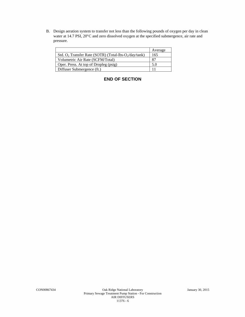
CON00867434 Oak Ridge National Laboratory January 30, 2015 Primary Sewage Treatment Pump Station - For Construction AIR DIFFUSERS 11376 - 6
B. Design aeration system to transfer not less than the following pounds of oxygen per day in clean water at 14.7 PSI, 20C and zero dissolved oxygen at the specified submergence, air rate and pressure.
Average Std. O2 Transfer Rate (SOTR) (Total-lbs-O2/day/tank) 165 Volumetric Air Rate (SCFM/Total) 87 Oper. Press. At top of Dropleg (psig) 5.0 Diffuser Submergence (ft.) 11
END OF SECTION

CON00867434 Oak Ridge National Laboratory January 30, 2015 Primary Sewage Treatment Pump Station - For Construction SAMPLERS 11395 - 1
SECTION 11395
SAMPLERS
PART 1 - GENERAL
1.1 WORK INCLUDED
A. The Contractor shall furnish, install, test, and place in service one (1) complete refrigerated composite wastewater sampler as indicated on the Drawings and as specified (one for influent located the the Headworks facility).
1.2 RELATED WORK
A. Division 1 - General Requirements.
B. Division 15 - Mechanical.
C. Division 16 - Electrical.
1.3 SUBMITTALS
A. Descriptive literature, catalog cuts, dimension prints, shop drawings, and installation, operation and maintenance instructions shall be submitted to the Engineer for review before shipment. The data shown on the shop drawings shall be complete with respect to dimensions, materials of construction, wiring diagrams, and the like, to enable the Engineer to review the information as required. At the time of submission, the Contractor shall in writing, call the Engineer's attention to any deviations that the Drawings may have from the requirements of these Specifications.
B. All material submitted for review shall be contained in one submission. Partial submittals will not be reviewed. Sales bulletins or other general publications are not acceptable as submittals for review except where necessary to provide supplemental technical data.
C. Operating and Maintenance Instructions and Separate Parts Lists: Operating instructions shall also incorporate a functional description of the entire system including the system schematics which reflect "as-built" modifications. Special maintenance requirements particular to the system shall be clearly defined along with special calibration and test procedures.
PART 2 - PRODUCTS
2.1 MANUFACTURER
A. The refrigerated composite wastewater sampler shall be Model 5800 refrigerated sampler with fiberglass cabinet as manufactured by Isco, Inc., or approved equal.
2.2 SAMPLER
A. The refrigerated composite wastewater sampler shall be engineered for outstanding corrosion resistance and shall be suitable for use over a wide range of sampling applications. A corrosion resistant fiberglass body and temperature control system shall allow the refrigerated sampler to be used outdoors without an enclosure in ambient temperatures from minus 20 to 120 degrees F.
B. The refrigerated composite sampler shall be capable of collecting repeated sample increments and depositing them into a single bottle. The sampler shall be provided with a 2.5gallon polyethylene sample container with two lids, polypropylene screw cap, locating base, two discharge tubes, and 25 feet of 3/8” vinyl suction line with standard weighted polypropylene strainer, including tubing coupler.

CON00867434 Oak Ridge National Laboratory January 30, 2015 Primary Sewage Treatment Pump Station - For Construction SAMPLERS 11395 - 2
C. The collected sample shall be stored in a refrigerated enclosure capable of maintaining a sample temperature of 39 plus/minus 1.8 degrees Fahrenheit in ambient temperatures from minus 20 to 120 degrees F.
D. The refrigerator shall include long-life electronic sensing devices for measuring ambient air temperature, evaporator plate temperature, and interior air temperature. Built-in temperature control circuitry shall utilize these sensors to control the operation of the compressor and built-in heaters. The built-in heaters shall be used to prevent the sample from freezing if the ambient air temperature drops below freezing. The unit shall be self-defrosting and shall use a forced air condensing coil with filtered frontal ventilation. A compressor with a minimum rating of 1/6 horsepower shall be used. The refrigerator shall have a 5-minute typical recovery time to return to 39 degrees F after the door has been opened for one minute with the unit operating at 39 degrees F.
E. The exterior and base of the refrigerator shall be constructed of fiberglass reinforced plastic with a UV resistant gel-coat. The interior of the refrigerator shall be food grade ABS plastic for easy cleaning and to inhibit bacterial growth. The copper refrigeration lines shall be protected with polyester tubing and phenolic resin. The condenser coil shall be powder coated with UV resistant polyurethane for added corrosion resistance. The refrigerator evaporator plate shall be aluminum and power coated with a food grade epoxy to resist corrosion. The refrigerator shall include 1-1/2 inches of rigid foamed-in-place insulation on the sides to aid in sample preservation. The top insulation shall consist of 3 inches of rigid insulation. The refrigerator shall have a hinged, reinforced fiberglass controller cover which is capable of being locked. The refrigerator's door shall also have hasps capable of accepting a padlock to prevent unauthorized tampering with the sample compartment contents. A magnetic gasket shall be used to seal the refrigerator door. The refrigerator power supply and solid state thermostat shall be contained in a sealed, NEMA 4X equivalent, aluminum enclosure inside the refrigerator base. All other exposed metal components shall be either anodized or irradiated aluminum, stainless steel, or galvanized steel.
F. The refrigerator shall be provided with an adjustable, weight activated mechanism to automatically terminate sampling at a predetermined level; no contact with the sample liquid shall be acceptable in determining the shut-off level. An exterior indicator light shall be provided to indicate when the container is full.
G. Samples shall be collected using a peristaltic pump typically producing a line velocity of 2.5 feet per second in a 3/8-inch ID suction line at 3 feet of head height. The body of the peristaltic pump shall be made of high strength plastic for corrosion resistance and extended pump tubing life. The pump shall be capable of producing 26 feet of lift. A settable indicator shall count the pump revolutions and warn the user when it is time to replace the pump tubing to prevent missed samples due to broken tubing. Before and after each sample is collected, the pump shall air purge the suction line. Pre-purges and post-purges shall be automatically controlled, and no precalibration adjustments shall be required. The sample stream shall not pass through any valves or metering chambers, or through any distribution tubing unless under pumped flow. The materials in contact with the flow stream shall be limited to medical grade silicone rubber, vinyl or Teflon, and stainless steel. The suction line shall be made of 3/8-inch ID Teflon.
H. The sampler shall utilize a non-wetted, non-conductive detector to sense the presence of the liquid at the inlet to the pump. The sensor shall not be dependent on, or affected by any compositional, chemical, or physical property of the liquid, including high or low conductivity of the sample. The liquid detector shall require no routine maintenance or cleaning to allow the detector or sampler to operate. The liquid detector shall eliminate entering the head height in programming and shall minimize the effects of changing head, intermittent flow in the suction line, or variable battery conditions on sample volume. Once the liquid has been detected at the pump inlet, the sampler shall deliver repeatable and accurate sample volumes regardless of battery condition by counting the revolutions of the peristaltic pump. The sampler shall deliver repeatable sample volumes typically with plus/minus 10 ml to prevent any single sample from biasing the collected sample.

CON00867434 Oak Ridge National Laboratory January 30, 2015 Primary Sewage Treatment Pump Station - For Construction SAMPLERS 11395 - 3
I. The sampling program shall be established using a 24-position sealed keypad and a 2 line, 40 character liquid crystal display. The display shall continuously communicate sampler status. Two programming modes, "basic" and "extended" shall, be provided. The basic programming mode shall allow the user to easily setup typical sampling routines. The extended programming mode shall expand the versatility of the sampler by providing options to allow the user to create complex sampling routines. The sampler shall have software capable of storing up to three sampling routines identified by number. The sampler shall contain an internal lithium battery which provides the sampler with continuous memory. The battery shall have a minimum typical life of five (5) years, and shall maintain sampler program settings and stored programs when the sampler is turned off, or in the event of an external power interruption.
J. The basic and extended modes shall allow the user to program the sampler to collect composite samples at user-definable time intervals (time pacing), or at equal flow volume intervals based on flow pulse inputs from an external flow meter (flow pacing). The flow intervals shall be selectable from 1 to 9,999 flow pulses. The sampler shall use an internal real-time clock to provide both time and date information. It shall also offer two types of time pacing: uniform and non-uniform. Uniform time paced samples shall be collected at regular time intervals from 1 minute to 99 hours and 59 minutes. Non-uniform time intervals from 1 to 999 minutes between samples or, based on real-time settings, shall be capable of being programmed. A delay to first sample shall be programmable in minutes from 0 to 9,999, or by the real time clock. The sampler shall have the ability to be programmed for up to 24 real time sampling stop/resume times to allow unattended sampling of shift related discharges. A software program lock shall be provided to prevent unauthorized tampering or accidental changing of the sampler control settings.
K. The sampler software shall provide manually initiated diagnostic routines to evaluate the operational status of the sampler. The sampler shall alert the user to a low battery condition. The sample volume shall be programmed from the keypad from 10 to 9990 ml in 1 ml increments.
L. The controller shall be programmable for up to three sample collection retries if liquid is not detected due to suction line plugging or absence of liquid. Up to three suction line rinse cycles shall be programmable to precondition the suction line before each sample to prevent contamination from the previous sample.
M. The sampler shall be capable of storing key information for each sampling routine such as start time, halt and resume times, the time each sample was collected, and cause of any missed samples. This information shall be accessible at any time during or after a sampling routine, before the next routine has started. The sampler shall also create and store two types of reports - a program settings report and a sampling results report. These reports can be accessed with the field printer.
N. The sampling results report shall list the sample number, reason the sample was initiated, any errors which occurred, time the sample was taken including date, and the pump revolution counts which occurred. Any error codes used in the report shall be listed and defined in a key listing at the end of the report. This report shall be able to be used to verify correct operation, indicate regulatory compliance, or used as an enforcement document.
O. The program settings report shall allow the sampler programming to be verified before or after sampling. This report shall include the sampling mode, enable time or mode, delay to first sample, and the intervals between samples and other programmed parameters.
P. All mechanical and electronic components shall be housed in a watertight control box mounted on top of the refrigerated section. The controller shall be made of at least 1/4-inch thick NorylTM plastic and shall conform to NEMA 4X standards for watertight, dust-tight, and corrosion resistant operation. The controller shall also be protected from accidental submersion under 6 feet of water for 30 minutes (NEMA 6 self certified). A desiccator shall be installed in the control box to prevent moisture damage to the components. The sealed control box shall be removable to allow use on either a portable or refrigerated sampler.

CON00867434 Oak Ridge National Laboratory January 30, 2015 Primary Sewage Treatment Pump Station - For Construction SAMPLERS 11395 - 4
Q. The sampler shall operate on 120 volt AC, 60 Hz 4 line power and shall require a single power cord.
R. Sampler shall be equipped with a pulse-to-analog converter to accept a 4-20mA input signal based on flow.
PART 3 - EXECUTION
3.1 FACTORY TEST
A. The Contractor shall furnish sworn certificates to the effect that the sampler has been tested by the manufacturer.
3.2 OPERATION AND MAINTENANCE MANUALS
A. Every piece of equipment furnished and installed shall be provided with complete maintenance and operation manuals. These shall be detailed in instructions to the Company's personnel. They shall be attractively bound for the Company's records. 1. The manuals shall be submitted to the Engineer for review as to adequacy and
completeness.
B. The form of operation and maintenance manual submittals is detailed in Division 1.
3.3 WARRANTY
A. The sampling station as specified shall be warranted for a period of two (2) years from the date the equipment is placed in service.
B. Warranty submittals shall be as detailed in Division 1.
END OF SECTION

CON00867434 Oak Ridge National Laboratory January 30, 2015 Primary Sewage Treatment Pump Station - For Construction PRECAST CONCRETE BUILDING 13123 - 1
SECTION 13123
PRECAST CONCRETE BUILDING
PART 1 - GENERAL
1.1 SUMMARY
A. Section Includes: 1. Pre-cast concrete building.
a. Building design. b. Materials. c. Fabrication. d. Delivery.
2. Installation of building. 3. Accessories as noted in this Specification and Contract Drawings.
B. Related Sections include but are not necessarily limited to: 1. Division 1 - General Requirements. 2. Division 3 - Concrete. 3. Section 07900 - Joint Sealants.
1.2 QUALITY ASSURANCE
A. Referenced Standards: 1. American Concrete Institute (ACI):
a. ACI-318, Building Code Requirements for Structural Concrete. 2. ASTM:
a. A36, Standard Specification for Carbon Structural Steel. b. A108, Standard Specification for Steel Bars, Carbon, Cold Finished, Standard Quality. c. A123, Standard Specification for Zinc (Hot-Dip Galvanized) Coatings on Iron and Steel
Products. d. A153, Standard Specification for Zinc Coating (Hot-Dip) on Iron and Steel Hardware. e. ASTM A283, Standard Specification for Low and Intermediate Tensile Strength Carbon
Steel Plates. f. ASTM A307, Standard Specification for Carbon Steel Bolts and Studs, 60,000 PSI
Tensile Strength. g. A416, Standard Specification for Steel Strand, Uncoated Seven-Wire for Prestressed
Concrete. h. A496, Standard Specification for Steel Wire, Deformed, for Concrete Reinforcement. i. ASTM A615, Standard Specification for Deformed and Plain Carbon-Steel Bars for
Concrete Reinforcement. j. A706, Standard Specification for Low-Alloy Steel Deformed and Plain Bars for Concrete
Reinforcement. k. C31, Standard Practice for Making and Curing Concrete Test Specimens in the Field. l. C33, Standard Specification for Concrete Aggregates. m. C39, Standard Test Method for Compressive Strength of Cylindrical Concrete
Specimens. n. C138, Standard Test Method of Test for Density (Unit Weight, Yield, and Air Content
(Gravimetric) of Concrete. o. C143, Standard Test Method for Slump of Hydraulic Cement Concrete. p. C150, Standard Specification for Portland Cement. q. C172, Standard Practice for Sampling Freshly Mixed Concrete. r. C173, Standard Test Method for Air Content of Freshly Mixed Concrete by the
Volumetric Method.

CON00867434 Oak Ridge National Laboratory January 30, 2015 Primary Sewage Treatment Pump Station - For Construction PRECAST CONCRETE BUILDING 13123 - 2
s. C231, Standard Test Method for Air Content of Freshly Mixed Concrete by the Pressure Method.
3. American Welding Society (AWS): a. A5.1, Standard Specification for Carbon Steel Electrodes for Shielded Metal Arc
Welding. b. A5.5, Standard Specification for Low-Alloy Steel Covered Arc-Welding Electrodes. c. D1.1, Structural Welding Code Steel. d. D1.4, Structural Welding Code Reinforcing Steel.
4. Prestressed Concrete Institute (PCI): a. MNL-116, Manual for Quality Control for Plants and Production of Precast Prestressed
Concrete Products. b. MNL-117, Manual for Quality Control for Plants and Production of Architectural Precast
Concrete Products. c. PCI Design Handbook - Precast and Prestressed Concrete.
5. Building code(s): a. 2009 International Building Code and associated standards, referred to herein as Building
Code.
B. Qualifications: 1. Building fabricator must be a current producer/member of the National Precast Concrete
Association (NPCA) or Precast Concrete Institute (PCI) and be certified under its plant certification program. a. Plant shall be certified within the past calendar year from project bid date.
2. Building fabricator must have a minimum of five years experience manufacturing and erecting transportable pre-cast concrete buildings.
3. Building fabricator must have successfully completed minimum of five projects of similar scope in the past two years. a. Provide project name, location, dollar value and contact person name and phone number.
4. Assure fabricator's testing facilities meet requirements PCI MNL-116 or PCI MNL-117 as applicable.
5. Welding operators and processes to be qualified in accordance with: a. AWS D1.1 for welding steel shapes and plates. b. AWS D1.4 for welding reinforcing bars.
6. Welding operators to have passed qualification tests for type of welding required during the previous 12 months prior to commencement of welding.
1.3 DEFINITIONS
A. Galvanizing: 1. Hot-dip galvanizing per ASTM A123 or ASTM A153 with minimum coating of 2.0 OZ of
zinc per square foot of metal (average of specimens) unless noted otherwise or dictated by standard.
B. Architectural Concrete Surfaces: 1. Concrete that will be permanently exposed to view and therefore requiring special care in the
selection of materials, placing and finishing to obtain the desired appearance, includes but is not limited to: a. Exterior and interior faces of exterior wall panels. b. Interior wall panels. c. Interior faces of structural precast members.
1) May include columns, beams, roof tees, hollow core slabs, and lintels.
1.4 SUBMITTALS
A. See Division 01 for requirements of the mechanics and administration of the submittal process.
B. Shop Drawings: 1. Technical data including:

CON00867434 Oak Ridge National Laboratory January 30, 2015 Primary Sewage Treatment Pump Station - For Construction PRECAST CONCRETE BUILDING 13123 - 3
a. Concrete mix design. b. Manufacturer’s plant certification. c. Project reference list. d. Shop drawings of all accessory items with data sheets of each component. e. Acknowledgement that products submitted meet requirements of standards referenced. f. Manufacturer’s installation instructions. g. Sizes, types and manufacturer of bearing pads. h. Hardware to be utilized to support suspended appurtenances.
2. General: a. Prior to submittal to the Engineer for review and action, all Shop Drawings shall be
processed by the Contractor, the electrical and mechanical subcontractor and any other subcontractors having work that impacts the fabrication of the precast members. 1) Provide certification letter as cover sheet to each submittal confirming that all
impacted trades have reviewed the submittal and coordinated any work associated with the precast fabrication.
b. All Drawings, including erection Drawings, certifications and calculations shall be sealed and signed by a professional Structural or Civil Engineer registered in the State of Tennessee. 1) Provide certification stating calculations provided have been prepared specifically
for this Project and that they match and pertain to the Shop Drawings provided. 2) Provide a summary document as part of the above certification listing the design
criteria used for precast design including: a) Appropriate codes and standards. b) Snow loads. c) Live loads. d) Wind loads. e) Seismic loads. f) Equipment loads.
3. Foundation Requirements a. Provide all anchoring details. b. Specify any unusual requirements of the foundation system.
C. Samples: 1. Minimum two 8 x 8 IN samples of exterior finish in thickness required.
D. Miscellaneous Submittals: 1. Qualifications of testing lab and technician. 2. Fabricator to submit copy of qualifications stated in paragraph 1.2.B. 3. Test results for all concrete testing. 4. Concrete mix design(s) including submittal information defined in Specification
Section 03308. 5. Copies of source quality control tests, including compressive strength and air content. 6. Certifications:
a. Certification that fabricator’s plant complies with PCI Manual referenced. b. Welder and welding process certification. c. Certification of erector qualifications.
E. Building design engineering calculations sealed by a professional engineer, with a minimum of five (5) years experience in the design of precast buildings and licensed to practice in Tennessee, shall be submitted for informational purposes only. Calculations will not be checked by Engineer.
1.5 DELIVERY AND HANDLING
A. Deliver to project site to allow immediate installation at final location.
B. Handle with special equipment to avoid damage.

CON00867434 Oak Ridge National Laboratory January 30, 2015 Primary Sewage Treatment Pump Station - For Construction PRECAST CONCRETE BUILDING 13123 - 4
1.6 WARRANTY
A. The manufacturer shall provide a written warranty for all materials and workmanship extending a minimum of 12 months after startup as specified in the General and Supplementary Conditions. All materials, equipment and workmanship furnished under these specifications shall be free from defects in material or workmanship.
PART 2 - PRODUCTS
2.1 ACCEPTABLE MANUFACTURERS
A. Subject to compliance with the Contract Documents, the following manufacturers are acceptable: 1. Pre-cast Concrete Building:
a. Easi-Set Industries (Virginia). b. Submit request for substitution in accordance with Division 01.
2.2 MATERIALS
A. Aggregate Base Layer: 1. ASTM C33, size No. 67 washed crushed stone with 1% (maximum) passing a No. 200 sieve
per ASTM D422.
B. Concrete: ASTM A615 Steel-reinforced, 5000 PSI minimum 28-day compressive strength, air-entrained. Reference Division 3 specifications for additional requirements. Pozzolan addition to mix shall not be required.
C. Post-tensioning Strand: 1. Roof and floor (if required) shall be post-tensioned in field after grout keyway is filled and
has cured to required PSI strength. 2. Post-tensioning cable shall be 41K polystrand CP50, 0.50 IN, 270 KSI, 7-wire strand,
enclosed within a greased plastic sheath (ASTM A416). 3. Minimum of three post-tensioning cables connecting roofs and floors together to provide a
watertight joint.
D. Reinforcing Steel and Welded Wire Fabric: 1. Reinforcing bars to be welded: ASTM A706. 2. All other reinforcing steel and welded wire fabric: See Specification Section 03208.
E. Headed Studs: 1. ASTM A108. 2. Minimum yield strength: 50,000 psi. 3. Minimum tensile strength: 60,000 psi.
F. Electrodes: 1. E70 series conforming to AWS A5.1 or AWS A5.5 for welding steel shapes and plates. 2. E90 series conforming to AWS A5.5 for welding rebar.
G. Sealants: 1. Refer to Section 07900. 2. All joints between panels shall be caulked on the exterior and interior surface of the joints. 3. Roof shall be covered with an adhered single ply, 0.045 IN minimum thickness.
H. Panel Connections: 1. All panels shall be fastened together with 1/4 IN thick galvanized steel brackets to meet
loading criteria. 2. Steel: ASTM A283, Grade C hot dipped galvanized after fabrication.

CON00867434 Oak Ridge National Laboratory January 30, 2015 Primary Sewage Treatment Pump Station - For Construction PRECAST CONCRETE BUILDING 13123 - 5
3. Fasteners: Minimum 1/2 IN diameter galvanized bolts complying with ASTM A307. Cast-in anchors used for panel connections to be Dayton-Superior #F-63 or approved equal. All inserts for corner connections must be bolted directly to form before casting panels. No floating-in of connection inserts shall be allowed.
4. Wall panels shall be connected to floor slab with 4 IN expansion anchors; diameter and embedded depth to meet loading criteria.
I. Doors and Frames: 1. Supply all aluminum construction (mill finish or clear anodized) ASTM B221 and B209. 2. Doors: 1-3/4 IN thick, face sheet 0.062 IN minimum thick. 3. Insulated Core (R5 minimum). 4. Reinforced hinges and hardware areas. 5. Frame Thickness: 0.125 IN minimum, reinforced at jambs and all hardware locations. 6. Frame Anchors: Stainless steel.
J. Door Hardware: 1. Lockset: Falcon B581D 32D Lever Lockset. 2. Hinges: 4-1/2 IN x 4-1/2 IN - 5 knuckle, heavy weight full mortise, 0.180 IN thick stainless
steel concealed bearing hinges with NRP. Similar to Stanley C0199. 3. Deadbolt Lock: 626 finish, ANSI Function F17, 2-3/4 IN backset, brass 6 pin with high
security cylinders. 4. Surface Bolts: Heavy-duty rated, stainless steel 630 or B260 finish, 5/8 minimum diameter
by 8 IN long. 5. Astragal: Similar to Reese No. 92C. 6. Threshold: 4 IN by 1/2 IN aluminum similar to Reese No. S104A. 7. Perimeter weatherstripping: Similar to Reese No. 797B. 8. Door Holder: Glynn-Johnson 904H US32D. 9. Door Sweep: Similar to Reese No. 701A. 10. Door Stop: Similar to Ives 445B32D (Inactive leaf only). 11. Drip Cap: National Guard 15D72 or equal. 12. All locks are to be keyed to match Oak Ridge National Laboratory master key system.
K. Heating and Cooling Unit The unit shall be one-piece, wall-mounted, factory-assembled, pre-charged, prewired, tested and ready-to-operate. The unit shall have a limited warranty of 5-years on parts and 1-year on compressor. Capacity and EER certified in accordance with ANSI/ARI Standard390-2003. Install per manufacturer’s recommendations. 1. One (1) each exterior wall mounted, hard-wired as shown; 2. Enclosed weatherproof casing constructed of 20 gauge galvanized steel, finished with baked-
on polyester enamel paint; 3. One (1) washable filter; 4. Remote adjustable thermostat; 5. Refrigerant: 410A (HFC); 6. Minimum EER Rating: 9.00 7. Barometric fresh air damper set to 50 CFM.
Cooling Capacity
BTUH Breaker size
CFM @ 0.2” ESP, (Max/Min)
Heater Bard Manufacturing Part Number
2 Ton 24,000 15 865/800 6 KW W24A1-C06XW
2.3 FABRICATION
A. Design Loads: 1. Standard Seismic Loading - per Contract Drawings. 2. Standard Live Roof Load – per Contract Drawings. 3. Floor Live Load – per Contract Drawings. 4. Standard Wind Loading - per Contract Drawings.

CON00867434 Oak Ridge National Laboratory January 30, 2015 Primary Sewage Treatment Pump Station - For Construction PRECAST CONCRETE BUILDING 13123 - 6
5. Standard Ground Snow Loading – per Contract Drawings. 6. Equipment Roof Load - actual per equipment.
B. Building Inside (UNO) Dimensions: Per Contract Drawings. 1. Inside dimensions shown are to the finished face of the buildings wall and roof assembly
including but not limited to precast concrete, interior furring, and gypsum board finish. 2. The contractor shall coordinate the size of the concrete foundation and floor slab with the
precast manufacturer before fabrication.
C. Door Dimensions: Per Contract Drawings.
D. Roof: 1. Roof panel minimum slope 2 IN from center peak to edges, unless otherwise specified. 2. Extend 3 IN beyond the wall panel with a turndown design extending 1/2 IN below the top of
wall panels, providing a drip to prevent water migration into the building along top of wall panels.
3. Integral architectural ribbed edge. 4. Roof shall be provided with metal furring inside the building with rigid insulation with a
minimum R-Value of (R-15) and a gypsum board finish painted.
E. Walls: 1. Wall panels shall be provided with metal furring inside the building with rigid insulation with
a minimum R-Value of (R-15) and a gypsum board finish painted.
F. Keyway Roof Joints: 1. Grout in keyways to be polymer concrete placed after coating keyways with a methyl
methacrylate resin and isocyanate resin. Top of keyway to be coated with primer followed by one coat of a polymeric joint sealant followed by a fiberglass resin fabric and a second coat of polymeric joint sealant.
G. Finishes: 1. Interior of Building: Smooth steel form finish on all interior panel surfaces. 2. Exterior of Building:
a. Stamped brick finish on exterior wall surfaces. b. Smooth trowel finish on exterior roof surface. c. Color of exterior surface to be neutral color as selected by Company from the
manufacturer’s standard color palate. 3. Per Specification 07176, apply liquid water repellent to exterior of completed roof and wall
panels.
H. Building Openings: 1. Coordinate all required openings for factory fabrication. 2. Do not field cut or drill wall or roof panels.
PART 3 - EXECUTION
3.1 PREPARATION
A. Slab on-grade foundation to be provided by general Contractor per drawings and specifications.
B. Building penetrations must be coordinated with all disciplines prior to fabrication. Field drill or cut wall or panels only with fabricator approval.
3.2 INSTALLATION
A. Install products in accordance with manufacturer's instructions. 1. A weathertight enclosure is required with all joints properly sealed.
B. Manufacturer is responsible for site erection of the building at its final location. Manufacturer to coordinate activities and delivery with Contractor’s schedule and Work activities.

CON00867434 Oak Ridge National Laboratory January 30, 2015 Primary Sewage Treatment Pump Station - For Construction PRECAST CONCRETE BUILDING 13123 - 7
C. Contractor to coordinate with Manufacturer site access requirements for delivery and installation.
D. After installation is completed, the Contractor shall paint the interior walls with two (2) coats of a High-Build Polyamide Epoxy applied at the rate of 230 square feet per gallon to 8.6 total dry mils thickness. The color shall be chosen by the Company.
E. After installation is completed, the Contractor shall paint the interior and exterior of the doors .
3.3 FIELD QUALITY CONTROL
A. Repair all damage to units after erection in accordance with manufacturer's recommendations and to satisfaction of Engineer.
B. Causes for rejection of units include, but are not necessarily limited to the following: 1. Cracked units. 2. Chipped, broken, or spalled edges. 3. Units not within allowable casting tolerances. 4. Voids or air pockets which, in opinion of Engineer, are too numerous or too large. 5. Non-uniform finish or appearance. 6. Low concrete strength. 7. Improperly placed embedded items and/or openings. 8. Exposed wire mesh, reinforcing or prestressing strands.
3.4 CLEANING
A. After completion of setting, repair and caulking, clean all precast work thoroughly by scrubbing with fiber brushes, detergent, and clean water.
B. Leave precast units clean and free of traces of cleaning compound.
END OF SECTION

This page intentionally left blank.

CON00867434 Oak Ridge National Laboratory January 30, 2015 Primary Sewage Treatment Pump Station - For Construction PREFABRICATED FRP BUILDING 13126 - 1
SECTION 13126
PREFABRICATED FRP BUILDING
PART 1 - GENERAL
1.1 WORK INCLUDED
A. The Contractor shall furnish and install at the Flow Equalization Basin Recirculation Pump, one (1) pre-engineered, pre-fabricated, insulated fiberglass reinforced plastic (FRP) building with electrical service panel, all necessary conduit, wire, lighting, heating system, exhaust fan, and miscellaneous equipment and necessary appurtenances as shown on the plans and specified herein. The completed FRP building shall be one (1) piece when delivered and require only off-loading, installation on a slab foundation, installation of specified accessories, and connection of electrical service to be fully functional.
B. The Contractor shall provide all labor and materials to connect electrical power to the internal electrical service panel.
1.2 RELATED SECTIONS
A. Division 01 - Submittals.
B. Division 03 - Concrete.
C. Division 16 - Electrical.
1.3 SUBMITTALS
A. Submittals shall be bound and in accordance with Section 01300 and this section. The Company will retain four (4) copies. The submittals shall be specific to this project, and shall illustrate the National Electrical Code (NEC) clearances per Section 110-16 of the Code.
B. Equipment submittals shall include the following as a minimum: 1. Building system design information sheet. 2. Dimension and general arrangement on 24IN x 36IN drawings, to scale. 3. Electrical wiring diagrams. 4. Catalog information on lighting, exhaust fan, heater, panelboard and components, and door
hardware.
C. Foundation Requirements 1. Provide all anchorage details. 2. Specify any unusual requirements of the foundation system.
1.4 BUILDING DESIGN REQUIREMENTS
A. Design pre-fabricated FRP building to withstand code mandated loading for criteria per Contract Drawings.
1.5 QUALITY ASSURANCE
A. The materials and equipment covered by these specifications are intended to be of proven reliability, as manufactured, engineered, and assembled by reputable firms having experience in the production of pre-engineered, pre-fabricated products. The manufacturer shall have not less than five (5) years of successful experience in the manufacture of FRP building panels and pre-fabricated buildings.
1.6 DELIVERY, STORAGE AND HANDLING OF EQUIPMENT
A. The entire building shall be factory assembled and shipped as a complete unit.

CON00867434 Oak Ridge National Laboratory January 30, 2015 Primary Sewage Treatment Pump Station - For Construction PREFABRICATED FRP BUILDING 13126 - 2
B. The installation contractor shall comply with manufacturer's instructions for transporting, rigging, unloading, storage, and setting of the building.
PART 2 - PRODUCTS
2.1 MANUFACTURERS
A. Acceptable manufacturer is Warminster Fiberglass Company, or engineer accepted equivalent.
2.2 MODULAR STRUCTURE
A. The FRP building will be a complete factory assembled modular building, delivered as a one (1) piece unit. It will require only off-loading, installation on the prescribed foundation slab, and electrical service connection to complete the installation.
B. Locations: 1. Equalization Basin Recirculation Pump – building size 14’ wide x 12’ deep x 11’ high 2. Waste Sludge Pump – building size 70” wide x 54” deep x 72” high
2.3 MATERIALS
A. Molded composite: Exterior and interior resin-fiberglass laminate with foam core. 1. Laminate: Polyester resin and chopped strand fiberglass with a minimum glass content of
25%. Exterior surface shall be a white gel coat with low luster finish, smooth and free from fiber pattern, roughness, or other irregularities. The exterior laminate shall be a minimum of 1/8-inch thick, chemically bonded to gel coat. Interior laminate to be a minimum of 1/8-inch thick, white in color and shall encapsulate the panel core in place. The laminate shall have the following minimum properties: a. Tensile strength (ASTM D 638): 11,000 PSI b. Flexural strength (ASTM D 790): 18,000 PSI c. Shear strength (ASTM D 732): 12,000 PSI d. Barcol hardness (ASTM D 2583): 40 e. Impact (ASTM D 256): 12 ft lbs/per inch. f. Density (ASTM D 792): 93.6 lbs/ft3. g. Surface burning characteristics (ASTM E 84): Class A, flame spread 25
2. Core: Rigid closed cell, self extinguishing, polyisocyanurate foam. The core shall have a 2-inch thickness with a minimum insulating value of R-14. The core foam shall have the following minimum properties: a. Thermal conductivity (ASTM C 518): 0.13 BTU Inch/ Hr. b. Density (ASTM D 1622): 2.0 lbs/ft3. c. Surface burning characteristics (ASTM E 84): Flame spread, 35 smoke density, 240.
B. The FRP manufacturer shall maintain a continuous quality control program and shall furnish to the engineer certified test results of the physical properties upon request.
2.4 COMPONENTS
A. Personal Door: One-piece, resin transfer molded (RTM) in matched metal molds to produce an industrial quality door, 36-inches by 78-inches, which exhibits a smooth finished, seamless, monolithic, warp-free composite consisting of a gel-coat, fiberglass reinforcement, polyester resin, insulating core, and internal reinforcements with all mortises, openings, recesses, and pockets molded in place. 1. Door shall be mounted with a continuous stainless steel hinge. 2. Door gasket: Neoprene sponge rubber bulb type gasket with flexible lock to retain
permanent grip. 3. The entrance door shall be supplied with a shield above the door to divert rain and snow
from the door opening.

CON00867434 Oak Ridge National Laboratory January 30, 2015 Primary Sewage Treatment Pump Station - For Construction PREFABRICATED FRP BUILDING 13126 - 3
4. An extruded aluminum sillplate shall be provided on the entrance door, complete with friction-type vinyl weatherseal.
5. The entrance door shall have an upper glass window with nominal 10" x 10" tempered safety glass.
B. Roll-up Door 1. The roll up door shall be 6’ wide by 8’ tall with lock and lifting handle. 2. The roll-up door shall be aluminum and insulated. 3. The lifting mechanism shall allow easy lifting by one person.
The roll-up door shall have a lower gasket to provide a weather seal.
C. Door Hardware: Door hardware shall be Best 30H Series, "B" function, mortise lockset with satin chrome finish. Two (2) keys will be provided, on a key ring complete with the manufac-turer's identification.
D. Base Mounting Flange Gasket: 3 inch thick by 4 inches wide closed cell neoprene sponge rubber to provide weather tight seal around the building perimeter.
E. Lifting Eye Bolts: Provide 3/4-inch stainless steel eye bolts in roof.
2.5 PRE-ENGINEERED FIBERGLASS COMPOSITE BUILDING
A. Assembly: Provide factory-assembled building. 1. A weathertight enclosure is required with all joints properly sealed.
B. Size: 12 feet X 14 feet. Ceiling height 10 feet
C. Encapsulated aluminum extrusion 4-inches tall with thicknesses as required by manufacturer design shall be encapsulated into each corner of end panels (full height) and around the entire roof perimeter to maintain flatness, straightness, and structural integrity. Integral internal flanges on mating panels shall be provided for bolting the sides, ends and roof to the encapsulated aluminum extrusions. 1. Aluminum extrusions: Incorporate threaded inserts on 12-inch centers for internal bolting
to mating panel flange during assembly. 2. Assemble panels with 3/8 inch diameter stainless steel bolts on 12- inch centers and a 3 inch
thick by 3 inches wide urethane foam gasket for a weather tight seal at all joints. Assembly bolts shall not penetrate the exterior wall of the structure.
3. Structurally reinforce wall and roof panels with steel and aluminum extrusions to meet loading conditions. a. Aluminum reinforcement: Extruded channel sections 4 inches tall with thicknesses
sized as required by manufacturer design. b. Galvanized steel mounting channel reinforcement: Minimum 0.078 inch thick by
13/16-inch high by 1-5/8-inch wide. Mechanically attach to the interior surface with aluminum pop rivets on 12-inch centers, on all walls.
c. Steel reinforcement: Minimum 3-inch angle with 1/2 inch leg thickness. d. Shall be encapsulated in walls at end and roof perimeter, to form a continuous,
one-piece molded composite wall or roof panel. 4. Provide wall panels with an integral 4-inch wide internal mounting flange pre-drilled on a
12-inch centers with 5/8-inch diameter holes for attaching to floor. 5. Floors: Concrete pad, provided by general contractor per drawings and specifications.
2.6 ACCESSORIES
A. Anchor bolts for attaching building to concrete pad: Manufacturer designed stainless steel post installed anchors.
B. Exhaust Fan: Thermostatically controlled exhaust fan with fiberglass gravity shutter, and PVC shroud with insect screen, capable of not less than 200 CFM of free air exhaust shall be provided.
C. Louver: PVC intake Louver: 12 inches square with fiberglass gravity shutter and insect screen.

CON00867434 Oak Ridge National Laboratory January 30, 2015 Primary Sewage Treatment Pump Station - For Construction PREFABRICATED FRP BUILDING 13126 - 4
D. Interior Lighting: The lighting shall be a two (2) tube, 40 watt per tube, rapid start, "OSHA" approved enclosed and gasketed fluorescent light fixture installed within the building. The light fixtures shall be located as detailed on the Drawings and be of 48 inch minimum length. The fixtures shall be Holophane 7200-4 or approved equivalent.
E. Exhaust Fan and Lighting Controls: Door actuated switch and selector switch for each; 2 position (manual/automatic).
F. Heater: One (1) wall mounted heater shall be provided and shall include: 1. Rating - 10,239 BTU/HR-3000 watts, 240 volt. 2. Enclosed resistance wire within steel finned element. 3. Control - off/heat/constant. 4. UL listed. 5. Vane axial fan - floor flow discharge. 6. Hard wired in conduit per UL 400-1.
G. Panelboard: The panelboard shall be a NEMA 12 enclosure, surface mount, bottom feed. The main breaker shall be 60 amp. The electrical service provided for the station will be 240-volt, single-phase, 60 cycle, 3-wire. 1. The enclosure shall also include seven (7) auxiliary circuit breakers, 20 amp, single pole,
for: a. Pump Condensate Heater. b. Lights. c. Exhaust Fan. d. Receptacles. e. Level sensor. f. Spare. g. Spare.
2. One (1) 20 amp, 2-pole circuit breaker for heating. 3. Transient voltage surge suppressor.
H. Conduits, Wiring and Receptacles 1. Conduits as specified and as sized on the Contract Drawings shall be installed from the main
power and control panel through the building side panel and terminate in a threaded coupling exterior to the building. The service entrance conduit connection shall be plugged for shipment. Additional conduits as shown on the Plans., shall also be installed as described above.
2. All wiring within the building and outside of the control panel or panels shall be run in hard conduit except that neoprene covered flexible conduit, and fittings shall be used to connect the fan motors, heaters, etc. All internal equipment conduit and wire shall be in accordance with the Contract Drawings and Specifications.
3. One (1) duplex, ground fault circuit interrupter type receptacle shall be furnished and installed where shown on the Drawings.
I. Equipment Grounding: 1. Each electrical equipment item in the building shall be properly grounded per Section 250
of the National Electrical Code. Items to be grounded include, but are not limited to, panelboard, convenience receptacles, heater, lights, exhaust fan, and switches.
2. All ground wires from installed equipment shall be in conduit and shall lead back to the control panel to a copper ground buss specific for grounding purposes and so labeled. The ground buss shall be complete with a lug large enough to accept the installing electrician=s bare copper earth ground wire. The buss shall serve as a bond between the earth ground and the equipment ground wires.
2.7 FINISHES
A. Building color shall be as selected by the Owner.
CON00867434 Oak Ridge National Laboratory January 30, 2015 Primary Sewage Treatment Pump Station - For Construction PREFABRICATED FRP BUILDING 13126 - 5
PART 3 - EXECUTION
3.1 EXAMINATION
A. Verify that concrete is level and true to plane and of correct dimensions to receive structure. Correct any deficiencies before proceeding.
3.2 INSTALLATION
A. Layout anchor bolt pattern according to drawings. Drill holes of depth and diameter required by anchor bolt manufacturer.
B. Install structure in accordance with manufacturer's instructions.
C. Erect structures true to line and plumb, free of twist and warp.
D. Install and test accessories in accordance with manufacturer's instructions.
3.3 ADJUST AND CLEAN
A. Adjust components for proper operation.
B. Leave project site clean and free of debris.
END OF SECTION

This page intentionally left blank.

CON00867434 Oak Ridge National Laboratory January 30, 2015 Primary Sewage Treatment Pump Station - For Construction RESERVOIRS: PRESTRESSED CONCRETE 13215 - 1
SECTION 13215
RESERVOIRS: PRESTRESSED CONCRETE
PART 1 - GENERAL
1.1 SUMMARY
A. Section Includes: 1. Design and installation of one (1) AWWA D110 Type II pre-stressed tank.
B. Related Specification Sections include but are not necessarily limited to: 1. Division 00 - Bidding Requirements, Contract Forms, and Conditions of the Contract. 2. Division 01 - General Requirements. 3. Section 02200 - Earthwork. 4. Section 03208 - Reinforcement. 5. Section 03308 - Concrete Materials and Proportioning. 6. Section 03311 - Concrete Mixing, Placing, Jointing, and Curing. 7. Section 03348 - Concrete Finishing and Repair of Surface Defects.
1.2 QUALITY ASSURANCE
A. Referenced Standards: 1. American Concrete Institute (ACI):
a. 506 - Shotcreting. 2. American Society of Civil Engineers (ASCE):
a. 7, Minimum Design Loads for Buildings and Other Structures. 3. ASTM International (ASTM):
a. A185, Standard Specification for Steel Welded Wire Reinforcement, Plain, for Concrete.
b. A320, Standard Specification for Alloy-Steel and Stainless Steel Bolting Materials for Low-Temperature Service.
c. A615, Standard Specification for Deformed and Plain Carbon-Steel Bars for Concrete Reinforcement.
d. A821, Standard Specification for Steel Wire, Hard Drawn for Prestressing Concrete Tanks.
e. A1008, Standard Specification for Steel, Sheet, Cold-Rolled, Carbon, Structural, High-Strength Low-Alloy, High-Strength Low-Alloy with Improved Formability, Solution Hardened, and Bake Hardenable.
f. A1064, Standard Specification for Steel Wire and Welded Wire Reinforcement, Plain and Deformed, for Concrete.
g. B209, Standard Specification for Aluminum and Aluminum-Alloy Sheet and Plate. h. B241, Standard Specification for Aluminum and Aluminum-Alloy Seamless Pipe and
Seamless Extruded Tube. i. C309, Standard Specification for Liquid Membrane-Forming Compounds for Curing
Concrete. j. C881, Standard Specification for Epoxy-Resin-Base Bonding Systems for Concrete. k. D1056, Standard Specification for Flexible Cellular Materials-Sponge or Expanded
Rubber. l. D2000, Standard Classification System for Rubber Products in Automotive
Applications. m. D4253, Standard Test Methods for Maximum Index Density and Unit Weight of Soils
Using a Vibratory Table. n. D4254, Standard Test Methods for Minimum Index Density and Unit Weight of Soils
and Calculation of Relative Density. 4. American Water Works Association (AWWA):
a. C652, Disinfection of Water-Storage Facilities. b. D110, Wire- and Strand-Wound, Circular, Prestressed Concrete Water Tanks.
CON00867434 Oak Ridge National Laboratory January 30, 2015 Primary Sewage Treatment Pump Station - For Construction RESERVOIRS: PRESTRESSED CONCRETE 13215 - 2
5. American Welding Society (AWS). 6. Corps of Engineers (COE):
a. CRD-C572, Specifications for Polyvinylchloride Waterstop. 7. Occupational Safety and Health Administration (OSHA). 8. Building code:
a. International Code Council (ICC): 1) International Building Code 2009 Edition including all local amendments, referred
to herein as Building Code.
B. Qualifications: 1. The company designing and constructing the tank:
a. At least five (5) years experience in design and construction of wire-wound circular prestressed composite tanks.
b. Has skill, reliability, and financial stability to build and guarantee the tank in accordance with the Contract Documents.
c. Has constructed, in the past five (5) years, in its own name, and is presently responsible for a minimum of five (5) dome covered prestressed composite tanks of 1,000,000 GAL capacity or greater, which meet these Specifications and are currently providing satisfactory service.
2. Professional engineer in responsible charge of engineering work: a. Five (5) years experience in design and field construction of circular prestressed
composite tanks. b. In responsible charge of engineering work to be done for tank design, construction, and
testing. c. Registered in state where the tank is constructed.
C. Certifications: 1. Drawings and design calculations for the tank to be signed by Engineer using his
professional Engineer's seal for the State of Tennessee.
1.3 SUBMITTALS
A. Shop Drawings: 1. See Specification Section 01300 for requirements for the mechanics and administration of
the submittal process. 2. Product technical data including:
a. Manufacturer's installation instructions. 3. Mill tests indicating ultimate and yield strength of all reinforcing bars, prestressing and post
tensioning wires and cables, and any other steel components.
B. Furnish applicable "Affidavits of Compliance" to Building Codes and OSHA Standards.
C. Structural design calculations or analyses for record purposes only.
D. All concrete design mixes.
E. Guarantee Document as specified in the WARRANTY Article in PART 1 of this Specification Section.
F. Detailed construction Drawings.
G. Operation and Maintenance Manuals: 1. See Specification Section 01730 for requirements for:
a. The mechanics and administration of the submittal process. b. The content of Operation and Maintenance Manuals.
1.4 WARRANTY
A. The tank constructor will warrant workmanship and materials on the complete structural portion of the tank for a five (5) year period from date of Substantial Completion of the Work.

CON00867434 Oak Ridge National Laboratory January 30, 2015 Primary Sewage Treatment Pump Station - For Construction RESERVOIRS: PRESTRESSED CONCRETE 13215 - 3
1. In case leakage or other defects appear within the five (5) year period, the tank constructor to promptly repair the tank at its own expense upon written notice by the Company that such defects have been found.
2. Leakage is defined as a stream flow of liquid appearing on the exterior of the tank, the source of which is from the inside of the tank.
B. To satisfy the five (5) year warranty, tank constructor is required to furnish the Company with a written company warranty for additional four (4) year period beginning one (1) year after the date of Substantial Completion.
PART 2 - PRODUCTS
2.1 ACCEPTABLE TANK CONSTRUCTORS
A. Subject to compliance with the Contract Documents, the following tank constructors are acceptable: 1. The Crom Corporation; Gainesville, Florida. 2. DN Corporation; Wakefield, Massachusetts. 3. Preload Company; Garden City, New York. 4. Or approved equal.
B. Submit request for substitution in accordance with Specification Section 01640.
2.2 MATERIALS
A. Concrete: 1. 28 day compressive strength not less than 4000 psi.
B. Shotcrete: 1. 28 day compressive strength not less than 4500 psi. 2. Cement: Conform to Specification Section 03308. 3. Conform to ACI 506.
C. Prestress Wire: 1. Cold drawn, high-carbon wire. 2. Conform to ASTM A821.
D. Reinforcing Bars, Wire Mesh: 1. ASTM A615, Grade 40. 2. ASTM A1064. 3. Conform to Specification Section 03208.
E. Steel Diaphragm: 1. Provide vertically ribbed steel sheets with adjacent and opposing channels that provide a
mechanical bond to the concrete. 2. Conform to ASTM A1008. 3. Minimum thickness: 0.017 IN.
F. Elastomeric Materials: 1. Waterstops that are polyvinyl chloride conforming to COE CRD-C572. 2. Bearing pads conforming to ASTM D2000. 3. Sponge filler conforming to ASTM D1056. 4. Epoxy: ASTM C881, Type III, Grade I.
G. Prestressing Steel: 1. Steel for prestressing: Cold drawn, high carbon wire, meeting the requirements of
ASTM A821.

CON00867434 Oak Ridge National Laboratory January 30, 2015 Primary Sewage Treatment Pump Station - For Construction RESERVOIRS: PRESTRESSED CONCRETE 13215 - 4
2.3 DESIGN CRITERIA
A. The design shall be in conformance with applicable portions of American Concrete Institute (ACI) 372R Design and Construction of Circular Wire- and Strand-Wrapped Prestressed Concrete Structures, ANSI/AWWA D110 Wire- and Strand-Wound, Circular, Prestressed Concrete Water Tanks, and currently accepted engineering principles and practices for the design of such structures.
B. The following loadings shall be utilized in the design: 1. Capacity: 750,000 Gallons 2. Dimensions:
a. 65 feet Inside Diameter b. 30.2 feet Water Depth
3. Fluid Loads: Shall be the weight of all liquid when the reservoir is filled to capacity. a. The unit weight of the liquid material shall be 62.4 lbs/ft3.
4. Dead Loads: Consideration shall be given to all permanent imposed loads including concrete and steel.
5. Seismic Loads: Seismic forces and moments resulting from water sloshing and seismic accelerations of the tank wall and water loads shall be calculated in accordance with ACI 350.3 or ANSI/AWWA D110.
6. Soil Pressure: Earth loads shall be determined by rational methods of soil mechanics. Soil pressure shall not be used in the design of the core wall to counteract hydraulic loads or provide residual compression in the wall.
7. Differential Backfill Loads: Forces from differential backfill loads shall be considered in the design and shall be based on the at-rest coefficient. Passive resistance shall not be used to resist differential backfill loads.
8. Wind Loads: Wind loads shall be considered in the design in accordance with ASCE 7.
C. Floor: The design of the floor for the prestressed concrete tank shall conform to the following: 1. Concrete membrane floors shall be a minimum of 4 in. thick and have a minimum thickness
of 8 in. of concrete over all pipe encasements and around sumps. 2. A minimum percentage of 0.60% reinforcing steel shall be used in the membrane floor. The
minimum percentage shall apply to all thickened sections and shall extend a minimum of 2 ft into the adjacent membrane floor.
D. Core wall: 1. The wire-wound, prestressed concrete tank core wall shall be designed as a thin shell
cylindrical element using shotcrete and an embedded, mechanically bonded, galvanized steel shell diaphragm.
2. The design of the core wall shall take into account appropriate edge restraint. To compensate for bending moments, shrinkage, differential drying, and temperature stresses, the following minimum reinforcing steel shall be incorporated into the design: a. The top 2 ft of core wall shall have not less than 1% circumferential reinforcing. b. The bottom 3 ft of core wall shall have not less than 1% circumferential reinforcing. c. Inside Face:
1) The inside face of the core wall shall utilize the diaphragm as effective reinforcing. 2) Additional vertical and horizontal reinforcing steel bars shall be used as required
by design computations. d. Outside Face:
1) Vertical reinforcing steel in the outside face of the core wall shall be: minimum of #4 bars at 12 in. center to center.
2) Additional vertical and horizontal reinforcing steel bars shall be used as required by design computations.
3. The minimum core wall thickness shall be 3½ in. 4. Reinforcing steel used in the core wall shall be designed using a maximum allowable design
tensile stress, fs, of 18,000 psi. 5. Allowable compressive stress in the core wall due to initial prestressing force, fgi, shall be:

CON00867434 Oak Ridge National Laboratory January 30, 2015 Primary Sewage Treatment Pump Station - For Construction RESERVOIRS: PRESTRESSED CONCRETE 13215 - 5
a. 1250 psi + 75t psi/in. with 0.5 f'gi maximum or less (where f'gi is defined as compressive strength at time initial prestressing force is applied and t is the thickness of the core wall in inches).
b. Maximum of 2250 psi. 6. Allowable compressive stress in the core wall due to final prestressing force, fg, shall be:
a. 1250 psi + 75t psi/in. with 0.45 f'g maximum (where f'g is defined as compressive strength required for final prestressing force and t is the thickness of the core wall in inches).
b. Maximum of 2025 psi.
E. Prestressing: 1. Circumferential prestressing of the tank shall be achieved by the application of cold-drawn,
high-carbon steel wire placed under high tension. 2. A substantial allowance shall be made for prestressing losses due to shrinkage and plastic
flow in the shotcrete and due to relaxation in the prestressing steel. 3. The prestressing design shall conform to the following minimum requirements:
a. Working stress for the tank wall, fs, shall be a maximum of 115,000 psi. b. The allowable design tensile stress in the prestressing wire before losses, fsi shall be
145,600 psi or no greater than 0.63 fu, where fu is defined as the ultimate strength of the wire.
c. Areas to be prestressed will contain no fewer than 10 wires per foot of wall for 8 gauge and 8 wires per foot of wall for 6 gauge.
d. A maximum of 24 wires per layer per foot for 8 gauge and 20 wires per layer per foot for 6 gauge will be allowed.
F. Wall Openings: 1. When it is necessary for a pipe to pass through the tank wall, the invert of such pipe or
sleeve shall be no less than 18 in. above the floor slab. The prestressing wires required at the pipe elevation shall be distributed into circumferential bands immediately above and below the opening to maintain the required prestressing force while leaving an unbanded strip around the entire tank.
2. Unbanded strips shall have a vertical dimension of no more than 36 in. unless an axi-symmetric shell analysis is performed to account for compressive forces plus shear and moments caused by displacement of the prestressing wires into adjacent bands.
2.4 PERFORMANCE
A. Performance of the materials used in the tank construction shall conform to the minimum requirements of this specification.
B. Substitutions to the materials in this specification may only be made if submitted in writing and approved by the engineer.
2.5 CONCRETE
A. Concrete shall conform to ACI 301/301M.
B. All concrete shall utilize Type I/II Portland cement.
C. A maximum of 25% of cementitious material may be fly ash.
D. Admixtures other than air-entraining and water reducing admixtures will not be permitted unless approved by the engineer.
E. Coarse and fine aggregate shall meet the requirements of ASTM C33/C33M.
F. Concrete mixes used in the construction of the tank shall conform to the following:
Mix Compressive Strength
(psi)
Minimum Cement Content
(lbs)
Maximum Aggregate Size
(in)
Maximum W/C Ratio
Air Content
(%)
Slump (in)
Floor 4000 560 ¾ 0.45 4"+/-1"

CON00867434 Oak Ridge National Laboratory January 30, 2015 Primary Sewage Treatment Pump Station - For Construction RESERVOIRS: PRESTRESSED CONCRETE 13215 - 6
2.6 SHOTCRETE
A. Shotcrete shall conform to the requirements of ACI 506.2 except as modified herein.
B. All shotcrete mixes shall utilize Type I/II cement.
C. A maximum of 25% of cementitious material may be fly ash.
D. All shotcrete in contact with diaphragm or prestressing wire shall be proportioned to consist of not more than three parts sand to one part Portland cement by weight. All other shotcrete shall be proportioned to consist of not more than four parts sand to one part Portland cement by weight.
E. Admixtures will not contain more than trace amounts of chlorides, fluorides, sulfides or nitrates.
F. Fine aggregate shall meet the requirements of ASTM C33/C33M.
G. Shotcrete mixes used in the tank construction shall conform to the following:
2.7 PRESTRESSED REINFORCEMENT
A. The prestressing wire shall conform to the requirements of ASTM A821/A821M, Type B.
B. The prestressing wire size shall be 0.162 in. (8 gauge), 0.192 in. (6 gauge) or larger, but no larger than 0.250 in.
C. The ultimate tensile strength, fu shall be, 231,000 psi or greater for 8 gauge wire, 222,000 psi or greater for 6 gauge.
D. Splices for horizontal prestressed reinforcement shall be ferrous material compatible with the prestressing reinforcement and shall develop the full strength of the wire.
2.8 NON-PRESTRESSED REINFORCEMENT
A. Non-prestressed mild reinforcing steel shall be new billet steel meeting the requirements of ASTM A615/A615M with a minimum yield strength, fy, of 60,000 psi.
B. Welded wire reinforcing shall be plain wire conforming to the requirements of ASTM A1064/A1064M with a minimum yield strength, fy, of 65,000 psi.
2.9 GALVANIZED STEEL DIAPHRAGM
A. The galvanized steel diaphragm used in the construction of the core wall shall be 26 gauge with a minimum thickness of 0.017 in. conforming to the requirements of ASTM A653/A653M. Weight of zinc coating shall be not less than G90 of Table 1 of ASTM A653/A653M.
B. The diaphragm shall be formed with re-entrant angles and erected so that a mechanical key is created between the shotcrete and diaphragm.
C. The diaphragm shall be continuous to within 3 inches of the top and bottom of the wall. Horizontal joints or splices will not be permitted.
D. All vertical joints in the diaphragm shall be rolled seamed, crimped and sealed watertight using epoxy injection.
E. In all tanks designed to use a waterstop at the floor/wall joint, the steel shell diaphragm shall be epoxy bonded to the waterstop.
F. 2.7 PVC WATERSTOPS, BEARING PADS AND SPONGE FILLER
Mix Compressive Strength
(psi)
Maximum W/C Ratio
Air Content
(%)
Slump (in)
Fiber Reinforcement
(lbs/cyd) Core Wall 4000 0.42 4"+/-1" - Covercoat 4000 0.42 4"+/-1"

CON00867434 Oak Ridge National Laboratory January 30, 2015 Primary Sewage Treatment Pump Station - For Construction RESERVOIRS: PRESTRESSED CONCRETE 13215 - 7
G. Plastic waterstops shall be extruded from an elastomeric plastic material of which the base resin is virgin polyvinyl chloride.
H. The profile and size of the waterstop shall be suitable for the hydrostatic pressure and movements to which it is exposed.
I. Bearing pads used in floor/wall joints shall consist of neoprene, natural rubber or polyvinyl chloride.
J. Sponge filler at the floor/wall joint shall be closed-cell neoprene.
2.10 EPOXY
A. Epoxy Sealants: 1. Epoxy shall conform to the requirements of ASTM C881/C881M. 2. Epoxy used for sealing the diaphragm shall be, Type III, Grade 1, and shall be 100% solids,
moisture insensitive, low modulus epoxy. 3. Epoxy used for placing the waterstop shall be Type II, Grade 2, and shall be 100% solids,
moisture insensitive, low exotherm epoxy. 4. When pumped, maximum viscosity of the epoxy shall be 10 poises at 77°F. 5. The epoxy sealants used in the tank construction shall be suitable for bonding to concrete,
shotcrete, PVC, and steel.
B. Bonding Epoxy: 1. Epoxy resins used for enhancing the bond between fresh concrete and hardened concrete
shall conform to the requirements of ASTM C881/C881M. 2. Epoxy resins shall be a two-component, 100% solids, moisture-insensitive epoxy and shall
be Type II, Grade 2.
2.11 SEISMIC RESTRAINT CABLES
A. When required by design, seismic restraint cables shall be seven-wire strand conforming to ASTM A416/A416M.
B. The strand shall be protected with a fusion-bonded, grit-impregnated epoxy coating conforming to ASTM A882/A882M.
C. The minimum yield strength of the seven-wire strand shall be 270,000 psi.
D. The tank shall be designed relative to the local seismic rating.
2.12 TANK ACCESSORIES
A. Minimum of two, 3’ x 6’ rectangular Type 316 stainless steel wall manholes for access to the interior of the tank. The cover shall also be of Type 316 stainless steel. The wall manhole shall be designed to resist hydraulic loading without excessive deflection.
B. Vented Riser Pipe shall be included for the Equalization Tank inlet for the purpose of establishing a more consistent static head condition.
C. Through-wall pipe sleeves shall be Type 316 stainless steel sleeves with neoprene modular seal units.
D. Accessory hardware, unless otherwise noted, shall be Type 316 stainless steel conforming to ASTM F593.
E. Aluminum stairway with platforms complying with OSHA standards shall be provided to allow the Owner access to view the tank contents while in operation.
2.13 COATINGS
A. Exterior coating system shall consist of one of the following: 1. Two coats Tnemec Series 156 Enviro-Crete Modified Waterborne Acrylate. 2. Two coats Thoroseal Waterproof Cement-Based Coating. 3. The Owner selects the choice of color.

CON00867434 Oak Ridge National Laboratory January 30, 2015 Primary Sewage Treatment Pump Station - For Construction RESERVOIRS: PRESTRESSED CONCRETE 13215 - 8
PART 3 - EXECUTION
3.1 EXAMINATION
A. All subgrade elevations shall be verified prior to starting tank construction.
3.2 INSTALLATION
A. Floor: 1. The subgrade shall be prepared by fine grading to ensure proper placement of reinforcing
steel with proper bottom cover. 2. A 6-mil polyethylene vapor-barrier shall be placed after subgrade preparation has been
completed. 3. Form and screed boards shall be of proper thickness and sufficiently braced to ensure that
the floor is constructed within proper thickness tolerances. 4. Plate bolsters shall be used to support reinforcing steel supported directly on the subgrade to
ensure positive control of placement of reinforcing steel. 5. The floor shall be vibratory screeded to effect consolidation of concrete and proper
encasement of floor reinforcing steel. 6. The floor shall be water cured for a minimum of 7 days after casting. 7. The floor shall receive a light broom finish.
B. Core Wall: 1. The wall shall be constructed utilizing diaphragm and shotcrete with each conforming to the
following: a. Diaphragm Erection:
1) The diaphragm shall be protected against damage before, during, and after erection. Nail or other holes shall not be made in the diaphragm for erection except in the top 3 inches. Holes shall not be made in the diaphragm except for inserting wall pipes or sleeves, reinforcing steel, bolts, or other special appurtenances. Such penetrations shall be sealed with an epoxy sealant which complies with Section 2.8 Epoxy.
b. Shotcrete: 1) All shotcrete shall be applied by or under direct supervision of experienced
nozzlemen certified by the American Concrete Institute (ACI) as outlined in ACI certification publication CP-60.
2) Each shotcrete layer shall be broomed prior to final set to effect satisfactory bonding of the following layer.
3) No shotcrete shall be applied to reinforcing steel or diaphragm that is encrusted with overspray.
4) No less than ⅛ in. thick shotcrete shall separate reinforcing steel and prestressing wire.
5) The diaphragm shall be encased and protected with no less than 1 in. of shotcrete in all locations.
6) The interior shotcrete shall receive a light broom finish. c. Curing:
1) Interior and exterior portions of the shotcrete wall shall be water cured for a minimum of 7 days or until prestressing is completed.
C. Epoxy Injection: 1. Epoxy injection shall be carried out from bottom to top of wall using a pressure pumping
procedure. 2. Epoxy injection shall proceed only after the diaphragm has been fully encased, inside and
outside, with shotcrete.
D. Prestressing: 1. The initial tension in each wire shall be read and recorded to verify that the total aggregate
force is no less than that required by the design. Averaging or estimating the force of the wire on the wall shall not be considered satisfactory evidence of correct placement of prestressing wires.

CON00867434 Oak Ridge National Laboratory January 30, 2015 Primary Sewage Treatment Pump Station - For Construction RESERVOIRS: PRESTRESSED CONCRETE 13215 - 9
2. Placement of the prestressing steel wire shall be in a continuous and uniform helix of such pitch as to provide in each lineal foot of core wall height an initial force and unit compressive force equal to that shown on the design drawings. Splicing of the wire shall be permitted only when completing the application of a full coil of wire or when removing a defective section of wire.
3. Shotcrete shall be used to completely encase each individual wire and to protect it from corrosion. To facilitate this encasement, the clear space between adjacent wires is to be no less than one wire diameter.
4. Prestressing shall be accomplished by a machine capable of continuously inducing a uniform initial tension in the wire before it is positioned on the tank wall. Tension in the wire shall be generated by methods not dependent on cold working or re-drawing of the wire. In determining compliance with design requirements, the aggregate force of all tensioned wires per foot of wall shall be considered rather than the force per individual wire, and such aggregate force shall be no less than that required by the design and as shown on approved drawings.
5. The tank construction company shall supply equipment at the construction site to measure tension in the wire after it is positioned on the tank wall. The stress measuring equipment shall include: electronic direct reading stressometer accurate to within 2%, calibrated dynamometers and a test stand to verify the accuracy of the equipment.
6. After circumferential prestressing wires have been placed, they shall be protected by encasement in shotcrete. This encasement shall completely encapsulate each wire and permanently bond the wire to the tank wall.
7. When multiple layers of wire are required, shotcrete cover between layers shall be no less than ⅛ in. thick.
E. Covercoat: 1. After all circumferential prestressing wires have been placed, a shotcrete cover having a
thickness of no less than 1 in. shall be placed over the prestressing wires. 2. Horizontal sections of the wall shall form true circles without flat areas, excessive bumps or
hollows. 3. The covercoat shall receive a sliced trowel finish.
F. Wall Openings: 1. All wall pipes, sleeves and manholes passing through the wall shall be sealed to the
diaphragm by epoxy injection.
G. Coatings: 1. All coatings shall be applied a minimum of 28 days after final application of concrete or
shotcrete. 2. All application procedures for coatings shall be in accordance with manufacturer's
recommendations.
3.3 FIELD QUALITY CONTROL
A. Inspection and Testing: 1. Concrete and Shotcrete Testing:
a. Compression Tests: 1) Compression est specimens shall be taken during construction from the first
placement of each class of concrete specified herein and at intervals thereafter as selected by the Engineer to insure continued compliance with these Specifications. At least one set of test specimens shall be made for each 50 yards of concrete/shotcrete placed. Each set of test specimens shall be a minimum of 5 cylinders.
2) Compression test specimens for concrete/shotcrete shall conform to ASTM C172/C172M for sampling and ASTM C31/C31M for making and curing test cylinders. Test specimens shall be 6-inch diameter by 12-inch high or 4-inch diameter by 8-inch high cylinders.

CON00867434 Oak Ridge National Laboratory January 30, 2015 Primary Sewage Treatment Pump Station - For Construction RESERVOIRS: PRESTRESSED CONCRETE 13215 - 10
3) Compression test shall be performed in accordance with ASTM C39/C39M. Two test cylinders will be tested at 7 days and two at 28 days. The remaining cylinder will be held to verify test results, if needed.
b. Air Content Tests: 1) Air content tests shall conform to ASTM C231/C231M (Pressure Method for Air
Content). 2) Tests for air content shall be made prior to concrete placement and whenever
compression test specimens are made. c. Slump Tests:
1) Slump tests shall be made in accordance with ASTM C143/C143M. 2) Slump tests shall be made whenever compression test specimens are made.
2. Hydrostatic Testing: a. The tank shall be tested for watertightness upon completion. b. The testing for watertightness shall be completed as follows:
1) Fill the tank with water to the maximum water level and let it stand for a minimum of 24 hours.
2) Inspect the exterior of the tank wall and footing for damp spots. Damp spots shall be defined as spots where moisture can be picked up on a dry hand, the source of which is from inside the tank.
3) Leakage through the wall or wall-base joint shall be repaired and the tank shall be retested using the above procedure.
4) The contractor shall dechlorinate all test water before it can be discharged from the Tank
3.4 CLEANING
A. The interior of the tank shall be cleaned to remove debris, construction items, and equipment prior to testing.
3.5 DECORATIVE COATING
A. Apply decorative coating to all exposed concrete wall and dome surfaces in accordance with coating manufacturer's recommendations. Color to be selected by the Owner.
END OF SECTION

CON00867434 Oak Ridge National Laboratory January 30, 2015 Primary Sewage Treatment Pump Station - For Construction SUPERVISORY CONTROL AND DATA ACQUISITION (SCADA) SYSTEM 13400 - 1
SECTION 13400
SUPERVISORY CONTROL AND DATA ACQUISITION (SCADA) SYSTEM
PART 1 - GENERAL
1.1 WORK INCLUDED
A. Work provided under Divisions 13440 through 13502 includes final system design implementation, furnishing all components, system installation services, required support services, and complete documentation for the SCADA System. This work shall include all materials, labor, and tools required to fabricate, deliver, unload, handle, erect, adjust, field calibrate, and test a complete and operable SCADA System as indicated on the Drawings and Specifications. This work shall include: 1. Install all panels and designated instrumentation devices and provide all mechanical and
pneumatic interconnections between the various components and their local sources of supply.
2. Auxiliary and accessory equipment necessary for placing in operation the complete system, such as transducers or relays to interface with equipment provided under other sections of the specifications.
B. The intent of these Specifications is for the Contractor to provide a complete and operational SCADA System. Additional items of equipment, materials, or labor not specifically called for by these Specifications, which may reasonably be considered to make the system complete and operational, shall be supplied as part of this work.
1.2 COMPANY FURNISHED SERVICES
A. Programming 1. All PLC control programming and workstation HMI programming shall be performed by the
Company. The Contractor shall prepare the hardware, described in other sections, ready to receive and execute the PLC control and HMI programming. In the case of the PLC, this shall include the configuration of I/O racks and communication modules as well as the assignment and mapping of all I/O to a fixed PLC I/O address. In the case of the control workstation, this shall include the configuration of the operating system, the installation of the control system application and supporting control programs, (i.e. programming modules, database modules, report applications, etc) and the installation of drivers, communication modules or software patches to allow the control workstation to support all installed applications without error. Control strategies may be requested by the Contractor during bidding or construction phases for reference only.
1.3 DEFINITIONS
A. Provide: Furnish, install, and connect.
B. Product Data: Catalog cuts and descriptive literature.
C. Shop Drawings: Factory prepared documentation, specific to the installation.
D. Indicated: Shown on the Drawings.
E. Noted: Indicated or specified elsewhere.
1.4 WORK SPECIFIED ELSEWHERE
A. Installation of Instruments: Instruments such as flow meters, piping, etc., which are specified in this Division and require mechanical mounting, are installed under other Divisions.

CON00867434 Oak Ridge National Laboratory January 30, 2015 Primary Sewage Treatment Pump Station - For Construction SUPERVISORY CONTROL AND DATA ACQUISITION (SCADA) SYSTEM 13400 - 2
B. Vendor-Supplied Devices: Field instrumentation and panels supplied as part of mechanical equipment or equipment packages shall be furnished, installed, and calibrated under other Divisions.
C. Conductors: Discrete signal conductors and twisted pair analog signal conductors are furnished and installed under Division 16. All other instrumentation and signal conductors, including digital data conductors and fiber optic cables are furnished under this Division and installed under Division 16. Special cables for a particular instrument device which are specified in this Section are installed under Division 16.
D. Raceways: All raceways and pulling of conductors are furnished under Division 16.
E. Terminations: All control and signal conductor terminations are provided under this Section. This shall include, but not be limited to, terminations for all control panels. Exceptions: HVAC control terminations are provided under Division 15. Interconnections between equipment and integral equipment control panels are provided under the applicable equipment Section. Terminations to motor and all power wiring terminations for new equipment are provided under Division 16.
1.5 QUALITY ASSURANCE
A. The Contractor shall ensure that the SCADA System is an integrated system furnished by an Instrumentation Supplier who shall provide all of the equipment and appurtenances, regardless of manufacture and be responsible to the Contractor for correct operation of the entire system.
B. The Instrumentation Supplier shall be responsible for the detailed design implementation and the proper functioning of the SCADA System, preparation of required submittal data including operations and maintenance manuals, preparation of test procedures, factory and field tests, start-up including field calibration, operational demonstrations, providing technical supervision for installation and connections to equipment, and training of the Company’s operating personnel.
C. The Instrumentation Supplier shall be regularly engaged in the type of work called for under these Specifications and must have capital facilities, personnel, plant, and service capabilities required to successfully perform the work. The Instrumentation Supplier shall employ competent personnel experienced in the design, and manufacture of equipment and systems required. The Instrumentation Supplier shall assign an experienced person who shall act as Project Manager. This person shall have responsible project experience on similar systems of a comparable complexity to that specified herein.
D. The Instrumentation Supplier shall have in employment, a permanent field service organization capable of providing service and maintenance of the system.
E. The Instrumentation Supplier shall have installed similar systems which have been in satisfactory operation to establish the reliability of the equipment proposed to be furnished.
1.6 SUBMITTALS
A. The Instrumentation Supplier shall make submittals in accordance with the requirements of Section 01300. The submittal shall be divided into separate sections as listed below. Refer to related work sections for additional requirements.
B. Field Devices: This Section shall include primary elements, transmitters, switches, analytical instruments, etc. List all dimensions, power requirements, enclosure types, ranges, and signal form or value. Provide data, including proposed length, on special cables required between sensing elements and electronics units and data on any special equipment used for calibration or maintenance of a particular device. Field device submittals shall also include specific data sheets for each device which shall contain the following information: 1. Tag number per Specifications and Drawings. 2. Manufacturer’s complete model number with complete model number breakdown. 3. Input – output characteristics. 4. Range, size, and graduations.

CON00867434 Oak Ridge National Laboratory January 30, 2015 Primary Sewage Treatment Pump Station - For Construction SUPERVISORY CONTROL AND DATA ACQUISITION (SCADA) SYSTEM 13400 - 3
5. Physical size with dimensions, NEMA enclosure classification and mounting details. 6. Materials of construction of all components. 7. Instrument or control device sizing calculations where applicable. 8. Certified calibration data on all flow metering devices. 9. Environmental requirements during storage and operation. 10. Power requirements.
C. Digital System Hardware: This Section shall include computer hardware complete with cables, UPS systems, and other peripherals. Include PLC hardware, communications hardware, and LAN and data highway conductors.
D. Digital System Software: This Section shall include documentation on system software, and standard software packages supplied.
E. Control Panels: This Section shall include dimensions, terminal block designations, front panel arrangement, back panel layout, and ladder logic diagrams for both PLC-based and discrete component type control panels, etc. Provide catalog sheets for all panel components, indicate ranges, and provide nameplate schedules. All connections for new instruments terminating in the Instrumentation Supplier’s panels shall be clearly shown. All devices installed in each panel or connected to each panel, shall be identified on the panel drawings by the tag number included in the Specifications and Drawings. Any miscellaneous equipment not clearly falling into one of the above volumes, including recommended spare parts list, shall be included in the control panel volume. A bill of materials shall be provided for each control panel which enumerates all devices associated with the control panel.
F. Loop Diagrams: This Section includes no more than 10 typical loop diagrams for approval of format only. The submitted loop diagrams shall represent different types of process measurements.
G. Factory Test: This Section shall include the witness test and final checkout procedural outline detailed in Article 3.04.
H. The submittal shall be in conformance with ISA-20-Standard Forms for Process Measurement and Control Instruments, Primary Elements and Control Valves, and shall be submitted as a singular complete bound volume or multi-volume package within 120 calendar days after Notice to Proceed.
1.7 CONSTRUCTION DOCUMENTATION
A. The Instrumentation Supplier shall provide loop diagrams to the Contractor. The Contractor shall provide loop diagrams to the electrical subcontractor. Loop diagrams shall be issued as a group with the delivery of their respective control panel or area instrumentation. Two sets of loop diagrams shall be issued to the electrical contractor and one set to the Engineer.
1.8 RECORD DOCUMENTATIONS
A. General: Record documentation shall be provided in accordance with Section 01720. Additionally, provide all information listed in Article 1.06 above, corrected to reflect the system as installed. Include also any instruction books, operation manuals, and other information pertaining to service and maintenance. Bind record documents in 3-ring, hardback notebooks complete with tabs and index. Include name, address, and telephone number for each manufacturer’s service contact. For all major components, provide a recommended spare parts list.
B. Loop Diagrams:

CON00867434 Oak Ridge National Laboratory January 30, 2015 Primary Sewage Treatment Pump Station - For Construction SUPERVISORY CONTROL AND DATA ACQUISITION (SCADA) SYSTEM 13400 - 4
1. Provide an individual wiring diagram for each analog and discrete loop showing all terminations, terminal numbers, conductor numbers, cable numbers, the location of the DC power supply, power panel, and circuit numbers for all 120 VAC power to field instruments, signal polarity, the location of any dropping resistors, surge protectors, shielding, grounding, etc. Devices shall be identified by the tag number included in the Specifications and Drawings. Cabling between sensors/elements and associated transmitter shall be included. The loop diagrams shall meet the minimum requirements of ISA S5.4 plus the requirements below.
2. Each loop diagram shall be divided into areas for identification of device locations (e.g. panel face, back-of-panel, field, etc.). Loop diagrams shall be on 11 x 17inch drawings.
3. The loop number shall be incorporated into the loop diagram drawing number. If the Instrumentation Supplier does not have any specific loop diagram drawing number requirements, the drawing number shall be the loop number (the drawing number for loop F-1004 would be 1004). If a requirement exists (one requirement may be to incorporate the project number XXXXXX), the loop number shall be included as the suffix. The drawing number for loop F-1004 would be XXXXXX1004.
C. Instrument Hardware: Record documents shall include bills of material, front views, assembly drawings, component layout drawings and schematics, nameplates, schedules, electrical schematics, electrical connection diagrams, and tubing/piping connection diagrams. Electrical and piping connection diagrams shall show all terminations of equipment, complete with instrumentation, wire, equipment, and cable designations. Interconnecting diagrams shall be prepared in a neat and legible manner on 11 x 17-inch or 24 x 36-inch sheets.
D. Software Documentation: In addition to the hard copies of drawings, software and literature generated specifically for the project, two sets of compact disks shall be provided to the Company with copies of all custom files specifically created for the project, including all panel drawings, I/O drawings, termination drawings, communication architecture drawings, data sheets, bills of material, operating procedures, etc. Additional files included in this set shall be PLC programs and copies of the operator interface software application program. Drawing format shall be the latest version of AutoCAD. All Drawings shall also be furnished as Acrobat *.pdf files. Include copies of all *.shp and *.shx files used in the AutoCAD drawings. Compact discs shall have a complete listing of their contents along with the names and version numbers of the software used to generate each file. Discs shall be clearly identified by the following: 1. Project Name 2. Volume Number 3. Labeled “AS-INSTALLED”
E. Configuration Documentation: Instrument Configuration and Calibration sheets shall be generated for all instruments requiring configuration and/or calibration. The intent of the Instrument Configuration and Calibration sheets is to provide all necessary information required to enable the Company to calibrate and/or configure a replacement instrument identical to the original instrument. One sheet shall be provided for each instrument. The sheets shall be 8-1/2 x 11 inch size and shall be included in the O&M Manual. Each sheet shall list the instrument tag number (as depicted on the Drawings and Specifications), the date, the Instrumentation Supplier company name and phone number, the name of the individual who filled out the sheet, the instrument manufacturer’s name and phone number, the complete model number, the calibrated range, and all configuration information.
F. SCADA Documentation: Generate a SCADA software document containing the following information for each SCADA related software product purchased. 1. The facility/plant name where the software is installed. 2. The computer name that the software is installed on (master SCADA workstation, historical
data computer, etc.). 3. The computer manufacturer and model, processor speed, and installed RAM. 4. The computer operating system (model and version). 5. The product name, version, and serial number.

CON00867434 Oak Ridge National Laboratory January 30, 2015 Primary Sewage Treatment Pump Station - For Construction SUPERVISORY CONTROL AND DATA ACQUISITION (SCADA) SYSTEM 13400 - 5
6. The name and quantity of client licenses (if applicable). 7. The product name and version of all supporting software installed. 8. The date purchased and the company name it was purchased from. 9. The name of the person purchasing the software, and the person’s company name. 10. The date the software was installed.
1.9 DELIVERY, STORAGE, AND HANDLING
A. After completion of shop assembly and tests, control panels shall be enclosed in heavy polyethylene envelopes to provide complete protection from dust and moisture. Desiccant materials shall be placed inside the envelope prior to sealing. The equipment shall then be mounted on skids, enclosed in protective boxes, and braced for final transport. Removable lifting rings shall be provided on all sections weighing more than 150 pounds to permit moving without removal of protective covering. Shipping weights shall be shown on shipping tags together with instructions for unloading, transporting, storing, and handling on the job site. If practical, termination cabinets shall be delivered first to permit field wiring to be complete and checked out before receipt of remainder of equipment. None of the control room equipment shall be delivered until the environmental services required by the Specifications and Drawings are available and operating in accordance with manufacturer’s specifications.
B. The Contractor shall be fully responsible for moving the equipment through new and existing facilities and setting it in the proper location.
1.10 WARRANTY
A. The complete PLCS (and associated software) included herein shall be guaranteed to meet or exceed the design requirements set forth in the Contract Documents.
B. Equipment, software, and materials which do not achieve design requirements after installation shall be replaced or modified by the Instrumentation Contractor to attain compliance. All associated costs shall be the responsibility of the Contractor. Following replacement or modification, the Contractor shall retest the system and perform any additional procedures needed to place the complete PLCS in satisfactory operation and attain design compliance approval from the Engineer.
C. The Contractor warrants the materials and workmanship used for the PLCS control system and further guarantees the materials and workmanship used for any equipment and materials produced and furnished hereunder as a part of the Work to be as herein specified and agreed upon, free from injurious defects, and in all respects satisfactory for the service required.
D. The Contractor shall install in the workstations the means to communicate with the manufacturer factory in order to diagnose PLC failures remotely.
E. The Contractor warrants/guarantees the satisfactory performance of the equipment and materials under operating conditions for a period of two years after the date of final acceptance of the entire PLCS (i.e., completion of all contractual items including a successful full system-wide 30 day performance test as specified in Section 3). In the event that tests and inspections disclose latent defects or failure to meet the specified requirements, the Instrumentation Supplier upon notification by the Engineer shall proceed at once to correct or repair any such defects or non-conformance or to furnish, at the delivery point named in the Contract Documents, such new equipment or parts as may be necessary for conformity to the specified requirements, and shall receive no additional compensation therefore. In the case of any required repairs or other corrective or remedial work covered under warranty, the warranties on all such corrections, repairs, new equipment, or parts shall be extended for an additional 24 months from the date of final acceptance or 12 months from the date of completion of any such corrections, repairs, new equipment, or parts, whichever date is later. The Contractor shall reimburse the Company for all costs incurred in the removal of the defective material and installation of the replacement.

CON00867434 Oak Ridge National Laboratory January 30, 2015 Primary Sewage Treatment Pump Station - For Construction SUPERVISORY CONTROL AND DATA ACQUISITION (SCADA) SYSTEM 13400 - 6
PART 2 - PRODUCTS
2.1 EQUIPMENT
A. Quality Standards: It is not the intention of these Specifications to detail every component, accessory, signal conditioning device, etc. that is required to provide a complete system. The System Manufacturer shall provide all required components, using equipment from established manufacturers with a proven history of service and support.
B. Electronic Equipment: All solid state, printed circuit boards and components shall be suitable for the specified environment. Provide complete circuit diagrams for troubleshooting and repair. All parts shall be replaceable with standard commercial components without degrading the performance of the completed assembly.
2.2 GENERAL INSTRUMENTATION REQUIREMENTS
A. All instrumentation supplied shall be of the manufacturer's latest design.
B. All electronic instrumentation shall be solid-state and shall utilize linear transmission signals of 4 to 20 mAdc. However, signals between instruments within the same panel or cabinet may be 0-10 Vdc, 1-5 Vdc, or the like.
C. Outputs of equipment that are not of the standard signals as outlined, shall have the output immediately raised and/or converted to compatible standard signals for remote transmission. No zero based signals will be allowed for remote transmission.
D. All instruments shall be provided with mounting hardware, floor stands, wall brackets or instrument racks as shown on the Drawings or as required.
E. Equipment installed in areas designated as hazardous shall be designed for the Class, Division, and Group rating as required on the Drawings to comply with the National Electrical Code.
F. All indicators and recorder readouts shall be linear, direct reading in process units, unless otherwise noted.
G. All transmitters shall be provided with either integral indicators or conduit mounted indicators, direct reading in process units, accurate to 2 percent, unless otherwise noted.
H. Electronic equipment shall be of the manufacturer's latest design, utilizing printed circuitry and shall be suitably coated to prevent contamination by dust, moisture and fungus. Solid state components shall be conservatively rated for their purpose, to assure optimum long term performance and dependability over ambient atmosphere fluctuations and 0 to 100 percent relative humidity. The field mounted equipment and system components shall be designed for installation in dusty, humid, and slightly corrosive service conditions.
I. All equipment, cabinets and devices furnished shall be heavy-duty type, designed for continuous industrial service. The system shall consist of equipment models which are currently in production. All equipment provided shall be of modular construction and shall be capable of field expansion.
J. All equipment shall be designed to operate on nominal 115 Vac, 60 Hz power except where specifically noted. All regulators and power supplies required for compliance with the above shall be provided between power supply and interconnected instrument loops. Where equipment requires voltage regulation, constant voltage transformers shall be supplied.
K. All analog transmitter and controller outputs shall be 4 to 20 mAdc into a load of 0-750 ohms, unless specifically noted otherwise.
L. Materials and equipment used shall be U.L. listed wherever such listed equipment and materials are available.

CON00867434 Oak Ridge National Laboratory January 30, 2015 Primary Sewage Treatment Pump Station - For Construction SUPERVISORY CONTROL AND DATA ACQUISITION (SCADA) SYSTEM 13400 - 7
M. All equipment shall be designed and constructed so that in the event of power interruption, the equipment specified herein shall resume normal operation without manual resetting when power is restored.
N. Open and short circuit protection shall be provided except for two-wire transmitters.
O. Power supplies required for operation of two wire transmitters specified herein shall be provided and installed in panels or enclosures as required.
P. Lightning protection shall be installed for protection against damaging transients induced by lightning on both signal and power supply lines. DC protectors shall be installed on both ends of the current signal lines to protect the signal source and its receiver from propagating surges. DC protectors shall be installed on the panel (receiver) end of discrete I/O connected to field devices. AC protectors shall be installed on all field instrument 120 Vac power supply lines.
2.3 SPARE PARTS
A. The Instrumentation Supplier shall supply spare parts for the SCADA System.
B. The Instrumentation Supplier shall provide a list of all spare parts being provided under this Division. The spare parts list shall be included in the documents to be reviewed by the Engineer during the shop drawing review process. The spare parts shall include, but shall not be limited to, the items included in the list below. 1. One lot of Terminal Fuses, 5 spare fuses for each type of miscellaneous fuse used in local
control panels. 2. One lot of surge protectors, including 5 spare of each type used. 3. One 24 VDC power supply. 4. One (1) spare control relay. 5. One (1) spare time delay relay. 6. One (1) spare intrinsically safe relay. 7. Two (2) spare float switches. 8. 20% spare bulbs for each type of bulb used.
PART 3 - EXECUTION
3.1 INSTALLATION
A. The Instrumentation Supplier shall assign a full time representative to provide coordination and supervision of on-site SCADA System construction work. The individual is to be on-site during all times when owner furnished system integrator work is being done.
B. The system, peripherals, and accessory equipment shall be installed in accordance with the manufacturer’s instructions and located as shown on the Drawings unless otherwise approved by the Engineer.
C. All work shall be executed in full accordance with all applicable codes and local rulings. Should any work be performed contrary to said rulings, ordinances, or regulations, the Instrumentation Supplier shall bear the full responsibility for such violations and assume all costs arising therefrom.
D. The Contractor shall investigate each space in the building through which equipment must pass to reach its final location. If necessary, the manufacturer shall ship the equipment in sections sized to permit passage through such areas.
3.2 SYSTEM NOISE REJECTION
A. Electrical isolation shall be provided between input systems and the processor units. Noise rejection for common mode shall be at least 100 decibels from 0 to 100 Hertz, and up to 175 volts. Normal voltage rejection shall be not less than 35 decibels at 60 Hertz.

CON00867434 Oak Ridge National Laboratory January 30, 2015 Primary Sewage Treatment Pump Station - For Construction SUPERVISORY CONTROL AND DATA ACQUISITION (SCADA) SYSTEM 13400 - 8
B. All instrument signal wiring, control wiring, and AC control power wiring shall be protected against lightning, spikes, and other transient surges at all field and control panel termination points per the requirements of Section 13449.
3.3 GROUNDING
A. Bond all instrument and control panel enclosures to the power system ground.
B. Ground analog signal conductor shields at the control panel end only.
3.4 TESTS AND ACCEPTANCE
A. The equipment and programs shall be factory-tested prior to shipment for compliance with the conditions of this Section, these Specifications, and for environmental conditions. If the factory acceptance test is conducted outside a 150 miles radius, then the Contractor shall include in their bid, the cost for two (2) Company employees to witness the test. This includes airfare, ground transportation, meals and lodging.
B. Factory Testing: Factory-test setup shall demonstrate peripheral performance. All discrete and analog points shall be verified. A 100-hour burn-in test shall be performed on all solid-state devices. The Company reserves the right to witness the factory tests. At least 20 days written notice shall be given to the Company and the Engineer by the Contractor prior to the date of starting factory tests. Submit detailed witness test and final checkout procedural outlines for approval to the Engineer not less than 60 days prior to starting factory tests. Testing shall include the complete system with all cabinet doors in place and peripherals attached, for an agreed to period time, with documentation via periodic printouts.
C. Field Testing: After installation of the complete system, the Instrumentation Supplier shall provide the services of a qualified systems engineer to test the complete system under the observation of the Company or Company’s representative to verify that all functions specified are performed without error or malfunction. As a part of the test procedure, Contractor’s personnel, when requested by the system supplier, shall cause each remote process to change state or value three times to verify all functions during the checkout period. This shall be repeated until the system performs correctly to the satisfaction of the Company or Company’s representative. Field testing shall be completed prior to the live-flow start-up of the tunnel.
3.5 START-UP ASSISTANCE
A. The Instrumentation Supplier shall provide the on-site services of a project engineer for a minimum of two days for start-up assistance. The individual provided shall be familiar with the Project and with all software packages and supplied hardware.
3.6 TRAINING
A. The cost of training programs shall be included in the Control Price. The training and instruction shall be directly related to the SCADA System being supplied.
B. The Instrumentation Supplier shall provide system hardware maintenance training courses for designated Company’s personnel. The courses shall be taught by professional, full-time instructors. All course materials required to adequately support the material presented shall be included. The Instrumentation Supplier shall bear the cost of student transportation, meals, and lodging for any courses taught away from the Company’s facility. The Instrumentation Supplier shall set the schedule for all courses with the Company at least 20 days prior to the proposed date.
C. The Instrumentation Supplier shall videotape all training sessions and deliver to the Company one (1) copy of each session.

CON00867434 Oak Ridge National Laboratory January 30, 2015 Primary Sewage Treatment Pump Station - For Construction SUPERVISORY CONTROL AND DATA ACQUISITION (SCADA) SYSTEM 13400 - 9
3.7 CLEANING
A. All instruments and equipment shall be left free from shipping stickers, paint, splatter, dirt, grease, etc., and shall be clean and in working condition at final acceptance. Touch-up paint shall be furnished as needed to repair blemishes and scratches in finish paint on panels and enclosures, which shall be corrected by the Contractor.
3.8 CONTROL PANEL WIRING
A. Restrain control and signal wiring in control panels by plastic ties or ducts. Secure hinge wiring at each end so bending or twisting will occur around the longitudinal axis of wire. Protect bend area with a sleeve.
B. Arrange wiring neatly, cut to proper length, and remove surplus wire. Install abrasion protection for wire bundles passing through holes or across edges of sheet metal.
C. Use manufacturer’s recommended tool with sized anvil for crimp terminations. No more than one wire may be terminated in a single crimp lug. No more than two lugs may be installed on a single screw terminal.
D. Do not splice or tap wiring except at device terminals or terminal blocks.
3.9 SOFTWARE LICENSE AND REGISTRATION
A. All software provided shall be installed and used within the terms of the software manufacturer’s license agreement. All software purchased by the Contractor shall be registered to the Engineer during the construction phase of this project. During that time, the Contractor shall be responsible for providing, at the Engineer’s request, minor software package updates issued by the software manufacturer. For example, if Version 3.1 of a program is purchased, and Version 3.2 and 3.3 were released prior to project completion, the Contractor shall be responsible for supplying these later versions. The Contractor shall not be responsible for supplying major software revisions such as the release of a Version 4.0 or 4.1.
END OF SECTION

This page intentionally left blank.

CON00867434 Oak Ridge National Laboratory January 30, 2015 Primary Sewage Treatment Pump Station - For Construction PRIMARY ELEMENTS AND TRANSMITTERS 13442 - 1
SECTION 13442
PRIMARY ELEMENTS AND TRANSMITTERS
PART 1 - GENERAL
1.1 SUMMARY
A. Section Includes: 1. Flow components. 2. Level components. 3. Analytical components.
B. Related Specification Sections include but are not necessarily limited to: 1. Division 0 - Bidding Requirements, Contract Forms, and Conditions of the Contract. 2. Division 1 - General Requirements. 3. Section 13440 - Instrumentation for Process Control: Basic Requirements.
1.2 QUALITY ASSURANCE
A. Referenced Standards: 1. American Gas Association (AGA):
a. Gas Measurement Committee Report #3. 2. American Iron and Steel Institute (AISI). 3. American National Standards Institute (ANSI). 4. American Society of Mechanical Engineers (ASME):
a. B16.5, Pipe Flanges and Flanged Fittings. b. B31.1, Power Piping. c. PTC 19.3, Instruments and Apparatus, Part 3 Temperature Measurement. d. PTC 19.5, Application of Fluid Meters, Part 2. e. Section II, Part A SA-182, Forged or Rolled Alloy Steel Pipe Flanges, Forged Fittings,
and Valves and Parts for High-Temperature Service. f. Section II, Part A SA-479, Stainless Steel Bars and Shapes for Use in Boilers and Other
Pressure Vessels. 5. ASTM International (ASTM):
a. A106, Standard Specification for Seamless Carbon Steel Pipe for High-Temperature Service.
b. A126, Standard Specification for Gray Iron Castings for Valves, Flanges, and Pipe Fittings.
c. A182, Standard Specification for Forged or Rolled Alloy and Stainless Steel Pipe Flanges, Forged Fittings, and Valves and Parts for High-Temperature Service.
d. A269, Standard Specification for Seamless and Welded Austenitic Stainless Steel Tubing for General Service.
e. A276, Standard Specification for Stainless Steel Bars and Shapes. f. A479, Standard Specification for Stainless Steel Bars and Shapes for Use in Boilers and
Other Pressure Vessels. g. B16, Standard Specification for Free-Cutting Brass Rod, Bar and Shapes for Use in
Screw Machines. h. B75, Standard Specification for Seamless Copper Tube. i. B124, Standard Specification for Copper and Copper Alloy Forging Rod, Bar, and
Shapes. j. B283, Standard Specification for Copper and Copper-Alloy Die Forgings (Hot-
Pressed). k. B453, Standard Specification for Copper-Zinc-Lead Alloy (Leaded-Brass) Rod, Bar,
and Shapes. l. B626, Standard Specification for Welded Nickel and Nickel-Cobalt Alloy Tube.

CON00867434 Oak Ridge National Laboratory January 30, 2015 Primary Sewage Treatment Pump Station - For Construction PRIMARY ELEMENTS AND TRANSMITTERS 13442 - 2
6. Federal Communications Commission (FCC) a. 47 CFR 15, Radio Frequency Devices.
7. Instrumentation, Systems, and Automation Society (ISA): a. MC96.1, Temperature Measurement Thermocouples.
8. National Electrical Manufacturers Association (NEMA): a. 250, Enclosures for Electrical Equipment (1000 Volts Maximum).
9. US Department of Interior Bureau of Reclamation (USDIBR): a. Water Measurement Manual.
1.3 SYSTEM DESCRIPTION
A. The instruments specified in this Specification Section are the primary element components for the control loops shown on the "Y" series Drawings and specified in Specification Section 13442. 1. These instruments are integrated with other control system components specified under
Specification Section 13440 series to produce the functional control defined in the Contract Documents.
1.4 SUBMITTALS
A. Shop Drawings: 1. See Specification Section 01300 for requirements for the mechanics and administration of
the submittal process. 2. See Specification Section 13440.
B. Operation and Maintenance Manuals: 1. See Specification Section 01730for requirements for:
a. The mechanics and administration of the submittal process. b. The content of Operation and Maintenance Manuals.
PART 2 - PRODUCTS
2.1 ACCEPTABLE MANUFACTURERS
A. Subject to compliance with the Contract Documents, the manufacturers listed in the Articles describing the elements are acceptable.
2.2 FLOW COMPONENTS
A. Magnetic Flow Meter: 1. Acceptable Manufacturers:
a. Rosemount b. Krohne c. Endress & Hauser
2. Materials a. Body: As required by the schedule. b. Process connection/material: 1-inch thread minimum PVC with gasket. c. Transmitter:
1) Power: 120 VAC 2) Enclosure: NEMA 4, coated aluminum or fiberglass. 3) Local indicator: included. 4) Cabling: Sufficient to connect flow element to transmitter. 5) Output: 4-20 mADC. 6) Accuracy: ± 1.0 percent of flow.

CON00867434 Oak Ridge National Laboratory January 30, 2015 Primary Sewage Treatment Pump Station - For Construction PRIMARY ELEMENTS AND TRANSMITTERS 13442 - 3
3. Schedule: TAG
NUMBER SIZE RANGE LINER
MATERIAL GROUND
RINGS SERVICE
FE/FIT-101 8-inch 0-2.0 MGD Viton Note¹ Influent PS
FE/FIT-301 8-inch 0-2.0 MGD Viton Note¹ Wet Weather PS
FE/FIT-601 4-inch 0-1.0 MGD Viton Note¹ Intermediate PS
Note¹: Powder coated die cast aluminum.
B. Eyewash Flow Switch: 1. Acceptable manufacturers:
a. Universal Flow Monitors, Inc. (UFM) b. Or, equal.
2. Materials: a. Housing: 316L stainless steel. b. Seal Material: Buna N. c. Enclosure: NEMA 4X.
3. Design and Fabrication: a. Pressure Range: 0-300 psi. b. Calibration in gallons per minute. c. Contact: SPDT.
4. Schedule:
TAG NUMBER SERVICE
FS-206 Headworks Screen Room
2.3 LEVEL ELEMENTS
A. Float-Tilt Type Level Switches: 1. Acceptable Manufacturers:
a. Anchor Scientific, Inc. b. Consolidated Electric.
2. Materials a. Flow material: Polypropylene or Teflon coated type 316 stainless steel. b. Cable jacket: PVC, neoprene. c. Cable clamp: Polypropylene or 316 stainless steel.
3. Design and fabrication: a. Sealed mercury switch in float. b. Provide switch complete with flexible electric cables. c. SPDT contact rated at 4.5 amp at 120 Vac. d. Direct acting float switch:
1) Switch actuates on rising level. 2) Switch deactuates when liquid falls 1 IN below actuation level.
e. Terminate cables in junction box. 4. Schedule:
TAG NUMBER SERVICE CONTACT (NO/NC)
LL-101 Influent PS Wet Well Low Level Alarm NO
LH-101 Influent PS Wet Well High Level Alarm NO
LL-301 Wet Weather PS Wet Well Low Level Alarm NO
LH-301 Wet Weather PS Wet Well Level Alarm NO
LL-601 Intermediate PS Wet Well Low Level Alarm NO
LH-601 Intermediate PS Wet Well Low Level Alarm NO

CON00867434 Oak Ridge National Laboratory January 30, 2015 Primary Sewage Treatment Pump Station - For Construction PRIMARY ELEMENTS AND TRANSMITTERS 13442 - 4
B. Ultrasonic Level Sensor and Transmitter: 1. Acceptable manufacturers:
a. Milltronics. b. Endress + Hauser. c. Magnetrol.
2. Materials: a. Sensor wetted parts: PVC, polypropylene, KYNAR or polyvinylidene fluoride
(PVDF). 3. Design and fabrication:
a. Sensor: 1) Emits ultrasonic sound. 2) Detects return echo reflected from surface and converts it to electrical energy
proportional to level. b. Temperature compensated. c. Capable of being configured to ignore false targets. d. Operating temperature: -4 to 140 DegF. e. Humidity: 95 percent non-condensing. f. Transmitter:
1) Capable of producing output signal proportional to level of 4-20 mA DC into 500 ohm load.
2) Power supply: 120 Vac (+/-10 percent), 60 Hz. 3) Inaccuracy: 0.25 percent of range or 0.24 IN, whichever is greater. 4) Resolution: 0.1 percent of span or 0.08 IN, whichever is greater. 5) Display: Four-digit LED or LCD scalable to engineering units with selectable
decimal point. 6) Temperature: -5 to 122 DegF. 7) Humidity: 95 percent noncondensing. 8) Memory: EEPROM (non-volitile). 9) Keypad programmer.
g. Install sensor and transmitter per drawing details. 4. Schedule:
TAG NUMBER SERVICE RANGE MOUNT
LE/LIT-101 Influent PS Wet Well Level 0-15’ Flange
LE/LIT-301 Wet Weather PS Wet Well Level 0-16’ Flange
LE/LIT-401 Flow Equalization Mixing Tank Level 0-30’ Per Drawing Detail
FE/FIT-520 Palmer Bowlus Flume 0-3’ Per Drawing Detail
LE/LIT-601 Intermediate PS Wet Well Level 0-14’ Flange
LE/LIT-721 Waste Sludge Holding Tank No. 1 Level 0-14’ Per Drawing Detail
LE/LIT-722 Waste Sludge Holding Tank No. 2 Level 0-14’ Per Drawing Detail
2.4 ANALYTICAL ELEMENTS
A. Combustible and Toxic Gas Detectors: 1. Acceptable manufacturers:
a. Bacharach. b. MSA Instruments.
2. Control unit: a. Front mounted indication.
1) Minimum three-digit display of gas concentration associated with each sensor. 2) Alarm status indicators for each gas sensing channel:
a) Trouble. b) High gas level detected. c) High high gas level detected.
b. Alarm relay outputs:

CON00867434 Oak Ridge National Laboratory January 30, 2015 Primary Sewage Treatment Pump Station - For Construction PRIMARY ELEMENTS AND TRANSMITTERS 13442 - 5
1) Separate contacts for each alarm or trouble condition associated with each gas sensing channel.
2) Separate "system trouble" contact to indicate trouble in the event any of the following conditions are true: a) System power loss. b) Signal loss from any sensor. c) Signal out of appropriate range. d) Control module malfunction or removal.
3) Each output contact shall be Form C, SPDT, rated for 3 amps resistive at 120 Vac. c. Output signals: 4-20 mA signal representing gas concentration for each gas sensor. d. Temperature range: 32 to 158 DegF. e. Relative humidity range: 0-95 percent non-condensing.
3. Sensor and transmitter design and fabrication: a. Sensor mounting type shall be diffusion mounted. b. Duct mounted gas sensor shall be able to monitor gas flow rates up to 85 fps. c. Combustible gas sensor shall be catalytic bead type with demonstrated resistance to
poisoning by silicones and hydrogen sulfide gases. d. Toxic gas sensor shall be the electrochemical type and shall not require the periodic
addition of reagents. e. Interconnect wiring from sensor to transmitter (if not integral) or control unit shall be 3
wire shielded cable. f. Sensing element shall have minimum useful life of one (1) year. g. Transmitter output: 4-20 mA signal proportional to measured gas level.
1) Capable of driving 600 ohm load at 24 Vdc supply voltage. h. Accuracy:
1) Combustible gas detection: a) +3 percent LEL to 50 percent full scale. b) +5 percent LEL, 50 to 100 percent full scale.
2) Toxic gas detection: a) +10 percent full scale or 2 PPM, whichever is greater.
i. Environmental: 1) Ambient operating temperature: -40 to 185 DegF. 2) Relative humidity: 0-95 percent non-condensing.
j. Housing: In accordance with the area classification shown on Drawings. k. Provide nonintrusive means of calibration. l. Local displays:
1) 3-1/2 digit LCD or LED display of measured gas level. 2) Fault LED.
m. Stand alone sensors and transmitters (without central control unit): 1) Provide relay contacts rated at 1/2 amps at 120 Vac for each of the following
conditions: a) High gas level (warning level). b) High high gas level (alarm level). c) Sensor fault condition.
n. Relay contacts shall be normally energized (normally closed); contacts shall open in the event of a warning, alarm or trouble condition.
o. Minimum detector response time when exposed to 100 percent LEL gas concentration: 1) 10 seconds to 50 percent LEL. 2) 30 seconds to 90 percent LEL.
p. Store calibration data in nonvolatile memory or back up with battery. 4. Provide one (1) calibration kit for each type of gas monitored.
a. Calibration kits shall be furnished complete with all tubing, regulators, fittings, communication devices, and accessories required to calibrate sensors.
b. Calibration kit shall utilize nonintrusive means of calibrating sensors/transmitters. 5. Provide two (2) full cylinders of each type of calibration check gas.
a. Cylinder size: 17 liters.

CON00867434 Oak Ridge National Laboratory January 30, 2015 Primary Sewage Treatment Pump Station - For Construction PRIMARY ELEMENTS AND TRANSMITTERS 13442 - 6
6. Provide the same quantity of zero air cylinders as the total required number of calibration check gas cylinders (of all types).
7. Schedule: a. Transmitters:
TAG NO SERVICE GAS AE-207 AE-262
Screen Room Grit Room
Combustible Gas, Hydrogen Sulfide & Oxygen Combustible Gas, Hydrogen Sulfide & Oxygen
b. Sensors:
TAG NO SERVICE GAS RANGE O2-207
H2S-207 LEL-207 O2-262
H2S-262 LEL-262
Screen Room Screen Room Screen Room
Grit Containment Room Grit Containment Room Grit Containment Room
Oxygen Hydrogen Sulfide Combustible Gas
Oxygen Hydrogen Sulfide Combustible Gas
0 – 25% 0 – 50 ppm
0 – 100 LEL 0 – 25%
0 – 50 ppm 0 – 100 LEL
2.5 ACCESSORIES
A. Furnish all mounting brackets, hardware and appurtenances required for mounting primary elements and transmitters. 1. Materials, unless otherwise specified, shall be as follows:
a. Bolts, nuts, washers, expansion anchors: 316 stainless steel. b. Mounting brackets:
1) Standard: 316 stainless steel. 2) Highly corrosive areas: Aluminum.
c. Mounting plates, angles: 1) Standard: Carbon steel. 2) Corrosive areas: Aluminum.
d. Instrument pipe stands: 1) Standard: Hot-dip galvanized 2 IN schedule 40, ASTM A106, Grade B carbon
steel. 2) Corrosive areas: Aluminum.
B. Cable lengths between sensors and transmitters shall be continuous (without splices) and as required to accommodate locations as shown on Drawings.
PART 3 - EXECUTION
3.1 INSTALLATION
A. Install products in accordance with manufacturer's instructions.
B. Install instrument mounting pipe stands level and plumb.
C. Locate instrument so as to be free of vibration and interference with other piping, conduit, or equipment.
D. Keep foreign matter out of the system.
E. Instrument Mounting: 1. Mount all instruments where they will be accessible from fixed ladders, platforms, or grade. 2. Mount all local indicating instruments with face forward toward the normal operating area,
within reading distance, and in the line of sight. 3. Mount instruments level, plumb, and support rigidly.

CON00867434 Oak Ridge National Laboratory January 30, 2015 Primary Sewage Treatment Pump Station - For Construction PRIMARY ELEMENTS AND TRANSMITTERS 13442 - 7
4. Mount to provide: a. Protection from heat, shock, and vibrations. b. Accessibility for maintenance. c. Freedom from interference with piping, conduit and equipment.
3.2 TRAINING
A. Provide on-site training as required.
END OF SECTION

This page intentionally left blank.

CON00867434 Oak Ridge National Laboratory January 30, 2015 Primary Sewage Treatment Pump Station - For Construction INSTRUMENT I/O LISTING 13443 - 1
SECTION 13443
INSTRUMENT I/O LISTING
PART 1 - GENERAL
1.1 WORK INCLUDED
A. This Section includes a detailed listing of control system I/O requirements associated with this Project. Different numbers of I/O may be required, based on System Manufacturer design. The I/O List for the control panel PLC is attached.
PART 2 - PRODUCTS (NOT APPLICABLE TO THIS SECTION)
PART 3 - EXECUTION
3.1 I/O SCHEDULE
A. RTU-INF - See attached.
B. RTU-HW – See attached.

3.1
I/
O S
CH
ED
UL
E
A.
RT
U-I
NF
I/O T
ype
I/O R
efF
ield
Dev
ice
P&
IDT
agD
escr
ipti
on
EG
U M
inE
GU
Max
EG
U u
nit
sC
om
men
ts
AI
AI1
VF
D-1
0000
3S
I-10
0In
fluen
t Pum
p N
o. 1
Spe
ed In
dica
tion
010
0%
AI
AI2
VF
D-1
1000
3S
I-11
0In
fluen
t Pum
p N
o. 2
Spe
ed In
dica
tion
010
0%
AI
AI3
VF
D-1
2000
3S
I-12
0In
fluen
t Pum
p N
o. 3
Spe
ed In
dica
tion
010
0%
AI
AI4
LE/L
IT-1
0100
3LI
R-1
01In
fluen
t Pum
p S
tatio
n W
et W
ell L
evel
015
ftA
IA
I5F
E/F
IT-1
0100
3F
IR-1
01In
fluen
t Pum
p E
fflue
nt F
low
Met
er0
2M
GD
AI
AI6
VF
D-7
0401
0S
I-70
4W
aste
Slu
dge
Pum
p S
peed
Indi
catio
n0
100
%A
IA
I7LE
/LIT
-721
010
LIR
-721
Was
te S
ludg
e H
oldi
ng T
ank
No.
1 L
evel
014
ftA
IA
I8LE
/LIT
-722
010
LIR
-722
Was
te S
ludg
e H
oldi
ng T
ank
No.
2 L
evel
014
ft
AI
AI9
VF
D-6
0001
2S
I-60
0In
term
diat
e P
ump
No.
1 S
peed
Indi
catio
n0
100
%A
IA
I10
VF
D-6
1001
2S
I-61
0In
term
diat
e P
ump
No.
2 S
peed
Indi
catio
n0
100
%A
IA
I11
LE/L
IT-6
0101
2LI
R-6
01In
term
edia
te P
ump
Sta
tion
Wet
Wel
l Lev
el0
14ft
AI
AI1
2F
E/F
IT-6
0101
2F
IR-6
01In
term
edia
te P
ump
Effl
uent
Flo
w M
eter
01
MG
DA
IA
I13
SP
AR
E A
IA
IA
I14
SP
AR
E A
IA
IA
I15
SP
AR
E A
IA
IA
I16
SP
AR
E A
I
AO
AO
1V
FD
-100
003
SC
-100
Influ
ent P
ump
No.
1 S
peed
Con
trol
010
0%
AO
AO
2V
FD
-110
003
SC
-110
Influ
ent P
ump
No.
2 S
peed
Con
trol
010
0%
AO
AO
3V
FD
-120
003
SC
-120
Influ
ent P
ump
No.
3 S
peed
Con
trol
010
0%
AO
AO
4V
FD
-704
010
SC
-704
Was
te S
ludg
e P
ump
Spe
ed C
ontr
ol0
100
%A
OA
O5
VF
D-6
0001
2S
C-6
00In
term
edia
te P
ump
No.
1 S
peed
Con
trol
010
0%
AO
AO
6V
FD
-610
012
SC
-610
Inte
rmed
iate
Pum
p N
o. 2
Spe
ed C
ontr
ol0
100
%A
OA
O7
SP
AR
E A
OA
OA
O8
SP
AR
E A
O
DI
DI1
VF
D-1
0000
3M
N-1
00In
fluen
t Pum
p N
o. 1
Sta
tus
DI
DI2
VF
D-1
0000
3X
A-1
00In
fluen
t Pum
p N
o. 1
Ala
rmD
ID
I3V
FD
-100
003
HS
I-10
0In
fluen
t Pum
p N
o. 1
In A
uto
DI
DI4
VF
D-1
1000
3M
N-1
10In
fluen
t Pum
p N
o. 2
Sta
tus
DI
DI5
VF
D-1
1000
3X
A-1
10In
fluen
t Pum
p N
o. 2
Ala
rmD
ID
I6V
FD
-110
003
HS
I-11
0In
fluen
t Pum
p N
o. 2
In A
uto
DI
DI7
VF
D-1
2000
3M
N-1
20In
fluen
t Pum
p N
o. 3
Sta
tus
DI
DI8
VF
D-1
2000
3X
A-1
20In
fluen
t Pum
p N
o. 3
Ala
rmD
ID
I9V
FD
-120
003
HS
I-12
0In
fluen
t Pum
p N
o. 3
In A
uto
DI
DI1
0LL
-101
003
LAL-
101
Influ
ent W
et W
ell L
ow L
evel
Ala
rmS
et F
loat
at E
lev.
769
.0D
ID
I11
LH-1
0100
3LA
H-1
01In
fluen
t Wet
Wel
l Hig
h Le
vel A
larm
Set
Flo
at a
t Ele
v. 7
73.5
DI
DI1
2V
FD
-704
010
MN
-704
Was
te S
ludg
e P
ump
Sta
tus
DI
DI1
3V
FD
-704
010
XA
-704
Was
te S
ludg
e P
ump
Ala
rmD
ID
I14
VF
D-7
0401
0H
SI-
704
Was
te S
ludg
e P
ump
In A
uto
DI
DI1
5S
PA
RE
DI
DI
DI1
6S
PA
RE
DI
RT
U-I
NF
CO
N00
8677
434
134
43 -
2

3.1
I/
O S
CH
ED
UL
E
A.
RT
U-I
NF
I/O T
ype
I/O R
efF
ield
Dev
ice
P&
IDT
agD
escr
ipti
on
EG
U M
inE
GU
Max
EG
U u
nit
sC
om
men
ts
DI
DI1
7F
VN
R-7
0101
0M
N-7
01W
aste
Slu
dge
Tan
k B
low
er N
o. 1
Sta
tus
DI
DI1
8F
VN
R-7
0101
0X
A-7
01W
aste
Slu
dge
Tan
k B
low
er N
o. 1
Ala
rmD
ID
I19
FV
NR
-701
010
HS
I-70
1W
aste
Slu
dge
Tan
k B
low
er N
o. 1
In A
uto
DI
DI2
0F
VN
R-7
0201
0M
N-7
02W
aste
Slu
dge
Tan
k B
low
er N
o. 2
Sta
tus
DI
DI2
1F
VN
R-7
0201
0X
A-7
02W
aste
Slu
dge
Tan
k B
low
er N
o. 2
Ala
rmD
ID
I22
FV
NR
-702
010
HS
I-70
2W
aste
Slu
dge
Tan
k B
low
er N
o. 2
In A
uto
DI
DI2
3F
VN
R-7
0301
0M
N-7
03W
aste
Slu
dge
Tan
k B
low
er N
o. 3
Sta
tus
DI
DI2
4F
VN
R-7
0301
0X
A-7
03W
aste
Slu
dge
Tan
k B
low
er N
o. 3
Ala
rmD
ID
I25
FV
NR
-703
010
HS
I-70
3W
aste
Slu
dge
Tan
k B
low
er N
o. 3
In A
uto
DI
DI2
6G
EN
800
010
JA-8
20In
fluen
t Pum
p S
tatio
n P
ower
Fai
lure
DI
DI2
7G
EN
800
010
MN
-820
Influ
ent P
ump
Sta
tion
Gen
erat
or S
tatu
sD
ID
I28
GE
N 8
0001
0X
A-8
20In
fluen
t Pum
p S
tatio
n G
ener
ator
Fai
lure
DI
DI2
9G
EN
800
010
LAL-
820
Influ
ent P
ump
Sta
tion
Gen
erat
or L
ow F
uel
DI
DI3
0G
EN
800
010
ZI-
820A
Influ
ent P
ump
Sta
tion
AT
S N
orm
al P
ositi
onD
ID
I31
GE
N 8
0001
0Z
I-82
0BIn
fluen
t Pum
p S
tatio
n A
TS
Em
erge
ncy
Pos
ition
DI
DI3
2S
PA
RE
DI
DI
DI3
3G
EN
900
010
JA-9
20H
eadw
orks
Pow
er F
ailu
reD
ID
I34
GE
N 9
0001
0M
N-9
20H
eadw
orks
Gen
erat
or S
tatu
sD
ID
I35
GE
N 9
0001
0X
A-9
20H
eadw
orks
Gen
erat
or F
ailu
reD
ID
I36
GE
N 9
0001
0LA
L-92
0H
eadw
orks
Gen
erat
or L
ow F
uel
DI
DI3
7G
EN
900
010
ZI-
920A
Hea
dwor
ks A
TS
Nor
mal
Pos
ition
DI
DI3
8G
EN
900
010
ZI-
920B
Hea
dwor
ks A
TS
Em
erge
ncy
Pos
ition
DI
DI3
9V
FD
-600
012
MN
-600
Inte
rmed
iate
Pum
p N
o. 1
Sta
tus
DI
DI4
0V
FD
-600
012
XA
-600
Inte
rmed
iate
Pum
p N
o. 1
Ala
rmD
ID
I41
VF
D-6
0001
2H
SI-
600
Inte
rmed
iate
Pum
p N
o. 1
In A
uto
DI
DI4
2V
FD
-610
012
MN
-610
Inte
rmed
iate
Pum
p N
o. 2
Sta
tus
DI
DI4
3V
FD
-610
012
XA
-610
Inte
rmed
iate
Pum
p N
o. 2
Ala
rmD
ID
I44
VF
D-6
1001
2H
SI-
610
Inte
rmed
iate
Pum
p N
o. 2
In A
uto
DI
DI4
5LL
-601
012
LAL-
601
Inte
rmed
iate
PS
Wet
Wel
l Low
Lev
el A
larm
Set
Flo
at a
t Ele
v. 7
68.0
DI
DI4
6LH
-601
012
LAH
-601
Inte
rmed
iate
PS
Wet
Wel
l Hig
h Le
vel A
larm
Set
Flo
at a
t Ele
v. 7
73.5
DI
DI4
7S
PA
RE
DI
DI
DI4
8S
PA
RE
DI
DO
DO
1V
FD
-100
003
MC
-100
Influ
ent P
ump
No.
1 R
un C
omm
and
DO
DO
2V
FD
-110
003
MC
-110
Influ
ent P
ump
No.
2 R
un C
omm
and
DO
DO
3V
FD
-120
003
MC
-120
Influ
ent P
ump
No.
3 R
un C
omm
and
DO
DO
4V
FD
-704
010
MC
-704
Was
te S
ludg
e P
ump
Run
Com
man
dD
OD
O5
FV
NR
-701
010
MC
-701
Was
te S
ludg
e T
ank
Blo
wer
No.
1 R
un C
omm
and
DO
DO
6F
VN
R-7
0201
0M
C-7
02W
aste
Slu
dge
Tan
k B
low
er N
o. 2
Run
Com
man
dD
OD
O7
FV
NR
-703
010
MC
-703
Was
te S
ludg
e T
ank
Blo
wer
No.
3 R
un C
omm
and
DO
DO
8V
FD
-600
012
MC
-600
Inte
rmed
iate
Pum
p N
o. 1
Run
Com
man
dD
OD
O9
VF
D-6
1001
2M
C-6
10In
term
edia
te P
ump
No.
2 R
un C
omm
and
CO
N00
8677
434
134
43 -
3

3.1
I/
O S
CH
ED
UL
E
A.
RT
U-I
NF
I/O T
ype
I/O R
efF
ield
Dev
ice
P&
IDT
agD
escr
ipti
on
EG
U M
inE
GU
Max
EG
U u
nit
sC
om
men
tsD
OD
O10
SP
AR
E D
OD
OD
O11
SP
AR
E D
OD
OD
O12
SP
AR
E D
OD
OD
O13
SP
AR
E D
OD
OD
O14
SP
AR
E D
OD
OD
O15
SP
AR
E D
OD
OD
O16
SP
AR
E D
O
CO
N00
8677
434
134
43 -
4

3.1
I/
O S
CH
ED
UL
E
B.
RT
U-H
W
I/O T
ype
I/O R
efF
ield
Dev
ice
P&
IDT
agD
escr
ipti
on
EG
U M
inE
GU
Max
EG
U u
nit
sC
om
men
ts
AI
AI1
LE/L
IT-3
0100
6LI
R-3
01W
et W
eath
er W
et W
ell L
evel
016
ftA
IA
I2F
E/F
IT-3
0100
6F
IR-3
01W
et W
eath
er E
fflue
nt F
low
Met
er0
2M
GD
AI
AI3
LE/L
IT-4
0100
7LI
R-4
01F
low
EQ
Mix
ing
Tan
k Le
vel
030
ftA
IA
I4F
E/F
IT-5
2000
8F
IR-5
20P
alm
er B
owlu
s F
lum
e F
low
Met
er0
1M
GD
AI
AI5
MC
V-5
2000
8Z
I-50
1M
odul
atin
g V
alve
Pos
ition
Indi
catio
n0
100
%A
IA
I6F
S-2
0500
7F
I-20
5S
cree
n R
oom
EF
-1 F
low
015
00cf
mA
IA
I7F
S-2
6400
7F
I-26
4G
rit R
oom
EF
-3 F
low
015
00cf
mA
IA
I8S
PA
RE
AI
AI
AI9
SP
AR
E A
IA
IA
I10
SP
AR
E A
IA
IA
I11
SP
AR
E A
IA
IA
I12
SP
AR
E A
IA
IA
I13
SP
AR
E A
IA
IA
I14
SP
AR
E A
IA
IA
I15
SP
AR
E A
IA
IA
I16
SP
AR
E A
I
AO
AO
1A
E-2
0800
5F
C-2
42S
ampl
er In
fluen
t Flo
w P
acin
g0
2M
GD
AO
AO
2M
CV
-520
008
ZC
-501
Mod
ulat
ing
Val
ve P
ositi
on C
ontr
ol0
100
%P
ositi
on v
ia F
low
FIR
-520
AO
SP
AR
E A
OA
OS
PA
RE
AO
AO
SP
AR
E A
OA
OS
PA
RE
AO
AO
SP
AR
E A
OA
OS
PA
RE
AO
DI
DI1
FC
P-2
0100
5LA
H-2
13In
fluen
t Scr
een
FS
-210
Hig
h Le
vel A
larm
Set
at E
lev.
799
.0D
ID
I2F
CP
-201
005
HS
I-21
0In
fluen
t Scr
een
FS
-210
In A
uto
DI
DI3
FC
P-2
0100
5M
N-2
10In
fluen
t Scr
een
FS
-210
Sta
tus
DI
DI4
FC
P-2
0100
5X
A-2
10In
fluen
t Scr
een
FS
-210
Ala
rmD
ID
I5F
CP
-202
005
LAH
-223
Influ
ent S
cree
n F
S-2
20 H
igh
Leve
l Ala
rmS
et a
t Ele
v. 7
99.0
DI
DI6
FC
P-2
0200
5H
SI-
220
Influ
ent S
cree
n F
S-2
20 In
Aut
oD
ID
I7F
CP
-202
005
MN
-220
Influ
ent S
cree
n F
S-2
20 S
tatu
sD
ID
I8F
CP
-202
005
XA
-220
Influ
ent S
cree
n F
S-2
20 A
larm
DI
DI9
LCP
-203
A00
5A
AH
-202
Scr
een
Roo
m G
as A
larm
DI
DI1
0LC
P-2
03A
005
AA
H-2
04S
cree
n R
oom
Ven
tilat
ion
Fai
lure
DI
DI1
1LC
P-2
03A
005
AA
H-2
05S
cree
n R
oom
Sm
oke
Ala
rmD
ID
I12
LCP
-261
A00
5A
AH
-262
Grit
Roo
m G
as A
larm
DI
DI1
3LC
P-2
61A
005
AA
H-2
64G
rit R
oom
Ven
tilat
ion
Fai
lure
DI
DI1
4LC
P-2
61A
005
AA
H-2
65G
rit R
oom
Sm
oke
Ala
rmD
ID
I15
FS
-206
5F
A-2
06E
yew
ash/
Sho
wer
Flo
w A
larm
DI
DI1
6S
PA
RE
DI
RT
U-H
W
CO
N00
8674
34 1
3443
- 5
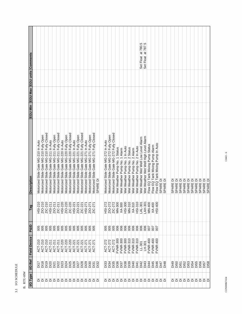
3.1
I/
O S
CH
ED
UL
E
B.
RT
U-H
W
I/O T
ype
I/O R
efF
ield
Dev
ice
P&
IDT
agD
escr
ipti
on
EG
U M
inE
GU
Max
EG
U u
nit
sC
om
men
ts
DI
DI1
7A
CT
-210
005
HS
I-21
0M
otor
ized
Slid
e G
ate
MG
-210
In A
uto
DI
DI1
8A
CT
-210
005
ZIO
-210
Mot
oriz
ed S
lide
Gat
e M
G-2
10 F
ully
Ope
nD
ID
I19
AC
T-2
1000
5Z
IC-2
10M
otor
ized
Slid
e G
ate
MG
-210
Ful
ly C
lose
dD
ID
I20
AC
T-2
1100
5H
SI-
211
Mot
oriz
ed S
lide
Gat
e M
G-2
11 In
Aut
oD
ID
I21
AC
T-2
1100
5Z
IO-2
11M
otor
ized
Slid
e G
ate
MG
-211
Ful
ly O
pen
DI
DI2
2A
CT
-211
005
ZIC
-211
Mot
oriz
ed S
lide
Gat
e M
G-2
11 F
ully
Clo
sed
DI
DI2
3A
CT
-220
005
HS
I-22
0M
otor
ized
Slid
e G
ate
MG
-220
In A
uto
DI
DI2
4A
CT
-220
005
ZIO
-220
Mot
oriz
ed S
lide
Gat
e M
G-2
20 F
ully
Ope
nD
ID
I25
AC
T-2
2000
5Z
IC-2
20M
otor
ized
Slid
e G
ate
MG
-220
Ful
ly C
lose
dD
ID
I26
AC
T-2
2100
5H
SI-
221
Mot
oriz
ed S
lide
Gat
e M
G-2
21 In
Aut
oD
ID
I27
AC
T-2
2100
5Z
IO-2
21M
otor
ized
Slid
e G
ate
MG
-221
Ful
ly O
pen
DI
DI2
8A
CT
-221
005
ZIC
-221
Mot
oriz
ed S
lide
Gat
e M
G-2
21 F
ully
Clo
sed
DI
DI2
9A
CT
-271
005
HS
I-27
1M
otor
ized
Slid
e G
ate
MG
-271
In A
uto
DI
DI3
0A
CT
-271
005
ZIO
-271
Mot
oriz
ed S
lide
Gat
e M
G-2
71 F
ully
Ope
nD
ID
I31
AC
T-2
7100
5Z
IC-2
71M
otor
ized
Slid
e G
ate
MG
-271
Ful
ly C
lose
dD
ID
I32
SP
AR
E D
I
DI
DI3
3A
CT
-272
005
HS
I-27
2M
otor
ized
Slid
e G
ate
MG
-272
In A
uto
DI
DI3
4A
CT
-272
005
ZIO
-272
Mot
oriz
ed S
lide
Gat
e M
G-2
72 F
ully
Ope
nD
ID
I35
AC
T-2
7200
5Z
IC-2
72M
otor
ized
Slid
e G
ate
MG
-272
Ful
ly C
lose
dD
ID
I36
FV
NR
-300
006
MN
-300
Wet
Wea
ther
Pum
p N
o. 1
Sta
tus
DI
DI3
7F
VN
R-3
0000
6X
A-3
00W
et W
eath
er P
ump
No.
1 A
larm
DI
DI3
8F
VN
R-3
0000
6H
SI-
300
Wet
Wea
ther
Pum
p N
o. 1
In A
uto
DI
DI3
9F
VN
R-3
1000
6M
N-3
10W
et W
eath
er P
ump
No.
2 S
tatu
sD
ID
I40
FV
NR
-310
006
XA
-310
Wet
Wea
ther
Pum
p N
o. 2
Ala
rmD
ID
I41
FV
NR
-310
006
HS
I-31
0W
et W
eath
er P
ump
No.
2 In
Aut
oD
ID
I42
LL-3
0100
6LA
L-30
1W
et W
eath
er W
et W
ell L
ow L
evel
Ala
rmS
et F
loat
at 7
80.5
DI
DI4
3LH
-301
006
LAH
-301
Wet
Wea
ther
Wet
Wel
l Hig
h Le
vel A
larm
Set
Flo
at a
t 787
.5D
ID
I44
FV
NR
-400
007
MN
-400
Flo
w E
Q T
ank
Mix
ing
Pum
p S
tatu
sD
ID
I45
FV
NR
-400
007
XA
-400
Flo
w E
Q T
ank
Mix
ing
Pum
p A
larm
DI
DI4
6F
VN
R-4
0000
7H
SI-
400
Flo
w E
Q T
ank
Mix
ing
Pum
p In
Aut
oD
ID
I47
SP
AR
E D
ID
ID
I48
SP
AR
E D
I
DI
DI4
9S
PA
RE
DI
DI
DI5
0S
PA
RE
DI
DI
DI5
1S
PA
RE
DI
DI
DI5
2S
PA
RE
DI
DI
DI5
3S
PA
RE
DI
DI
DI5
4S
PA
RE
DI
DI
DI5
5S
PA
RE
DI
DI
DI5
6S
PA
RE
DI
DI
DI5
7S
PA
RE
DI
DI
DI5
8S
PA
RE
DI
CO
N00
8674
34 1
3443
- 6

3.1
I/
O S
CH
ED
UL
E
B.
RT
U-H
W
I/O T
ype
I/O R
efF
ield
Dev
ice
P&
IDT
agD
escr
ipti
on
EG
U M
inE
GU
Max
EG
U u
nit
sC
om
men
tsD
ID
I59
SP
AR
E D
ID
ID
I60
SP
AR
E D
ID
ID
I61
SP
AR
E D
ID
ID
I62
SP
AR
E D
ID
ID
I63
SP
AR
E D
ID
ID
I64
SP
AR
E D
I
DO
DO
1A
CT
-210
005
ZC
O-2
10M
otor
ized
Slid
e G
ate
MG
-210
Ope
n C
omm
and
DO
DO
2A
CT
-210
005
ZC
C-2
10M
otor
ized
Slid
e G
ate
MG
-210
Clo
se C
omm
and
DO
DO
3A
CT
-211
005
ZC
O-2
11M
otor
ized
Slid
e G
ate
MG
-211
Ope
n C
omm
and
DO
DO
4A
CT
-211
005
ZC
C-2
11M
otor
ized
Slid
e G
ate
MG
-211
Clo
se C
omm
and
DO
DO
5A
CT
-220
005
ZC
O-2
20M
otor
ized
Slid
e G
ate
MG
-220
Ope
n C
omm
and
DO
DO
6A
CT
-220
005
ZC
C-2
20M
otor
ized
Slid
e G
ate
MG
-220
Clo
se C
omm
and
DO
DO
7A
CT
-221
005
ZC
O-2
21M
otor
ized
Slid
e G
ate
MG
-221
Ope
n C
omm
and
DO
DO
8A
CT
-221
005
ZC
C-2
21M
otor
ized
Slid
e G
ate
MG
-221
Clo
se C
omm
and
DO
DO
9A
CT
-270
005
ZC
O-2
70M
otor
ized
Slid
e G
ate
MG
-270
Ope
n C
omm
and
DO
DO
10A
CT
-270
005
ZC
C-2
70M
otor
ized
Slid
e G
ate
MG
-270
Clo
se C
omm
and
DO
DO
11A
CT
-271
005
ZC
O-2
71M
otor
ized
Slid
e G
ate
MG
-271
Ope
n C
omm
and
DO
DO
12A
CT
-271
005
ZC
C-2
71M
otor
ized
Slid
e G
ate
MG
-271
Clo
se C
omm
and
DO
DO
13S
PA
RE
DO
DO
DO
14S
PA
RE
DO
DO
DO
15S
PA
RE
DO
DO
DO
16S
PA
RE
DO
DO
DO
17F
CP
-252
005
MN
-253
Grit
Pum
p S
tatu
sD
OD
O18
FC
P-2
5200
5M
N-2
54G
rit D
rive
Sta
tus
DO
DO
19F
CP
-252
005
MN
-256
Grit
Cla
ssifi
er S
tatu
sD
OD
O20
FC
P-2
5200
5X
A-2
53G
rit P
ump
Fai
lure
DO
DO
21F
CP
-252
005
XA
-256
Grit
Pum
p C
lass
ifier
DO
DO
22F
VN
R-3
0000
6M
C-3
00W
et W
eath
er P
ump
No.
1 R
un C
omm
and
DO
DO
23F
VN
R-3
1000
6M
C-3
10W
et W
eath
er P
ump
No.
2 R
un C
omm
and
DO
DO
24F
VN
R-4
0000
7M
C-4
00F
low
EQ
Tan
k M
ixin
g P
ump
Run
Com
man
dD
OD
O25
FS
-205
007
LCP
-203
AS
cree
n R
oom
EF
-1 L
ow F
low
Ala
rmD
OD
O26
FS
-264
007
LCP
-261
AG
rit R
oom
EF
-3 L
ow F
low
Ala
rmD
OD
O27
SP
AR
E D
OD
OD
O28
SP
AR
E D
OD
OD
O29
SP
AR
E D
OD
OD
O30
SP
AR
E D
OD
OD
O31
SP
AR
E D
OD
OD
O32
SP
AR
E D
O
CO
N00
8674
34 1
3443
- 7

This page intentionally left blank.

CON00867434 Oak Ridge National Laboratory January 30, 2015 Primary Sewage Treatment Pump Station - For Construction CONTROL AUXILIARIES 13446 - 1
SECTION 13446
CONTROL AUXILIARIES
PART 1 - GENERAL
1.1 SUMMARY
A. Section Includes: 1. Pilot devices:
a. Selector switches. b. Pushbuttons. c. Indicating lights. d. Combination selector switch/indicator light.
2. Relays/timers: a. Control relay. b. Time delay relays.
3. Termination equipment: a. Terminal blocks. b. Fuse holders.
4. Power supplies: a. DC power supplies. b. Isolation transformers.
5. Voltage surge protection devices. 6. Running time indicator.
B. Related Specification Sections include but are not necessarily limited to: 1. Division 0 - Bidding Requirements, Contract Forms, and Conditions of the Contract. 2. Division 1 - General Requirements. 3. Section 13440 - Instrumentation for Process Control: Basic Requirements. 4. Section 16491 - Low Voltage Surge Protective Devices (SPD).
1.2 QUALITY ASSURANCE
A. Referenced Standards: 1. The Instrumentation, Systems, and Automation Society (ISA):
a. S18.1, Annunciator Sequences and Specifications. 2. National Electrical Manufacturers Association (NEMA):
a. 250, Enclosures for Electrical Equipment (1000 Volts Maximum). b. ICS 2, Industrial Control and Systems: Controllers, Contactors, and Overload Relays
Rated 600 Volts. 3. Underwriters Laboratories, Inc. (UL).
B. Miscellaneous: 1. Assure units comply with electrical area classifications and NEMA enclosure type shown on
Drawings.
1.3 SUBMITTALS
A. Shop Drawings: 1. See Specification Section 01300 for requirements for the mechanics and administration of
the submittal process. 2. See Specification Section 13440.
B. Operation and Maintenance Manuals: 1. See Specification Section 01730 for requirements for:
a. The mechanics and administration of the submittal process.

CON00867434 Oak Ridge National Laboratory January 30, 2015 Primary Sewage Treatment Pump Station - For Construction CONTROL AUXILIARIES 13446 - 2
b. The content of Operation and Maintenance Manuals.
PART 2 - PRODUCTS
2.1 ACCEPTABLE MANUFACTURERS
A. Subject to compliance with the Contract Documents, the manufacturers listed in the applicable Articles below are acceptable.
B. Provide similar components from the same manufacturer for uniformity of appearance, operations, and maintenance.
2.2 PILOT DEVICES
A. Selector Switches: 1. Acceptable manufacturers:
a. Cutler Hammer. b. Allen-Bradley.
2. Design and fabrication: a. Heavy-duty type. b. Oiltight NEMA 4. c. Rotary cam units conforming to NEMA ICS 2-216.22. d. Mounting hole: 30.5 mm. e. Supply switches having number of positions required with contact blocks to fulfill
functions shown and specified. f. UL listed. g. Maintained contact type. h. Knob type operators. i. Black colored operators. j. Designed with cam and contact block with approximate area of 2 IN SQ. k. Legend plate marked per Contract Documents. l. Contact block requirements:
1) Dry and indoor locations: Standard contact blocks rated for 10 A continuous current.
2) Wet or outside locations: Hermetically sealed contact blocks.
B. Pushbuttons: 1. Acceptable manufacturers:
a. Cutler Hammer. b. Allen-Bradley.
2. Materials: a. Backing diaphragm: Buna-N.
3. Design and fabrication: a. Heavy-duty type. b. Oiltight NEMA 4. c. Conforming to NEMA ICS 2-216.22. d. Mounting hole: 30.5 mm. e. Diaphragm backed. f. UL listed. g. Emergency stop pushbuttons to have mushroom head operator and maintained contact. h. Non-illuminated type:
1) Momentary contact with necessary contact blocks. 2) Molded, solid color melamine buttons. 3) Standard flush operators with full shroud. 4) Green colored buttons for START or ON and red color for STOP or OFF. 5) Appropriate contact blocks to fulfill functions shown or specified.
i. Contact block requirements:

CON00867434 Oak Ridge National Laboratory January 30, 2015 Primary Sewage Treatment Pump Station - For Construction CONTROL AUXILIARIES 13446 - 3
1) Dry and indoor locations: Standard contact blocks rated for 10 A continuous current.
2) Wet or outside locations: Hermetically sealed contact blocks. 3) Legend plate marked per Contract Documents.
j. Illuminating type: 1) Momentary contact with necessary contact blocks. 2) Serves as both pushbutton control and indicating light. 3) Green colored lenses for start or on and red for STOP or OFF. 4) Resistor-type full voltage light unit with lens and panel gasket. 5) Legend plate marked per Contract Documents. 6) Appropriate contact blocks to fulfill functions shown or specified.
C. Indicating Lights: 1. Acceptable manufacturers:
a. Cutler Hammer. b. Allen-Bradley.
2. Design and fabrication: a. Heavy duty type. b. Oiltight NEMA 4. c. Type allowing replacement of bulb without removal from control panel. d. LED. e. UL listed. f. 24 V lamp. g. Legends marked per Contract Documents. h. Nominal 2 IN SQ face. i. Mounting hole: 30.5 mm. j. Push-to-test indicating lights. k. Glass lens. l. Color code lights as follows:
1) Green: ON or running; valve open. 2) Amber: Standby; auto mode; ready. 3) Red: OFF or stopped; valve open.
m. Legend plate engraved for each light.
2.3 RELAYS/TIMERS
A. Control Relays: 1. Acceptable manufacturers:
a. Idec. b. Potter & Brumsfield. c. Allen-Bradley.
2. Design and fabrication: a. Plug-in general purpose relay. b. Blade connector type. c. Switching capacity: 10 A. d. Contact material: Silver cadmium oxide. e. Provide relays with a minimum of 3 SPDT contacts. f. Coil voltage: 120 Vac or 24 Vdc. g. Relay sockets are DIN rail mounted. h. Internal neon or LED indicator is lit when coil is energized. i. Clear polycarbonate dust cover with clip fastener. j. Check button. k. Temperature rise:
1) Coil: 85 DegF max. 2) Contact: 65 DegF max.
l. Insulation resistance: 100 Meg min. m. Frequency response: 1800 operations/hour.

CON00867434 Oak Ridge National Laboratory January 30, 2015 Primary Sewage Treatment Pump Station - For Construction CONTROL AUXILIARIES 13446 - 4
n. Operating temperature: -20 to +150 DegF. o. Life expectancy:
1) Electrical: 500,000 operations or more. 2) Mechanical: 50,000,000 operations or more.
p. UL listed or recognized.
B. Time Delay Relays: 1. Acceptable manufacturers:
a. Eagle Signal Controls. b. Idec.
2. Design and fabrication: a. Melt design test and performance requirements of NEMA ICS 2-218. b. Heavy-duty. c. Solid-state construction. d. External adjusting dial. e. Auxiliary relays as required to perform functions specified or shown on Drawings. f. Operates on 117 Vac (±10 percent) power source. g. Contact rating: A150 per NEMA ICS 2-125. h. Furnish with "on" and "timing out" indicators.
2.4 TERMINATION EQUIPMENT
A. Terminal Blocks: 1. Acceptable manufacturers:
a. Phoenix Contact. b. Allen-Bradley.
2. Design and fabrication: a. Modular type with screw compression clamp. b. Screws: Stainless steel. c. Current bar: Nickel-plated copper allow. d. Thermoplastic insulation rated for -40 to +90 DegC. e. Wire insertion area: Funnel-shaped to guide all conductor strands into terminal. f. Install end sections and end stops at each end of terminal strip. g. Install machine-printed terminal markers on both sides of block. h. Spacing: 6 mm. i. Wire size: 22-12 AWG. j. Rated voltage: 600 V. k. Din rail mounting. l. UL listed.
3. Standard-type block: a. Rated current: 30 A. b. Color: Gray body.
4. Bladed-type block: a. Terminal block with knife blade disconnect which connects or isolated the two (2) sides
of the block. b. Rated current: 10 A. c. Color:
1) Panel control voltage leaves enclosure - normal: Gray body, orange switch. 2) Foreign voltage entering enclosure: Orange body, orange switch.
5. Grounded-type block: a. Electrically grounded to mounting rail. b. Use to terminal ground wires and analog cable shields. c. Color: Green and yellow body.
B. Fuse Holders: 1. Acceptable manufacturers:
a. Phoenix Contact.

CON00867434 Oak Ridge National Laboratory January 30, 2015 Primary Sewage Treatment Pump Station - For Construction CONTROL AUXILIARIES 13446 - 5
b. Allen-Bradley. 2. Design and fabrication:
a. Modular-type with screw compression clamp. b. Screws: Stainless steel. c. Current bar: Nickel-plated copper alloy. d. Thermoplastic insulation rated for -40 to +105 DegC. e. Wire insertion area: Funnel-shaped to guide all conductor strands into terminal. f. Blocks can be ganged for multi-pole operation. g. Install end sections and end stops at each end of terminal strip. h. Install machine-printed terminal markers on both sides of block. i. Spacing: 9.1 mm. j. Wire size: 30-12 AWG. k. Rated voltage: 300 V. l. Rated current: 12 A. m. Fuse size: 1/4 x 1-1/4. n. Blown fuse indication. o. DIN rail mounting. p. UL listed.
2.5 POWER SUPPLIES
A. DC Power Supplies: 1. Acceptable manufacturers:
a. Sola Hevi-Duty. b. Phoenix Contact. c. Rockwell Automation.
2. Design and fabrication: a. Converts 120 Vac input to DC power at required voltage. b. DIN rail mount with enclosure (i.e., not open frame). c. Switching type. d. AC input: 120 Vac +/-15 percent, nominal 60 Hz. e. Efficiency: Minimum 86 percent. f. Rated mean time between failure (MTBF): 500,000 HRS. g. Voltage regulation:
1) Static: Less than 1.0 percent Vout. 2) Dynamic: +/-2 percent Vout overall.
h. Output ripple/noise: Less than 100 mV peak to peak (20 MHz). i. Overload, short circuit and open circuit protection. j. Temperature rating: 0 to 60 DegC full rated, derated linearly to 50 percent at 70 DegC. k. Humidity rating: Up to 90 percent, non-condensing. l. LED status indication for DC power.
B. Isolation Transformers: 1. Acceptable manufacturers:
a. Topaz Noise Suppressor Noise Isolator. b. MGE UPS Systems, Topaz T1.
2. Design and fabrication: a. Protects sensitive electronic equipment from electrical noise. b. Common-mode noise attenuation: 146 dB at 0.0005 pF coupling capacitance. c. Normal-mode attenuation: 60 dB. d. Input voltage range: ±10 percent of rated. e. Regulation: 3.5 percent or less from full-load to no-load. f. Dielectric strength: 2,500 Vac minimum. g. Harmonic distortion: 1 percent maximum. h. Electromagnetic interference: 0-1 gauss maximum at 18 IN. i. UL listed.

CON00867434 Oak Ridge National Laboratory January 30, 2015 Primary Sewage Treatment Pump Station - For Construction CONTROL AUXILIARIES 13446 - 6
2.6 VOLTAGE SURGE PROTECTION DEVICES
A. See Specification Section 16491.
2.7 RUNNING TIME INDICATORS
A. Acceptable Manufacturer: 1. Eagle Signal Controls.
B. Design and Fabrication: 1. Six-digit wheels including a 1/10 digit. 2. Non-reset type. 3. Time range in hours. 4. Automatic recycle at zero. 5. Accuracy: 1 percent. 6. Sealed against dirt and moisture. 7. Tamperproof.
PART 3 - EXECUTION
3.1 INSTALLATION
A. Install products in accordance with manufacturer's instructions.
END OF SECTION

CON00867434 Oak Ridge National Laboratory January 30, 2015 Primary Sewage Treatment Pump Station - For Construction CONTROL PANELS AND ENCLOSURES 13448 - 1
SECTION 13448
CONTROL PANELS AND ENCLOSURES
PART 1 - GENERAL
1.1 SUMMARY
A. Section Includes: 1. Requirements for control panels and enclosures utilized as follows:
a. Unless noted otherwise, all control panels and enclosures house control components that are specified in Specification Sections 13442, 13446, 13449, 13500, and/or 13502.
B. This Specification Section is only applicable to panels furnished with Division 11 equipment packages when so stated in the applicable Division 11 Specification Section.
C. This Section is only applicable to panels housing Division 16 specified equipment (e.g., motor starters, lighting controls, etc.) when so stated in the applicable Division 16 Specification Section.
D. Related Sections include but are not necessarily limited to: 1. Division 0 - Bidding Requirements, Contract Forms, and Conditions of the Contract. 2. Division 1 - General Requirements. 3. Division 11 - Equipment. 4. Section 13440 - Instrumentation for Process Control: Basic Requirements. 5. Section 13442 - Primary Elements and Transmitters. 6. Section 13446 - Control Auxiliaries. 7. Section 13449 - Surge Protection Devices (SPD) for Instrumentation and Control
Equipment. 8. Section 13500 - Programmable Logic Controller (PLC) Control System. 9. Section 13502 – Computer Network and Human Machine Interface (HMI) System. 10. Division 16 - Electrical.
1.2 QUALITY ASSURANCE
A. Referenced Standards: 1. American National Standards Institute (ANSI). 2. ASTM International (ASTM):
a. B75, Standard Specification for Seamless Copper Tube. 3. National Electrical Manufacturers Association (NEMA):
a. 250, Enclosures for Electrical Equipment (1000 Volts Maximum). b. ICS 4, Industrial Control and Systems: Terminal Blocks.
4. National Fire Protection Association (NFPA): a. 70, National Electrical Code (NEC):
1) Article 409, Industrial Control Panels. 5. Underwriters Laboratories, Inc. (UL):
a. 508A, Standard for Safety Industrial Control Panels.
B. Miscellaneous: 1. Approved supplier of Industrial Control Panels under provisions of UL 508A.
a. Entire assembly shall be affixed with a UL 508A label "Listed Enclosed Industrial Control Panel" prior to shipment to the jobsite.
b. Control panel(s) without an affixed UL 508A label shall be rejected and sent back to the Contractor’s factory.

CON00867434 Oak Ridge National Laboratory January 30, 2015 Primary Sewage Treatment Pump Station - For Construction CONTROL PANELS AND ENCLOSURES 13448 - 2
1.3 DEFINITIONS
A. The term "panel" refers to control panels or enclosures listed in the schedule included in this Specification Section.
B. Foreign Voltages: Voltages that may be present in circuits when the panel main power is disconnected.
C. Intrinsically Safe: 1. A device, instrument or component that will not produce sparks or thermal effects under
normal or abnormal conditions that will ignite a specified gas mixture. 2. Designed such that electrical and thermal energy limits inherently are at levels incapable of
causing ignition.
D. Cable: Multi-conductor, insulated, with outer sheath containing either building wire or instrumentation wire.
E. Instrumentation Cable: 1. Multiple conductor, insulated, twisted or untwisted, with outer sheath. 2. Instrumentation cable is typically either TSP (twisted-shielded pair) or TST (twisted-
shielded triad), and is used for the transmission of low current or low voltage signals.
F. Ground Fault Circuit Interrupter (GFCI): A type of device (e.g., circuit breaker or receptacle) which detects an abnormal current flow to ground and opens the circuit preventing a hazardous situation.
G. Programmable Logic Controller (PLC): A specialized industrial computer using programmed, custom instructions to provide automated monitoring and control functions by interfacing software control strategies to input/output devices.
H. Input/Output (I/O): Hardware for the moving of control signals into and/or out of a PLC or RTU.
I. Supervisory Control and Data Acquisition (SCADA): Used in process control applications, where programmable logic controllers (PLCs) perform control functions but are monitored and supervised by computer workstations.
J. Highway Addressable Remote Transducer (HART): An open, master-slave protocol for bus addressable field instruments.
K. Digital Signal Cable: Used for the transmission of digital communication signals between computers, PLCs, RTUs, etc.
L. Uninterruptible Power Supply (UPS): A backup power unit that provides continuous power when the normal power supply is interrupted.
M. Loop Calibrator: Portable testing and measurement tool capable of accurately generating and measuring 4-20ma DC analog signals.
1.4 SUBMITTALS
A. Shop Drawings: 1. See Section 01300 for requirements for the mechanics and administration of the submittal
process. 2. See Section 13440. 3. Prepared with computer aided design (CAD) software. 4. Printed on 11 by 17 IN sheets. 5. Drawings shall include a title block containing the following:
a. Plant or facility name where panel(s) are to be installed. b. Drawing title. c. Drawing number. d. Revision list with revision number and date e. Drawing date.

CON00867434 Oak Ridge National Laboratory January 30, 2015 Primary Sewage Treatment Pump Station - For Construction CONTROL PANELS AND ENCLOSURES 13448 - 3
f. Drawing scale. g. Manufacturer name, address, and telephone number.
6. Cover sheet for each drawing set shall indicate the following: a. Plant or facility name. b. Project name. c. Submittal description. d. Revision number. e. Issue date.
7. Table of contents sheet(s) shall indicate the following for each drawing in the set: a. Drawing number. b. Drawing title. c. Sheet number.
8. Legend and abbreviation sheet shall indicate the following: a. Description of symbols and abbreviations used. b. Panel construction notes including enclosure NEMA rating, finish type and color, wire
type, wire color strategy, conductor sizes, and wire labeling strategy. c. Confirmation that the panel(s) are to be affixed with a UL 508A label prior to shipment
from the factory. 9. Bill of Material for each panel shall include the following component information:
a. Instrument tag number. b. Quantity. c. Functional name or description. d. Manufacturer. e. Complete model number. f. Size or rating.
10. Panel exterior layout drawings to scale and shall indicate the following: a. Panel materials of construction, dimensions, and total assembled weight. b. Panel access openings. c. Conduit access locations. d. Front panel device layout. e. Nameplate schedule:
1) Nameplate location. 2) Legend which indicates text, letter height and color, and background color.
f. Alarm annunciator window engraving schedule. g. Layouts of graphic panels or mosaic displays.
11. Panel interior layout drawings shall be drawn to scale and shall indicate the following: a. Sub-panel or mounting pan dimensions. b. Interior device layouts. c. PLC/RTU general arrangement layouts. d. Wire-way locations, purpose, and dimensions. e. Terminal strip designations. f. Location of external wiring and/or piping connections. g. Location of lighting fixtures, switches and receptacles.
12. Wiring diagrams shall consist of the following: a. Panel power distribution diagrams. b. Control and instrumentation wiring diagrams. c. PLC I/O information:
1) Model number of I/O module. 2) Description of I/O module type and function. 3) Rack and slot number. 4) Terminal number on module. 5) Point or channel number. 6) Programmed point addresses. 7) Signal function and type.
d. Wiring diagrams shall identify each wire as it is to be labeled.

CON00867434 Oak Ridge National Laboratory January 30, 2015 Primary Sewage Treatment Pump Station - For Construction CONTROL PANELS AND ENCLOSURES 13448 - 4
B. Manufacturer catalog cut sheets for enclosure, finish, panel devices, control auxiliaries, and accessories.
C. Electrical load calculations for each panel: 1. Total connected load. 2. Peak electrical demand for each panel.
D. Climate control calculations for each panel. 1. Verify that sufficient dissipation and/or generation of heat is provided to maintain interior
panel temperatures within the rated operating temperatures of panel components.
E. Miscellaneous: 1. Record Drawings:
a. Updated panel drawings delivered with the panel(s) from the Contractor’s factory. b. Drawings shall be enclosed in transparent plastic and firmly secured within each panel.
F. Operation and Maintenance Manuals: 1. See Section 01730 for requirements for:
a. The mechanics and administration of the submittal process. b. The content of Operation and Maintenance Manuals.
2. See Section 13440.
PART 2 - PRODUCTS
2.1 ACCEPTABLE MANUFACTURERS
A. Subject to compliance with the Contract Documents, the following manufacturers are acceptable: 1. Enclosures:
a. Hoffman Engineering Co. b. Rittal. c. Hammond Manufacturing. d. Millbank Mfg. Co.
2. Panel heaters: a. Hoffman Enclosures, Inc. b. Rittal. c. Hammond Manufacturing.
3. Internal corrosion inhibitors: a. Hoffman Enclosures, Inc.; Model A-HCI. b. Northern Technologies International Corporation (NTIC); Model Zerust VC. c. Cortec Corporation; Model VpCl Emitting Systems.
2.2 ACCESSORIES
A. Panel Nameplates and Identification as required.
2.3 FABRICATION
A. General: 1. Fabricate panels with instrument arrangements and dimensions identified in the Contract
Documents. 2. Provide panel(s) with the required enclosure rating per NEMA 250 to meet classifications
identified in the Contract Documents. 3. Devices installed in panel openings shall have a NEMA enclosure rating at least equal to the
panel enclosure rating. a. Devices that cannot be obtained with an adequate NEMA rating shall be installed
behind a transparent viewing window. b. The window shall maintain the required NEMA rating of the enclosure.
4. Panel(s) shall be completely assembled at the Contractor’s factory.

CON00867434 Oak Ridge National Laboratory January 30, 2015 Primary Sewage Treatment Pump Station - For Construction CONTROL PANELS AND ENCLOSURES 13448 - 5
a. No fabrication other than correction of minor defects or minor transit damage shall be performed on panels at the jobsite.
5. Painting: a. Panels fabricated from steel shall have their internal and external surfaces prepared,
cleaned, primed, and painted. 1) Mechanically abrade all surfaces to remove rust, scale, and surface imperfections. 2) Provide final surface treatment with 120 grit abrasives or finer, followed by spot
putty to fill all voids. 3) Utilize solvent or chemical methods to clean panel surfaces. 4) Apply surface conversion of zinc phosphate prior to painting to improve paint
adhesion and to increase corrosion resistance. 5) Electrostatically apply polyester urethane powder coating to all inside and outside
surfaces. 6) Bake powder coating at high temperatures to bond coating to enclosure surface.
a) Panel interior shall be white with semi-gloss finish. b) Panel exterior shall be ANSI #61 gray with flat finish.
7) Application of alkyd liquid enamel coating shall be allowed in lieu of polyester urethane powder for wall mounted NEMA 12 rated panels.
b. Panels fabricated from stainless steel, aluminum, or fiberglass shall not be painted. 6. Finish opening edges of panel cutouts to smooth and true surface conditions.
a. Panels fabricated from steel shall have the opening edges finished with the panel exterior paint.
7. Panel shall meet all requirements of UL 508A. a. If more than one (1) disconnect switch is required to disconnect all power within a
panel or enclosure, provide a cautionary marking with the word "CAUTION" and the following or equivalent, "Risk of Electric Shock-More than one (1) disconnect switch required to de-energize the equipment before servicing."
8. Provide control panel in accordance with NFPA 70, Article 409. a. In the event of any conflict between NFPA 70, Article 409 and UL 508A, the more
stringent requirement shall apply.
B. Free-Standing Panels: 1. Welded construction. 2. Completely enclosed, self-supporting, and gasketed dusttight. 3. Rolled lip around all sides of enclosure door opening. 4. Seams and corners welded and ground smooth to touch and smooth in visual appearance. 5. Full height, fully gasketed flush pan doors. 6. Full length piano hinges rated for 1.5 times door plus instrument weight. 7. Doors with keyed alike locking handles and three-point catch. 8. Appropriate conduit, wiring, and instrument openings shall be provided. 9. Lifting eyebolts to allow simple, safe rigging and lifting of panel during installation.
C. Wall Mounted Panels: 1. Seams continuously welded and ground smooth. 2. Rolled lip around all sides of enclosure door opening. 3. Gasketed dust tight. 4. Door clamps and hasp/staple for padlocking. 5. Three-point latching mechanism operated by oil tight key-locking handle. 6. Key doors alike. 7. Continuous heavy GA hinge pin on doors.
a. Hinges rated for 1.5 times door plus instrument weight. 8. Front full opening door. 9. Brackets for wall mounting.
D. Internal Panel Wiring: 1. Panel wire duct shall be installed between each row of components, and adjacent to each
terminal strip. a. Route wiring within the panel in wire-duct neatly tied and bundled with tie wraps.

CON00867434 Oak Ridge National Laboratory January 30, 2015 Primary Sewage Treatment Pump Station - For Construction CONTROL PANELS AND ENCLOSURES 13448 - 6
b. Follow wire-duct manufacturer's recommended fill limits. c. Wire-duct shall have removable snap-on covers and perforated walls for easy wire
entrance. d. Wire-duct shall be constructed of nonmetallic materials with rating in excess of the
maximum voltage carried therein. 2. Wiring shall be installed such that if wires are removed from one (1) device, source of
power will not be disrupted to other devices. 3. Splicing and tapping of wires permitted only at terminal blocks. 4. Wire bunches to doors shall be secured at each end so that bending or twisting will be
around longitudinal axis of wire. a. Protect bend area with sleeve.
5. Arrange wiring neatly, cut to proper length, with surplus wire removed. a. Arrange wiring with sufficient clearance. b. Provide abrasion protection for wire bundles that pass through openings or across edges
of sheet metal. 6. AC circuits shall be routed separate from analog signal cables and digital signal cables.
a. Separate by at least 6 IN, except at unavoidable crossover points and at device terminations.
7. Provide at least 6 IN of separation between intrinsically safe devices and circuits and non-intrinsically safe devices and circuits.
8. Wiring to pilot devices or rotary switches shall be individually bundled and installed with a "flexible loop" of sufficient length to permit the component to be removed from panel for maintenance without removing terminations.
9. Conductors for AC and DC circuits shall be type MTW stranded copper listed for operation with 600 V at 90 DegC. a. Conductor size shall be as required for load and 16 AWG minimum. b. Internal panel wiring color code:
1) AC circuits: a) Power wiring: Black. b) Control interconnections: Yellow. c) Neutral: White. d) Ground: Green.
2) Low voltage DC circuits: a) Power wiring: Blue. b) Control interconnections: Violet.
3) Foreign voltage circuits: Pink. 4) Annunciator circuits: Red. 5) Intrinsically safe circuits: Orange.
10. Analog signal cables shall be of 600 V insulation, stranded copper, twisted-shielded pairs. a. Conductor size: 18 AWG minimum. b. Terminate shield drain conductors to ground only at one (1) end of the cable.
11. High precision 250 ohm resistors with 0.25 percent accuracy shall be used where 4-20 mA DC analog signals are converted to 1-5 Vdc signals. a. Resistors located at terminal strips. b. Resistors terminated using individual terminal blocks and with no other conductors. c. Resistor leads shall be un-insulated and of sufficient length to allow test or calibration
equipment (e.g., HART communicator, loop calibrator) to be properly attached to the circuit with clamped test leads.
12. Analog signals for devices in separate enclosures shall not be wired in series. a. Loop isolators shall be used where analog signals are transmitted between control
enclosures. 13. Wire and cable identification:
a. Wire and cables numbered and tagged at each termination. b. Wire tags:
1) Slip-on, PVC wire sleeves with legible, machine-printed markings. 2) Adhesive, snap-on, or adhesive type labels are not acceptable.

CON00867434 Oak Ridge National Laboratory January 30, 2015 Primary Sewage Treatment Pump Station - For Construction CONTROL PANELS AND ENCLOSURES 13448 - 7
c. Markings as identified in the Shop Drawings.
E. Grounding Requirements: 1. Equipment grounding conductors shall be separated from incoming power conductors at the
point of entry. 2. Minimize grounding conductor length within the enclosure by locating the ground reference
point as close as practical to the incoming power point of entry. 3. Bond electrical racks, chassis and machine elements to a central ground bus.
a. Nonconductive materials, such as paint, shall be removed from the area where the equipment contacts the enclosure.
4. Bond the enclosure to the ground bus. a. It is imperative that good electrical connections are made at the point of contact
between the ground bus and enclosure. 5. Panel-mounted devices shall be bonded to the panel enclosure or the panel grounding
system by means of locknuts or pressure mounting methods. 6. Sub-panels and doors shall be bonded to ground.
F. Termination Requirements: 1. Wiring to circuits external to the panel connected to interposing terminal blocks. 2. Terminal blocks rigidly mounted on DIN rail mounting channels. 3. Terminal strips located to provide adequate space for entrance and termination of the field
conductors. 4. One (1) side of each strip of terminal blocks reserved exclusively for the termination of field
conductors. 5. Terminal block markings:
a. Marking shall be the same as associated wire marking. b. Legible, machine-printed markings. c. Markings as identified in the shop drawings.
6. Terminal block mechanical characteristics, and electrical characteristics shall be in accordance with NEMA ICS 4.
7. Terminal blocks with continuous marking strips. a. Each terminal block shall be identified with machine printed labels.
8. Terminals shall facilitate wire sizes as follows: a. 120 Vac applications: Conductor size 12 AWG minimum. b. Other: Conductor size 14 AWG minimum..
9. Analog signal cable shield drain conductors shall be individually terminated. 10. Install minimum of 20 percent spare terminals. 11. Bladed, knife switch, isolating type terminal blocks where control voltages enter or leave
the panel. 12. Fused terminal blocks shall be used in the following circuits:
a. Control voltage is used to energize a solenoid valve. b. DC power is connected to 2-wire, loop-powered instruments.
13. Fused terminal blocks shall be provided with blown fuse indicators. 14. When control circuits require more than one (1) field conductor connected to a single wiring
point, a sufficient number of terminal points shall be connected internally to allow termination of only one (1) field conductor per terminal block.
15. DIN rail mounting channels shall be installed along full length of the terminal strip areas to facilitate future expansion.
16. Connections to devices with screw type terminals shall be made using spade-tongue, insulated, compression terminators.
G. Component Mounting and Placement: 1. Components shall be installed per manufacturer instructions. 2. Control relays and other control auxiliaries shall be mounted on DIN rail mounting channels
where practical. 3. Front panel devices shall be mounted within a range of 40 to 70 IN above the finished floor,
unless otherwise shown in the Contract Documents. 4. PLC and I/O rack installation:

CON00867434 Oak Ridge National Laboratory January 30, 2015 Primary Sewage Treatment Pump Station - For Construction CONTROL PANELS AND ENCLOSURES 13448 - 8
a. Located such that the LED indicators and switches are readily visible with the panel door open.
b. Located such that repair and/or replacement of component can be accomplished without the need to remove wire terminations or other installed components.
5. Locate power supplies with sufficient spacing for circulation of air. 6. Where components such as magnetic starters, contactors, relays, and other electromagnetic
devices are installed within the same enclosure as the PLC system components, provide a barrier of at least 6 IN of separation between the “power area containing the electromagnetic devices” and the “control area”.
7. Components mounted in the panel interior shall be fastened to an interior sub-panel using machine screws. a. Fastening devices shall not project through the outer surface of the panel enclosure.
8. Excess mounting space of at least 20 percent for component types listed below to facilitate future expansion: a. Fuse holders. b. Circuit breakers. c. Control relays. d. Time delay relays. e. Intrinsically safe barriers and relays.
9. Components installed on sub-panels shall be provides with a minimum spacing between component and wire duct of 1 IN. a. Minimum of 2 IN separation between terminal strips and wire ducts.
H. Power Distribution: 1. Main incoming power circuits shall be protected with a thermal magnetic circuit breaker.
a. Limit load to maximum of 80 percent of circuit breaker rating. 2. Component types listed below shall be individually fused so that they may be individually
de-energized for maintenance: a. PLC power supply modules. b. Single-loop controllers.
3. Each control panel with PLC components shall be furnished with power protection in the form of a double conversion UPS.
4. Equip each panel with necessary power supplies with ratings required for installed equipment and with minimum 25 percent spare capacity.
5. Constant voltage transformers, balancing potentiometers, and rectifiers as necessary for specific instrument requirements.
I. Internal Panel Lighting and Service Receptacles: 1. Panels less than or equal to 4 FT wide:
a. One (1) electrical GFCI duplex receptacle. b. One (1) compact fluorescent light fixture with manual switch(es).
2. Panels or panel faces greater than 4 FT wide: a. One (1) duplex electrical GFCI receptacle per 6 FT of length. b. Continuous fluorescent lighting strip with manual switches.
J. Environmental Controls: 1. Indoor panels located in a designated electrical room or control room:
a. Thermostat controlled cooling fans with exhaust louvers if required to maintain temperature inside panel(s) below the maximum operating temperature rating of the internal components.
b. Internal corrosion inhibitors. 2. Indoor panels not located within a designated electrical room or control room:
a. Thermostat controlled heaters to maintain temperature approximately 10 DegF above ambient for condensation prevention inside the panels.
b. Internal corrosion inhibitors. 3. Outdoor panels:
a. Outdoor temperature range of 0 DegF through 120 DegF.

CON00867434 Oak Ridge National Laboratory January 30, 2015 Primary Sewage Treatment Pump Station - For Construction CONTROL PANELS AND ENCLOSURES 13448 - 9
b. Thermostat controlled heaters to maintain temperature approximately 10 DegF above ambient for condensation prevention inside the panels.
c. Outdoor temperature range of 0 DegF through 120 DegF. d. Internal corrosion inhibitors.
4. Environmental control components: a. Panel heaters:
1) Thermostat controlled. 2) Fan driven. 3) Components mounted in an anodized aluminum housing. 4) Designed for sub-panel mounting. 5) Powered from 120 Vac and protected with a dedicated circuit breaker.
b. Cooling fans and exhaust packages: 1) Cooling fan with louver or grill and replaceable filter. 2) Designed to be mounted within a panel cutout to provide positive airflow through
the panel. 3) Cooling fan and exhaust louvers shall be designed and listed to maintain a
NEMA 12 enclosure rating. 4) Fitted with replaceable, high-density foam or synthetic fiber. 5) Cooling fan controlled with a separately mounted thermostat with bi-metal sensor
and adjustable dial for temperature setting. 6) Powered from 120 Vac and protected with a dedicated circuit breaker.
c. Internal corrosion inhibitors: 1) Contains chemical which vaporizes and condenses on surfaces in the enclosure. 2) Inhibitor shall be applied in accordance with manufacturer instructions for the
enclosure volume. 3) Inhibitor shall be applied in the panel(s) prior to shipment from the Contractor’s
factory.
2.4 MAINTENANCE MATERIALS
A. Extra Materials: 1. Quantity of 25 percent replacement lamps for each type installed (minimum of 12 of each
type). 2. Minimum 12 replacement filters for each type installed. 3. One (1) quart of exterior finish touch-up paint. 4. One (1) complete set of replacement corrosion inhibitors in sealed packages for each panel.
PART 3 - EXECUTION
3.1 FACTORY TESTING
A. Scope: Inspect and test entire panel assembly to verify readiness for shipment.
B. Location: Contractor’s factory.
C. Factory Tests: 1. Tests shall be fully documented and signed by the Contractor’s factory supervisor. 2. The panel shop shall fully test the control panel for correct wiring.
a. Each I/O point shall be checked by measuring or connecting circuits at the field terminal blocks.
3. Burn-in test: Panel(s) shall be fully energized for a minimum period of 48 HRS. 4. A PLC Central Processing Unit (CPU) shall be obtained and connected to the panel(s) if
necessary for testing purposes. 5. Testing equipment (such as digital multi-meters, analog loop calibrators, and laptop
computers with PLC programming software) shall be used as required for testing. 6. The following functions shall be tested as a minimum:
a. Demonstrate functions of the panel(s) required by the Contract Documents.

CON00867434 Oak Ridge National Laboratory January 30, 2015 Primary Sewage Treatment Pump Station - For Construction CONTROL PANELS AND ENCLOSURES 13448 - 10
b. Correctness of wiring from all panel field terminals to all I/O points and to all panel components.
c. Simulate and test each discrete signal at the field terminal strips. d. Simulate and test each analog signal using loop calibrators. e. Correct operation of communications between PLC system Central Processing Units
(CPUs) and Remote I/O bases. f. Correct operation of single-loop controllers (including digital communication to
microprocessor based devices). g. Correct operation of all digital communication devices. h. Demonstrate online and offline diagnostic tests and procedures. i. The Contractor shall notify the Engineer in writing a minimum of 15 calendar days
prior to the Factory Tests. 1) Engineer has the option to witness all required tests.
7. Make following documentation available to the Engineer at test site during the tests: a. Contract Documents. b. Factory Demonstration Testing procedures. c. List of equipment to be testing including make, model, and serial number. d. Shop Drawing submittal data for equipment being tested.
8. Deficiencies shall be corrected prior to shipment from the Contractor’s factory.
3.2 INSTALLATION
A. Install free-standing panels on 4 IN high concrete housekeeping pads.
B. Anchor panels in a manner to prevent the enclosure from racking, which may cause the access doors to become misaligned.
C. Obtain approved panel layouts prior to installation of conduits.
D. Install products in accordance with manufacturer’s instructions.
3.3 SCHEDULE
A. Schedule:
END OF SECTION
TAG NUMBER LOCATION TYPE MATERIAL
LIGHT/ RECEPTACLE OIT UPS
RTU-HW Headworks Electrical Room
NEMA 12 Free Standing Yes/Yes Yes Yes
RTU-INF Influent PS Electrical Building
NEMA 12 Free Standing Yes/Yes Yes Yes
LCP-203A Headworks Electrical Room
NEMA 12 Wall Mounted No/No No No
LCP-203B Screen Room Entrance NEMA 4X Wall Mounted No/No No No LCP-203C Screen Room Entrance NEMA 7 Wall Mounted No/No No No LCP-261A Grit Classifier Room NEMA 4X Wall Mounted No/No No No LCP-261B Grit Room Entrance NEMA 4X Wall Mounted No/No No No LCP-261C Grit Room Entrance NEMA 7 Wall Mounted No/No No No

CON00867434 Oak Ridge National Laboratory January 30, 2015 Primary Sewage Treatment Pump Station - For Construction SURGE PROTECTION DEVICES (SPD) FOR INSTRUMENTATION AND CONTROL EQUIPMENT 13449 - 1
SECTION 13449
SURGE PROTECTION DEVICES (SPD) FOR INSTRUMENTATION AND CONTROL EQUIPMENT
PART 1 - GENERAL
1.1 SUMMARY
A. Section Includes: 1. Type IC1 SPD - Dedicated 120 Vac circuit, series connection, control panel mounted. 2. Type IC2 SPD - Individual equipment plug-in device (point of use protection). 3. Type IC3 SPD - Discrete 120 Vac control signal, control panel mounted. 4. Type IC4 SPD - Analog instrumentation signal, field mounted. 5. Type IC5 SPD - Analog instrumentation signal, control panel mounted. 6. Type IC6 SPD - Combination 120 Vac circuit and analog signal, field mounted. 7. Type IC7 SPD - Discrete low voltage control signal, control panel mounted. 8. Type IC8 SPD - Data line, control panel mounted.
B. Related Sections include but are not necessarily limited to: 1. Division 0 - Bidding Requirements, Contract Forms, and Conditions of the Contract. 2. Division 1 - General Requirements. 3. Section 13440 - Instrumentation for Process Control: Basic Requirements.
1.2 QUALITY ASSURANCE
A. Referenced Standards: 1. Institute of Electrical and Electronics Engineers, Inc. (IEEE):
a. C62.41, Recommended Practice for Surge Voltages in Low-Voltage AC Power Circuits.
2. National Electrical Manufacturers Association (NEMA): a. 250, Enclosures for Electrical Equipment (1000 Volts Maximum). b. LS 1, Low Voltage Surge Protection Devices.
3. Underwriters Laboratories, Inc. (UL): a. 497B, Standard for Safety Protectors for Data Communications and Fire-Alarm
Circuits. b. 1283, Standard for Safety Electromagnetic Interference Filters. c. 1363, Standard for Safety Relocatable Power Taps. d. 1449, Standard for Safety Transient Voltage Surge Suppressors.
B. Qualifications: 1. Provide devices for a manufacturer who has been regularly engaged in the development,
design, testing, listing and manufacturing of SPDs of the types and ratings required for a period of 10 years or more and whose products have been in satisfactory use in similar service.
2. Upon request, suppliers or manufacturers shall provide a list of not less than three (3) customer references showing satisfactory operation.
1.3 DEFINITIONS
A. Clamping Voltage: The voltage measured at the end of the 6 IN output leads of the SPD and from the zero voltage reference to the peak of the surge when the applied surge is induced at the 90 degree phase angle of the applied system frequency voltage.
B. Let-Through Voltage: The voltage measured at the end of the 6 IN output leads of the SPD and from the system peak voltage to the peak of the surge when the applied surge is induced at the 90 degree phase angle of the applied system frequency voltage.

CON00867434 Oak Ridge National Laboratory January 30, 2015 Primary Sewage Treatment Pump Station - For Construction SURGE PROTECTION DEVICES (SPD) FOR INSTRUMENTATION AND CONTROL EQUIPMENT 13449 - 2
C. Maximum Continuous Operating Voltage (MCOV): The maximum steady state voltage at which the SPD device can operate and meet it specification within its rated temperature.
D. Maximum Surge Current: 1. The maximum 8 x 20 microsecond surge current pulse the SPD device is capable of
surviving on a single-impulse basis without suffering either performance degradation or more than 10 percent deviation of clamping voltage at a specified surge current.
2. Listed by mode, since number and type of components in any SPD may vary by mode.
E. Protection Modes: This parameter identifies the modes for which the SPD has directly connected protection elements, i.e., line-to-neutral (L-N), line-to-line (L-L), line-to-ground (L-G), neutral-to-ground (N-G).
F. Surge Current per Phase: 1. The per phase rating is the total surge current capacity connected to a given phase
conductor. 2. For example, a wye system surge current per phase would equal L-N plus L-G; a delta
system surge current per phase would equal L-L plus L-G. a. The N-G mode is not included in the per phase calculation.
G. System Peak Voltage: The electrical equipment supply voltage sine wave peak (i.e., for a 120 V system the L-N peak voltage is 170 V).
1.4 SUBMITTALS
A. Shop Drawings: 1. See Section 01300 for requirements for the mechanics and administration of the submittal
process. 2. For named products, submit only a catalog cut sheet.
a. For all other products, submit the data required below. 3. See Section 13440. 4. Product technical data for non-specified models:
a. Manufacturer’s experience. b. Standard catalog cut sheet. c. Electrical and mechanical drawing showing unit dimensions, weights, mounting
provisions, connection details and layout diagram of the unit. d. Create a Product Data Sheet for each different model number of SPD provided.
1) Data in the Product Data Sheet heading: a) SPD Type per PART 2 of the Specification. b) Manufacturer’s Name. c) Product model number.
2) Data in the Product Data Sheet body: a) Column one: Specified value/feature of every paragraph of PART 2 of the
Specification. b) Column two: Manufacturer’s certified value confirming the product meets the
specified value/feature. 3) Data in the Product Data Sheet closing:
a) Signature of the manufacturer’s official (printed and signed). b) Title of the official. c) Date of signature.
B. Operation and Maintenance Manual: 1. See Section 01730 for requirements for:
a. The mechanics and administration of the submittal process. b. The content of Operation and Maintenance Manuals.

CON00867434 Oak Ridge National Laboratory January 30, 2015 Primary Sewage Treatment Pump Station - For Construction SURGE PROTECTION DEVICES (SPD) FOR INSTRUMENTATION AND CONTROL EQUIPMENT 13449 - 3
1.5 WARRANTY
A. The manufacturer shall provide a minimum of a five (5) year Limited Warranty from date of shipment against failure when installed in compliance with applicable national/local electrical codes and the manufacturer’s installation, operation and maintenance instructions.
PART 2 - PRODUCTS
2.1 ACCEPTABLE MANUFACTURERS
A. Subject to compliance with the Contract Documents, the manufacturers model numbers listed in the individual product paragraphs below are acceptable.
2.2 TYPE IC1 SPD
A. Approved Products: 1. Cutler Hammer AGSHW CH-120N-15-XS. 2. EDCO HSP121BT-1RU. 3. MTL MA15/D/1/SI. 4. Phoenix Contact SFP 1-20/120AC (2856702).
B. Standards: UL 1449.
C. Design: 1. General:
a. Mounted internally to control panels for point-of-use loads. b. MOV based or multi-stage hybrid solid state high performance suppression system. c. Designed for series connection. d. Enclosure: Metallic or plastic, flange or DIN rail mounting. e. Field connection: Provide unit with external terminal screws for each phase, neutral
and ground that will accept #14 through #12 conductors. f. Device monitoring: Long-life, solid state, externally visible indicators that monitors the
on-line status of the units suppression filter system or power loss in any of the phases. 2. Operating voltage: 120 Vac. 3. Operating current: 15 A minimum. 4. Operating frequency: 45 to 65 Hz. 5. Modes of protection: All modes, L-N, L-G and N-G. 6. Maximum continuous operating voltage: Less than 130 percent of system peak voltage. 7. Maximum surge current: 20,000A per phase, 10,000A per mode minimum. 8. Minimum repetitive surge current capacity: 1000 impulses with no degradation of more
than 10 percent deviation of the clamping voltage. 9. Fusing: Optional integral unit level and/or component level short circuit and/or thermal
overload protection. a. External protection as recommended by manufacturer.
10. Maximum clamping voltages, dynamic test with voltages measured from the zero voltage reference and 90 degree phase angle:
System Voltage Test Mode IEEE C62.41
UL 1449 B Comb. Wave A Ring Wave L-N = 120 V L-N 400 V 300 V 330 V
L-G 500 V 400 V 400 V N-G 500 V 400 V 400 V
2.3 TYPE IC2 SPD
A. Approved Product: 1. MTL Zone Guardian ZG-43006.

CON00867434 Oak Ridge National Laboratory January 30, 2015 Primary Sewage Treatment Pump Station - For Construction SURGE PROTECTION DEVICES (SPD) FOR INSTRUMENTATION AND CONTROL EQUIPMENT 13449 - 4
2. Tripp Lite Isobar 6 Ultra.
B. Standards: UL 1283, UL 1363 and UL 1449.
C. Design: 1. General:
a. Multi-stage hybrid solid state high performance suppression system. b. Point of use protection, designed for plug-in devices. c. Enclosure: Metallic or impact resistant plastic. d. Field connection:
1) The minimum line cord shall be #14 three (3) conductors, 6 FT in length, with a single piece strain relief NEMA 5-15P plug.
2) The minimum plug-in strip shall have six (6) single NEMA 5-15R receptacles. e. ON/OFF toggle switch. f. Device monitoring:
1) Long-life, solid state, externally visible indicators that monitor the on-line status of the units suppression filter system or power loss in any of the phases.
2) A fuse or circuit breaker status only monitor system is not acceptable. 2. Operating voltage: 120 Vac. 3. Modes of protection: All modes, L-N, L-G and N-G. 4. Maximum continuous operating voltage: Less than 130 percent of system peak voltage. 5. Operating frequency: 45 to 65 Hz. 6. Maximum surge current: 20,000 A per phase, 10,000A per mode minimum. 7. Minimum repetitive surge current capacity: 1000 impulses with no degradation of more
than 10 percent deviation of the clamping voltage. 8. Overcurrent protection: The SPD may contain internal fuses or circuit breaker, but an IEEE
B3 combination wave shall not cause the fuse or circuit breaker to open and render the SPD inoperable.
9. Maximum clamping voltages, dynamic test with voltages measured from the zero voltage reference and 90 degree phase angle:
System Voltage Test Mode IEEE C62.41
UL 1449 B Comb. Wave A Ring Wave L-N = 120 V L-N 400 V 300 V 330 V
L-G 500 V 400 V 400 V N-G 500 V 400 V 400 V
10. EMI-RFI noise rejection: Attenuation greater than 30 dB for frequencies between 100 kHz
and 100 MHz.
2.4 TYPE IC3 SPD
A. Approved Products: 1. EDCO DRS-130RMS. 2. MTL MA-15/D/1/SI. 3. MTL SD-150X. 4. Phoenix Contact PT 2x1VA-120AC-ST (2839185) with PT BE/FM (2839282) base for non-
isolated wiring. 5. Phoenix Contact PT-2 PE/S-120 AC-ST (2839334 with PT-BE/FM (2839282) base for
isolated wiring.
B. Standards: UL 497B or UL 1449.
C. Design: 1. General:
a. Mounted internally to control panels for point-of-use loads. b. Multi-stage hybrid solid state high performance suppression system. c. Designed for series connection.

CON00867434 Oak Ridge National Laboratory January 30, 2015 Primary Sewage Treatment Pump Station - For Construction SURGE PROTECTION DEVICES (SPD) FOR INSTRUMENTATION AND CONTROL EQUIPMENT 13449 - 5
d. Enclosure: Metallic or plastic, flange or DIN rail mounting. e. Field connection: Provide unit with external terminal screws for each phase, neutral
and ground that will accept #14 through #12 conductors. f. Device monitoring: Long-life, solid state, externally visible indicators that monitors the
on-line status of the units suppression filter system or power loss in any of the phases. 2. Operating voltage: 120 Vac. 3. Operating current: 3 A minimum. 4. Operating frequency: 45 to 65 Hz. 5. Modes of protection: L-N; when ground conductor is present L-G and N-G. 6. Maximum continuous operating voltage: Less than 130 percent of system peak voltage. 7. Maximum surge current: 6000 A per phase, 3000A per mode minimum. 8. Minimum repetitive surge current capacity:
a. The SPD shall meet one (1) of the following: 1) 1000 occurrences of a 200A, 10x1000 microsecond waveform. 2) 400 occurrences of a 500A, 10x1000 microsecond waveform. 3) 100 occurrences of a 400A, 10x700 microsecond waveform. 4) 100 occurrences of a 2000A, 8x20 microsecond waveform.
9. Maximum clamping voltages, measured from the zero voltage reference: a. The SPD shall meet one (1) of the following:
1) 400A, 10x700 microsecond waveform: 200 percent of system voltage. 2) IEEE B3 combination wave: 250 percent of system voltage. 3) IEEE B3 ring wave: 200 percent of system peak voltage. 4) IEEE A3 ring wave: 200 percent of system peak voltage. 5) Mode N-G clamping voltage may be 175 percent higher than the L-G levels.
2.5 TYPE IC4 SPD
A. Approved Products: 1. Cutler Hammer DPIPE S0362. 2. EDCO SS64-036-1, SS64-036-2, SS65-036-1 or SS65-036-2. 3. MTL TP48-NDI. 4. Phoenix Contact S-PT1-2PE-24DC (2818122).
B. Standards: None.
C. Design: 1. General:
a. For protection of field mounted equipment connected to 4-20mA analog signal loops. b. Mounted directly to an unused conduit entry on a process transmitter housing. c. Multi-stage hybrid solid state high performance suppression system. d. Designed for series connection. e. Enclosure: 1/2 IN to 3/4 IN stainless steel conduit pipe nipple.
2. Operating voltage: 24 Vdc or as indicated on the Drawings. 3. Modes of protection: All modes, L-L and L-G. 4. Maximum continuous operating voltage: Less than 130 percent of system peak voltage. 5. Maximum surge current: 10,000 A. 6. Minimum repetitive surge current capacity:
a. The SPD shall meet one (1) of the following: 1) 1000 occurrences of a 200A, 10x1000 microsecond waveform. 2) 400 occurrences of a 500A, 10x1000 microsecond waveform. 3) 100 occurrences of a 400A, 10x700 microsecond waveform. 4) 100 occurrences of a 2000A, 8x20 microsecond waveform. 5) 10 occurrences of a 10,000A, 8x20 microsecond waveform.
7. Maximum clamping voltages, L-L: a. The SPD shall meet one (1) of the following:
1) 400A, 10x700 microsecond waveform: 400 percent of system voltage. 2) 10,000A, 8x20 microsecond waveform: 400 percent of system voltage.

CON00867434 Oak Ridge National Laboratory January 30, 2015 Primary Sewage Treatment Pump Station - For Construction SURGE PROTECTION DEVICES (SPD) FOR INSTRUMENTATION AND CONTROL EQUIPMENT 13449 - 6
3) IEEE B3 combination wave: 250 percent of system voltage. 8. Maximum clamping voltages, L-G:
a. The SPD shall meet one (1) of the following: 1) 400A, 10x700 microsecond waveform: 200 percent of system voltage. 2) 10,000A, 8x20 microsecond waveform: 200 percent of system voltage. 3) IEEE B3 combination wave: 300 percent of system voltage.
2.6 TYPE IC5 SPD
A. Approved Products: 1. Cutler Hammer DHW2P036. 2. EDCO DRS-036 or PC642C-036 with PCB1B base. 3. MTL SD32 or SD32X. 4. Phoenix Contact PT 2x2-24DC-ST (2838228) with PT 2x2-BE (2838208) or PT 2x2+F-BE
(2839224) base.
B. Standards: UL 497B.
C. Design: 1. General:
a. Mounted internally to control panels for protection of equipment connected to analog signal loops.
b. Multi-stage hybrid solid state high performance suppression system. c. Designed for series connection. d. Enclosure: Metallic or plastic, flange or DIN rail mounting. e. Field connection: The unit shall have external terminal screws for line and ground
conductors. 2. Operating voltage: 24 Vdc or as indicated on the Drawings. 3. Modes of protection: All modes, L-L and L-G. 4. Maximum continuous operating voltage: Less than 130 percent of system peak voltage. 5. Maximum surge current: 10,000 A. 6. Minimum repetitive surge current capacity:
a. The SPD shall meet one (1) of the following: 1) 1000 occurrences of a 200A, 10 x 1000 microsecond waveform. 2) 400 occurrences of a 500A, 10 x 1000 microsecond waveform. 3) 100 occurrences of a 400A, 10 x 700 microsecond waveform. 4) 100 occurrences of a 2000A, 8 x 20 microsecond waveform. 5) 10 occurrences of a 10,000A, 8 x 20 microsecond waveform.
7. Maximum clamping voltages, L-L: a. The SPD shall meet one (1) of the following:
1) 400A, 10x700 microsecond waveform: 400 percent of system voltage. 2) 10,000A, 8x20 microsecond waveform: 400 percent of system voltage. 3) IEEE B3 combination wave: 225 percent of system voltage.
8. Maximum clamping voltages, L-G: a. The SPD shall meet one (1) of the following:
1) 400A, 10x700 microsecond waveform: 200 percent of system voltage. 2) 10,000A, 8x20 microsecond waveform: 200 percent of system voltage. 3) IEEE B3 combination wave: 300 percent of system voltage.
2.7 TYPE IC6 SPD
A. Approved Products: 1. EDCO SLAC-12036. 2. MTL TPAC-4W. 3. Phoenix Contact BXT-N4X 4-Wire.

CON00867434 Oak Ridge National Laboratory January 30, 2015 Primary Sewage Treatment Pump Station - For Construction SURGE PROTECTION DEVICES (SPD) FOR INSTRUMENTATION AND CONTROL EQUIPMENT 13449 - 7
B. Product: 1. Field mounted for protection of field mounted equipment connected to 120V power and 4-
20mA analog signal loops. 2. Type IC1 and Type IC5 SPDs mounted in a common enclosure. 3. Enclosure: Metallic or nonmetallic NEMA 4X.
2.8 TYPE IC7 SPD
A. Approved Products: 1. Cutler Hammer DDIN Series. 2. EDCO DRS Series. 3. MTL SD Series. 4. Phoenix Contact: PT Series.
B. Standards: UL 497B.
C. Design: 1. General:
a. Mounted internally to control panels for protection of equipment connected to a discrete signal.
b. Multi-stage hybrid solid state high performance suppression system. c. Designed for series connection. d. Enclosure: Metallic or plastic, flange or DIN rail mounting. e. Field connection: Provide unit with external terminal screws for line and ground
conductors. 2. Operating voltage: 24 Vdc or 24 Vac or 120 Vac or as indicated on the Drawings. 3. Modes of protection: All modes:
a. AC applications: L-N, L-G, N-G b. DC applications: Pos-Neg, Pos-Gnd, Neg-Gnd.
4. Maximum continuous operating voltage: Less than 130 percent of system peak voltage. 5. Maximum surge current: 10,000 A. 6. Minimum repetitive surge current capacity:
a. The SPD shall meet one (1) of the following: 1) 1000 occurrences of a 200A, 10 x 1000 microsecond waveform. 2) 400 occurrences of a 500A, 10 x 1000 microsecond waveform. 3) 100 occurrences of a 400A, 10 x 700 microsecond waveform. 4) 100 occurrences of a 2000A, 8 x 20 microsecond waveform. 5) 10 occurrences of a 10,000A, 8 x 20 microsecond waveform.
7. Maximum clamping voltages, L-L (Pos-Neg): a. The SPD shall meet one (1) of the following:
1) 400A, 10x700 microsecond waveform: 400 percent of system voltage. 2) 10,000A, 8x20 microsecond waveform: 400 percent of system voltage. 3) IEEE B3 combination wave: 250 percent of system voltage.
8. Maximum clamping voltages, L-G: a. The SPD shall meet one (1) of the following:
1) 400A, 10x700 microsecond waveform: 200 percent of system voltage. 2) 10,000A, 8x20 microsecond waveform: 200 percent of system voltage. 3) IEEE B3 combination wave: 300 percent of system voltage.
2.9 TYPE IC8 SPD
A. Approved Products: 1. Cutler Hammer DHW2P Series. 2. EDCO PC642 Series. 3. MTL SD Series. 4. Phoenix Contact: PT Series.
B. Standards: UL 497B.
CON00867434 Oak Ridge National Laboratory January 30, 2015 Primary Sewage Treatment Pump Station - For Construction SURGE PROTECTION DEVICES (SPD) FOR INSTRUMENTATION AND CONTROL EQUIPMENT 13449 - 8
C. Design: 1. General:
a. Mounted internally to control panels for protection of equipment connected to data lines.
b. Multi-stage hybrid solid state high performance suppression system. c. Designed for series connection. d. Enclosure: Metallic or plastic, flange or DIN rail mounting. e. Field connection: Provide unit with external terminal screws for line and ground
conductors. 2. Operating voltage: Nominal unit operating voltage and configuration as specified or as
indicated on the Drawings. 3. Modes of protection: All modes. 4. Maximum continuous operating voltage: Less than 130 percent of system peak voltage. 5. Maximum surge current: 10,000 A. 6. Minimum repetitive surge current capacity:
a. The SPD shall meet one (1) of the following: 1) 1000 occurrences of a 200A, 10 x 1000 microsecond waveform. 2) 400 occurrences of a 500A, 10 x 1000 microsecond waveform. 3) 100 occurrences of a 400A, 10 x 700 microsecond waveform. 4) 100 occurrences of a 2000A, 8 x 20 microsecond waveform. 5) 10 occurrences of a 10,000A, 8 x 20 microsecond waveform.
7. Maximum clamping voltages, L-L (Pos-Neg): a. The SPD shall meet one (1) of the following:
1) 400A, 10x700 microsecond waveform: 400 percent of system voltage. 2) 10,000A, 8x20 microsecond waveform: 400 percent of system voltage. 3) IEEE B3 combination wave: 250 percent of system voltage.
8. Maximum clamping voltages, L-G: a. The SPD shall meet one (1) of the following:
1) 400A, 10x700 microsecond waveform: 200 percent of system voltage. 2) 10,000A, 8x20 microsecond waveform: 200 percent of system voltage. 3) IEEE B3 combination wave: 300 percent of system voltage.
2.10 SOURCE QUALITY CONTROL
A. Performance tests to be performed or independently verified by a certified testing laboratory.
B. The SPD are to be tested as a complete SPD system including: Integral unit level and/or component level fusing.
PART 3 - EXECUTION
3.1 INSTALLATION
A. Install products in accordance with manufacturer's instructions.
B. Type IC1 SPD: 1. Provide on the following applications:
a. Incoming 120 V power to all control panels. b. Line side of 120 V power terminals to equipment (e.g., PLCs, transmitters).
2. Connected in series with the panel's or equipment’s branch circuit. 3. Provide fuse protection as recommended by manufacturer. 4. Flange mount or DIN rail mount in control panel. 5. Connect all SPDs in the panel to the same grounding point.
C. Type IC2 SPD: 1. Provide on the following applications:

CON00867434 Oak Ridge National Laboratory January 30, 2015 Primary Sewage Treatment Pump Station - For Construction SURGE PROTECTION DEVICES (SPD) FOR INSTRUMENTATION AND CONTROL EQUIPMENT 13449 - 9
a. All desk top or rack mounted equipment that is cord and plug connected (e.g., computers, printers).
2. Locate near equipment to be protected.
D. Type IC3 SPD: 1. Provide on the following applications:
a. 120 V discrete PLC signals into a control panel from float switches, position switches, etc., where the device is mounted outdoors or in a remote building or structure from the control panel and where the control conductors are routed above grade or underground.
b. 120 V discrete PLC signals into a control panel from float switches, position switches, etc., where both the device and control panel are mounted outdoors and the control conductors are routed above grade or underground.
2. Connected in series with the equipment. 3. Provide fuse protection as recommended by manufacturer. 4. Flange mount or DIN rail mount in control panel. 5. Connect all SPDs in the panel to the same grounding point.
E. Type IC4 SPD: 1. Provide on the following applications:
a. Loop powered transmitter (flow, level, etc.) where the transmitter is mounted outdoors or in a remote building or structure from the control panel and the signal conductors are routed above grade or underground.
b. Loop powered transmitter (flow, level, etc.) where both the transmitter and control panel are mounted outdoors and the signal conductors are routed above grade or underground.
2. Connect in series with the equipment. 3. Attach to spare conduit entry of transmitter or inline of conduit at the transmitter. 4. Bond transmitter to a grounded structure or provide a ground rod. 5. Ground shield at control panel end. 6. Verify SPDs series resistance and capacitance does not interfere with the transmitters signal.
F. Type IC5 SPD: 1. Provide on the following applications:
a. Incoming 4-20mA signals into a control panel from transmitters (flow, level, etc.) where the transmitter is mounted outdoors or in a remote building or structure from the control panel and the signal conductors are routed above grade or underground.
b. Incoming 4-20mA signals into a control panel from transmitters (flow, level, etc.) where both the transmitter and control panel are mounted outdoors and the signal conductors are routed above grade or underground.
2. Connect in series with the equipment. 3. Flange mount or DIN rail mount in control panel. 4. Connect all SPDs in the control panel to the same grounding point. 5. Verify SPDs series resistance and capacitance does not interfere with the transmitters signal.
G. Type IC6 SPD: 1. Provide on the following applications:
a. Outdoor field mounted transmitter (flow, level, etc.) that requires 120 V power and provides a 4-20mA signal to a control panel where the conductors are routed above grace or underground.
2. Connect in series with the equipment. 3. Mounted adjacent to equipment. 4. Bond transmitter to a grounded structure or provide a ground rod. 5. Ground shield at control panel end. 6. Verify SPDs series resistance and capacitance does not interfere with the transmitters signal.
H. Type IC7 SPD: 1. Provide on the following applications:

CON00867434 Oak Ridge National Laboratory January 30, 2015 Primary Sewage Treatment Pump Station - For Construction SURGE PROTECTION DEVICES (SPD) FOR INSTRUMENTATION AND CONTROL EQUIPMENT 13449 - 10
a. Low voltage (e.g., 24 Vac, 24 Vdc) discrete PLC signals into a control panel from float switches, position switches, etc., where the device is mounted outdoors or in a remote building or structure from the control panel and where the control conductors are routed above grade or underground.
b. Low voltage (e.g., 24 Vac, 24 Vdc) discrete PLC signals into a control panel from float switches, position switches, etc., where both the device and control panel are mounted outdoors and the control conductors are routed above grade or underground.
2. Connect in series with the equipment. 3. Flange mount or DIN rail mount in control panel. 4. Connect all SPDs in the control panel to the same grounding point.
I. Type IC8 SPD: 1. Provide on the following applications:
a. On both ends of data lines that interconnect devices that are locked outdoors or in remote buildings or structures where the conductors are routed above grade or underground. 1) PLC network.
2. Connect in series with the equipment. 3. Flange mount or DIN rail mount in control panel. 4. Connect all SPDs in the control panel to the same grounding point. 5. Verify SPDs series resistance and capacitance does not interfere with the data line signal.
END OF SECTION

CON00867434 Oak Ridge National Laboratory January 30, 2015 Primary Sewage Treatment Pump Station - For Construction PROGRAMMABLE LOGIC CONTROLLER (PLC) CONTROL SYSTEM 13500 - 1
SECTION 13500
PROGRAMMABLE LOGIC CONTROLLER (PLC) CONTROL SYSTEM
PART 1 - GENERAL
1.1 SUMMARY
A. Section Includes: 1. Programmable logic controller (PLC) control system(s), including software, and training
for: a. RTU-INF. b. RTU-HW.
B. Related Sections include but are not necessarily limited to: 1. Division 0 - Bidding Requirements, Contract Forms, and Conditions of the Contract. 2. Division 1 - General Requirements. 3. Section 13448 - Control Panels and Enclosures. 4. Section 16120 - Wire and Cable - 600 Volt and Below.
1.2 QUALITY ASSURANCE
A. Referenced Standards: 1. Institute of Electrical and Electronics Engineers, Inc. (IEEE):
a. C37.90.2, Trial-Use Standard Withstand Capability of Relay Systems to Radiated Electromagnetic Interference from Transceivers.
b. C62.41, Recommended Practice on Surge Voltages in Low-Voltage AC Power Circuits. 2. National Electrical Manufacturers Association (NEMA):
a. ICS 1, General Standards for Industrial Control and Systems.
B. Qualifications: 1. Installation supervisor shall have had experience in overseeing installation and startup of at
least three (3) similar installations. 2. Programmer(s) shall have had experience in programming PLCs for at least two (2) projects
of similar size and complexity.
1.3 SUBMITTALS
A. Shop Drawings: 1. See Section 01300 for requirements for the mechanics and administration of the submittal
process. 2. See Section 13440. 3. Product technical data including:
a. Annotated hard copies of PLC software programs. 1) Submit program for logic in ladder diagram format as used for the specific PLC
system. 2) Annotate program listing to include the following:
a) Written description of each rung's function. b) Reference to control loop number for each rung where applicable. c) Reference to instrumentation tag number of I/O devices for each rung where
applicable. 3) Provide written descriptions completely defining all function blocks used in
program. 4) Provide list of all addresses referenced in logic diagram with description of data
associated with each address. b. Results of factory testing procedures.

CON00867434 Oak Ridge National Laboratory January 30, 2015 Primary Sewage Treatment Pump Station - For Construction PROGRAMMABLE LOGIC CONTROLLER (PLC) CONTROL SYSTEM 13500 - 2
c. Drawings containing the following information to be submitted as part of Section 13448 submittals: 1) Arrangement drawings for PLC system components. 2) Panel and enclosure plans, sections and details. 3) Access opening locations and required clearances for each panel and enclosure. 4) Enclosure internal wiring and terminal blocks.
d. Catalog cut sheets containing information on PLC components to be submitted as part of this Specification Section submittals.
4. Certifications: a. Qualifications of installation supervisor. b. Qualifications of programmer(s).
B. Operation and Maintenance Manuals: 1. See Section 01730 for requirements for:
a. The mechanics and administration of the submittal process. b. The content of Operation and Maintenance Manuals.
2. Submit maintenance procedures available to Owner. a. Include the location and phone numbers of service centers (including 24 HR "hot
lines"). b. Provide specific information including operation and maintenance requirements,
programming assistance, troubleshooting guide, parts ordering, field service personnel requests, and service contracts.
PART 2 - PRODUCTS
2.1 ACCEPTABLE MANUFACTURERS
A. Subject to compliance with the Contract Documents, the following manufacturers are acceptable: 1. PLCs:
a. Rockwell Automation, Allen-Bradley Compact Logix. b. Or equal.
2. PLC Programming Software: a. Logix 5000. b. Or equal.
2.2 PERFORMANCE AND DESIGN REQUIREMENTS
A. See Section 13440.
B. The PLC system shall accomplish the control requirements of the loop descriptions, Drawings, and Specifications.
C. PLC programming shall be documented and factory tested.
D. The PLC system shall operate in ambient conditions of 32 to 140 DegF temperature and 5 to 95 percent relative humidity without the need for purging or air conditioning.
E. Environmental Controls: 1. Furnish circulation fans in solid state control system enclosures. 2. Over-temperature switches shall be utilized to provide special cooling if required to
maintain operating temperatures within the manufacturer's specified range. 3. Air conditioning applications shall include means of preventing moisture condensation.
F. Where the PLC is utilized to control multiple trains of equipment and where the equipment in each train operates as a unit relatively independent of other equipment trains (e.g., facility with multiple boiler units or filter trains), the PLC components (I/O modules, power supplies, etc.) shall be assigned so that the failure of any one (1) component does not affect equipment on all trains.

CON00867434 Oak Ridge National Laboratory January 30, 2015 Primary Sewage Treatment Pump Station - For Construction PROGRAMMABLE LOGIC CONTROLLER (PLC) CONTROL SYSTEM 13500 - 3
1. I/O modules shall be segregated on a train basis unless required otherwise for safety reasons.
2. Where several equipment units operate in parallel, but are not considered assigned to a particular equipment train (e.g., multiple raw water pumps or chemical feed pumps all discharging into a common system), the PLC I/O modules associated with each equipment unit shall be assigned so that the failure of any one (1) I/O module does not affect all of the parallel operating equipment units.
G. All PLC control system components shall be capable of meeting or exceeding electromagnetic interference tests per IEEE C37.90.2.
H. Incorporate the following minimum safety measures: 1. Watchdog function to monitor:
a. Internal processor clock failure. b. Processor memory failure. c. Loss of communication between processor and I/O modules. d. Processor ceases to execute logic program.
2. Safety function wiring: Emergency shutdown switches shall not be wired into the controller.
3. Safe wiring: a. Unless otherwise specified, activation of alarms and stopping of equipment shall result
from the de-energization of control circuits, rather than the energization of control circuits.
b. Low voltage control signal wires: 1) Place in conduit segregated for that purpose only. 2) Twisted shielded wire pair. 3) Not located in the same conduit or bundle with power wiring.
4. Initial safety conditions: a. Utilize program module to dictate output states in a known and safe manner prior to
running of control program. b. Utilize program each time PLC is re-initiated and the control program activated.
5. Monitoring of internal faults and display: a. Internal PLC system status and faults shall be monitored and displayed.
1) Monitored items shall include: a) Memory ok/loss of memory. b) Processor ok/processor fault. c) Scan time overrun.
6. Control of programs: Protect access to PLC program loading with password protection or with locked, key operated selector switches.
7. Design PLC system with high noise immunity to prevent occurrence of false logic signals resulting from switching transients, relay and circuit breaker noise or conducted and radiated radio frequency interference.
8. Operator intervention: a. Logic system failure shall not preclude proper operator intervention. b. Safety shutdown of equipment or a system shall require manual operator intervention
before the equipment or system operation may be reestablished.
2.3 COMPONENTS
A. PLC System Central Processor Unit (CPU): 1. CPU shall provide communications with other control systems and man-machine interfaces
as specified. 2. Memory:
a. Battery-backed RAM. b. EEPROM program back-up:
1) Automatically download to RAM in the event RAM is corrupted. 3. Memory battery backup shall be capable of 60 days memory retention with fresh battery.

CON00867434 Oak Ridge National Laboratory January 30, 2015 Primary Sewage Treatment Pump Station - For Construction PROGRAMMABLE LOGIC CONTROLLER (PLC) CONTROL SYSTEM 13500 - 4
a. Provide visual indication of battery status and alarm low battery voltage. b. Memory battery backup shall be capable of 14 days memory retention after the "Battery
Low" indicating LED is on. 4. Plug-in card design to allow quick field replacement of faulty devices.
a. Provide unit designed for field replacement and expansion of memory without requiring rewiring or use of special tools.
5. 20 percent minimum spare useable memory capacity after all required programming is in place and operating.
6. Capable of executing all control functions required by the Specifications and Drawings. 7. Built-in three-mode (proportional-integral-derivative) control capabilities.
a. As directly selectable algorithms requiring no user knowledge of programming languages.
8. On-line reconfigurable. 9. Lighted status indicators for "RUN" and "FAILURE." 10. Maximum scan times:
a. Program scan: 100 mSec/K. b. I/O scan: 100 mSec.
11. Capable of manual or automatic control mode transfer from the operating console stations or from within the control strategy. a. Transfer shall be bumpless and balanceless.
B. Input/output (I/O) Modules: 1. Provide plug-in modular-type I/O racks with cables to connect to all other required PLC
system components. 2. Provide I/O system with:
a. I/O solid state boards with status lights indicating I/O status. b. Electric isolation between logic and field device. c. Capability of withstanding low energy common mode transient to 1000 V without
failure. d. Incorporate noise suppression design. e. Capable of meeting or exceeding electrical noise tests, NEMA ICS 1-109.60-109.66. f. Capable of being removed and inserted into the I/O rack under power, without affecting
any other I/O modules in the rack. g. Install 20 percent spare I/O modules.
3. Input/output connection requirements: a. Make connections to I/O subsystem by terminating all field wiring on terminal blocks
within the I/O enclosure. b. Prewire I/O modules to terminal blocks. c. Provide terminal blocks with continuous marking strip. d. Size terminals to accommodate all active data base points and spares. e. Provide terminals for individual termination of each signal shield. f. Field wiring shall not be disturbed when removing or replacing an I/O module.
4. Discrete I/O modules: a. Interface to ON/OFF devices. b. I/O status indicator on module front. c. Voltage rating to match circuit voltage. d. Output module current rating:
1) Match maximum circuit current draw. 2) Minimum 1.0 continuous A/point for 120 Vac applications.
e. Isolated modules for applications where one (1) module interfaces with devices utilizing different sources of power.
5. Discrete outputs shall be fused: a. Provide one (1) fuse per common or per isolated output. b. Provide blown fuse indication. c. External fusing shall be provided if output module does not possess internal fusing. d. Fuses provided external to output model shall:

CON00867434 Oak Ridge National Laboratory January 30, 2015 Primary Sewage Treatment Pump Station - For Construction PROGRAMMABLE LOGIC CONTROLLER (PLC) CONTROL SYSTEM 13500 - 5
1) Be in accordance with module manufacturer's specifications. 2) Be installed at terminal block.
6. Analog I/O modules: a. Input modules to accept signals indicated on Drawings or Specifications. b. Minimum 12 bit resolution. c. I/O chassis supplied power for powering connected field devices. d. Differential inputs and outputs. e. User configurable for desired fault-response state. f. Provide output signals as indicated on Drawings and Specifications. g. Individual D/A converter for each output module. h. Individual A/D converter for each input module.
C. Power Supply Units: 1. Provide regulated power units:
a. Designed to operate with PLC system and shall provide power to: 1) All components of PLC system. 2) All two-wire field instruments. 3) Other devices as indicated on Drawings or Specifications.
b. Capable of supplying PLC system when all of the specified spare capacity is utilized. c. Each power supply shall be sized such that it will carry no more than 75 percent of
capacity under normal loads. 2. Electrical service to PLC system is 105 to 125 V, 60 Hz, +1 percent, 1 PH power. 3. Separate AC circuit breakers shall be provided for each power supply. 4. If the PLC system is field expandable beyond the specified spare capacity, and if such
expansion requires power supply modification, note such requirements in the submittals and allow room for power supply modification in the PLC system enclosure.
5. Capable of meeting or exceeding electrical noise tests, NEMA ICS 1-109.60-109.66. 6. Power distribution:
a. Immune to transients and surges resultant from noisy environment. b. Shall provide constant voltage level DC distribution to all devices.
7. Provide uninterruptible power supply (UPS) to sustain full power to UPS powered loads listed below for a minimum of 15 minutes following loss of primary power and to ensure that the transient power surges and dips do not affect the operation of the PLC system. a. UPS powered loads:
1) All rack mounted PLC components. 2) Local operator consoles. 3) All power supplies furnished with the PLC and associated loads.
b. Input: 1) 120 Vac +10 percent. 2) 60 Hz. 3) Line fuse protection.
c. Output: 1) 120 Vac (5 percent. 2) 60 Hz. 3) Short circuit protected. 4) Instantaneous transfer time.
d. IEEE C62.41 Class A voltage surges of 6000 V attenuated to less than 50 V on the output.
e. Battery: Maintenance free lead acid.
D. PLC System Enclosure: 1. In accordance with Section 13448. 2. Component placement:
a. Mount all controller components vertically within the enclosure to allow maximum convection cooling.

CON00867434 Oak Ridge National Laboratory January 30, 2015 Primary Sewage Treatment Pump Station - For Construction PROGRAMMABLE LOGIC CONTROLLER (PLC) CONTROL SYSTEM 13500 - 6
b. Either install power supplies above all other equipment with at least 10 IN of clearance between the power supply and the enclosure top, or adjacent to other components, but with sufficient spacing for circulation of cooling air.
c. Do not place I/O racks directly above the CPU or power supply. d. Locate incoming line devices (isolation or constant voltage transformers, local power
disconnects, surge suppressors, etc.) so as to keep power wire runs within an enclosure as short as possible.
e. If items such as magnetic starters, contactors, relays, and other electromagnetic devices must be located within the same enclosure as the PLC system components, place a barrier with at least 6 IN of separation between the magnetic area and the control area.
f. Place circulating fans close to major heat generating devices. g. Segregate input/output modules into groups of identical type.
3. Wiring and grounding to be in accordance with Section 13448. 4. Termination requirements:
a. In accordance with Section 13448. b. Make connections to I/O subsystem by terminating all field wiring on terminal blocks
within the enclosure. c. Prewire I/O modules to terminal blocks. d. Size terminals to accommodate all active database points and spares. e. Provide terminals for individual termination of each signal shield. f. Field wiring shall not be disturbed when removing or replacing an I/O module.
E. PLC System Software and Programming: 1. Provide all hardware and programming required to provide communication between the
PLC and the man-machine interface. 2. Provide programming to accomplish all control and monitoring requirements of the
Drawings and Specifications. 3. Provide two (2) copies of control logic program on 3-1/2 IN disks or on CD. 4. IBM compatible software. 5. Full documentation capability.
a. Provide description for each rung. 6. On/off line programming. 7. Offline simulation prior to download. 8. Two-step commands requiring operator verification prior to deletion of any programming.
2.4 ACCESSORIES
A. Provide all accessories required to furnish a complete PLC control system to accomplish the requirements of the Drawings and Specifications.
2.5 SOURCE QUALITY CONTROL
A. Provide a performance test after factory completion and prior to shipment. 1. Conduct a test where the system is operated continuously and checked for correct operation
including loop controls, displays, printing, keyboard functions, alarm responses, and on/off sequencing control.
2. Conduct testing with dummy I/Os to verify each control loop operation. 3. Allow for Owner and Engineer representatives to witness testing program.
a. Provide minimum of 15 days notice prior to testing. 4. Do not ship prior to successful completion of this testing program.
2.6 MAINTENANCE MATERIALS
A. Furnish Owner with the following extra materials: 1. One (1) spare I/O card of each card type installed.

CON00867434 Oak Ridge National Laboratory January 30, 2015 Primary Sewage Treatment Pump Station - For Construction PROGRAMMABLE LOGIC CONTROLLER (PLC) CONTROL SYSTEM 13500 - 7
PART 3 - EXECUTION
3.1 INSTALLATION
A. Install PLC control system in accordance with manufacturer's written instructions.
3.2 FIELD QUALITY CONTROL
A. Employ and pay for services of equipment manufacturer's field service representative(s) to: 1. Inspect equipment covered by these Specifications. 2. Supervise adjustments and installation checks. 3. Maintain and submit an accurate daily or weekly log of all commissioning functions.
a. All commissioning functions may be witnessed by the Engineer. b. All reports shall be cosigned by the Contractor and the Engineer if witnessed.
4. Conduct startup of equipment and perform operational checks. 5. Provide Owner with a written statement that manufacturer's equipment has been installed
properly, started up, and is ready for operation by Owner's personnel.
3.3 DEMONSTRATION
A. Demonstrate system in accordance with Section 13440.
END OF SECTION

This page intentionally left blank.

CON00867434 Oak Ridge National Laboratory January 30, 2015 Primary Sewage Treatment Pump Station - For Construction COMPUTER NETWORK AND HUMAN MACHINE INTERFACE (HMI) SYSTEM 13502 - 1
SECTION 13502
COMPUTER NETWORK AND HUMAN MACHINE INTERFACE (HMI) SYSTEM
PART 1 - GENERAL
1.1 SUMMARY
A. Section Includes: 1. Computer network and HMI hardware requirements which includes but is not necessarily
limited to: a. LCD flat panel type monitors. b. HMI computer workstations. c. Panel mounted operator interface terminals (OIT). d. External data storage. e. Field mounted flat face panels. f. Ethernet switches. g. Printers. h. Software. i. Fiber optic cables. j. Accessories and maintenance materials.
B. Related Specification Sections include but are not necessarily limited to: 1. Division 0 - Bidding Requirements, Contract Forms, and Conditions of the Contract. 2. Division 1 - General Requirements. 3. Section 13440 - Instrumentation for Process Control: Basic Requirements.
1.2 QUALITY ASSURANCE
A. Referenced Standards: 1. Institute of Electrical and Electronics Engineers, Inc. (IEEE):
a. 802.3, Information Technology - Local and Metropolitan Area Networks - Part 3: Carrier Sense Multiple Access with Collision Detection (CSMA/CD) Access Method and Physical Layer Specifications. 1) 802.3u: IEEE Standards for Local and Metropolitan Area Networks: Supplement
to Carrier Sense Multiple Access with Collision Detection (CSMA/CD) Access Method and Physical Layer Specifications Media Access Control (MAC) Parameters, Physical Layer, Medium Attachment Units, and Repeater for 100 Mb/s Operation, Type 100BASE-T.
2) 802.3x: IEEE Standards for Local and Metropolitan Area Networks: Specification for 802.3 Full Duplex Operation.
1.3 DEFINITIONS
A. HMI: Human Machine Interface.
B. LCD: Liquid Crystal Display.
C. OPC: “OLE for Process Control”, a software standard utilizing a client/server model that makes interoperability possible between automation/control applications and field systems/devices.
D. PC: Personal Computer.
E. RAID: Redundant Array of Independent Disks, a method of storing the same data in different places on multiple hard disks.
F. RAM: Random Access Memory.
G. SCSI: Short for Small Computer System Interface, a parallel interface standard used for attaching peripheral devices to computers.

CON00867434 Oak Ridge National Laboratory January 30, 2015 Primary Sewage Treatment Pump Station - For Construction COMPUTER NETWORK AND HUMAN MACHINE INTERFACE (HMI) SYSTEM 13502 - 2
H. SDRAM: Synchronous Dynamic RAM.
I. SNMP: Simple Network Management Protocol, a set of protocols for managing complex networks.
J. TFT: Thin-Film Transistor, a technology for building LCD screens.
1.4 SUBMITTALS
A. Shop Drawings: 1. See Specification Section 01300 for requirements for the mechanics and administration of
the submittal process. 2. See Specification Section 13440. 3. Product technical data including:
a. Acknowledgement that products submitted meet requirements of standards referenced.
B. Operation and Maintenance Manuals: 1. See Specification Section 01730 for requirements for:
a. The mechanics and administration of the submittal process. b. The content of Operation and Maintenance Manuals.
PART 2 - PRODUCTS
2.1 ACCEPTABLE MANUFACTURERS
A. Subject to compliance with the Contract Documents, the manufacturers listed within the following Articles are acceptable.
2.2 LCD FLAT PANEL TYPE MONITOR
A. Acceptable Manufacturers: 1. Dell. 2. NEC. 3. Samsung. 4. Hewlett-Packard.
B. Design Requirements: 1. Type of display: Color TFT active matrix LCD. 2. Native Resolution:
a. 20 IN: 1600 x 1200. b. 17 IN: 1280 x 1024.
3. Aspect ratio: 4:3. 4. Image brightness: Minimum 300 cd/m2. 5. Display image contrast ratio: 800:1 or higher. 6. Maximum sync rate (vertical scan rate x horizontal scan rate): At least 75 Hz x 80 KHz. 7. Viewing angle: 170 degrees both vertical and horizontal. 8. Adjustable tilt and swivel. 9. Anti-glare flat screen. 10. VGA and DVI video connection. 11. Power input: 120 Vac. 12. Speakers: display mounted soundbar.
2.3 HMI COMPUTER WORKSTATION
A. Acceptable Manufacturers: 1. Dell. 2. HP/Compaq.
B. PC shall be in accordance with the following minimum requirements: 1. Minimum 3 GHz processing speed and 1 MB cache. 2. Minimum 2 GB RAM, expandable up to 4 GB. 3. Minimum 320 GB hard drive.

CON00867434 Oak Ridge National Laboratory January 30, 2015 Primary Sewage Treatment Pump Station - For Construction COMPUTER NETWORK AND HUMAN MACHINE INTERFACE (HMI) SYSTEM 13502 - 3
4. Chip: Dual-core. 5. Hard disk drive: SATA 3.0 GB/s, 7200 RPM with 16 MB cache. 6. DVD-RW drive.
a. Read speed: 1) 40x CD. 2) 16x DVD.
7. Accelerated graphics port video card with minimum 4 MB. 8. Communication ports as listed below:
a. All communication ports as required by functional requirements of Contract Documents.
b. Minimum four (4) USB 2.0. c. Ethernet 10/100 MB/s/1 GB/s.
9. Ethernet networking cards for LAN communication. 10. Case style: Tower. 11. Case color: Black.
C. Keyboard: 1. Incorporate Standard IBM-QWERTY design with numeric keypad and assigned function
keys. 2. Sculptured keys. 3. Tactile feedback.
D. High performance mouse with laser sensor and tilt wheel wireless.
2.4 EXTERNAL DATA STORAGE
A. Data Storage/Retrieval Requirements: 1. Utilize user friendly, menu driven means for operator to select:
a. Either manual or automatic data capture and storage. b. Operator selectable data to include as a minimum:
1) Measured process variables. 2) Alarm conditions. 3) Status conditions monitored by the control system.
2. Provide backup/restore utility to prompt user prior to over writing any existing files. 3. Data retrieval based on either time and date or tag name.
2.5 PANEL MOUNTED OPERATOR INTERFACE PANELS (OIT)
A. Acceptable Manufacturers: 1. Allen-Bradley Panel View Plus. 2. GE QuickPanel. 3. Schneider Electric (Modicon) Magelis.
B. Design and Fabrication: 1. Display: color graphics. 2. Touch screen. 3. 120 Vac power supply. 4. Real time battery-backed clock, time stamp data. 5. Communicate via Ethernet to Plant’s HMI Network. 6. Provide password protection to prevent unauthorized entries for a minimum of two (2)
levels: a. Authorization to operate. b. Authorization to adjust setpoints.
7. Operating temperature: 32 DegF to 131 DegF. 8. Humidity: 10 to 90 percent RH non-condensing.
C. Configuration software: 1. Provide latest version of configuration software licensed to Owner.

CON00867434 Oak Ridge National Laboratory January 30, 2015 Primary Sewage Treatment Pump Station - For Construction COMPUTER NETWORK AND HUMAN MACHINE INTERFACE (HMI) SYSTEM 13502 - 4
2.6 ETHERNET SWITCHES
A. Acceptable Manufacturers: 1. Hirschmann. 2. Siemens. 3. N-TRON. 4. Weed. 5. GarrettCom. 6. Allen-Bradley/Cisco.
B. Managed Ethernet Switches: 1. Design and fabrication:
a. Support Ethernet 100 MBit/s. b. Support SNMP and Web based management. c. Rapid Spanning Tree Protocol. d. IGMP (Internet Group Management Protocol) support for IP multicast filtering to
enable switches to automatically route messages only to appropriate ports. e. Backbone ports for connection to multimode fiber via type ST connectors.
1) Quantity as required for communication with devices as depicted in the Contract Documents.
f. 10/100 MBit/s twisted pair ports (RJ45) as required for communication with devices as depicted in the Contract Documents. 1) Unless otherwise noted, provide at least two (2) spare 10/100 MBit/s port (twisted
pair) at each Ethernet switch. g. Check all received data for validity.
1) Discard invalid and defective frames or fragments. h. Monitor connected TP/TX line segments for short-circuit or interrupt using regular link
test pulses in accordance with IEEE 802.3. i. Monitor attached fiber optic lines for open circuit conditions in accordance with
IEEE 802.3. j. As applicable, meet requirements of IEEE 802.3. k. Power switch with 24 Vdc power input. l. Provide LED status lights to indicate:
1) Power: Supply voltage present. 2) Fault. 3) Port status.
m. Environmental rating: 1) Operating temperature: 32 Deg F to 122 Deg F. 2) Humidity: 95 percent relative humidity, non-condensing.
2.7 PRINTERS
A. Color Laser Printers: 1. Acceptable manufacturers:
a. Dell. b. Hewlett Packard. c. Lexmark. d. Oki Data.
2. Rated engine speed: a. Monochrome: 24 pages per minute. b. Color: 16 pages per minute.
3. Printer engine resolution: Up to 1200 x 1200 dpi. 4. Minimum input paper tray capacity: 500 sheets. 5. Capable of printing on standard bond paper, glossy paper, and transparency film. 6. Capable of printing:
a. Letter size paper. b. Legal size paper.
7. Memory: Minimum 64 MB.

CON00867434 Oak Ridge National Laboratory January 30, 2015 Primary Sewage Treatment Pump Station - For Construction COMPUTER NETWORK AND HUMAN MACHINE INTERFACE (HMI) SYSTEM 13502 - 5
8. Integral interfaces: a. Ethernet. b. USB.
9. Minimum toner or cartridge capacity: 10,000 pages based on 5 percent coverage. 10. Operating temperature: 50 to 90 DegF. 11. Operating humidity: 20 to 80 percent (non-condensing).
2.8 SOFTWARE
A. Provide all software and associated programming/configuration required to meet performance requirements of the Contract Documents. 1. At substantial completion of the Project:
a. Turn current licenses for all software over to the Owner in the Owner's name and install the latest version, upgrade or service pack for all software.
b. Provide the respective software supplier's Comprehensive Support Contract for all software covering a full one (1) year warranty period following substantial completion which shall provide no cost software upgrades, service packs and tech support from the software supplier.
B. Ethernet Network Management Software: 1. Software to include an OPC Server, capable of integrating real-time SNMP tag data into
OPC client enabled HMI software databases. 2. Software shall allow control of polling rate for SNMP requests, as well as limit access to
write SNMP data on each SNMP tag. 3. Software shall have pre-developed tag databases for several manufacturer’s Ethernet
network devices, as well as generic MIB (Management Information Base) tag databases. 4. Software shall have integrated OPC client data viewer software, so that SNMP data may be
viewed without having to create HMI tags.
C. Provide each PC with the latest edition of the following software: 1. Operating system: Microsoft Windows XP. 2. Microsoft Word. 3. Microsoft Excel.
D. All software must be latest edition and licensed to the Owner.
2.9 FIBER OPTIC CABLE AND PATCH CORDS
A. The fiber optic cable for communication between control panels shall be all-dielectric. Fiber optic cable and patch cords shall be multimode, graded index profile, dual window type, with the following characteristics: 1. Core diameter: 62.5 microns. 2. Cladding diameter: 125 microns. 3. Attenuation at 850 nm: 3.5 dB/km (maximum). 4. Attenuation at 1300 nm: 1.5 dB/km (maximum). 5. Bandwidth at 850 nm: 160 MHz/km (minimum). 6. Bandwidth at 1300 nm: 500 MHz/km (minimum).
B. The fiber optic cable shall be loose tube style, waterblocking water-swellable tape and yarn type, with non-metallic strength members. Patch cords shall be provided with connectors installed. Cable shall be provided with a minimum number of fibers as shown on the Plant Control System Architecture drawing. Cable shall be suitable for continuous underwater submergence within underground ductbanks.
C. All fiber optic connectors shall be “ST” type, or as required to match device connections.
D. Acceptable Manufacturers: Corning Cable Systems (Altos or Altos/LST), Comm Scope Arid Core (LST/CT), or Optical Cable Corp.
CON00867434 Oak Ridge National Laboratory January 30, 2015 Primary Sewage Treatment Pump Station - For Construction COMPUTER NETWORK AND HUMAN MACHINE INTERFACE (HMI) SYSTEM 13502 - 6
2.10 FIBER OPTIC PATCH PANELS
A. Provide one fiber optic panel for each fiber cable entering each LCP as shown on the Plant Control System Architecture drawing. Each fiber cable shall have a separate fiber optic patch panel. All fibers within each fiber cable shall be terminated in their respective patch panel. Fiber optic patch cords shall be installed between the patch panels for all spare fibers.
B. Acceptable Manufacturers: Leviton, Corning Cable Systems, CommScope, or Black Box.
2.11 ETHERNET FIBER/COPPER MEDIA CONVERTER
A. Provide Ethernet fiber/copper media converters as shown on the Plant Control System Newtork Diagram. The converter shall be compatible with 62.5/125 micron fiber optic cable and shall be compliant with the 10BASE-FL standard and/or the 10/100BASE-T standards, as required. Converters shall have ST style fiber connectors. Acceptable Manufacturers: Phoenix Contact, Hirschmann, Modicon, or Black Box.
2.12 FIBER TERMINATION KIT
A. Provide one fiber terminating kit for installation of fiber connectors. Acceptable Manufacturers: Corning Cable Systems, CommScope, or Black Box.
2.13 ACCESSORIES AND MAINTENANCE MATERIALS
A. Provide all accessories required to furnish a complete computer-based network for the control system to accomplish the requirements of the Drawings and Specifications.
B. Furnish Owner with the following extra materials: 1. One (1) spare Ethernet switch of each type utilized. 2. One (1) spare toner cartridge per laser printer provided. 3. One (1) spare black ink cartridge per inkjet printer provided. 4. One (1) spare color ink cartridge per inkjet printer provided.
PART 3 - EXECUTION
3.1 DEMONSTRATION
A. Demonstrate system in accordance with Specification Section 13440.
3.2 INSTALLATION AND CHECKOUT
A. Provide installation and checkout in accordance with Specification Section 13440.
3.3 FIBER OPTIC LABELING
A. Fiber optic patch panel fiber connectors shall be individually labeled on the outside of the panel. Labels shall be made of engraved lamacoid and shall be permanently affixed to the panel side. Labels shall bear the numbers 1 through X, with X being the total number of fibers in the cable. A directory card shall be provided with each panel and shall list the service of each fiber. Spare fibers shall be listed as such. All plant control system network backbone fiber optic patch panels shall use the same numbering scheme such that fiber No. 1 is always in the same location.
3.4 FIBER OPTIC CABLE TESTING
A. The System Manufacturer shall perform testing on all fiber optic cable provided under Division 13. 1. Provide all equipment, instrumentation, and supplies necessary for testing. 2. After on-site receipt of each cable, and prior to installation of the cable, conduct an end-to-
end attenuation test on each fiber on the shipping spool, in both directions, at 850 nm wavelength. The end-to-end test shall verify that each fiber meets the manufacturer’s attenuation specifications and that the cable was not damaged during shipment. Testing should be completed immediately after receipt of cable. Provide a hard copy and disk test documentation, including reference power reading, to the Owner prior to installation of the cable.

CON00867434 Oak Ridge National Laboratory January 30, 2015 Primary Sewage Treatment Pump Station - For Construction COMPUTER NETWORK AND HUMAN MACHINE INTERFACE (HMI) SYSTEM 13502 - 7
3. After all PCS backbone cables are installed and all fibers are connected to the patch panels, install all patch cords between the patch panels in each LCP. Each fiber in the PCS backbone cables shall have patch cords installed.
4. Conduct an Optical Time Domain Reflecto meter (OTDR) test at 850 nm wavelength on each fiber. Use a stabilized light source and an optical power meter. Submit a completed hard copy of the test documentation to the Engineer. Provide a finalized hard copy and disk of the test documentation, including reference power reading, to the Owner.
5. OTDR test documentation shall include cable and fiber identification; fiber length; test direction; test wavelength; traces; fiber attenuation; attenuation breakdown for each fiber segment, connector, and coupling, and splice attenuation, if applicable.
END OF SECTION

This page intentionally left blank.

CON00867434 Oak Ridge National Laboratory January 30, 2015 Primary Sewage Treatment Pump Station - For Construction PIPE AND PIPE FITTINGS: BASIC REQUIREMENTS 15060 - 1
SECTION 15060
PIPE AND PIPE FITTINGS: BASIC REQUIREMENTS
PART 1 - GENERAL
1.1 SUMMARY
A. Section Includes: 1. Process piping systems. 2. Utility piping systems. 3. Plumbing piping systems.
B. Related Specification Sections include but are not necessarily limited to: 1. Division 00 - Bidding Requirements, Contract Forms, and Conditions of the Contract. 2. Division 01 - General Requirements. 3. Section 02221 - Trenching, Backfilling, and Compacting for Utilities. 4. Section 10400 - Identification Devices. 5. Section 11005 - Equipment: Basic Requirements. 6. Section 15090 - Pipe Support Systems. 7. Section 15100 - Valves: Basic Requirements. 8. Section 15183 - Pipe, Duct and Equipment Insulation.
1.2 QUALITY ASSURANCE
A. Referenced Standards: 1. American Association of State Highway and Transportation Officials (AASHTO):
a. M36, Corrugated Steel Pipe, Metallic-Coated, for Sewers and Drains (Equivalent ASTM A760).
b. M190, Standard Specification for Bituminous Coated Corrugated Metal Culvert Pipe and Pipe Arches.
c. M252, Standard Specification for Corrugated Polyethylene Drainage Tubing. d. M294, Interim Specification for Corrugated Polyethylene Pipe 12 to 24 Inch Diameter.
2. American Iron and Steel Institute (AISI). 3. American Society of Mechanical Engineers (ASME):
a. B16.3, Malleable Iron Threaded Fittings. b. B16.5, Pipe Flanges and Flanged Fittings. c. B16.9, Factory-Made Wrought Steel Butt-Welding Fittings. d. B16.22, Wrought Copper and Bronze Solder - Joint Pressure Fittings. e. B16.26, Cast Copper Alloy Fittings for Flared Copper Tubes. f. B36.19, Stainless Steel Pipe. g. B40.100, Pressure Gauges and Gauge Attachments.
4. ASTM International (ASTM): a. A53, Standard Specification for Pipe, Steel, Black and Hot-Dipped, Zinc-Coated,
Welded and Seamless. b. A74, Standard Specification for Cast Iron Soil Pipe and Fittings. c. A106, Standard Specification for Seamless Carbon Steel Pipe for High-Temperature
Service. d. A126, Standard Specification for Gray Iron Castings for Valves, Flanges, and Pipe
Fittings. e. A182, Standard Specification for Forged or Rolled Alloy-Steel Pipe Flanges, Forged
Fittings, and Valves and Parts for High-Temperature Service. f. A197, Standard Specification for Cupola Malleable Iron. g. A234, Standard Specification for Pipe Fittings of Wrought Carbon Steel and Alloy
Steel for Moderate and High Temperature Service. h. A269, Standard Specification for Seamless and Welded Austenitic Stainless Steel
Tubing for General Service.

CON00867434 Oak Ridge National Laboratory January 30, 2015 Primary Sewage Treatment Pump Station - For Construction PIPE AND PIPE FITTINGS: BASIC REQUIREMENTS 15060 - 2
i. A312, Standard Specification for Seamless, Welded, and Heavily Cold Worked Austenitic Stainless Steel Pipes.
j. A518, Standard Specification for Corrosion-Resistant High-Silicon Iron Castings. k. A536, Standard Specification for Ductile Iron Castings. l. A587, Standard Specification for Electric-Resistance-Welded Low-Carbon Steel Pipe
for the Chemical Industry. m. A760, Standard Specification for Corrugated Steel Pipe, Metallic-Coated for Sewers
and Drains. n. A774, Standard Specification for As-Welded Wrought Austenitic Stainless Steel
Fittings for General Corrosive Service at Low and Moderate Temperatures. o. A778, Standard Specification for Welded, Unannealed Austenitic Stainless Steel
Tubular Products. p. B88, Standard Specification for Seamless Copper Water Tube. q. C14, Standard Specification for Concrete Sewer, Storm Drain, and Culvert Pipe. r. C76, Standard Specification for Reinforced Concrete Culvert, Storm Drain, and Sewer
Pipe. s. C425, Standard Specification for Compression Joints for Vitrified Clay Pipe and
Fittings. t. C443, Standard Specification for Joints for Concrete Pipe and Manholes, Using Rubber
Gaskets. u. C564, Standard Specification for Rubber Gaskets for Cast Iron Soil Pipe and Fittings. v. C700, Standard Specification for Vitrified Clay Pipe, Extra Strength, Standard Strength
and Perforated. w. D1785, Standard Specification for Poly(Vinyl Chloride) (PVC) Plastic Pipe, Schedules
40, 80, and 120. x. D2466, Standard Specification for Poly(Vinyl Chloride) (PVC) Plastic Pipe Fittings,
Schedule 40. y. D2467, Standard Specification for Poly(Vinyl Chloride) (PVC) Plastic Pipe Fittings,
Schedule 80. 5. American Water Works Association (AWWA):
a. B300, Standard for Hypochlorites. b. C207, Standard for Steel Pipe Flanges for Waterworks Service - Sizes 4 IN through 144
IN. c. C208, Standard for Dimensions for Fabricated Steel Water Pipe Fittings. d. C606, Standard for Grooved and Shouldered Joints. e. C651, Standard for Disinfecting Water Mains. f. C800, Standard for Underground Service Line Valves and Fittings.
6. American Water Works Association/American National Standards Institute (AWWA/ANSI): a. C110/A21.10, Standard for Ductile-Iron and Gray-Iron Fittings. b. C111/A21.11, Standard for Rubber-Gasket Joints for Ductile-Iron Pressure Pipe and
Fittings. c. C115/A21.15, Standard for Flanged Ductile-Iron Pipe with Ductile-Iron or Gray-Iron
Threaded Flanges. d. C151/A21.51, Standard for Ductile-Iron Pipe, Centrifugally Cast, for Water. e. C153/A21.53, Standard for Ductile-Iron Compact Fittings for Water Service.
7. Chlorine Institute, Inc. (CI): a. Pamphlet 6, Piping Systems for Dry Chlorine.
8. International Plumbing Code (IPC). 9. National Fire Protection Association (NFPA):
a. 54, National Fuel Gas Code. b. 69, Standard on Explosion Prevention Systems.
10. Underwriters Laboratories, Inc. (UL).
B. Coordinate flange dimensions and drillings between piping, valves, and equipment.
CON00867434 Oak Ridge National Laboratory January 30, 2015 Primary Sewage Treatment Pump Station - For Construction PIPE AND PIPE FITTINGS: BASIC REQUIREMENTS 15060 - 3
1.3 DEFINITIONS
A. Hazardous Gas Systems: Digester gas, chlorine gas, sulfur dioxide gas, carbon dioxide gas, lab gases.
B. PVDF: Polyvinylidene fluoride.
1.4 SYSTEM DESCRIPTION
A. Piping Systems Organization and Definition: 1. Piping services are grouped into designated systems according to the chemical and physical
properties of the fluid conveyed, system pressure, piping size and system materials of construction.
2. See PIPING SPECIFICATION SCHEDULES in PART 3.
1.5 SUBMITTALS
A. Shop Drawings: 1. See Specification Section 01300 for requirements for the mechanics and administration of
the submittal process. 2. Product technical data including:
a. Acknowledgement that products submitted meet requirements of standards referenced. b. Copies of manufacturer's written directions regarding material handling, delivery,
storage and installation. c. Separate schedule sheet for each piping system scheduled in this Specification Section
showing compliance of all system components. 1) Attach technical product data on gaskets, pipe, fittings, and other components.
3. Fabrication and/or layout drawings: a. Exterior yard piping drawings (minimum scale 1 IN equals 10 FT) with information
including: 1) Dimensions of piping lengths. 2) Invert or centerline elevations of piping crossings. 3) Acknowledgement of bury depth requirements. 4) Details of fittings, tapping locations, thrust blocks, restrained joint segments,
harnessed joint segments, hydrants, and related appurtenances. 5) Acknowledge designated valve or gate tag numbers, manhole numbers, instrument
tag numbers, pipe and line numbers. 6) Line slopes and vents.
b. Interior piping drawings (minimum scale 1/8 IN equals 1 FT) with information including: 1) Dimensions of piping from column lines or wall surfaces. 2) Invert dimensions of piping. 3) Centerline elevation and size of intersecting ductwork, conduit/conduit racks, or
other potential interferences requiring coordination. 4) Location and type of pipe supports and anchors. 5) Locations of valves and valve actuator type. 6) Details of fittings, tapping locations, equipment connections, flexible expansion
joints, connections to equipment, and related appurtenances. 7) Acknowledgement of valve, equipment and instrument tag numbers. 8) Provisions for expansion and contraction. 9) Line slopes and air release vents. 10) Rough-in data for plumbing fixtures.
c. Schedule of interconnections to existing piping and method of connection.
B. Operation and Maintenance Manuals: 1. See Specification Section 01730 for requirements for:
a. The mechanics and administration of the submittal process. b. The content of Operation and Maintenance Manuals.

CON00867434 Oak Ridge National Laboratory January 30, 2015 Primary Sewage Treatment Pump Station - For Construction PIPE AND PIPE FITTINGS: BASIC REQUIREMENTS 15060 - 4
C. Informational Submittals: 1. Qualifications of lab performing disinfection analysis on water systems. 2. Test reports:
a. Copies of pressure test results on all piping systems. b. Reports defining results of dielectric testing and corrective action taken. c. Disinfection test report. d. Notification of time and date of piping pressure tests.
1.6 DELIVERY, STORAGE, AND HANDLING
A. Protect pipe coating during handling using methods recommended by manufacturer. 1. Use of bare cables, chains, hooks, metal bars or narrow skids in contact with coated pipe is
not permitted.
B. Prevent damage to pipe during transit. 1. Repair abrasions, scars, and blemishes. 2. If repair of satisfactory quality cannot be achieved, replace damaged material immediately.
PART 2 - PRODUCTS
2.1 ACCEPTABLE MANUFACTURERS
A. Subject to compliance with the Contract Documents, the following manufacturers are acceptable: 1. Insulating unions:
a. "Dielectric" by Epco. 2. Dirt strainers (Y type):
a. Mueller (#351). b. Sarco. c. Armstrong.
3. Chemical strainers (Y type): a. Chemtrol. b. Asahi.
4. Dry disconnect couplings: a. Kamlock.
5. Dielectric flange kit: a. PSI. b. Maloney. c. Central Plastics.
6. Pipe saddles (for gage installation): a. Dresser Style 91 (steel and ductile iron systems). b. Dresser Style 194 (nonmetallic systems).
7. Expansion joint at FRP and poly tanks: a. PROCO.
B. Submit request for substitution in accordance with Specification Section 01640.
2.2 PIPING SPECIFICATION SCHEDULES
A. Piping system materials, fittings and appurtenances are subject to requirements of specific piping specification schedules located at the end of PART 3 of this Specification Section.
2.3 COMPONENTS AND ACCESSORIES
A. Insulating Components: 1. Dielectric flange kits:
a. Flat faced. b. 1/8 IN thick dielectric gasket, phenolic, non-asbestos. c. Suitable for 175 psi, 210 DegF. d. 1/32 IN wall thickness bolt sleeves.

CON00867434 Oak Ridge National Laboratory January 30, 2015 Primary Sewage Treatment Pump Station - For Construction PIPE AND PIPE FITTINGS: BASIC REQUIREMENTS 15060 - 5
e. 1/8 IN thick phenolic insulating washers. 2. Dielectric unions:
a. Screwed end connections. b. Rated at 175 psi, 210 DegF. c. Provide dielectric gaskets suitable for continuous operation at union rated temperature
and pressure.
B. Dirt Strainers: 1. Y-type. 2. Composition bronze. 3. Rated for test pressure and temperature of system in which they are installed. 4. 20 mesh Monel screen. 5. Threaded bronze plug in the blowoff outlet. 6. Threaded NPT end connections.
C. Strainers for Chemical Applications: 1. Y-type. 2. Strainers of same material, test pressure, and temperature rating as system in which strainer
is placed.
D. Reducers: 1. Furnish appropriate size reducers and reducing fittings to mate pipe to equipment
connections. 2. Connection size requirements may change from those shown on Drawings depending on
equipment furnished.
E. Protective Coating and Lining: 1. Include pipe, fittings, and appurtenances where coatings, linings, paint, tests and other items
are specified.
F. Underground Warning Tape: 1. See Specification Section 10400.
G. Pressure Gages: 1. See Specification Section 11005.
H. Dry Disconnect Couplings: 1. Adapters:
a. Male adapters: Size shown on Drawings. b. Adapters:
1) Female NPT end connection for sludge and flush applications. 2) Male NPT end connection for chemical applications.
c. Construct adapters for sludge applications from cast iron or steel. d. Construct adapters for chemical and PVC system applications 3 IN and below from
polypropylene. 1) Above 3 IN size, provide stainless steel units.
2. Couplers: a. Built-in valve and spring loaded poppet which close automatically when disconnected. b. Designed to remain with only one (1) arm locked in closed position. c. Construct couplers for sludge applications fabricated from material utilized for
adapters. d. Construct couplers for chemical and PVC system applications 3 IN and less from
polypropylene with stainless steel arms and pins. 1) Above 3 IN, provide stainless steel units.
e. Gasket: Compatible with conveyed liquid. 3. Dust caps: For all adapters.
I. Sacrificial Anode Cathodic Protection:

CON00867434 Oak Ridge National Laboratory January 30, 2015 Primary Sewage Treatment Pump Station - For Construction PIPE AND PIPE FITTINGS: BASIC REQUIREMENTS 15060 - 6
1. 3 LB magnesium sacrificial anodes, prepackaged in a cloth bag containing 75 percent hydrated gypsum, 20 percent bentonite and 5 percent anhydrous sodium sulphate.
2. TW 600 V or an HMWPE insulated copper lead attached to the anode.
J. Valves: 1. See schematics and details for definition of manual valves used in each system under 4 IN
in size. a. See Specification Section 15100 schedule for valve types 4 IN and above and for
automatic valves used in each system. 2. See Specification Section 15100.
K. Expansion Joints at FRP and Poly Tanks: 1. Materials:
a. Bellows: PTFE-62. b. Flanges: PVC. c. Limit bolts and nuts: 316 stainless steel. d. Reinforcing rings: Stainless steel.
2. Pressure rating at 70 DegF: 70 psig. 3. Minimum axial movement: 3/8 IN.
PART 3 - EXECUTION
3.1 EXTERIOR BURIED PIPING INSTALLATION
A. Unless otherwise shown on the Drawings, provide a minimum of 4 FT and maximum of 8 FT earth cover over exterior buried piping systems and appurtenances conveying water, fluids, or solutions subject to freezing.
B. Enter and exit through structure walls, floors, and ceilings by using penetrations and seals specified in Specifications and as shown on Drawings.
C. When entering or leaving structures with buried mechanical joint piping, install joint within 2 FT of point where pipe enters or leaves structure. 1. Install second joint not more than 6 FT nor less than 4 FT from first joint.
D. Install expansion devices as necessary to allow expansion and contraction movement.
E. Laying Pipe In Trench: 1. Excavate and backfill trench in accordance with Specification Section 02221. 2. Clean each pipe length thoroughly and inspect for compliance to specifications. 3. Grade trench bottom and excavate for pipe bell and lay pipe on trench bottom. 4. Install gasket or joint material according to manufacturer's directions after joints have been
thoroughly cleaned and examined. 5. Except for first two (2) joints, before making final connections of joints, install two (2) full
sections of pipe with earth tamped along side of pipe or final with bedding material placed. 6. Lay pipe in only suitable weather with good trench conditions.
a. Never lay pipe in water except where approved by Engineer. 7. Seal open end of line with watertight plug if pipe laying stopped. 8. Remove water in trench before removal of plug.
F. Lining Up Push-On Joint Piping: 1. Lay piping on route lines shown on Drawings. 2. Deflect from straight alignments or grades by vertical or horizontal curves or offsets. 3. Observe maximum deflection values stated in manufacturer's written literature. 4. Provide special bends when specified or where required alignment exceeds allowable
deflections stipulated. 5. Install shorter lengths of pipe in such length and number that angular deflection of any joint,
as represented by specified maximum deflection, is not exceeded.

CON00867434 Oak Ridge National Laboratory January 30, 2015 Primary Sewage Treatment Pump Station - For Construction PIPE AND PIPE FITTINGS: BASIC REQUIREMENTS 15060 - 7
G. Anchorage and Blocking: 1. Provide reaction blocking, anchors, joint harnesses, or other acceptable means for
preventing movement of piping caused by forces in or on buried piping tees, wye branches, plugs, or bends.
2. Place concrete blocking so that it extends from fitting into solid undisturbed earth wall. a. Concrete blocks shall not cover pipe joints.
3. Provide bearing area of concrete in accordance with drawing detail.
H. Install underground hazard warning tape per Specification Section 10400.
I. Install insulating components where dissimilar metals are joined together.
3.2 INTERIOR AND EXPOSED EXTERIOR PIPING INSTALLATION
A. Install piping in vertical and horizontal alignment as shown on Drawings.
B. Alignment of piping smaller than 4 IN may not be shown; however, install according to Drawing intent and with clearance and allowance for: 1. Expansion and contraction. 2. Operation and access to equipment, doors, windows, hoists, moving equipment. 3. Headroom and walking space for working areas and aisles. 4. System drainage and air removal.
C. Enter and exit through structure walls, floor and ceilings using penetrations and seals specified in Specifications and as shown on the Drawings.
D. Install vertical piping runs plumb and horizontal piping runs parallel with structure walls.
E. Pipe Support: 1. Use methods of piping support as shown on Drawings and as required in Specification
Section 15090. 2. Where pipes run parallel and at same elevation or grade, they may be grouped and
supported from common trapeze-type hanger, provided hanger rods are increased in size as specified for total supported weight. a. The pipe in the group requiring the least maximum distance between supports shall set
the distance between trapeze hangers. 3. Size pipe supports with consideration to specific gravity of liquid being piped.
F. Locate and size sleeves and castings required for piping system. 1. Arrange for chases, recesses, inserts or anchors at proper elevation and location.
G. Use reducing fittings throughout piping systems. 1. Bushings will not be allowed unless specifically approved.
H. Equipment Drainage and Miscellaneous Piping: 1. Provide drip pans and piping at equipment where condensation may occur. 2. Hard pipe stuffing box leakage to nearest floor drain. 3. Avoid piping over electrical components such as motor control centers, panelboards, etc.
a. If piping must be so routed, utilize 16 GA, 316 stainless steel drip pan under piping and over full length of electrical equipment.
b. Hard pipe drainage to nearest floor drain. 4. Collect system condensate at drip pockets, traps and blowoff valves. 5. Provide drainage for process piping at locations shown on Drawings in accordance with
Drawing details. 6. For applications defined above and for other miscellaneous piping which is not addressed by
a specific piping service category in PART 1, provide 304 stainless steel piping and fittings. a. Size to handle application with 3/4 IN being minimum size provided.
I. Unions: 1. Install in position which will permit valve or equipment to be removed without dismantling
adjacent piping.

CON00867434 Oak Ridge National Laboratory January 30, 2015 Primary Sewage Treatment Pump Station - For Construction PIPE AND PIPE FITTINGS: BASIC REQUIREMENTS 15060 - 8
2. Mechanical type couplings may serve as unions. 3. Additional flange unions are not required at flanged connections.
J. Install expansion devices as necessary to allow expansion/contraction movement.
K. Provide full face gaskets on all systems.
L. Anchorage and Blocking: 1. Block, anchor, or harness exposed piping subjected to forces in which joints are installed to
prevent separation of joints and transmission of stress into equipment or structural components not designed to resist those stresses.
M. Equipment Pipe Connections: 1. Equipment - General:
a. Exercise care in bolting flanged joints so that there is no restraint on the opposite end of pipe or fitting which would prevent uniform gasket pressure at connection or would cause unnecessary stresses to be transmitted to equipment flanges.
b. Where push-on joints are used in conjunction with flanged joints, final positioning of push-on joints shall not be made until flange joints have been tightened without strain.
c. Tighten flange bolts at uniform rate which will result in uniform gasket compression over entire area of joint. 1) Provide tightening torque in accordance with manufacturer's recommendations.
d. Support and match flange faces to uniform contact over their entire face area prior to installation of any bolt between the piping flange and equipment connecting flange.
e. Permit piping connected to equipment to freely move in directions parallel to longitudinal centerline when and while bolts in connection flange are tightened.
f. Align, level, and wedge equipment into place during fitting and alignment of connecting piping.
g. Grout equipment into place prior to final bolting of piping but not before initial fitting and alignment.
h. To provide maximum flexibility and ease of alignment, assemble connecting piping with gaskets in place and minimum of four (4) bolts per joint installed and tightened. 1) Test alignment by loosening flange bolts to see if there is any change in
relationship of piping flange with equipment connecting flange. 2) Realign as necessary, install flange bolts and make equipment connection.
i. Provide utility connections to equipment shown on Drawings, scheduled or specified. 2. Plumbing and HVAC equipment:
a. Make piping connections to plumbing and HVAC equipment, including but not limited to installation of fittings, strainers, pressure reducing valves, flow control valves and relief valves provided with or as integral part of equipment.
b. Furnish and install sinks, fittings, strainers, pressure reducing valves, flow control valves, pressure relief valves, and shock absorbers which are not specified to be provided with or as integral part of equipment.
c. For each water supply piping connection to equipment, furnish and install union and gate or angle valve. 1) Provide wheel handle stop valve at each laboratory sink water supply. 2) Minimum size: 1/2 IN.
d. Furnish and install "P" trap for each waste piping connection to equipment if waste is connected directly to building sewer system. 1) Size trap as required by IPC.
e. Stub piping for equipment, sinks, lavatories, supply and drain fittings, key stops, "P" traps, miscellaneous traps and miscellaneous brass through wall or floor and cap and protect until such time when later installation is performed.
N. Provide insulating components where dissimilar metals are joined together.
O. Instrument Connections: 1. See drawing details.

CON00867434 Oak Ridge National Laboratory January 30, 2015 Primary Sewage Treatment Pump Station - For Construction PIPE AND PIPE FITTINGS: BASIC REQUIREMENTS 15060 - 9
3.3 CONNECTIONS WITH EXISTING PIPING
A. Where connection between new work and existing work is made, use suitable and proper fittings to suit conditions encountered.
B. Perform connections with existing piping at time and under conditions which will least interfere with service to customers affected by such operation.
C. Undertake connections in fashion which will disturb system as little as possible.
D. Provide suitable equipment and facilities to dewater, drain, and dispose of liquid removed without damage to adjacent property.
E. Where connections to existing systems necessitate employment of past installation methods not currently part of trade practice, utilize necessary special piping components.
F. Where connection involves potable water systems, provide disinfection methods as prescribed in this Specification Section.
G. Once tie-in to each existing system is initiated, continue work continuously until tie-in is made and tested.
3.4 ACCESS PROVISIONS
A. Provide access doors or panels in walls, floors, and ceilings to permit access to valves, piping and piping appurtenances requiring service.
B. Size of access panels to allow inspection and removal of items served, minimum 10 x 14 IN size.
C. Fabricate door and frame of minimum 14 GA, stretcher leveled stock, cadmium plated or galvanized after fabrication and fitted with screw driver lock of cam type.
D. Provide with key locks, keyed alike, in public use areas.
E. Furnish panels with prime coat of paint.
F. Style and type as required for material in which door installed.
G. Where door is installed in fire-rated construction, provide door bearing UL label required for condition.
3.5 CATHODIC PROTECTION
A. Isolate, dielectrically, all piping from all other metals including reinforcing bars in concrete slabs, other pipe lines, and miscellaneous metal.
B. Make all connections from wire or cable by Thermit Cadwelding accomplished by operators experienced in this process.
C. Install all cables with a loop and overhead knot around each pipe and slack equal to at least 50 percent of the straight line length.
D. After cadwelding, coat all exposed metallic surfaces with hot applied tape.
3.6 PRESSURE GAGES
A. Provide at locations shown on the Drawings and specified.
B. See Specification Section 11005.
3.7 FIELD QUALITY CONTROL
A. Pipe Testing - General: 1. Test piping systems as follows:
a. Test exposed, non-insulated piping systems upon completion of system. b. Test exposed, insulated piping systems upon completion of system but prior to
application of insulation.

CON00867434 Oak Ridge National Laboratory January 30, 2015 Primary Sewage Treatment Pump Station - For Construction PIPE AND PIPE FITTINGS: BASIC REQUIREMENTS 15060 - 10
c. Test concealed interior piping systems prior to concealment and, if system is insulated, prior to application of insulation.
d. Test buried piping (insulated and non-insulated) prior to backfilling and, if insulated, prior to application of insulation.
2. Utilize pressures, media and pressure test durations as specified in the PIPING SPECIFICATION SCHEDULES.
3. Isolate equipment which may be damaged by the specified pressure test conditions. 4. Perform pressure test using calibrated pressure gages and calibrated volumetric measuring
equipment to determine leakage rates. a. Select each gage so that the specified test pressure falls within the upper half of the
gage's range. b. Notify the Engineer 24 HRS prior to each test.
5. Completely assemble and test new piping systems prior to connection to existing pipe systems.
6. Acknowledge satisfactory performance of tests and inspections in writing to Engineer prior to final acceptance.
7. Bear the cost of all testing and inspecting, locating and remedying of leaks and any necessary retesting and re-examination.
B. Pressure Testing: 1. Testing medium: Unless otherwise specified in the PIPING SPECIFICATION
SCHEDULES, utilize the following test media. a. Process and plant air systems:
PIPE LINE SIZE SPECIFIED TEST PRESSURE TESTING MEDIUM 2 IN and smaller 75 psi or less Air or water 2 IN and smaller Greater than 75 psi Water Greater than 2 IN 3 psi or less Air or water Greater than 2 IN Greater than 3 psi Water
b. Laboratory gases and natural gas systems: Cylinder nitrogen. c. Liquid systems:
PIPE LINE SIZE (DIA) GRAVITY
OR PUMPED SPECIFIED TEST
PRESSURE TESTING MEDIUM
Up to and including 48 IN Gravity 25 psig or less Air or water Above 48 IN Gravity 25 psig or less Water
All sizes Pumped 250 psig or less Water
2. Allowable leakage rates: a. Hazardous gas systems, all exposed piping systems, all pressure piping systems and all
buried, insulated piping systems which are hydrostatically pressure tested shall have zero leakage at the specified test pressure throughout the duration of the test.
b. Hydrostatic exfiltration and infiltration for sanitary and stormwater sewers (groundwater level is below the top of pipe): 1) Leakage rate: 200 GAL per inch diameter per mile of pipe per day at average head
on test section of 3 FT. 2) Average head is defined from groundwater elevation to average pipe crown. 3) Acceptable test head leakage rate for heads greater than 3 FT: Acceptable leakage
rate (gallons per inch diameter per mile per day) equals 115 by (actual test head to the 1/2 power).
c. Hydrostatic infiltration test for sanitary and stormwater sewers (groundwater level is above the top of pipe): 1) Allowable leakage rate: 200 GAL per inch diameter per mile of pipe per day when
depth of groundwater over top of pipe is 2 to 6 FT.

CON00867434 Oak Ridge National Laboratory January 30, 2015 Primary Sewage Treatment Pump Station - For Construction PIPE AND PIPE FITTINGS: BASIC REQUIREMENTS 15060 - 11
2) Leakage rate at heads greater than 6 FT: Allowable leakage rate (gallons per inch diameter per mile of pipe per day) equals 82 by (actual head to the 1/2 power).
d. Large diameter (above 48 IN) gravity plant piping systems shall have a maximum exfiltration of 25 gpd per inch-mile.
e. Non-hazardous gas and air systems which are tested with air shall have a maximum pressure drop of 5 percent of the specified test pressure throughout the duration of the test.
f. For low pressure (less than 25 psig) air testing, the acceptable time for loss of 1 psig of air pressure shall be:
PIPE SIZE (IN DIA) TIME, MINUTES/100 FT
4 0.3 6 0.7 8 1.2
10 1.5 12 1.8 15 2.1 18 2.4 21 3.0 24 3.6 27 4.2 30 4.8 33 5.4 36 6.0 42 7.3 48 7.6
3. Hydrostatic pressure testing methodology:
a. General: 1) All joints, including welds, are to be left exposed for examination during the test. 2) Provide additional temporary supports for piping systems designed for vapor or gas
to support the weight of the test water. 3) Provide temporary restraints for expansion joints for additional pressure load under
test. 4) Isolate equipment in piping system with rated pressure lower than pipe test
pressure. 5) Do not paint or insulate exposed piping until successful performance of pressure
test. b. Soil, waste, drain and vent systems:
1) Test at completion of installation of each stack or section of piping by filling system with water and checking joints and fittings for leaks.
2) Eliminate leaks before proceeding with work or concealing piping. 3) Minimum test heights shall be 10 FT above highest stack inlet.
c. Larger diameter (above 36 IN) gravity plant piping: 1) Plug downstream end of segment to be tested.
a) Provide bracing as required. 2) Fill segment and upstream structure to normal operating level as per hydraulic
profile. 3) Allow 24 HRS for absorption losses.
a) Refill to original level. 4) Provide reservoir to maintain constant head over duration of test. 5) Record reservoir water volume at beginning and end of test.
4. Air testing methodology: a. General:
1) Assure air is ambient temperature.

CON00867434 Oak Ridge National Laboratory January 30, 2015 Primary Sewage Treatment Pump Station - For Construction PIPE AND PIPE FITTINGS: BASIC REQUIREMENTS 15060 - 12
b. Low pressure air testing: 1) Place plugs in line and inflate to 25 psig. 2) Check pneumatic plugs for proper sealing. 3) Introduce low pressure air into sealed line segment until air pressure reaches 4 psig
greater than ground water that may be over the pipe. a) Use test gage conforming to ASME B40.100 with 0 to 15 psi scale and
accuracy of 1 percent of full range. 4) Allow 2 minutes for air pressure to stabilize. 5) After stabilization period (3.5 psig minimum pressure in pipe) discontinue air
supply to line segment. 6) Record pressure at beginning and end of test.
C. Dielectric Testing Methods and Criteria: 1. Provide electrical check between metallic non-ferrous pipe or appurtenances and ferrous
elements of construction to assure discontinuity has been maintained. 2. Wherever electrical contact is demonstrated by such test, locate the point or points of
continuity and correct the condition.
3.8 CLEANING, DISINFECTION AND PURGING
A. Cleaning: 1. Clean interior of piping systems thoroughly before installing. 2. Maintain pipe in clean condition during installation. 3. Before jointing piping, thoroughly clean and wipe joint contact surfaces and then properly
dress and make joint. 4. Immediately prior to pressure testing, clean and remove grease, metal cuttings, dirt, or other
foreign materials which may have entered the system. 5. At completion of work and prior to Final Acceptance, thoroughly clean work installed under
these Specifications. a. Clean equipment, fixtures, pipe, valves, and fittings of grease, metal cuttings, and
sludge which may have accumulated by operation of system, from testing, or from other causes.
b. Repair any stoppage or discoloration or other damage to parts of building, its finish, or furnishings, due to failure to properly clean piping system, without cost to Company.
6. Clean chlorine piping in accordance with CI Pamphlet 6. 7. Purge all neat liquid polymer tubing or piping between the neat polymer storage tank or tote
and the polymer blending units with mineral oil to remove residual water prior to introducing neat polymer. Following purging, drain as much of the mineral oil out of the system as possible. Dispose of purged fluids and waste mineral oil in accordance with local environmental regulations.
B. Disinfection of Potable Water Systems: 1. After favorable performance of pressure test and prior to Final Acceptance, thoroughly flush
entire potable water piping system including supply, source and any appurtenant devices and perform disinfection as prescribed.
2. Perform work, including preventative measures during construction, in full compliance with AWWA C651.
3. Perform disinfection using sodium hypochlorite complying with AWWA B300. 4. Flush each segment of system to provide flushing velocity of not less than 2.5 FT per
second. 5. Drain flushing water to sanitary sewer.
a. Do not drain flushing water to receiving stream. 6. Use continuous feed method of application.
a. Tag system during disinfection procedure to prevent use. 7. After required contact period, flush system to remove traces of heavily chlorinated water. 8. After final flushing and before placing water in service, obtain an independent laboratory
approved by the Company to collect samples and test for bacteriological quality.

CON00867434 Oak Ridge National Laboratory January 30, 2015 Primary Sewage Treatment Pump Station - For Construction PIPE AND PIPE FITTINGS: BASIC REQUIREMENTS 15060 - 13
a. Repeat entire disinfection procedures until satisfactory results are obtained. 9. Secure and deliver to Company, satisfactory bacteriological reports on samples taken from
system. a. Ensure sampling and testing procedures are in full compliance to AWWA C651, local
water purveyor and applicable requirements of State of Tennessee.
3.9 LOCATION OF BURIED OBSTACLES
A. Furnish exact location and description of buried utilities encountered and thrust block placement.
B. Reference items to definitive reference point locations such as found property corners, entrances to buildings, existing structure lines, fire hydrants and related fixed structures.
C. Include such information as location, elevation, coverage, supports and additional pertinent information.
D. Incorporate information on "As-Recorded" Drawings.
3.10 PIPE INSULATION
A. Insulate pipe and pipe fittings in accordance with Specification Section 15183.
B. SPECIFICATION SCHEDULE - SYSTEM 7 1. General:
a. Piping symbol and service: 1) SS – Sanitary Sewer. 2) SD – Storm Drain. 3) SSD – Secondary Storm Drain
b. Test requirements pressure lines: 1) Test medium: Water. 2) Pressure: 125 psig. 3) Duration: 6 HRS.
c. Test requirements vacuum lines: 1) Test medium: Air. 2) Pressure: -27 IN HG. 3) Duration: 6 HRS.
d. Gaskets and O-rings: 1) Viton for ALS, CARS, CLS, FLU, POSA, POSC, SDS. 2) Teflon for AMGV. 3) EPDM for AMS. 4) CI standard for CLGV.
2. System components: a. Pipe size 12 IN and smaller:
1) Exposed service: a) Material: PVC, Type 1, Grade 1, Schedule 80. b) Reference: ASTM D1785. c) Lining: None. d) Coating: Paint. e) Fittings: Solvent welded socket type complying with ASTM D2467. f) Joints: Solvent welded with unions at valves, penetrations through structures
and equipment connections for pipe 2 IN and less and flanges at those locations for pipe above 2 IN.
2) Buried service: a) Material: PVC, Type 1, Grade 1, Schedule 40. b) Reference: ASTM D1785. c) Lining: None. d) Coating: None. e) Fittings: Solvent welded socket type complying with ASTM D2466.

CON00867434 Oak Ridge National Laboratory January 30, 2015 Primary Sewage Treatment Pump Station - For Construction PIPE AND PIPE FITTINGS: BASIC REQUIREMENTS 15060 - 14
f) Joints: Solvent welded.
C. SPECIFICATION SCHEDULE - SYSTEM 10 1. General:
a. Piping symbol and service: 1) PWC - Potable Water Cold. 2) PWH - Potable Water Hot.
b. Test requirements: 1) Test medium: Water. 2) Pressure: ____ psig. 3) Duration: 6 HRS.
c. Gaskets and O-rings: 1) O-rings: Neoprene or rubber. 2) Flanged, push-on and mechanical joints (ductile iron): Rubber,
AWWA/ANSI C111/A21.11. 3) Flanged joints (steel): Rubber, AWWA C207. 4) Grooved coupling joints (ductile and steel): Rubber, AWWA C606.
2. System components: a. Pipe size to 3 IN:
1) Exposed service: a) Material: Copper tubing, Type L. b) Solder: Cadmium and lead-free solder compatible with tubing and fittings
materials. c) Reference: ASTM B88. d) Lining: None. e) Coating: Paint. f) Fittings: Wrought copper or bronze fittings meeting ASME B16.22. g) Joints: Soldered or brazed with unions at valves and equipment.
2) Buried service: a) Material: Copper tubing, Type K. b) Reference: ASTM B88. c) Lining: None. d) Coating: None. e) Fittings: AWWA C800. f) Joints: Flared.
3. Install drain tees with capped nipples of IPS brass 3 IN long at low points. a. If low point occurs in concealed piping, provide approved flush access panel. b. These drains are not shown on Drawings.
4. Slope water lines down to drain points not less than 1 IN in 60 FT. 5. Install all threaded piping with clean-cut tapered threads and with ends thoroughly reamed
after cutting to remove burrs. a. Pipe joint cement permitted only on external threads.
6. For screwed nipples for connections to flush valves, lavatory supplies, and other equipment with threaded connections use iron, copper, or brass pipe.
7. Install ball, butterfly and plug valves where indicated or required to adequately service all parts of system and equipment. a. Install valves on each branch serving restroom. b. Install valves on inlet and outlet connections of heat exchangers and on other
equipment connected to water lines. 8. Install unions between valves and connections to each piece of equipment, and install
sufficient number of unions throughout piping system to facilitate installation and servicing. a. On copper pipe lines, install wrought, solder-joint, copper to copper unions for lines
2 IN and smaller and, for lines 2-1/2 IN and over install brass flange unions. 9. Construct and equip plumbing fixtures and equipment with anti-siphon devices as to entirely
eliminate any danger of siphoning waste material into potable water supply system.

CON00867434 Oak Ridge National Laboratory January 30, 2015 Primary Sewage Treatment Pump Station - For Construction PIPE AND PIPE FITTINGS: BASIC REQUIREMENTS 15060 - 15
10. Where exposed pipes 6 IN in size and smaller pass through floors, finished walls, or finished ceilings, fit with nickel or chrome-plated plates large enough to completely close hole around pipes. a. Secure plates to pipe by set screw in approved manner.
11. Size supply branches to individual fixtures as scheduled or indicated on Drawings. 12. Install piping so as to be free to expand with proper loops, anchors and joints without injury
to system or structure. 13. Provide branches to wall hydrants or hose bibbs in exterior locations with interior shutoff
and drain valves. 14. Provide approved type vacuum breaker and backflow preventer installations indicated or as
required by Code. 15. Install concealed in finished structures such as administration and office facilities and at
locations shown on Drawings.
END OF SECTION

This page intentionally left blank.

CON00867434 Oak Ridge National Laboratory January 30, 2015 Primary Sewage Treatment Pump Station - For Construction PIPE: COPPER 15063 - 1
SECTION 15063
PIPE: COPPER
PART 1 - GENERAL
1.1 SUMMARY
A. Section Includes: 1. Copper piping, fittings, and appurtenances.
B. Related Specification Sections include but are not necessarily limited to: 1. Division 00 - Bidding Requirements, Contract Forms, and Conditions of the Contract. 2. Division 01 - General Requirements. 3. Section 02221 - Trenching, Backfilling, and Compacting for Utilities. 4. Section 15060 - Pipe and Pipe Fittings: Basic Requirements. 5. Section 15090 - Pipe Support Systems.
1.2 QUALITY ASSURANCE
A. Referenced Standards: 1. American Society of Mechanical Engineers (ASME):
a. B16.22, Wrought Copper and Bronze Solder - Joint Pressure Fittings. b. B16.23, Cast Bronze Solder Joint Drainage Fittings - DWV. c. B16.26, Cast Bronze Alloy Fittings for Flared Copper Tubes.
2. ASTM International (ASTM): a. B32, Standard Specification for Solder Metal. b. B42, Standard Specification for Seamless Copper Pipe, Standard Sizes. c. B88, Standard Specification for Seamless Copper Water Tube. d. B306, Standard Specification for Copper Drainage Tube (DWV).
3. American Welding Society (AWS): a. A5.8M/A5.8, Specification for Filler Metals for Brazing and Braze Welding.
1.3 SUBMITTALS
A. See Specification Section 01300 for requirements for the mechanics and administration of the submittal process.
B. See Specification Section 15060.
1.4 MATERIALS
A. Copper Tubing: 1. Pressure non-buried: ASTM B88, Type L hard. 2. Pressure buried: ASTM B88, Type K. 3. Non-pressure: ASTM B306.
B. Copper Pipe: ASTM B42, regular strength.
C. Fittings: 1. Pressure non-buried: ASME B16.22. 2. Pressure buried: ASME B16.22 or ASME B16.26. 3. Non-pressure: ASME B16.23
D. Soldering and Brazing: 1. Non-buried:
a. ASTM B32 solder with a tin/antimony ratio of 95/5 and non-corrosive flux up to 180 DegF water temperature.

CON00867434 Oak Ridge National Laboratory January 30, 2015 Primary Sewage Treatment Pump Station - For Construction PIPE: COPPER 15063 - 2
b. At 180 DegF and above, use brazing alloy with melting temperature above 1000 DegF and suitable flux.
2. Buried: Silver solder per AWS A5.8M/A5.8.
E. See Piping Systems in Specification Section 15060.
F. Unions: 1. Pipe sizes 2 IN and smaller: Copper, ground joint. 2. Pipe sizes 2-1/2 IN and larger: Brass flanged unions.
PART 2 - EXECUTION
2.1 INSTALLATION
A. Comply with Specification Section 15060.
2.2 FIELD QUALITY CONTROL
A. Test piping systems in accordance with Specification Section 15060.
B. Utilize only annealed (soft) type tubing where flared joints are used and drawn temper (hard) type tubing where soldered or brazed joints are used.
C. Support exposed piping in accordance with Specification Section 15060 and Specification Section 15090.
D. Install buried piping in accordance with Specification Section 02221 and Specification Section 15060.
END OF SECTION

CON00867434 Oak Ridge National Laboratory January 30, 2015 Primary Sewage Treatment Pump Station - For Construction PIPE: PLASTIC 15064 - 1
SECTION 15064
PIPE: PLASTIC
PART 1 - GENERAL
1.1 SUMMARY
A. Section Includes: 1. Plastic pipe.
B. Related Specification Sections include but are not necessarily limited to: 1. Division 00 - Bidding Requirements, Contract Forms, and Conditions of the Contract. 2. Division 01 - General Requirements. 3. Section 15060 - Pipe and Pipe Fittings: Basic Requirements.
1.2 QUALITY ASSURANCE
A. See Specification Section 15060.
B. Referenced Standards: 1. ASTM International (ASTM):
a. PVC (polyvinyl chloride) materials: 1) D1784, Standard Specification for Rigid Poly(Vinyl Chloride) (PVC) Compounds
and Chlorinated Poly(Vinyl Chloride) (CPVC) Compounds. 2) D1785, Standard Specification for Poly(Vinyl Chloride) PVC Plastic Pipe,
Schedules 40, 80 and 120. 3) D2467, Standard Specification for Poly(Vinyl Chloride) (PVC) Plastic Pipe
Fittings, Schedule 80. 4) D3034, Standard Specification for Type PSM Poly(Vinyl Chloride) (PVC) Sewer
Pipe and Fittings. 5) D3139, Standard Specification for Joints for Plastic Pressure Pipes Using Flexible
Elastomeric Seals. 6) D3212, Standard Specification for Joints for Drain and Sewer Plastic Pipes Using
Flexible Elastomeric Seals. 7) F593, Standard Specification for Stainless Steel Bolts, Hex Cap Screws, and Studs. 8) F679, Standard Specification for Poly(Vinyl Chloride) (PVC) Large-Diameter
Plastic Gravity Sewer Pipe and Fittings. 9) F794, Standard Specification for Poly(Vinyl Chloride) (PVC) Profile Gravity
Sewer Pipe and Fittings Based on Controlled Inside Diameter. 10) F949, Standard Specification for Poly(Vinyl Chloride) (PVC) Corrugated Sewer
Pipe with a Smooth Interior and Fittings. b. Installation:
1) D2321, Standard Practice for Underground Installation of Thermosplastic Pipe for Sewers and Other Gravity-Flow Applications.
2. NSF International (NSF).
1.3 SUBMITTALS
A. See Specification Section 01300 for requirements for the mechanics and administration of the submittal process.
B. See Specification Section 15060.

CON00867434 Oak Ridge National Laboratory January 30, 2015 Primary Sewage Treatment Pump Station - For Construction PIPE: PLASTIC 15064 - 2
PART 2 - PRODUCTS
2.1 PVC DRAINAGE, SEWER PIPING
A. Materials: 1. Furnish materials in full compliance to the following material specification. 2. PVC pipe shall be rigid, unplasticized polyvinyl chloride (PVC) made of PVC plastic
having a cell classification of 12454-B or 12454-C as described in specification ASTM D1784.
3. The requirements of this Specification are intended to provide for pipe and fittings suitable for non-pressure drainage of wastewater and surface water.
4. Joining systems shall consist of an elastomeric gasket joint meeting requirements of ASTM D3212.
5. Supply to the Engineer all information and sample of joining method for his evaluation. a. Only jointing methods acceptable to the Engineer will be permitted.
6. Provide pipe and fittings meeting or exceeding the following requirements: a. 4-27 IN DIA: ASTM D3034 and ASTM F679, SDR 35. b. 8-30 IN DIA: ASTM F794. c. 4-18 IN DIA: ASTM F949.
7. Ensure impact strengths and pipe stiffnesses in full compliance to these Specifications.
B. Installation: Install pipe and fittings in accordance with ASTM D2321 and as recommended by the manufacturer. 1. Provide for a maximum deflection of not more than 3 percent.
C. Infiltration and Exfiltration: 1. The maximum allowable infiltration measured by test shall not exceed 100 GAL per inch of
pipe diameter per mile per 24 HRS. 2. For exfiltration, all the pipe and fittings shall exceed performance requirements by an air
test procedure as specified in Section 15060. 3. Observe full instructions of the Engineer for carrying of testing procedures.
a. Perform tests only during presence of the Engineer or his authorized representative. 4. Should any test on any section of pipe line disclose either infiltration rates greater than
allowed or disclose air loss rate greater than that permitted, locate and repair the defective joints or pipes at no cost to Company and retest until requirements stated are met.
D. Deflection: 1. After backfilling, each section of pipe shall be checked for deflection by pulling a mandrel
through the pipe. 2. Pipe with deflection exceeding 5 percent of the inside diameter shall have backfill removed
and replaced to provide a deflection of less than 5 percent. 3. Any repaired pipe shall be retested.
PART 3 - EXECUTION
3.1 IDENTIFICATION
A. Identify each length of pipe clearly at intervals of 5 FT or less. 1. Include manufacturer's name and trademark. 2. Nominal size of pipe, appurtenant information regarding polymer cell classification and
critical identifications regarding performance specifications and NSF approvals when applicable.
3.2 PVC DRAINAGE, SEWER PIPING
A. Installation: Install pipe and fittings in accordance with ASTM D2321 and as recommended by the manufacturer.

CON00867434 Oak Ridge National Laboratory January 30, 2015 Primary Sewage Treatment Pump Station - For Construction PIPE: PLASTIC 15064 - 3
1. Provide for a maximum deflection of not more than 3 percent.
B. Infiltration and Exfiltration: 1. The maximum allowable infiltration measured by test shall not exceed 100 GAL per inch of
pipe diameter per mile per 24 HRS. 2. For exfiltration, all the pipe and fittings shall exceed performance requirements by an air
test procedure as specified in Section 15060. 3. Observe full instructions of the Engineer for carrying of testing procedures.
a. Perform tests only during presence of the Engineer or his authorized representative. 4. Should any test on any section of pipe line disclose either infiltration rates greater than
allowed or disclose air loss rate greater than that permitted, locate and repair the defective joints or pipes at no cost to Company and retest until requirements stated are met.
C. Deflection: 1. After backfilling, each section of pipe shall be checked for deflection by pulling a mandrel
through the pipe. 2. Pipe with deflection exceeding 5 percent of the inside diameter shall have backfill removed
and replaced to provide a deflection of less than 5 percent. 3. Any repaired pipe shall be retested.
END OF SECTION

This page intentionally left blank.

CON00867434 Oak Ridge National Laboratory January 30, 2015 Primary Sewage Treatment Pump Station - For Construction PIPE SUPPORT SYSTEMS 15090 - 1
SECTION 15090
PIPE SUPPORT SYSTEMS
PART 1 - GENERAL
1.1 SUMMARY
A. Section Includes: 1. Pipe support and anchor systems.
B. Related Specification Sections include but are not necessarily limited to: 1. Division 00 - Bidding Requirements, Contract Forms, and Conditions of the Contract. 2. Division 01 - General Requirements. 3. Section 15183 - Pipe, Duct and Equipment Insulation.
1.2 QUALITY ASSURANCE
A. Referenced Standards: 1. American Society of Mechanical Engineers (ASME):
a. B31.1, Power Piping. b. B31.3, Process Piping.
2. ASTM International (ASTM): a. A36, Standard Specification for Carbon Structural Steel. b. A575, Standard Specification for Steel Bars, Carbon, Merchant Quality, M-Grades. c. A576, Standard Specification for Steel Bars, Carbon, Hot-Wrought, Special Quality.
3. American Welding Society (AWS): a. D1.1, Structural Welding Code - Steel.
4. Manufacturers Standardization Society of the Valve and Fittings Industry Inc. (MSS): a. SP-58, Pipe Hangers and Supports - Materials, Design and Manufacture. b. SP-69, Pipe Hangers and Supports - Selection and Application.
1.3 SUBMITTALS
A. Shop Drawings: 1. See Specification Section 01300 for requirements for the mechanics and administration of
the submittal process. 2. Product technical data including:
a. Acknowledgement that products submitted meet requirements of standards referenced. b. Manufacturer's installation instructions. c. Itemized list of wall sleeves, anchors, support devices and all other items related to pipe
support system. d. Scale drawings showing guides, hangers, supports, anchors, structural members and
appurtenances to describe the pipe support system.
PART 2 - PRODUCTS
2.1 ACCEPTABLE MANUFACTURERS
A. Subject to compliance with the Contract Documents, the manufacturers listed in the applicable Articles below are acceptable.
B. Submit request for substitution in accordance with Specification Section 01640.
2.2 MANUFACTURED UNITS
A. Hanger Rods:

CON00867434 Oak Ridge National Laboratory January 30, 2015 Primary Sewage Treatment Pump Station - For Construction PIPE SUPPORT SYSTEMS 15090 - 2
1. Material: a. ASTM A36. b. ASTM A575, Grade M1020. c. ASTM A576, Grade 1020. d. Minimum allowable tensile stress of 12,000 psi at 650 DegF per MSS SP-58.
2. Continuously threaded. 3. Electro-galvanized or cadmium plated after threads are cut. 4. Load limit:
NOMINAL ROD DIAMETER MAXIMUM SAFE LOAD, (LBS)
3/8 IN DIA (min) 610 1/2 IN DIA 1,130 5/8 IN DIA 1,810 3/4 IN DIA 2,710 7/8 IN DIA 3,770 1 IN DIA 4,960
B. Hangers: 1. Hangers for use directly on copper pipe: Copper or cadmium plated. 2. Hangers for use other than directly on copper pipe: Cadmium plated or galvanized. 3. Hanger type schedule:
APPLICATION PIPE SIZE HANGER TYPE
All except noted 4 IN and less ANVIL Figure 108 with Figure 114 All except noted Over 4 IN ANVIL Figure 590 Steam, condensate and hot water All ANVIL Figure 181, Figure 82
C. Concrete Inserts for Hanger Rods: 1. Continuous slots: Unistrut #P1000. 2. Individual inserts: ANVIL Figure 281. 3. Self-drilling expansion anchors: Phillips flush-end or snap-off end type.
D. Beam Clamps for Hanger Rods: 1. Standard duty. 2. ANVIL Figure 133.
E. Trapeze Hangers for Suspended Piping: 1. Material: Steel. 2. Galvanized. 3. Angles, channels, or other structural shapes. 4. Curved roller surfaces at support point corresponding with type of hanger required.
F. Vertical Pipe Supports: 1. At base of riser. 2. Lateral movement:
a. Clamps or brackets: 1) ANVIL Figure 40.
G. Expanding Pipe Supports: 1. Spring hanger type. 2. MSS SP-58.
H. Pipe Support Saddle: 1. For pipe located 3 FT or less from floor elevation, except as otherwise indicated on
Drawings. 2. ANVIL Figure 264.

CON00867434 Oak Ridge National Laboratory January 30, 2015 Primary Sewage Treatment Pump Station - For Construction PIPE SUPPORT SYSTEMS 15090 - 3
I. Pipe Support Risers: 1. Schedule 40 pipe. 2. Galvanized. 3. As recommended by saddle manufacturer.
J. Pipe Support Base Plate: 1. 4 IN larger than support. 2. Collar 3/16 IN thickness, circular in shape, and sleeve type connection to pipe. 3. Collar fitted over outside of support pipe and extended 2 IN from floor plate. 4. Collar welded to floor plate. 5. Edges ground smooth. 6. Assembly hot-dipped galvanized after fabrication.
K. Pipe Covering Protection Saddle: 1. For insulated pipe at point of support. 2. ANVIL Figure 167, Type B.
L. Wall Brackets: 1. For pipe located near walls and 8 FT or more above floor elevation or as otherwise indicated
on the Drawings. 2. ANVIL Figure 199.
M. Pipe Anchors: 1. For locations shown on the Drawings. 2. 1/4 IN steel plate construction. 3. Hot-dipped galvanized after fabrication. 4. Designed to prevent movement of pipe at point of attachment.
N. Pipe Guides: 1. For locations on both sides on each expansion joint or loop. 2. To ensure proper alignment of expanding or contracting pipe. 3. ANVIL Figure 256.
2.3 DESIGN REQUIREMENTS
A. Supports capable of supporting the pipe for all service and testing conditions. 1. Provide 5 to 1 safety factor.
B. Allow free expansion and contraction of the piping to prevent excessive stress resulting from service and testing conditions or from weight transferred from the piping or attached equipment.
C. Design supports and hangers to allow for proper pitch of pipes.
D. For chemical and waste piping, design, materials of construction and installation of pipe hangers, supports, guides, restraints, and anchors: 1. ASME B31.3. 2. MSS SP-58 and MSS SP-69. 3. Except where modified by this Specification.
E. For steam and hot and cold water piping, design, materials of construction and installation of pipe hangers, supports, guides, restraints, and anchors: 1. ASME B31.1. 2. MSS SP-58 and MSS SP-69.
F. Check all physical clearances between piping, support system and structure. 1. Provide for vertical adjustment after erection.
G. Support vertical pipe runs in pipe chases at base of riser. 1. Support pipes for lateral movement with clamps or brackets.
H. Place hangers are to be installed on outside of pipe insulation. 1. Use a pipe covering protection saddle for insulated pipe at support point.

CON00867434 Oak Ridge National Laboratory January 30, 2015 Primary Sewage Treatment Pump Station - For Construction PIPE SUPPORT SYSTEMS 15090 - 4
2. Insulated piping 1-1/2 IN and less: a. Provide a 9 IN length of high density perlite or high density calcium silicate at saddle. b. See Specification Section 15183.
3. Insulated piping over 1-1/2 IN: Provide a 12 IN length of high density perlite or high density calcium silicate at saddle.
I. Provide 20 GA galvanized steel pipe saddle for fiberglass and plastic support points to ensure minimum contact width of 4 IN.
J. Pipe Support Spacing: 1. General:
a. Factor loads by specific weight of liquid conveyed if specific weight is greater than water.
b. Locate pipe supports at maximum spacing scheduled unless indicated otherwise on the Drawings.
c. Provide at least one (1) support for each length of pipe at each change of direction and at each valve.
2. Steel, stainless steel, cast-iron pipe support schedule:
PIPE SIZES - IN MAXIMUM SPAN - FT 1-1/2 and less 5
2 thru 4 10 5 thru 8 15
10 and greater 20
3. Copper pipe support schedule:
PIPE SIZES - IN MAXIMUM SPAN - FT 2-1/2 and less 5
3 thru 6 10 8 and greater 15
4. PVC pipe support schedule:
PIPE SIZES - IN MAXIMUM SPAN - FT
1-1/4 and less 3 1-1/2 thru 3 4 4 and greater 5
* Maximum fluid temperature of 120 DegF.
5. Support each length and every fitting: a. Bell and spigot piping:
1) At least one (1) hanger. 2) Applied at bell.
b. Mechanical coupling joints: 1) Place hanger within 2 FT of each side of fittings to keep pipes in alignment.
6. Space supports for soil and waste pipe and other piping systems not included above every 5 FT.
7. Provide continuous support for nylon tubing.

CON00867434 Oak Ridge National Laboratory January 30, 2015 Primary Sewage Treatment Pump Station - For Construction PIPE SUPPORT SYSTEMS 15090 - 5
PART 3 - EXECUTION
3.1 INSTALLATION
A. Provide piping systems exhibiting pulsation, vibration, swaying, or impact with suitable constraints to correct the condition. 1. Included in this requirement are movements from:
a. Trap discharge. b. Water hammer. c. Similar internal forces.
B. Weld Supports: 1. AWS D1.1. 2. Weld anchors to pipe in accordance with ASME B31.3.
C. Locate piping and pipe supports as to not interfere with open accesses, walkways, platforms, and with maintenance or disassembly of equipment.
D. Inspect hangers for: 1. Design offset. 2. Adequacy of clearance for piping and supports in the hot and cold positions. 3. Guides to permit movement without binding. 4. Adequacy of anchors.
E. Inspect hangers after erection of piping systems and prior to pipe testing and flushing.
F. Install individual or continuous slot concrete inserts for use with hangers for piping and equipment. 1. Install concrete inserts as concrete forms are installed.
G. Welding: 1. Welding rods: ASTM and AWS standards. 2. Integral attachments:
a. Include welded-on ears, shoes, plates and angle clips. b. Ensure material for integral attachments is of good weldable quality.
3. Preheating, welding and postheat treating: ASME B31.3, Chapter V.
END OF SECTION

This page intentionally left blank.

CON00867434 Oak Ridge National Laboratory January 30, 2015 Primary Sewage Treatment Pump Station - For Construction VALVES: BASIC REQUIREMENTS 15100 - 1
SECTION 15100
VALVES: BASIC REQUIREMENTS
PART 1 - GENERAL
1.1 SUMMARY
A. Section Includes: 1. Valving, actuators, and valving appurtenances.
B. Related Specification Sections include but are not necessarily limited to: 1. Division 00 - Bidding Requirements, Contract Forms, and Conditions of the Contract. 2. Division 01 - General Requirements. 3. Section 11005 - Equipment: Basic Requirements. 4. Section 15060 - Pipe and Pipe Fittings: Basic Requirements. 5. Section 15101 - Gate Valves. 6. Section 15104 - Ball Valves. 7. Section 15105 - Globe Valves. 8. Section 15114 - Miscellaneous Valves.
1.2 QUALITY ASSURANCE
A. Referenced Standards: 1. American Society of Mechanical Engineers (ASME):
a. B1.20.1, Pipe Threads, General Purpose. b. B16.1, Gray Iron Pipe Flanges and Flanged Fittings: Classes 25, 125, and 250. c. B16.18, Cast Copper Alloy Solder Joint Pressure Fittings.
2. ASTM International (ASTM): a. A126, Standard Specification for Gray Iron Castings for Valves, Flanges, and Pipe
Fittings. b. D256, Standard Test Methods for Determining the Izod Pendulum Impact Resistance of
Plastics. c. D638, Standard Test Method for Tensile Properties of Plastics. d. D648, Standard Test Method for Deflection Temperature of Plastics Under Flexural
Load in the Edgewise Position. e. D695, Standard Test Method for Compressive Properties of Rigid Plastics. f. D2240, Standard Test Method for Rubber Property-Durometer Hardness.
3. American Water Works Association (AWWA): a. C500, Standard for Metal-Seated Gate Valves for Water Supply Service. b. C509, Standard for Resilient-Seated Gate Valves for Water Supply Service. c. C550, Standard for Protective Coatings for Valves and Hydrants. d. C606, Standard for Grooved and Shouldered Joints.
4. American Water Works Association/American National Standards Institute (AWWA/ANSI): a. C111/A21.11, Standard for Rubber-Gasket Joints for Ductile-Iron Pressure Pipe and
Fittings.
1.3 DEFINITIONS
A. The following are definitions of abbreviations used in this Specification Section or one (1) of the individual valve sections: 1. CWP: Cold water working pressure.
1.4 SUBMITTALS
A. Shop Drawings:

CON00867434 Oak Ridge National Laboratory January 30, 2015 Primary Sewage Treatment Pump Station - For Construction VALVES: BASIC REQUIREMENTS 15100 - 2
1. See Specification Section 01300 for requirements for the mechanics and administration of the submittal process.
2. Product technical data including: a. Acknowledgement that products submitted meet requirements of standards referenced. b. Manufacturer's installation instructions. c. Valve pressure and temperature rating. d. Valve material of construction. e. Special linings. f. Valve dimensions and weight. g. Valve flow coefficient. h. Wiring and control diagrams for electric or cylinder actuators.
3. Test reports.
B. Operation and Maintenance Manuals: 1. See Specification Section 01730 for requirements for:
a. The mechanics and administration of the submittal process. b. The content of Operation and Maintenance Manuals.
C. Informational Submittals: 1. Verification from valve actuator manufacturer that actuators have been installed properly,
that all limit switches and position potentiometers have been properly adjusted, and that the valve actuator responds correctly to the valve position command.
PART 2 - PRODUCTS
2.1 ACCEPTABLE MANUFACTURERS
A. Subject to compliance with the Contract Documents, refer to individual valve Specification Sections for acceptable manufacturers.
2.2 MATERIALS
A. Refer to individual valve Specification Sections.
2.3 VALVE ACTUATORS
A. Valve Actuators - General: 1. Provide actuators as shown on Drawings or specified. 2. Counter clockwise opening as viewed from the top. 3. Direction of opening and the word OPEN to be cast in handwheel or valve bonnet. 4. Size actuator to produce required torque with a maximum pull of 80 LB at the maximum
pressure rating of the valve provided and withstand without damage a pull of 200 LB on handwheel or chainwheel or 300 foot-pounds torque on the operating nut.
5. Unless otherwise specified, actuators for valves to be buried, submerged or installed in vaults or manholes shall be sealed to withstand at least 20 FT of submergence.
6. Extension stem: a. Install where shown or specified. b. Solid steel with actuator key and nut, diameter not less than stem of valve actuator
shaft. c. Pin all stem connections. d. Center in valve box or grating opening band with guide bushing.
B. Exposed Valve Manual Actuators: 1. Provide for all exposed valves not having electric or cylinder actuators. 2. Provide handwheels for gate and globe valves.
a. Size handwheels for valves in accordance with AWWA C500. 3. Provide lever actuators for plug valves, butterfly valves and ball valves 3 IN DIA and
smaller.

CON00867434 Oak Ridge National Laboratory January 30, 2015 Primary Sewage Treatment Pump Station - For Construction VALVES: BASIC REQUIREMENTS 15100 - 3
a. Lever actuators for butterfly valves shall have a minimum of 5 intermediate lock positions between full open and full close.
b. Provide at least two (2) levers for each type and size of valve furnished.
2.4 FABRICATION
A. End Connections: 1. Provide the type of end connections for valves as required in the Piping Schedules presented
in Specification Section 15060 or as shown on the Drawings. 2. Comply with the following standards:
a. Threaded: ASME B1.20.1. b. Flanged: ASME B16.1, Class 125 unless otherwise noted or AWWA C207. c. Bell and spigot or mechanical (gland) type: AWWA/ANSI C111/A21.11. d. Soldered: ASME B16.18. e. Grooved: Rigid joints per Table 5 of AWWA C606.
B. Refer to individual valve Specification Sections for specifications of each type of valve used on Project.
C. Nuts, Bolts, and Washers: 1. Wetted or internal to be bronze or stainless steel.
a. Exposed to be zinc or cadmium plated.
D. On Insulated Piping: Provide valves with extended stems to permit proper insulation application without interference from handle.
E. Epoxy Interior Coating: Provide epoxy interior coating for all ferrous surfaces in accordance with AWWA C550.
PART 3 - EXECUTION
3.1 INSTALLATION
A. Install products in accordance with manufacturer's instructions.
B. Support exposed valves and piping adjacent to valves independently to eliminate pipe loads being transferred to valve and valve loads being transferred to the piping.
C. For grooved coupling valves, install rigid type couplings or provide separate support to prevent rotation of valve from installed position.
D. For threaded valves, provide union on one (1) side within 2 FT of valve to allow valve removal.
E. Install valves accessible for operation, inspection, and maintenance.
3.2 ADJUSTMENT
A. Adjust valves, actuators and appurtenant equipment to comply with Manufacturer’s specifications. 1. Operate valve, open and close at system pressures.

CON00867434 Oak Ridge National Laboratory January 30, 2015 Primary Sewage Treatment Pump Station - For Construction VALVES: BASIC REQUIREMENTS 15100 - 4
B. Unless shown otherwise on Drawings and drawing schedules, provide valves as follows: SERVICE SIZE TYPE Water 2-1/2 IN and smaller 125 LB bronze gate, screwed
bonnet, non-rise stem, solid wedge disc. See Specification Section 15101.
or 150 LB bronze globe, union
bonnet, renewable Teflon disc. See Specification Section 15105.
END OF SECTION

CON00867434 Oak Ridge National Laboratory January 30, 2015 Primary Sewage Treatment Pump Station - For Construction GATE VALVES 15101 - 1
SECTION 15101
GATE VALVES
PART 1 - GENERAL
1.1 SUMMARY
A. Section Includes: 1. Gate valves.
B. Related Specification Sections include but are not necessarily limited to: 1. Division 00 - Bidding Requirements, Contract Forms, and Conditions of the Contract. 2. Division 01 - General Requirements. 3. Section 15100 - Valves: Basic Requirements.
1.2 QUALITY ASSURANCE
A. Referenced Standards: 1. ASTM International (ASTM):
a. A126, Standard Specification for Gray Iron Castings for Valves, Flanges, and Pipe Fittings.
2. American Water Works Association (AWWA): a. C500, Standard for Metal-Seated Gate Valves for Water Supply Service. b. C509, Standard for Resilient-Seated Gate Valves for Water Supply Service. c. C515, Standards for Reduced-Wall, Resilient-Seated Gate Valves for Water Supply
Systems. d. C550, Standard for Protective Epoxy Interior Coatings for Valves and Hydrants.
3. Manufacturers Standardization Society of the Valve and Fittings Industry Inc. (MSS): a. SP-9, Spot Facing for Bronze, Iron and Steel Flanges. b. SP-70, Cast Iron Gate Valves, Flanged and Threaded Ends. c. SP-80, Bronze Gate, Globe, Angle and Check Valves.
1.3 DEFINITIONS
A. OS&Y: Outside Screw and Yoke.
B. NRS: Non-rising Stem.
C. RS: Rising Stem.
1.4 SUBMITTALS
A. Shop Drawings: 1. See Specification Section 01730 for requirements for the mechanics and administration of
the submittal process. 2. See Specification Section 15100.
B. Operation and Maintenance Manuals: 1. See Specification Section 01300 for requirements for:
a. The mechanics and administration of the submittal process. b. The content of Operation and Maintenance Manuals.

CON00867434 Oak Ridge National Laboratory January 30, 2015 Primary Sewage Treatment Pump Station - For Construction GATE VALVES 15101 - 2
PART 2 - PRODUCTS
2.1 ACCEPTABLE MANUFACTURERS
A. Subject to compliance with the Contract Documents, the manufacturers listed in the applicable Articles below are acceptable.
B. Submit request for substitution in accordance with Specification Section 01640.
2.2 VALVES: WATER, STEAM CONDENSATE, STEAM TO 125 PSI, AIR; 2-1/2 IN AND SMALLER
A. Class 125 bronze gate valve.
B. Comply with MSS SP-80.
C. Materials: 1. Body, bonnet, wedge: Bronze. 2. Stem: Silicon bronze. 3. Packing: Aramid fibers with graphite (Kevlar®).
D. Design Requirements: 1. 125 psi steam, 200 psi nonshock WOG. 2. Screw in bonnet, non-rising stem, solid wedge.
E. Acceptable Manufacturers: 1. Nibco. 2. Stockham.
2.3 ACCESSORIES
A. Refer to Drawings and valve schedule for type of actuators. 1. Furnish actuator integral with valve.
B. Refer to Specification Section 15100 for actuator requirements.
2.4 FABRICATION
A. General: 1. Provide valves with clear waterways the full diameter of the valve.
B. Spot valves in accordance with MSS SP-9.
PART 3 - EXECUTION
3.1 INSTALLATION
A. See Specification Section 15100.
B. Where larger buried valves utilize smaller bypass valves, provide a second valve box installed over the bypass valve operating nut.
C. Do not install gate valves inverted or with the stems sloped more than 45 degrees from the upright unless the valve was ordered and manufactured specifically for this orientation.
END OF SECTION

CON00867434 Oak Ridge National Laboratory January 30, 2015 Primary Sewage Treatment Pump Station - For Construction BALL VALVES 15104 - 1
SECTION 15104
BALL VALVES
PART 1 - GENERAL
1.1 SUMMARY
A. Section Includes: 1. Ball valves.
B. Related Specification Sections include but are not necessarily limited to: 1. Division 00 - Bidding Requirements, Contract Forms, and Conditions of the Contract. 2. Division 01 - General Requirements. 3. Section 15100 - Valves: Basic Requirements.
1.2 QUALITY ASSURANCE
A. Referenced Standards: 1. ASTM International (ASTM):
a. A48, Standard Specification for Gray Iron Castings. b. A126, Standard Specification for Gray Iron Castings for Valves, Flanges, and Pipe
Fittings. c. A276, Standard Specification for Stainless Steel Bars and Shapes. d. A351, Standard Specification for Castings, Austenitic, for Pressure-Containing Parts.
2. American Water Works Association (AWWA): 3. Manufacturers Standardization Society of the Valve and Fittings Industry Inc. (MSS):
a. SP-110, Ball Valves; Threaded, Socket-Welding, Solder Joint, Grooved and Flared Ends.
1.3 DEFINITIONS
A. PVDF: Polyvinylidene fluoride.
B. PTFE: Polytetrafluoroethylene.
C. RPTFE: Reinforced PolyTetraFluoroEthylene.
1.4 SUBMITTALS
A. Shop Drawings: 1. See Specification Section 01300 for requirements for the mechanics and administration of
the submittal process. 2. See Specification Section 15100. 3. Test results for AWWA valves.
B. Operation and Maintenance Manuals: 1. See Specification Section 01730 for requirements for:
a. The mechanics and administration of the submittal process. b. The content of Operation and Maintenance Manuals.
PART 2 - PRODUCTS
2.1 ACCEPTABLE MANUFACTURERS
A. Subject to compliance with the Contract Documents, the manufacturers listed in the applicable Articles below are acceptable.
B. Submit request for substitution in accordance with Specification Section 01640.

CON00867434 Oak Ridge National Laboratory January 30, 2015 Primary Sewage Treatment Pump Station - For Construction BALL VALVES 15104 - 2
2.2 METALLIC BALL VALVES 1/4 TO 3 IN DIA
A. Comply with MSS SP-110.
B. Acceptable Manufacturers: 1. Apollo. 2. Jamesbury. 3. Watts. 4. Stockham. 5. Nibco.
C. Materials - all stainless steel: 1. Body: Three-part stainless steel, ASTM A351 CF8M. 2. Ball: Stainless steel ASTM A276. 3. Seats: RPTFE.
D. Design Requirements: 1. Rated for a minimum of:
a. 500 psi CWP. b. 150 psi of saturated steam. c. 29 IN vacuum.
2. Two-position lockable handle. 3. Stem with blowout-proof design. 4. Balancing stop for all applications. 5. Bodies with mounting pad for applications requiring actuators.
2.3 ACCESSORIES
A. Refer to Drawings and valve schedule for type of actuators. 1. Furnish actuator integral with valve.
B. Refer to Specification Section 15100 for actuator requirements.
2.4 SOURCE QUALITY CONTROL
A. Shop test AWWA C507 ball valves in accordance with AWWA C507.
B. Furnish record of test.
C. Product Testing: MSS SP-110.
PART 3 - EXECUTION
3.1 INSTALLATION
A. See Specification Section 15100.
3.2 FIELD QUALITY CONTROL
A. For AWWA C507 ball valves, employ and pay for services of equipment manufacturer's field service representative(s) to: 1. Inspect equipment covered by this Specification Section. 2. Supervise adjustments and installation checks. 3. Provide test equipment, tools, and instruments necessary to accomplish equipment testing. 4. Conduct startup of equipment and perform operational checks. 5. Provide Company with a written statement that manufacturer's equipment has been installed
properly, has been started up, and is ready for operation by Company's personnel.
END OF SECTION

CON00867434 Oak Ridge National Laboratory January 30, 2015 Primary Sewage Treatment Pump Station - For Construction GLOBE VALVES 15105 - 1
SECTION 15105
GLOBE VALVES
PART 1 - GENERAL
1.1 SUMMARY
A. Section Includes: 1. Globe valves.
B. Related Sections include but are not necessarily limited to: 1. Division 00 - Bidding Requirements, Contract Forms, and Conditions of the Contract. 2. Division 01 - General Requirements. 3. Section 15100 - Valves: Basic Requirements.
1.2 QUALITY ASSURANCE
A. Referenced Standards: 1. Manufacturers Standardization Society of the Valve and Fittings Industry Inc. (MSS):
a. SP-80, Bronze Gate, Globe, Angle and Check Valves. b. SP-85, Cast Iron Globe and Angle Valves, Flanged and Threaded Ends.
1.3 SUBMITTALS
A. Shop Drawings: 1. See Specification Section 01300 for requirements for the mechanics and administration of
the submittal process. 2. See Specification Section 15100.
B. Operation and Maintenance Manuals: 1. See Specification Section 01730 for requirements for:
a. The mechanics and administration of the submittal process. b. The content of Operation and Maintenance Manuals.
PART 2 - PRODUCTS
2.1 ACCEPTABLE MANUFACTURERS
A. Subject to compliance with the Contract Documents, the manufacturers listed under the specific valve types are acceptable.
B. Submit request for substitution in accordance with Specification Section 01640.
2.2 VALVES: WATER, STEAM CONDENSATE, STEAM TO 125 PSI; 2-1/2 IN AND SMALLER
A. Class 150 bronze globe valve.
B. Comply with MSS SP-80.
C. Acceptable Manufacturers: 1. Nibco T235Y. 2. Stockham B22.
D. Materials: 1. Body, bonnet, disc holder and nut: Bronze. 2. Stem: Copper silicon alloy. 3. Packing: Teflon impregnated fiber.

CON00867434 Oak Ridge National Laboratory January 30, 2015 Primary Sewage Treatment Pump Station - For Construction GLOBE VALVES 15105 - 2
4. Disc: Teflon.
E. Design Requirements: 1. 150 psi steam at 400 DegF, 300 psi non-shock WOG. 2. Union bonnet, rising stem, renewable disc.
PART 3 - EXECUTION
3.1 INSTALLATION
A. See Section 15100.
B. Install globe valves with stem in horizontal position wherever possible.
END OF SECTION

CON00867434 Oak Ridge National Laboratory January 30, 2015 Primary Sewage Treatment Pump Station - For Construction MISCELLANEOUS VALVES 15114 - 1
SECTION 15114
MISCELLANEOUS VALVES
PART 1 - GENERAL
1.1 SUMMARY
A. Section Includes: 1. Air release and vacuum relief valves. 2. Automatic control valves:
a. Pressure relief and pressure-sustaining valves. b. Surge arrester valves.
3. Pressure relief valves (1 IN and smaller).
B. Related Specification Sections include but are not necessarily limited to: 1. Division 00 - Bidding Requirements, Contract Forms, and Conditions of the Contract. 2. Division 01 - General Requirements. 3. Section 11005 - Equipment: Basic Requirements. 4. Section 15100 - Valves: Basic Requirements.
1.2 QUALITY ASSURANCE
A. Referenced Standards: 1. American Society of Mechanical Engineers (ASME):
a. B16.1, Gray Iron Pipe Flanges and Flanged Fittings: Classes 25, 125, and 250. 2. American Water Works Association (AWWA):
a. C512, Standard for Air-Release, Air-Vacuum, and Combination Air Valves for Waterworks Service.
b. C550, Standard for Protective Interior Coatings for Valves and Hydrants. 3. Canadian Standards Association (CSA). 4. National Electrical Manufacturers Association (NEMA):
a. 250, Enclosures for Electrical Equipment (1000 Volts Maximum).
1.3 SUBMITTALS
A. Shop Drawings: 1. See Specification Section 01300 for requirements for the mechanics and administration of
the submittal process. 2. See Specification Section 15100.
B. Operation and Maintenance Manuals: 1. See Specification Section 01730 for requirements for:
a. The mechanics and administration of the submittal process. b. The content of Operation and Maintenance Manuals.
PART 2 - PRODUCTS
2.1 ACCEPTABLE MANUFACTURERS
A. Subject to compliance with the Contract Documents, the manufacturers listed in the applicable Articles below are acceptable.
B. Submit request for substitution in accordance with Specification Section 01640.
2.2 PRESSURE RELIEF VALVE (1 IN AND SMALLER)
A. Acceptable Manufacturer: 1. Fisher 98 Series.

CON00867434 Oak Ridge National Laboratory January 30, 2015 Primary Sewage Treatment Pump Station - For Construction MISCELLANEOUS VALVES 15114 - 2
B. Materials: 1. Body: Cast iron. 2. Spring: Steel. 3. Diaphragm water - neoprene. 4. Trim: 416 stainless steel.
C. Design Requirements: 1. Pipe relief to discharge at non-hazardous location. 2. Relief pressure: 100 psig. 3. Relief volume: 1.3 gpm.
2.3 ACCESSORIES
A. Furnish any accessories required to provide a completely operable valve.
2.4 FABRICATION
A. Completely shop assemble unit including any interconnecting piping, speed control valves, control isolation valves and electrical components.
B. Provide internal epoxy coating suitable for potable water for all iron body valves in accordance with AWWA C550.
2.5 SOURCE QUALITY CONTROL
A. Shop hydrostatically test to unit test pressure.
2.6 MAINTENANCE MATERIALS
A. Provide one (1) set of any special tools or wrenches required for operation or maintenance for each type valve.
PART 3 - EXECUTION
3.1 INSTALLATION
A. General: See Specification Section 11005 and Specification Section 15100.
B. Air Release, Vacuum Relief, and Pressure Relief Valves: 1. Pipe exhaust to a suitable disposal point. 2. Where exhausted to a trapped floor drain, terminate exhaust line 6 IN minimum above floor.
C. Float-Operated Valves: Install baffle around float to minimize turbulence adjacent to float.
3.2 FIELD QUALITY CONTROL
A. Clean, inspect, and operate valve to ensure all parts are operable and valve seats properly.
B. Check and adjust valves and accessories in accordance with manufacturer's instructions and place into operation.
END OF SECTION

CON00867434 Oak Ridge National Laboratory January 30, 2015 Primary Sewage Treatment Pump Station - For Construction PIPE, DUCT AND EQUIPMENT INSULATION 15183 - 1
SECTION 15183
PIPE, DUCT AND EQUIPMENT INSULATION
PART 1 - GENERAL
1.1 SUMMARY
A. Section Includes: 1. Insulation:
a. Piping insulation. b. Equipment insulation.
B. Related Specification Sections include but are not necessarily limited to: 1. Division 00 - Bidding Requirements, Contract Forms, and Conditions of the Contract. 2. Division 01 - General Requirements. 3. Section 15090 - Pipe Support Systems.
1.2 QUALITY ASSURANCE
A. Referenced Standards: 1. ASTM International (ASTM):
a. C177, Standard Test Method for Steady-State Heat Flux Measurements and Thermal Transmission Properties by Means of Guarded-Hot-Plate Apparatus.
b. C411, Standard Test Method for Hot-Surface Performance of High-Temperature Thermal Insulation.
c. C423, Standard Test Method for Sound Absorption and Sound Absorption Coefficients by the Reverberation Room Method.
d. C518, Standard Test Method for Steady-State Thermal Transmission Properties by Means of the Heat Flow Meter Apparatus.
e. C553, Standard Specification for Mineral Fiber Blanket Thermal Insulation for Commercial and Industrial Applications.
f. C665, Standard Specification for Mineral-Fiber Blanket Thermal Insulation for Light Frame Construction and Manufactured Housing.
g. C1071, Standard Specification for Fibrous Glass Duct Lining Insulation (Thermal and Sound Absorbing Material).
h. D1056, Standard Specification for Flexible Cellular Materials-Sponge or Expanded Rubber.
i. E84, Standard Test Method for Surface Burning Characteristics of Building Materials. j. E96, Standard Test Methods for Water Vapor Transmission of Materials. k. F25, Standard Test Method for Sizing and Counting Airborne Particulate
Contamination in Cleanrooms and Other Dust-Controlled Areas. 2. National Fire Protection Association (NFPA):
a. 255, Standard Method of Test of Surface Burning Characteristics of Building Materials. 3. Underwriters Laboratories, Inc. (UL):
a. 723, Standard for Test for Surface Burning Characteristics of Building Materials.
1.3 SUBMITTALS
A. Shop Drawings: 1. See Specification Section 01300 for requirements for the mechanics and administration of
the submittal process. 2. Product technical data including:
a. Acknowledgement that products submitted meet requirements of standards referenced. b. Manufacturer's installation instructions.

CON00867434 Oak Ridge National Laboratory January 30, 2015 Primary Sewage Treatment Pump Station - For Construction PIPE, DUCT AND EQUIPMENT INSULATION 15183 - 2
c. Submit complete specification of insulation materials, adhesives, cement, together with manufacturer's recommended methods of application and coverage for coatings and adhesives.
3. Submit itemized schedule by building of proposed insulation systems showing density, thermal conductivity, thickness, adhesive, jackets and vapor barriers.
4. Certifications: Products will meet the requirements of the Contract Documents.
PART 2 - PRODUCTS
2.1 ACCEPTABLE MANUFACTURERS
A. Subject to compliance with the Contract Documents, the following manufacturers are acceptable: 1. Elastomeric insulation:
a. Rubatex. b. Armstrong.
2. Fiberglass insulation: a. Certainteed Corporation. b. Schuller (Manville). c. Owens Corning. d. Knauf.
3. PVC jacket: a. Ceel-Co. b. PIC Plastics.
4. High density perlite: a. Johns Manville. b. Industrial Insulation Group (LIC).
5. High density calcium silicate: a. Industrial Insulation Group (LIC).
B. Submit request for substitution in accordance with Specification Section 01640.
2.2 PIPING INSULATION - FIBERGLASS
A. Pipe and Fitting Insulation: 1. Preformed fiberglass pipe insulation:
a. Density: 4 LBS/CF. b. Temperature rated: 650 DegF. c. Average thermal conductivity not to exceed 0.22 (Btu-IN)/(HR-FT2-DegF) at mean
temperature of 75 DegF. d. Fire hazard rating:
1) UL 723, ASTM E84, NFPA 255. 2) Flame spread not exceeding 25 and smoke developed not exceeding 50.
2. Moisture adsorption: a. ASTM C553. b. Not greater than 0.5 percent moisture by volume when exposed to moisture laden air at
120 DegF and 96 percent RH. 3. Fungi and bacteria resistance:
a. ASTM C665. b. Does not breed or promote growth. c. Flame attenuated glass fibers bonded with thermosetting resin.
4. Piping jackets (general applications): a. Aluminum: 16 mil embossed aluminum. b. PVC: Preformed 0.028 IN thick PVC jackets fabricated from B.F. Goodrich PVC
sheeting V-66 with proven resistance to ultraviolet degradation when temperatures do not exceed the limits of PVC.

CON00867434 Oak Ridge National Laboratory January 30, 2015 Primary Sewage Treatment Pump Station - For Construction PIPE, DUCT AND EQUIPMENT INSULATION 15183 - 3
c. Piping jacket not required on concealed piping. 5. Provide minimum insulation thickness conforming to schedules or as shown on the
Drawings.
2.3 PIPE INSULATION INSERTS AT HANGERS
A. High Density Perlite: 1. Pre-formed. 2. Fire hazard rating:
a. UL 723, ASTM E84, NFPA 255. b. Flame spread: Zero (0). c. Smoke developed: Zero (0).
3. Average density: 13 LBS/CF. 4. Compressive strength: 80 psi to produce 5 percent compression. 5. Maximum surface temperature: 1,200 DegF.
B. High Density Calcium Silicate: 1. Pre-formed. 2. Fire hazard rating:
a. UL 723, ASTM E84, NFPA 255. b. Flame spread: Zero (0). c. Smoke developed: Zero (0).
3. Average density: 14 LBS/CF. 4. Compressive strength: 100 psi to produce 5 percent compression. 5. Maximum surface temperature: 1,200 DegF.
PART 3 - EXECUTION
3.1 INSTALLATION
A. Install products in accordance with manufacturer's instructions.
B. General: 1. Piping below ground covered with earth will not be insulated. 2. Consider piping as exposed, except as otherwise indicated. 3. Consider piping in walls, partitions, floors, pipe chases, pipe shafts and duct shafts as
concealed. a. Consider piping above ceilings as concealed.
4. Provide release for insulation application after installation and testing is complete. a. Apply insulation on clean, dry surfaces after inspection.
5. Provide insulation continuous through wall, roof and ceiling openings, pipe hangers, supports and sleeves.
6. Provide insulation with vapor barrier for piping where surfaces may be cooler than surrounding air temperatures. a. Provide vapor barrier (0.17 perm-IN; ASTM C553) continuous and unbroken. b. Hangers, supports, anchors, and related items that are secured directly to cold surfaces
must be adequately insulated and vapor-sealed to prevent condensation. 7. Apply specified adhesives, mastics and coatings at the manufacturer's recommended
coverage per unit volume.
C. Piping Insulation - Elastomeric: 1. Slip insulation on pipe prior to connection.
a. Whenever the slip-on technique is not possible provide insulation neatly slit and snapped over the pipe.
2. Fabricate and install fitting cover insulation according to manufacturer's recommendations. 3. Seal joints, slits, miter-cuts and other exposed edges of insulation with adhesive,
recommended by the insulation manufacturer, to ensure complete vapor barrier.

CON00867434 Oak Ridge National Laboratory January 30, 2015 Primary Sewage Treatment Pump Station - For Construction PIPE, DUCT AND EQUIPMENT INSULATION 15183 - 4
D. Piping Insulation - Fiberglass: 1. Apply over clean dry pipe.
a. Butt all joints together firmly. 2. Seal joints, slits, miter-cuts and other exposed edges of insulation as recommended by the
insulation manufacturer. 3. Insulate fittings, valves, and flanges with insulation thickness equal to adjacent pipe. 4. PVC pipe jacket:
a. Apply jacketing with a minimum of 1 IN overlap. 1) Weld longitudinal and circumferential seams with adhesives as recommended by
manufacturer. b. Provide slip-joints every 30 FT and between fittings if distance exceeds 8 FT.
1) Construct slip-joints by overlapping jacket sections 6 to 10 IN. c. Provide premolded PVC covers of same material and manufacturer as jacket for
fittings, valves, flanges, and related items in insulated piping systems. 5. Aluminum pipe jacket:
a. Field-applied aluminum jacket with vapor-sealed longitudinal and butt joints. b. Provide smooth and straight joint with a minimum 2 IN overlap. c. Secure joints with corrosion-resistant screws spaced 0.25 to 0.50 IN back from edge. d. Center spacing of screws 5 IN maximum or as required to provide smooth tight-fitted
joints. e. Place joints on least exposed side of piping to obtain neat appearance.
3.2 REPAIR
A. Whenever any factory applied insulation or job-applied insulation is removed or damaged, replace with the same quality of material and workmanship.
3.3 SCHEDULES
A. Refrigeration Lines (35-60 DegF): 1. Elastomeric. 2. 1/2 IN thickness for lines 1 IN and smaller.
B. Pipe, Fittings and Valves: 1. Fiberglass.
APPLICATION PIPE SIZE THICKNESS JACKET
Waste Sludge FM Dewatered Sludge Feed Line Roof Drainage
2 ½ to 6 IN 2 ½ to 6 IN 2-1/2 to 6 IN
2 IN 2 IN 1/2 IN
PVC PVC PVC
Hot Water (domestic) 6 IN and less 3/4 IN PVC
Cold Water (domestic) 3 IN and less 3/4 IN PVC Over 3 IN 1 IN
END OF SECTION

CON00867434 Oak Ridge National Laboratory January 30, 2015 Primary Sewage Treatment Pump Station - For Construction PLUMBING FIXTURES AND EQUIPMENT 15440 - 1
SECTION 15440
PLUMBING FIXTURES AND EQUIPMENT
PART 1 - GENERAL
1.1 SUMMARY
A. Section Includes: 1. Plumbing fixtures, trim, and equipment.
B. Related Specification Sections include but are not necessarily limited to: 1. Division 00 - Bidding Requirements, Contract Forms, and Conditions of the Contract. 2. Division 01 - General Requirements. 3. Section 11005 - Equipment: Basic Requirements. 4. Section 15060 - Pipe and Pipe Fittings: Basic Requirements.
1.2 QUALITY ASSURANCE
A. Referenced Standards: 1. Americans with Disabilities Act (ADA):
a. Accessibility Guidelines for Buildings and Facilities (ADAAG). 2. American National Standards Institute (ANSI):
a. Z358.1, Emergency Eyewash and Shower Equipment. 3. American Society of Heating, Refrigerating and Air Conditioning Engineers/Illuminating
Engineering Society of North America (ASHRAE/IESNA): a. 90.1 IP, Energy Standard for Buildings Except Low-Rise Residential Buildings.
4. American Society of Mechanical Engineers (ASME): a. A112.6.3, Floor and trench drains. b. A112.19.3, Stainless Steel Plumbing Fixtures (Designed for Residential Use).
5. American Society of Sanitation Engineers (ASSE): a. 1011, Performance Requirements for Hose Connection Vacuum Breaker.
6. Canadian Standards Association (CSA). 7. NSF International (NSF).
a. 14, Plastics Piping System Components and Related Materials. 8. Underwriters Laboratories, Inc. (UL). 9. Building code:
a. International Code Council (ICC): 1) International Building Code and associated standards, 2009 Edition including all
amendments, referred to herein as Building Code.
1.3 SUBMITTALS
A. Shop Drawings: 1. See Specification Section 01330 for requirements for the mechanics and administration of
the submittal process. 2. See Specification Section 11005 and Specification Section 15060. 3. Color selection charts for Company color selection. 4. Fabrication and/or layout drawings:
a. Layout plan(s) showing dimensions, elevations, etc. b. Details showing connections, installation, rough-in locations, etc.
5. Product technical data including: a. Acknowledgement that products submitted meet requirements of standards referenced. b. Manufacturer's installation instructions. c. Chemical-resistance data.
B. Operation and Maintenance Manuals:

CON00867434 Oak Ridge National Laboratory January 30, 2015 Primary Sewage Treatment Pump Station - For Construction PLUMBING FIXTURES AND EQUIPMENT 15440 - 2
1. See Specification Section 01330 for requirements for: a. The mechanics and administration of the submittal process. b. The content of Operation and Maintenance Manuals.
PART 2 - PRODUCTS
2.1 ACCEPTABLE MANUFACTURERS
A. Subject to compliance with the Contract Documents, the following manufacturers are acceptable: 1. Mop Receptacles:
a. Zurn. b. Powers - Fiat. c. Standard - Elsmer Granite Co. d. Williams. e. Florestone.
2. Service sink: a. Zurn Industries. b. American Standard. c. Kohler. d. Eljer.
3. Service sink fittings: a. Zurn Industries. b. American Standard. c. Chicago Faucets. d. Kohler.
4. Mop Receptacle fittings: a. Zurn. b. American Standard. c. Chicago Faucets. d. Kohler.
5. Emergency eyewash: a. Haws Co. b. Speakman. c. Guardian Equipment.
6. Drains, roof drains, carriers, and shock absorbers: a. Zurn. b. Wade. c. Josam. d. Smith.
7. Trap Guard a. ProVent Systems.
8. Hose bibs: a. Zurn b. Nibco. c. Woodford.
9. Hydrants: a. Zurn. b. Wade. c. Josam. d. Smith.
10. Reduced pressure backflow preventer: a. Watts. b. Febco. c. Clayton.

CON00867434 Oak Ridge National Laboratory January 30, 2015 Primary Sewage Treatment Pump Station - For Construction PLUMBING FIXTURES AND EQUIPMENT 15440 - 3
B. Submit request for substitution in accordance with Specification Section 01640.
2.2 MANUFACTURED UNITS
A. Mop Receptacle (MR): 1. Precast terrazzo (marble chips cast in Portland cement, ground and polished with all air
voids grouted). 2. One-piece. 3. Drop front. 4. 2 IN wide shoulder. 5. Stainless steel threshold. 6. Integral drain body, removable strainer and 3 IN drain pipe. 7. Type: As indicated on drawings.
B. Service Sink (SS): 1. Enameled cast iron 22 x 18 IN. 2. Wall hanger. 3. Rim guard. 4. Cast iron P-trap, acid-resisting enamel inside. 5. Chrome strainer. 6. Type: As indicated on drawings.
C. Service Sink Fittings: 1. Type: As indicated on drawings.
a. Sink with holes (hot and cold service).
D. Mop Receptacle Fittings: 1. Type: As indicated on drawings
E. Emergency Fixtures: 1. Emergency eye/face wash (EW):
a. ANSI Z358.1. b. Aerated eye/face wash. c. Stainless steel bowl. d. 1/2 IN stay-open full port ball valve. e. Push handle control. f. Supply line strainer. g. Type:
1) EW-1: As indicated on drawings.
F. Drains, Roof Drains and Downspout Nozzle: 1. Floor drain (FD):
a. Bottom outlet. b. Clamping seepage flange. c. Seepage openings. d. Size as shown on Drawings. e. Type: Cast iron body.
1) FD-1: As indicated on drawings. 2. Roof drain (RD):
a. Bottom outlet cast iron drain with flashing clamp, removable cast iron mushroom-type dome and cast iron deck clamp.
b. Provide cast iron extension flange (-DF) where insulation thickness exceeds 2 IN. c. Type:
1) RD-1: As indicated on drawings. 2) RD-2: As indicated on drawings.
3. Downspout nozzle (DSN): a. Cast bronze downspout. b. DSN-1: As indicated on drawings.

CON00867434 Oak Ridge National Laboratory January 30, 2015 Primary Sewage Treatment Pump Station - For Construction PLUMBING FIXTURES AND EQUIPMENT 15440 - 4
G. Traps: 1. Floor and equipment drains:
a. See specification section 15060. b. 3 IN minimum seal.
2. Fixture drains: a. 2 IN minimum seal. b. Cast brass. c. Chrome plated. d. Size as required.
3. Ventilation housing drains: Extra-deep seal sufficient to maintain seal against static pressure maintained in fan housing.
H. Trap Guards: Sewer gas and sewage backup protection for floor drains 1. Description:
a. Material: Smooth, soft, flexible, elastomeric PVC material molded into shape of duck’s bill, open on top with curl closure at bottom.
b. Allows wastewater to open and adequately discharge floor drain through is interior. c. Closes and returns to original molded shape after wastewater discharge is complete.
2. Compliance: a. ASME A112.6.3. b. NSF/ANSI 14. c. CSA B 79.
3. Load Rating: a. Nickel Bronze, Chrome Plated, or Polished Brass Strainer: Maximum of 2,000 pounds. b. Cast Iron Strainer: Maximum of 7,499 pounds.
4. Body: a. Diameter:
1) Nickel Bronze, Chrome Plate, or Polished Brass Strainer: 7 inches. 2) Cast Iron Strainer: 11 inches.
b. PVC body with anchor flange and weep holes. c. Throat: 3 inches. d. Threads: 3-inch NPS machined integral-body threads.
5. Strainer: a. Shape: As indicated on the drawings. b. Material: As indicated on the drawings. c. Screws: Stainless steel.
6. Funnel Drain Top: 2-3/8 by 3-1/2 inches. 7. Tailpiece: Same as material strainer. 8. Pipe Size: As indicated on the drawings. 9. Type of Floor Drains:
a. Adjustable Floor Drain with PVC Plastic Hub Joint: Connects floor drain to plastic pipe in ground floor concrete slab.
b. As indicated on the drawings. 10. Hub Drains:
a. Size: As indicated on drawings. b. Plumbing connection: Plastic pipe. c. Recessed strainer: Recessed down 2-1/2 inches inside hub.
I. Cleanouts (CO, FCO, WCO): 1. Cleanouts for cast iron pipe:
a. Tapped extra heavy cast iron ferrule. b. Calked into cast iron fittings. c. Extra heavy brass neoprene seal screw plug with solid hexagonal nut.
2. Cleanouts for steel pipe: Extra heavy brass screw plug in drainage fittings. 3. Cleanouts turning out through walls and up through floor shall be made by long sweep ells
or "y" and 1/8 bends with plugs and face or deck plates to conform to architectural finish in room.
CON00867434 Oak Ridge National Laboratory January 30, 2015 Primary Sewage Treatment Pump Station - For Construction PLUMBING FIXTURES AND EQUIPMENT 15440 - 5
a. Where definite finish is not indicated, wall plates shall be chrome-plated cast-brass and floor plates polished brass.
4. Code: a. Provide cleanouts of same size as pipe up to 4 IN and not less than 4 IN for larger
pipes. b. Close access openings for concealed cleanouts with flush floor or flush wall cover
plates or flush ceiling access panels. c. Provide wall plates with chrome plated cast-brass round cleanout cover with flanged
ring. d. Provide screws which match cover plate material.
5. Cleanouts installed in concrete floor (FCO): As indicated on drawings. 6. Cleanouts installed in completely accessible pipe chases or where piping is exposed do not
require special covers.
J. Hose Bibb (HB): 1. 3/4 IN boiler drain with attached vacuum breaker-backflow preventer. 2. Vacuum breaker: Non-removable, manual draining, meeting the requirements of the
ASSE 1011. 3. Type:
a. HB-1: As indicated on drawings.
K. Hydrants (WH): 1. Wall hydrant:
a. Non-freeze. b. Integral vacuum breaker. c. Nylon seat. d. 3/4 IN hose connection. e. 3/4 IN inlet connection. f. Length as recommended by manufacturer for wall thickness. g. Type:
1) WH-1: As indicated on drawings.
L. Reduced Pressure Backflow Preventer (RPBP): 1. Backflow preventers consist of two (2) check valves, test cocks and relief valve, all
assembled as an integral unit. 2. Reduced pressure backflow preventers: As indicated on drawings. 3. Backflow preventer to have threaded ends in sizes through 2 IN, flanged 2-1/2 IN and
larger. 4. Pressure loss through backflow preventer not exceeding 14 psi at design flow. 5. Provide air gap and pipe discharge to within 6 IN of finished floor.
2.3 FABRICATION
PART 3 - EXECUTION
3.1 INSTALLATION
A. Cross Connection: Do not install any plumbing components that will provide a cross connection between potable and non-potable or drainage systems.
B. Drains: 1. Install drains at locations indicated on Drawings and in compliance with local Codes. 2. In quarry tile floors:
a. 24 x 24 IN 6 LB lead sheet clamped to drain. b. Set 1-1/2 IN above structural slab for mortar set and 1/2 IN for thin set.
3. In uncovered concrete slabs: a. Install at the low points of surface areas to be drained or as indicated.

CON00867434 Oak Ridge National Laboratory January 30, 2015 Primary Sewage Treatment Pump Station - For Construction PLUMBING FIXTURES AND EQUIPMENT 15440 - 6
b. Set tops of drains flush with the finished floor. c. Install drain flashing collar or a flange so that no leakage occurs between the drain and
the adjoining surfaces. d. Maintain the integrity of waterproof membranes, where penetrated.
4. Trap Guards: a. Install in accordance with the manufacturer’s instructions and the requirement of the
applicable codes. b. Elastomeric Plug: Employ as test plug and remove before normal floor drain use,
factory-installed elastomeric plug under strainer. c. Do not touch floor drains with primer or solvent cement. d. Seal seepage openings in floor drain body with mastic when pan is not used. e. Protect installed floor drains and finish from damage during construction.
C. Wall Hydrants: 1. Install 24 IN above exterior grade. 2. Support units from the structure and mount flush with structure face. 3. Prior to final setting, fill the back of the face with a non-hardening silicone calk and press
firmly in place to stop infiltration and water leakage. 4. Install isolation valves in line to each wall hydrant.
D. Hose Bibbs: 1. Install 36 IN above finished floor. 2. In exterior locations, provide interior isolation valve.
E. Shock Absorbers: 1. Install on hot and cold water lines adjacent to each battery of fixtures or other equipment
where indicated on Drawings. 2. Size as recommended by manufacturer for length of pipe served. 3. Locations having two (2) fixtures or less, install capped air chamber 12 IN long on hot and
cold water runouts to each fixture, same size as runout. 4. Runouts to hose bibbs and wall hydrants do not require air chambers. 5. Install units vertically on top of pipe or as detailed on the Drawings.
F. Cleanouts: 1. Install cleanouts:
a. Above floor in each vertical riser that connects to horizontal branch below floor. b. At test tee to receive proper test plugs in each vertical riser at least every other floor. c. As required by local Code.
G. Wall Plates and Escutcheons: Install as specified in Specification Section 15060 or this Specification Section.
H. Reduce Pressure Backflow Preventer: Install on water lines as required by Code.
3.2 FIELD QUALITY CONTROL
A. Test piping and fixtures for leaks per Specification Section 15060.
END OF SECTION

CON00867434 Oak Ridge National Laboratory January 30, 2015 Primary Sewage Treatment Pump Station - For Construction INSTANTANEOUS DOMESTIC WATER HEATERS 15450 - 1
SECTION 15450
INSTANTANEOUS DOMESTIC WATER HEATERS
PART 1 - GENERAL
1.1 SUMMARY
A. Section includes: 1. All labor and materials for the complete installation of electric and gas-fired instantaneous
domestic water heaters indicated and scheduled on Contract Drawings including but not limited to the following components: controls, piping, valves, wiring, vents, supports, accessories and testing for a code compliant operable installation.
B. Related sections include but are not essarily limited to: 1. Division 00 - Bidding Requirements, Contract Forms, and Conditions of the Contract. 2. Division 01 - General Requirements.
1.2 QUALITY ASSURANCE
A. Referenced Standards: 1. All materials, installation and workmanship shall comply with the applicable requirements
and standards addressed within the following references: 2. American Society of Heating, Refrigerating and Air-Conditioning Engineers (ASHRAE):
a. 90.1, Energy Standard for Buildings Except Low-Rise Residential Buildings. 3. Canadian Standard s Association/American National Standard Institue (CSA/ANSI):
a. Z21.22/CSA 4.4, Relief Valves for Hot Water Supply Systems. 4. International Code Council (ICC):
a. IPC, International Plumbing Code. 5. International Organization for Standardization (ISO):
a. 9001, Quality Management Systems- Requirements. 6. National Fire Protection Association (NFPA):
a. 70, National Electrical Code. 7. NSF International (NSF). 8. Underwriters Laboratories, Inc. (UL).
B. Design heaters to limit the maximum temperature to avoid scalding possibilities at low flow rates and provide constant set hot water temperatures whether one or multiple faucets are open simultaneously.
C. Manufacturer Qualifications: 1. Company shall have minimum three (3) years documented experience specializing in
manufacturing the products specified in this Specification Section. 2. Water heaters shall be manufactured by a company that has achieved certification to the ISO
9001. 3. Provide equipment with manufacturer's name, model number, and rating/capacity
permanently identified.
D. Installer Qualifications: 1. Company shall have minimum three (3) years documented experience specializing in
performing the Work of this Specification Section. a. Installation of plumbing systems shall be performed by individuals licensed as a
Journeyman or Master Plumber by the state in which the work is performed. b. Installation may be performed by Apprentice Plumbers provided they are registered
with the state and under direct supervision of a licensed plumber. c. All installation shall be supervised by a licensed Master Plumber.
CON00867434 Oak Ridge National Laboratory January 30, 2015 Primary Sewage Treatment Pump Station - For Construction INSTANTANEOUS DOMESTIC WATER HEATERS 15450 - 2
1.3 SUBMITTALS
A. Shop Drawings: 1. See Specification Section 01300 for requirements for the mechanics and administration of
the submittal process. 2. Product technical data including:
a. Dimension drawings of water heaters indicating piping, components and required connections.
b. Manufacturer's data sheets and installation instructions. c. Wiring diagrams, electrical characteristics, minimum water pressure requirements and
connection types.
B. Operation and Maintenance Manuals: 1. See Specification Section 01730 for requirements for:
a. The mechanics and administration of the submittal process. b. The content of Operation and Maintenance Manuals.
2. Include operation, maintenance, and inspection data, replacement part numbers and availability, and service depot location and telephone number.
1.4 DELIVERY, STORAGE AND HANDLING
A. Accept products on Site in factory packaging. 1. Inspect for damage. 2. Maintain products in factory packaging until installation.
B. Provide temporary inlet and outlet caps when not factory provided. 1. Maintain caps in place until installation.
C. Protect components from damage after installation.
D. Do not allow use of heater for any reason, other than testing, during the construction phase of this project.
1.5 WARRANTY
A. Provide full written description of manufacturer's warranty.
B. Water heaters shall be warranted in writing against failure due to leaks of heater body and element assembly under normal use and service for a minimum period of five (5) years after date of Substantial Completion. 1. Electric heating element shall be warranted for a minimum period of one (1) year, gas heat
exchanger shall be warranted for a minimum of five (5) years.
PART 2 - PRODUCTS
2.1 ACCEPTABLE MANUFACTURERS
A. Subject to compliance with the Contract Documents, the manufacturers listed in the applicable Articles below are acceptable.
B. Submit request for substitution in accordance with Specification Section 01640.
2.2 GENERAL
A. Furnish and install instantaneous domestic hot water heaters with dimensions, capacities and electrical characteristics as scheduled on the Contract Drawings and as outlined herein. 1. This Specification describes minimum quality and performance requirements. 2. Variations of system components by the individual referenced manufacturers are acceptable
for installation in this project provided they meet or exceed all of the requirements indicated herein, are compatible with the electrical service provided and fit properly in the allocated space.

CON00867434 Oak Ridge National Laboratory January 30, 2015 Primary Sewage Treatment Pump Station - For Construction INSTANTANEOUS DOMESTIC WATER HEATERS 15450 - 3
2.3 ELECTRIC TANKLESS HOT WATER HEATER (EMERGENCY APPLICATIONS)
A. Acceptable Manufacturers: 1. Eemax. 2. Stiebel Eltron. 3. Seisco. 4. EcoSmart. 5. Rheem.
B. Product: 1. Type: Point-of-Use. 2. Dimensions: 15.25”H x 12.25”W x 4.25”D 3. Weight: 15 lbs. 4. Color: White 5. Element: Triple Ni Chrome cartridge elements insert. Field replaceable. Iron free. 6. Fittings: 1/2" compression fittings at BOTTOM of unit. 7. Pressure: Min. 25 psi, Max 150 psi. 8. Enclosure: NEMA 4X 9. Compliance: ANSI Z358.1-2009. 10. Service: Tepid water for emergency equipment.
C. Power: As indicated on drawings.
D. Capacity: As indicated on drawings.
E. All point-of-use water heaters provided within this project shall be the product of one (1) manufacturer.
F. Water Heater shall be tankless, instantaneous electric type with microprocessing temperature control capable of maintaining set outlet temperature with +/- 1 DegF accuracy with a minimum water supply pressure of 25 psig.
G. Heater shall be fitted with 1/2 IN pipe compression nuts (5/8 IN OD) or 3/8 IN sleeves. 1. Solder type connections shall not be accepted.
H. UL listed.
2.4 MAINTENANCE MATERIALS
A. For electric type heaters, furnish and provide to Company a minimum of one heating element for each size and type of heater element provided within this project.
PART 3 - EXECUTION
3.1 INSTALLATION
A. All installation shall be in accordance with: 1. IPC, International Plumbing Code. 2. 70, National Electrical Code,
B. All installation shall be in accordance with manufacturer's manufacturer's installation instructions.
C. Furnish all supports required by the equipment included in this Contract in accordance with the manufacturer's published instructions.
D. Furnish and install all necessary valves, strainers, unions, etc. to facilitate proper functioning and servicing of equipment.
E. Provide dielectric isolation device where copper lines connect to ferrous lines or equipment.
F. Install heater in a vertical position as close as possible to the hot water outlets with a minimum of 6 IN" of clearance on all sides for servicing or as shown on the Contract Drawings.

CON00867434 Oak Ridge National Laboratory January 30, 2015 Primary Sewage Treatment Pump Station - For Construction INSTANTANEOUS DOMESTIC WATER HEATERS 15450 - 4
1. Coordinate location of unit to avoid conflicts with piping, electrical outlets, casework and handicap access to plumbing fixture.
2. Do not install unit where it would routinely be splashed with water.
G. Install a line size shutoff valve in cold water inlet close to each heater.
H. Flush water supply line to remove all air, scale and dirt prior to connecting heater.
I. Take precautions to prevent heat generated by soldering procedures from being transmitted to heater components.
J. Verify and insure that flow control outlets on faucets being served by water heater correspond with the flow requirements of the installed heater.
K. Coordinate with Electrical Contractor for power and wiring required. 1. Verify that electrical power is connected to a properly grounded dedicated branch circuit of
proper voltage rating and equipped with ground fault interrupter. 2. Each electric heater shall be provided with an independent circuit. 3. Insure that the correct wire and circuit breaker sizes are provided. 4. Provide acid neutralizer on condensate drainage of condensing heaters.
3.2 FIELD QUALITY CONTROL
A. When all plumbing installation is completed, check for leaks and take corrective action before proceeding. 1. Flow hot water until temperature has stabilized. 2. Verify that the water meets scheduled temperature at all outlets.
B. Clean heater water inlet line strainer prior to final inspection of installation.
END OF SECTION

CON00867434 Oak Ridge National Laboratory January 30, 2015 Primary Sewage Treatment Pump Station - For Construction HVAC: EQUIPMENT 15605 - 1
SECTION 15605
HVAC: EQUIPMENT
PART 1 - GENERAL
1.1 SUMMARY
A. Section Includes: 1. Heating, ventilating, and cooling equipment.
B. Related Specification Sections include but are not necessarily limited to: 1. Division 00 - Bidding Requirements, Contract Forms, and Conditions of the Contract. 2. Division 01 - General Requirements. 3. Section 11005 - Equipment: Basic Requirements. 4. Section 15890 - HVAC: Ductwork. 5. Section 15970 - Instrumentation and Control for HVAC Systems. 6. Section 15990 - HVAC Systems: Balancing and Testing.
1.2 QUALITY ASSURANCE
A. Referenced Standards: 1. Air Movement and Control Association (AMCA). 2. Air Conditioning and Refrigeration Institute (ARI). 3. American Society of Heating, Refrigerating and Air Conditioning Engineers (ASHRAE):
a. HVAC Applications Handbook, Chapter entitled "Noise and Vibration Control." b. 20, Methods of Testing for Rating Remote Mechanical-Draft Air-Cooled Refrigerant
Condensers. c. 52.2, Method of Testing General Ventilation Air-Cleaning Devices for Removal
Efficiency by Particle Size. 4. Canadian Standards Association (CSA). 5. National Electrical Manufacturers Association (NEMA):
a. 250, Enclosures for Electrical Equipment (1000 Volts Maximum). 6. National Fire Protection Association (NFPA):
a. 70, National Electrical Code (NEC). 7. National Roofing Contractors Association (NRCA). 8. Underwriters Laboratories, Inc. (UL):
a. 507, Standard for Electric Fans. 9. Building code:
a. International Code Council (ICC): 1) International Building Code and associated standards, 2009 Edition including all
amendments, referred to herein as Building Code.
B. Miscellaneous: 1. Gage thickness specified herein shall be manufacturer's standard gage for steel and Brown
and Sharpe gage for non-ferrous metals. 2. Corrosion protection of equipment to be as specified herein.
1.3 SUBMITTALS
A. Shop Drawings: 1. See Specification Section 01300 for requirements for the mechanics and administration of
the submittal process. 2. Fabrication and/or layout drawings. 3. Product technical data including:
a. Acknowledgement that products submitted meet requirements of standards referenced. b. Manufacturer's installation instructions.

CON00867434 Oak Ridge National Laboratory January 30, 2015 Primary Sewage Treatment Pump Station - For Construction HVAC: EQUIPMENT 15605 - 2
c. Wiring diagrams. d. Control diagrams. e. Manufacturer's catalog cuts and technical data. f. Corrosion-protection information. g. Fan curves. h. Sound data. i. Vibration isolation. j. Control description. k. Performance data on all equipment.
4. Certifications: a. Provide certification of thickness of corrosion-protection coating.
B. Operation and Maintenance Manuals: 1. See Specification Section 01730 for requirements for:
a. The mechanics and administration of the submittal process. b. The content of Operation and Maintenance Manuals.
PART 2 - PRODUCTS
2.1 ACCEPTABLE MANUFACTURERS
A. Subject to compliance with the Contract Documents, the following manufacturers are acceptable: 1. Vibration isolation assemblies:
a. Mason. b. Vibration Mounting and Controls Co. c. Vibro-Acoustics.
2. Corrosion-protective coatings: a. Heresite and Chemical Co.; "Heresite." b. Aero-Marine Engineering, Inc. c. Luvata ElectroFin.
3. Unit heater - electric: a. Indeeco. b. Modine. c. QMark.
4. Centrifugal fans: a. Greenheck. b. Loren Cook. c. Aerovent. d. Twin City.
5. Wall-mounted propeller-type exhaust fans: a. Loren Cook. b. Greenheck. c. PennBarry Ventilator Co., Inc.
6. Unitary split system heat pump: a. Daikin. b. Mitsubishi. c. LG Corporation.
B. Submit request for substitution in accordance with Specification Section 01640.
2.2 GENERAL
A. All Manufactured Units: 1. Comply with Specification Section 11005. 2. Factory wired and assembled. 3. Use fasteners made of same material as unit. 4. Fabricate motor assemblies and unit housings with vibration isolation assemblies:

CON00867434 Oak Ridge National Laboratory January 30, 2015 Primary Sewage Treatment Pump Station - For Construction HVAC: EQUIPMENT 15605 - 3
a. Type: As per Table 47, Chapter 48, ASHRAE HVAC Applications Handbook.
B. Indicated manufactured units shall be constructed with corrosion-resistant materials or have corrosion-resistant coating. 1. Type:
a. Corrosion-resistant materials: 1) Aluminum. 2) Stainless steel. 3) FRP.
b. Corrosion-resistant coating: 1) Phenolic-based coating: 2) 3 mil minimum dry thickness, air-dried coating, for surfaces exposed to
temperatures less than 150 DegF. 3) 5 mil baked-on coating for heat transfer surfaces and surfaces exposed to
temperatures greater than 150 DegF. 4) Factory applied. 5) Provide factory certification of application.
2.3 MANUFACTURED UNITS
A. Equipment Coils: 1. Cooling coils - direct expansion:
a. ARI certified. b. Material:
1) Aluminum. 2) Copper with aluminum fins for use in administration units only.
c. Fin spacing: Minimum 80 fins per foot. d. Minimum standard operating limit: 250 psi. e. Size and capacity as scheduled.
2. Heating coil - electric: a. ARI certified. b. 80-percent nickel, 20-percent chromium elements. c. Maximum heating density: 35 watts/SQ IN. d. Built-in thermal protection. e. Airflow switch. f. Built-in circuit fusing. g. Control voltage transformer. h. Terminal block. i. Magnetic contactor. j. Fused disconnect switch. k. Step controller as required by instrumentation. l. Single point electrical connection. m. Size and capacity as scheduled on Drawings.
B. Unit Heater - Electric: 1. Type: Horizontal. 2. UL listed for non-rated areas. 3. Material:
a. Cabinet: 18 GA steel. b. Heating elements: Copper-clad steel.
4. Fan motors: a. See Specification Section 11005. b. Built-in automatic reset overload protection.
5. Dynamically balanced fan. 6. Built-in automatic reset cutout protection. 7. Accessories:
a. Mounting bracket.

CON00867434 Oak Ridge National Laboratory January 30, 2015 Primary Sewage Treatment Pump Station - For Construction HVAC: EQUIPMENT 15605 - 4
b. 40 to 90 DegF, 5 DegF differential internal thermostat. 8. Electrical, fan motor, and airflow data as scheduled on Drawings.
C. Unit Heater - Electric: 1. UL listed for Class 1, Group D, Division 1 areas. 2. Material:
a. Fan and heater case: Non-sparking aluminum. b. Heating bank: Cast aluminum. c. Junction box: Cast aluminum.
3. Fan motor: a. See Specification Section 11005. b. Built-in overload protection.
4. Built-in over temperature protection. 5. Integral line voltage terminal block. 6. Accessories: Mounting bracket. 7. Electrical, fan motor and airflow data as scheduled on Drawings.
D. Mixed Flow Inline Fans: 1. AMCA certified. 2. Belt-driven. 3. Materials:
a. Wheel and blades: Cast aluminum, aluminum, or aluminum alloy. b. Housing: Continously welded steel housing. c. Belt cover: Aluminum or stainless steel. d. Drive shaft: Solid stainless steel.
4. Welded airfoil design blades. 5. All welded housing. 6. Bearings:
a. Cast iron pillow blocks. b. Concentric bearing locking collar for drive shafts 1 IN and larger.
1) SKF "ConCentra." 2) Dodge "D Lock."
c. Regreaseable. d. 120,000 HR average life.
7. Motor: a. See Specification Section 11005. b. Driver and driven sheaves:
1) Keyed hub type. 2) Drive sheaves: Fixed pitch diameter. 3) Driver:
a) Shipped with variable pitch diameter sheave. b) Fixed pitch diameter size based on approved test and balance reports.
4) V-belt drives sized for 150 percent motor horsepower. 8. Adjustable motor base. 9. Automatic drive belt tensioner. 10. Slip-fit inlet and outlet collars. 11. Accessories:
a. Belt guard. b. Extended grease lines and fittings. c. Spark resistant construction:
1) Type C: Aluminum inlet cone and an aluminum rub ring where the fan shaft passes through the housing.
d. Industrial epoxy coating – thermosetting epoxy powder with chemical resistance to a wide variety of chemicals.
12. Size and capacity as scheduled on Drawings.

CON00867434 Oak Ridge National Laboratory January 30, 2015 Primary Sewage Treatment Pump Station - For Construction HVAC: EQUIPMENT 15605 - 5
E. Wall-Mounted Propeller-Type Exhaust Fans: 1. AMCA certified. 2. Industrial quality. 3. Materials:
a. Propeller: Cast aluminum or aluminum. b. Venturi: Spun aluminum. c. Panel and supports: Aluminum or stainless steel. d. Drive shaft: Solid stainless steel. e. Sheaves: Cast iron.
4. Propellers: a. Statically and dynamically balanced. b. Airfoil design. c. Minimum four (4) blades.
5. Bearings: a. Cast iron pillow blocks. b. Concentric bearing locking collar for drive shafts 1 IN and larger.
1) SKF "ConCentra." 2) Dodge "D Lock."
c. Regreaseable. d. 200,000 HR average life.
6. Welded reinforced motor base plate. 7. Adjustable motor base. 8. Motor:
a. See Specification Section 11005. b. Driver and driven sheaves:
1) Keyed hub type. 2) Drive sheaves: Fixed pitch diameter. 3) Driver:
a) Shipped with variable pitch diameter sheave. b) Fixed pitch diameter size based on approved test and balance reports.
4) V-belt drives sized for 150 percent motor horsepower. 9. Automatic drive belt tensioner. 10. Accessories:
a. Inlet guard. b. Wall housing constructed of galvanized steel with heavy guage mounting flanges and
prepunched mounting holes. c. Heavy-duty automatic shutter. d. Bird screen. e. Extended grease lines and fittings. f. Backdraft damper:
1) Material: a) Galvanized steel. b) Blade edge seals: Extruded vinyl.
2) Fabrication: a) Frame: 18 gauge minimum. b) Blade thickness: 0.032 IN minimum. c) Linkage: External, aluminum steel tie bars d) Bearings: Synthetic
g. Industrial epoxy coating – thermosetting epoxy powder with chemical resistance to a wide variety of chemicals.
11. Size and capacity as scheduled on Drawings.
F. Unitary Split System Heat Pump: 1. Outdoor Unit:
a. Casing and frame: 1) Material: Heavy gage galvanized steel, factory painted.

CON00867434 Oak Ridge National Laboratory January 30, 2015 Primary Sewage Treatment Pump Station - For Construction HVAC: EQUIPMENT 15605 - 6
2) Insulation: 1 IN thick neoprene-coated glass fiber. 3) Installation: Base equipped with lifting brackets with lifting holes. 4) Removable end panel for access to components and connections.
b. Compressors: 1) {Modulating} Scroll type, with 5 year non-prorated warranty. 2) Suction and discharge service valves. 3) Crankcase heater. 4) Thermal overload protection.
c. Refrigeration circuit: 1) Sight glass. 2) Filter dryer. 3) Manual shut-off valve. 4) High pressure relief valve.
d. Compressor isolators. e. Condenser coils:
1) Nominal 3/8 IN OD seamless copper mechanically bonded to corrugated aluminum fins.
2) Factory leak tested at 315 psig under water. f. Condenser fans:
1) Direct drive: See Specification Section 11005. 2) Propeller type.
g. Condenser fan motors: 1) Heavy duty, inherently protected, non-reversing. 2) Permanently lubricated bearings. 3) Integral rain shield.
h. Defrost control: Defrost cycles at a preselected time interval when the outdoor coil is below a preset initiation temperature.
i. Expansion valve: Designed and sized specifically for heat pump service. j. Reversing valve: Four-way interchange reversing valve, operates on pressure
differential between the outdoor unit and indoor unit. 2. Indoor unit:
a. The indoor unit shall be factory assembled and pre-wired with all necessary electronic and refrigerant controls. Both liquid and suction lines must be individually insulated between the outdoor and indoor units.
b. Unit Cabinet: 1) The indoor unit shall have a white finish. 2) The drain and refrigerant piping shall be accessible from six (6) positions for
flexible installation (right side, right back, and right bottom; and left side, left back, and left bottom).
3) The cabinet shall be supplied with a mounting plate to be installed onto a wall for securely mounting the cabinet.
c. Fan: 1) The evaporator fan shall be an assembly consisting of a direct-driven fan by single
motor. 2) The fan shall be statically and dynamically balanced and operated on a motor with
permanent lubricated bearings. 3) An auto-swing louver for adjustable air flow (vertically) is standard via the wired
controller furnished with system. 4) The indoor fan shall offer a choice of five speeds, plus quiet and auto settings.
d. Filter: 1) The return air filter provided will be a mildew proof, removable and washable
filter. e. Coil:
1) The evaporator coil shall be a nonferrous, aluminum fin on copper tube heat exchanger.
2) All tube joints shall be brazed with silver alloy or phoscopper.

CON00867434 Oak Ridge National Laboratory January 30, 2015 Primary Sewage Treatment Pump Station - For Construction HVAC: EQUIPMENT 15605 - 7
3) All coils will be factory pressure tested. 4) A condensate pan shall be provided under the coil with a drain connection.
f. Electrical: 1) The outdoor unit shall be powered as scheduled on drawings. The indoor unit shall
receive power from the outdoor unit. 3. Outdoor Unit:
a. The outdoor unit shall be specifically matched to the corresponding indoor unit size. The outdoor unit shall be compete factory assembled and pre-wired with all necessary electronic and refrigerant controls.
b. Unit Cabinet: 1) The outdoor unit shall be completely weatherproof and corrosion resistant. The
unit shall be constructed from rust-proofed mild steel panels coated with a baked enamel finish.
c. Fan: 1) The fan shall be a direct drive, propeller type fan. 2) The motor shall be inverter driven, permanently lubricated type bearings, inherent. 3) The fan shall be capable of operating in “silent operation” which lowers the
outdoor fan speed in either cool, heat, or auto modes. 4) A fan guard is provided on the outdoor unit to prevent contact with fan operation. 5) Airflow shall be horizontal discharge.
d. Coil: 1) The outdoor coil shall be nonferrous construction with corrugated fin tube. 2) The fins are to be covered with an anti-corrosion acrylic resin and hydrophilic film
type E1. 3) Refrigerant flow from the condenser will be controlled via a metering device.
e. Compressor: 1) The compressor shall be an inverter-driven compressor. 2) The outdoor unit shall have an accumulator and four-way reversing valve. 3) The compressor shall have an internal thermal overload. 4) The outdoor unit can operate with a maximum vertical height difference of 66 feet
and overall maximum length of 98 feet without any oil traps or additional components.
f. Electrical: 1) The electrical power requirement is as scheduled on drawings.
PART 3 - EXECUTION
3.1 INSTALLATION
A. Install in accordance with Specification Section 11005.
B. Install fixed pitched drive sheave after sheave has been sized based on accepted test and balance report.
3.2 FIELD QUALITY CONTROL
A. Comply with Specification Section 15990.
3.3 ADJUSTING
A. Install new filters on units which have been running prior to acceptance of Project.
END OF SECTION

This page intentionally left blank.

CON00867434 Oak Ridge National Laboratory January 30, 2015 Primary Sewage Treatment Pump Station - For Construction HVAC: DUCTWORK 15890 - 1
SECTION 15890
HVAC: DUCTWORK
PART 1 - GENERAL
1.1 SUMMARY
A. Section Includes: 1. HVAC ductwork and accessories.
B. Related Specification Sections include but are not necessarily limited to: 1. Division 00 - Bidding Requirements, Contract Forms, and Conditions of the Contract. 2. Division 01 - General Requirements. 3. Section 10200 - Louvers and Vents. 4. Section 11005 - Equipment: Basic Requirements. 5. Section 15970 - Instrumentation and Control for HVAC Systems.
1.2 QUALITY ASSURANCE
A. Referenced Standards: 1. American Society of Heating, Refrigerating and Air Conditioning Engineers (ASHRAE):
a. 52, Method of Testing Air Conditioning Devices Used in General Ventilation for Removing Particulate Matter.
2. National Fire Protection Association (NFPA). 3. Sheet Metal and Air Conditioning Contractors' National Association (SMACNA):
a. Ducted Electric Heat Guide for Air Handling Systems. b. HVAC Duct Construction Standards - Metal and Flexible.
4. Underwriters Laboratory, Inc. (UL): a. 555, Standard for Safety Fire Damper and Ceiling Fire Damper. b. 555S, Standard for Safety Leakage Rated Dampers for Use in Smoke Control Systems. c. Building Materials Directory.
5. Building code: a. International Code Council (ICC):
1) International Building Code and associated standards, 2009 Edition including all amendments, referred to herein as Building Code.
B. Qualifications: 1. Fabricator: Firms regularly engaged in the manufacture of the specific product, of type, size
required, whose products have been in use in similar service for not less than three (3) years. 2. Installers: Firm with at least five (5) years installation experience on products similar to that
required for this Project.
1.3 DEFINITIONS
A. Installer or Applicator: 1. Installer or applicator is the person actually installing or applying the product in the field at the
Project site. 2. Installer and applicator are synonymous.
1.4 SUBMITTALS
A. Shop Drawings: 1. See Specification Section 01300 for requirements for the mechanics and administration of the
submittal process. 2. See Specification Section 11005. 3. Efficiency ratings per ASHRAE 52 for factory built and assembled filter units.

CON00867434 Oak Ridge National Laboratory January 30, 2015 Primary Sewage Treatment Pump Station - For Construction HVAC: DUCTWORK 15890 - 2
4. Scaled ductwork drawings (1/4 IN equals 1 FT) showing duct and accessory layout and support.
B. Operation and Maintenance Manuals: 1. See Specification Section 01730 for requirements for:
a. The mechanics and administration of the submittal process. b. The content of Operation and Maintenance Manuals.
C. Miscellaneous Submittal: 1. Documentation of qualifications for fabricators and installers.
PART 2 - PRODUCTS
2.1 ACCEPTABLE MANUFACTURERS
A. Subject to compliance with the Contract Documents, the following manufacturers are acceptable: 1. Transverse joints (factory fabricated aluminum):
a. Ductmate Industries, Inc. 2. Flexible duct connections:
a. Vent Fabrics. b. Duro Dyne.
3. Flexible connector thrust restraint: a. Mason WB.
4. Backdraft dampers: a. Greenheck. b. Ruskin. c. American Warming.
5. Grilles and registers: a. Anemostat. b. Price. c. Titus.
6. Air filters: a. American Air Filter. b. Farr. c. Continental.
7. Manual (volume) dampers: a. Air Balance. b. Ruskin. c. American Warming.
8. Duct sealers: a. Chicago Mastic. b. 3M Co. c. Permatex. d. Benjamin Foster.
9. Temperature control and automatic dampers: a. Air Balance. b. Ruskin. c. American Warming.
10. Louvers: a. Ruskin. b. Greenheck. c. American Warming.
B. Submit request for substitution in accordance with Specification Section 01640.
2.2 COMPONENTS
A. Duct and Fittings (Metallic):

CON00867434 Oak Ridge National Laboratory January 30, 2015 Primary Sewage Treatment Pump Station - For Construction HVAC: DUCTWORK 15890 - 3
1. Materials: 3003 H-14 aluminum alloy. 2. Fabrication:
a. Minimum sheet material thickness: 1) Ducts with largest side or diameter to 30 IN: 0.05 IN thick. 2) Ducts with largest side or diameter greater than 30 IN: 0.08 IN thick.
b. Utilize SMACNA HVAC Duct Construction Standards for minimum of 2 IN water gage static pressure for the minimum sheet material thickness specified herein. 1) Heavier gage sheet material may be used with associated reinforcement as an alternate
to minimum thickness specified. 2) Lighter gage sheet material with associated reinforcement shall not be used as an
alternate to minimum thickness specified. c. Longitudinal seams:
1) 0.050 material: a) Pittsburgh seam. b) Continuously welded.
2) 0.080 material: Continuously welded. d. Continuously weld seams on factory assembled units. e. Transverse joints (Alternate A):
1) SMACNA T-22 companion flange. 2) Gasketed. 3) Rigidity class:
a) Ducts with largest side or diameter to 30 IN: SMACNA Class D (1-1/2 x 1-1/2 x 1/8 IN angles).
b) Ducts with largest side or diameter greater than 30 to 54 IN: SMACNA Class H (2-1/2 x 2-1/2 x 3/16 IN angles).
f. Transverse joints (Alternate B): 1) Materials and fabrication:
a) Angles: Aluminum. (1) Ductmate 35.
b) Corners: Aluminum. (1) Ductmate DC 35.
c) Snap cleats: Aluminized or stainless steel. d) Gaskets: Closed cell neoprene. e) Bolts: Stainless steel. f) Sheet metal screws: Self-drilling stainless steel with unthreaded section under
head. 2) Fabrication:
a) Rigidity class: SMACNA Class H. b) 3/8 IN DIA x 1 IN bolts.
B. Supports and Hangers: 1. Materials:
a. Support angles: Aluminum or stainless steel. b. Hanger rods: Stainless steel. c. Anchors: Stainless steel wedge type.
2. Fabrication: Trapeze type units.
C. Flexible Connections: 1. Materials: Hypalon, double coated closely woven glass fabric. 2. Fabrication: Withstand 4.5 IN water column, positive and negative pressure.
D. UL listed, Class 1 with flame spread of 25 or less and smoke development rating not to exceed 50.Drain Pan: 1. Materials: Aluminum. 2. Fabrication: 0.080 IN.
E. Backdraft Dampers:

CON00867434 Oak Ridge National Laboratory January 30, 2015 Primary Sewage Treatment Pump Station - For Construction HVAC: DUCTWORK 15890 - 4
1. Material: a. 6063 T5 aluminum. b. Blade edge seals: Extruded vinyl.
2. Fabrication: a. Frame thickness: 0.125 IN minimum. b. Blade thickness: 0.070 IN minimum. c. Linkage: 1/2 IN tie bars. d. Bearings: Synthetic.
F. Air Grille and Register Assembly: 1. Materials:
a. Assembly: Extruded aluminum. b. Gaskets: Sponge rubber.
2. Fabrication: a. Supply registers: Two (2) sets individually adjustable louvers. b. Exhaust and return registers: 45-degree deflection front blades. c. Dampers: Key-operated opposed blade. d. Screws, duct collars, and transitions as required. e. Finish:
1) Manufacturer's standard factory applied finish. 2) Color: White.
G. Air Filters: 1. Materials:
a. Holding frame: Aluminum. 2. Fabrication:
a. Factory built and assembled unit. b. Efficiency rating as per ASHRAE 52. c. 2 IN thickness minimum. d. Efficiency: 20 percent. e. Air velocity: 450 FPM maximum. f. Clean pressure drop: 0.2 IN WG maximum. g. Size, capacity, and type: As indicated on Drawings.
H. Temperature Control, Automatic and Manually (Volume) Operated Dampers: 1. Material:
a. Body: 6063 T5 aluminum. b. Seal blade edge: Extruded vinyl.
2. Fabrication: a. Frame thickness: 0.125 IN minimum. b. Provide flanged connections. c. Blades:
1) Two-position damper: Parallel blade. 2) Mixing and volume damper: Opposed blade. 3) Airfoil shape. 4) Maximum 6 IN width.
d. Linkage: Concealed in frame. e. Axles: 1/2 IN plated steel hex. f. Bearings: Molded synthetic. g. Seals:
1) Jamb: Flexible compression type. h. Control shaft: Removable, 1/2 IN DIA. i. Air leakage (4 FT SQ damper) at 4 IN WG pressure: 99 cfm maximum. j. Motors for motor operated damper: See Specification Section 15970. k. Provide outboard support for operator linkage where damper motor is to be installed outside
of duct. l. Provide stainless steel locking quadrants for manual (volume) dampers.

CON00867434 Oak Ridge National Laboratory January 30, 2015 Primary Sewage Treatment Pump Station - For Construction HVAC: DUCTWORK 15890 - 5
m. Provide fold out operator mounting bracket where damper motor is to be installed on face of damper or inside duct.
n. Finish: 215 R1 anodized.
I. Louvers: See Specification Section 10200.
2.3 MAINTENANCE MATERIALS
A. Extra Materials: 1. Furnish Company with the following extra materials:
a. {Twelve} complete filter media changes for each filter unit. b. Filter media used during construction is in addition to this requirement.
PART 3 - EXECUTION
3.1 INSTALLATION
A. See Specification Section 11005.
B. Metal Ductwork: 1. Install with longitudinal seams sealed for zero leakage.
a. For welded seams, submit sample for approval by Engineer. 2. Install gaskets at each transverse joint and fasten sections together with bolts.
a. Tighten for zero leakage. 3. Install supports and hangers with anchors in accordance with SMACNA HVAC Duct
Construction Standards. 4. Install flexible connections at fans:
a. Locate as close as possible to fan. b. Allow 1 IN of slack to prevent vibration transmission. c. Install thrust restraints across connectors.
5. Install access doors where indicated on Drawings and at smoke and fire damper in accordance with NFPA requirements.
C. Drain Pans: 1. Install at fan coil cooling coils, control valves above finished ceilings and at other sources of
moisture. 2. Install metal tubing at drain and terminate above floor drain, equipment drain and as shown on
Drawings.
D. Dampers: 1. Install where indicated on Drawings of sizes shown. 2. Install fire and smoke dampers in ductwork passing through 1 HR or higher fire-rated
construction. a. Install in wall and floor openings utilizing steel sleeves, angles and other materials
following practices required to provide installation in accordance with local Building Codes.
E. Air Grille and Register Assemblies: 1. Install where shown on Drawings of size and capacities scheduled on Drawings. 2. Install prime painted grilles and registers in areas where duct work is concealed.
a. Field paint to match adjacent surface finish.
F. Air Filters: 1. Install where shown on Drawings of size and capacity scheduled on Drawings. 2. Do not operate equipment during construction without filters.
END OF SECTION

This page intentionally left blank.

CON00867434 Oak Ridge National Laboratory January 30, 2015 Primary Sewage Treatment Pump Station - For Construction INSTRUMENTATION AND CONTROL FOR HVAC SYSTEMS 15970 - 1
SECTION 15970
INSTRUMENTATION AND CONTROL FOR HVAC SYSTEMS
PART 1 - GENERAL
1.1 SUMMARY
A. Section Includes: 1. Instrumentation and control for HVAC systems. 2. Temperature control. 3. Ventilation control. 4. Heating control. 5. Cooling control. 6. Control wiring. 7. Panels and accessories. 8. Miscellaneous.
B. Related Specification Sections include but are not necessarily limited to: 1. Division 00 - Bidding Requirements, Contract Forms, and Conditions of the Contract. 2. Division 01 - General Requirements. 3. Section 10400 -Identification Devices. 4. Section 11005 - Equipment: Basic Requirements. 5. Section 15605 - HVAC: Equipment. 6. Section 15890 - HVAC: Ductwork. 7. Division 16 - Electrical.
1.2 QUALITY ASSURANCE
A. See Specification Section 11005.
B. Referenced Standards: 1. ASTM International (ASTM):
a. D1693, Standard Test Method for Environmental Stress-Cracking of Ethylene Plastics. 2. Instrumentation, Systems, and Automation Society (ISA):
a. S5.1, Instrumentation Symbols and Identification. b. S5.4, Standard Instrument Loop Diagrams.
3. National Electrical Manufacturers Association (NEMA): a. 250, Enclosures for Electrical Equipment (1000 Volts Maximum).
4. National Fire Protection Association (NFPA): a. 70, National Electrical Code (NEC).
5. Underwriters Laboratories, Inc. (UL).
C. Miscellaneous: 1. Controls to be in compliance with Specification Section 16010 for NEMA and NFPA 70
enclosure class requirements unless noted or specified otherwise. 2. Unless specifically noted otherwise, components of systems shall be industrial duty suitable
for moist, corrosive environments.
1.3 SYSTEM DESCRIPTION
A. Work shall be provided as an integrated operating system.
B. Provide a complete system of automatic temperature control, thermostats, relays, valves, damper operators and other associated controls and appurtenances required to maintain minimum conditions described in detail herein and on Drawings, together with thermometers, gages and other accessory equipment.

CON00867434 Oak Ridge National Laboratory January 30, 2015 Primary Sewage Treatment Pump Station - For Construction INSTRUMENTATION AND CONTROL FOR HVAC SYSTEMS 15970 - 2
1. Assemble control system with complete system of wiring to fulfill requirements of the Contract Documents.
C. Install system using competent mechanics under direct supervision of control manufacturer.
D. Controls, as set out in "Sequence of Operation," are designed to illustrate operating functions only. 1. Control sequence shall be considered supplementary to "Sequence of Operation." 2. These minimum specified items, and any additional controls, not indicated but required to
meet performance as outlined in the Contract Documents, shall be furnished and installed at no additional cost to Company to make a complete system.
E. Sequence of Operation - General: 1. Sequence of operation indicated illustrates basic operating functions only. 2. Contractor shall review Drawings and submit complete installation data, including minor
details, to provide proper operation in his proposal. 3. Where an item differs from specifications, control manufacturer shall submit manufacturer's
recommendations subject to Engineer's approval.
1.4 SUBMITTALS
A. Shop Drawings: 1. See Specification Section 01300 for requirements for the mechanics and administration of
the submittal process. 2. Wiring diagrams showing point to point termination with auxiliary interlocks for each item
in each control loop. 3. Information on equipment proposed for use including corrosion protection. 4. Instrument loop diagrams and word description of loop function for each individual unit
controlled including auxiliary interlocks in full compliance with ISA S5.4. a. Show components in system and ensure diagrams are in full compliance with ISA S5.1
(Instrumentation Symbols and Identification) and other related ISA standards.
B. Quality Control Submittals: 1. Secure from equipment manufacturers, detailed and complete control and power wiring
diagrams, word descriptions of controls provided as part of the HVAC equipment or equipment interfaced or interlocked thereto, and submit with equipment manufacturer's submittals. a. Provide the above information to control manufacturer.
C. Operation and Maintenance Manuals: 1. See Specification Section 01730 for requirements for:
a. The mechanics and administration of the submittal process. b. The content of Operation and Maintenance Manuals.
1.5 PROJECT CONDITIONS
A. Unless stated otherwise, the environment and air streams will include varying concentrations of the following chemical components: 1. H2SO4 - Sulfuric acid. 2. NH3 - Ammonia. 3. Cl2 - Chlorine. 4. H2S - Hydrogen sulfide. 5. HCl - Hydrochloric acid. 6. Condensation.

CON00867434 Oak Ridge National Laboratory January 30, 2015 Primary Sewage Treatment Pump Station - For Construction INSTRUMENTATION AND CONTROL FOR HVAC SYSTEMS 15970 - 3
PART 2 - PRODUCTS
2.1 ACCEPTABLE MANUFACTURERS
A. Subject to compliance with the Contract Documents, the following manufacturers are acceptable: 1. Manufacturer's catalog numbers hereinafter are for reference to type, style, dimension,
related items and to establish a standard of quality. a. Reference to a manufacturer's number hereinafter does not imply full compliance to
these Specifications. 2. Instrumentation and control systems:
a. Honeywell. b. Johnson Control Co.
B. Submit request for substitution in accordance with Specification Section 01640.
2.2 EQUIPMENT
A. Motor-Operated Valves: 1. Valves shall have modulating plugs and contoured disc type inner valve construction to
ensure modulation of flow and shut-off features as the application demands.
B. Valve Operators: 1. Provide operators of proper size and number to secure true throttling or two-position action
as required. 2. Provide electric operators with fully immersed in oil gear train, in tightly closed cast
aluminum housing. a. Provide valve linkage.
C. Electric Control Instruments: 1. Provide transformers for supplying current to control equipment operating at less than 120 V
and where required by manufacturer's automatic control system design capable of supplying 125 percent of energy requirements of equipment connected for not less than 1 HR. a. Enclose transformers in UL listed cabinets with conduit connections. b. Provide fused disconnect switches on both primary and secondary sides. c. Provide in full compliance with Division 16 Specification Sections.
2. Provide low limit electric thermostats of two-position type with 20 FT bulb and manual reset. a. Shall be capable of opening thermostat circuit if any 1 FT section of bulb is subjected to
a temperature below thermostat setting. b. Each thermostat shall have two (2) circuits, one (1) to shut down fan, another for alarm. c. Install all freeze-stats to override starter circuits regardless of position. d. For corrosive environments provide thermostats with stainless steel sensing elements.
1) Ensure element is installed to sense coldest point should stratification occur. 3. Provide each thermostat with an accurate red-reading thermometer sensing temperature
outside of enclosure. 4. Label thermostat with identification tag of HVAC equipment controlled using phenolic
nameplate in accordance with Specification Section 10400.
D. Industrial Controllers: 1. Provide control instruments, devices, and incidentals of industrial process control quality
capable of producing the outlined performances. 2. Controller shall be capable of receiving both pneumatic and analog electric systems. 3. Electronic (and electric) controller shall have three (3) control mode capabilities of
proportional rate (time), and dead band within following minimum performance and application criteria: a. Setpoint adjustment: 0 to 110 percent of span. b. Repeatability: Setpoint repeats within +0.1 percent of span. c. Dead band: 1 percent of span, standard. d. Rate: 5 to 30 seconds adjustable.

CON00867434 Oak Ridge National Laboratory January 30, 2015 Primary Sewage Treatment Pump Station - For Construction INSTRUMENTATION AND CONTROL FOR HVAC SYSTEMS 15970 - 4
e. Response level: 50 milliseconds for a step change of 1 percent of span beyond setpoints. f. Output: SPDT relay contacts, 5 amps at 117 Vac noninductive.
4. Controller shall be capable of remote setpoint adjustment, permanently mounted in air flow control panel unless otherwise indicated.
5. Provide each controller with instruments (pressure gages, milliampmeters, voltmeters, etc.) to indicate magnitude of output signal in both medium of signal (psig, mA, volt DC, etc.) and percentage of full output signal.
6. Recording controllers: a. Where recording controllers are required by "Sequence of Controls," they shall be 10 IN
chart, 24 HR or 30-day charts (field selection), with one (1), two (2), or three (3) pens as listed in control sequence.
b. Pens shall have capillary ink supply and cartridge type ink supply. c. Recorders shall operate on 110 V power supply. d. Optional 4 IN strip chart recorders may be used with the strip traveling vertically.
E. Local Temperature Control Panel: 1. Panel shall be floor or wall-mounted and be sized to accommodate electrical switches,
protective devices (except electrical switches and devices furnished as an integral part of air handling unit).
2. Mount indicating controllers or receiver-controllers, relay, switching relays, ammeters and other accessory items on local sub-panels set in vicinity of equipment to be served. a. Where two (2) similar items of equipment, such as pumps, are installed adjacent to each
other a single panel may be used to contain all instruments. 3. Fully compensated capillaries connected to instruments shall be of sufficient length to allow
them to be run between equipment and placed in such a position so that they will not obstruct service of equipment or become damaged.
4. Air pressure gages for pneumatic controls of at least 2 IN in diameter shall be provided for indication of transmitter signals and output signal of all controllers, relays, EP switches, outdoor air dampers, PE switches, control valves larger than 4 IN and other points throughout system. a. Provide visual indication for operating purposes. b. Temperature and pressure indicating gages where scheduled for panel door mounting
shall be not less than 2-1/2 IN in diameter, flush mounted with accuracy of +1 DegF. c. Where a temperature indication gage is used, a pressure gage is not required for same
signal. d. Transmitter signal and controller output gages shall be in-line mounted or mounted on
controllers if provided with tapped connections. e. One (1) or more permanently mounted gages with flexible hose terminating in a
hypodermic needle may be used for checking other parts of control signals; however, signal connections may not be used as a substitute for in-line mounted gages.
f. All gages and instruments shall be suitably tagged with their function. 5. Miniature milliamp meters for electronic temperature transmission may be used. 6. Manufacture panels in one (1) of the following manners:
a. NEMA electrical panel boxes with windows. b. Install gages flush mounted in swing out panel behind window with instruments and
other control items located inside enclosures behind panel. 1) Refer to Paragraph "Corrosion Protection."
7. Mount all relays, PE switches, pressure switches, etc., on rear inside of enclosure. a. Tag each instrument corresponding to symbols used on control diagrams.
8. Temperatures, pressures, equipment operation, and related items shall be continuously indicated on panels.
9. Points to be monitored are scheduled under another paragraph of this Specification Section.
2.3 FABRICATION
A. Corrosion Protection:

CON00867434 Oak Ridge National Laboratory January 30, 2015 Primary Sewage Treatment Pump Station - For Construction INSTRUMENTATION AND CONTROL FOR HVAC SYSTEMS 15970 - 5
1. Protect metal parts of controls, instrumentation and related items from corrosive atmosphere by either protective coatings or select materials. a. Aluminum and stainless steel require no further protection.
2. Provide NEMA 4X fiberglass control enclosures with tempered glass windows and vapor tight gaskets, illustrated in Hoffman Bulletin A-50, for protection of controls from corrosive environment. a. Install control instruments inside enclosure and extend remote stainless steel sensing
elements through enclosure wall. b. Provide vaportight seals for penetrations of enclosure.
3. Provide in each enclosure industrial corrosion inhibitors, Hoffman Corrosion Inhibitors, as illustrated in Hoffman's technical Bulletin HCI.
4. Protect metal accessory items such as mounting brackets and fasteners not stainless steel, fiberglass or aluminum by epoxy or phenolic coatings.
5. Protect electric motor operator with corrosion inhibitors inside enclosure.
PART 3 - EXECUTION
3.1 INSTALLATION
A. Comply with requirements of Specification Section 16120 and Specification Section 16130.
B. Identification: See Specification Section 10400.
C. Connect control devices to perform functions indicated and perform in required sequence.
D. Use remote element temperature transmitters for points of temperature transmitters for points of temperature measurement occurring in air ducts or shafts, or in mechanical piping system.
E. Use remote element pressure transmitters of panel-mounted pressure gages.
F. Where continuous indication of space temperature is on local control panels, install a thermostat and a temperature transmitter side by side. 1. Pipe continuous indication signal to a receiver on panel. 2. A resistance element or thermocouple signal may be used with continuous indicating meter,
calibrated in degrees Fahrenheit.
G. In general, locate thermostats for room control immediately inside door, above light switch, unless shown otherwise. 1. Where light switch is in an entryway to room, locate thermostat on wall within room so it is
capable of sensing true space conditions. 2. Prior to installation, coordinate thermostat location with Engineer.
H. Mount local control panels adjacent to equipment served.
I. Where a temperature indicating gage is used at the panel, a pressure gage indicating transmitter signal is not required.
J. Provide appropriate type continuous reading indicator for each controller, transmitter and transducer. 1. Mount in-line or tapped on controller. 2. Mount at local control panel.
K. Gages with flexible hose terminating with hypodermic needle may be used for checking control system. 1. Do not substitute for in-line gages.
L. Locate panels so visual observation and adjustment can be accomplished from floor level.
END OF SECTION

This page intentionally left blank.
CON00867434 Oak Ridge National Laboratory January 30, 2015 Primary Sewage Treatment Pump Station - For Construction HVAC SYSTEMS: BALANCING AND TESTING 15990 - 1
SECTION 15990
HVAC SYSTEMS: BALANCING AND TESTING
PART 1 - GENERAL
1.1 SUMMARY
A. Section Includes: 1. Adjusting, balancing, and testing of all heating, ventilating and air conditioning (HVAC)
systems, including the following systems: a. Air distribution and exhaust systems. b. Air moving equipment. c. Refrigeration system. d. Heating system.
B. Related Sections include but are not necessarily limited to: 1. Division 00 - Bidding Requirements, Contract Forms, and Conditions of the Contract. 2. Division 01 - General Requirements. 3. Section 15605 - HVAC: Equipment. 4. Section 15890 - HVAC: Ductwork. 5. Section 15970 - Instrumentation and Control for HVAC Systems.
1.2 QUALITY ASSURANCE
A. Referenced Standards: 1. Associated Air Balance Council (AABC):
a. National Standards for Total System Balance. 2. American Industrial Hygiene Association (AIHA):
a. Z9.5, Laboratory Ventilation. 3. American Society of Heating, Refrigerating and Air Conditioning Engineers (ASHRAE):
a. HVAC Systems and Equipment Handbook, Chapter entitled "Testing, Adjusting, and Balancing."
4. National Environmental Balancing Bureau (NEBB): a. Procedural Standards for Testing Adjusting Balancing of Environmental Systems.
B. Qualifications: 1. Work of this Section to be accomplished by an independent testing and balancing firm
certified by one (1) of the following: a. Associated Air Balance Council (AABC). b. National Environmental Balancing Bureau (NEBB). c. Other certification entity approved by Engineer.
2. The independent firm shall not be the same firm as the firm installing the HVAC equipment, nor under contract to the firm installing the equipment.
1.3 SUBMITTALS
A. Shop Drawings: 1. See Specification Section 01300 for requirements for the mechanics and administration of the
submittal process. 2. Certifications:
a. Letter stating the name and qualifications of the firm proposed. b. Evidence that relevant subcontractors have been notified of the requirement to coordinate
balance and test elements in the work with the testing and balancing firm. 3. Report forms:
a. Procedures and forms to be used in calibrating of test instruments, balancing systems, and recording and reporting test data.

CON00867434 Oak Ridge National Laboratory January 30, 2015 Primary Sewage Treatment Pump Station - For Construction HVAC SYSTEMS: BALANCING AND TESTING 15990 - 2
B. Informational Submittals: 1. Completed test reports and data forms upon completion of installation, balance and testing of
HVAC systems. a. Insert recorded information on report forms required by specifications and approved for
use on project. b. Additional written verification and other related information clearly identifying project,
date and specifics of verification. c. Utilize report forms similar to those shown in Section V of AABC Standard. d. Provide forms typed and signed by the testing and balancing firm.
PART 2 - PRODUCTS - (NOT APPLICABLE TO THIS SECTION)
PART 3 - EXECUTION
3.1 PREPARATION
A. Secure approved Shop Drawings of all HVAC equipment.
B. Procedures and Forms: 1. Submit procedures and forms to be used in calibration of test instruments, balancing systems,
and recording and reporting test data. 2. Obtain approval before beginning balancing and testing.
C. Do not begin balancing and testing until HVAC systems are complete and in full working order. 1. Place HVAC systems into full operation and continue their operation during each working day
of balancing and testing.
D. Provide qualified heating and ventilating Engineer(s) to supervise and perform balancing and testing.
E. Review design Drawings, specifications, approved Shop Drawings and other related items to become thoroughly acquainted with the design of HVAC systems.
F. Check all installed systems against Contract Drawings, Specifications and Shop Drawings to see that system is installed as required. 1. Report deficiencies to the Engineer. 2. Report deficiencies to Contractor for remedial action including providing corrective measures
required in the function of any part of system to complete balancing.
G. Make necessary adjustments as required to balance the systems.
3.2 FIELD QUALITY CONTROL
A. Balance and Test Air Systems: 1. Adjust equipment RPM to design requirements. 2. Report motor full load amperes. 3. Obtain design CFM at fans.
a. Make pitot tube traverse of main supply and exhaust ducts within 5 percent. 4. Test and record system static pressures, suction and discharge. 5. Obtain design CFM for recirculated air. 6. Obtain design CFM outside air. 7. Test and record entering air temperatures, (DB, heating and cooling). 8. Test and record leaving air temperatures, (DB, heating and cooling). 9. Test and record leaving air temperatures, (WB, cooling). 10. Adjust dampers in supply, exhaust and return air ducts to design CFM. 11. Test diffusers, grilles, and registers as follows:
a. Adjust to comply with design requirements within 10 percent.

CON00867434 Oak Ridge National Laboratory January 30, 2015 Primary Sewage Treatment Pump Station - For Construction HVAC SYSTEMS: BALANCING AND TESTING 15990 - 3
b. Identify location and area of each. c. Adjust face velocity to establish required CFM.
1) Retest after initial adjustments. d. Adjust to minimize drafts and to ensure uniform air distribution in all areas.
12. Identify and list size, type and manufacturer of diffusers, grilles, registers, and HVAC equipment. a. Use manufacturer's ratings on equipment to make required calculations.
13. Adjust and assure that the operation of automatically operated dampers are as specified. a. Check and calibrate controls.
14. Prepare and submit reports.
END OF SECTION

This page intentionally left blank.

CON00867434 Oak Ridge National Laboratory January 30, 2015 Primary Sewage Treatment Pump Station - For Construction ELECTRICAL: BASIC REQUIREMENTS 16010 - 1
SECTION 16010
ELECTRICAL: BASIC REQUIREMENTS
PART 1 - GENERAL
1.1 SUMMARY
A. Section Includes: 1. Basic requirements for electrical systems.
B. Related Specification Sections include but are not necessarily limited to: 1. Division 0 - Bidding Requirements, Contract Forms, and Conditions of the Contract. 2. Division 1 - General Requirements. 3. Division 11 – Equipment. 4. Division 16 - Electrical. 5. Section 16120 - Wire and Cable - 600 Volt and Below. 6. Section 16130 - Raceways and Boxes.
1.2 QUALITY ASSURANCE
A. Referenced Standards: 1. Aluminum Association (AA). 2. American Iron and Steel Institute (AISI). 3. ASTM International (ASTM):
a. A123, Standard Specification for Zinc (Hot-Dip Galvanized) Coatings on Iron and Steel Products.
b. A153, Standard Specification for Zinc Coating (Hot-Dip) on Iron and Steel Hardware. 4. ETL Testing Laboratories (ETL). 5. Institute of Electrical and Electronics Engineers, Inc. (IEEE):
a. C2, National Electrical Safety Code (NESC). 6. National Electrical Manufacturers Association (NEMA):
a. 250, Enclosures for Electrical Equipment (1000 Volts Maximum). 7. National Fire Protection Association (NFPA):
a. 70, National Electrical Code (NEC). 8. Underwriters Laboratories, Inc. (UL).
B. Where UL test procedures have been established for the product type, use UL or ETL approved electrical equipment and provide with the UL or ETL label.
1.3 DEFINITIONS
A. For the purposes of providing materials and installing electrical work the following definitions shall be used. 1. Outdoor area: Exterior locations where the equipment is normally exposed to the weather
and including below grade structures, such as vaults, manholes, handholes and in-ground pump stations.
2. Architecturally finished interior area: Offices, laboratories, conference rooms, restrooms, corridors and other similar occupied spaces.
3. Non-architecturally finished interior area: Pump, chemical, mechanical, electrical rooms and other similar process type rooms.
4. Highly corrosive and corrosive area: Areas identified on the Drawings where there is a varying degree of spillage or splashing of corrosive materials such as water, wastewater or chemical solutions; or chronic exposure to corrosive, caustic or acidic agents, chemicals, chemical fumes or chemical mixtures.
5. Hazardous areas: Class I, II or III areas as defined in NFPA 70. 6. Shop fabricated: Manufactured or assembled equipment for which a UL test procedure has
not been established.
CON00867434 Oak Ridge National Laboratory January 30, 2015 Primary Sewage Treatment Pump Station - For Construction ELECTRICAL: BASIC REQUIREMENTS 16010 - 2
1.4 SUBMITTALS
A. Shop Drawings: 1. See Specification Section 01300 for requirements for the mechanics and administration of
submittal process. 2. See Division 11 and individual specification sections for submittal requirements for
products defined as equipment. 3. General requirements:
a. Provide manufacturer's technical information on products to be used, including product descriptive bulletin.
b. Include data sheets that include manufacturer's name and product model number. 1) Clearly identify all optional accessories.
c. Acknowledgement that products are UL or ETL listed or are constructed utilizing UL or ETL recognized components.
d. Manufacturer's delivery, storage, handling and installation instructions. e. Product installation details. f. See individual specification sections for any additional requirements.
B. Operation and Maintenance Manuals: 1. See Specification Section 01730 for requirements for:
a. The mechanics and administration of the submittal process. b. The content process of Operation and Maintenance Manuals.
C. When a Specification Section includes products specified in another Specification Section, each Specification Section shall have the required Shop Drawing transmittal form per Specification Section 01300 and all Specification Sections shall be submitted simultaneously.
1.5 DELIVERY, STORAGE, AND HANDLING
A. See Specification Section 01710.
B. Protect nameplates on electrical equipment to prevent defacing.
1.6 AREA DESIGNATIONS
A. Designation of an area will determine the NEMA rating of the electrical equipment enclosures, types of conduits and installation methods to be used in that area. 1. Outdoor areas:
a. Wet. b. Also, corrosive and/or hazardous when specifically designated on the Drawings or in
the Specifications. 2. Indoor areas:
a. Dry. b. Also, wet, corrosive and/or hazardous when specifically designated on the Drawings or
in the Specifications.
1.7 CLASSIFICATION OF AREAS
A. Refer to the drawings for details concerning the classification rating of each area of work. Materials and methods used in each area shall comply with the appropriate classification.
1.8 EXISTING CONDITIONS AND DIMENSIONS
A. The work in this Contract will primarily be performed in or around existing facilities which must remain functional. This Contractor must maintain the required items and/or systems functional without additional effort by plant personnel and at no extra costs to the Company.
B. The Contractor is responsible for verifying all existing conditions, elevations, dimensions, etc., and providing his finished work to facilitate existing conditions.

CON00867434 Oak Ridge National Laboratory January 30, 2015 Primary Sewage Treatment Pump Station - For Construction ELECTRICAL: BASIC REQUIREMENTS 16010 - 3
PART 2 - PRODUCTS
2.1 ACCEPTABLE MANUFACTURERS
A. Subject to compliance with the Contract Documents, refer to specific Division 16 Specification Sections and specific material paragraphs below for acceptable manufacturers.
B. Provide all components of a similar type by one (1) manufacturer.
2.2 MATERIALS
A. Electrical Equipment Support Pedestals and/or Racks: 1. Approved manufacturers:
a. Modular strut: 1) Unistrut Building Systems. 2) B-Line. 3) Globe Strut.
2. Material requirements: a. Modular strut:
1) Stainless steel: AISI Type 316. 2) PVC coated galvanized steel: ASTM A123 or ASTM A153 and 20 mil PVC
coating. 3) Aluminum: AA Type 6063-T6.
b. Mounting hardware: 1) Stainless steel.
PART 3 - EXECUTION
3.1 INSTALLATION
A. Install and wire all equipment, including prepurchased equipment, and perform all tests necessary to assure conformance to the Drawings and Specification Sections and ensure that equipment is ready and safe for energization.
B. Install equipment in accordance with the requirements of: 1. NFPA 70. 2. IEEE C2. 3. The manufacturer's instructions.
C. In general, conduit routing is not shown on the Drawings. 1. The Contractor is responsible for routing all conduits including those shown on one-line and
control block diagrams and home runs shown on floor plans. 2. Conduit routings and stub-up locations that are shown are approximate; exact routing to be
as required for equipment furnished and field conditions.
D. When complete branch circuiting is not shown on the Drawings: 1. A homerun indicating panelboard name and circuit number will be shown and the circuit
number will be shown adjacent to the additional devices (e.g., light fixture and receptacles) on the same circuit.
2. The Contractor is to furnish and install all conduit and conductors required for proper operation of the circuit.
3. The indicated home run conduit and conductor size shall be used for the entire branch circuit.
4. See Specification Section 16120 for combining multiple branch circuits in a common conduit.
E. Do not use equipment that exceed dimensions or reduce clearances indicated on the Drawings or as required by the NFPA 70.

CON00867434 Oak Ridge National Laboratory January 30, 2015 Primary Sewage Treatment Pump Station - For Construction ELECTRICAL: BASIC REQUIREMENTS 16010 - 4
F. Install equipment plumb, square and true with construction features and securely fastened.
G. Install electrical equipment, including pull and junction boxes, minimum of 6 IN from process, gas, air and water piping and equipment.
H. Install equipment so it is readily accessible for operation and maintenance, is not blocked or concealed and does not interfere with normal operating and maintenance requirements of other equipment.
I. Device Mounting Schedule: 1. Unless indicated otherwise on the Drawings, mounting heights are as indicated below:
a. Light switch (to center): 48 IN. b. Receptacle in architecturally finished areas (to center): 18 IN. c. Receptacle on exterior wall of building (to center): 18 IN. d. Receptacle in non-architecturally finished areas (to center): 48 IN. e. Safety switch (to center of operating handle): 54 IN. f. Separately mounted motor starter (to center of operating handle): 54 IN. g. Pushbutton or selector switch control station (to center): 48 IN. h. Panelboard (to top): 72 IN.
J. Avoid interference of electrical equipment operation and maintenance with structural members, building features and equipment of other trades. 1. When it is necessary to adjust the intended location of electrical equipment, unless
specifically dimensioned or detailed, the Contractor may make adjustments of up to 6 IN in equipment location without the Engineer's approval.
K. Provide all necessary anchoring devices and supports rated for the equipment load based on dimensions and weights verified from approved submittals, or as recommended by the manufacturer. 1. Do not cut, or weld to, building structural members. 2. Do not mount safety switches or other equipment to equipment enclosures, unless enclosure
mounting surface is properly braced to accept mounting of external equipment.
L. Provide corrosion resistant spacers to maintain 1/4 IN separation between metallic equipment and/or metallic equipment supports and mounting surface in wet areas, on below grade walls and on walls of liquid containment or processing areas.
M. Do not place equipment fabricated from aluminum in direct contact with earth or concrete.
N. Screen or seal all openings into equipment mounted outdoors to prevent the entrance of rodents and insects.
O. Do not use materials that may cause the walls or roof of a building to discolor or rust.
P. Identify electrical equipment and components as required.
3.2 FIELD QUALITY CONTROL
A. Verify exact rough-in location and dimensions for connection to electrified equipment, provided by others.
B. Replace equipment and systems found inoperative or defective and re-test.
C. Cleaning: 1. See Specification Section 01710.
D. The protective coating integrity of support structures and equipment enclosures shall be maintained. 1. Repair galvanized components utilizing a zinc rich paint. 2. Repair painted components utilizing touch up paint provided by or approved by the
manufacturer.

CON00867434 Oak Ridge National Laboratory January 30, 2015 Primary Sewage Treatment Pump Station - For Construction ELECTRICAL: BASIC REQUIREMENTS 16010 - 5
3. Repair PVC coated components utilizing a patching compound, of the same material as the coating, provided by the manufacturer of the component.
4. Repair surfaces which will be inaccessible after installation prior to installation. 5. See Specification Section 16130 for requirements for conduits and associated accessories.
E. Replace nameplates damaged during installation.
3.3 DEMONSTRATION
A. Demonstrate equipment in accordance with Specification Section 16080.
3.4 PERMITS AND APPROVALS
A. The Contractor shall obtain all permits necessary. The Contractor shall furnish inspection by an agency licensed or otherwise qualified to perform electrical inspections in the State of Tennessee.
B. The Contractor shall notify the Electrical Inspector, in writing, immediately upon the start of the work and a copy of the notice shall be sent to the Engineer.
C. Inspection shall be scheduled for rough-in as well as finish work. The rough-in inspection shall be divided into as many inspections as may become necessary to cover all roughing-in.
D. All costs incidental to the electrical inspection shall be borne by the Contractor.
E. The Contractor shall furnish certificates of final approval by the electrical inspector and final payment will be withheld until he has presented the Engineer with the aforementioned certificate of approval.
F. When it is determined by the Electrical Inspector that materials, equipment or installations shown on the Drawings or specified herein are in violation of the National Electrical Code, the Contractor shall contact the Engineer immediately. The Contractor shall be prepared to tell the Engineer the Articles of the National Electrical Code that are violated by the project requirements.
END OF SECTION

This page intentionally left blank.
CON00867434 Oak Ridge National Laboratory January 30, 2015 Primary Sewage Treatment Pump Station - For Construction POWER SYSTEM STUDIES 16015 - 1
SECTION 16015
POWER SYSTEM STUDIES
PART 1 - GENERAL
1.1 WORK INCLUDED
A. This section shall address the requirements for the following: 1. Short Circuit Study 2. Coordination Study 3. Arc-Flash Hazard Analysis 4. Harmonic Analysis Study
1.2 REFERENCES
A. Institute of Electrical and Electronic Engineers (IEEE)
B. American National Standards Institute (ANSI)
C. National Electrical Code (NEC)
D. Occupation Safety and Health Administration (OSHA)
1.3 SUBMITTALS
A. Shop Drawings: As per requirements outlined in Specification Section 01300.
1.4 SEQUENCING AND SCHEDULING
A. An initial complete study must be submitted and reviewed prior to approval of the electrical equipment shop drawings.
1.5 GENERAL
A. Equipment and component titles used in the studies shall be identical to the equipment and component titles shown on the Drawings.
PART 2 - PRODUCTS (NOT APPLICABLE TO THIS SECTION)
PART 3 - EXECUTION
3.1 SHORT CIRCUIT STUDY
A. Scope of Study: Determine the short-circuit current available at each component of the electrical system and the ability of the component to withstand and/or interrupt the current. Provide an analysis of all possible operating scenarios which will be or have been influenced by the proposed or completed additions or changes to the subject system.
B. Procedure: The short-circuit study shall be performed in accordance with the recommended practices and procedures set forth in ANSI/IEEE standard 399 and the step-by-step procedures outlined in the short-circuit calculation chapters of IEEE standard 141 and ANSI/IEEE standard 242.
C. Study Report: Results of the short-circuit study shall be summarized in a final report containing the following items: 1. Basis, description, purpose, and scope of the study. 2. Tabulations of the data used to model the system components and a corresponding one-line
diagram.

CON00867434 Oak Ridge National Laboratory January 30, 2015 Primary Sewage Treatment Pump Station - For Construction POWER SYSTEM STUDIES 16015 - 2
3. Descriptions of the scenarios evaluated and identification of the scenario used to evaluate equipment short-circuit ratings.
4. Tabulations of equipment short-circuit ratings versus available fault duties. The tabulation shall identify percentage of rated short circuit and clearly note equipment with insufficient ratings.
5. Conclusions and recommendations.
3.2 COORDINATION STUDY
A. Scope of Study: Determine protective device characteristics, settings, or sizes which provide a balance between equipment protection and selective device operations that is optimum for the electrical system. Provide an analysis of all possible operating scenarios which will be or have been influenced by the proposed or completed additions or changes to the subject system.
B. Procedure: The coordination study shall be performed in accordance with the recommended practices and procedures set forth in ANSI/IEEE standard 399 and ANSI/IEEE standard 242. Protective device selection and settings shall comply with requirements of the National Electrical Code.
C. Study Report: Results of the coordination study shall be summarized in a final report containing the following items: 1. Basis, description, purpose, and scope of the study and a corresponding one-line diagram. 2. Time-current curves demonstrating the coordination of time-overcurrent protective devices. 3. Tabulations of protective devices identifying circuit location, manufacture, type, range of
adjustment, IEEE device number, current transformer ratios, recommended settings or device size, and referenced time-current curve.
4. Conclusions and recommendations.
3.3 ARC-FLASH HAZARD ANALYSIS
A. Scope of Study: The arc-flash study requires short-circuit and coordination studies for the different modes in which the system may operate. After short-circuit and coordination studies have been performed, provide a detailed analysis to determine worst case arc-flash hazards and associated incident energy conditions.
B. Procedure: Identify all locations and equipment to be included in the arc-flash hazard analysis. 1. Identify the possible system operating modes, including tie-breaker positions parallel
generations, etc. 2. Calculate the arcing fault current flowing through each branch for each fault location using
empirical formula in accordance with NFPA, IEEE, or other standards. 3. Determine the time required to clear the arcing fault current using the protective device
settings and associated trip curves. 4. Select the working distances based on system voltage and equipment class. 5. Calculate the incident energy at each fault location at the prescribed working distance.
Determine hazard/risk category (HRC) for the estimated energy level. 6. Calculate the flash protection boundary at each fault location. 7. Document the assessment in reports and one-line diagrams. Place appropriate labels on the
equipment.
C. Study Report: Results of the arc-flash shall be summarized in a final report containing the following items: 1. Basis, method of hazard assessment, description, purpose, scope, and date of study. 2. Tabulations of the data used to model the system components and a corresponding one-line
diagram. 3. Descriptions of the scenarios evaluated and identification of the scenario used to evaluate
equipment ratings.

CON00867434 Oak Ridge National Laboratory January 30, 2015 Primary Sewage Treatment Pump Station - For Construction POWER SYSTEM STUDIES 16015 - 3
4. Tabulations of equipment incident energies, hazard risk categories, and flash protection boundaries. The tabulation shall identify and clearly note equipment that exceeds allowable incident energy ratings.
5. Required arc-flash labeling and placement of labels. 6. Conclusions and recommendations.
3.4 HARMONIC – ANALYSIS STUDY
A. Scope of Study: Determine the impact of nonlinear loads and their associated harmonic contributions on the voltage and currents throughout the electrical system. Provide an analysis of all possible operating scenarios which will be or have been influenced by the proposed or completed additions or changes to the subject system.
B. Procedure: The harmonic-analysis study shall be performed in accordance with the recommended practices and procedures set forth in ANSI/IEEE standard 399.
C. Study Report: Results of the harmonic-analysis study shall be summarized in a final report containing the following items: 1. Basis, description, purpose, and scope of the study. 2. Tabulations of the data used to model the system components and a corresponding one-line
diagram. 3. Descriptions of the scenarios evaluated and the basis for each. 4. Tabulations of rms voltages, peak voltages, and rms currents versus associated equipment
ratings. Equipment with insufficient ratings shall be clearly identified for each of the scenarios evaluate.
5. Tabulations of calculated voltage distortion factors, current distortion factors, and individual harmonics versus the limits specified by IEEE standard 519. Calculate values exceeding the limits specified in the standard shall be clearly noted.
6. Plots of impedance versus frequency showing resonant frequencies to be avoided. 7. Tabulations of the system transformer capabilities based on the calculated nonsinusoidal
load current and the procedures set forth in ANSI/IEEE C57.110. Overloaded transformers shall be clearly noted.
8. Conclusions and recommendations.
END OF SECTION

This page intentionally left blank.

CON00867434 Oak Ridge National Laboratory January 30, 2015 Primary Sewage Treatment Pump Station - For Construction GROUNDING 16060 - 1
SECTION 16060
GROUNDING
PART 1 - GENERAL
1.1 SUMMARY
A. Section Includes: 1. Material and installation requirements for grounding system(s).
B. Related Specification Sections include but are not necessarily limited to: 1. Division 0 - Bidding Requirements, Contract Forms, and Conditions of the Contract. 2. Division 1 - General Requirements. 3. Section 16010 - Electrical: Basic Requirements. 4. Section 16080 - Acceptance Testing. 5. Section 16120 - Wire and Cable - 600 Volt and Below. 6. Section 16130 - Raceways and Boxes.
1.2 QUALITY ASSURANCE
A. Referenced Standards: 1. ASTM International (ASTM):
a. B8, Standard Specification for Concentric-Lay-Stranded Copper Conductors, Hard, Medium-Hard, or Soft.
2. Institute of Electrical and Electronics Engineers, Inc. (IEEE): a. 837, Standard for Qualifying Permanent Connections Used in Substation Grounding.
3. National Fire Protection Association (NFPA): a. 70, National Electrical Code (NEC).
1) Article 250, Grounding and Bonding. 2) Article 610, Cranes and Hoists. 3) Article 620, Elevators, Dumbwaiters, Escalators, Moving Walks, Platform Lifts,
and Stairway Chairlifts. 4. Underwriters Laboratories, Inc. (UL):
a. 467, Grounding and Bonding Equipment.
B. Assure ground continuity is continuous throughout the entire Project.
1.3 SUBMITTALS
A. Shop Drawings: 1. See Specification Section 01300 for requirements for the mechanics and administration of
the submittal process. 2. Product technical data.
a. Provide submittal data for all products specified in PART 2 of this Specification Section except: 1) Grounding clamps, terminals and connectors. 2) Exothermic welding system.
b. See Specification Section 16010 for additional requirements.
PART 2 - PRODUCTS
2.1 ACCEPTABLE MANUFACTURERS
A. Subject to compliance with the Contract Documents, the following manufacturers are acceptable:

CON00867434 Oak Ridge National Laboratory January 30, 2015 Primary Sewage Treatment Pump Station - For Construction GROUNDING 16060 - 2
1. Ground rods and bars and grounding clamps, connectors and terminals: a. Burndy. b. Harger Lightning Protection. c. Heary Brothers. d. Joslyn. e. Robbins Lightning Protection. f. Thomas & Betts (Blackburn). g. Thompson.
2. Exothermic weld connections: a. Erico Products Inc., Cadweld. b. Harger Lightning Protection. c. Thermoweld.
2.2 COMPONENTS
A. Wire and Cable: 1. Bare conductors: Soft drawn stranded copper meeting ASTM B8. 2. Insulated conductors: Color coded green, per Specification Section 16120.
B. Conduit: As specified in Specification Section 16130.
C. Ground Bars: 1. Solid copper:
a. 1/4 IN thick. b. 2 or 4 IN wide. c. 24 IN long minimum in main service entrance electrical rooms, 12 IN long elsewhere.
2. Predrilled grounding lug mounting holes. 3. Stainless steel or galvanized steel mounting brackets. 4. Insulated standoffs.
D. Ground Rods: 1. 3/4 IN x 10 FT. 2. Copperclad:
a. Heavy uniform coating of electrolytic copper molecularly bonded to a rigid steel core. b. Corrosion resistant bond between the copper and steel. c. Hard drawn for a scar-resistant surface.
E. Grounding Clamps, Connectors and Terminals: 1. Mechanical type:
a. Standards: UL 467. b. High copper alloy content.
2. Compression type for interior locations: a. Standards: UL 467. b. High copper alloy content. c. Non-reversible. d. Terminals for connection to bus bars shall have two bolt holes.
3. Compression type suitable for direct burial in earth or concrete: a. Standards: UL 467, IEEE 837. b. High copper alloy content. c. Non-reversible.
F. Exothermic Weld Connections: 1. Copper oxide reduction by aluminum process. 2. Molds properly sized for each application.

CON00867434 Oak Ridge National Laboratory January 30, 2015 Primary Sewage Treatment Pump Station - For Construction GROUNDING 16060 - 3
PART 3 - EXECUTION
3.1 INSTALLATION
A. General: 1. Install products in accordance with manufacturer's instructions. 2. Size grounding conductors and bonding jumpers in accordance with NFPA 70, Article 250,
except where larger sizes are indicated on the Drawings. 3. Remove paint, rust, or other nonconducting material from contact surfaces before making
ground connections. 4. Where ground conductors pass through floor slabs or building walls provide nonmetallic
sleeves. 5. Do not splice grounding conductors except at ground rods. 6. Install ground rods and grounding conductors in undisturbed, firm soil.
a. Provide excavation required for installation of ground rods and ground conductors. b. Use driving studs or other suitable means to prevent damage to threaded ends of
sectional rods. c. Unless otherwise specified, connect conductors to ground rods with compressor type
connectors or exothermic weld. d. Provide sufficient slack in grounding conductor to prevent conductor breakage during
backfill or due to ground movement. e. Backfill excavation completely, thoroughly tamping to provide good contact between
backfill materials and ground rods and conductors. 7. Do not use exothermic welding if it will damage the structure the grounding conductor is
being welded to.
B. Grounding Electrode System: 1. Provide a grounding electrode system in accordance with NFPA 70, Article 250 and as
indicated on the Drawings. 2. Grounding conductor terminations:
a. Ground bars mounted on wall, use compression type terminal and bolt it to the ground bar with two bolts.
b. Ground bars in electrical equipment, use compression type terminal and bolt it to the ground bar.
c. Piping systems use mechanical type connections. d. Building steel, below grade and encased in concrete, use compression type connector or
exothermic weld. e. At all above grade terminations, the conductors shall be labeled as required.
3. Ground ring grounding system: a. Ground ring consists of ground rods and a grounding conductor looped around the
structure. b. Placed at a minimum of 10 FT from the structure foundation and 2 FT-6 IN below
grade. c. Provide a minimum of four (4) ground rods placed at the corners of the structure and
additional rods so that the maximum distance between ground rods does not exceed 50 FT.
d. Building/Structure grounding: 1) Bond building/structure metal support columns to the ground ring at all corners of
the structure. e. Grounding conductor: Bare conductor, size as indicated on the Drawings.
C. Supplemental Grounding Electrode: 1. Provide the following grounding in addition to the equipment ground conductor supplied
with the feeder conductors whether or not shown on the Drawings. 2. Metal light poles:
a. Grounding conductor: Bare #6 AWG minimum.

CON00867434 Oak Ridge National Laboratory January 30, 2015 Primary Sewage Treatment Pump Station - For Construction GROUNDING 16060 - 4
3. Equipment support rack and pedestals mounted outdoors: a. Connect metallic structure to a ground rod. b. Grounding conductor: #6 AWG minimum.
D. Low Voltage Transformer Separately Derived Grounding System: 1. Ground separately mounted step-down transformers XO terminal to one of the following:
a. Closest building steel using mechanical type terminal bolted to the steel, compression type connection or exothermic weld.
b. Closest water pipe using a mechanical type connection. 2. Ground step-down transformer integrally mounted in motor control center to motor control
center ground bus.
E. Raceway Bonding/Grounding: 1. All metallic conduit shall be installed so that it is electrically continuous. 2. All conduits to contain a grounding conductor with insulation identical to the phase
conductors, unless otherwise indicated on the Drawings. 3. NFPA 70 required grounding bushings shall be of the insulating type. 4. Provide double locknuts at all panels. 5. Bond all conduit, at entrance and exit of equipment, to the equipment ground bus or lug. 6. Provide bonding jumpers if conduits are installed in concentric knockouts. 7. Make all metallic raceway fittings and grounding clamps tight to ensure equipment
grounding system will operate continuously at ground potential to provide low impedance current path for proper operation of overcurrent devices during possible ground fault conditions.
F. Equipment Grounding: 1. All utilization equipment shall be grounded with an equipment ground conductor.
3.2 FIELD QUALITY CONTROL
A. Leave grounding system uncovered until observed by Company.
B. Acceptance testing: 1. See Specification Section 16080.
END OF SECTION

CON00867434 Oak Ridge National Laboratory January 30, 2015 Primary Sewage Treatment Pump Station - For Construction ACCEPTANCE TESTING 16080 - 1
SECTION 16080
ACCEPTANCE TESTING
PART 1 - GENERAL
1.1 SUMMARY
A. Section Includes: 1. Basic requirements for acceptance testing.
B. Related Specification Sections include but are not necessarily limited to: 1. Division 0 - Bidding Requirements, Contract Forms, and Conditions of the Contract. 2. Division 1 - General Requirements. 3. Division 11 - Equipment. 4. Division 16 - Electrical. 5. Section 16230 - Engine Generator - Diesel.
1.2 QUALITY ASSURANCE
A. Referenced Standards: 1. Institute of Electrical and Electronics Engineers, Inc. (IEEE):
a. 400, Guide for Field Testing and Evaluation of the Insulation of Shielded Power Cable Systems.
b. 400.3, Guide for Partial Discharge Testing of Power Cable Systems in a Field Environment.
2. InterNational Electrical Testing Association (NETA): a. ATS, Standard for Acceptance Testing Specifications for Electric Power Equipment
and Systems. 3. Nationally Recognized Testing Laboratory (NRTL). 4. Telecommunications Industry Association/Electronic Industries Alliance/American National
Standards Institute (TIA/EIA/ANSI): a. 455-78-B, Optical Fibres - PART 1-40: Measurement Methods and Test Procedures -
Attenuation.
B. Phasing Diagram: 1. Coordinate with Utility Company for phase rotations and Phase A, B and C markings.
a. Create a phasing diagram showing the coordinated phase rotations with generators and motors through the transformers.
1.3 SUBMITTALS
A. Shop Drawings: 1. See Specification Section 01300 for requirements for the mechanics and administration of
the submittal process. 2. See Division 11 for electrical equipment and connection testing plan submittal
requirements.
B. Miscellaneous Submittals: 1. See Specification Section 16010 for requirements for the mechanics and administration of
the submittal process. 2. Prior to energizing equipment:
a. Coordinated phasing diagram. b. Photocopies of continuity tests.
3. Within two (2) weeks after successful completion of Demonstration Period (Commissioning Period): a. Single report containing information including:
1) Summary of Project.

CON00867434 Oak Ridge National Laboratory January 30, 2015 Primary Sewage Treatment Pump Station - For Construction ACCEPTANCE TESTING 16080 - 2
2) Information from pre-energization testing. 3) See testing and monitoring reporting requirements in Division 11.
PART 2 - PRODUCTS
2.1 FACTORY QUALITY CONTROL
A. Provide Division 16 equipment with all routing factory tests required by the applicable industry standards or NRTL.
B. Factory testing will not be accepted in lieu of field acceptance testing requirements specified in this Specification Section and Division 11.
PART 3 - EXECUTION
3.1 FIELD QUALITY CONTROL
A. General: 1. See Division 11. 2. Complete electrical testing in three (3) phases:
a. Pre-energization testing phase. b. Equipment energized with no load. c. Equipment energized under load.
3. Perform testing in accordance with this Specification Section and NETA ATS.
B. Electrical Equipment and Connections Testing Program: 1. See individual Division 11 specification section for specific equipment testing. 2. See individual Division 16 specification sections for equipment specific testing
requirements. 3. Test all electrical equipment.
a. Perform all required NETA testing. b. Perform all required NETA testing plus the optional testing identified with each
specific type of equipment in Article 3.2 of this Specification Section.
3.2 SPECIFIC EQUIPMENT TESTING REQUIREMENTS
A. Switchboards: 1. Perform inspections and tests per NETA ATS 7.1. 2. Components: Test all components per applicable paragraphs of this Specification Section
and NETA ATS.
B. Transformers - Small Dry Type: 1. Perform inspections and tests per NETA ATS 7.2.1.1. 2. Perform the following additional tests:
a. Record phase-to-phase, phase-to-neutral, and neutral-to-ground voltages at no load after energizing, and at operating load after startup.
3. Adjust tap connections as required to provide secondary voltage within 2-1/2 percent of nominal under normal load after approval of Engineer.
4. Record as-left tap connections.
C. Cable - Low Voltage: 1. Perform inspections and tests per NETA ATS 7.3.2.
D. Low Voltage Molded Case Circuit Breakers: 1. Perform inspections and tests per NETA ATS 7.6.1.1. 2. Components:
a. Test all components per applicable paragraphs of this Specification Section and NETA ATS.

CON00867434 Oak Ridge National Laboratory January 30, 2015 Primary Sewage Treatment Pump Station - For Construction ACCEPTANCE TESTING 16080 - 3
b. Thermal magnetic breakers: Visual and mechanical inspection per NETA ATS only. c. Solid state trip type: Visual and mechanical inspection and electrical tests per NETA
ATS. 3. Record as-left settings.
E. Metering: 1. Perform inspections and tests per NETA ATS 7.11. 2. Components: Test all components per applicable paragraphs of this Specification Section
and NETA ATS.
F. Grounding: 1. Perform inspections and tests per NETA ATS 7.13. 2. Components: Test all components per applicable paragraphs of this Specification Section
and NETA ATS.
G. Ground Fault Protection: 1. Perform inspections and tests per NETA ATS 7.14. 2. Components: Test all components per applicable paragraphs of this Specification Section
and NETA ATS. 3. Perform the following optional tests per NETA ATS:
a. Control wiring insulation resistance. 4. Perform the following additional tests for four-wire systems:
a. Primary current injection into switchgear bus with test set configured to simulate transformer source and high current jumper used to simulate unbalanced load and ground fault conditions.
b. Verify no tripping for unbalanced load on each feeder and each main breaker. c. Verify no tripping for unbalanced load across tie breaker for dual-source schemes. d. Verify tripping for ground fault on load side of feeder each feeder and on each main
bus. e. Verify tripping for ground fault on a single feeder and on each main bus through tie
breaker(s) for multiple-source schemes.
H. Motors: 1. Perform inspections and tests per NETA ATS 7.15. 2. See Division 11.
I. Motor Controllers: 1. Perform inspections and tests per NETA ATS 7.16. 2. Components: Test all components per applicable paragraphs of this Specification Section
and NETA ATS.
J. Generators: 1. Perform inspections and tests per NETA ATS 7.15.2. 2. Components: Test all components per applicable paragraphs of this Specification Section
and NETA ATS.
K. Control System Functional Test: 1. Perform test upon completion of equipment acceptance tests. 2. The test is to prove the correct interaction of all sensing, processing and action devices. 3. Develop a test plan and parameters for the purpose of evaluating the performance of the
system. 4. Perform the following tests:
a. Verify the correct operation of all interlock safety devices for fail-safe functions in addition to design function.
b. Verify the correct operation of all sensing devices, alarms and indicating devices. 5. Systems to be tested:
END OF SECTION

This page intentionally left blank.

CON00867434 Oak Ridge National Laboratory January 30, 2015 Primary Sewage Treatment Pump Station - For Construction WIRE AND CABLE: 600 VOLT AND BELOW 16120 - 1
SECTION 16120
WIRE AND CABLE: 600 VOLT AND BELOW
PART 1 - GENERAL
1.1 SUMMARY
A. Section Includes: 1. Material and installation requirements for:
a. Building wire. b. Power cable. c. Control cable. d. Instrumentation cable. e. Wire connectors. f. Insulating tape. g. Pulling lubricant.
B. Related Specification Sections include but are not necessarily limited to: 1. Division 0 - Bidding Requirements, Contract Forms, and Conditions of the Contract. 2. Division 1 - General Requirements. 3. Section 16010 - Electrical: Basic Requirements. 4. Section 16080 - Acceptance Testing.
1.2 QUALITY ASSURANCE
A. Referenced Standards: 1. Canadian Standards Association (CSA). 2. Institute of Electrical and Electronics Engineers, Inc. (IEEE). 3. Insulated Cable Engineers Association (ICEA):
a. S-58-679, Standard for Control Cable Conductor Identification. 4. National Electrical Manufacturers Association (NEMA):
a. ICS 4, Industrial Control and Systems: Terminal Blocks. 5. National Electrical Manufacturers Association/Insulated Cable Engineers Association
(NEMA/ICEA): a. WC 57/S-73-532, Standard for Control Cables. b. WC 70/S-95-658, Non-Shielded Power Cables Rated 2000 Volts or Less for the
Distribution of Electrical Energy. 6. National Fire Protection Association (NFPA):
a. 70, National Electrical Code (NEC). b. 262, Standard Method of Test for Flame Travel and Smoke of Wires and Cables for
Use in Air-Handling Spaces. 7. Telecommunications Industry Association/Electronic Industries Alliance/American National
Standards Institute (TIA/EIA/ANSI): a. 568, Commercial Building Telecommunications Cabling Standard.
8. Underwriters Laboratories, Inc. (UL): a. 44, Standard for Safety Thermoset-Insulated Wires and Cables. b. 83, Standard for Safety Thermoplastic-Insulated Wires and Cables. c. 467, Standard for Safety Grounding and Bonding Equipment. d. 486A, Standard for Safety Wire Connectors and Soldering Lugs for use with Copper
Conductors. e. 486C, Standard for Safety Splicing Wire Connections. f. 510, Standard for Safety Polyvinyl Chloride, Polyethylene and Rubber Insulating Tape. g. 1581, Standard for Safety Reference Standard for Electrical Wires, Cables, and Flexible
Cords.

CON00867434 Oak Ridge National Laboratory January 30, 2015 Primary Sewage Treatment Pump Station - For Construction WIRE AND CABLE: 600 VOLT AND BELOW 16120 - 2
1.3 DEFINITIONS
A. Cable: Multi-conductor, insulated, with outer sheath containing either building wire or instrumentation wire.
B. Instrumentation Cable: 1. Multiple conductor, insulated, twisted or untwisted, with outer sheath. 2. The following are specific types of instrumentation cables:
a. Analog signal cable: 1) Used for the transmission of low current (e.g., 4-20mA DC) or low voltage (e.g., 0-
10 Vdc) signals, using No. 16 AWG and smaller conductors. 2) Commonly used types are defined in the following:
a) TSP: Twisted shielded pair. b) TST: Twisted shielded triad.
b. Digital signal cable: Used for the transmission of digital signals between computers, PLC's, RTU's, etc.
C. Power Cable: Multi-conductor, insulated, with outer sheath containing building wire, No. 8 AWG and larger.
D. Control Cable: Multi-conductor, insulated, with outer sheath containing building wires, No. 14, No. 12 or No. 10 AWG.
E. Building Wire: Single conductor, insulated, with or without outer jacket depending upon type.
1.4 SUBMITTALS
A. Shop Drawings: 1. See Specification Section 01300 for requirements for the mechanics and administration of
the submittal process. 2. Product technical data:
a. Provide submittal data for all products specified in PART 2 of this Specification Section except: 1) Wire connectors. 2) Insulating tape. 3) Cable lubricant.
b. See Specification Section 16010 for additional requirements.
1.5 DELIVERY, STORAGE, AND HANDLING
A. See Specification Section 16010.
PART 2 - PRODUCTS
2.1 ACCEPTABLE MANUFACTURERS
A. Subject to compliance with the Contract Documents, the following manufacturers are acceptable: 1. Building wire, power and control cable:
a. Aetna Insulated Wire. b. Alphawire. c. Cerrowire. d. Encore Wire Corporation. e. General Cable. f. Okonite Company. g. Southwire Company.
2. Instrumentation cable: a. Analog cable:
1) Alphawire.

CON00867434 Oak Ridge National Laboratory January 30, 2015 Primary Sewage Treatment Pump Station - For Construction WIRE AND CABLE: 600 VOLT AND BELOW 16120 - 3
2) Belden Inc. 3) General Cable.
3. Wire connectors: a. Burndy Corporation. b. Buchanan. c. Ideal. d. Ilsco. e. 3M Co. f. Teledyne Penn Union. g. Thomas and Betts. h. Phoenix Contact.
4. Insulating and color coding tape: a. 3M Co. b. Plymouth Bishop Tapes. c. Red Seal Electric Co.
2.2 MANUFACTURED UNITS
A. Building Wire: 1. Conductor shall be copper with 600 V rated insulation. 2. Conductors shall be stranded, except for conductors used in lighting and receptacle circuits
which may be stranded or solid. 3. Surface mark with manufacturer's name or trademark, conductor size, insulation type and
UL label. 4. Conform to NEMA/ICEA WC 70/S-95-658 and UL 83 for type THHN/THWN and
THHN/THWN-2 insulation. 5. Conform to NEMA/ICEA WC 70/S-95-658 and UL 44 for type XHHW-2 insulation.
B. Power Cable: 1. Conductor shall be copper with 600 V rated insulation. 2. Surface mark with manufacturer's name or trademark, conductor size, insulation type and
UL label. 3. Conform to NEMA/ICEA WC 70/S-95-658 and UL 83 and UL 1277 for type
THHN/THWN insulation with an overall PVC jacket. 4. Number of conductors as required, including a bare ground conductor. 5. Individual conductor color coding:
a. ICEA S-58-679, Method 4. b. See PART 3 of this Specification Section for additional requirements.
6. Conform to NFPA 70 Type TC and IEEE 1202 or CSA FT-4.
C. Control Cable: 1. Conductor shall be copper with 600 V rated insulation. 2. Surface mark with manufacturer's name or trademark, conductor size, insulation type and
UL label. 3. Conform to NEMA/ICEA WC 57/S-73-532 and UL 83 and UL 1277 for type
THHN/THWN insulation with an overall PVC jacket. 4. Number of conductors as required, provided with or without bare ground conductor of the
same AWG size. a. When a bare ground conductor is not provided, an additional insulated conductor shall
be provided and used as the ground conductor (e.g., 6/c No. 14 w/g and 7/c No. 14 are equal).
5. Individual conductor color coding: a. ICEA S-58-679, Method 1, Table E-2. b. See PART 3 of this Specification Section for additional requirements.
6. Conform to NFPA 70 Type TC and IEEE 1202, CSA FT-4 or NFPA 262.
D. Electrical Equipment Control Wire: 1. Conductor shall be copper with 600 V rated insulation.

CON00867434 Oak Ridge National Laboratory January 30, 2015 Primary Sewage Treatment Pump Station - For Construction WIRE AND CABLE: 600 VOLT AND BELOW 16120 - 4
2. Conductors shall be stranded. 3. Surface mark with manufacturer's name or trademark, conductor size, insulation type and
UL label. 4. Conform to UL 44 for Type SIS insulation. 5. Conform to UL 83 for Type MTW insulation.
E. Instrumentation Cable: 1. Surface mark with manufacturer's name or trademark, conductor size, insulation type and
UL label. 2. Analog cable:
a. Tinned copper conductors. b. 300 V or 600 V PVC insulation with PVC jacket. c. Twisted with 100 percent foil shield coverage with drain wire. d. Six (6) twists per foot minimum. e. Individual conductor color coding: ICEA S-58-679, Method 1, Table E-2. f. Conform to IEEE 1202 or CSA FT-4 or NFPA 262, UL 2250, UL 1581 and NFPA 70
Type ITC. 3. Digital cable:
a. As recommended by equipment (e.g., PLC, RTU) manufacturer. b. Horizontal voice and data cable:
1) Category 6 per TIA/EIA/ANSI 568. 2) Cable shall be label-verified. 3) Cable jacket shall be factory marked at regular intervals indicating verifying
organization and performance level. 4) Conductors: No. 24 AWG solid untinned copper. 5) Rated CMP per NFPA 70.
c. Conform to IEEE 1202 or CSA FT-4 or NFPA 262 and NFPA 70 Type ITC.
F. Wire Connectors: 1. Twist/screw on type:
a. Insulated pressure or spring type solderless connector. b. 600 V rated. c. Ground conductors: Conform to UL 486C and/or UL 467 when required by local
codes. d. Phase and neutral conductors: Conform to UL 486C.
2. Compression and mechanical screw type: a. 600 V rated. b. Ground conductors: Conform to UL 467. c. Phase and neutral conductors: Conform to UL 486A.
3. Terminal block type: a. High density, screw-post barrier-type with white center marker strip. b. 600 V and ampere rating as required, for power circuits. c. 600 V, 20 ampere rated for control circuits. d. 300 V, 15 ampere rated for instrumentation circuits. e. Conform to NEMA ICS 4 and UL 486A.
G. Insulating and Color Coding Tape: 1. Pressure sensitive vinyl. 2. Premium grade. 3. Heat, cold, moisture, and sunlight resistant. 4. Thickness, depending on use conditions: 7, 8.5, or 10 mil. 5. For cold weather or outdoor location, tape must also be all-weather. 6. Color:
a. Insulating tape: Black. b. Color coding tape: Fade-resistant color as specified herein.
7. Comply with UL 510.

CON00867434 Oak Ridge National Laboratory January 30, 2015 Primary Sewage Treatment Pump Station - For Construction WIRE AND CABLE: 600 VOLT AND BELOW 16120 - 5
H. Pulling Lubricant: Cable manufacturer's standard containing no petroleum or other products which will deteriorate insulation.
PART 3 - EXECUTION
3.1 INSTALLATION
A. Permitted Usage of Insulation Types: 1. Type XHHW-2:
a. Building wire and power and control cable in architectural and non-architectural finished areas.
b. Building wire and power and control cable in conduit below grade. 2. Type THHN/THWN and THHN/THWN-2:
a. Building wire and power and control cable No. 8 AWG and smaller in architectural and non-architectural finished areas.
3. Type SIS and MTW: a. For the wiring of control equipment within control panels and field wiring of control
equipment within switchgear, switchboards, motor control centers.
B. Conductor Size Limitations: 1. Feeder and branch power conductors shall not be smaller than No. 12 AWG unless
otherwise indicated on the Drawings. 2. Control conductors shall not be smaller than No. 14 AWG unless otherwise indicated on the
Drawings. 3. Instrumentation conductors shall not be smaller than No. 18 AWG unless otherwise
indicated on the Drawings.
C. Color Code All Wiring as Follows: 1. Building wire:
240 V, 208 V, 240/120 V,
208/120 V 480 V,
480/277 V Phase 1 Black Brown Phase 2 Red * Orange Phase 3 Blue Yellow Neutral White White or Gray Ground Green Green
* Orange when it is a high leg of a 120/240 V Delta system.
a. Conductors No. 6 AWG and smaller: Insulated phase, neutral and ground conductors shall be identified by a continuous colored outer finish along its entire length.
b. Conductors larger than No. 6 AWG: 1) Insulated phase and neutral conductors shall be identified by one (1) of the
following methods: a) Continuous colored outer finish along its entire length. b) 3 IN of colored tape applied at the termination.
2) Insulated grounding conductor shall be identified by one (1) of the following methods: a) Continuous green outer finish along its entire length. b) Stripping the insulation from the entire exposed length. c) Using green tape to cover the entire exposed length.
3) The color coding shall be applied at all accessible locations, including but not limited to: Junction and pull boxes, wireways, manholes and handholes.
2. Power cables ICEA S-58-679, Method 4 with: a. Phase and neutral conductors identified with 3 IN of colored tape, per the Table herein,
applied at the terminations.

CON00867434 Oak Ridge National Laboratory January 30, 2015 Primary Sewage Treatment Pump Station - For Construction WIRE AND CABLE: 600 VOLT AND BELOW 16120 - 6
b. Ground conductor: Bare. 3. Control cables ICEA S-58-679, Method 1, Table E-2:
a. When a bare ground is not provided, one (1) of the colored insulated conductors shall be re-identified by stripping the insulation from the entire exposed length or using green tape to cover the entire exposed length.
b. When used in power applications the colored insulated conductors used as phase and neutral conductors may have to be re-identified with 3 IN of colored tape, per the Table herein, applied at the terminations.
D. Install all wiring in raceway unless otherwise indicated on the Drawings.
E. Feeder, branch, control and instrumentation circuits shall not be combined in a raceway, cable tray, junction or pull box, except as permitted in the following: 1. Where specifically indicated on the Drawings. 2. Where field conditions dictate and written permission is obtained from the Engineer. 3. Control circuits shall be isolated from feeder and branch power and instrumentation circuits
but combining of control circuits is permitted. a. The combinations shall comply with the following:
1) 12 Vdc, 24 Vdc and 48 Vdc may be combined. 2) 125 Vdc shall be isolated from all other AC and DC circuits. 3) AC control circuits shall be isolated from all DC circuits.
4. Instrumentation circuits shall be isolated from feeder and branch power and control circuits but combining of instrumentation circuits is permitted. a. The combinations shall comply with the following:
1) Analog signal circuits may be combined. 2) Digital signal circuits may be combined but isolated from analog signal circuits.
5. Multiple branch circuits for lighting, receptacle and other 120 Vac circuits are allowed to be combined into a common raceway. a. Contractor is responsible for making the required adjustments in conductor and
raceway size, in accordance with all requirements of the NFPA 70, including but not limited to: 1) Up sizing conductor size for required ampacity de-ratings for the number of current
carrying conductors in the raceway. 2) Up sizing raceway size for the size and quantity of conductors.
F. Ground the drain wire of shielded instrumentation cables at one (1) end only. 1. The preferred grounding location is at the load (e.g., control panel), not at the source (e.g.,
field mounted instrument).
G. Splices and terminations for the following circuit types shall be made in the indicated enclosure type using the indicated method. 1. Feeder and branch power circuits:
a. Device outlet boxes: 1) Twist/screw on type connectors.
b. Junction and pull boxes and wireways: 1) Twist/screw on type connectors for use on No. 8 and smaller wire. 2) Compression, mechanical screw or terminal block or terminal strip type connectors
for use on No. 6 AWG and larger wire. c. Motor terminal boxes:
1) Twist/screw on type connectors for use on No. 10 AWG and smaller wire. 2) Insulated mechanical screw type connectors for use on No. 8 AWG and larger
wire. 2. Control circuits:
a. Junction and pull boxes: Terminal block type connector. b. Control panels and motor control centers: Terminal block or strips provided within the
equipment or field installed within the equipment by the Contractor.

CON00867434 Oak Ridge National Laboratory January 30, 2015 Primary Sewage Treatment Pump Station - For Construction WIRE AND CABLE: 600 VOLT AND BELOW 16120 - 7
3. Instrumentation circuits can be spliced where field conditions dictate and written permission is obtained from the Engineer. a. Maintain electrical continuity of the shield when splicing twisted shielded conductors. b. Junction and pull boxes: Terminal block type connector. c. Control panels and motor control centers: Terminal block or strip provided within the
equipment or field installed within the equipment by the Contractor. 4. Non-insulated compression and mechanical screw type connectors shall be insulated with
tape or hot or cold shrink type insulation to the insulation level of the conductors.
H. Insulating Tape Usage: 1. For insulating connections of No. 8 AWG wire and smaller: 7 mil vinyl tape. 2. For insulating splices and taps of No. 6 AWG wire or larger: 10 mil vinyl tape. 3. For insulating connections made in cold weather or in outdoor locations: 8.5 mil, all
weather vinyl tape.
I. Color Coding Tape Usage: For color coding of conductors.
3.2 FIELD QUALITY CONTROL
A. Acceptance Testing: 1. See Specification Section 16080.
END OF SECTION

This page intentionally left blank.

CON00867434 Oak Ridge National Laboratory January 30, 2015 Primary Sewage Treatment Pump Station - For Construction RACEWAYS AND BOXES 16130 - 1
SECTION 16130
RACEWAYS AND BOXES
PART 1 - GENERAL
1.1 SUMMARY
A. Section Includes: 1. Material and installation requirements for:
a. Conduits. b. Conduit fittings. c. Conduit supports. d. Outlet boxes. e. Pull and junction boxes.
B. Related Specification Sections include but are not necessarily limited to: 1. Division 0 - Bidding Requirements, Contract Forms, and Conditions of the Contract. 2. Division 1 - General Requirements. 3. Section 16010 - Electrical: Basic Requirements. 4. Section 16135 - Electrical: Exterior Underground. 5. Section 16140 - Wiring Devices.
1.2 QUALITY ASSURANCE
A. Referenced Standards: 1. American Iron and Steel Institute (AISI). 2. ASTM International (ASTM):
a. A123, Standard Specification for Zinc (Hot-Dip Galvanized) Coatings on Iron and Steel Products.
b. A153, Standard Specification for Zinc Coating (Hot-Dip) on Iron and Steel Hardware. c. D2564, Standard Specification for Solvent Cements for Poly (Vinyl Chloride) (PVC)
Plastic Piping Systems. 3. National Electrical Manufacturers Association (NEMA):
a. 250, Enclosures for Electrical Equipment (1000 Volts Maximum). b. RN 1, Polyvinyl Chloride (PVC) Externally Coated Galvanized Rigid Steel Conduit
and Intermediate Metal Conduit (IMC). c. TC 2, Electrical Polyvinyl Chloride (PVC) Tubing and Conduit. d. TC 3, Polyvinyl Chloride (PVC) Fittings for Use with Rigid PVC Conduit and Tubing.
4. National Electrical Manufacturers Association/American National Standards Institute (NEMA/ANSI): a. C80.1, Electric Rigid Steel Conduit (ERSC). b. C80.3, Steel Electrical Metallic Tubing (EMT). c. OS 1, Sheet-Steel Outlet Boxes, Device Boxes, Covers, and Box Supports.
5. National Fire Protection Association (NFPA): a. 70, National Electrical Code (NEC).
6. Underwriters Laboratories, Inc. (UL): a. 1, Standard for Flexible Metal Conduit. b. 6, Standard for Electrical Rigid Metal Conduit - Steel. c. 50, Enclosures for Electrical Equipment, Non-Environmental Considerations. d. 360, Standard for Liquid-Tight Flexible Steel Conduit. e. 467, Grounding and Bonding Equipment. f. 514A, Metallic Outlet Boxes. g. 514B, Conduit, Tubing, and Cable Fittings. h. 651, Standard for Schedule 40 and 80 Rigid PVC Conduit and Fittings.

CON00867434 Oak Ridge National Laboratory January 30, 2015 Primary Sewage Treatment Pump Station - For Construction RACEWAYS AND BOXES 16130 - 2
i. 797, Electrical Metallic Tubing - Steel. j. 870, Standard for Wireways, Auxiliary Gutters, and Associated Fittings. k. 886, Standard for Outlet Boxes and Fittings for Use in Hazardous (Classified)
Locations.
1.3 SUBMITTALS
A. Shop Drawings: 1. See Specification Section 01300 for requirements for the mechanics and administration of
the submittal process. 2. Product technical data:
a. Provide submittal data for all products specified in PART 2 of this Specification Section except: 1) Conduit fittings. 2) Support systems.
b. See Specification Section 16010 for additional requirements. 3. Fabrication and/or layout drawings:
a. Identify dimensional size of pull and junction boxes to be used.
1.4 DELIVERY, STORAGE, AND HANDLING
A. See Specification Section 16010.
PART 2 - PRODUCTS
2.1 ACCEPTABLE MANUFACTURERS
A. Subject to compliance with the Contract Documents, the following manufacturers are acceptable: 1. Rigid metallic conduits:
a. Allied Tube and Conduit Corporation. b. Triangle PWC Inc. c. Western Tube and Conduit Corporation. d. Wheatland Tube Company. e. LTV Steel Company.
2. Rigid nonmetallic conduit: a. Carlon. b. Cantex. c. Osburn Associates.
3. Flexible conduit: a. AFC Cable Systems. b. Anamet, Inc. c. Electri-Flex. d. Flexible Metal Hose Company. e. International Metal Hose Company. f. Triangle PWC Inc. g. LTV Steel Company.
4. Conduit fittings and accessories: a. Appleton. b. Carlon. c. Cantex. d. Crouse-Hinds. e. Killark. f. Osburn Associates. g. OZ Gedney Company. h. RACO.

CON00867434 Oak Ridge National Laboratory January 30, 2015 Primary Sewage Treatment Pump Station - For Construction RACEWAYS AND BOXES 16130 - 3
i. Steel City. j. Thomas and Betts.
5. Support systems: a. Unistrut Building Systems. b. B-Line Systems Inc. c. Kindorf. d. Minerallac Fastening Systems. e. Caddy.
6. Outlet, pull and junction boxes: a. Appleton Electric Co. b. Crouse-Hinds. c. Killark. d. O-Z/Gedney. e. Steel City. f. Raco. g. Bell. h. Hoffman Engineering Co. i. Wiegmann. j. B-Line Circle AW. k. Adalet. l. Rittal.
2.2 RIGID METALLIC CONDUITS
A. Rigid Galvanized Steel Conduit (RGS): 1. Mild steel with continuous welded seam. 2. Metallic zinc applied by hot-dip galvanizing or electro-galvanizing. 3. Threads galvanized after cutting. 4. Internal coating: Baked lacquer, varnish or enamel for a smooth surface. 5. Standards: NEMA/ANSI C80.1, UL 6.
B. Rigid Aluminum Conduit (RAC): 1. Meet requirements of UL 514B. 2. Type: threaded, copper-free. 3. Set screw fittings not permitted.
2.3 RIGID NONMETALLIC CONDUIT
A. Schedules 40 (PVC-40) and 80 (PVC-80): 1. Polyvinyl-chloride (PVC) plastic compound which includes inert modifiers to improve
weatherability and heat distribution. 2. Rated for direct sunlight exposure. 3. Fire retardant and low smoke emission. 4. Shall be suitable for use with 90 DegC wire and shall be marked "maximum 90 DegC". 5. Standards: NEMA TC 2, UL 651.
2.4 FLEXIBLE CONDUIT
A. PVC-Coated Flexible Galvanized Steel (liquid-tight) Conduit (FLEX-LT): 1. Core formed of continuous, spiral wound, hot-dip galvanized steel strip with successive
convolutions securely interlocked. 2. Extruded PVC outer jacket positively locked to the steel core. 3. Liquid and vaportight. 4. Standard: UL 360.
2.5 CONDUIT FITTINGS AND ACCESSORIES
A. Fittings for Use with RGS and RAC: 1. General:

CON00867434 Oak Ridge National Laboratory January 30, 2015 Primary Sewage Treatment Pump Station - For Construction RACEWAYS AND BOXES 16130 - 4
a. In hazardous locations listed for use in Class I, Groups C and D locations. 2. Locknuts:
a. Threaded steel or malleable iron. b. Gasketed or non-gasketed. c. Grounding or non-grounding type.
3. Bushings: a. Threaded, insulated metallic. b. Grounding or non-grounding type.
4. Hubs: Threaded, insulated and gasketed metallic for raintight connection. 5. Couplings:
a. Threaded straight type: Same material and finish as the conduit with which they are used on.
b. Threadless type: Gland compression or self-threading type, concrete tight. 6. Unions: Threaded galvanized steel or zinc plated malleable iron. 7. Conduit bodies (ells and tees):
a. Body: Zinc plated cast iron or cast copper free aluminum with threaded hubs. b. Standard and mogul size. c. Cover:
1) Clip-on type with stainless steel screws. 2) Gasketed or non-gasketed galvanized steel, zinc plated cast iron or cast copper free
aluminum. 8. Conduit bodies (round):
a. Body: Zinc plated cast iron or cast copper free aluminum with threaded hubs. b. Cover: Threaded screw on type, gasketed, galvanized steel, zinc plated cast iron or cast
copper free aluminum. 9. Sealing fittings:
a. Body: Zinc plated cast iron or cast copper free aluminum with threaded hubs. b. Standard and mogul size. c. With or without drain and breather. d. Fiber and sealing compound: UL listed for use with the sealing fitting.
10. Expansion couplings: a. 2 IN nominal straight-line conduit movement in either direction. b. Galvanized steel with insulated bushing. c. Gasketed for wet locations. d. Internally or externally grounded.
11. Expansion/deflection couplings: a. 3/4 IN nominal straight-line conduit movement in either direction. b. 30-degree nominal deflection from the normal in all directions. c. Metallic hubs, neoprene outer jacket and stainless steel jacket clamps. d. Internally or externally grounded. e. Watertight, raintight and concrete tight.
12. Standards: UL 467, UL 514B, UL 886.
B. Fittings for Use with FLEX: 1. Connector:
a. Zinc plated malleable iron. b. Squeeze or clamp-type.
2. Standard: UL 514B.
C. Fittings for Use with Rigid Nonmetallic PVC Conduit: 1. Coupling, adapters and conduit bodies:
a. Same material, thickness, and construction as the conduits with which they are used. b. Homogeneous plastic free from visible cracks, holes or foreign inclusions. c. Bore smooth and free of blisters, nicks or other imperfections which could damage the
conductor. 2. Solvent cement for welding fittings shall be supplied by the same manufacturer as the
conduit and fittings.

CON00867434 Oak Ridge National Laboratory January 30, 2015 Primary Sewage Treatment Pump Station - For Construction RACEWAYS AND BOXES 16130 - 5
3. Standards: ASTM D2564, NEMA TC 3, UL 651, UL 514B.
D. Weather and Corrosion Protection Tape: 1. PVC based tape, 10 mils thick. 2. Protection against moisture, acids, alkalis, salts and sewage and suitable for direct bury. 3. Used with appropriate pipe primer.
2.6 ALL RACEWAY AND FITTINGS
A. Mark Products: 1. Identify the nominal trade size on the product. 2. Stamp with the name or trademark of the manufacturer.
2.7 OUTLET BOXES
A. Cast Outlet Boxes: 1. Zinc plated cast iron or die-cast copper free aluminum with manufacturers standard finish. 2. Threaded hubs and grounding screw. 3. Styles:
a. "FS" or "FD". b. "Bell". c. Single or multiple gang and tandem. d. "EDS" or "EFS" for hazardous locations.
4. Accessories: 40 mil PVC exterior coating and 2 mil urethane interior coating. 5. Standards: UL 514A, UL 886.
B. See Specification Section 16140 for wiring devices, wallplates and coverplates.
2.8 PULL AND JUNCTION BOXES
A. NEMA 4X Rated (metallic): 1. Body and cover: 14 GA Type 304 or 316 stainless steel. 2. Seams continuously welded and ground smooth. 3. No knockouts. 4. External mounting flanges. 5. Hinged door and stainless steel screws and clamps. 6. Door with oil-resistant gasket.
B. NEMA 12 Rated: 1. Body and cover:
a. 14 GA steel finished with rust inhibiting primer and manufacturers standard paint inside and out.
b. Type 5052 H-32 aluminum, unpainted. 2. Seams continuously welded and ground smooth. 3. No knockouts. 4. External mounting flanges. 5. Non-hinged cover held closed with captivated cover screws threaded into sealed wells or
hinged cover held closed with stainless steel screws and clamps. 6. Flat door with oil resistant gasket.
C. Miscellaneous Accessories: 1. Rigid handles for covers larger than 9 SF or heavier than 25 LBS. 2. Split covers when heavier than 25 LBS. 3. Weldnuts for mounting optional panels and terminal kits. 4. Terminal blocks: Screw-post barrier-type, rated 600 volt and 20 ampere minimum.
D. Standards: NEMA 250, UL 50.
2.9 SUPPORT SYSTEMS
A. Multi-conduit Surface or Trapeze Type Support and Pull or Junction Box Supports:

CON00867434 Oak Ridge National Laboratory January 30, 2015 Primary Sewage Treatment Pump Station - For Construction RACEWAYS AND BOXES 16130 - 6
1. Material requirements. a. Stainless steel: AISI Type 316.
B. Single Conduit and Outlet Box Support Fasteners: 1. Material requirements:
a. Stainless steel. b. Malleable iron.
2.10 OPENINGS AND PENETRATONS IN WALLS AND FLOORS
A. Sleeves, smoke and fire stop fitting through walls and floors.
PART 3 - EXECUTION
3.1 RACEWAY INSTALLATION - GENERAL
A. Shall be in accordance with the requirements of: 1. NFPA 70. 2. Manufacturer instructions.
B. Size of Raceways: 1. Raceway sizes are shown on the Drawings, if not shown on the Drawings, then size in
accordance with NFPA 70. 2. Unless specifically indicated otherwise, the minimum raceway size shall be:
a. Conduit: 3/4 IN.
C. Field Bending and Cutting of Conduits: 1. Utilize tools and equipment recommended by the manufacturer of the conduit, designed for
the purpose and the conduit material to make all field bends and cuts. 2. Do not reduce the internal diameter of the conduit when making conduit bends. 3. Prepare tools and equipment to prevent damage to the PVC coating. 4. Degrease threads after threading and apply a zinc rich paint. 5. Debur interior and exterior after cutting.
D. Male threads of conduit systems shall be coated with an electrically conductive anti-seize compound.
E. The protective coating integrity of conduits, fittings, outlet, pull and junction boxes and accessories shall be maintained. 1. Repair galvanized components utilizing a zinc rich paint. 2. Repair painted components utilizing touch up paint provided by or approved by the
manufacturer. 3. Repair surfaces which will be inaccessible after installation prior to installation.
F. Remove moisture and debris from conduit before wire is pulled into place. 1. Pull mandrel with diameter nominally 1/4 IN smaller than the interior of the conduit, to
remove obstructions. 2. Swab conduit by pulling a clean, tight-fitting rag through the conduit. 3. Tightly plug ends of conduit with tapered wood plugs or plastic inserts until wire is pulled.
G. Only nylon or polyethylene rope shall be used to pull wire and cable in conduit systems.
H. Where portions of a raceway are subject to different temperatures and where condensation is known to be a problem, as in cold storage areas of buildings or where passing from the interior to the exterior of a building, the raceway shall be sealed to prevent circulation of warm air to colder section of the raceway.
I. Fill openings in walls, floors, and ceilings and finish flush with surface.

CON00867434 Oak Ridge National Laboratory January 30, 2015 Primary Sewage Treatment Pump Station - For Construction RACEWAYS AND BOXES 16130 - 7
3.2 RACEWAY ROUTING
A. Raceways shall be routed in the field unless otherwise indicated. 1. Conduit and fittings shall be installed, as required, for a complete system that has a neat
appearance and is in compliance with all applicable codes. 2. Run in straight lines parallel to or at right angles to building lines. 3. Do not route conduits:
a. Through areas of high ambient temperature or radiant heat. b. In suspended concrete slabs.
4. Conduit shall not interfere with, or prevent access to, piping, valves, ductwork, or other equipment for operation, maintenance and repair.
5. Provide pull boxes or conduit bodies as needed so that there is a maximum of 360 degrees of bends in the conduit run or in long straight runs to limit pulling tensions.
B. All rigid conduits within a structure shall be installed exposed except as follows: 1. As indicated on the Drawings.
C. Maintain minimum spacing between parallel conduit and piping runs in accordance with the following when the runs are greater than 30 FT: 1. Between instrumentation and telecommunication: 1 IN. 2. Between instrumentation and 125 V, 48 V and 24 Vdc, 2 IN. 3. Between instrumentation and 600 V and less AC power or control: 6 IN. 4. Between instrumentation and greater than 600 Vac power: 12 IN. 5. Between telecommunication and 125 V, 48 V and 24 Vdc, 2 IN. 6. Between telecommunication and 600 V and less AC power or control: 6 IN. 7. Between telecommunication and greater than 600 Vac power: 12 IN. 8. Between 125 V, 48 V and 24 Vdc and 600 V and less AC power or control: 2 IN. 9. Between 125 V, 48 V and 24 Vdc and greater than 600 Vac power: 2 IN. 10. Between 600 V and less AC and greater than 600 Vac: 2 IN. 11. Between process, gas, air and water pipes: 6 IN.
D. Conduits shall be installed to eliminate moisture pockets. 1. Where water cannot drain to openings, provide drain fittings in the low spots of the conduit
run.
E. Conduit shall not be routed on the exterior of structures except as specifically indicated on the Drawings.
F. Where sufficient room exists within the housing of roof-mounted equipment, the conduit shall be stubbed up inside the housing.
G. Provide all required openings in walls, floors, and ceilings for conduit penetration.
3.3 RACEWAY APPLICATIONS
A. Permitted Raceway Types Per Wire or Cable Types: 1. Power wire or cables: All raceway types. 2. Control wire or cables: All raceway types. 3. Instrumentation cables: Metallic raceway except nonmetallic may be used underground. 4. Motor leads from a VFD: RAC or shielded VFD cables in all other raceways. 5. Telecommunication cables: All raceway types.
B. Permitted Raceway Types Per Area Designations: 1. Dry areas:
a. RAC. 2. Wet areas:
a. RAC. 3. Corrosive areas:
a. PVC-40 or PVC-80.

CON00867434 Oak Ridge National Laboratory January 30, 2015 Primary Sewage Treatment Pump Station - For Construction RACEWAYS AND BOXES 16130 - 8
C. Permitted Raceway Types Per Routing Locations: 1. Embedded in poured concrete walls and floors:
a. PVC-40. 2. Beneath floor slab-on-grade:
a. PVC-40. 3. Through floor penetrations:
a. RGS. 4. Direct buried conduits and ductbanks:
a. PVC-80. b. Transitions to above grade:
1) RGS.
D. FLEX conduits shall be installed for connections to light fixtures, HVAC equipment and other similar devices. 1. The maximum length shall not exceed:
a. 6 FT to light fixtures. b. 3 FT to all other equipment.
E. Underground Conduit: See Specification Section 16135.
3.4 CONDUIT FITTINGS AND ACCESSORIES
A. Conduit Seals: 1. Installed in conduit systems located in hazardous areas as required by the NFPA 70.
B. Rigid nonmetallic conduit and fittings shall be joined utilizing solvent cement. 1. Immediately after installation of conduit and fitting, the fitting or conduit shall be rotated
1/4 turn to provide uniform contact.
C. Install Expansion Fittings: 1. Where conduits are exposed to the sun and conduit run is greater than 200 FT. 2. Elsewhere as identified on the Drawings.
D. Install Expansion/Deflection Fittings: 1. Where conduits enter a structure.
a. Except electrical manholes and handholes. b. Except where the ductbank is tied to the structure with rebar.
2. Where conduits span structural expansions joints. 3. Elsewhere as identified on the Drawings.
E. Threaded connections shall be made wrench-tight.
F. Conduit joints shall be watertight: 1. Where subjected to possible submersion. 2. In areas classified as wet. 3. Underground.
G. Terminate Conduits: 1. In NEMA 12 rated enclosures:
a. Watertight, insulated and gasketed hub and locknut. b. Use grounding type locknut or bushing when required by NFPA 70.
2. In NEMA 4X rated enclosures: a. Watertight, insulated and gasketed hub and locknut.
3. When stubbed up through the floor into floor mount equipment: a. With an insulated grounding bushing on metallic conduits. b. With end bells on nonmetallic conduits.
H. Threadless couplings shall only be used to join new conduit to existing conduit when the existing conduit end is not threaded and it is not practical or possible to cut threads on the existing conduit with a pipe threader.

CON00867434 Oak Ridge National Laboratory January 30, 2015 Primary Sewage Treatment Pump Station - For Construction RACEWAYS AND BOXES 16130 - 9
3.5 CONDUIT SUPPORT
A. Permitted multi-conduit surface or trapeze type support system per area designations and conduit types: 1. Dry or wet and/or hazardous areas:
a. Aluminum system consisting of: Aluminum channels, fittings and condit clamps with stainless steel nuts and hardware.
2. Corrosive areas: a. Aluminum system consisting of: Aluminum channels, fittings and conduit clamps with
stainless steel nuts and hardware. b. PVC coated steel system consisting of: PVC coated galvanized steel channels and
fittings and conduit clamps with stainless steel nuts and hardware. 3. Highly corrosive areas:
a. PVC coated steel system consisting of: PVC coated galvanized steel channels and fittings and conduit clamps with stainless steel nuts and hardware.
b. Fiberglass system consisting of: Fiberglass channels and fittings, nuts and hardware and conduit clamps.
4. Conduit type shall be compatible with the support system material. a. Stainless steel system may be used with RGS and RAC. b. PVC coated galvanized steel system may be used with RAC, PVC-40 and PVC-80. c. Aluminum system may be used with RAC. d. Fiberglass system may be used with PVC-40 and PVC-80.
B. Permitted single conduit support fasteners per area designations and conduit types: 1. Dry or wet and/or hazardous areas:
a. Material: Zinc plated steel, stainless steel and malleable iron. b. Types of fasteners: Straps, hangers with bolts, clamps with bolts and bolt on beam
clamps. 2. Corrosive areas:
a. Material: Stainless steel and PVC coat malleable iron or steel. b. Types of fasteners: Straps, hangers with bolts, clamps with bolts and bolt on beam
clamps. 3. Conduit type shall be compatible with the support fastener material.
a. Stainless steel system may be used with RGS and RAC. b. PVC coated fasteners may be used with PVC-40 and PVC-80. c. Nonmetallic fasteners may be used with PVC-40 and PVC-80.
C. Conduit Support General Requirements: 1. Maximum spacing between conduit supports per NFPA 70. 2. Support conduit from the building structure. 3. Do not support conduit from process, gas, air or water piping; or from other conduits. 4. Provide hangers and brackets to limit the maximum uniform load on a single support to
25 LBS or to the maximum uniform load recommended by the manufacturer if the support is rated less than 25 LBS. a. Do not exceed maximum concentrated load recommended by the manufacturer on any
support. b. Conduit hangers:
1) Continuous threaded rods combined with struts or conduit clamps: Do not use perforated strap hangers and iron bailing wire.
c. Do not use suspended ceiling support systems to support raceways. d. Hangers in metal roof decks:
1) Utilize fender washers. 2) Not extend above top of ribs. 3) Not interfere with vapor barrier, insulation, or roofing.
5. Conduit support system fasteners: a. Use sleeve-type expansion anchors as fasteners in masonry wall construction. b. Do not use concrete nails and powder-driven fasteners.

CON00867434 Oak Ridge National Laboratory January 30, 2015 Primary Sewage Treatment Pump Station - For Construction RACEWAYS AND BOXES 16130 - 10
3.6 OUTLET, PULL AND JUNCTION BOX INSTALLATION
A. General: 1. Install products in accordance with manufacturer's instructions. 2. See Specification Section 16010 and the Drawings for area classifications. 3. Fill unused punched-out, tapped, or threaded hub openings with insert plugs. 4. Size boxes to accommodate quantity of conductors enclosed and quantity of conduits
connected to the box.
B. Outlet Boxes: 1. Permitted uses of metallic outlet boxes:
a. Housing of wiring devices: 1) Recessed in all stud framed walls and ceilings. 2) Recessed in poured concrete, concrete block and brick walls of architecturally
finished areas and exterior building walls. 2. Permitted uses of cast outlet boxes:
a. Housing of wiring devices surface mounted in non-architecturally finished dry, wet, corrosive, highly corrosive and hazardous areas.
b. Pull and junction box surface mounted in non-architecturally finished dry, wet, corrosive and highly corrosive areas.
3. Mount device outlet boxes where indicated on the Drawings and at heights as scheduled in Specification Section 16010.
4. Set device outlet boxes plumb and vertical to the floor. 5. Outlet boxes recessed in walls:
a. Install with appropriate stud wall support brackets or adjustable bar hangers so that they are flush with the face of the wall.
b. Locate in ungrouted cell of concrete block with bottom edge of box flush with bottom edge of block and flush with the face of the block.
6. Place barriers between switches in boxes with 277 V switches on opposite phases. 7. Back-to-back are not permitted. 8. When an outlet box is connected to a PVC coated conduit, the box shall also be PVC coated.
C. Pull and Junction Boxes: 1. Install pull or junction boxes in conduit runs where indicated or required to facilitate pulling
of wires or making connections. a. Make covers of boxes accessible.
2. Permitted uses of NEMA 4X metallic enclosure: a. Pull or junction box surface mounted in areas designated as wet and/or corrosive.
3. Permitted uses of NEMA 7 enclosure: a. Pull or junction box surface mounted in areas designated as Class I hazardous.
1) Provide PVC coating in corrosive and highly corrosive areas when PVC coated conduit is used.
4. Permitted uses of NEMA 12 enclosure: a. Pull or junction box surface mounted in areas designated as dry.
END OF SECTION

CON00867434 Oak Ridge National Laboratory January 30, 2015 Primary Sewage Treatment Pump Station - For Construction ELECTRICAL: EXTERIOR UNDERGROUND 16135 - 1
SECTION 16135
ELECTRICAL: EXTERIOR UNDERGROUND
PART 1 - GENERAL
1.1 SUMMARY
A. Section Includes: 1. Material and installation requirements for:
a. Handhole. b. Underground conduits and ductbanks.
B. Related Specification Sections include but are not necessarily limited to: 1. Division 0 - Bidding Requirements, Contract Forms, and Conditions of the Contract. 2. Division 1 - General Requirements. 3. Division 3 - Concrete. 4. Section 16060 - Grounding. 5. Section 16130 - Raceways and Boxes.
1.2 QUALITY ASSURANCE
A. Referenced Standards: 1. American Association of State Highway and Transportation Officials (AASHTO):
a. HB, Standard Specifications for Highway Bridges. 2. ASTM International (ASTM):
a. A536, Standard Specification for Ductile Iron Castings. 3. National Fire Protection Association (NFPA):
a. 70, National Electrical Code (NEC). 4. Society of Cable Telecommunications Engineers (SCTE):
a. 77, Specification for Underground Enclosure Integrity.
1.3 DEFINITIONS
A. Direct-buried conduit(s): 1. Individual (single) underground conduit. 2. Multiple underground conduits, arranged in one or more planes, in a common trench.
B. Concrete encased ductbank: An individual (single) or multiple conduit(s), arranged in one or more planes, encased in a common concrete envelope.
1.4 SUBMITTALS
A. Shop Drawings: 1. See Specification Section 01300 for requirements for the mechanics and administration of
the submittal process. 2. Product technical data:
a. Provide submittal data for all products specified in PART 2 of this Specification Section.
3. Fabrication and/or layout drawings: a. Provide dimensional drawings of each manhole indicating all specified accessories and
conduit entry locations.
CON00867434 Oak Ridge National Laboratory January 30, 2015 Primary Sewage Treatment Pump Station - For Construction ELECTRICAL: EXTERIOR UNDERGROUND 16135 - 2
PART 2 - PRODUCTS
2.1 ACCEPTABLE MANUFACTURERS
A. Subject to compliance with the Contract Documents, the following manufacturers are acceptable: 1. Prefabricated composite handholes:
a. Quazite Composolite. b. Armorcast Products Company. c. Synertech.
2. Precast handholes: a. Utility Vault Co. b. Oldcastle Precast, Inc. c. Lister Industries.
3. Handhole and ductbank accessories: a. Neenah. b. Unistrut. c. Condux International, Inc. d. Underground Devices, Inc.
2.2 MANHOLES AND HANDHOLES
A. Prefabricated Composite Material Handholes: 1. Handhole body and cover: Fiberglass reinforced polymer concrete conforming to all test
provisions of SCTE 77. 2. Minimum load ratings: SCTE 77 Tier 15. 3. Open bottom. 4. Stackable design as required for specified depth. 5. Cover:
a. Engraved legend of "ELECTRIC" or "COMMUNICATIONS". b. Non-gasketed bolt down with stainless steel penta head bolts. c. Lay-in non-bolt down, when cover is over 100 LBS. d. One or multiple sections so the maximum weight of a section is 125 LBS.
6. Cover lifting hook: 24 IN minimum in length.
B. Precast Handholes: 1. Fiberglass reinforced polymer concrete or steel reinforced cement concrete structures: 2. AASHTO live load rating: H-20 for full deliberate vehicle traffic. 3. Mating edges: Tongue and groove type. 4. Gasketed removable top slab with lifting eyes and cast in frame for cover. 5. Cable pulling eyes opposite all conduit entrances.
a. Coordinate exact location with installation contractor.
2.3 CONCRETE HANDHOLE ACCESSORIES
A. Cover and Frame: 1. Cast ductile iron: ASTM A536. 2. AASHTO live load rating: H-20. 3. Diameter: 30 IN. 4. Cast the legend "ELECTRICAL" or "COMMUNICATIONS" into manhole and handhole
covers.
B. Cable Racks and Hooks: 1. Material: Heavy-duty nonmetallic (glass reinforced nylon). 2. Hook loading capacity: 400 LBS minimum. 3. Rack loading capacity: Four (4) hooks maximum. 4. Hook deflection: 0.25 IN maximum. 5. Hooks: Length, as required, with positive locking device to prevent upward movement.

CON00867434 Oak Ridge National Laboratory January 30, 2015 Primary Sewage Treatment Pump Station - For Construction ELECTRICAL: EXTERIOR UNDERGROUND 16135 - 3
6. Mounding hardware: Stainless steel.
C. Cable Pulling Irons: 1. 7/8 IN DIA hot-dipped galvanized steel. 2. 6000 LB minimum pulling load.
D. Ground Rods and Grounding Equipment: See Specification Section 16060.
2.4 UNDERGROUND CONDUIT AND ACCESSORIES
A. Concrete: Comply with Division 3 Specifications
B. Conduit: See Specification Section 16130.
C. Duct Spacers/Supports: 1. High density polyethylene or high impact polystyrene. 2. Interlocking. 3. Provide 2 IN minimum spacing between conduits. 4. Accessories, as required:
a. Hold down bars. b. Ductbank strapping.
PART 3 - EXECUTION
3.1 GENERAL
A. Drawings indicate the intended location of handholes and routing of ductbanks and direct buried conduit. 1. Field conditions may affect actual routing.
B. Handhole Locations: 1. Approximately where shown on the Drawings. 2. As required for pulling distances. 3. As required to keep pulling tensions under allowable cable tensions. 4. As required for number of bends in ductbank routing. 5. Shall not be installed in a swale or ditch. 6. Determine the exact locations after careful consideration has been given to the location of
other utilities, grading, and paving. 7. Locations are to be approved by the Engineer prior to excavation and placement or
construction of manholes and handholes.
C. Install products in accordance with manufacturer's instructions.
D. Install handholes in conduit runs where indicated or as required to facilitate pulling of wires or making connections.
E. Comply with detail on Drawings for trenching, backfilling and compacting.
3.2 HANDHOLES
A. Prefabricated Composite Material Handholes: 1. For use in areas subjected to occasional non-deliberate vehicular traffic. 2. Place handhole on a foundation of compacted 1/4 to 1/2 IN crushed rock or gravel a
minimum of 8 IN thick and 6 IN larger than handholes footprint on all sides. 3. Install so that the surrounding grade is 1 IN lower than the top of the handhole. 4. Size: As indicated on the Drawings or as required for the number and size of conduits. 5. Provide cable rails and pulling eyes as needed.
B. Precast Handholes: 1. For use in vehicular and non-vehicular traffic areas. 2. Construction:

CON00867434 Oak Ridge National Laboratory January 30, 2015 Primary Sewage Treatment Pump Station - For Construction ELECTRICAL: EXTERIOR UNDERGROUND 16135 - 4
a. Grout or seal all joints, per manufacturer's instructions. b. Support cables on walls by cable racks:
1) Provide a minimum of two (2) racks, install symmetrically on each wall of handholes. a) Provide additional cable racks, as required, so that both ends of cable splices
will be supported horizontally. 2) Equip cable racks with adjustable hooks: Quantity of cable hooks as required by
the number of conductors to be supported. c. In each handhole, drive 3/4 IN x 10 FT long copper clad ground rod into the earth with
approximately 6 IN exposed above finished floor. 1) Connect all metallic components to ground rod by means of #8 AWG minimum
copper wire and approved grounding clamps. 2) Utilize a ground bar in the handhole if the quantity of ground wires exceeds three
(3). a) Connect ground bar to ground rod with a #2/0 AWG minimum copper wire.
3. Place handhole on a foundation of compacted 1/4 to 1/2 IN crushed rock or gravel a minimum of 8 IN thick and 6 IN larger than handholes footprint on all sides.
4. Install so that the top of cover is 1 IN above finished grade. a. Where existing grades are higher than finished grades, install sufficient number of
courses of curved segmented concrete block between top of handhole frame to temporarily elevate manhole cover to existing grade level.
5. After installation is complete, backfill and compact soil around handholes. 6. Handhole size:
a. As indicated on the Drawings or as required for the number and size of conduits entering or as indicated on the Drawings.
3.3 UNDERGROUND CONDUITS
A. General Installation Requirements: 1. Ductbank types per location:
a. Concrete encased ductbank: 1) Under roads. 2) Pad mounted transformer secondaries. 3) Plant process equipment feeders and controls.
b. Direct-buried conduit(s): 1) Area/Roadway lighting. 2) As indicated on the Drawings.
2. Do not place concrete or soil until conduits have been observed by the Engineer. 3. Ductbanks shall be sloped a minimum of 4 IN per 100 FT or as detailed on the Drawings.
a. Low points shall be at manholes or handholes. 4. During construction and after conduit installation is complete, plug the ends of all conduits. 5. Provide conduit supports and spacers.
a. Place supports and spacers for rigid nonmetallic conduit on maximum centers as indicated for the following trade sizes: 1) 1 IN and less: 3 FT. 2) 1-1/4 to 3 IN: 5 FT. 3) 3-1/2 to 6 IN: 7 FT.
b. Place supports and spacers for rigid steel conduit on maximum centers as indicated for the following trade sizes: 1) 1 IN and less: 10 FT. 2) 1-1/4 to 2-1/2 IN: 14 FT. 3) 3 IN and larger: 20 FT.
c. Securely anchor conduits to supports and spacers to prevent movement during placement of concrete or soil.
6. Stagger conduit joints at intervals of 6 IN vertically. 7. Make conduit joints watertight and in accordance with manufacturer's recommendations.

CON00867434 Oak Ridge National Laboratory January 30, 2015 Primary Sewage Treatment Pump Station - For Construction ELECTRICAL: EXTERIOR UNDERGROUND 16135 - 5
8. Accomplish changes in direction of runs exceeding a total of 15 degrees by long sweep bends having a minimum radius of 25 FT. a. Sweep bends may be made up of one or more curved or straight sections or
combinations thereof. 9. Furnish manufactured bends at end of runs.
a. Minimum radius of 18 IN for conduits less than 3 IN trade size and 36 IN for conduits 3 IN trade size and larger.
10. Field cuts requiring tapers shall be made with the proper tools and shall match factory tapers.
11. After the conduit run has been completed: a. Prove joint integrity and test for out-of-round duct by pulling a test mandrel through
each conduit. 1) Test mandrel:
a) Length: Not less than 12 IN b) Diameter: Approximately 1/4 IN less than the inside diameter of the conduit.
b. Clean the conduit by pulling a heavy duty wire brush mandrel followed by a rubber duct swab through each conduit.
12. Pneumatic rodding may be used to draw in lead wire. a. Install a heavy nylon cord free of kinks and splices in all unused new ducts. b. Extend cord 3 FT beyond ends of conduit.
13. Transition from rigid nonmetallic conduit to rigid metallic conduit, per Specification Section 16130, prior to entering a structure or going above ground. a. Except rigid nonmetallic conduit may be extended directly to manholes, handholes, pad
mounted transformer boxes and other exterior pad mounted electrical equipment where the conduit is concealed within the enclosure.
b. Terminate rigid PVC conduits with end bells. c. Terminate steel conduits with insulated bushings.
14. Place warning tape in trench directly over ductbanks, direct-buried conduit, and direct-buried wire and cable in accordance with details on the Drawings.
15. Placement of conduits stubbing into handholes and manholes shall be located to allow for proper bending radiuses of the cables.
B. Concrete Encased Ductbank: 1. Ductbank system consists of conduits completely encased in minimum 2 IN of concrete and
with separations between different cabling types as required in Specification Section 16130 or as detailed on the Drawings.
2. Install so that top of concrete encased duct, at any point: a. Is not less than 24 IN below grade. b. Is below pavement sub-grading.
3. Conduit supports shall provide a uniform minimum clearance of 2 IN between the bottom of the trench and the bottom row of conduit.
4. Conduit separators shall provide a uniform minimum clearance of 2 IN between conduits or as required in Specification Section 16130 for different cabling types.
C. Direct-Buried Conduit(s): 1. Install so that the top of the uppermost conduit, at any point:
a. Is not less than 30 IN below grade. b. Is below pavement sub-grading.
2. Provide a uniform minimum clearance of 2 IN between conduits or as required in Specification Section 16130 for different cabling types. a. Maintain the separation of multiple planes of conduits by one of the following methods:
1) Install multilevel conduits with the use of conduit supports and separators to maintain the required separations, and backfill with flowable fill (100 PSI) or concrete.

CON00867434 Oak Ridge National Laboratory January 30, 2015 Primary Sewage Treatment Pump Station - For Construction ELECTRICAL: EXTERIOR UNDERGROUND 16135 - 6
2) Install the multilevel conduits one level at a time. a) Each level is backfilled with the appropriate amount of soil and compaction to
maintain the required separations.
END OF SECTION

CON00867434 Oak Ridge National Laboratory January 30, 2015 Primary Sewage Treatment Pump Station - For Construction WIRING DEVICES 16140 - 1
SECTION 16140
WIRING DEVICES
PART 1 - GENERAL
1.1 SUMMARY
A. Section Includes: 1. Material and installation requirements for:
a. Light switches. b. Receptacles. c. Device wallplates and coverplates.
B. Related Specification Sections include but are not necessarily limited to: 1. Division 0 - Bidding Requirements, Contract Forms, and Conditions of the Contract. 2. Division 1 - General Requirements. 3. Section 16010 - Electrical: Basic Requirements. 4. Section 16130 - Raceways and Boxes. 5. Section 16442 - Motor Control Equipment.
1.2 QUALITY ASSURANCE
A. Referenced Standards: 1. National Electrical Manufacturers Association (NEMA):
a. 250, Enclosures for Electrical Equipment (1000 Volts Maximum). b. WD 1, General Color Requirements for Wiring Devices. c. WD 6, Wiring Devices - Dimensional Requirements.
2. Underwriters Laboratories, Inc. (UL): a. 20, General-Use Snap Switches. b. 498, Standard for Attachment Plugs and Receptacles. c. 514A, Metallic Outlet Boxes. d. 894, Standard for Switches for Use in Hazardous (Classified) Locations. e. 943, Ground-Fault Circuit-Interrupters. f. 1010, Standard for Receptacle-Plug Combinations for Use in Hazardous (Classified)
Locations.
1.3 SUBMITTALS
A. Shop Drawings: 1. See Specification Section 01300 for requirement for the mechanics and administration of
the submittal process. 2. Product technical data:
a. Provide submittal data for all products specified in PART 2 of this Specification Section.
b. See Specification Section 16010 for additional requirements.
PART 2 - PRODUCTS
2.1 ACCEPTABLE MANUFACTURERS
A. Subject to compliance with the Contract Documents, the following manufacturers are acceptable: 1. Light switches and receptacles:
a. Bryant. b. Cooper Wiring Devices.

CON00867434 Oak Ridge National Laboratory January 30, 2015 Primary Sewage Treatment Pump Station - For Construction WIRING DEVICES 16140 - 2
c. Hubbell. d. Leviton. e. Pass & Seymour. f. Crouse-Hinds. g. Appleton Electric Co. h. Killark.
2.2 LIGHT SWITCHES
A. General requirements unless modified in specific requirements paragraph of switches per designated areas or types: 1. Toggle type, quiet action, Industrial Specification Grade. 2. Self grounding with grounding terminal. 3. Back and side wired. 4. Solid silver cadmium oxide contacts. 5. Rugged urea housing and one-piece switch arm. 6. Rated 20 A, 120/277 Vac. 7. Switch handle color: Gray. 8. Types as indicated on the Drawings:
a. Single-pole. b. Double-pole. c. 3-way. d. 4-way.
9. Standards: UL 20, UL 514A, NEMA WD 6.
B. Dry Non-architecturally Finished Areas: 1. Coverplate:
a. Zinc plated malleable iron or galvanized steel. b. Single or multiple gang as required.
C. Wet Non-architecturally Finished Areas: 1. Coverplate:
a. Gasketed zinc plated malleable iron or aluminum with stainless steel screws utilizing rocker, front mounted toggle or pull type switch.
b. Single or multiple gang as required.
D. Corrosive Areas: 1. Corrosion resistant nickel plated metal parts. 2. Coverplate:
a. Gasketed zinc plated malleable iron or copper free aluminum with stainless steel screws utilizing rocker, front mounted toggle or pull type switch.
b. Single or multiple gang as required.
E. Hazardous Areas: 1. Rated for Class I, Division 1 and 2, Groups B, C, and D areas, Groups E, F, and G. 2. Switch enclosed in separate sealing chamber.
a. Sealing chamber has prewired factory sealed pigtail leads. 3. Coverplate:
a. Zinc plated malleable iron or copper free aluminum with stainless steel screws utilizing rocker or front mounted toggle type switch.
b. Single or multiple gang as required. 4. Standards: UL 894.
2.3 RECEPTACLES
A. General requirements unless modified in specific requirements paragraph of receptacles per designated areas: 1. Straight blade, Industrial Specification Grade. 2. Brass triple wipe line contacts.

CON00867434 Oak Ridge National Laboratory January 30, 2015 Primary Sewage Treatment Pump Station - For Construction WIRING DEVICES 16140 - 3
3. One-piece grounding system with double wipe brass grounding contacts and self grounding strap.
4. Back and side wired. 5. Rated 20 A, 125 Vac. 6. High impact nylon body. 7. Receptacle body color:
a. Normal power: Gray. b. Generator or UPS power: Red.
8. Types as indicated on the Drawings: a. Normal: Self grounding with grounding terminal. b. Ground fault circuit interrupter: Feed-through type with test and reset buttons.
9. Duplex or simplex as indicated on the Drawings. 10. Configuration: NEMA 5-20R. 11. Standards: UL 498, UL 514A, UL 943, NEMA WD 1, NEMA WD 6.
B. Dry Non-architecturally Finished Areas: 1. Coverplate:
a. Zinc plated malleable iron or galvanized steel. b. Single or multiple gang as required.
C. Wet Non-architecturally Finished Areas: 1. Coverplate: Weatherproof (NEMA 3R) while in use, gasketed, copper-free aluminum, 2.5
IN minimum cover depth.
D. Exterior Locations: 1. Coverplate: Weatherproof (NEMA 3R) while in use, gasketed, copper-free aluminum, 2.5
IN minimum cover depth.
E. Corrosive Areas: 1. Corrosion resistant nickel plated metal parts. 2. Receptacle body color: Yellow. 3. Coverplate:
a. Zinc plated malleable iron or galvanized steel. b. Single or multiple gang as required.
2.4 MISCELLANEOUS WIRING DEVICES
A. Manual Motor Starters: Horsepower rated with or without thermal overloads, see Specification Section 16442.
PART 3 - EXECUTION
3.1 INSTALLATION
A. Install products in accordance with manufacturer's instructions.
B. Mount devices where indicated on the Drawings and as scheduled in Specification Section 16010.
C. See Specification Section 16130 for device outlet box requirements.
D. Where more than one (1) receptacle is installed in a room, they shall be symmetrically arranged.
E. Provide blank plates for empty outlets.
END OF SECTION

This page intentionally left blank.

CON00867434 Oak Ridge National Laboratory January 30, 2015 Primary Sewage Treatment Pump Station - For Construction ENGINE GENERATOR: DIESEL 16230 - 1
SECTION 16230
ENGINE GENERATOR: DIESELENGINE GENERATOR: DIESEL
PART 1 - GENERAL
1.1 SUMMARY
A. Section includes two (2) complete generator sets.
1.2 REFERENCES AND STANDARDS
A. The generator set covered by these specifications shall be designed, tested, rated, assembled and installed in strict accordance with all applicable standards below: 1. CSA C22.2 No14 2. CSA 282 3. CSA 100 4. EN61000-6 5. EN55011 6. FCC Part 15 Subpart B 7. ISO8528 8. IEC61000 9. UL508 10. UL2200 11. UL142 12. Designed to allow for installed compliance to NFPA 70, NFPA99 and NFPA 110
1.3 RELATED SECTIONS
A. Division 3 - Concrete
B. Division 15 - Mechanical
1.4 WORK INCLUDED
A. Installation 1. The work includes supplying and installing a complete integrated generator system. The
system consists of a diesel generator set with related component accessories and automatic transfer switches specified under a separate section.
B. Fuel System 1. The CONTRACTOR shall provide a full tank of diesel fuel for the completion of all testing.
C. System Test 1. A complete system load test shall be performed after all equipment is installed. Guidelines
in the Start-up Section.
D. Requirements, Codes and Regulations 1. The equipment supplied and installed shall meet the requirements of the NEC and all
applicable local codes and regulations. All equipment shall be of new and current production by a MANUFACTURER who has 25 years of experience building this type of equipment. Manufacturer shall be ISO9001 certified.
1.5 SUBMITTALS
A. Engine-generator submittals shall include the following information: 1. Factory published specification sheet. 2. Manufacturer's catalog cut sheets of all auxiliary components such as battery charger,
control panel, enclosure, etc. 3. Dimensional elevation and layout drawings of the generator set, enclosure and transfer
switchgear and related accessories.

CON00867434 Oak Ridge National Laboratory January 30, 2015 Primary Sewage Treatment Pump Station - For Construction ENGINE GENERATOR: DIESEL 16230 - 2
4. Weights of all equipment. 5. Concrete pad recommendation, layout and stub-up locations of electrical and fuel systems. 6. Interconnect wiring diagram of complete emergency system, including generator,
switchgear, day tank, remote pumps, battery charger, control panel, and remote alarm indications.
7. Engine mechanical data, including heat rejection, exhaust gas flows, combustion air and ventilation air flows, fuel consumption, etc.
8. Generator electrical data including temperature and insulation data, cooling requirements, excitation ratings, voltage regulation, voltage regulator, efficiencies, waveform distortion and telephone influence factor.
9. Generator resistances, reactances and time constants. 10. Generator locked rotor motor starting curves. 11. Manufacturer's documentation showing maximum expected transient voltage and frequency
dips, and recovery time during operation of the generator set at the specified site conditions with the specified loads.
12. Manufacturer's and dealer's written warranty.
1.6 SYSTEM RESPONSIBILITY
A. Generator Set Distributor 1. The completed engine generator set shall be supplied by the Manufacturer's authorized
distributor only.
B. Requirements, Codes and Regulations 1. The equipment supplied and installed shall meet the requirements of NEC and all-applicable
local codes and regulations. All equipment shall be new, of current production. There shall be one source responsibility for warranty; parts and service through a local representative with factory trained service personnel.
C. Automatic Transfer Switch 1. The automatic transfer switch(es) specified in another section shall be supplied by the
generator set manufacturer in order to establish and maintain a single source of system responsibility and coordination.
1.7 WARRANTY
A. Two Year Standby (ISO 8528-1: ESP) Generator Set Warranty 1. The manufacturer's standard warranty shall in no event be for a period of less than two (2)
years from date of initial start-up of the system and shall include repair parts, labor, reasonable travel expense necessary for repairs at the job site, and expendables (lubricating oil, filters, antifreeze, and other service items made unusable by the defect) used during the course of repair. Running hours shall be limited to 500 hours annually for the system warranty by both the manufacturer and servicing distributor. Submittals received without written warranties as specified will be rejected in their entirety.
1.8 PARTS AND SERVICE QUALIFICATIONS
A. Service Facility 1. The engine-generator supplier shall maintain 24-hour parts and service capability within 100
miles of the project site. The distributor shall stock parts as needed to support the generator set package for this specific project. The supplier must carry sufficient inventory to cover no less than 80% parts service within 24hrs and 95% within 48 hours.
B. Service Personnel 1. The dealer shall maintain qualified factory trained service personnel.

CON00867434 Oak Ridge National Laboratory January 30, 2015 Primary Sewage Treatment Pump Station - For Construction ENGINE GENERATOR: DIESEL 16230 - 3
PART 2 - PRODUCTS
2.1 ACCEPTABLE MANUFACTURERS
A. The power system has been designed to the specified manufacturer's electrical and physical characteristics. The equipment sizing, spacing, amounts, electrical wiring, ventilation equipment, fuel, and exhaust components have all been sized and designed around CATERPILLAR supplied equipment. Should any substitutions be made, the CONTRACTOR shall bear responsibility for the installation, coordination and operation of the system as well as any engineering and redesign costs, which may result from such substitutions.
2.2 GENERAL REQUIREMENTS
A. Genset Requirements 1. One generator set shall be Standby Duty rated at 125.0 kW, 156.3 kVA, N/A RPM, 0.8
power factor, 480 V, 3-Phase, 60 hertz, including radiator fan and all parasitic loads. Generator set shall be sized to operate at the specified load at a maximum ambient of 105F (40.6C) and altitude of 1,000.0 feet (304.8 m).
2. The other generator set shall be Standby Duty rated at 250.0 kW, 312.5.0 kVA, 1800 RPM, 0.8 power factor, 480 V, 3-Phase, 60 hertz, including radiator fan and all parasitic loads. Generator set shall be sized to operate at the specified load at a maximum ambient of 105F (40.6C) and altitude of 1,000.0 feet (304.8 m). a. Standby Power Rating: b. Power is available for the duration of an emergency outage c. Average Power Output = 70% of standby power d. Load = Varying e. Typical Hours/Year = 200 Hours f. Maximum Expected Usage = 500 hours/year g. Typical Application = Standby
B. Material and Parts 1. All materials and parts comprising the unit shall be new and unused.
C. Engine 1. The engine shall be diesel fueled, four (4) cycle, water-cooled, while operating with
nominal speed not exceeding 1800 RPM. The engine will utilize in-cylinder combustion technology, as required, to meet applicable EPA non-road mobile regulations and/or the EPA NSPS rule for stationary reciprocating compression ignition engines. Additionally, the engine shall comply with the State Emission regulations at the time of installation/commissioning. Actual engine emissions values must be in compliance with applicable EPA emissions standards per ISO 8178 – D2 Emissions Cycle at specified kW / bHP rating. Utilization of the “Transition Program for Equipment Manufacturers” (also known as “Flex Credits”) to achieve EPA certification is not acceptable. The in-cylinder engine technology must not permit unfiltered exhaust gas to be introduced into the combustion cylinder. Emissions requirements / certifications of this package: EPA T3
D. Engine Governing 1. The engine governor shall be a electronic Engine Control Module (ECM) with 24-volt DC
Electric Actuator. The ECM shall be enclosed in an environmentally sealed, die-cast aluminum housing which isolates and protects electronic components from moisture and dirt contamination. Speed droop shall be adjustable from 0 (isochronous) to 10%, from no load to full rated load. Steady state frequency regulation shall be +/- 6 RPM. Speed shall be sensed by a magnetic pickup off the engine flywheel ring gear. A provision for remote speed adjustment shall be included. The ECM shall adjust fuel delivery according to exhaust smoke, altitude and cold mode limits. In the event of a DC power loss, the forward acting actuator will move to the minimum fuel position.

CON00867434 Oak Ridge National Laboratory January 30, 2015 Primary Sewage Treatment Pump Station - For Construction ENGINE GENERATOR: DIESEL 16230 - 4
2.3 GENERATOR
A. Generator Specifications 1. The synchronous three phase generator shall be a single bearing, self-ventilated, drip-proof
design in accordance with NEMA MG 1 and directly connected to the engine flywheel housing with a flex coupling. The generator shall meet performance class G2 of ISO 8528. The excitation system shall enable the alternator to sustain 300% (250% for 50Hz) of rated current based on the 125C (Class H) or 105C (Class F) rise rating for ten seconds during a fault condition and shall improve the immunity of the voltage regulator to non-linear distorting loads. The excitation system shall be of brushless construction and be independent of main stator windings (either permanent magnet or auxiliary windings).
B. Voltage Regulator 1. Digital Voltage Regulator
a. The digital voltage regulator shall be microprocessor based with fully programmable operating and protection characteristics. The regulator shall maintain generator output voltage within +/- 0.25% for any constant load between no load and full load. The regulator shall be capable of sensing true RMS in three phases of alternator output voltage, or operating in single phase sensing mode. The voltage regulator shall include a VAR/Pf control feature as standard. The regulator shall provide an adjustable dual slope regulation characteristic in order to optimize voltage and frequency response for site conditions. The voltage regulator shall include standard the capability to provide generator paralleling with reactive droop compensation and reactive differential compensation.
b. The voltage regulator shall communicate with the Generator Control Panel via a J1939 communication network with generator voltage adjustments made via the controller keypad. Additionally, the controller shall allow system parameter setup and monitoring, and provide fault alarm and shutdown information through the controller. A PC-based user interface shall be available to allow viewing and modifying operating parameters in a windows compatible environment.
C. Motor Starting 1. Provide locked rotor motor starting capability at 30% instantaneous voltage dip as defined
per NEMA MG 1. Sustained voltage dip data is not acceptable.
2.4 CIRCUIT BREAKER
A. Circuit Breaker Specifications 1. Provide two generator mounted 100% circuit breakers, molded case, 3 pole, NEMA 1/IP22.
a. 125 kW Generator – One 200 amp circuit breaker for the load and one 150 amp circuit breaker for the load bank.
b. 250 kW Generator - One 400 amp circuit breaker for the load and one 250 amp circuit breaker for the load bank.
2. Breakers shall utilize a solid state trip unit. The breaker shall be UL/CSA Listed and connected to engine/generator safety shutdowns. Breaker shall be housed in an extension terminal box which is isolated from vibrations induced by the generator set. Mechanical type lugs, sized for the circuit breaker feeders shown on drawing, shall be supplied on the load side of breaker.
2.5 CONTROLS – GENERATOR SET MOUNTED (EMCP 4.2)
A. Provide a fully solid-state, microprocessor based, generator set control. The control panel shall be designed and built by the engine manufacturer. The control shall provide all operating, monitoring, and control functions for the generator set. The control panel shall provide real time digital communications to all engine and regulator controls via SAE J1939.
B. Environmental 1. The generator set control shall be tested and certified to the following environmental
conditions:

CON00867434 Oak Ridge National Laboratory January 30, 2015 Primary Sewage Treatment Pump Station - For Construction ENGINE GENERATOR: DIESEL 16230 - 5
a. –40°C to +70°C Operating Range b. 100% condensing humidity, 30°C to 60°C c. IP22 protection for rear of controller; IP55 when installed in control panel d. 5% salt spray, 48 hours, +38°C, 36.8V system voltage e. Sinusoidal vibration 4.3G's RMS, 24-1000Hz f. Electromagnetic Capability (89/336/EEC, 91/368/EEC, 93/44/EEC, 93/68/EEC, BS EN
50081-2, 50082-2) g. Shock: withstand 15G
C. Functional Requirements 1. The following functionality shall be integral to the control panel.
a. The control shall include a minimum 33 x 132 pixel, 24mm x 95mm, positive image, transflective LCD display with text based alarm/event descriptions.
b. The control shall include a minimum of 3-line data display c. Audible horn for alarm and shutdown with horn silence switch d. Standard ISO labeling e. Multiple language capability f. Remote start/stop control g. Local run/off/auto control integral to system microprocessor h. Cooldown timer i. Speed adjust j. Lamp test k. Emergency stop push button l. Voltage adjust m. Voltage regulator V/Hz slope - adjustable n. Password protected system programming
2.6 DIGITAL MONITORING CAPABILITY
A. The controls shall provide the following digital readouts for the engine and generator. All readings shall be indicated in either metric or English units
B. Engine 1. Engine oil pressure 2. Engine oil temperature 3. Engine coolant temperature 4. Engine RPM 5. Battery volts 6. Engine hours 7. Engine crank attempt counter 8. Engine successful start counter 9. Service maintenance interval 10. Real time clock 11. Engine exhaust stack temperature 12. Engine main bearing temperature
C. Generator 1. Generator AC volts (Line to Line, Line to Neutral and Average) 2. Generator AC current (Avg and Per Phase) 3. Generator AC Frequency 4. Generator kW (Total and Per Phase) 5. Generator kVA (Total and Per Phase) 6. Generator kVAR (Total and Per Phase) 7. Power Factor (Avg and Per Phase) 8. Total kW-hr 9. Total kVAR-hr 10. % kW 11. % kVA

CON00867434 Oak Ridge National Laboratory January 30, 2015 Primary Sewage Treatment Pump Station - For Construction ENGINE GENERATOR: DIESEL 16230 - 6
12. % kVAR 13. Generator bearing temperature 14. Generator stator winding temperature
D. Voltage Regulation 1. Excitation voltage 2. Excitation current
2.7 ALARMS AND SHUTDOWNS
A. The control shall monitor and provide alarm indication and subsequent shutdown for the following conditions. All alarms and shutdowns are accompanied by a time, date, and engine hour stamp that are stored by the control panel for first and last occurrence:
B. Engine Alarm/Shutdown 1. Low oil pressure alarm/shutdown 2. High coolant temperature alarm/shutdown 3. Loss of coolant shutdown 4. Overspeed shutdown 5. Overcrank shutdown 6. Emergency stop shutdown 7. Low coolant temperature alarm 8. Low battery voltage alarm 9. High battery voltage alarm 10. Control switch not in auto position alarm 11. Battery charger failure alarm
C. Generator Alarm/Shutdown 1. Generator phase sequence 2. Generator over voltage 3. Generator under voltage 4. Generator over frequency 5. Generator under frequency 6. Generator reverse power (real and reactive) 7. Generator overcurrent
D. Voltage Regulator Alarm/Shutdown 1. Loss of excitation alarm/shutdown 2. Instantaneous over excitation alarm/shutdown 3. Time over excitation alarm/shutdown 4. Rotating diode failure 5. Loss of sensing 6. Loss of PMG
2.8 INPUTS AND OUTPUTS
A. Programmable Digital Inputs 1. The Controller shall include the ability to accept programmable digital input signals. The
signals may be programmed for either high or low activation using programmable Normally Open or Normally Closed contacts.
B. Programmable Relay Outputs 1. The control shall include the ability to operate programmable relay output signals, integral
to the controller. The output relays shall be rated for 2A @ 30VDC and consist of six (6) Form A (Normally Open) contacts and two (2) Form C (Normally Open & Normally Closed) contacts.
C. Programmable Discrete Outputs 1. The control shall include the ability to operate two (2) discrete outputs, integral to the
controller, which are capable of sinking up to 300mA.

CON00867434 Oak Ridge National Laboratory January 30, 2015 Primary Sewage Treatment Pump Station - For Construction ENGINE GENERATOR: DIESEL 16230 - 7
2.9 MAINTENANCE
A. All engine, voltage regulator, control panel and accessory units shall be accessible through a single electronic service tool. The following maintenance functionality shall be integral to the generator set control 1. Engine running hours display 2. Service maintenance interval (running hours or calendar days) 3. Engine crank attempt counter 4. Engine successful starts counter 5. 40 events are stored in control panel memory 6. Programmable cycle timer that starts and runs the generator for a predetermined time. The
timer shall use 7 user-programmable sequences that are repeated in a 7-day cycle. Each sequence shall have the following programmable set points: a. Day of week b. Time of day to start c. Duration of cycle
2.10 REMOTE COMMUNICATIONS
A. Remote Communications 1. The control shall include Modbus RTU communications as standard via RS-485 half duplex
with configurable baud rates from 2.4k to 57.6k.
B. Remote Monitoring Software 1. The control shall provide Monitoring Software with the following functionality
a. Monitor up to eight (8) generator sets, plus ATS and UPS. b. Provide access to all date and events on generator set communications network c. Provide remote control capability for the generator set(s) d. Ability to communicate via Modbus RTU or remote modem
2.11 LOCAL AND REMOTE ANNUNCIATION
A. Local Annunciator (NFPA 99/110, CSA 282) 1. Provide a local, control panel mounted, annunciator to meet the requirements of NFPA 110,
Level 1. 2. Annunciators shall be networked directly to the generator set control 3. Local Annunciator shall include a lamp test pushbutton, alarm horn and alarm acknowledge
pushbutton 4. Provide the following individual light indications for protection and diagnostics
a. Overcrank b. Low coolant temperature c. High coolant temperature warning d. High coolant temperature shutdown e. Low oil pressure warning f. Low oil pressure shutdown g. Overspeed h. Low coolant level i. EPS supplying load j. Control switch not in auto k. High battery voltage l. Low battery voltage m. Battery charger AC failure n. Emergency stop o. Spare p. Spare
B. Remote Annunciator (NFPA 99/110, CSA 282) 1. Provide a remote annunciator to meet the requirements of NFPA 110, Level 1.

CON00867434 Oak Ridge National Laboratory January 30, 2015 Primary Sewage Treatment Pump Station - For Construction ENGINE GENERATOR: DIESEL 16230 - 8
2. The annunciator shall provide remote annunciation of all points stated above and shall incorporate ring-back capability so that after silencing the initial alarm, any subsequent alarms will sound the horn.
3. Ability to be located up to 4000 ft from the generator set
2.12 COOLING SYSTEM
A. The generator set shall be equipped with a rail-mounted, engine-driven radiator with blower fan and all accessories. The cooling system shall be sized to operate at full load conditions and 110 F* ambient air entering the room or enclosure (If an enclosure is specified). The generator set supplier is responsible for providing a properly sized cooling system based on the enclosure static pressure restriction.
2.13 FUEL SYSTEM
A. Fuel System 1. The fuel system shall be integral with the engine. In addition to the standard fuel filters
provided by the engine manufacturer, there shall also be installed a primary fuel filter/water separator in the fuel inlet line to the engine. All fuel piping shall be black iron or flexible fuel hose rated for this service. No galvanized piping will be permitted. Flexible fuel lines shall be minimally rated for 300 degrees F and 100 psi.
B. Fuel Sub Base Tank 1. Provide a double wall sub-base tank constructed to meet all local codes and requirements. A
fuel tank base of 24 hour capacity shall be provided as an integral part of the enclosure. It shall be contained in a rupture basin with 110% capacity. The tank shall meet UL142 standards. A locking fill cap, a mechanical reading fuel level gauge, low fuel level alarm contact, and fuel tank rupture alarm contact shall be provided.
2.14 EXHAUST SYSTEM
A. Silencer 1. A residential grade silencer, companion flanges, and flexible stainless steel exhaust fitting
properly sized shall be furnished and installed according to the manufacturer's recommendation. Mounting shall be provided by the contractor as shown on the drawings. The silencer shall be mounted so that its weight is not supported by the engine nor will exhaust system growth due to thermal expansion be imposed on the engine. Exhaust pipe size shall be sufficient to ensure that exhaust backpressure does not exceed the maximum limitations specified by the engine manufacturer.
2.15 STARTING SYSTEM
A. Starting Motor 1. A DC electric starting system with positive engagement shall be furnished. The motor
voltage shall be as recommended by the engine manufacturer.
B. Jacket Water Heater 1. Jacket water heater shall be provided and shall be sized to insure that genset will start within
the specified time period and ambient conditions.
C. Batteries 1. Batteries - A lead-acid storage battery set of the heavy-duty diesel starting type shall be
provided. Battery voltage shall be compatible with the starting system.
D. Battery Charger 1. Battery Charger - A current limiting battery charger shall be furnished to automatically
recharge batteries. The charger shall be dual charge rate with automatic switching to the boost rate when required. The battery charger shall be mounted on the genset package or inside the genset enclosure/room.
CON00867434 Oak Ridge National Laboratory January 30, 2015 Primary Sewage Treatment Pump Station - For Construction ENGINE GENERATOR: DIESEL 16230 - 9
2.16 ENCLOSURE
A. Attenuated Enclosure (Standard Sound optional) 1. The complete diesel engine generator set, including generator control panel, engine starting
batteries and fuel oil tank, shall be enclosed in a factory assembled, sound attenuated enclosure mounted on the fuel tank base.
2. A weather resistant enclosure of steel with electrostatically applied powder coated baked polyester paint. It shall consist of a roof, side walls, and end walls. Fasteners shall be either zinc plated or stainless steel.
3. 2. Enclosure Sound Attenuation: Acoustical foam shall be provided between all supports and inside doors and sound baffles on air intake and air discharge.
PART 3 - EXECUTION
3.1 INSTALLATION
A. Install equipment in accordance with manufacturer's recommendations, the project drawings and specifications, and all applicable codes.
3.2 START-UP AND TESTING
A. Coordinate all start-up and testing activities with the Engineer and Owner. After installation is complete and normal power is available, the manufacturer's local dealer shall perform the following:
B. NFPA 110 Load Test Reqs 1. Verify that the equipment is installed properly. 2. Check all auxiliary devices for proper operation, including battery charger, jacket water
heater(s), generator space heater, remote annunciator, etc. 3. Test all alarms and safety shutdown devices for proper operation and annunciation. 4. Check all fluid levels. 5. Start engine and check for exhaust, oil, fuel leaks, vibrations, etc. 6. Verify proper voltage and phase rotation at the transfer switch before connecting to the load. 7. Connect the generator to building load and verify that the generator will start and run all
designated loads. 8. The system shall be tested under full load and monitor the following readings:
a. Oil pressure b. Coolant temperature c. Battery charge rate d. AC volts e. AC Amperes- all phases f. Frequency g. Kilowatts h. Ambient Temperature
3.3 OPERATION AND MAINTENANCE MANUALS
A. Provide two (2) sets of operation and maintenance manuals covering the generator, switchgear, and auxiliary components. Include final as-built wiring interconnect diagrams and recommended preventative maintenance schedules.
3.4 TRAINING
A. On-Site Training 1. Provide on-site training to instruct the Owner's personnel in the proper operation and
maintenance of the equipment. Review operation and maintenance manuals, parts manuals, and emergency service procedures.
END OF SECTION

This page intentionally left blank.

CON00867434 Oak Ridge National Laboratory January 30, 2015 Primary Sewage Treatment Pump Station - For Construction RADIATOR MOUNTED RESISTIVE LOAD BANK 16231 - 1
SECTION 16231
RADIATOR MOUNTED RESISTIVE LOAD BANKRADIATOR MOUNTED RESISTIVE LOAD BANK
PART 1 - GENERAL
1.1 SCOPE
A. This specification contains the minimum requirements for the design, manufacture and testing of a UL listed, radiator style resistive load bank.
B. The load bank is required for periodic exercising and testing of the (standby) emergency power source. The load bank shall use the air discharge from the generator radiator for cooling.
C. This specification shall apply if the load bank is supplied to the purchaser, or as a part of other equipment.
D. Should the vendor take exception to any part of this specification, it shall be stated in the bid, and referenced to the specification line number.
1.2 SUBMITTALS
A. The manufacturer shall submit for review technical data including features, performance, electrical characteristics, physical characteristics, ratings, accessories, and finishes.
B. Shop drawings shall include dimensional plans and mounting details sufficient to properly install the load bank. Load bus configuration and load connections termination area shall be clearly identified.
C. Electrical schematic drawings shall be provided to detail the operation of the load bank and the provided safety circuits. Over-current protection and control devices shall be identified and their ratings marked. An interconnection drawing shall be included for control wiring related to the load bank.
1.3 STANDARDS
A. The equipment covered by this specification shall be designed with the latest applicable NEMA, NEC, and ANSI standards.
B. The load bank shall be listed to UL Standard 508A.
PART 2 - PRODUCTS
2.1 QUALIFICATIONS OF MANUFACTURER
A. The load bank shall be manufactured by a firm regularly engaged in the manufacture of load banks and who can demonstrate at least twenty five (25) years experience with at least twenty five (25) installations of load banks similar or equal to the ones specified herein.
B. The manufacturer shall have a written Quality Control procedure available for review by the purchaser, which will document all phases of operations, engineering, and manufacturing.
C. Manufacturer must have a field service organization with service personnel having a minimum of an Associate Degree in Electrical Engineering.
D. The load bank shall be as manufactured by Avtron Loadbank, Inc. or approved equivalent.
2.2 RATINGS
A. The total KW and amperage capacity of the load bank shall be rated to match the associated generator at 480 Volts, 3-Phase, 3-Wire, 60 Hertz.

CON00867434 Oak Ridge National Laboratory January 30, 2015 Primary Sewage Treatment Pump Station - For Construction RADIATOR MOUNTED RESISTIVE LOAD BANK 16231 - 2
B. The load step resolution shall be a nominal 20% of the load bank rating.
C. The load bank shall be designed for continuous duty cycle operation with no limitations.
D. Radiator/Duct mounted load banks are designed as a supplemental load to the generator set, and shall be sized at 50-60% of generator nameplate KW rating (not 100%).
2.3 MATERIAL AND CONSTRUCTION
A. The load bank shall be suitable for installation on the generator radiator core, or within the radiator exhaust ductwork.
B. Due to the high radiator exhaust from the generator, the load bank shall be constructed of heavy gauge aluminized steel per ASTM A463. Aluminized steel provides superior corrosion protection and extended service life, with a better tolerance to high heat exposure compared to the more common Galvanized steel.
C. The main input load bus, load step relays, fuses and control relays shall be located within the load bank enclosure.
D. The load bank shall have a core size as required with a self-contained 2″ flange on the top and bottom edges for mounting. Load banks with a depth of 13″ shall have provisions for overhead lifting and duct adaptors.
E. The load bank shall be designed for installation and operation outdoors. Load Bank shall have a screened exhaust louver. Load bank will be painted ASA-61 grey and have a baked polyester powder coated finish with a film thickness of 2.8 +/- 0.4 Mils per coat.
2.4 RESISTIVE LOAD ELEMENTS
A. Load elements shall be Avtron Helidyne™, helically wound chromium alloy rated to operate at approximately ½ of maximum continuous rating of wire. Elements must be fully supported across the entire length within the air stream by segmented ceramic insulators on stainless steel rods. Element supports shall be designed to prevent a short circuit to adjacent elements or to ground.
B. The change in resistance due to temperature shall be minimized by maintaining conservative watt densities.
C. The overall tolerance of the load bank shall be –0% to +5% KW at rated voltage. A –5%, +5% rating allows the load bank to deliver less than rated KW and shall not be used. The load bank must deliver full rated KW at rated voltage.
D. Sealed wire type elements (which have the internal resistance wire totally enclosed) prevent internal cooling of the element wire and shall not be used.
2.5 COOLING
A. The engine generator shall provide the required CFM of air to cool the load bank. The load bank shall have a static pressure drop of approximately 0.1″ H2O at design velocity (850 ft/min).
2.6 PROTECTIVE DEVICES
A. An over-temperature switch shall be provided to sense the load bank exhaust. The switch shall be electrically interlocked with the load application controls to prevent load from being applied in the event of an over temperature condition.
B. To provide for major fault protection, branch fuses shall be provided on all three phases of switched load steps above 50KW. Branch fuses shall be current limiting type with an interrupting rating of 200K A.I.C.
C. The exterior of the load bank shall have appropriate warning/caution statements on access panels.

CON00867434 Oak Ridge National Laboratory January 30, 2015 Primary Sewage Treatment Pump Station - For Construction RADIATOR MOUNTED RESISTIVE LOAD BANK 16231 - 3
2.7 CONTROL PANEL
A. The control panel shall be a local panel mounted on the load bank. The control panel shall contain the following manual controls: 1. Power ON/OFF switch 2. Master load ON/OFF switch. 3. Load step switches for ON/OFF application of individual load steps.
B. Control panel visual indicators shall be as follows: 1. Power ON indication light. 2. OVER-TEMPERATURE light.
C. A standard remote load dump circuit shall be provided as part of the load bank control circuit. Provisions shall be provided to remove the load bank off-line from the operation of a remote normally closed set of auxiliary contacts from a transfer switch or other device. In the event of the remote contact opening, all load is removed.
D. Remote 19″ control panel housed in a NEMA 4 type wall mount enclosure shall be provided.
2.8 DOCUMENTATION
A. Installation and operation manuals shall be provided with the equipment and shall include complete details for the installation, commissioning, operation, and maintenance of the load bank.
B. The manuals shall include the electrical schematic and interconnect drawings for the power and control wiring for the load bank and all control devices.
C. A complete parts list with part numbers, device identification, and rating shall be included in the manuals. The original manufacturers name and part number shall be included in the parts listing.
D. Two (2) sets of manuals shall be provided with the load bank.
PART 3 - EXECUTION
3.1 QUALITY CONTROL
A. The load bank shall be fully tested using a test specification written by the supplier. Tests shall include electrical functional testing, verifying conformance to assembly drawings and specifications. Each load step shall be cold resistance checked to verify proper calibration of resistive load steps and proper ohmic value.
B. The manufacturer shall maintain this data on file for inspection purposes by the purchaser. Tests using high potential equipment shall be performed to ensure isolation of the load circuits from the control circuits and to determine isolation of the load circuits from the load bank frame. Tests of all safety circuits shall be performed to verify conformance to the specification
C. All electrical circuits shall have a high potential insulation resistance test performed at twice rated voltage plus 1000 VAC to assure insulation integrity.
D. All quality control test equipment shall be regularly maintained and calibrated to traceable national standards.
E. The Company’s Quality System shall be ISO9001 Certified.
END OF SECTION

This page intentionally left blank.


December 17, 2015


This page intentionally left blank.

CON00867434 Oak Ridge National Laboratory January 30, 2015 Primary Sewage Treatment Pump Station - For Construction POWER DISTRIBUTION BY OTHERS 16300 - 1
SECTION 16300
POWER DISTRIBUTION BY OTHERS
PART 1 - GENERAL
1.1 WORK INCLUDED
A. This section of the Specifications shall include the installation of a new underground electrical service. 1. The Owner will provide and install the following:
a. Overhead three-phase primary power to the site. b. Underground primary cabling from the riser pole to the pad transformer. c. Primary riser pole d. Pad mount transformer.
2. The Electrical Contractor shall provide and install the following: a. New concrete transformer pad to Owner’s specifications. b. Underground secondary cabling, trenching, backfilling and duct. c. Primary elbows at pad and riser pole.
PART 2 - PRODUCTS (NONE)
PART 3 - EXECUTION
3.1 COORDINATION
A. This Contractor shall coordinate with the Owner and arrange to have the work done in an orderly and timely manner. Complete coordination shall be made between the Contractor, Engineer and the Company, keeping all informed of the plans and any other particulars concerning the work.
B. The Contractor shall coordinate with the Owner and provide any work contribution required by them to get the work completed such as trenching/ backfilling, conduit, etc.
END OF SECTION

This page intentionally left blank.

CON00867434 Oak Ridge National Laboratory January 30, 2015 Primary Sewage Treatment Pump Station - For Construction SAFETY SWITCHES 16410 - 1
SECTION 16410
SAFETY SWITCHES
PART 1 - GENERAL
1.1 SUMMARY
A. Section Includes: 1. Safety switches.
B. Related Specification Sections include but are not necessarily limited to: 1. Division 0 - Bidding Requirements, Contract Forms, and Conditions of the Contract. 2. Division 1 - General Requirements. 3. Section 16010 - Electrical: Basic Requirements. 4. Section 16490 - Overcurrent and Short Circuit Protective Devices.
1.2 QUALITY ASSURANCE
A. Referenced Standards: 1. National Electrical Manufacturers Association (NEMA):
a. 250, Enclosures for Electrical Equipment (1000 Volts Maximum). b. KS 1, Enclosed and Miscellaneous Distribution Equipment Switches (600 Volts
Maximum). 2. Underwriters Laboratories, Inc. (UL):
a. 98, Enclosed and Dead-Front Switches.
1.3 SUBMITTALS
A. Shop Drawings: 1. See Specification Section 01300 for requirements for the mechanics and administration of
the submittal process. 2. Product technical data:
a. Provide submittal data for all products specified in PART 2 of this Specification Section.
b. Provide a table that associates safety switch model number with connected equipment tag number.
c. See Specification Section 16010 for additional requirements.
B. Operation and Maintenance Manuals: 1. See Specification Section 01730 for requirements for:
a. The mechanics and administration of the submittal process. b. The content of Operation and Maintenance Manuals.
PART 2 - PRODUCTS
2.1 ACCEPTABLE MANUFACTURERS
A. Subject to compliance with the Contract Documents, the following safety switch manufacturers are acceptable: 1. Cutler-Hammer. 2. Square D Company. 3. Siemens.

CON00867434 Oak Ridge National Laboratory January 30, 2015 Primary Sewage Treatment Pump Station - For Construction SAFETY SWITCHES 16410 - 2
2.2 SAFETY SWITCHES
A. General: 1. Non-fusible or fusible as indicated on the Drawings. 2. Suitable for service entrance when required. 3. NEMA Type HD heavy-duty construction. 4. Switch blades will be fully visible in the OFF position with the enclosure door open. 5. Quick-make/quick-break operating mechanism. 6. Deionizating arc chutes. 7. Manufacture double-break rotary action shaft and switchblade as one (1) common
component. 8. Clear line shields to prevent accidental contact with line terminals. 9. Operating handle (except NEMA 7 and NEMA 9 rated enclosures):
a. Red and easily recognizable. b. Padlockable in the OFF position c. Interlocked to prevent door from opening when the switch is in the ON position with a
defeater mechanism.
B. Ratings: 1. Horsepower rated of connected motor. 2. Voltage and amperage: As indicated on the Drawings. 3. Short circuit withstand:
a. Non-fused: 10,000A. b. Fused: 200,000A.
C. Accessories, when indicated in PART 3 of this Specification Section or on the Drawings: 1. Neutral kits. 2. Ground lug kits. 3. Auxiliary contact kits with 1 N.O. and 1 N.C. contact.
D. Enclosures: 1. NEMA 3R rated:
a. Body and cover: Sheet steel finished with rust inhibiting primer and manufacturers standard paint inside and out.
b. With or without knockouts, hinged and lockable door. 2. NEMA 4X rated (metallic):
a. Body and cover: Type 304 or 316 stainless steel. b. No knockouts, external mounting flanges, hinged and gasketed door.
3. NEMA 4X rated (nonmetallic): a. Body and cover: Ultraviolet light protected fiberglass-reinforced polyester boxes. b. No knockouts, external mounting flanges, hinged, gasketed and lockable door.
4. NEMA 7 and NEMA 9 rated: a. Cast gray iron alloy or copper-free aluminum with manufacturers standard finish. b. Drilled and tapped openings or tapered threaded hub. c. Gasketed cover bolted-down with stainless steel bolts. d. External mounting flanges. e. Operating handle padlockable in the OFF position.
5. NEMA 12 rated: a. Body and cover: Sheet steel finished with rust inhibiting primer and manufacturers
standard paint inside and out. b. No knockouts, external mounting flanges, hinged and gasketed door.
E. Overcurrent and short circuit protective devices: 1. Fuses. 2. See Specification Section 16490 for overcurrent and short circuit protective device
requirements.
F. Standards: NEMA KS 1, UL 98.

CON00867434 Oak Ridge National Laboratory January 30, 2015 Primary Sewage Treatment Pump Station - For Construction SAFETY SWITCHES 16410 - 3
PART 3 - EXECUTION
3.1 INSTALLATION
A. Install as indicated and in accordance with manufacturer's instructions and recommendations.
B. Install switches adjacent to the equipment they are intended to serve unless otherwise indicated on the Drawings.
C. Provide auxiliary contact kit on local safety switches for motors being controlled by a variable frequency drive. 1. The VFD is to be disabled with the switch is in the open position.
D. Permitted uses of NEMA 4X metallic enclosure: 1. Surface mounted in areas designated as wet and/or corrosive.
E. Permitted uses of NEMA 7 enclosure: 1. Surface mounted in areas designated as Class I hazardous. 2. Provide PVC coating in corrosive and highly corrosive areas when PVC coated conduit is
used.
F. Permitted uses of NEMA 12 enclosure: 1. Surface mounted in areas designated as dry in non-architecturally finished areas.
END OF SECTION

This page intentionally left blank.

CON00867434 Oak Ridge National Laboratory January 30, 2015 Primary Sewage Treatment Pump Station - For Construction TRANSFER SWITCHES 16411 - 1
SECTION 16411
TRANSFER SWITCHESTRANSFER SWITCHES
PART 1 - GENERAL
1.1 SCOPE
A. Furnish and install two (2) automatic transfer switches (3ATS) with number of poles, amperage, voltage, and withstand current ratings as shown on the plans. Each automatic transfer shall consist of an inherently double throw power transfer switch unit and a microprocessor controller, interconnected to provide complete automatic operation. All transfer switches and control panels shall be the product of the same manufacturer.
1.2 ACCEPTABLE MANUFACTURERS
A. Automatic transfer switches shall be ASCO Series 300 (3ATS). Any alternate shall be submitted to the consulting engineer in writing at least 10 days prior to bid. Each alternate bid must list any deviations from this specification.
1.3 CODES AND STANDARDS
A. The automatic transfer switches and accessories shall conform to the requirements of: 1. UL 1008 - Standard for Automatic Transfer Switches 2. CSA C22.2 No.178 – 1978 3. NFPA 70 - National Electrical Code 4. NFPA 99 – Health Care Facilities 5. NFPA 110 - Emergency and Standby Power Systems 6. IEEE Standard 446 - IEEE Recommended Practice for Emergency and Standby Power
Systems for Commercial and Industrial Applications 7. NEMA Standard ICS10-1993 (formerly ICS2-447) - AC Automatic Transfer Switches 8. NEC Articles 700, 701, 702 9. International Standards Organization ISO 9001: 2008 10. IEC 60947 – 6 – 1
PART 2 - PRODUCTS
2.1 MECHANICALLY HELD TRANSFER SWITCH
A. The transfer switch unit shall be electrically operated and mechanically held. The electrical operator shall be a single-solenoid mechanism, momentarily energized. Main operators which include over current disconnect devices will not be accepted. The switch shall be mechanically interlocked to ensure only one of two possible positions, normal or emergency.
B. The switch shall be positively locked and unaffected by momentary outages so that contact pressure is maintained at a constant value and temperature rise at the contacts is minimized for maximum reliability and operating life.
C. All main contacts shall be silver composition. Switches rated 600 amperes and above shall have segmented blow-on construction for high withstand current capability and be protected by separate arcing contacts.
CON00867434 Oak Ridge National Laboratory January 30, 2015 Primary Sewage Treatment Pump Station - For Construction TRANSFER SWITCHES 16411 - 2
D. Inspection of all contacts shall be possible from the front of the switch without disassembly of operating linkages and without disconnection of power conductors. A manual operating handle shall be provided for maintenance purposes. The handle shall permit the operator to manually stop the contacts at any point throughout their entire travel to inspect and service the contacts when required.
E. Designs utilizing components of molded-case circuit breakers, contactors, or parts thereof which are not intended for continuous duty, repetitive switching or transfer between two active power sources are not acceptable.
F. Where neutral conductors must be switched, the 3ATS shall be provided with fully-rated neutral transfer contacts.
G. Where neutral conductors are to be solidly connected, a neutral terminal plate with fully-rated AL-CU pressure connectors shall be provided.
2.2 GROUP ‘G’ CONTROLLER WITH INTEGRATED USER INTERFACE PANEL
A. The controller shall be connected to the transfer switch by an interconnecting wiring harness. The harness shall include a keyed disconnect plug to enable the controller to be disconnected from the transfer switch for routine maintenance.
B. The controller shall direct the operation of the transfer switch. The controller's sensing and logic shall be controlled by a built-in microprocessor for maximum reliability, minimum maintenance, inherent serial communications capability, and the ability to communicate via the Ethernet through optional communications module
C. A single controller shall provide single and three phase capability for maximum application flexibility and minimal spare part requirements. Voltage sensing shall be true RMS type and shall be accurate to ± 1% of nominal voltage. Frequency sensing shall be accurate to ± 0.1Hz. Time delay settings shall be accurate to ± 0.5% of the full scale value of the time delay. The panel shall be capable of operating over a temperature range of -20 to + 70 degrees C, and storage from -55 to + 85 degrees C.
D. The controller shall be enclosed with a protective cover and be mounted separate from the transfer switch unit for safety and ease of maintenance. Sensing and control logic shall be provided on printed circuit boards.
E. The controller shall meet or exceed the requirements for Electromagnetic Compatibility (EMC) as follows: 1. IEEE C37.90 2. IEC 60947 – 6 - 1, 61000-4
a. IEC 61000 – 4 - 2 Electrostatic Discharge Immunity b. IEC 61000 – 4 - 3 Radiated RF Field Immunity c. IEC 61000 – 4 - 4 Electrical Fast Transient/Burst Immunity d. IEC 61000 – 4 - 5 Surge Immunity e. IEC 61000 – 4 – 6 Conducted RF Immunity
3. CISPR 11 – Conducted RF Emissions and Radiated RF Emissions
2.3 ENCLOSURE
A. The ATS shall be furnished in a NEMA type 12 enclosure unless otherwise shown on the plans.
B. Controller shall be mounted on, visable, and operational through enclosure door.

CON00867434 Oak Ridge National Laboratory January 30, 2015 Primary Sewage Treatment Pump Station - For Construction TRANSFER SWITCHES 16411 - 3
PART 3 - OPERATIONS
3.1 CONTROLLER DISPLAY AND KEYPAD
A. A 128*64 graphical LCD display and keypad shall be an integral part of the controller for viewing all available data and setting desired operational parameters.
B. Operational parameters shall also be available for viewing and limited control through communications port. The following parameters shall only be adjustable via DIP switches on the controller. 1. Nominal line voltage and frequency 2. Single or three phase sensing on normal, and single phase sensing on emergency 3. Transfer operating mode configuration, (open transition, or delayed transition) 4. All instructions and controller settings shall be easily accessible, readable and
accomplished without the use of codes, calculations, or instruction manuals.
3.2 VOLTAGE AND FREQUENCY SENSING
A. Voltage and frequency on both the normal and emergency sources (as noted below) shall be continuously monitored, with the following pickup,dropout, and trip settings capabilities (values shown as % of nominal unless otherwise specified.
Parameter Sources Dropout/Trip Pickup/Reset Undervoltage N & E 70 to 98% 85 to 100% Overvoltage N & E 102 to115% 2% below trip Undervoltage N & E 85 to 98% 90 to 100% Overfrequency N & E 102 to 110% 2% bellow trip
B. Repetitive accuracy of all settings shall be within 1% at +25C
C. Voltage and frequency settings shall be field adjustable in 1% increments either locally with the display and keypad or remotely via serial communications port access.
D. Source status screens shall be provided for both normal & emergency to provide digital readout of voltage on all 3 phases, and frequency.
E. The backlit 128*64 graphical display shall have multiple language capability. Languages can be selected from the user interface.
3.3 TIME DELAYS
A. A time delay shall be provided to override momentary normal source outages and delay all transfer and engine starting signals, adjustable 0 to 6 seconds. It shall be possible to bypass the time delay from the controller user interface.
B. A time delay shall be provided on transfer to emergency, adjustable from 0 to 60 minutes 59 seconds for controlled timing of transfer of loads to emergency. It shall be possible to bypass the time delay from the controller user interface.
C. A generator stabilization time delay shall be provided after transfer to emergency adjustable 0 or 4 seconds.
D. A time delay shall be provided on retransfer to normal, adjustable 0 to 9 hours 59 minutes 59 seconds. Time delay shall be automatically bypassed if emergency source fails and normal source is acceptable.
E. A cooldown time delay shall be provided on shutdown of engine generator, Adjustable 0 to 60 minutes 59 seconds.
F. All adjustable time delays shall be field adjustable without the use of special tools.

CON00867434 Oak Ridge National Laboratory January 30, 2015 Primary Sewage Treatment Pump Station - For Construction TRANSFER SWITCHES 16411 - 4
G. A time delay activated output signal shall also be provided to drive an external relay(s) for selective load disconnect control. The controller shall have the ability to activate an adjustable 0 to 5 minutes 59 seconds time delay in any of the following modes: 1. Prior to transfer only. 2. Prior to and after transfer. 3. Normal to emergency only. 4. Emergency to normal only. 5. Normal to emergency and emergency to normal. 6. All transfer conditions or only when both sources are available.
H. In the event that the alternate source is not accepted within the configured Failure to Accept time delay, the common alert indication shall become active.
I. The controller shall also include the following built-in time delay for delayed transition operation. 1. A time delay for the load disconnect position for delayed transition operation adjustable 0 to
5 minutes 59 seconds.
3.4 ADDITIONAL FEATURES
A. The user interface shall be provided with test/reset modes. The test mode will simulate a normal source failure. The reset mode shall bypass the time delays on either transfer to emergency or retransfer to normal.
B. A set of contacts rated 2 amps, 30 VDC shall be provided for a low-voltage engine start signal. The start signal shall prevent dry cranking of the engine by requiring the generator set to reach proper output, and run for the duration of the cool down. setting, regardless of whether the normal source restores before the load is transferred.
C. Auxiliary contacts, rated 10 amps, 250 VAC shall be provided consisting of two contacts, closed when the ATS is connected to the normal source and two contacts closed when the ATS is connected to the emergency source.
D. A single alarm indication shall light up the alert indicator and de – energize the configured common alarm output relay for external monitoring.
E. LED indicating lights shall be provided; one to indicate when the ATS is connected to the normal source (green) and one to indicate when the ATS is connected to the emergency source (red).
F. LED indicating lights shall be provided and energized by controller outputs. The lights shall provide true source availability of the normal (green) and emergency (red) source, as determined by the voltage sensing trip and reset settings for each source.
G. LED indicating light shall be provided to indicate switch not in automatic mode (manual); and blinking (amber) to indicate transfer inhibit.
H. LED indicating light shall be provided to indicate any alarm condition or active time delay (red).
I. Provide the ability to select “commit/no commit to transfer” to determine whether the load should be transferred to the emergency generator if the normal source restores before the generator is ready to accept the load.
J. A variable window inphase monitor shall be provided in the controller. The monitor shall control transfer so that motor load inrush currents do not exceed normal starting currents, and shall not require external control of power sources. The inphase monitor shall be specifically designed for and be the product of the ATS manufacturer. The inphase monitor shall be equal to ASCO feature 27.

CON00867434 Oak Ridge National Laboratory January 30, 2015 Primary Sewage Treatment Pump Station - For Construction TRANSFER SWITCHES 16411 - 5
K. An engine generator exercising timer shall be provided to configure weekly and bi-weekly automatic testing of an engine generator set with or without load for 20 minutes fixed. It shall be capable of being configured to indicate a day of the week, and time weekly testing should occur.
L. Terminals shall be provided for a remote contact to signal the ATS to transfer to emergency. This inhibit signal can be enabled through the keypad or serial port.
M. System Status - The controller LCD display shall include a “System Status” screen which shall be readily accessible from any point in the menu by depressing the “ESC” key. This screen shall display a clear description of the active operating sequences and switch position. For example, 1. Normal Failed 2. Load on Normal 3. TD Normal to Emerg 4. 2min15s 5. Controllers that require multiple screens to determine system status or display “coded”
system status messages, which must be explained by references in the operator’s manual are not permissible.
N. Self Diagnostics – The controller shall contain a diagnostic screen for the purpose of detecting system errors. This screen shall provide information on the status input signals to the controller which may be preventing load transfer commands from being completed.
O. Communications Interface – The controller shall be capable of interfacing, through an optional serial communication port with a network of transfer switches, locally (up to 4000 ft.). Standard software specific for transfer switch applications shall be available by the transfer switch manufacturer. This software shall allow for the monitoring, control, and setup of parameters.
P. Data Logging – The controller shall have the ability to log data and to maintain the last 300 events, even in the event of total power loss. The following events shall be time and date stamped and maintained in a non – volatile memory. 1. Event Logging
a. Data and time and reason for transfer normal to emergency b. Data and time and reason for transfer emergency to normal c. Data and time and reason for engine start d. Data and time engine stopped e. Data and time emergency source available f. Data and time emergency source not available
2. Statistical Data a. Total number of transfers b. Total number of transfers due to source failure c. Total number of day’s controller is energized d. Total number of hours both normal and emergency sources are available e. Total time load is connected to normal f. Total time load is connected to emergency g. Last engine start h. Last engine start up time i. Input and output status
3.5 OPTIONAL FEATURES
A. Accessory Package - An accessory bundle shall be provided that includes: 1. A fully programmable engine exerciser with seven independent routines to exercise the
engine generator, with or without load on a daily weekly, biweekly, or monthly basis. 2. Event log display that shows event number, time and date of events, event type, and reason
(if applicable). A minimum of 300 events shall be stored. 3. RS – 485 communications port enabled.
CON00867434 Oak Ridge National Laboratory January 30, 2015 Primary Sewage Treatment Pump Station - For Construction TRANSFER SWITCHES 16411 - 6
4. Common alarm output contact. a. This feature shall be equal to ASCO accessory 11BE, and shall be capable of being
activated for existing switches through optional accessory dongle.
B. Controller Power Supply 1. A backup power UPS shall be provided to allow controller to run for 3 minutes minimum
without AC power. (This feature shall be equal to ASCO accessory 1UP, and shall be capable of being added to existing switches without modification).
C. Expansion Module 1. A relay expansion module (REX) is a standard feature when delayed transition transfer is
specified. A REX module shall also be provided for open transition transfer that includes one form C contact for source availability of the normal (18G) and emergency (18B) sources. Additional output relay shall be provided to indicate a common alarm. The REX module shall have the capability of being daisy chained for multiple sets of contacts. (This feature shall be equal to ASCO accessory 18RX, and shall be capable of being added to existing switches without modification).
D. Current Sensing Card 1. A load current metering card shall be provided that measures either single or three phase
load current. It shall include current transformers (CT’s) and shorting block. Parameters shall be able to be viewed via the user interface. (This feature shall be equal to ASCO accessory 23GA (single phase), 23GB (three phase), and shall be capable of being added to existing switches without modification).
E. Communication Interface 1. A Quad – Ethernet module shall be provided to allow several different serial devices that
communicate at different baud rates and with different protocols to a common Ethernet media. The module shall be used to connect Series 300 and ASCO ATS Annunciators to the standard Ethernet network. It shall include (2) RJ – 45, (2) RS – 485, (2) TTL, and (2) CAN ports. The module shall be designed to communicate with multiple clients such as Web Browsers, and PowerQuest® systems simultaneously over the Ethernet connection. (This feature shall be equal to ASCO accessory 72EE, and shall be capable of being added to existing switches without modification).
F. Transfer Alarm 1. An audible alarm with silencing feature shall be provided to signal each time transfer to
emergency occurs. (This feature shall be equal to ASCO accessory 62W).
G. Load Shed Circuit (Contact) 1. A load shed shall be initiated by opening of customer supplied contact to match generator
set capacity to the load. Relay deenergization opens emergency contactor (CE) disconnecting the load from the emergency source. If the normal source is acceptable, normal source contactor (CN) is closed to connecting the load to the normal source. When the load is reconnected to normal the control panel is reset in readiness for the next normal source failure. (This feature shall be equal to ASCO accessory 30A).
H. Load Shed Circuit (Voltage) 1. A load shed shall be initiated by the removal of the control voltage to a relay to match
generator capacity to the load. Relay deenergization opens emergencey contactor (CE) disconnecting the load from emergency source. If the normal source is acceptable, normal source contactor (CN) is closed connecting the load to the normal source. When the load is reconnected to normal the control panel is reset in readiness for the next normal source failure. (This feature shall be equal to ASCO accessory 30B*). a. * User control voltages: 12, 24, 32, 48, 120 Vdc, and 120 Vac.
I. Enclosure Heater
J. Surge Suppression

CON00867434 Oak Ridge National Laboratory January 30, 2015 Primary Sewage Treatment Pump Station - For Construction TRANSFER SWITCHES 16411 - 7
1. A TVSS with a surge current rating of 65kA shall be provided with individually matched fused metal oxide varistors (MOVs). It shall include LED status indication of normal operation, under voltage, power loss, phase loss or component failure. Shall include form C dry contacts for external alarm or monitoring. The unit shall be enclosed in a Noryl housing rated NEMA 4, 12, and 4X. Shall comply with UL 1449 3rd edition (This feature shall be equal to ASCO accessory 73, and shall be capable of being added to existing switches).
K. Power Meter (This feature shall be equal to ASCO accessory 135L). 1. Furnish Power Meters at locations shown to monitor all functions specified below. 2. The Power Meters shall be listed to UL3111-1,CSA,CE Mark, and industrially rated for an
operating temperature range of -20◦C to 60◦C. 3. The Power Meter shall be accuarte to 1% measured, 2% computed values and display
resolution to 1%. Voltage and current for all phases shall be sampled simultaneously to assure hig accuracy in conditions of low power factor or large waveform distortions (harmonics).
4. The Power Meter shall be capable of operating without modification at nominal frequencies of 45 to 66Hz and over a control power input range of 9 – 36VDC.
5. Each Power Meter shall be capable of interfacing with an optional communications module to permit information to be sent to central location for display, analysis, and logging.
6. The Power Meter shall accept inputs from industry standard instrument transformers (120 VAC secondary PTs and 5A secondary CTs). Direct phase voltage connections, 600 VAC and under, shall be possible without the use of PTs.
7. The Power Meter shall be applied in single, 3 phase, or three & four wire circuits. A fourth CT input shall be available to measure neutral or ground current.
8. All setup parameters required by the Power Meter shall be stored in non – volatile memory and retained in the event of a control power interruption.
9. The following metered readings shall be communicated by the Power Meter, via serial communication, when equipped with optional serial communications module. a. Current, per phase RMS and neutral (if applicable) b. Current Unbalance % c. Voltage, phase – to – phase and phase – to – neutral d. Voltage Unbalance % e. Real power (KW), per phase and 3 – phase total f. Apparent power (KVA), per phase and 3 – phase total g. Reactive power (KVAR), per phase and 3 – phase total h. Power factor, 3 – phase total & per phase i. Frequency j. Accumulated Energy, (MWH, MVAH, and MVARH) k. Total Harmonic Distortion
10. The following energy readings shall be communicated by the Power Meter: a. Accumulated real energy KWH b. Accumulated reactive energy KVAH c. Accumulated apparent energy KVARH
L. Power Monitoring and Control 1. A PowerQuest ® PC based Automatic Transfer Switch (ATS) remote monitoring and control
system designed to communicate with other ATSs located in remote locations shall be provided. System shall utilize serial communications capability inherent with the ATS microprocessor based control panel offering. Refer to separate Suggested Specification.
2. A SiteWeb™ remote monitoring and control system that is accessible from any network connected pc. It shall be an internet browser based system that can be configured to remotely monitor and control from a pc connected to the internet. Refer to separate Suggested Specification.

CON00867434 Oak Ridge National Laboratory January 30, 2015 Primary Sewage Treatment Pump Station - For Construction TRANSFER SWITCHES 16411 - 8
3.6 WITHSTAND AND CLOSING RATINGS
A. The ATS shall be rated to close on and withstand the available RMS symmetrical short circuit current at the ATS terminals with the type of overcurrent protection shown on the plans. WCR ATS ratings shall be as follows when used with specific circuit breakers:
ATS Size Withstand & Closing Rating
MCCB (480v/60hz) W/CLF
30 10,000A 100,000 70 - 200 22,000A 200,000
230 22,000A 100,000 260 – 400 42,000A 200,000
600 50,000A 200,000 800 – 1200 65,000A 200,000
1600 – 2000 85,000A 200,000 2600 – 3000 100,000A 200,000
3.7 TESTS AND CERTIFICATION
A. The complete 3ATS shall be factory tested to ensure proper operation of the individual components and correct overall sequence of operation and to ensure that the operating transfer time, voltage, frequency and time delay settings are in compliance with the specification requirements.
B. Upon request, the manufacturer shall provide a notarized letter certifying compliance with all of the requirements of this specification including compliance with the above codes and standards, and withstand and closing ratings. The certification shall identify, by serial number(s), the equipment involved. No exceptions to the specifications, other than those stipulated at the time of the submittal, shall be included in the certification.
C. The ATS manufacturer shall be certified to ISO 9001: 2008 International Quality Standard and the manufacturer shall have third party certification verifying quality assurance in design/development, production, installation and servicing in accordance with ISO 9001: 2008.
3.8 SERVICE REPRESENTATION
A. The ATS manufacturer shall maintain a national service organization of company-employed personnel located throughout the contiguous United States. The service center's personnel must be factory trained and must be on call 24 hours a day, 365 days a year.
B. The manufacturer shall maintain records of each switch, by serial number, for a minimum of 20 years.
C. For ease of maintenance, the transfer switch nameplate shall include drawing numbers and serviceable part numbers.
END OF SECTION

CON00867434 Oak Ridge National Laboratory January 30, 2015 Primary Sewage Treatment Pump Station - For Construction PANELBOARDS 16441 - 1
SECTION 16441
PANELBOARDS
PART 1 - GENERAL
1.1 SUMMARY
A. Section Includes: 1. Lighting and appliance panelboards. 2. Power distribution panelboards.
B. Related Specification Sections include but are not necessarily limited to: 1. Division 0 - Bidding Requirements, Contract Forms, and Conditions of the Contract. 2. Division 1 - General Requirements. 3. Section 16010 - Electrical: Basic Requirements. 4. Section 16490 - Overcurrent and Short Circuit Protective Devices.
1.2 QUALITY ASSURANCE
A. Referenced Standards: 1. National Electrical Manufacturers Association (NEMA):
a. 250, Enclosures for Electrical Equipment (1000 Volts Maximum). b. PB 1, Panelboards.
2. National Fire Protection Association (NFPA): a. 70, National Electrical Code (NEC).
3. Underwriters Laboratories, Inc. (UL): a. 50, Enclosures for Electrical Equipment, Non-Environmental Considerations. b. 67, Standard for Panelboards.
1.3 SUBMITTALS
A. Shop Drawings: 1. See Specification Section 01300 for requirements for the mechanics and administration of
the submittal process. 2. Product technical data.
a. Provide submittal data for all products specified in PART 2 of this Specification Section.
b. See Specification Section 16010 for additional requirements. 3. Fabrication and/or layout drawings:
a. Panelboard layout with alphanumeric designation, branch circuit breakers size and type, as indicated in the panelboard schedules.
B. Operation and Maintenance Manuals: 1. See Specification Section 01730 for requirements for:
a. The mechanics and administration of the submittal process. b. The content of Operations and Maintenance Manuals.
2. Panelboard schedules with as-built conditions.
PART 2 - PRODUCTS
2.1 ACCEPTABLE MANUFACTURERS
A. Subject to compliance with the Contract Documents, the following manufacturers are acceptable: 1. Cutler-Hammer.

CON00867434 Oak Ridge National Laboratory January 30, 2015 Primary Sewage Treatment Pump Station - For Construction PANELBOARDS 16441 - 2
2. Square D Company. 3. Siemens.
2.2 MANUFACTURED UNITS
A. Standards: NEMA PB 1, NFPA 70, UL 50, UL 67.
B. Ratings: 1. Current, voltage, number of phases, number of wires as indicated on the Drawings. 2. Panelboards rated 240 Vac or less: 10,000 amp minimum short circuit rating or as indicated
in the schedule. 3. Service Entrance Equipment rated when indicated on the Drawings.
C. Construction: 1. Interiors factory assembled and designed such that switching and protective devices can be
replaced without disturbing adjacent units and without removing the main bus connectors. 2. Multi-section panelboards: Feed-through or sub-feed lugs. 3. Main lugs: Solderless type approved for copper and aluminum wire.
D. Bus Bars: 1. Main bus bars:
a. Plated aluminum or copper sized to limit temperature rise to a maximum of 65 DegC above an ambient of 40 DegC.
b. Drilled and tapped and arranged for sequence phasing of the branch circuit devices. 2. Ground bus and isolated ground bus, when indicated on the Drawings: Solderless
mechanical type connectors. 3. Neutral bus bars: Insulated 100 percent rated or 200 percent rated, when indicated on the
Drawings and with solderless mechanical type connectors.
E. Enclosure: 1. Boxes: Code gage galvanized steel, furnish without knockouts. 2. Trim assembly: Code gage steel finished with rust inhibited primer and manufacturers
standard paint inside and out. 3. Lighting and appliance panelboard:
a. Trims supplied with hinged door over all circuit breaker handles. b. Trims for surface mounted panelboards, same size as box. c. Trims for flush mounted panelboards, overlap the box by 3/4 IN on all sides. d. Doors lockable with corrosion resistant chrome-plated combination lock and catch, all
locks keyed alike. e. Nominal 20 IN wide and 5-3/4 IN deep with gutter space in accordance with NFPA 70. f. Clear plastic cover for directory card mounted on the inside of each door. g. NEMA 12 rated: Door gasketed.
F. Overcurrent and Short Circuit Protective Devices: 1. Main overcurrent protective device:
a. Molded case circuit breaker. 2. Branch overcurrent protective devices:
a. Mounted molded case circuit breaker. 3. See Section 16490 for overcurrent and short circuit protective device requirements. 4. Factory installed.
PART 3 - EXECUTION
3.1 INSTALLATION
A. Install as indicated on the Drawings, in accordance with the NFPA 70, and in accordance with manufacturer's instructions.
CON00867434 Oak Ridge National Laboratory January 30, 2015 Primary Sewage Treatment Pump Station - For Construction PANELBOARDS 16441 - 3
B. Support panelboard enclosures from wall studs or modular channels support structure, per Specification Section 16010.
C. Provide NEMA 12 rated enclosure as indicated on the Drawings.
D. Provide each panelboard with a typed directory: 1. Identify all circuit locations in each panelboard with the load type and location served. 2. Mechanical equipment shall be identified by Company-furnished designation if different
than designation indicated on the Drawings. 3. Room names and numbers shall be final building room names and numbers as identified by
the Company if different than designation indicated on the Drawings.
END OF SECTION

This page intentionally left blank.
CON00867434 Oak Ridge National Laboratory January 30, 2015 Primary Sewage Treatment Pump Station - For Construction MOTOR CONTROL EQUIPMENT 16442 - 1
SECTION 16442
MOTOR CONTROL EQUIPMENT
PART 1 - GENERAL
1.1 SUMMARY
A. Section Includes: 1. Motor control centers. 2. Separately mounted motor starters (including those supplied with equipment). 3. Manual motor starters.
B. Related Specification Sections include but are not necessarily limited to: 1. Division 0 - Bidding Requirements, Contract Forms, and Conditions of the Contract. 2. Division 1 - General Requirements. 3. Section 16010 - Electrical: Basic Requirements. 4. {Section 16080 - Acceptance Testing.} 5. Section 16265 - Variable Frequency Drives - Low Voltage. 6. Section 16490 - Overcurrent and Short Circuit Protective Devices. 7. Section 16491 - Low Voltage Surge Protective Devices (SPD). 8. Section 16492 - Electrical Metering Devices. 9. Section 16493 - Control Equipment Accessories.
1.2 QUALITY ASSURANCE
A. Referenced Standards: 1. International Electrotechnical Commission (IEC). 2. National Electrical Manufacturers Association (NEMA):
a. 250, Enclosures for Electrical Equipment (1000 Volt Maximum). b. ICS 2, Controllers, Contactors and Overload Relays Rated 600 V. c. ICS 3, Medium-Voltage Controllers Rated 2001 to 7200 V AC.
3. Underwriters Laboratories, Inc. (UL): a. 508, Standard for Industrial Control Equipment. b. 845, Motor Control Centers.
B. Miscellaneous: 1. Verify motor horsepower loads, other equipment loads, and controls from approved shop
drawings and notify Engineer of any discrepancies. 2. Verify the required instrumentation and control wiring for a complete system and notify
Engineer of any discrepancies.
1.3 SUBMITTALS
A. Shop Drawings: 1. See Specification Section 01300 for requirements for the mechanics and administration of
the submittal process. 2. Product technical data:
a. Provide submittal data for all products specified in PART 2 of this Specification Section. b. See Specification Section 16010 for additional requirements.
3. Fabrication and/or layout drawings: a. Motor control center:
1) Elevation drawing with overall dimensions. 2) Starter and component schedule. 3) Identification of units and their location in the MCC. 4) Location of incoming line terminals. 5) Mounting dimensions.
CON00867434 Oak Ridge National Laboratory January 30, 2015 Primary Sewage Treatment Pump Station - For Construction MOTOR CONTROL EQUIPMENT 16442 - 2
6) Available conduit entrance areas. 7) Nameplate schedule. 8) Assembly ratings (amps, volts, short circuit, etc.). 9) Unit ladder logic wiring for each unit depicting electrical interlocking and wiring
between units (NEMA ICS 3 Class II) and identification of terminals where field devices or remote control signals are to be terminated (NEMA ICS 3 Class II-S) as indicated on the Drawings and/or loop descriptions.
b. Separately mounted combination starters: 1) Unit ladder logic wiring for each unit depicting electrical wiring and identification
of terminals where field devices or remote control signals are to be terminated as indicated on the Drawings and/or loop descriptions.
B. Operation and Maintenance Manuals: 1. See Specification Section 01730 for requirements for:
a. The mechanics and administration of the submittal process. b. The content of Operation and Maintenance Manuals. c. Fabrication and/or layout drawings updated with as-built conditions.
PART 2 - PRODUCTS
2.1 ACCEPTABLE MANUFACTURERS
A. Subject to compliance with the Contract Documents, the following manufacturers are acceptable: 1. Allen-Bradley. 2. Cutler Hammer. 3. Square D Company. 4. Siemens.
2.2 MOTOR CONTROL CENTERS
A. Ratings: 1. 600 V class, 3 PH, 60 Hz with operating voltage and number of wires as indicated on the
Drawings. 2. Assembly short circuit current and interrupting device rating as indicated on the Drawings. 3. Service Entrance Equipment rated when indicated on the Drawings.
B. Construction: 1. Standards: UL 845. 2. Totally enclosed, dead front, free standing assemblies, bolted together to form a single
assembly. 3. Fabricate of not less than 14 GA steel with 16 GA steel doors in standardized units. 4. Nominal size per section: 20 IN wide, 20 or 21 IN deep, and 90 IN high. 5. Enclosure:
a. NEMA 12: 1) Dust-tight and drip-proof. 2) Gasketed material round all doors, door cutouts, cover plates, side, top and back
sheets. 3) Gasketed bottom plate.
6. Horizontal wireways: a. At the top, isolated from the main bus b. At the bottom. c. Easily accessible. d. Full length of the MCC.
7. Vertical wireway: a. Located in each MCC section that accepts plug-in units. b. Connect to top and bottom wireways. c. Isolated from the unit interiors.

CON00867434 Oak Ridge National Laboratory January 30, 2015 Primary Sewage Treatment Pump Station - For Construction MOTOR CONTROL EQUIPMENT 16442 - 3
d. Accessible through a separate hinged door. e. Cable tie supports to hold wiring in place.
8. Unit doors: a. Formed round corners and rolled edges. b. Minimum of two (2) heavy-duty hinges or continuous piano hinge. c. Held closed by means of captive fasteners. d. Fabricate to be a part of the structure and not part of the starter.
9. Unit cubicles: a. Draw-out type for motor starters through NEMA Size 5. b. Guide rails for supporting and aligning starters. c. Operating handle:
1) With the unit stabs engaged and door closed the handle mechanism allows complete ON/OFF control of the unit disconnect and clear indication of the disconnect status.
2) Circuit breaker and MCP operators includes a separate TRIPPED position. 3) Mechanical interlock to prevent the opening of the door when the disconnect is in
the ON position with a defeater mechanism. 4) Mechanical interlock to prevent the placement of the disconnect in the ON position
with the door open with a defeater mechanism. 5) Non-defeatable interlock to prevent the installation or removal of a unit unless the
disconnect is in the OFF position. 6) Padlockable in the OFF position.
d. Control panel: 1) Provide control devices (selector switch, indicating devices, etc.) as indicated on the
Drawings per Specification Section 16493. e. Control power:
1) Control power transformer: a) 120 V secondary. b) Fused on primary and secondary side. c) Sized for 140 percent of required load.
f. Minimum of one (1) full size space unit (12 IN) for any combination magnetic motor starter or starter without overload relay.
g. One-half full size space unit (6 IN) for circuit breakers 100 A and less. h. Effectively baffled to isolate any ionized gases which may occur within unit starter.
10. Externally mounted overload relay pushbutton. 11. Assemblies effectively ventilated to allow relocation of starters and other components:
a. Within the assembly and with the same load. b. Without having to compensate for changes in location.
12. Finish: Rust inhibited primer and manufacturer's standard paint inside and out. 13. Provide ample unrestricted space for conduit entry from the bottom. 14. Wiring: NEMA ICS 3 Class II, Type B-D.
C. Buses: 1. Material: Tin-plated copper. 2. Main horizontal bus:
a. 600 A unless otherwise indicated on the Drawings. b. Extend the full-length of the MCC with provisions for splicing additional sections to
either end. 3. Vertical buses:
a. 300 A minimum. b. Securely bolted to the horizontal main bus with joint easily accessible for maintenance. c. Completely isolated and insulated by means of a barrier. d. Extended full length of vertical section to distribute incoming power to each circuit
breaker and starter in structure. 1) Starters NEMA Size 5 and larger and certain other components may be cable
connected to the main bus with the approval of the Engineer. e. Extend Vertical bus to spaces provided for future equipment.

CON00867434 Oak Ridge National Laboratory January 30, 2015 Primary Sewage Treatment Pump Station - For Construction MOTOR CONTROL EQUIPMENT 16442 - 4
4. Ground bus: a. Extend the full-length of the MCC with provisions for splicing additional sections to
either end. b. 300 A tin-plated copper. c. Solidly grounded to each structure. d. Locate near bottom of structure. e. Provide for lug connection of equipment ground wires.
D. Overcurrent and Short Circuit Protective Devices: 1. Main device:
a. Molded case circuit breaker. b. Fusible switch.
2. Feeder devices: a. Molded case circuit breaker. b. Fusible switch.
3. Motor protection with full voltage starters: a. Motor circuit protector. b. Molded case circuit breaker. c. Class RK-1 fuse.
4. Motor protection with reduced voltage starters: a. Molded case circuit breaker. b. Motor circuit protector. c. Class RK-1 fuse.
5. See Specification Section 16490 for overcurrent and short circuit protective device requirements.
6. Factory installed.
E. Motor Starters: See requirements within this Specification Section.
F. Surge Protective Device: Integrally mounted, see Specification Section 16491.
G. Power Monitor Metering: 1. Separate compartment. 2. See Specification Section 16492 for meter requirements.
H. Miscellaneous: 1. See Drawings for items provided by other but factory installed (e.g., submersible motor
temperature/leak controller, control system gateways or switches).
2.3 SEPARATELY MOUNTED COMBINATION STARTERS
A. Standards: 1. NEMA 250, NEMA ICS 2. 2. UL 508.
B. Enclosure: 1. NEMA 4X rated:
a. Body and cover: Type 304 or 316 stainless steel. b. No knockouts, external mounting flanges, hinged and gasketed door.
2. NEMA 7 and NEMA 9 rated: a. Cast gray iron alloy or copper-free aluminum with manufacturer's standard finish. b. Drilled and tapped openings or tapered threaded hub. c. Gasketed cover bolted-down with stainless steel bolts. d. External mounting flanges. e. Front operating handle padlockable in the OFF position. f. Accessories: 40 mil PVC exterior coating.
3. NEMA 12 rated: a. Body and cover: Sheet steel finished with rust inhibiting primer and manufacturer's
standard paint inside and out.

CON00867434 Oak Ridge National Laboratory January 30, 2015 Primary Sewage Treatment Pump Station - For Construction MOTOR CONTROL EQUIPMENT 16442 - 5
b. No knockouts, external mounting flanges, hinged and gasketed door.
C. Operating Handle: 1. With the door closed the handle mechanism allows complete ON/OFF control of the unit
disconnect and clear indication of the disconnect status. 2. Circuit breaker and MCP operators includes a separate TRIPPED position. 3. Mechanical interlock to prevent to prevent the opening of the door when the disconnect is in
the ON position with a defeater mechanism for use by authorized personnel. 4. Mechanical interlock to prevent the placement of the disconnect in the ON position with the
door open with a defeater mechanism for use by authorized personnel. 5. Padlockable in the OFF position. 6. Exceptions: NEMA 7 and NEMA 9 enclosures.
D. External mounted overload relay pushbutton.
E. Control Devices: 1. Provide control devices as indicated on the Drawings per Specification Section 16493. 2. Devices will be accessible with the door closed.
F. Control Power Transformer: 1. 120V secondary. 2. Fused on primary and secondary side. 3. Sized for 140 percent of required load.
G. Fault Current Withstand Rating: Equal to the rating of the electrical gear from which it is fed.
H. Motor Starters: See requirements within this Specification Section.
I. Disconnect Switch, Overcurrent and Short Circuit Protective Devices: 1. Motor circuit protector. 2. See Specification Section 16490 for overcurrent and short circuit protective device
requirements. 3. Factory installed.
2.4 MOTOR STARTERS
A. Standards: 1. NEMA ICS 2. 2. UL 508.
B. Full Voltage Non-Reversing (FVNR) Magnetic Starters: 1. NEMA full size rated contactor.
a. NEMA half sizes and IEC contactors are not permitted. 2. Double-break silver alloy contacts. 3. Overload relays:
a. Ambient insensitive, adjustable solid state type with phase loss protection, phase imbalance protection and manual reset.
4. Interlock and auxiliary contacts, wired to terminal blocks: a. Holding circuit contact, normally open. b. Overload alarm contact, normally open. c. Normally open auxiliary contact, for remote run status. d. Additional field replaceable auxiliary contacts as required per the Sequence of
Operation. e. Two (2) additional normally open spare field replaceable auxiliary contacts.
C. Variable Frequency Drives: See Specification Section 16265.
2.5 MANUAL MOTOR STARTERS
A. Standards: 1. NEMA 250, NEMA ICS 2.

CON00867434 Oak Ridge National Laboratory January 30, 2015 Primary Sewage Treatment Pump Station - For Construction MOTOR CONTROL EQUIPMENT 16442 - 6
2. UL 508.
B. Quick-make, quick-break toggle mechanism that is lockable in the OFF position.
C. Types: 1. Horsepower rated, for ON/OFF control. 2. Horsepower rated, for ON/OFF control and thermal overload protection.
a. Switch to clearly indicate ON, OFF, and TRIPPED position.
D. Voltage and current ratings and number of poles as required for the connected motor.
E. Enclosures: 1. NEMA 4X rated:
a. Type 304 or 316 stainless steel. b. No knockouts, external mounting flanges.
2. NEMA 7 and NEMA 9 rated: a. Cast gray iron alloy or copper-free aluminum with manufacturer's standard finish. b. Drilled and tapped openings or tapered threaded hub, external mounting flanges. c. Accessories: 40 mil PVC exterior coating.
3. NEMA 12 rated: a. Body and cover: Sheet steel finished with rust inhibiting primer and manufacturer's
standard paint inside and out. b. No knockouts, external mounting flanges.
PART 3 - EXECUTION
3.1 INSTALLATION
A. Install as indicated on the Drawings and in accordance with manufacturer's recommendations and instructions.
B. Mounting height for surface mounted equipment: See Specification Section 16010.
C. Mount MCC on 4 IN high concrete pad: 1. Install two (2) 4 IN wide channel sills flush in pads to support and maintain alignment of the
MCC. 2. Align front of MCC with top edge of pad chamfer.
D. Overload Heaters: 1. Size for actual motor full load current of the connected motor. 2. For motors with power factor correction capacitors, size to compensate for the capacitors
effect on load current.
E. Combination and Manual Starter Enclosures: 1. Permitted uses of NEMA 4X enclosure:
a. Surface mounted in areas designated as wet and/or corrosive. 2. Permitted uses of NEMA 7 enclosure:
a. Surface mounted in areas designated as Class I hazardous. b. Provide PVC coating in corrosive and highly corrosive areas when PVC coated conduit
is used. 3. Permitted uses of NEMA 12 enclosure:
a. Surface mounted in areas designated as dry.
3.2 FIELD QUALITY CONTROL
A. Acceptance Testing: See Specification Section 16080.
END OF SECTION

CON00867434 Oak Ridge National Laboratory January 30, 2015 Primary Sewage Treatment Pump Station - For Construction DRY-TYPE TRANSFORMERS 16460 - 1
SECTION 16460
DRY-TYPE TRANSFORMERS
PART 1 - GENERAL
1.1 SUMMARY
A. Section Includes: 1. Dry-type transformers, 1000 kVA and less.
B. Related Sections include but are not necessarily limited to: 1. Division 0 - Bidding Requirements, Contract Forms, and Conditions of the Contract. 2. Division 1 - General Requirements. 3. Section 16010 - Electrical: Basic Requirements. 4. Section 16060 - Grounding.
1.2 QUALITY ASSURANCE
A. Referenced Standards: 1. Institute of Electrical and Electronics Engineers, Inc. (IEEE):
a. C57.96, Guide for Loading Dry-Type Distribution and Power Transformers. 2. National Electrical Manufacturers Association (NEMA):
a. 250, Enclosures for Electrical Equipment (1000 Volts Maximum). b. ST 20, Dry-Type Transformers for General Applications. c. TP 1, Guide for Determining Energy Efficiency for Distribution Transformers.
3. Underwriters Laboratories, Inc. (UL): a. 506, Standard for Safety Specialty Transformers. b. 1561, Standard for Safety Dry-Type General Purpose and Power Transformers.
1.3 SUBMITTALS
A. Shop Drawings: 1. See Section 01300 for requirements for the mechanics and administration of the submittal
process. 2. Product technical data:
a. Provide submittal data for all products specified in PART 2 of this Specification: b. See Section 16010 for additional requirements.
3. Fabrication and/or layout drawings. a. Nameplate drawing.
4. Certifications: a. Sound level certifications.
B. Operation and Maintenance Manuals: 1. See Section 01730 for:
a. The mechanics and administration of the submittal process. b. The content of Operation and Maintenance Manuals.
PART 2 - PRODUCTS
2.1 ACCEPTABLE MANUFACTURERS
A. Subject to compliance with the Contract Documents, the following manufacturers are acceptable: 1. Cutler-Hammer. 2. Square D Company.

CON00867434 Oak Ridge National Laboratory January 30, 2015 Primary Sewage Treatment Pump Station - For Construction DRY-TYPE TRANSFORMERS 16460 - 2
3. Siemens. 4. Sola/Hevi-Duty.
2.2 GENERAL PURPOSE DRY-TYPE TRANSFORMERS
A. Ventilated or non-ventilated, air cooled, two (2) winding type.
B. Cores: 1. High grade, non-aging silicon steel with high magnetic permeability, and low hysteresis and
eddy current losses. 2. Magnetic flux densities are to be kept well below the saturation point.
C. Coils: Continuous wound with electrical grade aluminum.
D. Ventilated Units: 1. Core and coils assembly impregnated with non-hygroscopic, thermosetting varnish and
cured to reduce hot spots and seal out moisture and completely isolated from the enclosure by means of vibration dampening pads.
2. Dripproof, NEMA 1, steel enclosure finished with a weather-resistant enamel and ventilation openings protected from falling dirt.
E. Furnish Taps for Transformers as follows: 1. 1 PH, 2 kVA and below: None. 2. 1 PH, 3 to 25 kVA: Two (2) 5 percent FCBN. 3. 1 PH, 25 kVA and above: Two (2) 2.5 percent FCAN and four (4) 2.5 percent FCBN. 4. 3 PH, 3 to 15 kVA: Two (2) 5 percent FCBN. 5. 3 PH, 15 kVA and above: Two (2) 2.5 percent FCAN and four (4) 2.5 percent FCBN.
F. Sound Levels: 1. Manufacturer shall guarantee not to exceed the following:
a. Up to 9 kVA: 40 dB. b. 10 to 50 kVA: 45 dB. c. 51 to 150 kVA: 50 dB. d. 151 to 300 kVA: 55 dB.
G. Efficiency: 1. Ventilated, 15 kVA and larger: Energy efficient meeting NEMA TP 1 requirements.
H. Insulating Material (600 V and below): 1. 3 to 15 kVA units: 185 DegC insulation system with a 115 DegC rise. 2. 15 kVA and above units: 220 DegC insulation system with a 150 DegC rise.
I. Ratings: 60 Hz, voltage, KVA and phase, as indicated on the Drawings.
J. Finish: Rust inhibited primer and manufacturers standard paint inside and out.
K. Standards: IEEE C57.96, NEMA ST 20, NEMA TP 1, UL 506, UL 1561.
PART 3 - EXECUTION
3.1 INSTALLATION
A. Install products in accordance with manufacturer's instructions.
B. Indoor Locations: 1. Provide ventilated type for 15 kVA units and above. 2. Provide non-ventilated type for 9 kVA units and below and were indicated on the Drawings. 3. Mount 9 kVA units and below on wall. 4. Mount 15 kVA units and above on chamfered 4 IN high concrete housekeeping pad or from
wall and/or ceiling, at 7 FT above finished floor, using equipment support brackets per Section 16010.

CON00867434 Oak Ridge National Laboratory January 30, 2015 Primary Sewage Treatment Pump Station - For Construction DRY-TYPE TRANSFORMERS 16460 - 3
5. Provide rubber vibrations isolation pads.
C. Enclosures: Painted steel in all areas except stainless steel in highly corrosive areas.
D. Ground in accordance with Section 16060.
END OF SECTION

This page intentionally left blank.

CON00867434 Oak Ridge National Laboratory January 30, 2015 Primary Sewage Treatment Pump Station - For Construction OVERCURRENT AND SHORT CIRCUIT PROTECTIVE DEVICES 16490 - 1
SECTION 16490
OVERCURRENT AND SHORT CIRCUIT PROTECTIVE DEVICES
PART 1 - GENERAL
1.1 SUMMARY
A. Section Includes: 1. Low voltage circuit breakers.
B. Related Specification Sections include but are not necessarily limited to: 1. Division 0 - Bidding Requirements, Contract Forms, and Conditions of the Contract. 2. Division 1 - General Requirements. 3. Section 16010 - Electrical: Basic Requirements. 4. Section 16080 - Acceptance Testing.
1.2 QUALITY ASSURANCE
A. Referenced Standards: 1. Institute of Electrical and Electronics Engineers, Inc. (IEEE):
a. C37.13, Standard for Low-Voltage AC Power Circuit Breakers Used in Enclosures. b. C37.16, Low-Voltage Power Circuit Breakers and AC Power Circuit Protectors -
Preferred Ratings, Related Requirements, and Application Recommendations. c. C37.17, Trip Devices for AC and General Purpose DC Low Voltage Power Circuit
Breakers. 2. National Electrical Manufacturers Association (NEMA):
a. AB 1, Molded-Case Circuit Breakers, Molded Case Switches, and Circuit-Breaker Enclosures. (Equivalent to UL 489)
3. National Fire Protection Association (NFPA): a. 70, National Electrical Code (NEC).
4. Underwriters Laboratories, Inc. (UL): a. 489, Standard for Safety Molded-Case Circuit Breakers, Molded-Case Switches, and
Circuit-Breaker Enclosures. b. 943, Standard for Safety for Ground-Fault Circuit-Interrupters. c. 1066, Standard for Low-Voltage AC and DC Power Circuit Breakers Used in
Enclosures.
1.3 SUBMITTALS
A. Shop Drawings: 1. See Specification Section 01300 for requirements for the mechanics and administration of
the submittal process. 2. Product technical data including:
a. Provide submittal data for all products specified in PART 2 of this Specification Section.
b. See Specification Section 16010 for additional requirements.
B. Operation and Maintenance Manual: 1. See Specification Section 01730 for requirements for:
a. The mechanics and administration of the submittal process. b. The content of Operation and Maintenance Manuals.
C. Miscellaneous Submittals: 1. See Specification Section 01300 for requirements for the mechanics and administration of
the submittal process. 2. Reports:

CON00867434 Oak Ridge National Laboratory January 30, 2015 Primary Sewage Treatment Pump Station - For Construction OVERCURRENT AND SHORT CIRCUIT PROTECTIVE DEVICES 16490 - 2
a. As-left condition of all circuit breakers that have adjustable settings.
PART 2 - PRODUCTS
2.1 ACCEPTABLE MANUFACTURERS
A. Subject to compliance with the Contract Documents, the following manufacturers are acceptable: 1. Circuit breakers:
a. Cutler-Hammer. b. Square D Company. c. Siemens.
2.2 CIRCUIT BREAKERS
A. Molded Case Type: 1. General:
a. Standards: NEMA AB 1, UL 489. b. Unit construction. c. Over-center, toggle handle operated. d. Quick-make, quick-break, independent of toggle handle operation. e. Manual and automatic operation. f. All poles open and close simultaneously. g. Three (3) position handle: On, off and tripped. h. Molded-in ON and OFF markings on breaker cover. i. One-, two- or three-pole as indicated on the Drawings. j. Current and interrupting ratings as indicated on the Drawings. k. Bolt on type.
2. Thermal magnetic type: a. Inverse time overload and instantaneous short circuit protection by means of a thermal
magnetic element. b. Frame size 150 amp and below:
1) Non-interchangeable, non-adjustable thermal magnetic trip units. c. Frame sizes 225 to 400 amp (trip settings less than 400A):
1) Interchangeable and adjustable instantaneous thermal magnetic trip units. d. Ground Fault Circuit Interrupter (GFCI) Listed:
1) Standard: UL 943. 2) One- or two-pole as indicated on the Drawings. 3) Class A ground fault circuit. 4) Trip on 5 mA ground fault (4-6 mA range).
3. Solid state trip type: a. Inverse time overload, instantaneous short circuit and ground fault protection by means
of a solid state trip element, associated current monitors and flux shunt trip mechanism. b. Frame size 400 amp to 1200 amp (trip settings between 400 and 1200A):
1) Standard rating. 2) Interchangeable current sensor or rating plug. 3) Adjustable long time pick-up setting.
a) Adjustable from 50 to 100 percent of the current sensor or rating plug. 4) Adjustable short time pick-up setting. 5) Adjustable instantaneous pick-up. 6) Fixed ground fault pick-up, when indicated on the Drawings.
4. Motor circuit protector: a. Adjustable instantaneous short circuit protection by means of a magnetic or solid state
trip element. b. Sized for the connected motor.

CON00867434 Oak Ridge National Laboratory January 30, 2015 Primary Sewage Treatment Pump Station - For Construction OVERCURRENT AND SHORT CIRCUIT PROTECTIVE DEVICES 16490 - 3
PART 3 - EXECUTION
3.1 INSTALLATION
A. Current and interrupting ratings as indicated on the Drawings.
B. Series rated systems not acceptable.
C. Devices shall be ambient temperature compensated.
D. Circuit Breakers: 1. Molded case circuit breakers shall incorporate the following, unless indicated otherwise on
the Drawings: a. Frame sizes 400 amp and less with trip setting less than 400A shall be thermal magnetic
type. b. Motor circuit protectors sized for the connected motor.
2. Insulated case circuit breakers shall incorporate the following, unless indicated otherwise on the Drawings: a. Set current sensor or rating plugs long time pick-up setting so that the indicated trip
level is near the 75 percent trip point.
3.2 FIELD QUALITY CONTROL
A. Adjustable Circuit Breakers: 1. Set all circuit breaker adjustable taps as defined on the Drawings, except adjust motor
circuit protectors per the motor nameplate and NFPA 70 requirements.
B. Ground Fault Protection System: 1. Single source system:
a. Main breaker using the residual sensing method system {coordinated with individual feeder breakers using the residual sensing method}.
b. Main and feeder breakers: Utilize four (4) individual current sensors; the phase sensors are integral to the circuit breaker and the neutral sensor is external to the circuit breaker.
C. Testing: 1. Acceptance testing: See Specification Section 16080.
END OF SECTION

This page intentionally left blank.

CON00867434 Oak Ridge National Laboratory January 30, 2015 Primary Sewage Treatment Pump Station - For Construction LOW VOLTAGE SURGE PROTECTION DEVICES (SPD) 16491 - 1
SECTION 16491
LOW VOLTAGE SURGE PROTECTION DEVICES (SPD)
PART 1 - GENERAL
1.1 SUMMARY
A. Section Includes: 1. Type 1 SPD - High exposure locations (switchboard, or panelboard), integrally mounted. 2. Type 2 SPD - High exposure locations (switchboard, or panelboard), externally mounted. 3. Type 3 SPD - Medium exposure locations (switchboard, panelboard and motor control
center), integrally mounted. 4. Type 4 SPD - Medium exposure location (switchboard and panelboard), externally
mounted. 5. Type 5 SPD - Medium or low exposure locations at individual equipment locations,
external, parallel connection.
B. Related Sections include but are not necessarily limited to: 1. Division 0 - Bidding Requirements, Contract Forms, and Conditions of the Contract. 2. Division 1 - General Requirements.
1.2 QUALITY ASSURANCE
A. Referenced Standards: 1. Institute of Electrical and Electronics Engineers, Inc. (IEEE):
a. C62.41, Recommended Practice for Surge Voltages in Low-Voltage AC Power Circuits.
b. C62.41.1, Guide on the Surge Environment in Low-Voltage (1000V and Less) AC Power Circuits.
c. C62.41.2, Recommended Practice on Characterization of Surges in Low-Voltage (1000 V and Less) AC Power Circuits.
d. C62.45, Recommended Practice on Surge Testing For Equipment Connected to Low-Voltage (1000V and Less) AC Power Circuits.
2. Military Standard: a. MIL-STD-220B, Method of Insertion-Loss Measurement.
3. National Electrical Manufacturers Association (NEMA): a. 250, Enclosures for Electrical Equipment (1000 Volts Maximum). b. LS 1, Low Voltage Surge Protective Devices.
4. National Fire Protection Association (NFPA): a. 70, National Electrical Code (NEC).
5. Underwriters Laboratories, Inc. (UL): a. 1283, Standard for Electromagnetic Interference Filters. b. 1449, Standard for Safety Transient Voltage Surge Suppressors.
B. Qualifications: 1. Provide devices from a manufacturer who has been regularly engaged in the development,
design, testing, listing and manufacturing of SPDs of the types and ratings required for a period of 10 years or more and whose products have been in satisfactory use in similar service. a. Upon request, suppliers or manufacturers shall provide a list of not less than three (3)
customer references showing satisfactory operation.

CON00867434 Oak Ridge National Laboratory January 30, 2015 Primary Sewage Treatment Pump Station - For Construction LOW VOLTAGE SURGE PROTECTION DEVICES (SPD) 16491 - 2
1.3 DEFINITIONS
A. Clamping Voltage: 1. The applied surge shall be induced at the 90 degree phase angle of the applied system
frequency voltage. 2. The voltage measured at the end of the 6 IN output leads of the SPD and from the zero
voltage reference to the peak of the surge.
B. Let-Through Voltage: 1. The applied surge shall be induced at the 90 degree phase angle of the applied system
frequency voltage. 2. The voltage measured at the end of the 6 IN output leads of the SPD and from the system
peak voltage to the peak of the surge.
C. Maximum Continuous Operating Voltage (MCOV): The maximum steady state voltage at which the SPD device can operate and meet its specification within its rated temperature.
D. Maximum Surge Current: 1. The maximum 8 x 20 microsecond surge current pulse the SPD device is capable of
surviving on a single-impulse basis without suffering either performance degradation or more than 10 percent deviation of clamping voltage at a specified surge current.
2. Listed by mode, since number and type of components in any SPD may very by mode.
E. MCC: Motor Control Center.
F. Protection Modes: This parameter identifies the modes for which the SPD has directly connected protection elements, i.e., line-to-neutral (L-N), line-to-line (L-L), line-to-ground (L-G), neutral-to-ground (N-G).
G. Surge Current per Phase: 1. The per phase rating is the total surge current capacity connected to a given phase
conductor. a. For example, a wye system surge current per phase would equal L-N plus L-G; a delta
system surge current per phase would equal L-L plus L-G. b. The N-G mode is not included in the per phase calculation.
H. System Peak Voltage: The electrical equipment supply voltage sine wave peak (i.e., for a 480/277 V system the L-L peak voltage is 679V and the L-N peak voltage is 392 V).
1.4 SUBMITTALS
A. Shop Drawings: 1. See Section 01300 for requirements for the mechanics and administration of the submittal
process. 2. Product technical data including:
a. Manufacturer's qualifications. b. Standard catalog cut sheet. c. Electrical and mechanical drawing showing unit dimensions, weights, mounting
provisions, connection details and layout diagram of the unit. d. Testing procedures and testing equipment data. e. Create a Product Data Sheet for each different model number of SPD provided (i.e.,
Model XYZ with disconnect and Model XYZ without disconnect, each require a Product Data Sheet). 1) Data in the Product Data Sheet heading:
a) SPD Type Number per PART 2 of the Specification. b) Manufacturer’s Name. c) Product model number.
2) Data in the Product Data Sheet body: a) Column one: Specified value/feature of every paragraph of PART 2 of the
Specification.

CON00867434 Oak Ridge National Laboratory January 30, 2015 Primary Sewage Treatment Pump Station - For Construction LOW VOLTAGE SURGE PROTECTION DEVICES (SPD) 16491 - 3
b) Column two: Manufacturer’s certified value confirming the product meets the specified value/feature.
c) Name of the nationally recognized testing laboratory that preformed the tests. d) Warranty information.
3) Data in the Product Data Sheet closing: a) Signature of the manufacturer’s official (printed and signed). b) Title of the official.
4) Date of signature.
B. Operation and Maintenance Manual: 1. See Section 01730 for requirements for:
a. The mechanics and administration of submittal process. b. The content of the Operation and Maintenance Manuals.
2. Warranty.
1.5 WARRANTY
A. Minimum of a five (5) year Warranty from date of shipment against failure when installed in compliance with applicable national/local electrical codes and the manufacturer's installation, operation and maintenance instructions.
PART 2 - PRODUCTS
2.1 GENERAL
A. Standards: IEEE C62.41.1, IEEE C62.41.2, IEEE C62.45, NEMA LS 1, MIL-STD 220B, UL 1283, UL 1449.
2.2 TYPE 1 SPD
A. Product: 1. Integrally mounted in switchboards. 2. Hybrid solid-state high performance suppression system.
a. Do not use a suppression system with gas tubes, spark gaps or other components which might short or crowbar the line resulting in interruption of normal power flow to connected loads.
3. Do not connect multiple SPD modules in series to achieve the specified performance. 4. Designed for parallel connection. 5. Field connection: Use mechanical or compression lugs for each phase, neutral and ground
that will accept bus bar or #10 through #1/0 conductors. 6. Device monitor:
a. Long-life, solid state, externally visible indicators and Form C dry contact(s) that monitors the on-line status of each mode of the units suppression filter system and power loss in any of the phases.
b. A fuse status only monitor system is not acceptable.
B. Operating Voltage: The nominal unit operating voltage and configuration as indicated on Drawings.
C. Modes of Protection: All modes. 1. Three phase (delta): L-L, L-G. 2. Three phase (wye): L-N, L-L, L-G and N-G. 3. Single phase (2 pole): L-L, L-N, L-G and N-G. 4. Single phase: L-N, L-G and N-G.
D. Maximum Continuous Operating Voltage: Less than 130 percent of system peak voltage.
E. Operating Frequency: 45 to 65 Hz.

CON00867434 Oak Ridge National Laboratory January 30, 2015 Primary Sewage Treatment Pump Station - For Construction LOW VOLTAGE SURGE PROTECTION DEVICES (SPD) 16491 - 4
F. Short Circuit Rating: Equal to or greater than rating of equipment SPD is connected to.
G. Maximum Surge Current: 240,000 A per phase, 120,000 A per mode minimum.
H. Minimum Repetitive Surge Current Capacity: 4000 IEEE C High waveform impulses with no degradation greater than 10 percent deviation of the clamping voltage.
I. SPD Protection: 1. Integral unit level and/or component level overcurrent fuses and sustained overvoltage
thermal cutout device. 2. An IEEE C High waveforms shall not cause the fuse to open and render the SPD inoperable.
J. Maximum Clamping Voltages: Dynamic test at the 90 degree phase angle including 6 IN lead length and measured from the zero voltage reference:
System Voltage Test
Mode
IEEE C62.41
UL 1449 C High V & I
Wave B Combination
Wave L-L < 250 V L-N < 150 V
L-L 1470 V 1000 V 800 V L-N 850 V 600 V 500 V L-G 1150 V 800 V 600 V N-G 1150 V 800 V 600 V
L-L > 250 V L-N > 150 V
L-L 2700 V 2000 V 1800 V L-N 1500 V 1150 V 1000 V L-G 2000 V 1550 V 1200 V N-G 2000 V 1550 V 1200 V
K. EMI-RFI Noise Rejection: Attenuation greater than 30 dB for frequencies between 100 kHz and 100 MHz.
2.3 TYPE 2 SPD
A. Product: 1. Externally mounted next to switchboards. 2. Hybrid solid-state high performance suppression system.
a. Do not use suppression system with gas tubes, spark gaps or other components which might short or crowbar the line resulting in interruption of normal power flow to connected loads.
3. Do not connect multiple SPD modules in series to achieve the specified performance. 4. Designed for parallel connection. 5. Enclosure:
a. Metallic NEMA 4 or 12 for interior locations. b. Metallic NEMA 4 or 4X for exterior locations.
6. Field connection: a. Mechanical or compression lugs for each phase, neutral and ground that will accept #10
through #1/0 conductors. {OR} b. Preinstalled lead conductors: Size per manufacturer, length as required with a
maximum of 5 FT. 7. Device monitor:
a. Long-life, solid state, externally visible indicators and Form C dry contact(s) that monitor the on-line status of each mode of the units suppression filter system or power loss in any of the phase.
b. A fuse status only monitor system is not acceptable. 8. Accessories (when specifically specified): Unit mounted disconnect switch.
B. Operating Voltage: Nominal unit operating voltage and configuration as indicated on the Drawings.

CON00867434 Oak Ridge National Laboratory January 30, 2015 Primary Sewage Treatment Pump Station - For Construction LOW VOLTAGE SURGE PROTECTION DEVICES (SPD) 16491 - 5
C. Modes of Protection: All modes. 1. Three phase (delta): L-L, L-G. 2. Three phase (wye): L-N, L-L, L-G and N-G. 3. Single phase (2 pole): L-L, L-N, L-G and N-G. 4. Single phase: L-N, L-G and N-G.
D. Maximum Continuous Operating Voltage: Less than 130 percent of system peak voltage.
E. Operating Frequency: 45 to 65 Hz.
F. Short Circuit Rating: Equal to or greater than rating of equipment SPD is connected to.
G. Maximum Surge Current: 240,000 A per phase, 120,000 A per mode minimum.
H. Minimum Repetitive Surge Current Capacity: 4000 IEEE C High waveform impulses with no degradation of more than 10 percent deviation of the clamping voltage.
I. SPD Protection: 1. Integral unit level and/or component level overcurrent fuses and sustained overvoltage
thermal cutout device. 2. An IEEE C High waveforms shall not cause the fuse to open and render the SPD inoperable.
J. Maximum Clamping Voltages: Dynamic test at the 90 degree phase angle including 6 IN lead length and measured from the zero voltage reference:
System Voltage Test
Mode
IEEE C62.41
UL 1449 C High V & I
Wave B Combination
Wave L-L < 250 V L-N < 150 V
L-L 1470 V 1000 V 800 V L-N 850 V 600 V 500 V L-G 1150 V 800 V 600 V N-G 1150 V 800 V 600 V
L-L > 250 V L-N > 150 V
L-L 2700 V 2000 V 1800 V L-N 1500 V 1150 V 1000 V L-G 2000 V 1550 V 1200 V N-G 2000 V 1550 V 1200 V
K. EMI-RFI Noise Rejection: Attenuation greater than 30 dB for frequencies between 100 kHz and 100 MHz.
2.4 TYPE 3 SPD
A. Product: 1. Integrally mounted in a switchboard, panelboards or motor control centers. 2. Hybrid solid state high performance suppression system.
a. Do not use gas tubes, spark gaps or other components in suppression system which might short or crowbar the line resulting in interruption of normal power flow to connected loads.
3. Do not connect multiple SPD modules in series to achieve the specified performance. 4. Designed for parallel connection. 5. Field connection: Use mechanical or compression lugs for each phase, neutral and ground
that will accept bus bar or #10 through #1/0 conductors. 6. Device monitor:
a. Long-life, solid state, externally visible indicators and Form C contact(s) that monitor the on-line status of each mode of the units suppression filter system or power loss in any of the phases.
b. A fuse status only monitor system is not acceptable.

CON00867434 Oak Ridge National Laboratory January 30, 2015 Primary Sewage Treatment Pump Station - For Construction LOW VOLTAGE SURGE PROTECTION DEVICES (SPD) 16491 - 6
B. Operating Voltage: The nominal unit operating voltage and configuration as indicated on the Drawings.
C. Modes of Protection: All modes. 1. Three phase (delta): L-L, L-G. 2. Three phase (wye): L-N, L-L, L-G and N-G. 3. Single phase (2 pole): L-L, L-N, L-G and N-G. 4. Single phase: L-N, L-G and N-G.
D. Maximum Continuous Operating Voltage: Less than 130 percent of system peak voltage.
E. Operating Frequency: 45 to 65 Hz.
F. Short Circuit Rating: Equal to or greater than rating of equipment SPD is connected to.
G. Maximum Surge Current: 160,000 A per phase, 80,000 A per mode minimum.
H. Minimum Repetitive Surge Current Capacity: 4000 IEEE C High or B combination waveform impulses with no degradation of more than 10 percent deviation of the clamping voltage.
I. SPD Protection: 1. Integral unit level and/or component level overcurrent fuses and sustained overvoltage
thermal cutout device. 2. An IEEE B combination wave shall not cause the fuse to open and render the SPD
inoperable.
J. Maximum Clamping Voltages: Dynamic test at the 90 degree phase angle including 6 IN lead length and measured from the zero voltage reference:
System Voltage Test
Mode IEEE C62.41
UL 1449 B Comb. Wave B3 Ring Wave L-L < 250 V L-N < 150 V
L-L 1000 V 700 V 800 V L-N 600 V 400 V 500 V L-G 800 V 550 V 600 V N-G 800 V 550 V 600 V
L-L > 250 V L-N > 150 V
L-L 2000 V 1400 V 1800 V L-N 1150 V 800 V 1000 V L-G 1550 V 1000 V 1200 V N-G 1550 V 1000 V 1200 V
K. EMI-RFI Noise Rejection: Attenuation greater than 30 dB for frequencies between 100 kHz and 100 MHz.
2.5 TYPE 4 SPD
A. Product: 1. Externally mounted next to Switchboards. 2. Hybrid solid state high performance suppression system.
a. Do not use gas tubes, spark gaps or other suppression system components which might short or crowbar the line resulting in interruption of normal power flow to connected loads.
3. Do not connect multiple SPD modules in series to achieve the specified performance. 4. Designed for parallel connection. 5. Enclosure:
a. Metallic NEMA 4 or 12 for interior locations. b. Metallic NEMA 4 or 4X for exterior locations.
6. Field connection: a. Mechanical or compression lugs for each phase, neutral and ground that will accept #10
through #1/0 conductors. OR

CON00867434 Oak Ridge National Laboratory January 30, 2015 Primary Sewage Treatment Pump Station - For Construction LOW VOLTAGE SURGE PROTECTION DEVICES (SPD) 16491 - 7
b. Preinstalled lead conductors: Size per manufacturer, length as required with a maximum of 5 FT.
7. Device monitor: a. Long-life, solid state, externally visible indicators and Form C dry contact(s) that
monitor the on-line status of each mode of the units suppression filter system or power loss in any of the phase.
b. A fuse status only monitor system is not acceptable. 8. Accessories (when specifically specified): Unit mounted disconnect switch.
B. Operating Voltage: Nominal unit operating voltage and configuration as indicated on the Drawings.
C. Modes of Protection: All modes. 1. Three phase (delta): L-L, L-G. 2. Three phase (wye): L-N, L-L, L-G and N-G. 3. Single phase (2 pole): L-L, L-N, L-G and N-G. 4. Single phase: L-N, L-G and N-G.
D. Maximum Continuous Operating Voltage: Less than 130 percent of system peak voltage.
E. Operating Frequency: 45 to 65 Hz.
F. Maximum Surge Current: 160,000 A per phase, 80,000 A per mode minimum.
G. Minimum Repetitive Surge Current Capacity: 4000 IEEE C High or B combination waveform impulses with no degradation of more than 10 percent deviation of the clamping voltage.
H. SPD Protection: 1. Integral unit level and/or component level overcurrent fuses and sustained overvoltage
thermal cutout device. 2. An IEEE B combination wave shall not cause the fuse to open and render the SPD
inoperable.
I. Maximum Clamping Voltages: Dynamic test at the 90 degree phase angle including 6 IN lead length and measured from the zero voltage reference:
System Voltage Test
Mode IEEE C62.41
UL 1449 B Comb. Wave B Ring Wave L-L < 250 V L-N < 150 V
L-L 1000 V 700 V 800 V L-N 600 V 400 V 500 V L-G 800 V 550 V 600 V N-G 800 V 550 V 600 V
L-L > 250 V L-N > 150 V
L-L 2000 V 1400 V 1800 V L-N 1150 V 800 V 1000 V L-G 1550 V 1000 V 1200 V N-G 1550 V 1000 V 1200 V
J. EMI-RFI Noise Rejection: Attenuation greater than 30 dB for frequencies between 100 kHz and 100 MHz.
2.6 TYPE 5 SPD
A. Product: 1. Externally mounted next to equipment or internally to control panel for point-of-use loads. 2. Hybrid solid state high performance suppression system.
a. Do not use gas tubes, spark gaps or other suppression system components which might short or crowbar the line resulting in interruption of normal power flow to connected loads.
3. Designed for parallel connection.

CON00867434 Oak Ridge National Laboratory January 30, 2015 Primary Sewage Treatment Pump Station - For Construction LOW VOLTAGE SURGE PROTECTION DEVICES (SPD) 16491 - 8
4. Enclosure: a. Metallic NEMA 4 or 12 for interior locations. b. Metallic NEMA 4 or 4X for exterior locations.
5. Field connection: a. Mechanical or compression lugs for each phase, neutral and ground that will accept #10
through #1/0 conductors. OR b. Preinstalled lead conductors: Size per manufacturer, length as required with a
maximum of 2 FT. 6. Device monitor:
a. Long-life, solid state, externally visible indicators and Form C dry contact(s) that monitor the on-line status of each mode of the units suppression filter system or power loss in any of the phase.
b. A fuse status only monitor system is not acceptable. 7. Accessories (when specifically specified): Unit mounted disconnect switch.
B. Operating Voltage: Nominal unit operating voltage and configuration as indicated on the Drawings.
C. Modes of Protection: All modes. 1. Three phase (delta): L-L, L-G. 2. Three phase (wye): L-N, L-L, L-G and N-G. 3. Single phase (2 pole): L-L, L-N, L-G and N-G. 4. Single phase: L-N, L-G and N-G.
D. Maximum Continuous Operating Voltage: Less than 130 percent of system peak voltage.
E. Operating Frequency: 45 to 65 Hz.
F. Short Circuit Rating: Equal to or greater than rating of equipment SPD is connected to.
G. Maximum Surge Current: 120,000 A per phase, 60,000 A per mode minimum.
H. Minimum Repetitive Surge Current Capacity: 4000 IEEE C High or B combination waveform impulses with no degradation of more than 10 percent deviation of the clamping voltage.
I. SPD Protection: 1. Integral unit level and/or component level overcurrent fuses and sustained overvoltage
thermal cutout device. 2. An IEEE B combination wave shall not cause the fuse to open and render the SPD
inoperable.
J. Maximum Clamping Voltages: Dynamic test at the 90 degree phase angle including 6 IN lead length and measured from the zero voltage reference:
System Voltage Test Mode IEEE C62.41
UL 1449 B Comb. Wave B Ring Wave L-L < 250 V L-N < 150 V
L-L 1000 V 700 V 800 V L-N 600 V 400 V 500 V L-G 800 V 550 V 600 V N-G 800 V 550 V 600 V
L-L > 250 V L-N > 150 V
L-L 2000 V 1400 V 1800 V L-N 1150 V 8000 V 1000 V L-G 1550 V 1000 V 1200 V N-G 1550 V 1000 V 1200 V
K. EMI-RFI Noise Rejection: Attenuation greater than 30 dB for frequencies between 100 kHz and 100 MHz.

CON00867434 Oak Ridge National Laboratory January 30, 2015 Primary Sewage Treatment Pump Station - For Construction LOW VOLTAGE SURGE PROTECTION DEVICES (SPD) 16491 - 9
2.7 SOURCE QUALITY CONTROL
A. SPD approvals and ratings shall be obtained by manufacturers from nationally recognized testing laboratories.
B. The SPD are to be tested as a complete SPD system including: 1. Integral unit level and/or component level fusing. 2. Neutral and ground shall not be bonded during testing. 3. 6 IN lead lengths. 4. Integral disconnect switch when provided.
C. The “as installed” SPD system including the manufacturers recommended circuit breaker, the SPD is connected to, will not open when tested with a IEEE C3 combination waveform.
D. Tests to be performed in accordance with IEEE C62.45: 1. Clamping voltage performance testing using IEEE C62.41 Category waveforms. 2. Single pulse surge current capacity test. 3. Repetitive surge current capacity testing. 4. Spectrum analysis for EMI-RFI noise rejection.
PART 3 - EXECUTION
3.1 INSTALLATION
A. Install products in accordance with manufacturer's instructions.
B. Type 1 and 3 SPD: 1. Connected in parallel to the equipment. 2. Install in dedicated electrical equipment compartment, bucket or panelboard box at the
factory before shipment. 3. Provide leads that are as short and straight as possible. 4. Maximum lead length: 12 IN. 5. Minimum lead size: #2 stranded AWG or bus bar. 6. Connect leads to the equipment to be protected by one (1) of the following means:
a. Through a circuit breaker or molded case switch mounted in the equipment. b. Use manufacturer recommended circuit breaker size. c. Circuit breaker or switch to be operable from the equipment exterior or from behind a
hinged door.
C. Type 2, 4 and 5 SPD: 1. Mounting options:
a. On wall or support structure adjacent to the equipment to be protected with leads routed through conduit. OR
b. Nipple connection directly to the equipment to be protected. 2. Install leads as short and straight as possible. 3. Maximum lead length: 5 FT. 4. Minimum lead size:
a. Type 2 and 4 SPD: #2 stranded AWG. b. Type 5: #10 stranded AWG.
5. When conduit connection is used, provide a minimum of four (4) twists per foot in the lead conductors and install in NFPA 70 sized conduit.
6. Connect leads to the equipment to be protected by one (1) of the following means: a. Through a circuit breaker or molded case switch mounted in the equipment.
1) Use manufacturer recommended circuit breaker size. b. Directly to the protected equipment bus, when SPD has integral disconnect switch. c. To the load side of field mounted equipment’s local disconnect switch.
1) Provide taps or lugs as required to provide a UL and NFPA 70 compliant connection.
END OF SECTION

This page intentionally left blank.

CON00867434 Oak Ridge National Laboratory January 30, 2015 Primary Sewage Treatment Pump Station - For Construction ELECTRICAL METERING DEVICES 16492 - 1
SECTION 16492
ELECTRICAL METERING DEVICES
PART 1 - GENERAL
1.1 SUMMARY
A. Section Includes: 1. Digital metering equipment.
B. Related Sections include but are not necessarily limited to: 1. Division 0 - Bidding Requirements, Contract Forms, and Conditions of the Contract. 2. Division 1 - General Requirements. 3. Section 16010 - Electrical: Basic Requirements. 4. Section 16080 - Acceptance Testing.
1.2 QUALITY ASSURANCE
A. Referenced Standards: 1. National Electrical Manufacturers Association (NEMA):
a. 250, Enclosures for Electrical Equipment (1000 Volts Maximum). 2. National Electrical Manufacturers Association/American National Standards Institute
(NEMA/ANSI): a. C12.20, For Electricity Meter - 0.2 and 0.5 Accuracy Classes.
3. National Fire Protection Association (NFPA): a. 262, Standard Method of Test for Flame Travel and Smoke of Wires and Cables for
Use in Air-Handling Spaces. 4. Underwriters Laboratories, Inc. (UL):
a. 508, Standard for Safety Industrial Control Equipment.
1.3 SUBMITTALS
A. Shop Drawings: 1. See Section 01300 for requirements for the mechanics and administration of the submittal
process. 2. Product technical data including:
a. Provide submittal data for all products specified in PART 2 of this Specification: b. See Section 16010 for additional requirements.
B. Operation and Maintenance Manuals: 1. See Section 01730 for requirements for:
a. The mechanics and administration of the submittal process. b. The content of Operation and Maintenance Manuals.
PART 2 - PRODUCTS
2.1 ACCEPTABLE MANUFACTURERS
A. Subject to compliance with the Contract Documents, the following manufacturers are acceptable: 1. Cutler Hammer. 2. Electro Industries. 3. General Electric Company. 4. Power Measurement. 5. Square D Company.

CON00867434 Oak Ridge National Laboratory January 30, 2015 Primary Sewage Treatment Pump Station - For Construction ELECTRICAL METERING DEVICES 16492 - 2
6. Siemens.
2.2 DIGITAL METERING DEVICES
A. General: 1. Direct reading metered or calculated values. 2. Microprocessor based. 3. Integral LED or LCD display. 4. Current and potential transformers as required. 5. Integral fusing. 6. Operating temperature: 0 DegF to 150 DegF. 7. Standards:
a. NEMA/ANSI C12.20. b. UL 508.
B. Type 'B' Midrange Meter: 1. Display the following minimum electrical parameters (accuracy):
a. RMS current per phase (+0.3 percent full scale). b. RMS voltage line-to-line and line-to-neutral (+0.3 percent full scale). c. Real power (W): 3 PH total (+0.6 percent full scale). d. Apparent power (VA): 3 PH total (+0.6 percent full scale). e. Reactive power (VAR): 3 PH total (+0.6 percent full scale). f. Power factor (+1.0 percent). g. Frequency (+0.17 percent). h. Percent current total harmonic distortion (31st). i. Percent voltage total harmonic distortion (31st).
2. Communication ports and protocols: As specified herein and/or as required for a functioning system.
3. Supply voltage: 120 Vac.
PART 3 - EXECUTION
3.1 INSTALLATION
A. Install as indicated and in accordance with manufacturer's recommendations and instructions. 1. Provide all equipment as necessary to provide a compete and functioning system. 2. Coordinate with the Company on final computer screen layouts, trending requirements and
printouts.
3.2 FIELD QUALITY CONTROL
A. Acceptance Testing: See Section 16080.
3.3 TRAINING
A. A qualified factory-trained manufacturer's representative shall provide the Company with 2 HRS of on-site training in the operation and maintenance of the metering system and its components.
END OF SECTION

CON00867434 Oak Ridge National Laboratory January 30, 2015 Primary Sewage Treatment Pump Station - For Construction CONTROL EQUIPMENT ACCESSORIES 16493 - 1
SECTION 16493
CONTROL EQUIPMENT ACCESSORIES
PART 1 - GENERAL
1.1 SUMMARY
A. Section Includes: 1. Operator control devices (selector switches, pushbuttons, indicator lights, etc.). 2. Control devices (timers, relays, contactors, etc.). 3. Control panels and operator stations.
B. Related Sections include but are not necessarily limited to: 1. Division 0 - Bidding Requirements, Contract Forms, and Conditions of the Contract. 2. Division 1 - General Requirements. 3. Section 16010 - Electrical: Basic Requirements.
1.2 QUALITY ASSURANCE
A. Referenced Standards: 1. National Electrical Manufacturers Association (NEMA):
a. 250, Enclosures for Electrical Equipment (1000 Volts Maximum). b. ICS 2, Industrial Control and System Controllers, Contactors and Overload Relays
Rated 600 Volts. 2. Underwriters Laboratories, Inc. (UL):
a. 508, Standard for Safety Industrial Control Equipment. b. 508A, Standard for Safety Industrial Control Panels.
B. Miscellaneous: 1. Supplier of Industrial Control Panels shall build control panel under the provisions of
UL 508A. a. Entire assembly shall be affixed with a UL 508A label "Listed Enclosed Industrial
Control Panel" prior to shipment to the jobsite.
1.3 SUBMITTALS
A. Shop Drawings: 1. See Section 01300 for requirements for the mechanics and administration of the submittal
process. 2. Product technical data:
a. Provide submittal data for all products specified in PART 2 of this Specification: b. Control panel bill of material. c. See Section 16010 for additional requirements.
3. Fabrication and/or layout drawings. a. Control panel interior and exterior layout. b. Control panel wiring diagrams.
B. Operation and Maintenance Manuals: 1. See Section 01730 for requirements for:
a. The mechanics and administration of submittal process. b. The content of Operation and Maintenance Manuals.
CON00867434 Oak Ridge National Laboratory January 30, 2015 Primary Sewage Treatment Pump Station - For Construction CONTROL EQUIPMENT ACCESSORIES 16493 - 2
PART 2 - PRODUCTS
2.1 ACCEPTABLE MANUFACTURERS
A. Subject to compliance with the Contract Documents, the following manufacturers are acceptable: 1. Pilot devices and relays:
a. Idec. b. Potter & Brumsfield. c. Time Mark. d. ATC Diversified Electronics.
2. Contactors: a. Automatic Switch Company (ASCO). b. Cutler-Hammer. c. General Electric Company. d. Square D Company. e. Siemens. f. Allen Bradley.
3. Photocells and time clocks: a. Grasslin. b. Tork. c. Intermatic. d. Paragon.
4. Alarm devices: a. Edwards Signaling. b. Federal Signal Corp.
5. Terminal blocks: a. Phoenix Contact. b. Allen-Bradley.
6. Enclosures: a. Hoffman Engineering Co. b. Wiegmann. c. B-Line Circle AW. d. Adalet.
2.2 PILOT DEVICES
A. General Requirements: 1. Standards: NEMA ICS 2, UL 508. 2. Heavy-duty NEMA 4/13 watertight/oiltight. 3. Heavy-duty NEMA 4/4X corrosion resistant. 4. Mounting hole: 30.5 mm. 5. Contact blocks: 10 amp, NEMA A600 rated, number as required to fulfill functions shown
or specified. 6. Legend plate marked as indicated on Drawings or specified.
B. Selector Switches: 1. Two, three- or four-position rotary switch as required to fulfill functions shown or specified. 2. Maintained contact type. 3. Knob or lever type operators.
C. Pushbuttons: 1. Non-illuminated type:
a. Protective boot. b. Momentary contact. c. Standard flush and mushroom operators. d. Black colored buttons for START or ON and black color for STOP or OFF.

CON00867434 Oak Ridge National Laboratory January 30, 2015 Primary Sewage Treatment Pump Station - For Construction CONTROL EQUIPMENT ACCESSORIES 16493 - 3
e. Emergency stop pushbuttons: Mushroom head operator and maintained contact. 2. Illuminating type:
a. Protective boot. b. Momentary contact. c. Standard flush operator. d. Serves as both pushbutton control and indicating light. e. Red colored lenses for START or ON and green color for STOP or OFF. f. Resistor-type full voltage light unit with lens and panel gasket.
D. Indicating Lights: 1. Allowing replacement of bulb without removal from control panel. 2. Lamp: LED, 120 V or 24 V as required. 3. Full voltage type. 4. Push-to-test indicating lights. 5. Glass lens. 6. Color code lights as follows:
a. Green: OFF or stopped; valve open. b. Amber: Standby; auto mode; ready. c. Red: ON or running; valve closed.
2.3 RELAYS
A. General Requirements: 1. Standards: NEMA ICS 2, UL 508.
B. Control Relays: 1. General purpose (ice cube) type:
a. Plug-in housing. b. Clear polycarbonate dust cover with clip fastener. c. Coil voltage: 120 Vac or as required. d. Contacts:
1) 10 amp continuous. 2) Silver cadmium oxide. 3) Minimum of 3 SPDT contacts.
e. Sockets: DIN rail mounted. f. Internal neon or LED indicator is lit when coil is energized. g. Manual operator switch.
2. Industrial type: a. Coil voltage: 120 Vac or as required. b. Contacts:
1) 10 amp, NEMA A600 rated. 2) Double break, silver alloy. 3) Convertible from normally open to normally closed or vice versa, without
removing any wiring. 4) Expandable from 2 poles to 12 poles.
c. Provide contacts for all required control plus two spares.
C. Time Delay Relays: 1. General purpose type:
a. Timing modes: On and Off delay, interval, one shot and repeat cycle. b. Plug-in housing. c. Polycarbonate dust cover with clip fastener. d. Coil voltage: 120 Vac or as required. e. Contacts:
1) 10 amp continuous. 2) Silver cadmium oxide. 3) Two normally open and two normally closed DPDT contacts.
f. Sockets: DIN rail mounted.

CON00867434 Oak Ridge National Laboratory January 30, 2015 Primary Sewage Treatment Pump Station - For Construction CONTROL EQUIPMENT ACCESSORIES 16493 - 4
g. External timing adjustment knob. h. Timing ranges: 0.05 seconds to 16.65 HRS. i. Repeat accuracy: +1 percent.
2. Solid State industrial type: a. Timing modes: On and Off delay and repeat cycle. b. Industrial housing. c. Coil voltage: 120 Vac or as required. d. Contacts:
1) 5 amp, NEMA B150 rated. 2) Silver alloy. 3) Convertible On Delay and Off Delay contacts. 4) One normally open and one normally closed timed contacts. 5) One normally open and one normally closed instantaneous contacts.
e. Furnish with "on" and "timing out" indicators. f. External timing adjustment knob. g. Timing ranges: 0.05 seconds to 10 HRS. h. Repeat accuracy: +1 percent.
3. Mechanical industrial type: a. Timing modes: On and Off delay. b. Coil voltage: 120 Vac or as required. c. Contacts:
1) 10 amp, NEMA A600 rated. 2) Double break, silver alloy. 3) Convertible On Delay and Off Delay contacts. 4) Convertible normally open and normally closed timed contacts. 5) Convertible normally open instantaneous contacts.
d. External timing adjustment knob. e. Timing ranges: 0.2 - 60 sec or 5 - 180 sec. f. Repeat accuracy: Greater than +10 percent.
2.4 CONTACTORS
A. General Requirements: 1. Standards: NEMA ICS 2, UL 508.
B. Lighting and Remote Control Switches: 1. Electrically operated, electrically held. 2. Coil voltage: 120 Vac or as required. 3. Contacts: Totally enclosed, double-break silver-cadmium-oxide. 4. Rated for ballasted lighting, tungsten and general use loads. 5. Number of poles, continuous ampere rating and voltage, as indicated on Drawings or as
specified. 6. Auxiliary control relays, as indicated on Drawings or as specified. 7. Auxiliary contacts, as indicated on Drawings or as specified.
C. Definite Purpose: 1. Coil voltage: 120 Vac or as required. 2. Contacts: Totally enclosed, double-break silver-cadmium-oxide. 3. Resistive load and horsepower rated. 4. Number of poles, continuous ampere rating and voltage, as indicated on Drawings or as
specified. 5. Auxiliary contacts, as indicated on Drawings or as specified.
2.5 PHOTOCELLS AND TIME CLOCKS
A. Photocells: 1. Weatherproof enclosure. 2. Adjustable turn-on range, initially set at 1.0 footcandles.

CON00867434 Oak Ridge National Laboratory January 30, 2015 Primary Sewage Treatment Pump Station - For Construction CONTROL EQUIPMENT ACCESSORIES 16493 - 5
a. Turn-off level approximately three times turn-on. 3. Provide time delay device to eliminate nuisance switching. 4. Voltage, amperage and/or wattage ratings as required for the application.
B. General Requirements for Time Clocks: 1. Separate manual on-off operation without disturbing automatic settings. 2. Enclosure:
a. NEMA 1 for indoor locations. b. Stand alone or DIN rail for mounting in control panel. c. NEMA 3R or 4 for exterior locations.
3. Voltage, amperage and/or wattage ratings as required for the application.
C. Electronic: 1. 24 HR and seven (7) day programmable using solid state technology. 2. Minimum of 72 HR carryover power utilizing rechargeable battery or capacitor. 3. Minimum of seven (7) on and seven (7) off set points.
2.6 ALARM DEVICES
A. Alarm Horns: 1. Vibrating horn type. 2. PLC compatible as required. 3. Heavy-duty die cast housing with corrosion resistant finish. 4. Adjustable volume: 78 to 103 dB at 10 FT. 5. Voltage: 120 Vac or as required. 6. Enclosures/mountings:
a. Flush wall or panel mounting in dry areas. b. NEMA 4X panel mounting in wet areas. c. Surface mounting in dry areas. d. NEMA 4X surface mounting in wet areas. e. NEMA 4X, hazardous location surface mounting in wet and hazardous areas.
1) Fixed volume: 97 dB at 10 FT.
B. Alarm Lights: 1. Panel mounted:
a. Strobe type. b. Shatter resistant polycarbonate lens and base. c. Lens color as indicated on Drawings. d. NEMA 4X enclosure. e. PLC compatible. f. Voltage: 120 Vac.
2. Wall mounted: a. Heavy-duty strobe type. b. Weatherproof shatter resistant polycarbonate lens and cast base. c. Optically designed fresnel lens with color as indicated on Drawings. d. Immune to shock and vibration, no moving parts. e. Xenon flash tube providing a minimum of 65 single flashes per minute. f. Mounting: Wall or corner wall brackets.
C. Explosion-proof Horn/Strobe: 1. Provide a horn and strobe alarm to be mounted inside the Screen Room and Grit
Containment Room. Each unit shall be explosion-proof. 2. The horn shall be single stroke bells. 3. Each unit shall operate at 120 volt AC. 4. The horn shall be Edwards Adaptabel or equivalent. 5. The strobe shall be Edwards AdaptaBeacon or equivalent.

CON00867434 Oak Ridge National Laboratory January 30, 2015 Primary Sewage Treatment Pump Station - For Construction CONTROL EQUIPMENT ACCESSORIES 16493 - 6
2.7 MISCELLANEOUS DEVICES
A. Run Time Meters: 1. Six-digit wheels including a 1/10 digit. 2. Non-reset type. 3. Time range in hours. 4. Automatic recycle at zero. 5. Accuracy: 1 percent. 6. Sealed against dirt and moisture. 7. Tamperproof.
2.8 TERMINATION EQUIPMENT
A. General Requirements: 1. Modular type with screw compression clamp. 2. Screws: Stainless steel. 3. Current bar: Nickel-plated copper alloy. 4. Thermoplastic insulation rated for -40 to +90 DegC. 5. Wire insertion area: Funnel-shaped to guide all conductor strands into terminal. 6. End sections and end stops at each end of terminal strip. 7. Machine-printed terminal markers on both sides of block. 8. Spacing: 6 mm. 9. Wire size: 22-12 AWG. 10. Rated voltage: 600 V. 11. DIN rail mounting.
B. Standard-type block: 1. Rated current: 30 A. 2. Color: Gray body.
C. Bladed-type disconnect block: 1. Terminal block with knife blade disconnect which connects or isolated the two sides of the
block. 2. Rated current: 10 A. 3. Color:
a. Panel control voltage leaves enclosure - normal: Gray body, orange switch. b. Foreign voltage entering enclosure: Orange body, orange switch.
D. Grounded-type block: 1. Electrically grounded to mounting rail. 2. Terminal ground wires and analog cable shields. 3. Color: Green and yellow body.
E. Fuse Holders: 1. Blocks can be ganged for multi-pole operation. 2. Spacing: 9.1 mm. 3. Wire size: 30-12 AWG. 4. Rated voltage: 300 V. 5. Rated current: 12 A. 6. Fuse size: 1/4 x 1-1/4. 7. Blown fuse indication. 8. DIN rail mounting.
2.9 ENCLOSURES
A. Control Panels: 1. NEMA 4X rated:
a. Body and cover: 14 GA Type 304 or 316 stainless steel. b. Seams continuously welded and ground smooth.

CON00867434 Oak Ridge National Laboratory January 30, 2015 Primary Sewage Treatment Pump Station - For Construction CONTROL EQUIPMENT ACCESSORIES 16493 - 7
c. No knockouts. d. External mounting flanges. e. Hinged door and stainless steel screws and clamps. f. Door with oil-resistant gasket.
2. NEMA 12 enclosure: a. Body and cover: 14 GA steel finished with rust inhibiting primer and manufacturers
standard paint inside and out. b. No knockouts. c. External mounting flanges. d. Non-hinged stainless steel cover held closed with captivated cover screws threaded into
sealed wells or hinged cover held closed with stainless steel screws and clamps. e. Flat door with oil resistant gasket.
3. Control panel miscellaneous accessories: a. Back plane mounting panels: Steel with white enamel finish or Type 304 stainless
steel. b. Interiors shall be white or light gray in color. c. Wire management duct:
1) Bodies: PVC with side holes. 2) Cover: PVC snap-on. 3) Size as required.
d. Rigid handles for covers larger than 9 SF or heavier than 25 LBS. e. Split covers when heavier than 25 LBS. f. Floor stand kits made of same material as the enclosure. g. Weldnuts for mounting optional panels and terminal kits. h. Ground bonding jumper from door, across hinge, to enclosure body.
4. Standards: NEMA 250, UL 508.
B. Operator Control Stations: 1. NEMA 4X rated:
a. Type 304 or 316 stainless steel body. b. Gasketed Type 304 or 316 stainless steel cover. c. Number of device mounting holes as required.
2.10 MAINTENANCE MATERIALS
A. Provide 100 percent replacement lamps for indicating lights.
B. Provide 10 percent replacement caps for indicating lights.
PART 3 - EXECUTION
3.1 INSTALLATION
A. Install as indicated and in accordance with manufacturer's recommendations and instructions.
B. Control Panels: a. Surface mounted in areas designated as wet.
2. Permitted uses of NEMA 4X enclosure: a. Surface mounted in areas designated as wet and/or corrosive or highly corrosive.
3. Permitted uses of NEMA 12 enclosure: a. Surface mounted in areas designated as dry and/or dusty architecturally or non-
architecturally finished areas.
C. Operator Control Stations: 1. Permitted uses of NEMA 4X enclosure:
a. Surface mounted in areas designated as wet and/or corrosive or highly corrosive.

CON00867434 Oak Ridge National Laboratory January 30, 2015 Primary Sewage Treatment Pump Station - For Construction CONTROL EQUIPMENT ACCESSORIES 16493 - 8
3.2 FIELD QUALITY CONTROL
A. See Section 16010.
END OF SECTION

CON00867434 Oak Ridge National Laboratory January 30, 2015 Primary Sewage Treatment Pump Station - For Construction INTERIOR AND EXTERIOR LIGHTING 16500 - 1
SECTION 16500
INTERIOR AND EXTERIOR LIGHTING
PART 1 - GENERAL
1.1 SUMMARY
A. Section Includes: 1. Material and installation requirements for:
a. Interior building lighting fixtures. b. Exterior building and site lighting fixtures. c. Lamps. d. Ballasts. e. Light poles. f. Lighting control.
B. Related Specification Sections include but are not necessarily limited to: 1. Division 0 - Bidding Requirements, Contract Forms, and Conditions of the Contract. 2. Division 1 - General Requirements. 3. Division 3 - Concrete. 4. Section 16010 - Electrical: Basic Requirements. 5. Section 16120 - Wire and Cable - 600 Volt and Below. 6. Section 16493 - Control Equipment Accessories. 7.
1.2 QUALITY ASSURANCE
A. Referenced Standards: 1. American National Standards Institute (ANSI). 2. Certified Ballast Manufacturers (CBM). 3. Federal Communications Commission (FCC):
a. Code of Federal Regulations (CFR), 47 CFR 18, Industrial, Scientific and Medical Equipment.
4. Institute of Electrical and Electronics Engineers, Inc. (IEEE): a. C62.41, Recommended Practice on Surge Voltages in Low-Voltage AC Power Circuits.
5. National Electrical Manufacturers Association (NEMA): a. 250, Enclosures for Electrical Equipment (1000Volts Maximum). b. LE 4, Recessed Luminaires, Ceiling Compatibility.
6. National Electrical Manufacturers Association/American National Standards Institute (NEMA/ANSI): a. C82.1, Lamp Ballasts - Line Frequency Fluorescent Lamp Ballast. b. C82.4, Ballasts for High-Intensity Discharge and Low-Pressure Sodium (LPS) Lamps
(Multiple-Supply Type). c. C82.11, High-Frequency Fluorescent Lamp Ballasts - Supplements.
7. National Fire Protection Association (NFPA): a. 70, National Electrical Code (NEC). b. 101, Life Safety Code.
8. Underwriters Laboratories, Inc. (UL): a. 248-4, Low-Voltage Fuses - Part 4: Class CC Fuses. b. 924, Standard for Emergency Lighting and Power Equipment. c. 935, Standard for Fluorescent-Lamp Ballasts. d. 1029, Standard for High-Intensity-Discharge Lamp Ballasts. e. 1598, Luminaires.
9. United States Department of Energy (USDOE):

CON00867434 Oak Ridge National Laboratory January 30, 2015 Primary Sewage Treatment Pump Station - For Construction INTERIOR AND EXTERIOR LIGHTING 16500 - 2
a. EPAct, the National Energy Policy Act.
1.3 SUBMITTALS
A. Shop Drawings: 1. See Specification Section 01300 for requirements for the mechanics and administration of
the submittal process. 2. Product technical data:
a. Provide submittal data for all products specified in PART 2 of this Specification Section.
b. Identify fixtures by Fixture Schedule number. c. Fixture data sheet including:
1) Photometric performance data including candlepower distribution and coefficient of utilization (CU) table.
2) Fixture effective projected areas for pole mounted fixtures. d. Pole data shall include:
1) Pole wind loading. 2) Anchor bolt template.
e. See Specification Section 16010 for additional requirements.
PART 2 - PRODUCTS
2.1 ACCEPTABLE MANUFACTURERS
A. Subject to compliance with the Contract Documents, the following manufacturers are acceptable: 1. Lighting fixtures: See Fixture Schedule. 2. Lamps:
a. Osram/Sylvania. b. General Electric. c. Philips. d. Venture.
3. Ballasts: Fixture manufacturer's standard. 4. Emergency ballasts: Bodine. 5. Emergency transfer devices: Bodine. 6. Poles: Fixture manufacturer's standard.
2.2 GENERAL REQUIREMENTS
A. All lighting fixtures and electrical components: 1. UL labeled. 2. Fixtures complete with lamps and ballasts. 3. Rated for area classification as indicated on the Drawings.
a. In Class I, Division 1 and 2 areas, the temperature rating of the luminaires and lamp combination shall not exceed the auto-ignition temperature of the atmosphere in which the fixture is used.
B. Provide all recessed fixtures with gaskets of rubber, fiberglass, or equivalent material to prevent light leaks around flush trim. 1. Provide recessed fixtures with trim gaskets cemented in proper position.
C. Provide standard plaster frame for all recessed lighting fixtures installed in plaster walls or ceilings. 1. Design, finish and fabricate material to preclude possibility of rust stain in plaster.
D. No live parts normally exposed to contact.
E. When intended for use in wet areas: Mark fixtures "Suitable for wet locations."

CON00867434 Oak Ridge National Laboratory January 30, 2015 Primary Sewage Treatment Pump Station - For Construction INTERIOR AND EXTERIOR LIGHTING 16500 - 3
F. When intended for use in damp areas: Mark fixtures "Suitable for damp locations" or "Suitable for wet locations."
2.3 LIGHT FIXTURES
A. Incandescent: 1. UL 1598. 2. Lamp base.
a. Less than or equal to 300W: Medium base. b. Greater than 300W: Mogul base.
3. Visibly marked to indicate maximum lamp wattage that can be used with the fixture.
B. Fluorescent: 1. UL 1598. 2. NEMA LE 4 for recessed locations. 3. Lenses: As indicated in Fixture Schedule, with the following minimums:
a. Troffer: 100 percent virgin acrylic, conical shaped, female 0.1875 IN, square based prisms, aligned 45 degrees to the length and width, 0.125 IN nominal thickness.
4. Finish: a. Manufacturer's standard polyester, acrylic enamel or epoxy powder coating applied
after fabrication. b. Manufacturer's standard color or special color specified in Fixture Schedule.
5. Prewired and provided with lamps that are properly mated to the ballast operating characteristics.
C. High Intensity Discharge: 1. UL 1598. 2. Finish:
a. Manufacturer's standard polyester, acrylic enamel or epoxy powder coating applied after fabrication.
b. Manufacturer's standard color or special color specified in Fixture Schedule. 3. Prewired and provided with lamps that are properly mated to the ballast operating
characteristics. 4. Provided with safety chain.
D. Exit Signs and Emergency Lighting Units: 1. UL 924, NFPA 101.
2.4 LAMPS
A. Fluorescent: 1. T8 (265 mA) instant or rapid-start medium bipin lamps.
a. Correlated color temperature of 3500 degrees Kelvin. b. Minimum color rendering index (CRI) of 70. c. Minimum initial lumen ratings for each lamp type shall be:
1) 1300 lumens for 24 IN, 17 watt F17T8 lamp. 2) 2025 lumens for 36 IN, 25 watt F25T8 lamp. 3) 2800 lumens for 48 IN, 32 watt F32T8 lamp. 4) 5700 lumens for 96 IN, 59 watt F96T8 lamp. 5) 2725 lumens for 22.5 IN, 32 watt F32T8/U/6 lamp (U-shaped 6 IN leg spacing).
2. T5 instant or rapid-start 4 pin (2G11 base) compact fluorescent lamps. a. Correlated color temperature of 3500 degrees Kelvin. b. Minimum color rendering index (CRI) of 80. c. Minimum initial lumen ratings for each lamp type shall be:
1) 1250 lumens for 10.5 IN, 18 watt F18BX lamp. 2) 1800 lumens for 12.8 IN, 24 or 27 watt F27BX lamp. 3) 2850 lumens for 16.5 IN, 36 or 39 watt F39BX lamp. 4) 3150 lumens for 22.5 IN, 39 watt F39BX lamp.

CON00867434 Oak Ridge National Laboratory January 30, 2015 Primary Sewage Treatment Pump Station - For Construction INTERIOR AND EXTERIOR LIGHTING 16500 - 4
B. High Intensity Discharge (HID) Lamps: 1. Metal halide lamps:
a. Metal halide lamps shall be pulse-start type. 1) If used in an open luminaire, the lamp shall be rated for use in an open fixture and
incorporate a protective arc tube shroud design. b. Clear lamps:
1) Correlated color temperature of 4000 degrees Kelvin. 2) Minimum color rendering index (CRI) of 65.
c. Minimum initial lumen ratings for metal halide lamps with a medium base in a vertical position shall be: 1) 3200 lumens for 50 watt, ED-17 (ANSI M110) clear lamp. 2) 5600 lumens for 70 watt, ED-17 (ANSI M98) clear lamp. 3) 8500 lumens for 100 watt, ED-17 (ANSI M90) clear lamp. 4) 14250 lumens for 150 watt, ED-17 (ANSI M102) clear lamp. 5) 17500 lumens for 175 watt, ED-17 (ANSI M137) clear lamp.
d. Minimum initial lumen ratings for metal halide lamps with a mogul base in a vertical position shall be: 1) 14250 lumens for 150 watt, ED-28 (ANSI M102) clear lamp. 2) 17500 lumens for 175 watt, ED-28 (ANSI M137) clear lamp. 3) 20000 lumens for 200 watt, ED-28 (ANSI M136) clear lamp. 4) 25000 lumens for 250 watt, ED-28 (ANSI M138) clear lamp. 5) 32300 lumens for 320 watt, ED-28 or ED-37 (ANSI M132) clear lamp. 6) 36000 lumens for 350 watt, ED-28 or ED-37 (ANSI M131) clear lamp. 7) 42000 lumens for 400 watt, ED-28 or ED-37 (ANSI M135) clear lamp. 8) 47500 lumens for 450 watt, ED-37 (ANSI M144) clear lamp.
2. High pressure sodium lamps: a. Correlated color temperature of 2100 degrees Kelvin. b. Minimum color rendering index (CRI) of 21. c. High pressure sodium lamps are designated on the lighting Fixture Schedule by the
prefix HPS. 3. Uncoated (clear) unless identified as coated in the fixture schedule. 4. The specified fixture in the fixture schedule shall dictate the required lamp operating
position and base type. 5. Provide lamps that have the correct bulb shape for the fixture specified.
2.5 BALLASTS
A. Fluorescent Electromagnetic Ballasts: 1. UL 935. 2. High-efficiency energy saving electromagnetic core and coil design. 3. CBM certification for full light output. 4. Operate lamps at a frequency of 60 Hz. 5. Power factor: Greater than 90 percent. 6. Input current with Total Harmonic Distortion (THD) of less than 32 percent. 7. Lamp current crest factor: Less than 1.7, in accordance with lamp manufacturer's
recommendations and NEMA/ANSI C82.1. 8. Ballast factor: Greater than the following per NEMA/ANSI C82.1:
a. 0.925 for rapid start 265 mA (T8) and 430 mA (T12) ballasts. 9. Audible noise rating: Greater than or equal to the following:
a. Class A for rapid start 265 mA (T8) and 430 mA (T12) ballasts. 10. Coil temperature not to exceed 65 DegC (150 DegF) temperature rise over 40 DegC (105
DegF) ambient. a. Maximum case temperature not to exceed 90 DegC (195 DegF).
11. Meet the requirements of the FCC 47 CFR 18, for non-consumer equipment for EMI and RFI.

CON00867434 Oak Ridge National Laboratory January 30, 2015 Primary Sewage Treatment Pump Station - For Construction INTERIOR AND EXTERIOR LIGHTING 16500 - 5
12. Meet all applicable ANSI and IEEE standards regarding harmonic distortion and transient protection such as IEEE C62.41, Cat. A, for transient protection.
13. UL listed, Class P. 14. Fully encapsulated (potted) to ensure maximum thermal and structural integrity. 15. Contain no polychlorinated biphenyls (PCB's).
B. Fluorescent High Frequency Electronic Ballasts: 1. UL 935. 2. "High Frequency" electronic operating lamps at a frequency of 20 KHz or higher without
visible flicker. 3. Power factor: Greater than 90 percent. 4. Input current total harmonic distortion (THD) of less than 20 percent. 5. Lamp current crest factor: Less than 1.7, in accordance with lamp manufacturer's
recommendations and NEMA/ANSI C82.11. 6. Instant start with lamps wired in parallel. 7. Support a sustained short to ground or open circuit of any output leads without damage to
the ballast. 8. Ballast Factor: Greater than 0.85 per NEMA/ANSI C82.11. 9. Audible noise rating: Class A or better. 10. Operation in ambient temperatures up to 40 DegC (105 DegF) without damage. 11. Light output to remain constant for a line voltage fluctuation of +5 percent. 12. Meet the requirements of the FCC 47 CFR 18, for non-consumer equipment for EMI and
RFI. 13. Meet NEMA/ANSI C82.11 standards regarding harmonic distortion. 14. Meet IEEE C62.41 Cat. A for transient protection. 15. Comply with all applicable state and federal efficiency standards. 16. UL listed, Class P. 17. Contain no Polychlorinated Biphenyls (PCB's).
C. Fluorescent Emergency Ballasts: 1. UL 924, NFPA 101. 2. High temperature, 24 Watt-hour, maintenance-free nickel cadmium battery with charger. 3. Charging indicator light (LED) to monitor the charger and battery. 4. Double-pole test switch. 5. Light one (1) lamp for 90 minutes in 1, 2 and 3-lamp fixtures.
a. Light two (2) lamps for 90 minutes in 4-lamp fixtures. 6. Dual input voltage (120/277V), 4 Watts input. 7. Compatible with the install lamp type. 8. Initial lumen output: 975 to 1400. 9. Contain no Polychlorinated Biphenyls (PCB's).
D. High Intensity Discharge Ballasts: 1. NEMA/ANSI C82.4, UL 1029. 2. Metal halide:
a. Input voltage variation: +10 percent. b. Maximum lamp regulation spread: 20 percent. c. Minimum power factor: 90 percent. d. Starting current: Not greater than operating current. e. Maximum input voltage dip: 40 percent. f. Crest factor: 1.5 to 1.8. g. Types:
1) Lead-type regulators: Constant wattage autotransformer (CWA) and pulse start. 2) Lag-type regulators: Magnetic regulator and pulse start.
h. Contain no Polychlorinated Biphenyls (PCB's). 3. High pressure sodium:
a. Input voltage variation: +10 percent. b. Maximum lamp regulation spread: 30 percent.

CON00867434 Oak Ridge National Laboratory January 30, 2015 Primary Sewage Treatment Pump Station - For Construction INTERIOR AND EXTERIOR LIGHTING 16500 - 6
c. Minimum power factor: 90 percent. d. Starting current: Not greater than operating current. e. Maximum input voltage dip: 20 percent. f. Crest factor: 1.6 to 1.8. g. The Volts-Watts trace shall be within the lamp manufacturer's trapezoid. h. Types:
1) Lead-type regulators: Constant wattage autotransformer (CWA). 2) Lag-type regulators: Magnetic regulator and regulated lag.
i. Ballast shall not contain Polychlorinated Biphenyls (PCB's). 4. Ballasts for interior use:
a. Encased and potted type. b. Audible noise rating of B or better. c. Built-in automatic resetting thermal protection switch.
5. Ballasts for exterior use: a. Starting temperature: -20 DegF.
2.6 POLES
A. As scheduled or noted on the Drawings.
2.7 MAINTENANCE MATERIALS
A. Furnish a minimum of 2 or 10 percent of total of each type and wattage of lamps, whichever is greater.
B. Furnish a minimum of 10 percent of total of each type and amperage of fuses for fixtures indicated to be fused.
C. Spare parts are to be stored in a box clearly labeled as to its contents.
PART 3 - EXECUTION
3.1 INSTALLATION
A. Coordinate fixture types with ceiling construction. 1. Provide mounting hardware for the ceiling system in which the fixture is to be installed.
B. Fasten lighting fixtures supported by suspended ceiling systems to ceiling framing system with hold down clips.
C. Provide mounting brackets and/or structural mounting support for wall-mounted fixtures. 1. Do not support fixture from conduit system. 2. When fixtures are supported from outlet boxes, install per NFPA 70. 3. Supports for fixtures mounted on exterior walls shall not be attached to exterior face of the
wall.
D. Provide pendant incandescent, compact fluorescent, and/or HID fixtures with swivel hangers which will allow fixture to swing in any direction but will not permit stem to rotate. 1. Provide hangers with enclosure rating (NEMA 1, 4, or 7) equal to enclosure requirements of
area in which they are installed. 2. Swivel hangers for fixtures in mechanical equipment areas: Shock absorbing type. 3. Secure HID fixtures with safety chain.
E. Pendant mounted, open, industrial fluorescent fixtures: 1. Not in continuous rows, shall be supported by conduit or by approved chains:
a. Hardwired to ceiling mounted junction box. 2. In continuous rows, shall be rigidly supported with conduit and fasten fixtures to each other
or mount on continuous metal channel per Specification Section 16010. a. Hardwired to ceiling mounted junction box.

CON00867434 Oak Ridge National Laboratory January 30, 2015 Primary Sewage Treatment Pump Station - For Construction INTERIOR AND EXTERIOR LIGHTING 16500 - 7
b. Provide reflector alignment clips.
F. Locate fixtures in accordance with reflected ceiling plans.
G. Locate in exact center of tile when indicated. 1. Relocate misplaced fixtures and replace damaged ceiling materials.
H. Mount lighting fixtures at heights indicated in Specification Section 16010 or per fixture schedule or as indicted on the Drawings.
I. Install exterior fixtures so that water can not enter or accumulate in the wiring compartment.
J. Where indicated provide two-level control of three (3) and/or four (4) lamp fluorescent fixtures. 1. Provide two (2) ballasts per fixture and control inside lamp(s) in each fixture by one (1)
switch or set of switches and the outside two (2) lamps by a second switch or group of switches.
K. Ground fixtures and ballasts.
3.2 POLE INSTALLATION
A. Drawings indicate the intended location of light pole. 1. Field conditions may affect actual location. 2. Coordinate location with all existing or new utilities and pavement.
B. Steel and Aluminum Poles: 1. Mounted on cast-in-place foundations, as detailed on the Drawings.
a. Concrete and reinforcing steel, in accordance with Division 3 Specification Sections. 2. Protect pole finish during installation.
a. Repair damage to pole finish with manufacturer approved repair kit.
C. Ground poles as indicated on the Drawings.
D. Conductors: 1. See Specification Section 16120 for required underground conductors. 2. Use interior building wire, as specified in Specification Section 16120, from pole base to
fixture, #12 AWG minimum.
E. Overcurrent and Short Circuit Protection: 1. Protect each phase with a UL Class CC fuse:
a. Size: Three (3) times load current. b. Standard: UL 248-4.
2. Fuseholder: a. Watertight, in-line and break-a-way style. b. Accept up to a 30 A, 600 V fuse. c. Neutral conductor shall utilize a fuseholder with a solid copper rod. d. Conductor terminal: Adequate size for the installed conductors.
3.3 LIGHTING CONTROL
A. See Specification Section 16493 for lighting control equipment.
B. Exterior wall mounted and pole mounted fixtures controlled as detailed on the Drawings.
3.4 ADJUST AND CLEAN
A. Replace all inoperable lamps with new lamps prior to final acceptance.
B. Aim all emergency lighting units, so that, the path of egress is illuminated.
END OF SECTION

This page intentionally left blank.

CON00867434 Oak Ridge National Laboratory January 30, 2015 Primary Sewage Treatment Pump Station - For Construction FIRE PROTECTION AND SIGNALING SYSTEM 16721 - 1
SECTION 16721
FIRE PROTECTION AND SIGNALING SYSTEM
PART 1 - GENERAL
1.1 SUMMARY
A. Section Includes: 1. Design, material and installation requirements for:
a. Fire Protection and Signaling System Control Panel (FACP). b. Signal Initiating Devices. c. Notification Appliances. d. Miscellaneous Devices.
B. Areas of Work: 1. Headworks:
a. Ventilation failure monitoring for the following rooms: 1) Screenings Room. 2) Grit Room.
b. Gas monitoring for hydrogen sulfide, combustible gas and low oxygen level for the following rooms: 1) Screenings Room. 2) Washer/Compactor Room.
C. Related Sections include but are not necessarily limited to: 1. Division 0 - Bidding Requirements, Contract Forms, and Conditions of the Contract. 2. Division 1 - General Requirements. 3. Section 16010 - Electrical: Basic Requirements. 4. Section 16130 - Raceways and Boxes.
1.2 QUALITY ASSURANCE
A. Referenced Standards: 1. FM Global (FM):
a. All applicable standards. b. All components FM approved.
2. National Electrical Manufacturers Association (NEMA). 3. National Fire Protection Association (NFPA):
a. 70, National Electrical Code (NEC). b. 72, National Fire Alarm Code.
4. Underwriters Laboratories, Inc. (UL): a. 38, Standard for Safety Manually Activated Signaling Boxes. b. 464, Standard for Safety Audible Signaling Appliances. c. 864, Standard for Safety Control Units for Fire Protective Signaling Systems. d. 1971, Standard for Safety Visual Signaling Appliances.
5. Building Code Regulations and Standards: a. International Code Council (ICC): b. National Fire Protection Code 820, standard for Fire Protection in Wastewater
Treatment and Collection Facilities, 2008 Edition.

CON00867434 Oak Ridge National Laboratory January 30, 2015 Primary Sewage Treatment Pump Station - For Construction FIRE PROTECTION AND SIGNALING SYSTEM 16721 - 2
B. Design Criteria: 1. This Section covers the design, furnishing and installation of a fire protection and signaling
system. All associated equipment, devices, and controls necessary for proper operation shall be included. Provide a complete fire protection and signaling system as described in the Contract Documents and according to criteria of the Authority(ies) Having Jurisdiction (AHJ), and NFPA.
2. Where system requirements described in the Contract Documents exceed those of the AHJ and/or NFPA, meet the requirements of both.
3. The design of the system shall consist of, but shall not be limited to, a determination of the applicable fire and safety codes; an analysis of the various plant ambient temperatures, noise levels and environments (wet, dusty, oily, corrosive, hazardous, etc.); and the proper wiring and mounting configurations.
4. Peripheral components as specified shall be located as indicated on the Drawings and provided in sufficient number and located as needed to meet all applicable codes. Contractor shall supplement the design shown as specified herein. a. At a minimum, make the following adjustments to the Contract Drawing as required by
the AHJ and/or NFPA and the manufacturer: 1) Location and spacing of notification appliances.
a) Candela of strobes associated with the spacing. 2) Location and spacing of initiating devices. 3) Device enclosure type to meet the Area Type Designation indicated on the
Drawings. 5. The signaling system supplier shall coordinate the monitoring of ventilation system flow
detection switches and with the instrument supplier for the monitoring of combustible gas detectors.
6. Complete system design wiring diagrams, interface wiring diagrams, plan drawings with locations of all devices, and operational details by system manufacturer or authorized technical representative.
C. Service Organization Qualifications: 1. Ten (10) years experience minimum serving fire alarm systems. 2. Provide for 24 HR emergency service.
1.3 DEFINITIONS
A. For the purposes of providing materials and installing electrical work the following definitions shall be used. 1. Outdoor Area: Exterior locations where the equipment is normally exposed to the weather
and including below grade structures, such as vaults, manholes, handholes and in-ground pump stations.
2. Architecturally Finished Area: Offices, laboratories, conference rooms, restrooms, corridors and other similar occupied spaces.
3. Non-architecturally Finished Area: Pump, chemical, mechanical, electrical rooms and other similar process type rooms.
4. Hazardous areas: Class I, II or III areas as defined in NFPA 70. 5. Shop Fabricated: Manufactured or assembled equipment for which a UL test procedure has
not been established.
1.4 SYSTEM DESCRIPTION
A. Automatic and manual, analog addressable, general alarm and non-coded evacuation alarm, supervised, closed-circuit, 24 Vdc microprocessor based fire detection and alarm system.
B. Provide components including but not limited to following: 1. Main fire protection and signaling system control panel. 2. Analog addressable heat sensors(when indicated on the Drawings). 3. Analog addressable smoke sensors(when indicated on the Drawings).

CON00867434 Oak Ridge National Laboratory January 30, 2015 Primary Sewage Treatment Pump Station - For Construction FIRE PROTECTION AND SIGNALING SYSTEM 16721 - 3
4. Combination alarm horns with strobe. 5. General alarm strobes. 6. Addressable manual pull station. 7. Fire alarm system wire, with all wiring in conduit in accordance with Division 16.
C. Connect to other equipment as shown on the Drawings.
D. Basic Performance: 1. Signal Line Circuits (SLC) shall be wired Class B (NFPA Style 4). 2. Notificaton Appliance Circuits (NAC) shall be wired Class B (NFPA Style Y). 3. Each SLC shall be limited to only 80 percent of its total capacity at the time of initial
installation.
1.5 SUBMITTALS
A. Shop Drawings: 1. See Section 01300 for requirements for the mechanics and administration of the submittal
process. 2. Product technical data:
a. Provide Submittal data for all products specified in PART 2 of this Specification. b. Battery calculations. c. Voltage drop calculations. d. Description of system operation. e. Name of local service organization.
3. Fabrication and/or layout drawings: a. Plan drawing(s) showing type and locations of all devices.
1) Indicate salient features of each device (e.g., weatherproof, explosionproof, strobe candela rating).
b. Wiring diagrams and riser diagrams.
B. Operation and Maintenance Manuals: 1. See Section 01730 for requirements for:
a. The mechanics and administration of submittal process. b. The content of Operation and Maintenance Manuals.
C. Programmed Settings: 1. For each device with programmable requirements, provide the final “as-built” settings for
all devices. 2. Submit on 8.5”x11” sheets in 3-ring binders. 3. Provide in accordance with the submittals section.
D. Software: 1. Provide two copies of unrestricted control panel software. 2. Provide software license for Owner’s usage. 3. Provide two cables of each type for connection from each equipment type to a laptop
computer.
E. Miscellaneous: 1. Field test reports.
1.6 AREA DESIGNATIONS
A. Designation of an area will determine the NEMA rating of the electrical equipment enclosures, types of conduits and installation methods to be used in that area. 1. Outdoor areas:
a. Wet. b. Also, corrosive and/or hazardous when specifically designated on the Drawings or in
the Specifications. 2. Indoor areas:
a. Dry.

CON00867434 Oak Ridge National Laboratory January 30, 2015 Primary Sewage Treatment Pump Station - For Construction FIRE PROTECTION AND SIGNALING SYSTEM 16721 - 4
b. Also, wet, corrosive and/or hazardous when specifically designated on the Drawings or in the Specifications.
PART 2 - PRODUCTS
2.1 ACCEPTABLE MANUFACTURERS
A. Subject to compliance with the Contract Documents, the following manufacturers are acceptable. 1. Fire alarm system:
a. Edwards Systems Technology. b. Notifier. c. Pyrotronics. d. SimplexGrinnell.
2. Manufacturer must have local service organization.
B. All Equipment: 1. UL listed as a product of a single manufacturer under appropriate category. 2. Equipment shall not be modified or installed to alter or void UL label or listing. 3. FM approved. 4. Approved by Fire Marshal, when required by state or local codes.
2.2 FIRE PROTECTION AND SIGNALING SYSTEM CONTROL PANEL (FACP)
A. Provide an addressable type supervised alarm system. Initiating devices, notification devices, and signaling line circuits shall be Class B type circuiting per NFPA 72.
B. Construction shall be modular with solid-state, microprocessor-based electronics. 1. NEMA Type 12 enclosure, surface mounted. 2. An 80-character LCD display shall indicate alarms, supervisory service conditions and any
troubles.
C. Keyboards or keypads shall not be required to operate system during alarm conditions.
D. Provide necessary switches, relays, indicator lamps, wiring terminals, etc., to provide complete operation supervising, control, and testing facilities for entire system.
E. FACP shall allow for loading or editing special instructions and operating sequences as required. 1. System shall be capable of on-site programming to accommodate and facilitate expansion,
building parameter changes or changes as required by local codes. 2. All software operations shall be stored in a non-volatile programmable memory within
FACP.
F. System shall have provisions for disabling and enabling all circuits individually for maintenance and testing purposes.
G. System shall be capable of logging and storing 100 events in an alarm log and 100 events in a trouble log. 1. These events shall be stored in a battery protected random access memory. 2. Each recorded event shall include time and date of that event's occurrence. 3. System shall have capability of recalling alarms, trouble conditions, acknowledgments,
silencing and reset activities in chronological order for purpose of recreating an event history.
H. FACP shall be listed under UL 864.
I. FACP shall be in an enclosed metal cabinet with glass door specifically designed for public areas. 1. Mounting: Surface. 2. Finish: Red baked enamel.

CON00867434 Oak Ridge National Laboratory January 30, 2015 Primary Sewage Treatment Pump Station - For Construction FIRE PROTECTION AND SIGNALING SYSTEM 16721 - 5
J. Each addressable device shall be represented individually in FACP. 1. Indicate TROUBLE by a discrete LCD readout for each supervised circuit. 2. Indicate ALARM by a discrete LCD readout for each alarm initiating addressable device. 3. Include individual supervisory and alarm relays in each circuit arranged so that ground or
open condition in any circuit or group of circuits, will not affect proper operation of any other device.
K. FACP shall include a system testing capability to help ensure that zoning and supervision have been maintained throughout system. 1. Actuation of the enable walk test program at FACP shall activate "Walk-Test" mode of
system which shall cause the following to occur: a. Control relay functions shall be bypassed. b. FACP shall indicate a trouble condition. c. Alarm activation of any initiation device shall cause audible signals to activate for 2
seconds. d. FACP shall automatically reset itself after code is complete. e. Any momentary opening of alarm initiating or alarm indicating circuit wiring shall
cause audible signals to sound continuously for 4 seconds to indicate trouble condition. f. System shall have 7 distinctive walk test groups such that only a portion of system need
be disabled during testing and an alarm in any other area will be processed normally.
L. General Alarm Circuits: Positive non-interfering type so that a second device can be annunciated simultaneously, or closely following first zone.
M. Power Supply: 1. 120 Vac dedicated circuit from panelboard to integral 24 Vdc regulated power supply in
FACP and battery charger. a. The power supply shall provide all panel and peripheral device power needs.
2. If the FACP cannot provide power for the required number of notification appliances a power extender shall be used. a. An additional 120 Vac dedicated circuit from a panelboard shall be used to power the
power extenders power supply and battery charger.
N. Battery: 1. Low maintenance sealed type, for fire alarm use with automatic battery charger. 2. Batteries shall be capable of operating maximum normal load of system for 24 HRS and
then capable of operating system for 5 minutes in alarm condition. 3. Size batteries for the total maximum number of devices that can be connected to the FACP
not the install number of devices. 4. The notification appliance power extender shall have the same battery requirements as the
FACP.
2.3 SIGNAL INITIATING DEVICES
A. Addressable Manual Pull Stations: 1. Pull-type with handle which shall lock in a protruding manner to facilitate quick visual
identification of activated station. a. Key reset after operation. b. Non-coded. c. Single action.
2. High impact red Lexan with operating directions in white letters. a. Semi-flush mounted in architecturally finished areas. b. Surface mounted in non-architecturally finished areas. c. Surface mounted with clear Lexan weatherproof protective shield in areas designated as
wet or in areas indicated in the schedules herein. 4. Stations shall be keyed alike with FACP. 5. Standards: UL 38.

CON00867434 Oak Ridge National Laboratory January 30, 2015 Primary Sewage Treatment Pump Station - For Construction FIRE PROTECTION AND SIGNALING SYSTEM 16721 - 6
B. Addressable Sensor Base: 1. Plug-in arrangement:
a. Sensor and associated encapsulated electronic components are mounted in a module that connects to a fixed base with a twist-locking plug connection.
b. The plug connection requires no springs for secure mounting and contact maintenance. c. Terminals in the fixed base accept building wiring. d. Sensor construction shall have a mounting base with a twist-lock detecting head that is
lockable. e. The locking feature must be field removable when not required. f. Removal of the sensor head shall interrupt the supervisory circuit of the fire alarm
detection loop and cause a trouble signal at the Control Unit. 2. LED that will flash each time it is scanned by the Control Unit.
a. When the Control Unit determines that a sensor is in an alarm or a trouble condition, the Control Unit shall command the LED on that sensor's base to turn on steady indicating that abnormal condition exists.
b. Sensors which do not provide a visible indication of an abnormal condition at the sensor location shall not be acceptable.
3. Magnetically actuated test switch to provide for easy alarm testing at the sensor location. 4. Each sensor shall be scanned by the Control Unit for its type identification to prevent
inadvertent substitution of another sensor type. a. The Control Unit shall operate with the installed device but shall initiate a "Wrong
Device" trouble condition until the proper type is installed or the programmed sensor type is changed.
5. Addressability: Sensors include a communication transmitter and receiver in the mounting base having a unique identification and capability for status reporting to the FACP.
6. Provide auxiliary relays in base to provide local control of equipment as described under system operation. a. Provide separate 24 volt supply to sensors with auxiliary relays to guarantee that
sufficient power will be available to operate relays.
C. Analog Addressable Heat Sensors: 1. Fixed temperature type or combination rate-of-rise and fixed temperature type. 2. Rated at 135 DegF for ordinary areas where normal ceiling temperatures do not exceed 100
DegF, or rated 190 DegF for up to 150 DegF ceiling temperatures. 3. Self-restoring: Sensors do not require resetting or readjustment after actuation to restore
them to normal operation. 4. The sensor's electronics shall be immune from false alarms caused by EMI and RFI. 5. Quantity and spacing:
a. Smooth ceilings: In accordance with UL rating. b. Non-smooth ceilings: In accordance with State Fire Marshal's requirements. c. High hazard areas: As indicated.
6. Standards: UL 521.
D. Analog Addressable Smoke Sensors: 1. Photoelectric type, dual chamber products of combustion sensors. 2. An infrared sensor light with matching silicon cell receiver and actuated by the presence of
visible products of combustion. 3. Self-restoring: Sensors do not require resetting or readjustment after actuation to restore
them to normal operation. 4. The sensor's electronics shall be immune from false alarms caused by EMI and RFI. 5. Standards: UL 268.
E. Ventilation Failure Sensors: 1. Provide monitor module as specified herein for air flow sensor(s).

CON00867434 Oak Ridge National Laboratory January 30, 2015 Primary Sewage Treatment Pump Station - For Construction FIRE PROTECTION AND SIGNALING SYSTEM 16721 - 7
F. Combustible Gas Detection Controllers: 1. Provide monitor module as specified herein for each combustible gas detection controller.
This shall include both the alarm and trouble conditions of each controller.
2.4 AUTOMATIC CONTROL DEVICES
A. Addressable Relay/Control Modules: 1. Allows FACP to control a remotely located device.
2.5 NOTIFICATION APPLIANCES
A. Alarm Horns: 1. Electric-vibrating polarized type, operating on 24 Vdc, with provision for housing the
operating mechanism behind a grille. 2. Horns produce a sound pressure level of 85 dB, measured at 10 FT. 3. Housing: Red with white "ALARM" lettering.
a. Semi-flush or flush mounted in architecturally finished areas. b. Surface-mounted in non-architecturally finished areas.
4. Horns shall be weatherproof in areas designated as wet or in areas indicated in the schedules herein.
5. Provide NEMA 7 enclosures for hazardous locations.
B. Alarm Strobes: 1. White tamper resistant Lexan lens with 24 Vdc xenon strobe. 2. Provide Candela rating as required per ADAAG and synchronize of multiple strobes when
required. 3. Housing: Red with white "ALARM" lettering.
a. Semi-flush or flush mounted in architecturally finished areas. b. Surface-mounted in non-architecturally finished areas.
4. Strobes shall be weatherproof in areas designated as wet or in areas indicated in the schedules herein.
C. Combination Audio/Visual Devices: 1. Shall be mounted in an integral unit and shall have the same features as the individual units
specified herein.
D. Standards: UL 464, UL 1971.
2.6 MISCELLANEOUS DEVICES
A. Isolated Loop Circuit Protector (Transient Suppression): 1. Hybrid solid state high performance suppression system.
a. Do not use gas tubes, spark gaps or other suppression system components which might short or crowbar the line resulting in interruption of normal power flow to connected loads.
2. Line-to-line response time of less than one (1) nanosecond capable of accepting a 2000 amps (8 x 20 usec pulse) at 28 V.
3. Line-to-ground response time of less than 1 nanosecond capable of accepting a 2000 amps (8 x 20 usec pulse) to earth.
4. Shield-to-ground shall be capable of accepting a 5000 amps (10 x 50 usec pulse) to earth. 5. Standard: UL 497B.
2.7 WIRING
A. Conduit: 1. Provide dedicated raceways per Section 16130 without exception.
B. Conductors: 1. Insulation type per NEC 760. 2. 120 Vac and power supply connections: 12 GA, minimum.

CON00867434 Oak Ridge National Laboratory January 30, 2015 Primary Sewage Treatment Pump Station - For Construction FIRE PROTECTION AND SIGNALING SYSTEM 16721 - 8
3. Low-voltage general alarm circuits: 14 GA, minimum. 4. Low-voltage signal initiating circuits: 18 GA, minimum. 5. Annunciator and data communication circuits: As required by manufacturer, UL listed. 6. Use larger wire sizes when recommended by equipment manufacturer and per voltage drop
calculations.
C. Outlet Boxes: See Section 16130.
2.8 SYSTEM OPERATION
A. Fire Alarm Activation Sequence. The alarm sequence initiated by the activation of any manual station, automatic smoke/heat detection device, or sprinkler flow switch shall be as follows: 1. Audible alarm indicating devices within the room or facility served by the detection
equipment or ventilation duct shall sound a march time code until silenced by the alarm silence switch at the FACP.
2. Visual alarm indicating devices within the room or facility served by the detection equipment or ventilation ducts shall display a continuous strobe pattern until the system is reset.
3. Provide audio/visual devices on the exterior of the building when required by NFPA 72 and local codes.
4. For duct smoke detection, the system shall simultaneously provide an isolated alarm contact indication to the temperature control system to deactivate HVAC systems as indicated in the HVAC sequence of operations or as indicated on the Drawings.
5. Provide a minimum of two SPDT isolated output contacts for indication of a fire alarm system activation for remote monitoring.
B. Ventilation Failure Activation Sequence. The alarm sequence initiated by the deactivation of each ventilation flow detection switch or each set of flow detection switches shall be as follows: 1. Audible alarm indicating devices on each side of an entrance into such space shall sound a
separate and distinguishable code until silenced by the alarm silence switch at the FACP. 2. Visual alarm indicating devices on each side of an entrance into such space shall display a
continuous strobe pattern until the system is reset. 3. An isolated output contact to the mechanical temperature control system shall indicate
ventilation failure as required in the HVAC sequence of operations or as indicated on the Drawings.
4. Provide a minimum of two SPDT isolated output contacts for indication of ventilation failure activation for remote monitoring.
C. Gas Detection Activation Sequence. The alarm sequence initiated by the activation of each gas detection system shall be as follows: 1. Audible alarm indicating devices within the room space and outside each entrance to the
room space shall sound a separate and distinguishable code until silenced by the alarm silence switch at the FACP.
2. Visual alarm indicating devices within the room space and outside each entrance to the room space shall display a continuous strobe pattern until the system is reset.
3. Provide a minimum of two SPDT isolated output contacts for indication of each gas type received from the gas monitoring controller for remote monitoring.
D. All individual alarm signals are automatically locked in at FACP and remote LCD displayed annunciators until originating device is returned to normal and FACP is manually reset. 1. Audible alarm signals shall be silence-able from FACP allowing for re-initiation following a
subsequent alarm. a. Silencing of alarm signals shall not impair ability of system to continue to perform as
specified.
E. Air Handling Equipment Fan Control: 1. Provide auxiliary contacts in quantity required. 2. See Section 15970 for mechanical equipment sequence of operation and coordinate all fan
controls.
CON00867434 Oak Ridge National Laboratory January 30, 2015 Primary Sewage Treatment Pump Station - For Construction FIRE PROTECTION AND SIGNALING SYSTEM 16721 - 9
3. Fans shall not restart until FACP is manually reset.
F. Activation of any system trouble shall initiate the following: 1. Common audible trouble signal shall sound and common trouble light shall illuminate at
FACP and any remote annunciators. 2. FACP shall indicate specific device. 3. Provide a minimum of two SPDT isolated contacts for indication of “Trouble” for remote
monitoring.
G. Audible trouble signal shall be silenceable by FACP. 1. Visual trouble indication remains until trouble condition is corrected.
a. A subsequent trouble condition received after manually silencing shall cause audible trouble signal to resound.
b. Restoration of system to normal causes audible trouble signal until silencing switch is returned to normal position.
c. Trouble signal will be initiated under following conditions: 1) Open on an initiation or alarm indicating circuit. 2) Open in wiring to remote LCD annunciator(s). 3) Ground fault condition. 4) Auxiliary manual control switch out of normal position. 5) Loss of 120 volt operating power to FACP, transponders, or remote LCD
annunciators. 6) Low or no battery voltage condition. 7) Main sprinkler valve is closed. 8) Post indicator valve is closed. 9) Any sprinkler or standpipe OS&Y valve is closed.
PART 3 - EXECUTION
3.1 INSTALLATION
A. Install all fire alarm equipment and wiring in accordance with local and national codes and NFPA 72.
B. Install all wiring in raceways: 1. Install raceways and boxes in accordance with Section 16130. 2. The inside of all boxes are to be painted red.
C. Install all components as indicated and in accordance with manufacturer's wiring diagrams, instructions and recommendations.
D. Make all fire alarm wiring continuous from terminal to terminal or from terminal to device pigtail lead. 1. Circuit splices not permitted. 2. Wiring joints, only when required at device pigtail leads shall utilize Scotchlok insulate
conical spring connector.
E. Color code all wiring by type of device. 1. Coordinate colors with Owner.
F. Installation of equipment and devices that pertain to other work in contract shall be closely coordinated with appropriate subcontractors. 1. Coordinate 8 IN minimum square access door with rubber gasket in duct approximately 2
FT upstream from smoke sensor for testing and servicing with Division 15.
G. Cover all smoke detectors with plastic bags immediately after installation to maintain cleanliness.

CON00867434 Oak Ridge National Laboratory January 30, 2015 Primary Sewage Treatment Pump Station - For Construction FIRE PROTECTION AND SIGNALING SYSTEM 16721 - 10
H. Device Mounting Schedule: 1. Dimensions are to center of item unless otherwise indicated. 2. Mounting heights as indicated below unless otherwise indicated on the Drawings.
a. Manual pull stations: 48 IN. b. Notification appliances: 80 IN. c. Control panels and remote annunciators: 72 IN to top.
I. Device enclosures: 1. Permitted uses of NEMA 4X metallic enclosure:
a. Surface mounted in areas designated as wet and/or corrosive. 2. Permitted uses of NEMA 7 enclosure:
a. Surface mounted in areas designated as Class I hazardous. 3. Permitted uses of NEMA 12 enclosure:
a. Surface mounted in areas designated as dry in non-architecturally finished areas.
3.2 TESTING
A. Obtain services of a factory trained representative of system manufacturer to supervise installation and its progress, supervise final connections to equipment and provide testing to assure that system is in proper operating condition, and is in compliance with all applicable regulations.
B. Test system to satisfaction of the Engineer and state and local fire authorities in accordance with NFPA 72, state and local codes and manufacturer's requirements.
3.3 INSTRUCTION
A. Manufacturer shall provide an authorized representative to instruct and train Fire Department personnel and Owner's personnel in operation of system.
B. Provide training of Owner’s personnel as specified in Section 01650.
END OF SECTION

A P P E N D I X A
G E O T E C H N I C A L R E P O R T

This page intentionally left blank.

Report of Geotechnical Exploration ONRL Sewer Treatment Plant Upgrade
Oak Ridge, TN
Prepared for: Ms. Jane Anne Holly, P.E.
Facilities Development Division Oak Ridge National Laboratory
Building 4500N, Room B224 P.O. Box 2008 Mail Stop 6331
Bethel Valley Road Oak Ridge, TN 37831
Prepared by: Shield Engineering, Inc.
300 Forestal Drive Knoxville, TN 37918
Shield Project No. 1145066-01 January 19, 2015

TABLE OF CONTENTS
1.0 PROJECT INFORMATION ................................................................................................. 1
2.0 OBJECTIVE OF SUBSURFACE EXPLORATION .......................................................... 2
3.0 GEOLOGY & GENERAL SUBSURFACE CONDITIONS .............................................. 2
4.0 SINKHOLE DEVELOPMENT AND RISK ASSESSMENT ............................................. 3
5.0 FIELD EXPLORATION PROCEDURES ........................................................................... 4
6.0 LABORATORY TESTING PROGRAM ............................................................................. 6
6.1 Summary of Laboratory Testing: ...................................................................................... 6
7.0 SUBSURFACE CONDITIONS ............................................................................................. 7
7.1 Description of General Soil Profile: .................................................................................. 7
8.0 FOUNDATION RECOMMENDATIONS ........................................................................... 9
8.1 Storage Tank Foundation Recommendations: ............................................................... 10
8.2 Pump Stations Foundation Recommendations: ............................................................. 10
8.3 General Shallow Foundation Recommendations: .......................................................... 11
9.0 SITE PREPARATION RECOMMENDATIONS ............................................................. 12
9.1 Site Preparation Recommendations: ............................................................................... 12
9.2 Structural Fill Recommendations: .................................................................................. 12
10.0 SUBSURFACE WALL RECOMMENDATIONS ........................................................... 13
11.0 TEMPORARY EXCAVATION SLOPING REQUIREMENTS ................................... 15
12.0 SEISMIC SITE CLASSIFICATION ................................................................................ 15
12.1 Storage Tank Supported on Shallow Foundations: ..................................................... 15
12.2 Pump Stations Bearing on Bedrock: ............................................................................. 16
13.0 PAVEMENT RECOMMENDATIONS ............................................................................ 17
14.0 CONSTRUCTION QUALITY ASSURANCE ................................................................. 19
15.0 LIMITATIONS ................................................................................................................... 19
Attachments: Appendix A Figure 1 – Site Location Plan Figure 2 – Boring Location Plan Figure 3 – Subsurface Wall Detail
Appendix B Key to Soil Classification Geotechnical Boring Logs

TABLE OF CONTENTS
Appendix C Rock Core Photos
Appendix D
Well Plugging and Abandonment Forms
Appendix E Laboratory Test Results

January 19, 2015 Ms. Jane Ann Holly, P.E. Structural Engineer Facilities Development Division Oak Ridge National Laboratory Building 4500N, Room B224 P.O. Box 2008 Mail Stop 6331 Bethel Valley Road Oak Ridge, TN 37831 Office: 865-576-6376 Cell: 865-300-6286 Subject: Report of Geotechnical Exploration ORNL Sewer Treatment Plant Updates Oak Ridge National Laboratory Oak Ridge, Tennessee
Shield Project No. 1145066-01
Dear Ms. Holly: Shield Engineering, Inc. (Shield) has completed our report of geotechnical exploration for the proposed ORNL Sewer Treatment Plant Updates at Oak Ridge National Laboratory (ORNL) in Oak Ridge, Tennessee in general accordance with our proposal P2014-800 rev. 1 dated November 7, 2014. The purpose of our geotechnical exploration was to determine general subsurface conditions and obtain data to provide geotechnical recommendations and considerations for design and construction of the proposed building and pavements. The scope of work authorized for this project included field activities, laboratory testing, and report preparation. Presented herein are the results of Shield’s subsurface exploration, conclusions and geotechnical recommendations as they relate to our understanding of the proposed project.
1.0 PROJECT INFORMATION Information has been provided by you in the form of an email with attachments dated October 20, 2014 as well as an email attachment on November 7, 2014. Included in the emails were the following attachments:
300 Forestal Drive
Knoxville, TN 37918
Telephone 865.544.5959
Fax 865.544.5885 www.shieldengineering.com

Report of Geotechnical Exploration
ORNL Sewer Treatment Plant Updates
Oak Ridge, Tennessee
Shield Project No. 1145066-01
January 19, 2015
2
Undated drawing entitled “Primary Sewage Treatment Pumpstation” Undated Drawing entitled “Proposed Boring Locations – Primary Sewage Treatment
Pumpstation Project” S&ME “Report of Subsurface Investigation - Maintenance and Laundry Facilities - X-10
Plant ORNL” dated August 11, 1988 Geotechnical Scope of Work (Raleigh) 2014
An additional drawings was provided by Ms. Debbie McCarter with ORNL on January 7, 2015 that included the following:
Undated Drawing number J3EXXXXXXA002 entitled “Sewage Treatment Pump Station - ORNL Hydraulic Profile”, 90% design
Ms. Carter indicated the elevations in the drawing for the structures has been raised approximately 3 feet to eliminate as much rock excavation. The subject site is a relatively flat grass covered area located near the aeration ponds and south of White Oak Avenue and to the east of First Street in the sewage treatment facility portion of ORNL’s West Campus.
2.0 OBJECTIVE OF SUBSURFACE EXPLORATION
The objectives of this subsurface exploration will be to assess general subsurface conditions and provide geotechnical-related recommendations/considerations for site preparation and foundations for the proposed building.
3.0 GEOLOGY & GENERAL SUBSURFACE CONDITIONS The Oak Ridge Reservation (ORR) is situated within the Valley and Ridge Physiographic Province. This province is characterized by elongated, roughly parallel, northeasterly-trending ridges formed on more resistant sandstones, dolostones, and shales. Between ridges, broad valleys and rolling hills are formed on less resistant limestones, dolostones, and shales. Most of these strata have been folded and faulted in the ancient past and are now inclined. The bedrock has been subjected to an extended period of erosion since this period of structural deformation. The erosion has produced the characteristic subparallel alternating ridges and valleys of this physiographic province. Geologic mapping by Hatcher and others (1992) indicates the site is underlain by the Witten Formation. “The Witten Formation was proposed by Cooper and Prouty (1943) for limestones overlying the Bowen Formation in Virginia and eastern Tennessee. The uppermost limestone-

Report of Geotechnical Exploration
ORNL Sewer Treatment Plant Updates
Oak Ridge, Tennessee
Shield Project No. 1145066-01
January 19, 2015
3
dominated unit in the Chickamauga Group in Bethel Valley is the Witten Formation. In many respects, the lower Witten resembles upper Benbolt, and, without the presence of the maroon Bowen between, the Witten and Benbolt might otherwise be mapped together. The Witten consists of interbedded nodular limestone; calcarenite; amorphous, thinbedded limestone and siltstone; and wavy limestone. Extensively bioturbated beds and beds with numerous bryozoa are distinctive of the upper part of the Witten Formation. Much of the Witten is exposed along the interchange road cut connecting Bethel Valley Drive with Edgemoor Road The Witten constitutes Unit G of Stockdale.”
4.0 SINKHOLE DEVELOPMENT AND RISK ASSESSMENT
The limestone bedrock underlying the proposed site is of great geologic age and over time has undergone a natural weathering process that sometimes results in the formation of solution features (e.g. sinkholes). The formation of a sinkhole occurs from the loss of surrounding soil into a solution feature or void in the underlying bedrock and the eventual collapse of the overlying soil dome. The development of sinkholes is a natural and ongoing geologic process facilitated by the in-place weathering of the parent bedrock and movement of groundwater. However, the formation of sinkholes is often accelerated during the construction grading process by the downward seepage of surface water through freshly exposed fractures in the soil which remain from the geologic structure of the parent bedrock. Based on a review of the USGS Bethel Valley (2013), Tennessee topographic quadrangle, it is Shield’s opinion the property has a “low” risk for the development of future sinkholes affecting structures. It is important an owner understand and be made conscious of the risk associated with building in an area with sinkhole development in order to make a well informed decision regarding this risk. Shield has developed the three categories of “low risk,” “moderate risk,” and “high risk” to define the risk to the owner as follows:
Low Risk - Less than one in ten thousand buildings built in a geologic setting underlain by bedrock susceptible to sinkhole development will undergo significant structural distress requiring demolition or significant repair.
Moderate Risk - Between one in one thousand and one in ten thousand
buildings built in a geologic setting underlain by bedrock susceptible to sinkhole development will undergo significant structural distress requiring demolition or significant repair.
High Risk - More than one in one thousand buildings built in a geologic
setting underlain by bedrock susceptible to sinkhole development will undergo significant structural distress requiring demolition or significant repair.

Report of Geotechnical Exploration
ORNL Sewer Treatment Plant Updates
Oak Ridge, Tennessee
Shield Project No. 1145066-01
January 19, 2015
4
As mentioned previously, the exposed soils during grading often contain relic structures of the parent bedrock. During grading and stripping of topsoil, the soils are exposed to surface water from rainfall and will transport groundwater downward more rapidly resulting in a greater possibility of new sinkhole formation. This risk increases in areas where the underlying bedrock has been exposed. To reduce the risk of sinkhole formation, designing and creating positive drainage to maintain a well-drained condition for the entire development area is imperative. The pooling or collection of standing water in areas other than designated and designed detention/retention ponds is discouraged. The continued formation and development of sinkholes cannot be eliminated, but during site development there are several good practices that can be utilized to further reduce the potential for sinkhole formation. The four recommended practices are as follows:
1. In areas of cut, scarify and recompact the exposed upper nine inches of soil to develop a less permeable layer of material.
2. In suspect areas, utilize a liner system for ditches and water collection
systems such as asphalt, concrete or geo-membranes. 3. Prior to slab placement, pressure test all under-slab piping before beginning
service. 4. Rout roof drains away from structure and specifically not beneath the
structure.
5.0 FIELD EXPLORATION PROCEDURES
The field exploration was performed between November 24, 2014 through November 26, 2014 by our subcontractor, Tri-State Drilling, Inc. under the direction of Shield’s on-site representative. The borings were drilled with a CME-55X ATV mounted drill rig. A total of six (6) soil test borings were extended to auger refusal depths ranging from11.8 feet to 14.3 feet. Upon refusal in all soil test borings, bedrock materials were sampled to a depth of approximately 30 feet below the existing ground surface using diamond rock coring techniques to retrieve NQ size rock core. The boring locations were selected and located in the field by ORNL located by ORNL’s surveyor. The location of each boring is shown on the Boring Location Plan (Figure 2, in Appendix A). The test borings were advanced utilizing continuous flight hollow stem augers, with standard penetration test (SPT) and soil sampling performed by means of the split-barrel sampling procedure
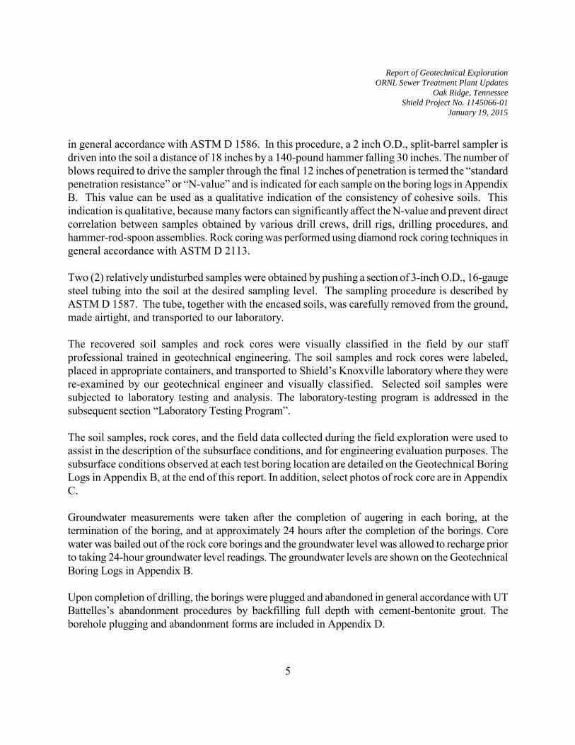
Report of Geotechnical Exploration
ORNL Sewer Treatment Plant Updates
Oak Ridge, Tennessee
Shield Project No. 1145066-01
January 19, 2015
5
in general accordance with ASTM D 1586. In this procedure, a 2 inch O.D., split-barrel sampler is driven into the soil a distance of 18 inches by a 140-pound hammer falling 30 inches. The number of blows required to drive the sampler through the final 12 inches of penetration is termed the “standard penetration resistance” or “N-value” and is indicated for each sample on the boring logs in Appendix B. This value can be used as a qualitative indication of the consistency of cohesive soils. This indication is qualitative, because many factors can significantly affect the N-value and prevent direct correlation between samples obtained by various drill crews, drill rigs, drilling procedures, and hammer-rod-spoon assemblies. Rock coring was performed using diamond rock coring techniques in general accordance with ASTM D 2113. Two (2) relatively undisturbed samples were obtained by pushing a section of 3-inch O.D., 16-gauge steel tubing into the soil at the desired sampling level. The sampling procedure is described by ASTM D 1587. The tube, together with the encased soils, was carefully removed from the ground, made airtight, and transported to our laboratory. The recovered soil samples and rock cores were visually classified in the field by our staff professional trained in geotechnical engineering. The soil samples and rock cores were labeled, placed in appropriate containers, and transported to Shield’s Knoxville laboratory where they were re-examined by our geotechnical engineer and visually classified. Selected soil samples were subjected to laboratory testing and analysis. The laboratory-testing program is addressed in the subsequent section “Laboratory Testing Program”. The soil samples, rock cores, and the field data collected during the field exploration were used to assist in the description of the subsurface conditions, and for engineering evaluation purposes. The subsurface conditions observed at each test boring location are detailed on the Geotechnical Boring Logs in Appendix B, at the end of this report. In addition, select photos of rock core are in Appendix C. Groundwater measurements were taken after the completion of augering in each boring, at the termination of the boring, and at approximately 24 hours after the completion of the borings. Core water was bailed out of the rock core borings and the groundwater level was allowed to recharge prior to taking 24-hour groundwater level readings. The groundwater levels are shown on the Geotechnical Boring Logs in Appendix B. Upon completion of drilling, the borings were plugged and abandoned in general accordance with UT Battelles’s abandonment procedures by backfilling full depth with cement-bentonite grout. The borehole plugging and abandonment forms are included in Appendix D.

Report of Geotechnical Exploration
ORNL Sewer Treatment Plant Updates
Oak Ridge, Tennessee
Shield Project No. 1145066-01
January 19, 2015
6
Prior to the start of the exploration, ORNL Radiation Control Technicians (RCTs) checked the drill rig to verify that it was free of radiation above background level. Subsequently, upon completion of the subsurface exploration, ORNL RCTs verified that the soil samples, rock core, and our drilling equipment were free of significant amounts of radiological contamination prior to our demobilization from the site.
6.0 LABORATORY TESTING PROGRAM The purpose of the laboratory testing program was to evaluate the mechanical and index properties of the subsurface soils encountered, and to assist in soil classification and relative strength evaluations. Representative soil samples were obtained at various depth intervals within the test borings for laboratory testing and analysis. These samples were divided into groups of similar samples according to color and visual classification. The laboratory testing program included the following tests:
Natural moisture content tests (ASTM D 2216) Atterberg limits (ASTM D 4318) Grain size analysis with hydrometer (ASTM D 422) Classification in accordance with the Unified Soil Classification System (ASTM D 2487) Unconfined Compressive Strength of Soil (ASTM D 2166) Unconfined Compressive Strength of Rock (ASTM D 2938)
6.1 Summary of Laboratory Testing:
The laboratory testing generally indicated that the soils are typical of soils encountered in the Valley and Ridge Physiographic Providence. The results reported are only for the samples that were selected for testing. Atterberg Limit, grain size analysis, and natural moisture content testing were performed to assist in the classification and characterization of the soils encountered on site. Testing revealed the soils have Liquid Limits ranging from 41 to 88 and Plasticity Indices ranging from 26 to 66. Based on the grain size analysis and Atterberg Limit test results; the soils that were tested classify as lean clay (CL) and fat clay (CH) based on the Unified Soil Classification System (USCS) per the results attached. Natural moisture content testing was performed on random samples and revealed natural moisture contents ranging from 6.4 percent to 35.2 percent. Unconfined compressive strength test were performed on two undisturbed samples and are summarized in the following table.

Report of Geotechnical Exploration
ORNL Sewer Treatment Plant Updates
Oak Ridge, Tennessee
Shield Project No. 1145066-01
January 19, 2015
7
Table 1 – Soil Unconfined Compressive Strength
Boring Location Depth of
Sample (ft)
Unconfined Compressive Strength
(psi) Failure Strain
(%) BH-6 16.0 – 16.5 3,546 4.3 BH-6 12.0 – 12.5 5,424 5.1
Three rock core specimens were subjected to unconfined compressive strength testing. The following table summarizes the unconfined compressive strength results for the rock core specimens selected. Table 2 – Rock Core Unconfined Compressive Strength
Boring Location Depth of
Sample (ft) Unconfined Compressive
Strength (psi) BH-1 16.0 – 16.5 3,546 BH-2 12.0 – 12.5 5,424 BH-6 17.5 – 18.0 5,488
The results of our laboratory testing are included in Appendix E.
7.0 SUBSURFACE CONDITIONS The Geotechnical Boring Logs in Appendix B represent our interpretation of the subsurface conditions based on tests and observations performed during the drilling operations at the test boring locations and visual examination of the soil samples and rock cores. The lines designating the interfaces between various strata on the Geotechnical Boring Logs represent the approximate strata boundary; however, the transition between strata may be more gradual than shown, especially where indicated by a broken line. Subsurface conditions may vary between our boring locations. 7.1 Description of General Soil Profile: The following paragraphs provide a general description of the soil conditions encountered. For soil descriptions at a particular boring location and depth, the respective boring log should be reviewed in Appendix B. Soils encountered on site were typically composed of topsoil, alluvial soils, fill / possible fill, residual soils. Topsoil is the dark-colored organic soil that develops naturally at the ground surface. Alluvial soils are soils that have been transported by a stream or water. Fill soil is composed of materials transported to its current location by man. Residual soils are composed of soil

Report of Geotechnical Exploration
ORNL Sewer Treatment Plant Updates
Oak Ridge, Tennessee
Shield Project No. 1145066-01
January 19, 2015
8
materials developed from the in-place weathering of the underlying bedrock materials. In some cases, it was difficult to distinguish the origins of the soils recovered in the soil borings. Therefore, the soil origins depicted in the soil boring logs should be considered approximate. At the ground surface in soil test borings BH-1 and BH-2 a layer of gravel was encountered approximately 0.3 feet in thickness at both boring locations. Topsoil was encountered in soil test borings BH-3 through BH-6 ranging in thickness from 0.3 feet to 0.5 feet. Underlying the gravel and topsoil layers in soil test boring BH-1 through BH-4, and BH-6, fill soils were encountered. The fill soils generally consisted of light brown to dark brown, yellowish brown, and tan silty clay with traces of organic rootlets and black oxide staining. Standard penetration resistance values ranged from 3 to 30 blows per foot indicating, the soils to have a soft to very stiff consistency with most of the fill soils being in the firm to stiff range. Below the fill soils in soil test boring BH-2, a layer of possible alluvium was encountered. The alluvial soils generally consisted of dark brown and gray silty clay with trace organics, and was observed to be in a moist to very moist condition while extracting the sample in the field. Standard penetration resistance values ranged from 4 to 10 blows per foot indicating the soils to have a soft to stiff consistency. Underlying the gravel, topsoil, and/or fill in soil test boring BH-1 and BH-3 through BH-6, residual soils were encountered. The residual soils generally consisted of light brown to brown and yellowish brown silty clay to clay with traces of black oxide staining in some sample intervals. Standard penetration resistance values ranged from 5 to 26 blows per foot, indicating the soils to have a firm to very stiff consistency. Auger refusal was encountered in all borings at depths ranging from 11.8 feet to 14.3 feet. Diamond rock coring techniques were used to retrieve rock core specimens of refusal materials at all soil test boring locations. The recovered rock core was typical of bedrock described as Witton Formations. The bedrock was typically composed of light gray to gray limestone with calcareous lenses. The measured dip of the bedding plane of the bedrock was generally 35 degrees. The Recovery Ratio and Rock Quality Designation (RQD) of the rock core samples were determined in our laboratory. These values are used to evaluate the quality of bedrock in the general area of the boring. The Recovery Ratio is defined as the percentage ratio between the length of core recovered, to the length of core drilled in a given core run. The RQD is defined as the percentage ratio between the length of the recovered core pieces that are at least 4 inches in length, to the length of core drilled in a given core run. The rock core recovery ratio for the cored borings ranged from 8 percent to 100

Report of Geotechnical Exploration
ORNL Sewer Treatment Plant Updates
Oak Ridge, Tennessee
Shield Project No. 1145066-01
January 19, 2015
9
percent, but was typically greater than 75 percent. RQD's ranged from 0 percent to 100 percent, but was typically greater than 45 percent. A very low Recovery Ratio and RQD value typically indicates the bedrock to be discontinuous, highly jointed, or fractured to very fractured as well as very poor quality. At soil test boring location BH-6 a soil void was encountered from 12.8 feet to 17.0 feet. 7.2 Groundwater Observations: Groundwater measurements were taken at the time of completion and after 24 hours in all borings. During rock coring, water is introduced into the subsurface as part of the coring process. Thus, water levels measured after rock coring can be influenced by water pumped into the borehole during rock coring. Therefore, after the completion of rock coring, water in the coreholes was bailed out and allowed to recharge prior to taking 24-hour water level readings. Water levels were detected in the borings at the time of completion in soil test borings BH-1 through BH-2 at depths ranging from 3 feet to 8 feet below existing grades. Water levels were recorded after 24 hours in borings BH-1 through BH-5 at depths ranging from 4.5 feet to 10.0 feet below existing grades. It is important to note that fluctuations in the elevations of the static groundwater table may occur seasonally and are also influenced by variations in precipitation, evaporation, site grading activities, surface water run off and/or the nearby presence of surface water features. The actual depth to groundwater at the time of site grading may be higher or lower than that encountered at the time of the subsurface exploration. Shield anticipates groundwater will be an issue during construction based on 24-hour water level readings and proposed grades. Temporary construction dewatering can likely be accomplished by establishing sumps in the excavation and pumping groundwater from the sump. However, depending upon the type of foundation system selected, depth of excavation and the exposed material (e.g. soil versus rock), alternate methods of dewatering may be required.
8.0 FOUNDATION RECOMMENDATIONS Based on a review of the project information from your representatives, the known design elevations of the storage tank and the pump stations, and review of the geotechnical logs, it is Shield’s understanding that the proposed storage tank is to be supported by shallow foundations bearing in soil and the pump stations will be supported at bedrock elevations. Therefore Shield has prepared recommendations based on supporting the storage tank on shallow foundations bearing in soil and the pump stations bearing on bedrock.

Report of Geotechnical Exploration
ORNL Sewer Treatment Plant Updates
Oak Ridge, Tennessee
Shield Project No. 1145066-01
January 19, 2015
10
8.1 Storage Tank Foundation Recommendations: Based on a review of the information from the soil test borings, laboratory test results and project information, the residual soils and/or newly compacted soil fill appear appear generally suitable, for the support of shallow spread footing foundations using conventional construction methods. A review of the design drawings indicates the proposed bearing elevation of the storage tank is to be approximately 795 feet. Therefore, Shield recommends that the existing fill soils and less than stiff residual soils in the storage tank footprint be undercut to a stiff or better residual soil profile. We estimate an average depth of 4 feet of undercut below existing grades. The undercut should extend a minimum of 10 feet outside the storage tank footprint. The area should then be brought back to design subgrade elevation with structural fill in general accordance with section 9.2 General
Structural Fill Recommendations. The onsite materials do appear suitable for use as structural fill provided our subsequent “Structural Fill Recommendations” are followed. Newly compacted fill soil under building areas, paving and driveway areas should be composed of clay, silt or shale types of soils. We recommend sizing the footings for a design soil bearing pressure of 2,500 psf when bearing in the stiff or better residual soils or newly compacted structural fill. A footing inspection by a geotechnical engineer should be performed at the time of construction. It is important to note that if a footing inspection is not performed, then the design soil bearing pressure provided above should be considered invalid. 8.2 Pump Stations Foundation Recommendations: Based on proposed bearing elevations of each pump station and information obtained during the subsurface exploration, the pump stations design elevations are near or below auger refusal (bedrock) elevations. Shield recommends that it may be possible to support the pump stations with a of shallow foundations bearing on a combination of rock and controlled low-strength material (CLSM) such as flowable fill or lean concrete due to the varying depth to bedrock and topography of the site. CLSM should conform to the National Ready Mixed Concrete Association’s “Guide Specification for Controlled Low Strength Material (CLSM). The section of footings that extend across soil would be undercut to rock and replaced with CLSM back to bearing elevations. The exposed bedrock would need to be cleaned of loose material and debris. Weathered, loose and pinnacled rocks will need to be ripped and removed. Open voids or clay filled cavities will need to undergo “dental” cleaning to remove soft wet soils. The backfill material would be appropriate to fill these slots and voids. It is possible to use CLSM with as little a minimum compressive strength of 150 psi strength (21.6 Ksf). Once backfilled, foundations should be proportioned for a maximum allowable bearing pressure of 6,000 psf. Shield recommends a minimum CLSM thickness of 1 foot.

Report of Geotechnical Exploration
ORNL Sewer Treatment Plant Updates
Oak Ridge, Tennessee
Shield Project No. 1145066-01
January 19, 2015
11
8.3 General Shallow Foundation Recommendations: In order to avoid a local shear or "punching" failure of the footings, we recommend minimum widths of 24-inches for isolated/rectangular footings and 18-inches for continuous footings. The footings should be embedded a minimum of 18 inches below the final exterior ground surface to provide adequate frost protection and confinement. The suitability of foundation and/or slab bearing soils in areas between borings should be verified by qualified visual inspection and/or proofrolling as described in subsequent sections. In addition, the opened footing excavations should be examined for uniformity of soil properties and tested using a hand auger and a dynamic cone penetrometer (DCP). The footing evaluation should be performed by a geotechnical engineer and/or his representative prior to the placement of reinforcing steel or concrete. The purpose of the footing evaluation is to locate any unexpected soft soil areas or unsuitable soil areas which may require undercutting and backfilling. Areas in the foundation subgrade that are determined to be unsuitable should be repaired or modified as directed by the geotechnical engineer. It is important to note that the foundation recommendations described above should not be considered valid unless a footing evaluation is conducted at the time of foundation installation. We recommend that the footings be poured as soon as possible after the geotechnical footing excavation evaluation in order to minimize potential disturbance of the bearing soil. The prepared foundation bearing soils should not be left exposed overnight or during inclement weather. If the subgrade soils are exposed overnight or during inclement weather, we recommend the placement of a two to four inch thick "mud-mat" of lean concrete on the bearing soils. Saturation and subsequent disturbance of the foundation subgrade soils can result in a loss of strength and bearing capacity, leading to increased settlement. We recommend that the slab-on-grade subgrade be carefully proofrolled under the supervision of a Shield geotechnical engineer to check for soft areas. The proofrolling for structural fill should be performed as recommended in the site preparation section of this report. The slab-on-grade should be placed only on soils which proofroll successfully and should have an adequate thickness of granular base. The floor slab should be designed with an adequate number of joints to minimize cracking. The slab should be designed as a floating slab, not rigidly connected to bearing walls or foundations in order to accommodate differential settlement between the foundation and the slab. The slab should be nominally reinforced to maintain its integrity should minor differential movement occur. In addition, aggregate, such as ASTM D 448 No. 57 or No. 67 stone, should be densified and placed beneath the slab to allow for a suitable base on which to work as well as reduce damage/degradation of the prepared subgrade during construction. The aggregate layer should be at least 4 inches thick.

Report of Geotechnical Exploration
ORNL Sewer Treatment Plant Updates
Oak Ridge, Tennessee
Shield Project No. 1145066-01
January 19, 2015
12
Subgrade soils to support floor slabs shall consist of suitable bearing natural soils and/or properly placed controlled structural fill and be firm and unyielding. Interior utility trenches should be properly backfilled and compacted as recommended herein. Proof rolling of the subgrade soils is recommended prior to placement of the recommended granular cushion to detect any possible soft or yielding areas which may be present. Any soft or unsuitable bearing subgrade areas which are detected during proof rolling should be removed and replaced with suitably compacted and controlled structural fill in accordance with the recommendations contained herein.
9.0 SITE PREPARATION RECOMMENDATIONS
9.1 Site Preparation Recommendations: We recommend that all topsoil, asphalt, basestone, vegetation, debris, and surface soil containing organic material be stripped from areas to be graded. If suitable, topsoil can be reused in areas to be landscaped. Some of the alluvial soils may require additional undercut and replacement. After the completion of stripping and excavation to design subgrade elevations in cut areas, the exposed soil subgrade in cut and fill areas should be proofrolled with a fully loaded, tandem-axle dump truck, or other similarly-loaded, pneumatic-tired construction equipment. Proofrolling should be done after a suitable period of dry weather to avoid degrading an otherwise acceptable subgrade. The proofrolling equipment should make at least four passes over each section, with the last two passes perpendicular to the first two, where accessible. Areas not accessible for proofrolling should be probed by the Shield geotechnical engineer or his representative. Proofrolling should be observed and documented by the Shield geotechnical engineer or his representative. Soft, rutting or pumping soils should be undercut to stiffer, more competent soils and backfilled with structural fill or stabilized as recommended by Shield. 9.2 Structural Fill Recommendations: Representative samples of each proposed fill material should be collected and tested to determine the compaction and classification characteristics. Bulk samples were collected during our investigation for Proctor testing, but it is not uncommon during grading to expose soils for use as fill not identified during the investigation. Soils which are found to contain deleterious material, including organics and topsoil, should not be used as structural fill for the support of structures or pavement. In addition, soils having a Plasticity Index (PI) in excess of 30 and/or a Standard Proctor (ASTM D 698) maximum dry density of less than 90 pcf should not be used without prior engineering evaluation and approval.

Report of Geotechnical Exploration
ORNL Sewer Treatment Plant Updates
Oak Ridge, Tennessee
Shield Project No. 1145066-01
January 19, 2015
13
We recommend that fill placement be carefully observed by a Shield representative to determine if proper compaction is being achieved within the building and other structural fill areas. Improper compaction may result in premature deterioration of the pavement areas and/or differential foundation settlement. The surface of the placed fill should be graded to provide positive drainage of surface water and prevent deterioration of the subgrade. We recommend that the contractor be responsible for maintaining a drained stable surface during and after the filling operations. All controlled fill beneath footings, floor slabs and pavement areas should be placed in uniform lifts not exceeding 8 inch loose (un-compacted) thickness and compacted to at least 98 percent of the standard Proctor maximum dry density (ASTM D 698). The upper 2 feet of fill beneath paved areas and upper 1 foot beneath floor slabs should be compacted to at least 100 percent of standard Proctor maximum dry density. The density of each lift should be tested and approved by a qualified soils technician prior to the placement of additional fill. Fill surfaces should be gently sloped and sealed with rubber tired or steel drummed equipment at the end of each day’s operations and when precipitation is expected. This will improve surface run-off and minimize construction delays caused by the effects of ponding water. All sloped areas to receive fill with slopes steeper than 5H:1V should be properly benched. The horizontal limits of the areas subject to these recommendations should include a minimum 10 feet outside proposed building footprints, as well as other areas to receive additional fill.
10.0 SUBSURFACE WALL RECOMMENDATIONS
It is our understanding the project may incorporate below-grade walls. The below-grade walls should be supported by shallow bearing foundations. The walls will be constructed of concrete and incorporated into the foundation design and be less than 20 feet high. Both wall types may be designed for the active earth pressure condition if the tops of the walls will not be restrained. However, at corners, such walls are typically restrained and the structural rigidity is much greater. In these areas, the earth pressure on the wall will exceed the active pressure. Therefore, we recommend corners be designed to withstand at-rest pressures. The proposed walls must be designed to withstand lateral soil pressure. If placement of a floor slab on top of the subsurface walls or interior wall design will eventually prevent their moving, they should be designed to withstand a residual or long-term at-rest pressure condition. In addition, if subsurface walls will be backfilled before they are braced with floor slabs, they should be capable of withstanding the active earth pressure as self-supporting cantilever walls.

Report of Geotechnical Exploration
ORNL Sewer Treatment Plant Updates
Oak Ridge, Tennessee
Shield Project No. 1145066-01
January 19, 2015
14
We recommend clean aggregate, such as ASTM D 448 No. 57 or 67 stone, be used as backfill directly behind the walls to lessen lateral earth pressures exerted on the walls. The wedge of clean aggregate backfill should have a minimum width of 1 foot at the base of the wall or the width of the footing heel, whichever is greater, and increase in width a minimum of 0.6 feet per foot of wall height. The aggregate should be fully encapsulated with a properly designed geotextile (filter fabric) to prevent migration of the adjacent soils into the aggregate. A Sketche of our recommended backfill detail (Figure 3) is attached in Appendix A. Since the base of the wall will be below existing grade and the known water table, it may be advisable to install a sump along the perimeter of the wall to reduce the risk of water seepage and infiltration through the structure walls. This may be achieved by including a drainage interval and perforated piping behind the wall to intercept ground-water seepage and thereby reduce hydrostatic pressures. The pipe should be designed to prevent clogging by backfilling with particles sloped to drain to a central point or daylighted, if possible. If not daylighted, for maintenance purposes, cleanout ports for the piping system should be considered. Surface-water seepage into the backfill will increase lateral pressures on the wall. To reduce the possibility of excessive surface-water seepage, we recommend capping the backfill with a 1- to 2-foot-thick layer of clayey soil, sloping away from the structure. Compaction of backfill materials can cause excessive lateral pressure on the walls under certain circumstances. Heavy compactors and grading equipment should not be allowed to operate within 10 feet of the walls during the backfilling to lessen temporary and long-term lateral soil pressures. Backfill adjacent to the walls should be densified by light compaction equipment. Given the backfill, compaction, and drainage recommendations provided in this report, and assuming a horizontal backfill surface without a surcharge, the following values in Table 3 of equivalent fluid pressure may be used to design the proposed below-grade walls. Table 5 – Equivalent Fluid Pressure
Backfill Type Unified Soil
Classification Estimated Unit Weight (PCF)
Pressure per Foot of Depth (PSF)
Clean graded aggregate (either ASTM D 448 No. 57 or 67)
GP 100 Active 35
At Rest 55
The above equivalent fluid pressures are derived based on active and at rest earth pressure coefficients of 0.35 and 0.55, respectively.

Report of Geotechnical Exploration
ORNL Sewer Treatment Plant Updates
Oak Ridge, Tennessee
Shield Project No. 1145066-01
January 19, 2015
15
11.0 TEMPORARY EXCAVATION SLOPING REQUIREMENTS Shield recommends that the Department of Labor’s Occupational Safety and Health Organization’s (OSHA) regulation standard 29 CFR be consulted. Standard number 1926 Subpart P of 29 CFR addresses sloping and benching for temporary excavations and the proper identification of soil materials. This manual can be found at http://www.osha.gov/dts/osta/otm/otm_v/otm_v_2.html. Shield also recommends the design and construction of temporary excavations should be the responsibility of the contractor. We understand that there is concern for the pump station located to the east of the containment pond 2453. The excavation for the pump station will require temporary shoring of the containment pond berm. A specialty contractor specializing in shoring should be consulted to stabilize the area before excavation begins. There are various options for temporary stabilization of the excavation adjacent to the existing pond berms. Options may include soldier pile and lagging, sheet piling, temporary soil nailed wall, grout curtain and a polyurethane foam curtain. Although soldier pile and lagging and diven sheet piles are typically a very acceptable option for temporary slope stabilization, the shallow depth to bed rock it may not be possible to seat the piles into the underlying bedrock due to the hard nature. Additionally there will be very little passive earth pressure below the toe of the temporary wall making it more critical that the piles or sheet piles are seated into bedrock.
12.0 SEISMIC SITE CLASSIFICATION
Shield has reviewed the soil Geotechnical Boring Logs, the site geology and the 2012 International Building Code (IBC). The IBC requires that a site be evaluated for seismic forces based upon the characteristics of the subsurface profile within the upper 100 feet of the ground surface, as permitted by Section 1613 of the code. Soil properties were estimated based upon our previous experience conducting subsurface explorations in the site area. Through previous discussions with you and your structural engineer we have reviewed the site for two scenarios based on the assumption that the storage tank will be supported on shallow foundations bearing on soil and the pump stations will be supported on bedrock. The seismic site classifications for each case are provided in the following sections. 12.1 Storage Tank Supported on Shallow Foundations: It is Shield’s understanding that the storage thank will be supported on shallow foundations bearing in soil. Based upon this evaluation, the subsurface conditions within the site are consistent with the characteristics of a Site Class "D" as defined in Table 1613, 5.5 of the building code. Probabilistic

Report of Geotechnical Exploration
ORNL Sewer Treatment Plant Updates
Oak Ridge, Tennessee
Shield Project No. 1145066-01
January 19, 2015
16
ground acceleration values and site coefficients for the storage tank are presented below. Table 4 - Ground Motion Values* Period(sec) Mapped MCE
Spectral Response Acceleration**(g)
Site Coefficients Adjusted MCE Spectral Response
Acceleration(g)
Design Spectral Response
Acceleration(g) 0.2 SS 0.375 Fa 1.500 SMS 0.562 SDS 0.375 1.0 S1 0.122 Fv 2.313 SM1 0.282 SD1 0.188
*2% Probability of Event in 50 years for Latitude 35.924115 and Longitude -84.318865. **At B-C interface (i.e. top of bedrock). MCE = Maximum Considered Earthquake 12.2 Pump Stations Bearing on Bedrock:
It is Shield’s understands that the pump stations will required to be located below the existing ground surface with a design bearing elevation at the bedrock surface elevations. Based upon this evaluation that the pump stations will be supported on bedrock, the subsurface conditions within the site are consistent with the characteristics of a Site Class "B" as defined in Table 1613, 5.5 of the building code. Probabilistic ground acceleration values and site coefficients for the storage tank are presented below. Table 4 - Ground Motion Values* Period(sec) Mapped MCE
Spectral Response Acceleration**(g)
Site Coefficients Adjusted MCE Spectral Response
Acceleration(g)
Design Spectral Response
Acceleration(g) 0.2 SS 0.375 Fa 1.000 SMS 0.375 SDS 0.250 1.0 S1 0.122 Fv 1.000 SM1 0.122 SD1 0.081 *2% Probability of Event in 50 years for Latitude 35.923131 and Longitude -84.317852. **At B-C interface (i.e. top of bedrock). MCE = Maximum Considered Earthquake Shield has obtained probabilistic ground acceleration values and site coefficients for the general site area from the USGS geohazards web page (http://earthquake.usgs.gov/research/hazmaps/design). The Site Coefficients, Fa and Fv, presented in the above table were also obtained from the noted USGS webpage, as a function of the site classification and mapped spectral response acceleration at the short (SS) and 1-second (S,) periods, but can also be interpolated from IBC Tables 1613.5.3(1) and 1613.5.3(2).

Report of Geotechnical Exploration
ORNL Sewer Treatment Plant Updates
Oak Ridge, Tennessee
Shield Project No. 1145066-01
January 19, 2015
17
13.0 PAVEMENT RECOMMENDATIONS Based on the project information previously described, we anticipate that light-duty and heavy-duty pavement sections would be required for flexible pavements and a heavy-duty pavement section would be required for rigid pavements. The light-duty pavement section would be applicable to the passenger vehicle parking areas. The heavy-duty flexible pavement section would be applicable to access drives and loading dock / delivery areas. The heavy-duty rigid pavement section would be applicable to high-stress pavement areas such as dumpster pads, loading dock aprons, and possibly turning and braking areas (i.e. parking lot entrances/exits). Pavement design requires knowledge of the soil subgrade strength and anticipated traffic conditions. Soil strength is typically expressed in terms of a California Bearing Ratio (CBR) for flexible pavement design and a modulus of subgrade reaction (k) for rigid pavement design. For the design of flexible and rigid pavements, proposed single- and tandem-axle loads of varying weights are described in terms of an equivalent number of 18-kip single-axle loads, which would effect the same wear on a similar pavement. This is termed an equivalent axle loading (EAL). We were not provided traffic loads for the anticipated pavement sections. In order to provide pavement thickness recommendations, we have estimated EALs for light-duty and heavy-duty pavement sections of 50,000 and 150,000, respectively. For comparison, an EAL value of 50,000 is typically used to design pavements in areas with light traffic with few or no loaded trucks such as a parking lot for a medium office building or a medium strip shopping center. An EAL value of 150,000 is typically used to design pavements in areas having heavy traffic with less than 30 percent loaded trucks such as a parking lot for a large office complex, warehouse, small manufacturing plant, city streets, a delivery lane for a strip shopping center, or secondary roads. No subgrade strength tests have been performed for this project. However, we have assumed a design CBR of 3 for flexible pavements and a modulus of subgrade reaction, k, of 100 pounds per cubic inch (pci) for rigid pavements. These estimated subgrade strength values are predicated on successful proofrolling in cut areas and in fill areas, a compaction of the soil subgrade to at least 100 percent of standard Proctor maximum dry density (ASTM D 698) as previously recommended. Thickness analyses for flexible and rigid pavements were performed in general accordance with American Association of State Highway and Transportation Officials (AASHTO) procedures. Based on the estimated EAL values, a terminal serviceability index of 2.0, a CBR value of 3, a k value of 100 pci, a 28-day compressive strength of 4,000 pounds per square inch (psi) for Portland cement concrete, and our experience with similar projects, the following pavement sections are recommended below in Table 5:

Report of Geotechnical Exploration
ORNL Sewer Treatment Plant Updates
Oak Ridge, Tennessee
Shield Project No. 1145066-01
January 19, 2015
18
Table 5 – Flexible and Rigid Pavement Sections Pavement Type
Material
Thickness (inches)
TDOT Section Reference
Light-Duty Flexible
Asphaltic Concrete Surface Bituminous Plant Mix Base Mineral Aggregate Base
1-1/2 2-1/2 5
407, 411, and 903.11 307, 407, and 903.06 303 and 903.05
Heavy-Duty Flexible
Asphaltic Concrete Surface Bituminous Plant Mix Base Mineral Aggregate Base
1-1/2 2-1/2 10
407, 411, and 903.11 307, 407, and 903.06 303 and 903.05
Heavy-Duty Rigid
Portland Cement Concrete Mineral Aggregate Base
6 4
501 303 and 903.05
Flexible and rigid pavement systems should generally conform to the requirements of the Tennessee Department of Transportation Bureau of Highways Standard Specifications for Road and Bridge Construction (1995), except as recommended otherwise in this report. Asphaltic concrete surface should be in accordance with Section 411, with aggregate grading per Subsection 903.11, Grading “E”. Bituminous plant mix base should be in accordance with Section 307, with aggregate grading per Subsection 903.06, Grading “B”. Asphaltic concrete surface and bituminous plant mix base should be constructed in accordance with Section 407. Portland cement concrete pavement should be constructed in accordance with Section 501. Mineral aggregate base should conform to the requirements for Class “A” and Grading “D” per Subsection 903.05. Mineral aggregate base should be constructed in accordance with Section 303. Rigid pavements should be appropriately reinforced to control cracking associated with curing shrinkage and temperature effects. Please reference the PCA publications, Building Quality Concrete Parking Areas (1981) and Design of Heavy Industrial Concrete Pavements (1988), for recommendations regarding materials and proportioning, jointing, reinforcing, and other design considerations for rigid pavements. It is recommended that the concrete pads for loading dock aprons and dumpster pads be large enough to accommodate the entire length of the truck while loading. Also, the perimeter of concrete pads should be thickened to reduce the potential for pavement damage associated with overstressing of the pavement edges. Just before placement of the mineral aggregate base course, the subgrade should be proofrolled to detect soft areas, filled-in ruts, or poorly compacted material that may have been created during construction. If the prepared mineral aggregate base course is left in place for an extended period after construction or is rained on prior to placement of bituminous plant mix base or Portland cement concrete pavement, additional proofrolling should be performed to detect potentially weakened areas.

Report of Geotechnical Exploration
ORNL Sewer Treatment Plant Updates
Oak Ridge, Tennessee
Shield Project No. 1145066-01
January 19, 2015
19
Good surface drainage must be incorporated into pavement design to reduce the potential for saturating the mineral aggregate base course and/or soil subgrade. Experience has shown that most pavement failures are the result of poor soil subgrade preparation and improper soil subgrade drainage. Pavement design should include subsurface drains (i.e. French drains and/or blanket drains) in areas of high groundwater and/or areas of groundwater seeps. Curbs for grassed or otherwise landscaped islands should be provided with weep holes or other positive means of drainage. Perimeter curbs should be designed to intercept shallow upgradient groundwater seepage from unpaved areas and direct it away from the mineral aggregate base via a shallow interceptor ditch, French drain, or prefabricated edge drain.
14.0 CONSTRUCTION QUALITY ASSURANCE We recommend that the geotechnical engineering firm of record (Shield) be retained to monitor the construction activities and to verify that the field conditions are consistent with the findings of our investigation. If significant variations are encountered or if the design is altered, Shield should be notified and given the opportunity to evaluate potential impacts on the geotechnical elements of the project. The geotechnical engineer of record should provide personnel full-time to monitor, test, and approve subgrades and fill layers before, during and after fill placement. The field density testing of the fill soils should be achieved by performing field density tests in accordance with either ASTM D 2937 (Drive-Cylinder Method), ASTM D 1556 (Sand-Cone Method) or ASTM D 6938 (Nuclear Method). The contractor should provide at least 24 hours notice before starting operations and/or changing construction equipment or procedures. Regardless of notification, any fill placed by the contractor in the absence of the geotechnical engineer’s representative shall be removed and replaced at the contractor’s expense and under the full-time observation of the geotechnical engineer’s representative. Prior to completion of final design, we recommend Shield have the opportunity to review the drawings and specifications to verify the recommendations contained within this report have been properly interpreted.
15.0 LIMITATIONS
This report has been prepared for the exclusive use of Oak Ridge National Laboratory for the subject site in Oak Ridge, Tennessee. The information and recommendations reported herein are presented to assist in the evaluation of the site for development. In the event there are any significant changes in the size, design, or location of the project, changes in the planned construction from the concepts previously outlined, or changes of the design parameters stated in this report, the Shield geotechnical engineer should be consulted. The conclusions and recommendations contained in this report should not be considered valid unless all changes have been reviewed and our conclusions and


APPENDIX A
Figure 1 – Site Location Plan Figure 2 – Boring Location Plan
Figure 3 – Subsurface Wall Detail

ORNL SEWER TREATMENT PLANT UPGRADES OAK RIDGE, TENNESSEE
SHIELD PROJECT NO.: 1145066-01
SCALE:
DATE: DRAWN BY:
FIGURE:
1/14/2015
NTS 1
SITE VICINITY MAP
SOURCE: USGS TOPO, 7.5 MINUTE MAP
300 FORESTAL DRIVE KNOXVILLE, TN 37918
OFFICE: (865)544-5959 FAX: (865)544-5885
JAG BEHTHAL VALLEY, TENNESSEE - 2013
SITE LOCATION

ONRL SEWAGE TREATMENT PLANT UPGRADE OAK RIDGE, TENNESSEE
SHIELD PROJECT NO.: 1145066-01
SCALE:
DATE: DRAWN BY:
FIGURE:
1/14/2015
NTS 2
BORING LOCATION PLAN
SOURCE: “Proposed Boring Locations for Primary Sewage Treatment Pump Station Project” ORNL Project Record No. X2014-0002.
300 FORESTAL DRIVE KNOXVILLE, TN 37918
OFFICE: (865)544-5959 FAX: (865)544-5885
JAG
Approximate Boring Location B-1
B-2
B-1
B-6
B-5 B-3
B-4

ONRL SEWER TREATMENT PLANT UPGRADES OAK RIDGE, TENNESSEE
SHIELD PROJECT NO.: 1145066-01
SCALE:
DATE: DRAWN BY:
FIGURE:
1/13/2015
NTS 3
TYPICAL SUBSURFACE WALL DETAIL
300 FORESTAL DRIVE KNOXVILLE, TN 37918
OFFICE: (865)544-5959 FAX: (865)544-5885
JAG

APPENDIX B
Key to Soil Classification Geotechnical Boring Logs

KEY TO SOIL CLASSIFICATION
Correlation of Penetration Resistances with Relative Density and Consistency
Sands and Gravels Silts and Clays Standard Standard Penetration Relative Penetration Resistance Density Resistance Consistency 0 - 4 Very Loose 0 - 2 Very Soft 5 - 10 Loose 3 - 4 Soft 11 - 30 Medium 5 - 8 Firm 31 - 50 Dense 9 - 15 Stiff Over 50 Very Dense 16 - 30 Very Stiff
31 - 50 Hard Over 50 Very Hard
Particle Size Identification
(Unified Soil Classification System)
Boulders – exceeds 12 inches diameter Cobbles – greater than 3 inches to 12 inches diameter Coarse gravel – greater than ¾ inch to 3 inches diameter Fine gravel – greater than 4.75 mm to ¾ inch diameter Coarse sand – greater than 2.0 mm to 4.75 mm diameter Medium sand – greater than 0.425 mm to 2.0 mm diameter Fine sand – greater than 0.075 mm to 0.425 mm Silt and clay – less than or equal to 0.075 mm diameter
(particles cannot be seen with naked eye)
Secondary Modifiers
The second modifiers are generally included when a soil type comprises less than 35 percent of the entire sample.
Percent of Sample Modifier
0 – 10 Trace 11 - 20 Little 21 - 35 Some

8
10
6
5
8
3
6
1
2
3
4
5
6
7
GravelStiff to very stiff, tan silty CLAY with traceorganics - Fill
Firm to stiff, tan silty CLAY to CLAY withtraces of black oxide staining, moist to verymoist - Residuum
Auger Refusal at 12.0 Feet
RUN #1Hard gray slightly weathered limestone (DIP ~35 degrees)
RUN #2Hard gray slightly weathered limestone (DIP ~35 degrees)
RUN #3Hard gray slightly weathered limestone (DIP ~35 degrees)
RUN #4Hard gray slightly weathered limestone (DIP ~35 degrees)
Coring Terminated at 30.0 Feet
3
6
2
3
5
2
3
6
8
4
4
5
2
4
14
18
10
9
13
5
10
REC: 42%RQD: 28%
REC: 100%RQD: 100%
REC: 100%RQD: 95%
REC: 100%RQD: 100%
0.3
3.0
12.0
16.6
21.6
26.6
30.0
22
15
29
33
35
31
GEOTECHNICAL BORING LOG
AutomaticBoring No.:
781.437
DESCRIPTION OF MATERIALS
BH-1of:
Tri-State Drilling, Inc.Sheet:
Date Finished:
1Date Started:DAZ
SPTSurface Elevation: +/-
Driller:S
ampl
e N
o.
Hollow Stem Auger
Boring Location:Logged By:
Hammer Type:
blows per
Boring Method:
Rec
over
y(i
nche
s)
(Classification)6 in. foot
Report Date:
11/26/1411/24/14
1
During Drilling:
300 Forestal Dr.Knoxville, TN 37918Telephone: 865-544-5959Fax: 865-544-5885
780
775
770
765
760
755
750
LL
At Completion:North:
MC
(%
)
Oak Ridge National Laboratory
Datum:
Shield Project No.:
2115.075
FIN
ES
(%
)
After 24 Hours:
GROUNDWATER DATA:GENERAL REMARKS:
Dep
th (
feet
)
Ele
vati
on (
feet
)
COMMENTS:
East:
5
10
15
20
25
30
PI
5
10
15
20
25
30
780
775
770
765
760
755
750
30016.833
GPS DATA:
1145066-01Shield Project No.:
FeetFeetFeetFeet
1145066-01
Str
atum
Gro
undw
ater
ONRL STP Upgrades
Oak Ridge, Tennessee
ONRL STP Upgrades
Caved:
DRY4.513.34.5

15
6
5
2
2
4
6
1
2
3
4
5
6
7
GravelStiff to very stiff, dark brown and gray siltyCLAY to CLAY with trace organics, wet - Fill
Stiff to very stiff, dark brown and gray siltyCLAY to CLAY with trace organics, moist tovery moist - Possible Alluvium
Auger Refusal at 11.8 Feet
RUN #1Hard gray slightly weathered limestone (DIP ~35 degrees)
RUN #2Hard gray slightly weathered limestone (DIP ~35 degrees)
RUN #3Hard gray slightly weathered limestone (DIP ~35 degrees)
RUN #4Hard gray slightly weathered limestone (DIP ~35 degrees)
Coring Terminated at 30.0 Feet
10
9
3
WOH
2
1
3
15
4
3
1
2
2
4
30
10
8
3
4
6
10
REC: 42%RQD: 28%
REC: 100%RQD: 58%
REC: 96%RQD: 55%
REC: 100%RQD: 90%
0.3
6.0
11.8
16.4
21.4
25.8
30.0
26 6343
6
19
26
26
22
GEOTECHNICAL BORING LOG
AutomaticBoring No.:
779.246
DESCRIPTION OF MATERIALS
BH-2of:
Tri-State Drilling, Inc.Sheet:
Date Finished:
1Date Started:DAZ
SPTSurface Elevation: +/-
Driller:S
ampl
e N
o.
Hollow Stem Auger
Boring Location:Logged By:
Hammer Type:
blows per
Boring Method:
Rec
over
y(i
nche
s)
(Classification)6 in. foot
Report Date:
11/26/1411/24/14
1
During Drilling:
300 Forestal Dr.Knoxville, TN 37918Telephone: 865-544-5959Fax: 865-544-5885
775
770
765
760
755
750
745
LL
At Completion:North:
MC
(%
)
Oak Ridge National Laboratory
Datum:
Shield Project No.:
21227.058
FIN
ES
(%
)
After 24 Hours:
GROUNDWATER DATA:GENERAL REMARKS:
Dep
th (
feet
)
Ele
vati
on (
feet
)
COMMENTS:
East:
5
10
15
20
25
30
PI
5
10
15
20
25
30
775
770
765
760
755
750
745
30151.973
GPS DATA:
1145066-01Shield Project No.:
FeetFeetFeetFeet
1145066-01
Str
atum
Gro
undw
ater
ONRL STP Upgrades
Oak Ridge, Tennessee
ONRL STP Upgrades
Caved:
33104.5

5
6
6
10
13
10
13
1
2
3
4
5
6
7
8
TopsoilStiff, tan silty CLAY to CLAY with organics,moist to wet - FILLStiff, tan silty CLAY to CLAY with organics,moist to wet - FILL
Stiff to very stiff, light brown to brown andyellowish brown CLAY - Reisduum
Probable Partially Weathered RockAuger Refusal at 14.3 Feet
RUN #1Hard gray slightly weathered limestone (DIP ~35 degrees)RUN #2Hard gray slightly weathered limestone (DIP ~35 degrees)RUN #3Hard gray slightly weathered limestone (DIP ~35 degrees)
RUN #4Hard gray very weathered fractured limestone(DIP ~ 35 degrees)RUN #5Hard gray slightly weathered limestone (DIP ~35 degrees)
Coring Terminated at 30.0 Feet
6
7
3
3
6
3
11
12
5
5
4
6
9
5
12
50/6
10
11
10
16
22
15
25
50/6
REC: 100%RQD: 86%
REC: 100%RQD: 83%
REC: 100%RQD: 45%
REC: 100%RQD: 0%
REC: 100%RQD: 26%
0.3
1.5
4.5
14.014.3
16.5
21.5
24.8
26.5
30.0
32
59
63
84
49
87
22
20
29
26
21
29
GEOTECHNICAL BORING LOG
AutomaticBoring No.:
793.240
DESCRIPTION OF MATERIALS
BH-3of:
Tri-State Drilling, Inc.Sheet:
Date Finished:
1Date Started:DAZ/JAG
SPTSurface Elevation: +/-
Driller:S
ampl
e N
o.
Hollow Stem Auger
Boring Location:Logged By:
Hammer Type:
blows per
Boring Method:
Rec
over
y(i
nche
s)
(Classification)6 in. foot
Report Date:
11/26/1411/25/14
1
During Drilling:
300 Forestal Dr.Knoxville, TN 37918Telephone: 865-544-5959Fax: 865-544-5885
790
785
780
775
770
765
760
LL
At Completion:North:
MC
(%
)
Oak Ridge National Laboratory
Datum:
Shield Project No.:
21617.74
FIN
ES
(%
)
After 24 Hours:
GROUNDWATER DATA:GENERAL REMARKS:
Dep
th (
feet
)
Ele
vati
on (
feet
)
COMMENTS:
East:
5
10
15
20
25
30
PI
5
10
15
20
25
30
790
785
780
775
770
765
760
30026.091
GPS DATA:
1145066-01Shield Project No.:
FeetFeetFeetFeet
1145066-01
Str
atum
Gro
undw
ater
ONRL STP Upgrades
Oak Ridge, Tennessee
ONRL STP Upgrades
Caved:
DRY8106

4
9
10
10
14
9
15
1
2
3
4
5
6
7
8
TopsoilFirm to very stiff, light brown to brown andyellowish brown silty CLAY to CLAY withtraces of rock fragments - FILL
Stiff to very stiff, light brown to brown andyellowish brown silty CLAY to CLAY -Residuum
Probable Partially Weathered RockAuger Refusal at 14.3 Feet
RUN #1Hard gray slightly weathered limestone (DIP ~35 degrees)RUN #2Hard gray slightly weathered limestone (DIP ~35 degrees)RUN #3Hard gray slightly weathered limestone (DIP ~35 degrees)
RUN #4Hard gray slightly weathered limestone (DIP ~35 degrees)RUN #5Hard gray slightly weathered limestone (DIP ~35 degrees)
Coring Terminated at 30.0 Feet
2
6
5
4
6
4
8
2
3
8
7
7
8
5
11
50/5
7
17
17
17
22
14
26
50/5
REC: 100%RQD: 46%
REC: 74%RQD: 44%
REC: 92%RQD: 81%
REC: 76%RQD: 44%
REC: 91%RQD: 53%
0.5
4.5
14.014.3
16.5
21.5
24.8
26.5
30.0
23
27
26
30
33
27
GEOTECHNICAL BORING LOG
AutomaticBoring No.:
794.367
DESCRIPTION OF MATERIALS
BH-4of:
Tri-State Drilling, Inc.Sheet:
Date Finished:
1Date Started:JAG
SPTSurface Elevation: +/-
Driller:S
ampl
e N
o.
Hollow Stem Auger
Boring Location:Logged By:
Hammer Type:
blows per
Boring Method:
Rec
over
y(i
nche
s)
(Classification)6 in. foot
Report Date:
11/26/1411/25/14
1
During Drilling:
300 Forestal Dr.Knoxville, TN 37918Telephone: 865-544-5959Fax: 865-544-5885
790
785
780
775
770
765
760
LL
At Completion:North:
MC
(%
)
Oak Ridge National Laboratory
Datum:
Shield Project No.:
21642.563
FIN
ES
(%
)
After 24 Hours:
GROUNDWATER DATA:GENERAL REMARKS:
Dep
th (
feet
)
Ele
vati
on (
feet
)
COMMENTS:
East:
5
10
15
20
25
30
PI
5
10
15
20
25
30
790
785
780
775
770
765
760
30041.03
GPS DATA:
1145066-01Shield Project No.:
FeetFeetFeetFeet
1145066-01
Str
atum
Gro
undw
ater
ONRL STP Upgrades
Oak Ridge, Tennessee
ONRL STP Upgrades
Caved:
DRYDRY1210
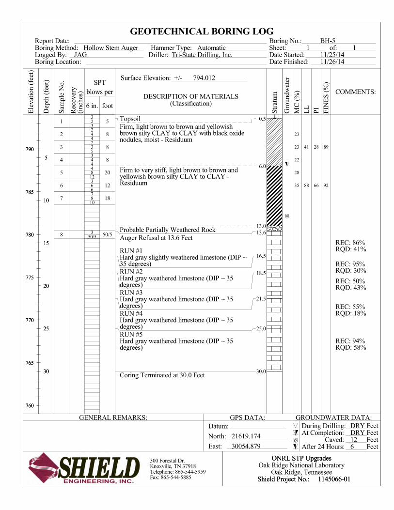
3
4
5
4
12
6
10
1
2
3
4
5
6
7
8
TopsoilFirm, light brown to brown and yellowishbrown silty CLAY to CLAY with black oxidenodules, moist - Residuum
Firm to very stiff, light brown to brown andyellowish brown silty CLAY to CLAY -Residuum
Probable Partially Weathered RockAuger Refusal at 13.6 Feet
RUN #1Hard gray slightly weathered limestone (DIP ~35 degrees)RUN #2Hard gray weathered limestone (DIP ~ 35degrees)RUN #3Hard gray weathered limestone (DIP ~ 35degrees)RUN #4Hard gray weathered limestone (DIP ~ 35degrees)RUN #5Hard gray weathered limestone (DIP ~ 35degrees)
Coring Terminated at 30.0 Feet
3
2
2
3
4
3
7
3
2
4
3
4
8
6
8
50/5
5
8
8
8
20
12
18
50/5
REC: 86%RQD: 41%
REC: 95%RQD: 30%
REC: 50%RQD: 43%
REC: 55%RQD: 18%
REC: 94%RQD: 58%
0.5
6.0
13.013.6
16.5
18.5
21.5
25.0
30.0
28
66
89
92
41
88
23
23
22
28
35
GEOTECHNICAL BORING LOG
AutomaticBoring No.:
794.012
DESCRIPTION OF MATERIALS
BH-5of:
Tri-State Drilling, Inc.Sheet:
Date Finished:
1Date Started:JAG
SPTSurface Elevation: +/-
Driller:S
ampl
e N
o.
Hollow Stem Auger
Boring Location:Logged By:
Hammer Type:
blows per
Boring Method:
Rec
over
y(i
nche
s)
(Classification)6 in. foot
Report Date:
11/26/1411/25/14
1
During Drilling:
300 Forestal Dr.Knoxville, TN 37918Telephone: 865-544-5959Fax: 865-544-5885
790
785
780
775
770
765
760
LL
At Completion:North:
MC
(%
)
Oak Ridge National Laboratory
Datum:
Shield Project No.:
21619.174
FIN
ES
(%
)
After 24 Hours:
GROUNDWATER DATA:GENERAL REMARKS:
Dep
th (
feet
)
Ele
vati
on (
feet
)
COMMENTS:
East:
5
10
15
20
25
30
PI
5
10
15
20
25
30
790
785
780
775
770
765
760
30054.879
GPS DATA:
1145066-01Shield Project No.:
FeetFeetFeetFeet
1145066-01
Str
atum
Gro
undw
ater
ONRL STP Upgrades
Oak Ridge, Tennessee
ONRL STP Upgrades
Caved:
DRYDRY126
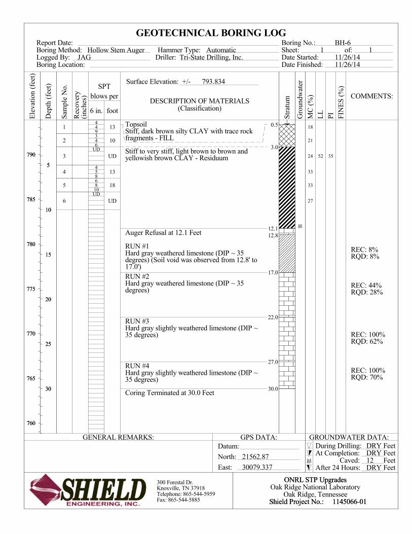
9
6
8
10
1
2
3
4
5
6
TopsoilStiff, dark brown silty CLAY with trace rockfragments - FILL
Stiff to very stiff, light brown to brown andyellowish brown CLAY - Residuum
Auger Refusal at 12.1 Feet
RUN #1Hard gray weathered limestone (DIP ~ 35degrees) (Soil void was observed from 12.8' to17.0')RUN #2Hard gray weathered limestone (DIP ~ 35degrees)
RUN #3Hard gray slightly weathered limestone (DIP ~35 degrees)
RUN #4Hard gray slightly weathered limestone (DIP ~35 degrees)
Coring Terminated at 30.0 Feet
4
3
UD
4
6
UD
4
4
5
8
13
10
UD
13
18
UD
REC: 8%RQD: 8%
REC: 44%RQD: 28%
REC: 100%RQD: 62%
REC: 100%RQD: 70%
0.5
3.0
12.112.8
17.0
22.0
27.0
30.0
3552
18
21
24
33
33
27
GEOTECHNICAL BORING LOG
AutomaticBoring No.:
793.834
DESCRIPTION OF MATERIALS
BH-6of:
Tri-State Drilling, Inc.Sheet:
Date Finished:
1Date Started:JAG
SPTSurface Elevation: +/-
Driller:S
ampl
e N
o.
Hollow Stem Auger
Boring Location:Logged By:
Hammer Type:
blows per
Boring Method:
Rec
over
y(i
nche
s)
(Classification)6 in. foot
Report Date:
11/26/1411/26/14
1
During Drilling:
300 Forestal Dr.Knoxville, TN 37918Telephone: 865-544-5959Fax: 865-544-5885
790
785
780
775
770
765
760
LL
At Completion:North:
MC
(%
)
Oak Ridge National Laboratory
Datum:
Shield Project No.:
21562.87
FIN
ES
(%
)
After 24 Hours:
GROUNDWATER DATA:GENERAL REMARKS:
Dep
th (
feet
)
Ele
vati
on (
feet
)
COMMENTS:
East:
5
10
15
20
25
30
PI
5
10
15
20
25
30
790
785
780
775
770
765
760
30079.337
GPS DATA:
1145066-01Shield Project No.:
FeetFeetFeetFeet
1145066-01
Str
atum
Gro
undw
ater
ONRL STP Upgrades
Oak Ridge, Tennessee
ONRL STP Upgrades
Caved:
DRYDRY12DRY

APPENDIX C
Rock Core Photos

Report of Geotechnical Exploration
ORNL Sewer Treatment Plant Upgrade
Oak Ridge, Tennessee
Shield Project No. 1145066-01
January 16, 2015
Photo 1: Boring BH-1 (1 of 2) Rock Core
Photo 2: Boring BH-1 (2 of 2) Rock Core

Report of Geotechnical Exploration
ORNL Sewer Treatment Plant Upgrade
Oak Ridge, Tennessee
Shield Project No. 1145066-01
January 16, 2015
Photo 3: Boring BH-2 (1 of 1) Rock Core
Photo 4: Boring BH-2 (2 of 2) Rock Core

Report of Geotechnical Exploration
ORNL Sewer Treatment Plant Upgrade
Oak Ridge, Tennessee
Shield Project No. 1145066-01
January 16, 2015
Photo 5: Boring BH-3 (1 of 2) Rock Core
Photo 6: Boring BH-3 (2 of 2) Rock Core

Report of Geotechnical Exploration
ORNL Sewer Treatment Plant Upgrade
Oak Ridge, Tennessee
Shield Project No. 1145066-01
January 16, 2015
Photo 7: Boring BH-4 (1 of 2) Rock Core
Photo 8: Boring BH-4 (2 of 2) Rock Core

Report of Geotechnical Exploration
ORNL Sewer Treatment Plant Upgrade
Oak Ridge, Tennessee
Shield Project No. 1145066-01
January 16, 2015
Photo 9: Boring BH-5 (1 of 2) Rock Core
Photo 10: Boring BH-5 (2 of 2) Rock Core

Report of Geotechnical Exploration
ORNL Sewer Treatment Plant Upgrade
Oak Ridge, Tennessee
Shield Project No. 1145066-01
January 16, 2015
Photo 11: Boring BH-6 (1 of 2) Rock Core
Photo 12: Boring BH-6 (2 of 2) Rock Core

APPENDIX D
Well Plugging and Abandonment Forms

Subject: Plugging and Abandonment of Wells and Coreholes at ORNL
Well Plugging and Abandonment Field Operations Planning Form
1. Well/Boring No.: BH-1 Date Installed: 11/24/2014
2. Coordinates: Northing: 2115.075 Easting: 30016.833 Location: N/A
3. Total Depth (ft): 30.0 Inside Dia. (in): Soil 6.25 Casing Length (ft): N/A
4. Screen Length (ft): N/A Ground Elev. (ft): 781.437 Casing Material: N/A
5. Reason for abandonment: Required by UT-Battelle, LLC and State of Tennessee
6. Required site preparation (removal of posts, pads, pumps, etc.): ------------------
7. Plugging specification document no.: --------- Section No.: ------------------
8. Health and safety considerations for well abandonment crew: ---------------------
9. Facility Manager: --------------------------------- Phone No.: -------------------
10. Proposed technical oversight: -----------------------------------------------------------
11. Approved by: ER Program PM: -------------------------------- Date: -----------
12. Approved by GWPC: ------------------------------------------- Date: -----------
Field Operations Planning Form
1. Well abandonment: Date Started: 11/24/2014 Date Completed: 11/26/2014
2. Observation via downhole camera: N/A
3. Actual method used to abandon this borehole/well: Auger Boring and Rock Core
Boring Backfilled Cement Grout.
4. Actual depth grouted (ft): N/A Was casing split, perforated, drilled etc.? If so, please provide dimensions and locations: N/A
5. Problems and/or deviations from specifications: N/A
6. Date site cleanup completed: 11/26/2014
7. Comments: Total bentonite volume (cf): 6.3 cubic feet of grout
8. P&A report prepared by: Justin Goss, P.E. Date: 11/26/2014

Subject: Plugging and Abandonment of Wells and Coreholes at ORNL
Well Plugging and Abandonment Field Operations Planning Form
1. Well/Boring No.: BH-2 Date Installed: 11/24/2014
2. Coordinates: Northing: 21227.058 Easting: 30151.973 Location: N/A
3. Total Depth (ft): 30.0 Inside Dia. (in): Soil 6.25 Casing Length (ft): N/A
4. Screen Length (ft): N/A Ground Elev. (ft): 779.246 Casing Material: N/A
5. Reason for abandonment: Required by UT-Battelle, LLC and State of Tennessee
6. Required site preparation (removal of posts, pads, pumps, etc.): ------------------
7. Plugging specification document no.: --------- Section No.: ------------------
8. Health and safety considerations for well abandonment crew: ---------------------
9. Facility Manager: --------------------------------- Phone No.: -------------------
10. Proposed technical oversight: -----------------------------------------------------------
11. Approved by: ER Program PM: -------------------------------- Date: -----------
12. Approved by GWPC: ------------------------------------------- Date: -----------
Field Operations Planning Form
1. Well abandonment: Date Started: 11/24/2014 Date Completed: 11/26/2014
2. Observation via downhole camera: N/A
3. Actual method used to abandon this borehole/well: Auger Boring and Rock Core
Boring Backfilled Cement Grout.
4. Actual depth grouted (ft): N/A Was casing split, perforated, drilled etc.? If so, please provide dimensions and locations: N/A
5. Problems and/or deviations from specifications: N/A
6. Date site cleanup completed: 11/26/2014
7. Comments: Total bentonite volume (cf): 6.3 cubic feet of grout
8. P&A report prepared by: Justin Goss, P.E. Date: 11/26/2014

Subject: Plugging and Abandonment of Wells and Coreholes at ORNL
Well Plugging and Abandonment Field Operations Planning Form
1. Well/Boring No.: BH-3 Date Installed: 11/25/2014
2. Coordinates: Northing: 21617.74 Easting: 30026.091 Location: N/A
3. Total Depth (ft): 30.0 Inside Dia. (in): Soil 6.25 Casing Length (ft): N/A
4. Screen Length (ft): N/A Ground Elev. (ft): 793.240 Casing Material: N/A
5. Reason for abandonment: Required by UT-Battelle, LLC and State of Tennessee
6. Required site preparation (removal of posts, pads, pumps, etc.): ------------------
7. Plugging specification document no.: --------- Section No.: ------------------
8. Health and safety considerations for well abandonment crew: ---------------------
9. Facility Manager: --------------------------------- Phone No.: -------------------
10. Proposed technical oversight: -----------------------------------------------------------
11. Approved by: ER Program PM: -------------------------------- Date: -----------
12. Approved by GWPC: ------------------------------------------- Date: -----------
Field Operations Planning Form
1. Well abandonment: Date Started: 11/25/2014 Date Completed: 11/26/2014
2. Observation via downhole camera: N/A
3. Actual method used to abandon this borehole/well: Auger Boring and Rock Core
Boring Backfilled Cement Grout.
4. Actual depth grouted (ft): N/A Was casing split, perforated, drilled etc.? If so, please provide dimensions and locations: N/A
5. Problems and/or deviations from specifications: N/A
6. Date site cleanup completed: 11/26/2014
7. Comments: Total bentonite volume (cf): 6.3 cubic feet of grout
8. P&A report prepared by: Justin Goss, P.E. Date: 11/26/2014

Subject: Plugging and Abandonment of Wells and Coreholes at ORNL
Well Plugging and Abandonment Field Operations Planning Form
1. Well/Boring No.: BH-4 Date Installed: 11/25/2014
2. Coordinates: Northing: 21642.563 Easting: 30041.03 Location: N/A
3. Total Depth (ft): 30.0 Inside Dia. (in): Soil 6.25 Casing Length (ft): N/A
4. Screen Length (ft): N/A Ground Elev. (ft): 794.367 Casing Material: N/A
5. Reason for abandonment: Required by UT-Battelle, LLC and State of Tennessee
6. Required site preparation (removal of posts, pads, pumps, etc.): ------------------
7. Plugging specification document no.: --------- Section No.: ------------------
8. Health and safety considerations for well abandonment crew: ---------------------
9. Facility Manager: --------------------------------- Phone No.: -------------------
10. Proposed technical oversight: -----------------------------------------------------------
11. Approved by: ER Program PM: -------------------------------- Date: -----------
12. Approved by GWPC: ------------------------------------------- Date: -----------
Field Operations Planning Form
1. Well abandonment: Date Started: 11/25/2014 Date Completed: 11/26/2014
2. Observation via downhole camera: N/A
3. Actual method used to abandon this borehole/well: Auger Boring and Rock Core
Boring Backfilled Cement Grout.
4. Actual depth grouted (ft): N/A Was casing split, perforated, drilled etc.? If so, please provide dimensions and locations: N/A
5. Problems and/or deviations from specifications: N/A
6. Date site cleanup completed: 11/26/2014
7. Comments: Total bentonite volume (cf): 6.3 cubic feet of grout
8. P&A report prepared by: Justin Goss, P.E. Date: 11/26/2014

Subject: Plugging and Abandonment of Wells and Coreholes at ORNL
Well Plugging and Abandonment Field Operations Planning Form
1. Well/Boring No.: BH-5 Date Installed: 11/25/2014
2. Coordinates: Northing: 21619.174 Easting: 30054.879 Location: N/A
3. Total Depth (ft): 30.0 Inside Dia. (in): Soil 6.25 Casing Length (ft): N/A
4. Screen Length (ft): N/A Ground Elev. (ft): 794.012 Casing Material: N/A
5. Reason for abandonment: Required by UT-Battelle, LLC and State of Tennessee
6. Required site preparation (removal of posts, pads, pumps, etc.): ------------------
7. Plugging specification document no.: --------- Section No.: ------------------
8. Health and safety considerations for well abandonment crew: ---------------------
9. Facility Manager: --------------------------------- Phone No.: -------------------
10. Proposed technical oversight: -----------------------------------------------------------
11. Approved by: ER Program PM: -------------------------------- Date: -----------
12. Approved by GWPC: ------------------------------------------- Date: -----------
Field Operations Planning Form
1. Well abandonment: Date Started: 11/25/2014 Date Completed: 11/26/2014
2. Observation via downhole camera: N/A
3. Actual method used to abandon this borehole/well: Auger Boring and Rock Core
Boring Backfilled Cement Grout.
4. Actual depth grouted (ft): N/A Was casing split, perforated, drilled etc.? If so, please provide dimensions and locations: N/A
5. Problems and/or deviations from specifications: N/A
6. Date site cleanup completed: 11/26/2014
7. Comments: Total bentonite volume (cf): 6.3 cubic feet of grout
8. P&A report prepared by: Justin Goss, P.E. Date: 11/26/2014

Subject: Plugging and Abandonment of Wells and Coreholes at ORNL
Well Plugging and Abandonment Field Operations Planning Form
1. Well/Boring No.: BH-6 Date Installed: 11/26/2014
2. Coordinates: Northing: 21562.87 Easting: 30079.337 Location: N/A
3. Total Depth (ft): 30.0 Inside Dia. (in): Soil 6.25 Casing Length (ft): N/A
4. Screen Length (ft): N/A Ground Elev. (ft): 793.834 Casing Material: N/A
5. Reason for abandonment: Required by UT-Battelle, LLC and State of Tennessee
6. Required site preparation (removal of posts, pads, pumps, etc.): ------------------
7. Plugging specification document no.: --------- Section No.: ------------------
8. Health and safety considerations for well abandonment crew: ---------------------
9. Facility Manager: --------------------------------- Phone No.: -------------------
10. Proposed technical oversight: -----------------------------------------------------------
11. Approved by: ER Program PM: -------------------------------- Date: -----------
12. Approved by GWPC: ------------------------------------------- Date: -----------
Field Operations Planning Form
1. Well abandonment: Date Started: 11/26/2014 Date Completed: 11/26/2014
2. Observation via downhole camera: N/A
3. Actual method used to abandon this borehole/well: Auger Boring and Rock Core
Boring Backfilled Cement Grout.
4. Actual depth grouted (ft): N/A Was casing split, perforated, drilled etc.? If so, please provide dimensions and locations: N/A
5. Problems and/or deviations from specifications: N/A
6. Date site cleanup completed: 11/26/2014
7. Comments: Total bentonite volume (cf): 6.3 cubic feet of grout
8. P&A report prepared by: Justin Goss, P.E. Date: 11/26/2014

APPENDIX E
Laboratory Test Results

Report of Geotechnical Exploration ORNL Sewer Treatment Plant Upgrades
Oak Ridge, Tennessee Shield Project No.: 1145066-01
Laboratory Test Results (Interior of Building)
Boring
Sample
Depth (feet)
Natural Moisture Content
(%)
Atterberg Limits
Liquid Limit
(%)
Plasticity Index
(%)
BH-1 1 0 – 1.5 21.6 BH-1 2 1.5 – 3.0 14.5 BH-1 3 3.0 – 4.5 29.3 BH-1 4 4.5 – 6.0 33.1 BH-1 5 6.0 – 7.5 35.2 BH-1 6 7.5 – 9.0 31.4 BH-2 2 1.5 – 3.0 6.4 BH-2 3 3.0 – 4.5 19.0 BH-2 4 4.5 – 6.0 26.1 43 26 BH-2 5 6.0 – 7.5 26.5 BH-2 6 7.5 – 9.0 21.6 BH-3 2 1.5 – 3.0 22.1 BH-3 3 3.0 – 4.5 20.2 49 33 BH-3 4 4.5 – 6.0 28.6 BH-3 5 6.0 – 7.5 26.1 BH-3 6 7.5 – 9.0 21.4 87 60 BH-3 7 9.0 – 10.5 28.7 BH-4 2 1.5 – 3.0 22.6 BH-4 3 3.0 – 4.5 26.5 BH-4 4 4.5 – 6.0 25.7 BH-4 5 6.0 – 7.5 29.6 BH-4 6 7.5 – 9.0 33.0 BH-4 7 9.0 – 10.5 27.4 BH-5 2 1.5 – 3.0 23.0 BH-5 3 3.0 – 4.5 23.4 41 27 BH-5 4 4.5 – 6.0 22.5 BH-5 5 6.0 – 7.5 27.7 BH-5 6 7.5 – 9.0 34.6 88 66 BH-6 1 0 – 1.5 17.8 BH-6 2 1.5 – 3.0 20.6 BH-6 3 3.0 – 5.0 24.2 52 35 BH-6 4 5.0 – 6.5 33.0 BH-6 5 6.5 – 8.0 33.2 BH-6 6 8.0 – 10.0 27.4

^^
0
10
20
30
40
50
60
0 20 40 60 80 100
ML MH
CL CH
CL-ML
PLASTICITY
INDEX
LIQUID LIMIT
BH-2
BH-3
BH-3
BH-5
BH-5
LL PL PI
Dark brown and gray silty CLAY (CL)
Tan silty CLAY (CL)
Light brown to brown yellow CLAY (CH)
Light brown to brown yellow silty CLAY (CL)
Light brown to brown yellow CLAY (CH)
Specimen Identification
ATTERBERG LIMITS' RESULTS
Fines Classification
43
49
87
41
88
17
16
27
14
22
26
33
60
27
66
63
63
84
89
92
5.3
3.8
8.3
3.8
8.3
Z:\ADMIN\GINT\PROJECTS\2014\1145066-01 ONRL STP.GPJBH-512/23/2014 10:56:09 AM
300 Forestal DriveKnoxville, TN 37918Office: (865)544-5959Fax: (865)544-5885
ONRL STP UpgradesOak Ridge National Laboratory
Oak Ridge, TennesseeShield Project No.: 1145066-01

0
5
10
15
20
25
30
35
40
45
50
55
60
65
70
75
80
85
90
95
100
0.0010.010.1110100
D30
5.3
3.8
8.3
3.8
8.3
16 20 30 40
D100 D60
6 810 14
Specimen Identification
Specimen Identification
5.3
3.8
8.3
3.8
8.3
CuPI Cc
501.5
29.3
29.6
18.6
43.4
15.7
0.059
0.054
0.003
0.011
9.525
9.525
9.525
9.525
4.75
0.004
0.003
0.001
200
Classification
34.1
33.9
65.4
45.3
76.6
D10
41 3/4 1/23/8 3
%Gravel
60
fine
HYDROMETERU.S. SIEVE OPENING IN INCHES U.S. SIEVE NUMBERS
Dark brown and gray silty CLAY (CL)
Tan silty CLAY (CL)
Light brown to brown yellow CLAY (CH)
Light brown to brown yellow silty CLAY (CL)
Light brown to brown yellow CLAY (CH)
43
49
87
41
88
2.7
11.6
7.1
0.3
0.0
33.8
24.9
9.0
11.0
7.7
%Sand %Silt %Clay
BH-2
BH-3
BH-3
BH-5
BH-5
100 1403 2
26
33
60
27
66
COBBLESGRAVEL SAND
SILT OR CLAY
4
BH-2
BH-3
BH-3
BH-5
BH-5
LL PL
GRAIN SIZE IN MILLIMETERS
PE
RC
EN
T F
INE
R B
Y W
EIG
HT
coarse fine coarse medium
6
GRAIN SIZE DISTRIBUTION
17
16
27
14
22
Z:\ADMIN\GINT\PROJECTS\2014\1145066-01 ONRL STP.GPJBH-512/23/2014 10:56:09 AM
300 Forestal DriveKnoxville, TN 37918Office: (865)544-5959Fax: (865)544-5885
ONRL STP UpgradesOak Ridge National Laboratory
Oak Ridge, TennesseeShield Project No.: 1145066-01

Client
Project
Project No. Figure
Geo/EnvironmentalAssociates, Inc.
Knoxville, Tennessee
Shield Engineering, Inc.
1145066-01
Source Sample # Depth/Elev. Date Sampled USCS Material Description NM % LL PL
PE
RC
EN
T F
INE
R
0
10
20
30
40
50
60
70
80
90
100
GRAIN SIZE - mm.
0.0010.010.1110100
% +3"Coarse
% GravelFine Coarse Medium
% SandFine Silt
% FinesClay
0.0 0.0 0.1 0.9 6.3 6.7 39.7 46.3
6 in. 3 in. 2 in.1½ in.
1 in.¾ in.
½ in.3/8 in.
#4 #10 #20 #30 #40 #60 #100#140
#200
U.S. SIEVE OPENING IN INCHES U.S. STANDARD SIEVE NUMBERS HYDROMETER
Particle Size Distribution Report
BH-6 5-7 01/12/15 CH Clay, silty, medium brown 24.2 52 17
ORNL STP
3-5

UNCONFINED COMPRESSION TEST
UNCONFINED COMPRESSION TESTGeo/Environmental Associates, Inc.
Knoxville, Tennessee
Project No.: 1145066-01
Date Sampled: 01/12/15
Remarks:
Figure 1
Client: Shield Engineering, Inc.
Project: ORNL STP
Sample Number: BH-6 Depth: 5-7
Description: Clay, silty, medium brownLL = 52 PI = 35PL = 17 Assumed GS= 2.70 Type: Shelby Tube
Sample No.
Unconfined strength, ksf
Undrained shear strength, ksf
Failure strain, %
Strain rate, in./min.
Water content, %
Wet density, pcf
Dry density, pcf
Saturation, %
Void ratio
Specimen diameter, in.
Specimen height, in.
Height/diameter ratio
1
3.03
1.51
4.3
0.10
24.2
124.7
100.4
96.4
0.6786
2.89
5.88
2.03
Com
pres
sive
Str
ess,
ksf
0
1
2
3
4
Axial Strain, %
0 1.5 3 4.5 6
1
3-5

UNCONFINED COMPRESSION TEST
UNCONFINED COMPRESSION TESTGeo/Environmental Associates, Inc.
Knoxville, Tennessee
Project No.: 1145066-01
Date Sampled: 01/12/15
Remarks:
Figure 1
Client: Shield Engineering, Inc.
Project: ORNL STP
Sample Number: BH-6 Depth: 9-11
Description: Clay, silty,light brownLL = PI = PL = Assumed GS= 2.70 Type: Shelby Tube
Sample No.
Unconfined strength, ksf
Undrained shear strength, ksf
Failure strain, %
Strain rate, in./min.
Water content, %
Wet density, pcf
Dry density, pcf
Saturation, %
Void ratio
Specimen diameter, in.
Specimen height, in.
Height/diameter ratio
1
7.26
3.63
5.1
0.10
27.4
122.9
96.5
99.1
0.7471
2.88
5.85
2.03
Com
pres
sive
Str
ess,
ksf
0
2.5
5
7.5
10
Axial Strain, %
0 2.5 5 7.5 10
1
8-10

Clarifying comments havebeen added in this sectionfor procurement purposes.


Clarifying comments havebeen added in this sectionfor procurement purposes.