west corners sanitary sewer pump station replacement
249
TOWN OF UNION BROOME COUNTY WEST CORNERS SANITARY SEWER PUMP STATION REPLACEMENT DEPARTMENT OF PUBLIC WORKS FEBRUARY 2022 PREPARED BY: SHUMAKER CONSULTING ENGINEERING & LAND SURVEYING, D.P.C. 143 COURT STREET BINGHAMTON, NY 13901 No Alteration Permitted Herein Except as Provided under Section 7209 Subdivision 2 of the New York State Education Law
-
Upload
khangminh22 -
Category
Documents
-
view
1 -
download
0
Transcript of west corners sanitary sewer pump station replacement

TOWN OF UNION BROOME COUNTY
WEST CORNERS SANITARY SEWER PUMP STATION
REPLACEMENT
DEPARTMENT OF PUBLIC WORKS
FEBRUARY 2022
PREPARED BY:
SHUMAKER CONSULTING ENGINEERING & LAND
SURVEYING, D.P.C.
143 COURT STREET
BINGHAMTON, NY 13901
No Alteration Permitted Herein Except as Provided under Section 7209 Subdivision 2 of the New
York State Education Law
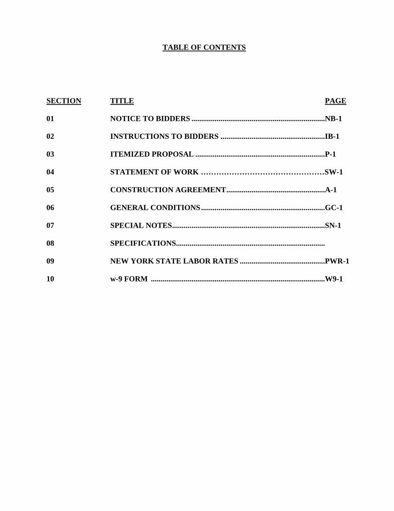
TABLE OF CONTENTS
SECTION TITLE PAGE
01 NOTICE TO BIDDERS .....................................................................NB-1
02 INSTRUCTIONS TO BIDDERS ......................................................IB-1
03 ITEMIZED PROPOSAL ...................................................................P-1
04 STATEMENT OF WORK …………………………………………SW-1
05 CONSTRUCTION AGREEMENT ...................................................A-1
06 GENERAL CONDITIONS ................................................................GC-1
07 SPECIAL NOTES ...............................................................................SN-1
08 SPECIFICATIONS.............................................................................
09 NEW YORK STATE LABOR RATES ............................................PWR-1
10 w-9 FORM ..........................................................................................W9-1

SECTION 1
NOTICE TO BIDDERS

NB-1
NOTICE TO BIDDERS
PLEASE TAKE NOTICE that pursuant to a motion of the Town Board of the Town of
Union, Broome County, New York, sealed bids for the West Corners Sanitary Sewer Pump
Station Replacement in the Town of Union, New York, will be received by the Town Clerk at,
3111 East Main Street, Endwell, New York, until 10:00 a.m. on the 11h. day of March 2022, at
which time they will be publicly opened and read aloud.
Bids must be submitted in sealed envelopes at the above address and shall bear on the face
thereof the name and address of the bidder and shall be marked:
WEST CORNERS SANITARY SEWER PUMP STATION REPLACEMENT
It is the Contractor's responsibility to meet the minimum guidelines of the Manual On
Uniform Traffic Control Devices (MUTCD) and the Occupational Safety and Health Act
(O.S.H.A), in particular Part 1926, the Safety and Health Regulations for Construction. The
Town of Union Safety Officer has the authority to issue a Stop Work Order if the applicable
MUTCD or O.S.H.A. regulations are violated. The Stop Work Order will remain in effect until
such violations of the MUTCD or O.S.H.A. regulations have been rectified.
Drawings, specifications, bidding and contract documents may be examined at the office
of the Town Clerk, Town of Union, or the Town Engineer's office and obtained from the Town
Clerk, Town of Union, for a deposit of fifty dollars ($50.00) per set. Full refund of the deposit
for one set of plans and specifications will be made to bidders who return the plans and
specifications in good condition within 30 days following the award of the contract or rejection
of the bids covered by such plans and specifications. Bidders who have placed deposits for
additional sets will be refunded 50% of their deposit per set of plans and specifications returned
in good condition within 30 days following the award of the contract or rejection of the bids
covered by such plans and specifications. Non-bidders who have placed deposits for any sets of
plans and specifications will be refunded 50% of their deposit per set of plans and specifications
returned in good condition within 30 days following the award of the contract or rejection of the
bids covered by such plans and specifications.
A bid guarantee in the form of cash, certified check or bid bond in the amount of ten
percent (10%) of the proposal will be required of all bidders.
The Town Board reserves the right to reject any and all bids and to re-advertise for bids at
its discretion. The Town Board further reserves the right to reject bids from contractors whose
main office is located outside a twenty-five (25) mile radius of the Town of Union.
Direct all technical questions no later than 7 days before bid opening to:
SHUMAKER CONSULTING ENGINEERING & LAND SURVEYING, D.P.C
James Cummings, P.E.
(607) 798-8081

NB-1
Direct all administrative questions no later than 7 days before bid opening to:
Town of Union, Engineering Division
Lou Caforio, Commissioner of Public Works
607-786-2950
___________________________
Leonard J. Perfetti
TOWN CLERK
TOWN OF UNION
Dated:___February 20, 2022___________

SECTION 2
INSTRUCTIONS TO BIDDERS

INSTRUCTIONS TO BIDDERS
Sealed proposals shall be submitted in accordance with the Notice to Bidders. Proposals shall be
hand or typewritten in black ink on the form furnished and shall be enclosed in a sealed envelope
endorsed with the name of the bidder and the name of the contract. The bidder shall not change
the wording of the proposal, any explanatory matter which the bidder may wish to submit shall
be in the form of a separate letter accompanying the proposal.
Bidders shall make a personal examination of the site of the work, the drawings and
specifications, and the other contract documents, and shall inform themselves by such means as
they prefer as to the difficulties to be experienced in fulfilling the contract, before submitting
their bids.
Any explanation desired by bidders regarding the meaning or interpretation of the drawings and
specifications must be requested in writing (on the form in the proposal book) and with sufficient
time allowed for a reply to reach them before the submission of their bids, no request will be
entertained within two (2) days before bidding. Oral explanations given before the award of the
contract will not be binding. Any interpretation made will be in the form of an addendum to the
drawings or specifications and will be furnished to all bidders and its receipt by the bidder shall
be acknowledged. Failure of any bidder to receive any such addendum or interpretation shall not
relieve any bidder from any obligation under his bid as submitted. All addenda so issued shall
become a part of the contract documents.
Each proposal shall be accompanied by cash, certified check, or bid bond acceptable to the
owner, in an amount not less than ten percent (10%) of the proposal payable without condition to
the owner as a guaranty that the bidder, if awarded the contract, will execute the Agreement.
The bidder whose proposal is accepted shall, within ten (10) calendar days after receiving Notice
of Award, execute the agreement in accordance with the proposal and the other contract
documents, and furnish a performance bond in the amount of one-hundred percent (100%) of the
contract amount for the faithful performance of the contract. The Contractor must also furnish a
payment bond in the amount of one-hundred percent (100%) of the contract amount to assure
payment as required by law of all persons supplying labor and material in the execution of the
work provided for in the contract.
In the event the bidder fails or neglects to execute the contract as required, the Owner will
consider that the bidder has abandoned the contract, and the proposal guaranty accompanying his
proposal shall be immediately forfeited to the Owner as liquidated damages for such failure or
neglect.
A bidder may not withdraw his proposal within thirty (30) days after the actual date of the
opening thereof without forfeiting his proposal guaranty to the Owner as liquidated damages for
such action. However, a bidder may withdraw his proposal at any time prior to the opening of
the proposals without penalty.
IB-1
The proposal guarantee of the three (3) lowest bidders will be retained until an agreement is
signed, but in no event more than sixty (60) days. The proposal guaranty of all other bidders will
be returned within seven (7) days after opening of the proposals.
The contract will be awarded to the lowest responsible bidder whose proposal complies with the
requirements of the contract documents. An informal or irregular proposal may be rejected. The
Owner reserves the right to waive any informality, to reject any or all proposals, or to accept the
proposal which will best serve the public interest.
The attention of the bidders is particularly called to the requirements of the contract documents
concerning conditions of employment to be observed, the prevention of discrimination in
employment, the minimum wage rates to be paid for the work performed under this contract, and
statement of non-collusion in the proposal.
Every Contractor and sub-contractor is required by Article 8, Section 220 of the New York State
Labor Law, to submit to the Town of Union Engineering Department within thirty (30) days after
issuance of its first payroll, and every thirty days thereafter, a transcript of the original payroll
record, as provided by this article, subscribed and affirmed as true under penalties of perjury.
Every Contractor and sub-contractor, awarded a contract, shall submit valid NYS Worker’s
Compensation form WC/DB-100 or WC/DB-101. To be valid, these forms must be notarized
and also stamped as received by the NYS Worker’s Compensation Board.
The attention of bidders is particularly called to the requirements of the General Conditions of
the contract concerning safety, insurance and indemnity.
The amount specified in the Agreement will be retained by the Owner for one (1) year to
guarantee the correction of faulty materials and workmanship during the guaranty period.
Bidders will be required to comply with the President's Executive Orders No. 10925, No. 11114
and No. 11246.
Within 10 days of award the contractor shall submit to the owner a schedule of values.
Breakdown each lump-sum item into component parts of work for which progress payments may
be requested. The total costs for the component parts of work shall equal the contract price for
that lump-sum item. The Engineer may request data to verify accuracy of dollar values. Include
mobilization, general condition costs, overhead or profit as a separate item.
IB-2

SECTION 3
PROPOSAL

TOWN OF UNION
BROOME COUNTY, NEW YORK
PROPOSAL FOR
WEST CORNERS SANITARY SEWER PUMP STATION REPLACEMENT
IP-1
SUBMITTED BY:_____________________________________________________________
Name of Firm
_______________________________________________________
Address
_______________________________________________________
_______________________________________________________
Phone
________________________________________________________
The undersigned declares that he has carefully examined the form of the contract and the
specifications therein referred to, examined the site of the work, examined the minimum wage
rate schedule that is applicable to the work and performed such other tests as deemed necessary
to provide all necessary plant, machinery, tools, labor and material and other means for the
construction of the specified work in strict accordance with the plans and specifications.
A. Base Bid, Contract for WEST CORNERS SANITARY SEWER PUMP STATION
REPLACEMENT Work: The undersigned Bidder, having carefully examined the Procurement
and Contracting Requirements, Conditions of the Contract, Drawings, Specifications, and all
subsequent Addenda, as prepared by OWNER, having visited the site, and being familiar with all
conditions and requirements of the Work, hereby agrees to furnish all material, labor, equipment,
and services, including all scheduled allowances, necessary to complete the construction of the
work for above-named Project, according to the requirements of the Procurement and
Contracting Documents, for the stipulated sum of:
1.______________________________________________Dollars $(______________).
Accompanying this proposal is bid security in the form of cash, certified check or bid bond
(circle which) in the amount of $_____________________(10% of the amount bid) made
payable to the Supervisor of the Town of Union as a guarantee that the bidder will enter a
contract if awarded the same.
The said bid security shall be forfeited to the Town of Union as liquidated damages, in the event
this proposal is accepted by the Town of Union and the undersigned shall not, within (10) days

TOWN OF UNION
BROOME COUNTY, NEW YORK
PROPOSAL FOR
WEST CORNERS SANITARY SEWER PUMP STATION REPLACEMENT
IP-2
after receipt of the Notice of Award, execute copies of the contract agreement, submit certificates
of insurance, executed for the various types and amounts of insurance, and an executed
performance bond, all in the various forms required by the bidding documents.
All Surety Companies are subject to the approval of the Town Attorney and must be authorized
to do business in the State of New York.
The undersigned further states that it is a duly licensed Contractor, for the type of work
proposed, in the Town of Union, Broome County, New York State, and that all fees, permits,
etc., pursuant to submitting this proposal have been paid in full.
Every contractor and sub-contractor, awarded a contract, Shall submit valid NYS worker’s
compensation form WC/db-100 or WC/db-101. To be valid, these forms must be notarized and
also Stamped as received by the NYS worker’s compensation board.
Every contractor and sub-contractor is required by article 8, Section 220 (3-a) of the New York
State labor law, to comply with Specific requirements for signs at public work locations.
Every contractor and sub-contractor is required by article 8, Section 220 of the New York State
labor law, to submit to the Town of Union Engineering Department within thirty (30) days
After issuance of its first payroll, and every thirty days Thereafter, a transcript of the original
payroll record, as Provided by the article, subscribed and affirmed as true under Penalties of
perjury.
Manual on uniform traffic control devices requirements for Work zone traffic control will be
enforced. The contractor Shall consider the cost of compliance.
Every contractor and sub-contractor is required by 16 NYCRR Part 753 to call dig safely New
York for a stake-out request at least two working days before any excavation starts.
Contractor shall submit W-9 with this proposal.
Addenda numbered consecutively thru No.__________have been received.
Respectfully submitted this ____ day of ____________, 2022.
Submitted By:___________________________________(Name of bidding firm or corporation).
Authorized Signature:___________________________________(Handwritten signature).
Signed By:______________________________________________(Type or print name).
Title:___________________________________(Owner/Partner/President/Vice President).

TOWN OF UNION
BROOME COUNTY, NEW YORK
PROPOSAL FOR
WEST CORNERS SANITARY SEWER PUMP STATION REPLACEMENT
IP-3
CERTIFICATION OF BIDDER REGARDING
EQUAL EMPLOYMENT OPPORTUNITY
INSTRUCTIONS
This certification is required pursuant to Executive Orders 11246, (30 F.R. 12319) as amended
by Executive Order 11275, and the implementing rules and regulations provide that any bidder
or prospective contractor, or any of their proposed subcontractors shall state as an initial part of
the bid or negotiations of the contract whether it has participated in any previous contract or
subcontract subject to the equal opportunity clause; and, if so, whether it has filed all compliance
reports due under applicable instructions.
Where the certification indicates that the bidder has not filed a compliance report due under
applicable instructions, such bidder shall be required to submit a compliance report within seven
(7) calendar days after the bid opening. No contract shall be awarded unless such report is
submitted.
Signature on this bid certifies the following:
1. Bidder has participated in a previous contract or subcontract subject to
the Equal Opportunity Clause. YES_______ NO_______
2. Compliance reports were required to be filed in connection with such
contract or subcontract. YES_______ NO_______
3. Bidder has filed all compliance reports due under applicable
instructions, including SF-100. YES_______ NO_______
4. If answer to Item 3 is "NO", please explain in detail on reverse side of
this certificate.
THE BIDDER CERTIFIES BY SIGNATURE OF THIS BID THAT THE INFORMATION
IS TRUE AND COMPLETE TO THE BEST OF HIS KNOWLEDGE AND BELIEF.

TOWN OF UNION
BROOME COUNTY, NEW YORK
PROPOSAL FOR
WEST CORNERS SANITARY SEWER PUMP STATION REPLACEMENT
IP-4
NON-COLLUSIVE BIDDING CERTIFICATION
(REQUIRED BY SECTION 139-d OF THE STATE FINANCE LAW)
By submission of this bid or proposal, each bidder and each person signing behalf of any bidder
certifies, and in the case of a joint bid each party thereto certifies as to its own organization,
under penalty of perjury, that to the best of his knowledge and belief:
a. The prices in this bid or proposal has been independently arrived at without collusion,
consultation, communication, or agreement, for the purpose of restricting competition, as to
any matter relating to such prices with any other bidder or with any competitor;
b. Unless otherwise required by law, the prices which have been quoted in this bid have not
been knowingly disclosed by the bidder and will not be knowingly disclosed by the bidder
prior to opening, directly or indirectly, to any other bidder or to any competitor;
c. No attempt has been or will be made by the bidder to induce any other person, partnership or
corporation to submit or not submit a bid or proposal for the purpose of restricting
competition;

TOWN OF UNION
BROOME COUNTY, NEW YORK
PROPOSAL FOR
WEST CORNERS SANITARY SEWER PUMP STATION REPLACEMENT
IP-5
SUBCONTRACTORS AND SUPPLIERS
SUBCONTRACTOR AND SUPPLIER
NAME AND TITLE OF SIGNER SIGNATURE AND DATE
1. ____________________________________ ____________________________________
2. ____________________________________ ____________________________________
3. ____________________________________ ____________________________________
4. ____________________________________ ____________________________________
5. ____________________________________ ____________________________________
6. ____________________________________ ____________________________________
7. ____________________________________ ____________________________________
8. ____________________________________ ____________________________________
9. ____________________________________ ____________________________________
10. ____________________________________ ____________________________________
NOTE: The penalty for making false statements in offers is prescribed in 18 U.S.C. 1001.

TOWN OF UNION
BROOME COUNTY, NEW YORK
PROPOSAL FOR
WEST CORNERS SANITARY SEWER PUMP STATION REPLACEMENT
IP-6
Signature of Bidder:_______________________________________________
Address:___________________________________________________________
___________________________________________________________________
Date:______________________________________________________________
STATE OF )
SS )
COUNTY OF )
Being duly sworn deposes and says that he has signed the above bid after having read the
foregoing certification, and knows the content thereof, and that the same is true to deponents
own knowledge, except as to the matters therein stated to be upon information and belief, and as
to those matters the deponent believes it to be true.
________________________________
N O T A R Y P U B L I C
Subscribed and sworn to before me this
______ day of ___________________

TOWN OF UNION
BROOME COUNTY, NEW YORK
PROPOSAL FOR
WEST CORNERS SANITARY SEWER PUMP STATION REPLACEMENT
IP-7
RESOLUTION
(Required if Bidder is a Corporation)
Resolved that __________________________________________________be authorized
(Authorized Agent or Corporation)
to sign and submit the bid or proposal of this corporation for the following
project:_____________________________________________________________
_____________________________________________________________________
_____________________________________________________________________
(Describe the Project)
and to include in such bid or proposal the certificate as to Non-Collusion required by Section
139-d of the State Finance Law as the act and deed of such corporation and for any inaccuracies
or misstatements in such certificate this corporate bidder shall be liable under the penalties of
perjury.
The foregoing is a true and correct copy of the Resolution adopted by the
___________________________________________________ corporation at a meeting
of its Board of Directors held on the _____ day of ______20___.
(SEAL OF THE CORPORATION)
__________________________________
Secretary

TOWN OF UNION
BROOME COUNTY, NEW YORK
PROPOSAL FOR
WEST CORNERS SANITARY SEWER PUMP STATION REPLACEMENT
IP-8
BID BOND
KNOW ALL MEN BY THESE PRESENTS, that we, the undersigned_________
____________________________as Principal, and_________________________
____________________________as Surety, are hereby held and firmly bound
unto________________________as Owner in the penal sum of______________
for the payment of which, well and truly to be made, we hereby jointly and severely bind
ourselves, our heirs, executors, administrators, successors and assigns.
Signed this __________day of ___________________________, 20__:
The condition of the above obligation is such that whereas the
Principal has submitted to ___________________________________________
a certain proposal, attached hereto and hereby made a part hereof, to
enter a contract in writing, for the construction of __________________
______________________________________________________________________
NOW, THEREFOR,
(a) If said Proposal shall be rejected, or in the alternate,
(b) If said Proposal shall be accepted, and the Principal shall execute and deliver a contract
in the form attached hereto (properly completed in accordance with said Proposal) and
shall furnish a bond for his faithful performance of said contract, and for the payment of all
persons performing labor or furnishing materials in connection therewith, and shall in all
other respects perform the agreement created by the acceptance of said Proposal
then this obligation shall be void, otherwise the same shall remain in force and effect; it being
expressly understood and agreed that the liability of the Surety for any and all claims hereunder
shall, in no event, exceed the penal amount of this obligation as herein stated.
TOWN OF UNION
BROOME COUNTY, NEW YORK
PROPOSAL FOR
WEST CORNERS SANITARY SEWER PUMP STATION REPLACEMENT
IP-9
The Surety, for value received, hereby stipulates and agrees that the
obligations of said Surety and its bond shall be in no way impaired
or affected by any extension of the time within which the Owner may
receive or accept such Proposal; and said Surety does hereby waive
notice of any such extension.
IN WITNESS WHEREOF, the Principal and Surety have hereunto set their
hands and seals, and such of them as are corporations have caused
their corporate seals to be hereto affixed and these presents to be
signed by their proper officers, the day and year first set forth
above.
______________________________(L.S.)
Principal
______________________________
Surety
BY:____________________________
( S E A L )

TOWN OF UNION
BROOME COUNTY, NEW YORK
PROPOSAL FOR
WEST CORNERS SANITARY SEWER PUMP STATION REPLACEMENT
IP-10
PERFORMANCE BOND
KNOW ALL MEN BY THESE PRESENTS, that we _________________________
___________________________________, as Principal and ________________
___________________________, as Surety, are hereby held and firmly
bound unto ______________________ in the Penal Sum of ________________
dollars, lawful money of the United States of America, to be paid to
the said __________________________, its successors and assigns, for
which payment will and truly to be made, we bind ourselves, our
heirs, executors, and administrators, successors and assigns, jointly
and severally, firmly by these presents.
Signed and sealed with our seals and dated at ___________________
____________________, this _____day of _______________________A.D.____.
WHEREAS, the said ____________________________________ has entered
into a contract with _____________________________________ bearing
date______________________, a copy of which is attached hereto, the
terms of which are herein referred to and made part of this
instrument if fully set forth herein;
NOW THE CONDITIONS OF THIS OBLIGATION ARE SUCH THAT if the
said___________________________________________ shall well and truly
keep and perform all the terms and conditions of said contract on
___________________________ part to be kept and performed, (including

TOWN OF UNION
BROOME COUNTY, NEW YORK
PROPOSAL FOR
WEST CORNERS SANITARY SEWER PUMP STATION REPLACEMENT
IP-11
guarantee and maintenance and provisions therein) and shall pay for all
materials and labor used or employed in the execution of said Contract
and shall indemnify and save harmless the said ________________________
_______________ as therein stipulated, then this obligation shall be of
no effect; otherwise, it shall remain in full force and virtue. And, the said Surety, for value
received, hereby stipulates and agrees that no change, extension of time, alteration, or addition to
the terms of the Contract or to the work to be performed thereunder of the Specifications
accompanying the same shall in any way affect its obligation on this Bond, and it does hereby
waive notice of any such change, extension of time, alteration, or addition to the terms of the
Contract or to the work or to the Specifications.
(S E A L) _______________________________
_______________________________
(Principal)
ATTEST:____________________________
(S E A L) ______________________________
______________________________
(Surety)
ATTEST:____________________________
Authorization of the Surety Agent to execute the Performance Bond and a financial statement
shall be attached to each copy of the Performance Bond.
If the Bonding Company is a foreign corporation, a proper certification authorizing it to do
business in the State of New York shall also be attached to each copy of the Performance Bond.

TOWN OF UNION
BROOME COUNTY, NEW YORK
PROPOSAL FOR
WEST CORNERS SANITARY SEWER PUMP STATION REPLACEMENT
IP-12
PAYMENT BOND
KNOW ALL MEN BY THESE PRESENTS: that
______________________________________________________________________
(Name of Contractor)
______________________________________________________________________
(Address of Contractor)
__________________________________________________, hereinafter called
(Corporation, Partnership or Individual)
Principal, and _______________________________________________________
(Name of Surety)
______________________________________________________________________
(Address of Surety)
hereinafter called Surety, are held and firmly bound unto_____________
______________________________________________________________________
(Name of Owner)
______________________________________________________________________
(Address of Owner)
hereinafter called Owner, in the penal sum of ________________________
dollars ($___________) in lawful money of the United States, for the payment of which sum
well and truly to be made, we bind ourselves, successors, and
assigns, jointly and severally, firmly by these presents.
THE CONDITION OF THIS OBLIGATION is such that whereas, the Principal entered into a
certain contract with the Owner, dated the _____day of
____________________, 20__, a copy of which is hereto attached and made
a part hereof for the construction of:_______________________________
_____________________________________________________________________
NOW, THEREFORE, if the Principal shall promptly make payment to all persons, firms, subcontractors,
and corporations furnishing materials for or performing labor in the prosecution of the work provided for
in such contract, and any authorized extension or modification thereof, including all amounts due for the
materials, lubricants, oil, gasoline, coal and coke, repairs on machinery, equipment and tools, consumed
or used in connection with the construction of such work, and all insurance premiums on said work, and
for all labor, performed in such work whether by such subcontractor or otherwise, then this obligation
shall be void; otherwise to remain in full force and effect.

TOWN OF UNION
BROOME COUNTY, NEW YORK
PROPOSAL FOR
WEST CORNERS SANITARY SEWER PUMP STATION REPLACEMENT
IP-13
PROVIDED. FURTHER, that the said Surety, for value received hereby stipulates and agrees that no
change, extension of time, alteration or addition to the terms of the contract or to the work to be
performed thereunder or the specifications accompanying the same shall in any way affect its obligation
on this bond, and it does hereby waive notice of any such change, extension of time, alteration or addition
to the terms of the contract or to the work or to the specifications.
PROVIDED, FURTHER, that no final settlement between the Owner and the Contractor shall abridge the
right of any beneficiary hereunder, whose claim may be unsatisfied.
IN WITNESS WHEREOF, this instrument is executed in _____(number) counterparts, each one of which
shall be deemed an original, this the ______day of __________________, 20___.
ATTEST: ______________________________
Principal
___________________________________
(Principal) Secretary
BY______________________________
______________________________
Address
______________________________
(SEAL)
___________________________________
Witness as to Principal
___________________________________
(Address)
___________________________________ ______________________________
Surety
BY______________________________
Attorney-In-Fact
ATTEST: ________________________________
(Address)
___________________________________
(Surety) Secretary
________________________________
(SEAL)
___________________________________
Witness as to Surety
___________________________________
(Address)
___________________________________

SECTION 4
STATEMENT OF WORK

TOWN OF UNION
BROOME OF COUNTY, NEW YORK
WEST CORNERS SANITARY SEWER PUMP STATION REPLACEMENT
STATEMENT OF WORK
1. DESCRIPTION OF WORK:
a. Location:
The work will be performed in the Town of Union at Ardmore Street/River Drive.
b. Work to be Done:
The work consists of furnishing all new materials and performing all operation in strict
accordance with the drawings and specifications for the construction of the West
Corners Sanitary Sewer Pump Station Replacement.
c. Commencement, Prosecution and Completion of Work:
The contractor will be required to commence the work under the contract within ten
(10) calendar days after the date of receipt by him or her of the Notice to Proceed, to
prosecute said work with faithfulness and energy, and complete the work on or before
December 1, 2022.
2. PRINCIPAL FEATURES:
The work to be performed generally consists of the following principal features, but it
is not limited to: Selective demolition, construction of a new pump station with valve
vault and raised platform, installation of new structures and piping, installation of
standby generator, coordination and installation of natural gas service, maintenance
and protection of traffic, protection of existing utilities, and such other work as
indicated by the drawings and specifications or as ordered by the Engineer.
3. CONSTRUCTION STAKEOUT:
The Contractor will be responsible for all construction stakeout work for this project.
SW-1
SECTION 5
CONSTRUCTION
AGREEMENT

A-1
TOWN OF UNION
CONSTRUCTION CONTRACT AGREEMENT
WITH
___________________________________________
for
WEST CORNERS SANITARY SEWER PUMP STATION
REPLACEMENT

A-2
TOWN OF UNION
THIS AGREEMENT, entered into this ____day of ____________ 2022, by the Town of Union,
hereinafter referred to as "PROJECT SPONSOR", acting pursuant to the Highway Law, and
.
A corporation organized and existing under the laws of the State of _______________
A partnership, consisting of
An individual conducting business as
A limited liability company (LLC), organized under the laws of the State of
_______________
the location of whose principal office is
hereinafter called the “CONTRACTOR".
WITNESSETH: That the PROJECT SPONSOR and the Contractor for the consideration
hereinafter named agree as follows:
ARTICLE 1. WORK TO BE DONE. The Contractor shall (a) furnish all the materials,
appliances, tools and labor of every kind required, and construct and complete in the most
substantial and skillful manner, the construction, improvement or reconstruction of the project on
or before the final completion date of the 1st day of December 2022 as further described in Article
4, and as generally identified and shown on the plans entitled:
WEST CORNERS SANITARY SEWER PUMP STATION REPLACEMENT
In accordance with the “Standard Specifications" of the New York State Department of
Transportation and the Proposal which contain the information for bidders; proposal form, contract
agreement, and bonds; and payment items; and (b) do everything required by the Contract and/or
Contract Documents as defined herein.
The contractor further agrees their bid proposal is not based upon the assumption that any
specifications, traffic restrictions, scheduling or phasing/staging requirements will be waived; an
extension of Contract Completion Date will be granted; a labor dispensation will be granted;
substitution of non-approved products, alternatives or claimed functional equivalents for specified
construction materials and methods will be allowed; or any Value Engineering Change Proposals
will be approved.

A-3
ARTICLE 2: DOCUMENTS FORMING THE CONTRACT. The Contract (and Contract
Documents) shall be deemed to include the advertisement for proposals; the contract proposal,
including General Conditions, Special Notes and Specifications contained therein; the contractor’s
proposal; the Equal Employment Opportunity (EEO) participation goals; the contract agreement;
the base line data; the "Standard Specifications" including all addenda thereto identified in the
contract proposal; the Standard Sheets; the plans; any amendments issued prior to the date of
proposal submission, and all provisions required by law to be inserted in the contract whether
actually inserted or not. Whenever separate publications are referenced in the Contract Documents
it shall mean those, as amended, which are current on the date of advertisement for bids.
ARTICLE 3. EXAMINATION OF DOCUMENTS AND SITE. The Contractor agrees that
before making its proposal it carefully examined the contract documents, together with the site of
the proposed work, as well as its surrounding territory, and is informed regarding all of the
conditions affecting the work to be done and labor and materials to be furnished for the completion
of this contract, including the existence of poles, wires, pipes and other facilities and structures of
municipal and other public service corporations on, over or under the site, except latent conditions
that meet the requirements of §104-03 Differing Site Conditions of the NYSDOT Standard
Specifications, and that its information was secured by personal and other investigation and
research.
ARTICLE 4. DATE OF COMPLETION. The Contractor further agrees that it will begin the
work herein embraced within ten days of the effective date hereof, unless the consent of the
PROJECT SPONSOR, in writing, is given to begin at a later date, and that it will prosecute the
same so that it shall be entirely completed and performed on or before the final completion date
shown in Article 1.
For each calendar day that any work shall remain incomplete past the time period allowed for the
entire contract, liquidated damages will be deducted from any money due the contractor. The
amount of such liquidated damages will be as specified in the General Conditions
No extension beyond the date of completion fixed by the terms of this contract shall be effective
unless in writing signed by the PROJECT SPONSOR. Such extension shall be for such time and
upon such terms and conditions as shall be fixed by the PROJECT SPONSOR, which may include
the assessment of liquidated damages and a charge for engineering and inspection expenses
actually incurred upon the work. Notice of application for such extension shall be filed with the
PROJECT SPONSOR at least fifteen days prior to the date of completion fixed by the terms of
this agreement.
ARTICLE 5. ALTERATIONS AND OMISSIONS. The said work shall be performed in
accordance with the true intent and meaning of the contract documents without any further expense
of any nature whatsoever to the PROJECT SPONSOR other than the consideration named in this
agreement.
The PROJECT SPONSOR reserves the right, at any time during the progress of the work, to alter
the plans or omit any portion of the work as it may deem reasonably necessary for the public
interest - making allowances for additions and deductions with compensation made in accordance
with the Standard Specifications, for this work without constituting grounds for any claim by the
contractor for allowance for damages or for loss of anticipated profits, or for any variations
between the approximate quantities and the quantities of the work as done.

A-4
ARTICLE 6. NO COLLUSION OR FRAUD. The Contractor hereby agrees that the only person
or persons interested as principal or principals in the bid or proposal submitted by the Contractor
for this contract are named therein, and that no person other than those mentioned therein has any
interest in the above mentioned proposal or in securing of the award, and that this contract has
been secured without any connection with any person or persons other than those named, and that
the proposal is in all respects fair and was prepared and the contract was secured without collusion
or fraud and that neither any officer nor employee of the PROJECT SPONSOR has or shall have
a financial interest in the performance of the contract or in the supplies, work or business to which
it relates, or in any portion of the profits thereof. (See also Sections 139-a and 139-b of the State
Finance Law referred to in the Standard Specifications which are made a part of this contract).
ARTICLE 7. CONTRACT PAYMENTS. As the work progresses in accordance with the
contract and in a manner that is satisfactory to the PROJECT SPONSOR, the PROJECT
SPONSOR hereby agrees to make payments to the Contractor therefore, based upon the proposal
attached hereto and made a part hereof, as follows: The PROJECT SPONSOR shall once in each
month and on such days as it may fix, make an estimate of the quantity of work completed and of
material which has actually been put in place in accordance with the terms and conditions of the
contract, during the preceding month, and compute the value thereof and pay to the Contractor the
monies due as provided in subdivision 7 of 38 of the Highway Law. No monthly estimate shall be
rendered unless the value of the work completed exceeds 5% of the contract amount or $1,000,
whichever is the lesser. Semimonthly estimates may be rendered provided (a) the value of the work
performed in two successive weeks is more than $50,000 or (b) the PROJECT SPONSOR deems
it to be in the best interests of the PROJECT SPONSOR to do so. The Contractor shall not hold
any retainage from any Subcontractor.
ARTICLE 8. NO PAYMENT DUE TO CONTRACTOR'S NON-COMPLIANCE. It is
further agreed that so long as any lawful or proper direction concerning the work or material given
by the PROJECT SPONSOR, or his/her representative, shall remain uncomplied with, the
Contractor shall not be entitled to have said payment processed, nor shall any contract payment(s)
be processed for work done or material furnished until such lawful or proper direction aforesaid
has been fully and satisfactorily complied with.
ARTICLE 9. FINAL ACCEPTANCE OF WORK. When in the opinion of the PROJECT
SPONSOR a Contractor has fully performed the work under the contract, the PROJECT
SPONSOR shall thereupon by letter notify the Contractor, with copies to other interested parties,
of such acceptance.
Final acceptance shall be final and conclusive except for defects not readily ascertainable by the
PROJECT SPONSOR, actual or constructive, fraud, gross mistakes amounting to fraud or other
errors which the Contractor knew or should have known about as well as the PROJECT
SPONSOR’S rights under any warranty or guarantee. Final acceptance may be revoked by the
PROJECT SPONSOR at any time prior to the issuance of the final check upon the PROJECT
SPONSOR’S discovery of such defects, mistakes, fraud or errors in the work.
ARTICLE 10. FINAL PAYMENT. After the final acceptance of the work, the Engineer shall
prepare a final agreement of the work performed and the materials placed and shall compute the
value of such work and materials under and according to the terms of the contract. This final
agreement shall be certified, as to its correctness, by the Engineer and shall be submitted to
PROJECT SPONSOR for final approval. The right, however, is hereby reserved to the PROJECT

A-5
SPONSOR to reject the whole or any portion of the final agreement, should the said certificate of
the Engineer be found or known to be inconsistent with the terms of the agreement or otherwise
improperly given. All certificates upon which partial payments may have been made, shall be
subject to correction in the final certificate or final agreement.
ARTICLE 11A. RIGHT TO SUSPEND WORK AND CANCEL CONTRACT. It is further
mutually agreed that if at any time during the prosecution of the work the PROJECT SPONSOR
shall determine that the work upon the contract is not being performed according to the contract
or for the best interest of the PROJECT SPONSOR, the execution of the work by the Contractor
may be temporarily suspended by the PROJECT SPONSOR, who may then proceed with the work
under the PROJECT SPONSOR’S own direction in such a manner as will accord with the contract
specifications and be for the best interests of the PROJECT SPONSOR; or the PROJECT
SPONSOR may terminate the Contractor's employment under the contract while it is in progress,
and thereupon proceed with the work, in affirmance of the contract, by contract negotiated or
publicly let, by the use of the PROJECT SPONSOR’s own forces, by calling upon the surety to
complete the work in accordance with the plans and specifications or by a combination of any such
methods; or the PROJECT SPONSOR may cancel the contract and either readvertise or relet as
provided in Section 38 of the Highway Law, or complete the work under its own direction in such
a manner as will accord with the contract specifications and be for the interests of the PROJECT
SPONSOR; any excess in the cost of completing the contract beyond the price for which it was
originally awarded shall be charged to and paid by the Contractor failing to perform the work or
its surety; all in pursuance of the provisions of Section 40 of the Highway Law.
Whenever the PROJECT SPONSOR determines to suspend or stop work under the contract, a
written notice sent by mail to the Contractor at its address and to the sureties at their respective
addresses, shall be sufficient notice of its action in the premises.
ARTICLE 12. DETERMINATION AS TO VARIANCES. In any case of any ambiguity in
the plans, specifications or maps, or between any of them, the matter must be immediately
submitted to the PROJECT SPONSOR, who shall adjust the same, and his/her decision in relation
thereto shall be final and conclusive upon the parties.
ARTICLE 13. SUCCESSORS AND ASSIGNS. This agreement shall bind the successors,
assigns and representatives of the parties hereto.
ARTICLE 14. INTERNATIONAL BOYCOTT PROHIBITION. In accordance with §139-h
of State Finance Law, the Contractor hereby promises, asserts and represents that neither the
Contractor nor any substantially owned or affiliated person, firm, partnership or corporation has
participated, is participating or shall participate in an international boycott in violation of
provisions of the United States Export Administration Act of 1969, as amended, or the United
States Export Administration Act of 1979, or the effective Regulations of the United States
Department of Commerce promulgated under either act.
It is understood further that the PROJECT SPONSOR in awarding a contract does so in material
reliance upon the promise and representation made by the Contractor in the previous paragraph
and that such contract shall be rendered forfeit and void by the PROJECT SPONSOR if subsequent
to the bid execution date, the Contractor or such owned or affiliated person, firm, partnership or
corporation has been convicted of a violation of the aforesaid Acts or Regulations or has been
found upon final determination of the United States Commerce Department or any other
appropriate agency of the United States to have violated such Acts or Regulations.
A-6
The Contractor agrees to and shall notify the PROJECT SPONSOR of any such conviction or final
determination of violation within five (5) days thereof.
ARTICLE 15. WRITTEN NOTICES.
1. All notices permitted or required hereunder shall be in writing and shall be transmitted either:
a. via certified or registered United States mail, return receipt requested;
b. by facsimile transmission;
c. by personal delivery;
d. by expedited delivery service; or
e. by e-mail.
Such notices shall be addressed to the individuals or titles named in the contract documents, or
which are designated by the Contractor or the PROJECT SPONSOR at the pre-construction
meeting, or which are designated by the PROJECT SPONSOR or the Contractor from time to time
during the course of the Contract pursuant to Paragraph 3 herein.
2. Any such notice shall be deemed to have been given either at the time of personal delivery or,
in the case of expedited delivery service or certified or registered United States mail, as of the date
of first attempted delivery at the address and in the manner provided herein, or in the case of
facsimile transmission or email, upon receipt.
3. The parties may, from time to time, specify any new or different address in the United States as
their address for purpose of receiving notice under this Agreement by giving fifteen (15) days
written notice to the other party sent in accordance herewith. The parties agree to mutually
designate individuals as their respective representatives for the purposes of receiving notices under
this Agreement. Additional individuals may be designated in writing by the parties for purposes
of implementation and administration/billing, resolving issues and problems and/or for dispute
resolution.
A-7
IN WITNESS WHEREOF, this agreement has been executed by the PROJECT SPONSOR, and
the Contractor or its appointed representative, who has executed this agreement on the day and
year first written above.
TOWN OF UNION: CONTRACTOR’S NAME:
Recommended by: Agreed by:
Signature Signature
Printed Name Printed Name
Title Title
Date Date
Approved by:
Signature
Printed Name
Title
Date
(Acknowledgement of contractor, if a corporation)
STATE OF
ss.:
COUNTY OF
On this ____________ day of ___________________ 2022, before me personally came
________________________________, to me known and known to me to be the person, who being duly
sworn, did depose and say that he/she resides in __________________________; that he/she is the
_______________________ of __________________________________ the corporation described in and
which executed the foregoing instrument; and that he/she signed his/her name thereto by order of the Board
of Directors of said Corporation.

A-8
Notary Public
(Acknowledgement of individual contractor)
STATE OF
ss.:
COUNTY OF
On this ____________ day of ___________________ 2022, before me personally came
________________________________, to me known and known to me to be the person described in and
who executed the foregoing instrument; and acknowledged that he/she executed the same.
Notary Public
(Acknowledgement of co-partnership contractor)
STATE OF
ss.:
COUNTY OF
On this ____________ day of ___________________ 2022, before me personally came
________________________________, to me known and known to me to be the person who executed the
foregoing instrument, who, being duly sworn by me, did for himself/herself depose and say that he/she is a
member of the firm of ____________________________________________________, consisting of
himself/herself and _____________________________________ and that he/she executed the foregoing
instrument and that he/she had authority to sign same, and he/she did duly acknowledge to me that he/she
executed the same as the act and deed of said firm for the uses and purposes mentioned therein.
Notary Public (Acknowledgement of contractor, if a limited liability company)
STATE OF
ss.:
COUNTY OF
On this ____________ day of ___________________ 2022, before me personally came
________________________________, to me known and known to me to be the person, who being duly
sworn, did depose and say that he/she resides in __________________________; that he/she is the duly
authorized member of the limited liability company described in and which executed the foregoing
instrument; and that he/she executed the foregoing instrument on behalf of the limited liability company
for the purposes set forth therein as the act and deed of said limited liability company.
Notary Public

SECTION 6
GENERAL CONDITIONS

GENERAL CONDITIONS
1. DEFINITIONS
Wherever used in any of the Contract Documents, the following meanings shall be given to
the terms herein defined.
a. The term "CONTRACT" means the Contract executed by the Town of Union and the
Contractor, of which these GENERAL CONDITIONS form a part.
b. The term "TOWN" means the Town of Union, a political subdivision of Broome County,
New York.
c. OWNER is the Town of Union.
d. ENGINEER is the DCPW-Engineering or his representative which he designates in writing
to act on his behalf.
e. The term "CONTRACTOR" means the person, firm or corporation entering into the Contract
with the Town of Union to perform the work described in the Contract Documents.
f. SUB-CONTRACTOR is any person, firm or corporation with a direct contract with the
Contractor who acts for or in behalf of the Contractor in executing any part of the Contract,
but does not include one who merely furnishes material.
g. PROPOSAL: The offer of a Bidder to perform the work described by the Contract
Documents when made out and submitted on the prescribed Proposal Form, properly signed
and guaranteed.
h. PROPOSAL QUARANTY: The cash, certified check or bid bond as called for in the
Instructions to Bidders and submitted by the Bidder, as a guaranty that the Bidder will enter
into a Contract with the Owner for the construction of the work, if the Contract is awarded to
him.
i. CONTRACT is the agreement covering the performance of the work described in the
Contract Documents including all supplemental agreements thereto and all general and
special provisions pertaining to the work or materials thereof.
j. The term "CONTRACT DOCUMENTS" shall include the following, Notice To Bidders,
Instructions to Bidders, Proposal, Executed Agreement, General Conditions, Special
Conditions, Technical Specifications, and Drawings.
k. The term "DRAWINGS" means the drawings listed in the SCHEDULE OF DRAWINGS.
GC-1

l. The term "TECHNICAL SPECIFICATIONS" or "SPECIFICATIONS" means that part of
the Contract Documents which describes, the materials of construction required and the
manner and methods of construction to be used in the execution of the contract.
m. WRITTEN NOTICE: Written Notice shall be considered as served when delivered in person
or sent by registered mail to the individual, firm or corporation or to the last business address
of such known to him who serves the notice.
n. ACT OF GOD means an earthquake, flood, cyclone or other cataclysmic phenomenon of
nature. Rain, wind, flood or other natural phenomenon of normal intensity for the locality
shall not be construed as an Act of God and no reparation shall be made to the Contractor for
damages to the work .
o. The term "Addendum" or "Addenda" means any changes, revisions or clarifications of the
Contract Documents which have been duly issued by the Owner to prospective Bidders prior
to time of receiving bids.
2. INTENT OF DRAWINGS AND TECHNICAL SPECIFICATIONS
The intent of the Drawings and Technical Specifications is that the Contractor furnish all labor
and materials, equipment and transportation necessary for the proper execution of the work
unless specifically noted otherwise. The Contractor shall do all the work shown on the Drawings
and described in the Technical Specifications and all incidental work considered necessary to
complete the project in a substantial and acceptable manner and to fully complete the work or
improvement, ready for use, occupancy and operation by the Owner.
Anything mentioned in the Technical Specifications and not shown on the Drawings, or shown
on the Drawings and not mentioned in the Technical Specifications, shall be of like effect as if
shown on or mentioned in both. In case of difference between Drawings and Technical
Specifications, the Technical Specifications shall govern. In case of any discrepancy in
Drawings or Technical Specifications, the matter shall be immediately submitted to the DCPW-
Engineering without whose decision said discrepancy shall not be adjusted by the Contractor,
save only at his own risk and expense. The omission from both Drawings and Technical
Specifications of express reference to any work which was obviously intended under the
Contract shall not excuse or relieve the Contractor from furnishing the same.
3. NOTICE TO PROCEED
Following completion of the Agreement by the Contractor and the Town Supervisor, the DCPW-
Engineering will issue a "Notice to Proceed" advising the Contractor that he may proceed with
the work. The Contractor shall begin work within ten (10) calendar days of the "Notice To
Proceed". The date of the "Notice To Proceed" shall fix the starting date of the contract.
4. COPIES OF DRAWINGS AND SPECIFICATIONS FURNISHED
The contractor will be furnished with one (1) hard copy set and one (1) PDF set of the plans and
specifications. Any additional copies shall be made by the contractor at the contractors expense.
GC-2

5. DRAWINGS AND SPECIFICATIONS AT JOB SITE
One complete set of all drawings and Specifications shall be maintained at the job site and shall
be available to the Engineer at all times.
6. ADDITIONAL INSTRUCTIONS
Further instructions may be issued by the Engineer during the progress of the work by means of
drawings or otherwise to make more clear or specific the drawings and specifications or as may
be necessary to explain or illustrate changes in the work to be done.
7. DIMENSIONS
Figured dimensions on the plans will be used in preference to scaling the drawings. Where the
work of the Contractor is affected by finish dimensions, these shall be determined by the
Contractor at the site, and he shall assume the responsibility therefor.
8. SCHEDULES
The Contractor shall submit prior to pre-construction meeting, but no more than 20 days from
award, a progress schedule, which shall show the proposed starting, and completion dates of
each of the major subdivisions of the work. These subdivisions shall be tied to the subdivisions
shown in the schedule of values. The schedule shall also show the percentage of completion on
the first of each month and shall show that all work is to be completed within the contract time.
During the course of construction the contractor shall adjust his work force as required to
maintain the work schedule as approved.
9. SAMPLES
All samples called for in the Specifications or required by the Engineer shall be furnished by the
Contractor and shall be submitted to the Engineer for his approval. Samples shall be furnished
so as not to delay fabrication, allowing the Engineer reasonable time for the consideration of the
samples submitted.
10. SHOP DRAWINGS
The Contractor shall provide shop drawings, settings, schedules and such other drawings as may
be necessary for the prosecution of the work in the shop and in the field as required by the
Drawings, Specifications or Engineer’s Instructions. The approval of shop drawings shall be
general only in character and shall not be construed to mean that all dimensions on the drawings
have been checked. The approval of shop drawings by the Engineer shall in no way relieve the
Contractor of the responsibility for proper fitting and construction of the work, nor from the
necessity of furnishing materials or doing the work required by the Drawings and or
Specifications, which may not be indicated on the approved shop drawings.
The Contractor shall submit three (3) copies of all shop drawings and schedules at least thirty
(30) days before the materials indicated thereon are to be needed, or earlier if required to prevent
delay to the work. The SHOP DRAWINGS Engineer’s approval of any drawings shall not
GC-3

release the Contractor from responsibility for such deviations.
Shop drawings shall be submitted according to the following schedule:
Three (3) copies shall be submitted at least (30) days before the materials indicated thereon
are needed, or earlier if required to prevent delay of the work.
The Engineer shall promptly review the shop drawings returning one (1) copy to the
Contractor marked with all corrections and changes.
The Contractor shall then correct the shop drawings to conform to the corrections and
changes requested by the Engineer.
Following completion of such corrections and changes, the Contractor shall furnish the
Engineer two copies of the shop drawings conforming to the required corrections and
changes.
11. QUALITY OF EQUIPMENT MATERIALS
In order to establish standards of quality, the Engineer has, in the detailed Specifications,
referred to certain products by name and catalog number. This procedure is not to be construed
as eliminating from competition other products of equal or better quality by other manufacturers
where fully suitable in design.
The Contractor shall furnish the complete list of proposed desired substitutions prior to signing
of the Contract, together with such engineering and catalog data as the Engineer may require.
The Contractor shall abide by the Engineer's judgment when proposed substitute materials or
items of equipment are judged to be unacceptable and shall furnish the specified material or item
of equipment in such case. All proposals for substitutions shall be submitted in writing by the
General Contractor and not by individual trades or material suppliers. The Engineer will
approve or disapprove proposed substitutions in writing within a reasonable time. No substitute
materials shall be used unless approved in writing.
12. EQUIPMENT APPROVAL DATA
The Contractor shall furnish one (1) copy of complete catalog data for every manufactured item
of equipment and all components to be used in the work, including specific name, catalog
number and general type.
a. This submission shall be compiled by the Contractor and approved by the Engineer before
any of the equipment is ordered.
b. Each data sheet or catalog in the submission shall be indexed to specification section and
paragraph for easy reference.
GC-4

EQUIPMENT APPROVAL DATA (Continued)
c. After written approval, this submission shall become a part of the Contract, and may not be
deviated from except upon written approval of the Engineer.
d. Catalog data for equipment approved by the Engineer does not in any case supersede the
Engineer's Contract Documents. The approval of the Engineer shall not relieve the
Contractor from responsibility for deviations from drawings or specifications, unless he has
in writing called the Engineer's attention to such deviations at the time of submission, nor
shall it relieve him from responsibility for errors of any sort in the items submitted. The
Contractor shall check the work described by the catalog data with the Engineer's Contract
Documents for deviations and errors.
e. It shall be the responsibility of the Contractor to insure that items to be furnished fit the space
available. He shall make necessary field measurements to ascertain space requirements,
including those for connections and shall order such sizes and shapes of equipment that the
final installation shall suit the true intent and meaning of the drawings and specifications.
f. Where equipment requiring different arrangement of connections from those shown is
approved, it shall be the responsibility of the Contractor to install the equipment to operate
properly, and in harmony with the intent of the drawings and specifications, and to make all
changes in the work required by the different arrangement of connections.
13. LAND BY OWNER
The Contractor shall confine his equipment, storage of materials and operations to the limits
prescribed on the plans or as directed by the Engineer. The Contractor shall not encumber the
project area unreasonably and shall comply with all reasonable instruction of the Town and its
Ordinances and Codes regarding signs, advertising, traffic, fire, explosives, danger signals,
barricades and fire prevention.
14. LAND BY THE CONTRACTOR
Any additional land and access thereto not shown on the drawings that may be required for
temporary construction facilities or for storage of materials shall be provided by the Contractor
with no liability to the Owner. The Contractor shall confine his apparatus and storage of
materials and operation of his workmen to those areas described in the drawings and
specifications and such additional areas which he may provide as approved by the Engineer.
15. PRIVATE PROPERTY
The Contractor shall not enter upon private property for any purpose without obtaining
permission, and he shall be responsible for the preservation of all public property, trees,
monuments, etc. along and adjacent to the street and/or right-of-way, and shall use every
GC-5

precautions to prevent damage to pipes, conduits, and other underground structures, precaution
necessary to prevent damage or injury thereto. He shall use suitable and shall protect carefully
from disturbance or damage all monuments and property marks until an authorized agent has
witnessed or otherwise referenced their location and shall not remove them until directed.
16. SURVEYS, LINES AND GRADES
The TOWN OF UNION shall provide the Contractor with all base lines for the location of the
principal component parts of the work together with a suitable number of bench makers adjacent
to the work. Based upon the information provided, the Contractor shall develop and make all
detail surveys necessary for construction, including slope stakes, batter boards, stakes for pile
locations and other working points, lines and elevations. It will be the Contractor's responsibility
to engage competent workmen to layout the details of the construction work. No separate
payment will be made for this item of work, the cost of such work is to be included in the various
unit prices of the lump sum price bid for the construction project. The Contractor shall have the
responsibility to carefully preserve bench marks, reference points and stakes, and, in the case of
destruction thereof by the Contractor or resulting from his negligence, the Contractor shall be
charged with the expense and damage resulting therefrom and shall be responsible for any
mistakes that may be caused by the unnecessary loss or disturbance of such bench marks,
reference points and stakes.
The Engineer reserves the right to inspect or check the Contractor's survey and paper work,
however, the accuracy of such survey and paper work is the sole responsibility of the Contractor.
The furnishing of data to the Engineer for checking shall not be construed as a transfer of
responsibility for checking, and any delay occasioned by the Engineer exercising this right or by
an corrective work resulting from such check shall not constitute a claim for extra compensation.
17. PROPERTY IRONS
The Contractor shall protect all existing property irons and monuments whether shown on the
plans or not. In the event that the property irons or monuments are accidentally disturbed by the
Contractor's operations, he shall be required to engage the services of a New York State Licensed
Land Surveyor to replace the same, all at his own expense.
18. SUPERINTENDENCE BY CONTRACTOR
The Contractor shall have a qualified superintendent, who is acceptable to the Engineer, on the
job at all times during working hours except where the Contractor is an individual who gives his
personal superintendence to and is present on the job at all times. The superintendent shall have
full authority to act in behalf of the Contractor, and all directions given to the superintendent
shall be considered given to the Contractor.
19. ENGINEER'S RESPONSIBILITY AND AUTHORITY
All work shall be done under the general supervision of the Engineer. The Engineer shall decide
any and all questions which may arise as to the quality and acceptability of materials furnished,
GC-6

work performed, rate of progress of work, interpretation of drawings and specifications and all
questions as to the acceptable fulfillment of the contract on the part of the Contractor.
20. ENGINEER'S DECISION
All claims of the Owner or the Contractor shall be presented to the Engineer for decision which
shall be made in writing within a reasonable time. All decisions of the Engineer shall be final
except in cases where time and/or financial considerations are involved, which shall be subject to
arbitration.
21. SUSPENSION OF WORK
The Engineer shall have the authority to suspend the work, wholly or in part, for such period or
periods, as he may deem necessary, due to unsuitable weather, or such other conditions as are
considered unfavorable for prosecution of the work, or failure on the part of the Contractor to
carry out the provisions of the contract or to supply materials meeting the requirements of the
specifications. The Contractor shall not suspend operation with the Engineer's permission.
22. DISPUTES
a. All disputes arising under this contract or its interpretation, except those disputes or claims
covered by the FEDERAL LABOR-STANDARD PROVISIONS whether involving law or
fact or both, or extra work, and all claims for alleged breach of contract shall with ten (10)
days of commencement of the dispute, be presented by the Contractor to the Town of Union
Board for decision. All papers pertaining to claims shall be filed in quadruplicate. Such
notice need not detail the amount of the claim but shall state the facts surrounding the claim
in sufficient detail to identify the claim together with its character and scope. In the
meantime, the Contractor shall proceed with the work as directed. Any claim not presented
within the time limit specified within this paragraph shall be deemed to have been waived,
except that if the claim is of continuing character and notice of the claim is not given within
ten (10) days if its commencement, the claim will be considered only for a period
commencing ten (10) days prior to the receipt by the Town of notice thereof.
b. The Contractor shall submit in detail his claim and his proof thereof. Each decision by the
Town of Union Board will be in writing and will be mailed to the Contractor by registered
mail, return receipt requested.
c. If the Contractor does not agree with any decision of the Town of Union Board he shall in no
case allow the dispute to delay the work but shall notify the Board promptly that he is
proceeding with the work under protest and he may then except the matter in question from
the final releases.
23. ARBITRATION
Should the dispute or any questioned decision of the Engineer which is subject to arbitration
remain unresolved it shall be promptly submitted to arbitration upon demand by either party to
GC-7

dispute. The Contractor shall not delay the work because arbitration proceedings are pending
unless he shall have written permission from the Engineer to do so and such delay shall not
extend beyond the time when the arbitrators shall have the opportunity to determine whether the
work shall continue or be suspended pending decision by the arbitrators of such a dispute. Any
demand for arbitration shall be in writing and shall be delivered to the Engineer and any adverse
party either by personal delivery or by registered mail addressed to the last known address of
each within ten (10) days of receipt of the Engineer's decision, and in no event after final
payment has been made and accepted, subject, however, to any express stipulation to the
contrary in the contract documents. Should the Engineer fail within a reasonable period to make
a decision, a demand for arbitration may then be made as if the Engineer's decision had been
rendered against the party demanding arbitration.
a. No one shall be qualified to act as an arbitrator who had, directly or indirectly, any financial
interest in the contract or who has any business or family relationship with Owner, the
Contractor, or the Engineer. Each arbitrator selected shall be qualified by experience and
knowledge of the work involved in the matter to be submitted to arbitration.
b. Arbitration shall be in accordance with the procedure and standards of the American
Arbitration Association.
24. INSPECTION OF WORK
All materials and each part or detail of the work shall be subject at all times to inspection by the
Engineer, and the Contractor will be held strictly to the true intent of the specifications in regard
to quality of materials, workmanship, and the diligent execution of the contract. Such inspection
may include mill, plant or shop inspection, and any material furnished under these specifications
is subject to such inspection. The Engineer shall be allowed access to all parts of the work and
shall be furnished with such information and assistance by the Contractor as is required to make
a complete and detailed inspection.
25. EXAMINATION OF COMPLETED WORK
If the Engineer requests it, the Contractor at any time before acceptance of the work shall remove
or uncover such portions of the finished work as may be directed. After examination, the
Contractor shall restore said portions of the work to the standard required by the specifications.
Should the work thus exposed or examined prove acceptable, the uncovering or removing, and
the replacing of the covering or making good of the parts removed shall be paid for as Extra
work, but should the work so exposed or examined prove unacceptable, the uncovering, re-
moving and replacing shall be at the Contractor's expense.
26. OWNER'S RIGHT TO CORRECT DEFICIENCIES
Upon failure of the Contractor to perform the work in accordance with the contract documents,
including any requirements with respect to the schedule of completion, and after five (5) days
written notice to the Contractor and receipt of written approval from the Engineer, the Owner
may, without prejudice to any other remedy he may have, correct such deficiencies.
GC-8

27. OWNER'S RIGHT TO TERMINATE CONTRACT AND COMPLETE THE WORK
If the Contractor refuses or fails to prosecute the work with such diligence as will insure its
completion within the time specified in these Contract Documents, plus any extension thereof as
provided in these Contract Documents, the Town of Union, by written notice to the Contractor,
may terminate the Contractor's right to proceed with the work. Upon such termination, the Town
of Union may take over the work and prosecute the same to completion, by contract or
otherwise, and the Contractor and his sureties shall be liable to the Town of Union for any
additional cost incurred by the Town of Union in its completion of the work and they shall also
be liable to the Town of Union for liquidated damages for any delay in the completion of the
work as provided below. If the Contractor's right to proceed is terminated, the Town of Union
may take possession of and utilize in completing the work such materials, tools, equipment, and
plant as may be on the site of the work.
28. LIQUIDATED DAMAGES, DELAYS
If the work is not completed within the time stipulated in the AGREEMENT, including any
extensions of time for excusable delays as herein provided, or reductions in time due to omission
of part of the work, the Contractor further expressly agrees that for each day this Contract shall
remain uncompleted after the completion time, the Owner may deduct the sum of one-hundred
dollars ($100.00) from the Contract Price hereinafter specified and retain said sum out of the
Contract Price as payment to the Owner by the Contractor of the liquidated damages sustained
by the aforesaid. This sum of $100.00 per day shall be in addition to the moneys specified for
Engineering Charges.
When the work embraced in the Contract is not completed with in the time stipulated in the
AGREEMENT, engineering and construction review expenses incurred by the Owner upon the
work, from the completion date fixed by the above, to the completion date of the work, will be
charged to the Contractor. Engineering and construction review expenses will be computed at
the rate of two-hundred fifty dollars ($250.00) per day per man for each and every man and day
the Engineer needs to furnish engineering and construction review or both at the job site.
Excusable Delays. The right of the Contractor to proceed shall not be terminated nor shall the
Contractor be charged with liquidated damages for any delays in the completion of the work due:
a. To any acts of Government, including controls or requisitioning of materials, equipment,
tools or labor by reason of war, National Defense, or any other National emergency.
b. To any acts of the Town of Union.
c. To causes not reasonably foreseeable by the parties to this contract at the time of the
execution of the contract which are beyond the control and without the fault or negligence of
the Contractor, including, but not restricted to, Acts of God or of the Public Enemy, acts of
another Contractor in the performance of some other contract with the Town of Union, fires,
floods, epidemics, quarantine restrictions, strikes, freight embargoes, and weather of unusual
severity such as hurricanes, tornadoes, cyclones and other extreme weather conditions;
GC-9

d. To any delay of sub-contractor occasioned by any of the causes specified in subparagraphs
(a), (b) and (c) of this paragraph.
Provided, however, that the Contractor promptly (within ten (10) days) notifies the Town of
Union, in writing, of the cause of the delay. The Town of Union, shall then ascertain the facts
concerning the cause of the delay and the extent to which completion of the project as a whole
has been delayed. If the facts show the delay to be properly excusable under the terms of the
contract, the Town of Union shall extend the contract time by a period commensurate with the
period of excusable delay.
The Owner reserves the right to utilize the services of the next lowest available and responsible
Bidder if, in the opinion of the Owner, the work or any portion thereof has not progressed at a
satisfactory rate, or if any portion of the work is being done in an unsatisfactory manner and the
Owner does not wish to terminate the services of the original Contractor, the next lowest
available and responsible Bidder shall than progress the remaining work as a supplement to the
original Contractor at the direction of the Engineer.
29. CONTRACTOR'S RIGHT TO SUSPEND WORK OR TERMINATE CONTRACT
The Contractor may suspend work or terminate Contract upon ten (10) days written notice to the
Owner and the Engineer, for any of the following reasons:
a. If an order of any Court, or other Public Authority caused the work to be stopped or
suspended for a period of ninety (90) days through no act or fault of the Contractor or his
employees.
b. If the Engineer should fail to act upon any Request for Payment within ten (10) days after is
presented in accordance with the General Conditions of the Contract.
c. If the Owner should fail to act upon any Request for Payment within (30) days after its
approval by the Engineer.
d. If the Owner should fail to pay Contractor any sum within thirty (30) days after its award by
arbitrators.
30. RIGHTS OF VARIOUS INTERESTS
Wherever work being done by the Owner's forces or by other Contractors is contiguous to work
covered by this Contract, the respective rights of the various interests involved shall be
established by the Engineer, to secure the completion of the various portions of the work in
general harmony.
31. ASSIGNMENT OF CONTRACT
In accordance with the provisions of Section 109 of the General Municipal Law, the Contractor
is hereby prohibited from assigning, transferring, conveying, subletting or otherwise disposing of
GC-10

this contract, or of his right, title, or interest therein, or his power to execute this contract,
without the previous consent in writing of the Town of Union.
32. SEPARATE CONTRACTS
The Owner may let other contracts in connection with the work of the Contractor. The
Contractor shall cooperate with other Contractors with regard to storage of materials and
execution of their work. It shall be the Contractor's responsibility to inspect all work by other
Contractors affecting his work and to report to the Engineer any irregularities which will not
permit him to complete his work in a satisfactory manner.
His failure to notify the Engineer of such irregularities shall indicate the work of other
Contractors has been satisfactorily completed to receive his work. The Contractor shall not be
responsible for defects of which he could not have known, which develop in the work of others
after the work is completed. It shall be the responsibility of the Contractor to measure the
completed work in place and report to the Engineer immediately any difference between
completed work by others and the Drawings.
33. SUB-CONTRACTS
At the time specified by the Contract Documents or when requested by the Engineer, the
Contractor shall submit in writing to the Owner for approval of the Engineer the names of the
Sub-Contractors proposed for the work. Sub-Contractors may not be changed except at the
request or with the approval of the Engineer. The Contractor is responsible to the Owner for the
acts and omissions of his Sub-Contractors, and of their direct and indirect employees, to the
same extent as he is responsible for the acts and omissions of his employees. The Contract
Documents shall not be construed as creating any contractual relation between any Sub-
Contractor and the Owner. The Contractor shall bind every Sub-Contractor by the terms of the
Contract Documents.
34. REMOVAL OF CONSTRUCTION EQUIPMENT, TOOLS AND SUPPLIES
At the termination of this contract, before acceptance of the work by the Engineer, the Contractor
shall remove all of his equipment, tools and supplies from the property of the Owner. Should the
Contractor fail to remove such equipment, tools, and supplies, the Owner shall have the right to
remove them.
35. WORK DURING AN EMERGENCY
The Contractor shall perform any work and shall furnish and install any materials and equipment
necessary during an emergency endangering life or property. In all cases he shall notify the
Engineer of the emergency as soon as practicable, but he shall not wait for instructions before
proceeding to properly protect both life and property.
In an emergency affecting the safety of life or property, on or adjoining the site the Contractor
shall act, either at his own discretion or as instructed by the Engineer to prevent such threatened
loss or injury. Any compensation claimed by the Contractor on account of such emergency work
will be determined by the Engineer as provided in the section entitled, Payments for Extra Work.
GC-11
36. ORAL AGREEMENTS
No oral order, objection, claim or notice by any party to the others shall affect or modify any of
the terms or obligations contained in any of the Contract Documents, and none of the provisions
of the Contract Documents shall be held to be waived or modified by reason of any act
whatsoever, other than by a definitely agreed waiver or modification thereof in writing, and no
evidence shall be introduced in any proceeding of any other waiver or modification.
37. MATERIALS FURNISHED BY THE CONTRACTOR
All materials used in the work shall be new unless otherwise specified and shall meet the
requirements of the respective Specifications, and no material shall be used until it has been
approved by the Engineer. All materials not otherwise specifically indicated shall be furnished
by the Contractor.
38. MATERIALS FURNISHED BY THE OWNER
Materials specifically indicated shall be furnished by the Owner. The fact that the Owner is to
furnish material is conclusive evidence of its acceptability for the purpose intended, and the
Contractor may continue to use it until otherwise directed. If the Contractor discovers any defect
in material furnished by the Owner, he shall notify the Engineer. Unless otherwise noted or
specifically stated, materials furnished by the Owner, which are not of local occurrence, are
considered to be F.O.B. the nearest railroad station. The Contractor shall be prepared to unload
and properly protect all such material from damage or loss. The Contractor shall be responsible
for material loss or damage after receipt of material at the point of delivery.
39. STORAGE OF MATERIALS
Materials shall be so stored as to insure the preservation of their quality and fitness for the work.
When considered necessary, they shall be placed on wooden platforms or other hard, clean
surfaces and not on the ground and/or they shall be placed under cover. Stored materials shall be
located so as to facilitate prompt inspection. Private property shall not be used for storage
purposes without the written permission of the owner or lessee.
40. CHARACTER OF WORKMEN
The Contractor shall at all times be responsible for the conduct and discipline of his employees
and/or any Sub-Contractor or persons employed by Sub-Contractors. All workmen must have
sufficient knowledge, skill, and experience to perform properly the work assigned to them. Any
foreman or workman employed by the Contractor or Sub-Contractor who, in the opinion of the
Engineer, does not perform his work in a skillful manner, or appears to be incompetent or to act
in a disorderly or intemperate manner shall, at the written request of the Engineer, be discharged
immediately and shall not be employed again in any portion of the work without approval of the
Engineer.
GC-12

41. REJECTED WORK AND MATERIALS
All materials which do not conform to the requirements of the Contract Documents, are not equal
to samples approved by the Engineer, or are in any way unsatisfactory or unsuited to the purpose
for which they are intended, shall be rejected. Any defective work whether the result of poor
workmanship, use of defective materials, damage through carelessness or any other cause shall
be removed within ten (10) days after written notice is given by the Engineer and the work shall
be re-executed by the Contractor. The fact that the Engineer may have previously overlooked
such defective work shall not constitute an acceptance of any part of it.
a. Should the Contractor fail to remove rejected work or materials within ten (10) days after
written notice to do so, the Owner may remove them and may store the materials.
b. Correction of Faulty Work after Final Payment shall be in accordance with Section 76.
42. MANUFACTURER'S DIRECTIONS
Manufactured articles, material and equipment shall be applied, installed, connected, erected,
used, cleaned and conditioned as directed by the manufacturer unless herein specified to the
contrary.
43. CUTTING AND PATCHING
The Contractor shall do all necessary cutting and patching of the work that may be required to
properly receive the work of the various trades or as required by the Drawings and Specifications
to complete the structure. He shall restore all such cut or patched work as directed by the
Engineer. Cutting of existing structure that shall endanger the work, adjacent property, workmen
or the public shall not be done unless approved by the Engineer and under his direction.
44. CLEANING UP
The Contractor shall remove from the site of the work, and from all public and private property,
all temporary structures, rubbish, and waste materials resulting from his operation or caused by
his employees, and shall remove all surplus materials leaving the site smooth, clean, and true to
line and grade.
45. GUARANTY PERIOD
The Contractor shall warrant all equipment furnished and work performed by him for a period of
one (1) year from the date of written acceptance of the work.
a. Correction of Faulty Work after Final Payment shall be provided in Section 76.
46. INSURANCE
The Contractor shall comply with the following insurance requirements:
GC-13

GC-15
Risk Management & Insurance Specifications
Project Description or
Contract Number
WEST CORNERS SANITARY SEWER PUMP STATION
REPLACEMENT
Date Issued February 20, 2022
Vendor name (“Contractor”) TBD
Town Department Town of Union, Engineering Division
Please read these specifications very carefully. These specifications are part of your contract with
Town of Union. It is advisable that you forward a copy of these specifications to your insurance
agent. Town of Union’s waiver of any requirement(s) set forth herein shall not constitute a waiver of
any other contract provision.
Part I. General Provisions
1. The Contractor shall procure and maintain during the term of this contract, at the Contractor’s
expense, the insurance policies listed in Part II with limits equal to or greater than the
enumerated limits. The Contractor shall require all subcontractors to carry the same insurance
limits.
2. The contractor shall be solely responsible for any self-insured retention or deductible losses
under each of the required policies.
3. Every required policy, including any required endorsements and any umbrella / excess policy,
shall be primary insurance. Insurance carried by Town of Union, its officers, or its employees, if
any, shall be excess and not contributory insurance to that provided by the Contractor.
4. Every required coverage type shall be “occurrence basis”.
5. The Contractor may utilize umbrella/excess liability coverage to achieve the limits required
hereunder; such coverage must be at least as broad as the primary coverage (follow form).
6. All insurance certificates must be approved by the Office of Risk & Insurance Management. See
section II for specific requirements regarding insurance proof. The insurance required herein
shall be submitted on the ACORD FORM 25-S Certificate of Insurance.
7. The Town reserves its right to request certified copies of any policy or endorsement thereto.
8. All insurance shall be provided by insurance carriers licensed & admitted to do business in the
State of New York and must be rated “A−:VII” or better by A.M. Best (Current Rate Guide).
9. If the Contractor fails to procure and maintain the required coverage(s) and minimum limits such
failure shall constitute a material breach of contract, whereupon Town of Union may exercise
any rights it has in law or equity, including but not limited to the following:
(a) immediate termination of the contract;
(b) withholding any / all payment(s) due under this contract or any other contract it has with the
vendor (common law set-off); OR
(c) procuring or renewing any required coverage(s) or any extended reporting period thereto and
paying any premiums in connection therewith. All monies so paid by Town of Union shall be
repaid upon demand, or at the Town’s option, may be offset against any monies due to the
Contractor.

GC-16
Part II. Required Insurance – Minimum coverage types and amounts
1.
Coverage Type Minimum Limits Commercial General Liability (CGL) including:
➢ Products & completed operations shall not be excluded. ➢ XCU to be included and shown on certificate
1,000,000 / 2,000,000 Per occurrence / minimum
annual aggregate limit
➢ Town of Union and Shumaker Consulting Engineering and Land Surveying, D.P.C. shall be named
additional insured. The additional insured endorsement for the insurance shall not contain any exclusion
for bodily injury or property damage arising from completed operations.
➢ Proof of additional insured coverage shall be evidenced through a carrier issued
endorsement. (ISO CG 20 10 11 85 or equivalent)
Automobile Liability (Comprehensive Form) Must cover owned, non-owned, and hired vehicles
1,000,000 Combined Single Limit
Performance Bond
Labor & Material Bond
100% of contract
100% of contract
Environmental Liability Town of Union and Shumaker Consulting Engineering and Land Surveying,
D.P.C. shall be named as the additional insured.
1,000,000/2,000,000
Asbestos/Lead Abatement Insurance – see below See
OCP 1,000,00/2,000,000
Personal and Advertising Injury 1,000,000
Products and completed Operations Aggregate 2,000,000
Fire Damage Legal Liability 50,000
Medical Expense 5,000
Excess Liability 5,000,000/5,000,000
Workers’ Compensation and Employer’s Liability If you have no employees (sole proprietor) you may provide a certificate
of attestation of exemption. (WCB form CE 200) if the box to the left is
checked.
Statutory amount /
100,000
Disability Insurance If you have no employees (sole proprietor) you may provide a certificate
of attestation of exemption. (WCB form CE 200) if the box to the left is
checked.
Statutory limits
2. The certificate face shall:
➢ indicate coverage(s) (other than Workers’ Compensation & Disability) & minimum
amounts required in part II.1
➢ provide that the coverage(s) shall not be cancelled, terminated or materially changed
(including an insurance limits reduction) unless thirty (30) days prior written notice has
been given to the Town of Union.
➢ Disclose all policy exclusions
➢ Disclose the amount of self-insured retention or deductibles.
➢ Show Products & completed operation

GC-17
3. Proof of Workers’ Compensation Coverage must be provided on WCB form C-105.2 or U-26.3.
4. Proof of NYS Disability Coverage must be provided on WCB form DB-120.1 or DB-820/829 or
DB-155.
5. The Certificate Holder should read:
Town of Union
3111 East Main Street, Endwell, New York
The Additional Insured should read:
Shumaker Consulting Engineering & Land Surveying, D.P.C.
143 Court Street, Binghamton, NY 13901

GC-18
Part III Defense and Indemnification
The following provisions concerning indemnification shall not be construed to
indemnify the Town for damages arising from bodily injury to persons or property
contributed to, caused by or resulting from the sole negligence of the Town or its
employees.
The Contractor agrees to indemnify and hold the Town of Union and any officer,
employee and/or agent thereof free and harmless from any and all losse(s), penalty(ies),
damages, settlement(s), cost(s), charge(s), professional fee(s) or other expense(s) or
liability(ies) of every kind arising from or relating to any and all claim(s), lien(s),
demand(s), obligation(s), action(s), proceedings or causes of action of any kind in
connection with, or arising directly or indirectly from the negligent error(s) and/or
omission(s) and/or act(s) of the Contractor (including Contractor’s employees, agents or
and/or subcontractors) in the performance of this agreement.
Without limiting the generality of the preceding paragraphs, the following shall be
included in the indemnity hereunder: any and all such claims, etc., relating to personal
injury, death, damage to property, or any actual or alleged violation of any applicable
statute (including specifically but not limited to New York State Labor Law §§ 200; 202;
240 & 241), ordinance, administrative order, executive order, rule or regulation, or decree
of any court of competent jurisdiction in connection with, or arising directly or indirectly
from, errors and/or negligent acts by the Contractor, as aforesaid,.
Part IV Safety
Town of Union specifically reserves the right to suspend or terminate all work under this
contract whenever Contractor and/or contractor’s employees or subcontractors are proceeding in
a manner that threatens the life, health or safety of any of contractor’s employees,
subcontractor’s employees, Town employees or member(s) of the general public on Town
property. This reservation of rights by Town of Union in no way obligates Town of Union to
inspect the safety practices of the Contractor.
If Town of Union exercises its rights pursuant to this part, the contractor shall be given three
days to cure the defect, unless Town of Union, in its sole and absolute discretion, determines that
the service cannot be suspended for three days due to Town of Union’s legal obligation to
continuously provide contractor’s service to the public or Town of Union’s immediate need for
completion of the Contractor’s work. In such case, Contractor shall immediately cure the defect.
If the Contractor fails to cure the identified defect(s), Town of Union shall have the right to
immediately terminate this contract. In the event that Town of Union terminates this contract,
any payments for work completed by the Contractor shall be reduced by the costs incurred by
Town of Union in re-bidding the work and /or by the increase in cost that results from using a
difference vendor.

GC-19
47. Performance Bond And Payment Bond
The Owner shall have the right to require the Contractor to furnish bonds covering faithful
performance of the Contract and payment of obligations arising thereunder as stipulated in
bidding requirements or specifically required in the Contract Documents on the date of execution
of the Contract.
Upon the request of any person or entity appearing to be a potential beneficiary of bonds
covering payment of obligations arising under the Contract, the Contractor shall promptly
furnish a copy of the bonds or shall permit a copy to be made.
48. PATENTS AND ROYALTIES
If any design, device, material or process covered by letters patent or copyright is used by the
Contractor, he shall provide for such use by legal agreement with the Owner of the patent or a
duly authorized license of such Owner, and shall save harmless the Owner from any and all loss
or expense on account thereof, including its use by the Owner.
49. PERMITS
All permits and licenses necessary for the prosecution of the work shall be secured by the
Contractor.
50. LAWS TO BE OBSERVED
The Contractor shall give all notices and comply with all Federal, State and Local Laws,
ordinances and regulations in any manner affecting the conduct of the work, and all such orders
and decrees as exist, or may be enacted by bodies or tribunals having jurisdiction or authority
over the work, and shall indemnify and save harmless the Owner against any claim or liability
arising from or based on, the violation of any such law, ordinance, regulation, order or decree,
whether by himself or his employees.
51. WARNING SIGNS AND BARRICADES
The Contractor shall provide adequate signs, barricades, amber lights and watchmen and take all
necessary precautions for the protection of the work and the safety of the public. All barricades
and obstructions shall be protected at night by amber signal lights which shall be kept burning
from sunset to sunrise. Barricades shall be of substantial construction and shall be painted white
or whitewashed to increase their visibility at night. Suitable warning signs shall be so placed and
illuminated at night as to show in advance where construction, barricades, or detours exist.
52. PUBLIC SAFETY AND CONVENIENCE
The Contractor shall at all times so conduct his work as to insure the least possible obstruction to
traffic and inconvenience to the general public and the residents in the vicinity of the work, and
to insure the protection of persons and property in a manner satisfactory to the Engineer. No
road or street shall be closed to the public except with the permission of the Engineer and proper

GC-20
governmental authority. Fire hydrants on or adjacent to the work shall be kept accessible to fire
fighting equipment at all times. Temporary provisions shall be made by the Contractors to insure
the use of sidewalks and the proper functioning of all gutters, sewer inlets, drainage ditches, and
irrigation ditches, which shall not be obstructed except as approved by the Engineer.
53. CROSSING UTILITIES
When new construction crosses highways, railroads, street or utilities under jurisdiction of State,
County, City, or other public agency, public utility or private entity, the Contractor shall secure
written permission from the proper authority before executing such new construction. A copy of
this written permission must be filed with the Owner before any work is done. The Contractor
will be required to furnish a release from the proper authority before final acceptance of the
work.
54. SANITARY FACILITIES
The Contractor shall furnish, install and maintain ample sanitary facilities for the workmen. A
sufficient number of enclosed temporary toilets shall be conveniently placed as required by the
sanitary code of New York State. Drinking water shall be provided from an approved source, so
piped or transported as to keep it safe and fresh and served from single service containers or
satisfactory types of sanitary drinking stands or fountains. All such facilities and services shall
be furnished in strict accordance with existing and governing health regulations.
55. CONTRACT TIME
The Contractor shall complete, in an acceptable manner, all of the work contracted for in the
time stated in the proposal. Computation of contract time shall commence on the date of the
Notice to Proceed and every calendar day following, except as herein provided, shall be counted
as a working day.
Contract time shall be 120 calendar days.
56. CHANGES IN THE WORK
a. The Town of Union may make changes in the scope of the work required to be performed by
the Contractor by making additions thereto, or by omitting work therefrom, without
invalidating the Contract, and without relieving or releasing the Contractor from any of his
obligations under the contract or any guarantee given by him pursuant to the contract
provisions, and without affecting the validity of the guaranty bonds, and without relieving or
releasing the surety or sureties of said bonds provided that the total net amount of the
changes does not change the contract amount by more than twenty-five percent (25%). All
such work shall be executed under the terms of the original contact unless it is expressly
provided otherwise.
b. Except for the purpose of affording protection against any emergency endangering life or
property, the Contractor shall make no change in the work, provide any extra or additional

GC-21
work, or supply additional labor, services or materials beyond that actually required for the
ordered.
c. If applicable unit prices are contained in the Agreement (established as a result of either a
unit price bid or a supplemental schedule of unit prices submitted with a lump-sum bid) the
Engineer shall order the Contractor to proceed with desired changes in the work, the value of
such changes to be determined by the measured quantities involved and the applicable unit
prices; provided that in case of a unit price contract the net value of all changes does not
increase or decrease the original total amount shown in the Agreement by more than twenty-
five (25%) percent.
d. If applicable unit prices are not contained in the Agreement or if the total net changes
increase or decrease the total contract price more than twenty-five (25%) percent the
Engineer shall before ordering the Contractor to proceed with desired changes, request an
itemized proposal from him covering the work involved in the change after which the
procedure shall be as follows:
1. If the proposal is acceptable to the Town Board, the Engineer will prepare the change
order
in accordance therewith for acceptance by the Contractor, and;
2. If the proposal is not acceptable to the Town Board and prompt agreement between the
two parties cannot be reached, the Town Board may order the Contractor to proceed with
the work on a cost-plus-limited basis. A cost-plus-limited basis is defined as the net cost of
the Contractor's labor, materials and insurance plus fifteen percent (15%) of said net cost to
cover over-head and profit, the total cost not to exceed a specified limit.
e. Each change order shall include in its final form: 1. A detailed description of the change in
the work, 2. The Contractor's proposal (if any) or a copy thereof, 3. A definite statement as
to the resulting change in the contract price and/or time, and 4. The statement that all work
involved in the change shall be performed in accordance with contract requirements except
as modified by the change order.
57. CLAIMS FOR EXTRA WORK
a. If the Contractor claims that any instructions by drawings or otherwise involve extra cost or
extension of time, he shall, within ten (10) days after receipt of such instructions, and in an
event before proceeding to execute the work, submit his protest thereto in writing to the
Engineer stating clearly and in detail the basis of his objections. No such claim will be
considered unless so made.
b. Any discrepancies which may be discovered between actual conditions and those represented
by the drawings shall at once be reported to the Engineer and work shall not proceed, except
at the Contractor's risk, until written instructions have been received by him from the
Engineer.

GC-22
c. If, on the basis of the available evidence, the Engineer determines that an adjustment of the
contract price and/or time is justifiable, the procedure shall then be as provided for in Section
- CHANGES IN THE WORK.
58. EXTENSION OF CONTRACT TIME
A delay beyond the Contractor's control occasioned by an Act of God, or act or omission on the
part of the Owner, by strikes, lockouts, fire, etc., may entitle the Contractor to an extension of
time in which to complete the work as determined by the Engineer, provided, however, that the
Contractor shall immediately give written notice to the Engineer of the cause of such delay.
59. USE OF COMPLETED PORTIONS
The Owner shall have the right to take possession of and use any completed or partially
completed portions of the work, notwithstanding that the time for completing the entire work or
such portions may not have expired, but such taking possession and use shall not be deemed an
acceptance of any work not completed in accordance with the Contract Documents. If such prior
use increases the cost of or delays the completion of uncompleted work or causes refinishing of
completed work, the Contractor shall be entitled to such extra compensation, or extension of time
or both, as the Engineer may determine.
60. ACCIDENT PREVENTION
a. The Contractor shall exercise proper precaution at all times for the protection of persons and
property and shall be responsible for all damages to persons or property, either on or off the
site, which occur as a result of his fault or negligence in connection with the prosecution of
the work. The safety provisions of applicable laws and building and construction codes shall
be observed and the Contractor shall take or cause to be taken such additional safety and
health measures as the Engineer may determine to be reasonable necessary. Machinery,
equipment, and all hazards shall be guarded in accordance with the safety provisions of the
"Manual of Accident Prevention in Construction" published by the Associated General
Contractors of America, Inc. to the extent that such provisions are not in conflict with
applicable local laws.
b. The Contractor shall maintain an accurate record of all cases of death, occupational disease,
and injury requiring medical attention or causing loss of time from work, arising out of and
in the course of employment on work under contract. The Contractor shall promptly furnish
the Engineer with reports concerning these matters.
c. The Contractor shall indemnify and save harmless the Engineer from any claims for damages
resulting from personal injury and/or death suffered or alleged to have been suffered by any
person as a result of any work conducted under this contract.
61. PROGRESS PAYMENTS
Payments for projects which were bid at less than Two Thousand Five Hundred Dollars ($2,500)
will be made upon satisfactory completion and acceptance of the work. On projects which

GC-23
exceed Two Thousand Five Hundred Dollars ($2,500) the Contractor may prepare and submit a
monthly estimate based on the total percentage of each line item in the schedule of values which
has been completed up to and including the last day of the preceding month, the value of the
work is so completed and determined in accordance with the schedule of values for such items
together with such supporting evidence as may be required by the Owner and/or Engineer.
The Owner agrees to make monthly payments to the Contractor on account of the contract based
on the approved estimate of values completed in a satisfactory manner less ten percent (10%)
retained, less previous payments. No allowance will be made for ordinary construction materials
stored on the site but not incorporated into the final work. Consideration shall be given to
payment for specialty items stored on the site upon presentation to the Owner of evidence to
establish the Owner's title to such materials.
62. ENGINEER'S ACTION ON A REQUEST FOR PAYMENT
Within ten (10) days of submission of any Request for Payment by the Contractor, the Engineer
shall:
a. Approve the Request for Payment as submitted.
b. Approve such other amount as he shall decide is due the Contractor, informing the Contractor
in writing of his reasons for approving the amended amount.
c. Withhold the Request for Payment, informing the Contractor in writing of his reasons for
withholding it.
63. OWNER'S ACTION ON AN APPROVED REQUEST FOR PAYMENT
Within thirty (30) days from the date of approval of a Request for Payment by the Engineer, the
Owner shall:
a. Pay the Request for Payment as approved.
b. Pay such other amount in accordance with Section 64 as he shall decide is due the Contractor,
informing the Contractor and the Engineer in writing of his reasons for paying the amended
amount.
c. Withhold payment in accordance with Section 64 informing the Contractor of his reasons for
withholding payment.
64. OWNER'S RIGHT TO WITHHOLD PAYMENT OF
AN APPROVED REQUEST FOR PAYMENT
The Owner may withhold payment in whole or in part on an approved Request for Payment to
the extent necessary to protect himself from loss on account of any of the following causes
discovered subsequent to approval of a Request for Payment by the Engineer:
GC-24
a. Defective Work.
b. Evidence indicating the probable filing of claims by other parties against the Contractor.
c. Failure of the Contractor to make payment to Sub-Contractors, material suppliers or labor.
d. Damage to another Contractor.
65. RESPONSIBILITY OF THE CONTRACTOR
Unless specifically noted otherwise, the Contractor shall furnish all materials and services and
perform all the work described by the Contract Documents or shall have all materials and
services furnished and all the work performed at his expense. It shall be the Contractor's
responsibility to pay for:
a. Replacement of survey bench marks, reference points and stakes provided by the Owner
under Section 16.
b. Lands by Contractor provided in accordance with Section 14.
c. Insurance obtained in accordance with Section 46.
d. Fire Insurance obtained in accordance with Section 46.
e. Performance Bond obtained in accordance with Section 47.
f. Royalties required under Section 48.
g. Permits and Licenses required of the Contractor and all Sub-Contractors.
66. PAYMENT FOR UNCORRECTED WORK
Should the Engineer direct the Contractor not to correct work that has been damaged or that was
not performed in accordance with the Contract Documents, an equitable deduction from the
Contract Amount shall be made to compensate the Owner for the uncorrected work.
67. PAYMENT FOR REJECTED WORK AND MATERIALS
The removal of work and materials rejected under Section 41 and re-execution of acceptable
work by the Contractor shall be at the expense of the Contractor, and he shall pay the cost of
replacing the work of other contractors destroyed or damaged by the removal of the rejected
work or materials and the subsequent replacement of acceptable work.
a. Removal of rejected work or materials and storage of materials by the Owner in accordance
with Section 41 shall be paid by the Contractor within thirty (30) days after written notice to
pay is given by the Owner. If the Contractor does not pay the expenses of such removal and
GC-25
after ten (10) days written notice being given by the Owner of his intent to sell the materials,
the Owner may sell the materials at auction or at private sale and shall pay to the Contractor
the net proceeds therefrom after deducting all the costs and expenses that should have been
borne by the Contractor.
68. PAYMENT FOR WORK SUSPENDED BY THE OWNER
If the work or any part thereof shall be suspended by the Owner and abandoned by the
Contractor as provided in Section 21, the Contractor will then be entitled to payment for all work
done on the portions so abandoned, plus fifteen percent (15%) of the value of the abandoned
work to compensate for overhead, plant expense, and anticipated profit.
69. PAYMENT FOR WORK BY THE OWNER
The cost of the work performed by the Owner in removing construction equipment, tools, and
supplies in accordance with Section 34 and in correcting deficiencies in accordance with Section
26 shall be paid by the Contractor.
70. PAYMENT FOR WORK BY THE OWNER
FOLLOWING HIS TERMINATION OF THE CONTRACT
Upon termination of the Contract by the Owner in accordance with Section 27, no further
payment shall be due the Contractor until the work is completed. If the unpaid balance of the
Contract Amount shall exceed the cost of completing the work including all overhead costs, the
excess shall be paid to the Contractor. If the cost of completing the work shall exceed the unpaid
balance, the Contractor shall pay the difference to the Owner. The cost incurred by the Owner,
as herein provided, and the damage incurred through the Contractor's default, shall be certified
by the Owner, and approved by the Engineer.
71. PAYMENT FOR WORK TERMINATED BY THE CONTRACTOR
Upon suspension of the work or termination of the Contract by the Contractor in accordance with
Section 29, the Contractor shall recover payment from the Owner for the work performed, plus
loss on plant and materials, plus established profit and damages, as approved by the Engineer.
72. PAYMENT FOR SAMPLES AND TESTING OF MATERIALS
Samples furnished in accordance with Section 9 shall be furnished by the Contractor at his
expense. The testing of all samples and materials as required by the drawings or technical
specifications shall be performed by the Contractor at his own expense.
73. RELEASE OF LIENS
The Contractor shall deliver to the Owner a complete release of all liens arising out of this
contract before the retained percentage or before the final Request for Payment is paid. If any
lien remains unsatisfied after all payments are made, the Contractor shall refund to the Owner

GC-26
such amounts as the Owner may have been compelled to pay in discharging such liens including
all costs and a reasonable attorney's fee.
74. ACCEPTANCE AND FINAL PAYMENT
When the Contractor shall have completed the work in accordance with the terms of the Contract
Documents, the Engineer shall certify his acceptance to the Owner and his approval of the
Contractor's final Request for Payment, which shall be the Contract Amount plus all approved
additions less all approved deductions and less previous payments made. The Contractor shall
furnish evidence that he has fully paid all debts for labor, materials, and equipment incurred in
connection with the work, following which the Owner shall accept the work and release the
Contractor except as to the conditions of the Performance Bond, any legal rights of the Owner,
required guarantees, and Correction of Faulty Work after Final Payment, and shall authorize
payment of the Contractor's final Request for Payment. The Contractor must allow sufficient
time between the time of completion of the work and approval of the final Request for Payment
for the Engineer to assemble and check the necessary data.
75. TERMINATION OF CONTRACTOR'S RESPONSIBILITY
The Contract will be considered complete when all work has been finished, the final inspection
made by the Engineer, and the project accepted by action of the Town Board. The Contractor's
responsibility shall then cease, except as set forth in his Performance Bond, as required by the
Guaranty Period in accordance with Section 45 and as provided in Section 76.
76. CORRECTION OF FAULTY WORK AFTER FINAL PAYMENT
The approval of the final Request for Payment by the Engineer and the making of the final
payment by the Owner to the Contractor shall not relieve the Contractor of responsibility for
faulty materials or workmanship. The Owner shall promptly give notice of faulty materials or
workmanship and the Contractor shall promptly replace any such defects discovered within one
(1) year from the date of written acceptance of the work. The Engineer shall decide all questions
arising under this paragraph, and all such decisions shall be subject to arbitration.
77. O.S.H.A. REQUIREMENT
It is the Contractor's responsibility to meet the minimum guidelines of the Occupational Safety
and Health Act, in particular, Part 1926, the Safety and Health Regulations for Construction.
The Town of Union Safety Officer has the authority to issue a Stop Work Order if the applicable
O.S.H.A. regulations are violated. The Stop Work Order will remain in effect until such
violations of the O.S.H.A. regulations have been rectified.
78. MUTCD REQUIREMENT
It is the Contractor's responsibility to meet the standards of the Manual On Uniform Traffic
Control Devices (MUTCD), in particular, Part VI, the work zone traffic control standards. The
Town of Union Safety Officer has the authority to issue a Stop Work Order if the applicable

GC-27
MUTCD standards are not met. The Stop Work Order will remain in effect until such standards
have been satisfied.
79. SCHEDULE OF VALUES
Within 10 days of award the contractor shall submit to the owner a schedule of values.
Breakdown each lump-sum item into component parts of work for which progress payments may
be requested. The total costs for the component parts of work shall equal the contract price for
that lump-sum item. The Engineer may request data to verify accuracy of dollar values. Include
mobilization, general condition costs, overhead or profit as a separate item.

SECTION 7
SPECIAL NOTES

SN-1
SPECIAL NOTES
ENVIRONMENTAL CONSERVATION
No work shall be done before 7:00 A.M. or after 6:00 P.M. local time on a working day, on
Sundays, or on legal holidays, except as necessary for the proper care and protection of work
already performed, or during emergencies. The contractor shall observe local ordinances
regarding working hours.
The contractor shall make every effort to minimize noise caused by his operations. Equipment
shall be equipped with silencers or mufflers designed to operate with the least possible noise.
The contractor shall not permit the use of loud, abusive, obnoxious or profane language by his
employees or by the employees of his sub-contractors. The contractor shall observe local
ordinances regarding noise standards.
The contractor shall minimize the introduction of noxious fumes into the air. Motor equipment
shall be kept in repair and equipped with anti-pollution devices to cut down on exhaust
emissions. The contractor shall take active measures to control dust and air borne debris
resulting from his operations. Burning as a method of clearing or disposal will not be permitted.
The contractor shall conduct his operations to minimize damage to natural watercourses and
shall not permit petroleum products to excessive amounts of silt, clay or mud to enter any
drainage system. The bed of natural watercourses shall be restored to normal gradient and cross
section after being disturbed.
The contractor shall not dispose of debris, refuse or sanitary wastes in an open dump or in a
natural watercourse, whether on public or private property, or in such places that undesirable
wastes can eventually be exposed or carried to a natural watercourse.
The contractor shall restrict his operations as nearly as possible to the immediate use.
Unnecessary cutting of vegetation adjacent to the site is prohibited. Every effort shall be made
to minimize erosion during and after construction and the site shall be returned to its original
condition, except where improvements are indicated or required.
The contractor shall not erect or permit the erection of advertising signs. Only minimal
identification and direction signs shall be permitted on the site. Unnecessary or obnoxious
posters, pictures, signs, symbols, drawings or writing on work, material, or equipment, resulting
from vandalism or other causes, shall be covered or removed by the contractor.
The contractor shall take affirmative action to prevent the misuse of our natural environment,
wasting of our natural resources, or destruction of natural values.

SN-2
SPECIAL NOTES
WAGE RATES
The Owner has applied for a New York State Department of Labor minimum wage rate schedule
for the various classes of laborers and skilled workers which will be required for the construction
of this project. This schedule of wage rates will show the minimum hourly rate of pay which the
contractor is obligated to pay.
A copy of the "Prevailing Rate Schedule" will be available at the Town Engineer's Office for any
interested bidders.
By copy of this notice, the "Prevailing Rate Schedule" is included and made a part of the bidding
documents as though it were set forth in detail.
Every Contractor and sub-contractor is required by Article 8, Section 220 of the New York State
Labor Law, to submit to the Town of Union Engineering Department within thirty (30) days after
issuance of its first payroll, and every thirty days thereafter, a transcript of the original payroll
record, as provided by this article, subscribed and affirmed as true under penalties of perjury.
Every contractor and sub-contractor is required by Article 8, Section 220 (3-a) of the New York
State Labor Law, to comply with specific requirements for signs at public work locations.
CONSTRUCTION STAKEOUT
The contractor will be responsible to perform all construction stakeout work for this project.
HOT-DIP GALVANIZED STEEL
All structural steel shall be hot-dip galvanized in accordance with ASTM A123 and ASTM A385
after fabrication. Fasteners shall be in accordance with ASTM A153. Repair damaged
galvanizing in accordance with ASTM A780.

SN-3
SPECIAL NOTES
"ANTI-KICK BACK" ACT
The Contractor shall comply with the Copeland "Anti-Kick Back" Act (18 U.S.C. 874) as
supplemented in Department of Labor regulations (29 CFR, Part 3). This Act provides that each
Contractor or Subgrantee shall be prohibited from inducing, by any means, any person employed
in the construction, completion, or repair of public work, to give up on any part of the
compensation to which he is otherwise entitled. The Grantee shall report all suspected or
reported violations to the Grantor Agency.
EXEMPTION FROM SALES AND COMPENSATING USE TAXES OF
THE STATE OF NEW YORK AND OF CITIES AND COUNTIES
The Owner is exempt from payment of sales and compensating use taxes of the State of New
York and of cities and counties on all supplies and materials which are to become an integral
component of a structure, building, or real property, pursuant to this contract. This exemption
does not, however, apply to tools, machinery, equipment, or other property purchased by, leased
by or to the contractor or a sub-contractor or to supplies or materials not incorporated into the
completed project. The contractor and his sub-contractors shall be responsible for and pay any
and all applicable taxes, including sales and compensating use taxes, on such tools, machinery,
equipment, or other property or such unincorporated supplies and materials.
It shall be the contractor's responsibility to comply with all requirements of the State of New
York Department of Taxation prior to purchase of any supplies and materials.

SN-4
SPECIAL NOTES
PRE-CONSTRUCTION CONFERENCE
The low bidder will be required to attend a pre-construction conference prior to the start of
construction. The date of the conference shall be set by the Engineer, and notice in writing given
to the contractor.
The purpose of the meeting shall be to discuss in detail the contractor's approach to the execution
of the work. Representatives of the various utility companies, as necessary, will be invited to the
conference to discuss he impact that the construction will produce on their facilities.
The contractor shall submit the following information at least 5 business days before the pre-
construction conference:
1. A detailed construction schedule shall be provided that will show the exact
sequence of various portions of the work. This schedule shall be updated monthly
by the contractor.
2. The contractor shall submit a list of personnel to be employed on the project. The
names of the job superintendent and the crew foreman shall be provided, as well as
the number of men on each crew.
3. The contractor shall submit a list of major equipment to be utilized on the project.
4. In the event that portions of the work are to be sub-contracted, names of sub-
contractor and their personnel on the project shall also be submitted.
The Engineer will set forth at the pre-construction conference the methods to be used in
accounting for the work, the submission of periodic payments, the rules and regulations for
federal aid projects, if applicable, and any other information applicable to the project.
LIQUIDATED DAMAGES
The Contractor's attention is called to the liquidated damages clause in the Agreement.

SECTION 8
SPECIFICATIONS
SCE Town of Union February 2022
Project No. 20044.00 West Corners SS Pump Station
SELECTIVE UTILITY AND SITE DEMOLITION 024120 - 1
SECTION 024120
SELECTIVE UTILITY AND SITE DEMOLITON
PART 1 - GENERAL
1.1 SUMMARY
A. Section includes: Selective removal and subsequent disposal of utilities, pavements, and other
items indicated to be removed.
1. Extent of demolition work is indicated on Contract Drawings and in Contract documents.
B. Related Sections: Refer to the following sections for related work:
1. Section 312000 – Earthwork
2. Section 312500 – Erosion and Sediment Control
3. Section 330001 – Underground Pressure Pipe Installation
4. Section 334000 – Sewage and Drainage Pipe installation
1.3 REFERENCES
A. Code of Federal Regulations (CFR)
29 CFR Part 1910 Occupational Safety and Health Standards
29 CFR Part 1926 Safety and Health Regulations for Construction
B. Uniform Federal Accessibility Standards (UFAS) FED-STD-795
C. New York State Department of Transportation (NYSDOT) Standard Specifications, Construction
and Materials dated January 1, 2022
1.4 REFERENCES
A. Competent Person: Capable of identifying existing and predictable hazards in the surroundings or
working conditions that are unsanitary, hazardous, or dangerous to employees; and who has
authorization to take prompt corrective measures to eliminate them.
B. Demolish: Completely remove and legally dispose of off-site.
C. Recycle: Recovery of demolition waste for subsequent processing in preparation for reuse.
D. Salvage: Carefully detach from existing construction, in a manner to prevent damage, and deliver
to Owner. Include fasteners or brackets needed for reattachment elsewhere.

SCE Town of Union February 2022
Project No. 20044.00 West Corners SS Pump Station
SELECTIVE UTILITY AND SITE DEMOLITION 024120 - 2
1.5 SUBMITTALS
A. Provide in accordance with the General Requirements Section, “Submittal Procedures”:
1. Photographs or videotape, sufficiently detailed of existing conditions of trees and
planting adjoining construction, and site improvements that might be misconstrued as
damage caused by site cleaning.
2. Utility Shutdown Schedule – Identifying proposed dates that each utility or individual
line will be cut and capped or redirected.
1.6 QUALITY ASSURANCE
A. Preinstallation Conference: Conduct conference at Project site to comply with requirements of the
General Requirements Section.
1.7 PROJECT/SITE CONDITIONS
A. Occupancy: Residential land owners will continuously occupy areas of site immediately adjacent
to areas of selective demolition. Conduct demolition work in manner that will minimize need for
disruption.
B. Explosives: Use of explosives is not permitted.
C. Salvageable Improvements: Carefully remove items indicated to be salvaged and store on
Owner’s premises were indicated or as directed by Engineer.
D. Notify utility locator service for area where Project is located before site clearing.
E. Hazardous Materials: If asbestos-containing or suspect materials are discovered or disturbed,
cease operations immediately and notify Owner and Engineer.
1.8 MATERIALS OWNERSHIP
A. Unless otherwise indicated, demolition waste becomes property of Contractor.
B. Historic items, relics, antiques, and similar objects including; but not limited to, commemorative
plaques and tablets, memorial trees, and other items of interest or value to Owner that may be
uncovered during demolition, remain the property of the Owner.
1. Carefully salvage in a manner to prevent damage and promptly return to Owner.
PART 2 - PRODUCTS
NONE
PART 3 - EXECUTION

SCE Town of Union February 2022
Project No. 20044.00 West Corners SS Pump Station
SELECTIVE UTILITY AND SITE DEMOLITION 024120 - 3
3.1 EXAMINATION
A. Survey existing conditions prior to beginning on-site demolition operations. Survey must be
performed by a “competent person”.
1. Provide written pre-demolition survey to the Owner and Engineer that includes the
following:
a. Determination of condition of framing, floors, and walls, add possibility of
unplanned collapse of any portion of structure or adjacent structure where
employees may be exposed.
b. Various phases of demolition and description of how employees will be protected
from unplanned contact with active utilities, exposure to toxic materials and
gasses, falling objects, structural collapse, and any other hazards routinely
associated with demolition activities.
B. Verify that utilities have been disconnected and capped.
C. If unanticipated mechanical, electrical, or structural elements that conflict with intended function
or design are encountered, investigate and measure nature and extent of conflict.
1. Promptly submit written report to the Owner and Engineer as provided by provisions of
the general conditions.
2. Pending receipt of directive from the Owner and Engineer, rearrange selective demolition
schedule and notify Owner as necessary to continue overall job progress without delay.
3.2 UTILITY SERVICES
A. Maintain existing utilities indicated to remain in service and protect against damage during
demolition operations.
1. Extent of utilities to be removed is shown on Contract Drawings.
2. Utilities not designated for removal shall be considered remaining in service.
B. Schedule utility outages through the Owner and Engineer. At least two weeks’ notice is required
for most outages.
1. Submit a schedule in advance of all proposed shutdowns as identified in the submittal
section of this specification
3.3 PREPARATION
A. Conduct demolition operations and remove debris in manner to ensure minimum interference with
roads, streets, walks, and other adjacent occupied or used facilities.
B. Conduct demolition operations to prevent injury to people and damage to adjacent buildings and
facilities designated to remain.

SCE Town of Union February 2022
Project No. 20044.00 West Corners SS Pump Station
SELECTIVE UTILITY AND SITE DEMOLITION 024120 - 4
1. Provide protective measures as required to provide free and safe passage to and from
occupied portions of buildings and for the handicapped that meet UFAS.
2. Provide temporary barricades and other forms of protection as required for safety and
security.
3. Provide barriers and appropriate signs meeting requirements of 29 CFR 1910 on the
NYSDOT Standard Specification Section 645 for size and color where necessary to
restrict pedestrians from wandering into construction areas.
4. Cover and protect equipment and fixtures that are to remain from soiling and damage.
5. Protect and maintain benchmarks and survey control points from disturbance during
construction.
6. Provide erosion-control measures to prevent soil erosion and discharge from soil-bearing
water runoff or airborne dust to adjacent properties and walkways.
C. Provide and maintain shoring, bracing, or structural support to preserve stability and prevent
movement, settlement, or collapse of utilities and adjacent facilities that are not part of
demolition.
D. Provide acceptable temporary security barriers where physical security of buildings or fences is
compromised due to demolition work.
3.4 TREE PROTECTION
A. Erect and maintain a temporary fence around drip line of individual trees or around perimeter drip
line of groups of trees to remain. Remove fence when construction is complete.
1. Do not store construction materials, debris, or excavating material within drip line of
remaining trees.
2. Do not permit vehicles, equipment, or foot traffic within drip line of remaining trees.
B. Do not excavate within drip line of trees unless otherwise indicated.
C. Where excavation for new construction is required within drip line of trees, hand clear and
excavate to minimize damage to root systems. Use narrow-tine spading forks, comb soil to
expose roots, and cleanly cut roots as close to excavation as possible.
1. Temporarily support and protect roots from damage until they are permanently relocated
and covered with soil.
2. Coat cut faces of roots more than 1-1/2 inches (38 mm) in diameter with emulsified
asphalt or other approved coating formulated for use on damaged plant tissues.
3. Cover exposed roots with wet burlap to prevent roots from drying out. Backfill with soil
as soon as possible.

SCE Town of Union February 2022
Project No. 20044.00 West Corners SS Pump Station
SELECTIVE UTILITY AND SITE DEMOLITION 024120 - 5
D. Repair or replace trees and vegetation indicated to remain and are damaged by construction
operations in a manner approved by Owner and Engineer.
1. Employ a qualified arborist, licensed in the jurisdiction where the Project is located, to
submit details of proposed repairs and to repair damage to trees and shrubs.
2. Replace trees that cannot be repaired and restored to full-growth status as determined by
the qualified arborist.
3. For memorial or specially designated trees, review status of the tree with Owner,
Engineer, and arborist. Owner may choose to replace the tree with the same or another
species.
3.5 CLEARING AND GRUBBING
A. Remove obstructions, trees, shrubs, grass, and other vegetation to permit insulation of new
construction. Removal includes digging out stumps and obstructions and grubbing roots.
1. Do not remove trees, shrubs, grass, and other vegetation indicated to remain or to be
relocated.
2. Cut minor roots and branches of trees indicated to remain in a clean and careful manner
where such roots and branches obstruct installation of new construction.
3. Completely remove stumps, roots, obstructions, and debris extending to a depth of 18
inches below exposed subgrade.
4. Use only hand methods of grubbing within drip line of remaining trees.
5. Carefully remove roots and stumps that are shown over or near existing utilities to
remain. Use only hand methods at utilities to avoid damage to piping, wiring, or conduit.
3.6 TOPSOIL STRIPPING
A. Remove sod and grass before stripping topsoil.
B. Strip topsoil to whatever depths are encountered in a manner to prevent intermingling with
underlying subsoil or other waste materials.
1. Strip surface soil of unsuitable topsoil, including trash, debris, weeds, roots, and other
waste materials.
C. Stockpile topsoil materials away from edge of excavations without intermixing with subsoil.
Grade and shape stockpiles to drain surface water. Cover to prevent windblown dust. Encircle
with silt fence.
1. Limit height of topsoil stockpiles to 72 inches (6 feet).
2. Do not stockpile topsoil within drip line of remaining trees.
3. Dispose of excess topsoil as specified for waste material disposal.

SCE Town of Union February 2022
Project No. 20044.00 West Corners SS Pump Station
SELECTIVE UTILITY AND SITE DEMOLITION 024120 - 6
3.7 SITE IMPROVEMENTS
A. Remove existing above- and below-grade improvements as indicated and as necessary to facilitate
new construction.
3.8 DEMOLITION
A. General: Perform demolition work in accordance with 27 CFR 1926, with particular attention to
requirements set forth in Subpart T, “Demolition”.
1. Perform work in safe and systematic manner.
2. Use such methods as required to complete work indicated on Contract Drawings and
minimize disturbance of Owner’s normal operations.
B. Demolish and remove existing construction only to extent required, and as indicated in Contract
documents.
C. Wear proper personal protective equipment at all times.
D. Use water as necessary to lay dust when chipping, coring, or sawing concrete, masonry or similar
materials. Prevent water from entering electrical ducts.
E. Completely backfill below-grade areas and voids resulting from utility removal and other
demolition work.
3.9 REPAIRS
A. Repair demolition performed in excess of that required.
B. Return structures and surfaces not part of demolition to conditions existing prior to
commencement of demolition work.
C. Promptly repair adjacent construction or surfaces soiled or damaged by demolition work at no cost
to Owner.
3.10 DISPOSAL OF DEMOLISHED MATERIALS
A. General: Promptly dispose of debris, rubbish, and other materials resulting from building site
demolition operations.
B. If Contractor encounters material during removal that is suspected to be potential hazard, stop
work immediately and notify the Owner and Engineer.
C. The Owner and Engineer representative shall determine salvageable items, if not indicated in
Contract documents.
SCE Town of Union February 2022
Project No. 20044.00 West Corners SS Pump Station
SELECTIVE UTILITY AND SITE DEMOLITION 024120 - 7
3.11 CLEANING
A. Remove tools, equipment, and demolished materials from site upon completion of demolition
work.
Remove protections as approved by Owner’s representative.
3.12 NON-HAZARDOUS MATERIAL REMOVAL
A. Soils excavated for removal should be placed on and covered with plastic sheeting if soil is not
immediately placed in a truck and transported off-site for disposal at a NYSDEC approved
“non-hazardous” landfill.
B. The contractor will be responsible for assuring stockpiled soil is covered with plastic sheeting at
the end of each work day.
C. The contractor will provide copies of disposal documentation including landfill receipts stating the
tonnage of solid waste disposed.
D. The Engineer reserves the right to contact and visit the disposal facility and regulatory agencies to
verify the agreement to accept the stated material and to verify any other information provided.
This does not in any way relieve the Contractor of his responsibilities under this contract.
E. In the event that the identified and approved facility ceases to accept the stated materials or the
facility ceases operations, it is the Contractor’s responsibility to locate an alternate approved
and permitted facility(ies) for accepting materials. The Contractor is responsible for making
the necessary arrangements to utilize the facility(ies), and the alternate facility(ies) must be
approved in writing by the Engineer.
F. The Contractor shall be held responsible for any and all actions necessary to remedy situations
involving material spilled in transit or mud and dust tracked off site. This cleanup shall be
accomplished at the Contractor’s expense.
G. The Contractor shall be responsible for inspecting the access routes for road conditions, overhead
clearance, and weight restrictions prior to commencement of hauling.
H. Contractor shall comply with all applicable governmental agency codes, rules, and regulations for
handling non-hazardous industrial, commercial and non-industrial waste.
END OF SECTION 024102

SCE Town of Union February 2022
Project No. 20044.00 West Corners SS Pump Station
CONCRETE FOR PIPELINES 033053 - 1
SECTION 033053
CONCRETE FOR PIPELINES
PART 1 - GENERAL
1.1 RELATED DOCUMENTS
A. Section 312000 - Earthwork
B. Section 330001 – Underground Pressure Pipe Installation
C. Section 334000 - Sewage and Drainage Pipe Installation
D. Section 334413- Precast Concrete Manholes, Catch Basins and Structures
1.2 SUMMARY
A. This Section includes cast-in-place concrete used in the construction of pipelines, ducts and
appurtenances including cradles, encasements, thrust blocks, anchors, and manholes; cast-in-
place concrete used in the construction of sidewalks, gutters, curbs, and other items of
restoration; and reinforcing steel, formwork, and items of concrete accessories required for the
completion of the work.
1.3 REFERENCES
A. Materials and installation shall be in accordance with the latest revisions of the following codes,
standards, and specifications except where more stringent requirements have been specified
herein:
1. American Society for Testing and Materials (ASTM)
2. American Concrete Institute (ACI)
1.4 SUBMITTALS
A. Submittals shall be submitted in accordance with the provisions set forth in the Special Project
Conditions, General Provisions, and General Specifications.
B. The following additional items shall be submitted:
1. Name and location of concrete supplier.
2. Concrete mix design indicating amount of all ingredients for each class of concrete to be
used in the work.
3. Manufacturer's literature for curing compounds, joint materials, admixtures, etc.

SCE Town of Union February 2022
Project No. 20044.00 West Corners SS Pump Station
CONCRETE FOR PIPELINES 033053 - 2
PART 2 - PRODUCTS
2.1 MATERIALS
A. Cement
1. Cement shall conform to ASTM C150, Type II.
2. Type I or III may be employed with the Engineer’s acceptance.
B. Fine and Coarse Aggregates
1. Aggregates shall comply in all respects to ASTM C33.
2. Maximum size of coarse aggregate:
a. General concrete - 1 1/2 inch
C. Water
1. Water shall be obtained from the public potable water supply and shall be clear and free
from injurious substances.
D. Admixtures
1. Water reducing admixtures shall conform to ASTM C 494, Type A.
2. Air-entraining admixtures shall conform to ASTM C260.
E. Reinforcing steel bars shall be deformed new billet steel conforming to ASTM A615, Grade 60.
Wire fabric shall be cold drawn steel conforming to ASTM A185.
F. Expansion joint material shall be resilient and nonextruding type premolded bituminous
impregnated fiberboard, 1/2-inch thickness and of the width required for full depth joints.
G. Membrane curing compound shall be pigmented and conform to the requirements of ASTM
C309.
H. Grout
1. All grout shall be non-shrink, non-metallic, non-gas forming, preblended and ready for
use requiring only the addition of water.
PART 3 - EXECUTION
3.1 MIX DESIGN
A. Mix design shall be established by the concrete supplier based on a proven strength record for
concrete made with similar ingredients.
B. Mix designs shall conform to ACI 211, except as specified herein, using approved materials.

SCE Town of Union February 2022
Project No. 20044.00 West Corners SS Pump Station
CONCRETE FOR PIPELINES 033053 - 3
C. The various classes of concrete are designated as follows:
Class
Design
Compressive
Strength
at 28 Day, psi
Maximum
Water/Cement
Ratio by Weights
Minimum Sack of
Cement Per
Cu. Yd.
A (air-entrained) 4500 0.45 6 ½
B (air-entrained) 4000 0.50 6
C 3000 0.64 5 ½
D. Maximum Slump
1. General - 4 inches
2. Use minimum water possible subject to workability.
E. Except where otherwise specified, all concrete exposed to the weather, or in contact with
sewage, shall be air-entrained in the range of 5% to 7%.
3.2 BATCHING AND MIXING
A. Batching
1. The Contractor shall have at his disposal a modern and dependable NYSDOT approved
batch plant within a reasonable distance from the work.
2. Batching shall conform to ACI 304.
3. Use only approved materials.
B. Mixing and Delivery
1. Mixing and delivery shall conform to ASTM C94.
3.3 PLACING CONCRETE
A. Placing shall conform to ACI 304.
B. Forms shall be substantially free from surface defects and sufficiently tight to prevent leakage
of mortar. They shall be properly braced and tied so as to maintain position and shape during
and after placing of concrete.
C. The Contractor shall build into the concrete reinforcing steel, sleeves, waterstops, etc., as shown
on the Contract Drawings, or in restoration work, reinforcing steel and other embedded items
equal to that found in the concrete being replaced.
D. All concrete shall be thoroughly consolidated by the use of vibrators or by spading or puddling
sticks and tampers.

SCE Town of Union February 2022
Project No. 20044.00 West Corners SS Pump Station
CONCRETE FOR PIPELINES 033053 - 4
E. No concrete shall be deposited under water without written permission of the Engineer and then
only in accordance with proper tremie techniques.
F. Cold weather concreting shall conform to ACI 306.
G. Hot weather concreting shall conform to ACI 305.
3.4 FINISHING
A. All formed concrete surfaces to be exposed shall be given a rubbed finish. In the case of
restoration, the rubbed finish shall be equal to that of the concrete surface being replaced.
3.5 CURING
A. Concrete shall be maintained in a moist condition for seven days using methods that will insure
complete and continuous saturation.
3.6 NON-SHRINK GROUTING
A. For openings that are left in new concrete or where made in existing concrete for the insertion
of wall castings, pipes, or other fixtures; the space around these items shall be made watertight
by completely filling with a non-shrink grout unless another means is specified elsewhere in the
Contract Documents.
B. All work shall be done in strict accordance with the manufacturer's recommendations.
3.7 QUALITY CONTROL
A. The Contractor shall be solely responsible for the quality control of all concrete.
B. Concrete which does not meet the requirements of these specifications may be rejected by the
Engineer.
END OF SECTION 033053

SCE Town of Union February 2022
Project No. 20044.00 West Corners SS Pump Station
PIPE HANGERS AND SUPPORTS 220529 - 1
SECTION 220529
PIPE HANGERS AND SUPPORTS
PART 1 GENERAL
1.01 RELATED WORK SPECIFIED ELSEWHERE
A. Plumbing Piping: Section 221100.
1.02 SUBMITTALS
A. Product Data: Catalog sheets, specifications and installation instructions for each
item specified except fasteners.
1.03 QUALITY ASSURANCE
A. Regulatory Requirements:
1. Comply with the applicable requirements of the ASME B31 Piping
Codes.
2. Unless otherwise shown or specified, comply with the requirements of
the Manufacturer’s Standardization Society of the Valve and Fittings
Industry (MSS) Standards SP-58, and SP-69.
3. Hang and support cast iron soil pipe and fittings in accordance with the
recommendations of the Cast Iron Soil Pipe’s Institute’s (CISPI) Cast
Iron Soil Pipe and Fittings Handbook.
PART 2 PRODUCTS
2.01 PIPE HANGERS AND SUPPORTS
A. Combination clevis hanger, pipe insulation shield and vapor barrier jacketed high
density insulating saddle with companion high density filler piece.
1. Insulating saddles and filler pieces shall be of the same thickness and
materials as the adjoining pipe insulation. Saddles shall cover the lower
180 degrees of the pipe or tubing, and companion filler pieces shall cover
the upper 180 degrees of the pipe or tubing. Physical sizes, gages, etc. of
the components of insulated hangers shall be in accordance with the
following schedule:

SCE Town of Union February 2022
Project No. 20044.00 West Corners SS Pump Station
PIPE HANGERS AND SUPPORTS 220529 - 2
PIPE OR
TUBING SIZE (Inches)
SHIELD
LENGTH (Inches)
SHIELD GAGE
SADDLE
LENGTH (Inches)
VAPOR BARRIER
JACKET LENGTH (Inches)
Up to 2-1/2 4 16 6 10
3 to 6 4 14 6 10
B. Pipe Insulation Shields: Fabricated of steel, with a minimum arc of 180 degrees,
unless otherwise indicated. Shields for use with hangers and supports, with the
exception of combination clevis type hangers, shall be in accordance with the
following schedule:
PIPE OR TUBING SIZE (Inches) SHIELD LENGTH (Inches) SHIELD GAGE
Up to 2-1/2 8 18
3 to 8 10 16
C. Pipe Covering Protection Saddles: 3/16 inch thick steel, of sufficient depth for
the insulation thickness specified, notched so that saddle contact with the pipe is
approximately 50 percent of the total axial cross section. Saddles for pipe 12
inches in size and larger shall have a center support.
D. Pipe Hangers: Height adjustable standard duty clevis type, with cross bolt and
nut.
E. Adjustable Floor Rests and Base Flanges: Steel.
F. Hanger Rods: Mild, low carbon steel, fully threaded or threaded at each end,
with two nuts at each end for positioning rod and hanger, and locking each in
place.
G. Riser Clamps: Malleable iron or steel.
H. Rollers: Cast Iron.
2.02 ANCHORS AND ATTACHMENTS
A. Sleeve Anchors (Group II, Type 3, Class 3): Molly’s Div./USM Corp. Parasleeve Series, Ramset’s Dynabolt Series, or Red Head/Phillips AN, HN, or FS Series.
B. Wedge Anchors (Zinc Plated, Group II, Type 4, Class 1): Hilti’s Kwik Bolt Series, Molly’s Div./USM Corp. Parabolt PB Series, Ramset’s Trubolt T Series, or Red Head/Phillips WS Series.
C. Self-Drilling Anchors (Group III, Type 1): Ramset’s RD Series, or Red Head/Phillips S Series.
D. Non-Drilling Anchors (Group VIII, Type 1): Ramset’s Dynaset DS Series, Hilti’s HDI Series, or Red Head/Phillips J Series.
E. Stud Anchors (Group VIII, Type 2): Red Head/Phillips JS Series.

SCE Town of Union February 2022
Project No. 20044.00 West Corners SS Pump Station
PIPE HANGERS AND SUPPORTS 220529 - 3
F. Beam Clamps: Forged steel beam clamp, with weldless eye nut (right hand thread), steel tie rod, nuts, and washers, Grinnell’s Fig No. 292 (size for load, beam flange width, and rod size required).
G. Metal Deck Ceiling Bolts: B-Line Systems’ Fig. B3019.
2.03 FASTENERS
A. Bolts, Nuts, Washers, Lags, and Screws: Medium carbon steel; size and type to
suit application; galvanized for high humidity locations, and treated wood; plain
finish for other interior locations. Except where shown otherwise on the
Drawings, furnish type, size, and grade required for proper installation of the
Work.
2.04 SHOP PAINTING AND PLATING
A. Hangers, supports, rods, inserts and accessories used for pipe supports, unless
chromium plated, cadmium plated or galvanized shall be shop coated with metal
primer paint. Electroplated copper hanger rods, hangers and accessories may be
used with copper pipe or copper tubing.
B. Hanger supports for chromium plated pipe shall be chromium plated brass.
PART 3 EXECUTION
3.01 INSTALLATION
A. Do not hang or support one pipe from another or from ductwork.
1. Do not bend threaded rod.
B. Support all insulated horizontal piping conveying fluids below ambient
temperature, by means of hangers or supports with insulation shields installed
outside of the insulation.
C. Space hangers or supports for horizontal piping on maximum center distances as
listed in the following hanger schedules, except as otherwise specified, or noted
on the Drawings.
1. For Copper Pipe and Copper Tubing:
PIPE OR TUBING SIZE (Inches) MAXIMUM SPACING (Feet)
1-1/2 and under 6
2 and over 10
2. Cast Iron Soil Pipe:
a. General:
1) Where piping is suspended on centers in excess of 18
inches by means of non-rigid hangers, provide sway
bracing to prevent horizontal pipe movement.

SCE Town of Union February 2022
Project No. 20044.00 West Corners SS Pump Station
PIPE HANGERS AND SUPPORTS 220529 - 4
2) Additionally, brace piping 5 inches and larger to prevent
horizontal movement and/or joint separation. Provide
braces, blocks, rodding or other suitable method at each
branch opening, or change of direction
b. For Bell & Spigot Cast Iron Soil Pipe: Space hangers or support
pipe at each joint or on maximum centers of 5 feet. Place
hangers or supports as close as possible to joints and when
hangers or supports do not come within 1 foot of a branch line
fitting, install an additional hanger or support at the fitting.
c. For Hubless Cast Iron Soil Pipe: Space hangers or support pipe
at each joint or on maximum centers of 5 feet. Place hanger or
supports as close as possible to joints and when hangers or
supports do not come within 1 foot of a branch line fitting, install
an additional hanger or support at the fitting.
3. For Directional Changes: Install a hanger or support close to the point of
change of direction of all pipe runs in either a horizontal or vertical
plane.
4. For Concentrated Loads: Install additional hangers or supports, spaced
as required and directed, at locations where concentrated loads such as
in-line pumps, valves, fittings or accessories occur, to support the
concentrated loads.
5. For Branch Piping Runs and Runouts Over 5 feet In Length: Install a
minimum of one hanger, and additional hangers if required by the hanger
spacing schedules.
6. Parallel Piping Runs: Where several pipe lines run parallel in the same
plane and in close proximity to each other, trapeze hangers may be
submitted for approval. Base hanger spacing for trapeze type hangers on
the smallest size of pipe being supported. Design the entire hanger
assembly based on a safety factor of five, for the ultimate strength of the
material being used.
D. Size hanger rods in accordance with the following:
PIPE OR TUBING
SIZE
(Inches)
SINGLE ROD HANGER SIZE (Inches)
DOUBLE ROD HANGER SIZE (Inches)
PIPE TUBING PIPE TUBING
1/2 to 2 3/8 1/4 3/8 1/4
2-1/2 and 3 1/2 3/8 3/8 1/4
4 and 5 5/8 1/2 1/2 3/8
6 3/4 1/2 5/8 1/2
1. Secure hanger rods as follows: Install one nut under clevis, angle or steel
member; one nut on top of clevis, angle or steel member; one nut on top
of upper hanger attachment and one nut and washer on lower side of
upper hanger attachment. A total of four nuts are required for each rod,
two at upper hanger attachment and two at hanger.
E. Vertical Piping:

SCE Town of Union February 2022
Project No. 20044.00 West Corners SS Pump Station
PIPE HANGERS AND SUPPORTS 220529 - 5
1. Support vertical risers of piping systems, by means of heavy duty
hangers installed close to base of pipe risers, and by riser clamps with
extension arms at intermediate floors, with the distance between clamps
not to exceed 25 feet, unless otherwise specified. Support pipe risers in
vertical shafts equivalent to the aforementioned. Install riser clamps
above floor slabs, with the extension arms resting on floor slabs. Provide
adequate clearances for risers that are subject to appreciable expansion
and contraction, caused by operating temperature ranges.
2. Support extension arms of riser clamps, secured to risers to be insulated
for cold service, 4 inches above floor slabs, to allow room for insulating
and vapor sealing around riser clamps.
3. Install intermediate supports between riser clamps on maximum 6 foot
centers, for copper tubing risers 1-1/4” in size and smaller, installed in
finished rooms or spaces other than mechanical equipment machine or
steam service rooms, or penthouse mechanical equipment rooms.
4. Support cast iron risers, by means of heavy duty hangers installed close
to the base of the pipe risers, and 1/4 inch thick malleable iron or steel
riser clamps with extension arms at each floor level, with the distance
between clamps not to exceed 25 feet. Support cast iron risers in vertical
shafts equivalent to the aforementioned.
5. Support hubless cast iron risers, by means of heavy duty hangers
installed close to the base of the pipe risers, and by malleable iron or
steel riser clamps with the extension arms at each floor level, with the
distance between clamps or intermediate supports not to exceed 12 feet.
Support risers in vertical shafts equivalent to the aforementioned.
F. Floor Supports: Install adjustable yoke rests with base flanges, for the support of
piping, unless otherwise indicated on the Drawings. Install supports in a manner,
which will not be detrimental to the building structure.
G. Underground Cast Iron Pipe Supports: Firmly bed pipe laid underground, on
solid ground along bottom of pipe. Install masonry piers for pipe laid in
disturbed or excavated soil or where suitable bearing cannot be obtained.
Support pipe, laid proximate to building walls in disturbed or excavated soil, or
where suitable bearing cannot be obtained, by means of wall brackets or hold-
fasts secured to walls in an approved manner.
3.02 UPPER HANGER ATTACHMENTS
A. General:
1. Secure upper hanger attachments to overhead structural steel, steel bar
joists, or other suitable structural members.
2. Do not attach hangers to steel decks that are not to receive concrete fill.
3. Do not use flat bars or bent rods as upper hanger attachments.
B. Attachment to Steel Frame Construction: Provide intermediate structural steel
members where required by pipe support spacing. Select steel members for use
as intermediate supports based on a minimum safety factor of five.
1. Do not use drive-on beam clamps.
2. Do not support piping over 4 inches in size from steel bar joists. Secure
upper hanger attachments to steel bar joists at panel points of joists.

SCE Town of Union February 2022
Project No. 20044.00 West Corners SS Pump Station
PIPE HANGERS AND SUPPORTS 220529 - 6
3. Do not drill holes in main structural steel members.
4. Beam clamps, with tie rods as specified, may be used as upper hanger
attachments for the support of piping, subject to clamp manufacturer’s
recommended limits.
C. Attachment to Cored Precast Concrete Decks (Flexicore, Dox Plank, Spancrete,
etc.): Toggle bolts may be installed in cells for the support of piping up to a
maximum of 2-1/2 inches in size.
3.03 COMBINATION CLEVIS HANGER, PIPE INSULATION SHIELD AND VAPOR
BARRIER JACKETED HIGH DENSITY INSULATING SADDLES
A. Install a combination clevis hanger, pipe insulation shield and vapor barrier
jacketed high density insulating saddles, at all points of support for piping or
tubing to be insulated for cold service. Furnish companion high density vapor
barrier jacketed saddle pieces, of the same material, thickness and length, for
installation over the top 180 degree surface of pipe or tubing, at each point of
support where an insulated clevis hanger is utilized.
3.04 PIPE INSULATION SHIELDS
A. Unless otherwise specified, install a pipe insulation shield, at all points of
support. Center shields on all hangers and supports outside of high density
insulation insert, and install in such a manner so as not to cut, or puncture jacket.
END OF SECTION

SCE Town of Union February 2022
Project No. 20044.00 West Corners SS Pump Station
Plumbing Piping 221100 - 1
SECTION 221100
PLUMBING PIPING
PART 1 GENERAL
1.01 RELATED DOCUMENTS
A. Drawings and general provisions of the Contract, including General and
Supplementary Conditions and Division 01 Specification Sections, apply to this
Section.
1.02 SUBMITTALS
A. Product Data:
1. Catalog sheets and specifications indicating manufacturer name, type,
applicable reference standard, schedule, or class for specified pipe and
fittings.
2. Material Schedule: Itemize pipe and fitting materials for each specified
application in Pipe and Fittings Schedule in Part 3 of this Section.
Where optional materials are specified indicate option selected.
PART 2 PRODUCTS
2.01 STEEL PIPE, FITTINGS AND VALVES
A. Steel Pipe for Threading: Standard weight, Schedule 40, black or galvanized;
ASTM A 53 or ASTM A 135.
B. Malleable Iron, Steam Pattern Threaded Fittings:
1. 150 lb Class: ASME B16.3.
C. Cast Iron Fittings:
1. Drainage Pattern, Threaded: ASME B16.12.
2. Steam Pattern, Threaded: ASME B16.4.
a. Standard Weight: Class 125.
b. Extra Heavy Weight: Class 250.
3. Flanged Fittings and Threaded Flanges: ASME B16.1.
a. Standard Weight: Class 125.
b. Extra Heavy: Class 250.
D. Unions: Malleable iron, 250 lb class, brass to iron or brass to brass seats.
E. Couplings: Same material and pressure rating as adjoining pipe, conforming to
standards for fittings in such pipe. Use taper tapped threaded type in screwed
pipe systems operating in excess of 15 psig.
F. Nipples: Same material and strength as adjoining pipe, except nipples having a
length of less than one inch between threads shall be extra heavy.
SCE Town of Union February 2022
Project No. 20044.00 West Corners SS Pump Station
Plumbing Piping 221100 - 2
G. Outdoor, Appliance Flexible Connectors: Comply with ANSI Z21.75.
H. Valves: Comply with ANSI Z21.15B.
2.02 HIGH DENSITY POLYETHYLENE (HDPE) PIPING AND FITTINGS
A. Pipe: PE 3408, ASTM D 2513, unless otherwise required by the serving gas
supplier.
B. Fittings:
1. Butt Fusion Fittings: ASTM D 3261.
2. Socket Fusion Fittings: ASTM D 2683.
2.03 JOINING AND SEALANT MATERIALS
A. Thread Sealant (Natural Gas Piping): Rectorseal Corp.’s T Plus 2 non-hardening
pipe dope with teflon.
PART 3 EXECUTION
3.01 INSTALLATION
A. Install piping at approximate locations indicated, and at maximum height.
B. Install piping clear of door swings, and above sash heads.
C. Make allowances for expansion and contraction.
D. Install vertical piping plumb.
E. Use fittings for offsets and direction changes.
F. Cut pipe and tubing ends square; ream before joining.
G. Threading: Use American Standard Taper Pipe Thread Dies.
3.02 NATURAL GAS PIPING SYSTEM
A. Install gas piping system in conformance with the National Fuel Gas Code,
NFPA 54, or as required by the serving gas supplier.
B. Use non-hardening pipe dope on threads. Do not use thread seal tape.
3.03 PIPE JOINT MAKE-UP
A. Threaded Joint: Make up joint with a pipe thread compound applied in
accordance with manufacturer’s printed application instructions for the intended

SCE Town of Union February 2022
Project No. 20044.00 West Corners SS Pump Station
Plumbing Piping 221100 - 3
service.
B. High Density Polyethylene Pipe Joint (HDPE): Follow manufacturer’s printed
installation instructions.
3.04 PIPE AND FITTING SCHEDULE
A. Natural Gas Piping:
1. Standard weight black steel pipe, with 150 lb malleable iron fittings, and
threaded joints.
2. Underground: HDPE piping with butt or socket fusion fittings, unless
otherwise required by serving gas supplier.
3.05 PAINTING
A. Paint exposed, exterior metal piping, valves, service regulators, service meters
and meter bars, earthquake valves, and piping specialties, except components,
with factory-applied paint or protective coating.
B. Alkyd System: MPI EXT 5.1D.
C. Prime Coat: Alkyd anticorrosive metal primer.
D. Intermediate Coat: Exterior alkyd enamel matching topcoat.
E. Topcoat: Exterior alkyd enamel, semi-gloss.
F. Color: gray.
3.06 TESTING
A. Inspect, test, and purge natural gas systems according to NFPA 54, Part 4 "Gas
Piping Inspection, Testing and Purging" and local gas utility requirements.
1. Repair leaks and defects with new materials, and retest system until
satisfactory results are obtained.
2. Report test results promptly and in writing to the Architect and the
authority having jurisdiction.
END OF SECTION

SCE Town of Union February 2022
Project No. 20044.00 West Corners SS Pump Station
SECTION 263213
ENGINE GENERATOR SPECIFICATION
Part 1 General
1.1. Description of System & Site
A. Provide a 40-kW standby power system to supply electrical power at 480/277 Volts, 60 Hertz, 3 Phase. The system will utilize generators rated 40 kW. The generator shall consist of a liquid cooled, natural gas, propane or dual fuel gaseous driven engine, a synchronous AC alternator and system controls with all necessary accessories for a complete operating system, including but not limited to the items as specified hereinafter.
B. The site is an NEC ordinary location with no specific harsh environment requirements. C. The genset shall be applied at the listed ambient and elevation. Bidders to submit the generators rated
power output at 95 ambient (˚F) and 1000 elevation (Ft). D. Bidders are to submit the genset’s sound level in dBA at 23 ft based on the configuration specified. E. The on-site gas pressure is 15 inches of water column.
1.2. Requirements of Regulatory Agencies
A. An electric generating system, consisting of a prime mover, generator, governor, coupling and all controls, must have been tested, as a complete unit, on a representative engineering prototype model of the equipment to be sold.
B. The generator set must conform to applicable NFPA requirements. C. The generator set must be available with the Underwriters Laboratories listing (UL2200) for a stationary
engine generator assembly.
D. The generator set must be pre-certified to meet EPA federal emission requirements for stationary standby. On-site emission testing & certification will not be acceptable for standby applications.
1.3. Manufacturer Qualifications
A. This system shall be supplied by an original equipment manufacturer (OEM) who has been regularly engaged in the production of engine-alternator sets, automatic transfer switches, and associated controls for a minimum of 25 years, thereby identifying one source of supply and responsibility. Approved suppliers are Generac Industrial Power or an approved equal.
B. The manufacturer shall have printed literature and brochures describing the standard series specified, not
a one of a kind fabrication. Custom designed solutions using site specific PLC programs and site specific schematics are not acceptable.
C. Manufacturer’s authorized service representative shall meet the following criteria:
i. Certified, factory trained, industrial generator technicians ii. Service support 24/7 iii. Service location within 200 miles iv. Response time of 4 hours v. Service & repair parts in-stock at performance level of 95%
1.4. Submittals
A. Engine Generator specification sheet
SCE Town of Union February 2022
Project No. 20044.00 West Corners SS Pump Station
B. Controls specification sheet(s) C. Installation / Layout dimensional drawing D. Wiring schematic E. Sound data F. Emission certification
1.5 Manuals
A. Three (3) sets of owner’s manuals specific to the product supplied must accompany delivery of the equipment. General operating instruction, preventive maintenance, wiring diagrams, schematics and parts exploded views specific to this model must be included.
1.6 Warranty
A. The standby electric generating system components, complete genset and instrumentation panel shall be warranted by the manufacturer against defective materials and factory workmanship for a period of five (5) years. Such defective parts shall be repaired or replaced at the manufacturer's option, free of charge for parts, labor and travel.
B. The warranty period shall commence when the standby power system is first placed into service. Multiple warranties for individual components (engine, alternator, controls, etc.) will not be acceptable. Satisfactory warranty documents must be provided. Also, in the judgment of the specifying authority, the manufacturer supplying the warranty for the complete system must have the necessary financial strength and technical expertise with all components supplied to provide adequate warranty support.
1.7 Service
A. Supplier of the genset and associated items shall have permanent service facilities in this trade area. These facilities shall comprise a permanent force of factory trained service personnel on 24-hour call, experienced in servicing this type of equipment, providing warranty and routine maintenance service to afford the owner maximum protection. Delegation of this service responsibility for any of the equipment listed herein will not be considered fulfillment of these specifications. Service contracts shall also be available.
1.8 Training A. Training is to be supplied by the start-up technician for the end-user during commissioning. The training
should cover basic generator operation and common generator issues that can be managed by the end-user.
B. Training is to include manual operation of system.
1.9 Factory testing
A. Before shipment of the equipment, the engine-generator set shall be tested under rated load for performance and proper functioning of control and interfacing circuits. Tests shall include:
i. Verify voltage & frequency stability. ii. Verify transient voltage & frequency dip response. iii. Load test the generator for 30 minutes.
PART 2 PRODUCTS 2.1 Engine

SCE Town of Union February 2022
Project No. 20044.00 West Corners SS Pump Station
A. Engine Rating and Performance
i. The prime mover shall be a liquid cooled, spark-ignited, 4-cycle engine. It will have adequate horsepower to achieve rated kW output.
ii. The engine shall support a 100% load step.
iii. The system shall be sized and sequenced to allow emergency system loads as defined by NEC 700 to be transferred onto the generator(s) within 10 seconds. Non-emergency system loads will be sequenced onto the generator(s) as generator capacity comes on-line.
B. Engine Oil System
i. Full pressure lubrication shall be supplied by a positive displacement lube oil pump. The engine shall have a replaceable oil filter(s) with internal bypass and replaceable element(s).
ii. The engine shall operate on mineral based oil. Synthetic oils shall not be required. The oil shall be cooled by an oil cooler which is integrated into the engine system.
C. Engine Cooling System
i. The engine is to be cooled with a unit mounted radiator, fan, water pump, and closed coolant recovery
system. The coolant system shall include a coolant fill box which will provide visual means to determine if the system has adequate coolant level. The radiator shall be designed for operation in 122 degrees F, (50 degrees C) ambient temperature.
ii. The engine shall have (a) unit mounted, thermostatically controlled water jacket heater(s) to aid in quick
starting. The wattage shall be as recommended by the manufacturer.
iii. Engine coolant and oil drain extensions, equipped with pipe plugs and shut-off valves, must be provided to the outside of the mounting base for cleaner and more convenient engine servicing.
iv. A radiator fan guard must be installed for personnel safety that meets UL and OSHA safety requirements.
D. Engine Starting System
i. Starting shall be by a solenoid shift, DC starting system.
ii. The engine’s cranking batteries shall be lead acid. The batteries shall be sized per the manufacturer’s recommendations. The batteries supplied shall meet NFPA 110 cranking requirements of 90 seconds of total crank time. Battery specifications (type, amp-hour rating, cold cranking amps) to be provided in the submittal.
iii. The genset shall have an engine driven, battery charging alternator with integrated voltage regulation.
iv. The genset shall have an automatic dual rate, float equalize, 10 amp battery charger. The charger must be protected against a reverse polarity connection. The chargers charging current shall be monitored within the generator controller to support remote monitoring and diagnostics. The battery charger is to be factory installed on the generator set. Due to line voltage drop concerns, a battery charger mounted in the transfer switch will be unacceptable.
E. Engine Fuel System
i. The engine shall be configured to operate on pipe line grade natural gas.

SCE Town of Union February 2022
Project No. 20044.00 West Corners SS Pump Station
ii. The engine shall utilize a fuel system inclusive of carburetor, gas regulator, low gas pressure switch, and
fuel shut-off solenoid. Generators larger than 80 kW are to include air-fuel-ratio control.
iii. The engines internal fuel connections shall be terminated to the generator frame via an NPT fitting for easy installation
F. Engine Controls
i. Engine speed shall be controlled with an integrated isochronous governor function with no change in alternator frequency from no load to full load. Steady state regulation is to be 0.25%.
ii. To support EPA emission requirements, gensets larger than 80 kW will incorporate an active air-fuel-ratio controller. The air-fuel-ratio controller shall be integrated into the generator controller to ensure security of settings and to support monitoring and remote diagnostics. External air-fuel-ratio controllers are not acceptable.
iii. Engine sensors used for monitoring and control are to be conditioned to a 4-20ma signal level to enhance noise immunity.
iv. All engine sensor connections shall be sealed to prevent corrosion and improve reliability.
G. Engine Exhaust & Intake
i. The engine exhaust emissions shall meet the EPA emission requirements for stationary emergency power
generation.
ii. For generators larger than 80 kW, the engine will incorporate a 3-way catalytic convertor to meet EPA emission requirements.
iii. The manufacturer shall supply its recommended stainless steel, flexible connector to couple the engine exhaust manifold to the exhaust system. A rain cap will terminate the exhaust pipe after the silencer. All components must be properly sized to assure operation without excessive back pressure when installed.
iv. The manufacturer shall supply a critical grade exhaust silencer as standard. For applications with site specific sound requirements (reference section 1.1), the silencer shall be selected to achieve site sound levels.
v. For gensets in a weather or sound attenuated enclosure, all exhaust piping from the turbo-charger discharge to the silencer shall be thermally wrapped to minimize heat dissipation inside the enclosure.
vi. The engine intake air is to be filtered with engine mounted, replaceable, dry element filters.
2.2 Alternator
A. The alternator shall be the voltage and phase configuration as specified in section 1.1.1.
B. The alternator shall be a 4-pole, revolving field, stationary armature, synchronous machine. The excitation system shall utilize a brushless exciter with a three phase full wave rectifier assembly protected against abnormal transient conditions by a surge protector. Photo-sensitive components will not be permitted in the rotating exciter.
C. The alternator shall include a permanent magnet generator (PMG) for excitation support. The system shall supply a minimum short circuit support current of 300% of the rating (250% for 50Hz operation) for 10 seconds.
D. The alternator shall support 76 skVA with a maximum voltage dip of 30%.

SCE Town of Union February 2022
Project No. 20044.00 West Corners SS Pump Station
E. Three phase alternators shall be 12 lead, broad range capable of supporting voltage reconnection. Single phase alternators shall be four lead and dedicated voltage designs (600v) shall be six lead. All leads must be extended into a NEMA 1 connection box for easy termination. A fully rated, isolated neutral connection must be included by the generator set manufacturer.
F. The alternator shall use a single, sealed bearing design. The rotor shall be connected to the engine flywheel using flexible drive disks. The stator shall be direct connected to the engine to ensure permanent alignment.
G. The alternator shall meet temperature rise standards of UL2200 (120 degrees C). The insulation system material shall be class "H" capable of withstanding 150 degrees C temperature rise. The alternator shall be protected against overloads and short circuit conditions by advanced control panel protective functions. The control panel is to provide a time current algorithm that protects the alternator against short circuits. To ensure precision protection and repeatable trip characteristics, these functions must be implemented electronically in the generator control panel -- thermal magnetic breaker implementation are not acceptable.
I. An alternator strip heater shall be installed to prevent moisture condensation from forming on the alternator windings. A tropical coating shall also be applied to the alternator windings to provide additional protection against the entrance of moisture.
2.3 Controls
A. The generator control system shall be a fully integrated microprocessor-based control system for standby
emergency engine generators meeting all requirements of NFPA 110 level 1.
B. The generator control system shall be a fully integrated control system enabling remote diagnostics and easy building management integration of all generator functions. The generator controller shall provide integrated and digital control over all generator functions including: bi-fuel control, engine protection, alternator protection, speed governing, voltage regulation and all related generator operations. The generator controller must also provide seamless digital integration with the engine’s electronic engine control module (ECM) if so equipped. Generator controller’s that utilize separate voltage regulators and speed governors or do not provide seamless integration with the engine management system are considered less desirable.
C. Communications shall be supported with building automation via the Modbus protocol without network cards. Optional internet and intranet connectivity shall be available.
D. The control system shall provide an environmentally sealed design including encapsulated circuit boards and sealed automotive style plugs for all sensors and circuit board connections. The use of non-encapsulated boards, edge cards, and pc ribbon cable connections are considered unacceptable.
E. Circuit boards shall utilize surface mount technology to provide vibration durability. Circuit boards that utilize large capacitors or heat sinks must utilize encapsulation methods to securely support these components.
F. A predictive maintenance algorithm that alarms when maintenance is required. The controller shall have the capability to call out to the local servicing dealer when maintenance is required.
G. Diagnostic capabilities should include time-stamped event and alarm logs, ability to capture operational parameters during events, simultaneous monitoring of all input or output parameters, callout capabilities, support for multi-channel digital strip chart functionality and .2 msec data logging capabilities.
H. In addition to standard NFPA 110 alarms, the application loads should also be protected through instantaneous and steady state protective settings on system voltage, frequency, and power levels.
I. The control system shall provide pre-wired customer use I/O: 4 relay outputs (user definable functions), communications support via RS232 and RS485. Additional I/O must be an available option.
J. Customer I/O shall be software configurable providing full access to all alarm, event, data logging, and

SCE Town of Union February 2022
Project No. 20044.00 West Corners SS Pump Station
shutdown functionality. In addition, custom ladder logic functionality inside the generator controller shall be supported to provide application support flexibility. The ladder logic function shall have access to all the controller inputs and customer assignable outputs.
K. The control panel will display all user pertinent unit parameters including engine and alternator operating conditions; oil pressure and optional oil temperature; coolant temperature and level alarm; fuel level (where applicable); engine speed; DC battery voltage; run time hours; generator voltages, amps, frequency, kilowatts, and power factor; alarm status and current alarm(s) condition per NFPA 110 level 1.
2.4 Engine / Alternator Packaging A. The engine/alternator shall be isolated from the generator frame with rubber isolators. The packaging shall not
require the addition of external spring isolators. B. A mainline, thermal magnetic circuit breaker carrying the UL mark shall be factory installed. The breaker shall
be rated between 100 to 125% of the rated ampacity of the genset. C. The generator shall include a unit mounted auxiliary power load center. All ancillary AC devices (block heater,
battery charger, alternator strip heater, etc) shall have a dedicated breaker within the load center.
2.5 Enclosure
i. The genset shall be packaged with a weather protective enclosure.
ii. The enclosure shall utilize an upward discharging radiator hood. Due to concerns relative to radiator damage, circulating exhaust, and prevailing winds, equipment without a radiator discharge hood will not be acceptable.
2.6 Loose Items Supplier to itemize loose parts that require site mounting and installation. Preference will be shown for gensets that factory mount items like mufflers, battery chargers, etc. B. Spare Parts:
i. Fuses: One spare set ii. Filters One spare set (air, fuel, oil)
PART 3 EXECUTION
3.1 Installation
A. Contractor shall install the complete electrical generating system including all external fuel connections in accordance with requirements of NEC, NFPA, and the manufacturer’s recommendations as reviewed by the Engineer.
3.2 Startup and Commissioning
A. The supplier of the electric generating plant and associated items covered herein shall provide factory trained technicians to check out the completed installation and to perform an initial startup inspection to include:
i. Ensuring the engine starts (both hot and cold) within the specified time.
ii. Verification of engine parameters within specification.

SCE Town of Union February 2022
Project No. 20044.00 West Corners SS Pump Station
iii. Verify no load frequency and voltage, adjusting if required.
iv. Test all automatic shutdowns of the engine-generator.
v. Perform a load test of the electric plant, ensuring full load frequency and voltage are within
specification by using building load.
END OF SECTION 263213

SCE Town of Union February 2022
Project No. 20044.00 West Corners SS Pump Station
EARTHWORK 312000 - 1
SECTION 312000
EARTHWORK
PART 1 GENERAL
1.1 SECTION INCLUDES
A. This work shall consist of excavation, disposal, placement, and compaction of all materials that are
not provided for under another section of these Specifications, and shall be executed in
conformance with payment lines, grades, thickness, details and typical sections specified in the
contract documents.
B. This Section includes all labor, materials, services, and equipment necessary to complete the
earthwork required for completion of the work.
1.2 RELATED WORK SPECIFIED ELSEWHERE
A. Section 330001 – Underground Pressure Piping Installation
B. Section 334000 - Sewage and Drainage Piping Installation
C. Section 321216- Asphalt Concrete Paving
D. Section 329333 – Landscsping
1.3 REFERENCES
A. Material and installation shall be in accordance with the latest revisions of the following codes,
standards, and specifications except where more stringent requirements are specified herein:
B. American Society for Testing and Materials (ASTM)
C. New York State Department of Transportation (NYSDOT) Standard Specifications, Construction
and Materials, dated January 1, 2022.
D. American National Standards Institute (ANSI)
E. New York State (NYS) Standards and Specifications for Erosion and Sediment Control
F. Department of Labor (DOL) requirements.
1.4 DEFINITIONS
A. Earthwork is defined to include, but not be limited to, clearing, topsoil removal and storage,
asphalt and concrete pavement removal, concrete roadbase removal, classified and unclassified
excavation for structures and trenches, handling and disposal of surplus materials, maintenance of
excavations, removal of water, sheeting and bracing, steel sheet piling, backfilling operations,
rough grading, embankments and fills, compaction, and protection of existing structures and
facilities.

SCE Town of Union February 2022
Project No. 20044.00 West Corners SS Pump Station
EARTHWORK 312000 - 2
B. Excavated material shall be classified as provided herein.
1. Unclassified Excavation
a. Unclassified excavation shall consist of the excavation and disposal of all
materials, of any description, encountered in the course of construction unless
otherwise specified in the contract. Estimated limits and descriptions of subsurface
deposits and formations which may be shown on the plans, or otherwise provided
by the Engineer, are supplied in accordance with the following:
1) Boring logs and other subsurface information made available for the
inspection of the bidders were obtained with reasonable care and recorded
in good faith.
2) The soil and rock descriptions shown are as determined by a visual
inspection of the samples from the various explorations unless otherwise
noted. The observed water levels and/or water conditions indicated
thereon are as recorded at the time of the exploration. These levels and/or
conditions may vary considerably, with time, according to the prevailing
climate, rainfall, and other factors.
3) The locations of utilities or other underground man-made features were
ascertained with reasonable care and recorded in good faith from various
sources, including the records of municipal and other public service
corporations, and; therefore, the location of known utilities may only be
approximate. The contractor is responsible for field verifying all existing
utilities.
4) The subsurface information was obtained for Owner design and estimate
purposes. It is made available to bidders so that they may have access to
the same information available to the Owner. It is presented in good faith,
but as with all subsurface information, it represents only a small fraction
of the total volume of material at the site. Interpolation between data
points may not be indicative of the actual material to be encountered.
b. Unclassified excavation shall include earth excavation as defined herein.
c. Unless specifically designated otherwise in the appropriate payment items of the
Bid proposal, all excavation shall be considered to be unclassified excavation.
2. Earth Excavation
a. Earth excavation shall include all excavation except rock excavation.
b. All unconsolidated and non-hardened material, rippable rock, loose rock, soft
mineral matter, weathered rock, and soft or friable shale, which are removable
with normal earth excavation equipment, shall be classified as earth excavation.
c. All boulders and detached pieces of solid rock or concrete or masonry less than
one cubic yard in volume shall be classified as earth excavation.

SCE Town of Union February 2022
Project No. 20044.00 West Corners SS Pump Station
EARTHWORK 312000 - 3
3. Embankment
a. The embankment is defined as the portion of a fill section situated between the
embankment foundation and the subgrade surface, excluding any material placed
under another section of these specifications.
4. Embankment Foundation
a. The embankment foundation is defined as the surface upon which an embankment
is constructed after all preparatory work required prior to embankment placement
has been completed.
5. Subgrade Surface
a. The subgrade surface is defined as the surface of the road, pavement, structure
excavation, pipe trench, or site section upon which the select/fill materials and/or
subbase are placed.
6. Subgrade Area
a. The subgrade area is defined as that portion of an embankment situated above
either of the following, but excluding any material placed under another section of
these specifications.
1) A line located 2 feet below the subgrade surface and extended to the
intersection with the embankment side slopes, or
2) The embankment foundation, whichever is higher. In cut sections, the
subgrade area is not defined except where undercut and backfill with a
select material item is specified or ordered. In such cases, the payment
lines for undercut work shall define the subgrade area.
7. Embankment Side Slope Area
a. The embankment side slope areas shall be defined as those cross-sectional areas of
an embankment situated outside of lines projected downward and outward on a
one-on-one slope from the edges of the subgrade surface to their intersection with
the embankment foundation, but excluding any portion lying within a subgrade
area.
8. Suitable Material
a. A material whose composition is satisfactory for use in embankment construction
is designated as a suitable material. The moisture content has no bearing upon
such designation. In general, any mineral (inorganic) soil, blasted or broken rock,
and similar materials of natural or man made origin, including mixtures thereof,
are considered as suitable materials. Determinations of whether a specific
material is a suitable material shall be made by the Engineer on the above basis.
Waste Glass from recycling facilities shall be considered suitable material for
embankment construction.

SCE Town of Union February 2022
Project No. 20044.00 West Corners SS Pump Station
EARTHWORK 312000 - 4
9. Unsuitable Materials
a. Any material containing organic matter, such as muck, peat, organic silt, topsoil,
or sod, that is not satisfactory for use in embankment construction, is designated
as an unsuitable material. Certain man made deposits of industrial waste, sludge,
or landfill may also be determined to be unsuitable materials.
10. Proof Rolling
a. Proof rolling shall consist of applying test loads over the subgrade surface by
means of a two ton steel drum roller on static mode, making at least two passes
over all subgrade, on a dry day, free from rain, to locate and permit timely
correction of deficiencies likely to adversely affect performance of the pavement
structure or building foundation.
11. Graded Surfaces
a. The Contractor shall form and trim all graded surfaces to the lines and grades
shown on the plans or as modified by the Engineer.
12. Applying Water
a. Under this work, the Contractor shall furnish and apply water for dust control, for
compaction purposes, and for such other purposes (not provided for in other
Sections) as called for on the plans, in the itemized proposal, or as directed by the
Engineer.
13. Modifying Cut Slopes and Other Means of Obtaining Borrow
a. The Engineer may approve the modification of cut slopes and other means of
obtaining borrow, which is not part of the contract, so long as proper provisions
are made to prevent unsafe conditions, damage, and nuisances to property,
wildlife areas, and haul routes within and outside the contract limits. Such
approval may be granted only after review of a written proposal by the Contractor
showing the final deposition of the material, the haul route, hauling hours, and
provisions necessary to comply with the above. Should unanticipated conditions
arise resulting in any unsatisfactory situation, the Engineer shall immediately
rescind the approval pending satisfactory correction.
14. Cleaning Culverts, Closed Drainage Systems, Drainage Structures and Manholes.
a. The Contractor shall clean and maintain clean for the duration of the contract the
existing culverts, closed drainage systems, drainage structures, and manholes
indicated in the contract documents or where directed by the Engineer.
1.5 COLD WEATHER REQUIREMENTS
A. Excavation: When freezing temperatures are anticipated, do not excavate to final required
elevations for concrete work unless concrete can be placed immediately.

SCE Town of Union February 2022
Project No. 20044.00 West Corners SS Pump Station
EARTHWORK 312000 - 5
B. Backfilling: If backfill is being placed during freezing temperatures the backfilling operations
shall be monitored by the Owner’s Field Consultant and the following procedures shall be
followed:
1. Frozen ground shall be removed in its entirety from beneath and five (5) feet beyond the
area of fill placement.
2. The fill material placed shall consist of Selected Fill and shall be free of all frozen chunks
that exceed four (4) inches in size. The material transported to the project site shall only
consist of material excavated from below the frost depth.
3. At the end of the work day, the area of fill placement shall be covered with insulated
blankets, or left unprotected. Other means of protection (hay, wood chips etc.) may also
be used for protection provided it is approved by the Owner’s Field Consultant.
4. Following work day - Remove the insulated blankets and/or strip the area of all frozen
material as specified previously.
5. Upon establishing the subgrade elevations, protect the grades with insulated blankets or
place additional material that will adequately insulate the exposed earth surface from frost.
This additional fill or protective material shall be stripped just prior to pouring concrete.
1.7 SUBMITTALS
A. Submittals shall be submitted in accordance with the provisions set forth in the General
Specifications. Material submittals shall include NYSDOT approved source numbers, gradations,
proctors and soundness test results
B. NYSDOT approved source letter.
C. Samples: Submit samples as follows. Take the samples in the presence of the Engineer, and
submit to the Engineer the laboratory test results for gradation, proctors, and soundness tests.
These tests shall be performed in accordance with ASTM standards, shall be performed and signed
by a certified soils laboratory, and shall be submitted as part of the original submittal. At a
minimum the samples taken shall be of the following quantities:
1. Select Granular Material: 50 - 60 lb. (Two Samples).
2. Subbase Materials: 50 - 60 lb. (Two Samples).
3. Selected Fill: 40 - 50 lb.
4. Item B -12: 30 lb, each gradation.
5. Underdrain filter Type #1: 30 lb.
6. Wetland topsoil: 50-60 lb. (two samples).
7. Crushed Stone: 30 lb.

SCE Town of Union February 2022
Project No. 20044.00 West Corners SS Pump Station
EARTHWORK 312000 - 6
8. All other Crushed Stone, Crushed Grave, Stone, Gravel or Screened Gravel:: 30lb., each.
D. Other Submittals
1. Contractor's proposed method(s) of compaction and equipment.
2. Contractors Flow bypass plan.
3. Dewatering Plan
A plan for removal of groundwater (dewatering) for the project which documents, at a
minimum, the following:
a. Dewatering Pumping Plan
1) Number, type, capacities, anticipated operating noise levels, and locations
for all pumps proposed.
2) Annotated drawings depicting the location of pumps, wells, piezometers,
suction and discharge lines, sediment control facilities, and other
components.
3) Pump noise control measures.
4) Scheduling and sequencing information on the intended dewatering
system setup, construction operation, and removal.
b. Pollution Control/Groundwater Discharge Plan
1) Number, location, description of operation for all pollution control
equipment, including portable sediment control/removal devices.
2) Groundwater discharge plan/locations.
3) Names and qualifications of dewatering subcontractors, as required.
4) Submit sheeting and bracing layouts in accordance with Section 3.14.L. of
this specification.
PART 2 PRODUCTS
2.1 MATERIALS
A. Suitable material
Suitable material shall consist of any suitable material having no particles greater than 6 inches in
maximum dimension. Material placed by the Owner under previous site contracts shall be
considered suitable.
In general, any mineral (inorganic) soil, blasted or broken rock and similar materials of natural or
man made (i.e. recycled) origin, including mixtures thereof, are considered suitable materials.

SCE Town of Union February 2022
Project No. 20044.00 West Corners SS Pump Station
EARTHWORK 312000 - 7
Determinations of whether a specific natural material is a suitable material shall be made by the
Engineer.
Any material containing organic matter, such as muck, peat, organic silt, topsoil or sod, that is not
satisfactory for use in embankment construction under Subsection 203-1.01 of the NYSDOT
Standard Specifications, is designated as an unsuitable material.
B. Selected Fill
Selected Fill shall conform to the requirements of Section 203-2.05 of the NYSDOT Standard
Specifications and shall have the following gradation:
Percent Passing by Weight Sieve
100 No. 40
C. No. 1B Crushed Stone
Standard Crushed stone as described in the current NYSDOT Standard Specifications, Section 703
- Aggregates, physical requirements stated therein and the gradation below:
Percent Passing by Weight Sieve
100 1/4 inch
90-100 1/8 inch
0-15 No. 40
0-1.0 No. 200
D. No. 1 Crushed Stone
Crushed stone as described in the current NYSDOT Standard Specifications, Section 703 -
Aggregates, physical requirements stated therein and the gradation below:
Percent Passing by Weight Sieve
100 1 inch
90-100 1/2 inch
0-15 1/4 inch
0-1.0 No. 200
.
E. No. 2 Crushed Stone
Crushed stone as described in the current NYSDOT Standard Specifications, Section 703 -
Aggregates, physical requirements stated therein and the gradation below:
Percent Passing by Weight Sieve

SCE Town of Union February 2022
Project No. 20044.00 West Corners SS Pump Station
EARTHWORK 312000 - 8
100 1 ½ inch
90-100 1 inch
0-15 1/2 inch
0-1.0 No. 200
F. No. 3 Crushed Stone
Crushed stone as described in the current NYSDOT Standard Specifications, Section 703 -
Aggregates, physical requirements stated therein and the gradation below:
Percent Passing by Weight Sieve
100 2 ½ inch
90-100 2 inch
35-75 1 1/2 inch
0-15 1 inch
G. Light Stone Fill
Light Stone Filling shall conform to the requirements of Section 620-2.02 of the NYSDOT
Standard Specifications
H. Medium Stone Fill
Medium Stone Filling shall conform to the requirements of Section 620-2.02 of the NYSDOT
Standard Specifications
I. Subbase Course Type 2: Stockpiled, crushed ledge rock, or approved blast furnace slag that shall
conform to the requirements of Section 304 of the NYSDOT Standard Specifications and Comply
with the gradation and material requirements specified below:
Percent Passing by Weight Sieve
100 2 inch
25-60 1/4 inch
5-40 No. 40
0-10 No. 200
1. Magnesium Sulfate Soundness Test: 20 percent maximum loss by weight after 4 test
cycles.
2. Plasticity Index: The plasticity index of the material passing the No. 40 mesh sieve shall
not exceed 5.0.
3. Elongated Particles: Not more than 30 percent, by weight, of the particles retained on a
1/2 inch sieve shall consist of flat or elongated particles. A flat or elongated particle is
defined as one which has its greatest dimension more than 3 times its least dimension.

SCE Town of Union February 2022
Project No. 20044.00 West Corners SS Pump Station
EARTHWORK 312000 - 9
J. Subbase Course Type 4: Stone, sand, gravel ,approved blast furnace slag or blends of these
materials that shall conform to the requirements of Section 304 of the NYSDOT Standard
Specifications and comply with the gradation and material requirements specified below:
Percent Passing by Weight Sieve
100 2 inch
30-65 1/4 inch
5-40 No. 40
0-10 No. 200
1. Magnesium Sulfate Soundness Test: 20 percent maximum loss by weight after 4 test
cycles.
2. Plasticity Index: The plasticity index of the material passing the No. 40 mesh sieve shall
not exceed 5.0.
3. Elongated Particles: Not more than 30 percent, by weight, of the particles retained on a
1/2 inch sieve shall consist of flat or elongated particles. A flat or elongated particle is
defined as one which has its greatest dimension more than 3 times its least dimension.
K. Select Granular and Structural Fill shall conform to the requirements of Section 203-2.05 & 2.06
of the NYSDOT Standard Specifications and shall have the following gradation:
Percent Passing by Weight Sieve
100 4 inch
0 - 70 No. 40
0 - 15 No. 200
L. Granular Fill
Granular Fill shall consist of a clean screened, crushed or bank-run gravel meeting the following
gradation requirements:
Percent Passing by Weight Sieve
100 4 inch
35-65 No. 40
0-10 No. 200
M. Engineered Structural Fill
Engineered Structural Fill shall consist of a clean screened, crushed or bank-run gravel meeting the
following gradation requirements:
Percent Passing by Weight Sieve
100 3 inch
80-95 1 inch

SCE Town of Union February 2022
Project No. 20044.00 West Corners SS Pump Station
EARTHWORK 312000 - 10
45-75 1/2 inch
30-60 No. 4
10-40 No. 40
0-7 No. 200
N. Type #1 Underdrain Filter
Type 1 underdrain filter material shall meet the requirements of NYSDOT sections 605-2.02 and
733-20.
O. Washed River Gravel
Washed River gravel shall be smooth, rocks in shades of brown, maroon, gray and tan. They shall
be size #2 and be rounded.
P. Wetland Topsoil
Topsoil shall conform to ASTM D 5268, pH range of 5.5 to 7, 15 -20% organic material, free of
stones 1 inch or larger in any dimension, there shall be not less than 20% nor more than 80% of
the material passing the 200 mesh (0.075 mm) sieve as determined by the wash test in accordance
with ASTM C 117, nor other extraneous materials harmful to plant growth.
Q. All materials shall come from a NYSDOT approved source.
PART 3 EXECUTION
3.1 ARCHAEOLOGICAL SALVAGE
A. Whenever, during the course of construction, historical objects are encountered, such objects shall
not be destroyed or moved. Work shall be stopped and rescheduled to avoid disturbing such areas
and the Engineer of the project shall be notified immediately.
B. The Engineer will, through proper channels, notify the Owner who will arrange to have an
immediate inspection of the site made by the State Education Department. In the event that the
objects are to be removed or salvaged, agreements between the Owner and the Contractor will be
made to cover the cost of any extra work. Such work will be limited to that performed within the
project limits and at any location under direct control of the Contractor used as a source of
approved borrow material.
3.2 SITE CLEARING AND GRADING
A. Sites of all construction work shall be cleared of all trees, stumps, brush, large roots, rubbish,
snow, water, and other surface materials within the limits outlined in the Contract Documents or, if
not designated, as required for the work.
B. All such material shall be removed from the project site to a location approved by the Owner and
disposed of as surplus.
C. All trees, shrubbery, or other vegetation that are designated to remain or whose removal is not
specifically required for construction shall be adequately protected and preserved in an approved
manner.

SCE Town of Union February 2022
Project No. 20044.00 West Corners SS Pump Station
EARTHWORK 312000 - 11
D. When trees are to be protected or preserved, excavation and grubbing; except as directly required
for construction, shall not be performed under the spread of tree branches.
E. No storage of topsoil, materials, or construction equipment will be permitted under the radius of
tree spread.
F. Where trees are removed, such removal shall include complete removal of stump and roots to a
distance of five feet all around the trunk of the tree.
3.3 TOPSOIL REMOVAL AND STORAGE
A. All topsoil, loam, or other natural organic materials covering the work areas shall be removed and,
when suitable for reuse as topsoil, shall be stockpiled.
1. Topsoil shall be tested prior to stockpiling. Stockpile only quantities of topsoil approved
in writing for re-use. Dispose of excess topsoil as specified.
B. Stockpiles shall be established only at approved locations and shall be maintained to prevent
erosion and contamination until reuse. Do not stockpile immediately adjacent to other stockpiled
materials.
3.4 PAVEMENT REMOVAL
A. Asphalt and concrete pavements covering areas to be excavated shall be broken up, removed, and
then disposed of in accordance with Subsection 3.09, Surplus Material.
B. Where pavement work adjacent and matching to existing pavement is required by this project, all
pavement required to be removed shall be saw cut and removed such that the integrity of
pavements to remain is protected.
3.5 STRUCTURE EXCAVATION
A. Minimum limits for structure excavation shall be the lines and subgrades shown on the Contract
Drawings and a minimum distance of four feet outside the base of wall footings or edge of slabs
unless otherwise shown.
B. Excavations shall be carried to slopes which are safe for the specific material in which the
excavation is made. Undercutting of excavation faces will not be permitted. No claim may be
made by the Contractor for extra work for damages resulting from slope instability or extra
earthwork required to maintain safe slope conditions.
C. The Contractor shall determine the amount of additional excavation required beyond the minimum
specified distance from the structure.
D. Contractor shall be responsible for excavation of all types of materials encountered.
E. Care shall be taken that excavations for structures are not excavated below the planned structure
subgrade, unless required to remove clay, silt, fine sand, or other subgrade materials which are
determined to be unacceptable for the support of the structures. Unsuitable soils shall be

SCE Town of Union February 2022
Project No. 20044.00 West Corners SS Pump Station
EARTHWORK 312000 - 12
excavated below the required subgrade and a special backfill material installed in conformance
with the Contract Documents.
F. Special backfill material required as a result of the Contractor's carelessness in excavating to
required subgrade levels shall be at the Contractor's expense.
G. Exposed subgrade surfaces shall remain undisturbed, drained, protected, and maintained as
uniform, plane areas shaped as required to receive the foundation components of the structure.
3.6 TRENCH EXCAVATION
A. Trench excavations shall be carried to the lines and pipe subgrades shown on the Contract
Drawings, or as otherwise stated in the specifications.
B. The Contractor is responsible for excavation of all material encountered, and trench widths for
pipes shall be held within the minimum and maximum limits shown on the Contract Drawings
except where safety standards dictate a modification in trench side slopes.
C. Contractor is solely responsible for meeting all applicable safety standards.
D. Where unit price payment items are included in the contract, maximum payment limits are
described in the Payment Items.
E. Excavation shall be such that a flat bottom trench of allowable width is established at the required
subgrade elevation for subsequent installation of pipe foundation material.
F. If indicated on the Contract Drawings or when required as a result of unsuitable soil conditions,
trench excavation shall be carried below the required subgrade and a special pipe foundation
installed. In any event, the Contractor's operations shall result in stable trench walls and a stable
base, free from standing water, in accordance with trench width requirements.
G. Bedrock, boulders, and cobbles greater than 6 inches shall be trimmed back or removed on all
faces of the trench so that no rock protrudes within 6 inches of any installed pipe.
H. In general, trenches shall not be opened for more than 50 feet in advance of installed pipe.
Excavation of the trench shall be fully completed at least 10 feet in advance of pipe laying
operation.
I. No trenches shall be left unsecured overnight. Trenches shall be backfilled or plated overnight.
3.7 UNDERCUTTING
A. Removal of Unsuitable Material Beneath Required Excavation for Structures and Other
Improvements: Excavate encountered unsuitable materials, which extend below required
excavation elevations, to additional depth as directed by the Engineer. Have cross sections taken,
under the supervision of an independent Land Surveyor, to determine the quantity of such
excavation. Do not backfill this excavation prior to quantity measurement.
1. Such additional excavation and backfilling, not due to error, fault, or neglect of the
Contractor and exceeding the numeric quantities indicated on the Drawings, will be paid
for at the unit prices specified in this Section.
SCE Town of Union February 2022
Project No. 20044.00 West Corners SS Pump Station
EARTHWORK 312000 - 13
2. Under the floor slabs, the required excavation depth is 2 feet. Under footings, the required
excavation depth is the depth of the footing or the depth required to reach the glacial till,
whichever is deeper.
3. Undercutting shall be backfilled with type 2 subbase, unless otherwise specified in the
Contract Documents, or as directed by the Engineer.
3.8 INSPECTION OF EXCAVATION
A. Notify the Engineer upon completion of excavation operations. Do not proceed with the Work
until the excavation is inspected and approved. Inspection of the excavation by the Engineer will
be made on 3 working days’ notice.
3.9 UNAUTHORIZED EXCAVATION
A. The Contractor shall not be entitled to any compensation for excavation carried beyond or below
the lines and subgrades prescribed in the Contract Documents, unless authorized to do so by the
Engineer. The Contractor shall refill and compact such unauthorized excavations at his own
expense and in conformance with the provisions of this subsection.
B. Should the Contractor, through negligence or for reasons of his own, carry his excavation below
the designated subgrade, such material as may be approved by the Engineer shall be furnished and
placed as backfill in sufficient quantities to reestablish the required subgrade surface. Granular
material used for backfilling shall be spread and compacted in conformance with the requirements
of this section. The cost of any tests required as a result of this refilling operation shall be borne
by the Contractor.
C. If the maximum widths of pipe trenches are exceeded, the installed pipes shall be fully cradled in a
minimum of 6 inches of 3,000 psi concrete, at the Contractor's expense. Excavation below
subgrade which is ordered by the Engineer because the normal subgrade has been disturbed by the
Contractor's operations shall be considered as unauthorized excavation, and is subject to correction
as outlined above.
3.10 SITE EXCAVATION
A. Excavate earth as required for the work.
B. Excavate to pavement/sidewalk subgrade surface elevation or as specified in the contract
documents.
3.11 SURPLUS MATERIAL
A. On-site disposal of surplus materials from excavations, if permitted, shall be as approved by the
Engineer. Otherwise, surplus material shall be hauled from the site and the Contractor shall make
all arrangements for disposal sites, unless the Engineer designates special locations. All expenses
for hauling and disposal shall be borne by the Contractor. Bidders shall investigate all aspects of
surplus material disposing operations. All surplus materials including pavement rubble, tree
stumps, trash, and debris shall be disposed of in a legal manner.

SCE Town of Union February 2022
Project No. 20044.00 West Corners SS Pump Station
EARTHWORK 312000 - 14
B. Vehicles used to haul soft or wet material over streets or pavements shall be sufficiently tight to
prevent material leakage on the streets or pavements. In all cases where any materials are dropped
from the vehicles of the Contractor, the Contractor shall clean up the same immediately and keep
crosswalks, street, and pavements clean and free from debris.
C. Prior to disposal of surplus material at any off-site location, the Contractor shall obtain a written
agreement between himself and the owner of the property on which the disposal of the material is
proposed. The agreement shall state that the owner of the property gives permission for the
Contractor to enter and deposit material of a particular classification on the Owner’s property at no
expense to the project Owner, and shall include any other conditions pertinent to the situation as
agreed upon by each party. A copy of such agreement shall be promptly furnished to the Engineer.
3.12 MAINTENANCE OF EXCAVATIONS
A. All excavations shall be properly and legally maintained while open and exposed.
B. All excavations shall be enclosed with suitably supported temporary fencing.
C. Sufficient and suitable barricades, warning lights, flood lights, signs, etc. to protect the public shall
be installed and maintained at all times until the excavation has been backfilled and graded to a
safe and satisfactory condition.
D. All barricades, signs, and markers shall be reflective and shall conform to the requirements of the
Federal and/or New York State Manual of Uniform Traffic Control Devices (NMUTCD) and the
New York State supplements.
3.13 REMOVAL OF WATER
A. Upon entering a project site, the Contractor shall assume responsibility for site surface and
subsurface drainage and shall maintain such drainage in an acceptable manner during the life of
the Contract.
B. The Contractor shall provide, maintain, and operate pumps and related equipment, including
standby equipment of sufficient capacity to keep all excavations and trenches and the immediate
vicinity thereof free of all water, ice, and snow at all times and under any and all contingencies
that may arise until all foundations, structures, and pipe installations have been completed and
backfilled and are safe from damage, flotation, settlement, or displacement. Under no conditions
shall water be allowed to rise in an unbackfilled trench, after pipe has been placed.
C. The Contractor shall provide all supervision, labor, material, and equipment necessary to promptly
and properly remove all accumulated water, ice, and snow, as well as construct and subsequently
maintain all drains, ditching, sluiceways, pumping, bailing, wicking, sumps, wells, well points,
cut-off trenches, curtains, sheeting, and other appurtenances and structures required to obtain and
maintain a dry excavation as may be necessary to construct the project.
D. The Contractor shall perform all work necessary to keep excavations and areas to be filled free of
all groundwater, surface waters, all supply water and all wastewater to a minimum level of 2-feet
below subgrade.
E. The Contractor shall maintain groundwater in or below the bearing strata at a safe level at all times
by methods which prevent loss of fines, which preserve the undisturbed state of subgrade soils,

SCE Town of Union February 2022
Project No. 20044.00 West Corners SS Pump Station
EARTHWORK 312000 - 15
and which sufficiently lower the groundwater level in permeable strata at or below excavation and
fill levels such that pumping, blowing, or otherwise unstable conditions do not develop in the
bottom or sides of excavations or fill areas.
F. Subgrade soils which become disturbed, or otherwise unsatisfactory for support of structures, fills,
or pipeline construction as a result of inadequate excavation, dewatering, or other construction
methods shall be removed and replaced at no additional cost to the Owner.
G. The Contractor shall protect all adjacent structures, whether existing or under construction, from
settlement or other adverse effects resulting from his water removal or dewatering methods.
H. Where suitable construction conditions cannot be obtained by other methods, the Contractor shall
arrange to install and operate a subsurface dewatering system to drain the construction area.
1. As a part of such dewatering system, the Contractor shall provide and install groundwater
level observation wells or piezometers in sufficient numbers and in such a manner that
water levels can be verified to be drawn down to required levels throughout all foundation
areas and along the entire length of pipe locations prior to excavation for those items.
2. Observation wells or piezometers shall be installed at intervals of not less than 50 feet
along the proposed excavation to a depth of at least 5 feet below the proposed excavation.
3. Observation wells or piezometers shall be not less than 1-½ inches in diameter.
4. Where feasible, observation wells or piezometers shall be staggered to provide
groundwater level indication on both sides of the proposed excavation.
5. The subsurface dewatering system shall be designed and installed by, or under the
supervision of, an organization whose principal business is subsurface dewatering; and can
furnish evidence of a minimum of five years' work in similar installations to that proposed.
6. The Contractor shall be responsible for protecting public as well as private water supplies
within the zone of influence of any water removal or dewatering system which is required.
7. Should the drawdown of groundwater levels caused by the dewatering system disrupt
public or private well supplies, the Contractor shall make arrangements to furnish
adequate potable water to the owners or users of such water supplies until groundwater
levels have recovered sufficiently to restore those supplies.
8. Temporary water supplies shall meet the requirements of local and state health
departments or other regulatory agencies.
9. Installation and approvals of any temporary water supply system and/or source shall be at
the Contractor's expense.
I. The discharge from water removal or dewatering systems shall be made directly to approved
discharge points of system or channels by means of discharge pipes, lines, or channels installed
from the dewatering site to the point of discharge. The contractor must abide by the projects storm
water pollution prevention plan (SWPPP) when discharging water.
J. Large amounts of water will not be permitted to be discharged as overland flow.

SCE Town of Union February 2022
Project No. 20044.00 West Corners SS Pump Station
EARTHWORK 312000 - 16
K. No groundwater shall be discharged to sanitary sewers. No groundwater shall be discharged to
storm sewers without appropriate filtering.
L. Sewage encountered in earthwork operations must be disposed of in a manner satisfactory to the
local Public Health Officer, if sanitary sewers are not available.
M. The Contractor shall protect all existing facilities, structures, homes, roadways, and drainageways
from damage from the flow of discharge water.
N. The Contractor shall provide for erosion control at all discharge points.
O. The Contractor shall also provide temporary sediment basins or filtration systems in accordance
with NYS Standards & Specifications for Erosion and Sediment Control the projects SWPPP and
as reviewed with the Engineer
P. At all times, the method of discharge shall be in conformance with the requirements of regulatory
agencies having jurisdiction.
3.14 SHEETING AND BRACING
A. If ordinary open-cut excavation is not possible or if excavation endangers adjacent facilities or
results in a hazardous condition, the Contractor shall be responsible for furnishing and installing
adequate sheeting and bracing in all such excavations.
B. In addition, sheeting and bracing shall be installed at all locations shown on the Contract Drawings
or as required by OSHA regulations.
C. The Contractor shall furnish and place all sheeting, wales, stringers, braces, timbers, etc.,
necessary to prevent damage to the work and for the safety of his employees, the general public, or
adjacent property and such work shall be in complete accordance with all details of applicable
codes, rules, and regulations.
D. Sheeting and bracing work shall comply with OSHA Standards.
E. Unless sheeting and bracing is to remain in place, it shall be removed as the work progresses and
in such a manner as to prevent loosening and caving of the sides of the excavation and to prevent
damage to finished work or adjacent structures and property.
F. As soon as withdrawn, all voids left by the removal of the sheeting and bracing shall be carefully
filled with rodded and tamped selected fill.
G. Mobile Trench Shield
1. If the Contractor utilizes a prefabricated, mobile trench shield in place of conventional
sheeting and bracing in pipe trenches, the bottom of the shield shall be maintained as high
as possible (preferably above the elevation of the spring line of the pipe) so as to prevent
disturbance of the pipe foundation material and to avoid forces which would tend to pull
pipe joints apart when the shield is dragged forward.

SCE Town of Union February 2022
Project No. 20044.00 West Corners SS Pump Station
EARTHWORK 312000 - 17
2. Gouged openings or troughs left by the shield shall be filled with additional pipe sidefill
material and thoroughly compacted.
3. Mobile trench shields shall not be utilized in lieu of conventional sheeting if temporary
sheeting is specifically shown on the Contract Drawings, as per Part K of this section.
H. No excavation shall be permitted below a line drawn down and away at a slope of one vertical and
two horizontal from the nearest footing or grade beam of any existing building or structure or as
otherwise shown on the Contract Drawings without providing sheeting, shoring, and bracing to
provide sufficient lateral support for soils beneath the foundation of the structure and to prevent
damage to the structure.
I. In addition, sheeting shall be provided for all excavations below a line drawn at a slope of one
horizontal and one vertical from edges of travel lanes where excavations take place along
highways. Shoulders of such highways are not considered traffic lanes.
J. Sheeting and Bracing Left In Place
1. Sheeting and bracing shall be left in place wherever shown on the Contract Drawings, or
when ordered by the Engineer.
2. The sheeting shall be cut off and removed to a depth of at least 3 feet below finished
grade, unless otherwise shown on the Contract Drawings.
3. Good grade and quality of sheeting material shall be used for such sheeting left in place.
4. If not ordered to leave sheeting and bracing in place, the Contractor shall completely
remove sheeting. Any damages caused by this operation shall be repaired by the
contractor at his own expense.
K. Steel Sheet Piling
1. Where specifically shown on the Contract Drawings and required in the Specifications, the
Contractor shall design, furnish, and install interlocking steel sheet piling in accordance
with Section 552 of the NYSDOT Standard Specifications.
L. Layout Drawings
1. All sheeting and bracing shall be designed by a Professional Owner’s Field Consultant
registered to practice in New York State, who is experienced in the design of sheeting and
bracing at conditions similar to those of this Contract. All designs shall consider
construction loadings and nature of work to be completed.
2. Three (3) copies of the stamped and signed (by the Professional Owner’s Field Consultant)
layout drawings and calculations shall be submitted for record purposes only
3. The layout drawings and calculations will be retained by the Owner for record purposes,
and will not be returned to the Contractor. The Contractor shall make additional copies as
necessary to complete the work.

SCE Town of Union February 2022
Project No. 20044.00 West Corners SS Pump Station
EARTHWORK 312000 - 18
4. The layout drawings shall show all starting points and stopping points as well as cross-
sections at all locations. Drawings shall also show all materials, structures, utilities, poles,
and pertinent items.
3.15 BACKFILL MATERIAL PLACEMENT
A. Granular materials required for filling, backfilling, bedding, subbase, and other purposes shall be
as shown on the Contract Drawings.
B. Select fill materials shall be used as specified for backfill and when excavated material cannot be
used as backfill.
C. If the excavated material on site is approved for reuse and as being suitable for filling or
backfilling purposes, it shall be used.
D. When on-site material is used, Contractor shall remove all frozen material, material over 6-inch
diameter, trash, and debris from such material prior to placement.
3.16 GENERAL BACKFILLING REQUIREMENTS
A. Backfilling shall be started as soon as practicable and after structures or pipe installations have
been completed and inspected and/or concrete has acquired a suitable degree of strength.
B. Backfilling shall be carried on expeditiously thereafter.
C. Backfill shall be started at the lowest section of the area to be backfilled.
D. Natural drainage shall be maintained at all times.
E. Areas to be backfilled shall be inspected by the Engineer prior to backfilling operations; and all
unsuitable materials, including sheeting, bracing, forms, and all other deleterious debris shall be
removed by the Contractor as requested.
F. No backfill shall be placed against foundation walls or structural members unless properly shored
and braced or of sufficient strength to withstand lateral soil pressures.
G. Backfill material shall be inspected by the Engineer prior to placement and all roots, vegetation,
organic matter, or other foreign debris shall be removed.
H. Stones larger than 12 inches in any dimension shall be removed or broken.
I. Stones shall not be allowed to form clusters with voids.
J. Backfill material shall not be placed when moisture content is too high to allow proper
compaction.
K. When material is too dry for adequate compaction, water shall be added to the extent necessary.
L. No backfill material shall be placed on frozen ground nor shall the material itself be frozen or
contain frozen soil fragments when placed.
SCE Town of Union February 2022
Project No. 20044.00 West Corners SS Pump Station
EARTHWORK 312000 - 19
M. No calcium chloride or other chemicals shall be added to prevent freezing.
N. Material incorporated in the backfilling operation which is not in satisfactory condition shall be
subject to rejection and removal at the Contractor's expense.
O. If the Contractor fails to stockpile and protect on-site excavated material acceptable for backfill,
then the Contractor shall provide an equal quantity of acceptable off-site material at no expense to
the Owner.
3.17 SUBBASE PLACEMENT
A. Place the upper course material on the grade in a manner to minimize segregation using equipment
and procedures approved by the Engineer. Do not perform controlled spreading from piles
dumped on the grade.
B. The maximum compacted subbase thickness is 15 inches or as shown on the Contract Drawings.
In all areas, the maximum compacted layer thickness is 6 inches. The minimum loose lift thickness
is 1.5 times the maximum particle size. Where the final compacted layer thickness is to be in
excess of 6 inches, the subbase shall be placed and compacted in two (2) or more loose lifts of
equal thickness.
C. Should the subbase course become unstable at any time prior to the placement of the overlying
course due to the gradation of the material furnished, correct the unstable condition to the
satisfaction of the Owner’s Field Consultant at no additional cost. Perform any required
modification prior to placing the material on the grade.
D. Place subbase material so that after compaction the top surface of the course does not extend more
than ¼ inch above nor more than ¼ inch below true grade for the course at any location.
E. If, in the opinion of the Engineer, the subbase is damaged or mixed with the subgrade or any other
material due to the Contractor’s operation, remove such material and replace it with the
appropriate subbase material at no additional cost to the Owner.
3.18 METHOD OF COMPACTION
A. General
1. The Contractor shall adopt compaction methods which will produce the degree of
compaction specified herein, prevent subsequent settlement, and provide adequate support
for the surface treatment, pavement, structure, and piping to be placed thereon, or therein,
without damage to the new or existing facilities.
2. Methods used shall avoid disturbance to underlying fine-grained soils and to subsurface
utilities.
3. Before filling or backfilling is initiated, the Contractor shall submit, in writing, a
description of the equipment and method for compaction which he proposes to use.
4. Hydraulic compaction by ponding or jetting will not be permitted.
5. Backfill material shall not be left in an uncompacted state at the close of a day's operation.

SCE Town of Union February 2022
Project No. 20044.00 West Corners SS Pump Station
EARTHWORK 312000 - 20
6. Prior to terminating work, the final layer of compacted fill, after compaction, shall be
rolled with a smooth-wheel roller if necessary to eliminate ridges of soil left by tractors or
trucks used for compaction.
7. As backfill progresses, the surface shall be graded such that no ponding of water shall
occur on the surface of the fill.
8. Fill shall not be placed on snow, ice, or soil that was permitted to freeze prior to
compaction. These unsatisfactory materials shall be removed prior to fill placement.
9. When a subbase course has been placed, but subsequent paving operations have been
delayed so that the subbase has been disturbed by frost action, recompact the subbase
where directed by the Engineer.
B. Equipment
1. Compaction equipment shall comply with the requirements of Subsection 203-3.12 of the
NYSDOT Standard Specifications.
2. Generally, equipment for compaction of foundation bearing surfaces shall be the largest
equipment consistent with space limitations of the work areas and the need to protect
adjacent facilities.
3. Compaction of granular material adjacent to foundation walls, footings, piers, and in other
confined areas shall be accomplished by means of a drum-type, power driven, hand-
guided vibratory compactor or by hand-guided vibratory plate tampers.
4. If the proposed method does not give the degree of compaction required, an alternate
method shall be adopted until the required compaction is achieved.
5. The moisture content of backfill or fill material shall be adjusted, if necessary, to achieve
the required degree of compaction.
C. Inside Buildings
1. Select Fill placed within the building lines or outside the building lines, but below the
bearing level of adjacent foundation elements, shall be placed in layers 6 inches in
thickness (measured prior to compaction) where hand-guided compaction equipment is
used, and not exceeding 8 inches when self-propelled or tractor-drawn compaction
equipment is used.
2. Under slabs on grade and within the footing limits of structures above the footings,
backfill shall be placed in 8-inch maximum layers.
3. This Select fill shall be compacted to at least 95 percent of the maximum dry density as
determined by ASTM D1557.
D. Outside Buildings

SCE Town of Union February 2022
Project No. 20044.00 West Corners SS Pump Station
EARTHWORK 312000 - 21
1. Backfill and fill placed outside the building lines and above the bearing level of adjacent
foundation elements shall be placed in layers not exceeding 12 inches in thickness
(measured prior to compaction) and shall be compacted to at least 90 percent of the
maximum dry density as determined by ASTM D1557.
E. Natural Subgrade
1. The natural subgrade for all structural components or pipes shall consist of firm
undisturbed natural soil at the grades shown on the Contract Drawings.
2. After excavation to subgrade is completed, the subgrade shall be compacted.
3. Compaction shall be limited to that required to compact loose surface material and shall be
terminated in the event that it causes disturbance to underlying fine-grained soils as
revealed by weaving or deflection of the subgrade under the compaction equipment.
4. If the subgrade soils consist of saturated fine or silty sands, silts, or clay, no compaction
shall be applied.
F. Minimum Compaction Requirements
1. Unless specified otherwise on the Contract Drawings or in these specifications, the degree
of compaction specified for the various items listed in Table 1 shall be the minimum
allowable.
2. Unless the Contractor can successfully demonstrate that his methods will produce the
required degree of compaction, materials to be compacted shall be placed in layers not
exceeding the uncompacted thicknesses listed in Table 1.
3. Notify the Engineer at least 3 working days in advance of all phases of filling and
backfilling operations. Compaction testing will be performed by the Engineer to ascertain
the compacted density of the fill and backfill materials. Compaction testing will be
performed on certain layers of the fill and backfill as determined by the Engineer. If a
compacted layer fails to meet the specified percentage of maximum density, the layer shall
be recompacted and will be retested. No additional material may be placed over a
compacted layer until the specified density is achieved.
4. Tests may be ordered for every 200 cubic yards of fill or backfill placed or at 75 linear
foot intervals of pipeline backfilled, or frequencies deemed necessary by the Engineer to
reliably and consistently determine the general compaction level being achieved.
5. The Contractor shall dig test holes at no additional cost to the Owner when requested for
the purpose of taking an in-place density test below the current fill level.
6. The Contractor shall provide free access to trenches and fill areas for the purpose of
making such tests. Payment for these tests will be made by the Contractor unless
otherwise specified elsewhere in the General Specifications.
7. The Contractor shall anticipate time needed due to testing procedures and shall not have
claims for extra compensation occasioned by such time.

SCE Town of Union February 2022
Project No. 20044.00 West Corners SS Pump Station
EARTHWORK 312000 - 22
8. All laboratory moisture/density testing will be conducted in accordance with ASTM
Standard D1557 (Modified Method D) and D698 (Standard).
9. Minimum field compaction requirements in Table 1 are expressed as a percentage of the
maximum dry unit weight of the material compacted in this laboratory.
10. Proof rolling in shall be in accordance with section 106, B, 11 of this specification.
11. Moisture Control:
a. Where fill or backfill must be moisture conditioned before compaction, uniformly
apply water to the surface and to each layer of fill or backfill. Prevent ponding or
other free water on surface subsequent to, and during, compaction operations.
b. Remove and replace, or scarify and air dry, soil that is too wet to permit
compaction to specified density. Soil that has been removed because it is too wet
to permit compaction may be stockpiled or spread and allowed to dry. Assist
drying by discing, harrowing, or pulverizing, until moisture content is reduced to a
value which will permit compaction to the percentage of maximum density
specified.
TABLE 1

SCE Town of Union February 2022
Project No. 20044.00 West Corners SS Pump Station
EARTHWORK 312000 - 23
MINIMUM COMPACTION REQUIREMENTS
Type of Backfill
Max. Uncompacted
Fill Layer Thickness
(Inches)
Minimum
Compaction
(Percent)
Per
ASTM
Method
1. Fill Beneath Structure Foundation Elements
- Hand-Guided Compaction 6 98 D1557
2. Fill Beneath Structure Foundation Elements
- Self-Propelled or Tractor-Drawn
Compaction
8 98 D1557
3. Fill Under Slabs-On-Grade and Backfill
Around Structures and Above Footings 8 95 D1557
4. Fill Under Pipelines and Pipe Bedding 6 95 D1557
5. Pipe Sidefills and Top 4 Feet of Trench
Backfill Under Paved Areas 6 95 D1557
6. Cement-Gravel Trench Backfill 6 95 D1557
7. Trench Backfill Under Lawns, Gardens, and
Cultivated Fields 12 90 D698
8. Trench backfill Supporting pavements 12 95 D698
9. Embankments Not Supporting Pavement or
Structures 18 90 D1557
10. Embankments Supporting Pavement 12 95 D1557
11. Rough Site Grading 24 90 D698
12. Impervious Embankments 8 95 D1557
3.19 BACKFILL FOR PIPE TRENCHES
A. General
1. Pipe foundations, to a depth of 1 foot above the pipe, shall be placed in 6-inch layers and
thoroughly compacted by approved mechanical methods to ensure firm bedding and side
support. Refer to Table 1, nos. 4 and 5 for density requirements.
2. For plastic or polyethylene pipe materials, do not compact directly over pipe until two feet
of cover has been installed. Compaction shall be applied on both sides of pipe as
otherwise specified. Pipe foundations are specified in the appropriate Specification
Sections covering underground piping.
3. When backfill reaches 1 foot above the top of the pipe, the entire surface shall be
compacted by mechanical means except as provided above.
SCE Town of Union February 2022
Project No. 20044.00 West Corners SS Pump Station
EARTHWORK 312000 - 24
4. The remainder of the trench shall be backfilled and compacted in accordance with the
subsection 3.18 above entitled Method of Compaction and by one of the following
methods, depending on the nature of backfill material and location of trench.
B. Method A (All paved areas including driveways, parking areas, walks, etc.)
1. Backfill material shall be placed in layers not exceeding 6 inches thick; and each layer
thoroughly compacted with a backhoe mounted hydraulic or vibratory tamper, up to 4 feet
under pavement (below bottom of pavement base). The upper 4 feet shall be compacted
using hand-guided or small self-propelled vibratory or static rollers or pads in layers not
exceeding 12 inches in thickness. Refer to Table 1, Nos. 5 and 6 for density requirements.
2. For pipelines in Campus, State, County, City, Town, or Village highways, backfill
material and compaction shall conform to the standard specifications or specific
requirements of the highway owner.
3. Where a gravel-cement mixture backfill is specified, the dry gravel and cement mixture
shall be placed in the trench in 6-inch layers and thoroughly tamped using mechanical or
vibratory tampers. Water shall not be introduced to the gravel-cement mixture during its
placement and compaction.
C. Method B (For lawns, cultivated fields, gardens and non-paved areas where minimum subsequent
settlement is required.)
1. Refer to Table 1, No. 7 for density requirements. Top of backfill shall be compacted by
mechanical means and surface maintained prior to topsoil installation, fine grading, and
seeding. Regrade and reseed if required to maintain grade within guarantee period.
3.20 TEMPORARY PAVING
A. The Contractor shall place temporary paving over all trenches and excavations within paved areas
as soon as backfilling is completed. All backfilled trenches in paved areas shall be provided with
temporary paving at the completion of any days work operations regardless of whether such
paving must be removed for subsequent work.
B. All temporary paving materials and installation shall be in accordance with the section for asphalt
concrete paving.
3.21 BACKFILL FOR STRUCTURES
A. Backfill shall be placed in layers not exceeding 8-inches thick and thoroughly compacted by
mechanical means.
B. In addition, where pipelines or conduits are to be placed in structure backfill, all backfill under the
pipes within the structure excavation shall be select granular fill, unless a specific method of
supporting such pipes is specified.
3.22 BACKFILL FOR EMBANKMENTS AND FILLS
A. General

SCE Town of Union February 2022
Project No. 20044.00 West Corners SS Pump Station
EARTHWORK 312000 - 25
1. Embankment areas shall be cleared and grubbed prior to initiating fill operations.
2. Embankments shall be formed of satisfactory materials placed in successive layers,
approximately horizontal, of not more than 12 inches in loose depth for the full width of
the embankment.
3. All materials placed in constructing the embankment shall be free of organic matter,
leaves, grass, roots, and other objectionable material.
4. At all times the Contractor shall slope the embankment to provide surface drainage.
5. The materials placed in the layers shall be of the proper moisture content to obtain the
prescribed compaction.
6. Wetting or drying of the material to secure a uniform moisture content throughout the
layer may be required.
7. Water content shall be between 1 percent over optimum and 2 percent under optimum.
B. Compaction
1. Compaction operations shall be continued until the embankment is compacted to the
density as specified in the subsection 3.18 above entitled Method of Compaction.
2. Any areas inaccessible to rollers shall be compacted by mechanical tampers.
3. In the construction of embankments, starting layers shall be placed in the deepest portion
of the fill; and as placement progresses, layers shall be constructed approximately
horizontal, maintaining drainage and keying layers into adjoining slopes.
4. The compaction equipment shall be of such design, weight, and quantity as to obtain the
required density.
3.23 GRADING
A. After the completion of all fill and backfill operations, the Contractor shall grade the site to the
lines, grades, and elevations shown on the Contract Drawings taking into account any subsequent
site restoration and paving requirements.
B. Finish grading shall not be done until the installation of all underground utilities has been
completed.
C. Grade areas adjacent to building lines so as to drain away from structures and to prevent ponding.
D. Finish surfaces free from irregular surface changes, and as follows:
1. Grassed Areas: Finish areas to receive topsoil to within 1 inch above or below the
required subgrade surface elevations.

SCE Town of Union February 2022
Project No. 20044.00 West Corners SS Pump Station
EARTHWORK 312000 - 26
2. Walks: Place and compact subbase material as specified. Shape surface of areas under
walks to required line, grade, and cross section with the finish surface not more than 1/2
inch above or below the required subbase elevation.
3. Pavements: Place and compact subbase material as specified. Shape surface of areas
under pavement to required line, grade, and cross section with the finish surface not more
than 1/2 inch above or below the required subbase elevation.
4. Building Slabs: Grade subbase material smooth and even, free of voids, compacted as
specified, and to required subbase elevation. Finish final grades within a tolerance of 1/4
inch when tested with a 10 foot straightedge.
5. Surfaces to Receive Vapor Barrier: Provide smooth surfaces graded, tamped, and/or
rolled entirely free of obstructions or protruding objects.
E. Spread topsoil directly upon prepared subgrade surface to a depth measuring 3 inches after natural
settlement of the topsoil has occurred in areas to be seeded or to receive sod. Place to greater
depth when necessary to adjust grades to required elevations.
1. Approved existing topsoil within the Grading Limit Line may be used. Provide additional
topsoil from outside sources as required.
F. Finish topsoil surface free of depressions which will trap water, free of stones over 1 inch in any
dimension, and free of debris.
3.24 SITE MAINTENANCE AND RESTORATION
A. Restore grades to indicated levels where settlement or damage due to performance of the Work has
occurred. Correct conditions contributing to settlement. Remove and replace improperly placed
or poorly compacted fill materials.
B. Restore pavements, walks, curbs, lawns, and other exterior surfaces damaged during performance
of the Work to match the appearance and performance of existing corresponding surfaces as
closely as practicable.
C. Topsoil and seed or sod damaged lawn areas outside grading limits as shown on the contract
documents and new lawn areas inside the same limits. Water as required until physical completion
of the Work.
3.25 EXISTING FACILITIES
A. General
1. Some of the existing subsurface facilities likely to be encountered during construction of
the work, or located in such close proximity to the work to be done under the Contract as
to require special precautions and methods for their protection, are indicated on the
Contract Drawings.
2. These facilities include but are not limited to, buildings, tanks, sewers, drains, water
mains, gas mains, utility poles, conduits, and their appurtenances.
SCE Town of Union February 2022
Project No. 20044.00 West Corners SS Pump Station
EARTHWORK 312000 - 27
3. The sizes, locations, and heights or depths of existing facilities indicated are only
approximate and the Contractor shall conduct his or her operations with caution and
satisfy himself or herself as to the accuracy of the information given.
4. The Contractor shall not claim nor shall be entitled to receive compensation for damages
sustained by reason of the inaccuracy of the information given or by reason of the
Contractor’s failure to properly maintain and support such structures.
5. There may be other subsurface facilities, the existence and/or location of which are not
known, such as individual water and gas services, electrical conduits, telephone, storm
drains, etc.
6. The Contractor shall consult with the owners of such facilities; and, if possible, shall
determine prior to construction, the location and depth of any such facilities which may
exist in the area to be excavated.
7. If underground facilities are known to exist in an area but their location is uncertain, the
Contractor shall exercise reasonable care in his excavation technique to avoid damage to
them.
B. Notification and Protection Procedures
1. Except where superseded by state or local regulations, or in the absence of any application
regulations, the Contractor shall, as a minimum, include the following procedures in his
operations:
a. Prior to Excavating or Blasting
1) Determine correct field location of all nearby underground facilities or
arrange for the owner of the utilities to locate them.
a) Contractor shall contact Dig Safe New York.
2) Notify owners of nearby underground facilities when excavating or
blasting is to take place allowing them reasonable time to institute
precautionary procedures or preventive measures which they deem
necessary for protection of their facilities.
3) In cooperation with owners of nearby facilities, provide temporary
support and protection of those underground facilities which may be
especially vulnerable to damage by virtue of their physical condition or
location or those which could create hazardous conditions if damaged.
b. Immediately notify any utility owner of any damage to his underground facilities
resulting from the Contractor's operations; and arrange for repairs to be made as
soon as possible, as coordinated with the owners of the damaged utilities and as
reviewed with the Engineer.
c. In case of an electrical short or escape of gas or hazardous fluids (resulting from
damage to an underground facility), immediately notify the Owner and Fire

SCE Town of Union February 2022
Project No. 20044.00 West Corners SS Pump Station
EARTHWORK 312000 - 28
Department and all persons who might be endangered and assist in evacuation of
people from the area.
C. Support of Existing Facilities
1. Existing facilities encountered within an excavated area shall be adequately supported,
blocked, and/or braced in a manner approved by the owner of the facility.
2. If required by the owner of such facility, such supports shall be left in place to the extent
required. Backfilling and compaction under and around the facilities shall be
accomplished with extreme caution so as not to disturb or damage the facility or its
supports, and so as to prevent future settlement and possible rupture of the facilities.
3. Existing facilities removed by the Contractor in lieu of support of such facilities shall be
replaced at the Contractor's cost.
D. Relocation of Existing Facilities (Except as Otherwise Provided)
1. Should the location or position of any gas or water pipe, public or private sewer or drain,
conduit, or other structure be such as, in the opinion of the Engineer, to require its
removal, realignment, or change; such alteration shall be without the cost to the Contractor
for the work of removal, realignment, or change only. However, such structure shall be
uncovered and supported or sustained by the Contractor, at his own cost and expense,
before such removal or before and after such realignment or changes as constituting part
of his contract.
2. The Contractor shall not become entitled to claim any damages or extra compensation for,
or on account of, the presence of such structures or on account of any delay due to
removal or rearrangement of the same; but the Contractor shall be entitled to such an
extension of time for the completion of the work as the Engineer shall decide that the work
has been delayed by the removal, realignment, or change of such obstruction.
E. Specific Protection of Water Mains
A minimum 10-foot horizontal separation and a minimum 18-inch vertical separation (bottom of
water pipe to top of sewer pipe) shall be maintained between a water main and a sewer line.
F. New York State Requirements
The Contractor shall comply with the applicable requirements of Industrial Code Rule 53 issued
by the New York State Department of Labor (as amended), entitled "Construction, Excavation and
Demolition Operations At or Near Underground Facilities."
G. Pad/Protect Existing Paved Areas and Road Surfaces
1. If Contractor supervised, owned, and/or operated tracked excavating machines are used
on, near, or over existing paved areas and/or road surfaces, then planking or other
appropriate padding must be utilized by the Contractor to distribute the load over a large
section of pavement.

SCE Town of Union February 2022
Project No. 20044.00 West Corners SS Pump Station
EARTHWORK 312000 - 29
2. All paved areas and/or road surfaces that are damaged or destroyed due to the Contractor's
actions shall be properly and promptly restored. All such restoration shall be carried out
in accordance with the Contract Documents, to the satisfaction of the Engineer and at no
cost to the Owner.
END OF SECTION 312000

SCE Town of Union February 2022
Project No. 20044.00 West Corners SS Pump Station
EROSION AND SEDIMENT CONTROL 312500 - 1
SECTION 312500
EROSION AND SEDIMENT CONTROL
PART 1 - GENERAL
1.1 RELATED DOCUMENTS
A. Section 312000 – Earthwork
1.2 SUMMARY
A. This section includes furnishing, installing, maintaining, and removing temporary erosion and
sediment control measures as shown on the Contract Drawings or as ordered by the Engineer
throughout the life of the contract to control soil erosion sediment and water pollution through the use
of temporary check dams, bales, sediment traps, and silt fences or other devices shown on the plans.
1.3 REFERENCES
A. Materials and installation shall be in accordance with the latest revisions of the following codes,
standards, and specifications, except where more stringent requirements are specified herein:
1. New York State Department of Transportation (NYSDOT) Standard Specifications dated
January 1, 2022.
2. New York State (NYS) Standards and Specifications for Erosion and Sediment Control.
1.4 SUBMITTALS
A. Submittals shall be submitted in accordance with the provisions set forth in the General
Specifications.
B. Submittal shall contain source and supplier of material showing its compliance with specifications
and associated standards.
1. Samples of any kind shall be submitted upon Engineers request.
C. The Contractor shall submit schedules for the accomplishment of temporary and permanent erosion
and sediment control work.
D. Contractor shall submit manufactures recommended installation instructions.
E. Contractor shall submit detailed shop drawings and instructions for installation for the skimmer and
riser pipe/anti-vortex section.

SCE Town of Union February 2022
Project No. 20044.00 West Corners SS Pump Station
EROSION AND SEDIMENT CONTROL 312500 - 2
PART 2 - PRODUCTS
2.1 MATERIALS
A. Unless otherwise stated elsewhere in the Contract Drawings, the materials used to construct
temporary soil and erosion control measures shall be as stated herein.
1. Stone filling shall meet requirements of NYSDOT Standard Specifications Subsection 620-
2.02.
2. Haybale/Strawbale shall be tightly bound and shall meet the requirements of NYSDOT
Standard Specifications Subsection 713-18 and 713-19. Loose or broken bales will not be
accepted.
3. Geotextiles shall meet the requirements of NYSDOT Standard Specifications Subsection
207-2 and shall be as shown on the NYSDOT Approved List of Materials.
4. Prefabricated Checkdams and Inlet Protection shall meet the requirements of NYSDOT
Standard Specifications Subsection 207-2 and shall be as shown on the NYSDOT Approved
List of Materials.
5. Turf reinforcement Mats stall meet the requirements of NYSDOT Standard Specifications
Subsection 713-07, class III, Type D and shall be as shown on the NYSDOT Approved List
of Materials. The mat shall be capable of being infilled with soil.
6. Erosion Control Blankets shall meet the requirements of NYSDOT Standard Specifications
Subsection 713-07, jute mesh or other approved erosion control materials. Control Blankets
shall be Class II, type C blankets. Erosion Control Blankets used shall be on the NYSDOT
approved list for the proper class and type.
7. Temporary Plastic Barrier Fence materials shall meet the following requirements:
a. Fence: High-density polyethylene mesh, ultraviolet-stabilized min. 2 years;
minimum height 4.0 feet. Color: high-visibility orange.
b. Posts: Rigid metal or wood posts, minimum length 6.0 feet.
c. Ties: Steel wire, #14 gauge or nylon cable ties.
d. Warning signs: Sheet metal, plastic or other rigid, waterproof material, 1.5 feet by
2.0 feet with 4 inch black letters on a white background. Text shall be: "Protected
Site - Keep Out" unless otherwise specified.
8. Filter Fabric: Nonwoven geotextile, specifically manufactured as a drainage geotextile; made
from plyolefins, polyesters, or polyamides; and with the following minimum properties
determined according to ASTM D 4759 and referenced standard test methods:
a. Grab Tensile Strength: 110 lbf (490 N); ASTM D 4632.
b. Tear Strength: 40 lbf (178 N); ASTM D 4533.
c. Puncture Resistance: 50 lbf (222 N); ASTM D 4833.
d. Water Flow Rate: 150 gpm per sq. ft. (100 L/s per sq. m); ASTM D 4491.
e. Apparent Opening Size: No. 50 (0.3 mm); ASTM D 4751.
SCE Town of Union February 2022
Project No. 20044.00 West Corners SS Pump Station
EROSION AND SEDIMENT CONTROL 312500 - 3
9. Silt fence shall consist of a geotextile (woven type), posts, mesh reinforcement backing and
fasteners. Sit fence shall be listed on the NYSDOT Approved List for.
a. Silt fence, posts, mesh reinforcement and fasteners shall be as described in the
NYSDOT Standard Specifications Section 209.
10. Sediment trap/basin skimmer and riser/anti-vortex section
a. The skimmer devices shall be constructed with Schedule 40 PVC pipe with
diameters of 4 to 6 inches. The flexible arm shall be equal diameter of non-
perforated, corrugated, plastic tubing.
b. Skimmer shall be manufactured by J.W Faircloth & Son Inc, Hillsborough NC; IAS,
LLC, Snow Camp, NC; or approved equal.
c. Skimmer shall provide orifice size as called out on the plans.
d. The riser pipe and anti-vortex section shall be constructed from galvanized
corrugated metal pipe and shall be of the size and construction as shown on the
plans. Corrugated metal pipe shall be listed on the NYSDOT approved list.
PART 3 - EXECUTION
3.1 INSTALLATION
A. In the event of conflict between these specification requirements and pollution control laws, rules or
regulations by other federal, state or local government agencies, the more restrictive rules and
regulations shall apply.
Temporary erosion and sediment control measures shall be inspected by the Contractor and
maintained during the life of the project, including winter shutdown, etc., and such maintenance and
inspection shall continue until permanent stabilization measures are in place and the temporary
control measures are ordered to be removed by the Engineer, and the disturbed area returned to its
original condition.
B. The Engineer has the authority to limit the surface area of erodible earth material exposed by clearing
and grubbing, material exposed by excavation, borrow and fill operations and to direct the Contractor
to provide immediate permanent or temporary erosion and sediment control measures to minimize
damage to adjacent property and to minimize contamination of adjacent streams or other
watercourses, lakes, ponds or other areas of water impoundment, and wetlands.
C. The Contractor shall submit schedules for the accomplishment of temporary and permanent erosion
and sediment control work to the Engineer for acceptance. All work done under this section shall be
included as part of the construction schedule submitted by the Contractor. The Contractor schedules
and methods shall be consistent with the soil erosion and sediment control plan included in the
Contract Drawings.
The Contractor’s schedule shall reflect the incorporation of all permanent erosion and sediment
control features into the project at the earliest practical time consistent with good construction and
management practices.
D. The Engineer shall direct the Contractor to limit the area of clearing and grubbing, excavation,
borrow and embankment operations in progress, commensurate with the Contractor’s capability and

SCE Town of Union February 2022
Project No. 20044.00 West Corners SS Pump Station
EROSION AND SEDIMENT CONTROL 312500 - 4
progress in keeping the finish grading, mulching, seeding and other temporary and/or permanent
control measures current in accordance with the accepted schedule.
Under no conditions shall the area of unprotected earth material exposed at one time by clearing and
grubbing, excavation, borrow or fill within the right-of-way exceed 100,000 FT² without prior
approval by the Engineer. The same limitation shall apply to each borrow or spoil area and erodible
haul road outside the right-of-way.
The Engineer may decrease the area of unprotected erodible earth material to be exposed at one time
by clearing and grubbing, excavation, borrow and fill operations as determined by his analysis of
project conditions.
Under no condition shall any area of unprotected erodible earth material exposed by clearing and
grubbing, excavation, borrow or fill or other work within the right-of-way be left in an unprotected
condition for a period of greater than 14 days unless the Contractor plans to resume work on that
portion of the area within 21 days from when activities temporarily ceased. However, any portion of
an area on which clearing and grubbing, excavation, borrow or fill, or other work within the right-of-
way has permanently ceased shall be stabilized, by either temporary or permanent means, within 14
days from the time such work was completed.
When the Engineer determines the final stabilization, specified elsewhere in the Contract Drawings
cannot be completed, temporary stabilization shall be provided as specified in this section. The same
limitations shall apply to all borrow or spoil areas and erodible haul roads outside the right-of-way.
E. Check dams shall be constructed as shown and located on the Contract Drawings and as directed by
the engineer. A bedding type geotextile and/or stone scour protection shall be placed as indicated on
the plans. Dams shall be inspected by the Contractor after each storm event, or if no storm occurs, at
the end of each week. At the time of inspection the Contractor shall:
1. Repair or rebuild the dam as necessary.
2. Remove any sediment deposits that exceed one-half the height of the dam. All sediment
deposits shall be considered unsuitable material and disposed of in accordance with Section
312000 - Earthwork. Sediment deposits should be disposed of away from wetland,
watercourses or other bodies of water.
After the erodible area is permanently stabilized, the check dam materials shall become the
property of the Contractor and shall be removed from the site.
F. Bales shall be placed at locations and in configurations shown on the plans and as directed by the
Engineer. Each bale shall be embedded into the soil a minimum of 3 inches and be securely
anchored. Stakes shall be installed a minimum of 12 inches into the ground. The first stake in each
bale shall be driven toward the previously laid bale at an angle to force the bales together.
A bedding type geotextile and/or stone scour protection shall be placed as indicated on the Contract
Drawings.
Bales shall be inspected by the Contractor after each storm event, or at the end of each week. At the
time of inspection the Contractor shall:

SCE Town of Union February 2022
Project No. 20044.00 West Corners SS Pump Station
EROSION AND SEDIMENT CONTROL 312500 - 5
1. Replace any broken, or deformed or rotten bales.
2. Remove any sediment deposits that exceed 6 inches. All sediment deposits shall be
considered unsuitable material and disposed of in accordance with Section 312000 -
Earthwork.
3. Reinstall unaligned bales.
4. After the erodible area is permanently stabilized, as determined by the Engineer, the
Contractor shall remove the bales and stakes which shall become the property of the
Contractor and shall be removed from the site.
G. Temporary sediment traps shall be constructed as shown and located in the Contract Drawings, and
or as directed by the Engineer.
The Contractor shall inspect the sediment trap after each storm event, or at the end of each week. At
the time of inspection the Contractor shall:
1. Repair the sediment trap as necessary due to water or other damage.
2. Remove any sediment deposits, which exceed 6 inches or one-half of the design capacity,
whichever is less. All sediment deposits shall be considered unsuitable material and
disposed of in accordance with Section 312000 - Earthwork.
After the surface area draining into the sediment trap has been stabilized to the satisfaction of the
Engineer, the Contractor shall remove the installation (accumulated sediment, etc.) which shall
become the property of the Contractor and shall be removed from the site.
H. Unless otherwise detailed in the Contract Drawings, the silt fence shall be installed as follows:
1. Posts shall be driven into the ground, or adequately anchored if in rock.
2. Geotextile and mesh reinforcement shall be placed on the up flow side of the posts.
3. The geotextile shall be attached to each post in no less than 4 locations with approved
fasteners.
4. The mesh reinforcement shall be attached to each post at the top, bottom, and two additional
evenly spaced locations, or by a continuous corded attachment along the top of the assembly.
Attachment of Chorded assembly at top shall be made with approved fasteners.
5. Any geotextile or mesh splices necessary for fence erection shall be continuous between two
post sections.
6. Geotextile at the bottom of the fence shall be buried in a trench shall be back filled with the
excavated soil and the soil compacted by tamping, in accordance with the contract drawings.
7. The Contractor shall continuously maintain the integrity of the silt fence, including providing
all necessary labor, equipment and materials until earthwork construction is completed and
permanent erosion control measures are in place. The Contractor shall inspect all temporary
SCE Town of Union February 2022
Project No. 20044.00 West Corners SS Pump Station
EROSION AND SEDIMENT CONTROL 312500 - 6
silt fence immediately after each storm and at least daily during prolonged rainfall to
determine if the structure is functioning a designed. Any deficiencies shall be immediately
correct by the Contractor. Should the silt fence become damaged or otherwise ineffective
while the barrier is still necessary, it shall be repaired or replaced promptly as directed by the
Engineer.
8. Sediment deposits shall be removed wherever the deposit or debris buildup creates
“Breaches” or “Bulges” in the fence or more than 6 inches of material has accumulated.
9. Maintenance shall be performed as directed by the Engineer. All sediment deposits shall be
considered unsuitable material and disposed of in accordance with Section 02300 -
Earthwork.
10. The Contractor shall immediately repair or replace defective or damaged portions of the
fence assembly. Torn or punctured fabric shall be repaired by the placement of a patch, on
the up slope side, consisting of an additional layer of fabric over the damaged area.
11. Maintenance shall continue until permanent erosion and sediment control measures are in
place, established or stabilized to the satisfaction of the Engineer.
12. The silt fence shall remain in place until the area is permanently stabilized as shown in the
project plans and the Engineer directs that it be removed. Upon removal, the Contractor
shall remove and dispose of any sediment accumulations and restore the area as directed by
the Engineer. The removed fence materials shall become the property of the Contractor and
be removed from the site.
I. Portable sediment tanks shall be used to remove sediment from all pump discharges on the site.
Tanks shall be constructed as shown on the contract documents.
1. Sediment tanks may be constructed out of any tank vessel as long as the volume
requirements are met. Contractor shall get approval of the material and vessel from the
Owner’s Field Consultant before constructing the tank.
2. One tank shall be provided for each pump discharge.
3. The tanks shall be cleaned out when they are 1/3 full of sediment.
4. Sediment removed from the tanks shall be considered unsuitable material and shall be
disposed of appropriately.
5. The following formula shall be used to determine the storage volume required for each
tank: Vol (cf) = 16 X pump discharge (GPM)
J. Erosion Control Blankets shall be used on all slopes 1 on 3 or steeper, or where specified on the
plans and/or ordered by the Owner’s Field Consultant.
1. Erosion Control Blankets shall be installed in accordance with the manufacturer’s
instructions.

SCE Town of Union February 2022
Project No. 20044.00 West Corners SS Pump Station
EROSION AND SEDIMENT CONTROL 312500 - 7
2. The Erosion Control Blanket shall be securely anchored to the approval of the Owner’s
Field Consultant.
3. Erosion Control Blankets shall be installed within 2 days of topsoil placement.
4. Before the Erosion Control Blanket is placed the area shall be cleared of all loose stones,
clods, sticks or other undesirable materials.
K. Temporary Plastic Barrier Fence shall be constructed as follows:
1. Fences shall be erected prior to moving construction equipment onto any area designated
for protection.
2. The line of fences as indicated on the plans shall be staked or marked out on the ground
by the Contractor and approved by the Engineer before any fence is installed. Where used
for protection of individual trees, fence shall be placed at the drip line (extent of canopy).
If not possible, placement shall be as close to the drip line as possible and in no case less
than 5.0 feet away from the tree trunk.
3. On approval of the stakeout, posts shall be securely driven on 6.0 foot-maximum centers,
normal to the ground, to a depth 1/3 of the total post length. Plastic barrier fence shall be
placed along the side of all posts. Ends of fencing segments shall overlap a distance of at
least one half the fence height.
4. Fencing shall be secured to posts with wire or cable ties at top, middle and bottom of
post. Fastener shall be tight enough to prevent the fencing from slipping down. Overlaps
shall also be securely fastened.
5. Warning signs shall be mounted on the fence at no more than 100 foot intervals.
6. Maintenance shall commence immediately after erection of the fence and continue until
one week prior to acceptance of the contract, and shall consist of: replacing damaged
post(s) and fencing; re-fastening and tightening fencing; and restoring fence to its
intended height.
7. Fencing used for tree or other vegetation protection shall not be temporarily removed to
allow equipment access over a protected area, except as required for items of work
specifically shown on the plans and approved by the Engineer in writing.
L. Sediment trap/basin skimmer and riser/anti-vortex section
1. Skimmer shall be installed in accordance with the manufacturers’ installation
instructions. Pipe flotation section shall be solvent welded to ensure an airtight
assembly. The contractor is required to conduct a test to check for leaks prior to
installation.
2. Skimmer section shall have 12 rows of 1/2” diameter holes, 1 1/4” on center. If additional
filtration is necessary, the filtering media shall consist of a Type GD-II geotextile fabric
wrapped around the perforated portion of the skimmer and attached with plastic snap ties,
bands, etc.

SCE Town of Union February 2022
Project No. 20044.00 West Corners SS Pump Station
EROSION AND SEDIMENT CONTROL 312500 - 8
3. Flexible pipe shall be inserted into solid pipe and fastened with 2 #8 wood screws.
4. At a minimum, the structure shall be inspected after each rain and repairs made as
needed. If vandalism is a problem, more frequent inspection may be necessary.
5. The riser shall have a base attached with a watertight connection and shall have sufficient
weight to prevent flotation of the riser. A base shall be constructed from concrete
(Section 033053, mix Type C) and to the size and thickness called for on the plans. The
riser shall be embedded in the concrete base 9 inches and the concrete shall fill the
interior of the riser pipe for the 9 inches. 2-#4 bars shall be placed perpendicular to each
other through the base of the riser, 4” above the bottom of the pipe to assist in anchoring
the pipe into the concrete base.
6. Construct the anit-vortex section as detailed in the plans from materials shown on the
plans. The anti-vortex section shall be firmly attached to the riser pipe by welds or by
straps bolted through the pipe at least 3” down from the top.
M. Turf reinforcement mats shall be installed per the manufactures recommendations. Mats shall be
appropriately anchored to the soil per the manufacturers’ required staple pattern.
N. Inlet protection shall be established after the inlet has been connected to the downstream pipe.
O. Litter will be controlled by picking up the garbage and miscellaneous debris at the end of each
day. Pallets and other debris will be hauled away and disposed of properly each day by the
contractor. Banding that is used on piping, hay/straw bales, fencing, etc. will be collected and
disposed of daily as well. All excess pieces of pipe (new or old) will be collected and removed
daily.
P. The Contractor shall be required to keep a dumpster in his yard, for daily placement of all litter
and debris that is to be disposed of at a landfill. The intent of the daily cleanup is to prevent
debris from getting into storm water and polluting, the Susquehanna River and its tributaries.
Q. Wood from concrete forms shall be removed from the site and disposed of in an appropriate
manner by the contractor.
R. Silt fence that is removed, shall be disposed of in an appropriate manner by the contractor.
S. The Contractor shall be responsible and take appropriate measures to prevent contamination of
any water body by silt, sediment, fuels, solvents, lubricants, epoxy coatings or pain, concrete or
its leachate, dust or any other pollution associated with the contractor’s operations.
T. During concrete pouring operations, no fresh concrete, concrete leachate or wash water shall be
allowed to enter into any water body including wetlands. The Contractor shall collect and treat
excess concrete and concrete wash water appropriately before allowing the water to leave the
project site.
U. The Contractor will ensure that his equipment does not leak fluids that may seep into the
groundwater or into the stormwater carried to the Susquehanna River or its tributaries. In the

SCE Town of Union February 2022
Project No. 20044.00 West Corners SS Pump Station
EROSION AND SEDIMENT CONTROL 312500 - 9
event that a piece of equipment leaks excessive amounts of fluids, it shall be removed from the
project site immediately and until it can be repaired.
V. The Contractor will not refuel his equipment at the project site. Refueling shall take place in the
contractor’s storage yard in an approved area that will not cause pollution at the site.
W. The Contractor shall have on site an appropriate amount of fuel absorbent pads to absorb a full
tank of fuel from his largest piece of equipment on the site. The pads shall be stored and used in
accordance with the manufacturer’s recommendations
END OF SECTION 312500

SCE Town of Union February 2022
Project No. 20044.00 West Corners SS Pump Station
CONCRETE CURBS AND WALKS 321000 - 1
SECTION 321000 CONCRETE CURBS AND WALKS
PART 1 - GENERAL
1.1 SECTION INCLUDES
A. This section includes all labor, materials, and equipment necessary to complete the concrete
curbs and walks including; but not limited to, installing curbs, single course reinforced
concrete sidewalks, curb ramps, detectable warning surfaces, base preparation, placing,
finishing, curing, tolerances, and warranty as shown on the contract drawings or directed by the
Engineer.
1.2 RELATED WORK SPECIFIED ELSEWHERE
A. Section 312000 Earthwork
1.3 REFERENCES
A. Materials and installation shall be in accordance with the latest revisions of the following
codes, standards, and specifications except where more stringent requirements are specified
herein:
1. American Society of Testing and Materials (ASTM)
2. New York State Department of Transportation (NYSDOT) Standard Specifications
dated January 1, 2022.
3. Americans with Disabilities Act (ADA).
4. New York State Department of Environmental Conservation (NYSDEC) regulation
6NYCRR, Part 205, “Architectural Surface Coatings”.
5. Department of Labor (DOL) Requirements.
1.5 SUBMITTALS
A. Submittals shall be submitted in accordance with the provisions set forth in the general
specifications.
B. The General Contractor shall submit in writing to the Town the name and qualifications of the
organization which he proposes to employ for the sidewalk work.
C. Prior to any construction provide a joint layout pattern specifically calling out all expansion
and contraction joints for approval.
D. If required to install a surface applied detectable warning system, the contractor shall submit
three copies of the following to the Engineer for approval at least 30 days prior to the proposed
installation:

SCE Town of Union February 2022
Project No. 20044.00 West Corners SS Pump Station
CONCRETE CURBS AND WALKS 321000 - 2
1. The detectable warning surface material
2. All associated materials
3. Preparation requirements
4. Equipment needed
5. Name(s) of suppliers
6. Name(s) of subcontractor(s)
In addition, a minimum 1 ft. x 1 ft. sample of the detectable warning surface material shall be
submitted to the Engineer for approval.
1.6 QUALITY ASSURANCE
A. Obtain concrete and its material from same source throughout project.
B. A qualified sidewalk contractor or sub-contractor acceptable to the Owner and the Engineer
shall perform all sidewalk work.
C. It shall be the Contractor’s responsibility to perform all work within the prescribed
temperature, moisture, and weather limitations imposed herein.
D. Concrete shall not be placed when base surface is less than 40 degrees F or when surface is
frozen.
1. Protect surface of freshly placed concrete from adverse weather conditions, rain,
freezing, and damage or defacement from vandalism.
E. Warranty
1. For a period of one (1) year after final acceptance, the Contractor shall promptly
maintain, repair, and/or replace any sidewalk which settles, cracks, or becomes
damaged due to settlement or defective materials or workmanship.
2. If settlement or tilting of ¼ inch or more as measured length or width of each square
block has occurred, the sidewalk shall be removed and the subbase and/or base course
restored to proper grade before restoration of the surface course.
PART 2 - PRODUCTS
2.1 MATERIALS
A. Concrete
1. Portland Cement shall be ASTM C 150, Type II.
a. Use one brand of cement throughout Project.
SCE Town of Union February 2022
Project No. 20044.00 West Corners SS Pump Station
CONCRETE CURBS AND WALKS 321000 - 3
2. Normal-weight aggregates shall meet ASTM C 33. Provide aggregates from a single
source for exposed concrete.
a. Class: Severe weathering region, but not less than 3S.
b. Nominal Maximum Aggregate Size: 1 inch (38mm) Refer to design mix.
c. Combined Aggregate Gradation: Well graded from coarsest to finest with not
more that 18 percent and not less than 10 percent retained on an individual
sieve, except that less than 8 percent may be retained on sieves finer than No.
5 (0.3mm).
d. Do not use fine or coarse aggregates containing substances that cause spalling.
3. Water shall be potable and meet ASTM C 94.
4. Admixtures
a. Provide concrete admixtures that contain not more than 0.1 percent chloride
ions.
b. Air-entraining admixture shall comply with ASTM C 260 and shall be
certified by manufacturer to be compatible with other admixtures.
c. Water-reducing admixture shall meet ASTM C 494, Type A.
d. High-range water-reducing admixture shall meet ASTM C 494, Type F.
e. Water-reducing, accelerating admixture shall meet ASTM C 494, Type E.
f. Water-reducing, retarding admixture shall meet ASTM C 494, Type D.
g. Color Pigment: ASTM C 979, synthetic mineral-oxide pigments or colored
waterreducing admixtures; color stable, free of carbon black, nonfading, and
resistant to lime and other alkalis.
5. Acceptable Manufacturers:
a Davis Colors.
b Increte Systems Inc.
c Scofield, L. M. Company.
d Solomon Colors.
e Approved equivalent.
6. Ready-Mixed Concrete: Comply with requirements and with ASTM C 94. Furnish
batch ticket information to concrete testing representative.
a. When air temperature is between 85 degrees F (30 degrees C) and 90 degrees
F (32 degrees C), reduce mixing and delivery time from 1-1/2 hours to 75
minutes; when air temperature is above 90 degrees F (32 degrees C), reduce

SCE Town of Union February 2022
Project No. 20044.00 West Corners SS Pump Station
CONCRETE CURBS AND WALKS 321000 - 4
mixing and delivery time to 60 minutes.
B. Forms
Sidewalk and curb forms shall be either steel or wood and shall be equal in depth to the
thickness of the sidewalk or curb.
C. Curing
1. Absorptive Cover: AASHTO M 182, Class 2, burlap cloth made from jute or kenaf,
weighing approximately 9 oz./sq. yd. (305 g/sq. m) dry.
2. Moisture-Retaining Cover: ASTM C 171 or white burlap-polyethylene sheet.
3. Water: Potable.
4. Evaporation Retarder: NOT PERMITTED.
5. Chemical Surface Retarder: Water-soluble, liquid set retarder with color dye for
horizontal concrete surface application capable of temporarily delaying final hardening
of concrete to a depth of 1/8 to 1/4 inch (3 to 6 mm).
a. Products: Subject to compliance with requirements, provide one of the
following:
1) Delay S; Conspec Marketing & Manufacturing Co., Inc.
2) Approved equivalent.
6. Clear Waterborne Membrane-Forming Curing Compound for Colored Exposed
Aggregate Concrete Only:
a. Curing compound shall comply with ASTM C309 and be approved by color
additive manufacturer for use with colored concrete and exposed aggregate
materials.
1) W-1000 Clear Cure & Seal by Davis Colors, Inc.
D. Aggregate Base
1. Aggregate base course material shall be subbase material and shall be prepared as
specified in Section 312000 - Earthwork.
E. Concrete Sidewalks
1. Proportion mixes to provide concrete with the following properties:
a. Compressive Strength (28 Days): 4000 psi (27.6 MPa).
b. Type I/II Cement: 479 #/CY.

SCE Town of Union February 2022
Project No. 20044.00 West Corners SS Pump Station
CONCRETE CURBS AND WALKS 321000 - 5
c. Concrete Sand: 1450 #/CY
d. Crushed Gravel: 3/4" (1620 #/CY) , 1” (1050 #/CY)
e. ISG TYPE F Flyash: 85 #/CY+/-.
f. Air Entrained: 6% +/- 1%.
g. Maximum Water-Cementitious Materials Ratio: 0.46.
h. Curing: Moist cure exposed portions with two (2) coats Kure-N-Seal W AND
moist cure for seven (7) days minimum with burlene or approved equivalent.
Limit percentage, by weight, of cementitious materials other than Portland Cement
according to ACI 301 requirements for concrete exposed to deicing chemicals.
Limit water-soluble, chloride-ion content in hardened concrete to 0.15 percent by
weight of cement.
Color Pigment: Add color pigment to concrete mixture according to manufacturer's
written instructions and to result in hardened concrete color consistent with existing
colored walks.
F. Cast-in-Place Concrete Curbs
1. Cast-in-place concrete curbs shall meet the requirements of the NYSDOT Standard
Specification Subsection 609-2 for either:
a. Conventionally formed curb, or
b. Machine formed concrete curb.
G. Reinforcing
1. Welded Reinforcement Bars: ASTM A 615/A 615M, Grade 60 (Grade 420),
deformed.
2. Bar Supports: Bolsters, chairs, spacers, and other devices for spacing, supporting, and
fastening reinforcement bars, welded wire fabric, and dowels in place. Manufacture
bar supports according to CRSI’s “Manual of Standard Practice” from steel wire,
plastic, or precast concrete or fiber-reinforced concrete of greater compressive strength
than concrete, and as follows:
a. Equip wire bar supports with sand plates or horizontal runners where base
material will not support chair legs.
H. Premolded Joint Filler and Sealant
1. Expansion joint material shall be bituminous joint filler in accordance with ASTM D-
1751.

SCE Town of Union February 2022
Project No. 20044.00 West Corners SS Pump Station
CONCRETE CURBS AND WALKS 321000 - 6
2. Joint sealant to be a grey or white color synthetic-rubber base sealing compound.
a. Acceptable manufactures are Sonolastic SL2 ; Sonneborn Building Products
Division, Chem-Caulk 550 ; Bostik, Inc., Sikaflex 2cSl ; Sika Corporation or
approved equal.
I. Exterior Sealer: Penetrating, anti-spalling formulation for concrete sidewalks and walls.
1. Products.
a. Euco-Guard 100, Euclid Chemical Co.
b. Masterseal SL, Master Builders
c. Enviroseal 20, Hydrozo, Inc.
J. Detectable Warning Surface
1. The Contractor shall install detectable warning surfaces on all sidewalk curb ramps as
shown in the contract drawings. The detectable warning surfaces shall meet the
dimensional details and other requirements as noted on NYSDOT Standard Sheet 608-
01 and Sections 726-01 and 726-02 of the NYSDOT Standard Specifications.
2. The Contractor may elect to use any of the following detectable warning systems:
a. Stamped detectable warning system.
Stamped detectable warning systems must be capable of uniformly providing
the NYSDOT standard detectable warning pattern on sidewalk curb ramps
and other surfaces constructed of NYSDOT standard class of concrete for
sidewalks.
b. Surface applied detectable warning units.
For surface applied detectable warning systems, the manufacturer shall submit
certified test results indicating compliance with the following requirements to
the Engineer at least thirty (30) calendar days prior to proposed installation:
STANDARD PROPERTY RESULTS
ASTM-C-501 Wear Resistance Wear Index: 25
MIL-D-3124 Impact Resistance
9 N steel balls dropped
twice from eight (8) feet
produced no adhesion
failures or cracking
ASTM E-96 Water Vap. Transm 100
ASTM C-109 Compressive Strength 6000 psi average
ASTM D-C190 Tensile Strength 450 psi
MIL D-3134 Bonding Strength 320 psi shear, 500 psi pull
ASTM C-293 Flexural Strength 1885 psi minimum
ASTM E-162 Fire Resistance Flame spread index 0
Smoke deposited 1 mg

SCE Town of Union February 2022
Project No. 20044.00 West Corners SS Pump Station
CONCRETE CURBS AND WALKS 321000 - 7
In addition, the manufacturer shall demonstrate in writing and by providing
references that the surface-applied detectable warning surface material and the
proposed system for bonding the detectable warnings to the substrate, if
applicable, have been satisfactorily used for roadway, sidewalk curb ramp,
path, or exterior floor applications in high-pedestrian use locations under
weather conditions similar to those experienced in New York State, for a
minimum period of five (5) years.
Manufacturers of surface-applied detectable warning systems shall certify that
their materials comply with the volatile organic compound (VOC)
requirements of the New York State Department of Environmental
Conservation (NYSDEC) regulation 6NYCRR, Part 205, “Architectural
Surface Coatings.”
Installers of surface-applied detectable warning systems shall be approved by
the detectable warning system manufacturer. In no case shall the Contractor
permit the use of any method, or application of any materials, by untrained
personnel or non-approved installers of surface-applied detectable warning
systems. If a surface-applied detectable warning system is used, the surface
material manufacturer’s certification of compliance with this requirement
shall be provided to the Engineer.
The detectable warning systems must be capable of uniformly providing the
NYSDOT standard detectable warning pattern on sidewalk curb ramps and
other surfaces constructed of NYSDOT standard class of concrete for
sidewalks.
c. Embedded detectible warning units.
Embedded detectable warning systems shall be installed in accordance with
the applicable construction details specified in Section 608 and 727.02 of the
Standard Specifications.
3. Prior to the start of work, the Contractor shall show evidence of successful completion
of similar installations and provide a job site sample for the approval of the Engineer.
The sample size shall be 5 ft. x 2 ft., minimum, and constructed at a location selected
by the Engineer.
As many test panels will be constructed as necessary to achieve a sample panel that
meets the satisfaction of the Engineer. All work shall conform to the appearance of
the approved sample to the satisfaction of the Engineer. The sample shall not be
incorporated into the work and will be removed when ordered by the Engineer.
4. Follow all applicable supplier’s and manufacturer’s requirements for environmental
conditions, surface preparation, installation procedures, curing procedures, and
materials capability.
5. The Contractor is responsible for removing any and all material spatter from areas not
included in the scope of the work.

SCE Town of Union February 2022
Project No. 20044.00 West Corners SS Pump Station
CONCRETE CURBS AND WALKS 321000 - 8
6. The Contractor shall repair any damage that should arise from the installation or the
clean-up effort.
7. All detectable warning surfaces shall meet the following color and friction
requirements:
a. The color of the detectable warning surface shall be dark gray, Munsell Book
Notation BG-PB3/5; dark brown, Munsell Book Notation 10YR 3/2; dark red,
Munsell Book Notation 10R 3/6; or dark green, Munsell Book Notation 2.5G
3/6. The color of the constructed detectable warning surfaces shall be
uniform over the entire surface.
b. The friction characteristics of the completed detectable warning surfaces shall
be approximately the same as the adjoining sidewalk or sidewalk curb ramp
surfaces.
PART 3 - EXECUTION
3.1 EXAMINATION
A. The finished grade and alignment of sidewalk and curb replacements is to match existing
conditions, jointing, and shape that existed prior to removal unless otherwise shown on the
contract drawings.
B. New concrete curbs and walks at street or parking lot intersections shall be constructed with
ADA-type ramps in accordance with regulatory requirements and with the details shown on the
contract drawings.
3.2 PREPARATION
A. Prior to the start of each day’s concrete placement, the curb and sidewalk forms shall be placed
and graded to the proper alignment and grade.
B. Forms shall be held firmly in place using steel pins driven into the ground.
C. Subgrade
a. The subgrade, in accordance with Section 312000 Earthwork, shall be free from all
bumps, depressions, standing water, roots, organic material, and all deleterious
material.
The subgrade shall be graded, leveled, and compacted to a smooth surface parallel to
the final surface.
This subgrade shall be at a minimum depth of six (6) inches below final grade for
sidewalks.
D. Where new or replacement concrete sidewalk is to meet existing sidewalk, the existing
sidewalk shall be removed back to the first expansion or contraction joint.

SCE Town of Union February 2022
Project No. 20044.00 West Corners SS Pump Station
CONCRETE CURBS AND WALKS 321000 - 9
E. Tree roots which interrupt the proposed alignment and profile on the new sidewalk shall be
removed to provide a 6-inch clearance between root and edge or bottom of sidewalk.
F. Any valve boxes, curb boxes, manhole covers, utility vaults, pullboxes, etc., encountered or
located in the sidewalk area shall be adjusted so that the cover is flush with the top surface of
the sidewalk.
1. All valve boxes, curb boxes, manhole covers, utility vaults, pullboxes, etc., shall be
left in such a way that the covers are easily removed and the boxes shall function in
the manner in which they were intended.
2. All covers shall be cleaned and restored to their original condition - free from concrete
and asphalt.
3.3 PAVEMENT CUTTING AND BREAKING
A. Pavements covering those areas to be excavated shall be broken up, removed, and then
disposed of in accordance with Section 312000 – Earthwork. Sidewalk shall be removed in
five (5) foot sections, or sections matching the local patterning. All paved areas shall be first
cut or sawed continuously along a straight line at a width sufficient for the trench excavation or
structure excavation.
B. Pavement cuts in concrete pavement or pavement with a concrete base shall be made by
scoring or cutting the concrete with a concrete saw. The depth of the saw cut shall be a
minimum of one-third the concrete pavement thickness. Before excavation, the concrete
pavement shall then be broken up with hand-operated, pneumatic paving breakers or
mechanical drop hammers designed for such purpose providing they may be used without
endangering existing utilities or causing undesirable vibrations. “Headache balls” will not be
permitted for breaking up concrete pavement.
C. Pavement cuts in concrete curb shall be made by cutting the curb with a concrete saw. The
curb cut must be continuous and made for the full depth of the curb.
D. Pavement cuts for final pavement replacement shall be made as outlined above. Pavement cuts
shall be made parallel to the centerline of the trench, shall be located at a minimum of twelve
(12) inches outside the backfilled trench on undisturbed subgrade, or as directed on the plans.
Sidewalk shall be removed in 5- foot sections, or sections matching the local patterning.
Where a sidewalk and curb are removed and loose, torn, cut, marked up, or damaged curb or
sidewalk outside the removal areas shall be removed and replaced at the Contractor’s expense
and shall match the existing curb and sidewalk..
3.4 INSTALLATION
A. Concrete Sidewalks
1. Concrete thickness shall be five (5) inches.
a. Furnish and install one (1) layer of reinforcement.

SCE Town of Union February 2022
Project No. 20044.00 West Corners SS Pump Station
CONCRETE CURBS AND WALKS 321000 - 10
2. The final surface shall be screed/leveled, floated, and allowed to “set” slightly prior to
the final troweling.
3. Limit concrete surface irregularities, designated by ACI 347R as abrupt or gradual, as
follows:
a. Class A, 1/8 inch (3mm).
4. Removing formwork:
Formwork that does not support weight of concrete may be removed after
cumulatively curing at not less than 50 degrees F (10 degrees C) for 24 hours after
placing concrete if the concrete is hard enough to not be damaged by form-removal
operations and curing and protection operations are maintained.
Leave formwork that supports weight of concrete in place until concrete has achieved
at least 70 percent of its twenty-eight (28)-day design compressive strength.
a. Determine compressive strength of in-place concrete by testing representative
field or laboratory cure test specimens according to ACI 301.
b. Remove forms only if shores have been arranged to permit removal of forms
without loosening or disturbing shores.
5. Contractor shall match the existing concrete color and patterning of the concrete
removed.
B. Expansion Joints
1. Sidewalks shall have transverse expansion joints consisting of ½ inch wide premolded
bituminous joint filler for full depth of concrete, spaced fifteen (15) feet apart or every
third joint.
2. The Contractor shall match adjacent expansion or contraction joints in curbs or
pavements.
3. Premolded bituminous joint filler shall also be placed between sidewalk and curbs,
pavements, buildings, steps, changes in direction, manhole frames, valve boxes, and
other fixed items within the concrete sidewalk area including any construction joints.
a. The top of the premolded bituminous joint filler shall be set ¼ inch below
finished grade to allow room for the joint sealant.
b. After completion of finishing the concrete walk surface, the joint sealant shall
be installed to completely fill all expansion joints.
C. Contraction Joints
1. The top surface shall be scored with contraction joints not less than two (2) inches
deep at intervals of five (5) feet (or to match the pattern of the existing walk) so that

SCE Town of Union February 2022
Project No. 20044.00 West Corners SS Pump Station
CONCRETE CURBS AND WALKS 321000 - 11
the finished walk will be marked in squares both longitudinally and transversely (as
close to the remaining walkway).
a. Coordinate joint layout with expansion joints, intersections, structures, and
unit pavers.
b. Contraction joints may be constructed using ¼ inch by 2-inch steel plates
inserted in the freshly screeded concrete prior to finishing.
c. After finishing is complete and the initial set is started, remove plate and
finish joints.
D. Cast-in-Place Curb
1. Cast-in-place concrete curb of the type and material specified shall be placed at the
locations, line, and grade as shown on the contract drawings. The curb shall be set or
placed in accordance with the contract documents and in a manner approved by the
Owner Representative. The Contractor shall keep the curb aligned and protected from
damage until the final acceptance of the work. Any curb found to be dirty or damaged
shall be cleaned, repaired, or replaced as necessary by the Contractor prior to the final
acceptance of the work.
2. Cast-in-place concrete curb shall be constructed in conformance with the applicable
subsections of NYSDOT Standard Specification Subsection 609-3.
3.5 STEEL REINFORCEMENT
A. General: Comply with CRSI’s “Manual of Standard Practice” for fabricating reinforcement
and with recommendations in CRSI’s “Placing Reinforcing Bars” for placing and supporting
reinforcement.
B. Clean reinforcement of loose rust and mill scale, earth, ice, or other bond-reducing materials.
C. Accurately position, support, and secure reinforcement against displacement. Locate and
support reinforcement with bar supports to maintain minimum concrete cover. Do not tack
weld crossing reinforcing bars.
1. Shop or field weld reinforcement according to AWS D1.4 where indicated.
D. Set wire ties with ends directed into concrete; not toward exposed concrete surfaces.
E. Install fabricated bar mats in lengths as long as practicable. Handle units to keep them flat and
free of distortions. Straighten bends, kinks, and other irregularities or replace units as required
before placement. Set mats for a minimum 2-inch (50-mm) overlap to adjacent mats.
3.6 FINISH
A. Vertical faces of concrete remaining exposed after final grading shall receive a smooth rubbed
finish.

SCE Town of Union February 2022
Project No. 20044.00 West Corners SS Pump Station
CONCRETE CURBS AND WALKS 321000 - 12
B. Sidewalk top surface shall be finish troweled with a steel trowel followed by a medium broom
finish and final edging.
1. Where walk grades are more than 5 percent and at ramps the broom finish shall leave
striations approximately 1/8 inch deep.
2. After brooming, all edges and joints shall be edged with an edging tool of ¼ inch
radius.
3.7 CURING
A. The edges and faces of concrete exposed by the removal of forms shall be protected
immediately to provide these surfaces with continuous curing treatment equal to the method
selected for curing the walk surface.
B. The selection of materials and methods shall provide protection from freezing temperatures.
C. Concrete shall be kept cured and free of vehicles for at least five (5) days.
1. Where necessary to provide vehicular access, provide suitable bridging or plates (not
supported by the fresh concrete) during the curing process.
D. After curing, the exposed concrete surface shall be sealed with a sealing membrane as specified
in this section.
3.8 SEALER
A. Exterior Sealer: Apply two (2) coats of specified sealer to exterior concrete slabs, walks,
landings, steps, walls, ramps and curbs according to manufacturer’s directions. Apply
uniformly in a continuous operation by power spray or roller according to manufacturer's
written instructions. Recoat areas subjected to heavy rainfall within three hours after initial
application. Repeat process 24 hours later and apply a second coat. Maintain continuity of
coating and repair damage during curing period.
3.9 TOLERANCES
A. Finished subgrade shall be ± ½ inch of proposed grades.
B. Finished aggregate base course shall be ± ¼ inch of proposed grade.
C. Finished walk surfaces shall be ¼ inch of proposed grade.
1. Joints having more than ¼ inch differential between one side or the other shall be
corrected to the same elevation.
3.10 FLATNESS TEST
A. After the concrete has hardened sufficiently to avoid marking the surface, the Engineer shall
test the surface, longitudinally and transversely, with a straight edge or string line 6 to 10 feet
long (two walk blocks long).

SCE Town of Union February 2022
Project No. 20044.00 West Corners SS Pump Station
CONCRETE CURBS AND WALKS 321000 - 13
1. Areas with high spots of more than ¼ inch but not exceeding ½ inch shall be marked
and ground down with an approved grinding tool such that the surface deviations shall
not exceed ¼ inch in 6 to 10 feet.
a. Grinding shall be accomplished in such a manner as to match the texture of
the adjacent walk surfaces.
2. Where surface is concave and exceeds ½ inch in 6 to 10 feet, the sidewalk shall be
removed to the nearest joints and replaced at the Contractor’s expense.
3.11 PROTECTION
A. Any sidewalk existing, constructed or reconstructed, which is subsequently damaged due to negligence
or activity of work or failure to protect surfaces from vandalism or becoming marked by equipment,
vehicular, or pedestrian traffic, shall be removed and replaced by the Contractor at no additional cost to
the Owner.
END OF SECTION 321000

SCE Town of Union February 2022
Project No. 20044.00 West Corners SS Pump Station
ASPHALT CONCRETE PAVING 321216 - 1
SECTION 321216
ASPHALT CONCRETE PAVING
PART 1 GENERAL
1.1 SECTION INCLUDES
A. This section shall include constructing a pavement course of plant-mixed hot mix asphalt
concrete on a prepared base in accordance with the Contract Drawings and in reasonably close
conformity with the required lines, grades, thickness, and typical sections as shown in the
Contract Drawings or established by the Engineer.
1.2 RELATED SECTIONS
A. Section 312000 – Earthwork
B. Section 321000 – Concrete Curbs and Walks
1.3 REFERENCES
A. Materials and installation shall be in accordance with the latest revisions of the following codes,
standards, and specifications, except where more stringent requirements are specified herein:
1. New York State Department of Transportation (NYSDOT) Standard Specifications dated
January 1, 2022.
2. The Federal Manual of Uniform Traffic Control Devices (MUTCD)
3. New York State (NYS) supplement to the Federal Manual of Uniform Traffic Control
Devices (NMUTCD)
4. Department of Labor (DOL) requirements.
1.4 SUBMITTALS
A. Submit qualification of paving contractor or subcontractor for approval.
B. Submit certification of plant job mix formulas that have been approved by the NYSDOT.
C. Compaction methods, equipment list.
1.5 QUALITY ASSURANCE
A. Perform work in accordance with Section 400, Bituminous Pavements, of the NYSDOT Standard
Specifications.

SCE Town of Union February 2022
Project No. 20044.00 West Corners SS Pump Station
ASPHALT CONCRETE PAVING 321216 - 2
B. Paving work shall be performed by a qualified paving contractor or subcontractor acceptable to
the Engineer.
C. Obtain asphalt concrete materials from the same source throughout project. The source shall be
an approved NYSDOT Asphalt Plant.
1.6 COORDINATION
A. Coordinate fieldwork including maintenance of traffic, access to driveways, and emergency
vehicle access.
1.7 SCHEDULING
A. Schedule the paving operations such that all paving necessary to provide safe and adequate
maintenance and protection of traffic or for protection of previously laid courses is completed
within the weather and seasonal limitations.
1. Such scheduling shall include expediting construction operations to permit paving before
the seasonal limitations or by limiting the length of work to that which can be completed
before the seasonal shutdown.
2. The cost of scheduling and sequencing of work to conform to the seasonal limitations
shall be reflected in the bid prices for the related contract items.
1.8 MAINTENANCE
A. The Contractor shall maintain driving surfaces, free of ruts and potholes, for maintenance of
traffic until permanent paving is installed.
1. All temporary paving and pavement replacement shall be maintained in a safe, drivable
condition until the pavement-wearing course is installed.
2. All subgrade, subbase, and base courses shall also be maintained in their specific finish
condition prior to placement of the next course.
B. If the Contractor fails to complete the necessary paving operations prior to weather and seasonal
limitations, all temporary materials and work which become necessary as a result of such failure;
such as the lowering or shimming or castings and protrusions, drainage of the roadway, providing
acceptable rideability, and other work needed for the adequate maintenance and protection of
traffic until paving operations can be completed the following paving season, shall be at the
Contractor’s expense.
C. For a period of one year after final acceptance by Engineer, the Contractor shall promptly patch,
maintain, repair, and/or replace any pavement which settles or becomes damaged due to
settlement or defective materials or workmanship.
1. Areas to be repaired shall be cut out in a square or rectangular shape to the depth
matching the top course.
2. The vertical face of asphalt shall be painted with asphalt emulsion prior to placing the
asphalt concrete.

SCE Town of Union February 2022
Project No. 20044.00 West Corners SS Pump Station
ASPHALT CONCRETE PAVING 321216 - 3
3. If more than top course depth of 1-1/2 inch settlement has occurred, the pavement shall
be removed to the subbase and subbase and/or binder and base course restored to proper
grade before restoration of the wearing course.
4. The finished grade, in any case, shall be as shown on the Contract Drawings.
D. Maintain pedestrian and handicap (ADA) access to existing facilities at all times.
PART 2 PRODUCTS
2.1 MATERIALS
A. Asphalt concrete shall meet the specification of an 70 Series Hot Mix Asphalt as defined in
Section 402-2 of the NYSDOT standard Specification.
1. Base shall be mix type-37, compaction series 70, F9 friction and quality adjustment -
density
2. Binder shall be mix type-19, compaction series 70, F9 friction and quality adjustment -
density
3. Top shall be mix type-09, compaction series 70, F3 friction and quality adjustment -
density
B. Tack Coat
1. NYSDOT Straight Tack Coat meeting the properties of NYSDOT Standard
Specifications Table 702-8, Straight Tack Coat shall be furnished and applied in
accordance with NYSDOT Standard Specifications Section 407, Tack Coat.
PART 3 EXECUTIONS
3.1 EXAMINATION
A. Permanent restoration of pavements shall not begin until after trench or structure backfill has
been completed in accordance with the applicable specifications or until testing of the installed
utility has been completed in accordance with the specifications (whichever is the longest period
of time after completion of trench or structural backfill).
1. Completion of backfill shall include compaction tests to ascertain compliance with
degree of compaction required as described in Section 312000 - Earthwork.
a. Verify base conditions under provisions of Section 312000 - Earthwork.
b. Verify that compacted subbase or existing bituminous surface is dry and ready to
support paving.
c. Verify gradients and elevations of base are correct.
B. If painted traffic markings on the pavement are to be interrupted by the pavement replacement,
they are to be restored as described in Section 321723 - Pavement Markings.

SCE Town of Union February 2022
Project No. 20044.00 West Corners SS Pump Station
ASPHALT CONCRETE PAVING 321216 - 4
C. Driveway and Parking Areas.
1. Driveways and parking areas which are disturbed or damaged by the Contractor’s
operations shall be restored equal to a new condition.
2. Driveway or parking area aprons which do not meet the elevation of the edge of new road
pavement installed under this project shall be adjusted to meet the new pavement at a
slope not to exceed 1 inch per foot with top course material of the new pavement, so that
the apron conforms to the elevation of the road pavement at each location.
3. New driveways or parking areas shall be constructed as described herein and as shown on
the Drawings.
D. Road shoulders to be constructed or reconstructed as described herein and as shown on the
Drawings.
1. Existing roads and road shoulders which are disturbed or damaged by the Contractor’s
operations shall be restored equal to, or to conditions superior to that which existed prior
to construction.
2. Existing roads and road shoulders which do not meet the elevation of the edge of new
road pavement installed under this project shall be adjusted to meet the new pavement at
a slope not to exceed 1-1/2 inches per foot. Paving materials shall match existing unless
otherwise shown on the Drawings.
3.2 PREPARATION
A. Where project consists of reconstructing existing streets, lower valve boxes, existing manholes,
and catch basins to subgrade level by removing frame and cover and brick masonry.
1. Cover valve boxes, manholes, and catch basins with steel plates and locate with measured
ties.
2. After constructing the subbases and pavement courses, and prior to placing the final top
course, uncover valve boxes and manholes and rise to finished grade.
B. All existing and new manholes, frames and covers, valve boxes, curb boxes, etc. shall be raised or
lowered to be ½ inch below the new pavement grade.
1. No manhole covers or valve box covers shall be covered with paving material, or be
exposed in a depression in the pavement greater than ½ inch.
C. Catch basin frames and grates shall be raised or lowered to be 1 inch below the new pavement
finished grade. Bevel slope of wearing course (for 6-inch width) around catch basin frame.
D. Pavement Cuts
1. Pavement cuts for final pavement replacement shall be made as described below.
E. Preparation of Existing Surfaces

SCE Town of Union February 2022
Project No. 20044.00 West Corners SS Pump Station
ASPHALT CONCRETE PAVING 321216 - 5
1. Prior to placing of asphalt concrete, the existing pavement surfaces shall be cleaned
including brooming, mechanical sweeping, and flushing with water such that no dust or
foreign material remains on the existing surface and in accordance with NYSDOT
Standard Specifications Subsections 402-3.05, Conditioning of Existing Surface and 633-
3.01, Cleaning Existing Pavement and/or Shoulders.
2. Apply tack coat to each successive overlay in accordance with NYSDOT Standard
Specifications Section 407, Tack Coat.
3. Prior to placing of asphalt concrete, vertical faces of existing pavement, structures, curbs
and gutters shall receive a tack coat as described in NYSDOT Standard Specifications
Section 407, Tack Coat. Curbs and gutter faces to be sprayed only to the extent to be
covered by the asphalt concrete.
F. All new pavement where meeting existing pavement shall be butted up against a vertical face in
the existing pavement.
1. This vertical face to be cut to the depth of the new pavement.
2. Where the new pavement is an overlay, the beginning and end of the top course shall be
similarly butted against a vertical face.
3. The existing pavement shall be removed for a minimum length of 2 feet, as measured
parallel to the direction of paving, or greater if required to eliminate any noticeable bump
or to provide adequate drainage away from structures, and to the width of new pavement.
4. Matching to existing pavement shall be in accordance with the Contract Document
details.
G. Removal of Existing Pavement
1. Where shown on the Contract Drawings, the Contractor shall remove the existing
pavement including; Portland Cement concrete paving, asphalt concrete pavement, or to
remove an asphalt concrete overlay pavement from a Portland Cement concrete pavement
base course, to the limits and profile specified on the Contract Drawings or as described
in Section 312000 - Earthwork.
3.3 PAVEMENT CUTTING AND BREAKING
A. Pavements covering those areas to be excavated shall be broken up, removed, and then disposed
of in accordance with Section 312000 – Earthwork. All paved areas shall be first cut or sawed
continuously along a straight line, parallel to and on each side of the centerline of the trench or
excavation, at a width sufficient for the trench excavation or structure excavation.
B. Pavement cuts in concrete pavement or pavement with a concrete base shall be made by scoring
or cutting the concrete with a concrete saw. The depth of the saw cut shall be a minimum of one-
third the concrete pavement thickness. Before excavation, the concrete pavement shall then be
broken up with hand operated, pneumatic paving breakers, or mechanical drop hammers designed
for such purpose, providing they may be used without endangering existing utilities or causing

SCE Town of Union February 2022
Project No. 20044.00 West Corners SS Pump Station
ASPHALT CONCRETE PAVING 321216 - 6
undesirable vibrations. “Headache balls” will not be permitted for breaking up concrete
pavement.
C. Pavement cuts in blacktop pavement shall be made by scoring or cutting the pavement with a
concrete saw, wheel cutter, pneumatic paving breaker or drop hammer type pavement cutter. The
pavement cut must be continuous and made for the full depth of the pavement.
D. Pavement cuts for final pavement replacement shall be made as outlined above. Pavement cuts
shall be made parallel to the centerline of the trench, shall be located at a minimum of 12 inches
outside the backfilled trench on undisturbed subgrade, and shall be in a straight line for minimum
length of 100 feet between manholes or between those stations where changes in direction of the
installed piping were made. Where a full street width overlay is to be installed the cutbacks may
follow the backfilled trench alignment. Loose, torn, cut, marked up, or damaged pavement
outside the cutback areas shall be removed and replaced at the Contractor’s expense and shall
match the proposed permanent paving.
E. Pavement cuts in driveways shall be made in a straight alignment perpendicular or parallel to the
driveway and for its full width.
F. Pavement cuts in parking areas shall be made in a straight alignment parallel to the centerline of
trench.
G. Asphalt concrete removed by these processes shall be removed and disposed of in accordance
with Section 312000 - Earthwork.
3.4 INSTALLATION
A. Install work in accordance with the details on the Contract Drawing.
B. Place asphalt within four hours of applying tack coat.
C. Develop rolling with consecutive passes to achieve even and smooth finish, without roller marks.
D. Paving - All asphalt concrete shall be installed using self-powered units in accordance with the
NYSDOT Standard Specifications Section 400 Hot Mix Asphalt.
1. A self-powered paving unit shall be provided except where hand methods are permitted
by the Engineer in small areas or areas inaccessible to a paving unit. For such areas, the
mixture shall be dumped, spread, screened, and compacted to give the required section
and compaction thickness.
E. Placement of the asphalt course shall be carefully planned to assure that the longitudinal joints in the
surface course will correspond with the edges of the proposed traffic lanes. They shall not be located
within the normal wheel path of vehicular traffic.
1. When paving adjoining lanes, the asphalt concrete shall be laid such that it uniformly overlaps the
adjacent land 2 inches to 3 inches. The thickness of the overlap material shall be approximately ¼
the compacted thickness of the course so as to result in a smooth and well compacted joint after
rolling. The overlapped material shall be broomed or raked back onto the adjacent hot lane so that
the roller operator can crowd the small excess into the hot side of the joint. If the overlap is

SCE Town of Union February 2022
Project No. 20044.00 West Corners SS Pump Station
ASPHALT CONCRETE PAVING 321216 - 7
excessive, the excess material shall be trimmed off so that the material along the joint is uniform.
The coarse particles of aggregate in the overlap material shall be removed and wasted if deemed
necessary by the Engineer.
2. Traverse joints shall be staggered a minimum of 10 feet from adjacent lanes.
F. Compaction – Asphalt concrete shall be compacted in accordance with NYSDOT Standard Section 400
Hot Mix Asphalt.
G. Tack coat shall be applied to the following surfaces at the rates shown:
3.5 TOLERANCES
A. Surface Tolerance – The pavement surface shall be constructed to a ¼-inch tolerance. If, in the opinion
of the Engineer, the pavement surface is not being constructed or has not been constructed to this
tolerance based upon visual observation or upon riding quality, he may test the surface with a 16-foot
straight edge (furnished by the Contractor) or string line placed parallel to the centerline of the pavement
and with a 10-foot straight edge or string line placed transversely to the centerline of the pavement on any
portion of the pavement.
1. Variations exceeding ¼-inch shall be satisfactorily corrected or the pavement relayed at no
additional cost as ordered by the Engineer.
B. Thickness Tolerance – The thickness indicated for each of the various courses of bituminous pavement is
the nominal thickness. The pavement shall be so constructed that the final compacted thickness is near to
the nominal thickness as is practical, and within the tolerances specified below.
1. Material which is part of a trueing or leveling course or shim course will not be considered in
pavement thickness determination.
2. A tolerance not to exceed ¼-inch from the nominal thickness required for the course specified in
the Contract Documents would be acceptable where the required nominal thickness is 4 inches or
less. A tolerance not to exceed ½-inch from the nominal thickness required for the course or
courses specified in the Contract Documents will be acceptable where the required nominal
thickness is over 4 inches. In addition, the sum total thickness of all bituminous mixture courses
shall not vary from the total of the nominal thickness indicated on the plans by more than ¼-inch
where the total nominal thickness is 4 inches or less; or more than ½-inch where the total nominal
thickness is over 4 inches but not more than 8 inches; and by not more than 5/8-inch where the
total nominal thickness is more than 8 inches.
Surface Type Application Rate(L/m2)
New Hot Mix Asphalt 0.14 -0.18
Milled Surfaces 0.21 -0.25
Existing Hot Mix Asphalt 0.21 -0.25
Portland Cement Concrete 0.17 -0.30
Vertical Surfaces ( curbs, concrete
drainage structures and
appurtenances)
0.27 -0.32

SCE Town of Union February 2022
Project No. 20044.00 West Corners SS Pump Station
ASPHALT CONCRETE PAVING 321216 - 8
3.6 FIELD QUALITY CONTROL
A. The required degree of compaction for wearing or top courses and shim course is a finished product
having not more than 7 percent air voids.
3.7 PROTECTION
A. Any pavement constructed or reconstructed, which is subsequently damaged due to activity of work under
this contract, shall be removed and replaced by the Contractor at no additional cost to the Owner.
B. Protect pavement from vehicular traffic until compaction is completed.
END OF SECTION 321216

SCE Town of Union February 2022
Project No. 20044.00 West Corners SS Pump Station
WORK ZONE TRAFFIC CONTROL 321725 - 1
SECTION 321725
WORK ZONE TRAFFIC CONTROL
PART 1 - DESCRIPTION
1.1 Under this item the contractor shall provide for the safe and efficient movement of vehicles and
pedestrians through and around his/her work areas, protect workers and the public from damage to
person and property which may result directly or indirectly from any construction operations as shown
on the construction documents and as ordered by the Engineer.
1.2 NOTICES
A. Provide required notice to the local Fire and Police Departments prior to working in any roadway.
1.3 The duration of the contract, for the purpose of this work, shall be from the date any work is started on
the contract, including any preparatory work or moving in equipment, signs, trailers, and the like, until
the date the work is officially accepted and the contractor has completely demobilized.
1.4 Unless otherwise authorized, the contractor will be responsible for placing/relocating/covering traffic
signs during construction until the work is complete. Signs requiring temporary relocation shall be
coordinated by the Contractor. All sign work shall be approved by the engineer and authority having
jurisdiction over the roadway prior to placing/relocating/covering.
1.5 All work and materials must comply with Section 619 of the NYSDOT Standard Specifications (latest
edition), Federal MUTCD (latest Edition), and NYSDOT Supplement to the MUTCD, latest edition.
1.6 SUBMITTALS
A. Submit detailed Work Zone traffic control plans and schedules. Emergency numbers for staff
available 24 hours to make repairs, flagger training certifications and material certifications.
B. Contractor shall submit catalog cuts, manufacturer’s certification, or other materials to prove the
materials used for MPT meet all contract requirements and any local, state, and federal law,
regulations, or code. Submittals shall be submitted in accordance with the contract documents.
PART 2 - MATERIALS
2.1 Such materials as are required that are not to be a part of the completed contract shall be as
determined by the Contractor except that they shall conform to any pertinent local, state, and
federal law, regulations, or code. All traffic control devices shall meet the specifications stated in
the National Manual of Traffic Control Devices (NMUTCD) and the NYS supplement. Materials
and equipment must also meet the requirements of the NYSDOT specifications for temporary
work zone traffic control (item 619).
2.2 Concrete Barrier shall conform to NYSDOT standard specifications section 619-2.12.
2.3 Signs, delineators, barricades, barrels, cones, flagging procedures, markings, and similar materials
shall meet the requirements of these specifications and shall be in accordance with the plans,
applicable NYSDOT Standard Sheets and the Federal Manual of Uniform Traffic Control Devices
and NYS Supplement.

SCE Town of Union February 2022
Project No. 20044.00 West Corners SS Pump Station
WORK ZONE TRAFFIC CONTROL 321725 - 2
2.4 Steel road plates shall be 1” thick A-36 steel.
PART 3 - EXECUTION
3.1 GENERAL
A. Such work as is done in providing the facilities and services under this item shall be done in a safe
and workmanlike manner and shall conform with any pertinent local, state, or federal law,
regulation, or code. Items shall be placed and used in accordance with the manufacturer’s
recommendations.
B. Contractor shall maintain all roadways with at least one lane of traffic controlled by flaggers as
shown in the contract documents during working hours. Contractor shall provide for two-way
traffic during non-working hours.
C. Contractor shall erect sidewalks closed signs at the nearest intersection along the sidewalk closed
to warn pedestrians that the sidewalk is closed.
D. Contractor shall provide accommodations for pedestrians and access to all pedestrian push buttons
along the entire project unless otherwise noted on the plans or approved by the County or
NYSDOT. Pedestrians shall not be accommodated in open travel lanes at any time.
3.1 BASIC WORK ZONE TRAFFIC CONTROL
A. Plans – Provide basic work zone traffic control as shown on the plans. The contractor shall submit
detailed means of controlling traffic during construction to the engineer, County, and NYSDOT
for approval.
B. Truck Access – All Contractor vehicles shall conform to the contract, NYSDOT, County, and
local requirements.
C. Contractor shall provide work zone traffic control operations that conform to all sections of
NYSDOT Standard Specification 619.
D. Cleaning of Roadway
1. Contractor shall keep the traveled way free of foreign objects such as spilled earth,
concrete, stone, rock, timber, and other items that may fall from transporting
vehicles. Materials spilled by or dropped from the undercarriage of any carrying
vehicle used in Contractor's hauling operations along or across any public traveled
way shall be removed immediately.
2. Dusty conditions resulting from Contractor's operations shall be corrected by the
use of water. Water used as a dust palliative shall be distributed uniformly over a
minimum width of 8 feet by the use of suitable spray heads or spray bar.
3. The roadway shall be inspected by the Contractor near the end of each working
day and any deficiencies corrected immediately.
E. Flaggers – Contractor shall employ a sufficient number of competent flagmen to control one lane
traffic continuously. The County and/or Engineer shall have the authority to require the

SCE Town of Union February 2022
Project No. 20044.00 West Corners SS Pump Station
WORK ZONE TRAFFIC CONTROL 321725 - 3
Contractor to provide additional flagmen at no additional cost, where, in the opinion of the
County, NYSDOT and/or Engineer, vehicular and pedestrian safety is a concern. All flaggers
shall be adequately trained in flagging operations by recognized training programs, including the
American Traffic Safety Services Association, the National Safety Council, unions, or
construction industry associations, or by an individual who holds a current certification as a
flagger training instructor from such a program. Flaggers shall be able to communicate verbally
either directly to one another or by radio.
F. Drainage – Contractor shall devote particular attention to all drainage facilities, keeping them fully
operative at all times.
G. Contractor shall have staff available 24 hrs a day, 7 days a week to make repairs to roadways and
delineation and guiding devices to ensure the safe passage of vehicles through and around the
work areas.
3.2 CONSTRUCTION SIGNS AND BARRICADES
A. Contractor shall furnish, install, move, remove, and maintain all signs and barricades where
indicated on the plans or as directed by the Engineer.
3.3 DELINEATION AND GUIDING DEVICES
A. Contractor shall provide and maintain delineation and guiding devices which shall include
delineators, cones, barrels, flashers, railing, temporary concrete barrier, temporary curb of any
kind, pavement markings (paint, tape or other), and other similar materials or methods acceptable
to the Engineer.
1. Provide reflectorized cones and reflectorized barrels with operable flashers on the
project site for use where required.
2. NYSDOT Temporary Concrete Barrier (TCB) shall be utilized where shown on
plans and where necessary to protect the traveling public from open excavations
and other potential hazards within the construction area, which are allowed to
remain open overnight.
3. TCB shall be installed with flared end section on both ends and the end sections
shall be flared back from the roadway in accordance with NYSDOT requirements.
END OF SECTION

SCE Town of Union February 2022 Project No. 20044.00 West Corners SS Pump Station
CHAIN LINK FENCE AND GATES 323100-1
SECTION 323100 CHAIN LINK FENCE AND GATES PART 1 GENERAL 1.1 SECTION INCLUDES
This Section includes furnishing and installing galvanized steel chain link fence and fence gate at the location and in accordance with the details indicated on the contract drawings or as directed by the Owner’s Representative, and these specifications.
1.2 RELATED WORK SPECIFIED ELSEWHERE
A. Section 024120 – Selective Utility and Site Demolition 1.3 REFERENCES
A. Material and installation shall be in accordance with the latest revisions of the following codes, standards, and specifications, except where more stringent requirements have been specified herein.
1. American Society for Testing and Materials (ASTM)
a. ASTM A392 – Standard for Zinc coated steel chain link fence
fabric.
b. ASTM F567 – Standard practice for installation of chain link fence.
c. ASTM F626 – Standard specification for fence fittings.
d. ASTM F668 – Standard specification for Polyvinyl Chloride (PVC), Polyolefin, and other Polymer coated steel chain link fence fabric.
e. ASTM F900 – Standard specification for industrial and commercial
steel swing gates.
f. ASTM F1083 – Standard specification for pipe, steel, hot dipper Zinc coated (galvanized) welded for fence structure.
g. ASTM F934 – Standard specification for standard colors for
Polymer coated chain link fence materials.
h. ASTM F1043 – Standard specification for strength and protective coatings on steel industrial fence framework.
1.4 SUBMITTALS
A. Product data in the form of manufacturer's technical data, specifications, and installation instructions for fence and gate posts, fabric, gates, and accessories.

SCE Town of Union February 2022 Project No. 20044.00 West Corners SS Pump Station
CHAIN LINK FENCE AND GATES 323100-2
B. Shop drawings showing location of fence, gates, each post, and details of post installation, extension arms, gate swing, hardware, and accessories.
1.5 QUALITY ASSURANCE
A. Installer Qualifications: Engage an experienced Installer who has at least three years' experience and has completed at least five chain link fence projects with same material and of similar scope to that indicated for this Project with a successful construction record of in-service performance.
B. Single-Source Responsibility: Obtain chain link fences and gates, including
accessories, fittings, and fastenings, from a single source. 1.6 PROJECT CONDITIONS
A. Field Measurements: Verify layout information for fences and gates shown on the Drawings in relation to the property survey and existing structures. Verify dimensions by field measurements.
B. Materials: The fence and framework shall be consistent in overall dimension and
type as the existing fence that will remain in place. PART 2 PRODUCTS 2.1 MANUFACTURERS
A. Manufacturer’s: Subject to compliance with requirements, provide products by one of the following:
1. Anchor Fence Products by Master-Halco
2. Ameristar
3. Boundary Fence and Railing Systems, Inc.
4. Approved Equal
2.2 MATERIALS
A. Fabric
1. Selvage: Knuckled on both selvages.
2. Steel Chain-Link Fence Fabric: Fabricated in one-piece widths for fencing 12 feet and less in height to comply with Chain Link Fence Manufacturers Institute (CLFMI) "Product Manual" and with requirements indicated below:
a. Mesh and Wire Size: 2-inch mesh, 9 gauge

SCE Town of Union February 2022 Project No. 20044.00 West Corners SS Pump Station
CHAIN LINK FENCE AND GATES 323100-3
b. Coating: 1.048 thick black coated galvanized steel, Class 1.
B. Framing
1. Round member sizes are given in actual outside diameter (OD) to the nearest thousandth of inches. Round fence posts and rails are often referred to in ASTM standard specifications by nominal pipe sizes (NPS) or the equivalent trade sizes in inches. The following indicates these equivalents all measured in inches:
Actual OD
NPS Size Trade Size
1.315 1 1-3/8 1.660 1-1/4 1-5/8 1.900 1-1/2 2 2.375 2 2-1/2 2.875 2-1/2 3 3.500 3 3-1/2 4.000 3-1/2 4 6.625 6 6-5/8 8.625 8 8-5/8
2. Type I Round Posts: Black coated galvanized steel posts with minimum
yield strength of 25,000 psi.
Actual OD
Weight (lb/ft)
NPS Size
2.375 3.65 2 2.875 5.79 2-1/2 3.500 7.58 3 4.000 9.11 3-1/2 6.625 8.97 6 8.625 28.55 8

SCE Town of Union February 2022 Project No. 20044.00 West Corners SS Pump Station
CHAIN LINK FENCE AND GATES 323100-4
3. Type II Round Posts: Black coated galvanized steel posts with minimum yield strength of 50,000 psi.
Actual OD
Weight (lb/ft)
NPS Size
2.375 3.12 2 2.875 4.64 2-1/2 3.500 5.71 3 4.000 6.56 3-1/2
4. Top Rail: Manufacturer's longest lengths (17 to 21 feet) with swedged-
end or expansion-type coupling, approximately 6 inches long for joining. Provide rail ends or other means for attaching top rail securely to each gate corner, pull, and end post.
a. Round Steel: Black coated galvanized steel, 1.660-inch OD Type I
or II steel pipe.
5. Steel posts for fabric heights over 6 feet:
a. Round Line or Intermediate Posts: Black coated galvanized steel, 2.375-inch OD Type I or II steel pipe.
b. Round End, Corner, and Pull Posts: Black coated galvanized
steel, 2.875-inch OD Type I or II steel pipe.
6. Swing Gate Posts: Furnish posts to support single gate leaf, or one leaf of a double-gate installation, according to ASTM F 900, sized as follows for steel and aluminum pipe posts:
a. Steel posts for fabric height over 6 feet and gate leaf width:
1) Over 12 to 18 Feet: Black coated galvanized steel, 6.625-
inch OD pipe weighing at least 10.02 lb per ft.
C. Fittings And Accessories
1. Material: Comply with ASTM F 626. Black coated, mill-finished aluminum or galvanized iron or steel to suit manufacturer's standards.
2. Post and Line Caps: Provide weather tight closure cap for each post.
Provide line post caps with loop to receive tension wire or top rail.
3. Post Brace Assembly: Manufacturer's standard adjustable brace. Use material specified below for brace, and truss to line posts with 3/8-inch-diameter rod and adjustable tightener. Provide manufacturer's standard galvanized-steel, cast-iron or cast-aluminum cap for each end.
a. Round Steel: Black coated galvanized steel, 1.660-inch OD Type
I or II steel pipe.

SCE Town of Union February 2022 Project No. 20044.00 West Corners SS Pump Station
CHAIN LINK FENCE AND GATES 323100-5
4. Bottom and Center Rail: Same material as top rail. Provide
manufacturer's standard galvanized-steel, cast-iron or cast-aluminum cap for each end.
5. Tension or Stretcher Bars: Black coated, hot-dip galvanized steel with a
minimum length 2 inches less than the full height of fabric, a minimum cross section of 3/16 inch by 3/4 inch, and a minimum of 1.2 oz. of zinc coating per sq. ft. Provide one bar for each gate and end post, and two for each corner and pull post, except where fabric is integrally woven into the post.
6. Tension and Brace Bands: 3/4-inch-wide minimum black coated, hot-dip
galvanized steel with a minimum of 1.2 oz. of zinc coating per sq. ft.
7. Tension Bands: Black coated, galvanized steel, 0.074-inch thick (14 gage) minimum.
8. Brace Bands: Black coated, galvanized steel, 0.105-inch thick (12 gage)
minimum.
9. Tie Wires: 0.106-inch-diameter (12-gage) black coated, galvanized steel with a minimum of 0.80 oz. per sq. ft. of zinc coating or 0.148-inch-diameter (9-gage) black coated aluminum wire alloy 1350-H19 or equal, to match fabric wire.
D. Concrete
1. Concrete: Provide concrete consisting of Portland cement per
ASTM C 150, aggregates per ASTM C 33, and potable water. Mix materials to obtain concrete with a minimum 28-day compressive strength of 3000 psi. Use at least four sacks of cement per cu. yd., 1-inch maximum size aggregate, 3-inch maximum slump.
E. Gates
1. Fabricate perimeter frames of gates from same material and finish as
fence framework. Assemble gate frames by welding. Provide horizontal and vertical members to ensure proper gate operation and attachment of fabric, hardware, and accessories. Space frame members maximum of 8 feet apart unless otherwise indicated.
a. Fabric: Same as for fence unless otherwise indicated. Secure
fabric at vertical edges with tension bars and bands and to top and bottom of frame with tie wires.
a. Bracing: Install diagonal cross bracing consisting of 5/16-inch-
diameter adjustable-length truss rods on gates to ensure frame rigidity without sag or twist.

SCE Town of Union February 2022 Project No. 20044.00 West Corners SS Pump Station
CHAIN LINK FENCE AND GATES 323100-6
c. Padlock: Provide a high security padlock with precision 5-pin tumbler mechanism, 2-inch laminated steel case with resilient bumper, 7/16” diameter case hardened alloy steel shackle with dual steel levers that lock each shackle leg independently. The padlock shall be cadmium rust proofed and shall be furnished with six (6) like keys. Padlock shall be as manufactured by Master Lock Company or approved equal. Lock keying shall be approved by the Owner to assure compatibility with the existing on-site security lock keying.
d. Signage: On vehicle access gates, provide 12” x 18” reflective
aluminum sign with “STOP” in white letters on red background. Install on moving part of each gate.
2. Swing Gate: Comply with ASTM F 900.
a. Steel: Gates up to 8 feet wide:
1) Over 6 Feet High: Fabricate perimeter frames of 1.90-inch
minimum OD Type I or II black coated galvanized steel pipe.
b. Gate Hardware: Provide black coated galvanized hardware and
accessories for each gate according to the following:
1) Hinges: Size and material to suit gate size, non-lift-off type, offset to permit 180-degree gate opening. Provide 1-1/2 pair of hinges for each leaf over 6-foot nominal height.
2) Latch: Forked type or plunger-bar type to permit operation
from either side of gate, with padlock eye as an integral part of latch.
3) Keeper: Provide a keeper for vehicle gates that
automatically engages gate leaf and holds it in the open position until manually released.
4) Gate Stops: Provide gate stops for double gates
consisting of mushroom-type flush plate with anchors, set in concrete, and designed to engage a center drop rod or plunger bar. Include a locking device and padlock eyes as an integral part of the latch, permitting both gate leaves to be locked with a single padlock.
3. Sliding Gate: Comply with ASTM F 1184.
a. Provide cantilever, manufacturer’s standard top rail gate
incorporating a track for the top roller. Brace frame to prevent sagging and apply fabric to entire gate.

SCE Town of Union February 2022 Project No. 20044.00 West Corners SS Pump Station
CHAIN LINK FENCE AND GATES 323100-7
b. Provide locking devices, latches and other hardware and accessories as required for a complete operating gate.
PART 3 EXECUTION 3.1 INSTALLATION
A. General: Install fence to comply with ASTM F 567. Do not begin installation and erection before final grading is completed, unless otherwise permitted.
B. Excavation: Drill or hand-excavate (using post-hole digger) holes for posts to
diameters and spacing indicated, in firm, undisturbed or compacted soil.
1. Excavate holes for each post to minimum diameter recommended by fence manufacturer, but not less than four times the largest cross section of post.
2. Unless otherwise indicated, excavate hole depths approximately 6 inches
lower than post bottom, with bottom of posts set not less than 48 inches below finish grade surface.
C. Setting Posts: Center and align posts in holes on 6-inch layer of compacted
subbase material. Space a maximum of 10 feet o.c., unless otherwise indicated.
1. Protect portion of posts above ground from concrete splatter. Place concrete around posts and vibrate or tamp for consolidation. Check each post for vertical and top alignment and hold in position during placement and finishing operations.
a. Unless otherwise indicated, extend concrete footings 2
inches above finish grade and trowel to a crown to shed water.
D. Top Rails: Run rail continuously through line post caps, bending to radius for
curved runs and at other posts terminating into rail end attached to posts or post caps fabricated to receive rail. Provide expansion couplings as recommended by fencing manufacturer.
E. Center Rails: Install center rails in one piece between posts and flush with post
on fabric side, using rail ends and special offset fittings where necessary.
F. Brace Assemblies: Install braces at end and gate posts and at both sides of corner and pull posts. Locate horizontal braces at midheight of fabric on fences with top rail and at two-thirds fabric height on fences without top rail. Install so posts are plumb when diagonal rod is under proper tension.
G. Fabric: Leave approximately 6 inches between finish grade and bottom selvage
unless otherwise indicated. Pull fabric taut and tie to posts, rails, and tension wires. Install fabric on security side of fence, and anchor to framework so that fabric remains under tension after pulling force is released.

SCE Town of Union February 2022 Project No. 20044.00 West Corners SS Pump Station
CHAIN LINK FENCE AND GATES 323100-8
H. Tension or Stretcher Bars: Thread through fabric and secure to end, corner, pull, and gate posts with tension bands spaced not over 15 inches o.c.
I. Tie Wires: Use wire of proper length to secure fabric firmly to posts and rails.
Bend ends of wire to minimize hazard to persons or clothing.
1. Maximum Spacing: Tie fabric to line posts 12 inches o.c. and to rails and braces 24 inches o.c.
J. Fasteners: Install nuts for tension bands and carriage bolts on the side of the
fence opposite the fabric side. Peen ends of bolts or score threads to prevent removal of nuts for added security.
3.2 GATE INSTALLATION
A. Install gates plumb, level, and secure for full opening without interference. Install ground-set items in concrete for anchorage. Adjust hardware for smooth operation and lubricate where necessary. Install gates according to manufacturer's instructions, plumb, level, and secure.
3.3 ADJUSTING
A. Gates: After repeated operation of completed installation equivalent to 3 days' use by normal traffic, readjust gates.
END OF SECTION 323100

SCE Town of Union February 2022
Project No. 20044.00 West Corners SS Pump Station
NEW AND RESET TRAFFIC SIGNS 324113 - 1
SECTION 324113
NEW AND RESET TRAFFIC SIGNS
PART 1 - GENERAL
1.1 SECTION INCLUDES
A. This section includes fabricating, furnishing, and installing new traffic signs, sign posts, and sign panels
and resetting signs in accordance with the contract drawings, these specifications, and the directions of
the Engineer.
1.2 RELATED SECTIONS
A. Not used.
1.3 REFERENCES
A. Materials and installation shall be in accordance with the latest revisions of the following codes,
standards, and specifications except where more stringent requirements are specified herein:
1. Federal Highway Administration (FHA)
2. New York State Department of Transportation (NYSDOT) Standard Specifications, Construction
and Materials, dated January 1, 2022.
3. New York State Department of Transportation (NYSDOT) Standard Sheets.
4. Federal Manual of Uniform Traffic Control Devices (MUTCD) and the New York State
supplements.
1.4 SUBMITTALS
A. Submittals shall be submitted in accordance with the provisions set forth in general specifications.
B. Submittals shall contain source and supplier of material showing its compliance with specifications and
associated standards.
1. Sign face layout of each new sign.
2. Sign face material for new signs.
PART 2 – PRODUCTS
2.1 MATERIALS
A. New sign panels shall conform to Section 645-2.02 of the NYSDOT Standard Specifications.
B. The reflective sheeting materials used on new sign panels shall conform to the class (type) and usage
requirements described in Table 1 of the NYSDOT Standard Specifications Subsection 730-05.

SCE Town of Union February 2022
Project No. 20044.00 West Corners SS Pump Station
NEW AND RESET TRAFFIC SIGNS 324113 - 2
C. Type A sign supports shall meet the requirements of NYSDOT Standard Specifications Subsection 730-
24 and be selected from the NYSDOT Approved List of Type A Sign Supports.
PART 3 - EXECUTION
3.1 SIGN CONSTRUCTION
A. New sign panels, reset signs, and sign posts shall be constructed in accordance with these specifications,
plan details, NMUTCD and New York State Supplements, materials, details, and the directions of the
Engineer.
B. Ground mounted signs on Type A Sign Supports shall be constructed with a sign and structure able to
withstand the wind loadings as described in NYSDOT Standard Specifications Subsection 645-3.01.A,
Wind Loads.
C. Fabrication of all components of the completed sign shall produce a finished sign installation to the
satisfaction of the Engineer. Holes may be punched or drilled. Edges shall be smooth and true and free
from burrs or ragged breaks.
D. The sign fabricator shall clearly identify and date each is completed. The fabrication date shall be located
on the back of the sign panel substrate at either lower corner.
E. Sign face construction including sign face shape, color, dimensions, characters, symbols, wording,
lettering, and reflectorization shall be in accordance with the contract drawings, the NMUTCD and the
New York State Supplements, and all applicable FHA Standards.
1. Layout, size, and arrangement of sign panels and sign assemblies shall be as shown in the
contract drawings.
2. Standard sign face layouts for signs are shown in the NMUTCD and the New York State
Supplements.
3. Sign face characters and background shall be reflective; however, black portions of a sign face
shall not be reflective.
4. Characters shall include letters, numerals, route shields, symbols, and borders. Characters shall
be the size, series, and color specified in the NMUTCD and the New York State Supplements and
as specified in the plans. Only Type IV or Type V characters, as appropriate, shall be used. All
white legend and border shall be formed with directly applied Type IV Characters.
5. Corner radii and border widths shall be as designated in the NMUTCD and the New York State
Supplements. In the event border radii are not otherwise designated, they shall be approximately
one eighth (1/8) of the height of the sign; but shall not exceed twelve (12) inches. In the event
border width is not designated it shall be the same as the stroke width of the major lettering on the
sign.
3.2 INSTALLATION
A. The Contractor shall remove and reset existing signs in such a manner that the traveling public is
provided all necessary regulatory, warning, and guidance information at all times. It may also be required

SCE Town of Union February 2022
Project No. 20044.00 West Corners SS Pump Station
NEW AND RESET TRAFFIC SIGNS 324113 - 3
that certain items, designed in the contract drawings or by the Engineer, be preformed prior to other items
of work.
B. Reset signs shall be installed on a new sign post(s).
C. Sign locations shown on the contract drawings are approximate and the exact location for each sign will
be determined by the Engineer in the field.
D. Sign panels, sign support systems, and sign posts shall be erected in accordance with details shown on the
contract drawings, NYSDOT materials details, and as directed by the Engineer.
E. Type A sign posts shall be used individually or in groups such that the number of posts acting together
can resist the moment required.
F. The actual number and strength of Type A sign posts to be installed shall be based on conditions at the
final sign location which shall be determined or approved by the Engineer. The Contractor shall either
compute the bending moment to be resisted by the Type A sign post(s) due to the wind loads indicated in
NYSDOT Standard Specifications Subsection 645-3.01 or use the design tables given on the NYSDOT
Approved List for Type A sign post Materials Details to propose an appropriate number and strength of
Type A sign posts subject to the criteria given below and the approval of the Engineer. The Contractor
shall submit the approved materials details and any computations to the Engineer, and supply and install
the required number of Type A sign posts subject to the following criteria:
1. For signs wider than 30 inches, at least two posts shall be required. Except the nominal 30” x 30”
diamond panel and the nominal 36-inch wide “YIELD” panel shall require only one post.
2. The maximum number of posts installed within a 7.0-foot path, as described on the Approved
Materials Details, shall be complied with.
3. For single flanged channel post installations only, the calculated bending moment to be resisted
by the post shall be augmented by 25% to adjust for torsional shear.
G. Each new sign panel shall be marked in the lower right corner of the back of the panel with the month and
year of installation. Markings shall be a minimum of 1 inch high and with either a permanent paint or ink
or stamped into the material.
H. All materials and labor shall be inspected in the field. All work of erection shall be subject to the
inspection of the Engineer, who shall be given all facilities for a thorough inspection of the work. All
inspection of the completely erected sign shall be made in the daylight for proper location, line, and grade
of signs, vertical post alignment, appearance, and visibility. The completely erected signs shall also be
inspected at night by the Engineer for orientation, specular reflection, and defects. Each sign shall be
inspected day and night for acceptable color and reflectivity.
I. All apparent defects disclosed after day and night inspection shall be corrected by the Contractor to the
satisfaction of the Engineer.
3.3 REMOVAL AND STORAGE
A. Contractor shall remove and store sign in a safe location. Sign shall be protected from any damage. If sign is
damaged, then contractor shall supply a new sign with the exact layout of the existing damaged sign.
END OF SECTION 324113

SCE Town of Union February 2022
Project No. 20044.00 West Corners SS Pump Station
LANDSCAPING 329333 – 1
SECTION 329333
LANDSCAPING
PART 1 - GENERAL
1.1 SUMMARY
A. This section includes the following:
1. Lawns
2. Topsoil and soil amendments
3. Fertilizers and mulches
4. Planting/Relocating trees/shrubs/plants
1.2 RELATED SECTIONS
A. Section 321000- Earthwork
1.3 REFERENCES
A. Plant Nomenclature
1. Conform to the latest edition of "Standardized Plant Names" as adopted by the
American Joint Committee of Horticulture Nomenclature.
B. Size and Grading Standards
1. Conform to the current edition of "American Standard for Nursery Stock" -
Sponsor - the American Association of Nurserymen Inc., unless otherwise
specified.
1.4 SUBMITTALS
A. Submittals shall be submitted in accordance with the provisions set forth in the General
Specifications.
B. Product certificates signed by manufacturers certifying that their products comply with
specified requirements.
1. Manufacturer's certified analysis for standard products.
2. Label data substantiating that plants, trees, shrubs, and planting materials comply
with specified requirements.
C. Certification of grass seed from seed vendor for each grass-seed mixture stating the
botanical and common name and percentage by weight of each species and variety,

SCE Town of Union February 2022
Project No. 20044.00 West Corners SS Pump Station
LANDSCAPING 329333 – 2
percentage of purity, germination, and weed seed. Include the year of production and
date of packaging.
D. Samples of each of the following:
1. 2 lbs. each of organic mulch in labeled plastic bags.
2. Shredded bone mulch in labeled plastic bags.
E. Qualification data for firms and persons specified in the "Quality Assurance" article to
demonstrate their capabilities and experience. Include lists of completed projects with
project names and addresses, names and address of Owner Representative and Owner,
and other information specified.
F. Material test reports from qualified, independent testing agency indicating and
interpreting test results relative to compliance of the following materials with
requirements indicated.
1. Analysis of existing surface soil.
2. Analysis of imported topsoil.
G. Planting schedule indicating anticipated dates and locations for each type of planting.
H. Maintenance instructions recommending procedures to be established by Owner for
maintenance of landscaping during an entire year. Submit before expiration of required
maintenance periods.
1.5 QUALITY ASSURANCE
A. Engage an experienced installer who is a Certified Nursery Landscape Professional
(CNLP), certified by the New York State Nursery Landscape Association, Inc. and who
has completed landscaping work similar in material, design, and extent to that indicated
for this project and with a record of successful landscape establishment.
1. Installer shall maintain a CNLP-certified supervisor on the project site while
grass planting and landscaping are in progress.
B. To qualify for acceptance an independent testing agency must demonstrate to Owner
Representative's satisfaction, based on evaluation of agency-submitted criteria
conforming to ASTM E 699, that it has the experience and capability to satisfactorily
conduct the testing indicated without delaying the work.
C. Furnish a soil analysis made by a qualified, independent soil-testing agency stating
percentages of organic matter, inorganic matter (silt, clay, and sand), deleterious material,
pH, and mineral and plant-nutrient content of topsoil.
1. Report suitability of topsoil for growth of applicable planting material. State
recommended quantities of nitrogen, phosphorus, and potash nutrients and any
limestone, aluminum sulfate, or other soil amendments to be added to produce
satisfactory topsoil.

SCE Town of Union February 2022
Project No. 20044.00 West Corners SS Pump Station
LANDSCAPING 329333 – 3
D. Conduct a preinstallation conference at project site.
1.6 DELIVERY, STORAGE, AND HANDLING
A. Deliver packaged materials in containers showing weight, analysis, and name of
manufacturer. Protect materials from deterioration during delivery and while stored at
site.
B. Deliver seed in original sealed, labeled, and undamaged containers.
1.7 PROJECT CONDITIONS
A. Utilities
1. Determine location of above-grade and underground utilities and perform work
in a manner which will avoid damage. Hand excavate, as required. Maintain
grade stakes until removal is mutually agreed upon by parties concerned.
B. Excavation
1. When conditions detrimental to plant growth are encountered, such as rubble fill,
adverse drainage conditions, or obstructions; notify Owner Representative before
seeding.
C. Protection
1. Protect existing and new utilities, paving, and other features from damage caused
by seeding or landscaping operations.
2. Restrict traffic from lawn areas until grass is established. Erect signs and barriers
as needed.
1.8 COORDINATION AND SCHEDULING
A. Coordinate installation of planting materials during normal planting seasons for each type
of plant material required.
1.9 WARRANTY
A. The special warranty specified in this section shall not deprive the Owner of other rights
the Owner may have under other provisions of the contract documents and shall be in
addition to, and run concurrent with, other warranties made by the Contractor under
requirements of the contract documents.
B. Warrant the following living planting materials for a period of one year after date of
substantial completion against defects including death and unsatisfactory growth, except
for defects resulting from lack of adequate maintenance, neglect, or abuse by Owner;
abnormal weather conditions unusual for warranty period; or incidents that are beyond
Contractor's control.
SCE Town of Union February 2022
Project No. 20044.00 West Corners SS Pump Station
LANDSCAPING 329333 – 4
1. Lawn
2. Replanted trees/shrubs/plants
1.10 LAWN MAINTENANCE
A. Begin maintenance of lawns immediately after each area is planted and continue until
acceptable lawn is established, but for not less than the following periods:
1. Seeded Lawns: 60 days after date of substantial completion.
a. When full maintenance period has not elapsed before end of planting
season, or if lawn is not fully established at that time, continue
maintenance during next planting season.
B. Maintain and establish lawns by watering, fertilizing, weeding, mowing, trimming,
replanting, and other operations. Roll, regrade, and replant bare or eroded areas and
remulch to produce a uniformly smooth lawn.
C. Provide and maintain temporary piping, hoses, and lawn-watering equipment to convey
water from sources and to keep lawns uniformly moist to a depth of 4 inches.
1. Water lawn at the minimum rate of 1 inch per week.
D. Mow lawns as soon as there is enough top growth to cut with mower set at specified
height for principal species planted. Repeat mowing as required to maintain specified
height without cutting more than 40 percent of the grass height. Remove no more than
40 percent of grass-leaf growth in initial or subsequent mowing. Do not delay mowing
until grass blades bend over and become matted. Do not mow when grass is wet.
E. Apply fertilizer to lawn after first mowing and when grass is dry.
1. Use fertilizer that will provide actual nitrogen of at least 1 lb. per 1000 sq. ft. of
lawn area.
1.11 TREE AND PLANT MAINTENANCE
A. Maintenance Period
1. Trees/shrubs/plants: 60 days after date of substantive completion.
B. Watering of trees, shrubs, and plants
1. Watering shall be accomplished by either natural or artificial means.
2. Amount shall be as recommended by CNLP based on type and time of year.
C. Fertilization: Type and rate shall be done as recommended by the CNLP based on plant
type and time of year.

SCE Town of Union February 2022
Project No. 20044.00 West Corners SS Pump Station
LANDSCAPING 329333 – 5
D. Mulching: All tree circles and planting beds shall be mulched twice during the
maintenance period.
E. Removal of tree stakes: All tree stakes shall be removed and disposed of by the
Contractor at the end of one year warranty period.
PART 2 - PRODUCTS
2.1 GRASS MATERIALS
A. Grass seed shall be fresh, clean, dry, new-crop seed complying with the Association of
Official Seed Analysts' "Rules for Testing Seeds" for purity and germination tolerances.
1. Provide seed of grass species and varieties, proportions by weight, and minimum
percentages of purity, germination, and maximum percentage of weed seed as
indicated on schedules at the end of this section.
2.2 TOPSOIL
A. Topsoil shall conform to ASTM D 5268, pH range of 5.5 to 7, 4 percent organic material
minimum, free of stones 1 inch or larger in any dimension, and other extraneous
materials harmful to plant growth.
1. Amend existing surface soil to produce topsoil. Supplement with imported
topsoil. Import topsoil from off-site sources. Obtain topsoil from naturally well-
drained sites where topsoil occurs at least 4 inches deep. Do not obtain from
bogs or marshes.
2.3 SOIL AMENDMENTS
A. Lime shall conform to ASTM C 602, Class T, agricultural limestone containing a
minimum 80 percent calcium carbonate equivalent, with a minimum 99 percent passing a
No. 8 sieve and a minimum 75 percent passing a No. 60 sieve.
B. Peat Humus shall be finely divided or granular texture, with a pH range of 6 to 7.5,
composed of partially decomposed moss peat (other than sphagnum), peat humus, or
reed-sedge peat.
C. Hydrogel shall be potassium propenoate-propenamide copolymer Hydrogel as
manufactured by Gelscape, Amereq Corporation, 800 832-8788.
D. Water shall be of potable quality.
2.4 FERTILIZER
A. Commercial-grade complete fertilizer shall be of neutral character, consisting of fast- and
slow-release nitrogen, 50 percent derived from natural organic sources of urea-form,
phosphorous, and potassium in the following composition:

SCE Town of Union February 2022
Project No. 20044.00 West Corners SS Pump Station
LANDSCAPING 329333 – 6
1. 1 lb. per 1000 sq. ft. of actual nitrogen, 4 percent phosphorous, and 2 percent
potassium, by weight.
2. Nitrogen, phosphorous, and potassium in amounts recommended in soil reports
from a qualified soil-testing agency.
B. Slow-Release Fertilizer shall be granular fertilizer consisting of 50 percent water-
insoluble nitrogen, phosphorus, and potassium in the following composition:
1. 5 percent nitrogen, 10 percent phosphorous, and 5 percent potassium, by weight.
2. Nitrogen, phosphorous, and potassium in amounts recommended in soil reports
from a qualified soil-testing agency.
2.5 MULCHES
A. Organic straw mulch shall be free from deleterious materials and suitable as a top
dressing lawn consisting of one of the following:
1 Threshed straw.
B. Biodegradable dyed-wood cellulose-fiber mulch, nontoxic, free of plant growth- or
germination-inhibitors, with maximum moisture content of 15 percent and a pH range of
4.5 to 6.5.
C. Colloidal tackifier recommended by fiber-mulch manufacturer for slurry application -
nontoxic and free of plant growth or germination-inhibitors.
D. Organic bark mulch shall be free from all deleterious materials and be suitable as a to
dressing for tree circles and planting beds.
1. Provide either hard wood or soft wood bark mulch free from sawdust and
shavings and no pieces larger than three (3) inches in greatest dimension.
PART 3 - EXECUTION
3.1 EXAMINATION
A. Examine areas to receive landscaping for compliance with requirements and for
conditions affecting performance of work of this section. Do not proceed with
installation until unsatisfactory conditions have been corrected.
3.2 PREPARATION
SCE Town of Union February 2022
Project No. 20044.00 West Corners SS Pump Station
LANDSCAPING 329333 – 7
A. Lay out lawn seeding and relocated plant locations. Stake locations, outline areas, and
secure Owner Representative's acceptance before the start of seeding work. Make minor
adjustments as may be required.
3.3 LAWN PLANTING PREPARATION
A. Limit subgrade preparation to areas that will be planted in the immediate future.
B. Loosen subgrade to a minimum depth of 4 inches. Remove stones larger than 1 inch in
any dimension and sticks, roots, rubbish, and other extraneous materials.
C. Spread planting soil mixture to depth required to meet thickness, grades, and elevations
shown, after light rolling and natural settlement. Do not spread if planting soil or
subgrade is frozen.
1. Place approximately 1/2 the thickness of planting soil mixture required. Work
into top of loosened subgrade to create a transition layer and then place
remainder of planting soil mixture.
D. Where lawns are to be planted in areas unaltered or undisturbed by excavating, grading,
or surface soil stripping operations, prepare soil as follows:
1. Remove and dispose of existing grass, vegetation, and turf. Do not turn over into
soil being prepared for lawns.
2. Till surface soil to a depth of at least 6 inches. Apply required soil amendments
and initial fertilizers and mix thoroughly into top 4 inches of soil. Trim high
areas and fill in depressions. Till soil to a homogenous mixture of fine texture.
3. Clean surface soil of roots, plants, sods, stones, clay lumps, and other extraneous
materials harmful to plant growth.
4. Remove waste material, including grass, vegetation, and turf, and legally dispose
of it off the Owner's property.
E. Grade lawn and grass areas to a smooth, even surface with loose, uniformly fine texture.
Roll and rake, remove ridges, and fill depressions to meet finish grades. Limit fine
grading to areas that can be planted in the immediate future. Remove trash, debris, stones
larger than 1 inch in any dimension, and other objects that may interfere with planting or
maintenance operations.
F. Moisten prepared lawn areas before planting when soil is dry. Water thoroughly and
allow surface to dry before planting. Do not create muddy soil.
G. Restore prepared areas if eroded or otherwise disturbed after fine grading and before
planting.
3.4 SEEDING NEW LAWNS

SCE Town of Union February 2022
Project No. 20044.00 West Corners SS Pump Station
LANDSCAPING 329333 – 8
A. Sow seed with a spreader or a seeding machine. Do not broadcast or drop seed when
wind velocity exceeds 5 mph. Evenly distribute seed by sowing equal quantities in 2
directions at right angles to each other.
1. Do not use wet seed or seed that is moldy or otherwise damaged in transit or
storage.
B. Sow seed at the following rates:
1. Seeding Rate: 3 to 4 lbs. per 1000 sq. ft.
C. Rake seed lightly into top 1/8 inch of topsoil, roll lightly, and water with fine spray.
3.5 HYDROSEEDING NEW LAWNS
A. Mix specified seed, fertilizer, and fiber mulch in water, using equipment specifically
designed for hydroseed application. Continue mixing until uniformly blended into
homogenous slurry suitable for hydraulic application.
1. Mix slurry with nonasphaltic tackifier.
2. Apply slurry uniformly to all areas to be seeded in a 2-step process. Apply first
slurry application at the minimum rate of 500 lbs. per acre dry weight but not less
than the rate required to obtain specified seed-sowing rate. Apply slurry cover
coat of fiber mulch at a rate of 1000 lbs. per acre.
3.6 RECONDITIONING LAWNS
A. Recondition existing lawn areas damaged by Contractor's operations, including storage of
materials or equipment and movement of vehicles. Also recondition lawn areas where
settlement or washouts occur or where minor regrading is required.
1. Recondition other existing lawn areas.
B. Remove sod and vegetation from diseased or unsatisfactory lawn areas; do not bury into
soil. Remove topsoil containing foreign materials resulting from Contractor's operations,
including oil drippings, fuel spills, stone, gravel, and other construction materials, and
replace with new topsoil.
C. Where substantial lawn remains, mow, dethatch, core aerate, and rake. Remove weeds
before seeding. Where weeds are extensive, apply selective herbicides as required. Do
not use pre-emergence herbicides.
D. Remove waste and foreign materials, including weeds, soil cores, grass, vegetation, and
turf, and legally dispose of it off the Owner's property.
E. Till stripped, bare, and compacted areas thoroughly to a depth of 6 inches.
F. Apply required soil amendments and initial fertilizers and mix thoroughly into top 4
inches of soil. Provide new planting soil as required to fill low spots and meet new finish
grades.

SCE Town of Union February 2022
Project No. 20044.00 West Corners SS Pump Station
LANDSCAPING 329333 – 9
G. Apply seed and protect with straw mulch as required for new lawns.
H. Water newly planted areas and keep moist until new grass is established.
3.7 EXCAVATION FOR TREES, SHRUBS, AND PLANTS
A. Planting shall be performed only by experienced workmen familiar with planting
procedures and under the supervision of a qualified supervisor.
B. Place plants as indicated on drawings and obtain Owner Representative’s approval of
locations prior to installing plants. If obstructions are encountered that are not shown on
the drawings, do not proceed with planting operations until alternate plant locations have
been selected.
C. Pits and Trenches: Excavate with vertical sides and with bottom of excavation slightly
raised at center to assist drainage and as shown on planting details. Loosen hard subsoil
in bottom of excavation.
1. Shrub Beds: 24” depth.
2. Tree Pits: Excavate to the depth of root ball.
D. Excavate and remove existing soil from entire area designated as planting beds. Dispose
of subsoil removed from landscape excavations. Do not mix with planting soil or use
backfill.
E. Obstructions: Notify Owner Representative if unexpected rock or obstructions
detrimental to trees are encountered in excavations.
1. Hardpan Layer: Drill 6-inch (150-mm-) diameter holes 10’-0” O.C. into free-
draining strata or to a depth of ten (10) feet (3 m), whichever is less, and backfill
with free-draining material.
F. Drainage: If subsoil conditions indicate retention of water in planting areas, as shown by
seepage or other evidence indicating presence of underground water, notify Owner
Representative before backfilling. A change order may be issued to direct installation of
drain tile or other measures beyond drainage requirements indicated.
G. Fill excavations with water and allow to percolate out before setting trees and shrubs.
3.8 REPLANTING TREES AND SHRUBS
A. Set root ball on compacted sub-grade.
1. Set plants plumb, upright, and faced to give best appearance.
2. Mound up planting beds and islands so that plants sit with root flare visible above
finish grade.
SCE Town of Union February 2022
Project No. 20044.00 West Corners SS Pump Station
LANDSCAPING 329333 – 10
3. Place as directed by CNLP.
4. Place backfill around ball in layers tamping to settle backfill and eliminate voids
and air pockets. When pit is approximately ½ backfilled, water thoroughly
before placing remainder of planting soil backfill. Repeat watering until no more
is absorbed. Water again after placing and tamping final layer of backfill.
5. Stake and guy trees immediately after planting to maintain trunk plumb. Adjust
and reset stakes and guys during maintenance period as necessary. Remove
stakes and guys at the end of maintenance period.
B. Dish top of backfill to allow mulching. Provide same size ring as tree’s original location.
C. Apply granular weed suppressant according to strict manufacturer’s specifications to soil
surface prior to placing mulch in all mulched areas.
D. Provided spaded edge at all plant beds: 4 – 6” depth.
E. Fertilizer:
1. Evenly spread fertilizer at rates specified in soils analysis.
3.9 REPLANTING PERENNIALS
A. Lay out individual plant locations and areas for multiple plantings. Stake locations,
outline areas, and secure Owner Representative’s acceptance before starting planting
work.
B. Dig holes in prepared planting beds and backfill with planting soil.
C. Plant perennials at same level at which they were in the original locations.
D. Work soil around roots to eliminate air pockets and leave a slight saucer indentation
around plants to hold water.
E. Water thoroughly after planting taking care not to cover plant crowns with wet soil.
F. Protect plants from hot sun and wind. Remove protection when plants show evidence of
recovery from transplanting shock.
3.10 MULCHING
A. Mulch backfilled surfaces of pits, trenches, planted areas, and other areas indicated.
1. In planting beds with trees and shrubs, provide 4” shredded bark mulch.
2. Around perennials, provide 2” shredded bark mulch.
B. Install gravel mulch and landscape edging per details.
3.11 PLANT MAINTENANCE

SCE Town of Union February 2022
Project No. 20044.00 West Corners SS Pump Station
LANDSCAPING 329333 – 11
A. Begin maintenance immediately after planting.
B. Maintain plantings by pruning, cultivating, watering, weeding, fertilizing, mulching,
restoring planting saucers, resetting to proper grades or vertical position, and performing
other operations as required to establish healthy, viable plantings. Spray or treat as
required to keep trees and shrubs free of insects and disease.
C. Fill in any necessary soil subsidence that may occur because of settling or other
processes. Replace mulch materials damaged or lost in areas of subsidence.
D. Apply treatments as required to keep plant materials, planted areas, and soils free of pests
and pathogens or disease. Use practices to minimize the use of pesticides and reduce
hazards.
E. Apply pesticides and other chemical products and biological control agents in accordance
with authorities having jurisdictional and manufacturer’s written recommendations.
Coordinate applications with Owner’s operations and others in proximity to the work.
Notify Owner before each application is performed.
F. Protect plants from damage due to landscape operations and operations of other
contractors and trades. Maintain protection during installation and maintenance periods.
Treat, repair, or replace damaged plantings.
3.12 INSPECTION AND ACCEPTANCE
A. Planted areas will be inspected at completion of installation and accepted subject to
compliance with specified materials and installation requirements.
B. Inspection to determine final acceptance of planted areas will be made by the Owner
Representative upon Contractor’s request. Provide notification at least ten (10) working
days before requested inspection date.
1. Landscape work may be inspected for acceptance in parts agreeable to Owner
Representative provided work offered for inspection is complete, including
maintenance.
C. Where inspected landscape work does not comply with requirements replace rejected
work and continue specified maintenance until re-inspected by Owner Representative and
found to be acceptable. Remove rejected plants and materials promptly from project site.
D. Upon final acceptance, and within one (1) week of such acceptance, Owner
Representative will notify the Owner’s Representative, in writing, before final turn over.
E. Warranty inspection of the entire project will be done at the end of the 1-year warranty
period by the Owner Representative.
3.13 CLEANUP AND PROTECTION
A. During landscaping, keep pavements and lawn areas clean and work area in an orderly
condition. Clean wheels of vehicles before leaving site to avoid tracking soil into toad
surfaces, walks or other paved areas.

SCE Town of Union February 2022
Project No. 20044.00 West Corners SS Pump Station
LANDSCAPING 329333 – 12
B. Protect landscaping from damage due to landscape operations, operations by other
contractors and trades, and trespassers. Maintain protection during installation and
maintenance periods. Treat, repair, or replace damaged landscape work as directed.
3.14 DISPOSAL OF SURPLUS AND WASTE MATERIALS
A. Remove surplus soil and waste material, including excess subsoil, unsuitable soil, trash,
and debris, and legally dispose of it off the Owner's property.
3.15 PLANTING SOIL AMENDMENTS SCHEDULE
A. Lawns: Provide soil amendments in not less than the following quantities:
1. Ratio of loose peat humus to topsoil by volume to meet organic content required.
2. Weight of lime per 1000 sq. ft.: 50 lbs.
3. Weight of commercial fertilizer per 1000 sq. ft.: 20 lbs.

SCE Town of Union February 2022
Project No. 20044.00 West Corners SS Pump Station
LANDSCAPING 329333 – 13
3.16 SEED MIXTURES SCHEDULE
A. Lawn Seed Mix: Provide certified grass-seed blends or mixes, proportioned by weight,
as follows:
Proportion Name
Min.
Pct.
Germ.
Min. Pct.
Pure Sd.
45 % Kentucky Bluegrass 80 95
(Poa pratensis)
varieties: Adelphi, Eclipse, Merit
25 % Fine Fescue 85 98
(Festuca rubra)
varieties: Reliant (hard type),
Jamestown (chewings type)
20 % Perennial Ryegrass 90 98
(Lolium perenne)
varieties: Delaware Dwarf,
Commander, Pennant
10 % Annual Ryegrass 90 95
(Lolium multiflorum))
END OF SECTION
SCE Town of Union February 2022
Project No. 20044.00 West Corners SS Pump Station
UNDERGROUND PRESSURE PIPING INSTALLATION 330001 - 1
SECTION 330001
UNDERGROUND PRESSURE PIPING INSTALLATION
PART 1 - GENERAL
1.1 RELATED DOCUMENTS
A. Section 312000 - Earthwork
B. Section 331111 – Ductile Iron Pipe
C. Section 331114 – Valves
D. Section 331001 - Pressure and Leakage Testing
E. Section 033053 - Concrete for Pipelines
1.2 SUMMARY
A. This Section includes labor, materials, equipment, tools, and services required for the installation
of underground pressure piping on this project.
B. Piping shall be furnished and installed of the materials and sizes and at elevations and locations
shown on the Contract Drawings and/or as designated in these specifications or those Sections
covering the specific pipe type.
1.3 REFERENCES
A. Material and installation shall be in accordance with the latest revisions of the following codes,
standards, and specifications, except where more stringent requirements are specified herein:
1. American Society for Testing and Materials (ASTM)
2. American Water Works Association (AWWA)
3. American National Standards Institute (ANSI)
4. New York State Department of Transportation (NYSDOT) Standard Specifications dated
January 1, 2022.
5. Sullivan County requirements
PART 2 - PRODUCTS
2.1 MATERIALS
A. All piping materials shall be in accordance with the appropriate section of these specifications.

SCE Town of Union February 2022
Project No. 20044.00 West Corners SS Pump Station
UNDERGROUND PRESSURE PIPING INSTALLATION 330001 - 2
B. Metallic Locator Tape
1. Locator tape shall be required to be installed for all buried non-metallic utilities and is
intended to allow for future locating of buried non-metallic utilities. Tape shall be of
metallic material with a corrosion resistant coating, and be a minimum of ¼-inch wide.
Tape shall be installed along the full length of the pipe and in accordance with
manufacturer’s recommendations.
C. Geotextile Stabilization and Geotextile Bedding Fabric
1. Geotextile stabilization and geotextile bedding fabric shall be a woven fabric composed
of polypropylene yarns formed into a stable network such that the yarns retain their
relative position. The fabric shall be inert to biological degradation and naturally
encountered chemicals, acids and alkalies.
2. Geotextile stabilization and geotextile bedding fabric shall conform to the following
minimum property values:
Fabric Property
Unit
Test Method
Minimum
Value Grab Tensile Strength
lb
ASTM D-4632-861
300
Grab Tensile Elongation
%
ASTM D-4632-86
15
Trapezoid Tear Strength
lb
ASTM D-4533-85
115
Burst Strength
psi
ASTM D-3786-80a2
600
Puncture Resistance
lb
ASTM D-4833
618
Apparent Opening Size
US Standard
Sieve
ASTM D-4751
40
Min. Permittivity
(sec-1)
ASTM D-4491-853
0.5
Ultraviolet Resistance
%
ASTM D-4355-84
70
Water Flow Rate
gpm/sf
ASTM D-4491-853
2
Notes:
1. Tension Testing Machine with ring clamp; steel ball replaced with a 5/16-inch
diameter solid steel cylinder centered within the ring clamp.
2. Diaphragm Bursting Tester.
3. 5 cm Constant Head Test Method.
Geotextile stabilization and geotextile bedding fabric shall appear on the
NYSDOT approved list for the appropriate geotextile type.

SCE Town of Union February 2022
Project No. 20044.00 West Corners SS Pump Station
UNDERGROUND PRESSURE PIPING INSTALLATION 330001 - 3
PART 3 - EXECUTION
3.1 PIPE FOUNDATIONS
A. All pipes, fittings or specials which are to be installed in the open trench excavation shall be
properly bedded in, and uniformly supported on pipe foundations of the various types specified
herein and shown on the Contract Drawings.
B. Trenches shall be excavated to the necessary depth and maintained in accordance with Section
312000 - Earthwork, prior to installing the foundation.
C. Trenches shall be dewatered and all work performed in a dry trench.
D. Bedding material shall be spread in a maximum of 8-inch layers to the midpoint of the pipe and
each layer shall be compacted until the required total depth of bedding has been built up.
E. Compaction methods include hand tamping with T-bars, flat heads, and shovel slicing, as well as
mechanical compactors.
F. The Contractor shall perform his bedding operations with care to maintain line and grade.
G. The pipe foundation above the midpoint of the pipe shall be spread and compacted in 12-inch
layers to 12 inches above the top of the pipe. When PVC, plastic or polyethylene pipe is used, do
not compact directly over pipe until the depth of backfill has reached 2 feet above the top of the
pipe.
1. Type I - Normal Soil Conditions
a. Unless otherwise indicated on the Contract Documents, or when ordered by the
Engineer, all pipes shall be supported on a Type I foundation.
b. The trench shall be excavated from 6 to 12 inches deeper than the bottom of the
pipe, depending on the diameter of the pipe as shown on the Contract Drawings.
c. Select Granular Fill bedding material per Section - 312000 - Earthwork, shall be
furnished, placed and compacted in the trench for its full width such that, the
required minimum depth of Select Granular Fill material remains between pipe
and undisturbed trench bottom, as noted on the Contract Drawings.
d. Suitable holes shall be provided in the trench bottom to permit adequate bedding
of bells, couplings, or similar projections.
e. Select Granular Fill shall extend upward to a point 12 inches over the top of the
pipe.
f. If required on the Contract Drawings geotextile bedding material shall be utilized
in Type I foundation and shall be installed in accordance with manufacturer's

SCE Town of Union February 2022
Project No. 20044.00 West Corners SS Pump Station
UNDERGROUND PRESSURE PIPING INSTALLATION 330001 - 4
recommendation. Minimum lap of three feet of overlapping fabric shall be
provided at all joints in the fabric.
2. Type II - Unstable Soil Conditions
a. Where indicated on the Contract Drawings or as dictated by field conditions, the
pipe shall be supported on Type II foundation.
b. The trench shall be excavated to the depth shown or as required below the bottom
of the pipe.
c. A 12-inch depth layer of No. 3 crushed stone, shall then be furnished and placed
in the trench for its full width. All material shall be spread in layers and each
layer shall be compacted until their respective total depths have been built up as
required. The No. 3 stone depth will normally extend up to an elevation 6 or 12
inches below the bottom of the pipe, depending upon the pipe diameter but may
be installed at greater depth as warranted by soil conditions to provide proper
support. In such cases, an additional depth of No. 3 crushed stone shall be
installed to bring the foundation to levels such to support the Type I foundation.
d. Bedding materials shall then be installed in accordance with Type I Pipe
Foundation requirements. If acceptable to the Engineer, all installed sheeting
below an elevation established at 12 inches above the top of the pipe shall be left
in place and undisturbed.
e. Geotextile bedding material shall be utilized in Type II foundation and shall be
installed in accordance with manufacturer's recommendation. Minimum lap of
three feet of overlapping fabric shall be provided at all joints in the fabric.
3. Type III - Concrete Encasement
a. When specifically called for on the Contract Drawings or as dictated by field
conditions, the pipe shall be supported on Type III foundation.
b. For pipes 36-inches in diameter and smaller, the trench shall be excavated to a
depth below the bottom of the pipe equal to one-quarter of the inside diameter of
the pipe, or 6 inches, whichever is greater.
c. For pipes larger than 36-inches in diameter, the trench shall be excavated to a
depth below the bottom of the pipe equal to one-quarter of the inside diameter of
the pipe, or 12 inches, whichever is greater.
d. The excavated space shall then be completely filled with, and the entire pipe
encased in, concrete such that the minimum concrete encasement at any point
around the outside barrel of the pipe measures 6 inches thick. The total
minimum width of the concrete encasement shall equal the outside diameter of
the pipe plus 12 inches and such minimum width shall be constant for the entire
length of the encasement. Unless shown otherwise on the Contract Drawings,
concrete shall be Mix "C" (maximum slump of 4 inches), and the top surface of
the encasement shall be screeded flat.

SCE Town of Union February 2022
Project No. 20044.00 West Corners SS Pump Station
UNDERGROUND PRESSURE PIPING INSTALLATION 330001 - 5
e. Concrete mix, formwork, curing, etc., shall be in accordance with the
requirements of the 033053, Concrete for Pipelines. Freshly placed concrete
shall be maintained free from ground water and no backfilling of the trench shall
begin until initial set has taken place, but not less than three hours has lapsed
after the encasement has been cast. Backfill to a depth of 12 inches over top of
concrete before beginning compaction with mechanical equipment.
3.2 PIPE INSTALLATION
A. Proper and suitable tools and appliances for convenient handling and laying of pipe and fittings
shall be used. Care shall be taken to prevent entrance of dirt or foreign matter, and to prevent
damage of pipe lining and coating. All pipes shall be carefully examined for defects and no piece
shall be laid which is known to be defective. If any defective piece should be discovered after
having been laid, it shall be removed and replaced with a sound one in a satisfactory manner, by
the Contractor, to the lines, grade and depth of cover shown on the Contract Drawings.
B. Pipe and fittings shall be laid on stable foundations, free from standing water, and trimmed to the
shape of the pipe to be installed. Stones two inches or larger shall be removed from the bearing
surface of the pipe foundation. At the joints, enough depth and width shall be provided to permit
the bedding layer to reach entirely around the pipe so that the joints may be made in a proper
manner. When laid in tunnels, pipes shall be blocked in such a manner as to take the weight off
the bells. Pipe laid in normal trench excavation shall not be laid on wood blocking. Mechanical
type joints shall be tightened within the AWWA recommended torque range.
C. The following sources shall be reviewed by the Contractor for installation guidelines and
requirements:
D.
Pipe Material Sources
Ductile Iron Pipe AWWA Standard C600; Specifications; Contract Drawings;
Manufacturer's recommendations.
Copper Service Pipe AWWA C800 Underground Service Line Valves and Fittings,
ASTM B 88, Type K soft temper
High Density Polyethylene (HDPE) Pipe
AWWA Manual M55; PE Pipe – Design and Installation
ASTM D2774 Standard Practice for Underground Installation of
Thermoplastic Pressure Piping.
E. Unless otherwise shown on the Contract Drawings, the minimum total finished cover over the top
of the pipe barrel of all pipes shall be 5-feet 0-inches.
F. Installation of Ductile Iron Pipe
1. Ductile iron pipe shall be installed in accordance with the applicable provisions of
ANSI/AWWA C600, and the pipe manufacturer’s recommendations.

SCE Town of Union February 2022
Project No. 20044.00 West Corners SS Pump Station
UNDERGROUND PRESSURE PIPING INSTALLATION 330001 - 6
2. Polyethylene encasement for ductile iron pipe shall be provided and installed in
accordance with AWWA C105/ANSI A21.5 for all ductile iron pipe.
3. All ductile iron pipe and fittings shall be handled with padded slings or other appropriate
equipment. The use of cables, hooks or chains will not be permitted.
4. Couplings shall be installed in accordance with the manufacturer’s instructions.
Coupling and bolts shall be completely coated with a bitumastic seal coat.
5. Install concrete thrust blocks where indicated on the Contract Drawings. Thrust block
installation shall be in accordance with the Contract Drawings, and as specified
elsewhere.
6. Push-on joint locking gasket and mechanical joint retainer type restraints shall be
installed where indicated on the Contract Drawings and in accordance with
manufacturer's recommendations.
G. Installation of Copper Service Pipe
1. Copper Service pipe shall be installed in accordance with the applicable provisions of
ANSI/AWWA C800, and the pipe manufacturer’s recommendations.
2. Couplings shall be installed in accordance with the manufacturer’s instructions.
H. Installation of HDPE pipe
1. HDPE pipe shall be installed in accordance with the applicable provisions of AWWA
Manual M55; ASTM D2774, and the pipe manufacturer’s recommendations.
2. All HDPE pipe and fittings shall be handled with padded slings or other appropriate
equipment. The use of cables, hooks or chains will not be permitted.
3. High density PE pipe and accessories shall be joined by the heat fusion process to produce
homogeneous, sealed, leak tight joints. Pipe shall be provided in 40 foot lengths or greater
to minimize the number of joints. A trial fused joint shall be tested in accordance with the
manufacturer’s standard bent strap method at the start of each day’s work.
4. Install concrete thrust blocks where indicated on the Contract Drawings. Thrust block
installation shall be in accordance with the Contract Drawings, and as specified
elsewhere.
5. Locator wire shall be securely attached to the exterior of the pipe prior to installation. The
wire shall be secured to the pipe at frequent intervals and secured to the pulling head in a
way to prevent cutting or damage.
3.3 TEMPORARY PLUGGING

SCE Town of Union February 2022
Project No. 20044.00 West Corners SS Pump Station
UNDERGROUND PRESSURE PIPING INSTALLATION 330001 - 7
A. At all times when pipe laying is not actually in progress, the open ends of the pipes shall be
closed temporarily with pipe plugs or by other means such that there is no possibility of any water
or foreign material entering the line. If water is in the trench when work is resumed, the plugs
shall not be removed until all possibility of water entering the pipe has passed.
3.4 PIPELINE CLEANING
A. At the conclusion of the pipe installation, the Contractor shall thoroughly clean all new pipes by
flushing with water or other means to remove all dirt, stones, pieces of wood, etc., which may
have entered during the construction period. If, after this cleaning, any obstructions remain, they
shall be corrected to the satisfaction of the Engineer. Pipes shall be flushed at a rate of 2.5 feet
per second for a suitable duration.
3.5 TESTING
A. All testing for pressure pipes shall be in accordance with Section 331001 - Pressure and Leakage
Testing.
B. All testing for water distribution system piping shall be in accordance with Section 331000 -
Water Distribution Systems.
3.6 ENCASEMENT
A. In the event an underground pressure pipe 10 inches in diameter or smaller is shown under a base
slab and there is less than 30 inches separation between the top of the pipe and the bottom of the
slab, then the pipe shall be encased in concrete for its entire length under the slab in accordance
with the details shown on the Contract Drawings. Where no detail is shown, encasement shall be
formed to provide a minimum of 8 inches of concrete cover reinforced with #5 reinforcing bars
spaced 12 inches each way. When the top of the pipe is within 12 inches of the bottom of the
slab, the encasement shall be tied to the base slab with reinforcing.
3.7 PIPE SCHEDULE
END OF SECTION 330001
Designation
Identity
Size
Pipe Material/
Class or Schedule
Joints
Test
Pressure
SSFM Sanitary Sewer Force
Force Main
4” Ø DIP/AWWA C150/151 Restrained/Push on - MJ 150 psi
SSFM Sanitary Sewer Force
Force Main
6” Ø DIP/AWWA C150/151 Restrained/Push on - MJ 150 psi
SSFM Sanitary Sewer Force
Force Main
8” Ø DIP/AWWA C150/151 Restrained/Push on - MJ 150 psi

SCE Town of Union February 2022
Project No. 20044.00 West Corners SS Pump Station
PRESSURE AND LEAKAGE TESTING 331001 - 1
SECTION 331001
PRESSURE AND LEAKAGE TESTING
PART 1 – GENERAL
1.1 RELATED DOCUMENTS
A. Section 330001 - Underground Pressure Piping Installation
B. Section 331111 – Ductile Iron Pipe
1.2 SUMMARY
A. This Section includes pressure and leakage testing requirements for all underground pressure pipes
installed under this Contract.
1.3 REFERENCES
A. Testing shall be in accordance with the latest revisions of the following codes, standards, and
specifications, except where more stringent requirements are specified herein:
1. American Society for Testing and Materials (ASTM)
2. American Water Works Association (AWWA)
3. National Fire Protection Association (NFPA)
1.4 SUBMITTALS
A. Submittals shall be submitted in accordance with the provisions set forth in the Special Project
Conditions, General Provisions, and General Specifications.
B. For each test, a completed Tabulation Sheet (Attachment A or B, as appropriate) shall be
submitted.
C. Proof of testing as required by County, State, or Federal Agencies and this Section shall be
submitted.
PART 2 - PRODUCTS
2.1 WATER SUPPLY
A. Water supplied for flushing and testing shall be clean, clear and from potable sources acceptable to
the Engineer.
B. All water necessary for flushing and testing shall be furnished and disposed of in accordance with
the General Specifications.
PART 3 - EXECUTION

SCE Town of Union February 2022
Project No. 20044.00 West Corners SS Pump Station
PRESSURE AND LEAKAGE TESTING 331001 - 2
3.1 TEST REQUIREMENTS FOR DUCTILE IRON PIPE
A. All ductile iron pressure piping shall be tested in accordance with AWWA Standard C-600. The
following procedure shall be used:
1. All newly laid pipe or any valved section thereof, shall be subjected to a hydrostatic
pressure 50 percent in excess of the working pressure at any point in the section being
tested, but in no case less than 150 pounds per square inch for a period of two hours.
2. The Contractor shall accomplish the required tests on the pipeline by individually testing
each component section of the installed main. The maximum length of section permitted
to be tested at any one time will be approximately one mile, and normally will be less.
B. Test Pressure Restrictions
1. The test pressure shall not be less than 150 psi at the highest point along the test section.
2. The test pressures shall not exceed pipe or thrust restraint design pressures.
3. The test pressures shall be of at least 2-hour duration and not vary by more than +5 psi.
4. The test pressures shall not exceed twice the rated pressure of the valves when the pressure
boundary of the test section includes closed gate valves.
C. Leakage Test
1. All leakage tests shall be conducted concurrently with the pressure test.
2. Leakage shall be defined as the quantity of water that must be supplied into the newly laid
pipe, or any valved section thereof, to maintain pressure within 5 psi of the specified test
pressure throughout the duration of the test after the pipe has been filled with water to the
test pressure.
3. The rate of leakage shall not exceed 11.65 gallons per day, per mile of pipe, per inch of
nominal pipe diameter based on a test pressure of 150 psi. To calculate allowable leakage
in gallons per hour (gph) for other test pressures, refer to AWWA C600.
3.2 TEST REQUIREMENTS FOR HDPE PIPING
A. All HDPE pressure piping shall be leak tested in accordance with AWWA Manual M55 and
ASTM F2164. This hydrostatic leak test procedure will consist of filling, an initial expansion
phase, a test phase, and depressurizing.
1. HDPE pipe shall be subjected to a hydrostatic pressure 1.5 times the design working
pressure at the lowest point in the section being tested, corrected to the elevation of the test
gauge.
2. Pressure shall not exceed the design pressure of any fitting, pipe or restraint system.

SCE Town of Union February 2022
Project No. 20044.00 West Corners SS Pump Station
PRESSURE AND LEAKAGE TESTING 331001 - 3
B. Initial Expansion Phase
1. Gradually pressurize the test section to test pressure and ensure that air is bled from the
system.
2. Maintain test pressure for four (4) hours. Add clean water as required to maintain test
pressure.
C. Test Phase
1. Monitor pressure for one (1) hour.
2. If test pressure remains steady (within 5% of the target value) during the one hour test
phase, no leakage is indicated.
D. Maximum Testing Duration
1. Under no circumstances should the total time for initial pressurization and time at test
pressure exceed eight (8) hours at 1.5 times the system pressure rating. If the test is not
completed because of leakage, equipment failure, or any other reason within this total
time, the test section should be depressurized and allowed to “relax” for at least eight (8)
hours before resuming the test.
3.3 FIELD MEASUREMENTS
A. The length of the test section shall be measured.
B. The quantity of water used to maintain test pressure during test period shall be measured (for
ductile iron pipe only).
C. All measurements required to complete the Tabulation Sheet shall be measured and recorded.
3.4 COORDINATION
A. 48-hour notice shall be provided to the Engineer when water for flushing and testing is required.
B. The owner of the existing water system shall operate all valves and hydrants unless Contractor has
been authorized by said owner to operate water systems, valves and hydrants.
3.5 PREPARATION
A. The Contractor shall supply all water, plugs, blind flanges, pumps, weirs, gauges, etc., necessary to
conduct the tests, including means to accurately measure the quantity of water used to maintain
test pressure during the test period.
B. All piping systems shall be flushed with water prior to testing.
3.6 TESTING
A. Pressure and leakage tests shall be conducted on all pressure piping.

SCE Town of Union February 2022
Project No. 20044.00 West Corners SS Pump Station
PRESSURE AND LEAKAGE TESTING 331001 - 4
B. The Engineer shall be notified of the test at least 48-hours in advance and shall witness all tests.
C. All test results shall be recorded on the appropriate Tabulation Sheet (Attachment A or B).
D. Each section of pipe to be tested shall be slowly filled with clean water. The specified test
pressure, based on the elevation of the lowest point of the line or section under test and corrected
to the elevation of the test gauge, shall be applied by means of a pump connected to the pipe.
E. Before applying the specified test pressure, air shall be expelled completely from the pipe and
valves.
F. Any exposed pipe, fittings, valves, and joints shall be examined carefully during the test. Any
damaged or defective pipe, fittings, or valves that are discovered following the pressure test shall
be repaired or replaced with sound material as directed by the Engineer and the test shall be
repeated.
G. All visible leaks, regardless of the amount, shall be repaired.
H. If the section being tested fails to pass the pressure or leakage test, the Contractor shall determine,
at his own expense, the source or sources of leakage, and they shall permanently repair or replace
all defective materials and/or workmanship. The extent and type of repair as well as results, shall
be subject to the approval of the Engineer. The completed pipe installation shall then be retested
and required to meet the pressure and leakage requirements of this test.
I. Testing and retesting shall be completed prior to final paving.
J. The use of sealants, applied from outside or inside of pipe, is not acceptable.
END OF SECTION 331001 (ATTACHMENTS A and B FOLLOW)

SCE Town of Union February 2022
Project No. 20044.00 West Corners SS Pump Station
PRESSURE AND LEAKAGE TESTING 331001 - 5
ATTACHMENT A
FLUSHING AND TESTING OF DUCTILE IRON WATER MAINS TABULATION SHEET
Job No. ___________ Location ______________________________________________________
Contract No. _____________ Contractor ______________________________________________
Project _____________________________________________________________________________
Contractor’s Representative _____________________ Observed by __________________________
FLUSHING
Date _________________ Weather ________________________________ Temperature _______
Section Flushed __________________ ft. of ________-inch diameter pipe
Line Flushed ______________ hrs. ________ min. @ _________gal/min
Line Flushed Through _________________ Manhole # ________________
PRESSURE AND LEAKAGE TESTING
Date _________________ Weather ________________________________ Temperature _______
Section Tested _______________________________________________________________________ft.
of _____________-inch diameter pipe in _______________-ft. laying lengths
Time Started ___________ Time Finished ____________ Elapsed Time _______________
Test Pressure: Start __________ psi Finish ________ psi
Water to Make up Initial Pressure _______________________ gallons
Allowable leakage, as calculated ________________________ gallons per hour
_________ gallons (allowable leakage from AWWA C600 or Technical Provisions Section ________ )
Pass _________ Fail _________
𝐿 =𝑆𝐷√𝑃
144,800
L = Testing allowance (makeup water) in gallons/hour
S = Length of pipe tested (linear feet)
D = Nominal diameter of pipe (inches)
P = Average test pressure during test, psi (gauge)
*Refer to C600 for additional allowance leakage against closed metal-seated valves.

SCE Town of Union February 2022
Project No. 20044.00 West Corners SS Pump Station
PRESSURE AND LEAKAGE TESTING 331001 - 6
ATTACHMENT B
FLUSHING AND TESTING OF HDPE WATER MAINS SEWER FORCE MAINS TABULATION
SHEET
Job No. ____________ Location ______________________________________________________
Contract No. _______________ Contractor _____________________________________________
Project _____________________________________________________________________________
Contractor’s Representative _____________________ Observed by __________________________
FLUSHING
Date _________________ Weather ________________________________ Temperature _______
Section Flushed __________________ ft. of ________-inch diameter pipe
Line Flushed ______________ hrs. ________ min. @ _________gal/min
Line Flushed Through _________________ Manhole # ________________
LEAKAGE TESTING
Date _________________ Weather ________________________________ Temperature _______
Section Tested _______________________________________________________________________ft.
of ___________-inch diameter pipe in ___________-ft. laying lengths
Initial Expansion Phase:
Time Started ___________ Time Finished ____________ Elapsed Time ______________
Target Test Pressure: _________ psi
Test Phase:
Time Started ___________ Time Finished ____________ Elapsed Time _______________
Test Pressure: Start __________ psi Finish _________ psi
Pass _________ Fail _________

SCE Town of Union February 2022
Project No. 20044.00 West Corners SS Pump Station
DUCTILE IRON PIPE 331111 - 1
SECTION 331111
DUCTILE IRON PIPE
PART 1 - GENERAL
1.1 RELATED DOCUMENTS
A Section 312000 - Earthwork
B. Section 330001 - Underground Pressure Piping Installation
C. Section 331114 - Valves
D. Section 033053 - Concrete for Pipelines
E. Section 331001 - Pressure and Leakage Testing
1.2 SUMMARY
A. This Section includes centrifugally cast ductile iron pipe and fittings of the thickness class as
specified, or as indicated on the Contract Drawings.
1.3 REFERENCES
A. Material and installation shall be in accordance with the latest revisions of the following codes,
standards, and specifications, except where more stringent requirements have been specified
herein.
1. American National Standards Institute (ANSI)
2. American Water Works Association (AWWA)
3. American Society for Testing and Materials (ASTM)
4. American Society of Mechanical Engineers (ASME)
5. Sullivan County and Village of Monticello requirements
1.4 SUBMITTALS
A. Submittals shall be submitted in accordance with the provisions set forth in the Special Project
Conditions, General Provisions, and General Specifications.
B. Certified copies of the manufacturer's affidavit stating that pipe and fittings were manufactured
and tested in accordance with applicable provisions in the above-specified Standards shall be
submitted.

SCE Town of Union February 2022
Project No. 20044.00 West Corners SS Pump Station
DUCTILE IRON PIPE 331111 - 2
C. Prior to obtaining any material in connection with this Section, detailed shop drawings,
installation guides, and data on pipes, fittings, couplings, supports, anchors, bolts, nuts, and other
necessary accessories shall be submitted.
1.5 QUALITY ASSURANCE
A All shipments of pipe shall be tested, at the Contractor’s expense, in accordance with the
provisions for testing in the applicable standards.
PART 2 - PRODUCTS
2.1 MANUFACTURERS
A. The following are acceptable manufacturers of ductile iron pipe:
1. United States Pipe and Foundry Company
2. American Cast Iron Pipe Company
3. Approved equal
B. The following are acceptable manufacturers of straight couplings:
1. Smith Blair Product 441, Limited Range only
2. Dresser Style 38 and 138
3. J.C.M. Industries Product 210
4. Clow Product 3203
5. Romac Industries Style 501
6. Ford Meter Box Company Style FC-1
7. Cascade Product CDC
8. Approved Equal
2.2 MATERIAL
A. Ductile Iron Pipe
1. Ductile iron pipe shall be centrifugally cast, manufactured and tested in accordance with
AWWA C-150 and C-151.
2. Buried ductile iron pipe shall be thickness class 52, unless indicated otherwise on the
Contract Drawings.
B. Pipe Joints
SCE Town of Union February 2022
Project No. 20044.00 West Corners SS Pump Station
DUCTILE IRON PIPE 331111 - 3
1. Buried ductile iron pipe shall have push-on joints in conformance with AWWA C111,
unless specified or shown otherwise on the Contract Drawings. Push-on joints shall be
made using lubricant furnished by the manufacturer. The joint shall be made by guiding
the plain end into the bell until contact is made with the gasket and exerting sufficient
force to drive the pipe home until penetration is made to the depth recommended by the
manufacturer.
2. Mechanical joints may be used for closures, subject to meeting thrust restraint
requirements, or as shown on the Contract Drawings. Mechanical joints shall be
assembled in accordance with AWWA C111. All bolts shall be tightened by means of
torque wrenches such that the follower shall be brought up evenly. If effective sealing is
not obtained at the specified torques, the joint shall be disassembled, cleaned and
reassembled. Mechanical joints to be made with restraining glands shall be installed in
compliance with manufacturer's recommendations.
3. Flanged joints shall be in accordance with AWWA C115 and shall be assembled with
through bolts of the size required for the pipe being installed unless otherwise shown or
required. Connecting flanges shall be in proper alignment and no external force shall be
required or used to bring them together. All flanges shall be in accordance with
ANSI/AWWA C115/A21.15 and shall be rated for 250 psi or greater working pressure.
The flanges shall have facing and drilling identical to ASME/ANSI B16.1, Class 125
flanges.
a. Flange bolts and nuts shall be steel, ASTM A307, Grade B, and shall be
cadmium plated except where other materials are called for on the drawings or in
this specification. Cadmium plating shall be a thickness of 0.0003 to 0.0005
inches.
b. Gaskets for flanged water piping shall be reinforced rubber Chesterton Model
No. 120, or approved equal.
c. Filler flanges and beveled filler flanges shall be furnished and installed as
required. Filler flanges and beveled filler flanges shall be furnished faced and
drilled complete with extra length bolts. Filler and beveled filler flanges shall be
Clow F-1984 and F-1986, respectively, or approved equal.
4. Grooved and shoulder type joints are not permitted.
C. Fittings
1. Fittings for buried ductile iron pipe shall be ductile iron with mechanical joint unless
indicated otherwise on the Contract Drawings. Mechanical joint fittings shall be compact
body, manufactured and tested in accordance with AWWA C-153.
2. The pressure class for all fittings shall be 350 psi, unless indicated otherwise on the
Contract Drawings.
3. Mechanical joints for fittings shall be in accordance with AWWA C-111. The required
joint accessories including ductile iron glands, high strength low-alloy steel tee bolts and

SCE Town of Union February 2022
Project No. 20044.00 West Corners SS Pump Station
DUCTILE IRON PIPE 331111 - 4
nuts, plain backed rubber gaskets, and joint lubricant shall be supplied by the pipe
manufacturer.
D. Straight Couplings
1. General
a. Sleeve type couplings shall be constructed from ductile iron or steel. All
hardware, including bolts and nuts, shall be Type 304 Stainless Steel.
b. Sleeve type couplings shall be sized to fit the outside diameter of the pipes they
connect.
c. Gaskets shall be natural or synthetic rubber of a grade suitable for the intended
service.
2. Standards
a. ANSI/AWWA C111 - Rubber-Gasket Joints for Ductile-Iron and Gray Iron
Pressure Pipe.
b. ASTM A536 - Standard Specification for Ductile Iron Castings.
E. Thrust-Restraint
1. Thrust Blocks
a. Concrete thrust blocks shall be furnished and installed as indicated and specified
on the Contract Drawings and Section 033053 Concrete for Pipelines.
2. Push-On Joint Locking Gasket Type
a. The locking gasket type restrained joint shall consist of stainless steel locking
segments molded into the pipe gasket that are designed to grip the spigot end of
the pipe to prevent joint separation.
b. Locking gasket-type restraints shall be Field Lok gaskets, as manufactured by
United States Pipe and Foundry Company, or equal.
c. Locking gasket-type restraints shall be used where indicated on the Contract
Drawings.
3. Mechanical Joint Retainer Type
a. Thrust restraint mechanical joint retainers shall be a multiple wedge style
restraint mechanism with ductile iron components conforming to ASTM A536
Grade 60-42-10. Proper actuation of the wedges shall be ensured with torque
limiting twist-off nuts. Ductile iron wedges shall be heat treated to a range of 370
to 470 BHN.

SCE Town of Union February 2022
Project No. 20044.00 West Corners SS Pump Station
VALVES 331114 - 1
SECTION 331114
GATE VALVES
PART 1 - GENERAL
1.1 RELATED DOCUMENTS
A Section 330001 – Underground Pressure Pipe Installation
B. Section 331111 – Ductile Iron Pipe
1.2 SUMMARY
A This Section includes the material and quality requirements for resilient-seated gate valves
1.3 SUBMITTALS
A. Product Data: Catalog sheets and specifications for each valve type and size and all other items
required by this Section.
PART 2 - PRODUCTS
2.1 MANUFACTURERS
A Clow Valve Co., 902 South 2nd St., Oskaloosa, IA 52577, (515) 673-8611, Kennedy Valve Co.,
1021 E. Water St., Elmira, NY 14901, (607) 734-2211, Mueller Valve Co., 500 W. Eldorado St.,
Decatur, IL 62525, (217) 423-4471, or approved equivalent.
2.2 MATERIALS
A. BURIED GATE VALVES
1. Buried in-line gate valves shall be resilient-seated in conformance with ANSI/AWWA
C509.
2. Gate valves shall have an iron body, a non-rising manganese bronze stem, and a triple o-
ring seal stuffing box. Body and bonnet bolts shall be Type 304 stainless steel.
3. Gate valves shall be furnished with a standard 2 inch square operating nut and shall open
left.
4. Ends shall be mechanical joint with retainer glands.
5. Resilient wedge shall be constructed from cast iron that is fully encapsulated in molded
rubber conforming to ASTM D2000.
SCE Town of Union February 2022
Project No. 20044.00 West Corners SS Pump Station
VALVES 331114 - 2
6. All interior and exterior iron surfaces of the gate valve shall be coated with manufacturer-
applied, 10-mil thick fusion epoxy coating in conformance with AWWA C550. Coating
shall be NSF certified.
7. Gate valves shall be rated for a maximum working pressure of 250 psi.
B. GATE VALVES IN VAULTS
1. Gate valves shall be resilient-seated in conformance with ANSI/AWWA C509.
2. Gate valves shall have an iron body, a non-rising manganese bronze stem, and a triple o-
ring seal stuffing box. Body and bonnet bolts shall be Type 304 stainless steel.
3. Gate valves shall be furnished with a handwheel.
4. Ends shall be ANSI B16.1 Class 125 flanges.
5. Resilient wedge shall be constructed from cast iron that is fully encapsulated in molded
rubber conforming to ASTM D2000.
6. All interior and exterior iron surfaces of the gate valve shall be coated with manufacturer-
applied, 10-mil thick fusion epoxy coating in conformance with AWWA C550. Coating
shall be NSF certified.
7. Gate valves shall be rated for a maximum working pressure of 250 psi.
B. VALVE BOXES
1. Boxes shall be cast iron slide type with 5-1/4 inch inside diameter.
2. All box covers shall have the word "WATER" cast into them.
C. FINISHES
1. All interior and exterior iron surfaces of gate valves shall be coated with
manufacturer-applied 10-mil thick fusion epoxy coating in conformance with
AWWA C550. Coating shall be ANSI/NSF 61 certified.
2. Exterior of valve boxes shall be coated with a bitumastic seal coat.
D. TAPPING VALVES
1. Special valves complete with tapping sleeve and designed so as to allow for their
installation onto existing piping without interruption of piping service. Furnish valves
similar to the product manufactured by U.S. Pipe and Foundry Co., or approved equal for
each complete with valve box.
E. CORPORATION STOPS

SCE Town of Union February 2022
Project No. 20044.00 West Corners SS Pump Station
VALVES 331114 - 3
1. Ground key type unless otherwise noted. Acceptable Manufacturer: Mueller Co.
F. CURB STOPS
1. Round-way, ground key type unless otherwise noted. Acceptable Manufacturer: Mueller
Co. or approved equivalent.
G. INDICATOR POSTS
1. Furnish with handwheels or locking device wrench with bronze lock and keys, as noted
on the drawings. Acceptable Manufacturers: “National Standard”, Ludlow, Kennedy.
H. LIVE VALVES (HOT TAPPED VALVE)
1. Special valves complete with tapping sleeve and designed so as to allow for their
installation onto existing piping without interruption of piping service. Furnish valves
similar to the product manufactured by Advanced Valve Technologies, Hydra-Stop., or
approved equal for each complete with valve box.
PART 3 - EXECUTION
3.1 INSTALLATION
A. Install valves of type and kind as indicated on the drawings. Size valves the same size as the
piping in which they are installed, unless otherwise indicated.
B. Install a valve box and cover, extending from the valve to final grade, for each gate valve buried
in the ground.
C. Install buried gate valve on cement block support so that gate valve is supported independently of
pipeline.
D. Install buried gate valve in accordance with manufacturer's recommendations and as specified
herein.
E. Place and compact No. 1 crushed stone around valve up to base of valve box. Refer to Section
312000 Earthwork.
F. Center and plumb valve box over operating nut. Set box cover flush with finished grade.
END OF SECTION 331114

SCE Town of Union February 2022
Project No. 20044.00 West Corners SS Pump Station
VALVES 331114 - 3
E. CORPORATION STOPS
1. Ground key type unless otherwise noted. Acceptable Manufacturer: Mueller Co.
F. CURB STOPS
1. Round-way, ground key type unless otherwise noted. Acceptable Manufacturer: Mueller
Co. or approved equivalent.
G. INDICATOR POSTS
1. Furnish with handwheels or locking device wrench with bronze lock and keys, as noted
on the drawings. Acceptable Manufacturers: “National Standard”, Ludlow, Kennedy.
H. LIVE VALVES (HOT TAPPED VALVE)
1. Special valves complete with tapping sleeve and designed so as to allow for their
installation onto existing piping without interruption of piping service. Furnish valves
similar to the product manufactured by Advanced Valve Technologies, Hydra-Stop., or
approved equal for each complete with valve box.
PART 3 - EXECUTION
3.1 INSTALLATION
A. Install valves of type and kind as indicated on the drawings. Size valves the same size as the
piping in which they are installed, unless otherwise indicated.
B. Install a valve box and cover, extending from the valve to final grade, for each gate valve buried
in the ground.
C. Install buried gate valve on cement block support so that gate valve is supported independently of
pipeline.
D. Install buried gate valve in accordance with manufacturer's recommendations and as specified
herein.
E. Place and compact No. 1 crushed stone around valve up to base of valve box. Refer to Section
312000 Earthwork.
F. Center and plumb valve box over operating nut. Set box cover flush with finished grade.
END OF SECTION 331114

SCE Town of Union February 2022
Project No. 20044.00 West Corners SS Pump Station
SWING CHECK VALVES 331118 - 1
SECTION 331118
SWING CHECK VALVES
PART 1 - GENERAL
1.01 RELATED DOCUMENTS
A Section 330001 – Underground Pressure Pipe Installation
B. Section 331111 – Ductile Iron Pipe
1.02 SUMMARY
Furnish labor, materials, equipment and incidentals necessary to install swing check valves of the
sizes and types indicated.
1.03 REFERENCES
A. Material and installation shall be in accordance with the latest revisions of the following codes,
standards, and specifications, except where more stringent requirements have been specified herein.
1. American National Standards Institute (ANSI)
2. American Water Works Association (AWWA)
3. American Society for Testing and Materials (ASTM)
1.04 SUBMITTALS
A Submittals shall be in accordance with Section 013300 and shall include:
1. Product Data: Manufacturer’s catalog sheets indicating type, size, materials of construction,
end connections, and installation instructions.
2. Operation and Maintenance Manuals
PART 2 - PRODUCTS
2.01 MANUFACTURERS
A. DeZuric – APCO
B. Flomatic
C. Kennedy Valve
D. Mueller
E. ValMatic
F. Approved Equal
2.02 STANDARDS

SCE Town of Union February 2022
Project No. 20044.00 West Corners SS Pump Station
SWING CHECK VALVES 331118 - 2
A. Valves shall be manufactured and tested in accordance with American Water Works
Association (AWWA) Standard C508.
B. Valves used in potable water service shall be certified to NSF/ANSI 61 Drinking Water
System Components – Health Effects.
2.04 DESIGN
A. Epoxy coated ductile iron full port body with ANSI B16.1 Class 125 flanged ends
B. Bronze trim, stainless steel shaft, rubber disc facing.
C. 200 psi minimum working pressure.
D. Assisted closure with adjustable lever and spring.
PART 3 - EXECUTION
3.01 INSTALLATION
A. Carefully handle and install valves vertically in such a manner as to prevent damage to any part of
the valves. Installation shall be in accordance with the Manufacturer's instructions. Provide
stainless steel hardware and gaskets where applicable.
END OF SECTION

SCE Town of Union February 2022
Project No. 20044.00 West Corners SS Pump Station
333211 - 1 Project No. 20044.00
SECTION 333211
FIELD ERECTED WASTEWATER PUMPING STATION
PART 1 - GENERAL
1.1 SUMMARY
A. Section Includes: Submersible septic tank effluent pump station and accessories for dosing
sub-surface absorption fields.
1.2 RELATED SPECIFIED ELSEWHERE
A. Earthwork: Section 312000.
B. Polyvinyl Chloride (PVC) Non-Pressure Pipe: Section 334601.
C. Ductile Iron Pipe – Section 331111
D. Precast Concrete Manholes, Catch Basins and Structures: Section 334413
1.3 SUBMITTALS
A. Product Data
1. Submit data sheets for all major pieces of equipment and components, electrical
schematics for power and control, component and assembly warranties, pump data
and curves including make, model, speed, horsepower, head- capacity, and
efficiency. Submit certified test curves showing the specified data.
B. Shop Drawings:
1. Certified performance data curves showing the following parameters as defined in
the Hydraulic Institute Standards over the full operating range of each pump:
a. Total developed head in feet
b. Capacity in gallons per minute
c. Horsepower
d. Pump efficiency
e. Net positive suction head required in feet
2. Electrical wiring diagrams
3. Provide manufacturer’s data and drawings describing the equipment in sufficient
detail, including parts lists and materials of construction, to indicate full
conformance with the detailed specifications
4. Detailed drawings showing the dimensions and weight of the pumps.
5. Installation instructions.
6. Aluminum Floor Access Doors.
7. Submit shop drawings for manholes, piping, and valves under their respective sections.
C. Quality Assurance:

SCE Town of Union February 2022
Project No. 20044.00 West Corners SS Pump Station
333211 - 2 Project No. 20044.00
1. Factory Tests Reports:
a. Signed copy of hydrostatic test, pump curves, and performance test reports.
D. O&M Manuals:
1. Furnish 3 copies of acceptable bound operating, installation, and maintenance
instructions covering each component and each assembly furnished. Manuals of
instruction shall be submitted prior to equipment delivery. Also furnish one pdf
copy.
2. The operating, installation, and maintenance instructions shall include as a
minimum the following data for each item furnished hereunder.
a. Lubrication Schedule, if required.
b. Recommended preventive maintenance procedures and schedules.
c. Spare parts: for both pumps provide upper and lower bearings, upper and lower seal,
gaskets, or O-rings required for rebuilding pumps.
d. Part lists by generic title, material of construction, and identification
number (actual manufacturer's number, not supplier's). e. Disassembly and reassembly instructions.
f. Recommended troubleshooting and start-up procedures.
g. Electrical schematics.
h. List of special tools and description of use.
1.4 QUALITY ASSURANCE
A. Electrical Components, Devices, and Accessories: Listed and labeled as defined in NFPA
70, by a qualified testing agency, and marked for intended location and application.
B. UL Compliance: Comply with UL 778 for motor-operated water pumps.
1.5 WARRANTY
A. The pump and motor manufacturer shall warranty each unit against defects in the
workmanship and materials for a period of [5] years prorated for both parts and labor.
PART 2 - PRODUCTS
2.1 SUBMERSIBLE SEWAGE PUMPS
A. Explosion-Proof Non-Clog Solids Handling Vortex Sewage Pumps:
1. Manufacturer and Model:
a. Gorman-Rupp SFD4D-1
2. Description: Factory-assembled and tested non-clog sewage pump unit with guide-
rail supports.

SCE Town of Union February 2022
Project No. 20044.00 West Corners SS Pump Station
333211 - 3 Project No. 20044.00
3. Pump Design
a. The pump manufacturer must be ISO 9001:2008 revision certified, with scope of
registration including design control and service after sales activities. Documentation
to be made available upon request.
b. The pump manufacturer must be registered to the ISO 14001 Environmental
Management System standard and as such is committed to minimizing the impact of
its activities on the environment and promoting environmental sustainability by the
use of best management practices, technological advances, promoting environmental
awareness and continual improvement.
c. Hydraulic Components and Solids Handling:
1. The pump casing shall be of gray iron, ASTM A-48, Class 30, or ductile iron,
Class 65-45-12, with a 125# Flange. Casing shall be easily removable from the
motor for full inspection of impeller.
2. All pump openings and passages shall be of adequate size to pass a minimum 3”
diameter spheres and any trash or stringy material which can pass through an
average house collection system.
3. Vortex Impeller Design: The impeller shall be a multi-vane vortex type with
integral stagger-step winglets on each vane. The winglet shall form a stagger-
stepped L-shaped cross section at the face of the vane for improved
hydrodynamic efficiency. Impeller shall be of ductile iron and precision
balanced. Balancing shall not deform or weaken the impeller. The impeller
shall be recessed into the pump casing and shall not require flow of liquid
through the impeller. The impeller and seal housing shall incorporate auxiliary
vanes to hydraulically reduce pressure on the primary seal and force fibrous
materials and solids away from the close axial clearance on the backside of the
impeller. The impeller shall be driven by means of a key slotted into the shaft.
Impeller fasteners shall be non-corroding. No impeller clearance adjustment or
wear rings shall be required.
4. A hoisting bail shall provide for proper balance of pump while it is being lifted.
5. All other major pump components such as motor housing, seal housing, and
bearing brackets shall be of gray iron, ASTM A-48, Class 30. All external
surfaces coming into contact with pumped media shall be protected by water-
based epoxy primer and a waterborne enamel topcoat with a minimum 8 mil
thickness. All exposed fasteners and lock washers shall be of 300 series
stainless steel.
d. Shaft Seal
1. Two separate mechanical seals shall be provided, arranged in tandem. The
upper seal shall have a carbon rotating face and ni-resist stationary face. The
lower seal shall incorporate silicon carbide on both the rotating and stationary
faces. Cage and springs shall be of stainless steel and elastomers of Viton or
Buna-N.
2. The rotating seal faces shall be lubricated from an oil filled reservoir between
pump and motor; the oil serving as both lubricating and a cooling media. The
reservoir shall have two oil fill and drain plugs to ensure accuracy when
measuring lubricant level, and for ease of maintenance.
3. Seal shall require no special maintenance or routine adjustment; however, shall

SCE Town of Union February 2022
Project No. 20044.00 West Corners SS Pump Station
333211 - 4 Project No. 20044.00
be easily inspected or replaced. No seal damage shall result from operating the
pump for short periods of time without liquid.
4. A seal failure electric probe sensor shall be installed in the seal chamber. The
sensor shall be capable of sensing leakage into the seal chamber and the
sensitivity level shall be set in the control panel.
5. Pump Motor
a. Motor Description
1. Motor shall be NEMA premium efficiency.
2. The motor and pump must be connected to form an integral unit. Motor shall be
a squirrel cage, induction type in an air-filled watertight enclosure, oil-filled
motors shall not be acceptable. The motor shall conform to NEMA design
standards and incorporate Class H insulation materials to withstand a continuous
operating temperature of 1800C (3560F). The pump and motor shall be capable
of handling liquids with a maximum temperature of 400C (1040F).
2. Motor shall be capable of sustaining a minimum of 10 starts per hour and shall
be inverter duty rated in accordance with NEMA MG1. The motor shall not
require a cooling jacket or any other means of auxiliary cooling during normal
continuous operation.
3. Motor housing shall be of cast iron. The stator shall consist of copper windings
with copper connectors applied to high grade electrical steel laminations. The
stator shall be held securely in place by a heat shrink fit into the motor housing.
Any other means of securing the stator which would require penetration of the
motor housing shall not be considered acceptable.
4. Combined rotor and shaft assembly shall be dynamically balanced for vibration
free operation. Rotor end bars and short circuit rings shall be of aluminum. The
pump shaft shall be of 17-4 PH series stainless steel. The shaft shall be
machined with shoulders or snap ring grooves for positive placement of
bearings.
5. The upper and lower bearing shall be of heavy-duty design, capable of
supporting the shaft and rotor while under maximum radial and thrust loads.
The bearings shall be permanently grease lubricated and sealed at the time of
installation. The minimum B-10 bearing life shall be 50,000 hours over the
normal operating range of the curve.
b. Watertight Integrity
1. All static seals at watertight mating surfaces shall be of Buna-N or Viton rubber
O-ring type. Use of auxiliary sealing compounds shall not be required.
2. The power and control cables shall enter the motor through a terminal housing.
The entrance shall be sealed with a rubber grommet and clamp set which when
compressed longitudinally causes a radial watertight seal. The individual leads
of the power and control cables shall be separated by a compressible grommet,
which shall provide protection from wicking through the cable. Any other cable
entrance design requiring use of epoxies, silicones, or similar caulking materials
shall be considered unacceptable.
3. The motor and sensor leads shall be mated to the cable leads through a group of
quick-connect, color-coded cable connectors.
4. The pump and electrical cables shall be capable of continuous submergence
without loss of waterproof integrity to a depth of 65 feet.
5. The watertight integrity of the motor housing and shaft seal shall be tested

SCE Town of Union February 2022
Project No. 20044.00 West Corners SS Pump Station
333211 - 5 Project No. 20044.00
during manufacture by vacuum testing the completed pump assembly.
c. Motor Protection
1. The motor shall be protected from thermal damage by a group of three separate
thermostatic switches embedded into the stator windings, one per stator phase.
Each switch shall open independently and terminate motor operation if
temperature of the protected winding reaches the high temperature set point of
320°F and shall automatically reset upon cooling of the winding. The thermal
sensing device shall be connected to the pump control panel by the contractor.
2. The pump shall utilize a single probe to monitor both the motor and seal
chambers for moisture intrusion. The detection of moisture in either chamber
shall send a signal to the control panel which shall be used to notify the user of
the need for an inspection.
5. Guide-Rail Supports:
a. Guide Rails: Vertical stainless-steel pipes attached to baseplate and basin
sidewall with stainless steel brackets.
b. Baseplate: Stainless steel attached to basin floor, supporting guide rails and
stationary elbow.
c. Pump Yoke: Motor-mounted or casing-mounted yokes or other attachments for
aligning pump during connection of flanges.
d. Movable Elbow: Pump discharge elbow fitting with flange, seal, and positioning
device.
e. Stationary Elbow: Fixed discharge-elbow fitting with flange that mates to
movable-elbow flange and support attached to baseplate.
f. Lifting Chain: Stainless steel; attached to pump and cover at manhole.
B. Capacities and Characteristics:
1. 500-gpm at 33-feet TDH.
2. 10 HP motor size.
3. 460 V, 3-phase, 60 Hz.
C. Pump Controls, Pressure Transducer, and Float Level Switch:
1. Control Panel:
a. UL 508A compliance for industrial control panels. b. Enclosure: NEMA 250, Type 3.
c. Dead Front Door with alarm lights (no switches or buttons).
d. Submersible Level Transducer: Birdcage Model No. BC001 with BCP3000
Surge Protector. Mount per manufacturer’s instructions using stainless steel
hardware.
e. High Level Alarm Float Switch: Mechanical-float type, in NEMA 250,
Type 6 enclosures with mounting rod and electric cables. 120-Vac, with
transformer and contacts for remote alarm horn.
1) Install float level switch on a float bracket or float tree suitable for
wastewater lift station applications.
f. Timed delay to prevent both pumps starting simultaneously.
g. Automatic Alternator: Start pumps on successive cycles and start multiple
SCE Town of Union February 2022
Project No. 20044.00 West Corners SS Pump Station
333211 - 6 Project No. 20044.00
pumps if one cannot handle load.
h. Hand-Off-Auto Switch: Provide a hand-off-auto switch for each pump. The
auto switch with allow the pumps to be controlled by the position of the level
transducer.
i. Elapsed Time Meter (ETM): An elapsed time meter (hour counter) for each
pump. j. Cycle Counter (CC): A cycle counter for each pump.
k. Power and Run light for each pump.
l. Power light for control panel.
m. Alarm light, horn and alarm silence for control panel.
n. Cellular Alarm Transmitter: OmniBeaconTM for transmitting High Water Level
Alarm through the GuardDog website, with SMS fallback mode in event of loss
of connection to GuardDog website. With 6-VDC rechargeable sealed lead-acid
battery backup, LED Alarm Light, Alarm Light Annunciator @ 2.8kHz & 85 db,
4G LTE CAT-1 cellular radio with integral antenna, 120 VAC power. Costs for
web interface monitoring shall be prepaid for the first year. Programming and
operator training shall be provided by authorized factory representative.
o. Power transformer: 480V – 120V, fused 1.5 kVA to feed a convenience outlet
mounted adjacent to panel.
p. Provide one 277V single-phase 15A circuit breaker to feed platform lighting.
2. Control-Interface Features:
a. Remote Alarm Contacts: For remote alarm interface.
2.2 SPLICE BOXES
A. Not allowed. Pump power cables shall be continuous from pumps and level controls to control
panel.
2.3 ALUMINUM FLOOR ACCESS DOORS
A. Wet Well Access: 42” x 42” single leaf channel frame rated for H20 loading, with safety grate,
pneumatic Lift Assist, hold open arm, stainless steel hinges, and recessed padlock clip. EJ Model
H42421891 or approved equal.
B. Valve Vault Access: 36” x 36” single leaf channel frame rated for H20 loading, with safety grate,
pneumatic Lift Assist, hold open arm, stainless steel hinges, and recessed padlock clip. EJ Model
H36361891 or approved equal.
1. Ladder up safety post for valve vault: Bilco Model LU-4, Aluminum, or equal.
PART 3 - EXECUTION
3.1 INSTALLATION
A. Comply with pump manufacturer’s written recommendations for installation of submersible
pumps.
3.2 STATION TESTING
A. Ensure that wiring schematic is in door pocket of control panel.

SCE Town of Union February 2022
Project No. 20044.00 West Corners SS Pump Station
333211 - 7 Project No. 20044.00
B. Verify pump rotation, reverse leads if necessary.
C. General inspection of field wiring.
D. Simulate power failure (disconnect main breaker); verify automatic start of genset.
E. Verify automatic transfer of power to emergency source; check for proper time delay
between sequences.
F. Add water to system and/or simulate flow; confirm operation of liquid level control
system.
G. Draw-Down Test - Calculate actual GPM and compare to design specifications (check
both pumps).
H. Inspect sealing flange of pump for proper seal (no leaks).
I. Pull pumps and extract from wet well; ensure clearances are maintained and pumps travel
smoothly on rail system; check pump cords for obvious obstructions.
J. Note any unusual noises/vibration and correct.
END OF SECTION

SCE Town of Union February 2022
Project No. 20044.00 West Corners SS Pump Station
GRAVITY SEWAGE AND DRAINAGE PIPING INSTALLATION 334000 - 1
SECTION 334000
GRAVITY SEWAGE AND DRAINAGE PIPING INSTALLATION
PART 1 - GENERAL
1.1 RELATED DOCUMENTS
A. Section 312000 – Earthwork
B. Section 334413 - Precast Concrete Manholes, Catch Basins, and Structures
C. Section 334601 – Polyvinyl Chloride (PVC) Non-Pressure Pipe
1.2 SUMMARY
A This Section includes installing underground sewage and drainage piping in compliance with this
Section of the specifications.
B Piping shall be furnished and installed of the materials, sizes and classes designated on the
Contract Drawings and as specified in the section for the specific pipe material, or as otherwise
specified and at the grades and locations shown on the Contract Drawings.
1.3 REFERENCES
A. Material and installation shall be in accordance with the latest revisions of the following codes,
standards, and specifications, except where more stringent requirements are specified herein.
1. American Society for Testing and Materials (ASTM)
2. American National Standards Institute (ANSI)
3. New York State Department of Transportation (NYSDOT) Standard Specifications,
Construction and Materials, dated January 1, 2022.
4. Sullivan County Requirements
1.4 SUBMITTALS
A. Submittals shall be submitted in accordance with the provisions set forth in the Special Project
Conditions, General Provisions, and General Specifications.
B. Detailed shop drawings of the wye, tee, or manifolds used for connections and laterals shall be
submitted.
C. Detailed shop drawings for the anti-seep collars shall be submitted.
PART 2 - PRODUCTS

SCE Town of Union February 2022
Project No. 20044.00 West Corners SS Pump Station
GRAVITY SEWAGE AND DRAINAGE PIPING INSTALLATION 334000 - 2
2.1 MATERIALS
A. All piping materials shall be in accordance with the appropriate section of these specifications.
B. Metallic Locator Tape
1. Locator tape, intended to allow for future locating of buried non-metallic utilities, shall
be required for all buried non-metallic utilities. Tape shall be of metallic material with a
corrosion resistant coating, and be a minimum ¼-inch wide. The tape shall be installed
along the full length of the pipe and be in accordance with manufacturer’s
recommendations.
C. Geotextile Stabilization and Geotextile Bedding Fabric
1. Geotextile stabilization and geotextile bedding fabric shall be a woven fabric composed
of polypropylene yarns formed into a stable network such that the yarns retain their
relative position. The fabric shall be inert to biological degradation and naturally
encountered chemicals, acids and alkalies.
2. Geotextile stabilization and geotextile bedding fabric shall conform to the following
minimum property values:
Fabric Property
Unit
Test Method
Minimum
Value Grab Tensile Strength
lb
ASTM D-4632-861
157
Grab Tensile Elongation
%
ASTM D-4632-86
≥50
Trapezoid Tear Strength
lb
ASTM D-4533-85
56
Puncture Resistance
lbf
ASTM D-6241 (2”
probe)
309
Apparent Opening Size
US Standard
Sieve
ASTM D-4751
70
Permittivity (min.)
(sec-1)
ASTM D-4491-852
0.1
Ultraviolet Resistance
%
ASTM D-4355-84
90
Water Flow Rate (min)
gpm/sf
ASTM D-4491-852
75
Notes:
1. Tension Testing Machine with ring clamp; steel ball replaced with a
5/16-inch diameter solid steel cylinder centered within the ring clamp.
2. 5 cm Constant Head Test Method.

SCE Town of Union February 2022
Project No. 20044.00 West Corners SS Pump Station
GRAVITY SEWAGE AND DRAINAGE PIPING INSTALLATION 334000 - 3
Geotextile stabilization and geotextile bedding fabric shall be Mirafi 600X, Mirafi Inc.,
Charlotte, North Carolina; Amoco 2016, Amoco Fabrics and Fibers Company, Atlanta,
Georgia; or approved equivalent and shall appear on the NYSDOT approved list.
D. Anti-seep Collars
1. Anti- Seep collars shall either be case in place concrete (Section 033053, mix Type C) or
shall be commercially available prefabricated collars made of concrete, PVC, HDPE or
corrugated Metal. Precast and cast in place collars shall be at least 6” thick. All collars
shall match the dimensions shown on the plans and fit the host pipe with a water tight
seal.
PART 3 - EXECUTION
3.1 PROTECTION OF EXISTING FACILITIES
A. The Contractor's responsibilities regarding the protection, maintenance, repair and restoration of
existing facilities are specified in the sections entitled General Provisions, General Specifications,
and Information for Bidders.
B. The Contractor shall conduct his operations such that no interruptions to the existing utility
system shall occur. Where existing sanitary sewers or storm drain systems are being replaced or
interrupted, the Contractor shall provide temporary bypass pumping or temporary piping to
maintain flow around the work site such that no backups occur in these sewer systems.
C. Existing sanitary sewer laterals damaged in the work or temporarily disconnected shall be
restored to operation by the end of each work day. Existing sanitary sewer laterals where
crossing over new pipelines to be restored in accordance with details shown on the Contract
Drawings or equal to pre-construction conditions.
D. The Contractor shall maintain existing manholes, catch basins and other utility structures in their
pre-construction condition. Any material or debris entering same due to the Contractor's
operation shall be promptly removed.
E. Staking
2. Prior to start of construction, the Contractor shall have staked or marked all underground
utilities. Utilities include water, gas, electrical, telephone, cable, storm sewer, sanitary
sewers, laterals, and services.
3. In the event such locations indicate a possible interference, or when needed to locate
points of connection to existing facilities, the Contractor shall perform exploratory
excavations to determine the utilities' location and elevation. The Contractor shall
provide the Engineer with the results of the exploratory excavations.
4. The Contractor shall allow the Engineer sufficient time to determine any changes
required as a result of such exploratory excavations prior to start of construction. Refer
also to the Special Conditions and Section 02300 Earthwork for additional details
regarding existing facilities.

SCE Town of Union February 2022
Project No. 20044.00 West Corners SS Pump Station
GRAVITY SEWAGE AND DRAINAGE PIPING INSTALLATION 334000 - 4
F. When the project consists of reconstructing sanitary sewers and reconnection of existing sanitary
laterals, the Contractor shall only reconnect live laterals, unless otherwise shown on the Contract
Drawings. The Contractor shall verify whether the lateral is alive or abandoned and the source of
the lateral using such methods as necessary including dyeing, flushing with water, rodding, pipe
locators and exploratory excavations.
3.2 LINES AND GRADES
A. Pipes shall be laid to the lines and grades shown on the Contract Drawings and shall be straight
between manholes, except where specifically shown otherwise on the Contract Drawings.
B. The grade of the sewer between manholes and from pipe length to pipe length shall not vary from
the design grade shown on the Contract Drawings, unless a change in grade has been ordered by
the Engineer, in which case the same tolerance shall apply. In addition, invert elevations at any
location shall not vary from the design elevations by more than 0.05 feet, unless a change in
invert elevation has been ordered by the Engineer, in which case the same tolerance shall apply.
C. Any sewer grade or invert elevation which exceeds these tolerances shall be corrected by the
Contractor at his own expense.
D. The method used to install the sewer shall be consistent with standard practice of establishing line
and grade and sufficiently accurate to insure that the above requirements are met.
E. Where replacing short sections of existing sewer of length less than distance of manhole to
manhole, the Contractor shall verify by exploratory excavation the existing location and grade at
each end of the section to be replaced and employ methods, such as transit and level, to install the
new sewer true to line and grade within the prescribed tolerances. The final alignment of the
sewer shall be such that a clear and unobstructed line of sight exists between manholes.
F. For manhole-to-manhole reaches, the Contractor shall use the laser beam method to establish line
and grade, and the Contractor shall check the grade of pipe at not more than 50-foot intervals by
use of level instrument and tripod.
G. The Contractor shall furnish all labor, materials, surveying instruments and tools to establish and
maintain all lines and grades. The Contractor shall have personnel on duty at all times who are
qualified to set and check grades of sewers and manholes as they are installed. The
responsibilities of the Engineer to provide, and the Contractor to maintain, basic control points for
line and grade are outlined in the section entitled Special Project Conditions.
H. The Contractor shall employ a licensed land surveyor to verify final rim and invert elevations at
manholes of all piping installed on this project and the length between manholes. This
information shall be recorded on the record drawings to be delivered to the Engineer.
I. Location of the pipe invert elevation is the point where the pipe enters or exits a structure.
3.3 TRENCH EXCAVATION
A. Trenches for underground drainage and sewer piping shall be excavated and maintained as shown
on the Contract Drawings and specified in Section 321000, Earthwork.

SCE Town of Union February 2022
Project No. 20044.00 West Corners SS Pump Station
GRAVITY SEWAGE AND DRAINAGE PIPING INSTALLATION 334000 - 5
B. As specified in this section, trench widths shall be held within the minimum and maximum limits
shown on the Contract Drawings.
C. If the Contractor utilizes a prefabricated, mobile shield in lieu of conventional sheeting and
bracing in pipe trenches, the bottom of the shield shall be maintained as high as possible
(preferably at or above the top of the pipe) so as to prevent disturbance of the pipe foundation
material and to avoid forces which would tend to pull pipe joints apart when the shield is dragged
forward.
D. Gouged openings or troughs left by the shield shall be filled with additional pipe foundation
material and thoroughly compacted.
3.4 PIPE FOUNDATIONS
A. All pipes, fittings or specials which are to be installed in the open trench excavation shall be
properly bedded in, and uniformly supported on pipe foundations as shown on the Contract
drawings. Where conditions are encountered outside the fill limits that require alternate methods,
they shall be of the various types specified herein.
B. Trenches shall be excavated to the necessary depth and maintained in accordance with Section
312000 - Earthwork, prior to installing the foundation.
C. Trenches shall be de-watered and all work shall be performed in a dry trench.
D. Bedding material shall be spread in a maximum of 6-inch layers to the midpoint of the pipe and
each layer shall be compacted until the required total depth of bedding has been built up.
E. Compaction methods include hand tamping with T-bars, flat heads, shovel slicing, as well as
mechanical compactors.
F. The Contractor shall perform his bedding operations with care to maintain line and grade.
G. Contractor shall install tracer wire as specified on the plans and in Section 330526 – Tracer Wire.
H. The pipe foundation above the midpoint of the pipe shall be spread and compacted in 12-inch
layers to 12 inches above the top of the pipe. When PVC, plastic or polyethylene pipe is used, do
not compact directly over pipe until the depth of backfill has reached 2 feet above the top of the
pipe.
1. Type I - Normal Soil Conditions
a. Unless otherwise indicated on the Contract Documents or as dictated by field
conditions, all pipes shall be supported on a Type I foundation.
b. The trench shall be excavated from 6 to 12 inches deeper than the bottom of the
pipe, depending on the diameter of the pipe as shown on the Contract Drawings.
c. Select Granular Fill standard bedding material, per Section 31 2000, Select Fill,
shall be furnished, placed and compacted in the trench for its full width such that
the required minimum depth of Select Granular Fill material remains between
pipe and undisturbed trench bottom, as shown on the Contract Drawings.

SCE Town of Union February 2022
Project No. 20044.00 West Corners SS Pump Station
GRAVITY SEWAGE AND DRAINAGE PIPING INSTALLATION 334000 - 6
d. Suitable holes shall be provided in the trench bottom to permit adequate bedding
of bells, couplings, or similar projections.
e. Select Granular Fill shall extend upward to a point 12 inches over the top of the
pipe.
f. If required on the Contract Drawings, geotextile bedding material shall be
utilized in Type I foundation and shall be installed in accordance with
manufacturer's recommendation. Minimum lap of three feet of overlapping
fabric shall be provided at all joints in the fabric.
2. Type II - Unstable Soil Conditions
a. Where indicated on the Contract Drawings or as dictated by field conditions, the
pipe shall be supported on a Type II foundation.
b. The trench shall be excavated to the depth shown or as required below the bottom
of the pipe.
c. A 12-inch depth layer of No. 3 crushed stone shall then be furnished and placed
in the trench for its full width. All material shall be spread in layers and each
layer shall be compacted until their respective total depths have been built up as
required. The No. 3 stone depth will normally extend up to an elevation 6 or 12
inches below the bottom of the pipe, depending upon the pipe diameter but may
be installed at greater depth as warranted by soil conditions to provide proper
support. In such cases, an additional depth of No. 3 crush stone shall be installed
to bring the foundation to levels such to support the Type I foundation.
d. Bedding materials shall then be installed in accordance with Type I Pipe
Foundation requirements. If acceptable to the Engineer, all installed sheeting
below an elevation established at 12 inches above the top of the pipe shall be left
in place and undisturbed.
e. Geotextile bedding fabric material shall be utilized in Type II foundation and
shall be installed in accordance with manufacturer's recommendation. Minimum
lap of three feet of overlapping fabric shall be provided at all joints in the fabric.
3. Type III - Concrete Encasement
a. When specifically called for on the Contract Drawings or as dictated by field
conditions, the pipe shall be supported on Type III foundation.
b. For pipes 36-inches in diameter and smaller, the trench shall be excavated to a
depth below the bottom of the pipe equal to one-quarter of the inside diameter of
the pipe, or 6 inches, whichever is greater.
c. For pipes larger than 36-inches in diameter, the trench shall be excavated to a
depth below the bottom of the pipe equal to one-quarter of the inside diameter of
the pipe, or 12 inches, whichever is greater.

SCE Town of Union February 2022
Project No. 20044.00 West Corners SS Pump Station
GRAVITY SEWAGE AND DRAINAGE PIPING INSTALLATION 334000 - 7
d. The excavated space shall then be completely filled with, and the entire pipe
encased in, concrete such that the minimum concrete encasement at any point
around the outside barrel of the pipe measures 6 inches thick. The total
minimum width of the concrete encasement shall equal the outside diameter of
the pipe plus 12 inches and such minimum width shall be constant for the entire
length of the encasement. Unless shown otherwise on the Contract Drawings,
concrete shall be Mix "C" (maximum slump of 4 inches), and the top surface of
the encasement shall be screed flat.
e. Concrete mix, formwork, curing, etc., shall be in accordance with the
requirements of the Section 033053 - Concrete for Pipelines. Freshly placed
concrete shall be maintained free from ground water and no backfilling of the
trench shall begin until initial set has taken place, but not less than three hours
has lapsed after the encasement has been cast. Backfill to a depth of 12 inches
over top of concrete before beginning compaction with mechanical equipment.
3.5 INSPECTION OF PIPE BEFORE INSTALLATION
A. All pipe, fittings, and specials shall be carefully inspected in the field before lowering into the
trench.
B. Cracked, broken, warped, out-of-round, damaged joints, or otherwise defective pipe, fittings or
specials, as determined by the Engineer, shall not be installed. Any pipe or fitting which has
received a blow that may have caused an incipient fracture, even though no such fracture can be
seen, shall be marked as rejected and removed from the site.
C. Rejected pipe and fittings shall be clearly tagged in such a manner as not to deface or damage
them, and then shall be removed from the job site by the Contractor at his own expense.
D. Care shall be taken in shipping, handling, and laying to avoid damaging the pipe and fittings.
Extra care will be necessary during cold weather construction.
E. The pipe shall be cut in a neat and workmanlike manner without damage to the pipe. All pipe
ends shall be cut square at right angles to the axis of the pipe, deburred and beveled. The chamfer
shall be 15° and cut 1½-inches from the spigot end.
F. While stored, pipe shall be adequately supported from below at not more than 3 feet intervals to
prevent deformation. Pipe shall not be stacked higher than 2 units high. Pipe and fittings shall be
stored in a manner which will keep them at ambient outdoor temperatures. Temporary shading as
required to meet this requirement shall be provided. Simple covering of the pipe and fittings
which allows temperature build-up when exposed to direct sunlight will not be permitted.
Smooth Interior Corrugated Polyethylene Pipe (SICPP) shall be covered at all times to avoid pipe
degradation caused by UV sunlight.
3.6 INSTALLATION OF PIPE
A. Installation of piping shall be in accordance with manufacturer’s technical data and printed
instructions, and these specifications.

SCE Town of Union February 2022
Project No. 20044.00 West Corners SS Pump Station
GRAVITY SEWAGE AND DRAINAGE PIPING INSTALLATION 334000 - 8
B. All pipe, fittings and specials shall be carefully lowered into the trench with ropes, slings or other
equipment.
C. Pipe which becomes cracked, broken or otherwise damaged during or after installation, shall be
marked and removed from the job site by the Contractor at his own expense.
D. The cutting of pipe, if required, to make connections to new or existing work, shall be done with
proper tools in accordance with the pipe manufacturer’s recommendations.
E. Ends of pipe which terminate at manholes, catch basins or other structures shall be cut cleanly
and trimmed to a neat, sheared edge which comes flush with the inside wall of the structure
unless shown otherwise on the Contract Drawings.
F. All pipes entering or leaving a structure shall have two joints within 4 feet from the wall of the
structure.
G. The pipe, fittings and specials shall be installed to the required line and grade, and shall be firmly
bedded in the trench so that the pipe barrel is uniformly supported and cradled throughout its
length, consistent with the requirements of the pipe foundation used.
H. Blocking will not be permitted under the pipe, except where the pipe is to be installed in concrete
encasement or concrete cradle.
I. Holes and depressions in the pipe foundation shall be provided to receive bells, couplings, or
similar projections to assure proper bedding of the pipe barrel.
J. When the pipe is in proper position, it shall be joined or coupled to the mating end of the
previously laid pipe using the manufacturer's recommended assembly procedure.
K. The completed assembly of pipe sections shall form a sewer or drain with uniform slope unless
indicated otherwise on the Contract Documents.
L. Manufactured pipe plugs or temporary bulkheads shall be placed in the open ends of sewer lines
whenever pipe laying is stopped overnight, over weekends, or whenever dirt or debris could enter
the pipeline during construction.
3.7 CONNECTIONS TO EXISTING OR NEW PIPE
A. For all connections between existing sewer pipe and proposed sewer pipe installed under this
Contract, connection shall be made using flexible rubber couplings, Fernco Model 1056 series or
equal, with stainless steel shear sleeves, Fernco Model SR series or equal, and stainless steel
clamps specially sized for the pipes involved. Couplings shall be Fernco Flexible Couplings as
manufactured by Fernco, Davison, MI (use custom sizes as and if required); or equal.
B. For all connections between new PVC sewer pipe and new ductile iron sewer pipe installed under
this Contract, connection shall be made using steel reducing couplings, Dresser Model 62,
Dresser Manufacturing Division, Bradford, Pennsylvania; or equal.
3.8 CONNECTION TO EXISTING STRUCTURES

SCE Town of Union February 2022
Project No. 20044.00 West Corners SS Pump Station
GRAVITY SEWAGE AND DRAINAGE PIPING INSTALLATION 334000 - 9
A. Where sewers or drains are to be connected to existing manholes, catch basins, or other
structures, and where no stub or opening has been provided for the connection, the Contractor
shall cut an opening of minimum diameter through the side wall of the structure for inserting the
pipe, at the required location. After inserting the pipe, the annular space remaining outside the
pipe shall be completely filled with a non-shrinking watertight mortar and such joint made
watertight so that leakage of water into the structure is prevented.
B. Unless indicated otherwise on the Contract Drawings, the pipe shall be positioned so that the
finished or trimmed end of the pipe is flush with the inside wall surface of the structure.
C. The mortar filler shall be struck off neatly to form a smooth, dense surface flush with the inside
wall surface of the structure.
D. For PVC, plastic or polyethylene pipe, furnish and install a rubber donut or waterstop ring around
exterior of pipe or provide manhole adaptor to make a watertight manhole connection as
manufactured by Fernco Type "CMA" adaptor, the General Engineering Co. Type "CT" adaptor,
or approved equal.
E. For large diameter PVC pipe applications, use custom clamp-around steel/rubber waterstop ring
as provided by Fernco or equal.
F. Benchwalls in existing structures shall be altered to form a new trough so that the new connection
will enter the existing flow channel at a 45° angle in the direction of flow, or as shown on the
Contract Drawings.
G. Benchwalls to be extended upwards to the top of pipes or as shown on the Contract Drawings.
H. In making connections to existing manholes or structures, care shall be taken to avoid damage to
the manhole or structure or allowing debris to enter the pipelines.
I. Any damage resulting from the Contractor's operations shall be repaired and made good by the
Contractor at his own expense.
3.9 SERVICE CONNECTIONS, SEWER LATERALS AND CLEANOUTS
A. When shown on the Contract Drawings, specified, service connections, sewer laterals and
cleanouts shall be furnished and installed to the extent shown and/or ordered by the Engineer.
B. It is the responsibility of the Contractor to verify locations, material, type and size of all sewer
laterals and cleanouts during construction.
C. Wye or tee branch fittings shall be installed in the "run" of the main sewer at the required
locations. Saddles will be permitted in lieu of wye and bend or wye-tee fittings. Saddles shall be
of cast iron/stainless steel construction, Type "CS" as manufactured by the General Engineering
Co., or equal. Such fittings shall be located at the required locations and installed as specified,
and in a manner satisfactory to the Engineer.
D. Branch fittings shall be positioned so that the stem falls above the horizontal diameter of the pipe,
as shown. (The requirements for proper pipe foundation, bedding, joint assembly, etc., shall be
observed when installing the fittings in the "run" of the main sewer.)

SCE Town of Union February 2022
Project No. 20044.00 West Corners SS Pump Station
GRAVITY SEWAGE AND DRAINAGE PIPING INSTALLATION 334000 - 10
E. A cleanout and cap shall be installed as shown on the Contract Drawings and/or as needed to
properly connect the new lateral to the existing lateral, during construction. Cleanouts shall be
installed using extra heavy weight cast iron soil pipe and fittings, sized to match the new lateral
installed. The cleanout pipe and fittings shall be centrifugally cast in one piece in accordance
with ASTM A74. The cleanout cap shall be a screw brass plug in a threaded hub. Syracuse
Castings pattern no. 4155 or equal cast iron frame and cover shall be installed over the cleanout in
paved areas. The top of the cleanout or cast iron cover (in paved areas only) shall be installed
flush with finished grade.
F. After installation, branches shall not be backfilled until their location has been measured and
recorded by the Contractor on the daily construction record drawings.
G. Unless otherwise shown on the Contract Drawings, sewer lateral pipe shall conform to the
following:
1. Pipe shall be installed on Type I pipe foundation.
2. Pipe shall be laid at a uniform slope of not less than 1/8-inch per foot.
3. Pipe shall be laid in straight alignment to the property line or other point of termination.
H. Each installed sewer lateral shall not be covered with the pipe foundation material until the
installation has been approved by the Engineer.
I. Following inspection and approval by the Engineer, the installed service connection and portion
of the sewer lateral adjacent thereto shall be encased with Type "C" Concrete in accordance with
the Section 033053, Concrete for Pipelines or with commercial bagged mixtures approved by the
Enigneer.
J. If not required to be connected to an existing lateral, the end of the installed sewer lateral shall be
capped and its location marked with a length of 4-inch x 4-inch or 2-inch x 6-inch timber
extending from the end of the pipe vertically to a point 12 inches above finished grade. The
marker shall be maintained in proper position during and after all backfilling operations.
a. Prior to backfilling, the Contractor shall determine the depth and elevation of the invert
of the end of the pipe, and also the location thereof by means of suitable "tie"
measurements to existing buildings, etc., which are permanent in nature.
b. This information and other pertinent data will be recorded on the daily construction
record drawings by the Contractor.
c. The ends of the sewer laterals to be capped shall be closed by means of approved
manufactured removable stoppers, plugs or end caps, which are compatible with the end
of the pipe. The capping device shall be properly sealed and secured to withstand
internal testing, yet be installed in such a manner that it can be conveniently removed at a
later date.
d. All connections for the new sewer lateral between the existing lateral and the new service
connection shall be made with flexible type couplings, adaptors, and donuts by Fernco

SCE Town of Union February 2022
Project No. 20044.00 West Corners SS Pump Station
GRAVITY SEWAGE AND DRAINAGE PIPING INSTALLATION 334000 - 11
couplings as manufactured by the General Engineering Company, or Pomona Pipe
Products, or equal. Straps and bolts shall be stainless steel.
3.10 FINAL INSPECTION
A. Each section of installed sewer or drain between manholes, catch basins or structures must be
inspected by the Contractor, Engineer, and Owner before final acceptance.
B. Such inspection will be continuous color VHS videotaped and logged over the pipe interior's
entire length. Groundwater determinations shall be made at the same time and submitted to the
Engineer. The Contractor shall engage the services of an approved professional independent
sewer inspection service, which specializes and is experienced in the color videotape methods and
pay all costs associated with this work. The televised sewer inspection shall be conducted after
the final backfill has been in place at least thirty (30) days. Pipes shall be televised in the
direction of flows. The color videotape record shall be made in the presence of the Engineer and
submitted to him directly by the sewer inspection service. The color videotape record shall be
properly identified, narrated as necessary and accompanied by a written record of each televised
run.
C. The pipe and fittings shall be true to both line and grade, shall show no leaks, shall show no
obstruction to flow, shall have no projections of connecting pipe into the line, shall be free from
cracks and protruding joint materials, and shall contain no deposits of dirt, debris or other
material which will in any way reduce the full cross sectional area of the pipe. Refer to Section
3.02, Lines and Grades, for allowable tolerances.
D. Any section of sewer or drain, or portions thereof, which do not comply with the inspection
criteria defined above, as determined by the Engineer, shall be promptly corrected or repaired by
the Contractor at his own expense.
E. Pipe which is cracked or collapsed shall be dug up and replaced with new pipe; pipe which is out
of line or grade shall be dug up and re-laid to the correct line and grade.
F. Connecting pipes which protrude into the line shall be dug up and the connection remade, or the
protruding portion of the connecting pipe shall be trimmed back flush with the wall of the main
sewer, if the main line can be entered.
G. Deposits of dirt and debris shall be flushed with water through to the downstream manhole and
removed.
H. At points of leakage, the pipe shall be dug up and replaced or repaired with approved repair
clamp couplings (stainless steel Type 304 with stainless steel bolts and nuts or cast iron coupling
with stainless steel bolts and nuts) so as to permanently stop the leak.
I. All manholes shall be watertight. All joints and precast wall sections, between cast iron frame
and brick, and between brick units themselves shall be neat, continuous, and flush with the
adjacent surfaces. Dirt and debris shall be removed from all manholes.
3.11 LEAKAGE TESTS ON GRAVITY SANITARY SEWERS, DRAINS AND MANHOLES

SCE Town of Union February 2022
Project No. 20044.00 West Corners SS Pump Station
GRAVITY SEWAGE AND DRAINAGE PIPING INSTALLATION 334000 - 12
A. All gravity sanitary sewers and drains, including manholes, and other structures constructed under
this Contract, shall be tested for leakage and shall satisfactorily meet the test requirements prior to
final acceptance of the work.
B. The Contractor shall furnish all labor, testing materials, and equipment and shall perform the tests
described herein. All water necessary for flushing and testing shall be furnished in accordance
with the General Specifications.
C. The Contractor shall re-excavate the pipe and make all necessary repairs or replacements as
directed by the Engineer, and shall repeat the final leakage test(s) until the leakage requirements
are met.
D. A series of consecutive sections of sewer or drain may be tested simultaneously except that the
maximum length tested at any one time shall not exceed 1,000 feet. A section of sewer or drain is
defined as the length of sewer between two consecutive manholes.
E. Testing shall be completed prior to final paving and/or final restoration.
F. Leakage and Drain Tests - New Sewer or Drain Systems
1. Leakage tests shall be performed on all new sewers, drains, and new manholes using
exfiltration testing.
G. Leakage Tests - Replacement of Existing Sewer Systems
1. Leakage tests shall be performed on new sewer and manholes replacing existing sewers
and manholes using one of the two methods described as follows:
a. Where existing live sewers and live laterals have been replaced with new piping,
leakage tests shall be performed by the above-described methods if:
i. the section has no laterals between manholes;
ii. can be plugged off without affecting existing connected facilities;
iii. the flow at the upstream manhole can be pumped around the section to
be tested.
b. Where the Section to be tested has live lateral connections, test methods shall be
performed by television inspection and joint testing methods as described in this
Section.
2. Where the new piping fails to pass inspection or joint tests, the failed pipe or joint shall
be re-excavated and replaced with a permanent repair satisfactory to the Engineer (using
chemical sealant to stop leaks in new pipe is not an acceptable method).
H. Leakage Tests - Storm Drain Systems

SCE Town of Union February 2022
Project No. 20044.00 West Corners SS Pump Station
GRAVITY SEWAGE AND DRAINAGE PIPING INSTALLATION 334000 - 13
1. Leakage tests on storm drain systems, storm manholes or catch basins are not required.
However, visibly cracked pipe shall be replaced and visible leaks in these pipes,
manholes or catch basins shall be permanently repaired as directed by the Engineer.
I. Exfiltration Testing of Installed Sewer Pipe, Drain and Manholes
1. The sewer, drains and manholes are filled with clear water to provide a head of at least 5
feet above the top of the sewer pipe or drain or 5 feet above the level of the ground-water
table, whichever is higher, at the highest point of the pipe line under test, and then
measuring the loss of water from the line by the amount which must be added during the
length of the test to maintain the original level.
2. In this test, the line must remain filled with water for at least 24 hours prior to taking
measurements, and test period (for taking measurements) shall not be less than two hours.
3. Visible leaks in manholes shall be permanently repaired prior to start of filling line with
water.
J. Exfiltration shall be measured by the drop of water level in the manholes of the section being
tested or in a standpipe.
K. When the level of the ground-water table is of such height that the manholes cannot be used for
measuring, or if the vertical distance between the top of the pipe and the manhole rim is less than
5 feet, the Contractor shall test the pipe separately from the manholes utilizing the standpipe
method including plugs, hoses, etc., to establish the required head of water. When a standpipe
and plug arrangement is used in the upper manhole of a line under test, the Contractor shall
provide a positive method of releasing entrapped air in the sewer prior to taking measurements.
When standpipes are used for pipe tests, the manholes shall be tested for infiltration as follows:
1. Measure leakage by means of a watertight weir or other approved means installed at the
lower end of each section under test (next downstream manhole).
2. Test for a period of at least five days.
3. Total leakage of any pipe section tested shall not exceed the total of the following:
a. 100 gallons per mile of pipe per 24 hours per inch of nominal internal pipe
diameter.
4. If the leakage in the system tested exceeds the specified amount, the Contractor shall
make the necessary repairs or replacements required to reduce the leakage to within the
specified limits and the test shall be repeated until the leakage requirement is met.
L. The total leakage of any section tested shall not exceed the rate of 100 gallons per mile of pipe
per 24 hours per inch of nominal pipe diameter; plus leakage allowance for manholes included in
the test section.
M. The equivalent leakage allowance shall be 4.5 gallons per manhole per 24 hours for 48-inch
diameter manholes, and shall be 5.7 gallons per manhole per 24 hours for 60-inch and above
diameter manholes.

SCE Town of Union February 2022
Project No. 20044.00 West Corners SS Pump Station
GRAVITY SEWAGE AND DRAINAGE PIPING INSTALLATION 334000 - 14
N. Sewer sections that fail test shall be repaired prior to retesting. A period of not less than 24 hours
shall be maintained between draining of line for repair and refilling of pipeline for retesting.
O. Determination of Ground-Water Level
1. An accurate determination of ground-water level shall be obtained at each manhole.
2. The Contractor shall install a ½-inch diameter capped, non-corrosive pipe nipple through
the manhole wall along the side of the lowest sewer line entering the manhole extending
not more than 2 inches inside the manhole.
3. The outer end shall be covered with clean crushed stone. This shall be done at the time
the sewer line is installed.
4. Immediately prior to the performance of the leakage test, the height of ground water shall
be determined by removing the pipe cap, blowing air through the pipe nipple into the
ground so as to clear it, and then connecting a clear plastic tube to the nipple.
5. The hose shall be held vertically and a measurement of the height in feet of water over
the top of the pipe shall be taken after the water has stopped rising in this plastic tube.
6. To the height of the ground water, add 5 feet to arrive at the required test height.
7. After completion of the test, fill test pipe with grout, cap end, and cover with grout.
P. The Contractor may elect to determine the elevation of the top of the ground-water table by
furnishing and installing an open-end standpipe of perforated pipe.
1. The standpipe shall be installed at least 24 hours before the line is filled with water. One
standpipe shall be installed for each section, or series of sections, of sewer line tested.
2. Following successful completion of the leakage tests, the standpipe shall be filled with
approved material and the top cut off at least 2 feet below finished grade.
3.12 DEFLECTION TESTING OF PVC PIPE
A. Pipe deflection shall be checked by passing a deflection gauge ("Go-No Go" mandrel type or
approved equivalent) through all completed pipelines.
1. Maximum deflection allowed shall be five percent
2. The test for deflection shall be made not less than 30 days after the completion of the
installation.
3. Deflection gauge shall be pulled through the pipe by hand.
4. Any section of pipe found to have a deflection in excess of five percent shall be corrected
by the Contractor.

SCE Town of Union February 2022
Project No. 20044.00 West Corners SS Pump Station
GRAVITY SEWAGE AND DRAINAGE PIPING INSTALLATION 334000 - 15
3.13 PIPE SCHEDULE
Designation Identity Size Pipe Material/Class or Sched. Joints
SS
SS
Sanitary Sewer
Sanitary Sewer
8”
10”
PVC
PVC
Push-On
Push-On
END OF SECTION 334000

SCE Town of Union February 2022
Project No. 20044.00 West Corners SS Pump Station
POLYVINYL CHLORIDE
(PVC) NON-PRESSURE PIPE
334601 - 1
SECTION 334601 – POLYVINYL CHLORIDE (PVC) NON-PRESSURE PIPE
PART 1 - GENERAL
1.1 RELATED DOCUMENTS
A. Section 033053 – Concrete for Pipelines
B. Section 312000 – Earthwork
C. Section 334000 - Sewage and Drainage Piping Installation
D. Section 334413 - Precast Concrete Manholes, Catch Basins, and Drainage Structures
E. Section 334438- Alterations for Manholes and Drainage Structures
1.2 SUMMARY
A. This section includes the material and quality requirements, for polyvinyl chloride (PVC) non-
pressure pipe and fittings.
1.3 REFERENCES
A. Material and installation shall be in accordance with the latest revisions of the following codes,
standards, and specifications, except where more stringent requirements have been specified
herein:
1. American National Standards Institute (ANSI)
2. American Society for Testing and Materials (ASTM)
1.4 SUBMITTALS
A. Submittals shall be submitted in accordance with the provisions set forth in the Special Project
Conditions, General Provisions, and General Specifications.
B. Prior to obtaining any material in connection with this Section, detailed shop drawings and
manufacturers' data of the pipe, joints and fittings showing compliance with this specification
shall be submitted.
C. Other Submittals
1. Manufacturer's affidavit that all delivered materials complies with the requirements of the
specified Standards.

SCE Town of Union February 2022
Project No. 20044.00 West Corners SS Pump Station
POLYVINYL CHLORIDE
(PVC) NON-PRESSURE PIPE
334601 - 2
1.5 DELIVERY, STORAGE, AND HANDLING
A. Polyvinyl chloride pipe shall be handled and stored in accordance with the manufacturer’s
recommendations.
PART 2 - PRODUCTS
2.1 MATERIALS
A. Pipe
1. Polyvinyl chloride pipe shall be made from Class 12454-B materials or better in
accordance with ANSI/ASTM D 1784.
2. Polyvinyl chloride pipe and accessories for non-pressure services shall conform to the
requirements of the following with minimum pipe stiffness at 46 psi at a maximum
deflection of five percent.
ANSI/ASTM D3034 (4" - 15" diameter) SDR-35 minimum
ASTM F679 [SDR-35 minimum] (18" - 27" diameter)
ASTM F794 (30” – 42” diameter)
B. Fittings and Couplings
1. Polyvinyl chloride fittings and couplings shall conform to the requirements of the PVC
pipe for classification and size.
C. Joints
1. Joints shall be of the push-on type with integral bell and elastomeric joints.
2. Rubber gaskets for elastomeric joints shall conform to ANSI/ASTM F477.
a. Lubricant for the joints shall be furnished by the pipe manufacturer.
b. The rubber gaskets shall be factory installed in the bell of the pipe, fittings and
couplings (4” to 27” diameter).
3. The plain end of the pipe shall be marked by the manufacturer to show the depth of
penetration into the bell or coupling.

SCE Town of Union February 2022
Project No. 20044.00 West Corners SS Pump Station
POLYVINYL CHLORIDE
(PVC) NON-PRESSURE PIPE
334601 - 3
PART 3 - EXECUTION
3.1 INSTALLATION
A. General
1. Polyvinyl chloride non-pressure pipe shall be installed in accordance with the applicable
provisions of Section 334000 Sewage and Drainage Piping Installation and the
manufacturer’s installation instructions.
B. Testing
1. All testing shall be in accordance with Section 334000 Sewage and Drainage Piping
Installation.
END OF SECTION 33 4601

SCE Town of Union February 2022
Project No. 20044.00 West Corners SS Pump Station
PRECAST CONCRETE MANHOLES, CATCH BASINS, AND STRUCTURES 334413 - 1
SECTION 334413
PRECAST CONCRETE MANHOLES, CATCH BASINS, AND STRUCTURES
PART 1 – GENERAL
1.1 RELATED DOCUMENTS
A. Section 312000 - Earthwork
B. Section 334000 - Sewage and Drainage Piping Installation
C. Section 334414 - Leak Tests for Concrete Structures
D. Section 334601: - Polyvinyl Chloride (PVC) Non-Pressure Pipe
E. Section 033053- Concrete for Pipelines
1.2 SUMMARY
A The Contractor shall furnish and install precast concrete manholes, catch basins (with sumps),
and structures of the type(s) shown on the Contract Drawings and as specified herein. The work
shall include the following:
1. Required inlet and outlet pipe connections for new and/or existing storm drains, frames
and covers, masonry, concrete, reinforcing steel, special pipe fittings, precast units, all
other materials, tools and equipment necessary to produce complete manholes, catch
basins, and structures.
2. Manholes and structures shall be watertight. Testing shall be in accordance with Section
334000 – Sewage and Drainage Piping Installation and Section – 334414 Leak Test for
Concrete Structures. Associated work such as excavation, backfilling, grading and
paving is specified elsewhere.
1.3 REFERENCES
A. Material and installation shall be in accordance with the latest revisions of the following codes,
standards, and specifications, except where more stringent standards have been specified herein:
1. American Society for Testing and Materials (ASTM)
2. American Association of State Highway and Transportation Officials (AASHTO)
3. New York State Department of Transportation (NYSDOT) Standard Specifications,
Construction and Materials, dated January 1, 2022.
4. New York State Department of Transportation (NYSDOT) English Unit Standard Sheets,
current set.

SCE Town of Union February 2022
Project No. 20044.00 West Corners SS Pump Station
PRECAST CONCRETE MANHOLES, CATCH BASINS, AND STRUCTURES 334413 - 2
1.4 SUBMITTALS
A. Submittals shall be submitted in accordance with the provisions set forth in the General
Specifications.
B. Prior to obtaining any material in connection with this Section, detailed shop drawings and details
of all precast concrete units shall be submitted.
C. Contractor shall supply appropriate NYSDOT Precast Concrete Working Drawing Sheet (WDS)
and/or Precast Concrete Fabrication Request Sheet (FRS) routing sheet for each precast structure.
D. Other Submittals
1. Pipe to structure joint details.
2. Manufacturer’s data on Non-shrink grout(s).
3. Shop drawing of structure steps, including attachment details if not integrally cast with
the structure.
4. Shop drawings of structure frames and covers.
5. Six (6) complete sets of structural design calculations for each precast structure supplied
to have structural design prepared by the manufacturer including manholes and vaults.
Design calculations shall be performed by a licensed Professional Engineer currently
registered to practice in the State of New York. Design calculations shall be submitted
for record purposes.
6. Schedule of all manholes, catch basins or structures with type size, locations, numbers,
dimensions, etc.
7. Manufacturers’ information on Block and rebar.
1.5 QUALITY ASSURANCE
A Only precast reinforced concrete sections made in a plant currently approved by NYSDOT shall
be used to construct structures.
B The manufacturer shall certify that all precast concrete structures furnished to this project shall
conform to the requirements of the Contract Documents and shall conform to ASTM
Specification C-478, or ASTM Specification C-789 or C-850, as appropriate, except as modified
and/or supplemented in this section of the specifications.
C The manufacturer shall certify that the frames, grates and covers meet NYSDOT specifications
section 655 requirements and AASHTO M105 and M306
PART 2 - PRODUCTS

SCE Town of Union February 2022
Project No. 20044.00 West Corners SS Pump Station
PRECAST CONCRETE MANHOLES, CATCH BASINS, AND STRUCTURES 334413 - 3
2.1 MANUFACTURERS
A. Manufacturers for manholes, catch basins and structures shall be on the NYSDOT list of
approved manufacturers.
B. Manufacturers of frames and grates shall be on the NYSDOT approved list
2.2 MATERIALS
A. Pre Cast Concrete Bases
1. Bases may be precast concrete. Their design and fabrication shall conform to the
following:
a. The general requirements of this section.
b. The provisions of ASTM Specification C-478.
c. The basic dimensions shown on the Contract Drawings.
d. Section 706-04, Precast Concrete Drainage Units, of the NYSDOT Standard
Specifications.
2. The horizontal joint at the top of the base shall be compatible with that of the precast wall
sections.
3. The precast bases shall be manufactured with precast or machine cored openings in the
wall to receive the ends of the pipe, and shall be accurately set to conform with line and
grade of the pipe.
4. Structure bases shall conform to the details shown on the Contract Drawings.
5. All precast concrete bases shall be free from cracks, damaged joints, exposed reinforcing,
aggregate pockets, spalls, and dimensional distortions or other irregularities. Any
rejected units shall be tagged and removed from the job site immediately.
A PreCast Concrete Walls And Tops
1. Precast Concrete Walls
a. Precast Concrete Structure riser, transition and spacers shall be manufactured in
accordance with ASTM C-478.
b. The total height of Precast units shall be field verified before installation.

SCE Town of Union February 2022
Project No. 20044.00 West Corners SS Pump Station
PRECAST CONCRETE MANHOLES, CATCH BASINS, AND STRUCTURES 334413 - 4
c. The vertical distance between the top of the assembled precast units and the
bottom of the installed frame shall be a minimum of 4 inches and a maximum of
12 inches, to allow for masonry work or precast concrete grade rings.
2. Precast Reinforced Concrete Tops
a. Precast reinforced concrete tops shall be manufactured in accordance with ASTM
Specification C-478, and sufficient to provide HS-5 wheel loading.
b. Openings shall be eccentric and the proper diameter o size to receive the frame
specified.
3. Minimum longitudinal and circumferential reinforcing steel shall be in conformance with
ASTM Specification C-478. All units shall withstand HS-25 surface wheel loading.
4. Joints
a. Unless shown otherwise on the Contract Drawings, all tongue-and-groove (or
male and female) joints in the precast wall, including the joint at the top of the
base, shall be made up using the "Snap-On" Type "0"-ring gasket.
b. All joints shall conform to ASTM Specification C-443; except that joint taper
shall not exceed 3½ degrees.
c. The precast sections shall be provided with a special groove, cast into the male
end, to receive and hold the gasket in position during joint assembly.
d. Joint sealant shall be Anti-Hydro "Axpandcretes," Masterflow 713 by Master
Builders; or Five Star Grout by U.S. Grout Corp, or approved equal.
e. There shall be concrete to concrete bearing between the various sections, and the
gasket shall not support the weight of the section.
f. Joints shall be as detailed on the Contract Drawings.
5. All precast concrete sections shall be free from cracks, damaged joints, exposed
reinforcing, aggregate pockets, spalls, dimensional distortions, or other irregularities.
Any rejected units shall be tagged and removed from the job site immediately.
B. Masonry Work And Grade Rings
1. The frame shall be supported and adjusted to finished grade using solid, block masonry
as shown for the structures. Precast concrete grade rings may be utilized, in lieu of block,
to support and adjust the frames. Grade rings shall conform to ASTM Specification C-
478, and shall be carefully set in a full bed of mortar.
2. Materials shall conform to the following requirements:

SCE Town of Union February 2022
Project No. 20044.00 West Corners SS Pump Station
PRECAST CONCRETE MANHOLES, CATCH BASINS, AND STRUCTURES 334413 - 5
Item ASTM Specification Remarks
Concrete Block C-90 Grade "U-1"
Portland Cement C-150 Type I or III
Sand C-144 ---
Lime C-270 Type "N"
Water --- Potable quality
Mortar Mix C-207 Type "M" (min. 2500 psi)
1 part cement
3 part hydrated lime
3 parts sand
C. Frames, Covers And Grates
1. The Contractor shall furnish and install new frames and covers, or grates on all new
structures.
2. Frames, Covers and Grates shall be as manufactured by Neenah Foundry Company, East
Jordan Iron Works or approved equal.
3. Material
a. Material shall be gray cast iron conforming to ASTM Specification A-48 class
35B and AASHTO M105; or shall be ductile cast iron conforming to ASTM
Specification A-536, Grade 80-55-06 and ASSHTO M306.
4. Castings
a. Castings shall be manufactured true to pattern and shall be of uniform quality,
free from blowholes, porosity, hard spots, shrinkage distortion, or other defects.
Components shall fit together in a satisfactory manner.
5. Frames and Covers
a. Frames and covers shall be heavy duty, non-penetrating pickhole type of non-
rocking design, or shall have machined bearing surfaces to prevent rocking and
rattling under traffic loads. Frames and covers shall meet AASHTO H20 wheel
loading requirements. Covers shall have cast in, 1½-inch wide, raised letters.
Storm manholes shall have the words "STORM" cast in the covers. Sanitary
manholes shall have the words "SANITARY" cast in the covers. Electric
manholes shall have the words “POWER” cast in the covers. Telecom and data
manholes shall have the words “TELECOM” cast in the covers.

SCE Town of Union February 2022
Project No. 20044.00 West Corners SS Pump Station
PRECAST CONCRETE MANHOLES, CATCH BASINS, AND STRUCTURES 334413 - 6
b. Frames and covers for drainage manholes/structures shall conform to Neenah R-
1557 or approved equal.
c. Catch basin frames and grates without curb box shall be:
i. Rectangular with an ADA compliant grate, East Jordan Iron Works
45660803C02 or approved equal.
ii. Round with an ADA compliant grate, Neenah R-1557 Frame or
approved equal.
iii. Rectangular with a Bicycle Safe grate, East Jordan Iron Works
44067231C01 or approved equal.
iv. The grates or frames shall have the words “DRAINS TO RIVER NO
DUMPING” on them.
d. Access coves shall conform to Section 083100 Floor Access Doors.
6. Finish
a. Finish shall be smooth and well-cleaned by shot-blasting or by other approved
method.
b. All surfaces shall be clean and free from rust, scale, grease, oil or other
impurities prior to application of one shop coat of asphalt paint.
D Steps
1. Steps shall be furnished for all manholes. Steps shall be copolymer polypropylene steel
reinforced as manufactured by M.A. Industries, Inc. or approved equal conforming to
ASTM D-4101, ASTM C-478, AASHTO M-199 and OSHA STD. 1-1.9. Steps shall be
cast integrally with manholes or attached in other methods as approved by Engineer.
2. All steps shall have a serrated non-slip surface of minimum 12-inch width and shall be
placed as shown on the Contract Drawings. All steps shall be installed in vertical
alignment spaced 12-inches on center, placed over the largest bench wall within the
manhole/structure unless otherwise shown on the Contract Drawings.
E. Reinforcement
1. Reinforcing Steel Bars: ASTM A615 including supplemental requirements s1, grade 60.
PART 3 - EXECUTION
3.1 INSTALLATION
A. Installation of Precast Concrete Manholes, Catch Basins, and Structures, with appurtenances,
shall be in accordance with this specification, the contract drawings, 312000 - Earthwork, and
NYSDOT Standard Specifications Subsection 604-3.

SCE Town of Union February 2022
Project No. 20044.00 West Corners SS Pump Station
PRECAST CONCRETE MANHOLES, CATCH BASINS, AND STRUCTURES 334413 - 7
B. The precast bases shall be uniformly supported on a compacted, level foundation mat of select
granular fill, as specified in Section 33312000 – Earthwork and Detailed on the Contract
Drawings.
1. The foundation mat shall bear on sound undisturbed earth or select fill.
2. The minimum depth of the mat shall be twelve (12) inches throughout, but shall vary to
the depth necessary to reach undisturbed earth.
3. Minimum dimension of the mat shall be the outside dimensions or diameter of the base
plus two feet.
4. The Contractor shall recheck invert elevations of the ends of the pipe and perform any
adjustments which are necessary to establish the required line and grade of the pipe.
C All precast units shall be laid up plumb and level. After joint assembly, the gap between sections
shall be packed on the inside and outside with Anti-Hydro "Axpandcretes," Masterflow 713 by
Master Builders; or Five Star Grout by U.S. Grout Corp., and shall be troweled smooth so that no
projections remain on the inside.
D The cover or grate frame shall be supported and adjusted to finished grade using solid, block
masonry as stated in the Contract Documents. Precast concrete grade rings may be utilized, in
lieu of block, to support and adjust manhole frames. Grade rings shall conform to ASTM
Specification C-478, and shall be carefully set in a full bed of mortar.
1. Block shall be wetted just prior to being laid.
2. Block shall be full mortar bed, and mortar for the bed shall be spread to a uniform
thickness (not furrowed).
3. All interior joints shall be filled solidly before laying the next course; and all vertical
joints shall be shoved tight.
4. All Block is to be laid true to lines, with both sides plumb. Bed joints shall be 3/8-inch to
1/2-inch thick.
5. Mortar on inside and outside joints shall be struck off flush with wall surface and joints
shall be so planned that courses will come level with and conform to the overall
dimensions required.
6. The interior and exterior face of the block to be finished smooth with mortar.
7. Weather Conditions
a. No masonry work shall be done during heavy rains; or when the temperature is
below 40°F; or when a satisfactory job cannot be accomplished.

SCE Town of Union February 2022
Project No. 20044.00 West Corners SS Pump Station
PRECAST CONCRETE MANHOLES, CATCH BASINS, AND STRUCTURES 334413 - 8
b. The Contractor shall protect his work with coverings, plastic envelopes, etc., and
shall maintain the air temperature within these coverings at a minimum of 45°F
for a period of three days after the masonry has been laid.
8. Frames shall be firmly seated in full bed of mortar and be positioned to conform to the
adjacent finished grade or to the specific elevation shown on the Contract Drawings.
Where required, frames shall be cast into the structure top.
9. Frames to be set parallel to surface slopes. Covers and grates shall seat uniformly in any
position in the frame without rocking.
END OF SECTION 334413

SCE Town of Union February 2022
Project No. 20044.00 West Corners SS Pump Station
LEAKAGE TESTS FOR CONCRETE STRUCTURES 334414 - 1
SECTION 334414
LEAKAGE TESTS FOR CONCRETE STRUCTURES
PART 1 - GENERAL
1.1 RELATED DOCUMENTS:
A. Section 334413 - Precast Concrete Manholes, Catch Basins and Structures
1.2 SUMMARY
A. This Section includes leakage tests of all hydraulic concrete structures.
1. The General Contractor shall furnish all labor, equipment, clean water and materials
necessary for carrying out leakage tests.
2. Possible source for clean water is site hydrant(s) as designated by the Engineer. The use
of site hydrant(s) as source for clean water must be done such as to prevent water
pressure drop elsewhere. The contractor will be responsible for the cost of water required
to fill concrete structures for leakage testing purposes. The cost of disposal or additional
water required due to Contractor operations or retesting shall be the responsibility of the
Contractor.
3. Meet ACI 350.1 R-93/AWWA 400-93.
1.3 SUBMITTALS
A. Submittals shall be submitted in accordance with the provisions set forth in the Special Project
Conditions, General Provisions and General Specifications.
B. The following additional items shall be submitted:
1. All testing shall be witnessed by the Engineer.
2. Reports of test results.
PART 2 - PRODUCTS
NOT USED
PART 3 - EXECUTION
3.1 LEAKAGE TESTS FOR CONCRETE STRUCTURES
A. Tanks, vaults, channels and other fluid containing concrete structures, (excluding manholes) shall
be tested prior to installation of internal process components (unless otherwise directed by the
Engineer) or backfilling by filling the structure with clean water to overflowing, or other level as
may be directed by the Engineer. Concrete structures shall be filled with clean water at least 24

SCE Town of Union February 2022
Project No. 20044.00 West Corners SS Pump Station
LEAKAGE TESTS FOR CONCRETE STRUCTURES 334414 - 2
hours before the test is started. Once the test is started, the water surface level shall be observed
and recorded twenty-four hours thereafter.
B. The exterior surface, especially at construction joints, will be inspected for leakage during and
upon completion of the 24 hour test.
1. Leakage will be considered to be within the allowable limits when there is no visible sign
of leakage on the exterior surface and where the water surface does not drop except as
associated with evaporation.
2. A slight dampness on the exterior wall surface during the test period will not be
considered as leakage, except in the case of prestressed concrete structures.
3.2 MANHOLE TESTING
A. General
1. Each manhole shall be tested by either exfiltration or infiltration.
2. A manhole will be acceptable if the leakage does not exceed an allowable of one gallon
per vertical foot of depth for 24 hours. Regardless of the allowable leakage any leaks
detected shall be permanently stopped.
A. Exfiltration test may be performed prior to or after backfilling. The test shall be made by filling
the manhole with clean water and observing the level for a minimum of eight hours.
B. Infiltration tests shall be performed when the groundwater level is above the joint of the top
section of a precast manhole.
END OF SECTION 334414

SCE Town of Union February 2022
Project No. 20044.00 West Corners SS Pump Station
ALTERATION OF MANHOLES AND DRAINAGE STRUCTURES 334438 - 1
SECTION 334438
ALTERATIONS OF MANHOLES AND DRAINAGE STRUCTURES
PART 1 - GENERAL
1.1 RELATED DOCUMENTS
A. Section 312000 – Earthwork
B. Section 334000 – Sewage and Drainage Pipe Installation
C. Section 334601 – Polyvinyl Chloride (PVC) Non-Pressure Pipe
1.2 REFERENCES
A. Material and installation shall be in accordance with the latest revisions of the following codes,
standards, and specifications, except where more stringent standards have been specified herein:
1. American Society for Testing and Materials (ASTM)
2. American Association of State Highway and Transportation Officials (AASHTO)
3. New York State Department of Transportation (NYSDOT) Standard Specifications,
Construction and Materials, dated January 1, 2022.
4. Department of Labor (DOL) requirements
1.3 SUBMITTALS
A Submittals shall be submitted in accordance with the provisions set forth in the General
Specifications.
B Manufacturers Specifications and Composition of the Non-shrink grout(s).
PART 2 - PRODUCTS
2.1 MATERIALS
A. The manhole frame shall be supported and adjusted to finished grade using solid, brick masonry
as shown for the structures. Precast concrete grade rings may be utilized, in lieu of brick, to
support and adjust manhole frames. Grade rings shall conform to ASTM Specification C-478,
and shall be carefully set in a full bed of mortar.
B. Materials shall conform to the following requirements:

SCE Town of Union February 2022
Project No. 20044.00 West Corners SS Pump Station
ALTERATION OF MANHOLES AND DRAINAGE STRUCTURES 334438 - 2
Item ASTM Specification Remarks
Brick C-62 Grade "SW"
Concrete Block C-90 Grade "U-1"
Portland Cement C-150 Type I or III
Sand C-144 ---
Lime C-270 Type "N"
Water --- Potable quality
Mortar Mix C-207 Type "M" (min. 2500 psi)
1 part cement
3 part hydrated lime
3 parts sand
C. Pipe addition insert
Insertion of new pipe into existing structure shall be performed with a ADS Insertatee, Fernco
Quick Seal or approved equal.
D. Frames, Covers And Grates
1. The Contractor shall furnish and install new frames and covers, or grates on structures as
shown on the plans.
2. Frames, Covers and Grates shall be as stated in section 334413 - Precast Concrete
Manholes, Catch Basins And Drainage Structures.
PART 3 - EXECUTION
3.1 ADDITION OF NEW PIPE
A. Contractor shall install pipe addition insert in accordance with the manufacturer’s
recommendations and instruction.
3.2 GRADE ADJUSTMENTS
A. Raise or lower the existing frames, covers and gratings of manholes, and drainage structures to
the grades specified in the contract documents.
B. Frames, covers or gratings to be reused shall be removed and cleaned. If a frame, cover or
grating is damaged during this work, it shall be replaced by the Contractor at no cost to the
Owner.
C. When Frames, covers or gratings are to be replaced the existing frame, cover or grate shall be
removed and the new one place at the new grade specified in the plans.
D. The cover or grate frame shall be supported and adjusted to finished grade using solid, brick
masonry as stated in the Contract Documents. Precast concrete grade rings may be utilized, in
lieu of brick, to support and adjust manhole frames. Grade rings shall conform to ASTM
Specification C-478, and shall be carefully set in a full bed of mortar.

SCE Town of Union February 2022
Project No. 20044.00 West Corners SS Pump Station
ALTERATION OF MANHOLES AND DRAINAGE STRUCTURES 334438 - 3
1. Brick shall be wetted just prior to being laid.
2. Brick shall be full mortar bed, and mortar for the bed shall be spread to a uniform
thickness (not furrowed).
3. All interior joints shall be filled solidly before laying the next course; and all vertical
joints shall be shoved tight.
4. All brick is to be laid true to lines, with both sides plumb. Bed joints shall be 3/8-inch to
1/2-inch thick.
5. Mortar on inside and outside joints shall be struck off flush with wall surface and joints
shall be so planned that courses will come level with and conform to the overall
dimensions required.
6. The interior and exterior face of the brick to be finished smooth with mortar.
7. Weather Conditions:
a. No masonry work shall be done during heavy rains; or when the temperature is
below 40°F; or when a satisfactory job cannot be accomplished.
b. The Contractor shall protect his work with coverings, plastic envelopes, etc., and
shall maintain the air temperature within these coverings at a minimum of 45°F
for a period of three days after the masonry has been laid.
8. Frames shall be firmly seated in full bed of mortar and be positioned to conform to the
adjacent finished grade or to the specific elevation shown on the Contract Drawings.
9. Frames to be set parallel to surface slopes. Covers and grates shall seat uniformly in any
position in the frame without rocking.
END OF SECTION 334438

SECTION 09
NEW YORK STATE LABOR RATES

NEW YORK STATE
WAGE RATES
The Contractor shall ensure that workers are paid the appropriate wages and supplemental
(fringe) benefits. Throughout the contract, the Contractor shall obtain and pay workers in
accordance with periodic wage rate schedule updates from the NYS Department of Labor
(NYSDOL). Wage rate amendments and supplements are available on the NYSDOL web site at
https://labor.ny.gov/workerprotection/publicwork/OWSaccess.shtm. All changes or clarification
of labor classification(s) and applicability of prevailing wage rates shall be obtained in writing
from the Office of Director, NYSDOL Bureau of Public Work.
The NYSDOL prevailing wage rate schedule for this contract has been determined and is
available on the internet. The prevailing wage rate schedule is accessed by visiting he NYSDOL
website navigating to the appropriate web page, and entering the Prevailing Rate Case No.
(PRC#) PRC#: 2022000887
https://apps.labor.ny.gov/wpp/publicViewProject.do?method=showIt&id=1526368

SECTION 10
W-9 FORM

Form W-9(Rev. October 2018)Department of the Treasury Internal Revenue Service
Request for Taxpayer Identification Number and Certification
Go to www.irs.gov/FormW9 for instructions and the latest information.
Give Form to the
requester. Do not
send to the IRS.
Pri
nt
or
typ
e.
See
Sp
ec
ific
In
str
uc
tio
ns o
n p
age
3.
1 Name (as shown on your income tax return). Name is required on this line; do not leave this line blank.
2 Business name/disregarded entity name, if different from above
3 Check appropriate box for federal tax classification of the person whose name is entered on line 1. Check only one of the following seven boxes.
Individual/sole proprietor or single-member LLC
C Corporation S Corporation Partnership Trust/estate
Limited liability company. Enter the tax classification (C=C corporation, S=S corporation, P=Partnership)
Note: Check the appropriate box in the line above for the tax classification of the single-member owner. Do not check LLC if the LLC is classified as a single-member LLC that is disregarded from the owner unless the owner of the LLC is another LLC that is not disregarded from the owner for U.S. federal tax purposes. Otherwise, a single-member LLC that is disregarded from the owner should check the appropriate box for the tax classification of its owner.
Other (see instructions)
4 Exemptions (codes apply only to certain entities, not individuals; see instructions on page 3):
Exempt payee code (if any)
Exemption from FATCA reporting
code (if any)
(Applies to accounts maintained outside the U.S.)
5 Address (number, street, and apt. or suite no.) See instructions.
6 City, state, and ZIP code
Requester’s name and address (optional)
7 List account number(s) here (optional)
Part I Taxpayer Identification Number (TIN)
Enter your TIN in the appropriate box. The TIN provided must match the name given on line 1 to avoid backup withholding. For individuals, this is generally your social security number (SSN). However, for a resident alien, sole proprietor, or disregarded entity, see the instructions for Part I, later. For other entities, it is your employer identification number (EIN). If you do not have a number, see How to get a TIN, later.
Note: If the account is in more than one name, see the instructions for line 1. Also see What Name and Number To Give the Requester for guidelines on whose number to enter.
Social security number
– –
orEmployer identification number
–
Part II Certification
Under penalties of perjury, I certify that:
1. The number shown on this form is my correct taxpayer identification number (or I am waiting for a number to be issued to me); and2. I am not subject to backup withholding because: (a) I am exempt from backup withholding, or (b) I have not been notified by the Internal Revenue
Service (IRS) that I am subject to backup withholding as a result of a failure to report all interest or dividends, or (c) the IRS has notified me that I am no longer subject to backup withholding; and
3. I am a U.S. citizen or other U.S. person (defined below); and
4. The FATCA code(s) entered on this form (if any) indicating that I am exempt from FATCA reporting is correct.
Certification instructions. You must cross out item 2 above if you have been notified by the IRS that you are currently subject to backup withholding because you have failed to report all interest and dividends on your tax return. For real estate transactions, item 2 does not apply. For mortgage interest paid, acquisition or abandonment of secured property, cancellation of debt, contributions to an individual retirement arrangement (IRA), and generally, payments other than interest and dividends, you are not required to sign the certification, but you must provide your correct TIN. See the instructions for Part II, later.
Sign Here
Signature of
U.S. person Date
General InstructionsSection references are to the Internal Revenue Code unless otherwise noted.
Future developments. For the latest information about developments related to Form W-9 and its instructions, such as legislation enacted after they were published, go to www.irs.gov/FormW9.
Purpose of FormAn individual or entity (Form W-9 requester) who is required to file an information return with the IRS must obtain your correct taxpayer identification number (TIN) which may be your social security number (SSN), individual taxpayer identification number (ITIN), adoption taxpayer identification number (ATIN), or employer identification number (EIN), to report on an information return the amount paid to you, or other amount reportable on an information return. Examples of information returns include, but are not limited to, the following.
• Form 1099-INT (interest earned or paid)
• Form 1099-DIV (dividends, including those from stocks or mutual funds)
• Form 1099-MISC (various types of income, prizes, awards, or gross proceeds)
• Form 1099-B (stock or mutual fund sales and certain other transactions by brokers)
• Form 1099-S (proceeds from real estate transactions)
• Form 1099-K (merchant card and third party network transactions)
• Form 1098 (home mortgage interest), 1098-E (student loan interest), 1098-T (tuition)
• Form 1099-C (canceled debt)
• Form 1099-A (acquisition or abandonment of secured property)
Use Form W-9 only if you are a U.S. person (including a resident alien), to provide your correct TIN.
If you do not return Form W-9 to the requester with a TIN, you might be subject to backup withholding. See What is backup withholding, later.
Cat. No. 10231X Form W-9 (Rev. 10-2018)

Form W-9 (Rev. 10-2018) Page 2
By signing the filled-out form, you:
1. Certify that the TIN you are giving is correct (or you are waiting for a number to be issued),
2. Certify that you are not subject to backup withholding, or
3. Claim exemption from backup withholding if you are a U.S. exempt payee. If applicable, you are also certifying that as a U.S. person, your allocable share of any partnership income from a U.S. trade or business is not subject to the withholding tax on foreign partners' share of effectively connected income, and
4. Certify that FATCA code(s) entered on this form (if any) indicating that you are exempt from the FATCA reporting, is correct. See What is FATCA reporting, later, for further information.
Note: If you are a U.S. person and a requester gives you a form other than Form W-9 to request your TIN, you must use the requester’s form if it is substantially similar to this Form W-9.
Definition of a U.S. person. For federal tax purposes, you are
considered a U.S. person if you are:
• An individual who is a U.S. citizen or U.S. resident alien;
• A partnership, corporation, company, or association created or organized in the United States or under the laws of the United States;
• An estate (other than a foreign estate); or
• A domestic trust (as defined in Regulations section 301.7701-7).
Special rules for partnerships. Partnerships that conduct a trade or business in the United States are generally required to pay a withholding tax under section 1446 on any foreign partners’ share of effectively connected taxable income from such business. Further, in certain cases where a Form W-9 has not been received, the rules under section 1446 require a partnership to presume that a partner is a foreign person, and pay the section 1446 withholding tax. Therefore, if you are a U.S. person that is a partner in a partnership conducting a trade or business in the United States, provide Form W-9 to the partnership to establish your U.S. status and avoid section 1446 withholding on your share of partnership income.
In the cases below, the following person must give Form W-9 to the partnership for purposes of establishing its U.S. status and avoiding withholding on its allocable share of net income from the partnership conducting a trade or business in the United States.
• In the case of a disregarded entity with a U.S. owner, the U.S. owner of the disregarded entity and not the entity;
• In the case of a grantor trust with a U.S. grantor or other U.S. owner, generally, the U.S. grantor or other U.S. owner of the grantor trust and not the trust; and
• In the case of a U.S. trust (other than a grantor trust), the U.S. trust (other than a grantor trust) and not the beneficiaries of the trust.
Foreign person. If you are a foreign person or the U.S. branch of a foreign bank that has elected to be treated as a U.S. person, do not use Form W-9. Instead, use the appropriate Form W-8 or Form 8233 (see Pub. 515, Withholding of Tax on Nonresident Aliens and Foreign
Entities).
Nonresident alien who becomes a resident alien. Generally, only a nonresident alien individual may use the terms of a tax treaty to reduce or eliminate U.S. tax on certain types of income. However, most tax treaties contain a provision known as a “saving clause.” Exceptions specified in the saving clause may permit an exemption from tax to continue for certain types of income even after the payee has otherwise become a U.S. resident alien for tax purposes.
If you are a U.S. resident alien who is relying on an exception contained in the saving clause of a tax treaty to claim an exemption from U.S. tax on certain types of income, you must attach a statement to Form W-9 that specifies the following five items.
1. The treaty country. Generally, this must be the same treaty under which you claimed exemption from tax as a nonresident alien.
2. The treaty article addressing the income.3. The article number (or location) in the tax treaty that contains the
saving clause and its exceptions.4. The type and amount of income that qualifies for the exemption
from tax.5. Sufficient facts to justify the exemption from tax under the terms of
the treaty article.
Example. Article 20 of the U.S.-China income tax treaty allows an exemption from tax for scholarship income received by a Chinese student temporarily present in the United States. Under U.S. law, this student will become a resident alien for tax purposes if his or her stay in the United States exceeds 5 calendar years. However, paragraph 2 of the first Protocol to the U.S.-China treaty (dated April 30, 1984) allows the provisions of Article 20 to continue to apply even after the Chinese student becomes a resident alien of the United States. A Chinese student who qualifies for this exception (under paragraph 2 of the first protocol) and is relying on this exception to claim an exemption from tax on his or her scholarship or fellowship income would attach to Form W-9 a statement that includes the information described above to support that exemption.
If you are a nonresident alien or a foreign entity, give the requester the appropriate completed Form W-8 or Form 8233.
Backup WithholdingWhat is backup withholding? Persons making certain payments to you must under certain conditions withhold and pay to the IRS 24% of such payments. This is called “backup withholding.” Payments that may be subject to backup withholding include interest, tax-exempt interest, dividends, broker and barter exchange transactions, rents, royalties, nonemployee pay, payments made in settlement of payment card and third party network transactions, and certain payments from fishing boat operators. Real estate transactions are not subject to backup withholding.
You will not be subject to backup withholding on payments you receive if you give the requester your correct TIN, make the proper certifications, and report all your taxable interest and dividends on your tax return.
Payments you receive will be subject to backup withholding if:
1. You do not furnish your TIN to the requester,
2. You do not certify your TIN when required (see the instructions for Part II for details),
3. The IRS tells the requester that you furnished an incorrect TIN,
4. The IRS tells you that you are subject to backup withholding because you did not report all your interest and dividends on your tax return (for reportable interest and dividends only), or
5. You do not certify to the requester that you are not subject to backup withholding under 4 above (for reportable interest and dividend accounts opened after 1983 only).
Certain payees and payments are exempt from backup withholding. See Exempt payee code, later, and the separate Instructions for the Requester of Form W-9 for more information.
Also see Special rules for partnerships, earlier.
What is FATCA Reporting?The Foreign Account Tax Compliance Act (FATCA) requires a participating foreign financial institution to report all United States account holders that are specified United States persons. Certain payees are exempt from FATCA reporting. See Exemption from FATCA reporting code, later, and the Instructions for the Requester of Form W-9 for more information.
Updating Your InformationYou must provide updated information to any person to whom you claimed to be an exempt payee if you are no longer an exempt payee and anticipate receiving reportable payments in the future from this person. For example, you may need to provide updated information if you are a C corporation that elects to be an S corporation, or if you no longer are tax exempt. In addition, you must furnish a new Form W-9 if the name or TIN changes for the account; for example, if the grantor of a grantor trust dies.
PenaltiesFailure to furnish TIN. If you fail to furnish your correct TIN to a
requester, you are subject to a penalty of $50 for each such failure unless your failure is due to reasonable cause and not to willful neglect.
Civil penalty for false information with respect to withholding. If you make a false statement with no reasonable basis that results in no backup withholding, you are subject to a $500 penalty.

Form W-9 (Rev. 10-2018) Page 3
Criminal penalty for falsifying information. Willfully falsifying
certifications or affirmations may subject you to criminal penalties including fines and/or imprisonment.
Misuse of TINs. If the requester discloses or uses TINs in violation of federal law, the requester may be subject to civil and criminal penalties.
Specific Instructions
Line 1
You must enter one of the following on this line; do not leave this line blank. The name should match the name on your tax return.
If this Form W-9 is for a joint account (other than an account maintained by a foreign financial institution (FFI)), list first, and then circle, the name of the person or entity whose number you entered in Part I of Form W-9. If you are providing Form W-9 to an FFI to document a joint account, each holder of the account that is a U.S. person must provide a Form W-9.
a. Individual. Generally, enter the name shown on your tax return. If you have changed your last name without informing the Social Security Administration (SSA) of the name change, enter your first name, the last name as shown on your social security card, and your new last name.
Note: ITIN applicant: Enter your individual name as it was entered on your Form W-7 application, line 1a. This should also be the same as the name you entered on the Form 1040/1040A/1040EZ you filed with your application.
b. Sole proprietor or single-member LLC. Enter your individual name as shown on your 1040/1040A/1040EZ on line 1. You may enter your business, trade, or “doing business as” (DBA) name on line 2.
c. Partnership, LLC that is not a single-member LLC, C
corporation, or S corporation. Enter the entity's name as shown on the entity's tax return on line 1 and any business, trade, or DBA name on line 2.
d. Other entities. Enter your name as shown on required U.S. federal tax documents on line 1. This name should match the name shown on the charter or other legal document creating the entity. You may enter any business, trade, or DBA name on line 2.
e. Disregarded entity. For U.S. federal tax purposes, an entity that is disregarded as an entity separate from its owner is treated as a “disregarded entity.” See Regulations section 301.7701-2(c)(2)(iii). Enter the owner's name on line 1. The name of the entity entered on line 1 should never be a disregarded entity. The name on line 1 should be the name shown on the income tax return on which the income should be reported. For example, if a foreign LLC that is treated as a disregarded entity for U.S. federal tax purposes has a single owner that is a U.S. person, the U.S. owner's name is required to be provided on line 1. If the direct owner of the entity is also a disregarded entity, enter the first owner that is not disregarded for federal tax purposes. Enter the disregarded entity's name on line 2, “Business name/disregarded entity name.” If the owner of the disregarded entity is a foreign person, the owner must complete an appropriate Form W-8 instead of a Form W-9. This is the case even if the foreign person has a U.S. TIN.
Line 2
If you have a business name, trade name, DBA name, or disregarded entity name, you may enter it on line 2.
Line 3
Check the appropriate box on line 3 for the U.S. federal tax classification of the person whose name is entered on line 1. Check only one box on line 3.
IF the entity/person on line 1 is
a(n) . . .
THEN check the box for . . .
• Corporation Corporation
• Individual • Sole proprietorship, or • Single-member limited liability company (LLC) owned by an individual and disregarded for U.S. federal tax purposes.
Individual/sole proprietor or single-member LLC
• LLC treated as a partnership for U.S. federal tax purposes, • LLC that has filed Form 8832 or 2553 to be taxed as a corporation, or • LLC that is disregarded as an entity separate from its owner but the owner is another LLC that is not disregarded for U.S. federal tax purposes.
Limited liability company and enter the appropriate tax classification. (P= Partnership; C= C corporation; or S= S corporation)
• Partnership Partnership
• Trust/estate Trust/estate
Line 4, Exemptions
If you are exempt from backup withholding and/or FATCA reporting, enter in the appropriate space on line 4 any code(s) that may apply to you.
Exempt payee code.
• Generally, individuals (including sole proprietors) are not exempt from backup withholding.
• Except as provided below, corporations are exempt from backup withholding for certain payments, including interest and dividends.
• Corporations are not exempt from backup withholding for payments made in settlement of payment card or third party network transactions.
• Corporations are not exempt from backup withholding with respect to attorneys’ fees or gross proceeds paid to attorneys, and corporations that provide medical or health care services are not exempt with respect to payments reportable on Form 1099-MISC.
The following codes identify payees that are exempt from backup withholding. Enter the appropriate code in the space in line 4.
1—An organization exempt from tax under section 501(a), any IRA, or a custodial account under section 403(b)(7) if the account satisfies the requirements of section 401(f)(2)
2—The United States or any of its agencies or instrumentalities
3—A state, the District of Columbia, a U.S. commonwealth or possession, or any of their political subdivisions or instrumentalities
4—A foreign government or any of its political subdivisions, agencies, or instrumentalities
5—A corporation
6—A dealer in securities or commodities required to register in the United States, the District of Columbia, or a U.S. commonwealth or possession
7—A futures commission merchant registered with the Commodity Futures Trading Commission
8—A real estate investment trust
9—An entity registered at all times during the tax year under the Investment Company Act of 1940
10—A common trust fund operated by a bank under section 584(a)
11—A financial institution
12—A middleman known in the investment community as a nominee or custodian
13—A trust exempt from tax under section 664 or described in section 4947

Form W-9 (Rev. 10-2018) Page 4
The following chart shows types of payments that may be exempt from backup withholding. The chart applies to the exempt payees listed above, 1 through 13.
IF the payment is for . . . THEN the payment is exempt
for . . .
Interest and dividend payments All exempt payees except for 7
Broker transactions Exempt payees 1 through 4 and 6 through 11 and all C corporations. S corporations must not enter an exempt payee code because they are exempt only for sales of noncovered securities acquired prior to 2012.
Barter exchange transactions and patronage dividends
Exempt payees 1 through 4
Payments over $600 required to be reported and direct sales over $5,0001
Generally, exempt payees 1 through 52
Payments made in settlement of payment card or third party network transactions
Exempt payees 1 through 4
1 See Form 1099-MISC, Miscellaneous Income, and its instructions.2 However, the following payments made to a corporation and reportable on Form 1099-MISC are not exempt from backup
withholding: medical and health care payments, attorneys’ fees, gross proceeds paid to an attorney reportable under section 6045(f), and payments for services paid by a federal executive agency.
Exemption from FATCA reporting code. The following codes identify payees that are exempt from reporting under FATCA. These codes apply to persons submitting this form for accounts maintained outside of the United States by certain foreign financial institutions. Therefore, if you are only submitting this form for an account you hold in the United States, you may leave this field blank. Consult with the person requesting this form if you are uncertain if the financial institution is subject to these requirements. A requester may indicate that a code is not required by providing you with a Form W-9 with “Not Applicable” (or any similar indication) written or printed on the line for a FATCA exemption code.
A—An organization exempt from tax under section 501(a) or any individual retirement plan as defined in section 7701(a)(37)
B—The United States or any of its agencies or instrumentalities
C—A state, the District of Columbia, a U.S. commonwealth or possession, or any of their political subdivisions or instrumentalities
D—A corporation the stock of which is regularly traded on one or more established securities markets, as described in Regulations section 1.1472-1(c)(1)(i)
E—A corporation that is a member of the same expanded affiliated group as a corporation described in Regulations section 1.1472-1(c)(1)(i)
F—A dealer in securities, commodities, or derivative financial instruments (including notional principal contracts, futures, forwards, and options) that is registered as such under the laws of the United States or any state
G—A real estate investment trust
H—A regulated investment company as defined in section 851 or an entity registered at all times during the tax year under the Investment Company Act of 1940
I—A common trust fund as defined in section 584(a)
J—A bank as defined in section 581
K—A broker
L—A trust exempt from tax under section 664 or described in section 4947(a)(1)
M—A tax exempt trust under a section 403(b) plan or section 457(g) plan
Note: You may wish to consult with the financial institution requesting this form to determine whether the FATCA code and/or exempt payee code should be completed.
Line 5
Enter your address (number, street, and apartment or suite number). This is where the requester of this Form W-9 will mail your information returns. If this address differs from the one the requester already has on file, write NEW at the top. If a new address is provided, there is still a chance the old address will be used until the payor changes your address in their records.
Line 6
Enter your city, state, and ZIP code.
Part I. Taxpayer Identification Number (TIN)Enter your TIN in the appropriate box. If you are a resident alien and you do not have and are not eligible to get an SSN, your TIN is your IRS individual taxpayer identification number (ITIN). Enter it in the social security number box. If you do not have an ITIN, see How to get a TIN below.
If you are a sole proprietor and you have an EIN, you may enter either your SSN or EIN.
If you are a single-member LLC that is disregarded as an entity separate from its owner, enter the owner’s SSN (or EIN, if the owner has one). Do not enter the disregarded entity’s EIN. If the LLC is classified as a corporation or partnership, enter the entity’s EIN.
Note: See What Name and Number To Give the Requester, later, for further clarification of name and TIN combinations.
How to get a TIN. If you do not have a TIN, apply for one immediately. To apply for an SSN, get Form SS-5, Application for a Social Security Card, from your local SSA office or get this form online at www.SSA.gov. You may also get this form by calling 1-800-772-1213. Use Form W-7, Application for IRS Individual Taxpayer Identification
Number, to apply for an ITIN, or Form SS-4, Application for Employer Identification Number, to apply for an EIN. You can apply for an EIN online by accessing the IRS website at www.irs.gov/Businesses and clicking on Employer Identification Number (EIN) under Starting a Business. Go to www.irs.gov/Forms to view, download, or print Form W-7 and/or Form SS-4. Or, you can go to www.irs.gov/OrderForms to place an order and have Form W-7 and/or SS-4 mailed to you within 10 business days.
If you are asked to complete Form W-9 but do not have a TIN, apply for a TIN and write “Applied For” in the space for the TIN, sign and date the form, and give it to the requester. For interest and dividend payments, and certain payments made with respect to readily tradable instruments, generally you will have 60 days to get a TIN and give it to the requester before you are subject to backup withholding on payments. The 60-day rule does not apply to other types of payments. You will be subject to backup withholding on all such payments until you provide your TIN to the requester.
Note: Entering “Applied For” means that you have already applied for a TIN or that you intend to apply for one soon.
Caution: A disregarded U.S. entity that has a foreign owner must use the appropriate Form W-8.
Part II. CertificationTo establish to the withholding agent that you are a U.S. person, or resident alien, sign Form W-9. You may be requested to sign by the withholding agent even if item 1, 4, or 5 below indicates otherwise.
For a joint account, only the person whose TIN is shown in Part I should sign (when required). In the case of a disregarded entity, the person identified on line 1 must sign. Exempt payees, see Exempt payee code, earlier.
Signature requirements. Complete the certification as indicated in items 1 through 5 below.

Form W-9 (Rev. 10-2018) Page 5
1. Interest, dividend, and barter exchange accounts opened
before 1984 and broker accounts considered active during 1983.
You must give your correct TIN, but you do not have to sign the certification.
2. Interest, dividend, broker, and barter exchange accounts
opened after 1983 and broker accounts considered inactive during
1983. You must sign the certification or backup withholding will apply. If you are subject to backup withholding and you are merely providing your correct TIN to the requester, you must cross out item 2 in the certification before signing the form.
3. Real estate transactions. You must sign the certification. You may cross out item 2 of the certification.
4. Other payments. You must give your correct TIN, but you do not have to sign the certification unless you have been notified that you have previously given an incorrect TIN. “Other payments” include payments made in the course of the requester’s trade or business for rents, royalties, goods (other than bills for merchandise), medical and health care services (including payments to corporations), payments to a nonemployee for services, payments made in settlement of payment card and third party network transactions, payments to certain fishing boat crew members and fishermen, and gross proceeds paid to attorneys (including payments to corporations).
5. Mortgage interest paid by you, acquisition or abandonment of
secured property, cancellation of debt, qualified tuition program
payments (under section 529), ABLE accounts (under section 529A),
IRA, Coverdell ESA, Archer MSA or HSA contributions or
distributions, and pension distributions. You must give your correct TIN, but you do not have to sign the certification.
What Name and Number To Give the RequesterFor this type of account: Give name and SSN of:
1. Individual The individual
2. Two or more individuals (joint account) other than an account maintained by an FFI
The actual owner of the account or, if combined funds, the first individual on
the account1
3. Two or more U.S. persons (joint account maintained by an FFI)
Each holder of the account
4. Custodial account of a minor (Uniform Gift to Minors Act)
The minor2
5. a. The usual revocable savings trust (grantor is also trustee) b. So-called trust account that is not a legal or valid trust under state law
The grantor-trustee1
The actual owner1
6. Sole proprietorship or disregarded entity owned by an individual
The owner3
7. Grantor trust filing under Optional Form 1099 Filing Method 1 (see Regulations section 1.671-4(b)(2)(i)(A))
The grantor*
For this type of account: Give name and EIN of:
8. Disregarded entity not owned by an individual
The owner
9. A valid trust, estate, or pension trust Legal entity4
10. Corporation or LLC electing corporate status on Form 8832 or Form 2553
The corporation
11. Association, club, religious, charitable, educational, or other tax-exempt organization
The organization
12. Partnership or multi-member LLC The partnership
13. A broker or registered nominee The broker or nominee
For this type of account: Give name and EIN of:
14. Account with the Department of Agriculture in the name of a public entity (such as a state or local government, school district, or prison) that receives agricultural program payments
The public entity
15. Grantor trust filing under the Form 1041 Filing Method or the Optional Form 1099 Filing Method 2 (see Regulations section 1.671-4(b)(2)(i)(B))
The trust
1 List first and circle the name of the person whose number you furnish. If only one person on a joint account has an SSN, that person’s number must be furnished.2 Circle the minor’s name and furnish the minor’s SSN.3 You must show your individual name and you may also enter your business or DBA name on the “Business name/disregarded entity” name line. You may use either your SSN or EIN (if you have one), but the IRS encourages you to use your SSN.4 List first and circle the name of the trust, estate, or pension trust. (Do not furnish the TIN of the personal representative or trustee unless the legal entity itself is not designated in the account title.) Also see Special rules for partnerships, earlier.
*Note: The grantor also must provide a Form W-9 to trustee of trust.
Note: If no name is circled when more than one name is listed, the number will be considered to be that of the first name listed.
Secure Your Tax Records From Identity TheftIdentity theft occurs when someone uses your personal information such as your name, SSN, or other identifying information, without your permission, to commit fraud or other crimes. An identity thief may use your SSN to get a job or may file a tax return using your SSN to receive a refund.
To reduce your risk:
• Protect your SSN,
• Ensure your employer is protecting your SSN, and
• Be careful when choosing a tax preparer.
If your tax records are affected by identity theft and you receive a notice from the IRS, respond right away to the name and phone number printed on the IRS notice or letter.
If your tax records are not currently affected by identity theft but you think you are at risk due to a lost or stolen purse or wallet, questionable credit card activity or credit report, contact the IRS Identity Theft Hotline at 1-800-908-4490 or submit Form 14039.
For more information, see Pub. 5027, Identity Theft Information for Taxpayers.
Victims of identity theft who are experiencing economic harm or a systemic problem, or are seeking help in resolving tax problems that have not been resolved through normal channels, may be eligible for Taxpayer Advocate Service (TAS) assistance. You can reach TAS by calling the TAS toll-free case intake line at 1-877-777-4778 or TTY/TDD 1-800-829-4059.
Protect yourself from suspicious emails or phishing schemes.
Phishing is the creation and use of email and websites designed to mimic legitimate business emails and websites. The most common act is sending an email to a user falsely claiming to be an established legitimate enterprise in an attempt to scam the user into surrendering private information that will be used for identity theft.

Form W-9 (Rev. 10-2018) Page 6
The IRS does not initiate contacts with taxpayers via emails. Also, the IRS does not request personal detailed information through email or ask taxpayers for the PIN numbers, passwords, or similar secret access information for their credit card, bank, or other financial accounts.
If you receive an unsolicited email claiming to be from the IRS, forward this message to [email protected]. You may also report misuse of the IRS name, logo, or other IRS property to the Treasury Inspector General for Tax Administration (TIGTA) at 1-800-366-4484. You can forward suspicious emails to the Federal Trade Commission at [email protected] or report them at www.ftc.gov/complaint. You can contact the FTC at www.ftc.gov/idtheft or 877-IDTHEFT (877-438-4338). If you have been the victim of identity theft, see www.IdentityTheft.gov and Pub. 5027.
Visit www.irs.gov/IdentityTheft to learn more about identity theft and how to reduce your risk.
Privacy Act NoticeSection 6109 of the Internal Revenue Code requires you to provide your correct TIN to persons (including federal agencies) who are required to file information returns with the IRS to report interest, dividends, or certain other income paid to you; mortgage interest you paid; the acquisition or abandonment of secured property; the cancellation of debt; or contributions you made to an IRA, Archer MSA, or HSA. The person collecting this form uses the information on the form to file information returns with the IRS, reporting the above information. Routine uses of this information include giving it to the Department of Justice for civil and criminal litigation and to cities, states, the District of Columbia, and U.S. commonwealths and possessions for use in administering their laws. The information also may be disclosed to other countries under a treaty, to federal and state agencies to enforce civil and criminal laws, or to federal law enforcement and intelligence agencies to combat terrorism. You must provide your TIN whether or not you are required to file a tax return. Under section 3406, payers must generally withhold a percentage of taxable interest, dividend, and certain other payments to a payee who does not give a TIN to the payer. Certain penalties may also apply for providing false or fraudulent information.