Construction Documents Project Manual - City of Buda
492
City of Buda ASR1 Surface Facilities Project Construction Documents Project Manual Issued for Bid March 2020 HDR Project No. 10089719 Prepared by: HDR Engineering, Inc. TBPE Firm Registration No. F-754 4401 West Gate Blvd., Suite 400 Austin, TX 78745 512-912-5100 www.hdrinc.com
-
Upload
khangminh22 -
Category
Documents
-
view
2 -
download
0
Transcript of Construction Documents Project Manual - City of Buda
City of Buda
ASR1 Surface Facilities Project
Construction Documents
Project Manual
Issued for Bid
March 2020
HDR Project No. 10089719
Prepared by:
HDR Engineering, Inc.
TBPE Firm Registration No. F-754
4401 West Gate Blvd., Suite 400
Austin, TX 78745
512-912-5100
www.hdrinc.com

This page intentionally left blank.
HDR Project No. 10089719 City of Buda March 2020
ASR1 Surface Facilities Project Issued for Bid
Table of Contents 00 01 10 - 1
TABLE OF CONTENTS
DIVISION 00 — PROCUREMENT AND CONTRACTING REQUIREMENTS
00 11 13 - ADVERTISEMENT FOR BIDS
00 21 13 - INSTRUCTIONS TO BIDDERS
00 41 13 - BID FORM
00 43 13 - BID BOND (PENAL SUM)
00 45 02 - CONFLICT OF INTEREST QUESTIONNAIRE
00 45 13 - QUALIFICATIONS STATEMENT
00 45 46 - VENDOR COMPLIANCE TO STATE LAW
00 52 13 - AGREEMENT
00 61 13 - PERFORMANCE BOND
00 61 14 - PAYMENT BOND
00 62 16 - CERTIFICATE OF LIABILITY INSURANCE
00 72 13 - EJCDC C-700 GENERAL CONDITIONS 2013
00 73 00 - SUPPLEMENTARY CONDITIONS
00 73 46 - PREVAILING WAGE RATES
DIVISION 01 — GENERAL REQUIREMENTS
01 11 00 - SUMMARY OF WORK
01 22 00 - MEASUREMENT AND PAYMENT (UNIT PRICE CONTRACTS)
01 30 00 - SPECIAL CONDITIONS
01 32 17 - CONSTRUCTION PROGRESS SCHEDULE
01 33 00 - SUBMITTALS
01 33 04 - OPERATION AND MAINTENANCE MANUALS
01 35 05 - ENVIRONMENTAL PROTECTION AND SPECIAL CONTROLS
01 71 14 - MOBILIZATION AND DEMOBILIZATION
01 75 00 - FACILITY START-UP
DIVISION 03 — CONCRETE
03 05 05 - CONCRETE TESTING AND INSPECTION
03 09 00 - CONCRETE
03 11 13 - FORMWORK
03 15 19 - ANCHORAGE TO CONCRETE
03 21 00 - REINFORCEMENT
03 31 31 - CONCRETE MIXING, PLACING, JOINTING, AND CURING
DIVISION 05 — METALS
05 14 00 - STRUCTURAL ALUMINUM
05 50 00 - METAL FABRICATIONS
DIVISION 07 — THERMAL AND MOISTURE PROTECTION
07 62 00 - FLASHING AND SHEET METAL
07 92 00 - JOINT SEALANTS
DIVISION 09 — FINISHES
09 96 00 - HIGH PERFORMANCE INDUSTRIAL COATINGS
DIVISION 10 — SPECIALTIES
10 14 00 - IDENTIFICATION DEVICES
DIVISION 26 — ELECTRICAL
26 05 00 - ELECTRICAL - BASIC REQUIREMENTS
26 05 19 - WIRE AND CABLE - 600 VOLT AND BELOW
26 05 26 - GROUNDING AND BONDING
26 05 33 - RACEWAYS AND BOXES
26 05 43 - ELECTRICAL - EXTERIOR UNDERGROUND
26 08 13 - ACCEPTANCE TESTING
HDR Project No. 10089719 City of Buda March 2020
ASR1 Surface Facilities Project Issued for Bid
Table of Contents 00 01 10 - 2
26 09 16 - CONTROL EQUIPMENT ACCESSORIES
26 27 26 - WIRING DEVICES
26 28 00 - OVERCURRENT AND SHORT CIRCUIT PROTECTIVE DEVICES
26 28 16 - SAFETY SWITCHES
26 29 13 - REDUCED VOLTAGE SOLID STATE STARTERS - LOW VOLTAGE
26 41 13 - LIGHTNING PROTECTION SYSTEM
DIVISION 40 — PROCESS INTERCONNECTIONS
40 05 00 - PIPE AND PIPE FITTINGS - BASIC REQUIREMENTS
40 05 07 - PIPE SUPPORT SYSTEMS
40 05 51 - VALVES - BASIC REQUIREMENTS
40 05 61 - GATE VALVES
40 05 63 - BALL VALVES
40 05 64 - BUTTERFLY VALVES
40 05 65 - GLOBE VALVES
40 05 68 - PRESSURE RELIEF VALVE (DIRECT SPRING TYPE)
40 41 13 - HEAT TRACING CABLE
40 42 00 - PIPE DUCT AND EQUIPMENT INSULATION
40 61 13 - PROCESS CONTROL SYSTEMS GENERAL REQUIREMENTS
40 61 96 - PROCESS CONTROL DESCRIPTIONS
40 62 16 - COMPUTER NETWORK AND HUMAN MACHINE INTERFACE (HMI) HARDWARE
40 63 43 - PROGRAMMABLE LOGIC CONTROLLER (PLC) CONTROL SYSTEM
40 67 00 - CONTROL SYSTEM EQUIPMENT PANELS AND RACKS
40 71 00 - FLOW INSTRUMENTATION
40 72 00 - LEVEL INSTRUMENTATION
DIVISION 43 — PROCESS GAS AND LIQUID HANDLING, PURIFICATION AND STORAGE
EQUIPMENT
43 24 27 - PUMPING EQUIPMENT - VERTICAL TURBINE (LINE SHAFT)

D I V I S I O N 0 0
PROCUREMENT AND CONTRACTING
REQUIREMENTS

This page intentionally left blank.
HDR Project No. 10089719 City of Buda March 2020
ASR1 Surface Facilities Project Issued for Bid
ADVERTISEMENT FOR BIDS 00 11 13 - 1
CITY OF BUDA Buda, TX
ASR 1 Surface Facilities Project #IFB 20-007.
SECTION 00 11 13
ADVERTISEMENT FOR BIDS
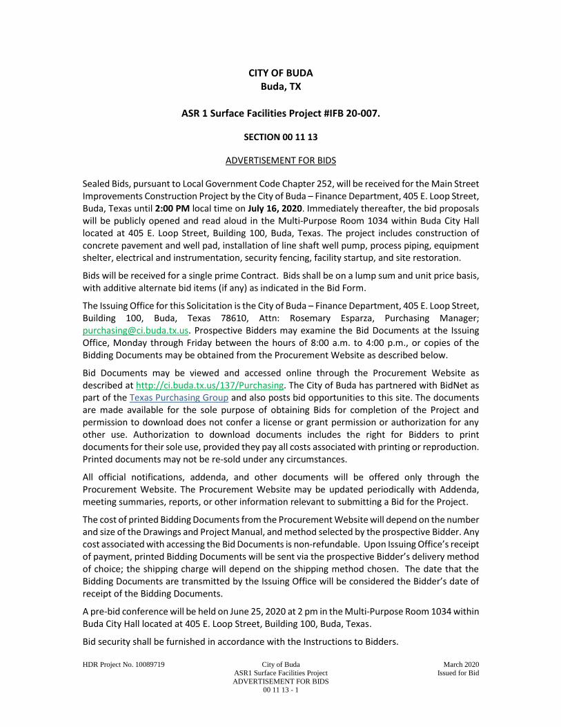
Sealed Bids, pursuant to Local Government Code Chapter 252, will be received for the Main Street Improvements Construction Project by the City of Buda – Finance Department, 405 E. Loop Street, Buda, Texas until 2:00 PM local time on July 16, 2020. Immediately thereafter, the bid proposals will be publicly opened and read aloud in the Multi-Purpose Room 1034 within Buda City Hall located at 405 E. Loop Street, Building 100, Buda, Texas. The project includes construction of concrete pavement and well pad, installation of line shaft well pump, process piping, equipment shelter, electrical and instrumentation, security fencing, facility startup, and site restoration.
Bids will be received for a single prime Contract. Bids shall be on a lump sum and unit price basis, with additive alternate bid items (if any) as indicated in the Bid Form.
The Issuing Office for this Solicitation is the City of Buda – Finance Department, 405 E. Loop Street, Building 100, Buda, Texas 78610, Attn: Rosemary Esparza, Purchasing Manager; [email protected]. Prospective Bidders may examine the Bid Documents at the Issuing Office, Monday through Friday between the hours of 8:00 a.m. to 4:00 p.m., or copies of the Bidding Documents may be obtained from the Procurement Website as described below.
Bid Documents may be viewed and accessed online through the Procurement Website as described at http://ci.buda.tx.us/137/Purchasing. The City of Buda has partnered with BidNet as part of the Texas Purchasing Group and also posts bid opportunities to this site. The documents are made available for the sole purpose of obtaining Bids for completion of the Project and permission to download does not confer a license or grant permission or authorization for any other use. Authorization to download documents includes the right for Bidders to print documents for their sole use, provided they pay all costs associated with printing or reproduction. Printed documents may not be re-sold under any circumstances.
All official notifications, addenda, and other documents will be offered only through the Procurement Website. The Procurement Website may be updated periodically with Addenda, meeting summaries, reports, or other information relevant to submitting a Bid for the Project.
The cost of printed Bidding Documents from the Procurement Website will depend on the number and size of the Drawings and Project Manual, and method selected by the prospective Bidder. Any cost associated with accessing the Bid Documents is non-refundable. Upon Issuing Office’s receipt of payment, printed Bidding Documents will be sent via the prospective Bidder’s delivery method of choice; the shipping charge will depend on the shipping method chosen. The date that the Bidding Documents are transmitted by the Issuing Office will be considered the Bidder’s date of receipt of the Bidding Documents.
A pre-bid conference will be held on June 25, 2020 at 2 pm in the Multi-Purpose Room 1034 within Buda City Hall located at 405 E. Loop Street, Building 100, Buda, Texas.
Bid security shall be furnished in accordance with the Instructions to Bidders.
HDR Project No. 10089719 City of Buda March 2020
ASR1 Surface Facilities Project Issued for Bid
ADVERTISEMENT FOR BIDS 00 11 13 - 2
Owner: City of Buda
By: John Nett, PE
Title: City Engineer
Date: June 5, 2020
+ + END OF ADVERTISEMENT FOR BIDS + +
HDR Project No. 10089719 City of Buda March 2020
ASR1 Surface Facilities Project Issued for Bid
INSTRUCTIONS TO BIDDERS 00 21 13 - 1
INSTRUCTIONS TO BIDDERS
ARTICLE 1 – DEFINED TERMS
1.01 Terms used in these Instructions to Bidders have the meanings indicated in the Glossary of Defined Terms.
1.02 Unless otherwise defined, “day” refers to a calendar day.
ARTICLE 2 – COPIES OF BIDDING DOCUMENTS
2.01 Complete sets of the Bidding Documents may be obtained from the Procurement Website in the number and format stated in the advertisement or invitation to bid.
2.02 Complete sets of Bidding Documents shall be used in preparing Bids; neither Owner nor Engineer assumes any responsibility for errors or misinterpretations resulting from the use of incomplete sets of Bidding Documents.
2.03 Owner and Engineer, in making copies of Bidding Documents available on the above terms, do so only for the purpose of obtaining Bids for the Work and do not authorize or confer a license for any other use.
ARTICLE 3 – QUALIFICATIONS OF BIDDERS
3.01 To demonstrate Bidder’s qualifications to perform the Work, Bidder shall submit with its Bid the completed qualifications statement of bidders included in Section 00 45 13 “Qualifications Statement.”
3.02 A Bidder’s failure to demonstrate the minimum qualifications, as defined in Section 00 45 13 “Qualifications Statement”, will disqualify Bidder from receiving an award of the Contract.
3.03 No requirement in this Article 3 to submit information will prejudice the right of Owner to seek additional pertinent information regarding Bidder’s qualifications.
3.04 Bidder is advised to carefully review those portions of the Bid Form requiring Bidder’s representations and certifications.
ARTICLE 4 – SITE AND OTHER AREAS; EXISTING SITE CONDITIONS; EXAMINATION OF SITE; OWNER’S SAFETY PROGRAM; OTHER WORK AT THE SITE
4.01 Site and Other Areas
A. The Site is identified in the Bidding Documents. By definition, the Site includes rights-of-way, easements, and other lands furnished by Owner for the use of the Contractor. Any additional lands required for temporary construction facilities, construction equipment, or storage of materials and equipment, and any access needed for such additional lands, are to be obtained and paid for by Contractor.
4.02 Existing Site Conditions
A. Subsurface and Physical Conditions; Hazardous Environmental Conditions
1. The Supplementary Conditions identify:

HDR Project No. 10089719 City of Buda March 2020
ASR1 Surface Facilities Project Issued for Bid
INSTRUCTIONS TO BIDDERS 00 21 13 - 2
a. those reports known to Owner of explorations and tests of subsurface conditions at or adjacent to the Site.
b. those drawings known to Owner of physical conditions relating to existing surface or subsurface structures at the Site (except Underground Facilities).
c. reports and drawings known to Owner relating to Hazardous Environmental Conditions that have been identified at or adjacent to the Site.
d. Technical Data contained in such reports and drawings.
2. Owner will make copies of reports and drawings referenced above available to any Bidder on request. These reports and drawings are not part of the Contract Documents, but the Technical Data contained therein upon whose accuracy Bidder is entitled to rely, as provided in the General Conditions, has been identified and established in the Supplementary Conditions. Bidder is responsible for any interpretation or conclusion Bidder draws from any Technical Data or any other data, interpretations, opinions, or information contained in such reports or shown or indicated in such drawings.
3. If the Supplementary Conditions do not identify Technical Data, the default definition of Technical Data set forth in Article 1 of the General Conditions will apply.
4. Geotechnical Baseline Report: The Bidding Documents do not contain a Geotechnical Baseline Report (GBR).
B. Underground Facilities: Information and data shown or indicated in the Bidding Documents with respect to existing Underground Facilities at or adjacent to the Site are set forth in the Contract Documents and are based upon information and data furnished to Owner and Engineer by owners of such Underground Facilities, including Owner, or others.
C. Adequacy of Data: Provisions concerning responsibilities for the adequacy of data furnished to prospective Bidders with respect to subsurface conditions, other physical conditions, and Underground Facilities, and possible changes in the Bidding Documents due to differing or unanticipated subsurface or physical conditions appear in Paragraphs 5.03, 5.04, and 5.05 of the General Conditions. Provisions concerning responsibilities for the adequacy of data furnished to prospective Bidders with respect to a Hazardous Environmental Condition at the Site, if any, and possible changes in the Contract Documents due to any Hazardous Environmental Condition uncovered or revealed at the Site which was not shown or indicated in the Drawings or Specifications or identified in the Contract Documents to be within the scope of the Work, appear in Paragraph 5.06 of the General Conditions.
4.03 Site Visit and Testing by Bidders
A. Bidder shall conduct the required Site visit during normal working hours, and shall not disturb any ongoing operations at the Site. The site is generally accessible to the public.

HDR Project No. 10089719 City of Buda March 2020
ASR1 Surface Facilities Project Issued for Bid
INSTRUCTIONS TO BIDDERS 00 21 13 - 3
B. Bidder is not required to conduct any subsurface testing, or exhaustive investigations of Site conditions.
C. On request, and to the extent Owner has control over the Site, and schedule permitting, the Owner will provide Bidder access to the Site to conduct such additional examinations, investigations, explorations, tests, and studies as Bidder deems necessary for preparing and submitting a successful Bid. Owner will not have any obligation to grant such access if doing so is not practical because of existing operations, security or safety concerns, or restraints on Owner’s authority regarding the Site.
D. Bidder shall comply with all applicable Laws and Regulations regarding excavation and location of utilities, obtain all permits, and comply with all terms and conditions established by Owner or by property owners or other entities controlling the Site with respect to schedule, access, existing operations, security, liability insurance, and applicable safety programs.
E. Bidder shall fill all holes and clean up and restore the Site to its former condition upon completion of such explorations, investigations, tests, and studies.
4.04 Owner’s Safety Program
A. Site visits and work at the Site may be governed by an Owner safety program. As the General Conditions indicate, if an Owner safety program exists, it will be noted in the Supplementary Conditions.
4.05 Other Work at the Site
A. Reference is made to Article 8 of the Supplementary Conditions for the identification of the general nature of other work of which Owner is aware (if any) that is to be performed at the Site by Owner or others (such as utilities and other prime contractors) and relates to the Work contemplated by these Bidding Documents. If Owner is party to a written contract for such other work, then on request, Owner will provide to each Bidder access to examine such contracts (other than portions thereof related to price and other confidential matters), if any.
ARTICLE 5 – BIDDER’S REPRESENTATIONS
5.01 It is the responsibility of each Bidder before submitting a Bid to:
A. examine and carefully study the Bidding Documents, and any data and reference items identified in the Bidding Documents;
B. visit the Site, conduct a thorough, alert visual examination of the Site and adjacent areas, and become familiar with and satisfy itself as to the general, local, and Site conditions that may affect cost, progress, and performance of the Work;
C. become familiar with and satisfy itself as to all Laws and Regulations that may affect cost, progress, and performance of the Work;
D. carefully study all: (1) reports of explorations and tests of subsurface conditions at or adjacent to the Site and all drawings of physical conditions relating to existing surface or subsurface structures at the Site that have been identified in the Supplementary Conditions, if any, especially with respect to Technical Data in such

HDR Project No. 10089719 City of Buda March 2020
ASR1 Surface Facilities Project Issued for Bid
INSTRUCTIONS TO BIDDERS 00 21 13 - 4
reports and drawings, and (2) reports and drawings relating to Hazardous Environmental Conditions, if any, at or adjacent to the Site that have been identified in the Supplementary Conditions, especially with respect to Technical Data in such reports and drawings;
E. consider the information known to Bidder itself; information commonly known to contractors doing business in the locality of the Site; information and observations obtained from visits to the Site; the Bidding Documents, with respect to the effect of such information, observations, and documents on (1) the cost, progress, and performance of the Work; (2) the means, methods, techniques, sequences, and procedures of construction to be employed by Bidder; and (3) Bidder’s safety precautions and programs;
F. agree, based on the information and observations referred to in the preceding paragraph, that at the time of submitting its Bid no further examinations, investigations, explorations, tests, studies, or data are necessary for the determination of its Bid for performance of the Work at the price bid and within the times required, and in accordance with the other terms and conditions of the Bidding Documents;
G. become aware of the general nature of the work to be performed by Owner and others at the Site that relates to the Work as indicated in the Bidding Documents;
H. promptly give Engineer written notice of all conflicts, errors, ambiguities, or discrepancies that Bidder discovers in the Bidding Documents and confirm that the written resolution thereof by Engineer is acceptable to Bidder;
I. determine that the Bidding Documents are generally sufficient to indicate and convey understanding of all terms and conditions for the performance and furnishing of the Work; and
J. agree that the submission of a Bid will constitute an incontrovertible representation by Bidder that Bidder has complied with every requirement of this Article, that without exception the Bid and all prices in the Bid are premised upon performing and furnishing the Work required by the Bidding Documents.
ARTICLE 6 – INTERPRETATIONS AND ADDENDA
6.01 All questions about the meaning or intent of the Bidding Documents are to be submitted to Engineer in writing. Interpretations or clarifications considered necessary by Engineer in response to such questions will be issued by Addenda delivered to all parties recorded as having received the Bidding Documents. The deadline for answering questions is July1, 2020. Questions received less than eleven days prior to the date for opening of Bids may not be answered. Only questions answered by Addenda will be binding. Oral and other interpretations or clarifications will be without legal effect.
6.02 Addenda may be issued to clarify, correct, supplement, or change the Bidding Documents.
ARTICLE 7 – BID SECURITY
7.01 A Bid must be accompanied by Bid security made payable to Owner in an amount of 5 percent of Bidder’s maximum Bid price (determined by adding the base bid and all

HDR Project No. 10089719 City of Buda March 2020
ASR1 Surface Facilities Project Issued for Bid
INSTRUCTIONS TO BIDDERS 00 21 13 - 5
alternates) and in the form of a certified check, bank money order, or a Bid bond (on the form included in the Bidding Documents) issued by a surety meeting the requirements of Paragraphs 6.01 and 6.02 of the General Conditions.
7.02 The Bid security of the apparent Successful Bidder will be retained until Owner awards the contract to such Bidder, and such Bidder has executed the Contract Documents, furnished the required contract security, and met the other conditions of the Notice of Award, whereupon the Bid security will be released. If the Successful Bidder fails to execute and deliver the Contract Documents and furnish the required contract security within 15 days after the Notice of Award, Owner may consider Bidder to be in default, annul the Notice of Award, and the Bid security of that Bidder will be forfeited. Such forfeiture shall be Owner’s exclusive remedy if Bidder defaults.
7.03 The Bid security of other Bidders that Owner believes to have a reasonable chance of receiving the award may be retained by Owner until the earlier of seven days after the Effective Date of the Contract or 61 days after the Bid opening, whereupon Bid security furnished by such Bidders will be released.
7.04 Bid security of other Bidders that Owner believes do not have a reasonable chance of receiving the award will be released within seven days after the Bid opening.
ARTICLE 8 – CONTRACT TIMES
8.01 The number of days within which, or the dates by which, the Work is to be substantially completed, and completed and ready for final payment, are set forth in the Agreement.
ARTICLE 9 – LIQUIDATED DAMAGES
9.01 Provisions for liquidated damages, if any, for failure to timely attain a Milestone, Substantial Completion, or completion of the Work in readiness for final payment, are set forth in the Agreement.
ARTICLE 10 – SUBSTITUTE AND “OR-EQUAL” ITEMS
10.01 The Contract for the Work, as awarded, will be on the basis of materials and equipment specified or described in the Bidding Documents without consideration during the bidding and Contract award process of possible substitute or “or-equal” items. In cases in which the Contract allows the Contractor to request that Engineer authorize the use of a substitute or “or-equal” item of material or equipment, application for such acceptance may not be made to and will not be considered by Engineer until after the Effective Date of the Contract.
10.02 All prices that Bidder sets forth in its Bid shall be based on the presumption that the Contractor will furnish the materials and equipment specified or described in the Bidding Documents, as supplemented by Addenda. Any assumptions regarding the possibility of post-Bid approvals of “or-equal” or substitution requests are made at Bidder’s sole risk.
ARTICLE 11 – SUBCONTRACTORS, SUPPLIERS, AND OTHERS
11.01 A Bidder shall be prepared to retain specific Subcontractors, Suppliers, or other individuals or entities for the performance of the Work if required by the Bidding

HDR Project No. 10089719 City of Buda March 2020
ASR1 Surface Facilities Project Issued for Bid
INSTRUCTIONS TO BIDDERS 00 21 13 - 6
Documents (most commonly in the Specifications) to do so. If a prospective Bidder objects to retaining any such Subcontractor, Supplier, or other individual or entity, and the concern is not relieved by an Addendum, then the prospective Bidder should refrain from submitting a Bid.
11.02 Subsequent to the submittal of the Bid, Owner may not require the Successful Bidder or Contractor to retain any Subcontractor, Supplier, or other individual or entity against which Contractor has reasonable objection.
11.03 Bidder shall submit with the Bid a list of Subcontractors and description of their work, if work to be performed by Subcontractors exceeds 25 percent of Total Amount Bid. The apparent Successful Bidder, and any other Bidder so requested, shall within five days after Bid opening, submit to Owner a list of the Subcontractors or Suppliers proposed for the Work.
If requested by Owner, such list shall be accompanied by an experience statement with pertinent information regarding similar projects and other evidence of qualification for each such Subcontractor, Supplier, or other individual or entity. If Owner or Engineer, after due investigation, has reasonable objection to any proposed Subcontractor, Supplier, individual, or entity, Owner may, before the Notice of Award is given, request apparent Successful Bidder to submit an acceptable substitute, in which case apparent Successful Bidder shall submit a substitute, Bidder’s Bid price will be increased (or decreased) by the difference in cost occasioned by such substitution, and Owner may consider such price adjustment in evaluating Bids and making the Contract award.
11.04 If apparent Successful Bidder declines to make any such substitution, Owner may award the Contract to the next lowest Bidder that proposes to use acceptable Subcontractors, Suppliers, or other individuals or entities. Declining to make requested substitutions will constitute grounds for forfeiture of the Bid security of any Bidder. Any Subcontractor, Supplier, individual, or entity so listed and against which Owner or Engineer makes no written objection prior to the giving of the Notice of Award will be deemed acceptable to Owner and Engineer subject to subsequent revocation of such acceptance as provided in Paragraph 7.06 of the General Conditions.
ARTICLE 12 – PREPARATION OF BID
12.01 The Bid Form is included with the Bidding Documents.
A. All blanks on the Bid Form shall be completed in ink and the Bid Form signed in ink. Erasures or alterations shall be initialed in ink by the person signing the Bid Form. A Bid price shall be indicated for each section, Bid item, alternate, adjustment unit price item, and unit price item listed therein.
B. If the Bid Form expressly indicates that submitting pricing on a specific alternate item is optional, and Bidder elects to not furnish pricing for such optional alternate item, then Bidder may enter the words “No Bid” or “Not Applicable.”
12.02 A Bid by a corporation shall be executed in the corporate name by a corporate officer (whose title must appear under the signature), accompanied by evidence of authority to sign. The corporate address and state of incorporation shall be shown.
HDR Project No. 10089719 City of Buda March 2020
ASR1 Surface Facilities Project Issued for Bid
INSTRUCTIONS TO BIDDERS 00 21 13 - 7
12.03 A Bid by a partnership shall be executed in the partnership name and signed by a partner (whose title must appear under the signature), accompanied by evidence of authority to sign. The partnership’s address for receiving notices shall be shown.
12.04 A Bid by a limited liability company shall be executed in the name of the firm by a member or other authorized person and accompanied by evidence of authority to sign. The state of formation of the firm and the firm’s address for receiving notices shall be shown.
12.05 A Bid by an individual shall show the Bidder’s name and address for receiving notices.
12.06 A Bid by a joint venture shall be executed by an authorized representative of each joint venturer in the manner indicated on the Bid Form. The joint venture’s address for receiving notices shall be shown.
12.07 All names shall be printed in ink below the signatures.
12.08 The Bid shall contain an acknowledgment of receipt of all Addenda, the numbers of which shall be filled in on the Bid Form.
12.09 Postal and e-mail addresses and telephone number for communications regarding the Bid shall be shown.
12.10 See Paragraph 3.01 for instructions to Bidder on how to demonstrate qualifications to perform the Work.
ARTICLE 13 – BASIS OF BID
13.01 Unit Price
A. Bidders shall submit a Bid on a unit price basis for each item of Work listed in the unit price section of the Bid Form.
B. The “Bid Price” (sometimes referred to as the extended price) for each unit price Bid item will be the product of the “Estimated Quantity” (which Owner or its representative has set forth in the Bid Form) for the item and the corresponding “Bid Unit Price” offered by the Bidder. The total of all unit price Bid items will be the sum of these “Bid Prices”; such total will be used by Owner for Bid comparison purposes. The final quantities and Contract Price will be determined in accordance with Paragraph 13.03 of the General Conditions.
C. Discrepancies between the multiplication of units of Work and unit prices will be resolved in favor of the unit prices. Discrepancies between the indicated sum of any column of figures and the correct sum thereof will be resolved in favor of the correct sum.
13.02 Allowances
A. For cash allowances the Bid price shall include such amounts as the Bidder deems proper for Contractor's overhead, costs, profit, and other expenses on account of cash allowances, if any, named in the Contract Documents, in accordance with Paragraph 13.02.B of the General Conditions.

HDR Project No. 10089719 City of Buda March 2020
ASR1 Surface Facilities Project Issued for Bid
INSTRUCTIONS TO BIDDERS 00 21 13 - 8
ARTICLE 14 – SUBMITTAL OF BID
14.01 With each copy of the Bidding Documents, a Bidder is furnished one separate unbound copy of the Bid Form, and, if required, the Bid Bond Form. The unbound copy of the Bid Form is to be completed and submitted with the Bid security and the other documents required to be submitted under the terms of Article 7 of the Bid Form.
14.02 A Bid shall be received no later than the date and time prescribed and at the place indicated in the advertisement or invitation to bid and shall be enclosed in a plainly marked package with the Project title (and, if applicable, the designated portion of the Project for which the Bid is submitted), the name and address of Bidder, and shall be accompanied by the Bid security and other required documents. If a Bid is sent by mail or other delivery system, the sealed envelope containing the Bid shall be enclosed in a separate package plainly marked on the outside with the notation “BID ENCLOSED.” A mailed Bid shall be addressed to the address listed in Section C-111 “Advertisement.”
14.03 Bids received after the date and time prescribed for the opening of bids, or not submitted at the correct location or in the designated manner, will not be accepted and will be returned to the Bidder unopened.
ARTICLE 15 – MODIFICATION AND WITHDRAWAL OF BID
15.01 A Bid may be withdrawn by an appropriate document duly executed in the same manner that a Bid must be executed and delivered to the place where Bids are to be submitted prior to the date and time for the opening of Bids. Upon receipt of such notice, the unopened Bid will be returned to the Bidder.
15.02 If a Bidder wishes to modify its Bid prior to Bid opening, Bidder must withdraw its initial Bid in the manner specified in Paragraph 16.01 and submit a new Bid prior to the date and time for the opening of Bids.
15.03 If within 24 hours after Bids are opened any Bidder files a duly signed written notice with Owner and promptly thereafter demonstrates to the reasonable satisfaction of Owner that there was a material and substantial mistake in the preparation of its Bid, that Bidder may withdraw its Bid, and the Bid security will be returned. Thereafter, if the Work is rebid, that Bidder will be disqualified from further bidding on the Work.
ARTICLE 16 – OPENING OF BIDS
16.01 Bids will be opened at the time and place indicated in the advertisement or invitation to bid and, unless obviously non-responsive, read aloud publicly. An abstract of the amounts of the base Bids and major alternates, if any, will be made available to Bidders after the opening of Bids.
ARTICLE 17 – BIDS TO REMAIN SUBJECT TO ACCEPTANCE
17.01 All Bids will remain subject to acceptance for the period of time stated in the Bid Form, but Owner may, in its sole discretion, release any Bid and return the Bid security prior to the end of this period.
HDR Project No. 10089719 City of Buda March 2020
ASR1 Surface Facilities Project Issued for Bid
INSTRUCTIONS TO BIDDERS 00 21 13 - 9
ARTICLE 18 – EVALUATION OF BIDS AND AWARD OF CONTRACT
18.01 Owner reserves the right to reject any or all Bids, including without limitation, nonconforming, nonresponsive, unbalanced, or conditional Bids. Owner will reject the Bid of any Bidder that Owner finds, after reasonable inquiry and evaluation, to not be responsible. If Bidder purports to add terms or conditions to its Bid, takes exception to any provision of the Bidding Documents, or attempts to alter the contents of the Contract Documents for purposes of the Bid, then the Owner will reject the Bid as nonresponsive; provided that Owner also reserves the right to waive all minor informalities not involving price, time, or changes in the Work.
18.02 If Owner awards the contract for the Work, such award shall be to the responsible Bidder who provides goods or services at the lowest Base Bid price.
18.03 Evaluation of Bids
A. In evaluating Bids, Owner will consider whether or not the Bids comply with the prescribed requirements, and such alternates, unit prices, and other data, as may be requested in the Bid Form or prior to the Notice of Award.
18.04 In evaluating whether a Bidder is responsible, Owner will consider the qualifications of the Bidder and may consider the qualifications and experience of Subcontractors and Suppliers proposed for those portions of the Work for which the identity of Subcontractors and Suppliers must be submitted as provided in the Bidding Documents.
18.05 Owner may conduct such investigations as Owner deems necessary to establish the responsibility, qualifications, and financial ability of Bidders and any proposed Subcontractors or Suppliers.
ARTICLE 19 – BONDS AND INSURANCE
19.01 Article 6 of the General Conditions, as may be modified by the Supplementary Conditions, sets forth Owner’s requirements as to performance and payment bonds and insurance. When the Successful Bidder delivers the Agreement (executed by Successful Bidder) to Owner, it shall be accompanied by required bonds and insurance documentation.
19.02 Provide performance and payment bonds for this Project that fully comply with the provisions of Texas Government Code Chapter 2253. Administration of these bonds will conform to Texas Government Code Chapter 2253 and the provisions of the Contract Documents.
ARTICLE 20 – SIGNING OF AGREEMENT
20.01 When Owner issues a Notice of Award to the Successful Bidder, it shall be accompanied by the unexecuted counterparts of the Agreement along with the other Contract Documents as identified in the Agreement. Within 15 days thereafter, Successful Bidder shall execute and deliver the required number of counterparts of the Agreement (and any bonds and insurance documentation required to be delivered by the Contract Documents) to Owner. Within ten days thereafter, Owner shall deliver one fully executed counterpart of the Agreement to Successful Bidder, together with printed and electronic copies of the Contract Documents as stated in Paragraph 2.02 of the General Conditions.
HDR Project No. 10089719 City of Buda March 2020
ASR1 Surface Facilities Project Issued for Bid
INSTRUCTIONS TO BIDDERS 00 21 13 - 10
ARTICLE 21 – SALES AND USE TAXES
21.01 Owner is exempt from the State of Texas state sales and use taxes on materials and equipment to be incorporated in the Work. (Exemption No. 74-1707220). Said taxes shall not be included in the Bid. Refer to Paragraph SC-7.09 of the Supplementary Conditions for additional information.

HDR Project No. 10089719 City of Buda March 2020
ASR1 Surface Facilities Project Issued for Bid
BID FORM 00 41 13 - 1
BID FORM
–ASR1 Surface Facilities
Construction Project
City of Buda
405 E. Loop Street
Buda, Texas 78610
Attention: Purchasing Manager
HDR Project No. 10089719 City of Buda March 2020
ASR1 Surface Facilities Project Issued for Bid
BID FORM 00 41 13 - 2
ARTICLE 1 – BID RECIPIENT
1.01 This Bid is submitted to:
City of Buda – Finance Department 405 E. Loop Street Buda, Texas 78610
1.02 The undersigned Bidder proposes and agrees, if this Bid is accepted, to enter into an Agreement with Owner in the form included in the Bidding Documents to perform all Work as specified or indicated in the Bidding Documents for the prices and within the times indicated in this Bid and in accordance with the other terms and conditions of the Bidding Documents.
ARTICLE 2 – BIDDER’S ACKNOWLEDGEMENTS
2.01 Bidder accepts all of the terms and conditions of the Instructions to Bidders, including without limitation those dealing with the disposition of Bid security. This Bid will remain subject to acceptance for 60 days after the Bid opening, or for such longer period of time that Bidder may agree to in writing upon request of Owner.
2.02 BIDDER will sign and deliver the required number of counterparts of the AGREEMENT with the Bonds and other documents required by the Bidding Requirements within {15} days after the date of OWNER's Notice of Award.
ARTICLE 3 – BIDDER’S REPRESENTATIONS
3.01 In submitting this Bid, Bidder represents that:
A. Bidder has examined and carefully studied the Bidding Documents, and any data and reference items identified in the Bidding Documents, and hereby acknowledges receipt of the following Addenda:
Addendum No. Addendum, Date
B. Bidder has visited the Site, conducted a thorough, alert visual examination of the Site and adjacent areas, and become familiar with and satisfied itself as to the general, local, and Site conditions that may affect cost, progress, and performance of the Work.
C. Bidder is familiar with and has satisfied itself as to all Laws and Regulations that may affect cost, progress, and performance of the Work
D. Bidder has considered the information known to Bidder itself; information commonly known to contractors doing business in the locality of the Site; information and observations obtained from visits to the Site; the Bidding
HDR Project No. 10089719 City of Buda March 2020
ASR1 Surface Facilities Project Issued for Bid
BID FORM 00 41 13 - 3
Documents; and any Site-related reports and drawings identified in the Bidding Documents, with respect to the effect of such information, observations, and documents on (1) the cost, progress, and performance of the Work; (2) the means, methods, techniques, sequences, and procedures of construction to be employed by Bidder; and (3) Bidder’s safety precautions and programs.
E. Bidder agrees, based on the information and observations referred to in the preceding paragraph, that no further examinations, investigations, explorations, tests, studies, or data are necessary for the determination of this Bid for performance of the Work at the price bid and within the times required, and in accordance with the other terms and conditions of the Bidding Documents.
F. Bidder is aware of the general nature of work to be performed by Owner and others at the Site that relates to the Work as indicated in the Bidding Documents.
G. Bidder has given Engineer written notice of all conflicts, errors, ambiguities, or discrepancies that Bidder has discovered in the Bidding Documents, and confirms that the written resolution thereof by Engineer is acceptable to Bidder.
H. The Bidding Documents are generally sufficient to indicate and convey understanding of all terms and conditions for the performance and furnishing of the Work.
I. The submission of this Bid constitutes an incontrovertible representation by Bidder that Bidder has complied with every requirement of this Article, and that without exception the Bid and all prices in the Bid are premised upon performing and furnishing the Work required by the Bidding Documents.
ARTICLE 4 – BIDDER’S CERTIFICATION
4.01 Bidder certifies that:
A. This Bid is genuine and not made in the interest of or on behalf of any undisclosed individual or entity and is not submitted in conformity with any collusive agreement or rules of any group, association, organization, or corporation;
B. Bidder has not directly or indirectly induced or solicited any other Bidder to submit a false or sham Bid;
C. Bidder has not solicited or induced any individual or entity to refrain from bidding; and
D. Bidder has not engaged in corrupt, fraudulent, collusive, or coercive practices in competing for the Contract. For the purposes of this Paragraph 4.01.D:
1. “corrupt practice” means the offering, giving, receiving, or soliciting of anything of value likely to influence the action of a public official in the bidding process;
2. “fraudulent practice” means an intentional misrepresentation of facts made (a) to influence the bidding process to the detriment of Owner, (b) to establish bid prices at artificial non-competitive levels, or (c) to deprive Owner of the benefits of free and open competition;

HDR Project No. 10089719 City of Buda March 2020
ASR1 Surface Facilities Project Issued for Bid
BID FORM 00 41 13 - 4
3. “collusive practice” means a scheme or arrangement between two or more Bidders, with or without the knowledge of Owner, a purpose of which is to establish bid prices at artificial, non-competitive levels; and
4. “coercive practice” means harming or threatening to harm, directly or indirectly, persons or their property to influence their participation in the bidding process or affect the e execution of the Contract.
ARTICLE 5 – BASIS OF BID
5.01 Bidder will complete the Work in accordance with the Contract Documents for the following price(s):
Please use the excel file supplied for entering in unit costs
ARTICLE 6 – TIME OF COMPLETION
6.01 Bidder agrees that the Work will be substantially complete and will be completed and ready for final payment in accordance with Paragraph 15.06 of the General Conditions on or before the dates or within the number of calendar days indicated in the Agreement.
6.02 Bidder accepts the provisions of the Agreement as to liquidated damages.
ARTICLE 7 – ATTACHMENTS TO THIS BID
7.01 The following documents are submitted with and made a condition of this Bid:
A. Required Bid security;
B. List of Proposed Subcontractors;
C. List of Proposed Suppliers;
D. Evidence of authority to do business in the state of the Project; or a written covenant to obtain such license within the time for acceptance of Bids;
E. Required Bidder Qualification Statement with supporting data;
F. Executed Section 00 45 46 “Vendor Compliance to State Law”; and
G. Executed Section 00 45 02 “Conflict of Interest Questionnaire”
ARTICLE 8 – DEFINED TERMS
8.01 The terms used in this Bid with initial capital letters have the meanings stated in the Glossary of Defined Terms.
HDR Project No. 10089719 City of Buda March 2020
ASR1 Surface Facilities Project Issued for Bid
BID FORM 00 41 13 - 5
ARTICLE 9 – BID SUBMITTAL
BIDDER: (Indicate correct name of bidding entity)
By: (Signature)
(Printed name)
(If Bidder is a corporation, a limited liability company, a partnership, or a joint venture, attach evidence of authority to sign.)
Attest: (Signature)
(Printed name)
Title:
Submittal Date:
Address for giving notices:
Telephone Number:
Fax Number:
Contact Name and e-mail address:
Bidder’s License No.:
(where applicable)

This page intentionally left blank.

HDR Project No. 10089719 City of Buda March 2020
ASR1 Surface Facilities Project Issued for Bid
BID BOND (PENAL SUM) 00 43 13 - 1
BID BOND
Any singular reference to Bidder, Surety, Owner or other party shall be considered plural where applicable.
BIDDER (Name and Address):
SURETY (Name, and Address of Principal Place of Business):
OWNER (Name and Address):
BID Bid Due Date:
Description (Project Name— Include Location):
BOND
Bond Number:
Date:
Penal sum $
(Words) (Figures) Surety and Bidder, intending to be legally bound hereby, subject to the terms set forth below, do each cause this Bid Bond to be duly executed by an authorized officer, agent, or representative. BIDDER SURETY
(Seal) (Seal)
Bidder’s Name and Corporate Seal Surety’s Name and Corporate Seal
By: By:
Signature Signature (Attach Power of Attorney)
Print Name Print Name
Title Title
Attest: Attest:
Signature Signature
Title Title

HDR Project No. 10089719 City of Buda March 2020
ASR1 Surface Facilities Project Issued for Bid
BID BOND (PENAL SUM) 00 43 13 - 2
Note: Addresses are to be used for giving any required notice. Provide execution by any additional parties, such as joint venturers, if necessary.
1. Bidder and Surety, jointly and severally, bind themselves, their heirs, executors, administrators,
successors, and assigns to pay to Owner upon default of Bidder the penal sum set forth on the face of this
Bond. Payment of the penal sum is the extent of Bidder’s and Surety’s liability. Recovery of such penal
sum under the terms of this Bond shall be Owner’s sole and exclusive remedy upon default of Bidder.
2. Default of Bidder shall occur upon the failure of Bidder to deliver within the time required by the Bidding Documents (or any extension thereof agreed to in writing by Owner) the executed Agreement required by the Bidding Documents and any performance and payment bonds required by the Bidding Documents.
3. This obligation shall be null and void if:
3.1 Owner accepts Bidder’s Bid and Bidder delivers within the time required by the Bidding Documents (or any extension thereof agreed to in writing by Owner) the executed Agreement required by the Bidding Documents and any performance and payment bonds required by the Bidding Documents, or
3.2 All Bids are rejected by Owner, or
3.3 Owner fails to issue a Notice of Award to Bidder within the time specified in the Bidding Documents (or any extension thereof agreed to in writing by Bidder and, if applicable, consented to by Surety when required by Paragraph 5 hereof).
4. Payment under this Bond will be due and payable upon default of Bidder and within 30 calendar days after receipt by Bidder and Surety of written notice of default from Owner, which notice will be given with reasonable promptness, identifying this Bond and the Project and including a statement of the amount due.
5. Surety waives notice of any and all defenses based on or arising out of any time extension to issue Notice of Award agreed to in writing by Owner and Bidder, provided that the total time for issuing Notice of Award including extensions shall not in the aggregate exceed 120 days from the Bid due date without Surety’s written consent.
6. No suit or action shall be commenced under this Bond prior to 30 calendar days after the notice of default required in Paragraph 4 above is received by Bidder and Surety and in no case later than one year after the Bid due date.
7. Any suit or action under this Bond shall be commenced only in a court of competent jurisdiction located in the state in which the Project is located.
8. Notices required hereunder shall be in writing and sent to Bidder and Surety at their respective addresses shown on the face of this Bond. Such notices may be sent by personal delivery, commercial courier, or by United States Registered or Certified Mail, return receipt requested, postage pre-paid, and shall be deemed to be effective upon receipt by the party concerned.
9. Surety shall cause to be attached to this Bond a current and effective Power of Attorney evidencing the authority of the officer, agent, or representative who executed this Bond on behalf of Surety to execute, seal, and deliver such Bond and bind the Surety thereby.
HDR Project No. 10089719 City of Buda March 2020
ASR1 Surface Facilities Project Issued for Bid
BID BOND (PENAL SUM) 00 43 13 - 3
10. This Bond is intended to conform to all applicable statutory requirements. Any applicable requirement of any applicable statute that has been omitted from this Bond shall be deemed to be included herein as if set forth at length. If any provision of this Bond conflicts with any applicable statute, then the provision of said statute shall govern and the remainder of this Bond that is not in conflict therewith shall continue in full force and effect.
11. The term “Bid” as used herein includes a Bid, offer, or proposal as applicable.

This page intentionally left blank.
Conflict of Interest Questionnaire 00 45 02 - 1
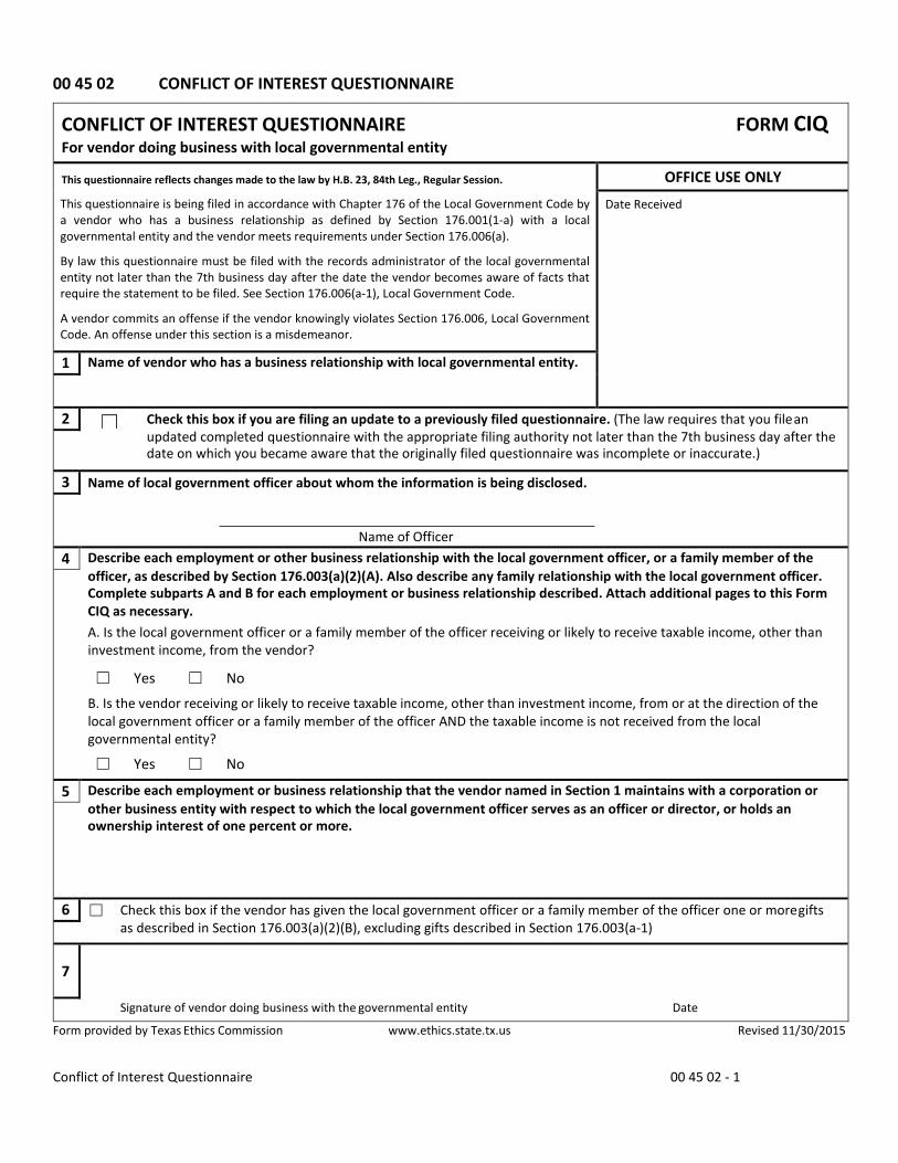
00 45 02 CONFLICT OF INTEREST QUESTIONNAIRE
CONFLICT OF INTEREST QUESTIONNAIRE FORM CIQ For vendor doing business with local governmental entity
This questionnaire reflects changes made to the law by H.B. 23, 84th Leg., Regular Session.
This questionnaire is being filed in accordance with Chapter 176 of the Local Government Code by a vendor who has a business relationship as defined by Section 176.001(1-a) with a local governmental entity and the vendor meets requirements under Section 176.006(a).
By law this questionnaire must be filed with the records administrator of the local governmental entity not later than the 7th business day after the date the vendor becomes aware of facts that require the statement to be filed. See Section 176.006(a-1), Local Government Code.
A vendor commits an offense if the vendor knowingly violates Section 176.006, Local Government Code. An offense under this section is a misdemeanor.
OFFICE USE ONLY
Date Received
1 Name of vendor who has a business relationship with local governmental entity.
2 ☐ Check this box if you are filing an update to a previously filed questionnaire. (The law requires that you file an updated completed questionnaire with the appropriate filing authority not later than the 7th business day after the date on which you became aware that the originally filed questionnaire was incomplete or inaccurate.)
3 Name of local government officer about whom the information is being disclosed.
Name of Officer 4 Describe each employment or other business relationship with the local government officer, or a family member of the
officer, as described by Section 176.003(a)(2)(A). Also describe any family relationship with the local government officer. Complete subparts A and B for each employment or business relationship described. Attach additional pages to this Form CIQ as necessary. A. Is the local government officer or a family member of the officer receiving or likely to receive taxable income, other than investment income, from the vendor?
☐ Yes ☐ No B. Is the vendor receiving or likely to receive taxable income, other than investment income, from or at the direction of the local government officer or a family member of the officer AND the taxable income is not received from the local governmental entity?
☐ Yes ☐ No
5 Describe each employment or business relationship that the vendor named in Section 1 maintains with a corporation or other business entity with respect to which the local government officer serves as an officer or director, or holds an ownership interest of one percent or more.
6 ☐ Check this box if the vendor has given the local government officer or a family member of the officer one or more gifts as described in Section 176.003(a)(2)(B), excluding gifts described in Section 176.003(a-1)
7
Signature of vendor doing business with the governmental entity Date
Form provided by Texas Ethics Commission www.ethics.state.tx.us Revised 11/30/2015

Conflict of Interest Questionnaire 00 45 02 - 2
CONFLICT OF INTEREST QUESTIONNAIRE For vendor doing business with local governmental entity
A complete copy of Chapter 176 of the Local Government Code may be found at http://www.statutes.legis.state.tx.us/ Docs/LG/htm/LG.176.htm. For easy reference, below are some of the sections cited on this form.
Local Government Code § 176.001(1-a): "Business relationship" means a connection between two or more parties based on commercial activity of one of the parties. The term does not include a connection based on:
(A) a transaction that is subject to rate or fee regulation by a federal, state, or local governmental entity or an agency of a federal, state, or local governmental entity; (B) a transaction conducted at a price and subject to terms available to the public; or (C) a purchase or lease of goods or services from a person that is chartered by a state or federal agency and that is subject to regular examination by, and reporting to, that agency.
Local Government Code § 176.003(a)(2)(A) and (B): (a) A local government officer shall file a conflicts disclosure statement with respect to a vendor if:
*** (2) the vendor:
(A) has an employment or other business relationship with the local government officer or a family member of the officer that results in the officer or family member receiving taxable income, other than investment income, that exceeds $2,500 during the 12-month period preceding the date that the officer becomes aware that
(i) a contract between the local governmental entity and vendor has been executed; or (ii) the local governmental entity is considering entering into a contract with the vendor;
(B) has given to the local government officer or a family member of the officer one or more gifts that have an aggregate value of more than $100 in the 12-month period preceding the date the officer becomes aware that:
(i) a contract between the local governmental entity and vendor has been executed; or (ii) the local governmental entity is considering entering into a contract with the vendor.
Local Government Code § 176.006(a) and (a-1) (a) A vendor shall file a completed conflict of interest questionnaire if the vendor has a business relationship with a local governmental entity and:
(1) has an employment or other business relationship with a local government officer of that local governmental entity, or a family member of the officer, described by Section 176.003(a)(2)(A); (2) has given a local government officer of that local governmental entity, or a family member of the officer, one or more gifts with the aggregate value specified by Section 176.003(a)(2)(B), excluding any gift described by Section 176.003(a-1); or (3) has a family relationship with a local government officer of that local governmental entity.
(a-1) The completed conflict of interest questionnaire must be filed with the appropriate records administrator not later than the seventh business day after the later of:
(1) the date that the vendor: (A) begins discussions or negotiations to enter into a contract with the local governmental entity; or (B) submits to the local governmental entity an application, response to a request for proposals or bids, correspondence, or another writing related to a potential contract with the local governmental entity; or
(2) the date the vendor becomes aware: (A) of an employment or other business relationship with a local government officer, or a family member of the officer, described by Subsection (a); (B) that the vendor has given one or more gifts described by Subsection (a); or (C) of a family relationship with a local government officer.
Form provided by Texas Ethics Commission www.ethics.state.tx.us Revised 11/30/2015
END OF SECTION

HDR Project No. 10089719 City of Buda March 2020 ASR1 Surface Facilities Project Issued for Bid QUALIFICATIONS STATEMENT 00 45 13 - 1
QUALIFICATIONS STATEMENT
THE INFORMATION SUPPLIED IN THIS DOCUMENT IS CONFIDENTIAL TO THE EXTENT PERMITTED BY LAWS AND REGULATIONS
1. SUBMITTED BY:
Official Name of Firm:
Address:
2. SUBMITTED TO:
3. SUBMITTED FOR:
Owner:
Project Name:
TYPE OF WORK:
4. CONTRACTOR'S CONTACT INFORMATION:
Contact Person:
Title:
Phone:
Email:
5. AFFILIATED COMPANIES:
Name:
Address:

HDR Project No. 10089719 City of Buda March 2020 ASR1 Surface Facilities Project Issued for Bid QUALIFICATIONS STATEMENT 00 45 13 - 2
6. TYPE OF ORGANIZATION:
SOLE PROPRIETORSHIP
Name of Owner:
Doing Business As:
Date of Organization:
PARTNERSHIP
Date of Organization:
Type of Partnership:
Name of General Partner(s):
CORPORATION
State of Organization:
Date of Organization:
Executive Officers:
‐ President:
‐ Vice President(s):
‐ Treasurer:
‐ Secretary:
LIMITED LIABILITY COMPANY
State of Organization:
Date of Organization:
Members:

HDR Project No. 10089719 City of Buda March 2020 ASR1 Surface Facilities Project Issued for Bid QUALIFICATIONS STATEMENT 00 45 13 - 3
JOINT VENTURE
Sate of Organization:
Date of Organization:
Form of Organization:
Joint Venture Managing Partner
‐ Name:
‐ Address:
Joint Venture Managing Partner
‐ Name:
‐ Address:
Joint Venture Managing Partner
‐ Name:
‐ Address:
7. LICENSING:
Jurisdiction:
Type of License:
License Number:
Jurisdiction:
Type of License:
License Number:

HDR Project No. 10089719 City of Buda March 2020 ASR1 Surface Facilities Project Issued for Bid QUALIFICATIONS STATEMENT 00 45 13 - 4
8. CERTIFICATIONS: CERTIFIED BY:
Disadvantage Business Enterprise:
Minority Business Enterprise:
Woman Owned Enterprise:
Small Business Enterprise:
Other ( ):
9. BONDING INFORMATION:
Bonding Company:
Address:
Bonding Agent:
Address:
Contact Name:
Phone:
Aggregate Bonding Capacity:
Available Bonding Capacity as of date of this submittal:
10. FINANCIAL INFORMATION:
Financial Institution:
Address:
Account Manager:
Phone:

HDR Project No. 10089719 City of Buda March 2020 ASR1 Surface Facilities Project Issued for Bid QUALIFICATIONS STATEMENT 00 45 13 - 5
11. MINIMUM BIDDER EXPERIENCE:
A responsive bidder shall have successfully completed at least three (3) projects in the last five (5) years meeting one or more of the following requirements:
Municipal finished water pumping facility with a minimum total capacity of 0.5 million gallons per day (mgd).
Municipal well‐site improvements (including well pump) with a minimum total capacity of 0.5 mgd.
List on Schedule A projects meeting the above criteria (If Joint Venture list each participant's projects separately).
12. OTHER PERFORMANCE CONSIDERATIONS:
Has firm listed in Section 1 ever failed to complete a construction contract awarded to it?
YES NO
If YES, attach as an Attachment details including Project Owner's contact information.
Has any Corporate Officer, Partner, Joint Venture participant or Proprietor ever failed to complete a construction contract awarded to them in their name or when acting as a principal of another entity?
YES NO
If YES, attach as an Attachment details including Project Owner's contact information.
Are there any judgments, claims, disputes or litigation pending or outstanding involving the firm listed in Section 1 or any of its officers (or any of its partners if a partnership or any of the individual entities if a joint venture)?
YES NO
If YES, attach as an Attachment details including Project Owner's contact information.
HDR Project No. 10089719 City of Buda March 2020 ASR1 Surface Facilities Project Issued for Bid QUALIFICATIONS STATEMENT 00 45 13 - 6
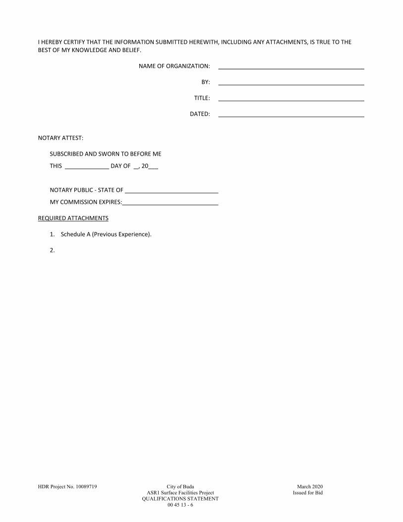
I HEREBY CERTIFY THAT THE INFORMATION SUBMITTED HEREWITH, INCLUDING ANY ATTACHMENTS, IS TRUE TO THE BEST OF MY KNOWLEDGE AND BELIEF.
NAME OF ORGANIZATION:
BY:
TITLE:
DATED:
NOTARY ATTEST:
SUBSCRIBED AND SWORN TO BEFORE ME
THIS DAY OF , 20___ NOTARY PUBLIC ‐ STATE OF
MY COMMISSION EXPIRES: REQUIRED ATTACHMENTS
1. Schedule A (Previous Experience).
2.

HDR Project No. 10089719 City of Buda March 2020 ASR1 Surface Facilities Project Issued for Bid QUALIFICATIONS STATEMENT 00 45 13 - 0
SCHEDULE A
PREVIOUS EXPERIENCE
Project Name Owner's Contact Person Design Engineer Contract Date Type of Work Status Cost of Work
Name:
Address:
Telephone:
Name:
Company:
Telephone:
Name:
Address:
Telephone:
Name:
Company:
Telephone:
Name:
Address:
Telephone:
Name:
Company:
Telephone:
Name:
Address:
Telephone:
Name:
Company:
Telephone:
Name:
Address:
Telephone:
Name:
Company:
Telephone:

THIS PAGE INTENTIONALLY LEFT BLANK
HDR Project No. 10089719 City of Buda March 2020
ASR1 Surface Facilities Project Issued for Bid
VENDOR COMPLIANCE TO STATE LAW 00 45 46 - 1
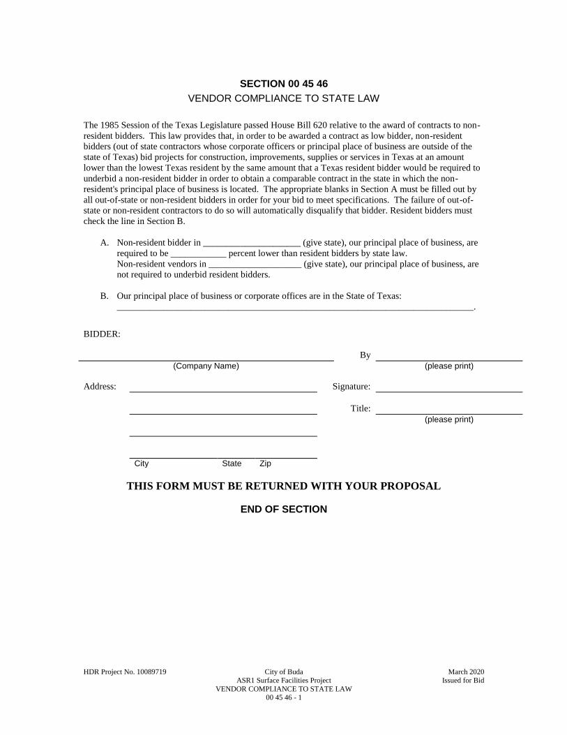
SECTION 00 45 46
VENDOR COMPLIANCE TO STATE LAW
The 1985 Session of the Texas Legislature passed House Bill 620 relative to the award of contracts to non-
resident bidders. This law provides that, in order to be awarded a contract as low bidder, non-resident
bidders (out of state contractors whose corporate officers or principal place of business are outside of the
state of Texas) bid projects for construction, improvements, supplies or services in Texas at an amount
lower than the lowest Texas resident by the same amount that a Texas resident bidder would be required to
underbid a non-resident bidder in order to obtain a comparable contract in the state in which the non-
resident's principal place of business is located. The appropriate blanks in Section A must be filled out by
all out-of-state or non-resident bidders in order for your bid to meet specifications. The failure of out-of-
state or non-resident contractors to do so will automatically disqualify that bidder. Resident bidders must
check the line in Section B.
A. Non-resident bidder in _____________________ (give state), our principal place of business, are
required to be ____________ percent lower than resident bidders by state law.
Non-resident vendors in ____________________ (give state), our principal place of business, are
not required to underbid resident bidders.
B. Our principal place of business or corporate offices are in the State of Texas:
_____________________________________________________________________________.
BIDDER:
By
(Company Name) (please print)
Address: Signature:
Title:
(please print)
City State Zip
THIS FORM MUST BE RETURNED WITH YOUR PROPOSAL
END OF SECTION

This page intentionally left blank.

HDR Project No. 10089719 City of Buda March 2020
ASR1 Surface Facilities Project Issued for Bid
AGREEMENT 00 52 13 - 1
AGREEMENT
BETWEEN OWNER AND CONTRACTOR
FOR CONSTRUCTION CONTRACT (STIPULATED PRICE)
THIS AGREEMENT is by and between The City of Buda, Texas (“Owner”) and
(“Contractor”).
Owner and Contractor hereby agree as follows:
ARTICLE 1 – WORK
1.01 Contractor shall complete all Work as specified or indicated in the Contract Documents. The Work is generally described as follows: Construction of concrete pavement, well pad, process piping, vertical turbine pump and motor installation, electrical components and equipment canopy, instrumentation, fencing, erosion and sediment controls; and site restoration.
ARTICLE 2 – THE PROJECT
2.01 The Project, of which the Work under the Contract Documents is a part, is generally described as follows: City of Buda ASR1 Surface Facilities Project
ARTICLE 3 – ENGINEER
3.01 The part of the Project that pertains to the Work has been designed by
HDR Engineering, Inc. 4401 West Gate Blvd., Suite 400 Austin, TX 78745
ARTICLE 4 – CONTRACT TIMES
4.01 Time of the Essence
A. All time limits for Milestones, if any, Substantial Completion, and completion and readiness for final payment as stated in the Contract Documents are of the essence of the Contract.
4.02 Contract Times: Days
A. The Work will be substantially completed within 170 days after the date when the Contract Times commence to run as provided in Paragraph 4.01 of the General Conditions and completed and ready for final payment in accordance with Paragraph 15.06 of the General Conditions within 200 days after the date when the Contract Times commence to run (30 days after Substantial Completion).
4.03 Liquidated Damages
A. Contractor and Owner recognize that time is of the essence as stated in Paragraph 4.01 above and that Owner will suffer financial and other losses if the Work is not completed and Milestones not achieved within the times specified in Paragraph
HDR Project No. 10089719 City of Buda March 2020
ASR1 Surface Facilities Project Issued for Bid
AGREEMENT 00 52 13 - 2
4.02 above, plus any extensions thereof allowed in accordance with the Contract. The damages incurred by the Owner include, but are not limited to, the impediment to the public use of the public property, the extension of consultant and City staff time in managing the Project and the Contract, and the continued legal risk associated with the construction of the Project. The parties also recognize the delays, expense, and difficulties involved in proving, in a legal or arbitration proceeding, the actual loss suffered by Owner if the Work is not completed on time. Accordingly, instead of requiring any such proof, Owner and Contractor agree that as liquidated damages for delay (but not as a penalty):
1. Substantial Completion: Contractor shall pay Owner $300.00 for each day that expires after the time (as duly adjusted pursuant to the Contract) specified in Paragraph 4.02.A above for Substantial Completion until the Work is substantially complete.
2. Completion of Remaining Work: After Substantial Completion, if Contractor shall neglect, refuse, or fail to complete the remaining Work within the Contract Times (as duly adjusted pursuant to the Contract) for completion and readiness for final payment, Contractor shall pay Owner $300.00 for each day that expires after such time until the Work is completed and ready for final payment.
3. Liquidated damages for failing to timely attain Substantial Completion and final completion are not additive and will not be imposed concurrently.
ARTICLE 5 – CONTRACT PRICE
5.01 Owner shall pay Contractor for completion of the Work in accordance with the Contract Documents the amounts that follow, subject to adjustment under the Contract:
A. For all Work, at the prices stated in Contractor’s Bid, attached hereto as an exhibit.
ARTICLE 6 – PAYMENT PROCEDURES
6.01 Submittal and Processing of Payments
A. Contractor shall submit Applications for Payment in accordance with Article 15 of the General Conditions. Applications for Payment will be processed by Engineer as provided in the General Conditions.
6.02 Progress Payments; Retainage
A. Owner shall make progress payments on account of the Contract Price on the basis of Contractor’s Applications for Payment on or about the 30th day of each month during performance of the Work as provided in Paragraph 6.02.A.1 below, provided that such Applications for Payment have been submitted in a timely manner and otherwise meet the requirements of the Contract. All such payments will be measured by the Schedule of Values established as provided in the General Conditions (and in the case of Unit Price Work based on the number of units completed) or, in the event there is no Schedule of Values, as provided elsewhere in the Contract.

HDR Project No. 10089719 City of Buda March 2020
ASR1 Surface Facilities Project Issued for Bid
AGREEMENT 00 52 13 - 3
1. Prior to Substantial Completion, progress payments will be made in an amount equal to the percentage indicated below but, in each case, less the aggregate of payments previously made and less such amounts as Owner may withhold, including but not limited to liquidated damages, in accordance with the Contract
a. Ninety-five (95) percent of Work completed (with the balance being retainage). If the Work has been 50 percent completed as determined by Engineer, and if the character and progress of the Work have been satisfactory to Owner and Engineer, then as long as the character and progress of the Work remain satisfactory to Owner and Engineer, there will be no additional retainage; and
b. Ninety-five (95) percent of cost of materials and equipment not incorporated in the Work (with the balance being retainage).
B. Upon Substantial Completion, Owner shall pay an amount sufficient to increase total payments to Contractor to one-hundred (100) percent of the Work completed, less such amounts set off by Owner pursuant to Paragraph 15.01.E of the General Conditions, and less one-hundred (100) percent of Engineer’s estimate of the value of Work to be completed or corrected as shown on the punch list of items to be completed or corrected prior to final payment.
6.03 Final Payment
A. Upon final completion and acceptance of the Work in accordance with Paragraph 15.06 of the General Conditions, Owner shall pay the remainder of the Contract Price as recommended by Engineer as provided in said Paragraph 15.06.
ARTICLE 7 – INTEREST (NOT USED)
ARTICLE 8 – CONTRACTOR’S REPRESENTATIONS
8.01 In order to induce Owner to enter into this Contract, Contractor makes the following representations:
A. Contractor has examined and carefully studied the Contract Documents, and any data and reference items identified in the Contract Documents.
B. Contractor has visited the Site, conducted a thorough, alert visual examination of the Site and adjacent areas, and become familiar with and is satisfied as to the general, local, and Site conditions that may affect cost, progress, and performance of the Work.
C. Contractor is familiar with and is satisfied as to all Laws and Regulations that may affect cost, progress, and performance of the Work.
D. Contractor has carefully studied all: (1) reports of explorations and tests of subsurface conditions at or adjacent to the Site and all drawings of physical conditions relating to existing surface or subsurface structures at the Site that have been identified in the Supplementary Conditions, especially with respect to Technical Data in such reports and drawings, and (2) reports and drawings relating to Hazardous Environmental Conditions, if any, at or adjacent to the Site that have
HDR Project No. 10089719 City of Buda March 2020
ASR1 Surface Facilities Project Issued for Bid
AGREEMENT 00 52 13 - 4
been identified in the Supplementary Conditions, especially with respect to Technical Data in such reports and drawings.
E. Contractor has considered the information known to Contractor itself; information commonly known to contractors doing business in the locality of the Site; information and observations obtained from visits to the Site; the Contract Documents; and the Site-related reports and drawings identified in the Contract Documents, with respect to the effect of such information, observations, and documents on (1) the cost, progress, and performance of the Work; (2) the means, methods, techniques, sequences, and procedures of construction to be employed by Contractor; and (3) Contractor’s safety precautions and programs.
F. Based on the information and observations referred to in the preceding paragraph, Contractor agrees that no further examinations, investigations, explorations, tests, studies, or data are necessary for the performance of the Work at the Contract Price, within the Contract Times, and in accordance with the other terms and conditions of the Contract.
G. Contractor is aware of the general nature of work to be performed by Owner and others at the Site that relates to the Work as indicated in the Contract Documents.
H. Contractor has given Engineer written notice of all conflicts, errors, ambiguities, or discrepancies that Contractor has discovered in the Contract Documents, and the written resolution thereof by Engineer is acceptable to Contractor.
I. The Contract Documents are generally sufficient to indicate and convey understanding of all terms and conditions for performance and furnishing of the Work.
J. Contractor’s entry into this Contract constitutes an incontrovertible representation by Contractor that without exception all prices in the Agreement are premised upon performing and furnishing the Work required by the Contract Documents.
ARTICLE 9 – CONTRACT DOCUMENTS
9.01 Contents
A. The Contract Documents consist of the following:
1. This Agreement (pages 1 to 7, inclusive).
2. Performance bond, Payment bond, and Other bonds.
3. General Conditions (pages 1 to 63, inclusive).
4. Supplementary Conditions (pages 1 to 8, inclusive).
5. Certificate of Interested Parties (Form 1295).
6. House Bill 89 Verification.
7. Vendor Compliance to State Law.
8. Certificate of Liability Insurance.
9. Specifications as listed in the table of contents of the Project Construction Manual.

HDR Project No. 10089719 City of Buda March 2020
ASR1 Surface Facilities Project Issued for Bid
AGREEMENT 00 52 13 - 5
10. Drawings (not attached but incorporated by reference) consisting of ______ sheets with each sheet bearing the following general title: ASR1 Surface Facilities.
11. Addenda (numbers _____ to ______, inclusive).
12. Exhibits to this Agreement (enumerated as follows):
a. Contractor’s Bid (pages 1 to 17, inclusive).
13. The following which may be delivered or issued on or after the Effective Date of the Contract and are not attached hereto:
a. Notice to Proceed.
b. Work Change Directives.
c. Change Orders.
d. Field Orders.
B. The documents listed in Paragraph 9.01.A are attached to this Agreement (except as expressly noted otherwise above).
C. There are no Contract Documents other than those listed above in this Article 9.
D. The Contract Documents may only be amended, modified, or supplemented as provided in the General Conditions.
E. These Contract Documents, identified above, contain the complete and exclusive understanding of the parties with respect to their subject matter. There are no understandings, agreements, promises or representations, expressed or implied, not specified in this Agreement and this instrument contains the entire agreement between the parties. Parol evidence shall not be offered by the parties or admitted as evidence in any dispute involving the terms and provisions of this Agreement.
ARTICLE 10 – MISCELLANEOUS
10.01 Terms
A. Terms used in this Agreement will have the meanings stated in the Glossary of Defined Terms.
10.02 Assignment of Contract
A. Unless expressly agreed to elsewhere in the Contract, no assignment by a party hereto of any rights under or interests in the Contract will be binding on another party hereto without the written consent of the party sought to be bound; and, specifically but without limitation, money that may become due and money that is due may not be assigned without such consent (except to the extent that the effect of this restriction may be limited by law), and unless specifically stated to the contrary in any written consent to an assignment, no assignment will release or discharge the assignor from any duty or responsibility under the Contract Documents.

HDR Project No. 10089719 City of Buda March 2020
ASR1 Surface Facilities Project Issued for Bid
AGREEMENT 00 52 13 - 6
10.03 Successors and Assigns
A. Owner and Contractor each binds itself, its successors, assigns, and legal representatives to the other party hereto, its successors, assigns, and legal representatives in respect to all covenants, agreements, and obligations contained in the Contract Documents.
10.04 Severability
A. Any provision or part of the Contract Documents held to be void or unenforceable under any Law or Regulation shall be deemed stricken, and all remaining provisions shall continue to be valid and binding upon Owner and Contractor, who agree that the Contract Documents shall be reformed to replace such stricken provision or part thereof with a valid and enforceable provision that comes as close as possible to expressing the intention of the stricken provision.
10.05 Contractor’s Certifications
A. Contractor certifies that it has not engaged in corrupt, fraudulent, collusive, or coercive practices in competing for or in executing the Contract. For the purposes of this Paragraph 10.05:
1. “corrupt practice” means the offering, giving, receiving, or soliciting of any thing of value likely to influence the action of a public official in the bidding process or in the Contract execution;
2. “fraudulent practice” means an intentional misrepresentation of facts made (a) to influence the bidding process or the execution of the Contract to the detriment of Owner, (b) to establish Bid or Contract prices at artificial non-competitive levels, or (c) to deprive Owner of the benefits of free and open competition;
3. “collusive practice” means a scheme or arrangement between two or more Bidders, with or without the knowledge of Owner, a purpose of which is to establish Bid prices at artificial, non-competitive levels; and
4. “coercive practice” means harming or threatening to harm, directly or indirectly, persons or their property to influence their participation in the bidding process or affect the execution of the Contract.
HDR Project No. 10089719 City of Buda March 2020
ASR1 Surface Facilities Project Issued for Bid
AGREEMENT 00 52 13 - 7
IN WITNESS WHEREOF, Owner and Contractor have signed this Agreement.
This Agreement will be effective on ____________ (which is the Effective Date of the Contract).
OWNER: CONTRACTOR:
By: By:
Title: Title:
(If Contractor is a corporation, a partnership, or a joint venture, attach evidence of authority to sign.)
Attest: Attest:
Title: Title:
Address for giving notices: Address for giving notices:
License No.:
(where applicable)
(If Owner is a corporation, attach evidence of authority to sign. If Owner is a public body, attach evidence of authority to sign and resolution or other documents authorizing execution of this Agreement.)
NOTE TO USER: Use in those states or other
jurisdictions where applicable or required.

This page intentionally left blank.
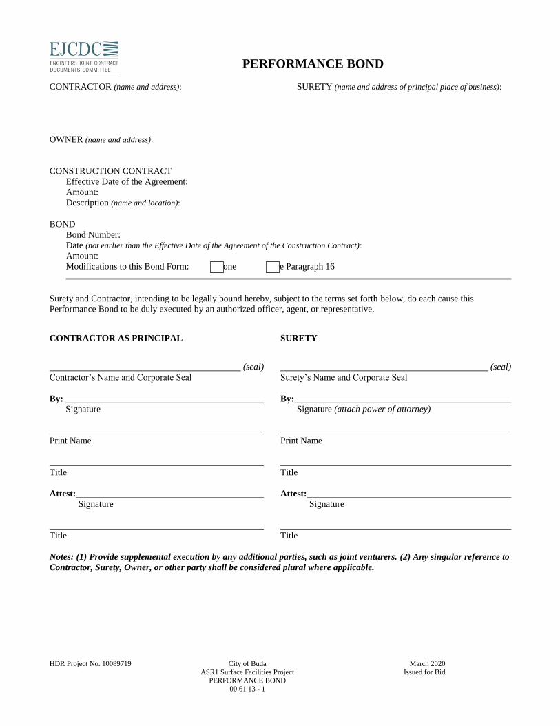
HDR Project No. 10089719 City of Buda March 2020
ASR1 Surface Facilities Project Issued for Bid
PERFORMANCE BOND 00 61 13 - 1
PERFORMANCE BOND
CONTRACTOR (name and address):
SURETY (name and address of principal place of business):
OWNER (name and address):
CONSTRUCTION CONTRACT
Effective Date of the Agreement:
Amount:
Description (name and location):
BOND
Bond Number:
Date (not earlier than the Effective Date of the Agreement of the Construction Contract):
Amount:
Modifications to this Bond Form: None See Paragraph 16
Surety and Contractor, intending to be legally bound hereby, subject to the terms set forth below, do each cause this
Performance Bond to be duly executed by an authorized officer, agent, or representative.
CONTRACTOR AS PRINCIPAL SURETY
(seal) (seal)
Contractor’s Name and Corporate Seal Surety’s Name and Corporate Seal
By: By: Signature Signature (attach power of attorney)
Print Name Print Name
Title Title
Attest: Attest: Signature Signature
Title Title
Notes: (1) Provide supplemental execution by any additional parties, such as joint venturers. (2) Any singular reference to
Contractor, Surety, Owner, or other party shall be considered plural where applicable.
HDR Project No. 10089719 City of Buda March 2020
ASR1 Surface Facilities Project Issued for Bid
PERFORMANCE BOND 00 61 13 - 2
1. The Contractor and Surety, jointly and severally, bind
themselves, their heirs, executors, administrators, successors, and
assigns to the Owner for the performance of the Construction Contract,
which is incorporated herein by reference.
2. If the Contractor performs the Construction Contract, the Surety
and the Contractor shall have no obligation under this Bond, except
when applicable to participate in a conference as provided in
Paragraph 3.
3. If there is no Owner Default under the Construction Contract, the
Surety’s obligation under this Bond shall arise after:
3.1 The Owner first provides notice to the Contractor and
the Surety that the Owner is considering declaring a Contractor
Default. Such notice shall indicate whether the Owner is
requesting a conference among the Owner, Contractor, and Surety
to discuss the Contractor’s performance. If the Owner does not
request a conference, the Surety may, within five (5) business
days after receipt of the Owner’s notice, request such a
conference. If the Surety timely requests a conference, the Owner
shall attend. Unless the Owner agrees otherwise, any conference
requested under this Paragraph 3.1 shall be held within ten (10)
business days of the Surety’s receipt of the Owner’s notice. If the
Owner, the Contractor, and the Surety agree, the Contractor shall
be allowed a reasonable time to perform the Construction
Contract, but such an agreement shall not waive the Owner’s
right, if any, subsequently to declare a Contractor Default;
3.2 The Owner declares a Contractor Default, terminates
the Construction Contract and notifies the Surety; and
3.3 The Owner has agreed to pay the Balance of the
Contract Price in accordance with the terms of the Construction
Contract to the Surety or to a contractor selected to perform the
Construction Contract.
4. Failure on the part of the Owner to comply with the notice
requirement in Paragraph 3.1 shall not constitute a failure to comply
with a condition precedent to the Surety’s obligations, or release the
Surety from its obligations, except to the extent the Surety
demonstrates actual prejudice.
5. When the Owner has satisfied the conditions of Paragraph 3, the
Surety shall promptly and at the Surety’s expense take one of the
following actions:
5.1 Arrange for the Contractor, with the consent of the
Owner, to perform and complete the Construction Contract;
5.2 Undertake to perform and complete the Construction
Contract itself, through its agents or independent contractors;
5.3 Obtain bids or negotiated proposals from qualified
contractors acceptable to the Owner for a contract for
performance and completion of the Construction Contract,
arrange for a contract to be prepared for execution by the Owner
and a contractor selected with the Owners concurrence, to be
secured with performance and payment bonds executed by a
qualified surety equivalent to the bonds issued on the
Construction Contract, and pay to the Owner the amount of
damages as described in Paragraph 7 in excess of the Balance of
the Contract Price incurred by the Owner as a result of the
Contractor Default; or
5.4 Waive its right to perform and complete, arrange for
completion, or obtain a new contractor, and with reasonable
promptness under the circumstances:
5.4.1 After investigation, determine the amount for
which it may be liable to the Owner and, as soon as
practicable after the amount is determined, make payment to
the Owner; or
5.4.2 Deny liability in whole or in part and notify the
Owner, citing the reasons for denial.
6. If the Surety does not proceed as provided in Paragraph 5 with
reasonable promptness, the Surety shall be deemed to be in default on
this Bond seven days after receipt of an additional written notice from
the Owner to the Surety demanding that the Surety perform its
obligations under this Bond, and the Owner shall be entitled to enforce
any remedy available to the Owner. If the Surety proceeds as provided
in Paragraph 5.4, and the Owner refuses the payment or the Surety has
denied liability, in whole or in part, without further notice the Owner
shall be entitled to enforce any remedy available to the Owner.
7. If the Surety elects to act under Paragraph 5.1, 5.2, or 5.3, then
the responsibilities of the Surety to the Owner shall not be greater than
those of the Contractor under the Construction Contract, and the
responsibilities of the Owner to the Surety shall not be greater than
those of the Owner under the Construction Contract. Subject to the
commitment by the Owner to pay the Balance of the Contract Price,
the Surety is obligated, without duplication for:
7.1 the responsibilities of the Contractor for correction of
defective work and completion of the Construction Contract;
7.2 additional legal, design professional, and delay costs
resulting from the Contractor’s Default, and resulting from the
actions or failure to act of the Surety under Paragraph 5; and
7.3 liquidated damages, or if no liquidated damages are
specified in the Construction Contract, actual damages caused by
delayed performance or non-performance of the Contractor.
8. If the Surety elects to act under Paragraph 5.1, 5.3, or 5.4, the
Surety’s liability is limited to the amount of this Bond.
9. The Surety shall not be liable to the Owner or others for
obligations of the Contractor that are unrelated to the Construction
Contract, and the Balance of the Contract Price shall not be reduced or
set off on account of any such unrelated obligations. No right of
action shall accrue on this Bond to any person or entity other than the
Owner or its heirs, executors, administrators, successors, and assigns.
10. The Surety hereby waives notice of any change, including
changes of time, to the Construction Contract or to related
subcontracts, purchase orders, and other obligations.
11. Any proceeding, legal or equitable, under this Bond may be
instituted in any court of competent jurisdiction in the location in
which the work or part of the work is located and shall be instituted
within two years after a declaration of Contractor Default or within
two years after the Contractor ceased working or within two years

HDR Project No. 10089719 City of Buda March 2020
ASR1 Surface Facilities Project Issued for Bid
PERFORMANCE BOND 00 61 13 - 3
after the Surety refuses or fails to perform its obligations under this
Bond, whichever occurs first. If the provisions of this paragraph are
void or prohibited by law, the minimum periods of limitations
available to sureties as a defense in the jurisdiction of the suit shall be
applicable.
12. Notice to the Surety, the Owner, or the Contractor shall be mailed
or delivered to the address shown on the page on which their signature
appears.
13. When this Bond has been furnished to comply with a statutory or
other legal requirement in the location where the construction was to
be performed, any provision in this Bond conflicting with said
statutory or legal requirement shall be deemed deleted herefrom and
provisions conforming to such statutory or other legal requirement
shall be deemed incorporated herein. When so furnished, the intent is
that this Bond shall be construed as a statutory bond and not as a
common law bond.
14. Definitions
14.1 Balance of the Contract Price: The total amount payable
by the Owner to the Contractor under the Construction Contract
after all proper adjustments have been made including allowance
for the Contractor for any amounts received or to be received by
the Owner in settlement of insurance or other claims for damages
to which the Contractor is entitled, reduced by all valid and
proper payments made to or on behalf of the Contractor under the
Construction Contract.
14.2 Construction Contract: The agreement between the
Owner and Contractor identified on the cover page, including all
Contract Documents and changes made to the agreement and the
Contract Documents.
14.3 Contractor Default: Failure of the Contractor, which has
not been remedied or waived, to perform or otherwise to comply
with a material term of the Construction Contract.
14.4 Owner Default: Failure of the Owner, which has not
been remedied or waived, to pay the Contractor as required under
the Construction Contract or to perform and complete or comply
with the other material terms of the Construction Contract.
14.5 Contract Documents: All the documents that comprise
the agreement between the Owner and Contractor.
15. If this Bond is issued for an agreement between a contractor and
subcontractor, the term Contractor in this Bond shall be deemed to be
Subcontractor and the term Owner shall be deemed to be Contractor.
16. Modifications to this Bond are as follows:

This page intentionally left blank.

HDR Project No. 10089719 City of Buda March 2020
ASR1 Surface Facilities Project Issued for Bid PAYMENT BOND
00 61 14 - 1
PAYMENT BOND CONTRACTOR (name and address):
SURETY (name and address of principal place of business):
OWNER (name and address):
CONSTRUCTION CONTRACT
Effective Date of the Agreement:
Amount:
Description (name and location):
BOND
Bond Number:
Date (not earlier than the Effective Date of the Agreement of the Construction Contract):
Amount:
Modifications to this Bond Form: None See Paragraph 18
Surety and Contractor, intending to be legally bound hereby, subject to the terms set forth below, do each cause this Payment
Bond to be duly executed by an authorized officer, agent, or representative.
CONTRACTOR AS PRINCIPAL SURETY
(seal) (seal)
Contractor’s Name and Corporate Seal Surety’s Name and Corporate Seal
By: By: Signature Signature (attach power of attorney)
Print Name Print Name
Title Title
Attest: Attest: Signature Signature
Title Title
Notes: (1) Provide supplemental execution by any additional parties, such as joint venturers. (2) Any singular reference
to Contractor, Surety, Owner, or other party shall be considered plural where applicable.

HDR Project No. 10089719 City of Buda March 2020
ASR1 Surface Facilities Project Issued for Bid
PAYMENT BOND 00 61 14 - 2
1. The Contractor and Surety, jointly and severally, bind themselves, their heirs, executors, administrators,
successors, and assigns to the Owner to pay for labor, materials, and equipment furnished for use in the
performance of the Construction Contract, which is incorporated herein by reference, subject to the following
terms.
2. If the Contractor promptly makes payment of all sums due to Claimants, and defends, indemnifies, and holds
harmless the Owner from claims, demands, liens, or suits by any person or entity seeking payment for labor,
materials, or equipment furnished for use in the performance of the Construction Contract, then the Surety and the
Contractor shall have no obligation under this Bond.
3. If there is no Owner Default under the Construction Contract, the Surety’s obligation to the Owner under this
Bond shall arise after the Owner has promptly notified the Contractor and the Surety (at the address described in
Paragraph 13) of claims, demands, liens, or suits against the Owner or the Owner’s property by any person or
entity seeking payment for labor, materials, or equipment furnished for use in the performance of the Construction
Contract, and tendered defense of such claims, demands, liens, or suits to the Contractor and the Surety.
4. When the Owner has satisfied the conditions in Paragraph 3, the Surety shall promptly and at the Surety’s expense
defend, indemnify, and hold harmless the Owner against a duly tendered claim, demand, lien, or suit.
5. The Surety’s obligations to a Claimant under this Bond shall arise after the following:
5.1 Claimants who do not have a direct contract with the Contractor,
5.1.1 have furnished a written notice of non-payment to the Contractor, stating with substantial
accuracy the amount claimed and the name of the party to whom the materials were, or equipment
was, furnished or supplied or for whom the labor was done or performed, within ninety (90) days
after having last performed labor or last furnished materials or equipment included in the Claim;
and
5.1.2 have sent a Claim to the Surety (at the address described in Paragraph 13).
5.2 Claimants who are employed by or have a direct contract with the Contractor have sent a Claim to the
Surety (at the address described in Paragraph 13).
6. If a notice of non-payment required by Paragraph 5.1.1 is given by the Owner to the Contractor, that is sufficient
to satisfy a Claimant’s obligation to furnish a written notice of non-payment under Paragraph 5.1.1.
7. When a Claimant has satisfied the conditions of Paragraph 5.1 or 5.2, whichever is applicable, the Surety shall
promptly and at the Surety’s expense take the following actions:
7.1 Send an answer to the Claimant, with a copy to the Owner, within sixty (60) days after receipt of the
Claim, stating the amounts that are undisputed and the basis for challenging any amounts that are disputed;
and
7.2 Pay or arrange for payment of any undisputed amounts.
7.3 The Surety’s failure to discharge its obligations under Paragraph 7.1 or 7.2 shall not be deemed to
constitute a waiver of defenses the Surety or Contractor may have or acquire as to a Claim, except as to
undisputed amounts for which the Surety and Claimant have reached agreement. If, however, the Surety
fails to discharge its obligations under Paragraph 7.1 or 7.2, the Surety shall indemnify the Claimant for
the reasonable attorney’s fees the Claimant incurs thereafter to recover any sums found to be due and
owing to the Claimant.
8. The Surety’s total obligation shall not exceed the amount of this Bond, plus the amount of reasonable attorney’s
fees provided under Paragraph 7.3, and the amount of this Bond shall be credited for any payments made in good
faith by the Surety.
9. Amounts owed by the Owner to the Contractor under the Construction Contract shall be used for the performance
of the Construction Contract and to satisfy claims, if any, under any construction performance bond. By the
HDR Project No. 10089719 City of Buda March 2020
ASR1 Surface Facilities Project Issued for Bid
PAYMENT BOND 00 61 14 - 3
Contractor furnishing and the Owner accepting this Bond, they agree that all funds earned by the Contractor in the
performance of the Construction Contract are dedicated to satisfy obligations of the Contractor and Surety under
this Bond, subject to the Owner’s priority to use the funds for the completion of the work.
10. The Surety shall not be liable to the Owner, Claimants, or others for obligations of the Contractor that are
unrelated to the Construction Contract. The Owner shall not be liable for the payment of any costs or expenses of
any Claimant under this Bond, and shall have under this Bond no obligation to make payments to or give notice on
behalf of Claimants, or otherwise have any obligations to Claimants under this Bond.
11. The Surety hereby waives notice of any change, including changes of time, to the Construction Contract or to
related subcontracts, purchase orders, and other obligations.
12. No suit or action shall be commenced by a Claimant under this Bond other than in a court of competent
jurisdiction in the state in which the project that is the subject of the Construction Contract is located or after the
expiration of one year from the date (1) on which the Claimant sent a Claim to the Surety pursuant to Paragraph
5.1.2 or 5.2, or (2) on which the last labor or service was performed by anyone or the last materials or equipment
were furnished by anyone under the Construction Contract, whichever of (1) or (2) first occurs. If the provisions
of this paragraph are void or prohibited by law, the minimum period of limitation available to sureties as a defense
in the jurisdiction of the suit shall be applicable.
13. Notice and Claims to the Surety, the Owner, or the Contractor shall be mailed or delivered to the address shown
on the page on which their signature appears. Actual receipt of notice or Claims, however accomplished, shall be
sufficient compliance as of the date received.
14. When this Bond has been furnished to comply with a statutory or other legal requirement in the location where the
construction was to be performed, any provision in this Bond conflicting with said statutory or legal requirement
shall be deemed deleted herefrom and provisions conforming to such statutory or other legal requirement shall be
deemed incorporated herein. When so furnished, the intent is that this Bond shall be construed as a statutory bond
and not as a common law bond.
15. Upon requests by any person or entity appearing to be a potential beneficiary of this Bond, the Contractor and
Owner shall promptly furnish a copy of this Bond or shall permit a copy to be made.
16. Definitions
16.1 Claim: A written statement by the Claimant including at a minimum:
1. The name of the Claimant;
2. The name of the person for whom the labor was done, or materials or equipment furnished;
3. A copy of the agreement or purchase order pursuant to which labor, materials, or equipment was
furnished for use in the performance of the Construction Contract;
4. A brief description of the labor, materials, or equipment furnished;
5. The date on which the Claimant last performed labor or last furnished materials or equipment for use
in the performance of the Construction Contract;
6. The total amount earned by the Claimant for labor, materials, or equipment furnished as of the date of
the Claim;
7. The total amount of previous payments received by the Claimant; and
8. The total amount due and unpaid to the Claimant for labor, materials, or equipment furnished as of the
date of the Claim.
16.2 Claimant: An individual or entity having a direct contract with the Contractor or with a subcontractor of
the Contractor to furnish labor, materials, or equipment for use in the performance of the Construction
Contract. The term Claimant also includes any individual or entity that has rightfully asserted a claim
under an applicable mechanic’s lien or similar statute against the real property upon which the Project is
located. The intent of this Bond shall be to include without limitation in the terms of “labor, materials, or
equipment” that part of the water, gas, power, light, heat, oil, gasoline, telephone service, or rental
equipment used in the Construction Contract, architectural and engineering services required for
performance of the work of the Contractor and the Contractor’s subcontractors, and all other items for
which a mechanic’s lien may be asserted in the jurisdiction where the labor, materials, or equipment were
furnished.

HDR Project No. 10089719 City of Buda March 2020
ASR1 Surface Facilities Project Issued for Bid
PAYMENT BOND 00 61 14 - 4
16.3 Construction Contract: The agreement between the Owner and Contractor identified on the cover page,
including all Contract Documents and all changes made to the agreement and the Contract Documents.
16.4 Owner Default: Failure of the Owner, which has not been remedied or waived, to pay the Contractor as
required under the Construction Contract or to perform and complete or comply with the other material
terms of the Construction Contract.
16.5 Contract Documents: All the documents that comprise the agreement between the Owner and Contractor.
17. If this Bond is issued for an agreement between a contractor and subcontractor, the term Contractor in this Bond
shall be deemed to be Subcontractor and the term Owner shall be deemed to be Contractor.
18. Modifications to this Bond are as follows:


This page intentionally left blank.

License Agreement Before you use this EJCDC document: 1. Read this License Agreement in its entirety. As
purchaser, you agree to comply with and are bound by the License Agreement’s terms, conditions, and instructions when you use the attached EJCDC document. Commencement of use of the attached document indicates your acceptance of these terms, conditions, and instructions. If you do not agree to them, you should promptly return the materials to the vendor.
2. This License Agreement applies to the attached document only. Other licensing terms and instructions may apply to other EJCDC documents.
3. The Engineers Joint Contract Documents Committee ("EJCDC") provides EJCDC Design and Construction Related Documents (including but not limited to the EJCDC document that is attached, and all other documents in the EJCDC Construction Series, Engineering Series, Design-Build Series, Remediation Series, Procurement Series, and Narrative Series) and licenses their use worldwide. You assume sole responsibility for the selection of specific documents or portions thereof to achieve your intended results, and for the installation, use, and results obtained from EJCDC Design and Construction Related Documents.
4. You acknowledge that you understand that the text of the EJCDC Design and Construction Related Documents has important legal consequences and that consultation with an attorney is recommended with respect to use or modification of the text. You further acknowledge that EJCDC documents are protected by the copyright laws of the United States.
5. Make sure that you have the correct word processing
software for the attached EJCDC document, which is distributed in Microsoft Word (.doc) format.
6. EJCDC allows the end user wide discretion in using and editing the attached document, subject to the provisions of the License Agreement. You are advised, however, that EJCDC documents contain
numeric and other cross-references, and that changes to one part of the document may affect other parts. It is solely your responsibility to assure the adequacy and consistency of the final document for your purposes.
How to Use This Document: 1. Although EJCDC has made reasonable efforts to
achieve uniformity of formatting, some document controls (e.g., bold, underline, font size, indentation, numbering, pagination, table of contents) may be affected by software versioning and translators, user settings, changes during editing, and other factors, and may require user intervention to restore intended format and appearance.
2. The term “Standard EJCDC Text” for the attached
document generally refers to all text prepared by EJCDC in the main body of the document, and does not include covers, logos, footers, instructions, license agreement, copyright notices, Notes to Users, or text options. The content of document exhibits (if any) is not Standard EJCDC Text for this purpose.
2. If you do not alter the Standard EJCDC Text of the attached document, you may use it as published, with all EJCDC logos, footers, and copyright notices retained.
3. If you modify the Standard EJCDC Text of the attached document, you must follow the following instructions that address if, when, and how to show the changes to other parties.
4. During the drafting or negotiating process for the document, it is important that the two contracting parties are both aware of any changes that have been made to the Standard EJCDC Text. Thus if a draft of the document purports to be or appears to be an EJCDC document, the user must plainly show all changes to the Standard EJCDC Text, using “Track Changes” (redline/strikeout), highlighting, or other means of clearly indicating additions and deletions.

5. As between contracting parties, once the document is ready to be finalized (and if applicable executed by the contracting parties), it is no longer necessary to continue to show changes to the Standard EJCDC Text. The parties may produce a final version of the document in a format in which all changes are accepted, and the document at that point does not need to include any “Track Changes,” redline/strikeout, highlighting, or other indication of additions and deletions to the Standard EJCDC Text.
6. If the attached document is revised or altered and then presented to others (such as potential bidders, grant agencies, lenders, or sureties) as an EJCDC document, then the changes to the Standard EJCDC Text must be shown, or the third parties must receive access to a version that shows the changes.
7. The attached EJCDC document may contain “Notes to User,” bracketed comments, or prompts that provide instructions for filling in project-specific information, selecting the appropriate clause from a list of options, or making additions or deletions, or that give background information regarding a particular provision. The user may (and in most cases should) delete these notes, comments, and prompts during the drafting process. Deletion of such notes, comments, and prompts is not subject to the License Agreement requirement that additions or deletions to Standard EJCDC Text be shown clearly, and therefore does not need to be shown with “Track Changes,” redline/strikeout, highlighting, or other means of indicating changes, at any point in the drafting process.
8. The attached EJCDC document may contain exhibits that are to be used to set out project-specific provisions, such as scope of services, compensation, and insurance requirements. These exhibits are meant to be revised, supplemented, and altered by the user, or discarded if not applicable to the specific project. The text of the various exhibits is not considered Standard EJCDC Text and is not subject to the License Agreement requirement that additions or deletions to the Standard EJCDC Text be shown clearly, and therefore does not need to be shown with “Track Changes,” redline/strikeout, highlighting, or other means of indicating changes, at any point in the drafting process.
9. In a few instances the EJCDC Notes to User will instruct the user of a document to choose one of two or more text options in the main body of the document. In such cases the options that are not selected should be discarded or deleted, and not included in the final version of the document. Such discarding or deletion of text options is not subject to the License Agreement requirement that additions or deletions to Standard EJCDC Text be shown clearly, and therefore does not need to be shown with highlighting, redline/strikeout, or other means of tracking changes, at any point in the drafting process.
Note, however, that the text that is selected (which in this scenario is in the main body of the document and not in an exhibit) is Standard EJCDC Text, and any revision or alteration of the text that is selected is subject to the License Agreement requirement that additions or deletions to Standard EJCDC Text be shown clearly.
10. The License Agreement typically is removed when a document is being prepared for use on a specific project. Such removal is not subject to the License Agreement requirement that additions or deletions to Standard EJCDC Text be shown clearly, and therefore does not need to be shown with highlighting, redline/strikeout, or other means of tracking changes, at any point in the drafting process. The terms of the License Agreement remain in effect regardless of whether it has been removed or remains attached to the document.
11. When a document is being prepared for use on a specific project, some users remove the EJCDC front cover page, and the “inside front cover page” containing specific information regarding the EJCDC sponsoring organizations. Such removal is not subject to the License Agreement requirement that additions or deletions to Standard EJCDC Text be shown clearly, and therefore does not need to be shown with highlighting, redline/strikeout, or other means of tracking changes, at any point in the drafting process.
12. As purchaser of the attached document, you may choose to use it as the basis or platform for creating purchaser’s own custom version. In such case you must remove all EJCDC logos, footers, and other items that might create the false impression that the document remains an EJCDC standard document, and the requirements regarding the need to show additions and deletions to the Standard EJCDC Text no longer apply. Note, however, that the copyright requirements of the License Agreement continue to apply.
13. A purchaser may choose to select clauses or sections of the attached document for inclusion in other non-EJCDC documents. When this occurs, do not use any EJCDC logos, footers, or other items that would imply that the receiving document is an EJCDC document. Note, however, that the copyright requirements of the License Agreement continue to apply.
Limited License: As purchaser, you have a limited nonexclusive license to: 1. Use the attached EJCDC document on any number of
machines owned, leased, or rented by your company or organization.
2. Use the attached EJCDC document for bona fide
contractual and project purposes. Such purposes expressly include controlled distribution to bona fide
bidders and proposers, either through direct transmittal in printed or electronic format or posting on a website or other electronic distribution point to which access is limited to bona fide bidders and proposers or others having direct interest in the contract or project.
3. Copy the attached EJCDC document into any machine-readable or printed form for backup or modification purposes in support of your use of the document.
You further agree: 1. To comply with all terms, conditions, and instructions
in this License Agreement.
2. That all proprietary and intellectual property rights in the attached EJCDC document and all other EJCDC Design and Construction Related Documents are and shall remain the property of EJCDC and its sponsoring organizations.
3. To include the appropriate EJCDC copyright notice (selected from the versions below) on any copy, modified or finalized version, or portion of the attached EJCDC document. For this document, at a minimum one of the following EJCDC copyright notices must appear in a prominent location:
If the standard EJCDC text is not altered, then use the copyright that is already stated in the published document:
Copyright © [EJCDC document date]
National Society of Professional Engineers, American Council of Engineering Companies, and American Society of Civil Engineers. All rights reserved.
If the standard EJCDC text has been altered, or if only portions of the EJCDC document have been used, then use the following copyright notice:
This document is a MODIFIED version of
EJCDC® Z-xxx, Copyright © 20xx by the National Society of Professional Engineers, American Council of Engineering Companies, and American Society of Civil Engineers, or is based in part on excerpts from copyrighted EJCDC documents. Those portions of the text that originated in copyrighted EJCDC documents remain subject to the copyright.
4. To not use, copy, modify, or transfer the attached
EJCDC document or any other EJCDC Design and Construction Related Documents, or any copy, modification or merged portion, in whole or in part, except as expressly provided for in this license. Reproduction of the attached EJCDC document, or any other EJCDC Design and Construction Related
Document, in printed or machine-readable format for resale, and any resale of this document in any format, are expressly prohibited. Making the attached EJCDC document or any other EJCDC Design and Construction Related Document, in whole or in part, available or accessible on an uncontrolled, public-access website or other uncontrolled electronic distribution point—in any format whatever, whether with or without watermarks, as a Microsoft Word document or in portable document format (PDF)—is expressly prohibited.
5. As an EJCDC limited licensee you may seek advance
written permission from the EJCDC Copyright Administrator to use the attached EJCDC document for educational purposes, subject to terms and conditions to be established by the Copyright Administrator for the specific educational use.
Term: This license is effective for three years after date of purchase, or six years after the last day of the year of issuance for the attached document (shown in the copyright notice), whichever occurs later, and shall terminate at that time, unless earlier terminated as provided herein, or unless EJCDC extends the term of this license to you, in writing, or publishes on the ejcdc.org website or the websites of the National Society of Professional Engineers, American Council of Engineering Companies, and American Society of Civil Engineers, an applicable extension of the term of license for a certain period of time for bona fide contractual and project or other authorized uses. You agree upon termination to destroy the attached EJCDC Design and Construction Related Document along with all copies, modifications and merged portions in any form (except those copies already in actual project or contract use, or maintained in files or records of completed projects). EJCDC reserves the right during the term of this agreement to provide access to the purchased document through alternative means, based on improvements or changes in technology, or to transition the document to secure document platforms or other formats, while maintaining user’s access privileges. EJCDC from time to time publishes new, updated editions of the EJCDC Design and Construction Related Documents. EJCDC highly recommends the use of the most current editions of its documents. EJCDC may, at its sole discretion, withdraw from authorized use any document that has been subsequently updated and for which the license has expired. You may terminate the license at any time by destroying the attached EJCDC document together with all copies, modifications and merged portions in any form (except those copies already in actual project or contract use, or maintained in files or records of completed projects). It will also terminate upon conditions set forth elsewhere in

this License Agreement or if you fail to comply with any term or condition of this License Agreement. Limited Warranty: If EJCDC has distributed this document on a compact disc, then EJCDC warrants the CD on which this document is furnished to be free from physical defects in materials and workmanship under normal use for a period of ninety (90) days from the date of delivery to you as evidenced by a copy of your receipt. There is no other warranty of any kind, either express or implied, including, but not limited to the implied warranties of merchantability and fitness for a particular purpose. Some states do not allow the exclusion of implied warranties, so the above exclusion may not apply to you. You may also have other rights which vary from state to state. EJCDC does not warrant that the functions contained in EJCDC Design and Construction Related Documents will meet your requirements or that the operation of EJCDC Design and Construction Related Documents will be uninterrupted or error free. Limitations of Remedies: EJCDC’s entire liability and your exclusive remedy shall be: 1. the replacement of the CD (if any) distributed by
EJCDC, containing this document, provided such CD does not meet EJCDC's "Limited Warranty" and is returned to EJCDC’s selling agent with a copy of your receipt, or
2. if EJCDC’s selling agent is unable to deliver a
replacement CD which is free of defects in materials and workmanship, you may terminate this Agreement by returning EJCDC Document and your money will be refunded.
As purchaser, you assume full responsibility for determining the suitability of this document to your purposes, and for the application and use of this document for contract or project purposes. To the fullest extent permitted by law, in no event will EJCDC, its sponsoring organizations, its committee members, attorneys, consultants, authorized vendors, or advisors, or their respective staff members, employees, agents, or contractors, be liable to you or any other party for any damages, including any lost profits, lost savings, contractual liabilities, disappointed commercial expectations, economic loss, or other direct, incidental, or consequential damages arising out of the content, unenforceability, insufficiency, inadequacy, use or inability to use the attached EJCDC document or any other EJCDC Design and Construction Related Documents, even if EJCDC has been advised of the possibility of such damages, or for any claim by any other party.
Some states do not allow the limitation or exclusion of liability for incidental or consequential damages, so portions of the above limitation or exclusion may not apply to you. General: You may not sublicense, assign, or transfer this license except as expressly provided in this License Agreement. Any attempt otherwise to sublicense, assign, or transfer any of the rights, duties, or obligations hereunder is void. If you transfer or purport to transfer such rights, duties, or obligations to another party, your license is automatically terminated. This License Agreement shall be governed by the laws of the State of Virginia. If you have any questions concerning this License Agreement, or any requests or inquiries regarding the EJCDC copyright, you may contact EJCDC by writing to: EJCDC Copyright Administrator
c/o National Society of Professional Engineers 1420 King Street Alexandria, VA 22314 Phone: (703) 684-2845 Fax: (703) 836-4875 e-mail: [email protected] You acknowledge that you have read this License Agreement, understand it and agree to be bound by its terms and conditions. You further agree that it is the complete and exclusive statement of the License Agreement and supersedes any proposal or prior agreement, oral or written, and any other communications between us relating to the subject matter of this License Agreement.
Information regarding the content of the attached EJCDC document and other EJCDC Design and Construction Related Documents may be obtained at ejcdc.org or from the following EJCDC sponsoring organizations:
National Society of Professional Engineers 1420 King Street, Alexandria, VA 22314-2794
(703) 684-2882 www.nspe.org
American Council of Engineering Companies
1015 15th Street N.W., Washington, D.C. 20005 (202) 347-7474 www.acec.org
American Society of Civil Engineers
1801 Alexander Bell Drive, Reston, VA 20191-4400 (800) 548-2723 www.asce.org
EJCDC® C-700 (Rev. 1), Standard General Conditions of the Construction Contract. Copyright © 2013 National Society of Professional Engineers, American Council of Engineering Companies,
and American Society of Civil Engineers. All rights reserved.
This document has important legal consequences; consultation with an attorney is encouraged with respect to its use or modification. This document should be adapted to the particular circumstances of the contemplated Project and the controlling Laws and Regulations.
STANDARD GENERAL CONDITIONS OF THE CONSTRUCTION CONTRACT

EJCDC® C-700 (Rev. 1), Standard General Conditions of the Construction Contract. Copyright © 2013 National Society of Professional Engineers, American Council of Engineering Companies,
and American Society of Civil Engineers. All rights reserved.
These General Conditions have been prepared for use with the Agreement Between Owner and Contractor for Construction Contract (EJCDC® C-520, Stipulated Sum, or C-525, Cost-Plus, 2013 Editions). Their provisions are interrelated and a change in one may necessitate a change in the other.
To prepare supplementary conditions that are coordinated with the General Conditions, use EJCDC’s Guide to the Preparation of Supplementary Conditions (EJCDC® C-800, 2013 Edition). The full EJCDC Construction series of documents is discussed in the Commentary on the 2013 EJCDC Construction Documents (EJCDC® C-001, 2013 Edition).
Copyright © 2013:
National Society of Professional Engineers
1420 King Street, Alexandria, VA 22314-2794
(703) 684-2882
www.nspe.org
American Council of Engineering Companies
1015 15th Street N.W., Washington, DC 20005
(202) 347-7474
www.acec.org
American Society of Civil Engineers
1801 Alexander Bell Drive, Reston, VA 20191-4400
(800) 548-2723
www.asce.org
The copyright for this document is owned jointly by the three sponsoring organizations listed above. The National Society of Professional Engineers is the Copyright Administrator for the EJCDC documents; please direct all inquiries regarding EJCDC copyrights to NSPE.
NOTE: EJCDC publications may be purchased at www.ejcdc.org, or from any of the sponsoring organizations above.
EJCDC® C-700 (Rev. 1), Standard General Conditions of the Construction Contract. Copyright © 2013 National Society of Professional Engineers, American Council of Engineering Companies,
and American Society of Civil Engineers. All rights reserved. Page i
STANDARD GENERAL CONDITIONS OF THE CONSTRUCTION CONTRACT
TABLE OF CONTENTS
Page Article 1 – Definitions and Terminology ......................................................................................... 1
1.01 Defined Terms ........................................................................................................................ 1
1.02 Terminology ........................................................................................................................... 5
Article 2 – Preliminary Matters ....................................................................................................... 6
2.01 Delivery of Bonds and Evidence of Insurance ........................................................................ 6
2.02 Copies of Documents ............................................................................................................. 6
2.03 Before Starting Construction ................................................................................................. 6
2.04 Preconstruction Conference; Designation of Authorized Representatives ........................... 7
2.05 Initial Acceptance of Schedules ............................................................................................. 7
2.06 Electronic Transmittals ........................................................................................................... 7
Article 3 – Documents: Intent, Requirements, Reuse .................................................................... 8
3.01 Intent ...................................................................................................................................... 8
3.02 Reference Standards .............................................................................................................. 8
3.03 Reporting and Resolving Discrepancies ................................................................................. 8
3.04 Requirements of the Contract Documents ............................................................................ 9
3.05 Reuse of Documents ............................................................................................................ 10
Article 4 – Commencement and Progress of the Work ................................................................ 10
4.01 Commencement of Contract Times; Notice to Proceed ...................................................... 10
4.02 Starting the Work ................................................................................................................. 10
4.03 Reference Points .................................................................................................................. 10
4.04 Progress Schedule ................................................................................................................ 10
4.05 Delays in Contractor’s Progress ........................................................................................... 11
Article 5 – Availability of Lands; Subsurface and Physical Conditions; Hazardous Environmental Conditions ..................................................................................................................................... 12
5.01 Availability of Lands ............................................................................................................. 12
5.02 Use of Site and Other Areas ................................................................................................. 12
5.03 Subsurface and Physical Conditions ..................................................................................... 13
5.04 Differing Subsurface or Physical Conditions ........................................................................ 14
5.05 Underground Facilities ......................................................................................................... 15

EJCDC® C-700 (Rev. 1), Standard General Conditions of the Construction Contract. Copyright © 2013 National Society of Professional Engineers, American Council of Engineering Companies,
and American Society of Civil Engineers. All rights reserved. Page ii
5.06 Hazardous Environmental Conditions at Site....................................................................... 17
Article 6 – Bonds and Insurance ................................................................................................... 19
6.01 Performance, Payment, and Other Bonds ........................................................................... 19
6.02 Insurance—General Provisions ............................................................................................ 19
6.03 Contractor’s Insurance ......................................................................................................... 20
6.04 Owner’s Liability Insurance .................................................................................................. 23
6.05 Property Insurance ............................................................................................................... 23
6.06 Waiver of Rights ................................................................................................................... 25
6.07 Receipt and Application of Property Insurance Proceeds ................................................... 25
Article 7 – Contractor’s Responsibilities ....................................................................................... 26
7.01 Supervision and Superintendence ....................................................................................... 26
7.02 Labor; Working Hours .......................................................................................................... 26
7.03 Services, Materials, and Equipment ..................................................................................... 26
7.04 “Or Equals” ........................................................................................................................... 27
7.05 Substitutes ........................................................................................................................... 28
7.06 Concerning Subcontractors, Suppliers, and Others ............................................................. 29
7.07 Patent Fees and Royalties .................................................................................................... 31
7.08 Permits ................................................................................................................................. 31
7.09 Taxes .................................................................................................................................... 32
7.10 Laws and Regulations ........................................................................................................... 32
7.11 Record Documents ............................................................................................................... 32
7.12 Safety and Protection ........................................................................................................... 32
7.13 Safety Representative .......................................................................................................... 33
7.14 Hazard Communication Programs ....................................................................................... 33
7.15 Emergencies ......................................................................................................................... 34
7.16 Shop Drawings, Samples, and Other Submittals .................................................................. 34
7.17 Contractor’s General Warranty and Guarantee................................................................... 36
7.18 Indemnification .................................................................................................................... 37
7.19 Delegation of Professional Design Services ......................................................................... 37
Article 8 – Other Work at the Site ................................................................................................ 38
8.01 Other Work .......................................................................................................................... 38
8.02 Coordination ........................................................................................................................ 39
8.03 Legal Relationships ............................................................................................................... 39
EJCDC® C-700 (Rev. 1), Standard General Conditions of the Construction Contract. Copyright © 2013 National Society of Professional Engineers, American Council of Engineering Companies,
and American Society of Civil Engineers. All rights reserved. Page iii
Article 9 – Owner’s Responsibilities .............................................................................................. 40
9.01 Communications to Contractor ............................................................................................ 40
9.02 Replacement of Engineer ..................................................................................................... 40
9.03 Furnish Data ......................................................................................................................... 40
9.04 Pay When Due ...................................................................................................................... 40
9.05 Lands and Easements; Reports, Tests, and Drawings .......................................................... 40
9.06 Insurance .............................................................................................................................. 40
9.07 Change Orders ...................................................................................................................... 40
9.08 Inspections, Tests, and Approvals ........................................................................................ 41
9.09 Limitations on Owner’s Responsibilities .............................................................................. 41
9.10 Undisclosed Hazardous Environmental Condition ............................................................... 41
9.11 Evidence of Financial Arrangements .................................................................................... 41
9.12 Safety Programs ................................................................................................................... 41
Article 10 – Engineer’s Status During Construction ...................................................................... 41
10.01 Owner’s Representative ....................................................................................................... 41
10.02 Visits to Site .......................................................................................................................... 41
10.03 Project Representative ......................................................................................................... 42
10.04 Rejecting Defective Work ..................................................................................................... 42
10.05 Shop Drawings, Change Orders and Payments .................................................................... 42
10.06 Determinations for Unit Price Work .................................................................................... 42
10.07 Decisions on Requirements of Contract Documents and Acceptability of Work ................ 42
10.08 Limitations on Engineer’s Authority and Responsibilities .................................................... 42
10.09 Compliance with Safety Program ......................................................................................... 43
Article 11 – Amending the Contract Documents; Changes in the Work ...................................... 43
11.01 Amending and Supplementing Contract Documents .......................................................... 43
11.02 Owner-Authorized Changes in the Work ............................................................................. 44
11.03 Unauthorized Changes in the Work ..................................................................................... 44
11.04 Change of Contract Price ..................................................................................................... 44
11.05 Change of Contract Times .................................................................................................... 45
11.06 Change Proposals ................................................................................................................. 45
11.07 Execution of Change Orders ................................................................................................. 46
11.08 Notification to Surety ........................................................................................................... 47
Article 12 – Claims ......................................................................................................................... 47
EJCDC® C-700 (Rev. 1), Standard General Conditions of the Construction Contract. Copyright © 2013 National Society of Professional Engineers, American Council of Engineering Companies,
and American Society of Civil Engineers. All rights reserved. Page iv
12.01 Claims ................................................................................................................................... 47
Article 13 – Cost of the Work; Allowances; Unit Price Work ........................................................ 48
13.01 Cost of the Work .................................................................................................................. 48
13.02 Allowances ........................................................................................................................... 50
13.03 Unit Price Work .................................................................................................................... 51
Article 14 – Tests and Inspections; Correction, Removal or Acceptance of Defective Work ....... 52
14.01 Access to Work ..................................................................................................................... 52
14.02 Tests, Inspections, and Approvals ........................................................................................ 52
14.03 Defective Work..................................................................................................................... 53
14.04 Acceptance of Defective Work ............................................................................................. 53
14.05 Uncovering Work ................................................................................................................. 53
14.06 Owner May Stop the Work .................................................................................................. 54
14.07 Owner May Correct Defective Work .................................................................................... 54
Article 15 – Payments to Contractor; Set-Offs; Completion; Correction Period .......................... 55
15.01 Progress Payments ............................................................................................................... 55
15.02 Contractor’s Warranty of Title ............................................................................................. 58
15.03 Substantial Completion ........................................................................................................ 58
15.04 Partial Use or Occupancy ..................................................................................................... 59
15.05 Final Inspection .................................................................................................................... 59
15.06 Final Payment ....................................................................................................................... 59
15.07 Waiver of Claims .................................................................................................................. 61
15.08 Correction Period ................................................................................................................. 61
Article 16 – Suspension of Work and Termination ....................................................................... 62
16.01 Owner May Suspend Work .................................................................................................. 62
16.02 Owner May Terminate for Cause ......................................................................................... 62
16.03 Owner May Terminate For Convenience ............................................................................. 63
16.04 Contractor May Stop Work or Terminate ............................................................................ 63
Article 17 – Final Resolution of Disputes ...................................................................................... 64
17.01 Methods and Procedures ..................................................................................................... 64
Article 18 – Miscellaneous ............................................................................................................ 64
18.01 Giving Notice ........................................................................................................................ 64
18.02 Computation of Times .......................................................................................................... 64
18.03 Cumulative Remedies .......................................................................................................... 64

EJCDC® C-700 (Rev. 1), Standard General Conditions of the Construction Contract. Copyright © 2013 National Society of Professional Engineers, American Council of Engineering Companies,
and American Society of Civil Engineers. All rights reserved. Page v
18.04 Limitation of Damages ......................................................................................................... 65
18.05 No Waiver ............................................................................................................................ 65
18.06 Survival of Obligations ......................................................................................................... 65
18.07 Controlling Law .................................................................................................................... 65
18.08 Headings ............................................................................................................................... 65
EJCDC® C-700 (Rev. 1), Standard General Conditions of the Construction Contract. Copyright © 2013 National Society of Professional Engineers, American Council of Engineering Companies,
and American Society of Civil Engineers. All rights reserved. Page 1 of 65
ARTICLE 1 – DEFINITIONS AND TERMINOLOGY
1.01 Defined Terms
A. Wherever used in the Bidding Requirements or Contract Documents, a term printed with initial capital letters, including the term’s singular and plural forms, will have the meaning indicated in the definitions below. In addition to terms specifically defined, terms with initial capital letters in the Contract Documents include references to identified articles and paragraphs, and the titles of other documents or forms.
1. Addenda—Written or graphic instruments issued prior to the opening of Bids which clarify, correct, or change the Bidding Requirements or the proposed Contract Documents.
2. Agreement—The written instrument, executed by Owner and Contractor, that sets forth the Contract Price and Contract Times, identifies the parties and the Engineer, and designates the specific items that are Contract Documents.
3. Application for Payment—The form acceptable to Engineer which is to be used by Contractor during the course of the Work in requesting progress or final payments and which is to be accompanied by such supporting documentation as is required by the Contract Documents.
4. Bid—The offer of a Bidder submitted on the prescribed form setting forth the prices for the Work to be performed.
5. Bidder—An individual or entity that submits a Bid to Owner.
6. Bidding Documents—The Bidding Requirements, the proposed Contract Documents, and all Addenda.
7. Bidding Requirements—The advertisement or invitation to bid, Instructions to Bidders, Bid Bond or other Bid security, if any, the Bid Form, and the Bid with any attachments.
8. Change Order—A document which is signed by Contractor and Owner and authorizes an addition, deletion, or revision in the Work or an adjustment in the Contract Price or the Contract Times, or other revision to the Contract, issued on or after the Effective Date of the Contract.
9. Change Proposal—A written request by Contractor, duly submitted in compliance with the procedural requirements set forth herein, seeking an adjustment in Contract Price or Contract Times, or both; contesting an initial decision by Engineer concerning the requirements of the Contract Documents or the acceptability of Work under the Contract Documents; challenging a set-off against payments due; or seeking other relief with respect to the terms of the Contract.
10. Claim—(a) A demand or assertion by Owner directly to Contractor, duly submitted in compliance with the procedural requirements set forth herein: seeking an adjustment of Contract Price or Contract Times, or both; contesting an initial decision by Engineer concerning the requirements of the Contract Documents or the acceptability of Work under the Contract Documents; contesting Engineer’s decision regarding a Change Proposal; seeking resolution of a contractual issue that Engineer has declined to address; or seeking other relief with respect to the terms of the Contract; or (b) a demand or assertion by Contractor directly to Owner, duly submitted in compliance with the procedural requirements set forth herein, contesting Engineer’s decision regarding a Change Proposal; or seeking resolution of a contractual issue that Engineer
EJCDC® C-700 (Rev. 1), Standard General Conditions of the Construction Contract. Copyright © 2013 National Society of Professional Engineers, American Council of Engineering Companies,
and American Society of Civil Engineers. All rights reserved. Page 2 of 65
has declined to address. A demand for money or services by a third party is not a Claim.
11. Constituent of Concern—Asbestos, petroleum, radioactive materials, polychlorinated biphenyls (PCBs), hazardous waste, and any substance, product, waste, or other material of any nature whatsoever that is or becomes listed, regulated, or addressed pursuant to (a) the Comprehensive Environmental Response, Compensation and Liability Act, 42 U.S.C. §§9601 et seq. (“CERCLA”); (b) the Hazardous Materials Transportation Act, 49 U.S.C. §§5101 et seq.; (c) the Resource Conservation and Recovery Act, 42 U.S.C. §§6901 et seq. (“RCRA”); (d) the Toxic Substances Control Act, 15 U.S.C. §§2601 et seq.; (e) the Clean Water Act, 33 U.S.C. §§1251 et seq.; (f) the Clean Air Act, 42 U.S.C. §§7401 et seq.; or (g) any other federal, state, or local statute, law, rule, regulation, ordinance, resolution, code, order, or decree regulating, relating to, or imposing liability or standards of conduct concerning, any hazardous, toxic, or dangerous waste, substance, or material.
12. Contract—The entire and integrated written contract between the Owner and Contractor concerning the Work.
13. Contract Documents—Those items so designated in the Agreement, and which together comprise the Contract.
14. Contract Price—The money that Owner has agreed to pay Contractor for completion of the Work in accordance with the Contract Documents. .
15. Contract Times—The number of days or the dates by which Contractor shall: (a) achieve Milestones, if any; (b) achieve Substantial Completion; and (c) complete the Work.
16. Contractor—The individual or entity with which Owner has contracted for performance of the Work.
17. Cost of the Work—See Paragraph 13.01 for definition.
18. Drawings—The part of the Contract that graphically shows the scope, extent, and character of the Work to be performed by Contractor.
19. Effective Date of the Contract—The date, indicated in the Agreement, on which the Contract becomes effective.
20. Engineer—The individual or entity named as such in the Agreement.
21. Field Order—A written order issued by Engineer which requires minor changes in the Work but does not change the Contract Price or the Contract Times.
22. Hazardous Environmental Condition—The presence at the Site of Constituents of Concern in such quantities or circumstances that may present a danger to persons or property exposed thereto. The presence at the Site of materials that are necessary for the execution of the Work, or that are to be incorporated in the Work, and that are controlled and contained pursuant to industry practices, Laws and Regulations, and the requirements of the Contract, does not establish a Hazardous Environmental Condition.
23. Laws and Regulations; Laws or Regulations—Any and all applicable laws, statutes, rules, regulations, ordinances, codes, and orders of any and all governmental bodies, agencies, authorities, and courts having jurisdiction.
EJCDC® C-700 (Rev. 1), Standard General Conditions of the Construction Contract. Copyright © 2013 National Society of Professional Engineers, American Council of Engineering Companies,
and American Society of Civil Engineers. All rights reserved. Page 3 of 65
24. Liens—Charges, security interests, or encumbrances upon Contract-related funds, real property, or personal property.
25. Milestone—A principal event in the performance of the Work that the Contract requires Contractor to achieve by an intermediate completion date or by a time prior to Substantial Completion of all the Work.
26. Notice of Award—The written notice by Owner to a Bidder of Owner’s acceptance of the Bid.
27. Notice to Proceed—A written notice by Owner to Contractor fixing the date on which the Contract Times will commence to run and on which Contractor shall start to perform the Work.
28. Owner—The individual or entity with which Contractor has contracted regarding the Work, and which has agreed to pay Contractor for the performance of the Work, pursuant to the terms of the Contract.
29. Progress Schedule—A schedule, prepared and maintained by Contractor, describing the sequence and duration of the activities comprising the Contractor’s plan to accomplish the Work within the Contract Times.
30. Project—The total undertaking to be accomplished for Owner by engineers, contractors, and others, including planning, study, design, construction, testing, commissioning, and start-up, and of which the Work to be performed under the Contract Documents is a part.
31. Project Manual—The written documents prepared for, or made available for, procuring and constructing the Work, including but not limited to the Bidding Documents or other construction procurement documents, geotechnical and existing conditions information, the Agreement, bond forms, General Conditions, Supplementary Conditions, and Specifications. The contents of the Project Manual may be bound in one or more volumes.
32. Resident Project Representative—The authorized representative of Engineer assigned to assist Engineer at the Site. As used herein, the term Resident Project Representative or “RPR” includes any assistants or field staff of Resident Project Representative.
33. Samples—Physical examples of materials, equipment, or workmanship that are representative of some portion of the Work and that establish the standards by which such portion of the Work will be judged.
34. Schedule of Submittals—A schedule, prepared and maintained by Contractor, of required submittals and the time requirements for Engineer’s review of the submittals and the performance of related construction activities.
35. Schedule of Values—A schedule, prepared and maintained by Contractor, allocating portions of the Contract Price to various portions of the Work and used as the basis for reviewing Contractor’s Applications for Payment.
36. Shop Drawings—All drawings, diagrams, illustrations, schedules, and other data or information that are specifically prepared or assembled by or for Contractor and submitted by Contractor to illustrate some portion of the Work. Shop Drawings, whether approved or not, are not Drawings and are not Contract Documents.
EJCDC® C-700 (Rev. 1), Standard General Conditions of the Construction Contract. Copyright © 2013 National Society of Professional Engineers, American Council of Engineering Companies,
and American Society of Civil Engineers. All rights reserved. Page 4 of 65
37. Site—Lands or areas indicated in the Contract Documents as being furnished by Owner upon which the Work is to be performed, including rights-of-way and easements, and such other lands furnished by Owner which are designated for the use of Contractor.
38. Specifications—The part of the Contract that consists of written requirements for materials, equipment, systems, standards, and workmanship as applied to the Work, and certain administrative requirements and procedural matters applicable to the Work.
39. Subcontractor—An individual or entity having a direct contract with Contractor or with any other Subcontractor for the performance of a part of the Work.
40. Substantial Completion—The time at which the Work (or a specified part thereof) has progressed to the point where, in the opinion of Engineer, the Work (or a specified part thereof) is sufficiently complete, in accordance with the Contract Documents, so that the Work (or a specified part thereof) can be utilized for the purposes for which it is intended. The terms “substantially complete” and “substantially completed” as applied to all or part of the Work refer to Substantial Completion thereof.
41. Successful Bidder—The Bidder whose Bid the Owner accepts, and to which the Owner makes an award of contract, subject to stated conditions.
42. Supplementary Conditions—The part of the Contract that amends or supplements these General Conditions.
43. Supplier—A manufacturer, fabricator, supplier, distributor, materialman, or vendor having a direct contract with Contractor or with any Subcontractor to furnish materials or equipment to be incorporated in the Work by Contractor or a Subcontractor.
44. Technical Data—Those items expressly identified as Technical Data in the Supplementary Conditions, with respect to either (a) subsurface conditions at the Site, or physical conditions relating to existing surface or subsurface structures at the Site (except Underground Facilities) or (b) Hazardous Environmental Conditions at the Site. If no such express identifications of Technical Data have been made with respect to conditions at the Site, then the data contained in boring logs, recorded measurements of subsurface water levels, laboratory test results, and other factual, objective information regarding conditions at the Site that are set forth in any geotechnical or environmental report prepared for the Project and made available to Contractor are hereby defined as Technical Data with respect to conditions at the Site under Paragraphs 5.03, 5.04, and 5.06.
45. Underground Facilities—All underground pipelines, conduits, ducts, cables, wires, manholes, vaults, tanks, tunnels, or other such facilities or attachments, and any encasements containing such facilities, including but not limited to those that convey electricity, gases, steam, liquid petroleum products, telephone or other communications, fiber optic transmissions, cable television, water, wastewater, storm water, other liquids or chemicals, or traffic or other control systems.
46. Unit Price Work—Work to be paid for on the basis of unit prices.
47. Work—The entire construction or the various separately identifiable parts thereof required to be provided under the Contract Documents. Work includes and is the result of performing or providing all labor, services, and documentation necessary to produce such construction; furnishing, installing, and incorporating all materials and equipment into such construction; and may include related services such as testing, start-up, and commissioning, all as required by the Contract Documents.

EJCDC® C-700 (Rev. 1), Standard General Conditions of the Construction Contract. Copyright © 2013 National Society of Professional Engineers, American Council of Engineering Companies,
and American Society of Civil Engineers. All rights reserved. Page 5 of 65
48. Work Change Directive—A written directive to Contractor issued on or after the Effective Date of the Contract, signed by Owner and recommended by Engineer, ordering an addition, deletion, or revision in the Work.
1.02 Terminology
A. The words and terms discussed in the following paragraphs are not defined but, when used in the Bidding Requirements or Contract Documents, have the indicated meaning.
B. Intent of Certain Terms or Adjectives:
1. The Contract Documents include the terms “as allowed,” “as approved,” “as ordered,” “as directed” or terms of like effect or import to authorize an exercise of professional judgment by Engineer. In addition, the adjectives “reasonable,” “suitable,” “acceptable,” “proper,” “satisfactory,” or adjectives of like effect or import are used to describe an action or determination of Engineer as to the Work. It is intended that such exercise of professional judgment, action, or determination will be solely to evaluate, in general, the Work for compliance with the information in the Contract Documents and with the design concept of the Project as a functioning whole as shown or indicated in the Contract Documents (unless there is a specific statement indicating otherwise). The use of any such term or adjective is not intended to and shall not be effective to assign to Engineer any duty or authority to supervise or direct the performance of the Work, or any duty or authority to undertake responsibility contrary to the provisions of Article 10 or any other provision of the Contract Documents.
C. Day:
1. The word “day” means a calendar day of 24 hours measured from midnight to the next midnight.
D. Defective:
1. The word “defective,” when modifying the word “Work,” refers to Work that is unsatisfactory, faulty, or deficient in that it:
a. does not conform to the Contract Documents; or
b. does not meet the requirements of any applicable inspection, reference standard, test, or approval referred to in the Contract Documents; or
c. has been damaged prior to Engineer’s recommendation of final payment (unless responsibility for the protection thereof has been assumed by Owner at Substantial Completion in accordance with Paragraph 15.03 or 15.04).
E. Furnish, Install, Perform, Provide:
1. The word “furnish,” when used in connection with services, materials, or equipment, shall mean to supply and deliver said services, materials, or equipment to the Site (or some other specified location) ready for use or installation and in usable or operable condition.
2. The word “install,” when used in connection with services, materials, or equipment, shall mean to put into use or place in final position said services, materials, or equipment complete and ready for intended use.
EJCDC® C-700 (Rev. 1), Standard General Conditions of the Construction Contract. Copyright © 2013 National Society of Professional Engineers, American Council of Engineering Companies,
and American Society of Civil Engineers. All rights reserved. Page 6 of 65
3. The words “perform” or “provide,” when used in connection with services, materials, or equipment, shall mean to furnish and install said services, materials, or equipment complete and ready for intended use.
4. If the Contract Documents establish an obligation of Contractor with respect to specific services, materials, or equipment, but do not expressly use any of the four words “furnish,” “install,” “perform,” or “provide,” then Contractor shall furnish and install said services, materials, or equipment complete and ready for intended use.
F. Unless stated otherwise in the Contract Documents, words or phrases that have a well-known technical or construction industry or trade meaning are used in the Contract Documents in accordance with such recognized meaning.
ARTICLE 2 – PRELIMINARY MATTERS
2.01 Delivery of Bonds and Evidence of Insurance
A. Bonds: When Contractor delivers the executed counterparts of the Agreement to Owner, Contractor shall also deliver to Owner such bonds as Contractor may be required to furnish.
B. Evidence of Contractor’s Insurance: When Contractor delivers the executed counterparts of the Agreement to Owner, Contractor shall also deliver to Owner, with copies to each named insured and additional insured (as identified in the Supplementary Conditions or elsewhere in the Contract), the certificates and other evidence of insurance required to be provided by Contractor in accordance with Article 6.
C. Evidence of Owner’s Insurance: After receipt of the executed counterparts of the Agreement and all required bonds and insurance documentation, Owner shall promptly deliver to Contractor, with copies to each named insured and additional insured (as identified in the Supplementary Conditions or otherwise), the certificates and other evidence of insurance required to be provided by Owner under Article 6.
2.02 Copies of Documents
A. Owner shall furnish to Contractor four printed copies of the Contract (including one fully executed counterpart of the Agreement), and one copy in electronic portable document format (PDF). Additional printed copies will be furnished upon request at the cost of reproduction.
B. Owner shall maintain and safeguard at least one original printed record version of the Contract, including Drawings and Specifications signed and sealed by Engineer and other design professionals. Owner shall make such original printed record version of the Contract available to Contractor for review. Owner may delegate the responsibilities under this provision to Engineer.
2.03 Before Starting Construction
A. Preliminary Schedules: Within 10 days after the Effective Date of the Contract (or as otherwise specifically required by the Contract Documents), Contractor shall submit to Engineer for timely review:
1. a preliminary Progress Schedule indicating the times (numbers of days or dates) for starting and completing the various stages of the Work, including any Milestones specified in the Contract;
2. a preliminary Schedule of Submittals; and

EJCDC® C-700 (Rev. 1), Standard General Conditions of the Construction Contract. Copyright © 2013 National Society of Professional Engineers, American Council of Engineering Companies,
and American Society of Civil Engineers. All rights reserved. Page 7 of 65
3. a preliminary Schedule of Values for all of the Work which includes quantities and prices of items which when added together equal the Contract Price and subdivides the Work into component parts in sufficient detail to serve as the basis for progress payments during performance of the Work. Such prices will include an appropriate amount of overhead and profit applicable to each item of Work.
2.04 Preconstruction Conference; Designation of Authorized Representatives
A. Before any Work at the Site is started, a conference attended by Owner, Contractor, Engineer, and others as appropriate will be held to establish a working understanding among the parties as to the Work and to discuss the schedules referred to in Paragraph 2.03.A, procedures for handling Shop Drawings, Samples, and other submittals, processing Applications for Payment, electronic or digital transmittals, and maintaining required records.
B. At this conference Owner and Contractor each shall designate, in writing, a specific individual to act as its authorized representative with respect to the services and responsibilities under the Contract. Such individuals shall have the authority to transmit and receive information, render decisions relative to the Contract, and otherwise act on behalf of each respective party.
2.05 Initial Acceptance of Schedules
A. At least 10 days before submission of the first Application for Payment a conference, attended by Contractor, Engineer, and others as appropriate, will be held to review for acceptability to Engineer as provided below the schedules submitted in accordance with Paragraph 2.03.A. Contractor shall have an additional 10 days to make corrections and adjustments and to complete and resubmit the schedules. No progress payment shall be made to Contractor until acceptable schedules are submitted to Engineer.
1. The Progress Schedule will be acceptable to Engineer if it provides an orderly progression of the Work to completion within the Contract Times. Such acceptance will not impose on Engineer responsibility for the Progress Schedule, for sequencing, scheduling, or progress of the Work, nor interfere with or relieve Contractor from Contractor’s full responsibility therefor.
2. Contractor’s Schedule of Submittals will be acceptable to Engineer if it provides a workable arrangement for reviewing and processing the required submittals.
3. Contractor’s Schedule of Values will be acceptable to Engineer as to form and substance if it provides a reasonable allocation of the Contract Price to the component parts of the Work.
2.06 Electronic Transmittals
A. Except as otherwise stated elsewhere in the Contract, the Owner, Engineer, and Contractor may transmit, and shall accept, Project-related correspondence, text, data, documents, drawings, information, and graphics, including but not limited to Shop Drawings and other submittals, in electronic media or digital format, either directly, or through access to a secure Project website.
B. If the Contract does not establish protocols for electronic or digital transmittals, then Owner, Engineer, and Contractor shall jointly develop such protocols.
C. When transmitting items in electronic media or digital format, the transmitting party makes no representations as to long term compatibility, usability, or readability of the items resulting from the recipient’s use of software application packages, operating systems, or

EJCDC® C-700 (Rev. 1), Standard General Conditions of the Construction Contract. Copyright © 2013 National Society of Professional Engineers, American Council of Engineering Companies,
and American Society of Civil Engineers. All rights reserved. Page 8 of 65
computer hardware differing from those used in the drafting or transmittal of the items, or from those established in applicable transmittal protocols.
ARTICLE 3 – DOCUMENTS: INTENT, REQUIREMENTS, REUSE
3.01 Intent
A. The Contract Documents are complementary; what is required by one is as binding as if required by all.
B. It is the intent of the Contract Documents to describe a functionally complete project (or part thereof) to be constructed in accordance with the Contract Documents.
C. Unless otherwise stated in the Contract Documents, if there is a discrepancy between the electronic or digital versions of the Contract Documents (including any printed copies derived from such electronic or digital versions) and the printed record version, the printed record version shall govern.
D. The Contract supersedes prior negotiations, representations, and agreements, whether written or oral.
E. Engineer will issue clarifications and interpretations of the Contract Documents as provided herein.
3.02 Reference Standards
A. Standards Specifications, Codes, Laws and Regulations
1. Reference in the Contract Documents to standard specifications, manuals, reference standards, or codes of any technical society, organization, or association, or to Laws or Regulations, whether such reference be specific or by implication, shall mean the standard specification, manual, reference standard, code, or Laws or Regulations in effect at the time of opening of Bids (or on the Effective Date of the Contract if there were no Bids), except as may be otherwise specifically stated in the Contract Documents.
2. No provision of any such standard specification, manual, reference standard, or code, or any instruction of a Supplier, shall be effective to change the duties or responsibilities of Owner, Contractor, or Engineer, or any of their subcontractors, consultants, agents, or employees, from those set forth in the part of the Contract Documents prepared by or for Engineer. No such provision or instruction shall be effective to assign to Owner, Engineer, or any of their officers, directors, members, partners, employees, agents, consultants, or subcontractors, any duty or authority to supervise or direct the performance of the Work or any duty or authority to undertake responsibility inconsistent with the provisions of the part of the Contract Documents prepared by or for Engineer.
3.03 Reporting and Resolving Discrepancies
A. Reporting Discrepancies:
1. Contractor’s Verification of Figures and Field Measurements: Before undertaking each part of the Work, Contractor shall carefully study the Contract Documents, and check and verify pertinent figures and dimensions therein, particularly with respect to applicable field measurements. Contractor shall promptly report in writing to Engineer any conflict, error, ambiguity, or discrepancy that Contractor discovers, or has actual knowledge of, and shall not proceed with any Work affected thereby until the conflict,

EJCDC® C-700 (Rev. 1), Standard General Conditions of the Construction Contract. Copyright © 2013 National Society of Professional Engineers, American Council of Engineering Companies,
and American Society of Civil Engineers. All rights reserved. Page 9 of 65
error, ambiguity, or discrepancy is resolved, by a clarification or interpretation by Engineer, or by an amendment or supplement to the Contract Documents issued pursuant to Paragraph 11.01.
2. Contractor’s Review of Contract Documents: If, before or during the performance of the Work, Contractor discovers any conflict, error, ambiguity, or discrepancy within the Contract Documents, or between the Contract Documents and (a) any applicable Law or Regulation, (b) actual field conditions, (c) any standard specification, manual, reference standard, or code, or (d) any instruction of any Supplier, then Contractor shall promptly report it to Engineer in writing. Contractor shall not proceed with the Work affected thereby (except in an emergency as required by Paragraph 7.15) until the conflict, error, ambiguity, or discrepancy is resolved, by a clarification or interpretation by Engineer, or by an amendment or supplement to the Contract Documents issued pursuant to Paragraph 11.01.
3. Contractor shall not be liable to Owner or Engineer for failure to report any conflict, error, ambiguity, or discrepancy in the Contract Documents unless Contractor had actual knowledge thereof.
B. Resolving Discrepancies:
1. Except as may be otherwise specifically stated in the Contract Documents, the provisions of the part of the Contract Documents prepared by or for Engineer shall take precedence in resolving any conflict, error, ambiguity, or discrepancy between such provisions of the Contract Documents and:
a. the provisions of any standard specification, manual, reference standard, or code, or the instruction of any Supplier (whether or not specifically incorporated by reference as a Contract Document); or
b. the provisions of any Laws or Regulations applicable to the performance of the Work (unless such an interpretation of the provisions of the Contract Documents would result in violation of such Law or Regulation).
3.04 Requirements of the Contract Documents
A. During the performance of the Work and until final payment, Contractor and Owner shall submit to the Engineer all matters in question concerning the requirements of the Contract Documents (sometimes referred to as requests for information or interpretation—RFIs), or relating to the acceptability of the Work under the Contract Documents, as soon as possible after such matters arise. Engineer will be the initial interpreter of the requirements of the Contract Documents, and judge of the acceptability of the Work thereunder.
B. Engineer will, with reasonable promptness, render a written clarification, interpretation, or decision on the issue submitted, or initiate an amendment or supplement to the Contract Documents. Engineer’s written clarification, interpretation, or decision will be final and binding on Contractor, unless it appeals by submitting a Change Proposal, and on Owner, unless it appeals by filing a Claim.
C. If a submitted matter in question concerns terms and conditions of the Contract Documents that do not involve (1) the performance or acceptability of the Work under the Contract Documents, (2) the design (as set forth in the Drawings, Specifications, or otherwise), or (3) other engineering or technical matters, then Engineer will promptly give written notice to Owner and Contractor that Engineer is unable to provide a decision or interpretation. If Owner and Contractor are unable to agree on resolution of such a matter in question, either party may pursue resolution as provided in Article 12.
EJCDC® C-700 (Rev. 1), Standard General Conditions of the Construction Contract. Copyright © 2013 National Society of Professional Engineers, American Council of Engineering Companies,
and American Society of Civil Engineers. All rights reserved. Page 10 of 65
3.05 Reuse of Documents
A. Contractor and its Subcontractors and Suppliers shall not:
1. have or acquire any title to or ownership rights in any of the Drawings, Specifications, or other documents (or copies of any thereof) prepared by or bearing the seal of Engineer or its consultants, including electronic media editions, or reuse any such Drawings, Specifications, other documents, or copies thereof on extensions of the Project or any other project without written consent of Owner and Engineer and specific written verification or adaptation by Engineer; or
2. have or acquire any title or ownership rights in any other Contract Documents, reuse any such Contract Documents for any purpose without Owner’s express written consent, or violate any copyrights pertaining to such Contract Documents.
B. The prohibitions of this Paragraph 3.05 will survive final payment, or termination of the Contract. Nothing herein shall preclude Contractor from retaining copies of the Contract Documents for record purposes.
ARTICLE 4 – COMMENCEMENT AND PROGRESS OF THE WORK
4.01 Commencement of Contract Times; Notice to Proceed
A. The Contract Times will commence to run on the thirtieth day after the Effective Date of the Contract or, if a Notice to Proceed is given, on the day indicated in the Notice to Proceed. A Notice to Proceed may be given at any time within 30 days after the Effective Date of the Contract. In no event will the Contract Times commence to run later than the sixtieth day after the day of Bid opening or the thirtieth day after the Effective Date of the Contract, whichever date is earlier.
4.02 Starting the Work
A. Contractor shall start to perform the Work on the date when the Contract Times commence to run. No Work shall be done at the Site prior to such date.
4.03 Reference Points
A. Owner shall provide engineering surveys to establish reference points for construction which in Engineer’s judgment are necessary to enable Contractor to proceed with the Work. Contractor shall be responsible for laying out the Work, shall protect and preserve the established reference points and property monuments, and shall make no changes or relocations without the prior written approval of Owner. Contractor shall report to Engineer whenever any reference point or property monument is lost or destroyed or requires relocation because of necessary changes in grades or locations, and shall be responsible for the accurate replacement or relocation of such reference points or property monuments by professionally qualified personnel.
4.04 Progress Schedule
A. Contractor shall adhere to the Progress Schedule established in accordance with Paragraph 2.05 as it may be adjusted from time to time as provided below.
1. Contractor shall submit to Engineer for acceptance (to the extent indicated in Paragraph 2.05) proposed adjustments in the Progress Schedule that will not result in changing the Contract Times.
EJCDC® C-700 (Rev. 1), Standard General Conditions of the Construction Contract. Copyright © 2013 National Society of Professional Engineers, American Council of Engineering Companies,
and American Society of Civil Engineers. All rights reserved. Page 11 of 65
2. Proposed adjustments in the Progress Schedule that will change the Contract Times shall be submitted in accordance with the requirements of Article 11.
B. Contractor shall carry on the Work and adhere to the Progress Schedule during all disputes or disagreements with Owner. No Work shall be delayed or postponed pending resolution of any disputes or disagreements, or during any appeal process, except as permitted by Paragraph 16.04, or as Owner and Contractor may otherwise agree in writing.
4.05 Delays in Contractor’s Progress
A. If Owner, Engineer, or anyone for whom Owner is responsible, delays, disrupts, or interferes with the performance or progress of the Work, then Contractor shall be entitled to an equitable adjustment in the Contract Times and Contract Price. Contractor’s entitlement to an adjustment of the Contract Times is conditioned on such adjustment being essential to Contractor’s ability to complete the Work within the Contract Times.
B. Contractor shall not be entitled to an adjustment in Contract Price or Contract Times for delay, disruption, or interference caused by or within the control of Contractor. Delay, disruption, and interference attributable to and within the control of a Subcontractor or Supplier shall be deemed to be within the control of Contractor.
C. If Contractor’s performance or progress is delayed, disrupted, or interfered with by unanticipated causes not the fault of and beyond the control of Owner, Contractor, and those for which they are responsible, then Contractor shall be entitled to an equitable adjustment in Contract Times. Contractor’s entitlement to an adjustment of the Contract Times is conditioned on such adjustment being essential to Contractor’s ability to complete the Work within the Contract Times. Such an adjustment shall be Contractor’s sole and exclusive remedy for the delays, disruption, and interference described in this paragraph. Causes of delay, disruption, or interference that may give rise to an adjustment in Contract Times under this paragraph include but are not limited to the following:
1. severe and unavoidable natural catastrophes such as fires, floods, epidemics, and earthquakes;
2. abnormal weather conditions;
3. acts or failures to act of utility owners (other than those performing other work at or adjacent to the Site by arrangement with the Owner, as contemplated in Article 8); and
4. acts of war or terrorism.
D. Delays, disruption, and interference to the performance or progress of the Work resulting from the existence of a differing subsurface or physical condition, an Underground Facility that was not shown or indicated by the Contract Documents, or not shown or indicated with reasonable accuracy, and those resulting from Hazardous Environmental Conditions, are governed by Article 5.
E. Paragraph 8.03 governs delays, disruption, and interference to the performance or progress of the Work resulting from the performance of certain other work at or adjacent to the Site.
F. Contractor shall not be entitled to an adjustment in Contract Price or Contract Times for any delay, disruption, or interference if such delay is concurrent with a delay, disruption, or interference caused by or within the control of Contractor.

EJCDC® C-700 (Rev. 1), Standard General Conditions of the Construction Contract. Copyright © 2013 National Society of Professional Engineers, American Council of Engineering Companies,
and American Society of Civil Engineers. All rights reserved. Page 12 of 65
G. Contractor must submit any Change Proposal seeking an adjustment in Contract Price or Contract Times under this paragraph within 30 days of the commencement of the delaying, disrupting, or interfering event.
ARTICLE 5 – AVAILABILITY OF LANDS; SUBSURFACE AND PHYSICAL CONDITIONS; HAZARDOUS ENVIRONMENTAL CONDITIONS
5.01 Availability of Lands
A. Owner shall furnish the Site. Owner shall notify Contractor of any encumbrances or restrictions not of general application but specifically related to use of the Site with which Contractor must comply in performing the Work.
B. Upon reasonable written request, Owner shall furnish Contractor with a current statement of record legal title and legal description of the lands upon which permanent improvements are to be made and Owner’s interest therein as necessary for giving notice of or filing a mechanic’s or construction lien against such lands in accordance with applicable Laws and Regulations.
C. Contractor shall provide for all additional lands and access thereto that may be required for temporary construction facilities or storage of materials and equipment.
5.02 Use of Site and Other Areas
A. Limitation on Use of Site and Other Areas:
1. Contractor shall confine construction equipment, temporary construction facilities, the storage of materials and equipment, and the operations of workers to the Site, adjacent areas that Contractor has arranged to use through construction easements or otherwise, and other adjacent areas permitted by Laws and Regulations, and shall not unreasonably encumber the Site and such other adjacent areas with construction equipment or other materials or equipment. Contractor shall assume full responsibility for (a) damage to the Site; (b) damage to any such other adjacent areas used for Contractor’s operations; (c) damage to any other adjacent land or areas; and (d) for injuries and losses sustained by the owners or occupants of any such land or areas; provided that such damage or injuries result from the performance of the Work or from other actions or conduct of the Contractor or those for which Contractor is responsible.
2. If a damage or injury claim is made by the owner or occupant of any such land or area because of the performance of the Work, or because of other actions or conduct of the Contractor or those for which Contractor is responsible, Contractor shall (a) take immediate corrective or remedial action as required by Paragraph 7.12, or otherwise; (b) promptly attempt to settle the claim as to all parties through negotiations with such owner or occupant, or otherwise resolve the claim by arbitration or other dispute resolution proceeding, or at law; and (c) to the fullest extent permitted by Laws and Regulations, indemnify and hold harmless Owner and Engineer, and the officers, directors, members, partners, employees, agents, consultants and subcontractors of each and any of them from and against any such claim, and against all costs, losses, and damages (including but not limited to all fees and charges of engineers, architects, attorneys, and other professionals and all court or arbitration or other dispute resolution costs) arising out of or relating to any claim or action, legal or equitable, brought by any such owner or occupant against Owner, Engineer, or any other party indemnified hereunder to the extent caused directly or indirectly, in whole or in part
EJCDC® C-700 (Rev. 1), Standard General Conditions of the Construction Contract. Copyright © 2013 National Society of Professional Engineers, American Council of Engineering Companies,
and American Society of Civil Engineers. All rights reserved. Page 13 of 65
by, or based upon, Contractor’s performance of the Work, or because of other actions or conduct of the Contractor or those for which Contractor is responsible.
B. Removal of Debris During Performance of the Work: During the progress of the Work the Contractor shall keep the Site and other adjacent areas free from accumulations of waste materials, rubbish, and other debris. Removal and disposal of such waste materials, rubbish, and other debris shall conform to applicable Laws and Regulations.
C. Cleaning: Prior to Substantial Completion of the Work Contractor shall clean the Site and the Work and make it ready for utilization by Owner. At the completion of the Work Contractor shall remove from the Site and adjacent areas all tools, appliances, construction equipment and machinery, and surplus materials and shall restore to original condition all property not designated for alteration by the Contract Documents.
D. Loading of Structures: Contractor shall not load nor permit any part of any structure to be loaded in any manner that will endanger the structure, nor shall Contractor subject any part of the Work or adjacent structures or land to stresses or pressures that will endanger them.
5.03 Subsurface and Physical Conditions
A. Reports and Drawings: The Supplementary Conditions identify:
1. those reports known to Owner of explorations and tests of subsurface conditions at or adjacent to the Site;
2. those drawings known to Owner of physical conditions relating to existing surface or subsurface structures at the Site (except Underground Facilities); and
3. Technical Data contained in such reports and drawings.
B. Reliance by Contractor on Technical Data Authorized: Contractor may rely upon the accuracy of the Technical Data expressly identified in the Supplementary Conditions with respect to such reports and drawings, but such reports and drawings are not Contract Documents. If no such express identification has been made, then Contractor may rely upon the accuracy of the Technical Data (as defined in Article 1) contained in any geotechnical or environmental report prepared for the Project and made available to Contractor. Except for such reliance on Technical Data, Contractor may not rely upon or make any claim against Owner or Engineer, or any of their officers, directors, members, partners, employees, agents, consultants, or subcontractors, with respect to:
1. the completeness of such reports and drawings for Contractor’s purposes, including, but not limited to, any aspects of the means, methods, techniques, sequences, and procedures of construction to be employed by Contractor, and safety precautions and programs incident thereto; or
2. other data, interpretations, opinions, and information contained in such reports or shown or indicated in such drawings; or
3. any Contractor interpretation of or conclusion drawn from any Technical Data or any such other data, interpretations, opinions, or information.
EJCDC® C-700 (Rev. 1), Standard General Conditions of the Construction Contract. Copyright © 2013 National Society of Professional Engineers, American Council of Engineering Companies,
and American Society of Civil Engineers. All rights reserved. Page 14 of 65
5.04 Differing Subsurface or Physical Conditions
A. Notice by Contractor: If Contractor believes that any subsurface or physical condition that is uncovered or revealed at the Site either:
1. is of such a nature as to establish that any Technical Data on which Contractor is entitled to rely as provided in Paragraph 5.03 is materially inaccurate; or
2. is of such a nature as to require a change in the Drawings or Specifications; or
3. differs materially from that shown or indicated in the Contract Documents; or
4. is of an unusual nature, and differs materially from conditions ordinarily encountered and generally recognized as inherent in work of the character provided for in the Contract Documents;
then Contractor shall, promptly after becoming aware thereof and before further disturbing the subsurface or physical conditions or performing any Work in connection therewith (except in an emergency as required by Paragraph 7.15), notify Owner and Engineer in writing about such condition. Contractor shall not further disturb such condition or perform any Work in connection therewith (except with respect to an emergency) until receipt of a written statement permitting Contractor to do so.
B. Engineer’s Review: After receipt of written notice as required by the preceding paragraph, Engineer will promptly review the subsurface or physical condition in question; determine the necessity of Owner’s obtaining additional exploration or tests with respect to the condition; conclude whether the condition falls within any one or more of the differing site condition categories in Paragraph 5.04.A above; obtain any pertinent cost or schedule information from Contractor; prepare recommendations to Owner regarding the Contractor’s resumption of Work in connection with the subsurface or physical condition in question and the need for any change in the Drawings or Specifications; and advise Owner in writing of Engineer’s findings, conclusions, and recommendations.
C. Owner’s Statement to Contractor Regarding Site Condition: After receipt of Engineer’s written findings, conclusions, and recommendations, Owner shall issue a written statement to Contractor (with a copy to Engineer) regarding the subsurface or physical condition in question, addressing the resumption of Work in connection with such condition, indicating whether any change in the Drawings or Specifications will be made, and adopting or rejecting Engineer’s written findings, conclusions, and recommendations, in whole or in part.
D. Possible Price and Times Adjustments:
1. Contractor shall be entitled to an equitable adjustment in Contract Price or Contract Times, or both, to the extent that the existence of a differing subsurface or physical condition, or any related delay, disruption, or interference, causes an increase or decrease in Contractor’s cost of, or time required for, performance of the Work; subject, however, to the following:
a. such condition must fall within any one or more of the categories described in Paragraph 5.04.A;
b. with respect to Work that is paid for on a unit price basis, any adjustment in Contract Price will be subject to the provisions of Paragraph 13.03; and,
EJCDC® C-700 (Rev. 1), Standard General Conditions of the Construction Contract. Copyright © 2013 National Society of Professional Engineers, American Council of Engineering Companies,
and American Society of Civil Engineers. All rights reserved. Page 15 of 65
c. Contractor’s entitlement to an adjustment of the Contract Times is conditioned on such adjustment being essential to Contractor’s ability to complete the Work within the Contract Times.
2. Contractor shall not be entitled to any adjustment in the Contract Price or Contract Times with respect to a subsurface or physical condition if:
a. Contractor knew of the existence of such condition at the time Contractor made a commitment to Owner with respect to Contract Price and Contract Times by the submission of a Bid or becoming bound under a negotiated contract, or otherwise; or
b. the existence of such condition reasonably could have been discovered or revealed as a result of any examination, investigation, exploration, test, or study of the Site and contiguous areas expressly required by the Bidding Requirements or Contract Documents to be conducted by or for Contractor prior to Contractor’s making such commitment; or
c. Contractor failed to give the written notice as required by Paragraph 5.04.A.
3. If Owner and Contractor agree regarding Contractor’s entitlement to and the amount or extent of any adjustment in the Contract Price or Contract Times, or both, then any such adjustment shall be set forth in a Change Order.
4. Contractor may submit a Change Proposal regarding its entitlement to or the amount or extent of any adjustment in the Contract Price or Contract Times, or both, no later than 30 days after Owner’s issuance of the Owner’s written statement to Contractor regarding the subsurface or physical condition in question.
5.05 Underground Facilities
A. Contractor’s Responsibilities: The information and data shown or indicated in the Contract Documents with respect to existing Underground Facilities at or adjacent to the Site is based on information and data furnished to Owner or Engineer by the owners of such Underground Facilities, including Owner, or by others. Unless it is otherwise expressly provided in the Supplementary Conditions:
1. Owner and Engineer do not warrant or guarantee the accuracy or completeness of any such information or data provided by others; and
2. the cost of all of the following will be included in the Contract Price, and Contractor shall have full responsibility for:
a. reviewing and checking all information and data regarding existing Underground Facilities at the Site;
b. locating all Underground Facilities shown or indicated in the Contract Documents as being at the Site;
c. coordination of the Work with the owners (including Owner) of such Underground Facilities, during construction; and
d. the safety and protection of all existing Underground Facilities at the Site, and repairing any damage thereto resulting from the Work.
B. Notice by Contractor: If Contractor believes that an Underground Facility that is uncovered or revealed at the Site was not shown or indicated in the Contract Documents, or was not shown or indicated with reasonable accuracy, then Contractor shall, promptly after

EJCDC® C-700 (Rev. 1), Standard General Conditions of the Construction Contract. Copyright © 2013 National Society of Professional Engineers, American Council of Engineering Companies,
and American Society of Civil Engineers. All rights reserved. Page 16 of 65
becoming aware thereof and before further disturbing conditions affected thereby or performing any Work in connection therewith (except in an emergency as required by Paragraph 7.15), identify the owner of such Underground Facility and give written notice to that owner and to Owner and Engineer.
C. Engineer’s Review: Engineer will promptly review the Underground Facility and conclude whether such Underground Facility was not shown or indicated in the Contract Documents, or was not shown or indicated with reasonable accuracy; obtain any pertinent cost or schedule information from Contractor; prepare recommendations to Owner regarding the Contractor’s resumption of Work in connection with the Underground Facility in question; determine the extent, if any, to which a change is required in the Drawings or Specifications to reflect and document the consequences of the existence or location of the Underground Facility; and advise Owner in writing of Engineer’s findings, conclusions, and recommendations. During such time, Contractor shall be responsible for the safety and protection of such Underground Facility.
D. Owner’s Statement to Contractor Regarding Underground Facility: After receipt of Engineer’s written findings, conclusions, and recommendations, Owner shall issue a written statement to Contractor (with a copy to Engineer) regarding the Underground Facility in question, addressing the resumption of Work in connection with such Underground Facility, indicating whether any change in the Drawings or Specifications will be made, and adopting or rejecting Engineer’s written findings, conclusions, and recommendations in whole or in part.
E. Possible Price and Times Adjustments:
1. Contractor shall be entitled to an equitable adjustment in the Contract Price or Contract Times, or both, to the extent that any existing Underground Facility at the Site that was not shown or indicated in the Contract Documents, or was not shown or indicated with reasonable accuracy, or any related delay, disruption, or interference, causes an increase or decrease in Contractor’s cost of, or time required for, performance of the Work; subject, however, to the following:
a. Contractor did not know of and could not reasonably have been expected to be aware of or to have anticipated the existence or actual location of the Underground Facility in question;
b. With respect to Work that is paid for on a unit price basis, any adjustment in Contract Price will be subject to the provisions of Paragraph 13.03;
c. Contractor’s entitlement to an adjustment of the Contract Times is conditioned on such adjustment being essential to Contractor’s ability to complete the Work within the Contract Times; and
d. Contractor gave the notice required in Paragraph 5.05.B.
2. If Owner and Contractor agree regarding Contractor’s entitlement to and the amount or extent of any adjustment in the Contract Price or Contract Times, or both, then any such adjustment shall be set forth in a Change Order.
3. Contractor may submit a Change Proposal regarding its entitlement to or the amount or extent of any adjustment in the Contract Price or Contract Times, or both, no later than 30 days after Owner’s issuance of the Owner’s written statement to Contractor regarding the Underground Facility in question.
EJCDC® C-700 (Rev. 1), Standard General Conditions of the Construction Contract. Copyright © 2013 National Society of Professional Engineers, American Council of Engineering Companies,
and American Society of Civil Engineers. All rights reserved. Page 17 of 65
5.06 Hazardous Environmental Conditions at Site
A. Reports and Drawings: The Supplementary Conditions identify:
1. those reports and drawings known to Owner relating to Hazardous Environmental Conditions that have been identified at or adjacent to the Site; and
2. Technical Data contained in such reports and drawings.
B. Reliance by Contractor on Technical Data Authorized: Contractor may rely upon the accuracy of the Technical Data expressly identified in the Supplementary Conditions with respect to such reports and drawings, but such reports and drawings are not Contract Documents. If no such express identification has been made, then Contractor may rely on the accuracy of the Technical Data (as defined in Article 1) contained in any geotechnical or environmental report prepared for the Project and made available to Contractor. Except for such reliance on Technical Data, Contractor may not rely upon or make any claim against Owner or Engineer, or any of their officers, directors, members, partners, employees, agents, consultants, or subcontractors with respect to:
1. the completeness of such reports and drawings for Contractor’s purposes, including, but not limited to, any aspects of the means, methods, techniques, sequences and procedures of construction to be employed by Contractor and safety precautions and programs incident thereto; or
2. other data, interpretations, opinions and information contained in such reports or shown or indicated in such drawings; or
3. any Contractor interpretation of or conclusion drawn from any Technical Data or any such other data, interpretations, opinions or information.
C. Contractor shall not be responsible for removing or remediating any Hazardous Environmental Condition encountered, uncovered, or revealed at the Site unless such removal or remediation is expressly identified in the Contract Documents to be within the scope of the Work.
D. Contractor shall be responsible for controlling, containing, and duly removing all Constituents of Concern brought to the Site by Contractor, Subcontractors, Suppliers, or anyone else for whom Contractor is responsible, and for any associated costs; and for the costs of removing and remediating any Hazardous Environmental Condition created by the presence of any such Constituents of Concern.
E. If Contractor encounters, uncovers, or reveals a Hazardous Environmental Condition whose removal or remediation is not expressly identified in the Contract Documents as being within the scope of the Work, or if Contractor or anyone for whom Contractor is responsible creates a Hazardous Environmental Condition, then Contractor shall immediately: (1) secure or otherwise isolate such condition; (2) stop all Work in connection with such condition and in any area affected thereby (except in an emergency as required by Paragraph 7.15); and (3) notify Owner and Engineer (and promptly thereafter confirm such notice in writing). Owner shall promptly consult with Engineer concerning the necessity for Owner to retain a qualified expert to evaluate such condition or take corrective action, if any. Promptly after consulting with Engineer, Owner shall take such actions as are necessary to permit Owner to timely obtain required permits and provide Contractor the written notice required by Paragraph 5.06.F. If Contractor or anyone for whom Contractor is responsible created the Hazardous Environmental Condition in question, then Owner may remove and remediate the Hazardous Environmental Condition, and impose a set-off against payments to account for the associated costs.
EJCDC® C-700 (Rev. 1), Standard General Conditions of the Construction Contract. Copyright © 2013 National Society of Professional Engineers, American Council of Engineering Companies,
and American Society of Civil Engineers. All rights reserved. Page 18 of 65
F. Contractor shall not resume Work in connection with such Hazardous Environmental Condition or in any affected area until after Owner has obtained any required permits related thereto, and delivered written notice to Contractor either (1) specifying that such condition and any affected area is or has been rendered safe for the resumption of Work, or (2) specifying any special conditions under which such Work may be resumed safely.
G. If Owner and Contractor cannot agree as to entitlement to or on the amount or extent, if any, of any adjustment in Contract Price or Contract Times, or both, as a result of such Work stoppage or such special conditions under which Work is agreed to be resumed by Contractor, then within 30 days of Owner’s written notice regarding the resumption of Work, Contractor may submit a Change Proposal, or Owner may impose a set-off.
H. If after receipt of such written notice Contractor does not agree to resume such Work based on a reasonable belief it is unsafe, or does not agree to resume such Work under such special conditions, then Owner may order the portion of the Work that is in the area affected by such condition to be deleted from the Work, following the contractual change procedures in Article 11. Owner may have such deleted portion of the Work performed by Owner’s own forces or others in accordance with Article 8.
I. To the fullest extent permitted by Laws and Regulations, Owner shall indemnify and hold harmless Contractor, Subcontractors, and Engineer, and the officers, directors, members, partners, employees, agents, consultants, and subcontractors of each and any of them from and against all claims, costs, losses, and damages (including but not limited to all fees and charges of engineers, architects, attorneys, and other professionals and all court or arbitration or other dispute resolution costs) arising out of or relating to a Hazardous Environmental Condition, provided that such Hazardous Environmental Condition (1) was not shown or indicated in the Drawings, Specifications, or other Contract Documents, identified as Technical Data entitled to limited reliance pursuant to Paragraph 5.06.B, or identified in the Contract Documents to be included within the scope of the Work, and (2) was not created by Contractor or by anyone for whom Contractor is responsible. Nothing in this Paragraph 5.06.I shall obligate Owner to indemnify any individual or entity from and against the consequences of that individual’s or entity’s own negligence.
J. To the fullest extent permitted by Laws and Regulations, Contractor shall indemnify and hold harmless Owner and Engineer, and the officers, directors, members, partners, employees, agents, consultants, and subcontractors of each and any of them from and against all claims, costs, losses, and damages (including but not limited to all fees and charges of engineers, architects, attorneys, and other professionals and all court or arbitration or other dispute resolution costs) arising out of or relating to the failure to control, contain, or remove a Constituent of Concern brought to the Site by Contractor or by anyone for whom Contractor is responsible, or to a Hazardous Environmental Condition created by Contractor or by anyone for whom Contractor is responsible. Nothing in this Paragraph 5.06.J shall obligate Contractor to indemnify any individual or entity from and against the consequences of that individual’s or entity’s own negligence.
K. The provisions of Paragraphs 5.03, 5.04, and 5.05 do not apply to the presence of Constituents of Concern or to a Hazardous Environmental Condition uncovered or revealed at the Site.
EJCDC® C-700 (Rev. 1), Standard General Conditions of the Construction Contract. Copyright © 2013 National Society of Professional Engineers, American Council of Engineering Companies,
and American Society of Civil Engineers. All rights reserved. Page 19 of 65
ARTICLE 6 – BONDS AND INSURANCE
6.01 Performance, Payment, and Other Bonds
A. Contractor shall furnish a performance bond and a payment bond, each in an amount at least equal to the Contract Price, as security for the faithful performance and payment of all of Contractor’s obligations under the Contract. These bonds shall remain in effect until one year after the date when final payment becomes due or until completion of the correction period specified in Paragraph 15.08, whichever is later, except as provided otherwise by Laws or Regulations, the Supplementary Conditions, or other specific provisions of the Contract. Contractor shall also furnish such other bonds as are required by the Supplementary Conditions or other specific provisions of the Contract.
B. All bonds shall be in the form prescribed by the Contract except as provided otherwise by Laws or Regulations, and shall be executed by such sureties as are named in “Companies Holding Certificates of Authority as Acceptable Sureties on Federal Bonds and as Acceptable Reinsuring Companies” as published in Circular 570 (as amended and supplemented) by the Financial Management Service, Surety Bond Branch, U.S. Department of the Treasury. A bond signed by an agent or attorney-in-fact must be accompanied by a certified copy of that individual’s authority to bind the surety. The evidence of authority shall show that it is effective on the date the agent or attorney-in-fact signed the accompanying bond.
C. Contractor shall obtain the required bonds from surety companies that are duly licensed or authorized in the jurisdiction in which the Project is located to issue bonds in the required amounts.
D. If the surety on a bond furnished by Contractor is declared bankrupt or becomes insolvent, or its right to do business is terminated in any state or jurisdiction where any part of the Project is located, or the surety ceases to meet the requirements above, then Contractor shall promptly notify Owner and Engineer and shall, within 20 days after the event giving rise to such notification, provide another bond and surety, both of which shall comply with the bond and surety requirements above.
E. If Contractor has failed to obtain a required bond, Owner may exclude the Contractor from the Site and exercise Owner’s termination rights under Article 16.
F. Upon request, Owner shall provide a copy of the payment bond to any Subcontractor, Supplier, or other person or entity claiming to have furnished labor or materials used in the performance of the Work.
6.02 Insurance—General Provisions
A. Owner and Contractor shall obtain and maintain insurance as required in this Article and in the Supplementary Conditions.
B. All insurance required by the Contract to be purchased and maintained by Owner or Contractor shall be obtained from insurance companies that are duly licensed or authorized, in the state or jurisdiction in which the Project is located, to issue insurance policies for the required limits and coverages. Unless a different standard is indicated in the Supplementary Conditions, all companies that provide insurance policies required under this Contract shall have an A.M. Best rating of A-VII or better.
C. Contractor shall deliver to Owner, with copies to each named insured and additional insured (as identified in this Article, in the Supplementary Conditions, or elsewhere in the Contract), certificates of insurance establishing that Contractor has obtained and is
EJCDC® C-700 (Rev. 1), Standard General Conditions of the Construction Contract. Copyright © 2013 National Society of Professional Engineers, American Council of Engineering Companies,
and American Society of Civil Engineers. All rights reserved. Page 20 of 65
maintaining the policies, coverages, and endorsements required by the Contract. Upon request by Owner or any other insured, Contractor shall also furnish other evidence of such required insurance, including but not limited to copies of policies and endorsements, and documentation of applicable self-insured retentions and deductibles. Contractor may block out (redact) any confidential premium or pricing information contained in any policy or endorsement furnished under this provision.
D. Owner shall deliver to Contractor, with copies to each named insured and additional insured (as identified in this Article, the Supplementary Conditions, or elsewhere in the Contract), certificates of insurance establishing that Owner has obtained and is maintaining the policies, coverages, and endorsements required of Owner by the Contract (if any). Upon request by Contractor or any other insured, Owner shall also provide other evidence of such required insurance (if any), including but not limited to copies of policies and endorsements, and documentation of applicable self-insured retentions and deductibles. Owner may block out (redact) any confidential premium or pricing information contained in any policy or endorsement furnished under this provision.
E. Failure of Owner or Contractor to demand such certificates or other evidence of the other party’s full compliance with these insurance requirements, or failure of Owner or Contractor to identify a deficiency in compliance from the evidence provided, shall not be construed as a waiver of the other party’s obligation to obtain and maintain such insurance.
F. If either party does not purchase or maintain all of the insurance required of such party by the Contract, such party shall notify the other party in writing of such failure to purchase prior to the start of the Work, or of such failure to maintain prior to any change in the required coverage.
G. If Contractor has failed to obtain and maintain required insurance, Owner may exclude the Contractor from the Site, impose an appropriate set-off against payment, and exercise Owner’s termination rights under Article 16.
H. Without prejudice to any other right or remedy, if a party has failed to obtain required insurance, the other party may elect to obtain equivalent insurance to protect such other party’s interests at the expense of the party who was required to provide such coverage, and the Contract Price shall be adjusted accordingly.
I. Owner does not represent that insurance coverage and limits established in this Contract necessarily will be adequate to protect Contractor or Contractor’s interests.
J. The insurance and insurance limits required herein shall not be deemed as a limitation on Contractor’s liability under the indemnities granted to Owner and other individuals and entities in the Contract.
6.03 Contractor’s Insurance
A. Workers’ Compensation: Contractor shall purchase and maintain workers’ compensation and employer’s liability insurance for:
1. claims under workers’ compensation, disability benefits, and other similar employee benefit acts.
2. United States Longshoreman and Harbor Workers’ Compensation Act and Jones Act coverage (if applicable).
3. claims for damages because of bodily injury, occupational sickness or disease, or death of Contractor’s employees (by stop-gap endorsement in monopolist worker’s compensation states).
EJCDC® C-700 (Rev. 1), Standard General Conditions of the Construction Contract. Copyright © 2013 National Society of Professional Engineers, American Council of Engineering Companies,
and American Society of Civil Engineers. All rights reserved. Page 21 of 65
4. Foreign voluntary worker compensation (if applicable).
B. Commercial General Liability—Claims Covered: Contractor shall purchase and maintain commercial general liability insurance, covering all operations by or on behalf of Contractor, on an occurrence basis, against:
1. claims for damages because of bodily injury, sickness or disease, or death of any person other than Contractor’s employees.
2. claims for damages insured by reasonably available personal injury liability coverage.
3. claims for damages, other than to the Work itself, because of injury to or destruction of tangible property wherever located, including loss of use resulting therefrom.
C. Commercial General Liability—Form and Content: Contractor’s commercial liability policy shall be written on a 1996 (or later) ISO commercial general liability form (occurrence form) and include the following coverages and endorsements:
1. Products and completed operations coverage:
a. Such insurance shall be maintained for three years after final payment.
b. Contractor shall furnish Owner and each other additional insured (as identified in the Supplementary Conditions or elsewhere in the Contract) evidence of continuation of such insurance at final payment and three years thereafter.
2. Blanket contractual liability coverage, to the extent permitted by law, including but not limited to coverage of Contractor’s contractual indemnity obligations in Paragraph 7.18.
3. Broad form property damage coverage.
4. Severability of interest.
5. Underground, explosion, and collapse coverage.
6. Personal injury coverage.
7. Additional insured endorsements that include both ongoing operations and products and completed operations coverage through ISO Endorsements CG 20 10 10 01 and CG 20 37 10 01 (together); or CG 20 10 07 04 and CG 20 37 07 04 (together); or their equivalent.
8. For design professional additional insureds, ISO Endorsement CG 20 32 07 04, “Additional Insured—Engineers, Architects or Surveyors Not Engaged by the Named Insured” or its equivalent.
D. Automobile liability: Contractor shall purchase and maintain automobile liability insurance against claims for damages because of bodily injury or death of any person or property damage arising out of the ownership, maintenance, or use of any motor vehicle. The automobile liability policy shall be written on an occurrence basis.
E. Umbrella or excess liability: Contractor shall purchase and maintain umbrella or excess liability insurance written over the underlying employer’s liability, commercial general liability, and automobile liability insurance described in the paragraphs above. Subject to industry-standard exclusions, the coverage afforded shall follow form as to each and every one of the underlying policies.
F. Contractor’s pollution liability insurance: Contractor shall purchase and maintain a policy covering third-party injury and property damage claims, including clean-up costs, as a result
EJCDC® C-700 (Rev. 1), Standard General Conditions of the Construction Contract. Copyright © 2013 National Society of Professional Engineers, American Council of Engineering Companies,
and American Society of Civil Engineers. All rights reserved. Page 22 of 65
of pollution conditions arising from Contractor’s operations and completed operations. This insurance shall be maintained for no less than three years after final completion.
G. Additional insureds: The Contractor’s commercial general liability, automobile liability, umbrella or excess, and pollution liability policies shall include and list as additional insureds Owner and Engineer, and any individuals or entities identified in the Supplementary Conditions; include coverage for the respective officers, directors, members, partners, employees, agents, consultants, and subcontractors of each and any of all such additional insureds; and the insurance afforded to these additional insureds shall provide primary coverage for all claims covered thereby (including as applicable those arising from both ongoing and completed operations) on a non-contributory basis. Contractor shall obtain all necessary endorsements to support these requirements.
H. Contractor’s professional liability insurance: If Contractor will provide or furnish professional services under this Contract, through a delegation of professional design services or otherwise, then Contractor shall be responsible for purchasing and maintaining applicable professional liability insurance. This insurance shall provide protection against claims arising out of performance of professional design or related services, and caused by a negligent error, omission, or act for which the insured party is legally liable. It shall be maintained throughout the duration of the Contract and for a minimum of two years after Substantial Completion. If such professional design services are performed by a Subcontractor, and not by Contractor itself, then the requirements of this paragraph may be satisfied through the purchasing and maintenance of such insurance by such Subcontractor.
I. General provisions: The policies of insurance required by this Paragraph 6.03 shall:
1. include at least the specific coverages provided in this Article.
2. be written for not less than the limits of liability provided in this Article and in the Supplementary Conditions, or required by Laws or Regulations, whichever is greater.
3. contain a provision or endorsement that the coverage afforded will not be canceled, materially changed, or renewal refused until at least 10 days prior written notice has been given to Contractor. Within three days of receipt of any such written notice, Contractor shall provide a copy of the notice to Owner, Engineer, and each other insured under the policy.
4. remain in effect at least until final payment (and longer if expressly required in this Article) and at all times thereafter when Contractor may be correcting, removing, or replacing defective Work as a warranty or correction obligation, or otherwise, or returning to the Site to conduct other tasks arising from the Contract Documents.
5. be appropriate for the Work being performed and provide protection from claims that may arise out of or result from Contractor’s performance of the Work and Contractor’s other obligations under the Contract Documents, whether it is to be performed by Contractor, any Subcontractor or Supplier, or by anyone directly or indirectly employed by any of them to perform any of the Work, or by anyone for whose acts any of them may be liable.
J. The coverage requirements for specific policies of insurance must be met by such policies, and not by reference to excess or umbrella insurance provided in other policies.

EJCDC® C-700 (Rev. 1), Standard General Conditions of the Construction Contract. Copyright © 2013 National Society of Professional Engineers, American Council of Engineering Companies,
and American Society of Civil Engineers. All rights reserved. Page 23 of 65
6.04 Owner’s Liability Insurance
A. In addition to the insurance required to be provided by Contractor under Paragraph 6.03, Owner, at Owner’s option, may purchase and maintain at Owner’s expense Owner’s own liability insurance as will protect Owner against claims which may arise from operations under the Contract Documents.
B. Owner’s liability policies, if any, operate separately and independently from policies required to be provided by Contractor, and Contractor cannot rely upon Owner’s liability policies for any of Contractor’s obligations to the Owner, Engineer, or third parties.
6.05 Property Insurance
A. Builder’s Risk: Unless otherwise provided in the Supplementary Conditions, Contractor shall purchase and maintain builder’s risk insurance upon the Work on a completed value basis, in the amount of the full insurable replacement cost thereof (subject to such deductible amounts as may be provided in the Supplementary Conditions or required by Laws and Regulations). This insurance shall:
1. include the Owner and Contractor as named insureds, and all Subcontractors, and any individuals or entities required by the Supplementary Conditions to be insured under such builder’s risk policy, as insureds or named insureds. For purposes of the remainder of this Paragraph 6.05, Paragraphs 6.06 and 6.07, and any corresponding Supplementary Conditions, the parties required to be insured shall collectively be referred to as “insureds.”
2. be written on a builder’s risk “all risk” policy form that shall at least include insurance for physical loss or damage to the Work, temporary buildings, falsework, and materials and equipment in transit, and shall insure against at least the following perils or causes of loss: fire; lightning; windstorm; riot; civil commotion; terrorism; vehicle impact; aircraft; smoke; theft; vandalism and malicious mischief; mechanical breakdown, boiler explosion, and artificially generated electric current; earthquake; volcanic activity, and other earth movement; flood; collapse; explosion; debris removal; demolition occasioned by enforcement of Laws and Regulations; water damage (other than that caused by flood); and such other perils or causes of loss as may be specifically required by the Supplementary Conditions. If insurance against mechanical breakdown, boiler explosion, and artificially generated electric current; earthquake; volcanic activity, and other earth movement; or flood, are not commercially available under builder’s risk policies, by endorsement or otherwise, such insurance may be provided through other insurance policies acceptable to Owner and Contractor.
3. cover, as insured property, at least the following: (a) the Work and all materials, supplies, machinery, apparatus, equipment, fixtures, and other property of a similar nature that are to be incorporated into or used in the preparation, fabrication, construction, erection, or completion of the Work, including Owner-furnished or assigned property; (b) spare parts inventory required within the scope of the Contract; and (c) temporary works which are not intended to form part of the permanent constructed Work but which are intended to provide working access to the Site, or to the Work under construction, or which are intended to provide temporary support for the Work under construction, including scaffolding, form work, fences, shoring, falsework, and temporary structures.
4. cover expenses incurred in the repair or replacement of any insured property (including but not limited to fees and charges of engineers and architects).

EJCDC® C-700 (Rev. 1), Standard General Conditions of the Construction Contract. Copyright © 2013 National Society of Professional Engineers, American Council of Engineering Companies,
and American Society of Civil Engineers. All rights reserved. Page 24 of 65
5. extend to cover damage or loss to insured property while in temporary storage at the Site or in a storage location outside the Site (but not including property stored at the premises of a manufacturer or Supplier).
6. extend to cover damage or loss to insured property while in transit.
7. allow for partial occupation or use of the Work by Owner, such that those portions of the Work that are not yet occupied or used by Owner shall remain covered by the builder’s risk insurance.
8. allow for the waiver of the insurer’s subrogation rights, as set forth below.
9. provide primary coverage for all losses and damages caused by the perils or causes of loss covered.
10. not include a co-insurance clause.
11. include an exception for ensuing losses from physical damage or loss with respect to any defective workmanship, design, or materials exclusions.
12. include performance/hot testing and start-up.
13. be maintained in effect, subject to the provisions herein regarding Substantial Completion and partial occupancy or use of the Work by Owner, until the Work is complete.
B. Notice of Cancellation or Change: All the policies of insurance (and the certificates or other evidence thereof) required to be purchased and maintained in accordance with this Paragraph 6.05 will contain a provision or endorsement that the coverage afforded will not be canceled or materially changed or renewal refused until at least 10 days prior written notice has been given to the purchasing policyholder. Within three days of receipt of any such written notice, the purchasing policyholder shall provide a copy of the notice to each other insured.
C. Deductibles: The purchaser of any required builder’s risk or property insurance shall pay for costs not covered because of the application of a policy deductible.
D. Partial Occupancy or Use by Owner: If Owner will occupy or use a portion or portions of the Work prior to Substantial Completion of all the Work as provided in Paragraph 15.04, then Owner (directly, if it is the purchaser of the builder’s risk policy, or through Contractor) will provide notice of such occupancy or use to the builder’s risk insurer. The builder’s risk insurance shall not be canceled or permitted to lapse on account of any such partial use or occupancy; rather, those portions of the Work that are occupied or used by Owner may come off the builder’s risk policy, while those portions of the Work not yet occupied or used by Owner shall remain covered by the builder’s risk insurance.
E. Additional Insurance: If Contractor elects to obtain other special insurance to be included in or supplement the builder’s risk or property insurance policies provided under this Paragraph 6.05, it may do so at Contractor’s expense.
F. Insurance of Other Property: If the express insurance provisions of the Contract do not require or address the insurance of a property item or interest, such as tools, construction equipment, or other personal property owned by Contractor, a Subcontractor, or an employee of Contractor or a Subcontractor, then the entity or individual owning such property item will be responsible for deciding whether to insure it, and if so in what amount.

EJCDC® C-700 (Rev. 1), Standard General Conditions of the Construction Contract. Copyright © 2013 National Society of Professional Engineers, American Council of Engineering Companies,
and American Society of Civil Engineers. All rights reserved. Page 25 of 65
6.06 Waiver of Rights
A. All policies purchased in accordance with Paragraph 6.05, expressly including the builder’s risk policy, shall contain provisions to the effect that in the event of payment of any loss or damage the insurers will have no rights of recovery against any insureds thereunder, or against Engineer or its consultants, or their officers, directors, members, partners, employees, agents, consultants, or subcontractors. Owner and Contractor waive all rights against each other and the respective officers, directors, members, partners, employees, agents, consultants, and subcontractors of each and any of them, for all losses and damages caused by, arising out of, or resulting from any of the perils or causes of loss covered by such policies and any other property insurance applicable to the Work; and, in addition, waive all such rights against Engineer, its consultants, all Subcontractors, all individuals or entities identified in the Supplementary Conditions as insureds, and the officers, directors, members, partners, employees, agents, consultants, and subcontractors of each and any of them, under such policies for losses and damages so caused. None of the above waivers shall extend to the rights that any party making such waiver may have to the proceeds of insurance held by Owner or Contractor as trustee or fiduciary, or otherwise payable under any policy so issued.
B. Owner waives all rights against Contractor, Subcontractors, and Engineer, and the officers, directors, members, partners, employees, agents, consultants and subcontractors of each and any of them, for:
1. loss due to business interruption, loss of use, or other consequential loss extending beyond direct physical loss or damage to Owner’s property or the Work caused by, arising out of, or resulting from fire or other perils whether or not insured by Owner; and
2. loss or damage to the completed Project or part thereof caused by, arising out of, or resulting from fire or other insured peril or cause of loss covered by any property insurance maintained on the completed Project or part thereof by Owner during partial occupancy or use pursuant to Paragraph 15.04, after Substantial Completion pursuant to Paragraph 15.03, or after final payment pursuant to Paragraph 15.06.
C. Any insurance policy maintained by Owner covering any loss, damage or consequential loss referred to in Paragraph 6.06.B shall contain provisions to the effect that in the event of payment of any such loss, damage, or consequential loss, the insurers will have no rights of recovery against Contractor, Subcontractors, or Engineer, or the officers, directors, members, partners, employees, agents, consultants, or subcontractors of each and any of them.
D. Contractor shall be responsible for assuring that the agreement under which a Subcontractor performs a portion of the Work contains provisions whereby the Subcontractor waives all rights against Owner, Contractor, all individuals or entities identified in the Supplementary Conditions as insureds, the Engineer and its consultants, and the officers, directors, members, partners, employees, agents, consultants, and subcontractors of each and any of them, for all losses and damages caused by, arising out of, relating to, or resulting from any of the perils or causes of loss covered by builder’s risk insurance and any other property insurance applicable to the Work.
6.07 Receipt and Application of Property Insurance Proceeds
A. Any insured loss under the builder’s risk and other policies of insurance required by Paragraph 6.05 will be adjusted and settled with the named insured that purchased the
EJCDC® C-700 (Rev. 1), Standard General Conditions of the Construction Contract. Copyright © 2013 National Society of Professional Engineers, American Council of Engineering Companies,
and American Society of Civil Engineers. All rights reserved. Page 26 of 65
policy. Such named insured shall act as fiduciary for the other insureds, and give notice to such other insureds that adjustment and settlement of a claim is in progress. Any other insured may state its position regarding a claim for insured loss in writing within 15 days after notice of such claim.
B. Proceeds for such insured losses may be made payable by the insurer either jointly to multiple insureds, or to the named insured that purchased the policy in its own right and as fiduciary for other insureds, subject to the requirements of any applicable mortgage clause. A named insured receiving insurance proceeds under the builder’s risk and other policies of insurance required by Paragraph 6.05 shall distribute such proceeds in accordance with such agreement as the parties in interest may reach, or as otherwise required under the dispute resolution provisions of this Contract or applicable Laws and Regulations.
C. If no other special agreement is reached, the damaged Work shall be repaired or replaced, the money so received applied on account thereof, and the Work and the cost thereof covered by Change Order, if needed.
ARTICLE 7 – CONTRACTOR’S RESPONSIBILITIES
7.01 Supervision and Superintendence
A. Contractor shall supervise, inspect, and direct the Work competently and efficiently, devoting such attention thereto and applying such skills and expertise as may be necessary to perform the Work in accordance with the Contract Documents. Contractor shall be solely responsible for the means, methods, techniques, sequences, and procedures of construction.
B. At all times during the progress of the Work, Contractor shall assign a competent resident superintendent who shall not be replaced without written notice to Owner and Engineer except under extraordinary circumstances.
7.02 Labor; Working Hours
A. Contractor shall provide competent, suitably qualified personnel to survey and lay out the Work and perform construction as required by the Contract Documents. Contractor shall at all times maintain good discipline and order at the Site.
B. Except as otherwise required for the safety or protection of persons or the Work or property at the Site or adjacent thereto, and except as otherwise stated in the Contract Documents, all Work at the Site shall be performed during regular working hours, Monday through Friday. Contractor will not perform Work on a Saturday, Sunday, or any legal holiday. Contractor may perform Work outside regular working hours or on Saturdays, Sundays, or legal holidays only with Owner’s written consent, which will not be unreasonably withheld.
7.03 Services, Materials, and Equipment
A. Unless otherwise specified in the Contract Documents, Contractor shall provide and assume full responsibility for all services, materials, equipment, labor, transportation, construction equipment and machinery, tools, appliances, fuel, power, light, heat, telephone, water, sanitary facilities, temporary facilities, and all other facilities and incidentals necessary for the performance, testing, start up, and completion of the Work, whether or not such items are specifically called for in the Contract Documents.
B. All materials and equipment incorporated into the Work shall be of good quality and new, except as otherwise provided in the Contract Documents. All special warranties and
EJCDC® C-700 (Rev. 1), Standard General Conditions of the Construction Contract. Copyright © 2013 National Society of Professional Engineers, American Council of Engineering Companies,
and American Society of Civil Engineers. All rights reserved. Page 27 of 65
guarantees required by the Specifications shall expressly run to the benefit of Owner. If required by Engineer, Contractor shall furnish satisfactory evidence (including reports of required tests) as to the source, kind, and quality of materials and equipment.
C. All materials and equipment shall be stored, applied, installed, connected, erected, protected, used, cleaned, and conditioned in accordance with instructions of the applicable Supplier, except as otherwise may be provided in the Contract Documents.
7.04 “Or Equals”
A. Whenever an item of material or equipment is specified or described in the Contract Documents by using the name of a proprietary item or the name of a particular Supplier, the Contract Price has been based upon Contractor furnishing such item as specified. The specification or description of such an item is intended to establish the type, function, appearance, and quality required. Unless the specification or description contains or is followed by words reading that no like, equivalent, or “or equal” item is permitted, Contractor may request that Engineer authorize the use of other items of material or equipment, or items from other proposed suppliers under the circumstances described below.
1. If Engineer in its sole discretion determines that an item of material or equipment proposed by Contractor is functionally equal to that named and sufficiently similar so that no change in related Work will be required, Engineer shall deem it an “or equal” item. For the purposes of this paragraph, a proposed item of material or equipment will be considered functionally equal to an item so named if:
a. in the exercise of reasonable judgment Engineer determines that:
1) it is at least equal in materials of construction, quality, durability, appearance, strength, and design characteristics;
2) it will reliably perform at least equally well the function and achieve the results imposed by the design concept of the completed Project as a functioning whole;
3) it has a proven record of performance and availability of responsive service; and
4) it is not objectionable to Owner.
b. Contractor certifies that, if approved and incorporated into the Work:
1) there will be no increase in cost to the Owner or increase in Contract Times; and
2) it will conform substantially to the detailed requirements of the item named in the Contract Documents.
B. Contractor’s Expense: Contractor shall provide all data in support of any proposed “or equal” item at Contractor’s expense.
C. Engineer’s Evaluation and Determination: Engineer will be allowed a reasonable time to evaluate each “or-equal” request. Engineer may require Contractor to furnish additional data about the proposed “or-equal” item. Engineer will be the sole judge of acceptability. No “or-equal” item will be ordered, furnished, installed, or utilized until Engineer’s review is complete and Engineer determines that the proposed item is an “or-equal”, which will be evidenced by an approved Shop Drawing or other written communication. Engineer will advise Contractor in writing of any negative determination.
EJCDC® C-700 (Rev. 1), Standard General Conditions of the Construction Contract. Copyright © 2013 National Society of Professional Engineers, American Council of Engineering Companies,
and American Society of Civil Engineers. All rights reserved. Page 28 of 65
D. Effect of Engineer’s Determination: Neither approval nor denial of an “or-equal” request shall result in any change in Contract Price. The Engineer’s denial of an “or-equal” request shall be final and binding, and may not be reversed through an appeal under any provision of the Contract Documents.
E. Treatment as a Substitution Request: If Engineer determines that an item of material or equipment proposed by Contractor does not qualify as an “or-equal” item, Contractor may request that Engineer considered the proposed item as a substitute pursuant to Paragraph 7.05.
7.05 Substitutes
A. Unless the specification or description of an item of material or equipment required to be furnished under the Contract Documents contains or is followed by words reading that no substitution is permitted, Contractor may request that Engineer authorize the use of other items of material or equipment under the circumstances described below. To the extent possible such requests shall be made before commencement of related construction at the Site.
1. Contractor shall submit sufficient information as provided below to allow Engineer to determine if the item of material or equipment proposed is functionally equivalent to that named and an acceptable substitute therefor. Engineer will not accept requests for review of proposed substitute items of material or equipment from anyone other than Contractor.
2. The requirements for review by Engineer will be as set forth in Paragraph 7.05.B, as supplemented by the Specifications, and as Engineer may decide is appropriate under the circumstances.
3. Contractor shall make written application to Engineer for review of a proposed substitute item of material or equipment that Contractor seeks to furnish or use. The application:
a. shall certify that the proposed substitute item will:
1) perform adequately the functions and achieve the results called for by the general design,
2) be similar in substance to that specified, and
3) be suited to the same use as that specified.
b. will state:
1) the extent, if any, to which the use of the proposed substitute item will necessitate a change in Contract Times,
2) whether use of the proposed substitute item in the Work will require a change in any of the Contract Documents (or in the provisions of any other direct contract with Owner for other work on the Project) to adapt the design to the proposed substitute item, and
3) whether incorporation or use of the proposed substitute item in connection with the Work is subject to payment of any license fee or royalty.
c. will identify:
1) all variations of the proposed substitute item from that specified, and

EJCDC® C-700 (Rev. 1), Standard General Conditions of the Construction Contract. Copyright © 2013 National Society of Professional Engineers, American Council of Engineering Companies,
and American Society of Civil Engineers. All rights reserved. Page 29 of 65
2) available engineering, sales, maintenance, repair, and replacement services.
d. shall contain an itemized estimate of all costs or credits that will result directly or indirectly from use of such substitute item, including but not limited to changes in Contract Price, shared savings, costs of redesign, and claims of other contractors affected by any resulting change.
B. Engineer’s Evaluation and Determination: Engineer will be allowed a reasonable time to evaluate each substitute request, and to obtain comments and direction from Owner. Engineer may require Contractor to furnish additional data about the proposed substitute item. Engineer will be the sole judge of acceptability. No substitute will be ordered, furnished, installed, or utilized until Engineer’s review is complete and Engineer determines that the proposed item is an acceptable substitute. Engineer’s determination will be evidenced by a Field Order or a proposed Change Order accounting for the substitution itself and all related impacts, including changes in Contract Price or Contract Times. Engineer will advise Contractor in writing of any negative determination.
C. Special Guarantee: Owner may require Contractor to furnish at Contractor’s expense a special performance guarantee or other surety with respect to any substitute.
D. Reimbursement of Engineer’s Cost: Engineer will record Engineer’s costs in evaluating a substitute proposed or submitted by Contractor. Whether or not Engineer approves a substitute so proposed or submitted by Contractor, Contractor shall reimburse Owner for the reasonable charges of Engineer for evaluating each such proposed substitute. Contractor shall also reimburse Owner for the reasonable charges of Engineer for making changes in the Contract Documents (or in the provisions of any other direct contract with Owner) resulting from the acceptance of each proposed substitute.
E. Contractor’s Expense: Contractor shall provide all data in support of any proposed substitute at Contractor’s expense.
F. Effect of Engineer’s Determination: If Engineer approves the substitution request, Contractor shall execute the proposed Change Order and proceed with the substitution. The Engineer’s denial of a substitution request shall be final and binding, and may not be reversed through an appeal under any provision of the Contract Documents. Contractor may challenge the scope of reimbursement costs imposed under Paragraph 7.05.D, by timely submittal of a Change Proposal.
7.06 Concerning Subcontractors, Suppliers, and Others
A. Contractor may retain Subcontractors and Suppliers for the performance of parts of the Work. Such Subcontractors and Suppliers must be acceptable to Owner.
B. Contractor shall retain specific Subcontractors, Suppliers, or other individuals or entities for the performance of designated parts of the Work if required by the Contract to do so.
C. Subsequent to the submittal of Contractor’s Bid or final negotiation of the terms of the Contract, Owner may not require Contractor to retain any Subcontractor, Supplier, or other individual or entity to furnish or perform any of the Work against which Contractor has reasonable objection.
D. Prior to entry into any binding subcontract or purchase order, Contractor shall submit to Owner the identity of the proposed Subcontractor or Supplier (unless Owner has already deemed such proposed Subcontractor or Supplier acceptable, during the bidding process or otherwise). Such proposed Subcontractor or Supplier shall be deemed acceptable to Owner unless Owner raises a substantive, reasonable objection within five days.
EJCDC® C-700 (Rev. 1), Standard General Conditions of the Construction Contract. Copyright © 2013 National Society of Professional Engineers, American Council of Engineering Companies,
and American Society of Civil Engineers. All rights reserved. Page 30 of 65
E. Owner may require the replacement of any Subcontractor, Supplier, or other individual or entity retained by Contractor to perform any part of the Work. Owner also may require Contractor to retain specific replacements; provided, however, that Owner may not require a replacement to which Contractor has a reasonable objection. If Contractor has submitted the identity of certain Subcontractors, Suppliers, or other individuals or entities for acceptance by Owner, and Owner has accepted it (either in writing or by failing to make written objection thereto), then Owner may subsequently revoke the acceptance of any such Subcontractor, Supplier, or other individual or entity so identified solely on the basis of substantive, reasonable objection after due investigation. Contractor shall submit an acceptable replacement for the rejected Subcontractor, Supplier, or other individual or entity.
F. If Owner requires the replacement of any Subcontractor, Supplier, or other individual or entity retained by Contractor to perform any part of the Work, then Contractor shall be entitled to an adjustment in Contract Price or Contract Times, or both, with respect to the replacement; and Contractor shall initiate a Change Proposal for such adjustment within 30 days of Owner’s requirement of replacement.
G. No acceptance by Owner of any such Subcontractor, Supplier, or other individual or entity, whether initially or as a replacement, shall constitute a waiver of the right of Owner to the completion of the Work in accordance with the Contract Documents.
H. On a monthly basis Contractor shall submit to Engineer a complete list of all Subcontractors and Suppliers having a direct contract with Contractor, and of all other Subcontractors and Suppliers known to Contractor at the time of submittal.
I. Contractor shall be fully responsible to Owner and Engineer for all acts and omissions of the Subcontractors, Suppliers, and other individuals or entities performing or furnishing any of the Work just as Contractor is responsible for Contractor’s own acts and omissions.
J. Contractor shall be solely responsible for scheduling and coordinating the work of Subcontractors, Suppliers, and all other individuals or entities performing or furnishing any of the Work.
K. Contractor shall restrict all Subcontractors, Suppliers, and such other individuals or entities performing or furnishing any of the Work from communicating with Engineer or Owner, except through Contractor or in case of an emergency, or as otherwise expressly allowed herein.
L. The divisions and sections of the Specifications and the identifications of any Drawings shall not control Contractor in dividing the Work among Subcontractors or Suppliers or delineating the Work to be performed by any specific trade.
M. All Work performed for Contractor by a Subcontractor or Supplier shall be pursuant to an appropriate contractual agreement that specifically binds the Subcontractor or Supplier to the applicable terms and conditions of the Contract Documents for the benefit of Owner and Engineer.
N. Owner may furnish to any Subcontractor or Supplier, to the extent practicable, information about amounts paid to Contractor on account of Work performed for Contractor by the particular Subcontractor or Supplier.
EJCDC® C-700 (Rev. 1), Standard General Conditions of the Construction Contract. Copyright © 2013 National Society of Professional Engineers, American Council of Engineering Companies,
and American Society of Civil Engineers. All rights reserved. Page 31 of 65
O. Nothing in the Contract Documents:
1. shall create for the benefit of any such Subcontractor, Supplier, or other individual or entity any contractual relationship between Owner or Engineer and any such Subcontractor, Supplier, or other individual or entity; nor
2. shall create any obligation on the part of Owner or Engineer to pay or to see to the payment of any money due any such Subcontractor, Supplier, or other individual or entity except as may otherwise be required by Laws and Regulations.
7.07 Patent Fees and Royalties
A. Contractor shall pay all license fees and royalties and assume all costs incident to the use in the performance of the Work or the incorporation in the Work of any invention, design, process, product, or device which is the subject of patent rights or copyrights held by others. If a particular invention, design, process, product, or device is specified in the Contract Documents for use in the performance of the Work and if, to the actual knowledge of Owner or Engineer, its use is subject to patent rights or copyrights calling for the payment of any license fee or royalty to others, the existence of such rights shall be disclosed by Owner in the Contract Documents.
B. To the fullest extent permitted by Laws and Regulations, Owner shall indemnify and hold harmless Contractor, and its officers, directors, members, partners, employees, agents, consultants, and subcontractors from and against all claims, costs, losses, and damages (including but not limited to all fees and charges of engineers, architects, attorneys, and other professionals, and all court or arbitration or other dispute resolution costs) arising out of or relating to any infringement of patent rights or copyrights incident to the use in the performance of the Work or resulting from the incorporation in the Work of any invention, design, process, product, or device specified in the Contract Documents, but not identified as being subject to payment of any license fee or royalty to others required by patent rights or copyrights.
C. To the fullest extent permitted by Laws and Regulations, Contractor shall indemnify and hold harmless Owner and Engineer, and the officers, directors, members, partners, employees, agents, consultants and subcontractors of each and any of them from and against all claims, costs, losses, and damages (including but not limited to all fees and charges of engineers, architects, attorneys, and other professionals and all court or arbitration or other dispute resolution costs) arising out of or relating to any infringement of patent rights or copyrights incident to the use in the performance of the Work or resulting from the incorporation in the Work of any invention, design, process, product, or device not specified in the Contract Documents.
7.08 Permits
A. Unless otherwise provided in the Contract Documents, Contractor shall obtain and pay for all construction permits and licenses. Owner shall assist Contractor, when necessary, in obtaining such permits and licenses. Contractor shall pay all governmental charges and inspection fees necessary for the prosecution of the Work which are applicable at the time of the submission of Contractor’s Bid (or when Contractor became bound under a negotiated contract). Owner shall pay all charges of utility owners for connections for providing permanent service to the Work
EJCDC® C-700 (Rev. 1), Standard General Conditions of the Construction Contract. Copyright © 2013 National Society of Professional Engineers, American Council of Engineering Companies,
and American Society of Civil Engineers. All rights reserved. Page 32 of 65
7.09 Taxes
A. Contractor shall pay all sales, consumer, use, and other similar taxes required to be paid by Contractor in accordance with the Laws and Regulations of the place of the Project which are applicable during the performance of the Work.
7.10 Laws and Regulations
A. Contractor shall give all notices required by and shall comply with all Laws and Regulations applicable to the performance of the Work. Except where otherwise expressly required by applicable Laws and Regulations, neither Owner nor Engineer shall be responsible for monitoring Contractor’s compliance with any Laws or Regulations.
B. If Contractor performs any Work or takes any other action knowing or having reason to know that it is contrary to Laws or Regulations, Contractor shall bear all resulting costs and losses, and shall indemnify and hold harmless Owner and Engineer, and the officers, directors, members, partners, employees, agents, consultants, and subcontractors of each and any of them from and against all claims, costs, losses, and damages (including but not limited to all fees and charges of engineers, architects, attorneys, and other professionals and all court or arbitration or other dispute resolution costs) arising out of or relating to such Work or other action. It shall not be Contractor’s responsibility to make certain that the Work described in the Contract Documents is in accordance with Laws and Regulations, but this shall not relieve Contractor of Contractor’s obligations under Paragraph 3.03.
C. Owner or Contractor may give notice to the other party of any changes after the submission of Contractor’s Bid (or after the date when Contractor became bound under a negotiated contract) in Laws or Regulations having an effect on the cost or time of performance of the Work, including but not limited to changes in Laws or Regulations having an effect on procuring permits and on sales, use, value-added, consumption, and other similar taxes. If Owner and Contractor are unable to agree on entitlement to or on the amount or extent, if any, of any adjustment in Contract Price or Contract Times resulting from such changes, then within 30 days of such notice Contractor may submit a Change Proposal, or Owner may initiate a Claim.
7.11 Record Documents
A. Contractor shall maintain in a safe place at the Site one printed record copy of all Drawings, Specifications, Addenda, Change Orders, Work Change Directives, Field Orders, written interpretations and clarifications, and approved Shop Drawings. Contractor shall keep such record documents in good order and annotate them to show changes made during construction. These record documents, together with all approved Samples, will be available to Engineer for reference. Upon completion of the Work, Contractor shall deliver these record documents to Engineer.
7.12 Safety and Protection
A. Contractor shall be solely responsible for initiating, maintaining, and supervising all safety precautions and programs in connection with the Work. Such responsibility does not relieve Subcontractors of their responsibility for the safety of persons or property in the performance of their work, nor for compliance with applicable safety Laws and Regulations. Contractor shall take all necessary precautions for the safety of, and shall provide the necessary protection to prevent damage, injury, or loss to:
1. all persons on the Site or who may be affected by the Work;

EJCDC® C-700 (Rev. 1), Standard General Conditions of the Construction Contract. Copyright © 2013 National Society of Professional Engineers, American Council of Engineering Companies,
and American Society of Civil Engineers. All rights reserved. Page 33 of 65
2. all the Work and materials and equipment to be incorporated therein, whether in storage on or off the Site; and
3. other property at the Site or adjacent thereto, including trees, shrubs, lawns, walks, pavements, roadways, structures, other work in progress, utilities, and Underground Facilities not designated for removal, relocation, or replacement in the course of construction.
B. Contractor shall comply with all applicable Laws and Regulations relating to the safety of persons or property, or to the protection of persons or property from damage, injury, or loss; and shall erect and maintain all necessary safeguards for such safety and protection. Contractor shall notify Owner; the owners of adjacent property, Underground Facilities, and other utilities; and other contractors and utility owners performing work at or adjacent to the Site, when prosecution of the Work may affect them, and shall cooperate with them in the protection, removal, relocation, and replacement of their property or work in progress.
C. Contractor shall comply with the applicable requirements of Owner’s safety programs, if any. The Supplementary Conditions identify any Owner’s safety programs that are applicable to the Work.
D. Contractor shall inform Owner and Engineer of the specific requirements of Contractor’s safety program with which Owner’s and Engineer’s employees and representatives must comply while at the Site.
E. All damage, injury, or loss to any property referred to in Paragraph 7.12.A.2 or 7.12.A.3 caused, directly or indirectly, in whole or in part, by Contractor, any Subcontractor, Supplier, or any other individual or entity directly or indirectly employed by any of them to perform any of the Work, or anyone for whose acts any of them may be liable, shall be remedied by Contractor at its expense (except damage or loss attributable to the fault of Drawings or Specifications or to the acts or omissions of Owner or Engineer or anyone employed by any of them, or anyone for whose acts any of them may be liable, and not attributable, directly or indirectly, in whole or in part, to the fault or negligence of Contractor or any Subcontractor, Supplier, or other individual or entity directly or indirectly employed by any of them).
F. Contractor’s duties and responsibilities for safety and protection shall continue until such time as all the Work is completed and Engineer has issued a notice to Owner and Contractor in accordance with Paragraph 15.06.B that the Work is acceptable (except as otherwise expressly provided in connection with Substantial Completion).
G. Contractor’s duties and responsibilities for safety and protection shall resume whenever Contractor or any Subcontractor or Supplier returns to the Site to fulfill warranty or correction obligations, or to conduct other tasks arising from the Contract Documents.
7.13 Safety Representative
A. Contractor shall designate a qualified and experienced safety representative at the Site whose duties and responsibilities shall be the prevention of accidents and the maintaining and supervising of safety precautions and programs.
7.14 Hazard Communication Programs
A. Contractor shall be responsible for coordinating any exchange of material safety data sheets or other hazard communication information required to be made available to or

EJCDC® C-700 (Rev. 1), Standard General Conditions of the Construction Contract. Copyright © 2013 National Society of Professional Engineers, American Council of Engineering Companies,
and American Society of Civil Engineers. All rights reserved. Page 34 of 65
exchanged between or among employers at the Site in accordance with Laws or Regulations.
7.15 Emergencies
A. In emergencies affecting the safety or protection of persons or the Work or property at the Site or adjacent thereto, Contractor is obligated to act to prevent threatened damage, injury, or loss. Contractor shall give Engineer prompt written notice if Contractor believes that any significant changes in the Work or variations from the Contract Documents have been caused thereby or are required as a result thereof. If Engineer determines that a change in the Contract Documents is required because of the action taken by Contractor in response to such an emergency, a Work Change Directive or Change Order will be issued.
7.16 Shop Drawings, Samples, and Other Submittals
A. Shop Drawing and Sample Submittal Requirements:
1. Before submitting a Shop Drawing or Sample, Contractor shall have:
a. reviewed and coordinated the Shop Drawing or Sample with other Shop Drawings and Samples and with the requirements of the Work and the Contract Documents;
b. determined and verified all field measurements, quantities, dimensions, specified performance and design criteria, installation requirements, materials, catalog numbers, and similar information with respect thereto;
c. determined and verified the suitability of all materials and equipment offered with respect to the indicated application, fabrication, shipping, handling, storage, assembly, and installation pertaining to the performance of the Work; and
d. determined and verified all information relative to Contractor’s responsibilities for means, methods, techniques, sequences, and procedures of construction, and safety precautions and programs incident thereto.
2. Each submittal shall bear a stamp or specific written certification that Contractor has satisfied Contractor’s obligations under the Contract Documents with respect to Contractor’s review of that submittal, and that Contractor approves the submittal.
3. With each submittal, Contractor shall give Engineer specific written notice of any variations that the Shop Drawing or Sample may have from the requirements of the Contract Documents. This notice shall be set forth in a written communication separate from the Shop Drawings or Sample submittal; and, in addition, in the case of Shop Drawings by a specific notation made on each Shop Drawing submitted to Engineer for review and approval of each such variation.
B. Submittal Procedures for Shop Drawings and Samples: Contractor shall submit Shop Drawings and Samples to Engineer for review and approval in accordance with the accepted Schedule of Submittals. Each submittal will be identified as Engineer may require.
1. Shop Drawings:
a. Contractor shall submit the number of copies required in the Specifications.
b. Data shown on the Shop Drawings will be complete with respect to quantities, dimensions, specified performance and design criteria, materials, and similar data to show Engineer the services, materials, and equipment Contractor proposes to
EJCDC® C-700 (Rev. 1), Standard General Conditions of the Construction Contract. Copyright © 2013 National Society of Professional Engineers, American Council of Engineering Companies,
and American Society of Civil Engineers. All rights reserved. Page 35 of 65
provide and to enable Engineer to review the information for the limited purposes required by Paragraph 7.16.D.
2. Samples:
a. Contractor shall submit the number of Samples required in the Specifications.
b. Contractor shall clearly identify each Sample as to material, Supplier, pertinent data such as catalog numbers, the use for which intended and other data as Engineer may require to enable Engineer to review the submittal for the limited purposes required by Paragraph 7.16.D.
3. Where a Shop Drawing or Sample is required by the Contract Documents or the Schedule of Submittals, any related Work performed prior to Engineer’s review and approval of the pertinent submittal will be at the sole expense and responsibility of Contractor.
C. Other Submittals: Contractor shall submit other submittals to Engineer in accordance with the accepted Schedule of Submittals, and pursuant to the applicable terms of the Specifications.
D. Engineer’s Review:
1. Engineer will provide timely review of Shop Drawings and Samples in accordance with the Schedule of Submittals acceptable to Engineer. Engineer’s review and approval will be only to determine if the items covered by the submittals will, after installation or incorporation in the Work, conform to the information given in the Contract Documents and be compatible with the design concept of the completed Project as a functioning whole as indicated by the Contract Documents.
2. Engineer’s review and approval will not extend to means, methods, techniques, sequences, or procedures of construction or to safety precautions or programs incident thereto.
3. Engineer’s review and approval of a separate item as such will not indicate approval of the assembly in which the item functions.
4. Engineer’s review and approval of a Shop Drawing or Sample shall not relieve Contractor from responsibility for any variation from the requirements of the Contract Documents unless Contractor has complied with the requirements of Paragraph 7.16.A.3 and Engineer has given written approval of each such variation by specific written notation thereof incorporated in or accompanying the Shop Drawing or Sample. Engineer will document any such approved variation from the requirements of the Contract Documents in a Field Order.
5. Engineer’s review and approval of a Shop Drawing or Sample shall not relieve Contractor from responsibility for complying with the requirements of Paragraph 7.16.A and B.
6. Engineer’s review and approval of a Shop Drawing or Sample, or of a variation from the requirements of the Contract Documents, shall not, under any circumstances, change the Contract Times or Contract Price, unless such changes are included in a Change Order.
7. Neither Engineer’s receipt, review, acceptance or approval of a Shop Drawing, Sample, or other submittal shall result in such item becoming a Contract Document.
EJCDC® C-700 (Rev. 1), Standard General Conditions of the Construction Contract. Copyright © 2013 National Society of Professional Engineers, American Council of Engineering Companies,
and American Society of Civil Engineers. All rights reserved. Page 36 of 65
8. Contractor shall perform the Work in compliance with the requirements and commitments set forth in approved Shop Drawings and Samples, subject to the provisions of Paragraph 7.16.D.4.
E. Resubmittal Procedures:
1. Contractor shall make corrections required by Engineer and shall return the required number of corrected copies of Shop Drawings and submit, as required, new Samples for review and approval. Contractor shall direct specific attention in writing to revisions other than the corrections called for by Engineer on previous submittals.
2. Contractor shall furnish required submittals with sufficient information and accuracy to obtain required approval of an item with no more than three submittals. Engineer will record Engineer’s time for reviewing a fourth or subsequent submittal of a Shop Drawings, sample, or other item requiring approval, and Contractor shall be responsible for Engineer’s charges to Owner for such time. Owner may impose a set-off against payments due to Contractor to secure reimbursement for such charges.
3. If Contractor requests a change of a previously approved submittal item, Contractor shall be responsible for Engineer’s charges to Owner for its review time, and Owner may impose a set-off against payments due to Contractor to secure reimbursement for such charges, unless the need for such change is beyond the control of Contractor.
7.17 Contractor’s General Warranty and Guarantee
A. Contractor warrants and guarantees to Owner that all Work will be in accordance with the Contract Documents and will not be defective. Engineer and its officers, directors, members, partners, employees, agents, consultants, and subcontractors shall be entitled to rely on Contractor’s warranty and guarantee.
B. Contractor’s warranty and guarantee hereunder excludes defects or damage caused by:
1. abuse, modification, or improper maintenance or operation by persons other than Contractor, Subcontractors, Suppliers, or any other individual or entity for whom Contractor is responsible; or
2. normal wear and tear under normal usage.
C. Contractor’s obligation to perform and complete the Work in accordance with the Contract Documents shall be absolute. None of the following will constitute an acceptance of Work that is not in accordance with the Contract Documents or a release of Contractor’s obligation to perform the Work in accordance with the Contract Documents:
1. observations by Engineer;
2. recommendation by Engineer or payment by Owner of any progress or final payment;
3. the issuance of a certificate of Substantial Completion by Engineer or any payment related thereto by Owner;
4. use or occupancy of the Work or any part thereof by Owner;
5. any review and approval of a Shop Drawing or Sample submittal;
6. the issuance of a notice of acceptability by Engineer;
7. any inspection, test, or approval by others; or
8. any correction of defective Work by Owner.
EJCDC® C-700 (Rev. 1), Standard General Conditions of the Construction Contract. Copyright © 2013 National Society of Professional Engineers, American Council of Engineering Companies,
and American Society of Civil Engineers. All rights reserved. Page 37 of 65
D. If the Contract requires the Contractor to accept the assignment of a contract entered into by Owner, then the specific warranties, guarantees, and correction obligations contained in the assigned contract shall govern with respect to Contractor’s performance obligations to Owner for the Work described in the assigned contract.
7.18 Indemnification
A. To the fullest extent permitted by Laws and Regulations, and in addition to any other obligations of Contractor under the Contract or otherwise, Contractor shall indemnify and hold harmless Owner and Engineer, and the officers, directors, members, partners, employees, agents, consultants and subcontractors of each and any of them from and against all claims, costs, losses, and damages (including but not limited to all fees and charges of engineers, architects, attorneys, and other professionals and all court or arbitration or other dispute resolution costs) arising out of or relating to the performance of the Work, provided that any such claim, cost, loss, or damage is attributable to bodily injury, sickness, disease, or death, or to injury to or destruction of tangible property (other than the Work itself), including the loss of use resulting therefrom but only to the extent caused by any negligent act or omission of Contractor, any Subcontractor, any Supplier, or any individual or entity directly or indirectly employed by any of them to perform any of the Work or anyone for whose acts any of them may be liable.
B. In any and all claims against Owner or Engineer or any of their officers, directors, members, partners, employees, agents, consultants, or subcontractors by any employee (or the survivor or personal representative of such employee) of Contractor, any Subcontractor, any Supplier, or any individual or entity directly or indirectly employed by any of them to perform any of the Work, or anyone for whose acts any of them may be liable, the indemnification obligation under Paragraph 7.18.A shall not be limited in any way by any limitation on the amount or type of damages, compensation, or benefits payable by or for Contractor or any such Subcontractor, Supplier, or other individual or entity under workers’ compensation acts, disability benefit acts, or other employee benefit acts.
C. The indemnification obligations of Contractor under Paragraph 7.18.A shall not extend to the liability of Engineer and Engineer’s officers, directors, members, partners, employees, agents, consultants and subcontractors arising out of:
1. the preparation or approval of, or the failure to prepare or approve maps, Drawings, opinions, reports, surveys, Change Orders, designs, or Specifications; or
2. giving directions or instructions, or failing to give them, if that is the primary cause of the injury or damage.
7.19 Delegation of Professional Design Services
A. Contractor will not be required to provide professional design services unless such services are specifically required by the Contract Documents for a portion of the Work or unless such services are required to carry out Contractor’s responsibilities for construction means, methods, techniques, sequences and procedures. Contractor shall not be required to provide professional services in violation of applicable Laws and Regulations.
B. If professional design services or certifications by a design professional related to systems, materials, or equipment are specifically required of Contractor by the Contract Documents, Owner and Engineer will specify all performance and design criteria that such services must satisfy. Contractor shall cause such services or certifications to be provided by a properly licensed professional, whose signature and seal shall appear on all drawings, calculations, specifications, certifications, and other submittals prepared by such professional. Shop
EJCDC® C-700 (Rev. 1), Standard General Conditions of the Construction Contract. Copyright © 2013 National Society of Professional Engineers, American Council of Engineering Companies,
and American Society of Civil Engineers. All rights reserved. Page 38 of 65
Drawings and other submittals related to the Work designed or certified by such professional, if prepared by others, shall bear such professional’s written approval when submitted to Engineer.
C. Owner and Engineer shall be entitled to rely upon the adequacy, accuracy, and completeness of the services, certifications, or approvals performed by such design professionals, provided Owner and Engineer have specified to Contractor all performance and design criteria that such services must satisfy.
D. Pursuant to this paragraph, Engineer’s review and approval of design calculations and design drawings will be only for the limited purpose of checking for conformance with performance and design criteria given and the design concept expressed in the Contract Documents. Engineer’s review and approval of Shop Drawings and other submittals (except design calculations and design drawings) will be only for the purpose stated in Paragraph 7.16.D.1.
E. Contractor shall not be responsible for the adequacy of the performance or design criteria specified by Owner or Engineer.
ARTICLE 8 – OTHER WORK AT THE SITE
8.01 Other Work
A. In addition to and apart from the Work under the Contract Documents, the Owner may perform other work at or adjacent to the Site. Such other work may be performed by Owner’s employees, or through contracts between the Owner and third parties. Owner may also arrange to have third-party utility owners perform work on their utilities and facilities at or adjacent to the Site.
B. If Owner performs other work at or adjacent to the Site with Owner’s employees, or through contracts for such other work, then Owner shall give Contractor written notice thereof prior to starting any such other work. If Owner has advance information regarding the start of any utility work at or adjacent to the Site, Owner shall provide such information to Contractor.
C. Contractor shall afford each other contractor that performs such other work, each utility owner performing other work, and Owner, if Owner is performing other work with Owner’s employees, proper and safe access to the Site, and provide a reasonable opportunity for the introduction and storage of materials and equipment and the execution of such other work. Contractor shall do all cutting, fitting, and patching of the Work that may be required to properly connect or otherwise make its several parts come together and properly integrate with such other work. Contractor shall not endanger any work of others by cutting, excavating, or otherwise altering such work; provided, however, that Contractor may cut or alter others' work with the written consent of Engineer and the others whose work will be affected.
D. If the proper execution or results of any part of Contractor’s Work depends upon work performed by others under this Article 8, Contractor shall inspect such other work and promptly report to Engineer in writing any delays, defects, or deficiencies in such other work that render it unavailable or unsuitable for the proper execution and results of Contractor’s Work. Contractor’s failure to so report will constitute an acceptance of such other work as fit and proper for integration with Contractor’s Work except for latent defects and deficiencies in such other work.
EJCDC® C-700 (Rev. 1), Standard General Conditions of the Construction Contract. Copyright © 2013 National Society of Professional Engineers, American Council of Engineering Companies,
and American Society of Civil Engineers. All rights reserved. Page 39 of 65
8.02 Coordination
A. If Owner intends to contract with others for the performance of other work at or adjacent to the Site, to perform other work at or adjacent to the Site with Owner’s employees, or to arrange to have utility owners perform work at or adjacent to the Site, the following will be set forth in the Supplementary Conditions or provided to Contractor prior to the start of any such other work:
1. the identity of the individual or entity that will have authority and responsibility for coordination of the activities among the various contractors;
2. an itemization of the specific matters to be covered by such authority and responsibility; and
3. the extent of such authority and responsibilities.
B. Unless otherwise provided in the Supplementary Conditions, Owner shall have sole authority and responsibility for such coordination.
8.03 Legal Relationships
A. If, in the course of performing other work at or adjacent to the Site for Owner, the Owner’s employees, any other contractor working for Owner, or any utility owner for whom the Owner is responsible causes damage to the Work or to the property of Contractor or its Subcontractors, or delays, disrupts, interferes with, or increases the scope or cost of the performance of the Work, through actions or inaction, then Contractor shall be entitled to an equitable adjustment in the Contract Price or the Contract Times, or both. Contractor must submit any Change Proposal seeking an equitable adjustment in the Contract Price or the Contract Times under this paragraph within 30 days of the damaging, delaying, disrupting, or interfering event. The entitlement to, and extent of, any such equitable adjustment shall take into account information (if any) regarding such other work that was provided to Contractor in the Contract Documents prior to the submittal of the Bid or the final negotiation of the terms of the Contract. When applicable, any such equitable adjustment in Contract Price shall be conditioned on Contractor assigning to Owner all Contractor’s rights against such other contractor or utility owner with respect to the damage, delay, disruption, or interference that is the subject of the adjustment. Contractor’s entitlement to an adjustment of the Contract Times is conditioned on such adjustment being essential to Contractor’s ability to complete the Work within the Contract Times.
B. Contractor shall take reasonable and customary measures to avoid damaging, delaying, disrupting, or interfering with the work of Owner, any other contractor, or any utility owner performing other work at or adjacent to the Site. If Contractor fails to take such measures and as a result damages, delays, disrupts, or interferes with the work of any such other contractor or utility owner, then Owner may impose a set-off against payments due to Contractor, and assign to such other contractor or utility owner the Owner’s contractual rights against Contractor with respect to the breach of the obligations set forth in this paragraph.
C. When Owner is performing other work at or adjacent to the Site with Owner’s employees, Contractor shall be liable to Owner for damage to such other work, and for the reasonable direct delay, disruption, and interference costs incurred by Owner as a result of Contractor’s failure to take reasonable and customary measures with respect to Owner’s other work. In response to such damage, delay, disruption, or interference, Owner may impose a set-off against payments due to Contractor.
EJCDC® C-700 (Rev. 1), Standard General Conditions of the Construction Contract. Copyright © 2013 National Society of Professional Engineers, American Council of Engineering Companies,
and American Society of Civil Engineers. All rights reserved. Page 40 of 65
D. If Contractor damages, delays, disrupts, or interferes with the work of any other contractor, or any utility owner performing other work at or adjacent to the Site, through Contractor’s failure to take reasonable and customary measures to avoid such impacts, or if any claim arising out of Contractor’s actions, inactions, or negligence in performance of the Work at or adjacent to the Site is made by any such other contractor or utility owner against Contractor, Owner, or Engineer, then Contractor shall (1) promptly attempt to settle the claim as to all parties through negotiations with such other contractor or utility owner, or otherwise resolve the claim by arbitration or other dispute resolution proceeding or at law, and (2) indemnify and hold harmless Owner and Engineer, and the officers, directors, members, partners, employees, agents, consultants and subcontractors of each and any of them from and against any such claims, and against all costs, losses, and damages (including but not limited to all fees and charges of engineers, architects, attorneys, and other professionals and all court or arbitration or other dispute resolution costs) arising out of or relating to such damage, delay, disruption, or interference.
ARTICLE 9 – OWNER’S RESPONSIBILITIES
9.01 Communications to Contractor
A. Except as otherwise provided in these General Conditions, Owner shall issue all communications to Contractor through Engineer.
9.02 Replacement of Engineer
A. Owner may at its discretion appoint an engineer to replace Engineer, provided Contractor makes no reasonable objection to the replacement engineer. The replacement engineer’s status under the Contract Documents shall be that of the former Engineer.
9.03 Furnish Data
A. Owner shall promptly furnish the data required of Owner under the Contract Documents.
9.04 Pay When Due
A. Owner shall make payments to Contractor when they are due as provided in the Agreement.
9.05 Lands and Easements; Reports, Tests, and Drawings
A. Owner’s duties with respect to providing lands and easements are set forth in Paragraph 5.01.
B. Owner’s duties with respect to providing engineering surveys to establish reference points are set forth in Paragraph 4.03.
C. Article 5 refers to Owner’s identifying and making available to Contractor copies of reports of explorations and tests of conditions at the Site, and drawings of physical conditions relating to existing surface or subsurface structures at the Site.
9.06 Insurance
A. Owner’s responsibilities, if any, with respect to purchasing and maintaining liability and property insurance are set forth in Article 6.
9.07 Change Orders
A. Owner’s responsibilities with respect to Change Orders are set forth in Article 11.
EJCDC® C-700 (Rev. 1), Standard General Conditions of the Construction Contract. Copyright © 2013 National Society of Professional Engineers, American Council of Engineering Companies,
and American Society of Civil Engineers. All rights reserved. Page 41 of 65
9.08 Inspections, Tests, and Approvals
A. Owner’s responsibility with respect to certain inspections, tests, and approvals is set forth in Paragraph 14.02.B.
9.09 Limitations on Owner’s Responsibilities
A. The Owner shall not supervise, direct, or have control or authority over, nor be responsible for, Contractor’s means, methods, techniques, sequences, or procedures of construction, or the safety precautions and programs incident thereto, or for any failure of Contractor to comply with Laws and Regulations applicable to the performance of the Work. Owner will not be responsible for Contractor’s failure to perform the Work in accordance with the Contract Documents.
9.10 Undisclosed Hazardous Environmental Condition
A. Owner’s responsibility in respect to an undisclosed Hazardous Environmental Condition is set forth in Paragraph 5.06.
9.11 Evidence of Financial Arrangements
A. Upon request of Contractor, Owner shall furnish Contractor reasonable evidence that financial arrangements have been made to satisfy Owner’s obligations under the Contract Documents (including obligations under proposed changes in the Work).
9.12 Safety Programs
A. While at the Site, Owner’s employees and representatives shall comply with the specific applicable requirements of Contractor’s safety programs of which Owner has been informed.
B. Owner shall furnish copies of any applicable Owner safety programs to Contractor.
ARTICLE 10 – ENGINEER’S STATUS DURING CONSTRUCTION
10.01 Owner’s Representative
A. Engineer will be Owner’s representative during the construction period. The duties and responsibilities and the limitations of authority of Engineer as Owner’s representative during construction are set forth in the Contract.
10.02 Visits to Site
A. Engineer will make visits to the Site at intervals appropriate to the various stages of construction as Engineer deems necessary in order to observe as an experienced and qualified design professional the progress that has been made and the quality of the various aspects of Contractor’s executed Work. Based on information obtained during such visits and observations, Engineer, for the benefit of Owner, will determine, in general, if the Work is proceeding in accordance with the Contract Documents. Engineer will not be required to make exhaustive or continuous inspections on the Site to check the quality or quantity of the Work. Engineer’s efforts will be directed toward providing for Owner a greater degree of confidence that the completed Work will conform generally to the Contract Documents. On the basis of such visits and observations, Engineer will keep Owner informed of the progress of the Work and will endeavor to guard Owner against defective Work.
B. Engineer’s visits and observations are subject to all the limitations on Engineer’s authority and responsibility set forth in Paragraph 10.08. Particularly, but without limitation, during
EJCDC® C-700 (Rev. 1), Standard General Conditions of the Construction Contract. Copyright © 2013 National Society of Professional Engineers, American Council of Engineering Companies,
and American Society of Civil Engineers. All rights reserved. Page 42 of 65
or as a result of Engineer’s visits or observations of Contractor’s Work, Engineer will not supervise, direct, control, or have authority over or be responsible for Contractor’s means, methods, techniques, sequences, or procedures of construction, or the safety precautions and programs incident thereto, or for any failure of Contractor to comply with Laws and Regulations applicable to the performance of the Work.
10.03 Project Representative
A. If Owner and Engineer have agreed that Engineer will furnish a Resident Project Representative to represent Engineer at the Site and assist Engineer in observing the progress and quality of the Work, then the authority and responsibilities of any such Resident Project Representative will be as provided in the Supplementary Conditions, and limitations on the responsibilities thereof will be as provided in Paragraph 10.08. If Owner designates another representative or agent to represent Owner at the Site who is not Engineer’s consultant, agent, or employee, the responsibilities and authority and limitations thereon of such other individual or entity will be as provided in the Supplementary Conditions.
10.04 Rejecting Defective Work
A. Engineer has the authority to reject Work in accordance with Article 14.
10.05 Shop Drawings, Change Orders and Payments
A. Engineer’s authority, and limitations thereof, as to Shop Drawings and Samples, are set forth in Paragraph 7.16.
B. Engineer’s authority, and limitations thereof, as to design calculations and design drawings submitted in response to a delegation of professional design services, if any, are set forth in Paragraph 7.19.
C. Engineer’s authority as to Change Orders is set forth in Article 11.
D. Engineer’s authority as to Applications for Payment is set forth in Article 15.
10.06 Determinations for Unit Price Work
A. Engineer will determine the actual quantities and classifications of Unit Price Work performed by Contractor as set forth in Paragraph 13.03.
10.07 Decisions on Requirements of Contract Documents and Acceptability of Work
A. Engineer will render decisions regarding the requirements of the Contract Documents, and judge the acceptability of the Work, pursuant to the specific procedures set forth herein for initial interpretations, Change Proposals, and acceptance of the Work. In rendering such decisions and judgments, Engineer will not show partiality to Owner or Contractor, and will not be liable to Owner, Contractor, or others in connection with any proceedings, interpretations, decisions, or judgments conducted or rendered in good faith.
10.08 Limitations on Engineer’s Authority and Responsibilities
A. Neither Engineer’s authority or responsibility under this Article 10 or under any other provision of the Contract, nor any decision made by Engineer in good faith either to exercise or not exercise such authority or responsibility or the undertaking, exercise, or performance of any authority or responsibility by Engineer, shall create, impose, or give rise to any duty in contract, tort, or otherwise owed by Engineer to Contractor, any Subcontractor, any Supplier, any other individual or entity, or to any surety for or employee or agent of any of them.
EJCDC® C-700 (Rev. 1), Standard General Conditions of the Construction Contract. Copyright © 2013 National Society of Professional Engineers, American Council of Engineering Companies,
and American Society of Civil Engineers. All rights reserved. Page 43 of 65
B. Engineer will not supervise, direct, control, or have authority over or be responsible for Contractor’s means, methods, techniques, sequences, or procedures of construction, or the safety precautions and programs incident thereto, or for any failure of Contractor to comply with Laws and Regulations applicable to the performance of the Work. Engineer will not be responsible for Contractor’s failure to perform the Work in accordance with the Contract Documents.
C. Engineer will not be responsible for the acts or omissions of Contractor or of any Subcontractor, any Supplier, or of any other individual or entity performing any of the Work.
D. Engineer’s review of the final Application for Payment and accompanying documentation and all maintenance and operating instructions, schedules, guarantees, bonds, certificates of inspection, tests and approvals, and other documentation required to be delivered by Paragraph 15.06.A will only be to determine generally that their content complies with the requirements of, and in the case of certificates of inspections, tests, and approvals, that the results certified indicate compliance with the Contract Documents.
E. The limitations upon authority and responsibility set forth in this Paragraph 10.08 shall also apply to the Resident Project Representative, if any.
10.09 Compliance with Safety Program
A. While at the Site, Engineer’s employees and representatives will comply with the specific applicable requirements of Owner’s and Contractor’s safety programs (if any) of which Engineer has been informed.
ARTICLE 11 – AMENDING THE CONTRACT DOCUMENTS; CHANGES IN THE WORK
11.01 Amending and Supplementing Contract Documents
A. The Contract Documents may be amended or supplemented by a Change Order, a Work Change Directive, or a Field Order.
1. Change Orders:
a. If an amendment or supplement to the Contract Documents includes a change in the Contract Price or the Contract Times, such amendment or supplement must be set forth in a Change Order. A Change Order also may be used to establish amendments and supplements of the Contract Documents that do not affect the Contract Price or Contract Times.
b. Owner and Contractor may amend those terms and conditions of the Contract Documents that do not involve (1) the performance or acceptability of the Work, (2) the design (as set forth in the Drawings, Specifications, or otherwise), or (3) other engineering or technical matters, without the recommendation of the Engineer. Such an amendment shall be set forth in a Change Order.
2. Work Change Directives: A Work Change Directive will not change the Contract Price or the Contract Times but is evidence that the parties expect that the modification ordered or documented by a Work Change Directive will be incorporated in a subsequently issued Change Order, following negotiations by the parties as to the Work Change Directive’s effect, if any, on the Contract Price and Contract Times; or, if negotiations are unsuccessful, by a determination under the terms of the Contract Documents governing adjustments, expressly including Paragraph 11.04 regarding change of Contract Price. Contractor must submit any Change Proposal seeking an

EJCDC® C-700 (Rev. 1), Standard General Conditions of the Construction Contract. Copyright © 2013 National Society of Professional Engineers, American Council of Engineering Companies,
and American Society of Civil Engineers. All rights reserved. Page 44 of 65
adjustment of the Contract Price or the Contract Times, or both, no later than 30 days after the completion of the Work set out in the Work Change Directive. Owner must submit any Claim seeking an adjustment of the Contract Price or the Contract Times, or both, no later than 60 days after issuance of the Work Change Directive.
3. Field Orders: Engineer may authorize minor changes in the Work if the changes do not involve an adjustment in the Contract Price or the Contract Times and are compatible with the design concept of the completed Project as a functioning whole as indicated by the Contract Documents. Such changes will be accomplished by a Field Order and will be binding on Owner and also on Contractor, which shall perform the Work involved promptly. If Contractor believes that a Field Order justifies an adjustment in the Contract Price or Contract Times, or both, then before proceeding with the Work at issue, Contractor shall submit a Change Proposal as provided herein.
11.02 Owner-Authorized Changes in the Work
A. Without invalidating the Contract and without notice to any surety, Owner may, at any time or from time to time, order additions, deletions, or revisions in the Work. Such changes shall be supported by Engineer’s recommendation, to the extent the change involves the design (as set forth in the Drawings, Specifications, or otherwise), or other engineering or technical matters. Such changes may be accomplished by a Change Order, if Owner and Contractor have agreed as to the effect, if any, of the changes on Contract Times or Contract Price; or by a Work Change Directive. Upon receipt of any such document, Contractor shall promptly proceed with the Work involved; or, in the case of a deletion in the Work, promptly cease construction activities with respect to such deleted Work. Added or revised Work shall be performed under the applicable conditions of the Contract Documents. Nothing in this paragraph shall obligate Contractor to undertake work that Contractor reasonably concludes cannot be performed in a manner consistent with Contractor’s safety obligations under the Contract Documents or Laws and Regulations.
11.03 Unauthorized Changes in the Work
A. Contractor shall not be entitled to an increase in the Contract Price or an extension of the Contract Times with respect to any work performed that is not required by the Contract Documents, as amended, modified, or supplemented, except in the case of an emergency as provided in Paragraph 7.15 or in the case of uncovering Work as provided in Paragraph 14.05.
11.04 Change of Contract Price
A. The Contract Price may only be changed by a Change Order. Any Change Proposal for an adjustment in the Contract Price shall comply with the provisions of Paragraph 11.06. Any Claim for an adjustment of Contract Price shall comply with the provisions of Article 12.
B. An adjustment in the Contract Price will be determined as follows:
1. where the Work involved is covered by unit prices contained in the Contract Documents, then by application of such unit prices to the quantities of the items involved (subject to the provisions of Paragraph 13.03); or
2. where the Work involved is not covered by unit prices contained in the Contract Documents, then by a mutually agreed lump sum (which may include an allowance for overhead and profit not necessarily in accordance with Paragraph 11.04.C.2); or
3. where the Work involved is not covered by unit prices contained in the Contract Documents and the parties do not reach mutual agreement to a lump sum, then on
EJCDC® C-700 (Rev. 1), Standard General Conditions of the Construction Contract. Copyright © 2013 National Society of Professional Engineers, American Council of Engineering Companies,
and American Society of Civil Engineers. All rights reserved. Page 45 of 65
the basis of the Cost of the Work (determined as provided in Paragraph 13.01) plus a Contractor’s fee for overhead and profit (determined as provided in Paragraph 11.04.C).
C. Contractor’s Fee: When applicable, the Contractor’s fee for overhead and profit shall be determined as follows:
1. a mutually acceptable fixed fee; or
2. if a fixed fee is not agreed upon, then a fee based on the following percentages of the various portions of the Cost of the Work:
a. for costs incurred under Paragraphs 13.01.B.1 and 13.01.B.2, the Contractor’s fee shall be 15 percent;
b. for costs incurred under Paragraph 13.01.B.3, the Contractor’s fee shall be five percent;
c. where one or more tiers of subcontracts are on the basis of Cost of the Work plus a fee and no fixed fee is agreed upon, the intent of Paragraphs 11.04.C.2.a and 11.04.C.2.b is that the Contractor’s fee shall be based on: (1) a fee of 15 percent of the costs incurred under Paragraphs 13.01.A.1 and 13.01.A.2 by the Subcontractor that actually performs the Work, at whatever tier, and (2) with respect to Contractor itself and to any Subcontractors of a tier higher than that of the Subcontractor that actually performs the Work, a fee of five percent of the amount (fee plus underlying costs incurred) attributable to the next lower tier Subcontractor; provided, however, that for any such subcontracted work the maximum total fee to be paid by Owner shall be no greater than 27 percent of the costs incurred by the Subcontractor that actually performs the work;
d. no fee shall be payable on the basis of costs itemized under Paragraphs 13.01.B.4, 13.01.B.5, and 13.01.C;
e. the amount of credit to be allowed by Contractor to Owner for any change which results in a net decrease in cost will be the amount of the actual net decrease in cost plus a deduction in Contractor’s fee by an amount equal to five percent of such net decrease; and
f. when both additions and credits are involved in any one change, the adjustment in Contractor’s fee shall be computed on the basis of the net change in accordance with Paragraphs 11.04.C.2.a through 11.04.C.2.e, inclusive.
11.05 Change of Contract Times
A. The Contract Times may only be changed by a Change Order. Any Change Proposal for an adjustment in the Contract Times shall comply with the provisions of Paragraph 11.06. Any Claim for an adjustment in the Contract Times shall comply with the provisions of Article 12.
B. An adjustment of the Contract Times shall be subject to the limitations set forth in Paragraph 4.05, concerning delays in Contractor’s progress.
11.06 Change Proposals
A. Contractor shall submit a Change Proposal to Engineer to request an adjustment in the Contract Times or Contract Price; appeal an initial decision by Engineer concerning the requirements of the Contract Documents or relating to the acceptability of the Work under the Contract Documents; contest a set-off against payment due; or seek other relief under
EJCDC® C-700 (Rev. 1), Standard General Conditions of the Construction Contract. Copyright © 2013 National Society of Professional Engineers, American Council of Engineering Companies,
and American Society of Civil Engineers. All rights reserved. Page 46 of 65
the Contract. The Change Proposal shall specify any proposed change in Contract Times or Contract Price, or both, or other proposed relief, and explain the reason for the proposed change, with citations to any governing or applicable provisions of the Contract Documents.
1. Procedures: Contractor shall submit each Change Proposal to Engineer promptly (but in no event later than 30 days) after the start of the event giving rise thereto, or after such initial decision. The Contractor shall submit supporting data, including the proposed change in Contract Price or Contract Time (if any), to the Engineer and Owner within 15 days after the submittal of the Change Proposal. The supporting data shall be accompanied by a written statement that the supporting data are accurate and complete, and that any requested time or price adjustment is the entire adjustment to which Contractor believes it is entitled as a result of said event. Engineer will advise Owner regarding the Change Proposal, and consider any comments or response from Owner regarding the Change Proposal.
2. Engineer’s Action: Engineer will review each Change Proposal and, within 30 days after receipt of the Contractor’s supporting data, either deny the Change Proposal in whole, approve it in whole, or deny it in part and approve it in part. Such actions shall be in writing, with a copy provided to Owner and Contractor. If Engineer does not take action on the Change Proposal within 30 days, then either Owner or Contractor may at any time thereafter submit a letter to the other party indicating that as a result of Engineer’s inaction the Change Proposal is deemed denied, thereby commencing the time for appeal of the denial under Article 12.
3. Binding Decision: Engineer’s decision will be final and binding upon Owner and Contractor, unless Owner or Contractor appeals the decision by filing a Claim under Article 12.
B. Resolution of Certain Change Proposals: If the Change Proposal does not involve the design (as set forth in the Drawings, Specifications, or otherwise), the acceptability of the Work, or other engineering or technical matters, then Engineer will notify the parties that the Engineer is unable to resolve the Change Proposal. For purposes of further resolution of such a Change Proposal, such notice shall be deemed a denial, and Contractor may choose to seek resolution under the terms of Article 12.
11.07 Execution of Change Orders
A. Owner and Contractor shall execute appropriate Change Orders covering:
1. changes in the Contract Price or Contract Times which are agreed to by the parties, including any undisputed sum or amount of time for Work actually performed in accordance with a Work Change Directive;
2. changes in Contract Price resulting from an Owner set-off, unless Contractor has duly contested such set-off;
3. changes in the Work which are: (a) ordered by Owner pursuant to Paragraph 11.02, (b) required because of Owner’s acceptance of defective Work under Paragraph 14.04 or Owner’s correction of defective Work under Paragraph 14.07, or (c) agreed to by the parties, subject to the need for Engineer’s recommendation if the change in the Work involves the design (as set forth in the Drawings, Specifications, or otherwise), or other engineering or technical matters; and
4. changes in the Contract Price or Contract Times, or other changes, which embody the substance of any final and binding results under Paragraph 11.06, or Article 12.

EJCDC® C-700 (Rev. 1), Standard General Conditions of the Construction Contract. Copyright © 2013 National Society of Professional Engineers, American Council of Engineering Companies,
and American Society of Civil Engineers. All rights reserved. Page 47 of 65
B. If Owner or Contractor refuses to execute a Change Order that is required to be executed under the terms of this Paragraph 11.07, it shall be deemed to be of full force and effect, as if fully executed.
11.08 Notification to Surety
A. If the provisions of any bond require notice to be given to a surety of any change affecting the general scope of the Work or the provisions of the Contract Documents (including, but not limited to, Contract Price or Contract Times), the giving of any such notice will be Contractor’s responsibility. The amount of each applicable bond will be adjusted to reflect the effect of any such change.
ARTICLE 12 – CLAIMS
12.01 Claims
A. Claims Process: The following disputes between Owner and Contractor shall be submitted to the Claims process set forth in this Article:
1. Appeals by Owner or Contractor of Engineer’s decisions regarding Change Proposals;
2. Owner demands for adjustments in the Contract Price or Contract Times, or other relief under the Contract Documents; and
3. Disputes that Engineer has been unable to address because they do not involve the design (as set forth in the Drawings, Specifications, or otherwise), the acceptability of the Work, or other engineering or technical matters.
B. Submittal of Claim: The party submitting a Claim shall deliver it directly to the other party to the Contract promptly (but in no event later than 30 days) after the start of the event giving rise thereto; in the case of appeals regarding Change Proposals within 30 days of the decision under appeal. The party submitting the Claim shall also furnish a copy to the Engineer, for its information only. The responsibility to substantiate a Claim shall rest with the party making the Claim. In the case of a Claim by Contractor seeking an increase in the Contract Times or Contract Price, or both, Contractor shall certify that the Claim is made in good faith, that the supporting data are accurate and complete, and that to the best of Contractor’s knowledge and belief the amount of time or money requested accurately reflects the full amount to which Contractor is entitled.
C. Review and Resolution: The party receiving a Claim shall review it thoroughly, giving full consideration to its merits. The two parties shall seek to resolve the Claim through the exchange of information and direct negotiations. The parties may extend the time for resolving the Claim by mutual agreement. All actions taken on a Claim shall be stated in writing and submitted to the other party, with a copy to Engineer.
D. Mediation:
1. At any time after initiation of a Claim, Owner and Contractor may mutually agree to mediation of the underlying dispute. The agreement to mediate shall stay the Claim submittal and response process.
2. If Owner and Contractor agree to mediation, then after 60 days from such agreement, either Owner or Contractor may unilaterally terminate the mediation process, and the Claim submittal and decision process shall resume as of the date of the termination. If the mediation proceeds but is unsuccessful in resolving the dispute, the Claim
EJCDC® C-700 (Rev. 1), Standard General Conditions of the Construction Contract. Copyright © 2013 National Society of Professional Engineers, American Council of Engineering Companies,
and American Society of Civil Engineers. All rights reserved. Page 48 of 65
submittal and decision process shall resume as of the date of the conclusion of the mediation, as determined by the mediator.
3. Owner and Contractor shall each pay one-half of the mediator’s fees and costs.
E. Partial Approval: If the party receiving a Claim approves the Claim in part and denies it in part, such action shall be final and binding unless within 30 days of such action the other party invokes the procedure set forth in Article 17 for final resolution of disputes.
F. Denial of Claim: If efforts to resolve a Claim are not successful, the party receiving the Claim may deny it by giving written notice of denial to the other party. If the receiving party does not take action on the Claim within 90 days, then either Owner or Contractor may at any time thereafter submit a letter to the other party indicating that as a result of the inaction, the Claim is deemed denied, thereby commencing the time for appeal of the denial. A denial of the Claim shall be final and binding unless within 30 days of the denial the other party invokes the procedure set forth in Article 17 for the final resolution of disputes.
G. Final and Binding Results: If the parties reach a mutual agreement regarding a Claim, whether through approval of the Claim, direct negotiations, mediation, or otherwise; or if a Claim is approved in part and denied in part, or denied in full, and such actions become final and binding; then the results of the agreement or action on the Claim shall be incorporated in a Change Order to the extent they affect the Contract, including the Work, the Contract Times, or the Contract Price.
ARTICLE 13 – COST OF THE WORK; ALLOWANCES; UNIT PRICE WORK
13.01 Cost of the Work
A. Purposes for Determination of Cost of the Work: The term Cost of the Work means the sum of all costs necessary for the proper performance of the Work at issue, as further defined below. The provisions of this Paragraph 13.01 are used for two distinct purposes:
1. To determine Cost of the Work when Cost of the Work is a component of the Contract Price, under cost-plus-fee, time-and-materials, or other cost-based terms; or
2. To determine the value of a Change Order, Change Proposal, Claim, set-off, or other adjustment in Contract Price. When the value of any such adjustment is determined on the basis of Cost of the Work, Contractor is entitled only to those additional or incremental costs required because of the change in the Work or because of the event giving rise to the adjustment.
B. Costs Included: Except as otherwise may be agreed to in writing by Owner, costs included in the Cost of the Work shall be in amounts no higher than those prevailing in the locality of the Project, shall not include any of the costs itemized in Paragraph 13.01.C, and shall include only the following items:
1. Payroll costs for employees in the direct employ of Contractor in the performance of the Work under schedules of job classifications agreed upon by Owner and Contractor. Such employees shall include, without limitation, superintendents, foremen, and other personnel employed full time on the Work. Payroll costs for employees not employed full time on the Work shall be apportioned on the basis of their time spent on the Work. Payroll costs shall include, but not be limited to, salaries and wages plus the cost of fringe benefits, which shall include social security contributions, unemployment, excise, and payroll taxes, workers’ compensation, health and retirement benefits, bonuses, sick leave, and vacation and holiday pay applicable

EJCDC® C-700 (Rev. 1), Standard General Conditions of the Construction Contract. Copyright © 2013 National Society of Professional Engineers, American Council of Engineering Companies,
and American Society of Civil Engineers. All rights reserved. Page 49 of 65
thereto. The expenses of performing Work outside of regular working hours, on Saturday, Sunday, or legal holidays, shall be included in the above to the extent authorized by Owner.
2. Cost of all materials and equipment furnished and incorporated in the Work, including costs of transportation and storage thereof, and Suppliers’ field services required in connection therewith. All cash discounts shall accrue to Contractor unless Owner deposits funds with Contractor with which to make payments, in which case the cash discounts shall accrue to Owner. All trade discounts, rebates, and refunds and returns from sale of surplus materials and equipment shall accrue to Owner, and Contractor shall make provisions so that they may be obtained.
3. Payments made by Contractor to Subcontractors for Work performed by Subcontractors. If required by Owner, Contractor shall obtain competitive bids from subcontractors acceptable to Owner and Contractor and shall deliver such bids to Owner, who will then determine, with the advice of Engineer, which bids, if any, will be acceptable. If any subcontract provides that the Subcontractor is to be paid on the basis of Cost of the Work plus a fee, the Subcontractor’s Cost of the Work and fee shall be determined in the same manner as Contractor’s Cost of the Work and fee as provided in this Paragraph 13.01.
4. Costs of special consultants (including but not limited to engineers, architects, testing laboratories, surveyors, attorneys, and accountants) employed for services specifically related to the Work.
5. Supplemental costs including the following:
a. The proportion of necessary transportation, travel, and subsistence expenses of Contractor’s employees incurred in discharge of duties connected with the Work.
b. Cost, including transportation and maintenance, of all materials, supplies, equipment, machinery, appliances, office, and temporary facilities at the Site, and hand tools not owned by the workers, which are consumed in the performance of the Work, and cost, less market value, of such items used but not consumed which remain the property of Contractor.
c. Rentals of all construction equipment and machinery, and the parts thereof, whether rented from Contractor or others in accordance with rental agreements approved by Owner with the advice of Engineer, and the costs of transportation, loading, unloading, assembly, dismantling, and removal thereof. All such costs shall be in accordance with the terms of said rental agreements. The rental of any such equipment, machinery, or parts shall cease when the use thereof is no longer necessary for the Work.
d. Sales, consumer, use, and other similar taxes related to the Work, and for which Contractor is liable, as imposed by Laws and Regulations.
e. Deposits lost for causes other than negligence of Contractor, any Subcontractor, or anyone directly or indirectly employed by any of them or for whose acts any of them may be liable, and royalty payments and fees for permits and licenses.
f. Losses and damages (and related expenses) caused by damage to the Work, not compensated by insurance or otherwise, sustained by Contractor in connection with the performance of the Work (except losses and damages within the deductible amounts of property insurance established in accordance with Paragraph 6.05), provided such losses and damages have resulted from causes
EJCDC® C-700 (Rev. 1), Standard General Conditions of the Construction Contract. Copyright © 2013 National Society of Professional Engineers, American Council of Engineering Companies,
and American Society of Civil Engineers. All rights reserved. Page 50 of 65
other than the negligence of Contractor, any Subcontractor, or anyone directly or indirectly employed by any of them or for whose acts any of them may be liable. Such losses shall include settlements made with the written consent and approval of Owner. No such losses, damages, and expenses shall be included in the Cost of the Work for the purpose of determining Contractor’s fee.
g. The cost of utilities, fuel, and sanitary facilities at the Site.
h. Minor expenses such as communication service at the Site, express and courier services, and similar petty cash items in connection with the Work.
i. The costs of premiums for all bonds and insurance that Contractor is required by the Contract Documents to purchase and maintain.
C. Costs Excluded: The term Cost of the Work shall not include any of the following items:
1. Payroll costs and other compensation of Contractor’s officers, executives, principals (of partnerships and sole proprietorships), general managers, safety managers, engineers, architects, estimators, attorneys, auditors, accountants, purchasing and contracting agents, expediters, timekeepers, clerks, and other personnel employed by Contractor, whether at the Site or in Contractor’s principal or branch office for general administration of the Work and not specifically included in the agreed upon schedule of job classifications referred to in Paragraph 13.01.B.1 or specifically covered by Paragraph 13.01.B.4. The payroll costs and other compensation excluded here are to be considered administrative costs covered by the Contractor’s fee.
2. Expenses of Contractor’s principal and branch offices other than Contractor’s office at the Site.
3. Any part of Contractor’s capital expenses, including interest on Contractor’s capital employed for the Work and charges against Contractor for delinquent payments.
4. Costs due to the negligence of Contractor, any Subcontractor, or anyone directly or indirectly employed by any of them or for whose acts any of them may be liable, including but not limited to, the correction of defective Work, disposal of materials or equipment wrongly supplied, and making good any damage to property.
5. Other overhead or general expense costs of any kind and the costs of any item not specifically and expressly included in Paragraph 13.01.B.
D. Contractor’s Fee: When the Work as a whole is performed on the basis of cost-plus, Contractor’s fee shall be determined as set forth in the Agreement. When the value of any Work covered by a Change Order, Change Proposal, Claim, set-off, or other adjustment in Contract Price is determined on the basis of Cost of the Work, Contractor’s fee shall be determined as set forth in Paragraph 11.04.C.
E. Documentation: Whenever the Cost of the Work for any purpose is to be determined pursuant to this Article 13, Contractor will establish and maintain records thereof in accordance with generally accepted accounting practices and submit in a form acceptable to Engineer an itemized cost breakdown together with supporting data.
13.02 Allowances
A. It is understood that Contractor has included in the Contract Price all allowances so named in the Contract Documents and shall cause the Work so covered to be performed for such sums and by such persons or entities as may be acceptable to Owner and Engineer.

EJCDC® C-700 (Rev. 1), Standard General Conditions of the Construction Contract. Copyright © 2013 National Society of Professional Engineers, American Council of Engineering Companies,
and American Society of Civil Engineers. All rights reserved. Page 51 of 65
B. Cash Allowances: Contractor agrees that:
1. the cash allowances include the cost to Contractor (less any applicable trade discounts) of materials and equipment required by the allowances to be delivered at the Site, and all applicable taxes; and
2. Contractor’s costs for unloading and handling on the Site, labor, installation, overhead, profit, and other expenses contemplated for the cash allowances have been included in the Contract Price and not in the allowances, and no demand for additional payment on account of any of the foregoing will be valid.
C. Contingency Allowance: Contractor agrees that a contingency allowance, if any, is for the sole use of Owner to cover unanticipated costs.
D. Prior to final payment, an appropriate Change Order will be issued as recommended by Engineer to reflect actual amounts due Contractor on account of Work covered by allowances, and the Contract Price shall be correspondingly adjusted.
13.03 Unit Price Work
A. Where the Contract Documents provide that all or part of the Work is to be Unit Price Work, initially the Contract Price will be deemed to include for all Unit Price Work an amount equal to the sum of the unit price for each separately identified item of Unit Price Work times the estimated quantity of each item as indicated in the Agreement.
B. The estimated quantities of items of Unit Price Work are not guaranteed and are solely for the purpose of comparison of Bids and determining an initial Contract Price. Payments to Contractor for Unit Price Work will be based on actual quantities.
C. Each unit price will be deemed to include an amount considered by Contractor to be adequate to cover Contractor’s overhead and profit for each separately identified item.
D. Engineer will determine the actual quantities and classifications of Unit Price Work performed by Contractor. Engineer will review with Contractor the Engineer’s preliminary determinations on such matters before rendering a written decision thereon (by recommendation of an Application for Payment or otherwise). Engineer’s written decision thereon will be final and binding (except as modified by Engineer to reflect changed factual conditions or more accurate data) upon Owner and Contractor, subject to the provisions of the following paragraph.
E. Within 30 days of Engineer’s written decision under the preceding paragraph, Contractor may submit a Change Proposal, or Owner may file a Claim, seeking an adjustment in the Contract Price if:
1. the quantity of any item of Unit Price Work performed by Contractor differs materially and significantly from the estimated quantity of such item indicated in the Agreement;
2. there is no corresponding adjustment with respect to any other item of Work; and
3. Contractor believes that it is entitled to an increase in Contract Price as a result of having incurred additional expense or Owner believes that Owner is entitled to a decrease in Contract Price, and the parties are unable to agree as to the amount of any such increase or decrease.
EJCDC® C-700 (Rev. 1), Standard General Conditions of the Construction Contract. Copyright © 2013 National Society of Professional Engineers, American Council of Engineering Companies,
and American Society of Civil Engineers. All rights reserved. Page 52 of 65
ARTICLE 14 – TESTS AND INSPECTIONS; CORRECTION, REMOVAL OR ACCEPTANCE OF DEFECTIVE WORK
14.01 Access to Work
A. Owner, Engineer, their consultants and other representatives and personnel of Owner, independent testing laboratories, and authorities having jurisdiction will have access to the Site and the Work at reasonable times for their observation, inspection, and testing. Contractor shall provide them proper and safe conditions for such access and advise them of Contractor’s safety procedures and programs so that they may comply therewith as applicable.
14.02 Tests, Inspections, and Approvals
A. Contractor shall give Engineer timely notice of readiness of the Work (or specific parts thereof) for all required inspections and tests, and shall cooperate with inspection and testing personnel to facilitate required inspections and tests.
B. Owner shall retain and pay for the services of an independent inspector, testing laboratory, or other qualified individual or entity to perform all inspections and tests expressly required by the Contract Documents to be furnished and paid for by Owner, except that costs incurred in connection with tests or inspections of covered Work shall be governed by the provisions of Paragraph 14.05.
C. If Laws or Regulations of any public body having jurisdiction require any Work (or part thereof) specifically to be inspected, tested, or approved by an employee or other representative of such public body, Contractor shall assume full responsibility for arranging and obtaining such inspections, tests, or approvals, pay all costs in connection therewith, and furnish Engineer the required certificates of inspection or approval.
D. Contractor shall be responsible for arranging, obtaining, and paying for all inspections and tests required:
1. by the Contract Documents, unless the Contract Documents expressly allocate responsibility for a specific inspection or test to Owner;
2. to attain Owner’s and Engineer’s acceptance of materials or equipment to be incorporated in the Work;
3. by manufacturers of equipment furnished under the Contract Documents;
4. for testing, adjusting, and balancing of mechanical, electrical, and other equipment to be incorporated into the Work; and
5. for acceptance of materials, mix designs, or equipment submitted for approval prior to Contractor’s purchase thereof for incorporation in the Work.
Such inspections and tests shall be performed by independent inspectors, testing laboratories, or other qualified individuals or entities acceptable to Owner and Engineer.
E. If the Contract Documents require the Work (or part thereof) to be approved by Owner, Engineer, or another designated individual or entity, then Contractor shall assume full responsibility for arranging and obtaining such approvals.
F. If any Work (or the work of others) that is to be inspected, tested, or approved is covered by Contractor without written concurrence of Engineer, Contractor shall, if requested by Engineer, uncover such Work for observation. Such uncovering shall be at Contractor’s expense unless Contractor had given Engineer timely notice of Contractor’s intention to

EJCDC® C-700 (Rev. 1), Standard General Conditions of the Construction Contract. Copyright © 2013 National Society of Professional Engineers, American Council of Engineering Companies,
and American Society of Civil Engineers. All rights reserved. Page 53 of 65
cover the same and Engineer had not acted with reasonable promptness in response to such notice.
14.03 Defective Work
A. Contractor’s Obligation: It is Contractor’s obligation to assure that the Work is not defective.
B. Engineer’s Authority: Engineer has the authority to determine whether Work is defective, and to reject defective Work.
C. Notice of Defects: Prompt notice of all defective Work of which Owner or Engineer has actual knowledge will be given to Contractor.
D. Correction, or Removal and Replacement: Promptly after receipt of written notice of defective Work, Contractor shall correct all such defective Work, whether or not fabricated, installed, or completed, or, if Engineer has rejected the defective Work, remove it from the Project and replace it with Work that is not defective.
E. Preservation of Warranties: When correcting defective Work, Contractor shall take no action that would void or otherwise impair Owner’s special warranty and guarantee, if any, on said Work.
F. Costs and Damages: In addition to its correction, removal, and replacement obligations with respect to defective Work, Contractor shall pay all claims, costs, losses, and damages arising out of or relating to defective Work, including but not limited to the cost of the inspection, testing, correction, removal, replacement, or reconstruction of such defective Work, fines levied against Owner by governmental authorities because the Work is defective, and the costs of repair or replacement of work of others resulting from defective Work. Prior to final payment, if Owner and Contractor are unable to agree as to the measure of such claims, costs, losses, and damages resulting from defective Work, then Owner may impose a reasonable set-off against payments due under Article 15.
14.04 Acceptance of Defective Work
A. If, instead of requiring correction or removal and replacement of defective Work, Owner prefers to accept it, Owner may do so (subject, if such acceptance occurs prior to final payment, to Engineer’s confirmation that such acceptance is in general accord with the design intent and applicable engineering principles, and will not endanger public safety). Contractor shall pay all claims, costs, losses, and damages attributable to Owner’s evaluation of and determination to accept such defective Work (such costs to be approved by Engineer as to reasonableness), and for the diminished value of the Work to the extent not otherwise paid by Contractor. If any such acceptance occurs prior to final payment, the necessary revisions in the Contract Documents with respect to the Work shall be incorporated in a Change Order. If the parties are unable to agree as to the decrease in the Contract Price, reflecting the diminished value of Work so accepted, then Owner may impose a reasonable set-off against payments due under Article 15. If the acceptance of defective Work occurs after final payment, Contractor shall pay an appropriate amount to Owner.
14.05 Uncovering Work
A. Engineer has the authority to require additional inspection or testing of the Work, whether or not the Work is fabricated, installed, or completed.

EJCDC® C-700 (Rev. 1), Standard General Conditions of the Construction Contract. Copyright © 2013 National Society of Professional Engineers, American Council of Engineering Companies,
and American Society of Civil Engineers. All rights reserved. Page 54 of 65
B. If any Work is covered contrary to the written request of Engineer, then Contractor shall, if requested by Engineer, uncover such Work for Engineer’s observation, and then replace the covering, all at Contractor’s expense.
C. If Engineer considers it necessary or advisable that covered Work be observed by Engineer or inspected or tested by others, then Contractor, at Engineer’s request, shall uncover, expose, or otherwise make available for observation, inspection, or testing as Engineer may require, that portion of the Work in question, and provide all necessary labor, material, and equipment.
1. If it is found that the uncovered Work is defective, Contractor shall be responsible for all claims, costs, losses, and damages arising out of or relating to such uncovering, exposure, observation, inspection, and testing, and of satisfactory replacement or reconstruction (including but not limited to all costs of repair or replacement of work of others); and pending Contractor’s full discharge of this responsibility the Owner shall be entitled to impose a reasonable set-off against payments due under Article 15.
2. If the uncovered Work is not found to be defective, Contractor shall be allowed an increase in the Contract Price or an extension of the Contract Times, or both, directly attributable to such uncovering, exposure, observation, inspection, testing, replacement, and reconstruction. If the parties are unable to agree as to the amount or extent thereof, then Contractor may submit a Change Proposal within 30 days of the determination that the Work is not defective.
14.06 Owner May Stop the Work
A. If the Work is defective, or Contractor fails to supply sufficient skilled workers or suitable materials or equipment, or fails to perform the Work in such a way that the completed Work will conform to the Contract Documents, then Owner may order Contractor to stop the Work, or any portion thereof, until the cause for such order has been eliminated; however, this right of Owner to stop the Work shall not give rise to any duty on the part of Owner to exercise this right for the benefit of Contractor, any Subcontractor, any Supplier, any other individual or entity, or any surety for, or employee or agent of any of them.
14.07 Owner May Correct Defective Work
A. If Contractor fails within a reasonable time after written notice from Engineer to correct defective Work, or to remove and replace rejected Work as required by Engineer, or if Contractor fails to perform the Work in accordance with the Contract Documents, or if Contractor fails to comply with any other provision of the Contract Documents, then Owner may, after seven days written notice to Contractor, correct or remedy any such deficiency.
B. In exercising the rights and remedies under this Paragraph 14.07, Owner shall proceed expeditiously. In connection with such corrective or remedial action, Owner may exclude Contractor from all or part of the Site, take possession of all or part of the Work and suspend Contractor’s services related thereto, and incorporate in the Work all materials and equipment stored at the Site or for which Owner has paid Contractor but which are stored elsewhere. Contractor shall allow Owner, Owner’s representatives, agents and employees, Owner’s other contractors, and Engineer and Engineer’s consultants access to the Site to enable Owner to exercise the rights and remedies under this paragraph.
C. All claims, costs, losses, and damages incurred or sustained by Owner in exercising the rights and remedies under this Paragraph 14.07 will be charged against Contractor as set-offs against payments due under Article 15. Such claims, costs, losses and damages will
EJCDC® C-700 (Rev. 1), Standard General Conditions of the Construction Contract. Copyright © 2013 National Society of Professional Engineers, American Council of Engineering Companies,
and American Society of Civil Engineers. All rights reserved. Page 55 of 65
include but not be limited to all costs of repair, or replacement of work of others destroyed or damaged by correction, removal, or replacement of Contractor’s defective Work.
D. Contractor shall not be allowed an extension of the Contract Times because of any delay in the performance of the Work attributable to the exercise by Owner of Owner’s rights and remedies under this Paragraph 14.07.
ARTICLE 15 – PAYMENTS TO CONTRACTOR; SET-OFFS; COMPLETION; CORRECTION PERIOD
15.01 Progress Payments
A. Basis for Progress Payments: The Schedule of Values established as provided in Article 2 will serve as the basis for progress payments and will be incorporated into a form of Application for Payment acceptable to Engineer. Progress payments on account of Unit Price Work will be based on the number of units completed during the pay period, as determined under the provisions of Paragraph 13.03. Progress payments for cost-based Work will be based on Cost of the Work completed by Contractor during the pay period.
B. Applications for Payments:
1. At least 20 days before the date established in the Agreement for each progress payment (but not more often than once a month), Contractor shall submit to Engineer for review an Application for Payment filled out and signed by Contractor covering the Work completed as of the date of the Application and accompanied by such supporting documentation as is required by the Contract Documents. If payment is requested on the basis of materials and equipment not incorporated in the Work but delivered and suitably stored at the Site or at another location agreed to in writing, the Application for Payment shall also be accompanied by a bill of sale, invoice, or other documentation warranting that Owner has received the materials and equipment free and clear of all Liens, and evidence that the materials and equipment are covered by appropriate property insurance, a warehouse bond, or other arrangements to protect Owner’s interest therein, all of which must be satisfactory to Owner.
2. Beginning with the second Application for Payment, each Application shall include an affidavit of Contractor stating that all previous progress payments received on account of the Work have been applied on account to discharge Contractor’s legitimate obligations associated with prior Applications for Payment.
3. The amount of retainage with respect to progress payments will be as stipulated in the Agreement.
C. Review of Applications:
1. Engineer will, within 10 days after receipt of each Application for Payment, including each resubmittal, either indicate in writing a recommendation of payment and present the Application to Owner, or return the Application to Contractor indicating in writing Engineer’s reasons for refusing to recommend payment. In the latter case, Contractor may make the necessary corrections and resubmit the Application.
2. Engineer’s recommendation of any payment requested in an Application for Payment will constitute a representation by Engineer to Owner, based on Engineer’s observations of the executed Work as an experienced and qualified design professional, and on Engineer’s review of the Application for Payment and the accompanying data and schedules, that to the best of Engineer’s knowledge, information and belief:
EJCDC® C-700 (Rev. 1), Standard General Conditions of the Construction Contract. Copyright © 2013 National Society of Professional Engineers, American Council of Engineering Companies,
and American Society of Civil Engineers. All rights reserved. Page 56 of 65
a. the Work has progressed to the point indicated;
b. the quality of the Work is generally in accordance with the Contract Documents (subject to an evaluation of the Work as a functioning whole prior to or upon Substantial Completion, the results of any subsequent tests called for in the Contract Documents, a final determination of quantities and classifications for Unit Price Work under Paragraph 13.03, and any other qualifications stated in the recommendation); and
c. the conditions precedent to Contractor’s being entitled to such payment appear to have been fulfilled in so far as it is Engineer’s responsibility to observe the Work.
3. By recommending any such payment Engineer will not thereby be deemed to have represented that:
a. inspections made to check the quality or the quantity of the Work as it has been performed have been exhaustive, extended to every aspect of the Work in progress, or involved detailed inspections of the Work beyond the responsibilities specifically assigned to Engineer in the Contract; or
b. there may not be other matters or issues between the parties that might entitle Contractor to be paid additionally by Owner or entitle Owner to withhold payment to Contractor.
4. Neither Engineer’s review of Contractor’s Work for the purposes of recommending payments nor Engineer’s recommendation of any payment, including final payment, will impose responsibility on Engineer:
a. to supervise, direct, or control the Work, or
b. for the means, methods, techniques, sequences, or procedures of construction, or the safety precautions and programs incident thereto, or
c. for Contractor’s failure to comply with Laws and Regulations applicable to Contractor’s performance of the Work, or
d. to make any examination to ascertain how or for what purposes Contractor has used the money paid on account of the Contract Price, or
e. to determine that title to any of the Work, materials, or equipment has passed to Owner free and clear of any Liens.
5. Engineer may refuse to recommend the whole or any part of any payment if, in Engineer’s opinion, it would be incorrect to make the representations to Owner stated in Paragraph 15.01.C.2.
6. Engineer will recommend reductions in payment (set-offs) necessary in Engineer’s opinion to protect Owner from loss because:
a. the Work is defective, requiring correction or replacement;
b. the Contract Price has been reduced by Change Orders;
c. Owner has been required to correct defective Work in accordance with Paragraph 14.07, or has accepted defective Work pursuant to Paragraph 14.04;
d. Owner has been required to remove or remediate a Hazardous Environmental Condition for which Contractor is responsible; or

EJCDC® C-700 (Rev. 1), Standard General Conditions of the Construction Contract. Copyright © 2013 National Society of Professional Engineers, American Council of Engineering Companies,
and American Society of Civil Engineers. All rights reserved. Page 57 of 65
e. Engineer has actual knowledge of the occurrence of any of the events that would constitute a default by Contractor and therefore justify termination for cause under the Contract Documents.
D. Payment Becomes Due:
1. Ten days after presentation of the Application for Payment to Owner with Engineer’s recommendation, the amount recommended (subject to any Owner set-offs) will become due, and when due will be paid by Owner to Contractor.
E. Reductions in Payment by Owner:
1. In addition to any reductions in payment (set-offs) recommended by Engineer, Owner is entitled to impose a set-off against payment based on any of the following:
a. claims have been made against Owner on account of Contractor’s conduct in the performance or furnishing of the Work, or Owner has incurred costs, losses, or damages on account of Contractor’s conduct in the performance or furnishing of the Work, including but not limited to claims, costs, losses, or damages from workplace injuries, adjacent property damage, non-compliance with Laws and Regulations, and patent infringement;
b. Contractor has failed to take reasonable and customary measures to avoid damage, delay, disruption, and interference with other work at or adjacent to the Site;
c. Contractor has failed to provide and maintain required bonds or insurance;
d. Owner has been required to remove or remediate a Hazardous Environmental Condition for which Contractor is responsible;
e. Owner has incurred extra charges or engineering costs related to submittal reviews, evaluations of proposed substitutes, tests and inspections, or return visits to manufacturing or assembly facilities;
f. the Work is defective, requiring correction or replacement;
g. Owner has been required to correct defective Work in accordance with Paragraph 14.07, or has accepted defective Work pursuant to Paragraph 14.04;
h. the Contract Price has been reduced by Change Orders;
i. an event that would constitute a default by Contractor and therefore justify a termination for cause has occurred;
j. liquidated damages have accrued as a result of Contractor’s failure to achieve Milestones, Substantial Completion, or final completion of the Work;
k. Liens have been filed in connection with the Work, except where Contractor has delivered a specific bond satisfactory to Owner to secure the satisfaction and discharge of such Liens;
l. there are other items entitling Owner to a set off against the amount recommended.
2. If Owner imposes any set-off against payment, whether based on its own knowledge or on the written recommendations of Engineer, Owner will give Contractor immediate written notice (with a copy to Engineer) stating the reasons for such action and the specific amount of the reduction, and promptly pay Contractor any amount
EJCDC® C-700 (Rev. 1), Standard General Conditions of the Construction Contract. Copyright © 2013 National Society of Professional Engineers, American Council of Engineering Companies,
and American Society of Civil Engineers. All rights reserved. Page 58 of 65
remaining after deduction of the amount so withheld. Owner shall promptly pay Contractor the amount so withheld, or any adjustment thereto agreed to by Owner and Contractor, if Contractor remedies the reasons for such action. The reduction imposed shall be binding on Contractor unless it duly submits a Change Proposal contesting the reduction.
3. Upon a subsequent determination that Owner’s refusal of payment was not justified, the amount wrongfully withheld shall be treated as an amount due as determined by Paragraph 15.01.C.1 and subject to interest as provided in the Agreement.
15.02 Contractor’s Warranty of Title
A. Contractor warrants and guarantees that title to all Work, materials, and equipment furnished under the Contract will pass to Owner free and clear of (1) all Liens and other title defects, and (2) all patent, licensing, copyright, or royalty obligations, no later than seven days after the time of payment by Owner.
15.03 Substantial Completion
A. When Contractor considers the entire Work ready for its intended use Contractor shall notify Owner and Engineer in writing that the entire Work is substantially complete and request that Engineer issue a certificate of Substantial Completion. Contractor shall at the same time submit to Owner and Engineer an initial draft of punch list items to be completed or corrected before final payment.
B. Promptly after Contractor’s notification, Owner, Contractor, and Engineer shall make an inspection of the Work to determine the status of completion. If Engineer does not consider the Work substantially complete, Engineer will notify Contractor in writing giving the reasons therefor.
C. If Engineer considers the Work substantially complete, Engineer will deliver to Owner a preliminary certificate of Substantial Completion which shall fix the date of Substantial Completion. Engineer shall attach to the certificate a punch list of items to be completed or corrected before final payment. Owner shall have seven days after receipt of the preliminary certificate during which to make written objection to Engineer as to any provisions of the certificate or attached punch list. If, after considering the objections to the provisions of the preliminary certificate, Engineer concludes that the Work is not substantially complete, Engineer will, within 14 days after submission of the preliminary certificate to Owner, notify Contractor in writing that the Work is not substantially complete, stating the reasons therefor. If Owner does not object to the provisions of the certificate, or if despite consideration of Owner’s objections Engineer concludes that the Work is substantially complete, then Engineer will, within said 14 days, execute and deliver to Owner and Contractor a final certificate of Substantial Completion (with a revised punch list of items to be completed or corrected) reflecting such changes from the preliminary certificate as Engineer believes justified after consideration of any objections from Owner.
D. At the time of receipt of the preliminary certificate of Substantial Completion, Owner and Contractor will confer regarding Owner’s use or occupancy of the Work following Substantial Completion, review the builder’s risk insurance policy with respect to the end of the builder’s risk coverage, and confirm the transition to coverage of the Work under a permanent property insurance policy held by Owner. Unless Owner and Contractor agree otherwise in writing, Owner shall bear responsibility for security, operation, protection of the Work, property insurance, maintenance, heat, and utilities upon Owner’s use or occupancy of the Work.
EJCDC® C-700 (Rev. 1), Standard General Conditions of the Construction Contract. Copyright © 2013 National Society of Professional Engineers, American Council of Engineering Companies,
and American Society of Civil Engineers. All rights reserved. Page 59 of 65
E. After Substantial Completion the Contractor shall promptly begin work on the punch list of items to be completed or corrected prior to final payment. In appropriate cases Contractor may submit monthly Applications for Payment for completed punch list items, following the progress payment procedures set forth above.
F. Owner shall have the right to exclude Contractor from the Site after the date of Substantial Completion subject to allowing Contractor reasonable access to remove its property and complete or correct items on the punch list.
15.04 Partial Use or Occupancy
A. Prior to Substantial Completion of all the Work, Owner may use or occupy any substantially completed part of the Work which has specifically been identified in the Contract Documents, or which Owner, Engineer, and Contractor agree constitutes a separately functioning and usable part of the Work that can be used by Owner for its intended purpose without significant interference with Contractor’s performance of the remainder of the Work, subject to the following conditions:
1. At any time Owner may request in writing that Contractor permit Owner to use or occupy any such part of the Work that Owner believes to be substantially complete. If and when Contractor agrees that such part of the Work is substantially complete, Contractor, Owner, and Engineer will follow the procedures of Paragraph 15.03.A through E for that part of the Work.
2. At any time Contractor may notify Owner and Engineer in writing that Contractor considers any such part of the Work substantially complete and request Engineer to issue a certificate of Substantial Completion for that part of the Work.
3. Within a reasonable time after either such request, Owner, Contractor, and Engineer shall make an inspection of that part of the Work to determine its status of completion. If Engineer does not consider that part of the Work to be substantially complete, Engineer will notify Owner and Contractor in writing giving the reasons therefor. If Engineer considers that part of the Work to be substantially complete, the provisions of Paragraph 15.03 will apply with respect to certification of Substantial Completion of that part of the Work and the division of responsibility in respect thereof and access thereto.
4. No use or occupancy or separate operation of part of the Work may occur prior to compliance with the requirements of Paragraph 6.05 regarding builder’s risk or other property insurance.
15.05 Final Inspection
A. Upon written notice from Contractor that the entire Work or an agreed portion thereof is complete, Engineer will promptly make a final inspection with Owner and Contractor and will notify Contractor in writing of all particulars in which this inspection reveals that the Work, or agreed portion thereof, is incomplete or defective. Contractor shall immediately take such measures as are necessary to complete such Work or remedy such deficiencies.
15.06 Final Payment
A. Application for Payment:
1. After Contractor has, in the opinion of Engineer, satisfactorily completed all corrections identified during the final inspection and has delivered, in accordance with the Contract Documents, all maintenance and operating instructions, schedules, guarantees, bonds, certificates or other evidence of insurance, certificates of
EJCDC® C-700 (Rev. 1), Standard General Conditions of the Construction Contract. Copyright © 2013 National Society of Professional Engineers, American Council of Engineering Companies,
and American Society of Civil Engineers. All rights reserved. Page 60 of 65
inspection, annotated record documents (as provided in Paragraph 7.11), and other documents, Contractor may make application for final payment.
2. The final Application for Payment shall be accompanied (except as previously delivered) by:
a. all documentation called for in the Contract Documents;
b. consent of the surety, if any, to final payment;
c. satisfactory evidence that all title issues have been resolved such that title to all Work, materials, and equipment has passed to Owner free and clear of any Liens or other title defects, or will so pass upon final payment.
d. a list of all disputes that Contractor believes are unsettled; and
e. complete and legally effective releases or waivers (satisfactory to Owner) of all Lien rights arising out of the Work, and of Liens filed in connection with the Work.
3. In lieu of the releases or waivers of Liens specified in Paragraph 15.06.A.2 and as approved by Owner, Contractor may furnish receipts or releases in full and an affidavit of Contractor that: (a) the releases and receipts include all labor, services, material, and equipment for which a Lien could be filed; and (b) all payrolls, material and equipment bills, and other indebtedness connected with the Work for which Owner might in any way be responsible, or which might in any way result in liens or other burdens on Owner's property, have been paid or otherwise satisfied. If any Subcontractor or Supplier fails to furnish such a release or receipt in full, Contractor may furnish a bond or other collateral satisfactory to Owner to indemnify Owner against any Lien, or Owner at its option may issue joint checks payable to Contractor and specified Subcontractors and Suppliers.
B. Engineer’s Review of Application and Acceptance:
1. If, on the basis of Engineer’s observation of the Work during construction and final inspection, and Engineer’s review of the final Application for Payment and accompanying documentation as required by the Contract Documents, Engineer is satisfied that the Work has been completed and Contractor’s other obligations under the Contract have been fulfilled, Engineer will, within ten days after receipt of the final Application for Payment, indicate in writing Engineer’s recommendation of final payment and present the Application for Payment to Owner for payment. Such recommendation shall account for any set-offs against payment that are necessary in Engineer’s opinion to protect Owner from loss for the reasons stated above with respect to progress payments. At the same time Engineer will also give written notice to Owner and Contractor that the Work is acceptable, subject to the provisions of Paragraph 15.07. Otherwise, Engineer will return the Application for Payment to Contractor, indicating in writing the reasons for refusing to recommend final payment, in which case Contractor shall make the necessary corrections and resubmit the Application for Payment.
C. Completion of Work: The Work is complete (subject to surviving obligations) when it is ready for final payment as established by the Engineer’s written recommendation of final payment.
D. Payment Becomes Due: Thirty days after the presentation to Owner of the final Application for Payment and accompanying documentation, the amount recommended by Engineer (less any further sum Owner is entitled to set off against Engineer’s recommendation,

EJCDC® C-700 (Rev. 1), Standard General Conditions of the Construction Contract. Copyright © 2013 National Society of Professional Engineers, American Council of Engineering Companies,
and American Society of Civil Engineers. All rights reserved. Page 61 of 65
including but not limited to set-offs for liquidated damages and set-offs allowed under the provisions above with respect to progress payments) will become due and shall be paid by Owner to Contractor.
15.07 Waiver of Claims
A. The making of final payment will not constitute a waiver by Owner of claims or rights against Contractor. Owner expressly reserves claims and rights arising from unsettled Liens, from defective Work appearing after final inspection pursuant to Paragraph 15.05, from Contractor’s failure to comply with the Contract Documents or the terms of any special guarantees specified therein, from outstanding Claims by Owner, or from Contractor’s continuing obligations under the Contract Documents.
B. The acceptance of final payment by Contractor will constitute a waiver by Contractor of all claims and rights against Owner other than those pending matters that have been duly submitted or appealed under the provisions of Article 17.
15.08 Correction Period
A. If within one year after the date of Substantial Completion (or such longer period of time as may be prescribed by the terms of any applicable special guarantee required by the Contract Documents, or by any specific provision of the Contract Documents), any Work is found to be defective, or if the repair of any damages to the Site, adjacent areas that Contractor has arranged to use through construction easements or otherwise, and other adjacent areas used by Contractor as permitted by Laws and Regulations, is found to be defective, then Contractor shall promptly, without cost to Owner and in accordance with Owner’s written instructions:
1. correct the defective repairs to the Site or such other adjacent areas;
2. correct such defective Work;
3. if the defective Work has been rejected by Owner, remove it from the Project and replace it with Work that is not defective, and
4. satisfactorily correct or repair or remove and replace any damage to other Work, to the work of others, or to other land or areas resulting therefrom.
B. If Contractor does not promptly comply with the terms of Owner’s written instructions, or in an emergency where delay would cause serious risk of loss or damage, Owner may have the defective Work corrected or repaired or may have the rejected Work removed and replaced. Contractor shall pay all claims, costs, losses, and damages (including but not limited to all fees and charges of engineers, architects, attorneys, and other professionals and all court or arbitration or other dispute resolution costs) arising out of or relating to such correction or repair or such removal and replacement (including but not limited to all costs of repair or replacement of work of others).
C. In special circumstances where a particular item of equipment is placed in continuous service before Substantial Completion of all the Work, the correction period for that item may start to run from an earlier date if so provided in the Specifications.
D. Where defective Work (and damage to other Work resulting therefrom) has been corrected or removed and replaced under this paragraph, the correction period hereunder with respect to such Work will be extended for an additional period of one year after such correction or removal and replacement has been satisfactorily completed.

EJCDC® C-700 (Rev. 1), Standard General Conditions of the Construction Contract. Copyright © 2013 National Society of Professional Engineers, American Council of Engineering Companies,
and American Society of Civil Engineers. All rights reserved. Page 62 of 65
E. Contractor’s obligations under this paragraph are in addition to all other obligations and warranties. The provisions of this paragraph shall not be construed as a substitute for, or a waiver of, the provisions of any applicable statute of limitation or repose.
ARTICLE 16 – SUSPENSION OF WORK AND TERMINATION
16.01 Owner May Suspend Work
A. At any time and without cause, Owner may suspend the Work or any portion thereof for a period of not more than 90 consecutive days by written notice to Contractor and Engineer. Such notice will fix the date on which Work will be resumed. Contractor shall resume the Work on the date so fixed. Contractor shall be entitled to an adjustment in the Contract Price or an extension of the Contract Times, or both, directly attributable to any such suspension. Any Change Proposal seeking such adjustments shall be submitted no later than 30 days after the date fixed for resumption of Work.
16.02 Owner May Terminate for Cause
A. The occurrence of any one or more of the following events will constitute a default by Contractor and justify termination for cause:
1. Contractor’s persistent failure to perform the Work in accordance with the Contract Documents (including, but not limited to, failure to supply sufficient skilled workers or suitable materials or equipment or failure to adhere to the Progress Schedule);
2. Failure of Contractor to perform or otherwise to comply with a material term of the Contract Documents;
3. Contractor’s disregard of Laws or Regulations of any public body having jurisdiction; or
4. Contractor’s repeated disregard of the authority of Owner or Engineer.
B. If one or more of the events identified in Paragraph 16.02.A occurs, then after giving Contractor (and any surety) ten days written notice that Owner is considering a declaration that Contractor is in default and termination of the contract, Owner may proceed to:
1. declare Contractor to be in default, and give Contractor (and any surety) notice that the Contract is terminated; and
2. enforce the rights available to Owner under any applicable performance bond.
C. Subject to the terms and operation of any applicable performance bond, if Owner has terminated the Contract for cause, Owner may exclude Contractor from the Site, take possession of the Work, incorporate in the Work all materials and equipment stored at the Site or for which Owner has paid Contractor but which are stored elsewhere, and complete the Work as Owner may deem expedient.
D. Owner may not proceed with termination of the Contract under Paragraph 16.02.B if Contractor within seven days of receipt of notice of intent to terminate begins to correct its failure to perform and proceeds diligently to cure such failure.
E. If Owner proceeds as provided in Paragraph 16.02.B, Contractor shall not be entitled to receive any further payment until the Work is completed. If the unpaid balance of the Contract Price exceeds the cost to complete the Work, including all related claims, costs, losses, and damages (including but not limited to all fees and charges of engineers, architects, attorneys, and other professionals) sustained by Owner, such excess will be paid to Contractor. If the cost to complete the Work including such related claims, costs, losses,
EJCDC® C-700 (Rev. 1), Standard General Conditions of the Construction Contract. Copyright © 2013 National Society of Professional Engineers, American Council of Engineering Companies,
and American Society of Civil Engineers. All rights reserved. Page 63 of 65
and damages exceeds such unpaid balance, Contractor shall pay the difference to Owner. Such claims, costs, losses, and damages incurred by Owner will be reviewed by Engineer as to their reasonableness and, when so approved by Engineer, incorporated in a Change Order. When exercising any rights or remedies under this paragraph, Owner shall not be required to obtain the lowest price for the Work performed.
F. Where Contractor’s services have been so terminated by Owner, the termination will not affect any rights or remedies of Owner against Contractor then existing or which may thereafter accrue, or any rights or remedies of Owner against Contractor or any surety under any payment bond or performance bond. Any retention or payment of money due Contractor by Owner will not release Contractor from liability.
G. If and to the extent that Contractor has provided a performance bond under the provisions of Paragraph 6.01.A, the provisions of that bond shall govern over any inconsistent provisions of Paragraphs 16.02.B and 16.02.D.
16.03 Owner May Terminate For Convenience
A. Upon seven days written notice to Contractor and Engineer, Owner may, without cause and without prejudice to any other right or remedy of Owner, terminate the Contract. In such case, Contractor shall be paid for (without duplication of any items):
1. completed and acceptable Work executed in accordance with the Contract Documents prior to the effective date of termination, including fair and reasonable sums for overhead and profit on such Work;
2. expenses sustained prior to the effective date of termination in performing services and furnishing labor, materials, or equipment as required by the Contract Documents in connection with uncompleted Work, plus fair and reasonable sums for overhead and profit on such expenses; and
3. other reasonable expenses directly attributable to termination, including costs incurred to prepare a termination for convenience cost proposal.
B. Contractor shall not be paid on account of loss of anticipated overhead, profits, or revenue, or other economic loss arising out of or resulting from such termination.
16.04 Contractor May Stop Work or Terminate
A. If, through no act or fault of Contractor, (1) the Work is suspended for more than 90 consecutive days by Owner or under an order of court or other public authority, or (2) Engineer fails to act on any Application for Payment within 30 days after it is submitted, or (3) Owner fails for 30 days to pay Contractor any sum finally determined to be due, then Contractor may, upon seven days written notice to Owner and Engineer, and provided Owner or Engineer do not remedy such suspension or failure within that time, terminate the contract and recover from Owner payment on the same terms as provided in Paragraph 16.03.
B. In lieu of terminating the Contract and without prejudice to any other right or remedy, if Engineer has failed to act on an Application for Payment within 30 days after it is submitted, or Owner has failed for 30 days to pay Contractor any sum finally determined to be due, Contractor may, seven days after written notice to Owner and Engineer, stop the Work until payment is made of all such amounts due Contractor, including interest thereon. The provisions of this paragraph are not intended to preclude Contractor from submitting a Change Proposal for an adjustment in Contract Price or Contract Times or otherwise for

EJCDC® C-700 (Rev. 1), Standard General Conditions of the Construction Contract. Copyright © 2013 National Society of Professional Engineers, American Council of Engineering Companies,
and American Society of Civil Engineers. All rights reserved. Page 64 of 65
expenses or damage directly attributable to Contractor’s stopping the Work as permitted by this paragraph.
ARTICLE 17 – FINAL RESOLUTION OF DISPUTES
17.01 Methods and Procedures
A. Disputes Subject to Final Resolution: The following disputed matters are subject to final resolution under the provisions of this Article:
1. A timely appeal of an approval in part and denial in part of a Claim, or of a denial in full; and
2. Disputes between Owner and Contractor concerning the Work or obligations under the Contract Documents, and arising after final payment has been made.
B. Final Resolution of Disputes: For any dispute subject to resolution under this Article, Owner or Contractor may:
1. elect in writing to invoke the dispute resolution process provided for in the Supplementary Conditions; or
2. agree with the other party to submit the dispute to another dispute resolution process; or
3. if no dispute resolution process is provided for in the Supplementary Conditions or mutually agreed to, give written notice to the other party of the intent to submit the dispute to a court of competent jurisdiction.
ARTICLE 18 – MISCELLANEOUS
18.01 Giving Notice
A. Whenever any provision of the Contract Documents requires the giving of written notice, it will be deemed to have been validly given if:
1. delivered in person, by a commercial courier service or otherwise, to the individual or to a member of the firm or to an officer of the corporation for which it is intended; or
2. delivered at or sent by registered or certified mail, postage prepaid, to the last business address known to the sender of the notice.
18.02 Computation of Times
A. When any period of time is referred to in the Contract by days, it will be computed to exclude the first and include the last day of such period. If the last day of any such period falls on a Saturday or Sunday or on a day made a legal holiday by the law of the applicable jurisdiction, such day will be omitted from the computation.
18.03 Cumulative Remedies
A. The duties and obligations imposed by these General Conditions and the rights and remedies available hereunder to the parties hereto are in addition to, and are not to be construed in any way as a limitation of, any rights and remedies available to any or all of them which are otherwise imposed or available by Laws or Regulations, by special warranty or guarantee, or by other provisions of the Contract. The provisions of this paragraph will be as effective as if repeated specifically in the Contract Documents in connection with each particular duty, obligation, right, and remedy to which they apply.

EJCDC® C-700 (Rev. 1), Standard General Conditions of the Construction Contract. Copyright © 2013 National Society of Professional Engineers, American Council of Engineering Companies,
and American Society of Civil Engineers. All rights reserved. Page 65 of 65
18.04 Limitation of Damages
A. With respect to any and all Change Proposals, Claims, disputes subject to final resolution, and other matters at issue, neither Owner nor Engineer, nor any of their officers, directors, members, partners, employees, agents, consultants, or subcontractors, shall be liable to Contractor for any claims, costs, losses, or damages sustained by Contractor on or in connection with any other project or anticipated project.
18.05 No Waiver
A. A party’s non-enforcement of any provision shall not constitute a waiver of that provision, nor shall it affect the enforceability of that provision or of the remainder of this Contract.
18.06 Survival of Obligations
A. All representations, indemnifications, warranties, and guarantees made in, required by, or given in accordance with the Contract, as well as all continuing obligations indicated in the Contract, will survive final payment, completion, and acceptance of the Work or termination or completion of the Contract or termination of the services of Contractor.
18.07 Controlling Law
A. This Contract is to be governed by the law of the state in which the Project is located.
18.08 Headings
A. Article and paragraph headings are inserted for convenience only and do not constitute parts of these General Conditions.
HDR Project No. 10089719 City of Buda March 2020
ASR1 Surface Facilities Project Issued for Bid
SUPPLEMENTARY CONDITIONS 00 73 00 - 1
This document has important legal consequences; consultation with an attorney is encouraged with respect to its use or modification. This document should be adapted to the particular circumstances of the contemplated Project and the controlling Laws and Regulations.
SUPPLEMENTARY CONDITIONS
HDR Project No. 10089719 City of Buda March 2020
ASR1 Surface Facilities Project Issued for Bid
SUPPLEMENTARY CONDITIONS 00 73 00 - 2
This Supplementary Conditions has been prepared for use with the Standard General Conditions of the Construction Contract (EJCDC® C-700, 2013 Edition). Their provisions are interrelated and a change in one may necessitate a change in the other. The suggested language contained in the Guide to the Preparation of Instructions to Bidders (EJCDC® C-200, 2013 Edition) is also carefully integrated with the suggested language of this document. The full EJCDC Construction series of documents is discussed in the Commentary on the 2013 EJCDC Construction Documents (EJCDC® C-001, 2013 Edition).
Copyright © 2013:
National Society of Professional Engineers
1420 King Street, Alexandria, VA 22314-2794
(703) 684-2882
www.nspe.org
American Council of Engineering Companies
1015 15th Street N.W., Washington, DC 20005
(202) 347-7474
www.acec.org
American Society of Civil Engineers
1801 Alexander Bell Drive, Reston, VA 20191-4400
(800) 548-2723
www.asce.org
The copyright for this EJCDC document is owned jointly by the three sponsoring organizations listed above. The National Society of Professional Engineers is the Copyright Administrator for the EJCDC documents; please direct all inquiries regarding EJCDC copyrights to NSPE.
NOTE: EJCDC publications may be purchased at www.ejcdc.org, or from any of the sponsoring organizations above.
HDR Project No. 10089719 City of Buda March 2020
ASR1 Surface Facilities Project Issued for Bid
SUPPLEMENTARY CONDITIONS 00 73 00 - 1
TABLE OF CONTENTS
Page ARTICLE 2 – PRELIMINARY MATTERS 1
SC- 2.02 Copies of Documents 1
ARTICLE 3 – DOCUMENTS: INTENT, REQUIREMENTS, REUSE 1
SC- 3.01 Intent 1
ARTICLE 5 – AVAILABILITY OF LANDS; SUBSURFACE AND PHYSICAL CONDITIONS; HAZARDOUS
ENVIRONMENTAL CONDITIONS 2
SC- 5.03 Subsurface and Physical Conditions 2
SC- 5.06 Hazardous Environmental Conditions 3
ARTICLE 6 – BONDS AND INSURANCE 3
SC- 6.02 Insurance—General Provisions 3
SC- 6.05 Property Insurance 5
SC- 7.01 Supervision and Superintendence 5
SC- 7.02 Labor; Working Hours 6
SC- 7.03 Services, Materials, and Equipment 6
SC- 7.08 Permits 6
SC- 7.09 Taxes 6
ARTICLE 10 – ENGINEER’S STATUS DURING CONSTRUCTION 6
SC- 10.03 Project Representative 6
SC- 10.06 Determinations for Unit Price Work 7
ARTICLE 13 – COST OF THE WORK; ALLOWANCES; UNIT PRICE WORK 7
SC- 13.03 Unit Price Work 7
ARTICLE 15 – PAYMENTS TO CONTRACTOR; SET-OFFS; COMPLETION; CORRECTION PERIOD
8
SC- 15.03 Substantial Completion 8
SC- 15.07 Waiver of Claims 8
ARTICLE 17 – FINAL RESOLUTION OF DISPUTES 8
SC- 17.02 Arbitration 8

HDR Project No. 10089719 City of Buda March 2020
ASR1 Surface Facilities Project Issued for Bid
SUPPLEMENTARY CONDITIONS 00 73 00 - 1
I. SUPPLEMENTARY CONDITIONS
A. Caption and Introductory Statements
Supplementary Conditions
These Supplementary Conditions amend or supplement the Standard General Conditions of the Construction Contract, EJCDC® C-700 (2013 Edition). All provisions that are not so amended or supplemented remain in full force and effect.
The terms used in these Supplementary Conditions have the Glossary of Defined Terms.
The address system used in these Supplementary Conditions is the same as the address system used in the General Conditions, with the prefix "SC" added thereto.
ARTICLE 2 – PRELIMINARY MATTERS
SC-2.02 Copies of Documents
SC-2.02.A. Amend the first sentence of Paragraph 2.02.A. to read as follows:
Owner shall furnish to Contractor up to five copies of the Contract Documents (including one fully executed counterpart of the Agreement), and one copy in electronic portable document format (PDF).
SC-2.02 Add the following new paragraph immediately after Paragraph 2.02.B:
C. Conformed documents incorporate and integrate Addenda and amendments negotiated prior to the Effective Date of the Contract. The conformed documents are produced for the convenience of the user and are not binding on the Owner nor do conformed documents take the place of the Contract Documents.
ARTICLE 3 – DOCUMENTS: INTENT, REQUIREMENTS, REUSE
SC-3.01 Intent
SC-3.01 Add the following new paragraphs immediately after Paragraph 3.01.E:
F. The Specifications may vary in form, format and style. Some specification sections are written in varying degrees of streamlined or declarative style and some sections may be relatively narrative by comparison. Omissions of such words and phrases as "the Contractor shall," "in conformity with," "as shown," or "as specified" are intentional in streamlined sections. Omitted words and phrases shall be supplied by inference. Similar types of provisions may appear in various parts of a section or articles within a part depending on the format of the section. The Contractor shall not take advantage of any variation of form, format or style in making claims for extra Work.
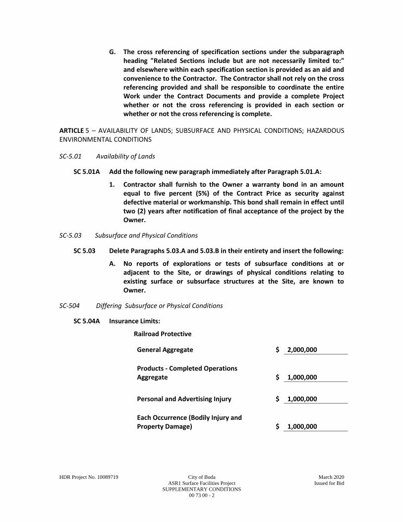
HDR Project No. 10089719 City of Buda March 2020
ASR1 Surface Facilities Project Issued for Bid
SUPPLEMENTARY CONDITIONS 00 73 00 - 2
G. The cross referencing of specification sections under the subparagraph heading "Related Sections include but are not necessarily limited to:" and elsewhere within each specification section is provided as an aid and convenience to the Contractor. The Contractor shall not rely on the cross referencing provided and shall be responsible to coordinate the entire Work under the Contract Documents and provide a complete Project whether or not the cross referencing is provided in each section or whether or not the cross referencing is complete.
ARTICLE 5 – AVAILABILITY OF LANDS; SUBSURFACE AND PHYSICAL CONDITIONS; HAZARDOUS ENVIRONMENTAL CONDITIONS
SC-5.01 Availability of Lands
SC 5.01A Add the following new paragraph immediately after Paragraph 5.01.A:
1. Contractor shall furnish to the Owner a warranty bond in an amount equal to five percent (5%) of the Contract Price as security against defective material or workmanship. This bond shall remain in effect until two (2) years after notification of final acceptance of the project by the Owner.
SC-5.03 Subsurface and Physical Conditions
SC 5.03 Delete Paragraphs 5.03.A and 5.03.B in their entirety and insert the following:
A. No reports of explorations or tests of subsurface conditions at or adjacent to the Site, or drawings of physical conditions relating to existing surface or subsurface structures at the Site, are known to Owner.
SC-504 Differing Subsurface or Physical Conditions
SC 5.04A Insurance Limits:
Railroad Protective
General Aggregate $ 2,000,000
Products - Completed Operations Aggregate $ 1,000,000
Personal and Advertising Injury $ 1,000,000
Each Occurrence (Bodily Injury and Property Damage) $ 1,000,000
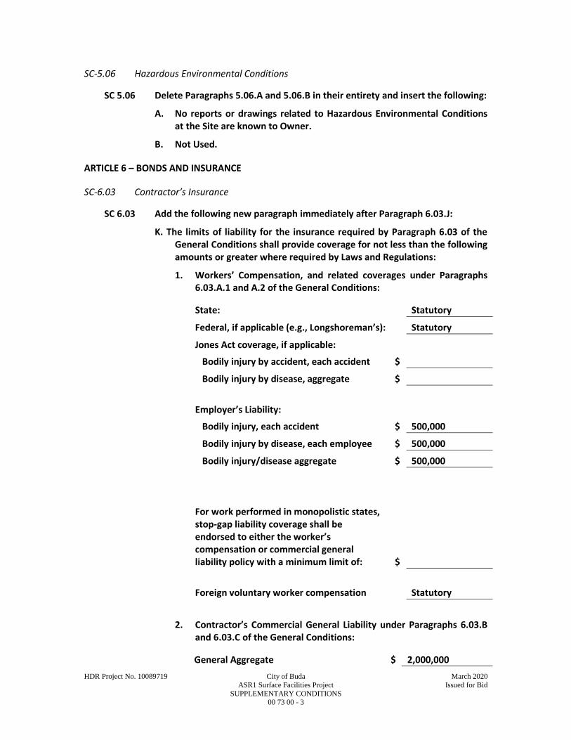
HDR Project No. 10089719 City of Buda March 2020
ASR1 Surface Facilities Project Issued for Bid
SUPPLEMENTARY CONDITIONS 00 73 00 - 3
SC-5.06 Hazardous Environmental Conditions
SC 5.06 Delete Paragraphs 5.06.A and 5.06.B in their entirety and insert the following:
A. No reports or drawings related to Hazardous Environmental Conditions at the Site are known to Owner.
B. Not Used.
ARTICLE 6 – BONDS AND INSURANCE
SC-6.03 Contractor’s Insurance
SC 6.03 Add the following new paragraph immediately after Paragraph 6.03.J:
K. The limits of liability for the insurance required by Paragraph 6.03 of the General Conditions shall provide coverage for not less than the following amounts or greater where required by Laws and Regulations:
1. Workers’ Compensation, and related coverages under Paragraphs 6.03.A.1 and A.2 of the General Conditions:
State: Statutory
Federal, if applicable (e.g., Longshoreman’s): Statutory
Jones Act coverage, if applicable:
Bodily injury by accident, each accident $
Bodily injury by disease, aggregate $
Employer’s Liability:
Bodily injury, each accident $ 500,000
Bodily injury by disease, each employee $ 500,000
Bodily injury/disease aggregate $ 500,000
For work performed in monopolistic states, stop-gap liability coverage shall be endorsed to either the worker’s compensation or commercial general liability policy with a minimum limit of: $
Foreign voluntary worker compensation Statutory
2. Contractor’s Commercial General Liability under Paragraphs 6.03.B and 6.03.C of the General Conditions:
General Aggregate $ 2,000,000
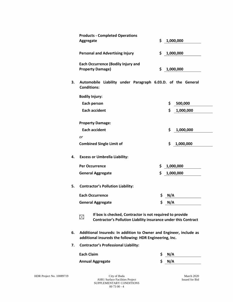
HDR Project No. 10089719 City of Buda March 2020
ASR1 Surface Facilities Project Issued for Bid
SUPPLEMENTARY CONDITIONS 00 73 00 - 4
Products - Completed Operations Aggregate $ 1,000,000
Personal and Advertising Injury $ 1,000,000
Each Occurrence (Bodily Injury and Property Damage) $ 1,000,000
3. Automobile Liability under Paragraph 6.03.D. of the General Conditions:
Bodily Injury:
Each person $ 500,000
Each accident $ 1,000,000
Property Damage:
Each accident $ 1,000,000
or
Combined Single Limit of $ 1,000,000
4. Excess or Umbrella Liability:
Per Occurrence $ 1,000,000
General Aggregate $ 1,000,000
5. Contractor’s Pollution Liability:
Each Occurrence $ N/A
General Aggregate $ N/A
If box is checked, Contractor is not required to provide Contractor’s Pollution Liability insurance under this Contract
6. Additional Insureds: In addition to Owner and Engineer, include as additional insureds the following: HDR Engineering, Inc.
7. Contractor’s Professional Liability:
Each Claim $ N/A
Annual Aggregate $ N/A

HDR Project No. 10089719 City of Buda March 2020
ASR1 Surface Facilities Project Issued for Bid
SUPPLEMENTARY CONDITIONS 00 73 00 - 5
SC-6.04 Owner’s Liability Insurance
SC 6.04A Insurance Limits:
Railroad Protective
General Aggregate $ 6,000,000
Each Occurrence $ 2,000,000
SC-6.05 Property Insurance
SC-6.05.A.1 Add the following new subparagraph after subparagraph 6.05.A.1:
a. In addition to Owner, Contractor, and all Subcontractors, include as insureds the following:
City of Buda, TX and HDR Engineering, Inc.
SC-6.05.A. Add the following to the list of items in Paragraph 6.05.A, as numbered items:
15. include for the benefit of Owner loss of profits and soft cost coverage including, without limitation, fixed expenses and debt service for a minimum of 12 months with a maximum deductible of 30 days, plus attorney’s fees and engineering or other consultants’ fees, if not otherwise covered;
16. include, in addition to the Contract Price amount, the value of the following equipment and materials to be installed by the Contractor but furnished by the Owner or third parties:
a. none
17. include by express endorsement coverage of damage to Contractor’s equipment.
7 – CONTRACTOR’S RESPONSIBILITIES
SC-7.01 Supervision and Superintendence
SC-7.01.B. Amend Paragraph 7.01.B to add the following sentences: “The Contractor shall identify their representative at the Site that shall have authority to act on behalf of Contractor. All communications given to or received from this representative shall be binding on Contractor.”
SC-7.01.C. Add the following new paragraph immediately after Paragraph 7.01.B:
Any superintendent or other personnel, who repeatedly fails to follow the Engineer’s written or oral orders, directions, instructions, or determinations, shall be subject to removal from the project. Upon the written request of the Engineer, the Contractor shall immediately remove such superintendent or other personnel and name a replacement in writing. Noncompliance with the

HDR Project No. 10089719 City of Buda March 2020
ASR1 Surface Facilities Project Issued for Bid
SUPPLEMENTARY CONDITIONS 00 73 00 - 6
Engineer’s request to remove and replace personnel at any level shall be grounds for terminating the Contract.
SC-7.02 Labor; Working Hours
SC-7.02.B. Amend Paragraph 7.02.B to read as follows:
Except as otherwise required for the safety or protection of persons or the Work or property at the Site or adjacent thereto, and except as otherwise stated in the Contract Documents, all Work at the Site shall be performed from 7 AM through 9 PM, Sunday through Saturday. Contractor will not perform Work on any legal holiday. Contractor may perform Work outside regular working hours or legal holidays only with Owner’s written consent, which will not be unreasonable withheld.
SC-7.03 Services, Materials, and Equipment
SC-7.03.B. Add the following new subparagraphs immediately after Paragraph 7.03.B:
1. Where the Work requires equipment be furnished, due to the lack of standardization of equipment as produced by the various manufacturers, it may become necessary to make minor modifications in the structures, buildings, piping, mechanical work, electrical work, accessories, controls, or other work, to accommodate the particular equipment offered. Contractor's bid price for any equipment offered shall include the cost of making any necessary changes subject to the approval of Engineer.
SC-7.08 7.09 Taxes
SC 7.09 Add the following paragraphs immediately after Paragraph 7.09.A:
B. Owner is exempt from payment of sales and compensating use taxes of the State of Texas and of cities and counties thereof on all materials to be incorporated into the Work.
1. Owner will furnish the required certificates of tax exemption to Contractor for use in the purchase of supplies and materials to be incorporated into the Work.
2. Owner’s exemption does not apply to construction tools, machinery, equipment, or other property purchased by or leased by Contractor, or to supplies or materials not incorporated into the Work.
ARTICLE 10 – ENGINEER’S STATUS DURING CONSTRUCTION
SC-10.03 Project Representative
SC-10.03 Add the following new paragraphs immediately after Paragraph 10.03.A:
B. On this Project, by agreement with the Owner, Engineer will not furnish a Resident Project Representative to represent Engineer at the Site or assist Engineer in observing the progress and quality of the Work.
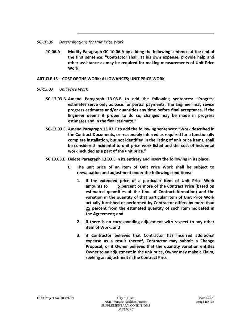
HDR Project No. 10089719 City of Buda March 2020
ASR1 Surface Facilities Project Issued for Bid
SUPPLEMENTARY CONDITIONS 00 73 00 - 7
SC-10.06 Determinations for Unit Price Work
10.06.A Modify Paragraph GC-10.06.A by adding the following sentence at the end of the first sentence: "Contractor shall, at his own expense, provide help and other assistance as may be required for making measurements of Unit Price Work.
ARTICLE 13 – COST OF THE WORK; ALLOWANCES; UNIT PRICE WORK
SC-13.03 Unit Price Work
SC-13.03.B. Amend Paragraph 13.03.B to add the following sentences: “Progress estimates serve only as basis for partial payments. The Engineer may revise progress estimates and/or quantities any time before final acceptance. If the Engineer deems it proper to do so, changes may be made in progress estimates and in the final estimate.”
SC-13.03.C. Amend Paragraph 13.03.C to add the following sentences: “Work described in the Contract Documents, or reasonably inferred as required for a functionally complete installation, but not identified in the listing of unit price items, shall be considered incidental to unit price work listed and the cost of incidental work included as a part of the unit price.”
SC 13.03.E Delete Paragraph 13.03.E in its entirety and insert the following in its place:
E. The unit price of an item of Unit Price Work shall be subject to reevaluation and adjustment under the following conditions:
1. if the extended price of a particular item of Unit Price Work amounts to 5 percent or more of the Contract Price (based on estimated quantities at the time of Contract formation) and the variation in the quantity of that particular item of Unit Price Work actually furnished or performed by Contractor differs by more than 25 percent from the estimated quantity of such item indicated in the Agreement; and
2. if there is no corresponding adjustment with respect to any other item of Work; and
3. if Contractor believes that Contractor has incurred additional expense as a result thereof, Contractor may submit a Change Proposal, or if Owner believes that the quantity variation entitles Owner to an adjustment in the unit price, Owner may make a Claim, seeking an adjustment in the Contract Price.
HDR Project No. 10089719 City of Buda March 2020
ASR1 Surface Facilities Project Issued for Bid
SUPPLEMENTARY CONDITIONS 00 73 00 - 8
ARTICLE 15 – PAYMENTS TO CONTRACTOR; SET-OFFS; COMPLETION; CORRECTION PERIOD
SC-15.03 Substantial Completion
SC 15.03.B Add the following new subparagraph to Paragraph 15.03.B:
1. If some or all of the Work has been determined not to be at a point of Substantial Completion and will require re-inspection or re-testing by Engineer, the cost of such re-inspection or re-testing, including the cost of time, travel and living expenses, shall be paid by Contractor to Owner. If Contractor does not pay, or the parties are unable to agree as to the amount owed, then Owner may impose a reasonable set-off against payments due under Article 15.
SC-15.07 Waiver of Claims
SC-15.07.B. Amend Paragraph 15.07.B to state "The acceptance of final payment by Contractor will constitute a waiver by Contractor of all claims and rights against Owner and/or Engineer other than those pending matters that have been duly submitted or appealed under the provisions of Article 17.”
SC-15.08 Correction Period
SC-15.08 Replace Paragraph A in its entirety with the following:
A. In within two years after the date of Final Acceptance (or such longer period of time as may be prescribed by the terms of any applicable special guarantee required by the Contract Documents, or by any specific provision of the Contract Documents), any Work is found to be defective, or if the repair of any damages to the Site, adjacent areas that the Contractor has arranged to use through construction easements or otherwise, and other adjacent areas used by the Contractor as permitted by Laws and Regulations, is found to be defective, then the Contractor shall promptly, without cost to the Owner and in accordance with the Owner’s written instructions:
ARTICLE 17 – FINAL RESOLUTION OF DISPUTES
SC-17.02 Arbitration
SC-17.02 Add the following new paragraph immediately after Paragraph 17.01.
SC-17.02 Arbitration
A. All matters subject to final resolution under this Article will be decided by arbitration in accordance with the rules of insert name of selected arbitration agency, subject to the conditions and limitations of this paragraph. This agreement to arbitrate and any other agreement or consent to arbitrate entered into will be specifically enforceable under the prevailing law of any court having jurisdiction.
HDR Project No. 10089719 City of Buda March 2020
ASR1 Surface Facilities Project Issued for Bid
SUPPLEMENTARY CONDITIONS 00 73 00 - 9
B. The demand for arbitration will be filed in writing with the other party to the Contract and with the selected arbitrator or arbitration provider, and a copy will be sent to Engineer for information. The demand for arbitration will be made within the specific time required in this Article, or if no specified time is applicable within a reasonable time after the matter in question has arisen, and in no event shall any such demand be made after the date when institution of legal or equitable proceedings based on such matter in question would be barred by the applicable statute of limitations. The demand for arbitration should include specific reference to Paragraph SC-17.02.D below.
C. No arbitration arising out of or relating to the Contract shall include by consolidation, joinder, or in any other manner any other individual or entity (including Engineer, and Engineer’s consultants and the officers, directors, partners, agents, employees or consultants of any of them) who is not a party to this Contract unless:
1. the inclusion of such other individual or entity is necessary if complete relief is to be afforded among those who are already parties to the arbitration; and
2. such other individual or entity is substantially involved in a question of law or fact which is common to those who are already parties to the arbitration and which will arise in such proceedings.
D. The award rendered by the arbitrator(s) shall be consistent with the agreement of the parties, in writing, and include a concise breakdown of the award, and a written explanation of the award specifically citing the Contract provisions deemed applicable and relied on in making the award.
E. The award will be final. Judgment may be entered upon it in any court having jurisdiction thereof, and it will not be subject to modification or appeal, subject to provisions of the Laws and Regulations relating to vacating or modifying an arbitral award.
F. The fees and expenses of the arbitrators and any arbitration service shall be shared equally by Owner and Contractor.

6/4/2019 https://www.wdol.gov/wdol/scafiles/davisbacon/tx7.dvb
https://www.wdol.gov/wdol/scafiles/davisbacon/tx7.dvb 1/5
General Decision Number: TX190007 01/04/2019 TX7 Superseded General Decision Number: TX20180016 State: Texas Construction Types: Heavy and Highway Counties: Atascosa, Bandera, Bastrop, Bell, Bexar, Brazos, Burleson, Caldwell, Comal, Coryell, Guadalupe, Hays, Kendall, Lampasas, McLennan, Medina, Robertson, Travis, Williamson and Wilson Counties in Texas. HEAVY (excluding tunnels and dams, not to be used for work on Sewage or Water Treatment Plants or Lift / Pump Stations in Bell, Coryell, McClennon and Williamson Counties) and HIGHWAY Construction Projects Note: Under Executive Order (EO) 13658, an hourly minimum wage of $10.60 for calendar year 2019 applies to all contracts subject to the Davis-Bacon Act for which the contract is awarded (and any solicitation was issued) on or after January 1, 2015. If this contract is covered by the EO, the contractor must pay all workers in any classification listed on this wage determination at least $10.60 per hour (or the applicable wage rate listed on this wage determination, if it is higher) for all hours spent performing on the contract in calendar year 2019. If this contract is covered by the EO and a classification considered necessary for performance of work on the contract does not appear on this wage determination, the contractor must pay workers in that classification at least the wage rate determined through the conformance process set forth in 29 CFR 5.5(a)(1)(ii) (or the EO minimum wage rate, if it is higher than the conformed wage rate). The EO minimum wage rate will be adjusted annually. Please note that this EO applies to the above-mentioned types of contracts entered into by the federal government that are subject to the Davis-Bacon Act itself, but it does not apply to contracts subject only to the Davis-Bacon Related Acts, including those set forth at 29 CFR 5.1(a)(2)-(60). Additional information on contractor requirements and worker protections under the EO is available at www.dol.gov/whd/govcontracts. Modification Number Publication Date 0 01/04/2019 * SUTX2011-006 08/03/2011 Rates Fringes CEMENT MASON/CONCRETE FINISHER (Paving and Structures)......................$ 12.56 ELECTRICIAN......................$ 26.35 FORM BUILDER/FORM SETTER Paving & Curb...............$ 12.94 Structures..................$ 12.87
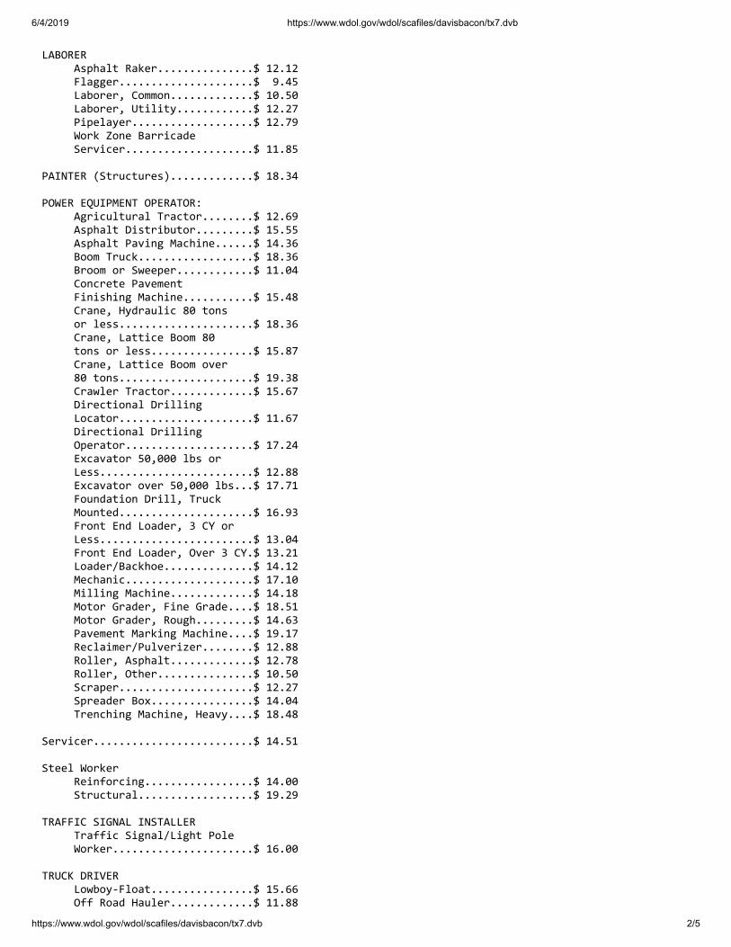
6/4/2019 https://www.wdol.gov/wdol/scafiles/davisbacon/tx7.dvb
https://www.wdol.gov/wdol/scafiles/davisbacon/tx7.dvb 2/5
LABORER Asphalt Raker...............$ 12.12 Flagger.....................$ 9.45 Laborer, Common.............$ 10.50 Laborer, Utility............$ 12.27 Pipelayer...................$ 12.79 Work Zone Barricade Servicer....................$ 11.85 PAINTER (Structures).............$ 18.34 POWER EQUIPMENT OPERATOR: Agricultural Tractor........$ 12.69 Asphalt Distributor.........$ 15.55 Asphalt Paving Machine......$ 14.36 Boom Truck..................$ 18.36 Broom or Sweeper............$ 11.04 Concrete Pavement Finishing Machine...........$ 15.48 Crane, Hydraulic 80 tons or less.....................$ 18.36 Crane, Lattice Boom 80 tons or less................$ 15.87 Crane, Lattice Boom over 80 tons.....................$ 19.38 Crawler Tractor.............$ 15.67 Directional Drilling Locator.....................$ 11.67 Directional Drilling Operator....................$ 17.24 Excavator 50,000 lbs or Less........................$ 12.88 Excavator over 50,000 lbs...$ 17.71 Foundation Drill, Truck Mounted.....................$ 16.93 Front End Loader, 3 CY or Less........................$ 13.04 Front End Loader, Over 3 CY.$ 13.21 Loader/Backhoe..............$ 14.12 Mechanic....................$ 17.10 Milling Machine.............$ 14.18 Motor Grader, Fine Grade....$ 18.51 Motor Grader, Rough.........$ 14.63 Pavement Marking Machine....$ 19.17 Reclaimer/Pulverizer........$ 12.88 Roller, Asphalt.............$ 12.78 Roller, Other...............$ 10.50 Scraper.....................$ 12.27 Spreader Box................$ 14.04 Trenching Machine, Heavy....$ 18.48 Servicer.........................$ 14.51 Steel Worker Reinforcing.................$ 14.00 Structural..................$ 19.29 TRAFFIC SIGNAL INSTALLER Traffic Signal/Light Pole Worker......................$ 16.00 TRUCK DRIVER Lowboy-Float................$ 15.66 Off Road Hauler.............$ 11.88
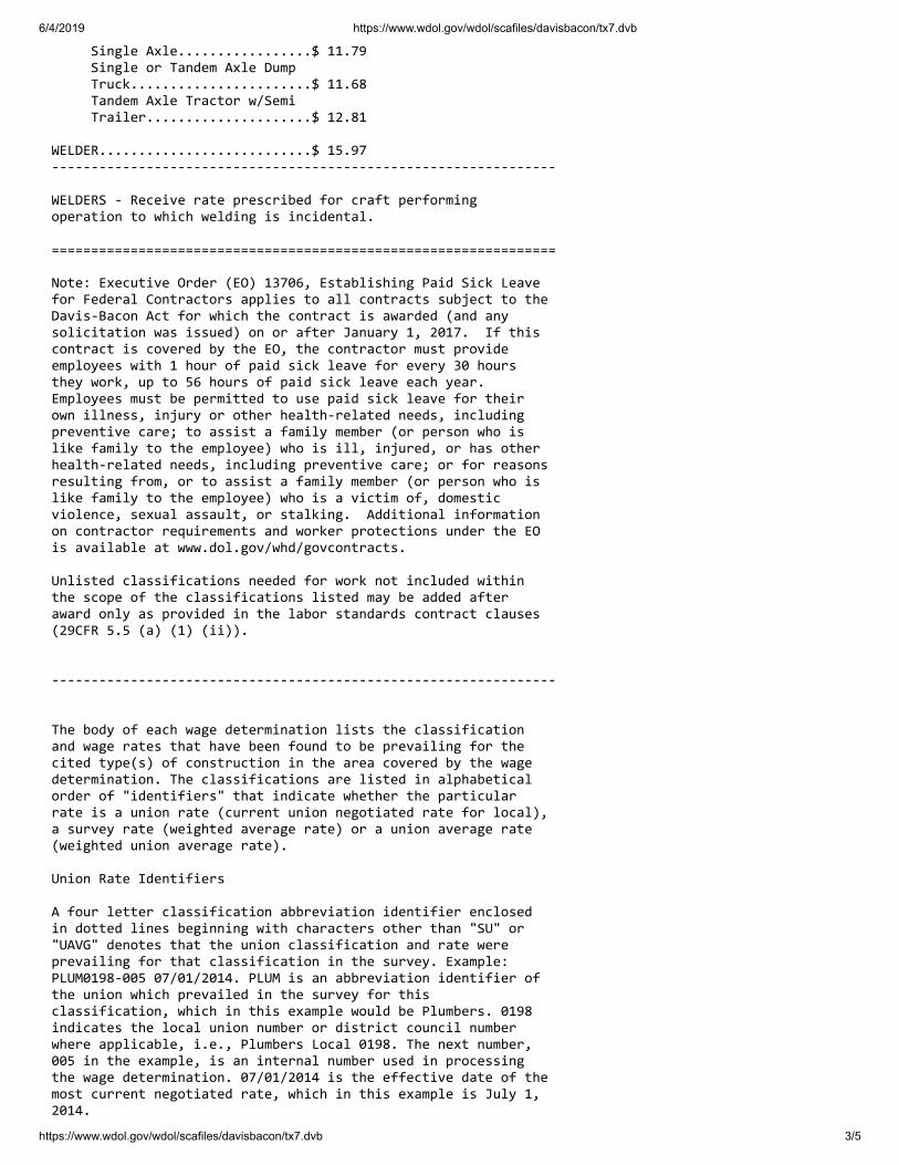
6/4/2019 https://www.wdol.gov/wdol/scafiles/davisbacon/tx7.dvb
https://www.wdol.gov/wdol/scafiles/davisbacon/tx7.dvb 3/5
Single Axle.................$ 11.79 Single or Tandem Axle Dump Truck.......................$ 11.68 Tandem Axle Tractor w/Semi Trailer.....................$ 12.81 WELDER...........................$ 15.97 ---------------------------------------------------------------- WELDERS - Receive rate prescribed for craft performing operation to which welding is incidental. ================================================================ Note: Executive Order (EO) 13706, Establishing Paid Sick Leave for Federal Contractors applies to all contracts subject to the Davis-Bacon Act for which the contract is awarded (and any solicitation was issued) on or after January 1, 2017. If this contract is covered by the EO, the contractor must provide employees with 1 hour of paid sick leave for every 30 hours they work, up to 56 hours of paid sick leave each year. Employees must be permitted to use paid sick leave for their own illness, injury or other health-related needs, including preventive care; to assist a family member (or person who is like family to the employee) who is ill, injured, or has other health-related needs, including preventive care; or for reasons resulting from, or to assist a family member (or person who is like family to the employee) who is a victim of, domestic violence, sexual assault, or stalking. Additional information on contractor requirements and worker protections under the EO is available at www.dol.gov/whd/govcontracts. Unlisted classifications needed for work not included within the scope of the classifications listed may be added after award only as provided in the labor standards contract clauses (29CFR 5.5 (a) (1) (ii)). ---------------------------------------------------------------- The body of each wage determination lists the classification and wage rates that have been found to be prevailing for the cited type(s) of construction in the area covered by the wage determination. The classifications are listed in alphabetical order of "identifiers" that indicate whether the particular rate is a union rate (current union negotiated rate for local), a survey rate (weighted average rate) or a union average rate (weighted union average rate). Union Rate Identifiers A four letter classification abbreviation identifier enclosed in dotted lines beginning with characters other than "SU" or "UAVG" denotes that the union classification and rate were prevailing for that classification in the survey. Example: PLUM0198-005 07/01/2014. PLUM is an abbreviation identifier of the union which prevailed in the survey for this classification, which in this example would be Plumbers. 0198 indicates the local union number or district council number where applicable, i.e., Plumbers Local 0198. The next number, 005 in the example, is an internal number used in processing the wage determination. 07/01/2014 is the effective date of the most current negotiated rate, which in this example is July 1, 2014.

6/4/2019 https://www.wdol.gov/wdol/scafiles/davisbacon/tx7.dvb
https://www.wdol.gov/wdol/scafiles/davisbacon/tx7.dvb 4/5
Union prevailing wage rates are updated to reflect all rate changes in the collective bargaining agreement (CBA) governing this classification and rate. Survey Rate Identifiers Classifications listed under the "SU" identifier indicate that no one rate prevailed for this classification in the survey and the published rate is derived by computing a weighted average rate based on all the rates reported in the survey for that classification. As this weighted average rate includes all rates reported in the survey, it may include both union and non-union rates. Example: SULA2012-007 5/13/2014. SU indicates the rates are survey rates based on a weighted average calculation of rates and are not majority rates. LA indicates the State of Louisiana. 2012 is the year of survey on which these classifications and rates are based. The next number, 007 in the example, is an internal number used in producing the wage determination. 5/13/2014 indicates the survey completion date for the classifications and rates under that identifier. Survey wage rates are not updated and remain in effect until a new survey is conducted. Union Average Rate Identifiers Classification(s) listed under the UAVG identifier indicate that no single majority rate prevailed for those classifications; however, 100% of the data reported for the classifications was union data. EXAMPLE: UAVG-OH-0010 08/29/2014. UAVG indicates that the rate is a weighted union average rate. OH indicates the state. The next number, 0010 in the example, is an internal number used in producing the wage determination. 08/29/2014 indicates the survey completion date for the classifications and rates under that identifier. A UAVG rate will be updated once a year, usually in January of each year, to reflect a weighted average of the current negotiated/CBA rate of the union locals from which the rate is based. ---------------------------------------------------------------- WAGE DETERMINATION APPEALS PROCESS 1.) Has there been an initial decision in the matter? This can be: * an existing published wage determination * a survey underlying a wage determination * a Wage and Hour Division letter setting forth a position on a wage determination matter * a conformance (additional classification and rate) ruling On survey related matters, initial contact, including requests for summaries of surveys, should be with the Wage and Hour Regional Office for the area in which the survey was conducted because those Regional Offices have responsibility for the Davis-Bacon survey program. If the response from this initial contact is not satisfactory, then the process described in 2.) and 3.) should be followed.
6/4/2019 https://www.wdol.gov/wdol/scafiles/davisbacon/tx7.dvb
https://www.wdol.gov/wdol/scafiles/davisbacon/tx7.dvb 5/5
With regard to any other matter not yet ripe for the formal process described here, initial contact should be with the Branch of Construction Wage Determinations. Write to: Branch of Construction Wage Determinations Wage and Hour Division U.S. Department of Labor 200 Constitution Avenue, N.W. Washington, DC 20210 2.) If the answer to the question in 1.) is yes, then an interested party (those affected by the action) can request review and reconsideration from the Wage and Hour Administrator (See 29 CFR Part 1.8 and 29 CFR Part 7). Write to: Wage and Hour Administrator U.S. Department of Labor 200 Constitution Avenue, N.W. Washington, DC 20210 The request should be accompanied by a full statement of the interested party's position and by any information (wage payment data, project description, area practice material, etc.) that the requestor considers relevant to the issue. 3.) If the decision of the Administrator is not favorable, an interested party may appeal directly to the Administrative Review Board (formerly the Wage Appeals Board). Write to: Administrative Review Board U.S. Department of Labor 200 Constitution Avenue, N.W. Washington, DC 20210 4.) All decisions by the Administrative Review Board are final. ================================================================ END OF GENERAL DECISION

This page intentionally left blank.

D I V I S I O N 0 1
GENERAL REQUIREMENTS

This page intentionally left blank.

HDR Project No. 10089719 City of Buda March 2020
ASR1 Surface Facilities Project Issued for Bid
SUMMARY OF WORK 01 11 00 - 1
SECTION 01 11 00
SUMMARY OF WORK
PART 1 - GENERAL
1.1 DESCRIPTION
A. General:
1. Furnish all labor, materials, tools, equipment and services as indicated in accordance with
provisions of Contract Documents.
2. It is the intent of the Contract Documents to describe a functionally complete project.
Furnish and install all supplementary or miscellaneous items, appurtenances, and devices
incidental to or necessary for a sound, secure, complete, and functional installation.
1.2 WORK COVERED BY CONTRACT
A. The Work of this Contract generally includes the following:
1. Mobilize equipment and materials to the well location.
2. Construct concrete pad and well sealing block.
3. Install well pump and motor.
4. Construct wellhead, piping and valves.
5. Construct electrical canopy, install electrical components.
6. Perform all required testing.
7. Perform all required sampling and laboratory analyses.
8. Restore site and demobilize.
1.3 WORK SEQUENCE
A. Organize and plan the construction activities to assure the safety and reliability of, and to
minimize the interruption to, adjacent properties and pubic roadways.
B. The proposed Work sequence shall be submitted to the Engineer in the Schedule of
Construction. The Work sequence shall be in accordance with requirements in the Contract
documents.
1.4 CONTRACTOR-FURNISHED PRODUCTS
A. Furnish all products, other than Owner-furnished products designated above.
B. Components required to be supplied in quantity within a specification section shall all be the
same and shall be interchangeable.
C. Unless otherwise indicated in the Contract Documents, materials and equipment shall be:
1. Produced by reputable manufacturers having adequate experience in the manufacture of
these items; and
2. Designed for the service intended; and
3. New and have not been previously been incorporated into another project or facility; and
4. Have not changed ownership since their initial production or fabrication and shipment from
the manufacturer’s factory or facility; and
5. Properly maintained and serviced in accordance with the manufacturer’s recommendations
for long-term storage; submit documentation under the relevant technical section that such
maintenance and service has been performed; and
6. Current model(s) or type(s) furnished by the Supplier and only modified as necessary to
comply with the design.
1.5 UNDERGROUND UTILITIES
A. Utilities known to the Engineer who may have underground facilities in the vicinity of the Work,
may be contacted as follows:
HDR Project No. 10089719 City of Buda March 2020
ASR1 Surface Facilities Project Issued for Bid
SUMMARY OF WORK 01 11 00 - 2
John Nett, P.E.
City Engineer
City of Buda, Texas
(512) 312-5745
1.6 TREE TRIMMING, CLEARING, AND TREE REMOVAL
A. Provide all required labor and equipment for trimming, clearing, and tree removal within the
limits of Work, as indicated in the Drawings.
1.7 FENCES
A. All fences affected by the Work shall be maintained by the Contractor until completion of the
Work. Fences disturbed by the construction shall be restored by the Contractor to their original
or better condition and to their original location unless otherwise indicated.
PART 2 - PRODUCTS - (NOT APPLICABLE TO THIS SPECIFICATION SECTION)
PART 3 - EXECUTION - (NOT APPLICABLE TO THIS SPECIFICATION SECTION) END OF SECTION
HDR Project No. 10089719 City of Buda March 2020
ASR1 Surface Facilities Project Issued for Bid
MEASUREMENT AND PAYMENT (UNIT PRICE CONTRACTS) 01 22 00 - 1
SECTION 01 22 00
MEASUREMENT AND PAYMENT (UNIT PRICE CONTRACTS)
PART 1 - GENERAL
1.1 SUMMARY
A. Section Includes:
1. Defines how work items are measured and paid for on Unit Price Contracts. These items
include unit price, lump sum price, and allowance payment items.
2. In the case of conflict between this Section and the measurement methods specified in the
individual Technical Specification Sections, the measurement methods in Technical
Specification Sections shall govern.
3. Receive payment for work after it is installed. Payment for material on hand can only be
paid for if allowed by the Agreement, the General and/or Special Conditions.
4. Partial payment may be requested for items partially installed when agreed to by the Owner.
B. Related Specification Sections include but are not necessarily limited to:
1. Division 00 - Procurement and Contracting Requirements.
2. Division 01 - General Requirements.
3. Applications for Payment requirements are included in Specification Section 01 30 00 -
Special Conditions.
1.2 UNIT PRICE ITEMS
A. Quantity and measurement estimates stated in the Bid Form are estimates for bidding purposes
only. Actual payments shall be based on actual quantities installed, in-place, as measured and/or
verified by the Engineer.
B. Unless otherwise stated in the Contract Documents, the bid unit prices shall be in effect
throughout the contract duration. When the variance between the estimated quantities and the
actual installed quantities is more than 25 PCT, the Contractor or the Owner may negotiate a
change to the Unit Price. That change will be made in accordance with the Change Order
process as defined in the Contract Documents.
C. Except as defined above, make no claim, nor receive any compensation, for anticipated profits,
loss of profit, damages, or any extra payment due to any difference between the amounts of work
actually completed, or materials or equipment furnished, and the estimated quantities.
D. The Owner can only pay for quantities that exceed the estimated quantities so long as the total
payments to the Contractor do not exceed the Contract Price. If the added quantities will result
in payments that exceed the Contract Price, a Change Order will need to be executed before
payment can be made for the added quantities.
E. Assist Engineer by providing necessary equipment, workers, and survey personnel as required to
measure quantities.
F. Unless stated in the Contract Documents, measured quantities shall be rounded to the nearest
whole integer.
G. General Measurement:
1. Measurement for progress payment shall be made by, or approved by, the Engineer based
on the actual quantities installed. The actual quantities installed can be adjusted for
corrections to previous calculations, incomplete elements or components if agreed to in
advance and in writing by the Engineer.
2. Unless otherwise provided for in the Contract Documents, unit price items are all inclusive
of all related work, direct and indirect costs, to provide a complete and functional item.
HDR Project No. 10089719 City of Buda March 2020
ASR1 Surface Facilities Project Issued for Bid
MEASUREMENT AND PAYMENT (UNIT PRICE CONTRACTS) 01 22 00 - 2
3. The final measurement shall be based on actual installed quantities, jointly measured and
agreed to by the Contractor and the Engineer. Quantities can be adjusted (increased or
decreased) based on a final calculation of quantities by the Engineer and Contractor.
H. General Payment:
1. Progress payments shall be in accordance with the Contract Documents based on estimated
quantities installed paid at the bid unit price.
2. The final payment shall be based on actual quantities, fully installed, tested and placed into
service, paid at the bid unit price.
1.3 LUMP SUM ITEMS
A. Progress payments for Lump Sum items in the Bid Schedule will be based on the breakdown
prepared by the Contractor and approved by the Engineer and Owner before acceptance of the
Application for Payment for the Lump Sum item.
B. Lump Sum payment will be for the entire item as specified and as indicated in the Contract
Documents. Payment for all bid items indicated as Lump Sums shall include the cost of all
labor, materials, equipment and incidentals necessary to furnish, install, clean, test, and place
each bid item into operation; including permitting, general conditions, overhead and profit.
C. Bid Item Details:
1. Bid Item No. 1–Mobilization, Demobilization, and Re-grading
a. Measurement – This item includes, but is not limited to, all materials, tools, labor,
equipment, supplies, permits, removal and disposal of waste or excess materials, etc.
necessary to mobilize and demobilize, and restore the site grade to the initial condition.
b. Payment - Payment for this item shall be at the lump sum price indicated in the Bid
Form, which price shall constitute full compensation for the completed Work, all in
accordance with the Contract Documents. In addition, Owner will pay:
1) No greater than 5 PCT of the original Contract Amount as a separate pay item for
mobilization.
2) No greater than 1/2 PCT of the original Contract Amount as a separate pay item for
demobilization.
3) 50 PCT of the Mobilization lump sum price when 5 PCT of the original Contract
Amount is earned.
4) Remaining 50 PCT of the Mobilization lump sum price when 10 PCT of the
original Contract Amount is earned.
5) 100 PCT of the Demobilization lump sum price when all closeout activities and
documents are completed.
2. Bid Item No. 2–Concrete Pavement and Well Pad
a. Measurement – This item includes, but is not limited to, all materials, tools, labor,
equipment, supplies, etc. necessary to provide construct the concrete pavement and well
pad.
b. Payment - Payment for this item shall be at the lump sum price indicated in the Bid
Form, which price shall constitute full compensation for the completed Work, all in
accordance with the Contract Documents.
3. Bid Item No. 3–Connection to Well Casing
a. Measurement – This item includes, but is not limited to, all materials, tools, labor,
equipment, supplies, etc. necessary to install the pump discharge head, discharge head
support assembly, sole plate, and casing ring flange.
b. Payment - Payment for this item shall be at the lump sum price indicated in the Bid
Form, which price shall constitute full compensation for the completed Work, all in
accordance with the Contract Documents.
4. Bid Item No. 4–Line Shaft Well Pump
a. Measurement – This item includes, but is not limited to, all materials, tools, labor,
equipment, supplies, etc. necessary to provide and install the well pump and motor.
HDR Project No. 10089719 City of Buda March 2020
ASR1 Surface Facilities Project Issued for Bid
MEASUREMENT AND PAYMENT (UNIT PRICE CONTRACTS) 01 22 00 - 3
b. Payment - Payment for this item shall be at the lump sum price indicated in the Bid
Form, which price shall constitute full compensation for the completed Work, all in
accordance with the Contract Documents.
5. Bid Item No. 5–Process Piping
a. Measurement – This item includes, but is not limited to, all materials, tools, labor,
equipment, supplies, etc. necessary to provide piping, pre-lube line, pipe supports,
insulation, heat tracing, and associated valves, meters and interconnect to existing Well
No. 5.
b. Payment - Payment for this item shall be at the lump sum price indicated in the Bid
Form, which price shall constitute full compensation for the completed Work, all in
accordance with the Contract Documents.
6. Bid Item No. 6–Equipment Shelter
a. Measurement – This item includes, but is not limited to, all materials, tools, labor,
equipment, supplies, etc. necessary to construct equipment shelter and pad.
b. Payment - Payment for this item shall be at the lump sum price indicated in the Bid
Form, which price shall constitute full compensation for the completed Work, all in
accordance with the Contract Documents.
7. Bid Item No. –Electrical
a. Measurement – This item includes, but is not limited to, all materials, tools, labor,
equipment, supplies, etc. necessary to installing conduit, wiring, and electrical
equipment including pump control panel, valve actuators, lighting, and outlets.
b. Payment - Payment for this item shall be at the lump sum price indicated in the Bid
Form, which price shall constitute full compensation for the completed Work, all in
accordance with the Contract Documents.
8. Bid Item No. 8–Instrumentation and Controls
a. Measurement – This item includes, but is not limited to, all materials, tools, labor,
equipment, supplies, etc. necessary to install instrumentation, transmitters, and controls.
b. Payment - Payment for this item shall be at the lump sum price indicated in the Bid
Form, which price shall constitute full compensation for the completed Work, all in
accordance with the Contract Documents.
9. Bid Item No. 9–Fence and Gates
a. Measurement – This item includes, but is not limited to, all materials, tools, labor,
equipment, supplies, etc. necessary to install permanent security fence and gates.
b. Payment - Payment for this item shall be at the lump sum price indicated in the Bid
Form, which price shall constitute full compensation for the completed Work, all in
accordance with the Contract Documents.
10. Bid Item No. 10–Erosion Controls, Tree Protection and Rip Rap
a. Measurement – This item includes, but is not limited to, all materials, tools, labor,
equipment, supplies, etc. necessary to install permanent rip rap and maintain and
remove existing temporary fencing, tree protection and silt fencing (provided by
others).
b. Payment - Payment for this item shall be at the lump sum price indicated in the Bid
Form, which price shall constitute full compensation for the completed Work, all in
accordance with the Contract Documents.
11. Bid Item No.11–Facility Startup
a. Measurement – This item includes, but is not limited to, all materials, tools, labor,
equipment, supplies, etc. necessary to test and perform a startup of the ASR well and
instrumentation.
b. Payment - Payment for this item shall be at the lump sum price indicated in the Bid
Form, which price shall constitute full compensation for the completed Work, all in
accordance with the Contract Documents.
1.4 APPLICATION FOR PAYMENT
A. Provide a Summary Sheets and breakdown sheets equivalent to those of EJCDC document C-
620, Contractor's Application for Payment forms.
HDR Project No. 10089719 City of Buda March 2020
ASR1 Surface Facilities Project Issued for Bid
MEASUREMENT AND PAYMENT (UNIT PRICE CONTRACTS) 01 22 00 - 4
PART 2 - PRODUCTS - (NOT APPLICABLE TO THIS SPECIFICATION SECTION)
PART 3 - EXECUTION - (NOT APPLICABLE TO THIS SPECIFICATION SECTION) END OF SECTION
HDR Project No. 10089719 City of Buda March 2020
ASR1 Surface Facilities Project Issued for Bid
SPECIAL CONDITIONS 01 30 00 - 1
SECTION 01 30 00
SPECIAL CONDITIONS
PART 1 - GENERAL
1.1 SUMMARY
A. Section Includes:
1. Administrative and procedural requirements for:
a. Preconstruction conference.
b. Project signs.
c. Temporary sanitary facilities.
d. Temporary utilities.
e. Protection of Work and property.
f. Temporary controls.
g. Drawings and Contract Documents for Contractor use.
h. Project meetings.
i. Special considerations related to adjacent properties and facilities.
j. Historical and archaeological finds.
k. Administrative procedures.
B. Related Specification Sections include but are not necessarily limited to:
1. Division 00 - Procurement and Contracting Requirements.
2. Division 01 - General Requirements.
1.2 SUBMITTALS
A. Shop Drawings:
1. See Specification Section 01 33 00 for requirements for the mechanics and administration of
the submittal process.
2. Project Sign Layout and mounting design.
1.3 PRECONSTRUCTION CONFERENCE
A. A preconstruction conference shall be held at the City of Buda offices after award of Contract.
1. Engineer will notify the Contractor as to the date and time of the conference two (2) weeks
in advance of the proposed date.
2. Contractor's Project Manager and Project Superintendent and Contractor's Subcontractor
Representatives shall attend.
1.4 PROJECT SIGNS
A. Within 10 days after receipt of Notice to Proceed, furnish, install, and maintain a Project Sign as
defined herein. No other signs will be allowed on the project unless approved in writing by the
Owner.
B. Project Sign Materials:
1. The Project Sign will be produced by an experienced professional sign company.
2. The Project Sign shall be structurally adequate and suitable for exterior application. Project
Sign panels shall be constructed using a 4 FT and 8 FT, 3/4 IN new A-B Grade, exterior
type, APA MDO plywood both sides.
3. The Project Sign paint shall be exterior quality, as specified in Division 09 or as a
minimum, primer and finish coat: exterior, semi-gloss, enamel. Colors for the sign and
structure, framing, sign surfaces, and graphics shall be as shown on the Drawings or as
selected by the Engineer.
4. Prior to producing the sign, submit a layout of the sign to the Engineer for review and
approval. The layout shall include content, lettering style and color and background colors.
C. Information to be included on the Project Sign will include:
HDR Project No. 10089719 City of Buda March 2020
ASR1 Surface Facilities Project Issued for Bid
SPECIAL CONDITIONS 01 30 00 - 2
1. Project Name.
2. Owner’s Name.
3. Engineer.
4. Contractor.
5. Construction Manager.
6. Funding Agencies if required by the funding agreement.
7. Construction dollar amount if required by the funding agency and/or client.
8. Company and Agency Logos if approved by the Owner.
9. Coordinate Project Sign layout with the Owner prior to installation.
D. Installation of the Project Sign:
1. The Project Sign shall be constructed with new materials and kept clean throughout the
project duration.
a. Install Project Sign as shown in the Drawings.
2. The Project Sign shall be mounted to resist wind loads as required by authorities having
jurisdiction but not less than wind velocity of 50 MPH.
3. Prior to installing the sign, submit mounting design to the Engineer for review and approval.
4. The Project Sign shall be erected level and plumb.
E. Remove signs, framing, supports, and foundations to a depth of at least 2 FT upon completion of
Project. Restore area to a condition equal to or better than before construction.
1.5 TEMPORARY SANITARY FACILITIES
A. Provide temporary sanitary facilities for use of construction workers during construction
activities.
B. Do not use existing toilet facilities in occupied areas or new toilet facilities in construction area
without Owner’s written consent.
C. Provide facilities complying with local, State and Federal sanitary laws and regulations. At no
time shall toilet facilities be within 50 feet of the well borehole.
D. Follow facility provider's minimum maintenance frequency or service more frequently to keep in
clean and sanitary condition.
E. Provide adequate supplies of toilet paper, cleaning supplies, and other required items.
1.6 TEMPORARY UTILITIES
A. Power:
1. No electric power is available at Site. Make arrangements to obtain and pay for electrical
power used until final payment and acceptance by Owner, unless otherwise recommended
by Owner’s Representative at Substantial Completion.
2. The Contractor shall provide and maintain lighting for construction operations.
3. Temporary electrical power for use during construction shall not interfere with or adversely
affect the normal operation of any adjacent facilities.
4. Temporary electrical power installations shall meet construction safety requirements of
OSHA, State, and other governing agencies.
B. Lighting: Provide temporary lighting to meet applicable safety requirements to allow erection,
application, or installation of materials and equipment, and observation or inspection of the
Work.
C. Water:
1. Potable water is available at Site. Make arrangements with Owner and bear costs of
providing water required for construction purposes and for drinking by construction
personnel during construction.
D. Fire Protection:
1. The Contractor shall maintain fire extinguishing equipment onsite. Debris and flammable
materials shall be removed weekly to minimize potential hazards.

HDR Project No. 10089719 City of Buda March 2020
ASR1 Surface Facilities Project Issued for Bid
SPECIAL CONDITIONS 01 30 00 - 3
2. Fires shall be reported immediately to local authorities and the Owner.
1.7 PROTECTION OF WORK AND PROPERTY
A. General:
1. Perform Work within right-of-way and easements in a systematic manner that minimizes
inconvenience to property owners and the public.
2. Maintain in continuous service existing oil and gas pipelines, underground power, telephone
or communication cable, water mains, irrigation lines, sewers, poles and overhead power,
and other utilities encountered along line of the Work, unless other arrangements
satisfactory to owners of said utilities have been made.
3. Where completion of the Work requires temporary or permanent removal or relocation of
existing utility, coordinate activities with owner of said utility and perform work to their
satisfaction.
4. Protect, shore, brace, support, and maintain underground pipes, conduits, drains, and other
underground utility construction uncovered or otherwise affected by construction
operations.
5. Keep fire hydrants and water control valves free from obstruction and available for use at all
times.
6. In areas where Contractor’s operations are adjacent to or near a utility, such as gas,
telephone, television, electric power, water, sewer, or irrigation system, and such operations
may cause damage or inconvenience, suspend operations until arrangements necessary for
protection have been made by Contractor.
7. Maintain original Site drainage wherever possible.
B. Trees and Plantings:
1. Protect from damage and preserve trees, shrubs, and other plants outside limits of the Work
and within limits of the Work, which are designated on Drawings to remain undisturbed.
2. Refer to drawings for tree protection measures
C. Existing Structures:
1. Where Contractor contemplates removal of small structures such as mailboxes, signposts,
and culverts that interfere with Contractor’s operations, obtain approval of property owner
and Owner’s Representative.
2. Replace items removed in their original location and a condition equal to or better than
original.
D. Waterways: Keep ditches, culverts, and natural drainages continuously free of construction
materials and debris.
E. Dewatering: Construct, maintain, and operate cofferdams, channels, flume drains, sumps,
pumps, or other temporary diversion and protection works. Furnish materials required, install,
maintain, and operate necessary pumping and other equipment for the environmentally safe
removal and disposal of water from the various parts of the Work. Maintain foundations and
parts of the Work free from water.
1.8 TEMPORARY CONTROLS
A. Fencing
1. The Contractor shall provide fencing to restrict unauthorized entry to construction areas and
to protect existing facilities and adjacent properties from construction operations.
2. The Contractor shall provide barriers to protect plants and trees designated to remain.
1.9 DRAWINGS AND CONTRACT DOCUMENTS FOR CONTRACTOR USE
A. Refer to General Conditions.
B. Pick up all "no-charge" documents within 10 days from date of Notice to Proceed.
C. Additional documents after "no-charge" documents will be furnished to Contractor at cost.

HDR Project No. 10089719 City of Buda March 2020
ASR1 Surface Facilities Project Issued for Bid
SPECIAL CONDITIONS 01 30 00 - 4
1.10 PROJECT MEETINGS
A. Construction Meetings:
1. The Owner may conduct construction meetings involving:
a. Contractor's project manager.
b. Contractor's project superintendent.
c. Owner's designated representative(s).
d. Engineer's designated representative(s).
e. Contractor's subcontractors as appropriate to the Work in progress.
2. The Engineer will take meeting minutes and submit copies of meeting minutes to
participants and designated recipients identified at the Preconstruction Conference.
a. Corrections, additions or deletions to the minutes shall be noted and addressed at the
following meeting.
3.
1.11 SPECIAL CONSIDERATIONS RELATED TO ADJACENT PROPERTIES AND
FACILITIES
A. Contractor shall be responsible for negotiations of any waivers or alternate arrangements
required to enable transportation of materials to the site.
B. Access, Traffic Control, and Parking:
1. Maintain conditions of access road to site such that access is not hindered as the result of
construction related deterioration.
2. Do not permit driving across or transporting materials or equipment across areas outside the
construction limits shown on the Drawings.
3. Provide traffic control devices and personnel necessary to ensure a safe interface of
construction traffic with business traffic to and from adjacent sites.
4. Provide access routes for emergency vehicles at all times.
5. Provide daily sweeping of hard-surface roadways to remove soils tracked onto roadway.
6. Provide on-site parking for all staff to limit interference with adjacent properties and
businesses.
1.12 HISTORICAL AND ARCHAEOLOGICAL
A. A desktop review of the project site by the Texas Historical Commission did not identify any
historic properties that would be impacted by the project. If during the course of construction,
evidence of deposits of historical or archeological interest is found, cease operations affecting
the find and shall notify Owner.
1. No further disturbance of the deposits shall ensue until the Contractor has been notified by
Owner that Contractor may proceed.
2. Owner will issue a notice to proceed after appropriate authorities have surveyed the find and
made a determination to Owner.
3. Compensation to the Contractor, if any, for lost time or changes in construction resulting
from the find, shall be determined in accordance with changed or extra work provisions of
the Contract Documents.
4. The site has been previously investigated and has no known history of historical or
archaeological finds.
PART 2 - PRODUCTS - (NOT APPLICABLE TO THIS SPECIFICATION SECTION)
PART 3 - EXECUTION - (NOT APPLICABLE TO THIS SPECIFICATION SECTION)

HDR Project No. 10089719 City of Buda March 2020
ASR1 Surface Facilities Project Issued for Bid
SPECIAL CONDITIONS 01 30 00 - 5
ATTACH EXHIBIT A (IF USED) - SEE THE PROJECT SIGNS ARTICLE
END OF SECTION

This page intentionally left blank.
HDR Project No. 10089719 City of Buda March 2020
ASR1 Surface Facilities Project Issued for Bid
CONSTRUCTION PROGRESS SCHEDULE 01 32 17 - 1
SECTION 01 32 17
CONSTRUCTION PROGRESS SCHEDULE
PART 1 - GENERAL
1.1 SUMMARY
A. Section Includes:
1. Specific requirements for the preparation, submittal, updating, and status reporting of the
construction Progress Schedule.
B. Related Specification Sections include, but are not necessarily limited to:
1. Division 00 - Procurement and Contracting Requirements.
2. Division 01 - General Requirements.
C. Review of the CPM Schedule:
1. In so far as the Contractor is solely responsible for its means and methods and the CPM
schedule represents in part its means and methods, the review of the CPM schedules
(preliminary, baseline, updates, revisions, etc.) is for compliance with the requirements as
defined in the contract documents.
2. The review of the CPM schedule is not intended to be complete or exhaustive or check
every activity and its relation to the work.
3. The Owner will provide comments on the CPM schedule compliance with those contract
requirements and anomalies that might appear to the Owner.
4. If the Contractor fails to include contract requirements (e.g. specified cure times,
commissioning periods) in the CPM schedule, or the Owner fails to notify the Contractor of
anomalies the Contractor is not relieved of the contract requirements.
5. Acceptance of the CPM schedule does not imply that the Owner has approved or accepted
the Contractor’s means and methods or sequence for performing the work to construct the
project.
6. If the Contractor has questions or concerns about comments, the Contractor and Owner shall
meet to resolve those issues prior to issuance of future updates or revisions.
1.2 DEFINITIONS
A. The following definitions shall apply to this Specification Section:
1. EXECUTION OF THE CONTRACT: The date the contract is signed by the last party,
either the Owner or the Contractor.
2. WORKING DAYS: Monday through Friday except holidays as directed by the Owner.
3. BASELINE SCHEDULE: The initial detailed Progress Schedule prepared by the
Contractor defining its plan for constructing the Project in accordance with the Contract
Documents.
4. SCHEDULE UPDATE: The initially accepted Baseline Schedule, or subsequently
approved Revised Baseline Schedules, updated each month to reflect actual start and finish
dates of each schedule activity and the remaining duration of activities that began during the
period.
5. CURRENT SCHEDULE: The current schedule is either the Baseline Schedule or Revised
Baseline Schedule including and incorporating Schedule Updates.
6. REVISED BASELINE SCHEDULE: The initially accepted Baseline Schedule revised to
reflect approved contract change orders and modifications.
7. RECOVERY SCHEDULE:
a. A schedule indicating the Contractor’s plan for recovering lost time.
b. A recovery schedule will be requested when the Contractor is forecasting at least 10
working days or more delays in meeting a contract milestone or the contract completion
date.
8. SHORT INTERVAL SCHEDULE:

HDR Project No. 10089719 City of Buda March 2020
ASR1 Surface Facilities Project Issued for Bid
CONSTRUCTION PROGRESS SCHEDULE 01 32 17 - 2
a. Schedule prepared by the Contractor reflecting the work planned for the coming weeks.
b. This is also known as a Look-Ahead Schedule.
1.3 SUBMITTALS
A. Baseline Schedule:
1. Submittal and review:
a. Submit within 30 days after Execution of the Contract or the effective date of the
contract, whichever is earlier.
b. The Owner shall review the baseline schedule and provide comments to the Contractor
within twenty (20) working days after receipt of the schedule.
c. After receiving comments, the Contractor and Owner shall meet to review the
comments within five (5) working days.
d. After the meeting, the Contractor will modify the schedule as agreed and resubmit the
baseline schedule within 5 working days.
e. After the Owner confirms that the Contractor has made the changes as agreed, the
schedule will become the baseline schedule.
2. Submittal package:
a. CPM time-scaled network diagram:
1) A printed logic diagram and PDF that include the following information:
a) Unique activity number/identifier; numeric, alpha or combination of
numeric/alpha.
b) Activity description.
c) Activity duration.
d) Early start and early finish for each activity.
e) Late start and late finish for each activity.
f) Total float (TF) for each activity.
g) Predecessor activities.
h) Successor activities.
i) Bar showing the early start and completion dates of each activity.
2) The activities will be sorted by area, trades, and subcontractors as agreed on with
the Owner.
3) Print the CPM time-scaled network diagram on minimum sheet size of 11 IN x
17 IN.
B. Schedule Updates:
1. Submittal and Review:
a. Provide a Schedule Update on the 4th of each month after the Baseline Schedule is
completed.
b. The Owner shall provide comments to the Contractor on the Schedule Update.
c. Incorporate the Owner comments into the next Schedule Update.
2. CPM time-scaled network diagram as described for the Baseline Schedule:
a. Do not change the description of an activity number.
1) Any activity added to the schedule shall have a new unique activity number and
description.
2) If activities are deleted, the deleted activity number(s) will not be used again.
C. Recovery Schedule:
1. When the activities on the critical path or the completion milestones appear to be fifteen
(15) working days beyond the contract time, the Owner may request and provide a Recovery
Schedule demonstrating how the Contractor will recover the lost time so that the Work will
be completed within the Contract Time.
2. Provide the Recovery schedule within ten (10) working days after requested by the Owner.
3. Activities will be added or the durations modified to reflect the changes to the work.
4. The Owner will review and provide comments to the Contractor on the Recovery Schedule
within five (5) working days.
5. Incorporate the Owner comments into the Recovery Schedule.
6. After acceptance by the Owner, the Recovery Schedule use for future Schedule Updates.
HDR Project No. 10089719 City of Buda March 2020
ASR1 Surface Facilities Project Issued for Bid
CONSTRUCTION PROGRESS SCHEDULE 01 32 17 - 3
7. CPM time-scaled network diagram as described for the Baseline Schedule:
a. Do not change the description of an activity number.
1) Any activity added to the schedule shall have a new activity number and
description.
2) If activities are deleted, the deleted activity number(s) will not be used again.
8. Provide a narrative with an explanation of the changes in logic and/or activity durations.
1.4 GENERAL REQUIREMENTS
A. Prepare and submit construction progress schedules as specified herein.
1. Develop and maintain Baseline, Updates and Recovery schedules using Microsoft Project or
equal as approved by the Owner.
2. Include the following information:
a. Construction start dates (Award date, Notice(s) to Proceed date).
b. Procurement activities.
c. Preparation of key submittals for materials and equipment.
d. Engineers review and approval of key submittals.
e. Material and equipment fabrication lead times.
f. Material and equipment deliveries for Contractor, Owner and third parties.
g. Grout curing after placement.
h. Inspections and hold points.
i. Testing of equipment and systems.
j. Contract milestones:
1) Intermediate milestones.
2) Substantial Completion Date.
3) Physical Completion Date.
3. The following CPM schedule outputs will be rejected without further review:
a. Schedules indicating the start of the critical path at a date point or activity beyond the
date of Notice to Proceed, or schedules indicating a discontinuous critical path from
Notice to Proceed to Contract completion.
b. Schedules defining critical activities as those on a path or paths having some minimum
value of float.
c. Schedules with multiple critical paths.
d. Schedules indicating a completion date beyond the contractual completion date.
B. The number of activities shall be sufficient to assure adequate planning of the project, to permit
monitoring and evaluation of progress, and to do an analysis of time impacts.
1. Work activities shall not exceed durations of 10 days or 2 weeks.
a. Procurement and fabrication activity durations may exceed 10 days or 2 weeks.
2. Schedule activities shall include the following:
a. A clear and legible description.
b. At least one (1) predecessor and one (1) successor activity, except for project start and
finish milestones.
C. Early Completion Schedule:
1. Contractor may show early completion time on any schedule provided that the requirements
of the contract are met.
2. Contractor may increase early completion time by improving production, reallocating
resources to be more efficient, performing sequential activities concurrently or by
completing activities earlier than planned.
3. Any time between the Contractor’s early completion and the Contract Time will be
considered float.
D. Plan working durations to incorporate the effects of normal weather impacts.
E. Float:
1. The project owns the float, therefore neither the Owner nor the Contractor has exclusive use
of the float; the float can used by either party.

HDR Project No. 10089719 City of Buda March 2020
ASR1 Surface Facilities Project Issued for Bid
CONSTRUCTION PROGRESS SCHEDULE 01 32 17 - 4
2. Once float is used, liability for delay of the project completion date rests with the party
actually causing delay to the project completion date.
PART 2 - PRODUCTS - (NOT APPLICABLE TO THIS SPECIFICATION SECTION)
PART 3 - EXECUTION - (NOT APPLICABLE TO THIS SPECIFICATION SECTION)
END OF SECTION
HDR Project No. 10089719 City of Buda March 2020
ASR1 Surface Facilities Project Issued for Bid
SUBMITTALS 01 33 00 - 1
SECTION 01 33 00
SUBMITTALS
PART 1 - GENERAL
1.1 SUMMARY
A. Section Includes:
1. Mechanics and administration of the submittal process for:
a. Shop Drawings.
b. Samples.
c. Informational submittals.
2. General content requirements for Shop Drawings.
B. Related Specification Sections include but are not necessarily limited to:
1. Division 00 - Procurement and Contracting Requirements.
2. Division 01 - General Requirements.
3. Construction Progress Schedule submittal requirements are specified in Specification
Section 01 32 17.
4. Technical Specification Sections identifying required submittals.
1.2 DEFINITIONS
A. Shop Drawings:
1. See General Conditions.
2. Product data and samples are Shop Drawing information.
B. Informational Submittals:
1. Submittals other than Shop Drawings and samples required by the Contract Documents that
do not require review and/or approval by the Engineer.
2. Representative types of informational submittal items include but are not limited to:
a. Geophysical logs and surveys.
b. Laboratory analyses.
c. Health and safety plans.
d. Work plans.
e. Delegated designs per performance specification requirements
3. For-Information-Only submittals upon which the Engineer is not expected to conduct
review or take responsive action may be so identified in the Contract Documents.
1.3 SUBMITTAL SCHEDULE
A. Schedule of Shop Drawings:
1. Submitted and approved within 10 days of receipt of Notice to Proceed.
2. Account for multiple transmittals under any specification section where partial submittals
will be transmitted.
B. Shop Drawings: Submittal and approval prior to 20 percent completion of project.
C. Informational Submittals:
1. Reports and installation certifications submitted within seven days of conducting testing,
installation, or examination.
2. Submittals showing compliance with required qualifications submitted 20 days prior to any
work beginning using the subject qualifications.

HDR Project No. 10089719 City of Buda March 2020
ASR1 Surface Facilities Project Issued for Bid
SUBMITTALS 01 33 00 - 2
D. The submittal schedule shall include the following columns as a minimum:
Submittal Section
Submittal Description Planned Submittal Date
Submittal Need Date
Actual Submittal Date
Actual Return Date
Disposition
1.4 PREPARATION OF SUBMITTALS
A. General:
1. All submittals and all pages of all copies of a submittal shall be completely legible.
2. Submittals which, in the Engineer’s sole opinion, are illegible will be returned without
review.
3. Minimize extraneous information for equipment and products not relevant to the submittal.
4. Contractors or vendors written comments on the submittal drawings shall be in green
B. Shop Drawings, Product Data, and Samples:
1. Scope of any submittal and transmittal form:
a. Limited to one Specification Section.
b. Submittals with more than one Specification section included will be rejected.
c. Do not submit under any Specification Section entitled (in part) "Basic Requirements"
unless the product or material submitted is specified, in total, in a "Basic Requirements"
Specification Section.
2. Numbering transmittal form:
a. Include as prefix the Specification Section number followed by a series number, "-xx",
beginning with "01” and increasing sequentially with each additional transmittal for
that Specification Section.
b. If more than one (1) submittal under any Specification Section, assign consecutive
series numbers to subsequent transmittal letters.
3. Describing transmittal contents:
a. Provide listing of each component or item in submittal capable of receiving an
independent review action.
b. Identify for each item:
1) Manufacturer and Manufacturer's Drawing or data number.
2) Contract Document tag number(s).
3) Contract Drawing Section or detail number if appropriate.
4) Specification Section Article/Paragraph number if appropriate.
5) Unique page numbers for each page of each separate item.
c. When submitting "or-equal" items that are not the products of named manufacturers,
include the words "or-equal" in the item description.
4. Contractor certification of review and approval:
a. Execute Exhibit AA, Contractor's Submittal Certification form, to indicate Contractor
has reviewed and approved the submittal contents.
1) Clearly identify the person who reviewed the submittal and the date it was
reviewed."
b. Submittals containing multiple independent items shall be prepared with each item
listed on the letter of transmittal or on an index sheet for all items listing the discrete
page numbers for each page of each item.
1) Each independent item shall have a cover sheet with the transmittal number and
item number recorded.
a) Provide clear space of 3 IN SQ for Engineer stamping.
2) Individual pages or sheets of independent items shall be numbered in a manner that
permits the entire contents of a particular item to be readily recognized and
associated with Contractor's certification.
5. Resubmittals:
a. Number with original Specification Section and series number with a suffix letter
starting with "A" on a (new) duplicate transmittal form.
HDR Project No. 10089719 City of Buda March 2020
ASR1 Surface Facilities Project Issued for Bid
SUBMITTALS 01 33 00 - 3
b. Do not increase the scope of any prior transmittal.
c. Provide cover letter indicating how each "B", "C", or "D" Action from previous
submittal was addressed and where the correction is found in the resubmittal.
d. Account for all components of prior transmittal.
1) If items in prior transmittal received "A" or "B" Action code, list them and indicate
"A" or "B" as appropriate.
a) Do not include submittal information for items listed with prior "A" or "B"
Action in resubmittal.
2) Indicate "Outstanding-To Be Resubmitted At a Later Date" for any prior "C" or
"D" Action item not included in resubmittal.
a) Obtain Engineer's approval to exclude items.
6. Do not use red color for marks on transmittals.
a. Duplicate all marks on all copies transmitted, and ensure marks are photocopy
reproducible.
b. Engineer will use red marks or enclose marks in a cloud.
7. Transmittal contents:
a. Coordinate and identify Shop Drawing contents so that all items can be easily verified
by the Engineer.
b. Provide submittal information or marks defining specific equipment or materials
utilized on the Project.
1) Generalized product information, not clearly defining specific equipment or
materials to be provided, will be rejected.
c. Identify equipment or material project use, tag number, Drawing detail reference,
weight, and other Project specific information.
d. Provide sufficient information together with technical cuts and technical data to allow
an evaluation to be made to determine that the item submitted is in compliance with the
Contract Documents.
e. Do not modify the manufacturer's documentation or data except as specified herein.
f. Submit items such as equipment brochures, cuts of fixtures, product data sheets or
catalog sheets not exceeding 11 x 17 IN pages.
1) Indicate exact item or model and all options proposed by arrow and leader.
g. When a Shop Drawing submittal is called for in any Specification Section, include as
appropriate, scaled details, sizes, dimensions, performance characteristics, capacities,
test data, anchoring details, installation instructions, storage and handling instructions,
color charts, layout Drawings, rough-in diagrams, wiring diagrams, controls, weights
and other pertinent data in addition to information specifically stipulated in the
Specification Section.
1) Arrange data and performance information in format similar to that provided in
Contract Documents.
2) Provide, at minimum, the detail specified in the Contract Documents.
h. If proposed equipment or materials deviate from the Contract Drawings or
Specifications in any way, clearly note the deviation and justify the said deviation in
detail in a separate letter immediately following transmittal sheet. Any deviation from
plans or specifications not depicted in the submittal or included but not clearly noted by
the Contractor may not have been reviewed. Review by the Engineer shall not serve to
relieve the Contractor of the contractual responsibility for any error or deviation from
contract requirements.
8. Samples:
a. Identification:
1) Identify sample as to transmittal number, manufacturer, item, use, type, project
designation, tag number, Specification Section or Drawing detail reference, color,
range, texture, finish and other pertinent data.
2) If identifying information cannot be marked directly on sample without defacing or
adversely altering samples, provide a durable tag with identifying information
securely attached to the sample.
b. Include application specific brochures, and installation instructions.
HDR Project No. 10089719 City of Buda March 2020
ASR1 Surface Facilities Project Issued for Bid
SUBMITTALS 01 33 00 - 4
c. Provide Contractor's review and approval certification stamp or Contractor's Submittal
Certification form as indication of Contractor's checking and verification of dimensions
and coordination with interrelated work.
d. Resubmit revised samples of rejected items.
C. Informational Submittals:
1. Prepare in the format and detail specified in Specification requiring the informational
submittal.
1.5 TRANSMITTAL OF SUBMITTALS
A. Shop Drawings and Samples:
1. Utilize attached Exhibit A to transmit all Shop Drawings and samples.
2. All submittals must be from Contractor.
a. Submittals will not be received from or returned to subcontractors.
B. Informational Submittals:
1. Transmit under Contractor's standard letter of transmittal or letterhead.
C. Electronic Transmission of Submittals:
1. All Shop Drawings and Informational transmittals shall be made electronically.
a. Use email.
b. Protocols and processes will be determined at the Pre-Construction Conference.
2. Provide documents in Adobe Acrobat Portable Document Format (PDF), latest version.
3. Do not password protect or lock the PDF document.
4. Drawings or other graphics must be converted to PDF file format from the original drawing
file format and made part of the PDF document.
a. Scanning of drawings is to be used only where actual file conversion is not possible and
drawings must be scanned at a resolution of 300 dpi or greater.
b. Required signatures may be applied prior to scanning for transmittal.
5. Electronic drawings shall be formatted to be at full-scale (or half-scale when printed to
11x17).
a. Do not reduce drawings by more than 50 PCT in size.
b. Reduced drawings shall be clearly marked "HALF-SIZE" and shall scale accurately at
that size.
6. Rotate sheets that are normally viewed in landscape mode so that when the PDF file is
opened the sheet is in the appropriate position for viewing.
7. Create bookmarks in the bookmarks panel for the cover, the Table of Contents, and each
major section of the document.
8. Using Adobe Acrobat Standard or Adobe Acrobat Professional, set the PDF document
properties, initial view as follows:
a. Select File PropertiesInitial View.
b. Select the Navigation tab: Bookmarks Panel and Page.
c. Select the Page layout: Single Page.
d. Select the Magnification: Fit Page.
e. Select Open to page: 1.
f. Set the file to open to the cover page with bookmarks to the left, and the first bookmark
linked to the cover page.
9. Set the PDF file "Fast Web View" option to open the first several pages of the document
while the rest of the document continues to load.
a. To do this:
1) Select EditPreferences DocumentsSave Settings.
2) Check the Save As optimizes for Fast Web View box.
10. File naming conventions:
11. File names shall use a "ten dot three" convention (XXXXXX-YY-Z.PDF) where XXXXXX
is the Specification Section number, YY is the Shop Drawing Root number and Z is an ID
number used to designate the associated volume.

HDR Project No. 10089719 City of Buda March 2020
ASR1 Surface Facilities Project Issued for Bid
SUBMITTALS 01 33 00 - 5
1.6 ENGINEER'S REVIEW ACTION
A. Shop Drawings and Samples:
1. Items within transmittals will be reviewed for overall design intent and will receive one of
the following actions:
a. A - FURNISH AS SUBMITTED.
b. B - FURNISH AS NOTED (BY ENGINEER).
c. C - REVISE AND RESUBMIT.
d. D - REJECTED.
e. E - ENGINEER'S REVIEW NOT REQUIRED.
2. Submittals received will be initially reviewed to ascertain inclusion of Contractor's
Submittal Certification form.
a. Submittals not certified by the Contractor will not be reviewed for technical content and
will be returned rejected.
3. In relying on the representation on the Contractor’s review and approval Certification form,
Owner and Engineer reserve the right to review and process poorly organized and poorly
described submittals as follows:
a. Submittals transmitted with a description identifying a single item and found to contain
multiple independent items:
1) Review and approval will be limited to the single item described on the transmittal
letter.
2) Other items identified in the submittal will:
a) Not be logged as received by the Engineer.
b) Be removed from the submittal package and returned without review and
comment to the Contractor for coordination, description and stamping.
c) Be submitted by the Contractor as a new series number, not as a re-submittal
number.
b. Engineer, at Engineer’s discretion, may revise the transmittal letter item list and
descriptions, and conduct review.
1) Unless Contractor notifies Engineer in writing that the Engineer’s revision of the
transmittal letter item list and descriptions was in error, Contractor’s review and
approval certification will be deemed to have applied to the entire contents of the
submittal package.
4. Submittals returned with Action "A" or "B" are considered ready for fabrication and
installation.
a. If for any reason a submittal that has an "A" or "B" Action is resubmitted, it must be
accompanied by a letter defining the changes that have been made and the reason for
the resubmittal.
b. Destroy or conspicuously mark "SUPERSEDED" all documents having previously
received "A" or "B" Action that are superseded by a resubmittal.
5. Submittals with Action "A" or "B" combined with Action "C" (Revise and Resubmit) or
"D" (Rejected) will be individually analyzed giving consideration as follows:
a. The portion of the submittal given "C" or "D" will not be distributed (unless previously
agreed to otherwise at the Preconstruction Conference).
1) One (1) copy or the one (1) transparency of the "C" or "D" Drawings will be
marked up and returned to the Contractor.
a) Correct and resubmit items so marked.
b. Items marked "A" or "B" will be fully distributed.
c. If a portion of the items or system proposed are acceptable, however, the major part of
the individual Drawings or documents are incomplete or require revision, the entire
submittal may be given "C" or "D" Action.
1) This is at the sole discretion of the Engineer.
2) In this case, some Drawings may contain relatively few or no comments or the
statement, "Resubmit to maintain a complete package."
3) Distribution to the Owner and field will not be made (unless previously agreed to
otherwise).

HDR Project No. 10089719 City of Buda March 2020
ASR1 Surface Facilities Project Issued for Bid
SUBMITTALS 01 33 00 - 6
6. Failure to include any specific information specified under the submittal paragraphs of the
Specifications will result in the submittal being returned to the Contractor with "C" or "D"
Action.
7. Calculations required in individual Specification Sections will be received for information
purposes only, as evidence calculations have been stamped by the professional as defined in
the specifications and for limited purpose of checking conformance with given performance
and design criteria. The Engineer is not responsible for checking the accuracy of the
calculations and the calculations will be returned stamped "E. Engineer's Review Not
Required" to acknowledge receipt.
8. Transmittals of submittals which the Engineer considers as "Not Required" submittal
information, which is supplemental to but not essential to prior submitted information, or
items of information in a transmittal which have been reviewed and received "A" or "B"
action in a prior submittal, will be returned with action "E. Engineer's Review Not
Required."
9. Samples may be retained for comparison purposes.
a. Remove samples when directed.
b. Include in bid all costs of furnishing and removing samples.
10. Approved samples submitted or constructed, constitute criteria for judging completed work.
a. Finished work or items not equal to samples will be rejected.
PART 2 - PRODUCTS - (NOT APPLICABLE TO THIS SPECIFICATION SECTION)
PART 3 - EXECUTION - (NOT APPLICABLE TO THIS SPECIFICATION SECTION)
END OF SECTION
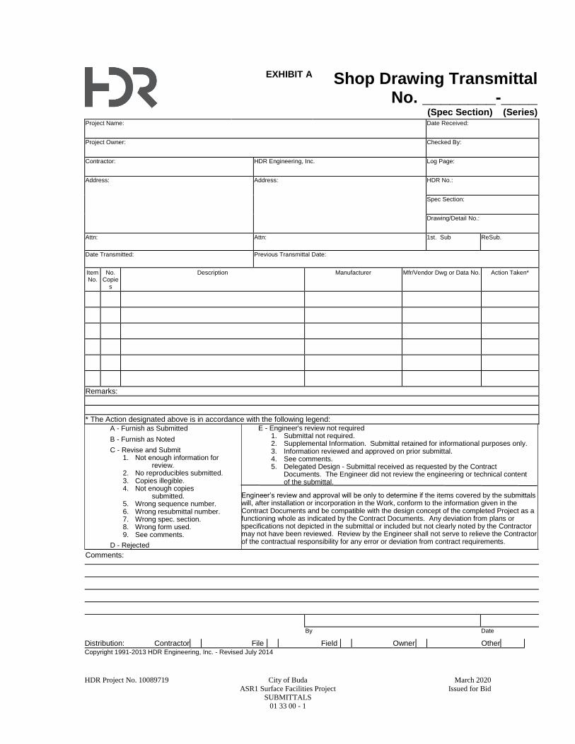
HDR Project No. 10089719 City of Buda March 2020
ASR1 Surface Facilities Project Issued for Bid
SUBMITTALS 01 33 00 - 1
EXHIBIT A Shop Drawing Transmittal No. ________-____
(Spec Section) (Series) Project Name: Date Received:
Project Owner: Checked By:
Contractor: HDR Engineering, Inc. Log Page:
Address: Address: HDR No.:
Spec Section:
Drawing/Detail No.:
Attn: Attn: 1st. Sub ReSub.
Date Transmitted: Previous Transmittal Date:
Item No.
No. Copie
s
Description Manufacturer Mfr/Vendor Dwg or Data No. Action Taken*
Remarks:
* The Action designated above is in accordance with the following legend:
A - Furnish as Submitted
B - Furnish as Noted
C - Revise and Submit 1. Not enough information for
review. 2. No reproducibles submitted. 3. Copies illegible. 4. Not enough copies
submitted. 5. Wrong sequence number. 6. Wrong resubmittal number. 7. Wrong spec. section. 8. Wrong form used. 9. See comments.
D - Rejected
E - Engineer's review not required 1. Submittal not required. 2. Supplemental Information. Submittal retained for informational purposes only. 3. Information reviewed and approved on prior submittal. 4. See comments. 5. Delegated Design - Submittal received as requested by the Contract
Documents. The Engineer did not review the engineering or technical content of the submittal.
Engineer’s review and approval will be only to determine if the items covered by the submittals will, after installation or incorporation in the Work, conform to the information given in the Contract Documents and be compatible with the design concept of the completed Project as a functioning whole as indicated by the Contract Documents. Any deviation from plans or specifications not depicted in the submittal or included but not clearly noted by the Contractor may not have been reviewed. Review by the Engineer shall not serve to relieve the Contractor of the contractual responsibility for any error or deviation from contract requirements.
Comments:
By Date
Distribution: Contractor File Field Owner Other Copyright 1991-2013 HDR Engineering, Inc. - Revised July 2014
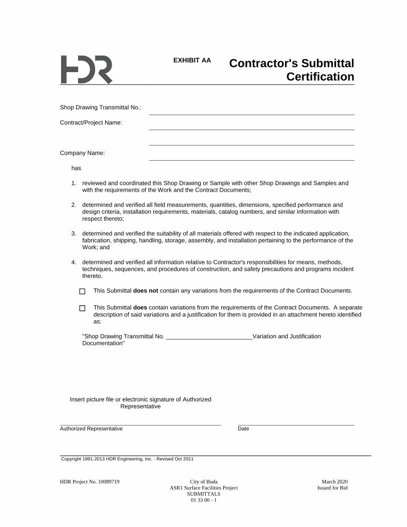
HDR Project No. 10089719 City of Buda March 2020
ASR1 Surface Facilities Project Issued for Bid
SUBMITTALS 01 33 00 - 1
EXHIBIT AA Contractor's Submittal Certification
Shop Drawing Transmittal No.:
Contract/Project Name:
Company Name:
has
1. reviewed and coordinated this Shop Drawing or Sample with other Shop Drawings and Samples and with the requirements of the Work and the Contract Documents;
2. determined and verified all field measurements, quantities, dimensions, specified performance and design criteria, installation requirements, materials, catalog numbers, and similar information with respect thereto;
3. determined and verified the suitability of all materials offered with respect to the indicated application, fabrication, shipping, handling, storage, assembly, and installation pertaining to the performance of the Work; and
4. determined and verified all information relative to Contractor's responsibilities for means, methods, techniques, sequences, and procedures of construction, and safety precautions and programs incident thereto.
This Submittal does not contain any variations from the requirements of the Contract Documents.
This Submittal does contain variations from the requirements of the Contract Documents. A separate
description of said variations and a justification for them is provided in an attachment hereto identified as:
"Shop Drawing Transmittal No. __________________________Variation and Justification Documentation"
Insert picture file or electronic signature of Authorized Representative
Authorized Representative Date
Copyright 1991-2013 HDR Engineering, Inc. - Revised Oct 2011
HDR Project No. 10089719 City of Buda March 2020
ASR1 Surface Facilities Project Issued for Bid
OPERATION AND MAINTENANCE MANUALS 01 33 04 - 1
SECTION 01 33 04
OPERATION AND MAINTENANCE MANUALS
PART 1 - GENERAL
1.1 SUMMARY
A. Section Includes:
1. Administration of the submittal process for Operation and Maintenance Manuals.
2. Content requirements for Operation and Maintenance Manuals.
B. Related Specification Sections include but are not necessarily limited to:
1. Division 00 - Procurement and Contracting Requirements.
2. Division 01 - General Requirements.
3. General submittal requirements are specified in Specification Section 01 33 00 - Submittals.
4. Technical Specification Sections identifying required Operation and Maintenance Manual
submittals.
1.2 DEFINITIONS
A. Equipment Operation and Maintenance Manuals:
1. Contain the technical information required for proper installation, operation and
maintenance of process, electrical and mechanical equipment and systems.
B. Building Materials and Finishes Operation and Maintenance Manuals:
1. Contain the information required for proper installation and maintenance of building
materials and finishes.
1.3 SUBMITTALS
A. List of all the Operation and Maintenance Manuals required by the Contract as identified in the
Technical Specification Sections. These may be referred to as "Operation and Maintenance
Data" submittals.
B. Operation and Maintenance Manuals:
1. Draft and final electronic copies.
2. Final paper copies: One.
1.4 SUBMITTAL SCHEDULE
A. List of Required Operation and Maintenance Manuals:
1. Submit list with Specification Section number and title within 90 days after Notice to
Proceed.
B. Draft Operation and Maintenance Manuals:
1. Submit approvable draft manuals in electronic format (PDF) within 30 days following
approval of the respective Shop Drawing.
a. Include placeholders or fly sheet pages where information is not final or is missing
from the draft manual.
2. All Draft Operation and Maintenance Manuals shall be received by no later than 50 PCT
project completion.
C. Final Operation and Maintenance Manuals:
1. Final approval of Operation and Maintenance Manuals in electronic format (PDF) must be
obtained 30 days prior to equipment start-up.
2. Provide paper copies and CD-ROMs of approved final Operation and Maintenance Manuals
in electronic format (PDF), a minimum of 30 days prior to equipment start-up.
3. Issue addenda to Final Approved Operation and Maintenance Manual to include:
HDR Project No. 10089719 City of Buda March 2020
ASR1 Surface Facilities Project Issued for Bid
OPERATION AND MAINTENANCE MANUALS 01 33 04 - 2
a. Equipment data that requires collection after start-up, for example but not limited to
HVAC balancing reports, electrical switchgear, automatic transfer switch and circuit
breaker settings.
b. Equipment field testing data.
c. Equipment start-up reports.
1.5 PREPARATION OF SUBMITTALS
A. General:
1. All pages of the Operation and Maintenance Manual submittal shall be legible.
a. Submittals which, in the Engineer’s sole opinion, are illegible will be rejected without
review.
2. Identify each equipment item in a manner consistent with names and identification numbers
used in the Contract Documents, not the manufacturer’s catalog numbers.
3. Neatly type any data not furnished in printed form.
4. Operation and Maintenance Manuals are provided for Owner's use, to be reproduced and
distributed as training and reference materials within Owner's organization.
a. This requirement is:
1) Applicable to both paper copy and electronic files.
2) Applicable to materials containing copyright notice as well as those with no
copyright notice.
5. Notify supplier and/or manufacturer of the intended use of Operations and Maintenance
Manuals provided under the Contract.
B. Operation and Maintenance Manual Format and Delivery:
1. Draft electronic submittals:
a. Provide manual in Adobe Acrobat Portable Document Format (PDF), latest version.
b. Create one (1) PDF file for each equipment Operation and Maintenance Manual.
c. Do not password protect or lock the PDF document.
d. Scanned images of paper documents are not acceptable. Create the Operation and
Maintenance Manual PDF file from the original source document.
e. Drawings or other graphics must be converted to PDF file format from the original
drawing file format and made part of the PDF document.
f. Scanning of drawings is to be used only where actual file conversion is not possible and
drawings must be scanned at a resolution of 300 DPI or greater.
g. Rotate sheets that are normally viewed in landscape mode so that when the PDF file is
opened the sheet is in the appropriate position for viewing.
h. Create bookmarks in the bookmarks panel for the Operation and Maintenance Manual
cover, the Table of Contents and each major section of the Table of Contents.
i. Using Adobe Acrobat Standard or Adobe Acrobat Professional, set the PDF document
properties, initial view as follows:
1) Select File PropertiesInitial View.
2) Select the Navigation tab: Bookmarks Panel and Page.
3) Select the Page layout: Single Page Continuous.
4) Select the Magnification: Fit Page.
5) Select Open to page: 1.
6) Set the file to open to the cover page of the manual with bookmarks to the left, and
the first bookmark linked to the cover page.
7) Window Options: Check the "Resize window to initial page" box.
j. Set the PDF file "Fast Web View" option to open the first several pages of the
document while the rest of the document continues to load.
1) To do this:
a) Select EditPreferences DocumentsSave Settings.
b) Check the "Save As optimizes for Fast Web View" box.
k. PDF file naming convention:
1) Use the Specification Section number, the manufacturer’s name and the equipment
description, separated by underscores.
HDR Project No. 10089719 City of Buda March 2020
ASR1 Surface Facilities Project Issued for Bid
OPERATION AND MAINTENANCE MANUALS 01 33 04 - 3
2) Example: 46 51 21_Sanitaire_Coarse_Bubble_Diffusers.pdf.
3) Do not put spaces in the file name.
2. Final electronic submittals:
a. Submit two copies in PDF file format on two USB flash drives or on two CD-ROM
discs (one copy per electronic media), each secured in a protective case.
b. Labeling:
1) Provide the following printed labeling on all electronic media:
a) Project name.
b) Specification Section.
c) Equipment names and summary of tag(s) covered.
d) Manufacturer name.
e) Date (month, year).
c. Binding:
1) Include labeled electronic media in a protective case.
a) Bind protective case in three-ring binder, inserted at the front of the Final
paper copy submittal.
b) Protective case(s) to have means for securing electronic media to prevent loss
(e.g., zip case, flap and strap, or equivalent).
3. Final paper copy submittals:
a. Quantity: Provide two copies.
b. Paper: 8.5 x 11 IN or 11 x 17 IN bright white, 20 LB paper with standard three-hole
punching.
c. 3-Ring Binder:
1) Provide D-ring binder with clear vinyl sleeves (i.e. view binder) on front and spine.
2) Insert binder title sheet with the following information under the front and spine
sleeves:
a) Project name.
b) Specification Section.
c) Equipment names and summary of tag(s) covered.
d) Manufacturer name.
e) Date (month, year).
3) Provide plastic sheet lifters prior to first page and following last page.
d. Drawings:
1) Provide all drawings at 11 x 17 IN size, triple folded and three-hole punched for
insertion into manual.
2) Where reduction is not practical to ensure readability, fold larger drawings
separately and place in three-hole punched vinyl envelopes inserted into the binder.
3) Identify vinyl envelopes with drawing numbers.
e. Use plastic coated dividers to tab each section of each manual in accordance with the
Table of Contents.
C. Equipment Operation and Maintenance Manual Content:
1. Provide a cover page as the first page of each manual with the following information:
a. Manufacturer(s) Name and Contact Information.
b. Vendor’s Name and Contact Information.
c. Date (month, year).
d. Project Owner and Project Name.
e. Specification Section.
f. Project Equipment Tag Numbers.
g. Model Numbers.
h. Engineer’s Name.
i. Contractor’s Name.
2. Provide a Table of Contents for each manual.
3. Provide Equipment Record sheets as follows:
a. Printed copies of the Equipment Record (Exhibits B1, B2 and B3), as the first tab
following the Table of Contents.
HDR Project No. 10089719 City of Buda March 2020
ASR1 Surface Facilities Project Issued for Bid
OPERATION AND MAINTENANCE MANUALS 01 33 04 - 4
1) For Instrumentation and Control equipment, International Society of Automation
(ISA) Data Sheets will be acceptable in lieu of the Equipment Record sheets.
b. Exhibits B1-B3 are available as Fillable PDF Form documents from the Engineer.
c. Each section of the Equipment Record must be completed in detail; simply referencing
the related equipment Operation and Maintenance Manual sections for nameplate,
maintenance, spare parts or lubricant information is not acceptable.
d. For equipment involving separate components (for example, a motor and gearbox), a
fully completed Equipment Record is required for each component.
e. Submittals that do not include the Equipment Record(s) will be rejected without further
content review.
4. Provide a printed copy of the Manufacturer’s Field Services report as required by
Specification Section 01 75 00 following the Equipment Record sheets.
5. Provide the following detailed information, as applicable:
a. Use equipment tag numbers from the Contract Documents to identify equipment and
system components.
b. Equipment function, normal and limiting operating characteristics.
c. Instructions for assembly, disassembly, installation, alignment, adjustment, and
inspection.
d. Operating instructions for start-up, normal operation, control, shutdown, and
emergency conditions.
e. Maintenance instructions, including lubrication instructions if applicable
f. Troubleshooting guide.
g. Mark each sheet to clearly identify specific products and component parts and data
applicable to the installation for the Project; delete or cross out information that does
not specifically apply to the Project.
h. Parts lists:
1) A parts list and identification number of each component part of the equipment.
2) Exploded view or plan and section views of the equipment with a detailed parts
callout matching the parts list.
3) A list of recommended spare parts.
4) List of spare parts provided as specified in the associated Specification Section.
5) A list of any special storage precautions which may be required for all spare parts.
i. General arrangement, cross-section, and assembly drawings.
j. Electrical diagrams, including elementary diagrams, wiring diagrams, connection
diagrams, and interconnection diagrams.
k. Factory and field test data and performance curves (if applicable).
l. As-constructed fabrication or layout drawings and wiring diagrams.
m. Copy of the equipment manufacturer’s warranty meeting the requirements of the
Contract.
n. Copy of any service contracts provided for the specific piece of equipment as part of
the Contract.
6. Additional information as required in the associated equipment or system Specification
Section.
7. Include in Submittal the final, configured control setpoints and similar configurable
parameters provided in the equipment.
D. Building Materials and Finishes Operation and Maintenance Manual Content:
1. Provide a cover page as the first page of each manual with the following information:
a. Manufacturer(s) Name and Contact Information.
b. Vendor’s Name and Contact Information.
c. Date (month, year).
d. Project Owner and Project Name.
e. Specification Section.
f. Model Numbers.
g. Engineer’s Name.
h. Contractor’s Name.

HDR Project No. 10089719 City of Buda March 2020
ASR1 Surface Facilities Project Issued for Bid
OPERATION AND MAINTENANCE MANUALS 01 33 04 - 5
2. Provide a Table of Contents for each manual.
3. Building products, applied materials and finishes:
a. Include product data, with catalog number, size, composition and color and texture
designations.
b. Provide information for ordering custom manufactured products.
4. Necessary precautions:
a. Include product MSDS for each approved product.
b. Include any precautionary application and storage guidelines.
5. Instructions for care and maintenance:
a. Include manufacturer's recommendations for cleaning agents and methods, precautions
against detrimental agents and methods and recommended schedule for cleaning and
maintenance.
6. Moisture protection and weather exposed products:
a. Include product data listing, applicable reference standards, chemical composition, and
details of installation.
b. Provide recommendations for inspections, maintenance and repair.
7. Additional requirements as specified in individual product specifications.
E. National Fire Protection Association 70 (National Electrical Code) Documentation:
1. Assemble documented calculations of Arc-Fault Current, Equipment Available Fault
Current and Short Circuit Current Rating (SCCR) provided as part of equipment submittals
into one O&M manual volume.
1.6 TRANSMITTAL OF SUBMITTALS
A. Operation and Maintenance Manuals.
1. Transmit all submittals to:
a. The address specified in Specification Section 01 33 00 - SUBMITTALS.
2. Transmittal form: Use Operation and Maintenance Manual Transmittal, Exhibit A.
3. Transmittal numbering:
a. Number each submittal with the Specification Section number followed by a series
number beginning with "-01" and increasing sequentially with each additional
transmittal, followed by "-OM" (for example: 43 23 14-01-OM).
4. Submit draft and final Operation and Maintenance Manual in electronic format (PDF) to
Engineer, until manual is approved.
1.7 ENGINEER'S REVIEW ACTION
A. Draft Electronic (PDF) Submittals:
1. Engineer will review and indicate one of the following review actions:
a. A - ACCEPTABLE
b. B - FURNISH AS NOTED
c. C - REVISE AND RESUBMIT
d. D - REJECTED
2. Submittals marked as Acceptable or Furnish As Noted will be retained; however, the
transmittal form will be returned with a request for the final paper and electronic documents
to be submitted.
3. Copies of submittals marked as Revise and Resubmit or Rejected will be returned with the
transmittal form marked to indicate deficient areas.
4. Resubmit until approved.
B. Final Paper Copy Submittals:
1. Engineer will review and indicate one of the following review actions:
a. A - ACCEPTABLE
b. D - REJECTED
2. Submittals marked as Acceptable will be retained with the transmittal form returned as
noted.
3. Submittals marked as Rejected will be returned with the transmittal form marked to indicate
deficient areas.

HDR Project No. 10089719 City of Buda March 2020
ASR1 Surface Facilities Project Issued for Bid
OPERATION AND MAINTENANCE MANUALS 01 33 04 - 6
4. Resubmit until approved.
PART 2 - PRODUCTS - (NOT USED)
PART 3 - EXECUTION - (NOT USED)
END OF SECTION
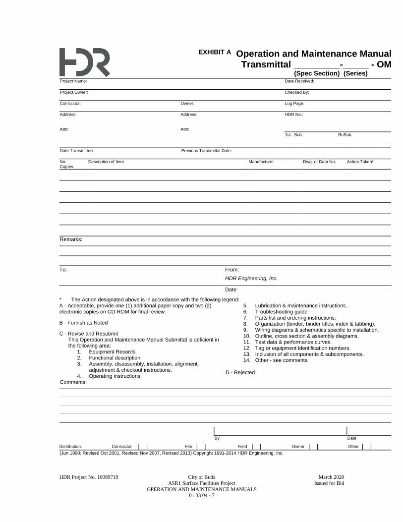
HDR Project No. 10089719 City of Buda March 2020
ASR1 Surface Facilities Project Issued for Bid
OPERATION AND MAINTENANCE MANUALS 01 33 04 - 7
EXHIBIT A Operation and Maintenance Manual Transmittal _________-_____ - OM
(Spec Section) (Series) . Project Name: Date Received:
Project Owner: Checked By:
Contractor: Owner: Log Page:
Address: Attn:
Address: Attn:
HDR No.:
1st. Sub. ReSub.
Date Transmitted: Previous Transmittal Date:
No. Copies
Description of Item Manufacturer Dwg. or Data No. Action Taken*
Remarks:
To: From:
HDR Engineering, Inc.
Date:
* The Action designated above is in accordance with the following legend: A - Acceptable, provide one (1) additional paper copy and two (2) electronic copies on CD-ROM for final review. B - Furnish as Noted C - Revise and Resubmit
This Operation and Maintenance Manual Submittal is deficient in the following area: 1. Equipment Records. 2. Functional description. 3. Assembly, disassembly, installation, alignment,
adjustment & checkout instructions. 4. Operating instructions.
5. Lubrication & maintenance instructions. 6. Troubleshooting guide. 7. Parts list and ordering instructions. 8. Organization (binder, binder titles, index & tabbing). 9. Wiring diagrams & schematics specific to installation. 10. Outline, cross section & assembly diagrams. 11. Test data & performance curves. 12. Tag or equipment identification numbers. 13. Inclusion of all components & subcomponents. 14. Other - see comments.
D - Rejected
Comments:
By Date
Distribution: Contractor File Field Owner Other
(Jun 1990; Revised Oct 2001, Revised Nov 2007, Revised 2013) Copyright 1991-2014 HDR Engineering, Inc.

HDR Project No. 10089719 City of Buda March 2020
ASR1 Surface Facilities Project Issued for Bid
OPERATION AND MAINTENANCE MANUALS 01 33 04 - 8
EXHIBIT B1 Equipment Record
Equipment Data and Spare Parts Summary
Project Name Specification Section:
Equipment Name Year Installed:
Project Equipment Tag No(s).
Equipment Manufacturer Project/ Order No.
Address Phone
Fax Web Site E-mail
Local Vendor/Service Center
Address Phone
Fax Web Site E-mail
MECHANICAL NAMEPLATE DATA
Equip. Serial No.
Make Model No.
ID No. Frame No. HP RPM Cap.
Size TDH Imp. Sz. CFM PSI
Other:
ELECTRICAL NAMEPLATE DATA
Equip. Serial No.
Make Model No.
ID No. Frame No. HP V. Amp. HZ PH RPM SF
Duty Code Ins. Cl. Type NEMA C Amb. Temp. Rise Rating
Other:
SPARE PARTS PROVIDED PER CONTRACT
Part No. Part Name Quantity
RECOMMENDED SPARE PARTS
Part No. Part Name Quantity
(Jun 1990; Revised Oct 2001, Revised Nov 2007, Revised 2013) Copyright 1991-2014 HDR Engineering, Inc.
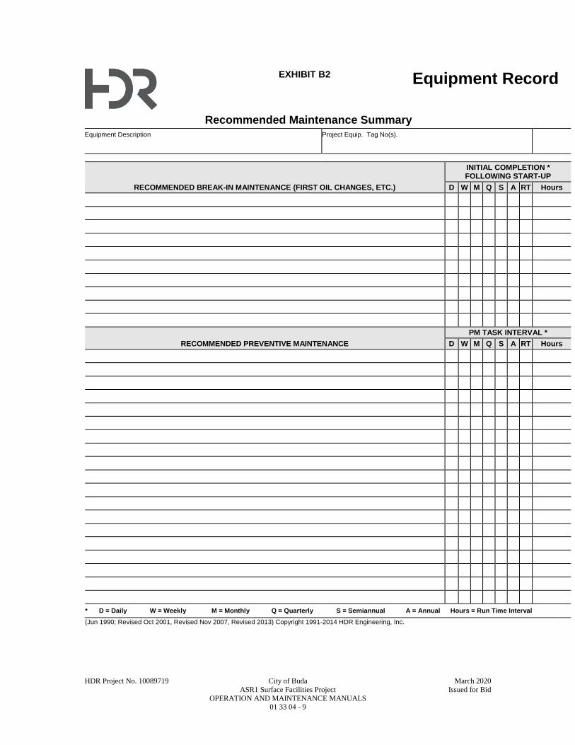
HDR Project No. 10089719 City of Buda March 2020
ASR1 Surface Facilities Project Issued for Bid
OPERATION AND MAINTENANCE MANUALS 01 33 04 - 9
EXHIBIT B2 Equipment Record
Recommended Maintenance Summary Equipment Description Project Equip. Tag No(s).
RECOMMENDED BREAK-IN MAINTENANCE (FIRST OIL CHANGES, ETC.)
INITIAL COMPLETION * FOLLOWING START-UP
D W M Q S A RT Hours
RECOMMENDED PREVENTIVE MAINTENANCE
PM TASK INTERVAL *
D W M Q S A RT Hours
* D = Daily W = Weekly M = Monthly Q = Quarterly S = Semiannual A = Annual Hours = Run Time Interval
(Jun 1990; Revised Oct 2001, Revised Nov 2007, Revised 2013) Copyright 1991-2014 HDR Engineering, Inc.
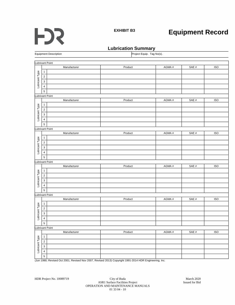
HDR Project No. 10089719 City of Buda March 2020
ASR1 Surface Facilities Project Issued for Bid
OPERATION AND MAINTENANCE MANUALS 01 33 04 - 10
EXHIBIT B3 Equipment Record
Lubrication Summary
Equipment Description Project Equip. Tag No(s).
Lubricant Point
Lub
rica
nt
Typ
e
Manufacturer Product AGMA # SAE # ISO
1
2
3
4
5
Lubricant Point
Lub
rica
nt
Typ
e
Manufacturer Product AGMA # SAE # ISO
1
2
3
4
5
Lubricant Point
Lub
rica
nt
Typ
e
Manufacturer Product AGMA # SAE # ISO
1
2
3
4
5
Lubricant Point
Lub
rica
nt
Typ
e
Manufacturer Product AGMA # SAE # ISO
1
2
3
4
5
Lubricant Point
Lub
rica
nt
Typ
e
Manufacturer Product AGMA # SAE # ISO
1
2
3
4
5
Lubricant Point
Lub
rica
nt
Typ
e
Manufacturer Product AGMA # SAE # ISO
1
2
3
4
5
(Jun 1990; Revised Oct 2001, Revised Nov 2007, Revised 2013) Copyright 1991-2014 HDR Engineering, Inc.

HDR Project No. 10089719 City of Buda March 2020
ASR1 Surface Facilities Project Issued for Bid
ENVIRONMENTAL PROTECTION AND SPECIAL CONTROLS 01 35 05 - 1
SECTION 01 35 05
ENVIRONMENTAL PROTECTION AND SPECIAL CONTROLS
PART 1 - GENERAL
1.1 SUMMARY
A. Section Includes:
1. Minimizing the pollution of air, water, or land; control of noise, the disposal of solid waste
materials, and protection of deposits of historical or archaeological interest.
B. Related Specification Sections include but are not necessarily limited to:
1. Division 00 - Procurement and Contracting Requirements.
2. Division 01 - General Requirements.
1.2 SUBMITTALS
A. Shop Drawings:
1. See Specification Section 01 33 00 for requirements for the mechanics and administration of
the submittal process.
2. Prior to the start of any construction activities submit:
a. A detailed proposal of all methods of control and preventive measures to be utilized for
environmental protection.
b. A copy of the NPDES permit for storm water discharges from construction activities.
c. A copy of the approved pollution prevention plan.
PART 2 - PRODUCTS - (NOT APPLICABLE TO THIS SPECIFICATION SECTION)
PART 3 - EXECUTION
3.1 INSTALLATION
A. Employ and utilize environmental protection methods, obtain all necessary permits, and fully
observe all local, state, and federal regulations.
B. Land Protection:
1. Except for any work or storage area and access routes specifically assigned for the use of
the Contractor, the land areas outside the limits of construction shall be preserved in their
present condition.
a. Confine construction activities to areas defined for work within the Contract
Documents.
2. Manage and control all borrow areas, work or storage areas, access routes and embankments
to prevent sediment from entering nearby water or land adjacent to the work site.
3. Stabilize all disturbed areas including borrow and haul areas and establish permanent type
of locally adaptable vegetative cover.
4. Unless earthwork is immediately paved or surfaced, protect all side slopes and backslopes
immediately upon completion of final grading.
5. Plan and execute earthwork in a manner to minimize duration of exposure of unprotected
soils.
6. Except for areas designated by the Contract Documents to be cleared and grubbed, do not
deface, injure or destroy trees and vegetation, nor remove, cut, or disturb them without
approval of the Engineer.
a. Any damage caused by the Contractor's equipment or operations shall be restored as
nearly as possible to its original condition at no additional cost to the Owner.
C. Surface Water Protection:

HDR Project No. 10089719 City of Buda March 2020
ASR1 Surface Facilities Project Issued for Bid
ENVIRONMENTAL PROTECTION AND SPECIAL CONTROLS 01 35 05 - 2
1. Utilize, as necessary, erosion control methods to protect side and backslopes, minimize and
the discharge of sediment to the surface water leaving the construction site as soon as rough
grading is complete.
a. These controls shall be maintained until the site is ready for final grading and
landscaping or until they are no longer warranted and concurrence is received from the
Engineer.
b. Physically retard the rate and volume of run-on and runoff by:
1) Implementing structural practices such as diversion swales, terraces, straw bales,
silt fences, berms, storm drain inlet protection, rocked outlet protection, sediment
traps and temporary basins.
2) Implementing vegetative practices such as temporary seeding, permanent seeding,
mulching, sod stabilization, vegetative buffers, hydroseeding, anchored erosion
control blankets, sodding, vegetated swales or a combination of these methods.
3) Providing Construction sites with graveled or rocked access entrance and exit
drives and parking areas to reduce the tracking of sediment onto public or private
roads.
2. Discharges from the construction site shall not contain pollutants at concentrations that
produce objectionable films, colors, turbidity, deposits or noxious odors in the receiving
stream or waterway.
D. Solid Waste Disposal:
1. Collect solid waste on a daily basis.
2. Provide disposal of degradable solid waste to an approved solid waste disposal site.
3. Provide disposal of nondegradable solid waste to an approved solid waste disposal site or in
an alternate manner approved by Engineer and regulatory agencies.
4. No building materials wastes or unused building materials shall be buried, dumped, or
disposed of on the site.
E. Fuel and Chemical Handling:
1. Store and dispose of chemical wastes in a manner approved by regulatory agencies.
2. Take special measures to prevent chemicals, fuels, oils, greases, herbicides, and insecticides
from entering drainage ways.
3. Do not allow water used in onsite material processing, concrete curing, cleanup, and other
waste waters to enter a drainage way(s) or stream.
4. Provide containment around fueling and chemical storage areas to ensure that spills in these
areas do not reach waters of the state.
F. Control of Dust:
1. The control of dust shall mean that no construction activity shall take place without
applying all such reasonable measures as may be required to prevent particulate matter from
becoming airborne so that it remains visible beyond the limits of construction.
a. Reasonable measures may include paving, frequent road cleaning, planting vegetative
groundcover, and application of water.
2. Utilize methods and practices of construction to eliminate dust in full observance of agency
regulations.
3. The Engineer will determine the effectiveness of the dust control program and may request
the Contractor to provide additional measures, at no additional cost to Owner.
G. Burning:
1. Do not burn material on the site.
H. Control of Noise:
1. Control noise by fitting equipment with appropriate mufflers.
I. Completion of Work:
1. Upon completion of work, leave area in a clean condition.
2. Ensure all signs of temporary construction and activities incidental to construction of
required permanent work are removed.
3. Grade, fill and seed all disturbed areas.
HDR Project No. 10089719 City of Buda March 2020
ASR1 Surface Facilities Project Issued for Bid
ENVIRONMENTAL PROTECTION AND SPECIAL CONTROLS 01 35 05 - 3
J. Historical Protection:
1. Refer to Section 01 30 00
END OF SECTION

This page intentionally left blank.
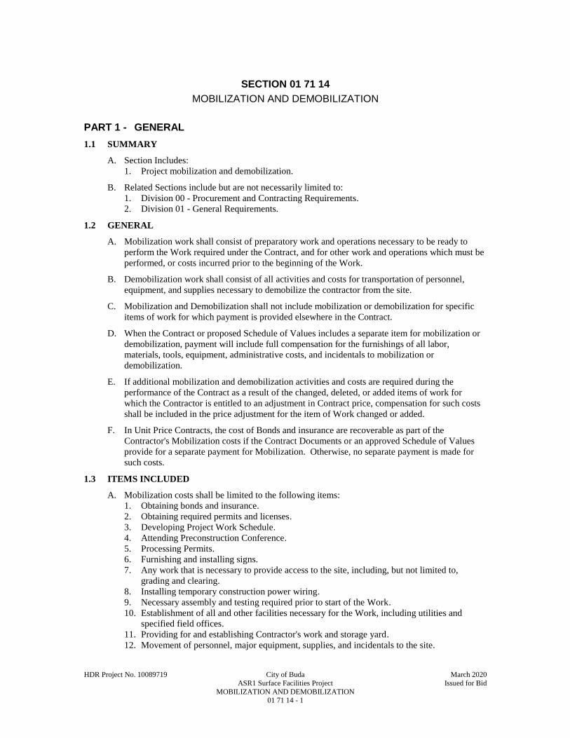
HDR Project No. 10089719 City of Buda March 2020
ASR1 Surface Facilities Project Issued for Bid
MOBILIZATION AND DEMOBILIZATION 01 71 14 - 1
SECTION 01 71 14
MOBILIZATION AND DEMOBILIZATION
PART 1 - GENERAL
1.1 SUMMARY
A. Section Includes:
1. Project mobilization and demobilization.
B. Related Sections include but are not necessarily limited to:
1. Division 00 - Procurement and Contracting Requirements.
2. Division 01 - General Requirements.
1.2 GENERAL
A. Mobilization work shall consist of preparatory work and operations necessary to be ready to
perform the Work required under the Contract, and for other work and operations which must be
performed, or costs incurred prior to the beginning of the Work.
B. Demobilization work shall consist of all activities and costs for transportation of personnel,
equipment, and supplies necessary to demobilize the contractor from the site.
C. Mobilization and Demobilization shall not include mobilization or demobilization for specific
items of work for which payment is provided elsewhere in the Contract.
D. When the Contract or proposed Schedule of Values includes a separate item for mobilization or
demobilization, payment will include full compensation for the furnishings of all labor,
materials, tools, equipment, administrative costs, and incidentals to mobilization or
demobilization.
E. If additional mobilization and demobilization activities and costs are required during the
performance of the Contract as a result of the changed, deleted, or added items of work for
which the Contractor is entitled to an adjustment in Contract price, compensation for such costs
shall be included in the price adjustment for the item of Work changed or added.
F. In Unit Price Contracts, the cost of Bonds and insurance are recoverable as part of the
Contractor's Mobilization costs if the Contract Documents or an approved Schedule of Values
provide for a separate payment for Mobilization. Otherwise, no separate payment is made for
such costs.
1.3 ITEMS INCLUDED
A. Mobilization costs shall be limited to the following items:
1. Obtaining bonds and insurance.
2. Obtaining required permits and licenses.
3. Developing Project Work Schedule.
4. Attending Preconstruction Conference.
5. Processing Permits.
6. Furnishing and installing signs.
7. Any work that is necessary to provide access to the site, including, but not limited to,
grading and clearing.
8. Installing temporary construction power wiring.
9. Necessary assembly and testing required prior to start of the Work.
10. Establishment of all and other facilities necessary for the Work, including utilities and
specified field offices.
11. Providing for and establishing Contractor's work and storage yard.
12. Movement of personnel, major equipment, supplies, and incidentals to the site.

HDR Project No. 10089719 City of Buda March 2020
ASR1 Surface Facilities Project Issued for Bid
MOBILIZATION AND DEMOBILIZATION 01 71 14 - 2
13. Cost incurred prior to the start of the Work which must be performed, such as a down
payment on a long lead item.
B. Demobilization costs shall be limited to the following items:
1. Disassembly, removal and site cleanup/repair of offices, buildings, and other facilities
assembled on the site for the Contract.
2. Costs for final site cleanup, packaging of miscellaneous items for return to the yard and
other project closeout related expenses.
3. Cost for final payment documents, and provision of Acknowledgement Certification
Request, Bond, and Certificate of Completion.
C. The Owner will pay all costs for the Mobilization and Demobilization of all of the Contractor's
personnel, equipment, supplies, and incidentals at the contract lump sum price as follows:
1. Furnish cost data and documentation to justify this portion of the bid if Owner believes that
the percentages in this paragraph do not bear a reasonable relation to the cost of the work in
this contract.
2. Failure to justify such price to the satisfaction of the Owner will result in payment as
determined by the Owner, of:
a. Actual mobilization costs at completion of mobilization.
b. Actual demobilization costs at completion of demobilization; and.
c. The remainder of this item in the final payment under this contract.
3. The Owner's determination of the actual costs in this paragraph is not subject to appeal.
4. This schedule of mobilization progress payments will not limit or preclude progress
payments otherwise provided by the Contract.
PART 2 - PRODUCTS - (NOT APPLICABLE TO THIS SPECIFICATION SECTION)
PART 3 - EXECUTION - (NOT APPLICABLE TO THIS SPECIFICATION SECTION)
END OF SECTION

HDR Project No. 10089719 City of Buda March 2020
ASR1 Surface Facilities Project Issued for Bid
FACILITY START-UP 01 75 00 - 1
SECTION 01 75 00
FACILITY START-UP
PART 1 - GENERAL
1.1 SUMMARY
A. Section Includes:
1. Procedures and actions, required of the Contractor, which are necessary to achieve and
demonstrate Substantial Completion.
2. Requirements for Substantial Completion Submittals.
B. Related Sections include but are not necessarily limited to:
1. Division 00 - Procurement and Contracting Requirements.
2. Division 01 - General Requirements.
1.2 DEFINITIONS
A. Pre-Demonstration Period: The period of time, of unspecified duration after initial construction
and installation activities during which Contractor, with assistance from manufacturer's
representatives, performs in the following sequence:
1. Finishing type construction work to ensure the Project has reached a state of Substantial
Completion.
2. Equipment start-up.
3. Personnel training.
B. Demonstration Period: A period of time, of specified duration, following the Pre-Demonstration
Period, during which the Contractor initiates product through the facility and starts up and
operates the facility, without exceeding specified downtime limitations, to prove the functional
integrity of the mechanical and electrical equipment and components and the control interfaces
of the respective equipment and components comprising the facility as evidence of Substantial
Completion.
C. Substantial Completion: See the General Conditions.
1.3 SUBMITTALS
A. See Specification Section 01 33 00 for requirements for the mechanics and administration of the
submittal process.
B. Submit in the chronological order listed below prior to the completion of the Pre-Demonstration
Period.
1. Master operation and maintenance training schedule:
a. Submit 30 days (minimum) prior to first training session for Owner's personnel.
b. Schedule to include:
1) Target date and time for Owner witnessing of each system initial start-up.
2) Target date and time for Operation and Maintenance training for each system, both
field and classroom.
3) Target date for initiation of Demonstration Period.
c. Submit for review and approval by Owner.
d. Include holidays observed by Owner.
e. Attend a schedule planning and coordination meeting 90 calendar days prior to first
anticipated training session.
1) Provide a status report and schedule-to-complete for requirements prerequisite to
manufacturer's training.
2) Identify initial target dates for individual manufacturer's training sessions.
f. Owner reserves the right to insist on a minimum seven days' notice of rescheduled
training session not conducted on master schedule target date for any reason.

HDR Project No. 10089719 City of Buda March 2020
ASR1 Surface Facilities Project Issued for Bid
FACILITY START-UP 01 75 00 - 2
g. Schedule to be resubmitted until approved.
2. Substantial Completion Submittal:
a. File Contractor's Notice of Substantial Completion and Request for Inspection.
b. Approved Operation and Maintenance manuals received by Engineer minimum 30 days
prior to scheduled training.
c. Written request for Owner to witness each system pre-demonstration start-up.
1) Request to be received by Owner minimum one week before scheduled training of
Owner's personnel on that system.
d. Equipment installation and pre-demonstration start-up certifications.
e. Letter verifying completion of all pre-demonstration start-up activities including receipt
of all specified items from manufacturers or suppliers as final item prior to initiation of
Demonstration Period.
1.4 SEQUENCING AND SCHEDULING
1.5 COST OF START-UP
A. Contractor to pay all costs associated with Facility start-up.
PART 2 - PRODUCTS - (NOT USED)
PART 3 - EXECUTION
3.1 GENERAL
A. Facility Start-up Divided into Two Periods:
1. Pre-Demonstration Period including:
a. Completion of construction work to bring Project to a state of Substantial Completion.
b. Start-up of Equipment.
c. Training of Personnel.
d. Completion of the filing of all required submittals.
e. Filing of Contractor's Notice of Substantial Completion and Request for Inspection.
2. Demonstration Period including:
a. Demonstration of functional integrity of facility or PCS.
3.2 PRE-DEMONSTRATION PERIOD
A. Completion of Construction Work:
1. Complete the work to bring the Project to a state of substantial completion.
B. Equipment Start-up:
1. Requirements for individual items of equipment are included in the Technical Specification
Sections.
2. Prepare the equipment so it will operate properly and safely and be ready to demonstrate
functional integrity during the Demonstration Period.
3. Perform Equipment Start-up to extent possible without introducing product flow.
4. Introduce product flow to complete Equipment Start-up for the following equipment:
a. Well and appurtenances.
5. Procedures include but are not necessarily limited to the following:
a. Test or check and correct deficiencies of:
1) Power, control, and monitoring circuits for continuity prior to connection to power
source.
2) Voltage of all circuits.
3) Phase sequence.
4) Cleanliness of connecting piping systems.
5) Alignment of connected machinery.
6) Vacuum and pressure of all closed systems.
7) Lubrication.
HDR Project No. 10089719 City of Buda March 2020
ASR1 Surface Facilities Project Issued for Bid
FACILITY START-UP 01 75 00 - 3
8) Valve orientation and position status for manual operating mode.
9) Pumping equipment using product flow.
10) Instrumentation and control signal generation, transmission, reception, and
response.
11) Tagging and identification systems.
12) All equipment: Proper connections, alignment, calibration and adjustment.
b. Calibrate all safety equipment.
c. Manually rotate or move moving parts to assure freedom of movement.
d. "Bump" start electric motors to verify proper rotation.
e. Perform other tests, checks, and activities required to make the equipment ready for
Demonstration Period.
f. Documentation:
1) Prepare a log showing each equipment item subject to this paragraph and listing
what is to be accomplished during Equipment Start-up.
2) Provide a place for the Contractor to record date and person accomplishing
required work.
3) Submit completed document before requesting inspection for Substantial
Completion certification.
6. Obtain certifications, without restrictions or qualifications, and deliver to Engineer:
a. Manufacturer's equipment installation check letters (sometimes referred to as
Manufacturer’s Field Services report).
b. Instrumentation Supplier's Instrumentation Installation Certificate.
C. Personnel Training:
1. See individual equipment specification sections.
2. Conduct all personnel training after completion of Equipment Start-up for the equipment for
which training is being conducted.
a. Personnel training on individual equipment or systems will not be considered
completed unless:
1) All pretraining deliverables are received and approved before commencement of
training on the individual equipment or system.
2) No system malfunctions occur during training.
3) All provisions of field and classroom training specifications are met.
b. Training not in compliance with the above will be performed again in its entirety by the
manufacturer at no additional cost to Owner.
3. Field and classroom training requirements:
a. Hold classroom training on-site.
b. Notify each manufacturer specified for on-site training that the Owner reserves the right
to video record any or all training sessions.
1) Organize each training session in a format compatible with video recording.
c. Training instructor qualification: Factory trained and familiar with giving both
classroom and "hands-on" instructions.
d. Training instructors:
1) Be at classes on time.
2) Session beginning and ending times to be coordinated with the Owner and
indicated on the master schedule.
3) Normal time lengths for class periods can vary, but brief rest breaks should be
scheduled and taken.
e. Organize training sessions into maintenance verses operation topics and identify on
schedule.
f. Plan for minimum class attendance of 4 people at each session and provide sufficient
classroom materials, samples, and handouts for those in attendance.
g. Instructors to have a typed agenda and well prepared instructional material.
1) The use of visual aids, e.g., films, pictures, and slides is recommended for use
during the classroom training programs.
HDR Project No. 10089719 City of Buda March 2020
ASR1 Surface Facilities Project Issued for Bid
FACILITY START-UP 01 75 00 - 4
2) Deliver agendas to the Engineer a minimum of seven days prior to the classroom
training.
3) Provide equipment required for presentation of films, slides, and other visual aids.
h. In the on-site training sessions, cover the information required in the Operation and
Maintenance Manuals and the following areas as applicable to PCS's.
1) Operation of equipment.
2) Lubrication of equipment.
3) Maintenance and repair of equipment.
4) Troubleshooting of equipment.
5) Preventive maintenance procedures.
6) Adjustments to equipment.
7) Inventory of spare parts.
8) Optimizing equipment performance.
9) Capabilities.
10) Operational safety.
11) Emergency situation response.
12) Takedown procedures (disassembly and assembly).
i. Address above Paragraphs 1), 2), 8), 9), 10), and 11) in the operation sessions. Address
above Paragraphs 3), 4), 5), 6), 7), and 12) in the maintenance sessions.
j. Maintain a log of classroom training provided including: Instructors, topics, dates,
time, and attendance.
D. Complete the filing of all required submittals:
1. Shop Drawings.
2. Operation and Maintenance Manuals.
3. Training material.
E. Filing of Contractor's Notice of Substantial Completion and Request for Inspection of Project or
PCS:
1. File the notice when the following have been completed:
a. Construction work (brought to state of Substantial Completion).
b. Equipment Start-up.
c. Personnel Training.
d. Submittal of required documents.
2. Engineer will review required submittals for completeness within five calendar days of
Contractor's notice. If complete, Engineer will complete inspection of the Work, within 10
calendar days of Contractor's notice.
3. Engineer will inform Contractor in writing of the status of the Work reviewed, within 14
calendar days of Contractor's notice.
a. Work determined not meeting state of Substantial Completion:
1) Contractor: Correct deficiencies noted or submit plan of action for correction
within five days of Engineer's determination.
2) Engineer: Reinspect work within five days of Contractor's notice of correction of
deficiencies.
3) Reinspection costs incurred by Engineer will be billed to Owner who will deduct
them from final payment due Contractor.
b. Work determined to be in state of tentative Substantial Completion: Engineer to
prepare tentative "Engineer's Certificate of Substantial Completion."
c. Engineer's Certificate of Substantial Completion:
1) Certificate tentatively issued subject to successful Demonstration of functional
integrity.
2) Issued for Project as a whole or for one or more PCS.
3) Issued subject to completion or correction of items cited in the certificate (punch
list).
4) Issued with responsibilities of Owner and Contractor cited.
5) Executed by Engineer.
6) Accepted by Owner.

HDR Project No. 10089719 City of Buda March 2020
ASR1 Surface Facilities Project Issued for Bid
FACILITY START-UP 01 75 00 - 5
7) Accepted by Contractor.
d. Upon successful completion of Demonstration Period, Engineer will endorse certificate
attesting to the successful demonstration, and citing the hour and date of ending the
successful Demonstration Period of functional integrity as the effective date of
Substantial Completion.
3.3 DEMONSTRATION PERIOD
A. General:
1. Demonstrate the functional integrity of the mechanical, electrical, and control interfaces of
the respective equipment and components comprising the facility as evidence of Substantial
Completion.
2. Duration of Demonstration Period: 48 consecutive hours.
3. If, during the Demonstration Period, the aggregate amount of time used for repair,
alteration, or unscheduled adjustments to any equipment or systems that renders the affected
equipment or system inoperative exceed 10 PCT of the Demonstration Period, the
demonstration of functional integrity will be deemed to have failed.
a. In the event of failure, a new Demonstration Period will recommence after correction of
the cause of failure.
b. The new Demonstration Period shall have the same requirements and duration as the
Demonstration Period previously conducted.
4. Conduct the demonstration of functional integrity under full operational conditions.
5. Owner will provide operational personnel to provide process decisions affecting plant
performance.
a. Owner's assistance will be available only for process decisions.
b. Contractor will perform all other functions including but not limited to equipment
operation and maintenance until successful completion of the Demonstration Period.
6. Owner reserves the right to simulate operational variables, equipment failures, routine
maintenance scenarios, etc., to verify the functional integrity of automatic and manual
backup systems and alternate operating modes.
7. Time of beginning and ending any Demonstration Period shall be agreed upon by
Contractor, Owner, and Engineer in advance of initiating Demonstration Period.
8. Throughout the Demonstration Period, provide knowledgeable personnel to answer Owner's
questions, provide final field instruction on select systems and to respond to any system
problems or failures which may occur.
a. Provide final field instruction on the following systems:
b. For the above systems, provide a total of 4 HRS instruction, divided among the systems
as follows:
1) Line Shaft Well Pump and Motor
2) Valve Actuators.
9. Provide all labor, supervision, utilities, chemicals, maintenance, equipment, vehicles or any
other item necessary to operate and demonstrate all systems being demonstrated.
END OF SECTION

This page intentionally left blank.

D I V I S I O N 0 3
CONCRETE

This page intentionally left blank.
HDR Project No. 10089719 City of Buda March 2020
ASR1 Surface Facilities Project Issued for Bid
CONCRETE TESTING AND INSPECTION 03 05 05 - 1
SECTION 03 05 05
CONCRETE TESTING AND INSPECTION
PART 1 - GENERAL
1.1 SUMMARY
A. Section Includes:
1. Contractor requirements for testing of concrete and grout.
2. Definition of Owner provided testing.
3. Acceptance criteria for concrete.
B. Related Specification Sections include but are not necessarily limited to:
1. Division 00 - Procurement and Contracting Requirements.
2. Division 01 - General Requirements.
3. Section 03 21 00 - Reinforcement.
1.2 RESPONSIBILITY AND PAYMENT
A. Owner will hire an independent Testing Agency/Service Provider to perform the following
testing and inspection and provide test results to the Engineer and Contractor.
1. Testing and inspection of concrete and grout produced for incorporation into the work
during the construction of the Project for compliance with the Contract Documents.
2. Additional testing or retesting of materials occasioned by their failure, by test or inspection,
to meet requirements of the Contract Documents.
3. Strength testing on concrete required by the Engineer or Special Inspector when the water-
cement ratio exceeds the water-cement ratio of the typical test cylinders.
4. In-place testing of concrete as may be required by Engineer when strength of structure is
considered potentially deficient.
5. Other testing services needed or required by Contractor such as field curing of test
specimens and testing of additional specimens for determining when forms, form shoring or
reshoring may re-removed.
6. Owner will pay for services defined in Paragraph 1.2A.1.
7. See Specification Section 01 30 00.
B. Duties and Authorities of Testing Agency/Service Provider:
1. Any Testing Agency/Service Provider or agencies and their representatives retained by
Contractor or Owner for any reason are not authorized to revoke, alter, relax, enlarge, or
release any requirement of Contract Documents, nor to reject, approve or accept any portion
of the Work.
2. Testing Agency/Service Provider shall inform the Contractor and Engineer regarding
acceptability of or deficiencies in the work including materials furnished and work
performed by Contractor that fails to fulfill requirements of the Contract Documents.
3. Testing Agency to submit test reports and inspection reports to Engineer and Contractor
immediately after they are performed.
a. All test reports to include exact location in the work at which batch represented by a
test was deposited.
b. Reports of strength tests to include detailed information on storage and curing of
specimens prior to testing.
4. Owner retains the responsibility for ultimate rejection or approval of any portion of the
Work.
1.3 QUALITY ASSURANCE
A. Referenced Standards:
1. American Concrete Institute (ACI):
HDR Project No. 10089719 City of Buda March 2020
ASR1 Surface Facilities Project Issued for Bid
CONCRETE TESTING AND INSPECTION 03 05 05 - 2
a. 318, Building Code Requirements for Structural Concrete.
2. ASTM International (ASTM):
a. ASTM Cement and Concrete Reference Laboratory (CCRL).
b. C31, Standard Practice for Making and Curing Concrete Test Specimens in the Field.
c. C39, Standard Test Method for Compressive Strength of Cylindrical Concrete
Specimens.
d. C42, Standard Test Method for Obtaining and Testing Drilled Cores and Sawed Beams
of Concrete.
e. C94, Standard Specification for Ready-Mixed Concrete.
f. C143, Standard Test Method for Slump of Hydraulic-Cement Concrete.
g. C172, Standard Practice for Sampling Freshly Mixed Concrete.
h. C1019, Standard Test Method for Sampling and Testing Grout.
i. C1218, Standard Test Method for Water-Soluble Chloride in Mortar and Concrete.
j. E329, Standard Specification for Agencies Engaged in Construction Inspection,
Testing, or Special Inspection.
B. Qualifications:
1. Contractor’s Testing Agency:
a. Meeting requirements of ASTM E329 and ASTM C94.
b. Provide evidence of recent inspection by CCRL of NBS, and correction of deficiencies
noted.
C. Use of Testing Agency and approval by Engineer of proposed concrete mix design shall in no
way relieve Contractor of responsibility to furnish materials and construction in full compliance
with Contract Documents.
1.4 DEFINITIONS
A. Testing Agency/Service Provider: An independent professional testing/inspection firm or
service hired by Contractor or by Owner to perform testing, inspection or analysis services as
directed, and as provided in the Contract Documents.
1.5 SUBMITTALS
A. Shop Drawings:
1. See Specification Section 01 33 00 for requirements for the mechanics and administration of
the submittal process.
2. Product technical data including:
a. Concrete materials and concrete mix designs proposed for use.
1) Include results of all testing performed to qualify materials and to establish mix
designs.
2) Place no concrete until approval of mix designs has been received in writing.
3) Submittal for each concrete mix design to include:
a) Sieve analysis and source of fine and coarse aggregates.
b) Test for aggregate organic impurities.
c) Proportioning of all materials.
d) Type of cement with mill certificate for the cement.
e) Brand, quantity and class of fly ash proposed for use along with other
submittal data as required for fly ash
f) Slump.
g) Brand, type and quantity of air entrainment and any other proposed
admixtures.
h) Shrinkage test results.
i) Total water soluble chloride ion concentration in hardened concrete from all
ingredients determined per ASTM C1218.
j) 28-day compression test results to establish concrete mix design.
3. Certifications:
a. Testing Agency qualifications.
HDR Project No. 10089719 City of Buda March 2020
ASR1 Surface Facilities Project Issued for Bid
CONCRETE TESTING AND INSPECTION 03 05 05 - 3
PART 2 - PRODUCTS - (NOT USED)
PART 3 - EXECUTION
3.1 TESTING SERVICES TO BE PERFORMED SERVICE PROVIDER/TESTING AGENCY
A. The following concrete testing will be performed by the Service Provider/Testing Agency:
1. Concrete strength testing:
a. Secure concrete samples in accordance with ASTM C172.
1) Obtain each sample from a different batch of concrete on a random basis, avoiding
selection of test batch other than by a number selected at random before
commencement of concrete placement.
b. For each strength test, mold and cure cylinders from each sample in accordance with
ASTM C31.
1) Record any deviations from requirements on test report.
2) Cylinder size: Per ASTM C31.
a) 4 IN cylinders shall not be used for concrete mixes with maximum aggregate
size larger than 1 IN.
b) Use the same size cylinder for all tests for each concrete mix.
3) Quantity:
a) 4 IN DIA by 8 IN high: Six cylinders.
c. Field cure one cylinder for the seven day test.
1) Laboratory cure the remaining.
2) 4 IN DIA cylinders:
a) Test three cylinders at 28 days for strength test result and the one field cured
cylinder at seven days for information.
b) Hold remaining cylinders in reserve.
d. Strength test result:
1) Average of strengths of three, 4 IN DIA cylinders from the same sample tested at
28 days.
2) If one cylinder in a test manifests evidence of improper sampling, molding,
handling, curing, or testing, discard and test reserve cylinder(s); average strength of
remaining cylinders shall be considered strength test result.
3) Should all cylinders in any test show any of above defects, discard entire test.
e. Frequency of tests:
1) One strength test to be taken not less than once a day, nor less than once for each
60 CUYD or fraction thereof placed in any one day.
2) Once for each 5000 SQFT of slab or wall surface area placed each day
3) If total volume of concrete on Project is such that frequency of testing required in
above paragraph will provide less than five strength tests for each concrete mix,
tests shall then be made from at least five randomly selected batches or from each
batch if fewer than five batches are provided.
2. Slump testing:
a. Determine slump of concrete sample for each strength test.
1) Determine slump in accordance with ASTM C143.
b. If consistency of concrete appears to vary, the Engineer or Owner’s Representative
shall be authorized to require a slump test for each concrete truck.
1) This practice shall continue until three consecutive batches are determined to be
consistent and meet the slump requirements specified.
3. Air content testing: Determine air content of concrete sample for each strength test in
accordance with ASTM C231.
3.2 SAMPLING ASSISTANCE AND NOTIFICATION FOR OWNER
A. To facilitate testing and inspection, perform the following:
1. Furnish any necessary labor to assist Testing Agency in obtaining and handling samples at
site.
HDR Project No. 10089719 City of Buda March 2020
ASR1 Surface Facilities Project Issued for Bid
CONCRETE TESTING AND INSPECTION 03 05 05 - 4
2. Provide and maintain for sole use of Testing Agency adequate facilities for safe storage and
proper curing of test specimens on site for first 24 HRS as required by ASTM C31.
3. Take samples at point of placement into concrete member.
B. Notify Engineer and Owner's Testing Agency sufficiently in advance of operations (minimum of
24 HRS) to allow for assignment of personnel and for scheduled completion of quality tests.
3.3 ACCEPTANCE
A. Completed concrete work which meets applicable requirements will be accepted without
qualification.
B. Completed concrete work which fails to meet one or more requirements but which has been
repaired to bring it into compliance will be accepted without qualification.
C. Completed concrete work which fails to meet one or more requirements and which cannot be
brought into compliance may be accepted or rejected as provided in these Contract Documents.
1. In this event, modifications may be required to assure that concrete work complies with
requirements.
2. Modifications, as directed by Engineer, to be made at no additional cost to Owner.
D. Dimensional Tolerances:
1. Formed surfaces resulting in concrete outlines smaller than permitted by tolerances shall be
considered potentially deficient in strength and subject to modifications required by
Engineer.
2. Formed surfaces resulting in concrete outlines larger than permitted by tolerances may be
rejected and excess material subject to removal.
a. If removal of excess material is permitted, accomplish in such a manner as to maintain
strength of section and to meet all other applicable requirements of function and
appearance.
3. Concrete members cast in wrong location may be rejected if strength, appearance or
function of structure is adversely affected or misplaced items interfere with other
construction.
4. Inaccurately formed concrete surfaces exceeding limits of tolerances and which are exposed
to view, may be rejected.
a. Repair or remove and replace if required.
5. Finished slabs exceeding tolerances may be required to be repaired provided that strength or
appearance is not adversely affected.
a. High spots may be removed with a grinder, low spots filled with a patching compound,
or other remedial measures performed as permitted or required.
E. Appearance:
1. Concrete surfaces exposed to view with defects which, in opinion of Engineer, adversely
affect appearance as required by specified finish shall be repaired by approved methods.
2. Concrete not exposed to view is not subject to rejection for defective appearance unless, in
the opinion of the Engineer, the defects impair the long-term strength or function of the
member.
F. High Water-Cement Ratio:
1. Concrete with water in excess of the specified maximum water-cement ratio will be
rejected.
2. Remove and replace concrete with high water-cement ratio or make other corrections as
directed by Engineer.
G. Strength of Structure:
1. Strength of structure in place will be considered potentially deficient if it fails to comply
with any requirements which control strength of structure, including but not necessarily
limited to following:
a. Low concrete strength:

HDR Project No. 10089719 City of Buda March 2020
ASR1 Surface Facilities Project Issued for Bid
CONCRETE TESTING AND INSPECTION 03 05 05 - 5
1) Test results for standard molded and cured test cylinders to be evaluated separately
for each mix design.
a) Such evaluation shall be valid only if tests have been conducted in accordance
with specified quality standards.
b) For evaluation of potential strength and uniformity, each mix design shall be
represented by at least three strength tests.
c) A strength test shall be the average of two, 6 IN diameter cylinders or three, 4
IN diameter cylinders from the same sample tested at 28 days.
2) Acceptance:
a) Strength level of each specified compressive strength shall be considered
satisfactory if both of the following requirements are met:
(1) Average of all sets of three consecutive strength tests equal or exceed the
required specified 28 day compressive strength.
(2) No individual strength test falls below the required specified 28 day
compressive strength by more than 500 PSI.
b. Reinforcing steel size, configuration, quantity, strength, position, or arrangement at
variance with requirements in Specification Section 03 21 00 or requirements of the
Contract Drawings or approved Shop Drawings.
c. Concrete which differs from required dimensions or location in such a manner as to
reduce strength.
d. Curing time and procedure not meeting requirements of this Specification Section.
e. Inadequate protection of concrete from extremes of temperature during early stages of
hardening and strength development.
f. Mechanical injury, construction fires, accidents or premature removal of formwork
likely to result in deficient strength.
g. Concrete defects such as voids, honeycomb, cold joints, spalling, cracking, etc., likely
to result in deficient strength or durability.
2. Structural analysis and/or additional testing may be required when strength of structure is
considered potentially deficient.
3. In-place testing of concrete may be required when strength of concrete in place is
considered potentially deficient.
a. Testing by impact hammer, sonoscope, or other nondestructive device may be
permitted by Engineer to determine relative strengths at various locations in the
structure or for selecting areas to be cored.
1) Such tests shall not be used as a basis for acceptance or rejection.
b. Core tests:
1) Where required, test cores will be obtained in accordance with ASTM C42.
a) If concrete in structure will be dry under service conditions, air dry cores
(temperature 60 to 80 DEGF, relative humidity less than 60 PCT) for seven
days before test then test dry.
b) If concrete in structure will be wet or subjected to high moisture atmosphere
under service conditions, test cores after immersion in water for at least 40
HRS and test wet.
c) Testing wet or dry to be determined by Engineer.
2) Three representative cores may be taken from each member or area of concrete in
place that is considered potentially deficient.
a) Location of cores shall be determined by Engineer so as least to impair
strength of structure.
b) If, before testing, one or more of cores shows evidence of having been
damaged subsequent to or during removal from structure, damaged core shall
be replaced.
3) Concrete in area represented by a core test will be considered adequate if average
strength of three cores is equal to at least 85 PCT of specified strength and no
single core is less than 75 PCT of specified strength.
4) Fill core holes with non-shrink grout and finish to match surrounding surface when
exposed in a finished area.
HDR Project No. 10089719 City of Buda March 2020
ASR1 Surface Facilities Project Issued for Bid
CONCRETE TESTING AND INSPECTION 03 05 05 - 6
4. If core tests are inconclusive or impractical to obtain or if structural analysis does not
confirm safety of structure, load tests may be required and their results evaluated in
accordance with ACI 318, Chapter 20.
5. Correct or replace concrete work judged inadequate by structural analysis or by results of
core tests or load tests with additional construction, as directed by Engineer, at Contractor's
expense.
6. Contractor to pay all costs incurred in providing additional testing and/or structural analysis
required.
END OF SECTION
HDR Project No. 10089719 City of Buda March 2020
ASR1 Surface Facilities Project Issued for Bid
CONCRETE 03 09 00 - 1
SECTION 03 09 00
CONCRETE
PART 1 - GENERAL
1.1 SUMMARY
A. Section Includes:
1. Cast-in-place concrete and grout.
B. Related Specification Sections include but are not necessarily limited to:
1. Division 00 - Procurement and Contracting Requirements.
2. Division 01 - General Requirements.
1.2 QUALITY ASSURANCE
A. Referenced Standards:
1. American Concrete Institute (ACI):
a. 117, Specification for Tolerances for Concrete Construction and Materials.
b. 211.1, Standard Practice for Selecting Proportions for Normal, Heavyweight and Mass
Concrete.
c. 212.3R, Chemical Admixtures for Concrete.
d. 304R, Guide for Measuring, Mixing, Transporting, and Placing Concrete.
e. 304.2R, Placing Concrete by Pumping Methods.
f. 305.1, Hot Weather Concreting.
g. 306.1, Cold Weather Concreting.
h. 318, Building Code Requirements for Structural Concrete.
i. 347, Guide to Formwork for Concrete.
j. CT-13, Concrete Terminology.
2. ASTM International (ASTM):
a. A82, Standard Specification for Steel Wire, Plain, for Concrete Reinforcement.
b. A185, Standard Specification for Steel Welded Wire Reinforcement, Plain, for
Concrete.
c. A615, Standard Specification for Deformed and Plain Carbon-Steel Bars for Concrete
Reinforcement.
d. A1064, Standard Specification for Steel Wire and Welded Wire Replacement, Plain and
Deformed, for Concrete.
e. C31, Standard Practice for Making and Curing Concrete Test Specimens in the Field.
f. C33, Standard Specification for Concrete Aggregates.
g. C39, Standard Test Method for Compressive Strength of Cylindrical Concrete
Specimens.
h. C94/C94M, Standard Specification for Ready-Mixed Concrete.
i. C138, Standard Method of Test for Density (Unit Weight), Yield, and Air Content
(Gravimetric) of Concrete.
j. C143, Standard Test Method for Slump of Hydraulic Cement Concrete.
k. C150, Standard Specification for Portland Cement.
l. C172, Standard Practice for Sampling Freshly Mixed Concrete.
m. C173, Standard Test Method for Air Content of Freshly Mixed Concrete by the
Volumetric Method.
n. C231, Standard Test Method for Air Content of Freshly Mixed Concrete by the
Pressure Method.
o. C260, Standard Specification for Air-Entraining Admixtures for Concrete.
p. C309, Standard Specification for Liquid Membrane-Forming Compounds for Curing
Concrete.
q. C494, Standard Specification for Chemical Admixtures for Concrete.

HDR Project No. 10089719 City of Buda March 2020
ASR1 Surface Facilities Project Issued for Bid
CONCRETE 03 09 00 - 2
r. C618, Standard Specification for Coal Fly Ash and Raw or Calcined Natural Pozzolan
for Use in Concrete.
s. C1293, Standard Test Method for Determination of Length Change of Concrete Due to
Alkali-Silica Reaction.
t. C1315, Standard Specification for Liquid Membrane-Forming Compounds Having
Special Properties for Curing and Sealing Concrete.
u. D882, Standard Test Method for Tensile Properties of Thin Plastic Sheeting.
v. D994, Standard Specification for Preformed Expansion Joint Filler for Concrete
(Bituminous Type).
w. D1056, Standard Specification for Flexible Cellular Materials-Sponge or Expanded
Rubber.
x. D1709, Standard Test Methods for Impact Resistance of Plastic Film by the Free-
Falling Dart Method.
y. D1751, Standard Specification for Preformed Expansion Joint Filler for Concrete
Paving and Structural Construction (Nonextruding and Resilient Bituminous Types).
z. E96, Standard Test Methods for Water Vapor Transmission of Materials.
aa. E329, Standard Specification for Agencies Engaged in Construction Inspection and/or
Testing.
3. Corps of Engineers (COE):
a. CRD-C621, Standard Specification for Packaged, Dry, Hydraulic-Cement Grout
(Nonshrink).
4. National Ready Mixed Concrete Association (NRMCA).
5. National Sanitation Foundation (NSF):
a. 61, Drinking Water System Components - Health Effects.
B. Quality Control:
1. Concrete testing agency:
a. Contractor to employ and pay for services of a testing laboratory to:
1) Perform materials evaluation.
2) Design concrete mixes.
b. Concrete testing agency to meet requirements of ASTM E329.
2. Do not begin concrete production until proposed concrete mix design has been approved by
Engineer.
a. Approval of concrete mix design by Engineer does not relieve Contractor of his
responsibility to provide concrete that meets the requirements of this Specification.
3. Adjust concrete mix designs when material characteristics, job conditions, weather, strength
test results or other circumstances warrant.
a. Do not use revised concrete mixes until submitted to and approved by Engineer.
C. Qualifications:
1. Ready mixed concrete batch plant certified by NRMCA.
1.3 DEFINITIONS
A. Per ACI CT-13 except as modified herein:
1. Concrete fill: Non-structural concrete.
2. Concrete Testing Agency: Testing agency employed to perform materials evaluation,
design of concrete mixes or testing of concrete placed during construction.
3. Exposed concrete: Exposed to view after construction is complete.
4. Indicated: Indicated by Contract Documents.
5. Nonexposed concrete: Not exposed to view after construction is complete.
6. Required: Required by Contract Documents.
7. Specified strength: Specified compressive strength at 28 days.
8. Submitted: Submitted to Engineer.
1.4 SUBMITTALS
A. Shop Drawings:
HDR Project No. 10089719 City of Buda March 2020
ASR1 Surface Facilities Project Issued for Bid
CONCRETE 03 09 00 - 3
1. See Specification Section 01 33 00 for requirements for the mechanics and administration of
the submittal process.
2. Concrete mix designs proposed for use.
a. Concrete mix design submittal to include the following information:
1) Sieve analysis and source of fine and coarse aggregates.
2) Test for aggregate organic impurities.
3) Test for deleterious aggregate per ASTM C1293.
4) Proportioning of all materials.
5) Type of cement with mill certificate for cement.
6) Type of fly ash with certificate of conformance to specification requirements.
7) Slump.
8) Air content.
9) Brand, type, ASTM designation, and quantity of each admixture proposed for use.
10) 28-day cylinder compressive test results of trial mixes per ACI 318 and as
indicated herein.
3. Product technical data including:
a. Acknowledgement that products submitted meet requirements of standards referenced.
b. Manufacturer's installation instructions.
c. Manufacturers and types:
1) Joint fillers.
2) Curing agents.
3) Chemical sealer.
4) Bonding and patching mortar.
5) Construction joint bonding adhesive.
6) Nonshrink grout with cure/seal compound.
4. Reinforcing steel:
a. Show grade, sizes, number, configuration, spacing, location and all fabrication and
placement details.
b. In sufficient detail to permit installation of reinforcing without having to make
reference to Contract Drawings.
c. Obtain approval of Shop Drawings by Engineer before fabrication.
d. Mill certificates.
5. Certifications:
a. Certification of standard deviation value in psi for ready mix plant supplying the
concrete.
b. Certification that the material and sources submitted in the mix design will be used in
the concrete for this project.
6. Test reports:
a. Cement mill reports for all cement to be supplied.
1.5 DELIVERY, STORAGE, AND HANDLING
A. Storage of Material:
1. Cement and pozzolan:
a. Store in moisture proof, weather tight enclosures.
b. Do not use if caked or lumpy.
2. Aggregate:
a. Store to prevent segregation and contamination with other sizes or foreign materials.
b. Obtain samples for testing from aggregates at point of batching.
c. Do not use frozen or partially frozen aggregates.
d. Do not use bottom 6 IN of stockpiles in contact with ground.
e. Allow sand to drain until moisture content is uniform prior to use.
3. Admixtures:
a. Protect from contamination, evaporation, freezing, or damage.
b. Maintain within temperature range recommended by manufacturer.
c. Completely mix solutions and suspensions prior to use.
4. Reinforcing steel: Support and store all rebars above ground.
HDR Project No. 10089719 City of Buda March 2020
ASR1 Surface Facilities Project Issued for Bid
CONCRETE 03 09 00 - 4
B. Delivery:
1. Concrete:
a. Prepare a delivery ticket for each load for ready-mixed concrete.
b. Truck operator shall hand ticket to at the time of delivery.
c. Ticket to show:
1) Mix identification mark.
2) Quantity delivered.
3) Amount of each material in batch.
4) Outdoor temp in the shade.
5) Time at which cement was added.
6) Numerical sequence of the delivery.
7) Amount of water added.
2. Reinforcing steel:
a. Ship to jobsite with attached plastic or metal tags with permanent mark numbers.
b. Mark numbers to match Shop Drawing mark number.
PART 2 - PRODUCTS
2.1 MANUFACTURERS
A. Subject to compliance with the Contract Documents, the following products and manufacturers
are acceptable:
1. Nonshrink, nonmetallic grout:
a. Sika "SikaGrout 212."
b. Euclid Chemial "NS Grout."
c. BASF Admixtures, Inc. "Masterflow 713."
2. Expansion joint fillers:
a. Permaglaze Co.
b. Rubatex Corp.
c. Williams Products, Inc.
3. Form coating:
a. Richmond "Rich Cote."
b. Industrial Lubricants "Nox-Crete Form Coating."
c. Euclid Chemical "Kurez DR VOX."
4. Cementitious concrete coating:
a. Aquafin International.
b. BASF Building Systems.
c. Euclid Chemical Company.
5. Chemical sealer:
a. L&M Construction Chemicals, Inc.
b. Euclid Chemical Company.
c. Dayton Superior.
2.2 MATERIALS
A. Portland Cement: Conform to ASTM C150.
B. Fly Ash:
1. ASTM C618, Class F or Class C.
2. Nonstaining.
a. Hardened concrete containing fly ash to be uniform light gray color.
3. Maximum loss on ignition: 6 PCT.
4. Compatible with other concrete ingredients.
5. Obtain proposed fly ash from a source approved by the State Highway Department in the
state where the Project is located for use in concrete for bridges.
C. Admixtures:
1. Air entraining admixtures: ASTM C260.
HDR Project No. 10089719 City of Buda March 2020
ASR1 Surface Facilities Project Issued for Bid
CONCRETE 03 09 00 - 5
2. Water reducing, retarding, and accelerating admixtures:
a. ASTM C494 Type A through E.
b. Conform to provisions of ACI 212.3R.
c. Do not use retarding or accelerating admixtures unless specifically approved in writing
by Engineer and at no cost to Owner.
d. Follow manufacturer's instructions.
e. Use chloride free admixtures only.
3. Maximum total water soluble chloride ion content contributed from all ingredients of
concrete including water, aggregates, cementitious materials and admixtures by weight
percent of cement:
a. 0.10 all concrete.
4. Do not use calcium chloride.
5. Pozzolanic admixtures: ASTM C618.
6. Provide admixtures of same type, manufacturer and quantity as used in establishing required
concrete proportions in the mix design.
D. Water: Potable, clean, free of oils, acids and organic matter.
E. Aggregates:
1. Normal weight concrete: ASTM C33, except as modified below.
2. Fine aggregate:
a. Clean natural sand.
b. No manufactured or artificial sand.
3. Coarse aggregate:
a. Crushed rock, natural gravel, or other inert granular material.
b. Maximum amount of clay or shale particles: 1 PCT.
4. Gradation of coarse aggregate:
a. Lean concrete and concrete topping: Size #7.
b. All other concrete: Size #57 or #67.
F. Concrete Grout:
1. Nonshrink, nonmetallic grout:
a. Nonmetallic, noncorrosive, nonstaining, premixed with only water to be added.
b. Grout to produce a positive but controlled expansion.
c. Mass expansion not to be created by gas liberation.
d. Minimum compressive strength of nonshrink grout at 28 days: 6500 PSI.
e. In accordance with COE CRD-C621.
2. Epoxy grout:
a. 3-component epoxy resin system.
1) Two liquid epoxy components.
2) One inert aggregate filler component.
b. Each component packaged separately for mixing at jobsite.
G. Reinforcing Steel:
1. Reinforcing bars: ASTM A615, Grade 60.
2. Welded wire reinforcement:
a. ASTM A185 or ASTM A1064.
b. Minimum yield strength: 60,000 PSI.
3. Column spirals: ASTM A82 or ASTM A1064.
H. Forms:
1. Prefabricated or job built.
2. Wood forms:
a. 5/8 or 3/4 IN 5-ply structural plywood of concrete form grade.
b. Built-in-place or prefabricated type panel.
3. Metal forms:
a. Metal forms may be used except for aluminum in contact with concrete.
HDR Project No. 10089719 City of Buda March 2020
ASR1 Surface Facilities Project Issued for Bid
CONCRETE 03 09 00 - 6
b. Forms to be tight to prevent leakage, free of rust and straight without dents to provide
members of uniform thickness.
4. Chamfer strips: Clear white pine, surface against concrete planed.
I. Form Ties:
1. Commercially fabricated for use in form construction.
a. Field fabricated ties are unacceptable.
2. Constructed so that ends or end fasteners can be removed without causing spalling at
surfaces of the concrete.
3. 3/4 IN minimum to 1 IN maximum diameter cones on both ends.
4. Embedded portion of ties to be not less than 1-1/2 IN from face of concrete after ends have
been removed.
5. Cone size:
a. 3/4 IN minimum to 2 1/2 IN maximum diameter cones on both ends.
b. Depth of cone not to exceed the concrete reinforcing cover.
6. Form release: Nonstaining and shall not prevent bonding of future finishes to concrete
surface.
J. Chairs, Runners, Bolsters, Spacers, and Hangers:
1. Stainless steel, epoxy coated, or plastic coated metal.
a. Plastic coated: Rebar support tips in contact with the forms only.
K. Chemical Floor Sealer:
1. Colorless low VOC water-based solution containing acrylic copolymers.
a. ASTM C1315, Class B, minimum 30 PCT solids.
2. L&M Construction Chemicals Inc. Dress & Seal WB 30.
L. Cementitious Concrete Coating:
1. Polymer modified Portland cement based coating for concrete and masonry.
a. Waterproof.
b. Resistant to both positive and negative hydrostatic pressure.
c. Breathable.
2. BASF “Masterseal 581 Thoroseal”.
a. Color:
1) Interior surfaces: Standard gray.
2) Exterior surfaces: Custom color to match concrete surface.
3) Texture: Fine.
M. Membrane Curing Compound:
1. ASTM C309, Type 1D, Class A or B.
2. Fugitive dye shall dissipate over time and exposure.
3. Curing compound shall not prevent bonding of any future coverings, coatings or finishes.
N. Expansion Joint Filler:
1. In contact with water or sewage:
a. Closed cell neoprene.
b. ASTM D1056, Class SC (oil resistant and medium swell) of 2 to 5 PSI compression
deflection (Grade SCE41).
2. Exterior driveways, curbs and sidewalks:
a. Asphalt expansion joint filler.
b. ASTM D994.
3. Other use:
a. Fiber expansion joint filler.
b. ASTM D1751.
2.3 CONCRETE MIXES
A. General:
1. All concrete to be ready mixed concrete conforming to ASTM C94/C94M.

HDR Project No. 10089719 City of Buda March 2020
ASR1 Surface Facilities Project Issued for Bid
CONCRETE 03 09 00 - 7
2. Provide concrete of specified quality capable of being placed without segregation and, when
cured, of developing all properties required.
3. All concrete to be normal weight concrete.
4. Provide pozzolan content for all cast-in-place construction.
B. Strength:
1. Provide specified strength and type of concrete for each use in structure(s) as follows:
TYPE WEIGHT SPECIFIED STRENGTH*
All other general use concrete Normal weight 4000 PSI
* Minimum 28-day compressive strength.
C. Air Entrainment:
1. Provide air entrainment in all concrete resulting in a total air content percent by volume as
follows:
MAX AGGREGATE SIZE TOTAL AIR CONTENT PERCENT
1 IN or 3/4 IN 6 ±1-1/2
<3/4 IN 6-1/2 ±1-1/2
2. Air content to be measured in accordance with ASTM C231, ASTM C173, or ASTM C138.
D. Slump - 4 IN maximum, 1 IN minimum:
1. Measured at point of discharge of the concrete into the concrete construction member.
2. 8 IN maximum after addition of superplasticizer (if used).
3. Concrete of lower than minimum slump may be used provided it can be properly placed and
consolidated.
4. Pumped concrete:
a. Provide additional water at batch plant to allow for slump loss due to pumping.
b. Provide only enough additional water so that slump of concrete at discharge end of
pump hose does not exceed maximum slump specified and the maximum specified
water-cement ratio is not exceeded.
5. Slump may be adjusted in the field through the use of water reducers.
a. Coordinate dosage and mixing requirements with concrete supplier.
6. Determine slump per ASTM C143.
E. Selection of Proportions:
1. General:
a. Proportion ingredients to:
1) Produce proper workability, durability, strength, and other required properties.
2) Prevent segregation and collection of excessive free water on surface.
2. Minimum cement contents and maximum water cement ratios for concrete to be as follows:
SPECIFIED STRENGTH
MINIMUM CEMENT, MAXIMUM AGGREGATE SIZE
MAXIMUM WATER CEMENT RATIO BY WEIGHT
1/2 IN 3/4 IN 1 IN
4000 564 564 564 0.45
3. Fly ash:
HDR Project No. 10089719 City of Buda March 2020
ASR1 Surface Facilities Project Issued for Bid
CONCRETE 03 09 00 - 8
a. For cast-in-pace concrete only, a maximum of 25 PCT by weight of Portland cement
content per cubic yard may be replaced with fly ash at rate of 1 LB fly ash for 1 LB of
cement.
b. When fly ash is used, the water to cementitious materials ratio shall not exceed the
maximum value specified herein.
4. Concrete mix proportioning methods for normal weight concrete:
a. Proportion mixture to provide desired characteristics using one of methods described
below:
1) Method 1 (Trial Mix):
a) Per ACI 318, Chapter 5, except as modified herein.
b) Air content within range specified above.
c) Record and report temperature of trial mixes.
d) Proportion trial mixes per ACI 211.1.
2) Method 2 (Field Experience):
a) Per ACI 318, Chapter 5, except as modified herein:
b) Field test records must be acceptable to Engineer to use this method.
c) Test records shall represent materials, proportions and conditions similar to
those specified.
5. Required average strength to exceed the specified 28-day compressive strength by the
amount determined or calculated in accordance with the requirements of Chapter 5 of ACI
318 using the standard deviation of the proposed concrete production facility.
PART 3 - EXECUTION
3.1 FORMING AND PLACING CONCRETE
A. Formwork:
1. Contractor is responsible for design and erection of formwork.
2. Construct formwork so that concrete members and structures are of correct size, shape,
alignment, elevation and position.
a. Allowable tolerances: As recommended in ACI 347.
3. Provide slabs and beams of minimum indicated depth when sloping foundation base slabs or
elevated floor slabs to drains.
a. For slabs on grade, slope top of subgrade to provide floor slabs of minimum uniform
indicated depth.
b. Do not place floor drains through beams.
4. Openings:
a. Provide openings in formwork to accommodate work of other trades.
b. Accurately place and securely support items built into forms.
5. Chamfer strips: Place 3/4 IN chamfer strips in forms to produce 3/4 IN wide beveled edges
on permanently exposed corners of members.
6. Clean and adjust forms prior to concrete placement.
7. Tighten forms to prevent mortar leakage.
8. Coat form surfaces with form release agents prior to placing reinforcing bars in forms.
B. Reinforcement:
1. Position, support and secure reinforcement against displacement.
2. Locate and support with chairs, runners, bolsters, spacers and hangers, as required.
3. Set wire ties so ends do not touch forms and are directed into concrete, not toward exposed
concrete surfaces.
4. Lap splice lengths: ACI 318 Class B top bar tension splices unless indicated otherwise on
the Drawings.
5. Extend reinforcement to within 2 IN of concrete perimeter edges.
a. If perimeter edge is earth formed, extend reinforcement to within 3 IN of the edge.
6. Minimum concrete protective covering for reinforcement: As shown on Drawings.
7. Do not weld reinforcing bars.
8. Welded wire reinforcement:
HDR Project No. 10089719 City of Buda March 2020
ASR1 Surface Facilities Project Issued for Bid
CONCRETE 03 09 00 - 9
a. Install welded wire reinforcement in maximum practical sizes.
b. Splice sides and ends with a splice lap length measured between outermost cross wires
of each fabric sheet not less than:
1) One spacing of cross wires plus 2 IN.
2) 1.5 x development length.
3) 6 IN.
c. Development length: ACI 318 basic development length for the specified fabric yield
strength.
C. Construction, Expansion, and Contraction Joints:
1. Locate joints as indicated on Contract Drawings or as shown on approved Shop Drawings.
a. Where construction joint spacing shown on Drawings exceeds the joint spacing
indicated in Paragraph below, submit proposed construction joint location in
conformance with this Specification Section.
2. Unplanned construction joints will not be allowed.
3. Locate wall vertical construction joints at 30 FT maximum.
4. Locate construction joints in floor slabs and foundation base slabs so that concrete
placements are approximately square and do not exceed 2500 SQFT.
5. Locate construction joints in columns and walls:
a. At the underside of beams, girders, haunches, drop panels, column capitals, and at floor
panels.
b. Haunches, drop panels, and column capitals are considered part of the supported floor
or roof and shall be placed monolithically therewith.
c. Column based need not be placed monolithically with the floor below.
6. Install construction joints perpendicular to main reinforcement with all reinforcement
continued across construction joints.
7. At least 48 HRS shall elapse between placing of adjoining concrete construction.
8. Thoroughly clean and remove all laitance and loose and foreign particles from construction
joints.
9. Before new concrete is placed, dampen concrete surfaces.
D. Embedments:
1. Set and build in anchorage devices and other embedded items required for other work that is
attached to, or supported by concrete.
2. See Specification Section 03 15 19 - Anchorage to Concrete.
3. Use setting diagrams, templates and instructions for locating and setting.
E. Placing Concrete:
1. Place concrete in compliance with ACI 304R and ACI 304.2R.
2. Place in a continuous operation within planned joints or sections.
3. Begin placement when work of other trades affecting concrete is completed.
4. Place concrete by methods which prevent aggregate segregation.
5. Do not allow concrete to free fall more than 4 FT.
6. Where free fall of concrete will exceed 4 FT, place concrete by means of tremie pipe or
chute.
F. Consolidation: Consolidate all concrete using mechanical vibrators supplemented with hand
rodding and tamping, so that concrete is worked around reinforcement and embedded items into
all parts of forms.
G. Protection:
1. Protect concrete from physical damage or reduced strength due to weather extremes.
2. In cold weather comply with ACI 306.1 except as modified herein.
a. Do not place concrete on frozen ground or in contact with forms or reinforcing bars
coated with frost, ice or snow.
b. Do not place heated concrete that is warmer than 80 DEGF.
c. If freezing temperatures are expected during curing, maintain the concrete temperature
at or above 50 DEGF for seven days or 70 DEGF for 3 days.

HDR Project No. 10089719 City of Buda March 2020
ASR1 Surface Facilities Project Issued for Bid
CONCRETE 03 09 00 - 10
d. Do not allow concrete to cool suddenly.
3. In hot weather comply with ACI 305.1 except as modified herein.
a. At air temperature of 90 DEGF and above, keep concrete as cool as possible during
placement and curing.
b. Do not allow concrete temperature to exceed 90 DEGF at placement.
c. Prevent plastic shrinkage cracking due to rapid evaporation of moisture.
d. Do not place concrete when the actual or anticipated evaporation rate equals or exceeds
0.2 LBS/SF/HR as determined from ACI 305.1, Figure 2.1.5.
H. Curing:
1. Begin curing concrete as soon as free water has disappeared from exposed surfaces.
2. Cure concrete by use of moisture retaining cover, burlap kept continuously wet or by
membrane curing compound.
3. Provide protection as required to prevent damage to concrete and to prevent moisture loss
from concrete during curing period.
4. Provide curing for minimum of seven days.
5. Form materials left in place may be considered as curing materials for surfaces in contact
with the form materials except in periods of hot weather.
6. In hot weather follow curing procedures outlined in ACI 305.1.
7. In cold weather follow curing procedures outlined in ACI 306.1.
8. Curing vertical surfaces with a curing compound:
a. Cover vertical surfaces with a minimum of two coats of the curing compound.
b. Allow the preceding coat to completely dry prior to applying the next coat.
c. Apply the first coat of curing compound immediately after form removal.
d. Vertical surface at the time of receiving the first coat shall be damp with no free water
on the surface.
e. A vertical surface is defined as any surface steeper than 1 vertical to 4 horizontal.
I. Form Removal:
1. Remove forms after concrete has hardened sufficiently to resist damage from removal
operations or lack of support.
2. Where no reshoring is planned, leave forms and shoring used to support concrete until it has
reached its specified 28-day compressive strength.
3.2 CONCRETE FINISHES
A. Tolerances:
1. Class A: 1/8 IN in 10 FT.
2. Class B: 1/4 IN in 10 FT.
B. Surfaces Exposed to View:
1. Provide a smooth finish for exposed concrete surfaces and surfaces that are:
a. To be covered with a coating or covering material applied directly to concrete.
b. Scheduled for grout cleaned finish.
2. Remove fins and projections, and patch voids, air pockets, and honeycomb areas with
cement grout.
3. Cementitious concrete coating:
a. Form facing material shall produce a smooth, hard, uniform texture.
1) Use forms specified for surfaces exposed to view.
b. Prepare the surface in accordance with manufactures printed installation instructions.
c. Brush on coating to entire surface.
1) As a mixing liquid for the coating, use bonding agent and water mixture as
recommended by the manufacture.
2) Apply two (2) coats at 2 LB/SQYD per coat.
d. When second coat is set, float to a uniform texture with a sponge coat.
e. Provide this finish at the following locations:
1) Walls, columns, exposed to view.
C. Surfaces Not Exposed to View:

HDR Project No. 10089719 City of Buda March 2020
ASR1 Surface Facilities Project Issued for Bid
CONCRETE 03 09 00 - 11
1. Patch voids, air pockets and honeycomb areas with cement grout.
2. Fill tie holes with nonshrink, nonmetallic grout.
D. Slab Float Finish:
1. After concrete has been placed, consolidated, struck off, and leveled, do no further work
until ready for floating.
2. Do not use water to aid in finishing.
3. Begin floating when water sheen has disappeared and surface has stiffened sufficiently to
permit operation.
4. During or after first floating, check planeness of entire surface with a 10 FT straightedge
applied at not less than two different angles.
5. Cut down all high spots and fill all low spots during this procedure to produce a surface
within Class B tolerance throughout.
6. Refloat slab immediately to a uniform sandy texture.
E. Troweled Finish:
1. Float finish surface.
2. Next power trowel, and finally hand trowel.
3. Do not use water to aid in finishing.
4. Produce a smooth surface which is relatively free of defects with first hand troweling.
5. Perform additional trowelings by hand after surface has hardened sufficiently.
6. Final trowel when a ringing sound is produced as trowel is moved over surface.
7. Thoroughly consolidate surface by hand troweling.
8. Leave finished surface essentially free of trowel marks, uniform in texture and appearance
and plane to a Class A tolerance.
9. On surfaces intended to support floor coverings remove any defects of sufficient magnitude
that would show through floor covering by grinding.
F. Broom Finish: Immediately after concrete has received a float finish as specified, give it a
transverse scored texture by drawing a broom across surface.
3.3 GROUT
A. Preparation:
1. Nonshrinking, nonmetallic grout:
a. Clean concrete surface to receive grout.
b. Saturate concrete with water for 24 HRS prior to grouting.
B. Application:
1. Nonshrinking, nonmetallic grout:
a. Mix in a mechanical mixer.
b. Use no more water than necessary to produce flowable grout.
c. Place in accordance with manufacturer's instructions.
d. Completely fill all spaces and cavities below the bottom of baseplates.
e. Provide forms where baseplates and bedplates do not confine grout.
f. Where exposed to view, finish grout edges smooth.
g. Except where a slope is indicated on Drawings, finish edges flush at the baseplate,
bedplate, member, or piece of equipment.
h. Protect against rapid moisture loss by covering with wet rags or polyethylene sheets.
i. Wet cure grout for seven days, minimum.
3.4 FIELD QUALITY CONTROL
A. Owner will employ and pay for services of a concrete testing laboratory to perform testing of
concrete placed during construction.
1. Contractor to cooperate with Owner in obtaining and testing samples.
B. Tests During Construction:
1. Strength test:

HDR Project No. 10089719 City of Buda March 2020
ASR1 Surface Facilities Project Issued for Bid
CONCRETE 03 09 00 - 12
a. For each strength test, mold and cure cylinders from each sample in accordance with
ASTM C31.
1) Cylinder size: Per ASTM C31.
a) 4 IN cylinders may not be used for concrete mixes with concrete aggregate
size larger than 1 IN.
2) Quantity:
a) 6 IN DIA by 12 IN high: Four cylinders.
b) 4 IN DIA by 8 IN high: Six cylinders.
b. Field cure one (1) cylinder for the seven day test.
1) Laboratory cure the remaining.
c. Test cylinders in accordance with ASTM C39.
1) 6 IN DIA cylinders:
a) Test two cylinders at 28 days for strength test result and the one field cured
sample at seven days for information.
b) Hold remaining cylinder in reserve.
2) 4 IN DIA cylinders:
a) Test three cylinders at 28 days for strength test result and the one field cured
cylinder at seven days for information.
b) Hold remaining cylinders in reserve.
d. Strength test result:
1) Average of strengths of two 6 IN DIA cylinders or three 4 IN DIA cylinders from
the same sample tested at 28 days.
2) If one cylinder in a test manifests evidence of improper sampling, molding,
handling, curing, or testing, discard and test reserve cylinder(s); average strength of
remaining cylinders shall be considered strength test result.
3) Should all cylinders in any test show any of above defects, discard entire test.
e. Frequency of tests:
a) One strength test to be taken not less than once a day, nor less than once for
each 60 CUYD or fraction thereof placed in any one day.
b) Once for each 5000 SQFT of slab or wall surface area placed each day.
c) If total volume of concrete on Project is such that frequency of testing required
in above paragraph will provide less than five strength tests for each concrete
mix, tests shall then be made from at least five randomly selected batches or
from each batch if fewer than five batches are provided.
2. Slump test:
a. Per ASTM C143.
b. Determined for each strength test sample.
c. Additional slump tests may be taken.
3. Air content:
a. Per ASTM C231, ASTM C173, and ASTM C138.
b. Determined for each strength test sample.
4. Temperature: Determined for each strength test sample.
C. Evaluation of Tests:
1. Strength test results:
a. Average of 28-day strength of two cylinders from each sample.
1) If one cylinder manifests evidence of improper sampling, molding, handling,
curing or testing, strength of remaining cylinder will be test result.
2) If both cylinders show any of above defects, test will be discarded.
D. Acceptance of Concrete:
1. Strength level of each type of concrete shall be considered satisfactory if both of the
following requirements are met:
a. Average of all sets of three consecutive strength tests equals or exceeds the required
specified 28-day compressive strength.
b. No individual strength test falls below the required specified 28-day compressive
strength by more than 500 PSI.

HDR Project No. 10089719 City of Buda March 2020
ASR1 Surface Facilities Project Issued for Bid
CONCRETE 03 09 00 - 13
2. If tests fail to indicate satisfactory strength level, perform additional tests and/or corrective
measures as directed by Engineer.
a. Perform additional tests and/or corrective measures at no additional cost to Owner.
E. Concrete tolerances per ACI 117.
3.5 SCHEDULES
A. Form Types:
1. Surfaces exposed to view:
a. Prefabricated or job-built wood forms.
b. Laid out in a regular and uniform pattern with long dimensions vertical and joints
aligned.
c. Produce finished surfaces free from offsets, ridges, waves, and concave or convex
areas.
d. Construct forms sufficiently tight to prevent leakage of mortar.
2. Surfaces normally submerged or not normally exposed to view: Wood or steel forms
sufficiently tight to prevent leakage of mortar.
3. Other types of forms may be used:
a. For surfaces not restricted to plywood or lined forms.
b. As backing for form lining.
B. Grout:
1. Nonshrinking, nonmetallic grout: General use.
C. Concrete:
1. Normal weight concrete: All concrete.
D. Concrete Finishes:
1. Slab finishes:
a. Use following finishes as applicable, unless otherwise indicated:
1) Floated finish: Surfaces intended to receive roofing, concrete topping, lean
concrete, concrete fill and waterproofing.
2) Troweled finish: Interior floor slabs, exposed roof slabs and base slabs of
structures, equipment bases, and column bases.
3) Broom finish: Sidewalks, docks, concrete stairs, and ramps.
END OF SECTION

This page intentionally left blank.

HDR Project No. 10089719 City of Buda March 2020
ASR1 Surface Facilities Project Issued for Bid
FORMWORK 03 11 13 - 1
SECTION 03 11 13
FORMWORK
PART 1 - GENERAL
1.1 SUMMARY
A. Section Includes:
1. Formwork requirements for concrete construction.
B. Related Specification Sections include but are not necessarily limited to:
1. Division 00 - Procurement and Contracting Requirements.
2. Division 01 - General Requirements.
3. Section 03 05 05 - Concrete Testing and Inspection.
1.2 QUALITY ASSURANCE
A. Referenced Standards:
1. American Concrete Institute (ACI):
a. CT-13, Concrete Terminology.
b. 117, Specification for Tolerances for Concrete Construction and Materials.
c. 347R, Guide to Formwork for Concrete.
B. Qualifications:
1. Formwork, shoring and reshoring to be designed by a licensed professional engineer
currently registered or having a minimum of three years of experience in this type of design
work.
a. Above qualifications apply to slabs and beams not cast on the ground.
C. Miscellaneous:
1. Design and engineering of formwork, shoring and reshoring as well as its construction is the
responsibility of the Contractor.
2. Design requirements:
a. Design formwork for loads, lateral pressures and allowable stresses outlined in
ACI 347R and for design considerations, wind loads, allowable stresses and other
applicable requirements of the controlling local building code.
1) Where conflicts occur between the above two standards, the more stringent
requirements shall govern.
b. Design formwork to limit maximum deflection of form facing materials reflected in
concrete surfaces exposed to view to 1/240 of span between structural members.
1.3 DEFINITIONS
A. Words and terms used in these Specifications are defined in ACI CT-13.
1.4 SUBMITTALS
A. Shop Drawings:
1. See Specification Section 01 33 00 for the requirements for the mechanics and
administration of the submittal process.
2. Product technical data including:
a. Manufacturer and type of proposed form ties.
PART 2 - PRODUCTS
2.1 MATERIALS
A. Forms for Surfaces Exposed to View:
1. Wood forms:
HDR Project No. 10089719 City of Buda March 2020
ASR1 Surface Facilities Project Issued for Bid
FORMWORK 03 11 13 - 2
a. 5/8 or 3/4 IN 5-ply structural plywood of concrete form grade.
b. Built-in-place or prefabricated type panel.
2. Metal forms:
a. Metal forms may be used except for aluminum in contact with concrete.
b. Forms to be tight to prevent leakage, free of rust and straight without dents to provide
members of uniform thickness.
B. Forms for Surfaces Not Exposed to View:
1. Wood or metal sufficiently tight to prevent leakage.
2. Do not use aluminum forms.
2.2 ACCESSORIES
A. Form Ties:
1. Commercially fabricated for use in form construction.
a. Field fabricated ties are unacceptable.
2. Constructed so that ends or end fasteners can be removed without causing spalling at
surfaces of the concrete.
3. Embedded portion of ties to be not less than 1-1/2 IN from face of concrete after ends have
been removed.
4. Cone size:
a. 3/4 IN minimum diameter cones on both ends.
b. Depth of cone not to exceed the concrete reinforcing cover.
5. Provide ties with built-in waterstops in all walls that will be in contact with below grade
soil.
6. Through-wall ties that are designed to be entirely removed are not allowed in all walls that
will be in contact with process liquid during plant operation.
PART 3 - EXECUTION
3.1 PREPARATION
A. Form Surface Treatment:
1. Before placing of reinforcing steel or concrete, cover surfaces of forms with an approved
release material that will effectively prevent absorption of moisture and prevent bond with
concrete, will not stain concrete or prevent bonding of future finishes.
a. A field applied form release agent or sealer of approved type or a factory applied
nonabsorptive liner may be used.
2. Do not allow excess form release material to stand in puddles in forms nor in contact with
hardened concrete against which fresh concrete is to be placed.
B. Provide temporary openings at base of column and wall forms and at other points where
necessary to facilitate cleaning and observation immediately before concrete is placed, and to
limit height of free fall of concrete to prevent aggregate segregation.
1. Temporary openings to limit height of free fall of concrete shall be spaced no more than 8
FT apart.
C. Clean surfaces of forms, reinforcing steel and other embedded materials of any accumulated
mortar or grout from previous concreting and of all other foreign material before concrete is
placed.
3.2 ERECTION
A. Install products in accordance with manufacturer's instructions.
B. Tolerances:
1. Conform to ACI 117.
2. Variation from plumb:
a. In lines and surfaces of columns, piers, walls, and in risers.
1) Maximum in any 10 FT of height: 1/4 IN.
HDR Project No. 10089719 City of Buda March 2020
ASR1 Surface Facilities Project Issued for Bid
FORMWORK 03 11 13 - 3
2) Maximum for entire height: 1/2 IN.
b. For exposed corner columns, control-joint grooves, and other exposed to view lines:
1) Maximum in any 20 FT length: 1/4 IN.
2) Maximum for entire length: 1/2 IN.
3. Variation from level or from grades specified:
a. In slab soffits, ceilings, beam soffits and in arises, measured before removal of
supporting shores.
1) Maximum in any 10 FT of length: 1/4 IN.
2) Maximum in any bay or in any 20 FT length: 3/8 IN.
3) Maximum for entire length: 3/4 IN.
b. In exposed lintels, sills, parapets, horizontal grooves, and other exposed to view lines:
1) Maximum in any bay or in 20 FT length: 1/4 IN.
2) Maximum for entire length: 1/2 IN.
4. Variation of linear structure lines from established position in plan and related position of
columns, walls, and partitions:
a. Maximum in any bay: 1/2 IN.
b. Maximum in any 20 FT of length: 1/2 IN.
c. Maximum for entire length: 1 IN.
5. Variation in sizes and location of sleeves, floor openings, and wall openings: Maximum of
+1/2 IN.
6. Variation in horizontal plan location of beam, column and wall centerlines from required
location: Maximum of +1/2 IN.
7. Variation in cross sectional dimensions of columns and beams and in thickness of slabs and
walls: Maximum of -1/4 IN, +1/2 IN.
8. Footings and foundations:
a. Variations in concrete dimensions in plan: -1/2 IN, +2 IN.
b. Misplacement or eccentricity:
1) 2 PCT of footing width in direction of misplacement but not more than 2 IN.
c. Thickness:
1) Decrease in specified thickness: 5 PCT.
2) Increase in specified thickness: No limit except that which may interfere with
other construction.
9. Variation in steps:
a. In a flight of stairs:
1) Rise: +1/8 IN.
2) Tread: +1/4 IN.
b. In consecutive steps:
1) Rise: +1/16 IN.
2) Tread: +1/8 IN.
10. Establish and maintain in an undisturbed condition and until final completion and
acceptance of Project, sufficient control points and bench marks to be used for reference
purposes to check tolerances.
11. Regardless of tolerances listed allow no portion of structure to extend beyond legal
boundary of Project.
12. To maintain specified tolerances, camber formwork to compensate for anticipated
deflections in formwork prior to hardening of concrete.
C. Make forms sufficiently tight to prevent loss of mortar from concrete.
D. Place 3/4 IN chamfer strips in exposed to view corners of forms to produce 3/4 IN wide beveled
edges.
E. At construction joints, overlap contact surface of form sheathing for flush surfaces exposed to
view over hardened concrete in previous placement by at least 1 IN.
1. Hold forms against hardened concrete to prevent offsets or loss of mortar at construction
joint and to maintain a true surface.
HDR Project No. 10089719 City of Buda March 2020
ASR1 Surface Facilities Project Issued for Bid
FORMWORK 03 11 13 - 4
2. Where possible, locate juncture of built-in-place wood or metal forms at architectural lines,
control joints or at construction joints.
F. Where circular walls are to be formed and forms made up of straight sections are proposed for
use, provide straight lengths not exceeding 2 FT wide.
1. Brace and tie formwork to maintain correct position and shape of members.
G. Construct wood forms for wall openings to facilitate loosening, if necessary, to counteract
swelling.
H. Anchor formwork to shores or other supporting surfaces or members so that movement of any
part of formwork system is prevented during concrete placement.
I. Provide runways for moving equipment with struts or legs, supported directly on formwork or
structural member without resting on reinforcing steel.
J. Provide positive means of adjustment (wedges or jacks) of shores and struts and take up all
settlement during concrete placing operation.
1. Securely brace forms against lateral deflection.
2. Fasten wedges used for final adjustment of forms prior to concrete placement in position
after final check.
3.3 REMOVAL OF FORMS
A. No construction loads shall be supported on, nor any shoring removed from, any part of the
structure under construction except when that portion of the structure in combination with
remaining forming and shoring system has sufficient strength to safely support its weight and
loads places thereon.
B. When required for concrete curing in hot weather, required for repair of surface defects or when
finishing is required at an early age, remove forms as soon as concrete has hardened sufficiently
to resist damage from removal operations or lack of support.
C. Remove top forms on sloping surfaces of concrete as soon as concrete has attained sufficient
stiffness to prevent sagging.
1. Perform any needed repairs or treatment required on such sloping surfaces at once, followed
by curing specified in Specification Section 03 31 31.
D. Loosen wood forms for wall openings as soon as this can be accomplished without damage to
concrete.
E. Formwork for columns, walls, sides of beams, and other parts not supporting weight of concrete
may be removed as soon as concrete has hardened sufficiently to resist damage from removal.
F. Where no reshoring is planned, leave forms and shoring used to support weight of concrete in
place until concrete has attained its specified 28 day compressive strength.
1. Where a reshoring procedure is planned, supporting formwork may be removed when
concrete has reached the concrete strength required by the formwork designer's structural
calculations.
G. When shores and other vertical supports are so arranged that non-load-carrying form facing
material may be removed without loosening or disturbing shores and supports, facing material
may be removed when concrete has sufficiently hardened to resist damage from removal.
3.4 RESHORING
A. No construction loads shall be supported on, nor any shoring removed from, any part of the
structure under construction except when that portion of the structure in combination with
remaining forming and shoring system has sufficient strength to safely support its weight and
loads placed thereon.
B. While reshoring is underway, no superimposed dead or live loads shall be permitted on the new
construction.

HDR Project No. 10089719 City of Buda March 2020
ASR1 Surface Facilities Project Issued for Bid
FORMWORK 03 11 13 - 5
C. During reshoring do not subject concrete in structural members to combined dead and
construction loads in excess of loads that structural members can adequately support.
D. Place reshores as soon as practicable after stripping operations are complete but in no case later
than end of working day on which stripping occurs.
E. Tighten reshores to carry their required loads without overstressing.
F. Shoring, reshoring and supporting formwork may be removed when concrete has reached the
concrete strength required by the formwork designer's structural calculations.
G. For floors supporting shores under newly placed concrete leave original supporting shores in
place or reshore.
1. Reshoring system shall have a capacity sufficient to resist anticipated loads.
2. Locate reshores directly under a shore position above.
H. In multi-story buildings, extend reshoring over a sufficient number of stories to distribute weight
of newly placed concrete, forms, and construction live loads in such a manner that design
superimposed loads of floors supporting shores are not exceeded.
3.5 FIELD QUALITY CONTROL
A. Special Inspection:
1. See Section 03 05 05.
END OF SECTION

This page intentionally left blank.
HDR Project No. 10089719 City of Buda March 2020
ASR1 Surface Facilities Project Issued for Bid
ANCHORAGE TO CONCRETE 03 15 19 - 1
SECTION 03 15 19
ANCHORAGE TO CONCRETE
PART 1 - GENERAL
1.1 SUMMARY
A. Section Includes:
1. Requirements for all cast-in-place anchor bolts, anchor rods, reinforcing adhesive
anchorage, and post-installed concrete anchors required for the Project but not specified
elsewhere in the Contract Documents.
2. Design of all concrete anchors not indicated on the Drawings including, but not limited to,
installation of anchors into concrete for the following structural and nonstructural
components:
a. Structural members and accessories.
b. Metal, wood, and plastic fabrications.
c. Architectural components.
d. Mechanical and electrical equipment and components.
e. Plumbing, piping, and HVAC work.
f. All other components requiring attachment to concrete.
B. Related Specification Sections include but are not necessarily limited to:
1. Division 00 - Procurement and Contracting Requirements.
2. Division 01 - General Requirements.
3. Section 03 05 05 - Concrete Testing and Inspection.
4. Section 40 05 07 - Pipe Support Systems.
1.2 QUALITY ASSURANCE
A. Referenced Standards:
1. American Concrete Institute (ACI):
a. 318, Building Code Requirements for Structural Concrete and Commentary.
2. American Concrete Institute/Concrete Reinforcing Steel Institute (ACI-CRSI):
a. Adhesive Anchor Installation Certification Program: Adhesive Anchor Installer.
3. American Institute of Steel Construction (AISC):
a. 303, Code of Standard Practice for Steel Buildings and Bridges.
4. ASTM International (ASTM):
a. A36, Standard Specification for Carbon Structural Steel.
b. A108, Standard Specification for Steel Bar, Carbon and Alloy, Cold-Finished.
c. A123, Standard Specification for Zinc (Hot-Dip Galvanized) Coatings on Iron and Steel
Products.
d. A153, Standard Specification for Zinc Coating (Hot-Dip) on Iron and Steel Hardware.
e. A307, Standard Specification for Carbon Steel Bolts and Studs, 60,000 PSI Tensile
Strength.
f. A496, Standard Specification for Steel Wire, Deformed, for Concrete Reinforcement.
g. A563, Standard Specification for Carbon and Alloy Steel Nuts.
h. A780, Standard Practice for Repair of Damaged and Uncoated Areas of Hot-Dip
Galvanized Coatings.
i. F436, Standard Specification for Hardened Steel Washers.
j. F593, Standard Specification for Stainless Steel Bolts, Hex Cap Screws, and Studs.
k. F594, Standard Specification for Stainless Steel Nuts.
l. F1554, Standard Specification for Anchor Bolts, Steel, 36, 55, and 105-ksi Yield
Strength.
m. F2329, Standard Specification for Zinc Coating, Hot-Dip, Requirements for
Application to Carbon and Alloy Steel Bolts, Screws, Washers, Nuts, and Special
Threaded Fasteners
HDR Project No. 10089719 City of Buda March 2020
ASR1 Surface Facilities Project Issued for Bid
ANCHORAGE TO CONCRETE 03 15 19 - 2
5. ICC Evaluation Service (ICC-ES):
a. AC193, Acceptance Criteria for Mechanical Anchors in Concrete Elements.
b. AC308, Acceptance Criteria for Post-Installed Adhesive Anchors in Concrete
Elements.
B. Qualifications:
1. Anchor designer for Contractor-designed post-installed anchors and cast in place anchorage
shall be a professional civil engineer licensed in the State that the Project is located in.
2. Installer for post-installed anchors shall be trained by the manufacturer or certified by a
training program approved by the Engineer.
C. Post-installed anchors and related materials shall be listed by the following agencies:
1. ICC-ES.
2. Engineer approved equivalent.
1.3 DEFINITIONS
A. Adhesive Anchors:
1. Post-installed anchors developing their strength primarily from chemical bond between the
concrete and the anchor.
2. Includes anchors using acrylics, epoxy and other similar adhesives.
B. Anchor Bolt: Any cast-in-place anchorage that is made of a headed (i.e. bolt) material.
C. Anchor Rod: Any cast-in-place or post-installed anchorage made from unheaded, threaded, rod
or deformed bar material.
D. Concrete Anchor: Generic term for either an anchor bolt or an anchor rod.
E. Galvanizing: Hot-dip galvanizing per ASTM A123, ASTM A153 or ASTM F2329 with
minimum coating of 2.0 OZ of zinc per square foot of metal (average of specimens) unless noted
otherwise or dictated by standard.
F. Hardware: As defined in ASTM A153.
G. Installer or Applicator:
1. Installer or applicator is the person actually installing or applying the product in the field at
the Project site.
2. Installer and applicator are synonymous.
H. MPII: Manufacturer’s printed installation instructions.
I. Mechanical Anchors:
1. Post-installed anchors developing their strength from attachment other than thru adhesives
or chemical bond to concrete.
2. Includes expansion anchors, expansion sleeve, screw anchors, undercut anchors, specialty
inserts and other similar types of anchorages.
3. Drop-in anchors and other similar anchors are not allowed.
J. Post-Installed Anchor: Any adhesive or mechanical anchor installed into previously placed and
adequately cured concrete.
1.4 SUBMITTALS
A. Shop Drawings:
1. See Specification Section 01 33 00 for requirements for the mechanics and administration of
the submittal process.
2. Product technical data including:
a. Acknowledgement that submitted products meet requirements of referenced standards.
b. Manufacturer material data sheet for each anchor.
1) Clearly indicate which products on the data sheet are proposed for use on the
Project.
c. Manufacturer's printed installation instructions.

HDR Project No. 10089719 City of Buda March 2020
ASR1 Surface Facilities Project Issued for Bid
ANCHORAGE TO CONCRETE 03 15 19 - 3
d. Current ICC-ES report for each post-installed anchor system indicating the following:
1) Certification that anchors meet all requirements indicated in this Specification.
2) Performance data showing that anchor is approved for use in cracked concrete.
3) Seismic design categories for which anchor system has been approved.
4) Required installation procedures.
5) Special inspection requirements for installation.
e. Anchorage layout drawings and details:
1) Indicate anchor diameter, embedment, length, anchor type, material and finish.
2) Drawings showing location, configuration, spacing and edge distance.
f. Contractor Designed Post-Installed Anchors:
1) Show diameter and embedment depth of each anchor.
2) Indicate compliance with ACI 318, Appendix D.
3) Design tension and shear loads used for anchor design.
4) Engineering design calculations:
a) Indicate design load to each anchor.
b) When the design load is not indicated on Drawings, include calculations to
develop anchor forces based on Design Criteria listed herein.
c) Sealed and signed by contractor’s professional structural engineer.
d) Calculations will be submitted for information purposes only.
5) Type of post-installed anchor system used.
a) Provide manufacturer's ICC-ES report for the following:
(1) Mechanical anchorage per ICC-ES AC193.
(2) Adhesive anchorage per ICC-ES AC308.
B. Informational Submittals:
1. See Specification Section 01 33 00 for requirements for the mechanics and administration of
the submittal process.
2. Certification of qualifications for each installer of post-installed anchors.
a. Indicate successful completion or certification for each type of approved post-installed
anchor as required by the Contract Documents.
b. Provide one of the following for each type of anchor, as required by this specification
section:
1) Letter from manufacturer documenting successful training completion.
2) Certification of completion for Engineer approved program.
1.5 DELIVERY, STORAGE, AND HANDLING
A. Deliver products to job site in manufacturer’s or distributor’s packaging undamaged and
complete with installation instructions.
B. Store above ground on skids or other supports to keep items free of dirt and other foreign debris
and to protect against corrosion.
C. Protect and handle materials in accordance with manufacturer’s recommendations to prevent
damage or deterioration.
PART 2 - PRODUCTS
2.1 MATERIALS
A. Cast-in-place Concrete Anchors:
1. Building, nonbuilding structures, and equipment:
a. ASTM F1554, Grade 36 or Grade 55 with weldability supplement S1 for galvanized
threaded rods.
b. ASTM A307, Grade A for galvanized headed bolts.
2. All other cast-in-place concrete anchors:
a. Stainless steel with matching nut and washer.
b. Submerged application: ASTM F593, Type 316.
HDR Project No. 10089719 City of Buda March 2020
ASR1 Surface Facilities Project Issued for Bid
ANCHORAGE TO CONCRETE 03 15 19 - 4
c. Non-submerged application: ASTM F593, Type 304 or Type 316.
B. Post-Installed Mechanical and Adhesive Concrete Anchors:
1. Stainless steel with matching nut and washer.
2. Submerged application: ASTM F593, Type 316.
3. Non-submerged application: ASTM F593, Type 304 or Type 316.
C. Reinforcement: See Section 03 21 00.
D. Headed Studs: ASTM A108 with a minimum yield strength of 50,000 PSI and a minimum
tensile strength of 60,000 PSI.
E. Deformed Bar Anchors: ASTM A496 with minimum yield strength of 70,000 PSI and a
minimum tensile strength of 80,000 PSI.
F. Washers:
1. ASTM F436 unless noted otherwise.
2. If stainless steel anchorage is being used for cast-in-place anchorage, furnish washers of the
same material and alloy as in the accompanying anchorage.
3. Plate washers: Minimum 1/2 IN thick fabricated ASTM A36 square plates as required.
4. Follow manufacturer’s requirements for all post-installed anchorage.
G. Nuts:
1. ASTM A563 for all cast-in-place anchorage.
2. If stainless steel anchorage is being used for cast-in-place anchorage, nuts shall meet ASTM
F594 and be the matching material and alloy as in the accompanying anchorage.
3. Follow manufacturer’s requirements if using post-installed anchorage.
H. Galvanizing Repair Paint:
1. High zinc dust content paint for regalvanizing welds and abrasions.
2. ASTM A780.
3. Zinc content: Minimum 92 PCT in dry film.
4. ZRC "ZRC Cold Galvanizing" or Clearco "High Performance Zinc Spray."
I. Dissimilar Materials Protection: See Specification Section 09 96 00.
2.2 ENGINEER DESIGNED ANCHORAGE
A. When the size, length and details of anchorages are shown on Contract Structural Drawings,
Contractor design of anchorage is not required unless otherwise indicated.
B. Manufacturers:
1. Additional newer post-installed anchor systems for the listed manufacturers will be
considered only if a current evaluation agency report is submitted in accordance with the
SUBMITTALS Article in PART 1 of this Specification Section, the anchor system is
certified by ICC-ES for cracked concrete conditions, and if approved by the Engineer.
2. Mechanical Anchors:
a. Hilti:
1) Kwik Bolt TZ (ICC-ES ESR-1917).
3. Adhesive Concrete Anchors:
a. Hilti:
1) HIT RE 500 V3 (ICC ESR-3814).
4. Concrete Screw Anchors:
a. Hilti:
1) Kwik HUS-EZ Screw (ICC-ES ESR-3027).
PART 3 - EXECUTION
3.1 GENERAL
A. Cast-in-Place Anchorage:
HDR Project No. 10089719 City of Buda March 2020
ASR1 Surface Facilities Project Issued for Bid
ANCHORAGE TO CONCRETE 03 15 19 - 5
1. Use where anchor rods or bolts are indicated on the Drawings, unless another anchor type is
approved by the Engineer.
2. Provide concrete anchorage as shown on the Drawings or as required to secure components
to concrete.
B. Adhesive Anchorage:
1. Use only where specifically indicated on the Drawings or when approved for use by the
Engineer.
2. May be used where subjected to vibration or where buried or submerged.
3. Do not use in overhead applications or sustained tension loading conditions such as utility
hangers.
4. Contact Engineer for clarification when anchors will not be installed in compliance with
manufacturer's printed installation requirements.
C. Mechanical Anchorage:
1. Use only where specifically indicated on the Drawings or when approved for use by the
Engineer.
2. Do not use where subjected to vibration.
3. May be used in overhead applications.
4. Contact Engineer for clarification when anchors will not be installed in compliance with
manufacturer's printed installation requirements.
D. Do not use powder actuated fasteners and other types of bolts and fasteners not specified herein
for structural applications unless approved by the Engineer or specified in Contract Documents.
3.2 PREPARATION
A. Provide adequate time to allow for proper installation and inspection prior to placing concrete
for cast-in-place concrete anchorage.
B. Prior to installation, inspect and verify areas and conditions under which concrete anchorage is
to be installed.
1. Notify Engineer of conditions detrimental to proper and timely completion of work.
2. Do not proceed with work until unsatisfactory conditions have been corrected in a manner
acceptable to the Engineer.
C. Special Inspection is required in accordance with the building code for all concrete anchorage.
1. Notify the Special Inspector that an inspection is required prior to concrete placement (or
during post-installed anchorage installation).
2. See the FIELD QUALITY CONTROL Article in PART 3 of this Specification Section for
additional requirements.
D. Post-installed anchor manufacturer’s representative shall demonstrate and observe the proper
installation procedures for the post-installed anchors at no additional expense to the Owner.
1. Follow such procedures to assure acceptable installation.
2. Adhesive anchors must be installed in concrete aged a minimum of 21 days.
3.3 INSTALLATION
A. Tie cast-in-place anchorage in position to embedded reinforcing steel using wire.
1. Tack welding of anchorage is prohibited.
2. Coat the projected portion of carbon steel anchors and nut threads with a heavy coat of clean
grease after concrete has cured.
3. Anchorage location tolerance shall be in accordance with AISC 303.
4. Provide steel or durable wood templates for all column and equipment anchorage.
a. Templates to be placed above top of concrete and not impede proper concrete
placement and consolidation.
B. Unless noted or specified otherwise:
1. Connect aluminum and steel members to concrete and masonry using stainless steel cast-in-
place anchorage unless shown otherwise.
HDR Project No. 10089719 City of Buda March 2020
ASR1 Surface Facilities Project Issued for Bid
ANCHORAGE TO CONCRETE 03 15 19 - 6
a. Provide dissimilar materials protection per Specification Section 09 96 00.
2. Provide washers for all anchorage.
3. Where exposed, extend threaded anchorage a maximum of 3/4 IN and a minimum of 1/2 IN
above the top of the fully engaged nut.
a. If anchorage is cut off to the required maximum height, threads must be dressed to
allow nuts to be removed without damage to the nuts.
C. Do the following after nuts are snug-tightened down:
1. If using post-installed anchorage, follow MPII.
2. Upset threads of anchorage to prevent nuts from backing off.
a. Provide double nut or lock nut in lieu of upset threads for items that may require
removal in the future.
3. For all other cast-in-place anchorage material, tighten nuts down an additional 1/8 turn to
prevent nuts from backing off.
4. If two nuts are used per concrete anchor above the base plate, tighten the top nut an
additional 1/8 turn to "lock" the two nuts together.
5. If using post-installed anchorage, follow manufacturer’s installation procedures.
D. Assure that embedded items are protected from damage and are not filled in with concrete.
E. Secure architectural components such that it will not be aesthetically distorted nor fasteners
overstressed from expansion, contraction or installation.
F. Coat aluminum surfaces in contact with dissimilar materials in accordance with Specification
Section 09 96 00.
G. Repair damaged galvanized surfaces in accordance with ASTM A780.
1. Prepare damaged surfaces by abrasive blasting or power sanding.
2. Apply galvanizing repair paint to minimum 6 mils DFT in accordance with manufacturer's
instructions and ASTM A780.
H. For post-installed anchors, comply with the MPII on the hole diameter and depth required to
fully develop the tensile strength of the anchor or reinforcing bar.
1. Use hammer drills to create holes.
2. Properly clean out the hole per the ICC-ES reports utilizing a non-metallic fiber bristle
brush and compressed air or as otherwise required to remove all loose material from the
hole prior to installing the anchor in the presence of the Special Inspector.
3.4 FIELD QUALITY CONTROL
A. Special Inspection:
1. See Section 03 05 05.
3.5 CLEANING
A. After concrete has been placed, remove protection and clean all anchorage of all concrete, dirt,
and other foreign matter.
B. Provide surface acceptable to receive field applied paint coatings when specified in Specification
Section 09 96 00.
END OF SECTION

HDR Project No. 10089719 City of Buda March 2020
ASR1 Surface Facilities Project Issued for Bid
REINFORCEMENT 03 21 00 - 1
SECTION 03 21 00
REINFORCEMENT
PART 1 - GENERAL
1.1 SUMMARY
A. Section Includes:
1. Reinforcing bar requirements for concrete construction.
B. Related Specification Sections include but are not necessarily limited to:
1. Division 00 - Procurement and Contracting Requirements.
2. Division 01 - General Requirements.
3. Section 03 05 05 - Concrete Testing and Inspection.
4. Section 03 15 19 - Anchorage to Concrete.
1.2 QUALITY ASSURANCE
A. Referenced Standards:
1. American Concrete Institute (ACI):
a. SP 66, ACI Detailing Manual.
b. 117, Specification for Tolerances for Concrete Construction and Materials.
c. 315, Manual of Standard Practice for Detailing Reinforced Concrete Structures.
d. 318, Building Code Requirements for Structural Concrete.
2. ASTM International (ASTM):
a. A36, Standard Specification for Carbon Structural Steel.
b. A276, Standard Specification for Stainless Steel Bars and Shapes.
c. A615, Standard Specification for Deformed and Plain Carbon-Steel Bars for Concrete
Reinforcement.
d. A706, Standard Specification for Low-Alloy Steel Deformed and Plain Bars for
Concrete Reinforcement.
e.
f. A970, Standard Specification for Headed Steel Bars for Concrete Reinforcement.
g. A1064, Standard Specification for Steel Wire and Welded Wire Reinforcement, Plain
and Deformed, for Concrete.
3. Concrete Reinforcing Steel Institute (CRSI):
a. Manual of Standard Practice.
1.3 SUBMITTALS
A. Shop Drawings:
1. See Specification Section 01 33 00 for requirements for the mechanics and administration of
the submittal process.
2. Product technical data including:
a. Acknowledgement that products submitted meet requirements of standards referenced.
b. Manufacturer's installation instructions.
c. Mill certificates for all reinforcing.
d. Manufacturer and type of proprietary reinforcing mechanical splices.
3. Qualifications of welding operators, welding processes and procedures.
4. Reinforcing number, sizes, spacing, dimensions, configurations, locations, mark numbers,
lap splice lengths and locations, concrete cover and reinforcing supports.
5. Sufficient reinforcing details to permit installation of reinforcing.
6. Reinforcing details in accordance with ACI SP 66 and ACI 315.
7. Locations where proprietary reinforcing mechanical splices are required or proposed for
use.
8. Shop Drawings shall be in sufficient detail to permit installation of reinforcing without
reference to Contract Drawings.
HDR Project No. 10089719 City of Buda March 2020
ASR1 Surface Facilities Project Issued for Bid
REINFORCEMENT 03 21 00 - 2
a. Shop Drawings shall not be prepared by reproducing the plans and details indicated on
the Contract Drawings but shall consist of completely redrawn plans and details as
necessary to indicate complete fabrication and installation of all reinforcing steel.
b. Where multiple types of supports for reinforcing steel (such as chairs, runners, bolsters,
and other types of supports) will be used in the Work, clearly indicate on the Shop
Drawings the support types and materials of supports.
1.4 DELIVERY, STORAGE, AND HANDLING
A. Support and store all reinforcing above ground.
B. Ship to jobsite with attached plastic or metal tags with permanent mark numbers which match
the Shop Drawing mark numbers.
PART 2 - PRODUCTS
2.1 ACCEPTABLE MANUFACTURES
A. Subject to compliance with the Contract Documents, the following manufacturers are
acceptable:
1. Reinforcing adhesive anchors:
a. See Specification Section 03 15 19.
2. Reinforcing mechanical splices:
a. Lenton Rebar Splicing by Erico, Inc.
b. Richmond dowel bar splicer system by Richmond Screw and Anchor Co., Inc.
c. Bar-Grip Systems by Barsplice Products, Inc.
B.
2.2 MATERIALS
A. Reinforcing Bars: ASTM A615, grade 60, deformed.
B. Reinforcing Bars to be Welded: ASTM A706, Grade 60, deformed.
C. Welded Wire Reinforcement: ASTM A1064.
D. Smooth Dowel Bars:
1. Water containing structures: ASTM A276, Type 304.
2. All other locations: ASTM A36, with metal end cap to allow longitudinal movement equal
to joint width plus 1 IN.
E. Reinforcing Adhesive Anchors:
1. See Specification 03 15 19.
2.3 ACCESSORIES
A. Chairs, Runners, Bolsters, Spacers, Hangers, and Other Reinforcing Supports:
1. Metal fabrications with plastic-coated tips in contact with forms.
a. Plastic coating meeting requirements of CRSI Manual of Standard Practice.
2. All plastic construction meeting the requirements of CRSI Manual of Standard Practice.
a. 100 PCT non-metallic, non-corrosive.
b. Required for all walls and elevated construction exposed to liquid containing structures.
B. Protective plastic caps at mechanical splices.
2.4 FABRICATION
A. Tolerances:
1. Conforms to ACI 117, expect as modified herein.
2. Sheared lengths: +1 IN.
3. Overall dimensions of stirrups, ties and spirals: +1/2 IN.
4. All other bends: +0 IN, -1/2 IN.
HDR Project No. 10089719 City of Buda March 2020
ASR1 Surface Facilities Project Issued for Bid
REINFORCEMENT 03 21 00 - 3
B. Minimum diameter of bends measured on the inside of the reinforcing bar to be as indicated in
ACI 318 Paragraph 7.2.
C. Ship reinforcing to jobsite with attached plastic or metal tags.
1. Place on each tag the mark number of the reinforcing corresponding to the mark number
indicated on the Shop Drawing.
2. Mark numbers on tags to be so placed that the numbers cannot be removed.
PART 3 - EXECUTION
3.1 INSTALLATION
A. Tolerances:
1. Conform to ACI 117, except as modified herein.
2. Reinforcing placement:
a. Clear distance to formed surfaces: +1/4 IN.
b. Minimum spacing between bars: -1/4 IN.
c. Top bars in slabs and beams:
1) Members 8 IN deep or less: +1/4 IN.
2) Members between 8 IN and 2 FT deep: -1/4 IN, +1/2 IN.
3) Members more than 2 FT deep: -1/4 IN, +1 IN.
d. Crosswise of members: Spaced evenly within +1 IN.
e. Lengthwise of members: +2 IN.
3. Minimum clear distances between reinforcing bars:
a. Beams, walls and slabs: Distance equal to bar diameter or 1 IN, whichever is greater.
b. Columns: Distance equal to 1-1/2 times the bar diameter or 1-1/2 IN, whichever is
greater.
c. Beam and slab reinforcing shall be threaded through the column vertical rebars without
displacing the column vertical bars and still maintaining the clear distances required for
the beam and slab reinforcing bars.
B. Minimum concrete protective covering for reinforcement: As shown on Drawings.
C. Welding:
1. Welding reinforcing is not permitted.
D. Placing Reinforcing:
1. Assure that reinforcement at time concrete is placed is free of mud, oil or other materials
that may affect or reduce bond.
2. Reinforcement with rust, mill scale or a combination of both will be accepted as being
satisfactory without cleaning or brushing provided dimensions and weights including
heights of deformations on a cleaned sample is not less than required by applicable ASTM
specification that governs for the reinforcing supplied.
3. Reinforcing support:
a. Uncoated reinforcing:
1) Support reinforcing and fasten together to prevent displacement by construction
operations.
a) Locate and support reinforcement with bar supports to maintain minimum
concrete cover.
b) Set wire ties with ends directed into concrete, not toward exposed concrete
surfaces.
c) Reinforcement shown on the Contract Documents may not be repositioned for
use a support for reinforcement. Additional drop bars may be provided for
support of reinforcing,
2) Reinforcing supported on ground:
a) Slab on grade and other members with only one mat of reinforcing:
(1) Provide metal bar supports with bottom plate.
(2) Do not use concrete blocks to support slab-on-grade reinforcing.

HDR Project No. 10089719 City of Buda March 2020
ASR1 Surface Facilities Project Issued for Bid
REINFORCEMENT 03 21 00 - 4
b) All other members: Provide supporting concrete blocks or metal bar supports
with bottom plate.
3) Reinforcing supported on formwork:
a) Concrete surfaces in contact with or over process liquid: All-Plastic chairs,
runners and bar supports.
b) All other formed surfaces:
(1) Provide plastic-coated metal chairs, runners, bolsters, spacers, hangers and
other reinforcing support.
(2) Only tips in contact with the forms need to be plastic coated.
4. Where parallel horizontal reinforcement in beams is indicated to be placed in two or more
layers, bars in the upper layers shall be placed directly above bars in the bottom layer with
clear distance between layers to be 1 IN.
a. Place spacer bars at 3 FT maximum centers to maintain the required 1 IN clear distance
between layers.
5. Extend reinforcement to within 2 IN of concrete perimeter edges.
a. If perimeter edge is formed by earth, extend reinforcement to within 3 IN of the edge.
6. To assure proper placement, furnish templates for all column vertical bars and dowels.
7. Do not bend reinforcement after embedding in hardened concrete unless approved by
Engineer.
a. Do not bend reinforcing by means of heat.
8. Do not tack weld reinforcing.
9. Embed reinforcing into hardened concrete utilizing adhesive anchor system specifically
manufactured for such installation:
a. See Specification Section 03 15 19.
3.2 FIELD QUALITY CONTROL
A. Reinforcement Congestion and Interferences:
1. Notify Engineer whenever the specified clearances between bars cannot be met.
2. Do not place any concrete until the Engineer submits a solution to reinforcing congestion
problem.
3. Reinforcing may be moved as necessary to avoid interference with other reinforcing steel,
conduits, or embedded items.
4. If bars are moved more than one bar diameter, obtain Engineer's approval of resulting
arrangement of reinforcing.
5. No cutting of reinforcing shall be done without written approval of Engineer.
B. Special Inspection:
1. See Section 03 05 05.
END OF SECTION
HDR Project No. 10089719 City of Buda March 2020
ASR1 Surface Facilities Project Issued for Bid
CONCRETE MIXING, PLACING, JOINTING, AND CURING 03 31 31 - 1
SECTION 03 31 31
CONCRETE MIXING, PLACING, JOINTING, AND CURING
PART 1 - GENERAL
1.1 SUMMARY
A. Section Includes:
1. Mixing, placing, jointing, and curing of concrete construction.
B. Related Specification Sections include but are not necessarily limited to:
1. Division 00 - Procurement and Contracting Requirements.
2. Division 01 - General Requirements.
3. Section 03 05 05 - Concrete Testing and Inspection.
4. Section 03 11 13 - Formwork.
5. Section 03 21 00 - Reinforcement.
6. Section 07 92 00 - Joint Sealants.
1.2 QUALITY ASSURANCE
A. Referenced Standards:
1. American Concrete Institute (ACI):
a. CT-13, Concrete Terminology.
b. 117, Specification for Tolerances for Concrete Construction and Materials.
c. 304R, Guide for Measuring, Mixing, Transporting and Placing Concrete.
d. 304.2R, Placing Concrete by Pumping Methods.
e. 305R, Guide to Hot Weather Concreting.
f. 305.1, Specification for Hot Weather Concreting.
g. 306R, Guide to Cold Weather Concreting.
h. 306.1, Standard Specification for Cold Weather Concreting.
i. 308.1, Specification for Curing Concrete.
j. 309R, Guide for Consolidation of Concrete.
k. 318, Building Code Requirements for Structural Concrete and Commentary.
l. 360R, Guide to Design of Slabs-on-Ground.
2. ASTM International (ASTM):
a. C94/C94M, Standard Specification for Ready-Mixed Concrete.
b. C309, Standard Specification for Liquid Membrane-Forming Compounds for Curing
Concrete.
c. C1107, Standard Specification for Packaged Dry, Hydraulic-Cement Grout (Non-
shrink).
d. C1315, Standard Specification for Liquid Membrane-Forming Compounds Having
Special Properties for Curing and Sealing Concrete.
e. D994, Standard Specification for Preformed Expansion Joint Filler for Concrete
(Bituminous Type).
f. D1056, Standard Specification for Flexible Cellular Materials-Sponge or Expanded
Rubber.
g. D1751, Standard Specification for Preformed Expansion Joint Filler for Concrete
Paving and Structural Construction (Nonextruding and Resilient Bituminous Types).
3. Corps of Engineers (COE):
a. CRD-C572, Specifications for Polyvinylchloride Waterstop.
4. National Ready Mixed Concrete Association (NRMCA):
a. Checklist for Certification of Ready Mixed Concrete Production Facilities.
B. Qualifications:
1. Ready Mixed Concrete Batch Plant: Certified by NRMCA.
HDR Project No. 10089719 City of Buda March 2020
ASR1 Surface Facilities Project Issued for Bid
CONCRETE MIXING, PLACING, JOINTING, AND CURING 03 31 31 - 2
1.3 DEFINITIONS
A. Words and terms used in this Specification Section are defined in ACI CT-13.
1.4 SUBMITTALS
A. Shop Drawings:
1. See Specification Section 01 33 00 for requirements for the mechanics and administration of
the submittal process.
2. Product technical data including:
a. Acknowledgement that products submitted meet requirements of standards referenced.
b. Manufacturer's installation instructions.
1) Procedure for adding high-range water reducer at the jobsite.
c. Scaled (minimum 1/8 IN per foot) drawings showing proposed locations of
construction joints, control joints, expansion joints (as applicable) and joint profile
dimensions for each joint type.
d. Manufacturers and types:
1) Joint fillers.
2) Curing agents.
3) Construction joint bonding adhesive.
4) Non-shrink grout and grout cure/seal compound.
3. Certifications:
a. Ready mix concrete plant certification.
B. Informational Submittals:
1. See Specification Section 01 33 00 for requirements for the mechanics and administration of
the submittal process.
2. Copies of concrete delivery tickets.
3. Description of proposed curing methods.
1.5 DELIVERY, STORAGE, AND HANDLING
A. Concrete Delivery:
1. Prepare a delivery ticket for each load of ready mixed concrete.
2. Truck operator shall hand ticket to Contractor at the time of delivery.
3. Ticket to show:
a. Mix identification.
b. Quantity delivered.
c. Amount of material in each batch.
d. Outdoor temperature in the shade.
e. Time at which cement was added.
f. Time of delivery.
g. Time of discharge.
h. Amount of water that may be added at the site without exceeding the specified water-
cement ratio.
i. Amount of any approved water added at the site.
4. Store cement and SCM in weathertight buildings, bins, or silos which will exclude moisture
and contaminants.
B. Store non-shrink grout in weathertight buildings, bins, or silos which will exclude moisture and
contaminants.
1.6 PROJECT CONDITIONS
A. Adjust concrete mix design when material characteristics, job conditions, weather, strength test
results or other circumstances warrant.
1. Do not use revised concrete mixes until submitted to and approved by Engineer.

HDR Project No. 10089719 City of Buda March 2020
ASR1 Surface Facilities Project Issued for Bid
CONCRETE MIXING, PLACING, JOINTING, AND CURING 03 31 31 - 3
1.7 SEQUENCING AND SCHEDULING
A. Do not begin concrete production until proposed concrete mix design has been approved by
Engineer.
1. Approval of concrete mix design does not relieve Contractor of his responsibility to provide
concrete that meets the requirements of the Contract Documents.
PART 2 - PRODUCTS
2.1 PRODUCTS
A. Subject to compliance with the Contract Documents, the manufacturers listed in this article are
acceptable.
B. Neoprene Expansion Joint Fillers:
1. Acceptable manufacturers:
a. Permaglaze.
b. Rubatex.
c. Williams Products.
2. Materials:
a. Closed cell neoprene.
b. ASTM D1056, Type 2, Class A or C.
c. Grade: Compression deflection as required to limit deflection to 25 PCT of joint
thickness under pressure from concrete pour height.
C. Asphalt Expansion Joint Fillers:
1. Acceptable manufacturers:
a. W.R Meadows.
b. J and P Petroleum Products.
2. Materials: ASTM D994.
D. Fiber Expansion Joint Fillers:
1. Materials: ASTM D1751.
E. Non-shrink Grout:
1. Acceptable manufacturers:
a. BASF Corporation.
b. Euclid Chemical Company.
c. Five Star Products, Inc.
2. Materials:
a. Conform to ASTM C1107, Grade B.
b. Premixed with only water to be added in accordance with manufacturer's instructions at
jobsite.
c. Grout to produce a positive but controlled expansion.
d. Mass expansion shall not be created by gas liberation or by other means.
Minimum 28 day compressive strength: 7,000 PSI.
F. Curing Products to conform to one or more of the following:
1. Absorbent Covers.
a. AASHTO M182, Class 2, burlap cloth made from jute or kenaf, weighting
approximately 9 OZ/SQYD (305 G/SQM) when dry.
1) These materials must be free of harmful substances, such as sugar or fertilizer, or
substances that may discolor the concrete.
2) To remove soluble substances, burlap should be thoroughly rinsed in water before
placing it on the concrete.
2. Dissipating curing compound:
a. Fugitive dye, waterborne, membrane-forming.
b. ASTM C309, Type 1D, Class A or B, shall be composed of hydrocarbon resins, and
dissipating agents that begin to break down upon exposure to UV light, and traffic,
HDR Project No. 10089719 City of Buda March 2020
ASR1 Surface Facilities Project Issued for Bid
CONCRETE MIXING, PLACING, JOINTING, AND CURING 03 31 31 - 4
approximately four to six weeks after applications, providing a film that is removable
with standard degreasing agents, and mechanized scrubbing actions so as to not impair
the later addition and performance of applied finishes.
c. Acceptable Products:
1) Dayton Superior Corporation; Day Chem Rez Cure (J-11-WD).
2) Euclid Chemical Company (The); Kurez DR VOX.
3) L&M Construction Chemicals, Inc.; L&M Cure R.
G. Water:
1. Potable.
2. Containing less than 50 ppm of chlorides.
3. Clean and free from deleterious substances.
4. Free of oils, acids and organic matter.
2.2 SOURCE QUALITY CONTROL
A. The concrete plant shall conform to the Checklist for Certification of Ready Mixed Concrete
Production Facilities of the NRMCA.
PART 3 - EXECUTION
3.1 PREPARATION
A. General:
1. All materials and construction shall conform to the tolerances as specified in ACI 117.
2. Complete formwork.
a. See Specification Section 03 11 13.
3. Remove earth, snow, ice, water, and other extraneous/foreign materials from areas that will
receive concrete.
4. Secure reinforcement in place.
a. See Specification Section 03 21 00.
5. Position expansion joint material, anchors and other embedded items.
6. Obtain approval of formwork, reinforcement installation and placement prior to placing
concrete.
7. Do not place concrete during rain, sleet, or snow, unless adequate protection is provided and
prior Engineer approval is obtained.
a. Plan size of crews with due regard for effects of concrete temperature and atmospheric
conditions on rate of hardening of concrete as required to obtain good surfaces and
avoid unplanned cold joints.
b. Do not allow rainwater to increase mixing water nor to damage surface finish.
8. Remove hardened concrete and foreign materials from inner surfaces of conveying
equipment and formwork.
9. Provide slabs and beams of minimum indicated required depth when sloping structural
foundation base slabs and elevated slabs to drains.
a. For floor slabs on grade, slope top of subgrade to provide slab of required uniform
thickness.
B. Preparation of Subgrade for Slabs On Ground:
1. Granular subgrade to be wetted without standing water immediately prior to placing
concrete.
2. Obtain approval of granular subgrade compaction density prior to placing slabs on ground.
C. Edge Forms and Screeds:
1. Set accurately to produce designated elevations and contours of finished surface.
2. Sufficiently strong to support vibrating screeds or roller pipe screeds, if required.
3. Use strike off templates, or approved vibrating type screeds, to align concrete surfaces to
contours of screed strips.

HDR Project No. 10089719 City of Buda March 2020
ASR1 Surface Facilities Project Issued for Bid
CONCRETE MIXING, PLACING, JOINTING, AND CURING 03 31 31 - 5
3.2 CONCRETE MIXING
A. General:
1. Provide all concrete from a central plant certified by TXDOT.
2. Batch, mix, and transport in accordance with ASTM C94/C94M.
B. Control of Admixtures:
1. Control at the batch plant:
a. All admixtures to be introduced at the batch plant in accordance with manufacturer's
recommendations.
b. Charge admixtures into mixer as solutions.
1) Measure by means of an approved mechanical dispensing device.
2) Liquid considered a part of mixing water.
3) Admixtures that cannot be added in solution may be weighed or measured by
volume if so recommended by manufacturer.
c. Add separately, when two or more admixtures are used in concrete, to avoid possible
interaction that might interfere with efficiency of either admixture, or adversely affect
concrete.
d. Complete addition of retarding admixtures within one minute after addition of water to
cement has been completed, or prior to beginning of last three quarters of required
mixing, whichever occurs first.
2. Control of Admixtures in the field:
a. Additional quantities of admixtures (with the exception of retarders) may be added in
the field provided:
1) Addition of admixtures shall be under the supervision of the ready mix quality
control representative.
2) Addition of each admixture to be documented on the delivery ticket.
3) Provide additional mixing per ASTM C94.
C. Tempering and Control of Mixing Water:
1. Mix concrete only in quantities for immediate use.
2. Discard concrete which has set.
3. Discharge concrete from ready mix trucks within time limit stated in ASTM C94.
4. Addition of water at the jobsite:
a. Do not exceed maximum specified water cement ratio or slump.
b. Incorporate water by additional mixing equal to at least half of total mixing required.
3.3 PLACING OF CONCRETE
A. General:
1. Place concrete as such a rate that concrete, which is being integrated with fresh concrete, is
still workable.
a. Select placement equipment and manpower in order to assure timely delivery of
concrete into forms to avoid unintended cold joints and placement consolidation issues.
2. Comply with ACI 304R and ACI 304.2R.
3. Do not begin placing concrete during rain, sleet, or snow.
a. Protect fresh concrete from ensuing inclement weather.
4. Do not deposit concrete which has partially hardened or has been contaminated by foreign
materials.
5. Begin work only when work of other trades affecting concrete is complete.
6. Do not use excess grout or mortar to lubricate lines when pumping concrete.
7. Do not use excess water for workability or any reason when placing concrete by freefall.
8. Deposit concrete continuously to avoid cold joints.
9. Locate construction joints at locations specified or approved by Engineer.
a. Plan size of crews with due regard for effects of concrete temperature and atmosphere
conditions to avoid unplanned cold joints.
10. Spreaders:
a. Temporary: Remove as soon as concrete placing renders their function unnecessary.

HDR Project No. 10089719 City of Buda March 2020
ASR1 Surface Facilities Project Issued for Bid
CONCRETE MIXING, PLACING, JOINTING, AND CURING 03 31 31 - 6
b. Embedded:
1) Obtain approval of Engineer for their use.
2) Materials: Concrete or metal.
3) Ends of metal spreaders coated with plastic coating 2 IN from each end.
11. Deposit concrete as nearly as practicable in its final position to avoid segregation.
a. Maximum free fall: 4 FT.
b. Place concrete by means of hopper, elephant trunk or tremie pipe extending down to
within 4 FT of surface.
12. Perform the following operations before bleeding water has an opportunity to collect on
surface:
a. Spread.
b. Consolidate.
c. Straightedge.
d. Darby or bull float.
13. No water shall be added to the concrete surface to ease finishing operation.
14. Do not discharge water into forms.
15. Consider use of form vibrators for certain placement situations.
B. Cold Weather Concrete Placement:
1. Comply with ACI 306.1.
2. Do not place concrete on forms or subgrades that are below 32 DEGF or contain frozen
material.
3. Maintain all materials, forms, reinforcement, subgrade and any other items which concrete
will come in contact with free of frost, ice or snow at time of concrete placement.
4. Temperature of concrete when discharged at site: Per ACI 306.1.
5. Heat subgrade forms, embedments and reinforcement to between 45 and 70 DEGF, when
temperature of surrounding air is 40 DEGF or below at time concrete is placed.
a. Remove all frost from subgrade, forms and reinforcement before concrete is placed.
6. Combine water with aggregate in mixer before cement is added, if water or aggregate is
heated above 90 DEGF.
7. Do not mix cement with water or with mixtures of water and aggregate having a
temperature greater than 90 DEGF.
8. Follow ACI 306R for specific requirements dealing with elevated steel troweled slabs that
will be exposed to freeze-thaw cycles.
C. Hot Weather Concrete Placement:
1. Comply with ACI 305.1.
2. Cool ingredients before mixing, or add flake ice or well crushed ice of a size that will melt
completely during mixing for all or part of mixing water if high temperature, low slump,
flash set, cold joints, or shrinkage cracks are encountered.
3. Temperature of concrete at point of delivery (i.e. truck discharge) when placed:
a. Not to exceed 90 DEGF.
b. Not so high as to cause:
1) Shrinkage cracks.
2) Difficulty in placement due to loss of slump.
3) Flash set.
4. Temperature of forms and reinforcing when placing concrete:
a. Not to exceed 90 DEGF.
b. May be reduced by spraying with water to cool below 90 DEGF.
1) Leave no standing water to contact concrete being placed.
5. Prevent plastic shrinkage cracking and/or slab curling due to evaporation.
D. Consolidating:
1. Consolidate in accordance with ACI 309R except as modified herein.
2. Consolidate by vibration so that concrete is thoroughly worked around reinforcement,
embedded items and into corners of forms.
a. Ensure no displacement of reinforcing or other embeds from final position.
HDR Project No. 10089719 City of Buda March 2020
ASR1 Surface Facilities Project Issued for Bid
CONCRETE MIXING, PLACING, JOINTING, AND CURING 03 31 31 - 7
b. Eliminate:
1) Air or stone pockets.
2) Honeycombing or pitting.
3) Planes of weakness.
3. Use suitable form vibrators located just below top surface of concrete, where internal
vibrators cannot be used in areas of congested reinforcing.
a. Size and coordinate external vibrators to specifically match forming system used.
4. Internal vibrators:
a. Minimum frequency of 8000 vibrations per minute.
b. Insert and withdraw at points approximately 18 IN apart.
1) Allow sufficient duration at each insertion to consolidate concrete but not sufficient
to cause segregation.
c. Use in:
1) Beams and girders of framed slabs.
2) Columns and walls.
3) Vibrating concrete around all waterstops.
d. Size of vibrators shall be in accordance with ACI 309R, Table 5.1.5.
5. Obtain consolidation of slabs with internal vibrators, vibrating screeds, roller pipe screeds,
or other approved means.
6. Do not use vibrators to transport concrete within forms.
7. When placing self-consolidating concrete, the use of form or pencil vibrators is acceptable,
provided such methods do not cause aggregate segregation, or otherwise adversely affect the
quality of the work.
8. Provide sufficient spare vibrators on jobsite during all concrete placing operations to assure
continuous vibration.
9. Bring a full surface of mortar against form by vibration supplemented if necessary by
spading to work coarse aggregate back from formed surface, where concrete is to have an
as-cast finish.
10. Prevent construction equipment, construction operations, and personnel from introducing
vibrations into freshly placed concrete after the concrete has been placed and consolidated.
E. Handle concrete from mixer to place of final deposit by methods which will prevent segregation
or loss of ingredients and in a manner which will assure that required quality of concrete is
maintained.
1. Use truck mixers, agitators, and non-agitating units in accordance with ASTM C94.
2. Horizontal belt conveyors:
a. Mount at a slope which will not cause segregation or loss of ingredients.
b. Protect concrete against undue drying or rise in temperature.
c. Use an arrangement at discharge end to prevent segregation.
d. Do not allow mortar to adhere to return length of belt.
e. Discharge conveyor runs into equipment specially designed for spreading concrete.
3. Metal or metal lined chutes:
a. Slope not exceeding 1 vertical to 2 horizontal and not less than 1 vertical to 3
horizontal.
b. Chutes more than 20 FT long and chutes not meeting slope requirements may be used
provided they discharge into a hopper before distribution.
c. Provide end of each chute with a device to prevent segregation.
4. Pumping or pneumatic conveying equipment:
a. Designed for concrete application and having adequate pumping capacity.
b. Control pneumatic placement so segregation is avoided in discharged concrete.
c. Loss of slump in pumping or pneumatic conveying equipment shall not exceed
1-1/2 IN.
d. Do not convey concrete through pipe made of aluminum or aluminum alloy.
e. Provide pumping equipment without Y sections.
HDR Project No. 10089719 City of Buda March 2020
ASR1 Surface Facilities Project Issued for Bid
CONCRETE MIXING, PLACING, JOINTING, AND CURING 03 31 31 - 8
3.4 JOINTS AND EMBEDDED ITEMS
A. Construction Joints - General:
1. Locate joints as indicated on Contract Drawings or as shown on approved Shop Drawings.
a. Where construction joint spacing shown on Drawings exceeds the joint spacing
indicated in Paragraph B. below, submit proposed construction joint location in
conformance with this Specification Section.
2. Unplanned construction joints will not be allowed.
a. If concrete cannot be completely placed between planned construction joints, then it
must be removed.
3. In general, locate joints near middle of spans of slabs, beams and girders unless a beam
intersects a girder at this point, in which case, offset joint in girder a distance equal to twice
the width of the beam.
4. Locate joints in walls and columns at underside of floors, slabs, beams, or girders, and at
tops of foundations or floor slabs, unless shown otherwise.
a. At Contractor's option, beam pockets may be formed into concrete walls.
b. Size pockets to allow beam reinforcing to be placed as detailed on Drawings.
5. Place beams, girders, column capitals and drop panels at same time as slabs.
6. Make joints perpendicular to main reinforcement with all reinforcement continuous across
joints.
7. Provide the following joints unless noted otherwise on Drawings:
a. Roughen joints: horizontal construction joints.
b. Keyed joints: vertical construction joints.
8. Roughen construction joints:
a. Clean the previously hardened concrete interface and remove all laitance.
b. Intentionally roughen the interface to a full amplitude of 1/4 IN.
1)
9. Minimum time before placement of adjoining concrete construction:
a. All concrete: 60 HRS, unless otherwise noted.
B. Construction Joints - Spacing Unless Otherwise Specified:
1. Structures not intended to contain liquid:
a. Wall vertical construction joints:
1) 50 FT maximum centers.
2) At wall intersections, 4 FT minimum from corner.
b. Base slab, floor, and roof slab construction joints:
1) Placements to be approximately square and not to exceed 2500 SQFT.
2) Maximum side dimension of a slab pour to be 70 FT.
C. Construction Joints - Bonding:
1. Obtain bond between concrete pours at construction joints by thoroughly cleaning and
removing all laitance from construction joints.
2. Before new concrete is placed, all construction joints shall be coated with cement grout, or
dampened, as outlined below:
3. Roughen construction joints:
a. Roughen the surface of the concrete to expose the coarse aggregate uniformly with
1/4 IN minimum amplitude.
1) Remove laitance, loosened particles of aggregate or damaged concrete at the
surface.
4. Keyed construction joints:
a. Thoroughly clean construction joints and remove all laitance.
b. Dampen the hardened concrete immediately prior to placing of fresh concrete.
D. Slab On Grade Joints:
1. Locate construction and control joints in slabs on grade as indicated on Drawings.
2. Time cutting properly with set of concrete, if saw cut joints are required or permitted.
a. Start cutting as soon as concrete has hardened sufficiently to prevent aggregates being
dislodged by saw.
HDR Project No. 10089719 City of Buda March 2020
ASR1 Surface Facilities Project Issued for Bid
CONCRETE MIXING, PLACING, JOINTING, AND CURING 03 31 31 - 9
b. Complete before shrinkage stresses become sufficient to produce cracking.
E. Expansion Joints:
1. Do not permit reinforcement or other embedded metal items bonded to concrete (except
smooth dowels bonded on only one side of joint) to extend continuously through an
expansion joint.
2. Use neoprene expansion joint fillers, unless noted otherwise on Drawings.
F. Other Embedded Items:
1. Place sleeves, inserts, anchors, and embedded items required for adjoining work or for its
support, prior to initiating concreting.
a. Give Contractor whose work is related or integral to concrete, or supported by it, ample
notice and opportunity to furnish and install items before placing concrete.
2. Do not route electrical conduit, drains, or pipes in concrete slabs, walls, columns,
foundations, beams or other structural members unless approved by Engineer.
G. Placing Embedded Items:
1. Support against displacement.
2. Fill voids in sleeves, inserts and anchor slots temporarily with readily removable material to
prevent entry of concrete into voids.
3. Provide adequate means for anchoring waterstop in concrete.
a. Provide means to prevent waterstops in the forms from being folded over by the
concrete as it is placed.
3.5 FINISHING
A. Coordinate mixing and placing with finishing.
3.6 INSTALLATION OF GROUT
A. Grout Schedule:
1. Sand cement grout:
a. Fill keyways in precast HCU.
b. Construction joint bedding (base of wall pours with comparable compressive strength
to wall).
c. General use.
d. As noted on Drawings.
2. Non-shrinking non-metallic grout:
a. Filling form tie holes.
b. Under column and beam base plates.
c. Other uses indicated on the Drawings.
3. Epoxy grout:
a. Patching cavities in concrete.
b. Grouting of dowels and anchor bolts into existing concrete.
c. Grouting of rotating or oscillating equipment base plates where driving motor is 500
HP and above.
d. As noted on the Drawings.
B. Grout Installation:
1. Sand cement grout:
a. Fill wetted keyways between precast concrete hollow core slabs with sand cement
grout.
b. Consolidate grout by rodding or by other means to assure complete filling of keyways.
c. Cure grout by one of methods specified.
2. Non-shrink non-metallic grout:
a. Clean concrete surface to receive grout.
b. Saturate concrete with water for 24 HRS prior to grouting.
c. Mix in a mechanical mixer.
d. Use no more water than necessary to produce flowable grout.
e. Place in accordance with manufacturer's instructions.

HDR Project No. 10089719 City of Buda March 2020
ASR1 Surface Facilities Project Issued for Bid
CONCRETE MIXING, PLACING, JOINTING, AND CURING 03 31 31 - 10
f. Provide under beam, column, and equipment base plates, in joints between precast
concrete and cast slabs, and in other locations indicated on the Drawings.
g. Completely fill all spaces and cavities below the top of base plates.
h. Provide forms where base plates and bed plates do not confine grout.
i. Where exposed to view, finish grout edges smooth.
j. Except where a slope is indicated on the Drawings, finish edges flush at the base plate,
bed plate, member or piece of equipment.
k. Coat exposed edges of grout with cure or seal compound recommended by the grout
manufacturer.
3. Epoxy grout:
a. Mix and place in accordance with manufacturer's instructions.
b. Apply only to clean, dry, sound surface.
c. Completely fill all cavities and spaces around dowels and anchors without voids.
d. Grout base and bed plates as specified for non-shrinking, non-metallic grout.
e. Obtain manufacturer's field technical assistance as required to assure proper placement.
3.7 CURING AND PROTECTION
A. Protect concrete from premature drying, excessively hot or cold temperatures, and mechanical
injury immediately after placement, and maintain with minimal moisture loss at relatively
constant temperature for period necessary for hydration of cement, hardening, and compressive
strength gain.
1. Follow recommendations of ACI 308.1 except as modified herein.
2. All traffic shall be kept from the surface as necessary to protect the concrete but not less
than the first 48 HRS of curing.
B. Apply one of the following curing procedures immediately after completion of placement and
finishing (surfaces not in contact with forms).
1. Application of wet Absorbent Covers:
a. Minimum lap: 12 IN.
b. Provide continuous uniform supply of moisture, such as sprinklers or soaker hoses as
required to keep concrete surface continuously wet.
c. Monitor Absorbent Covers as required to prevent cover materials or concrete surface
from drying out.
2. Application of a curing compound.
a. Apply curing compound in accordance with manufacturer's recommendations
immediately after any water sheen, which may develop after finishing, has disappeared
from concrete surface.
b. Do not use on any surface against which additional concrete or other material is to be
bonded unless it is proven that curing compound will not prevent bond.
c. Where a vertical surface is cured with a curing compound, the vertical surface shall be
covered with a minimum of two coats of the curing compound.
1) Apply the first coat of curing compound to a vertical surface immediately after
form removal.
2) The vertical concrete surface at the time of receiving the first coat shall be damp
with no free water on the surface.
3) Allow the preceding coat to completely dry prior to applying the next coat.
4) A vertical surface: Any surface steeper than 1 vertical to 4 horizontal.
3. Surfaces In Contact with Forms:
a. Formed surfaces: Cure formed concrete surfaces utilizing final curing methods per ACI
308.1, including underside of beams, supported slabs, and other similar surfaces,
1) See Section 03 11 13.
b. Minimize moisture loss from and temperature gain of concrete placed in forms exposed
to heating by sun by keeping forms wet and cool until they can be safely removed.
c. Make provisions to keep concrete wall moist while stripping forms and until curing
measures are in place.
d. After form removal, cure concrete until end of time prescribed.
HDR Project No. 10089719 City of Buda March 2020
ASR1 Surface Facilities Project Issued for Bid
CONCRETE MIXING, PLACING, JOINTING, AND CURING 03 31 31 - 11
e. Use one of the methods listed above.
f. Forms left in place shall not be used as a method of curing in hot weather.
g. The term "hot weather", where used in these specifications, is defined in ACI 305.1.
h. In hot weather, remove forms from vertical surfaces as soon as concrete has gained
sufficient strength so that the formwork is no longer required to support the concrete.
C. Curing Period:
1. Continue curing for at least seven days for all concrete except Type III, high early strength
concrete for which period shall be at least three days.
a. If one of curing procedures indicated above is used initially, it may be replaced by one
of other procedures indicated any time after concrete is two days old, provided concrete
is not permitted to become surface dry during transition.
D. Cold Weather:
1. Follow recommendations of ACI 306.1.
2. Maintain temperature of concrete per ACI 306.1 for a minimum of 72 HRs after concrete is
placed, when outdoor temperature is 40 DEGF, or less.
a. Maximum temperature rate of decrease: Per ACI 306.1.
3. Use heating, covering, insulating, or housing of the concrete work to maintain required
temperature without injury due to concentration of heat.
4. Do not use combustion heaters unless precautions are taken to prevent exposure of concrete
to exhaust gases which contain carbon dioxide.
5. Interior slabs in areas intended to be heated shall be adequately protected so that frost does
not develop in the supporting subgrade.
E. Hot Weather:
1. Follow recommendations of ACI 305.1 and ACI 308.1.
2. Make provision for cooling forms, reinforcement and concrete, windbreaks, shading, fog
spraying, sprinkling, ponding, or wet covering with a light colored material.
3. Provide protective measures as quickly as concrete hardening and finishing operations will
allow.
4. Maximum temperature rate of decrease: Per ACI 305.1.
F. Rate of Temperature Change:
1. Keep changes in temperature of air immediately adjacent to concrete as uniform as possible,
during and immediately following curing period.
G. Protection from Mechanical Injury:
1. Protect concrete from damaging mechanical disturbances, such as load stresses, heavy
shock, and excessive vibration.
2. Protect finished concrete surfaces from damage by construction equipment, materials, or
methods, and by rain or running water.
3. Do not load self-supporting structures in such a way as to overstress concrete.
3.8 FIELD QUALITY CONTROL
A. Special Inspections per building code:
1. See Section 03 05 05.
END OF SECTION

This page intentionally left blank.

D I V I S I O N 0 5
METALS

This page intentionally left blank.
HDR Project No. 10089719 City of Buda March 2020
ASR1 Surface Facilities Project Issued for Bid
STRUCTURAL ALUMINUM 05 14 00 - 1
SECTION 05 14 00
STRUCTURAL ALUMINUM
PART 1 - GENERAL
1.1 SUMMARY
A. Section Includes:
1. Structural aluminum including the fabrication and erection of framing and bracing
members, including connection design as required.
B. Related Specification Sections include but are not necessarily limited to:
1. Division 00 - Procurement and Contracting Requirements.
2. Division 01 - General Requirements.
3. Section 03 15 19 - Anchorage to Concrete.
4. Section 05 50 00 - Metal Fabrications.
5. Section 09 96 00 - High Performance Industrial Coatings.
1.2 QUALITY ASSURANCE
A. Referenced Standards:
1. Aluminum Association (AA):
a. ADM 1, The Aluminum Design Manual.
b. DAF 45, Designation System for Aluminum Finishes.
2. American Institute of Steel Construction (AISC):
a. 325, Manual of Steel Construction.
3. ASTM International (ASTM):
a. B209, Standard Specification for Aluminum and Aluminum-Alloy Sheet and Plate.
b. B308, Standard Specification for Aluminum-Alloy 6061-T6 Standard Structural
Profiles.
c. B429, Standard Specification for Aluminum-Alloy Extruded Structural Pipe and Tube.
d. F467, Standard Specification for Nonferrous Nuts for General Use.
e. F468, Standard Specification for Nonferrous Bolts, Hex Cap Screws, Socket Head Cap
Screws, and Studs for General Use.
f. F593, Standard Specification for Stainless Steel Bolts, Hex Cap Screws, and Studs.
g. F594, Standard Specification for Stainless Steel Nuts
4. American Welding Society (AWS):
a. D1.2, Structural Welding Code - Aluminum.
B. Qualifications:
1. Minimum of 10 years of experience in fabrication of structural aluminum.
2. For welding aluminum:
a. Qualify welding procedures and welding operators in accordance with AWS D1.2.
b. Welding operators to have been qualified during the 12-month period prior to
commencement of welding.
1.3 SUBMITTALS
A. Shop Drawings:
1. See Specification Section 01 33 00 for requirements for the mechanics and administration of
the submittal process.
2. Fabrication and/or layout drawings:
a. Erection plans and details of each piece including connection details:
1) Show all cuts, copes and holes.
2) Indicate all shop welds using AWS symbols.
3) Indicate all shop and field bolts.

HDR Project No. 10089719 City of Buda March 2020
ASR1 Surface Facilities Project Issued for Bid
STRUCTURAL ALUMINUM 05 14 00 - 2
b. Complete shop drawings for all of the work showing clearly all pieces, details,
connections, materials and shop-applied coatings.
c. Prepare complete erection drawings showing the location and marks of all pieces.
3. Product technical data including:
a. Acknowledgement that products submitted meet requirements of standards referenced.
b. Manufacturer's installation instructions.
4. Certifications.
a. Certificates of compliance with standards specified for all major components and
fasteners incorporated into work.
b. Copies of current welding certificates for each welder assigned to perform welding
indicating compliance with testing specified by AWS.
5. Test reports.
a. Certified copies of material mill tests.
b. Manufacturer's load test and temperature sensitivity data for expansion anchor bolt and
adhesive anchor bolts.
PART 2 - PRODUCTS
2.1 MANUFACTURERS
A. Subject to compliance with the Contract Documents, the following manufacturers are
acceptable:
1. Mechanical anchor bolts: See Specification Section 03 15 19.
2. Adhesive anchor bolts: See Specification Section 03 15 19.
2.2 MATERIALS
A. Alloy 6061-T6, 32,000 PSI tensile yield strength minimum.
1. ASTM B209 for sheets and plates.
2. ASTM B221 and ASTM B308 for shapes: Beams , channels , angles , tees and zees
3. ASTM B247 for forgings.
B. Nonferrous Bolts and Nuts: ASTM F467 and ASTM F468 of alloy 2024-T4 (60,000 PSI tensile
strength minimum).
C. Stainless Steel Bolts and Nuts : ASTM F593 and ASTM F594, Type 304 or 316 with a
minimum yield strength of 30,000 PSI and a minimum tensile strength of 75,000 PSI.
D. Washers: Same material and alloy as found in bolts and nuts with which the washers are to be
used.
E. Electrodes for Welding Aluminum: AWS D1.2 filler alloy 5356.
F. Mechanical and Adhesive Anchor Bolts for Fastening to Concrete:
1. Where approved by Engineer.
2. Stainless steel, Type 304 or 316.
3. See Specification Section 05 50 00.
2.3 FABRICATION
A. Fabrication of bolted and welded connections of aluminum work shall be in accordance with
AA ADM 1.
B. Contractor to be solely responsible for correctness of all shop and field fabrication and fit.
Verify field conditions and dimensions prior to fabrication.
C. Fabricate aluminum work and assemble in shop to greatest extent possible.
1. Make splices only where indicated or approved by Engineer.
D. Provide connections as indicated.
1. Where not indicated, design and provide connections in accordance with requirements of
this Specification Section.
HDR Project No. 10089719 City of Buda March 2020
ASR1 Surface Facilities Project Issued for Bid
STRUCTURAL ALUMINUM 05 14 00 - 3
2. One-sided or other types of eccentric connections are not acceptable unless indicated on
Contract Drawings or approved on Shop Drawings.
E. Drill or punch holes at right angles to surface of metal.
1. Do not make or enlarge holes by burning.
2. Provide holes clean and free of torn or ragged edges.
3. Use tools which will make a 1/16 IN bevel to remove outside burrs resulting from drilling or
punching operations.
4. Punch or drill for field connections and for attachment of work by other trades.
F. Cope at 45 DEG corners of stiffener plates at junction of member flanges with webs.
G. Welding:
1. Weld connections to members in shop and bolt connections in field.
2. Perform welding using electrodes of filler alloy 5356.
3. Perform welding in accordance with AWS D1.2.
4. Use only welding procedures and welding operators qualified in accordance with
requirements of Paragraph 1.2B. Qualifications.
H. All full penetration welds shall be nondestructively tested by liquid penetrant or ultrasonic
methods per AWS standards.
I. Form to shapes indicated with straight lines, true angles and smooth curves.
1. Grind smooth all rough welds and sharp edges.
2. Round all corners to approximately 1/8 IN radius.
J. Finish: Mill finish as fabricated.
2.4 SOURCE QUALITY CONTROL
A. Special Inspection and Testing:
1. Contractor responsible for testing to qualify shop welders and as needed for Contractor's
own quality control to ensure compliance with Contract Documents.
2. Contractor to inspect and test fabrication in accordance with the fabricators quality control
procedures and in accordance with ADM-1 2015 or later.
3. Contractor inspect shop welding in accordance with AWS D1.2, Section 5 including the
following non-destructive testing:
a. Visually inspect all welds.
b. In addition to visual inspection, test 50 PCT of full penetration welds and 20 PCT of
fillet welds with liquid dye penetrant.
c. Test 20 PCT of liquid dye penetrant tested full penetration welds with ultrasonic or
radiographic testing.
PART 3 - EXECUTION
3.1 ERECTION
A. Contractor is solely responsible for safety.
1. Construction means and methods and sequencing of work is prerogative of the Contractor.
2. Take into consideration that full structural capacity of many structural members is not
realized until structural assembly is complete; e.g., until decks and diagonal bracing or rigid
moment connections are installed.
3. Partially complete structural members shall not be loaded without an investigation by the
Contractor.
4. Until all elements of the permanent structure and lateral bracing system are complete,
provide temporary bracing designed, furnished and installed by the Contractor.
B. Bolting:
1. Protect bolt threads from damage.
2. Rest bolt heads and nuts squarely against surfaces.
HDR Project No. 10089719 City of Buda March 2020
ASR1 Surface Facilities Project Issued for Bid
STRUCTURAL ALUMINUM 05 14 00 - 4
3. Where bolt heads or nuts rest on beveled surfaces having slope greater that 1 IN 20 with
plane normal to bolt axis, use beveled washers to provide full bearing to head and nut.
4. Correct poor matching of holes by drilling to next larger size and use larger diameter bolt.
5. Unless otherwise specified, connect aluminum members to:
a. Aluminum members using 3/4 IN DIA nonferrous bolts of alloy 2024-T4 or stainless
steel bolts (ASTM F593 and ASTM F594).
b. Carbon and low alloy steel using 3/4 IN DIA stainless steel bolts (ASTM F593 and
ASTM F594).
1) Provide dissimilar materials protection.
c. Concrete or masonry using stainless steel expansion anchor bolts or adhesive anchor
bolts unless shown otherwise.
1) Provide dissimilar materials protection.
C. Welding: Field welding of aluminum is not allowed unless indicated on Drawings.
D. Correct fabrication errors and damaged members in shop.
1. Do not use cutting torch in shop or in field to cut any members, to correct fabrication errors,
or to cut openings.
E. Provide templates for anchors, bolts, and other items to be installed in other work.
F. Field Assembly:
1. Tolerances shall comply with AISC 325 and the ADM-1.
a. Before members are assembled, thoroughly clean all bearing surfaces and surfaces that
will be in permanent contact.
b. After assembly, carefully align all members of each frame or assembly and accurately
adjust until final, correct and true location is achieved.
1) As work progresses, securely fasten in place.
2. Provide full length members without splices.
3. Securely tighten and leave in place all erection bolts used in welded construction, unless
removal is required.
G. Set beam and column baseplates accurately, as indicated on nonshrink grout, in accordance with
Division 03.
1. If not indicated, provide minimum of 1 IN grout thickness under base plates.
2. Set and anchor each base plate to proper line and elevation.
a. Use aluminum wedges, shims, or setting nuts for leveling and plumbing columns and
beams.
1) Tighten anchor bolts.
b. Fill space between bearing surface and bottom of base plate with nonshrink grout.
1) Fill space until voids are completely filled and base plates are fully bedded on
wedges, shims, and grout.
c. Do not remove wedges or shims and where they protrude, cut off flush with edge of
base plate.
H. Temporary Protection:
1. Suitably protect aluminum surfaces against lime mortar stains, discoloration, surface
abrasion and other construction abuses.
2. Remove protection.
I. Contact with Dissimilar Materials: Where aluminum surfaces will be embedded in concrete,
built into masonry, or in contact with steel, concrete, grout, masonry, or other dissimilar
materials, coat the aluminum surfaces as described in Specification Section 09 96 00.
END OF SECTION
HDR Project No. 10089719 City of Buda March 2020
ASR1 Surface Facilities Project Issued for Bid
METAL FABRICATIONS 05 50 00 - 1
SECTION 05 50 00
METAL FABRICATIONS
PART 1 - GENERAL
1.1 SUMMARY
A. Section Includes:
1. Custom fabricated metal items and certain manufactured units not otherwise indicated to be
supplied under work of other Specification Sections.
2. Design of all temporary bracing not indicated on Drawings.
3. Design of systems and components, including but not limited to:
a. Modular framing system.
b. Pump discharge head support assembly.
B. Related Specification Sections include but are not necessarily limited to:
1. Division 00 - Procurement and Contracting Requirements.
2. Division 01 - General Requirements.
3. Division 03 - Concrete.
4. Section 03 15 19 - Anchorage to Concrete.
5. Section 09 96 00 - High Performance Industrial Coatings.
1.2 QUALITY ASSURANCE
A. Referenced Standards:
1. Aluminum Association (AA):
a. ADM 1, Aluminum Design Manual.
2. American Association of State Highway and Transportation Officials (AASHTO):
a. HB, Standard Specifications for Highway Bridges.
3. American Institute of Steel Construction (AISC):
a. 325, Manual of Steel Construction.
b. 360, Specifications for Structural Steel Buildings (referred to herein as AISC
Specification).
4. The American Ladder Institute (ALI):
a. A14.3, Ladders - Fixed - Safety Requirements.
5. American Society of Civil Engineers (ASCE):
a. 7, Minimum Design Loads for Buildings and Other Structures.
6. ASTM International (ASTM):
a. A6, Standard Specification for General Requirements for Rolled Structural Steel Bars,
Plates, Shapes, and Sheet Piling.
b. A36, Standard Specification for Carbon Structural Steel.
c. A47, Standard Specification for Ferritic Malleable Iron Castings.
d. A48, Standard Specification for Gray Iron Castings.
e. A53, Standard Specification for Pipe, Steel, Black and Hot-Dipped, Zinc-Coated,
Welded and Seamless.
f. A108, Standard Specification for Steel Bar, Carbon and Alloy, Cold Finished.
g. A123/A123M, Standard Specification for Zinc (Hot-Dip Galvanized) Coatings on Iron
and Steel Products.
h. A153/A153M, Standard Specification for Zinc Coating (Hot-Dip) on Iron and Steel
Hardware.
i. A197, Standard Specification for Cupola Malleable Iron.
j. A269, Standard Specification for Seamless and Welded Austenitic Stainless Steel
Tubing for General Service.
k. A276, Standard Specification for Stainless Steel Bars and Shapes.
l. A307, Standard Specification for Carbon Steel Bolts and Studs, 60,000 PSI Tensile
Strength.
HDR Project No. 10089719 City of Buda March 2020
ASR1 Surface Facilities Project Issued for Bid
METAL FABRICATIONS 05 50 00 - 2
m. A312, Standard Specification for Seamless, Welded, and Heavily Cold Worked
Austenitic Stainless Steel Pipes.
n. A380, Standard Practice for Cleaning, Descaling, and Passivation of Stainless Steel
Parts, Equipment, and Systems.
o. A500, Standard Specification for Cold-Formed Welded and Seamless Carbon Steel
Structural Tubing in Rounds and Shapes.
p. A501, Standard Specification for Hot-Formed Welded and Seamless Carbon Steel
Structural Tubing.
q. A536, Standard Specification for Ductile Iron Castings.
r. A554, Standard Specification for Welded Stainless Steel Mechanical Tubing.
s. A572, Standard Specification for High-Strength Low-Alloy Columbium-Vanadium
Structural Steel.
t. A618, Standard Specification for Hot-Formed Welded and Seamless High-Strength
Low-Alloy Structural Tubing.
u. A563, Standard Specification for Carbon and Alloy Steel Nuts.
v. A666, Standard Specification for Annealed or Cold-Worked Austenitic Stainless Steel
Sheet, Strip, Plate, and Flat Bar.
w. A668, Standard Specification for Steel Forgings, Carbon and Alloy, for General
Industrial Use.
x. A780, Standard Practice for Repair of Damaged and Uncoated Areas of Hot-Dip
Galvanized Coatings.
y. A786, Standard Specification for Hot-Rolled Carbon, Low-Alloy, High-Strength Low-
Alloy, and Alloy Steel Floor Plates.
z. A992, Standard Specification for Steel for Structural Shapes.
aa. A1064, Standard Specification for Steel Wire and Welded Wire Reinforcement, Plain
and Deformed, for Concrete.
bb. A1011, Standard Specification for Steel, Sheet and Strip, Hot-Rolled, Carbon,
Structural, High-Strength Low-Alloy, High-Strength Low-Alloy with Improved
Formability, and Ultra-High Strength.
cc. B26, Standard Specification for Aluminum-Alloy Sand Castings.
dd. B209, Standard Specification for Aluminum and Aluminum-Alloy Sheet and Plate.
ee. B221, Standard Specification for Aluminum and Aluminum-Alloy Extruded Bars,
Rods, Wire, Profiles, and Tubes.
ff. B308, Standard Specification for Aluminum-Alloy 6061-T6 Standard Structural
Profiles.
gg. B429, Standard Specification for Aluminum-Alloy Extruded Structural Pipe and Tube.
hh. B632, Standard Specification for Aluminum-Alloy Rolled Tread Plate.
ii. F436, Standard Specification for Hardened Steel Washers Inch and Metric Dimensions.
jj. F467, Standard Specification for Nonferrous Nuts for General Use.
kk. F468, Standard Specification for Nonferrous Bolts, Hex Cap Screws, and Studs for
General Use.
ll. F593, Standard Specification for Stainless Steel Bolts, Hex Cap Screws, and Studs.
mm. F835, Standard Specification for Alloy Steel Socket Button and Flat
Countersunk Head Cap Screws.
nn. F879, Standard Specification for Stainless Steel Socket Button and Flat Countersunk
Head Cap Screws.
oo. F1789, Standard Terminology for F16 Mechanical Fasteners.
pp. F3125, Standard Specification for High Strength Structural Bolts, Steel and Alloy Steel,
Heat Treated, 120 ksi (830 MPa) and 150 ksi (1040 MPa) Minimum Tensile Strength,
Inch and Metric Dimensions.
7. American Welding Society (AWS):
a. A5.1/A5.1M, Specification for Carbon Steel Electrodes for Shielded Metal Arc
Welding.
b. D1.1, Structural Welding Code - Steel.
c. D1.2, Structural Welding Code - Aluminum.
d. D1.6/D1.6M, Structural Welding Code - Stainless Steel.
HDR Project No. 10089719 City of Buda March 2020
ASR1 Surface Facilities Project Issued for Bid
METAL FABRICATIONS 05 50 00 - 3
8. National Association of Architectural Metal Manufacturers (NAAMM):
a. AMP 510, Metal Stairs Manual.
b. AMP 555, Code of Standard Practice for the Architectural Metal Industry (Including
Miscellaneous Iron).
c. MBG 531, Metal Bar Grating Manual.
9. NACE International (NACE).
10. Nickel Development Institute (NiDI):
a. Publication 11 007, Guidelines for the welded fabrication of nickel-containing stainless
steels for corrosion resistant services.
11. Occupational Safety and Health Administration (OSHA):
a. 29 CFR 1910, Occupational Safety and Health Standards, referred to herein as OSHA
Standards.
12. Building code:
a. International Code Council (ICC):
1) International Building Code and associated standards, Edition including all
amendments, referred to herein as Building Code.
b. A117.1, Accessible and Usable Buildings and Facilities.
B. Qualifications:
1. Qualify welding procedures and welding operators in accordance with AWS.
2. Fabricator shall have minimum of 10 years experience in fabrication of metal items
specified.
3. Engineer for contractor-designed systems and components: Professional structural engineer
licensed in the State of Texas.
4. NACE certified inspector shall have minimum of two years experience performing
inspections as indicated.
a. Have a current Level III coating inspector certification.
1.3 DEFINITIONS
A. Fasteners: As defined in ASTM F1789.
B. Galvanizing: Hot-dip galvanizing per ASTM A123/A123M or ASTM A153/A153M with
minimum coating of 2.0 OZ of zinc per square foot of metal (average of specimens) unless noted
otherwise or dictated by standard.
C. Hardware: As defined in ASTM A153/A153M.
D. Installer or Applicator:
1. Installer or applicator is the person actually installing or applying the product in the field at
the Project site.
2. Installer and applicator are synonymous.
1.4 SUBMITTALS
A. Shop Drawings:
1. See Specification Section 01 33 00 for requirements for the mechanics and administration of
the submittal process.
2. Qualifications:
a. NACE inspector qualifications.
3. Fabrication and/or layout drawings and details:
a. Submit drawings for all fabrications and assemblies.
1) Include erection drawings, plans, sections, details and connection details.
b. Identify materials of construction, shop coatings and third party accessories.
4. Product technical data including:
a. Acknowledgement that products submitted meet requirements of standards referenced.
b. Manufacturer's installation instructions.
B. Informational Submittals:

HDR Project No. 10089719 City of Buda March 2020
ASR1 Surface Facilities Project Issued for Bid
METAL FABRICATIONS 05 50 00 - 4
1. See Specification Section 01 33 00 for requirements for the mechanics and administration of
the submittal process.
2. Certification of welders and welding processes.
a. Indicate compliance with AWS.
3. NACE certification of surface preparation.
4. NACE certification of paint application.
1.5 DELIVERY, STORAGE, AND HANDLING
A. Deliver and handle fabrications to avoid damage.
B. Store above ground on skids or other supports to keep items free of dirt and other foreign debris
and to protect against corrosion.
PART 2 - PRODUCTS
2.1 MANUFACTURERS
A. Subject to compliance with the Contract Documents, the following manufacturers are
acceptable:
1. Mechanical anchor bolts:
a. See Section 03 15 19.
2. Epoxy adhesive anchor bolts:
a. See Section 03 15 19.
3. Concrete screw anchors:
a. See Section 03 15 19.
4. Galvanizing repair paint:
a. Clearco Products Co., Inc.
b. ZRC Products.
5. Modular framing system:
a. Unistrut Building Systems.
b. B-Line Systems.
c. Kindorf.
d. Superstrut.
2.2 MATERIALS
A. Steel:
1. Structural:
a. W-shapes and WT-shapes: ASTM A992, Grade 50.
b. All other plates and rolled sections: ASTM A36.
2. Pipe: ASTM A53, Types E or S, Grade B or ASTM A501.
3. Structural tubing:
a. ASTM A500, Grade B (46 KSI minimum yield).
4. Bolts, high strength:
a. ASTM F3125, Grade A325.
5. Nuts, high strength:
a. ASTM A563.
6. Washers (hardened):
a. ASTM F436.
b. Provide two (2) washers with all bolts.
7. Bolts and nuts (unfinished):
a. ASTM A307, Grade A.
8. Welding electrodes: AWS D1.1, E70 Series.
9. Steel forgings: ASTM A668.
B. Stainless Steel:
1. Stainless steel in welded applications: Low carbon 'L' type.
2. Minimum yield strength of 30,000 PSI and minimum tensile strength of 75,000 PSI.

HDR Project No. 10089719 City of Buda March 2020
ASR1 Surface Facilities Project Issued for Bid
METAL FABRICATIONS 05 50 00 - 5
a. Bars, shapes: ASTM A276, Type 304.
b. Tubing and pipe: ASTM A269, ASTM A312 or ASTM A554, Type 304 or 316.
c. Strip, plate and flat bars: ASTM A666, Type 304 or 316.
d. Bolts and nuts: ASTM F593, Type 304 or 316.
3. Minimum yield strength of 25,000 PSI and minimum tensile strength of 70,000 PSI.
a. Strip, plate and flat bar for welded connections, ASTM A666, Type 304L or 316L.
4. Welding electrodes: In accordance with AWS for metal alloy being welded.
C. Washers: Same material and alloy as found in accompanying bolts and nuts.
D. Embedded Anchor Bolts:
1. See Specification Section 03 15 19.
E. Mechanical Anchor Bolts and Adhesive Anchor Bolts:
1. See Specification Section 03 15 19.
F. Deformed Bar Anchors: ASTM A1064 with a minimum yield strength of 70,000 PSI and a
minimum tensile strength of 80,000 PSI.
G. Iron and Steel Hardware: Galvanized in accordance with ASTM A153/A153M when required to
be galvanized.
H. Galvanizing Repair Paint:
1. High zinc dust content paint for regalvanizing welds and abrasions.
2. ASTM A780.
3. Zinc content: Minimum 92 PCT in dry film.
4. ZRC "ZRC Cold Galvanizing" or Clearco "High Performance Zinc Spray."
I. Dissimilar Materials Protection: See Specification Section 09 96 00.
2.3 MANUFACTURED UNITS
A. Bollards:
1. 8 IN DIA extra strength steel pipe, ASTM A53.
a. Galvanized.
b. See Specification Section 09 96 00 for painting requirements.
c. Reinforce joints and openings with additional angles to provide required load carrying
capacity.
2. Unless shown otherwise, frame for opening with steel checkered plate cover:
a. Steel support angles:
1) 3 by 2 by 1/4 IN minimum size with long leg vertical.
2) 5/8 IN DIA adhesive anchor bolts spaced at maximum of 24 IN OC along each side
with not less than two anchor bolts per side.
b. Steel concrete insert seats:
1) 2 by 2 by 1/4 IN minimum size.
2) Auto-welded studs or strap anchors, ASTM A108 at 18 IN OC with not less than
two studs or anchors per side.
c. Drill and tap frame to receive 3/8 IN DIA fasteners at not more than 24 IN OC with not
less than two fasteners per side.
1) Fasteners: Flat countersunk cap screws, ASTM F835.
a) Galvanized, ASTM A153/A153M.
B. Modular Framing System:
1. Materials:
a. Steel: ASTM A1011, stainless steel, Grade 33.
1) Hot-dipped galvanized, ASTM A123 or ASTM A153.
b. Aluminum: ASTM B221 or ASTM B209.
c. Stainless steel: ASTM A666.
2. Channels and inserts:
a. Steel or stainless steel: Minimum 12 GA.
b. Aluminum: Minimum 0.080 IN.
HDR Project No. 10089719 City of Buda March 2020
ASR1 Surface Facilities Project Issued for Bid
METAL FABRICATIONS 05 50 00 - 6
c. Channels to have one side with a continuous slot with in-turned lips.
1) Width: 1-5/8 IN.
2) Depth and configuration as necessary for loading conditions.
3. Fittings: Same material as system major components.
4. Fasteners:
a. Nuts: Toothed groves in top of nuts to engage the in-turned lips of channel.
b. Bolts: Hex-head cap screws.
c. Same material as system major components.
5. End caps:
a. At each exposed end of each piece mounted on walls, or guardrails, or suspended from
framing 7 FT or less above the floor or platform.
a) Plastic for all exposed ends 7 FT or more above floor or platform.
b) Plastic or metallic for all other exposed ends.
6. Schedule:
a. All areas: Hot-dipped galvanized steel.
7. Provide dissimilar materials protection in accordance with Specification Section 09 96 00.
8. Repair all cut ends or otherwise damaged areas of galvanized steel in accordance with
ASTM A780.
2.4 FABRICATION
A. Verify field conditions and dimensions prior to fabrication.
B. Form materials to shapes indicated with straight lines, true angles, and smooth curves.
1. Grind smooth all rough welds and sharp edges.
a. Round all corners to approximately 1/16 IN nominal radius.
C. Provide drilled or punched holes with smooth edges.
1. Punch or drill for field connections and for attachment of work by other trades.
D. Weld Shop Connections:
1. Welds to be continuous fillet type unless indicated otherwise.
2. Full penetration butt weld at bends in stair stringers and ladder side rails.
3. Weld structural steel in accordance with AWS D1.1 using Series E70 electrodes conforming
to AWS A5.1/A5.1M.
4. Weld aluminum in accordance with AWS D1.2.
5. Weld stainless steel in accordance with AWS D1.6.
a. Treat all welded areas in accordance with ASTM A380.
6. All headed studs to be welded using automatically timed stud welding equipment.
7. Grind smooth welds that will be exposed.
E. Passivate stainless steel items and stainless steel welds after they have been ground smooth.
1. ASTM A380.
F. Conceal fastenings where practicable.
G. Fabricate work in shop in as large assemblies as is practicable.
H. Tolerances:
1. Rolling:
a. ASTM A6.
b. When material received from the mill does not satisfy ASTM A6 tolerances for
camber, profile, flatness, or sweep, the Contractor is permitted to perform corrective
work by the use of controlled heating and mechanical straightening, subject to the
limitations of the AISC Specification.
2. Fabrication tolerance:
a. Member length:
1) Both ends finished for contact bearing: 1/32 IN.
2) Framed members:
a) 30 FT or less: 1/16 IN.
HDR Project No. 10089719 City of Buda March 2020
ASR1 Surface Facilities Project Issued for Bid
METAL FABRICATIONS 05 50 00 - 7
b) Over 30 FT: 1/8 IN.
b. Member straightness:
1) Compression members: 1/1000 of axial length between points laterally supported.
2) Non-compression members: ASTM A6 tolerance for wide flange shapes.
c. Specified member camber (except compression members):
1) 50 FT or less: -0/+1/2 IN.
2) Over 50 FT: -0/+1/2 IN (+1/8 IN per 10 FT over 50 FT).
3) Members received from mill with 75 PCT of specified camber require no further
cambering.
4) Beams/trusses without specified camber shall be fabricated so after erection,
camber is upward.
5) Camber shall be measured in fabrication shop in unstressed condition.
d. At bolted splices, depth deviation shall be taken up by filler plates.
1) At welded joints, adjust weld profile to conform to variation in depth.
2) Slope weld surface per AWS requirements.
e. Finished members shall be free from twists, bends and open joints.
1) Sharp kinks, bends and deviation from above tolerances are cause for rejection of
material.
I. See Specification Section 09 96 00 for preparation and painting of ferrous metals and other
surfaces.
2.5 SOURCE QUALITY CONTROL
A. Surface Preparation:
1. Refer to Specification Section 09 96 00 for surface preparation requirements.
2. All miscellaneous metal fabrication item surfaces shall be inspected and approved by NACE
certified coatings inspector prior to application of shop-applied coatings.
a. Inspection shall be performed to determine depth of blast profile and cleanliness of
surface.
b. Fabricator shall reblast and or re-clean surfaces as required until acceptable.
B. Shop Applied Coating Application:
1. Refer to Specification Section 09 96 00 for coating requirements.
2. After surface has been accepted in writing by NACE certified coatings inspector, fabricator
may proceed with application of coatings.
3. Application of coatings shall be observed and certified by NACE certified coatings
inspector.
C. Shop Inspection and Testing:
1. Owner will employ and pay for the services of a qualified independent testing agency to
inspect and test all structural steel work for compliance with Contract Documents.
2. Contractor responsible for testing to qualify shop and field welders and as needed for
Contractor's own quality control to ensure compliance with Contract Documents.
3. Independent testing agency shall have a minimum of five years performing similar work and
shall be subject to Owner's approval.
D. Responsibilities of Testing Agency:
1. Inspect shop and field welding in accordance with AWS Code including the following non-
destructive testing:
a. Visually inspect all welds.
b. In addition to visual inspection, test 50 PCT of full penetration welds and 20 PCT of
fillet welds with liquid dye penetrant or mag particle.
c. Test 20 PCT of liquid dye penetrant tested full penetration welds with ultrasonic or
radiographic testing.
2. Inspect high-strength bolting in accordance with the RCSC Specification for Structural
Joints Using High-Strength Bolts, Section 9.
a. Verify direct tension indicator gaps, if applicable.
3. Inspect structural steel which has been erected.

HDR Project No. 10089719 City of Buda March 2020
ASR1 Surface Facilities Project Issued for Bid
METAL FABRICATIONS 05 50 00 - 8
4. Inspect stud welding in accordance with AWS Code.
5. Prepare and submit inspection and test reports to Engineer.
a. Assist Engineer to determine corrective measures necessary for defective work.
PART 3 - EXECUTION
3.1 PREPARATION
A. Provide items to be built into other construction in time to allow their installation.
1. If such items are not provided in time for installation, cut in and install.
B. Prior to installation, inspect and verify condition of substrate.
C. Correct surface defects or conditions which may interfere with or prevent a satisfactory
installation.
1. Field welding aluminum is not permitted unless approved in writing by Engineer.
3.2 INSTALLATION
A. Set metal work level, true to line, plumb.
1. Shim and grout as necessary.
B. Contractor is solely responsible for safety.
1. Construction means and methods and sequencing of work is the prerogative of the
Contractor.
2. Take into consideration that full structural capacity of many structural members is not
realized until structural assembly is complete; e.g., until slabs, decks, and diagonal bracing
or rigid connections are installed.
3. Partially complete structural members shall not be loaded without an investigation by the
Contractor.
4. Until all elements of the permanent structure and lateral bracing system are complete,
temporary bracing for the partially complete structure will be required.
C. Adequate temporary bracing to provide safety, stability and to resist all loads to which the
partially complete structure may be subjected, including construction activities and operation of
equipment is the responsibility of the Contractor.
1. Plumb, align, and set structural steel members to specified tolerances.
2. Use temporary guys, braces, shoring, connections, etc., necessary to maintain the structural
framing plumb and in proper alignment until permanent connections are made, the
succeeding work is in place, and temporary work is no longer necessary.
3. Use temporary guys, bracing, shoring, and other work to prevent injury or damage to
adjacent work or construction from stresses due to erection procedures and operation of
erection equipment, construction loads, and wind.
4. Contractor shall be responsible for the design of the temporary bracing system and must
consider the sequence and schedule of placement of such elements and effects of loads
imposed on the structural steel members by partially or completely installed work, including
work of all other trades.
a. If not obvious from experience or from the Drawings, confer with the Engineer to
identify those structural steel elements that must be complete before the temporary
bracing system is removed.
5. Remove and dispose of all temporary work and facilities off-site.
D. Examine work-in-place on which specified work is in any way dependent to ensure that
conditions are satisfactory for the installation of the work.
1. Report defects in work-in-place which may influence satisfactory completion of the work.
2. Absence of such notification will be construed as acceptance of work-in-place.
E. Field Measurement:
1. Take field measurements as necessary to verify or supplement dimensions indicated on the
Drawings.
HDR Project No. 10089719 City of Buda March 2020
ASR1 Surface Facilities Project Issued for Bid
METAL FABRICATIONS 05 50 00 - 9
2. Contractor responsible for the accurate fit of the work.
F. Check the elevations of all finished footings or foundations and the location and alignment of all
anchor bolts before starting erection.
1. Use surveyor's level.
2. Notify Engineer of any errors or deviations found by such checking.
G. Framing member location tolerances after erection shall not exceed the frame tolerances listed in
the FIELD QUALITY CONTROL Article in PART 3 of this Specification Section.
H. Erect plumb and level; introduce temporary bracing required to support erection loads.
I. Use light drifting necessary to draw holes together.
1. Drifting to match unfair holes is not allowed.
J. Welding:
1. Conform to AWS D1.1 and requirements of the FABRICATION Article in PART 2 of this
Specification Section.
2. When joining two sections of steel of different ASTM designations, welding techniques
shall be in accordance with a qualified AWS D1.1 procedure.
K. Shore existing members when unbolting of common connections is required.
1. Use new bolts for rebolting connections.
L. Clean stored material of all foreign matter accumulated prior to the completion of erection.
M. Bolt Field Connections: Where practicable, conceal fastenings.
N. Field Welding:
1. Follow AWS procedures.
2. Grind welds smooth where field welding is required.
O. Field cutting grating or checkered plate to correct fabrication errors is not acceptable.
1. Replace entire section.
P. Remove all burrs and radius all sharp edges and corners of miscellaneous plates, angles, framing
system elements, etc.
Q. Unless noted or specified otherwise:
1. Connect steel members to steel members with 3/4 IN DIA ASTM F3125, Grade A325 high
strength bolts.
2. Connect aluminum to aluminum with 3/4 IN DIA stainless bolts.
3. Connect aluminum to structural steel using 3/4 IN DIA stainless steel bolts.
a. Provide dissimilar metals protection.
4. Connect aluminum and steel members to concrete and masonry using stainless steel
mechanical anchor bolts or adhesive anchor bolts unless shown otherwise.
a. Provide dissimilar materials protection.
5. Provide washers for all bolted connections.
6. Where exposed, bolts shall extend a maximum of 3/4 IN and a minimum of 1/2 IN above
the top of installed nut.
a. If bolts are cut off to required maximum height, threads must be dressed to allow nuts
to be removed without damage to the bolt or the nuts.
R. Install and tighten ASTM F3125, Grade A325 high-strength bolts in accordance with the AISC
325, Allowable Stress Design (ASD).
1. Provide hardened washers for all Grade A325 bolts.
a. Provide the hardened washer under the element (nut or bolt head) turned in tightening.
S. After bolts are tightened, upset threads of ASTM A307 bolts or anchor bolts to prevent nuts
from backing off.
T. Secure metal to wood with lag screws of adequate size with appropriate washers.

HDR Project No. 10089719 City of Buda March 2020
ASR1 Surface Facilities Project Issued for Bid
METAL FABRICATIONS 05 50 00 - 10
U. Do not field splice fabricated items unless said items exceed standard shipping length or change
of direction requires splicing.
1. Provide full penetration welded splices where continuity is required.
V. Provide each fabricated item complete with attachment devices as indicated or required to
install.
W. Anchor such that work will not be distorted nor fasteners overstressed from expansion and
contraction.
X. Set beam and column base plates accurately on nonshrink grout as indicated on Drawings.
1. See Division 03 Specification Sections for non-shrink grout and anchorage.
2. Set and anchor each base plate to proper line and elevation.
a. Use metal wedges, shims, or setting nuts for leveling and plumbing columns and
beams.
1) Wedges, shims and setting nuts to be of same metal as base plate they support.
2) Tighten nuts on anchor bolts.
b. Fill space between bearing surface and bottom of base plate with nonshrink grout.
1) Fill space until voids are completely filled and base plates are fully bedded on
wedges, shims, and grout.
c. Do not remove wedges or shims.
1) Where they protrude, cut off flush with edge of base plate.
d. Fill sleeves around anchor bolts solid with non-shrink grout.
Y. Tie anchor bolts in position to embedded reinforcing steel using wire.
1. Tack welding prohibited.
a. Coat projecting bolt threads and nuts with heavy coat of clean grease.
2. Anchor bolt location tolerance:
a. Per Section 03 15 19.
Z. Install bollards as detailed on Drawings.
1. Fill pipe with concrete and round off at top.
AA. Coat aluminum surfaces in contact with dissimilar materials in accordance with Specification
Section 09 96 00.
BB. Repair damaged galvanized surfaces in accordance with ASTM A780.
1. Prepare damaged surfaces by abrasive blasting or power sanding.
2. Apply galvanizing repair paint to minimum 6 mils DFT in accordance with manufacturer's
instructions.
3.3 FIELD QUALITY CONTROL
A. Tolerances (unless otherwise noted on the Drawings):
1. Frame placement, after assembly and before welding or tightening.
a. Deviation from plumb, level and alignment: 1 IN 500, maximum.
b. Displacement of centerlines of columns: 1/2 IN maximum, each side of centerline
location shown on Drawings.
c. Displacement of centerlines of columns: 1/2 IN maximum, each side of centerline
location shown on Drawings.
B. OWNER Pays for Field Inspection and Testing:
1. Owner will employ and pay for services of an independent testing agency to inspect and test
structural steel shop and field work for compliance with this Specification Section.
2. Contractor provides sufficient notification and access so inspection and testing can be
accomplished.
3. Contractor pays for retesting of failed tests and for additional testing required when defects
are discovered.
HDR Project No. 10089719 City of Buda March 2020
ASR1 Surface Facilities Project Issued for Bid
METAL FABRICATIONS 05 50 00 - 11
3.4 CLEANING
A. After fabrication, erection, installation or application, clean all miscellaneous metal fabrication
surfaces of all dirt, weld slag and other foreign matter.
B. All stainless steel products in addition to Paragraph A. above:
1. Remove all heat tint, rusting, discoloration by passivation, ASTM A380, or other acceptable
means as listed in NiDI 11 007 as approved by the Engineer.
C. Provide surface acceptable to receive field applied paint coatings specified in Specification
Section 09 96 00.
END OF SECTION

This page intentionally left blank.

D I V I S I O N 0 7
THERMAL AND MOISTURE PROTECTION

This page intentionally left blank.

HDR Project No. 10089719 City of Buda March 2020
ASR1 Surface Facilities Project Issued for Bid
FLASHING AND SHEET METAL 07 62 00 - 1
SECTION 07 62 00
FLASHING AND SHEET METAL
PART 1 - GENERAL
1.1 SUMMARY
A. Section Includes:
1. Architectural flashing and sheet metal work.
B. Related Specification Sections include but are not necessarily limited to:
1. Division 00 - Procurement and Contracting Requirements.
2. Division 01 - General Requirements.
3. Section 07 92 00 - Joint Sealants.
4. Section 09 96 00 - High Performance Industrial Coatings.
1.2 QUALITY ASSURANCE
A. Referenced Standards:
1. American Architectural Manufacturers Association (AAMA):
a. 2605, Voluntary Specification, Performance Requirements and Test Procedures for
Superior Performing Organic Coatings on Aluminum Extrusions and Panels.
2. American National Standards Institute/Single Ply Roofing Industry (ANSI/SPRI):
a. ES-1, Wind Design Standard for Edge Systems Used with Low Slope Roof Systems.
3. ASTM International (ASTM):
a. A653/A653M, Standard Specification for Steel Sheet, Zinc-Coated (Galvanized) or
Zinc-Iron Alloy Coated (Galvannealed) by the Hot-Dip Process.
b. A666, Standard Specification for Annealed or Cold-Worked Austenitic Stainless Steel
Sheet, Strip, Plate, and Flat Bar.
c. B32, Standard Specification for Solder Metal.
d. B209, Standard Specification for Aluminum and Aluminum-Alloy Sheet and Plate.
4. FM Global (FM).
5. Sheet Metal and Air Conditioning Contractors' National Association (SMACNA):
a. Architectural Sheet Metal Manual.
B. Qualifications:
1. Sheet metal fabricator shall have minimum 10 years experience in fabrication of sheet metal
items similar to items specified.
2. Sheet metal installer shall have minimum five years experience installing sheet metal items
specified.
1.3 DEFINITIONS
A. Installer or Applicator:
1. Installer or applicator is the person actually installing or applying the product in the field at
the Project site.
2. Installer and applicator are synonymous.
B. PVDF: Polyvinylidene fluoride.
1.4 SUBMITTALS
A. Shop Drawings:
1. See Specification Section 01 33 00 for requirements for the mechanics and administration of
the submittal process.
2. Product technical data including:
a. Acknowledgement that products submitted meet requirements of standards referenced.
b. Manufacturer's installation instructions.
3. Fabrication and/or layout drawings.

HDR Project No. 10089719 City of Buda March 2020
ASR1 Surface Facilities Project Issued for Bid
FLASHING AND SHEET METAL 07 62 00 - 2
a. Scaled drawing showing expansion joint locations, special conditions, profile, fastening
and jointing details.
1) Minimum plan scale: 1/8 IN = 1 FT.
2) Minimum detail scale: 1-1/2 IN = 1 FT.
4. Fabricator qualifications.
5. Installer qualifications.
B. Samples:
1. Finish and color samples for each product specified for Engineer preliminary color
selection.
2. For final color selection, provide two, 2 IN x 3 IN colored metal samples for each color
selected during the preliminary color selection.
C. Informational Submittals:
1. See Specification Section 01 33 00 for requirements for the mechanics and administration of
the submittal process.
2. Warranty: Manufacturer's sample warranty language.
PART 2 - PRODUCTS
2.1 MANUFACTURERS
A. Subject to compliance with the Contract Documents, the following manufacturers are
acceptable:
1. Pre-finished sheet metal:
a. Carlisle SynTec Systems.
b. Firestone Building Products Company.
c. Petersen Aluminum Corporation.
2. Factory-formed fascia system.
a. OMG Roofing Products.
b. Metal Era.
3. Factory-formed coping system.
a. OMG Roofing Products.
b. Metal Era.
4. Butyl sealant:
a. Pecora Corporation.
b. Sika.
c. Tremco Commercial Sealants & Waterproofing.
B.
2.2 MATERIALS
A. Sheet Metal:
1. Aluminum: ASTM B209.
B. Fasteners: Non-ferrous compatible with sheet metal.
C. Sealants:
1. Non-curing Butyl Sealant:
a. Pecora "BA-98".
b. Sika "SikaLastomer 511".
c. Tremco "TremPro JS-773".
2. Building sealants:
a. See Specification Section 07 92 00.
D. Fasteners: Non-ferrous compatible with sheet metal.
E. Retainer Clips and Continuous Cleats: Galvanized steel or stainless steel.
F. Solder: ASTM B32.
HDR Project No. 10089719 City of Buda March 2020
ASR1 Surface Facilities Project Issued for Bid
FLASHING AND SHEET METAL 07 62 00 - 3
G. Dissimilar Metal Protection: Comply with Specification Section 09 96 00.
2.3 MANUFACTURED ITEMS
1. Factory fabricated accessories, including but not limited to:
a. Ridge cap, corners, end caps, end terminations.
b. Scuppers and spill-outs.
c. All accessories to be factory mitered and welded.
B. Finish:
1. PVDF coating with minimum 70 PCT resin content.
a. Meet requirements of AAMA 2605.
2.4 FABRICATED ITEMS
A. General:
1. Shop fabricate items to maximum extent possible.
a. Fabricate true and sharp to profiles and sizes indicated on Drawings.
1) Shop fabricate and weld all corners.
2. Pre-finished aluminum:
a. Thickness: Minimum 0.032 IN.
b. Texture: Smooth.
c. Coated on exposed face with PVDF coating having a minimum 70 PCT resin content
and a minimum 1.0 MIL dry film thickness.
1) Meet requirements of AAMA 2605.
2) Color: Match coping and fascia.
PART 3 - EXECUTION
3.1 PREPARATION
A. Provide items to be built into other construction to Contractor in time to allow their installation.
3.2 INSTALLATION
A. Install products in accordance with manufacturer's instructions, SMACNA, and as indicated on
Drawings.
B. Weld aluminum to achieve weathertight joints and required details.
1. Do not weld slip joints.
2. Touch-up damaged prefinished items.
C. Fasten materials at intervals recommended by SMACNA.
D. Install slip joints to allow for thermal movement as recommended by SMACNA and
manufacturer.
1. Maximum spacing: 10 FT OC.
2. Provide slip joint 24 IN from corners.
3. Provide slip joint at each vertical expansion joint location in wall.
a. Provide break in continuous cleat at each vertical expansion joint.
b. The above expansion joints do not include brick veneer expansion joints.
E. Seal slip joints with two beads of non-curing butyl sealant on each side of slip joint overlap.
F. Form flashings to provide spring action with exposed edges hemmed or folded to create tight
junctures.
G. Provide dissimilar metals and materials protection where dissimilar metals come in contact or
where sheet metal contacts mortar, concrete masonry or concrete.
H. Provide all miscellaneous sheet metal items not specifically covered elsewhere, as indicated or
required to provide a weathertight installation.
HDR Project No. 10089719 City of Buda March 2020
ASR1 Surface Facilities Project Issued for Bid
FLASHING AND SHEET METAL 07 62 00 - 4
1. Provide all components necessary to create weather-tight junctures between roofing and
sheet metal work.
END OF SECTION
HDR Project No. 10089719 City of Buda March 2020
ASR1 Surface Facilities Project Issued for Bid
JOINT SEALANTS 07 92 00 - 1
SECTION 07 92 00
JOINT SEALANTS
PART 1 - GENERAL
1.1 SUMMARY
A. Section Includes:
1. Sealing all joints which will permit penetration of dust, air or moisture.
B. Related Specification Sections include but are not necessarily limited to:
1. Division 00 - Procurement and Contracting Requirements.
2. Division 01 - General Requirements.
3. Section 09 96 00 - High Performance Industrial Coatings.
1.2 QUALITY ASSURANCE
A. Referenced Standards:
1. American Concrete Institute (ACI):
a. 302.1R, Guide for Concrete Floor and Slab Construction.
2. ASTM International (ASTM):
a. C834, Standard Specification for Latex Sealants.
b. C920, Standard Specification for Elastomeric Joint Sealants.
c. C1521, Standard Practice for Evaluating Adhesion of Installed Weatherproofing
Sealant Joints.
3. NSF International (NSF):
a. 61, Drinking Water System Components -- Health Effects.
4. Underwriters Laboratories, Inc. (UL).
B. Qualifications: Sealant applicator shall have minimum five years experience using products
specified on projects with similar scope.
1.3 DEFINITIONS
A. Defect(ive): Failure of watertightness or airtightness.
B. Finish sealant: Sealant material per this specification applied over face of compressible sealant
or expanding foam sealant specified, to provide a finished, colored sealant joint.
C. Installer or Applicator:
1. Installer or applicator is the person actually installing or applying the product in the field at
the Project site.
2. Installer and applicator are synonymous.
D. "Seal," "sealing" and "sealant": Joint sealant work.
1.4 SUBMITTALS
A. Shop Drawings:
1. See Specification Section 01 33 00 for requirements for the mechanics and administration of
the submittal process.
2. Product technical data including:
a. Acknowledgement that products submitted meet requirements of standards referenced.
b. Manufacturer's installation instructions.
c. Manufacturer's recommendations for joint cleaner, primer, backer rod, tooling and bond
breaker.
3. Certification from sealant manufacturer stating product being used is recommended for and
is best suited for joint in which it is being applied.
4. Certification of applicator qualification.

HDR Project No. 10089719 City of Buda March 2020
ASR1 Surface Facilities Project Issued for Bid
JOINT SEALANTS 07 92 00 - 2
B. Informational Submittals:
1. See Specification Section 01 33 00 for requirements for the mechanics and administration of
the submittal process.
1.5 DELIVERY, STORAGE, AND HANDLING
A. Deliver material in manufacturer's original unopened containers with labels intact: Labels shall
indicate contents and expiration date on material.
PART 2 - PRODUCTS
2.1 MANUFACTURERS
A. Subject to compliance with the Contract Documents, the following manufacturers are
acceptable:
1. Polyurethane sealants:
a. Pecora Corporation.
b. Sika.
c. BASF Corporation.
d. Tremco Commercial Sealants & Waterproofing.
B.
2.2 MATERIALS
A. Sealants - General:
1. Provide colors matching materials being sealed.
2. Where compound is not exposed to view in finished work, provide manufacturer's color
which has best performance.
3. Nonsagging sealant for vertical and overhead horizontal joints.
4. Sealants for horizontal joints: Self-leveling pedestrian/traffic grade.
5. Joint cleaner, primer, bond breaker: As recommended by sealant manufacturer.
B. Polyurethane Sealant:
1. One or two components.
2. Paintable.
3. Meet ASTM C920 Type S or Type M, Grade NS or P, Class 25, Use NT, T, M, A and O.
a. Pecora Dynatrol-IXL, Dynatrol II, Urexpan NR-200, NR-201.
b. Sika Chemical Corporation Sikaflex-1a, Sikaflex-2C NS/SL.
c. BASF MasterSeal NP-1, NP-II, SL-1 SL-2.
d. Tremco Dymonic or Dymeric, Vulkem 116,227,45,245.
PART 3 - EXECUTION
3.1 PREPARATION
A. Before use of any sealant, investigate its compatibility with joint surfaces, fillers and other
materials in joint system.
B. Use only compatible materials.
C. Where required by manufacturer, prime joint surfaces.
1. Limit application to surfaces to receive sealant.
2. Mask off adjacent surfaces.
D. Provide joint depth for joints receiving polyurea joint filler in accordance with manufacturer's
recommendations.
3.2 INSTALLATION
A. Install products in accordance with manufacturer's instructions and UL requirements.

HDR Project No. 10089719 City of Buda March 2020
ASR1 Surface Facilities Project Issued for Bid
JOINT SEALANTS 07 92 00 - 3
B. Clean all joints.
C. Make all joints water and airtight.
D. At changes in direction of joints, joint intersections and where sealant joints interface with other
construction, install continuous sealant as necessary to ensure a weather-tight seal.
E. Make depth of sealing compounds, except expanding foam and polyurea sealant, not more than
one-half width of joint, but in no case less than 1/4 IN nor more than 1/2 IN unless
recommended otherwise by the manufacturer.
F. Apply bond breaker where required.
G. Tool sealants using sufficient pressure to fill all voids.
H. Upon completion, leave sealant with smooth, even, neat finish.
3.3 SEALANT WORK
A. General:
1. Work includes but is not limited to: Sealing all joints which will permit penetration of dust,
air, or moisture.
B. Flashing, reglets and retainers.
C. Other joints where sealant, expanding foam sealant or compressible sealant is indicated.
a.
END OF SECTION

This page intentionally left blank.

D I V I S I O N 0 9
FINISHES

This page intentionally left blank.
HDR Project No. 10089719 City of Buda March 2020
ASR1 Surface Facilities Project Issued for Bid
HIGH PERFORMANCE INDUSTRIAL COATINGS 09 96 00 - 1
SECTION 09 96 00
HIGH PERFORMANCE INDUSTRIAL COATINGS
PART 1 - GENERAL
1.1 SUMMARY
A. Section Includes:
1. High performance industrial coatings (HPIC).
2. Any other coating, thinner, accelerator, inhibitor, etc., specified or required as part of a
complete System specified in this Specification Section.
3. Minimum surface preparation requirements.
B. Related Specification Sections include but are not necessarily limited to:
1. Division 00 - Procurement and Contracting Requirements.
2. Division 01 - General Requirements.
3. Division 26 - Electrical.
4. Division 40 - Process Interconnections.
1.2 QUALITY ASSURANCE
A. Referenced Standards:
1. ASTM International (ASTM):
a. D3359, Standard Test Methods for Rating Adhesion by Tape Test.
b. D4258, Standard Practice for Surface Cleaning Concrete for Coating.
c. D4259, Standard Practice for Abrading Concrete.
d. D4261, Standard Practice for Surface Cleaning Concrete Masonry Units for Coating.
e. D4262, Standard Test Method for pH of Chemically Cleaned or Etched Concrete
Surfaces.
f. D4263, Standard Test Method for Indicating Moisture in Concrete by the Plastic Sheet
Method.
g. D4414, Standard Practice for Measurement of Wet Film Thickness by Notch Gages.
h. D4541, Standard Test Method for Pull-Off Strength of Coatings Using Portable
Adhesion Testers.
i. D6677, Standard Test Method for Evaluating Adhesion by Knife.
j. D7091, Standard Practice for Nondestructive Measurement of Dry Film Thickness of
Nonmagnetic Coatings Applied to Ferrous Metals and Nonmagnetic, Nonconductive
Coatings Applied to Non-Ferrous Metals.
k. F1869, Standard Test Method for Measuring Moisture Vapor Emission Rate of
Concrete Subfloor Using Anhydrous Calcium Chloride.
l. F2170, Standard Test Method for Determining Relative Humidity in Concrete Floor
Slabs Using in situ Probes.
2. International Concrete Repair Institute (ICRI):
a. 310.2, Selecting and Specifying Concrete Surface Preparation for Sealers, Coatings,
Polymer Overlays, and Concrete Repair.
3. National Association of Pipe Fabricators (NAPF):
a. 500-03, Surface Preparation Standard for Ductile Iron Pipe and Fittings in Exposed
Locations Receiving Special External Coatings and/or Special Internal Linings:
1) 500-03-04, Abrasive Blast Cleaning for Ductile Iron Pipe.
2) 500-03-05, Abrasive Blast Cleaning for Cast Ductile Iron Fittings.
4. NSF International (NSF).
a. 61, Drinking Water System Components - Health Effects.
5. The Society for Protective Coatings (SSPC):
a. PA 2, Procedure for Determining Conformance to Dry Coating Thickness
Requirements.

HDR Project No. 10089719 City of Buda March 2020
ASR1 Surface Facilities Project Issued for Bid
HIGH PERFORMANCE INDUSTRIAL COATINGS 09 96 00 - 2
b. SP 1, Solvent Cleaning.
c. SP 16, Brush-off Blast Cleaning of Coated and Uncoated Galvanized Steel, Stainless
Steels, and Non-Ferrous Metals.
6. The Society for Protective Coatings/ NACE International (SSPC/ NACE):
a. SP 5/ NACE No. 1, White Metal Blast Cleaning
b. SP 6/ NACE No. 3, Commercial Blast Cleaning.
c. SP 7/ NACE No. 4, Brush-off Blast Cleaning.
d. SP 10/ NACE No. 2, Near-White Blast Cleaning.
e. SP 13/ NACE No. 6, Surface Preparation of Concrete.
B. Qualifications:
1. Coating manufacturer's authorized representative shall provide written statement attesting
that applicator has been instructed on proper preparation, mixing and application procedures
for coatings specified.
2. Applicators shall have minimum of 10 years of experience in application of similar products
on similar project.
a. Provide references for minimum of three different projects completed in last five years
with similar scope of work.
b. Include name and address of project, size of project in value (painting) and contact
person.
C. Miscellaneous:
1. Furnish coating through one manufacturer unless noted otherwise.
D. Deviation from specified MIL thickness or product type is not allowed without written
authorization of Engineer.
E. Material shall not be thinned unless approved, in writing, by coating manufacturer's authorized
representative.
1.3 DEFINITIONS
A. Installer or Applicator:
1. Installer or applicator is the person actually installing or applying the product in the field, at
the Project site, or at an approved shop facility.
2. Installer and applicator are synonymous.
B. Approved Factory Finish: Finish on a product in compliance with the finish specified in the
Specification Section where the product is specified.
C. Holiday:
1. A void, crack, thin spot, foreign inclusion, or contamination in the coating film that
significantly lowers the dielectric strength of the coating.
2. May also be identified as a discontinuity or pinhole.
D. Exposed Exterior Surface:
1. Exterior surface which is exposed to view.
2. Exterior surface which is exposed to weather but not necessarily exposed to view.
E. HPIC: High performance industrial coatings.
1. Epoxies, urethanes, vinyl ester, waterborne vinyl acrylic emulsions, acrylates, silicones,
alkyds, acrylic emulsions and any other coating listed as a HPIC.
1.4 SUBMITTALS
A. Shop Drawings:
1. See Specification Section 01 33 00 for requirements for the mechanics and administration of
the submittal process.
2. Applicator experience qualifications.
a. No submittal information will be reviewed until Engineer has received and approved
applicator qualifications.
HDR Project No. 10089719 City of Buda March 2020
ASR1 Surface Facilities Project Issued for Bid
HIGH PERFORMANCE INDUSTRIAL COATINGS 09 96 00 - 3
3. Product technical data including:
a. Acknowledgement that products submitted meet requirements of standards referenced.
b. Manufacturer's application instructions.
c. Manufacturer's surface preparation instructions.
d. If products being used are manufactured by Company other than listed in the
MATERIALS Article of this Specification Section, provide complete individual data
sheet comparison of proposed products with specified products including application
procedure, coverage rates and verification that product is designed for intended use.
e. Contractor's written plan of action for containing airborne particles created by blasting
operation and location of disposal of spent contaminated blasting media.
f. Coating manufacturer's recommendation on abrasive blasting.
g. Manufacturer's recommendation for universal barrier coat.
h. Manufacturer's recommendation for providing temporary or supplemental heat or
dehumidification or other environmental control measures.
4. Results of discontinuity testing indicating any corrective action taken.
5. Manufacturer's statement regarding applicator instruction on product use.
6. Certification that High Performance Coating Systems proposed for use have been reviewed
and approved by Senior Corrosion Specification Specialist employed by the coating
manufacturer.
B. NACE inspector experience qualifications.
C. Samples:
1. Manufacturer's full line of colors for Engineer's preliminary color selection.
2. After preliminary color selection by Engineer provide two, 3 x 5 IN samples of each final
color selected.
D. Informational Submittals:
1. See Specification Section 01 33 00 for requirements for the mechanics and administration of
the submittal process.
2. Approval of application equipment.
3. Applicator's daily records:
a. Submit daily records at end of each week in which coating work is performed unless
requested otherwise by Engineer's on-site representative.
1.5 DELIVERY, STORAGE, AND HANDLING
A. Deliver in original containers, labeled as follows:
1. Name or type number of material.
2. Manufacturer's name and item stock number.
3. Contents, by volume, of major constituents.
4. Warning labels.
5. VOC content.
B. Store materials in tightly covered containers in well-ventilated areas with ambient temperatures
continuously maintained at not less than 45 DEGF.
1.6 PROJECT CONDITIONS
A. Verify that atmosphere in area where coating is to take place is within coating manufacturer's
acceptable temperature, humidity and sun exposure limits.
1. Provide temporary heating, shade and/or dehumidification as required to bring area within
2. Do not apply coatings in snow, rain, fog or mist.
PART 2 - PRODUCTS
2.1 MANUFACTURERS
A. Subject to compliance with the Contract Documents, the following manufacturers are
acceptable:
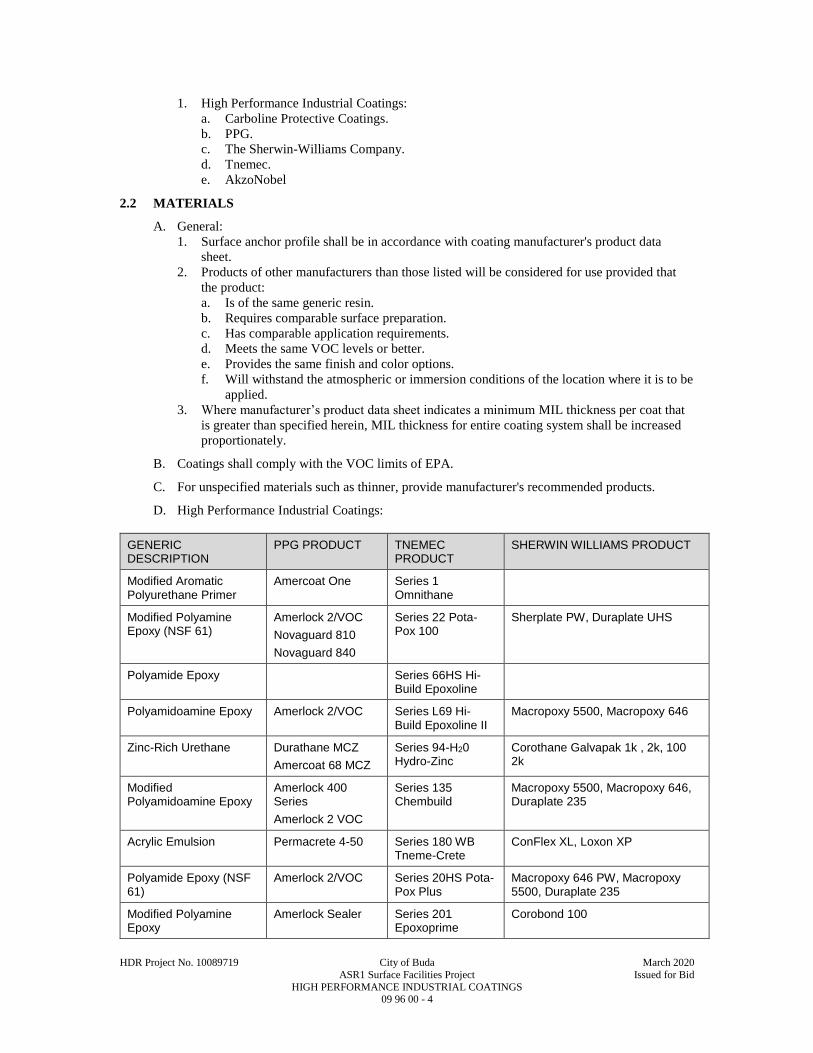
HDR Project No. 10089719 City of Buda March 2020
ASR1 Surface Facilities Project Issued for Bid
HIGH PERFORMANCE INDUSTRIAL COATINGS 09 96 00 - 4
1. High Performance Industrial Coatings:
a. Carboline Protective Coatings.
b. PPG.
c. The Sherwin-Williams Company.
d. Tnemec.
e. AkzoNobel
2.2 MATERIALS
A. General:
1. Surface anchor profile shall be in accordance with coating manufacturer's product data
sheet.
2. Products of other manufacturers than those listed will be considered for use provided that
the product:
a. Is of the same generic resin.
b. Requires comparable surface preparation.
c. Has comparable application requirements.
d. Meets the same VOC levels or better.
e. Provides the same finish and color options.
f. Will withstand the atmospheric or immersion conditions of the location where it is to be
applied.
3. Where manufacturer’s product data sheet indicates a minimum MIL thickness per coat that
is greater than specified herein, MIL thickness for entire coating system shall be increased
proportionately.
B. Coatings shall comply with the VOC limits of EPA.
C. For unspecified materials such as thinner, provide manufacturer's recommended products.
D. High Performance Industrial Coatings:
GENERIC DESCRIPTION
PPG PRODUCT TNEMEC PRODUCT
SHERWIN WILLIAMS PRODUCT
Modified Aromatic Polyurethane Primer
Amercoat One Series 1 Omnithane
Modified Polyamine Epoxy (NSF 61)
Amerlock 2/VOC
Novaguard 810
Novaguard 840
Series 22 Pota-Pox 100
Sherplate PW, Duraplate UHS
Polyamide Epoxy Series 66HS Hi-Build Epoxoline
Polyamidoamine Epoxy Amerlock 2/VOC Series L69 Hi-Build Epoxoline II
Macropoxy 5500, Macropoxy 646
Zinc-Rich Urethane Durathane MCZ
Amercoat 68 MCZ
Series 94-H20 Hydro-Zinc
Corothane Galvapak 1k , 2k, 100 2k
Modified Polyamidoamine Epoxy
Amerlock 400 Series
Amerlock 2 VOC
Series 135 Chembuild
Macropoxy 5500, Macropoxy 646, Duraplate 235
Acrylic Emulsion Permacrete 4-50 Series 180 WB Tneme-Crete
ConFlex XL, Loxon XP
Polyamide Epoxy (NSF 61)
Amerlock 2/VOC Series 20HS Pota-Pox Plus
Macropoxy 646 PW, Macropoxy 5500, Duraplate 235
Modified Polyamine Epoxy
Amerlock Sealer Series 201 Epoxoprime
Corobond 100

HDR Project No. 10089719 City of Buda March 2020
ASR1 Surface Facilities Project Issued for Bid
HIGH PERFORMANCE INDUSTRIAL COATINGS 09 96 00 - 5
GENERIC DESCRIPTION
PPG PRODUCT TNEMEC PRODUCT
SHERWIN WILLIAMS PRODUCT
Modified Flexible Polyamine Epoxy
Novaguard 840 Series 206SC Chembloc
GP3552, GP3552W
Modified Polyamine Epoxy Surfacer/Filler
Amercaot 114A Series 215 Surfacing Epoxy
Steel Seam FT 910, GP3513
Epoxy Modified Cementitious Mortar
Amercoat 100A Series 218 MortarClad
Corobond 300
Modified Polyamine Epoxy
Megaseal RS Series 237 Power-Tread
GP3745, Cor Cote HP
Modified Polyamine Epoxy (Secondary Containment)
Amercoat 351 + 880
Novaguard 840 GF
Series 237SC Chembloc
Cor Cote HP, Cor Cote HCR FF
Novolac Vinyl Ester (Primer)
PolySpec PE 310 Series 251SC Chembloc
Corobond Vinyl Ester Primer
Novolac Vinyl Ester (Secondary Containment)
PolySpec FlakeRez 8202 or 8303
Series 252SC Chembloc
Cor Cote VEN FF
Polyamine Novolac Epoxy
PolySpec Novarez 351
Series 282 Tneme-Glaze
Cor Cote EN7000, Cor Cote HCR
Aliphatic Polyester Polyurethane
Amershield Series Series 290 CRU Polylon HP
Polyfunctional Hybrid Urethane (Gloss)
Amershield Series Series 740 UVX Acrolon Ultra, Hi Solids Polyurethane
Polyfunctional Hybrid Urethane (Semi-Gloss)
Amershield Series Series 750 UVX Acrolon Ultra, Hi Solids Polyurethane
Inorganic Hybrid Water-Based Epoxy
Aquapon WB or Pitt Glaze WB
Series 1254 Epoxoblock WB
GP4685W Polycote
Aliphatic Polyurethane Chemical Resistant
Amershield Series GP4685W Polycote
2.3 SHERWIN-WILLIAMS COATING SYSTEMS
A. The following tables denote Sherwin-Williams products for high performance industrial
coatings, high temperature coatings, and coating systems by environment.
ENVIRONMENT SURFACE PREPARATION
PRIME COAT INTERMEDIATE COAT
FINISH COAT
Ferrous Metals (Structural & Miscellaneous Metals)
Immersion (NSF)
SSPC-SP10/ NACE No. 2 2 MIL anchor profile
3 - 5 MILS, Corothane Galvapak
|
20 - 25 MILS Sherplate PW
Galvanized Steel
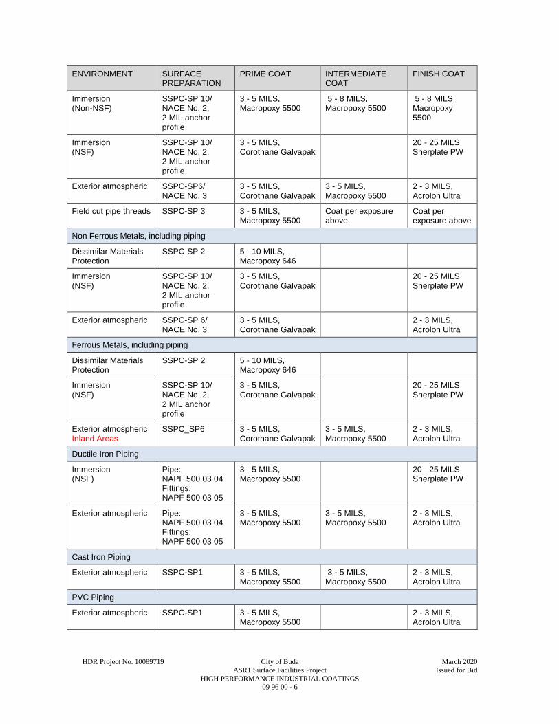
HDR Project No. 10089719 City of Buda March 2020
ASR1 Surface Facilities Project Issued for Bid
HIGH PERFORMANCE INDUSTRIAL COATINGS 09 96 00 - 6
ENVIRONMENT SURFACE PREPARATION
PRIME COAT INTERMEDIATE COAT
FINISH COAT
Immersion (Non-NSF)
SSPC-SP 10/ NACE No. 2, 2 MIL anchor profile
3 - 5 MILS, Macropoxy 5500
5 - 8 MILS, Macropoxy 5500
5 - 8 MILS, Macropoxy 5500
Immersion (NSF)
SSPC-SP 10/ NACE No. 2, 2 MIL anchor profile
3 - 5 MILS, Corothane Galvapak
20 - 25 MILS Sherplate PW
Exterior atmospheric SSPC-SP6/ NACE No. 3
3 - 5 MILS, Corothane Galvapak
3 - 5 MILS, Macropoxy 5500
2 - 3 MILS, Acrolon Ultra
Field cut pipe threads SSPC-SP 3 3 - 5 MILS, Macropoxy 5500
Coat per exposure above
Coat per exposure above
Non Ferrous Metals, including piping
Dissimilar Materials Protection
SSPC-SP 2 5 - 10 MILS, Macropoxy 646
Immersion (NSF)
SSPC-SP 10/ NACE No. 2, 2 MIL anchor profile
3 - 5 MILS, Corothane Galvapak
20 - 25 MILS Sherplate PW
Exterior atmospheric SSPC-SP 6/ NACE No. 3
3 - 5 MILS, Corothane Galvapak
2 - 3 MILS, Acrolon Ultra
Ferrous Metals, including piping
Dissimilar Materials Protection
SSPC-SP 2 5 - 10 MILS, Macropoxy 646
Immersion (NSF)
SSPC-SP 10/ NACE No. 2, 2 MIL anchor profile
3 - 5 MILS, Corothane Galvapak
20 - 25 MILS Sherplate PW
Exterior atmospheric Inland Areas
SSPC_SP6 3 - 5 MILS, Corothane Galvapak
3 - 5 MILS, Macropoxy 5500
2 - 3 MILS, Acrolon Ultra
Ductile Iron Piping
Immersion (NSF)
Pipe: NAPF 500 03 04 Fittings: NAPF 500 03 05
3 - 5 MILS, Macropoxy 5500
20 - 25 MILS Sherplate PW
Exterior atmospheric Pipe: NAPF 500 03 04 Fittings: NAPF 500 03 05
3 - 5 MILS, Macropoxy 5500
3 - 5 MILS, Macropoxy 5500
2 - 3 MILS, Acrolon Ultra
Cast Iron Piping
Exterior atmospheric SSPC-SP1 3 - 5 MILS, Macropoxy 5500
3 - 5 MILS, Macropoxy 5500
2 - 3 MILS, Acrolon Ultra
PVC Piping
Exterior atmospheric SSPC-SP1 3 - 5 MILS, Macropoxy 5500
2 - 3 MILS, Acrolon Ultra
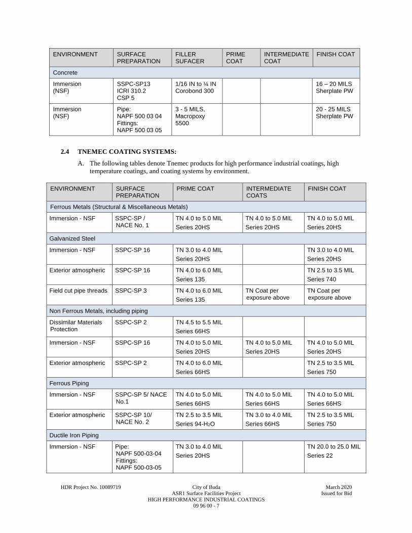
HDR Project No. 10089719 City of Buda March 2020
ASR1 Surface Facilities Project Issued for Bid
HIGH PERFORMANCE INDUSTRIAL COATINGS 09 96 00 - 7
ENVIRONMENT SURFACE PREPARATION
FILLER SUFACER
PRIME COAT
INTERMEDIATE COAT
FINISH COAT
Concrete
Immersion (NSF)
SSPC-SP13 ICRI 310.2 CSP 5
1/16 IN to ¼ IN Corobond 300
16 – 20 MILS Sherplate PW
Immersion (NSF)
Pipe: NAPF 500 03 04 Fittings: NAPF 500 03 05
3 - 5 MILS, Macropoxy 5500
20 - 25 MILS Sherplate PW
2.4 TNEMEC COATING SYSTEMS:
A. The following tables denote Tnemec products for high performance industrial coatings, high
temperature coatings, and coating systems by environment.
ENVIRONMENT SURFACE PREPARATION
PRIME COAT INTERMEDIATE COATS
FINISH COAT
Ferrous Metals (Structural & Miscellaneous Metals)
Immersion - NSF SSPC-SP / NACE No. 1
TN 4.0 to 5.0 MIL
Series 20HS
TN 4.0 to 5.0 MIL
Series 20HS
TN 4.0 to 5.0 MIL
Series 20HS
Galvanized Steel
Immersion - NSF SSPC-SP 16 TN 3.0 to 4.0 MIL
Series 20HS
TN 3.0 to 4.0 MIL
Series 20HS
Exterior atmospheric SSPC-SP 16 TN 4.0 to 6.0 MIL
Series 135
TN 2.5 to 3.5 MIL
Series 740
Field cut pipe threads SSPC-SP 3 TN 4.0 to 6.0 MIL
Series 135
TN Coat per exposure above
TN Coat per exposure above
Non Ferrous Metals, including piping
Dissimilar Materials Protection
SSPC-SP 2 TN 4.5 to 5.5 MIL
Series 66HS
Immersion - NSF SSPC-SP 16 TN 4.0 to 5.0 MIL
Series 20HS
TN 4.0 to 5.0 MIL
Series 20HS
TN 4.0 to 5.0 MIL
Series 20HS
Exterior atmospheric SSPC-SP 2 TN 4.0 to 6.0 MIL
Series 66HS
TN 2.5 to 3.5 MIL
Series 750
Ferrous Piping
Immersion - NSF SSPC-SP 5/ NACE No.1
TN 4.0 to 5.0 MIL
Series 66HS
TN 4.0 to 5.0 MIL
Series 66HS
TN 4.0 to 5.0 MIL
Series 66HS
Exterior atmospheric
SSPC-SP 10/ NACE No. 2
TN 2.5 to 3.5 MIL
Series 94-H2O
TN 3.0 to 4.0 MIL
Series 66HS
TN 2.5 to 3.5 MIL
Series 750
Ductile Iron Piping
Immersion - NSF Pipe: NAPF 500-03-04 Fittings: NAPF 500-03-05
TN 3.0 to 4.0 MIL
Series 20HS
TN 20.0 to 25.0 MIL
Series 22
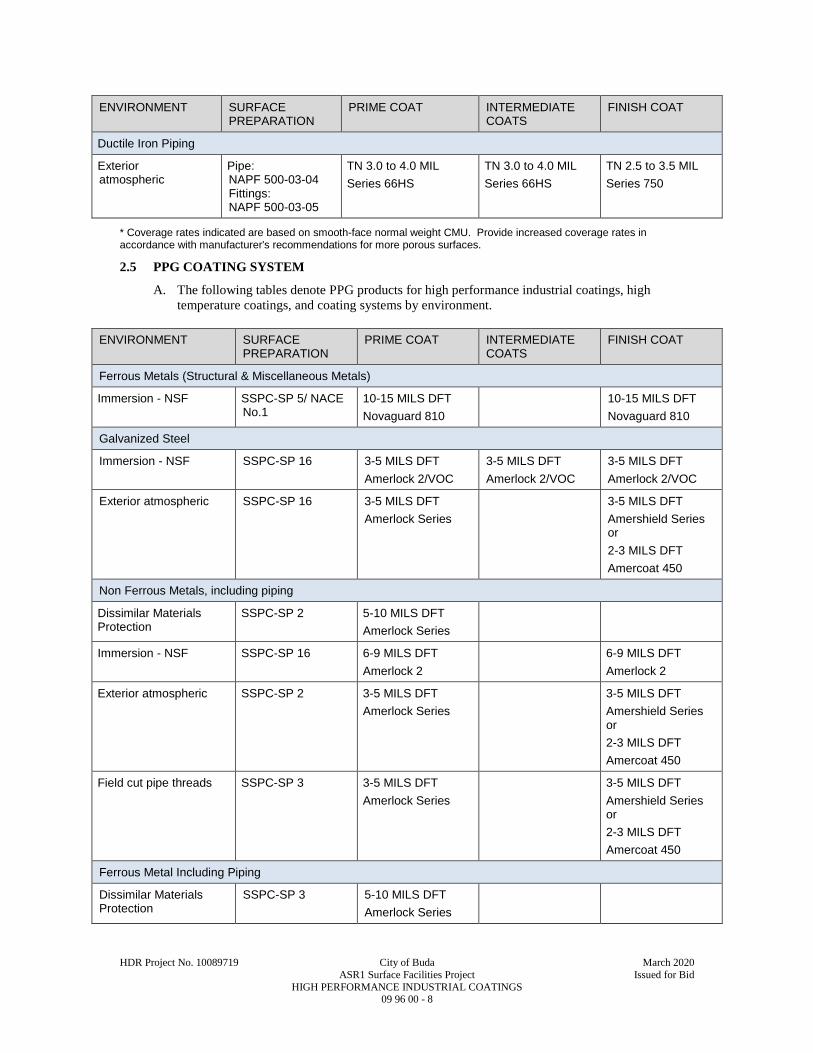
HDR Project No. 10089719 City of Buda March 2020
ASR1 Surface Facilities Project Issued for Bid
HIGH PERFORMANCE INDUSTRIAL COATINGS 09 96 00 - 8
ENVIRONMENT SURFACE PREPARATION
PRIME COAT INTERMEDIATE COATS
FINISH COAT
Ductile Iron Piping
Exterior atmospheric
Pipe: NAPF 500-03-04 Fittings: NAPF 500-03-05
TN 3.0 to 4.0 MIL
Series 66HS
TN 3.0 to 4.0 MIL
Series 66HS
TN 2.5 to 3.5 MIL
Series 750
* Coverage rates indicated are based on smooth-face normal weight CMU. Provide increased coverage rates in accordance with manufacturer's recommendations for more porous surfaces.
2.5 PPG COATING SYSTEM
A. The following tables denote PPG products for high performance industrial coatings, high
temperature coatings, and coating systems by environment.
ENVIRONMENT SURFACE PREPARATION
PRIME COAT INTERMEDIATE COATS
FINISH COAT
Ferrous Metals (Structural & Miscellaneous Metals)
Immersion - NSF SSPC-SP 5/ NACE No.1
10-15 MILS DFT
Novaguard 810
10-15 MILS DFT
Novaguard 810
Galvanized Steel
Immersion - NSF SSPC-SP 16 3-5 MILS DFT
Amerlock 2/VOC
3-5 MILS DFT
Amerlock 2/VOC
3-5 MILS DFT
Amerlock 2/VOC
Exterior atmospheric SSPC-SP 16 3-5 MILS DFT
Amerlock Series
3-5 MILS DFT
Amershield Series or
2-3 MILS DFT
Amercoat 450
Non Ferrous Metals, including piping
Dissimilar Materials Protection
SSPC-SP 2 5-10 MILS DFT
Amerlock Series
Immersion - NSF SSPC-SP 16 6-9 MILS DFT
Amerlock 2
6-9 MILS DFT
Amerlock 2
Exterior atmospheric SSPC-SP 2 3-5 MILS DFT
Amerlock Series
3-5 MILS DFT
Amershield Series or
2-3 MILS DFT
Amercoat 450
Field cut pipe threads SSPC-SP 3 3-5 MILS DFT
Amerlock Series
3-5 MILS DFT
Amershield Series or
2-3 MILS DFT
Amercoat 450
Ferrous Metal Including Piping
Dissimilar Materials Protection
SSPC-SP 3 5-10 MILS DFT
Amerlock Series
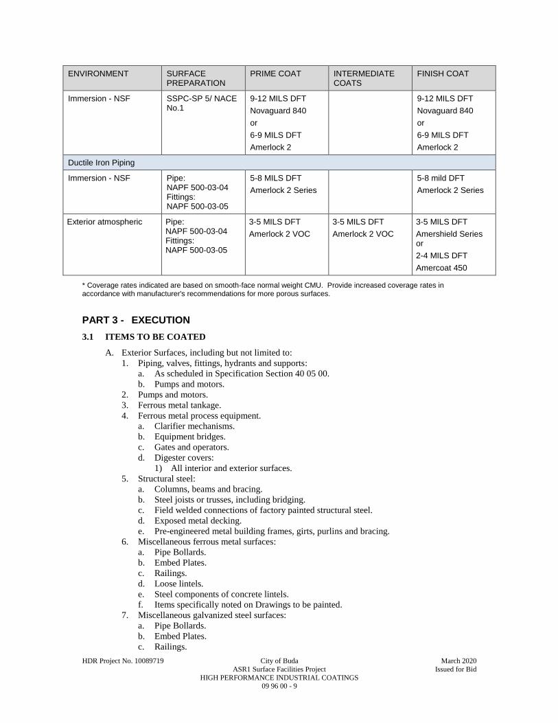
HDR Project No. 10089719 City of Buda March 2020
ASR1 Surface Facilities Project Issued for Bid
HIGH PERFORMANCE INDUSTRIAL COATINGS 09 96 00 - 9
ENVIRONMENT SURFACE PREPARATION
PRIME COAT INTERMEDIATE COATS
FINISH COAT
Immersion - NSF SSPC-SP 5/ NACE No.1
9-12 MILS DFT
Novaguard 840
or
6-9 MILS DFT
Amerlock 2
9-12 MILS DFT
Novaguard 840
or
6-9 MILS DFT
Amerlock 2
Ductile Iron Piping
Immersion - NSF Pipe: NAPF 500-03-04 Fittings: NAPF 500-03-05
5-8 MILS DFT
Amerlock 2 Series
5-8 mild DFT
Amerlock 2 Series
Exterior atmospheric Pipe: NAPF 500-03-04 Fittings: NAPF 500-03-05
3-5 MILS DFT
Amerlock 2 VOC
3-5 MILS DFT
Amerlock 2 VOC
3-5 MILS DFT
Amershield Series or
2-4 MILS DFT
Amercoat 450
* Coverage rates indicated are based on smooth-face normal weight CMU. Provide increased coverage rates in accordance with manufacturer's recommendations for more porous surfaces.
PART 3 - EXECUTION
3.1 ITEMS TO BE COATED
A. Exterior Surfaces, including but not limited to:
1. Piping, valves, fittings, hydrants and supports:
a. As scheduled in Specification Section 40 05 00.
b. Pumps and motors.
2. Pumps and motors.
3. Ferrous metal tankage.
4. Ferrous metal process equipment.
a. Clarifier mechanisms.
b. Equipment bridges.
c. Gates and operators.
d. Digester covers:
1) All interior and exterior surfaces.
5. Structural steel:
a. Columns, beams and bracing.
b. Steel joists or trusses, including bridging.
c. Field welded connections of factory painted structural steel.
d. Exposed metal decking.
e. Pre-engineered metal building frames, girts, purlins and bracing.
6. Miscellaneous ferrous metal surfaces:
a. Pipe Bollards.
b. Embed Plates.
c. Railings.
d. Loose lintels.
e. Steel components of concrete lintels.
f. Items specifically noted on Drawings to be painted.
7. Miscellaneous galvanized steel surfaces:
a. Pipe Bollards.
b. Embed Plates.
c. Railings.

HDR Project No. 10089719 City of Buda March 2020
ASR1 Surface Facilities Project Issued for Bid
HIGH PERFORMANCE INDUSTRIAL COATINGS 09 96 00 - 10
d. Loose lintels.
e. Steel components of concrete lintels.
f. Items specifically noted on Drawings to be painted.
3.2 ITEMS NOT TO BE PAINTED
A. General: Do not paint items listed in this Article, unless noted otherwise.
B. Items with Approved Factory Finish: These items may require repair of damaged painted areas
or painting of welded connections.
C. Electrical Equipment.
D. Moving parts of mechanical and electrical units where painting would interfere with the
operation of the unit.
E. Code labels, equipment identification or rating plates and similar labels, tagging and
identification.
F. Contact surfaces of friction-type structural connections.
G. Stainless Steel Surfaces, except:
1. Piping where specifically noted to be painted.
2. Banding as required to identify piping.
H. Aluminum Surfaces, except:
1. Where specifically shown in the Contract Documents.
2. Where in contact with concrete.
3. Where in contact with dissimilar metals.
4. Appurtenant surfaces as described in the ITEMS TO BE PAINTED article.
I. Mechanical piping scheduled to be insulated.
J. Galvanized Steel Items, unless specifically noted to be painted.
K. Architectural Finishes:
1. PVDF coated metals.
2. Standing seam metal roof, fascia, trim, soffit and accessories.
3.3 EXAMINATION
A. Concrete:
1. Test pH of surface to be painted in accordance with ASTM D4262.
a. If surface pH is not within coating manufacturer's required acceptable range, use
methods acceptable to coating manufacturer as required to bring pH within acceptable
range.
b. Retest pH until acceptable results are obtained.
2. Verify that moisture content of surface to be painted is within coating manufacturer's
recommended acceptable limits.
a. Test surface to be coated in accordance with ASTM D4263 to determine the presence
of moisture.
1) If moisture is detected, test moisture content of surface to be coated in accordance
with ASTM F1869 or ASTM F2170.
2) Provide remedial measures as necessary to bring moisture content within coating
manufacturer’s recommended acceptable limits.
3) Retest surface until acceptable results are obtained.
B. Concrete Unit Masonry:
1. Test pH of surface to be painted in accordance with ASTM D4262.
a. If surface pH is not within coating manufacturer's required acceptable range, use
methods acceptable to coating manufacturer as required to bring pH within acceptable
limits.
b. Retest pH until acceptable results are obtained.
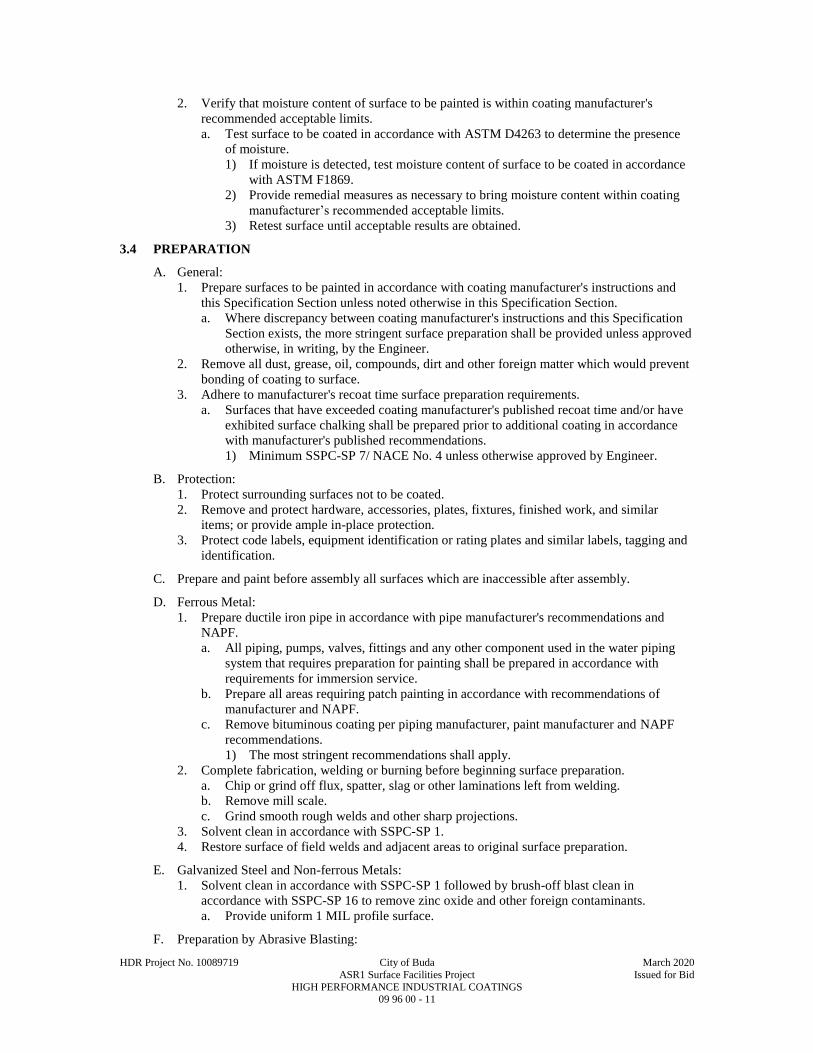
HDR Project No. 10089719 City of Buda March 2020
ASR1 Surface Facilities Project Issued for Bid
HIGH PERFORMANCE INDUSTRIAL COATINGS 09 96 00 - 11
2. Verify that moisture content of surface to be painted is within coating manufacturer's
recommended acceptable limits.
a. Test surface to be coated in accordance with ASTM D4263 to determine the presence
of moisture.
1) If moisture is detected, test moisture content of surface to be coated in accordance
with ASTM F1869.
2) Provide remedial measures as necessary to bring moisture content within coating
manufacturer’s recommended acceptable limits.
3) Retest surface until acceptable results are obtained.
3.4 PREPARATION
A. General:
1. Prepare surfaces to be painted in accordance with coating manufacturer's instructions and
this Specification Section unless noted otherwise in this Specification Section.
a. Where discrepancy between coating manufacturer's instructions and this Specification
Section exists, the more stringent surface preparation shall be provided unless approved
otherwise, in writing, by the Engineer.
2. Remove all dust, grease, oil, compounds, dirt and other foreign matter which would prevent
bonding of coating to surface.
3. Adhere to manufacturer's recoat time surface preparation requirements.
a. Surfaces that have exceeded coating manufacturer's published recoat time and/or have
exhibited surface chalking shall be prepared prior to additional coating in accordance
with manufacturer's published recommendations.
1) Minimum SSPC-SP 7/ NACE No. 4 unless otherwise approved by Engineer.
B. Protection:
1. Protect surrounding surfaces not to be coated.
2. Remove and protect hardware, accessories, plates, fixtures, finished work, and similar
items; or provide ample in-place protection.
3. Protect code labels, equipment identification or rating plates and similar labels, tagging and
identification.
C. Prepare and paint before assembly all surfaces which are inaccessible after assembly.
D. Ferrous Metal:
1. Prepare ductile iron pipe in accordance with pipe manufacturer's recommendations and
NAPF.
a. All piping, pumps, valves, fittings and any other component used in the water piping
system that requires preparation for painting shall be prepared in accordance with
requirements for immersion service.
b. Prepare all areas requiring patch painting in accordance with recommendations of
manufacturer and NAPF.
c. Remove bituminous coating per piping manufacturer, paint manufacturer and NAPF
recommendations.
1) The most stringent recommendations shall apply.
2. Complete fabrication, welding or burning before beginning surface preparation.
a. Chip or grind off flux, spatter, slag or other laminations left from welding.
b. Remove mill scale.
c. Grind smooth rough welds and other sharp projections.
3. Solvent clean in accordance with SSPC-SP 1.
4. Restore surface of field welds and adjacent areas to original surface preparation.
E. Galvanized Steel and Non-ferrous Metals:
1. Solvent clean in accordance with SSPC-SP 1 followed by brush-off blast clean in
accordance with SSPC-SP 16 to remove zinc oxide and other foreign contaminants.
a. Provide uniform 1 MIL profile surface.
F. Preparation by Abrasive Blasting:
HDR Project No. 10089719 City of Buda March 2020
ASR1 Surface Facilities Project Issued for Bid
HIGH PERFORMANCE INDUSTRIAL COATINGS 09 96 00 - 12
1. Schedule the abrasive blasting operation so blasted surfaces will not be wet after blasting
and before painting.
2. Provide compressed air for blasting that is free of water and oil.
a. Provide accessible separators and traps.
3. Protect nameplates, valve stems, rotating equipment, motors and other items that may be
damaged from blasting.
4. All abrasive-blasted ferrous metal surfaces shall be inspected immediately prior to
application of paint coatings.
a. Inspection shall be performed to determine cleanliness and profile depth of blasted
surfaces and to certify that surface has been prepared in accordance with these
Specifications.
5. Perform additional blasting and cleaning as required to achieve surface preparation required.
a. Re-blast surfaces not meeting requirements of these Specifications.
b. Prior to painting, re-blast surfaces allowed to set overnight and surfaces that show rust
bloom.
c. Surfaces allowed to set overnight or surfaces which show rust bloom prior to painting
shall be re-inspected prior to paint application.
6. Profile depth of blasted surface: Not less than 1 MIL or greater than 2 MILS unless
required otherwise by coating manufacturer.
7. Ensure abrasive blasting operation does not result in embedment of abrasive particles in
paint film.
8. Confine blast abrasives to area being blasted.
a. Provide shields of polyethylene sheeting or other such barriers to confine blast material.
b. Plug pipes, holes, or openings before blasting and keep plugged until blast operation is
complete and residue is removed.
9. Abrasive blasting media may be recovered, cleaned and reused providing Contractor
submits, for Engineer's review, a comprehensive recovery plan outlining all procedures and
equipment proposed in reclamation process.
10. Properly dispose of blasting material contaminated with debris from blasting operation.
3.5 APPLICATION
A. General:
1. Thin, mix and apply coatings by brush, roller, or spray in accordance with manufacturer's
installation instructions.
a. Application equipment must be inspected and approved in writing by coating
manufacturer.
b. Hollow metal shall be spray applied only.
2. Temperature and weather conditions:
a. Do not paint surfaces when surface temperature is below 50 DEGF unless product has
been formulated specifically for low temperature application and application is
approved in writing by Engineer and paint manufacturer's authorized representative.
b. Avoid painting surfaces exposed to hot sun.
c. Do not paint on damp surfaces.
3. Apply materials under adequate illumination.
4. Provide complete coverage to MIL thickness specified.
a. Thickness specified is dry MIL thickness.
5. Evenly spread to provide full, smooth coverage.
a. All paint systems are "to cover."
1) In situations of discrepancy between manufacturer's square footage coverage rates
and MIL thickness, MIL thickness requirements govern.
b. When color or undercoats show through, apply additional coats until paint film is of
uniform finish and color.
c. Finished paint system shall be uniform and without voids, bugholes, holidays, laps,
brush marks, roller marks, runs, sags or other imperfections.
6. If so directed by Engineer, do not apply consecutive coats until Engineer has had an
opportunity to observe and approve previous coats.

HDR Project No. 10089719 City of Buda March 2020
ASR1 Surface Facilities Project Issued for Bid
HIGH PERFORMANCE INDUSTRIAL COATINGS 09 96 00 - 13
7. Work each application of material into corners, crevices, joints, and other difficult to work
areas.
8. Avoid degradation and contamination of blasted surfaces and avoid inter-coat
contamination.
a. Clean contaminated surfaces before applying next coat.
b. Intercoat surface cleanliness shall be inspected and approved by the Engineer prior to
application of each coat.
9. Smooth out runs or sags immediately, or remove and recoat entire surface.
10. Allow preceding coats to dry before recoating.
a. Recoat within time limits specified by coating manufacturer.
b. If recoat time limits have expired re-prepare surface in accordance with coating
manufacturer's printed recommendations.
11. Allow coated surfaces to cure prior to allowing traffic or other work to proceed.
12. Coat all aluminum in contact with dissimilar materials.
13. When coating rough surfaces which cannot be backrolled sufficiently, hand brush coating to
work into all recesses provided that the maximum DFT is not exceeded.
14. Backroll surfaces if paint coatings are spray applied.
B. Employ services of coating manufacturer's qualified technical representative to ensure that field-
applied coatings are compatible with factory-applied or existing coatings.
1. Certify through material data sheets.
2. Perform test patch.
a. Prepare existing coating surface to receive specified coating system.
b. Apply coating to a minimum 1 SQFT area and allow to cure in accordance with
manufacturer's recommendations.
c. Evaluate adhesion to existing coating:
1) Concrete or Masonry substrates: ASTM D4541.
2) All other substrates: ASTM D6677 and ASTM D3359 (X-cut method).
3. If field-applied coating is found to be not compatible, require the coating manufacturer's
technical representative to recommend, in writing, product to be used as barrier coat,
thickness to be applied, surface preparation and method of application.
a. Perform test patch as described above.
4. At Contractor's option, coatings may be removed, surface re-prepared, and new coating
applied using appropriate paint system listed in the MATERIALS Article, Paint Systems
paragraph of this Specification Section.
a. All damage to surface as result of coating removal shall be repaired to original
condition or better by Contractor at no additional cost to Owner.
C. Prime Coat Application:
1. Apply structural steel and miscellaneous steel prime coat in the factory.
a. Finish coats shall be applied in the field.
b. Prime coat referred to here is prime coat as indicated in this Specification.
1) Prime coating applied in factory (shop) as part of Fabricator's standard rust
inhibiting and protection coating is not acceptable as replacement for specified
prime coating.
2. Prime all surfaces indicated to be painted.
a. Apply prime coat in accordance with coating manufacturer's written instructions and as
written in this Specification Section.
3. Prime ferrous metals embedded in concrete to minimum of 1 IN below exposed surfaces.
4. Apply zinc-rich primers while under continuous agitation.
5. Brush or spray bolts, welds, edges and difficult access areas with primer prior to primer
application over entire surface.
6. Touch up damaged primer coats prior to applying finish coats.
a. Restore primed surface equal to surface before damage.
7. All surfaces of steel lintels and steel components of concrete lintels used in wall
construction shall be completely painted with both prime and finish coats prior to placing in
wall.
HDR Project No. 10089719 City of Buda March 2020
ASR1 Surface Facilities Project Issued for Bid
HIGH PERFORMANCE INDUSTRIAL COATINGS 09 96 00 - 14
D. Finish Coat Application:
1. Apply finish coats in accordance with coating manufacturer's written instructions and in
accordance with this Specification Section; manufacturer instructions take precedent over
these Specifications.
2. Touch up damaged finish coats using same application method and same material specified
for finish coat.
a. Prepare damaged area in accordance with the PREPARATION Article of this
Specification Section.
3.6 COLOR CODING
A. Owner to select color from manufacturer’s standard color chart.
3.7 FIELD QUALITY CONTROL
A. Application Deficiencies:
1. Surfaces showing runs, laps, brush marks, telegraphing of surface imperfections or other
defects will not be accepted.
2. Surfaces showing evidence of fading, chalking, blistering, delamination or other defects due
to improper surface preparation, environmental controls or application will not be accepted.
a. Epoxy surfaces showing evidence of chalking or amine blush shall be prepared and
recoated as follows:
1) Solvent clean surfaces in accordance with SSPC-SP1 and abrasive blast in
accordance with SSPC-SP7/ NACE No. 4.
2) Recoat with intermediate and finish coats in accordance with coating system
specified herein.
B. Provide protection for painted surfaces.
1. Surfaces showing soiling, staining, streaking, chipping, scratches, or other defects will not
be accepted.
C. Contractor Performed Testing:
1. Provide ongoing testing and inspection, including but not limited to the following:
a. Measurement and recording of environmental conditions as specified herein.
b. Measurement and recording of substrate conditions as specified herein.
c. Thickness Testing:
1) Wet film thickness during application in accordance with ASTM D4414.
2) Dry Film Thickness (DFT) in accordance with SSPC-PA 2 and ASTM D7091.
D. Instrumentation:
1. Provide instrumentation as necessary to measure and record atmospheric and substrate
conditions, including but not limited to:
a. Dry Film Thickness Gauge.
b. Wet Film Thickness Gauge.
c. Sling Psychrometer.
d. Surface Temperature Gauge.
e. Anemometer.
f. Moisture Meter.
E. Maintain Daily Records:
1. Record the following information during application:
a. Date, starting time, end time, and all breaks taken by painters.
b. Air temperature.
c. Relative humidity.
d. Dew point.
e. Moisture content and pH level of concrete or masonry substrates prior to coating.
f. Surface temperature of substrate.
g. Provisions utilized to maintain work area within manufacturer's recommended
application parameters including temporary heating, ventilation, cooling,

HDR Project No. 10089719 City of Buda March 2020
ASR1 Surface Facilities Project Issued for Bid
HIGH PERFORMANCE INDUSTRIAL COATINGS 09 96 00 - 15
dehumidification and provisions utilized to mitigate wind blown dust and debris from
contaminating the wet paint film.
h. For exterior painting:
1) Sky condition.
2) Wind speed and direction.
i. Record environmental conditions, substrate moisture content and surface temperature
information not less than once every 4 HRS during application.
1) Record hourly when temperatures are below 50 DEGF or above 100 DEGF.
2. Record the following information daily for the paint manufacturer's recommended curing
period:
a. Date and start time of cure period for each item or area.
b. For exterior painting:
1) Sky conditions.
2) Wind speed and direction.
3) Air temperature.
a) Dry Bulb.
b) Wet Bulb.
4) Relative humidity.
5) Dew point.
6) Surface temperatures.
c. Record environmental conditions not less than once every 4 HRS.
1) Record hourly when temperatures are below 50 DEGF or above 100 DEGF.
d. Provisions utilized to protect each item or area and to maintain areas within
manufacturer's recommended curing parameters.
3. Format for daily record to be computer generated.
F. Measure wet coating with wet film thickness gages in accordance with ASTM D4414.
G. Measure coating dry film thickness in accordance with SSPC-PA 2.
1. Engineer may measure coating thickness at any time during project to assure conformance
with these Specifications.
H. Measure surface temperature of items to be painted with surface temperature gage specifically
designed for such.
I. Measure substrate humidity with humidity gage specifically designed for such.
J. Provide wet paint signs.
3.8 CLEANING
A. Clean paint spattered surfaces.
1. Use care not to damage finished surfaces.
B. Upon completion of painting, replace hardware, accessories, plates, fixtures, and similar items.
C. Remove surplus materials, scaffolding, and debris.
3.9 COLOR SCHEDULE
A. Pipe Bollards: 02SF Safety Yellow.
B. Owner to select color from manufacturer’s standard color chart.
END OF SECTION

This page intentionally left blank.
D I V I S I O N 1 0
SPECIALTIES

This page intentionally left blank.
HDR Project No. 10089719 City of Buda March 2020
ASR1 Surface Facilities Project Issued for Bid
IDENTIFICATION DEVICES 10 14 00 - 1
SECTION 10 14 00
IDENTIFICATION DEVICES
PART 1 - GENERAL
1.1 SUMMARY
A. Section Includes:
1. Tag, tape and stenciling systems for equipment and similar items.
B. Related Specification Sections include but are not necessarily limited to:
1. Division 00 - Procurement and Contracting Requirements.
2. Division 01 - General Requirements.
1.2 QUALITY ASSURANCE
A. Referenced Standards:
1. American Society of Mechanical Engineers (ASME):
a. A13.1, Scheme for the Identification of Piping Systems.
2. The International Society of Automation (ISA).
3. National Electrical Manufacturers Association/American National Standards Institute
(NEMA/ANSI):
a. Z535.1, Safety Color Code.
b. Z535.2, Environmental and Facility Safety Signs.
c. Z535.3, Criteria for Safety Symbols.
d. Z535.4, Product Safety Signs and Labels.
4. National Fire Protection Association (NFPA):
a. 70, National Electrical Code (NEC).
b. 704, Standard System for the Identification of Hazards of Materials for Emergency
Response.
5. Occupational Safety and Health Administration (OSHA):
a. 29 CFR 1910.145, Specification for Accident Prevention Signs and Tags.
1.3 SUBMITTALS
A. Shop Drawings:
1. Product technical data including:
a. Catalog information for all identification systems.
b. Acknowledgement that products submitted meet requirements of standards referenced.
2. Identification register, listing all items in PART 3 of this Specification Section to be
identified, type of identification system to be used, lettering, location and color.
PART 2 - PRODUCTS
2.1 MANUFACTURERS
A. Subject to compliance with the Contract Documents, the following manufacturers are
acceptable:
1. W.H. Brady Co.
2. Panduit.
3. Seton.
4. National Band and Tag Co.
5. Carlton Industries, Inc.
2.2 MANUFACTURED UNITS
A. Type A1 - Round Metal Tags:
1. Materials:
HDR Project No. 10089719 City of Buda March 2020
ASR1 Surface Facilities Project Issued for Bid
IDENTIFICATION DEVICES 10 14 00 - 2
a. Aluminum or stainless steel.
b. Stainless steel shall be used in corrosive environments.
2. Size:
a. Diameter: 1-1/2 IN minimum.
b. Thickness: 0.035 IN (20 GA) minimum.
3. Fabrication:
a. 3/16 IN minimum mounting hole.
b. Legend: Stamped and filled with black coloring.
4. Color: Natural.
B. Type A2 - Rectangle Metal Tags:
1. Materials: Stainless steel.
2. Size:
a. 3-1/2 IN x 1-1/2 IN minimum.
b. Thickness: 0.036 IN (20 GA) minimum.
3. Fabrication:
a. 3/16 IN minimum mounting hole.
b. Legend: Stamped and filled with black coloring.
4. Color: Natural.
C. Type A3 - Metal Tape Tags:
1. Materials: Aluminum or stainless steel.
2. Size:
a. Width 1/2 IN minimum.
b. Length as required by text.
3. Fabrication:
a. 3/16 IN minimum mounting hole.
b. Legend: Embossed.
4. Color: Natural.
D. Type B1- Square Nonmetallic Tags:
1. Materials: Fiberglass reinforced plastic.
2. Size:
a. Surface: 2 x 2 IN minimum.
b. Thickness: 100 MILS.
3. Fabrication:
a. 3/16 IN mounting hole with metal eyelet.
b. Legend: Preprinted and permanently embedded and fade resistant.
4. Color:
a. Background: Manufacturer standard or as specified.
b. Lettering: Black.
E. Type B2 - Nonmetallic Signs:
1. Materials: Fiberglass reinforced or durable plastic.
2. Size:
a. Surface: As required by text.
b. Thickness: 60 MILS minimum.
3. Fabrication:
a. Rounded corners.
b. Drilled holes in corners with grommets.
c. Legend: Preprinted, permanently embedded and fade resistant for a 10 year minimum
outdoor durability.
4. Color:
a. Background: Manufacturer standard or as specified.
b. Lettering: Black.
5. Standards for OSHA signs: NEMA/ANSI Z535.1, NEMA/ANSI Z535.2, NEMA/ANSI
Z535.3, NEMA/ANSI Z535.4, OSHA 29 CFR 1910.145.
HDR Project No. 10089719 City of Buda March 2020
ASR1 Surface Facilities Project Issued for Bid
IDENTIFICATION DEVICES 10 14 00 - 3
F. Type C - Laminated Name Plates:
1. Materials: Phenolic or DR (high impact) acrylic.
2. Size:
a. Surface: As required by text.
b. Thickness: 1/16 IN.
3. Fabrication:
a. Outdoor rated and UV resistant when installed outdoors.
b. Two layers laminated.
c. Legend: Engraved through top lamination into bottom lamination.
d. Two drilled side holes, for screw mounting.
4. Color: Black top surface, white core, unless otherwise indicated.
G. Type D - Self-Adhesive Tape Tags and Signs:
1. Materials: Vinyl tape or vinyl cloth.
2. Size:
a. Surface: As required by text.
b. Thickness: 5 MILS minimum.
3. Fabrication:
a. Indoor/Outdoor grade.
b. Weather and UV resistant inks.
c. Permanent adhesive.
d. Legend: Preprinted.
e. Wire markers to be self-laminating.
4. Color: White with black lettering or as specified.
5. Standards for OSHA signs: NEMA/ANSI Z535.1, NEMA/ANSI Z535.2, NEMA/ANSI
Z535.3, NEMA/ANSI Z535.4, OSHA 29 CFR 1910.145.
H. Type E - Heat Shrinkable Tape Tags:
1. Materials: Polyolefin.
2. Size: As required by text.
3. Fabrication:
a. Legend: Preprinted.
4. Color: White background, black printing.
I. Type F - Underground Warning Tape:
1. Materials: Polyethylene.
2. Size:
a. 6 IN wide (minimum).
b. Thickness: 3.5 MILS.
3. Fabrication:
a. Legend: Preprinted and permanently imbedded.
b. Message continuous printed.
c. Tensile strength: 1750 PSI.
4. Color: As specified.
J. Type G - Stenciling System:
1. Materials:
a. Exterior type stenciling enamel.
b. Either brushing grade or pressurized spray can form and grade.
2. Size: As required.
3. Fabrication:
a. Legend: As required.
4. Color: Black or white for best contrast.
K. Underground Tracer Wire:
1. Materials:
a. Wire:
1) 12 GA AWG.
HDR Project No. 10089719 City of Buda March 2020
ASR1 Surface Facilities Project Issued for Bid
IDENTIFICATION DEVICES 10 14 00 - 4
2) Solid.
b. Wire nuts: Waterproof type.
c. Split bolts: Brass.
2.3 ACCESSORIES
A. Fasteners:
1. Bead chain: #6 brass, aluminum or stainless steel.
2. Plastic strap: Nylon, urethane or polypropylene.
3. Screws: Self-tapping, stainless steel.
4. Adhesive, solvent activated.
2.4 MAINTENANCE MATERIALS
A. Where stenciled markers are provided, clean and retain stencils after completion and include in
extra stock, along with required stock of paints and applicators.
PART 3 - EXECUTION
3.1 GENERAL INSTALLATION
A. Install identification devices at specified locations.
B. All identification devices to be printed by mechanical process, hand printing is not acceptable.
C. Attach tags to equipment with sufficient surface or body area with solvent activated adhesive
applied to back of each tag.
D. Attach tags with 1/8 IN round or flat head screws to equipment without sufficient surface or
body area, or porous surfaces.
1. Where attachment with screws should not or cannot penetrate substrate, attach with plastic
strap.
E. Single items of equipment enclosed in a housing or compartment to be tagged on outside of
housing.
1. Several items of equipment mounted in housing to be individually tagged inside the
compartment.
F. Tracer Wire:
1. Attach to pipe at a maximum of 10 FT intervals with tape or tie-wraps.
2. Continuous pass from each valve box and above grade at each structure.
3. Coil enough wire at each valve box to extend wire a foot above the ground surface.
4. 1,000 FT maximum spacing between valve boxes.
5. If split bolts are used for splicing, wrap with electrical tape.
6. If wire nuts are used for splicing, knot wire at each splice point leaving 6 IN of wire for
splicing.
7. Use continuous strand of wire between valve box where possible.
a. Continuous length shall be no shorter than 100 FT.
3.2 SCHEDULES
A. Instrumentation Systems:
1. Instrumentation Equipment (e.g., flow control valves, primary elements, etc.):
a. Tag type:
1) Outdoor locations: Type B1 - Square Nonmetallic Tags.
2) Indoor noncorrosive:
a) Type A1 - Round Metal Tags.
b) Type B1 - Square Nonmetallic Tags.
3) Indoor corrosive:
a) Stainless steel Type A1 - Round Metal Tags.
b) Type B1 - Square Nonmetallic Tags.

HDR Project No. 10089719 City of Buda March 2020
ASR1 Surface Facilities Project Issued for Bid
IDENTIFICATION DEVICES 10 14 00 - 5
b. Fastener:
1) Type A1: Chain of the same material.
2) Type B1: Stainless steel chain.
c. Legend:
1) Letter height: 1/4 IN minimum.
2) Equipment ISA designation as indicated on the Drawings (e.g., “FIT-xxx”).
2. Enclosure for instrumentation and control equipment, (e.g., PLC control panels, etc.):
a. Tag type: Type C - Phenolic Name Plates.
b. Fastener: Screws.
c. Legend:
1) Letter height: 1/2 IN minimum.
2) Equipment name (e.g., "PLC CONTROL PANEL PCP-xxx").
3. Components inside equipment enclosure, (e.g., PLC’s, control relays, contactors, and
timers):
a. Tag type: Type D - Self-Adhesive Tape Tags.
b. Fastener: Self.
c. Legend:
1) Letter height: 3/16 IN minimum.
2) Description or function of component (e.g., "PLC-xxx” or “CR-xxx").
4. Through enclosure door mounted components (e.g., selector switches, controller digital
displays, etc.):
a. Tag type: Type C - Phenolic Name Plates.
b. Fastener: Screws.
c. Legend:
1) Letter height: 1/4 IN minimum.
2) Component ISA tag number as indicated on the Drawings (e.g., “HS-xxx”).
B. Electrical Systems:
1. Trenches with ductbanks, direct-buried conduit, or direct-buried wire and cable.
a. Tag type: Type F - Underground Warning Tape.
b. Letter height: 1-1/4 IN minimum.
c. Location:
1) Where trench is 12 IN or more below finished grade: In trench 6 IN below
finished grade.
2) Where trench is less than 12 IN below finished grade: In trench 3 IN below
finished grade.
d. Electrical power (e.g., low and medium voltage):
1) Color: Red with black letters.
2) Legend:
a) First line: “CAUTION CAUTION CAUTION”.
b) Second line: “BURIED ELECTRIC LINE BELOW”.
e. Communications (e.g., telephone, instrumentation, LAN, SCADA):
1) Color: Orange with black letters.
2) Legend:
a) First line: “CAUTION CAUTION CAUTION”.
b) Second line: “BURIED COMMUNICATION LINE BELOW”.
2. Exterior pad mounted equipment (e.g., transformers, switchgear):
a. Tag type: Type D - Self-Adhesive Tape Tags.
b. Fastener: Self.
c. General legend:
1) Letter height:
a) First line: 1-1/2 IN minimum.
b) Subsequent lines: 1/2 IN minimum.
2) First line: Equipment name (e.g., "TRANSFORMER Txxx").
3) Second line: System voltage (e.g., "13,800 V: 480/277 V").
4) Third line: Date installed (e.g., “INSTALLED JULY 20xx”).

HDR Project No. 10089719 City of Buda March 2020
ASR1 Surface Facilities Project Issued for Bid
IDENTIFICATION DEVICES 10 14 00 - 6
d. Each section/cubical legend:
1) Letter height: 1-1/2 IN minimum.
2) Description of source or load (e.g., "MAIN DISCONNECT" or "TO
SWITCHGEAR SGxxx" or "TO TRANSFORMER Txxx").
3. Switchgear, switchboards and motor control centers:
a. Tag type: Type C - Phenolic Name Plates.
b. Fastener: Screws.
c. Main equipment legend:
1) Letter height:
a) First line: 1 IN minimum.
b) Subsequent lines: 3/8 IN minimum.
2) First line: Equipment name (e.g., "MAIN SWITCHBOARD MSBxxx").
3) Second line:
a) Source of power (e.g., "FED FROM MCCxxx LOCATED IN ROOM xxx").
b) Include the building name or number if the source is in another building.
4) Third line: System voltage and phase (e.g., “480/277 V, 3PH”).
5) Fourth line: Date installed (e.g., “INSTALLED JULY 20xx”).
d. Main and feeder device legend:
1) Letter height: 3/8 IN minimum.
2) Description of load (e.g., “MAIN DISCONNECT”, "PUMP Pxxx" or
"PANELBOARD HPxxx").
4. Panelboards and transformers:
a. Tag type: Type C - Phenolic Name Plates.
b. Fastener: Screws.
c. Legend:
1) Letter height:
a) First line: 3/8 IN minimum.
b) Subsequent lines: 3/16 IN minimum.
2) First line: Equipment name (e.g., "PANELBOARD LPxxx" or "TRANSFORMER
Txxx").
3) Second line (panelboards only): System voltage and phase (e.g., “208/120V,
3PH”).
4) Third line:
a) Source of power (e.g., "FED FROM MCCxxx LOCATED IN ROOM xxx").
b) Include the building name or number if the source is in another building.
5) Fourth line: Date installed (e.g., “INSTALLED JULY 20xx”).
5. Safety switches, separately mounted circuit breakers and motor starters, VFD’s, etc.:
a. Tag type: Type C - Phenolic Name Plates.
b. Fastener: Screws.
c. Legend:
1) Letter height: 1/4 IN minimum.
2) First line: Description of load equipment is connected to (e.g., "PUMP Pxxx").
3) Second line:
a) Source of power (e.g., "FED FROM MCCxxx LOCATED IN ROOM xxx").
b) The source of power room number is only required when there are multiple
electrical rooms, if the source is in another building, the building name or
number shall be used.
6. Enclosure for instrumentation and control equipment, (e.g., lighting control panels, etc.):
a. Tag type: Type C - Phenolic Name Plates.
b. Fastener: Screws.
c. Legend:
1) Letter height: 1/2 IN minimum.
2) Equipment name (e.g., "LIGHTING CONTROL PANEL LCPxxx").
7. Components inside equipment enclosures (e.g., circuit breakers, fuses, control power
transformers, control relays, contactors, timers, etc.):
a. Tag type: Type D - Self-Adhesive Tape Tags and Signs.
HDR Project No. 10089719 City of Buda March 2020
ASR1 Surface Facilities Project Issued for Bid
IDENTIFICATION DEVICES 10 14 00 - 7
b. Fastener: Self.
c. Legend:
1) Letter height: 3/16 IN minimum.
2) Description or function of component (e.g., "M-xxx”, “CR-xxx” or “TR-xxx").
8. Through enclosure door mounted equipment (e.g., selector switches, controller digital
displays, etc.):
a. Tag type: Type C - Phenolic Name Plates.
b. Fastener: Screws.
c. Legend:
1) Letter height: 1/4 IN minimum.
2) Component tag number as indicated on the Drawings or as defined by contractor
(e.g., “HS-xxx”).
9. Conductors in control panels and in pull or junction boxes where multiple circuits exist.
a. Tag type: Type D - Self-Adhesive Tape Tags.
b. Fastener: Self.
c. Tag conductor at both ends.
d. Legend:
1) Letter height: 1/8 IN minimum.
2) Circuit number or wire number as scheduled on the Drawings or as furnished with
the equipment.
10. Conductors in cable trays.
a. Tag type: Type D - Self-Adhesive Tape Tags.
b. Fastener: Self.
c. Tag all conductors at the same location in the tray at 50 FT maximum intervals.
d. Legend:
1) Letter height: 1/8 IN minimum.
2) Circuit number or wire number as scheduled on the Drawings.
11. Conductors in handholes and manholes.
a. Tag type: Type A3 - Metal Tape Tags.
b. Fastener: Nylon strap.
c. Tag conductor at both ends.
d. Legend:
1) Letter height: 1/8 IN minimum.
2) Circuit number or wire number as scheduled on the Drawings.
12. Grounding conductors associated with grounding electrode system in accordance with the
following:
a. Tag type: Type D - Self-Adhesive Tape Tags.
b. Fastener: Self.
c. Legend:
1) Letter height: 1/8 IN minimum.
2) Function of conductor (e.g., "MAIN BONDING JUMPER", "TO GROUND
RING", "TO MAIN WATER PIPE").
13. Flash protection for switchboards, panelboards, industrial control panels and motor control
centers:
a. Tag type: Type D - Self-Adhesive Tape Signs.
b. Fastener: Self.
c. Legend: Per NFPA 70.
14. Poles:
a. Tag type: Type D - Self-Adhesive Tape Tags and Signs.
b. Fastener:
1) Metal pole: Self.
2) Wood pole:
a) Self mount tag on aluminum utility panel.
b) Panel thickness: 20 MILS.
c) Two mounting holes.
d) Screw or nail panel to pole.
HDR Project No. 10089719 City of Buda March 2020
ASR1 Surface Facilities Project Issued for Bid
IDENTIFICATION DEVICES 10 14 00 - 8
c. Color: Yellow with black letters.
d. Legend:
1) Letter height: 1 IN minimum.
2) Pole number as scheduled on the Drawings.
15. Equipment where more than one voltage source is present:
a. Tag type:
1) Type B2 - Nonmetallic Signs.
2) Type D - Self-Adhesive Tape Signs.
b. Fastener:
1) Screw or adhesive.
2) Self.
c. Size: 1-3/4 IN x 2-1/2 IN.
d. Location: Exterior face of enclosure or cubical.
e. Legend:
1) OSHA Danger Sign.
2) Description of Danger: “MULTIPLE VOLTAGE SOURCES”.
END OF SECTION

D I V I S I O N 2 6
ELECTRICAL

This page intentionally left blank.

HDR Project No. 10089719 City of Buda March 2020
ASR1 Surface Facilities Project Issued for Bid
ELECTRICAL - BASIC REQUIREMENTS 26 05 00 - 1
SECTION 26 05 00
ELECTRICAL - BASIC REQUIREMENTS
PART 1 - GENERAL
1.1 SUMMARY
A. Section Includes:
1. Basic requirements for electrical systems.
B. Related Specification Sections include but are not necessarily limited to:
1. Division 00 - Procurement and Contracting Requirements.
2. Division 01 - General Requirements.
3. Division 03 - Concrete.
4. Section 03 15 19 - Anchorage to Concrete.
5. Section 10 14 00 - Identification Devices.
6. Section 26 05 19 - Wire and Cable - 600 Volt and Below.
7. Section 26 05 33 - Raceways and Boxes.
1.2 QUALITY ASSURANCE
A. Referenced Standards:
1. Aluminum Association (AA):
a. ADM, Aluminum Design Manual.
2. American Institute of Steel Construction (AISC):
a. Steel Construction Manual.
3. American National Standards Institute (ANSI).
4. ASTM International (ASTM):
a. A36/A36M, Standard Specification for Carbon Structural Steel.
b. A123/A123M, Standard Specification for Zinc (Hot-Dip Galvanized) Coatings on Iron
and Steel Products.
c. A153/A153M, Standard Specification for Zinc Coating (Hot-Dip) on Iron and Steel
Hardware.
5. Institute of Electrical and Electronics Engineers, Inc. (IEEE):
a. C2, National Electrical Safety Code (NESC).
6. National Fire Protection Association (NFPA):
a. 70, National Electrical Code (NEC).
7. National Electrical Manufacturers Association (NEMA):
8. Underwriters Laboratories, Inc. (UL).
B. Products to be listed by a Nationally Recognized Testing Laboratory (NRTL) in accordance with
applicable product standards.
1. Applicable product standards including, but not limited to, ANSI, FM, IEEE, NEMA and
UL.
2. NRTL includes, but is not limited to, CSA Group Testing and Certification (CS), FM
Approvals LLC (FM), Intertek Testing Services NA, Inc. (ETL), and Underwriters
Laboratories, Inc. (UL).
1.3 DEFINITIONS
A. For the purposes of providing materials and installing electrical work the following definitions
shall be used.
1. Outdoor area: Exterior locations where the equipment is normally exposed to the weather
and including below grade structures, such as vaults, manholes, handholes and in-ground
pump stations.
2. Highly corrosive and corrosive area: Areas identified on the Drawings where there is a
varying degree of spillage or splashing of corrosive materials such as water, wastewater or
HDR Project No. 10089719 City of Buda March 2020
ASR1 Surface Facilities Project Issued for Bid
ELECTRICAL - BASIC REQUIREMENTS 26 05 00 - 2
chemical solutions; or chronic exposure to corrosive, caustic or acidic agents, chemicals,
chemical fumes or chemical mixtures.
3. Shop fabricated: Manufactured or assembled equipment for which a UL test procedure has
not been established.
1.4 SUBMITTALS
A. Shop Drawings:
1. See Specification Section 01 33 00 for requirements for the mechanics and administration of
submittal process.
2. General requirements:
a. Provide manufacturer's technical information on products to be used, including product
descriptive bulletin.
b. Include data sheets that include manufacturer's name and product model number.
1) Clearly identify all optional accessories.
c. Acknowledgement that products are NRTL listed or are constructed utilizing NRTL
recognized components.
d. Manufacturer's delivery, storage, handling and installation instructions.
e. Product installation details.
f. Short Circuit Current Rating (SCCR) nameplate marking per NFPA 70, include any
required calculations.
g. See individual specification sections for any additional requirements.
3. Fabrication and/or layout drawings:
a. Concrete and reinforcing steel, per Division 03 requirements.
b. Provide a conductor identification schedule for all power, control, communication and
protective circuits.
1) Schedule to include the following information:
a) Conductor identification number.
b) Conductor size.
c) Number of conductors.
d) Type of conductor.
e) Size of conductor.
f) Size of conductor usage descriptions.
g) Conductor run (to and from).
h) Conduit size and type.
c. Provide circuit schedules for all power, control, communication, and protective circuits.
1) Include a detailed description, list of individual loads per circuit and a total
estimated load per circuit.
B. Operation and Maintenance Manuals:
1. See Specification Section 01 33 04 for requirements for:
a. The mechanics and administration of the submittal process.
b. The content process of Operation and Maintenance Manuals.
C. When a Specification Section includes products specified in another Specification Section, each
Specification Section shall have the required Shop Drawing transmittal form per Specification
Section 01 33 00 and all Specification Sections shall be submitted simultaneously.
1.5 DELIVERY, STORAGE, AND HANDLING
A. Protect nameplates on electrical equipment to prevent defacing.
1.6 AREA DESIGNATIONS
A. Designation of an area will determine the NEMA rating of the electrical equipment enclosures,
types of conduits and installation methods to be used in that area.
1. Outdoor areas:
a. Wet.
b. Also, corrosive and/or hazardous when specifically designated on the Drawings or in
the Specifications.

HDR Project No. 10089719 City of Buda March 2020
ASR1 Surface Facilities Project Issued for Bid
ELECTRICAL - BASIC REQUIREMENTS 26 05 00 - 3
PART 2 - PRODUCTS
2.1 MANUFACTURERS
A. Subject to compliance with the Contract Documents, refer to specific Electrical Specification
Sections and specific material paragraphs below for acceptable manufacturers.
B. Provide all components of a similar type by one (1) manufacturer.
2.2 MATERIALS
A. Electrical Equipment Support Pedestals and/or Racks:
1. Manufacturers:
a. Modular strut:
1) Unistrut Building Systems.
2) B-Line by Eaton.
3) Globe Strut.
4) Superstrut by Thomas & Betts.
2. Material requirements:
a. Modular strut:
1) Galvanized steel: ASTM A123/123M or ASTM A153/A153M.
2) Stainless steel: AISI Type 316.
b. Structural members (e.g., I beams, L and C channels):
1) Galvanized steel: ASTM A36/A36M steel with galvanizing per ASTM
A123/A123M.
c. Mounting plates:
1) Galvanized steel: ASTM A36/A36M steel with galvanizing per ASTM
A123/A123M.
2) Aluminum: AA Type 6063-T6.
d. Mounting hardware:
1) Galvanized steel.
2) Stainless steel.
e. Anchorage per Specification Section 03 15 19.
f. Concrete and reinforcing steel: See Division 03 specifications.
B. Equipment pads (interior and exterior):
1. Concrete and reinforcing steel: See Division 03 specifications.
C. Field touch-up of galvanized surfaces.
1. Zinc-rich primer.
a. One coat, 3.0 MILS, ZRC by ZRC Products.
PART 3 - EXECUTION
3.1 INSTALLATION
A. Install and wire all equipment, including prepurchased equipment, and perform all tests
necessary to assure conformance to the Drawings and Specification Sections and ensure that
equipment is ready and safe for energization.
B. Install equipment in accordance with the requirements of:
1. NFPA 70.
2. IEEE C2.
3. The manufacturer's instructions.
C. In general, conduit routing is not shown on the Drawings.
1. The Contractor is responsible for routing all conduits including those shown on one-line and
control block diagrams and home runs shown on floor plans.
2. Conduit routings and stub-up locations that are shown are approximate; exact routing to be
as required for equipment furnished and field conditions.
HDR Project No. 10089719 City of Buda March 2020
ASR1 Surface Facilities Project Issued for Bid
ELECTRICAL - BASIC REQUIREMENTS 26 05 00 - 4
D. When complete branch circuiting is not shown on the Drawings:
1. A homerun indicating panelboard name and circuit number will be shown and the circuit
number will be shown adjacent to the additional devices (e.g., light fixture and receptacles)
on the same circuit.
2. The Contractor is to furnish and install all conduit and conductors required for proper
operation of the circuit.
3. The indicated home run conduit and conductor size shall be used for the entire branch
circuit.
4. See Specification Section 26 05 19 for combining multiple branch circuits in a common
conduit.
E. Do not use equipment that exceed dimensions or reduce clearances indicated on the Drawings or
as required by the NFPA 70.
F. Install equipment plumb, square and true with construction features and securely fastened.
G. Install electrical equipment, including pull and junction boxes, minimum of 6 IN from process,
gas, air and water piping and equipment.
H. Install equipment so it is readily accessible for operation and maintenance, is not blocked or
concealed and does not interfere with normal operation and maintenance requirements of other
equipment.
I. Device Mounting Schedule:
1. Unless indicated otherwise on the Drawings, mounting heights are as indicated below:
a. Light switch (to center): 46 IN.
b. Receptacle in architecturally finished areas (to center): 18 IN.
c. Receptacle on exterior wall of building (to center): 18 IN.
d. Receptacle in non-architecturally finished areas (to center): 46 IN.
e. Telephone outlet in architecturally finished areas (to center): 18 IN.
f. Telephone outlet for wall-mounted phone (to center): 46 IN.
g. Safety switch (to center of operating handle): 54 IN.
h. Separately mounted motor starter (to center of operating handle): 54 IN.
i. Pushbutton or selector switch control station (to center): 46 IN.
j. Panelboard (to top): 72 IN.
J. Avoid interference of electrical equipment operation and maintenance with structural members,
building features and equipment of other trades.
1. When it is necessary to adjust the intended location of electrical equipment, unless
specifically dimensioned or detailed, the Contractor may make adjustments of up to 6 IN in
equipment location with the Engineer's approval.
K. Provide electrical equipment support system per the following area designations:
1. Wet areas:
a. Galvanized system consisting of galvanized steel channels and fittings, nuts and
hardware.
b. Field touch-up cut ends and scratches of galvanized components with the specified
primer during the installation, before rust appears.
2. Corrosive areas:
a. Aluminum system consisting of aluminum channels and fittings with stainless steel nuts
and hardware.
L. Provide all necessary anchoring devices and supports rated for the equipment load based on
dimensions and weights verified from approved submittals, or as recommended by the
manufacturer.
1. See Specification Section 03 15 19.
2. Do not cut, or weld to, building structural members.
3. Do not mount safety switches or other equipment to equipment enclosures, unless enclosure
mounting surface is properly braced to accept mounting of external equipment.
HDR Project No. 10089719 City of Buda March 2020
ASR1 Surface Facilities Project Issued for Bid
ELECTRICAL - BASIC REQUIREMENTS 26 05 00 - 5
M. Provide non-metallic corrosion resistant spacers to maintain 1/4 IN separation between metallic
equipment and/or metallic equipment supports and mounting surface in wet areas, on below
grade walls and on walls of liquid containment or processing areas such as Basins, Clarifiers,
Digesters, Reservoirs, etc.
N. Do not place equipment fabricated from aluminum in direct contact with earth or concrete.
O. Screen or seal all openings into equipment mounted outdoors to prevent the entrance of rodents
and insects.
P. Do not use materials that may cause the walls or roof of a building to discolor or rust.
Q. Identify electrical equipment and components in accordance with Specification Section
10 14 00.
R. Provide field markings and/or documentation of available short-circuit current (available fault
current) and related information for equipment as required by the NFPA 70 and other applicable
codes.
S. Provide equipment or control panels with Short Circuit Current Rating (SCCR) labeling as
required by NFPA 70 and other applicable codes.
1. Determine the SCCR rating by one of the following methods:
a. Method 1: SCCR rating meets or exceeds the available fault current of the source
equipment when indicated on the Drawings.
b. Method 2: SCCR rating meets or exceeds the source equipment’s Amp Interrupting
Current (AIC) rating as indicated on the Drawings.
c. Method 3: SCCR rating meets or exceeds the calculated available short circuit current
at the control panel.
2. The source equipment is the switchboard, panelboard, motor control center or similar
equipment where the equipment or control panel circuit originates.
3. For Method 3, provide calculations justifying the SCCR rating. Utilize source equipment
available fault current or AIC rating as indicated on the Drawings.
3.2 FIELD QUALITY CONTROL
A. Replace equipment and systems found inoperative or defective and re-test.
B. The protective coating integrity of support structures and equipment enclosures shall be
maintained.
1. Repair galvanized components utilizing a zinc rich paint.
2. Repair painted components utilizing touch up paint provided by or approved by the
manufacturer.
3. Repair PVC coated components utilizing a patching compound, of the same material as the
coating, provided by the manufacturer of the component.
4. Repair surfaces which will be inaccessible after installation prior to installation.
5. See Specification Section 26 05 33 for requirements for conduits and associated accessories.
C. Replace nameplates damaged during installation.
3.3 DEMONSTRATION
A. Demonstrate equipment in accordance with Specification Section 01 75 00.
END OF SECTION

This page intentionally left blank.
HDR Project No. 10089719 City of Buda March 2020
ASR1 Surface Facilities Project Issued for Bid
WIRE AND CABLE - 600 VOLT AND BELOW 26 05 19 - 1
SECTION 26 05 19
WIRE AND CABLE - 600 VOLT AND BELOW
PART 1 - GENERAL
1.1 SUMMARY
A. Section Includes:
1. Material and installation requirements for:
a. Building wire.
b. Power cable.
c. Control cable.
d. Instrumentation cable.
e. Wire connectors.
f. Insulating tape.
g. Pulling lubricant.
B. Related Specification Sections include but are not necessarily limited to:
1. Division 00 - Procurement and Contracting Requirements.
2. Division 01 - General Requirements.
3. Section 26 05 00 - Electrical - Basic Requirements.
4. Section 26 08 13 - Acceptance Testing.
1.2 QUALITY ASSURANCE
A. Referenced Standards:
1. Insulated Cable Engineers Association (ICEA):
a. S-58-679, Standard for Control Cable Conductor Identification.
2. National Electrical Manufacturers Association (NEMA):
a. ICS 4, Industrial Control and Systems: Terminal Blocks.
3. National Electrical Manufacturers Association/Insulated Cable Engineers Association
(NEMA/ICEA):
a. WC 57/S-73-532, Standard for Control Cables.
b. WC 70/S-95-658, Non-Shielded Power Cables Rated 2000 Volts or Less for the
Distribution of Electrical Energy.
4. National Fire Protection Association (NFPA):
a. 70, National Electrical Code (NEC).
b. 262, Standard Method of Test for Flame Travel and Smoke of Wires and Cables for
Use in Air-Handling Spaces.
5. Telecommunications Industry Association/Electronic Industries Alliance/American National
Standards Institute (TIA/EIA/ANSI):
a. 568, Commercial Building Telecommunications Cabling Standard.
6. Underwriters Laboratories, Inc. (UL):
a. 44, Standard for Safety Thermoset-Insulated Wires and Cables.
b. 83, Standard for Safety Thermoplastic-Insulated Wires and Cables.
c. 467, Standard for Safety Grounding and Bonding Equipment.
d. 486A, Standard for Safety Wire Connectors and Soldering Lugs for use with Copper
Conductors.
e. 486C, Standard for Safety Splicing Wire Connections.
f. 510, Standard for Safety Polyvinyl Chloride, Polyethylene and Rubber Insulating Tape.
g. 1277, Standard for Safety Electrical Power and Control Tray Cables with Optional
Optical-Fiber Members.
h. 1581, Standard for Safety Reference Standard for Electrical Wires, Cables, and Flexible
Cords.
i. 2250, Standard for Safety Instrumentation Tray Cable.

HDR Project No. 10089719 City of Buda March 2020
ASR1 Surface Facilities Project Issued for Bid
WIRE AND CABLE - 600 VOLT AND BELOW 26 05 19 - 2
1.3 DEFINITIONS
A. Cable: Multi-conductor, insulated, with outer sheath containing either building wire or
instrumentation wire.
B. Instrumentation Cable:
1. Multiple conductor, insulated, twisted or untwisted, with outer sheath.
2. The following are specific types of instrumentation cables:
a. Analog signal cable:
1) Used for the transmission of low current (e.g., 4-20mA DC) or low voltage (e.g., 0-
10 VDC) signals, using No. 16 AWG and smaller conductors.
2) Commonly used types are defined in the following:
a) TSP: Twisted shielded pair.
b. Digital signal cable: Used for the transmission of digital signals between computers,
PLC's, RTU's, etc.
C. Power Cable: Multi-conductor, insulated, with outer sheath containing building wire, No. 8
AWG and larger.
D. Control Cable: Multi-conductor, insulated, with outer sheath containing building wires, No. 14,
No. 12 or No. 10 AWG.
E. Building Wire: Single conductor, insulated, with or without outer jacket depending upon type.
1.4 SUBMITTALS
A. Shop Drawings:
1. See Specification Section 01 33 00 for requirements for the mechanics and administration of
the submittal process.
2. Product technical data:
a. Provide submittal data for all products specified in PART 2 of this Specification
Section except:
1) Wire connectors.
2) Insulating tape.
3) Cable lubricant.
b. See Specification Section 26 05 00 for additional requirements.
B. Contract Closeout Information:
1. Operation and Maintenance Data:
a. See Specification Section 01 33 04 for requirements for the mechanics, administration,
and the content of Operation and Maintenance Manual submittals.
1.5 DELIVERY, STORAGE, AND HANDLING
A. See Specification Section 26 05 00.
PART 2 - PRODUCTS
2.1 MANUFACTURERS
A. Subject to compliance with the Contract Documents, the following manufacturers are
acceptable:
1. Building wire, power and control cable:
a. Aetna Insulated Wire.
b. Alphawire.
c. Cerrowire.
d. Encore Wire Corporation.
e. General Cable.
f. Okonite Company.
g. Southwire Company.
2. Instrumentation cable:

HDR Project No. 10089719 City of Buda March 2020
ASR1 Surface Facilities Project Issued for Bid
WIRE AND CABLE - 600 VOLT AND BELOW 26 05 19 - 3
a. Analog cable:
1) Alphawire.
2) Belden Inc.
3) General Cable.
3. Wire connectors:
a. Burndy Corporation.
b. Buchanan.
c. Ideal.
d. Ilsco.
e. 3M Co.
f. Teledyne Penn Union.
g. Thomas and Betts.
h. Phoenix Contact.
4. Insulating and color coding tape:
a. 3M Co.
b. Plymouth Bishop Tapes.
c. Red Seal Electric Co.
2.2 MANUFACTURED UNITS
A. Building Wire:
1. Conductor shall be copper with 600 V rated insulation.
2. Conductors shall be stranded, except for conductors used in lighting and receptacle circuits
which may be stranded or solid.
3. Surface mark with manufacturer's name or trademark, conductor size, insulation type and
UL label.
4. Conform to NEMA/ICEA WC 70/S-95-658 and UL 83 for type THHN/THWN and
THHN/THWN-2 insulation.
5. Conform to NEMA/ICEA WC 70/S-95-658 and UL 44 for type XHHW-2 insulation.
B. Power Cable:
1. Conductor shall be copper with 600 V rated insulation.
2. Surface mark with manufacturer's name or trademark, conductor size, insulation type and
UL label.
3. Conform to NEMA/ICEA WC 70/S-95-658 and UL 83 and UL 1277 for type
THHN/THWN insulation with an overall PVC jacket.
4. Conform to NEMA/ICEA WC 70/S-95-658 and UL 44 and UL 1277 for type XHHW-2
insulation with an overall PVC jacket.
5. Number of conductors as required, including a bare ground conductor.
6. Individual conductor color coding:
a. ICEA S-58-679, Method 4.
b. See PART 3 of this Specification Section for additional requirements.
7. Conform to NFPA 70 Type TC.
C. Control Cable:
1. Conductor shall be copper with 600 V rated insulation.
2. Surface mark with manufacturer's name or trademark, conductor size, insulation type and
UL label.
3. Conform to NEMA/ICEA WC 57/S-73-532 and UL 83 and UL 1277 for type
THHN/THWN insulation with an overall PVC jacket.
4. Conform to NEMA/ICEA WC 57/S-73-532 and UL 44 and UL 1277 for type XHHW-2
insulation with an overall PVC jacket.
5. Number of conductors as required, provided with or without bare ground conductor of the
same AWG size.
a. When a bare ground conductor is not provided, an additional insulated conductor shall
be provided and used as the ground conductor (e.g., 6/c No. 14 w/g and 7/c No. 14 are
equal).
6. Individual conductor color coding:

HDR Project No. 10089719 City of Buda March 2020
ASR1 Surface Facilities Project Issued for Bid
WIRE AND CABLE - 600 VOLT AND BELOW 26 05 19 - 4
a. ICEA S-58-679, Method 1, Table E-2.
b. See PART 3 of this Specification Section for additional requirements.
7. Conform to NFPA 70 Type TC.
D. Electrical Equipment Control Wire:
1. Conductor shall be copper with 600 V rated insulation.
2. Conductors shall be stranded.
3. Surface mark with manufacturer's name or trademark, conductor size, insulation type and
UL label.
4. Conform to UL 44 for Type SIS insulation.
5. Conform to UL 83 for Type MTW insulation.
E. Instrumentation Cable:
1. Surface mark with manufacturer's name or trademark, conductor size, insulation type and
UL label.
2. Analog cable:
a. Tinned copper conductors.
b. 300 V or 600 V PVC insulation with PVC jacket.
c. Twisted with 100 PCT foil shield coverage with drain wire.
d. Six (6) twists per foot minimum.
e. Individual conductor color coding: ICEA S-58-679, Method 1, Table E-2.
f. Conform to UL 2250, UL 1581 and NFPA 70 Type ITC.
3. Digital cable:
a. As recommended by equipment (e.g., PLC, RTU) manufacturer.
b. Horizontal voice and data cable:
1) Category 6 per TIA/EIA/ANSI 568.
2) Cable shall be label-verified.
3) Cable jacket shall be factory marked at regular intervals indicating verifying
organization and performance level.
4) Conductors: No. 24 AWG solid untinned copper.
5) Rated CMP per NFPA 70.
c. Conform to NFPA 262 and NFPA 70 Type ITC.
F. Wire Connectors:
1. Twist/screw on type:
a. Insulated pressure or spring type solderless connector.
b. 600 V rated.
c. Ground conductors: Conform to UL 486C and/or UL 467 when required by local
codes.
d. Phase and neutral conductors: Conform to UL 486C.
2. Compression and mechanical screw type:
a. 600 V rated.
b. Ground conductors: Conform to UL 467.
c. Phase and neutral conductors: Conform to UL 486A.
3. Terminal block type:
a. High density, screw-post barrier-type with white center marker strip.
b. 600 V and ampere rating as required, for power circuits.
c. 600 V, 20 ampere rated for control circuits.
d. 300 V, 15 ampere rated for instrumentation circuits.
e. Conform to NEMA ICS 4 and UL 486A.
G. Insulating and Color Coding Tape:
1. Pressure sensitive vinyl.
2. Premium grade.
3. Heat, cold, moisture, and sunlight resistant.
4. Thickness, depending on use conditions: 7, 8.5, or 10 MIL.
5. For cold weather or outdoor location, tape must also be all-weather.
6. Color:

HDR Project No. 10089719 City of Buda March 2020
ASR1 Surface Facilities Project Issued for Bid
WIRE AND CABLE - 600 VOLT AND BELOW 26 05 19 - 5
a. Insulating tape: Black.
b. Color coding tape: Fade-resistant color as specified herein.
7. Comply with UL 510.
H. Pulling Lubricant: Cable manufacturer's standard containing no petroleum or other products
which will deteriorate insulation.
PART 3 - EXECUTION
3.1 INSTALLATION
A. Permitted Usage of Insulation Types:
1. Type XHHW-2:
a. Building wire and power and control cable in conduit in outdoor areas and below grade.
2. Type THHN/THWN and THHN/THWN-2:
a. Building wire and power and control cable in conduit in outdoor areas.
3. Type SIS and MTW:
a. For the wiring of control equipment within control panels and field wiring of control
equipment within switchgear, switchboards, motor control centers.
B. Conductor Size Limitations:
1. Feeder and branch power conductors shall not be smaller than No. 12 AWG unless
otherwise indicated on the Drawings.
2. Control conductors shall not be smaller than No. 14 AWG unless otherwise indicated on the
Drawings.
3. Instrumentation conductors shall not be smaller than No. 18 AWG unless otherwise
indicated on the Drawings.
C. Color Code All Wiring as Follows:
1. Building wire:
240 V, 208 V, 240/120 V, 208/120 V 480 V, 480/277 V
Phase 1 Black Brown
Phase 2 Red * Orange
Phase 3 Blue Yellow
Neutral White White or Gray
Ground Green Green
* Orange when it is a high leg of a 120/240 V Delta system.
a. Conductors No. 6 AWG and smaller: Insulated phase, neutral and ground conductors
shall be identified by a continuous colored outer finish along its entire length.
b. Conductors larger than No. 6 AWG:
1) Insulated phase and neutral conductors shall be identified by one of the following
methods:
a) Continuous colored outer finish along its entire length.
b) 3 IN of colored tape applied at the termination.
2) Insulated grounding conductor shall be identified by one of the following methods:
a) Continuous green outer finish along its entire length.
b) Stripping the insulation from the entire exposed length.
c) Using green tape to cover the entire exposed length.
3) The color coding shall be applied at all accessible locations, including but not
limited to: Junction and pull boxes, wireways, manholes and handholes.
2. Power cables ICEA S-58-679, Method 4 with:
a. Phase and neutral conductors identified with 3 IN of colored tape, per the Table herein,
applied at the terminations.
HDR Project No. 10089719 City of Buda March 2020
ASR1 Surface Facilities Project Issued for Bid
WIRE AND CABLE - 600 VOLT AND BELOW 26 05 19 - 6
b. Ground conductor: Bare.
3. Control cables ICEA S-58-679, Method 1, Table E-2:
a. When a bare ground is not provided, one of the colored insulated conductors shall be
re-identified by stripping the insulation from the entire exposed length or using green
tape to cover the entire exposed length.
b. When used in power applications the colored insulated conductors used as phase and
neutral conductors may have to be re-identified with 3 IN of colored tape, per the Table
herein, applied at the terminations.
D. Install all wiring in raceway unless otherwise indicated on the Drawings.
E. Feeder, branch, control and instrumentation circuits shall not be combined in a raceway, cable
tray, junction or pull box, except as permitted in the following:
1. Where specifically indicated on the Drawings.
2. Where field conditions dictate and written permission is obtained from the Engineer.
3. Control circuits shall be isolated from feeder and branch power and instrumentation circuits
but combining of control circuits is permitted.
a. The combinations shall comply with the following:
1) 12 VDC, 24 VDC and 48 VDC may be combined.
2) 125 VDC shall be isolated from all other AC and DC circuits.
3) AC control circuits shall be isolated from all DC circuits.
4. Instrumentation circuits shall be isolated from feeder and branch power and control circuits
but combining of instrumentation circuits is permitted.
a. The combinations shall comply with the following:
1) Analog signal circuits may be combined.
2) Digital signal circuits may be combined but isolated from analog signal circuits.
5. Multiple branch circuits for similar loads may be combined in a common raceway, such as
multiple lighting circuits or multiple receptacle circuits or other 120Vac circuits. Do not
combine lighting and receptacle circuits.
a. Do not combine control device circuits with lighting or receptacle circuits.
b. Contractor is responsible for making the required adjustments in conductor and
raceway size, in accordance with all requirements of the NFPA 70, including but not
limited to:
1) Up sizing conductor size for required ampacity de-ratings for the number of current
carrying conductors in the raceway.
2) The neutral conductors may not be shared.
3) Up sizing raceway size for the size and quantity of conductors.
F. Ground the drain wire of shielded instrumentation cables at one end only.
1. The preferred grounding location is at the load (e.g., control panel), not at the source (e.g.,
field mounted instrument).
G. Splices and terminations for the following circuit types shall be made in the indicated enclosure
type using the indicated method.
1. Feeder and branch power circuits:
a. Device outlet boxes:
1) Twist/screw on type connectors.
b. Junction and pull boxes and wireways:
1) Twist/screw on type connectors for use on No. 8 and smaller wire.
2) Compression, mechanical screw or terminal block or terminal strip type connectors
for use on No. 6 AWG and larger wire.
c. Motor terminal boxes:
1) Twist/screw on type connectors for use on No. 10 AWG and smaller wire.
2) Insulated mechanical screw type connectors for use on No. 8 AWG and larger
wire.
d. Manholes or handholes:
1) Twist/screw on type connectors pre-filled with epoxy for use on No. 8 AWG and
smaller wire.
HDR Project No. 10089719 City of Buda March 2020
ASR1 Surface Facilities Project Issued for Bid
WIRE AND CABLE - 600 VOLT AND BELOW 26 05 19 - 7
2) Watertight compression or mechanical screw type connectors for use on No. 6
AWG and larger wire.
2. Control circuits:
a. Junction and pull boxes: Terminal block type connector.
b. Manholes or handholes: Twist/screw on type connectors pre-filled with epoxy.
c. Control panels and motor control centers: Terminal block or strips provided within the
equipment or field installed within the equipment by the Contractor.
3. Instrumentation circuits can be spliced where field conditions dictate and written permission
is obtained from the Engineer.
a. Maintain electrical continuity of the shield when splicing twisted shielded conductors.
b. Junction and pull boxes: Terminal block type connector.
c. Control panels and motor control centers: Terminal block or strip provided within the
equipment or field installed within the equipment by the Contractor.
4. Non-insulated compression and mechanical screw type connectors shall be insulated with
tape or hot or cold shrink type insulation to the insulation level of the conductors.
H. Insulating Tape Usage:
1. For insulating connections of No. 8 AWG wire and smaller: 7 MIL vinyl tape.
2. For insulating splices and taps of No. 6 AWG wire or larger: 10 MIL vinyl tape.
3. For insulating connections made in cold weather or in outdoor locations: 8.5 MIL, all
weather vinyl tape.
I. Color Coding Tape Usage: For color coding of conductors.
3.2 FIELD QUALITY CONTROL
A. Acceptance Testing:
1. See Specification Section 26 08 13.
END OF SECTION

This page intentionally left blank.
HDR Project No. 10089719 City of Buda March 2020
ASR1 Surface Facilities Project Issued for Bid
GROUNDING AND BONDING 26 05 26 - 1
SECTION 26 05 26
GROUNDING AND BONDING
PART 1 - GENERAL
1.1 SUMMARY
A. Section Includes:
1. Material and installation requirements for grounding and bonding system(s).
B. Related Specification Sections include but are not necessarily limited to:
1. Division 00 - Procurement and Contracting Requirements.
2. Division 01 - General Requirements.
3. Section 10 14 00 - Identification Devices.
4. Section 26 05 00 - Electrical - Basic Requirements.
5. Section 26 05 19 - Wire and Cable - 600 Volt and Below.
6. Section 26 05 33 - Raceways and Boxes.
7. Section 26 08 13 - Acceptance Testing.
1.2 QUALITY ASSURANCE
A. Referenced Standards:
1. ASTM International (ASTM):
a. B8, Standard Specification for Concentric-Lay-Stranded Copper Conductors, Hard,
Medium-Hard, or Soft.
2. Institute of Electrical and Electronics Engineers, Inc. (IEEE):
a. 837, Standard for Qualifying Permanent Connections Used in Substation Grounding.
3. National Fire Protection Association (NFPA):
a. 70, National Electrical Code (NEC).
4. Underwriters Laboratories, Inc. (UL):
a. 467, Grounding and Bonding Equipment.
B. Assure ground continuity is continuous throughout the entire Project.
1.3 SUBMITTALS
A. Shop Drawings:
1. See Specification Section 01 33 00 for requirements for the mechanics and administration of
the submittal process.
2. Product technical data.
a. Provide submittal data for all products specified in PART 2 of this Specification
Section except:
1) Grounding clamps, terminals and connectors.
2) Exothermic welding system.
b. See Specification Section 26 05 00 for additional requirements.
B. Contract Closeout Information:
1. Operation and Maintenance Data:
a. See Specification Section 01 33 04 for requirements for the mechanics, administration,
and the content of Operation and Maintenance Manual submittals.
C. Informational Submittals:
1. See Specification Section 01 33 00 for requirements for the mechanics and administration of
the submittal process.
2. Ground rod and/or grounding system resistance and continuity test reports signed by the
Project's supervising electrical foreman.
HDR Project No. 10089719 City of Buda March 2020
ASR1 Surface Facilities Project Issued for Bid
GROUNDING AND BONDING 26 05 26 - 2
PART 2 - PRODUCTS
2.1 MANUFACTURERS
A. Subject to compliance with the Contract Documents, the following manufacturers are
acceptable:
1. Ground rods and bars and grounding clamps, connectors and terminals:
a. ERICO by Pentair.
b. Harger Lightning & Grounding.
c. Heary Bros. Lightning Protection Co. Inc..
d. Burndy by Hubbell.
e. Robbins Lightning, Inc.
f. Blackburn by Thomas & Betts.
g. Thompson Lightning Protection, Inc.
2. Exothermic weld connections:
a. ERICO by Pentair - Cadweld.
b. Harger Lightning & Grounding - Ultraweld.
c. Burndy by Hubbell - Thermoweld.
d. FurseWELD by Thomas & Betts.
2.2 COMPONENTS
A. Wire and Cable:
1. Bare conductors: Soft drawn stranded copper meeting ASTM B8.
2. Insulated conductors: Color coded green, per Specification Section 26 05 19.
B. Conduit: As specified in Specification Section 26 05 33.
C. Ground Bars:
1. Solid copper:
a. 1/4 IN thick.
b. 2 or 4 IN wide.
c. 24 IN long minimum in main service entrance electrical rooms, 12 IN long elsewhere.
2. Predrilled grounding lug mounting holes.
3. Stainless steel or galvanized steel mounting brackets.
4. Insulated standoffs.
D. Ground Rods:
1. 3/4 IN x 10 FT.
2. Copper-clad:
a. 10 MIL minimum uniform coating of electrolytic copper molecularly bonded to a rigid
steel core.
b. Corrosion resistant bond between the copper and steel.
c. Hard drawn for a scar-resistant surface.
E. Grounding Clamps, Connectors and Terminals:
1. Mechanical type:
a. Standards: UL 467.
b. High copper alloy content.
2. Compression type for interior locations:
a. Standards: UL 467.
b. High copper alloy content.
c. Non-reversible.
d. Terminals for connection to bus bars shall have two bolt holes.
3. Compression type suitable for direct burial in earth or concrete:
a. Standards: UL 467, IEEE 837.
b. High copper alloy content.
c. Non-reversible.
d. Factory filled with oxide inhibiting compound.
HDR Project No. 10089719 City of Buda March 2020
ASR1 Surface Facilities Project Issued for Bid
GROUNDING AND BONDING 26 05 26 - 3
F. Exothermic Weld Connections:
1. Copper oxide reduction by aluminum process.
2. Molds properly sized for each application.
PART 3 - EXECUTION
3.1 INSTALLATION
A. General:
1. Install products in accordance with manufacturer's instructions.
2. Size grounding conductors and bonding jumpers in accordance with NFPA 70, Article 250,
except where larger sizes are indicated on the Drawings.
3. Remove paint, rust, or other non-conducting material from contact surfaces before making
ground connections. After connection, apply manufacturers approved touch-up paint to
protect metallic surface from corrosion.
4. Where ground conductors pass through floor slabs or building walls provide nonmetallic
sleeves and install sleeve per NFPA 70, Article 501.
a. Seal the sleeve interior to stop water penetration.
5. Do not splice grounding electrode conductors except at ground rods.
6. Install ground rods and grounding electrode conductors in undisturbed, firm soil.
a. Provide excavation required for installation of ground rods and conductors.
b. Use driving studs or other suitable means to prevent damage to threaded ends of
sectional rods.
c. Unless otherwise specified, connect conductors to ground rods with compression type
connectors or exothermic weld.
d. Provide sufficient slack in conductor to prevent conductor breakage during backfill or
due to ground movement.
e. Backfill excavation completely, thoroughly tamping to provide good contact between
backfill materials and ground rods and conductors.
7. Do not use exothermic welding if it will damage the structure the grounding conductor is
being welded to.
B. Grounding Electrode System:
1. Provide a grounding electrode system in accordance with NFPA 70, Article 250 and as
indicated on the Drawings.
a. All grounding electrode conductors terminate on a main ground bar located adjacent to
the service entrance equipment.
2. Grounding electrode conductor terminations:
a. Ground bars mounted on wall: Use a two-hole compression type conductor terminal
and bolt it to the ground bar with two bolts.
b. Ground bars in electrical equipment: Use compression type conductor terminal and
bolt it to the ground bar or manufacture's provided mechanical type termination device.
c. Piping systems: Use mechanical type connections.
d. Building steel, below grade and encased in concrete: Use compression type connector
or exothermic weld.
e. Building steel, above grade: Use a two-hole compression type conductor terminal and
bolt to the steel with two bolts or exothermic weld.
f. Ground rod: Compression type or exothermic weld, unless otherwise specified.
g. At all above grade terminations, the conductors shall be labeled per Specification
Section 10 14 00.
3. Ground ring grounding system:
a. Ground ring consists of ground rods and a conductor looped around the structure.
b. Placed at a minimum of 10 FT from the structure foundation and 2 FT-6 IN below
grade.
c. Provide a minimum of four ground rods placed at the corners of the structure and
additional rods so that the maximum distance between ground rods does not exceed
50 FT.
HDR Project No. 10089719 City of Buda March 2020
ASR1 Surface Facilities Project Issued for Bid
GROUNDING AND BONDING 26 05 26 - 4
d. Building/Structure grounding:
1) Bond building/structure metal support columns to the ground ring at all corners of
the structure.
e. Grounding conductor: Bare conductor, size as indicated on the Drawings.
4. Triad grounding system:
a. Triad consists of three ground rods arranged in a triangle separated by 20 FT and a
conductor interconnecting each ground rod.
b. Place first ground rod a minimum of 10 FT from the structure foundation and 2 FT-6 IN
below grade.
c. Grounding conductor: Bare conductor, size as indicated on the Drawings.
C. Supplemental Grounding Electrode:
1. Provide the following grounding in addition to the equipment ground conductor supplied
with the feeder conductors whether or not shown on the Drawings.
a. See Grounding Electrode System paragraph for conductor termination requirements.
2. Metal light poles:
a. Connect metal pole and pole base reinforcing steel to a ground rod.
b. Grounding conductor: Bare #6 AWG minimum.
3. Equipment support rack and pedestals mounted outdoors:
a. Connect metallic structure to a ground rod.
b. Grounding conductor: #6 AWG minimum.
D. Transformer Separately Derived Grounding System:
1. Install the System Bonding Jumper at the transformer. At the first disconnect, ensure the
neutral is isolated from ground.
2. Structures with a single electrical room/area:
a. Connect grounding electrode conductor to the Grounding Electrode System main
ground bar.
3. Structures with multiple electrical rooms/areas:
a. Provide a ground bar mounted in each electrical room/area.
b. Interconnect all ground bars in a daisy chain or radial fashion to the main ground bar as
indicated on the Drawings.
c. Connect grounding electrode conductor to the electrical room/area ground bar.
4. See Grounding Electrode System paragraph for conductor termination requirements.
E. Raceway Bonding/Grounding:
1. Install all metallic raceway so that it is electrically continuous.
2. Provide an equipment grounding conductor in all raceways with insulation identical to the
phase conductors, unless otherwise indicated on the Drawings.
3. NFPA 70 required grounding bushings shall be of the insulating type.
4. Provide double locknuts at all panels.
5. Bond all conduits, at entrance and exit of equipment, to the equipment ground bus or lug.
6. Provide bonding jumpers if conduits are installed in concentric knockouts.
7. Make all metallic raceway fittings and grounding clamps tight to ensure equipment
grounding system will operate continuously at ground potential to provide low impedance
current path for proper operation of overcurrent devices during possible ground fault
conditions.
F. Equipment Grounding:
1. Ground all utilization equipment with an equipment grounding conductor.
G. Manhole and Handhole Grounding:
1. Provide a ground rod and ground bar, when indicated or as needed, in each manhole and
handhole with exposed metal parts.
a. Expose a minimum of 4 IN of the rod above the floor for field connections to the rod.
2. Connect all exposed metal parts (e.g., conduits and cable racks) to the ground rod.
HDR Project No. 10089719 City of Buda March 2020
ASR1 Surface Facilities Project Issued for Bid
GROUNDING AND BONDING 26 05 26 - 5
3.2 FIELD QUALITY CONTROL
A. Leave grounding system uncovered until observed by Owner.
B. Acceptance testing:
1. See Specification Section 26 08 13.
END OF SECTION

This page intentionally left blank.
HDR Project No. 10089719 City of Buda March 2020
ASR1 Surface Facilities Project Issued for Bid
RACEWAYS AND BOXES 26 05 33 - 1
FSECTION 26 05 33
RACEWAYS AND BOXES
PART 1 - GENERAL
1.1 SUMMARY
A. Section Includes:
1. Material and installation requirements for:
a. Conduits.
b. Conduit fittings.
c. Conduit supports.
d. Wireways.
e. Outlet boxes.
f. Pull and junction boxes.
B. Related Specification Sections include but are not necessarily limited to:
1. Division 00 - Procurement and Contracting Requirements.
2. Division 01 - General Requirements.
3. Section 26 05 00 - Electrical - Basic Requirements.
4. Section 26 05 43 - Electrical - Exterior Underground.
5. Section 26 27 26 - Wiring Devices.
1.2 QUALITY ASSURANCE
A. Referenced Standards:
1. Aluminum Association (AA).
2. American Iron and Steel Institute (AISI).
3. ASTM International (ASTM):
a. A123/A123M, Standard Specification for Zinc (Hot-Dip Galvanized) Coatings on Iron
and Steel Products.
b. A153/A153M, Standard Specification for Zinc Coating (Hot-Dip) on Iron and Steel
Hardware.
c. D2564, Standard Specification for Solvent Cements for Poly(Vinyl Chloride) (PVC)
Plastic Piping Systems.
4. National Electrical Manufacturers Association (NEMA):
a. 250, Enclosures for Electrical Equipment (1000 Volts Maximum).
b. RN 1, Polyvinyl Chloride (PVC) Externally Coated Galvanized Rigid Steel Conduit
and Intermediate Metal Conduit.
c. TC 2, Electrical Polyvinyl Chloride (PVC) Tubing and Conduit.
d. TC 3, Polyvinyl Chloride (PVC) Fittings for Use with Rigid PVC Conduit and Tubing.
e. TC 14.AG, Aboveground Reinforced Thermosetting Resin Conduit and Fittings.
f. TC 14.BG, Belowground Reinforced Thermosetting Resin Conduit and Fittings.
5. National Electrical Manufacturers Association/American National Standards Institute
(NEMA/ANSI):
a. C80.1, Electric Rigid Steel Conduit (ERSC).
b. C80.3, Steel Electrical Metallic Tubing (EMT).
c. C80.5, Electrical Aluminum Rigid Conduit (ERAC).
d. OS 1, Sheet-Steel Outlet Boxes, Device Boxes, Covers, and Box Supports.
6. National Fire Protection Association (NFPA):
a. 70, National Electrical Code (NEC).
7. Underwriters Laboratories, Inc. (UL):
a. 1, Standard for Flexible Metal Conduit.
b. 6, Electrical Rigid Metal Conduit - Steel.
c. 50, Enclosures for Electrical Equipment, Non-Environmental Considerations.
d. 360, Standard for Liquid-Tight Flexible Metal Conduit.

HDR Project No. 10089719 City of Buda March 2020
ASR1 Surface Facilities Project Issued for Bid
RACEWAYS AND BOXES 26 05 33 - 2
e. 467, Grounding and Bonding Equipment.
f. 514A, Metallic Outlet Boxes.
g. 514B, Conduit, Tubing, and Cable Fittings.
h. 651, Standard for Schedule 40, 80, Type EB and A Rigid PVC Conduit and Fittings.
i. 797, Electrical Metallic Tubing - Steel.
j. 870, Standard for Wireways, Auxiliary Gutters, and Associated Fittings.
k. 2420, Belowground Reinforced Thermosetting Resin Conduit (RTRC) and Fittings.
l. 2515, Aboveground Reinforced Thermosetting Resin Conduit (RTRC) and Fittings.
1.3 SUBMITTALS
A. Shop Drawings:
1. See Specification Section 01 33 00 for requirements for the mechanics and administration of
the submittal process.
2. Product technical data:
a. Provide submittal data for all products specified in PART 2 of this Specification
Section except:
1) Conduit fittings.
2) Support systems.
b. See Specification Section 26 05 00 for additional requirements.
3. Fabrication and/or layout drawings:
a. Identify dimensional size of pull and junction boxes to be used.
B. Contract Closeout Information:
1. Operation and Maintenance Data:
a. See Specification Section 01 33 04 for requirements for the mechanics, administration,
and the content of Operation and Maintenance Manual submittals.
1.4 DELIVERY, STORAGE, AND HANDLING
A. See Specification Section 26 05 00.
PART 2 - PRODUCTS
2.1 MANUFACTURERS
A. Subject to compliance with the Contract Documents, the following manufacturers are
acceptable:
1. Rigid metal conduits and electrical metallic tubing:
a. Allied Tube and Conduit.
b. Western Tube and Conduit Corporation.
c. Wheatland Tube.
d. Patriot Aluminum Products, LLC.
2. PVC coated rigid metal conduits:
a. Ocal by Thomas & Betts.
b. Robroy Industries.
3. Rigid nonmetallic conduit:
a. Prime Conduit.
b. Cantex, Inc.
c. Osburn Associates, Inc.
d. Champion Fiberglass, Inc.
e. United Fiberglass of America, Inc.
4. Flexible conduit:
a. AFC Cable Systems.
b. Anamet, Inc.
c. Electri-Flex Company.
d. International Metal Hose Company.
e. Southwire Company, LLC.
HDR Project No. 10089719 City of Buda March 2020
ASR1 Surface Facilities Project Issued for Bid
RACEWAYS AND BOXES 26 05 33 - 3
5. Wireway:
a. Hoffman Engineering.
b. Wiegmann by Hubbell.
c. Square D by Schneider Electric.
6. Conduit fittings and accessories:
a. Appleton by Emerson Electric Co.
b. Carlon by Thomas & Betts.
c. Cantex, Inc.
d. Crouse-Hinds by Eaton.
e. Killark by Hubbell.
f. Osburn Associates, Inc.
g. O-Z/Gedney by Emerson Electric Co.
h. Raco by Hubbell.
i. Steel City by Thomas & Betts.
j. Thomas & Betts.
7. Support systems:
a. Unistrut by Atkore International, Inc.
b. B-Line by Eaton.
c. Kindorf by Thomas & Betts.
d. Minerallac Company.
e. CADDY by Pentair.
f. Superstrut by Thomas & Betts.
8. Outlet, pull and junction boxes:
a. Appleton by Emerson Electric Co.
b. Crouse-Hinds by Eaton
c. Killark by Hubbell.
d. O-Z/Gedney by Emerson Electric Co.
e. Steel City by Thomas & Betts.
f. Raco by Hubbell
g. Bell by Hubbell.
h. Hoffman Engineering.
i. Wiegmann by Hubbell.
j. B-Line by Eaton.
k. Adalet.
l. RITTAL North America LLC.
m. Stahlin by Robroy Enclosures.
2.2 RIGID METAL CONDUITS
A. PVC-Coated Rigid Steel Conduit (PVC-RGS):
1. Nominal 40 MIL Polyvinyl Chloride Exterior Coating:
a. Coating: Bonded to hot-dipped galvanized rigid steel conduit conforming to
NEMA/ANSI C80.1.
b. The bond between the PVC coating and the conduit surface: Greater than the tensile
strength of the coating.
2. Nominal 2 mil, minimum, urethane interior coating.
3. Urethane coating on threads.
4. Conduit: Epoxy prime coated prior to application of PVC and urethane coatings.
5. Female Ends:
a. Have a plastic sleeve extending a minimum of one pipe diameter or 2 IN, whichever is
less beyond the opening.
b. The inside diameter of the sleeve shall be the same as the outside diameter of the
conduit to be used with it.
6. Standards: NFPA 70 Type RMC, NEMA/ANSI C80.1, UL 6, NEMA RN 1.
B. Rigid Aluminum Conduit (RAC):
1. AA Type 6063 aluminum alloy, T-1 temper.
HDR Project No. 10089719 City of Buda March 2020
ASR1 Surface Facilities Project Issued for Bid
RACEWAYS AND BOXES 26 05 33 - 4
2. Maximum copper content of 0.10 PCT.
3. Extruded, seamless.
4. Standards: NFPA 70 Type RMC, NEMA/ANSI C80.5, UL 6.
2.3 RIGID NONMETALLIC CONDUIT
A. Schedules 40 (PVC-40) and 80 (PVC-80):
1. Polyvinyl-chloride (PVC) plastic compound which includes inert modifiers to improve
weatherability and heat distribution.
2. Rated for direct sunlight exposure.
3. Fire retardant and low smoke emission.
4. Shall be suitable for use with 90 DEGC wire and shall be marked "maximum 90 DEGC".
5. Standards: NFPA 70 Type PVC, NEMA TC 2, UL 651.
2.4 FLEXIBLE CONDUIT
A. PVC-Coated Flexible Galvanized Steel (liquid-tight) Conduit (FLEX-LT):
1. Core formed of continuous, spiral wound, hot-dip galvanized steel strip with successive
convolutions securely interlocked.
2. Extruded PVC outer jacket positively locked to the steel core.
3. Liquid and vaportight.
4. Standard: NFPA 70 Type LFMC, UL 360.
2.5 WIREWAY
A. General:
1. Suitable for lay-in conductors.
2. Designed for continuous grounding.
3. Covers:
a. Hinged or removable in accessible areas.
b. Non-removable when passing through partitions.
4. Finish: Rust inhibiting primer and manufacturer's standard paint inside and out except for
stainless steel type.
5. Standards: UL 870, NEMA 250.
B. Watertight (NEMA 4X rated) Wireway:
1. 14 GA Type 304 or 316 stainless steel bodies and covers without knockouts and 10 GA
stainless steel flanges.
2. Cover: Fully gasketed and held in place with captive clamp type latches.
3. Flanges: Fully gasketed and bolted.
2.6 CONDUIT FITTINGS AND ACCESSORIES
A. Fittings for Use with RGS and RAC:
1. General:
a. In hazardous locations listed for use in Class I, Groups C and D locations.
2. Locknuts:
a. Threaded steel or malleable iron.
b. Gasketed or non-gasketed.
c. Grounding or non-grounding type.
3. Bushings:
a. Threaded, insulated metallic.
b. Grounding or non-grounding type.
4. Hubs: Threaded, insulated and gasketed metallic for raintight connection.
5. Couplings:
a. Threaded straight type: Same material and finish as the conduit with which they are
used on.
b. Threadless type: Gland compression or self-threading type, concrete tight.
6. Unions: Threaded galvanized steel or zinc plated malleable iron.
7. Conduit bodies (ells and tees):

HDR Project No. 10089719 City of Buda March 2020
ASR1 Surface Facilities Project Issued for Bid
RACEWAYS AND BOXES 26 05 33 - 5
a. Body: Zinc plated cast iron or cast copper free aluminum with threaded hubs.
b. Standard and mogul size.
c. Cover:
1) Clip-on type with stainless steel screws.
2) Gasketed or non-gasketed galvanized steel, zinc plated cast iron or cast copper free
aluminum.
8. Conduit bodies (round):
a. Body: Zinc plated cast iron or cast copper free aluminum with threaded hubs.
b. Cover: Threaded screw on type, gasketed, galvanized steel, zinc plated cast iron or cast
copper free aluminum.
9. Sealing fittings:
a. Body: Zinc plated cast iron or cast copper free aluminum with threaded hubs.
b. Standard and mogul size.
c. With or without drain and breather.
d. Fiber and sealing compound: UL listed for use with the sealing fitting.
10. Service entrance head:
a. Malleable iron, galvanized steel or copper free aluminum.
b. Insulated knockout cover for use with a variety of sizes and number of conductors.
11. Expansion couplings:
a. 2 IN nominal straight-line conduit movement in either direction.
b. Galvanized steel with insulated bushing.
c. Gasketed for wet locations.
d. Internally or externally grounded.
12. Expansion/deflection couplings:
a. 3/4 IN nominal straight-line conduit movement in either direction.
b. 30 DEG nominal deflection from the normal in all directions.
c. Metallic hubs, neoprene outer jacket and stainless steel jacket clamps.
d. Internally or externally grounded.
e. Watertight, raintight and concrete tight.
13. Standards: UL 467, UL 514B, UL 1203.
B. Fittings for Use with PVC-RGS:
1. The same material and construction as those fittings listed under paragraph "Fittings for Use
with RGS and RAC" and coated as defined under paragraph "PVC Coated Rigid Steel
Conduit (PVC-RGS)."
C. Fittings for Use with EMT:
1. Connectors:
a. Straight, angle and offset types furnished with locknuts.
b. Zinc plated steel.
c. Insulated gland compression type.
d. Concrete and raintight.
2. Couplings:
a. Zinc plated steel.
b. Gland compression type.
c. Concrete and raintight.
3. Conduit bodies (ells and tees):
a. Body: Copper free aluminum with threaded hubs.
b. Standard and mogul size.
c. Cover:
1) Screw down type with steel screws.
2) Gasketed or non-gasketed galvanized steel or copper free aluminum.
4. Standard: UL 514B.
D. Fittings for Use with FLEX-LT:
1. Connector:
a. Straight or angle type.

HDR Project No. 10089719 City of Buda March 2020
ASR1 Surface Facilities Project Issued for Bid
RACEWAYS AND BOXES 26 05 33 - 6
b. Metal construction, insulated and gasketed.
c. Composed of locknut, grounding ferrule and gland compression nut.
d. Liquid tight.
2. Standards: UL 467, UL 514B.
E. Fittings for Use with Rigid Nonmetallic PVC Conduit:
1. Coupling, adapters and conduit bodies:
a. Same material, thickness, and construction as the conduits with which they are used.
b. Homogeneous plastic free from visible cracks, holes or foreign inclusions.
c. Bore smooth and free of blisters, nicks or other imperfections which could damage the
conductor.
2. Solvent cement for welding fittings shall be supplied by the same manufacturer as the
conduit and fittings.
3. Standards: ASTM D2564, NEMA TC 3, UL 651, UL 514B.
F. Weather and Corrosion Protection Tape:
1. PVC based tape, 10 mils thick.
2. Protection against moisture, acids, alkalis, salts and sewage and suitable for direct bury.
3. Used with appropriate pipe primer.
2.7 ALL RACEWAY AND FITTINGS
A. Mark Products:
1. Identify the nominal trade size on the product.
2. Stamp with the name or trademark of the manufacturer.
2.8 OUTLET BOXES
A. Metallic Outlet Boxes:
1. Hot-dip galvanized steel.
2. Conduit knockouts and grounding pigtail.
3. Styles:
a. 2 IN x 3 IN rectangle.
b. 4 IN square.
c. 4 IN octagon.
d. Masonry/tile.
4. Accessories:
a. Flat blank cover plates.
b. Barriers.
c. Extension, plaster or tile rings.
d. Box supporting brackets in stud walls.
e. Adjustable bar hangers.
5. Standards: NEMA/ANSI OS 1, UL 514A.
B. Cast Outlet Boxes:
1. Zinc plated cast iron or die-cast copper free aluminum with manufacturer's standard finish.
2. Threaded hubs and grounding screw.
3. Styles:
a. "FS" or "FD".
b. "Bell".
c. Single or multiple gang and tandem.
d. "EDS" or "EFS" for hazardous locations.
4. Accessories: 40 MIL PVC exterior coating and 2 MIL urethane interior coating.
5. Standards: UL 514A, UL 1203.
C. See Specification Section 26 27 26 for wiring devices, wallplates and coverplates.
2.9 PULL AND JUNCTION BOXES
A. NEMA 4X Rated (metallic):
1. Body and cover: 14 GA Type 304 or 316 stainless steel.
HDR Project No. 10089719 City of Buda March 2020
ASR1 Surface Facilities Project Issued for Bid
RACEWAYS AND BOXES 26 05 33 - 7
2. Seams continuously welded and ground smooth.
3. No knockouts.
4. External mounting flanges.
5. Hinged door and stainless steel screws and clamps.
6. Door with oil-resistant gasket.
B. NEMA 4X Rated (Nonmetallic):
1. Body and cover: Ultraviolet light protected fiberglass-reinforced polyester boxes.
2. No knockouts.
3. External mounting flanges.
4. Hinged door with quick release latches and padlocking hasp.
5. Door with oil resistant gasket.
C. Miscellaneous Accessories:
1. Rigid handles for covers larger than 9 SQFT or heavier than 25 LBS.
2. Split covers when heavier than 25 LBS.
3. Weldnuts for mounting optional panels and terminal kits.
4. Terminal blocks: Screw-post barrier-type, rated 600 volt and 20 ampere minimum.
D. Standards: NEMA 250, UL 50.
2.10 SUPPORT SYSTEMS
A. Multi-conduit Surface or Trapeze Type Support and Pull or Junction Box Supports:
1. Material requirements.
a. Galvanized steel: ASTM A123/A123M or ASTM A153/A153M.
b. Stainless steel: AISI Type 316.
c. PVC coat galvanized steel: ASTM A123/A123M or ASTM A153/A153M and 20 MIL
PVC coating.
B. Single Conduit and Outlet Box Support Fasteners:
1. Material requirements:
a. Zinc plated steel.
b. Stainless steel.
c. Malleable iron.
d. PVC coat malleable iron or steel: 20 MIL PVC coating.
e. Steel protected with zinc phosphate and oil finish.
2.11 OPENINGS AND PENETRATIONS IN WALLS AND FLOORS
A. Sleeves, smoke and fire stop fitting through walls and floors:
1. See NFPA 70, Article 501.
PART 3 - EXECUTION
3.1 RACEWAY INSTALLATION - GENERAL
A. Shall be in accordance with the requirements of:
1. NFPA 70.
2. Manufacturer instructions.
B. Size of Raceways:
1. Raceway sizes are shown on the Drawings, if not shown on the Drawings, then size in
accordance with NFPA 70.
2. Unless specifically indicated otherwise, the minimum raceway size shall be:
a. Conduit: 3/4 IN.
b. Wireway: 2-1/2 IN x 2-1/2 IN.
C. Field Bending and Cutting of Conduits:
1. Utilize tools and equipment recommended by the manufacturer of the conduit, designed for
the purpose and the conduit material to make all field bends and cuts.
HDR Project No. 10089719 City of Buda March 2020
ASR1 Surface Facilities Project Issued for Bid
RACEWAYS AND BOXES 26 05 33 - 8
2. Do not reduce the internal diameter of the conduit when making conduit bends.
3. Prepare tools and equipment to prevent damage to the PVC coating.
4. Degrease threads after threading and apply a zinc rich paint.
5. Debur interior and exterior after cutting.
D. Male threads of conduit systems shall be coated with an electrically conductive anti-seize
compound.
E. The protective coating integrity of conduits, fittings, outlet, pull and junction boxes and
accessories shall be maintained.
1. Repair galvanized components utilizing a zinc rich paint.
2. Repair painted components utilizing touch up paint provided by or approved by the
manufacturer.
3. Repair PVC coated components utilizing a patching compound, of the same material as the
coating, provided by the manufacturer of the conduit; or a self-adhesive, highly
conformable, cross-linked silicone composition strip, followed by a protective coating of
vinyl tape.
a. Total nominal thickness: 40 MIL.
4. Repair surfaces which will be inaccessible after installation prior to installation.
F. Remove moisture and debris from conduit before wire is pulled into place.
1. Pull mandrel with diameter nominally 1/4 IN smaller than the interior of the conduit, to
remove obstructions.
2. Swab conduit by pulling a clean, tight-fitting rag through the conduit.
3. Tightly plug ends of conduit with tapered wood plugs or plastic inserts until wire is pulled.
G. Only nylon or polyethylene rope shall be used to pull wire and cable in conduit systems.
H. Where portions of a raceway are subject to different temperatures and where condensation is
known to be a problem, as in cold storage areas of buildings or where passing from the interior
to the exterior of a building, the raceway shall be sealed to prevent circulation of warm air to
colder section of the raceway.
I. Fill openings in walls, floors, and ceilings and finish flush with surface.
1. See NFPA 70, Article 501.
3.2 RACEWAY ROUTING
A. Raceways shall be routed in the field unless otherwise indicated.
1. Conduit and fittings shall be installed, as required, for a complete system that has a neat
appearance and is in compliance with all applicable codes.
2. Run in straight lines parallel to or at right angles to building lines.
3. Do not route conduits:
a. Through areas of high ambient temperature or radiant heat.
b. In suspended concrete slabs.
c. In concrete members including slabs, slabs on grade, beams, walls, and columns unless
specifically located and detailed on structural Drawings.
4. Locate sleeves or conduits penetrating floors, walls, and beams so as not to significantly
impair the strength of the construction. Do not place conduit penetrations in columns.
5. Conduit shall not interfere with, or prevent access to, piping, valves, ductwork, or other
equipment for operation, maintenance and repair.
6. Provide pull boxes or conduit bodies as needed so that there is a maximum of 360 DEG of
bends in the conduit run or in long straight runs to limit pulling tensions.
B. All conduits within a structure shall be installed exposed except as follows:
1. As indicated on the Drawings.
C. Maintain minimum spacing between parallel conduit and piping runs in accordance with the
following when the runs are greater than 30 FT:
1. Between instrumentation and telecommunication: 1 IN.
2. Between instrumentation and 125 V, 48 V and 24 VDC, 2 IN.

HDR Project No. 10089719 City of Buda March 2020
ASR1 Surface Facilities Project Issued for Bid
RACEWAYS AND BOXES 26 05 33 - 9
3. Between instrumentation and 600 V and less AC power or control: 6 IN.
4. Between instrumentation and greater than 600 VAC power: 12 IN.
5. Between telecommunication and 125 V, 48 V and 24 VDC, 2 IN.
6. Between telecommunication and 600 V and less AC power or control: 6 IN.
7. Between telecommunication and greater than 600 VAC power: 12 IN.
8. Between 125 V, 48 V and 24 VDC and 600 V and less AC power or control: 2 IN.
9. Between 125 V, 48 V and 24 VDC and greater than 600 VAC power: 2 IN.
10. Between 600 V and less AC and greater than 600 VAC: 2 IN.
11. Between process, gas, air and water pipes: 6 IN.
D. Conduits shall be installed to eliminate moisture pockets.
1. Where water cannot drain to openings, provide drain fittings in the low spots of the conduit
run.
E. Conduit shall not be routed on the exterior of structures except as specifically indicated on the
Drawings.
F. Where sufficient room exists within the housing of roof-mounted equipment, the conduit shall
be stubbed up inside the housing.
G. Provide all required openings in walls, floors, and ceilings for conduit penetration.
1. See NFPA 70, Article 501.
3.3 RACEWAY APPLICATIONS
A. Permitted Raceway Types Per Wire or Cable Types:
1. Power wire or cables: All raceway types.
2. Control wire or cables: All raceway types.
3. Instrumentation cables: Metallic raceway except nonmetallic may be used underground.
4. Motor leads from a VFD: RGS, RAC or shielded VFD cables in all other raceways.
5. Telecommunication cables: All raceway types.
B. Permitted Raceway Types Per Area Designations:
1. Wet areas:
a. RAC.
2. Corrosive areas:
a. RAC.
C. Permitted Raceway Types Per Routing Locations:
1. Embedded in poured concrete walls and floors:
a. PVC-40.
b. PVC-RGS when emerging from concrete into areas designated as wet, corrosive or
highly corrosive.
2. Beneath floor slab-on-grade:
a. PVC-40.
3. Through floor penetrations, see NFPA 70, Article 501:
a. PVC-RGS in areas designated as wet, corrosive or highly corrosive.
4. Direct buried conduits and ductbanks:
a. PVC-80.
b. 90 DEG elbows for transitions to above grade:
1) PVC-RGS.
c. Long sweeping bends greater than 15 DEG:
1) PVC-RGS.
5. Concrete encased ductbanks:
a. PVC-40.
b. 90 degree elbows for transitions to above grade:
1) PVC-RGS.
c. Long sweeping bends greater than 15 DEG:
1) RGS for sizes 2 IN and larger.

HDR Project No. 10089719 City of Buda March 2020
ASR1 Surface Facilities Project Issued for Bid
RACEWAYS AND BOXES 26 05 33 - 10
D. FLEX-LT conduits shall be install as the final conduit connection to light fixtures, dry type
transformers, motors, electrically operated valves, instrumentation primary elements, and other
electrical equipment that is liable to vibrate.
1. The maximum length shall not exceed:
a. 6 FT to light fixtures.
b. 3 FT to motors.
c. 2 FT to all other equipment.
E. NEMA 4X Rated Wireway:
1. Surface mounted in areas designated as wet and or corrosive.
F. Underground Conduit: See Specification Section 26 05 43.
3.4 CONDUIT FITTINGS AND ACCESSORIES
A. Rigid nonmetallic conduit and fittings shall be joined utilizing solvent cement.
1. Immediately after installation of conduit and fitting, the fitting or conduit shall be rotated
1/4 turn to provide uniform contact.
B. Install Expansion Fittings:
1. Where conduits are exposed to the sun and conduit run is greater than 200 FT.
2. Elsewhere as identified on the Drawings.
C. Install Expansion/Deflection Fittings:
1. Where conduits enter a structure.
a. Except electrical manholes and handholes.
b. Except where the ductbank is tied to the structure with rebar.
2. Where conduits span structural expansions joints.
3. Elsewhere as identified on the Drawings.
D. Threaded connections shall be made wrench-tight.
E. Conduit joints shall be watertight:
1. Where subjected to possible submersion.
2. In areas classified as wet.
3. Underground.
F. Terminate Conduits:
1. In metallic outlet boxes:
a. RGS and RAC:
1) Conduit hub and locknut.
2) Insulated bushing and two locknuts.
3) Use grounding type locknut or bushing when required by NFPA 70.
b. EMT: Compression type connector and locknut.
2. In NEMA 4 and NEMA 4X rated enclosures:
a. Watertight, insulated and gasketed hub and locknut.
3. When stubbed up through the floor into floor mount equipment:
a. With an insulated grounding bushing on metallic conduits.
b. With end bells on nonmetallic conduits.
G. Threadless couplings shall only be used to join new conduit to existing conduit when the
existing conduit end is not threaded and it is not practical or possible to cut threads on the
existing conduit with a pipe threader.
3.5 CONDUIT SUPPORT
A. Permitted multi-conduit surface or trapeze type support system per area designations and conduit
types:
1. Dry or wet and/or hazardous areas:
a. Galvanized system consisting of: Galvanized steel channels and fittings, nuts and
hardware and conduit clamps.

HDR Project No. 10089719 City of Buda March 2020
ASR1 Surface Facilities Project Issued for Bid
RACEWAYS AND BOXES 26 05 33 - 11
b. Aluminum system consisting of: Aluminum channels, fittings and conduit clamps with
stainless steel nuts and hardware.
2. Corrosive areas:
a. Aluminum system consisting of: Aluminum channels, fittings and conduit clamps with
stainless steel nuts and hardware.
b. PVC coated steel system consisting of: PVC coated galvanized steel channels and
fittings and conduit clamps with stainless steel nuts and hardware.
3. Conduit type shall be compatible with the support system material.
a. Stainless steel system may be used with RGS, PVC-RGS and RAC.
b. Aluminum system may be used with RAC.
B. Permitted single conduit support fasteners per area designations and conduit types:
1. Dry or wet and/or hazardous areas:
a. Material: Zinc plated steel, stainless steel and malleable iron.
b. Types of fasteners: Straps, hangers with bolts, clamps with bolts and bolt on beam
clamps.
2. Corrosive areas:
a. Material: Stainless steel and PVC coat malleable iron or steel.
b. Types of fasteners: Straps, hangers with bolts, clamps with bolts and bolt on beam
clamps.
3. Conduit type shall be compatible with the support fastener material.
a. Stainless steel system may be used with RGS, PVC-RGS and RAC.
C. Conduit Support General Requirements:
1. Maximum spacing between conduit supports per NFPA 70.
2. Support conduit from the building structure.
3. Do not support conduit from process, gas, air or water piping; or from other conduits.
4. Provide hangers and brackets to limit the maximum uniform load on a single support to
25 LBS or to the maximum uniform load recommended by the manufacturer if the support
is rated less than 25 LBS.
a. Do not exceed maximum concentrated load recommended by the manufacturer on any
support.
b. Conduit hangers:
1) Continuous threaded rods combined with struts or conduit clamps: Do not use
perforated strap hangers and iron bailing wire.
c. Do not use suspended ceiling support systems to support raceways.
d. Hangers in metal roof decks:
1) Utilize fender washers.
2) Not extend above top of ribs.
3) Not interfere with vapor barrier, insulation, or roofing.
5. Conduit support system fasteners:
a. Use sleeve-type expansion anchors as fasteners in masonry wall construction.
b. Do not use concrete nails and powder-driven fasteners.
3.6 OUTLET, PULL AND JUNCTION BOX INSTALLATION
A. General:
1. Install products in accordance with manufacturer's instructions.
2. See Specification Section 26 05 00 and the Drawings for area classifications.
3. Fill unused punched-out, tapped, or threaded hub openings with insert plugs.
4. Size boxes to accommodate quantity of conductors enclosed and quantity of conduits
connected to the box.
B. Outlet Boxes:
1. Permitted uses of metallic outlet boxes:
a. Housing of wiring devices:
1) Recessed in poured concrete, concrete block and brick walls of architecturally
finished areas and exterior building walls.

HDR Project No. 10089719 City of Buda March 2020
ASR1 Surface Facilities Project Issued for Bid
RACEWAYS AND BOXES 26 05 33 - 12
2. Permitted uses of cast outlet boxes:
a. Housing of wiring devices surface mounted in non-architecturally finished dry, wet,
corrosive, highly corrosive and hazardous areas.
b. Pull and junction box surface mounted in non-architecturally finished dry, wet,
corrosive and highly corrosive areas.
3. Mount device outlet boxes where indicated on the Drawings and at heights as scheduled in
Specification Section 26 05 00.
4. Set device outlet boxes plumb and vertical to the floor.
5. Outlet boxes recessed in walls:
a. Install with appropriate stud wall support brackets or adjustable bar hangers so that they
are flush with the face of the wall.
b. Locate in ungrouted cell of concrete block with bottom edge of box flush with bottom
edge of block and flush with the face of the block.
6. Place barriers between switches in boxes with 277 V switches on opposite phases.
7. Back-to-back are not permitted.
8. When an outlet box is connected to a PVC coated conduit, the box shall also be PVC coated.
C. Pull and Junction Boxes:
1. Install pull or junction boxes in conduit runs where indicated or required to facilitate pulling
of wires or making connections.
a. Make covers of boxes accessible.
2. Permitted uses of NEMA 4X metallic enclosure:
a. Pull or junction box surface mounted in areas designated as wet and/or corrosive.
END OF SECTION

HDR Project No. 10089719 City of Buda March 2020
ASR1 Surface Facilities Project Issued for Bid
ELECTRICAL - EXTERIOR UNDERGROUND 26 05 43 - 1
SECTION 26 05 43
ELECTRICAL - EXTERIOR UNDERGROUND
PART 1 - GENERAL
1.1 SUMMARY
A. Section Includes:
1. Material and installation requirements for:
a. Handhole.
b. Underground conduits and ductbanks.
B. Related Specification Sections include but are not necessarily limited to:
1. Division 00 - Procurement and Contracting Requirements.
2. Division 01 - General Requirements.
3. Division 03 - Concrete.
4. Section 03 09 00 - Concrete.
5. Section 10 14 00 - Identification Devices.
6. Section 26 05 26 - Grounding.
7. Section 26 05 33 - Raceways and Boxes.
1.2 QUALITY ASSURANCE
A. Referenced Standards:
1. American Association of State Highway and Transportation Officials (AASHTO):
a. HB-17, Standard Specifications for Highway Bridges.
2. ASTM International (ASTM):
a. A536, Standard Specification for Ductile Iron Castings.
3. National Fire Protection Association (NFPA):
a. 70, National Electrical Code (NEC).
4. Society of Cable Telecommunications Engineers (SCTE):
a. 77, Specifications for Underground Enclosure Integrity.
1.3 DEFINITIONS
A. Direct-Buried Conduit(s):
1. Individual (single) underground conduit.
2. Multiple underground conduits, arranged in one or more planes, in a common trench.
B. Concrete Encased Ductbank: An individual (single) or multiple conduit(s), arranged in one or
more planes, encased in a common concrete envelope.
1.4 SUBMITTALS
A. Shop Drawings:
1. See Specification Section 01 33 00 for requirements for the mechanics and administration of
the submittal process.
2. Product technical data:
a. Provide submittal data for all products specified in PART 2 of this Specification
Section.
3. Fabrication and/or layout drawings:
a. Provide dimensional drawings of each manhole indicating all specified accessories and
conduit entry locations.

HDR Project No. 10089719 City of Buda March 2020
ASR1 Surface Facilities Project Issued for Bid
ELECTRICAL - EXTERIOR UNDERGROUND 26 05 43 - 2
PART 2 - PRODUCTS
2.1 MANUFACTURERS
A. Subject to compliance with the Contract Documents, the following manufacturers are
acceptable:
1. Prefabricated composite handholes:
a. Armorcast Products Company.
b. Quazite by Hubbell.
c. Synertech by Oldcastle Enclosure Solutions.
2. Precast manholes and handholes:
a. Lister Industries Ltd.
b. Oldcastle Enclosure Solutions.
c. Jensen Precast and Utility Concrete Products.
3. Manhole and handhole and ductbank accessories:
a. Cantex, Inc.
b. Condux International, Inc.
c. Neenah Enterprises, Inc.
d. Prime Conduit.
e. Thomas and Betts.
f. Underground Devices, Inc.
g. Unistrut by Atkore International, Inc.
2.2 MANHOLES AND HANDHOLES
A. Prefabricated Composite Material Handholes:
1. Handhole body and cover: Fiberglass reinforced polymer concrete conforming to all test
provisions of SCTE 77.
2. Minimum load ratings: SCTE 77 Tier 15.
3. Open bottom.
4. Stackable design as required for specified depth.
5. Cover:
a. Engraved legend of "ELECTRIC" or "COMMUNICATIONS".
b. Non-gasketed bolt down with stainless steel penta head bolts.
c. Lay-in non-bolt down, when cover is over 100 LBS.
d. One or multiple sections so the maximum weight of a section is 125 LBS.
6. Cover lifting hook: 24 IN minimum in length.
B. Precast Manholes and Handholes:
1. Fiberglass reinforced polymer concrete or steel reinforced cement concrete structures:
2. AASHTO live load rating: H-20 for full deliberate vehicle traffic.
3. Mating edges: Tongue and groove type.
4. Solid bottom with a 12 IN x 12 IN or 12 IN DIA french drain in the bottom of each
manhole.
5. Gasketed removable top slab with lifting eyes and cast in frame for cover.
6. Cover extension rings as required.
7. Cable pulling eyes opposite all conduit entrances.
a. Coordinate exact location with installation contractor.
2.3 CONCRETE MANHOLE AND HANDHOLE ACCESSORIES
A. Cover and Frame:
1. Cast ductile iron: ASTM A536.
2. AASHTO live load rating: H-20.
3. Diameter: 30 IN.
4. Cast the legend "ELECTRICAL" or "COMMUNICATIONS" into manhole and handhole
covers.
B. Cable Racks and Hooks:
1. Material: Heavy-duty nonmetallic (glass reinforced nylon).
HDR Project No. 10089719 City of Buda March 2020
ASR1 Surface Facilities Project Issued for Bid
ELECTRICAL - EXTERIOR UNDERGROUND 26 05 43 - 3
2. Hook loading capacity: 400 LBS minimum.
3. Rack loading capacity: Four hooks maximum.
4. Hook deflection: 0.25 IN maximum.
5. Hooks: Length, as required, with positive locking device to prevent upward movement.
6. Mounding hardware: Stainless steel.
C. Cable Pulling Irons:
1. 7/8 IN DIA hot-dipped galvanized steel.
2. 6000 LB minimum pulling load.
D. Ground Rods and Grounding Equipment: See Specification Section 26 05 26.
2.4 UNDERGROUND CONDUIT AND ACCESSORIES
A. Concrete and reinforcing steel: See Division 03 Specifications.
B. Conduit: See Specification Section 26 05 33.
C. Duct Spacers/Supports:
1. High density polyethylene or high impact polystyrene.
2. Interlocking web or mesh design.
3. Provide 3 IN minimum spacing between conduits.
4. Accessories, as required:
a. Hold down bars.
b. Ductbank strapping.
PART 3 - EXECUTION
3.1 GENERAL
A. Drawings indicate the intended location of manholes and handholes and routing of ductbanks
and direct buried conduit.
1. Field conditions may affect actual routing.
B. Manhole and Handhole Locations:
1. Approximately where shown on the Drawings.
2. As required for pulling distances.
3. As required to keep pulling tensions under allowable cable tensions.
4. As required for number of bends in ductbank routing.
5. Shall not be installed in a swale or ditch.
6. Determine the exact locations after careful consideration has been given to the location of
other utilities, grading, and paving.
7. Locations are to be approved by the Engineer prior to excavation and placement or
construction of manholes and handholes.
C. Install products in accordance with manufacturer's instructions.
D. Install manholes and handholes in conduit runs where indicated or as required to facilitate
pulling of wires or making connections.
E. Comply with Specification Sections 3.4, 3.5 and 3.6 for trenching, backfilling and compacting.
3.2 MANHOLES AND HANDHOLES
A. Prefabricated Composite Material Handholes:
1. For use in areas subjected to occasional non-deliberate vehicular traffic.
2. Place handhole on a foundation of compacted 1/4 to 1/2 IN crushed rock or gravel a
minimum of 8 IN thick and 6 IN larger than handholes footprint on all sides.
3. Provide concrete encasement ring around handhole per manufacturers installation
instructions (minimum of 10 IN wide x 12 IN deep).
4. Install so that the surrounding grade is 1 IN lower than the top of the handhole.
5. Size: As indicated on the Drawings or as required for the number and size of conduits.

HDR Project No. 10089719 City of Buda March 2020
ASR1 Surface Facilities Project Issued for Bid
ELECTRICAL - EXTERIOR UNDERGROUND 26 05 43 - 4
6. Provide cable rails and pulling eyes as needed.
B. Precast Manholes and Handholes:
1. For use in vehicular and non-vehicular traffic areas.
2. Construction:
a. Grout or seal all joints, per manufacturer's instructions.
b. Support cables on walls by cable racks:
1) Provide a minimum of two racks, install symmetrically on each wall of manholes
and handholes.
a) Provide additional cable racks, as required, so that both ends of cable splices
will be supported horizontally.
2) Equip cable racks with adjustable hooks: Quantity of cable hooks as required by
the number of conductors to be supported.
c. In each manhole and handhole, drive 3/4 IN x 10 FT long copper clad ground rod into
the earth with approximately 6 IN exposed above finished floor.
1) Drill opening in floor for ground rod.
2) Connect all metallic components to ground rod by means of #8 AWG minimum
copper wire and approved grounding clamps.
3) Utilize a ground bar in the manhole or handhole if the quantity of ground wires
exceeds three.
a) Connect ground bar to ground rod with a #2/0 AWG minimum copper wire.
3. Place manhole or handhole on a foundation of compacted 1/4 to 1/2 IN crushed rock or
gravel a minimum of 8 IN thick and 6 IN larger than manholes or handholes footprint on all
sides.
4. Install so that the top of cover is 1 IN above finished grade.
a. Where existing grades are higher than finished grades, install sufficient number of
courses of curved segmented concrete block between top of handhole and manhole
frame to temporarily elevate manhole cover to existing grade level.
5. After installation is complete, backfill and compact soil around manholes and handholes.
6. Handhole size:
a. As indicated on the Drawings or as required for the number and size of conduits
entering or as indicated on the Drawings.
b. Minimum floor dimension of 4 FT x 4 FT and minimum depth of 4 FT.
3.3 UNDERGROUND CONDUITS
A. General Installation Requirements:
1. Ductbank types per location:
a. Reinforced concrete ductbank:
1) As indicated on drawings.
b. Concrete encased ductbank:
1) Under roads.
2) Conduits containing medium voltage cables.
3) Pad mounted transformer secondaries.
4) Plant process equipment feeders and controls.
5) .
2. Do not place concrete or soil until conduits have been observed by the Engineer.
3. Ductbanks shall be sloped a minimum of 4 IN per 100 FT or as detailed on the Drawings.
a. Low points shall be at manholes or handholes.
4. During construction and after conduit installation is complete, plug the ends of all conduits.
5. Provide conduit supports and spacers.
a. Place supports and spacers for rigid nonmetallic conduit on maximum centers as
indicated for the following trade sizes:
1) 1 IN and less: 3 FT.
2) 1-1/4 to 3 IN: 5 FT.
3) 3-1/2 to 6 IN: 7 FT.
HDR Project No. 10089719 City of Buda March 2020
ASR1 Surface Facilities Project Issued for Bid
ELECTRICAL - EXTERIOR UNDERGROUND 26 05 43 - 5
b. Place supports and spacers for rigid steel conduit on maximum centers as indicated for
the following trade sizes:
1) 1 IN and less: 10 FT.
2) 1-1/4 to 2-1/2 IN: 14 FT.
3) 3 IN and larger: 20 FT.
c. Securely anchor conduits to supports and spacers to prevent movement during
placement of concrete or soil.
6. Stagger conduit joints at intervals of 6 IN vertically.
7. Make conduit joints watertight and in accordance with manufacturer's recommendations.
8. Accomplish changes in direction of runs exceeding a total of 15 DEG by long sweep bends
having a minimum radius of 25 FT.
a. Sweep bends may be made up of one or more curved or straight sections or
combinations thereof.
9. Furnish manufactured bends at end of runs.
a. Minimum radius of 18 IN for conduits less than 3 IN trade size and 36 IN for conduits 3
IN trade size and larger.
10. Field cuts requiring tapers shall be made with the proper tools and shall match factory
tapers.
11. After the conduit run has been completed:
a. Prove joint integrity and test for out-of-round duct by pulling a test mandrel through
each conduit.
1) Test mandrel:
a) Length: Not less than 12 IN.
b) Diameter: Approximately 1/4 IN less than the inside diameter of the conduit.
b. Clean the conduit by pulling a heavy duty wire brush mandrel followed by a rubber
duct swab through each conduit.
12. Pneumatic rodding may be used to draw in lead wire.
a. Install a heavy nylon cord free of kinks and splices in all unused new ducts.
b. Extend cord 3 FT beyond ends of conduit.
13. Transition from rigid nonmetallic conduit to rigid metallic conduit, per Specification
Section 26 05 33, prior to entering a structure or going above ground.
a. Except rigid nonmetallic conduit may be extended directly to manholes, handholes, pad
mounted transformer boxes and other exterior pad mounted electrical equipment where
the conduit is concealed within the enclosure.
b. Terminate rigid PVC conduits with end bells.
c. Terminate steel conduits with insulated bushings.
14. Place warning tape in trench directly over ductbanks, direct-buried conduit, and direct-
buried wire and cable in accordance with Specification Section 10 14 00.
15. Placement of conduits stubbing into handholes and manholes shall be located to allow for
proper bending radiuses of the cables.
B. Concrete Encased Ductbank:
1. Ductbank system consists of conduits completely encased in minimum 2 IN of concrete and
with separations between different cabling types as required in Specification Section 26 05
33 or as detailed on the Drawings.
2. Install so that top of concrete encased duct, at any point:
a. Is not less than 24 IN below grade.
b. Is below pavement sub-grading.
3. Where identified and for a distance 10 FT either side of the area, the concrete shall be
reinforced.
a. The reinforcement shall consist of #4 bars and #4 ties placed 12 IN on center, in
accordance with Division 03 Specification Sections or as detailed on the Drawings.
b. Conduit supports to be staggered to minimize weak vertical shear point.
4. Conduit supports shall provide a uniform minimum clearance of 3 IN between the bottom of
the trench and the bottom row of conduit.

HDR Project No. 10089719 City of Buda March 2020
ASR1 Surface Facilities Project Issued for Bid
ELECTRICAL - EXTERIOR UNDERGROUND 26 05 43 - 6
5. Conduit separators shall provide a uniform minimum clearance of 3 IN between conduits or
as required in Specification Section 26 05 33 for different cabling types.
3.4 TRENCH EXCAVATION:
1. Excavate trenches by open cut method to depth shown on Drawings and necessary to
accommodate work.
a. Support existing utility lines and yard piping where proposed work crosses at a lower
elevation.
1) Stabilize excavation to prevent undermining of existing utility and yard piping.
2. Open trench outside buildings, units, and structures:
a. No more than the distance between two manholes, structures, units, or 300 LF,
whichever is less.
b. Field adjust limitations as weather conditions dictate.
3. Trenching within buildings, units, or structures:
a. No more than 100 LF at any one time.
4. Any trench or portion of trench, which is opened and remains idle for seven (7) calendar
days, or longer, as determined by the Owner, may be directed to be immediately refilled,
without completion of work, at no additional cost to Owner.
a. Said trench may not be reopened until Owner is satisfied that work associated with
trench will be prosecuted with dispatch.
5. Observe following trenching criteria:
a. Trench size:
1) Excavate width to accommodate free working space.
2) Maximum trench width at top of pipe or conduit may not exceed outside diameter
of utility service by more than the following dimensions:
OVERALL DIAMETER OF UTILITY SERVICE EXCESS DIMENSION
33 IN and less 18 IN
more than 33 IN 24 IN
3) Cut trench walls vertically from bottom of trench to 1 FT above top of pipe,
conduit, or utility service.
4) Keep trenches free of surface water runoff.
a) Include cost in Bid.
b) No separate payment for surface water runoff pumping will be made.
B. Trenching for Electrical Installations:
1. Observe the preceding Trench Excavation paragraph in PART 3 of this Specification
Section.
2. Modify for electrical installations as follows:
a. Open no more than 600 LF of trench in exterior locations for trenches more than 12 IN
but not more than 30 IN wide.
b. Any length of trench may be opened in exterior locations for trenches which are 12 IN
wide or less.
c. Do not over excavate trench.
d. Cut trenches for electrical runs with minimum 30 IN cover, unless otherwise specified
or shown on Drawings.
3.5 BACKFILLING METHODS
A. Do not backfill until tests to be performed on system show system is in full compliance with
specified requirements.
B. Carefully Compacted Backfill:
1. Furnish where indicated on Drawings, specified for trench embedment conditions and for
compacted backfill conditions up to 12 IN above top of pipe or conduit.

HDR Project No. 10089719 City of Buda March 2020
ASR1 Surface Facilities Project Issued for Bid
ELECTRICAL - EXTERIOR UNDERGROUND 26 05 43 - 7
2. Comply with the following:
a. Place backfill in lifts not exceeding 8 IN (loose thickness).
b. Hand place, shovel slice, and pneumatically tamp all carefully compacted backfill.
c. Observe specific manufacturer's recommendations regarding backfilling and
compaction.
d. Compact each lift to specified requirements.
e. Observe notes and details on electrical drawings for fill in immediate vicinity of direct
burial cables.
C. Common Trench Backfill:
1. Perform in accordance with the following:
a. Place backfill in lift thicknesses capable of being compacted to densities specified.
b. Observe specific manufacturer's recommendations regarding backfilling and
compaction.
c. Avoid displacing joints and appurtenances or causing any horizontal or vertical
misalignment, separation, or distortion.
d. Observe notes and details on electrical drawings for fill in immediate vicinity of direct
burial cables.
3.6 COMPACTION
A. General:
1. Place and assure bedding, backfill, and fill materials achieve an equal or higher degree of
compaction than undisturbed materials adjacent to the work.
2. In no case shall degree of compaction below minimum compactions specified be accepted.
B. Compaction Requirements:
1. Unless noted otherwise on Drawings or more stringently by other Specification Sections,
comply with following minimum trench compaction criteria.
a. Bedding material:
LOCATION SOIL TYPE COMPACTION DENSITY
All locations Cohesionless soils 75 percent relative density by ASTM D4253 and ASTM D4254
b. Carefully compacted backfill:
LOCATION SOIL TYPE COMPACTION DENSITY
All applicable areas Cohesive soils 95 percent of maximum dry density by ASTM D698
Cohesionless soils 75 percent relative density by ASTM D4253 and ASTM D4254
c. Toe drain bedding and backfill:
LOCATION SOIL TYPE COMPACTION DENSITY
All locations Cohesionless soils 60 percent relative density by ASTM D4253 and ASTM D4254
d. Common trench backfill:
LOCATION SOIL TYPE COMPACTION DENSITY
Cohesive soils 95 percent of maximum dry density by ASTM D698

HDR Project No. 10089719 City of Buda March 2020
ASR1 Surface Facilities Project Issued for Bid
ELECTRICAL - EXTERIOR UNDERGROUND 26 05 43 - 8
Under pavements, roadways, surfaces within highway right-of-ways
Cohesionless soils 60 percent of relative density by ASTM D4253 and ASTM D4254
Under turfed, sodded, plant seeded, non-traffic areas
Cohesive soils 85 percent of maximum dry density by ATM D698
Cohesionless soils 40 percent of relative density by ASTM D4253 and ASTM D4254
END OF SECTION
HDR Project No. 10089719 City of Buda March 2020
ASR1 Surface Facilities Project Issued for Bid
ACCEPTANCE TESTING 26 08 13 - 1
SECTION 26 08 13
ACCEPTANCE TESTING
PART 1 - GENERAL
1.1 SUMMARY
A. Section Includes:
1. Basic requirements for acceptance testing.
B. Related Specification Sections include but are not necessarily limited to:
1. Division 00 - Procurement and Contracting Requirements.
2. Division 01 - General Requirements.
1.2 QUALITY ASSURANCE
A. Referenced Standards:
1. InterNational Electrical Testing Association (NETA):
a. ATS, Standard for Acceptance Testing Specifications for Electric Power Equipment
and Systems.
2. Nationally Recognized Testing Laboratory (NRTL).
3. Telecommunications Industry Association/Electronic Industries Alliance/American National
Standards Institute (TIA/EIA/ANSI):
a. 455-78-B, Optical Fibres - PART 1-40: Measurement Methods and Test Procedures -
Attenuation.
B. Qualifications:
1. Testing firm qualifications:
a. An independent firm performing, as the sole or principal part of its business for a
minimum of 10 years, the inspection, testing, calibration, and adjusting of systems.
b. Must have an established monitoring and testing equipment calibration program with
accuracy traceable in an unbroken chain, according to NIST.
2. Field personnel:
a. Minimum of one year field experience covering all phases of electrical equipment
inspection, testing, and calibration.
b. Relay test technician having previous experience with testing and calibration of relays
of the same manufacturer and type used on project and proficient in setting and testing
the types of protection elements used.
c. Supervisor certified by NETA or NICET.
d. As an alternative, supervising technician may be certified by the equipment
manufacturer.
3. Analysis personnel:
a. Minimum three years combined field testing and data analysis experience.
b. Supervisor certified by NETA or NICET.
c. As an alternative, supervising technician may be certified by the equipment
manufacturer.
C. Phasing Diagram:
1. Coordinate with Utility Company for phase rotations and Phase A, B and C markings.
a. Create a phasing diagram showing the coordinated phase rotations with generators and
motors through the transformers.
1.3 SUBMITTALS
A. Shop Drawings:
1. See Specification Section 01 33 00 for requirements for the mechanics and administration of
the submittal process.

HDR Project No. 10089719 City of Buda March 2020
ASR1 Surface Facilities Project Issued for Bid
ACCEPTANCE TESTING 26 08 13 - 2
B. Informational Submittals:
1. Testing firm:
a. An independent firm performing, as the sole or principal part of its business for a
minimum of 10 years, the inspection, testing, calibration , and adjusting of systems.
b. Must have an established monitoring and testing equipment calibration program with
accuracy traceable in an unbroken chain, according to NIST.
2. Field personnel:
a. Minimum of one year field experience covering all phases of electrical equipment
inspection, testing, and calibration.
b. Relay test technician having previous experience with testing and calibration of relays
of the same manufacturer and type used on project and proficient in setting and testing
the types of protection elements used.
c. Supervisor certified by NETA or NICET.
3. Analysis personnel:
a. Minimum three years combined field testing and data analysis experience.
b. Supervisor certified by NETA or NICET.
4. See Specification Section 01 33 00 for requirements for the mechanics and administration of
the submittal process.
5. Prior to energizing equipment:
a. Coordinated phasing diagram.
6. Within two weeks after successful completion of Demonstration Period (Commissioning
Period):
a. Single report containing information including:
1) Summary of Project.
2) Information from pre-energization testing.
PART 2 - PRODUCTS
2.1 FACTORY QUALITY CONTROL
A. Provide Electrical equipment with all factory tests required by the applicable industry standards
or NRTL.
B. Factory testing will not be accepted in lieu of field acceptance testing requirements specified in
this Specification Section.
PART 3 - EXECUTION
3.1 FIELD QUALITY CONTROL
A. General:
1. Furnish equipment manufacturer’s field quality control services and testing as specified in
the individual equipment Specification Sections.
2. Execute pre-demonstration requirements in accordance with Section 01 75 00.
3. Perform and report on all tests required by the equipment manufacturer’s Operation and
Maintenance Manual.
4. Provide testing of electrical equipment and connections in accordance with the Electrical
specifications.
5. Equip testing and analysis personnel with all appropriate project related reference material
required to perform tests, analyze results, and provide documentation including, but not
limited to:
a. Contract Drawings and Specifications.
b. Related construction change documentation.
c. Approved Shop Drawings.
d. Approved Operation and Maintenance Manuals.
6. Other pertinent information as requiredComplete electrical testing in three phases:
a. Pre-energization testing phase.
HDR Project No. 10089719 City of Buda March 2020
ASR1 Surface Facilities Project Issued for Bid
ACCEPTANCE TESTING 26 08 13 - 3
b. Equipment energized with no load.
c. Equipment energized under load.
7. Perform testing in accordance with this Specification Section and NETA ATS.
8. Provide field setting and programming of all adjustable protective devices and meters to
settings as determined by the approved coordination study.
B. Equipment Monitoring and Testing Plan:
1. Approved in accordance with Shop Drawing submittal schedule.
2. Included as a minimum:
a. Qualifications of firm, field personnel, and analysis personnel doing the Work.
b. List and description of testing and analysis equipment to be utilized.
c. List of all equipment to be testing, including:
1) Name and tag numbers identified in the Contract Documents.
2) Manufacturer’s serial numbers.
3) Other pertinent manufacturer identification,
C. Instruments Used in Equipment and Connections Quality Control Testing:
1. Minimum calibration frequency:
a. Field analog instruments: Not more than 6 months.
b. Field digital instruments: Not more than 12 months.
c. Laboratory instruments: Not more than 12 months.
d. If instrument manufacturer’s calibration requirements are more stringent, those
requirements shall govern.
2. Carry current calibration status and labels on all testing instruments.
3. See individual testing programs for additional instrumentation compliance requirements.
D. Testing and Monitoring Program Documentation:
1. Provide reports with tabbed sections for each piece of equipment tested.
2. Include all testing results associated with each piece of equipment under that equipment’s
tabbed section.
a. Include legible copies of all forms used to record field test information.
3. Prior to start of testing, submit one copy of preliminary report format for Engineer review
and comment
a. Include data gathering and sample test report forms that will be utilized.
4. In the final report, include as a minimum, the following information for all equipment
tested:
a. Equipment identification, including:
1) Name and tag numbers identified in the Contract Documents.
2) Manufacturer’s serial numbers.
3) Other pertinent manufacturer identification,
b. Date and time of each test.
c. Ambient conditions including temperature, humidity, and precipitation.
d. Visual inspection report.
e. Description of test and referenced standards, if any, followed while conducting tests.
f. Results of initial and all retesting.
g. Acceptance criteria.
h. "As found" and "as left" conditions.
i. Corrective action, if required, taken to meet acceptance.
j. Verification of corrective action signed by the Contractor, equipment supplier, and
Owner’s representative.
k. Instrument calibration dates of all instruments used in testing.
5. Provide three (3) bound final reports prior to Project final completion.
E. Electrical Equipment and Connections Testing Program:
F. Electrical Equipment and Connections Testing Program:
1. Perform testing on Electrical equipment and connections in accordance with the Electrical
specification requirements.
HDR Project No. 10089719 City of Buda March 2020
ASR1 Surface Facilities Project Issued for Bid
ACCEPTANCE TESTING 26 08 13 - 4
2. Testing of motors:
a. After installation and prior to energizing the motor, perform inspections and tests per
NETA ATS 7.15 for all motors.
b. Ensure motor has been lubricated.
c. Bump motor to check for correct rotation.
3. Repair or replace equipment shown to be out of range of the acceptable tolerance until the
equipment meets or exceeds acceptability standards.
4. See individual Division 26 Specification Sections for equipment specific testing
requirements.
5. Test all electrical equipment.
a. Perform all required NETA testing.
b. Perform all required NETA testing plus the optional testing identified with each
specific type of equipment in Article 3.2 of this Specification Section.
3.2 SPECIFIC EQUIPMENT TESTING REQUIREMENTS
A. Cable - Low Voltage:
1. Perform inspections and tests per NETA ATS 7.3.2.
B. Low Voltage Molded Case Circuit Breakers:
1. Perform inspections and tests per NETA ATS 7.6.1.1.
2. Components:
a. Test all components per applicable paragraphs of this Specification Section and NETA
ATS.
b. Thermal magnetic breakers: Visual and mechanical inspection per NETA ATS only.
c. Solid state trip type: Visual and mechanical inspection and electrical tests per NETA
ATS.
3. Record as-left settings.
C. Network Protectors:
1. Perform inspections and tests per NETA ATS 7.8.
2. Components: Test all components per applicable paragraphs of this Specification Section
and NETA ATS.
3. Perform all tests identified as optional per NETA ATS:
4. Perform the following additional tests:
a. Verify reverse current sensitivity by opening transformer primary switch with feeder
energized and no load on transformer and observing that network protector opens on
magnetizing current alone.
D. Protective Relays:
1. Perform inspections and tests per NETA ATS 7.9.
a. Tests to be performed using secondary injection of 3 PH current and potential at final
settings.
b. Test at manufacturer’s recommended test points and critical timing points identified on
relay setting sheet.
2. Perform all tests identified as optional per NETA ATS.
3. Perform the following additional tests:
a. Verification of direct trip of associated lockout relay or circuit breaker(s) by using relay
test function or shorting trip contact at relay case.
b. Microprocessor-based relays:
1) Complete commissioning procedure per manufacturer’s instructions, followed by
tests of each relay element at final settings.
2) Verification of all internally-programmed logic.
c. Verification of all auxiliary input and output signals.
d. Verification of power supply/self-diagnostic alarm contact and remote annunciation.
4. Record as-left settings.
E. Instrument Transformers:
1. Perform inspections and tests per NETA ATS 7.10.

HDR Project No. 10089719 City of Buda March 2020
ASR1 Surface Facilities Project Issued for Bid
ACCEPTANCE TESTING 26 08 13 - 5
2. Components: Test all components per applicable paragraphs of this Specification Section
and NETA ATS.
3. Perform the following optional tests per NETA ATS:
a. Dielectric withstand test on potential transformers.
F. Metering:
1. Perform inspections and tests per NETA ATS 7.11.
2. Components: Test all components per applicable paragraphs of this Specification Section
and NETA ATS.
G. Grounding:
1. Perform inspections and tests per NETA ATS 7.13.
2. Components: Test all components per applicable paragraphs of this Specification Section
and NETA ATS.
H. Motors:
1. Perform inspections and tests per NETA ATS 7.15.
I. Motor Controllers:
1. Perform inspections and tests per NETA ATS 7.16.
2. Components: Test all components per applicable paragraphs of this Specification Section
and NETA ATS.
J. DC Power Systems:
1. Perform inspections and tests per NETA ATS 7.18.
2. Components: Test all components per applicable paragraphs of this Specification Section
and NETA ATS.
3. Perform the following optional tests per NETA ATS:
a. Cell impedance test.
K. Control System Functional Test:
1. Perform test upon completion of equipment acceptance tests.
2. The test is to prove the correct interaction of all sensing, processing and action devices.
3. Develop a test plan and parameters for the purpose of evaluating the performance of the
system.
4. Perform the following tests:
a. Verify the correct operation of all interlock safety devices for fail-safe functions in
addition to design function.
b. Verify the correct operation of all sensing devices, alarms and indicating devices.
END OF SECTION

This page intentionally left blank.

HDR Project No. 10089719 City of Buda March 2020
ASR1 Surface Facilities Project Issued for Bid
CONTROL EQUIPMENT ACCESSORIES 26 09 16 - 1
SECTION 26 09 16
CONTROL EQUIPMENT ACCESSORIES
PART 1 - GENERAL
1.1 SUMMARY
A. Section Includes:
1. Operator control devices (selector switches, pushbuttons, indicator lights, etc.).
2. Control devices (timers, relays, contactors, etc.).
3. Industrial Control Panels.
4. Operator Control Stations.
B. Related Sections include but are not necessarily limited to:
1. Division 00 - Procurement and Contracting Requirements.
2. Division 01 - General Requirements.
3. Section 26 05 00 - Electrical - Basic Requirements.
1.2 QUALITY ASSURANCE
A. Referenced Standards:
1. National Electrical Manufacturers Association (NEMA):
a. 250, Enclosures for Electrical Equipment (1000 Volts Maximum).
b. ICS 2, Industrial Control and System Controllers, Contactors and Overload Relays
Rated 600 Volts.
c. ICS 5, Control Circuit and Pilot Devices.
2. Underwriters Laboratories, Inc. (UL):
a. 508, Standard for Safety Industrial Control Equipment.
b. 508A, Standard for Industrial Control Panels.
c. 698A, Standard for Industrial Control Panels Relating to Hazardous (Classified)
Locations.
1.3 SYSTEM DESCRIPTION
A. This Specification specifies components used within other equipment as referenced in other
technical specifications.
B. This Specification is used to specify the components and construction of Operator Control
Stations.
C. This Specification is used to specify the components and construction of Industrial Control
Panels.
1.4 SUBMITTALS
A. Shop Drawings:
1. See Section 01 33 00 for requirements for the mechanics and administration of the submittal
process.
2. Product technical data:
a. Provide submittal data for all products specified in PART 2 of this Specification:
1) When components are used within equipment specified in another Section,
submittal data for components specified herein shall be included with the submittal
for the equipment the components are used in.
b. Industrial Control Panel bill of material.
c. Control Station bill of material.
d. See Section 26 05 00 for additional requirements.
3. Fabrication and/or layout drawings.

HDR Project No. 10089719 City of Buda March 2020
ASR1 Surface Facilities Project Issued for Bid
CONTROL EQUIPMENT ACCESSORIES 26 09 16 - 2
a. Industrial Control Panel:
1) Interior and exterior layout.
2) Wiring/connection diagrams.
3) Copy of the UL 508A label.
4) Short Circuit Current Rating (SCCR) nameplate marking per NFPA 70. Include
any required calculations.
b. Operator Control Station:
1) Interior (if applicable) and exterior layout.
2) Wiring/connection diagrams.
c. Associate Industrial Control Panel and Operator Control Stations with associated
equipment name and tagging.
B. Informational Submittals:
1. See Section 01 33 00 for requirements for the mechanics and administration of the submittal
process.
2. Functional Test Plan.
C. Contract Closeout Information:
1. Operation and Maintenance Data:
a. See Section 01 33 04 for requirements for the mechanics, administration, and the
content of Operation and Maintenance Manual submittals.
b. Content of Operation and Maintenance Manual:
1) Product technical data of components used within Industrial Control Panels and
Operator Control Stations.
2) As-constructed wiring/connection diagrams for Industrial Control Panels and
Operator Control Stations.
3) Functional Test Report.
PART 2 - PRODUCTS
2.1 MANUFACTURERS
A. Subject to compliance with the Contract Documents, the following manufacturers are
acceptable:
1. Pilot devices, relays, contactors, and termination equipment:
a. Allen-Bradley by Rockwell Automation, Inc.
b. ATC Diversified Electronics by Bellofram Group of Companies.
c. ASCO by Emerson Electric Co.
d. c3controls.
e. Eaton.
f. General Electric.
g. IDEC Corporation.
h. Phoenix Contact.
i. Potter and Brumsfield (P&B) by TE Connectivity.
j. Schneider Electric.
k. Siemens Corporation.
l. Time Mark Corporation.
2. Photocells and time clocks:
a. Grasslin by Intermatic.
b. Tork by NSi Industries.
c. Intermatic.
d. Paragon Auto Control.
3. Alarm devices:
a. Edwards Signaling by United Technologies Corp.
b. Federal Signal Corporation.
4. Enclosures:
a. Hoffman Engineering.
HDR Project No. 10089719 City of Buda March 2020
ASR1 Surface Facilities Project Issued for Bid
CONTROL EQUIPMENT ACCESSORIES 26 09 16 - 3
b. Wiegmann by Hubbell.
c. B-Line by Eaton.
d. Adalet.
e. Stahlin by Robroy Enclosures.
2.2 PILOT DEVICES
A. General Requirements:
1. Standards: NEMA ICS 5, UL 508.
2. Heavy-duty NEMA 4/4X corrosion resistant.
3. Mounting hole: 30.5 MM.
4. Contact blocks: 10 amp, NEMA A600 rated, number as required to fulfill functions shown
or specified.
5. Legend plate marked as indicated on Drawings or specified.
B. Selector Switches:
1. Two, three- or four-position rotary switch as required to fulfill functions shown or specified.
2. Maintained contact type.
3. Knob or lever type operators.
C. Pushbuttons:
1. Non-illuminated type:
a. Protective boot.
b. Momentary contact.
c. Standard flush and mushroom operators.
d. Black colored buttons for START or ON and black color for STOP or OFF.
e. Emergency stop pushbuttons: Mushroom head operator and maintained contact.
2. Illuminating type:
a. Protective boot.
b. Momentary contact.
c. Standard flush operator.
d. Serves as both pushbutton control and indicating light.
e. Red colored lenses: START or ON.
f. Green colored lenses: STOP or OFF.
g. Resistor-type full voltage light unit with lens and panel gasket.
D. Indicating Lights:
1. Allowing replacement of bulb without removal from control panel.
2. Lamp: LED, 120 V or 24 V as required.
3. Full voltage type.
4. Push-to-test indicating lights.
5. Plastic lens.
6. Color code lights as follows:
a. Green: OFF or stopped; valve closed.
b. Amber: Standby; auto mode; ready.
c. Red: ON or running; valve open.
2.3 RELAYS
A. General Requirements:
1. Standards: NEMA ICS 5, UL 508.
B. Control Relays:
1. General purpose (ice cube) type:
a. Plug-in housing.
b. Clear polycarbonate dust cover with clip fastener.
c. Coil voltage: 120 VAC or as required.
d. Contacts:
1) 10 amp continuous.
2) Silver cadmium oxide.
HDR Project No. 10089719 City of Buda March 2020
ASR1 Surface Facilities Project Issued for Bid
CONTROL EQUIPMENT ACCESSORIES 26 09 16 - 4
3) Minimum of 3 SPDT contacts.
e. Sockets: DIN rail mounted.
f. Internal neon or LED indicator is lit when coil is energized.
g. Manual operator switch.
2. Industrial type:
a. Coil voltage: 120 VAC or as required.
b. Contacts:
1) 10 amp, NEMA A600 rated.
2) Double break, silver alloy.
3) Convertible from normally open to normally closed or vice versa, without
removing any wiring.
4) Expandable from 2 poles to 12 poles.
c. Provide contacts for all required control plus two spares.
C. Time Delay Relays:
1. General purpose type:
a. Timing modes: On and Off delay, interval, one shot and repeat cycle.
b. Plug-in housing.
c. Polycarbonate dust cover with clip fastener.
d. Coil voltage: 120 VAC or as required.
e. Contacts:
1) 10 amp continuous.
2) Silver cadmium oxide.
3) Two normally open and two normally closed DPDT contacts.
f. Sockets: DIN rail mounted.
g. External timing adjustment knob.
h. Timing ranges: 0.05 seconds to 16.65 HRS.
i. Repeat accuracy: +1 PCT.
2. Solid State industrial type:
a. Timing modes: On and Off delay and repeat cycle.
b. Industrial housing.
c. Coil voltage: 120 VAC or as required.
d. Contacts:
1) 5 amp, NEMA B150 rated.
2) Silver alloy.
3) Convertible On Delay and Off Delay contacts.
4) One normally open and one normally closed timed contacts.
5) One normally open and one normally closed instantaneous contacts.
e. Furnish with "on" and "timing out" indicators.
f. External timing adjustment knob.
g. Timing ranges: 0.05 seconds to 10 HRS.
h. Repeat accuracy: +1 PCT.
3. Mechanical industrial type:
a. Timing modes: On and Off delay.
b. Coil voltage: 120 VAC or as required.
c. Contacts:
1) 10 amp, NEMA A600 rated.
2) Double break, silver alloy.
3) Convertible On Delay and Off Delay contacts.
4) Convertible normally open and normally closed timed contacts.
5) Convertible normally open instantaneous contacts.
d. External timing adjustment knob.
e. Timing ranges: 0.2 - 60 seconds or 5 - 180 seconds.
f. Repeat accuracy: Greater than +10 PCT.
HDR Project No. 10089719 City of Buda March 2020
ASR1 Surface Facilities Project Issued for Bid
CONTROL EQUIPMENT ACCESSORIES 26 09 16 - 5
2.4 CONTACTORS
A. General Requirements:
1. Standards: NEMA ICS 2, UL 508.
B. Lighting and Remote Control Switches:
1. Electrically operated, electrically held.
2. Coil voltage: 120 VAC or as required.
3. Contacts: Totally enclosed, double-break silver-cadmium-oxide.
4. Rated for ballasted lighting, tungsten and general use loads.
5. Number of poles, continuous ampere rating and voltage, as indicated on Drawings or as
specified.
6. Auxiliary control relays, as indicated on Drawings or as specified.
7. Auxiliary contacts, as indicated on Drawings or as specified.
C. Definite Purpose:
1. Coil voltage: 120 VAC or as required.
2. Contacts: Totally enclosed, double-break silver-cadmium-oxide.
3. Resistive load and horsepower rated.
4. Number of poles, continuous ampere rating and voltage, as indicated on Drawings or as
specified.
5. Auxiliary contacts, as indicated on Drawings or as specified.
2.5 PHOTOCELLS AND TIME CLOCKS
A. Photocells:
1. Weatherproof enclosure.
2. Adjustable turn-on range, initially set at 1.0 foot-candles.
a. Turn-off level approximately three times turn-on.
3. Provide time delay device to eliminate nuisance switching.
4. Voltage, amperage and/or wattage ratings as required for the application.
2.6 ALARM DEVICES
A. Alarm Horns:
1. Vibrating horn type.
2. PLC compatible as required.
3. Heavy-duty die cast housing with corrosion resistant finish.
4. Adjustable volume: 78 to 103 dB at 10 FT.
5. Voltage: 120 VAC or as required.
6. Enclosures/mountings:
a. Flush wall or panel mounting in dry areas.
b. NEMA 4X panel mounting in wet areas.
c. Surface mounting in dry areas.
d. NEMA 4X surface mounting in wet areas.
e. NEMA 4X, hazardous location surface mounting in wet and hazardous areas.
1) Fixed volume: 97 dB at 10 FT.
B. Alarm Lights:
1. Panel mounted:
a. Strobe type.
b. Shatter resistant polycarbonate lens and base.
c. Lens color as indicated on Drawings.
d. NEMA 4X enclosure.
e. PLC compatible.
f. Voltage: 120 VAC.
2. Wall mounted:
a. Heavy-duty strobe type.
b. Weatherproof shatter resistant polycarbonate lens and cast base.
c. Optically designed fresnel lens with color as indicated on Drawings.
HDR Project No. 10089719 City of Buda March 2020
ASR1 Surface Facilities Project Issued for Bid
CONTROL EQUIPMENT ACCESSORIES 26 09 16 - 6
d. Immune to shock and vibration, no moving parts.
e. Xenon flash tube providing a minimum of 65 single flashes per minute.
f. Mounting: Wall or corner wall brackets.
3. Hazardous and corrosive locations:
a. Heavy-duty strobe type.
b. Weatherproof and rated for the indicated hazardous location.
c. Body: Zinc plated cast iron or cast copper free aluminum and/or coated with 20 mils of
PVC.
d. High impact glass dome with guard.
e. Shatter resistant polycarbonate lens with color as indicated on Drawings.
f. Immune to shock and vibration, no moving parts.
g. Xenon flash tube providing a minimum of 65 single flashes per minute.
h. Mounting: Wall bracket or pendant.
2.7 MISCELLANEOUS DEVICES
A. Run Time Meters:
1. Six-digit wheels including a 1/10 digit.
2. Non-reset type.
3. Time range in hours.
4. Automatic recycle at zero.
5. Accuracy: 1 PCT.
6. Sealed against dirt and moisture.
7. Tamperproof.
2.8 TERMINATION EQUIPMENT
A. General Requirements:
1. Modular type with screw compression clamp.
2. Screws: Stainless steel.
3. Current bar: Nickel-plated copper alloy.
4. Thermoplastic insulation rated for -40 to +90 DEGC.
5. Wire insertion area: Funnel-shaped to guide all conductor strands into terminal.
6. End sections and end stops at each end of terminal strip.
7. Machine-printed terminal markers on both sides of block.
8. Spacing: 6 MM.
9. Wire size: 22-12 AWG.
10. Rated voltage: 600 V.
11. DIN rail mounting.
B. Standard-Type Block:
1. Rated current: 30 A.
2. Color: Gray body.
C. Bladed-Type Disconnect Block:
1. Terminal block with knife blade disconnect which connects or isolated the two sides of the
block.
2. Rated current: 10 A.
3. Color:
a. Panel control voltage leaves enclosure - normal: Gray body, orange switch.
b. Foreign voltage entering enclosure: Orange body, orange switch.
D. Grounded-Type Block:
1. Electrically grounded to mounting rail.
2. Terminal ground wires and analog cable shields.
3. Color: Green and yellow body.
E. Fuse Holders:
1. Blocks can be ganged for multi-pole operation.
2. Spacing: 9.1 MM.
HDR Project No. 10089719 City of Buda March 2020
ASR1 Surface Facilities Project Issued for Bid
CONTROL EQUIPMENT ACCESSORIES 26 09 16 - 7
3. Wire size: 30-12 AWG.
4. Rated voltage: 300 V.
5. Rated current: 12 A.
6. Fuse size: 1/4 x 1-1/4.
7. Blown fuse indication.
8. DIN rail mounting.
2.9 ENCLOSURES
A. Industrial Control Panels:
1. NEMA 4X rated:
a. Body and cover: 14 GA Type 304 or 316 stainless steel.
b. Seams continuously welded and ground smooth.
c. No knockouts.
d. External mounting flanges.
e. Hinged door and stainless steel screws and clamps.
f. Door with oil-resistant gasket.
2. Control panel miscellaneous accessories:
a. Back plane mounting panels: Steel with white enamel finish or Type 304 stainless
steel.
b. Interiors shall be white or light gray in color.
c. Wire management duct:
1) Bodies: PVC with side holes.
2) Cover: PVC snap-on.
3) Size as required.
d. Rigid handles for covers larger than 9 SQFT or heavier than 25 LBS.
e. Split covers when heavier than 25 LBS.
f. Floor stand kits made of same material as the enclosure.
g. Weldnuts for mounting optional panels and terminal kits.
h. Ground bonding jumper from door, across hinge, to enclosure body.
3. Standards: NEMA 250, UL 508.
B. Operator Control Stations:
1. NEMA 4X rated:
a. Type 304 or 316 stainless steel body.
b. Gasketed Type 304 or 316 stainless steel cover.
c. Number of device mounting holes as required.
2.10 FABRICATION
A. Supplier of Industrial Control Panels shall build control panel under the provisions of UL 508A
or UL 698A.
1. Entire assembly shall be affixed with a UL 508A or UL 698A label "Listed Enclosed
Industrial Control Panel" prior to shipment to the jobsite.
2. Provide equipment or control panels with Short Circuit Current Rating (SCCR) labeling as
required by NFPA 70 and other applicable codes.
a. Determine the SCCR rating by one of the following methods:
1) Method 1: SCCR rating meets or exceeds the available fault current of the source
equipment when indicated on the Drawings.
2) Method 2: SCCR rating meets or exceeds the source equipment’s Amp
Interrupting Current (AIC) rating as indicated on the Drawings.
3) Method 3: SCCR rating meets or exceeds the calculated available short circuit
current at the control panel.
b. The source equipment is the switchboard, panelboard, motor control center or similar
equipment where the control panel circuit originates.
3. For Method 3, provide calculations justifying the SCCR rating. Utilize source equipment
available fault current or AIC rating as indicated on the Drawings.

HDR Project No. 10089719 City of Buda March 2020
ASR1 Surface Facilities Project Issued for Bid
CONTROL EQUIPMENT ACCESSORIES 26 09 16 - 8
PART 3 - EXECUTION
3.1 INSTALLATION
A. Install as indicated and in accordance with manufacturer's recommendations and instructions.
B. Control Panels:
1. Size as required to mount the equipment.
2. Permitted uses of NEMA 4X enclosure:
a. Surface mounted in areas designated as wet and/or corrosive or highly corrosive.
C. Operator Control Stations:
1. Permitted uses of NEMA 4X enclosure:
a. Surface mounted in areas designated as wet and/or corrosive or highly corrosive.
3.2 FIELD QUALITY CONTROL
A. See Section 26 05 00.
B. Industrial Control Panel(s) and Operator Control Station Functional Test:
1. The test is to prove the correct interaction of all sensing, processing and action devices.
2. Develop a test plan and parameters for the purpose of evaluating the performance of the
system.
a. Plan shall have witness signature lines for the contractor and owner and submitted
when system pass the test.
3. Perform the following tests:
a. Verify functionality of all control states.
b. Verify the correct operation of all interlock safety devices for fail-safe functions
c. Verify the correct operation of all sensing devices, alarms and indicating devices.
3.3 TRAINING
A. A qualified supplier representative shall provide the Owner with on-site training in the operation
and maintenance of the Industrial Control Panel(s) and its components.
END OF SECTION
HDR Project No. 10089719 City of Buda March 2020
ASR1 Surface Facilities Project Issued for Bid
WIRING DEVICES 26 27 26 - 1
SECTION 26 27 26
WIRING DEVICES
PART 1 - GENERAL
1.1 SUMMARY
A. Section Includes:
1. Material and installation requirements for:
a. Wall switches.
b. Receptacles.
c. Device wallplates and coverplates.
B. Related Specification Sections include but are not necessarily limited to:
1. Division 00 - Procurement and Contracting Requirements.
2. Division 01 - General Requirements.
3. Section 26 05 00 - Electrical - Basic Requirements.
4. Section 26 05 33 - Raceways and Boxes.
1.2 QUALITY ASSURANCE
A. Referenced Standards:
1. National Electrical Manufacturers Association (NEMA):
a. 250, Enclosures for Electrical Equipment (1000 Volts Maximum).
b. WD 1, General Color Requirements for Wiring Devices.
c. WD 6, Wiring Devices - Dimensional Requirements.
2. Underwriters Laboratories, Inc. (UL):
a. 20, General-Use Snap Switches.
b. 498, Standard for Attachment Plugs and Receptacles.
c. 514A, Metallic Outlet Boxes.
d. 894, Standard for Switches for Use in Hazardous (Classified) Locations.
e. 943, Ground-Fault Circuit-Interrupters.
f. 1010, Standard for Receptacle-Plug Combinations for Use in Hazardous (Classified)
Locations.
g. 1310, Standard for Class 2 Power Units.
1.3 SUBMITTALS
A. Shop Drawings:
1. See Specification Section 01 33 00 for requirements for the mechanics and administration of
the submittal process.
2. Product technical data:
a. Provide submittal data for all products specified in PART 2 of this Specification
Section.
b. See Specification Section 26 05 00 for additional requirements.
B. Contract Closeout Information:
1. Operation and Maintenance Data:
a. See Specification Section 01 33 04 for requirements for the mechanics, administration,
and the content of Operation and Maintenance Manual submittals.
PART 2 - PRODUCTS
2.1 MANUFACTURERS
A. Subject to compliance with the Contract Documents, the following manufacturers are
acceptable:
1. Wall switches and receptacles:
HDR Project No. 10089719 City of Buda March 2020
ASR1 Surface Facilities Project Issued for Bid
WIRING DEVICES 26 27 26 - 2
a. Bryant Electric.
b. Cooper Wiring Devices by Eaton.
c. Hubbell Incorporated Wiring Device-Kellems.
d. Leviton Manufacturing Company.
e. Legrand/Pass & Seymour.
f. Eaton Crouse-Hinds.
g. Appleton Electric Co.
h. Hubbell Killark.
2.2 WALL SWITCHES
A. Basic requirements unless modified in specific requirements paragraph of switches per
designated areas or types:
1. Industrial Specification Grade.
2. Quiet action, snap switch.
3. Self-grounding with grounding terminal.
4. Back and side wired.
5. Solid silver cadmium oxide contacts.
6. Rugged thermoplastic and/or nylon housing and one-piece switch arm.
7. Ratings: 20 A, 120/277 VAC.
8. Switch handle type: Toggle.
9. Switch handle color: Gray.
10. Types as indicated on the Drawings:
a. Single-pole.
b. Double-pole.
c. 3-way.
d. 4-way.
e. Momentary contact.
11. Standards: UL 20, UL 514A, NEMA WD 1, NEMA WD 6.
B. Wet or Damp Non-Architecturally Finished or Exterior Area Specific Requirements:
1. Coverplate:
a. Cast aluminum, gasketed, stainless steel hardware, natural, lacquer, or factory painted
finish.
b. Operator type:
1) Side mounted rocker type handle to operate snap switch.
2) Front mounted lever type handle to operate snap switch.
3) Push/pull operator to operate snap switch.
4) Spring type door to cover snap switch.
c. Wet location rated.
d. Single or multiple gang as required.
C. Corrosive and Wet or Damp Area Specific Requirements:
1. Corrosion resistant nickel plated metal parts.
2. Coverplate for use on metallic outlet boxes:
a. Cast aluminum, gasketed, stainless steel hardware, natural, lacquer, or factory painted
finish.
b. Operator type:
1) Front mounted lever to operate snap switch.
2) Push/pull operator to operate snap switch.
3) Spring type door to cover snap switch.
c. Wet location rated.
d. Single or multiple gang as required.
3. Coverplate for use on non-metallic outlet boxes:
a. High impact thermoplastic, gasketed, stainless steel screws.
1) Front mounted lever to operate snap switch.
2) Spring type door to cover snap switch.
b. Wet location rated.
HDR Project No. 10089719 City of Buda March 2020
ASR1 Surface Facilities Project Issued for Bid
WIRING DEVICES 26 27 26 - 3
c. Single or multiple gang as required.
2.3 RECEPTACLES
A. Basic requirements unless modified in specific requirements paragraph of receptacles and per
designated areas:
1. Industrial Specification Grade.
2. Straight blade.
3. Brass triple wipe line contacts.
4. One-piece grounding system with double wipe brass grounding contacts and self-grounding
strap with grounding terminal.
5. Back and side wired.
6. Rating: 20 A, 125 VAC.
7. High impact nylon body.
8. Receptacle body color:
a. Normal power: Gray.
b. Generator or UPS power: Red.
9. Duplex or simplex as indicated on the Drawings.
10. Configuration: NEMA 5-20R.
11. Standards: UL 498, UL 514A, NEMA WD 1, NEMA WD 6.
B. Receptacle Type Specific Requirements:
1. Basic receptacles:
a. Weather-resistant when located in exterior locations or interior damp or wet areas as
indicated on the Drawings.
1) Identification: Letters “WR” on face of receptacle.
2. Ground Fault Circuit Interrupter (GFCI):
a. Specification Grade.
b. Class A protection.
c. Feed through type.
d. Test and reset buttons.
e. Self-testing.
f. Visual indicator light.
g. Weather-resistant when located in exterior locations or interior damp or wet areas as
indicated on the Drawings.
1) Identification: Letters “WR” on face of receptacle.
h. Additional standards: UL 943.
C. Exterior Locations Specific Requirements:
1. Coverplate:
a. Extra-duty rated, weatherproof (NEMA 3R) while in use, gasketed, stainless steel
hardware, copper-free aluminum, 3.2 IN minimum cover depth for #12 AWG cord.
D. Corrosive and Wet or Damp Area Specific Requirements:
1. Corrosion resistant nickel plated metal parts.
2. Receptacle body color: Gray.
3. Weather-resistant.
a. Identification: Letters “WR” on face of receptacle.
4. Coverplate for use on metallic outlet boxes:
a. Extra-duty rated, weatherproof (NEMA 3R) while in use, gasketed, stainless steel
hardware, copper-free aluminum, 3.2 IN minimum cover depth for #12 AWG cord.
E. Special Purpose Receptacles:
1. NEMA configuration as indicated on the Drawings.
2. Coverplate: See requirements per area designations herein.

HDR Project No. 10089719 City of Buda March 2020
ASR1 Surface Facilities Project Issued for Bid
WIRING DEVICES 26 27 26 - 4
PART 3 - EXECUTION
3.1 INSTALLATION
A. Install products in accordance with manufacturer's instructions.
B. Mount devices where indicated on the Drawings and as scheduled in Specification Section 26 05
00.
C. See Specification Section 26 05 33 for device outlet box requirements.
D. Where more than one receptacle is installed in a room, they shall be symmetrically arranged.
E. Provide blank plates for empty outlets.
END OF SECTION

HDR Project No. 10089719 City of Buda March 2020
ASR1 Surface Facilities Project Issued for Bid
OVERCURRENT AND SHORT CIRCUIT PROTECTIVE DEVICES 26 28 00 - 1
SECTION 26 28 00
OVERCURRENT AND SHORT CIRCUIT PROTECTIVE DEVICES
PART 1 - GENERAL
1.1 SUMMARY
A. Section Includes:
1. Low voltage circuit breakers.
B. Related Specification Sections include but are not necessarily limited to:
1. Division 00 - Procurement and Contracting Requirements.
2. Division 01 - General Requirements.
3. Section 26 05 00 - Electrical - Basic Requirements.
4. Section 26 08 13 - Acceptance Testing.
1.2 QUALITY ASSURANCE
A. Referenced Standards:
1. Institute of Electrical and Electronics Engineers, Inc. (IEEE):
a. C37.13, Standard for Low-Voltage AC Power Circuit Breakers Used in Enclosures.
b. C37.16, Low-Voltage Power Circuit Breakers and AC Power Circuit Protectors -
Preferred Ratings, Related Requirements, and Application Recommendations.
c. C37.17, Trip Devices for AC and General Purpose DC Low Voltage Power Circuit
Breakers.
2. National Fire Protection Association (NFPA):
a. 70, National Electrical Code (NEC).
3. Underwriters Laboratories, Inc. (UL):
a. 489, Standard for Safety Molded-Case Circuit Breakers, Molded-Case Switches, and
Circuit-Breaker Enclosures.
b. 943, Standard for Safety for Ground-Fault Circuit-Interrupters.
1.3 SUBMITTALS
A. Shop Drawings:
1. See Specification Section 01 33 00 for requirements for the mechanics and administration of
the submittal process.
2. Product technical data including:
a. Provide submittal data for all products specified in PART 2 of this Specification
Section.
b. See Specification Section 26 05 00 for additional requirements.
B. Contract Closeout Information:
1. Operation and Maintenance Data:
a. See Specification Section 01 33 04 for requirements for the mechanics, administration,
and the content of Operation and Maintenance Manual submittals.
C. Informational Submittals:
1. See Specification Section 01 33 00 for requirements for the mechanics and administration of
the submittal process.
2. Reports:
a. As-left condition of all circuit breakers that have adjustable settings.
HDR Project No. 10089719 City of Buda March 2020
ASR1 Surface Facilities Project Issued for Bid
OVERCURRENT AND SHORT CIRCUIT PROTECTIVE DEVICES 26 28 00 - 2
PART 2 - PRODUCTS
2.1 MANUFACTURERS
A. Subject to compliance with the Contract Documents, the following manufacturers are
acceptable:
1. Circuit breakers:
a. Eaton.
b. General Electric Company.
c. Square D Company.
d. Siemens.
2.2 CIRCUIT BREAKERS
A. Molded Case Type:
1. General:
a. Standards: UL 489.
b. Unit construction.
c. Over-center, toggle handle operated.
d. Quick-make, quick-break, independent of toggle handle operation.
e. Manual and automatic operation.
f. All poles open and close simultaneously.
g. Three position handle: On, off and tripped.
h. Molded-in ON and OFF markings on breaker cover.
i. One-, two- or three-pole as indicated on the Drawings.
j. Current and interrupting ratings as indicated on the Drawings.
k. Bolt on type.
2. Thermal magnetic type:
a. Inverse time overload and instantaneous short circuit protection by means of a thermal
magnetic element.
b. Frame size 150 amp and below:
1) Non-interchangeable, non-adjustable thermal magnetic trip units.
c. Frame sizes 225 to 400 amp (trip settings less than 400A):
1) Interchangeable and adjustable instantaneous thermal magnetic trip units.
d. Ground Fault Circuit Interrupter (GFCI) Listed:
1) Standard: UL 943.
2) One- or two-pole as indicated on the Drawings.
3) Class A ground fault circuit.
4) Trip on 5 mA ground fault (4-6 mA range).
PART 3 - EXECUTION
3.1 INSTALLATION
A. Current and interrupting ratings as indicated on the Drawings.
B. Series rated systems not acceptable.
C. Devices shall be ambient temperature compensated.
D. Circuit Breakers:
1. Molded case circuit breakers shall incorporate the following, unless indicated otherwise on
the Drawings:
a. Frame sizes 400 amp and less with trip setting less than 400A shall be thermal magnetic
type.
b. Frame sizes 400 amp and larger shall be solid state trip type.
c. Motor circuit protectors sized for the connected motor.
HDR Project No. 10089719 City of Buda March 2020
ASR1 Surface Facilities Project Issued for Bid
OVERCURRENT AND SHORT CIRCUIT PROTECTIVE DEVICES 26 28 00 - 3
3.2 FIELD QUALITY CONTROL
A. Testing:
1. Acceptance testing: See Specification Section 26 08 13.
END OF SECTION

This page intentionally left blank.
HDR Project No. 10089719 City of Buda March 2020
ASR1 Surface Facilities Project Issued for Bid
SAFETY SWITCHES 26 28 16 - 1
SECTION 26 28 16
SAFETY SWITCHES
PART 1 - GENERAL
1.1 SUMMARY
A. Section Includes:
1. Safety switches.
B. Related Specification Sections include but are not necessarily limited to:
1. Division 00 - Procurement and Contracting Requirements.
2. Division 01 - General Requirements.
3. Section 26 05 00 - Electrical - Basic Requirements.
4. Section 26 28 00 - Overcurrent and Short Circuit Protective Devices.
1.2 QUALITY ASSURANCE
A. Referenced Standards:
1. National Electrical Manufacturers Association (NEMA):
a. 250, Enclosures for Electrical Equipment (1000 Volts Maximum).
b. KS 1, Heavy Duty Enclosed and Dead-Front Switches (600 Volts Maximum).
2. Underwriters Laboratories, Inc. (UL):
a. 98, Enclosed and Dead-Front Switches.
1.3 SUBMITTALS
A. Shop Drawings:
1. See Specification Section 01 33 00 for requirements for the mechanics and administration of
the submittal process.
2. Product technical data:
a. Provide submittal data for all products specified in PART 2 of this Specification
Section.
b. Provide a Summary Table or use Exhibit A that associates the safety switch features
with connected equipment tag number. Exhibit A indicates minimum data required.
c. See Specification Section 26 05 00 for additional requirements.
B. Contract Closeout Information:
1. Operation and Maintenance Data:
a. See Specification Section 01 33 04 for requirements for the mechanics, administration,
and the content of Operation and Maintenance Manual submittals.
PART 2 - PRODUCTS
2.1 MANUFACTURERS
A. Subject to compliance with the Contract Documents, the following safety switch manufacturers
are acceptable:
1. Eaton.
2. General Electric.
3. Square D by Schneider Electric.
4. Siemens Corporation.
5. Appleton by Emerson Electric Co.
6. Crouse-Hinds by Eaton.
7. Killark by Hubbell.
2.2 SAFETY SWITCHES
A. General:

HDR Project No. 10089719 City of Buda March 2020
ASR1 Surface Facilities Project Issued for Bid
SAFETY SWITCHES 26 28 16 - 2
1. Non-fusible or fusible as indicated on the Drawings.
2. Suitable for service entrance when required.
3. NEMA Type HD heavy-duty construction.
4. Switch blades will be fully visible in the OFF position with the enclosure door open.
5. Quick-make/quick-break operating mechanism.
6. Deionizating arc chutes.
7. Manufacture double-break rotary action shaft and switchblade as one common component.
8. Clear line shields to prevent accidental contact with line terminals.
9. Operating handle (except NEMA 7 and NEMA 9 rated enclosures):
a. Red and easily recognizable.
b. Padlockable in the OFF position.
c. Interlocked to prevent door from opening when the switch is in the ON position with a
defeater mechanism.
B. Ratings:
1. Voltage and amperage: As indicated on the Drawings.
2. Short circuit withstand:
a. Non-fused: 10,000A.
C. Accessories, when indicated in PART 3 of this Specification Section or on the Drawings:
1. Neutral kits.
2. Ground lug kits.
D. Enclosures:
1. NEMA 4X rated (metallic):
a. Body and cover: Type 304 or 316 stainless steel.
b. No knockouts, external mounting flanges, hinged and gasketed door.
2. NEMA 4X rated (nonmetallic):
a. Body and cover: Ultraviolet light protected fiberglass-reinforced polyester boxes.
b. No knockouts, external mounting flanges, hinged, gasketed and lockable door.
E. Overcurrent and short circuit protective devices:
1. See Specification Section 26 28 00 for overcurrent and short circuit protective device
requirements.
F. Standards: NEMA KS 1, UL 98.
PART 3 - EXECUTION
3.1 INSTALLATION
A. Install as indicated and in accordance with manufacturer's instructions and recommendations.
B. Install switches adjacent to the equipment they are intended to serve unless otherwise indicated
on the Drawings.
C. Permitted uses of NEMA 4X metallic enclosure:
1. Surface mounted in areas designated as wet and/or corrosive.
D. Permitted uses of NEMA 4X nonmetallic enclosure:
1. Surface mounted in areas designated as corrosive.
2. Surface mounted in areas designated as highly corrosive.
END OF SECTION
HDR Project No. 10089719 City of Buda March 2020
ASR1 Surface Facilities Project Issued for Bid
REDUCED VOLTAGE SOLID STATE STARTERS - LOW VOLTAGE 26 29 13 - 1
SECTION 26 29 13
REDUCED VOLTAGE SOLID STATE STARTERS - LOW VOLTAGE
PART 1 - GENERAL
1.1 SUMMARY
A. Section Includes:
1. Reduced voltage solid state (RVSS) starters.
B. Related Specification Sections include but are not necessarily limited to:
1. Division 00 - Procurement and Contracting Requirements.
2. Division 01 - General Requirements.
3. Section 26 05 00 - Electrical - Basic Requirements.
1.2 QUALITY ASSURANCE
A. Referenced Standards:
1. American National Standards Institute (ANSI).
2. ETL Testing Laboratories (ETL).
3. Institute of Electrical and Electronics Engineers, Inc. (IEEE):
a. C62.41.1, Guide on the Surge Environment in Low-Voltage (1000 V and Less) AC
Power Circuits
4. National Electrical Manufacturer's Association (NEMA):
a. 250, Enclosures for Electrical Equipment (1000 Volts Maximum).
5. National Fire Protection Association (NFPA):
a. 70, National Electrical Code (NEC).
6. Nationally Recognized Testing Laboratory (NRTL).
7. Occupational Safety and Health Administration (OSHA).
8. Underwriter's Laboratory, Inc. (UL):
a. 508, Standard for Safety Industrial Control Equipment.
B. Qualifications:
1. Provide drives that are listed and labeled by UL, ETL, or other NRTL as defined by OSHA
regulations, or that have been inspected and subsequent field-labeled by such NRTL.
a. Where listed drives and other components are installed in a common enclosure, the
assembly shall be listed and labeled per UL 508 or equivalent NRTL standard.
2. RVSS Supplier shall maintain an authorized service organization within 300 miles of the
project site.
C. Coordination:
1. RVSS manufacturer shall verify with the RVSS is compatible with the driven equipment
motor over its required operating range and will do so without exceeding the motor or
RVSS safety factors.
2. RVSS shall be supplied complete with all required control components.
a. RVSS manufacturer shall review the application and provide, at no additional cost to
the Buyer, the hardware and software necessary to allow the RVSS to control the
driven equipment motor over its required operating range.
1) These may include, but are not limited to, analog and digital interface modules,
communication interface modules, switches, lights and other devices.
b. Coordinate control devices with devices furnished with driven equipment such as
vibration switches, thermal sensors, leak detectors, etc.
1.3 SUBMITTALS
A. Shop Drawings:
1. See Specification Section 01 33 00 for requirements for the mechanics and administration of
the submittal process.
HDR Project No. 10089719 City of Buda March 2020
ASR1 Surface Facilities Project Issued for Bid
REDUCED VOLTAGE SOLID STATE STARTERS - LOW VOLTAGE 26 29 13 - 2
2. Schedule of RVSS's for the project listing for each RVSS:
a. Equipment Tag Number.
b. RVSS Complete Catalog Number.
c. RVSS Frame Size.
d. Rated Input Current.
e. Rated Continuous Output Current.
f. Rated Short Circuit Current.
g. Motor Manufacturer.
h. Motor Frame Size.
i. Motor Full Load Amps.
j. Motor Service Factor.
3. Product technical data:
a. Complete electrical ratings and performance specifications confirming compliance with
specified ratings and performance.
b. Manufacturer’s installation instructions.
c. Manufacturer’s programming and operating instructions.
4. Fabrication and/or layout drawings:
a. Top, front and side exterior views, with details showing maximum overall dimensions
of enclosure, mounting provisions and conduit/cable entry provisions.
b. Identify minimum clearances from other RVSS's or electrical equipment required for
proper cooling at top, bottom, sides and back of enclosure.
c. Three (3) line diagrams showing AC schematic of RVSS, input, output and bypass
devices including device ratings.
d. Interior layout drawings showing location of all components within enclosure, field
wiring terminal boards, and power and grounding connections.
e. Field wiring diagrams showing locations and sizes of all electrical connections, ground
terminations, and requirements for shielded wire usage or any other special installation
considerations.
f. Short Circuit Current Rating (SCCR) nameplate marking per NFPA 70, include any
required calculations.
5. Certifications:
a. Submit with Shop Drawings:
1) Letter from the RVSS manufacturer stating that the specific application has been
reviewed and that the RVSS will satisfy the drive duties required with the actual
motor furnished.
2) Identification and location of closest authorized service organization.
b. Submit prior to shipment:
1) Certified factory test reports confirming compliance with specified requirements.
c. Submit after installation:
1) Certified field service reports showing:
a) Each RVSS is operational.
b) Each RVSS and its driven equipment motor is compatible.
c) Each RVSS responds correctly to the input control signals.
B. Contract Closeout Information:
1. Operation and Maintenance Data:
a. See Specification Section 01 33 04 for requirements for the mechanics, administration,
and the content of Operation and Maintenance Manual submittals.
2. Approved copy of RVSS schedule per Submittals Article.
3. Manufacturer's instruction manuals.
4. Troubleshooting procedures with a cross-reference between symptoms and corrective
recommendations.
5. Connection data to permit removal and installation of recommended smallest field-
replaceable parts.
6. Recommended spare parts list.

HDR Project No. 10089719 City of Buda March 2020
ASR1 Surface Facilities Project Issued for Bid
REDUCED VOLTAGE SOLID STATE STARTERS - LOW VOLTAGE 26 29 13 - 3
7. Commissioning sheets showing “as-left” values of all user-programmable or adjustable
drive parameters.
PART 2 - PRODUCTS
2.1 MANUFACTURERS
A. Subject to compliance with the Contract Documents, the following manufacturers are
acceptable:
1. Reduced voltage solid state starters:
a. Allen Bradley.
b. ASEA-Brown Bovari (ABB).
c. Eaton.
d. Danfoss.
e. General Electric Company.
f. Halmar Robicon Group.
g. Square D Company.
2.2 GENERAL
A. The RVSS shall consist of a six SCR power section with two SCRs per phase connected inverse
parallel for variable AC output voltage with minimal motor and starter heating.
B. The RVSS power section shall be capable of providing maximum torque per amp throughout the
motor’s speed-torque curve.
C. The logic control shall consist of a power section for gating the drive SCRs and a control section
for performing all the necessary starter functions.
D. A snubber circuit shall be used to prevent false firing of SCRs due to dV/dt effects.
E. The RVSS shall be provided with a by-pass contactor that will effectively “short” the SCR
power section to the incoming line to the motor load without the SCR voltage drop.
1. Be a thermal rated contact to bypass the soft starter.
2. A horsepower rated across-the-line starter use to start the motor on a failure of the soft
starter is not required.
F. RVSS's, whether installed in motor control center (MCC) construction or separately-mounted,
shall constitute complete combination motor controllers per NEC Article 430 and shall provide
the following per the requirements of that article without the addition of any external
components or devices.
1. Motor control.
2. Motor overload protection.
3. Motor and motor branch circuit short circuit and ground fault protection.
4. Motor and controller disconnecting means.
G. RVSS's shall be “engineered” or “configured” drive packages in which the RVSS chassis, all
input, output and bypass power devices, RVSS accessories, ancillary switches, contactors,
relays, and related control devices are selected, furnished, factory assembled and tested by the
RVSS manufacturer in a single enclosure requiring only connection of the power supply circuit,
motor branch circuit, and external control wiring in the field.
2.3 PERFORMANCE AND DESIGN REQUIREMENTS
A. Application:
1. RVSS's shall be designed to operate successfully under the following site conditions:
a. Ambient:
1) Temperature: 0-40 DEGC.
2) 95 PCT non-condensing relative humidity.
b. Elevation: 3300 FT above MSL.
c. Power supply characteristics:

HDR Project No. 10089719 City of Buda March 2020
ASR1 Surface Facilities Project Issued for Bid
REDUCED VOLTAGE SOLID STATE STARTERS - LOW VOLTAGE 26 29 13 - 4
1) 480V, 3 PH, 3-wire, (±10 PCT).
2) Effectively grounded.
d. Available short circuit current:
1) 65,000 A RMS SYM.
B. Ratings and Performance Specifications:
1. Voltage rating:
a. Nominal: 460 or 480 VAC, 3 PH, 60 Hz.
b. Range for continuous full load operation: 432-528 VAC.
c. Voltage imbalance tolerance for full load operation: 3 PCT minimum.
2. Current ratings:
a. Continuous: Equal to or greater than the motor nameplate full load current multiplied
by the motor service factor.
b. Short-term overload: 500 PCT for 30 seconds.
c. Short circuit:
1) 65,000 A RMS SYM, minimum.
3. Efficiency: 98 PCT, minimum, at full speed and full load.
C. Operational Features:
1. Pump control functions.
2. Insensitive to input phase sequence.
3. Continued operation with momentary voltage dips of 25 PCT of rated voltage, or single
phase condition: 3 SEC, minimum.
4. Controls power loss ride-through: 500 MSEC, minimum.
5. Anti-windmilling; ability to safely start into turning motor, forward or reverse.
D. The RVSS shall be provided with the following minimum user-programmable parameters:
1. Selectable torque ramp start or current limit start.
2. Starts per hour.
3. Time between starts.
4. Initial current, maximum current and ramp time.
5. Kick current and time.
6. Torque ramp.
7. Motor deceleration time.
8. Relay outputs.
E. The RVSS shall be designed such that the power circuit components are fully protected from
line side disturbances and load side faults:
1. General:
a. Shutdown conditions associated with supply circuit conditions which can be corrected
external to the RVSS motor system shall be provided with automatic reset, with
shutdown cause logged in memory:
1) Input under/over voltage.
2) Input under/over frequency.
3) Input phase loss.
b. Shutdown conditions which indicate overload or fault within the RVSS, the output
circuit, or the motor shall require local manual reset at the RVSS, requiring operator
intervention.
1) Shorted SCR.
2) Component failure.
3) Under/over current.
4) Overload.
5) Short circuit
6) Ground fault.
7) Logic fault.
c. When automatic shutdown occurs, RVSS shall restart immediately upon reset, whether
the drive is in automatic or manual mode.
d. RVSS shall hold cause of trip data for a minimum of four shutdowns in memory.
HDR Project No. 10089719 City of Buda March 2020
ASR1 Surface Facilities Project Issued for Bid
REDUCED VOLTAGE SOLID STATE STARTERS - LOW VOLTAGE 26 29 13 - 5
1) Data to be accessible through the keypad, local communication link and remotely.
e. Common alarm contact.
2. Input protection:
a. Input circuit breaker or current-limiting fuses with externally operable disconnect:
1) Fault current interrupting rating equal to or greater than the specified withstand
rating of the RVSS.
2) Handle padlockable in the OFF position.
b. Incoming line transient suppression:
1) 6000 V peak per IEEE C62.41.1.
2) Phase-to-phase and phase-to-ground protection.
3. Internal protection:
a. Surge suppression and power device snubbers.
b. SCR peak inverse voltage (PIV): 2.5 times line voltage.
c. Instantaneous overcurrent trip.
d. Power device overtemperature trip.
e. Control logic circuit malfunction trip.
4. Output protection:
a. Inverse-time overload trip:
1) UL Class 10 characteristic.
b. Overvoltage trip.
c. Overfrequency trip.
d. Short circuit trip:
1) Line to line and line to ground.
e. Ground fault trip.
2.4 OPERATOR AND REMOTE CONTROL INTERFACE
A. Drive controls shall be microprocessor-based with on-board human machine interface and both
local and remote digital communications capability.
1. All monitoring and control functions, other than those shutdowns specified to be manual
reset only, shall be available both locally and remotely.
B. Control circuits shall be 115 VAC or 24 VDC:
1. 115 VAC supplied by CPT in the RVSS.
a. CPT shall have minimum additional capacity of 60 VA greater than that required by
control devices.
b. CPT shall have two fuses on the primary side and one fuse on the secondary side.
c. CPT shall have surge protection on the primary side independent of any other surge
protection in the VFD.
2. 24 VDC supplied by Class 2 power supply in the RVSS.
a. Power supply shall have minimum additional capacity of 33 PCT greater than that
required by control devices.
b. Provide two current-limiting fuses on the AC supply to the power supply.
c. Power supply shall have surge protection on the primary side independent of any other
surge protection in the RVSS.
C. Operator Interface:
1. Door mounted sealed keypad, membrane type with LED or LCD display.
a. Messages shall be in English and engineering units.
b. Drive operating parameters shall be programmable.
c. Menu driven.
d. Password security.
e. Display fault and diagnostic data.
f. Operating parameters, fault and diagnostic data maintained in non-volatile memory
with historic log of fault and diagnostic data.
1) Fault descriptions shall be in plain text.
2) Fault codes are not acceptable.
g. Gold plated plug-in contacts.

HDR Project No. 10089719 City of Buda March 2020
ASR1 Surface Facilities Project Issued for Bid
REDUCED VOLTAGE SOLID STATE STARTERS - LOW VOLTAGE 26 29 13 - 6
2. HAND-OFF-REMOTE selector switch.
3. Status indication:
a. POWER ON.
b. RUN STATUS.
c. RVSS FAULT.
4. Metering indications (minimum):
a. Amperes.
b. Voltage.
c. Frequency.
5. Diagnostic indicators located externally on the face of the drive shall show the type of fault
responsible for drive warning, shutdown or failure.
a. On occurrence of more than one condition each shall be recorded or indicated by the
diagnostics.
D. Remote Control Interface:
1. Contacts:
a. Contacts shall be rated 2 A inductive at 120 VAC.
b. All contacts shall be wired to field wiring terminal boards.
2. Network communications capability:
a. Provide RVSS with communication card, protocol and required programming for
digital communication of all RVSS program and operational parameters to plant control
system via:
1) Ethernet IP.
2.5 EQUIPMENT CONSTRUCTION
A. Fabrication and Assembly:
1. Each RVSS system shall be factory-assembled in an enclosure for remote mounting, and
shall utilize interchangeable plug-in printed circuit boards and power conversion
components wherever possible.
a. Factory assembly shall be performed by the RVSS manufacturer or authorized agent.
b. Systems fabricated or assembled in whole or in part by parties other than the RVSS
manufacturer or authorized agent will not be acceptable.
2. Cooling fans shall be provided, as required, to run when drive is running.
3. Enclosures for separately mounted RVSS's:
a. NEMA Type 4X for wet, damp, or outdoor areas. Provide enclosure cooling required to
not exceed drive temperature ratings.
B. Wiring:
1. The wiring in the RVSS shall be neatly installed in wire ways or with wire ties where wire
ways are not practical.
a. Where wire ties are used, the wire bundles are to be held at the back panel with a
screw-mounted wire tie mounting base.
b. Bases with a self-sticking back will not be allowed.
2. All plug-in contacts shall be gold-plated.
3. Provide terminal boards for all field wiring and inter-unit connections.
4. Terminal blocks shall be complete with marking strip, covers and pressure connectors.
a. They shall be non-brittle, interlocking, track-mounted type.
b. Screw terminals will not be allowed.
c. A terminal shall be provided for each conductor of external circuits plus one ground for
each shielded cable.
d. For free-standing panels, 8 IN of clearance shall be provided between terminals and the
panel base for conduit and wiring space.
e. Not less than 25 PCT spare terminals shall be provided.
f. Terminals shall be labeled to agree with identification indicated on the supplier’s
submittal drawings.
g. Each control loop or system shall be individually fused, and all fuses or circuit breakers
shall be clearly labeled and located for easy maintenance.
HDR Project No. 10089719 City of Buda March 2020
ASR1 Surface Facilities Project Issued for Bid
REDUCED VOLTAGE SOLID STATE STARTERS - LOW VOLTAGE 26 29 13 - 7
5. All grounding wires shall be attached to the enclosure sheet metal with a ring tongue
terminal.
a. The surface of the sheet metal shall be prepared to assure good conductivity and
corrosion protection.
6. Wiring shall not be kinked or spliced and shall have markings on both ends or be color
coded.
a. Markings or color code shall match the manufacturer's drawings.
7. With the exception of electronic circuits, all interconnecting wiring and wiring to terminals
for external connection shall be stranded copper, type MTW or SIS, insulated for not less
than 600 V, with a moisture-resistant and flame-retardant covering rated for not less than 90
DEGC.
C. Nameplates:
1. RVSS enclosure shall be provided with a suitable nameplate as specified in Specification
Section 26 05 00.
2. Push buttons, selector switches, and pilot lights shall have the device manufacturer's
standard legend plate.
3. Relays, terminals and special devices inside the control enclosure shall have permanent
markings to match identification used on manufacturer's wiring diagrams.
4. Use stainless steel screws to attach nameplates.
D. Factory Painting: Enclosure, after being phosphate washed, shall be thoroughly cleaned and
given at least one coat of rust-inhibiting primer on all inner surfaces prior to fabrication.
2.6 SOURCE QUALITY CONTROL
A. Factory Tests:
1. Conduct all standard tests in accordance with NEMA and ANSI standards to ensure
conformance to Specification requirements.
2. Prior to final assembly:
a. Inspect incoming components.
b. Test and inspect power devices.
c. Circuit cards:
1) Component and functional tests:
2) Burn-in chamber or temperature cycling test.
3) System test after burn-in, or temperature cycling.
3. After final assembly:
a. Continuity and insulation test of 480 VAC circuits.
1) Test voltage shall be 2500 VDC.
b. Continuity and insulation test of 120 VAC circuits.
1) Test voltage shall be 500 VDC.
c. Drive tests:
1) Burn-in complete drive at full load for 24 HRS.
2) Verify all auxiliary circuits operation.
3) Monitor output variables.
d. Systems test:
1) Provide inputs to field connections and simulate on-site operation.
2) Test all auxiliary equipment.
2.7 MAINTENANCE MATERIALS
A. Provide manufacturer's recommended renewable spare parts (e.g., power and control fuses).
B. Spare parts utilized during pre-start-up or start-up and demonstration testing shall be
immediately restocked, at no cost to the Owner.

HDR Project No. 10089719 City of Buda March 2020
ASR1 Surface Facilities Project Issued for Bid
REDUCED VOLTAGE SOLID STATE STARTERS - LOW VOLTAGE 26 29 13 - 8
PART 3 - EXECUTION
3.1 INSTALLATION
A. Install products in accordance with manufacturer's instructions and as indicated on the Drawings.
B. Verify the installed motor nameplate electrical requirements do not exceed the RVSS capacity.
3.2 START-UP
A. Pre-Start-up Services:
1. Shall be completed a minimum of 30 days prior to the start-up and demonstration period.
a. Shall consist of physical and electrical installation check.
2. Final adjustments and calibration of drive parameters.
3. Shall be complete when RVSS's are fully operational.
B. Start-up and Demonstration Services:
1. Provide services of manufacturer's representative to perform start-up services.
2. Supervise start-up of all units including recheck of settings made during the pre-start-up
tests.
a. Perform all work in the presence of the Owner's designated representatives.
3. Simulate operation of the RVSS and its associated control and instrumentation system in
both the manual and automatic modes.
a. Ensure compatibility of RVSS with associated control and instrumentation signals.
4. Simulate RVSS failures and demonstrate troubleshooting aids.
C. Instruct Owner's Designated Personnel:
1. Minimum of 4 HRS at the jobsite.
2. Include both field and classroom instruction.
3. Instructions shall include proper operation and maintenance procedures including, but not
limited to:
a. Lubrication.
b. Troubleshooting.
c. Repair and replacement.
d. Parts inventory.
e. Maintenance records.
END OF SECTION

HDR Project No. 10089719 City of Buda March 2020
ASR1 Surface Facilities Project Issued for Bid
LIGHTNING PROTECTION SYSTEM 26 41 13 - 1
SECTION 26 41 13
LIGHTNING PROTECTION SYSTEM
PART 1 - GENERAL
1.1 SUMMARY
A. Section Includes:
1. Material, design and installation requirements for:
a. Lightning protection system.
B. Related Specification Sections include but are not necessarily limited to:
1. Division 00 - Procurement and Contracting Requirements.
2. Division 01 - General Requirements.
3. Section 26 05 26 - Grounding.
4. Section 26 05 33 - Raceways and Boxes.
1.2 QUALITY ASSURANCE
A. Referenced Standards:
1. Lightning Protection Institute (LPI):
a. 175, Standard for the Design - Installation - Inspection of Lightning Protection
Systems.
2. National Fire Protection Association (NFPA):
a. 780, Standard for the Installation of Lightning Protection Systems.
3. Underwriters Laboratories, Inc. (UL):
a. 96A, Standard for Installation Requirements for Lightning Protection Systems.
1.3 DEFINITIONS
A. Classification of Buildings per NFPA 780:
1. Class I: Any commercial, industrial, or residential building less than 75 FT in height.
2. Class II: Any commercial, industrial, or residential building 75 FT or taller.
3. Heavy-duty stacks: Any smoke or vent stack with a flue cross-section area greater than 500
SQIN and a stack height greater than 75 FT.
1.4 SYSTEM DESCRIPTION
A. Provide a complete lightning protection system on the following:
1. Equipment Rack.
1.5 SUBMITTALS
A. Shop Drawings:
1. See Specification Section 01 33 00 for requirements for the mechanics and administration of
the submittal process.
2. Product technical data:
a. Provide submittal data for all products specified in PART 2 of this Specification
Section.
b. Provide manufacturer's technical information on products to be used, including product
descriptive bulletin.
c. Include data sheets that include manufacturer’s name and product model number.
Clearly identify all optional accessories.
d. Acknowledgement that products submitted are in compliance with LPI or UL.
e. Manufacturer’s delivery, storage, handling and installation instructions.
f. Equipment installation details.
3. Fabrication and/or layout drawings:
a. Plan drawing showing type, size, and locations of all lightning protection
hardware.Roof penetration details.
HDR Project No. 10089719 City of Buda March 2020
ASR1 Surface Facilities Project Issued for Bid
LIGHTNING PROTECTION SYSTEM 26 41 13 - 2
b. Verification that the installation shall comply with the requirements of, and shall
qualify for the UL Master Label Certificate.
B. Operation and Maintenance Manuals:
1. See Specification Section 01 33 04 for requirements for:
a. The mechanics and administration of submittal process.
b. The content of Operation and Maintenance Manuals.
2. Product data and as-built layout drawings.
3. Requirements for, and frequency of, periodic inspections.
C. Informational Submittals:
1. UL Master Label Certificate.
PART 2 - PRODUCTS
2.1 MANUFACTURERS
A. Subject to compliance with the Contract Documents, the following manufacturers are
acceptable:
1. A/C Lightning Protection, Inc.
2. Harger Lightning & Grounding.
3. Heary Bros. Lightning Protection Co. Inc.
4. National Lightning Protection Corporation.
5. Preferred Lightning Protection, Inc.
6. Thompson Lightning Protection, Inc.
7. VFC Lightning Protection.
8. East Coast Lightning Equipment, Inc.
9. Robbins Lightning, Inc.
2.2 MATERIALS
A. Standards: NFPA 780, UL 96A.
B. Material for air terminals, main conductors and bonding conductors: Copper or aluminum.
C. Size of air terminals, main conductors and bonding conductors: In accordance with Tables 3-
1.1(a) and 3-1.1(b) of NFPA 780.
D. Ground rods: In accordance with Specification Section 26 05 26.
E. Material for conductor fasteners, connector fittings, bonding fittings, conductor splicers and
thru-wall or thru-roof assemblies: Cast bronze, brass or copper with bolt pressure connectors.
F. Material for bolts, nuts, and screws: Stainless steel.
G. Raceways: In accordance with Specification Section 26 05 33.
PART 3 - EXECUTION
3.1 INSTALLATION
A. General:
1. Design and installation standards: LPI 175, NFPA 780, UL 96A.
2. Lightning protection material selected shall be compatible with the material of construction
for the structure being protected.
3. Components shall be adhesively fastened to the roof system unless specifically noted
otherwise.
a. Do not mechanically fasten to metal roof panels or penetrate roof membrane without
written consent of the roofing manufacturer and the Engineer.
b. Seal all penetrations in accordance with roofing manufacturer's recommended details.
B. Structures:
HDR Project No. 10089719 City of Buda March 2020
ASR1 Surface Facilities Project Issued for Bid
LIGHTNING PROTECTION SYSTEM 26 41 13 - 3
1. The protection system shall utilize Class I or Class II materials as defined by NFPA 780.
2. The system shall include:
a. Roof mounted air terminals.
b. Interconnecting conductors.
c. Downleads:
1) Metal structural steel members.
d. Ground terminations.
e. Bonding of other grounded structure/building systems.
3. Connect down leads to ground ring per Specification Section 26 05 26.
4. Connection to grounding electrode system shall be made in accordance with Specification
Section 26 05 26.
3.2 FIELD QUALITY CONTROL
A. Installation shall be performed in accordance with UL and NFPA.
B. The completed installation shall qualify for and receive the UL Master Label Certificate.
C. Provide a nameplate, attached to the structure, which includes the name and address of the
Contractor responsible for the installation of the lightning protection system.
END OF SECTION

This page intentionally left blank.

D I V I S I O N 4 0
PROCESS INTERCONNECTIONS

This page intentionally left blank.

HDR Project No. 10089719 City of Buda March 2020
ASR1 Surface Facilities Project Issued for Bid
PIPE AND PIPE FITTINGS - BASIC REQUIREMENTS 40 05 00 - 1
SECTION 40 05 00
PIPE AND PIPE FITTINGS - BASIC REQUIREMENTS
PART 1 - GENERAL
1.1 SUMMARY
A. Section Includes:
1. Process piping systems.
2. Utility piping systems.
3. Plumbing piping systems.
B. Related Specification Sections include but are not necessarily limited to:
1. Division 00 - Procurement and Contracting Requirements.
2. Division 01 - General Requirements.
3. Section 09 96 00 - High Performance Industrial Coatings.
4. Section 40 05 07 - Pipe Support Systems.
5. Section 40 05 51 - Valves - Basic Requirements.
6. Section 40 71 00 - Flow Instrumentation.
1.2 QUALITY ASSURANCE
A. Referenced Standards:
1. American Association of State Highway and Transportation Officials (AASHTO):
a. M36, Corrugated Steel Pipe, Metallic-Coated, for Sewers and Drains (Equivalent
ASTM A760).
b. M190, Standard Specification for Bituminous Coated Corrugated Metal Culvert Pipe
and Pipe Arches.
c. M252, Standard Specification for Corrugated Polyethylene Drainage Tubing.
d. M294, Interim Specification for Corrugated Polyethylene Pipe 12 to 24 Inch Diameter.
2. American Iron and Steel Institute (AISI).
3. American Society of Mechanical Engineers (ASME):
a. B16.3, Malleable Iron Threaded Fittings.
b. B16.5, Pipe Flanges and Flanged Fittings.
c. B16.9, Factory-Made Wrought Steel Butt-Welding Fittings.
d. B16.22, Wrought Copper and Bronze Solder - Joint Pressure Fittings.
e. B16.26, Cast Copper Alloy Fittings for Flared Copper Tubes.
f. B36.19, Stainless Steel Pipe.
g. B40.100, Pressure Gauges and Gauge Attachments.
4. ASTM International (ASTM):
a. A53, Standard Specification for Pipe, Steel, Black and Hot-Dipped, Zinc-Coated,
Welded and Seamless.
b. A74, Standard Specification for Cast Iron Soil Pipe and Fittings.
c. A106, Standard Specification for Seamless Carbon Steel Pipe for High-Temperature
Service.
d. A126, Standard Specification for Gray Iron Castings for Valves, Flanges, and Pipe
Fittings.
e. A182, Standard Specification for Forged or Rolled Alloy-Steel Pipe Flanges, Forged
Fittings, and Valves and Parts for High-Temperature Service.
f. A197, Standard Specification for Cupola Malleable Iron.
g. A234, Standard Specification for Pipe Fittings of Wrought Carbon Steel and Alloy
Steel for Moderate and High Temperature Service.
h. A269, Standard Specification for Seamless and Welded Austenitic Stainless Steel
Tubing for General Service.
i. A312, Standard Specification for Seamless, Welded, and Heavily Cold Worked
Austenitic Stainless Steel Pipes.
HDR Project No. 10089719 City of Buda March 2020
ASR1 Surface Facilities Project Issued for Bid
PIPE AND PIPE FITTINGS - BASIC REQUIREMENTS 40 05 00 - 2
j. A518, Standard Specification for Corrosion-Resistant High-Silicon Iron Castings.
k. A536, Standard Specification for Ductile Iron Castings.
l. A587, Standard Specification for Electric-Resistance-Welded Low-Carbon Steel Pipe
for the Chemical Industry.
m. A760, Standard Specification for Corrugated Steel Pipe, Metallic-Coated for Sewers
and Drains.
n. A774, Standard Specification for As-Welded Wrought Austenitic Stainless Steel
Fittings for General Corrosive Service at Low and Moderate Temperatures.
o. A778, Standard Specification for Welded, Unannealed Austenitic Stainless Steel
Tubular Products.
p. B88, Standard Specification for Seamless Copper Water Tube.
q. C14, Standard Specification for Concrete Sewer, Storm Drain, and Culvert Pipe.
r. C76, Standard Specification for Reinforced Concrete Culvert, Storm Drain, and Sewer
Pipe.
s. C425, Standard Specification for Compression Joints for Vitrified Clay Pipe and
Fittings.
t. C443, Standard Specification for Joints for Concrete Pipe and Manholes, Using Rubber
Gaskets.
u. C564, Standard Specification for Rubber Gaskets for Cast Iron Soil Pipe and Fittings.
v. C700, Standard Specification for Vitrified Clay Pipe, Extra Strength, Standard Strength
and Perforated.
w. D1785, Standard Specification for Poly(Vinyl Chloride) (PVC) Plastic Pipe, Schedules
40, 80, and 120.
x. D2466, Standard Specification for Poly(Vinyl Chloride) (PVC) Plastic Pipe Fittings,
Schedule 40.
y. D2467, Standard Specification for Poly(Vinyl Chloride) (PVC) Plastic Pipe Fittings,
Schedule 80.
z. D4101, Standard Specification for Polypropylene Plastic Injection and Extrusion
Materials.
aa. F439, Standard Specification for Chlorinated Poly(Vinyl Chloride) (CPVC) Plastic Pipe
Fittings, Schedule 80.
bb. F441, Standard Specification for Chlorinated Poly(Vinyl Chloride) (CPVC) Plastic
Pipe, Schedules 40 and 80.
5. American Water Works Association (AWWA):
a. B300, Standard for Hypochlorites.
b. C200, Standard for Steel Water Pipe - 6 IN and Larger.
c. C207, Standard for Steel Pipe Flanges for Waterworks Service - Sizes 4 IN through 144
IN.
d. C208, Standard for Dimensions for Fabricated Steel Water Pipe Fittings.
e. C606, Standard for Grooved and Shouldered Joints.
f. C651, Standard for Disinfecting Water Mains.
g. C800, Standard for Underground Service Line Valves and Fittings.
6. American Water Works Association/American National Standards Institute
(AWWA/ANSI):
a. C110/A21.10, Standard for Ductile-Iron and Gray-Iron Fittings.
b. C111/A21.11, Standard for Rubber-Gasket Joints for Ductile-Iron Pressure Pipe and
Fittings.
c. C115/A21.15, Standard for Flanged Ductile-Iron Pipe with Ductile-Iron or Gray-Iron
Threaded Flanges.
d. C151/A21.51, Standard for Ductile-Iron Pipe, Centrifugally Cast, for Water.
e. C153/A21.53, Standard for Ductile-Iron Compact Fittings for Water Service.
7. Chlorine Institute, Inc. (CI):
a. Pamphlet 6, Piping Systems for Dry Chlorine.
8. International Plumbing Code (IPC).
9. National Fire Protection Association (NFPA):
a. 54, National Fuel Gas Code.
HDR Project No. 10089719 City of Buda March 2020
ASR1 Surface Facilities Project Issued for Bid
PIPE AND PIPE FITTINGS - BASIC REQUIREMENTS 40 05 00 - 3
b. 69, Standard on Explosion Prevention Systems.
10. Underwriters Laboratories, Inc. (UL).
B. Coordinate flange dimensions and drillings between piping, valves, and equipment.
1.3 DEFINITIONS
A. Hazardous Gas Systems: Digester gas, chlorine gas, sulfur dioxide gas, carbon dioxide gas, lab
gases.
B. HPIC: High performance industrial coating.
C. PVDF: Polyvinylidene fluoride.
1.4 SYSTEM DESCRIPTION
A. Piping Systems Organization and Definition:
1. Piping services are grouped into designated systems according to the chemical and physical
properties of the fluid conveyed, system pressure, piping size and system materials of
construction.
2. See PIPING SPECIFICATION SCHEDULES in PART 3.
1.5 SUBMITTALS
A. Shop Drawings:
1. See Specification Section 01 33 00 for requirements for the mechanics and administration of
the submittal process.
2. Product technical data including:
a. Acknowledgement that products submitted meet requirements of standards referenced.
b. Copies of manufacturer's written directions regarding material handling, delivery,
storage and installation.
c. Separate schedule sheet for each piping system scheduled in this Specification Section
showing compliance of all system components.
1) Attach technical product data on gaskets, pipe, fittings, and other components.
3. Fabrication and/or Layout Drawings:
a. Exterior yard piping drawings (minimum scale 1 IN equals 10 FT) with information
including:
1) Dimensions of piping lengths.
2) Invert or centerline elevations of piping crossings.
3) Acknowledgement of bury depth requirements.
4) Details of fittings, tapping locations, thrust blocks, restrained joint segments,
harnessed joint segments, hydrants, and related appurtenances.
5) Acknowledge designated valve or gate tag numbers, manhole numbers, instrument
tag numbers, pipe and line numbers.
6) Line slopes and vents.
B. Contract Closeout Information:
1. Operation and Maintenance Data:
C. Informational Submittals:
1. Qualifications of lab performing disinfection analysis on water systems.
2. Test reports:
a. Copies of pressure test results on all piping systems.
b. Reports defining results of dielectric testing and corrective action taken.
c. Disinfection test report.
d. Notification of time and date of piping pressure tests.
1.6 DELIVERY, STORAGE, AND HANDLING
A. Protect pipe coating during handling using methods recommended by manufacturer.
1. Use of bare cables, chains, hooks, metal bars or narrow skids in contact with coated pipe is
not permitted.
HDR Project No. 10089719 City of Buda March 2020
ASR1 Surface Facilities Project Issued for Bid
PIPE AND PIPE FITTINGS - BASIC REQUIREMENTS 40 05 00 - 4
B. Prevent damage to pipe during transit.
1. Repair abrasions, scars, and blemishes.
2. If repair of satisfactory quality cannot be achieved, replace damaged material immediately.
PART 2 - PRODUCTS
2.1 MANUFACTURERS
A. Subject to compliance with the Contract Documents, the following manufacturers are
acceptable:
1. Insulating unions:
a. "Dielectric" by Epco.
2. Dirt strainers (Y type):
a. Mueller (#351).
b. Sarco.
c. Armstrong.
3. Chemical strainers (Y type):
a. Chemtrol.
b. Asahi.
4. Dry disconnect couplings:
a. Kamlock.
5. Dielectric flange kit:
a. PSI.
b. Maloney.
c. Central Plastics.
6. Pipe saddles (for gage installation):
a. Dresser Style 91 (steel and ductile iron systems).
b. Dresser Style 194 (nonmetallic systems).
7. Expansion joint at FRP and poly tanks:
a. PROCO.
b. Garlock, Style 215.
8. Elastomeric bellows type expansion joints:
a. Garlock, Guardian 200/204.
b. PROCO, equivalent model.
c. Red Valve, equivalent model.
d. Or equal.
9. Dismantling Joint
a. Romac DJ400.
b. Smith Blair 972.
2.2 PIPING SPECIFICATION SCHEDULES
A. Piping system materials, fittings and appurtenances are subject to requirements of specific piping
specification schedules located at the end of PART 3 of this Specification Section.
2.3 COMPONENTS AND ACCESSORIES
A. Insulating Components:
1. Dielectric flange kits:
a. Flat faced.
b. 1/8 IN thick dielectric gasket, phenolic, non-asbestos.
c. Suitable for 175 PSI, 210 DEGF.
d. 1/32 IN wall thickness bolt sleeves.
e. 1/8 IN thick phenolic insulating washers.
2. Dielectric unions:
a. Screwed end connections.
b. Rated at 175 PSI, 210 DEGF.
HDR Project No. 10089719 City of Buda March 2020
ASR1 Surface Facilities Project Issued for Bid
PIPE AND PIPE FITTINGS - BASIC REQUIREMENTS 40 05 00 - 5
c. Provide dielectric gaskets suitable for continuous operation at union rated temperature
and pressure.
B. Dirt Strainers:
1. Y-type.
2. Composition bronze.
3. Rated for test pressure and temperature of system in which they are installed.
4. 20 mesh Monel screen.
5. Threaded bronze plug in the blowoff outlet.
6. Threaded NPT end connections.
C. Strainers for Chemical Applications:
1. Y-type.
2. Strainers of same material, test pressure, and temperature rating as system in which strainer
is placed.
D. Reducers:
1. Furnish appropriate size reducers and reducing fittings to mate pipe to equipment
connections.
2. Connection size requirements may change from those shown on Drawings depending on
equipment furnished.
E. Protective Coating and Lining:
1. Include pipe, fittings, and appurtenances where coatings, linings, coating, tests and other
items are specified.
2. Field coating pipe in accordance with Specification Section 09 96 00.
PART 3 - EXECUTION
3.1 INTERIOR AND EXPOSED EXTERIOR PIPING INSTALLATION
A. Install piping in vertical and horizontal alignment as shown on Drawings.
B. Alignment of piping smaller than 4 IN may not be shown; however, install according to Drawing
intent and with clearance and allowance for:
1. Expansion and contraction.
2. Operation and access to equipment, doors, windows, hoists, moving equipment.
3. Headroom and walking space for working areas and aisles.
4. System drainage and air removal.
C. Enter and exit through structure walls, floor and ceilings using penetrations and seals as shown
on the Drawings.
D. Install vertical piping runs plumb and horizontal piping runs parallel with structure walls.
E. Pipe Support:
1. Use methods of piping support as shown on Drawings and as required in Specification
Section 40 05 07.
2. Where pipes run parallel and at same elevation or grade, they may be grouped and
supported from common trapeze-type hanger, provided hanger rods are increased in size as
specified for total supported weight.
a. The pipe in the group requiring the least maximum distance between supports shall set
the distance between trapeze hangers.
3. Size pipe supports with consideration to specific gravity of liquid being piped.
F. Locate and size sleeves and castings required for piping system.
1. Arrange for chases, recesses, inserts or anchors at proper elevation and location.
G. Use reducing fittings throughout piping systems.
1. Bushings will not be allowed unless specifically approved.
HDR Project No. 10089719 City of Buda March 2020
ASR1 Surface Facilities Project Issued for Bid
PIPE AND PIPE FITTINGS - BASIC REQUIREMENTS 40 05 00 - 6
H. Equipment Drainage and Miscellaneous Piping:
1. Provide drip pans and piping at equipment where condensation may occur.
2. Hard pipe stuffing box leakage to nearest floor drain.
3. Avoid piping over electrical components such as motor control centers, panelboards, etc.
a. If piping must be so routed, utilize 16 GA, 316 stainless steel drip pan under piping and
over full length of electrical equipment.
b. Hard pipe drainage to nearest floor drain.
4. Collect system condensate at drip pockets, traps and blowoff valves.
5. Provide drainage for process piping at locations shown on Drawings in accordance with
Drawing details.
6. For applications defined above and for other miscellaneous piping which is not addressed by
a specific piping service category in PART 1, provide 304 stainless steel piping and fittings.
a. Size to handle application with 3/4 IN being minimum size provided.
I. Unions:
1. Install in position which will permit valve or equipment to be removed without dismantling
adjacent piping.
2. Mechanical type couplings may serve as unions.
3. Additional flange unions are not required at flanged connections.
J. Install expansion devices as necessary to allow expansion/contraction movement.
K. Provide full face gaskets on all systems.
L. Anchorage and Blocking:
1. Block, anchor, or harness exposed piping subjected to forces in which joints are installed to
prevent separation of joints and transmission of stress into equipment or structural
components not designed to resist those stresses.
M. Equipment Pipe Connections:
1. Equipment - General:
a. Exercise care in bolting flanged joints so that there is no restraint on the opposite end of
pipe or fitting which would prevent uniform gasket pressure at connection or would
cause unnecessary stresses to be transmitted to equipment flanges.
b. Where push-on joints are used in conjunction with flanged joints, final positioning of
push-on joints shall not be made until flange joints have been tightened without strain.
c. Tighten flange bolts at uniform rate which will result in uniform gasket compression
over entire area of joint.
1) Provide tightening torque in accordance with manufacturer's recommendations.
d. Support and match flange faces to uniform contact over their entire face area prior to
installation of any bolt between the piping flange and equipment connecting flange.
e. Permit piping connected to equipment to freely move in directions parallel to
longitudinal centerline when and while bolts in connection flange are tightened.
f. Align, level, and wedge equipment into place during fitting and alignment of
connecting piping.
g. Grout equipment into place prior to final bolting of piping but not before initial fitting
and alignment.
h. To provide maximum flexibility and ease of alignment, assemble connecting piping
with gaskets in place and minimum of four bolts per joint installed and tightened.
1) Test alignment by loosening flange bolts to see if there is any change in
relationship of piping flange with equipment connecting flange.
2) Realign as necessary, install flange bolts and make equipment connection.
i. Provide utility connections to equipment shown on Drawings, scheduled or specified.
N. Provide insulating components where dissimilar metals are joined together.
O. Instrument Connections:
1. See drawing details.

HDR Project No. 10089719 City of Buda March 2020
ASR1 Surface Facilities Project Issued for Bid
PIPE AND PIPE FITTINGS - BASIC REQUIREMENTS 40 05 00 - 7
3.2 CONNECTIONS WITH EXISTING PIPING
A. Where connection between new work and existing work is made, use suitable and proper fittings
to suit conditions encountered.
B. Perform connections with existing piping at time and under conditions which will least interfere
with service to customers affected by such operation.
C. Undertake connections in fashion which will disturb system as little as possible.
D. Provide suitable equipment and facilities to dewater, drain, and dispose of liquid removed
without damage to adjacent property.
E. Where connections to existing systems necessitate employment of past installation methods not
currently part of trade practice, utilize necessary special piping components.
F. Where connection involves potable water systems, provide disinfection methods as prescribed in
this Specification Section.
G. Once tie-in to each existing system is initiated, continue work continuously until tie-in is made
and tested.
3.3 ACCESS PROVISIONS
A. Provide access doors or panels in walls, floors, and ceilings to permit access to valves, piping
and piping appurtenances requiring service.
B. Size of access panels to allow inspection and removal of items served, minimum 10 x 14 IN size.
C. Fabricate door and frame of minimum 14 GA, stretcher leveled stock, cadmium plated or
galvanized after fabrication and fitted with screw driver lock of cam type.
D. Provide with key locks, keyed alike, in public use areas.
E. Furnish panels with prime coat of HPIC. See Specification Section 09 96 00.
F. Style and type as required for material in which door installed.
G. Where door is installed in fire-rated construction, provide door bearing UL label required for
condition.
3.4 CATHODIC PROTECTION
A. Isolate, dielectrically, all piping from all other metals including reinforcing bars in concrete
slabs, other pipe lines, and miscellaneous metal.
B. Make all connections from wire or cable by Thermit Cadwelding accomplished by operators
experienced in this process.
C. Install all cables with a loop and overhead knot around each pipe and slack equal to at least 50
PCT of the straight line length.
D. After cadwelding, coat all exposed metallic surfaces with hot applied tape.
3.5 HEAT TRACING
A. See Specification Section 40 41 13 - Heat Tracing Cable.
3.6 PRESSURE GAGES
A. Provide at locations shown on the Drawings and specified.
3.7 FIELD QUALITY CONTROL
A. Pipe Testing - General:
1. Test piping systems as follows:
a. Test exposed, non-insulated piping systems upon completion of system.
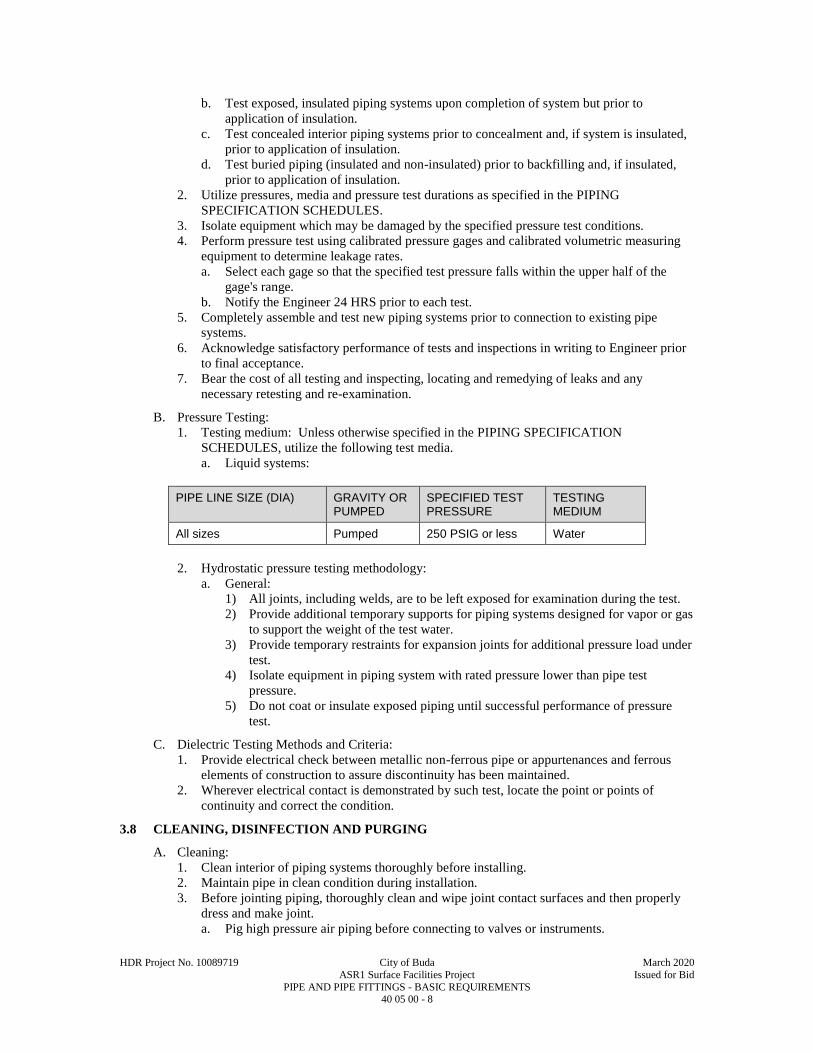
HDR Project No. 10089719 City of Buda March 2020
ASR1 Surface Facilities Project Issued for Bid
PIPE AND PIPE FITTINGS - BASIC REQUIREMENTS 40 05 00 - 8
b. Test exposed, insulated piping systems upon completion of system but prior to
application of insulation.
c. Test concealed interior piping systems prior to concealment and, if system is insulated,
prior to application of insulation.
d. Test buried piping (insulated and non-insulated) prior to backfilling and, if insulated,
prior to application of insulation.
2. Utilize pressures, media and pressure test durations as specified in the PIPING
SPECIFICATION SCHEDULES.
3. Isolate equipment which may be damaged by the specified pressure test conditions.
4. Perform pressure test using calibrated pressure gages and calibrated volumetric measuring
equipment to determine leakage rates.
a. Select each gage so that the specified test pressure falls within the upper half of the
gage's range.
b. Notify the Engineer 24 HRS prior to each test.
5. Completely assemble and test new piping systems prior to connection to existing pipe
systems.
6. Acknowledge satisfactory performance of tests and inspections in writing to Engineer prior
to final acceptance.
7. Bear the cost of all testing and inspecting, locating and remedying of leaks and any
necessary retesting and re-examination.
B. Pressure Testing:
1. Testing medium: Unless otherwise specified in the PIPING SPECIFICATION
SCHEDULES, utilize the following test media.
a. Liquid systems:
PIPE LINE SIZE (DIA) GRAVITY OR PUMPED
SPECIFIED TEST PRESSURE
TESTING MEDIUM
All sizes Pumped 250 PSIG or less Water
2. Hydrostatic pressure testing methodology:
a. General:
1) All joints, including welds, are to be left exposed for examination during the test.
2) Provide additional temporary supports for piping systems designed for vapor or gas
to support the weight of the test water.
3) Provide temporary restraints for expansion joints for additional pressure load under
test.
4) Isolate equipment in piping system with rated pressure lower than pipe test
pressure.
5) Do not coat or insulate exposed piping until successful performance of pressure
test.
C. Dielectric Testing Methods and Criteria:
1. Provide electrical check between metallic non-ferrous pipe or appurtenances and ferrous
elements of construction to assure discontinuity has been maintained.
2. Wherever electrical contact is demonstrated by such test, locate the point or points of
continuity and correct the condition.
3.8 CLEANING, DISINFECTION AND PURGING
A. Cleaning:
1. Clean interior of piping systems thoroughly before installing.
2. Maintain pipe in clean condition during installation.
3. Before jointing piping, thoroughly clean and wipe joint contact surfaces and then properly
dress and make joint.
a. Pig high pressure air piping before connecting to valves or instruments.
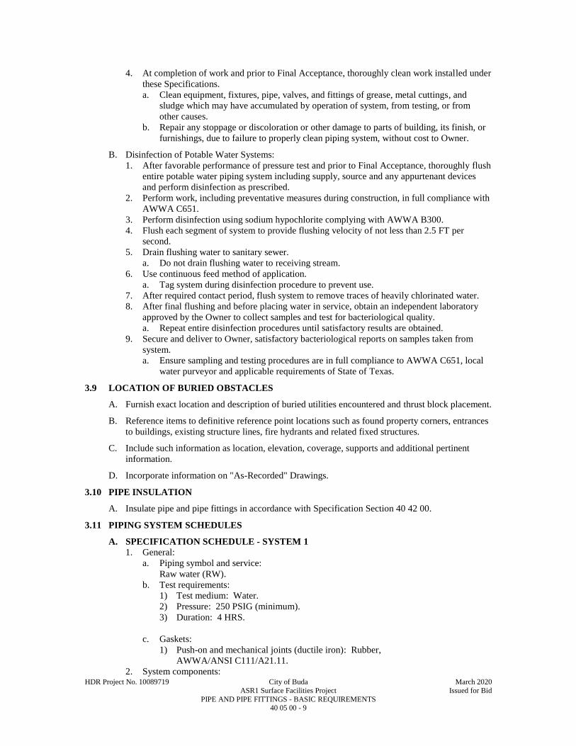
HDR Project No. 10089719 City of Buda March 2020
ASR1 Surface Facilities Project Issued for Bid
PIPE AND PIPE FITTINGS - BASIC REQUIREMENTS 40 05 00 - 9
4. At completion of work and prior to Final Acceptance, thoroughly clean work installed under
these Specifications.
a. Clean equipment, fixtures, pipe, valves, and fittings of grease, metal cuttings, and
sludge which may have accumulated by operation of system, from testing, or from
other causes.
b. Repair any stoppage or discoloration or other damage to parts of building, its finish, or
furnishings, due to failure to properly clean piping system, without cost to Owner.
B. Disinfection of Potable Water Systems:
1. After favorable performance of pressure test and prior to Final Acceptance, thoroughly flush
entire potable water piping system including supply, source and any appurtenant devices
and perform disinfection as prescribed.
2. Perform work, including preventative measures during construction, in full compliance with
AWWA C651.
3. Perform disinfection using sodium hypochlorite complying with AWWA B300.
4. Flush each segment of system to provide flushing velocity of not less than 2.5 FT per
second.
5. Drain flushing water to sanitary sewer.
a. Do not drain flushing water to receiving stream.
6. Use continuous feed method of application.
a. Tag system during disinfection procedure to prevent use.
7. After required contact period, flush system to remove traces of heavily chlorinated water.
8. After final flushing and before placing water in service, obtain an independent laboratory
approved by the Owner to collect samples and test for bacteriological quality.
a. Repeat entire disinfection procedures until satisfactory results are obtained.
9. Secure and deliver to Owner, satisfactory bacteriological reports on samples taken from
system.
a. Ensure sampling and testing procedures are in full compliance to AWWA C651, local
water purveyor and applicable requirements of State of Texas.
3.9 LOCATION OF BURIED OBSTACLES
A. Furnish exact location and description of buried utilities encountered and thrust block placement.
B. Reference items to definitive reference point locations such as found property corners, entrances
to buildings, existing structure lines, fire hydrants and related fixed structures.
C. Include such information as location, elevation, coverage, supports and additional pertinent
information.
D. Incorporate information on "As-Recorded" Drawings.
3.10 PIPE INSULATION
A. Insulate pipe and pipe fittings in accordance with Specification Section 40 42 00.
3.11 PIPING SYSTEM SCHEDULES
A. SPECIFICATION SCHEDULE - SYSTEM 1
1. General:
a. Piping symbol and service:
Raw water (RW).
b. Test requirements:
1) Test medium: Water.
2) Pressure: 250 PSIG (minimum).
3) Duration: 4 HRS.
c. Gaskets:
1) Push-on and mechanical joints (ductile iron): Rubber,
AWWA/ANSI C111/A21.11.
2. System components:

HDR Project No. 10089719 City of Buda March 2020
ASR1 Surface Facilities Project Issued for Bid
PIPE AND PIPE FITTINGS - BASIC REQUIREMENTS 40 05 00 - 10
a. Pipe size 3 IN through 12 IN:
1) Buried service:
a) Materials: Ductile iron, Class 250 PSIG (minimum).
b) Reference: AWWA/ANSI C151/A21.51.
c) Lining: Cement.
d) Coating: Bituminous.
e) Fittings:
(1) Either AWWA/ANSI C110/A21.10 ductile or gray iron.
(2) Optional: AWWA/ANSI C153/A21.53 ductile iron compact fittings for
sizes 3 IN to 16 IN.
f) Joints: Push-on joints with mechanical (stuffing box type) joints at fittings and
valves.
g) All buried, pipe, fittings, and components shall be wrapped in polyethylene
encasement.
2) Exposed service:
a) Material:
(1) Flanged: Ductile iron, Class 250 PSIG (minimum).
(2) Grooved type joint system: Use pipe thickness per AWWA C606.
b) Reference: AWWA/ANSI C115/A21.15.
c) Lining: Cement.
d) Coating: HPIC; See Specification Section 09 96 00.
e) Fittings: Either AWWA/ANSI C110/A21.10 ductile or gray iron.
f) Joints: AWWA/ANSI C115/A21.15 flanged joints with flanges at valves and
structure penetrations.
B. SPECIFICATION SCHEDULE - SYSTEM 2
1. General:
a. Piping symbol and service:
1) Pre-lube water (PLW)
b. Test requirements:
1) Test medium: Water.
2) Pressure: 100 PSIG (minimum).
3) Duration: 4 HRS.
c. Gaskets: Rubber, ASTM C564.
2. System components:
a. Pipe size 1 IN to 1-1/2 IN:
1) Exposed service.
a) Material: Galvanized steel, Schedule 40.
b) Reference: ASTM A53.
c) Lining: Galvanized.
d) Coating: HPIC; See Specification Section 09 96 00.
e) Fittings: Cast iron drainage.
(1) ASTM A126, Class B.
f) Joints: Threaded.
3.12 SERVICE SYSTEM SUMMARY
A. Service Systems as defined in the Drawings.
END OF SECTION

HDR Project No. 10089719 City of Buda March 2020
ASR1 Surface Facilities Project Issued for Bid
PIPE SUPPORT SYSTEMS 40 05 07 - 1
SECTION 40 05 07
PIPE SUPPORT SYSTEMS
PART 1 - GENERAL
1.1 SUMMARY
A. Section Includes:
1. Pipe support and anchor systems.
2. Design of Pipe Support Systems as specified.
B. Related Specification Sections include but are not necessarily limited to:
1. Division 00 - Procurement and Contracting Requirements.
2. Division 01 - General Requirements.
3. Section 03 15 19 - Anchorage to Concrete.
4. Section 05 50 00 - Metal Fabrications.
5. Section 09 96 00 - High Performance Industrial Coatings.
6. Section 40 42 00 - Pipe, Duct and Equipment Insulation.
1.2 QUALITY ASSURANCE
A. Referenced Standards:
1. American Society of Mechanical Engineers (ASME):
a. B31.1, Power Piping.
b. B31.3, Process Piping.
2. ANVIL International (ANVIL).
3. ASTM International (ASTM):
a. A36, Standard Specification for Carbon Structural Steel.
b. A276, Standard Specification for Stainless Steel Bars and Shapes.
c. A575, Standard Specification for Steel Bars, Carbon, Merchant Quality, M-Grades.
d. A576, Standard Specification for Steel Bars, Carbon, Hot-Wrought, Special Quality.
e. A917, Standard Specification for Steel Sheet, Coated by the Electrolytic Process for
Applications Requiring Designation of the Coating Mass on Each Surface (General
Requirements).
f. A918, Standard Specification for Steel Sheet, Zinc-Nickel Alloy Coated by the
Electrolytic Process for Applications Requiring Designation of the Coating Mass on
Each Surface.
g. B633, Standard Specification for Electrodeposited Coatings of Zinc on Iron and Steel.
4. American Welding Society (AWS):
a. D1.1, Structural Welding Code - Steel.
b. D1.6, Structural Welding Code - Stainless Steel.
5. Manufacturers Standardization Society of the Valve and Fittings Industry Inc. (MSS):
a. SP-58, Pipe Hangers and Supports - Materials, Design and Manufacture.
b. SP-69, Pipe Hangers and Supports - Selection and Application.
B. Responsibility:
1. Support systems for piping greater than 12 IN DIA, or with internal pressure over 100 PSI,
or piping with product temperatures over 200 DEGF, are shown on the Drawings and are
not to be designed by Contractor unless indicated in Contract Documents.
2. Design complete support systems for piping 12 IN and smaller where supports are not
shown on the Drawings.
3. Provide all labor, materials, equipment and incidentals as shown, specified and required to
design, furnish and install the system of hangers, supports, guidance, anchorage and
appurtenances.
4. General piping support details may be indicated on the Drawings in certain locations for
pipe 12 IN DIA and smaller.

HDR Project No. 10089719 City of Buda March 2020
ASR1 Surface Facilities Project Issued for Bid
PIPE SUPPORT SYSTEMS 40 05 07 - 2
5. Incorporate those details with requirements of this Specification Section to provide the
piping support system.
C. Each type of pipe hanger or support shall be the product of one manufacturer.
D. Qualifications:
1. Pipe support designer:
a. Licensed Professional Engineer registered in the state the project is located in.
b. Minimum of five years experience designing pipe supports for projects of similar size
and complexity.
1.3 SUBMITTALS
A. Shop Drawings:
1. See Specification Section 01 33 00 for requirements for the mechanics and administration of
the submittal process.
2. Product technical data including:
a. Acknowledgement that products submitted meet requirements of standards referenced.
b. Manufacturer's installation instructions.
c. Itemized list of wall sleeves, anchors, support devices and all other items related to pipe
support system.
d. Scaled drawings showing location, installation, material, loads and forces, and
deflection of all hangers and supports.
e. Analyze each pipe system for all loads and forces on hangers and supports and their
reaction forces to the structure to which they are fastened.
f. Where Contract Documents indicate contractor is to design pipe support systems,
submit detail design calculations and scaled drawings signed by Pipe support designer..
3. Certifications.
a. Pipe support designer qualifications
PART 2 - PRODUCTS
2.1 MANUFACTURERS
A. Subject to compliance with the Contract Documents, the manufacturers listed in the applicable
Articles below are acceptable.
2.2 MANUFACTURED UNITS
A. General:
1. Galvanized components:
a. Electro-galvanized components:
1) Bar, forged or cast fabrications: ASTM B633, SC4.
2) Rolled sheet fabrications: ASTM A917 and ASTM A918, 50N50NU.
b. Hot-dipped galvanized components: See Specification Section 05 50 00.
2. Dissimilar metals protection:
a. Galvanized-to-galvanized and galvanized-to-aluminum: No protection required.
b. All other galvanized-to-dissimilar metal connections: Neoprene or nylon pads, shims,
grommets, etc.
B. Hanger Rods:
1. Material:
a. ASTM A36.
b. ASTM A575, Grade M1020.
c. ASTM A576, Grade 1020.
d. Minimum allowable tensile stress of 12,000 PSI at 650 DEGF per MSS SP-58.
2. Continuously threaded.
3. Electro-galvanized or cadmium plated after threads are cut.
4. Load limit:

HDR Project No. 10089719 City of Buda March 2020
ASR1 Surface Facilities Project Issued for Bid
PIPE SUPPORT SYSTEMS 40 05 07 - 3
NOMINAL ROD DIAMETER MAXIMUM SAFE LOAD, (LBS)
3/8 IN DIA (min) 610
1/2 IN DIA 1,130
5/8 IN DIA 1,810
3/4 IN DIA 2,710
7/8 IN DIA 3,770
1 IN DIA 4,960
C. Hangers:
1. Hangers for use directly on copper pipe: Copper or cadmium plated.
2. Hangers for use other than directly on copper pipe: Cadmium plated or galvanized.
3. Hanger type schedule:
APPLICATION PIPE SIZE HANGER TYPE
All except noted 4 IN and less ANVIL Figure 108 with Figure 114
All except noted Over 4 IN ANVIL Figure 590
Steam, condensate and hot water All ANVIL Figure 181, Figure 82
Service in chemical storage areas and as indicated on drawings for corrosion resistance
All CorPro CP - Hanger or equal
D. Pipe Support Saddle:
1. For pipe located 3 FT or less from floor elevation, except as otherwise indicated on
Drawings.
2. ANVIL Figure 264.
E. Pipe Support Risers:
1. Schedule 40 pipe.
2. Galvanized.
3. Size: As recommended by saddle manufacturer.
F. Pipe Support Base Plate:
1. 4 IN larger than support.
2. Collar 3/16 IN thickness, circular in shape, and sleeve type connection to pipe.
3. Collar fitted over outside of support pipe and extended 2 IN from floor plate.
4. Collar welded to floor plate.
5. Edges ground smooth.
6. Assembly hot-dipped galvanized after fabrication.
G. Pipe Covering Protection Saddle:
1. For insulated pipe at point of support.
2. ANVIL Figure 167, Type B.
H. Wall Brackets:
1. For pipe located near walls and 8 FT or more above floor elevation or as otherwise indicated
on the Drawings.
2. ANVIL Figure 199.
I. Pipe Anchors:
1. For locations shown on the Drawings.
2. 1/4 IN steel plate construction.
3. Hot-dipped galvanized after fabrication.

HDR Project No. 10089719 City of Buda March 2020
ASR1 Surface Facilities Project Issued for Bid
PIPE SUPPORT SYSTEMS 40 05 07 - 4
4. Designed to prevent movement of pipe at point of attachment.
J. Pipe Guides:
1. For locations on both sides on each expansion joint or loop.
2. To ensure proper alignment of expanding or contracting pipe.
3. ANVIL Figure 256.
2.3 DESIGN REQUIREMENTS
A. Supports capable of supporting the pipe for all service and testing conditions.
1. Provide to 1 safety factor.
B. Allow free expansion and contraction of the piping to prevent excessive stress resulting from
service and testing conditions or from weight transferred from the piping or attached equipment.
C. Design supports and hangers to allow for proper pitch of pipes.
D. For chemical and waste piping, design, materials of construction and installation of pipe hangers,
supports, guides, restraints, and anchors:
1. ASME B31.3.
2. MSS SP-58 and MSS SP-69.
3. Except where modified by this Specification.
E. For steam and hot and cold water piping, design, materials of construction and installation of
pipe hangers, supports, guides, restraints, and anchors:
1. ASME B31.1.
2. MSS SP-58 and MSS SP-69.
F. Check all physical clearances between piping, support system and structure.
1. Provide for vertical adjustment after erection.
G. Support vertical pipe runs in pipe chases at base of riser.
1. Support pipes for lateral movement with clamps or brackets.
H. Place hangers are to be installed on outside of pipe insulation.
1. Use a pipe covering protection saddle for insulated pipe at support point.
2. Insulated piping 1-1/2 IN and less:
a. Provide a 9 IN length of high density perlite or high density calcium silicate at saddle.
b. See Specification Section 40 42 00.
3. Insulated piping over 1-1/2 IN: Provide a 12 IN length of high density perlite or high
density calcium silicate at saddle.
I. Provide 20 GA galvanized steel pipe saddle for fiberglass and plastic support points to ensure
minimum contact width of 4 IN.
J. Pipe Support Spacing:
1. General:
a. Factor loads by specific weight of liquid conveyed if specific weight is greater than
water.
b. Locate pipe supports at maximum spacing scheduled unless indicated otherwise on the
Drawings.
c. Provide at least one support for each length of pipe at each change of direction and at
each valve.
2. Steel, stainless steel, cast-iron pipe support schedule:
PIPE SIZES - IN MAXIMUM SPAN - FT
1-1/2 and less 5
2 thru 4 10
5 thru 8 15

HDR Project No. 10089719 City of Buda March 2020
ASR1 Surface Facilities Project Issued for Bid
PIPE SUPPORT SYSTEMS 40 05 07 - 5
PIPE SIZES - IN MAXIMUM SPAN - FT
10 and greater 20
3. Copper pipe support schedule:
PIPE SIZES - IN MAXIMUM SPAN - FT
2-1/2 and less 5
3 thru 6 10
8 and greater 15
4. PVC pipe support schedule:
PIPE SIZES - IN MAXIMUM SPAN - FT
1-1/4 and less 3
1-1/2 thru 3 4
4 and greater 5
* Maximum fluid temperature of 120 DEGF.
5. Support each length and every fitting:
a. Bell and spigot piping:
1) At least one hanger.
2) Applied at bell.
b. Mechanical coupling joints:
1) Place hanger within 2 FT of each side of fittings to keep pipes in alignment.
6. Space supports for soil and waste pipe and other piping systems not included above every
5 FT.
7. Provide continuous support for nylon tubing.
8. For PVC, FRP and copper piping:
a. Provide Unistrut Unicushion wrap of pipe at each support.
PART 3 - EXECUTION
3.1 INSTALLATION
A. Provide piping systems exhibiting pulsation, vibration, swaying, or impact with suitable
constraints to correct the condition.
1. Included in this requirement are movements from:
a. Trap discharge.
b. Water hammer.
c. Similar internal forces.
B. Weld Supports:
1. AWS D1.1.
2. Weld anchors to pipe in accordance with ASME B31.3.
3. AWS D1.6 for stainless steel supports.
C. Locate piping and pipe supports as to not interfere with open accesses, walkways, platforms, and
with maintenance or disassembly of equipment.
D. Inspect hangers for:
1. Design offset.
2. Adequacy of clearance for piping and supports in the hot and cold positions.
3. Guides to permit movement without binding.

HDR Project No. 10089719 City of Buda March 2020
ASR1 Surface Facilities Project Issued for Bid
PIPE SUPPORT SYSTEMS 40 05 07 - 6
4. Adequacy of anchors.
E. Inspect hangers after erection of piping systems and prior to pipe testing and flushing.
F. Anchorage to Concrete- reference Section 03 15 19.
G. Install individual or continuous slot concrete inserts for use with hangers for piping and
equipment.
1. Install concrete inserts as concrete forms are installed.
H. Welding:
1. Welding rods: ASTM and AWS standards.
2. Integral attachments:
a. Include welded-on ears, shoes, plates and angle clips.
b. Ensure material for integral attachments is of good weldable quality.
3. Preheating, welding and postheat treating: ASME B31.3, Chapter V.
I. Field Painting:
1. Comply with Specification Section 09 96 00.
END OF SECTION
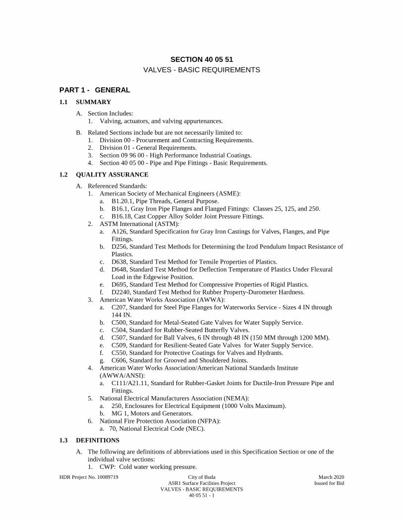
HDR Project No. 10089719 City of Buda March 2020
ASR1 Surface Facilities Project Issued for Bid
VALVES - BASIC REQUIREMENTS 40 05 51 - 1
SECTION 40 05 51
VALVES - BASIC REQUIREMENTS
PART 1 - GENERAL
1.1 SUMMARY
A. Section Includes:
1. Valving, actuators, and valving appurtenances.
B. Related Sections include but are not necessarily limited to:
1. Division 00 - Procurement and Contracting Requirements.
2. Division 01 - General Requirements.
3. Section 09 96 00 - High Performance Industrial Coatings.
4. Section 40 05 00 - Pipe and Pipe Fittings - Basic Requirements.
1.2 QUALITY ASSURANCE
A. Referenced Standards:
1. American Society of Mechanical Engineers (ASME):
a. B1.20.1, Pipe Threads, General Purpose.
b. B16.1, Gray Iron Pipe Flanges and Flanged Fittings: Classes 25, 125, and 250.
c. B16.18, Cast Copper Alloy Solder Joint Pressure Fittings.
2. ASTM International (ASTM):
a. A126, Standard Specification for Gray Iron Castings for Valves, Flanges, and Pipe
Fittings.
b. D256, Standard Test Methods for Determining the Izod Pendulum Impact Resistance of
Plastics.
c. D638, Standard Test Method for Tensile Properties of Plastics.
d. D648, Standard Test Method for Deflection Temperature of Plastics Under Flexural
Load in the Edgewise Position.
e. D695, Standard Test Method for Compressive Properties of Rigid Plastics.
f. D2240, Standard Test Method for Rubber Property-Durometer Hardness.
3. American Water Works Association (AWWA):
a. C207, Standard for Steel Pipe Flanges for Waterworks Service - Sizes 4 IN through
144 IN.
b. C500, Standard for Metal-Seated Gate Valves for Water Supply Service.
c. C504, Standard for Rubber-Seated Butterfly Valves.
d. C507, Standard for Ball Valves, 6 IN through 48 IN (150 MM through 1200 MM).
e. C509, Standard for Resilient-Seated Gate Valves for Water Supply Service.
f. C550, Standard for Protective Coatings for Valves and Hydrants.
g. C606, Standard for Grooved and Shouldered Joints.
4. American Water Works Association/American National Standards Institute
(AWWA/ANSI):
a. C111/A21.11, Standard for Rubber-Gasket Joints for Ductile-Iron Pressure Pipe and
Fittings.
5. National Electrical Manufacturers Association (NEMA):
a. 250, Enclosures for Electrical Equipment (1000 Volts Maximum).
b. MG 1, Motors and Generators.
6. National Fire Protection Association (NFPA):
a. 70, National Electrical Code (NEC).
1.3 DEFINITIONS
A. The following are definitions of abbreviations used in this Specification Section or one of the
individual valve sections:
1. CWP: Cold water working pressure.

HDR Project No. 10089719 City of Buda March 2020
ASR1 Surface Facilities Project Issued for Bid
VALVES - BASIC REQUIREMENTS 40 05 51 - 2
2. SWP: Steam working pressure.
3. WOG: Water, oil, gas working pressure.
4. WWP: Water working pressure.
1.4 SUBMITTALS
A. Shop Drawings:
1. See Section 01 33 00 for requirements for the mechanics and administration of the submittal
process.
2. Product technical data including:
a. Acknowledgement that products submitted meet requirements of standards referenced.
b. Manufacturer's installation instructions.
c. Valve pressure and temperature rating.
d. Valve material of construction.
e. Special linings.
f. Valve dimensions and weight.
g. Valve flow coefficient.
h. Wiring and control diagrams for electric or cylinder actuators.
i. Short Circuit Current Rating (SCCR) nameplate marking per NFPA 70.
3. Test reports.
B. Contract Closeout Information:
1. Operation and Maintenance Data:
C. Informational Submittals:
1. Verification from valve actuator manufacturer that actuators have been installed properly,
that all limit switches and position potentiometers have been properly adjusted, and that the
valve actuator responds correctly to the valve position command.
PART 2 - PRODUCTS
2.1 MANUFACTURERS
A. Subject to compliance with the Contract Documents, refer to individual valve Specification
Sections for acceptable manufacturers.
2.2 MATERIALS
A. Refer to individual valve Specification Sections.
2.3 VALVE ACTUATORS
A. Valve Actuators - General:
1. Provide actuators as shown on Drawings or specified.
2. Counter clockwise opening as viewed from the top.
3. Direction of opening and the word OPEN to be cast in handwheel or valve bonnet.
4. Size actuator to produce required torque with a maximum pull of 80 LB at the maximum
pressure rating of the valve provided and withstand without damage a pull of 200 LB on
handwheel or chainwheel or 300 FT-pounds torque on the operating nut.
5. Unless otherwise specified, actuators for valves to be buried, submerged or installed in
vaults or manholes shall be sealed to withstand at least 20 FT of submergence.
6. Extension stem:
a. Install where shown or specified.
b. Solid steel with actuator key and nut, diameter not less than stem of valve actuator
shaft.
c. Pin all stem connections.
d. Center in valve box or grating opening band with guide bushing.
B. Buried Valve Actuators:

HDR Project No. 10089719 City of Buda March 2020
ASR1 Surface Facilities Project Issued for Bid
VALVES - BASIC REQUIREMENTS 40 05 51 - 3
1. Provide screw or slide type adjustable cast iron valve box, 5 IN minimum diameter, 3/16 IN
minimum thickness, and identifying cast iron cover rated for traffic load.
2. Box base to enclose buried valve gear box or bonnet.
3. Provide 2 IN standard actuator nuts complying with AWWA C500, Section 3.16.
4. Provide at least two tee handle keys for actuator nuts, with 5 FT extension between key and
handle.
5. Extension stem:
a. Provide for buried valves greater than 4 FT below finish grade.
b. Extend to within 6 IN of finish grade.
6. Provide concrete pad encasement of valve box as shown for all buried valves unless shown
otherwise.
C. Exposed Valve Manual Actuators:
1. Provide for all exposed valves not having electric or cylinder actuators.
2. Provide handwheels for gate and globe valves.
a. Size handwheels for valves in accordance with AWWA C500.
3. Provide lever actuators for plug valves, butterfly valves and ball valves 3 IN DIA and
smaller.
a. Lever actuators for butterfly valves shall have a minimum of five intermediate lock
positions between full open and full close.
b. Provide at least two levers for each type and size of valve furnished.
4. Gear actuators required for plug valves, butterfly valves, and ball valves 4 IN DIA and
larger.
5. Provide gearing for gate valves 20 IN and larger in accordance with AWWA C500.
6. Gear actuators to be totally enclosed, permanently lubricated and with sealed bearings.
7. Provide chain actuators for valves 6 FT or higher from finish floor to valve centerline.
a. Cadmium-plated chain looped to within 3 FT of finish floor.
b. Equip chain wheels with chain guides to permit rapid operation with reasonable side
pull without "gagging" the wheel.
c. For smaller valves with lever or handle operators, provide offset tee handles with
attached chain for operation from the operating floor.
8. Provide cast iron floor stands where shown on Drawings.
a. Stands to be furnished by valve manufacturer with actuator.
b. Stands or actuator to include thrust bearings for valve operation and weight of
accessories.
2.4 FABRICATION
A. End Connections:
1. Provide the type of end connections for valves as required in the Piping Schedules presented
in Section 40 05 00 or as shown on the Drawings.
2. Comply with the following standards:
a. Threaded: ASME B1.20.1.
b. Flanged: ASME B16.1, Class 125 unless otherwise noted or AWWA C207.
c. Bell and spigot or mechanical (gland) type: AWWA/ANSI C111/A21.11.
d. Soldered: ASME B16.18.
e. Grooved: Rigid joints per Table 5 of AWWA C606.
B. Refer to individual valve Specification Sections for specifications of each type of valve used on
Project.
C. Nuts, Bolts, and Washers:
1. Wetted or internal to be bronze or stainless steel.
a. Exposed to be zinc or cadmium plated.
D. On Insulated Piping: Provide valves with extended stems to permit proper insulation application
without interference from handle.

HDR Project No. 10089719 City of Buda March 2020
ASR1 Surface Facilities Project Issued for Bid
VALVES - BASIC REQUIREMENTS 40 05 51 - 4
E. Epoxy Interior Coating: Provide epoxy interior coating for all ferrous surfaces in accordance
with AWWA C550.
PART 3 - EXECUTION
3.1 INSTALLATION
A. Install products in accordance with manufacturer's instructions.
B. Painting Requirements: Comply with Section 09 96 00 for High Performance Industrial
Coatings.
C. Setting Buried Valves:
1. Locate valves installed in pipe trenches where buried pipe indicated on Drawings.
2. Set valves and valve boxes plumb.
3. Place valve boxes directly over valves with top of box being brought to surface of finished
grade.
4. Install in closed position.
5. Place valve on firm footing in trench to prevent settling and excessive strain on connection
to pipe.
6. After installation, backfill up to top of box for a minimum distance of 4 FT on each side of
box.
D. Support exposed valves and piping adjacent to valves independently to eliminate pipe loads
being transferred to valve and valve loads being transferred to the piping.
E. Install electric or cylinder actuators above or horizontally adjacent to valve and gear box to
optimize access to controls and external handwheel.
F. For threaded valves, provide union on one side within 2 FT of valve to allow valve removal.
G. Install valves accessible for operation, inspection, and maintenance.
3.2 ADJUSTMENT
A. Adjust valves, actuators and appurtenant equipment to comply with Section 01 75 00.
1. Operate valve, open and close at system pressures.
END OF SECTION
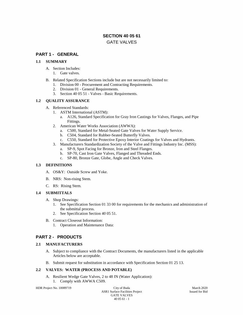
HDR Project No. 10089719 City of Buda March 2020
ASR1 Surface Facilities Project Issued for Bid
GATE VALVES 40 05 61 - 1
SECTION 40 05 61
GATE VALVES
PART 1 - GENERAL
1.1 SUMMARY
A. Section Includes:
1. Gate valves.
B. Related Specification Sections include but are not necessarily limited to:
1. Division 00 - Procurement and Contracting Requirements.
2. Division 01 - General Requirements.
3. Section 40 05 51 - Valves - Basic Requirements.
1.2 QUALITY ASSURANCE
A. Referenced Standards:
1. ASTM International (ASTM):
a. A126, Standard Specification for Gray Iron Castings for Valves, Flanges, and Pipe
Fittings.
2. American Water Works Association (AWWA):
a. C500, Standard for Metal-Seated Gate Valves for Water Supply Service.
b. C504, Standard for Rubber-Seated Butterfly Valves.
c. C550, Standard for Protective Epoxy Interior Coatings for Valves and Hydrants.
3. Manufacturers Standardization Society of the Valve and Fittings Industry Inc. (MSS):
a. SP-9, Spot Facing for Bronze, Iron and Steel Flanges.
b. SP-70, Cast Iron Gate Valves, Flanged and Threaded Ends.
c. SP-80, Bronze Gate, Globe, Angle and Check Valves.
1.3 DEFINITIONS
A. OS&Y: Outside Screw and Yoke.
B. NRS: Non-rising Stem.
C. RS: Rising Stem.
1.4 SUBMITTALS
A. Shop Drawings:
1. See Specification Section 01 33 00 for requirements for the mechanics and administration of
the submittal process.
2. See Specification Section 40 05 51.
B. Contract Closeout Information:
1. Operation and Maintenance Data:
PART 2 - PRODUCTS
2.1 MANUFACTURERS
A. Subject to compliance with the Contract Documents, the manufacturers listed in the applicable
Articles below are acceptable.
B. Submit request for substitution in accordance with Specification Section 01 25 13.
2.2 VALVES: WATER (PROCESS AND POTABLE)
A. Resilient Wedge Gate Valves, 2 to 48 IN (Water Application):
1. Comply with AWWA C509.
HDR Project No. 10089719 City of Buda March 2020
ASR1 Surface Facilities Project Issued for Bid
GATE VALVES 40 05 61 - 2
2. Materials:
a. Stem and stem nut: Bronze.
1) Wetted bronze parts in low zinc bronze.
2) Aluminum bronze components: Heat treated per AWWA C504.
b. Body, gate: Cast iron or Ductile iron.
c. Resilient wedge: Fully encapsulated rubber wedge. Styrene Butadiene Rubber (SBR).
3. Design requirements:
a. Minimum 200 PSIG working pressure.
b. Buried: NRS, O-ring stem seal, 2 IN square operating nut.
c. Exposed: NRS, O-ring, stem seal.
d. Counter clockwise open rotation.
e. Fusion bonded epoxy coating interior and exterior except stainless steel and bearing
surfaces.
1) Comply with AWWA C550.
2) Wetted bronze parts in low zinc bronze.
3) Aluminum bronze components: Heat treated per AWWA C504.
4. Acceptable manufacturers:
a. Clow.
b. Mueller.
c. American Flow Control.
d. M & H.
2.3 ACCESSORIES
A. Refer to Drawings and valve schedule for type of actuators.
1. Furnish actuator integral with valve.
B. Refer to Specification Section 40 05 51 for actuator requirements.
2.4 FABRICATION
A. General:
1. Provide valves with clear waterways the full diameter of the valve.
PART 3 - EXECUTION
3.1 INSTALLATION
A. See Specification Section 40 05 51.
B. Where larger buried valves utilize smaller bypass valves, provide a second valve box installed
over the bypass valve operating nut.
C. Do not install gate valves inverted or with the stems sloped more than 45 DEG from the upright
unless the valve was ordered and manufactured specifically for this orientation.
END OF SECTION

HDR Project No. 10089719 City of Buda March 2020
ASR1 Surface Facilities Project Issued for Bid
BALL VALVES 40 05 63 - 1
SECTION 40 05 63
BALL VALVES
PART 1 - GENERAL
1.1 SUMMARY
A. Section Includes:
1. Ball valves.
B. Related Specification Sections include but are not necessarily limited to:
1. Division 00 - Procurement and Contracting Requirements.
2. Division 01 - General Requirements.
3. Section 40 05 51 - Valves - Basic Requirements.
1.2 QUALITY ASSURANCE
A. Referenced Standards:
1. ASTM International (ASTM):
a. A48, Standard Specification for Gray Iron Castings.
b. A126, Standard Specification for Gray Iron Castings for Valves, Flanges, and Pipe
Fittings.
c. A276, Standard Specification for Stainless Steel Bars and Shapes.
d. A351, Standard Specification for Castings, Austenitic, for Pressure-Containing Parts.
2. American Water Works Association (AWWA):
a. C507, Standard for Ball Valves, 6 IN through 48 IN.
3. Manufacturers Standardization Society of the Valve and Fittings Industry Inc. (MSS):
a. SP-110, Ball Valves; Threaded, Socket-Welding, Solder Joint, Grooved and Flared
Ends.
1.3 DEFINITIONS
A. PVDF: Polyvinylidene fluoride.
B. PTFE: Polytetrafluoroethylene.
C. RPTFE: Reinforced PolyTetraFluoroEthylene.
1.4 SUBMITTALS
A. Shop Drawings:
1. See Specification Section 01 33 00 for requirements for the mechanics and administration of
the submittal process.
2. See Specification Section 40 05 51.
3. Test results for AWWA valves.
B. Contract Closeout Information:
1. Operation and Maintenance Data:
PART 2 - PRODUCTS
2.1 MANUFACTURERS
A. Subject to compliance with the Contract Documents, the manufacturers listed in the applicable
Articles below are acceptable.
B. Submit request for substitution in accordance with Specification Section 01 25 13.
2.2 V-PORT BALL VALVES
A. Manufacturers:

HDR Project No. 10089719 City of Buda March 2020
ASR1 Surface Facilities Project Issued for Bid
BALL VALVES 40 05 63 - 2
1. DeZurik.
2. Emerson.
B. Materials:
1. Body: Carbon Steel, ASTM A 216, Grade WCB.
2. Ball: 317 stainless steel.
3. Shaft: 2205 Duplex stainless steel.
4. Bearing: 317 stainless steel wire mesh reinforced PTFE.
5. Ball seat: Rigid 317 stainless steel with heat treated nickel overlay.
C. Design Requirements:
1. Design pressure: 150 PSI.
2. Flanges: Class 150.
3. Ball shall provide one direction seal or closure.
2.3 METALLIC BALL VALVES 1/4 TO 3 IN DIA
A. Comply with MSS SP-110.
B. Manufacturers:
1. Apollo.
2. Jamesbury.
3. Watts.
4. Stockham.
5. Nibco.
C. Materials (All Stainless Steel):
1. Body: Three-part stainless steel, ASTM A351 CF8M.
2. Ball: Stainless steel ASTM A276.
3. Seats: RPTFE.
D. Design Requirements:
1. Rated for a minimum of:
a. 500 PSI CWP.
b. 150 PSI of saturated steam.
c. 29 IN vacuum.
2. Two-position lockable handle.
3. Stem with blowout-proof design.
4. Balancing stop for all applications.
5. Bodies with mounting pad for applications requiring actuators.
2.4 AWWA C507 BALL VALVES: 6 IN TO 48 IN DIA
A. Comply with AWWA C507.
B. Manufacturers:
1. Pratt.
C. Materials:
1. Body:
a. Cast iron ASTM A126, Class B.
2. Ball:
a. Cast iron ASTM A48, Class 40
3. Shaft:
a. Stainless steel 18-8 Type 304.
4. Bearings, sleeve type, non-metallic:
a. Teflon lined.
5. Ball seat: Stainless steel Type 304.
6. Body seat:
a. Buna-N.
D. Design Requirements:

HDR Project No. 10089719 City of Buda March 2020
ASR1 Surface Facilities Project Issued for Bid
BALL VALVES 40 05 63 - 3
1. Design pressure: 150.
2. Ball shall provide one direction seal or closure.
3. Ball and body seats: Field adjustable and replaceable.
2.5 ACCESSORIES
A. Refer to Drawings and valve schedule for type of actuators.
1. Furnish actuator integral with valve.
B. Refer to Specification Section 40 05 51 for actuator requirements.
2.6 SOURCE QUALITY CONTROL
A. Shop test AWWA C507 ball valves in accordance with AWWA C507.
B. Furnish record of test.
C. Product Testing: MSS SP-110.
PART 3 - EXECUTION
3.1 INSTALLATION
A. See Specification Section 40 05 51.
3.2 FIELD QUALITY CONTROL
A. For AWWA C507 ball valves and in accordance with Specification Section 01 75 00, employ
and pay for services of equipment manufacturer's field service representative(s) to:
1. Inspect equipment covered by this Specification Section.
2. Supervise adjustments and installation checks.
3. Provide test equipment, tools, and instruments necessary to accomplish equipment testing.
4. Conduct startup of equipment and perform operational checks.
5. Provide Owner with a written statement that manufacturer's equipment has been installed
properly, has been started up, and is ready for operation by Owner's personnel.
END OF SECTION

This page intentionally left blank.

HDR Project No. 10089719 City of Buda March 2020
ASR1 Surface Facilities Project Issued for Bid
BUTTERFLY VALVES 40 05 64 - 1
SECTION 40 05 64
BUTTERFLY VALVES
PART 1 - GENERAL
1.1 SUMMARY
A. Section Includes:
1. Butterfly valves.
B. Related Sections include but are not necessarily limited to:
1. Division 00 - Procurement and Contracting Requirements.
2. Division 01 - General Requirements.
3. Section 40 05 00 - Pipe and Pipe Fittings - Basic Requirements.
4. Section 40 05 51 - Valves - Basic Requirements.
1.2 QUALITY ASSURANCE
A. Referenced Standards:
1. American Society of Mechanical Engineers (ASME):
a. B16.5, Pipe Flanges and Flanged Fittings - NPS 1/2 Through NPS 24.
2. ASTM International (ASTM):
a. A48, Standard Specification for Gray Iron Castings.
b. A126, Standard Specification for Gray Iron Castings for Valves, Flanges, and Pipe
Fittings.
c. A276, Standard Specification for Stainless Steel Bars and Shapes.
d. A395, Standard Specification for Ferritic Ductile Iron Pressure-Retaining Castings for
Use at Elevated Temperatures.
e. A436, Standard Specification for Austenitic Gray Iron Castings.
f. A536, Standard Specification for Ductile Iron Castings.
g. B148, Standard Specification for Aluminum-Bronze Sand Castings.
3. American Water Works Association (AWWA):
a. C504, Standard for Rubber-Seated Butterfly Valves.
4. Manufacturers Standardization Society of the Valve and Fittings Industry Inc. (MSS):
a. SP-67, Butterfly Valves.
1.3 SUBMITTALS
A. Shop Drawings:
1. See Specification Section 01 33 00 for requirements for the mechanics and administration of
the submittal process.
2. See Specification Section 40 05 51.
3. For valves 8 IN and larger, furnish "Affidavit of Compliance" with Owner in accordance
with AWWA C504.
B. Contract Closeout Information:
1. Operation and Maintenance Data:
PART 2 - PRODUCTS
2.1 MANUFACTURERS
A. Subject to compliance with the Contract Documents, the following manufacturers are
acceptable:
1. DeZurik.
2. Clow.
3. Mueller/Lineseal.
4. Pratt a Mueller Water Company.

HDR Project No. 10089719 City of Buda March 2020
ASR1 Surface Facilities Project Issued for Bid
BUTTERFLY VALVES 40 05 64 - 2
5. Bray.
6. Pentair/Keystone.
B. Submit request for substitution in accordance with Specification Section 01 25 13.
2.2 HIGH PERFORMANCE BUTTERFLY VALVES:
A. Install high performance butterfly valve on backflush line.
B. Design Requirements:
1. One-piece shaft.
2. Separate shaft seal.
3. Minimum shaft diameter to conform to AWWA C504, Class 150B.
4.
C. Materials of construction:
1. Valve body: Carbon steel, ASTM A216, Grade WCB.
2. Disc: 316 stainless steel.
3. Shaft and pins: 17-4PH stainless steel or 316 stainless steel.
4. Seals:
a. Water: PTFE.
b. Process air and high temperature: Graphite rings.
5. Backing ring: Stainless steel.
6. Bushings/Bearings: PTFE/Glass liner with a 316 Stainless steel shell.
7. Seat:
a. Two part with encapsulated RTFE or PTFE.
b. Seat Retainer: Stainless Steel.
8. End connection: Lugged valves may be used.
2.3 GENERAL USE BUTTERFLY VALVES
A. For use in all location, except where high performance butterfly valves are required.
B. Comply only with AWWA C504, as noted in this Specification Section.
C. Materials:
1. Valve bodies:
a. ASTM A126, Class B or ASTM A536 Grade 65-45-12 ductile iron.
b. Wafer valves may be constructed of ASTM A48, Class 40 cast iron.
2. Valve shafts:
a. One-piece stainless steel, Type 304.
b. Pins: 304 stainless steel.
c. Bushings/Packing/O-rings: EPDM, RTFE or TFE.
d. Bearings: Reinforced TFE or equal.
3. Valve discs:
a. Cast iron with welded nickel edge or 304 Stainless Steel disk.
4. Valve seats:
a. Water: EPDM or Hycar.
b. Compressed air: Teflon, PTFE.
c. Process air: Viton, RTFE, rate for 300 DEGF minimum or higher if required by
service.
5. Shaft bearing: Bronze, TFE-coated stainless steel or reinforced TFE.
6. Shaft seal in addition to any sealing provided by seat: Suitable synthetic rubber rings or
PTFE V-ring suitable for operating conditions.
D. Design Requirements:
1. Seat type: Resilient.
2. Body type:
a. Wafer Lug (laying length may vary from AWWA C504).
b. Equip wafer type with fully tapped anchor lugs drilled per ASME B16.5.
c. Working pressure: 150 PSI (Class 150B per AWWA C504).

HDR Project No. 10089719 City of Buda March 2020
ASR1 Surface Facilities Project Issued for Bid
BUTTERFLY VALVES 40 05 64 - 3
3. Shaft diameter: One-piece constant diameter.
2.4 ACCESSORIES
A. Refer to Drawings and/or valve schedule for type of actuators.
1. Furnish actuator integral with valve.
B. Refer to Section 40 05 51 for actuator requirements.
C. Valve Flange Seal Rings:
1. If Steel Slip-on flanges are being used on the process piping, flange seals will be required
for proper installation of valves.
PART 3 - EXECUTION
3.1 INSTALLATION
A. See Section 40 05 51.
END OF SECTION

This page intentionally left blank.
HDR Project No. 10089719 City of Buda March 2020
ASR1 Surface Facilities Project Issued for Bid
GLOBE VALVES 40 05 65 - 1
SECTION 40 05 65
GLOBE VALVES
PART 1 - GENERAL
1.1 SUMMARY
A. Section Includes:
1. Globe valves.
B. Related Sections include but are not necessarily limited to:
1. Division 00 - Procurement and Contracting Requirements.
2. Division 01 - General Requirements.
3. Section 40 05 51 - Valves - Basic Requirements.
1.2 QUALITY ASSURANCE
A. Referenced Standards:
1. Manufacturers Standardization Society of the Valve and Fittings Industry Inc. (MSS):
a. SP-80, Bronze Gate, Globe, Angle and Check Valves.
b. SP-85, Cast Iron Globe and Angle Valves, Flanged and Threaded Ends.
1.3 SUBMITTALS
A. Shop Drawings:
1. See Specification Section 01 33 00 for requirements for the mechanics and administration of
the submittal process.
2. See Specification Section 40 05 51.
B. Contract Closeout Information:
1. Operation and Maintenance Data:
PART 2 - PRODUCTS
2.1 MANUFACTURERS
A. Subject to compliance with the Contract Documents, the manufacturers listed under the specific
valve types are acceptable.
2.2 VALVES: WATER, STEAM CONDENSATE, STEAM TO 125 PSI; 2-1/2 IN AND
SMALLER
A. Class 150 bronze globe valve.
B. Comply with MSS SP-80.
C. Manufacturers:
1. Nibco T235Y.
2. Stockham B22.
D. Materials:
1. Body, bonnet, disc holder and nut: Bronze.
2. Stem: Copper silicon alloy.
3. Packing: Teflon impregnated fiber.
4. Disc: Teflon.
E. Design Requirements:
1. 150 PSI steam at 400 DEGF, 300 PSI non-shock WOG.
2. Union bonnet, rising stem, renewable disc.

HDR Project No. 10089719 City of Buda March 2020
ASR1 Surface Facilities Project Issued for Bid
GLOBE VALVES 40 05 65 - 2
2.3 GLOBE VALVE: STEAM CONDENSATE, STEAM TO 125 PSI; 3 IN AND LARGER
A. Class 125 iron globe valve.
B. Comply with MSS SP-85.
C. Manufacturers:
1. Nibco F718Y.
2. Stockham G514T.
D. Materials:
1. Body, bonnet: Cast iron.
2. Stem: Copper silicon alloy.
3. Disc: Teflon.
E. Design Requirements:
1. 125 PSI stem to 450 DEGF, 200 PSI non-shock WOG.
2. Bolted bonnet, rising stem, renewable disc, bronze mounted.
2.4 GLOBE VALVE: WATER FLOW CONTROL VALVE; 3 INCHES AND LARGER
A. Hydraulically operated, diaphragm actuated, pilot controlled globe valve with orifice plate used
to control the valve and maintain a constant downstream flow rate regardless of fluctuations in
upstream pressure. The valve shall operate as follows:
1. With the pump motor off, the solenoid is de-energized and the valve shall be in the closed
position with positive pressure on the down-stream side (check feature).
2. When the pump start sequence is initiated, the solenoid is energized and the valve is
prevented from opening, even after the pump motor starts.
3. After a pre-set time following pump start, the solenoid is de-energized and the valve shall
slowly open. The pump motor is stopped if the valve does not open to greater than 10 PCT
within a predetermined period.
4. Upon shutting down the pump motor, the solenoid is energized and the valve shall slowly
close. Upon reaching 10 PCT open, the pump motor is turned off and the solenoid is de-
energized.
5. The valve shall operate to provide smooth transition from flush mode to production mode.
B. Class 150 globe valve.
C. Manufacturers:
1. Cla-Val.
2. Singer.
3. Watts Water Technologies.
D. Materials:
1. Body, bonnet: Cast iron with bronze or stainless steel trim.
2. Stem: Stainless steel.
3. Disc: Buna-N® Rubber or Teflon.
4. Orifice plate: Stainless steel.
E. Design Requirements:
1. Provide externally mounted strainers with cocks on pilot tubes.
2. Provide with check feature to prevent flow in the reverse direction.
3. Installed one to five pipe diameters downstream of the main valve.
4. Provide adjustable limit switches to monitor open and closed positions.
5. Provide stainless steel braided pilot tubing with heat trace tape.
6. Solenoid to be provided by valve manufacturer.
7. Fusion bonded epoxy lining and coating installed in accordance with AWWA C550.
8.

HDR Project No. 10089719 City of Buda March 2020
ASR1 Surface Facilities Project Issued for Bid
GLOBE VALVES 40 05 65 - 3
PART 3 - EXECUTION
3.1 INSTALLATION
A. See Section 40 05 51.
B. Install globe valves with stem in horizontal position wherever possible.
END OF SECTION

This page intentionally left blank.

HDR Project No. 10089719 City of Buda March 2020
ASR1 Surface Facilities Project Issued for Bid
PRESSURE RELIEF VALVE (DIRECT SPRING TYPE) 40 05 68 - 1
SECTION 40 05 68
PRESSURE RELIEF VALVE (DIRECT SPRING TYPE)
PART 1 - GENERAL
1.1 SUMMARY
A. Section Includes:
1. Direct spring pressure relief valve.
B. Related Specification Sections include but are not necessarily limited to:
1. Division 00 - Procurement and Contracting Requirements.
2. Division 01 - General Requirements.
3. Section 40 05 51 - Valves - Basic Requirements.
1.2 QUALITY ASSURANCE
A. Referenced Standards:
1. ASME:
a. B16.42, Ductile Iron Pipe Flanges and Flanged Fittings: Classes 150 and 300.
2. American Water Works Association (AWWA):
a. C550, Standard for Protective Epoxy Interior Coatings for Valves and Hydrants.
3. Manufacturers Standardization Society of the Valve and Fittings Industry Inc. (MSS):
a. SP-9, Spot Facing for Bronze, Iron and Steel Flanges.
1.3 PRINCIPLE OF OPERATION
A. Normally closed by a compression spring. When the system pressure rises above the relief
pressure setting of the spring, the disc moves quickly to the open position, raising piston in the
cover. .
1.4 SUBMITTALS
A. Shop Drawings:
1. See Specification Section 01 33 00 for requirements for the mechanics and administration of
the submittal process.
2. See Specification Section 40 05 51.
B. Contract Closeout Information:
1. Operation and Maintenance Data:
PART 2 - PRODUCTS
2.1 MANUFACTURERS
A. Subject to compliance with the Contract Documents, the manufacturers listed in the applicable
Articles below are acceptable.
2.2 WATER
A. Inlet size: 2 IN.
B. Outlet size; 3 IN
C. Materials:
1. Body: SA216-WCB carbon steel.
2. Nozzle, spindle: 316 SS.
3. Spring: Inconel X750 or 316 SS.
4. Bonnet: A105 carbon steel, SA216-WCB carbon steel.
5. Seat and nozzle seat: PTEF (Anderson Greenwood).
HDR Project No. 10089719 City of Buda March 2020
ASR1 Surface Facilities Project Issued for Bid
PRESSURE RELIEF VALVE (DIRECT SPRING TYPE) 40 05 68 - 2
6. Bonnet seal: Glass filled PTFE (Anderson Greenwood).
D. Design Requirements:
1. Set Pressure: 100 PSI.
2. Min. orifice area: 1 IN2.
3. Flanges: 150 PSI.
E. Manufacturers:
1. Crosby (JOS-E-Series).
2. Anderson Greenwood (Series 80, Type 81).
2.3 ACCESSORIES
A. Refer to Drawings and valve schedule for type of actuators.
1. Furnish actuator integral with valve.
B. Refer to Specification Section 40 05 51 for actuator requirements.
C. Install valve as shown in Drawings.
PART 3 - EXECUTION
3.1 INSTALLATION
A. See Specification Section 40 05 51.
B. Install as shown on Drawings.
END OF SECTION
HDR Project No. 10089719 City of Buda March 2020
ASR1 Surface Facilities Project Issued for Bid
HEAT TRACING CABLE 40 41 13 - 1
SECTION 40 41 13
HEAT TRACING CABLE
PART 1 - GENERAL
1.1 SUMMARY
A. Section Includes:
1. Heat tracing cable as required for heat tracing of pipes as indicated on the Drawings.
B. Related Sections include but are not necessarily limited to:
1. Division 00 - Procurement and Contracting Requirements.
2. Division 01 - General Requirements.
3. Section 26 05 00 - Electrical - Basic Requirements.
1.2 QUALITY ASSURANCE
A. Referenced Standards:
1. National Electrical Manufacturers Association (NEMA):
a. 250, Enclosures for Electrical Equipment (1000 Volts Maximum).
1.3 SUBMITTALS
A. Shop Drawings:
1. See Specification Section 01 33 00 for requirements for the mechanics and administration of
the submittal process.
2. Product technical data:
a. Power requirements for each circuit based upon actual length of heat trace and
maintained temperature.
b. Circuit breaker rating based upon inrush current at minimum expected start-up
temperature.
c. Length of heat tape for each pipe size and run.
d. Coordinate and verify length and Watts/FT of heat tape required based upon pipe size
and insulation thickness.
1) Include the calculations to support the heat tape output.
e. See Section 26 05 00 for additional requirements.
3. Fabrication and/or layout drawings:
a. Wiring diagrams showing physical locations of thermostats and heat trace power
supply.
B. Contract Closeout Information:
1. Operation and Maintenance Data:
C. Informational Submittals:
1. See Specification Section 01 33 00 for requirements for the mechanics and administration of
the submittal process.
2. Test reports: Megger test results.
1.4 DELIVERY, STORAGE, AND HANDLING
A. Shall be stored such that they are not exposed to sunlight or other UV rays.
PART 2 - PRODUCTS
2.1 MANUFACTURERS
A. Subject to compliance with the Contract Documents, the following Manufacturers are
acceptable:
1. Thermon.
HDR Project No. 10089719 City of Buda March 2020
ASR1 Surface Facilities Project Issued for Bid
HEAT TRACING CABLE 40 41 13 - 2
2. Chemelex Division; Raychem Corp.
3. Chromalox.
2.2 HEAT TRACING
A. Design Parameters:
1. Pipe diameter, length and material: See Drawings and relevant piping Specifications.
2. Flange, valve, pipe support size: See Drawings and relevant piping Specifications.
3. Pipe insulation type and thickness: See Drawings and relevant piping Specifications.
4. Temperatures requirements:
a. Low ambient temperature for the specific location: -10 DEGF.
b. Start-up temperature (alarm thermostat set point):
1) Water lines: 40 DEGF.
c. Maintain temperature (power thermostat set point):
1) Water lines: 40 DEGF.
d. High temperature exposure with power off: 185 DEGF.
5. Wind factor for the specific location: 10 MPH.
6. Electrical requirements:
a. Voltage: 120 V.
b. Circuit breaker: Field coordinate if other than 20A GFEPCI type.
7. Safety factor: 10 PCT.
B. Self-regulating or power-limiting parallel circuit construction consisting of an inner core of
conductive material between parallel copper bus wires, with inverse temperature - conductivity
characteristics with metal overbraid.
C. Thermostats adjustable between 35 and 200 DEGF minimum with maximum differential range
of 9 DEGF, furnished complete with NEMA 4 enclosures in all areas, stainless steel temperature
bulb and capillary.
D. All necessary or required components and accessories, such as power connection boxes, end
seals, straps, tape and fitting brackets.
E. In noncorrosive and nonhazardous locations, insulation shall be Polyolefin.
F. In corrosive, hazardous and hydrocarbon locations insulation shall be Fluoropolymer (Teflon).
PART 3 - EXECUTION
3.1 PREPARATION
A. Install materials after piping has been tested and approved.
3.2 INSTALLATION
A. Insulate and heat trace wet pipe systems as indicated on Drawings.
B. Install materials in accordance with manufacturer's instructions.
1. Each circuit shall not exceed the manufacturer's recommended maximum length.
C. For Metallic Piping:
1. Heat tracing shall be installed completely wired.
2. Cut heat trace to lengths as required and secure to pipe with glass or polyester fiber tape.
D. Protection and Control Requirements:
1. Protection by a GFEPCI circuit breaker.
a. Breaker amperage rating shall be coordinated with Contractor when different than the
Contract Drawings.
2. Provide two line sensing thermostats, one for power and one for alarm.
3. The alarm thermostat shall be placed on the opposite end of the circuit from the power
thermostat or power connection to allow for annunciation of partial failure of a circuit or the
loss of power from a tripped GFEPCI circuit breaker.

HDR Project No. 10089719 City of Buda March 2020
ASR1 Surface Facilities Project Issued for Bid
HEAT TRACING CABLE 40 41 13 - 3
4. Provide a monitoring module that monitors the voltage (circuit breaker status) to each
circuit.
5. The alarm from the alarm thermostat and monitor module shall be annunciated on the
indicated control system.
3.3 TESTING
A. Megger the cables at the manufacturers recommended voltage level three times.
1. Before installation.
2. After attachment to pipe but before insulation is installed.
3. After pipe insulation is installed but before energization.
END OF SECTION

This page intentionally left blank.
HDR Project No. 10089719 City of Buda March 2020
ASR1 Surface Facilities Project Issued for Bid
PIPE DUCT AND EQUIPMENT INSULATION 40 42 00 - 1
SECTION 40 42 00
PIPE DUCT AND EQUIPMENT INSULATION
PART 1 - GENERAL
1.1 SUMMARY
A. Section Includes:
1. Insulation:
a. Piping insulation.
b. Equipment insulation.
2. Adhesives, mastics, sealants, and finishes.
B. Related Specification Sections include but are not necessarily limited to:
1. Division 00 - Procurement and Contracting Requirements.
2. Division 01 - General Requirements.
3. Section 40 05 07 - Pipe Support Systems.
1.2 QUALITY ASSURANCE
A. Referenced Standards:
1. ASTM International (ASTM):
a. C177, Standard Test Method for Steady-State Heat Flux Measurements and Thermal
Transmission Properties by Means of Guarded-Hot-Plate Apparatus.
b. C612, Standard Specification for Mineral Fiber Block and Board Thermal Insulation.
c. E96, Standard Test Methods for Water Vapor Transmission of Materials.
d. F25, Standard Test Method for Sizing and Counting Airborne Particulate
Contamination in Cleanrooms and Other Dust-Controlled Areas.
e. C518, Standard Test Method for Steady-State Thermal Transmission Properties by
Means of the Heat Flow Meter Apparatus.
f. E84, Standard Test Method for Surface Burning Characteristics of Building Materials.
g. E119 Standard Method of Fire Tests of Building Construction, 2 Hour Wall Panel Test,
2 Hour External Total Engulfment Test, hose stream evaluation.
h. E162, Surface Flammability of Materials.
i. E814, Through-Penetration, 2-Hour Firestop Test.
j.
2. National Fire Protection Association (NFPA):
a. 255, Standard Method of Test of Surface Burning Characteristics of Building Materials.
3. Underwriters Laboratories, Inc. (UL):
a. 723, Standard for Test for Surface Burning Characteristics of Building Materials.
4. National Commercial and Industrial Insulation Standards (2013 seventh edition).
a. Published by Midwest Insulation Contractors Association (MICA).
b. Endorsed by National Insulation Association (NIA).
c. MICA plate numbers listed in this specification reference this document.
1.3 SUBMITTALS
A. Shop Drawings:
1. See Specification Section 01 33 00 for requirements for the mechanics and administration of
the submittal process.
2. Product technical data including:
a. Acknowledgement that products submitted meet requirements of standards referenced.
b. Manufacturer's installation instructions.
c. Submit complete specification of insulation materials, adhesives, cement, together with
manufacturer's recommended methods of application and coverage for coatings and
adhesives.
HDR Project No. 10089719 City of Buda March 2020
ASR1 Surface Facilities Project Issued for Bid
PIPE DUCT AND EQUIPMENT INSULATION 40 42 00 - 2
PART 2 - PRODUCTS
2.1 MANUFACTURERS
A. Subject to compliance with the Contract Documents, the following manufacturers are
acceptable:
1. Fiberglass insulation:
a. CertainTeed Corporation.
b. Johns Manville.
c. Owens Corning.
d. Knauf.
2. Equipment insulation:
a. CertainTeed Corporation.
b. Johns Manville.
c. Owens Corning.
3. Adhesives, mastics, sealants, and finishes:
a. Foster Products.
b. Childers.
c. Dow Corning.
d. Johns Manville.
e. Knauf.
2.2 PIPING INSULATION - FIBERGLASS
A. Pipe and Fitting Insulation:
1. Preformed fiberglass pipe insulation:
a. Density: 4 LBS/CUFT.
b. Temperature rated: 650 DEGF.
c. Average thermal conductivity not to exceed 0.23 (BTU-IN)/(HR-FT2-DEGF) at mean
temperature of 75 DEGF.
d. Fire hazard rating:
1) UL 723, ASTM E84, NFPA 255.
2) Flame spread not exceeding 25 and smoke developed not exceeding 50.
2. Moisture adsorption:
a. ASTM C553.
b. Not greater than 5 PCT moisture by volume when exposed to moisture laden air at 120
DEGF and 96 PCT RH.
3. Fungi and bacteria resistance:
a. ASTM C665.
b. Does not breed or promote growth.
c. Flame attenuated glass fibers bonded with thermosetting resin.
4. Piping jackets (general applications):
a. Aluminum: 16 MIL embossed aluminum.
5. Provide minimum insulation thickness conforming to schedules or as shown on the
Drawings.
2.3 EQUIPMENT INSULATION
A. Insulation for Equipment:
1. Fire hazard classification:
a. UL 723, ASTM E84, NFPA 255.
b. Flame spread not exceeding 25 and smoke developed not exceeding 50.
2. Provide minimum insulation thickness conforming to Schedules, or as shown on Drawings.
PART 3 - EXECUTION
3.1 INSTALLATION
A. Install products in accordance with manufacturer's instructions.
HDR Project No. 10089719 City of Buda March 2020
ASR1 Surface Facilities Project Issued for Bid
PIPE DUCT AND EQUIPMENT INSULATION 40 42 00 - 3
B. General:
1. Piping below ground covered with earth will not be insulated.
2. Consider piping and equipment as exposed, except as otherwise indicated.
3. Consider piping and equipment in floors, pipe chases, and pipe shafts as concealed.
4. Provide release for insulation application after installation and testing is complete.
a. Apply insulation on clean, dry surfaces after inspection.
5. Apply specified adhesives, mastics and coatings at the manufacturer's recommended
coverage per unit volume.
C. Piping Insulation - Fiberglass:
1. Apply over clean dry pipe.
a. Butt all joints together firmly.
2. Seal joints, slits, miter-cuts and other exposed edges of insulation as recommended by the
insulation manufacturer.
3. Insulate fittings, valves, and flanges with insulation thickness equal to adjacent pipe.
4. Aluminum pipe jacket:
a. Field-applied aluminum jacket with vapor-sealed longitudinal and butt joints.
b. Provide smooth and straight joint with a minimum 2 IN overlap.
c. Secure joints with corrosion-resistant screws spaced 0.25 to 0.50 IN back from edge.
d. Center spacing of screws 5 IN maximum or as required to provide smooth tight-fitted
joints.
e. Place joints on least exposed side of piping to obtain neat appearance.
D. Equipment: Install per manufacturer's instructions.
3.2 REPAIR
A. Whenever any factory applied insulation or job-applied insulation is removed or damaged,
replace with the same quality of material and workmanship.
END OF SECTION

This page intentionally left blank.
HDR Project No. 10089719 City of Buda March 2020
ASR1 Surface Facilities Project Issued for Bid
PROCESS CONTROL SYSTEMS GENERAL REQUIREMENTS 40 61 13 - 1
SECTION 40 61 13
PROCESS CONTROL SYSTEMS GENERAL REQUIREMENTS
PART 1 - GENERAL
1.1 SUMMARY
A. Section Includes:
1. Basic requirements for complete instrumentation system for process control.
B. Related Specification Sections include but are not necessarily limited to:
1. Division 00 - Procurement and Contracting Requirements.
2. Division 01 - General Requirements.
3. Section 10 14 00 - Identification Devices.
4. Section 40 67 00 - Control System Equipment Panels and Racks.
1.2 QUALITY ASSURANCE
A. Referenced Standards:
1. The International Society of Automation (ISA):
a. 7.0.01, Quality Standard for Instrument Air.
b. S5.1, Instrumentation Symbols and Identification.
c. S5.3, Graphic Symbols for Distributed Control/Shared Display Instrumentation, Logic
and Computer Systems.
d. S20, Standard Specification Forms for Process Measurement and Control Instruments,
Primary Elements and Control Valves.
2. National Electrical Manufacturers Association (NEMA):
a. 250, Enclosures for Electrical Equipment (1000 Volts Maximum).
3. National Fire Protection Association (NFPA):
a. 70, National Electrical Code (NEC).
4. Underwriters Laboratories, Inc. (UL):
a. 913, Standard for Safety, Intrinsically Safe Apparatus and Associated Apparatus for
Use in Class I, II, and III, Division 1, Hazardous (Classified) Locations.
B. Qualifications:
1. System Integrator:
a. Experience:
1) Have satisfactorily provided a control system for a minimum of five projects of
similar magnitude and function.
C. Miscellaneous:
1. Comply with electrical classifications and NEMA enclosure types shown on Drawings.
1.3 DEFINITIONS
A. Calibrate: To standardize a device so that it provides a specified response to known inputs.
B. Hazardous Areas: Class I, II or III areas as defined in NFPA 70.
C. Highly Corrosive and Corrosive Areas: Rooms or areas identified on the Drawings where there
is a varying degree of spillage or splashing of corrosive materials such as water, wastewater or
chemical solutions; or chronic exposure to corrosive, caustic or acidic agents, chemicals,
chemical fumes or chemical mixtures.
D. Intrinsically Safe Circuit: A circuit in which any spark or thermal effect is incapable of causing
ignition of a mixture of flammable or combustible material in air under test conditions as
prescribed in UL 913.
HDR Project No. 10089719 City of Buda March 2020
ASR1 Surface Facilities Project Issued for Bid
PROCESS CONTROL SYSTEMS GENERAL REQUIREMENTS 40 61 13 - 2
E. System Integrator: A Contractor/Subcontractor who combines instrumentation, control devices,
hardware, software, and networking products from multiple vendors to provide a fully
functioning control system.
1.4 SYSTEM DESCRIPTION
A. Control System Requirements:
1. This Specification Section provides the general requirements for the control system.
2. The control system consists of all primary elements, transmitters, switches, controllers,
computers, communication devices, recorders, indicators, panels, signal converters, signal
boosters, amplifiers, special power supplies, special or shielded cable, special grounding or
isolation, auxiliaries, software, wiring, and other devices required to provide complete
control of the plant as specified in the Contract Documents.
B. Utilization of System Integrator:
1. Utilize a System Integrator to provide a fully functioning control system.
a. The System Integrator shall be responsible for the provision of an integrated control
system fully functioning in accordance with the requirements of the Contract
Documents.
2. Provide all required coordination of instrumentation with other work to ensure that
necessary wiring, conduits, contacts, relays, converters, and incidentals are provided in
order to transmit, receive, and control necessary signals to other control elements, to control
panels, and to receiving stations.
1.5 SUBMITTALS
A. Shop Drawings:
1. See Specification Section 01 33 00 for requirements for the mechanics and administration of
the submittal process.
2. Submittals shall be original printed material or clear unblemished photocopies of original
printed material.
a. Facsimile information is not acceptable.
3. Limit the scope of each submittal to one Specification Section.
a. Each submittal must be submitted under the Specification Section containing
requirements of submittal contents.
b. Do not provide any submittals for Specification Section 40 61 13.
4. Product technical data including:
a. Equipment catalog cut sheets.
b. Instrument data sheets:
1) ISA S20 or approved equal.
2) Separate data sheet for each instrument type.
c. Materials of construction.
d. Minimum and maximum flow ranges.
e. Pressure loss curves.
f. Physical limits of components including temperature and pressure limits.
g. Size and weight.
h. Electrical power requirements and wiring diagrams.
i. NEMA rating of housings.
j. Submittals shall be marked with arrows to show exact features to be provided.
5. Comprehensive asset inventory of all networked components:
a. Provide in Excel spreadsheet format.
b. Coordinate with the Owner or Engineer to determine the preferred method of delivery
to assure security of information contained in asset inventory.
c. Include:
1) Device ID.
2) Manufacturer.
3) Model Number.
4) Serial Number.
HDR Project No. 10089719 City of Buda March 2020
ASR1 Surface Facilities Project Issued for Bid
PROCESS CONTROL SYSTEMS GENERAL REQUIREMENTS 40 61 13 - 3
5) MAC Address.
6) IP Address.
7) Device Use description.
8) Firmware.
6. Comprehensive set of wiring diagrams as specified in Section 40 67 00.
7. Panel fabrication drawings as specified in Section 40 67 00.
8. RTU equipment drawings.
9. HMI graphics.
10. Nameplate layout drawings.
11. Drawings, systems, and other elements are represented schematically in accordance with
ISA S5.1 and ISA S5.3.
a. The nomenclature, tag numbers, equipment numbers, panel numbers, and related series
identification contained in the Contract Documents shall be employed exclusively
throughout submittals.
12. All panel and wiring drawings shall be provided in both hardcopy and softcopy.
a. Furnish electronic files on owner’s designated electronic media.
b. Drawings in AUTO CAD format.
13. Provide a parameter setting summary sheet for each field configurable device.
14. Certifications:
a. Documentation verifying that calibration equipment is certified with NIST traceability.
b. Approvals from independent testing laboratories or approval agencies, such as UL, FM
or CSA.
1) Certification documentation is required for all equipment for which the
specifications require independent agency approval.
15. Testing reports: Source quality control reports.
B. Qualifications Submittal:
1. Documentation verifying contractor/subcontractor adherence to specified certifications and
qualifications
C. Contract Closeout Information:
1. Operation and Maintenance Data:
a. See Specification Section 01 33 04 for requirements for the mechanics, administration,
and the content of Operation and Maintenance Manual submittals.
2. All Shop Drawings shall be modified with as-built information/corrections.
3. Instrumentation and Control Equipment Operation and Maintenance Manual Content:
a. Provide a printed copy of the following sheets following the Equipment Record sheets
or ISA Data Sheets.
1) Loop Check-out Sheet.
2) Instrument (calibration) Certification Sheet.
3) Final Control Element (i.e. control valve) Certification Sheet.
b. Provide the following detailed information:
1) Use equipment tag numbers from the Contract Documents to identify equipment
and system components.
2) As-constructed fabrication or layout drawings and wiring diagrams.
c. Additional information as required in the associated equipment or system Specification
Section.
4. Warranties: Provide copies of warranties and list of factory authorized service agents.
1.6 DELIVERY, STORAGE, AND HANDLING
A. Do not remove shipping blocks, plugs, caps, and desiccant dryers installed to protect the
instrumentation during shipment until the instruments are installed and permanent connections
are made.
HDR Project No. 10089719 City of Buda March 2020
ASR1 Surface Facilities Project Issued for Bid
PROCESS CONTROL SYSTEMS GENERAL REQUIREMENTS 40 61 13 - 4
PART 2 - PRODUCTS
2.1 NEMA TYPE REQUIREMENTS
A. Provide enclosures/housing for control system components in accordance with the area
designations provided on the Drawings.
1. Areas designated as wet: NEMA Type 4.
2. Areas designated as wet and/or corrosive: NEMA Type 4X.
2.2 PERFORMANCE AND DESIGN REQUIREMENTS
A. Unless stated otherwise, system operating criteria are as follows:
1. Stability: After controls have taken corrective action, as result of a change in the controlled
variable or a change in setpoint, oscillation of final control element shall not exceed two
cycles per minute or a magnitude of movement of 0.5 PCT full travel.
2. Response: Any change in setpoint or change in controlled variable shall produce a
corresponding corrective change in position of final control element and become stabilized
within 30 seconds.
3. Agreement: Setpoint indication of controlled variable and measured indication of controlled
variable shall agree within 3 PCT of full scale over a 6:1 operating range.
4. Repeatability: For any repeated magnitude of control signal, from either an increasing or
decreasing direction, the final control element shall take a repeated position within 0.5 PCT
of full travel regardless of force required to position final element.
5. Sensitivity: Controls shall respond to setpoint deviations and measured variable deviations
within 1.0 PCT of full scale.
6. Performance: All instruments and control devices shall perform in accordance with
manufacturer's specifications.
2.3 ACCESSORIES
A. Provide identification devices for instrumentation system components in accordance with
Specification Section 10 14 00.
B. Provide corrosion resistant spacers to maintain 1/4 IN separation between equipment and
mounting surface in wet areas, on below grade walls and on walls of liquid containment or
processing areas such as Clarifiers, Digesters, Reservoirs, etc.
PART 3 - EXECUTION
3.1 INSTALLATION
A. Wherever feasible, use bottom entry for all conduit entry to instruments and junction boxes.
B. Install electrical components per the requirements of the Electrical design.
C. Panel-Mounted Instruments:
1. Mount and wire so removal or replacement may be accomplished without interruption of
service to adjacent devices.
2. Locate all devices mounted inside enclosures so terminals and adjustment devices are
readily accessible without use of special tools and with terminal markings clearly visible.
3.2 FIELD QUALITY CONTROL
A. See Specification Section 01 75 00.
B. Maintain accurate daily log of all startup activities, calibration functions, and final setpoint
adjustments.
C. In the event that instrument air is not available during calibration and testing, supply either
filtered, dry, instrument quality air from a portable compressor or bottled, dry, instrument quality
air.
D. Instrumentation Calibration:

HDR Project No. 10089719 City of Buda March 2020
ASR1 Surface Facilities Project Issued for Bid
PROCESS CONTROL SYSTEMS GENERAL REQUIREMENTS 40 61 13 - 5
1. Verify and document that all instruments and control devices are calibrated to provide the
performance required by the Contract Documents.
a. Utilize the Instrument Certification Sheet located at the end of this Specification
Section (or Engineer approved equivalent) to document on-site calibration checks.
2. Factory furnished calibration certifications are acceptable for the following:
a. Flow meters.
b. Pressure sensors utilized with annular sleeve.
c. Temperature sensors.
3. On-site calibration verification is required for all other instruments, including “smart”
transmitters that have been factory calibrated.
a. Provide calibration checks at 0 PCT, 25 PCT, 50 PCT, 75 PCT and 100 PCT of span for
pressure transmitters and gages.
1) Check for both increasing and decreasing input signals to detect hysteresis.
b. In addition to factory calibration certification, temperature sensors and gages shall be
checked at a single point for conformance to required accuracy.
c. Level transducers/transmitters shall be checked at two points in addition to zero.
d. Analytical sensors shall be calibrated in accordance with manufacturer’s
recommendations.
e. Check operation of all switches to verify actuation occurs in accordance with
manufacturer’s specified accuracy.
f. Replace any instrument which cannot be properly adjusted.
g. Stroke pneumatic control valves with clean dry air to verify control action, positioner
settings, and solenoid functions.
4. Calibration equipment shall be certified by an independent agency with traceability to NIST.
a. Certification shall be up-to-date.
b. Use of equipment with expired certifications shall not be permitted.
5. Calibration equipment shall be at least three times more accurate as the device being
calibrated.
E. Loop check-out requirements are as follows:
1. Check control signal generation, transmission, reception and response for all control loops
under simulated operating conditions by imposing a signal on the loop at the instrument
connections.
a. Use actual signals where available.
b. Closely observe controllers, indicators, transmitters, HMI displays, recorders, alarm and
trip units, remote setpoints, ratio systems, and other control components.
1) Verify that readings at all loop components are in agreement.
2) Make corrections as required.
a) Following any corrections, retest the loop as before.
2. Stroke all control valves, cylinders, drives and connecting linkages from the local control
station and from the control room operator interface.
3. Check all interlocks to the maximum extent possible.
4. Utilize the Loop Check-Out Sheet located at the end of this Specification Section (or
Engineer approved equivalent) to document on-site calibration checks.
5. In addition to any other as-recorded documents, record all setpoint and calibration changes
on all affected Contract Documents and turn over to the Owner.
END OF SECTION

HDR Project No. 10089719 City of Buda March 2020
ASR1 Surface Facilities Project Issued for Bid
PROCESS CONTROL SYSTEMS GENERAL REQUIREMENTS 40 61 13 - 6
Loop Check-out Sheet
Project Name: Owner’s Project No. (if applicable): Page of
Project Owner: Regulatory Agency Project No. (if applicable):
HDR Project No.: Date:
LEAK AND TERMINATION/CONTINUITY CHECKS
FIELD CONTROL CAB
DESCRIPTION LEAK CHECK(1) TERM/CONT CHECK(2) TERM/CONT CHECK(2)
Device Tag No.
Process Conn.
Signal Tube
Device Tag No.
Termination Ident.
Device Tag No.
Termination Ident.
1. Leak check for pneumatic signal tubing to be per ISA-PR7.1. 2. Termination/continuity check includes check at terminated equipment for: (a) correct polarity, (b) appropriate signal generation, transmission
and reception, and (c) correct shield & ground terminations.
OPERATOR INTERFACE CHECK-OUT
MONITORING POINTS OBSERVED
PARAMETER TYPE TAG NO. TAG NO. TAG NO. TAG NO. TAG NO. TAG NO.
PROCESS VAR
EQUIP STATUS
ALARM POINT
OPERATOR CONTROL FUNCTIONS CHECKED
FUNCTION TYPE TAG NO. LOCATION TAG NO. LOCATION TAG NO. LOCATION
FINAL CONFIGURED SETTINGS
TAG NO. SWITCH & ALARM SP CONTROLLERS
Gain Reset, rpm Deriv. (rate), min PV Set Point
Describe all interlocks checked, equipment started/stopped, valves/operators stroked. Describe modes of operation checked, and location of operator interface (local/remote).
I certify that the control loop referenced on this page has been completely checked and functions in accordance with applicable drawings and specifications.
Certified by: Date: (Work Performed By)
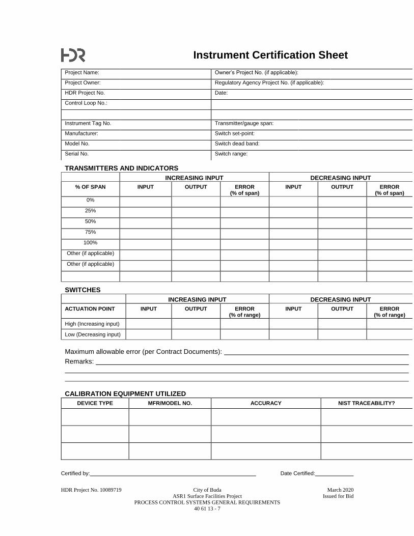
HDR Project No. 10089719 City of Buda March 2020
ASR1 Surface Facilities Project Issued for Bid
PROCESS CONTROL SYSTEMS GENERAL REQUIREMENTS 40 61 13 - 7
Instrument Certification Sheet
Project Name: Owner’s Project No. (if applicable):
Project Owner: Regulatory Agency Project No. (if applicable):
HDR Project No. Date:
Control Loop No.:
Instrument Tag No. Transmitter/gauge span:
Manufacturer: Switch set-point:
Model No. Switch dead band:
Serial No. Switch range:
TRANSMITTERS AND INDICATORS
INCREASING INPUT DECREASING INPUT
% OF SPAN INPUT OUTPUT ERROR (% of span)
INPUT OUTPUT ERROR (% of span)
0%
25%
50%
75%
100%
Other (if applicable)
Other (if applicable)
SWITCHES
INCREASING INPUT DECREASING INPUT
ACTUATION POINT INPUT OUTPUT ERROR (% of range)
INPUT OUTPUT ERROR (% of range)
High (Increasing input)
Low (Decreasing input)
Maximum allowable error (per Contract Documents):
Remarks:
CALIBRATION EQUIPMENT UTILIZED
DEVICE TYPE MFR/MODEL NO. ACCURACY NIST TRACEABILITY?
Certified by: Date Certified:

HDR Project No. 10089719 City of Buda March 2020
ASR1 Surface Facilities Project Issued for Bid
PROCESS CONTROL SYSTEMS GENERAL REQUIREMENTS 40 61 13 - 8
Final Control Element Certification Sheet
Project Name: Owner’s Project No. (if applicable):
Project Owner: Regulatory Agency Project No. (if applicable):
HDR Project No. Date:
Control Loop No.:
Actuator: Pneumatic: Electric:
Tag No. Positioner: Direct: Reverse:
Description: Positioner: Input: Output:
Manufacturer: I/P Converter: Input: Output:
Model No. Valve to on air failure
Serial No. Valve to on power failure
I/P CONVERTER
INCREASING INPUT DECREASING INPUT
% OF SPAN INPUT OUTPUT ERROR (% of span)
INPUT OUTPUT ERROR (% of span)
0%
25%
50%
75%
100%
Specified I/P converter accuracy: % of span.
FINAL CONTROL ELEMENT
INCREASING INPUT DECREASING INPUT
% OF SPAN INPUT TRAVEL ERROR (% of full travel)
INPUT TRAVEL ERROR (% of full travel)
0%
25%
50%
75%
100%
Remarks:
CALIBRATION EQUIPMENT UTILIZED
DEVICE TYPE MFR/MODEL NO. ACCURACY NIST TRACEABILITY?
Certified by: Date Certified:
HDR Project No. 10089719 City of Buda March 2020
ASR1 Surface Facilities Project Issued for Bid
PROCESS CONTROL DESCRIPTIONS 40 61 96 - 1
SECTION 40 61 96
PROCESS CONTROL DESCRIPTIONS
PART 1 - GENERAL
1.1 SUMMARY
A. This Section is intended to describe the functional and operational requirements of the process
being monitored and controlled by the process control system, and to define the Contractor's
responsibilities related to the work described herein.
B. Section Includes:
1. Document Maintenance and Content Requirements.
2. Process Control Description content and structure.
a. Process Control Description for each system includes:
1) Reference Documents.
2) Major Equipment and Field Instruments.
3) Overview Description.
4) Detailed Process Control Descriptions.
5) Response to Instrument or Equipment Failures.
6) Displays at HMI/OIT.
7) Report Descriptions.
C. Related Sections include but are not necessarily limited to:
1. Division 00 - Procurement and Contracting Requirements.
2. Division 01 - General Requirements.
3. Section 40 61 13 – Process Control Systems General Requirements.
D. General Requirements:
1. The Process Control Descriptions describe the operational interface and functional
requirements of the Process Control System (PCS) and of the control loops and other PCS
functions represented in the Contract Documents.
2. The Process Control Descriptions do not necessarily address every PCS point or alarm point
associated with the process or equipment. Provide and incorporate all hard-wired,
networked and internal equipment alarms as shown on the P&IDs, the I/O Lists, the
Instrument Lists, or elsewhere within the Contract Documents, as well as other points
required to meet the intent of the system control.
3. The process control descriptions are not intended to be an inclusive listing of all elements
and appurtenances required to execute loop functions, but are rather intended to supplement
and complement the Drawings and other Specification Sections.
4. The Process Control Descriptions shall not be considered equal to a bill of materials.
5. Provide instrumentation hardware and software as necessary to perform control functions
specified herein and shown on Drawings.
6. Unless otherwise specified, the following general requirements apply to all process control
descriptions.
a. Analog control loops shall operate based on a standard PID controller, with the
controller faceplate incorporated on the PCS HMI graphic display. The PID controller
faceplate includes (but is not limited to) the following functions:
1) Bar graphs for setpoint, process variable and percent output, poke point buttons for
Auto/Manual Mode selection, and a numeric entry field with popup keypad for
Operator entered values.
a) Auto/Manual Mode selection: In Auto Mode, the output of the controller is
based on the PID controller calculation. In Manual Mode, the output of the
controller is operator adjustable. Switching between the PID controller’s
operational modes shall be configured with setpoint tracking and bump-less
transfer.
HDR Project No. 10089719 City of Buda March 2020
ASR1 Surface Facilities Project Issued for Bid
PROCESS CONTROL DESCRIPTIONS 40 61 96 - 2
b) Compound Mode, where applicable: In the Compound Mode, the setpoint is
trimmed by a remote setpoint input. This mode is used in applications
requiring a cascade control loop such as level/flow.
2) When in the Automatic Mode, PID algorithms shall monitor the margin of error
between the setpoint value and the actual process variable. A deviation of +/- 10
PCT between setpoint and process variable generates a Deviation Alarm notifying
the operator of the condition. The % of deviation is an adjustable value.
b. All motors (constant and variable speed) must be monitored for the associated Run,
Stop, and Fail status. When the PCS initiates a run command output, the PCS logic
monitors the running status feedback from the motor (starter or variable speed drive)
and produces a “Fail to Run” or “Fail to Stop” alarm (as applicable) if the motor
feedback does not correspond with the status of the PCS initiated command output. A
PCS internal delay timer with typical preset of 15 SEC (individually adjustable) shall
be configured for each logic statement to allow the motor control adequate time to
comply with the output command.
1) The PCS output command is de-energized subsequent to the expiration of the
alarm delay time period, i.e. a timed-out command.
c. Valves or gates with limit switch functions for position feedback: when the PCS
initiates an Open/Close command output, the PCS logic monitors the position feedback
and produces a “Failure to Open” or Failure to Close” Alarm (as applicable) if the
valve/gate feedback does not correspond with the status of the PCS initiated command
output. A PCS internal delay timer preset of 60 SEC (operator adjustable to match
actual valve actuator speed) is configured for each logic statement allowing the
valve/gate actuator time to comply with the output command. The timer preset requires
adjustment at startup depending on the type of valve or gate and the full open to close
travel time for each.
1) The PCS output command is de-energized subsequent to the expiration of the
alarm delay time period, i.e. a timed-out command.
d. Analog inputs shall have a signal Out Of Range Alarm generated via a PCS internal
timer when the PCS input is < 3.8 mADC or > 20.5 mADC. The alarm delay timer
preset is initially set at 20 SEC. The delay preset value is operator adjustable.
e. All flow inputs shall be totalized (integrated) and logged on the PCS historian. All
totalized values are displayed on the PCS HMI graphic display in the appropriate
engineering units as required. Provide daily flow totals for all measured flows.
f. All equipment run times shall be totalized, displayed and logged on the PCS historian.
Run times shall have a resolution of one minute and be displayed in hours and tenths of
hours on the appropriate PCS HMI graphic display.
g. For each piece of process equipment controllable by the PCS, an equipment “ready” or
control mode permissive signal is needed to indicate to the PCS control logic PCS
control is allowed. The PCS shall monitor the Local Control Panel mounted L/R mode
selector switch and control the equipment that is in the Remote mode.
h. Non-modulating motorized valves or gates shall be controllable via Open-Stop-Close
buttons on HMI and OIT faceplates. The valves/gates shall be controlled in the Open
and Close directions by separate PCS control signals. The PCS shall stop the Open or
Close command to the actuator when the actuator reaches the respective end of travel.
i. I/O points shown on the P&IDs, I/O List or elsewhere within the Contract Documents
shall be incorporated into the PCS HMI and OIT graphic displays as indicated by their
function.
j. Operator entry of setpoints shall be limited to values within upper and lower operating
limits corresponding to the valid operating range of the equipment. An operator-
entered setpoint outside the valid range must be rejected by the PCS and the original
setpoint shall be maintained until a valid value is entered. When an invalid setpoint is
entered into the system, an Invalid Value message shall appear in the setpoint entry
faceplate, alerting the operator to the condition. The upper and lower range limits are
adjustable.
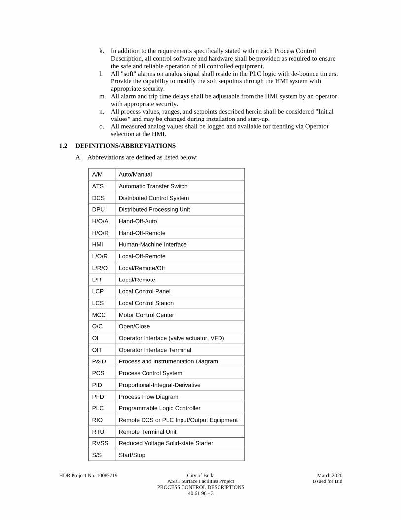
HDR Project No. 10089719 City of Buda March 2020
ASR1 Surface Facilities Project Issued for Bid
PROCESS CONTROL DESCRIPTIONS 40 61 96 - 3
k. In addition to the requirements specifically stated within each Process Control
Description, all control software and hardware shall be provided as required to ensure
the safe and reliable operation of all controlled equipment.
l. All "soft" alarms on analog signal shall reside in the PLC logic with de-bounce timers.
Provide the capability to modify the soft setpoints through the HMI system with
appropriate security.
m. All alarm and trip time delays shall be adjustable from the HMI system by an operator
with appropriate security.
n. All process values, ranges, and setpoints described herein shall be considered "Initial
values" and may be changed during installation and start-up.
o. All measured analog values shall be logged and available for trending via Operator
selection at the HMI.
1.2 DEFINITIONS/ABBREVIATIONS
A. Abbreviations are defined as listed below:
A/M Auto/Manual
ATS Automatic Transfer Switch
DCS Distributed Control System
DPU Distributed Processing Unit
H/O/A Hand-Off-Auto
H/O/R Hand-Off-Remote
HMI Human-Machine Interface
L/O/R Local-Off-Remote
L/R/O Local/Remote/Off
L/R Local/Remote
LCP Local Control Panel
LCS Local Control Station
MCC Motor Control Center
O/C Open/Close
OI Operator Interface (valve actuator, VFD)
OIT Operator Interface Terminal
P&ID Process and Instrumentation Diagram
PCS Process Control System
PID Proportional-Integral-Derivative
PFD Process Flow Diagram
PLC Programmable Logic Controller
RIO Remote DCS or PLC Input/Output Equipment
RTU Remote Terminal Unit
RVSS Reduced Voltage Solid-state Starter
S/S Start/Stop

HDR Project No. 10089719 City of Buda March 2020
ASR1 Surface Facilities Project Issued for Bid
PROCESS CONTROL DESCRIPTIONS 40 61 96 - 4
UPS Uninterruptible Power Supply
VFD Variable Frequency Drive
1.3 SUBMITTALS
A. Contract Closeout Information:
1. Operation and Maintenance Data:
a. See Specification Section 01 33 00 for requirements for the mechanics, administration,
and the content of Operation and Maintenance Manual submittals.
1.4 ADMINISTRATIVE REQUIREMENTS
A. Control Strategy for Record Documents:
1. Obtain this Specification Section 40 61 96 in electronic format (Microsoft Word) from
Engineer at beginning of Project. Provide updated Process Control Descriptions as follows:
a. As needed or requested following any PCS workshops, working sessions, and/or related
submittal reviews.
b. As needed or requested during the course of programming, start-up and testing to
reflect all refinements and changes that occur due to specific operational needs and the
characteristics of specific equipment and systems supplied under this Contract.
c. Show all revisions in 'track change' mode.
d. Change Specification Section Title to read "Process Control Descriptions - Contractor
Record Document."
e. Reference all changes by Request for Information (RFI) number or Change Proposal
Request (CPR) number.
2. Submit the revised and updated file as a final Process Control description Record Document
in the Operation and Maintenance Manual described in Specification Section 01 33 04.
a. Provide both paper copy and electronic copy (on CD-ROM) of the Record Document
process control descriptions in the Operation and Maintenance Manual described in
Specification Section 01 33 04.
B. Coordination with vendor-furnished control packages
1. Where vendor packages are supplied as part of the Contract, the vendor packages that are
supplied with PLC-based controls shall be programmed by the respective vendors. Provide
all programming as required to integrate Vendor-furnished controls into the PCS as
described in the Contract Documents.
PART 2 - PRODUCTS - (NOT USED)
PART 3 - EXECUTION
3.1 PROCESS CONTROL DESCRIPTIONS
A. The following Appendices to this Section contain the process control descriptions that define the
PCS procedural and operational requirements of the processes included in the Work:
1. 40 61 96 - Appendix A – ASR1 Pump Process Control Description.
END OF SECTION

HDR Project No. 10089719 City of Buda March 2020
ASR1 Surface Facilities Project Issued for Bid
PROCESS CONTROL DESCRIPTIONS 40 61 96 - 5
APPENDIX A
ASR1 PUMP
PROCESS CONTROL DESCRIPTION
Project: ASR1 Surface Facilitates Project
Process Areas: Well Pump
REFERENCE DOCUMENTS
A. Process & Instrument Diagrams, P&IDs:
SHEET 6Y-02.
MAJOR EQUIPMENT AND FIELD INSTRUMENTS
A. Major Equipment:
ASR1 Well (ASR-WELL-01).
Back-Flush Valve (ASR-6”-BFV-03).
Pre-lube Solenoid Valve.
Flow Control Valve (ASR-6”-FCV-01).
ASR1 Pump (ASR-WELL-01).
a. Well Pump Master Control Panel.
B. Major Field Instruments:
LIT-101, level transmitter in ASR1 Well.
FIT-101, flow transmitter in ASR1 discharge line.
OVERVIEW DESCRIPTION
A. The ASR1 pump is primarily operated to recover stored water from the well for delivery through
the 8” well discharge line to the existing ground storage tank. Recovery will normally be
continuous for 12 to 16 hours per day when additional supply is required. The ASR1 pump is
also operated infrequently, for less than 15 minutes, to remove accumulated solids from the well
and maintain recharge capacity.
DETAILED PROCESS CONTROL DESCRIPTIONS
Recovery Start Sequence
The sequence of recovery initiation is controlled automatically, as follows:
1. The HAND/OFF/REMOTE switches on the pump control panel in HAND position; FLUSH switch
in AUTO position.
2. The Flow Control Valve (ASR-6”-FCV-01), Primary Recharge Valve (6ASR-6”-VBV-01), Auxiliary
Recharge Valve (ASR-4”-BFV-01), and Back-Flush Valve (ASR-6”-BFV-03) are closed.
3. There are no alarms associated with the well pump and the motor is off.
4. Push START button in the pump control panel. The PLC simultaneously commands the:
Pre-lube Solenoid Valve to open (energized); Pre-lube Solenoid Valve open status is verified
by Flow Switch and an alarm is indicated if flow is not detected in the pre-lube line within
predetermined time. Note Pre-lube Solenoid Valve to fail closed.
Back-Flush Valve to open to predetermined position; and
Flow Control Valve pilot tube solenoid valve to close (energized); in closed position, pilot
tube solenoid valve prevents the Flow Control Valve from opening.

HDR Project No. 10089719 City of Buda March 2020
ASR1 Surface Facilities Project Issued for Bid
PROCESS CONTROL DESCRIPTIONS 40 61 96 - 6
5. After a predetermined period, the PLC simultaneously commands the Pre-lube Solenoid Valve to
close. If the Flow Control Valve is closed and the Back-Flush Valve is open to predetermined position,
the PLC will command the pump to start. The water from the well pump initially discharges to the
flush system. If either the Flow Control Valve is not closed or the Back-Flush Valve is not open, an
alarm is indicated and the start sequence is terminated.
6. After a predetermined flush period, the PLC simultaneously commands the:
Back-Flush Valve to close; close status is verified and an alarm is indicated and the pump
motor is stopped if the Back-Flush Valve does not close in a predetermined time period; and
Flow Control Valve pilot tube solenoid valve to open (in open position, pilot tube solenoid
valve allows the Flow Control Valve to control the flow rate); an alarm is indicated and the
pump motor is stopped if the Flow Control Valve does not open to greater than 20% in a
predetermined period.
7. Production continues until:
STOP button is pushed;
Pump motor high temperature or vibration interlock is triggered;
High pressure switch interlock is triggered; or
Low well casing water level is indicated.
Recovery Stop Sequence
The sequence of recovery termination is controlled automatically, as follows:
1. The HAND/OFF/REMOTE switches on the pump control panel must be in HAND position; FLUSH
switch in AUTO position.
2. The well pump is running. The Flow Control Valve is open; the Primary Recharge Valve, Auxiliary
Recharge Valve, and Back-Flush Valve are closed.
3. There are no alarms associated with the well pump.
4. Push STOP button in the pump control panel. The PLC commands the Flow Control Valve pilot tube
solenoid valve to close (in closed position, pilot tube solenoid valve causes the Flow Control Valve to
close).
5. After the Flow Control Valve reaches 20% open, the PLC simultaneously commands the:
Pump motor to stop; and
Flow Control Valve pilot tube solenoid valve to open (in open position the Flow Control
Valve will operate as a check valve preventing flow from Well No. 5 from entering the ASR
well).
6. If the Flow Control Valve does not reach the 20% open in a predetermined time period, an alarm is
indicated and the PLC commands the pump motor to stop.
Recharge Start Sequence
Prior to initiating recharge operations, the well pump should have been recently operated so that water in
the well pump column and well casing have relatively low suspended solids. If the well pump have not
been operated within three days, initiate a back-flush sequence.
The sequence of recharge initiation is controlled manually, as follows:
1. The HAND/OFF/REMOTE switches on the pump control panel must be in HAND position; FLUSH
switch in AUTO position.
HDR Project No. 10089719 City of Buda March 2020
ASR1 Surface Facilities Project Issued for Bid
PROCESS CONTROL DESCRIPTIONS 40 61 96 - 7
2. The Flow Control Valve (pilot tube solenoid valve is open), Primary Recharge Valve, Auxiliary
Recharge Valve, and Back-Flush Valve are closed.
3. There are no alarms associated with the well.
4. Well No. 5 is running.
5. Manually open the Primary Recharge Valve until the target recharge rate is achieved. If the pressure
downstream of the Primary Recharge Valve is negative (as indicated at the wellhead pressure gage),
continue to open the Primary Recharge Valve until positive pressure is measured downstream of the
Primary Recharge Valve. Do not exceed 400 gpm recharge rate.
6. If the Primary Recharge Valve is full open, the well casing water level is below the wellhead, and
recharge is below the target recharge rate, increase the production rate from the Well No. 5 pump
and/or manually throttle the Well No. 5 Isolation Valve until the target recharge rate is achieved.
7. If the Primary Recharge Valve is full open and the recharge rate is significantly below the target
because the well casing water level is above the wellhead (negative depth to water), manually open the
Auxiliary Recharge Valve until the target recharge rate is achieved.
8. Monitor and manually adjust the Primary Recharge Valve daily to approximate the target recharge rate
and maintain positive pressure downstream of the Primary Recharge Valve. Also maintain well casing
water level above the wellhead while the Auxiliary Recharge Valve is open.
9. Stop recharge if specific injectivity drops below the minimum target value and initiate back-flush
sequence.
Back-Flush Sequence
The sequence of back-flush initiation is controlled automatically, as follow:
1. The HAND/OFF/REMOTE switches on the pump control panel must be in HAND position; FLUSH
switch in MANUAL position.
2. The Flow Control Valve, Primary Recharge Valve, Auxiliary Recharge Valve, and Back-Flush Valve
are closed.
3. There are no alarms associated with the well pump and the motor is off.
4. Push START button in the pump control panel. The PLC simultaneously commands the:
Pre-lube Solenoid Valve to open (energized); Pre-lube Solenoid Valve open status is verified
by Flow Switch and an alarm is indicated if no flow is detected in the pre-lube line within
predetermined time.
Back-Flush Valve to open to predetermined position; and
Flow Control Valve pilot tube solenoid valve to close (energized); in closed position, pilot
tube solenoid valve prevents the Flow Control Valve from opening.
5. After a predetermined period, the PLC simultaneously commands the Pre-lube Solenoid Valve to
close. If the Flow Control Valve is closed and the Back-Flush Valve is open to the predetermined
position, the PLC will command the pump to start. The water from the well pump will discharge to the
flush system. If either the Flow Control Valve is not closed or the Back-Flush Valve is not open, an
alarm is indicated and the start sequence is terminated.
6. With FLUSH switch in MANUAL position, the Flow Control Valve will remain closed and the Back-
Flush Valve will remain open until STOP button is pushed on the pump control panel.
7. Once flush discharge runs clear, push STOP button on the pump control panel. The PLC
simultaneously commands the:
Pump motor to stop;

HDR Project No. 10089719 City of Buda March 2020
ASR1 Surface Facilities Project Issued for Bid
PROCESS CONTROL DESCRIPTIONS 40 61 96 - 8
Flow Control Valve pilot tube solenoid valve to open (in open position the Flow Control
Valve will operate as a check valve preventing flow from Well No. 5 from entering the ASR
well); and
Back-Flush Valve to close.
8. Return the FLUSH switch in the pump control panel to AUTO.
Recharge Stop Sequence
The sequence of recharge termination is controlled automatically, as follows:
1. The HAND/OFF/REMOTE switches on the pump control panel must be in HAND position; FLUSH
switch in AUTO position.
2. The Flow Control Valve (pilot tube solenoid valve is open), and Back-Flush Valve, are closed. The
Primary Recharge Valve is open. The Auxiliary Recharge Valve may be open or closed.
3. There are no alarms associated with the well.
4. Well No. 5 is running.
5. If the Auxiliary Recharge Valve is open, manually close the valve.
6. Manually close the Primary Recharge Valve.
7. If the Well No. 5 Isolation Valve is partially open (throttled), restore to the fully open position.
TABLE 1
Operator Adjustable Setpoints
PARAMETER DESCRIPTION SET POINT (RANGE)
Low Level Shut-off (feet water above transducer) 15 FT above suction case
Pre-lube Solenoid Valve Open Time (seconds) 180
Back-Flush Valve Open Position (degrees) Approx. 60
Back-Flush Valve Open Time-out (seconds) 30
Back-Flush Valve Close Time-out (seconds) 30
Flow Control Valve Limit Switch (Close) (%) 20
Flow Control Valve Limit Switch (Open) Time-out (seconds) 30
Flow Control Valve Limit Switch (Close) Time-out (seconds) 30
TABLE 2
Displays at HMI/OIT - Indications and Alarms
Equipment Indication or Alarm Description
Pump and Motor Pump OFF Indication
Pump START Indication

HDR Project No. 10089719 City of Buda March 2020
ASR1 Surface Facilities Project Issued for Bid
PROCESS CONTROL DESCRIPTIONS 40 61 96 - 9
TABLE 2
Displays at HMI/OIT - Indications and Alarms
Equipment Indication or Alarm Description
Pump ON Indication
Pump Fail-to-Run Alarm
Pump Shutdown Alarm
High Winding Temperature Indicator
High Pressure Indicator
Excessive Vibration Indication
Pre-lube Solenoid Valve Fail-to-Open Alarm (Flow Switch)
Flow Control Valve Fail-to-Open Alarm
Fail-to-Close Alarm
Back-Flush Valve Fail-to-Open Alarm
Fail-to-Close Alarm
Flow Transmitter Production Flow Rate Indication
Production Flow Total Indication
Recharge Flow Rate Indication
Recharge Flow Total Indication
Back-Flush Flow Rate Indication
Back-Flush Flow Total Indication
Well Level Transmitter Level Indication
Wellhead Pressure Transmitter Wellhead Pressure
TABLE 3
Pump Motor Shut-off
Equipment PLC or Interlock
Pump Motor High Winding Temperature Shut-off Interlock
Excessive Vibration Shut-off Interlock
Flow Control Valve Fail-to-Open Start Sequence Termination Control
Fail-to-Close to 20% Pump Motor Shut-off Control
Back-Flush Valve Fail-to-Open Start Sequence Termination Control
Fail-to-Close Pump Motor Shut-off Control
Discharge Pressure High Pressure Pump Motor Shut-off Interlock (250 PSI)

HDR Project No. 10089719 City of Buda March 2020
ASR1 Surface Facilities Project Issued for Bid
PROCESS CONTROL DESCRIPTIONS 40 61 96 - 10
TABLE 3
Pump Motor Shut-off
Equipment PLC or Interlock
Well Level Low Level Pump Motor Shut-off Control (20 FT)
END OF APPENDIX A

HDR Project No. 10089719 City of Buda March 2020
ASR1 Surface Facilities Project Issued for Bid
COMPUTER NETWORK AND HUMAN MACHINE INTERFACE (HMI) HARDWARE 40 62 16 - 1
SECTION 40 62 16
COMPUTER NETWORK AND HUMAN MACHINE INTERFACE (HMI) HARDWARE
PART 1 - GENERAL
1.1 SUMMARY
A. Section Includes:
1. Computer network and HMI hardware requirements, which include, but are not necessarily
limited to:
a. Panel Mounted OIT (Operator Interface Terminals).
b. Ethernet Switches.
c. Software.
d. Accessories and Maintenance Materials.
B. Related Specification Sections include, but are not necessarily limited to:
1. Division 00 - Procurement and Contracting Requirements.
2. Division 01 - General Requirements.
3. Section 40 61 13 - Process Control Systems General Requirements.
1.2 QUALITY ASSURANCE
A. Referenced Standards:
1. Institute of Electrical and Electronics Engineers, Inc. (IEEE):
a. 802.3, Information Technology - Local and Metropolitan Area Networks - Part 3:
Carrier Sense Multiple Access with Collision Detection (CSMA/CD) Access Method
and Physical Layer Specifications.
1) 802.3u: IEEE Standards for Local and Metropolitan Area Networks: Supplement
to Carrier Sense Multiple Access with Collision Detection (CSMA/CD) Access
Method and Physical Layer Specifications Media Access Control (MAC)
Parameters, Physical Layer, Medium Attachment Units, and Repeater for 100 Mb/s
Operation, Type 100BASE-T.
2) 802.3x: IEEE Standards for Local and Metropolitan Area Networks: Specification
for 802.3 Full Duplex Operation.
1.3 DEFINITIONS
A. HMI: Human Machine Interface.
B. LCD: Liquid Crystal Display.
C. OIT: Operator Interface Terminal.
D. OPC: “OLE for Process Control”, a software standard utilizing a client/server model that makes
interoperability possible between automation/control applications and field systems/devices.
E. PC: Personal Computer.
F. RAID: Redundant Array of Independent Disks, a method of storing the same data in different
places on multiple hard disks.
G. RAM: Random Access Memory.
H. SCSI: Short for Small Computer System Interface, a parallel interface standard used for
attaching peripheral devices to computers.
I. SDRAM: Synchronous Dynamic RAM.
J. SNMP: Simple Network Management Protocol, a set of protocols for managing complex
networks.
K. TFT: Thin-Film Transistor, a technology for building LCD screens.
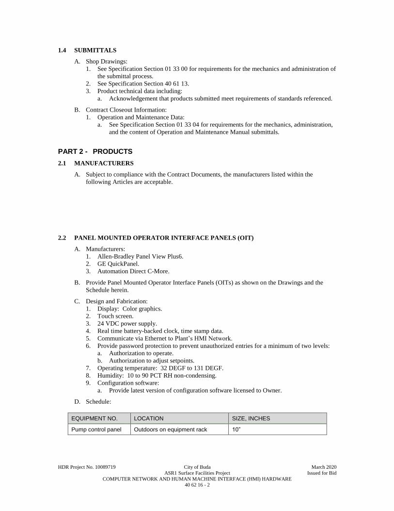
HDR Project No. 10089719 City of Buda March 2020
ASR1 Surface Facilities Project Issued for Bid
COMPUTER NETWORK AND HUMAN MACHINE INTERFACE (HMI) HARDWARE 40 62 16 - 2
1.4 SUBMITTALS
A. Shop Drawings:
1. See Specification Section 01 33 00 for requirements for the mechanics and administration of
the submittal process.
2. See Specification Section 40 61 13.
3. Product technical data including:
a. Acknowledgement that products submitted meet requirements of standards referenced.
B. Contract Closeout Information:
1. Operation and Maintenance Data:
a. See Specification Section 01 33 04 for requirements for the mechanics, administration,
and the content of Operation and Maintenance Manual submittals.
PART 2 - PRODUCTS
2.1 MANUFACTURERS
A. Subject to compliance with the Contract Documents, the manufacturers listed within the
following Articles are acceptable.
2.2 PANEL MOUNTED OPERATOR INTERFACE PANELS (OIT)
A. Manufacturers:
1. Allen-Bradley Panel View Plus6.
2. GE QuickPanel.
3. Automation Direct C-More.
B. Provide Panel Mounted Operator Interface Panels (OITs) as shown on the Drawings and the
Schedule herein.
C. Design and Fabrication:
1. Display: Color graphics.
2. Touch screen.
3. 24 VDC power supply.
4. Real time battery-backed clock, time stamp data.
5. Communicate via Ethernet to Plant’s HMI Network.
6. Provide password protection to prevent unauthorized entries for a minimum of two levels:
a. Authorization to operate.
b. Authorization to adjust setpoints.
7. Operating temperature: 32 DEGF to 131 DEGF.
8. Humidity: 10 to 90 PCT RH non-condensing.
9. Configuration software:
a. Provide latest version of configuration software licensed to Owner.
D. Schedule:
EQUIPMENT NO. LOCATION SIZE, INCHES
Pump control panel Outdoors on equipment rack 10”
HDR Project No. 10089719 City of Buda March 2020
ASR1 Surface Facilities Project Issued for Bid
COMPUTER NETWORK AND HUMAN MACHINE INTERFACE (HMI) HARDWARE 40 62 16 - 3
2.3 ETHERNET SWITCHES
A. Manufacturers:
1. Hirschmann.
2. Siemens.
3. N-TRON.
4. Phoenix Contact.
5. Allen-Bradley/Cisco.
B. Provided Managed Ethernet Switches and Unmanaged Ethernet Switches as shown on the
Drawings and the Schedule herein.
C. Managed Ethernet Switches:
1. Design and fabrication:
a. Support Ethernet 100 MBit/s.
b. Support SNMP and Web based management.
c. Rapid Spanning Tree Protocol.
d. IGMP (Internet Group Management Protocol) support for IP multicast filtering to
enable switches to automatically route messages only to appropriate ports.
e. 10/100/1000 MBit/s twisted pair ports (RJ45) as required for communication with
devices as depicted in the Contract Documents.
1) Unless otherwise noted, provide at least two spare 10/100/1000 MBit/s port
(twisted pair) at each Ethernet switch.
f. Check all received data for validity.
1) Discard invalid and defective frames or fragments.
g. Monitor connected TP/TX line segments for short-circuit or interrupt using regular link
test pulses in accordance with IEEE 802.3.
h. Monitor attached fiber optic lines for open circuit conditions in accordance with
IEEE 802.3.
i. As applicable, meet requirements of IEEE 802.3.
j. Power switch with 24 VDC power input.
k. Provide LED status lights to indicate:
1) Power: Supply voltage present.
2) Fault.
3) Port status.
l. Environmental rating:
1) Operating temperature: 32 DEGF to 122 DEGF.
2) Humidity: 95 PCT relative humidity, non-condensing.
D. Unmanaged Ethernet Switches:
1. Design and fabrication:
a. Support Ethernet 100 MBit/s.
b. 10/100/1000 MBit/s twisted pair ports (RJ45) as required for communication with
devices as depicted in the Contract Documents.
1) Unless otherwise noted, provide at least two spare 10/100/1000 MBit/s port
(twisted pair) at each Ethernet switch.
c. Check all received data for validity.
1) Discard invalid and defective frames or fragments.
d. Monitor connected TP/TX line segments for short-circuit or interrupt using regular link
test pulses in accordance with IEEE 802.3.
e. Monitor attached fiber optic lines for open circuit conditions in accordance with
IEEE 802.3.
f. As applicable, meet requirements of IEEE 802.3.
g. Power switch with 24 VDC power input.
h. Provide LED status lights to indicate:
1) Power: Supply voltage present.
2) Fault.
3) Port status.
HDR Project No. 10089719 City of Buda March 2020
ASR1 Surface Facilities Project Issued for Bid
COMPUTER NETWORK AND HUMAN MACHINE INTERFACE (HMI) HARDWARE 40 62 16 - 4
i. Environmental rating:
1) Operating temperature: 32 DEGF to 122 DEGF.
2) Humidity: 95 PCT relative humidity, non-condensing.
2.4 SOFTWARE
A. Provide all software and associated programming/configuration required to meet performance
requirements of the Contract Documents.
1. At substantial completion of the Project:
a. Turn current licenses for all software over to the Owner in the Owner's name and install
the latest version, upgrade or service pack for all software.
b. Provide the respective software supplier's Comprehensive Support Contract for all
software covering a full one year warranty period following substantial completion
which shall provide no cost software upgrades, service packs and tech support from the
software supplier.
B. HMI Software:
1. Subject to compliance with the Contract Documents, the following HMI software packages
are acceptable:
a. Wonderware System Platform.
2. Runtime HMI software:
a. Provide server/client individually licensed software with capability for all HMIs to be
active simultaneously.
3. Development software:
a. Install development software on engineering workstation.
4. Data Historian software:
a. Provide data historian software compatible with HMI software package.
5. I/O capacity requirements:
a. As required to meet performance requirements of the Contract Documents.
b. Capable of handling an additional 20 PCT more points (future expansion) without
impacting the license.
C. Ethernet Network Management Software:
1. Software to include an OPC Server, capable of integrating real-time SNMP data into OPC
client enabled HMI software databases.
2. Software shall allow control of polling rate for SNMP requests, as well as limit access to
write SNMP data on each SNMP point.
3. Software shall have pre-developed databases for several manufacturer’s Ethernet network
devices, as well as generic MIB (Management Information Base) databases.
4. Software shall have integrated OPC client data viewer software, so that SNMP data may be
viewed without having to create HMI points.
D. All software must be latest edition and licensed to the Owner.
2.5 ACCESSORIES AND MAINTENANCE MATERIALS
A. Provide all accessories required to furnish a complete computer-based network for the control
system to accomplish the requirements of the Drawings and Specifications.
PART 3 - EXECUTION
3.1 DEMONSTRATION
A. Demonstrate system in accordance with Specification Section 01 75 00.
3.2 INSTALLATION AND CHECKOUT
A. Provide installation and checkout in accordance with Specification Section 40 61 13.

HDR Project No. 10089719 City of Buda March 2020
ASR1 Surface Facilities Project Issued for Bid
COMPUTER NETWORK AND HUMAN MACHINE INTERFACE (HMI) HARDWARE 40 62 16 - 5
END OF SECTION

This page intentionally left blank.

HDR Project No. 10089719 City of Buda March 2020
ASR1 Surface Facilities Project Issued for Bid
PROGRAMMABLE LOGIC CONTROLLER (PLC) CONTROL SYSTEM 40 63 43 - 1
SECTION 40 63 43
PROGRAMMABLE LOGIC CONTROLLER (PLC) CONTROL SYSTEM
PART 1 - GENERAL
1.1 SUMMARY
A. Section Includes:
1. Programmable logic controller (PLC) control system(s), including Hardware, software,
programming, documentation, and training.
B. Related Sections include but are not necessarily limited to:
1. Division 00 - Procurement and Contracting Requirements.
2. Division 01 - General Requirements.
3. Section 10 14 00 - Identification Devices.
4. Section 26 05 19 - Wire and Cable - 600 Volt and Below.
5. Section 40 61 13 - Process Control Systems General Requirements.
6. Section 40 62 16 - Computer Network and Human Machine Interface (HMI) Hardware.
7. Section 40 67 00 - Control System Equipment Panels and Racks.
8. Section 40 61 96 – Process Control Descriptions.
1.2 QUALITY ASSURANCE
A. Referenced Standards:
1. The Institute of Electrical and Electronics Engineers, Inc. (IEEE):
a. C37.90.2, Withstand Capability of Relay Systems to Radiated Electromagnetic
Interference from Transceivers.
b. C62.41.2, Recommended Practice on Characterization of Surges in Low-Voltage (1000
V and Less) AC Power Circuits.
2. National Electrical Manufacturers Association (NEMA):
a. ICS 1, Industrial Control and Systems General Requirements.
B. Qualifications:
1. Installation supervisor shall have had experience in overseeing installation and startup of at
least three similar installations within the last five years.
2. Programmer(s) shall have had experience in programming PLCs for at least two projects of
similar size and complexity.
1.3 SUBMITTALS
A. Shop Drawings:
1. See Specification Section 01 33 00 for requirements for the mechanics and administration of
the submittal process.
2. See Specification Section 40 61 13.
3. Product technical data including:
a. Annotated copies of complete PLC software programs.
1) Provide one PDF-format file with fully annotated PLC code that can be read
without the native configuration and programming environment on electronic
media (DVD or USB drive).
2) Provide written descriptions completely defining all function blocks used in
program.
3) Provide list of all addresses referenced in logic diagram with description of data
associated with each address (Tag database).
b. Results of factory testing or simulation procedures.
c. Drawings containing the following information to be submitted as part of Specification
Section 40 67 00 (control panels) submittals:
1) Arrangement drawings for PLC system components.

HDR Project No. 10089719 City of Buda March 2020
ASR1 Surface Facilities Project Issued for Bid
PROGRAMMABLE LOGIC CONTROLLER (PLC) CONTROL SYSTEM 40 63 43 - 2
2) Panel and enclosure plans, sections and details.
3) Access opening locations and required clearances for each panel and enclosure.
4) Enclosure internal wiring and terminal blocks.
d. DIP Switch and Jumper Settings, if applicable.
e. I/O Rack and I/O Module Layout.
f. Wiring and Interconnection diagrams.
1) Power Supplies.
2) I/O Points.
3) Communications.
g. Catalog cut sheets containing information on PLC components to be submitted as part
of these Specification Section submittals.
4. Certifications:
a. Qualifications of installation supervisor.
b. Qualifications of programmer(s).
5. Software Licenses:
a. Documentation proving all software package licenses are assigned to owner.
B. Operation and Maintenance Data:
1. See Specification Section 01 33 04 for requirements for:
a. The mechanics and administration of the submittal process.
b. The content of Operation and Maintenance Manuals.
2. Program Documentation.
a. Program Overview.
b. Program Listing.
c. I/O Listing.
d. Memory Map.
e. I/O Cross Reference.
3. Submit maintenance procedures available to Owner.
a. Include the location and phone numbers of service centers (including 24 HR "hot
lines").
b. Provide specific information including operation and maintenance requirements,
programming assistance, troubleshooting guide, parts ordering, field service personnel
requests, and service contracts.
C. Informational Submittals:
1. See Specification Section 01 33 00 for requirements for the mechanics and administration of
the submittal process.
2. Index of all training offered by PLC system equipment manufacturers including operations
and maintenance.
3. List of all recommended spares for maintenance purposes with each item separately priced.
PART 2 - PRODUCTS
2.1 MANUFACTURERS
A. Subject to compliance with the Contract Documents, the following manufacturers are
acceptable:
1. Rockwell Automation: Allen-Bradley.
2. Schneider Electric: Modicon.
3. Siemens: SIMATIC.
B. Products nearing their "End of Life" shall not be used. "Used" hardware shall also not be used.
2.2 PERFORMANCE AND DESIGN REQUIREMENTS
A. See Specification Section 40 61 13.
B. The PLC system shall accomplish the control requirements of the Loop Descriptions, Drawings,
and Specifications.
HDR Project No. 10089719 City of Buda March 2020
ASR1 Surface Facilities Project Issued for Bid
PROGRAMMABLE LOGIC CONTROLLER (PLC) CONTROL SYSTEM 40 63 43 - 3
C. PLC programming shall be documented and factory tested.
D. The PLC system shall operate in ambient conditions of 32 to 140 DEGF temperatures and 5 to
95 PCT relative humidity without the need for purging or air conditioning.
E. Environmental Controls:
1. Furnish circulation fans in solid state control system enclosures.
2. Over-temperature switches shall be utilized to provide special cooling if required to
maintain operating temperatures within the manufacturer's specified range.
3. Air conditioning applications shall include means of preventing moisture condensation.
F. Where the PLC is utilized to control multiple trains of equipment and where the equipment in
each train operates as a unit relatively independent of other equipment trains (e.g., facility with
multiple boiler units or filter trains), the PLC components (I/O modules, power supplies, etc.)
shall be assigned so that the failure of any one component does not affect equipment on all
trains.
1. I/O modules shall be segregated on a train basis unless required otherwise for safety
reasons.
2. Where several equipment units operate in parallel, but are not considered assigned to a
particular equipment train (e.g., multiple raw water pumps or chemical feed pumps all
discharging into a common system), the PLC I/O modules associated with each equipment
unit shall be assigned so that the failure of any one I/O module does not affect all of the
parallel operating equipment units.
2.3 HARDWARE
A. Processor shall include diagnostic indicators for power, mode, low battery, communications
ports, and memory and I/O errors.
B. I/O modules shall be capable of being replaced while under power.
C. All I/O modules shall report to the CPU should a terminal block fail or be removed.
D. Analog output modules shall have a resolution of at least 12 bits.
E. Provide electric isolation between logic and field device.
F. Field wiring shall not be disturbed when removing or replacing an I/O module.
G. Power Supply Units:
1. Electrical service to PLC system is 105 to 125 V, 60 Hz, ±10 PCT, 1 PH power.
H. All PLC control system components shall be capable of meeting or exceeding electromagnetic
interference tests per IEEE C37.90.2.
I. Incorporate the following minimum safety measures:
1. Watchdog function to monitor:
a. Internal processor clock failure.
b. Processor memory failure.
c. Loss of communication between processor and I/O modules.
d. Processor ceases to execute logic program.
2. Safety function wiring: Emergency shutdown switches shall not be wired into the
controller.
3. Safe wiring:
a. Unless otherwise specified, activation of alarms and stopping of equipment shall result
from the de-energization of control circuits, rather than the energization of control
circuits.
b. Low voltage control signal wires:
1) Place in conduit segregated for that purpose only.
2) Twisted shielded wire pair.
3) Not located in the same conduit or bundle with power wiring.
4. Initial safety conditions:
HDR Project No. 10089719 City of Buda March 2020
ASR1 Surface Facilities Project Issued for Bid
PROGRAMMABLE LOGIC CONTROLLER (PLC) CONTROL SYSTEM 40 63 43 - 4
a. Utilize program module to dictate output states in a known and safe manner prior to
running of control program.
b. Utilize program each time PLC is re-initiated and the control program activated.
5. Monitoring of internal faults and display:
a. Internal PLC system status and faults shall be monitored and displayed.
1) Monitored items shall include:
a) Memory ok/loss of memory.
b) Processor ok/processor fault.
c) Scan time overrun.
6. Control of programs: Protect access to PLC program loading with password protection or
with locked, key operated selector switches.
a. Provide passwords and/or keys to owner at Substantial Completion.
7. Design PLC system with high noise immunity to prevent occurrence of false logic signals
resulting from switching transients, relay and circuit breaker noise or conducted and
radiated radio frequency interference.
8. Operator intervention:
a. Logic system failure shall not preclude proper operator intervention.
b. Safety shutdown of equipment or a system shall require manual operator intervention
before the equipment or system operation may be reestablished.
2.4 SOFTWARE
A. All software will be furnished and licensed to owner.
1. Once project is accepted as complete, transfer all licenses and media to owner.
2. All software must be latest edition and licensed to the Owner.
B. Programming.
1. Languages supported: All application programming in IEC 61131-3 compliant language.
2. Program PLC utilizing ladder diagram, function block, or structured text format.
3. Protect program via removable key switch or password to prevent unauthorized changes.
Provide password and/or programming keys to owner.
4. Capable of on-line and off-line programming.
C. PLC program Structure.
1. Clear, concise, well-annotated logic.
2. Implement a modular design to allow specific functions to be replicated to ensure
consistency.
3. Program shall align with the control strategies. Include comments reflecting alignment with
control strategies.
4. Include named variables that reflect the actual use of the variable.
5. Annotate program listing to include the following (using the features of the appropriate PLC
programming software):
a. Clearly identified variables, I/O points, contacts, and analog values.
b. Written description of each functional area.
c. Written description of each rung's function.
d. Reference to control loop number for each rung where applicable.
e. Reference to instrumentation tag number of I/O devices for each rung where applicable.
2.5 COMPONENTS
A. PLC System Central Processor Unit (CPU):
1. CPU shall provide communications with other control systems and man-machine interfaces
as specified.
2. CPU shall include capability to modify logic via an Ethernet port without taking processor
off line.
3. Memory:
a. Battery-backed RAM.
b. Non-volatile program storage via flash EEPROM:
1) Automatically download to RAM in the event RAM is corrupted.
HDR Project No. 10089719 City of Buda March 2020
ASR1 Surface Facilities Project Issued for Bid
PROGRAMMABLE LOGIC CONTROLLER (PLC) CONTROL SYSTEM 40 63 43 - 5
4. Memory battery backup shall be capable of 180 days memory retention with fresh battery.
a. Provide visual indication of battery status and alarm low battery voltage.
b. Memory battery backup shall be capable of 28 days memory retention after the "Battery
Low" indicating LED is on.
5. Plug-in card designed to allow quick field replacement of faulty devices.
a. Provide unit designed for field replacement and expansion of memory without requiring
rewiring or use of special tools.
6. 20 PCT minimum spare useable memory capacity after all required programming is in place
and operating.
7. Capable of executing all control functions required by the Specifications and Drawings.
8. Built-in three-mode (proportional-integral-derivative) control capabilities.
a. As directly selectable algorithms requiring no user knowledge of programming
languages.
9. Lighted status indicators for "RUN" and "FAILURE".
10. Capable of manual or automatic control mode transfer from the operating console stations or
from within the control strategy.
a. Transfer shall be bumpless and balanceless.
B. Input/output (I/O) Modules:
1. Provide plug-in modular-type I/O racks with cables to connect to all other required PLC
system components.
2. Provide I/O system with:
a. I/O solid state boards with status lights indicating I/O status.
b. Electric isolation between logic and field device.
c. Capability of withstanding low energy common mode transient to 1000 V without
failure.
d. Incorporate noise suppression design.
e. Capable of meeting or exceeding electrical noise tests, NEMA ICS 1-109.60-109.66.
f. Capable of being removed and inserted into the I/O rack under power, without affecting
any other I/O modules in the rack.
g. Install 20 PCT spare I/O points for each type.
3. Input/output connection requirements:
a. Make connections to I/O subsystem by terminating all field wiring on terminal blocks
within the I/O enclosure.
b. Prewire I/O modules to terminal blocks.
c. Provide terminal blocks with continuous marking strip.
d. Size terminals to accommodate all active data base points and spares.
e. Provide terminals for individual termination of each signal shield.
f. Field wiring shall not be disturbed when removing or replacing an I/O module.
4. Discrete I/O modules:
a. Interface to ON/OFF devices.
b. I/O status indicator on module front.
c. Voltage rating to match circuit voltage.
d. Output module current rating:
1) Match maximum circuit current draw.
2) Minimum 1.0 continuous A/point for 120 VAC applications.
e. Isolated modules for applications where one module interfaces with devices utilizing
different sources of power.
5. Discrete outputs shall be fused:
a. Provide one fuse per common or per isolated output.
b. Provide blown fuse indication.
c. External fusing shall be provided if output module does not possess internal fusing.
d. Fuses provided external to output model shall:
1) Be in accordance with module manufacturer's specifications.
2) Be installed at terminal block.
6. Analog I/O modules:

HDR Project No. 10089719 City of Buda March 2020
ASR1 Surface Facilities Project Issued for Bid
PROGRAMMABLE LOGIC CONTROLLER (PLC) CONTROL SYSTEM 40 63 43 - 6
a. Input modules to accept signals indicated on Drawings or Specifications.
b. Minimum 12 bit resolution.
c. I/O chassis supplied power for powering connected field devices.
d. Differential inputs and outputs.
e. User configurable for desired fault-response state.
f. Provide output signals as indicated on Drawings and Specifications.
g. Individual D/A converter for each output module.
h. Individual A/D converter for each input module.
C. Power Supply Units:
1. Provide regulated power units:
a. Designed to operate with PLC system and shall provide power to:
1) All components of PLC system.
2) All two-wire field instruments.
3) Other devices as indicated on Drawings or Specifications.
b. Capable of supplying PLC system when all of the specified spare capacity is utilized.
c. Each power supply shall be sized such that it will carry no more than 75 PCT of
capacity under normal loads.
2. Electrical service to PLC system is 105 to 125 V, 60 Hz, +1 PCT, 1 PH power.
3. Separate AC circuit breakers shall be provided for each power supply.
4. If the PLC system is field expandable beyond the specified spare capacity, and if such
expansion requires power supply modification, note such requirements in the submittals and
allow room for power supply modification in the PLC system enclosure.
5. Capable of meeting or exceeding electrical noise tests, NEMA ICS 1-109.60-109.66.
6. Power distribution:
a. Immune to transients and surges resultant from noisy environment.
b. Shall provide constant voltage level DC distribution to all devices.
7. Provide uninterruptible power supply (UPS) to sustain full power to UPS powered loads
listed below for a minimum of90 minutes following loss of primary power and to ensure
that the transient power surges and dips do not affect the operation of the PLC system.
a. UPS powered loads:
1) All rack mounted PLC components.
2) Local operator consoles.
3) All power supplies furnished with the PLC and associated loads.
b. Input:
1) 120 VAC +10 PCT.
2) 60 Hz.
3) Line fuse protection.
c. Output:
1) 120 VAC 5 PCT.
2) 60 Hz.
3) Short circuit protected.
4) Instantaneous transfer time.
d. IEEE C62.41 Class A voltage surges of 6000 V attenuated to less than 50 V on the
output.
e. Battery: Maintenance free lead acid.
D. PLC System Enclosure:
1. In accordance with Specification Section 40 67 00 - Control Panels.
2. Component placement:
a. Mount all controller components vertically within the enclosure to allow maximum
convection cooling.
b. Either install power supplies above all other equipment with at least 10 IN of clearance
between the power supply and the enclosure top, or adjacent to other components, but
with sufficient spacing for circulation of cooling air.
c. Do not place I/O racks directly above the CPU or power supply.
HDR Project No. 10089719 City of Buda March 2020
ASR1 Surface Facilities Project Issued for Bid
PROGRAMMABLE LOGIC CONTROLLER (PLC) CONTROL SYSTEM 40 63 43 - 7
d. Locate incoming line devices (isolation or constant voltage transformers, local power
disconnects, surge suppressors, etc.) so as to keep power wire runs within an enclosure
as short as possible.
e. If items such as magnetic starters, contactors, relays, and other electromagnetic devices
must be located within the same enclosure as the PLC system components, place a
barrier with at least 6 IN of separation between the magnetic area and the control area.
f. Place circulating fans close to major heat generating devices.
g. Segregate input/output modules into groups of identical type.
3. Wiring and grounding to be in accordance with Specification Section 40 67 00.
4. Termination requirements:
a. In accordance with Specification Section 40 67 00.
b. Make connections to I/O subsystem by terminating all field wiring on terminal blocks
within the enclosure.
c. Prewire I/O modules to terminal blocks.
d. Size terminals to accommodate all active database points and spares.
e. Provide terminals for individual termination of each signal shield.
f. Field wiring shall not be disturbed when removing or replacing an I/O module.
E. PLC System Software and Programming:
1. Provide all hardware and programming required to provide communication between the
PLC and the human-machine interface.
2. Coordinate with HMI programmer to allow modification of all setpoint through the HMI
utilizing appropriate security considerations.
3. Provide programming to accomplish all control and monitoring requirements of the
Drawings and Specifications.
4. Full documentation capability.
5. Online and offline programming.
6. Offline simulation prior to download.
7. Program over network capability.
8. Two-step commands requiring PLC programmer verification prior to modification of any
programming.
2.6 ACCESSORIES
A. Provide all accessories required to install and test a complete PLC control system to accomplish
the requirements of the Drawings and Specifications.
B. Provide all programming cables required to configure the PLC logic.
2.7 SOURCE QUALITY CONTROL
A. Provide a performance test after factory completion and prior to shipment.
1. Conduct a test where the system is operated continuously and checked for correct operation
including loop controls, displays, printing, keyboard functions, alarm responses, and on/off
sequencing control.
2. Conduct testing with simulated I/O to verify each control loop operation.
3. Allow for Owner and Engineer representatives to witness program testing.
a. Provide minimum of 15 days notice prior to testing.
4. Do not ship prior to successful completion of this testing program.
2.8 MAINTENANCE MATERIALS
A. Furnish Owner with the following extra materials:
1. One spare I/O card of each card type for every 10 cards or fraction thereof installed.
2. One spare power supply for every 10 power supplies or fraction thereof installed.
B. Include a complete bill of materials indicating detailed part model number.
C. Include a complete set of all special tools required to install, maintain and test the PLCs.

HDR Project No. 10089719 City of Buda March 2020
ASR1 Surface Facilities Project Issued for Bid
PROGRAMMABLE LOGIC CONTROLLER (PLC) CONTROL SYSTEM 40 63 43 - 8
PART 3 - EXECUTION
3.1 FUNCTIONALITY
A. Complete System.
1. Provide all programming, configuration, coordination, integration, and testing required for
furnishing a fully functioning system.
3.2 FACTORY TESTING
A. After assembly, wiring, configuration, and programming, and prior to shipment of the control
system to the project site, verify system functionality by applying test signals to all input points
and observing system response at output points.
B. Submit a factory test report indicating how the system was tested and which items were tested.
C. After Owner has had sufficient time to review the factory test report, provide an opportunity for
Owner and Owner’s technical representative to witness a factory acceptance test.
D. Retain the system in test configuration until approval of the factory acceptance test.
3.3 INSTALLATION
A. Install PLC control system in accordance with manufacturer's written instructions.
3.4 FIELD QUALITY CONTROL
A. Employ and pay for services of equipment manufacturer's field service representative(s) to:
1. Inspect equipment covered by these Specifications.
2. Supervise adjustments and installation checks.
3. Maintain and submit an accurate daily or weekly log of all commissioning functions.
a. All commissioning functions may be witnessed by the Engineer.
b. All reports shall be cosigned by the Contractor and the Engineer if witnessed.
4. Conduct startup of equipment and perform operational checks.
5. Provide Owner with a written statement that manufacturer's equipment has been installed
properly, started up, and is ready for operation by Owner's personnel.
3.5 COMMISSIONING AND ACCEPTANCE
A. Commission system in accordance with Specification Section 01 75 00, System Startup.
B. Demonstrate system in accordance with Specification Section 26 08 13, Acceptance Testing.
3.6 TRAINING
A. Employee of the manufacturer or certified representative to provide8 hoursof operation and
maintenance training at the Project site after the system has successfully undergone all field
testing and acceptance procedures.
B. As a minimum, training shall cover:
1. Hardware overview.
2. Software overview.
3. Documentation.
4. Maintenance.
5. Trouble shooting.
6. Operation, e.g., changing set points, passwords, etc.
3.7 DOCUMENTATION
A. Update O&M manuals to reflect as-built conditions.
3.8 SUPPORT
A. Provide on-call technical support for a period of one year after substantial completion. Include a
minimum of two site visits to work with owner on any final modifications to the logic.

HDR Project No. 10089719 City of Buda March 2020
ASR1 Surface Facilities Project Issued for Bid
PROGRAMMABLE LOGIC CONTROLLER (PLC) CONTROL SYSTEM 40 63 43 - 9
END OF SECTION

This page intentionally left blank.

HDR Project No. 10089719 City of Buda March 2020
ASR1 Surface Facilities Project Issued for Bid
CONTROL SYSTEM EQUIPMENT PANELS AND RACKS 40 67 00 - 1
SECTION 40 67 00
CONTROL SYSTEM EQUIPMENT PANELS AND RACKS
PART 1 - GENERAL
1.1 SUMMARY
A. Section Includes:
1. Requirements for control panels and enclosures utilized as follows:
a. Unless noted otherwise, all control panels and enclosures housing control components
that are specified in Section 40 71 00, Section 40 72 00, Section 40 63 43.
B. This Section is only applicable to panels furnished with Division 11 equipment packages when
so stated in the applicable Division 11 Section.
C. This Section is only applicable to panels housing Division 26 specified equipment (e.g., motor
starters, lighting controls, etc.) when so stated in the applicable Division 26 section.
D. Related Sections include but are not necessarily limited to:
1. Division 00 - Procurement and Contracting Requirements.
2. Division 01 - General Requirements.
3. Section 10 14 00 - Identification Devices.
4. Division 11 - Equipment.
5. Division 26 - Electrical.
6. Section 40 61 13 - Process Controls Systems General Requirements.
7. Section 40 63 43 - Programmable Logic Controller (PLC) Control System.
8. Section 40 71 00 - Flow Measurement.
9. Section 40 72 00 - Level Measurement.
1.2 QUALITY ASSURANCE
A. Referenced Standards:
1. American National Standards Institute (ANSI).
2. ASTM International (ASTM):
a. B75, Standard Specification for Seamless Copper Tube.
3. National Electrical Manufacturers Association (NEMA):
a. 250, Enclosures for Electrical Equipment (1000 Volts Maximum).
b. ICS 4, Industrial Control and Systems: Terminal Blocks.
4. National Fire Protection Association (NFPA):
a. 70, National Electrical Code (NEC):
1) Article 409, Industrial Control Panels.
2) Article 504, Intrinsically Safe Systems.
5. Underwriters Laboratories, Inc. (UL):
a. 508A, Standard for Safety Industrial Control Panels.
b. 698A, Standard for Industrial Control Panels Relating to Hazardous (Classified)
Locations.
c. 913, Standard for Safety Intrinsically Safe Apparatus and Associated Apparatus for Use
in Class I, II, and III, Division 1, Hazardous (Classified) Locations.
B. Miscellaneous:
1. Approved supplier of Industrial Control Panels under provisions of UL 508A or UL 698A.
a. Entire assembly shall be affixed with a UL 508A or UL 698A label "Listed Enclosed
Industrial Control Panel" prior to shipment to the jobsite.
b. Control panel(s) without an affixed UL 508A or UL 698A label shall be rejected and
sent back to the Contractor’s factory.

HDR Project No. 10089719 City of Buda March 2020
ASR1 Surface Facilities Project Issued for Bid
CONTROL SYSTEM EQUIPMENT PANELS AND RACKS 40 67 00 - 2
1.3 DEFINITIONS
A. Panel: Control panels or enclosures listed in the schedule included in this Specification Section.
B. Foreign Voltages: Voltages that may be present in circuits when the panel main power is
disconnected.
C. Intrinsically Safe:
1. A device, instrument or component that will not produce sparks or thermal effects under
normal or abnormal conditions that will ignite a specified gas mixture.
2. Designed such that electrical and thermal energy limits inherently are at levels incapable of
causing ignition.
D. Intrinsically Safe Circuit: A circuit in which any spark or thermal effect is incapable of causing
ignition of a mixture of flammable or combustible material in air under test conditions as
prescribed in UL 913.
E. Cable: Multi-conductor, insulated, with outer sheath containing either building wire or
instrumentation wire.
F. Instrumentation Cable:
1. Multiple conductor, insulated, twisted or untwisted, with outer sheath.
2. Instrumentation cable is typically either TSP (twisted-shielded pair) or TST (twisted-
shielded triad), and is used for the transmission of low current or low voltage signals.
G. Ground Fault Circuit Interrupter (GFCI): A type of device (e.g., circuit breaker or receptacle)
which detects an abnormal current flow to ground and opens the circuit preventing a hazardous
situation.
H. Programmable Logic Controller (PLC): A specialized industrial computer using programmed,
custom instructions to provide automated monitoring and control functions by interfacing
software control strategies to input/output devices.
I. Remote Terminal Unit (RTU): An industrial data collection device designed for location at a
remote site, that communicates data to a host system by using telemetry such as radio, dial-up
telephone, or leased lines.
J. Input/Output (I/O): Hardware for the moving of control signals into and/or out of a PLC or
RTU.
K. Supervisory Control and Data Acquisition (SCADA): Used in process control applications,
where programmable logic controllers (PLCs) perform control functions but are monitored and
supervised by computer workstations.
L. Highway Addressable Remote Transducer (HART): An open, master-slave protocol for bus
addressable field instruments.
M. Digital Signal Cable: Used for the transmission of digital communication signals between
computers, PLCs, RTUs, etc.
N. Uninterruptible Power Supply (UPS): A backup power unit that provides continuous power
when the normal power supply is interrupted.
O. Loop Calibrator: Portable testing and measurement tool capable of accurately generating and
measuring 4-20ma DC analog signals.
1.4 SUBMITTALS
A. Shop Drawings:
1. See Section 01 33 00 for requirements for the mechanics and administration of the submittal
process.
2. See Section 40 61 13.
3. Prepared with computer aided design (CAD) software.
4. Printed on 11 by 17 IN sheets.

HDR Project No. 10089719 City of Buda March 2020
ASR1 Surface Facilities Project Issued for Bid
CONTROL SYSTEM EQUIPMENT PANELS AND RACKS 40 67 00 - 3
5. Drawings shall include a title block containing the following:
a. Plant or facility name where panel(s) are to be installed.
b. Drawing title.
c. Drawing number.
d. Revision list with revision number and date
e. Drawing date.
f. Drawing scale.
g. Manufacturer name, address, and telephone number.
6. Cover sheet for each drawing set shall indicate the following:
a. Plant or facility name.
b. Project name.
c. Submittal description.
d. Revision number.
e. Issue date.
7. Table of contents sheet(s) shall indicate the following for each drawing in the set:
a. Drawing number.
b. Drawing title.
c. Sheet number.
8. Legend and abbreviation sheet shall indicate the following:
a. Description of symbols and abbreviations used.
b. Panel construction notes including enclosure NEMA rating, finish type and color, wire
type, wire color strategy, conductor sizes, and wire labeling strategy.
c. Confirmation that the panel(s) are to be affixed with a UL 508A or UL 698A label prior
to shipment from the factory.
9. Bill of Material for each panel shall include the following component information:
a. Instrument tag number.
b. Quantity.
c. Functional name or description.
d. Manufacturer.
e. Complete model number.
f. Size or rating.
10. Panel exterior layout drawings to scale and shall indicate the following:
a. Panel materials of construction, dimensions, and total assembled weight.
b. Panel access openings.
c. Conduit access locations.
d. Front panel device layout.
e. Nameplate schedule:
1) Nameplate location.
2) Legend which indicates text, letter height and color, and background color.
3) Short Circuit Current Rating (SCCR) marking per NFPA 70 or statement of
exception. Include any required calculations.
f. Alarm annunciator window engraving schedule.
g. Layouts of graphic panels or mosaic displays.
11. Panel interior layout drawings shall be drawn to scale and shall indicate the following:
a. Sub-panel or mounting pan dimensions.
b. Interior device layouts.
c. PLC/RTU general arrangement layouts.
d. Wire-way locations, purpose, and dimensions.
e. Terminal strip designations.
f. Location of external wiring and/or piping connections.
g. Location of lighting fixtures, switches and receptacles.
12. Wiring diagrams shall consist of the following:
a. Panel power distribution diagrams.
b. Control and instrumentation wiring diagrams.
c. PLC/RTU I/O information:
1) Model number of I/O module.

HDR Project No. 10089719 City of Buda March 2020
ASR1 Surface Facilities Project Issued for Bid
CONTROL SYSTEM EQUIPMENT PANELS AND RACKS 40 67 00 - 4
2) Description of I/O module type and function.
3) Rack and slot number.
4) Terminal number on module.
5) Point or channel number.
6) Programmed point addresses.
7) Signal function and type.
d. Wiring diagrams shall identify each wire as it is to be labeled.
B. Manufacturer catalog cut sheets for enclosure, finish, panel devices, control auxiliaries, and
accessories.
C. Electrical load calculations for each panel:
1. Total connected load.
2. Peak electrical demand for each panel.
D. Climate control calculations for each panel.
1. Verify that sufficient dissipation and/or generation of heat is provided to maintain interior
panel temperatures within the rated operating temperatures of panel components.
E. Contract Closeout Information:
1. Operation and Maintenance Data:
a. See Section 01 33 04 for requirements for the mechanics, administration, and the
content of Operation and Maintenance Manual submittals.
2. See Section 40 61 13.
F. Informational Submittals:
1. Record Drawings:
a. Updated panel drawings delivered with the panel(s) from the Contractor’s factory.
b. Drawings shall be enclosed in transparent plastic and firmly secured within each panel.
PART 2 - PRODUCTS
2.1 MANUFACTURERS
A. Subject to compliance with the Contract Documents, the following manufacturers are
acceptable:
1. Enclosures:
a. Hoffman Engineering Co.
b. Rittal.
c. Hammond Manufacturing.
d. Millbank Mfg. Co.
2. Panel heaters:
a. Hoffman Enclosures, Inc.
b. Rittal.
c. Hammond Manufacturing.
3. Heat exchangers and air conditioners:
a. Hoffman Enclosures, Inc.
b. Rittal.
c. Hammond Manufacturing.
4. Cooling fans and exhaust packages:
a. Hoffman Enclosures, Inc.
b. Rittal.
5. Internal corrosion inhibitors:
a. Hoffman Enclosures, Inc.; Model A-HCI.
b. Northern Technologies International Corporation (NTIC); Model Zerust VC.
c. Cortec Corporation; Model VpCl Emitting Systems.
HDR Project No. 10089719 City of Buda March 2020
ASR1 Surface Facilities Project Issued for Bid
CONTROL SYSTEM EQUIPMENT PANELS AND RACKS 40 67 00 - 5
2.2 ACCESSORIES
A. Panel Nameplates and Identification:
1. See Section 10 14 00.
2.3 FABRICATION
A. General:
1. Fabricate panels with instrument arrangements and dimensions identified in the Contract
Documents.
2. Provide panel(s) with the required enclosure rating per NEMA 250 to meet classifications
identified in the Contract Documents.
3. Devices installed in panel openings shall have a NEMA enclosure rating at least equal to the
panel enclosure rating.
a. Devices that cannot be obtained with an adequate NEMA rating shall be installed
behind a transparent viewing window.
b. The window shall maintain the required NEMA rating of the enclosure.
4. Panel(s) shall be completely assembled at the Contractor’s factory.
a. No fabrication other than correction of minor defects or minor transit damage shall be
performed on panels at the jobsite.
5. Painting:
a. Panels fabricated from steel shall have their internal and external surfaces prepared,
cleaned, primed, and painted.
1) Mechanically abrade all surfaces to remove rust, scale, and surface imperfections.
2) Provide final surface treatment with 120 grit abrasives or finer, followed by spot
putty to fill all voids.
3) Utilize solvent or chemical methods to clean panel surfaces.
4) Apply surface conversion of zinc phosphate prior to painting to improve paint
adhesion and to increase corrosion resistance.
5) Electrostatically apply polyester urethane powder coating to all inside and outside
surfaces.
6) Bake powder coating at high temperatures to bond coating to enclosure surface.
a) Panel interior shall be white with semi-gloss finish.
b) Panel exterior shall be ANSI #61 gray with flat finish.
7) Application of alkyd liquid enamel coating shall be allowed in lieu of polyester
urethane powder for wall mounted NEMA 1 or NEMA 12 rated panels.
b. Panels fabricated from stainless steel, aluminum, or fiberglass shall not be painted.
6. Finish opening edges of panel cutouts to smooth and true surface conditions.
a. Panels fabricated from steel shall have the opening edges finished with the panel
exterior paint.
7. Panels shall meet all requirements of UL 508A or UL 698A.
a. If more than one disconnect switch is required to disconnect all power within a panel or
enclosure, provide a cautionary marking with the word "CAUTION" and the following
or equivalent, "Risk of Electric Shock-More than one disconnect switch required to de-
energize the equipment before servicing."
8. Provide control panel in accordance with NFPA 70, Article 409.
a. In the event of any conflict between NFPA 70, Article 409 and UL 508A or UL 698A,
the more stringent requirement shall apply.
9. Provide equipment or control panels with Short Circuit Current Rating (SCCR) labeling as
required by NFPA 70 and other applicable codes.
a. Determine the SCCR rating by one of the following methods:
1) Method 1: SCCR rating meets or exceeds the available fault current of the source
equipment when indicated on the Drawings.
2) Method 2: SCCR rating meets or exceeds the source equipment’s Amp
Interrupting Current (AIC) rating as indicated on the Drawings.
3) Method 3: SCCR rating meets or exceeds the calculated available short circuit
current at the control panel.
HDR Project No. 10089719 City of Buda March 2020
ASR1 Surface Facilities Project Issued for Bid
CONTROL SYSTEM EQUIPMENT PANELS AND RACKS 40 67 00 - 6
b. The source equipment is the switchboard, panelboard, motor control center or similar
equipment where the control panel circuit originates.
c. For Method 3, provide calculations justifying the SCCR rating. Utilize source
equipment available fault current or AIC rating as indicated on the Drawings.
B. Wall Mounted Panels:
1. Seams continuously welded and ground smooth.
2. Rolled lip around all sides of enclosure door opening.
3. Gasketed dust tight.
4. Door clamps and hasp/staple for padlocking.
5. Key doors alike.
6. Continuous heavy GA hinge pin on doors.
a. Hinges rated for 1.5 times door plus instrument weight.
7. Front full opening door.
8. Brackets for wall mounting.
C. Internal Panel Wiring:
1. Panel wire duct shall be installed between each row of components, and adjacent to each
terminal strip.
a. Route wiring within the panel in wire-duct neatly tied and bundled with tie wraps.
b. Follow wire-duct manufacturer's recommended fill limits.
c. Wire-duct shall have removable snap-on covers and perforated walls for easy wire
entrance.
d. Wire-duct shall be constructed of nonmetallic materials with rating in excess of the
maximum voltage carried therein.
2. Wiring shall be installed such that if wires are removed from one device, source of power
will not be disrupted to other devices.
3. Splicing and tapping of wires permitted only at terminal blocks.
4. Wire bunches to doors shall be secured at each end so that bending or twisting will be
around longitudinal axis of wire.
a. Protect bend area with sleeve.
5. Arrange wiring neatly, cut to proper length, with surplus wire removed.
a. Arrange wiring with sufficient clearance.
b. Provide abrasion protection for wire bundles that pass through openings or across edges
of sheet metal.
6. AC circuits shall be routed separate from analog signal cables and digital signal cables.
a. Separate by at least 6 IN, except at unavoidable crossover points and at device
terminations.
7. Separation of intrinsically safe circuit conductors and non-intrinsically safe circuit
conductors:
a. Secure conductors so that any intrinsically safe circuit conductor that might come loose
from a terminal is unlikely to come into contact with another terminal.
b. Separate non-intrinsically safe circuit conductors from intrinsically safe circuit
conductors by one of the following methods:
1) Separation of non-intrinsically safe circuit conductors from intrinsically safe circuit
conductors by at least 2 IN (50 MM).
2) Separation of non-intrinsically safe circuit conductors from intrinsically safe circuit
conductors by use of a grounded metal partition 0.0359 IN (0.91 MM) or thicker.
3) Separation of non-intrinsically safe circuit conductors from intrinsically safe circuit
conductors by use of an approved insulating partition that extends to within 0.0625
IN (1.5 MM) of the enclosure walls.
4) Where either (1) all of the intrinsically safe circuit conductors or (2) all of the non-
intrinsically safe circuit conductors are in grounded metal-sheathed or metal-clad
cables where the sheathing or cladding is capable of carrying fault current to
ground.
8. Separate different intrinsically safe circuit conductors from each other by one of the
following means:
HDR Project No. 10089719 City of Buda March 2020
ASR1 Surface Facilities Project Issued for Bid
CONTROL SYSTEM EQUIPMENT PANELS AND RACKS 40 67 00 - 7
a. The conductors of each circuit are within a grounded metal shield.
b. The conductors of each circuit have insulation with a minimum thickness of 0.01 IN
(0.25 MM).
9. Provide minimum clearance of 0.125 IN (3 MM) between uninsulated parts of intrinsically
safe field wiring conductors connected to terminals and grounded metal or other conducting
parts.
10. Wiring to pilot devices or rotary switches shall be individually bundled and installed with a
"flexible loop" of sufficient length to permit the component to be removed from panel for
maintenance without removing terminations.
11. Conductors for AC and DC circuits shall be type MTW stranded copper listed for operation
with 600 V at 90 DEGC.
a. Conductor size shall be as required for load and 16 AWG minimum.
b. Internal panel wiring color code:
1) AC circuits:
a) Power wiring: Black.
b) Control interconnections: Yellow.
c) Neutral: White.
d) Ground: Green.
2) Low voltage DC circuits:
a) Power wiring: Blue.
b) Control interconnections: Violet.
3) Foreign voltage circuits: Pink.
4) Annunciator circuits: Red.
5) Intrinsically safe circuits: Light Blue.
12. Analog signal cables shall be of 600 V insulation, stranded copper, twisted-shielded pairs.
a. Conductor size: 18 AWG minimum.
b. Terminate shield drain conductors to ground only at one end of the cable.
13. High precision 250 ohm resistors with 0.25 PCT accuracy shall be used where 4 - 20 mA
DC analog signals are converted to 1 - 5 VDC signals.
a. Resistors located at terminal strips.
b. Resistors terminated using individual terminal blocks and with no other conductors.
c. Resistor leads shall be un-insulated and of sufficient length to allow test or calibration
equipment (e.g., HART communicator, loop calibrator) to be properly attached to the
circuit with clamped test leads.
14. Analog signals for devices in separate enclosures shall not be wired in series.
a. Loop isolators shall be used where analog signals are transmitted between control
enclosures.
15. Wire and cable identification:
a. Wire and cables numbered and tagged at each termination.
b. Wire tags:
1) Slip-on, PVC wire sleeves with legible, machine-printed markings.
2) Adhesive, snap-on, or adhesive type labels are not acceptable.
c. Markings as identified in the Shop Drawings.
D. Grounding Requirements:
1. Equipment grounding conductors shall be separated from incoming power conductors at the
point of entry.
2. Minimize grounding conductor length within the enclosure by locating the ground reference
point as close as practical to the incoming power point of entry.
3. Bond electrical racks, chassis and machine elements to a central ground bus.
a. Nonconductive materials, such as paint, shall be removed from the area where the
equipment contacts the enclosure.
4. Bond the enclosure to the ground bus.
5. It is imperative that good electrical connections are made at the point between the ground
bus and enclosure.
HDR Project No. 10089719 City of Buda March 2020
ASR1 Surface Facilities Project Issued for Bid
CONTROL SYSTEM EQUIPMENT PANELS AND RACKS 40 67 00 - 8
6. Panel-mounted devices shall be bonded to the panel enclosure or the panel grounding
system by means of locknuts or pressure mounting methods.
7. Sub-panels and doors shall be bonded to ground.
8. Associated apparatus (connected to intrinsically safe circuits) and associated cable shields:
a. Ground in accordance with the associated control drawing (drawing provided for the
intrinsically safe circuit and which contains manufacturer’s entity parameters).
E. Termination Requirements:
1. Wiring to circuits external to the panel connected to interposing terminal blocks.
2. Terminal blocks rigidly mounted on DIN rail mounting channels.
3. Terminal strips located to provide adequate space for entrance and termination of the field
conductors.
4. One side of each strip of terminal blocks reserved exclusively for the termination of field
conductors.
5. Terminal block markings:
a. Marking shall be the same as associated wire marking.
b. Legible, machine-printed markings.
c. Markings as identified in the shop drawings.
6. Terminal block mechanical characteristics, and electrical characteristics shall be in
accordance with NEMA ICS 4.
7. Terminal blocks with continuous marking strips.
a. Each terminal block shall be identified with machine printed labels.
8. Terminals shall facilitate wire sizes as follows:
a. 120 VAC applications: Conductor size 12 AWG minimum.
b. Other: Conductor size 14 AWG minimum.
9. Analog signal cable shield drain conductors shall be individually terminated.
10. Install minimum of 20 PCT spare terminals.
11. Bladed, knife switch, isolating type terminal blocks where control voltages enter or leave
the panel.
12. Fused terminal blocks shall be used in the following circuits:
a. Control voltage is used to energize a solenoid valve.
b. DC power is connected to 2-wire, loop-powered instruments.
13. Fused terminal blocks shall be provided with blown fuse indicators.
14. When control circuits require more than one field conductor connected to a single wiring
point, a sufficient number of terminal points shall be connected internally to allow
termination of only one field conductor per terminal block.
15. DIN rail mounting channels shall be installed along full length of the terminal strip areas to
facilitate future expansion.
16. Connections to devices with screw type terminals shall be made using spade-tongue,
insulated, compression terminators.
17. Intrinsically safe circuit termination:
a. Provide at least 0.25 IN (6 MM) clearance between two terminals for connection of
field wiring of different intrinsically safe circuits, unless this clearance is permitted to
be reduced by the control drawing this is provided for the intrinsically safe circuit and
which contains manufacturer’s entity parameters.
b. Identify intrinsically safe circuits at terminal and junction locations in a manner that is
intended to prevent unintentional interference with the circuits during testing and
servicing as required by NEC, Article 504.
F. Component Mounting and Placement:
1. Components shall be installed per manufacturer instructions.
2. Control relays and other control auxiliaries shall be mounted on DIN rail mounting channels
where practical.
3. Front panel devices shall be mounted within a range of 40 to 70 IN above the finished floor,
unless otherwise shown in the Contract Documents.
4. PLC/RTU and I/O rack installation:

HDR Project No. 10089719 City of Buda March 2020
ASR1 Surface Facilities Project Issued for Bid
CONTROL SYSTEM EQUIPMENT PANELS AND RACKS 40 67 00 - 9
a. Located such that the LED indicators and switches are readily visible with the panel
door open.
b. Located such that repair and/or replacement of component can be accomplished without
the need to remove wire terminations or other installed components.
5. Locate power supplies with sufficient spacing for circulation of air.
6. Where components such as magnetic starters, contactors, relays, and other electromagnetic
devices are installed within the same enclosure as the PLC/RTU system components,
provide a barrier of at least 6 IN of separation between the “power area containing the
electromagnetic devices” and the “control area”.
7. Components mounted in the panel interior shall be fastened to an interior sub-panel using
machine screws.
a. Fastening devices shall not project through the outer surface of the panel enclosure.
8. Excess mounting space of at least 20 PCT for component types listed below to facilitate
future expansion:
a. Fuse holders.
b. Circuit breakers.
c. Control relays.
d. Time delay relays.
e. Intrinsically safe barriers and relays.
9. Components installed on sub-panels shall be provides with a minimum spacing between
component and wire duct of 1 IN.
a. Minimum of 2 IN separation between terminal strips and wire ducts.
10. Pneumatic tubes and appurtenances:
a. Connect panel air piping and tubing penetrations with bulkhead fittings.
b. Pneumatic control tubing shall be 1/4 IN OD.
1) Tubing material: Either soft annealed ASTM B75 copper or flame-resistant
polyethylene.
c. Main headers within panels shall be minimum 1 IN.
d. Compression-type pressure fittings.
e. Equip panel instrument leads with ball type isolation valve.
f. Route tubing neatly and mount securely.
g. Do not route tubing in front of or in wire ducting.
h. Code terminal plates.
i. Pneumatic devices shall be served by a dual function filter regulator.
G. Power Distribution:
1. Main incoming power circuits shall be protected with a thermal magnetic circuit breaker.
a. Limit load to maximum of 80 PCT of circuit breaker rating.
2. Component types listed below shall be individually fused so that they may be individually
de-energized for maintenance:
a. PLC/RTU power supply modules.
b. Single-loop controllers.
c. Recorders.
d. Alarm annunciators.
3. Each control panel with PLC/RTU components shall be furnished with power protection in
the form of a double conversion UPS.
4. Equip each panel with necessary power supplies with ratings required for installed
equipment and with minimum 25 PCT spare capacity.
5. Constant voltage transformers, balancing potentiometers, and rectifiers as necessary for
specific instrument requirements.
H. Internal Panel Lighting and Service Receptacles:
1. Panels less than or equal to 4 FT wide:
a. One electrical GFCI duplex receptacle.
b. One compact fluorescent light fixture with manual switch(es).
2. Panels or panel faces greater than 4 FT wide:
a. One duplex electrical GFCI receptacle per 6 FT of length.

HDR Project No. 10089719 City of Buda March 2020
ASR1 Surface Facilities Project Issued for Bid
CONTROL SYSTEM EQUIPMENT PANELS AND RACKS 40 67 00 - 10
b. Continuous fluorescent lighting strip with manual switches.
I. Environmental Controls:
1. Indoor panels located in a designated electrical room or control room:
a. Thermostat controlled cooling fans with exhaust louvers if required to maintain
temperature inside panel(s) below the maximum operating temperature rating of the
internal components.
b. Internal corrosion inhibitors.
2. Indoor panels not located within a designated electrical room or control room:
a. Thermostat controlled heaters to maintain temperature approximately 10 DEGF above
ambient for condensation prevention inside the panels.
b. Automatically controlled, closed-loop heat exchangers or closed-loop air conditioners
where required to maintain temperature inside each enclosure below the maximum
operating temperature rating of the components inside the panel(s).
c. Internal corrosion inhibitors.
3. Outdoor panels:
a. Outdoor temperature range of 0 DEGF through 120 DEGF.
b. Thermostat controlled heaters to maintain temperature approximately 10 DEGF above
ambient dew point for condensation prevention inside the panels.
c. Outdoor temperature range of 0 DEGF through 120 DEGF.
d. Thermostat controlled closed-loop heat exchangers or closed-loop air conditioners if
required to maintain temperature inside each enclosure below the maximum operating
temperature rating of the components inside the panel.
e. Internal corrosion inhibitors.
4. Environmental control components:
a. Panel heaters:
1) Thermostat controlled.
2) Fan driven.
3) Components mounted in an anodized aluminum housing.
4) Designed for sub-panel mounting.
5) Powered from 120 VAC and protected with a dedicated circuit breaker.
b. Cooling fans and exhaust packages:
1) Cooling fan with louver or grill and replaceable filter.
2) Designed to be mounted within a panel cutout to provide positive airflow through
the panel.
3) Cooling fan and exhaust louvers shall be designed and listed to maintain a
NEMA 12 enclosure rating.
4) Fitted with replaceable, high-density foam or synthetic fiber.
5) Cooling fan controlled with a separately mounted thermostat with bi-metal sensor
and adjustable dial for temperature setting.
6) Powered from 120 VAC and protected with a dedicated circuit breaker.
c. Heat exchangers and air conditioners:
1) Dual-loop design to isolate panel interior air from exterior air.
2) Thermostat controlled.
3) Operate from 120 VAC and protected with a dedicated circuit breaker.
d. Internal corrosion inhibitors:
1) Contains chemical which vaporizes and condenses on surfaces in the enclosure.
2) Inhibitor shall be applied in accordance with manufacturer instructions for the
enclosure volume.
3) Inhibitor shall be applied in the panel(s) prior to shipment from the Contractor’s
factory.
2.4 MAINTENANCE MATERIALS
A. Extra Materials:
1. Quantity of 25 PCT replacement lamps for each type installed (minimum of 12 of each
type).

HDR Project No. 10089719 City of Buda March 2020
ASR1 Surface Facilities Project Issued for Bid
CONTROL SYSTEM EQUIPMENT PANELS AND RACKS 40 67 00 - 11
2. Minimum 12 replacement filters for each type installed.
3. 1 QT of exterior finish touch-up paint.
4. One complete set of replacement corrosion inhibitors in sealed packages for each panel.
PART 3 - EXECUTION
3.1 FACTORY TESTING
A. Scope: Inspect and test entire panel assembly to verify readiness for shipment.
B. Location: Contractor’s factory.
C. Factory Tests:
1. Tests shall be fully documented and signed by the Contractor’s factory supervisor.
2. The panel shop shall fully test the control panel for correct wiring.
a. Each I/O point shall be checked by measuring or connecting circuits at the field
terminal blocks.
3. Burn-in test: Panel(s) shall be fully energized for a minimum period of 48 HRS.
4. A PLC Central Processing Unit (CPU) shall be obtained and connected to the panel(s) if
necessary for testing purposes.
5. Testing equipment (such as digital multi-meters, analog loop calibrators, and laptop
computers with PLC programming software) shall be used as required for testing.
6. The following functions shall be tested as a minimum:
a. Demonstrate functions of the panel(s) required by the Contract Documents.
b. Correctness of wiring from all panel field terminals to all I/O points and to all panel
components.
c. Simulate and test each discrete signal at the field terminal strips.
d. Simulate and test each analog signal using loop calibrators.
e. Correct operation of communications between PLC system Central Processing Units
(CPUs) and Remote I/O bases.
f. Correct operation of single-loop controllers (including digital communication to
microprocessor based devices).
g. Correct operation of all digital communication devices.
h. Demonstrate online and offline diagnostic tests and procedures.
i. Notify the Engineer in writing a minimum of 15 calendar days prior to the Factory
Tests.
1) Engineer has the option to witness all required tests.
7. Make following documentation available to the Engineer at test site during the tests:
a. Contract Documents.
b. Factory Demonstration Testing procedures.
c. List of equipment to be testing including make, model, and serial number.
d. Shop Drawing submittal data for equipment being tested.
8. Deficiencies shall be corrected prior to shipment from the Contractor’s factory.
3.2 INSTALLATION
A. Install free-standing panels on 4 IN high concrete housekeeping pads.
B. Anchor panels in a manner to prevent the enclosure from racking, which may cause the access
doors to become misaligned.
C. Obtain approved panel layouts prior to installation of conduits.
D. Install products in accordance with manufacturer’s instructions.
END OF SECTION

This page intentionally left blank.
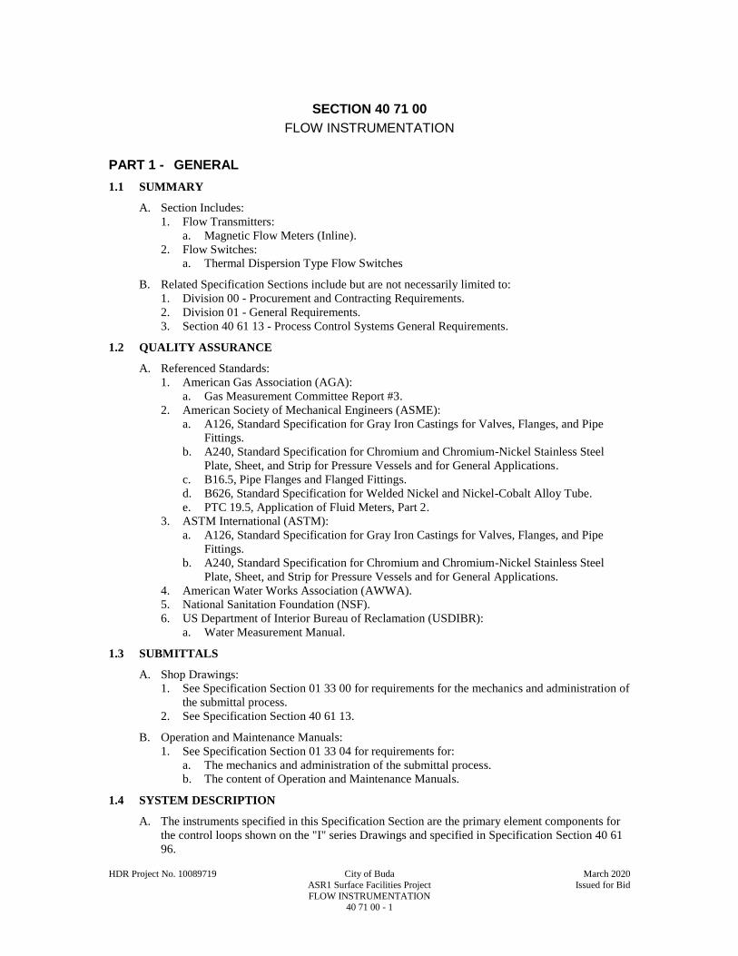
HDR Project No. 10089719 City of Buda March 2020
ASR1 Surface Facilities Project Issued for Bid
FLOW INSTRUMENTATION 40 71 00 - 1
SECTION 40 71 00
FLOW INSTRUMENTATION
PART 1 - GENERAL
1.1 SUMMARY
A. Section Includes:
1. Flow Transmitters:
a. Magnetic Flow Meters (Inline).
2. Flow Switches:
a. Thermal Dispersion Type Flow Switches
B. Related Specification Sections include but are not necessarily limited to:
1. Division 00 - Procurement and Contracting Requirements.
2. Division 01 - General Requirements.
3. Section 40 61 13 - Process Control Systems General Requirements.
1.2 QUALITY ASSURANCE
A. Referenced Standards:
1. American Gas Association (AGA):
a. Gas Measurement Committee Report #3.
2. American Society of Mechanical Engineers (ASME):
a. A126, Standard Specification for Gray Iron Castings for Valves, Flanges, and Pipe
Fittings.
b. A240, Standard Specification for Chromium and Chromium-Nickel Stainless Steel
Plate, Sheet, and Strip for Pressure Vessels and for General Applications.
c. B16.5, Pipe Flanges and Flanged Fittings.
d. B626, Standard Specification for Welded Nickel and Nickel-Cobalt Alloy Tube.
e. PTC 19.5, Application of Fluid Meters, Part 2.
3. ASTM International (ASTM):
a. A126, Standard Specification for Gray Iron Castings for Valves, Flanges, and Pipe
Fittings.
b. A240, Standard Specification for Chromium and Chromium-Nickel Stainless Steel
Plate, Sheet, and Strip for Pressure Vessels and for General Applications.
4. American Water Works Association (AWWA).
5. National Sanitation Foundation (NSF).
6. US Department of Interior Bureau of Reclamation (USDIBR):
a. Water Measurement Manual.
1.3 SUBMITTALS
A. Shop Drawings:
1. See Specification Section 01 33 00 for requirements for the mechanics and administration of
the submittal process.
2. See Specification Section 40 61 13.
B. Operation and Maintenance Manuals:
1. See Specification Section 01 33 04 for requirements for:
a. The mechanics and administration of the submittal process.
b. The content of Operation and Maintenance Manuals.
1.4 SYSTEM DESCRIPTION
A. The instruments specified in this Specification Section are the primary element components for
the control loops shown on the "I" series Drawings and specified in Specification Section 40 61
96.
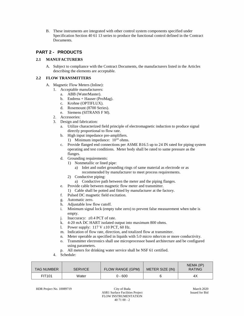
HDR Project No. 10089719 City of Buda March 2020
ASR1 Surface Facilities Project Issued for Bid
FLOW INSTRUMENTATION 40 71 00 - 2
B. These instruments are integrated with other control system components specified under
Specification Section 40 61 13 series to produce the functional control defined in the Contract
Documents.
PART 2 - PRODUCTS
2.1 MANUFACTURERS
A. Subject to compliance with the Contract Documents, the manufacturers listed in the Articles
describing the elements are acceptable.
2.2 FLOW TRANSMITTERS
A. Magnetic Flow Meters (Inline):
1. Acceptable manufacturers:
a. ABB (WaterMaster).
b. Endress + Hauser (ProMag).
c. Krohne (OPTIFLUX).
d. Rosemount (8700 Series).
e. Siemens (SITRANS F M).
2. Accessories:
3. Design and fabrication:
a. Utilize characterized field principle of electromagnetic induction to produce signal
directly proportional to flow rate.
b. High input impedance pre-amplifiers.
1) Minimum impedance: 1010 ohms.
c. Provide flanged end connections per ASME B16.5 up to 24 IN rated for piping system
operating and test conditions. Meter body shall be rated to same pressure as the
flanges.
d. Grounding requirements:
1) Nonmetallic or lined pipe:
a) Inlet and outlet grounding rings of same material as electrode or as
recommended by manufacturer to meet process requirements.
2) Conductive piping:
a) Conductive path between the meter and the piping flanges.
e. Provide cable between magnetic flow meter and transmitter.
1) Cable shall be potted and fitted by manufacturer at the factory.
f. Pulsed DC magnetic field excitation.
g. Automatic zero.
h. Adjustable low flow cutoff.
i. Minimum signal lock (empty tube zero) to prevent false measurement when tube is
empty.
j. Inaccuracy: ±0.4 PCT of rate.
k. 4-20 mA DC HART isolated output into maximum 800 ohms.
l. Power supply: 117 V ±10 PCT, 60 Hz.
m. Indication of flow rate, direction, and totalized flow at transmitter.
n. Meter operable as specified in liquids with 5.0 micro mho/cm or more conductivity.
o. Transmitter electronics shall use microprocessor based architecture and be configured
using parameters.
p. All meters for drinking water service shall be NSF 61 certified.
4. Schedule:
TAG NUMBER SERVICE FLOW RANGE (GPM) METER SIZE (IN) NEMA (IP) RATING
FIT101 Water 0 - 600 6 4X
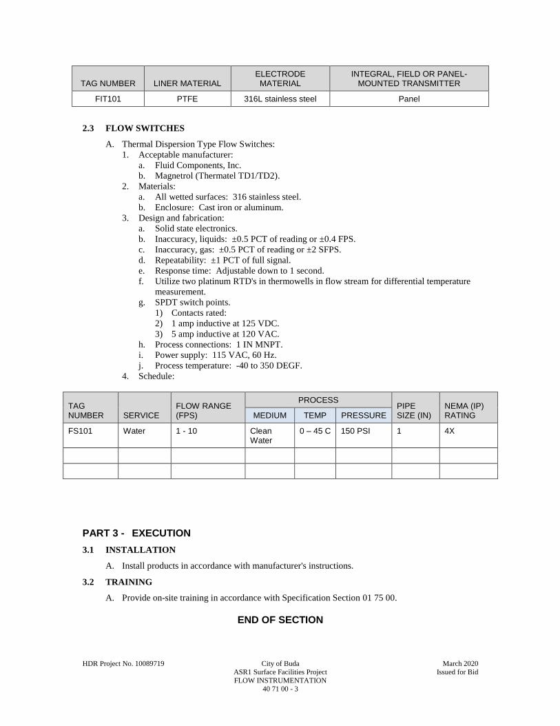
HDR Project No. 10089719 City of Buda March 2020
ASR1 Surface Facilities Project Issued for Bid
FLOW INSTRUMENTATION 40 71 00 - 3
TAG NUMBER LINER MATERIAL ELECTRODE MATERIAL
INTEGRAL, FIELD OR PANEL-MOUNTED TRANSMITTER
FIT101 PTFE 316L stainless steel Panel
2.3 FLOW SWITCHES
A. Thermal Dispersion Type Flow Switches:
1. Acceptable manufacturer:
a. Fluid Components, Inc.
b. Magnetrol (Thermatel TD1/TD2).
2. Materials:
a. All wetted surfaces: 316 stainless steel.
b. Enclosure: Cast iron or aluminum.
3. Design and fabrication:
a. Solid state electronics.
b. Inaccuracy, liquids: ±0.5 PCT of reading or ±0.4 FPS.
c. Inaccuracy, gas: ±0.5 PCT of reading or ±2 SFPS.
d. Repeatability: ±1 PCT of full signal.
e. Response time: Adjustable down to 1 second.
f. Utilize two platinum RTD's in thermowells in flow stream for differential temperature
measurement.
g. SPDT switch points.
1) Contacts rated:
2) 1 amp inductive at 125 VDC.
3) 5 amp inductive at 120 VAC.
h. Process connections: 1 IN MNPT.
i. Power supply: 115 VAC, 60 Hz.
j. Process temperature: -40 to 350 DEGF.
4. Schedule:
TAG NUMBER SERVICE
FLOW RANGE (FPS)
PROCESS PIPE SIZE (IN)
NEMA (IP) RATING MEDIUM TEMP PRESSURE
FS101 Water 1 - 10 Clean Water
0 – 45 C 150 PSI 1 4X
PART 3 - EXECUTION
3.1 INSTALLATION
A. Install products in accordance with manufacturer's instructions.
3.2 TRAINING
A. Provide on-site training in accordance with Specification Section 01 75 00.
END OF SECTION

This page intentionally left blank.
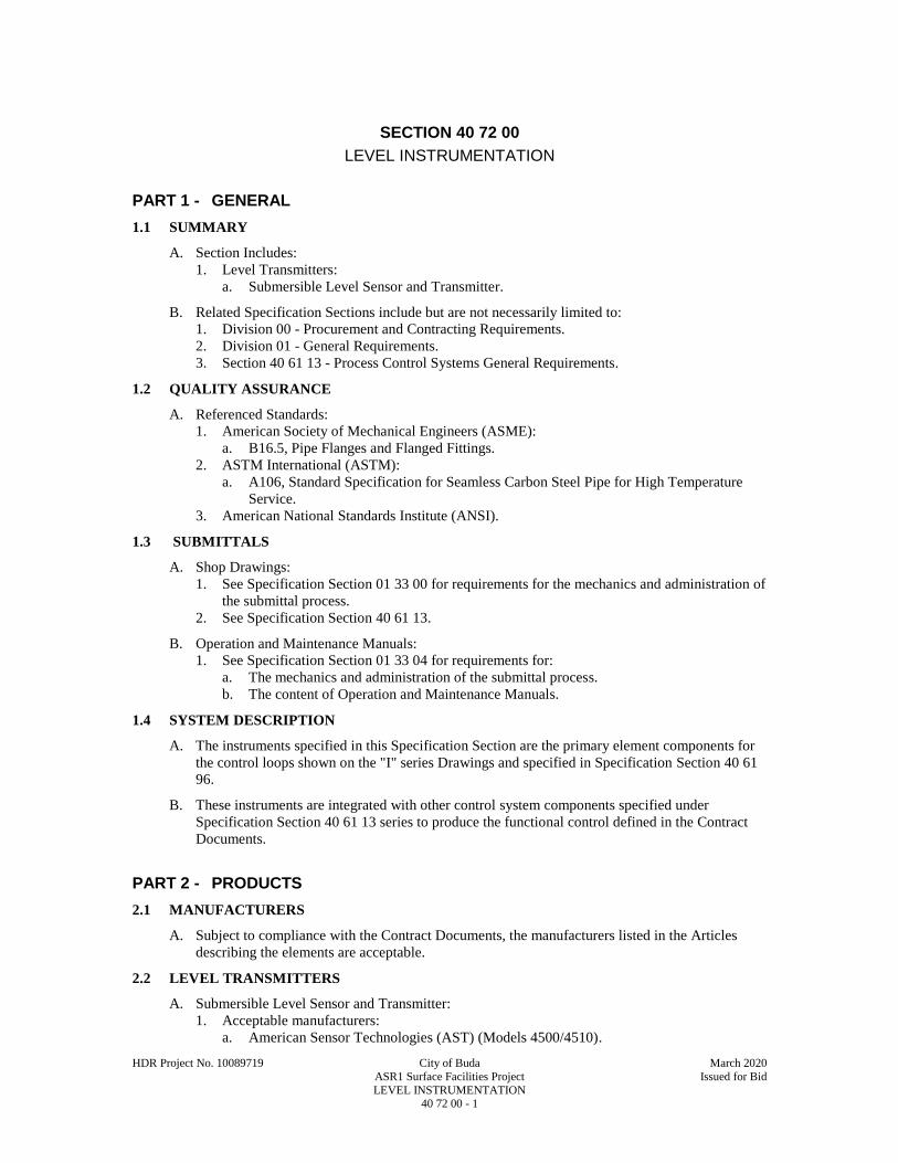
HDR Project No. 10089719 City of Buda March 2020
ASR1 Surface Facilities Project Issued for Bid
LEVEL INSTRUMENTATION 40 72 00 - 1
SECTION 40 72 00
LEVEL INSTRUMENTATION
PART 1 - GENERAL
1.1 SUMMARY
A. Section Includes:
1. Level Transmitters:
a. Submersible Level Sensor and Transmitter.
B. Related Specification Sections include but are not necessarily limited to:
1. Division 00 - Procurement and Contracting Requirements.
2. Division 01 - General Requirements.
3. Section 40 61 13 - Process Control Systems General Requirements.
1.2 QUALITY ASSURANCE
A. Referenced Standards:
1. American Society of Mechanical Engineers (ASME):
a. B16.5, Pipe Flanges and Flanged Fittings.
2. ASTM International (ASTM):
a. A106, Standard Specification for Seamless Carbon Steel Pipe for High Temperature
Service.
3. American National Standards Institute (ANSI).
1.3 SUBMITTALS
A. Shop Drawings:
1. See Specification Section 01 33 00 for requirements for the mechanics and administration of
the submittal process.
2. See Specification Section 40 61 13.
B. Operation and Maintenance Manuals:
1. See Specification Section 01 33 04 for requirements for:
a. The mechanics and administration of the submittal process.
b. The content of Operation and Maintenance Manuals.
1.4 SYSTEM DESCRIPTION
A. The instruments specified in this Specification Section are the primary element components for
the control loops shown on the "I" series Drawings and specified in Specification Section 40 61
96.
B. These instruments are integrated with other control system components specified under
Specification Section 40 61 13 series to produce the functional control defined in the Contract
Documents.
PART 2 - PRODUCTS
2.1 MANUFACTURERS
A. Subject to compliance with the Contract Documents, the manufacturers listed in the Articles
describing the elements are acceptable.
2.2 LEVEL TRANSMITTERS
A. Submersible Level Sensor and Transmitter:
1. Acceptable manufacturers:
a. American Sensor Technologies (AST) (Models 4500/4510).

HDR Project No. 10089719 City of Buda March 2020
ASR1 Surface Facilities Project Issued for Bid
LEVEL INSTRUMENTATION 40 72 00 - 2
b. Dwyer Instruments (MBLT Miniature).
c. Emerson Mobrey (9700).
d. Endress + Hauser (Waterpilot FMX21).
e. GE Druck (Series 1830/1840).
f. In-Situ (PXD-261/461).
g. Measurement Specialties (KPSI).
2. Specifications:
a. General:
1) Measurement Principle: Differential-pressure (hydrostatic) based on the height of
the liquid head with the use an integrated strain gauge or Ceramic Capacitive
Sensor (CCS).
a) Installation in water well.
b) Fully submersible.
c) Vented cable.
2) Minimum/Maximum Span: 1 to 200 PSIG.
3) Maximum O.D.: 1 IN
4) Accuracy: ±0.25 PCT of span.
b. Process Connection:
1) None: Mount vertically at the bottom of tank.
2) Option: 1/4 IN NPT connection on tank.
c. Display and Configuration:
1) Output variables: Pressure (converted to level).
2) Output Units: FT.
d. Electrical:
1) Signal Power: Loop-powered, 2-wire, 24 VDC.
2) Current Output: Analog 4-20 Ma into a 600 ohm loop.
3) Cable entry: 1/4 IN NPT connection to attached jacketed cable.
e. Materials of Construction:
1) Probe: 316SS, Viton, Titanium.
2) Cable: Hytrel, FEP, HDPE
f. Environment:
1) Ambient Temperature: -40 to 212 DEGF (-40 to 1000 DEGC).
2) Humidity: Up to 100 PCT, non-condensing.
3) Process Temperature: -4 to 104 DEGF (-20 to 60 DEGC).
4) Process Pressure: 0 to 35 PSIG.
3. Schedule (or Instrument List):
TAG NUMBER SERVICE
RANGE AREA
CLASSIFICATION
PART 3 - EXECUTION
3.1 INSTALLATION
A. Install products in accordance with manufacturer's instructions.
B. Install in monitoring tube to within 3 FT of base of pump column.
C. Locate instrument piping and tubing so as to be free of vibration and interference with other
piping, conduit, or equipment.
HDR Project No. 10089719 City of Buda March 2020
ASR1 Surface Facilities Project Issued for Bid
LEVEL INSTRUMENTATION 40 72 00 - 3
D. Keep foreign matter out of the system.
E. Remove all oil on piping and tubing with solvent before piping and tubing installation.
F. Plug all open ends and connections to keep out contaminants.
1. Cable penetration through discharge head to be water tight to 20 PSI.
3.2 TRAINING
A. Provide on-site training in accordance with Specification Section 01 75 00.
END OF SECTION

This page intentionally left blank.
D I V I S I O N 4 3
PROCESS GAS AND LIQUID HANDLING,
PURIFICATION, AND STORAGE EQUIPMENT

This page intentionally left blank.
HDR Project No. 10089719 City of Buda March 2020
ASR1 Surface Facilities Project Issued for Bid
PUMPING EQUIPMENT - VERTICAL TURBINE (LINE SHAFT) 43 24 27 - 1
PRE-SECTION 43 24 27
PUMPING EQUIPMENT - VERTICAL TURBINE (LINE SHAFT)
PART 1 - GENERAL
1.1 SUMMARY
A. Section Includes:
1. Vertical turbine pumps.
B. Related Sections include but are not necessarily limited to:
1. Division 00 - Procurement and Contracting Requirements.
2. Division 01 - General Requirements.
1.2 QUALITY ASSURANCE
A. Referenced Standards:
1. American National Standard for Vertical Pumps for Nomenclature, Definitions, Application
and Operation Hydraulic Institute ANSI/HI 2.1-2.5-1994 or latest standard.
2. American National Standard for Vertical Pump Tests Hydraulic Institute ANSI/HI 2.6-2000
or latest standard.
3. American National Standard for Pumps – General Guidelines for Types, Definitions,
Application and Sound Measurement Hydraulic Institute ANSI/HI 9.1-9.5-2015 or latest
standard.
4. American Water Works Association Standard for Vertical Turbine Pumps – Line Shaft and
Submersible Types ANSI/AWWA E101-88 or latest standard.
5. American Society of Mechanical Engineers (ASME):
a. B16.1, Gray Iron Pipe Flanges and Flanged Fittings: Classes 25, 125, and 250.
6. American Iron and Steel Institute (AISI)
a. 1045 Medium Carbon Steel
1.3 SUBMITTALS
A. Shop Drawings:
1. See Specification Section 01 33 00 for requirements for the mechanics and administration of
the submittal process.
2. Pump name, identification number, and specification section number.
3. Make, model, weight, and horsepower of each equipment assembly.
4. Complete catalog information, descriptive literature, specifications, and identification of
materials of construction.
5. Performance data curves (production), showing head, capacity, horsepower demand, and
pump efficiency over the entire operating range of the pump, from shutoff to maximum
capacity with a minimum of 5 points. Indicate separately the head, capacity, horsepower
demand, overall efficiency, and minimum submergence required at the guarantee point.
6. Performance data curves (reverse flow), showing head and capacity from 100 FT to 300 FT
of head, with a minimum of 5 points. Reverse flow testing to be performed with a locked
shaft.
7. The Contractor shall require the manufacturer to indicate the operating range limits on the
performance curves recommended for satisfactory operation without surge, cavitation, or
vibration. The operating range shall be as wide as possible based on actual hydraulic and
mechanical tests.
8. Detailed Drawings showing the equipment dimensions, size, and locations of connections
and weights of associated equipment.
9. Factory finish system.
10. Pump nameplate for each pump including manufacturer name, model number, serial
number, GPM at rated head, rpm-pertinent bearing and bearing lube information, and date
of manufacture.

HDR Project No. 10089719 City of Buda March 2020
ASR1 Surface Facilities Project Issued for Bid
PUMPING EQUIPMENT - VERTICAL TURBINE (LINE SHAFT) 43 24 27 - 2
B. Product technical data including:
a. Locked-rotor, reverse flow factor test pump curves for proposed pump make and
model.
C. Contract Closeout Information:
1. Operation and Maintenance Data:
a. Factory Functional and Performance Test Reports and Log (five copies).
b. Manufacturer’s Certificate of Proper Installation.
c. Copy of Texas pump installers’ license.
d. Results of bacteriological testing.
PART 2 - PRODUCTS
2.1 MANUFACTURERS
A. Subject to compliance with the Contract Documents, the following manufacturers are
acceptable:
1. Flowserve Corporation.
2. Sulzer Pumps.
3. National Pump.
4. ITT Goulds Pumps.
2.2 PERFORMANCE AND DESIGN REQUIREMENTS
A. Performance Parameters:
1. Name and tag number of pump:
a. Primary design conditions: 410 GPM at 374 FT TDH and 76 PCT efficiency.
b. Secondary design conditions: 510 GPM at 343 FT TDH and 81 PCT efficiency
c. Minimum impeller eye area: 13.8 SQ. IN .
d. Maximum speed: 1800 RPM.
e. Maximum horsepower: 60 HP.
f. Maximum Pump O.D.: 10 IN..
B. Provide pump with continuously increasing head from secondary design conditions to shutoff
condition. Provide pumps with net positive suction head requirements (NPSHR) less than the
net positive suction head available (NPSHA) at all operating conditions.
.
2.3 COMPONENTS
A. General:
1. Furnish units consisting of a vertical shaft turbine, direct connected to a vertical hollow
shaft motor. Design unit with non-reversing ratchets.
2. Weight of revolving parts of pump including unbalanced hydraulic thrust of impeller is
carried by thrust bearing in driver.
3. Make provision at driver shaft for adjusting impeller with reference to bowls.
B. Column:
1. Nominal diameter: 6 IN.
2. Length: 370 FT.
3. Construct discharge column pipe of steel and supply with threaded connections.
4. Provide top and bottom sections of column pipes to 5 FT lengths.
5. Provide intermediate column sections not exceeding 10 FT in length.
6. Abrasive blast column and coat with a minimum 15 mils dry film thickness epoxy system at
the factory.

HDR Project No. 10089719 City of Buda March 2020
ASR1 Surface Facilities Project Issued for Bid
PUMPING EQUIPMENT - VERTICAL TURBINE (LINE SHAFT) 43 24 27 - 3
7. Provide coating recommended by Tnemec or Koppers and approved for use with potable
water.
C. Open Line Shaft:
1. 416 stainless steel, rolled and ground.
2. Maximum length: 10 FT.
3. Furnish renewable shaft sleeves constructed from 416 stainless steel at each bearing
location.
4. Undercutting of shafting at sleeve locations is not permitted.
5. Provide rubber bearings at each column connection supported by retainers butted between
machined faces of discharge column.
6. Provide line shaft prelubrication system to water lubricate line shaft bearings prior to pump
startup. Solenoid valve controlling pre-lube system shall fail closed.
D. Pump Bowl and Suction Case:
1. Provide bowl constructed of close grained cast iron, free from imperfections and accurately
machined and fitted.
2. Coat pump bowl water passages with an abrasion-resistant baked enamel, phenolic or
epoxy.
3. Provide coating suitable for potable water service.
4. Design to ensure easy removal of bearings and impeller.
E. Bearings:
1. Provide units with sleeve bearings of SAE 660 bronze in each bowl and in suction case.
2. In bowl, provide main bronze bearing immediately above impeller and a lower bronze
bearing immediately below impeller.
3. Provide for lubrication of bowl bearings with pumped liquid.
4. Furnish suction case bearing having minimum length equal to five shaft diameters.
5. Ensure case bearing is permanently packed type with packing to be a nonsoluble grease.
6. Provide SAE 660 bronze collar for case bearing to prevent abrasives from entering bearing.
F. Pump Shaft and Impeller:
1. Provide pump unit shaft constructed of rolled and ground 416 stainless steel.
2. Furnish enclosed type impellers constructed of bronze and securely attached to impeller
shaft.
3. Ensure impeller is accurately fitted and statically and dynamically balanced.
4. Provide bronze replacement wear rings in each bowl to prevent wear on bowls.
G. Discharge Head Assemblies:
1. Design discharge head assembly for 150 PSI working pressure and 250 PSI test pressure.
2. Provide discharge head constructed of close-grained cast iron with integral discharge flange.
3. Supply pump discharge head support assembly and sole plate, in accordance with the
Drawings.
4. Mount discharge head on pump discharge head support assembly, in accordance with the
Drawings.
5. Ensure sole plate is of sufficient size to span opening in support structure.
6. Supply sole plate with lifting lugs capable of supporting weight of entire unit.
7. Furnish stuffing box constructed of cast iron and containing not less than four rings of non-
asbestos packing. Compress packing around shaft with adjustable gland. Furnish grease
fitting to provide additional lubrication to bronze upper shaft bearing. Provide connections
for grease inlet and pressure relief. Provide 416 stainless steel shaft at top section of line
shaft where it passes through stuffing box. Provide bronze upper shaft bearing directly
below stuffing box, in the head, to eliminate any shaft whip which could damage the seal.
Hard pipe stuffing box bleedoff to wet pit below pumps.
H. Suction Strainer:
1. Supply cone type strainer constructed of 304 stainless steel with net open area of not less
than four times the throat area of the suction case.

HDR Project No. 10089719 City of Buda March 2020
ASR1 Surface Facilities Project Issued for Bid
PUMPING EQUIPMENT - VERTICAL TURBINE (LINE SHAFT) 43 24 27 - 4
2. Maximum opening shall not be more than 75 PCT of the minimum opening of the water
passage through the bowls and impellers.
I. Data Plates:
1. Provide stainless steel data plate securely attached to pump.
2. Include manufacturer's name, pump size and type, serial number, speed, impeller diameter,
capacity and head rating, and other pertinent data.
J. Motors:
1. Reduce voltage starting, vertical hollow shaft, squirrel cage, induction type, and inverter
duty-rated.
2. 460 V, 60 HZ, 3 PH.
3. TEFC type with 1.15 service factor.
4. Size motor to drive pump continuously over the complete head - capacity range without the
load exceeding the nameplate rating.
5. Design motor for 42 DEG C ambient.
2.4 MAINTENANCE MATERIALS
A. Extra Materials:
1. Furnish the Owner the following extra parts for each pump service category:
a. Lower bearing assembly: One set.
b. Upper bowl bearing: One set.
c. Line shaft bearing assemblies: One set.
d. Packing, gland follower, studs and nuts: One set.
e. Lantern ring: One.
f. Wearing rings: One set.
PART 3 - EXECUTION
3.1 INSTALLATION
A. Installation of the pump and motor shall be in accordance with American National Standard for
Vertical Pumps for Nomenclature, Definitions, Application, and Operation Hydraulic Institute
ANSI/HI 2.1-2.5-1994 and manufacturer’s printed instructions. An authorized technical
representative of the manufacturer shall visit each site to witness the following and to certify in
writing that the equipment has been properly installed, aligned, lubricated, adjusted, and readied
for operation.
1. Installation of the Equipment: On-site service of 2 days per pump.
2. Inspection, Checking, and Adjusting the Equipment: Onsite service of 0.5.
3. Startup and Field Testing for Proper Operation: Onsite service of 1 day.
4. Performing Field Adjustments to Ensure that the Equipment Installation and Operation
Comply with Requirements: On-site service of 1 day.
B. Sealed Wellhead:
1. Well casing, sole plate, pump discharge head support assembly, and discharge head shall be
airtight.
2. The connection between the sole plate and casing shall be sealed by welding. The welding
procedure shall minimize warping of the sole plate. Warping tolerances shall be per the
pump manufacturer’s recommendation. Welding shall meet applicable standards of the
AWS for joining stainless steel to carbon steel and form an airtight seal at the joint between
the well casing and sole plate.
3. The space between the sole plate and the concrete pedestal shall be grouted with a non-
shrink grout of the proper category.
4. Install the pump discharge head, pump discharge head support assembly, and sole plate and
perform pressure tests on the annular space between the well casing and the pump column.
5. Demonstrate adequacy of the wellhead seal by pressurizing the annulus with compressed air
to 30 psi and checking for leaks at the seal using a foaming, detergent-based solution.
HDR Project No. 10089719 City of Buda March 2020
ASR1 Surface Facilities Project Issued for Bid
PUMPING EQUIPMENT - VERTICAL TURBINE (LINE SHAFT) 43 24 27 - 5
Performance of the seal is acceptable if there is not more than 1 psi loss after 30 minutes at a
pressure of 30 psi. If leakage is observed during the test, the source of the leak shall be
repaired, and the test repeated. The Contractor shall bear all expenses related to the leak
identification, repair, and retesting.
C. The well pump and appurtenances shall be disinfected to remove bacteriological contaminants
prior to installation. Following installation and start-up, bacteriological clearance will be
conducted in accordance with state standards. Disinfection and clearance procedures shall be
repeated until the well meets state requirements. Note all wells shall have met state disinfection
standards prior to pump installation.
D. A pump installer licensed in the State of Texas shall perform installation of in-well pump
components.
3.2 FIELD TESTS
A. Each pump system shall be field tested to demonstrate:
1. Satisfactory operation without noise and vibration at any operating head, including shutoff.
2. In production, indicated head, flow, and efficiency at the design point and at least two points
above and two points below the design point to satisfactorily demonstrate the range of pump
performance.
3. In reverse flow, indicated head and flow at five equally spaced points between 1 psi and up
to 60 psi wellhead pressure to satisfactorily demonstrate the range of pump performance
with locked rotor.
4. No undue attention is required for operation.
B. The following field testing shall be conducted:
1. Startup, check, and operate the pump system at max rpm.
2. Obtain concurrent readings of motor voltage, amperage, well water level, pumping rate, and
pump discharge head for at least five pumping conditions. Check each power lead to the
motor for proper current balance as defined in MG1 of NEMA.
3. Electrical and instrumentation tests shall conform to the requirements of the sections under
which that equipment is specified.
C. Field testing will be witnessed by the Engineer. The Contractor shall furnish 3 days advance
notice of field testing.
D. Field confirmation of the pump performance curves developed at the factory is required before
final acceptance of the pumping system. In the event any pumping system fails to meet the
specified requirements, the pump shall be modified or replaced by the manufacturer at no
expense to the Owner, and retested as above until it satisfies the requirements.
E. After each pumping system has satisfied the requirements, the Contractor shall certify in writing
that it has been satisfactorily tested and that all final adjustments have been made. Certification
shall include the date of the field tests, a listing of all persons present during the tests, and the
test data.
END OF SECTION

This page intentionally left blank.