
Bidding Documents - BUIDCO
612
Page 1 of 612 BIHAR URBAN INFRASTRCTURE DEVELOPMENT CORPORATION LIMITED(BUIDCo) Bidding Documents (for National Mission for Clean Ganga) NATIONAL COMPETITIVE BIDDING TO (I) DESIGN AND BUILD SEWAGE TREATMENT PLANTOF INSTALLED CAPACITY 32 MLD AND ALL APPURTENANT STRUCTURES AND ALLIED WORKS IN TWO MODULES (16MLD+16MLD);(II) SURVEY, REVIEW THE DESIGNS, REDESIGN WHERE NECESSARY, AND BUILD NEW DIVERSION WORKS WITH INTERCEPTION WITH RISING MAIN 2.3 KM, NEW TAPPINGS OF LENGTH 18.95 KM FOR 39 DRAINS CONTROLLED WITH SCADA INCLUDING SURVEY, DESIGN, CONSTRUCTION OF 5 NO. PUMPING STATIONS AND ALL APPURTENANT STRUCTURES AND ALLIED WORKS; AND CONSTRUCTION OF 31 OUTFALL STRUCTURE WITH SLUICE GATE INCLUDING EFFLUENT CHANNEL (250 MTR) FOR REUSE OF TREATED WASTE WATER (III) OPERATION & MAINTENANCE OF THE COMPLETE WORKS OF SEWAGE TREATMENT PLANT, INTERCEPTION & DIVERSION WORKS AND PUMPING STATIONS FOR A PERIOD OF 15 YEARS IN CHHAPRA TOWN , STATE OF BIHAR , INDIA. December 2018
-
Upload
khangminh22 -
Category
Documents
-
view
2 -
download
0
Transcript of Bidding Documents - BUIDCO

Page 1 of 612
B I H A R U R B A N I N F R A S T R C T U R E D E V E L O P M E N T C O R P O R A T I O N
L I M I T E D ( B U I D C o )
Bidding Documents (for National Mission for Clean Ganga)
NATIONAL COMPETITIVE BIDDING
TO (I) DESIGN AND BUILD SEWAGE TREATMENT PLANTOF INSTALLED CAPACITY 32 MLD AND ALL APPURTENANT STRUCTURES AND ALLIED WORKS IN TWO MODULES (16MLD+16MLD);(II) SURVEY, REVIEW THE DESIGNS, REDESIGN WHERE NECESSARY, AND BUILD NEW DIVERSION WORKS WITH INTERCEPTION WITH RISING MAIN 2.3 KM, NEW TAPPINGS OF LENGTH 18.95 KM FOR 39 DRAINS CONTROLLED WITH SCADA INCLUDING SURVEY, DESIGN, CONSTRUCTION OF 5 NO. PUMPING STATIONS AND ALL APPURTENANT STRUCTURES AND ALLIED WORKS; AND CONSTRUCTION OF 31 OUTFALL STRUCTURE WITH SLUICE GATE INCLUDING EFFLUENT CHANNEL (250 MTR) FOR REUSE OF TREATED WASTE WATER (III) OPERATION & MAINTENANCE OF THE COMPLETE WORKS OF SEWAGE TREATMENT PLANT, INTERCEPTION & DIVERSION WORKS AND PUMPING STATIONS FOR A PERIOD OF 15 YEARS IN CHHAPRA TOWN , STATE OF BIHAR , INDIA.
December 2018
Page 2 of 612
Invitation for Bids
FOR A CONTRACT
TO (I) DESIGN AND BUILD SEWAGE TREATMENT PLANTOF INSTALLED CAPACITY 32 MLD AND ALL APPURTENANT STRUCTURES AND ALLIED WORKS IN TWO MODULES (16MLD+16MLD);(II) SURVEY, REVIEW THE DESIGNS, REDESIGN WHERE NECESSARY, AND BUILD NEW DIVERSION WORKS WITH INTERCEPTION WITH RISING MAIN 2.3 KM, NEW TAPPINGS OF LENGTH 18.95 KM FOR 39 DRAINS CONTROLLED WITH SCADA INCLUDING SURVEY, DESIGN, CONSTRUCTION OF 5 NO. PUMPING STATIONS AND ALL APPURTENANT STRUCTURES AND ALLIED WORKS; AND CONSTRUCTION OF 31 OUTFALL STRUCTURE WITH SLUICE GATE INCLUDING EFFLUENT CHANNEL (250 MTR) FOR REUSE OF TREATED WASTE WATER (III) OPERATION & MAINTENANCE OF THE COMPLETE WORKS OF SEWAGE TREATMENT PLANT, INTERCEPTION & DIVERSION WORKS AND PUMPING STATIONS FOR A PERIOD OF 15 YEARS IN CHHAPRA TOWN , STATE OF BIHAR , INDIA.

Page 3 of 612
NOTICE INVITING TENDER FOR
Chhapra I&D and STP Project
[A Govt of Bihar Undertaking] NATIONAL MISSION FOR CLEAN GANGA
(NAMAMI GANGE PROGRAMME) Invitation for Bid
National1
1. ‘Namami Gange Programme’, is an Integrated Conservation Mission, approved as ‘Flagship Programme’ by the Union Government in June 2014 with budget outlay of Rs.20,000 Crore to accomplish the twin objectives of effective abatement of pollution, conservation and rejuvenation of National River Ganga.The National Mission for Clean Ganga (NMCG)(Ministry of Water Resources, River Development & Ganga Rejuvenation, Government of India)is the funding agency for Namami Gange Programme and intends to apply a part of the said budget outlay towards payments under the contract for work detailed below.
Competitive Bidding
No:BUIDCo/Yo-926/2018-77 Date: 20.12.2018
2. Qualification requirements as listed briefly below are required to be fulfilled by the bidder. [Bidders are advised to refer to the bidding documents for complete details.]
Financial:
a. The Bidder shall demonstrate that it possesses a net worth equivalent to minimum of INR 25.10 Cr. in each of the last three financial years preceding the date of submission of bid.
b. The Bidder shall demonstrate by submitting along with its bid, a banker’s certificate that it has available cash credit facility equivalent to minimum INR 167.35 million as on the date of submission of bid.
Technical:
1. The Bidder shall provide evidence that it has designed, developed, built, tested and commissioned at least 1 STP of 25.6 MLD or 2 STP of 19.2 MLD or 3 STP of 12.8 MLD during last 7 years preceding the month of publication of NIT.
2. The bidder or his nominated sub-contractor has successfully commissioned at least one Sewage Treatment Plant with the same technology as proposed for this contract for the lowest STP capacity mentioned in clause 1.4 (a) 1. above, operating successfully for a period of 1 year during the last 7 years preceding the month of publication of NIT.
BIHAR URBAN INFRASTRUCTURE DEVELOPMENT CORPORATION LTD

Page 4 of 612
3. The Bidder has the experience in operating and maintaining successfully STPs at least 1 STP of 25.6 MLD or 2 STP of 19.2 MLD or 3 STP of 12.8 MLD during 1 year over the last 7 years preceding the month of publication of NIT
4. The treatment technology proposed for this contract has been adopted (not necessarily built by the bidder) in at least 3 locations during last 7 years preceding the month of publication of NIT and that such STP has been operating successfully (meeting the required performance standards and environmental norms specified in the Contract) for a period of minimum 2 years over a period of last 7 years preceding the month of publication of NIT.
5 It has designed, developed, built, tested and commissioned sewerage network and Pumping station(s) of 17 km length of the total scope of sewerage network collectively maximum from 3 projects during the last 7 years preceding the month of publication of NIT.of which 2.1 Km should be above 1200 mm dia.
6. The bidder or his nominated sub-contractor has operated and maintained Sewerage network and pumping station(s)F of 17 km length of the total scope of sewerage network collectively from maximum 3 projects during 1 year over the last 7 years preceding the month of publication of NIT.
7. 2
Bidding will be conducted through the National Competitive Bidding and is open to all eligible bidders. bids will be received only through e-procurement mode
The bidder or his nominated sub-contractor has designed, built and commissioned Sewerage Network using trenchless technology for a minimum of 10 mtr of the proposed length of the network to be laid using trenchless technology, during the last 7 years preceding the month of publication of NIT.
www.eproc.bihar.gov.in
3. The Bihar Urban Infrastructure Development Corporation Ltd. for and on behalf of the Owner in the State of Bihar, India invites sealed bids from eligible bidders for the works detailed in the table below. The bidders may submit bids for the following work as per Instructions to Bidders and the Annexures thereto.
Name of the Work Bid
Security
Bid Processing fees (Beltron)
(In Rs.)
Cost of Bidding
Document Period
TO (I) DESIGN AND BUILD SEWAGE TREATMENT PLANTOF INSTALLED CAPACITY 32 MLD AND ALL APPURTENANT STRUCTURES AND ALLIED WORKS IN TWO MODULES (16MLD+16MLD);(II) SURVEY, REVIEW THE DESIGNS, REDESIGN WHERE NECESSARY, AND BUILD NEW DIVERSION WORKS WITH INTERCEPTION WITH RISING MAIN 2.3 KM, NEW TAPPINGS OF LENGTH 18.95 KM FOR 39 DRAINS CONTROLLED WITH SCADA INCLUDING SURVEY, DESIGN, CONSTRUCTION OF 5 NO. PUMPING
Rs. 20
million.
Rs. 17,700.00
Rs. 50,000.00
Design, Build, Test and
Commissioning period of 18 months, and
Operation and Maintenance period of 15
years.
2This clause 1.4(a) (3) is to be included only if trenchless technology is required to be used in the work.
Page 5 of 612
STATIONS AND ALL APPURTENANT STRUCTURES AND ALLIED WORKS; AND CONSTRUCTION OF 31 OUTFALL STRUCTURE WITH SLUICE GATE INCLUDING EFFLUENT CHANNEL (250 MTR) FOR REUSE OF TREATED WASTE WATER (III) OPERATION & MAINTENANCE OF THE COMPLETE WORKS OF SEWAGE TREATMENT PLANT, INTERCEPTION & DIVERSION WORKS AND PUMPING STATIONS FOR A PERIOD OF 15 YEARS IN CHHAPRA TOWN , STATE OF BIHAR , INDIA.
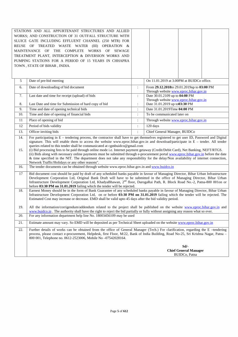
5 Date of pre-bid meeting On 11.01.2019 at 3.00PM at BUIDCo office.
6. Date of downloading of bid document : From 29.12.2018to 29.01.2019up to 03:00 PM Through website www.eproc.bihar.gov.in
7.
8.
Last date and time for receipt (upload) of bids Last Date and time for Submission of hard copy of bid
: :
Date 30.01.2109 up to 04:00 PM Through website www.eproc.bihar.gov.in Date 31.01.2019 up to03:30 PM
9. Time and date of opening technical bids : Date 31.01.2019Time 04:00 PM 10. Time and date of opening of financial bids : To be communicated later on 11 Place of opening of bid : Through website www.eproc.bihar.gov.in 12 Period of bids validity : 120 days 13. Officer inviting bids : Chief General Manager, BUIDCo 14.
15.
For participating in E – tendering process, the contractor shall have to get themselves registered to get user ID, Password and Digital signature. This will enable them to access the website www.eproc.bihar.gov.in and download/participate in E – tender. All tender queries related to this tender shall be communicated at [email protected] (i) Bid processing fees to be paid through online mode i.e. Internet payment getaway (Credit/Debit Card), Net Banking, NEFT/RTGS. (ii) Bids along with necessary online payments must be submitted through e-procurement portal www.eproc.bihar.gov.in before the date & time specified in the NIT. The department does not take any responsibility for the delay/Non availability of internet connection, Network Traffic/Holidays or any other reasons".
16. The tender documents can be obtained through website www.eproc.bihar.gov.in and www.buidco.in
17 Bid document cost should be paid by draft of any scheduled banks payable in favour of Managing Director, Bihar Urban Infrastructure Development Corporation Ltd, Original Bank Draft will have to be submitted in the office of Managing Director, Bihar Urban Infrastructure Development Corporation Ltd, KhadyaBhawan, 2nd floor, DarogaRai Path, R. Block Road No.-2, Patna-800 001on or before 03:30 PM on 31.01.2019 failing which the tender will be rejected.
18.
19.
Earnest Money should be in the form of Bank Guarantee of any scheduled banks payable in favour of Managing Director, Bihar Urban Infrastructure Development Corporation Ltd, on or before 03:30 PM on 31.01.2019 failing which the tender will be rejected. The Estimated Cost may increase or decrease. EMD shall be valid upto 45 days after the bid validity period. All the information/corrigendum/addendum related to the project shall be published on the website www.eproc.bihar.gov.in and www.buidco.in . The authority shall have the right to reject the bid partially or fully without assigning any reason what so ever.
20. For any information department help line No. 18003456109 may be used
21. Estimate amount may vary. So EMD will be deposited as per Technical Sheet uploaded on the website www.eproc.bihar.gov.in
22. Further details of works can be obtained from the office of General Manager (Tech.) For clarification, regarding the E –tendering process, please contact e-procurement, Helpdesk, first Floor, M/22, Bank of India Building, Road No-25, Sri Krishna Nagar, Patna – 800 001, Telephone no. 0612-2523006, Mobile No –07542028164.
Sd/- Chief General Manager
BUIDCo, Patna

Page 6 of 612
BIHAR URBAN INFRASTRUCTURE DEVELOPMENT CORPORATION LTD
NOTICE INVITING TENDER
FOR Chhapra I&D and STP Project
NATIONAL MISSION FOR CLEAN GANGA (NAMAMI GANGE PROGRAMME)
Invitation for Bids (IFB) National3
1. Period for design/ redesign, build, test and commissioning is 1.5 years and Operation and Maintenance period is 15years.
Competitive Bidding
No: BUIDCo/Yo-926/2018-77 Date: 20.12.2018
The BUIDCo for and on behalf of the Owner in the State of…Bihar, India invites sealed bids (to be submitted in hard copy only) from eligible Bidders for the works comprising (I) DESIGN AND BUILD SEWAGE TREATMENT PLANTOF INSTALLED CAPACITY 32 MLD AND ALL APPURTENANT STRUCTURES AND ALLIED WORKS IN TWO MODULES (16MLD+16MLD);(II) SURVEY, REVIEW THE DESIGNS, REDESIGN WHERE NECESSARY, AND BUILD NEW DIVERSION WORKS WITH INTERCEPTION WITH RISING MAIN 2.3 KM, NEW TAPPINGS OF LENGTH 18.95 KM FOR 39 DRAINS CONTROLLED WITH SCADA INCLUDING SURVEY, DESIGN, CONSTRUCTION OF 5 NO. PUMPING STATIONS AND ALL APPURTENANT STRUCTURES AND ALLIED WORKS; AND CONSTRUCTION OF 31 OUTFALL STRUCTURE WITH SLUICE GATE INCLUDING EFFLUENT CHANNEL (250 MTR) FOR REUSE OF TREATED WASTE WATER (III) OPERATION & MAINTENANCE OF THE COMPLETE WORKS OF SEWAGE TREATMENT PLANT, INTERCEPTION & DIVERSION WORKS AND PUMPING STATIONS FOR A PERIOD OF 15 YEARS IN CHHAPRA TOWN , STATE OF BIHAR , INDIA.
2. Detailed Invitation for Bid which includes instructions for submission of bids and all other relevant information is available on. www.eproc.bihar.gov.in. website i.e www.buidco.in. Bidding Documents will be available with effect from 29.12.2018
3. The last date & time of bid submission(in procurement portal) is 30.01.2019 up to 04:00 PM. The last date and time for submission of hard copy of bid (Bid document cost, EMD, all Affidavits, Undertakings) is 31.01.2019 up to 03:30 PM. The bids will be opened on the same day 31.01.2019 at 04:00 PM.
4. The interested eligible bidders may participate in the bidding process as per instructions given in the bidding documents.
Sd/-
Chief General Manager BUIDCo, Patna

Page 7 of 612
B I H A R U R B A N I N F R A S T R C T U R E D E V E L O P M E N T C O R P O R A T I O N
L I M I T E D ( B U I D C o )
Bidding Document
4
NATIONAL COMPETITIVE BIDDING
TO (I) DESIGN AND BUILD SEWAGE TREATMENT PLANTOF INSTALLED CAPACITY 32 MLD AND ALL APPURTENANT STRUCTURES AND ALLIED WORKS IN TWO MODULES (16MLD+16MLD);(II) SURVEY, REVIEW THE DESIGNS, REDESIGN WHERE NECESSARY, AND BUILD NEW DIVERSION WORKS WITH INTERCEPTION WITH RISING MAIN 2.3 KM, NEW TAPPINGS OF LENGTH 18.95 KM FOR 39 DRAINS CONTROLLED WITH SCADA INCLUDING SURVEY, DESIGN, CONSTRUCTION OF 5 NO. PUMPING STATIONS AND ALL APPURTENANT STRUCTURES AND ALLIED WORKS; AND CONSTRUCTION OF 31 OUTFALL STRUCTURE WITH SLUICE GATE INCLUDING EFFLUENT CHANNEL (250 MTR) FOR REUSE OF TREATED WASTE WATER (III) OPERATION & MAINTENANCE OF THE COMPLETE WORKS OF SEWAGE TREATMENT PLANT, INTERCEPTION & DIVERSION WORKS AND PUMPING STATIONS FOR A PERIOD OF 15 YEARS IN CHHAPRA TOWN , STATE OF BIHAR , INDIA.

Page 8 of 612

Page 9 of 612
INSTRUCTION TO BIDDERS
FOR A CONTRACT
TO (I) DESIGN AND BUILD SEWAGE TREATMENT PLANTOF INSTALLED CAPACITY 32 MLD AND ALL APPURTENANT STRUCTURES AND ALLIED WORKS IN TWO MODULES (16MLD+16MLD);(II) SURVEY, REVIEW THE DESIGNS, REDESIGN WHERE NECESSARY, AND BUILD NEW DIVERSION WORKS WITH INTERCEPTION WITH RISING MAIN 2.3 KM, NEW TAPPINGS OF LENGTH 18.95 KM FOR 39 DRAINS CONTROLLED WITH SCADA INCLUDING SURVEY, DESIGN, CONSTRUCTION OF 5 NO. PUMPING STATIONS AND ALL APPURTENANT STRUCTURES AND ALLIED WORKS; AND CONSTRUCTION OF 31 OUTFALL STRUCTURE WITH SLUICE GATE INCLUDING EFFLUENT CHANNEL (250 MTR) FOR REUSE OF TREATED WASTE WATER (III) OPERATION & MAINTENANCE OF THE COMPLETE WORKS OF SEWAGE TREATMENT PLANT, INTERCEPTION & DIVERSION WORKS AND PUMPING STATIONS FOR A PERIOD OF 15 YEARS IN CHHAPRA TOWN , STATE OF BIHAR , INDIA.

Page 10 of 612
Table of Clauses
Clause Description Page
1.1 Source of Funds & Scope of work
1.2 Eligible Bidders
1.3 Eligible Materials, Equipment, and Services
1.4 Inspection and Audit
1.5 Cost of Bidding
2.1 Content of Bidding Documents
2.2 Clarification of Bidding Documents
2.3 Site Visit
2.4 Data Room and Background Information
2.5 Pre-Bid Meeting
2.6 Amendment of Bidding Documents
2.7 Contact with the Owner for the Purpose of Clarification
2.8 Information Provided by the Owner/Bidders Due Diligence
2.9 Timetable
3.1 Language of Bid
3.2 Documents Comprising the Bid
3.3 Technical Section – Part I – Technical and Staffing Information
3.4 Technical Section – Part II – Bid Security
3.5 Technical Section – Part III – Bid Form and Qualification Information
3.6 Technical Section – Part IV - Joint Venture Documents and Requirements
3.7 Technical Section – Part V – Power of Attorney
3.8 Technical Section – Part VI – Commissions and Gratuities
3.9 Technical Section – Part VII – Pre-Printed Literature
3.10 Financial Section – Price Schedules
3.11 Financial Section – Bid Prices
3.12 Financial Section – Bid Currencies
3.13 Bidding of Alternatives not to be Considered
3.14 Period of Validity of Bid

Page 11 of 612
3.15 Format and Signing of Bid
4.1 Sealing and Marking of Bids
4.2 Deadline for Submission of Bids
4.3 Late Bids
4.4 Modification and Withdrawal of Bids
5.1 Opening of Bids by Owner
5.2 Clarification of Bid
5.3 Preliminary Examination of Bids
5.4 Technical Evaluation
5.5 Price Evaluation and Comparison of Bids
5.6 Qualification of the Bidder
5.7 Contacting the Owner
6.1 Award Criteria
6.2 Owner’s Right to Accept or Reject and Waive Irregularities
6.3 Notification of Award
6.4 Signing the Form of Contract
6.5 Performance Security
6.6 Failure to Sign the Form of Contract or provide the Performance Security
6.7 Adjudicator
6.8 Fraud and Corruption
6.9 Procurement Related Complaint
6.10 Environmental, social, health and safety requirements

Page 12 of 612
INSTRUCTIONS TO BIDDERS
Section 1. Introduction 1.1. Source of Funds & Scope of work
a. ‘Namami Gange Programme’, is an Integrated Conservation Mission, approved as ‘Flagship Programme’ by the Union Government in June 2014 with budget outlay of Rs.20,000 Crore to accomplish the twin objectives of effective abatement of pollution, conservation and rejuvenation of National River Ganga.The National Mission for Clean Ganga (NMCG)(Ministry of Water Resources, River Development & Ganga Rejuvenation, Government of India)is the funding agency for Namami Gange Programme and intends to apply a part of the said budget outlay towards payments under the contract for which these Bidding Documents are issued.
b. Ownernamed in the Bid Data Sheetintends to use the 100% funds from the Government of India (NationalMission for Clean Ganga, NMCGtowards the Capital Cost and Operation and Maintenance Cost for the Operations Period as per the provisions of this Contract.
c. Scope of work: The bidder’s scope of work shall include(i) design and build sewage treatment plant of installed capacityindicated in theBid Data Sheet and all appurtenant structures and allied works; (ii) survey, review the designs, redesign where necessary, and build new interception & diversion works including sewage pumping station(s) of length and capacity indicated in theBid Data Sheetand all appurtenant structures and allied works;and (iii) operation & maintenanceafter successful commissioning and testing of the complete works (“Project”) of sewage treatment plant, sewerage network and/or interception & diversion works and pumping stationsfor a period of 15years at the Place and Stateindicated in the Bid Data Sheet.
d. The Owner shall make available (i) the Right of Way and the land areafor the Sewage Treatment Plant and all appurtenant structuresup to the area allocated for this facility as indicated in the Bid Data Sheet; and (ii) the Right of Way for the Interception & Diversion Works, and the land area allocated for setting up the Sewage Pumping Station(s) and all appurtenant structures as indicated in the Bid Data Sheet.
e. For Sewage Treatment Plant: the selected Bidder shall adopt the most appropriate and techno economically feasible treatment process technology and Design the Sewage Treatment Plant ensuring that the Design standards and the performance standards as specified in the Contract are satisfied along with other conditions as may be applicable under the law.
f. For Interception & Diversion Works:
(a) the Owner shall make available all the designs and drawings pertaining to the proposed Interception & Diversion Worksincluding alignment, peripheral land etc.;
(b) the selected bidder shall conduct field survey, review the available designs, redesign where necessarythe Interception & Diversion Works based on the survey, ensuring that the design standards and the performance standards as specified in the

Page 13 of 612
Contract are satisfied along with other conditions as may be applicable as per the law; and
(c) if the selected bidder (Operator) redesigns where necessary, he shall obtain Owner’s approval of the redesigned component and work shall be carried out as per the revised approved design. Payments will be made for the actual quantities as per rates quoted by the bidder and incorporated in the Contract. Rates for items not found in the original BOQ or variations in quantities from the original BOQ will be regulated as per provisions of the Contract.
1.2. Eligible Bidders
1.2.1 A bidder may be a firm that is a private entity, a government-owned entity—subject to ITB 1.2.4— or any combination of such entities in the form of a joint venture (JV) under an existing agreement or with the intent to enter into such an agreement supported by a letter of intent.In the case of a joint venture, all members shall be jointly and severally liable for the execution of the Contract in accordance with the Contract terms. The JV shall nominate a Representative who shall have the authority to conduct all business for and on behalf of any and all the members of the JV during the bidding process and, in the event the JV is awarded the Contract, during contract execution. The number of members in a JV shall be limited to the number specified in the BDS.
1.2.2 Bidder shall not have a conflict of interest. Any Bidder found to have a conflict of interest shall be disqualified. A Bidder may be considered to have a conflict of interest for the purpose of this bidding process, if the Bidder:
(a) directly or indirectly controls, is controlled by or is under common control with another Bidder; or
(b) receives or has received any direct or indirect subsidy from another Bidder; or (c) has the same legal representative as another Bidder; or (d) has a relationship with another Bidder, directly or through common third
parties, that puts it in a position to influence the bid of another Bidder, or influence the decisions of the Owner regarding this bidding process; or
(e) participates in more than one bid in this bidding process. Participation by a Bidder in more than one Bid will result in the disqualification of all Bids in which such Bidder is involved. However, this does not limit the inclusion of the same subcontractor in more than one bid; or
(f) any of its affiliates participated as a consultant in the preparation of the design or technical specifications of the works that are the subject of the bid; or
(g) any of its affiliates has been hired (or is proposed to be hired) by the Owneror NMCGas Engineer for the Contract implementation; or
(h) would be providing goods, works, or non-consulting services resulting from or directly related to consulting services for the preparation or implementation of the project specified in the BDS ITB 1.1 that it provided or were provided by any affiliate that directly or indirectly controls, is controlled by, or is under common control with that firm; or
(i) has a close business or family relationship with a professional staff of the the project implementing agency, who: (i) are directly or indirectly involved in the preparation of the bidding documents or specifications of the contract, and/or the bid evaluation process of such contract; or (ii) would be involved

Page 14 of 612
in the implementation or supervision of such contract throughout the procurement process and execution of the contract.
1.2.3 A Bidder may have the nationality of any country. A Bidder shall be deemed to have the nationality of a country if the Bidder is constituted, incorporated or registered in and operates in conformity with the provisions of the laws of that country, as evidenced by its articles of incorporation (or equivalent documents of constitution or association) and its registration documents, as the case may be. This criterion also shall apply to the determination of the nationality of proposed sub-contractors or sub-consultants for any part of the Contract including related Services.
1.2.4 Bidders that are Government-owned enterprises or institutions in the Owner’s Country may participate only if they can establish that they (i) are legally and financially autonomous (ii) operate under commercial law, and (iii) are not dependent agencies of the Owner. To be eligible, a government-owned enterprise or institution shall establish through all relevant documents that it: (i) is a legal entity separate from the government (ii) does not currently receive substantial subsidies or budget support; (iii) operates like any commercial enterprise, and, inter alia, is not obliged to pass on its surplus to the government, can acquire rights and liabilities, borrow funds and be liable for repayment of its debts, and can be declared bankrupt; and (iv) is not bidding for a contract to be awarded by the department or agency of the government which under their applicable laws or regulations is the reporting or supervisory authority of the enterprise or has the ability to exercise influence or control over the enterprise or institution.
1.2.5 ABidder shall not be under suspension from bidding by the Owner as the result of the operation of a Bid–Securing Declaration.
1.2.6 A Bidder shall provide such evidence of eligibility satisfactory to the Owner, as the Owner shall reasonably request.
1.3. Eligible Materials, Equipment, and Services
The materials, equipment and services to be supplied under the Contract may have their origin in any country, subject to the restrictions specified in Annexure A Part g - Eligible Countries, and all expenditures under the Contract will not contravene such restrictions. At the Owner’s request, Bidders may be required to provide evidence of the origin of materials, equipment and services.
1.4. Inspection and Audit
The NMCG and Owner require compliance with theirpolicies in regard to corrupt and fraudulent practices as set forth in Section 6.8. In further pursuance of this policy, Bidders shall permit and shall cause its agents (whether declared or not), sub-contractors, sub-consultants, service providers, or suppliers and any personnel thereof, to permit the Owner to inspect all accounts, records and other documents relating to any

Page 15 of 612
prequalification process, bid submission, and contract performance (in the case of award), and to have them audited by auditors.
1.5. Cost of Bidding
The Bidder shall bear all costs associated with the preparation and submission of its bid, and the Owner will in no case be responsible for these costs, regardless of the conduct or outcome of the bidding process.

Page 16 of 612
Section 2. The Bidding Documents 2.1. Content of Bidding Documents
a. The nature of the services, the site and the plant that are to be designed, built, operated and maintained by the Bidder, the procedures that are to be followed during the bidding process and the contract terms and technical requirements are prescribed in the Bidding Documents. The Bidding Documents consist of:
1. the Instructions to Bidders (ITB);
2. the Bid Data Sheet;
3. Annexure A to the Bidding Documents – Forms
a. Bidder’s Bid Form
b. Bidder’s Price Schedules
c. Form of Bid Security
d. Form of Performance Security
e. Format of Curriculum Vitae for Proposed Key Staff
f. Form for Clarification Questions
g. List of eligible Countries
h. Qualification Criteria
i. Information Forms
j. Declaration Format for Deemed Export Benefits
k. Form of Letter of Intent by JV Partners
l. Form of Power of Attorney for Joint Venture
m. Form of undertaking by JV Partners
4. Annexure B to the Bidding Documents – the contract (the “Draft Contract”) consisting of:
i. Form of Contract;
ii. General Conditions of the Contract; and
iii. Schedulesattached to the Contract
5. Addenda to the documents listed in ITB Section 2.1(a) (1) to (4), if any are issued by the Owner.
The Invitation for Bids issued by the Owner is not part of the Bidding Documents.
2.1.1. The documents listed in ITB Section2.1(a) (1), (2), (3), (4) and (5) are collectively the “Bidding Documents”.
2.1.2. Each Bidder shall examine all instructions, terms and conditions, forms, specifications and other information contained in the Bidding Documents. If the Bidder fails to provide all documentation and information required by the Bidding Documents; or submits a Bid which is not substantially responsive to the terms and conditions of the Bidding
Page 17 of 612
Documents, such action is at the Bidder’s risk and the Owner may determine that the Bid is non-responsive to the Bidding Documents and may reject it.
2.2. Clarification of Bidding Documents
a. A prospective Bidder requiring any clarification of the Bidding Documents may notify the Owner in writing by mail, courier, fax or hand delivery at the Owner’s mailing address indicated in the Bid Data Sheet. Similarly, if a Bidder feels that any important provision in the Bidding Documents, such as those listed in ITB Section 3.3, will be unacceptable, such an issue must be raised during the clarification stage.
b. All such queries and requests for clarification shall be submitted using the Form for Clarification Questions contained in Annexure A Part f to the Bidding Documents.
c. The Owner will respond in writing to any request for clarification or modification of the Bidding Documents that it receives on the Form for Clarification Questions no later than the date set out in the timetable in the Bid Data Sheet. Written copies of the Owner’s response, including an explanation of the query but not identification of its source, (the “Response to Questions Document”) will be sent to all prospective Bidders that have received the Bidding Documents. If similar or repeated queries are made by Bidders, the Owner may list those queries as one query & respond to such query only once.
2.3. Site Visit
a. Each Bidder is advised to visit and inspect the site/alignment of (a) the proposed Sewage Treatment Plant; and (b) the Interception & Diversion Works,SPS (the “Site Visit”) and their surroundings and obtain for itself on its own responsibility all information that may be necessary for preparing the Bid and entering into the Contract. The Owner will schedule a time on or after the date set out in the timetable specified in the Bid Data Sheet and develop a procedure for Bidders to conduct a Site Visit. The costs of visiting the site shall be at the Bidder’s own expense.
b. Each Bidder and any of its personnel or agents will be granted permission by the Owner to enter upon its premises and lands for the purpose of such a Site Visit, but only upon the express condition that the Bidder, its personnel and agents will release and indemnify the Owner, the Borrower and their personnel and agents from and against all liability in respect thereof and will be responsible for death or personal injury, loss of or damage to property and any other loss, damage, costs and expenses incurred as a result of the Site Visit.
2.4. Data Room and Background Information
Owner shall establish a data room (the “Data Room”) at the location specified in Bid Data Sheet with a collection of relevant data to be accessible to Bidders or their representatives from the date set out in the timetable specified in the Bid Data Sheet until the deadline for submission of Bids (the “Submission Deadline”), in accordance with a schedule established by the Owner.
2.5 Pre-Bid Meeting
Each prospective Bidder is invited to attend a Pre-Bid Meeting, which will take place at the venue and time stipulated in the Bid Data Sheet. While attendance at the pre-bid meeting is not mandatory, Bidders are strongly encouraged to attend. The purpose of the

Page 18 of 612
pre-bid meeting is to provide a technical presentation and to clarify issues and answer questions on any matter that may be raised at the meeting. Each prospective Bidder is requested, as far as possible, to submit any question in writing to reach the Owner not later than one week before the pre-bid meeting. It may not be practicable at the meeting to answer questions received late, but questions and responses will be transmitted as indicated hereafter. Minutes of the pre-bid meeting will be transmitted without delay to all prospective Bidders that have been issued Bidding Documents. All responses to questions raised at the pre-bid meeting will be included in the Response to Questions Document. The proceedings of the pre-bid meeting, reply to the queries and corrigendum if any will also be uploaded on the websitespecified in the Bid Data Sheet.
2.6. Amendment of Bidding Documents
a. At any time prior to the Submission Deadline, the Owner may, for any reason, whether at its own initiative, or in response to a clarification requested by a prospective Bidder, amend the Bidding Documents by addendum. No other communications of any kind whatsoever, including, without limitation, the minutes of the pre-bid meeting or the Response to Questions Document, shall modify the Bidding Documents.
b. Addenda, if any, will be sent in writing by air mail, courier or facsimile to all prospective Bidders and will be binding on them. Bidders shall immediately acknowledge receipt to the Owner of any such amendment, and it will be assumed that the information contained therein has been taken into account by the Bidder in its Bid. Such Addenda will also be uploaded on the website specified in ITB 2.5.
c. In order to afford prospective Bidders reasonable time in which to take the amendment into account in preparing their Bids, the Owner may, at its discretion, extend the Submission Deadline, in which case, the Owner will notify all prospective Bidders in writing of the extended deadline.
2.7. Contact with the Owner for the Purpose of Clarification
The prospective Bidders shall contact only the persons named at the addresses in the Bid Data Sheet for the purpose of requesting information and clarification or for any other purpose relating to the bidding process. The prospective Bidders shall not contact any other person at the Owner during the bidding process. From the time of Bid opening to the time of Contract award, if any Bidder wishes to contact the Owner on any matter related to the bidding process, it may do so in writing.
2.8. Information Provided by the Owner/Bidders Due Diligence
a. Each Bidder is solely responsible for conducting its own independent research, due diligence, and any other work or investigations and for seeking any other independent advice necessary for the preparation of Bids, negotiation of agreements, and the subsequent delivery of all services to be provided by the Bidder that has been successful in the bidding process (the “Successful Bidder”). The Bidder shall submit its bid considering that the treated effluent from the STP has to be discharged into the location as specified in the Bid Data Sheet under ITB 3.3(b).
b. No representation or warranty, express or implied, is made and no responsibility of any kind is accepted by the Owner or its advisors, employees, consultants or agents,

Page 19 of 612
for the completeness or accuracy of any information contained in the Bidding Documents or the Response to Questions Document, or provided during the bidding process or during the term of the Contract. The Owner and its advisors, employees, consultants and agents shall not be liable to any person or entity as a result of the use of any information contained in the Bidding Documents or the Response to Questions Document, or provided during the bidding process or during the term of the Contract.
c. Bidders shall not rely on any oral statements made by the Owner or its advisors, employees, consultants or agents.
d. All Bidders shall, prior to submitting their Bid, review all requirements with respect to corporate registration and all other requirements that apply to companies that wish to conduct business in the Owner’s country. The Bidders are solely responsible for all matters relating to their legal capacity to operate in the jurisdiction to which this bidding process applies.
2.9. Timetable
a. The estimated timetable, from the issuance of the Bidding Documents to the identification by the Owner of the Successful Bidder and the execution of the Contract, is set out in the Bid Data Sheet.
b. The Owner may, in its sole discretion and without prior notice to the Bidders, amend the estimated timetable specified in the Bid Data Sheet. Bidders shall not rely in any way whatsoever on the estimated timetable specified in the Bid Data Sheet and the Owner shall not incur any liability whatsoever arising out of amendments to the estimated timetable. The Owner shall give notice of timetable changes, if any, by addenda.
Page 20 of 612
Section 3. Preparation of Bids 3.1. Language of Bid
The Bid prepared by the Bidder, all correspondence and documents related to the Bid exchanged by the Bidder and the Owner and the bidding process shall be written in the language specified in the Bid Data Sheet, provided that any printed literature furnished by the Bidder may be written in another language, as long as such literature is accompanied by a translation of its pertinent passages in the language specified in the Bid Data Sheet, in which case, for purposes of interpretation of the Bid, the translation shall govern.
3.2. Documents Comprising the Bid
a. Each Bidder shall submit only one Bid comprising of two covers, one containing the Technical Bid/ Proposal and the other the Financial or Price Bid/ Proposal. The bid shall consist of:
1. One Technical Bid/ Proposal which contains the following parts in the following order:
i. Part I – the information required by ITB Section 3.3;
ii. Part II – the Bid Security required by ITB Section 3.4;
iii. Part III – the Bid Form required by ITB Section 3.5(a), and the information required by ITB Section 3.5(b)and Appendix to Bid containing completed Tables of Schedule of Adjustment Data as required by ITB Section 3.11 b;
iv. Part IV – where applicable, the joint venture documents required by ITB Section 3.6;
v. Part V – the power of attorney required by ITB Section 3.7;
vi. Part VI – the declaration of commissions and gratuities required by ITB Section 3.8;
vii. Part VII – Optional, separately bound pre-printed literature as per ITB Section 3.9; and
2. One Financial Bid/Proposalwhich shall consist of the Price Schedules completed in accordance with ITB Section 3.10.
b. Each Bidder shall also submit an initialled Draft Contract, in accordance with ITB Section 3.15 (b), in the same envelopeas its Technical Section.
3.3. Technical Section – Part I – Technical and Staffing Information
The Bidder, while making his technical proposal shall consider the following aspects.
For STP
a. The Owner shall make available the right of way and the land area allocated for this facility for setting up of Sewage Treatment Plant. The Owner shall also make available the right of way to the facilities to be set up under the contract, for making
Page 21 of 612
arrangements in connection with reuse of treated effluent from STP as specified in the contract.
The bidders will be free to offer STP based on a technology of their choice and indicate in their bid the actual land requirement for setting up treatment facility as offered by them. The status of availability and ownership of the land is specified in the Bid Data Sheet.
b. The location for disposal of treated Sewage and sludge shall be as specified in the Bid Data Sheet.
c. The land that will be required for STP, roads, drains and other appurtenant structures shall be indicated by the bidder and the cost of such Land requirement as determined on the basis of land price specified in the Bid Data Sheet shall be added to the bid price for evaluation of the lowest evaluated substantially responsive bidder.
d. The Operator shall design and construct the STP with installed capacity as indicated in the Bid Data Sheet clause 1.1(d).
For Interception & Diversion
e. The owner shall make available the right of way for the Interception & Diversion Works and land area allocated for setting up the Sewage Pumping Station and all appurtenant structures. The status of availability and ownership of the land is specified in the Bid Data Sheet.
Part-I of the Technical Section of the Bid
f. For STP: Part-I of the Technical Section of the Bid shall consist of the following sub-parts in the following order:
1. an executive summary of the Technical Section;
2. a detailed design-build work plan including a detailed program timetable (the “Design-Build Work plan”) setting out the manner in which the Bidder proposes to carry out the Design-build services as defined in the Draft Contract (the “Design-Build Services”) and meet the Design-build technical standards in accordance with the Technical Standards Schedule to the General Conditions.The Design-Build Work plan shall be divided into the following sections:
i. (a) A well-defined proposal for the treatment process technology proposed by the Bidder with evidence showing the ability of the treatment process technology of meeting the service standards and the environmental norms;
(b) Plan for reuse of treated effluent along with conceptual drawings, to meet the requirements specified in the Schedule 2 of the Contract, namely Design Build Services Schedule (DBSS);
The Owner will make available the land required for the STP and ancillary works up to the limit specified in Section 3.3(a) above. The Bidder’s Design should aim at optimizing the land requirement. This shall also include details of modules of the treatment process and the details of modular approach to capacity addition if it is adopted in the proposal.

Page 22 of 612
ii. a section entitled “Drawings” which consists of conceptual drawings that are sufficiently detailed to communicate the Bidder’s Design intent for all components of the proposed Sewage Treatment Plant.The conceptual drawings shall include the following:
a. a site plan showing the location of the STP area, alignment and limits to the Bidders construction activities; along with the land required for the total planned area for STP. The site plan / layout shall include new STP, Layout of various units of preliminary and secondary treatment, Layout of piping between various units and unit bypass for each unit, plant bypass, Layout of internal roads, hard standing, parking, compound wall and gate house, etc. Location of power transformer, switch room, control room and switchgear, Power wiring and underground cable layout, Relative location of administrative office, lab and control centre, Internal roads and parking provisions, Landscaping and reservations for future expansion, possible future tertiary treatment and Any other features for safe and efficient working during operations and maintenance.
b. a site plan showing all proposed works listed in the Bid Data Sheet;
c. a detailed narrative in support of the conceptual drawings setting out the Bidder’s plan for compliance with the Design-Build Services Schedule and the technical standards set out in the Technical Standards Schedule, to include construction quality assurance and control;
iii. a detailed program and schedule setting out the proposed sequence of works to be undertaken, including estimated start date, finish date and time allocations for individual units of the works, proposed resources to be allocated and the identification of all major milestones, including the submission of schematic Design documents, Design development documents, the Design-Build Documents and the commissioning of individual units of the Sewage Treatment Plant (STP); and
iv. an itemised list of the principal codes of practice and standards proposed to be used for the Design-Build Services
3. a section specifying the power consumption for Operations and Maintenance of the STP on an annual basis. The Bidder shall further provide the breakup of electricity consumption in various facilities in the STP on an annual basis. The Bidder shall provide the total estimated connected load in KW, maximum power demand, average energy consumption in kWh per day with full load up to the installed capacity of the STP, estimated power factor, any proposals for improving efficiency in terms of lower power consumption.
g. For Interception & Diversion Works: Part-I of the Technical Section of the Bid for Network and/or Interception & Diversion Worksshall consist of the following sub-parts in the following order:
1. An Executive Summary of the Technical Section;

Page 23 of 612
2. A detailed work plan for conducting field survey, reviewing the designs provided by the owner, redesigning (where necessary or can submit a full design but the specifications such as proposed pipe materials etc. remain the same so that there will not be any need for revising BOQ etc. except modifying some quantities) and build-work-plan comprising a detailed program timetable (the “Design-Build Work Plan”) setting out the manner in which the Bidder proposes to carry out the design-build services as defined in the Draft Contract (the “Design-Build Services”) and meet the design-build technical standards in accordance with the Technical Standards Schedule to the General Conditions. The Design-Build Work plan shall be divided into the following sections:
i. A well-defined proposal for the configuration of Interception & Diversion Works proposed by the bidder along with the details of the manholes, Pumping Stations, system design of the pumping stations etc. The bidder’s design should aim at optimizing the energy requirements for pumping of the sewage.
ii. a section entitled “Drawings” which consists of conceptual drawings that are sufficiently detailed to communicate the Bidder’s design intent for all components of the proposed Interception & Diversion Works. The conceptual drawings shall include the following:
a. The site plan / layout for Pumping Station, Layout of piping between various units and unit bypass for each unit, plant bypass, compound wall and gate house, etc. Location of power transformer, if applicable, location of administrative office and control centre, and any other features for safe and efficient working during operations and maintenance.
b. a layout plan showing all proposed works listed in the Bid Data Sheet;
iii. a detailed narrative in support of the conceptual drawings setting out the Bidder’s plan for compliance with the Design-Build Services Schedule and the technical standards set out in the Technical Standards Schedule, to include construction quality assurance and control;
iv. a detailed program and schedule setting out the proposed sequence of works to be undertaken, including estimated start date, finish date and time allocations for individual units of the works, proposed resources to be allocated and the identification of all major milestones, including the submission of schematic design documents, design development documents, the Design-Build Documents and the commissioning of individual units of the Sewage Pumping Station; and
v. an itemized list of the principal codes of practice and standards proposed to be used for the Design-Build Services; and
A section specifying the Power Consumption for Operations and Maintenance of the Sewage Pumping Station on annual basis. The Bidder shall provide the total estimated connected load in kW, maximum power demand, average energy consumption in kWh per day with full load of

Page 24 of 612
pumping sewage up to the installed capacity, estimated power factor, any proposals for improving efficiency in terms of lower power consumption
h. For Both STP and Interception & Diversion Works: Part-I of the Technical Section of the Bid shall further consist of the following sub-parts in the following order:
1. a section entitled “Plant and Equipment and Operator’s Equipment” which consists of a list of proposed suppliers of major Plant and Equipment and Operator’s Equipment (Design-Build) and Operator’s Equipment (Operations), including:
i. plant and equipment;
ii. Materials including pipe work and principal construction materials.
For all items listed in ITB Section 3.3(h)(1), the Bidders shall provide either catalogues or detailed information with respect to manufacturer and source, model Designation, primary specifications, and year of manufacture, as applicable.
2. a detailed work plan (the “Operations Work Plan”) setting out the manner in which the Bidder proposes to carry out the operation of the STP and Sewerage Pumping Station as set out in the Contract (the “Operations Services”) and meet the operating technical standards in accordance with the Technical Standards Schedule to the General Conditions. The Operations Work Plan shall contain a section entitled “Operation and Maintenance Plan” which provides an outline contents and overview of the Bidder’s proposed plans and programs for Operations and Maintenance of STP and Interception & Diversion Works;
3. a detailed description of the Bidder’s plans and methodologies to ensure that the requirements of the applicable Environmental Management Plan specified in the special conditions of contract for the proposed STP, Interception & Diversion Works and allied services at Site will be implemented and monitored;
4. a detailed staffing plan (the “Staffing Plan”) setting out the Bidder’s proposed staffing arrangements for the carrying out of the Design-Build and Operations Services. The Staffing Plan shall be divided into the following sections:
i. two sub-sections, (one for the Design-Build Services and one for the Operations Services) each entitled the “Staffing Chart” and each consisting of a chart setting out a list of all proposed Operator’s Personnel positions, the role of each position, the duration of existence of the position, and the location of the staff person filling the position during the periods of assignment to carry out the Design-Build and Operations Services;
ii. a section entitled “Summary of Staff Qualifications” which consists of a summary table setting out,
a. for the Key Staff positions, the names of the Bidder’s employees who will occupy the Key Staff positions during Design-Build Services; and
b. all proposed positions for the Operator’s Key Personnel and the qualifications, years of experience and areas of expertise, including a

Page 25 of 612
clear indication of the expertise that the staff will provide consistent with the requirements set out in the Bid Data Sheet for each of the proposed positions; The Bidder’s personnel as indicated in the bid proposals shall not be changed during the period of the contract. In case if the successful Bidder, intends to change the key staff, such change will be subject to approval from the Owner on justification provided by the successful Bidder. The replaced key staff shall have to be of equivalent or higher qualification and experience.
iii. a section entitled, “Curriculum Vitae” which contains the signed curriculum vitae for each of the Key Staff, in the format set out in Annexure A Part e to the Bidding Documents;
5. For the purpose of ITB Section 3.3(h)(4), “Key Staff” means those individuals that will fill the positions listed in the Bid Data Sheet; and
6. A list of all nominated sub-contractor and sub- consultants and a detailed description of the services to be carried out or the Plant and Equipment to be provided by the nominated sub-Contractor and sub-consultants. The Bidder shall provide the name and nationality of all nominated sub-contractors and sub-consultants. The Bidder shall ensure that all nominated sub-contractorsand sub consultants complywith ITB Sections 1.3 and 6.8. The Bidder shall not exceed the maximum percentage of subcontracting and sub consulting set out in Bid Data Sheet.
i. Environmental, Social, Health and Safety (ESHS) Code of Conduct (For both STP and Network -combined or separate)
1. The Bidder shall submit the Environmental, Social, Health and Safety (ESHS) Code of Conduct that will apply to the Contractor’s employees and subcontractors. The Code of Conduct shall ensure compliance with the ESHS provisions of the contractincluding those described in the following documents.
a. [Scope of work];
b. [Environmental and Social Impact Assessment (ESIA)];
c. [Environmental and Social Management Plan (ESMP)];
d. [Consent Conditions (regulatory authority conditions attached to any permits or approvals for the project)]; and
e. Environmental and Social Management Framework for the Namami Gange Program
f. [specify any other relevant document/s]
2. The code of conduct will contain obligations on all project staff (including sub-contractors and day workers) that are suitable to address the following issues, as a minimum. Additional obligations may be added to respond to particular concerns of the region, the location and the project sector or to specific project requirements. The issues to be addressed include:
i. Compliance with applicable laws, rules, and regulations of the jurisdiction

Page 26 of 612
ii. Compliance with applicable health and safety requirements (including wearing prescribed personal protective equipment, preventing avoidable accidents and a duty to report conditions or practices that pose a safety hazard or threaten the environment)
iii. The use of illegal substances iv. Non-Discrimination (for example on the basis of family status, ethnicity,
race, gender, religion, language, marital status, birth, age, disability, or political conviction)
v. Interactions with community members (for example to convey an attitude of respect and non-discrimination)
vi. Sexual harassment (for example to prohibit use of language or behavior, in particular towards women or children, that is inappropriate, harassing, abusive, sexually provocative, demeaning or culturally inappropriate)
vii. Violence or exploitation (for example the prohibition of the exchange of money, employment, goods, or services for sex, including sexual favors or other forms of humiliating, degrading or exploitative behavior)
viii. Protection of children (including prohibitions against abuse, defilement, or otherwise unacceptable behavior with children, limiting interactions with children, and ensuring their safety in project areas)
ix. Sanitation requirements (for example, to ensure workers use specified sanitary facilities provided by their employer and not open areas)
x. Avoidance of conflicts of interest (such that benefits, contracts, or employment, or any sort of preferential treatment or favors, are not provided to any person with whom there is a financial, family, or personal connection)
xi. Respecting reasonable work instructions (including regarding environmental and social norms)
xii. Protection and proper use of property (for example, to prohibit theft, carelessness or waste)
xiii. Duty to report violations of this Code xiv. Non retaliation against workers who report violations of the Code, if that
report is made in good faith.
3. The Code of Conduct should be written in plain language and signed by each worker to indicate that they have:
i. received a copy of the code; ii. had the code explained to them;
iii. acknowledged that adherence to this Code of Conduct is a condition of employment; and
iv. understood that violations of the Code can result in serious consequences, up to and including dismissal, or referral to legal authorities.
4. In addition, the Bidder shall submit an outline of how this Code of Conduct will be implemented. This will include: how it will be introduced into conditions of employment/engagement, what training will be provided, how it will be monitored and how the Contractor proposes to deal with any breaches.
3.4. Technical Section – Part II – Bid Security
a. In Part II of the Technical Section of its Bid, the Bidder shall furnish, as part of its Bid, a Bid security in the amount and currency stipulated in the Bid Data Sheet.

Page 27 of 612
The bid security of a Joint Venture must define as “Bidder” all Joint Venture Partners and list them in the following manner:
“a Joint Venture consisting of ‘.......’, ‘..........’ and ‘............’.
b. The Bid Security shall, at the Bidder’s option, be in the form of a certified cheque, but only if the certified cheque shows a validity date, letter of credit/ demand draft or a bank guarantee from a scheduled bank in India selected by the Bidder The format of any bank guarantee provided by a Bidder shall be in accordance with the form of Bid Security contained in Annexure APart c to the Bidding Documents. The Bidder shall ensure that the Bid Security remains valid for a period of 45 days after the end of the original Bid Validity Period, as defined in ITB Section 3.14(a), and 45 days after any extension subsequently requested by the Owner in accordance with ITB Section 3.14(b).
c. Any Bid not accompanied by an acceptable Bid Security shall be rejected by the Owner as being non-responsive. The Bid Security of a joint venture must be in the name of all of the participants in the joint venture submitting the Bid.
d. The Owner will return the Bid Securities of the unsuccessful Bidders as promptly as possible, upon the successful Bidder’s signing the contract and furnishing the required performance securityandESHS Performance Security.
e. The Bid Security of the Successful Bidder will be returned when the Bidder has signed the Form of Contract pursuant to ITB Section 6.4 and has provided the required Performance Security and ESHS Performance Securityas set out in the Contract and ITB Section 6.5.
f. The Bid Security may, in the discretion of the Owner, be forfeited,
1. if the Bidder withdraws its Bid during the Bid Validity Period; or
2. in the case of the Successful Bidder, if the Successful Bidder fails within the specified time limit,
i. to execute the Form of Contract in accordance with ITB Section 6.4; or
ii. to furnish the Performance Securityand ESHS Performance Security to the Owner in accordance with ITB Section 6.5.
3.5. Technical Section – Part III – Bid Form and Qualification Information
a. In Part III of the Technical Section of its Bid, each Bidder shall provide a completed Bid Form in the same form and substance as the Bid Form contained in Annexure A Part a to the Bidding Documents.
b. In Part III of the Technical Section of its Bid, Bidders shall submit Information Forms duly completed to evidence compliance with the Qualification Criteria provided in the AnnexureAPart h to the bidding documents. The Information Forms are provided in the Annexure A Part i to the Bidding Documents.
3.6. Technical Section – Part IV - Joint Venture Documents and Requirements
a. Each Joint Venture Bidder shall submit, as Part IV of the Technical Section of its Bid, a written commitment, in the form of a letter duly executed by an authorized officer of each joint venture participant which,

Page 28 of 612
1. Confirms each joint venture participant’s commitment to the joint venture and acceptance of the joint venture arrangements described in the Bid in accordance with ITB Section 3.6(b);
2. Confirms each joint venture participant’s willingness to provide a joint and several guarantee to the Owner to underwrite the performance of the joint venture in respect of the Contract; and
3. Identifies which joint venture participant,
i. will assume the leading role on behalf of the other joint venture participants; and
ii. will have the authority to commit all joint venture participants.
iii. will have the authority to incur liabilities and receive instructions for and on behalf of any and all participants of the joint venture.
b. A copy of the Joint Venture Agreement entered into by the Partners (JV Participants) shall be submitted with the bid. Alternatively, a Letter of Intent as per format provided under Annexure A -Part K to execute a Joint Venture Agreement in the event of a successful bid shall be signed by all partners and submitted with the bid together with a copy of the proposed Agreement, clearly indicating the objectives of the joint venture, the proposed management structure, the contribution of each participant to the joint venture operations, the commitment of the participants to joint and several liability for performance of the contract, recourse or sanctions within the joint venture in the event of default or withdrawal of any participant, and arrangements for providing the required indemnities.
c. If the Successful Bidder is a Joint Venture to whom the contract is awarded, each partner of the Joint Venture shall sign and execute the contract with the Owner and shall be jointly and severally responsible to Owner for the performance of the contract.
3.7. Technical Section – Part V – Power of Attorney
Each Bidder shall provide, as Part V of the Technical Section of its Bid, a written power of attorney in accordance with ITB Section 3.15(c).
3.8. Technical Section – Part VI – Commissions and Gratuities
In Part VI of the Technical Section of its Bid, each Bidder shall provide detailed information listing all commissions and gratuities, if any, paid or to be paid by the Bidder to agents relating to this Bid or the Contract if the Bidder is awarded the Contract. The Bidder shall list the name and address of any agents, the amount and currency paid or to be paid to the agents and the purpose of the commission or gratuity. If no such commissions and gratuities have been paid, the Bidder shall provide this information in Part VI of the Technical Section of its Bid.
3.9. Technical Section – Part VII – Pre-Printed Literature
If the Bidder wishes to provide pre-printed literature about the Bidder or the joint venture participants, that pre-printed literature shall be contained in Part VII of the Technical Section of the Bid only and shall be separately bound.

Page 29 of 612
3.10. Financial Section – Price Schedules
Each Bidder shall submit completed and properly executed Price Schedules in the forms contained in Annexure A to the Bidding Documents. Bidders shall complete the Price Schedules in full and shall not amend or change the form in any way. The Financial Section of each Bidder’s Bid shall consist of only completed and properly executed Price Schedules.
3.11. Financial Section – Bid Prices
a. Bidders shall quote their Bid Price covering the total cost of (i) design, construction, testing, commissioning of the Sewage Treatment Plant; and of (ii) survey, review of design, redesign where necessary, construction, testing and commissioning of Sewerage Network and/or Interception and Diversion works(including pumping stations),and all appurtenant structures and allied works within the period indicated in the Bid Data Sheet, and of (iii) operation and maintenance of the complete works of Sewage Treatment Plant, Sewerage Network and/or Interception and Diversion works, and Pumping Stations for a further period of 15years on a “single responsibility” basis such that the total Bid Price covers all of the Operator’s obligations mentioned in or to be reasonably inferred from the Bidding Documents in respect of the design/redesign, construction, commissioning, installation, testing, operation and maintenance and provisions mandated in Environmental Management Plan (attached as ...............) [EA should insert the reference in the blank.] etc. of the Sewage Treatment Plant and Sewerage Network and/or Interception and Diversion works(including pumping stations) as set out in the Contract.
b. The Bidders shall quote their Bid Price in the following components:
For Sewage Treatment Plant:
1) Part A - Design-Build Price:
(i) The bidder shall quote total costof design, development, construction, testing and commissioning of the STP including the cost for all materials, electro mechanical equipment, labour, temporary works required for the construction, ancillary & allied works, consumables, acquisition of all permits / approvals / licences, duties and taxes and all related items of work as may be necessary for setting up the STP and making it fully functional in compliance with the provisions of the Contract.
Design-Build Priceshall remain firm and fixed and will not be subject to price adjustment unless specified otherwise in the Bid Data Sheet.
In case the contract is subject to price adjustment, the Bidder shall furnish in the Schedule of Adjustment Data(under Appendix to Bid) for the purpose of Price Adjustment formulae,proposed weightings for various indices The Owner may require the Bidder to justify its proposed weightings and/or the source of indices.
(ii) The bidder shall furnish requirement of land that will be required forthe proposed STP(considering the technology offered by the bidder), roads, drains and other appurtenant structures, in accordance with ITB 3.3 (c). The

Page 30 of 612
cost of such land requirement as determined on the basis of land price specified in the BDS ITB 3.3 (c) shall be indicated in the Price Schedule for determining the evaluated bid price.
The bidder should make a realistic assessment of land requirement. The bidder’s attention is also drawn to provision under SCC Clause 4.2 which will apply if the successful bidder finds at the time of construction of the facility that the requirement indicated in its bid is inadequate.
2) Part B - Annual O & M Prices of STP, for treatment of Threshold Sewage Flow indicated in the Bid Data Sheet,
The bidder shall quote annual O&M prices for treatment of threshold sewage flow rate for each of 15years after commencement of the Operations Period. These prices should include costs of skilled and unskilled manpower, establishment, consumables, energy consumption, replacements, routine maintenance and periodic maintenance of the STP in compliance with the provisions of the Contract, etc.
While quoting O&M prices, the bidder shall assume that full requirements of power for operating the STP shall be met by supply from the Electricity Utility Company throughout the O&M period.
The actual Payment of O&M price to the Operator shall, however, be based on the actual quantities of sewage handled by the STP, subject to the condition that the price quoted for the Threshold Flowshall be the base (minimum) price which shall not be subject to adjustment in case actual sewage flow falls short of the Threshold Sewage Flow.
The Payment of O&M price shallalso be subject to adjustment to compensate the Operator for the extra cost on account of Diesel consumption incurred by the Operator for using the power supply from the back-up power supply unit (DG set) when power from the Electricity Utility Company is not available.
The bidder is advised to refer to Schedule 6 of the Contract - Terms and Procedure of Payment and Schedule 8 of the Contract – Price Adjustment,while quoting the O&M prices.
3) Part C – Additional O&M Prices for treatment of sewage flow in excess of Threshold Sewage Flow on a per MLD basis foreach of the 15years after commencement of Operations Period and shall include all the fixed and variable costs such as costs of consumables, chemicals, energy consumption, etc. for treatment of the additional sewage flow in compliance with the provisions of the Contract.
For Interception and Diversion works:
4) Part D - Bid Price for-BOQ items: The Bidder shall quote rates and prices for all items of the Works described in the Bill of Quantities (BOQ). Items against which no rate or price is entered by the Bidder shall be deemed

Page 31 of 612
covered by the rates for other items in the Bill of Quantities and will not be paid for separately by the Owner. An item not listed in the priced Bill of Quantities shall be assumed to be not included in the Bid, and provided that the Bid is determined substantially responsive notwithstanding this omission, the average price of the item quoted by substantially responsive bidders will be added to the bid price and the equivalent total cost of the bid so determined will be used for price comparison. The bid prices shall remain firm and fixed and will not be subject to price adjustment, unless otherwise provided in the BDS and the Conditions of Contract.
5) Part E - Annual O&M Price for each of 15years after commencement of the Operations Period including skilled and unskilled manpower, establishment costs, replacements, routine maintenance and periodic maintenance of the Sewerage Network and/or Interception & Diversion Worksand Sewage Pumping Stations in compliance with the provisions of the Contract.
If O & M of the SPS(s) is included in the scope of work, the bidder shall for the purpose of quoting O&M prices assume that (a) the SPS(s) will be required to handlequantities of sewage in the respective years of the O&M period as per “Indicative Sewage Flow Rate for SPS” shown in the Appendix to Bid (Indicative Flow) and (b) full requirements of power for operating the SPS(s) shall be met by supply from the Electricity Utility Company throughout the O&M period. The actual Payment of O&M price to the Operator shall, however, be based on the actual quantities of sewage handled by the SPS(s) and will also be subject to adjustment to compensate the Operatorfor the extra cost on account of Diesel consumption incurred by the Operator for using the power supply from the back-up power supply unit (DG set) when power from the Electricity Utility Company is not available.
The bidder is advised to refer toSchedule 6 of the Contract - Terms and Procedure of Payment and Schedule 8 of the Contract – Price Adjustment, while quoting the O&M prices.
c. O&M Prices (Part B, Part C, and Part E) shall be subject to adjustment only on account of variation in electricity tariff evidenced by the electricity bills paid by the Operator for the Sewage Treatment Plant and the Sewage Pumping Station(s) to be operated and maintained by him as per Contract, with reference to the “Base Rate of Electricity” stipulated in BDS. The Bidder shall furnish with its Bid the Guaranteed Energy Consumption per MLD of the sewage handled by the Sewage Treatment Plant and the Pumping Station(s). Adjustment of O&M prices shall be applicable for the actual energy consumption evidenced by the electricity bills subject to the ceiling as per guaranteed energy consumptionlevel as per provisions of Schedule 8 of the Contract.
d. For the purpose of submitting Bids, Bidders should note that the Bid Price shall include all kinds of taxes, duties, levies or charges of the Owner’s country in accordance with the Contract. Note:

Page 32 of 612
Bidders may like to ascertain availability of GST/excise/custom duty exemption benefits available in India for similar contracts. They are solely responsible for obtaining such benefits which they have considered in their bid and in case of failure to receive such benefits for reasons whatsoever, the Owner will not compensate the bidder (Operator). The bidder shall furnish along with his bid a declaration to this effect in the Declaration Format provided in Annexure A Part j of the bidding documents. Where the bidder has quoted taking into account such benefits, he must give all information required for issue of certificates in terms of the Government of India Central Excise Notification and Customs Notification as per the form stipulated in AnnexureA Part jof the Bidding Documents. In case the bidder has not provided the required information or has indicated to be furnished later on in the Declaration Format, the same shall be construed that the goods/equipment for which certificate is required is Nil. To the extent the Owner determines the quantities indicated therein are reasonable keeping in view the work schedule, construction programme and methodology, the certificates will be issued and no subsequent changes will be permitted. The certificate will be issued within 60days of signing of the contract for material, equipment and machinery. If the bidder has considered the GST/customs/excise duty exemption for materials/construction equipment to be bought for the work, the bidder shall confirm and certify that the Owner will not be required to undertake any responsibilities of the Government of India Scheme or the said exemptions being available during the contract execution, except issuing the required certificate. Where such certificates are issued by the Owner, excise duty/GST will not be reimbursed separately. The bids which do not conform to the above provisions or any condition by the bidder which makes the bid subject to availability of customs/excise duty exemption for materials/construction equipment or compensation on withdrawal of any variations to the said exemptions will be treated as non-responsive and rejected.
Any delay in procurement of the construction equipment /machinery/goods as a result of the above shall not be entertained as a reason for granting any extension of time.
e. Bidders are strongly encouraged to review GC Section 5.5,Terms and Procedures of Payment Schedule (Schedule 6 of the Contract) and Price Adjustment Schedule (Schedule 8 of the Contract) prior to completing their Price Schedules and submitting their Bid Prices.
3.12. Financial Section – Bid Currencies
Bidders shall quote their prices in Indian Rupees only.
3.13. Bidding of alternatives not to be considered
a. The Bidders shall base their Bids on the terms and conditions of the Bidding Documents and, without limiting the generality of the foregoing, shall,
1. Submit their prices based on the terms and conditions in the Bidding Documents;

Page 33 of 612
2. submit their Bids based on the assumption that the final Contract will be the same as the Draft Contract and shall not base their Bids on the premise that they may be able to change the Draft Contract; and
3. Include in their Bids a Form of Contract and Draft Contract initialled on each page in accordance with ITB Section 3.15(b) (3).
b. No Bidder shall submit a Bid that contains statements that are inconsistent with the Bidding Documents.
c. A Bidder shall not submit a Bid that proposes an arrangement between the Owner and the Bidder which, in the discretion of the Owner, is different than the arrangement set out in the Bidding Documents (an “Alternative Bid”).The Owner intends to enter into a contract to design, build and operate a Sewage Treatment Facility and a Interception & Diversion Works based on the terms and conditions of the Bidding Documents. If a Bidder submits an Alternative Bid it will be returned to the Bidder and will not be considered, in any way, by the Owner.
3.14. Period of Validity of Bid
a. Bids shall remain valid for the period named in the Bid Data Sheet after the Submission Deadline or any extension thereof prescribed by the Owner for the receipt of Bids, pursuant to ITB Section 3.14(b). A Bid valid for a shorter period shall be rejected by the Owner as being non-responsive.
b. In exceptional circumstances, the Owner may solicit the Bidders’ consent to an extension of the Bid Validity Period. The request and responses thereto shall be made in writing and sent by air mail, courier or fax. If a Bidder accepts to prolong the Bid Validity Period, the Bid Security shall also be suitably extended. A Bidder may refuse the request without forfeiting its Bid Security. A Bidder granting the request will not be required nor permitted to modify its Bid, except as provided in ITB Section 4.4.
3.15. Format and Signing of Bid
a. Each Bidder shall prepare one electronic copy of the Technical e-bid (Vol-I) and financial e-bid (Vol-II) each separately.
b. The documents designated to be uploaded shall be physically signed at all places indicated.
c. The e-bid document shall be digitally signed, at the time of loading, by the bidder or a person or persons duly authorized to bind the bidder to the contract. All the pages/documents of the e-bid that are to be uploaded shall be digitally signed by the person authorized to sign the e-bid.
d. The authority of the person or persons signing the Bid to bind the Bidder shall be demonstrated by a written and duly notarized power of attorney included in the Bid and submitted as Part V of the Technical Section of the Bid and which shall bind the Bidder for the full length of the Bid Validity Period.
e. The Bid shall contain no alterations, omissions or additions, unless such corrections are initialled by the person or persons signing the Bid.
Page 34 of 612
Section 4. Submission of Bids 4.1. Sealing and Marking of Bids
a. The bidder shall download the bid document from the website: www.eproc.bihar.gov.in and upload the softcopy/scanned copy of required documents together with filled up documents on the website.: www.eproc.bihar.gov.in. The Bidder shall enclose the Technical Bid and the Financial Bid in separate covers.The contents of Technical and Financial Bids will be as per bid document.
b. Each Bidder shall submit a hard copy of the original Bid Security, Power of Attorney, the proof of payment of price of Bidding Document and processing fee to the …BUIDCo] in a sealed envelope. It is clarified that the Bidder will not be required to submit a hard copy of its Technical and/or Financial Bid, and if a hard copy of the Technical and/or Financial Bidis submitted, then the Bid submitted by such Bidder shall be rejected as being non-responsive.
c. The hard copy of the Bid Security, Power of Attorney, joint bidding agreement, etc will be duly sealed in an envelope, which will be super-scribed as follows:
“----------------------------- [project name in short] QUALIFICATION PROPOSAL
DO NOT OPEN BEFORE SPECIFIED TIME ON BID DUE DATE"
d. The hard copy of the Bid Security, Power of Attorney, etc will either be hand delivered or sent by registered post acknowledgement due or courier to the address specified in Bid Data Sheet.
4.2. Deadline for Submission of Bids
a. Bids must be uploaded on the Owner’s websitespecified in the Bid Data Sheet no later than the time and date stated in the Bid Data Sheet as the Submission Deadline.
b. The Owner may, at its discretion, extend the Submission Deadline by amending the Bidding Documents in accordance with ITB Sections 2.6 and 2.9(b), in which case all rights and obligations of Owner and Bidders will thereafter be subject to the Submission Deadline as extended.
4.3. Late Bids
Any Bid received by the Owner after the Submission Deadline prescribed by the Owner, pursuant to ITB Section 4.2, will be rejected.
4.4. Withdrawal, Substitution, and Modification of Bids
(1) Bidders may modify their bids by using the appropriate option for bid modification on e-Procurement Portal, before the deadline for submission of bids. For bid modification and consequential re-submission, the Bidder is not required to withdraw his bid submitted earlier. The last modified Bid submitted

Page 35 of 612
by the Bidder within the Bid Due Date shall be considered as the Bid. For this purpose, modification/withdrawal by other means will not be accepted. In online system of bid submission, the modification and consequential re-submission of Bid is allowed any number of times. A bidder may withdraw his Bid by using the appropriate option for Bid withdrawal, before the deadline for submission of Bids. However, if the Bid is withdrawn, re-submission of the Bid is not allowed.
(2) Bids requested to be withdrawn in accordance with ITB Section 4.4 (1) shall not be opened.
(3) No Bid may be modified, substituted or withdrawn in the interval between the deadline for Bid Submission and the expiration of the Bid Validity Period. Withdrawal of a Bid during this interval may result in the Bidder’s forfeiture of its Bid Security, pursuant to ITB Section 3.4(f).
Section 5. Bid Opening and Evaluation 5.1. Opening of Bids by Owner
(a) The electronic Technical Bids shall be opened by the Owner at the time, date and place specified in the Bid Data Sheet in the presence of the Bidders or their authorized representatives, who choose to be present.The Bidders may choose to witness the electronic Bid opening procedure online.
If the bidder fails to submit a hard copy of the original Bid Security, Power of Attorney, the proof of payment of price of Bidding Document and processing fee or the bid security furnished does not conform to the amount, form and validity period as specified in the Bid, upon verification then its technical bid will not be opened.
(b) The Financial Proposals of the Bids shall remain unopened in the e-Procurement System, until the subsequent public opening following the evaluation of the Technical Proposals of the Bids.
(c) First, envelopes marked “WITHDRAWAL” shall be opened and read out and the envelope with the corresponding bid shall not be opened, but returned to the Bidder. If the withdrawal envelope does not contain a copy of the “power of attorney” confirming the signature as a person duly authorized to sign on behalf of the Bidder, the corresponding bid will be opened. No bid withdrawal shall be permitted unless the corresponding withdrawal notice contains a valid authorization to request the withdrawal and is read out at bid opening. Next, envelopes marked “SUBSTITUTION” shall be opened and read out and exchanged with the corresponding Bid being substituted, and the substituted Bid shall not be opened, but returned to the Bidder. No Bid substitution shall be permitted unless the corresponding substitution notice contains a valid authorization to request the substitution and is read out at bid opening. Envelopes marked “MODIFICATION” shall be opened and read out with the corresponding Bid. No Bid modification shall be permitted unless the corresponding modification notice contains a valid

Page 36 of 612
authorization to request the modification and is read out at Bid opening. Only envelopes that are opened and read out at Bid opening shall be considered further.
(d) All other envelopes shall be opened one at a time, reading out: the name of the Bidder and whether there is a modification; the Bid Prices, including any discounts and alternative offers; the presence of a Bid Security or Bid-Securing Declaration, if required; and any other details as the Owner may consider appropriate. Only discounts and alternative offers read out at Bid opening shall be considered for evaluation. No Bid shall be rejected at Bid opening except for late bids, in accordance with ITB section 4.3.
(e) The Owner shall prepare a record of the Bid opening that shall include, as a minimum: the name of the Bidder and whether there is a withdrawal, substitution, or modification; and the presence or absence of a Bid Security. The Bidders’ representatives who are present shall be requested to sign the attendance sheet. A copy of the record shall be distributed to all Bidders who submitted bids in time.
(f) After the completion of Technical Evaluation, the bidders who have submitted substantially responsive technical bidsand who have been determined as being technically qualified will be informed of a date, time and place for opening of their Financial Proposals. The Financial Proposals will be opened in the presence of the representatives of the qualified Bidders that choose to be present.
5.2. Clarification of Bids
During Bid evaluation, the Owner may, at its discretion, ask the Bidder for a clarification of its Bid. The request for clarification and the response shall be in writing, and no change in the price or substance of the Bid shall be sought, offered or permitted.
5.3. Preliminary Examination of Bids
a. The Owner will examine each Bid to determine whether it is complete, whether any computational errors have been made, whether required securities have been furnished, whether the documents have been properly signed, and whether the Bid is generally in order.
b. Arithmetical errors in the Bids will be rectified on the following basis:
1. If there is a discrepancy between subtotals and the total price, the unit or subtotal price shall prevail, and the total price shall be corrected; and
2. If there is a discrepancy between words and figures, the amount in words shall prevail.
If the Bidder does not accept the correction of arithmetical errors, its Bid shall be rejected.
c. The Owner may waive any minor informality, nonconformity or irregularity in a Bid that does not constitute a material deviation, and that does not prejudice or affect the relative ranking of any Bidder as a result of the technical and price evaluation pursuant to ITB Sections 5.4 and 5.5.
d. Prior to the detailed evaluation, the Owner will determine whether each Bid is of acceptable quality, is complete and is substantially responsive to the Bidding

Page 37 of 612
Documents. For purposes of this determination, a substantially responsive Bid is one that conforms to all the terms, conditions and specifications of the Bidding Documents without material deviations, objections, conditionsor reservations. A material deviation, objection, conditionality or reservation is one,
1. that affects in any substantial way the scope, quality or performance of the contract;
2. that limits in any substantial way, inconsistent with the Bidding documents, the Owner’s rights or the Successful Bidder’s obligations under the contract; or
3. whose rectification would unfairly affect the competitive position of other Bidders who are presenting substantially responsive Bids.
e. If a Bid is not substantially responsive, it will be rejected by the Owner, and may not subsequently be made responsive by the Bidder by correction of the nonconformity. The Owner’s determination of a Bid’s responsiveness is to be based on the contents of the Bid itself without recourse to extrinsic evidence.
5.4. Technical Evaluation
a. The Owner will carry out a detailed evaluation of the Technical Sections previously determined to be substantially responsive in order to determine on a pass/fail basis whether the technical aspects are in accordance with the requirements set forth in the Bidding Documents. Bidders acknowledge that, in order to reach such a determination, the Owner will examine and analyse the technical aspects of each Bid on the basis of the information supplied by Bidders, taking into account the completeness, consistency and level of detail of the following factors:
1. with respect to the Design-Build construction plan,
i. the Bidder’s ability to demonstrate how it will meet the Owner’s project objective and requirements, the technical standards and the Environmental Management Plan;
ii. the soundness of the proposed methodology and approach, and the extent to which the Design-Build Work plan demonstrates an understanding of the local conditions and specific Project requirements;
2. with respect to the Operation and Maintenance Work plan,
i. the extent to which the Operations Work plan addresses all of the Operations Services that are to be provided in accordance with the Contract;
ii. the soundness of the proposed methodology and approach, and the extent to which the Operations Work plan demonstrates an understanding of the local conditions and specific Project requirements; and the Bidder’s ability to demonstrate how it will meet the technical standards; and
3. with respect to the Staffing Plan,
i. the qualifications and competence of the Key Staff; and
Page 38 of 612
ii. the overall quality of the Staffing Plan, including the depth and organisational strength demonstrated by the Plan and the extent to which it meets the expertise requirements set out in the BDS under ITB 3.3 (h) (4) and ITB 3.3 (h) (5).
b. For the purpose of ITB Section 0(a) (3)(ii), the evaluation of the overall quality of the Staffing Plan shall be based on,
1. the clarity, comprehensiveness and level of detail of the Staffing Plan;
2. the extent to which the expertise required by the Operator’s Key Staff as specified in the BDS underITB 3.3 (h) (4) and ITB 3.3 (h)(5) is included in the Staffing Plan; and
3. the extent to which the Staffing Plan addresses the specific Services that are required by the Design-Build and Operations Services Schedules to the General Conditions.
5.5. Price Evaluation and Comparison of Bids
a. The Owner shall examine each Bidder’s Financial Section to determine whether such Financial Section is complete and substantially responsive to the Bidding Documents.
b. The Financial Sections, which are substantially responsive to the Bidding Documents, shall be evaluated to determine the lowest evaluated bid.
c. The Owner shall evaluate the bid prices by determining and adding various components of cost and prices as under:
i. Price adjustment for correction of arithmetic errors in accordance with Section 5.3(b); plus
ii. Cost of design, development, construction, testing and successful commissioning of STP; plus
iii. Cost of land requirement for STP indicated by the bidder and as determined in accordance with ITB Section 3.3(c); plus
iv. Bid Price for BOQ items and quantities, for Interception &diversion; plus
v. NPV of the yearly payments due on account of O & M charges over 15 years of O & M in case of (a) STP assuming “Indicative Sewage FlowRate for STP” reaching the STP during respective years of the Operation Period as indicated in theAppendix to Bid (Indicative Flow); (b) Interception & Diversion Works, and SPS(s) in line with the specified scope of work, without considering any price adjustment applicable in terms of Section 3.11c. For the purpose of determining the NPV discount factor of 10 % per annum shall be applicable.
vi. For the purpose of evaluation, if operation of SPS is included in the scope of work, O&M charges referred to in v above will be determined on the basis of sewage flow projected by the Owner being pumped by SPS, as detailed year wise in the Appendix to Bid (Indicative Flow) and termed as “Indicative Sewage FlowRate for SPS”.

Page 39 of 612
d. The Owner shall compare the evaluated prices of all substantially responsive bids to determine the lowest evaluated bid.
5.6. Qualification of the Bidder
a. The Owner shall determine to its satisfaction whether the Bidder that is selected as having submitted the lowest evaluated and substantially responsive bid meets the Qualification Criteria specified in Annexure A Part h of bidding documents.
b. The determination shall be based upon an examination of the documentary evidence of the Bidder’s qualifications submitted by the Bidder, pursuant to Section 3.5 (b).
c. An affirmative determination shall be a prerequisite for award of the Contract to the Bidder. A negative determination shall result in disqualification of the bid, in which event the Owner shall proceed to the next lowest evaluated bid to make a similar determination of that Bidder’s qualifications to perform satisfactorily.
5.7. Contacting the Owner
a. From the time of bid opening to the time of Contract award, if any Bidder wishes to contact the Owner, it must do so in writing.
b. Any effort by a Bidder to influence the Owner, its advisors, employees, consultants or agents, in the Owner’s Bid evaluation, Bid comparison, or Contract award decision may, in the discretion of the Owner, result in rejection of the Bidder’s Bid.
Page 40 of 612
Section 6. Award of Contract 6.1. Award Criteria
Subject to ITB Section 6.2, the Owner will award the Contract to the Bidder whose Bid has been determined, by the technical and price evaluation, to be substantially responsive, has received a “pass” in the technical evaluation, and has the lowest evaluated Bid Price, provided further that the Bidder is determined to be qualified to perform the contract satisfactorily.
6.2. Owner’s Right to Accept or Reject and Waive Irregularities
a. The Owner reserves the right to,
1. accept any Bid;
2. reject any Bid;
3. annul the bidding process and reject all Bids;
4. annul the bidding process and commence a new process; and
5. Waive irregularities, minor informalities, or minor non-conformities which do not constitute material deviations in the submitted Bids from the Bidding Documents, at any time prior to the award of the Contract without incurring any liability to the affected Bidder or Bidders and without any obligation to inform the affected Bidder or Bidders of the grounds for the Owner’s actions.
b. Nothing in ITB Section 6.2(a) is intended to permit the Owner to refuse to provide reasons for rejection to an unsuccessful Bidder.
6.3. Notification of Award
Prior to the expiration of the Bid Validity Period, the Owner shall notify the Successful Bidder in writing by courier that its Bid has been accepted by the Owner (the “Notification of Award”). The effectiveness of the Contract shall be as of the date of the Owner’s signing of the Contract contingent on final approval by the NMCG.
6.4. Signing the Form of Contract
a. At the same time as the Owner sends the Successful Bidder the Notification of Award, the Owner shall send the Successful Bidder,
1. Form of Contract; and
2. the other Contract Documents.
b. Not later than 15days after the Successful Bidder’s receipt of the Notification Award, the Form of Contract and the other Contract Documents pursuant to ITB Sections 6.3 and 6.4(a), the Successful Bidder shall sign and date the Form of Contract and initial each page of the Contract and return them to the Owner.
6.5. Performance Security
a. No later than 15days after the Successful Bidder’s receipt of the Notification of Award, the Successful Bidder shall provide the Owner with the performance security ESHS Performance Securityin the amount given in the Bid Data Sheet and in the

Page 41 of 612
substance and form set out in Annexure A Part d or in another form approved by the Owner. The Performance Security and ESHS Performance Security Forms of a Joint Venture shall be in the name of Joint Venture.
b. In case if the Owner finds from the break-up of design build prices of STP and Network contained in Price Schedule Parts A and D, that the prices indicated therein are unbalanced, the successful bidder shall have to provide additional performance guarantee as may be required by the Owner for such unbalanced bid prices of value equal to 10% of such unbalanced amount.
6.6. Failure to Sign the Form of Contract or provide the Performance Security
If the Successful Bidder fails to comply with the provisions of ITB Sections 6.4(b) or 6.5, this failure shall constitute sufficient grounds for annulment of the award and forfeiture of the Bid Security and in which event the Owner may make the award to the next lowest evaluated Bidder or call for new bids.
6.7. Adjudicator
The Owner proposes that the person named in the Bid Data Sheet be appointed as Adjudicator under the contract, at a fee stated in the Bid Data Sheet. A résumé of the named person is attached to the Bid Data Sheet, as well as a description of the expenses that would be considered reimbursable. If a Bidder does not accept the Adjudicator proposed by the Owner, it should so state in its Bid Form and make a counterproposal of an Adjudicator and an hourly fee. If, on the day the Form of Contract is signed, the Owner and the Operator have not agreed on the appointment of the Adjudicator, the Adjudicator shall be appointed, at the request of either party, by the Appointing Authority specified in the Special Conditions of Contract.
6.8. Fraud and Corruption
NMCG, Owner, bidders, suppliers, Operators and their agents (whether declared or not), sub-contractor, sub-consultants, service providers or suppliers, and any personnel thereof, are required to observe the highest standard of ethics during the procurement and execution of contract.5
(i) “corrupt practice” is the offering, giving, receiving, or soliciting, directly or indirectly, of anything of value to influence improperly the actions of another party;
(a) For the purposes of this provision, the terms set forth below are defined as follows:
6
(ii) “fraudulent practice” is any act or omission, including a misrepresentation, that knowingly or recklessly misleads, or attempts to mislead, a party to obtain a financial or other benefit or to avoid an obligation;
7
(iii) “collusive practice” is an arrangement between two or more parties designed to achieve an improper purpose, including to influence improperly the actions of another party;
8

Page 42 of 612
(iv) “coercive practice” is impairing or harming, or threatening to impair or harm, directly or indirectly, any party or the property of the party to influence improperly the actions of a party;9
6.9. Procurement Related Complaint
(v) "obstructive practice" is
(aa) deliberately destroying, falsifying, altering, or concealing of evidence material to the investigation or making false statements to investigators in order to materially impede an Owner’s investigation into allegations of a corrupt, fraudulent, coercive or collusive practice; and/or threatening, harassing or intimidating any party to prevent it from disclosing its knowledge of matters relevant to the investigation or from pursuing the investigation, or
(bb) acts intended to materially impede the exercise of the Owner’s inspection and audit rights provided for under ITB Section 1.4.
(vi) “restrictive practice”means forming a cartel or arriving at any understanding or arrangement among Bidders with the objective of restricting or manipulating full and fair competition in the Bid Process.
(b) The Owner will reject a proposal for award if it determines that the bidder recommended for award, or any of its personnel, or its agents, or its sub-consultants, sub-Operators, service providers, suppliers and/or their employees, has, directly or indirectly, engaged in corrupt, fraudulent, collusive, coercive, or obstructive practices in competing for the contract in question;
(c) Without prejudice to the rights of the Owner under Clause 6.8 (b) above, in the event that a Bidder is found by NMCG or the Owner to have directly or indirectly or through an officer, employee, agent or advisor engaged or indulged in any corrupt, fraudulent, collusive, coercive, undesirable or restrictive practice during the Bid Process, such Bidder will not be eligible to participate in any tender or request for qualification issued by NMCG or the Owner for 5 years, from the date such Bidder is found by NMCG or the Owner to have directly or indirectly or through an officer, employee, agent or advisor engaged or indulged in any of the activities mentioned above.
6.9.1. The procedures for making a Procurement-related Complaint are as specified in the BDS.

Page 43 of 612
Bid Data Sheet10
ITB SECTION REFERENCE
The following bid-specific data for the facility and services to be procured shall amend or supplement the provisions in the Instructions to Bidders (ITB). Whenever there is a conflict, the provisions herein shall prevail over those in the ITB.
REQUIRED INFORMATION
ITB 1.1 (b) Name of Owner: Bihar Urban Infrastructure Development corporation Ltd.
ITB 1.1 (c) The installed capacity of the STP 32 MLD is in two modules (16 MLD+16MLD) and is located at sherpur ghegta area in chhapra. The bidder has to contruct the STP in two (2) phases. Phase 1 of 16 MLD be constructed now and the balance 16 MLD will be constructed in phase 2 after one year when the parameters of water supply will achieve in the northern part of town. The Interception & Diversion of sewer network is 18.95 Km in length; Interception/ tappingis of 31 drains; the number of Intermidiate Pumping Stations is 5 numbers and One Main Pumping station. The work is to be carried out at chhapra city in the state of Bihar in India. The Capaccity of IPS and MPS is below and is for 2050 demand. IPS1-75MLD( At Khanua nala Existing pumping station) , IPS2-0.4MLD(Near ajayabganj in telpa road ward-01), IPS3-0.4MLD(Near Tel river ward no-2), IPS4-20MLD(At municipal chowk ward -27), IPS5-11MLD (Near bhikhari chowk ward-43) and MPS-82MLD inside STP campus at sherpur gheghta in chapra. The rising main is of 2.3 km The bidder is free to see all the tentative IPS locations during site visit before bidding. The Civil Works of Pump Houses have to be designed for 2050 demand.
ITB 1.1 (d) Details of the maximum area of land available and allocated for (a) the Sewage Treatment Plant 3.00 Acre, (b) setting up the infrastructure required for reuse of the treated effluent and (c) arrangements needed for discharge of the balance unused treated effluentare as under: 3.0 Acre
ITB 1.2.1 The number of members of a JV bidder shall be limited to 3.
ITB 2.2(a) Address of Owner: Chief General Manager
Bihar Urban Infrastructure Development Corporation Ltd,

Page 44 of 612
ITB SECTION REFERENCE
REQUIRED INFORMATION
KhadyaBhawan, 2nd floor,
DarogaRai Path, R. Block Road No.-2, Patna-800 001
ITB 2.2 c A request for clarification of the Bidding Documents shall be received no later than 15 days prior to the deadline for submission of bids indicated in the BDS under ITB 4.2
ITB 2.4 Data Room: Data Room is at the following location: Chief General Manager
Bihar Urban Infrastructure Development Corporation Ltd,
KhadyaBhawan, 2nd floor,
DarogaRai Path, R. Block Road No.-2, Patna-800 001
ITB 2.5 Venue and time of pre-bid meeting: Not Applicable

Page 45 of 612
ITB SECTION REFERENCE
REQUIRED INFORMATION
ITB 2.7 Address of Owner, telephone, email and facsimile of contact persons: Chief General Manager BUIDCo 2nd
Email Id:
floor, Bihar Rajya Khadya Bhawan, DarogaRai Path, R. Block Road No.-2, Patna-800 001
[email protected], [email protected] ITB 2.9(a), 2.2(c), 2.3(a), 2.4, 2.9(b)
The estimated timetable is: (a) Issue of Bidding Documents: [From 29.12.2018 to 29.01.2019
at 03:00 PM ] (b) Site Visits [From 08.01.2019 to 08.01.2019] (c) Pre-Bid Meeting [11.01.2019] (d) Last Day for Bidders to Submit Questions on Bidding [15.01.2019]
Documents (e) Last Day for Bidders to Submit Supplementary Questions[15.01.2019]
(arising out of Site Visits only) (f) Issue of Response to Questions Document and Final asset condition
assessment study: [22.01.2019] (g)11
Error! Reference source not found.
Calculation Date for Conversion to a Single Currency for Evaluation (ITB Section
) [_______] (h) Deadline for Submission of Bids [30.01.2019 at 04:00 PM____] (Bid Submission Date) 4.00 pm local time (i) Opening of Bids (Bid opening date)[31.01.2019 at 04:00 PM_______]
4.00 pm local time (j) Identification of Successful Bidder [_______] (k Notification of Award [_______] (l) Contract Signature [_______] (m) Design-Build- Starting Date [_______] (n) Completion of STP and arrangements for reuse of treated effluent [_______] (o) Completion of Interception and Diversion Works& SPS(s), if
applicable [_______] ITB 3.1 Language of Bid is English. ITB 3.3 (a), 3.3 (e) Status of availability and Ownership of Land for STP is Goverment of
Bihar. Status of availability and Ownership of Land for Sewage Pumping Station(s) and appurtenant structures is Goverment of Bihar.
11Delete in case of NCB

Page 46 of 612
ITB SECTION REFERENCE
REQUIRED INFORMATION
ITB 3.3(b) Location of disposal of Sludge: With in Chhapra Town Distance of location of sludge disposal from STP: Approx. 5 Km The treated effluent, which is left after taking out the quantity intended for reuse, shall be discharged at near by Nala.
ITB 3.3 (c) Price of Land to be considered for evaluation of the Bid Prices: 3012 Rs. / Sq. M [Project should indicate the prevailing land rate]
ITB 3.3(f)(2)(ii)(b) Works to be specified in Site plan12
1. Intake arrangement for receiving the raw sewage into the STP, for STP:
2. Main Pumping Station (MPS) 3. Initial screening; 4. Various components of primary, and secondarySewage Treatment
processes, including tertiary treatment if proposed by the bidder; 5. Sludge treatment and reuse of sludge in power generation for
operation of STP (if any) 6. Sludge disposal arrangements 7. Arrangements for reuse of the specified minimum quantity of
treated effluent 8. Arrangements for disposal of treated effluent left over after taking
out the quantity intended for reuse 9. Onsite testing facility for parameters mentioned in SCC 10. Staff Quarters and Campus Development Works 11. Infrastructure for Electricity generation from solar photovoltaic arrangement (minimum 1000 watts for STP and 200 watts for each SPS to take care of internal lighting, fans etc.) 12. Any other facility as required to conform to effluent standards
ITB 3.3(g)(2)(ii)(b) Works to be specified in layout plan13
1. Diversion Structure
for Interception and Diversion Works:
2. Intercepting works 3. Five Nos of Sewage Pumping Station(s); 4. Inspection chambers and manholes; 5. Infrastructure, if any, proposed for reuse of treated effluent
ITB 3.3(h)(4)(ii)(b) Language capabilities for Bidder’s Personnel: English ITB 3.3(h)(4)(ii)(b), 3.3(h)(5)
List of Key Staff to be deployed by the Operator during the Design buildservices for STP and Interception & Diversion Works as stipulated in SCC 8.3 is reproduced here. [EA should ensure that the requirements indicated in the Table below are consistent with those specified in SCC 8.3. The key staff in the table below is indicative to which positions and qualifications could be adjusted/added]

Page 47 of 612
ITB SECTION REFERENCE
REQUIRED INFORMATION
S.No Staff No*
Minimum Qualifications
1 Project
Manager 1
A Graduate in Civil Engineering with not less than 10 years’ experience in construction of Sewage Treatment Plants/ Sewerage networks.
2 Civil Engineer
2
A Civil Engineer (Graduate Engineer) with not less than eight years’ experience in construction of similar engineering works or Diploma in Civil Engineering with 8 years’ experience
3 Electro
Mechanical Engineer
1
A Electro /Mechanical Engineer (Graduate Engineer) with not less than 8 years’ experience in construction of similar engineering works or Diploma in Electro/ Mechanical Engineering with 10 years’ experience
4 Civil
Supervisors 3 Diploma in Civil Engineering with minimum 2 years’ experience in Construction of Civil Engineering works
5 Environmental Engineer
1
Graduate in civil Engineering / environmental Science / environmental planning with total 5 years’ experience of which minimum 3 years’experience in environmental management works of urban infrastructure projects.
6
Health and Safety
Engineer 1
Graduate in any field with specialised qualification in Occupational Health and safety (OHS) with total 5 years’ of experience of which 3 years’ in management of OHS works in infrastructure projects.
7
Social Expert
1
Degree in Social science / Sociology / Social Work / Anthropology / Planning with total 5 years’ experience of which 3 years in management of social safeguard activities in infrastructure projects.
*EA to specify the number as per requirement and quantum of work. CVs of key staff shall be submitted along with the bid and shall be subject to approval of Owner. Bidder’s attention is drawn to Article 7.2 of

Page 48 of 612
ITB SECTION REFERENCE
REQUIRED INFORMATION
Schedule 2 (Design Build Services Schedule) of the Contract which shall be applicable, if the Operator proposes to replace any Key Staff during Design & build services period. For O&M services, qualifications and experience of the Key Staff have been specified in Article 2.6 of Schedule 3 (Operations and Maintenance Services Schedule) of Contract. The bidder shall take the same into account while submitting the Staffing Plan for O&M services with its bid.
ITB 3.3 (h)(6) Maximum percentage of sub-contracting the design-build services is 25%. However the nominated sub-contractor whose experience and qualification have been claimed for meeting the qualification criteria in accordance with stipulations in AnnexureA part h shall be excluded while applying the ceiling of 25 %.
ITB 3.3 (i) The Bidder shall submit the following additional documents in its Bid:
Code of Conduct (ESHS)
The Bidder shall submit its Code of Conduct that will apply to Operator’s Personnel (as defined in Sub-clause 1.1.2.7 of the GC), to ensure compliance with its Environmental, Social, Health and Safety (ESHS) obligations under the contract. [Note: Complete and include the risks to be addressed by the Code in accordance with works’ requirements, e.g. risks associated with: labor influx, spread of communicable diseases, sexual harassment, gender based violence, illicit behavior and crime, and maintaining a safe environment etc.]
In addition, the Bidder shall detail how this Code of Conduct will be implemented. This will include: how it will be introduced into conditions of employment/engagement, what training will be provided, how it will be monitored and how the Operator proposes to deal with any breaches.
The Operator shall be required to implement the agreed Code of Conduct.
In addition, the Operator shall be required to submit for approval, and subsequently implement, the Operator’s Environment and Social Management Plan (O-ESMP) and management strategies and implementation plan to manage ESHS risks, in accordance with Appendix 1 to Schedule 2 (Design Build Services), that includes the agreed Management Strategies and Implementation Plans described here.
ITB 3.4(a) Amount of Bid Security: Rs. 20 Million(Rupees twenty million )14or US$ ....... or an equivalent amount in a freely convertible currency.
ITB 3.11 a Period for TO (I) DESIGN AND BUILD SEWAGE TREATMENT PLANTOF INSTALLED CAPACITY 32 MLD AND ALL APPURTENANT STRUCTURES AND ALLIED WORKS IN TWO

Page 49 of 612
ITB SECTION REFERENCE
REQUIRED INFORMATION
MODULES (16MLD+16MLD);(II) SURVEY, REVIEW THE DESIGNS, REDESIGN WHERE NECESSARY, AND BUILD NEW DIVERSION WORKS WITH INTERCEPTION WITH RISING MAIN 2.3 KM, NEW TAPPINGS OF LENGTH 18.95 KM FOR 39 DRAINS CONTROLLED WITH SCADA INCLUDING SURVEY, DESIGN, CONSTRUCTION OF 5 NO. PUMPING STATIONS AND ALL APPURTENANT STRUCTURES AND ALLIED WORKS; AND CONSTRUCTION OF 31 OUTFALL STRUCTURE WITH SLUICE GATE INCLUDING EFFLUENT CHANNEL (250 MTR) FOR REUSE OF TREATED WASTE WATER (III) OPERATION & MAINTENANCE OF THE COMPLETE WORKS OF SEWAGE TREATMENT PLANT, INTERCEPTION & DIVERSION WORKS AND PUMPING STATIONS FOR A PERIOD OF 15 YEARS IN CHHAPRA TOWN , STATE OF BIHAR , INDIA.
ITB 3.11 b (1) The Design-Build prices quoted by the bidder for STP i.e. Part A of the
Bid Prices shall not be subject to price adjustment. ITB 3.11 b 2 & 3.11 b 3
The Threshold Sewage Flow is: 10 mld The threshold sewage flow means the expected level of sewage flow available for treatment immediately on completion of the STP facility
ITB 3.11 b (4) The Design-Build prices quoted by the bidder for I&D works i.e. Part D of the Bid Prices shall not be subject to price adjustment.
ITB 3.11 c The prevailing electricity tariff referred to as “Base Rate of Electricity Tariff” is INR 8.3 per kWh.
ITB 3.14(a) Bid Validity Period: 120days
ITB 4.2 (a) Bidders shall submit their Bids on-line only.
e-procurement portal for bid submission: www.eproc.bihar.gov.in
Deadline for online bid submission: Date : 30.01.2019 Time: 04:00 PM Hrs.
The address for submission of sealed envelope with hardcopy of bid security, power of attorney etc. as per ITB 4.1 (b) is:
OFFICE OF THE
Chief General Manager
Bihar Urban Infrastructure Development Corporation Ltd,
KhadyaBhawan, 2nd floor,
DarogaRai Path, R. Block Road No.-2,

Page 50 of 612
ITB SECTION REFERENCE
REQUIRED INFORMATION
Patna-800 001EMAIL: [email protected]
PHONE: ------------------------------------
Deadline for sealed envelope submission: Date : 31.01.2019 at 03:30 PM
Bidders shall submit their Bids electronically only (The Documents uploaded shall only be considered. No physical submission of documents is acceptable except the documents specified in Clause 4.1. b).
The Bidders shall submit the Bid online with all pages numbered serially and by giving an index of submissions. Each page of the submission shall be initialled by the Authorised Representative of the Bidder as per the terms of the tender. The Bidder shall be responsible for documents accuracy and correctness as per the Bid document uploaded by the Representative and shall ensure that there are no changes caused in the content of the downloaded document. The bidder shall follow the following instructions for online submission:
• Bidder who wants to participate in bidding will have to procure digital certificate as per IT Act to sign their electronic bids. Offers which are not digitally signed will not be accepted. Bidder shall submit their offer in electronic format on above mentioned website after digitally signing the same.
• Cost of bid document isRs 50,000/- only whereas the Bid Processing fee is Rs.17,700/-
• The Procuring Entity or the Representative will not be responsible for any mistake occurred at the time of uploading of bid or thereafter.
• If holiday is declared on physical submission (depositing documents in hard copy) & opening date of tender the scheduled activity will take place on next working day.
The Bid security shall be paid in the name of Managing Director, BUIDCo-as stipulated in tender document.
ITB 5.1 (a) The address where opening of the bid shall take place is:
Bid will be open on www.eproc.bihar.gov.in
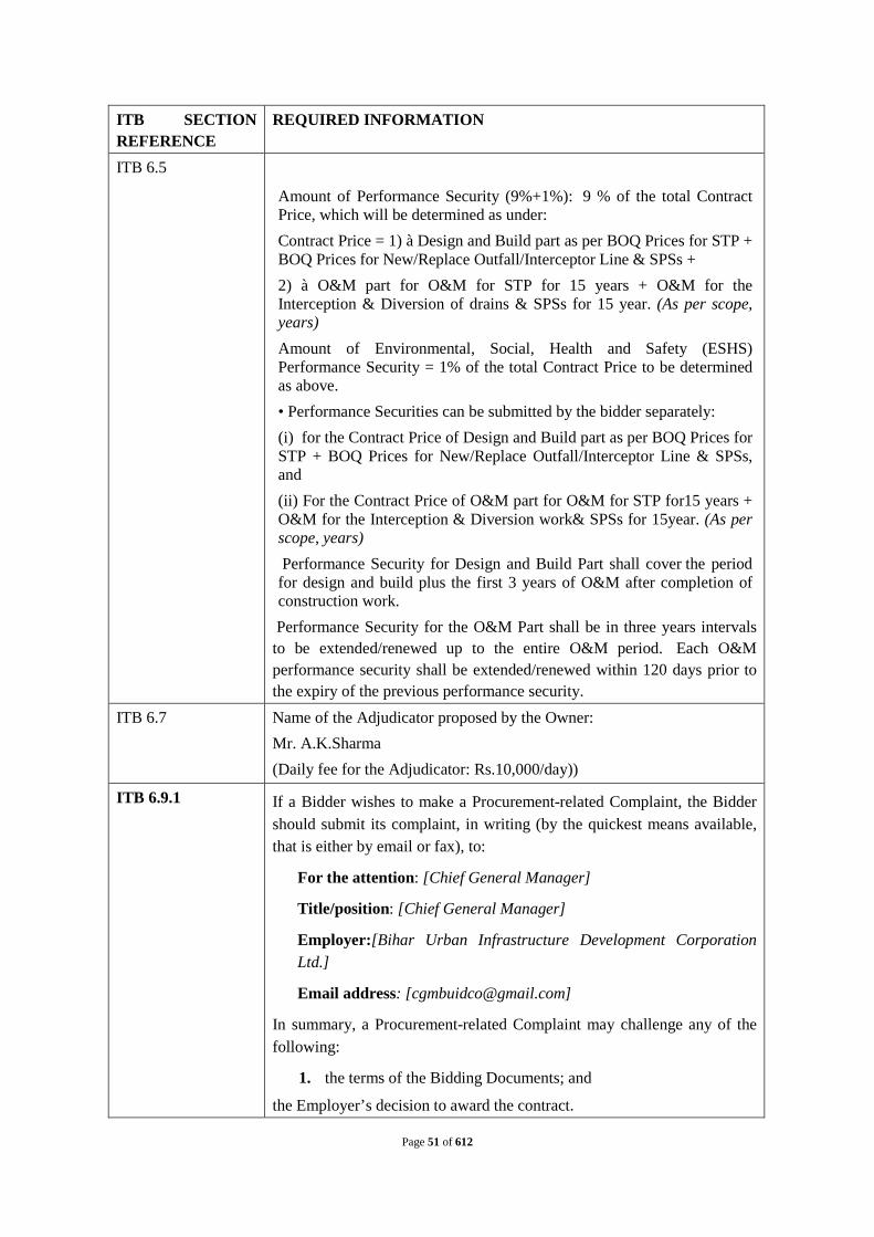
Page 51 of 612
ITB SECTION REFERENCE
REQUIRED INFORMATION
ITB 6.5
Amount of Performance Security (9%+1%): 9 % of the total Contract Price, which will be determined as under: Contract Price = 1) à Design and Build part as per BOQ Prices for STP + BOQ Prices for New/Replace Outfall/Interceptor Line & SPSs + 2) à O&M part for O&M for STP for 15 years + O&M for the Interception & Diversion of drains & SPSs for 15 year. (As per scope, years) Amount of Environmental, Social, Health and Safety (ESHS) Performance Security = 1% of the total Contract Price to be determined as above. • Performance Securities can be submitted by the bidder separately: (i) for the Contract Price of Design and Build part as per BOQ Prices for STP + BOQ Prices for New/Replace Outfall/Interceptor Line & SPSs, and (ii) For the Contract Price of O&M part for O&M for STP for15 years + O&M for the Interception & Diversion work& SPSs for 15year. (As per scope, years) Performance Security for Design and Build Part shall cover the period for design and build plus the first 3 years of O&M after completion of construction work.
Performance Security for the O&M Part shall be in three years intervals to be extended/renewed up to the entire O&M period. Each O&M performance security shall be extended/renewed within 120 days prior to the expiry of the previous performance security.
ITB 6.7 Name of the Adjudicator proposed by the Owner: Mr. A.K.Sharma (Daily fee for the Adjudicator: Rs.10,000/day))
ITB 6.9.1 If a Bidder wishes to make a Procurement-related Complaint, the Bidder should submit its complaint, in writing (by the quickest means available, that is either by email or fax), to:
For the attention: [Chief General Manager]
Title/position: [Chief General Manager]
Employer:[Bihar Urban Infrastructure Development Corporation Ltd.]
Email address: [[email protected]]
In summary, a Procurement-related Complaint may challenge any of the following:
1. the terms of the Bidding Documents; and
the Employer’s decision to award the contract.

Page 52 of 612

Page 53 of 612
Annexure A to the Bidding Documents
a. Bidder’s Bid Form
b. Bidder’s Price Schedules
c. Form of Bid Security
d. Form of Performance Security
e. Format of Curriculum Vitae for Proposed Key Staff
f. Form for Clarification Questions
g. List of Eligible Countries
h. Qualification Criteria
i. Information Forms
j. Declaration Format for Deemed Export Benefits
k. Form of Letter of Intent by JV Partners
l. Form of Power of Attorney for Joint Venture
m. Form of undertaking by JV Partners

Page 54 of 612
Annexure A – Part a
BIDDER’S BID FORM
Date:
Contract No:
[Name of Contract]: TO (I) DESIGN AND BUILD SEWAGE TREATMENT PLANTOF INSTALLED CAPACITY 32 MLD AND ALL APPURTENANT STRUCTURES AND ALLIED WORKS IN TWO MODULES (16MLD+16MLD);(II) SURVEY, REVIEW THE DESIGNS, REDESIGN WHERE NECESSARY, AND BUILD NEW DIVERSION WORKS WITH INTERCEPTION WITH RISING MAIN 2.3 KM, NEW TAPPINGS OF LENGTH 18.95 KM FOR 39 DRAINS CONTROLLED WITH SCADA INCLUDING SURVEY, DESIGN, CONSTRUCTION OF 5 NO. PUMPING STATIONS AND ALL APPURTENANT STRUCTURES AND ALLIED WORKS; AND CONSTRUCTION OF 31 OUTFALL STRUCTURE WITH SLUICE GATE INCLUDING EFFLUENT CHANNEL (250 MTR) FOR REUSE OF TREATED WASTE WATER (III) OPERATION & MAINTENANCE OF THE COMPLETE WORKS OF SEWAGE TREATMENT PLANT, INTERCEPTION & DIVERSION WORKS AND PUMPING STATIONS FOR A PERIOD OF 15 YEARS IN CHHAPRA TOWN , STATE OF BIHAR , INDIA.
To: [Name and address of Owner]
Gentlemen,
Having examined the Bidding Documents, including Addendum Numbers[insert numbers], the receipt of which is hereby acknowledged, we, the undersigned, offer TO (I) DESIGN AND BUILD SEWAGE TREATMENT PLANTOF INSTALLED CAPACITY 32 MLD AND ALL APPURTENANT STRUCTURES AND ALLIED WORKS IN TWO MODULES (16MLD+16MLD);(II) SURVEY, REVIEW THE DESIGNS, REDESIGN WHERE NECESSARY, AND BUILD NEW DIVERSION WORKS WITH INTERCEPTION WITH RISING MAIN 2.3 KM, NEW TAPPINGS OF LENGTH 18.95 KM FOR 39 DRAINS CONTROLLED WITH SCADA INCLUDING SURVEY, DESIGN, CONSTRUCTION OF 5 NO. PUMPING STATIONS AND ALL APPURTENANT STRUCTURES AND ALLIED WORKS; AND CONSTRUCTION OF 31 OUTFALL STRUCTURE WITH SLUICE GATE INCLUDING EFFLUENT CHANNEL (250 MTR) FOR REUSE OF TREATED WASTE WATER (III) OPERATION & MAINTENANCE OF THE COMPLETE WORKS OF SEWAGE TREATMENT PLANT, INTERCEPTION & DIVERSION WORKS AND PUMPING STATIONS FOR A PERIOD OF 15 YEARS IN CHHAPRA TOWN , STATE OF BIHAR , INDIA. under the above-named Contract in full conformity with the said Bidding Documents for the amounts specified in the Bidder’s Financial Bid.

Page 55 of 612
We meet the eligibility requirements and have no conflict of interest in accordance with ITB 1.2.2.
We have not been suspended nor declared ineligible by the Employer based on execution of a Bid Securing Declaration in the Owner’s country in accordance with ITB 1.2.5.
We undertake, if our Bid is accepted, to commence the construction of STP and Sewerage Network and/or Interception & Diversion Worksand to achieve Completion within the respective times stated in the Bidding Documents.
If our Bid is accepted, we undertake to provide an advance payment security and the Performance Securityand an Environmental, Social, Health and Safety (ESHS) Performance Security in the form, in the amounts, and within the times specified in the Bidding Documents.
Weare not participating, as a Bidder or as a subcontractor, in more than one bid in this bidding process in accordance with ITB 1.2.2 (e), other than alternative bids submitted in accordance with ITB 3.13;
We, including any of our subcontractors or suppliers for any part of the contract,have not been declared ineligible by the Owner,under the Owner’s country laws or official regulations;
We are not a government owned entity / We are a government owned entity but meet the requirements of ITB 1.2.4;
We have paid, or will pay the following commissions, gratuities, or fees with respect to the bidding process or execution of the Contract:
Name of Recipient Address Reason Amount
-------------------------- ---------------------- -------------------- --------------
-------------------------- ---------------------- -------------------- --------------
-------------------------- ---------------------- -------------------- --------------
-------------------------- ---------------------- -------------------- --------------
(If none has been paid or is to be paid, indicate “none.”)
[We accept the appointment of [name proposed in Bid Data Sheet] as the Adjudicator.]
or
[We do not accept the appointment of [name proposed in Bid Data Sheet] as the Adjudicator, and we propose instead that [name] be appointed as Adjudicator, whose résumé and hourly fees are attached.]
We agree to abide by this Bid, which consists of this letter and the other documents listed in ITB Section 3.14 (a), for .......... days, the period identified in the Bid Data Sheet as the length of the Bid Validity Period, and it shall remain binding upon us and may be accepted by you at any time before the expiration of that period.
Until a formal contract is prepared and executed between us, this Bid, together with your written acceptance thereof and your notification of award, shall constitute a binding contract between us.

Page 56 of 612
We hereby certify that we have taken steps to ensure that no person acting for us or on our behalf will engage in any type of fraud and corruption.
We understand that you are not bound to accept the lowest or any Bid you may receive.
Dated this day of , [Year].
[signature]
In the capacity of
[position]
Duly authorized to sign this bid for and on behalf of
[name of Bidder]
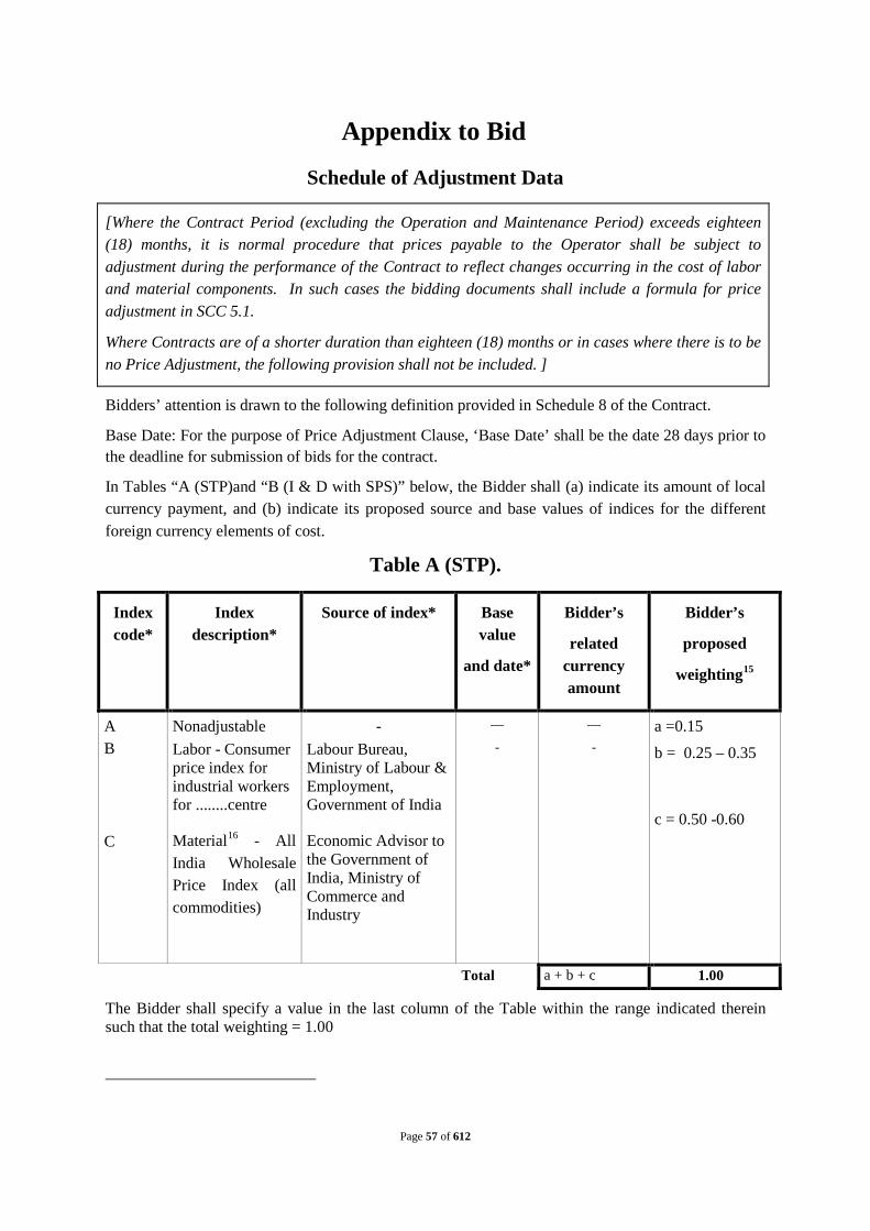
Page 57 of 612
Appendix to Bid
Schedule of Adjustment Data
Bidders’ attention is drawn to the following definition provided in Schedule 8 of the Contract.
Base Date: For the purpose of Price Adjustment Clause, ‘Base Date’ shall be the date 28 days prior to the deadline for submission of bids for the contract.
In Tables “A (STP)and “B (I & D with SPS)” below, the Bidder shall (a) indicate its amount of local currency payment, and (b) indicate its proposed source and base values of indices for the different foreign currency elements of cost.
Table A (STP).
Index code*
Index description*
Source of index* Base value
and date*
Bidder’s
related currency amount
Bidder’s
proposed
weighting15
A B
C
Nonadjustable Labor - Consumer price index for industrial workers for ........centre
Material16
- Labour Bureau, Ministry of Labour & Employment, Government of India
Economic Advisor to the Government of India, Ministry of Commerce and Industry
- All India Wholesale Price Index (all commodities)
—
-
—
- a =0.15
b = 0.25 – 0.35
c = 0.50 -0.60
Total a + b + c 1.00
The Bidder shall specify a value in the last column of the Table within the range indicated therein such that the total weighting = 1.00
[Where the Contract Period (excluding the Operation and Maintenance Period) exceeds eighteen (18) months, it is normal procedure that prices payable to the Operator shall be subject to adjustment during the performance of the Contract to reflect changes occurring in the cost of labor and material components. In such cases the bidding documents shall include a formula for price adjustment in SCC 5.1.
Where Contracts are of a shorter duration than eighteen (18) months or in cases where there is to be no Price Adjustment, the following provision shall not be included. ]

TableB ( I & D).
Index code
Index description Source of index
Base value
and date
Bidder’s
related currency amount
Bidder’s
proposed
weighting17
1. Nonadjustable - - - 0.15
2. Labour - Pl * - *
3. Cement - Pc * - *
4. Steel – Ps * - *
5. Bitumen - Pb * - *
6. POL – Pf * - *
7. Plant & Machinery Spares - PP
* - *
8 Other materials - Pm18
* - *
Total 1.00
Notes:
1. Source of Index for respective Indices shall be the same as indicated under Para4.2 of “Schedule 8 - Price Adjustment”attached to the Contract.
2. The Bidder shall specify a value in the last column of the Table within the range indicated therein such that the total weighting = 1.00

Page 59 of 612

Page 60 of 612
Indicative Flow Rate for STP
Indicative Flow Rate for the purpose of evaluation of bids in accordance with ITB 5.6 (c) (v)& (vi)during the Operation Period shall be as follows:
For STP
Year of Operations Indicative Sewage Flow Rate for STP 16 (MLD) for phase-1
Indicative Sewage Flow Rate for STP 16 (MLD) for phase-2
Year One 10.64 13.30
Year Two 11.98 13.48
Year Three 12.14 13.65
Year Four 13.83 13.83
Year Five 14.01 14.01
Year Six 14.19 14.19
Year Seven 14.36 14.36
Year Eight 14.54 14.54
Year Nine 14.72 14.72
Year Ten 14.89 14.89
Year Eleven 15.07 15.07
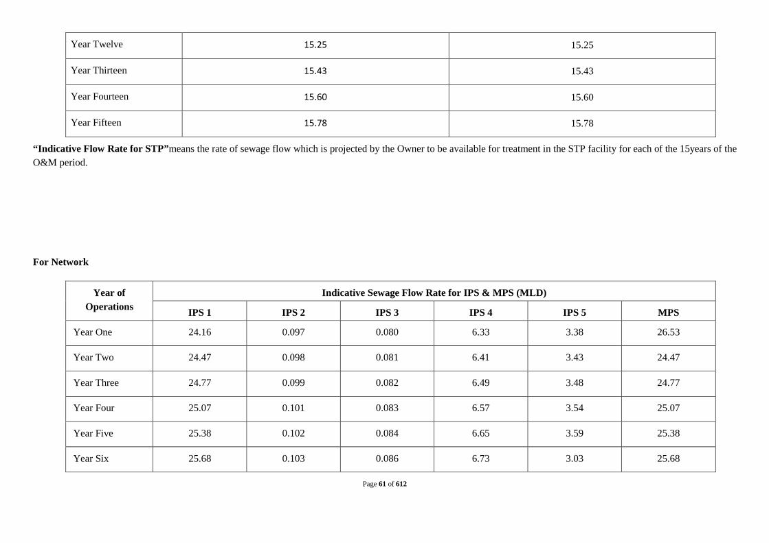
Page 61 of 612
Year Twelve 15.25 15.25
Year Thirteen 15.43 15.43
Year Fourteen 15.60 15.60
Year Fifteen 15.78 15.78
“Indicative Flow Rate for STP”means the rate of sewage flow which is projected by the Owner to be available for treatment in the STP facility for each of the 15years of the O&M period.
For Network
Year of Operations
Indicative Sewage Flow Rate for IPS & MPS (MLD)
IPS 1 IPS 2 IPS 3 IPS 4 IPS 5 MPS
Year One 24.16 0.097 0.080 6.33 3.38 26.53
Year Two 24.47 0.098 0.081 6.41 3.43 24.47
Year Three 24.77 0.099 0.082 6.49 3.48 24.77
Year Four 25.07 0.101 0.083 6.57 3.54 25.07
Year Five 25.38 0.102 0.084 6.65 3.59 25.38
Year Six 25.68 0.103 0.086 6.73 3.03 25.68

Page 62 of 612
Year Seven 25.98 0.105 0.087 6.81 3.69 25.98
Year Eight 26.28 0.106 0.088 6.89 3.74 26.28
Year Nine 26.59 0.107 0.089 6.97 3.79 26.59
Year Ten 26.89 0.109 0.090 7.05 3.84 26.89
Year Eleven 27.19 0.110 0.091 7.13 3.89 27.19
Year Twelve 27.50 0.111 0.092 7.21 3.94 27.50
Year Thirteen 27.80 0.113 0.093 7.29 3.99 27.80
Year Fourteen 28.10 0.114 0.094 7.37 4.04 28.10
Year Fifteen 28.71 0.117 0.097 7.53 4.14 28.71
“Indicative Flow Rate for SPS”means the rate of sewage flow which is projected by the Owner to be available for handling in the respective SPSsfor each of the 15years of the O&M period.
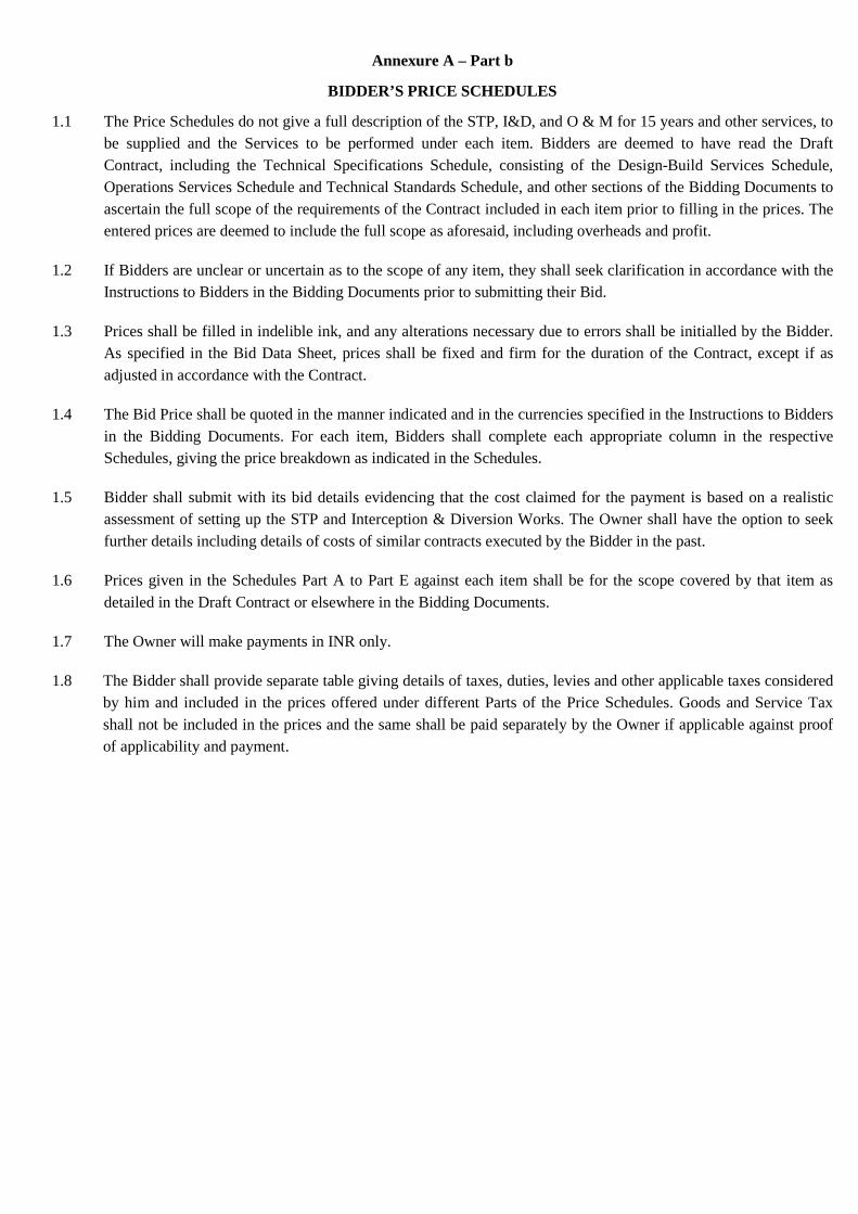
Annexure A – Part b
BIDDER’S PRICE SCHEDULES
1.1 The Price Schedules do not give a full description of the STP, I&D, and O & M for 15 years and other services, to be supplied and the Services to be performed under each item. Bidders are deemed to have read the Draft Contract, including the Technical Specifications Schedule, consisting of the Design-Build Services Schedule, Operations Services Schedule and Technical Standards Schedule, and other sections of the Bidding Documents to ascertain the full scope of the requirements of the Contract included in each item prior to filling in the prices. The entered prices are deemed to include the full scope as aforesaid, including overheads and profit.
1.2 If Bidders are unclear or uncertain as to the scope of any item, they shall seek clarification in accordance with the Instructions to Bidders in the Bidding Documents prior to submitting their Bid.
1.3 Prices shall be filled in indelible ink, and any alterations necessary due to errors shall be initialled by the Bidder. As specified in the Bid Data Sheet, prices shall be fixed and firm for the duration of the Contract, except if as adjusted in accordance with the Contract.
1.4 The Bid Price shall be quoted in the manner indicated and in the currencies specified in the Instructions to Bidders in the Bidding Documents. For each item, Bidders shall complete each appropriate column in the respective Schedules, giving the price breakdown as indicated in the Schedules.
1.5 Bidder shall submit with its bid details evidencing that the cost claimed for the payment is based on a realistic assessment of setting up the STP and Interception & Diversion Works. The Owner shall have the option to seek further details including details of costs of similar contracts executed by the Bidder in the past.
1.6 Prices given in the Schedules Part A to Part E against each item shall be for the scope covered by that item as detailed in the Draft Contract or elsewhere in the Bidding Documents.
1.7 The Owner will make payments in INR only.
1.8 The Bidder shall provide separate table giving details of taxes, duties, levies and other applicable taxes considered by him and included in the prices offered under different Parts of the Price Schedules. Goods and Service Tax shall not be included in the prices and the same shall be paid separately by the Owner if applicable against proof of applicability and payment.

ABSTRACT OF TOTAL COST SEWAGE TREATMENT PLANT AND I & D ALLIED WORKS FOR CHHAPRA TOWN
Grand Summary Table - 1
No. Component Price (INR)
1 Design-Build price for STP and allied infrastructure (Schedule A) - Phase-1
0.00
2 Design-Build price for STP and allied infrastructure (Schedule A) - Phase-2
0.00
3 Design-Build price for I & D and allied Works(Schedule B)
0.00
4A Total O & M Price of STP for 15 years for phase-1 0.00
4B NPV of Total O & M Price of STP for 15 years for phase-1
0.00
5A Total O & M Price of STP for 15 years for phase-2 0.00
5B NPV of Total O & M Price of STP for 15 years for phase-2
0.00
6 Total O & M Price of I & D works for 15 years 0 7 NPV of Total O & M Price of I & D works
including SPSs for 15 years 0
8 Cost of Land requirement for setting up the STP facility as indicated in the bid for phase-1
0
9 Cost of Land requirement for setting up the STP facility as indicated in the bid for phase-2
0
Total Price of STP phase-1 based on quoted O&M prices including price of land (1+3+4A+6+8) =
0.00
Total Price of STP phase-1 based on NPV of quoted O&M prices including price of land (1+3+4B+7+8) =
0.00
Total Price of STP phase-2 based on quoted O&M prices including price of land (2+3+5A+6+9) =
0.00
Total Price of STP phase-2 based on NPV of quoted O&M prices including price of land (2+3+5B+7+9) =
0.00

Page 65 of 612
Design-Build price for STP 16 MLD for phase-1 and allied infrastructure (Schedule A)
Table - 2 S.N. Works Activity Design-Build Price
1 Design, Build, Commissioning, trial and run of STP of capacity 16 mld along with the provision of online waste-water quality analyzer to measure, analyze and control PH, TSS, COD, BOD, TOC etc
Break-up of Price of item 1 above
1A
Civil and Structural Works (including that required for disposal and reuse) with Ancillary works like, internal roads, area grading etc
1B Installation, testing and commissioning of Electro – mechanical and Instrumentation equipment and accessories including equipments for electricity generation from solar photovoltaic arrangement.
C
Construction of RCC channel to Carry Treated Effluent
D Additional Piling Cost as per soil investigation report
E UV Disinfection System at STP
F Provision for Staff Quarter
Total Design Build Price
0.00

Page 66 of 612
Indicative Flow Indicative Flow for the purpose of evaluation of bids during the
Operations Period shall be as follows: Table - 3
Year of Operations
Indicative Sewage flow rate for STP 16 (MLD) for Phase-1
1 10.64 2 11.98 3 12.14 4 13.83 5 14.01 6 14.19 7 14.36 8 14.54 9 14.72
10 14.89 11 15.07 12 15.25 13 15.43 14 15.60 15 15.78

Page 67 of 612
Cost of Land requirement for setting up the STP facility as indicated in the bid
Table - 4 S. N. Component
1 Area of Land Required for STP as per given Technology by Bidder …… SQM
2 Price of Land per square meter 3012 Total Price of Land (INR): 0
Total O & M Price of STP for 15 years & NPV of Total O & M Price of STP for 15 years
PARTS B & C (STP ) and Annual O&M Price and Additional O&M Price
Table - 5 Year of Operations
Currency (INR) Total Annual O&M Price for STP , assuming
Indicative Sewage Flow reaching the STP
NPV factor (d) (Based on discount factor of 10% p.a.)
Value e = c*d
(a) (d) (e) 1 0 0.909 0 2 0 0.826 0 3 0 0.751 0 4 0 0.683 0 5 0 0.621 0 6 0 0.564 0 7 0 0.513 0 8 0 0.467 0 9 0 0.424 0 10 0 0.386 0 11 0 0.35 0 12 0 0.319 0 13 0 0.29 0 14 0 0.263 0 15 0 0.239 0
Total 0 0

Page 68 of 612
Part D (STP) Guaranteed Electricity Consumption
Table - 6 Year of
Operations Guaranteed Electricity Consumption for the
year (KWh / MLD) 1 2 3 4 5 6 7 8 9 10 11 12 13 14 15

Page 69 of 612

TABLE- 7 Price for Operation & Maintenance of STP for 15 years Sl. No.
Description Lump Sum Price 1ST 2
Year nd 3
Year rd 4
Year th 5
Year th 6
Year th 7
Year th 8
Year th 9
Year th 10
Year th 11
Year th 12
Year th 13
Year th 14
Year th 15
Year th
Year Fixed Price 1 O & M cost including
Spare Parts, tools and tackles Manpower, repair & maintenance of civil works, electromechanical works and all other costs related to operation and maintenance of STP and MPS facility but excluding energy consumption.
Variable Price
2 Cost of electrical Energy consumption per year (Guaranteed Electricity Consumption for the year per MLD x Base Rate of Electricity Tariff.)
0 0 0 0 0 0 0 0 0 0 0 0 0 0 0
3 Indicative Sewage Flow rate for STP 16 MLD for phase-1
10.64 11.98 12.14 13.83 14.01 14.19 14.36 14.54 14.72
14.89
15.07
15.25
15.43 15.60 15.78
4 Cost of Energy* (2x3x) 0 0 0 0 0 0 0 0 0 0 0 0 0 0 0
Total Price for O&M of STP for 15 years ( 1+4) for phase -1
0 0 0 0 0 0 0 0 0 0 0 0 0 0 0
Note:- The O&M cost arrived in this table for the respective years should be taken to the column (a) of table 4 for the respective years.

Page 71 of 612


Page 73 of 612
Design-Build price for STP 16 MLD for phase-2 and allied infrastructure (Schedule A)
Table - 2
S.N. Works Activity Design-Build Price
1 Design, Build, Commissioning, trial and run of STP of capacity 16 mld along with the provision of online waste-water quality analyzer to measure, analyze and control PH, TSS, COD, BOD, TOC etc
Break-up of Price of item 1 above
1A
Civil and Structural Works (including that required for disposal and reuse) with Ancillary works like, internal roads, area grading etc
1B Installation, testing and commissioning of Electro – mechanical and Instrumentation equipment and accessories including equipments for electricity generation from solar photovoltaic arrangement.
C Construction of RCC channel to Carry Treated Effluent
D Additional Piling Cost as per soil investigation report
E UV Disinfection System at STP
F Provision for Staff Quarter
Total Design Build Price
0.00

Page 74 of 612
Indicative Flow Indicative Flow for the purpose of evaluation of bids during the
Operations Period shall be as follows:
Table - 3
Year of Operations
Indicative Sewage flow rate for STP 16 (MLD) for Phase-2
1 13.30
2 13.48
3 13.65
4 13.83
5 14.01
6 14.19
7 14.36
8 14.54
9 14.72
10 14.89
11 15.07
12 15.25
13 15.43
14 15.60
15 15.78
Cost of Land requirement for setting up the STP facility as indicated in the bid
Table - 4 S. N. Component
1 Area of Land Required for STP as per given Technology by Bidder …… SQM
2 Price of Land per square meter 3012 Total Price of Land (INR): 0

Total O & M Price of STP for 15 years & NPV of Total O & M Price of STP for 15 years
PARTS B & C (STP ) and Annual O&M Price and Additional O&M Price
Table - 5 Year of Operations
Currency (INR) Total Annual O&M Price for STP , assuming Indicative Sewage
Flow reaching the STP
NPV factor (d) (Based on
discount factor of 10% p.a.)
Value e = c*d
(a) (d) (e) 1 0 0.909 0 2 0 0.826 0 3 0 0.751 0 4 0 0.683 0 5 0 0.621 0 6 0 0.564 0 7 0 0.513 0 8 0 0.467 0 9 0 0.424 0 10 0 0.386 0 11 0 0.35 0 12 0 0.319 0 13 0 0.29 0 14 0 0.263 0 15 0 0.239 0
Total 0 0

Part D (STP) Guaranteed Electricity Consumption
Table - 6 Year of
Operations Guaranteed Electricity Consumption for the
year (KWh / MLD) 1 2 3 4 5 6 7 8 9 10 11 12 13 14 15

TABLE- 7 Price for Operation & Maintenance of STP for 15 years Sl. No.
Description Lump Sum Price 1ST 2
Year nd 3
Year rd 4
Year th 5Year th 6 Year th 7
Year th 8
Year th 9
Year th 10
Year th 11
Year th 12
Year
th 13 Year
th 14 Yea
r
th 15 Yea
r
th Year
Fixed Price 1 O & M cost
including Spare Parts, tools and tackles Manpower, repair & maintenance of civil works, electromechanical works and all other costs related to operation and maintenance of STP and MPS facility but excluding energy consumption.
Variable Price
2 Cost of electrical Energy consumption per year (Guaranteed Electricity Consumption for the year per MLD x Base Rate of Electricity Tariff.)
0 0 0 0 0 0 0 0 0 0 0 0 0 0 0
3 Indicative Sewage Flow rate for STP 16 MLD for phase-1 13.30 13.48 13.65 13.83 14.01 14.19 14.36 14.54 14.72 14.89
15.07 15.25
15.43
15.60 15.78

Page 78 of 612
4 Cost of Energy* (2x3x)
0 0 0 0 0 0 0 0 0 0 0 0 0 0 0
Total Price for O&M of STP for 15 years ( 1+4) for phase -2
0 0 0 0 0 0 0 0 0 0 0 0 0 0 0
Note:- The O&M cost arrived in this table for the respective years should be taken to the column (a) of table 4 for the respective years.

Design-Build price for I & D and allied Works including SPSs (Schedule B) Table - 8
S.N. Works Activity Design-Build Price
1
CONSTRUCTING OF INTERCEPTION & DIVERSION WORKS INCLUDING 6 PUMPING STATIONS, RISING MAIN, TRIAL, RUN, TESTING, COMMISSIONING & MAINTENANCE OF COMPLETE SYSTEM ON DESIGN BUILD OPERATE& TRANSFER (DBOT) BASIS & THERE AFTER OPERATION & MAINTENANCE FOR 15 YEARS FOR Chhapra TOWN & SITC of PLC/SCADA along with necessary instruementations, cabling etc with communicating to main PLC at STP for entire works as per specification mentioned in the bid document/ as per direction of E/I.
Break-up of Price of item 1 above
1A Civil & Electromechanical Works of I & D Works (including SPSs and Rising Main)
0.00
Total Design Build Price 0.00

Page 80 of 612
Indicative Sewage Flow Rate for IPS & MPS Table - 9
Year of Operations
Indicative Sewage flow rate (MLD) (AVG) IPS 1 IPS 2 IPS 3 IPS 4 IPS 5 MPS
1st year 24.16 0.097 0.08 6.33 3.38 26.53 2nd year 24.47 0.10 0.08 6.41 3.43 24.47 3rd year 24.77 0.10 0.08 6.49 3.48 24.77 4th year 25.07 0.10 0.08 6.57 3.54 25.07 5th year 25.38 0.10 0.08 6.65 3.59 25.38 6th year 25.68 0.10 0.09 6.73 3.03 25.68 7th year 25.98 0.11 0.09 6.81 3.69 25.98 8th year 26.28 0.11 0.09 6.89 3.74 26.28 9th year 26.59 0.11 0.09 6.97 3.79 26.59 10th year 26.89 0.11 0.09 7.05 3.84 26.89 11th year 27.19 0.11 0.09 7.13 3.89 27.19 12th year 27.50 0.11 0.09 7.21 3.94 27.50 13th year 27.80 0.11 0.09 7.29 3.99 27.80 14th year 28.10 0.11 0.09 7.37 4.04 28.10 15th year 28.71 0.117 0.097 7.53 4.14 28.71

Page 81 of 612
PART C – Guaranteed Electricity Consumption for SPS The Electricity Consumption guaranteed by the bidder shall be as
under: IPS 1
Table - 10
Year of Operations Guaranteed Annual Energy Consumption for Sewage flow rate
(KWh / MLD of Sewage pumped over the year) 1 2 3 4 5 6 7 8 9 10 11 12 13 14 15

Page 82 of 612
The Electricity Consumption guaranteed by the bidder shall be as under:
For IPS 2 Table - 11
Year of Operations Guaranteed Annual Energy Consumption for Sewage flow rate
(KWh / MLD of Sewage pumped over the year) 1 2 3 4 5 6 7 8 9 10 11 12 13 14 15

Page 83 of 612
The Electricity Consumption guaranteed by the bidder shall be as under:
For IPS 3 Table - 12
Year of Operations Guaranteed Annual Energy Consumption for Sewage flow rate
(KWh / MLD of Sewage pumped over the year) 1 2 3 4 5 6 7 8 9 10 11 12 13 14 15
The Electricity Consumption guaranteed by the bidder shall be as under:
For IPS 4 Table - 13
Year of Operations Guaranteed Annual Energy Consumption for Sewage flow rate
(KWh / MLD of Sewage pumped over the year) 1 2 3 4 5 6 7 8 9 10 11 12 13

Page 84 of 612
14 15
The Electricity Consumption guaranteed by the bidder shall be as under:
For IPS 5 Table - 14
Year of Operations Guaranteed Annual Energy Consumption for Sewage flow rate
(KWh / MLD of Sewage pumped over the year) 1 2 3 4 5 6 7 8 9 10 11 12 13 14 15
The Electricity Consumption guaranteed by the bidder shall be as under:
For MPS Table - 15
Year of Operations Guaranteed Annual Energy Consumption for Sewage flow rate
(KWh / MLD of Sewage pumped over the year) 1 2 3 4 5 6 7 8 9 10

Page 85 of 612
11 12 13 14 15
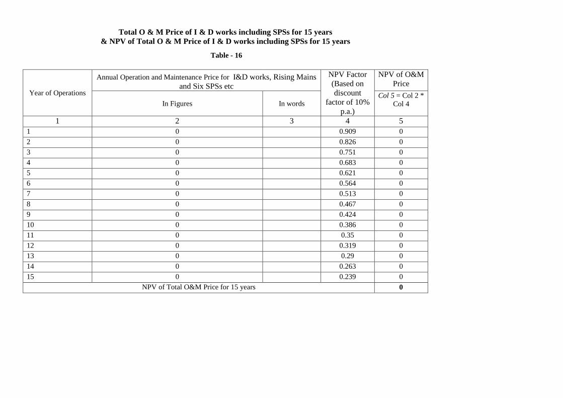
Total O & M Price of I & D works including SPSs for 15 years & NPV of Total O & M Price of I & D works including SPSs for 15 years
Table - 16
Year of Operations
Annual Operation and Maintenance Price for I&D works, Rising Mains and Six SPSs etc
NPV Factor (Based on discount
factor of 10% p.a.)
NPV of O&M Price
In Figures In words Col 5 = Col 2 *
Col 4
1 2 3 4 5 1 0 0.909 0 2 0 0.826 0 3 0 0.751 0 4 0 0.683 0 5 0 0.621 0 6 0 0.564 0 7 0 0.513 0 8 0 0.467 0 9 0 0.424 0 10 0 0.386 0 11 0 0.35 0 12 0 0.319 0 13 0 0.29 0 14 0 0.263 0 15 0 0.239 0
NPV of Total O&M Price for 15 years 0

Page 87 of 612
Summary of O & M Price Table - 17
Year
Quoted Bid Price for 15 Years O&M Total Price I&D Works, Rising Main IPS 1 IPS 2 IPS 3 IPS 4 IPS 5 MPS
1 2 3 4 5 6 7 8 (2+3+4+5+6+7+8) 1 0 2 0 3 0 4 0 5 0 6 0 7 0 8 0 9 0
10 0 11 0 12 0 13 0 14 0 15 0
Total 0

Page 88 of 612
O & M COST OF I&D WORKS AND RISING MAIN FOR 15 YEARS Table - 18
Year of Operation Annual O&M rate in figures In Rs In words In Rs 1 2 3 4 5 6 7 8 9
10 11 12 13 14 15
Total O&M price for 15 years
0

Page 89 of 612
Price for Operation & Maintenance of IPS 1 for 15 years Table - 19
Sl. No.
Description Lump Sum Price 1ST 2
Year nd 3
Year rd 4
Year th 5
Year th 6
Year th 7
Year th 8
Year th 9
Year th 10
Year th 11
Year th 12
Year th 13
Year th 14
Year th 15
Year th
Year Fixed Price 1 O & M cost including
Spare Parts, tools and tackles Manpower, repair & maintenance of civil works, electromechanical works and all other costs related to operation and maintenance of IPS facility but excluding energy consumption.
Variable Price
2 Cost of electrical Energy consumption per MLD of sewage pumped (Guaranteed Energy Consumption per MLD x Base Rate of Electricity Tariff.)
0 0 0 0 0 0 0 0 0 0 0 0 0 0 0
3 Indicative Sewage Flow to be pumped per year – MLD 24.16 24.47 24.77 25.07 25.38 25.68 25.98 26.28 26.59 26.89 27.19 27.5 27.8 28.1 28.71
4 Cost of Energy* (2x3) 0 0 0 0 0 0 0 0 0 0 0 0 0 0 0 Total Price for O&M of
IPS 1 for 15 years ( 1+4) 0 0 0 0 0 0 0 0 0 0 0 0 0 0 0

Page 90 of 612
Price for Operation & Maintenance of IPS 2 for 15 years Table - 20
Sl. No. Description Lump Sum Price 1ST 2
Year nd 3
Year rd 4
Year th 5
Year th 6
Year th 7
Year th 8
Year th 9
Year th 10
Year th 11
Year th 12
Year th 13
Year th 14
Year th 15
Year th
Year Fixed Price 1 O & M cost including Spare
Parts, tools and tackles Manpower, repair & maintenance of civil works, electromechanical works and all other costs related to operation and maintenance of IPS facility but excluding energy consumption.
Variable Price
2 Cost of electrical Energy consumption per MLD of sewage pumped (Guaranteed Energy Consumption per MLD x Base Rate of Electricity Tariff.)
0 0 0 0 0 0 0 0 0 0 0 0 0 0 0
3 Indicative Sewage Flow to be pumped per year – MLD
0.097 0.098 0.099 0.101 0.102 0.103 0.105 0.106 0.107 0.109 0.11 0.111 0.113 0.114 0.117
4 Cost of Energy* (2x3) 0 0 0 0 0 0 0 0 0 0 0 0 0 0 0 Total Price for O&M of
IPS 2 for 15 years ( 1+4) 0 0 0 0 0 0 0 0 0 0 0 0 0 0 0
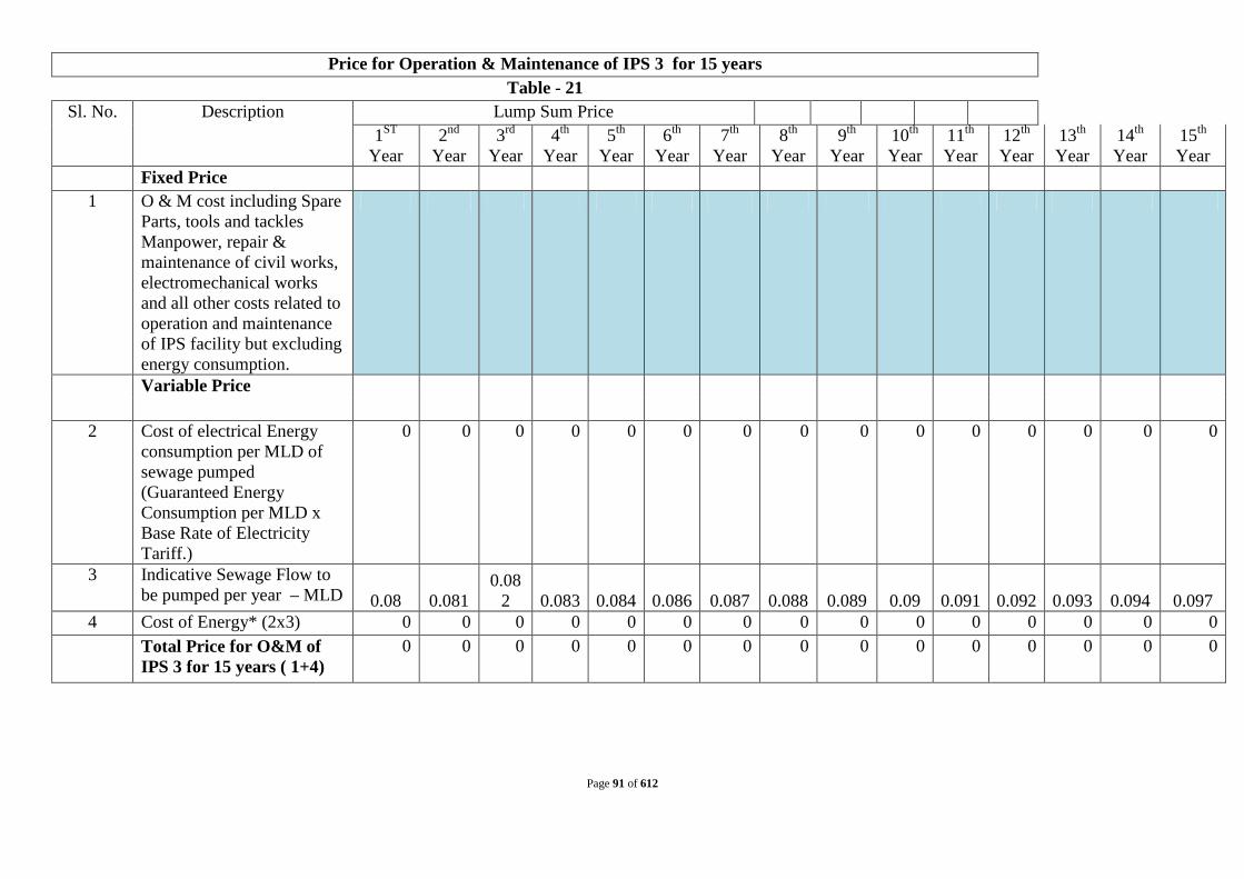
Page 91 of 612
Price for Operation & Maintenance of IPS 3 for 15 years Table - 21
Sl. No. Description Lump Sum Price 1ST 2
Year nd 3
Year rd 4
Year th 5
Year th 6
Year th 7
Year th 8
Year th 9
Year th 10
Year th 11
Year th 12
Year th 13
Year th 14
Year th 15
Year th
Year Fixed Price 1 O & M cost including Spare
Parts, tools and tackles Manpower, repair & maintenance of civil works, electromechanical works and all other costs related to operation and maintenance of IPS facility but excluding energy consumption.
Variable Price
2 Cost of electrical Energy consumption per MLD of sewage pumped (Guaranteed Energy Consumption per MLD x Base Rate of Electricity Tariff.)
0 0 0 0 0 0 0 0 0 0 0 0 0 0 0
3 Indicative Sewage Flow to be pumped per year – MLD 0.08 0.081
0.082 0.083 0.084 0.086 0.087 0.088 0.089 0.09 0.091 0.092 0.093 0.094 0.097
4 Cost of Energy* (2x3) 0 0 0 0 0 0 0 0 0 0 0 0 0 0 0 Total Price for O&M of
IPS 3 for 15 years ( 1+4) 0 0 0 0 0 0 0 0 0 0 0 0 0 0 0

Page 92 of 612
Price for Operation & Maintenance of IPS 4 for 15 years Table - 22
Sl. No. Description Lump Sum Price 1ST 2
Year nd 3
Year rd 4
Year
th 5Year
th 6 Year
th 7 Year
th 8 Year
th 9 Year
th 10 Year
th 11 Year
th 12 Year
th 13 Year
th 14 Year
th 15 Year
th Year
Fixed Price 1 O & M cost including Spare
Parts, tools and tackles Manpower, repair & maintenance of civil works, electromechanical works and all other costs related to operation and maintenance of IPS facility but excluding energy consumption.
Variable Price
2 Cost of electrical Energy consumption per MLD of sewage pumped (Guaranteed Energy Consumption per MLD x Base Rate of Electricity Tariff.)
0 0 0 0 0 0 0 0 0 0 0 0 0 0 0
3 Indicative Sewage Flow to be pumped per year – MLD
6.33 6.41 6.49
6.57 6.65 6.73 6.81 6.89 6.97 7.05 7.13 7.21 7.29 7.37 7.53
4 Cost of Energy* (2x3) 0 0 0 0 0 0 0 0 0 0 0 0 0 0 0 Total Price for O&M of
IPS 4 for 15 years ( 1+4) 0 0 0 0 0 0 0 0 0 0 0 0 0 0 0

Page 93 of 612
Price for Operation & Maintenance of IPS 5 for 15 years Table - 23
Sl. No. Description Lump Sum Price 1ST 2
Year nd 3
Year rd 4
Year
th 5Year
th 6 Year
th 7 Year
th 8 Year
th 9 Year
th 10 Year
th 11 Year
th 12 Year
th 13 Year
th 14 Year
th 15 Year
th Year
Fixed Price 1 O & M cost including
Spare Parts, tools and tackles Manpower, repair & maintenance of civil works, electromechanical works and all other costs related to operation and maintenance of IPS facility but excluding energy consumption.
Variable Price
2 Cost of electrical Energy consumption per MLD of sewage pumped (Guaranteed Energy Consumption per MLD x Base Rate of Electricity Tariff.)
0 0 0 0 0 0 0 0 0 0 0 0 0 0 0
3 Indicative Sewage Flow to be pumped per year – MLD
3.38 3.43 3.48
3.54 3.59 3.03 3.69 3.74 3.79 3.84 3.89 3.94 3.99 4.04 4.14
4 Cost of Energy* (2x3) 0 0 0 0 0 0 0 0 0 0 0 0 0 0 0 Total Price for O&M of
IPS 5 for 15 years ( 1+4) 0 0 0 0 0 0 0 0 0 0 0 0 0 0 0

Page 94 of 612
Price for Operation & Maintenance of MPS for 15 years Table - 24
Sl. No. Description Lump Sum Price 1ST 2Year
nd 3 Yea
r
rd 4 Yea
r
th 5Year
th 6 Year
th 7 Year
th 8 Year
th 9 Year
th 10 Year
th 11 Year
th 12 Year
th 13 Year
th 14 Year
th 15 Year
th Year
Fixed Price 1 O & M cost including Spare
Parts, tools and tackles Manpower, repair & maintenance of civil works, electromechanical works and all other costs related to operation and maintenance of MPS facility but excluding energy consumption.
Variable Price
2 Cost of electrical Energy consumption per MLD of sewage pumped (Guaranteed Energy Consumption per MLD x Base Rate of Electricity Tariff.)
0 0 0 0 0 0 0 0 0 0 0 0 0 0 0
3 Indicative Sewage Flow to be pumped per year – MLD
26.53
24.47
24.77
25.07 25.38 25.68 25.98 26.28 26.59 26.89 27.19 27.5 27.8 28.1 28.71
4 Cost of Energy* (2x3) 0 0 0 0 0 0 0 0 0 0 0 0 0 0 0 Total Price for O&M of
MPS for 15 years ( 1+4) 0 0 0 0 0 0 0 0 0 0 0 0 0 0 0
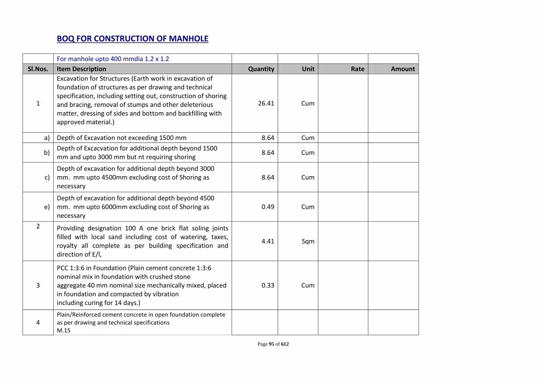
Page 95 of 612
BOQ FOR CONSTRUCTION OF MANHOLE
For manhole upto 400 mmdia 1.2 x 1.2
Sl.Nos. Item Description Quantity Unit Rate Amount
1
Excavation for Structures (Earth work in excavation of foundation of structures as per drawing and technical specification, including setting out, construction of shoring and bracing, removal of stumps and other deleterious matter, dressing of sides and bottom and backfilling with approved material.)
26.41 Cum
a) Depth of Excavation not exceeding 1500 mm 8.64 Cum
b) Depth of Excacvation for additional depth beyond 1500 mm and upto 3000 mm but nt requiring shoring 8.64 Cum
c)
Depth of excavation for additional depth beyond 3000 mm. mm upto 4500mm excluding cost of Shoring as necessary
8.64 Cum
e)
Depth of excavation for additional depth beyond 4500 mm. mm upto 6000mm excluding cost of Shoring as necessary
0.49 Cum
2 Providing designation 100 A one brick flat soling joints filled with local sand including cost of watering, taxes, royalty all complete as per building specification and direction of E/l,
4.41 Sqm
3
PCC 1:3:6 in Foundation (Plain cement concrete 1:3:6 nominal mix in foundation with crushed stone aggregate 40 mm nominal size mechanically mixed, placed in foundation and compacted by vibration including curing for 14 days.)
0.33 Cum
4
Plain/Reinforced cement concrete in open foundation complete as per drawing and technical specifications M.15

Page 96 of 612
Add for Benching: 1.37 Cum Deduction at Benching for pipe 0.19 Total 1.18 Cum
5
Plain/Reinforced cement concrete in open foundation complete as per drawing and technical specifications- Using Concrete Mixer M.20- 1:1:5:3(1 cement: 1.5 coarse sand:3 graded stone aggregate 20 mm nominal size
Cum
Add at bottom 1.52 Cum add at top 0.20 Cum deduction at manhole opening 0.12 Cum Less for Manhole cover 0.07 Cum Total 1.53 Cum
6 Centring and shuttering including strutting,propping etc and removal or form work for Foundations,footings, bases Columns
7
a) 25 mm to 30mm thick wooden shuttering 7.06 Sqm b) 25 mm to 30mm thick wooden shuttering without
staging 2.31 Sqm
Total 9.37 Sqm 8 Supplying, fitting and placing un-coated HYSD bar reinforcement
in foundation complete as per drawing and technical specifications
0.34 Tonne
9
Plain/Reinforced cement concrete in open foundation complete as per drawing and technical specifications- Using Concrete Mixer M.20- 1:1:5:3(1 cement: 1.5 coarse sand:3 graded stone aggregate 20 mm nominal size
250 mm thk 2.84 Total 2.84 Cum

Page 97 of 612
10
Pointing with cement mortar 1:3(1 cement:3 coarse sand): :Ruled pointing
250 mm thk wall 23.94 Total 23.94 Sqm
11
15 mm cement plaster 1:3 (1 cement: 3 coarse sand ) finished with a floating coat of neat cement on the rough side of single or half brick wall.
1.5 mm thk to Wall 9.40 Sqm Total= 9.40 Sqm
12
Filling available excavated earth (excluding rock) in trenches, plinth, sides of foundations etc. in layers not exceeding 20 cm in depth: consolidating each deposited layer by ramming and watering lead
1/5 th of Total Volume 5.28 Cum 13 Cost of Haulage of earth Excluding loading and Unloading (5
Kms) 33.80 Ton
14 Loading and Unloading of Stone Boulder/Stone Aggregates/Sand/Kanker/Moorum. 21.13 Cum
Total Cost Per Manhole
For manhole 500 to 1200 mmdia 2.2m X 2.2m
Sl.Nos. Item Description Quantity Unit Rate Amount
1
Excavation for Structures (Earth work in excavation of foundation of structures as per drawing and technical specification, including setting out, construction of shoring and bracing, removal of stumps and other deleterious matter, dressing of sides and bottom and backfilling with approved material.)
87.68 Cum

Page 98 of 612
a) Depth of Excavation not exceeding 1500 mm 17.34 Cum
b) Depth of Excacvation for additional depth beyond 1500 mm and upto 3000 mm but nt requiring shoring 17.34 Cum
c) Depth of excavation for additional depth beyond 3000 mm. mm upto 4500mm excluding cost of Shoring as necessary
17.34 Cum
d) Depth of excavation for additional depth beyond 4500 mm. mm upto 6000mm excluding cost of Shoring as necessary
17.34 Cum
e) Depth of excavation for additional depth beyond 6000 mm. mm upto 7500mm excluding cost of Shoring as necessary
18.32 Cum
2
Providing designation 100 A one brick flat soling joints filled with local sand including cost of watering, taxes, royalty all complete as per building specification and direction of E/l,
9.61 Sqm
3
PCC 1:3:6 in Foundation (Plain cement concrete 1:3:6 nominal mix in foundation with crushed stone aggregate 40 mm nominal size mechanically mixed, placed in foundation and compacted by vibration including curing for 14 days.)
0.72 Cum
4
Plain/Reinforced cement concrete in open foundation complete as per drawing and technical specifications M.15
Add for Benching: 9.05 Cum Deduction at Benching for pipe 2.65 Total 6.40 Cum

Page 99 of 612
5
Plain/Reinforced cement concrete in open foundation complete as per drawing and technical specifications- Using Concrete Mixer M.20- 1:1:5:3(1 cement: 1.5 coarse sand:3 graded stone aggregate 20 mm nominal size
1.92 Cum
Add at bottom 3.17 Cum add at top 0.97 Cum deduction at manhole opening 0.12 Cum Less for Manhole cover 0.07 Cum Total 5.87 Cum
6 Centring and shuttering including strutting,propping etc and removal or form work for Foundations,footings, bases Columns
7
a) 25 mm to 30mm thick wooden shuttering 20.24 Sqm b) 25 mm to 30mm thick wooden shuttering without
staging 3.41 Sqm
Total 23.65 Sqm
8 Supplying, fitting and placing un-coated HYSD bar reinforcement in foundation complete as per drawing and technical specifications
1.12 Tonne
9
Plain/Reinforced cement concrete in open foundation complete as per drawing and technical specifications- Using Concrete Mixer M.20- 1:1:5:3(1 cement: 1.5 coarse sand:3 graded stone aggregate 20 mm nominal size
250 mm thk 8.35 Total 8.35 Cum
10 Pointing with cement mortar 1:3(1 cement:3 coarse sand): :Ruled pointing
250 mm thk wall 46.33

Page 100 of 612
Total 46.33 Sqm
11
15 mm cement plaster 1:3 (1 cement: 3 coarse sand ) finished with a floating coat of neat cement on the rough side of single or half brick wall.
1.5 mm thk to Wall 9.40 Sqm Total= 9.40 Sqm
12
Filling available excavated earth (excluding rock) in trenches, plinth, sides of foundations etc. in layers not exceeding 20 cm in depth: consolidating each deposited layer by ramming and watering lead
1/5 th of Total Volume 17.54 Cum 13 Cost of Haulage of earth Excluding loading and Unloading (5
Kms) 112.23 Ton
14 Loading and Unloading of Stone Boulder/Stone Aggregates/Sand/Kanker/Moorum. 70.15 Cum
Total Cost Per Manhole
For manhole 500 to 1200 mmdia 2.2m X 2.2m
Sl.Nos. Item Description Quantity Unit Rate Amount
1
Excavation for Structures (Earth work in excavation of foundation of structures as per drawing and technical specification, including setting out, construction of shoring and bracing, removal of stumps and other deleterious matter, dressing of sides and bottom and backfilling with approved material.)
53.00 Cum
a) Depth of Excavation not exceeding 1500 mm 17.34 Cum
b) Depth of Excacvation for additional depth beyond 1500 mm and upto 3000 mm but nt requiring shoring 17.34 Cum

Page 101 of 612
c) Depth of excavation for additional depth beyond 3000 mm. mm upto 4500mm excluding cost of Shoring as necessary
17.34 Cum
e)
Depth of excavation for additional depth beyond 4500 mm. mm upto 6000mm excluding cost of Shoring as necessary
0.98 Cum
2 Providing designation 100 A one brick flat soling joints filled with local sand including cost of watering, taxes, royalty all complete as per building specification and direction of E/l,
9.61 Sqm
3
PCC 1:3:6 in Foundation (Plain cement concrete 1:3:6 nominal mix in foundation with crushed stone aggregate 40 mm nominal size mechanically mixed, placed in foundation and compacted by vibration including curing for 14 days.)
0.72 Cum
4
Plain/Reinforced cement concrete in open foundation complete as per drawing and technical specifications M.15
Add for Benching: 6.63 Cum Deduction at Benching for pipe 2.65 Total 3.98 Cum
5
Plain/Reinforced cement concrete in open foundation complete as per drawing and technical specifications- Using Concrete Mixer M.20- 1:1:5:3(1 cement: 1.5 coarse sand:3 graded stone aggregate 20 mm nominal size
1.92 Cum
Add at bottom 3.17 Cum add at top 0.97 Cum deduction at manhole opening 0.12 Cum Less for Manhole cover 0.07 Cum Total 5.87 Cum

Page 102 of 612
6 Centring and shuttering including strutting,propping etc and removal or form work for Foundations,footings, bases Columns
7
a) 25 mm to 30mm thick wooden shuttering 20.24 Sqm b) 25 mm to 30mm thick wooden shuttering without
staging 3.41 Sqm
Total 23.65 Sqm 8 Supplying, fitting and placing un-coated HYSD bar reinforcement
in foundation complete as per drawing and technical specifications
1.12 Tone
9
Plain/Reinforced cement concrete in open foundation complete as per drawing and technical specifications- Using Concrete Mixer M.20- 1:1:5:3(1 cement: 1.5 coarse sand:3 graded stone aggregate 20 mm nominal size
250 mm thk 8.35 Total 8.35 Cum
10
Pointing with cement mortar 1:3(1 cement:3 coarse sand): :Ruled pointing
250 mm thk wall 46.33 Total 46.33 Sqm
11
15 mm cement plaster 1:3 (1 cement: 3 coarse sand ) finished with a floating coat of neat cement on the rough side of single or half brick wall.
1.5 mm thk to Wall 9.40 Sqm Total= 9.40 Sqm
12
Filling available excavated earth (excluding rock) in trenches, plinth, sides of foundations etc. in layers not exceeding 20 cm in depth: consolidating each deposited layer by ramming and watering lead

Page 103 of 612
1/5 th of Total Volume 10.60 Cum 13 Cost of Haulage of earth Excluding loading and Unloading (5
Kms) 67.84 Ton
14 Loading and Unloading of Stone Boulder/Stone Aggregates/Sand/Kanker/Moorum. 42.40 Cum
Total Cost Per Manhole
Cost Estimate: Civil Works of Outfall- Type 1 Sl.
No Description of work Total Quantity Unit Rate (Rs) Amount (Rs)
A Cost of Civil Works 1 Excavation for Structures (Earth work in excavation of
foundation of structures as per drawing and technical specification, including setting out, construction of shoring and bracing, removal of stumps and other deleterious matter, dressing of sides and bottom and backfilling with approved material.)
a) Depth of Excavation not exceeding 1500 mm 1.50 Cum
b) Depth of Excacvation for additional depth beyond 1500 mm and upto 3000 mm but nt requiring shoring 1.50 Cum
2
Sand Filling in Foundation Trenches as per Drawing & Technical Specification 0.10 Cum
for buffel wall 0.20 Cum 3 Providing designation 100 A one brick flat soling joints
filled with local sand including cost of watering, taxes, royalty all complete as per building specification and direction of E/l,
1.00 Sqm
for buffel wall 1.20 Sqm

Page 104 of 612
4
PCC 1:3:6 in Foundation (Plain cement concrete 1:3:6 nominal mix in foundation with crushed stone aggregate 40 mm nominal size mechanically mixed, placed in foundation and compacted by vibration including curing for 14 days.)
0.08 Cum
for buffel wall 0.09 Cum 5 Plain/Reinforced cement concrete in open foundation
complete as per drawing and technical specifications M.25 using Concrete Mixure
i for bottom 0.28 Cum ii All work upto Ground level. 0.50 Cum for bottom of wall 0.24 Cum For extended Buffel wall 0.60 Cum 6 Centring and shuttering including strutting,propping etc.
and removal of form for.
(i) Foundations, footings, bases of columns etc. for mass concrete 6.30 Sqm
Walls (any thickness) including attached pilasters. Butteresses, plinth and string courses etc.
(ii) For Walls (any thickness) including attached pilasters. Butteresses, plinth and string courses etc. 12.00 Sqm
7 Supplying, fitting and placing un-coated HYSD bar reinforcement in foundation complete as per drawing and technical specifications
0.13 Kg
G.I pipes 40 mm nominal bore (class B) 352.76 Kg G.I pipes 50 mm nominal bore (class B) 182.47 Kg 8 12 mm cement plaster of mix:1:5 (i) Inside Wall (1 cement: 5 coarse sand) 9.00 Sqm 9 15 mm cement plaster on rough side of single or half brick
wall of mix.

Page 105 of 612
(i) Outside Wall 1:4 (1 cement: 4 coarse sand) 20.00 Sqm 10 6 mm cement plaster to ceiling of mix :1:3(1 cement: 3
coarse sand) 1.00 Sqm
11 Applying one coat of cement primer of approved brand and manufacture on wall surface: Distemper primer 20.00 Sqm
12 Finishing walls with water proofing cement paint of approved brand and manufacture and of required shade to give an even shadeNew work (three or more coats)
20.00 Sqm
13 Finishing with Epoxy paint (two or more coats) at all locations prepared and applied as per manufacture's specifications including appropriate priming coat, preparation of surface, etc. complete
12.00 Sqm
14 Cost of Haulage of earth Excluding loading and Unloading (5 Kms) 4.80 Ton
15 Loading and Unloading of Stone Boulder/Stone Aggregates/Sand/Kanker/Moorum. 3 Cum

Page 106 of 612
16
Providing and laying water proofing treatment on roofs of slabs by applying cement slurry mixed with water proofing cement compound consisting of applying: a) after surface preparation, first layer of slurry of cement @ 0.488 kg/sqm mixed with water proofing cement compound @ 0.253 kg/ sqm. b) laying second layer of Fibre glass cloth when the first layer is still green. Overlaps of joints of fibre cloth should not be less than 10 cm. c) third layer of 1.5 mm thickness consisting of slurry of cement @ 1.289 kg/sqm mixed with water proofing cement compound @ 0.670 kg/sqm and coarse sand @ 1.289 kg/sqm. This will be allowed to air cure for 4 hours followed by water curing for 48 hours. The entire treatment will be taken upto 30 cm on parapet wall and tucked into groove in parapet all around. d) fourth and final layer of brick tiling with cement mortar (which will be paid for separately. For the purpose of measurement the entire treated surface will be measured.
1.00 Sqm 28
Design, drawing fabrication, supply and erection of structural steel vertical lift gates for canals and Dam sluice etc. above 5.00 meters head fix wheel type with gate leaf (complete with skin plate stiffeners, ballast weight if required, guide embedded parts) first stage anchors sill beam fitted with stainless steel flat, rollers, track fitted with stainless steel flat guide tee, rubber seal etc. as per IS:4622 duly painted as per SOR item no. 1854 with screw hoist hoisting rod, hoist guide, support structure etc.
0.32 Tonne
Estimated Cost for Civil Works for Outfall Structure

Page 107 of 612
Cost Estimate: Civil Works of Outfall Station-Type 2 Sl.
No Description of work Total
Quantity Unit Rate (Rs) Amount (Rs)
A Cost of Civil Works 1 Excavation for Structures (Earth work in excavation of
foundation of structures as per drawing and technical specification, including setting out, construction of shoring and bracing, removal of stumps and other deleterious matter, dressing of sides and bottom and backfilling with approved material.)
a) Depth of Excavation not exceeding 1500 mm 15.36 Cum b) Depth of Excacvation for additional depth beyond 1500
mm and upto 3000 mm but nt requiring shoring 9.73 Cum
2 Sand Filling in Foundation Trenches as per Drawing & Technical Specification
0.30 Cum
for buffel wall 0.60 Cum 3 Providing designation 100 A one brick flat soling joints
filled with local sand including cost of watering, taxes, royalty all complete as per building specification and direction of E/l,
9.00 Sqm
for buffel wall 3.60 Sqm 4 PCC 1:3:6 in Foundation (Plain cement concrete 1:3:6
nominal mix in foundation with crushed stone aggregate 40 mm nominal size mechanically mixed, placed in foundation and compacted by vibration including curing for 14 days.)
0.68 Cum
for buffel wall 0.27 Cum

Page 108 of 612
5 Plain/Reinforced cement concrete in open foundation complete as per drawing and technical specifications M.25 using Concrete Mixure
i for bottom 2.48 Cum ii All work upto Ground level. 1.50 Cum iii All work above ground level. 1.88 Cum iv for Top 1.80 Cum for bottom of wall 0.72 Cum For extended Buffel wall 5.40 Cum 6 Centring and shuttering including strutting,propping etc.
and removal of form for.
(i) Foundations, footings, bases of columns etc. for mass concrete
54.90 Sqm
Walls (any thickness) including attached pilasters. Butteresses, plinth and string courses etc.
(ii) For Walls (any thickness) including attached pilasters. Butteresses, plinth and string courses etc.
90.00 Sqm
(iii) For Suspended floors, roots, landings, balcnies and access platform.
11.40 Sqm
7 Supplying, fitting and placing un-coated HYSD bar reinforcement in foundation complete as per drawing and technical specifications
1.62 Tonne
8 Structural steel work riveted or bolted in built up sections, trusess and framed work, including cutting,hoisting,fixing in position and applying a priming coat of approved primer all complete. For Ladder & rung
161.03 Kg
MS angle 75x75x8 114.45 Kg 16 mm rod 33.86 Kg 16 mm rod 12.72 Kg

Page 109 of 612
9 Providing and fixing hand rail by welding etc. to steel ladder railings & staircases railing including applying a priming coat of approved steel primer with G.I pipes 40 mm nominal bore (class B)
535.23 Kg
G.I pipes 40 mm nominal bore (class B) 352.76 Kg G.I pipes 50 mm nominal bore (class B) 182.47 Kg 10 12 mm cement plaster of mix:1:5 (i) Inside Wall (1 cement: 5 coarse sand) 80.10 Sqm 11 15 mm cement plaster on rough side of single or half brick
wall of mix.
(i) Outside Wall 1:4 (1 cement: 4 coarse sand) 130.80 Sqm 12 6 mm cement plaster to ceiling of mix :1:3(1 cement: 3
coarse sand) 9.00 Sqm
13 Applying one coat of cement primer of approved brand and manufacture on wall surface: Distemper primer
130.80 Sqm
14 Finishing walls with water proofing cement paint of approved brand and manufacture and of required shade to give an even shadeNew work (three or more coats)
130.80 Sqm
15 Finishing with Epoxy paint (two or more coats) at all locations prepared and applied as per manufacture's specifications including appropriate priming coat, preparation of surface, etc. complete
90.00 Sqm
16 Cost of Haulage of earth Excluding loading and Unloading (5 Kms)
40.14 Ton
17 Loading and Unloading of Stone Boulder/Stone Aggregates/Sand/Kanker/Moorum.
25.088 Cum
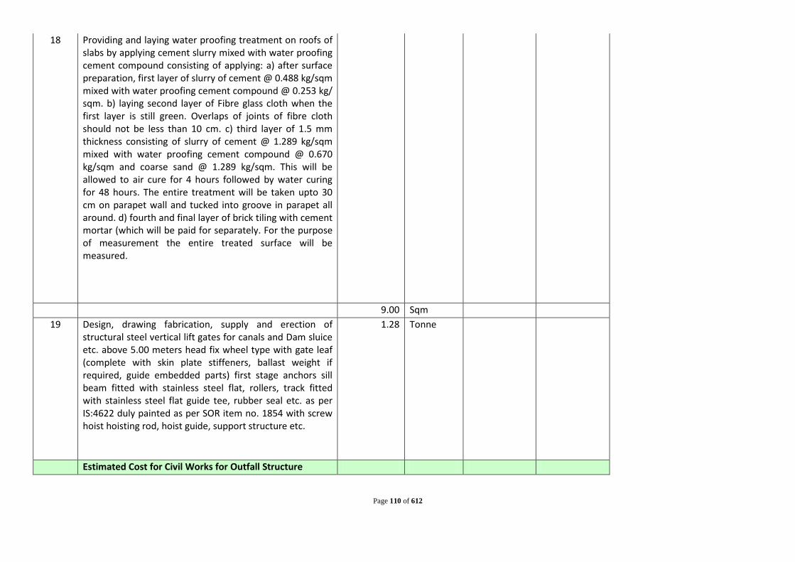
Page 110 of 612
18 Providing and laying water proofing treatment on roofs of slabs by applying cement slurry mixed with water proofing cement compound consisting of applying: a) after surface preparation, first layer of slurry of cement @ 0.488 kg/sqm mixed with water proofing cement compound @ 0.253 kg/ sqm. b) laying second layer of Fibre glass cloth when the first layer is still green. Overlaps of joints of fibre cloth should not be less than 10 cm. c) third layer of 1.5 mm thickness consisting of slurry of cement @ 1.289 kg/sqm mixed with water proofing cement compound @ 0.670 kg/sqm and coarse sand @ 1.289 kg/sqm. This will be allowed to air cure for 4 hours followed by water curing for 48 hours. The entire treatment will be taken upto 30 cm on parapet wall and tucked into groove in parapet all around. d) fourth and final layer of brick tiling with cement mortar (which will be paid for separately. For the purpose of measurement the entire treated surface will be measured.
9.00 Sqm 19 Design, drawing fabrication, supply and erection of
structural steel vertical lift gates for canals and Dam sluice etc. above 5.00 meters head fix wheel type with gate leaf (complete with skin plate stiffeners, ballast weight if required, guide embedded parts) first stage anchors sill beam fitted with stainless steel flat, rollers, track fitted with stainless steel flat guide tee, rubber seal etc. as per IS:4622 duly painted as per SOR item no. 1854 with screw hoist hoisting rod, hoist guide, support structure etc.
1.28 Tonne
Estimated Cost for Civil Works for Outfall Structure

Page 111 of 612

Page 112 of 612
BOQ OF NETWORK
Sl. No. Description Unit Quantity Rate (Rs) Amount (Rs)
Part - I: Earth Working & Timbering
1
Dismantling of Flexible Pavements (Dismantling of flexible pavements and disposal of dismantled materials up to a lead of 1000 metres, stacking serviceable and unserviceable materials separately)
By Mechanical Means: Bituminous course Cum 1354
2
Dismantling of Cement Concrete Pavement (Dismantling of cement concrete pavement by mechanical means using pneumatic tools, breaking to pieces not exceeding 0.02 cum in volume and stock piling at designated locations and disposal of dismantled materials up to a lead of 1000 metres, stacking serviceable and unserviceable materials separately)
Cum 2030
3
Excavating trenches of required width for pipes cables, etc, including excavation for sockets, and dressing of sides, ramming of bottoms, depth upto 1.5 m including getting out the excavated soil , and then returning the soil as required , in layers not exceeding 20 cm in depth including consolidating each deposited layer by ramming, watering, etc. and disposing of surplus excavated soil as directed , within a lead of 50 m. All Kinds of Soil.
(i) For, Pipes , cables etc. exceeding 80mm dia. but not exceeding 300m dia
a) Upto 1.5m Rm 0 b) Exceeding 1.5 m , but not exceeding 3 m. Rm 1330 c) Exceeding 3.0 m , but not exceeding 4.5 m. Rm 2609 d) Exceeding 4.5 m , but not exceeding 6.0 m. Rm 660 e) Exceeding 6 m , but not exceeding 7.5 m. Rm 0
(ii) Pipes , cables etc. exceeding 300m dia.

Page 113 of 612
a) Upto 1.5m Rm 0 b) Exceeding 1.5 m , but not exceeding 3 m. Rm 706 c) Exceeding 3.0 m , but not exceeding 4.5 m. Rm 2363 d) Exceeding 4.5 m , but not exceeding 6.0 m. Rm 3859 e) Exceeding 6.0 m , but not exceeding 7.5 m. Rm 3297
4 Filling available excavated earth (excluding rock) in trenches, plinth, sides of foundations etc. in layers not exceeding 20 cm in depth: consolidating each deposited layer by ramming and watering lead
(i) Upto 1.5m Cum 33839 (ii) Extra for every additional lift of 1.5 m or part thereof: Cum 52606
5 Supplying and Filling in plinth with local sand and under floors including, watering, ramming consolidating and dressing complet for DWC pipe
Cum 2884
6
Providing average 150mm thick dry rammed khoa beaten to 112mm (compacted with water) made of well burnt or jhama bricks including ramming properly till compacted thickness is achieved, curing and carriage of water with all leads, making proper slope and blinding the top with cement mortar (1: 10) all complete as per building specification and direction of E/l, for DWC pipe
sqm 6685
7 Close timbering in trenches including strutting, shoring and packing cavities (wherever required) complete. (Measurements to be taken of the face area timbered).
(i) Depth not exceeding 1.5 m Sqm 0 (ii) Depth exceeding 1.5 m but not exceeding 3 m Sqm 9548 (iii) Depth exceeding 3.0 m but not exceeding 4.5 m Sqm 65724
8 Extra For Planking, Struting and packing materials for cavities(in Close Timbering) if required to be left permanently in Position (10% of Close Timbering)
Sqm 3764

Page 114 of 612
9
Hire and labour charge for installing standard M.S sheet piles for excavation of any type and size including junction and corner taper piles etc . With clutch bars or any other febricated sheet pile where necessary by bany means (either manual, mechanical or vibratory hammers) in all kinds of soli including cutting hard crust, drilling holes and welding of piles as necessary , stagging,scaffolding , supply of all equipments (except of M.S Sheet pile and carriage) of M.S sheet piles from departmental godown to worksite. (Hire charges of sheet piles if supplied will be payeble by the contractor) for above 4.5 m depth
Sqm 92928
10 Withdrawing sheet piles , carriage and stacking the same property in the departmental stackyard/godown properly as per direction of the Engineer-in -charge.)
Sqm 92928
11 Providing designation 100 A one brick flat soling joints filled with local sand including cost of watering, taxes, royalty all complete as per building specification and direction of E/l,
Sqm 22559
12 Plain/Reinforced cement concrete in open foundation complete as per drawing and technical specificationsM.15 Cum 1372
13
Plain/Reinforced cement concrete in open foundation complete as per drawing and technical specifications M.15 for Anchor Block of (300 MMX200 MM) @ 6 m c/c (at the center of Each Pipe)( If necesary)
cum 137
14
Plain/Reinforced cement concrete in open foundation complete as per drawing and technical specifications- Using Concrete Mixer M.20- 1:1:5:3(1 cement: 1.5 coarse sand:3 graded stone aggregate 20 mm nominal size
cum 3561
15 Centring and shuttering including strutting,propping etc and removal or form work for Foundations,footings, bases Columns Sqm 5013

Page 115 of 612
16 Supplying, fitting and placing un-coated HYSD bar reinforcement in foundation complete as per drawing and technical specifications Tonne 285
17 Cost of Haulage of earth Excluding loading and Unloading (5 Kms) Ton 33075
18 Loading and Unloading of Stone Boulder/Stone Aggregates/Sand/Kanker/Moorum. Cum 20672
19
Providing sal ballah barricading with departmental sal ballah average 150 dia. And 2M long sal ballah post at interval of 2.5 M C/C fixed 0.5 M average below ground, packed with earth and Brick bats, well watered and rammed with three rows of average 100mm dia. Sal ballah horizontal runners fixed with iron spikes and wires, white washing one coat to exposed surface, dismantling the barricade after function, filling the holes, excluding carriage of sal ballah from and to godown up to 5K.M. lead, stacking them in countable stacks in godown including cost of all labour and materials and taxes all complete job as per specification and direction of E/l.
Per m 37892
Estimated Cost: Part - I Part-II: Providing and Laying of Sewer Lines
1
Supplying and laying of DWC Class SN 8 Pipes, bailing out / dewatering (by pumps or otherwise) water in trenches, lowering the same into the trench, aligning and jointing the pipes to prescribed gradient, depth and alignment ; fixing, making connection to new manholes and checking the 'as-laid' pipe with joints etc, as per the drawings, specification and direction of the Engineer. (The rate shall include all cost of materials and labour for pipes, jointing with manhole, aggregate packing, dewatering, cleaning the inside surfaces of pipe after laying, bonning rods, sight rails, levelling instruments etc. as required for the above mentioned works). (Hydralic testing shall be paid seperately)
(i) 150 mm dia Rm 0 (ii) 200 mm dia Rm 2800
(iii) 250 mm dia Rm 851 (iv) 300 mm dia Rm 948
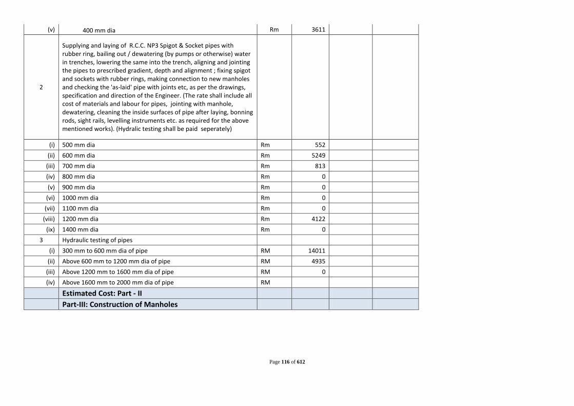
Page 116 of 612
(v) 400 mm dia Rm 3611
2
Supplying and laying of R.C.C. NP3 Spigot & Socket pipes with rubber ring, bailing out / dewatering (by pumps or otherwise) water in trenches, lowering the same into the trench, aligning and jointing the pipes to prescribed gradient, depth and alignment ; fixing spigot and sockets with rubber rings, making connection to new manholes and checking the 'as-laid' pipe with joints etc, as per the drawings, specification and direction of the Engineer. (The rate shall include all cost of materials and labour for pipes, jointing with manhole, dewatering, cleaning the inside surfaces of pipe after laying, bonning rods, sight rails, levelling instruments etc. as required for the above mentioned works). (Hydralic testing shall be paid seperately)
(i) 500 mm dia Rm 552 (ii) 600 mm dia Rm 5249
(iii) 700 mm dia Rm 813 (iv) 800 mm dia Rm 0 (v) 900 mm dia Rm 0
(vi) 1000 mm dia Rm 0 (vii) 1100 mm dia Rm 0
(viii) 1200 mm dia Rm 4122 (ix) 1400 mm dia Rm 0
3 Hydraulic testing of pipes (i) 300 mm to 600 mm dia of pipe RM 14011
(ii) Above 600 mm to 1200 mm dia of pipe RM 4935 (iii) Above 1200 mm to 1600 mm dia of pipe RM 0 (iv) Above 1600 mm to 2000 mm dia of pipe RM
Estimated Cost: Part - II Part-III: Construction of Manholes

Page 117 of 612
1
Supply and construction of Manhole Type in cement brickwork (1:3) placed over 200mm thick PCC (1:2:4) with 20mm & down stonechips bed laid over a layer of brick flat soling, including M-20 grade 150mm thick doubly reinforced RCC cover slab having opening for manhole, formation of channel at the invert with PCC (1:2:4) finished with 1.5mm thick neat cement finish over 15mm thick plaster in cement sand mortar (1:3) on all internal faces, including supplying and fixing polypropylene coated foot-rests, conforming to ASTMD 4101 specification, injection moulded around a 12 mm steel reinforcing bar of grade Fe 415, IS:1786 (approx. wt. 900 gm each) built into brickwork, including shuttering, reinforcement, bailing out/dewatering (by pumps or otherwise) of water [excluding supply, fitting and fixing of RCPC manhole cover with frame & packing around with PCC (1:2:4)], complete as per drawing, specification and as directed by the Engineer. (Excavation, backfilling, dismantling of road crust, shoring shall be paid seperately).
(i) Upto 1.2m Nos 0 (ii) 1.2m - 2.0m Nos 22
(iii) 2.0m - 4.0m Nos 332 (iv) 4.0m - 7.0m Nos 262 (v) 7.0m - 10.5m Nos 58
2 Providing and fixing in position DI. manhole cover and frame of required shape and approved quality (including GST) with locking facility
(i) DI Manhole cover & frame (HD 35) - Loading capacity 35 MT (Hinged type) Nos 202
(ii) DI Manhole cover & frame (HD 35) - Loading capacity 35 MT (Hinged type with Double layer seal) Nos 202
(iii) DI Manhole cover & frame (MD 10) - Loading capacity 10 MT (Hinged type) Nos 135
(iv) DI Manhole cover & frame (MD 10) - Loading capacity 10 MT (Hinged type with Double layer seal) Nos 135

Page 118 of 612
3 Close timbering in case of shafts, wells, cesspits, manholes and the like including strutting and shoring complete (measurements to be taken of the face area timbered):
sqm
(i) Depth upto 1.5 m sqm 0 (ii) For additional depth beyond 1.5 m and upto 3.0m sqm 566
(iii) Depth exceeding 3 m but not exceeding 4.5 m sqm 12430
4 Extra For Planking, Struting and packing materials for cavities(in Close Timbering) if required to be left permanently in Position (10% of Close Timbering)
Sqm 650
5
Hire and labour charge for installing standard M.S sheet piles for excavation of any type and size including junction and corner taper piles etc . With clutch bars or any other febricated sheet pile where necessary by bany means (either manual, mechanical or vibratory hammers) in all kinds of soli including cutting hard crust, drilling holes and welding of piles as necessary , stagging,scaffolding , supply of all equipments (except of M.S Sheet pile and carriage) of M.S sheet piles from departmental godown to worksite. (Hire charges of sheet piles if supplied will be payeble by the contractor)
Sqm 26283
6 Withdrawing sheet piles , carriage and stacking the same property in the departmental stackyard/godown properly as per direction of the Engineer-in -charge.)
Sqm 26282.67

Page 119 of 612
7
Supply and construction of Inspection Pits of inside measurement 450mm X 500mm X upto 1000mm depth with 250mm thick second class brickwork in cement mortar(1:4) on all sides, bottom of pit consisting of 100mm thick PCC slab (1:2:4) over a 150 mm layer of hand packed stone soling, 15mm thick(1:4) cement plaster to inside walls and pointing on outside faces with cement mortar 1:4, formation of channel at the invert with PCC with cement concrete (1:2:4) with graded stonechips as per direction, neat cement finishing to entire internal surfaces, top of the pit covered with 100mm thick R.C.C. slab (M-20) with graded stone chips and necessary reinforcement and shuttering including one MD-10 RCC circular manhole cover with frame as per IS:12592 of approved make supplied, fitted and fixed on the slab with PCC (1:2:4) packing; necessary earthwork in excavation in all kinds of soil, dewatering if required, filling sides of the pit with earth and removing spoils after work, all complete
Nos 0.00
8
Supplying and laying of DWC Class SN 8 Pipes for secondary sewer connection upto invert depth of 1.5m below G.L. and making connection wherever required, including aligning, laying and joinining with solvent cement joints supplied by manufacturer of pipes and placing over 150mm average thick coarse sand/crushed stone dust bedding and encasing the same with coarse sand/crushed stone dust (as per technical specification) all round, upto 100 mm above the crown of the pipe as shown in drawing, including excavation of earth, dewatering of any kind (if required), backfilling, disposal, compaction and plugging end with suitable capping (if required) and grouting the junction of pipe with manhole and inspection pit etc. complete as per drawing (into precast riser rings/cover slab), specification or/ as directed by the Engineer. (The rate includes connection to new manholes/inspection chambers etc. by grouting the annular space with special grouting material as per technical specification, including restoration of manholes, if necesssary).
150mm Dia. Rm 0.00

Page 120 of 612
9
Supplying and laying of DWC Class SN 8 Pipes for house sewer connection upto invert depth of 1.5m below G.L. and making connection to inspection pit wherever required, including aligning, laying and joinining with solvent cement joints supplied by manufacturer of pipes and placing over 150mm average thick coarse sand/crushed stone dust bedding and encasing the same with coarse sand/crushed stone dust (as per technical specification) all round, upto 100 mm above the crown of the pipe as shown in drawing, including excavation of earth, dewatering of any kind (if required), backfilling, disposal, compaction and plugging end with suitable capping (if required) and grouting the junction of pipe with manhole and inspection pit etc. complete as per drawing (into precast riser rings/cover slab), specification or/ as directed by the Engineer. (The rate includes connection to new manholes/inspection chambers etc. by grouting the annular space with special grouting material as per technical specification, including restoration of manholes, if necesssary).
(i) 150mm Dia. Rm 0.00
10 Supplying and Filling in plinth with local sand and under floors including, watering, ramming consolidating and dressing complet for DWC pipe
Cum 0

Page 121 of 612
11
Providing sand cast iron drop connection externally for 60 cm drop from branch sewer line to main sewer manhole including inspection and cleaning eye with chain and lid, sand cast iron drop pipe and bend encased all-round with cement concrete 1:5:10 (1 cement : 5 fine sand : 10 graded stone aggregate 40 mm nominal size) with all centering and shuttering required, cutting holes in walls and making good with brick work in cement mortar 1:4 (1 cement : 4 coarse sand) plastered with cement mortar 1:3 (1 cement : 3 coarse sand) on inside of the manhole wall, lead caulked joints between sand cast iron pipes and fittings, stiff cement mortar 1:1 (1 cement : 1 fine sand) joints between sand cast iron tee and S.W. pipe, making required channels complete as per standard design and specifications : Extra for depths beyond 60 cm of sand cast iron drop connection complete :
For 150 mm dia sand cast iron drop connection Each 3.00
Estimated Cost: Part - III Part-IV: Road restoration
1
Construction of un-reinforced, dowel jointed, plain cement concrete pavement over a prepared sub base with 43 grade cement @ 400 kg per cum, coarse and fine aggregate conforming to IS 383, maximum size of coarse aggregate not exceeding 25 mm, mixed in a batching and mixing plant as per approved mix design, transported to site, laid with a fixed form or slip form paver, spread, compacted and finished in a continuous operation including provision of contraction, expansion, construction and longitudinal joints, joint filler, separation membrane, sealant primer, joint sealant, debonding strip, dowel bar, tie rod, admixtures as approved, curing compound, finishing to lines and grades as per drawing )
Cum 2030

Page 122 of 612
2
Bituminous Macadam (Providing and laying bituminous macadam with 100-120 TPH hot mix plant producing an average output of 75 tonnes per hour using crushed aggregates of specified grading premixed with bituminous binder, transported to site, laid over a previously prepared surface with paver finisher to the required grade, level and alignment and rolled as per clauses 501.6 and 501.7 to achieve the desired compaction)
Cum 1354
3
Close Graded Premix Surfacing/Mixed Seal Surfacing (Mechanical means using HMP of appropriate capacity not less than 75 tonnes/hour. Providing, laying and rolling of closegraded premix surfacing material of 20 mm thickness composed of 11.2 mm to 0.09 mm (Type-a) or 13.2 mm to 0.09 mm (Type-b) aggregates using penetration grade bitumen to the required line, grade and level to serve as wearing course on a previously prepared base, including mixing in a suitable plant, laying and rolling with a Smooth wheeled roller 8-10 tonne capacity, and finishing to required level and grade. )
Sqm 27071
4
Water Bound Macadam (Providing, laying, spreading and compacting stone aggregates of specific sizes to water bound macadam specification including spreading in uniform thickness, hand packing, rolling with vibratory roller 8-10 tonnes / Smooth 3 wheeled Steel Roller in stages to proper grade and camber, applying and brooming requisite type of screening/ binding Materials to fill up the interstices of coarse aggregate, watering and compacting to the required density.)
Cum 2030
5
Railway Crossing /Road /cannal crossing by trenchless technologies tunneling work through specialized pipe jacking method in co-ordination with concern authorities for as per approved drawings , installing to correct level gradient and alignment by hydraulic pipe jacking technique complete including tunneling excavation drive and receive pits, excavation and all machines transportation charges and other required materials but excluding cost of encasing pipe
m 0
Estimated Cost: Part - IV Estimated Cost for Intercepting network

Page 123 of 612
Name of the Work : Construction of Screen Chamber at Lifting Station (Intermediate Pumping Station 1)
Ref. Description of work Total
Quantity Unit Rate Amount
1 Excavation for Structures (Earth work in excavation of foundation of structures as per drawing and technical specification, including setting out, construction of shoring and bracing, removal of stumps and other deleterious matter, dressing of sides and bottom, backfilling the excavation earth to the extent required and utilising the remaining earth locally for WELL work.
Ordinary soil(Manual Means ) 49.59 cum (Depth upto 3 m) 49.59 cum 3 M TO 4.5 M 49.59 cum 4.5 M TO 6 M 49.59 cum 6 M TO 7.5 M 49.59 cum 2 Hire & labour charges for driving MS sheet pile of any tipe and size including junction and corner taper piles etc, with clutch
bars where necessary by any means (Manual/Mechanical) in any kind of soil including cutting hard crust drilling holes aqnd welding of piles as necessary staging, scaffolding supply of all equipments (except MS sheet piles and carriage) of MS sheet piles from department godown to work site 150.00 Sqm
3 Withdrawing sheet piles, carriage and stacking the same property in the dept stackyard/ godown properly as per direction of Engineer-in-charge 150.00 SQm
4 Providing designation 100 A one brick flat soling joints filled with local sand including cost of watering, taxes, royalty all complete as per building specification and direction of E/l, 33.06 Sqm
5 Plain cement concrete in open foundation complete as per drawing and technical specifications M.15 using Concrete Mixure
B.SCREENING STATION 9.92 cum

Page 124 of 612
6 Plain/Reinforced cement concrete in open foundation complete as per drawing and technical specifications M.25 using Concrete Mixure
B.SCREENING STATION (a)WALL(250MM) 46.9 cum B) Wall 400mm th 75.0 cum (c )BAFFLE WALL-300 mm thick 9.9 cum (d) Wall (150mm th) 3.9 cum (e)Raft-500 mm thick 16.5 cum 152.2425 cum 7 Steel work welded in built up sections/framed worK including cutting hoisting, rixing in position and applying a priming coat of
approved steel primer using structural steel, etc. as required. 9.375 kg
8 Providing and fixing hand rail by welding etc. to steel ladder railings & staircases railing including applying a priming coat of approved steel primer --G.I pipes 40 mm nominal bore (class B) 3.75kg/m
93.75 kg
9 Providing Steps at screen chamber MS rod (16mm dia) (1.58KG/m) for step 47.00 kg MS rod (16mm dia) (1.58KG/m) for back guard 122.00 kg MS angle 75x75x8 134.00 kg angle for grouting 6.00 kg Welding 9530.00 cm
10 Supplying, fitting and placing un-coated HYSD bar reinforcement in foundation complete as per drawing and technical specifications 18.27 Tonne
11 Centring and shuttering including strutting,propping etc. and removal of form for.
(i) Foundations, footings, bases of columns etc. for mass concrete 86.12 sqm (ii)
For Walls (any thickness) including attached pilasters. Butteresses, plinth and string courses etc. 486.94 Sqm

Page 125 of 612
(iii) For Suspended floors, roots, landings, balcnies and access platform. 0.00 Sqm (iv)
Total for Lintels, beams, plinth bams, griders, bressumers and cantilevers. 0.00 Sqm
(v) For Columns,Pillars, Piers, Abutments, Posts and Struts 0.00 Sqm 12 Carriage of earth Excluding loading and Unloading (5 Kms) 396.72 Ton 13
Loading and Unloading of Stone Boulder/Stone Aggregates/Sand/Kanker/Moorum. 247.95 cum
Name of the Work : Construction of Screen Chamber at Lifting Station (Intermediate Pumping Station 2)
Ref. Description of work Total
Quantity Unit Rate Amount
1 Excavation for Structures (Earth work in excavation of foundation of structures as per drawing and technical specification, including setting out, construction of shoring and bracing, removal of stumps and other deleterious matter, dressing of sides and bottom, backfilling the excavation earth to the extent required and utilising the remaining earth locally for WELL work.
Ordinary soil(Manual Means ) 7.20 Cum (Depth upto 3 m) 4.56 Cum 3 M TO 4.5 M 4.5 M TO 6 M 6 M TO 7.5 M

Page 126 of 612
2 Hire & labour charges for driving MS sheet pile of any tipe and size including junction and corner taper piles etc, with clutch bars where necessary by any means (Manual/Mechanical) in any kind of soil including cutting hard crust drilling holes aqnd welding of piles as necessary staging, scaffolding supply of all equipments (except MS sheet piles and carriage) of MS sheet piles from department godown to work site
17.60 Sqm
3 Withdrawing sheet piles, carriage and stacking the same property in the dept stackyard/ godown properly as per direction of Engineer-in-charge 17.60 SQm
4 Providing designation 100 A one brick flat soling joints filled with local sand including cost of watering, taxes, royalty all complete as per building specification and direction of E/l,
4.80 Sqm
5 Plain cement concrete in open foundation complete as per drawing and technical specifications M.15 using Concrete Mixure
B.SCREENING STATION 1.44 Cum 6 Plain/Reinforced cement concrete in open foundation complete as per
drawing and technical specifications M.25 using Concrete Mixure
B.SCREENING STATION (a)WALL(250MM) 4.4 Cum B) Wall 400mm th 7.0 Cum (c )BAFFLE WALL-300 mm thick 2.6 Cum (d) Wall (150mm th) 1.1 Cum (e)Raft-500 mm thick 2.4 Cum 17.53 Cum 7 Steel work welded in built up sections/framed worK including cutting
hoisting, rixing in position and applying a priming coat of approved steel primer using structural steel, etc. as required.
3.3 Kg

Page 127 of 612
8 Providing and fixing hand rail by welding etc. to steel ladder railings & staircases railing including applying a priming coat of approved steel primer --G.I pipes 40 mm nominal bore (class B) 3.75kg/m 33.00 Kg
9 Providing Steps at screen chember MS rod (16mm dia) (1.58KG/m) for step 13.00 Kg MS rod (16mm dia) (1.58KG/m) for back guard 32.00 Kg MS angle 75x75x8 36.00 Kg angle for grouting 6.00 Kg Welding 2776.00 Cm
10 Supplying, fitting and placing un-coated HYSD bar reinforcement in foundation complete as per drawing and technical specifications
2.10 Tonne
11 Centring and shuttering including strutting,propping etc. and removal of form for.
(i) Foundations, footings, bases of columns etc. for mass concrete 16.64 Sqm (ii) For Walls (any thickness) including attached pilasters. Butteresses,
plinth and string courses etc. 70.53 Sqm
(iii) For Suspended floors, roots, landings, balcnies and access platform. 0.00 Sqm (iv) Total for Lintels, beams, plinth bams, griders, bressumers and
cantilevers. 0.00 Sqm
(v) For Columns,Pillars, Piers, Abutments, Posts and Struts 0.00 Sqm 12 Carriage of earth Excluding loading and Unloading (5 Kms) 18.82 Ton 13 Loading and Unloading of Stone Boulder/Stone
Aggregates/Sand/Kanker/Moorum. 11.76 Cum

Page 128 of 612
Name of the Work : Construction of Screen Chamber at Lifting Station (Intermediate Pumping Station 3)
Ref. Description of work Total
Quantity Unit Rate Amount
1 Excavation for Structures (Earth work in excavation of foundation of structures as per drawing and technical specification, including setting out, construction of shoring and bracing, removal of stumps and other deleterious matter, dressing of sides and bottom, backfilling the excavation earth to the extent required and utilising the remaining earth locally for WELL work.
Ordinary soil(Manual Means ) 7.20 cum (Depth upto 3 m) 13.68 cum 3 M TO 4.5 M 4.56 cum 2 Hire & labour charges for driving MS sheet pile of any tipe and size including junction and corner taper piles etc, with clutch
bars where necessary by any means (Manual/Mechanical) in any kind of soil including cutting hard crust drilling holes aqnd welding of piles as necessary staging, scaffolding supply of all equipments (except MS sheet piles and carriage) of MS sheet piles from department godown to work site 30.80 Sqm
3 Withdrawing sheet piles, carriage and stacking the same property in the dept stackyard/ godown properly as per direction of Engineer-in-charge 30.80 SQm
4 Providing designation 100 A one brick flat soling joints filled with local sand including cost of watering, taxes, royalty all complete as per building specification and direction of E/l, 4.80 Sqm
5 Plain cement concrete in open foundation complete as per drawing and technical specifications M.15 using Concrete Mixure
B.SCREENING STATION 1.44 cum

Page 129 of 612
6 Plain/Reinforced cement concrete in open foundation complete as per drawing and technical specifications M.25 using Concrete Mixure
B.SCREENING STATION (a)WALL(250MM) 7.7 cum B) Wall 400mm th 12.3 cum (c )BAFFLE WALL-300 mm thick 4.6 cum (d) Wall (150mm th) 1.8 cum (e)Raft-500 mm thick 2.4 cum 28.8775 cum 7 Steel work welded in built up sections/framed worK including cutting hoisting, rixing in position and applying a priming coat of
approved steel primer using structural steel, etc. as required. 3.3 kg
8 Providing and fixing hand rail by welding etc. to steel ladder railings & staircases railing including applying a priming coat of approved steel primer --G.I pipes 40 mm nominal bore (class B) 3.75kg/m
33.00 kg
9 Providing Steps at screen chamber MS rod (16mm dia) (1.58KG/m) for step 22.00 kg MS rod (16mm dia) (1.58KG/m) for back guard 57.00 kg MS angle 75x75x8 62.00 kg angle for grouting 6.00 kg Welding 4618.00 cm
10 Supplying, fitting and placing un-coated HYSD bar reinforcement in foundation complete as per drawing and technical specifications 3.47 Tonne
11 Centring and shuttering including strutting,propping etc. and removal of form for.
(i) Foundations, footings, bases of columns etc. for mass concrete 16.64 sqm (ii)
For Walls (any thickness) including attached pilasters. Butteresses, plinth and string courses etc. 112.08 Sqm
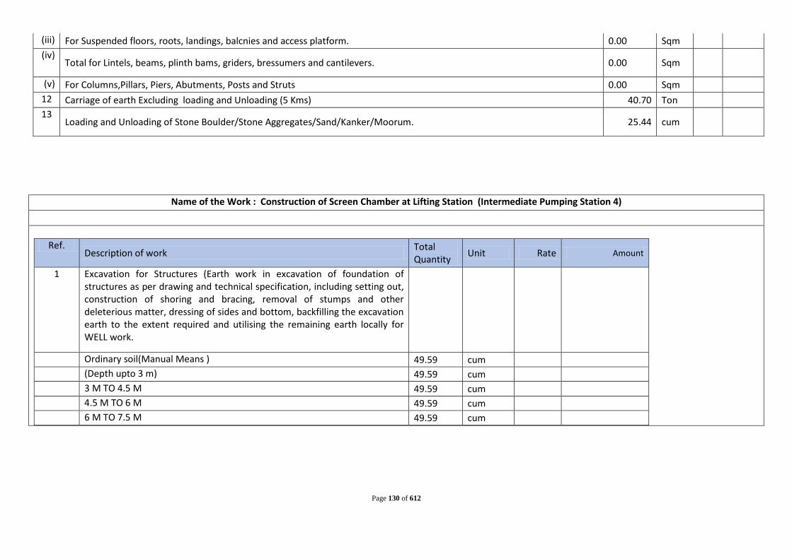
Page 130 of 612
(iii) For Suspended floors, roots, landings, balcnies and access platform. 0.00 Sqm (iv)
Total for Lintels, beams, plinth bams, griders, bressumers and cantilevers. 0.00 Sqm
(v) For Columns,Pillars, Piers, Abutments, Posts and Struts 0.00 Sqm 12 Carriage of earth Excluding loading and Unloading (5 Kms) 40.70 Ton 13
Loading and Unloading of Stone Boulder/Stone Aggregates/Sand/Kanker/Moorum. 25.44 cum
Name of the Work : Construction of Screen Chamber at Lifting Station (Intermediate Pumping Station 4)
Ref. Description of work Total
Quantity Unit Rate Amount
1 Excavation for Structures (Earth work in excavation of foundation of structures as per drawing and technical specification, including setting out, construction of shoring and bracing, removal of stumps and other deleterious matter, dressing of sides and bottom, backfilling the excavation earth to the extent required and utilising the remaining earth locally for WELL work.
Ordinary soil(Manual Means ) 49.59 cum (Depth upto 3 m) 49.59 cum 3 M TO 4.5 M 49.59 cum 4.5 M TO 6 M 49.59 cum 6 M TO 7.5 M 49.59 cum

Page 131 of 612
2 Hire & labour charges for driving MS sheet pile of any tipe and size including junction and corner taper piles etc, with clutch bars where necessary by any means (Manual/Mechanical) in any kind of soil including cutting hard crust drilling holes aqnd welding of piles as necessary staging, scaffolding supply of all equipments (except MS sheet piles and carriage) of MS sheet piles from department godown to work site
150.00 Sqm
3 Withdrawing sheet piles, carriage and stacking the same property in the dept stackyard/ godown properly as per direction of Engineer-in-charge 150.00 SQm
4 Providing designation 100 A one brick flat soling joints filled with local sand including cost of watering, taxes, royalty all complete as per building specification and direction of E/l,
33.06 Sqm
5 Plain cement concrete in open foundation complete as per drawing and technical specificationsM.15using Concrete Mixure
B.SCREENING STATION 9.92 cum 6 Plain/Reinforced cement concrete in open foundation complete as per
drawing and technical specifications M.25 using Concrete Mixure
B.SCREENING STATION (a)WALL(250MM) 46.9 cum B) Wall 400mm th 75.0 cum (c )BAFFLE WALL-300 mm thick 9.9 cum (d) Wall (150mm th) 3.9 cum (e)Raft-500 mm thick 16.5 cum 152.2425 cum 7 Steel work welded in built up sections/framed worK including cutting
hoisting, rixing in position and applying a priming coat of approved steel primer using structural steel, etc. as required.
9.375 kg

Page 132 of 612
8 Providing and fixing hand rail by welding etc. to steel ladder railings & staircases railing including applying a priming coat of approved steel primer --G.I pipes 40 mm nominal bore (class B) 3.75kg/m 93.75 kg
9 Providing Steps at screen chamber MS rod (16mm dia) (1.58KG/m) for step 47.00 kg MS rod (16mm dia) (1.58KG/m) for back guard 122.00 kg MS angle 75x75x8 134.00 kg angle for grouting 6.00 kg Welding 9530.00 cm
10 Supplying, fitting and placing un-coated HYSD bar reinforcement in foundation complete as per drawing and technical specifications 18.27 Tonne
11 Centring and shuttering including strutting,propping etc. and removal of form for.
(i) Foundations, footings, bases of columns etc. for mass concrete 86.12 sqm (ii) For Walls (any thickness) including attached pilasters. Butteresses, plinth
and string courses etc. 486.94 Sqm
(iii) For Suspended floors, roots, landings, balcnies and access platform. 0.00 Sqm (iv)
Total for Lintels, beams, plinth bams, griders, bressumers and cantilevers. 0.00 Sqm
(v) For Columns,Pillars, Piers, Abutments, Posts and Struts 0.00 Sqm 12 Carriage of earth Excluding loading and Unloading (5 Kms) 396.72 Ton 13 Loading and Unloading of Stone Boulder/Stone
Aggregates/Sand/Kanker/Moorum. 247.95 cum

Page 133 of 612
Name of the Work : Construction of Screen Chamber at Lifting Station (Intermediate Pumping Station 5)
Ref.
Description of work Total Quantity Unit Rate Amount
1 Excavation for Structures (Earth work in excavation of foundation of structures as per drawing and technical specification, including setting out, construction of shoring and bracing, removal of stumps and other deleterious matter, dressing of sides and bottom, backfilling the excavation earth to the extent required and utilising the remaining earth locally for WELL work.
Ordinary soil(Manual Means ) 49.59 cum
(Depth upto 3 m) 49.59 cum
3 M TO 4.5 M 49.59 cum
2 Hire & labour charges for driving MS sheet pile of any tipe and size including junction and corner taper piles etc, with clutch bars where necessary by any means (Manual/Mechanical) in any kind of soil including cutting hard crust drilling holes aqnd welding of piles as necessary staging, scaffolding supply of all equipments (except MS sheet piles and carriage) of MS sheet piles from department godown to work site
112.50 Sqm
3 Withdrawing sheet piles, carriage and stacking the same property in the dept stackyard/ godown properly as per direction of Engineer-in-charge 112.50 SQm
4 Providing designation 100 A one brick flat soling joints filled with local sand including cost of watering, taxes, royalty all complete as per building specification and direction of E/l,
33.06 Sqm
5 Plain cement concrete in open foundation complete as per drawing and technical specifications M.15 using Concrete Mixure

Page 134 of 612
B.SCREENING STATION 9.92 cum
6 Plain/Reinforced cement concrete in open foundation complete as per drawing and technical specifications M.25 using Concrete Mixure
B.SCREENING STATION
(a)WALL(250MM) 28.1 cum
B) Wall 400mm th 45.0 cum
(c )BAFFLE WALL-300 mm thick 5.9 cum
(d) Wall (150mm th) 2.4 cum
(e)Raft-500 mm thick 16.5 cum
97.9575 cum
7 Steel work welded in built up sections/framed worK including cutting hoisting, rixing in position and applying a priming coat of approved steel primer using structural steel, etc. as required.
9.375 kg
8 Providing and fixing hand rail by welding etc. to steel ladder railings & staircases railing including applying a priming coat of approved steel primer --G.I pipes 40 mm nominal bore (class B) 3.75kg/m
93.75 kg
9 Providing Steps at screen chamber
MS rod (16mm dia) (1.58KG/m) for step 28.00 kg
MS rod (16mm dia) (1.58KG/m) for back guard 73.00 kg
MS angle 75x75x8 80.00 kg
angle for grouting 6.00 kg
Welding 5846.00 cm
10 Supplying, fitting and placing un-coated HYSD bar reinforcement in foundation complete as per drawing and technical specifications 11.75 Tonne
11 Centring and shuttering including strutting,propping etc. and removal of form for.
(i) Foundations, footings, bases of columns etc. for mass concrete
86.12 sqm
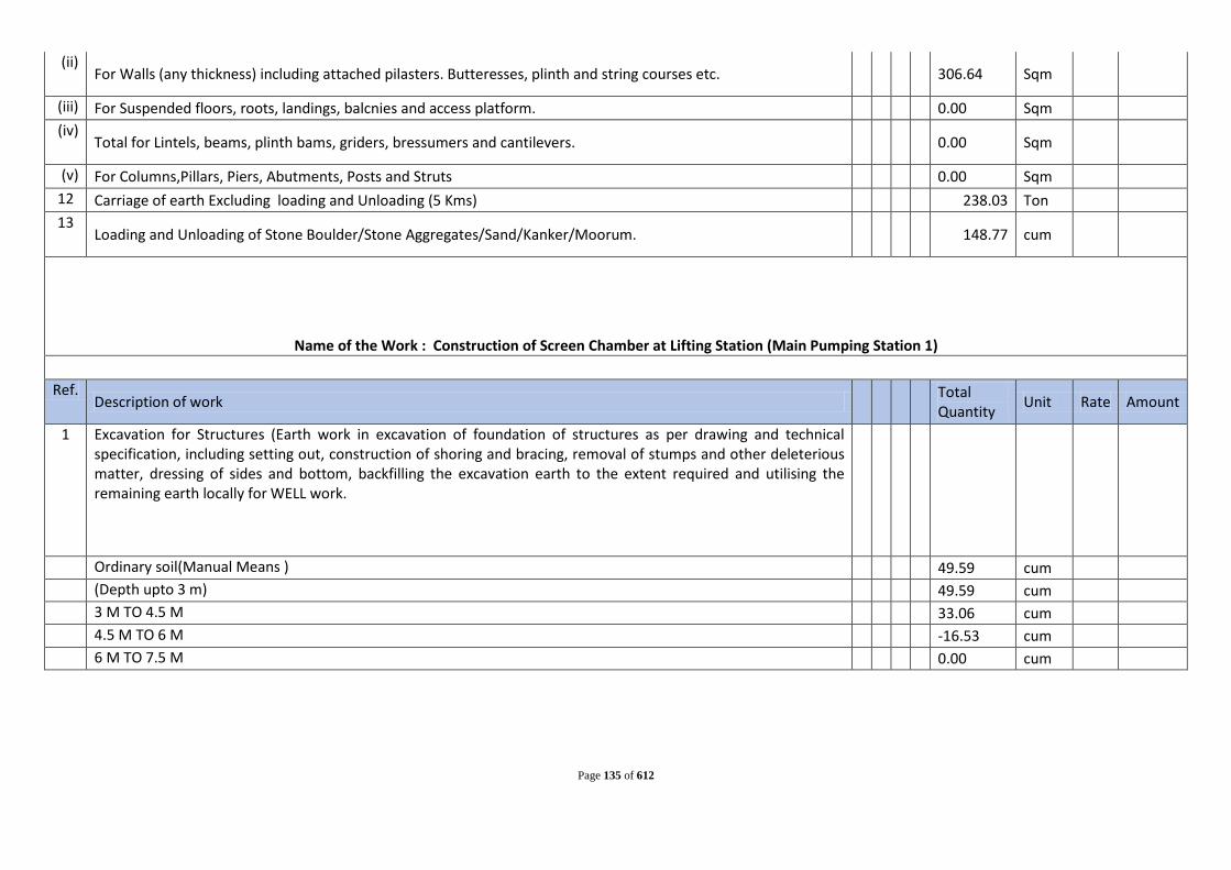
Page 135 of 612
(ii) For Walls (any thickness) including attached pilasters. Butteresses, plinth and string courses etc.
306.64 Sqm
(iii) For Suspended floors, roots, landings, balcnies and access platform. 0.00 Sqm (iv)
Total for Lintels, beams, plinth bams, griders, bressumers and cantilevers.
0.00 Sqm
(v) For Columns,Pillars, Piers, Abutments, Posts and Struts 0.00 Sqm 12 Carriage of earth Excluding loading and Unloading (5 Kms) 238.03 Ton 13
Loading and Unloading of Stone Boulder/Stone Aggregates/Sand/Kanker/Moorum. 148.77 cum
Name of the Work : Construction of Screen Chamber at Lifting Station (Main Pumping Station 1)
Ref. Description of work
Total Quantity Unit Rate Amount
1 Excavation for Structures (Earth work in excavation of foundation of structures as per drawing and technical specification, including setting out, construction of shoring and bracing, removal of stumps and other deleterious matter, dressing of sides and bottom, backfilling the excavation earth to the extent required and utilising the remaining earth locally for WELL work.
Ordinary soil(Manual Means ) 49.59 cum
(Depth upto 3 m) 49.59 cum
3 M TO 4.5 M 33.06 cum
4.5 M TO 6 M -16.53 cum
6 M TO 7.5 M 0.00 cum

Page 136 of 612
2 Hire & labour charges for driving MS sheet pile of any tipe and size including junction and corner taper piles etc, with clutch bars where necessary by any means (Manual/Mechanical) in any kind of soil including cutting hard crust drilling holes aqnd welding of piles as necessary staging, scaffolding supply of all equipments (except MS sheet piles and carriage) of MS sheet piles from department godown to work site
87.50 Sqm
3 Withdrawing sheet piles, carriage and stacking the same property in the dept stackyard/ godown properly as per direction of Engineer-in-charge 87.50 SQm
4 Providing designation 100 A one brick flat soling joints filled with local sand including cost of watering, taxes, royalty all complete as per building specification and direction of E/l,
33.06 Sqm
5 Providing and laying in position cement concrete of specified grade exluding the cost of centring and shuttering-all work upto plinth level. 1:2:4 (1 Cement: 2 coarse sand : 4 graded stone aggregate 40 mm nominal size)
B.SCREENING STATION 9.92 cum
6 Providing and laying in position specified grade of reinforced cement concrete excluding the cost of centring,shuttering,finishing and reinforcement-All work puto plinth level
B.SCREENING STATION
(a)WALL(250MM) 25.0 cum
B) Wall 400mm th 40.0 cum
(c )BAFFLE WALL-300 mm thick 5.3 cum
(d) Wall (150mm th) 2.1 cum
(e)Raft-500 mm thick 16.5 cum
88.91 cum
7 Steel work welded in built up sections/framed worK including cutting hoisting, rixing in position and applying a priming coat of approved steel primer using structural steel, etc. as required.
9.375 kg

Page 137 of 612
8 Providing and fixing hand rail by welding etc. to steel ladder railings & staircases railing including applying a priming coat of approved steel primer --G.I pipes 40 mm nominal bore (class B) 3.75kg/m
93.75 kg
9 Providing Steps at screen chamber
MS rod (16mm dia) (1.58KG/m) for step 25.00 kg
MS rod (16mm dia) (1.58KG/m) for back guard 65.00 kg
MS angle 75x75x8 71.00 kg
angle for grouting 6.00 kg
Welding 5232.00 cm
10 Reinforcement for R.C.C. work including straightening, cutting, bending, placing in position and binding all complete. Thermo-Mechanically Treated bars TMT Fe-500- I6mrn dia..
10.67 Tonne
11 Centring and shuttering including strutting,propping etc. and removal of form for.
(i) Foundations, footings, bases of columns etc. for mass concrete
86.12 sqm (ii)
For Walls (any thickness) including attached pilasters. Butteresses, plinth and string courses etc.
276.59 Sqm
(iii) For Suspended floors, roots, landings, balcnies and access platform.
0.00 Sqm (iv)
Total for Lintels, beams, plinth bams, griders, bressumers and cantilevers.
0.00 Sqm
(v) For Columns,Pillars, Piers, Abutments, Posts and Struts
0.00 Sqm 12 Carriage of earth Excluding loading and Unloading (5 Kms) 185.14 Ton 13
Loading and Unloading of Stone Boulder/Stone Aggregates/Sand/Kanker/Moorum. 115.71 cum

Page 138 of 612
Cost Estimate: Civil Works of Intermediate Pumping Station
IPS-01
Progamme Town: Chapra
Sl. No Description of work Unit Total
Quantity Rate (Rs) Amount (Rs)
A Cost of Civil Works 1
Excavation for Structures (Earth work in excavation of foundation of structures as per drawing and technical specification, including setting out, construction of shoring and bracing, removal of stumps and other deleterious matter, dressing of sides and bottom, backfilling the excavation earth to the extent required and utilising the remaining earth locally for WELL work.) Ordinary soil (Manual Means )
(i) Depth upto 3 m cum 285.00
(ii) 3m To 6m cum 285.00 (iii) 6m To 9m cum 285.00 (iv) 9m To 12m cum 494.00
Total cum 1349.00 2
Hire and labour charge for installing standard M.S sheet piles for excavation of any type and size including junction and corner taper piles etc . With clutch bars or any other febricated sheet pile where necessary by bany means (either manual, mechanical or vibratory hammers) in all kinds of soli including cutting hard crust, drilling holes and welding of piles as necessary , stagging,scaffolding , supply of all equipments (except of M.S Sheet pile and carriage) of M.S sheet piles from departmental godown to worksite. (Hire charges of sheet piles if supplied will be payeble by the contractor)
sqm 654.29
3 Withdrawing sheet piles , carriage and stacking the same property in the departmental stackyard/godown properly as per direction of the Engineer-in -charge.)
sqm 654.29

Page 139 of 612
4 Supplying and Filling in plinth with local sand and under floors including, watering, ramming consolidating and dressing complete. cum 28.50
5 PCC 1:3:6 in Foundation (Plain cement concrete 1:3:6 nominal mix in foundation with crushed stone aggregate 40 mm nominal size mechanically mixed, placed in foundation and compacted by vibration including curing for 14 days.)
(i) Below Well cum 13.00 6 Plain/Reinforced cement concrete in open foundation complete as
per drawing and technical specifications M.25 using Concrete Mixure
(i) All work upto Plinth level. cum 359.10 (ii) All work above Plinth level. cum 105.00
7 Brick work with bricks of class designation 100A in Cement mortar 1:4 (1 cement: 4 coarse sand )
(i) Above plinth level upto floor V cum 72.78 8 Half brick masonry with bricks of class designation 100A each for four floors
or part thereof.Cement mortar 1:3 (1 cement: 3 coarse send) cum 300.00
9 Centring and shuttering including strutting,propping etc. and removal of form for.
(i) Foundations, footings, bases of columns etc. for mass concrete sqm 27.14 (ii) For Walls (any thickness) including attached pilasters. Butteresses, plinth and
string courses etc. Sqm 800.07
(iii) For Suspended floors, roots, landings, balcnies and access platform. Sqm 308.84 (iv) Total for Lintels, beams, plinth bams, griders, bressumers and cantilevers. Sqm 229.93 (v) For Columns,Pillars, Piers, Abutments, Posts and Struts Sqm 32.00
10 Supplying, fitting and placing un-coated HYSD bar reinforcement in foundation complete as per drawing and technical specifications Tonne 55.69
11 Structural steel work riveted or bolted in built up sections, trusess and framed work, including cutting,hoisting,fixing in position and applying a priming coat of approved primer all complete. For Ladder & rung
Kg 189.39

Page 140 of 612
12 Providing and fixing hand rail by welding etc. to steel ladder railings & staircases railing including applying a priming coat of approved steel primer with G.I pipes 40 mm nominal bore (class B)
Kg 535.23
13 12 mm cement plaster of mix:1:5
(i) Inside Wall (1 cement: 5 coarse sand) sqm 283.00 14 15 mm cement plaster on rough side of single or half brick wall of mix.
(i) Outside Wall 1:4 (1 cement: 4 coarse sand) sqm 293.00 15
6 mm cement plaster to ceiling of mix :1:3(1 cement: 3 coarse sand) sqm 304.72
16 White washing with whiting to give an even shade :New work (three or more goats) sqm 304.72
17 Applying one coat of cement primer of approved brand and manufacture on wall surface: Distemper primer sqm 576.00
18 Finishing walls with water proofing cement paint of approved brand and manufacture and of required shade to give an even shadeNew work (three or more coats)
sqm 576.00
19 Finishing with Epoxy paint (two or more coats) at all locations prepared and applied as per manufacture's specifications including appropriate priming coat, preparation of surface, etc. complete
sqm 800.07
20 Welding by electric plant including transportation of electric welding plant at site etc. complete. cm 71.68
21 62 mm thick cement concrete flooring with metallic concrete hardener topping under layer 50 mm thick cement concrete 1:2:4(1 cement:2 coarse sand:4 graded stone aggregate 20 mm nominal size) and top layer 12mm thick metallic cement hardener consisting of mix 1:2(1 cement hardener mix:2 stone aggregate) nominal size by volume hardning compound is mixed @ 2 liter per 50 kg of cement or as per manufacture specification. This includes cost of cement slurry, etc. but excluding the cost of nosing of steps etc. complete.
sqm 66.48
22 Providing laminated veneer lumber conforming to IS:14616 & TAD 15:2001 (parts),manufactured in factories by approved manufacturers, in frames of doors, windows, clerestory windows and other frames, through framed and fixed in position as per directions of Engineer in charge
(i) For Windows cum 0.81

Page 141 of 612
23 Providing and fixing 35mm thick factory mode laminated veneer lumber door shutter conforming to IS:14616 & TADS 15-2001 (part B),manufactured in factories by approved manufacturers, including black enamelled M.S.butt hinges with necessary screws as per directions of Engineer in charge and panelling with panels of: 12 mm thick plain Grade-1 .medium density flat pressed three layer and graded particles board(FPT-I) conforming to 1S:3087 bonded with BWP type synthetic resin adhesive asperlS:848.
(i) For Windows sqm 3.24 24 Supplying and fixing rrlltng shuters of approved make,made of required size
of M.S.laths inter locked together through their intire length jnd jointed together at the end by end locks mounted on specially designed pipe shaft with brackets, side guides and arragements for insfde and outside locking with push and pull operation complete including the cost of prioviding and fixing necessary 27.5 cm long wire springs grade no. 2 and M.S. top cover of required thickness for rolling shutters.
(i) 80x1.25mmM.S. Laths with 1.25mm thick top cover. sqm 9.00
(ii) Providing and fixing ball bearing for rolling shutters sqm 9.00 25 Carriage of earth Excluding loading and Unloading (5 Kms) Ton 2158.40 26 Loading and Unloading of Stone Boulder/Stone
Aggregates/Sand/Kanker/Moorum. cum 1349
27 Providing and laying water proofing treatment on roofs of slabs by applying cement slurry mixed with water proofing cement compound consisting of applying: a) after surface preparation, first layer of slurry of cement @ 0.488 kg/sqm mixed with water proofing cement compound @ 0.253 kg/ sqm. b) laying second layer of Fibre glass cloth when the first layer is still green. Overlaps of joints of fibre cloth should not be less than 10 cm. c) third layer of 1.5 mm thickness consisting of slurry of cement @ 1.289 kg/sqm mixed with water proofing cement compound @ 0.670 kg/sqm and coarse sand @ 1.289 kg/sqm. This will be allowed to air cure for 4 hours followed by water curing for 48 hours. The entire treatment will be taken upto 30 cm on parapet wall and tucked into groove in parapet all around. d) fourth and final layer of brick tiling with cement mortar (which will be paid for separately. For the purpose of measurement the entire treated surface will be measured.
Sqm 36.00

Page 142 of 612
Estimated Cost for Civil Works for Sewage Pumping Station
Cost Estimate: Civil Works of Intermediate Pumping Station IPS-02
Progamme Town: Chapra Sl.
No Description of work Unit Total Quantity Rate (Rs) Amount (Rs)
A Cost of Civil Works 1
Excavation for Structures (Earth work in excavation of foundation of structures as per drawing and technical specification, including setting out, construction of shoring and bracing, removal of stumps and other deleterious matter, dressing of sides and bottom, backfilling the excavation earth to the extent required and utilising the remaining earth locally for WELL work.) Ordinary soil (Manual Means )
(i) Depth upto 3 m cum 103.00
(ii) 3m To 6m cum 103.00 (iii) 6m To 9m cum 103.00 (iv) 9m To 12m cum -123.00
Total cum 186.00 2
Hire and labour charge for installing standard M.S sheet piles for excavation of any type and size including junction and corner taper piles etc . With clutch bars or any other febricated sheet pile where necessary by bany means (either manual, mechanical or vibratory hammers) in all kinds of soli including cutting hard crust, drilling holes and welding of piles as necessary , stagging,scaffolding , supply of all equipments (except of M.S Sheet pile and carriage) of M.S sheet piles from departmental godown to worksite. (Hire charges of sheet piles if supplied will be payeble by the contractor)
sqm 149.29

Page 143 of 612
3 Withdrawing sheet piles , carriage and stacking the same property in the departmental stackyard/godown properly as per direction of the Engineer-in -charge.)
sqm 149.29
4 Supplying and Filling in plinth with local sand and under floors including, watering, ramming consolidating and dressing complete. cum 10.30
5 PCC 1:3:6 in Foundation (Plain cement concrete 1:3:6 nominal mix in foundation with crushed stone aggregate 40 mm nominal size mechanically mixed, placed in foundation and compacted by vibration including curing for 14 days.)
(i) Below Well cum 7.00 6 Plain/Reinforced cement concrete in open foundation complete as
per drawing and technical specifications M.25 using Concrete Mixure
(i) All work upto Plinth level. cum 89.18 (ii) All work above Plinth level. cum 80.00
7 Brick work with bricks of class designation 100A in Cement mortar 1:4 (1 cement: 4 coarse sand )
(i) Above plinth level upto floor V cum 47.78 8 Half brick masonry with bricks of class designation 100A each for four floors
or part thereof.Cement mortar 1:3 (1 cement: 3 coarse send) cum 200.00
9 Centring and shuttering including strutting,propping etc. and removal of form for.
(i) Foundations, footings, bases of columns etc. for mass concrete sqm 16.08 (ii) For Walls (any thickness) including attached pilasters. Butteresses, plinth and
string courses etc. Sqm 142.43
(iii) For Suspended floors, roots, landings, balcnies and access platform. Sqm 131.79 (iv) Total for Lintels, beams, plinth bams, griders, bressumers and cantilevers. Sqm 158.68 (v) For Columns,Pillars, Piers, Abutments, Posts and Struts Sqm 32.00
10 Supplying, fitting and placing un-coated HYSD bar reinforcement in foundation complete as per drawing and technical specifications Tonne 20.30

Page 144 of 612
11 Structural steel work riveted or bolted in built up sections, trusess and framed work, including cutting,hoisting,fixing in position and applying a priming coat of approved primer all complete. For Ladder & rung
Kg 161.59
12 Providing and fixing hand rail by welding etc. to steel ladder railings & staircases railing including applying a priming coat of approved steel primer with G.I pipes 40 mm nominal bore (class B)
Kg 535.23
13 12 mm cement plaster of mix:1:5
(i) Inside Wall (1 cement: 5 coarse sand) sqm 183.00 14 15 mm cement plaster on rough side of single or half brick wall of mix.
(i) Outside Wall 1:4 (1 cement: 4 coarse sand) sqm 193.00 15
6 mm cement plaster to ceiling of mix :1:3(1 cement: 3 coarse sand) sqm 138.06
16 White washing with whiting to give an even shade :New work (three or more goats) sqm 138.06
17 Applying one coat of cement primer of approved brand and manufacture on wall surface: Distemper primer sqm 376.00
18 Finishing walls with water proofing cement paint of approved brand and manufacture and of required shade to give an even shadeNew work (three or more coats)
sqm 376.00
19 Finishing with Epoxy paint (two or more coats) at all locations prepared and applied as per manufacture's specifications including appropriate priming coat, preparation of surface, etc. complete
sqm 142.43
20 Welding by electric plant including transportation of electric welding plant at site etc. complete. cm 71.68
21 62 mm thick cement concrete flooring with metallic concrete hardener topping under layer 50 mm thick cement concrete 1:2:4(1 cement:2 coarse sand:4 graded stone aggregate 20 mm nominal size) and top layer 12mm thick metallic cement hardener consisting of mix 1:2(1 cement hardener mix:2 stone aggregate) nominal size by volume hardning compound is mixed @ 2 liter per 50 kg of cement or as per manufacture specification. This includes cost of cement slurry, etc. but excluding the cost of nosing of steps etc. complete.
sqm 18.10

Page 145 of 612
22 Providing laminated veneer lumber conforming to IS:14616 & TAD 15:2001 (parts),manufactured in factories by approved manufacturers, in frames of doors, windows, clerestory windows and other frames, through framed and fixed in position as per directions of Engineer in charge
(i) For Windows cum 0.81 23
Providing and fixing 35mm thick factory mode laminated veneer lumber door shutter conforming to IS:14616 & TADS 15-2001 (part B),manufactured in factories by approved manufacturers, including black enamelled M.S.butt hinges with necessary screws as per directions of Engineer in charge and panelling with panels of: 12 mm thick plain Grade-1 .medium density flat pressed three layer and graded particles board(FPT-I) conforming to 1S:3087 bonded with BWP type synthetic resin adhesive asperlS:848.
(i) For Windows sqm 3.24 24 Supplying and fixing rrlltng shuters of approved make,made of required size
of M.S.laths inter locked together through their intire length jnd jointed together at the end by end locks mounted on specially designed pipe shaft with brackets, side guides and arragements for insfde and outside locking with push and pull operation complete including the cost of prioviding and fixing necessary 27.5 cm long wire springs grade no. 2 and M.S. top cover of required thickness for rolling shutters.
(i) 80x1.25mmM.S. Laths with 1.25mm thick top cover. sqm 9.00
(ii) Providing and fixing ball bearing for rolling shutters sqm 9.00 25 Carriage of earth Excluding loading and Unloading (5 Kms) Ton 297.60 26 Loading and Unloading of Stone Boulder/Stone
Aggregates/Sand/Kanker/Moorum. cum 186

Page 146 of 612
27 Providing and laying water proofing treatment on roofs of slabs by applying cement slurry mixed with water proofing cement compound consisting of applying: a) after surface preparation, first layer of slurry of cement @ 0.488 kg/sqm mixed with water proofing cement compound @ 0.253 kg/ sqm. b) laying second layer of Fibre glass cloth when the first layer is still green. Overlaps of joints of fibre cloth should not be less than 10 cm. c) third layer of 1.5 mm thickness consisting of slurry of cement @ 1.289 kg/sqm mixed with water proofing cement compound @ 0.670 kg/sqm and coarse sand @ 1.289 kg/sqm. This will be allowed to air cure for 4 hours followed by water curing for 48 hours. The entire treatment will be taken upto 30 cm on parapet wall and tucked into groove in parapet all around. d) fourth and final layer of brick tiling with cement mortar (which will be paid for separately. For the purpose of measurement the entire treated surface will be measured.
Sqm 36.00
Estimated Cost for Civil Works for Sewage Pumping Station
Cost Estimate: Civil Works of Intermediate Pumping Station IPS-03
Progamme Town: Chapra Sl.
No Description of work Unit Total Quantity Rate (Rs) Amount (Rs)
A Cost of Civil Works 1
Excavation for Structures (Earth work in excavation of foundation of structures as per drawing and technical specification, including setting out, construction of shoring and bracing, removal of stumps and other deleterious matter, dressing of sides and bottom, backfilling the excavation earth to the extent required and utilising the remaining earth locally for WELL work.) Ordinary soil (Manual Means )
(i) Depth upto 3 m cum 103.00
(ii) 3m To 6m cum 103.00 (iii) 6m To 9m cum 103.00

Page 147 of 612
(iv) 9m To 12m cum -73.00
Total cum 236.00 2
Hire and labour charge for installing standard M.S sheet piles for excavation of any type and size including junction and corner taper piles etc . With clutch bars or any other febricated sheet pile where necessary by bany means (either manual, mechanical or vibratory hammers) in all kinds of soli including cutting hard crust, drilling holes and welding of piles as necessary , stagging,scaffolding , supply of all equipments (except of M.S Sheet pile and carriage) of M.S sheet piles from departmental godown to worksite. (Hire charges of sheet piles if supplied will be payeble by the contractor)
sqm 189.93
3 Withdrawing sheet piles , carriage and stacking the same property in the departmental stackyard/godown properly as per direction of the Engineer-in -charge.)
sqm 189.93
4 Supplying and Filling in plinth with local sand and under floors including, watering, ramming consolidating and dressing complete. cum 10.30
5 PCC 1:3:6 in Foundation (Plain cement concrete 1:3:6 nominal mix in foundation with crushed stone aggregate 40 mm nominal size mechanically mixed, placed in foundation and compacted by vibration including curing for 14 days.)
(i) Below Well cum 7.00 6 Plain/Reinforced cement concrete in open foundation complete as
per drawing and technical specifications M.25 using Concrete Mixure
(i) All work upto Plinth level. cum 104.15 (ii) All work above Plinth level. cum 80.00
7 Brick work with bricks of class designation 100A in Cement mortar 1:4 (1 cement: 4 coarse sand )
(i) Above plinth level upto floor V cum 47.78

Page 148 of 612
8 Half brick masonry with bricks of class designation 100A each for four floors or part thereof.Cement mortar 1:3 (1 cement: 3 coarse send) cum 200.00
9 Centring and shuttering including strutting,propping etc. and removal of form for.
(i) Foundations, footings, bases of columns etc. for mass concrete sqm 16.08 (ii) For Walls (any thickness) including attached pilasters. Butteresses, plinth and
string courses etc. Sqm 192.28
(iii) For Suspended floors, roots, landings, balcnies and access platform. Sqm 131.79 (iv) Total for Lintels, beams, plinth bams, griders, bressumers and cantilevers. Sqm 158.68 (v) For Columns,Pillars, Piers, Abutments, Posts and Struts Sqm 32.00
10 Supplying, fitting and placing un-coated HYSD bar reinforcement in foundation complete as per drawing and technical specifications Tonne 22.10
11 Structural steel work riveted or bolted in built up sections, trusess and framed work, including cutting,hoisting,fixing in position and applying a priming coat of approved primer all complete. For Ladder & rung
Kg 166.23
12 Providing and fixing hand rail by welding etc. to steel ladder railings & staircases railing including applying a priming coat of approved steel primer with G.I pipes 40 mm nominal bore (class B)
Kg 535.23
13 12 mm cement plaster of mix:1:5
(i) Inside Wall (1 cement: 5 coarse sand) sqm 183.00 14 15 mm cement plaster on rough side of single or half brick wall of mix.
(i) Outside Wall 1:4 (1 cement: 4 coarse sand) sqm 193.00 15
6 mm cement plaster to ceiling of mix :1:3(1 cement: 3 coarse sand) sqm 138.06
16 White washing with whiting to give an even shade :New work (three or more goats) sqm 138.06
17 Applying one coat of cement primer of approved brand and manufacture on wall surface: Distemper primer sqm 376.00
18 Finishing walls with water proofing cement paint of approved brand and manufacture and of required shade to give an even shadeNew work (three or more coats)
sqm 376.00
19 Finishing with Epoxy paint (two or more coats) at all locations prepared and applied as per manufacture's specifications including appropriate priming coat, preparation of surface, etc. complete
sqm 192.28

Page 149 of 612
20 Welding by electric plant including transportation of electric welding plant at site etc. complete. cm 71.68
21 62 mm thick cement concrete flooring with metallic concrete hardener topping under layer 50 mm thick cement concrete 1:2:4(1 cement:2 coarse sand:4 graded stone aggregate 20 mm nominal size) and top layer 12mm thick metallic cement hardener consisting of mix 1:2(1 cement hardener mix:2 stone aggregate) nominal size by volume hardning compound is mixed @ 2 liter per 50 kg of cement or as per manufacture specification. This includes cost of cement slurry, etc. but excluding the cost of nosing of steps etc. complete.
sqm 18.10
22 Providing laminated veneer lumber conforming to IS:14616 & TAD 15:2001 (parts),manufactured in factories by approved manufacturers, in frames of doors, windows, clerestory windows and other frames, through framed and fixed in position as per directions of Engineer in charge
(i) For Windows cum 0.81 23
Providing and fixing 35mm thick factory mode laminated veneer lumber door shutter conforming to IS:14616 & TADS 15-2001 (part B),manufactured in factories by approved manufacturers, including black enamelled M.S.butt hinges with necessary screws as per directions of Engineer in charge and panelling with panels of: 12 mm thick plain Grade-1 .medium density flat pressed three layer and graded particles board(FPT-I) conforming to 1S:3087 bonded with BWP type synthetic resin adhesive asperlS:848.
(i) For Windows sqm 3.24 24 Supplying and fixing rrlltng shuters of approved make,made of required size
of M.S.laths inter locked together through their intire length jnd jointed together at the end by end locks mounted on specially designed pipe shaft with brackets, side guides and arragements for insfde and outside locking with push and pull operation complete including the cost of prioviding and fixing necessary 27.5 cm long wire springs grade no. 2 and M.S. top cover of required thickness for rolling shutters.
(i) 80x1.25mmM.S. Laths with 1.25mm thick top cover. sqm 9.00
(ii) Providing and fixing ball bearing for rolling shutters sqm 9.00 25 Carriage of earth Excluding loading and Unloading (5 Kms) Ton 377.60 26 Loading and Unloading of Stone Boulder/Stone
Aggregates/Sand/Kanker/Moorum. cum 236

Page 150 of 612
27 Providing and laying water proofing treatment on roofs of slabs by applying cement slurry mixed with water proofing cement compound consisting of applying: a) after surface preparation, first layer of slurry of cement @ 0.488 kg/sqm mixed with water proofing cement compound @ 0.253 kg/ sqm. b) laying second layer of Fibre glass cloth when the first layer is still green. Overlaps of joints of fibre cloth should not be less than 10 cm. c) third layer of 1.5 mm thickness consisting of slurry of cement @ 1.289 kg/sqm mixed with water proofing cement compound @ 0.670 kg/sqm and coarse sand @ 1.289 kg/sqm. This will be allowed to air cure for 4 hours followed by water curing for 48 hours. The entire treatment will be taken upto 30 cm on parapet wall and tucked into groove in parapet all around. d) fourth and final layer of brick tiling with cement mortar (which will be paid for separately. For the purpose of measurement the entire treated surface will be measured.
Sqm 36.00
Estimated Cost for Civil Works for Sewage Pumping Station
Cost Estimate: Civil Works of Intermediate Pumping Station IPS 4
Progamme Town: Chapra Sl.
No Description of work Unit Total Quantity Rate (Rs) Amount (Rs)
A Cost of Civil Works 1
Excavation for Structures (Earth work in excavation of foundation of structures as per drawing and technical specification, including setting out, construction of shoring and bracing, removal of stumps and other deleterious matter, dressing of sides and bottom, backfilling the excavation earth to the extent required and utilising the remaining earth locally for WELL work.) Ordinary soil (Manual Means )
(i) Depth upto 3 m cum 143.00
(ii) 3m To 6m cum 143.00 (iii) 6m To 9m cum 143.00

Page 151 of 612
(iv) 9m To 12m cum 173.00
Total cum 602.00 2
Hire and labour charge for installing standard M.S sheet piles for excavation of any type and size including junction and corner taper piles etc . With clutch bars or any other febricated sheet pile where necessary by bany means (either manual, mechanical or vibratory hammers) in all kinds of soli including cutting hard crust, drilling holes and welding of piles as necessary , stagging,scaffolding , supply of all equipments (except of M.S Sheet pile and carriage) of M.S sheet piles from departmental godown to worksite. (Hire charges of sheet piles if supplied will be payeble by the contractor)
sqm 412.65
3 Withdrawing sheet piles , carriage and stacking the same property in the departmental stackyard/godown properly as per direction of the Engineer-in -charge.)
sqm 412.65
4 Supplying and Filling in plinth with local sand and under floors including, watering, ramming consolidating and dressing complete. cum 14.30
5 PCC 1:3:6 in Foundation (Plain cement concrete 1:3:6 nominal mix in foundation with crushed stone aggregate 40 mm nominal size mechanically mixed, placed in foundation and compacted by vibration including curing for 14 days.)
(i) Below Well cum 8.00 6 Plain/Reinforced cement concrete in open foundation complete as
per drawing and technical specifications M.25 using Concrete Mixure
(i) All work upto Plinth level. cum 199.18 (ii) All work above Plinth level. cum 80.00
7 Brick work with bricks of class designation 100A in Cement mortar 1:4 (1 cement: 4 coarse sand )
(i) Above plinth level upto floor V cum 47.78

Page 152 of 612
8 Half brick masonry with bricks of class designation 100A each for four floors or part thereof.Cement mortar 1:3 (1 cement: 3 coarse send) cum 200.00
9 Centring and shuttering including strutting,propping etc. and removal of form for.
(i) Foundations, footings, bases of columns etc. for mass concrete sqm 19.10 (ii) For Walls (any thickness) including attached pilasters. Butteresses, plinth and
string courses etc. Sqm 473.75
(iii) For Suspended floors, roots, landings, balcnies and access platform. Sqm 142.15 (iv) Total for Lintels, beams, plinth bams, griders, bressumers and cantilevers. Sqm 158.68 (v) For Columns,Pillars, Piers, Abutments, Posts and Struts Sqm 32.00
10 Supplying, fitting and placing un-coated HYSD bar reinforcement in foundation complete as per drawing and technical specifications Tonne 33.50
11 Structural steel work riveted or bolted in built up sections, trusess and framed work, including cutting,hoisting,fixing in position and applying a priming coat of approved primer all complete. For Ladder & rung
Kg 184.43
12 Providing and fixing hand rail by welding etc. to steel ladder railings & staircases railing including applying a priming coat of approved steel primer with G.I pipes 40 mm nominal bore (class B)
Kg 535.23
13 12 mm cement plaster of mix:1:5
(i) Inside Wall (1 cement: 5 coarse sand) sqm 183.00 14 15 mm cement plaster on rough side of single or half brick wall of mix.
(i) Outside Wall 1:4 (1 cement: 4 coarse sand) sqm 193.00 15
6 mm cement plaster to ceiling of mix :1:3(1 cement: 3 coarse sand) sqm 138.06
16 White washing with whiting to give an even shade :New work (three or more goats) sqm 138.06
17 Applying one coat of cement primer of approved brand and manufacture on wall surface: Distemper primer sqm 376.00
18 Finishing walls with water proofing cement paint of approved brand and manufacture and of required shade to give an even shadeNew work (three or more coats)
sqm 376.00
19 Finishing with Epoxy paint (two or more coats) at all locations prepared and applied as per manufacture's specifications including appropriate priming coat, preparation of surface, etc. complete
sqm 473.75

Page 153 of 612
20 Welding by electric plant including transportation of electric welding plant at site etc. complete. cm 71.68
21 62 mm thick cement concrete flooring with metallic concrete hardener topping under layer 50 mm thick cement concrete 1:2:4(1 cement:2 coarse sand:4 graded stone aggregate 20 mm nominal size) and top layer 12mm thick metallic cement hardener consisting of mix 1:2(1 cement hardener mix:2 stone aggregate) nominal size by volume hardning compound is mixed @ 2 liter per 50 kg of cement or as per manufacture specification. This includes cost of cement slurry, etc. but excluding the cost of nosing of steps etc. complete.
sqm 28.27
22 Providing laminated veneer lumber conforming to IS:14616 & TAD 15:2001 (parts),manufactured in factories by approved manufacturers, in frames of doors, windows, clerestory windows and other frames, through framed and fixed in position as per directions of Engineer in charge
(i) For Windows cum 0.81 23
Providing and fixing 35mm thick factory mode laminated veneer lumber door shutter conforming to IS:14616 & TADS 15-2001 (part B),manufactured in factories by approved manufacturers, including black enamelled M.S.butt hinges with necessary screws as per directions of Engineer in charge and panelling with panels of: 12 mm thick plain Grade-1 .medium density flat pressed three layer and graded particles board(FPT-I) conforming to 1S:3087 bonded with BWP type synthetic resin adhesive asperlS:848.
(i) For Windows sqm 3.24 24 Supplying and fixing rrlltng shuters of approved make,made of required size
of M.S.laths inter locked together through their intire length jnd jointed together at the end by end locks mounted on specially designed pipe shaft with brackets, side guides and arragements for insfde and outside locking with push and pull operation complete including the cost of prioviding and fixing necessary 27.5 cm long wire springs grade no. 2 and M.S. top cover of required thickness for rolling shutters.
(i) 80x1.25mmM.S. Laths with 1.25mm thick top cover. sqm 9.00
(ii) Providing and fixing ball bearing for rolling shutters sqm 9.00 25 Carriage of earth Excluding loading and Unloading (5 Kms) Ton 963.20 26 Loading and Unloading of Stone Boulder/Stone
Aggregates/Sand/Kanker/Moorum. cum 602

Page 154 of 612
27 Providing and laying water proofing treatment on roofs of slabs by applying cement slurry mixed with water proofing cement compound consisting of applying: a) after surface preparation, first layer of slurry of cement @ 0.488 kg/sqm mixed with water proofing cement compound @ 0.253 kg/ sqm. b) laying second layer of Fibre glass cloth when the first layer is still green. Overlaps of joints of fibre cloth should not be less than 10 cm. c) third layer of 1.5 mm thickness consisting of slurry of cement @ 1.289 kg/sqm mixed with water proofing cement compound @ 0.670 kg/sqm and coarse sand @ 1.289 kg/sqm. This will be allowed to air cure for 4 hours followed by water curing for 48 hours. The entire treatment will be taken upto 30 cm on parapet wall and tucked into groove in parapet all around. d) fourth and final layer of brick tiling with cement mortar (which will be paid for separately. For the purpose of measurement the entire treated surface will be measured.
Sqm 36.00
Estimated Cost for Civil Works for Sewage Pumping Station
Cost Estimate: Civil Works of Intermediate Pumping Station IPS 5
Progamme Town: Chapra Sl.
No Description of work Unit Total Quantity Rate (Rs) Amount (Rs)
A Cost of Civil Works 1
Excavation for Structures (Earth work in excavation of foundation of structures as per drawing and technical specification, including setting out, construction of shoring and bracing, removal of stumps and other deleterious matter, dressing of sides and bottom, backfilling the excavation earth to the extent required and utilising the remaining earth locally for WELL work.) Ordinary soil (Manual Means )
(i) Depth upto 3 m cum 103.00
(ii) 3m To 6m cum 103.00 (iii) 6m To 9m cum 103.00

Page 155 of 612
(iv) 9m To 12m cum 10.00
Total cum 319.00 2
Hire and labour charge for installing standard M.S sheet piles for excavation of any type and size including junction and corner taper piles etc . With clutch bars or any other febricated sheet pile where necessary by bany means (either manual, mechanical or vibratory hammers) in all kinds of soli including cutting hard crust, drilling holes and welding of piles as necessary , stagging,scaffolding , supply of all equipments (except of M.S Sheet pile and carriage) of M.S sheet piles from departmental godown to worksite. (Hire charges of sheet piles if supplied will be payeble by the contractor)
sqm 257.11
3 Withdrawing sheet piles , carriage and stacking the same property in the departmental stackyard/godown properly as per direction of the Engineer-in -charge.)
sqm 257.11
4 Supplying and Filling in plinth with local sand and under floors including, watering, ramming consolidating and dressing complete. cum 10.30
5 PCC 1:3:6 in Foundation (Plain cement concrete 1:3:6 nominal mix in foundation with crushed stone aggregate 40 mm nominal size mechanically mixed, placed in foundation and compacted by vibration including curing for 14 days.)
(i) Below Well cum 7.00 6 Plain/Reinforced cement concrete in open foundation complete as
per drawing and technical specifications M.25 using Concrete Mixure
(i) All work upto Plinth level. cum 128.88 (ii) All work above Plinth level. cum 80.00
7 Brick work with bricks of class designation 100A in Cement mortar 1:4 (1 cement: 4 coarse sand )
(i) Above plinth level upto floor V cum 47.78
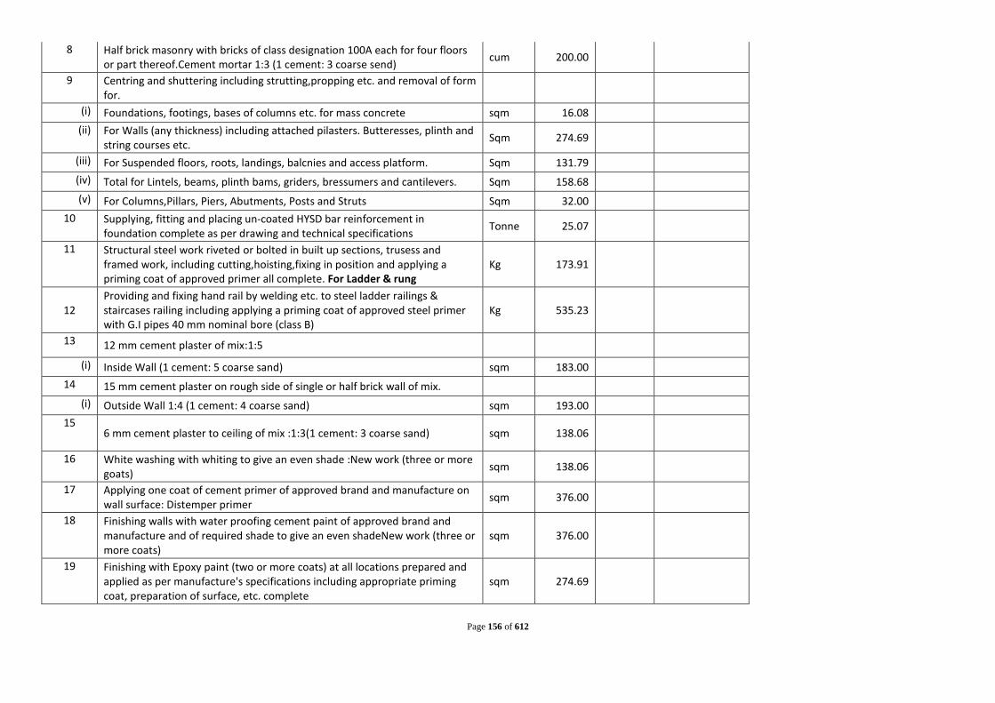
Page 156 of 612
8 Half brick masonry with bricks of class designation 100A each for four floors or part thereof.Cement mortar 1:3 (1 cement: 3 coarse send) cum 200.00
9 Centring and shuttering including strutting,propping etc. and removal of form for.
(i) Foundations, footings, bases of columns etc. for mass concrete sqm 16.08 (ii) For Walls (any thickness) including attached pilasters. Butteresses, plinth and
string courses etc. Sqm 274.69
(iii) For Suspended floors, roots, landings, balcnies and access platform. Sqm 131.79 (iv) Total for Lintels, beams, plinth bams, griders, bressumers and cantilevers. Sqm 158.68 (v) For Columns,Pillars, Piers, Abutments, Posts and Struts Sqm 32.00
10 Supplying, fitting and placing un-coated HYSD bar reinforcement in foundation complete as per drawing and technical specifications Tonne 25.07
11 Structural steel work riveted or bolted in built up sections, trusess and framed work, including cutting,hoisting,fixing in position and applying a priming coat of approved primer all complete. For Ladder & rung
Kg 173.91
12 Providing and fixing hand rail by welding etc. to steel ladder railings & staircases railing including applying a priming coat of approved steel primer with G.I pipes 40 mm nominal bore (class B)
Kg 535.23
13 12 mm cement plaster of mix:1:5
(i) Inside Wall (1 cement: 5 coarse sand) sqm 183.00 14 15 mm cement plaster on rough side of single or half brick wall of mix.
(i) Outside Wall 1:4 (1 cement: 4 coarse sand) sqm 193.00 15
6 mm cement plaster to ceiling of mix :1:3(1 cement: 3 coarse sand) sqm 138.06
16 White washing with whiting to give an even shade :New work (three or more goats) sqm 138.06
17 Applying one coat of cement primer of approved brand and manufacture on wall surface: Distemper primer sqm 376.00
18 Finishing walls with water proofing cement paint of approved brand and manufacture and of required shade to give an even shadeNew work (three or more coats)
sqm 376.00
19 Finishing with Epoxy paint (two or more coats) at all locations prepared and applied as per manufacture's specifications including appropriate priming coat, preparation of surface, etc. complete
sqm 274.69

Page 157 of 612
20 Welding by electric plant including transportation of electric welding plant at site etc. complete. cm 71.68
21 62 mm thick cement concrete flooring with metallic concrete hardener topping under layer 50 mm thick cement concrete 1:2:4(1 cement:2 coarse sand:4 graded stone aggregate 20 mm nominal size) and top layer 12mm thick metallic cement hardener consisting of mix 1:2(1 cement hardener mix:2 stone aggregate) nominal size by volume hardning compound is mixed @ 2 liter per 50 kg of cement or as per manufacture specification. This includes cost of cement slurry, etc. but excluding the cost of nosing of steps etc. complete.
sqm 18.10
22 Providing laminated veneer lumber conforming to IS:14616 & TAD 15:2001 (parts),manufactured in factories by approved manufacturers, in frames of doors, windows, clerestory windows and other frames, through framed and fixed in position as per directions of Engineer in charge
(i) For Windows cum 0.81 23
Providing and fixing 35mm thick factory mode laminated veneer lumber door shutter conforming to IS:14616 & TADS 15-2001 (part B),manufactured in factories by approved manufacturers, including black enamelled M.S.butt hinges with necessary screws as per directions of Engineer in charge and panelling with panels of: 12 mm thick plain Grade-1 .medium density flat pressed three layer and graded particles board(FPT-I) conforming to 1S:3087 bonded with BWP type synthetic resin adhesive asperlS:848.
(i) For Windows sqm 3.24 24 Supplying and fixing rrlltng shuters of approved make,made of required size
of M.S.laths inter locked together through their intire length jnd jointed together at the end by end locks mounted on specially designed pipe shaft with brackets, side guides and arragements for insfde and outside locking with push and pull operation complete including the cost of prioviding and fixing necessary 27.5 cm long wire springs grade no. 2 and M.S. top cover of required thickness for rolling shutters.
(i) 80x1.25mmM.S. Laths with 1.25mm thick top cover. sqm 9.00
(ii) Providing and fixing ball bearing for rolling shutters sqm 9.00 25 Carriage of earth Excluding loading and Unloading (5 Kms) Ton 510.40 26 Loading and Unloading of Stone Boulder/Stone
Aggregates/Sand/Kanker/Moorum. cum 319

Page 158 of 612
27 Providing and laying water proofing treatment on roofs of slabs by applying cement slurry mixed with water proofing cement compound consisting of applying: a) after surface preparation, first layer of slurry of cement @ 0.488 kg/sqm mixed with water proofing cement compound @ 0.253 kg/ sqm. b) laying second layer of Fibre glass cloth when the first layer is still green. Overlaps of joints of fibre cloth should not be less than 10 cm. c) third layer of 1.5 mm thickness consisting of slurry of cement @ 1.289 kg/sqm mixed with water proofing cement compound @ 0.670 kg/sqm and coarse sand @ 1.289 kg/sqm. This will be allowed to air cure for 4 hours followed by water curing for 48 hours. The entire treatment will be taken upto 30 cm on parapet wall and tucked into groove in parapet all around. d) fourth and final layer of brick tiling with cement mortar (which will be paid for separately. For the purpose of measurement the entire treated surface will be measured.
Sqm 36.00
Estimated Cost for Civil Works for Sewage Pumping Station
Cost Estimate: Civil Works of Main Pumping Station MPS
Progamme Town: Chapra Sl.
No Description of work Unit Total Quantity Rate (Rs) Amount (Rs)
A Cost of Civil Works 1
Excavation for Structures (Earth work in excavation of foundation of structures as per drawing and technical specification, including setting out, construction of shoring and bracing, removal of stumps and other deleterious matter, dressing of sides and bottom, backfilling the excavation earth to the extent required and utilising the remaining earth locally for WELL work.) Ordinary soil (Manual Means )
(i) Depth upto 3 m cum 306.00
(ii) 3m To 6m cum 306.00 (iii) 6m To 9m cum 306.00

Page 159 of 612
(iv) 9m To 12m cum 306.00 12m To 15m cum 0.00
Total cum 1224.00 2
Hire and labour charge for installing standard M.S sheet piles for excavation of any type and size including junction and corner taper piles etc . With clutch bars or any other febricated sheet pile where necessary by bany means (either manual, mechanical or vibratory hammers) in all kinds of soli including cutting hard crust, drilling holes and welding of piles as necessary , stagging,scaffolding , supply of all equipments (except of M.S Sheet pile and carriage) of M.S sheet piles from departmental godown to worksite. (Hire charges of sheet piles if supplied will be payeble by the contractor)
sqm 479.43
3 Withdrawing sheet piles , carriage and stacking the same property in the departmental stackyard/godown properly as per direction of the Engineer-in -charge.)
sqm 479.43
4 Supplying and Filling in plinth with local sand and under floors including, watering, ramming consolidating and dressing complete. cum 30.60
5 PCC 1:3:6 in Foundation (Plain cement concrete 1:3:6 nominal mix in foundation with crushed stone aggregate 40 mm nominal size mechanically mixed, placed in foundation and compacted by vibration including curing for 14 days.)
(i) Below Well cum 13.00 6 Plain/Reinforced cement concrete in open foundation complete as
per drawing and technical specifications M.25 using Concrete Mixure
(i) All work upto Plinth level. cum 294.45 (ii) All work above Plinth level. cum 105.00
7 Brick work with bricks of class designation 100A in Cement mortar 1:4 (1 cement: 4 coarse sand )
(i) Above plinth level upto floor V cum 72.78

Page 160 of 612
8 Half brick masonry with bricks of class designation 100A each for four floors or part thereof.Cement mortar 1:3 (1 cement: 3 coarse send) cum 300.00
9 Centring and shuttering including strutting,propping etc. and removal of form for.
(i) Foundations, footings, bases of columns etc. for mass concrete sqm 28.15 (ii) For Walls (any thickness) including attached pilasters. Butteresses, plinth and
string courses etc. Sqm 566.26
(iii) For Suspended floors, roots, landings, balcnies and access platform. Sqm 314.80 (iv) Total for Lintels, beams, plinth bams, griders, bressumers and cantilevers. Sqm 229.93 (v) For Columns,Pillars, Piers, Abutments, Posts and Struts Sqm 32.00
10 Supplying, fitting and placing un-coated HYSD bar reinforcement in foundation complete as per drawing and technical specifications Tonne 44.55
11 Structural steel work riveted or bolted in built up sections, trusess and framed work, including cutting,hoisting,fixing in position and applying a priming coat of approved primer all complete. For Ladder & rung
Kg 176.25
12 Providing and fixing hand rail by welding etc. to steel ladder railings & staircases railing including applying a priming coat of approved steel primer with G.I pipes 40 mm nominal bore (class B)
Kg 535.23
13 12 mm cement plaster of mix:1:5
(i) Inside Wall (1 cement: 5 coarse sand) sqm 283.00 14 15 mm cement plaster on rough side of single or half brick wall of mix.
(i) Outside Wall 1:4 (1 cement: 4 coarse sand) sqm 293.00 15
6 mm cement plaster to ceiling of mix :1:3(1 cement: 3 coarse sand) sqm 304.72
16 White washing with whiting to give an even shade :New work (three or more goats) sqm 304.72
17 Applying one coat of cement primer of approved brand and manufacture on wall surface: Distemper primer sqm 576.00
18 Finishing walls with water proofing cement paint of approved brand and manufacture and of required shade to give an even shadeNew work (three or more coats)
sqm 576.00
19 Finishing with Epoxy paint (two or more coats) at all locations prepared and applied as per manufacture's specifications including appropriate priming coat, preparation of surface, etc. complete
sqm 566.26

Page 161 of 612
20 Welding by electric plant including transportation of electric welding plant at site etc. complete. cm 71.68
21 62 mm thick cement concrete flooring with metallic concrete hardener topping under layer 50 mm thick cement concrete 1:2:4(1 cement:2 coarse sand:4 graded stone aggregate 20 mm nominal size) and top layer 12mm thick metallic cement hardener consisting of mix 1:2(1 cement hardener mix:2 stone aggregate) nominal size by volume hardning compound is mixed @ 2 liter per 50 kg of cement or as per manufacture specification. This includes cost of cement slurry, etc. but excluding the cost of nosing of steps etc. complete.
sqm 72.38
22 Providing laminated veneer lumber conforming to IS:14616 & TAD 15:2001 (parts),manufactured in factories by approved manufacturers, in frames of doors, windows, clerestory windows and other frames, through framed and fixed in position as per directions of Engineer in charge
(i) For Windows cum 0.81 23
Providing and fixing 35mm thick factory mode laminated veneer lumber door shutter conforming to IS:14616 & TADS 15-2001 (part B),manufactured in factories by approved manufacturers, including black enamelled M.S.butt hinges with necessary screws as per directions of Engineer in charge and panelling with panels of: 12 mm thick plain Grade-1 .medium density flat pressed three layer and graded particles board(FPT-I) conforming to 1S:3087 bonded with BWP type synthetic resin adhesive asperlS:848.
(i) For Windows sqm 3.24 24 Supplying and fixing rrlltng shuters of approved make,made of required size
of M.S.laths inter locked together through their intire length jnd jointed together at the end by end locks mounted on specially designed pipe shaft with brackets, side guides and arragements for insfde and outside locking with push and pull operation complete including the cost of prioviding and fixing necessary 27.5 cm long wire springs grade no. 2 and M.S. top cover of required thickness for rolling shutters.
(i) 80x1.25mmM.S. Laths with 1.25mm thick top cover. sqm 9.00
(ii) Providing and fixing ball bearing for rolling shutters sqm 9.00 25 Carriage of earth Excluding loading and Unloading (5 Kms) Ton 1958.40 26 Loading and Unloading of Stone Boulder/Stone
Aggregates/Sand/Kanker/Moorum. cum 1224

Page 162 of 612
27 Providing and laying water proofing treatment on roofs of slabs by applying cement slurry mixed with water proofing cement compound consisting of applying: a) after surface preparation, first layer of slurry of cement @ 0.488 kg/sqm mixed with water proofing cement compound @ 0.253 kg/ sqm. b) laying second layer of Fibre glass cloth when the first layer is still green. Overlaps of joints of fibre cloth should not be less than 10 cm. c) third layer of 1.5 mm thickness consisting of slurry of cement @ 1.289 kg/sqm mixed with water proofing cement compound @ 0.670 kg/sqm and coarse sand @ 1.289 kg/sqm. This will be allowed to air cure for 4 hours followed by water curing for 48 hours. The entire treatment will be taken upto 30 cm on parapet wall and tucked into groove in parapet all around. d) fourth and final layer of brick tiling with cement mortar (which will be paid for separately. For the purpose of measurement the entire treated surface will be measured.
Sqm 36.00
Estimated Cost for Civil Works for Sewage Pumping Station
Laying of Rising Main-1 IPS to Node 9A
Sl. No Description of work Unit Total
Quantity Rate Amount
Cost of Rising Mains form MPS 1
Excavating trenches of required width for pipes cables, etc, including excavation for sockets, and dressing of sides, ramming of bottoms, depth upto 1.5 m including getting out the excavated soil , and then returning the soil as required , in layers not exceeding 20 cm in depth including consolidating each deposited layer by ramming, watering, etc. and disposing of surplus excavated soil as directed , within a lead of 50 m. All Kinds of Soil. [Upto 1.5m Depth]
(i) For, Pipes , cables etc. exceeding 80mm dia. but not exceeding 300m dia Rm
(ii) Pipes , cables etc. exceeding 300m dia. Rm 15.00

Page 163 of 612
2 Providing and laying S&S Centrifugally Cast (Spun) / Ductile Iron Pipes conforming to IS : 8329 :
(i) 100 mm dia Ductile Iron Class K-9 pipes Rm
(ii) 150 mm dia Ductile Iron Class K-9 pipes Rm
(iii) 200 mm dia Ductile Iron Class K-9 pipes Rm
(iv) 250 mm dia Ductile Iron Class K-9 pipes Rm
(v) 300 mm dia Ductile Iron Class K-9 pipes Rm
(vi) 350 mm dia Ductile Iron Class K-9 pipes Rm
(vii) 400 mm dia Ductile Iron Class K-9 pipes Rm
(viii) 450 mm dia Ductile Iron Class K-9 pipes Rm
(ix) 500 mm dia Ductile Iron Class K-9 pipes Rm
(x) 600 mm dia Ductile Iron Class K-9 pipes Rm
(xi) 700 mm dia Ductile Iron Class K-9 pipes Rm
(xii) 750 mm dia Ductile Iron Class K-9 pipes Rm
(xiii) 800 mm dia Ductile Iron Class K-9 pipes Rm 15.00
(xiv) 900 mm dia Ductile Iron Class K-9 pipes Rm
(xv0 1000 mm dia Ductile Iron Class K-9 pipes Rm 3
Providing and laying D.I. specials of class K-12 suitable for push-on jointing as per IS : 9523 :
(i) Upto 600 mm dia Qunital
(ii) Above 600 mm dia Qunital 1.23
4 Providing and laying D.I. Specials of Class K - 12 suitable for mechanical jointing as per IS : 9523 :
(i) Upto 600 mm dia Qunital
(ii) Above 600 mm dia Qunital 0.37
5 Supplying of Knife edge valves complete with bolts, nuts, rubber insertions etc. (the tail pieces if required will be paid separately) including GST :

Page 164 of 612
(i) 150 mm diameter Each
(ii) 200 mm diameter Each 5.00
(iii) 300 mm diameter Each
(iv) 400 mm diameter Each
(v) 500 mm diameter Each
(vi) 600 mm diameter Each
(vii) 700 mm diameter Each
(viii) 800 mm diameter Each 2.00
(ix) 900 mm diameter Each
(x) 1000 mm diameter Each 6
Providing and fixing DI air valve of approved quality with bolts, nuts, rubber insertions etc. complete
(i) 50 mm dia Each 5.00
(ii) 100 mm dia Each
(iii) 150 mm dia Each
(ii) 200 mm dia Each 2.00 7
Supply and Pushing of MS casing pipe of specified thickness by trenchless method adopting any suitable technology below ground at required depth under running traffic condition as per railway standard including carrying out survey work at the job site for determining underground cable trenches like telephone, cable, water & sanitary lines and resistivity test for finding the soil strata using necessary equipments for completion of works, mobilizing of machineries and specialized crew at the job site complete in all respect, including excavation of driven pit and exit pit (upto 3 metre depth) with proper protection at three sites with shoring sheets and ISMB's. Providing MS cutting edges for front shield and Constructing thrust bed at designated level. Necessary de-watering and providing concrete foundation at the base of the driven pit, PVC/Rubber suddle as per the requirement of Railway Authority, crane for handing of pipe and any other machinery, tools, and tackles required, construction of temporary works as per requirement and as per approved by railway authorities, specification and the direction of the Engineer. (Protective coating/ lining if done that will be paid extra)
(ii) 600mm dia 12mm th casing pipe Rm

Page 165 of 612
9 Structural steel work riveted or bolted in built up sections, trusess and framed work, including cutting,hoisting,fixing in position and applying a priming coat of approved primer all complete. Kg
10 Welding by electric plant including transportation of electric welding plant at site etc. complete. Cm
11
Plain/Reinforced cement concrete in open foundation complete as per drawing and technical specifications M.15 Cum 1.20
12 Plain/Reinforced cement concrete in open foundation complete as per drawing and technical specifications- Using Concrete Mixer M.20- 1:1:5:3(1 cement: 1.5 coarse sand:3 graded stone aggregate 20 mm nominal size
(i) Cum 1.50 13
Brick work with bricks of class designation 100A in foundations and plinth in :
(i) Cement mortar 1:6 (1 cement: 6 coarse sand ) Cum 3.00 14
Supplying, fitting and placing un-coated HYSD bar reinforcement in foundation complete as per drawing and technical specifications
(i) Tonne 0.18
15 Centring and shuttering including strutting,propping etc and removal or form work for Foundations,footings, bases Columns Sqm 22.04
16 Dismantling of Flexible Pavements (Dismantling of flexible pavements and disposal of dismantled materials up to a lead of 1000 metres, stacking serviceable and unserviceable materials separately)
By Mechanical Means: Bituminous course Cum 0.34
17 Dismantling of Cement Concrete Pavement (Dismantling of cement concrete pavement by mechanical means using pneumatic tools, breaking to pieces not exceeding 0.02 cum in volume and stock piling at designated locations and disposal of dismantled materials up to a lead of 1000 metres, stacking serviceable and unserviceable materials separately)
Cum 1.54
18 Carriage of earth Excluding loading and Unloading (5 Kms) Ton 36.00

Page 166 of 612
19 Loading and Unloading of Stone Boulder/Stone Aggregates/Sand/Kanker/Moorum. cum 22.50
20
Providing sal ballah barricading with departmental sal ballah average 150 dia. And 2M long sal ballah post at interval of 2.5 M C/C fixed 0.5 M average below ground, packed with earth and Brick bats, well watered and rammed with three rows of average 100mm dia. Sal ballah horizontal runners fixed with iron spikes and wires, white washing one coat to exposed surface, dismantling the barricade after function, filling the holes, excluding carriage of sal ballah from and to godown up to 5K.M. lead, stacking them in countable stacks in godown including cost of all labour and materials and taxes all complete job as per specification and direction of E/l.
Per m 30.0
21 Cutting road and making good the same including supply of extra quantities of materials i.e. aggregate, moorum screening, red bajri and labour required
(i) Bituminous portion Cum 23.63 (ii) WBM Cum 10.13
A Estimated Cost for Laying of Rising main
Laying of Rising Main-2 IPS 2 to Node 20/1
Sl. No Description of work Unit Total
Quantity Rate Amount
Cost of Rising Mains form MPS 1
Excavating trenches of required width for pipes cables, etc, including excavation for sockets, and dressing of sides, ramming of bottoms, depth upto 1.5 m including getting out the excavated soil , and then returning the soil as required , in layers not exceeding 20 cm in depth including consolidating each deposited layer by ramming, watering, etc. and disposing of surplus excavated soil as directed , within a lead of 50 m. All Kinds of Soil. [Upto 1.5m Depth]

Page 167 of 612
(i) For, Pipes , cables etc. exceeding 80mm dia. but not exceeding 300m dia Rm 162.00
(ii) Pipes , cables etc. exceeding 300m dia. Rm 2
Providing and laying S&S Centrifugally Cast (Spun) / Ductile Iron Pipes conforming to IS : 8329 :
(i) 100 mm dia Ductile Iron Class K-9 pipes Rm 162.00
(ii) 150 mm dia Ductile Iron Class K-9 pipes Rm
(iii) 200 mm dia Ductile Iron Class K-9 pipes Rm
(iv) 250 mm dia Ductile Iron Class K-9 pipes Rm
(v) 300 mm dia Ductile Iron Class K-9 pipes Rm
(vi) 350 mm dia Ductile Iron Class K-9 pipes Rm
(vii) 400 mm dia Ductile Iron Class K-9 pipes Rm
(viii) 450 mm dia Ductile Iron Class K-9 pipes Rm
(ix) 500 mm dia Ductile Iron Class K-9 pipes Rm
(x) 600 mm dia Ductile Iron Class K-9 pipes Rm
(xi) 700 mm dia Ductile Iron Class K-9 pipes Rm
(xii) 750 mm dia Ductile Iron Class K-9 pipes Rm
(xiii) 800 mm dia Ductile Iron Class K-9 pipes Rm
(xiv) 900 mm dia Ductile Iron Class K-9 pipes Rm
(xv0 1000 mm dia Ductile Iron Class K-9 pipes Rm 3
Providing and laying D.I. specials of class K-12 suitable for push-on jointing as per IS : 9523 :
(i) Upto 600 mm dia Qunital 1.72
(ii) Above 600 mm dia Qunital
4 Providing and laying D.I. Specials of Class K - 12 suitable for mechanical jointing as per IS : 9523 :
(i) Upto 600 mm dia Qunital 0.52
(ii) Above 600 mm dia Qunital

Page 168 of 612
5 Supplying of Knife edge valves complete with bolts, nuts, rubber insertions etc. (the tail pieces if required will be paid separately) including GST :
(i) 100 mm diameter Each 6.00
(ii) 200 mm diameter Each
(iii) 300 mm diameter Each
(iv) 400 mm diameter Each
(v) 500 mm diameter Each
(vi) 600 mm diameter Each
(vii) 700 mm diameter Each
(viii) 800 mm diameter Each
(ix) 900 mm diameter Each
(x) 1000 mm diameter Each 6
Providing and fixing DI air valve of approved quality with bolts, nuts, rubber insertions etc. complete
(i) 50 mm dia Each 6.00
(ii) 100 mm dia Each
(iii) 150 mm dia Each
(ii) 200 mm dia Each 7
Supply and Pushing of MS casing pipe of specified thickness by trenchless method adopting any suitable technology below ground at required depth under running traffic condition as per railway standard including carrying out survey work at the job site for determining underground cable trenches like telephone, cable, water & sanitary lines and resistivity test for finding the soil strata using necessary equipments for completion of works, mobilizing of machineries and specialized crew at the job site complete in all respect, including excavation of driven pit and exit pit (upto 3 metre depth) with proper protection at three sites with shoring sheets and ISMB's. Providing MS cutting edges for front shield and Constructing thrust bed at designated level. Necessary de-watering and providing concrete foundation at the base of the driven pit, PVC/Rubber suddle as per the requirement of Railway Authority, crane for handing of pipe and any other machinery, tools, and tackles required, construction of temporary works as per requirement and as per approved by railway authorities, specification and the direction of the Engineer. (Protective coating/ lining if done that will be paid extra)

Page 169 of 612
(ii) 600mm dia 12mm th casing pipe Rm 9
Structural steel work riveted or bolted in built up sections, trusess and framed work, including cutting,hoisting,fixing in position and applying a priming coat of approved primer all complete. Kg
10 Welding by electric plant including transportation of electric welding plant at site etc. complete. Cm
11
Plain/Reinforced cement concrete in open foundation complete as per drawing and technical specifications M.15 Cum 1.20
12 Plain/Reinforced cement concrete in open foundation complete as per drawing and technical specifications- Using Concrete Mixer M.20- 1:1:5:3(1 cement: 1.5 coarse sand:3 graded stone aggregate 20 mm nominal size
(i) Cum 1.50 13
Brick work with bricks of class designation 100A in foundations and plinth in :
(i) Cement mortar 1:6 (1 cement: 6 coarse sand ) Cum 3.00 14
Supplying, fitting and placing un-coated HYSD bar reinforcement in foundation complete as per drawing and technical specifications
(i) Tonne 0.18
15 Centring and shuttering including strutting,propping etc and removal or form work for Foundations,footings, bases Columns Sqm 22.04
16 Dismantling of Flexible Pavements (Dismantling of flexible pavements and disposal of dismantled materials up to a lead of 1000 metres, stacking serviceable and unserviceable materials separately)
By Mechanical Means: Bituminous course Cum 0.00
17 Dismantling of Cement Concrete Pavement (Dismantling of cement concrete pavement by mechanical means using pneumatic tools, breaking to pieces not exceeding 0.02 cum in volume and stock piling at designated locations and disposal of dismantled materials up to a lead of 1000 metres, stacking serviceable and unserviceable materials separately)
Cum 0.00

Page 170 of 612
18 Carriage of earth Excluding loading and Unloading (5 Kms) Ton 0.00 19
Loading and Unloading of Stone Boulder/Stone Aggregates/Sand/Kanker/Moorum. cum 0.00
20
Providing sal ballah barricading with departmental sal ballah average 150 dia. And 2M long sal ballah post at interval of 2.5 M C/C fixed 0.5 M average below ground, packed with earth and Brick bats, well watered and rammed with three rows of average 100mm dia. Sal ballah horizontal runners fixed with iron spikes and wires, white washing one coat to exposed surface, dismantling the barricade after function, filling the holes, excluding carriage of sal ballah from and to godown up to 5K.M. lead, stacking them in countable stacks in godown including cost of all labour and materials and taxes all complete job as per specification and direction of E/l.
Per m 324.0
21 Cutting road and making good the same including supply of extra quantities of materials i.e. aggregate, moorum screening, red bajri and labour required
(i) Bituminous portion Cum 255.15 (ii) WBM Cum 109.35
A Estimated Cost for Laying of Rising main

Page 171 of 612
Laying of Rising Main-3 IPS 3 to Node 100
Sl. No Description of work Unit Total
Quantity Rate Amount
Cost of Rising Mains form MPS 1
Excavating trenches of required width for pipes cables, etc, including excavation for sockets, and dressing of sides, ramming of bottoms, depth upto 1.5 m including getting out the excavated soil , and then returning the soil as required , in layers not exceeding 20 cm in depth including consolidating each deposited layer by ramming, watering, etc. and disposing of surplus excavated soil as directed , within a lead of 50 m. All Kinds of Soil. [Upto 1.5m Depth]
(i) For, Pipes , cables etc. exceeding 80mm dia. but not exceeding 300m dia Rm 50.00
(ii) Pipes , cables etc. exceeding 300m dia. Rm 2
Providing and laying S&S Centrifugally Cast (Spun) / Ductile Iron Pipes conforming to IS : 8329 :
(i) 100 mm dia Ductile Iron Class K-9 pipes Rm 50.00
(ii) 150 mm dia Ductile Iron Class K-9 pipes Rm
(iii) 200 mm dia Ductile Iron Class K-9 pipes Rm
(iv) 250 mm dia Ductile Iron Class K-9 pipes Rm
(v) 300 mm dia Ductile Iron Class K-9 pipes Rm
(vi) 350 mm dia Ductile Iron Class K-9 pipes Rm
(vii) 400 mm dia Ductile Iron Class K-9 pipes Rm
(viii) 450 mm dia Ductile Iron Class K-9 pipes Rm
(ix) 500 mm dia Ductile Iron Class K-9 pipes Rm
(x) 600 mm dia Ductile Iron Class K-9 pipes Rm
(xi) 700 mm dia Ductile Iron Class K-9 pipes Rm
(xii) 750 mm dia Ductile Iron Class K-9 pipes Rm
(xiii) 800 mm dia Ductile Iron Class K-9 pipes Rm
(xiv) 900 mm dia Ductile Iron Class K-9 pipes Rm
(xv0 1000 mm dia Ductile Iron Class K-9 pipes Rm

Page 172 of 612
3 Providing and laying D.I. specials of class K-12 suitable for push-on jointing as per IS : 9523 :
(i) Upto 600 mm dia Qunital 0.53
(ii) Above 600 mm dia Qunital
4 Providing and laying D.I. Specials of Class K - 12 suitable for mechanical jointing as per IS : 9523 :
(i) Upto 600 mm dia Qunital 0.16
(ii) Above 600 mm dia Qunital
5 Supplying of Knife edge valves complete with bolts, nuts, rubber insertions etc. (the tail pieces if required will be paid separately) including GST :
(i) 100 mm diameter Each 6.00
(ii) 200 mm diameter Each
(iii) 300 mm diameter Each
(iv) 400 mm diameter Each
(v) 500 mm diameter Each
(vi) 600 mm diameter Each
(vii) 700 mm diameter Each
(viii) 800 mm diameter Each
(ix) 900 mm diameter Each
(x) 1000 mm diameter Each 6
Providing and fixing DI air valve of approved quality with bolts, nuts, rubber insertions etc. complete
(i) 50 mm dia Each 6.00
(ii) 100 mm dia Each
(iii) 150 mm dia Each
(ii) 200 mm dia Each

Page 173 of 612
7
Supply and Pushing of MS casing pipe of specified thickness by trenchless method adopting any suitable technology below ground at required depth under running traffic condition as per railway standard including carrying out survey work at the job site for determining underground cable trenches like telephone, cable, water & sanitary lines and resistivity test for finding the soil strata using necessary equipments for completion of works, mobilizing of machineries and specialized crew at the job site complete in all respect, including excavation of driven pit and exit pit (upto 3 metre depth) with proper protection at three sites with shoring sheets and ISMB's. Providing MS cutting edges for front shield and Constructing thrust bed at designated level. Necessary de-watering and providing concrete foundation at the base of the driven pit, PVC/Rubber suddle as per the requirement of Railway Authority, crane for handing of pipe and any other machinery, tools, and tackles required, construction of temporary works as per requirement and as per approved by railway authorities, specification and the direction of the Engineer. (Protective coating/ lining if done that will be paid extra)
(ii) 600mm dia 12mm th casing pipe Rm 20.00 9
Structural steel work riveted or bolted in built up sections, trusess and framed work, including cutting,hoisting,fixing in position and applying a priming coat of approved primer all complete. Kg
10 Welding by electric plant including transportation of electric welding plant at site etc. complete. Cm
11
Plain/Reinforced cement concrete in open foundation complete as per drawing and technical specifications M.15 Cum 1.20
12 Plain/Reinforced cement concrete in open foundation complete as per drawing and technical specifications- Using Concrete Mixer M.20- 1:1:5:3(1 cement: 1.5 coarse sand:3 graded stone aggregate 20 mm nominal size
(i) Cum 1.50 13
Brick work with bricks of class designation 100A in foundations and plinth in :
(i) Cement mortar 1:6 (1 cement: 6 coarse sand ) Cum 3.00

Page 174 of 612
14 Supplying, fitting and placing un-coated HYSD bar reinforcement in foundation complete as per drawing and technical specifications
(i) Tonne 0.18
15 Centring and shuttering including strutting,propping etc and removal or form work for Foundations,footings, bases Columns Sqm 22.04
16 Dismantling of Flexible Pavements (Dismantling of flexible pavements and disposal of dismantled materials up to a lead of 1000 metres, stacking serviceable and unserviceable materials separately)
By Mechanical Means: Bituminous course Cum 0.00
17 Dismantling of Cement Concrete Pavement (Dismantling of cement concrete pavement by mechanical means using pneumatic tools, breaking to pieces not exceeding 0.02 cum in volume and stock piling at designated locations and disposal of dismantled materials up to a lead of 1000 metres, stacking serviceable and unserviceable materials separately)
Cum 0.00
18 Carriage of earth Excluding loading and Unloading (5 Kms) Ton 0.00 19
Loading and Unloading of Stone Boulder/Stone Aggregates/Sand/Kanker/Moorum. cum 0.00
20
Providing sal ballah barricading with departmental sal ballah average 150 dia. And 2M long sal ballah post at interval of 2.5 M C/C fixed 0.5 M average below ground, packed with earth and Brick bats, well watered and rammed with three rows of average 100mm dia. Sal ballah horizontal runners fixed with iron spikes and wires, white washing one coat to exposed surface, dismantling the barricade after function, filling the holes, excluding carriage of sal ballah from and to godown up to 5K.M. lead, stacking them in countable stacks in godown including cost of all labour and materials and taxes all complete job as per specification and direction of E/l.
Per m 100.0
21 Cutting road and making good the same including supply of extra quantities of materials i.e. aggregate, moorum screening, red bajri and labour required
(i) Bituminous portion Cum 78.75 (ii) WBM Cum 33.75
A Estimated Cost for Laying of Rising main

Page 175 of 612
Laying of Rising Main-4 IPS 4 to Khanua nala
Sl. No Description of work Unit Total
Quantity Rate Amount
Cost of Rising Mains form MPS 1
Excavating trenches of required width for pipes cables, etc, including excavation for sockets, and dressing of sides, ramming of bottoms, depth upto 1.5 m including getting out the excavated soil , and then returning the soil as required , in layers not exceeding 20 cm in depth including consolidating each deposited layer by ramming, watering, etc. and disposing of surplus excavated soil as directed , within a lead of 50 m. All Kinds of Soil. [Upto 1.5m Depth]
(i) For, Pipes , cables etc. exceeding 80mm dia. but not exceeding 300m dia Rm
(ii) Pipes , cables etc. exceeding 300m dia. Rm 541.00 2
Providing and laying S&S Centrifugally Cast (Spun) / Ductile Iron Pipes conforming to IS : 8329 :
(i) 100 mm dia Ductile Iron Class K-9 pipes Rm
(ii) 150 mm dia Ductile Iron Class K-9 pipes Rm
(iii) 200 mm dia Ductile Iron Class K-9 pipes Rm
(iv) 250 mm dia Ductile Iron Class K-9 pipes Rm
(v) 300 mm dia Ductile Iron Class K-9 pipes Rm
(vi) 350 mm dia Ductile Iron Class K-9 pipes Rm
(vii) 400 mm dia Ductile Iron Class K-9 pipes Rm 541.00
(viii) 450 mm dia Ductile Iron Class K-9 pipes Rm
(ix) 500 mm dia Ductile Iron Class K-9 pipes Rm
(x) 600 mm dia Ductile Iron Class K-9 pipes Rm
(xi) 700 mm dia Ductile Iron Class K-9 pipes Rm
(xii) 750 mm dia Ductile Iron Class K-9 pipes Rm

Page 176 of 612
(xiii) 800 mm dia Ductile Iron Class K-9 pipes Rm
(xiv) 900 mm dia Ductile Iron Class K-9 pipes Rm
(xv0 1000 mm dia Ductile Iron Class K-9 pipes Rm 3
Providing and laying D.I. specials of class K-12 suitable for push-on jointing as per IS : 9523 :
(i) Upto 600 mm dia Qunital 32.13
(ii) Above 600 mm dia Qunital
4 Providing and laying D.I. Specials of Class K - 12 suitable for mechanical jointing as per IS : 9523 :
(i) Upto 600 mm dia Qunital 9.64
(ii) Above 600 mm dia Qunital
5 Supplying of Knife edge valves complete with bolts, nuts, rubber insertions etc. (the tail pieces if required will be paid separately) including GST :
(i) 150 mm diameter Each 4.00
(ii) 200 mm diameter Each
(iii) 300 mm diameter Each
(iv) 400 mm diameter Each 2.00
(v) 500 mm diameter Each
(vi) 600 mm diameter Each
(vii) 700 mm diameter Each
(viii) 800 mm diameter Each
(ix) 900 mm diameter Each
(x) 1000 mm diameter Each 6
Providing and fixing DI air valve of approved quality with bolts, nuts, rubber insertions etc. complete
(i) 50 mm dia Each 4.00
(ii) 100 mm dia Each 2.00

Page 177 of 612
(iii) 150 mm dia Each
(ii) 200 mm dia Each 7
Supply and Pushing of MS casing pipe of specified thickness by trenchless method adopting any suitable technology below ground at required depth under running traffic condition as per railway standard including carrying out survey work at the job site for determining underground cable trenches like telephone, cable, water & sanitary lines and resistivity test for finding the soil strata using necessary equipments for completion of works, mobilizing of machineries and specialized crew at the job site complete in all respect, including excavation of driven pit and exit pit (upto 3 metre depth) with proper protection at three sites with shoring sheets and ISMB's. Providing MS cutting edges for front shield and Constructing thrust bed at designated level. Necessary de-watering and providing concrete foundation at the base of the driven pit, PVC/Rubber suddle as per the requirement of Railway Authority, crane for handing of pipe and any other machinery, tools, and tackles required, construction of temporary works as per requirement and as per approved by railway authorities, specification and the direction of the Engineer. (Protective coating/ lining if done that will be paid extra)
(ii) 600mm dia 12mm th casing pipe Rm 0.00 9
Structural steel work riveted or bolted in built up sections, trusess and framed work, including cutting,hoisting,fixing in position and applying a priming coat of approved primer all complete. Kg
10 Welding by electric plant including transportation of electric welding plant at site etc. complete. Cm
11
Plain/Reinforced cement concrete in open foundation complete as per drawing and technical specifications M.15 Cum 1.20
12 Plain/Reinforced cement concrete in open foundation complete as per drawing and technical specifications- Using Concrete Mixer M.20- 1:1:5:3(1 cement: 1.5 coarse sand:3 graded stone aggregate 20 mm nominal size
(i) Cum 1.50 13
Brick work with bricks of class designation 100A in foundations and plinth in :

Page 178 of 612
(i) Cement mortar 1:6 (1 cement: 6 coarse sand ) Cum 3.00 14
Supplying, fitting and placing un-coated HYSD bar reinforcement in foundation complete as per drawing and technical specifications
(i) Tonne 0.18
15 Centring and shuttering including strutting,propping etc and removal or form work for Foundations,footings, bases Columns Sqm 22.04
16 Dismantling of Flexible Pavements (Dismantling of flexible pavements and disposal of dismantled materials up to a lead of 1000 metres, stacking serviceable and unserviceable materials separately)
By Mechanical Means: Bituminous course Cum 12.33
17 Dismantling of Cement Concrete Pavement (Dismantling of cement concrete pavement by mechanical means using pneumatic tools, breaking to pieces not exceeding 0.02 cum in volume and stock piling at designated locations and disposal of dismantled materials up to a lead of 1000 metres, stacking serviceable and unserviceable materials separately)
Cum 55.51
18 Carriage of earth Excluding loading and Unloading (5 Kms) Ton 1298.40 19
Loading and Unloading of Stone Boulder/Stone Aggregates/Sand/Kanker/Moorum. cum 811.50
20
Providing sal ballah barricading with departmental sal ballah average 150 dia. And 2M long sal ballah post at interval of 2.5 M C/C fixed 0.5 M average below ground, packed with earth and Brick bats, well watered and rammed with three rows of average 100mm dia. Sal ballah horizontal runners fixed with iron spikes and wires, white washing one coat to exposed surface, dismantling the barricade after function, filling the holes, excluding carriage of sal ballah from and to godown up to 5K.M. lead, stacking them in countable stacks in godown including cost of all labour and materials and taxes all complete job as per specification and direction of E/l.
Per m 1082.0
21 Cutting road and making good the same including supply of extra quantities of materials i.e. aggregate, moorum screening, red bajri and labour required
(i) Bituminous portion Cum 852.08 (ii) WBM Cum 365.18

Page 179 of 612
A Estimated Cost for Laying of Rising main
Laying of Rising Main-5 IPS 5 to Node 120
Sl. No Description of work Unit Total
Quantity Rate Amount
Cost of Rising Mains form MPS 1
Excavating trenches of required width for pipes cables, etc, including excavation for sockets, and dressing of sides, ramming of bottoms, depth upto 1.5 m including getting out the excavated soil , and then returning the soil as required , in layers not exceeding 20 cm in depth including consolidating each deposited layer by ramming, watering, etc. and disposing of surplus excavated soil as directed , within a lead of 50 m. All Kinds of Soil. [Upto 1.5m Depth]
(i) For, Pipes , cables etc. exceeding 80mm dia. but not exceeding 300m dia Rm 1422.00
(ii) Pipes , cables etc. exceeding 300m dia. Rm 2
Providing and laying S&S Centrifugally Cast (Spun) / Ductile Iron Pipes conforming to IS : 8329 :
(i) 100 mm dia Ductile Iron Class K-9 pipes Rm
(ii) 150 mm dia Ductile Iron Class K-9 pipes Rm
(iii) 200 mm dia Ductile Iron Class K-9 pipes Rm
(iv) 250 mm dia Ductile Iron Class K-9 pipes Rm
(v) 300 mm dia Ductile Iron Class K-9 pipes Rm 1422.00
(vi) 350 mm dia Ductile Iron Class K-9 pipes Rm
(vii) 400 mm dia Ductile Iron Class K-9 pipes Rm
(viii) 450 mm dia Ductile Iron Class K-9 pipes Rm
(ix) 500 mm dia Ductile Iron Class K-9 pipes Rm
(x) 600 mm dia Ductile Iron Class K-9 pipes Rm
(xi) 700 mm dia Ductile Iron Class K-9 pipes Rm
(xii) 750 mm dia Ductile Iron Class K-9 pipes Rm

Page 180 of 612
(xiii) 800 mm dia Ductile Iron Class K-9 pipes Rm
(xiv) 900 mm dia Ductile Iron Class K-9 pipes Rm
(xv0 1000 mm dia Ductile Iron Class K-9 pipes Rm 3
Providing and laying D.I. specials of class K-12 suitable for push-on jointing as per IS : 9523 :
(i) Upto 600 mm dia Qunital 53.83
(ii) Above 600 mm dia Qunital
4 Providing and laying D.I. Specials of Class K - 12 suitable for mechanical jointing as per IS : 9523 :
(i) Upto 600 mm dia Qunital 16.15
(ii) Above 600 mm dia Qunital
5 Supplying of Knife edge valves complete with bolts, nuts, rubber insertions etc. (the tail pieces if required will be paid separately) including GST :
(i) 150 mm diameter Each 4.00
(ii) 200 mm diameter Each
(iii) 300 mm diameter Each 2.00
(iv) 400 mm diameter Each
(v) 500 mm diameter Each
(vi) 600 mm diameter Each
(vii) 700 mm diameter Each
(viii) 800 mm diameter Each
(ix) 900 mm diameter Each
(x) 1000 mm diameter Each 6
Providing and fixing DI air valve of approved quality with bolts, nuts, rubber insertions etc. complete
(i) 50 mm dia Each 4.00
(ii) 100 mm dia Each 2.00

Page 181 of 612
(iii) 150 mm dia Each
(ii) 200 mm dia Each 7
Supply and Pushing of MS casing pipe of specified thickness by trenchless method adopting any suitable technology below ground at required depth under running traffic condition as per railway standard including carrying out survey work at the job site for determining underground cable trenches like telephone, cable, water & sanitary lines and resistivity test for finding the soil strata using necessary equipments for completion of works, mobilizing of machineries and specialized crew at the job site complete in all respect, including excavation of driven pit and exit pit (upto 3 metre depth) with proper protection at three sites with shoring sheets and ISMB's. Providing MS cutting edges for front shield and Constructing thrust bed at designated level. Necessary de-watering and providing concrete foundation at the base of the driven pit, PVC/Rubber suddle as per the requirement of Railway Authority, crane for handing of pipe and any other machinery, tools, and tackles required, construction of temporary works as per requirement and as per approved by railway authorities, specification and the direction of the Engineer. (Protective coating/ lining if done that will be paid extra)
(ii) 600mm dia 12mm th casing pipe Rm 0.00 9
Structural steel work riveted or bolted in built up sections, trusess and framed work, including cutting,hoisting,fixing in position and applying a priming coat of approved primer all complete. Kg
10 Welding by electric plant including transportation of electric welding plant at site etc. complete. Cm
11
Plain/Reinforced cement concrete in open foundation complete as per drawing and technical specifications M.15 Cum 1.20
12 Plain/Reinforced cement concrete in open foundation complete as per drawing and technical specifications- Using Concrete Mixer M.20- 1:1:5:3(1 cement: 1.5 coarse sand:3 graded stone aggregate 20 mm nominal size
(i) Cum 1.50 13
Brick work with bricks of class designation 100A in foundations and plinth in :

Page 182 of 612
(i) Cement mortar 1:6 (1 cement: 6 coarse sand ) Cum 3.00 14
Supplying, fitting and placing un-coated HYSD bar reinforcement in foundation complete as per drawing and technical specifications
(i) Tonne 0.18
15 Centring and shuttering including strutting,propping etc and removal or form work for Foundations,footings, bases Columns Sqm 22.04
16 Dismantling of Flexible Pavements (Dismantling of flexible pavements and disposal of dismantled materials up to a lead of 1000 metres, stacking serviceable and unserviceable materials separately)
By Mechanical Means: Bituminous course Cum 0.00
17 Dismantling of Cement Concrete Pavement (Dismantling of cement concrete pavement by mechanical means using pneumatic tools, breaking to pieces not exceeding 0.02 cum in volume and stock piling at designated locations and disposal of dismantled materials up to a lead of 1000 metres, stacking serviceable and unserviceable materials separately)
Cum 0.00
18 Carriage of earth Excluding loading and Unloading (5 Kms) Ton 0.00 19
Loading and Unloading of Stone Boulder/Stone Aggregates/Sand/Kanker/Moorum. cum 0.00
20
Providing sal ballah barricading with departmental sal ballah average 150 dia. And 2M long sal ballah post at interval of 2.5 M C/C fixed 0.5 M average below ground, packed with earth and Brick bats, well watered and rammed with three rows of average 100mm dia. Sal ballah horizontal runners fixed with iron spikes and wires, white washing one coat to exposed surface, dismantling the barricade after function, filling the holes, excluding carriage of sal ballah from and to godown up to 5K.M. lead, stacking them in countable stacks in godown including cost of all labour and materials and taxes all complete job as per specification and direction of E/l.
Per m 2844.0
21 Cutting road and making good the same including supply of extra quantities of materials i.e. aggregate, moorum screening, red bajri and labour required
(i) Bituminous portion Cum 2239.65 (ii) WBM Cum 959.85

Page 183 of 612
A Estimated Cost for Laying of Rising main
Laying of Rising Main-MPS to STP
Sl. No Description of work Unit Total
Quantity Rate Amount
Cost of Rising Mains form MPS 1
Excavating trenches of required width for pipes cables, etc, including excavation for sockets, and dressing of sides, ramming of bottoms, depth upto 1.5 m including getting out the excavated soil , and then returning the soil as required , in layers not exceeding 20 cm in depth including consolidating each deposited layer by ramming, watering, etc. and disposing of surplus excavated soil as directed , within a lead of 50 m. All Kinds of Soil. [Upto 1.5m Depth]
(i) For, Pipes , cables etc. exceeding 80mm dia. but not exceeding 300m dia Rm
(ii) Pipes , cables etc. exceeding 300m dia. Rm 50.00
2 Providing and laying S&S Centrifugally Cast (Spun) / Ductile Iron Pipes conforming to IS : 8329 :
(i) 100 mm dia Ductile Iron Class K-9 pipes Rm
(ii) 150 mm dia Ductile Iron Class K-9 pipes Rm
(iii) 200 mm dia Ductile Iron Class K-9 pipes Rm
(iv) 250 mm dia Ductile Iron Class K-9 pipes Rm
(v) 300 mm dia Ductile Iron Class K-9 pipes Rm
(vi) 350 mm dia Ductile Iron Class K-9 pipes Rm
(vii) 400 mm dia Ductile Iron Class K-9 pipes Rm

Page 184 of 612
(viii) 450 mm dia Ductile Iron Class K-9 pipes Rm
(ix) 500 mm dia Ductile Iron Class K-9 pipes Rm
(x) 600 mm dia Ductile Iron Class K-9 pipes Rm
(xi) 700 mm dia Ductile Iron Class K-9 pipes Rm
(xii) 750 mm dia Ductile Iron Class K-9 pipes Rm
(xiii) 800 mm dia Ductile Iron Class K-9 pipes Rm 50.00
(xiv) 900 mm dia Ductile Iron Class K-9 pipes Rm
(xv0 1000 mm dia Ductile Iron Class K-9 pipes Rm 3
Providing and laying D.I. specials of class K-12 suitable for push-on jointing as per IS : 9523 :
(i) Upto 600 mm dia Qunital
(ii) Above 600 mm dia Qunital 4.11
4 Providing and laying D.I. Specials of Class K - 12 suitable for mechanical jointing as per IS : 9523 :
(i) Upto 600 mm dia Qunital
(ii) Above 600 mm dia Qunital 1.23
5 Supplying of Knife edge valves complete with bolts, nuts, rubber insertions etc. (the tail pieces if required will be paid separately) including GST :
(i) 150 mm diameter Each
(ii) 200 mm diameter Each 4.00
(iii) 300 mm diameter Each
(iv) 400 mm diameter Each
(v) 500 mm diameter Each
(vi) 600 mm diameter Each
(vii) 700 mm diameter Each
(viii) 800 mm diameter Each 2.00

Page 185 of 612
(ix) 900 mm diameter Each
(x) 1000 mm diameter Each 6
Providing and fixing DI air valve of approved quality with bolts, nuts, rubber insertions etc. complete
(i) 50 mm dia Each 4.00
(ii) 100 mm dia Each 2.00
(iii) 150 mm dia Each
(ii) 200 mm dia Each 7
Supply and Pushing of MS casing pipe of specified thickness by trenchless method adopting any suitable technology below ground at required depth under running traffic condition as per railway standard including carrying out survey work at the job site for determining underground cable trenches like telephone, cable, water & sanitary lines and resistivity test for finding the soil strata using necessary equipments for completion of works, mobilizing of machineries and specialized crew at the job site complete in all respect, including excavation of driven pit and exit pit (upto 3 metre depth) with proper protection at three sites with shoring sheets and ISMB's. Providing MS cutting edges for front shield and Constructing thrust bed at designated level. Necessary de-watering and providing concrete foundation at the base of the driven pit, PVC/Rubber suddle as per the requirement of Railway Authority, crane for handing of pipe and any other machinery, tools, and tackles required, construction of temporary works as per requirement and as per approved by railway authorities, specification and the direction of the Engineer. (Protective coating/ lining if done that will be paid extra)
(ii) 600mm dia 12mm th casing pipe Rm 0.00 9
Structural steel work riveted or bolted in built up sections, trusess and framed work, including cutting,hoisting,fixing in position and applying a priming coat of approved primer all complete. Kg
10 Welding by electric plant including transportation of electric welding plant at site etc. complete. Cm
11
Plain/Reinforced cement concrete in open foundation complete as per drawing and technical specifications M.15 Cum 1.20

Page 186 of 612
12 Plain/Reinforced cement concrete in open foundation complete as per drawing and technical specifications- Using Concrete Mixer M.20- 1:1:5:3(1 cement: 1.5 coarse sand:3 graded stone aggregate 20 mm nominal size
(i) Cum 1.50 13
Brick work with bricks of class designation 100A in foundations and plinth in :
(i) Cement mortar 1:6 (1 cement: 6 coarse sand ) Cum 3.00 14
Supplying, fitting and placing un-coated HYSD bar reinforcement in foundation complete as per drawing and technical specifications
(i) Tonne 0.18
15 Centring and shuttering including strutting,propping etc and removal or form work for Foundations,footings, bases Columns Sqm 22.04
16 Dismantling of Flexible Pavements (Dismantling of flexible pavements and disposal of dismantledmaterials up to a lead of 1000 metres, stacking serviceable and unserviceable materials separately)
By Mechanical Means: Bituminous course Cum 1.14
17 Dismantling of Cement Concrete Pavement (Dismantling of cement concrete pavement by mechanical means using pneumatic tools, breaking to pieces not exceeding 0.02 cum in volume and stock piling at designated locations and disposal of dismantled materials up to a lead of 1000 metres, stacking serviceable and unserviceable materials separately)
Cum 5.13
18 Carriage of earth Excluding loading and Unloading (5 Kms) Ton 120.00 19
Loading and Unloading of Stone Boulder/Stone Aggregates/Sand/Kanker/Moorum. cum 75.00

Page 187 of 612
20
Providing sal ballah barricading with departmental sal ballah average 150 dia. And 2M long sal ballah post at interval of 2.5 M C/C fixed 0.5 M average below ground, packed with earth and Brick bats, well watered and rammed with three rows of average 100mm dia. Sal ballah horizontal runners fixed with iron spikes and wires, white washing one coat to exposed surface, dismantling the barricade after function, filling the holes, excluding carriage of sal ballah from and to godown up to 5K.M. lead, stacking them in countable stacks in godown including cost of all labour and materials and taxes all complete job as per specification and direction of E/l.
Per m 100.0
21 Cutting road and making good the same including supply of extra quantities of materials i.e. aggregate, moorum screening, red bajri and labour required
(i) Bituminous portion Cum 78.75 (ii) WBM Cum 33.75
A Estimated Cost for Laying of Rising main

Page 188 of 612
BOQ for CONSRUCTION OF BRIDGE (20 mtr Span) Over tail River
SNO. ITEM QUANTITY UNIT Rate Amount 1 Excavation for Structures (Earth work in excavation of foundation of structures as
per drawing and technical specification, including setting out, construction of shoring and bracing, removal of stumps and other deleterious matter, dressing of sides and bottom and backfilling with approved material.)
32.67 Cum
Ordinary rock (not requiring blasting) (60% of total Cutting) 19.60
2 PCC 1:3:6 in Foundation (Plain cement concrete 1:3:6 nominal mix in foundation with crushed stone aggregate 40 mm nominal size mechanically mixed, placed in foundation and compacted by vibration including curing for 14 days.) Cum
Left Pier 0.73 Right Pier 0.73
3 Plain/Reinforced cement concrete in sub-structure complete as per drawing and technical specifications -(Supplying ready mixed concrete of M 25 Grade with well graded stone chips of 20 mm nominal size containing designed quantity of cement per Cu.m of wet concrete produced in computerised batching plant under controlled condition using approved super plastisizer, designing concrete mix following I.S. 10262 and I.S. 456, transporting the mix with agitation in transit mixer to work site depositing the mix on a platform erected for the purpose at required levels of concreting and then placing the mix in its final location of form work compacting and curing the same complete as per specification & direction of the Engineer-in-charge including computerised batching plant transit mixer with all accessories vibrators etc. inclusive of all other incidental charges in this connection complete but excluding cost of hire charge of platform and its supporting staging which would be paid through separate item. [cement to be supplied by the Manufacturer/ supplier] (Add cost of Carriage upto 100m to site with necessary loading, unloading)
Cum

Page 189 of 612
RCC Grade M25 Height Upto 5m Case I : Using concrete mixer Left BASE RAFT 3.13 Left RCC Wall part (1.8x1.0 Section) 6.66 Left RCC Wall part (1.8x0.75 Section) 5.00 Left RCC Wall part (1.2x1.0 Section) 1.35 Right BASE RAFT 3.13 Right RCC Wall part (1.8x1.0 Section) 6.66 Right RCC Wall part (1.8x0.75 Section) 5.00 Right RCC Wall part (1.2x1.0 Section) 1.35 32.26
4 Centering and shuttering including strutting,propping etd. And removal of form for: Sqm c)Columns, pillars, piers, abutments, posts and struts. Left RCC Wall 39.67 Right RCC Wall 39.67 79.33
6 Supplying, fitting and placing HYSD bar reinforcement in sub-structure complete as per drawing and technical specifications tonne
Raft 0.63 Left Pier 1.30 Right Pier 1.30 3.23 0.16 3.39

Page 190 of 612
7 M.S. structural works in columns, beams etc. with structural members (e.g. joists, angle, channel sections conforming to IS: 226, IS: 808 & SP (6)- 1964 connected to one another with bracket, gussets, cleats as per design, direction of Engineer-incharge complete including cutting to requisite shape and length, fabrication with necessary bolting, metal arc welding conforming to IS: 816- 1956 & IS: 1995 using electrodes of approved make and brand conforming to IS:814- 1957, haulage, hoisting and erection all complete. The rate includes the cost of rolled steel section, consumables such as electrodes, gas and hire charge of all tools and plants and labour required for the work including all incidental chages such as electricity charges, labour insurance charges, painting with primer red oxide and synthetic enamel paint to safeguard the weathering and corrosion & Stiffner plate for pipe seating etc Payment to be made on the basis of calculated weight of structural members only in finished work as per IS specified weight. Payment for gusset, bracket, cleat, rivets, bolts and nuts may be make by adding the actual weight of such items with the weight of finished structural members or 7% of weight for finished structural members weighing not less than 22.5 Kg. / m. or 15 % of weight for finished structal members weighing less than 22.5 Kg. / m. may be increased allow for bracket, cleat, rivet, bolts and nuts etc. and no seperate payment being made for these items, as per direction of Engineer In Charge. The rates are considered for a height of erection 8m. / 2nd floor level from the ground. Add 1.5% extra over the rate for each additional floor or 4m. beyond initiial 8m. or part thereof.
4.821 kg
8 Steel work welded in built up sections/framed work including cutting, hoisting, fixing in position and applying a priming coat of approved steel primer using structural steel etc. as required.
a)In stringers, treads, landings etc. of stair-cases including use of chequered plates wherever required; all complete 705.00 kg
TOTAL AMOUNT

Annexure A – Part c
FORM OF BID SECURITY (BANK GUARANTEE)
WHEREAS, ...........................(name of Bidder including names of all Joint Venture Participants) (hereinafter called “the Bidder”) has submitted its Bid (hereinafter called the “Bid”) dated (date) for the performance of (name of Contract).
KNOW ALL PEOPLE by these presents that We .................... (name of Bank) of
.................... (name of country) having our registered office at .................... (hereinafter called “the Bank”) are bound unto .................... (hereinafter called “the Owner”) in the sum of ....................for which payment well and truly to be made to the said Owner, the Bank binds itself, its successors, and assigns by these presents.
[The Bidder should insert the amount of the guarantee in words and in figures. This figure should be the same amount as set out in ITB Section 3.4(a) and the Bid Data Sheet. The details related to the Bid Security are set out in the same ITB Section 3.4.]
The CONDITIONS of this obligation are:
a. if the Bidder withdraws its Bid during the Bid Validity Period; or
b. if the Bidder, having been notified of the acceptance of its Bid by the Owner during the period of Bid validity,
1. fails to sign the Form of Contract in accordance with and when required by ITB Section 6.4; or
2. fails to provide the performance security to the Owner in accordance with and when required by ITB Section 6.5.
We undertake to pay to the Owner up to the above amount upon receipt of its first written demand, without the Owner having to substantiate its demand, provided that in its demand the Owner will note that the amount claimed by it is due to it owing to the occurrence of one or more of the conditions set out above, specifying the occurred condition or conditions.
This Guarantee will remain in full force up to and including 45 days after the expiry of the Bid Validity Period and it may be extended by the Owner in accordance with the Bidding Documents, notice of which extension(s) to the Bank is hereby waived. Any demand in respect of this Guarantee should reach the Bank not later than the above date or the extended date.
This guarantee is subject to the Uniform Rules for Demand Guarantees (URDG) 2010 Revision, ICC Publication No. 758except that the supporting statement under Article 15(a) is hereby excluded.
.
SEALED with the Common Seal of the said

Page 192 of 612
Bank this ....... day of ...................., [Year].
_________________________ ___________________________
WITNESS SIGNATURE OF THE BANK
(signature, name and address) SEAL
Name:
Position:

Page 193 of 612
Annexure A – Part d
FORM OF PERFORMANCE SECURITY
[Bank’s Name, and Address of Issuing Branch or Office]
Beneficiary: [Name and Address of Owner]
Date:
PERFORMANCE GUARANTEE NO.:
We have been informed that [name of Operator] (hereinafter called “the Operator”) has entered into Contract No. [reference number of the contract] dated with you, concerning a contract to Design, build, operate and transfer STP, Sewerage Network, Pumping Stations, all appurtenant structures and allied works in ……..[city and State](hereinafter called “the Contract”).
Furthermore, we understand that, according to the conditions of the Contract, a performance guarantee is required.
At the request of the Operator, we [name of Bank] hereby irrevocably undertake to pay you any sum or sums not exceeding in total an amount of [amount in figures] ( )[amount in words], upon receipt by us of your first demand in writing accompanied by a written statement stating that the Operator is in breach of its obligations under the Contract, without your needing to prove or to show grounds for your demand or the sum specified therein.
This guarantee shall expire no later than the earlier of:
(a) six months after the End Date, as defined in the Contract; or
(b) six months after the date of termination of the Contract pursuant to its terms.
Consequently, any demand for payment under this guarantee must be received by us at this office on or before that date.
This guarantee is subject to the Uniform Rules for Demand Guarantees (URDG) 2010 Revision, ICC Publication No. 758 except that the supporting statement under Article 15(a) is hereby excluded.
Yours truly,
[Name of Bank]
Authorised Signature

Page 194 of 612
Annexure A – Part d1
Environmental, Social, Health and Safety (ESHS) Performance Security
ESHS Performance Security
[Guarantor letterhead or SWIFT identifier code]
Beneficiary: [insert name and Address of Employer]
Date: _ [Insert date of issue]
ESHS PERFORMANCE GUARANTEE No.: [Insert reference number]
Guarantor: [Insert name and address of place of issue, unless indicated in the letterhead]
We have been informed that ________________ (hereinafter called "the Applicant") has entered into Contract No. _____________ dated ____________ with the Beneficiary, for the execution of _____________________ (hereinafter called "the Contract").
Furthermore, we understand that, according to the conditions of the Contract, a performance guarantee is required.
At the request of the Applicant, we as Guarantor, hereby irrevocably undertake to pay the Beneficiary any sum or sums not exceeding in total an amount of ___________ (),1
This guarantee shall expire, no later than the …. Day of ……, 2…
such sum being payable in the types and proportions of currencies in which the Contract Price is payable, upon receipt by us of the Beneficiary’s complying demand supported by the Beneficiary’s statement, whether in the demand itself or in a separate signed document accompanying or identifying the demand, stating that the Applicant is in breach of its Environmental, Social, Health and/or Safety (ESHS) obligation(s) under the Contract, without the Beneficiary needing to prove or to show grounds for your demand or the sum specified therein.
2
1 The Guarantor shall insert an amount representing the percentage of the Accepted Contract
Amount specified in the Letter of Acceptance, less provisional sums, if any, and denominated either in the currency (cies) of the Contract or a freely convertible currency acceptable to the Beneficiary.
, and any demand for payment under it must be received by us at this office indicated above on or before that date.
2 Insert the date twenty-eight days after the expected completion date as described in GC Clause 11.9. The Employer should note that in the event of an extension of this date for completion of the Contract, the Employer would need to request an extension of this guarantee from the Guarantor. Such request must be in writing and must be made prior to the expiration date established in the guarantee. In preparing this guarantee, the Employer might consider adding the following text to the form, at the end of the penultimate paragraph: “The Guarantor agrees to a one-time extension of this guarantee for a period
Page 195 of 612
This guarantee is subject to the Uniform Rules for Demand Guarantees (URDG) 2010 Revision, ICC Publication No. 758, except that the supporting statement under Article 15(a) is hereby excluded.
_____________________ [signature(s)]
Note: All italicized text (including footnotes) is for use in preparing this form and shall be deleted from the final product.
not to exceed [six months] [one year], in response tothe Beneficiary’s written request for such extension, such request to be presented to the Guarantor before the expiry of the guarantee.”
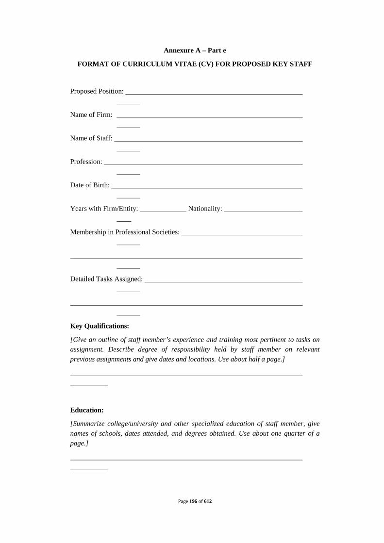
Page 196 of 612
Annexure A – Part e
FORMAT OF CURRICULUM VITAE (CV) FOR PROPOSED KEY STAFF
Proposed Position:
Name of Firm:
Name of Staff:
Profession:
Date of Birth:
Years with Firm/Entity: Nationality:
Membership in Professional Societies:
Detailed Tasks Assigned:
Key Qualifications:
[Give an outline of staff member’s experience and training most pertinent to tasks on assignment. Describe degree of responsibility held by staff member on relevant previous assignments and give dates and locations. Use about half a page.]
Education:
[Summarize college/university and other specialized education of staff member, give names of schools, dates attended, and degrees obtained. Use about one quarter of a page.]

Page 197 of 612
Employment Record:
[Starting with present position, list in reverse order every employment held. List all positions held by staff member since graduation, giving dates, names of employment organizations, titles of positions held, and locations of assignments. For experience in last ten years, also give types of activities performed and client references, where appropriate. Use about two pages.]
Languages:
[For each language indicate proficiency: excellent, good, fair or poor in speaking, reading and writing.]
Certification:
I, the undersigned, certify that to the best of my knowledge and belief, these data correctly describe me, my qualifications, and my experience. I also certify that I have only given permission for my CV to be included in the Bid submitted by
[Fill in name of Bidder here.]
Date:
[Signature of staff member and authorized representative of the firm] Day/Month/Year
Full name of staff member:
Full name of authorized representative:
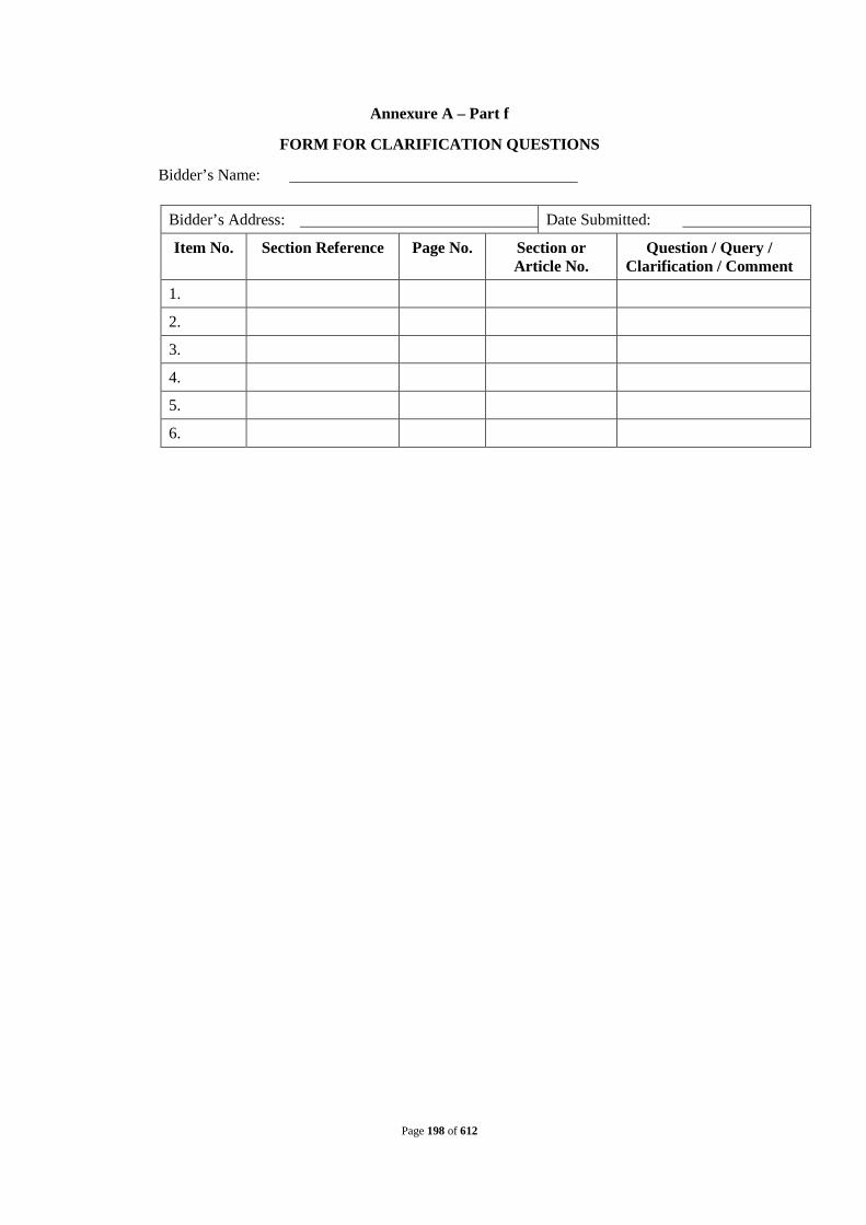
Page 198 of 612
Annexure A – Part f
FORM FOR CLARIFICATION QUESTIONS
Bidder’s Name:
Bidder’s Address: Date Submitted:
Item No. Section Reference Page No. Section or Article No.
Question / Query / Clarification / Comment
1.
2.
3.
4.
5.
6.

Page 199 of 612
Annexure A – Part g
Eligible Countries
Eligibility for the Provision of Goods, Works and Non Consulting Services
In reference to ITB 1.3, for the information of the Bidders, at the present time firms, goods and services from the following countries are excluded from this bidding process:
Under 1.3: None

Page 200 of 612
Annexure A – Part h
QUALIFICATION CRITERIA
Section 1. QUALIFICATION CRITERIA
1.1. General
a. Evaluation of the Bidders’ qualifications will be based on compliance with all the following minimum pass-fail criteria regarding their general Design, build, construct, operation and maintenance experience of Sewage Treatment Plant and Sewerage Network, and/or Interception & Diversion Works, financial strength, personnel and management capabilities, and other relevant information as demonstrated by the Bidders’ responses in the Information Forms that they submit as per the attached Bid Forms. Additional requirements for joint ventures are given in Section 2.
b. Bidders may submit the Bid either as,
1. A stand-alone firm, company, legal entity formed as per the applicable law; or
2. A joint venture of up to a maximum of 3 partners19
provided that they meet the requirements of the Bidding Documents. For the purpose of assessing some qualification criteria, the qualifications and experience of Sub-Contractors may be included and the specific provisions in this regard are set out in Section
,
1.3.
1.2. Subcontracting
a. Bidders will be evaluated based on the qualifications of,
1. the Bidder; and
2. nominated Sub-Contractors and Sub-Consultants only with respect to the experience evaluation as set out in Section 1.3, and only if the Sub-Contractors and Sub-Consultants are nominated for the purpose of this bid.
For the purposes of Section 1.6, Bidders may nominate personnel of Sub-Contractors and Sub-Consultants to fill the key positions, during the Design-Build Period and O&M period,as listed/referred to in the BDS - ITB 3.3 (h) (4).
b. The Bidder shall provide a detailed list of all nominated Sub-Contractors and Sub-Consultants and a record of their experience and qualifications in the applicable Information Forms. The Operator under the Contract shall be prohibited from entering into a contract or contracts that will result in the Operator exceeding the maximum
19Maximum number of JV partners may be changed depending on specific requirements of the
work and the figure should be consistent with BDS – ITB 1.2.1.

Page 201 of 612
percentage of subcontracting and sub-consulting permitted by the Owner, as set out in the BDS - ITB 3.3(h) (6).
c. Bidders will not be permitted to change the Sub-Contractors and Sub-Consultants nominated in their Bid.
1.3. Operator’s Responsibility
After award of the Contract, the subcontracting of any part of the work, except for those Sub-Contractors and Sub-Consultants nominated in the Bid, shall require the prior written consent of the Owner. Notwithstanding such consent, the Operator shall remain responsible for the acts, defaults, and neglects of all Sub-Contractors and Sub-Consultants during Contract implementation.
1.4. Exper ience in Construction and Operation and Maintenance of Sewage Treatment Plant and Interception & Diversion Works
For the purpose of determining a bidder’s compliance with the qualification criteria specified in Annexure A – Part h, following definitions shall apply:
“Sewage Treatment Plant (STP) means a treatment facility designed, developed and constructed, and operated for primary and secondary treatment of sewage for its safe disposal complying with the regulatory norms. Waste stabilization pond / other pond process will not be covered under this definition”; and.
“Interception & Diversion Works” means the diversion structure across nallah/drain along with intercepting sewer laid for conveying the sewage from nallah/drains up to the Sewage Treatment Plant and including Sewage lifting and pumping stations and all appurtenant structures forming a part of both the New/Existing Sewerage Infrastructure.
(a) The Bidder shall provide evidence that
1. The Bidder shall provide evidence that it has designed, developed, built, tested and commissioned at least 1 STP of 25.6 MLD or 2 STP of 19.2 MLD or 3 STP of 12.8 MLD during last 7 years preceding the month of publication of NIT.
2. The bidder or his nominated sub-contractor has successfully
commissioned at least one Sewage Treatment Plant with the same technology as proposed for this contract for the lowest STP capacity mentioned in clause 1.4 (a) 1. above, operating successfully for a period of 1 year during the last 7 years preceding the month of publication of NIT.
3. The Bidder has the experience in operating and maintaining successfully STPs at least 1 STP of 25.6 MLD or 2 STP of 19.2 MLD or 3 STP of 12.8 MLD during 1 year over the last 7 years preceding the month of publication of NIT.

Page 202 of 612
4. The treatment technology proposed for this contract has been adopted (not necessarily built by the bidder) in at least 3 locations during last 7 years preceding the month of publication of NIT and that such STP has been operating successfully (meeting the required performance standards and environmental norms specified in the Contract) for a period of minimum 2 years over a period of last 7 years preceding the month of publication of NIT.
5. It has designed, developed, built, tested and commissioned sewerage network and Pumping station(s) of 17 km length collectively maximum from 3 projects during the last 7 years preceding the month of publication of NIT.of which 2.1 Km should be above 1200 mm dia.
6. The bidder or his nominated sub-contractor has operated and maintained Sewerage network and pumping station(s) of 17 km length of the total scope of sewerage network collectively from maximum 3 projects during 1 year over the last 7 years preceding the month of publication of NIT.
7 The bidder or his nominated sub-contractor has designed, built and commissioned Sewerage Network using trenchless technology for a minimum of 10 mtr of the proposed length of the network to be laid using trenchless technology, during the last 7 years preceding the month of publication of NIT.
1.5. Financial Capabilities
a. The Bidder shall demonstrate that it possesses a net worth equivalent to minimum of INR 25.10 Cr. in each of the last three financial years preceding the date of submission of bid.
b. The Bidder shall demonstrate by submitting along with its bid, a banker’s certificate that it has available cash credit facility equivalent to minimum INR 167.35. million as onthe date of submission of bid.
c. The Bidder’s audited balance sheets or, if not required by the laws of the Bidder’s country, other financial statements acceptable to the Owner, for the last five years shall be submitted and must demonstrate the current soundness of the Bidder’s financial position and indicate its prospective long-term profitability. If deemed necessary by the Owner, the Owner shall have the authority to make inquiries with the Bidder’s bankers.

Page 203 of 612
1.6. Personnel Capabilities
The Bidder shall supply general information on the management structure of the firm, and shall make provision for suitably qualified personnel to fill the key positions listed/referred to in the BDS – ITB 3.3(h) (4), as required during Contract implementation. The Bidder shall supply information on a candidate for each key position, who shall meet the experience requirements specified. The Bidder may nominate personnel of sub-contractors and sub consultants to fill key positions listed/referred to in the BDS– ITB 3.3(h) (4).
1.7. Litigation History, Legal Matters and ESHS Performance
The Bidder shall provide accurate information on the “Historical Contract Non-Performance Form” and “Environmental Social Health and Safety (ESHS) Performance Declaration” about contract non-performance, pending litigation and ESHS performance with respect to contracts completed or ongoing under its execution over the last five years. A consistent history of awards against the Bidder or any Partner of a joint venture may result in rejection of the Bid.
1.8. Right to Waive
The Owner reserves the right to waive minor deviations in the qualification criteria if they do not materially affect the capability of a Bidder to perform the Contract.
Section 2. JOINT VENTURES
2.1. Qualification Cr iter ia
a. The Joint Venture partners shall together satisfy the criteria specified in Sections 1.4 (a) (1), 1.4(a) (3) and 1.4 (a) (5)
b. The joint venture partners or nominated sub-contractor(s) shall satisfy the requirements specified in Sections 1.4(a) (2),1.4 (a) (6)& 1.4 (a)(7)
c. The Joint Venture partners shall jointly satisfy all the requirements specified in Section1.4 of Qualification Criteria.
d. For the purpose of satisfying the qualification criteria set out in Section 1.5, Joint Venture partners must satisfy the following qualification criteria :
1. financial soundness
a. as stated in Section 1.5(a) for all partners jointly
b. as stated in Section 1.5 (c)in respect of each partner of the JV;

Page 204 of 612
2. adequate sources to meet financial commitments as set out in Section 1.5 (b)for all partners jointly;
3. personnel capabilities as stated in Section 1.6 for all partners jointly; and
4. legal disclosure as stated in Section 1.7 for each partner of the JV.
e. Each partner of a joint venture Bidder shall provide the information to evidence compliance with the criteria set out in Sections2.2(a) to (d).
2.2. (a) Lead Par tner
One of the joint venture Partners who is responsible for performing a key function in contract management or in executing a major component of the proposed Contract shall be nominated as being in charge during the bidding process and, in the event of a successful bid, during Contract execution (the “Lead Partner”). The Lead Partner shall be authorized to incur liabilities and receive instructions for and on behalf of any and all partners of the joint venture. This authorization shall be evidenced by the submission of a power of attorney signed by legally authorized signatories of each of the joint venture Partners as per proforma enclosed in Annexure A - Part L, as part of the Bid.
(b) All Partners
All partners of the joint venture shall be liable jointly and severally for the execution of the Contract in accordance with the Contract terms and a copy of the undertaking as per format provided under Annexure A - Part M signed by the joint venture partners shall be submitted with the bid.

Page 205 of 612
Annexure A – Part i
INFORMATION FORMS
Information Form (1)
General Information
All individual firms and each participant in a joint venture submitting the bids are required to complete the information in this form. Nationality information should be provided for all Bidders that are partnerships or individually owned firms.
If the Bidder proposes to use nominated sub-contractors or sub-consultants, the following information should also be supplied for the sub-contractor(s) and sub-consultant(s).
1. Name of firm
2. Head office address
3. Telephone Contact
4. Fax Telex
5. Place of incorporation / registration
Year of incorporation / registration
Nationality of Owners1
Name Nationality
1.
2.
3.
4.
5.
1. To be completed by all Owners of partnerships or individually owned firms.

Page 206 of 612
INFORMATION FORM (2)
(ref. Annexure A Part h Section2)
General Design, Build, Operation and Management Experience Information
Name of Bidder or participant of a joint venture
All individual firms and all participants of a joint venture are requested to complete the information in this form with regard to their experience in Designing, building, operating, managing and maintaining Sewage Treatment Plants and Sewerage Networksand/or Interception and Diversion Works
Description of Contract/ STP and Sewerage Network and/or Interception and Diversion Works
Components along with its Capacity and appurtenant structures
Name of Joint Venture Participant Responsible
Name of City
Country
Population served
Contract Role (joint venture participant, sub-contractor, sub consultant, lead, etc.) and percentage share in the total contract
Nature, role and extent of participation (describe fully)
Date of contract commencement
Date of contract termination
Contract value (INR)
Individual for reference
Address, Telephone, Fax for reference

Page 207 of 612
INFORMATION FORM (2A)
(Ref. Annexure A Part h Section 1.5)
Financial Capability Information#
Name of Bidder or participant of a joint venture
All individual firms and all participants of a joint venture are requested to complete the information in this form with regard to their experience in Designing, building, operating, managing and maintaining STPs and Sewerage Networksand/or Interception and Diversion Works. The information supplied should be the annual turnover of the Bidder (or each partner of a joint venture) in terms of the amounts billed to clients for each year for work in progress or completed, converted to INR at the rate of exchange at the end of the period reported. The annual periods should be calendar years, with partial accounting for the year up to the date of submission of Applications.
Use a separate sheet for each participant of a joint venture.
Bidders should not enclose testimonials, certificates, and publicity material with their Application as they will not be taken into account in the evaluation of qualifications.
Annual financial data (in the area of infrastructure development and engineering construction).
Year Turnover (Rs. Million)
Net Worth (Rs. Million)
Net Cash Accruals
(Rs. Million) [Year] [Year] [Year] [Year] [Year]
1.
# Instructions and Applicable Conditions:
2.
The applicant shall provide details of its own financial capacity;
a.
The Applicant / its constituent Joint Venture Partners shall attach copies of balance sheets, financial statements and Annual report for 5 (five) years preceding the Application due date. The financial statements shall:
b.
Reflect the financial situation of the Bidder or Joint Venture Partners,
c.
Be audited by a statutory auditor
d.
Be complete including all notes to the Financial statements; and
3.
Correspond to accounting periods already completed and audited (no statements for partial periods shall be requested or accepted)
a.
Net Worth (The definition of Net Worth shall be as follows: Based on the type of the Applicant whether a company, partnership firm, etc. the net worth is defined as follow:
In case of a company registered under Companies Act, 1956: Net worth shall mean the sum of subscribed and paid up equity share capital and reserves from which shall be deducted the sum of revaluation reserves,

Page 208 of 612
miscellaneous expenditure not written off and reserves not available for distribution to equity share holders.
b.
For the company = (Subscribed and Paid-up Equity + Reserves) less (Revaluation reserves + miscellaneous expenditure not written off + reserves not available for distribution to equity share holders).
In case of a Partnership firm: Net worth shall mean the sum of Aggregate of partners' capital account and Reserves from which the aggregate of drawings by partners and aggregate of advances to partners shall be deducted.
c.
For Partnership Firm = Aggregate of partners' capital account + Reserves - Aggregate of drawings by partners - Aggregate of advances to partners
In case of a Trust / Society: Net worth shall mean the sum of corpus and the returns not set aside for any particular purpose.
4.
For Trust / Society = corpus + returns not set aside for any particular purpose
5.
Net Cash Accruals shall be defined as follows: Net Cash Accruals = Profit after Tax + Depreciation;
6.
Year 1 will be the latest completed financial year, preceding the bidding. Year 2 shall be immediately preceding year 1 and so on. In case the Bid Submission date falls within 3 (three) months of the close of the latest financial year of the applicant, it shall ignore such financial year for the purpose of its bid and furnish all its information and certification with reference to the 5 (five) years preceding its latest financial year. For the avoidance of doubt, financial year shall, for the purpose of the Bid hereunder, mean the accounting year followed by the Bidder in the course of its normal business.
7.
The Bidder shall provide an Auditor’s Certificate specifying the Net Worth and Net Cash Accruals of the Bidder and also specifying the methodology adopted for calculating such net worth in accordance with the formula mentioned in point 3 and 4 above.
The Bidder shall provide from its concerned client (s) or Statutory Auditor, certificate(s) stating the payments made / received or works commissioned, as the case may be, during the past 5 (five) years in respect of the Projects specified in Information Forms 2, 3A and 3B.

Page 209 of 612
INFORMATION FORM (2B)
Joint Venture Summary
Names of all participants of a joint venture
1. Lead Participant
2. Participant
3. Participant
4. Participant
Annual turnover data (in the area of infrastructure development and engineering construction).
Participant
Information Form (2A) page no. [Year] [Year] [Year] [Year] [Year]
1. Lead Participant
2. Participant
3. Participant
4. Participant
Totals
Bidders shall append to Form 2B:
a. A document confirming the percentage shareholding of each joint venture participant in the company to be established including the financial stake of each partner in the JV partnership; and
b. A description of the role and responsibility of each joint venture participant. (Bidders shall make the precise role of each joint venture participant clear in this description).
Bidders are reminded to submit the appropriate powers of attorney as required by Section 2.2 ofAnnexure A – Part h. The Joint Venture Bidders may also note the requirements mentioned in ITB Section 3.6 for compliance while submitting the Bid.

Page 210 of 612
INFORMATION FORM (3A)
(Ref. Annexure A - Part h Section1.4 (a) 1.
Description of Contract/ STP and Interception and Diversion Works
)
Design, development, construction, testing and commissioning of STP and Interception and Diversion Works.
Name of Bidder or participant of a joint venture
Name of Joint Venture Participant Responsible
Name of City
Country
Capacity of STP and Sewerage Network
Population served
Contract Role (joint venture participant, sub-contractor, sub consultant, lead, etc.) and percentage share in the total contract
Nature, role and extent of participation (describe fully)
Date of contract commencement
Date of contract termination
Contract value in INR or equivalent to US$
Individual for reference
Address, Telephone, Fax for reference
Provide a complete description of the services provided under this contract demonstrating that the definition of a STPin Section 1.4 of Annexure A Part h to Bidding documents has been met.

Page 211 of 612
Information Form (3b)
(Ref. Annexure A Part h Section 1.4 (a) 3)
Successful experience in Operating and Maintaining STP and Interception and Diversion Works
Name of Bidder or participant of a joint venture
Description of Contract/STP and Interception and Diversion Works
Name of Joint Venture Participant Responsible
Name of City/Urban area
Country
Capacity of STP and Sewerage Network
Number of years operated (with period)
Population served
Contract Role (joint venture participant, sub-contractor, sub consultant, lead, etc.) and percentage share in the total contract
Nature, role and extent of participation (describe fully)
Date of contract commencement
Date of contract termination
Contract value in INR or equivalent to US$
Individual for reference
Address, Telephone, Fax for reference
Provide a complete description of the services provided under this contract demonstrating that the definition of a Sewage Treatment Plant and Sewerage Networkin Section 1.4 of Annexure A Part h to Bidding documents has been met.

Page 212 of 612
Financial Capabilities
Information Form (4)
Name of Bidder or participant of a joint venture
Bidders, including each partner of a joint venture, shall provide financial information to demonstrate that they meet the requirements stated in the Schedule to ITB. Each Bidder or participant of a joint venture shall complete this form. If necessary, separate sheets shall be used to provide complete banker information. A copy of the audited balance sheets shall be attached.
Banker Name of banker
Address of banker
Telephone Contact name and title
Fax Telex
Summarize actual assets and liabilities in INR or equivalent to U.S. dollar (at the rates of exchange current at the end of each year) for the previous five calendar years. Based upon known commitments, summarize Projected assets and liabilities in INR or equivalent to U.S. dollar for the next two calendar years, unless the withholding of such information by stock market listed public companies can be substantiated by the Bidder.
Financial information in INR or equivalent to US$
Actual: Previous five years
Projected: Next two years
[Year] [Year] [Year] [Year] [Year] [Year] [Year]
1. Total assets
2. Current assets
3. Total liabilities
4. Current liabilities
5. Profits before taxes
6. Profits after taxes
Specify proposed sources of financing, such as liquid assets, unencumbered real assets, lines of credit, and other financial means, net of current commitments, available to meet the total construction cash flow demands of the subject Contract or contracts as indicated in Schedule to ITB 1.4(2).
Source of Financing Amount in INR or equivalent to US $
1.
2.
3.
4.
Attach audited financial statements—including, as a minimum, profit and loss account, balance sheet, and explanatory notes—for the period stated in Section 1.5 of Annexure A Part h to Bidding documents (for the individual Bidder or each participant of a joint venture).

Page 213 of 612
Information Form (5)
(ref. Annexure A Part h - Section 1.6)
Personnel Capabilities
Name of Bidder or participant of a joint venture
For specific positionsnoted below, Bidders must provide the names of a candidate qualified to meet the specified requirements stated for each position. The data on their experience should be supplied on separate sheets using one Form (5A) for each candidate.
Bidders may propose alternative management and implementation arrangements requiring different key personnel, whose experience records should be provided.
If audits are not required by the laws of Bidders' countries of origin, partnerships and firms owned by individuals may submit their balance sheets certified by a registered accountant, and supported by copies of tax returns.
1. Title of position*
Name of candidate
2. Title of position*
Name of candidate
3. Title of position*
Name of candidate
4. Title of position*
Name of candidate
5. Title of position*
Name of candidate
6. Title of position*
Name of candidate
*As listed in BDS - ITB 3.3 (e) 8 & 3.3 (e) 9in respect of Section 1.6 of Annexure A part h to Bidding documents.

Page 214 of 612
Information Form (5A)
(ref.Annexure A – Part h – Section 1.6)
Candidate Summary
Name of Bidder or participant of a joint venture
Position Candidate
Candidate Information
Name of Candidate Date of Birth
Professional qualifications
Present Employment
Name of Owner
Address of Owner
Telephone Contact (manager/personnel officer)
Fax Telex
Job title of candidate Years with present Owner
Summarize professional experience over the last twenty years, in reverse chronological order. Indicate particular technical and managerial experience relevant to the Project.
From To Company/Project/Position/Relevant technical and management experience

Page 215 of 612
Contractor’s Representative and Key Personnel
Schedule
Bidders should provide the names and details of the suitably qualified Contractor’s Representative and Key Personnel to perform the Contract. The data on their experience should be supplied using the Form PER-2 below for each candidate.
Contractor’ Representative and Key Personnel
1. Title of position: Contractor’s Representative
Name of candidate:
Duration of appointment:
[insert the whole period (start and end dates) for which this position will be engaged]
Time commitment: for this position:
[insert the number of days/week/months/ that has been scheduled for this position]
Expected time schedule for this position:
[insert the expected time schedule for this position (e.g. attach high level Gantt chart]
2. Title of position: [Environmental Specialist]
Name of candidate:
Duration of appointment:
[insert the whole period (start and end dates) for which this position will be engaged]
Time commitment: for this position:
[insert the number of days/week/months/ that has been scheduled for this position]
Expected time schedule for this position:
[insert the expected time schedule for this position (e.g. attach high level Gantt chart]
3. Title of position: [Health and Safety Specialist]
Name of candidate:

Page 216 of 612
Duration of appointment:
[insert the whole period (start and end dates) for which this position will be engaged]
Time commitment: for this position:
[insert the number of days/week/months/ that has been scheduled for this position]
Expected time schedule for this position:
[insert the expected time schedule for this position (e.g. attach high level Gantt chart]
4. Title of position: [Social Specialist]
Name of candidate:
Duration of appointment:
[insert the whole period (start and end dates) for which this position will be engaged]
Time commitment: for this position:
[insert the number of days/week/months/ that has been scheduled for this position]
Expected time schedule for this position:
[insert the expected time schedule for this position (e.g. attach high level Gantt chart]
5. Title of position: [insert title]
Name of candidate
Duration of appointment:
[insert the whole period (start and end dates) for which this position will be engaged]
Time commitment: for this position:
[insert the number of days/week/months/ that has been scheduled for this position]
Expected time schedule for this position:
[insert the expected time schedule for this position (e.g. attach high level Gantt chart]

Page 217 of 612
Form ……: Resume and Declaration
Contractor’s Representative and Key Personnel
Name of Bidder
Position [#1]: [title of position from Form PER-1]
Personnel information
Name:
Date of birth:
Address:
E-mail:
Professional qualifications:
Academic qualifications:
Language proficiency:[language and levels of speaking, reading and writing skills]
Details
Address of employer:

Page 218 of 612
Telephone:
Contact (manager / personnel officer):
Fax:
Job title:
Years with present employer:
Summarize professional experience in reverse chronological order. Indicate particular technical and managerial experience relevant to the project.
Project Role
Duration of
involvement
Relevant experience
[main project details]
[role and responsibilities on the project]
[time in role]
[describe the experience relevant to this position]
Declaration
I, the undersigned [insert either “Contractor’s Representative” or “Key Personnel” as applicable], certify that to the best of my knowledge and belief, the information contained in this Form PER-2 correctly describes myself, my qualifications and my experience.
I confirm that I am available as certified in the following table and throughout theexpected time schedule for this position as provided in the Bid:
Commitment Details

Page 219 of 612
Commitment to duration of contract:
[insert period (start and end dates) for which this Contractor’s Representative or Key Personnel is available to work on this contract]
Time commitment: [insert period (start and end dates) for which this Contractor’s Representative or Key Personnel is available to work on this contract]
I understand that any misrepresentation or omission in this Form may:
(a) be taken into consideration during Bid evaluation;
(b) result in my disqualification from participating in the Bid;
(c) result in my dismissal from the contract.
Name of Contractor’s Representative or Key Personnel: [insert name]
Signature: __________________________________________________________
Date: (day month year): _______________________________________________
Countersignature of authorized representative of the Bidder:
Signature: ________________________________________________________
Date: (day month year): ______________________________________________

Page 220 of 612
Information Form (6)
Historical Contract Non-Performance (ref. Section 1.7 of Annexure A part h to Bidding documents)
[The following table shall be filled in for the Bidder and for each partner of a Joint Venture]
Bidder’s Legal Name: [insert full name] Date: [insert day, month, year]
Joint Venture Party Legal Name: [insert full name] ICB No. and title: [insert ICB number and title]
Page [insert page number] of [insert total number] pages
Non-Performing Contracts in accordance with Section 1.7 of Annexure A Part h to ITB
Contract non-performance did not occur during the [number] years specified in Section 1.7of Annexure A Part h to ITB. Contract(s) not performed during the [number] years specified in Section 1.7of Annexure A Part h to ITB.
Year Non performed portion of contract
Contract Identification Total Contract Amount (current
value in INR or equivalent
US$)
[insert year]
[insert amount and percentage]
Contract Identification: [indicate complete contract name/number, and any other identification] Name of Employer: [insert full name] Address of Employer: [insert street/city/country] Reason(s) for non-performance: [indicate main reason(s)]
[insert amount]
Pending Litigation, in accordance with Section 1.7 of Annexure A Part h of Bidding documents.
No pending litigation in accordance with Section 1.7 of Annexure A Part h of Bidding documents Pending litigation in accordance with Section 1.7 of Annexure A Part h of Bidding documents

Page 221 of 612
InformationForm (7) Environmental, Social, Health, and
Safety Performance Declaration [The following table shall be filled in for the Bidder, each member of a Joint Venture and
each Specialized Subcontractor]
Bidder’s Name: [insert full name] Date: [insert day, month, year]
Joint Venture Member’s or Specialized Subcontractor’s Name: [insertfull name]
Page [insert page number] of [insert total number] pages
Environmental, Social, Health, and Safety Performance Declaration
in accordance with Section 3, Qualification Criteria, and Requirements
No suspension or termination of contract: An employer has not suspended or terminated a contract and/or called the performance security for a contract for reasons related to Environmental, Social, Health, or Safety (ESHS) performance since the date specified in Section 3, Qualification Criteria, and Requirements, Sub-Factor 2.5.
Declaration of suspension or termination of contract: The following contract(s) has/have been suspended or terminated and/or Performance Security called by an employer(s) for reasons related to Environmental, Social, Health, or Safety (ESHS) performance since the date specified in Section 3, Qualification Criteria, and Requirements, Sub-Factor 2.5. Details are described below:
Year Suspended or
terminated portion of contract
Contract Identification
Total Contract Amount
(current value, currency,
exchange rate and US$
equivalent)
[insert year]
[insert amount and percentage]
Contract Identification: [indicate complete contract name/ number, and any other identification]
Name of Employer: [insert full name]
Address of Employer: [insert street/city/country]
Reason(s) for suspension or termination:
[insert amount]

Page 222 of 612
[indicate main reason(s)]
[insert year]
[insert amount and percentage]
Contract Identification: [indicate complete contract name/ number, and any other identification]
Name of Employer: [insert full name]
Address of Employer: [insert street/city/country]
Reason(s) for suspension or termination: [indicate main reason(s)]
[insert amount]
… … [list all applicable contracts] …
Performance Security called by an employer(s) for reasons related to ESHS performance
Year Contract Identification
Total Contract Amount (current value, currency, exchange rate and US$ equivalent)
[insert year]
Contract Identification: [indicate complete contract name/ number, and any other identification]
Name of Employer: [insert full name]
Address of Employer: [insert street/city/country]
Reason(s) for calling of performance security: [indicate main reason(s)]
[insert amount]

Page 223 of 612
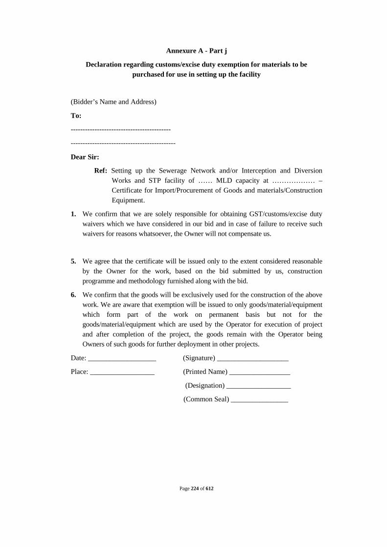
Page 224 of 612
Annexure A - Part j
Declaration regarding customs/excise duty exemption for materials to be purchased for use in setting up the facility
(Bidder’s Name and Address)
To:
------------------------------------------
--------------------------------------------
Dear Sir:
Ref: Setting up the Sewerage Network and/or Interception and Diversion Works and STP facility of …… MLD capacity at ……………… – Certificate for Import/Procurement of Goods and materials/Construction Equipment.
1. We confirm that we are solely responsible for obtaining GST/customs/excise duty waivers which we have considered in our bid and in case of failure to receive such waivers for reasons whatsoever, the Owner will not compensate us.
5. We agree that the certificate will be issued only to the extent considered reasonable by the Owner for the work, based on the bid submitted by us, construction programme and methodology furnished along with the bid.
6. We confirm that the goods will be exclusively used for the construction of the above work. We are aware that exemption will be issued to only goods/material/equipment which form part of the work on permanent basis but not for the goods/material/equipment which are used by the Operator for execution of project and after completion of the project, the goods remain with the Operator being Owners of such goods for further deployment in other projects.
Date: ___________________ (Signature) ____________________
Place: __________________ (Printed Name) _________________
(Designation) __________________
(Common Seal) ________________

Page 225 of 612
Annexure A - Part K
FORMOFLETTEROFINTENTBYJVPARTNERSTOENTERINTOJV AGREEMENT
THIS LETTER OF INTENT signed on this.......... day of........... Two Thousand and ................by....... a company incorporated under the laws of ............. and having its Registered Office at .......................(hereinafter called the "Party No.1" which expression shall include its successors, executors and permitted assigns) and M/s ............. a company incorporated under the laws of .......... and having its Registered Office at ...........(hereinafter called the "Party No.2" which expression shall include its successors, executors and permitted assigns) and M/s.. .. .. .. . .. . . . . .. . .. .. .... .. a Company incorporated under the laws of ................ and having its Registered Office at ............... (hereinafter called the "Party No.3" which expression shall include its successors, executors and permitted assigns) for the purpose of making a bid and entering into a contract [hereinafter called the "Contract" (in case of award) against the work for the design and build Sewage Treatment Plant and Sewerage Network and/or Interception and Diversion works and all Appurtenant Structures and Allied Works, and O & M of Complete Works associated with ……………….. ……………..(hereinafter called the "Owner").
WHEREAS the Party No.1, Party No.2 and Party No.3 intend to enter into a JointVenture Agreement
AND WHEREAS the Owner invited bids as per the above mentioned Specification to design and build Sewage Treatment Plant and Sewerage Network and all Appurtenant Structures and Allied Works, and O & M of Complete Works stipulated in the bidding documents.
AND WHEREAS ITB Clause 3.6 and Annexure A Part h Qualification Criteria forming part of the bidding documents, inter-alia, stipulates that two or more qualified partners, meeting the requirements of 'Qualification Requirement of the Bidder', as applicable may bid, provided, they submit a Letter of Intent to enter into Joint Venture Agreement and the Joint Venture Partners fulfill all other requirements under ITB Clause 5.7 ‘Qualification of the Bidder’ and in such a case, the Letter of Bid (Bid Form) shall be signed by the Partner - In Charge so as to legally bind all the Partners of the Joint Venture, who will be jointly and severally liable to perform the Contract by entering into Joint Venture Agreement as per proforma submitted with the Bid in accordance with ITB 3.6 which will be legally binding on all partners and all obligations hereunder.
The above clause further states that this Letter of Intent shall be attached to the bid and the Contract performance guarantee will be as per the format enclosed with the bidding document without any restrictions or liability for either party.

Page 226 of 612
AND WHEREAS the bid is being submitted to the Owner vide proposal No........dated...... by Party No.1 based on this letter of Intent between all the parties; under these presents and the bid has been signed by all the parties.
NOW THIS UNDERTAKING WITNESSETH AS UNDER:
InconsiderationoftheabovepremisesandagreementsallthepartiesofthisletterofIntentdoherebydeclareandundertake:
1. Inrequirementoftheawardofthe Contractby theOwnertotheJointVenture Partners,we,thePartiesdoherebyundertakethat M/s......... thePartyNo.1, shallactasleadPartnerandfurtherdeclareandconfirmthatwethepartiesto theJointVentureshalljointlyandseverallybebounduntotheOwner forthe successful performanceoftheContractandshallbefullyresponsibleforthe design and build Sewage Treatment Plant and Interception and Diversion works and all Appurtenant Structures and Allied Works, and O & M of Complete WorksaccordancewiththeContract forwhichweshallenterintoJointVenture Agreementasperproforma submitted with the Bid whichwillbelegallybindingonallpartners:
2. IftheContractisawardedtoJointVenturethenincaseofanybreachordefault ofthesaidContractbyanyofthepartiestotheJointVenture,theparty(s)willbe fullyresponsibleforthesuccessfulperformanceofthe Contractandtocarryout alltheobligationsandresponsibilitiesundertheContractinaccordancewith the requirementsoftheContract.
3. Further,iftheOwnersuffersanylossordamageonaccountofanybreachin theContract oranyshortfallintheperformanceoftheequipmentin meetingthe performancesguaranteedasperthespecificationintermsoftheContract,the Party(s)ofthesepresentswillpromptlymakegoodsuchlossordamagescaused totheOwner,onitsdemandwithoutanydemur.Itshallnotbenecessaryor obligatoryfortheOwnertoproceedagainstleadPartnertothesepresents beforeproceedingagainstordealingwiththeotherParty(s),theOwnercan proceedagainstanyofthepartieswhoshallbejointly andseverallyliableforthe performanceandallother liabilities/obligations under the Contract to the Owner.
4. ThefinancialliabilityofthePartiesoftheDeedofUndertakingtotheOwner intheeventofawardofContractontheJointVenture,withrespecttoanyofthe claims a risingoutoftheperformanceornon-performanceoftheobligationsset forthintheDeedofUndertaking,readinconjunctionwiththerelevantconditions oftheContractshall,howevernotbelimitedinanywaysoastorestrictorlimit theliabilitiesorobligationsofanyofthePartiesoftheDeedof Undertaking.
5. ItisexpresslyunderstoodandagreedbetweenthePartiestothisLetterofIntent thattheresponsibilitiesandobligations ofeachofthePartiesshallbeas delineated inAppendix-I(tobesuitablyappendedbythePartiesalong withthis LetterofIntentinitsbid).Itisfurtherundertakenbythepartiesthattheabove sharingofresponsibilitiesandobligationsshall notinanywaybealimitationof jointandseveralresponsibilitiesofthePartiesundertheContractintheeventof

Page 227 of 612
awardonJointVenture. 6. ItisalsounderstoodthatthisLetterofIntentisprovidedforthepurposesof
undertakingjointandseveralliabilitiesofthepartnerstotheJointVenturefor submissionof thebidandperformanceoftheContractifawardedandthatthis LetterofIntentshallnotbedeemedtogiverisetoanyadditionalliabilitiesor obligations,inanymanneroranylaw,onanyof theParties to thisLetterofIntent orontheJointVenture,otherthanthe expressprovisionsoftheContract.
7. ThisLetter ofIntent shallbeconstruedandinterpretedinaccordancewith theprovisionsoftheContract.
8. IncaseofanawardofaContract, we the parties to this Letter of Intent do hereby agree that we shall enter into Joint Venture Agreement as per proforma submitted with the Bid which will be legally binding on all partners and we shall be jointly and severally responsible for furnishing a Contract performance security from a bank in favor of the Owner in the currency/currencies of the Contract.
9. ItisfurtheragreedthatthisLetterofIntentshallbeirrevocableandshallforman integralpartof thebid.Itshallbeeffectivefromthedatefirstmentioned abovefor allpurposesandintents.
IN WITNESS WHEREOF, the Parties to this Letter of Intent have through their authorizedrepresentatives executedthesepresentsandaffixedCommonSealsoftheir companies,on theday,monthandyearfirstmentionedabove.
Common Seal of ............................ has been affixed in my/ our presence pursuant to Board of Director's Resolution dated ...............
ForLeadPartner (PartyNo.-1) ForandonbehalfofM/s
Name........................................
Designation ..................................
Signature..................................... Signatureoftheauthorized representative)
WITNESS:
I…………………………………….
II…………………………………….
Common Seal of ............................ has been affixed in my/ our presence pursuant to Board of Director's Resolution dated ...............
For PartyNo.-2ForandonbehalfofM/s
Name........................................

Page 228 of 612
Designation ..................................
Signature..................................... Signatureoftheauthorized representative)
WITNESS:
I…………………………………….
II…………………………………….
Common Seal of ............................ has been affixed in my/ our presence pursuant to Board of Director's Resolution dated ...............
For PartyNo.-3ForandonbehalfofM/s
Name........................................
Designation ..................................
Signature..................................... Signatureoftheauthorized representative)
WITNESS:
I…………………………………….
II…………………………………….

Page 229 of 612
Annexure A - Part L
FORMOFPOWEROF ATTORNEYFORJOINTVENTURE
(OnNon-judicialStampPaperofAppropriatevalue,ifrequiredasperlawsofthe countryofthebidder,tobepurchasedintheNameofJointVenture)
KNOW ALLMENBYTHESEPRESENTSTHATWE,the Partners whose details are givenhereunder.................................................................................haveformeda Joint Venture under the lawsof ...........................................(*)/ intendtoformaJoint Venture (*) [(*) delete whichever is not applicable] and having our Registe through M/s ....................................................... being the Partner in-chargedo hereby constitute, nominate and appoint M/s........................................................ aCompanyincorporatedunderthelawsof.........................................................and havingitsRegistered/HeadOfficeat...........................................asourdulyconstituted lawfulAttorney(hereinaftercalled"Attorney"or"AuthorizedRepresentative"or"Partner In-charge")toexercisealloranyofthepowersforandonbehalfoftheJointVenturein regardto work for the bids for whichhavebeeninvitedby………………………………..,………………………..(hereinaftercalledthe ‘Owner’)to undertakethefollowing acts:
i) TosignandsubmitproposalandparticipateintheaforesaidBidSpecificationof theOwneronbehalfofthe"JointVenture".
ii) To negotiate with the Owner the terms and conditions for award of the ContractpursuanttotheaforesaidBidandtosigntheContractwiththeOwner forandonbehalfofthe"JointVenture".
iii) To doanyotheractorsubmitany documentrelatedtotheabove.
iv) Toreceive,acceptandexecutetheContractforandonbehalfofthe"Joint Venture".
Fortheabovepurpose,theperson(s)authorized bythePartnerIn-chargeshallbethe person(s)authorizedtoactonbehalfofthe"JointVenture"asperthePower ofAttorney giventohim/her/themby thePartnerIn-Charge,
Itisclearly understoodthatallthepartnersof thejointventureshallbeliablejointlyand severallyfortheexecutionoftheContractinaccordancewiththeContracttermsand thePartnerIn-charge(LeadPartner) shallensureperformanceoftheContract(s)andif oneormorePartnerfailtoperformtheirrespectiveportionsofthe Contract(s),the same shallbedeemedto beadefaultbyallthePartners.
ItisexpresslyunderstoodthatthisPowerofAttorneyshallremainvalidbindingand irrevocabletillcompletionofthe Design Build as well as the Operations and Maintenance PeriodintermsoftheContract.
The Joint Venture hereby agrees and undertakes to ratify and confirm all the

Page 230 of 612
whatsoeverthesaidAttorney/AuthorizedRepresentatives/Partnerin-chargequotesin thebid, negotiatesandsignstheContractwiththeOwnerand/orproposestoacton behalfoftheJointVenturebyvirtueofthisPowerofAttorneyandthesameshallbind theJointVentureasif donebyitself.
INWITNESSTHEREOFthePartnersConstituting theJointVentureasaforesaidhave executedthesepresentsonthis ...........dayof .......................undertheCommon Seal(s)oftheirCompanies.
Forandonbehalfofthe PartnersofJointVenture
TheCommonSealof theabovePartnersof theJointVenture:
TheCommonSealhasbeenaffixedthereunto inthepresenceof: WITNESS
1. Signature......................................................
Name..........................................................
Designation...........................................................
Occupation.................................................
2. Signature.....................................................
Name.........................................................
Designation................................................................
Occupation..........................................................

Page 231 of 612
Annexure A - Part M
FORMOFUNDERTAKINGBYTHEJOINTVENTUREPARTNERS
(OnNon-JudicialStampPaperofAppropriateValue,ifrequiredasperlawsofthe countryofthebidder, tobepurchasedintheNameofJointVenture)
THISJOINTDEEDOFUNDERTAKINGexecutedonthis ..........dayof .......Two
Thousand and ..................by ....... a companyincorporated under the lawsof ............... and having its Registered Office at........................ (hereinaftercalled the"PartyNo.1..which expressionshallincludeits successors, executors and permitted assigns) and M/s ............... a company incorporatedunderthe lawsof .................. and having its Registered Officeat ...............(hereinaftercalledthe"PartyNo.2"whichexpressionshallinclude itssuccessors,executorsandpermittedassigns)andM/s ..........................a Companyincorporatedunderthelawsof .................... and havingits RegisteredOfficeat ................ (hereinaftercalledthe"PartyNo.3"whichexpression shallincludeitssuccessors,executorsandpermittedassigns)forthepurposeofmaking abidandenteringintoacontract[hereinaftercalledthe"Contract" (in case ofaward)againstthework to design and build Sewage Treatment Plant and Interception and Diversion works and all Appurtenant Structures and Allied Works, and O & M of Complete Worksassociated with ………………………………(hereinaftercalledthe"Owner").
WHEREASthePartyNo.1,PartyNo.2andPartyNo.3haveenteredintoanAgreement dated................
AND WHEREAStheOwnerinvitedbidsaspertheabovementionedSpecificationto design and build Sewage Treatment Plant and Sewerage Network and all Appurtenant Structures and Allied Works, and O & M of Complete Works stipulatedinthebidding documents.
ANDWHEREAS ITB Clause 3.6 and Annexure A Part h Qualification Criteria formingpartofthebiddingdocuments, inter-alia,stipulatethatan undertakingoftwoormorequalifiedpartners, meetingthe requirements of ‘ Q ua l i f i ca t i o n Criteria o f the Bidder',asapplicablemaybid,provided,theJointVenturefulfillsallother requirementsunder Clause 5.7 ‘Qualification of the Bidder’andinsuchacase,theLetterof Bid(BidForm)shallbesignedbythePartner- InChargesoastolegallybindallthe PartnersoftheJointVenture,whowillbejointlyandseverallyliabletoperformthe

Page 232 of 612
Contractandallobligations hereunder.
Theaboveclause furtherstates thatthisUndertakingshall beattachedtothebid andtheContractperformance guarantee will beaspertheformat enclosedwith thebiddingdocumentwithoutanyrestrictionsorliabilityforeitherparty.
AND WHEREAS the bid is being submitted to the Owner vide proposal No........dated...... by Party No.1 based on this Undertaking between all the parties; under these presents and the bid in accordance with the requirements of ITB Clause 3.6 and Annexure A Part h Qualification Criteria, has been signed by all the parties.
NOW THIS UNDERTAKING WITNESSETH AS UNDER:
In consideration of the above premises and agreements all the parties of this Deed of Undertaking do hereby declare and undertake:
1. In requirement of the award of the Contract by the Owner to the Joint Venture Partners, we, the Parties do hereby undertake that M/s......... the Party No.1, shall act as Lead Partner and further declare and confirm that we the parties to the Joint Venture shall jointly and severally be bound unto the Owner for the successful performance of the Contract and shall be fully responsible to design and build Sewage Treatment Plant and Interception and Diversion works and all Appurtenant Structures and Allied Works, and O & M of Complete Works in accordance with the Contract.
2. In case of any breach or default of the said Contract by any of the parties to the Joint Venture, the parties do hereby undertake to be fully responsible for the successful performance of the Contract and to carry out all the obligations and responsibilities under the Contract in accordance with the requirements of the Contract.
3. Further, if the Owner suffers any loss or damage on account of any breach in the Contract or any shortfall in the performance of the equipment in meeting the performances guaranteed as per the specification in terms of the Contract, the Party(s) of these presents undertake to promptly make good such loss or damages caused to the Owner, on its demand without any demur. It shall not be necessary or obligatory for the Owner to proceed against Lead Partner to these presents before proceeding against or dealing with the other Party(s), the Owner can proceed against any of the parties who shall be jointly and severally liable for the performance and all other liabilities/obligations under the Contract to the Owner.
4. The financial liability of the Parties of this Deed of Undertaking to the Owner, with respect to any of the claims arising out of the performance or non-performance of the obligations set forth in this Deed of Undertaking, read in conjunction with the relevant conditions of the Contract shall, however not be limited in any way so as to restrict or limit the liabilities or obligations of any of the Parties of this Deed of Undertaking.
5. It is expressly understood and agreed between the Parties to this Undertaking that the responsibilities and obligations of each of the Parties shall be as delineated in

Page 233 of 612
Appendix - I (to be suitably appended by the Parties along with this undertaking in its bid). It is further undertaken by the parties that the above sharing of responsibilities and obligations shall not in any way be a limitation of joint and several responsibilities of the Parties under the Contract.
6. It is also understood that this Undertaking is provided for the purposes of undertaking joint and several liabilities of the partners to the Joint Venture for submission of the bid and performance of the Contract if awarded and that this Undertaking shall not be deemed to give rise to any additional liabilities or obligations, in any manner or any law, on any of the Parties to this Undertaking or on the Joint Venture, other than the express provisions of the Contract.
7. ThisUndertakingshall beconstruedandinterpretedinaccordancewiththe provisionsoftheContract.
8. In case of an award of a Contract, we the parties to this Deed of Undertaking do hereby agree that we shall be jointly and severally responsibleforfurnishingaContractperformancesecurityfrom abank in favour oftheOwnerinthecurrency/currenciesoftheContract.
9. ItisfurtheragreedthatthisDeedofUndertakingshallbeirrevocableandshall formanintegralpartofthebidandshallcontinuetobeenforceable tillthe Owner dischargesthesameoruponthecompletionoftheContractin accordancewithitsprovisions,whicheverisearlier.Itshallbeeffective fromthe datefirstmentionedaboveforallpurposesandintents.
INWITNESSWHEREOF,thePartiestothisDeedofUndertakinghavethroughtheir authorizedrepresentatives executedthesepresentsandaffixedCommonSealsoftheir companies,ontheday,monthandyearfirstmentionedabove.
Common Seal of ............................ has been affixed in my/ our presence pursuant to Board of Director's Resolution dated ...............
ForLeadPartner (PartyNo.-1) ForandonbehalfofM/s
Name........................................
Designation ..................................
Signature..................................... Signatureoftheauthorized representative)
ForPartyNo.-2
Forandon behalf of M/s.......................
WITNESS:
I…………………………………….
II…………………………………….

Page 234 of 612
Common Seal of ............................ has been affixed in my/ our presence pursuant to Board of Director's Resolution dated ...............
For PartyNo.-2ForandonbehalfofM/s
Name........................................
Designation ..................................
Signature..................................... Signatureoftheauthorized representative)
WITNESS:
I…………………………………….
II…………………………………….
Common Seal of ............................ has been affixed in my/ our presence pursuant to Board of Director's Resolution dated ...............
For PartyNo.-3ForandonbehalfofM/s
Name........................................
Designation ..................................
Signature..................................... Signatureoftheauthorized representative)
WITNESS:
I…………………………………….
II…………………………………….

Page 235 of 612
Annex B to the Bidding Documents
The Draft Contract
a. Form of Contract
b. General Conditions of the Contract
c. Schedules attached to the Contract

Page 236 of 612
B I H A R U R B A N I N F R A S T R C T U R E D E V E L O P M E N T C O R P O R A T I O N
L I M I T E D ( B U I D C o )
Bidding Documents (for National Mission for Clean Ganga)
NATIONAL COMPETITIVE BIDDING
TO (I) DESIGN AND BUILD SEWAGE TREATMENT PLANTOF INSTALLED CAPACITY 32 MLD AND ALL APPURTENANT STRUCTURES AND ALLIED WORKS IN TWO MODULES (16MLD+16MLD);(II) SURVEY, REVIEW THE DESIGNS, REDESIGN WHERE NECESSARY, AND BUILD NEW DIVERSION WORKS WITH INTERCEPTION WITH RISING MAIN 2.3 KM, NEW TAPPINGS OF LENGTH 18.95 KM FOR 39 DRAINS CONTROLLED WITH SCADA INCLUDING SURVEY, DESIGN, CONSTRUCTION OF 5 NO. PUMPING STATIONS AND ALL APPURTENANT STRUCTURES AND ALLIED WORKS; AND CONSTRUCTION OF 31 OUTFALL STRUCTURE WITH SLUICE GATE INCLUDING EFFLUENT CHANNEL (250 MTR) FOR REUSE OF TREATED WASTE WATER (III) OPERATION & MAINTENANCE OF THE COMPLETE WORKS OF SEWAGE TREATMENT PLANT, INTERCEPTION & DIVERSION WORKS AND PUMPING STATIONS FOR A PERIOD OF 15 YEARS IN CHHAPRA TOWN , STATE OF BIHAR , INDIA.
Page 237 of 612
CONTRACT TO (I) DESIGN AND BUILD SEWAGE TREATMENT PLANTOF INSTALLED CAPACITY 32 MLD AND ALL APPURTENANT STRUCTURES AND ALLIED WORKS IN TWO MODULES (16MLD+16MLD);(II) SURVEY, REVIEW THE DESIGNS, REDESIGN WHERE NECESSARY, AND BUILD NEW DIVERSION WORKS WITH INTERCEPTION WITH RISING MAIN 2.3 KM, NEW TAPPINGS OF LENGTH 18.95 KM FOR 39 DRAINS CONTROLLED WITH SCADA INCLUDING SURVEY, DESIGN, CONSTRUCTION OF 5 NO. PUMPING STATIONS AND ALL APPURTENANT STRUCTURES AND ALLIED WORKS; AND CONSTRUCTION OF 31 OUTFALL STRUCTURE WITH SLUICE GATE INCLUDING EFFLUENT CHANNEL (250 MTR) FOR REUSE OF TREATED WASTE WATER (III) OPERATION & MAINTENANCE OF THE COMPLETE WORKS OF SEWAGE TREATMENT PLANT, INTERCEPTION & DIVERSION WORKS AND PUMPING STATIONS FOR A PERIOD OF 15 YEARS IN CHHAPRA TOWN , STATE OF BIHAR , INDIA.
FORM OF CONTRACT
THIS CONTRACT is made and entered into this ____ day of _______, [Year]
Between
_________, a corporation ________ under ______ law and having its principal place of business at ________
(hereafter the “Owner”)
– and –
[Name of Joint Venture formed by the Successful Bidder or the Individual successful Bidder goes here] with its principal place of business at [Address of the Operator]
(hereafter the “Operator”)
WHEREAS:
a. The Owner has the jurisdiction to enter into the Contract, as defined in Section 1.1 below, pursuant to the Applicable Law;

Page 238 of 612
b. The Owner has received all requisite approvals necessary and has conformed with all requisite laws in accordance with the Applicable Law to permit theOwner to enter into the Contract;
The Owner desires to engage the TO (I) DESIGN AND BUILD SEWAGE TREATMENT PLANTOF INSTALLED CAPACITY 32 MLD AND ALL APPURTENANT STRUCTURES AND ALLIED WORKS IN TWO MODULES (16MLD+16MLD);(II) SURVEY, REVIEW THE DESIGNS, REDESIGN WHERE NECESSARY, AND BUILD NEW DIVERSION WORKS WITH INTERCEPTION WITH RISING MAIN 2.3 KM, NEW TAPPINGS OF LENGTH 18.95 KM FOR 39 DRAINS CONTROLLED WITH SCADA INCLUDING SURVEY, DESIGN, CONSTRUCTION OF 5 NO. PUMPING STATIONS AND ALL APPURTENANT STRUCTURES AND ALLIED WORKS; AND CONSTRUCTION OF 31 OUTFALL STRUCTURE WITH SLUICE GATE INCLUDING EFFLUENT CHANNEL (250 MTR) FOR REUSE OF TREATED WASTE WATER (III) OPERATION & MAINTENANCE OF THE COMPLETE WORKS OF SEWAGE TREATMENT PLANT, INTERCEPTION & DIVERSION WORKS AND PUMPING STATIONS FOR A PERIOD OF 15 YEARS IN CHHAPRA TOWN , STATE OF BIHAR , INDIA.
and ensure the effectiveness and sustainability of the said facility;
The Operator has represented to the Owner that it has the skills and TO (I) DESIGN AND BUILD SEWAGE TREATMENT PLANTOF INSTALLED CAPACITY 32 MLD AND ALL APPURTENANT STRUCTURES AND ALLIED WORKS IN TWO MODULES (16MLD+16MLD);(II) SURVEY, REVIEW THE DESIGNS, REDESIGN WHERE NECESSARY, AND BUILD NEW DIVERSION WORKS WITH INTERCEPTION WITH RISING MAIN 2.3 KM, NEW TAPPINGS OF LENGTH 18.95 KM FOR 39 DRAINS CONTROLLED WITH SCADA INCLUDING SURVEY, DESIGN, CONSTRUCTION OF 5 NO. PUMPING STATIONS AND ALL APPURTENANT STRUCTURES AND ALLIED WORKS; AND CONSTRUCTION OF 31 OUTFALL STRUCTURE WITH SLUICE GATE INCLUDING EFFLUENT CHANNEL (250 MTR) FOR REUSE OF TREATED WASTE WATER (III) OPERATION & MAINTENANCE OF THE COMPLETE WORKS OF SEWAGE TREATMENT PLANT, INTERCEPTION & DIVERSION WORKS AND PUMPING STATIONS FOR A PERIOD OF 15 YEARS IN CHHAPRA TOWN , STATE OF BIHAR , INDIA.and ensure the effectiveness and sustainability of the said facility in an economical and effective manner and agrees to do so upon and subject to the terms and conditions of the Contract Documents;
c. The Operator responded to the Bidding Documents dated……..[xx.xx.xx] organized by the Owner and was selected as the recommended Operator to fulfil the Design-Build and Operating Services set out in the Technical Standards Schedule;
d. The Operator has the corporate capacity and authority to enter into the Contract;

Page 239 of 612
NOW THEREFORE, in consideration of the mutual covenants and Agreements hereinafter set forth, the Owner and the Operator agree as follows:
ARTICLE 1. CONTRACT DOCUMENTS 1.1. Contract Documents
This Contract TO (I) DESIGN AND BUILD SEWAGE TREATMENT PLANTOF INSTALLED CAPACITY 32 MLD AND ALL APPURTENANT STRUCTURES AND ALLIED WORKS IN TWO MODULES (16MLD+16MLD);(II) SURVEY, REVIEW THE DESIGNS, REDESIGN WHERE NECESSARY, AND BUILD NEW DIVERSION WORKS WITH INTERCEPTION WITH RISING MAIN 2.3 KM, NEW TAPPINGS OF LENGTH 18.95 KM FOR 39 DRAINS CONTROLLED WITH SCADA INCLUDING SURVEY, DESIGN, CONSTRUCTION OF 5 NO. PUMPING STATIONS AND ALL APPURTENANT STRUCTURES AND ALLIED WORKS; AND CONSTRUCTION OF 31 OUTFALL STRUCTURE WITH SLUICE GATE INCLUDING EFFLUENT CHANNEL (250 MTR) FOR REUSE OF TREATED WASTE WATER (III) OPERATION & MAINTENANCE OF THE COMPLETE WORKS OF SEWAGE TREATMENT PLANT, INTERCEPTION & DIVERSION WORKS AND PUMPING STATIONS FOR A PERIOD OF 15 YEARS IN CHHAPRA TOWN , STATE OF BIHAR , INDIA.
between the Owner and the Operator (the “Contract”) consists of the following documents (collectively, the “Contract Documents”), and each of the following shall be read and construed as an integral part of the Contract:
a. Form of Contract b. Letter of Acceptance c. Corrigenda Nos. ___ d. Minutes of Pre bid conference dated _____ e. Special Conditions of Contract (Schedule 1 to GCC) f. General Conditions of Contract g. Schedule “2” – Design Build Services (“the Design Build Services
Schedule”) h. Schedule “3” – Operations and Maintenance Services (“the Operations
and Maintenance Services Schedule”) i. Schedule “4” – Description of Site and Service Area j. Schedule “5” – Operator’s Price Schedule k. Schedule “6” – Terms and Procedure of Payment l. Schedule “7” –Liquidated Damages - Operations m. Schedule “8” – Price Adjustment n. Schedule “9” - Schedule of Performance Guarantee& Advance
Payment Guarantee

Page 240 of 612
o. Schedule “10” – Technical Specifications p. Schedule “11” - Allowed and Suggested alignments / locations for
design of the Interception and Diversion Works 1.2. Order of Precedence
a. In the event of any ambiguity or conflict between the Contract Documents listed in Section 1.1 of this Form of Contract, the order of precedence shall be the order in which the Contract Documents are listed in Section 1.1 of this Form of Contract.
b. Notwithstanding Section 1.2(a) of this Form of Contract and any other term or condition in the Contract Documents, if any statement or provision in Operator’s Bid incorporated in the Contract is not consistent with or conflicts with any other term or condition in the remainder of the Contract Documents, the remainder of the Contract Documents shall govern.
1.3. Definitions
Capitalized words and phrases used herein shall have the same meanings as are ascribed to them in the General Conditions of Contract and various Schedules attached to the Contract.
ARTICLE 2. OPERATOR’S COMPENSATION AND TERMS OF PAYMENT
2.1. Operator’s Compensation
The Owner hereby agrees to pay to the Operator the Contract Price, in consideration of the performance by the Operator of its obligations hereunder, and the Contract Price is specified in Schedule 5 of the Contract (Operator’s Price Schedule).
2.2. Terms of Payment
The terms and procedures of payment by which the Owner will compensate the Operatorare set out in the General Conditions of the Contract.
ARTICLE 3. EFFECTIVE DATE AND STARTING DATES
3.1. Effective Date and Starting Date
The Effective Date, the Design-Build Starting Date and Operations Starting Date for the Contract shall be determined in accordance with the General Conditions of the Contract.
IN WITNESS WHEREOF the Owner and the Operator have caused this Form of Contract to be duly executed by their duly authorized representatives.

Page 241 of 612
EXECUTED as of the date first written above.
[The Owner]
By: ____________________________________ Name: ____________________________________ Title: ____________________________________ Witness: ____________________________________
[TheOperator]
By: ____________________________________ Name: ____________________________________ Title: ____________________________________ Witness: ____________________________________

Page 242 of 612
Annexure B to the bidding document
The Draft Contract
NAMAMI GANGE PROJECT
AGREEMENT NO. ____________________
General Conditions of Contract (GCC)

Page 243 of 612
GENERAL CONDITIONS
FOR A CONTRACT
TO (I) DESIGN AND BUILD SEWAGE TREATMENT PLANTOF INSTALLED CAPACITY 32 MLD AND ALL APPURTENANT STRUCTURES AND ALLIED WORKS IN TWO MODULES (16MLD+16MLD);(II) SURVEY, REVIEW THE DESIGNS, REDESIGN WHERE NECESSARY, AND BUILD NEW DIVERSION WORKS WITH INTERCEPTION WITH RISING MAIN 2.3 KM, NEW TAPPINGS OF LENGTH 18.95 KM FOR 39 DRAINS CONTROLLED WITH SCADA INCLUDING SURVEY, DESIGN, CONSTRUCTION OF 5 NO. PUMPING STATIONS AND ALL APPURTENANT STRUCTURES AND ALLIED WORKS; AND CONSTRUCTION OF 31 OUTFALL STRUCTURE WITH SLUICE GATE INCLUDING EFFLUENT CHANNEL (250 MTR) FOR REUSE OF TREATED WASTE WATER (III) OPERATION & MAINTENANCE OF THE COMPLETE WORKS OF SEWAGE TREATMENT PLANT, INTERCEPTION & DIVERSION WORKS AND PUMPING STATIONS FOR A PERIOD OF 15 YEARS IN CHHAPRA TOWN , STATE OF BIHAR , INDIA.

Page 244 of 612
TABLE OF CONTENTS
ARTICLE 1. ............................................ CONTRACT AND INTERPRETATION .................................................................................................................................. 247
1.1. Definitions ............................................................................................ 247
1.2. Contract Documents ............................................................................. 252
1.3. Interpretation ........................................................................................ 252
1.4. Notice ................................................................................................... 255
1.5. Governing Law ..................................................................................... 255
1.6. Settlement of Disputes ......................................................................... 255
1.7. Assignment ........................................................................................... 257
1.8. Contract Records, Accounting and Auditing ....................................... 257
1.9. Operator’s Claims during the Design-Build Period ............................. 259
ARTICLE 2. ...................... CONTRACT TERM, TIMING AND COMPLETION .................................................................................................................................. 262
2.1. General ................................................................................................. 262
2.2. Design-Build Period and Operations Period ........................................ 262
2.3. Design-Build Period – Commencement, Delays and Suspension ........ 262
2.4. Operations Period ................................................................................. 266
ARTICLE 3. .............................................. OBLIGATIONS OF THE OPERATOR .................................................................................................................................. 268
3.1. General – Services and Standards of Performance ............................... 268
3.2. Law Governing Services ...................................................................... 268
3.3. Conflict of Interest ............................................................................... 268
3.4. Plant and Equipment, Operator’s Equipment (Design-Build) and Operations Equipment (Operations) ....................................................................... 269
3.5. Site Information and Investigation ....................................................... 269
3.6. Access to the Site and Project Facility ................................................. 271
ARTICLE 4. ..................................................... OBLIGATIONS OF THE OWNER .................................................................................................................................. 274
4.1. Owner’s Assistance to the Operator ..................................................... 274
4.2. Access to the Site and Project Facility ................................................. 274
4.3. Reviews and Approvals of Submissions .............................................. 274

Page 245 of 612
ARTICLE 5. ............................................... CONTRACT PRICE AND PAYMENT .................................................................................................................................. 276
5.1. Contract Price ....................................................................................... 276
5.2. Terms of Payment ................................................................................ 276
5.3. Performance Incentive Compensation .................................................. 277
5.4. Liquidated Damages - Operations ........................................................ 277
5.5. Securities .............................................................................................. 277
5.6. Taxes and Duties .................................................................................. 278
ARTICLE 6. .............................. COPYRIGHT : DESIGN-BUILD DOCUMENTS .................................................................................................................................. 279
6.1. Copyright – Design-Build Documents ................................................. 279
6.2. Confidentiality ...................................................................................... 279
ARTICLE 7.CONTRACT ADMINISTRATION AND SUPERVISION DURING THE DESIGN-BUILD AND OPERATIONS PERIODS .................................... 281
7.1. General ................................................................................................. 281
7.2. Design-Build Supervision .................................................................... 281
7.3. Operations Supervision ........................................................................ 283
ARTICLE 8. ............ REPRESENTATIVES, STAFF AND SUBCONTRACTING .................................................................................................................................. 284
8.1. Representatives ..................................................................................... 284
8.2. Operator’s Superintendence ................................................................. 285
8.3. Operator’s Personnel ............................................................................ 286
8.4. Replacement of Operator’s Personnel .................................................. 287
8.5. Existing Staff ........................................................................................ 287
8.6. Sub-contractors ..................................................................................... 287
ARTICLE 9. .......................................... LIABILITY AND RISK DISTRIBUTION .................................................................................................................................. 289
9.1. Defect Liability - .................................................................................. 289
9.2. Limitation of Liability .......................................................................... 290
9.3. Transfer of Ownership and Existing Equipment and Materials ........... 291
9.4. Care of the Site and Project Facility ..................................................... 292
9.5. Indemnification .................................................................................... 293
9.6. Insurance .............................................................................................. 294

Page 246 of 612
9.7. Unforeseeable Physical Conditions ...................................................... 294
9.8. Force Majeure ...................................................................................... 295
9.9. War Risks ............................................................................................. 297
9.10. Change in Laws and Regulations ......................................................... 298
9.11. Patent Indemnity .................................................................................. 298
9.12. Functional Guarantees .......................................................................... 299
ARTICLE 10. .......................................... CHANGE IN CONTRACT ELEMENTS .................................................................................................................................. 301
10.1. Change to the Design-Build Services ................................................... 301
10.2. Change to the Operations Services ....................................................... 304
ARTICLE 11. ............................................... SUSPENSION AND TERMINATION .................................................................................................................................. 305
11.1. Suspension ............................................................................................ 305
11.2. Termination .......................................................................................... 306

Page 247 of 612
GENERAL CONDITIONS OF CONTRACT
ARTICLE 1. CONTRACT AND INTERPRETATION 1.1. Definitions
Unless the context otherwise requires, the following terms wherever used in this Contract have the following meanings:
“Adjudicator” means the person that is named in the SCC;
“Applicable Law” means the laws and any other instruments having the force of law in the Country specified in the SCC, as they may be issued and in force from time to time, including any decree of the President or government of the Country;
“Appointing Authority” is the authority specified in the SCC;
“Authorities” means the Owner, ULB and the Country as specified in the SCC;
“Background Information Document” means the Background Information Document provided to the Operator by the Owner during the bidding process that preceded this Contract;
“Bidding Documents” means the documents issued by the Owner in respect of the bidding process for the selection of an operator to Design, build and operate the Project Facility and to perform the Services;
“Capital Investment Program” means the capital investment program of the Owner, if any, referred to in OSA Section 10.2(2);
“Change” is defined in GC Section 10.1.1(1);
“Change Order” is defined in GC Section 10.1.2(4);
“Completion” means that the Project Facility and all Design-Build Services have been completed operationally and structurally and put in a tight and clean condition in accordance with the Technical Standards Schedule, and the Operator is entitled to have anOperational Acceptance Certificate issued in respect of the Project Facility, or part thereof, in accordance with DBSS Section 6.3;
“Operational Acceptance Certificate” means a certificate issued by the Design-Build-Operations Engineer in accordance with DBSS Section 6.3;
“Contract” means the agreement between the Owner and the Operator which consists of the Contract Documents;
“Contract Documents” means the Form of Contract, General Conditions, and all appendices to the General Conditions as set out in GC Section 1.2;
“Contract Price” is defined in Section 2.1 of the Form of Contract;
“Contract Records” is defined in GC Section 1.8.1(1);

Page 248 of 612
“Contract Term” means the term of the Contract, including any renewals approved by theOwner, commencing on the Effective Date and continuing to, and including, the End Date;
“Costs” means all expenditures reasonably incurred, or to be incurred, by the Operator including overhead but excluding profit;
“Country” means the country specified in the SCC;
“Customers” mean all persons to which the Operator provides services, including those customers in existence as of the Operations Starting Date and persons who become customers after the Operations Starting Date;
“Data Room” means the data room which may be established by the Owner in the bidding process as set out in the Bidding Documents;
“DBSS Section” means Design-Build Services Schedule Section;
“Design-Build Documents” means the plans, specifications, designs, models, electronic models and other documents and materials relating to the design and construction of the Site and Project Facility as may be set out or contemplated in the Design-Build Services Schedule or agreed to by the Parties from time to time during the Contract Term;
“Design-Build-Operations Engineer” means the Consultant or Owner’s representative retained by the Owner to supervise the Operator, in accordance with the Contract Documents, in carrying out the Design-Build and Operations Services;
“Design-Build Period” is defined in GC Section 2.2(a);
“Design-Build Services” means the Design-build services to be performed by the Operator as contemplated by the General Conditions and the Design-Build Services Schedule;
“Design-Build Starting Date” is defined in GC Section 2.1.3(1);
“Discharge Point” means the point at which the Residual Treated Water is discharged from the treatment plant, and where the sample of the Residual Treated Water shall be drawn periodically for the purpose of testing it for conformity with the Discharge Standards;
“Effective Date” means the date on which this Contract comes into force and effect pursuant to GC Section 2.1.1;
“End Date” is defined in GC Section 2.1.2;
“Environmental Management Plan (EMP)’’– A set of mitigationmeasures to be implemented by the DBO Operator as indicated in [Please insert reference of the Schedule/Section of the bidding document where EMP have been specified] which shall be implemented by the Operator;
“Environmental, Social, Health and Safety Management Plan”- A set of mitigation and management measures to be implemented by the DBO operator as indicated in

Page 249 of 612
Appendix 1 Schedule 2 (design Build Services)which shall be implemented by the Operator;
“Existing Sewerage Network”20
20Retain this definition, if relevant.
shall mean the existing Sewerage Network in location specified in SCC andof length indicated in SCC that is included in the scope of work for repair and refurbishment/ integration with proposed network as a part of the Contract.
“Extension Date” is defined in GC Section 2.4.3;
“Force Majeure” is defined in GC Section 9.8(1);
“GC Section” means General Conditions of Contract Section;
“including”means including without limitation and “includes” means includes without limitation, unless expressly stated otherwise;
“Indicative FlowRate for STP” means the rate of sewage flow which is projected by the Owner to be available for treatment in the STP facility for each of the 15years of the O&M period.
“Indicative Flow Rate(s) for SPS” means the rate of sewage flow which is projected by the Owner to be available for handling in respective SPSs for each of the 15years of the O&M period;
“Interception & Diversion Works” means the diversion structure across nallah/drain along with intercepting sewer laid for conveying the sewage from nallah/drains up to the Sewage Treatment Plant and including Sewage lifting and pumping stations and all appurtenant structures forming a part of both the New/Existing Sewerage Infrastructure.“Liquidated Damages – Delay” is defined in GC Section 2.3.6(2);
“Liquidated Damages – Operations” is as defined in GCC Clause 5.4 read with SCC Clause 5.4;
“Manager” is defined in GC Section 8.2(3);
“Monthly Operations Payment” is defined in Para 4 of Schedule 6 of the Contract;
“New Sewerage Network” shall mean the new Sewerage Network in ..............[insert the name of the City] of approx. .............Km length including ….Number Sewage Pumping Station(s) of specified capacity and all appurtenant structures which shall be designed and built by the Operator as a part of the Contract.
“Operations Period” is defined in GC Section 2.2(b);
“Operations Starting Date” is defined in GC Section 2.1.3(2);
“Operational Acceptance” means the acceptance by the Owner of the Project Facility, or part thereof, in accordance with DBSS Section 6.3;

Page 250 of 612
“Operations Services” means the Operations Services to be performed by the Operator as contemplated by the General Conditions and the Operations Services Schedule;
“Operator” means the Sewerage Treatment Plant and Network Operator, and retained by theOwner to carry out the Services and is the Party named as the Operator in the Form of Contract;
“Operator’s Equipment (Design-Build)” means all machinery, apparatus, vehicles and other equipment required for the execution and completion of the Design-Build Services and the remedying of any defects, but does not include material, machinery, apparatus and other equipment forming part of the Plant and Equipment of the Project Facility;
“Operator’s Equipment (Operations)” means all things of any kind whatsoever, including the equipment, materials, supplies, vehicles and consumables required to operate, maintain and repair the Site and Project Facility;
“Operator’s Personnel” is defined in GC Section 8.3(1);
“Operator’s Representative” is defined in GC Section 8.1.2(1);
“OSA Section” means Operations Services Schedule Section;
“Owner” means the Party named as Owner in the Form of Contract;
“Owner’s Representative” is defined in GC Section 8.1.1(1);
“Party” means theOwner or the Operator, as the case may be, and “Parties” means both of them;
“Performance Security” is defined in GC Section 5.5.1(1);
“Plant and Equipment” means the permanent plant, equipment, machinery, apparatus, articles and things of all kinds to be provided and intended to permanently form or forming part of the Project Facility;
“Project Facility” means the Sewerage Treatment Plant, the Sewerage Network and Pumping Stations Designed, Built, refurbished, Operated and Maintained by the Operator pursuant to this Contract;
“Services” means the Design-Build Services and the Operations Services to be performed by the Operator as set out in the General Conditions and the Appendices to the General Conditions;
“Sewage” or “Wastewater” means the night soil and other discharges from water closets, latrines, privy, urinals, cesspools or drains and polluted water from sinks, bathroom, stables, cattle sheds and other like places and includes domestic sewage and wastewater effluents and discharges from manufacturers of all kinds;
“Sewage Treatment Plant” or “STP” means the new plant for treatment and processing including safe disposal of treated wastewater which shall be designed, built, operated and maintained by the Operator in accordance with the provisions of this Contract;

Page 251 of 612
“Sewerage Network” shall mean the pipe line network laid for collecting the Sewage from consumer connections including ‘nallaha’, main, trunk, secondary lines from the individual take over points of the Consumers up to the Sewage Treatment Plant and including Sewage lifting and pumping stations and all appurtenant structures forming a part of both the New Sewerage Network and the Existing Sewerage Network;
“Site” means the physical area as set out in the Site Schedule identified for the location of the Project Facility;
“Site Information” is defined in GC Section 3.5(1);
“Subcontract” means any contract, whether written or verbal, entered into by the Operator and a Sub-contractor for the performance of any part of the Services;
“Sub-contractor” means any person or entity to which the Operator subcontracts or sub-consults any part of the Services in accordance with the provisions of GC Section 8.6, including any person or entity engaged for the supply of any Plant and Equipment, Operator's Equipment (Design-Build) or Operator's Equipment (Operations) or for the provision of any Services;
“Submission Deadline” means the last date for the submission of bids, as stated in the Bidding Documents;
“Subsequent Operator” means the operator that is to assume the provision of the Services upon termination or completion of the Contract and may include one of the Authorities;
“Taxes” is defined in GC Section 5.6;
“Technical Standards” is defined in the Technical Standards Schedule;
“Tests on Completion” means those tests set out in Attachment 1 to the Technical Standards Schedule as conducted pursuant to DBSSSection 6.2;
“Testing, Trial and Commissioning Period” shall have the meaning as defined in Clause 2.3.2 of Special Conditions of Contract, Schedule 2;
“Third Party” means any person or entity other than the Parties;
“Threshold Sewage Flow Rate” means the expected level of sewage flow available for treatment immediately on completion of the STP facility.
“Time for Completion” is defined in GC Section 2.3.2;
“Time Schedule” is defined in GC Section 2.3.3(1);
“Transition Assistance” is defined in GC Section 2.4.2;
“TSS Section” means Technical Standards Schedule Section;
“Unforeseeable” means not reasonably foreseeable on the Submission Deadline by an experienced operator that conducted or should have conducted the inspections and examinations or who knew or should have known the information described in GC Section 3.5; and

Page 252 of 612
“War Risks” is defined in GC Section 9.9(1).
1.2. Contract Documents
Subject to the Form of Contract provisions, all documents forming part of the Contract, and all parts thereof, are intended to be correlative, complementary and mutually explanatory. The Contract shall be read as a whole. The following schedules which are incorporated by reference into the Contract shall be referred to as follows:
Schedule “1” – Special Conditions of Contract (the “SCC”)
Schedule “2” – Design Build Services (“the Design Build Services Schedule”)
Schedule “3” – Operations and Maintenance Services (“the Operations and Maintenance Services Schedule”)
Schedule “4” – Description of Site and Service Area
Schedule “5” – Operator’s Price Schedule
Schedule “6” – Terms and Procedure of Payment
Schedule “7” – Liquidated Damages – Operations
Schedule “8” – Price Adjustment
Schedule “9” - Schedule of Performance Guarantee& Advance Payment Guarantee
Schedule“10” – Technical Specifications Schedule “11” – MoU between the Central Government, the State Government
and the ULB [Deleted] Schedule “11” – Allowed and Suggested alignments/ locations for design of the
Sewerage Network
1.3. Interpretation
1.3.1. Language
(1) All Contract Documents, all correspondence and communications to be given, and all other documentation to be prepared and supplied under the Contract shall be written in the language specified in the SCC and the Contract shall be construed and interpreted in accordance with that language.
(2) If any of the Contract Documents, correspondence or communications are prepared in any language other than the governing language under GC Section 1.3.1(1), the translation of such documents, correspondence or communications into the governing language shall prevail in matters of interpretation.
1.3.2. Singular or Plural
The singular shall include the plural and the plural shall include the singular except where the context otherwise requires.

Page 253 of 612
1.3.3. Headings
The headings in the Contract Documents are included for ease of reference and shall neither constitute a part of the Contract nor affect its interpretation.
1.3.4. Persons
Words importing persons or entities shall include firms, corporations and government entities.
1.3.5. Incoterms
Unless inconsistent with any provision of the Contract, the meaning of any trade term and the rights and obligations of the Parties there under shall be prescribed by Incoterms 2010. Incoterms means international rules for interpreting trade terms published by the International Chamber of Commerce, 38 Cours Albert 1er, 75008 Paris, France.
1.3.6. Entire Agreement
This Contract constitutes the entire agreement between the Owner and the Operator with respect to the subject matter of the Contract and supersedes all communications, negotiations and agreements, whether written or oral, made by the Parties with respect thereto made prior to the date of the Contract.
1.3.7. Amendment
No amendment or other variation of the Contract shall be effective unless it is in writing, is dated, expressly refers to the Contract and is signed by a duly authorised representative of each Party to the Contract.
1.3.8. Number of Days
Except as expressly stated to the contrary elsewhere herein, in computing the number of days for the purposes of the Contract all days shall be counted, including Saturdays, Sundays and legal holidays in the Country, provided, however, that if the final day of any period shall fall on a Saturday, Sunday, or legal holiday in the Country, then the final day shall be deemed to be the next day which is not a Saturday, Sunday or legal holiday in the Country.
1.3.9. Independent Operator
(1) The Operator shall be an independent Operator in its performance of the Contract. The Contract does not create any agency, partnership, joint venture or other joint relationship between the Owner and the Operator or its Shareholders.

Page 254 of 612
(2) Subject to the provisions of the Contract, the Operator shall be solely responsible for the manner in which the Contract is performed. All employees, agents, representatives or Sub-contractors engaged by the Operator in connection with the performance of the Contract shall be under the complete control of the Operator and shall not be deemed to be employees of the Owner, and nothing contained in the Contract, or in any Subcontract awarded by the Operator, shall be construed to create any contractual relationship or legal obligation between the Operator’s employees, agents, representatives or Sub-contractors and the Owner.
1.3.10. Joint Venture
(1) If the Operator consists of a joint venture of more than one person, all the Partners hereby authorise the representative named in the SCC to act on their behalf in exercising all the Partner’s and Operator’s rights and obligations toward the Owner under this Contract, including the receiving of approvals, consents, orders, certificates, instructions and payments from the Owner, amendment of the Contract and in all other matters under the Contract, including the settlement of disputes.
(2) If the Operator is a joint venture of two or more Partners, each Partner of the joint venture, shall be jointly and severally bound to theOwner for the fulfilment of the provisions of the Contract by the Operator.
(3) The composition, control or constitution of the Operator shall be in accordance with the Operator’s Bid and shall not be altered without the prior consent of the Owner.
1.3.11. Non-waiver
(1) Subject to GC Section 1.3.11(2), no relaxation, waiver, forbearance, delay or indulgence by either Party in enforcing any of the terms and conditions of the Contract or the granting of time by either Party to the other shall prejudice, affect or restrict the rights of that Party under the Contract, nor shall any waiver by either Party of any breach of Contract operate as waiver of any subsequent or continuing breach of Contract.
(2) To be a valid waiver, any waiver of a Party’s rights, powers or remedies under the Contract shall,
(a) be in writing;
(b) be dated and signed by the Owner’s or Operator’s Representative, whichever is granting such waiver; and
(c) specify the right, power or remedy being waived and the extent to which it is being waived.
1.3.12. Severability
If any provision or condition of the Contract is prohibited or rendered invalid or unenforceable, such prohibition, invalidity or unenforceability

Page 255 of 612
shall not affect the validity or enforceability of any other provisions and conditions of the Contract.
1.3.13. Country of Origin
“Origin” means the place where the materials, equipment and other supplies for the Project Facility are mined, grown, produced or manufactured, and from which the services are provided.
1.3.14. Survival of Obligations
Upon the termination or expiration of the Contract pursuant to the Contract, all rights and obligations of the Parties hereunder shall cease, except those noted in the SCC.
1.4. Notice
(1) All notices to be given under the Contract shall be in writing and shall be sent by personal delivery, courier or facsimile to the address for notice of the relevant Party as set out in the SCC and the following provisions apply:
(a) Any notice sent by facsimile shall be confirmed by the sender no later than two days after dispatch by a notice sent by courier;
(b) Any notice sent by courier shall be deemed to have been delivered 10 days after dispatch. In proving the fact of dispatch, it shall be sufficient to show that the envelope containing such notice was properly addressed, with proper payment for the courier, and conveyed to the courier service for transmission; and
(c) Any notice delivered personally or sent by facsimile shall be deemed to have been delivered on the date of dispatch.
(2) A Party may change its address for notice pursuant to this Contract by giving the other Party notice of change in accordance with this GC Section 1.4.
(3) The Operator’s address for the purpose of giving notice pursuant to this GC Section 1.4 shall be in the Country named in the SCC.
(4) Notices shall be deemed to include any approvals, consents, instructions, orders, certificates and similar communications to be given under the Contract.
1.5. Governing Law
This Contract, its meaning and interpretation, and the relation between the Parties shall be governed by the Applicable Law.
1.6. Settlement of Disputes
1.6.1. Adjudicator

Page 256 of 612
(1) If any dispute of any kind whatsoever arises between the Owner and the Operator in connection with or arising out of the Contract including,
(a) any question regarding the existence, validity or termination of the Contract; and
(b) any matter related to the performance of the Services,
the Parties shall seek to resolve any such dispute or difference by mutual consultation. If the Parties fail to resolve such a dispute or difference by mutual consultation, the dispute shall be referred in writing, by either the Operator or the Owner, to the Adjudicator with a copy to the other Party or Parties.
(2) GC Section 1.6.1(1) shall apply,
(a) during the execution of the Services and after the completion of the Services; and
(b) before and after the termination, abandonment or breach of the Contract.
(3) The Adjudicator shall give its decision in writing to both Parties no later than 30 days after the referral of a dispute. If the Adjudicator has rendered its decision within the 30 day time limit, and no notice of intention to commence arbitration has been given by either the Owner or the Operator prior to the expiration of 60 days after the reference of the dispute to the Adjudicator, the Adjudicator’s decision shall become final and binding upon the Owner and the Operator. Any decision that has become final and binding shall be implemented by the Parties forthwith.
(4) The Adjudicator shall be paid a fee at the rate specified in the SCC plus reasonable expenditures incurred in the execution of its duties as Adjudicator, and these costs shall be divided equally between the Owner and the Operator.
(5) If the Adjudicator resigns or dies, or the Owner and the Operator agree that the Adjudicator is not fulfilling its functions in accordance with the provisions of the Contract, a new Adjudicator shall be jointly appointed by the Owner and the Operator. If the Owner and the Operator cannot agree on a new Adjudicator within 30 days after the resignation, death or removal of the existing Adjudicator, the new Adjudicator shall be appointed at the request of either Party by the Appointing Authority specified in the SCC.
1.6.2. Arbitration

Page 257 of 612
(1) If either the Owner or the Operator is dissatisfied with the Adjudicator’s decision, or if the Adjudicator fails to give a decision within 30 days after a dispute being referred to it, then either the Owner or the Operator may, within 60 days after such reference, give notice to the other Party, with a copy for information to the Adjudicator, of its intention to commence arbitration, as hereinafter provided, as to the matter in dispute, and no arbitration in respect of this matter may be commenced unless such notice is given.
(2) Any dispute in respect of which a notice of intention to commence arbitration has been given, in accordance with GC Section 1.6.2(1), shall be finally settled by arbitration.
(3) Arbitration proceedings shall be conducted in accordance with the rules of procedure Designated in the SCC.
1.6.3. Obligations during Arbitration
Notwithstanding any reference to the Adjudicator or arbitration herein,
(a) the Parties shall continue to perform their respective obligations under the Contract unless they otherwise agreed; and
(b) the Owner shall pay the Operator any monies due to the Operator.
1.7. Assignment
(1) The Operator shall not assign to any Third Party the Contract, or any part thereof, or any right, benefit, obligation or interest therein or thereunder without the prior consent of the Owner, which consent may not be unreasonably withheld.
(2) The Operator may assign, absolutely or by way of charge, any monies due and payable to it or that may become due and payable to it under the Contract.
(3) To be a valid assignment which has been approved by the Owner pursuant to GC Section 1.7(1), the assignment must,
(a) be in writing;
(b) be dated and signed by the Owner’s Representative; and
(c) state the specific details of the assignment.
1.8. Contract Records, Accounting and Auditing
1.8.1. Contract Records

Page 258 of 612
(1) Except as provided in GC Section 6.1, all data, information, documentation, account, plans, programs, reports, surveys and guidelines of any kind whatsoever (the “Contract Records”) prepared by the Operator in performing the Services shall become and remain the property of the Owner and the Operator shall deliver all Contract Records and a detailed inventory of those Contract Records to the Owner no later than the date of termination or expiration of the Contract, except in respect of such Contract Records that are required to be delivered at an earlier date.
(2) The Contract Records shall include,
(a) information of any kind whatsoever related to the finances, revenues or expenditures of the Owner’s operations;
(b) all files, documents, plans, drawings, specifications, notes, minutes of meetings and minutes of conversations;
(c) all the plans, programs, reports, surveys and guidelines prepared by the Operator in carrying out the Operations Services;
(d) the accounts of the Sewerage Treatment operations at the Project Facility;
(e) all manuals, reports, condition surveys, safety records, audit records, inventories, laboratory test results, procurement records, customer information, financial information, financial statements, invoices, accounting records, subcontracts and personnel records; and
(f) the Design-Build Documents, whether stored in hard copy or electronically.
(3) The Operator shall provide the Owner with unrestricted access to the Contract Records during the term of the Contract, including the right to make and retain copies.
(4) The Operator may retain a copy of the Contract Records but shall not use them for purposes unrelated to this Contract without the prior approval of the Owner. This GC Section 1.8.1(4) does not in any way relieve the Operator of its obligation of confidentiality pursuant to GC Section 6.2.
(5) Except as provided in GC Section 6.1, the Operator acknowledges that the Owner, as Owner of the Contract Records, may deal with the Contract Records in any way it determines, including making the Contract Records publicly available and making them available to prospective Bidders who may be involved in the process to select a Subsequent Operator.
1.8.2. Accounting

Page 259 of 612
The Operator shall keep accurate and systematic accounts in respect of the Services and the Contract in accordance with internationally accepted accounting principles.
1.8.3. Auditing the Operator’s Own Accounts and the Contract Records
(1) The Owner may, in its sole discretion, audit,
(a) the Operator’s own accounts, financial information, financial statements and technical information at any reasonable time and with 24 hours’ notice to the Operator; and
(b) the Contract Records and Design-Build Documents at any reasonable time and without notice to the Operator,
in respect of any matters related to the Contract.
(2) The Owner may complete the audit or audits itself or may retain an independent auditor, at the Owner’s expense, to complete the audit or audits.
1.8.4. Operator’s Audited Accounts
The Operator shall submit to the Owner, no later than 90 days after the end of the Operator’s fiscal year, the annual audited accounts of its own finances for each of the Operator’s fiscal years that occur during the Contract Term.
1.8.5. Inspections and Audit by the NMCG
The Operator shall permit the NMCGand/or persons appointed by the NMCG to inspect the Site and/or the Owner’s accounts and records relating to the performance of the Contract and to have such accounts and records audited by auditors appointed by the NMCG if required by the NMCG.
1.9. Operator’s Claims during the Design-Build Period
(1) If the Operator considers itself to be entitled to any extension of the Time for Completion or any additional payment, under any section related to the Design-Build Services of these General Conditions, the Operator shall give notice to the Design-Build-Operations Engineer, describing the event or circumstance giving rise to the claim. The notice shall be given as soon as practicable, and no later than 30 days, after the Operator became aware, or should have become aware, of the event or circumstance.
(2) If the Operator fails to give notice of a claim within such period of 30 days, the Time for Completion shall not be extended, the Operator shall not be entitled to additional payment, and the Owner shall be discharged from all liability in connection with the claim. Otherwise, the following provisions of this GC Section 1.9 shall apply.

Page 260 of 612
(3) The Operator shall also submit any other notices related to the Design-Build Services which are required by the Contract, and supporting particulars for the claim, that are relevant to such event or circumstance.
(4) The Operator shall keep such contemporary records as may be necessary to substantiate any claim related to the Design-Build Services, either on the Site or at another location acceptable to the Design-Build-Operations Engineer. Without admitting the Owner’s liability, the Design-Build-Operations Engineer may, after receiving any notice under this GC Section 1.9, monitor the record-keeping or instruct the Operator to keep further contemporary records. The Operator shall permit the Design-Build-Operations Engineer to inspect all these records, and shall, if instructed, submit copies to the Design-Build-Operations Engineer.
(5) No later than 42 days after the Operator became aware, or should have become aware, of the event or circumstance giving rise to the claim, or within such other period as may be proposed by the Operator and approved by the Design-Build-Operations Engineer, the Operator shall send to the Design-Build-Operations Engineer a fully detailed claim which includes full supporting particulars of the basis of the claim and of the extension of time or additional payment claimed. If the event or circumstance giving rise to the claim has a continuing effect,
(a) this fully detailed claim shall be considered as interim;
(b) the Operator shall send further interim claims at monthly intervals, giving the accumulated delay or amount claimed, and such further particulars as the Design-Build-Operations Engineer may reasonable require; and
(c) the Operator shall send a final claim no later than 30 days after the end of the effects resulting from the event or circumstance, or within such other period as may be proposed by the Operator and approved by the Design-Build-Operations Engineer.
(6) No later than 42 days after receiving a claim or any further particulars supporting a previous claim, or within such other period as may be proposed by the Design-Build-Operations Engineer and approved by the Operator, the Design-Build-Operations Engineer shall respond with approval, or with disapproval and detailed comments. The Design-Build-Operations Engineer may also request any necessary further particulars, but shall nevertheless give his response on the principles of the claim within such time.
(7) Each invoice sent by the Operator shall include such amounts for any claim as have been reasonably substantiated as due under the relevant provision of the Contract. Unless and until the particulars supplied are sufficient to substantiate the whole of the claim, the Operator shall only be entitled to payment for such part of the claim as it has been able to substantiate.

Page 261 of 612
(8) The Operator shall proceed in accordance with GC Section 7.2.6 to request,
(a) an extension, if any, of the Time for Completion before or after its expiry in accordance with GC Section 2.3.4; or
(b) an additional payment, if any, to which the Operator believes it is entitled under the Contract.
(9) The requirements of this GC Section 1.9 are in addition to those of any other provision which may apply to a claim. If the Operator fails to comply with this or another provision in relation to any claim, any extension of or additional payment shall take account of the extent, if any, to which the failure has prevented or prejudiced proper investigation of the claim, unless the claim is excluded under GC Section 1.9(2).
(10) This GC Section 1.9 shall apply only in respect of the Design-Build Services excluding the Existing Operations Services.

Page 262 of 612
ARTICLE 2. CONTRACT TERM, TIMING AND COMPLETION
2.1. General
2.1.1. Effectiveness of Contract
The Form of Contract shall be signed by the Operator, and all partners, if the Operator is a joint venture company, prior to its signing by the Owner. The Contract shall come into force and effect on the date the Form of Contract is signed by the Owner (the “Effective Date”).
2.1.2. Expiration of Contract
This Contract shall terminate on either,
(1) the specified number of months after the Operations Starting Date named in the SCC;
(2) the Extension Date pursuant to GC Section 2.4.3; or
(3) the date of Contract termination pursuant to GC Section 11.2,
(the “End Date”), whichever is applicable.
2.1.3. Commencement of Services
(1) Unless otherwise stated in the SCC, the Design-Build Starting Date shall be no later than 30 days after the Effective Date and the Owner shall give the Operator at least seven days prior notice of the Design-Build Starting Date.
(2) The “Operations Starting Date” shall be the date of the Operational Acceptance Certificate.
2.2. Design-Build Period and Operations Period
The Contract Term shall be divided into two periods as follows:
(a) the period commencing on the Effective Date and ending on the day immediately prior to the Operations Starting Date (the “Design-Build Period”); and
(b) the period commencing on the Operations Starting Date and ending on the End Date (the “Operations Period”), namely the date of completion of the Operation and Maintenance period of 15 years, commencing from the date of Operational Acceptance of the STP, Network, Pumping Stations and all appurtenant and allied works.
2.3. Design-Build Period – Commencement, Delays and Suspension
2.3.1. Commencement of the Design-Build Services

Page 263 of 612
The Operator shall commence the Design-Build Services no later than the Design-Build Starting Date, and shall then proceed with the Design-Build Services with due expedition and without delay.
2.3.2. Time for Completion
The Operator shall complete the whole of the Design-Build Services in accordance with the time for completion set out in the SCC (“Time for Completion”) for the Design-Build Services including,
(a) successfully completing the Tests on Commissioning; and
(b) completing all of the Design-Build Services such that the completed Project Facility can be used as a fully operational Project Facility in accordance with the Contract.
2.3.3. Design-Build Time Schedule
(1) The Operator shall submit a detailed time programme (the “Time Schedule”) to the Design-Build-Operations Engineer no later than 30 days after the Design-Build Starting Date. The Operator shall also submit a revised Time Schedule whenever the previous Time Schedule is inconsistent with actual progress or with the Operator’s obligations. Each Time Schedule shall include a description of,
(a) the order in which the Operator intends to carry out the Design-Build Services, including the anticipated timing of each stage of Design, Design-Build Documents, procurement, manufacture, inspection, delivery to the Site, construction, erection, testing and commissioning;
(b) the periods for review and any other submissions, approvals and consents specified in the Contract;
(c) the sequence and timing of inspections and tests specified in the Contract;
(d) the scheduled Time for Completion, the planned Time for Completion and the planned Operations Starting Date;
(e) all major events and activities in the production of Design-Build Documents; and
(f) all major phases and milestones of the Design-Build Services.

Page 264 of 612
(2) The Design-Build-Operations Engineer shall review each Time Schedule and provide comments to the Operator as to whether the Time Schedule complies with the Contract. If the Design-Build-Operations Engineer fails to provide such comments prior to the expiration of 21 days after receiving a Time Schedule, the Operator shall proceed in accordance with the Time Schedule, subject to its other obligations under the Contract. The Operator shall be entitled to rely upon the Time Schedule when planning its activities.
(3) The Operator shall promptly give notice to the Design-Build-Operations Engineer of specific probable future events or circumstances which may adversely affect the Design-Build Services or delay the execution of the Design-Build Services. The Design-Build-Operations Engineer may require the Operator to submit an estimate of the anticipated effect of the future event or circumstances, or a proposal under GC Section 10.1.3.
(4) If, at any time, the Design-Build-Operations Engineer gives notice to the Operator that a Time Schedule fails, to the extent stated, to comply with the Contract or to be consistent with actual progress and the Operator’s stated intentions, the Operator shall submit a revised Time Schedule to the Design-Build-Operations Engineer in accordance with this GC Section 2.3.3.
2.3.4. Extension of the Time for Completion
(1) The Time for Completion shall be extended if the Operator is delayed or impeded in the performance of the Design-Build Services by reason of any of the following:
(a) a Change, unless the Parties have already agreed to an adjustment to the Time for Completion as part of the applicable Change;
(b) an occurrence of Force Majeure as provided in GC Section 9.8, Unforeseeable physical conditions as provided for in GC Section 9.7, or loss or damage as a result of the occurrences set out in GC Section 9.4(2);
(c) any suspension order given by the Owner pursuant to GC Section 11.1.1;
(d) any change in the Applicable Law in accordance with GC Section 9.10;
(e) any default or breach of the Contract by the Owner or any activity, act or omission of any other Operators employed by the Owner; or
(f) any other matter specifically mentioned in the Contract.
by such period as shall be fair and reasonable in all the circumstances and as shall fairly reflect the actual delay or impediment sustained by the Operator.

Page 265 of 612
(2) The Operator shall submit, to the Design-Build-Operations Engineer, any notice of a claim for an extension of the Time for Completion in accordance with GC Section 10.1.3.
(3) The Operator shall, at all times, use reasonable efforts to minimize any delay in the performance of its obligations under the Contract.
2.3.5. Rate of Progress
(1) If, at any time, the Operator’s progress in respect of the Design-Build Services,
(a) is too slow to complete the Design-Build Services in accordance with the Time for Completion; or
(b) has fallen, or will fall, behind the current Time Schedule
other than as a result of a cause listed in GC Section 2.3.4, then the Design-Build-Operations Engineer may instruct the Operator to submit a revised Time Schedule and supporting report describing the revised methods which the Operator proposes to adopt in order to expedite progress and complete the Design-Build Services.
(2) Unless the Design-Build-Operations Engineer notifies otherwise, the Operator shall adopt the revised methods referred to in GC Section 2.3.5(2), which may require increases in,
(a) the working hours or in the numbers of Operator’s Personnel, or both; or
(b) Plant and Equipment,
at the risk and cost of the Operator. If these revised methods cause the Owner to incur additional costs, the Operator shall, subject to GC Section 1.9, pay these costs to the Owner, in addition to delay damages, if any, under GC Section 2.3.6.
2.3.6. Delay of Completion – Liquidated Damages - Delay
(1) The Operator guarantees that it shall attain Completion of the Project Facility in accordance with the Time for Completion specified in the SCC and GC Section 2.3.2 or in accordance with an extension of the Time for Completion granted to the Operator in accordance with GC Section 2.3.4.
Page 266 of 612
(2) If the Operator fails to attain Completion of the Project Facility within the Time for Completion, or any extension thereof in accordance with GC Section 2.3.4, the Operator shall pay to the Owner liquidated damages in the amount specified in the SCC (“Liquidated Damages-Delay”).The aggregate amount of Liquidated Damages - Delay shall in no event exceed the amount specified as “Maximum” in the SCC. The Owner may terminate the Contract pursuant to GC Section 11.2.3 if the Operator reaches the “Maximum” level for Liquidated Damages – Delay.
(3) The payment or payments by the Operator of Liquidated Damages – Delay shall completely satisfy the Operator’s obligation to attain Completion of the Project Facility within the Time for Completion or any extension thereof pursuant to GC Section 2.3.4.
(4) The payment or payments by the Operator of Liquidated Damages – Delay shall not in any way relieve the Operator of its obligations to complete the Project Facility or any other obligations and liabilities of the Operator under the Contract.
(5) If the Operator attains Completion of the Project Facility before the Time for Completion or any extension thereof pursuant to GC Section 2.3.4, and if the Owner intends to pay a bonus to the Operator for early completion, the amount of the bonus is as set out in the SCC. The aggregate amount of such bonus shall in no event succeed the amount specified as “Maximum” in the SCC.
2.3.7. Design-Build Period –(Special operation requirements) Deleted
2.4. Operations Period
2.4.1. Commencement of the Operations - Services
The Operator shall commence the Operations Services no later than the Operations Starting Date and shall then proceed with the Operations Services with due exception and without delay.
2.4.2. Services after the End Date
The Operator, upon written request by the Owner no later than 60 days prior to the End Date, shall provide assistance to the Owner, at no cost to the Owner, during a transitional period of up to 60 days after the End Date (the “Transition Assistance”). The purpose of the Transition Assistance is to ensure a smooth transition between the Operator and a Subsequent Operator of the Project Facility. The Transition Assistance shall be related to only transition services and shall not be the full range of Services as set out in the Operations Services Schedule.
2.4.3. Extension of the Contract
If both Parties agree, this Contract may be extended for a period of up to 5 years after the End Date. The Owner shall notify the Operator no later

Page 267 of 612
than 6 months prior to the End Date if it wishes to enter into negotiations in order to extend the duration of the Contract. The date on which the Contract is to expire as a result of an extension shall be the Extension Date.

Page 268 of 612
ARTICLE 3. OBLIGATIONS OF THE OPERATOR 3.1. General – Services and Standards of Performance
The Operator shall,
(a) perform the Design-Build Services set out in the Design-Build Services Schedule;
(b) perform the Operations Services set out in the Operations Services Schedule; and
(c) perform the Services in accordance with the Technical Standards set out in the Technical Standards Schedule,
3.2. Law Governing Services
The Operator shall comply with the Applicable Law and shall ensure that the Operator’s Personnel and Sub-contractors comply with the Applicable Law. The Operator shall indemnify and hold harmless the Owner from and against any and all liabilities, damages, claims, fines, penalties and expenses of whatever nature arising or resulting from violation of the Applicable Law by the Operator, the Operator’s Personnel the Sub-contractors and the Sub-contractors’ personnel.
3.3. Conflict of Interest
(1) The compensation of the Operator pursuant to GC Article 5 shall constitute the Operator’s sole compensation in connection with this Contract and, except as provided in GC Article 5, the Operator shall not accept for its own benefit any trade commission, discount or similar payment in connection with activities pursuant to this Contract or in the discharge of its obligations hereunder, and the Operator shall use its best efforts to ensure that the Operator’s Personnel, Sub-contractors, and the Sub-contractors’ employees and agents, similarly shall not receive any such additional remuneration.
(2) The Operator, Sub-contractors and any entity affiliated with the Operator or the Sub-contractors, shall be disqualified, during the Contract Term from providing goods, works or services, other than the Services, with respect to,
(a) the goods, works and services purchased from the Contingency Fund; and
(b) the Capital Investment Program.
(3) The Operator, Operator’s Personnel, Sub-contractors and the employees and affiliates of the Sub-contractors shall not engage, either directly or indirectly, in any business or professional activities which would conflict with the activities assigned to them under this Contract.
Page 269 of 612
(4) The Operator and its Shareholders shall not participate in any discussions or work and shall not provide any services or advice to the Owner related to,
(a) except with respect to their responsibilities as set out in the Operations Services Schedule, institutional restructuring or reorganisation of the Owner or a utility or department of the Owner;
(b) the development or review of bidding documents to retain any Subsequent Operator; or
(c) the preparations for the procurement process to retain any Subsequent Operator.
(5) Failure of the Operator or the Shareholders to comply with this GC Section 3.3, in addition to constituting a breach of this Contract, may result in the disqualification of the Operator and the Shareholders from bidding in the procurement process to retain any Subsequent Operator.
3.4. Plant and Equipment, Operator’s Equipment (Design-Build) and Operations Equipment (Operations)
(1) Any Plant and Equipment, Operator's Equipment (Design-Build) and Operator's Equipment (Operations) that will be incorporated in or be required for the Site and Project Facility or the Operation Services shall have their origin as specified under GC Section 1.1 (“Country of Origin”).
(2) The Operator shall prepare a list of all Operator's Equipment (Design-Build) and Operator's Equipment (Operations) (the “Operator’s Equipment Lists”). The Operator shall update the Operator’s Equipment Lists on an annual basis and shall provide the updated Operator’s Equipment Lists to the Owner no later than 30 days after the end of each of the Operator’s fiscal years during the Contract Term.
3.5. Site Information and Investigation
(1) The Operator acknowledges that the Owner made available to the Operator, during the bidding process, either directly or by placing the data in the Data Room and Background Information Document, all available data on hydrological and sub-surface conditions of the Site, and studies on environmental impact that had been obtained by or on behalf of the Owner from investigations in anticipation of the Design-Build and Operations Services (the “Site Information”). The Operator shall be responsible for interpreting all data about the Site that is provided to it by the Owner.
(2) The Operator shall be deemed to have inspected and examined the Site, its surroundings, the Site Information and other available information, and to have satisfied itself before entering into the Contract, as to,
Page 270 of 612
(a) the form and nature of the Site, including the sub-surface conditions;
(b) the applicable hydrological, hydro-geological and climatic conditions;
(c) the extent and nature of the work, Plant and Equipment, Operator's Equipment (Design-Build) and Operator's Equipment (Operations) necessary for the execution and completion of the Services, and the remedying of any defects; and
(d) the Operator’s requirements for access to the Site, accommodation, personnel, power, transport, water and other services.
(3) The Operator shall be deemed to have obtained all necessary information as to risks, contingencies and all other circumstances that may influence or affect the performance of its obligations under the Contract.
(4) “The Operator shall not commence any Works, including mobilization and/or pre-construction activities (e.g. limited clearance for haul roads, site accesses and work site establishment, geotechnical investigations or investigations to select ancillary features such as quarries and borrow pits), unless the Engineer is satisfied that appropriate measures are in place to address environmental, social, health and safety risks and impacts. At a minimum, the Operator shall apply the Management Strategies and Implementation Plans and Code of Conduct, submitted as part of the Bid and agreed as part of the Contract. The Operator shall submit, on a continuing basis, for the Engineer’s prior approval, such supplementary Management Strategies and Implementation Plans as are necessary to manage the ESHS risks and impacts of ongoing works. These Management Strategies and Implementation Plans collectively comprise the Operator’s Environmental and Social Management Plan (O-ESMP). The O-ESMP shall be approved prior to the commencement of construction activities (e.g. excavation, earth works, bridge and structure works, stream and road diversions, quarrying or extraction of materials, concrete batching and asphalt manufacture). The approved O-ESMP shall be reviewed, periodically (but not less than every six (6) months), and updated in a timely manner, as required, by the Operator to ensure that it contains measures appropriate to the Works activities to be undertaken. The updated O-ESMP shall be subject to prior approval by the Engineer.

Page 271 of 612
(5) To the extent the Operator did not make any of the interpretations, investigations or examinations, or did not satisfy itself, or did not obtain such information as called for in this GC Section 3.5, the Operator represents and warrants that it is willing to assume and does hereby assume responsibility for any and all loss and damage from any cause whatsoever which the Operator’s interpretations, investigations, examinations and obtaining of information may have avoided and agrees to indemnify the Owner from all risk thereof and from conditions arising or developing in the course of performing the Services which may make the performance of the Services more onerous and more expensive to fulfil or perform than was contemplated on the Effective Date. Notwithstanding anything in the Contract to the contrary, the Operator acknowledges and declares that in entering into the Contract it did not and does not rely upon any information or report provided by or on behalf of the Owner or its agents, representatives or employees.
3.6. Access to the Site and Project Facility
(1) The Operator shall, during both the Design-Build Period and the Operations Period, provide free and open access to the Site and the Project Facility at the Owner’s request. The Owner shall make reasonable efforts to provide reasonable notice to the Operator prior to the Owner’s access but such notice is not mandatory. The Owner’s representative on the Site, or at the Project Facility shall observe all safety and health regulations and reasonable instructions of the Operator.
(2) The Operator shall give all reasonable access to any other Operators employed by the Owner on or near the Site to carry out their work.
(3) If the Operator makes available to other Operators any roads or ways the maintenance for which the Operator is responsible, permits the use by such other Operators of the Operator's Equipment (Design-Build) and Operator's Equipment (Operations), or provides any other service of whatsoever nature for such other Operators, the Owner shall fully compensate the Operator for any loss or damage caused or occasioned by such other Operators in respect of any such use or service, and shall pay to the Operator reasonable remuneration for the use of such equipment or the provision of such services.
(4) The Operator shall also arrange to perform its work so as to minimize, to the extent possible, interference with the work of other Operators. The Design-Build-Operations Engineer shall determine the resolution of any difference or conflict that may arise between the Operator and other Operators and the workers of the Owner in regard to their work.

Page 272 of 612
(5) The Operator shall notify the Design-Build-Operations Engineer, as applicable, promptly of any defects in the other Operators’ work that come to its notice, and that could affect the performance of the Services by the Operator. The Design-Build-Operations Engineer, as applicable, shall determine the corrective measures, if any, required to rectify the situation after inspection of the Site, the STP and the Netwok. Decisions made by the Design-Build-Operations Engineer, as applicable, shall be binding on the Operator.
3.7. Safety Procedures
The operator shall:
(a) comply with all applicable safety regulations,
(b) take care for the safety of all persons entitled to be on the Site,
(c) use reasonable efforts to keep the Site and Works clear of unnecessary obstruction so as to avoid danger to these persons,
(d) provide fencing, lighting, guarding and watching of the Works until completion and taking over under Clause 10 [Employer’s Taking Over], and
(e) provide any Temporary Works (including roadways, footways, guards and fences) which may be necessary, because of the execution of the Works, for the use and protection of the public and of owners and occupiers of adjacent land.

Page 273 of 612
3.8. Fossils All fossils, coins, articles of value or antiquity, and structures and other remains or items of geological or archaeological interest found on the Site shall be placed under the care and authority of the Employer. The Operator shall take reasonable precautions to prevent Operator’s Personnel or other persons from removing or damaging any of these findings.
The Operator shall, upon discovery of any such finding, promptly give notice to the Engineer, who shall issue instructions for dealing with it. If the Operator suffers delay and/or incurs Cost from complying with the instructions, the Operator shall give a further notice to the Engineer and shall be entitled subject to Sub-Clause 1.9 [Contractor’s Claims] to:
(a) an extension of time for any such delay, if completion is or will be delayed, under GCC clause 2.3.4 [Extension of Time for Completion], and
(b) payment of any such Cost, which shall be included in the Contract Price.
After receiving this further notice, the Engineer shall proceed in accordance with GC Section 7.2.6 to agree or determine these matters.

Page 274 of 612
ARTICLE 4. OBLIGATIONS OF THE OWNER 4.1. Owner’s Assistance to the Operator
Owner shall obtain consent from the respective pollution control board/authority and all other requisite clearances to establish and operate the STP unless the same have been obtained already.
The Owner shall use reasonable efforts to,
(a) provide the Operator, Sub-contractors and Operator’s Personnel with work permits and such other documents as shall be necessary to enable the Operator, Sub-contractors or Operator’s Personnel to perform the Services;
(b) arrange for Operator’s Personnel and, if appropriate, their eligible dependants to obtain promptly all necessary entry and exit visas, residence permits, exchange permits and any other documents required for their stay in the Country;
(c) facilitate the prompt clearance through customs of any property required for the Services and of the personal effects of the Operator’s Personnel and their eligible dependants; and
(d) issue to officials, agents and representatives of theOwner all such instructions as may be necessary or appropriate for the prompt and effective implementation of the Services.
4.2. Access to the Site and Project Facility
the Owner shall be responsible for acquiring and providing legal and physical possession of the Site and access thereto and for providing possession and access to all other areas reasonably required for the proper execution of the Contract including all requisite rights of way. The Owner shall provide the Operator, free of charge, full possession of the Site and the Project Facility during the term of the Contract.
4.3. Reviews and Approvals of Submissions
(1) Except as otherwise provided in the Contract, if the Operator submits a plan, report or other documentation to the Owner in writing, and the Owner, or the Design-Build-Operations Engineer, is required to approve that submission, the Design-Build-Operations Engineer as applicable, shall review and either approve or provide written comment on the Operator’s submission no later than 14 days after the day of submission by the Operator to the Design-Build-Operations Engineer.
(2) If the Design-Build-Operations Engineer, as applicable, fails to approve or refuses to approve the Operator’s submission in accordance with GC Section 4.3(1), the Operator shall notify the Owner in writing that it has not received a response to its submission.

Page 275 of 612
(3) If the Design-Build-Operations Engineer, as applicable, fails to respond to the Operator’s written notification pursuant to GC Section 4.3(2) within 14 days after the receipt by the Design-Build-Operations Engineer, as applicable, of the Operator’s written notification, the Operator’s submission shall be deemed to be approved.

Page 276 of 612
ARTICLE 5. CONTRACT PRICE AND PAYMENT 5.1. Contract Price
(1) The Contract Price shall be as specified in the Price Schedules offered by the Operator and accepted by the Owner while awarding the Contract. These prices have been incorporated in Schedule 5 of the Contract.
(2) Subject to GC Section 9.7, the Operator shall be deemed to have satisfied itself as to the correctness and sufficiency of the Contract Price, which shall, except as otherwise provided for in the Contract, cover all its obligations under the Contract, including all costs and expenses for the Design, Building, Successful Commissioning, Operation & Maintenance of the Project Facility in accordance with the provisions of this Contract.
(3) Unless indicted in the SCC, the contract price shall not be subject to any alteration except in the event of a change to the design build services in accordance with GC section 10.1 or a change to the operations services in accordance with GC Section 10.2 and 10.3.
5.2. Terms of Payment
(1) The Contract Price shall be paid as specified in the SCC.
(2) No payment made by the Owner herein shall be deemed to constitute acceptance by the Owner of the Project Facility or any part thereof.
(3) In the event that the Owner fails to make any payment by its respective due date or within the period of 60 days, the Owner shall pay to the Operator interest on the amount of such delayed payment at the rate shown in the SCC and as specified in the SCC for the period of delay until payment has been made in full.
(4) The currency or currencies in which payments are made to the Operator under this Contract shall be specified in the SCC, subject to the general principle that payments will be made in the currency or currencies in which the Contract Price has been stated in the Operator’s Bid.
(5) All payments shall be made in the currency or currencies specified in the Article 2 of the Contract.
(6) if the Operator was, or is, failing to perform any ESHS obligations or work under the Contract, the value of this work or obligation, as determined by the Engineer, may be withheld until the work or obligation has been performed, and/or the cost of rectification or replacement, as determined by the Engineer, may be withheld until rectification or replacement has been completed. Failure to perform includes, but is not limited to the following:

Page 277 of 612
(i) failure to comply with any ESHS obligations or work described in the Works’ Requirements which may include: working outside site boundaries, excessive dust, failure to keep public roads in a safe usable condition, damage to offsite vegetation, pollution of water courses from oils or sedimentation, contamination of land e.g. from oils, human waste, damage to archeology or cultural heritage features, air pollution as a result of unauthorized and/or inefficient combustion;
(ii) failure to regularly review C-ESMP and/or update it in a timely manner to address emerging ESHS issues, or anticipated risks or impacts;
(iii) failure to implement the C-ESMP;
(iv) failing to have appropriate consents/permits prior to undertaking Works or related activities;
(v) failure to submit ESHS report/s (as described in Appendix 1 of Schedule 2 (Design Build Services), or failure to submit such reports in a timely manner;
(vi) failure to implement remediation as instructed by the Engineer within the specified timeframe (e.g. remediation addressing non-compliance/s).
5.3. Performance Incentive Compensation
If the Owner intends to pay the Operator performance incentive compensation, the Owner will pay such compensation at the end of the Operations Period and in accordance with the Performance Incentive Compensation Schedule.
5.4. Liquidated Damages - Operations
The Operator shall pay the Owner liquidated damages for failure to meet Technical and Operational Standards as set out in SCC.
5.5. Securities
5.5.1. Performance Security
(1) The Operator shall provide a security for the Operator’s proper performance of the Contract to the Owner no later than the date specified in the Bidding Documents (the “Performance Security”).
(2) The Performance Security shall be,
(a) in the amount specified in the SCC;
(b) denominated in the currency or currencies of the Contract, or in a freely convertible currency acceptable to the Owner; and

Page 278 of 612
(c) shall be in the form specified in the Bidding Documents or in another form approved by the Owner.
(3) The Performance Security is a bank guarantee and shall be issued by either,
(a) a bank or insurance company located in the Country; or
(b) a foreign bank or insurance company through a correspondent bank or insurance company located in the Country.
(4) The Performance Security shall be valid until 180 days after the End Date, or any extension to the End Date.
(5) The Owner shall release the Performance Security for the Design and Build Part after 3 years of completion of Design and Build work certified by the Owner and submission of the first 3 years O&M performance security.
(6) The cost of complying with this GC Section 5.5.1 shall be borne by the Operator.
5.5.2. Advance Payment Security
(1) The Operator shall provide a security in an amount equal to the advance payment calculated in accordance with the Terms and Procedures of Payment Schedule and in the same currency or currencies.
(2) The mobilization advance paid to the Operator by the Owner shall be recovered commencing from the date on which the payment to the Operator has reached 25% of the part A and Part D price and shall be fully recovered by completion of 90% of the time for completing the works under part A and Part D.
5.6. Taxes and Duties
(1) Except as otherwise specifically provided in the Contract, the Operator shall bear and pay all taxes, duties, levies and charges (the “Taxes”) assessed on the Operator, its Sub-contractors or their employees by all municipal, state or national government authorities in connection with the Services in and outside of the Country.
(2) Service Tax if applicable shall be reimbursed by the Owner against evidence of applicability and payment.
(3) If any tax exemptions, reductions, allowances or privileges and benefits may be available to the Operator in the Country, the same shall be passed on by the operator to the Owner.

Page 279 of 612
ARTICLE 6. COPYRIGHT : DESIGN-BUILD DOCUMENTS
6.1. Copyright – Design-Build Documents
(1) As between the Parties, the Operator shall retain the copyright and other intellectual property rights in the Design-Build Documents made by or on behalf of the Operator.
(2) The Operator shall be deemed, by signing the Contract, to give the Owner a non-terminable, transferable, non-exclusive, royalty-free licence to copy, use and communicate the Design-Build Documents, including making and using modifications of them. This licence shall,
(a) apply throughout the actual or intended working life, whichever is longer, of the relevant parts of the Site or Project Facility;
(b) entitle any person in proper possession of the relevant part of the Site or Project Facility to copy, use and communicate the Design-Build Documents for the purposes of completing, managing, operating, maintaining, altering, adjusting, and repairing the Project Facility;
(c) in the case of Design-Build Documents which are in the form of computer programs and other software, permit their use on any computer on the Site or at the Project Facility and other places as envisaged by the Contract, including replacements of any computers supplied by the Operator; and
(d) entitle the Owner to make the Design-Build Documents available for inspection by a prospective Bidder who may be involved in the process to select a Subsequent Operator.
(3) The Owner shall not, without the Operator’s consent, use, copy or communicate the Design-Build Documents to a Third Party by, or on behalf of, the Owner for purposes other than those permitted under GC Section 6.1(2).
6.2. Confidentiality
(1) The Operator shall keep confidential and shall not, without the written consent of the Owner, divulge to any Third Party any documents, data or other information arising directly or indirectly from the performance of Services under the Contract, whether such information has been furnished prior to, during or following termination of the Contract. Notwithstanding this GC Section 6.2(1), the Operator may furnish to its Sub-contractors such documents, data and other information to the extent required for the Sub-contractors to perform their work under the Contract, in which event the Operator shall obtain from such Sub-contractors an undertaking of confidentiality similar to that imposed on the Operator under this GC Section 6.2(1).

Page 280 of 612
(2) The Operator shall not use such documents, data and other information received from the Owner for any purpose other than the Services as are required for the performance of the Contract. The Operator shall not publish, permit to be published, or disclose any particulars of the Services, Site or Project Facility in any trade or technical paper or advertising materials without the prior written consent of the Owner.
(3) The obligations of the Operator under GC Sections 6.2(1) and 6.2(2), shall not apply to that information which,
(a) now or hereafter enters the public domain through no fault of the Operator;
(b) can be proven to have been possessed by the Operator at the time of disclosure and which was not previously obtained, directly or indirectly, from the Owner; or
(c) otherwise lawfully becomes available to the Operator from a Third Party that has no obligation of confidentiality.

Page 281 of 612
ARTICLE 7. CONTRACT ADMINISTRATION AND SUPERVISION DURING THE DESIGN-BUILD AND OPERATIONS PERIODS
7.1. General
The Parties acknowledge that two separate approaches to contract administration and supervision will be in place during the Contract Term as follows:
(a) from the Effective Date until the Operations Starting Date, the Design-Build Supervision approach will be put in place by the Owner; and
(b) from the Operations Starting Date until the End Date, the Operations Supervision approach will be put in place by the Owner.
7.2. Design-Build Supervision
7.2.1. Supervision during the Design-Build Period
GC Section 7.2 shall apply only during the Design-Build Period.
7.2.2. Design-Build-Operations Engineer’s Duties and Authority (Design-Build Period)
(1) The Owner shall appoint the Design-Build-Operations Engineer who shall be responsible for day to day contract management and supervision during the Design-Build Period. The Design-Build-Operations Engineer’s staff shall include suitably qualified engineers and other professionals who are competent to carry out these duties.
(2) The Design-Build-Operations Engineer shall have no authority to amend the Contract.
(3) Except, as specifically provided otherwise in the Contract, the Design-Build-Operations Engineer may exercise the authority attributable to the Design-Build-Operations Engineer as specified in or necessarily to be implied from the Contract. The Owner undertakes not to impose further constraints on the Design-Build-Operations Engineer’s authority, except as agreed with the Operator.
(4) If the Design-Build-Operations Engineer is obligated to obtain the approval of the Owner before exercising a specific authority, these restrictions shall be shall be set out in the SCC. If the Design-Build-Operations Engineer exercises a specified authority for which the Owner’s approval is required then, for the purposes of the Contract, the Owner shall be deemed to have given approval.
(5) Except as otherwise stated in the Contract,

Page 282 of 612
(a) if the Design-Build-Operations Engineer carries out duties or exercises authority, specified in or implied by the Contract, the Design-Build-Operations Engineer shall be deemed to act for the Owner;
(b) the Design-Build-Operations Engineer has no authority to relieve any Party of any duties, obligations or responsibilities under the Contract; and
(c) any approval, check, certificate, consent, examination, inspection, instruction, notice, proposal, request, test or similar act by the Design-Build-Operations Engineer, including absence of disapproval, shall not relieve the Operator from any responsibility it has under the Contract, including responsibility for errors, omissions, discrepancies and non-compliances.
7.2.3. Delegation by the Design-Build-Operations Engineer
(1) The Design-Build-Operations Engineer may from time to time assign duties and delegate authority to assistants, and may also revoke such assignment or delegation. These assistants may include a resident engineer, or independent inspectors appointed to inspect or test items of Plant or Equipment. The assignment, delegation or revocation shall be in writing and shall not take effect until copies have been received by both Parties. Unless otherwise agreed by both Parties, the Design-Build-Operations Engineer shall not delegate the authority to determine any matter in accordance with GC Section 7.2.6.
(2) Assistants shall be suitably qualified persons, who are competent to carry out these duties and exercise this authority, and who are fluent in the language for communications defined in GC Section 1.3.1.
(3) Each assistant, to whom duties have been assigned or authority has been delegated, shall only be authorized to issue instructions to the Operator to the extent defined by the delegation. Any approval, check, certificate, consent, examination, inspection, instruction, notice, proposal, request, test, or similar act by an assistant, in accordance with the delegation, shall have the same effect as though the act had been an act of the Design-Build-Operations Engineer. However,
(a) any failure to disapprove any work or Plant and Equipment shall not constitute approval, and shall therefore not prejudice the right of the Design-Build-Operations Engineer to reject the work or the Plant and Equipment; and
(b) if the Operator questions any determination or instruction of an assistant, the Operator may refer the matter to the Design-Build-Operations Engineer, who shall promptly confirm, reverse or vary the determination or instruction.
7.2.4. Instructions of the Design-Build-Operations Engineer

Page 283 of 612
(1) The Design-Build-Operations Engineer may issue to the Operator, at any time during the Design-Build Period, instructions which may be necessary for the execution of the Design-Build Services and the remedying of any defects, all in accordance with the Contract. The Operator shall only take instructions from the Design-Build-Operations Engineer, or from an assistant to whom the appropriate authority has been delegated under GC Section 10.1.
(2) The Operator shall comply with the instructions given by the Design-Build-Operations Engineer or delegated assistant, on any matter related to the Contract. These instructions shall be given in writing.
7.2.5. Replacement of the Design-Build-Operations Engineer
If the Owner intends to replace the Design-Build-Operations Engineer, the Owner shall, not less than 42 days before the intended date of replacement, give notice to the Operator of the name, address and relevant experience of the intended replacement Design-Build-Operations Engineer. The Owner shall not replace the Design-Build-Operations Engineer with a person against whom the Operator raises reasonable objection by notice to the Owner, with supporting particulars.
7.2.6. Determinations by the Design-Build-Operations Engineer
(1) Whenever the Contract provides that the Design-Build-Operations Engineer shall proceed in accordance with this GC Section 7.2.6 to agree or determine any matter, the Design-Build-Operations Engineer shall consult with each Party in an endeavour to reach agreement. If agreement is not achieved, the Design-Build-Operations Engineer shall make a fair determination in accordance with the Contract, taking due regard of all relevant circumstances.
(2) The Design-Build-Operations Engineer shall give notice to the Parties of each agreement or determination, with supporting particulars. Each Party shall give effect to each agreement or determination unless and until revised under GC Section 1.9.
7.3. Operations Supervision
7.3.1. Supervision during the Operations Period
This GC Section 7.3 shall apply only during the Operations Period and the period of time immediately after the End Date solely for the purpose of resolving transition issues and any outstanding issues arising during the Operations Period.
7.3.2. The Owner shall appoint its Representative for supervision of the “Operations’ during the O & M period of 15 years in accordance with SCC clause 8.1.1 (1) (b).

Page 284 of 612
ARTICLE 8. REPRESENTATIVES, STAFF AND SUBCONTRACTING
8.1. Representatives
8.1.1. Owner’s Representative
(1) The Owner’s representative (the “Owner’s Representative”) shall be as follows:
(a) during the Design-Build Period, the Owner’s Representative shall be the Design-Build-Operations Engineer; and
(b) during the Operations Period, the Owner’s Representative shall be the as mentioned in SCC
(2) The Owner shall name its representative,
(a) no later than 14 days after the Effective Date for the Design-Build-Operations Engineer; and
(3) The Owner may change its representative from time to time and shall give notice of the change without delay. The Owner shall not change its representative at a time and in such a manner as to impede the progress of either the Design-Build Services or the Operations Services.
(4) The Owner’s Representative shall represent and act for the Owner at all times during the performance of the Contract. All notices, instructions, orders, certificates, approvals and all other communications under the Contract by the Owner shall be given by the Design-Build-Operations Engineer as applicable, except as herein otherwise provided.
(5) All notices, instructions, information and other communications given by the Operator to the Owner under the Contract shall be given to the Design-Build-Operations Engineer as applicable, except as herein otherwise provided.
8.1.2. Operator’s Representative
(1) If the Operator’s representative is not named in the SCC, the Operator shall name its representative (the “Operator’s Representative”) no later than 14 days after the Effective Date and shall request the Owner to approve the proposed Operator’s Representative. If the Owner makes no objection to the proposed Operator’s Representative, the Operator’s Representative shall be deemed to have been approved.
(2) If the Owner objects to the proposed Operator’s Representative before the expiration of 14 days after the proposal, the Operator shall propose a replacement no later than 14 days after receiving the Owner’s objection and reasons for the objection and GC Section 8.1.2(1) shall apply to the proposed replacement.

Page 285 of 612
(3) The Operator’s Representative shall represent and act for the Operator at all times during the performance of the Contract. All notices, instructions, orders, certificates, approvals and all other communications under the Contract by the Operator shall be given by the Operator’s Representative, except as herein otherwise provided.
(4) All notices, instructions, information, and other communications given by the Owner to the Operator under the Contract shall be given to the Operator’s Representative as established pursuant to this GC Section 8.1.2.
(5) The Operator shall not revoke the appointment of the Operator’s Representative without the Owner’s prior written consent, which shall not be unreasonably withheld. If the Owner consents thereto, the Operator shall appoint some other person as the Operator’s Representative, pursuant to the procedure set out in this GC Section 8.1.2.
(6) The Operator’s Representative may, subject to the approval of the Owner, which shall not be unreasonably withheld, at any time delegate to any person any of the powers, functions and authorities vested in him or her. Any such delegation may be revoked at any time. Any such delegation or revocation shall be subject to a prior notice signed by the Operator’s Representative, and shall specify the powers, functions and authorities thereby delegated or revoked. No such delegation or revocation shall take effect unless and until a copy thereof has been delivered to the Owner and the Design-Build-Operations Engineer.
(7) Any act or exercise by any person of powers, functions and authorities so delegated to him or her in accordance with GC Section 8.1.2(6) shall be deemed to be an act or exercise by the Operator’s Representative.
8.2. Operator’s Superintendence
(1) Throughout the term of the Contract, the Operator shall provide all necessary superintendence to plan, arrange, direct, manage, inspect and test the Services.
(2) Superintendence shall be given by a sufficient number of persons having adequate knowledge of the language for communications as set out in the SCC and of the operations to be carried out, including the methods and techniques required, the hazards likely to be encountered and methods of preventing accidents, for the satisfactory and safe execution of the Services.

Page 286 of 612
(3) The Operator’s Representative shall appoint a suitable person as construction or operations manager as applicable (the “Manager”). The Manager shall supervise all work done at the Site and Project Facility by the Operator and shall be present at the Site or Project Facility through normal working hours except when on leave, sick or absence connected with the proper performance of the Contract. Whenever the Manager is absent from the Site Project Facility, a suitable person shall be appointed to act as his or her deputy.
8.3. Operator’s Personnel
(1) The Operator shall provide and employ on the Site for the performance of the Services such skilled, semi-skilled and unskilled labour as is necessary for the proper and timely execution of the Contract (the “Operator’s Personnel”). The Operator is encouraged to use local labour that has the necessary skills. The Operator shall provide all expertise needed to carry out the Services including the Key Staff with the expertise specified in the SCC for the design build services.
(2) Unless otherwise provided in the Contract, the Operator shall be responsible for the recruitment, employment, transportation, accommodation and catering of all labour, local or expatriate, required for the execution of the Contract and for all payments in connection therewith.
(3) The Operator shall be responsible for obtaining all necessary permits and visas from the appropriate authorities for the entry of all labour and personnel to be employed on the Site into the Country.
(4) The Operator shall at its own expense provide the means of repatriation to all of its and its Sub-contractor’s personnel employed on the Contract at the Site to their various home countries. It shall also provide suitable temporary maintenance of all such persons from the cessation of their employment on the Contract to the date programmed for their departure. In the event that the Operator defaults in providing such means of transportation and temporary maintenance, the Owner may provide the same to such personnel and recover the cost of doing so from the Operator.
(5) The Operator shall at all times during the progress of the Contract use its best endeavours to prevent any unlawful, riotous or disorderly conduct or behaviour by or amongst its employees and the labour of its Sub-contractors.
(6) The Operator shall, in all dealings with its labour and the labour of its Sub-contractors currently employed on or connected with the Contract, pay due regard to all recognized festivals, official holidays, religious or other customs and all local laws and regulations pertaining to the employment of labour.

Page 287 of 612
8.4. Replacement of Operator’s Personnel
The Owner or Design-Build-Operations Engineer may require the Operator to remove and replace any member of the Operator’s Personnel who,
(a) persists in any misconduct or lack of care;
(b) carries out duties incompetently or negligently;
(c) fails to comply with any provision of the Contract; or
(d) persists in any conduct which gives the Owner reasonable cause to be dissatisfied with him or her.Orundertakes behavior which breaches the Code of Conduct (ESHS) (e.g. spreading communicable diseases, sexual harassment, gender based violence, illicit activity or crime).”
“If appropriate, the Contractor shall then appoint (or cause to be appointed) a suitable replacement person.” “The Contractor’s Personnel includes Key Personnel. If the Contractor intends to replace a Key Personnel, the Contractor shall, not less than 30 days before the intended date of replacement, give notice to the Engineer, the name, address, academic qualifications and relevant experience of the intended replacement Key Personnel. The Contractor shall not, without the prior consent of the Engineer, revoke the appointment of the Key Personnel or appoint a replacement.”
8.5. Existing Staff
If the Operator is obliged to retain staff employed by the Owner as stated in the SCC, it shall do so in accordance with the Existing Staff Schedule.
8.6. Sub-contractors
(1) The Operator shall not enter into any contract or contracts that will result in the Operator exceeding the maximum percentage of subcontracting permitted by the Owner in respect of the Design-Build Services and the Operations Services, as set out in the Bidding Documents.
(2) Except with respect to the Sub-contractors named in the Operator’s Bid, the Operator shall not enter into a contract with any Sub-contractor without the prior consent of the Owner.
(3) The Operator shall be responsible for the observance by Sub-contractors of the terms and conditions of the Contract and shall ensure that all relevant terms of the Contract are included in the Operator’s contracts with Sub-contractors.

Page 288 of 612
(4) Subcontracting by the Operator shall not relieve the Operator of any of its obligations under the Contract and the Operator shall be responsible for the acts, omissions and defaults of all Sub-contractors, and the Sub-contractors, employees, agents and sub-sub-contractors, as fully as if they were acts, omissions or defaults of the Operator or the Operator’s Personnel.

Page 289 of 612
ARTICLE 9. LIABILITY AND RISK DISTRIBUTION
9.1. Defect Liability -
(1) The Operator warrants that the Site and Project Facility or any part thereof shall be free from defects in the Design, engineering, materials and workmanship of the Plant and Equipment supplied and of the work executed.
(2) The Defect Liability Period shall be 24 months after the date of Completion of the STP and successful completion of three months trial run of the Project Facility, whichever first occurs, unless specified otherwise in the SCC.
(3) If during the Defect Liability Period any defect should be found in the Design, engineering, materials and workmanship of the Site, Project Facility or Plant and Equipment supplied or of the work executed by the Operator, the Operator shall promptly, in consultation and agreement with the Owner regarding appropriate remedying of the defects, and at its cost, repair, replace or otherwise make good, as the Operator shall, at its discretion, determine, such defect as well as any damage to the Project Facility caused by such defect. The Operator shall not be responsible for the repair, replacement or making good of any defect or of any damage to the Project Facility arising out of or resulting from normal wear and tear.
(4) The Operator’s obligations under this GC Section 9.1 shall not apply to,
(a) any Designs, specifications or other data Designed, supplied or specified by or on behalf of the Owner; and
(b) any other materials supplied or any other work executed by or on behalf of the Owner, except for the work executed by the Owner under GC Section 9.1(10).
(5) The Owner shall give the Operator a notice stating the nature of any such defect together with all available evidence thereof, promptly following the discovery thereof. The Owner shall give all reasonable opportunity for the Operator to inspect any such defect.
(6) The Owner shall give the Operator all necessary access to the Project Facility and the Site to enable the Operator to perform its obligations under this GC Section 9.1.
(7) The Operator may, with the consent of the Owner, remove from the Site any Plant and Equipment, Operator's Equipment (Design-Build) and Operator's Equipment (Operations) or any part of the Project Facility that are defective if the nature of the defect, or any damage to the Project Facility caused by the defect, is such that repairs cannot be expeditiously carried out at the Site.

Page 290 of 612
(8) If the repair, replacement or making good is of such a character that it may affect the efficiency of the Project Facility or any part thereof, the Owner may give to the Operator a notice requiring that tests of the defective part of the Project Facility shall be made by the Operator immediately upon completion of such remedial work, whereupon the Operator shall carry out such tests.
(9) If such part fails the tests, the Operator shall carry out further repair, replacement or making good, as the case may be, until that part of the Project Facility passes such tests. The tests shall be agreed upon by the Owner and the Operator.
(10) If the Operator fails to commence the work necessary to remedy such defect or any damage to the Project Facility caused by such defect within a reasonable time, which shall in no event be considered to be less than 15 days, the Owner may, following notice to the Operator, proceed to do such work, and the reasonable costs incurred by the Owner in connection therewith shall be paid to the Owner by the Operator or may be deducted by the Owner from any monies due the Operator or claimed under the Performance Security.
(11) If the Project Facility or any part thereof cannot be used by reason of such defect or making good of such defect, the Defect Liability Period of the Project Facility or such part, as the case may be, shall be extended by a period equal to the period during which the Project Facility or such part cannot be used by the Owner because of any of the aforesaid reasons.
(12) Except as provided in GC Sections 9.1 and 9.5, the Operator shall be under no liability whatsoever and howsoever arising, and whether under the Contract or at law, in respect of defects in the Project Facility or any part thereof, the Plant and Equipment, Design or engineering or work executed that appear after Completion of the Site, the Project Facility or any part thereof, except where such defects are the result of the gross negligence, fraud, criminal or wilful action of the Operator.
(13) The Operator shall also provide an extended warranty for any such component of the Project Facility and during the period of time as may be specified in the SCC. Such obligation shall be in addition to the Defect Liability Period specified under GC Section 9.1(2).
9.2. Limitation of Liability
Except in cases of criminal negligence or wilful misconduct,
(a) the Operator shall not be liable to the Owner in contract, tort, or otherwise, for any indirect or consequential loss or damage, loss of use, loss of production, or loss of profits of interest costs, provided that this exclusion shall not apply to any obligation of the Operator to pay liquidated damages to the Owner; and

Page 291 of 612
(b) the aggregate liability of the Operator to the Owner, whether under the Contract, in tort or otherwise, shall not exceed the aggregate of the total Contract Price (including the Monthly payment during the Operations Period) and the total available Performance Incentive Compensation, provided that this limitation shall not apply to any obligation of the Operator to indemnify the Owner with respect to patent infringement.
9.3. Transfer of Ownership and Existing Equipment and Materials
9.3.1. Transfer of Ownership
(1) Ownership of the Plant and Equipment, including spare parts, to be imported into the Country shall be transferred to the Owner upon delivery at the Site.
(2) Ownership of the Plant and Equipment procured in the Country shall be transferred to the Owner when the Plant and Equipment are brought on to the Site.
(3) Ownership of any Plant and Equipment in excess of the requirements of the Project Facility shall revert to the Operator upon Completion of the Project Facility or such earlier time if the Owner and the Operator agree that the Plant and Equipment in question are no longer required for the Project Facility.
(4) Subject to GC Section 9.3.1(5), Ownership of the Operator's Equipment (Design-Build) and Operator's Equipment (Operations), including spare parts, shall remain with the Operator or its Sub-contractors.
(5) The Owner may, in its sole discretion, purchase as of the End Date any of the Operator’s Equipment (Operations), including spare parts, at the fair market value of such Operator’s Equipment (Operations) as determined by an independent valuator and the Operator shall transfer Ownership and possession of such Operator’s Equipment (Operations) to the Owner as of the End Date.
(6) Notwithstanding the transfer of Ownership of the Plant and Equipment, the responsibility for care and custody of the Plant and Equipment, Operator's Equipment (Design-Build) and Operator's Equipment (Operations), together with the risk of loss or damage thereto, shall remain with the Operator pursuant to GC Section 9.4 until the End Date.
9.3.2. (Existing Equipment and Materials) Deleted

Page 292 of 612
9.4. Care of the Site and Project Facility
(1) Except as provided in GC Sections 9.9 and 9.4(2), the Operator shall be responsible for the care and custody of the Site and Project Facility or any part thereof until the End Date and shall make good at its own cost any loss or damage that may occur to the Site or Project Facility from any cause whatsoever during such period. The Operator shall also be responsible for any loss or damage to the Site or Project Facility caused by the Operator or its Sub-contractors in the course of any work carried out, pursuant to GC Section 9.1.
(2) If any loss or damage occurs to the Site or Project Facility or any part thereof by reason of,
(a) insofar as they relate to the Country, nuclear reaction, nuclear radiation, radioactive contamination, pressure wave caused by aircraft or other aerial objects, or any other occurrences that an experienced Operator or operator could not reasonably foresee, or if reasonably foreseeable could not reasonably make provision for or insure against, insofar as such risks are not normally insurable on the insurance market and are mentioned in the general exclusions of the policy of insurance, including War Risks, taken out under GC Section 9.6;
(b) any use or occupation by the Owner or any Third Party, other than a Sub-contractor, authorized by the Owner of any part of the Site or Project Facility; or
(c) any use of or reliance upon any Design, data or specification provided or Designated by or on behalf of the Owner, or any such matter for which the Operator has disclaimed responsibility herein,
the Owner shall pay to the Operator all sums payable in respect of the Site executed, notwithstanding that the same be lost, destroyed or damaged. If the Owner requests the Operator in writing to make good any loss or damage to the Plant thereby occasioned, the Operator shall make good the same at the cost of the Owner in accordance with GC Section 10.1.If the Owner does not request the Operator in writing to make good any loss or damage to the Project Facility thereby occasioned, the Owner shall either request a change in accordance with GC Section 10.1, excluding the performance of that part of the Project Facility thereby lost, destroyed or damaged, or, where the loss or damage affects a substantial part of the Project Facility, the Owner shall terminate the Contract pursuant to GC Section 11.2.1.
(3) The Operator shall be liable for any loss of or damage to any Operator's Equipment (Design-Build), Operator's Equipment (Operations) or any other property of the Operator used or intended to be used for purposes of the Site or the Project Facility, except where such loss or damage arises by reason of any of the matters specified in GC Sections 9.4(2)(b) and 9.9.
Page 293 of 612
(4) With respect to any loss or damage caused to the Project Facility or any part thereof, the Operator's Equipment (Design-Build) or the Operator's Equipment (Operations) by reason of any of the matters specified in GC Section 9.9(1), the provisions of GC Section 9.9(3) shall apply.
9.5. Indemnification
(1) Subject to GC Section 9.5(5), the Operator shall indemnify and hold harmless the Owner and its employees and officers from and against any and all suits, actions or administrative proceedings, claims, demands, losses, damages, costs, and expenses of whatsoever nature, including attorney’s fees and expenses, in respect of the death or injury of any person or loss of or damage to any property, arising in connection with the Operator’s performance of the Services and by reason of the negligence of the Operator or its Sub-contractors, or their employees, officers or agents, except any injury, death or property damage caused by the negligence of the Owner, its Operators, employees, officers or agents.
(2) If any proceedings are brought or any claim is made against the Owner that might subject the Operator to liability under GC Section 9.5(1), the Owner shall promptly give the Operator a notice thereof and the Operator may at its own expense and in the Owner’s name conduct such proceedings or claim and any negotiations for the settlement of any such proceedings or claim.
(3) If the Operator fails to notify the Owner prior to the expiration of 30 days after receipt of a notice given pursuant to GC Section 9.5(2) that it intends to conduct any such proceedings or claim, then the Owner shall be free to conduct the same on its own behalf. Unless the Operator has so failed to notify the Owner within the 30 day period, the Owner shall make no admission that may be prejudicial to the defence of any such proceedings or claim.
(4) The Owner shall, at the Operator’s request, provide all available assistance to the Operator in conducting such proceedings or claim, and shall be reimbursed by the Operator for all reasonable expenses incurred in so doing.
(5) The Owner shall indemnify and hold harmless the Operator and its employees, officers and Sub-contractors from any liability for loss of or damage to property of the Owner that is caused by fire, explosion or any other perils, in excess of the amount recoverable from insurances procured under GC Section 9.6, provided that such fire, explosion or other perils were not caused by any act or omission of the Operator.
(6) The Party entitled to the benefit of an indemnity under this GC Section 9.5 shall take all reasonable measures to mitigate any loss or damage which has occurred. If the Party fails to take such measures, the other Party’s liabilities shall be correspondingly reduced.

Page 294 of 612
9.6. Insurance
The Insurance to be provided by the operator during his entire duration of Contract Term has been specified in SCC.
9.7. Unforeseeable Physical Conditions
(1) In this GC Section 9.7, “physical conditions” means natural physical conditions and man-made and other physical obstructions and pollutants, which the Operator encounters at the Site when performing of the Design-Build Services, including sub-surface and hydrological conditions but excluding climatic conditions.
(2) If the Operator encounters adverse physical conditions which it considers to have been Unforeseeable, the Operator shall give notice to the Design-Build-Operations Engineer as soon as practicable.
(3) The Operator’s Notice pursuant to GC Section 9.7(2) shall describe the physical conditions, so that they can be inspected by the Design-Build-Operations Engineer, and shall set out the reasons why the Operator considers them to be Unforeseeable. The Operator shall continue performing the Design-Build Services, using such proper and reasonable measures as are appropriate for the physical conditions, and shall comply with any instructions which the Design-Build-Operations Engineer may give. If an instruction constitutes a Change GC Section 10.1.3 shall apply.
(4) If and to the extent that the Operator encounters physical conditions which are Unforeseeable, gives the notice required by GC Section 9.7(2), and suffers delay or incurs Cost due to these conditions, the Operator shall be entitled subject to GC Section 1.9 to,
(a) an extension of time for any such delay, if completion is or will be delayed, under GC Section 2.3.4; and
(b) payment of any such Cost, which shall be included in the Contract Price.
(5) After receiving such notice and inspecting or investigating these physical conditions, the Design-Build-Operations Engineer shall proceed in accordance with GC Section 7.2.6 to agree or determine,
(a) whether and to what extent these physical conditions were Unforeseeable; and
(b) the amount of delay or Cost, if any, pursuant to GC Section 9.7(4).

Page 295 of 612
(6) Before additional Cost is finally agreed or determined under GC Section 9.7(5), the Design-Build-Operations Engineer, pursuant to GC Section 7.2.6, may also review whether other physical conditions were more favourable than could reasonably have been foreseen when the Operator submitted the Bid. If and to the extent that these more favourable conditions were encountered, the Design-Build-Operations Engineer may proceed in accordance with GC Section 7.2.6 to agree or determine the reductions in Cost which were due to these conditions, which may be included, as deductions, in the Contract Price. The net effect of all adjustments under GC Section 9.7(4)(b) and all these reductions, for all the physical conditions encountered on the Site, shall not result in a net reduction in the Contract Price.
(7) The Design-Build-Operations Engineer may take account of any evidence of the physical conditions foreseen by the Operator when submitting the Bid, which may be made available by the Operator, but shall not be bound by any such evidence.
9.8. Force Majeure
(1) “Force Majeure” shall mean any event,
(a) beyond the reasonable control of the Owner or of the Operator, as the case may be; and
(b) which is unavoidable notwithstanding the reasonable care of the Party affected.
(2) Force Majeure shall include the events listed below in this GC Section 9.8(2) if the conditions set out in GC Section 9.8(1)(a) and (b) are satisfied:
(a) war, hostilities or warlike operations, whether a state of war be declared or not, invasion, act of foreign enemy and civil war;
(b) rebellion, revolution, insurrection, mutiny, usurpation of civil or military government, conspiracy, riot, civil commotion and terrorist acts;
(c) confiscation, nationalization, mobilization, commandeering or requisition by or under the order of any government or de jure or de facto authority or ruler or any other act or failure to act of any local state or national government authority;
(d) strike, sabotage, lockout, embargo, import restriction, port congestion, lack of usual means of public transportation and communication, industrial dispute, shipwreck, shortage or restriction of power supply, epidemics, quarantine and plague;
(e) earthquake, landslide, volcanic activity, fire, flood or inundation, tidal wave, typhoon or cyclone, hurricane, storm, lightning, or other inclement weather condition, nuclear and pressure waves or other natural or physical disaster; and
Page 296 of 612
(f) shortage of labour, materials or utilities where caused by circumstances that are themselves Force Majeure.
(3) If the Parties are prevented, hindered or delayed from or in performing any of their obligations under the Contract by an event of Force Majeure, then it shall notify the other in writing of the occurrence of such event and the circumstances thereof within 14 days after the occurrence of such event.
(4) The Party who has given such notice shall be excused from the performance or punctual performance of its obligations under the Contract for so long as the relevant event of Force Majeure continues and to the extent that such Party’s performance is prevented, hindered or delayed. The Time for Completion shall be extended in accordance with GC Section 2.3.4(1) for events of Force Majeure during the Design-Build Period. If the Time for Completion is extended in accordance with GC Section 2.3.4(1), the End Date shall be extended for a period of time equal to the period of time during which the relevant event of Force Majeure continued.
(5) The Party or Parties affected by the event of Force Majeure shall use reasonable efforts to mitigate the effect thereof upon its or their performance of the Contract and to fulfil its or their obligations under the Contract, but without prejudice to either Party’s right to terminate the Contract under GC Sections 9.8(7) and 9.9(6).
(6) No delay or non-performance by either Party hereto caused by the occurrence of any event of Force Majeure shall,
(a) constitute a default or breach of the Contract; or
(b) subject to GC Sections 9.4(2), 9.9(3) and 9.9(5), give rise to any claim for damages or additional Cost occasioned thereby,
if and to the extent that such delay or non-performance is caused by the occurrence of an event of Force Majeure.
(7) If the performance of the Contract is substantially prevented, hindered or delayed for a single period of more than 60 days or an aggregate period of more than 120 days on account of one or more events of Force Majeure during the term of the Contract, the Parties will attempt to develop a mutually satisfactory solution, failing which either Party may terminate the Contract by giving a notice to the other, but without prejudice to either Party’s right to terminate the Contract under GC Section 9.9(6).
(8) In the event of termination pursuant to GC Section 9.8(7), the rights and obligations of the Owner and the Operator shall be as specified in GC Sections 11.2.1(2) and 11.2.2(1).
(9) Notwithstanding GC Section 9.8(6), Force Majeure shall not apply to any obligation of the Owner to make payments to the Operator herein.

Page 297 of 612
9.9. War Risks
(1) “War Risks” shall mean any event specified in GC Section 9.8(2)(a) and (b) and any explosion or impact of any mine, bomb, shell, grenade or other Projectile, missile, munitions or explosive of war, occurring or existing in or near the Country.
(2) Notwithstanding anything contained in the Contract, the Operator shall have no liability whatsoever for or with respect to,
(a) destruction of or damage to the Site and Plant and Equipment or any part thereof;
(b) destruction of or damage to property of the Owner or any Third Party; or
(c) injury or loss of life,
if such destruction, damage, injury or loss of life is caused by any War Risks, and the Owner shall indemnify and hold the Operator harmless from and against any and all claims, liabilities, actions, lawsuits, damages, costs, charges or expenses arising in consequence of or in connection with the same.
(3) If the Site, Project Facility or any Plant and Equipment, Operator's Equipment (Design-Build), Operator's Equipment (Operations) or any other property of the Operator used or intended to be used for the purposes of the Services sustains destruction or damage by reason of any War Risks, the Owner shall pay the Operator for,
(a) any part of the Project Facility or the Plant and Equipment so destroyed or damaged, to the extent not already paid for by the Owner;
(b) replacing or making good any Operator's Equipment (Design-Build), Operator's Equipment (Operations) or other property of the Operator so destroyed or damaged; and
(c) so far as may be required by the Owner, and as may be necessary for completion of the Services, replacing or making good any such destruction or damage to the Site, Project Facility or the Plant and Equipment or any part thereof.
(4) If the Owner does not require the Operator to replace or make good any such destruction or damage to the Site or Project Facility, the Owner shall either request a Change in accordance with GC Section 10.1 excluding the performance of that part of the Project Facility thereby destroyed or damaged or, where the loss, destruction or damage affects a substantial part of the Site or Project Facility, shall terminate the Contract, pursuant to GC Section 11.2.1.

Page 298 of 612
(5) Notwithstanding anything contained in the Contract, the Owner shall pay the Operator for any increased Costs that are in any way attributable to, consequent on, resulting from, or in any way connected with any War Risks, if the Operator notifies the Owner in writing of any such increased Cost as soon as practicable.
(6) If, during the term of the Contract, any War Risks occur that financially or otherwise materially affect the execution of the Contract by the Operator, the Operator shall use its reasonable efforts to execute the Contract with due and proper consideration given to the safety of its and its Sub-contractors’ personnel engaged in the work on the Services. If the execution of the Services becomes impossible or is substantially prevented for a single period of more than 60 days or an aggregate period of more than 120 days on account of any War Risks, the Parties will attempt to develop a mutually satisfactory solution, failing which either Party may terminate the Contract by giving a notice to the other.
(7) In the event of termination pursuant to GC Section 9.9(4) or 9.9(6), the rights and obligations of the Owner and the Operator shall be as specified in GC Section 11.2.1(2) and 11.2.2(1).
9.10. Change in Laws and Regulations
If, after a date which is 30 days prior to the Submission Deadline in the Bidding Documents, in the Country, any law, regulation, ordinance, order or by-law having the force of law is enacted, promulgated, abrogated or changed, which shall be deemed to include any change in interpretation or application by the competent authorities, that subsequently affects the costs and expenses of the Operator or the Time for Completion, the Contract Price shall be correspondingly increased or decreased, or the Time for Completion shall be reasonably adjusted to the extent that the Operator has thereby been affected in the performance of any of its obligations under the Contract. Notwithstanding the foregoing, such additional or reduced costs shall not be separately paid or credited if the same has already been accounted for in the Contract Price adjustment provisions where applicable, in accordance with the SCC if so provided.
9.11. Patent Indemnity
9.11.1. Indemnity by Operator
The Operator shall indemnify and hold harmless the Owner and its employees and officers from and against any and all suits, actions or administrative proceedings, claims, demands, losses, damages, costs, and expenses of whatsoever nature, including attorney’s fees and expenses, which the Owner may suffer as a result of any infringement or alleged infringement by the Operator, Sub-contractors, or their employees, agents, or representatives, of any patent, utility model, registered Design,

Page 299 of 612
trademark, copyright or other intellectual property right registered or otherwise existing.
9.11.2. Notice of Claim
(1) If any proceedings are brought or any claim is made against the Owner arising out of the matters referred to in GC Section 9.11.1, the Owner shall promptly give the Operator a notice thereof, and the Operator may at its own expense and in the Owner’s name conduct such proceedings or claim and any negotiations for the settlement of any such proceedings or claim.
(2) If the Operator fails to notify the Owner no later than 30 days after receipt of such notice that it intends to conduct any such proceedings or claim, then the Owner shall be free to conduct the same on its own behalf. Unless the Operator has so failed to notify the Owner no later than the 30 day period, the Owner shall make no admission that may be prejudicial to the defence of any such proceedings or claim.
(3) The Owner shall, at the Operator’s request, give all available assistance to the Operator in conducting such proceedings or claim, and shall be reimbursed by the Operator for all reasonable expenses incurred in so doing.
9.11.3. Indemnity by Owner
The Owner shall indemnify and hold harmless the Operator and its employees, officers and Sub-contractors from and against any and all suits, actions or administrative proceedings, claims, demands, losses, damages, costs, and expenses of whatsoever nature, including attorney’s fees and expenses, which the Operator may suffer as a result of any infringement or alleged infringement by the Owner of any patent, utility model, registered Design, trademark, copyright or other intellectual property right registered or otherwise existing at the Effective Date arising out of or in connection with any Design, data, drawing, specification, or other documents or materials provided or Designed by or on behalf of the Owner.
9.12. Functional Guarantees
(1) The Operator guarantees that during the Tests and Inspection set out in DBSS Article 5, the Project Facility and all parts thereof shall attain the Functional Guarantees as required.

Page 300 of 612
(2) If, for reasons attributable to the Operator, the minimum level of the Functional Guarantees are not met either in whole or in part, the Operator shall at its cost and expense make any such changes, modifications or additions to the Project Facility or any part thereof as may be necessary to meet at least the minimum level of the Functional Guarantees. The Operator shall notify the Owner upon completion of the necessary changes, modifications or additions, and shall request the Owner to repeat the applicable Tests and Inspection until the minimum level of the Functional Guarantees has been met. If the Operator eventually fails to meet the minimum level of Functional Guarantees, the Owner may consider termination of the Contract, pursuant to GC Section 11.2.3.
(3) If, for any reasons attributable to the Operator, the Functional Guarantees are not attained either in whole or in part, but the minimum level of the Functional Guarantees is met, the Operator shall, at the Operator’s option, either
(a) make such changes, modifications or additions to the Project Facility or any part thereof that are necessary to attain the Functional Guarantees at its cost and expense, and shall request the Owner to repeat the Tests and Inspection; or
(b) pay liquidated damages to the Owner in respect of the failure to meet the Functional Guarantees in accordance with the provisions of the Liquidated Damages.
The payment of liquidated damages under GC Section 9.12(3) up to the limitation of liability specified in the SCC, shall completely satisfy the Operator’s guarantees under GC Section 9.12(3), and the Operator shall have no further liability whatsoever to the Owner in respect thereof.
Page 301 of 612
ARTICLE 10. CHANGE IN CONTRACT ELEMENTS 10.1. Change to the Design-Build Services
10.1.1. Introducing a Change
(1) Subject to GC Sections 10.1.2(6) and 10.1.2(10), the Owner shall have the right to propose, and subsequently require, that the Design-Build-Operations Engineer order the Operator from time to time during the performance of the Contract to make any change, modification, addition or deletion to, in or from the Design-Build Services (the “Change”), provided that such Change falls within the general scope of the Design-Build Services and does not constitute unrelated work and that it is technically practicable, taking into account both the state of advancement of the Design-Build Services and the technical compatibility of the Change envisaged with the nature of the Design-Build Services as specified in the Contract and any changes suggested by the statutory pollution control authority while giving consent to establish or operate the STP..
(2) The Operator may from time to time during its performance of the Contract propose to the Owner, with a copy to the Design-Build-Operations Engineer, any Change that the Operator considers necessary or desirable to improve the quality, efficiency or safety of the Design-Build Services. The Owner may at its discretion approve or reject any Change proposed by the Operator.
(3) Notwithstanding GC Section 10.1.1(1) and 10.1.1(2), no change made necessary because of any default of the Operator in the performance of its obligations under the Contract shall be deemed to be a Change, and such change shall not result in any adjustment of the Contract Price or the Time for Completion.
(4) The procedure on how to proceed with and execute Changes is specified in GC Section 10.1.2 and 10.1.3, and the Design-Build-Operations Engineer shall provide Operator with further details and sample forms on the Change procedures prior to the Design-Build Starting Date.
10.1.2. Changes Originating from Owner
(1) If the Owner proposes a Change pursuant to GC Section 10.1.1(1), it shall send to the Operator a “Request for Change Proposal,” requiring the Operator to prepare and furnish to the Design-Build-Operations Engineer as soon as reasonably practicable a “Change Proposal,” which shall include the following:
(a) brief description of the Change;
(b) effect on the Time for Completion;
(c) estimated cost of the Change; and

Page 302 of 612
(d) effect on any other provisions of the Contract.
(2) Prior to preparing and submitting the Change Proposal, the Operator shall submit to the Design-Build-Operations Engineer an “Estimate for Change Proposal,” which shall be an estimate of the cost of preparing and submitting the Change Proposal.
(3) Upon receipt of the Operator’s Estimate for Change Proposal, the Owner shall,
(a) accept the Operator’s estimate with instructions to the Operator to proceed with the preparation of the Change Proposal;
(b) advise the Operator of any part of its Estimate for Change Proposal that is unacceptable and request the Operator to review its estimate; or
(c) advise the Operator that the Owner does not intend to proceed with the Change.
(4) Upon receipt of the Owner’s instruction to proceed under GC Section 10.1.2(3)(a) (the “Change Order”), the Operator shall, with proper expedition, proceed with the preparation of the Change Proposal, in accordance with GC Section 10.1.2(1).
(5) The pricing of any Change shall, as far as practicable, be calculated in accordance with the prices included in the Contract. If such prices are inequitable, the Parties thereto shall agree on specific rates for the valuation of the Change.
(6) If, before or during the preparation of the Change Proposal, it becomes apparent that the aggregate effect of compliance therewith and with all other Change Orders that have already become binding upon the Operator under this GC Section 10.1 would be to increase or decrease the Contract Price by more than 15 per cent, the Operator may give a written notice of objection thereto prior to furnishing the Change Proposal. If the Owner accepts the Operator’s objection, the Owner shall withdraw the proposed Change and shall notify the Operator in writing thereof.
(7) The Operator’s failure to object pursuant to GC Section 10.1.2(6) shall neither affect its right to object to any subsequent requested Changes or Change Orders herein, nor affect its right to take into account, when making such subsequent objection, the percentage increase or decrease in the Contract Price that any Change not objected to by the Operator represents.
(8) Upon receipt of the Change Proposal, the Owner and the Operator shall mutually agree upon all matters therein contained. No later than 14 days after such agreement, the Owner shall, if it intends to proceed with the Change, issue the Operator with a Change Order.

Page 303 of 612
(9) If the Owner decides not to proceed with the Change for whatever reason, it shall notify the Operator prior to the expiration of 14 days after the agreement on the Change. Under such circumstances, the Operator shall be entitled to reimbursement of all costs reasonably incurred by it in the preparation of the Change Proposal, provided that these do not exceed the amount given by the Operator in its Estimate for Change Proposal submitted in accordance with GC Section 10.1.2(2).
(10) If the Owner and the Operator cannot reach agreement on the price for the Change, an equitable adjustment to the Time for Completion, or any other matters identified in the Change Proposal, the Owner may nevertheless instruct the Operator to proceed with the Change by issue of a “Pending Agreement Change Order.”
(11) Upon receipt of a Pending Agreement Change Order, the Operator shall immediately proceed with effecting the Changes covered by such Order. The parties shall thereafter attempt to reach agreement on the outstanding issues under the Change Proposal.
(12) If the Parties cannot reach agreement prior to the expiration of 60 days after the date of issue of the Pending Agreement Change Order, then the matter may be referred to the Adjudicator in accordance with the provisions of GC Section 1.6.1.
10.1.3. Changes Originating from Operator
(1) If the Operator proposes a Change pursuant to GC Section 10.1.1(2), the Operator shall submit to the Design-Build-Operations Engineer a written “Application for Change Proposal,” giving reasons for the proposed Change and including the information specified in GC Section 10.1.2(1).
(2) Upon receipt of the Application for Change Proposal, the Parties shall follow the procedures outlined in GC Sections 10.1.2(8) and 10.1.2(10). If the Owner chooses not to proceed, the Operator shall not be entitled to recover the costs of preparing the Application for Change Proposal.
10.1.4. Payment in Applicable Currencies
If the Contract provides for payment of the Contract Price in more than one currency, then whenever a Change is agreed, approved or determined pursuant to GC Section 10.1.2 or 10.1.3, the amount payable in each of the applicable currencies shall be specified. For this purpose, reference shall be made to the actual or expected currency proportions of the Cost of the Change, and to the proportions of various currencies specified for payment of the Contract Price.
10.1.5. Design-Build Period

Page 304 of 612
GC Sections 10.1.1 to 10.1.4 shall apply during only the Design-Build Period.
10.2. Change to the Operations Services
(1) Except as specifically provided in GC Section 10.2(2) or elsewhere in the Contract, the Operator shall make no claim whatsoever for any adjustment to the Contract Price during the Operations Period.
(2) The Operator or the Owner may request an adjustment to the Monthly O & M Payment if the quantity of sewage delivered to the Site changes in accordance with the SCC. In the event of such a change to the volume of sewage, the Operator or the Owner, as applicable, shall be entitled to receive an increase or decrease equal to the actual increase or decrease in Cost demonstrated by the Operator.
(3) The Operator or the Owner may request an adjustment to the Monthly O & M Payment if the total sewer length to be maintained exceeds by more than 2% of the total sewer length included originally in accordance with the Contract.

Page 305 of 612
ARTICLE 11. SUSPENSION AND TERMINATION 11.1. Suspension
11.1.1. Suspension by the Owner
(1) The Owner may request the Design-Build-Operations Engineer, as applicable, by notice to the Operator, to order the Operator to suspend performance of any or all of its obligations under the Contract. Such notice shall specify the obligation of which performance is to be suspended, the effective date of the suspension and the reasons therefore. The Operator shall thereupon suspend performance of such obligation, except those obligations necessary for the care or preservation of the Site or Project Facility, until ordered in writing to resume such performance by the Design-Build-Operations Engineer as applicable.
(2) If, by virtue of a suspension order given by the Design-Build-Operations Engineer, as applicable, other than by reason of the Operator’s default or breach of the Contract, the Operator’s performance of any of its obligations is suspended for an aggregate period of more than 90 days, then at any time thereafter and provided that at that time such performance is still suspended, the Operator may give a notice to the Design-Build-Operations Engineer as applicable, requiring that the Owner shall, no later than 30 days after the Owner’s receipt of the notice, order the resumption of such performance or request and subsequently order a Change in accordance with GC Section 10.1, excluding the performance of the suspended obligations from the Contract.
(3) If the Owner fails to order the resumption of performance in accordance with GC Section 11.1.1(2), the Operator may, by a further notice to the Design-Build-Operations Engineer, elect to treat the suspension, where it affects a part only of the Services, as a deletion of such part in accordance with GC Section 10.1 or, where it affects the whole of the Services, as termination of the Contract pursuant to GC Section 11.2.1.
11.1.2. Suspension by the Operator
(1) If, the Owner has,
(a) failed to pay the Operator any sum due under the Contract within the period specified in the Contract;
(b) failed to approve any invoice or supporting documents without just cause under the Contract; or
(c) has committed a substantial breach of the Contract,
the Operator may give a notice to the Owner that requires payment of such sum, with interest thereon as stipulated in GC Section 5.2(3) requires

Page 306 of 612
approval of an invoice or supporting documents, or specifies a breach & requires the Owner to remedy the same, as the case may be.
(2) If the Owner fails to pay the sums required by the Operator in accordance with GC Section 11.1.2(1) or fails to remedy the breach or take steps to remedy the breach no later than 14 days after receipt of the Operator’s notice, then the Operator may, upon giving 14 days’ notice to the Owner, suspend performance of all or any of its obligations under the Contract, or, in the case of the Design-Build Services, reduce the Operator’s rate of progress.
(3) If the Operator is unable to carry out any of its obligations under the Contract for any reason attributable to the Owner, including the Owner’s failure to provide possession of or access to the Site or other areas in accordance with GC Section 4.2, then the Operator may, upon giving 14 days’ notice to the Owner, suspend performance of all or any of its obligations under the Contract, or, in the case of the Design-Build Services, reduce the Operator’s rate of progress.
(4) If the Operator’s performance of its obligations is suspended or the rate of progress is reduced pursuant to this GC Section 11.1.2, then the Time for Completion shall be extended in accordance with GC Section 2.3.4, and additional Costs incurred by the Operator as a result of such suspension or reduction shall be paid by the Owner to the Operator in addition to the Contract Price, except in the case of suspension order or reduction in the rate of progress by reason of the Operator’s default or breach of the Contract.
(5) During the period of suspension, the Operator shall not remove from the Site or Project Facility any Plant and Equipment, Operator's Equipment (Design-Build), Operator's Equipment (Operations), or any part of the Project Facility, without the prior written consent of the Owner.
11.2. Termination
11.2.1. Termination for Owner’s Convenience
(1) The Owner may at any time terminate the Contract for any reason by giving the Operator a notice of termination that refers to this GC Section 11.2.1(1).
(2) Upon receipt of the notice of termination under GC Section 11.2.1(1),
(a) the Operator shall, either immediately or upon the date specified in the notice of termination,
(i) cease all further work, except for such work as the Owner may specify in the notice of termination for the sole purpose of protecting that part of the Facility already

Page 307 of 612
executed, or any work required to leave the Site in a clean and safe condition;
(ii) terminate all Subcontracts; and
(iii) remove all Operator’s Equipment (Design-Build) and, except if the Owner asserts its rights pursuant to GC Section 9.3.1(5), Operator’s Equipment (Operations) from the Site, repatriate the Operator’s Personnel and its Sub-contractors’ personnel from the Site, remove from the Site any wreckage, rubbish and debris of any kind, and leave the whole of the Site in a clean and safe condition; and
(b) the Operator, subject to the payment specified in GC Section 11.2.2, shall,
(i) deliver to the Owner the parts of the Project Facility executed by the Operator and all materials which have been paid for by the owner up to the date of termination; and
(ii) deliver to the Owner all the Contract Records, including the Design-Build Documents, prepared by the Operator or its Sub-contractors as at the date of termination.
11.2.2. Payment upon Termination by the Owner for Convenience
(1) Upon termination of this Contract pursuant to GC Section 11.2.1, the Owner shall make only the following payments to the Operator,
(a) any portion of the Contract Price payable to the Operator for Services satisfactorily performed prior to the date of termination and calculated as set out in GC Section 5.2;
(b) the Costs reasonably incurred by the Operator in the removal of the Operator’s Equipment (Design-Build) and, except if the Owner asserts its rights pursuant to GC Section 9.3.1(5), Operator’s Equipment (Operations) from the Site and in the repatriation of the Operator’s Personnel and its Sub-contractors’ personnel;
(c) any amounts required to be paid by the Operator to its Sub-contractors in connection with the termination of any Subcontracts, including any reasonable cancellation charges;
(d) the reasonable Costs incurred by the Operator in protecting the Site, Existing Facility and Project Facility and leaving the Site in a clean and safe condition pursuant to GC Section 11.2.1(2)(a)(i); and
(e) the reasonable Cost of satisfying all other obligations, commitments and claims that the Operator may in good faith have undertaken with Third Parties in connection with the Contract and that are not covered by GC Section 11.2.2(1).

Page 308 of 612
(2) The Operator acknowledges that the only payments to be made to the Operator on termination by the Owner are set out in this GC Section 11.2.2. The Operator shall not make a claim for lost or foregone profits, revenues, consequential damages or any other costs, damages, expenses or losses of any kind as a result of or in connection with the termination of this Contract.
11.2.3. Termination for Operator’s Default
(1) The Owner, without prejudice to any other rights or remedies it may possess, may terminate the Contract forthwith in the following circumstances, by giving a notice of termination and its reasons therefore to the Operator, referring to this GC Section 11.2.3(1):
(a) If the Operator becomes bankrupt or insolvent, has a receiving order issued against it, compounds with its creditors, or, if the Operator is a corporation, a resolution is passed or order is made for its winding up, other than a voluntary liquidation for the purposes of amalgamation or reconstruction, a receiver is appointed over any part of its undertaking or assets, or if the Operator takes or suffers any other analogous action in consequence of debt;
(b) If the Operator assigns or transfers the Contract or any right or interest therein in violation of the provision of GC Section 1.7; or
(2) If the Operator,
(a) has abandoned or repudiated the Contract;
(b) has without valid reason failed to commence work on the Site or Project Facility promptly or has suspended, other than pursuant to GC Section 11.1.1(2), the progress of Contract performance for more than 30 days after receiving a written instruction from the Owner to proceed;
(c) persistently fails to carry out the Services in accordance with the Contract or persistently neglects to carry out its obligations under the Contract without just cause; or
(d) refuses or is unable to provide sufficient materials, services, labour or personnel to perform the Services,
then the Owner may, without prejudice to any other rights it may possess under the Contract, give a notice to the Operator stating the nature of the default and requiring the Operator to remedy the same. If the Operator fails to remedy or to take steps to remedy the same within 14 days after its receipt of such notice, then the Owner may terminate the Contract forthwith by giving a notice of termination to the Operator that refers to this GC Section 11.2.3(2).

Page 309 of 612
(3) Upon receipt of the notice of termination under GC Sections 11.2.3(1) or 11.2.3(2) the Operator shall, either immediately or upon such date as is specified in the notice of termination,
(a) cease all further work, except for such work as the Owner may specify in the notice of termination for the sole purpose of protecting that part of the Site and Project Facility already executed, or any work required to leave the Site and Project Facility in a clean and safe condition;
(b) terminate all Subcontracts;
(c) deliver to the Owner the parts of the Project Facility executed by the Operator up to the date of termination; and
(d) deliver to the Owner all Contract Records, including the Design-Build Documents, prepared by the Operator or its Sub-contractors as of the date of termination.
(4) The Owner may enter the Project Facility and upon the Site, expel the Operator, and, if the Project Facility is not completed, the Owner may complete the Facility itself or by employing any Third Party. The Owner may, to the exclusion of any right of the Operator over the same, take over and use with the payment of a fair rental rate to the Operator, with all the maintenance costs to the account of the Owner and with an indemnification by the Owner for all liability including damage or injury to persons arising out of the Owner’s use of such equipment, any Operator's Equipment (Design-Build) and Operator's Equipment (Operations) owned by the Operator and on the Site in connection with the Project Facility for such reasonable period as the Owner considers expedient for the completion of the Project Facility. Upon completion of the Project Facility or at such earlier date as the Owner thinks appropriate, the Owner shall give notice to the Operator that such Operator’s Equipment (Design-Build) and, except if the Owner asserts its rights pursuant to GC Section 9.3.1(5), Operator’s Equipment (Operations) will be returned to the Operator at or near the Site and shall return such Operator’s Equipment (Design-Build) and Operator’s Equipment (Operations) to the Operator in accordance with such notice. The Operator shall thereafter without delay and at its cost remove or arrange removal of the same from the Site.
11.2.3.1. Corrupt or Fraudulent Practices
If the Owner determines, based on reasonable evidence, that the Operator has engaged in corrupt, fraudulent, collusive or coercive practices, in competing for or in executing the Contract, then the Owner may, after giving 14 days’ notice to the Operator, terminate the Contract and expel him from the Site, and the provisions of Section 11.2 shall apply as if such termination had been made under Section 11.2.3 [Termination for Operator’s Default].

Page 310 of 612
Should any employee of the Operator be determined, based on reasonable evidence, to have engaged in corrupt, fraudulent or coercive practice during the execution of the work, then that employee shall be removed in accordance with Section 8.4 [Replacement of Operator’s Personnel].
For the purposes of this Sub-Clause:
(i) “corrupt practice” is the offering, giving, receiving or soliciting, directly or indirectly, of anything of value to influence improperly the actions of another party21
(ii) “fraudulent practice” is any act or omission, including a misrepresentation, that knowingly or recklessly misleads, or attempts to mislead, a party to obtain a financial or other benefit or to avoid an obligation;
;
22
(iii) “collusive practice” is an arrangement between two or more parties Designed to achieve an improper purpose, including to influence improperly the actions of another party;
23
(iv) “coercive practice” is impairing or harming, or threatening to impair or harm, directly or indirectly, any party or the property of the party to influence improperly the actions of a party;
24
(v) “obstructive practice” is
(i) deliberately destroying, falsifying, altering or concealing of evidence material to the investigation or making false statements to investigators in order to materially impede an Owner’s investigation into allegations of a corrupt, fraudulent, coercive or collusive practice; and/or threatening, harassing or intimidating any party to prevent it from disclosing its knowledge of matters relevant to the investigation or from pursuing the investigation, or
(ii) acts intended to materially impede the exercise of the Owner’s inspection and audit rights provided for under Section 1.8.5 [Inspections and Audits].
21“Another party” refers to a public official acting in relation to the procurement process or
contract execution]. In this context, “public official” includes employees of all organizations taking or reviewing procurement decisions.
22“Party” refers to a public official; the terms “benefit” and “obligation” relate to the
procurement process or contract execution; and the “act or omission” is intended to influence the procurement process or contract execution.
23“Parties” refers to participants in the procurement process (including public officials)
attempting to establish bid prices at artificial, non competitive levels. 24“Party” refers to aparticipant in the procurement process or contract execution.

Page 311 of 612
(vi) “restrictive practice”means forming a cartel or arriving at any understanding or arrangement among Bidders with the objective of restricting or manipulating full and fair competition in the Bid Process.
11.2.4. Payment upon Termination for Operator’s Default
(1) If the Contract is terminated pursuant to GC Section 11.2.3 and, subject to GC Section 11.2.4(2), the Operator shall be entitled to be paid,
(a) any portion of the Contract Price payable to the Operator for Services satisfactorily performed prior to the date of termination;
(b) the value of any unused or partially used Plant and Equipment on the Site, except to the extent that such Plant and Equipment have already been paid for by the Owner; and
(c) the Costs, if any, incurred by the Operator in protecting the Site and Project Facility and in leaving the Site in a clean and safe condition pursuant to GC Section 11.2.3(3)(a).
Any sums due the Owner from the Operator accruing prior to the date of termination shall be deducted from the amount to be paid to the Operator under this Contract.
(2) If the Owner completes the Project Facility pursuant to GC Section 11.2.3(4), the cost of completing the Project Facility by the Owner shall be determined, and, if the sum that the Operator is entitled to be paid, pursuant to GC Section 11.2.4(1), plus the reasonable costs incurred by the Owner in completing the Project Facility, exceeds the Contract Price, the Operator shall be liable for such excess as follows;
(a) if such excess is greater than the sums due the Operator under GC Section 11.2.4(1), the Operator shall pay the balance to the Owner; or
(b) if such excess is less than the sums due the Operator under GC Section 11.2.4(1), the Owner shall pay the balance to the Operator.
(3) The Parties shall agree in writing on the computation described in GC Section 11.2.4(2) and the manner in which any sums shall be paid.
11.2.5. Termination by Operator
(1) If,
(a) the Owner has,

Page 312 of 612
(i) failed to pay the Operator any sum due under the Contract within the specified period, has failed to approve any invoice or supporting documents without just cause pursuant to the corresponding Terms and Procedures of Payment Schedule, or commits a substantial breach of the Contract, the Operator may give a notice to the Owner that requires payment of such sum, with interest thereon as stipulated in GC Section 5.2(3), requires approval of such invoice or supporting documents, or specifies the breach and requires the Owner to remedy the same, as the case may be; and
(ii) failed to pay such sum together with such interest, failed to approve such invoice or supporting documents or give its reasons for withholding such approval, failed to remedy the breach or take steps to remedy the breach no later than 14 days after receipt of the Operator’s notice; or
(b) the Operator is unable to carry out any of its obligations under the Contract for any reason attributable to the Owner, including the Owner’s failure to provide possession of or access to the Site or other areas,
then the Operator may give a notice to the Owner thereof, and if the Owner has failed to pay the outstanding sum, to approve the invoice or supporting documents, to give its reasons for withholding such approval, or to remedy the breach no later than 30 days after receipt of such notice, or if the Operator is still unable to carry out any of its obligations under the Contract for any reason attributable to the Owner no later than 30 days after receipt of the notice, the Operator may, by a further notice to the Owner referring to this GC Section 11.2.5(1), forthwith terminate the Contract.
(2) The Operator may terminate the Contract forthwith by giving a notice to the Owner to that effect, referring to this GC Section 11.2.5(2),
(a) if the Owner becomes bankrupt or insolvent;
(b) has a receiving order issued against it, or compounds with its creditors;
(c) being a corporation, if a resolution is passed or order is made for its winding up, other than a voluntary liquidation for the purposes of amalgamation or reconstruction; or
(d) a receiver is appointed over any part of its undertaking or assets, or if the Owner takes or suffers any other analogous action in consequence of debt.
(3) If the Contract is terminated under GC Section 11.2.5(1) or 11.2.5(2), then,
Page 313 of 612
(a) the Operator shall immediately,
(i) cease all further work, except for such work as may be necessary for the purpose of protecting that part of the Site and Project Facility already executed, or any work required to leave the Site in a clean and safe condition; and
(ii) terminate all Subcontracts; and
(b) the Operator, subject to the payment specified in GC Section 11.2.6, shall
(i) deliver to the Owner the parts of the Project Facility executed by the Operator up to the date of termination; and
(ii) deliver to the Owner all Contract Records, including the Design-Build Documents, in existence as of the date of termination.
(4) Termination by the Operator pursuant to this GC Section 11.2.5 is without prejudice to any other rights or remedies of the Operator that may be exercised in lieu of or in addition to rights conferred by this GC Section 11.2.5.
11.2.6. Payment upon Termination by Operator
If the Contract is terminated under GC Sections 11.2.5(1) or 11.2.5(2), the Owner shall pay to the Operator all payments specified in GC Section 11.2.2(1), and reasonable compensation for all loss, except for loss of profit, or damage sustained by the Operator arising out of, in connection with or in consequence of such termination.
11.2.7. General Provisions - Termination
(1) In this GC Section 11.2, the expression “Project Facility executed” shall include all work executed, Services provided, and all Plant and Equipment acquired, or subject to a legally binding obligation to purchase by the Operator and used or intended to be used for the purpose of the performing the Services, up to and including the date of termination.
(2) In this GC Section 11.2, in calculating any monies due from the Owner to the Operator, account shall be taken of,
(a) any sum previously paid by the Owner to the Operator under the Contract, including any advance payment paid pursuant to the Terms and Procedures of Payment Schedule;
(b) any sum owing by the Operator to the Owner under the Contract, including Liquidated Damages – Delay or liquidated damages calculated pursuant to GC Section 5.4.
12.0SITE OFFICE ,COMPUTOR ,OPERATOR AND VEHICLE

Page 314 of 612
If the tendered cost is more than Rs. Five crores, contractor will have to provide Air conditioned (A/C) site office with one attendant on is site with furniture and toilet along with a computer with operator and also a four wheeled light motor vehicles (Not more than Three year old) with driver & fuel for the use of Engineer (Average 3000 km/month of capacity not less than 1800cc) till the completion of work including testing and trial run and performance period for which contractor shall make sufficient provision in his rates as below.
Note: For this project contractor has to provide facilities with respect to serial no.3 of above mentioned table.
S.No Contract Value Site office(A/C) Four wheel LMV
(A/C)&capacity not less than
1800 cc.
Computer
1 More than 5.00 crore to Rs. 25.00 crore
One (20 sq/m) One One Desktop with operator
2 More than 25.00 crore to Rs. 100.00 crore
One (30 sq/m) + One additional (20 sq/m)
Two Desktop computer with Operator +one laptop
3 More than 100.00 crore One (30 sq/m) + One additional (20 sq/m) with attendant
Three Desktop computer with Operator + two Laptop

Page 315 of 612
Schedule 1 Special Conditions of Contract
FOR A CONTRACT
TO (I) DESIGN AND BUILD SEWAGE TREATMENT PLANTOF INSTALLED CAPACITY 32 MLD AND ALL APPURTENANT STRUCTURES AND ALLIED WORKS IN TWO MODULES (16MLD+16MLD);(II) SURVEY, REVIEW THE DESIGNS, REDESIGN WHERE NECESSARY, AND BUILD NEW DIVERSION WORKS WITH INTERCEPTION WITH RISING MAIN 2.3 KM, NEW TAPPINGS OF LENGTH 18.95 KM FOR 39 DRAINS CONTROLLED WITH SCADA INCLUDING SURVEY, DESIGN, CONSTRUCTION OF 5 NO. PUMPING STATIONS AND ALL APPURTENANT STRUCTURES AND ALLIED WORKS; AND CONSTRUCTION OF 31 OUTFALL STRUCTURE WITH SLUICE GATE INCLUDING EFFLUENT CHANNEL (250 MTR) FOR REUSE OF TREATED WASTE WATER (III) OPERATION & MAINTENANCE OF THE COMPLETE WORKS OF SEWAGE TREATMENT PLANT, INTERCEPTION & DIVERSION WORKS AND PUMPING STATIONS FOR A PERIOD OF 15 YEARS IN CHHAPRA TOWN , STATE OF BIHAR , INDIA.
.

Page 316 of 612
SPECIAL CONDITIONS OF CONTRACT
The following Special Conditions of Contract (SCC) shall supplement the General Conditions. Whenever there is a conflict, the provisions herein shall prevail over those in the General Conditions of Contract (GCC). The corresponding article and section numbers of the General Conditions are indicated in parentheses.
Article 1: Contract and interpretation
1. Definitions (GC Section 1.1) No change
2. Clause 1.3.1 – Language
The language shall be “English”
3. Clause 1.3.14 – Survival of Obligations
Upon termination or expiration of the Contract, the following rights and obligations of the Parties survive:
(a) Such rights and obligations as may have accrued or to which the Parties may be entitled on the date of termination, and any rights which a Party may have under Applicable Law;
(b) On termination or expiration of the contract, the rights and obligations of the parties towards settlement of disputes through arbitration in the form of an arbitration clause / agreement.
(c) The Operator’s obligations with respect to Contract Records, accounting and auditing set out in GC Section 1.8;
(d) The Operator’s obligations with respect to Transition Assistance set out in GC Section 2.4.2;
(e) The Parties’ rights and obligations with respect to copyright set out in GC Section 6.1;
(f) The Operator’s obligations of confidentiality as set out in GC Section Error! Reference source not found.;
(g) The Parties’ rights and obligations with respect to defect liability set out in GC Section Error! Reference source not found.; and
(h) The Parties’ rights and obligations with respect to indemnification set out in GC Section Error! Reference source not found.5.
4. Clause 1.4 – Notice
All notices to the relevant party shall be sent to the following address:
a. Operator
_________________________
__________________________

Page 317 of 612
b. Owner
_________________________
__________________________
5. Clause 1.5– Governing Law
The Applicable Law will be the Laws of India as well as the laws prevailing in the State of _____.
6. Clause 1.6.1 (4) - Adjudicator
The Adjudicator is: [To be added at the time of signing of Contract]
[Name, address, telephone and facsimile numbers]
The adjudicator shall be paid a fee @ Rs. ______/- per day of effective hearing plus actual expenditure towards travel, transportation, lodging, and boarding. The fees and expenditure shall be shared equally by the operator and the Owner.
7. Clause 1.6.1 (5)- Adjudicator
The authority to appoint new adjudicator shall be with ______25
8. Clause 1.6.2 – Arbitration
.
All disputes arising in connection with this contract shall be finally settled under the arbitration rules of the United Nations Commission on International Trade Law (UNICITRAL) by one or more arbitrators appointed in accordance with the rules. However, if the contract is with the domestic Operator arbitration shall be conducted in accordance with the Arbitration & Conciliation Act 1996.
The place of arbitration shall be (i) the location from where the Contract has been issued if the contract is with a domestic Operator, or (ii) a neutral location if the contract is with a foreign Operator. The arbitration shall be conducted in the language for communications defined in GC Clause 1.3.1 [Language].
Article 2: Contract Term, Timing and Completion
9. Clause 2.1.2 (1) – Expiration of Contract
The Contract shall terminate 15 years after Operations Starting Date.
10. Clause 2.3.2 and Clause 2.3.6 (1) Time for Completion
The Time for completion of the Design – Build Services shall be .......months from the Effective Date.
11. Clause 2.3.6 (2) – Maximum Liquidated Damages – Delay
The Maximum Liquidated Damages – Delay shall be 10 % of the Design-Build price of the Contract.
25Specify an independent officer such as Chairman, Institution of Engineers of the State
Chapter.

Page 318 of 612
12. Clause 2.3.6 (2) Delay in Completion - Liquidated Damages
The Operator shall be liable to pay Liquidated Damages to the Owner in accordance with GCC clause 2.3.6 (2) if the Operator fails to achieve various activities/milestones as tabulated below.
S.N Activity/Milestone Target Completion
Time Liquidated damages per day for delay in completion of activity/Milestone
(1) (2) (3) (4) 1 Completion of works of
10% of Contract value of Design Build Services stipulated in the signed contract
……….. months [Insert period equivalent to 15% of specified Completion Time]
INR …………… [Insert amount equivalent to 0.05% of 10% of estimated value of Design-Build Services - rounded off to thousands of INR]
2 Completion of works of 20% (cumulative) of Contract value of Design Build Services stipulated in the signed contract
……….. months [Insert period equivalent to 30% of specified Completion Time]
INR ……………[Insert amount equivalent to 0.05% of 10% of estimated value of Design-Build Services - rounded off to thousands of INR]
3 Completion of works of 40% (cumulative) of Contract value of Design Build Services stipulated in the signed contract
……….. months [Insert period equivalent to 50% of specified Completion Time]
INR …………… [Insert amount equivalent to 0.05% of 20% of estimated value of Design-Build Services - rounded off to thousands of INR or hundreds of US dollar]
4 Completion of works of 60% (cumulative) of Contract value of Design Build Services stipulated in the signed contract
……….. months [Insert period equivalent to two thirds of specified Completion Time]
INR …………… [Insert amount equivalent to 0.05% of 20% of estimated value of Design-Build Services - rounded off to thousands of INR]
5 Completion of works of 75% (cumulative) of Contract value of Design Build Services stipulated in the signed contract
……….. months [Insert period equivalent to 85% of specified Completion Time]
INR …………… [Insert amount equivalent to 0.05% of 15% of estimated value of Design-Build Services - rounded off to thousands of INR]
6 Completion of works of contracted Design-Build Services in all respects
……….. months [Insert specified Completion Time]
0.05 % (Zero point zero five Percent) of the Value of the Design Build Services stipulated in the signed contract for each day of delay beyond the Completion Time.
Note
(1) The value of works stipulated in column 2 of the table above excludes the value of materials intended for the works but not used or incorporated in the works.

Page 319 of 612
(2) The target time for completion stipulated in column 3 will be subject to revision, if justified, in the event of extension of time for completion agreed under GCC clause 2.3.4.
Liquidated Damages recovered on account of delay in completion of an activity/activities listed in serial number 1 to 5 of the table above, will qualify for refund to the Operator, if the contracted works of the design-build services part of the contract are completed in all respects within the stipulated period or the revised completion period if so agreed to by the parties in accordance GCC clause 2.3.4.
13. Clause 2.3.6 (5)
This sub-paragraph is deleted.
Article 4: Obligations of the Owner
14. Clause 4.2 – Access to the Site and Project Facility
Add the following
(1) The Owner shall be responsible for acquiring and providing legal and physical possession of land as per requirement indicated by the Operator in his bid (as incorporated in Schedule 5 of the Contract), subject to a ceiling of 3.0 acres approximately for setting up the STP facility and allied works at the site of proposed STP and shall provide access thereto and all other areas reasonably required for the proper execution of the contract including all rights of way.
(2) If the Operator requests for additional land for setting up the STP facility over the above the requirement indicated by him in his bid, he shall furnish a justification for the same.
The Owner will examine the requestfrom feasibility angle as also the supporting justification. Based on the justification, if the Owner decides to allocate additional land, such allocation will be subject to the Operator bearing and depositing with the Owner, the cost of additional land worked out at twice the rate specified in the BDS ITB 3.3 (c), namely twice the rate of INR 3012 per square metre [EA should insert the same rate as given in the BDS]or a higher rate at the option of the Owner, in case the Owner incurs higher cost for acquiring the additional land.
(3) The Owner shall be responsiblefor acquiring and providing legal and physical access to land at __near STP__26 located at a distance of __4__ km from the STP site, for disposal of treated Sludge and providing legal and physical access to [please indicate the name of the nullah/ river/ sea] _____27
26Specify the location and size of the land parcel identified by the Owner for disposal of the
treated Sludge. 27 Specify the location and size of the land parcel identified by the Owner for disposal of the
treated Sludge.
located at a distance of ___ Km from the STP site for disposal of treated Wastewater.

Page 320 of 612
(4) The Owner shall provide the operator free of charge full possession and access of the above mentioned sites and right of way for the Project Facility only during the Contract Term.
(5) The Owner shall be responsible for acquiring and providing legal and physical possession of approximately 400 Sq.M for each Sewage Pumping Station(s)and/or diversion works at the site(s) of proposed Sewage Pumping Station(s)and/or diversion works and shall provide access thereto and all other areas along the selected alignment for the interception sewers, reasonably required for the proper execution of the contract including all rights of way.
(6) The Owner shall provide the operator free of charge possession and access of the above mentioned sites and right of way for the Sewerage Network and/or interception sewersduring the Contract Period, so as to ensure that the Operator shall achieve progress of work consistent with the milestones, if laid down in Para 12 above under SCC clause2.3.6 (2).
(7) The Operator shall complete the work on the sites handed over to him from time to time within in the specified time, as and when so instructed by the Design-Build-Operations Engineer or advised by the Owner, so as to minimize the inconvenience to the households and the public over prolonged durations of time.
Article 5: Contract Price and Payment
15. Clause 5.1(3)– Contract Price
(a) Price Adjustment for Design Build Price
The prices for the Design Build works and services shall/shall not* be subject to price adjustment during the performance of the contract. If price adjustment is applicable, details stipulated in Schedule 8 shall apply.
*Delete the words that are not applicable.
(b) Price Adjustment for O&M Price
Price adjustment for the O&M price payable during the O&M period will be determined in accordance with Schedule 8.
16. Clause 5.2 – Terms of Payment
Provisions in Clause 5.2 (1), (3) and (4) shall be replaced with the following clauses:
(1) The Contract Price shall be paid in accordance with the provisions in Schedule 5 – Operator’s Price Schedule and Schedule 6 – Terms and procedures of Payment of the Contract.
(3) In the event that the Owner fails to make any payment by its respective due date or within the period of 60 days from the date of submission of monthly statement of claim submitted in accordance with Schedule 6, the Owner shall pay to the Operator interest on the amount of such delayed payment at the rate of 8 % annually, for the period of delay until payment has been made in full.

Page 321 of 612
(4) The currency of payment shall be Indian Rupees Only.
17. Performance Incentive Compensation
This clause is deleted.
18. Clause 5.4 – Liquidated Damages - Operations
The Operator shall pay to the Owner liquidated damages for failure to meet Performance Standards as set out in the Liquidated Damages – Operations Schedule, i.e. Schedule 7 of the Contract.
19. Clause 5.5.1 (2) (a) – Performance Security
The Operator shall provide a Performance Security of 9% (Nine Percent) and ESHS Performance Security of 1% (One Percent) of the total Contract Price as defined in the sub-paragraphs below. Total Contract Price shall be determined as under on the basis of Operator’s Bid Prices quoted in various Parts of the Price Schedule and incorporated in Schedule 5 of the Contract:
Total Contract Price
1) à Design Build Price for STP as per Part A + Total price of BOQ items for I&D Works as per Part D +(plus)
2) à Total O & M Price for STP for the … year period as per Parts B & C, assuming indicative sewage flow rate reaching the STP during respective years of the O&M period as indicated in Appendix to Bid (Indicative Flow) Total O & M Price for Sewerage Network and/or Interception and Diversion Works and SPSs for the … year period as per Part E. (As per Scope, Years)
5.5.1 (4)
Performance Securities can be submitted by the Operator separately:
(i) for the Contract Price of Design and Build part as per BOQ Prices for STP + BOQ Prices for New/Replace Outfall/Interceptor sewer Line & SPSs, and
(ii) for the Contract Price of O&M part for O&M for STP for … years + O&M for the Network and/or Interception and Diversion Works & SPSs for … year.
Performance Security for Design and Build Part shall cover the period for design and build plus the first 3 years of O&M after completion of construction work.
Performance Security for the O&M Part shall be in three years intervals to be extended/renewed up to the entire O&M period. Each O&M performance security shall be extended/renew within 120 days prior to the expiry of the previous performance security.
It shall be the responsibility of the Operator to furnish the renewed the Performance Securities within 120 days prior to the expiry of the original Performance Securities. In case the renewed Performance Securities are not received by the Owner within 120 days prior to the expiry date of the original Performance Securities, the Owner will be

Page 322 of 612
entitled to take measures for enforcement/forfeiture of the Performance Securities in hand without any further notice to the Operator.
20. Clause 5.5.2 (2) – Advance Payment Security
Provisions in Clause 5.5.2 (2) shall be replaced with the following clause
(2) The Mobilization Advance paid to the Operator by the Owner shall be recovered commencing from the date on which the payment to the Operator has reached 20% of the value of Design, Build and Commissioning Services and shall be recovered at the rate of 15% from each bill submitted by the Operator for the payment. The entire amount of mobilization advance shall be recovered latest by the time 90% of the value of Design Build and Commissioning services has been claimed by the Operator.
Article 7: Contract administration and supervision during the Design-Build and Operations Periods
21. Clause 7.2 - Design-Build Supervision
Provisions in Clause 7.2 shall be replaced with the following clauses.
7.2.1 Supervision during the Design-Build Period
GC Section 7.2 shall apply during the Design-Build Period and Operations Period and immediately after the End date solely for the purpose of resolving transition issues and any outstanding issues arising during the Operations Period.
7.2.2 Design-Build-Operations Engineer’s Duties and Authority (Design-Build and Operations Period)
(1) The Owner shall appoint the Design-Build-Operations Engineer who shall be responsible for day to day contract management and supervision during the Design-Build Period and the Operations Period. The Design-Build-Operations Engineer’s staff shall include suitably qualified engineers and other professionals who are competent to carry out these duties.
(2) The Design-Build-Operations Engineer shall have no authority to amend the Contract.
(3) Except, as specifically provided otherwise in the Contract, the Design-Build-Operations Engineer may exercise the authority attributable to the Design-Build-Operations Engineer as specified in or necessarily to be implied from the Contract. The Owner undertakes not to impose further constraints on the Design-Build-Operations Engineer’s authority, except as agreed with the Operator.

Page 323 of 612
(4) The Design-Build-Operations Engineer is obligated to obtain the approval of the Ownerfor matters specified in the sub-clause 7.22 (5) (d) of the SCC. If the Design-Build-Operations Engineer exercises a specified authority for which the Owner’s approval is required then, for the purposes of the Contract, the Owner shall be deemed to have given approval.
(5) Except as otherwise stated in the Contract,
(a) if the Design-Build-Operations Engineer carries out duties or exercises authority, specified in or implied by the Contract, the Design-Build-Operations Engineer shall be deemed to act for the Owner;
(b) the Design-Build-Operations Engineer has no authority to relieve any Party of any duties, obligations or responsibilities under the Contract; and
(c) any approval, check, certificate, consent, examination, inspection, instruction, notice, proposal, request, test or similar act by the Design-Build-Operations Engineer, including absence of disapproval, shall not relieve the Operator from any responsibility it has under the Contract, including responsibility for errors, omissions, discrepancies and non-compliances.
(d) The Design Build Operations Engineer shall obtain the approval of the Owner before exercising its authority in the following circumstances:
(a) approving assignment of the Contract, or any part thereof; (b) determining an extension of the Time for Completion; (c) certifying additional costs determined under GCC 1.9(8)(b);
and (d) issuing a Change Order, except:
a. in an emergency situation, as reasonably determined by the Design-Build-Operations Engineer; or
b. if such Change Order would increase the Contract Price by less than 1%.
7.2.3 Delegation by the Design-Build-Operations Engineer
(1) The Design-Build-Operations Engineer may from time to time assign duties and delegate authority to assistants, and may also revoke such assignment or delegation. These assistants may include a resident engineer, or independent inspectors appointed to inspect or test items of Plant or Equipment. The assignment, delegation or revocation shall be in writing and shall not take effect until copies have been received by both Parties. Unless otherwise agreed by both Parties, the Design-Build-Operations Engineer shall not delegate the authority to determine any matter in accordance with GC Section 7.2.6.

Page 324 of 612
(2) Assistants shall be suitably qualified persons, who are competent to carry out these duties and exercise this authority, and who are fluent in the language for communications defined in GC Section 1.3.1.
(3) Each assistant, to whom duties have been assigned or authority has been delegated, shall only be authorized to issue instructions to the Operator to the extent defined by the delegation. Any approval, check, certificate, consent, examination, inspection, instruction, notice, proposal, request, test, or similar act by an assistant, in accordance with the delegation, shall have the same effect as though the act had been an act of the Design-Build-Operations Engineer. However,
(a) any failure to disapprove any work or Plant and Equipment shall not constitute approval, and shall therefore not prejudice the right of the Design-Build-Operations Engineer to reject the work or the Plant and Equipment; and
(b) if the Operator questions any determination or instruction of an assistant, the Operator may refer the matter to the Design-Build-Operations Engineer, who shall promptly confirm, reverse or vary the determination or instruction.
7.2.4 Instructions of the Design-Build-Operations Engineer
(1) The Design-Build-Operations Engineer may issue to the Operator, at any time during the Design-Build Period, instructions which may be necessary for the execution of the Design-Build Services and the remedying of any defects, all in accordance with the Contract. The Operator shall only take instructions from the Design-Build-Operations Engineer, or from an assistant to whom the appropriate authority has been delegated under GC Section 7.2.3. If an instruction constitutes a Change, GC Section 10.1 shall apply.
(2) The Operator shall comply with the instructions given by the Design-Build-Operations Engineer or delegated assistant, on any matter related to the Contract. These instructions shall be given in writing.
7.2.5 Replacement of the Design-Build-Operations Engineer
If the Owner intends to replace the Design-Build-Operations Engineer, the Owner shall, not less than 42 days before the intended date of replacement, give notice to the Operator of the name, address and relevant experience of the intended replacement Design-Build-Operations Engineer. The Owner shall not replace the Design-Build-Operations Engineer with a person against whom the Operator raises reasonable objection by notice to the Owner, with supporting particulars.
7.2.6 Determinations by the Design-Build-Operations Engineer

Page 325 of 612
(1) Whenever the Contract provides that the Design-Build-Operations Engineer shall proceed in accordance with this GC Section 7.2.6 to agree or determine any matter, the Design-Build-Operations Engineer shall consult with each Party in an endeavour to reach agreement. If agreement is not achieved, the Design-Build-Operations Engineer shall make a fair determination in accordance with the Contract, taking due regard of all relevant circumstances.
(2) The Design-Build-Operations Engineer shall give notice to the Parties of each agreement or determination, with supporting particulars. Each Party shall give effect to each agreement or determination unless and until revised under GC Section 1.9.
22. Clause 7.3 Operations Supervision
This clause stands deleted
Article 8: Representatives Staff and Sub-contracting
23. Clause 8.1.2 (1) Operator’s Representative
The Operator’s Representative is: ______________________
24. Clause 8.1 Existing Staff
The Operator is not obliged to retain staff employed by the Owner.
25. Clause 8.3 Operator’s Personnel
The Operator’s Key Staff employed during the design build services shall have the expertise and qualifications specified in the Table28
SN
below.
Staff No Minimum Qualifications
1 Project
Manager 1
A Graduate in Civil Engineer with not less than 10 years’ experience in construction of Sewage Treatment Plants/ Sewerage Networks.
2 Civil Engineer 2
A Civil Engineer (Graduate Engineer) with not less thaneightyears’ experience in construction of similar engineering works or Diploma in Civil Engineer with 10 years’ experience
3 Electro
Mechanical Engineer
1
A Electro /Mechanical Engineer (Graduate Engineer) with not less than 8 years’ experience in construction of similar engineering works or Diploma in Electro/ Mechanical Engineering with 10 years’ experience
4 Civil
Supervisors 3
Diploma in Civil Engineering with minimum 2 years’ experience in Construction of Civil Engineering
28EA should ensure that the requirements relating to the Key Staff given in the BDS under ITB
3.3 (h) 4 8are identical with the SCC 8.3.

Page 326 of 612
works
5 Environmental
Engineer 1
Graduate Degree in civil Engineering / environmental Science / environmental planning with total 5 years’ experience of which minimum 3 years’ experience in environmental management works of urban infrastructure projects.
6
Health and Safety
Engineer 1
Graduate in any field with specialised qualification in Occupational Health and safety (OHS) with total 5 years’ of experience of which 3 years’ in management of OHS works in infrastructure projects.
7
Social Expert
1
Degree in Social Science / Sociology / Social Work / Anthropology / Planning with total 5 years’ experience of which 3 years in management of social safeguard activities in infrastructure projects.
26. Clause 8.6 (1) Maximum Percentage of Sub contracting
Sub-contractingshall not exceed 25% percent. However, the nominated Sub-contractor whose experience and qualification have been claimed for meeting the qualification criteria in accordance with stipulations in annexure A part h shall be excluded while applying the ceiling of 25 %.
Article 9: Liability and Risk Distribution
27. Clause 9.1 Defect Liability Period
Clause 9.1 is hereby deleted. The Operator shall be responsible for the repair and maintenance of the STP, Interception and Diversion Works, SPSs and other facilities at his own cost during the O&M period of 15 years as stipulated in Schedule 3 – Operation and Maintenance Services Schedule.
28. Clause 9.6 - Insurance
Delete the existing clause and replace it with the following clause:
In this Clause, “insuring Party” means, for each type of insurance, the Party responsible for effecting and maintaining the insurance specified in the relevant Sub-Clause. Wherever the Operator is the insuring Party, each insurance shall be affected with insurers and in terms approved by the Owner. These terms shall be consistent with any terms agreed by both Parties before the date of the Letter of Acceptance. This agreement of terms shall take precedence over the provisions of this Clause.
Wherever the Owner is the insuring Party, eachinsurance shall be affected with insurers and in terms consistent with the details contained under this contract. If a policy is required to indemnify joint insured, the cover shall apply
Page 327 of 612
separately to each insured as though a separate policy had been issued for each of the joint insured. If a policy indemnifies additional joint insured, namely in addition to the insured specified in this Clause, (i) the Operator shall act under the policy on behalf of these additional joint insured except that the Owner shall act for Owner’s Personnel, (ii) additional joint insured shall not be entitled to receive payments directly from the insurer or to have any other direct dealings with the insurer, and (iii) the insuring Party shall require all additional joint insured to comply with the conditions stipulated in the policy.
Each policy insuring against loss or damage shall provide for payments to be made in the currencies required to rectify the loss or damage. Payments received from insurers shall be used for the rectification of the loss or damage.
The relevant insuring Party shall, within28 days from the Effective Date submit to the other Party:
a) evidence that the insurances described in this Clause have been effected, and
b) copies of the policies for the insurances described in Sub-Clause 9.6.2 (Insurance for works and Operator’s Equipment) and Sub-Clause 9.6.3 (Insurance against Injury to Persons and Damage to Property).
When each premium is paid, the insuring Party shall submit evidence of payment to the other Party. Whenever evidence or policies are submitted, the insuring Party shall also give notice to the Design Build Operations Engineer.
Each Party shall comply with the conditions stipulated in each of the insurance policies. The insuring Party shall keep the insurers informed of any relevant changes to the execution of the Project and ensure that insurance is maintained in accordance with this Clause. Neither Party shall make any material alteration to the terms of any insurance without the prior approval of the other Party. If an insurer makes (or attempts to make) any alteration, the Party first notified by the insurer shall promptly give notice to the other Party.
If the insuring Party fails to effect and keep in force any of the insurances it is required to effect and maintain under the Contract, or fails to provide satisfactory evidence and copies of policies in accordance with this Sub-Clause, the other Party may (at its option and without prejudice to any other right or remedy) effect insurance for the relevant coverage and pay the premiums due. The insuring Party shall pay the amount of these premiums to the other Party, and the Contract Price shall be adjusted accordingly.
Nothing in this Clause limits the obligations, liabilities or responsibilities of the Operator or the Owner, under the other terms of the Contract or otherwise. Any amounts not insured or not recovered from the insurers shall be borne by the Operator and/or the Owner in accordance with these obligations, liabilities or responsibilities. However, if the insuring Party fails to effect and keep in force an insurance which is available and which it is required to effect and maintain

Page 328 of 612
under the Contract, and the other Party neither approves the omission nor effects insurance for the coverage relevant to this default, any moneys which should have been recoverable under this insurance shall be paid by the insuring Party.
Payments by one Party to the other Party shall be subject to the provisions of GCC & SCC as contained in this contract as applicable. The Operator shall be entitled to place all insurance relating to the Contract (including, but not limited to the insurance referred to Clause 9.6) with insurers from any eligible source country.
9.6(2) Insurance for Works and Operator’s Equipment
The insuring Party shall insure the Works, Plant, Materials and Operator’s Documents for not less than the full reinstatement cost including the costs of demolition, removal of debris and professional fees and profit. This insurance shall be effective from the date by which the evidence is to be submitted under sub-paragraph (a) of Sub-Clause 9.6.1 (General Requirements for Insurances), until the End Date.
The insuring Party shall maintain this insurance to provide cover until the End Date, for loss or damage for which the Operator is liable arising from a cause occurring prior to the End Date, and for loss or damage caused by the Operator in the course of any other operations.
The insuring Party shall insure the Operator’s Equipment for not less than the full replacement value, including delivery to Site. For each item of Operator’s Equipment, the insurance shall be effective while it is being transported to the Site and until it is no longer required as Operator’s Equipment.
Unless otherwise stated in the Particular Conditions, insurances under this Sub-Clause:
a) shall be effected and maintained by the Operator as insuring Party,
b) shall be in the joint names of the Parties, who shall be jointly entitled to receive payments from the insurers, payments being held or allocated between the Parties for the sole purpose of rectifying the loss or damage,
c) shall cover all loss and damage from any cause not listed in the GCC / SCC of this contract.
d) shall also cover loss or damage to a part of the Projects which is attributable to the use or occupation by the Owner of another part of the Works, and loss or damage from the Owner’s risks listed in the GCC / SCC excluding (in each case) risks which are not insurable at commercially reasonable terms, with deductibles per occurrence of not more than the amount stated in the Contract Data (if an amount is not so stated, this sub-paragraph (d) shall not apply), and

Page 329 of 612
e) may however exclude loss of, damage to, and reinstatement of: (i) a part of the Works which is in a defective condition due to a defect in its design, materials or workmanship (but cover shall include any other parts which are lost or damaged as a direct result of this defective condition and not as described in sub-paragraph (ii) below), (ii) a part of the Works which is lost or damaged in order to reinstate any other part of the Works if this other part is in a defective condition due to a defect in its design, materials or workmanship, (iii) a part of the Works which has been taken over by the Owner, except to the extent that the Operator is liable for the loss or damage, and (iv) Goods while they are not in the Country, subject to the provisions of GCC / SCC contained in this contract as applicable.
If, more than one year after the Base Date, the cover described in sub-paragraph (d) above ceases to be available at commercially reasonable terms, the Operator shall (as insuring Party) give notice to the Owner, with supporting particulars. The Owner shall then (i) be entitled subject to provisions of GCC / SCC contained in this contract as applicable. to payment of an amount equivalent to such commercially reasonable terms as the Operator should have expected to have paid for such cover, and (ii) be deemed, unless he obtains the cover at commercially reasonable terms, to have approved the omission under Sub-Clause 9.6.1 [General Requirements for Insurances].
9.6.(3) Insurance29
1. Loss of human life – Rs. _______million or equivalent amount in convertible currency and to be recouped as and when it is used.
against Injury to Persons and Damage to Property
The insuring Party shall insure against each Party’s liability for any loss, damage, death or bodily injury which may occur to any physical property {except things insured under Clause 9.6.(2) [Insurance for Works and Operator’s Equipment]} or to any person {except persons insured under Sub-Clause 9.6.(2) [Insurance for Operator’s Personnel]}, which may arise out of the Operator’s performance of the Contract and occurring before the issue of the Performance Certificate.
The Insurance cover under this clause shall be as under and to be borne by the Operator:
2. Permanent Disability of human beings - Rs. __________million or equivalent amount in convertible currency and to be recouped as and when it is used..
3. Human Body Injury not resulting into permanent disability -Rs. _________million or equivalent amount in convertible currency and to be recouped as and when it is used.
29In case of NCB specify INR only

Page 330 of 612
Unless otherwise stated in the Particular Conditions, the insurances specified in this Sub-Clause:
a) shall be effected and maintained by the Operator as insuring Party,
b) shall be in the joint names of the Parties,
c) shall be extended to cover liability for all loss and damage to the Owner’s property (except things insured under Sub-Clause 18.2) arising out of the Operator’s performance of the Contract, and
d) may however exclude liability to the extent that it arises from:
i. the Owner’s right to have the Project executed on, over, under, in or through any land, and to occupy this land for the Project,
ii. damage which is an unavoidable result of the Operator’s obligations to execute the Works and remedy any defects, and
iii. a cause listed as Owner’s Risks as contained in GCC / SCC, except to the extent that cover is available at commercially reasonable terms.
9.6. (4) Insurance for Operator’s Personnel
The Operator shall effect and maintain insurance against liability for claims, damages, losses and expenses (including legal fees and expenses) arising from injury, sickness, disease or death of any person employed by the Operator or any other of the Operator’s Personnel. The Owner and the Design Build Operate Engineer shall also be indemnified under the policy of insurance, except that this insurance may exclude losses and claims to the extent that they arise from any act or neglect of the Owner or of the Owner’s Personnel.
The insurance shall be maintained in full force and effect during the whole time that these personnel are assisting in the execution of the Works. For Sub-contractor’s employees, the insurance may be affected by the Sub-contractors, but the Operator shall be responsible for compliance with this Clause
Article 10: Change in Contract Elements
29. Clause 10.2 - Change to Operations Services
(a) GCC sub-clause 10.2 (1) is amended to read as under:
“Except as specifically provided in Schedule 6 of the Contract (Terms and Procedure of Payment), Schedule 8 of the Contract – Price Adjustment or elsewhere in the Contract, the Operator shall make no claim whatsoever for any adjustment to the Contract Price during the Operations Period.”
(b) GCC sub-clause 10.2 (2) and 10.2 (3) shall stand deleted.

Page 331 of 612

Page 332 of 612
Schedule 2
Design Build Services Schedule (DBSS)
TO (I) DESIGN AND BUILD SEWAGE TREATMENT PLANTOF INSTALLED CAPACITY 32 MLD AND ALL APPURTENANT STRUCTURES AND ALLIED WORKS IN TWO MODULES (16MLD+16MLD);(II) SURVEY, REVIEW THE DESIGNS, REDESIGN WHERE NECESSARY, AND BUILD NEW DIVERSION WORKS WITH INTERCEPTION WITH RISING MAIN 2.3 KM, NEW TAPPINGS OF LENGTH 18.95 KM FOR 39 DRAINS CONTROLLED WITH SCADA INCLUDING SURVEY, DESIGN, CONSTRUCTION OF 5 NO. PUMPING STATIONS AND ALL APPURTENANT STRUCTURES AND ALLIED WORKS; AND CONSTRUCTION OF 31 OUTFALL STRUCTURE WITH SLUICE GATE INCLUDING EFFLUENT CHANNEL (250 MTR) FOR REUSE OF TREATED WASTE WATER (III) OPERATION & MAINTENANCE OF THE COMPLETE WORKS OF SEWAGE TREATMENT PLANT, INTERCEPTION & DIVERSION WORKS AND PUMPING STATIONS FOR A PERIOD OF 15 YEARS IN CHHAPRA TOWN , STATE OF BIHAR , INDIA.

Page 333 of 612
ARTICLE 12. General 12.1. Description of Design-Build Services:
For STP
The Operator shall carry out and be responsible for the Design and construction of the STP and all allied appurtenant structures. The Operator’s work and services as part of the “Design-Build Services” shall cover all necessary or desirable services / activities for the Design and construction of the STP and all allied works in accordance with and as contemplated by the Design-Build Documents and the Technical Standards including,
a. the Design services in respect of the STP and all allied works including treatment process, hydraulic, structural, electrical, instrumentation, mechanical and piping Design, and all civil, mechanical, electrical and piping drawing including architectural & construction drawings and environmental assessment with necessary mitigation measures, as set out in DBSS.
b. the building and construction work and services in respect of the STP and all allied works as set out in DBSS;
For Network
The Operator shall carry out and be responsible for the review of owner’s design and redesign where necessary; and construction of the Sewerage Network including pipe network, Sewage pumping stations and all allied appurtenant structures and be responsible for its performance. The Operator’s work and services as part of the “Design-Build Services” shall cover all necessary or desirable services / activities for the design and construction of the Sewerage Network and all allied works in accordance with and as contemplated by the Design-Build Documents and the Technical Standards including,
a) The redesign services in respect of Sewerage Network and allied appurtenant structures such as manholes, vent shafts etc., including design, alignment, layout, installation, all civil works, construction drawings and environmental and social assessments; social, safety and environmental safeguards; as set out in DBSS.
b) the design services in respect of the Sewage pumping stations and all allied works including operations process, hydraulic, electrical, instrumentation, mechanical and piping design, all civil, mechanical, electrical and piping drawing including architectural & construction drawings and environmental assessment with necessary mitigation measures, as set out in DBSS.

Page 334 of 612
The Operator shall propose its own structural design and configuration for SPS and the design will be subject to approval of the owner. The electromechanical components for the SPS will be adopted as the BOQ in the contract unless otherwise mandated by redesign of network and approved by owner.
c) the building and construction work and services in respect of the Sewerage Network and all allied works such as Pump stations, road restoration etc.as set out in DBSS;
d) Refurbishment or replacement of existing sewerage network in compliance to the conditions as set out in the DBSS.
e) Supervising connections to household or any other connections to the network approved by the Owner to ensure such connections are technically complied with necessary requirements for operations and performance.
For Interception & Diversion Works
The Operator shall carry out and be responsible for the review of owner’s design and redesign where necessary; and construction of the diversion structure across nallah/drain along with intercepting sewer laid for conveying the sewage from nallah/drains up to the Sewage Treatment Plant and including Sewage lifting and pumping stations and all appurtenant structures forming a part of both the New/Existing Sewerage Infrastructure and be responsible for its performance. The Operator’s work and services as part of the “Design-Build Services” shall cover all necessary or desirable services / activities for the design and construction of the Interception & Diversion Works and all allied works in accordance with and as contemplated by the Design-Build Documents and the Technical Standards including,
a) a) The redesign services in respect of I&D works and allied appurtenant structures such as manholes, vent shafts etc., including design, alignment, layout, installation, all civil works, construction drawings and environmental and social assessments; social, safety and environmental safeguards; as set out in DBSSthe design services in respect of the Sewage pumping stations and all allied works including operations process, hydraulic, electrical, instrumentation, mechanical and piping design, all civil, mechanical, electrical and piping drawing including architectural & construction drawings and environmental assessment with necessary mitigation measures, as set out in DBSS.
The Operator shall propose its own structural design and configuration for SPS and the design will be subject to approval of the owner. The electromechanical components for the SPS will be adopted as the BOQ in the contract unless otherwise mandated by redesign of network and approved by owner.

Page 335 of 612
b) the building and construction work and services in respect of the Sewerage Network and all allied works such as Pump stations, road restoration etc. as set out in DBSS;
12.2. Supplementing the General Conditions
The provisions contained in this Design-Build Services Schedule are to be read in conjunction with the General Conditions of Contract and Special Conditions of Contract as contained in this bid document for the purpose of providing greater specificity of the Design-Build Services that the Operator shall perform.

Page 336 of 612
ARTICLE 13. DESIGN SERVICES For STP
13.1. General
13.1.1. Design and Engineering
a. The Operator shall execute the basic and detailed Design of STP and allied structures and its execution in compliance with the technical specifications and requirements contained in the contract, codes of practices as published by the Bureau of Indian Standard (BIS) or its equivalent standard as well as the latest version of “Manual on Sewerage and Sewage Treatment” as published by the Central PublicHealth Engineering Organization (CPHEEO) of the Ministry of Urban Development, Government of India. Wherever, the codes, standards and manual do not provide for the Design and execution of some component i.e. required to be Designed and executed, the operator shall follow the standard engineering practices as approved by Design-Build-Operations Engineer.
13.1.2. Proposed treatment scheme
The treatment scheme shall include facilities (complete in all respects) for receiving sewage, screening, degritting, any proven treatment unit, flow measurement, disinfection and sludge management. Provision of exact components shall depend on the proposed technology. In addition, the following units shall be provided:
i. Electrical substation
ii. Adequate lighting to all the units.
iii. Fire-fighting equipment as per state Government department of Fire services
iv. Environmental, Social, Health and Safety Plan (ESHS) management Planmust be incorporated for the management of all staff and activities undertaken in construction and O&M of the STP. .
v. Provisions for power generation units(if power generation is found feasible), engine rooms with gas engines and accessories.
13.1.3. The following general rules shall be followed in arranging the Plant:
i. Minimum clear distance of 6 m shall be allowed between adjacent units of treatment or fixed structures to permit safe and convenient access for operation and maintenance;
ii. Open area with necessary pavement, adjacent to all mechanical Plant shall be provided as a maintenance lay down area;

Page 337 of 612
iii. Fixed runways, lifting eyes or other means shall be provided to permit the removal of Plant equipment that may logically be required to be removed during the course of its normal operational life for maintenance or any other purpose;
iv. Areas where leakage is likely to occur whether in normal use or during maintenance, shall be provided with covered drainage channels which shall direct the spillage either to a suitable drain or to a sump from where it can be pumped;
v. Provided acoustic coverings where necessary to limit the noise produced during normal operation to the limits detailed in these documents;
vi. Plant shall be arranged and the building designed to permit convenient maintenance and removal of equipment whenever deemed necessary;
vii. Management of environmental impacts during construction and installation/erection works and O&M shall be carried out as per the Environmental Management Plan provided in Appendix 1 of Schedule 2 (Design Build Services), recommendations of Environmental and Social Impact Assessment Report of the project (shared as part of the information to the bidders), ESHS implementation plan in line with the ESHS code of Practice submitted.
viii. Provide adequate supports and restraints for process piping, valves and appurtenances.
ix. Connect pipework to equipment with flexible connections or make other provisions to avoid transfer of pipe loads to devices.
x. All electro mechanical equipment, electronic instrumentation and Air conditioning facilities shall be designed to withstand the corrosive environment that will be prevailing in the STP.
xi. All sluice gates, valves, piping, Screens, degritting equipment, aerators and air piping, sludge handling equipment, etc., which will be submerged in or in contact with sewage or sludge and stairs or ladders and hand railings for access and platforms and walkways shall be designed with Corrosive resistant material.
xii. Chemical piping for supply and feed of chlorine and polymer shall be of corrosion resistant material and shall be secured to racks or trays to be fixed to duct walls or walls of tanks and buildings as necessary. The method of securing the pipes to the racks and / or trays shall be by clips or similar devices and shall be of corrosion – resistant material facilitating ease of

Page 338 of 612
xiii. removal in such a way that individual runs can be changed without dismantling adjacent pipes.
xiv. All chemical piping shall be colour banded and suitably labeled to enable individual lines to be identified throughout their run.
xv. Particular attention shall be paid to the layout of the chemical piping, which shall be functional and neat in appearance. Generally, where pipework is installed in ducts, it shall be supported not less than 150 mm clear of the floor.
xvi. Where materials subject to UV degradation are employed, they shall be shielded from direct sunlight.
xvii. Provide necessary platforms and walkways at all levels for operation of valves, gates and
xviii. mechanical equipment with stairs or ladders and hand railings for access.
xix. Human contact with the sewage or sludge during O&M of STP shall be strictly avoided
13.1.4. Provision of Modular Construction for Sewage Treatment Plants
All the treatment units shall be designed and constructed for their respective flows / capacities mentioned in these technical specifications and shall be constructed in suitable modular or treatment train capacities. The minimum number of modules or treatment trains and the minimum number of each unit process component required shall be provided to facilitate O&M.Wherever no modular approach and stand by equipment is being proposed, the Operator will provide proper justification and certify that the proposed system will fulfill effluent design standards and other safeguards in all possible flow fluctuations.
13.1.5. Receiving of Sewage
Raw Sewage will be delivered through …. mm dia with invert level of xx m at the ground level of …. m. into a Receiving Chamber to be constructed in this contract and from where it will be taken into downstream screens. Receiving Chamber shall be of adequate size to meet the working space requirements. The flow from the receiving chamber will lead to further units such as screening/ grit chamber/ secondary treatment unit etc. based on the technology and process flow being proposed by the bidder.
13.1.6. Flow Measurement:
Flow meters with transmitters shall be provided on all the common header of the raw sewage pumps.
13.1.7. Disinfection:

Page 339 of 612
The Treated Sewage from the Secondary treatment units will be disinfected using suitable cost effective process/ technology. The treated and disinfected sewage is to be disposed into the water stream by suitable outfall arrangements.
13.1.8. Sludge Handing System – meet the relevant disposal standards:
Efforts shall be made to reduce the sludge volume to the extent possible in a cost-effective manner. Sludge should be stabilised before disposal. Human contact with sludge shall be avoided.
13.1.9. Design criteria:
a. The Tenderers are to adopt the same nomenclature as mentioned in the bid document (to the extent possible) used for various treatment units in their design report.Wherever new/ proprietary terms are being used, they shall be explained in sufficient detail.
b. The STP shall be designed for __ mld capacity. The land provided is for augmenting the capacity to the ultimate flow of ….. mld. The General Arrangement Drawing (GAD) supported by hydraulic sizing calculation for ultimate flow of __ mld shall be provided. However the detailed design shall be furnished for only __ mld.
c. To the extent possible, the plant must be designed in modules so as to augment the capacity as and when the plant reaches its designed capacity. It is also informed that the expected sewage flows cannot be generated immediately after construction and that the sewage flows are likely to increase gradually and that the STP should be able to perform at the designed levels even with these low flows.
d. The process design of various units shall be done as per the norms prescribed in the CPHEEO Sewerage Manual (Latest Edition). If no guidelines are mandated by CPHEEO for a certain component, the bidder shall demonstrate that the guidelines being adopted are based on past successful experiences in similar situtations and conform to best engineering practices.
e. The Designs and drawings as formulated by the operator shall be subject to approval by the owner or its authorized representative.
f. The Operator shall be responsible for any discrepancies, errors or omissions in the specifications, drawings and other technical documents, desired output / performance of the STP, whether specifications, drawings and other documents have been approved by the Owner or its representative or not, provided that such discrepancies, errors or omissions are not because of inaccurate

Page 340 of 612
information furnished in writing to the Operator by or on behalf of the Owner.
13.1.10. Codes and Standards
Wherever references are made in the Contract to codes and standards, in accordance with which the Contract shall be executed, the edition or the revised version of such codes and standards 30 days prior to the Submission Deadline shall apply unless otherwise specified.During Contract execution, any changes in such codes and standards shall be applied after approval by the Owner/Owner’s Representative and shall be treated in accordance with GC Section 10.1.
13.1.11. Design Responsibilities
a. The Operator’s Design and Design-related services shall include, but not limited to the following:
1. Siteinvestigationanddatacollectionincludinggeotechnical assessmentandsoilanalysis forthe Design and construction of the structuresrequired fortheSTP and allied works;
2. Selection, adoption and detailed engineering Designs for the most appropriate techno economically feasible cost effective treatment process technology for the treatment of the sewage ensuring that the treated sewage meets with the stringent of the disposal standards prescribed by the MOEF / CPCB and in the contract as may be applicable. These standards are prescribed below:
S. No
Parameters Parameters Limit
(Standards )
Location
1 pH 6.5 – 9.0 Anywhere in the Country
2 BOD (mg/l) Not more than 20
Metro Cities*, all State Capitals except in the State of Arunachal Pradesh, Assam, Manipur, Meghalaya, Mizoram, Nagaland, Tripura, Sikkim, Himachal Pradesh, Uttarakhand, Jammu & Kashmir, and Union Territory of Andaman and Nicobar Islands, Dadar and Nagar Haveli, Daman & Diu and Lakshadweep
BOD (mg/l) Not more than 30
Areas/regions other than mentioned above

Page 341 of 612
3 TSS (mg/l) Not more than 50
Metro Cities*, all State Capitals except in the State of Arunachal Pradesh, Assam, Manipur, Meghalaya, Mizoram, Nagaland, Tripura, Sikkim, Himachal Pradesh, Uttarakhand, Jammu & Kashmir, and Union Territory of Andaman and Nicobar Islands, Dadar and Nagar Haveli, Daman & Diu and Lakshadweep
TSS (mg/l) Not more than 100
Areas/regions other than mentioned above
4 Fecal Coliform
(MPN/100ml)
Less than 1000
Anywhere in the country
*Metro cities are Delhi, Mumbai, Kolkata, Chennai, Bengaluru, Hyderabad, Ahmedabad and Pune
3. the acquisition of all data and information necessary to prepare the Design and that are required to demonstrate that the __ MLD STP meets or exceeds the Technical Standards;
4. Preparation of Design development documents, based on the approved HFD /schematic Design documents accepted by the Owner, consisting of drawings and other documents appropriate to the size of the _9_ MLD STP to describe the units and character of the entire proposed plant including architectural, mechanical, civil works, and electrical systems, materials, operations, landscaping, and such other elements as may be appropriate;
5. the preparation of Design-Build Documents setting forth in detail the requirements for construction based on the Design development documents accepted by the Owner;
6. obtaining all approvals, permits, including building permits, and licenses for the Design-Build Services, necessary compliances with environmental management plan and ESHS Management requirements as specified in Appendix 1 of the Schedule 2 (Design Build services)except for those approvals, permits or licenses that the Owner is explicitly required to obtain itself under the Applicable Lawin which case the Operator shall prepare all documentation and provide assistance to the Owner in obtaining such approval, permits or licenses;
7. the conducting of general reviews of the progress of theDesign process, to the extentnecessary, in order to determine tothe Operator’ssatisfaction that the Design services are performed in compliance with the requirements of the Contract and Applicable Laws.
Page 342 of 612
13.1.12. Design-Build Documents
a. The Operator shall prepare all the Design-Build Documents. The Design Build Documentsshallinclude the plans, Designs, drawings, as-builtdocuments, operations manuals, specifications, schematic Design documents, Design development documents, and all modifications thereto required in order to properly and fully test for, analyses for, plan, Design and build the STP and all allied works as contemplated in the Technical Standards and the remaining provisions of the Contract.
b. The Operator shall prepare any other document, as may be requested by the Design-Build-Operations Engineer, that the Owner considers necessary to monitor the progress of the Design-Build Services and assess the Operator’s compliance with the Contract.
c. The Operator shall provide the Owner with three sets of all of the Design-Build Documents in reproducible form and shall modify them to keep them up-to-date as requested by the Owner acting in a professionally reasonable manner.The Design-Build Documents, with the exception of the as-built documents, shall be subject to the review and approval of the Owner prior to performing any of the services set out in DBSS in respect of any Design-Build Document.
d. When the Operator notifies the Owner in accordance with DBSS, the Operator shallprovide to the Owner one copy of the “as built Designs, Drawings/Documents” in reproducible form showing the exact as built locations, sizes and details of the STP.The STP shall not be considered to have reached Completion for the purposes of DBSS until such Design-Build Documents havebeen provided. The Operator shall update the as built Designs, Build Drawings/Documents asnecessary for the correction of defects or deficiencies contemplated by DBSS.
13.1.13. Design Considerations
In preparing the Design for the STP and allied works and the Design-Build Documents, the Operator shall,
a. Protect public health and safety, including by the means set out in DBSS
b. maximize the protection of the environment and minimize any adverse environmental impacts caused by the construction of STP throughout the Service Area and Country, including as may be required, recommended or advisable pursuant to any technical standard or environmental assessments conducted on, at or near the STP site and by the means set out in DBSS;
c. Consider the existing infrastructure and the Sewage Treatment Plant to be connected with the Trunk infrastructure.

Page 343 of 612
d. Ensure the STP and allied works has the capacity to accommodate the anticipated sewage based upon the verifications prepared by the Operator pursuant to DBSS;
13.2. Design Responsibilities – On Site Issues
In preparing the Design for the STP and the Design-Build Documents, the Operator shall ensure that the Design,
a. makes adequate preparation and plans to ensure traffic movement and safety during the laying of the network.
b. makes adequate preparation and plans and takes adequate measures for controlling access to the STP site by animals and humans and vehicular traffic at the perimeter of the site, including plans for plantings and vegetation, fencing, lockable gates at vehicular access points, and the creation of an internal (perimeter access corridor inside or, with appropriate local and other approvals, surrounding the Site;
c. provides for allied works like control valves chambers, anchor /thrust /pedestal blocks, internal access roads within the site and proposed units within the STP site;
d. provides for ancillary works like new approach road that lead to or will be used to access the Plant, culverts, compound wall with gates, fencing etc.;
e. provides for all utility services required for all of the Services
f. provides utilities services at the STP site such as electricity, telephone, potable water, non- potable water and sewage collection and disposal.
13.3. Sewage Treatment Plant Layout and operation sequence
a. The Operator shall be responsible for the planning and Designing of the area of the Site for __9MLD STP, including,
b. Design and Construction of _9__ MLD STP and all allied /ancillary works with an approach road to enter the facility and then carry out STP Operation & Maintenance for 15years by way of other services. Operator shall verify these details as per site condition.
c. The STP shall comprise treatment process, as may be techno economically feasible and cost effective, leading to stringent of the effluent quality as prescribed by MoEF / CPCB/ NRCD/ contract as may be applicable.
d. The Operator shall have responsibility to dispose the treated sewage at the designated location under the Contract. The Operator shall have no right over the use of treated wastewater and sludge except for generation of power (if found feasible) from sludge for use in the STP.

Page 344 of 612
e. On completion of the 15years O & M period, the operator shall have to handover the STP to the Owner in full working condition, with necessary replacements of the components towards the end of their economic life as suggested by the manufacturers / operations manuals etc.
f. Landscaping of plant area, internal roads with access to all units, illumination of the entire STP site, pathways, storm water drainage, compound wall all around & gates, administrative building including store house for tools and spares, laboratory with water supply and waste water disposal arrangements, access road of 7 m carriageway, O&M manual and as-built drawings for all civil, electrical & mechanical works. All units shall be provided with draining arrangements with suitable valves/gates with chambers.
g. Supply and providing safety equipment namely gas mask, breathing apparatus, Air hose respirator, portable lighting equipment, non-sparking lighting equipment, portable air blowers, safety belts, inhalators and diver suit at the commencement of O & M.
h. The operator shall train the Owner’s selected staff for on job training during the specified 6 months of O & M period. A Maximum of Fifteen (15) staff of Owner will be trained for a total period of 45 days during the last year of the Operations Period.
i. Handing over of the Plant in good working condition with all relevant documents such as as-built drawings, physical & operational condition of the assets, rights on proprietary technologies, software, systems, O&M manual, periodical reports along with soft copy to Owner.
j. Design shall be such that the plant requires minimum land foot print within the total land made available under this contract and also lesser energy and less manpower requirement with full automation for its sustainable and efficient operation & maintenance.
k. Proposed STP shall include but not be limited to the following criteria:
i. The disinfected effluent shall be discharged in to the receiving water body through a suitable outlet channel and should be designed for the appropriate peak flow from the STP (. A suitable flow meter preferably ultrasonic electromagnetic shall be provided for measuring the flow through the outlet channel
ii. Sludge Handing and disposal System shall form an integral part of the treatment system. This should include stabilization of sludge before disposal and reuse for beneficial purposes including gas recovery and power generation to run the STP, agriculture manure, making stabilized clay bricks, etc.

Page 345 of 612
iii. Characteristics and properties of the stabilized sludge before disposal shall be in conformance with the applicable environmental norms and CPHEEO guidelines.
iv. For the disposal of Grit and screening materials, solid waste etc., the same shall be disposed of by the operator at his own cost at the site Designated by the Owner
13.4. Designation of __9__MLD STP on Site Areas for Other Uses
a. In preparing the Design and layout for the STP, the Operator shall Designate areas of the STP site for use in,
i. Sewage Treatment Unitsincluding receiving well/ equalisation chamber, pumping arrangement and other elctro-mechanical units/ equipment;;
ii. Sludge handling facilities;
iii. Ancillary works;
iv. Site administration and Lab building;
v. Perimeter buffer zones;
vi. Staff quarters etc.
13.5. Surface and Ground Water Management
In preparing the Design for the STP and all allied works and the Design-Build Documents, the Operator shall,
a. plan and Design the surface drainage at the Site of STP with adequate water drainage channels, pipes, sewers, structures and appurtenances, , adequate to manage the highest seasonal levels and volumes of storm water; and
b. plan and Design the STP site with adequate protection from flooding whether from rain, groundwater, high rivers, storms or any other source.
13.6. Site Administrative Facility
a. The Operator shall be responsible for the administration of the STP and all allied works during the Design-Build Period and the Operator shall Design,
b. temporary office facilities for use by the Operator and its Sub Operators in the administration and execution of the Design-Build Services;
c. Project Facility for use in the administration of the Operations Services to accommodate personnel, furniture, utility services, a lunch room, washrooms and public toilets adequate or the Operations staff;

Page 346 of 612
d. appropriate signage for the Site and the STP , including signs that,
i. identify the STP and its units;
ii. provide warning and hazard notification in Designated areas where warranted; and
iii. identify areas of the STP that are restricted to visitors and are accessible to only Designated employees of the Operator;
e. the landscaping for the Facility as per the Design-Build Documents;
For I&DWorks
2.1 General
2.1.1 Design and Engineering
a) The Operator shall execute the basic and detailed design of I&DWorks and allied structures and its execution in compliance with the technical specifications and requirements contained in the contract, codes of practices as published by the Bureau of Indian Standard (BIS) or its equivalent standard as well as the latest version of “Manual on Sewerage and Sewage Treatment” as published by the Central Public Health Engineering Organization (CPHEEO) of the Ministry of Urban Development, Government of India, New Delhi (draft or approved but whichever is latest). Wherever, the codes, standards and manual do not provide for the design and execution of some component i.e. required to be designed and executed, the operator shall follow the standard engineering practices as approved by Design Build Operations Engineer.
b) Where the Owner provides detailed designs. The Operator shall review owner’s designs andcome up with its own designs for the I&DWorks based on the alignment suggested/allowed by the Owner under Schedule 13 (Allowed alignments/locations). The changes in the suggested that include technical; allowed alignments etc shall be considered only due to compelling site conditions or unforeseen technical reasons, subject to the approval of the Owner or its authorised representative.
c) The designs and drawings as formulated by the operator shall be subject to approval by the Owner or its authorized representative.
d) The Operator shall be responsible for any discrepancies, errors or omissions in the specifications, drawings and other technical documents, desired output / performance of the I&DWorks, whether specifications, drawings and other documents have been approved by the Owner or its representative or not, provided that such

Page 347 of 612
discrepancies, errors or omissions are not because of inaccurate information furnished in writing to the Operator by or on behalf of the Owner. Normally it is expected that Operator will not deviate from the specifications prescribed by the Owner unless the proposed changes will result in better performance and cost effectiveness.
2.1.2 Codes and Standards
Wherever references are made in the Contract to codes and standards, in accordance with which the Contract shall be executed, the edition or the revised version of such codes and standards 30 days prior to the Submission Deadline shall apply unless otherwise specified. During Contract execution, any changes in such codes and standards shall be applied after approval by the Owner/Owner’s Representative and shall be treated in accordance with GC Section 10.1.
2.1.3 Design Responsibilities
a) The Operator’s design and design-related services shall include, but not limited to the following:
i. A confirmatory topographical study covering the proposed sites and the network alignment. Survey drawings are to be submitted in hard and soft copy to the owner;
ii. [Investigation and assessment of the design requirements taking into cognizance of the indicative results of the Asset Condition Assessment Study]
iii. Siteinvestigationanddatacollectionincludinggeotechnical assessmentandsoilanalysis forthe design and construction of the structuresrequired forthe I&D Works;
iv. Operator uses the population data/ projections for future supplied; and per capita wastewater production assumptionsby the Owner. Selection, adoption and detailed engineering designs for the most appropriate techno economically feasible cost effective pumping configuration, network alignment and network installation process ensuring that the sewerage system meets with the standards prescribed by the MOEF / CPHEEO / CPCB as may be applicable. The hydraulic designs use computer based approved/ proven software.
v. Selection, adoption and detailed engineering design for the sections of the Existing I&DWorks, wherever required, to integrate with the new network system and/or I&D Works. Usefulness of existing network will be conducted through a conditional assessment where Design-Build engineer’s team will also participate.Decision regarding the condition assessment shall be communicated by owner within 15 days

Page 348 of 612
after submitting complete condition assessment report by the contractor.
vi. the preparation of Hydraulic Flow Diagram (HFD)/schematic/preliminary design documents to illustrate the scale and character of the Design-Build Services and how the units of the process-adopted functionally relate to each other;
vii. Preparation of design development documents, based on the approved HFD /schematic design documents accepted by the Owner, consisting of drawings and other documents appropriate to the size of the Pumping Stations to describe the units and character of the entire proposed plant including architectural, mechanical, civil works, and electrical systems, materials, operations, landscaping, and such other elements as may be appropriate;
viii. the preparation of Design-Build Documents setting forth in detail the requirements for construction based on the design development documents accepted by the Owner;
ix. obtaining all approvals, permits, including building permits, and licenses for the Design-Build Services, necessary compliances with occupational health and safety requirements, except for those approvals, permits or licenses that the Owner is explicitly required to obtain itself under the Applicable Law in which case the Operator shall prepare all documentation and provide assistance to the Owner in obtaining such approval, permits or licenses;
x. the coordination required to integrate all parts of the Design-Build Services; such other Design-Build Services that may be required from time to time that are agreed to by the Operator and the Owner in writing; and
xi. the conducting of general reviews of the progress of the design process, to the extent necessary, in order to determine to the Operator’s satisfaction that the design services are performed in compliance with the requirements of the Contract and Applicable Laws.
2.1.4 Design-Build Documents
a) The Operator shall prepare all the Design-Build Documents. The Design Build Documents shall include the plans, designs, drawings, as-built documents, operations manuals, specifications, schematic design documents, design development documents, and all modifications thereto required in order to properly and fully test for,

Page 349 of 612
analyses for, plan, design and build the I&DWorks and all allied works as contemplated in the Technical Standards and the remaining provisions of the Contract.
b) The Operator shall prepare all the Refurbishment / Replacement drawings including sections and plans of the I&DWorks to be replaced / refurbished including schematic/ detailed drawings, engineering drawings, construction drawings, design basis documents, construction methodology and technical standards adopted. The network and other systems built will be placed on a GI based system at the end of construction and handed over to the owner before operations commences. It also includes hydraulic design system to help monitor and for future upgrades.
c) The Operator shall prepare any other document, as may be requested by the Design-Build Engineer, that the Owner considers necessary to monitor the progress of the Design-Build Services and assess the Operator’s compliance with the Contract.
d) The Operator shall provide the Owner with three sets of all of the Design-Build Documents in reproducible form and shall modify them to keep them up-to-date as requested by the owner acting in a professionally reasonable manner. The Design-Build Documents, with the exception of the as-built documents, shall be subject to the review and approval of the owner prior to performing any of the services set out in DBSS in respect of any Design-Build Document.
e) When the Operator notifies the Owner in accordance with DBSS, the Operator shall provide to the owner one copy of the “as built Designs, Drawings/Documents” in reproducible form showing the exact as built locations, sizes and details of the I&D Works and the Design-Build Services as executed. The I&DWorks shall not be considered to have reached Completion for the purposes of DBSS until such Design-Build Documents have been provided. The Operator shall update the as built Designs, Build Drawings/Documents as necessary for the correction of defects or deficiencies contemplated by DBSS.
2.1.5 Design Considerations
In preparing the design for the Sewerage System and all allied works and the Design-Build Documents, the Operator shall,
i. Protect public health and safety, including by the means set out in DBSS
ii. Consider the existing infrastructure and the Sewerage Network to be connected with the Trunk infrastructure.
iii. Consider the existing structures and Pumping facility at the proposed SPS site (if any).

Page 350 of 612
iv. Ensure the I&DWorks and all allied works has the capacity to accommodate the anticipated sewage based upon the verifications prepared by the Operator pursuant to DBSS;
2.2 Implementation Responsibilities – On Site Issues
In preparing the design for the I&D Works and the Design-Build Documents, the Operator shall ensure that the design,
i. makes adequate preparation and plans to ensure traffic movement and safety during the laying of the network, connecting service connections and construction of pump stations.
ii. makes adequate preparation and plans and takes adequate measures for controlling access to the Sewage Pumping Station(SPS) site by animals and humans and vehicular traffic at the perimeter of the SPS site, including plans for plantings and vegetation, fencing, lockable gates at vehicular access points, and the creation of an internal (perimeter access corridor inside or, with appropriate local and other approvals, surrounding the Site;
iii. allied works like control valves chambers, anchor /thrust /pedestal blocks, internal access roads within the site and proposed units within the SPS site;
iv. provides utilities services at the SPS site such as electricity, telephone, potable water, non- potable water and sewage collection and disposal.
2.3 I&D WorksLayout and operation sequence
The Operator shall be responsible for the planning and designing of the area along the I&DWorksand the Sewage Pumping Stations (SPS), including,
a) Design and Construction of …..No. SPSs and specified allied works and redesign and construction of___ Km long I&D Works, and all allied /ancillary works and then carry out Operation & Maintenance of the I&D Works, Sewage Pumping Stations and all allied / ancillary works for 15years by way of other services. Operator shall verify these details as per site condition.
b) Selection, adoption and detailed engineering designs for the most appropriate techno economically feasible cost effective pumping configuration, network alignment and network installation process ensuring that the sewerage system meets with the standards prescribed

Page 351 of 612
by the MOEF / CPHEEO / CPCB as may be applicable.
c) On completion of the 15 years O & M period, the operator shall have to handover the facilities to the Owner in full working condition, as it was on the date of commissioning of the I&D Works.
d) Design and construction including getting necessary approvals from the concerned public authorities for installation of sewerage network on road crossings, railway line crossings etc.; the Owner shall assist in facilitating such approvals as and when so requested by the Operator.
e) Plans for disposal of excavated earth in a safe and environmentally compliant manner.
f) Relocation of services within the network layout and restoration of roads, including approvals for relocation of the services from respective Authorities,
g) Plans for rehabilitation of excavated area / roads to its original condition,
h) Plans for the traffic diversion, clearing and excavation of land, disposal of excavated soil, dewatering, debris and other material at the SPS area; Site clearance, site surveys, topographical surveys, soil investigation, submission of process design and hydraulic design calculations, network alignment and SPS lay outs, hydraulic flow diagram (Process & Instrumentation diagram), preparation and submission of specific detailed Environmental Management Plan for the contract (C-ESMP) that complies to the requirements of Environmental Management Plan provided in Appendix 1of Schedule 2 (Design Build Services), recommendations of Environmental and Social Impact Assessment Report of the project(shared as part of the information to the bidders) and ESHS implementation plan in line with the ESHS code of Practice submitted, preparation & submission of civil, architectural, General arrangement drawings & structural design of all civil works, electrical & mechanical equipment drawings including equipment installation drawings, supporting calculations & technical information, instrumentation & control system, construction and laying of I&DWorks and all allied /ancillary works of required capacity as per approved designs, testing, commissioning, performance testing of process units & trial run.
i) landscaping of SPS area, internal roads with access to all units, illumination of the entire SPS site, pathways, storm water drainage, compound wall all around & gates, administrative building including store house for tools and spares.
j) Preparation of BOQ in accordance with Schedule 6 of this Contract to the satisfaction of the Owner.
k) O&M manual and as-built drawings for all civil, electrical &

Page 352 of 612
mechanical works.
l) Supply and providing safety equipment namely gas mask, breathing apparatus, Air hose respirator, portable lighting equipment, non-sparking lighting equipment, portable air blowers, safety belts, inhalators and diver suit at the commencement of O & M.
m) Mobilising necessary sewer cleaning equipment and maintaining such equipment for timely maintenance of sewer network
n) The operator shall train the Owner’s selected staff for on job training during the specified 6 months of O & M period. A Maximum of Fifteen (15) staff of Owner will be trained for a total period of 45 days.
o) Handing over of the Plant in good working condition with all relevant documents such as as-built drawings, physical & operational condition of the assets, rights on proprietary technologies, software, systems, O&M manual, periodical reports along with soft copy to Owner.
For Both STP and Networkand/or Interception and Diversion Works
13.7. Other Design Responsibilities
[EA to include specific requirements if any advised by NMCG in its Administrative Approval and Expenditure Sanction (AA&ES).]
The Operator shall carry out the following Design or Design-related responsibilities:
a. the Operator shall prepare plans and Designs for all temporary works as required by the Operator’s Design and as required by the Contract
b. the Operators shall prepare plans and Designs for landscaping of the site;
c. the Operator shall prepare plans and Designs for the acquisition of all data and information necessary to prepare the Design, including, but not limited to, any intrusive site investigations, off-site surveys and environmental baseline monitoring required or contemplated under the Contract; and
d. the Operator shall prepare detailed plans and methodologies for the testing and inspection of the Plant and Equipment.

Page 353 of 612
ARTICLE 14. BUILDING AND CONSTRUCTION SERVICES 14.1. General
a. The Operator shall carry out all building, refurbishment and construction of STP and I&D Workspursuant to Articles of DBSS
b. The Operator shall provide allof the demolition, excavation,building,co-ordination, repair,warranty, review, inspection, testing, quality assurance and control, monitoring, scheduling, clean-up etc. for connecting incoming sewage network, construction of the STP and the I&DWorksand all appurtenant structures and allied works as contemplated by Design-Build Documents.
c. The Operator shall effectively direct and supervise these services so as to ensure conformity with the Design-Build Documents.
d. The Operator shall be solely responsible for installation methodology, construction means, methods, techniques, sequences, and procedures and for co-ordinating the various parts of the Design-Build Services under the Contract.
e. Unless agreed with Owner, the operator has to establish casting RCC pipes; preferably using vertical casting method within the vicinity of the site of construction. Generally, procurement of RCC sewer lines from outside manufacturers is discouraged. Owner will only consider request for procurement from outside only on cases where quantity required is not viable for setting up a plant.
14.2. Procurement and Transportation
a. Subject to GC Section 3.4, the Operator shall procure and transport all the equipment in an expeditious and orderly manner to the Site.
b. The Operators shall at its own risk and expense for transport all equipment, to the site.
c. The Operator shall be responsible for obtaining, if necessary, approvals from the authorities for transportation of Equipment, to the Site. The Operator shall indemnify andhold harmless the Owner from and against anyclaim for damage to roads, bridges or any other traffic facilities that may be caused by the transport of the to the Site.
d. The Operator shall, at its own expense, handle all imported Equipment, at the point(s) of import and shall handle any formalities for customs clearance.If the Applicable Law requires any application or act to be made by or in the name of the Owner, the Owner shall take all
Page 354 of 612
necessary steps to comply with such Applicable Law.In the event of delays in customs clearance that are not the fault of the Operator, the Operator shall be entitled to an extension in the Time for Completion, pursuant to GC Section 2.3.4.
14.2.1. Temporary Supports, Structures and Utility Services
a. The Operatorshall have the sole responsibility for the Design, erection, operation,maintenance,and removal of temporarysupports,structures and utility services and the Design and execution of construction methods required in their use.
b. TheOperatorshallengage and pay for registeredprofessionalengineering personnel skilledin theappropriate disciplines to perform thosefunctions referred to in DBSS where required by law or by the Design- Build Documents and in all cases where such temporary supports, structures and utility services and their Designs and method of construction are of such a nature thatprofessional engineering skill is required to produce safe and satisfactory results
14.2.2. Document Review
The Operator shall review the Design-Build Documents and shall report promptly to the Owner any error, inconsistency or omission the Operator may discover. If the Operator does discover any error, inconsistency or omission in the Design-Build Documents, the Operator shall not proceed with the work affected until the Operator has corrected any such errors or inconsistency or supplied any missing information and these corrections have been approved in writing by the Owner.
14.2.3. Plant and Equipment
a. The Operator shall provide and pay for labor, Plant and Equipment, tools, construction and maintenance machinery and equipment, materials and supplies, water, heat, light, power, transportation, and all other facilities and services necessary for the performance of the Design-Build Services in accordance with the Design-Build Documents.
b. The Operator shall ensure that all Plant and Equipment provided are new. Plant and Equipment which are not specified shall be of a quality consistent with those specified and their use shall be acceptable to the Owner.
14.2.4. Documents at the Site
The Operator shall keep one copy of the Design-Build Documents as up-dated, submittals, reports and records of meetings at the Site, in good order and shall make them available to the Owner upon request and at any reasonable time.

Page 355 of 612
14.2.5. For STP
Use of the ___9_ MLD STP site
a. The Operator shall confine construction machinery and equipment, storage of Plant and Equipment, Operator’s Equipment (Design-Build) and Operator’s Equipment (Operations), and operations of Operator’s Personnel to limits indicated by laws, ordinances, permits or the Design-Build Documents and shall not unreasonably encumber the Site with Plant and Equipment, Operator’s Equipment (Design-Build) or Operator’s Equipment (Operations). .
b. The Operator shall not store Plant and Equipment, Operator’s Equipment (Design-Build) or Operator’s Equipment (Operations) at the Site which are not necessary for the construction of the STP.
For I&D Works
Alignment and Setting Out
a) The Operator shall be responsible for the true and appropriate alignment of the network and setting-out of the Site and the Sewage pumping Station in relation to benchmarks, reference marks, existing Infrastructure and lines specified in the Design-Build Documents.
b) If, at any time during the construction of the I&D Works / pumping stations etc., any error shall appear in the position, level or alignment of the network or any of its components, the Operator shall forthwith notify the Owner of such error and, at its own expense, immediately rectify such error to the reasonable satisfaction of the Owner.
14.2.6. Quality Assurance
a. The Operator shall institute a quality assurance system to ensure compliance with the requirements of the DBSS. Compliance with the quality assurance system shall not relieve the Operator of its duties, obligations or responsibilities.
b. The Operator shall submit for approval details of all quality assurance procedures and documents relating to Operator’s compliance with the quality assurance system to the Owner before each stage of the Design-Build Services is commenced as set out in the Time Schedule. When any document is issued to the Owner, it shall be accompanied by the signed quality statements for such document, if any. The Owner may audit any aspect of the quality assurance system and the Operator shall take any corrective action as the Owner may deem appropriate.

Page 356 of 612
14.2.7. Operator’s Access Routes and Rights of Way during the Design-Build Period
a. The Operator shall satisfy itself as to the suitability and availability of the access routes it chooses to use during the Design-Build Period for access to and from the Site. He shall, as between the Parties, be responsible for the maintenance of access routes during the Design-Build Period. The Owner will not be responsible for any claims which may arise from the use or otherwise of any access route. The Owner does not guarantee the suitability or availability of any particular access route, and will not entertain any claim for any non-suitability or non-availability for continuous use, during the Design-Build Period, of any such route.
b. The Operator shall bear all costs and charges for special or temporary rights-of- way required by it for access to the Site. The Operator shall also provide, at its own cost, any additional facilities outside the Site if required by it for the purposes of the Design-Build Services.
14.2.8. Site Regulations and Safety
a. The Operator shall establish Site regulations setting out the rules to be observed in the execution of the Contract at the Site and shall comply therewith. He shall prepare and submit to the Owner, proposed Site regulations for the Owner’s approval, which approval shall not be unreasonably withheld. Such Site regulations shall include rules in respect of security, safety of Plant, gate control, sanitation, medical care, emergency preparedness, emergency response, on-site safety training of employees and fire prevention.
b. The Operator shall comply with all applicable safety regulations in providing the Design-Build Services and in occupying any part of the Site, Unless otherwise stated in the Design-Build Documents, the Operator shall, during the Design- Build Period, provide secure fencing, lighting, guarding and watching; provide temporary roadways, footways, guards and fences which may be necessary for the accommodation and protection of its employees, Site visitors, Owners and occupiers of adjacent land, the public and others; carry out safety briefings of applicable site regulations to all employees, Sub-contractors, agents, representatives and visitors to the Site prior to permitting first access of the applicable person to the and at regular intervals thereafter.
c. During the Design-Build Period, the Operator shall develop and implement a comprehensive occupational health and safety program for the protection of the Operator’s Personnel and all other persons

Page 357 of 612
who may attend at the site. The program shall include a description of how the Operator will,
i. carry out all occupational health and safety responsibilities in respect of construction of STP and the laying of I&DWorks as required under the Applicable Law;
ii. develop and manage all required occupational health and safety reporting procedures; and
iii. manage all occupational health and safety claims.
14.2.9. Operator’s Equipment (Design-Build) and Site Clearance
a. All Operator’s Equipment (Design-Build) brought by the Operator onto the Site shall be deemed to be intended to be used exclusively for the execution of the Contract. The Operator shall not remove the same from the Site without the Owner’s consent that such Operator’s Equipment (Design-Build) is no longer required for the execution of the Contract.
b. The Operator shall maintain the site of construction and installation in a tidy condition and free from the accumulation of waste products and debris. The Operator shall remove waste products and debris resulting from the construction / laying and shall leave the Facility clean and suitable for occupancy and performance of the Operations Services before attainment of Substantial Completion. The Operator shall remove products, tools, construction machinery, and equipment, including the Operator’s Equipment (Design-Build), not required for the performance of the remaining Design-Build Services.
c. Prior to notifying the Owner pursuant to DBSS 6.2(1), the Operator shall remove products, tools, construction machinery and equipment, and waste products and debris, including the Operator’s Equipment (Design-Build).
d. Upon the issue of any Completion Certificate, the Operator shall clear away and remove, from the site, all Operators’ Equipment (Design-Build), surplus material, wreckage, rubbish and temporary work or structures. The Operator shall ensure that the site is in a clean and safe condition to the satisfaction of the Owner.
e. If the Operator fails to remove, no later than 30 days after the issue of the CompletionCertificate, any remaining Operator’s Equipment (Design-Build), surplus material, wreckage, rubbish and temporary work or structures, the Owner may sell or otherwise dispose of such items. The Owner shall be entitled to retain, from the proceeds of such sale, a sum sufficient to meet the costs incurred in connection with the

Page 358 of 612
sale or disposal, and in restoring the area around the STP, I&DWorksand SPS sites. Any balance of the proceeds shall be paid to the Operator. If the proceeds of the sale are insufficient to meet the Owner’s costs, the outstanding balance shall be recoverable from the Operator by the Owner.
f. The Owner will, if requested, use reasonable efforts to assist the Operator in obtaining any local, state or national government permission required by the Operator for the export of the Operator’s Equipment (Design-Build) imported by the Operator solely for use in the execution of the Contract that is no longer required for the execution of the Contract.
14.2.10. Protection of the Environment
a. The Operator shall take all reasonable steps to protect the environment, both on and off the Site, and to limit damage and nuisance to people and property resulting from pollution, noise, dust and other results of its Services, including,
1. adopting working practices that prevent or minimize the transfer of any pollutant off-site; maintaining the access roads in good repair;
2. using appropriate dust suppressant methods;
3. restricting trucking and loud machinery and equipment use to daylight hours;
4. using mufflers, silencers and other appropriate methods to minimize the noise of the construction;
5. Maintaining clean STP and SPS sites, that are free of garbage.
b. The Operator shall, at all times during building and construction,
ensure that the Environmental Management Plan specified in Appendix 1of Schedule 2 (Design Build Services) is fully complied and measures recommended in Environmental and Social Impact Assessment Study for the project (shared with the bidders as part of the information to the bidders)and ESHS implementation plans are implemented as per the ESHS code of practice.
c. The Operator shall monitor water quality upstream and downstream of the ___ MLD STP site, prior to and throughout the process of construction.
14.2.11. Emergency Work
a. If, by reason of an emergency arising in connection with and during the execution of the Design-Build Services, any protective or remedial work is necessary as a matter of urgency to prevent damage to the STP

Page 359 of 612
and I&D Worksinfrastructure, the Operator shall immediately carry out such work.
b. If the Operator is unable or unwilling to do such work immediately, the Owner may do or cause such work to be done as the Owner may determine is necessary in order to prevent damage to the Sewerage Infrastructure.In such event the Owner shall, as soon as practicable after the occurrence of any such emergency, notify the Operator in writing of such emergency, the work done and the reasons therefore. If the work done or caused to be done by the Owner is work that the Operator was liable to do at its own expense under the Contract, the reasonable costs incurred by the Owner in connection therewith shall be paid by the Operator to the Owner. Otherwise, the cost of such remedial work shall be borne by the Owner.

Page 360 of 612
ARTICLE 15. TEST ANDINSPECTION 15.1. Tests and Inspection
a. The Operator shall at its own expense carry out at the place of manufacture or on the Site all such tests and inspections of the Plant & Equipment. The Operator shall, in addition to those tests and inspections set out in the Contract, develop a plan for all testing and inspection of the equipment that is required in order to complete the STP and I&D Works in accordance with the Technical Standards Schedule and implement such quality assurance plan.
b. The Operator shall undertake such tests towards the Sewerage Network and/or Interception Sewer(sewers, man-holes etc.) so as to ascertain the attainment of self-cleansing velocity, leakage and completeness of the Sewerage Network and/or Interception Sewer.
c. The Owner or their Designated representatives shall be entitled to attend any test or inspection, provided that the Operator shall bear all costs and expenses incurred in connection with such attendance including, but not limited to, all traveling and board and lodging expenses.
d. Whenever the Operator is ready to carry out any test or inspection, the Operator shall give a reasonable advance notice of such test or inspection and of the place and time thereof to the Owner.The Operator shall obtain from any relevant third party or manufacturer any necessary permissionorconsent to enable theOwnerortheir Designated representatives to attend the test or inspection.
e. The Operator shall provide the Owner with a certified report of the results of any test or inspection.The Operator will also maintain photographic records with coordinates of all construction activities and use it in support of quality of construction and to support payments – more importantly shoring, bedding, bailing of water etc have to be supported by photographic evidence with proper referencing.
f. If the Owner, or their Designated representatives, fails to attend the test or inspection, or if it is agreed between the Parties that such persons shall not do so, then the Operator may proceed with the test or inspection in the absence of such persons, and shall provide the Owner with a certified report of the results thereof.
g. The Owner may require the Operator to carry out any test or inspection not required by the Contract, provided that the Operator’s reasonable costs and expenses incurred in the carrying out of such test or inspection shall be added to the Contract Price. Further, if such test or inspection impedes the progress of work on the STP and I&D

Page 361 of 612
Worksor the Operator’s performance of its other obligations under the Contract, due allowance will be made in respect of the Time for Completion and the other obligations so affected.
h. If any Plant and Equipment or any part of the STPand I&D Worksfails to pass any test or inspection, the Operator shall either rectify or replace such Plant and Equipment or part of the STP and I&D Worksand shall repeat the test or inspection upon giving a notice under DBSS Section 5.1(3).
i. If any dispute or difference of opinion arises between the Parties in connection with or arising out of the test or inspection of the Plant and Equipment or part of the STP and I&D Worksthat cannot be settled between the parties within a reasonable period of time, it may be referred to an Adjudicator for determination in accordance with GC Section 1.6.1(1).
j. The Operator shall give the Owner, at the Owner’s expense, access at any reasonable time to any part of the STP and I&D Worksor any place where the Plant and Equipment are being manufactured or installed in the STP and I&D Works, in order to inspect the progress of the work and the manner of manufacture or installation, provided that the Owner shall give the Operator a reasonable prior notice.
k. The Operator agrees that neither the execution of a test or inspection of Plant and Equipment or any part of the Site, STP and I&D Works,nor the attendance by the Owner, nor the issue of any test certificate pursuant to DBSS, shall release the Operator from any other responsibilities under the Contract.
l. No part of the STP, I&D Worksand Pumping Stations and foundations shall be covered up on the Site without the Operator carrying out any test or inspection required under the Contract. The Operator shall give a reasonable notice to the Owner whenever any such part of the plant or foundations is ready or about to be ready for test or inspection; such test or inspection and notice thereof shall be subject to the requirements of the Contract.

Page 362 of 612
ARTICLE 16. COMPLETION OFTHE STPAND I&D WORKS
16.1. MonthlyProgress Notice
a. The Operator shall submit to the Owner after the end of each month six copies, each signed by the Operator’s Representative named in accordance with GC Section 8.1.2, a notice (the “Monthly Progress Notice”) in such form as the Owner may from time to time prescribe, showing the percentage of completion that the Operator considers it has effected in the preceding month, in respect of the Design-Build Services.
b. The Owner shall, no later than 30 days after receipt of the Monthly Progress Notice, deliver to the Owner a statement (the “Design-Build-Operations Engineer’s Statement”) indicating, separately, the percentage of completion of the Design-Build Services with documentary evidence such as photographs etc. that the Owner considers the Operator has effected in the applicable month.
c. If the Owner notifies the Operator of any defects or deficiencies, or both, in any of the Design-Build Services, the Operator shall then correct the defects or deficiencies, and shall repeat the procedure described in DBSS Section 5.1(a).
16.2. Completion
a) As soon as the Design-Build Services have, in the opinion of the Operator, been completed in accordance with the Technical Standards Schedule (including restoration of services and roads cut to lay sewer lines),excluding minor items not materially affecting the operation or safety of the STP and I&D Works, has satisfactorily passed all Tests on Completion as set out in DBSS and Technical Standards Schedule, the Operator shall so notify the Owner in writing (the “Notice of Completion”) and provide the as-built Design-Build Documents referred to in DBSS.It may be true that at times, parts of the networks are commissioned and hence such completion should be notified to Owner. However, final completion has to cover all such part commissioned networks. Operation of such commissioned sub-networks shall be the responsibility of the Operator.
b) The Owner shall, no later than 30 days after receipt of the Operator’s notice under DBSS Section 5.2(a) either issue a Completion Certificate stating that the STP and I&D Workshas reached Completion as of the date of the Operator’s notice under DBSS Section 5.2(a), or notify the Operator in writing of any defects or deficiencies or both.

Page 363 of 612
c) If the Owner is not satisfied that the Design-Build Services are complete, the Owner shall notify the Operator in writing of any defects or deficiencies no later than 14 days after receipt of the Notice of Completion.
d) If the Owner notifies the Operator of any defects or deficiencies or both, the Operator shall then correct such defects or deficiencies, and shall repeat the procedure described in DBSS Section 5.2(a).
e) If the Owner is satisfied that the Design-Build Services have reached Completion, the Owner shall, no later than 7 days after receipt of the Operator’s repeated Notice of Completion, issue a Completion Certificate stating that the Design-Build Services have reached Completion as of the date of the Operator’s repeated Notice of Completion.
f) If the Owner fails to issue the CompletionCertificate and fails to inform the Operator of any defects or deficiencies 14 days after receipt of the Notice of Completion or 7 days after receipt of the Operator’s repeated Notice of Completion, then the Design- Build Services shall be deemed to have reached Completion as of the date of the Notice of Completion or repeated Notice of Completion as the case may be.
g) As soon as possible after Completion, the Operator shall complete all outstanding minor items so that the STP and I&D Worksare fully in accordance with the requirements of the Contract, failing which the Owner will undertake such completion and deduct the costs thereof from any monies owing to the Operator.

Page 364 of 612
ARTICLE 17. COMMISSIONING AND OPERATIONAL ACCEPTANCE 17.1. Commissioning
Commissioning of the STP and I&D Worksshall be commenced by the Operator immediately after issue of the Completion Certificate by the Design-Build-Operations Engineer, pursuant to DBSS Section5.2 (b) or immediately after issue of the deemed Completion, under DBSS Section 5.2 (f).
17.2. Testson Commissioning
a. The Tests on Commissioning as set out the Technical Standards Schedule, and repeats thereof, shall be conducted by the Operator during Commissioning of the STP and I&D Worksand all allied works to ascertain whether the STP and I&D Worksor the relevant part can attain the technical standards as required in the contract. The Operator’s and Design-Build-Operations Engineer’s advisory personnel shall attend the Tests on Commissioning, and shall advise and assist the Owner. The Owner shall promptly provide the Operator with such information as the Operator may reasonably require in relation to the conduct and results of the Tests on Commissioning, and any repeats thereof.
b. If for reasons not attributable to the Operator, the Tests on Commissioning of the STP and I&D Workscannot be successfully completed within 21 days after the period from the date of Completion specified in the SCC or any other period agreed upon by the Owner and the Operator, the Operator shall be deemed to have fulfilled its obligations with respect to the Tests on Commissioning.
17.3. Operational Acceptance
a. Operational Acceptance shall occur in respect of the STP and I&D Workswhen the Tests on Commissioning have been successfully completed.
b. The operator shall be responsible to obtain consent to operate in compliance to consent to establish from UPPCB / CPCB.
c. At any time after the successful completion of the Tests on Commissioning, the Operator may give a notice to the Owner requesting the issue of an Operational Acceptance Certificate in respect of the STPand I&D Works.
d. The Owner shall, after consultation with the Owner, and no later than 7 days after receipt of the Operator’s notice, issue an Operational Acceptance Certificate.

Page 365 of 612
e. If within 7 days after receipt of the Operator’s notice, the Owner fails to issue the Operational Acceptance Certificate or fails to inform the Operator in writing of the justifiable reasons why the Owner has not issued the Operational Acceptance Certificate, the STP and I&D Worksshall be deemed to have been accepted as of the date of the Operator’s said notice.
Page 366 of 612
ARTICLE 18. REPORTINGDURING THEDESIGN-BUILDPERIOD 18.1. Design-Build Progress Reports
a. The Operator shall prepare monthly progress reports of the Design-Build Services during the Design-BuildPeriod and submit sixcopies of the reports to the Design-Build-Operations Engineer. The first report shall cover the period up to the end of the calendar month after that in which the Design-Build Starting Date occurred and reports shall be submitted monthly thereafter, each no later than 14 days after the last day of the month to which it applies.
b. The Design-Build Services monthly reports shall include the following information:
1. photographs and detailed descriptions of progress, including each stage of design, procurement, manufacture, delivery to the STP and I&D Works site, construction, laying, erection, testing and commissioning;
2. charts showing the status of Design-Build Documents, purchase orders, manufacture and construction;
3. for the manufacture of each main item, equipment, machinery, floor or component of the STP and I&D Works, the name of manufacturer, manufacture location, percentage progress, and the actual or expected dates of commencement of manufacture, Operator’s inspections, tests and delivery relating thereto;
4. detailed records of the Operator’s Personnel and Operator’s Equipment (Design- Build) on the STP site, I&D Worksand the actual usage of the Operator’s Equipment (Design- Build) during the reporting period and the tasks performed by the Operator’s Personnel;
5. copies of quality assurance documents, test results and certificates of the Plant and Equipment;
6. all monitoring results;
7. the Environmental, Social, Health and Safety (ESHS) metrics set out in Appendix 1 of Schedule 2 (Design Build Services) Part 3”;
8. percentage completion achieved compared with the planned percentage completion for each activity; and
9. Where any activity is behind in the scheduled completion, comments and likely consequences and a description of the corrective action being taken.

Page 367 of 612
“The Contractor shall provide immediate notification to the Engineer of incidents in the following categories. Full details of such incidents shall be provided to the Engineer within the timeframe agreed with the Engineer.
(a) confirmed or likely violation of any law or international agreement;
(b) any fatality or serious (lost time) injury;
(c) significant adverse effects or damage to private property (e.g. vehicle accident, damage from fly rock, working beyond the boundary)
(d) major pollution of drinking water aquifer or damage or destruction of rare or endangered habitat (including protected areas) or species; or
(e) any allegation of sexual harassment or sexual misbehavior, child abuse, defilement, or other violations involving children.
18.2. Replacement of KeyStaffto be deployed by the Operator duringtheDesignbuild period.
If replacement of any Key Staff during design & build services period becomes necessary, the Operator shall submit a proposal for Owner’s approval, advising therein the name of the replacement staff of equivalent or higher qualifications duly supported by his CV.
The overlap period of the new key staff and the staff to be replaced shall be minimum of one month.

Page 368 of 612
Appendix 1
Environmental Management Plan (EMP) and Environmental, Social, Health and Safety Management Implementation Plan (ESHS-MSIP)
Part 1: Environmental Management Plan
Please include EMP chapter of ESMP Report (without cost details of the EMP) here
Part 2: Environmental, Social, Health and Safety Management Implementation Plan (ESHS-MSIP)
The operator shall submit Management Strategies and Implementation Plans (MSIP) to manage the following key Environmental, Social, Health and Safety (ESHS) risks, specific to the detailed design of the contract.
The plan should integrate environmental protection, occupational and community health and safety, gender, equality, child protection, vulnerable people (including those with disabilities), gender-based violence (GBV), HIV/AIDS awareness and prevention and specific to the activities involved in the execution of the Works. The plan should also include mechanisms for monitoring, continuously improving processes and activities and for reporting on the compliance with the policy.
As a minimum, the plan should, include:
1. traffic management plan to ensure safety of local communities from construction traffic];
2. water resource protection plan to prevent contamination of drinking water];
3. boundary marking and protection strategy for mobilization and construction to prevent offsite adverse impacts];
4. strategy for obtaining Consents/Permits prior to the start of relevant works such as opening a quarry or borrow pit].
5. apply good international industry practice to protect and conserve the natural environment and to minimize unavoidable impacts;
6. provide and maintain a healthy and safe work environment and safe systems of work;
7. protect the health and safety of local communities and users, with particular concern for those who are disabled, elderly, or otherwise vulnerable;
8. ensure that terms of employment and working conditions of all workers engaged in the Works meet the requirements of the ILO labour conventions to which the host country is a signatory;
9. be intolerant of, and enforce disciplinary measures for illegal activities. To be intolerant of, and enforce disciplinary measures for GBV, child sacrifice, child defilement, and sexual harassment;
10. incorporate a gender perspective and provide an enabling environment where women and men have equal opportunity to participate in, and benefit from, planning and development of the

Page 369 of 612
Works;
11. work co-operatively, including with end users of the Works, relevant authorities, contractors and local communities;
12. engage with and listen to affected persons and organizations and be responsive to their concerns, with special regard for vulnerable, disabled, and elderly people;
13. provide an environment that fosters the exchange of information, views, and ideas that is free of any fear of retaliation;
14. minimize the risk of HIV transmission and to mitigate the effects of HIV/AIDS associated with the execution of the Works;
Part 3: Environmental, Social, Health and Safety (ESHS) - Content of Progress Report
Contents for regular reporting:
a. environmental incidents or non-compliances with contract requirements, including contamination, pollution or damage to ground or water supplies;
b. health and safety incidents, accidents, injuries and all fatalities that require treatment;
c. interactions with regulators: identify agency, dates, subjects, outcomes (report the negative if none);
d. status of all permits and agreements:
i. work permits: number required, number received, actions taken for those not received;
ii. status of permits and consents:
- list areas/facilities with permits required (quarries, asphalt & batch plants), dates of application, dates issued (actions to follow up if not issued), dates submitted to resident engineer (or equivalent), status of area (waiting for permits, working, abandoned without reclamation, decommissioning plan being implemented, etc.);
- list areas with landowner agreements required (borrow and spoil areas, camp sites), dates of agreements, dates submitted to resident engineer (or equivalent);
- identify major activities undertaken in each area this month and highlights of environmental and social protection (land clearing, boundary marking, topsoil salvage, traffic management, decommissioning planning, decommissioning implementation);
- for quarries: status of relocation and compensation (completed, or details of monthly activities and current status).
e. health and safety supervision:
i. safety officer: number days worked, number of full inspections & partial inspections, reports to construction/project management;
ii. number of workers, work hours, metric of PPE use (percentage of workers with full personal protection equipment (PPE), partial, etc.), worker violations observed (by type of violation, PPE or otherwise), warnings given, repeat warnings given, follow-up actions taken (if any);

Page 370 of 612
f. worker accommodations:
iii. number of expats housed in accommodations, number of locals;
iv. date of last inspection, and highlights of inspection including status of accommodations’ compliance with national and local law and good practice, including sanitation, space, etc.;
v. actions taken to recommend/require improved conditions, or to improve conditions.
g. HIV/AIDS: provider of health services, information and/or training, location of clinic, number of non-safety disease or illness treatments and diagnoses (no names to be provided);
h. gender (for expats and locals separately): number of female workers, percentage of workforce, gender issues raised and dealt with (cross-reference grievances or other sections as needed);
i. training:
vi. number of new workers, number receiving induction training, dates of induction training;
vii. number and dates of toolbox talks, number of workers receiving Occupational Health and Safety (OHS), environmental and social training;
viii. number and dates of HIV/AIDS sensitization training, no. workers receiving training (this month and in the past); same questions for gender sensitization, flaglady/flagman training.
j. environmental and social supervision:
ix. environmentalist: days worked, areas inspected and numbers of inspections of each (road section, work camp, accommodations, quarries, borrow areas, spoil areas, swamps, forest crossings, etc.), highlights of activities/findings (including violations of environmental and/or social best practices, actions taken), reports to environmental and/or social specialist/construction/site management;
x. sociologist: days worked, number of partial and full site inspections (by area: road section, work camp, accommodations, quarries, borrow areas, spoil areas, clinic, HIV/AIDS center, community centers, etc.), highlights of activities (including violations of environmental and/or social requirements observed, actions taken), reports to environmental and/or social specialist/construction/site management; and
xi. community liaison person(s): days worked (hours community center open), number of people met, highlights of activities (issues raised, etc.), reports to environmental and/or social specialist /construction/site management.
k. Grievances: list this month’s and unresolved past grievances by date received, complainant, how received, to whom referred to for action, resolution and date (if completed), data resolution reported to complainant, any required follow-up(Cross-reference other sections as needed):
xii. Worker grievances;
xiii. Community grievances
l. Traffic and vehicles/equipment:
xiv. traffic accidents involving project vehicles & equipment: provide date, location, damage, cause, follow-up;
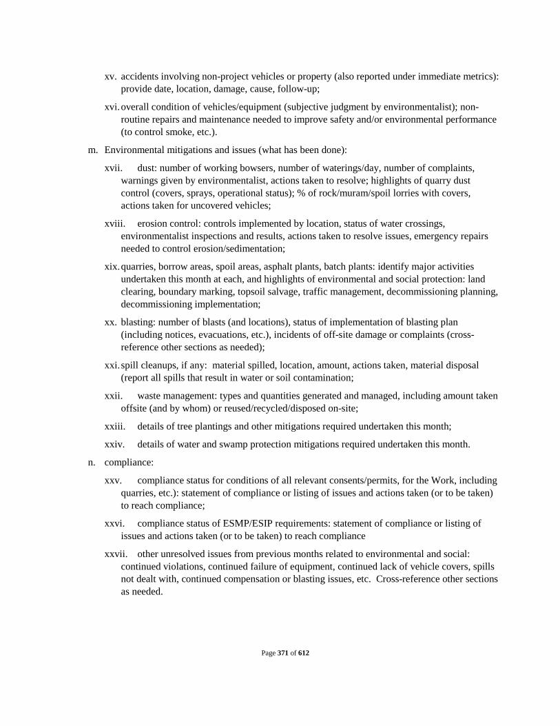
Page 371 of 612
xv. accidents involving non-project vehicles or property (also reported under immediate metrics): provide date, location, damage, cause, follow-up;
xvi. overall condition of vehicles/equipment (subjective judgment by environmentalist); non-routine repairs and maintenance needed to improve safety and/or environmental performance (to control smoke, etc.).
m. Environmental mitigations and issues (what has been done):
xvii. dust: number of working bowsers, number of waterings/day, number of complaints, warnings given by environmentalist, actions taken to resolve; highlights of quarry dust control (covers, sprays, operational status); % of rock/muram/spoil lorries with covers, actions taken for uncovered vehicles;
xviii. erosion control: controls implemented by location, status of water crossings, environmentalist inspections and results, actions taken to resolve issues, emergency repairs needed to control erosion/sedimentation;
xix. quarries, borrow areas, spoil areas, asphalt plants, batch plants: identify major activities undertaken this month at each, and highlights of environmental and social protection: land clearing, boundary marking, topsoil salvage, traffic management, decommissioning planning, decommissioning implementation;
xx. blasting: number of blasts (and locations), status of implementation of blasting plan (including notices, evacuations, etc.), incidents of off-site damage or complaints (cross-reference other sections as needed);
xxi. spill cleanups, if any: material spilled, location, amount, actions taken, material disposal (report all spills that result in water or soil contamination;
xxii. waste management: types and quantities generated and managed, including amount taken offsite (and by whom) or reused/recycled/disposed on-site;
xxiii. details of tree plantings and other mitigations required undertaken this month;
xxiv. details of water and swamp protection mitigations required undertaken this month.
n. compliance:
xxv. compliance status for conditions of all relevant consents/permits, for the Work, including quarries, etc.): statement of compliance or listing of issues and actions taken (or to be taken) to reach compliance;
xxvi. compliance status of ESMP/ESIP requirements: statement of compliance or listing of issues and actions taken (or to be taken) to reach compliance
xxvii. other unresolved issues from previous months related to environmental and social: continued violations, continued failure of equipment, continued lack of vehicle covers, spills not dealt with, continued compensation or blasting issues, etc. Cross-reference other sections as needed.

Page 372 of 612
Schedule 3
Operation and Maintenance Services Schedule
TO (I) DESIGN AND BUILD SEWAGE TREATMENT PLANTOF INSTALLED CAPACITY 32 MLD AND ALL APPURTENANT STRUCTURES AND ALLIED WORKS IN TWO MODULES (16MLD+16MLD);(II) SURVEY, REVIEW THE DESIGNS, REDESIGN WHERE NECESSARY, AND BUILD NEW DIVERSION WORKS WITH INTERCEPTION WITH RISING MAIN 2.3 KM, NEW TAPPINGS OF LENGTH 18.95 KM FOR 39 DRAINS CONTROLLED WITH SCADA INCLUDING SURVEY, DESIGN, CONSTRUCTION OF 5 NO. PUMPING STATIONS AND ALL APPURTENANT STRUCTURES AND ALLIED WORKS; AND CONSTRUCTION OF 31 OUTFALL STRUCTURE WITH SLUICE GATE INCLUDING EFFLUENT CHANNEL (250 MTR) FOR REUSE OF TREATED WASTE WATER (III) OPERATION & MAINTENANCE OF THE COMPLETE WORKS OF SEWAGE TREATMENT PLANT, INTERCEPTION & DIVERSION WORKS AND PUMPING STATIONS FOR A PERIOD OF 15 YEARS IN CHHAPRA TOWN , STATE OF BIHAR , INDIA.

Page 373 of 612
ARTICLE 1. Introduction The Operator shall ensure the Operation and Maintenance of the STP, I&D Works, Pumping Stations and other allied works in compliance to the guidelines contained in the Manual on “Sewerage & Sewage Treatment”, latest edition as published by the Central Public Health Environmental Engineering Organization (CPHEEO), Ministry of Urban Development, Government of India, New Delhi and the prescription laid down hereunder.
ARTICLE 2. Scope of Work
For STP 2.1. Operate the STP, for a period of 15 years as specified below:
2.1.1. General Scope
a. The Operator shall operate and maintain the STP under the Contract complete including the road works, landscaping, civil/structural, mechanical components, instrumentation system, Electrical System, all utility and ancillary buildings for the period of ten (10) years from the date of successful completion of "Tests after Completion of the Works".
b. The Operator shall make his own arrangements at his own cost for Works operation personnel, lubricants, diesel, spares, tools and tackles, routine maintenance, screenings collection, desilted material collection, transportation and disposal, co-ordination with respective pollution control board, agency supplying power to the STP, and any other activity required for the operation and maintenance of the constructed Works in full compliance with all applicable rules, regulations, laws, codes, effluent quality requirements and any other limitations.
c. Carrying out continuous flow measurements and recording of treated & untreated sewage at outlet and inlet of STP, regular calibration, cleaning, maintenance and replacement when required of measuring devices;
d. Collecting samples of influent and effluent and analyzing & testing them on a daily basis (inhouse) and getting tests done at weekly basis from [The EA should specify here the independent laboratory like the one under the control of State PCB, etc.]to determine the quality of sewage and performance of the treatment plant. Minimum 3 grab samples representative of different flow conditions (quantum and quality wise) in the day of the treated effluent shall be drawn every week jointly by the Owner and the Operator and the results of the test report shall be binding on both the parties.;

Page 374 of 612
e. Take all necessary measures to minimize the power consumption in carrying out its operations.
f. operate electrical equipment during power failures by making appropriate alternative arrangements,
g. Store or dispose: (i) the Residual Matter obtained after the processing and treatment of the Sewage such as sludge, grit, waste screens etc.; and (ii) the Residual Treated Water obtained from treatment of Sewage in a manner which is compliant to all applicable environmental laws and rules;
h. The Operator shall submit a weekly report to the Owner detailing the Operation and Maintenance indicating the labour hours expended, Electrical Power Consumed and other Consumables consumed and also problems faced and rectified.
i. The Operator shall submit detailed schedule/manual of all O& M activities with references of equipment manufacturers’ maintenance schedules/manuals to the Owner for review and approval.
j. The Operator shall submit Guidelines and Instructions manual for the maintenance staff of all levels for all the tools, plants and equipment and Operating STP to maintain the service levels within the standards prescribed within the contract;
k. The Operator shall carry out all O&M activities as per the approved Operation and Maintenance Manuals.
l. During the Operation and Maintenance period, the Operator shall ensure that the sewage detention time in wet well not exceeds 30 min. and there is no backflow of sewage.
m. The Operator’s responsibility shall also include the safety and security of the Works during the course of Operation and Maintenance.
n. Acquire and maintain sufficient stock of consumables such as chemicals, algal nutrients, safety gear, grit screens etc. and procure necessary electrical and mechanical equipment required for operations and maintenance of STP to ensure continuous operations.
o. Establish a Project office to manage the Project. The Project office can be located at the sewage treatment plant campus or at any other appropriate location where land is made available by the Owner.
p. All Project sites shall be well secured and kept in a clean and hygienic condition with sufficient measures for safety and security of man-power, built structures, equipment and other system components.
q. During Operation and Maintenance period, the Operator shall appoint an Operator and Electrical/Mechanical Technician. In addition, the Operator shall appoint suitable

Page 375 of 612
number of operators, drivers, cleaners,fitters, electricians, helpers, gardeners, office peons, security guards, labourers as required for the operation and maintenance of complete proposed STP for three shifts and adequate other staff / supporting personnel during general Shift. Security of man-power, built structures, equipment and other system components
2.1.2. General Scope
a. To Operate and maintain the sewage treatment plant, all instruments and mechanical, electrical equipment in accordance with the aim and purpose of treatment. The plant &equipment covered under the above contract will be totally attended to, by the Operator including any “Troubleshooting” to ensure smooth and trouble free operation.
b. The Operator will monitor the performance of the sewage treatment plant; conduct the analysis of the inlet sewage and water quality after treatment. Operator shall initiate and take adequate actions to ensure smooth and satisfactory performance / running of the plants on a 24 hours / round the clock basis.
c. The Operator shall prepare and implement an effective plant maintenance programme in consultation with the Owner. It is an absolutely operator’s responsibility to look after all sorts of maintenance whether preventive, Minor, Major, or break-down
d. The Operator will determine operating parameters, select settling (Chemical doses etc.) and generally optimize the process, and working of the treatment plant. Excessive chemical dozing i.e. dose more than normal should be avoided otherwise penalty shall be levied and recovered from the Operator.
e. The Operator should plan & procure all spares, Polyelectrolyte and all consumables including chemicals, grease, lubricating oil, cleaning agents, laboratory reagents etc. Further the Operator will plan about the requirement well in advance (At least 4 months) and procure the material from the market.
f. The Operator will be responsible for keeping up-to-date record of documents including History Card for equipment and maintaining every day log book relating to various analysis performed.
g. The Operator shall maintain and update logbook, in which details of operational parameters are recorded in every shift and at regular interval say hourly or as decided mutually.
h. The Operator will prepare and submit a daily report of plant performance and will assist the Owner in preparing the necessary documents for their purpose and records.

Page 376 of 612
i. The Operator will be responsible to carry out day to day periodic maintenance, necessary to ensure to smooth and efficient performance / running of all equipment / instruments comprising the sewage treatment plant and maintaining the record of the same.
j. The Operator shall have to issue identity cards with photographs to all the staff employed for Operation and Maintenance. The list of the same shall be submitted to the Owner mentioning qualification & experience.
k. The Operator will also be responsible to carry out day to day Maintenance of the rising main inside the STP premises.
l. The Operator will employ minimum staff for operation and maintenance of the Plant as per the list mentioned in the detailed scope of work.
m. The above staff shall be distributed in three shifts as per mutual agreement between Operator and Owner As per agreement the number of staff in each shift should always remain present otherwise penalty towards absence of any staff shall be recovered from the Operator as per Volume-I GCC . The Operator shall make the arrangement of reliever for weekly off/holiday etc. Absence on any ground like weekly off or holiday shall not be considered. The presence of staff in each shift should be marked in muster to be maintained at office of shift in charge at Sewage Treatment Plant that shall be considered as final. The Operator’s staff must mark their presence in this muster. The Operator may maintain a separate register for his own purpose.
n. The staff of Operator will always remain in contact with the Junior Engineer, Assistance Engineer/Electrical Supervisor, in charge of the Plant deployed by the Owner and follow their instruction.
o. Unsatisfactory and inefficient running of the plant and unnecessary and excessive usage of spare, consumable, etc. supported by the reasons which are under control of Operator will be highly objected. In such cases Engineer-in-charge’s decision will be final and binding to the Operator.
p. It is required that at least once in every one month a technical expert other than the Monthly Staff of the Operator will visit the plant and will suggest if required, to improve the efficiency and working of the plant etc. No separate payment will be made for such visits. The visit must be recorded and outcome of the visit/minutes of the meeting should be got signed by Owner authorities without which the visit shall not be considered.
q. Operator will comply with all safety rules and regulations as followed by the Owner.

Page 377 of 612
r. The Owner will not be responsible for any accident /injury to the staff of the Operator. Further the Owner will not provide any insurance or medical facility to the staff of Operator. The responsibility lies with the Operator.
s. All Central/State Government / Semi-Government / Local Body’s Rules and Regulations pertaining to this contract shall be followed and observed by the Operator without any extra cost to the Owner.
t. No accommodation / guesthouse / transportation facility will be provided by the to the Operator. Operation & maintenance staff will not be allowed any accommodation facility inside the plant premises.
u. The duration of the O&M shall be 120 months from the date of successful commissioning of the STP. The same can be extended for the further period if the Owner so desires. The Operator should employ all the staff within two days of successful commissioning. The Operator will provide the necessary tools and tackles required for day-to-day maintenance.
v. The scope of work also includes cleaning of complete plant area including floor, toilet block railing, door, windows, light fixtures and ceiling etc. The entire premises of the plant area shall also be cleaned and maintain by the Operator regularly.
w. This work is inclusive of but not limited to operation, maintenance, housekeeping, cleaning, removing sludge by its own carrier arrangement & disposes it off as per Owner’s instructions. Preparing data recording, correspondence work to Owner and Government Departments, etc. All this work should be done as per standard practices and by following labour, factory, electrical, STATE PCB, and all other latest updated regulations, Indian standards etc. as applied of Local, State and Central Government of India.
x. The Operator will not employ persons who are , pronounced guilty or charged with indiscipline.
y. Right is reserved by Owner of suspension, dismiss ion, termination of any officer / staff employed by Operator. He shall have taken prior permission to employ or to terminate his personals.
z. No watch and ward, safety insurance, security, storage, housing accommodation etc. will be provided by Owner. This will be responsibility of Operator.
aa. Consumable items like rubber bush, graphite packing, rubber sheet, nut-bolts, material required for cleaning and housekeeping etc. are to be brought by the Operator.
bb. Monitoring should be done as per guideline given by Engineer-in-charge. Operator has to maintain all the parameter of effluent within stipulated limit or he will be penalized for not maintaining the parameters given by STATE PCB and Owner. All expenditure incurred for the same like, suite fee, court fee, case fee, or

Page 378 of 612
the penalty as decided by Engineer of Owner and penalty charged by STATE PCB will be charged to Operator and deducted from his bills, S.D etc.
cc. Operator shall have to test the effluent / influent at his own cost at the plant lab on daily basis. The same be verified by and checked by Owner whenever required. The Operator shall also have to test the effluent / influent at STATE PCB lab for different parameter on weekly basis at his own cost.
dd. No equipment shall remain ideal or un-attended or damaged for the period of 3 days..
ee. The payment of O & M charges will be made as per the tender conditions. The other terms and condition described in these complete tender documents, wherever applicable shall remain unchanged. In case of any discrepancy the decision of Engineer-In-Charge will remain final & binding on the Operator.
ff. During Operation & Maintenance period, Operator has to supply all the spares, at his cost during preventive, major-minor breakdown, replacement and maintenance work. No extra payment will be made for such maintenance on any ground. The payment for the same will be made strictly as per tender document irrespective of the number of break down / minor, major repairs replacements. During the O & M Operator will have to enter annual maintenance agreement with Manufacturers of all major Mechanical Equipments like Centrifuge, Air Blowers, Screens, Decanters etc.
gg. Operator will have to maintain required Power Factor as per STATE EB rules and regulations. Incase penalty is levied by STATE EB for not maintaining the Power Factor the same will be recovered from the. Operator
hh. Maintenance of Garden, Lawns, Plants, Bushes, Plantation of new Plants, Lawns etc. and feeding, gardening, cleaning etc. is in the scope of the Operator. No separate payment will be made for the same.
ii. The Operator during his O&M period will have to follow all the guidelines set by STATE PCB for Operation & Maintenance of STP.
jj. Operation and maintenance of all General facilities and utility services including all other components of work done under this contract.
kk. Operation and maintenance of PLC based automation system and all instruments installed in the STP including all repairs, replacements towards the entire instrumentation works during the O & M period shall be in the scope of Operator.
ll. Any other services required for smooth running of the scheme.
mm. The Operator shall also dispose off the sludge, screenings, grit and any other material, as per specifications and to the satisfaction of the Engineer-in-Charge. It

Page 379 of 612
is to be noted that all costs during the O&M period, excluding the cost of power and chlorine are to be borne by the Operator. The Operator is to ensure that the following guarantees are maintained during the operation & maintenance period:
i. for quality of treated effluent
ii. for consumption of chemicals
iii. for automation
nn. The Operator shall provide on job training to the Local body staff as per specifications.
oo. At the end of every 2(1/2) year of operation & maintenance period, an assessment of the condition of the plant has to be done by the Owner through third party inspection at Owner’s cost and based on that assessment the Operator shall, at no extra cost to the Owner, repair and re-condition all the mechanical equipment in the concluding year of the O&M contract to a condition so that they are in running condition with regular preventive and recommended maintenance as per manufacturer's recommendations or as per CPHEEO manual.
pp. Variability of through output: If the quantity of treated sewage from the Facility can be increased in the existing system without impacting the annual fixed costs to the Operator, the Operator shall comply with such requirements. For a sustained requirement of higher throughout from the Facility, the Operator may be required to frame and submit a proposal that shall be implemented if mutually acceptable.
2.1.3. Treated Sludge Disposal
The Operator shall operate the Sewage Treatment Plant such that the sludge produced is of a spreadable consistency and the volume of sludge produced after necessary process is minimum. The sludge generated from the STP shall be disposed of through proper approved means of transport to the Compost yard site as designated by the Owner
2.1.4. Chemical Requirements
All chemicals consumed to operate the Sewage Treatment Plant and other facilities under this contract will be borne by the Operator.
2.2. Adverse Operating Condition
During which the raw sewage quality deteriorates beyond the Specifications in Volume I, the following provisions will be applicable
a. If the raw sewage can still be treated to meet the Output Standards, the Operator shall comply with such specifications.

Page 380 of 612
b. In the event it is not possible to meet the Output Standards, the Operator shall immediately inform the Owner.
c. In the event it is possible to meet the Output Standards, but an increase in fixed and variable costs is unavoidable, the Operator shall, as soon as practically possible, inform the Owner.
2.2.1. Alternate Output Standards;
The treated effluent output BOD, shall be maximum 7% of the influent BOD, the maximum period of adverse condition is 30 days.
2.3. Output and Operational Guarantees
The Operator is fully responsible for treating all the Sewage reaching the Receiving chamber. The performance of the Operator shall be treated as unsatisfactory if he fails to treat the complete sewage or does not maintain the guarantees listed in this clause excepting in force majeure condition or fails to fulfill other conditions of the contract.
2.4. Treated Effluent Quality
The Operator shall operate the Sewage Treatment Plant in such a way that the treated effluent quality attains the following parameters:-
S. No
Parameters Parameters Limit
(Standards )
Location
1 pH 6.5 – 9.0 Anywhere in the Country
2 BOD (mg/l) Not more than 20
Metro Cities*, all State Capitals except in the State of Arunachal Pradesh, Assam, Manipur, Meghalaya, Mizoram, Nagaland, Tripura, Sikkim, Himachal Pradesh, Uttarakhand, Jammu & Kashmir, and Union Territory of Andaman and Nicobar Islands, Dadar and Nagar Haveli, Daman & Diu and Lakshadweep
BOD (mg/l) Not more than 30
Areas/regions other than mentioned above
3 TSS (mg/l) Not more than 50
Metro Cities*, all State Capitals except in the State of Arunachal Pradesh, Assam, Manipur, Meghalaya, Mizoram, Nagaland, Tripura, Sikkim, Himachal Pradesh, Uttarakhand, Jammu & Kashmir, and Union Territory of Andaman and Nicobar Islands, Dadar and Nagar Haveli, Daman & Diu and Lakshadweep

Page 381 of 612
TSS (mg/l) Not more than 100
Areas/regions other than mentioned above
4 Fecal Coliform
(MPN/100ml)
Less than 1000
Anywhere in the country
*Metro cities are Delhi, Mumbai, Kolkata, Chennai, Bengaluru, Hyderabad, Ahmedabad and Pune
2.4.1 Treated Sludge Disposal
The Operator shall operate the Sewage Treatment Plant such that the sludge produced is of a spreadable consistency and the volume of sludge produced after necessary process, is minimum. The sludge generated from the STP shall be disposed off through proper approved means of transport to the place / yard site as Designated by the Owner
2.4.2 Undertaking capacity building measures:
Conduct a training and handholding assistance programme for six months in aspects of Operation and Maintenance of the Sewage Treatment Plant for maximum fifteen employees of the ULB.
2.5 Tests to be under taken dur ing the operations per iod:
The Operator should get analyzed / checked the untreated as well as treated sewage samples every week from respective pollution control authority/ Laboratory specified by Ownerfor parameters mentioned in Section 2.4. The necessary testing charges are to be borne by the Operator.
The parameters shall also be tested daily inhouse by the operator.
2.6. Staff:
The qualification and experience of the personnel required for O & M are specified below. However, the Operator shall mention the personnel proposed for O&M in his bid.
S. No.
Key Staff Nos. Required
Minimum Qualifications
1. Manager 1 Degree in Civil Engineering / Mechanical Engineering with minimum 5 years’ experience in Operating

Page 382 of 612
S. No.
Key Staff Nos. Required
Minimum Qualifications
&Maintaining a sewage treatment plant
2. Shift Engineer
1
B. Tech in Civil / Mechanical Engineeringwith 2 years’ experience or Diploma in Civil/Mechanical Engineering with 5 years’ experience in managing STPs
3. STP Operators
2 Diploma in Civil / Mechanical. Engineeringwith 2 years’ experience in Operating STPs
4. Electro – mechanical engineer
1
(Degree in Mechanical /Electrical Engineering with minimum 1 years’ experience in Operating /Maintaining STP)
5. Plumbers / fitters
1
Experience in laying / maintaining and operating TP and related electromechanical works for afor a minimum of 1 year.
6.
7.
8.
9. Helpers 2 -
10. Security and Housekeeping
3 -
The work shall be carried out on a 24 hr. basis, without intermission and the staff deployed by the Operator shall be in accordance with this contract.
a. The Operator shall give or provide all necessary superintendence during the O&M and as long thereafter as the Owner may consider necessary. Such superintendence shall be given by a competent person having adequate knowledge of the operation and Maintenance to be carried out (including the methods and techniques required),

Page 383 of 612
the hazards likely to be encountered and methods of preventing accident) as may be required for the satisfactory working of the entire plant.
b. No labor below the age to 18 years shall be employed on the work. List of staff is to be given by the agency to the Owner and advance intimation to be given before deputing/removing any staff from site during the period of contract. Not more than one of the Operator's key staff shall be absent from the Project site at any given time. In case it is necessary for more than one of the key personnel to be absent at a given time, the Operator shall provide replacement of equivalent or better qualifications. The CVs of such key staff replacements shall be got approved from Owner in advance.
c. Owner shall be authorized to direct the contracting agency to remove any or all staff employed on O&M of the STP if in his opinion continued presence of such staff is detrimental to safety or proper O&M of the STP. The Operator shall comply with such directions & post suitable substitute(s) thereof. Whenever the Engineer has to inform the Operator in writing that any person on the work is in his opinion unsatisfactory or/incompetent or unfaithful or dishonest, untruthful or disorderly or to be otherwise unsuitable/such person shall be discharged by the Operator from the work and shall not be employed again on it.
2.7. Reporting and Record Keeping:
a. Maintain a periodical reporting system to provide access and retrieval of Sewage Treatment Plant operating data including all such information which is necessary to verify costs and expenses incurred and otherwise to confirm that the Operator is in compliance with its obligations under the terms and conditions of this Contract;
b. The Operator will prepare daily and monthly reports (in Owner format) of pumping/treatment and project performance and submit to the Engineer-in-Charge and will assist the department in preparing the necessary documents for their purpose and record as per proforma given from time to time. The reports shall contain, inter-alia, the following:
c. Raw Sewage quantity and quality and effluent quality as per the on-line monitoring programme and other tests as specified in Clause 3.0 of this section and print outs of online monitoring shall be submitted to Engineer-in charge.
d. A description of the maintenance work carried out in the reporting period.
e. A report on major failures, if any, their causes and remedial actions taken.
f. Sludge quality and quantity (daily basis) in the reporting period.
g. Power and chemicals consumed in the reporting period.

Page 384 of 612
h. An inventory of the chemicals and spare parts available at the end of the reporting period.
i. O&M staff deployed by the Operator during the reporting period. Any major repair works, if any.
a. Operator shall maintain separate register/computerized records at all sites of following information:
1. Pumping register
2. Quantity of sewage treatment and performance register D
3. Working hours register
4. Electric break down register
5. Maintenance register
6. Staff attendance register
7. Equipment breakdown, repair record and extent of repair
8. Chlorination equipment and chlorine toner operating and using register
b. The Operator shall maintain a record for the entire Term of the following:
1. status or progress report of the operation and maintenance of each of the Sewage Treatment Plant components;
2. record of all consumables, tools, equipment’s manhole covers, etc. used / replaced towards operations and maintenance of the STP;
3. report certifying that the quality and quantity of the Residual Treated Water at the Discharge Point;
4. daily readings of the meters at the Receipt Point;
5. daily readings of the meters at the Discharge Point;
6. methods of disposal used for Residual Matter; and
7. Nature and scope of any ancillary activities being carried out in accordance with the terms and conditions of this Contract.
8. Provide reports on accidents in respect of the Sewage Treatment Plant, if any
9. Daily readings of the meters at the inlet of the STP;
10. Nature and scope of any ancillary activities being carried out in accordance with the terms and conditions of this Contract; and
11. Provide reports on accidents in respect of the Sewage Treatment Plant, if any.
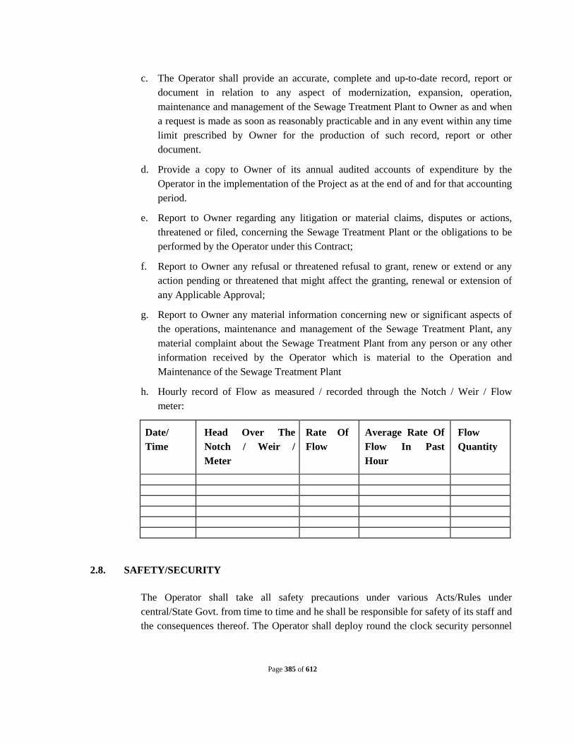
Page 385 of 612
c. The Operator shall provide an accurate, complete and up-to-date record, report or document in relation to any aspect of modernization, expansion, operation, maintenance and management of the Sewage Treatment Plant to Owner as and when a request is made as soon as reasonably practicable and in any event within any time limit prescribed by Owner for the production of such record, report or other document.
d. Provide a copy to Owner of its annual audited accounts of expenditure by the Operator in the implementation of the Project as at the end of and for that accounting period.
e. Report to Owner regarding any litigation or material claims, disputes or actions, threatened or filed, concerning the Sewage Treatment Plant or the obligations to be performed by the Operator under this Contract;
f. Report to Owner any refusal or threatened refusal to grant, renew or extend or any action pending or threatened that might affect the granting, renewal or extension of any Applicable Approval;
g. Report to Owner any material information concerning new or significant aspects of the operations, maintenance and management of the Sewage Treatment Plant, any material complaint about the Sewage Treatment Plant from any person or any other information received by the Operator which is material to the Operation and Maintenance of the Sewage Treatment Plant
h. Hourly record of Flow as measured / recorded through the Notch / Weir / Flow meter:
Date/ Time
Head Over The Notch / Weir / Meter
Rate Of Flow
Average Rate Of Flow In Past Hour
Flow Quantity
2.8. SAFETY/SECURITY
The Operator shall take all safety precautions under various Acts/Rules under central/State Govt. from time to time and he shall be responsible for safety of its staff and the consequences thereof. The Operator shall deploy round the clock security personnel

Page 386 of 612
at entrance of plant’s premises and in the compound for the safety of the plant and premises for the safety of the plant, equipment and personnel during this period.
2.8.1. Responsibility for damages
a. The care of the whole of the permanent works shall remain with the Operator who shall be responsible for all accidents or damages from whatever cause arising and chargeable for anything that may be stolen, removed destroyed or damaged to whomsoever belonging and also for making good all defects and damages to the said works or to any property adjoining or any cause whatever, whether such damage or defects were occasioned by the negligence of the Operator or not or may be or might have been discovered during the progress to be known after the completion whereof or whether payment may wholly or partially have been made or the works approved as supposed to have been properly done and no certificate of approval of any works by any officers or members of the Board shall affect or prejudice the right of the STATE PCB against the Operator or be considered or held as at all conclusive as to the sufficiency of any work materials.
b. Adequate safety precautions against fire, flooding, lightening, electrical shocks, accident due to moving/non-moving heavy/light equipments shall be strictly observed by the Operator at his own cost. Suitable safety measures like gumboots, gloves, safety belts, ladders, safety lamps, gas masks, Oxygen apparatus, insulated tools, alarms etc. shall be provided by the Operator. Necessary medical first aid kit shall be made available all the time. In absence of observance of above safety precautions, the Operator shall be responsible for any unforeseen loss of the equipments or persons dealing with it. Special care shall be taken by the Operator while carrying out the work in sewage gas zone. Any incidence of human life or accident will be totally Operator’s responsibility.
c. The Operator shall ensure that the staff employed takes all necessary precautions while carrying out the work either in shift duties or any general shift as per Indian Electricity Rules/Factory Act/CPHEEO Manual, or manufacturer's special instruction for safety / gas handling. The staff should use Gas masks, Oxygen apparatus, Gum Boots, Safety Belts and Safety Lamps, etc. while carrying out the work in Bar Screens, sumps etc.
d. The Operator will make arrangement for all necessary safety equipments for persons working at STP as per Factory Act/Safety Rules. In the event of any accident on or off site, in which the Operator or his personnel are involved, in which an injury occurs to any person whether directly concerned with the project or a third party, the Operator shall inform Owner within 24 hrs. of the occurrence of the event. The plant

Page 387 of 612
will be open to local/state/central agencies for verification of safety/emission/acts compliance.
e. During night hours, the main gate should be locked. However, shift duty staff should be alert and open the gate during surprise checking of Owner staff or any other Government Authorities or his nominee without any wait. Only bona-fide persons be allowed in the plant premises being a prohibited area. Smoking and drinking are prohibited in the plant. The staff engaged shall wear common uniform with name plate indicating name and designation during duty hours.
2.9. Operation and maintenance manual
a. The Operator shall prepare a detailed program (referred to as O&M Manual) covering the operation and maintenance of the treatment plants as a whole. This program shall include the work and activities described in this Chapter, as relevant to the specific items and technology.
b. The Operator shall provide 6 copies of draft O&M Manual to the Owner, at the time of the commissioning of the Project and on approval of draft, 10 copies of operation &maintenance manual shall be supplied by the Operator.
c. The O&M Manual shall include the daily, weekly, monthly, quarterly, half yearly and annual checks and remedies if necessary to be performed for effective operation of the plant, elaborate detail, all operating and maintenance procedures and policies which are required, advisable and / or necessary for the Facility to achieve full compliance with the operational guarantees and to achieve maintenance and repair standard for the Facility which will ensure compliance with the maintenance specifications. The O&M manual shall include interalia full explanation of all plant procedures and processes.
d. Without limiting the generality of the foregoing the O&M Manual shall include descriptions, procedures and shall comply with the requirements, set forth in the provisions of the Bid Documents.
e. The draft of the O&M Manual shall be subject to the review and approval of Owner, which shall have the right to make any changes and revisions to the O&M Manual as it may deem appropriate. The Operator shall revise such draft O&M Manual prior to the commencement of the O&M period.
f. At the end of the construction period, the Operator shall revise the draft O&M Manual to reflect any updates, changes or revisions it deems appropriate, inter-alia based on its experience and as necessary to reflect any modifications or adjustments to the plant. Without limiting the above, the Operator shall annually fully review, revise, update and modify the draft O&M Manual as may be necessary or

Page 388 of 612
appropriate. Any revision to the draft O&M Manual shall be subject to the review and approval of Owner.
g. Owner shall have the right to require revisions to the draft O&M Manual as it may deem appropriate. The Operator shall prepare and submit to Owner, for its review and approval, 30 days prior to the proposed date of commencement of O&M, a revised draft O&M Manual which reflects all changes, revisions and modifications. The Operator shall prepare the O&M Manual, as approved by the Owner, prior to the start of O&M.
h. During the term of this Agreement, the Operator shall promptly notify Owner of any revisions, additions or modifications which he, in his professional opinion, believes should be made to the O&M Manual, whether as a result of additional experience in operating and maintaining the Facility, changes in influent quality or volume, changes or modifications to any equipment part, component or structure incorporated in the Facility.
i. Such notification shall set forth the reason for the proposed revision. Any proposed revision shall be subject to the approval of the Owner. In addition, during the term of this Agreement, Owner shall have the right to require relevant changes, revisions, or additions to the O&M Manual as it, shall deem appropriate to ensure full compliance with the O&M Standards.
j. The Operator shall submit 10 copies of the final O & M manual along with a soft copy in Microsoft Word Format.
2.10. Technical Audit
a. The Owner has the right to conduct a technical audit of the Facility and to perform any analysis or inspection he deems necessary. The Operator shall at his cost provide all assistance the Owner required to complete these inspections. Such audits may cover all or any of the obligations of the Operator, including without limitation,
a. Verification of the system capacity and save for normal wear and tear during the O&M Period
b. Verification of the performance standards and useful life of the individual assets of the Facility, save for normal wear and tear during the O&M Period
c. Verification of the capacity of the Facility to meet Output Standards during the residual life of the Facility and save for normal deterioration expected during such residual life
d. Sampling, testing and verification of the Output Standards for treated sewage, sewage losses

Page 389 of 612
2.11. Facility Visits
a. At any time or at the end of each twelve month period, or at the initiative of the STATE PCB, a visit shall be organized so that both parties can check the condition of the installations at the facility.
b. A report shall be drawn up to record the opinions of the both parties. The STATE PCB reserves the right to call the equipment manufacturers or specialized technicians for these visits. All expenses are to be borne by the Operator for the purpose.
2.12. Maintenance schedules
a. The Operator shall prepare and follow a Maintenance plan, detailing the maintenance activities scheduled for each of the component of the STP on a periodic approved by Design-Build-Operations Engineer and / or the Owner.
b. Every part of the works and all the materials to be used therein shall be subjected to such tests from time to time during the execution of the work as the Owner may direct and the whole of such tests shall in all cases be made at the Operator’s sole expense.
c. The work shall be carried on and completed under the exclusive control direction and supervision and to the satisfaction of the Owner. The Owner shall likewise have full power to reject or condemn any work or material that he may deem unsuitable. In case of any work or material being rejected by the Engineer in-charge, the Operator shall immediately remove and replace the same to the satisfaction of the Owner or the Owner shall have full powers to get the same removed and replaced and deduct the expenditure incurred in the process from any amount due or that may become due to the Operator.
d. The Operator shall use only the original and genuine spares of the original equipment as per recommendations given in the maintenance booklet of the manufactures/as per directions of the Owner. Adequate stock of such spares is to be maintained by the Operator. Test certificate of manufacturer is required for bearings along with supplies. Test certificate of all major equipment will be submitted from the manufacturer.
e. The Operator shall also be responsible to maintain cleanliness in around the plant including machineries, disposal of floating removed from the Bar Screens/reactors, etc. Grit and other unwanted material.
f. If any material brought to the site of works, be in the judgment of the Engineer, found inferior or improper & not as per described standards, the said materials or workmanship shall where required by the Owner shall be removed or amended by

Page 390 of 612
the Operator forthwith or within such period for every breach by the Operator in this clause.
g. All leakages should be attended promptly to avoid any nuisance etc. Chokages should be removed at once. All the valves/gates which are not used regularly should be operated at least once a week and make sure that they are properly lubricated /greased.
h. All safety valves should be checked daily and ensure that they are working properly. In case of any fault the same should be attended immediately without any wait. The maintenance of the plant shall be as per maintenance manuals of the manufacturer for all equipment. Operator shall keep all the safety devices in working order.
i. All the steel structures and machines installed in open areas should be painted after every monsoon period after cleaning the surface as per the instructions of the Engineer- in-charge. Entire plant including all civil structures, mechanical equipment, HT panel and Transformers etc. shall be repainted after every 2(1/2) years as per original painting specifications.
j. All safety valves should be checked daily and ensure that they are working properly. In case of any fault the same should be attended immediately without any wait. The maintenance of the plant shall be as per maintenance manuals of the manufacturer for all equipment. Operator shall keep all the safety devices in working order.
k. The Operator should make sure that no unwanted material should float/grow in and around different units. In case it is found the same shall be removed /cleaned immediately. He shall also be responsible for cleaning/sweeping the plant buildings inside and outside, roads, foot path etc.
l. Launders/Weirs etc. of reactors etc. to be maintained clean round the clock. During preventive/ breakdown maintenance, the Operator has to visit the unit/units as and when needed. The pumping units or other machineries required if any shall have to be arranged by the Operator at his own costs for completing the work. In case of battery operated auto system panels and also system alarm etc., batteries are required to be maintained and replaced as and when needed by the Operator.
m. Consumables such as POL (petrol/Diesel Oil & Lubricants) etc. has to be arranged by the Operator as and when needed as per manufactures recommendations for periodical maintenance of entire Network. The Owner shall not provide such items.
n. In case of major repair due to normal wear and tear/break down, the Operator should bring the same to the notice of the Owner immediately and necessary measures for its repair should be taken simultaneously. Breakdown, all repairs of any kind are to be attended by the Operator. Any unit/equipment being irreparable in the opinion of the Owner will be replaced by the Operator at no cost to Owner.

Page 391 of 612
o. The Operator shall give his telephone no., contact addresses, etc. to the Owner as well as shift duty shift to contact him during emergency/odd hours etc.
p. The Operator will be responsible to carry day to day as well as periodic maintenance, necessary to ensure smooth and efficient performance/running of all equipment instruments installed at the STP. He shall be responsible for maintenance/replacement of street light poles and light etc. also. All the plant, building land, Sewage treated/untreated/sludge, etc. shall remain the property of Owner.
2.12.1. Oil & Grease Schedule
a. Routine & preventive maintenance of electrical /Mechanical/ hydraulic/ machines & equipments is to be carried out as per the operation & maintenance manual. Minimum oil & grease requirement for one year Operation & maintenance of the Plant to be procured by the Operator well in advance
2.13. Routine, Preventive, Minor & Major maintenance of all Civil, Electrical, Mechanical, hydraulic machines & Equipment of the plant
a. The Operator should prepare schedule of daily maintenance & preventive maintenance of all the equipment & machineries operated & run by him in the premises of the plant. The schedule should be as per the guidelines mentioned in the tender &as per the O& M manual. The scope covers Routine, Preventive, Minor & Major maintenance of all major minor equipment and machines in the Plant like Submersible pumps, Coarse &Fine screens Grit Removal Mechanism, Channel gates, Decanters, Sludge pumps, Centrifuge feed pumps, Centrifuges, All dosing systems including Chlorine Dosing equipment, etc.
b. The scope also covers Routine, Preventive, Minor & Major maintenance of all the instrumentation system installed like PLC, Actuators, Flow meters level indicators etc. The Operator should also carry out Routine, Preventive, Minor & Major maintenance of all major minor electrical equipment like Electrical Panels, Switch Gears, Power Cables, Control cables, Changeover switches DG set etc. so as to ensure uninterrupted round the clock operation of the Plant.
c. The Operator should maintain all civil structures including Administrative building, Store room, Storm Drains, fencing etc. in a neat manner. He should maintain all civil structures of the plant sturdy to complete the natural/Designed lifetime.
d. The Operator should carry out the safety audit of the plant & necessary certificate from the competent authorities. This item includes all types of Routine, Preventive, Minor & Major maintenance of all Civil, Electrical, Mechanical, hydraulic machines & equipment of the plant covering supply erection test &trial run of the part/machine to be repaired/ replaced with material &labor expenses, necessary

Page 392 of 612
hardware’s, sundry materials, lubricant oils, power oils, grease other materials plus machining charges etc.
e. The Operator should procure all the spares required for all types of maintenances in advance. The part/equipment/machine to be repaired /replaced should be as per the Owner approved list & as per the O& M manual or as per the existing manufacturer’s brand.
f. The Operator, after first notifying the UPCB shall be responsible for fulfilling all requirements associated with any release of any substance into the environment (form the facility or the site) as required by Applicable law or by any Legal Entitlement including but not limit to the notification or reporting of releases /
g. Hazardous substances or Hazardous Waste. The Operator shall prepare a memorandum evidence such notification or reporting and provide copies thereof to the Owner, along with any documents provided to the relevant regulatory agency regarding such release.
h. The Operator shall process and obtain the clearance of all such agencies as required for the purpose, including all clearances during O&M period. He shall be fully responsible to comply with all requirements of Laws including hazardous substances, emission standards for air, discharge standards for effluent oil, sub-soil pollution. The contracting agency shall not release any hazardous/toxic materials inside the premises.
2.14. Site Order Book
Site order Book shall be kept by the Engineer -in-charge at the plant site. Orders entered in this Book by the Engineer-in-Charge or his authorised representative shall be held to have been formally communicated to the Operator. The Engineer-in-Charge or his authorised representative shall sign each order as it is entered and will hand over the duplicate to the Operator or his agent, who shall sign the original in acknowledgment of having received the order
FOR I&DWORKSAND SPS
2.15. Operate the Sewerage System, for a period of 15 years from the date of commissioning as specified below:
1. The Operator shall operate and maintain the Sewage Pumping Station (SPS), Lift Stations and Sewer networks under the Contract complete including the road works (liability of restored portions of roads is limited to 3 years only, however the operator will not be held responsible for road restoration required on account of

Page 393 of 612
damage done by other agencies/ utilities), landscaping, civil/structural, mechanical components, instrumentation system, Electrical System, all utility and ancillary buildings, SPS premises area, lift station, for the period of Fifteen(15) years from the date of successful completion of "Tests after Completion of the Works".
2. The Operator shall make his own arrangements at his own cost for staff required for operation and maintenance of networks and other assets, lubricants, diesel, spares, tools and tackles, sewer cleaning vehicles and other equipment maintenance of all types such as routine, breakdown, periodic and repair maintenance, replacement of demaged/ unserviceable sewers, maintenance of house service connections after building lanes, screenings collection; desilted material collection, transportation and disposal; co-ordination with State Pollution Control Board (SPCB), State Power Supply Utilities30
Charter of Services
authorities and any other activity required for the operation and maintenance of the constructed Works in full compliance with all applicable rules, regulations, laws, codes, effluent quality requirements and any other limitations. The operator will also maintain a Customer grievance redressal centre and ensure that O&M services meet the standards of services/ service levels maintained as follows:
SN Nature of complaints Time for rectification (in days)
Minimum Maximum 1 Sewerage overflow on
the road
2 Choking at household premises
3 Replacement of missing manhole cover
[The EA shall fill in the details in the Table above keeping in view the Performance Standards specified in Schedule 7, default from which will attract Liquidated Damages - Operation.]
3. The operator ensures that there is a steady and uninterrupted flow of waste water/sewage to STPs.
4. Identify and inform the Owner about the illegal connections on the Sewerage Network within seven days of its being detected.
5. The Operator shall submit a weekly report to the Owner detailing the Operation and Maintenance indicating the labour hours expended, Electrical Power Consumed and other Consumables consumed and also problems faced and rectified.
30Modify for appropriate SPCBs and Power Supply Utilities

Page 394 of 612
6. The Operator shall submit detailed schedule/manual of all O& M activities with references of equipment manufacturers’ maintenance schedules/manuals to the Owner for review and approval.
7. The Operator shall submit Guidelines and Instructions manual for the maintenance staff of all levels for all the tools, plants and equipment and Operating I&DWorksto maintain the service levels within the standards prescribed within the contract;
8. The Operator shall carry out all O&M activities as per the approved Operation and Maintenance Manuals.
9. If any consumer connection needs extension of sewer line during O&M period, from an existing line, the same will be designed and estimated by the operator using prevailing schedule of rates and market rates. Such costs will also include 15% towards supervision charges. The owner will collect the same and pays to the Operator for executing the same after the connection is formally approved. However, Owner will retain connection fee/ charges.
10. During the Operation and Maintenance period, the Operator shall ensure that the sewage detention time in wet well not exceeds 30 min. and there is no backflow of sewage. The operator is responsible for maintaining back up power arrangements at his cost to ensure that the O&M services are not affected due to failure of power supply from the Public Utility Company.
11. The Operator’s responsibility shall also include the safety and security of the Works during the course of Operation and Maintenance.
12. During Operation and Maintenance period, the Operator shall appoint an Operator and Electrical/Mechanical Technician. In addition, the Operator shall appoint suitable number of operators, drivers, cleaners, fitters, electricians, helpers, gardeners, office peons, security guards, laborers as required for the operation and maintenance of complete proposed sewerage system for three shifts and adequate other staff / supporting personnel during general Shift. Security of man-power, built structures, equipment and other system components.
a. Undertaking capacity building measures:
Conduct a training and handholding assistance programme for six months in aspects of Operation and Maintenance of the Project Facilities for maximum fifteen employees of the ULB.
b. Staff
1. The minimum personnel required for O & M is as given below. However, the Operator shall mention the personnel required for O&M in his bid. The work shall be carried out on a 24 hour basis without intermission and the staff deployed by the Operator shall be in accordance with this contract.

Page 395 of 612
[The staff requirement shown in the Table below is only indicative. The EA should review and modify the same according to the size of the network to be maintained.]
S. N. Key Staff Nos. Required Minimum Qualifications

Page 396 of 612
2. The Operator shall give or provide all necessary superintendence during the O&M and as long thereafter as the Owner may consider necessary. Such superintendence shall be given by a competent person having adequate knowledge of the operation and Maintenance to be carried out (including the methods and techniques required), the hazards likely to be encountered and methods of preventing accident) as may be required for the satisfactory working of the entire plant.
1 Manager 1
Degree in Environmental / Civil Engineering / Post Graduate in Water Supply & Sewerage Engineering Mechanical Engineering with minimum 10 years’ experience in Operating & Maintaining a Sewerage Network)
2 Engineer
Degree in Environmental / Civil Engineering / Post Graduate in Water Supply & Sewerage Engineering Mechanical Engineering with minimum 5 years’ experience in Operating & Maintaining a Sewerage Network)
3 Shift In charge Diploma / B.Tech. in Civil / Mechanical. Electrical Engineeringwith 3 years’ experience in managing Sewerage Network
4 SPS and Lift station Operators
Diploma / B.Tech. in Civil / Mechanical. Electrical Engineeringwith 2 years’ experience in Operating SPS and Lift Stations.
5 Electro – mechanical engineer
(Degree in Mechanical /Electrical Engineering with minimum 1 years’ experience in Operating /Maintaining any Sewerage Network and SPS)
6 Plumbers / fitters Experience in laying / maintaining and operating Sewerage Networks and SPS for a minimum of 1 year.
7 Sewer cleaning works and other support staff
-
8 Security and Housekeeping
2 -

Page 397 of 612
3. No labor below the age to 18 years shall be employed on the work. List of staff is to be given by the agency to the Owner and advance intimation to be given before deputing/removing any staff from site during the period of contract. Not more than one of the Operator's key staff shall be absent from the project site at any given time. In case it is necessary for more than one of the key personnel to be absent at a given time, the Operator shall provide replacement of equivalent or better qualifications. The CVs of such key staff replacements shall be got approved from Owner in advance.
4. Owner shall be authorized to direct the contracting agency to remove any or all staff employed on O&M of the I&DWorksif in his opinion continued presence of such staff is detrimental to safety or proper O&M of the I&D Works. The Operator shall comply with such directions & post suitable substitute(s) thereof. Whenever the Engineer has to inform the Operator in writing that any person on the work is in his opinion unsatisfactory or/incompetent or unfaithful or dishonest, untruthful or disorderly or to be otherwise unsuitable/such person shall be discharged by the Operator from the work and shall not be employed again on it.
c. Reporting and Record Keeping:
1. Maintain a periodical reporting system to provide access and retrieval of Project Facilities operating data including all such information which is necessary to verify costs and expenses incurred and otherwise to confirm that the Operator is in compliance with its obligations under the terms and conditions of this Contract;
2. The Operator shall maintain a record for the entire Term of the following:
a. status or progress report of the operation and maintenance of each of the Project Facilities;
b. record of all consumables, tools, equipment’s manhole covers, etc. used / replaced towards operations and maintenance of the I&D Works;
c. Daily readings of the meters at the Sewage pumping stations;
d. identification and reporting of illegal connections on the sewerage network;
e. Nature and scope of any ancillary activities being carried out in accordance with the terms and conditions of this Contract; and
f. Provide reports on accidents in respect of the Project Facilities, if any.
3. The Operator shall provide an accurate, complete and up-to-date record, report or document in relation to any aspect of modernization, expansion, operation, maintenance and management of the Project Facilities to Owner as and when a request is made as soon as reasonably practicable and in any event within any time limit prescribed by Owner for the production of such record, report or other document.

Page 398 of 612
4. Provide a copy to Owner of its annual audited accounts of expenditure by the Operator in the implementation of the Project as at the end of and for that accounting period.
5. Report to Owner regarding any litigation or material claims, disputes or actions, threatened or filed, concerning the Project Facilities or the obligations to be performed by the Operator under this Contract;
6. Report to Owner any refusal or threatened refusal to grant, renew or extend or any action pending or threatened that might affect the granting, renewal or extension of any Applicable Approval;
7. Report to Owner any material information concerning new or significant aspects of the operations, maintenance and management of the Project Facilities, any material complaint about the Project Facilities from any person or any other information received by the Operator which is material to the Operation and Maintenance of the Project Facilities
a. Operation and maintenance manual
1. The Operator shall prepare a detailed program (referred to as O&M Manual) covering the operation and maintenance of the I&D Works as a whole. This program shall include the work and activities described in this Chapter, as relevant to the specific items and technology.
2. The Operator shall provide 6 copies of draft O&M Manual to the Owner, at the time of the commissioning of the project and on approval of draft, 10 copies of operation &maintenance manual shall be supplied by the Operator.
3. The O&M Manual shall include the daily, weekly, monthly, quarterly, half yearly and annual checks and remedies if necessary to be performed for effective operation of the plant, elaborate detail, all operating and maintenance procedures and policies which are required, advisable and / or necessary for the Facility to achieve full compliance with the operational guarantees and to achieve maintenance and repair standard for the Facility which will ensure compliance with the maintenance specifications. The O&M manual shall include interalia full explanation of all plant procedures and processes.
4. Without limiting the generality of the foregoing the O&M Manual shall include descriptions, procedures; schedule of maintenance, and shall comply with the requirements, set forth in the provisions of the Bid Documents.
5. The draft of the O&M Manual shall be subject to the review and approval of Owner, which shall have the right to make any changes and revisions to the O&M Manual as it may deem appropriate. The Operator shall revise such draft O&M Manual prior to the commencement of the O&M period.

Page 399 of 612
6. At the end of the construction period, the Operator shall revise the draft O&M Manual to reflect any updates, changes or revisions it deems appropriate, inter-alia based on its experience and as necessary to reflect any modifications or adjustments to the plant. Without limiting the above, the Operator shall annually fully review, revise, update and modify the draft O&M Manual as may be necessary or appropriate. Any revision to the draft O&M Manual shall be subject to the review and approval of Owner.
7. Owner shall have the right to require revisions to the draft O&M Manual as it may deem appropriate. The Operator shall prepare and submit to Owner, for its review and approval, 30 days prior to the proposed date of commencement of O&M, a revised draft O&M Manual which reflects all changes, revisions and modifications. The Operator shall prepare the O&M Manual, as approved by the Owner, prior to the start of O&M.
8. During the term of this Agreement, the Operator shall promptly notify Owner of any revisions, additions or modifications which he, in his professional opinion, believes should be made to the O&M Manual, whether as a result of additional experience in operating and maintaining the Facility, changes in influent quality or volume, changes or modifications to any equipment part, component or structure incorporated in the Facility.
9. Such notification shall set forth the reason for the proposed revision. Any proposed revision shall be subject to the approval of the Owner. In addition, during the term of this Agreement, Owner shall have the right to require relevant changes, revisions, or additions to the O&M Manual as it, shall deem appropriate to ensure full compliance with the O&M Standards.
10. The Operator shall submit 10 copies of the final O & M manual along with a soft copy in Microsoft Word Format.
b. Maintenance schedules 1. The Operator shall prepare and follow a Maintenance plan, detailing the maintenance
activities scheduled for each of the component of the I&D Works on a periodic approved by Design Build Operations Engineer and / or the Owner.
2. Every part of the works and all the materials to be used therein shall be subjected to such tests from time to time during the execution of the work as the Owner may direct and the whole of such tests shall in all cases be made at the Operator’s sole expense.
3. The work shall be carried on and completed under the exclusive control direction and supervision and to the satisfaction of the Owner. The Owner shall likewise have full power to reject or condemn any work or material that he may deem unsuitable. In case of any work or material being rejected by the Engineer in-charge, the Operator shall immediately remove and replace the same to the satisfaction of the Owner or the

Page 400 of 612
Owner shall have full powers to get the same removed and replaced and deduct the expenditure incurred in the process from any amount due or that may become due to the Operator.
4. The Operator shall use only the original and genuine spares of the original equipment as per recommendations given in the maintenance booklet of the manufactures/as per directions of the Owner. Adequate stock of such spares is to be maintained by the Operator. Test certificate of manufacturer is required for bearings along with supplies. Test certificate of all major equipment will be submitted from the manufacturer.
5. If any material brought to the site of works, be in the judgment of the Engineer, found inferior or improper & not as per described standards, the said materials or workmanship shall where required by the Owner shall be removed or amended by the Operator forthwith or within such period for every breach by the Operator in this clause.
6. All the steel structures and machines, if installed in open areas, should be painted after every monsoon period after cleaning the surface as per the instructions of the Engineer- in-charge. Entire plant including all civil structures, mechanical equipment, HT panel and Transformers etc. shall be repainted after every 2(1/2) years as per original painting specifications.
7. All leakages should be attended and all network blockages shall be removed within three days of them being identified and reported. All the valves/gates which are not used regularly should be operated at least once a week and make sure that they are properly lubricated /greased.
8. All safety valves should be checked daily and ensure that they are working properly. In case of any fault the same should be attended immediately without any wait. The maintenance of the plant shall be as per maintenance manuals of the manufacturer for all equipment. Operator shall keep all the safety devices in working order.
9. The Operator should make sure that no unwanted material should float/grow in and around different units. In case it is found the same shall be removed /cleaned immediately. He shall also be responsible for cleaning/sweeping the plant buildings inside and outside, roads, foot path etc.
10. Launders/Weirs etc. of reactors etc. to be maintained clean round the clock. During preventive/ breakdown maintenance, the Operator has to visit the unit/units as and when needed. The pumping units or other machineries required if any shall have to be arranged by the Operator at his own costs for completing the work. In case of battery operated auto system panels and also system alarm etc., batteries are required to be maintained and replaced as and when needed by the Operator.
11. The Operator shall maintain the Supervision, Control and Data Acquisition System (SCADA) in working condition for the 10 years of O & M period. The Operator shall not remove/ shift any equipment/ machinery even temporarily without

Page 401 of 612
written permission of the Owner or authorized representative. Though the Operator has to operate and maintain all the equipment/machineries, lighting (plant area, boundary walls, gate lightening etc.) but the machine of the equipment under warranty should not be dismantled without prior permission of the Owner. The list of such equipment (Under warranty), if any, will be given by the Operator.
12. Consumables such as Manhole covers, POL (petrol/Diesel Oil & Lubricants) etc. has to be arranged by the Operator as and when needed as per manufactures recommendations for periodical maintenance of entire Network. The Owner shall not provide such items.
13. The Operator shall carry out biannual cleaning of network before and after the monsoon season including cleaning of all manhole chambers and collection network.
14. In case of major repair due to normal wear and tear/break down, the Operator should bring the same to the notice of the Owner immediately and necessary measures for its repair should be taken simultaneously. Breakdown, all repairs of any kind are to be attended by the Operator. Any unit/equipment being irreparable in the opinion of the Owner will be replaced by the Operator at no cost to Owner. However, if there is any unexpected population growth / high flows are observed due to urban growth, which warrants replacement of sewer with higher diameters, such cases will be brought to the attention of the owner. Upon owner’s approval, at owner’s cost, the same shall be executed and commissioned by the Operator. In these cases no supervision or design and estimation charges will be paid by the owner.
15. The Operator shall give his telephone no., contact addresses, etc. to the Owner as well as shift duty shift to contact him during emergency/odd hours etc.
16. The Operator will be responsible to carry day to day as well as periodic maintenance, necessary to ensure smooth and efficient performance/running of all equipment instruments installed at the Sewage Pumping Stations. He shall be responsible for maintenance/replacement of street light poles and light etc. also. All the plant, building, land, etc. shall remain the property of Owner.
ARTICLE 3. Taking Over 3.1. TRANSITION PLAN
(1) At least two years prior to the End Date, the Operator shall develop a plan to hand-over the STP, I&D Works and all appurtenant structures and allied works to the Subsequent Operator at the end of the term of the Contract (the “Transition Plan”).
(2) The Transition Plan shall include,
(a) plans to transfer the STP and I&D Works to the Subsequent Operator;

Page 402 of 612
(b) transition plans with respect to the Operator’s Personnel including a plan for transition of the Operator’s Personnel to a Subsequent Operator;
(c) a proposed process for the transfer of all Contract Records to the Owner;
(d) plans to transfer operations and maintenance functions to the Subsequent Operator; and
(e) a program to train staff of the Owner in all aspects of the operation and maintenance of the New Facility.
3.2. TAKING OVER
(a) The STP, I&D Works and all appurtenant structures and allied works will be taken over by Owner on satisfactory completion of the Operation & Maintenance of the plant provided that
i. The plant /equipment are in good, smooth running condition.
ii. The result of the treated wastewater quality for last three months of operation of the plant is within the limits specified.
iii. In case of major repairs /replacement of equipment, the performance guarantee is extended by six months from the date of putting back into satisfactory operation of such unit/equipment, in case such putting back is at the end of completion of operation & maintenance period.
iv. All records of operation & maintenance are handed over to Owner in proper condition.
v. The Third Party Inspection of the STP, I&DWorksand all appurtenant structures and allied works viz: Civil units, Mechanical units/equipment, Electrical units/equipment, instruments, & all other Major & minor units/machines has to be carried out & the defects unsatisfactory working performances of the equipment/ machines are to be corrected by the Operator at his own cost. The necessary Third Party inspection Charges shall be borne by the Owner.
vi. The Operator should repaint the STP, SPSs and all appurtenant structures and allied works including all civil structures, mechanical, electrical equipment/ units /structures as per the tender specifications
(b) In case taking over is delayed on account of Operator's failure to meet the requirement specified in sub clause (a) above, the operation & maintenance period will be extended further till it meets the requirement without any additional cost to Owner.

Page 403 of 612
Schedule 4
SITE AND SITE AREA31
31Insert relevant details
TO (I) DESIGN AND BUILD SEWAGE TREATMENT PLANTOF INSTALLED CAPACITY 32 MLD AND ALL APPURTENANT STRUCTURES AND ALLIED WORKS IN TWO MODULES (16MLD+16MLD);(II) SURVEY, REVIEW THE DESIGNS, REDESIGN WHERE NECESSARY, AND BUILD NEW DIVERSION WORKS WITH INTERCEPTION WITH RISING MAIN 2.3 KM, NEW TAPPINGS OF LENGTH 18.95 KM FOR 39 DRAINS CONTROLLED WITH SCADA INCLUDING SURVEY, DESIGN, CONSTRUCTION OF 5 NO. PUMPING STATIONS AND ALL APPURTENANT STRUCTURES AND ALLIED WORKS; AND CONSTRUCTION OF 31 OUTFALL STRUCTURE WITH SLUICE GATE INCLUDING EFFLUENT CHANNEL (250 MTR) FOR REUSE OF TREATED WASTE WATER (III) OPERATION & MAINTENANCE OF THE COMPLETE WORKS OF SEWAGE TREATMENT PLANT, INTERCEPTION & DIVERSION WORKS AND PUMPING STATIONS FOR A PERIOD OF 15 YEARS IN CHHAPRA TOWN , STATE OF BIHAR , INDIA.

Page 404 of 612
Schedule 5
OPERATOR’S PRICE SCHEDULE
TO (I) DESIGN AND BUILD SEWAGE TREATMENT PLANTOF INSTALLED CAPACITY 32 MLD AND ALL APPURTENANT STRUCTURES AND ALLIED WORKS IN TWO MODULES (16MLD+16MLD);(II) SURVEY, REVIEW THE DESIGNS, REDESIGN WHERE NECESSARY, AND BUILD NEW DIVERSION WORKS WITH INTERCEPTION WITH RISING MAIN 2.3 KM, NEW TAPPINGS OF LENGTH 18.95 KM FOR 39 DRAINS CONTROLLED WITH SCADA INCLUDING SURVEY, DESIGN, CONSTRUCTION OF 5 NO. PUMPING STATIONS AND ALL APPURTENANT STRUCTURES AND ALLIED WORKS; AND CONSTRUCTION OF 31 OUTFALL STRUCTURE WITH SLUICE GATE INCLUDING EFFLUENT CHANNEL (250 MTR) FOR REUSE OF TREATED WASTE WATER (III) OPERATION & MAINTENANCE OF THE COMPLETE WORKS OF SEWAGE TREATMENT PLANT, INTERCEPTION & DIVERSION WORKS AND PUMPING STATIONS FOR A PERIOD OF 15 YEARS IN CHHAPRA TOWN , STATE OF BIHAR , INDIA.

Page 405 of 612

Page 406 of 612
Schedule 6
TERMS AND PROCEDURE OF PAYMENT
TO (I) DESIGN AND BUILD SEWAGE TREATMENT PLANTOF INSTALLED CAPACITY 32 MLD AND ALL APPURTENANT STRUCTURES AND ALLIED WORKS IN TWO MODULES (16MLD+16MLD);(II) SURVEY, REVIEW THE DESIGNS, REDESIGN WHERE NECESSARY, AND BUILD NEW DIVERSION WORKS WITH INTERCEPTION WITH RISING MAIN 2.3 KM, NEW TAPPINGS OF LENGTH 18.95 KM FOR 39 DRAINS CONTROLLED WITH SCADA INCLUDING SURVEY, DESIGN, CONSTRUCTION OF 5 NO. PUMPING STATIONS AND ALL APPURTENANT STRUCTURES AND ALLIED WORKS; AND CONSTRUCTION OF 31 OUTFALL STRUCTURE WITH SLUICE GATE INCLUDING EFFLUENT CHANNEL (250 MTR) FOR REUSE OF TREATED WASTE WATER (III) OPERATION & MAINTENANCE OF THE COMPLETE WORKS OF SEWAGE TREATMENT PLANT, INTERCEPTION & DIVERSION WORKS AND PUMPING STATIONS FOR A PERIOD OF 15 YEARS IN CHHAPRA TOWN , STATE OF BIHAR , INDIA.

Page 407 of 612
ARTICLE 1. Terms And Procedure of Payment 1. 1 Mobilisation Advance:
Advance payment as an interest free loan for mobilisation and cash flow support for an amount equal to 10 % of the Design-Build Price as stipulated in the contract shall be paid to the Operator against ‘Bank Guarantee for Advance Payment’ for the same amount in two instalments as under subject to the provisions of this Contract.
(i) 5% within 30 days of effective date of contract; and (ii) 5% on mobilization at the site including setting up of the Operator’s office, deployment
of manpower and machinery & equipments for construction.
Repayment of Mobilisation advance: The Mobilization Advance paid to the Operator by the Owner shall be recovered commencing from the date on which the payment to the Operator has reached 20 % of the Value of Design, Build and Commissioning Services and shall be recovered at the rate of 15 % from each bill submitted by the Operator for payment. The entire amount of mobilization advance shall be recovered latest by the time payments up to 90 % of the Value of Design, Build and Commissioning Services have been claimed by the Operator.
1.2 Secured Advance:
Secured Advance for the following non-perishable materials32
a. I&D Works – pipes, transformers, motor, starters, and DG Set;
brought to site:
b. STP – DG Set, pumps, motors, and transformers subject to acceptance of the rate by the Design, Build Operations Engineer; and
c. SPS - DG Set, pumps, and motors subject to acceptance of the rate by the Design, Build Operations Engineer .
Secured advance will be limited to 75% of invoice value or market value whichever is lower and will be subject to following conditions:
a. The quantities of materials are not excessive and shall be used within a reasonable time (not exceeding 3 months) as determined by the Owner.
b. The materials are in accordance with the specifications.
c. The materials have been delivered to site and are properly stored and protected against damage or deterioration to the satisfaction of the Owner.
32The list of item is indicative and the EA may modify as appropriate

Page 408 of 612
d. The Operator’s records of the requirement, orders, receipt and use of materials are kept in a form approved by the Owner and such records shall be available for inspection by the Owner.
e. The Operator has submitted with his monthly statement, the estimated value of the materials on site together with such documents as may be required by the Owner, for the purpose of valuation of material and providing evidence of ownership and payment thereof.
f. Ownership of such materials shall be deemed to vest in the Owner for which the Operator has submitted an indemnity bond in an acceptable format.
Repayment of Secured advance: The secured advance shall be repaid from each succeeding monthly payments to the extent the materials (for which advance was previously paid) have been incorporated into the works.
2. Payment of Design-Build Price(STP)
Subject to the provisions of this Contract Agreement and in consideration of the Operator undertaking the implementation of the Project, the Operator shall be paid as per the terms of payment contained hereunder:
Design-Build Price shall be paid in monthly amounts equal to the percentage of the Design-Build Services that the Design-Build-Operations Engineer indicates in the Design-Build Engineer’s Statement were completed or supplied, as applicable, in the preceding month. The amount of payments for completion of each stage of works shall not exceed the amounts indicated below.
1.0 Mobilization Advance 10% as per Para 1 above
1A Civil works
(a) Completion of Design and detailed engineering
5% of Contract Price as per SN 1A of Price Schedule Part A
(b) After Completion of various stages of civil structures
Stage 1 20% of cost of itemised Contract Price as per SN 1A of Price Schedule Part A
Stage 2 30% of cost of itemised Contract Price as per SN 1A of Price Schedule Part A
Stage 3 20% of cost of itemised Contract Price as per SN 1A of Price Schedule Part A
Stage 4 10% of cost of itemised Contract Price as per SN 1A
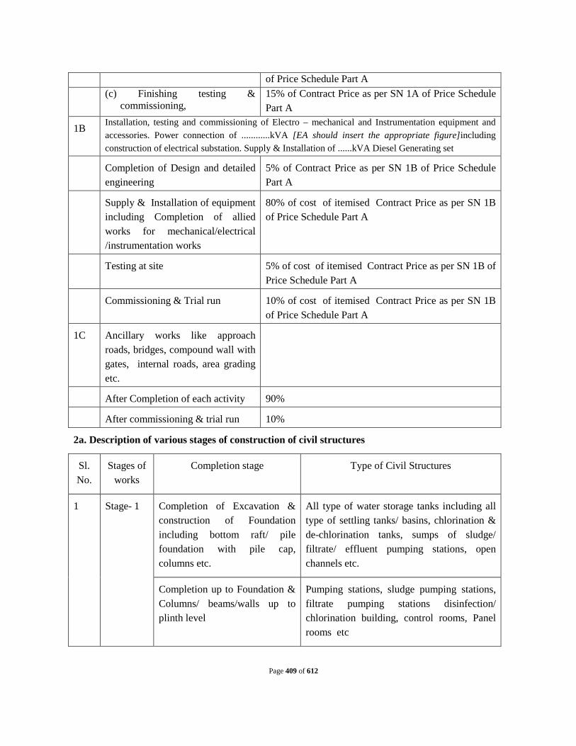
Page 409 of 612
of Price Schedule Part A
(c) Finishing testing & commissioning,
15% of Contract Price as per SN 1A of Price Schedule Part A
1B Installation, testing and commissioning of Electro – mechanical and Instrumentation equipment and accessories. Power connection of ............kVA [EA should insert the appropriate figure]including construction of electrical substation. Supply & Installation of ......kVA Diesel Generating set
Completion of Design and detailed engineering
5% of Contract Price as per SN 1B of Price Schedule Part A
Supply & Installation of equipment including Completion of allied works for mechanical/electrical /instrumentation works
80% of cost of itemised Contract Price as per SN 1B of Price Schedule Part A
Testing at site 5% of cost of itemised Contract Price as per SN 1B of Price Schedule Part A
Commissioning & Trial run 10% of cost of itemised Contract Price as per SN 1B of Price Schedule Part A
1C Ancillary works like approach roads, bridges, compound wall with gates, internal roads, area grading etc.
After Completion of each activity 90%
After commissioning & trial run 10%
2a. Description of various stages of construction of civil structures
Sl. No.
Stages of works
Completion stage Type of Civil Structures
1 Stage- 1 Completion of Excavation & construction of Foundation including bottom raft/ pile foundation with pile cap, columns etc.
All type of water storage tanks including all type of settling tanks/ basins, chlorination & de-chlorination tanks, sumps of sludge/ filtrate/ effluent pumping stations, open channels etc.
Completion up to Foundation & Columns/ beams/walls up to plinth level
Pumping stations, sludge pumping stations, filtrate pumping stations disinfection/ chlorination building, control rooms, Panel rooms etc

Page 410 of 612
2 Stage 2 Completion of side walls up to 60% height
All type of water storage tanks including chlorination & de-chlorination tanks, sumps of sludge/ filtrate/ effluent pumping stations, open channels etc.
Completion of super structures including columns, beams, walls, lintels, roof slab etc.
Pumping stations, sludge pumping stations, filtrate pumping stations disinfection/ chlorination building, control rooms, Panel rooms etc
3 Stage 3 Completion of side walls up to 100% height
All type of water storage tanks including chlorination & de-chlorination tanks, sumps of sludge/ filtrate/ effluent pumping stations, open channels etc.
After completion of all required fittings, e.g. internal electrification, shutters, doors & windows & plastering etc.
Pumping stations, sludge pumping stations, filtrate pumping stations disinfection/ chlorination building, control rooms, Panel rooms etc
4 Stage 4 Completion of all type of ancillary structures including required interconnection with other units & any other required for completion of the structures.
All type of water storage tanks including chlorination & de-chlorination tanks, sumps of sludge/ filtrate/ effluent pumping stations, open channels etc.
Completion of ancillary structures roof treatment, plastering, flooring, cable trench, painting, varnishing, apron, drainage etc and any other work required for proper completion of the structure.
Pumping stations, sludge pumping stations, filtrate pumping stations disinfection/ chlorination building, control rooms, Panel rooms etc
2.1 The Operator shall submit his claim for the price adjustment, if applicable to this contract as per SCC 5.1(3), along with his claim for payment for the work done during the month, and price adjustment will be paid as per formulae stipulated in Schedule 8 of the Contract.
3. Payment of Design-Build Price (I&DWorks)
a. The Operator shall submit to the Design Build Operations Engineer monthly statements of the value of the work completed less the cumulative amount certified previously along with
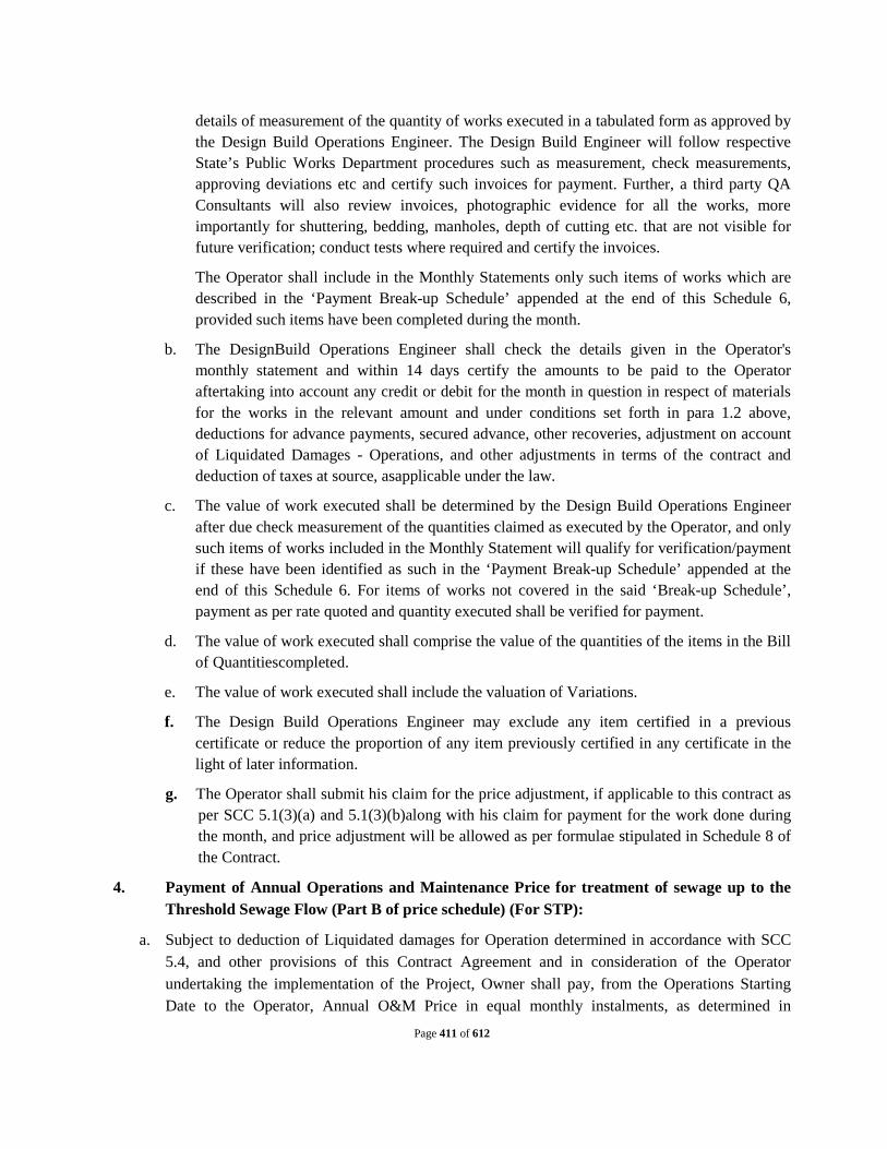
Page 411 of 612
details of measurement of the quantity of works executed in a tabulated form as approved by the Design Build Operations Engineer. The Design Build Engineer will follow respective State’s Public Works Department procedures such as measurement, check measurements, approving deviations etc and certify such invoices for payment. Further, a third party QA Consultants will also review invoices, photographic evidence for all the works, more importantly for shuttering, bedding, manholes, depth of cutting etc. that are not visible for future verification; conduct tests where required and certify the invoices.
The Operator shall include in the Monthly Statements only such items of works which are described in the ‘Payment Break-up Schedule’ appended at the end of this Schedule 6, provided such items have been completed during the month.
b. The DesignBuild Operations Engineer shall check the details given in the Operator's monthly statement and within 14 days certify the amounts to be paid to the Operator aftertaking into account any credit or debit for the month in question in respect of materials for the works in the relevant amount and under conditions set forth in para 1.2 above, deductions for advance payments, secured advance, other recoveries, adjustment on account of Liquidated Damages - Operations, and other adjustments in terms of the contract and deduction of taxes at source, asapplicable under the law.
c. The value of work executed shall be determined by the Design Build Operations Engineer after due check measurement of the quantities claimed as executed by the Operator, and only such items of works included in the Monthly Statement will qualify for verification/payment if these have been identified as such in the ‘Payment Break-up Schedule’ appended at the end of this Schedule 6. For items of works not covered in the said ‘Break-up Schedule’, payment as per rate quoted and quantity executed shall be verified for payment.
d. The value of work executed shall comprise the value of the quantities of the items in the Bill of Quantitiescompleted.
e. The value of work executed shall include the valuation of Variations.
f. The Design Build Operations Engineer may exclude any item certified in a previous certificate or reduce the proportion of any item previously certified in any certificate in the light of later information.
g. The Operator shall submit his claim for the price adjustment, if applicable to this contract as per SCC 5.1(3)(a) and 5.1(3)(b)along with his claim for payment for the work done during the month, and price adjustment will be allowed as per formulae stipulated in Schedule 8 of the Contract.
4. Payment of Annual Operations and Maintenance Price for treatment of sewage up to the Threshold Sewage Flow (Part B of price schedule) (For STP):
a. Subject to deduction of Liquidated damages for Operation determined in accordance with SCC 5.4, and other provisions of this Contract Agreement and in consideration of the Operator undertaking the implementation of the Project, Owner shall pay, from the Operations Starting Date to the Operator, Annual O&M Price in equal monthly instalments, as determined in

Page 412 of 612
accordance with the provisions of this Clause and other relevant provisions of this Contract Agreement. The O&M Prices in respect of Operation and Maintenance services shall be paid for a period of 15 years as monthly amounts. The monthly payments shall be taken as one twelfth of the Annual Operations and Maintenance Price payable by the Owner to the Operator.
b. In the event that the occurrence of the Operations Starting Date is delayed due to Owner or Force Majeure events, the Annual O&M Price shall be paid from the date of delayed Operations Start Date till the end of the Term (which shall be extended by the numbers of days of delay) so as to achieve total O&M period of 15 years.
5. Payment of Additional Operations and Maintenance Price per MLD (for STP):
a. Additional Operation and Maintenance Prices shall be paid only in the event the amount of sewage treated by the STP exceeds the specified Threshold Sewage Flow as per the provisions of this Contract.
b. Subject to the provisions of this Contract Agreement and in the event of the Operator treating sewage in excess of the Threshold Sewage Flow, Owner shall pay on a quarterly basis, Additional O&M Prices for each MLD of sewage above the Threshold Sewage Flow level treated and disposed in an environmentally compliant manner, as determined in accordance with the provisions of this Clause and other relevant provisions of this Contract Agreement. The Additional Operation and Maintenance Price stipulated in the contract for the relevant year shall be multiplied with the additional quantity of the Sewage treated and measured at the outfall point for that particular quarter.
6. Payment of O&M Prices for Operations and Maintenance of I&DWorks
a. Owner shall pay O&M prices on a Monthly basis, from the Operations Starting Date to the Operator, as determined in accordance with the provisions of this Clause and other relevant provisions of this Contract Agreement. The Monthly prices in respect of Operations and Maintenance services shall be paid for a period of 15 years as one twelfth of the quoted annual O&M prices for the relevant year of operation.
b. If the scope of O&M services is varied by the Owner owing to variation in the lengths of sewerage lines and number of pumping stations to be operated and maintained by the Operator during any part of the contract period, the Monthly O&M charges payable to the Operator shall be subject to adjustment on the basis of unit O&M prices provided in the Operator’s Price Schedule incorporated in Schedule 5 of the Contract.
c. In the event that the occurrence of the Operations Starting Date is delayed for any reasons, O&M prices shall be paid from the date of commencement of the Operations till the end of the O&M period of 15 years.
d. O & M price for operation of the SPSs quoted in the Operator’s Price Schedule comprises fixed and variable components. The said variable component shall be adjusted on the basis of actual quantity of sewage handled by the respective SPS. The adjusted variable component will be computed by multiplying the quoted Cost of Energy per MLD of sewage pumped (Variable Price) with the actual quantity of sewage handled.

Page 413 of 612
7. Payment of Electricity Dues
a. Owner shall assist the Operator on best effort basis in obtaining electricity required for the implementation of the Contract (covering Construction Period and Operation Period) and such assistance shall be subject to the terms and conditions as provided in this Clause.
b. The Parties hereby agree that the Bill for electricity usage by the Sewage Treatment Plant and SPSs (if applicable) during the Operations Period (the “Electricity Dues”), shall be paid by the Operator to the relevant utility.
8. Right to withhold:
The Design-Build-Operations Engineer / Owner may refuse to approve any such payment, because of subsequently discovered evidence as a result of subsequent inspections or tests, nullify any such payment previously approved and pay to such extent as may be necessary in the opinion of the Design Build Engineer because (a) the work is defective (b) third party claims have been filed or there is reasonable evidence indicating probability of such claims (c) of the Operator’s failure to make payment properly to sub-contractors or for labor, materials or equipment (d) of damage to another Operator or to the property of others caused by the Operator (e) of the Operator’s neglect or unsatisfactory proceeding of the work (f) Operator owes a liability or a sum to Owner.
When the grounds for withholding payments are removed, payments shall be made for amounts withheld to the extent the Operator is entitled to payment.

Page 414 of 612
FOR I&DWORKS
PAYMENT BREAK UP SCHEDULE OF CIVIL WORKS (EXECUTION)
[NOTE: THE FOLLOWING IS A TENTATIVE BREAKUP AND SHOULD BE FINALISED BY EA AS PER
REQUIREMENT]
PART –I, GRAVITY SEWERS LAYING OPEN CUT METHOD
Sl. No.
Description Component wise Percentage payment per
linear meter
(A) PROVIDING SEWER BY OPEN EXCAVATION
1 Approval of Design & Drawing 2% 2 Dewatering where required, barricading, traffic diversion,
Excavation, (excluding back filling), Timbering/Sheet piling, Bedding of pipes, Supply, laying & jointing of pipes
60%
3 Manholes 10% 4 Interconnecting of newly laid sewer with existing sewerage
network if required, otherwise that percentage will be given after reinstatement of road.
3%
5 Back filling, disposal of surplus earth and Temporary reinstatement of roads
5%
6 Temporary shifting and restoration of water mains/ sewer lines & Telephone lines/ cables and other utilities
5%
Sub-Total(A) 85% (B) TESTING & COMMISSIONING 1 Sectional Testing 5% 2 Final Testing & Commissioning sewer 10% Sub: Total (B) 15%
Grand Total A+B 100%
PART II SUPPLY & LAYING OF RISING MAIN BY OPEN CUT METHOD
Sl. No.
Description Component wise Percentage payment per linear meter
(A) SUPPLY & LAYING OF RISING MAIN BY OPEN CUT METHOD
1 Approval of Design & Drawing 2% 2 Supply & Laying of rising main including excavation laying jointing etc.
all complete. 70%
3 Supply & Fixing of sluice valve and air valves 10% 4 Refilling of trenches with full compaction 3% 5 Disposal of surplus earth including side cleaning including temporary
restoration of roads etc. 5%
Sub-Total(A) 90%

Page 415 of 612
(B) TESTING & COMMISSIONING 1 Final Testing & Commissioning sewer 10% Sub: Total (B) 10%
Grand Total A+B 100%
PART III SEWAGE PUMPING STATION
I. CONSTRUCTION OF WET WELL BY WELL SINKING METHOD
i Approval of design & drawing 3% ii Initial open excavation 1% iii Erection & fixing of cutting shoe 5% iv Construction of well staining and its sinking up to 50% depth BGL 25% v Construction of well staining & sinking upto 100% depth BGL 26% vi Plugging of well, boulder filing etc. 5%
vii R.C.C. work in bottom of well including bottom finishing with required slopes with cement concrete.
5%
viii Walkway and plate form 5% ix Beam, column including fixing of gantry girder 7% x Stair case, M.S. ladder, grill & other miscellaneous work 3% xi water tightness test 5% xii After commissioning & trial rum 10%
Total 100% II. SCREEN CHANNELS
i Approval of design & drawing 2% ii Construction of supporting columns 5% iii Constructions of base slab 18% iv Construction of side walls including partition wall 25% v Interconnection with incoming gravity sewer 5% vi Construction of Walkway, plate form and RCC stair case for
accessibility 30%
vii water tightness test 5% viii After commissioning & trial rum 10%
Total 100% iii. VALVE CHAMBER
i Approval of design & drawing 3% ii Initial open excavation 2% iii M-10 grade Lean concrete 5% iv Construction of RCC Raft 20% v Construction of RCC side walls 35% vi Construction of cover blocks. 10% vii Supply and fixing of M.S. plate form for operation of sluice valve &
other miscellaneous work 10%
viii water tightness test 5% ix After commissioning & trial rum 10% Total 100%
iv. MEP BUILDING
i. Approval of designs and drawings 2% ii. Excavation 2%

Page 416 of 612
iii. Sub Structure & Super structure a Raft footing/ pile foundation 10% b Construction of columns and beams 15% c Wall up to plinth level including plinth beam 3% d Wall up to lintel level including lintel beam 10% e Wall up to slab level 5% f Roof slab & beams including support for fixing gantry girders 13%
iv. Doors / Windows/Ventilators/Rolling shutter a Supply at site 3% b Fixing in position 2%
v Flooring/ cable trunk 5% vi Plastering 5%
vii. Internal electrification 2% viii Painting/ varnishing 5% ix Stair case/ M.S. ladder 5% x Drainage including construction of apron around the building 3%
xii Commissioning including site clearance & Misc. finishing items 10% Total 100%
v. DG PLATE FORM
i Approval of design & drawing 3% ii Initial open excavation 2% iii M-10 grade Lean concrete 5% iv Construction of RCC foundation for DG 25% v Construction of tubular shade 35% vi Construction of MS grill around the plate form with lobby arrangement. 20% vii After commissioning & trial rum 10%
Total 100% vi. MISC.BUILDINGS
i. Approval of designs and drawings 2% ii. Excavation 2% iii. Sub Structure & Super structure
a Raft footing/ pile foundation/footing 7% b Wall up to plinth level including plinth beam 3% c Wall up to lintel level including lintel beam 10% d Wall up to slab level 5% e Roof slab 10%
iv. Doors / Windows/Ventilators/Rolling shutter a Supply at site 3% b Fixing in position 2%
v Flooring/ cable trunk 5% vi Plastering 5%
viii Painting/ varnishing 5% ix Water supply & Sanitary fittings. 12.50% x Stair case 6%
xii Internal electrification. 12.50% xiii Commissioning including site clearance & Misc. finishing items 10%
Total 100% PART- IV ROAD REINSTATEMENT
A. Bituminous Roads
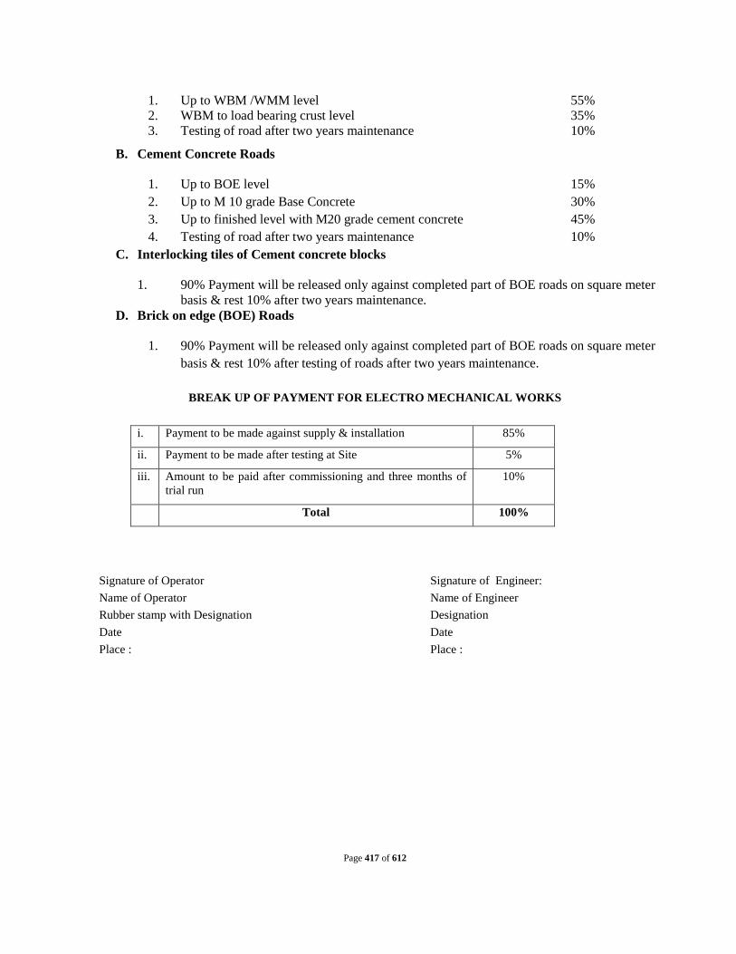
Page 417 of 612
1. Up to WBM /WMM level 55% 2. WBM to load bearing crust level 35% 3. Testing of road after two years maintenance 10%
B. Cement Concrete Roads
1. Up to BOE level 15% 2. Up to M 10 grade Base Concrete 30% 3. Up to finished level with M20 grade cement concrete 45% 4. Testing of road after two years maintenance 10%
C. Interlocking tiles of Cement concrete blocks
1. 90% Payment will be released only against completed part of BOE roads on square meter basis & rest 10% after two years maintenance.
D. Brick on edge (BOE) Roads
1. 90% Payment will be released only against completed part of BOE roads on square meter basis & rest 10% after testing of roads after two years maintenance.
BREAK UP OF PAYMENT FOR ELECTRO MECHANICAL WORKS
i. Payment to be made against supply & installation 85%
ii. Payment to be made after testing at Site 5%
iii. Amount to be paid after commissioning and three months of trial run
10%
Total 100%
Signature of Operator Signature of Engineer: Name of Operator Name of Engineer Rubber stamp with Designation Designation Date Date Place : Place :

Page 418 of 612
Schedule 7
LIQUIDATED DAMAGES - OPERATIONS
TO (I) DESIGN AND BUILD SEWAGE TREATMENT PLANTOF INSTALLED CAPACITY 32 MLD AND ALL APPURTENANT STRUCTURES AND ALLIED WORKS IN TWO MODULES (16MLD+16MLD);(II) SURVEY, REVIEW THE DESIGNS, REDESIGN WHERE NECESSARY, AND BUILD NEW DIVERSION WORKS WITH INTERCEPTION WITH RISING MAIN 2.3 KM, NEW TAPPINGS OF LENGTH 18.95 KM FOR 39 DRAINS CONTROLLED WITH SCADA INCLUDING SURVEY, DESIGN, CONSTRUCTION OF 5 NO. PUMPING STATIONS AND ALL APPURTENANT STRUCTURES AND ALLIED WORKS; AND CONSTRUCTION OF 31 OUTFALL STRUCTURE WITH SLUICE GATE INCLUDING EFFLUENT CHANNEL (250 MTR) FOR REUSE OF TREATED WASTE WATER (III) OPERATION & MAINTENANCE OF THE COMPLETE WORKS OF SEWAGE TREATMENT PLANT, INTERCEPTION & DIVERSION WORKS AND PUMPING STATIONS FOR A PERIOD OF 15 YEARS IN CHHAPRA TOWN , STATE OF BIHAR , INDIA.

Page 419 of 612
ARTICLE 1. Liquidated Damages (Operations) for STP Liquidated Damages (GC Section 5.4)
1) In case the Operator fails to meet the technical standards more specifically towards the quality of the treated sewage, the Operator shall pay to the owner Liquidated Damages amounting to INR........... [Please insert the amount as appropriate for the STP involved.] per day of occurrence, over and above the costs and compensation that might be required by the Owner to pay to the affected people and parties in the effluent discharge area.
2) Applicability of the Liquidated Damages shall be determined based on the weekly monitoring report of the quality of the treated effluent, submitted by the nominated Laboratory, namely.............. [The EA should specify here the independent laboratory like the one under the control of State PCB, etc.]. The said Laboratory will test the samples [minimum 3 grab samples representative of different flow conditions (quantum and quality wise) in the day] of the treated effluent drawn every week jointly by the Owner and the Operator and the results of the test report shall be binding on both the parties.
3) If any of the grab samples of the effluent so tested fails to meet with the CPCB /State PCB standards stipulated in the Contract, Liquidated Damages as stated herein above shall be deducted from the O & M payments due to the Operator for all the seven days of the week.
4) The Operator shall maintain the STP for treating the sewage without any interruption by ensuring timely measures for preventive maintenance. However, if the STP is unavailable for treating the sewage for a period exceeding ..... hours for reasons attributable to the Operator, Liquidated Damages shall be levied by the Owner at the rate of INR ............ ...........[Please insert the amount as appropriate for the STP involved.] per day or part of the day for the period the STP is not available beyond the allowed time of ...... hours as referred to above for repair/rectification. The Liquidate Damages shall apply over and above the costs and compensation which shall be reimbursed by the Operator in case such costs/compensations are required to be paid by the Owner to the affected people and parties in the effluent discharge area.

Page 420 of 612
ARTICLE 2. Liquidated Damages (Operations) for I&DWorks
1. Liquidated Damages (GC Section 5.4)
In case the Operator fails to meet the Performance Standards listed in the Table below, payments due to the Operator shall be subject to deduction on account of liquidated damages for defaults exceeding the Acceptable Limits. Such deductions shall be over and above the costs and compensation that might be required by the Owner to pay to the affected people and parties in the area where O&M of the I&DWorks and Pumping Stations has been entrusted to the Operator.
“Acceptable Limit” is the permissible number of instances of defaults or non-adherence to a particular Set of Performance Standardsduring the Quarter for which payment has been claimed by the Operator.
The Operator shall be required to meet all of the Performance Standards as specified herein below. He shall ensure that defaults from compliance with the said Standards shall not exceed the Acceptable Limit; otherwise Liquidated damages as specified herein shall be applicable.
Perf
orm
ance
set
Des
crip
tion
of
perf
orm
ance
set
Acc
epta
ble
limit33
Red
uctio
n in
pay
men
t as
% o
f qua
rter
ly O
&M
C
harg
es34
Per
form
ance
St
anda
rd
Set A
Sewerage Network and/or I&D Works Pipeline Breakages
1 per month / 50 km
1% of the quarterly
payments for each default
exceeding the Acceptable Limit
Sewer Network pipeline breakages that are not repaired within 24 hours (for sewers up 800 mm dia) and 48 hours (for all higher dia) of their being reported, will be considered as ‘Breakages’.
33Indicative value provided here, the actual value to be specified by the Owner on a project to project basis. 34Indicative value provided here, the actual reduction should be specified on a project to project basis by the
Owner.

Page 421 of 612
Set B
Chokes, Blockages and
1 per month / 10 km length
do Rectify Chokes / blockages within 24 hours of reporting / complaint / identification.
Set C
Pumping Stations
1 per month
do Instances of failure to maintain optimum wet well levels of pumping stations and or delay in recording wet well levels.
Set D
Pumping efficiency
2 per month
do Decrease in pumping efficiency by more than 10 % from the level as determined by Design Build Operations Engineer
Set E
Overflow from Pumping Station
1 per month
do No overflow shall be allowed from the pumping station.
Set F Replacement of Manhole Covers
1 per month / 10 km
Rs 500 per number of covers
not replaced in 48 hours
Replace damaged or stolen manhole covers immediately. Max 24 hours.

Page 422 of 612
Schedule 8
Price Adjustment
TO (I) DESIGN AND BUILD SEWAGE TREATMENT PLANTOF INSTALLED CAPACITY 32 MLD AND ALL APPURTENANT STRUCTURES AND ALLIED WORKS IN TWO MODULES (16MLD+16MLD);(II) SURVEY, REVIEW THE DESIGNS, REDESIGN WHERE NECESSARY, AND BUILD NEW DIVERSION WORKS WITH INTERCEPTION WITH RISING MAIN 2.3 KM, NEW TAPPINGS OF LENGTH 18.95 KM FOR 39 DRAINS CONTROLLED WITH SCADA INCLUDING SURVEY, DESIGN, CONSTRUCTION OF 5 NO. PUMPING STATIONS AND ALL APPURTENANT STRUCTURES AND ALLIED WORKS; AND CONSTRUCTION OF 31 OUTFALL STRUCTURE WITH SLUICE GATE INCLUDING EFFLUENT CHANNEL (250 MTR) FOR REUSE OF TREATED WASTE WATER (III) OPERATION & MAINTENANCE OF THE COMPLETE WORKS OF SEWAGE TREATMENT PLANT, INTERCEPTION & DIVERSION WORKS AND PUMPING STATIONS FOR A PERIOD OF 15 YEARS IN CHHAPRA TOWN , STATE OF BIHAR , INDIA.

Page 423 of 612
SCHEDULE 8
1. GENERAL
1.1 This Schedule lays down the procedure for determining the price adjustment to be applied to the following components of the contract price:
(i) Design-Build Price for the STP and Network, if SCC 5.1 (3) stipulates that price adjustment will apply to Design-Build Price.
(ii) Price for Operation &Maintenance of the STP and Network.
1.2 For the purpose of Price Adjustment, ‘Base Date’ shall be the date 28 days prior to the deadline for submission of bids for the contract. Thus Base date for this contract is............... [EA should insert the date at the time of signing the contract.]
1.3 Weightings for labor and various materials to be used in the Price Adjustment formulas laid down in the Tables under paragraphs 3 and 4 of this Schedule shall be based on the figures quoted by the Operator as a part of its bid under the Scheduleof Adjustment Data (in the Appendix to Bid), and as accepted by the Owner.
2. PRICE ADJUSTMENT FOR DESIGN BUILD PRICE
2.1 If this Clause applies, the amounts payable to the Operator shall be adjusted for rises or falls in the cost of labour, Goods and other inputs to the Design-Build Services, by the addition or deduction of the amounts determined by the formulae prescribed in this Clause. To the extent that full compensation for any rise or fall in Costs is not covered by the provisions of this or other Clauses, the Accepted Contract Amount shall be deemed to have included amounts to cover the contingency of other rises and falls in costs.
2.2 The adjustment to be applied to the amount otherwise payable to the Operator, as valued in accordance with the Contract prices incorporated inSchedule5, and certified by the Design-Build-Operations Engineer in Payment Certificates (referred to as ‘Interim Payment Certificates’) after examining the statements of monthly claims, shall be determined from formulae for each of the currencies in which the Contract Price is payable. No adjustment is to be applied to work valued on the basis of Cost or current prices. The formulae shall be of the following general type:
Pn = a + b Ln/ Lo + c En/Eo + d Mn/Mo + ...... where:
“Pn” is the adjustment multiplier to be applied to the estimated contract value in the relevant currency of the work carried out in period “n”, this period being a month;

Page 424 of 612
“a” is a fixed coefficient, stated in the relevant table of adjustment data, representing the non-adjustable portion in contractual payments;
“b”, “c”, “d”, … are coefficients representing the estimated proportion of each cost element related to the execution of the Design-Build Services, as stated in the relevant table of adjustment data; such tabulated cost elements may be indicative of resources such as labour, equipment and materials;
“Ln”, “En”, “Mn”, … are the current cost indices or reference prices for period “n”, expressed in the relevant currency of payment, each of which is applicable to the relevant tabulated cost element on the date 49 days prior to the last day of the period (to which the particular Payment Certificate relates); and
“Lo”, “Eo”, “Mo”, … are the base cost indices or reference prices, expressed in the relevant currency of payment, each of which is applicable to the relevant tabulated cost element on the Base Date.
2.3 The cost indices or reference prices stated in the table of adjustment data shall be used. If their source is in doubt, it shall be determined by the Design-Build-Operations Engineer.
2.4 Until such time as each current cost index is available, the Design-Build-Operations Engineer shall determine a provisional index for the issue of Interim Payment Certificates. When a current cost index is available, the adjustment shall be recalculated accordingly.
2.5 If the Operatorfails to complete the Design-Build Services within the stipulated Time for Completion, adjustment of prices thereafter shall be made using either (i) each index or price applicable on the date 49 days prior to the expiry of the specified Time for Completion, or (ii) the current index or price, whichever is more favorable to the Owner.
2.6 The weightings (coefficients) for each of the factors of cost stated in the table(s) of adjustment data shall only be adjusted if they have been rendered unreasonable, unbalanced or inapplicable, as a result of Variations.
3. Determination of Price Adjustment Multiplier for Design Build Price of STP
3.1 The Price adjustment multiplier “Pn” to be applied to the estimated value of work done in a month, as certified in the Interim Payment Certificates shall be determined using the coefficients/weightings and cost indices etc. for local currencyas provided in paragraphs 3.2.
3.2 Local currency

Page 425 of 612
Index code
Index description Source of index Weighting *
A Nonadjustable - a = 0.15
B
Labor - Consumer price index for industrial workers for ........centre
Labour Bureau, Ministry of Labour & Employment, Government of India
b =
C
Material - All India Wholesale Price Index (all commodities)
Economic Advisor to the Government of India, Ministry of Commerce and Industry
c =
Total 1.00
* The weightings for various cost indices will be inserted based on the Owner’s decision on the relevant details provided by the selected bidder in the Appendix to the Bid. 3.3 Foreign Currency
Index code
Index description Source of index@
Weighting++
A Nonadjustable a = 0.15
B Labor b =
C Material c =
Total 1.00
@The source of Indices will be inserted based on the relevant details provided by the selected bidder in the Appendix to the Bid.
++The weightings for various cost indices will be inserted based on the Owner’s decision on the relevant details provided by the selected bidder in the Appendix to the Bid.
4. Determination of Price Adjustment Multiplierfor Design-Build Price of Sewerage Network
4.1 The Price adjustment multiplier “Pn” to be applied to the estimated value of work done in a month, as certified in the Interim Payment Certificates shall be determined using the coefficients/weightings and cost indices etc. for local currency as provided in paragraphs 4.2.
4.2 Local Currency

Page 426 of 612
Index code
Index description Source of index Weighting *
A Nonadjustable - 0.15
B Labour - Consumer price index for industrial workers for ........centre
Labour Bureau, Ministry of Labour & Employment, Government of India
C Cement - All India Wholesale Price Index for grey cement
Office of the Economic Advisor to the Govt. of India, Ministry of Commerce and Industry
D Steel - All India Wholesale Price Index for steel rebars
Office of the Economic Advisor to the Govt. of India, Ministry of Commerce and Industry
E Bitumen - Average official retail price of bitumen
IOC depot at...............
F POL -average official retail price of High Speed Diesel
Retail outlet of IOC at...........
G Plant & Machinery Spares - All India Wholesale Price Index for Construction machinery
Office of the Economic Advisor to the Govt. of India, Ministry of Commerce and Industry
H Other materials - All India Wholesale Price Index for all commodities
Office of the Economic Advisor to the Govt. of India, Ministry of Commerce and Industry
Total 1.00
* The weightings for various cost indices will be inserted based on the Owner’s decision on the relevant details provided by the selected bidder in the Appendix to the Bid.
The Operator shall note that Paragraphs 5, 5.1, 5.2, 5.3 &5.4 of this Schedule shall be applicable in respect of payment of O&M prices for Sewerage Network only if operation of an SPS is included in the scope of work.

Page 427 of 612
5. PRICE ADJUSTMENT FOR O&M PRICES
5.1 Owner shall pay O&M prices to the Operator subject to adjustments as per following sub-paragraphs. 5.2 Adjustment for Variation in Electricity Tariff
O&M prices shall be subject to adjustment on account of variation in the Electricity Tariff during the O&M period with reference to ‘Base Rate of Electricity Tariff’ specified at the time of invitation of bids, namely INR ............ per KWh.[EA should insert the same rate as stipulated in BDS ITB 3.11 c.] The said adjustment shall be determined on the basis of the actual electricity consumption and the Tariff evidenced by the Electricity bills paid by the Operator to the Electricity Utility Company, subject to the following provisions:
(a) Variation shall be limited to the Guaranteed Energy Consumption applicable for the level of effluent treated by STP, and for the level of effluent pumped by the respective SPSs during the quarter.
(b) Guaranteed Energy Consumption for the actual level of effluent handled by the STP and by the SPS(s) if any will be calculated based on the energy consumption/MLD for the relevant year of the O&M period as quoted in the Operator’s Price Schedule incorporated in Schedule 5 of the Contract.
The variation applicable as per this sub-paragraph 5.2 shall be claimed by the Operator on Quarterlybasis.
5.3 Determination of cost of Diesel used in DG set
The Operator shall use back-up power supply from the DG set during the period power supply from the Electricity Utility Company is not available. The DG set equipped with standard accessories will record inter alia (i) energy supplied/generated by it and (ii) total period for which it was operated in a month/quarter. Cost of Diesel for which Operator will be entitled to compensation on account of energy obtained from the back-up power supply unit shall be determined as under:
a. Operator’s representative and the Design Build Operations Engineer shall jointly take the readings from the meters and gauges (sealed jointly by them at the commencement of the O&M period) of DG set every month to arrive at the total number of energy units (kWh) = E1obtained from the back-up power supply unit.
b. Number of energy units (kWh) obtained from the back-up power supply unit during the month for which Operator shall be entitled to compensation(referred to as ‘adjusted units of back-up energy supply’) shall be determined in a series of steps that follow.
The Owner will first determine the short-fall in supply from the Electricity Utility Company.
Short-fall in supply from the Electricity Utility Company (E2)
= Energy Requirement as per Guaranteed Energy Consumption applicable for the level of effluent treated by STP, and for the level of effluent pumped by the respective SPSs during the month

Page 428 of 612
(-) Units of energy (kWh) available/obtained during the month from the Electricity Utility Company as evidenced by the Bill of the Utility Company for the corresponding month
If the ‘Short-fall in supply from the Electricity Utility Company’ (E2)works out to be a negative figure, Operator shall not be entitled to compensation for using the energy supply from the back-up power supply unit.
If E2isa positive figure, compensation shall be based on E1orE2whichever is lower and this lower figure shall be termed as ‘adjusted units of back-up energy supply’.
c. Rated specific fuel consumption of the DG set specified by the Manufacturer in its Specifications will then be used for determining the estimated diesel consumption during the month forproducingthe ‘adjusted units of back-up energy supply’.
d. Cost of estimated Diesel consumption in a month shall then be calculatedon the basis of price of diesel prevailing at mid-point of the month in IOC or HPCL’s retail outlets in the city where STP and the SPS are installed. Cost figures of three months shall be added to arrive at the Cost of Diesel consumption in a quarter.
5.4 Adjustment in O&M Price for energy taken from the back-up power supply unit
O&M prices quoted in the Operator’s Price Schedule incorporated in Schedule 5 take into account energy requirements of the STP and SPSsbeing met fully by power from the Electricity Utility Company. Hence compensation payable to the Operator for Energy supply taken from an alternate source, namely the back-up power supply Unit shall be corrected as under:
Adjustment in quarterly O&M price = Cost of Diesel consumption in a quarter determined in accordance with sub-paragraph 5.3 (d) above minus ‘adjusted units of back-up energy supply’ determined as per sub-paragraph 5.3 (b) as applicable for the quarter multiplied by the ‘Base Rate of Electricity Tariff’.
The variation in O&M price applicable as per sub-paragraphs 5.3 and 5.4 shall be claimed by the Operator on Quarterlybasis.

Page 429 of 612
Schedule 9
SCHEDULE OF PERFORMANCE GUARANTEE
& ADVANCE PAYMENT GUARANTEE
TO (I) DESIGN AND BUILD SEWAGE TREATMENT PLANTOF INSTALLED CAPACITY 32 MLD AND ALL APPURTENANT STRUCTURES AND ALLIED WORKS IN TWO MODULES (16MLD+16MLD);(II) SURVEY, REVIEW THE DESIGNS, REDESIGN WHERE NECESSARY, AND BUILD NEW DIVERSION WORKS WITH INTERCEPTION WITH RISING MAIN 2.3 KM, NEW TAPPINGS OF LENGTH 18.95 KM FOR 39 DRAINS CONTROLLED WITH SCADA INCLUDING SURVEY, DESIGN, CONSTRUCTION OF 5 NO. PUMPING STATIONS AND ALL APPURTENANT STRUCTURES AND ALLIED WORKS; AND CONSTRUCTION OF 31 OUTFALL STRUCTURE WITH SLUICE GATE INCLUDING EFFLUENT CHANNEL (250 MTR) FOR REUSE OF TREATED WASTE WATER (III) OPERATION & MAINTENANCE OF THE COMPLETE WORKS OF SEWAGE TREATMENT PLANT, INTERCEPTION & DIVERSION WORKS AND PUMPING STATIONS FOR A PERIOD OF 15 YEARS IN CHHAPRA TOWN , STATE OF BIHAR , INDIA.

Page 430 of 612
FORM OF PERFORMANCE GUARANTEE
[Bank’s Name, and Address of Issuing Branch or Office]
Beneficiary: [Name and Address of Owner]
Date:
PERFORMANCE GUARANTEE NO.:
We have been informed that [name of Bidder] (hereinafter called “the Bidder”) has entered into Contract No. [reference number of the contract] dated with you, concerning a contract to design, build, refurbish and operate a Sewerage Treatment Plant and Sewerage Network and/or Interception and Diversion Worksin [Name of Location] (hereinafter called “the Contract”).
Furthermore, we understand that, according to the conditions of the Contract, a performance guarantee is required.
At the request of the Operator, we [name of Bank] hereby irrevocably undertake to pay you any sum or sums not exceeding in total an amount of [amount in figures] ( )[amount in words], upon receipt by us of your first demand in writing accompanied by a written statement stating that the Contract is in breach of its obligations under the Contract, without your needing to prove or to show grounds for your demand or the sum specified therein.
This guarantee shall expire no later than the earlier of:
(a) six months after the End Date, as defined in the Contract; or
(b) six months after the date of termination of the Contract pursuant to its terms.
Consequently, any demand for payment under this guarantee must be received by us at this office on or before that date.
This guarantee is subject to the Uniform Rules for Demand Guarantees, (URDG) 2010 Revision, ICC Publication No. 758 except that the supporting statement under Article 15(a) is hereby excluded.
Yours truly,
[Name of Bank]
Authorised Signature

Page 431 of 612
FORM OF BANK GUARANTEE – ADVANCE PAYMENT
[Name of Contract]
To: [Name and address of Owner]
Dear Ladies and/or Gentlemen,
We refer to the Contract Agreement (“the Contract”) signed on [date] between you and [name of Operator] (“the Operator”) concerning the Services set out in the Contract to Design, Build, Refurbish and Operate a Sewage Treatment Plant and a Sewerage Network and/or Interception and Diversion Works.
Whereas, in accordance with the terms of the Contract, the Owner agreed to pay or cause to be paid to the Operator an advance payment in the amount of [number] percent (____%) of the Contract Price for the Design-Build, Refurbish, Commission, Operate and Maintaining STP and Sewerage Network and/or Interception and Diversion Works for 15 years, namely a payment of: [amount of foreign currency in words], [amount in figures], and [amount of local currency in words], [amount in figures].
By this letter we, the undersigned, [name of Bank], a Bank (or company) organised under the laws of [country of Bank] and having its registered/principal office at [address of Bank], do hereby jointly and severally with the bidder irrevocably guarantee repayment of the amounts upon the first demand of the Owner without cavil or argument in the event that the bidder fails to commence or fulfil its obligations under the terms of the Contract, and in the event of such failure, refuses to repay all or part (as the case may be) of the advance payment to the Owner.
Provided always that the Bank’s obligation shall be limited to an amount equal to the outstanding balance of the advance payment, taking into account such amounts that have been repaid by the Bidder from time to time in accordance with the terms of payment of the Contract as evidenced by appropriate shipping documents or payments certificates.
This Guarantee shall remain in full force from the date upon which the advance payment is received by the bidder until the date upon which the bidder has fully repaid the amount is advanced to the Owner in accordance with the terms of the Contract. At the time at which the outstanding amount isnil, this Guarantee shall become null and void, whether the original is returned to us or not.
Any claims to be made under this Guarantee must be received by the Bank during its period of validity.
This guarantee is subject to the Uniform Rules for Demand Guarantees (URDG) 2010 Revision, ICC Publication No. 758, except that the supporting statement under Article 15(a) is hereby excluded. Yours truly,
[Name of the Bank] & Authorized Signature
Page 432 of 612
Schedule10
TECHNICAL SPECIFICATIONS FOR CONSTRUCTION AND OPERATION AND MAINTENANCE PHASE35
35Specifications pertaining to general civil works and the material requirements have been specified herewith.
However the specifications and the testing requirements shall be specified in accordance with the technology being selected by the bidder and the detailed design submitted.
TO (I) DESIGN AND BUILD SEWAGE TREATMENT PLANTOF INSTALLED CAPACITY 32 MLD AND ALL APPURTENANT STRUCTURES AND ALLIED WORKS IN TWO MODULES (16MLD+16MLD);(II) SURVEY, REVIEW THE DESIGNS, REDESIGN WHERE NECESSARY, AND BUILD NEW DIVERSION WORKS WITH INTERCEPTION WITH RISING MAIN 2.3 KM, NEW TAPPINGS OF LENGTH 18.95 KM FOR 39 DRAINS CONTROLLED WITH SCADA INCLUDING SURVEY, DESIGN, CONSTRUCTION OF 5 NO. PUMPING STATIONS AND ALL APPURTENANT STRUCTURES AND ALLIED WORKS; AND CONSTRUCTION OF 31 OUTFALL STRUCTURE WITH SLUICE GATE INCLUDING EFFLUENT CHANNEL (250 MTR) FOR REUSE OF TREATED WASTE WATER (III) OPERATION & MAINTENANCE OF THE COMPLETE WORKS OF SEWAGE TREATMENT PLANT, INTERCEPTION & DIVERSION WORKS AND PUMPING STATIONS FOR A PERIOD OF 15 YEARS IN CHHAPRA TOWN , STATE OF BIHAR , INDIA.

Page 433 of 612

Page 434 of 612
FOR STP GENERAL
The 32 MLD capacity sewage treatment plant in two modules (16 MLD + 16 MLD) to be Designed, Build, , Tested and Commissioned by the Operator / Operator shall comply with the guidelines contained in “Manual on Sewerage and Sewage Treatment” Latest Edition published by the Central Public Health & Environmental Engineering Organization (CPHEEO), Ministry of Urban Development, Government of India. The Technical Standards and Specifications contained in this contract shall be read along with the following standard specifications (latest versions) published by the Bureau of Indian Standard listed below:
The list is not exclusive and the operator shall be responsible to follow the appropriate standards:
i) IS 6280 – 1971 – Sewage Screens
ii) IS 8413 – 1982 – Biological Treatment Equipment – Part II and its modifications
iii) IS 10037 – Part I – 1981 & Part II & III – 1983 – Sludge dewatering equipments
iv) IS 10261 – Requirements for settling tank for waste water
v) IS 105533 – Part I, II, III – Chlorination Plants
vi) IS 5600 – 1970 - Sewage and Drainage Pumps
vii) IS 6279 – 1971 – Grit Removal devices
Documents Comprising the Technical Standards Appendix
The Technical Standards Appendix consists of Technical Specification to be followed for during Construction of Sewage treatment Plant and other ancillary/ allied works for all Civil, Mechanical, Electrical, Instrumentation required to be executed under this Contract. Notwithstanding to the said specification, the bidder is instructed the adopt and follow necessary standard and approved Codes /specification wherever required for fulfillment of all the works under this contract.
Supplementing the General Conditions and Design-Build or Operating Services Appendix
The Technical Standards Appendix shall be read along with the GCC / SCC and Design-Build and Operations Services Appendices for the purpose of providing greater specificity of the technical standards which the Bidder is required to meet.

Page 435 of 612
Design-Build or Operations Services Appendix Description
The descriptions contained in the Technical Standards Appendix Chart entitled, “Description of Service” are for the convenience of the Bidder and do not supersede the actual wording of the Design-Build and Operations Services Appendices.
General Quality Standards
The term “General Quality Standard” means a standard of performance which,
(a) is competent, efficient, economical and in accordance with internationally accepted techniques used in the sewer disposal and civil works construction industries;
(b) is in accordance with professional engineering, accounting and consulting standards, as applicable, recognized by national or international professional bodies;
(c) is in accordance with sound management, commercial, technical, design and engineering practices;
(d) employs appropriate technology and safe and effective equipment, machinery and methods;
(e) is in accordance with national and local standards and codes in the Owner’s Country;
(f) protects the interests of the Authorities;
(g) is in accordance with the Applicable Law;k
(h) is in accordance with the technical specifications and design standards of the Owner as provided to the Bidder;
(i) is in accordance with the applicable Environmental Assessment and Environmental Management and Mitigation Plan; and
(j) is in accordance with the Design-Build Documents as approved by the Owner.
In the event of any conflict or inconsistency between any standards that comprise the General Quality Standard, local and national standards in the Owner’s Country shall prevail over international standards.
The Operator shall, at all times, carry out the Services in accordance with the Technical Standards as specified and, where a specific technical standard of quality of performance has not been specified, the Bidder shall perform the Services to the standard of “General Quality Standards” set out in Section 2.2(1) of the Technical Standards Appendix.
If the Owner is subjected to fines or penalties as a result of the operator’s breach of these Technical Standards, such fines or penalties shall be paid by the Bidder

Page 436 of 612
Design-Build Services
In respect of the Design-Build Services, the operator shall ensure that the design of the STP is prepared by qualified designers who are professionally recognized to design the Sewage Treatment Plant and allied services.
The Operator warrants that the operator and its designers have the experience and capability necessary for the design.
The offers shall be based on the operator’s own design and operating philosophy which is to be based on the selected modern treatment technologies and should be within the overall framework and guidelines specified in the bid document and its specifications. The bidder’s design for the entire facility shall be such that the project shall
• Require minimum land space • Require minimum energy for treatment of sewage • Generates treated effluent that can be recycled
Planning of the entire system should be done in such a manner so as to optimize capital and operational costs of treatment of sewage and maintenance of the Plant on whole on sustainable basis.
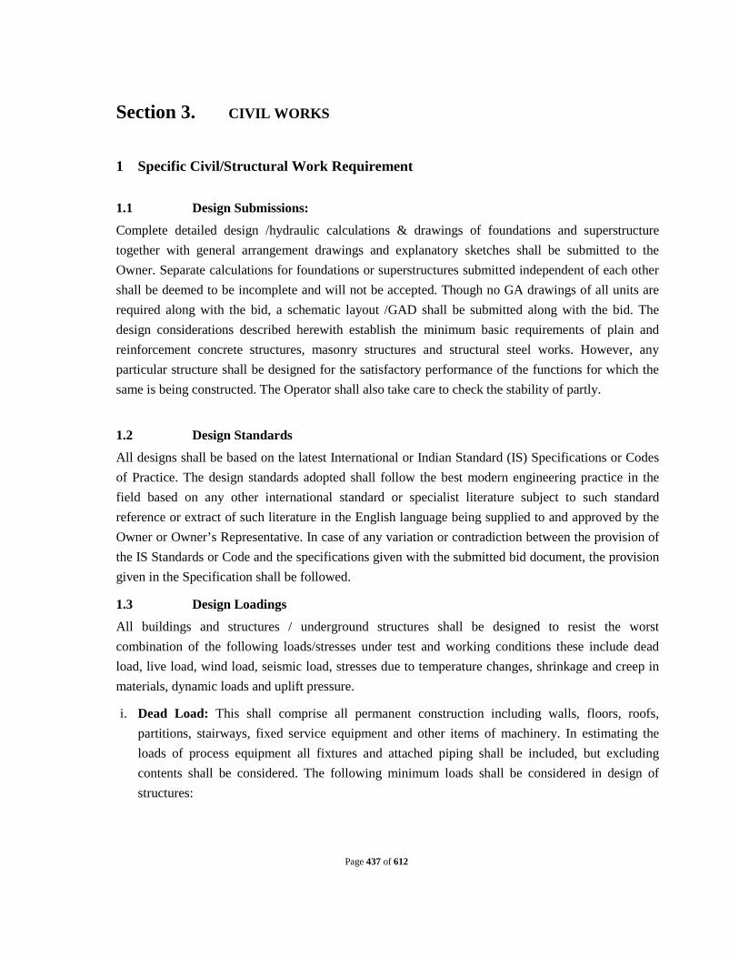
Page 437 of 612
Section 3. CIVIL WORKS
1 Specific Civil/Structural Work Requirement 1.1 Design Submissions:
Complete detailed design /hydraulic calculations & drawings of foundations and superstructure together with general arrangement drawings and explanatory sketches shall be submitted to the Owner. Separate calculations for foundations or superstructures submitted independent of each other shall be deemed to be incomplete and will not be accepted. Though no GA drawings of all units are required along with the bid, a schematic layout /GAD shall be submitted along with the bid. The design considerations described herewith establish the minimum basic requirements of plain and reinforcement concrete structures, masonry structures and structural steel works. However, any particular structure shall be designed for the satisfactory performance of the functions for which the same is being constructed. The Operator shall also take care to check the stability of partly.
1.2 Design Standards
All designs shall be based on the latest International or Indian Standard (IS) Specifications or Codes of Practice. The design standards adopted shall follow the best modern engineering practice in the field based on any other international standard or specialist literature subject to such standard reference or extract of such literature in the English language being supplied to and approved by the Owner or Owner’s Representative. In case of any variation or contradiction between the provision of the IS Standards or Code and the specifications given with the submitted bid document, the provision given in the Specification shall be followed.
1.3 Design Loadings
All buildings and structures / underground structures shall be designed to resist the worst combination of the following loads/stresses under test and working conditions these include dead load, live load, wind load, seismic load, stresses due to temperature changes, shrinkage and creep in materials, dynamic loads and uplift pressure.
i. Dead Load: This shall comprise all permanent construction including walls, floors, roofs, partitions, stairways, fixed service equipment and other items of machinery. In estimating the loads of process equipment all fixtures and attached piping shall be included, but excluding contents shall be considered. The following minimum loads shall be considered in design of structures:
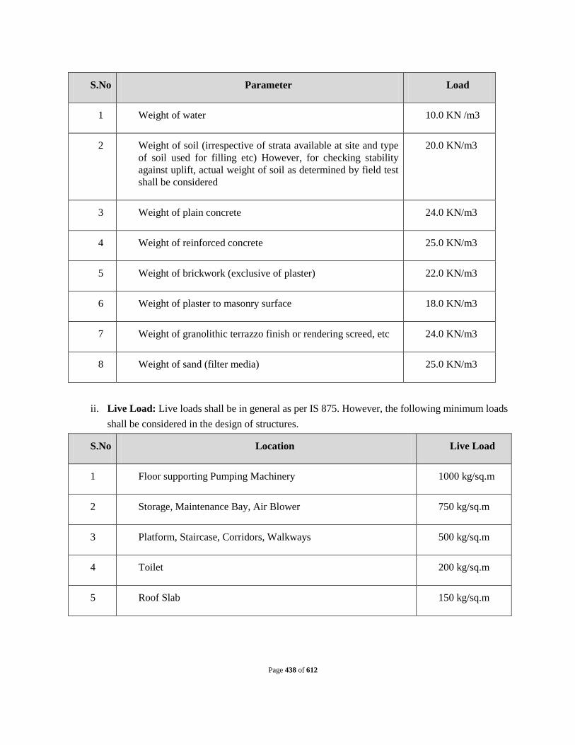
Page 438 of 612
S.No Parameter Load
1 Weight of water 10.0 KN /m3
2 Weight of soil (irrespective of strata available at site and type of soil used for filling etc) However, for checking stability against uplift, actual weight of soil as determined by field test shall be considered
20.0 KN/m3
3 Weight of plain concrete 24.0 KN/m3
4 Weight of reinforced concrete 25.0 KN/m3
5 Weight of brickwork (exclusive of plaster) 22.0 KN/m3
6 Weight of plaster to masonry surface 18.0 KN/m3
7 Weight of granolithic terrazzo finish or rendering screed, etc 24.0 KN/m3
8 Weight of sand (filter media) 25.0 KN/m3
ii. Live Load: Live loads shall be in general as per IS 875. However, the following minimum loads
shall be considered in the design of structures.
S.No Location Live Load
1 Floor supporting Pumping Machinery 1000 kg/sq.m
2 Storage, Maintenance Bay, Air Blower 750 kg/sq.m
3 Platform, Staircase, Corridors, Walkways 500 kg/sq.m
4 Toilet 200 kg/sq.m
5 Roof Slab 150 kg/sq.m

Page 439 of 612
In the absence of any suitable provisions for live loads in IS Codes or as given above for any particular type of floor or structure, assumptions made must receive the approval of the Owner’s Representative prior to starting the design work. Apart from the specified live loads or any other loads due to material stored any other equipment load or possible overloading during maintenance or erection/construction shall be considered and shall be partial or full whichever causes the most critical condition.
iii. Wind Load: Wind loads shall be as per IS: 875- 2002 Part-III. iv. Dynamic Load: Dynamic loads due to working of plant items such as pumps, blowers,
compressors, switchgears, traveling cranes, etc shall be considered in the design of structures. v. Other Loads: In addition to earth pressure and water pressure etc., the surcharge of 1 Ton/sq.m
shall be taken into account in the design for channels, tanks, pit etc. vi. Earthquake Load: This shall be computed as per IS: 1893 – 2000.
1.4 Joints
Movement joints such as expansion joints, complete contraction joints, partial contraction joints and sliding joints shall be designed to suit the structure as per relevant IS code provisions. Expansion joints of suitable gap at intervals not more than 30 m shall be provided in walls, floors and roof slabs of water retaining structures.
Construction joints shall be provided at right angles to the general direction of the member. The locations of construction joints shall be decided on convenience of construction. To avoid segregation of concrete in walls, horizontal construction joints are normally to be provided at every 2 m height, GI 18 guage/PVC water stops of suitable type and minimum 230 mm width, 6 m thick shall be used for walls and base slabs.
1.5 Water Retaining Structures
Liquid retaining/conveying structures including the members covering the same (such as roof of a chamber, channel etc.) shall be designed by uncracked method of design as per BIS: 3370 and 6494. Basement RC walls and slabs below ground shall also be designed by uncracked method of design as liquid retaining structures. Shear shall be checked by working stress method as per BIS: 456. Minimum temperature and shrinkage reinforcement shall be 0.3% in each direction.
All underground or partly underground liquid containing structures shall be designed for the following conditions:
Liquid depth up to full height of wall: no relief due to soil pressure from outside to be considered. Structure empty (i.e. empty of liquid, any material, etc) full earth pressure including saturated
condition and surcharge pressure wherever applicable to be considered.

Page 440 of 612
Structures shall be designed for uplift in empty conditions as per water table indicated in the geotechnical report or high flood level, whichever is maximum. No reduction factor for the uplift force shall be considered.
The dead weight of the empty structures should provide a safety factor of not less than 1.2 against uplift pressures during construction and in service.
Wall shall be designed under operating conditions to resist earthquake forces from earth pressure mobilization and dynamic water loads;
Underground or partially underground structures shall be checked against stresses developed due to any combination of full and empty compartments with appropriate ground/uplift pressures from below to base slab
The walls and base slabs shall be designed for saturated earth/water pressure corresponding to high flood level or finished plot level whichever is higher.
For design purpose, sub soil water level is to be considered as 2 meter below the average natural ground level. (Uplift pressure on the foundation shall be considered as per water table at site, in the rainy season. However, for design purpose ,minimum water table shall be considered at 2 m below the average ground level
1.6 Foundation The minimum depth of foundations for all structures, equipment’s buildings and frame
foundations and load bearing walls shall be as per IS: 1094. The earth fill above virgin ground level till formation level shall be taken as a surcharge load and
shall be added in the loads coming on foundations appropriately Care shall be taken to avoid the foundations of adjacent buildings or structure foundations, either
existing or not within the scope of this Contract Suitable adjustments in depth, location and sizes may have to be made depending on site conditions. No extra claims for such adjustments shall be accepted by the Owner.
Special attention is drawn to danger of uplift being caused by the ground water table Plinth level of all structures/top of tanks shall be at least (1000) mm above high flood level.
1.7 Design Requirements
The following are the design requirements for all reinforced or plain concrete structures: All blinding and leveling concrete shall be minimum 100 mm thick in concrete grade M15 for
Building & 150 mm thick in concrete grade M20 for Water Retaining Structures as per IS -3370 (Part- 1)-2009 latest version..
All structural reinforced concrete shall be with a maximum 25 mm aggregate size for footings and base slabs and with a maximum 20 mm aggregate size for all the Water Retaining Structures & other structural members.

Page 441 of 612
All liquid retaining structures shall be designed as per IS: 3370. The minimum grade of concrete shall be M30 using Sulphate resistant Cement.
All Buildings, Pipe Pedestals, Thrust Block, Pump Foundation & other structures shall be designed as per IS-456. The minimum grade of concrete shall be M20.
The maximum free water cement ratio shall not exceed 0.5 for all liquid retaining structures. The amount of reinforcement in each of the two directions at right angles within each surface
zone should not be less than the minimum specified as IS:3370 or IS:456 which ever is applicable for the type of structure.
Use of pressure relief valves to reduce uplift pressure due to ground water table shall not be allowed.
All buildings shall have a minimum 1.0 m wide, 100mm thick plinth protection paving in M15 grade concrete or stone slabs/tiles. All plinth protection shall be supported on well-compacted strata.
The following minimum thickness shall be used for different reinforced concrete members irrespective of design thickness.
S.No Civil Member Width(mm)
1 Walls for liquid retaining structures 200
2 Base Slab of liquid retaining structures 350
3 Wall foundation (At Junction of Base Slab & Wall) of liquid retaining structures
400
4 Roof Slab of liquid retaining structures 150
5 Walls of Launders 150
6 Base slab of Launders 125
7 Floor slabs including roof slabs, walkways canopy slabs 100
8 Walls of cables/pipe trenches, underground pits, etc 125
9 Footing – Edge Thickness 250
10 Footing – At the Face of Column 450
11 Column 230 (width) 300 (depth)
12 Parapets, chajja 100
13 Precast trench cover 75
14 Beam 230 (width) 300 (depth)

Page 442 of 612
1.8 MINIMUM COVER TO MAIN REINFORCEMENT
S.No. Member Details Cover (mm)
1 Slab Free Face 20
Face in contact with earth 30
2 Beam Top /Bottom 40
Side 30
Face in contact with earth 40
3 Column and pedestal Super Structure 40
Face in contact with earth 40
4 Retaining wall, Basement and Pit wall
Free side 30
Face in contact with earth 30
5 Liquid Retaining Structure Face in contact with liquid 40
Face in contact with earth 40
Free face 40
6 Foundation Bottom 60
Top 60
1.9 Minimum Bar Diameter
S.No Member Diameter (mm)
1 Major Foundation 10
2 Block Foundation Main Bars 8
3 Block Foundation – Tie Bars 8
4 Minor Foundation (Local Foundation etc.) 8
5 Column, Pedestal – Main Bars 12
6 Column, Pedestal – Ties 8

Page 443 of 612
S.No Member Diameter (mm)
7 Beam – Main Bars 12
8 Beam – Anchor Bars 10
9 Beam – Stirrups 8
10 Slab – Main Bars 8
11 Slab – Distribution Bars 8
12 Wall – Main Bars 10
13 Wall – Distribution Bars 8
14 Minor elements such as chajjas, Lintel Beams etc 8
1.10 Bar Spacing
S.No Member Minimum
(mm)
Maximum
(mm)
1 Foundations 125 200
2 Slabs 100 300
3 Stirrups for Beams 100 300
4 Ties for Columns, Pedestals 100 300
5 Walls 100 300
• Bar spacing shall be provided in multiple of 25 mm.
The design submitted by the operator shall be proof checked from the nearest IIT / Engineering college (Approved by the competent authority), for which the scrutiny charges shall be borne by the operator. The delay in checking designs by the third party as above shall be treated as the delay on the part of the operator for operation of the tender clause.
2 MATERIALS IN GENERAL
The term “materials” shall mean all materials, goods and articles of every kind whether raw, processed or manufactured and equipment and plant of every kind to be supplied by the Bidder for incorporation in the Works.
Expect as may be otherwise specified for particular parts of the works the provision of clauses in “Materials and Workmanship” shall apply to materials and workmanship for any part of the works. All materials shall be new and of the kinds and qualities described in the Contract and shall be at least equal to approved samples.

Page 444 of 612
As soon as practicable after receiving the order to commence the works, the Bidder shall inform the Owner’s Representative of the names of the suppliers from whom he proposes to obtain any materials but he shall not place any order without the approval of the Owner’s Representative which may be withheld until samples have been submitted and satisfactorily tested. The Bidder shall thereafter keep the Owner’s Representative informed of orders for and delivery dates of all materials.
Materials shall be transported handled and stored in such a manner as to prevent deterioration damage or contamination failing which such damaged materials will be rejected and shall not be used on any part of the Works under this contract.
2.1 Cement
The Cement shall be Sulphate Resistant Cement grade - 43 in all water retaining structures and SRC 43 grade cement for other structures, confirming to the relevant B.I.S. codes and approved by the Owner’s Representative. Manufacturers Test Certificate shall have to be furnished. Minimum cement consumption for RCC M20 shall be considered as 350 kg/cum and for RCC M25 shall be 380 kg/cum. mixing of fly ash in the concrete shall not be considered. Approved Manufacturers of Cement of reputed firm with ISO certification shall be used
2.2 Reinforcement Steel
Reinforcement Steel shall confirm to BIS Specification 432-1966 (with up to date revision) and B.I.S. Specification 1786-1985 (with up to date revision). All Reinforcement Steel will be TMT Grade approved by the Owner.
2.3 Minimum Cement Content
The minimum cement content for each grade of concrete shall be as per table below.
S.No. Grade of Concrete Minimum Cement Content in Concrete
(Kg/m3 of finished concrete)
1 M15 240
2 M20 300
3 M25 300
4 M30 320
Please refer clause no. 8.2.4 Table no: 5 for reinforced concrete of IS code 456 – 2000 (latest version)
3 SAMPLES AND TESTS OF MATERIALS
The operator shall submit samples of such materials as may be required by the Owner and shall carry out the specified tests directed at the site or at the supplier’s premises or at the laboratory approved

Page 445 of 612
by the Owner or the Owner’s Representative. Samples shall be submitted and tests carried out sufficiently early to enable further samples to be submitted and tested if required by the Owner.
The operator shall give the Owner seven days’ notice in writing of the date on which any of the materials will be ready for testing or inspection at the supplier’s premises or at a laboratory approved by the Owner. Owner or the Owner’s Representative shall attend the test at the appointed place within seven days of the said date on which the materials are expected to be ready for testing or inspection according to the Bidder, failing which the test may proceed in his absence unless instructed by the Owner’s Representative to carry out such a test on a mutually agreed date in his presence.
The operatorshall in any case submit to Owner within seven days of every test such number of certified copies (3) of the test results as the Owner’s Representative may require.
Approval by the Owner’s Representative as to the placing of orders for materials or as to samples or tests shall not prejudice any of the Owner’s Representative powers under the Contract. The provisions of this clause shall also apply to materials supplied under any nominated sub-contract.
4 ORIENTATION
The works shall be laid out within the confines of the site in order to be compatible with the existing infrastructural facilities, inlet and outlet pipe work/channels and nearby water bodies. Underground services requiring to be relocated in order to accommodate the proposed site layout shall be relocated by the operatorto alignments approved by the Owners Representative.
4.1 Buildings and Structures
All the building and structure works shall generally comply with the following Owner’s Requirements unless otherwise specified elsewhere:
All building works shall be of reinforced concrete framework.
All external walls shall be in 230 mm thick brick masonry built in cement mortar (1:5). Transoms and mullions of 115 mm x 230 mm size with four numbers 6 mm bars and 6 mm links at 150 mm c/c shall be provided to form panels not exceeding 3,500 mm x 3,500 mm in size. All internal partition walls except for toilets shall be in 230 mm thick brick masonry built in cement mortar 1:5 with transoms and mullions as in (b) above. Toilet partition walls shall be in 115 mm thick brick masonry built in cement mortar 1:4 and shall have transoms and mullions as in (b) above and shall form panels not exceeding 1,200 mm x 1,200 mm in size.
Finishes to concrete liquid retaining structures shall be:
a. F1 - External surfaces, buried
b. F2 - External surfaces exposed and up to 300 mm below ground level
c. F2 - Internal surfaces

Page 446 of 612
Finishes to other concrete structures shall be:
a. F1 – Buried
b. F1 - Exposed, where plastering is specified
c. F2 – Exposed
All internal masonry surfaces finish shall have 12 mm thick plain faced cement plaster in cement mortar (1:4) with neat cement finish on top. Over this, one coat of primer and two coats of plastic emulsion paint of approved quality and shade shall be provided.
All external masonry and concrete with rough board finish shall have 20 mm thick sand faced cement plaster in two coats, base coat 12 mm thick in cement mortar 1:4 and finishing coat 8 mm thick in cement mortar 1:4. Waterproofing compound of approved make and quality shall be added to the cement mortar in proportions as specified by the manufacturer.
All external surfaces above ground level shall have one coat of primer and two coats of waterproof cement based paint of approved quality and shade. A coat of silicone water repellent paint shall also be applied thereon.
Toilet areas, walls and ceilings, shall have one coat of primer and two coats of plastic emulsion paint. Toilet floor slab shall be filled with brick bat coba (broken bricks in lime) and provided with waterproofing as per the specifications of an approved specialist waterproofing company. The finished floor level in toilet areas shall be 25 mm below general finished floor level elsewhere in the building.
The flooring in all areas except toilets and staircases, pumping stations, chlorination building, centrifuge building, workshop, store room D.G. room shall be in 250 mm x 250 mm x 20 mm thick marble mosaic tiles of approved make unless otherwise specified, shade and pattern and placed in cement mortar 1:4 to give overall thickness of 50 mm. Half tile skirting shall also be provided in these areas.
The flooring in the pumping stations, chlorination building, centrifuge building, workshop, D.G.room shall be 60mm thick cement flooring with metallic concrete hardener topping, under layer of 42mm thick cement concrete 1:2:4 (1 cement : 2 coarse : 4 graded stone aggregate 16mm thick nominal size) and top layer of 18mm thick metallic concrete hardener consisting of mix 1:2 (1 cement : 2 stone aggregate 6mm nominal size) by volume & mixed with metallic hardening compound of approved quality @ 3 kg/m2 including cement slurry and rounding off edges.
The flooring in Operator’s room, loading/unloading bay, MCC cum Panel room shall be in 25mm thick Kota stone slab of approved shade and pattern and placed over 20 mm thick base of cement mortar 1:4 to give overall thickness of 45 mm. Half tile skirting shall also be provided in these areas.

Page 447 of 612
Toilet areas shall have 450 mm x 450 mm x 25 mm thick polished Kota stone tiles placed in cement mortar 1:4 to give an overall thickness of 50 mm. 2100 mm high dado, in 150 mm x 150 mm x 6 mm thick glazed tiles (approved make, shade and pattern) placed in cement mortar 1:3 shall also be provided in these areas.
The flooring along with skirting in administration cum laboratory building shall be 20 mm thick mirror polished, machine cut granite slab of approved shade and pattern placed in cement mortar (1:4). 150mm high skirting shall be provided in these areas. Granite stone shall be provided for laboratory platforms fixed over double sandwiched cuddappa support as directed and the edges of granite is to be embedded into the wall.
The toilet facilities shall include at least:
a. 3 Nos. Water closets with white porcelain Orissa pan minimum 580 mm long with low level flushing cistern of 10 litres capacity.
b. 4 Nos. urinals of sizes 600 mm x 400 mm x 300 mm flat back type in white porcelain
separated by a marble partition of size 680 mm x 300 mm.
c. 3 Nos. wash basins of size 510 mm x 400 mm in white porcelain with inlet, outlet and
overflow arrangements.
d. 3 Nos. mirror of size 400 mm x 600 mm wall mounted type fitted over wash basins.
e. 2 Nos. plastic liquid soap bottles
f. 2 Nos. chromium plated brass towel rails minimum 750 mm long.
g. All stopcocks, valves and pillar cocks shall be heavy duty chromium plated brass.
h. All fittings such as `P’ or `S’ traps, floor traps, pipes, down take pipes etc.
The sewage from toilet blocks shall be led to the wet well of terminal sewage pumping station if present or included under this contract or to the closest gravity sewer.
All staircases shall have 25 mm thick chequered mosaic tiles for treads and 25 mm thick plain mosaic tiles for risers of approved make and shade and half tile skirting set in cement mortar in 1:4 to give an overall thickness of 50 mm.
All concrete stairs shall have aluminum nosing over 2 mm thick rubber strip of width same as nosing for the full length of the tread. Nosing shall be fixed with countersunk screws. Stairways shall be

Page 448 of 612
provided to permit access between different levels within buildings. Staircase shall be minimum 1000mm wide unless specified otherwise. Staircases in general shall not be steeper than 40°. Staircases having space constraints may be steeper than 400. The maximum vertical run for a single flight of stairs shall be 3.0 M.
All roof tops and overhead tanks shall be made accessible with ladder provision. Vertical step ladders fitted with landing point extensions will be permitted where considered appropriate by the Engineer to access areas not frequently visited.
Steel staircases shall be constructed of standard channel stringers with M.S. grating treads 25mm thick with non skid nosing. Steel Ladders shall be minimum 600mm wide and shall not exceed 6m of straight run. The ladders shall be painted with epoxy paint.
All hand railing shall be provided with G.I “C” Class Pipe confirming to latest Indian standards. The minimum height of hand railing shall be 1m.
The reinforced concrete roofs shall be made waterproof by application of an approved roof polythene / bitumen membrane / brick bat coba. The finished roof surface shall have adequate slope to drain quickly the rain water to R.W down take inlet points.
All roof floors shall have minimum 750 mm height solid concrete block parapet wall where accessible is provided and shall have minimum 300 mm height solid concrete block parapet wall where accessible is not provided.
For roofing drainage, cast iron or uPVC rainwater down takes with C.I. bell mouth or u PVC bend and C.I. or uPVC grating at top shall be provided. For roof areas up to 40 sq m minimum two nos. 100 mm diameter down take pipes shall be provided. For every additional area of 40 sq m or part thereof, at least one no. 100 mm dia. down take pipe shall be provided.
Top surfaces of chajjas and canopies shall be made waterproof by providing a screed layer of adequate slope or application of an approved roof membrane and sloped to drain the rain water.
Building plinth shall be minimum 450 mm above average finished ground level around building or high flood level whichever is more.
All doors, windows, rolling shutters shall have lintels above. Chajja protection to lintels on external walls shall be such as to prevent the rain water splashing into the building. Chajja projection of minimum 750 mm for rolling shutters, 600 mm for doors and 450 mm for windows shall be provided to prevent the rain water splashing into the building. Chajja shall be projected 150 mm on either side from size of doors/windows/rolling shutters. All windows and ventilators shall have 25 mm thick Kota stone sills bedded in cement mortar (1:3).

Page 449 of 612
All doors and windows shall be painted with two coats of synthetic enamel paint over a priming coat (ready mixed Zinc Chromate Yellow primer of approved brand and manufacturer confirming to I.S.: 127-106, 341 and 340).
All doors, windows and ventilators shall be made of aluminium confirming to latest version of IS: 1948. All fixtures for doors, windows and ventilators shall also be of aluminium. Aluminium grills shall be provided in all the windows. Doors shall be in two panel and both panels shall be glazed/unglazed. Minimum weight of aluminum doors & windows shall be as follows
1. Single Glazed Window : (Weights indicated shall be aluminum) Open able Outer Frame: Weight 0.70 kg/Rmt Shutter Frame: Weight 0.97 kg/Rmt Intermediate Mullion: Weight 0.97 kg/RMt. Beading: Weight 0.31 kg/Rmt Fixing Louvers windows/ventilators Outer Frame: Weight 0.46 kg/Rmt
2. Double Glazed Window Outer Frame: Weight 0.72 kg/Rmt Shutter Frame: Weight 0.97 kg/ Rmt Intermediate Mullion: Weight 0.98 kg/ Rmt Beading: Weight 0.31 kg/ Rmt
3. Sliding Windows Bottom & Top Frame: Weight 0.70 kg/m Shutter Frame: Weight 0.42 kg/m Interlocking Section: Weight 0.47 kg/m
4. Aluminum Door Outer Frame: Weight 2.508 kg/Rmt Shutter Frame: Weight 2.508 kg/Rmt Bottom Stile: Weight 2.508 kg/Rmt Glazing shall be 5.5 mm thick glass.
a) Openings of the windows & ventilators shall be minimum 25% of the external wall area. b) Ventilator shall be provided where height of floor is more than 3m. c) All windows and ventilators shall have wire mesh. Frame of doors, windows and ventilators shall
be of aluminum of standard rolled section. Doors, Windows and Ventilators shall be of size as per schedule to be submitted by the Operator for approval of Engineer. The minimum size shall be as per below:
a. Door of opening size 1.2m x 2.1m b. Door of opening size 0.75m x 2.1m for toilets c. Glazed widows of minimum size 1.2m x 1.2m d. Ventilators of minimum size 0.6m x 0.6m

Page 450 of 612
d) Rolling shutters shall be made of 80 x 1.25 mm MS laths. Rolling shutter shall be of minimum size 3m wide x 3.0m high. Rolling shutter shall be provided in MCC cum panel room, chlorine toner shed, at entry and exit of the pump house for access to pumps, motors, valves, panels and as wherever required.
e) All concrete channels and ducts used for conveying liquid shall have inside finish of type F2. The width of concrete channels shall not be less than 500 mm. All open channels shall be provided with Stainless Steel Type 304 hand railings or concrete walls to a minimum height of 1 m from the access surface elevation. All concrete surfaces of structures conveying raw sewage or primary effluent shall be protected with Epoxy Coating as specified in Clause 10.21.
f) Kerbs to be provided below the hand railing on the catwalks/pathways should be as per relevant sections of Factory Act. It shall not be less than 150mm.
g) All exposed surfaces of inserts embedded in concrete shall be painted with two coats of enamel paint over one coat of red oxide zinc chrome primer. Surfaces in contact with concrete shall not be painted.
h) All structural steel members shall be painted with two coats of enamel paint over one shop and one field coat of red oxide zinc chrome primer.
i) All rooms in the treatment plant buildings shall be provided with appropriate sign boards indicating the function of the rooms involved written in Marathi and English Languages.
j) The design of buildings shall reflect the climatic conditions existing on site. Process buildings shall as far as is possible permit the entry of natural light , and the use of glazed panelling shall be kept to a minimum and preference given to wall openings protected by weather canopies.
k) Emergency exit doorways shall be provided from all buildings in order to comply with local and international regulations .Stairways and paved areas shall be provided at the exit points.
l) Toilet blocks in process buildings and control blocks shall be provided with a sink with two drinking water taps of 20 mm size with adequate inlet and outlet connections.
m) All the walkways in shall have minimum 1 m width and shall be covered with mosaic tiles. n) Hand railings shall be made up of G.I “C” Class Pipe confirming to latest Indian standards. o) For structures containing water or process liquid, the top of the wall shall be at least 0.5m higher
than the maximum water surface level calculated at high flood level and peak plant flow. The top level of internal plant roads and approaches shall be at least 0.5m above the site High Flood Level.
p) If the High flood level is more then Ground Level then road shall be constructed on the earthen embankment. Earthen embankment shall be constructed with side slope of atleast 2 horizontal to 1 vertical. Stone pitching shall be provided at both sides of the embankment as per IS: 8237. Top width of embankment shall be taken as 6.0m. Top level of embankment shall be 0.5m above high flood level. Excavated earth from the plant can be used for embankment construction and if required, extra earth can be borrowed from the borrow pit as approved by Engineer.
4.2 Roadways, Pathways & Hard standings a. Internal roads shall be provided around the treatment plant to link in with the existing units
and the approach road and permit access to the plant for necessary maintenance, delivery of consumables and personnel access. All roads shall be of asphalt macadam and minimum 3.75 meters wide. Vehicular access shall be provided for all Plant structures and buildings. All roads shall be provided with drainage and shall be constructed to prevent standing water.

Page 451 of 612
b. Hard standing areas with shading facility shall be provided to permit the parking of vehicles involved in the delivery of consumables from blocking site roadways during unloading or loading..
5 Site Drainage
The operato rshall provide a site drainage system. The system shall comprise of the following:
Storm Water Drainage Foul Drainage (if any)
5.1 Storm Water Drainage (a) Storm water drains adjacent to the existing and proposed roads (under this Contract)
shall be sized for a rainfall intensity of 50 mm/hr, allowing for 100% runoff. Drains adjacent to roads shall be in stone masonry in CM (1:4) of appropriate thickness, topped with 75 mm thick M10 concrete and internally flush pointed in cement mortar (1:4), 20 mm thick. The minimum width of drain shall be 450mm.
(b) The storm water drainage system shall also be designed to cater the run-off from the existing plot areas and structures, if necessary depending upon the site topography.
5.2 Foul Drainage (a) The foul drainage system shall accept discharge from toilets, washrooms, offices and
the laboratory. The foul drainage system shall be conveyed to the nearest public sewer wherever exist or to a pumping station or a new soak pit followed by septic tank shall be constructed.
6 Cable and Pipe work Trenches
(a) Cable and pipe work trenches shall generally be constructed in reinforced concrete. However, 500 mm x 500 mm size or smaller trenches, not on fill may be constructed in 200 mm thick solid cement concrete blocks over 150mm thick M 15 PCC base. The trenches will be 20mm thick plastered internally with cement mortar (1:4) and externally in cement mortar (1:3).
(b) All floor cut-outs and cable ducts, etc. shall be covered with M20 precast concrete covers (Heavy Duty) or MS grating as per direction of Engineer in outdoor areas and M.S. chequered plates, suitably painted of adequate thickness in indoor areas. All uncovered openings shall be protected with hand railing. The pipe, cable trenches shall be suitably sloped to drain off rainwater to a suitable location.
(c) Layout of trenches outside the buildings shall allow space for construction of future trenches where necessary with due consideration for planning for future developments. This aspect shall be brought to the notice of the Engineer while planning the works.
7 Pipes and Ducts

Page 452 of 612
(a) R.C.C ducts for drainage shall have minimum 1 metre pre-cast cover (M20 concrete, Heavy duty) while laid under roads. Access shafts of size not less than 600 mm x 1000 mm shall be provided.
(b) All drains (except storm water drains adjacent to roads) shall be covered and designed structurally for appropriate loads.
8 Main Gate
(a) Proposed treatment plant shall have minimum one main gate to access the plant irrespective of existing gate at the premises of existing plant site. Minimum width of main gate shall be 6m. Main gate shall have 1.5m wide wicket gate. Main gate shall have as external framework of GI pipes and internal framework of MS flats. Gate shall be fixed on RCC columns. The design and pattern of gate with drawing shall be submitted for approval of the Engineer. The gate shall have all necessary hinges, locking arrangement, rolling arrangement and painting complete, as approved by the Engineer.
9 Landscaping
(a) The site shall be landscaped once the works are substantially complete. Landscaping area shall be marked in the layout plan of STP.
(b) Landscaping shall include planting of suitable trees and development of lawn/grassed areas. Landscaping in general shall meet ecological and environmental conditions of the site. Road widths shall determine the size of the tree height and spread to be selected for planting. Trees suitable for local conditions shall be selected as approved by the Engineer. Medicinal and fruit trees shall be avoided. Landscaping shall be maintained in good condition till the completion of the contract.
10 Tree Planting
(a) Pits dug a few days in advance of actual planting shall be allowed to weather and be filled with top soil mixed with manure. Size of the pit shall be as per standard requirement. Only one tree shall be planted in each pit. A guard made of bamboo with wire mesh or bricks or M.S. ring as approved by Engineer, shall be provided.
11 EARTH WORK AND EXCAVATION 11.1 General
Applicable provisions of Conditions of contract shall govern work under this section. The Bidder shall report any water conditions encountered and will be given directions as to the type of procedure to be adopted in such cases. The Indian Standards wherever referred to herein shall be the latest edition of such Standards.
11.2 Excavation for Foundation, Trenches, Pits, etc.

Page 453 of 612
All foundation trenches shall be excavated to the full-widths and depths shown on the drawings or to such greater or smaller depths as may be found necessary or so ordered to him.
Should any excavation be taken down below the specified levels, the operatorshall fill in such excavation at his own cost with concrete as specified for foundations, well rammed in position until it is brought up to the level. The operatorshall notify to the Owner when the excavation is completed and no concrete or masonry shall be laid until the Owner has approved of the soil for each individual footing, rafts, etc.
The operatorshall keep the site clear of water at all times. To this end he shall provide arrangements for building or pumping of water as required. All foundation pits shall be refilled to the original surface of the ground with approved material, which shall be suitably consolidated.No extra will be paid for bailing out water collected in excavation due to rains, ordinarysprings etc.
11.3 Earth Filling
The space around the foundations in the trenches or sites shall be cleared of all trash and loose debris and filled with approved excavated earth, all clods being broken. Filling shall be done in 200 mm layers; each layer to be moistened and well rammed. This shall be done in step with the foundation masonry or foundation concrete work the difference between the tops of masonry and filling not exceeding a day’s work. The top of filling shall be finished off 150 mm above ground level to allow for settlement only pit or depressions occurring within twelve months of completion shall be filled up and rammed by the Bidder or his own expense.
11.4 Shoring, Planking & Shuttering
Shoring shall be done when sides of excavation do not stand up by themselves and sloping or stepping is not feasible or economical.
The shoring shall consist of vertical planks 38 mm to 50 mm thick and of Available width and required length. The planks shall be held by walling, vertical places and struts, and this to form a frame. The struts shall be not more than 1.5 m. apart, and the timber shall be sufficiently strong not to wrap. The planks shall be held tight by means of wedges between them and walling. The planks shall be driven in by cutting the earth beneath their toes or driving each plank separately after removing the wedges. The planks shall be driven in vertically and shall be set touching one another.
The shoring shall be adequate to prevent caving in of the trench walls of subsidence of areas adjacent
to the trench. In narrow trenches of limited depth, a simple form of shoring shall consist of a pair of
40 to 50 mm thick and 30 cm wide planks set vertically at intervals and firmly strutted. For wider and
deeper trenches a system of wall plates (Wales) and struts of heavy timber section is commonly used.
Continuous sheeting shall be provided outside the wall plates to maintain the stability of the trench
walls. The number and the size of the wall plates shall be fixed considering the depth of trench and

Page 454 of 612
type of soil. The cross struts shall be fixed in a manner to maintain pressure against the wall plates
which in turn shall be kept pressed against the timber sheeting by means of timber wedges or dog
spikes.
11.5 Wet Foundation:
As soon as water is encountered in foundations, a sump shall be dug for removing the water. The bottom level of this sump shall be kept 500 mm or more below the lowest level of the excavation. The difference between the levels of the bottom of the excavation and of the sump shall be kept constant as excavation depth is increased. If the excavation is to be taken to a substantial depth and a large quantity of water is encountered, two sumps shall be excavated and deepened alternatively so that the pump does not require to be stopped whilst the sump is deepened.
11.6 Earthwork in Site Levelling
All materials required for the purpose of filling shall be taken from high areas and stockpile, which are to be levelled to specified reduced level as required. Roots, sods, wood or other organic matter shall not be placed in the fill. Before a new layer is laid the existing ruts or other unevenness in the surface of the layer shall be removed and the surface of the layer shall be scarified and roughened by borrowing and ploughing to obtain bond with the material to be placed. The materials shall be placed continuous horizontal layers not greater than 200 mm thickness. The earth fill shall be kept slightly sloping from center to the edges to avoid formation of pools during the rain.
Page 455 of 612
Section 4. CONCRETE 12 Concrete 12.1 General
Applicable provisions of Conditions of Contract shall govern work under this section.
All concrete work, plain or reinforced shall be carried out in strict accordance with this specification and any working drawing or instructions given from time to time to the operator. The operator’s rates shall allow for wastage in all materials as well as for all tests of materials and for concrete. No concrete shall be cast in the absence of the Owner’s representative or any other person duly authorized by him. The operator’s Engineer shall personally check that both the formwork and reinforcement have been correctly placed and fixed, and shall satisfy himself that all work preparatory to the casting is completely ready, before calling the Owner’s representative for final inspection and approval and for which purpose at least 24 hours’ notice shall be given by the operator. The Indian Standards wherever referred to herein shall be the latest edition of such Standards.
12.2 Cement
Cement shall be ordinary Portland cement as per I.S. 269 or Sulphate Resistance Cement as per IS 12330. Cement tests shall have to be carried out at operator’s expense as and when directed.
12.3 Aggregate
The fine and coarse aggregate shall conform to IS: 383 & IS: 456. The necessary test indicated in IS – 383 and IS – 456 shall have to be carried out to ensure the acceptability and shall meet prior approval of the Owner.
12.4 Reinforcement
The epoxy coated reinforcement conforming to IS 13620 or latest relevant Indian Standards shall be of tested quality. It shall also comply with relevant part of IS. 456. All epoxy coated reinforcement shall be clean and free from dirt, oil, paint, grease, mill scale or loose or thick rust at the time of placing. The reinforcement shall be bent to the shapes shown on the drawings prior to placing and all bars must be bent cold. The Steel shall be placed in such a way that it is rigidly held in position while concrete is being cast. The correct clearance from the form shall be maintained by either precast mortar blocks or by metal supporting chairs to be supplied by the operator free of charge. The intersections of rods crossing one another shall bound together with soft pliable wire No. 16 S.W.G. at frequent intervals so that reinforcement will not be displaced during the process of depositing concrete. The loops of binding wire should be tightened by pliers.
12.5 Water
Water shall conform to IS: 456, clean and free from alkali, oil or injurious amounts of deleterious material. As far as possible, the water should be of such quality that is potable. If any chemical

Page 456 of 612
analysis of the water is necessary and ordered the same shall be got done at approval laboratory at the operator’s expense.
12.6 Concrete Proportioning
The concrete proportion shall be as indicated on the approved drawings and shall conform to IS: 456.The minimum cover to main reinforcement shall be 25 mm or the diameter of the bar whichever is greater. In the case of surfaces exposed to corrosive action as in sumps, the cover shall be increased up to 50 mm as directed.
Type of joints, spacing of joints, use of all jointing materials and other features pertaining to the provision of movement joints in liquid retaining structures shall be got approved prior to commencement of construction. All reinforced concrete work shall be thoroughly and efficiently vibrated during laying by use of vibrators.
For liquid retaining structures M:30 grade (SRC) shall be used, the same shall be deemed to be satisfactorily watertight if the external faces show no signs of leakage and remain apparently dry over the period of observation of 7 days after allowing a period of 7 days for absorption after filling. Covered tank, where all faces are not accessible for inspection, shall be kept filled with water for 7 days and thereafter the drop of water over the next 7 days shall not exceed totally a depth of 12.5 mm per day. Approved corrective measures, if necessary, shall be undertaken by the Bidder at his own expense. The operatorshall use appropriate water proofing compound during the process of pouring of concrete in required proportion.
12.7 Workmanship
All concreting work shall be carried out according to the IS: 456 ‘Indian Standard Code of Practice for Plain and Reinforced Concrete for general Building Construction’. It should, however, be note that for Over 60 m3 of concrete placed or for every one day’s work a minimum of 6 (six) cubes shall be cast for test purposes and tested at the operator’s expense in an approved laboratory.
12.8 Formwork
The formwork shall conform to IS: 456. Centering ; Only steel / plywood centering shall be used
12.9 Curing
The concrete shall be cured according to IS: 456 or as directed.
12.10 Concrete Finish:
The concrete surface on removal of form work shall be such that no finishing is necessary. If however the surface is not satisfactory, the operator shall, if so instructed, remove unwanted projecting parts by chipping and smoothening the surface with cement at his own expense and coated with corrosion resistance epoxy paint. .
12.11 Construction Joints / Water Stops

Page 457 of 612
These shall be in accordance with IS: 456 or as shown on the approved drawings.
The centering for forming, the construction joint shall be firmly fixed and adequately slotted for reinforcement extending beyond the joint. If any concrete has set, care shall be taken not to disturb the reinforcing steel in casting the second half of a member with a construction joint and thereby crack the concrete previously placed. The PVC joints shall be of the ‘rebated’ or ‘keyed’ type and shall have a minimum width of 300 mm inclined ‘feather’ or ‘straight joints’ shall not be permitted. The Joints/Water stops shall be got approved by the Engineer before their placement into the structure.
12.12 Expansion Joints
Expansion joints shall be provided at positions shown on the approved drawing or as directed and shall comply strictly with the details shown on construction drawings. Reinforcement shall not extend across any expansion joint and the break between the two sections MUST be complete. Unless otherwise specified, the gap shall be filled with an elastic joint filler consisting of the following ingredients (by weight), preheated to a temperature of 190 (375 F).
a) Very find sand 60%
b) Hot bitumen emulsion 33%
c) Cement 5%
d) Fine chopped hemp 2%
12.13 Operator’sSupervision
The operatorshall provide constant and strict supervision of all the item of construction during progress of work, including the proportioning and mixing of the concrete and bending and placing of reinforcement. Before any important operation such as concreting or stripping of formwork is begun, adequate notice shall be given.
12.14 Laying Cement Concrete in Foundations & Under Floors
Before laying the concrete, the bottom and sides of the trench up to the proposed height of the concrete shall be moistened. The concrete shall be tamped immediately after laying.
12.15 Protective Epoxy Paint Treatment:
Epoxy Paint of standard specifications manufactured/purchased from a reputed firm approved by IS shall be applied to the outside Concrete surface of R.C.C. Underground sump and all mild steel works within and near the sump. The coverage capacity of layers shall be at 125 Microns D.F.T. 7.60 sq. mt. /Litre .( Exposed steel inserts, embedded in concrete and ladders, submerged in water shall be provided with epoxy paint 360 microns)
12.16 Chases, Holes, Recesses and Inserts:

Page 458 of 612
All chases, holes and recesses for foundation bolts, various services and other requirements must be formed as shown on the drawings or as directed by the Owner’s Engineer during the execution of the work, without extra charge. The operatorshall fix all necessary inserts in the concrete for support of hangers for pipes and cables, ceiling clamps for lights and fans or for duct etc. If any of the inserts are to be supplied by other agencies not extra payment will be made to the Bidder for placing the inserts position.
12.17 Load Testing of Structures
Load tests shall be carried out in accordance with IS: 456, if required by the Executive Engineer.
Section 5. BRICK WORK 13 Brick Work 13.1 General
Applicable provisions of Conditions of Contract shall govern the work under this section. The operatorshall build the whole of brickwork shown on the drawings with first-class bricks in cement mortar. The Indian Standard wherever referred to herein shall be the latest edition of such Standards.
13.2 Materials
Bricks The bricks used shall generally conform to IS: 1077
Cement The cement used shall conform to IS: 269
Sand The sand used shall conform to IS: 1344
Water The water used shall be clean and free from injurious amounts of deleterious materials. As far as possible, the water should be of such quality that it is potable
13.3 Mortar Proportion
Unless otherwise specified, the proportions of cement-sand-mortar by volume for various classes of work shall be as under:
Type of work Cement Sand
Ordinary brickwork for building 1 5

Page 459 of 612
Brickwork in pillars 1 4
Half-brick thick or brick-on edge partition wall 1 4
13.4 Workmanship
The cement and sand shall be thoroughly mixed dry in specified proportions. Water shall then be added by a sprinkler just sufficient to make a stiff and workable paste. The mortar shall be used within half an hour of mixing. The mortar, which is unused within half an hour of mixing, shall be removed from the site.
13.5 Brick-work
All the bricks shall be kept in water till they are completely soaked & only thoroughly soaked bricks shall be used in the work. The operatorshall set out & build all brickwork to the respective dimensions, thickness and height, as shown on the drawings.
The operatorshall build all brickwork uniformly, no one portion being raised more than 1 meter above another at one time. The operatorshall keep wet all brickwork for at least 10 days after laying. The surface of unfinished work shall be cleaned and thoroughly wetted before joining new work to it.
In curved brickwork, the bricks shall be dressed to shape obtain joints redial to the curve. The joints shall not exceed 12 mm in thickness and should extend the full thickness of the curved brickwork.
13.6 Damp-proof Course
Damp-proof course shall be provided at positions where ever necessary. In masonry walls of buildings, it shall normally be placed above the external ground level. It shall be laid for the full width of solid walls and shall be prepared as specified.
A layer of cement concrete 1:2:4 (cement: sand: coarse aggregate) mix, and of specified thickness shall be provided. If a damp-proof course requiring the use of bitumen felt is specified, bitumen used shall conform to IS: 1322 and workmanship shall conform to IS: 1609. All exposed surface of the damp-proof course shall be finished fair and smooth. The external edge shall be chamfered if specified, and shall be finished flush with masonry surface.
Section 6. FLOORS AND PAVEMENTS 14 General
Applicable provisions of Conditions of Contract shall govern work under this section. The Indian Standards wherever referred to herein shall be the latest edition of such standards.
14.1 Types of Floors and Pavements

Page 460 of 612
The principal types of floors and pavements considered in this specification are as under:
a) Cast-in-situ artificial stone flooring (plain)
b) Natural stone slab flooring
c) Pre-cast artificial stone flooring (Plain/Textured)
14.2 Materials • Cement
Ordinary Portland cement and white and colored cement shall conform to IS: 269.
• Lime
Where lime is required to be used, it shall conform to IS: 712 and slaking of lime shall be done according to IS: 1635.
• Aggregates
The aggregates shall conform to IS: 383. Fine aggregates shall range in size from 1.5 mm to 6 mm. unless specified otherwise. Not more than 5 percent of grains shall pass IS sieve 15 (0.151 mm mesh) and not more than 10 per cent shall pass IS sieve 30 (0.296 mm mesh). Coarse aggregate shall all pass through 19 mm mesh, unless specified otherwise and shall be graded as directed. The coarse aggregate for concrete pavements for approaches and driveways shall all pass through 25 mm ring and shall be formed by mixing 80% of 25 mm to 12 mm size and 20% of 12 mm to 6 mm size. The above proportion shall be altered to suit workability if so approved.
• Natural Stone Slabs
The stone slabs if used shall be best quality obtainable from Neemuch, Kotah, Shahabad, Tandur or other places as specified and shall be hard, even durable, uniform in color and free from cracks, flakes and other defects. No stone shall be thinner at its thinnest part than 25 mm. unless otherwise specified; the stones shall be 300 mm x 300 mm in size dressed square and with straight edges. The top surface of stones shall be smooth or polished as specified and edges dressed to a true fir or chisel dressed as directed.
• Water
Water shall be clean and free from injurious amounts of deleterious materials. As far as possible, water shall be of potable quality.
14.3 Cast in situ Artificial Stone Flooring
Grey and colored artificial stone is to be composed of 4 parts of fine stone chips 12 mm and below 2 parts of sand and properly screened to one part of cement. The topping in all cases and to consist of clean and fine sand and cement (2:1) and sufficient skin thickness to be kept and

Page 461 of 612
finally trowelled with neat cement finish perfectly smooth to satisfaction. In the case of dados and skirting the total thickness is to be 19 mm of which the bottom layer is to be 12 mm and the toping 6 mm thick in all cases both the layers are to be laid simultaneously without hiatus so that it will in effect be one complete layer; the mixing be made in two different lots.
14.4 Natural stone slab flooring
The stone slabs shall be evenly and firmly bedded to the required level and slopes as directed. Unless otherwise specified, the thickness of joints shall not exceed 6 mm for unpolished stone slabs and 1 mm for polished stones. The joints shall be raked out to an adequate depth and pointed flush or slightly sunk, as directed, with cement-sand mortar of 1:2 proportions. The stone slabs shall be laid to pattern which shall be approved prior to ordering the stones. The flooring shall be kept wet with wet sand or water for at least seven days. The flooring shall be well washed and shall be perfectly clean and free from all mortar stains etc. when completed
Section 7. PLASTERING AND POINTING 15 General
Applicable provisions of Conditions of Contract shall govern work under this section. The Indian Standards wherever referred to herein shall be the latest edition of such Standards.
15.1 Cement Plaster Materials
Cement shall confirm to IS: 269 and Sand shall confirm to IS: 1542. Other materials, tools and Accessories, they shall confirm to relevant IS codes listed above and to the requirements specified in IS: 1661.
15.2 Proportioning and thickness of Cement Plasters:
The proportions of materials, number of coats and thickness of each coat shall be as a specified or as directed.
15.3 Workmanship
Unless otherwise specified, all plasterwork shall be carried out as per IS: 1661 “Code of Practice for Cement and Cement-Lime Plaster Finished on Walls and Ceilings”.Special finishing textures to the plaster shall be executed according to Clause 16 of IS: 1661 and/or as directed.
15.4 Curing
After the completion of the work, the pointed face shall be kept well wetted for at least for 10 days in the case of Cement Pointing.

Page 462 of 612
Section 8. PAINTING AND GLAZING 16 General
Applicable provisions of Conditions of Contract shall govern work under this section. The Indian Standards wherever referred to herein shall be the latest edition of such standards. 16.1 Painting of Iron and Steel Work
Painting of iron and steel work shall generally be carried out as per IS: 1447 (Part I).
16.2 Preparation of Surfaces:
The surface to be painted shall be cleaned free of dirt, oil rust, mill scale and be thoroughly dry before painting. Cleaning, degreasing, and descaling wherever necessary shall be carried out as specified in IS: 1477 (Part I) and the method adopted for surface preparation shall have prior approval.
16.3 Primer Coat:
Unless otherwise specified, the primer coat for steel and iron work shall be of Red Lead paint, conforming to IS: 102. The Red Lead primer shall be applied by means of approved brushes. The Red Lead paint shall be allowed to dry sufficiently hard before the application of the succeeding coat A red lead painted surface shall not however be left exposed permanently, as it is liable to heavy chalking. The primer coat shall be applied as specified in IS: 1477 (Part-I) and the number of coats shall be as necessary for as directed.
16.4 Finish Coat
The type of intermediate and finish coat and the number of coats to be applied shall be as necessary or as directed. Intermediate and finish coats may be oil bound bituminous, aluminum or other types of paints. Aluminum conforms to IS: 165. The intermediate and finish coats for structural steel work, sheet metal work and cast iron work shall be applied as specified in IS: 1477 (Part-I).
Section 9. GlazingMaterials 17 Glass
All glass used in the work shall be best quality glass free from specks, bubbles, smokes, wanes, air holes and other defects, Unless other-wise specified, sheet glass shall be transparent and of the following weights. For panes up to 600 mm x 600 mm in size, glass weighing not less than 7.97 kg/sq.m. shall be used for panes 750 mm x 750 mm to 900 mm x 900 mm size, the weight of glass shall be 9.76 kg/sq.m. Unless other-wise specified, for sizes of glass above 900 mm x 900, plate glass shall be used.
17.1 Putty
Putty for use on wooden frames shall conform to IS: 419 and on metal frames to IS: 420.

Page 463 of 612
17.2 Workmanship
All glass be cut according to the sizes required as per drawings. Glazing of metal doors, windows and ventilators shall conform to IS: 1081 and glazing of timber doors, windows, and ventilators shall conform to IS: 1003, unless specified otherwise. For glazing wooden doors and windows, the wooden frame, particularly the rebate, shall be well oiled to prevent oil from putty being sucked in by wood. The Bidder shall thoroughly clean all glass and replace all putty or glass damaged during the work.
Section 10. MISCELLANEOUS STEEL AND IRON WORK 18 General
Applicable provisions of Conditions of Contract shall govern work under this section.
The Indian Standards wherever referred to herein shall be the latest edition of such Standard.
18.1 Iron Grills
The grills for Windows, verandahs, balconies, etc. shall be of mild steel or wrought iron as specified for the work. The design of grills and shapes and sizes of various components shall be as approved. The edges, angles and corners shall be clean and true to shape. The joints shall be mechanically inter-locked and overlapping areas spot welded in such a way that the grill is rigid.
Where moulded grills are specified, the moulded work shall be as approved, and shall have clean, straight and sharply defined profiles. The operatorshall do the necessary cutting, fitting, drilling, tapping, scribing etc. required to fix grills to adjacent surfaces. The grills shall be fixed plumb, in line and level. Unless otherwise specified, grills shall be painted with two coats of red lead paint conforming to IS: 102 before they are fixed.
18.2 Rolling Shutters
Rolling shutters, where specified shall be of the size to suit the openings and shall be positioned as shown on the drawings and/or as directed.
The rolling shutter shall be fabricated from 18 B.G. Steel and machine rolled with 75 mm rolling contras with effective bridge depth of 12 mm lath sections, interlocked with each other and ends locked with malleable cast iron. The guides shall be either rolled or pressed deep channel sections 75 mm deep and 25 mm wide fitted with necessary fittings and fixtures.
The suspension shaft shall be formed from solid drawn seamless tubes 60 mm O.D. of wall thickness of 25 mm in 3 segments coupled 2 with 2 pairs C.I. dog-tailed flange coupling forming one complete unit eliminating deflection in the center to a minimum.
The springs shall be imported high tensile English flat springs 50/60 mm breadth and 1.6/1.8 mm thickness hardened and tempered. These shall be fitted inside the fabricated housing on either ends,

Page 464 of 612
which counterbalance the shutter curtain. The ball bearings shall be double row self aligning ball bearing fitted inside C.I. housing fixed on side brackets holding the suspension shaft at either end
.The suspension of the curtain shall be belted in specially fabricated cages formed from MS flats, and plates all are welded. The hood cover shall be made of 20 gauge G.P. sheets with necessary stiffeners and framework to prevent sag, the bottom lock plate shall be made of 3 mm thick M.S. plate and 95 mm wide reinforced with angle/T iron of suitable section with 6 mm dia. M.S.rivets interlocked with last stride of curtain.
The locking arrangement shall consist of hasp and staple on the bottom plate, lockable from both sides. Unless otherwise specified, for overall area of rolling shutters up to 9 sq. m. pull and push type hand-operated shutters shall be used, for area between 9 and 12 sq. m. Pull and Push type shutters shall be provided with ball bearings; for area larger than 12 sq. m, Mechanical Gear type shutters shall be supplied.
18.3 Collapsible Gates
Collapsible gates shall be of the size and type as specified by the Owner’s Engineer. The gates shall be manufactured out of M.S. channel pickets of size 20 mm x 10 mm and flats 20 mm x 6 mm. The top runner flat shall be at least 50 mm x 12 mm in section. The bottom guide shall consist of a channel or two angles of specified size laid in the flooring to guide the free movement of the gate. The gate shall move in the guide channel on rollers of adequate size fixed at the top and bottom of the gate as specified. The gate shall be painted with one coat of red lead paint conforming to IS : 102 before fixing in position.
Section 11. WOODWORK AND JOINARY
19 Wood:
All wood required to be used, shall be dry, well-seasoned, Bulsar teak wood and shall be free from knots, cracks or any other kind of defects frames for doors and windows.
19.1 Jointing Materials:
All nails, screws, fixtures shall be of standard quality as approved by the Owner.
19.2 Cutting Edges:
Cutting edge for well to be fabricated as per the drawing approved by Owner’s engineer The structural steel to be used, should confirm to IS: 226-1961 and IS: 2062-1962. The steel shall be free from defects as mentioned in IS: 226-1962 and shall have a smooth uniform finish. Material shall be

Page 465 of 612
free from loose mile scale, rusting or other defects affecting its strength and durability. The test certificates shall have to be submitted for the structural steel used in cutting edge.
21 ILLUMINATION:
All internal and external areas shall be provided with lighting. The illumination levels to be achieved shall be as follows:
AREA LUX
Office and labs 300 Lux
Switchgear Room 200 Lux
Control Room 300 Lux
Pump House 200 Lux
DG set room 200 Lux
Chemical and general store 150 Lux
Chemical Plant room 200 Lux
Other indoor areas 100 Lux
Outdoor plant from and 50 Lux
Building entrance 100 Lux
Indoor Plant Area 200 Lux
Outdoor Plant Area 50 Lux
Transformer Area 100 Lux
Roads 10 Lux
Fluorescent luminaries shall be used primarily for internal lighting. High pressure vapour or metal halide type luminaries shall be used in indoor application where their use is appropriate. If mercury or metal halide is used in indoor then they should be supplemented with fluorescent luminaries to assure that minimum illumination levels are maintained following momentary power dips. All other internal

Page 466 of 612
areas shall be lit with fluorescent luminaries. Where specific recommendations of lux level are not covered above, illumination level in such areas shall be finalized in consultation with Owner.
Owner shall be required to measure levels of illumination after completion of lighting installation work and short fall in illumination level shall be made good by the Bidder. Complete set of calculations showing, room, index, copy MF shall be given during detailed engineering.
21.6.1 Switches / sockets of piano type shall be used in general and in offices of staff, control room, MMI room, decorative modular switches shall be used. Suitable fans shall be provided in rooms/ plant areas as per standards. For exhaust fans it must be provided in panel rooms, pump rooms, chemical rooms, stores, toilets and at least 20 air changes per hour must be maintained.
21.6.2 The following type of lighting fixtures shall be proposed:
a) Decorative type 2x36W fixtures for fluorescent luminaries inside office/ administrative buildings and control rooms.
b) Corrosion resistant fixture with canopy made of FRP for fluorescent luminaries for corrosive areas like chlorine handling or chemical store or area with corrosive smell/gases etc.
c) Industrial type vitreous enameled fixture for fluorescent luminaries inside 415V switchgear, MCC room and pump house.
d) In outdoor process areas, lighting fixtures shall be sodium vapour type subjected to minimum of IP protection class.
e) All outside lights as plant field lights, building outside lights, flood lights etc. which are to be switched on only during night hours should be controlled through photo cell/ clock switch installed at a central place. All lights shall have minimum IP65 protection class.
f) Street lighting wiring shall be through buried underground.
g) All bulb fittings (except fluorescent lamps) will have screw type caps.
h) For outdoor lighting, the lighting feeder shall be operated through a contactor, controlled by photocell/ clock switch and shall also have a manual by pass switch.
21.6.3 Luminaries shall be installed to permit ease of maintenance i.e. it shall not be necessary to shut down plant in order to carryout maintenance or to access luminaries located over areas of water etc. The Operator shall provide all equipment necessary to carryout maintenance on the lighting installation and demonstrate its operation to the satisfaction of Owner
Page 467 of 612
21.6.4 Indoor lighting circuit will be arranged in such a way that 50% lighting can be put off in each room through switches. All lighting circuits will be wired with 2.5sq.mm. Stranded copper wire or through 2.5 sq.mm. armoured cable laid in cable trays. Sub circuit from switch to fixture could be wired with1.5 sq.mm. stranded copper wire in MS conduits or armoured copper cable of similar size provided total voltage drop in any lighting distribution board to last lighting point shall not exceed 2%. All lighting circuits will have separate neutral, separate earth from Lighting Distribution Board. For illumination of roads, outdoors areas where operation of equipment or units required and sub station area, lighting fixtures of appropriate type (such as street lighting type, flood lighting type, post top lanterns etc.) incorporating high pressure sodium vapour lamps shall be proposed. Street light poles shall not have less than 7500 mm height above the finished road level and the arm shall not project more than 1200 mm along the road width. Poles of bigger heights may also be used if some outdoor areas are to be illuminated. Poles of 4 / 4.5 Mtrs using post top lantern may be used in gate office walk way or in front of office area. Complete area, streets, lanes, boundary shall be covered with street lighting.
21.6.5 Receptacles (Lighting & Small Power) : a) Decorative and industrial type units of above shall be proposed in all plant areas, offices,
stores, workshop, plant room and they shall be located at least two numbers in each room. Distance between two receptacles shall not be more than 8 – 10 mtr. All small 5 amps 5 pin lighting & small power sockets shall be wired by multi stranded copper wire of 2.5 sq. mm laid in rigid MS conduits along with earth wire of1.5 sq.mm flexible copper wire or equivalent size armoured cables. All wiring shall be coded with Red, Yellow, Blue & Black as per the phase used. If required, wiring can be done alternatively through armoured copper cables of similar size laid in MS perforated trays of minimum 2.0 mm thick.
b) Three phase power receptacles (convenience outlets) suitable for operation of 415V,3 Phase 4 wire, 50 Hz power supply shall be proposed. In indoor areas one such unit shall be provided to cover areas of 20 meter radius (or at least one in each room housing plant items ) and in outdoors areas on such unit shall be provided at 50 meter interval. Actual requirement of such units shall be finalized by MMC during detailed engineering. One three phase receptacle shall be provided near entrance of each building for utilities like welding.
c) Single phase 15 Amp 5 Pin / 6 Pin receptacles will be provided in each room and in halls they will be provided in such a way that with 15 meter cord we should reach every place in building. These shall be wired with 4 sq. mm copper earth wire in MS rigid conduits along with 2.5 sq. mm earth wire. Not more than two sockets shall be looped in one circuit. Alternatively they can also be connected through armoured cable of 4 sq. mm running in appropriate cable trays.

Page 468 of 612
21.6.6 Separate lighting panels and lighting distribution boards shall be installed and they shall not take tapping for power from motor control centers or power distribution boards.
Section 12. WOODWORK AND JOINARY
20 Wood:
All wood required to be used, shall be dry, well-seasoned, Bulsar teak wood and shall be free from knots, cracks or any other kind of defects frames for doors and windows.
20.1 Jointing Materials:
All nails, screws, fixtures shall be of standard
Section 13. PIPING WORK 21 Cast Iron Pipes & Fittings 21.1 All protection and bedding of sewers work shall be carried out in strict accordance with the
specification and methods laid out in the CPHEEO manual. 21.2 Applicable Codes
The manufacturing, testing, supplying, jointing and testing at work sites of cast iron pipes and fittings shall comply with all currently applicable statutes, regulations, standards and codes. In particular, the following standards, unless otherwise specified herein, shall be referred. In all cases, the latest revision of the codes shall be referred to. If requirements of this specification conflict with the requirements of the code of standards, this specification shall govern.
• IS:210 - Specification for grey iron casting • IS: 290 - Specification for coal tar black paint. • IS: 638 - Specification for sheet rubber jointing and rubber insertion jointing. • IS:782 - Specification for caulking lead • IS:1387 - General requirements for the supply of Metallurgical material • IS: 1537 - Specification for vertically cast iron pressure pipes for water, gas and
sewage. • IS:1536 - Specification for centrifugally cast (spun) iron pressure pipes for water,
gas and sewage • IS: 1538 - Specification for cast iron fittings for pressure pipes for Water, gas and
sewage. • IS: 1500 - Method for Brinell hardness test for grey cast iron. • IS: 2078 - Method for tensile testing of grey cast iron. • IS:5382 - Specification for rubber sealing rings for gas mains, water mains, and
sewers • IS: 6587 - Specification for spun hemp yarn. • IS: 3114 - Code of practice for laying of cast iron pipes.

Page 469 of 612
22 Mild Steel ERW Pipe
The manufacturing, testing, supplying, jointing and testing at work sites of mild steel pipes and fittings shall comply with all currently applicable status, regulations, standards and codes. In particular, the following standards, unless otherwise specified herein, shall be referred. In all cases, the latest revision of the codes shall be referred to. If requirements of this specification conflict with the requirements of the code standards, Engineer-in-Charge decision shall be final.
Materials a. IS:226 : Specification for structural steel (standard quality). b. IS: 2062 : Specification for structural steel (fusion welding quality). c. IS: 6631 : Specification for steel pipes for hydraulic purposes. d. IS:3589 : Specification for electrically welded steel pipes for water, gas and
sewage (150 mm to 2000 mm nominal dia). e. IS:6392 : Specification for steel pipe flanges f. IS:814 : Specifications for electrodes for metal arc welding of structural steels:
Part 2 welding sheets.
Code of Practice a. IS: 5822 : Code of practice for laying of electric welded steel pipes. b. IS: 11906: Recommendations for cement mortar lining for mild steel pipes and fittings for
transportation of water. c. IS:10221 : Code of practice for coating and wrapping of underground mild steel pipelines. d. IS: 816 : Code of practice for use of metal arc welding for general construction in mild steel.
23 HDPE Pipes
These pipes have been used for carrying the effluent from distribution boxes to Feeding boxes of the Reactors. These pipes shall meet specifications as per IS: 4984.
23.1 Jointing
HDPE pipe shall be jointed properly with HDPE socketted specials to get smooth inner side surface without any extrusion to avoid any obstruction to the flow of wastewater. If in any particular case butt welding has to be done, smooth inner surface of pipe without intrusion inside shall be ensured.
24 Glazed Stone Wares Pipes
The drain pipes and filtrate pipes are to be made up of GSW. The GSW pipes to be provided should be of IS Specifications. They should be properly laid to proper gradient and as per drawings and approved by Engineer in Charge.
25 VALVES 25.1 Gate (Sluice) Valves
Gate Valves shall be either solid wedge or knife gate unless specifically defined on the drawings.

Page 470 of 612
The materials used for the manufacture of each component shall be the best available for the specific purpose and shall not, in any case be inferior to the following:
Cast Iron - IS. 210 Grade 20
Stainless Steel - IS. 1570 Grade, B.S. 970 Type EN, ASTM A 473.
Gun Metal - BS.1400-LG 2 -C or the equivalent Indian Standard.
Cast Steel - Plain Carbon Steel complying with IS. 1570 Grade, or BS: 970 Grade 431 S 29.
Valve Bodies shall be in cast steel for sewage treatment plants, Spindle shall conform to Stainless Steel and Valve Gates shall conform to Stainless Steel
26 Specifications Referred
The specifications contained herein are not exhaustive and for such items of works which may arise and which are not covered by this specification, or by the relevant Indian Standards, the provisions in the P.W.D. Handbook Vol. I and II (latest edition) shall apply. A list of few important Indian Standards is given below: Wherever reference to the Indian Standards mentioned below or otherwise appears in this specification, it shall be taken as a reference to the latest version of the standard.
IS No. Description General IS : 456 Code of Practice for Plain and Reinforced Concrete for
General Building Construction IS 3764 Safety code for excavation IS : 1200 Method of measurement of building and engineering (Part 1 to 28)
works IS : 3385 Code of practice for measurement of Civil Engineering works. IS : 1642 Fire safety of buildings (General): Details of Construction Code of
Practice. IS : 4082 Recommendations on stacking and storing of construction materials at
site. Sand IS: 2116 Sand for Masonry, Mortar IS: 1542 Sand for Plaster Aggregates IS: 383 Aggregates, Coarse and fine from National Sources for Concrete. IS: 515 Aggregates for use in Mass Concrete Natural and Manufactured. Cement IS : 12330 Specification for sulphate Resisting Portland cement. IS : 1489 Specification for Portland pozzolana cement IS : 12269 Specification for 53 grade ordinary Portland cement. Concrete Plain & Reinforced

Page 471 of 612
IS No. Description IS : 457 Code of practice for general construction of plain and reinforced
concrete for dams and other massive structures. IS: 3370 Concrete Structures for the Storage of liquids (Part I & Part II, III & IV) IS : 432 Specification for mild steel and medium tensile steel
(Part 1 and 2) bars and hard drawn steel wires for concrete reinforcement
IS : 1786 Specification for high strength deformed steel bars and wires for concrete reinforcement.
IS : 4326 Code of practice for earthquake resistant design and construction of building.
IS : 10262 Recommended guidelines for concrete mix design. Code for Construction safety
IS : 3696 Safety code for scaffolds and ladders. (Parts I and III) IS : 7969 Safety code for handling and storage of building materials. IS : 8989 Safety code for erection of concrete framed structures. Brickwork IS : 1077 Common Burnt Clay Building Bricks. Paving and Floor Finishes
IS : 1237 Flooring Tiles, Cement Concrete IS : 1443 Cement Concrete Flooring Tiles, Laying and Finishing of Plastering & Pointing
IS : 1661 Cement and Lime, Plaster Finishes on Walls and Ceilings Roof Coverings IS : 459 Asbestos Cement Sheets, Unreinforced Corrugated Sheets IS : 730 Fixing Accessories for Corrugated Sheet Roofing Steel & Iron Work IS : 226 Structural Steel (Revised) IS : 800
Use of Structural Steel in General Building Construction, code of Practice forPipes & Fittings Pipes
IS : 3486 Cast Iron Spigot & Socket Drain Pipes IS : 1538 Cast Iron fittings for Pressure pipes for water, Gas & Sewage IS : 1536 Centrifugally Cast Iron Pressure Pipes for water , Gas & Sewage. IS : 458 Concrete pipes with or without reinforcement IS : 783 Code of practice for laying Concrete pipes. IS : 3114 Code of practice for laying of C.I. Pipes IS : 1726 C.I. Manhole covers and frames intended for use in drainage works.

Page 472 of 612
This list does not necessarily cover all the Standards referred to.

Page 473 of 612
[EA will list detailed specifications for Electro mechanical and Electrical works specific to the Design/Technology being proposed]
27 Technical Specifications for Electrical Works
All works shall be carried out in accordance with the requirements of:
i. IE Rules
ii. State Electricity Board
iii. Rules and regulations of Local authorities, and
iv. The standards in this specification
The Operator is responsible for applying and obtaining necessary statutory approvals and shall ensure workmanship of good quality and shall assign qualified supervisor / engineers and competent labour who are skilled, careful and experienced in carrying out similar works.
Latest applicable standards specified below.
Code No. Title
IS 13118 / BS 5311 / IEC 56, 694 Circuit Breakers
IS 3427 / BSEN60298 / IEC298 Metal Enclosed switchgear
IS 2705 / BS 7626 Current Transformers IS 3156/BS 7625/IEC 186 Voltage Transformers
IS 5578, 11353 Arrangement for Switchgear Busbars, Main Connections and Auxiliary wiring
IS 2544 / BS 3297 / IEC 273 Busbar Support insulators
IS 13947 (Part 1) / IEC 947-1 / BSEN 60529 Degree of Protection
IS 3231, 3842 / BS 142 /
IEC 255
Electrical Relays for Power system protection
IS 1248 / BS 89 / IEC 51 Electrical Indicating Instruments
IS 9385 / BS 2692 / IEC 282 High Voltage Fuses
IS 722, 8530 / BS 5685 / IEC 145, 211 AC Electricity Meters
IS 613 Specification for copper rods and bars for electrical purposes
IS 6005 / BS 3189 Code of practice for phosphating iron and steel
IS 9920 / IEC 129, 265 & 298 Alternating current Switches for voltages above 1000 V

Page 474 of 612
Code No. Title
IS 13703 / BS 1362 / IEC 269 Low voltage fuses
IS 3452 / BS 3676 Toggle switches
IS 10118 Code of practice for selection, installation and maintenance of switchgear and control gear
IS6875/BSEN 60947/IEC 947 Control switches
Title Code No.
Basic climatic and mechanical
durability tests for components for
electronic and electrical equipment
IS:9000
Environmental tests for electronic and electrical equipment
IS:9000
Metal clad base material for printed circuits for use in electronic and telecommunication equipment
IS:5921
Transformers and inductors (power, audio, pulse and switching) for electronic equipment
IS:6297
Printed wiring boards IS:7405
Environmental requirements for
semi-conductor devices and
integrated circuits
IS 6553
Terminals for electronic equipment IS:4007
Factory built assemblies of
switchgear and control gear for voltages upto and including 1000 V AC and 1200 V DC
IS:8623/BS: 5486 /IEC:439
Air break switches IS : 13947 (Part –3)BSEN60947-3
Miniature circuit breakers IS 8828/BSEN:60898
HRC cartridge fuses IS:9224/BS:88
Contactors IS:13947(Part–3) /BS:775/ IEC:158-1
Control switches/push buttons IS:6875
Indicating instruments IS:1248/BC:89/ EC:51

Page 475 of 612
Title Code No.
Degree of Protection IS:13947-(Part1)/IEC:947-1
Climate-proofing of electrical equipment BSCP:1014
Code of practice for phosphating
iron and steel
IS:6005/BS:3189
Semi-conductor converters IEC:146
Semi-conductor rectifier
equipment safety code
IS:6619
Specification for copper rods
and bars for electrical purposes
IS : 613
Code No. Title
IS2026/BS171/IEC76 Power Transformer
IS3639 Fittings and Accessories
IS1180 Auxiliary Transformer
IS6600/BSCP.1010/IEC354 Loading of oil immersed transformer
IS335/BS 148/IEC296 Transformer Oil
IS2099/BS223/IEC137 Bushings for > 1000V, AC
IS7421 Bushings for ≤ 1000V, AC
IS13947 (Part 1) / IEC947-1 Degree of Protection
IS3637 Buchholz Relay
IS 1271/BS2757/IEC85 Insulation Materials for Electrical Machinery
IS 3202/ BSCP1014/ IEC354 Climate Proofing
IS 1886 Installation & Maintenance of Transformers
IS 2705 Current Transformers
IS 375 Marking & arrangement for switchgear, busbars, main connection and auxiliary wiring
IS 2147 Degree of Protection
IS 3202 Climate- proofing of electrical equipment
IS 5082 Aluminium Busbars

Page 476 of 612
IS 8081 For Non-segregated phase bus-ducts.
IS 3202 Code of Practice for climate – proofing of electrical equipment
IS 2516 Alternating current Circuit Breakers ( Relevant part/Section)
IS 3231 Electric Relays for Power System Protection
IS13947 Switchgear General Requirements
IS 3427 Metal Enclosed switchgear and control gear
IS 4237 General requirements for switch gear and control gear for voltage not exceeding 1000 volts
IS 694 Part I & II PVC insulated cables ( for voltages up to 1100V with copper and aluminium conductors)
IS 8623 Factory Built Assemblies of SWGR and Controlgear for Voltages upto and including 1000V AC & 1200V DC
IS 13947-P3 Air Break Switches
IS 8828 Miniature Circuit Breakers
IS 13703 Low voltage Fuses
IS13947 Contactors
IS13947 Starters
IS 6875 Control Switches / Push buttons
IS 2705 Current Transformers
IS 3156 Voltage Transformers
IS 1248 Direct Acting Electrical Indicating instruments
IS 2147 Degree of protection provided by enclosures for low voltage switch gears.
IS 2959 AC Contactors of voltage not exceeding 1000 volts
IS 11353 Marking and Identification of Conductors and Apparatus Terminals
IS 722 A.C. Electricity Meters
IS 10118 Selection installation and maintenance of switchgear and controlgear
IS : 2834 Shunt capacitors for power systems
IS : 2544 Specification for Porcelain Post Insulators (3.3 KV and above)
IS : 5553 Series Reactors (Part II)
IS : 12672 Internal fuses and internal overpressure disconnectors for

Page 477 of 612
shunt capacitors
IS:7098 (Part-II)
Cross linked polyethylene insulated PVC sheathed cables for working voltages from 3.3 kV up to and including 33 kV
IS : 5831 PVC insulation and sheath of
Electric cables
IS : 6474
Polyethylene insulation and
sheath for electric cables
IS : 8130
Conductors for insulated electric
Cables
IS : 3975 Mild Steel wires, strips and tapes for armouring of cables
IS : 10810 Methods of test for cables
IS : 3961 (Part II) Recommended current ratings for cables PVC insulated and PVC sheathed heavy duty cables
IS : 1753 Aluminium Conductors for insulated cables
IS : 10418 Specification for drums of Electric cables
IS : 2633 Methods of testing weight, thickness and uniformity of coating on hot dipped galvanized articles
IS : 209 Specifications for Zinc
IS : 694 PVC insulated cables (for Voltage up to 1100 V)
IS : 1554 (Part I) PVC insulated heavy duty electric cables for working voltage up to and including 1100 volts
IS : 5831 PVC insulation and sheath of Electric cables
IS : 6474 Polyethylene insulation and sheath for electric cables
IS : 8130 Conductors for insulated electric Cables
IS : 3975 Mild Steel wires, strips and tapes for armouring of cables
IS : 10810 Methods of test for cables
IS : 3961 (Part II) Recommended current ratings for cables PVC insulated and PVC sheathed heavy duty cables
IS : 1753 Aluminium Conductors for insulated cables
IS : 10418 Specification for drums of Electric cables
IS : 2633 Methods of testing weight, thickness and uniformity of coating on hot dipped galvanized articles

Page 478 of 612
IS : 209
Specifications for Zinc
IS2026/BS171/IEC76 Power Transformer
IS3639 Fittings and Accessories
IS1180 Auxiliary Transformer
IS6600/BSCP.1010/IEC354 Loading of oil immersed transformer
IS335/BS 148/IEC296 Transformer Oil
IS2099/BS223/IEC137 Bushings for > 1000V, AC
IS7421 Bushings for ≤ 1000V, AC
IS13947 (Part 1) / IEC947-1 Degree of Protection
IS3637 Buchholz Relay
IS 1271/BS2757/IEC85 Insulation Materials for Electrical Machinery
IS 3202/ BSCP1014/ IEC354 Climate Proofing
IS 1886 Installation & Maintenance of Transformers
IS 2705 Current Transformers
I.S. 3043 – 1987. Earth Pits
28 Mechanical equipment Mechanical equipment shall be required for following units based on chosen technology:
i. Inlet chamber and distribution box/channel.
ii. Screen channels, mechanically cleaned fine screens.
iii. Grit chambers with grit removal equipment and classifiers.
iv. Parshall flumes, Plant by-pass and distribution box to Treatment units
v. Disinfection facilities and Parshall flume for Plant effluent

Page 479 of 612
vi. Sludge pumps, thickened sludge pumps.
vii. Sludge gravity thickeners.
viii. Anaerobic digesters.
ix. Gas holders and gas burners.
x. Belt-filter press equipment and polymer feed for sludge drying in dewatering building.
xi. Filtrate sump and pumps in dewatering building.
xii. Compressors and accessories.
xiii. Various sizes of interconnecting piping.
xiv. Fire-fighting equipment as per state Government department of Fire services.

Page 480 of 612
xv. Power generation units, with gas engines andaccessories.
All mechanical equipment such as screens, de-gritting devices, sluice gates, sludge thickeners, centrifuges, belt presses etc which comes into contact with sewage or sludge shall be fabricated in non corrosive materials and metallic parts in contact with sewage shall conform to Stainless steel. All walkways shall be in RCC or stainless steel with stainless steel handrails. Provide appropriate explosion proof construction and devices at any enclosed locations components where incoming sewage is exposed to atmosphere.
Mechanical screens shall be operated with Shaftless screw conveyors to transfer screenings to the screw compactor to dewater and compact the screenings. The screen will be controlled by a timer as backup to level control, so that, the cleaning mechanism can run at a set interval.
The deposited grit will be removed from the grit chambers by appropriate and efficient removing mechanism. Grit removal shall be accompanied with a grit classifier and grit washing system to ensure the grit is free from organic matter before disposal.
All overflow weirs will be made from stainless steel and all fittings and fixtures will be stainless steel.
Parshall flumes downstream of each grit chamber structure shall be required where an ultrasonic flow meter will be installed for measuring and adding the total flow of raw sewage entering the site.
Isolation weir gates and bye pass shall be required to control and/or isolate flow to any one units
Treated sewage shall be disinfected
The gravity thickeners shall be provided where required to reduce the volume of sludge before feeding the anaerobic digesters depending on chosen technology. Thickener fixed bridge and rotating scraper mechanism shall be in Stainless steel.
Thickened sludge will be pumped into sludge digesters wherein continuous pump recirculation/mixing shall be done to stimulate anaerobic sludge digestion. Design of the anaerobic digester shall allow sufficient height of the digester to remain filled with gas. This gas can be used for future power generation.
Storage of biogas shall be required and accomplished by either gas holders or, if floating digester covers are provided, be contained within the floating cover of the anaerobic digester.
A gas flow meter for measuring gas shall be provided and installed in the digester control room. The gas flow meter shall be electrical transmitting type, ring balancing with transmitter, indicator and integrator, recorder all complete.

Page 481 of 612
The digested sludge shall be dewatered by belt-filter press equipment and addition of polymer. Necessary arrangements shall be made to dispose of the sludge after dewatering..
The treated effluent shall be conveyed to the disinfection point and final disposal point above the normal high water level of the nala or river identified for final disposal.
29 Process Instrumentation, Control. and SCADA System
The instrumentation shall include online measurement of influent and effluent parameters for sewage, sludge and sludge gas. Process Instrumentation, Control. and SCADA System shall include continuous monitoring the process parameters, process flow, tank level and other equipment protection devices. These measurements shall be connected to a network of Programmable Logic Control (PLC) based unit process controllers that will generate pre-programmed monitoring and control actions for process, equipment and other control devices.
A Supervisory Control and Data Acquisition (SCADA) system, networked to the PLC unit process controllers shall acquire and display process parameters, process flow, tank level, etc., monitor and issue remote control actions for maintaining process control. The SCADA system shall also achieve pre-determined process parameters and originate custom performance reports for management reporting.

Page 482 of 612
FOR NETWORK
Section 14. General The Sewerage Network to be Designed, Built, refurbished if applicable, operated and maintained, as detailed in the ITB/BDS sections, Tested and Commissioned by the Operator shall comply with the guidelines contained in “Manuals on Sewerage and Sewage Treatment - Part A - Engineering, Part B - O&M, and Part C - Management” Latest Edition(s) published by the Central Public Health & Environmental Engineering Organization (CPHEEO), Ministry of Urban Development, Government of India. Documents Comprising the Technical Standards The Technical Standards consist of Technical Specification to be followed during Construction of Sewerage Network and other ancillary/ allied works for all Civil, Mechanical, Electrical, and Instrumentation required to be executed under this Contract. Notwithstanding the said Specifications, the Operator shall adopt and follow necessary standards and approved Codes /specification wherever required for fulfillment of all the works under this contract.
Supplementing the General Conditions and Design-Build and Operating Services The Technical Standards specified in Schedule 10 shall be read along with the GCC / SCC and Design-Build and Operations Services Schedules for the purpose of providing greater specificity of the technical standards which the Operator shall meet.
General Quality Standards The term “General Quality Standard” means a standard of performance which, (a) Is competent, efficient, economical and in accordance with internationally accepted techniques
used in the sewer disposal and civil works construction industries; (b) Is in accordance with professional engineering, accounting and consulting standards, as
applicable, recognized by national or international professional bodies; (c) Is in accordance with sound management, commercial, technical, design and engineering
practices; (d) Employs appropriate technology and safe and effective equipment, machinery and methods; (e) Is in accordance with national and local standards and codes in the Owner’s Country; (f) Protects the interests of the Authorities; (g) Is in accordance with the Applicable Law; (h) Is in accordance with the technical specifications and design standards of the Owner as provided
to the Operator; (i) Is in accordance with the applicable Environmental Assessment and Environmental Management
and Mitigation Plan; and (j) Is in accordance with the Design-Build Documents as approved by the Owner.

Page 483 of 612
In the event of any conflict or inconsistency between any standards that comprise the General Quality Standard, local and national standards in the Owner’s Country shall prevail over international standards. The Operator shall, at all times, carry out the Services in accordance with the Technical Standards as specified and, where a specific technical standard of quality of performance has not been specified, the Operator shall perform the Services to the standard of “General Quality Standards”. If the Owner is subjected to fines or penalties as a result of the operator’s breach of these Technical Standards, such fines or penalties shall be paid by the Operator
Design-Build Services In respect of the Design-Build Services, the operator shall ensure that the design of the Sewerage Network is prepared by qualified designers who are professionally recognized to design the Sewerage Network and allied services. The Operator warrants that the operator and its designers have the experience and capability necessary for the design. Planning of the entire system should be done in such a manner so as to optimize capital and operational costs of treatment of sewage and maintenance of the Plant on whole on sustainable basis.
Section 2 SCOPE OF WORK & CONTRACTUAL REQUIREMENTS The scope of work under this contract shall include but not limited to the following and as specified in Bill of Quantities.
i. Review of Owner’s proposals and designs: The Operator has to (i) undertake field survey of the entire area proposed for coverage with sewerage, (ii) check the actual levels with the levels used in the owner’s proposal, (iii) review designs of sewerage system and sewage pumping proposals provided by the owner, (iv) re-design the sewers (using CAD Software) and undertake detailed design of sewage pumping systems wherever necessary and prepare revised drawings, (v) submit the revised designs & drawings and obtain approval of the Owner. The payment will be made as per the quoted rates in bill of quantities for conducting survey, reviewing and redesigning. The Bidder has to consider this aspect and make provision, while quoting the rates for Sewer pipe (less than 300mm), supply, laying and jointing item in the tender.
ii. Conducting Survey for laying of lateral sewers (less than 300 mm diameter) for proposed alignment and levels, at every 30 meters interval and other necessary locations before execution of the work including all data required for generating L section and GIS maps of sewer network. Submission of survey drawings showing L-Sections, ground levels at every

Page 484 of 612
30 meters interval and other necessary locations, detailed strip plans showing adjacent structures etc., in AutoCAD for approval of the Engineer before execution of the work.

Page 485 of 612
iii. Also, conducting Survey for laying of sewers (equal to or greater than 300 mm diameter) for proposed alignment and levels, at every 30 meters interval and other necessary locations before execution of the work including all data required for generating L section and GIS maps of sewer network. Submission of survey drawings showing L-Sections, ground levels at every 30 meters interval and other necessary locations, detailed strip plans showing adjacent structures etc., in AutoCAD for approval of the Engineer before execution of the work. The Operator shall take prior approval of the Owner before surveying in any changes in locations or alignments from the original proposals.
iv. Earth work excavation for pipeline trenches and manhole chambers including depositing on bank including, danger lighting and using sight rails and boning rods at every 100 meters and wherever necessary, including shoring, strutting, bailing out water, as directed with all lifts etc., complete & lead as per Bill of quantities for different strata and depth ranges.
v. De-watering for Excavation in all classifications in watery situation or foul conditions towards, including overnight recuperation for all depth ranges, with all lead and lifts etc., complete.
vi. Providing erecting and removing casurina pole three tier Barricading using poles of 7.50 to 10 cms. Dia. and 1.50m height above ground fixed vertically at intervals of 2.0 to 2.5 m C/C and horizontally at 0.50 m, above ground level, including fixing poles in the ground for a minimum depth of 0.30 m and tied with coir rope firmly including cost and conveyance of all materials, labour, lead and lift charges complete.
vii. Carting of excavated Earth of all types to a lead distance detailed in bill of quantities & stacking of earth at identified suitable site and re-carting back the stacked earth to the same site by vehicle, including loading , unloading charges for to & fro, with all lifts, labour, HOM of machinery etc. complete. Lead distance indicated is one side distance only. Bidder shall quote the rate for to & fro lead distance.
viii. Disposing off the excess excavated earth of all types to a distance detailed in bill of quantities by vehicle, including neatly stacking, loading, unloading, with all lifts, labour, HOM of machinery etc. complete
ix. Providing and installing steel trench sheeting or sheet piling for both sides of the trench with mild steel sheets not less than 6.5 mm thick, stronger knife edge, recessed spreader sockets, 3" single or double wall shields, to be designed by the Operator to withstand all types of soils, maximum depths of 6m to 12m, as per the design drawing and or as approved by the Engineer-in-charge. Including labour charges for installing and removing the sheet piling at various reaches of sewer line construction, including loading, unloading, transporting to the suitable location etc complete as directed by the Engineer-in-charge. (Measurement shall be taken one side only).
x. Manufacturing / Procurement, Supplying, Laying and Jointing the specified diameters of following pipes, for sewers in ..........36
36Project shall specify the relevant details.
AREA:

Page 486 of 612
• Glazed Stoneware (GSW) pipes confirming to IS: 651 with latest revisions & amendments, Spigot & Socket (S&S) type jointed with hemp yarn dipped in tar and with CM 1:1.5 as per IS: 4127 or with rubber gaskets applied with approved glue before inserting of gaskets at manufacturing site, as per standards EN:295, including cleaning the socket & spigot ends with soap solution and applying talcum powder for detecting cracks and jointing at site by pushing, etc. complete. (For cement joint sulphate resisting cement shall be used)
• RCC NP3 S&S RCC SPUN / VIBRATED CAST PIPES (REINFORCED) as per IS:458, with latest revisions & amendments, and manufactured using Sulphate Resisting Cement (SRC) confirming to IS 12330, with rubber rings as per IS:5382, and laying as per IS:783 with latest revisions & amendments etc. complete.
• DI K-7 class pressure pipes with CM lining using SRC as per IS: 8329 with latest revisions & amendments, with rubber rings as per IS: 5382, and laying as per IS: 12288 with latest revisions & amendments, with matching specials, fittings and jointing materials for sewers at road / railway crossings by trench less method etc. complete.
• Corrugated HDPE pipes conforming to BIS 16908- part 2-2013
Page 487 of 612
xi. Construction of all appurtenant structures such as Wire cut Brick, RCC Cast in-situ / Pre-cast manhole structures, using SRC (sulphate resisting cement confirming to IS 12330 with latest revisions) with SFRC frames & covers, plastic encapsulated M.S. footsteps, drop manholes, ventilating shafts, pipe supports, drain and road crossings, etc. as per Bill of Quantities, approved drawings and relevant IS codes including all temporary works and safety measures.
xii. Interlinking the existing sewer lines with proposed lines and vice versa. xiii. The contract covers, Conducting Level Survey of proposed and Existing sewerage system by
Collecting ground levels, invert level of sewers, size and type(material of construction) of Sewers and at every manhole, including depth of manhole and measuring length in between manholes and safely closing the manhole cover, preparation and submission of Drawings in AutoCAD with all particulars in complete manner as per specification and as directed by the Engineer in charge for cross verifying the adaptability of existing sewer network with the proposed, which will be verified by Owner’s engineers, and decision will be given to retain or reject the part or whole of the existing sewer network.. Levels shall be carried from the nearest Bench mark given by EMPLYER for conducting this survey.
xiv. Providing PVC / GSW pipes for House Service Connections from Manholes / Sewer lines as per specifications and approved drawings and as directed by the Engineer etc. including all materials such as connecting pipes, earthwork, pipe line laying and jointing, bedding etc. complete as per Bill of Quantities items of work.
xv. Construction of sewage pumping stations including Electro mechanical works xvi. Backfilling the trenches in layers of specified thickness, material as per detailed specifications
and items in bill of quantities. xvii. Providing Road or Railway crossing by adopting Trench less Method (i.e. pipe ramming method/
manual pipe jacking method)) as per items in bill of quantities at locations shown in the approved drawings, specifications and as directed by the Engineer.
xviii. Taking all measures for complying to the Environmental Management Plan and monitoring the same as per detailed specifications.
xix. Operator shall be responsible for providing insurance as provided in Contract data. xx. Testing and commissioning the sewers after laying and construction of manholes as per detailed
specifications. xxi. Restoration of Bituminous road with WBM and 20mm thick premix carpet with liquid seal coat
as per MORTH specifications and cement concrete roads as per specifications and as directed by the Engineer including preparation of sub-grade, all construction materials, tools and plants etc., complete.
xxii. Submission of as built drawings of sewer lines & its appurtenances, including L-sections and plans as per specifications including existing laterals for which the Operator has conducted the existing system level survey showing the entire sewer network in the scope of this contract. The scope also covers associated civil works including protective works, encasing of pipes with concrete and RCC NP-3 / D.I. and HDPE, PVC pipes at road crossings, all safety measures etc.
xxiii. All works shall be done as per the specifications in Bill of Quantities and in compliance to the Technical, Financial bids and as directed by the Engineer. The work shall be executed on item rate basis. Indicative Drawings related to the works to be done, are given for guidance of the

Page 488 of 612
Operator. For the execution of Works, exact details will be given in construction drawings based on the alignment drawings given by the Operator. The prospective bidder is expected to visit the site of works at his own expense to fully study the local conditions and to familiarize with the working area and local conditions and include all such factors in his quoted rates.
xxiv. Trial run of the System:-After commissioning of works or a section of the completed works, the Operator shall conduct trial run to demonstrate satisfactory performance to the Engineer prior to declaring commencement of O&M.
Operator’s Inspection of Sites The Operator is deemed to have visited the sites and familiarized himself of the conditions and restrictions under which the work will be executed. The omission of any details shall not relieve the Operator of his prima facie obligation and responsibility under the Contract to carry out and successfully complete the contract. The Owner will entertain no monetary or other claims, made by the Operator on the grounds of ‘want of knowledge’. Work plan The Operator shall prepare the work plan for the execution of works, which includes procurement of pipes before starting of the works. The Operator shall submit the planning (Survey, reviewing and redesigning, Construction, Quality control, and Commissioning) within 14 days after issue of letter of acceptance and take necessary approvals for the same. The planning’s shall be done on MS project and indicate, resources such as material, manpower, cash-flow etc. to complete the works as per agreed time. The planning shall include all allowances to guard against delays caused due to inclement weather or its effects (such as floods or draughts), fire or industrial disputes, unless such events could not reasonably have been foreseen by an experienced Operator. Alignment Survey and the L-Sections The Operator shall carry out the Survey work for laying of lateral sewers (less than 300 mm diameter) for proposed alignment and levels, at every 30 meters interval and other necessary locations, before execution of the work, including all data required for generating L section and GIS maps of sewer network. Operator shall submit the survey drawings showing L-Sections, ground levels at every 30 meters interval and other necessary locations, detailed strip plans showing adjacent structures etc., in latest version of AutoCAD for approval of the Engineer before execution of the work. The Operator shall be deemed to have considered this aspect and made provision, while quoting the rates for Sewer pipe (less than 300mm), supply, laying and jointing item in the tender. If the alignment and flow directions of the sewers are to be changed according to the site conditions and the Engineer In-charge agrees to that, the Operator has to redo the alignment and level survey at every 30 m and junction points, and submit all the details in latest version of Auto Cad in soft form to OWNER, for re-design of that particular stretch and take up the work on receipt of approved designsfrom OWNER.

Page 489 of 612
Also, the Operator shall carry out the Survey work for laying of branch/ sub-main /main / trunk sewers (more than 300 mm diameter) for proposed alignment and levels, at every 30 meters interval and other necessary locations, before execution of the work, including all data required for generating L section and GIS maps of sewer network. Operator shall submit the survey drawings showing L-Sections, ground levels at every 30 meters interval and other necessary locations, detailed strip plans showing adjacent structures etc., in latest version of AutoCAD for approval of the Engineer before execution of the work. The Operator shall take prior approval for location and length of the survey work for this paid item. The payment will be made as per the quoted rates for conducting survey in bill of quantities. If the alignment and flow directions of the sewers are to be changed according to the site conditions and the Engineer In-charge agrees to that, the Operator has to redo the alignment and level survey at every 30 m and junction points, and submit all the details in latest version of Auto Cad in soft form to OWNER, for re-design of that particular stretch and take up the work on receipt of approved designsfrom OWNER. The alignments, L-section and location of manholes may be changed at site if required, and after approval of the Engineer. The Survey work for all the sewer lines (for all diameters of sewers) alignment shall also include the following:
a) All the Survey works shall be carried out from G.T.S. Benchmarks, using Total Station instrument of standard make, and by qualified survey personnel. The survey shall consist of field data collection and related attribute information collection of all the aspects using GPS and transferring to GIS map of sewer network before and after laying of sewer pipes and allied structures, as required by OWNER.
b) Field attribute collection for Mapping with respect to existing sewerage network does not require any digging in the field. The existing maps / OWNER field staff knowledge can be utilized by the Operator to provide the data for mapping the said network and it will be paid as per the survey work item in Bill of quantities.
c) Network entity’s attribute information like pipe dia, pipe type, ground material, depth of the pipe, manhole type; manhole size, manhole depth etc. shall be submitted.
d) The data pertaining to House Service Connections (connection to consumers) have to be collected up to building footprint and submitted.
e) The Operator shall communicate regularly, with the OWNER regarding the GIS mapping survey data and for clarifications.

Page 490 of 612
Section 3 Technical Specifications 1 Applicable I.S. codes or other Standards The Technical Standards and Specifications contained in this contract shall be read along with the following standard specifications (latest versions) published by the Bureau of Indian Standards listed below: IS: 3764 with latest revisions & amendments ~ Excavation work- code of safety IS: 12330 with latest revisions & amendments ~ Specification for Sulphate resisting Portland cement. IS: 8112 with latest revisions & amendments specification for 43 grade OPC cement IS: 651:1992 with latest revisions & amendments ~ Specification for Salt glazed stone ware pipes & fittings. IS: 4127:1967 with latest revisions & amendments ~ Code of practice for Laying of Glazed Stoneware Pipes EN: 295 with latest revisions & amendments ~ Specification for GSW pipes with rubber gasket joints. EN: 681 & ASTM C-425 with latest revisions & amendments ~ Specification for Rubber gaskets and jointing of GSW pipes. IS 458-1988, IS4350-1967 with latest revisions & amendments ~ Specification for pre-cast Concrete Pipes. IS: 783-1959 with latest revisions & amendments ~ Code of Practice for Laying of Concrete Pipes IS: 8329:2000 with latest revisions & amendments ~ Specification for Ductile iron Pipes IS: 12288 with latest revisions & amendments ~ Code of practice for use & laying of ductile iron pipes IS: 4984:1995 with latest revisions & amendments ~ Specification for HDPE Pipes IS: 16098 (part 2): 2013 - Structured wall piping system for non-pressure drainage & sewerage IS: 4111 (Part 1 to 4) with latest revisions & amendments ~ Code of practice for ancillary structures in sewerage system. IS: 10910 with latest revisions & amendments ~ Specification for polypropylene & its co-polymers coatings. IS 12592 with latest revisions & amendments ~ Specification for manholes covers and frames. IS: 3597 with latest revisions & amendments ~Method of tests for concrete pipes. IS: 5382 with latest revisions & amendments ~ specification for rubber sealing rings for gas mains, water mains and sewers. IS: 383-1970 with latest revisions & amendments ~ Aggregates of Concrete IS 456:2000 with latest revisions & amendments ~ Code of practice for Plain & reinforced concrete. IS: 516 with latest revisions & amendments ~ Methods of test for strength of concrete IS: 2212-1962 with latest revisions & amendments ~ code of practice for Brickwork IS: 1957 (Part-I) with latest revisions & amendments ~ Construction of Rubble Stone Masonry. IS: 1957 (Part-II) with latest revisions & amendments ~ Construction of Ashlar Stone Masonry. IS: 2250 with latest revisions & amendments ~ Code of practice for preparation and use of masonry mortars IS: 73 with latest revisions & amendments ~ Specification for Paving Bitumen. IS: 215 with latest revisions & amendments ~ Specification for Road Tar. IS: 217 with latest revisions & amendments ~ Specification for Cutback Bitumen.

Page 491 of 612
IS: 460 (Part 1 to 3) with latest revisions & amendments ~ Specification for Test Sieves. IS: 2386 (Part 1 to 8) with latest revisions & amendments ~ Methods of test for aggregates for concrete. IS: 2720 with latest revisions & amendments ~ Method of Test for soils. IS: 6241 with latest revisions & amendments ~ Method of test for determinations of stripping value of road aggregates IRC: 16 with latest revisions & amendments ~ specification for priming of Base course with Bituminous Primers. IRC: 17 with latest revisions & amendments ~ Tentative for single coat Bituminous surface Dressing. IRC: 19 with latest revisions & amendments ~ Standard specification and code of practice for water bound macadam IRC: 29 with latest revisions & amendments ~ Specification for bituminous concrete for road pavement IS 6280 – 1971 – Sewage Screens IS 8413 – 1982 – Biological Treatment Equipment – Part II and its modifications IS 10037 – Part I – 1981 & Part II & III – 1983 – Sludge dewatering equipments IS 10261 – Requirements for settling tank for waste water IS 105533 – Part I, II, III – Chlorination Plants IS 5600 – 1970 - Sewage and Drainage Pumps IS 6279 – 1971 – Grit Removal devices The list is not exclusive and the operator shall be responsible to follow the appropriate standards. Equivalency of Standards and Codes Wherever reference is made in the Contract to specific standards and codes to be met by the goods and materials to be furnished, and work performed or tested, the provisions of the latest current edition or revision of the relevant standards and codes in effect shall apply, unless otherwise stated in the Contract. Where such standards and codes are national, or relate to a particular country or Region, other authoritative standards which ensure an equal or higher quality than the standards and codes specified will be acceptable subject to the Engineer's prior review and written approval. Differences between the standards specified and the proposed alternative standards must be fully described in writing by the Operator and submitted to the Engineer at least 28 days prior to the date when the Operator desires the Engineer's approval. In the event the Engineer determines that such proposed deviations do not ensure equal or higher quality, the Operator shall comply with the standards specified in the documents. 2 Samples and Tests
a) The Operator shall be responsible to develop a quality control program and to provide all necessary materials, apparatus, instruments, equipment, facilities, and qualified staff for sampling, testing and quality control of all the materials used for the works under this Contract.
b) The Operator shall obtain the approval of the Engineer for the quality control programme developed by him and incorporate any modifications suggested by the Engineer at no extra cost. Without limiting the generality of the foregoing, the Operator shall either –establish a testing laboratory at the site of works which is adequately equipped and staffed to carry out all sampling and testing in accordance with the requirement set out in the Specifications and /or

Page 492 of 612
these Special Specifications and provide all field equipment and apparatus as necessary to conduct all specified in-situ tests and/or any Tests on Completion, or arrange for routine sampling, testing and reporting, as required, through a certified independent testing laboratory approved by the Engineer.
c) All costs of such sampling, testing and reporting of test results will be borne by the Operator, and the Operator shall include sufficient provisions in his tendered rates to allow for independent sampling and laboratory testing under the direction of the Engineer of the required tests at no additional cost. The Operator shall furnish certified copies of all test reports to the Engineer within 5 days of completion of the specified tests ( The tests shall be conducted immediately prior/after delivery at site as directed by the Engineer In-charge / on due date of sample testing, as per relevant IS for In-situ items.)
d) The Operator shall, within 21 days after the date of the Letter of Acceptance, submit to the Engineer for his consent a detailed description of the arrangements for conducting the quality control program during execution of the Works, including details of his testing Laboratory, equipment, staff and general procedures. If following submission or at any time during the progress of Works, it appears to the Engineer that the Operator's quality control programme is not adequate to ensure the quality of the Works, the Operator shall produce a revised program as desired by the Engineer, which will be adequate to ensure satisfactory quality control.
e) Tests dur ing Construction For ensuring the requisite quality of construction, the Materials and Works shall be subject to the quality control tests as described in relevant IS as specified /applicable and as directed by the Engineer. The testing frequencies set forth are desirable minimum and the Engineer shall have full authority to get the additional tests carried out by the Operator as frequently as he may deem necessary, to satisfy himself that the Materials and Works comply with the appropriate Specifications. Where no specific testing procedure is mentioned, the tests shall be carried out as per the prevalent accepted Engineering practices as per the directions of the Engineer.
f) Third Par ty Inspections The Operator shall, at his own or manufacturer’s cost, at manufacturers premises, provide the necessary gauges, supply and prepare all test pieces and supply all labour and apparatus for testing which may be necessary for carrying out the tests as required as per relevant latest Indian Standard for all materials specified. The Owner appointed Third party inspection agency will inspect and certify the quality of specified materials as per relevant latest Indian Standard with all amendments. The inspection and certification charges will be paid directly by OWNER to the Third Party Inspecting and certifying Agency. The Operator shall be responsible to obtain permission and provide all facilities to carry out such testing as required. A mutually agreed quality assurance plan with, minimum requirements as specified below will be developed which provides for inspection and certification by the Third party inspection agency at specified times during the manufacture, fabrication and installation at site of such items.

Page 493 of 612
List of Items, which will be subject to, third party inspection and stages of inspections are as tabulated below:
Sl. No.
ITEMS STAGES OF INSPECTION
1). RCC Pipes & rubber rings.
Visual and dimension check. Quality of raw materials as per IS: 458 with latest revision and
amendments. Physical requirements as per IS: 458 with latest amendments. Hydrostatic Test Three edge bearing Test & permeability test as per IS: 458 with
latest amendments. All other Tests as may be found necessary as per relevant Indian
standards. Rubber ring for corrosion/elongation as per relevant IS Code and All other tests as per relevant standards as mentioned in this
Technical specifications and approved QAP. 2). Stoneware
Pipes, specials & rubber rings.
General Quality, Visual and dimension check as per as per IS: 651 with latest revision and amendments.
Hydraulic and water Absorption test as per as per IS: 651 with latest revision and amendments.
Acid and Alkali resistance test as per as per IS: 651 with latest revision and amendments.
Crushing strength test as per as per IS: 651 with latest revision and amendments.
EPDM Rubber rings for Elongation and other test as per relevant standard.
All other tests as per relevant standards as mentioned in this Technical specifications and approved QAP.
3). PVC pipes and Specials
1. General Quality, Visual and dimension check as per as per relevant IS with latest revision and amendments.
2. Hydraulic test as per relevant IS with latest revision and amendments.
3. Acid and Alkali resistance test as per as per relevant IS with latest revision and amendments.
4. All other tests as per relevant standards as mentioned in this Technical specifications and approved QAP.
4). DI Pipes, rubber rings & Specials.
Visual and Dimensions Check Review of Chemical and Physical test certificates as per relevant
IS standards.

Page 494 of 612
Sl. No.
ITEMS STAGES OF INSPECTION
Hydraulic Test Checking of Cement Mortar lining/ coating for strength, thickness,
cracks etc, Rubber Ring for Corrosion / Elongation as per IS code Three edge bearing test / Bursting Test and All other tests as per relevant standards as mentioned in this
Technical specifications and approved QAP. 5). HDPE Pipes,
Corrugated HDPE pipes& Specials
1. Visual and Dimensions Check 2. Review of Chemical and Physical test certificates as per
relevant IS standards. 3. Hydraulic Test and 4. All other tests as per relevant standards as mentioned in
this Technical specifications and approved QAP. 6). SFRC
manholes covers and frames (Heavy Duty)
1. Tests conforming to IS 12592 part I-1989 and part II-1991 with latest amendments, Load test etc. and
2. All other tests as per relevant standards as mentioned in this Technical specifications and approved QAP.
7). Valves.
1. Visual and dimension check 2. Review of material test certificate for valve body and
internals. 3. Operational Smoothness. 4. Hydraulic test / leakage test as per applicable codes. and 5. All other tests as per relevant standards as mentioned in this
Technical specifications and approved QAP.
3. Sign Board The Operator shall provide sign boards at the sites of the Works of approved size and design as directed by the Engineer, which provides (i) the name of the Project and National Mission for Clean Ganga; (ii) the logo of “Namami Gange” (iii) the names and addresses of the Owner, Operator and Consultants; (iv) short description of the Project, (v) the Contract amount (vi) the starting and completion dates. Such sign boards shall be located at specified places in the project coverage area as directed by the Engineer. Operator shall take care of signboard and replace it in case of loss, damage, theft etc., the sign boards may be in English or Hindi/ local language or in both as directed by the Engineer.
4. Protection of Utilities a. The Operator is required to examine carefully the locations of the works and their alignments.
Operator is to make enquiries and co-ordinate with all the departments /authorities concerning all utility lines such as water pipes, sewers, gas pipe, telephone (underground and /or overhead) lines,

Page 495 of 612
optic fibre cables, electric and telecommunication cables (underground and /or overhead) , any other utility lines etc.; to determine and verify to his satisfaction the character, sizes, position and lengths of such utilities from authentic records.
b. The Operator shall be wholly responsible for the protection of such utilities as may be required, and shall not make any claim for extra work or extra time that may be required to protect such utilities. Any damage, to the Utilities shall be restored/ repaired at Operator’s own cost. Shifting of any utilities if required will be taken up by OWNER or any other agency separately after site inspection.
c. In case of water supply house Service connections, if the connections encountered in the corridor of execution of the Bill of Quantities item of work of this package is damaged even after taking all precautions by the Operators for the safety of the structures, the cost of the item shall be paid to the Operator as per approved Bill of Quantities item rates in the contract.
d. In case the alignment of the pipeline crosses the high tension electrical transmission lines belonging to the other authorities/ departments, the Operator shall take all precautions necessary to see that the work is carried out with care and safety, without disturbing such transmission lines. The Operator will be responsible to carry out all construction activities in such reaches in consultation with the owners of such facilities. However, satisfactory completion of the entire work will be the responsibility of the Operator.
5. Performance Requirements:
The performance requirements have been spelt out in various parts of the Contract specification. The Operator shall ensure that, he fully understands and complies with all the requirements specified in the Contract. However, in the event of any conflicting performance requirements spelt out in the documents, the Operator shall promptly bring such matters in writing to the attention of the Engineer for Engineers decision. The Engineer’s decision will be conveyed to the Operator in writing and which is final. The Operator shall fully comply with Engineer’s decision on the matter. The Operator is deemed to have read and understood all performance requirements before bidding and he shall have no claim whatsoever with respect to the Engineer’s final decision on the matter.

Page 496 of 612
6. Operator’s Obligations: The Clauses in this section are meant to provide general guidelines and Compliance requirements to the Operator. It does not however relieve the Operator from taking every other step and precautions as deemed necessary to complete the works successfully within the specified Contract period and bid amount. Also, compliance to the approved Environmental management plan and monitoring the same is part of the contract.
Environmental Management Plan and Monitoring. The Operator shall be responsible for the mitigation measures to be taken for complying to the Environmental management plan and monitor as described below.
Environmental Management Plan - Construction Phase
[EA to insert project specific EMP here.]
7. PENALTY ON ACCOUNT OF NON-COMPLIANCE
If the operator in the opinion of the engineer in-charge does not comply to the environmental management plan and monitoring, the engineer in-charge reserves the right to stop the work and any delay on account of this will be on the part of the operator and penalty as per liquidated damages clause in conditions of contract and contract data shall be imposed upon approval by the concerned engineer, owner.
8. Confined Space Safety Procedure:
The Operator shall implement a well-prepared Space Entry Safety Procedure to work in Confined areas / Elevated areas. Such procedures shall incorporate all aspects of staff work activities, internationally adopted best practices, site staff and workmen training, hazard awareness, first aid procedures, particularly applicable to workmen in Elevated / Confined space, provision and use of appropriate safety equipment’s, personal hygiene, safety / emergency procedures, method of easy evacuation of workers etc. The Operator has to develop and implement his own safety procedures. He should also provide necessary insurance to the workers involved in the execution of work.
9. Special Traffic Precautions Operator’s Attention is specially drawn to the requirements by the traffic police and road authorities and specification regarding traffic control, access and reinstatement of road surface. It is necessary to obtain permission from traffic Inspector of Police prior to taking up any stretch of road for excavation and sewer laying. It is necessary to carry out the work in such a manner as to cause minimum interference with the public use of roads, footpaths and other thoroughfares.

Page 497 of 612
10. Working in Restricted areas In addition to the clause stated in other section of the special specification the Operator shall determine prior to constructing the lengths of sewers where access to properties commercial, domestic and institutional will be restricted.
The identification of these areas shall be agreed in consultation with the Engineer, Police and Urban local
body. In this case it may be necessary to operate one-way traffic system or to close roads. The Operator shall be responsible for liaising with the police and other local representatives to obtain permission to close roads or restrict traffic movement. No additional time will be allowed for these pre-construction activities. Where roads are closed alternative routes are to be determined in conjunction with the authorities. Sign Boards are to be placed at both junctions of the route indicating “ROAD CLOSED & WORK UNDER PROGRESS”. The expense for the same shall be borne by the Operator. The Operator shall discuss these arrangements with the occupants of houses affected to ensure that their disruption is kept to a minimum. The Operator is to offer assistance to residents who are infirm or need special arrangements for access during construction. In narrow roads and streets it may not be possible to operate excavation machinery in such cases hand excavation is to be done. The method of operation, length of sewer to be excavated, method of barricading, property access, dewatering, shoring, pipe laying, backfilling and road reinstatement shall be stated in a ‘Method Statement’ to be submitted at least 4 weeks before work is scheduled to commence in a particular location. The written agreement of the Engineer shall be obtained to the method statement. If any additional safeguards are required by the Engineer these shall be incorporated in the method statement at no extra cost and the method statement is to be resubmitted. The Operator will ensure that the noise created by his activities is suppressed. Adequate silencers fitted to construction machinery, particularly compressors and drills. Dust is to be kept to a minimum by using water sprinklers. Utility service connections shall be maintained to every property throughout the construction phase and thereafter. If any defect/ damage is caused it shall be repaired immediately and at the Operator’s expense. The disruption to the normal activities of residents and other members of the public is to be kept to an absolute minimum. Providing adequate noise control and other nuisances are kept to a minimum, extended working hours may be permitted with the agreement of the Engineer and local residents. No additional payment shall be made for any of these arrangements unless otherwise specified. Adequate lighting shall be provided by the Operator at his cost if night working is adopted.
11. Interfaces with other packages If this contract Package will have interface with other contracts, the Operator shall only undertake the end connections of sewers at the interface points, after the sewer has passed the hydraulic test on completion of end connections. The Operator shall lay the bedding and backfill for sewers in normal manner.
12. MEASUREMNTS & PAYMENTS

Page 498 of 612
a. MEASUREMENTS
i. Quantities The quantities set out in the Bill of Quantities are the estimated quantities for the Works, and they are not be taken as the actual and correct quantities of the Works to be executed by the Operator in fulfillment of his obligations under the Contract.
ii. Works to be measured The Engineer shall, except as otherwise stated, ascertain and determine by measurement the value of the works in accordance with the contract and the Operator shall be paid that value in accordance with applicable clauses of this contract. The Engineer shall, when he requires any part of the works to be measured, give reasonable notice to the Operator’s authorized agent, who shall:
Forthwith attend or send a qualified representative to assist the Engineer or his representative in making such measurement, and supply all particulars required by the Engineer or his representative. Should the Operator not attend, or neglect or omit to send such representative, then the measurement made by the Engineer or his representative or approved by him shall be taken to be the correct measurement for such part of the works. For the purpose of measuring such Permanent Works as are to be measured by records and drawings, the Engineer shall prepare such records and drawings as the work proceeds as he deems necessary or appropriate and the Operator, as and when called upon to do so in writing, shall within 14 days, attend to examine and agree such records and drawings with the Engineer and shall sign the same when so agreed. If after examination of such records and drawings, the Operator does not agree the same or does not sign the same as agreed, they shall nevertheless be taken to be correct, unless the Operator, within 14 days of such examination, lodges with the Engineer notice of the respects in which such records and drawings are claimed by him to be incorrect. On receipt of such notice, the Engineer shall review the records and drawings and either confirm or vary them.
iii. Method of Measurement The Works shall be measured net, notwithstanding any general or local custom, except where otherwise provided for in the Contract.
b. PAYMENTS No part payments will be made for all items of works under this contract, except for pipeline works, which will be paid as mentioned in contract data.
13. Earthwork excavations
a. General The Earthwork Excavation for laying of sewers shall be carried out as per applicable IS specifications, specification in the Bill of quantities and applicable clauses in this specifications. The Operator shall make all excavations required for laying and jointing of the pipeline and construction of pertinent structures as required by the project. Except where otherwise required by the project or instructed by the Engineer, all excavation shall be in open cut, to the specified widths and depths with shoring, strutting and bracing. The Operator is advised to satisfy himself and shall be deemed to have

Page 499 of 612
quoted rates accordingly with regard to the likely conditions that may be met with during the execution of the works, with regard to the underground obstructions or conditions, necessary dewatering requirements including well point system or other means of dewatering the trenches before, during and after excavation, laying of bedding material, laying and jointing sewers, hydraulic testing and till backfilling, construction of manholes, pipe supports etc., in sub terrain underground water, rain water, sewage and waste water etc. Earth work excavation for pipeline trenches and manhole chambers including depositing on bank including, danger lighting and using sight rails and boning rods, including shoring, strutting, bailing out water at every 100 metres wherever necessary as directed in the various strata with lead upto 30 meters and all lifts etc., complete. A minimum of three numbers of sight rails are to be maintained at all times during pipe laying between manholes, including barricading as per directions of Engineer In-charge of work. (The Excavation cost should include the cost of shoring, strutting to facilitate for laying, jointing & testing of sewers, manholes).
Classification of Excavation All Soils includes the following,
(a) Soft clay, soft murrum, gravel shale etc. including. Stiff heavy clay, hard shale or compact murrum requiring drifting tool or pick axe or both and shovel closely applied.
(b) Gravel, soft laterite, kankar and cobble stone having maximum diameter in anyone direction between 75 mm and 300 mm. (c) Soling of road paths etc., and hard core.
(d) Macadam surfaces such as water-bound and bitumen/tar bound. (e) Lime concrete, stone masonry in lime/cement mortar below ground level.
(f) Soft Conglomerate, where the stones may be detached from the matrix with pick axe. (g) Generally any material which requires the close application of pick axe or scarifiers to loosen and not
offering resistance to digging, greater than that offered by the hardest of any soil mentioned above.
Disintegrated Rock (D.I.R.) soft rock and medium hard rock includes, (a) Ordinary rock comprising of lime stone, sand stone, hard laterite fissured rock, conglomerate or
other soft or disintegrated rock which may be quarried or split with crow bars. (b) Un-reinforced cement concrete which may be broken up with crow bars or pick axe and stone
masonry in cement mortar below ground level. (c) Boulders which do not require blasting having maximum diameter in any direction of more than
300 mm; found lying loose on the surface or embedded in river bed, soil, talus, slope, wash, and terrace material of dissimilar origin.
(d) Hard laterite does not require blasting. It is to be classified under ordinary rock which does not require blasting.
Hard Rock includes,

Page 500 of 612
Any rock or cement concrete or RCC, excavation of which require the use of mechanical equipment or chiselling.
All soils The Earth work excavation in all soils, including the ones mixed with boulders of up to 30 cms size, includes excavation both by manual andmachine excavation based on location of excavation and space constraints. The quoted rates are applicable for both manual and machine excavation, the location and extent of manual and machine excavation should be as described below,
Manual excavation The manual excavation for laying the sewers in pipeline trenches shall be carried out as decided and directed by the Engineer In-charge, along the alignment of such narrow roads and main roads where it is not possible for machine excavation and, at excavations in deeper depths of more than 3m, providing all safety measures to workmen at Operator’s risk, also, manual excavation is to be adopted at the possible locations of underground utilities to safeguard against damage.
Machine excavation The machine excavation for laying the sewers in pipeline trenches shall be carried out along the alignment of wide roads and in depths where there are no underground utilities without causing any damage to public property, and inconvenience to public
Disintegrated Rock, Soft Rock and Soft Shale This category includes excavation in disintegrated rock, soft rock, soft shale and in medium rock comprising of lime stone, hard shale, schist, fissured rock, and all types of laterite with varying densities and composition requiring chiseling which can be cut by shovel and but without resorting to blasting.
Hard Rock This category includes excavation in hard rock requiring hand and/or mechanical chiselling. In case of difference in opinion between the classifications of rocks, the decision of the Engineer shall be final and binding on the Operator.
14 Shoring and Bracing a) As per Specifications and directions of the Engineer, the Operator shall supply, fix and
maintain necessary sheathing, shoring and bracing etc., in steel or wood, as may be required to support the sides of the excavation, to protect workmen in the trench and to prevent any trench movement which might any way injure or delay the work, change the required width of the trench, make unsafe condition for adjacent pavements, utilities, buildings or other structures above or below ground.

Page 501 of 612
b) Sheathing, shoring and bracing shall be withdrawn and removed as the backfilling is being done, except when the Engineer may agree that such sheathing, shoring and bracing be left in place, at the Operator's request. In any case, the Operator shall cut off any such sheathing at least 600 mm below the surface and shall remove the cut off material from the trench.
c) All sheathing, shoring and bracing which is left in place under the foregoing provisions shall be removed in a manner so as to, not endanger the completed work or other structures, utilities or property, whether public or private.
Excavation in Rock Excavation in rock shall be carried out without resorting to any kind of blasting, to a depth, 150 mm more than the bottom level of pipe and to a width equal to the diameter of the pipe plus specified working space on either side as given in drawing / as mentioned above. Unless otherwise directed by the Engineer, rock excavation shall be progressed at least by 20 m in advance of the pipe length proposed to be laid.
Limits of excavation. The trench for laying of sewers and construction of manholes shall be excavated in accordance with the relevant applicable Indian standard, as per the approved drawings, or as directed by the Engineer. The width at bottom of trenches for sewers, unless otherwise specified in the approved construction drawings, or directed and approved by Engineer, for different diameters of pipes laid at different depths shall be as given below, a) For all diameters, up to an average depth of 1.20 m, width of trench in mm is equal to diameter of pipe plus 300 mm. b) For all diameters for depths above 1.20 m, width of trench in mm is equal to diameter of pipe plus 400 mm. c) Not with standing (a) and (b) the total width of trench should not be less than 0.75 meters for depths exceeding 0.90 meters. The width at top of trenches for sewers shall depend on depth of sewer, location and alignment of sewer, as per the approved construction drawings and directions of Engineer. Unless other wise specified in the drawings or directed by Engineer, for providing of sheet piling as per specifications in Bill of quantities, the top widths for excavations up to 2 meters depth shall be equal to bottom width (i.e. vertical side cuts.) and for depths beyond two meters depth, for all types of soils/rock, steps shall be provided of 0.30 m width on either side of the trench at every lift of 2 meters and as per the directions of Engineer. The quoted rates for excavations in accordance with the above specifications shall include all shoring and strutting for all depths. The depth of excavations shall limit to the specified gradients/reduced levels as per the approved construction drawings at ends, considering the necessary beddings / encasement / surround. The Operator shall not excavate beyond the dimensions specified as above. Should the excavation occur beyond the dimensions specified therein, because of the negligence of the Operator, the Operator shall fill the excess space with granular material or concrete as directed by the Engineer. Nothing extra shall be paid to the Operator on account of this. The Operator shall quote the rates for excavation items, limiting the trench widths as above for whatsoever depths encountered, including necessary arrangements as

Page 502 of 612
required. Any extra claim and increase in quantity other than the widths specified above, shall not be entertained or paid.
15 Trial pits Trial pits shall be excavated by the Operator, as directed to do so, along the lines of the trenches as shown on the drawings in advance of the excavations for the purpose of satisfying himself as to the location of underground utilities, obstructions or soil strata’s and conditions. Trial pits shall be excavated preferably by manual excavation. The Operator has to take the permission of the concerned Executive Engineer, OWNER, before taking up the work. It involves, Earth work excavation for trial pits in all kinds of strata and for all depths, recording necessary details of underground utilities and kind of strata, including depositing on bank excavated earth, including barricading, posting safety sign boards, shoring, strutting, bailing out water, wherever necessary as directed with all lead and lifts etc., complete. Any damage to the existing utilities unless otherwise specified shall be repaired at Operator’s own cost. The Precautionary measures shall be taken by the Operator while making trial pits and shall inform the Engineer before commencing such works. The Operator will be paid as per the item in BOQ on account of this work. a. Dewatering Extra charges will be paid at quoted rates, for excavation in all classifications in watery situation or foul conditions towards dewatering including overnight recuperation for specified depth ranges with all lead and lifts etc., complete, including cost of installation and running of dewatering system such as well point system / any other system wherever required. Dewatering shall be done in accordance with specifications. The Operator shall be responsible for the adequate pumping, drainage and bailing out of water from the excavation in case of inundation etc., of trenches. The sewer lines shall be laid above normal ground water table level and as directed by the Engineer. Dewatering shall be either continuous or intermittent using Diesel pump or any other method approved by the Engineer. The method of dewatering shall depend on site condition and should be furnished by the Operator and approved by the Engineer. The method of dewatering shall be either well point system or sump pumping. The effectiveness of each method will depend upon the nature of the soil, the proportions of the trench and degree of lowering required. Pumping test may be necessary to determine which method is Suitable. If sump pumping is not practicable other control methods shall be considered and should be approved by the Engineer. The trenches should be kept dry till the completion of work, which includes excavation, pipeline laying, jointing, testing and commissioning and backfilling. Precaution should be taken against the floatation of the pipes. The Operator shall conduct ground studies if found necessary and the cost for such studies has to be borne by the Operator himself. The Operator shall be responsible for the adequate pumping, drainage and bailing out of water met due to all causes from the excavation for laying sewer lines, construction of manholes, wet wells and all types of constructions. In case of failure to make such provisions or any other provisions, which may result in unsuitable sub-grade conditions, the Operator shall replace and repair the sub-grade as directed to the satisfaction of the Engineer, at his own cost and responsibility. Should the Operator select to use a gravel sub-grade with or without un jointed pipes with the gravel layers to facilitate flow of water to pumps or other points of disposal, such gravel sub grade with or without conveying pipes shall not be measured or paid as an extra item.

Page 503 of 612
Sump pumping This method may be used in highly and moderately permeable soils such as gravels, sand and gravel mixtures. This method is simple and cheap to install and used with watertight trench sheeting to limit the volume of flow. To prevent the boiling in the bottom of the trench the following precaution should be taken
Drive sheeting deeper to lengthen drainage path Use open pipe surrounded in gravel as a sump. Move the sump to one side of the trench
To prevent removal of fines from soil causing loss of strength in the soil and undermining of the trench bottom and side support
Surround suction inlet with protected graded filter Increase flow rate through the soil by using open pipe surrounded with gravel.
The delivery side of the pump should be monitored by taking samples of water and checking the proportion of fines being removed. If fines are being continuously withdrawn or there are signs of trench instability, sump pumping should be stopped and alternative methods to the considered.
Well pointing In this method, well points are installed at regular intervals on one or both sides of the trench and linked parallel to a header main connected to a pump. Well points are usually installed at 0.6 to 2.0m centre to centre by jetting them in ground with dense layers or cobbles & boulders it may be necessary to pre bore the layers. The efficiency of the well points is increased by sanding in the well point and riser using a column of sharp sand. This Method has an advantage of drawing water away from the trench and in suitable conditions is effective in lowering the water by 4 to 6m. It will also reduce the hydrostatic heads on the trench support system. It is of greatest use, in sand, the heavy flows in permeable ground, such as gravels, the well points should not to be so close together that the method becomes impractical. In clays the rate of seepage is too small for the system to be properly effective. Silts can be stabilized in certain conditions by using special procedures. The well pointing shall be either single sided well point or double sided well point. For higher depths double sided well point with multi stage shall be considered. Should the Operator select to use a gravel sub-grade to facilitate flow of water to pumps or other points of disposal, such gravel sub-grade shall not be measured or paid for as an extra item. Operator should assess the availability of extra earth required for refilling in case of shortage in any particular reach well before quoting rates. Even in case the Operator resorts to mechanical excavation, the Operator should take care of proper refilling, consolidation and disposal of surplus earth. Disposal of ground water is to be away from the area of influence of the pipe laying area Suitable temporary pipelines are to be laid to existing watercourses. b. Slips and slides The Operator is responsible for proper protection of excavations made by him from any slips and slides. All slides and caving shall be handled, removed or corrected by the Operator without any extra compensation at whatever time and under whatever circumstances they may occur. The excavations shall be made good and brought to necessary depth, width and levels without any extra cost. Special care should be taken to protect the safety of the workmen, staff and public or whoever at the site.

Page 504 of 612
c. Stacking of excavated material Pursuant to specification in Bill of Quantities or directions of Engineer in-charge of execution, the excavated material shall be stacked at suitable locations so as not to cause any inconvenience to the public or traffic, with all safety measures in accordance with IS 3764 with latest revisions and amendments. The excavated material shall be placed away from the sides of the trench. The excavated materials shall be stacked at a suitable distance, keeping in view the safety aspect of working personnel due to sliding and slippage based on nature of soil and condition. The Operator shall be solely responsible for the untoward incident caused due to his negligence of stacking the excavated material. Under circumstances where in, sewers have to be laid in narrow pathways, the excavated material shall be transported or placed with all lifts & lead as detailed in bill of quantities to the nearby suitable place or as decided by the Engineer and brought back after laying and jointing for refilling of the trenches as per specifications under clause 19.12. d. Barricading The Operator shall Provide, erect and remove casurina pole three tier barricading using poles of 7.50 to 10 cms. Dia. And 1.50m height above ground fixed vertically at intervals of 2.0 to 2.5 mtrs. C/C and Horizontally at 0.50 mtrs, above ground level, including fixing poles in the ground for a minimum depth of 0.30 mtr. and tied with coir rope firmly including cost and conveyance of all materials, labour, lead and lift charges complete. The work will be paid as per the item in the BOQ. e. Carting and Re-Carting of Excavated earth The carting of excavated earth, of all types and at all depths, from trenches is to be carried out, for laying of sewers and construction of manholes in narrow roads and other roads where there is a space constraint, and at locations directed by the Engineer In-charge. where the trenches are to be backfilled with the same excavated earth, the excavated earth shall be Carted to a lead distance detailed in bill of quantities & stacking of earth at identified suitable site and re-carting back the stacked earth to the same site by vehicle, including loading, unloading charges for to & fro, with all lifts, labour, HOM of machinery etc. complete. Lead distance indicated is one side distance only. Bidder shall quote the rate for to & fro lead distance., Also, Disposing off the excess excavated Earth of manhole chambers & pipeline trenches of all types to a lead distance detailed in bill of quantities by vehicle, including neatly stacking, loading , unloading, with all lifts, labour, HOM of machinery etc. complete The responsibility of locating the site for stacking or disposal of excavated earth shall be the responsibility of the Operator, in coordination with the OWNER. Stacking/Disposal of earth shall not cause inconvenience to public or other agencies and should not cause environmental problems. The location and extent of the above specified work shall be taken up by the Operator, only after the approval and proper directions by the concerned Engineer, OWNER. The work will be paid as per the item in BOQ.
f. Safety measures Pursuant to Specifications in bill of quantities, relevant Indian standards or directions of the Engineer, the Operator shall provide adequate safety measures. They shall include:
(a) Barricading all sides of the open trenches. (b) Red danger lights as can be easily visible from dusk to dawn at an interval of 20 m and at all the road
crossings. (c) Traffic signals and display boards giving direction for diversion of traffic at the appropriate places as
may be directed by the Engineer.

Page 505 of 612
(d) Adequately safe wooden plank / board or steel plate over the trenches at every 15 meters interval or less depending upon access requirement to commercial, institutional and domestic properties to facilitate crossing by the public residing on either side of the trench.
(e) Round the clock watch and ward maintaining all safety regulations at the site of work and protecting the site from unauthorized intrusions.
(f) The work due to the above facilities/arrangements by the Operator will be paid for the items in bill of quantities and the cost for the remaining shall be deemed to be included in the relative items of work.
Progress of Excavation (g) The Operator shall adjust excavation of trenches in such lengths that the pipes can be laid in such
exposed portion of the trench within 3 days / less than 3 days as per criticality of site condition and directions of the Engineer.
(h) Unless otherwise directed by the Engineer, the following limitations for lengths of open trenches shall rule for a pipeline in one continuous reach.
(i) Not more than 50 m in built up area and 150 m elsewhere shall be opened in advance of pipe laying. (j) Not more than 50 m of pipeline left uncovered after pipe laying in built up areas and not more than
150 m elsewhere. g. Excavation for Manholes, Other Appurtenant and Structures.
(a) Excavation for Manholes and other appurtenant structures shall be done in accordance with the applicable clause of this Section. The Operator shall excavate as required for all the structures with foundations to firm, undisturbed earth up to the level of the underside of the structure.
(b) If the excavation is in rock, the Operator shall excavate all rock at least to the minimum limits shown in approved drawings.
(c) The standard details for trenches and to the grade of the bottom of Manholes and other structures are as per applicable clauses in this section and construction drawings issued for the execution of work. Where the bottom of the structure is in rock, it should be ensured that no rock shall project above the lower surface of the concrete in such a manner so as to reduce the required thickness of concrete placed simultaneously as an integral part of the foundation and to the outside of structure foundation where structure is to be built.
(d) The Operator shall excavate the trench / pit to provide necessary working space on all sides and for accommodating any sheathing, shoring or bracing etc.
h. Works Included in Excavation The following works as per specifications are also included in excavation and the term 'Excavation' shall construe to mean all such items of work. The quoted rates should include the same:
(a) Provision of side space or additional space in the trench / pit for working and /or accommodating sheathing, shoring, bracing, etc.
(b) Supply, installation and removal after the work, all-sheathing, shoring and bracing required, protecting the excavation where required or where such work is recommended by the Engineer.

Page 506 of 612
(c) The bidder shall verify the site conditions and wherever such dewatering is required it is considered that the rates quoted for dewatering item of work are inclusive of dewatering of surface and sub-surface water.
(d) Protection of excavations. (e) Providing adequate safety measures. (f) Additional work in connection with overhead wires and poles. (g) Excavations for socket and collar hollows. (h) Supplying and fixing of sight rails and boning rods in the trench to facilitate measurement
of work etc. complete (i) Temporary approaches to roads, properties etc., affected by excavation at no extra cost.
i. Sheet piling (a) Trenching at locations along the alignments of Trunk sewers or other locations where vertical
cutting of trenches is necessary as directed by Engineer, Sheet piling shall be provided as per the item in bill of quantities and the specifications in this section.
(b) The Operator shall Provide and install steel sheeting or sheet piling for both sides of the trench
for various depths detailed in bill of quantities, with mild steel sheets not less than 6.5 mm thick, stronger knife edge, recessed spreader sockets, single or double wall shields to be designed by the Operator to withstand all types of soils, maximum depths upto 12 m, as approved by the Engineer including all materials, equipment and labour charges for installing and removing the sheet piling at various reaches of sewer line construction, including loading, unloading, transporting to the suitable location etc complete as directed by the Engineer-in-charge.
(c) The location and extent of sheet piling shall be got approved by the Operator from the concerned
Engineer, OWNER prior to starting this work. Measurement for the sheet piling work shall be taken and paid for, on one face of wall shield only. Sheet piling will be measured for payment by the number of square meters of sheet piling completed and accepted, as computed from the horizontal and vertical payment lines shown on the plans or as ordered. The limits used for payment will be the actual horizontal limit of temporary sheet piling installed and accepted, and the vertical limit will be as measured from the bottom of the exposed face of the sheeting to the top of the trench. No measurement will be made for end extensions.
25 Measurements for excavation (a) The Earthwork excavation shall be measured net. Unit of measurement shall be in cubic
meters, and the measurements are limited to deci-meters (Two decimal places). Dimensions for the purpose of payment shall be reckoned on the horizontal area of the excavation at the base for foundation of the walls, columns, footings, tanks, rafts or other foundations/structures to be built, multiplied by the mean depth from the surface of the ground in accordance with the specifications and construction drawings. Excavations in side slopes will not be paid for. Operator may make such allowance in his rates to provide for excavation in side slopes keeping in mind the nature of the soil and safety of excavation. No payment will be made for working space except where clearly indicated in the drawing or is essential in the opinion of the Engineer. Where concreting is

Page 507 of 612
proposed against the excavated sides, no such over excavation will be permitted. In such cases over excavation shall be made good by the Operator with concrete of the class as in the foundations at his own cost.
(b) Trench excavation for sewers shall be measured using the dimensions detailed in the standard section shown on the construction drawings. Excavation beyond the widths or depths required will not be paid for, any additional concrete or bedding material required as a result of over excavation will be at the Operator’s expense.
(c) Backfilling for trenches shall be measured and paid separately. Volume of rock excavated shall be calculated on the basis of length, breadth and depth of excavation indicated on the construction drawings and the limits of excavation clause of this section. No payment will be made for excavation/over break beyond payment line specified. Where such measurement is not possible as in the case of strata intermixed with soil, excavated rock shall be properly stacked as directed by the Engineer and the volume of rock stacked will be calculated on the basis of stack measurements after making appropriate allowance for voids. The allowance to be made for voids shall be decided by the Engineer.
(d) Excavation in paved roads, pavements and concrete shall be billed separately and will be measured in cubic meter The quantities of paved roads and pavements will be calculated from the length of the trench excavated measured between the centers of two adjacent manholes multiplied by the standard width indicated on the drawings or the applicable clause in this section for the particular diameter of pipe and the actual measured depth of the road surfacing material. The quantities of concrete broken out during excavation will be calculated from the actual measured quantities.
Glazed Stoneware (GSW) Pipes
Manufacture of pipe The Stoneware Pipes shall conform to IS: 651-2007 with latest amendment. The method of manufacture of GSW pipes with rubber joints shall be such that the form and dimensions of the finished pipes are accurate. The pipe shall be free from visible defects such as fire cracks or hair cracks without any broken blisters. The thickness of barrel and socket for various diameters of pipes shall be as specified in IS: 651 / EN 295 as applicable. The push on type jointed, stoneware pipes of 1.0m length shall have pre-fixed Rubber Gaskets confirming to EN: 681 fixed with approved glue at manufacturing unit. Each pipe unit shall be of 0.6-1.0 m length, exclusive of the internal depth of socket.
Testing of pipes at manufacturing unit During manufacture, tests on Glazed stoneware pipes shall be carried out as per IS: 651 / EN 295 standards. The pipes shall be tested in accordance with relevant clauses of this Technical specification and with Clause 7 of IS: 651/ any other latest relevant IS standard, and tested in accordance with the methods described in relevant IS including the following,
1. Hydraulic test 2. Absorption test 3. Test for Acid Resistance

Page 508 of 612
4. Test for Alkali Resistance 5. Crushing Strength test.
Marking Marking shall be done conforming IS: 651 / EN 295 or any other relevant IS codes approved by the Engineer. The following information shall be clearly marked on each pipe, a). Internal diameter of pipe. b). Class of pipe. c). Date of manufacture and d). Name of manufacture or his registered trade-mark or both.
Carting & Handling All Pipes and fittings/specials shall be transported from the factory to the work sites at places along the alignment of pipeline as approved by Engineer in lengths not more than the length of the transporting vehicle. Operator shall be responsible for the safety of pipes and fittings/specials in transit, loading/unloading. Every care shall be exercised in handling pipes and fittings/specials to avoid damage. While unloading, the pipes and fittings/specials shall not be thrown down from the truck on to hard surfaces. They should be unloaded on timber skids with steadying ropes and / or by any other approved means. Padding shall be provided between coated pipes, fittings/specials and timber skids to avoid damage to the coating. Suitable gaps between pipes should be left at intervals in order to permit access from one side to the other. As far as possible, pipes shall be unloaded on one side of the trench only. The pipes shall be checked for any visible damage (such as broken edges, cracking or spalling of pipe) while unloading and shall be sorted out for replacement. Any pipe, which shows damage in the opinion of Engineer, shall be discarded and replaced by new one without extra cost. Dragging of pipes and fitting/specials along road or pipeline alignment shall be prohibited.
Trenching Trenching includes all excavation which shall be carried out either by hand or by machine and shall be carried out in accordance with all requirements of Earth work excavations clause. Wherever a socket or collar of pipe or fitting / special occurs, a grip is to be cut in the bottom of the trench or concrete bed to a depth of at least 75 mm below the bed of the pipe so that the pipe may have a fair bearing on its shaft and does not rest upon its socket. Such grip shall be of sufficient size in every respect to admit the hand all round the socket in order to make the joint, and the grip shall be maintained clear, until the joint has been approved by Engineer.
Bedding Before laying of GSW sewer pipes, necessary bedding (granular, concrete cradle, concrete arch etc.) shall be provided in accordance with approved construction drawings and as per detailed specifications 24.1 to 24.6 of this section
Laying of pipe Laying of GSW pipes shall conform to the Code of Practice IS: 4127 / EN 295. Pipes shall be laid underground with a minimum earth cover of 1m. Pipes shall be generally laid in sections of 300 m or for

Page 509 of 612
the entire length of GSW portion of branch sewers whichever is less. The stoneware pipes shall be laid with sockets facing up the gradient, on desired bedding. All pipes shall be laid perfectly true, both to line and gradient. At the close of each day’s work or at such other times when the pipe is not being laid, the end of the pipe should be protected by a close fitting stopper. Any Pipes, fittings or materials placed / used, before there testing and approval shall be removed and replaced with tested and approved material. Wherever GSW Pipes are laid in depth’s equal to or greater than 4.50 meters, the GSW pipe shall be encased all-round with 1:1.5:3 concrete as per item in Bill of Quantities, clauses/specifications in this section and approved drawings. The pipe encasement shall be done with all necessary care, so that the pipe does not get damaged during concreting and it shall be the responsibility of the Operator to replace the GSW pipes if damaged, without any extra cost.
Jointing of pipes • The jointing of GSW pipes shall be carried out by the following two methods as described below,
Jointing of GSW pipes shall be made by placing tarred gasket of hemp yarn soaked in thick cement slurry round the spigot of each pipe which shall be slipped into the socket of the previously laid pipe. The pipes shall then be adjusted and fixed in the correct position. After adjusting, the gasket shall be caulked tightly, so as to fill not more than 1/4th of the total depth of the socket. The remainder of the socket shall be filled with stiff mixture of cement mortar in the proportion of 1:1.5 (1 cement: 1.50 fine sand). Finally, a fillet shall be formed round the joint with a trowel forming an angle of 45degree with the barrel of the pipe.
• All extraneous material shall be removed from the inside of the pipe and the joints shall be cured for at least seven days.
• The jointing of salt glazed stoneware (SGSW) pipes shall also be made with EPD Mrubber rings (seals according to EN 681 and ASTM 425) as per Bill of Quantities item of work and in accordance with procedure in standard EN 295. The GSW pipes shall be confirming to IS 651 / 1992 (with fifth revision) in all respects. The rubber seal joints pipe will not have grooves in interior of socket and exterior of the spigot. The rubber gasket shall be prefixed at socket at the factory by the manufacturer and will be rigidly fixed with appropriate glue. The rubber gasket will be fixed with glue at the entrance of the socket and spigot end will be push fit to have leak proof joint.
Measurement of pipes The length of the sewer pipes shall be measured between the inner surfaces of consecutive manholes at the invert level of the pipes along the central line of pipeline to the nearest centimeter.
Testing at work site After laying and jointing of pipes is completed, the pipe line shall be tested at work site as per all the requirements in of this section and as approved by the Engineer.
Backfilling Backfilling shall be in accordance with requirements specified in this section for backfilling.

Page 510 of 612
REINFORCED CEMENT CONCRETE PIPES
Manufacture of pipe The RCC pipes to be used for lateral, branch and trunk / outfall sewers shall be of class NP-3, Spigot and Socket (S&S) type, RCC SPUN / VIBRATED CAST PIPES (REINFORCED), with rubber gasket jointing, manufactured in Conformity with IS 458. All the Pipes shall be manufactured using Sulphate Resisting cement only. The ends of the pipes shall conform to Clause 5.3 of IS 458 as applicable for S&S joints. The rubber ring shall conform to IS 5382 and IS 12820 as applicable for sewer lines and shall be of type ‘IA’. The diameters of pipes shall be as required for sewers as per designs and drawings. The method of manufacture shall be such that the form and dimensions of the finished pipes are accurate within the limits specified in relevant IS: 458. Pipes manufactured in compliance with IS: 458 shall be either water cured or steam cured in accordance with the relevant requirements of IS: 458. The Internal diameter, wall thickness, length of barrel, reinforcement (longitudinal and spiral), type of ends and minimum clear cover to reinforcement, strength test requirements, tolerances on - overall length, internal diameter or dimensions of sockets / spigots of pipes shall be as per the relevant clauses / tables of IS: 458. Minimum clear cover to reinforcement shall be 15 mm. The tolerances regarding overall length, internal diameter of pipes or socket and barrel wall thickness shall be as per relevant clauses of IS: 458. Each pipe unit shall be in lengths of 2 m to 4 m based on availability, ease in handling, transportation and laying. The workmanship and finish for the pipe will conform to the relevant Indian standard specification; Cleaning of pipes shall conform to relevant Indian Standard specification.
Special coating for Inside Surface of RCC Pipes The RCC pipes shall be provided with special coatings wherever there is possibility of excess generation of hydrogen sulphide gas during transportation of sewage through sewers. The location, length of coatings shall be as given in construction drawings or as approved by the Engineer. The work involves, Supply and application of Polymer based protective Elastomeric coating / Lining with zero V.O.C. for complete inside surface of RCC sewers, with minimum dry film thickness of 1mm, Acid resistant, Abrasive resistant, Adhesive to concrete surface, Durable and pinhole / break free, with smooth surface after application, complete as per the Clauses in this Section, including all labour, HOM of machinery, with all lead lifts, taxes etc. complete. spray coating / Lining shall be applied by approved and controlled mechanical spray method, for RCC sewers of diameters 400mm to 800 mm prior to delivery of sewers to site or applied at site, as approved by approving authority, including all surface preparation, testing, as per directions of the Engineer in charge. Rate shall be inclusive of cost of all materials, tools and plants, testing and inspection etc. complete, or Polymer based protective Elastomeric smooth coating / Lining with zero V.O.C. by spray method for complete inside surface of RCC sewers, with minimum dryfilm thickness of 1mm, Acid resistant, Abrasive resistant, Adhesive to concrete surface, Durable and pinhole / break free, smooth surface after application, complete as per the Clauses in this Section, including all labour, HOM of machinery, with all lead, lifts, taxes etc. complete, spray coating / Lining applied by approved method, for RCC sewers of diameters equal to and greater than 900mm prior to delivery of sewers to site or applied at site, as approved by approving authority, including all surface preparation, testing, and directions of the Engineer

Page 511 of 612
in charge, Rate shall be inclusive of cost of all materials, tools and plants, testing and inspection etc. complete.
Specifications for Protective Coating to inside surface of RCC sewers POLYMER BASED COATING: The inside of RCC pipes (of dia 400mm & above) & manholes (if required) shall be coated with an approved dual-component, solvent-free polymer protective coating of minimum 1mm dry film thickness. The protective coating shall be spray-applied to the inside of the pipes using suitable plural component spray equipment so as to form a completely impermeable, pin-hole-free & seamless lining. It shall form a good bond with host concrete surface, be resistant to acids & abrasion. It shall meet the following properties.
A – ACID RESISTANCE Acid & Chemical Resistance (to ASTM 3908- mod 365d immersion)
Change in weight (not more than).
Sulphuric Acid 22% 0.07% Hydrochloric Acid 10% 0.07% H2S-120,000ppm (Sour Brine) 0.66% Sodium Hydroxide 25% 0.07% Sodium hypochlorite(sat sol) 0.66% Salt water – 310g/l (Sat. Sol) 0.22% Ammonium Hydroxide-20% Nil Nacl/water-solution -10% Nil Wastewater anaerobic digesters 0.37% Wastewater API mo 1.1% B – BOND Bond / Adhesion to concrete (to ASTM D 4541) > 1.5 n/sq mm D - ABRASION RESISTANCE
Abrasion resistance (to ASTM D 4060 with Taber CS17-1000/1000rev) < 15 mg loss
Shore D Hardness ( to ASTM D-2240 ) 45
C – DURABALITY
Volume solids % 100
Tear resistance (to Die Cast ASTM D 624 ) > 85 Kn/m
Tensile strength ( to ASTM D412) >20 n/sq mm
Elongation ( to ASTM D-412 ) > 425%
Water absorption( to ASTM D 570 (2hr @95 C) 0.16

Page 512 of 612
Flash Point (Pensky martin) >93 deg C
a) The coating shall be suitable for long term service at any temperature within the range
between -10 Deg C and 100 Deg C and resistant to raw sewer, industrial sewer, treated sewer, effluents, chemicals, sea water, abrasives. The coating shall not be affected by high humidity or moisture during application.
b) All the coating materials including primer & finish coats shall be from a single manufacturer of repute, certified to ISO 9002 standards having a minimum 10 years experience in similar products & in projects of similar size and value as this project.
c) The material provided shall be tested in both liquid (lab-draw down films) and field applied samples and shall meet the properties specified for the project and defined in the approved manufacturer’s product data sheet.
d) All pre-coating concrete repairs, coating and lining works shall be carried out only by experienced & reputed Operator’s who are authorized, approved, and certified applicators of the approved coating manufacturer & certified by the manufacturer for the type of application detailed in this project.
e) The Operator should submit, the approved coating manufacturer’s detailed Method Statement for Coating Application along with their Quality Assurance / Inspection & Testing Plan to engineer in charge prior to commencement of coating activity.
Surface Preparation & Primer application i. Prior to commencement of coating activity, all concrete surfaces to be coated
shall be free from oil, grease, loose particles, decayed matter, moss, curing compound residue or algal growth. All such contamination and laitance must be removed by use of abrasive sweep blasting, high pressure water jetting, or other approved manual/ mechanical means.
ii. Concrete element’s surface irregularities, honeycombs spews must be removed
and repaired by a method approved by the engineer.
iii. Primer as recommended by the approved coating manufacturer shall be applied prior to coating application & the correct over coating time intervals shall be followed as per manufacturer’s approved method statement of application.
iv. The coating system shall be spray applied & shall gel/set rapidly. It shall form a
uniform monolithic film without any layering.
v. The pipes shall be coated either at pipe factory or at other department-approved coating yard prior to actual laying.

Page 513 of 612
Testing I. The finished coating shall be uniform, smooth & have a dry film thickness of
minimum 1000 microns, when tested with a standard dft gauge/ Elcometer. II. The dry film thickness shall be measured at points as instructed & predetermined
by the engineer in charge by fixing SS strips. The coating shall be uniform, smooth & pin hole free.
Personal Safety Requirements
a) The personnel at site shall strictly adhere to Standard guidelines during the chemical coating activity, at all times. The approved coating manufacturer shall supply complete standard requirement schedules for the personnel to follow, prior to start of any coating application. The general requirements are:-
b) Observe the owners standard policy at all times and obey all written and verbal instructions from site managers and representatives.
c) Wear all PPE at all times including Hard Hat, Safety glasses, Boots, Gloves and masks as required.
d) When preparing and applying coatings and chemical materials all PPE must be worn including Gloves, safety glasses and protective paper masks.
e) When using high pressure plural component spray equipment, all personnel working in the application area must wear double filter breathers with OSHA or of atleast equivalent make.
Physical & chemical properties & testing methods TABLE A – PHYSICAL PROPERTIES
Property Allowable Standard Method Tensile Strength Longitudinal 17.25 Mpa
Transverse 17.25 Mpa
ASTM D 638
Elongation at break Longitudinal 225% Transverse 225%
ASTM D 638
Hardness 54-62 Din 535.5 Plasticier Permanence
0.4% ASTM D 1203
Water Absorption 0.1% ASTM D 570 Water soluble matter
0.05% ASTM D570
Porosity No pin holes Spark Tester 7 KV
TABLE B – CHEMICAL PROPERTIES

Page 514 of 612
Chemical Agent Test Method Change in Weight
Not more than Sodium Hypo–Chloride 1% ASTM D 543
(7 days at 20 C) 0.20%
Ferric Chloride 1% 0.60% Sodium Chloride 5% 0.15% Sulphuric Acid 20% 0.12% Nitric Acid 1% 0.20% Sodium Hydroxide 5% 0.10% Ammonium Hydroxide 5% 0.40% Soap & Detergent Solution 2% 0.40%
Testing of pipes at manufacturing unit During manufacture, tests on concrete shall be carried out as per IS: 456, IS 458 / relevant IS with latest revisions and amendments. The specimen of pipes shall be tested in accordance with with IS: 458 and tested in accordance with the methods described in IS: 3597 including the following, a) Hydrostatic test. b) Three edge bearing test c) Absorption test.
Marking Marking shall be done as per IS: 458 or any other relevant IS codes approved by the Engineer. The following information shall be clearly marked on each pipe, a) Internal diameter of pipe. b) Class of pipe. c) Date of manufacture and d) Name of manufacture or his registered trade-mark or both.
Carting & Handling Carting and handling of RCC pipes and fittings shall be in accordance with relevant clause of this section (GSW pipes specifications).
Trenching Trenching includes all excavation which shall be carried out either by hand or by machine and shall be carried out in accordance with all requirements of Earth work excavations clause. Wherever a socket or collar of pipe or fitting / special occurs, a grip is to be cut in the bottom of the trench or concrete bed to a depth of at least 75 mm below the bed of the pipe so that the pipe may have a fair bearing on its shaft and does not rest upon its socket. Such grip shall be of sufficient size in every respect to admit the hand all round the socket in order to make the joint, and the grip shall be maintained clear, until the joint has been approved by Engineer.

Page 515 of 612
Bedding Necessary bedding (granular, concrete cradle, concrete arch etc.) shall be provided in accordance with approved construction drawings and specifications before laying of RCC sewer pipes.
Laying of the pipe Laying of concrete pipes shall conform to the Code of practice of IS: 783. Pipes shall be laid underground with a minimum earth cover of 1m. Pipes shall be generally laid in sections as per standard practices and as directed by the Engineer. The RCC pipes shall be laid with sockets facing up the gradient, on desired bedding. All pipes shall be laid perfectly true, both to line and gradient. At the close of each day’s work or at such other times when the pipe is not being laid, the end of the pipe should be protected by a close fitting stopper. All pipes, fittings and material shall be tested and approved by the Engineer before being laid. Any pipes, fittings or material placed before they are tested and approved shall be removed and replaced with tested and approved material. Before laying the pipe, necessary bedding shall be provided wherever required as mention in this section.
Jointing of pipes The pipe joints shall be flexible joints, jointed by rubber ring of type ‘IA’, as per IS 783-1985. The sections of the pipe shall be jointed in such a manner that there shall be as little unevenness as possible along the inside of pipe. Care should be taken while jointing to provide the correct gap between the end of spigot and back of the socket to ensure flexibility at each joint and correct location. The joints shall be finished as directed by the Engineer. The quality of rubber rings, tolerances, etc., shall be in conformity with IS 5382-1985 and latest revisions. After jointing, extraneous material, if any, shall be removed from the inside of the pipe
Measurement of pipes The length of the sewer pipes shall be measured between the inner surfaces of consecutive manholes at the invert level of the pipes along the central line of pipeline to the nearest centimeter.
Testing at work site After laying and jointing of pipes is completed, the pipe line shall be tested at work site as per all the requirements of this specifications and as approved by the Engineer.
Backfilling Backfilling shall be in accordance with requirements specified in these specifications.
28 DUCTILE IRON (DI) PIPES
Manufacture of pipe DI pipes and fittings (Class K7) shall be in accordance with IS: 8329 and IS: 9523. Pipes and fittings shall be procured from reputed manufacturers with Engineer's approval. Engineer shall at all reasonable times have free access to the place where the Pipes and fittings are manufactured for the purpose of examining and testing the pipes and fittings and for witnessing the test and manufacturing.

Page 516 of 612
All tests specified either in this specification or in the relevant Indian Standards specified above shall be performed by the Manufacturer / Operator at his own cost and in presence of Engineer if desired. For this, sufficient notice before testing of the pipes and fittings shall be given to Engineer If the test is found unsatisfactory, Engineer may reject any or all pipes and fittings of that lot. The decision of Engineer in this matter shall be final and binding on the Operator and not subject to any arbitration or appeal. The pipes and fittings shall be striped, with all precautions necessary to avoid warping or shrinking defects. The pipes and fittings shall be free from defects. Any defect in pipes and fittings in the opinion of Engineer shall be rejected and shall be replaced by new one. In the case of spigot and socket pipes and fittings, the socket shall be without the centre ring. In the case of flanged pipes, the flanges shall be at the right angles to the axis of the pipe and machined on face. The boltholes shall be drilled and located symmetrically off the centreline. The bolthole shall be concentric with the bore and boltholes equally spaced. The flanges shall be integrally cast with the pipes and fittings and the two flanges of the pipe shall be correctly aligned.
Materials The materials used in the manufacture of pipes and fittings shall comply with requirements specified in IS: 8329 and IS: 9523.
Dimensions and Tolerances The internal diameter, thickness and length of barrel, dimensions of pipes and fittings shall be as per relevant tables of IS: 8329/IS: 9523 for different class of pipes and fittings. Each pipe shall be of uniform thickness throughout its length. The tolerances for pipes and fittings regarding dimensions, mass, ovality and deviations from straight line in case of pipes shall be as per IS: 8329/IS: 9523.
Coatings Unless otherwise specified, DI pipes and fittings shall be coated with Bitumen in accordance with relevant IS Specifications. All buried DI pipes and fittings shall also have factory or site applied polythene sleeving. Coating shall not be applied to pipe and fittings unless its surface is clean, dry and free from rust. Pipe coatings shall be inspected at site and any damage or defective areas shall be made good to the satisfaction of the Engineer. Bitumen coating shall be of normal thickness of 75 microns unless otherwise specified. It shall be cold applied compound complying with the requirements of relevant Indian standards, suitable for tropical climates, factory applied in accordance with the manufacturer's instructions. Damaged areas of coating shall be repainted on site after removing any remaining loose coating and wire brushing any rusted areas of pipe.
Polythene Sleeving: Where polythene sleeving is specified to be applied in addition to bitumen coating, it shall comply with ISO 8180. Site applied sleeving shall be stored under cover out of direct sunlight and its exposure to sunlight shall be kept to a minimum. Pipes having a factory applied sleeving must be stored in the same conditions. Joints in the sleeving shall be properly overlapped and taped in accordance with manufacturer's instructions to provide continuous sleeving.

Page 517 of 612
Cement mortar lining: All pipes and fittings shall be internally lined with cement mortar in accordance with relevant IS. The cement used shall be Sulphate Resisting Cement confirming to IS: 12330. No admixtures in the mortar shall be used without the approval of the Engineer. Pipe linings shall be inspected on site and any damage or defective areas shall be made good to the satisfaction of the Engineer. Lining shall be uniform in thickness all along the pipe. The minimum thickness of factory applied cement mortar lining shall be as per IS: 11906.
Testing of pipes at manufacturing unit During manufacture, tests on pipes shall be carried out in accordance with these technical specification by the Third party inspecting agency.
Marking Marking shall be done as per IS: 8329 and IS: 9523 or any other relevant IS codes approved by the Engineer. The following information shall be clearly marked on each pipe, a) Internal diameter of pipe. b) Class of pipe. c) Date of manufacture and d) Name of manufacture or his registered trade-mark or both.
Carting & Handling Carting and handling of D.I. pipes and fittings shall be in accordance with the specifications in this section.
Trenching Trenching includes all excavation which shall be carried out either by hand or by machine and shall be carried out in accordance with all requirements of -Earth work excavations clause. Wherever a socket or collar of pipe or fitting / special occurs, a grip is to be cut in the bottom of the trench or concrete bed to a depth of at least 75 mm below the bed of the pipe so that the pipe may have a fair bearing on its shaft and does not rest upon its socket. Such grip shall be of sufficient size in every respect to admit the hand all round the socket in order to make the joint, and the grip shall be maintained clear, until the joint has been approved by Engineer. Wherever D.I. pipes are laid over pillar supports for nala crossings etc. the pipes shall be placed as per the construction drawings and as directed by the Engineer In-charge.
Bedding The type of bedding (granular, concrete cradle, concrete arch etc.) shall be as per approved construction drawings and specifications in this section.

Page 518 of 612
Laying of the pipe Laying of DI pipes shall conform to the Code of practice of IS: 12288. Pipes shall be laid as per the requirement in the drawing and as directed by the engineer. Laying of pipes shall be as per IS specified in Bill of Quantities and approved construction drawings. All pipes, fittings and material shall be tested and approved by the Engineer before being laid. Any pipes, fittings or material placed before they are tested and approved shall be removed and replaced with tested and approved material. Before laying the pipe, necessary bedding shall be provided wherever required. Polyethylene sleeves wounded pipes shall be used for water logged areas as per specification and as directed by the Engineer.
Jointing of pipes Jointing of DI pipes and fittings shall be done as per IS: 12288 and manufacturer's recommendations. After jointing, extraneous material, if any, shall be removed from the inside of the pipe. Rubber sealing rings/gaskets used for jointing shall conform to IS: 638, IS: 12820 and IS: 5382.
Spigot and Socket joints: These shall have sockets, which are integral with the pipe and incorporate an electrometric rubber ring gasket conforming to IS: 12820.The gaskets/sealant used for joints shall be suitable for water conveyance. In jointing DI pipes and fittings, the Operator shall take into account the manufacturer's recommendations as to the methods and equipment to be used in assembling the joints. In particular the Operator shall ensure that the spigot end of the pipe to be jointed is smooth and has been properly chamfered, so that the rubber ring as per IS: 12820 and IS: 5382 is correctly positioned in line, before the joint is made. The rubber rings and any recommended lubricant shall be obtained only through the approved supplier and as directed by the Engineer.
Gaskets for Flanges All gaskets used between flanges of pipes shall be of natural rubber conforming to IS: 638 of thickness 3 mm suitable for waste water conveyance and as specified by manufacturer.
Flanged joints These shall be of PN 1.0 rating and shall comply with dimensions and drilling details as specified in IS: 8329. These shall have isolation gaskets between the flanges, isolation sleeves around all bolts and isolation washers under all bolt heads and nuts. All material shall be supplied by a reputed manufacturer and shall be approved by the Engineer. Each bolt should be tightened a little at a time taking care to tighten diametrically opposite bolts alternatively. The recommended bolting torque to be followed for assembling flanges shall be as specified in manufacturer's instructions. The practice of fully tightening the bolts one after another is highly undesirable. The bolts shall be of mild steel unless otherwise specified. They shall be coated with coal tar epoxy coating after tightening.
Measurement of pipes

Page 519 of 612
The length of the sewer pipes shall be measured between the inner surfaces of consecutive manholes or start to end points of laid alignment (at road crossings and Nala Crossings) at the invert level of the pipes along the central line of pipeline to the nearest centimetre.
Testing at work site After laying and jointing of pipes is completed, the pipe line shall be tested at work site as per all the requirements of technical specifications and as approved by the Engineer.
Backfilling Backfilling shall be in accordance with requirements specified for backfilling.
29 Corrugated HDPE pipes37
Manufacture, factory testing and laying and jointing of Corrugated HDPE pipes used for this contract shall be conforming to BIS 16908- part 2-2013. Earthwork excavation, backfilling, testing etc. shall conform to relevant clauses applicable for SWG pipes.
:
30 BEDDING, ENCASING, SUPPORTS & BACKFILLING FOR SEWERS. 30.1 BEDDING FOR THE SEWERS.
Bedding shall be provided all along the stretch of the pipeline as shown on the approved construction drawings or as directed by the Engineer, which differs based on the depth and nature of foundation over which the pipeline is laid. Pipe shall be generally laid on murrum / gravel bedding as per approved construction drawings and specifications. When rock is met with, along the alignment, sewers shall be invariably provided with gravel / murrum bedding. Wherever the pipeline crosses under the road, Concrete arch bedding shall be provided in such situations. The various types of bedding, according to which the Operator shall execute the work, are specified below.
30.2 Earth Bedding. The trench excavations where the earth at foundation level of sewers is found to be of good quality, suitable for laying of pipe and does not require any import of murram /gravel etc. for foundation of sewers and as approved by the Engineer. Any extra bedding material need not be provided; the excavation shall be carried out to the exact gradient specified so that no making of the sub-grade by backfilling is required. Filling and removing earth or similar materials beneath the allowable depth as above to adjust with the grade will not be permitted except filling with compacted granular bedding material or murrum as directed by the Engineer.
37Projects using corrugated HDPE pipes should supplement the provisions as required.

Page 520 of 612
30.3 Gravel Bedding. Wherever bottom of the trench at sewer foundation level at the specified gradient is met with rock or found to be unsuitable as decided by the Engineer, the rock or earth shall be removed up to minimum 150 mm below the bottom level of the pipe to a minimum width as specified, equal to the width of the trench as per the approved construction drawing and the resulting space shall be filled up with good quality gravel/murrum and compacted to desired density as per approved drawings and item in Bill of quantities. The granular material shall be filled in the trench up to the level of ¼ the outer diameter of the pipeline above the bottom of trench, and well compacted and as in the approved drawing. Unless otherwise directed by the Engineer, rock excavation shall progress at least 20 m in advance of the pipe length proposed to be laid. The graded granular bed material used in bedding and surround shall consist of durable gravel / murrum. Any imported bed and surround materials shall be as per the approval of the Engineer and shall be supplied with certification, which gives details of its content, source and grading. In all cases the soluble sulphate and chloride content of the granular material shall not exceed 0.5% and 0.06% by weight respectively. All graded material shall pass through test sieves to IS 460 (Part 1) in the following proportions by mass:
Aperture Size % Passing 50 mm 100 % 37.5 mm 90 – 100 % 20 mm 35 – 70 % 14 mm 25 – 55 % 10 mm 10 – 40 % 5 mm 0 – 5 %
30.3.1 The gravel/murrum shall be evenly spread over the full width of the formation and compacted to 95% of maximum dry density to the specified gradient in accordance to IS 2720: Part-7, a level slightly higher than level corresponding to the underside of the pipe barrel to allow for settlement of the pipe to the correct level.
30.3.2 Following, placement and jointing of the pipe, further granular material shall be placed in the trench, special care being taken to fill under the sides of the pipes to ensure full contact with the barrel of the pipe. The granular material shall then be placed and compacted evenly to the specified depth.
30.3.3 Field joints which have not been tested shall be left exposed for a minimum length of 150 mm each side of the joint. Trench supports shall be withdrawn gradually in accordance with the progress of the fill with provision that such withdrawal shall not prejudice the safety of the works. After each section of the pipeline has passed the hydraulic test, the exposed joints shall be backfilled and compacted to the above specification.

Page 521 of 612
30.4 Concrete Arch / Cradle bedding and concrete encasement/surround Where the pipes are laid on a soft soil or super imposed load over pipe sewer laid exceeds the minimum crushing strength even after providing murrum/gravel bedding or with maximum water table level, lying at the invert level of the pipe, or rising above the invert level of the pipe but below the top of the barrel, or as per the approved construction drawings or as directed by the Engineer, the pipe sewers shall be bedded or surrounded in concrete to the specified gradient in accordance with the specifications in this section and applicable relevant Indian Standard for laying of sewers.
30.4.1 Before laying/placing of the bedding, all types of refuse, organic matter etc. shall be removed to the satisfaction of the engineer and the bottom/sub-grade shall be to the specified gradient, dimension and well compacted to the desired density. The pipes shall be supported near each joint with proper supports to avoid any damage to the joints while concreting. Concrete shall not be placed until the pipes have been jointed, inspected and tested. All water in the trench must be bailed out prior to taking up concreting work & the concrete shall be placed to ensure full contact with the pipe barrel throughout its length. The concrete shall be made discontinuous at all flexible pipe joints by a diaphragm of fibre board or other compressible material of at least 20 mm thickness extending for the full area of the surround.The bottom of the trench may be sloped on the sides or kerbed. The concrete grade shall be of 1:2:4 proportion for concrete cradle bedding and 1:1.5:3 proportion for concrete arch bedding or concrete surround as on approved construction drawings. For concrete arch bedding, the pipe shall be provided with approved gravel bedding to the desired compaction below in layers, and concrete arch above as per drawing.
30.4.2 The materials used in the concreting works shall comply to the relevant Indian standards and specifications in clause of specifications for general civil works. Dry mix shall not be permitted and the slump for concrete for the arching shall not be more than 25 mm. When concrete is to be placed over the pipe for arch portion or surround, it shall be placed carefully so as not to damage or injure the joints or displace the pipe. Back filling shall be done in a careful manner and at such time after the concrete is set, so as not to damage the concrete. Joints shall be avoided as far as possible under the roads. Where pipes are laid below storm water drains, at road crossings and where the depth of cover is less than 1.0m, and GSW pipes laid in 4.50m and below depths, the pipeline shall be encased / bedded. The concrete encasement shall be of RCC/PCC as specified.
30.5 Special bedding in poor sub grades During the progress of work, if the sub grade is observed to be of poor quality which is unsuitable for laying the pipe line and which is not the result of the Operator's negligence, the Engineer may direct the Operator to strengthen the sub grade as per, Specifications in Bill of Quantities and in the approved drawings. The strengthening shall be done either by approved gravel, with depth not exceeding 300 mm and/or by plain concrete of mix 1:2:4 complying to the specifications in this document or as directed by the engineer .
30.6 Measurements for Bedding. For providing Gravel and Concrete cradle/arch/surround bedding in accordance with above Clauses of this Section, the measurement for bedding actually used based on the neat line dimensions of the trench and deducting the volume occupied by the pipe will be considered.

Page 522 of 612
30.7 PIPE SUPPORT STRUCTURES.
30.7.1 Anchor, Thrust Blocks. Anchor blocks shall be provided wherever required in the sewers and for gradients steeper than 16% as per approved construction drawings or as directed by the Engineer and thrust blocks shall be provided for both horizontal and vertical bends wherever required in the rising main pipeline or gravity sewer works (In case of bends in house service connections) wherever necessary to effectively transfer the hydrostatic thrust developed to the surrounding ground. They shall be constructed at the locations shown in the construction drawings and are of the respective dimensions shown therein depending on the angle of the bends, and the pressures developed in the rising main/gravity main. All the anchor/thrust blocks shall be of 1:1.5:3 proportion plain or reinforced cement concrete. The surrounding virgin land of the anchor/thrust blocks shall not be disturbed, to effectively transfer the load/thrust developed by/in the main. The Operator should make his own arrangement for any dewatering or bailing out of water.
30.7.2 Pedestals Pedestals shall be constructed as per, specifications and construction drawings, wherever needed, and as per the directions of the Engineer. Pedestals shall also be provided for the stretches of the pipe, where the pipe is to be gradually brought above the ground for crossing any obstructions as shown in the drawings. The concrete used for pedestals shall be of 1:1.5:3 proportion RCC with materials and work complying to specifications mentioned in clauses for standard specifications for civil works. Pipe supports shall be placed at a distance of 2.5/5.0 m centre-to-centre depending upon the pipe material and length of pipe available. The dimensions of pipe supports for pipelines of various diameters shall be as shown in the concerned drawing and shall have sufficient height above ground to be able to support the pipe and surround up to a height of 200mm above the crown of sewer and minimum 150mm both the sides of the sewer. There shall be no joints at the location of the pipe supports. The joints shall be located on any one side of the support, at a minimum distance from the face of the support as given on drawings.
30.8 Measurements for Anchor, Thrust blocks and pipe supports For providing Anchor, Thrust blocks and pipe supports in accordance with above Clauses of this Section, the measurement shall be based on the neat line dimensions of the structure and deducting the volume occupied by the pipe will be considered.
30.9 BACKFILLING OF TRENCHES AND AROUND FOUNDATIONS OF STRUCTURES
30.9.1 General Filling of the trenches for sewers shall not be commenced until the sewers are tested and passed. The Operator shall use approved selected surplus soils from excavated materials for backfilling in accordance with the requirements in relevant Clauses in IS: 4127 and IS: 783 or with quarry dust as specified hereafter and as shown on drawings. The excavated materials suitable for backfilling shall be stored not closer than 600 mm from the edge of the trench and shall not obstruct any public utilities or interfere with

Page 523 of 612
travel by local inhabitants or general public. Handling and storage of excavated materials must meet with the regulations of the Local Government Authorities.
30.9.2 The materials for backfilling are: a) Excavated earth. Backfilling for locations of trenches along roads of lesser traffic and interior roads and valley portions, as decided and directed by the Engineer In-charge shall be done by with the available earth obtained from excavation including watering and consolidation to 95% proctor density by mechanical and manual means., complete with all lead and lifts. b) Quarry dust filling. Backfilling for locations of trenches along main roads and all road crossings, as decided and directed by the Engineer In-charge shall be done by with the Quarry dust of size not exceeding 5.6mm including watering and consolidation to 95% proctor density by mechanical and manual means., complete with all lead and lifts.
30.10 Method of Backfilling On completion of the pipe laying operations in any section, for a length of about 100 m and while further work is still in progress, refilling of trenches shall be started by the Operator with a view of restricting the length of open trenches. Pipe laying shall closely follow the progress of trench excavation and the Operator shall not permit unreasonably excessive lengths of trench excavation to remain open while awaiting testing of the pipeline. If Engineer considers that the Operator is not complying with any of the foregoing requirements, he may prohibit further trench excavation until he is satisfied with the progress of laying, testing of sewers and refilling of trenches. Trenches and excavated pits for structures shall be backfilled to original ground level or to such other levels, as the Engineer may direct. All backfilling shall be carried out in orderly manner expeditiously and consistent with good workmanship. Mechanical vibrators/equipments shall be used for compaction only after the back fill has reached its final level as required by the Engineer as the backfill top shall form the base for restoration road works. Backfill material put into the trenches/pits for backfilling, shall unless otherwise specified be compacted and built up as to minimize future settlement. For this, care shall be exercised in selecting backfill material free from large hard clay lumps, especially in cramped areas directly adjoining the walls of structures. Care shall be taken not to injure or disturb the pipes, joints and coatings, after the pipe is properly bedded, jointed and inspected and all measurements for the location of Junctions are properly recorded by the Engineer and sufficient time is allowed for the joint materials or cement concrete or mortar to set. Backfilling around and over the pipe, conduit, or structure shall be taken up uniformly on all sides and in the sequence and manner specified hereinafter, with care to avoid the displacement or damage to the pipe, conduit or structure. Trenches and pits should be carefully guarded till backfilling. For the purpose of backfilling, the depth of trench shall be divided into the following three zones measured from bottom to top of trench, as follows:

Page 524 of 612
Zone A: From bottom of trench or top of the concrete, when concrete bedding is provided, to the level of the
centre line of the pipe. Zone B: From the level of the centre line of the pipe to a level 300 mm above the top of the pipe. Zone C: From a level 300 mm above the top of the pipe to the top of the trench.
Backfilling in Zone A shall be done by hand with fine earth from excavated material as approved by the Engineer placed in layers of 80 mm and compacted by tamping. The backfilling material shall be deposited in the trench for its full width of each side of the pipe, fittings and appurtenance simultaneously. Backfilling in Zone B shall be done by hand or approved mechanical methods, special care being taken to avoid injuring or moving the pipe. The type of backfill material to be used and the method of placing and consolidating shall be as approved by Engineer to suit individual locations. Backfilling in Zone C shall be done by hand or approved mechanical methods. Unless other wise specified backfilling by hand shall be done in layers of 300mm, each layer well compacted before laying the next layer. As necessary to attain compaction to 95% of the maximum dry density as per part-7, of IS: 2720, the backfill material shall be moistened by sprinkling with water to optimum moisture content. After placing each layer of backfill material, the layer shall be thoroughly and uniformly compacted by means of mechanical or hand tampers. The compacting equipment and the manner of its use shall be subject to the approval of the Engineer. After the backfill material is placed in Zone A and Zone B as specified above, the remaining portion i.e., Zone C of the trench may be machine backfilled. Small pebbles of size less than 50 mm, if any, shall be so distributed throughout the mass, that all interstices are solidly filled with fine material. Machine backfill shall be so conducted that the material deposited in the trench shall not fall directly on top of the pipe from such a height as might result in damage to the pipe joints or alignment. If the trench is subjected to conditions, which might cause flotation of the pipe before sufficient backfill has been placed; the Operator shall take the necessary precautions to prevent floatation of the pipe, conduit or structure. Before final acceptance of the work, additional tamped earth shall be added to restore the settled trench surface to the required level of the adjacent earth surface or to the base of crushed rock wearing surface or to the finished earth base. As per the applicable clauses in this Specifications, if from the excavated soil, enough backfill material is not available, imported, selected and approved backfill material from the borrow pits shall be placed for backfill. The Operator shall include the above under backfilling rates. Also for backfilling of trenches, where the excavation is in the rock, refilling shall be made with the surplus soft soil with all lead and lifts. Accordingly, the same shall be taken into account by the Operator while quoting the rates for backfill. Should any subsidence take place either in the filling of the trenches or near about it during the works, the Operator shall make good the same at his own cost.

Page 525 of 612
30.11 Disposal of Surplus Excavated Material The excavated material, which is in surplus to the requirements after backfilling shall be removed/disposed off as directed by the Engineer with all lifts to a lead distance detailed in bill of quantities, from the site. For this, payment will be made as per the item in BOQ. The landfill site is to be identified by the Operator and got approved by the Engineer in charge of Execution. No surplus or excess material shall be disposed in a stream / channel nor in any place where the pre-construction surface drainage may have to be provided, without written permission of the Engineer.
30.12 Measurements Backfilling complied to the specifications in this section and in bill of quantities will be measured net in cubic meters, limiting to the dimensions of excavation and deducting the volume occupied by the sewers, bedding, encasement etc as applicable. The payment for backfilling will be made only after the Operator has cleared the road / pathway, of the soil and construction material debris, etc., due to the trench excavations and sewer line works to the satisfaction of the Engineer Incharge.
31 Ancillary STRUCTURES – MANHOLES, DROP MANHOLES AND VENTILATING SHAFTS
The Operator shall construct Wire cut brick, RCC-Manholes, Drop arrangements with HDPE pipes, Cast iron Ventilating shafts, Valve Chambers, at the locations shown on approved construction drawings, as directed by the Engineer as per the specification in the applicable Indian standards mentioned and as mentioned hereafter. The materials used and construction procedure adopted for the ancillary structures shall comply to the specifications as mentioned below and clause in standard specifications for civil works.
31.1.1 Excavation Earth work excavations for the Manholes, Drop arrangements and C.I. Ventilating shaft arrangements etc. shall be carried complying to specifications in this sectionand specifications in bill of quantities.
31.1.2 Backfilling Backfilling for sewer ancillary structures shall be in accordance with requirements specified for Backfilling.
31.2 Manholes Manholes shall be built at every change of alignment, gradient or diameter, at the head of all sewers and branches, at every junction of two or more sewers as shown on the drawings complying to IS: 4111 Part1-1967 and latest revisions and as per specifications in this section or as directed by Engineer. Sulphate resisting cement confirming to IS: 12330 shall be used for all the items of works for manholes. The shape of the manholes generally is circular with conical shape at top for Brick manholes, unless specifically stated as on drawings. The Operator shall be wholly responsible for giving suitable connections at the junctions of sewer lines with the manholes. The minimum depth of manhole shall be one meter or as in construction drawings or as directed by Engineer.

Page 526 of 612
For House service connections directly to manholes, 110/160mm PVC pipes shall be placed during construction of manholes as per specifications in this section and items in BOQ, if the provisional pipes for House service connections are not placed due to the negligence of the Operator, the Operator has to redo the total work of dismantling of manhole shaft and placing of the pipes etc. at his own cost. The Manholes have been divided into different categories based on depth, diameter and material of construction. Any manholes required to be provided extra, at the locations shown by the Engineer, shall be provided by the Operator, for which payment shall be made at the quoted rates.
31.2.1 Wire cut Brick Manholes
31.2.2 Construction The work shall be executed in accordance with the approved construction drawings and specifications involving,
a). Providing and constructing of 1:3:6Cement Concrete foundation using approved quality aggregates of 40mm and downsize with an offset of 150mm all round the chamber.
b). Providing and constructing wire cut brick masonry in C.M 1:4 proportion using modular wire cut bricks of
class designation 75 of approved quality and confirming to IS : 1077 with a tapering top portion as per approved construction drawings and providing cement mortar plaster in CM 1:3 proportion, 12mm thick inside and outside except for the conical surface outside, where the thickness of plaster shall be 20mm thick.Samples of bricks shall be tested as per IS : 3495 by the Operator. Bricks rejected by the Engineer shall be removed from the site within 24 hours.Construction of Brick works shall be in accordance with IS 2212:1962 and latest revisions.
c). Providing and constructing benching with Cement Concrete 1:2:4 to the dimensions as on drawings with
1:6 slope in the concrete towards the central drain, plastered with CM 1:3 proportion, 20mm thick and finished with smooth coat of neat cement and fixing of inlet and outlet sewers in the walls with the internal periphery protected with an arch of 1:2:4 Cement Concrete with graded metal of 10mm to 20mm size.
d). Supplying and fixing of, 3 mm thick plastic (as per IS: 10910) encapsulated over 12mm dia. Fe-415 steel
(as per IS: 1786) bar footsteps staggered at 300mm apart and providing and fixing of heavy duty circular steel fibre reinforced concrete (SFRC) manhole frame and covers of 560 mm diameter conforming to IS 12592 and the payment for providing of SFRC heavy duty manhole frame and covers shall be paid separately as per quoted rate for the item in bill of quantities.
e). The channel for the manhole shall be constructed in cement concrete of M15 grade. Both sides of the
channel shall be taken up to the level of the crown of the outgoing sewer. They shall be benched up in concrete and rendered in cement mortar (1:1) of 20 mm thickness and formed to a slope of 1 in 12 towards the channel.

Page 527 of 612
f). The manhole construction work includes curing, pouring tar over MH frame and cover, cost of tar,
engraving manhole number and flow direction on the inner surfaces etc., with all lead and lifts, finishing etc complete. The cement used for the construction of masonry works and internal & external plastering works of manholes shall be of sulphate resisting cement only confirming to IS:12330.
31.2.3 Testing All Brick Manholes shall be tested as per relevant provisions in CPHEEO Manual & relevant IS with latest revisions & amendments and specifications in this section for Testing and commissioning.
31.2.4 Measurement & payment The depth of manhole shall be measured from the top of cover to the invert level of the deepest outgoing sewer from the manhole.The quoted rate for the Manholes for various depths as per the specifications and drawings shall include the cost of sulphate resisting cement, bedding concrete, benching concrete, wire cut brick masonry, plastering, foot steps, fixing SFRC manhole frame with cover, dewatering to keep the manhole dry until final testing etc complete. The Rates for any fractional variation (increase or decrease) in the depth of the manhole on decimetre basis, shall be paid as per actuals, by adding the difference in rates between the immediately preceding and succeeding depths of such fractional depth of manhole on linear basis. For Example: To pay 1.22M depth manhole: Rate for 1M depth Manhole excluding manhole frame & cover and including encapsulated foot steps rate Rs. X. Rate for 2 M depths Manhole excluding manhole frame & cover and including encapsulated foot steps rate Rs. Y. Therefore rate for 1.22M depth Manhole = Rs. X + (Y-X)/1.00 x 0.22. Note: For the depths of manholes less than the lowest depths of Bill of Quantities item, the preceding manhole depth shall be taken as zero with zero value to arrive at the rate
31.3 RCC Manholes
31.3.1 Construction The construction of RCC manholes shall be by Cast In-situ of Circular in shape or approved type Pre-Cast RCC, constructed using form vibrators of standard type, using SRC Cement confirming to IS: 12330. The type of manhole to be constructed shall be as approved by OWNER, Operator shall take prior approval for the Design and Process of manufacture of the Pre-cast RCC manholes, the type of vibration for compaction of concrete for pre-cast manholes shall be invariably of form or table vibrator type. The work of Cast In-situ RCC manholes includes,

Page 528 of 612
a). Providing and constructing of 1:3:6Cement Concrete foundation using approved quality aggregates of 40mm and downsize with an offset as given in the drawings.
b). Providing and laying granite jelly cement concrete 1:1.5:3 for beds of manholes etc., using 20mm and
down size jelly including laying, tamping, etc. for a depth, as per drawings, with water proof compound for top plaster in CM 1:3 curing and smooth finishing for exposed faces with necessary centering and form work etc., complete as per specification, drawing and as directed by the Engineer.
c). Providing and laying cement concrete of 1:1.5:3 proportion for vertical walls using 20mm and down size
jelly including laying, tamping, mixing of required quantity of water proof compound for every one bag of cement for plastering in CM 1:3 curing and smooth finishing for exposed faces with necessary centering and form work etc., complete as per specification, drawing and as directed by the Engineer.
d). Providing and constructing benching with Cement Concrete 1:1.5:3 to the dimensions as on drawings with
1:6 slope in the concrete towards the central drain, plastered with CM 1:3 proportion, 20mm thick and finished with smooth coat of neat cement and fixing of inlet and outlet sewers in the walls with the internal periphery protected with an arch of 1:1.5:3 Cement Concrete with graded metal of 10mm to 20mm size.
e). Providing and laying cement concrete of grade 1:1.50:3 proportion with 12mm to 20mm I.S.I gauge of
approved gradation hard broken granite/aggregate including cost and conveyance of all materials with wood or steel shuttering form work including machine mixing , centering form work, scaffolding, tamping , vibrating , curing and smooth finish with CM 1:3, 12mm thick for inside surface for RCC Covering Flat Slab with all lead and lifts, etc. complete as per drawing, specification and as directed by the Engineer.
f). Providing, Supplying and fabricating of TMT (Fe-500) reinforcement steel of all sizes, including
straightening, cutting, bending, hooking, lapping and/or welding wherever required, placing in position, tieing with binding wire of approved quality and gauge including the cost of binding wire and anchoring to adjoining members wherever necessary including all laps and wastages etc., with all lead and lifts, complete as per design, specification and directed by Engineer.
g). Supplying and fixing of, 3 mm thick plastic (as per IS: 10910) encapsulated over 12mm dia. Fe-415 steel
(as per IS: 1786) bar footsteps staggered at 300mm apart and providing and fixing of heavy duty circular steel fibre reinforced concrete (SFRC) manhole frame and covers of 560 mm diameter conforming to IS 12592 and the payment for providing of SFRC heavy duty manhole frame and covers shall be paid separately as per quoted rate for the item in bill of quantities.
h). The RCC Manhole cost includes all materials, steel, curing, pouring tar over MH frame and cover, cost of
tar, engraving manhole number and flow direction on the inner surfaces etc., with all lead and lifts, finishing etc complete. The cement used for the construction of RCC manhole and internal & external plastering works of manholes shall be of sulphate resisting cement only, confirming to IS:12330.

Page 529 of 612
The work of construction of Pre-cast RCC manhole includes,
a). Providing & laying mechanically mixed cement concrete of M-15 grade with stone aggregate (with 20 mm nominal size graded stone aggregate) in benching, Neat cement punning over PCC benching, as given in the drawings.
b). Construction of approved type vibrated Pre-Cast RCC Manhole Chambers constructed using Sulphate
resistant Cement & form vibrator of standard type for Circular Manhole Chambers of various internal dia (as indicated in BOQ) at bottom and 0.50 dia at top made up of pre-cast monolithic base, modular riser and top cone in M- 30 grade concrete placed & aligned to provide vertical sides, with O ring rubber gasket at each joint, water tight & adjustment rings over top cone, complete and all connections shall have, a water tight seal between the pipe and the manhole complete as per standard design & drawing.
c). Making connection of drain or sewer line with existing manhole including breaking in to and making good
the walls, floors etc. with CC 1:1:5:3. Finishing with CM 1:3 with a floating coat of neat cement and making necessary channels for drain etc. as per specification, drawing and as directed by the Engineer.
d). Providing, Supplying and fabricating of TMT (Fe-500) reinforcement steel of all sizes, including
straightening, cutting, bending, hooking, lapping and/or welding wherever required, placing in position, tieing with binding wire of approved quality and gauge including the cost of binding wire and anchoring to adjoining members wherever necessary including all laps and wastages etc., with all lead and lifts, complete as per design, specification and directed by Engineer.
e). providing MS Foot rests (PVC encapsulated) and fixing in manhole with CC Block of 1:3:6 (1 cement : 3
coarse sand : 6 graded stone aggregate of 20 mm nominal size) of size 20x20x10 cm with 20mm square bar foot rest, and providing and fixing of heavy duty circular steel fibre reinforced concrete (SFRC) manhole frame and covers of 560 mm diameter conforming to IS 12592 and the payment for providing of SFRC heavy duty manhole frame and covers shall be paid separately as per quoted rate for the item in bill of quantities.
f). The RCC Manhole cost includes providing danger lighting & use of sight rails & boning roads shoring &
strutting wherever required, including sand bedding, watering, curing, cost of all materials, labour, supply & fabrication of steel, pouring tar over MH frame and cover, cost of tar, engraving manhole number and flow direction on the inner surfaces etc., with all lead and lifts, finishing etc complete. The cement used for the construction of RCC manhole and internal & external plastering works of manholes shall be of sulphate resisting cement only, confirming to IS:12330.
31.3.2 Testing All RCC Manholes shall be tested as in specifications for Testing and commissioning .
31.3.3 Measurement & payment

Page 530 of 612
The depth of manhole both for Cast In-Situ / Pre-Cast RCC manholes shall be measured from the top of cover to the invert level of the deepest outgoing sewer from the manhole. The quoted rate for the Manholes for various depths as per the specifications and drawings shall include the cost of sulphate resisting cement, bedding concrete, benching concrete, RCC floor & roof slab, shaft walls, plastering, footsteps, fixing SFRC manhole frame with cover, dewatering to keep the manhole dry until final testing etc complete. The Rates for any fractional variation (increase or decrease) in the depth of the manhole on decimetre basis, shall be paid as per actuals, by adding the difference in rates between the immediately preceding and succeeding depths of such fractional depth of manhole on linear basis. For Example: To pay 1.22M depth manhole: Rate for 1M depth Manhole excluding manhole frame & cover and including encapsulated foot steps rate Rs. X. Rate for 2 M depths Manhole excluding manhole frame & cover and including encapsulated foot steps rate Rs. Y. Therefore rate for 1.22M depth Manhole = Rs. X + (Y-X)/1.00 x 0.22. Note: For the depths of manholes less than the lowest depths of Bill of Quantities item, the preceding manhole depth shall be taken as zero with zero value to arrive at the rate.
31.4 Drop Manholes In a manhole, wherever the difference between the invert level of downstream sewer and the invert level of the upstream sewer is greater than 60 cm, a drop manhole shall be provided at that position. The locations and construction of the drop manholes shall be provided as on drawings. HDPE Grade PE-100 pipes confirming to PN 6 as per IS:4984 with latest revisions and amendments suitably supported with MS fasteners at 300 mm c/c. for diameters pipe line as per Bill of Quantities, construction drawings and as directed by Engineer, specials conforming to IS: 1729 shall be used for providing the drop in the manhole & a suitable expander/reducer T-Joint at the top with incoming sewer and 45 degree bend at the bottom with HDPE specials to the direction of flow in the receiving sewer, encasing the pipe with cement concrete of 1:2:4 proportion including necessary centering and form work, vibrating, curing, including cost and conveyance of all materials, labour with all lead and lifts, etc., complete as per specification and as in construction drawing. The benching concrete in the manhole should surround the joint of the terminating bend and a neat channel shall be made in the benching concrete to direct the flow to the receiving sewer. A continuation of the incoming sewer should be built through the shaft wall to form a rodding and inspection eye, which should be provided with half blank flange as on drawing. The drop manhole arrangements shall be tested along with sewer lines.

Page 531 of 612
31.5 Vent shafts CI Vent shafts shall be erected at places as on construction drawings or as directed by Engineer and as per Bill of Quantities. The work includes providing and fixing 150mm diameter, Cast Iron pipe for ventilating shaft of 5 meters high with specials and cowl and with suitable grips in C.C. 1:2:4 pillar using 10mm to 20mm graded hard granite/trap/basalt or any other approved metal with 15 cms thick C.C. around up to 1.22 mtrs above the GL and with a foundation base of 90x90x90 cms plastered with 12 mm thick CM 1:3 to all exposed faces and linking the shaft to the manhole by means of 15 cm dia GSW pipes and specials, jointing with tar dipped hemp 1:1 1/2 CM caulking, curing with all lead and lifts etc., complete for all materials earth work excavation and refilling in all strata, and disposal of surplus earth as directed with all lead and lifts etc. complete.(Sulphate resistant cement shall be used). 32 HOUSE SERVICE CONNECTIONS (HSC) AND EXISTING SEWERAGE SYSTEM SURVEY
32.1 House Service Connections House service connections shall be provided to collect sewage from individual houses as per approved drawings, specifications and items in Bill of Quantities. For connecting sewers directly to Manholes PVC pipes shall be used and for connecting sewers directly to the Sewer (i.e. online connection) GSW pipes and specials shall be used as on drawings and as decided upon by the Engineer in-charge. The survey for house service connections from the Nearest Manhole or sewer line as decided by the Engineer, to the property boundary shall be finalized before taking up the work. All the property connections/ House Service Connections (HSC) shall be done simultaneously while sewers are laid in a particular road/ area/ zone.
32.1.1 House Service Connection to Manholes The Location of House service connections directly to manholes shall be as decided by the Engineer In-charge. The work involves placing of required number of 110/160mm PVC Pipes, of length 200mm more than the shaft wall thickness on both sides, at time of construction of manholes, at a depth of about 1m below ground level or as directed by the Engineer In-charge including providing and laying granite or basalt or trap jelly cement concrete of proportion 1:2:4 for bed and surround of PVC pipe in wall shaft and making the joint water tight. After completion of the manhole construction, and for providing House service connection up to the property boundary 110mm dia 6 ksc PVC pipes or 160mm dia 6 ksc PVC pipes are to be laid and jointed with required slope, after excavation from property boundary to outside of manhole, and a 900 Bendwith cleaning eye and capis fixed for the pipe, inside the manhole as per specifications and drawings. The items shall include all labour, lead and lifts and handling charges as per Bill of Quantities PVC pipe joints are to be made with suitable solvents as per relevant IS Code.
32.1.2 House Service Connection to Sewers (Online connections)

Page 532 of 612
For House service connections directly to lateral sewers, the connections are divided into shallow depth and deeper depths as shown on drawings. The work shall be executed as per details on drawings and items in bill of quantities, and it involves earthwork excavations as per BOQ specifications, providing, laying and jointing of GSW Junctions, GSW pipes, of specified sizes. The pipes, specials and laying shall confirm to IS 651:1992, IS 4127 with latest amendments and specifications in BOQ. The cement used for jointing shall be of Sulphate Resisting Cement confirming to IS 12330-1988 with latest amendments.
32.2 Location and Protection of Existing Public and Private Utilities Prior to excavation, the Operator shall contact all concerned authorities such as Power distribution companies, ULB, police, telecommunications, forest department, etc and householders in roads where work is to take place and inform them of the nature of the work and its likely duration. Information should be obtained from utilities companies about the location of their utilities, preferably in the form of record drawings, and the Operator should carry out utilities tracing using electronic equipment to verify the positions of utilities. Trial excavations should also be carried by hand to further confirm locations of utilities. The Engineer will only permit trench excavation to proceed when he is satisfied that adequate efforts have been made to establish the alignments and depths of existing utilities Any damage to water supply utility connections which may occur during execution of House service connections, even after taking all necessary precautions by the Operator shall be paid as per rates quoted for the specified item indicated in Bill of Quantities. The damaged water supply house connections shall be restored with MDPE pipes including Encasing the MDPE Pipe with 40mm dia., MDPE Pipe at sewer crossings etc, The cost includes encasing the MDPE Pipe with 40mm dia. MDPE Pipe with all works complete as directed by the Engineer In-charge for items under heading “Miscellaneous works” in bill of quantities. The decision in this matter made by the Engineer in charge of work / concerned Engineer of OWNER shall be final and binding upon the Operator. For damaged soak pits and not to cause inconvenience to the public, the soak pits damaged during excavation shall be restored as per items in bill of quantities. However for any damage to other service utilities, the Operator shall make good the same at his own cost. No extra payment towards this will be made.
32.3 Existing sewerage system Survey It is anticipated that in the existing sewerage system, leaving the portion executed by OWNER, the system is not maintained properly and the system may not be functioning properly at certain locations. Hence the level survey of the existing sewerage system executed by the agencies other than OWNER has been included in this tender. It is the intended to retain portion of existing system which is properly functioning and suitable to be included into proposed network. The contract covers, Conducting Level Survey of Existing UGD system by Collecting ground levels, invert level of sewers, Size and type(MOC) of Sewers and at every manhole, including depth of manhole and measuring length in between manholes and safely closing the manhole cover, preparation and

Page 533 of 612
submission of Drawings in AutoCAD with all particulars in complete manner as per specification and as directed by the Engineer in charge.(The Manholes and sewers will be de-silted and cleared using sewer cleaning machine by OWNER, Levels shall be carried by the Operator, from the nearest Bench mark given by OWNER). OWNER will cross verify the adaptability of existing sewer network with the proposed network, and decision will be given to retain or reject the part or whole of the existing sewer network and the Operator shall carry out the same in accordance with the items in the Bill of quantities and as directed by Engineer. For laying of new sewers in place of damaged and unserviceable existing sewers, the earthwork excavation shall be measured including existing damaged sewers under all soils classification, the new sewer lines in place of damaged one’s, dismantling of existing damaged manholes and reconstruction of the same shall be done as per items in BOQ. The diversion of sewage for in service sewer lines and manholes, if required during this work will be done by the OWNER. The Operator shall collect all necessary specified details required for developing sewer network plan for providing the existing system network plan in Auto Cad. And also incorporate the same in the “AS BUILT DRAWINGS” of executed new works. Payment: - payment to Operator on completion of this item of work complying to the specifications above will be paid as per quoted rate and unit of measurement is meters. 33 TESTING AND COMMISSIONING
33.1 Testing at site All sewers and appurtenances shall be tested before commissioning and trial run as per the specifications in this section. After laying and jointing of sewer pipes and before backfilling the trenches, the complete length of the sewer is to be checked for water tightness and the sole responsibility of arranging the necessary equipments and apparatus lies with the Operator at his own cost. Any damage during testing shall be Operator’s responsibility and shall be rectified by him free of cost. Water for testing shall be arranged by the Operator at his own cost.
33.2 Water Test for Sewers After laying and jointing of sewer pipes and before backfilling the trenches, the complete length of the sewer is to be checked for water tightness. Owner may exempt water test for lateral sewers, where house service connections are to be connected immediately. The procedure for testing is as detailed below,
a) Each section of sewer shall be tested for water tightness from manhole to manhole To prevent change in alignment and disturbance after the pipes have been laid, it is desirable to backfill the pipes up to the top keeping at least 90cm length of the pipe open at the joints in case of longer length pipes.

Page 534 of 612
b) In case of concrete and stoneware pipes with cement mortar joints, pipes shall be tested three days after cement mortar joints have been made. It is necessary that the pipelines are filled with water for about a week before commencing the application of pressure to allow for the absorption by pipe wall.
c) The sewers are tested by plugging the upper end with a provision for an air outlet pipe with
stop cock.. The water is filled through a funnel connected at the lower end provided with a plug. After the air has been expelled through the air outlet, the stop cock is closed and the water level in the funnel is raised to 2.50m above the invert at the upper end. Water level in the funnel is noted after 30 minutes and quantity of water required to restore the original water level in the funnel is determined. The pipeline under pressure is then inspected while the funnel is still in position. There shall not be any leaks in the pipe or the joints (small sweating on the pipe surface is permitted). Any sewer or part there of that does not meet the test shall be emptied and repaired or re-laid as required and tested again.
d) The leakage or quantity of water to be supplied to maintain the test pressure during the period
of 10 minutes shall not exceed 0.2 lit/mm dia. of pipe per kilometer length per day. e) Ex filtration test for detection of leakage shall be carried out at a time when the ground water
table is low.
f) For concrete, R.C.C. pipes of more than 600mm dia. the quantity of water inflow can be increased by 10% for each additional 100mm of pipe dia.
g) After completion of the test all temporary seals shall be removed, the test water shall be
drained out / pumped out and the line cleaned properly.
33.3 Test for Straightness and obstruction As soon as a stretch of sewer is laid and tested, before commissioning the cleanliness of the pipeline is to be checked by the following tests as applicable and as decided by the Engineer.
33.3.1 Torch & Mirror Test In this method of testing, a torch will be held one end of the pipeline inside a manhole and its image through the pipeline will be reflected and seen on a mirror held at the opposite end of the pipeline, inside the next manhole. Any obstruction / debris / major mis-alignment will not give a clear image in which case the pipeline will again be cleaned / rectified and the tests re-done.
33.3.2 Ring Test In this method of testing two steel/ wooden rings of suitable thickness and design shall be fixed facing each other at a distance of 2 feet or more. The block of rings shall be inserted from one end of the pipeline, inside manhole and pulled by a rope fixed to the block from the other end of the pipeline, inside the next manhole. The rings shall be of dia 75 mm less than the inside diameter of pipe under testing. The rope used for pulling the ring block may be inserted in the pipeline by suitable means. Any construction /

Page 535 of 612
debris / major misalignment will prevent the ring to pass through the pipeline in which case the pipeline will again be cleaned / rectified and the test redone, and no extra payment will be made. Alternately upon the approval of the Engineer, the sewer may be tested by inserting at the high end of the sewer, a smooth ball of a diameter 13 mm less than the pipe bore. In the absence of obstruction, such as yarn or mortar projecting through the joints, the ball should roll down the invert of the pipe and emerge at the lower end. Any construction / debris / major misalignment that prevents the ball to pass through the pipeline in which case, the pipeline shall be again cleaned / rectified and the tests redone, and no extra payment will be made.
33.3.3 Water Test for Manholes The entire height of Brick and RCC manhole shall be tested for water-tightness by closing both the incoming and outgoing ends of the sewers and filling the manhole with water. A drop in water level not more than 50mm per 24 hours shall be permitted. In case of high subsoil water it should be ensured that there is no leakage of ground water into the manhole by observing the manhole for 24 hours after emptying it.
33.3.4 Test Records Complete test records shall be maintained for all tests carried out for sewers both during construction and after being in service. The tests carried out as in specifications, approved QAP shall be documented in the formats as approved by the Engineer and shall be carried out in the presence of the Engineer or his representative and shall be certified by the Engineer or his representative and the Operator. All completed Test records/documents shall be submitted to the Engineer before submission of bills.
33.4 Commissioning After satisfactory completion of works and Testing of the sewer lines and appurtenances as per specifications in above clauses, the system shall be commissioned for trial run and operation. 34 Final Finishing The Operator will ensure that the entire structure along with all its installations is in finished and in new and fully operative condition when handed over. He shall have repaired and removed all signs of damage that might have been done during the course of construction of manholes and laying of sewers. He shall also see that the entire exterior has been finished properly and the entire site is cleared of all extra construction material, debris, and excavated soil. This shall have to be done to the satisfaction of the Engineer. 35 As Built Drawings
The Operator shall submit to the Engineer within two months of actual completion of the work, “As Built” Drawings as specified below and operation and maintenance instructions for the whole of the Works. These Drawings shall be accurate and correct in all respects, including the existing sewer network for which the Operator has done the condition assessment survey, shall be submitted to, and approved by the Engineer. Completion Drawings as below on two prints and one polyester film shall be supplied by

Page 536 of 612
the Operator, along with a soft copy in CD. These drawings shall be developed in Auto CAD. Drawing shall be of standard size as below,
i). Strip Plans and L-sections of Under Ground Drainage system showing pipe work in package area on scale
as per standard practices to the satisfaction of the Engineer, showing sewer alignments, levels, appurtenances, sizes and material of pipe etc. complete.
ii). Structural Drawings showing reinforcement details of all the components covered under this contract as per standard practices.
36 Sewer crossings By Trench-less Method across National Highways / State Highways / Railway crossings / at any other Specified Locations
All works for Road and Railway crossings by Trench less method i.e. by Pipe Ramming /Manual pipe jacking shall be carried out as per specifications in this section mentioned below and for details and specifications not included in this section shall be carried out as per “Standard contract clauses for Trench less Contracts” and “Standard Guidelines for Trench less contracts”, 2008.
37 Design & Submittals 37.1.1 Design
The Operator shall be responsible for the design of the pipes used for the trenchless method including all joints, for the design of the thrust and reception pits including support and thrust wall and for the design of the jacking system in general. His design will be reviewed by the Engineer but this will not relieve him of his responsibility for the adequacy of the design.
37.1.2 Submittals In addition to the applicable requirement of this Specification, the following shall be submitted by the Operator and approved by the Engineer prior to commencement of any works; 1) Programme or work with resource and equipment allocation. 2) Design Calculations:
a) Pipes including jacking and frictional forces in the axial direction and earth, traffic and surcharge loading in the vertical direction and the pipes resistance to these loads. Also allowable deflections at joints to limit damage to the joint from eccentric loading under thrust and sealing limits,

Page 537 of 612
b) Thrust and reception pits to resist external soil and water pressures and stresses resulting from jacking machine. Drawings showing on plan and sections, the method of supporting excavations and equipment layout shall be included. All calculation shall be certified/ signed by a qualified Engineer.
37.1.3 Method Statement which shall include:
a) List of equipment and resources. b) Detailed step by step procedure describing how work will be carried out including clear definition of
responsibilities and authority. c) Support of existing services and adjacent structures. d) Safety arrangement for compliance with safety requirements. e) Locking pipe in position during insertion of next pipe. f) Sealing thrust and reception pits during exiting and entering of pipe.
38 Railway Crossings For Railway Crossings, The Operator has to decide the following issues. Check the profile of track and the strength of the bridge, longitudinally and laterally, the type strata and evolve a complete system from starting and completion with due interaction with owners, Southern Railway (SR) Authorities. The system shall be so evolved that there shall not be any hindrance to any day-to-day activities taking place in the area. He shall spell out likely danger, difficulty, and hindrance and suggest & provide suitable remedial measures to obviate them, keeping authorities in confidence. Suitable sign boards shall be designed and exhibited at proper places in local and English language to keep users informed of the guidance, notice etc.,
39 Site Investigation After award of the Contract, the Operator shall be responsible for all necessary geotechnical site investigations, including ground water level monitoring, which he considers necessary but as a minimum at the proposed access pit locations, and central median. The Operator’s site investigation programme shall be submitted to the Engineer for review. The results of such investigations shall be submitted to the Engineer and shall include recommendation for pipe laying, excavation support and soil stabilization if required.
The Operator shall be responsible for obtaining existing utility structures information after Conducting Ground Penetrating Radar Survey in a corridor of 4-6 meter width to detect buried utilities like pipes, cables etc. in such corridor, Marking of the detected utilities on the map of corridor with information of locations and depths to the top of various utilities detected. Work to be conducted using 500MHz and 300MHz antenna for best possible resolution and penetration.

Page 538 of 612
39.1 Utility Service structures The Operator shall replace at his own cost towards damage of any utility service structures during the excavation and rehabilitate if necessary at his own cost.
40 SPECIAL CONDITIONS FOR PIPE RAMMING (PR) 40.1 Descr iption
This method involves the forming of a bore from a drive pit, by driving a steel casing with an open end using a percussive hammer or pushing device that serves as a casing for carrier (sewer pipes). In this process of horizontal ramming of steel pipe involves an open steel pipe string being jacked dynamically with the aid of modified displacement hammer or a horizontal ram from the starting shaft though the subsoil to the target shaft. The soil core entering the pipe is removed continuously, at suitable intervals or after completion of jacking.
40.2 Mater ials a). Pipe
Pipe used in this method includes an external casing pipe (also called jacking pipe) and may include an interior carrier pipe.
b). Allowable Forces
Considerable ramming / jacking forces may be required to install pipe using this method.
i) Casing pipe shall be obtained from one manufacturer. Pipe shall be specifically designedand certified for Horizontal auger boring by the pipe manufacturer.
ii) The allowable jacking strength capacity of casing pipe shall be capable of withstanding the maximum
jacking forces imposed by the operation. The specified allowable jacking capacity of the casing pipe shall be 3 times greater than the maximum jacking forces imposed by jacking operations as identified by theoretical calculations.
iii) Steel casing pipe shall have minimum yield strength of 35,000 psi.
40.3 Casing Pipe a). Casing pipe shall be used within the entire roadbed influence area. The roadbed influence area is defined
as the subsurface area located under the road and shoulder surface, between each shoulder point or back of curb; and continues transversely outward and downward from each shoulder point or back of curb on a 1 on 1 slope
b). Casing pipe materials shall be steel.

Page 539 of 612
c). Only new casing pipe shall be used. d). Casing pipe shall normally be constructed without any longitudinal seams. However, longitudinally
welded casing pipe is allowed for 1.2 m or larger diameter pipes when a certified welder performs all the welding.
e). Casing pipe shall have smooth interior and exterior walls to reduce jacking force and prevent casing rotation.
f). The inside diameter (ID) of the casing pipe shall be at least 150 mm larger than the largest out side
diameter (OD) of the carrier pipe to allow the carrier pipe to be inserted or removed subsequently without disturbing the casing or the roadbed.
g). Casing pipe shall be round. Steel casing pipe shall have roundness tolerance, so that the difference
between the major and minor outside diameters shall not exceed 1% of the specified nominal outside diameter, or 6 mm, whichever is less.
h). Casing pipe shall have square and machine beveled ends. The pipe end maximum out –of –square
tolerance shall be 1 mm, (measured across the diameter). i). Casing pipe shall be straight. The maximum allowable straightness deviation over any 3m length of steel
casing pipe is 3 mm. j). Pipe shall be without any significant dimensional or surface deformities. All pipes shall be free of visible
cracks, holes, foreign material, foreign inclusions, blisters, or other deleterious or injurious faults or defects. Any section of the pipe with a gash, blister, abrasion, nick, scar, or other deleterious fault greater in depth than ten percent (10%) of the wall thickness, shall not be used and shall be immediately removed from the site.
k). Any of the following defects warrants pipe rejection:
i). Concentrated ridges, discoloration, excessive spot roughness, and pitting ii) Insufficient or variable wall thickness iii). Pipe damage from bending Crushing, stretching or other stress iv). Pipe damage that impacts the pipe strength, the intended use, the internal diameter of the pipe and
internal roughness characteristics v). Any other defect of manufacturing or handling.

Page 540 of 612
l). Casing pipe shall be provided with inside two coats of food grade epoxy painting over one coat of epoxy primer and outside two coats of anti-corrosive red oxide primer of approved quality.
m) The casing pipe shall be tested for seepage test after completion.
40.4 Carr ier Pipe Carrier Pipe material is of either Ductile iron or RCC NP-3. The carrier pipe shall be inserted into the casing pipe in conjunction with the casing spacers. The work includes, Supplying & Conveying of different diameters k-7 Class, Ductile Iron carrier Pipes detailed in bill of quantities, confirming to IS 8329 with latest amendments and conveying to work site lowering and placing horizontally into casing pipe with all necessary arrangements, true to line and level and perfect linking at joints, testing and commissioning, including cement mortar lining of thickness as per IS using sulphate resisting cement confirming to IS 12330, loading and unloading at both destinations and cuts of pipes wherever necessary including jointing of DI pipes and specials with rubber gaskets including cleaning the socket and spigot ends with soap solution and applying soft soap to the spigot and socket ends before insertion of rubber gaskets, jacking and fixing in perfect conditions including cost of soap solution, soft soap, waste etc. and giving necessary hydraulic test to the required pressure as per ISS with all lead and lifts including cost of jointing materials etc., complete (Operator will make his own arrangements for procuring water for testing)
Supplying of different diameters S&S RCC SPUN / VIBRATED CAST PIPES (REINFORCED) of NP-3 class detailed in bill of quantities, conforming to IS 458:1988 with latest amendments using Sulphate resistant cement, and conveying to worksite, rolling and lowering into trenches, laying true to line and level including loading and unloading at both destinations and jointing of pipes & specials including cost of specials including perfect linking of joints with jack to correct position including cost of jointing materials ie., rubber rings confirming to IS : 5382 for S&S RCC pipes with all lead and lifts as directed and giving necessary hydraulic test as per ISS and testing & commissioning etc., complete. (Operator will make his own arrangements for procuring water for testing)
40.5 Construction
40.5.1 Minimum Allowable Depth The minimum allowable depth of PR installed pipe under the road and shoulder surface should be usually twice the nominal diameter (OD) or 1 m or the minimum allowable depth as per the project requirement, whichever is higher. In location where the road surface is super elevated, the minimum depth of the bore shall be measured from the lowest side of the pavement surface.
40.5.2 Equipment Equipment used for this method shall have the basic operations of boring, removing tailings, and jacking pipe.
Page 541 of 612
40.5.3 Method The starting shaft shall be excavated to accommodate the steel pipe sections to be jacked and the ram. Steel support profiles shall be placed to direct the movement. If a long jacking is necessary string fabrication shall be done at site.
40.5.4 Access Pits a) Location
A minimum distance of 6 m, from the edge of the paved shoulder or curb to the face of any access pit, equipment, and supplies, shall be maintained in areas posted at 50 kmph or less; otherwise, a minimum distance of 9 m shall be maintained.
b). Sheeting and Bracing
Sheeting and bracing shall be required whenever any part of the access pit excavation is located within the roadbed influence area. Steel sheet pilling shall be furnished and installed. An additional earth retention structure shall be required above and below the bore hole on the drilling face of all access pits to prevent loss of material during construction. c) Protection
i). At the discretion of Engineer, and depending on the pit distance from the road embankment, traffic barriers may be required to be installed adjacent to access pit locations according to the owner’s plans. If instructed, temporary beam guardrail shall also be installed according to the current owner’s specifications.
ii). Fencing barriers shall be installed adjacent to access pits, open excavations, equipment and supplies with
suitable fencing and plastic drums to prohibit pedestrian access to the work site. Equipment shall not be used as fencing to protect access pits.
iii). The Operator shall construct and operate safe access pits according to all applicable regulatory
requirements.
40.5.5 Overcut Allowance Overcut is the annular space between the excavated hole and the outside diameter of the casing pipe. No overcut shall be allowed in case of pipe Ramming.
40.5.6 Water tight Joints Water tight pipe joints are required to ensure the integrity of the roadbed. Pipe shall be constructed to prevent water leakage or earth infiltration throughout its entire length.

Page 542 of 612
A watertight specification for each type of pipe material can be obtained through each pipe material industry. Necessary reference must be made to the appropriate industry specification for more detailed information.
40.6 SPECIAL CONDITIONS FOR MANUAL PIPE JACKING Manual pipe jacking involves forming entry and exit pits, lowering of pipe segment aligning, laying, jointing of product pipe line through jacking process from the jacking pit.
40.6.1 Scope of Work The scope of work includes all labour, materials and equipments and to perform all the work necessary to design and construct pipe lines crossing under paved roads, railway crossing using Manual pipe jacking. Construction shall be by using appropriate equipment and Operator shall propose the location of all working shafts having due regard to existing services, minimizing disruption to traffic and pedestrian movement. Locations shall be approved by the engineer prior to the commencement of construction. The Operator shall obtain approval of his method statement from the Engineer before commencement of the work.
40.6.2 Design The Operator shall be responsible for the design of the pipes used for the trenchless method including all joints for the design of thrust and reception pits including support and thrust wall for the design of the jacking system in general. His design will be reviewed by the Engineer but this will not relieve him of his responsibility for the adequacy of the design.
40.6.3 Submittals In addition to the applicable requirements of this specification, the following shall be submitted by the Operator and approved by the Engineer prior to commencement of any works; 1) Programme of work with resource and equipment allocations. 2) Additional soil investigations 3) Design calculations for the non disruptive method
a) Pipes including jacking and friction forces in the axial direction and earth, traffic and surcharge loading in the vertical direction and pipes resistance to these loads. Also allowable deflections at joints to limit damage to the joint from eccentric loading under thrust and sealing limits. b) Thrust and reception pits to resist external soil and water pressures and stresses resulting from jacking machine. Drawing showing on plan and sections the method of supporting excavations and equipment layout shall be included. All calculations shall be certified / signed by a qualified Engineer.
4) Materials specifications and product data.

Page 543 of 612
5) Method statement shall include a) List of equipment and resources
b) Detailed step by step procedure describing how work will be carried out including clear definition of responsibilities and authority
c) Support of existing services and adjacent structures d) Safety arrangement for compliance with safety requirements.
e) Arrangements for dealing with ground water taking due regard to controlling the loss of materials and preventing settlement around pits pit pipe interface and tunnel face
f) Dealing with different ground conditions g) Locking pipe in position during insertion of next pipe h) Sealing thrust and reception pits during exiting and entering of pipe i) Control of overbreak j) grout mix design and method of grouting
40.6.4 Casing Pipe a). Casing pipe shall be used within the entire roadbed influence area. The roadbed influence area is defined
as the subsurface area located under the road and shoulder surface, between each shoulder point or back of curb; and continues transversely outward and downward from each shoulder point or back of curb on a 1 on 1 slope
b). Casing pipe materials shall be steel. c). Only new casing pipe shall be used. d). Casing pipe shall normally be constructed without any longitudinal seams. However, longitudinally
welded casing pipe is allowed for 1.2 m or larger diameter pipes when a certified welder performs all the welding.
e). Casing pipe shall have smooth interior and exterior walls to reduced jacking force and prevent casing
rotation. f). The inside diameter (ID) of the casing pipe shall be at least 150 mm larger than the largest out side
diameter (OD) of the carrier pipe to allow the carrier pipe to be inserted or removed subsequently without disturbing the casing or the roadbed.
g). Casing pipe shall be round. Steel casing pipe shall have roundness tolerance, so that the difference
between the major and minor outside diameters shall not exceed 1% of the specified nominal outside diameter, or 6 mm, whichever is less.
Page 544 of 612
h). Casing pipe shall have square and machine beveled ends. The pipe end maximum out –of –square tolerance shall be 1 mm, (measured across the diameter).
i). Casing pipe shall be straight. The maximum allowable straightness deviation over any 3m length of steel
casing pipe is 3 mm. j). Pipe shall be without any significant dimensional or surface deformities. All pipes shall be free of visible
cracks, holes, foreign material, foreign inclusions, blisters, or other deleterious or injurious faults or defects. Any section of the pipe with a gash, blister, abrasion, nick, scar, or other deleterious fault greater in depth than ten percent (10%) of the wall thickness, shall not be used and shall be immediately removed from the site.
k). Any of the following defects warrants pipe rejection:
i). Concentrated ridges, discoloration, excessive spot roughness, and pitting ii) Insufficient or variable wall thickness iii). Pipe damage from bending Crushing, stretching or other stress iv). Pipe damage that impacts the pipe strength, the intended use, the internal diameter of the pipe
and internal roughness characteristics v). Any other defect of manufacturing or handling. l). Casing pipe shall be provided with inside two coats of food grade epoxy painting over one coat of
epoxy primer and outside two coats of anti-corrosive red oxide primer of approved quality. m). The casing pipe shall be tested for seepage test after completion.
40.6.5 Carrier Pipe Carrier Pipe material is of either Ductile iron or RCC NP-3. The carrier pipe shall be inserted into the casing pipe in conjunction with the casing spacers. The work includes, Supplying & Conveying of different diameters k-7 Class, Ductile Iron carrier Pipes detailed in bill of quantities, confirming to IS 8329 with latest amendments and conveying to work site lowering and placing horizontally into casing pipe with all necessary arrangements, true to line and level and perfect linking at joints, testing and commissioning, including cement mortar lining of thickness as per IS using sulphate resisting cement confirming to IS 12330, loading and unloading at both destinations and cuts of pipes wherever necessary including jointing of DI pipes and specials with rubber gaskets including cleaning the socket and spigot ends with soap solution and applying soft soap to the spigot and socket ends before insertion of rubber gaskets, jacking and fixing in perfect conditions including cost of

Page 545 of 612
soap solution, soft soap, waste etc. and giving necessary hydraulic test to the required pressure as per ISS with all lead and lifts including cost of jointing materials etc., complete (Operator will make his own arrangements for procuring water for testing) Or Supplying of different diameters S&S RCC SPUN / VIBRATED CAST PIPES (REINFORCED) of NP-3 class detailed in bill of quantities, conforming to IS 458:1988 with latest amendments using Sulphate resistant cement, and conveying to worksite, rolling and lowering into trenches, laying true to line and level including loading and unloading at both destinations and jointing of pipes & specials including cost of specials including perfect linking of joints with jack to correct position including cost of jointing materials ie., rubber rings confirming to IS : 5382 for S&S RCC pipes with all lead and lifts as directed and giving necessary hydraulic test as per ISS and testing & commissioning etc., complete. (Operator will make his own arrangements for procuring water for testing)
40.6.6 Quality Assurance The pipe line installation by manual pipe jacking shall be executed by firms having a record of at least three years of successful trouble free execution of similar works
40.6.7 Delivery Storage and Handling All materials shall be properly protected so that no damage or deterioration shall occur during a prolonged delay
40.6.8 Site Investigation Soil conditions and ground conditions shall constitute the Operator’s risk. After award of the contract the Operator shall be responsible for carrying out all geotechnical site investigation including ground water level monitoring which he considers necessary but as a minimum at the proposed access pit locations and central median. The Operator‘s site investigation programme shall be submitted to the engineer for review. The results of such investigation shall be submitted to the engineer and shall include recommendations for pipe laying, excavation support and soil stabilization if required.
40.6.9 Health and Safety The Operator shall adopt safe working practices for pipe jacking in accordance with appropriate standards. Only authorized persons shall be allowed access to the site. The Operator shall provide a safety officer suitably experienced in tunneling operations and with adequate authority to control and implement safe working practices. The Operator shall make suitable arrangements for accommodating his personnel at the site including the following as a minimum:
1) Telephone service. 2) Approved gas detectors. 3) First aid kit.

Page 546 of 612
4) One vehicle.
The excavated pits shall have a separate cage type ladder bay complete with ladder in addition to any other bay or bays required for the construction of the works.
The pits shall be fenced off on all sides with close steel panels at least 1.8m in height and equipped with safety warning lights. The panels (maximum space between 100mm) shall be joined by steel rods supported on concrete blocks.
Adequate lighting and ventilation shall be provided to the pits and electricity shall be supplied at no greater than 110/220 volts.
40.6.10 Skilled Operators and Supervision
All operators in the employment of the Operator shall be skilled and experienced in their respective trades and in particular shall be fully skilled in shaft sinking and manual pipe jacking.
The pipe manufacturer has to guarantee that this pipe and its material are suitable for its intended use.
Standard pipes shall be a minimum in length subject to the installation method used. Where required, pipes shall incorporate lubricant injection holes spaced equally around the circumference. Concrete pipes with a liner shall only be permitted to have lubricant injection holes in the concrete. Lubrication holes shall be clear of joints and shall be plugged on completion of the work. The liner shall be made good and continuous. Pipes may incorporate lifting holes and fixing holes for securing temporary apparatus. All such holes shall be threaded to enable plugs to be screwed into the sockets to withstand any external water pressures.
Joints which shall be used in conjunction with a resilient packing, shall be capable of accepting repeated annular deflections of up to 10 without.
i) damage to pipe or loss of structural strength.
ii) The ingress or egress of water or lubricant under the maximum
operational or test pressures.
iii) The ingress of soil / groundwater on to the bearing surfaces.
The joint design for concrete pipes shall be such that the areas available for transmitting the maximum permitted thrust force will be sufficient to ensure that with an annular deflection of 10 and with resilient

Page 547 of 612
packing material in place the maximum pressure applied to the joint bearing surface will not exceed 23.5 N/mm2 for drives in excess of 100 metres and up to 150 metres in length. Unless independently authenticated test results acceptable to the Engineer are available, two consecutive axial loading tests incorporating a 10 angular deflection with the application of double the maximum permissible thrust force (or, if greater, of the greatest thrust force that the proposed thrust equipment can apply) shall have been successfully conducted without any visible crushing, cracking or spalling of the pipe being evident, before any pipes will be accepted for use. The test shall be extended to record the loading at which any visible signs of failure become evident, and shall be carried out in an approved manner to simulate actual working conditions. Pipes which have been submitted to the proof load test will not be permitted in the Works. Where the Operator elects to construct certain sections within larger diameter pipes and grout the annular space, the external pipe may be of steel with full circumferential weld. The steel pipe and the grout shall be regarded as sacrificial and the inner pipe shall be designed as a stand alone pipe, capable of withstanding installation and grouting forces and soil, traffic and groundwater loads subject to the method.
40.7 Grout
40.7.1 As Slurry replacement: The grout shall consist of Portland cement and water as determined by geotechnical data and directed by the Engineer. It’s normal strength shall be at least 20 N/mm2. admixtures shall be used only if tests have shown to the satisfaction of the Engineer that their use improves the properties of the grout, e.g. by increasing workability or slightly expanding the grout.
40.7.2 As Annular Space Filling A low strength, non shrink grout or foam concrete shall be used and placed at low pressures. The density of the mix shall be in the range 900 – 1200 kg/m3 and the free water / cement ratio not greater than 0.6. The carrier pipe and joints shall be protected from the possible adverse physical or chemical – effect of grout. Compressible material shall be wrapped around pipe. The internal pipe shall be filled with water to avoid floatation forces, hydration temperatures and to resist forces during grouting. A 5m high free vented standpipe should be used. A free venting standpipe of not less than 100mm dia. Shall be installed on the grout injection feed to restrict grouting pressures to a maximum of 1 bar.

Page 548 of 612
40.8 Thrust and Reception Pits The dimensions of thrust and reception pits shall be limited to the minimum required to construct the Works. Thrust and reception pits shall be constructed within a sheet pile cofferdam or caisson if the ground conditions dictate. The pit bottom shall be sealed with concrete. Entry and exit sealing rings shall be provided. The Operator shall determine the excavated dimensions of the drive and reception shafts as required to suit the site conditions. Minimum shaft dimensions shall be used at all locations where utilities, roads or trees exist adjacent to the required shaft locations. Excavations shall be supported according to type of pit as specified below:
Type ‘A” Thrust and reception pit in all types of soils except rock, with high groundwater able and with the excavation secured by precast reinforced concrete caisson.
The caisson bottom shall be sealed with a concrete plug which shall be placed underwater and designed to resist water uplift as well as forces from the jacking equipment to be installed in the pit. All the joints between caisson rings shall be sealed with the joint sealant and the caisson grouted from outside in order to make in water tight. A reinforced concrete wall shall be provided in the thrust pit to resist the jacking force. A properly braced concrete wall shall be provided in the thrust and reception pits in order to install the entry and the exit rings.
Type ‘B’ Same as Type ‘A’ but the excavation is secured by inter – locked steel sheet piles. The sheet piles shall be braced by suitable steel framing welded to the sheet piles. No struts shall be used for bracing. The first set of bracing shall be at 0.5m from the ground surface.
Type ‘C’ Same as Type ‘A’ but in dry conditions.
Type ‘D’ Same as Type ‘B’ but in dry conditions.
Type ‘E’ Same as Type ‘A’ except that the pit is partially in soil and partially in rock. The portion in soil is secured
by caisson as in Type ‘A’ where as the portion in the rock can be unsupported. Special precautions shall be taken to seal the interface between the caisson and the rock so that it is water and soil tight.
Type ‘F’ Same as Type ‘E’ except that excavation in soil is secured by sheet piles instead of a caisson.
Type ‘G’ Same as Type ‘E’ but in dry conditions.
Type ‘H’ Same as Type ‘F’ but in dry conditions.

Page 549 of 612
Type ‘I’ The thrust and reception pits are in rock in an area of high groundwater table. The excavation can be
unsupported. A reinforced concrete wall shall be provided in the thrust pit to resist the jacking force. Properly braced concrete walls shall be provided in the thrust and reception pits in order to install the entry and exit rings.
Type ‘J’ Same as Type ‘I’ except in dry conditions.
The pits shall be completely dry prior to commencing and throughout Jacking works. Dealing with groundwater where required shall be conducted in a slow manner. Standby facilities shall be provided. The thrust wall shall be perpendicular to the proposed line of thrust. The thrust wall shall be sufficient to accept repeatedly the maximum permitted thrust force without undue movement. It will not be permissible to thrust directly off any permanent part of any shaft, chamber or pumping station unless this is specifically designed to withstand the thrust reaction. Thrust wall shall not be joined to the jacking rig base concrete. The maximum permissible thrust force.
i) 50% of the sum of the maximum forces recorded at the rigs used to construct the tail tunnel, or ii) If the over break to the tail tunnel has been grouted up, 100% of the sum
of the maximum forces recorded at the rigs used to construct the tail tunnel. Any tail tunnel which has been used as a reaction surface shall pass the specified water tightness test at a time not less than 14 days after the load has been removed. The design of thrust wall and any other associated Temporary Works shall be such as to prevent damage to any part of the Permanent Works or any immediately adjacent service or structure. Any void between the soil face used to provide a reaction to the thrust force and the thrust wall shall be filled completely with grout. The Operator shall take any measures necessary to prevent damage or deterioration of the soil reaction face during the construction of the Temporary and Permanent Works from whatever possible cause, such ingress of water, softening, corrosive soil or loss of fines from a granular soil.

Page 550 of 612
40.9 Pipe Installation within Sleeves Pipe sections shall be placed and joined individually within the sleeve or mounted on guide rails or trolleys in such a manner as to transmit the pulling / pushing forces through the carriage and not through pipe.
40.10 Thrust System The rig shall distribute the thrust to the pipes via a thrust ring and packing. The jacks shall apply the thrust to the thrust ring by means of a symmetrical distribution. Inter – jack stations shall be used where frictional resistance or other causes would otherwise result in unacceptable thrust forces. If used, spacer blocks shall be true and free form any distortions. All thrust rings shall be true and free from any distortions and sufficiently stiff so as to transfer the load from the jacks uniformly to the packing. Other than at the shield, each group of jacks shall be interconnected to ensure that an evenly distributed load is applied to the thrust ring. Each jack shall incorporate a load cell. At the rig and at intermediate stations automatic thrust recording equipment monitoring load cells incorporated in each jack is to be provided together with a pressure metering device. Other continuous records including cutter torque, rate of progress, slurry progress, pitch, roll, slurry slow, earth face pressure, etc. shall be provided. Copies of these records clearly stating the units measured shall be submitted daily to the Engineer. The thrust force shall not exceed the maximum permissible thrust force as determined by the Operator, based on calculations submitted by the Operator and approved by Engineer and on consideration of the behavior of the pipe joint at the maximum permitted angular deflection of 0.5 with the maximum permissible bearing stress in conjunction with the stress / strain relationship obtained form the packing compression tests.
40.11 Lubrication Holes Where lubrication holes are required, these shall be threaded to enable plugs to be screwed into the socket and withstand the external pressure. Non – return valves shall be fitted where opening a hole would permit ground loss. Lubrication holes shall be plugged watertight on completion, lining or coating shall be made good. The pressure of the lubricant shall be maintained until it is replaced by grout.
40.12 Grouting Upon completion of a section, if grouting is required or specified, the grout shall be pumped through all lubrication holes. The pressure and quantity of grout injected shall be calculated b the Operator and approved by the Engineer. Grouting shall commence at the lower holes and shall be carried out

Page 551 of 612
systematically working from one end of pipe jack to the other. Where injection holes can be opened without loss of ground, grout shall be pumped through the lower injection holes until it emerges from the upper holes. Grouting progress shall be continuously monitored to ensure no over pressurization. Upon completion of the pipeline, the Operator shall continue to monitor the settlement point elevations regularly during the maintenance period and report to the Engineer on a monthly basis. If the specified limits are exceeded then the Operator should report immediately and submit a proposal to rectify the road surface and prevent further settlement.
41 INSPECTION a). PRE – INSPECTION PLAN REVIEW a). Review geotechnical and soil reports. b). Ensure MDOT facilities and nearby utility information are shown on the plans and profile and that the proposed alignment does not interfere with them. c). Note the minimum cover above the top of the pipe and below the pavement surface, or ground elevation (for longitudinal installation outside the influence of the roadway) is ____ m. d). Note proposed pipe characteristics:
Pipe material ___________________________ Pipe Diameter_________________________mm, Pipe wall thickness _____________________mm, Over – cut diameter ______________________mm, Back ream dia. Increase ___________________mm,
e). Ensure that the appropriate penetration angle and curvature rate are identified. f). Review contingency plan. g). Review job site layout including: distance from access pits to roadbed, proposed sheeting and bracing, materials storage and fabrication area, safety devices (barrels, guardrail etc.) and dewatering pit locations. h). Review steel pipe coating requirements. i). Note unique or special items / circumstances: ______________

Page 552 of 612
b) CONSTRUCTION INSPECTION
a). Verify traffic control is consistent with the permit requirements, and the permits are available on-site. b). Verify job site layout is consistent with the approved plans, especially the alignment of the pipe and
machine. c). Verify continuous monitoring records indicate bearing and grade of the leading edge of the pipe is
consistent with the approved plans, dewatering effort is satisfactory, soil volume removed is consistent with projection, and that workers understand the contingency plan.
d) Verify pipe characteristics are consistent with permit requirements. e) Verify steel pipe is new with smooth interior and exterior surfaces, is used within the entire influence area
of the roadbed, has clean and square ends, joints are watertight, defective pipe is not used, and damaged pipe is removed. Verify each end of the pipe is sealed with a cap, restoration is completed, and attach Inspector’s Daily Report (IDR).
Permit No. _____________________________________________ Inspector: ______________________________________________ Date: _________________________________________________
42 Other Related works
42.1 Settlement/Heaving Monitoring The trench less method of pipe laying shall be performed in a manner that will minimize the movement of the ground in front of, above, and surrounding the ramming/jacking operation: and will minimize subsidence of the surface above and in the vicinity of the ramming. The ground shall be supported in a manner to prevent loss of ground and keep the perimeter and face of the boring stable at all times, including during shutdown periods. Potential settlement shall be monitored at each edge of right of way, each shoulder point, each edge of pavement, the each edge of each lane (or centerline for two lane roads), and otherwise at 15m intervals along the pipe centerline. A survey shall be performed one day prior to initiating this operation at each required monitoring location. A similar survey shall then be performed at each location, on a daily basis, until the permitted activity has received a final inspection. This survey establishes the pre-existing and post construction

Page 553 of 612
conditions, and the amount of settlement. All survey readings shall be recorded to the nearest one-hundredth (0.01) of a meter. Whenever possible, trench less pipe installations shall not be installed directly under a pavement crack. Digital photograph of a pavement condition shall also be taken prior and after the pipe installation. All operations shall stop immediately whenever monitored points indicate a vertical change in elevation of 12mm or more, or any surface disruption is observed. The Operator shall then immediately report the amount of settlement to the Engineer with all records.
42.2 Ground Water Control Dewatering shall be conducted wherever there is high ground water table level to prevent flooding and facilitate the operation. The water table elevation shall be maintained at least 600mm below the bottom of the casing at all times. When needed, dewatering may be initiated prior to any excavation and will be paid as per the item in bill of quantities. Minor water seepage or pockets of saturated soil may be effectively controlled through bailing or pumping. This control shall be accomplished without removing any adjacent soil that could weaken or undermine any access pit, its supports, or other nearby structure. Larger volume of ground water shall be controlled with one or more well points or with staged deep wells. Well points and staged deep well pumping system shall be installed and operated without damaged to property or structures, and without interference with the rights of the public, owners of private property, pedestrians, vehicular traffic, or the work of other Operator’s. Any pumping methods of de-watering and control of ground water and seepage shall have properly designated filters to ensure that the adjacent soil is not pumped along with the water. Well diameter, well spacing and the pump’s pumping rate, shall provide adequate draw down of the water level. Wells shall be located to intercept ground water that otherwise would enter the access pit excavation and interfere with the work. Upon removal of a well, the hole shall be filled and grouted. Existing storm sewer shall only be used to discharge water from the dewatering operation in accordance with a permit obtained from the appropriate storm sewer owner. Filters of sediment control devices shall be required to ensure that the existing system is not adversely affected by construction debris or sediment. If grouting is used to prevent ground water from entering the area of the access from pit, the grouting shall be installed without damage to property or structures and without interference with the rights of the public, owners of private property, pedestrians, vehicular traffic, or the work of other Operator. Whenever a significant amount of unexpected groundwater enters an access pit, and a catastrophic pit failure is imminent, the pit shall be backfilled immediately, until the groundwater level is at least 600 mm below the bottom of the casing.

Page 554 of 612
42.3 Boring failure Should anything prevent complete of this operation, the reminders of the pipe shall be constructed by the methods approved by the Engineer. Abandonment of any component of the installation shall be allowed as approved by the Engineer. If obstruction is encountered which prevents completion of installation of pipes, pipe remain shall be taken out of service and immediately filled with flowable fill.
42.4 Contamination When an area of contaminated ground is encountered, all operations shall stop immediately, and shall not proceed until approved by the Engineers. Any slurry shall be tested for contamination and disposed off, in a manner, which meets local, State and/ of federal requirements.
42.5 Bulk head Casing ends shall be enclosed or bulk headed with a 1:.1.5.:3 proportion concrete, or approved alternate to seal the ends to prevent water leakage or earth infiltration. The concrete shall extend longitudinally into the pipe end opening to create a minimum 300 mm thick bulk head barrier, or as required by permit. Engineers may allow rubber bulkheads in special situations.
42.6 Work site Restoration a). Access pits and excavation shall be backfilled with suitable material, and in a method approved by
Engineer. b). The disturbed grass surface area shall be top soiled, seeded, fertilized, mulched, and anchored according to
the current owners specifications. If a final site restoration is not completed within 5 days after completion of the operation, the installation of temporary soil erosion and sedimentation control measures shall be provided.
c). upon completion of the work, the Operator shall remove and properly dispose off all access materials and equipments from the work site.
d). The permit, including the surety requirements, shall remain in effect for a minimum of one year after completing the work to monitor for settlements of the pavement and /or slope.
42.7 Payments The payment for the works under Trench less method of pipe laying by Pipe Ramming/Manual pipe Jacking method will be made after executing according to the above specifications as per the relevant items in BOQ. All costs for works executed under the above specifications that are apart from the items in bill of quantities, shall be included in the item for installation of Casing Pipe by ramming / Manual pipe jacking method, No extra claim in this regard is entertained.
42.8 Interface between contracts The Operator shall under take the end connections at the interface points only after the pipe line as passed the Hydraulic tests on completion. After completing the end connections the Operator shall lay the bed and surround and backfill the trench in the normal manner.
43 Reinstatement of roads The road restoration / reinstatement shall be carried out after completion and necessary testing of all the

Page 555 of 612
Works and only after approval of the Engineer. Operator shall make good of the road surface to the original grade, level and specifications as per Bill of Quantities. Trenches shall be backfilled in layers as per clause mentioned in this section, well watered and well compacted before road restoration to avoid settlement of restored strip. In case any settlement of the road restoration strip, the Operator has to rectify the surface by redoing the restoration work at no extra cost to the owner as per Bill of Quantities. Road restoration shall be done as per the requirements of the concerned local authorities, requirements specified in this section of Technical specifications, applicable IRC guidelines and as directed by the Engineer. The replacement of road structures shall be carried out as soon as practicable and in conformity with IRC guidelines after backfilling has been completed. Suitable excavated road pavement which complies with the requirements of the Engineer may be used at the sub-base levels. Compaction shall be carried out with approved mechanical compacting equipments. The edges of the trench shall be cut to form a straight line consistent with fixed width of trench. A vertical joint shall be formed between the new work and the existing road surface and shall be painted with hot bitumen or rich cement slurry as the case may be, as approved by the Engineer. The joint between the base course and wearing course shall be stepped 75 mm. The finished levels of the completed reinstatement shall conform with the adjoining carriageway surface. Reinstatement of the wearing courses shall match as nearly as practicable the colour or other characteristics of the existing surface.
43.1 WATER BOUND MACADAM SUB – BASE / BASE.
43.1.1 Scope This work shall consist of clean, crushed aggregates mechanically interlocked by rolling and bonding together with screening, binding material where necessary and water laid on properly backfilled pipeline and manhole trenches and finished in accordance with the requirements of these specifications and as directed by the Engineer. The scope involves Providing, laying , spreading and compacting stone aggregates of specific sizes to Water Bound Macadam specification including spreading in uniform thickness, hand packing, rolling with 3 wheeled steel/vibratory roller 8-10 tones in stages to proper grade and camber, applying and brooming requisite type of screening/binding materials to fill up the interstices of coarse aggregates ,watering and compacting to the required density with all lead & lifts etc complete with the following two layers of materials each compacted to 75 mm thick,
(i). Materials (Refer table 400 - 7, 8 & 9) Using Screening Crushable type such as Moorum or Gravel Grading-II (Clause: 404 of MORT & H).
(ii).Material (Refer table 400 - 7, 8 & 9) Using Screening Crushable type such as Moorum or Gravel Grading-III (Clause: 404 of MORT & H).
43.1.2 Materials

Page 556 of 612
(a) Coarse aggregates - Coarse aggregates shall be either crushed or broken stone, crushed slag, over burnt (Jhama) brick aggregates or any other naturally occurring aggregates such as kankar and laterite of suitable quality. Materials other than crushed or broken stone and crushed slag shall be used in sub-base courses only. If crushed gravel / shingle is used, not less than 90 per cent by weight of the gravel/shingle pieces retained on 4.75 mm sieve shall have at least two fractured faces. The aggregates shall conform to the physical requirements set forth in Table 400-6. The type and size range of the aggregate shall be specified in the contract or shall be as specified by the engineer. If the water absorption value of the coarse aggregate is greater than 2 per cent, the soundness test shall be carried out on the material delivered to site as per IS: 2386 (Part 5). (b) Crushed or broken stone - The crushed or broken stone shall be hard, durable and free from excess flat, elongated, soft and distinguished particles, dirt and other deleterious material. Table 400-6, Physical requirements of coarse aggregates for water bound macadam for sub– base courses.
Test Test Method Requirements 1 * Los Angeles Abrasion
value Or *Aggregate impact value
IS:2386 IS:2386 (Part-4) or IS;5640**
40 percent (Maxi.) 30 percent (Maxi.)
2 Combined Flakiness and Elongation indices (Total)***
IS:2386 (Part - 1) 30 percent (Maxi.)
* Aggregate may satisfy requirements of either of the two sets. ** Aggregates like brick metal, kankar, laterite etc. which get softened in presence of water shall be tested for Impact value under wet condition in accordance with IS : 5640. *** The requirement of flakiness index and elongation index shall be enforced only in the case of crushed broken stone and crushed slag. (c) Crushed slag - Crushed slag shall be made from air-cooled blast furnace slag. It shall be of angular shape, reasonably uniform in quality and density and generally free from thin, elongated and soft pieces, dirt or other deleterious materials. The weight of crushed slag shall not be less than 11.2 KN per m3 and the percentage of glossy material shall not be more than 20. It should also comply with the following requirements:
(i) Chemical stability To comply with requirements of appendix of BS : 1047
(ii) Sulphur content Maximum 2 per cent (iii) Water absorption Maximum 10 per cent
(d) Over-burnt brick aggregates - Brick aggregates shall be made from over burnt bricks or brick bats and be free from dust and other objectionable and deleterious materials.

Page 557 of 612
(e) Grading requirement of coarse aggregates - The coarse aggregates shall conform to one of the Grading given in Table 400 – 7 as specified, provided; however, the use of Grading No. 1 shall be restricted to sub-base courses only.
Table 400 – 7, Grading requirements of coarse aggregates Gradation Size range I.S. Sieve designation Percent by weight
passing 1 90 mm to 45 mm 125 mm 100 90 mm 90-100 63 mm 25-60 45 mm 0-15 22.4 mm 0-5 2 63 to 45 mm 90 mm 100 63 mm 90-100 53 mm 25-75 45 mm 0-15 22.4 mm 0-5 3 53 to 22.4 mm 63 mm 100 53 mm 95-100 45 mm 65-90 22.4 mm 0-10 11.2 mm 0-5
Note: The compacted thickness for a layer with Grading 1 shall be 100 mm while for layer with other grading i.e., 2 & 3, it shall be 75 mm. (f) Screenings - Screenings to fill voids in the coarse aggregate shall generally consist of the screen material as the coarse aggregate. However, where permitted, predominantly non-plastic material such as murrum or gravel (other than rounded river borne material) may be used for this purpose provided liquid limit and plasticity index of such material are below 20 and 6 respectively and fraction passing 75 micron sieve does not exceed 10 per cent. Screenings shall conform to the grading set forth in Table 400-8. The consolidated details of quantity of screenings required for various grades of stone aggregates are given in Table 400 – 9. The table also gives the quantities of materials (loose) required for 10 m2 for sub-base base compacted thickness of 100/75 mm. The use of screenings shall be omitted in the case of soft aggregates such as brick metal, kankar, laterites, etc. as they are likely to get crushed to a certain extent under rollers. Table 400 – 8, Grading for screenings

Page 558 of 612
Table 400 – 9, Approximate quantities of coarse aggregates and screenings required for 100 / 75 mm compacted thickness of water bound macadam (wbm) sub-base / base course for 10 m2 area Classification
Size Range
Compact thickness Loose Qty.
Screenings
Stone screening Crushable type such as murram or gravel
Grading classification and size
For WBM sub-base/ base course (loose Qty)
Grading classification and size
Loose Qty.
Grading-1
90mm to 45mm
100 mm 1.21 to 1.43 m3
Type A13.2 mm
0.27 to 0.30 m3
Not Uniform 0.30 to 0.2 m3
Grading - 2
63mm to 45 mm
75 mm 0.91 to .7m3
Type A 13.2 mm
0.12 to 0.15 m3
- do - 0.22 to 0.24 m3
- do - - do - - do - Type B 11.2 mm
0.20 to 0.22 m3 - do - - do -
Grading-3
53mm to 22.4 mm
- do - - do - 0.18 to 0.21 m3
- do - - do -
(g) Binding material - Binding material to be used for water bound macadam as a filter material meant for preventing gravelling, shall comprise of a suitable material approved by the engineer having a Plasticity Index (PI) value of less than 6 as determined in accordance with IS : 2720 (Part 5).
Grading Classification
Size of Screenings
IS Sieve designation
Per cent by weight passing the IS sieve
A 13.2 mm 13.2 mm 100 11.2 mm 95-100 5.6 mm 15-35 180 mm 0-10 B 11.2 mm 11.2 mm 100 5.6 mm 90-100 180 mm 15-35

Page 559 of 612
The quantity of binding material where it is to be used will depend on the type of screenings. Generally, the quantity required for 75 mm compacted thickness of water bound macadam will be 0.06 – 0.09 m3 / 10m2 and 0.08 – 0.10 m3/ 10 m2 for 100 mm compacted thickness. The above mentioned quantities should be taken as a guide only, for estimation of quantities for construction etc. Application of binding materials may not be necessary when the screenings used are of Crushable type such as murrum or gravel.
43.2 Construction operations (a) Preparation of base - The surface of the sub-grade /sub-base/base to the specified lines and cross fall (camber) shall be made free of dust and other extraneous material. Any ruts or soft yielding places shall be corrected in an approved manner and rolled until firm surface is obtained if necessary by sprinkling water. Any sub-base /base / surface irregularities, where predominant, shall be made good by providing appropriate type of profile corrective course (levelling course) to applicable clause of these specifications. As far as possible, laying water bound macadam course over an existing thick bituminous layer may be avoided since it will cause problems of internal drainage of the pavement at the interface of two courses. It is desirable to completely pick out the existing thin bituminous wearing course where water bound macadam is proposed to be laid over it. However, where the intensity of rain is low and the interface drainage facility is efficient, water bound macadam can be laid over the existing thin bituminous surface by cutting 50 mm x 50 mm furrows at an angle of 45 degrees to the centre line of the pavement at one meter intervals in the existing road. The directions and depth of furrows shall be such that they provide adequate bondage and also serve to drain water to the existing granular base course beneath the existing thin bituminous surface. (b) Inverted choke - If water bound macadam is to be laid directly over the sub-grade, without any other intervening pavement course, a 25 mm course of screenings (Grading B) or coarse sand shall be spread on the prepared sub-grade before application of the aggregates is taken up. In case of a fine sand or silty or clayey subgrade, it is advisable to lay 100 mm insulating layer of screening or coarse sand on top of fine grained soil, the gradation of which will depend upon whether it is intended to act as a drainage layer as well. As a preferred alternative to inverted choke, appropriate geo-synthetics performing functions of separation and drainage may be used over the prepared subgrade as directed by the engineer. Section 700 shall be applicable for use of geo-synthetics. (c) Spreading coarse aggregates - The coarse aggregates shall be spread uniformly and evenly upon the prepared sub-grade/sub-base/base to proper profile by using templates placed across the road about 6 m apart, in such quantities that the thickness of each compacted layer is not more than 100 mm for Grading

Page 560 of 612
1 and 75 mm for Grading 2 and 3, as specified in specifications above. Wherever possible, approved mechanical devices such as aggregates spreader shall be used to spread the aggregates uniformly so as to minimize the need for manual rectification afterwards. Aggregates placed at spread in one or more layers by any approved means so as to achieve the specified results. The spreading shall be done from stockpiles along the side of the roadway or directly from vehicles. No segregation of large or fine aggregates shall be allowed and the coarse aggregate as spread shall be of uniform gradation with no pockets of fine material. The surface of the aggregates spread shall be carefully checked with templates and all high or low spots remedied by removing or adding aggregates as may be required. The surface shall be checked frequently with a straight edge while spreading and rolling so as to ensure a finished surface as per approved drawings. The coarse aggregates shall not normally be spread more than 3 days in advance of the subsequent construction operations. (d) Rolling - Immediately following the spreading of the coarse aggregate, rolling shall be started with three wheeled power rollers of 80 to 100 KN capacity or tandem or vibratory rollers of 80 to 100 KN static weight. The type of roller to be used shall be approved by the engineer based on trial run. Except on super-elevated portions where the rolling shall proceed from inner edge to the outer, rolling shall begin from the edges gradually progressing towards the centre. First the edge/ edges shall be compacted with roller running forward and backward. The roller shall then move inward parallel to the centre line of the road, in successive passes uniformly lapping preceding tracks by at least one half width. Rolling shall be discontinued when the aggregates are partially compacted with sufficient void space in them to permit application of screenings. However, where screenings are not to be applied, as in the case of crushed aggregates like brick metal, laterite and kankar, compaction shall be continued until the aggregates are thoroughly keyed. During rolling, slight sprinkling of water may be done, if necessary. Rolling shall not be done when the sub-grade is soft or yielding or when it causes a wave-like motion in the sub-grade or sub-base course. The rolled surface shall be checked transversely and longitudinally, with templates and any irregularities corrected by loosening the surface, adding or removing necessary amount of aggregates and re-rolling until the entire surface conforms to desired cross fall (camber) and grade. In no case shall the use of screenings be permitted to make up depressions. Material which gets crushed excessively during compaction or becomes segregated shall be removed and replaced with suitable aggregates. (e) Application of screenings - After the coarse aggregate has been rolled to as per above specification, screenings to completely fill the interstices shall be applied gradually over the surface. These shall not be damp or wet at the time of application. Dry rolling shall be done while the screenings are being spread so that vibrations of the roller cause them to settle into the voids of the coarse aggregates.

Page 561 of 612
The screenings shall not be dumped in piles but be spread uniformly in successive thin layers either by the spreading motions of hand shovels or by mechanical spreaders, or directly from tipper with suitable grit spreading arrangement. Tipper operating for spreading the screenings shall be so driven as not to disturb the coarse aggregate. The screenings shall be applied at a slow and uniform rate (in three or more applications) so as to ensure filling of all voids. This shall be accompanied by dry rolling with mechanical brooms, hand-brooms or both. In no case screenings shall be applied fast and thick as to form cakes or ridges on the surface in such a manner as would prevent filling of voids or prevent the direct bearing of the roller on the coarse aggregate. These operations shall continue until no more screenings can be forced into the voids of the coarse aggregate. The spreading, rolling, and brooming of screenings shall be carried out in only such lengths of the road which could be completed within one day’s operation. (f) Sprinkling of water and grouting - After the screenings have been applied, the surface shall be copiously sprinkled with water, swept and rolled. Hand brooms shall be used to sweep the wet screenings into voids and to distribute them evenly. The sprinkling, sweeping and rolling operation shall be continued, with additional screenings applied as necessary until the coarse aggregate has been thoroughly keyed, well-bonded and firmly set in its full depth and a grout has been formed of screenings. Care shall be taken to see that the base or sub-grade does not get damaged due to the addition of excessive quantities of water during construction. In case of lime treated soil sub-base, construction of water bound macadam on top of it can cause excessive water to flow down to the lime treated sub-base before it has picked up enough strength (is still “green”) and thus cause damage to the sub-base layer. The laying of water bound macadam layer in such cases shall be done after the sub-base attains adequate strength, as directed by the engineer. (g) Application of binding material - After the application of screenings in accordance with the above clause, the binding material where it is required to be used shall be applied successively in two or more thin layers at a slow and uniform rate. After each application, the surface shall be copiously sprinkled with water, the resulting slurry swept in with hand brooms, or mechanical brooms to fill the voids properly, and rolled during which water shall be applied to the wheels of the rollers if necessary to wash down the binding material sticking to them. These operations shall continue until the resulting slurry after filling of voids, forms a wave ahead of the wheels of the moving roller. (h) Setting and drying - After the final compaction of water bound macadam course, the pavement shall be allowed to dry overnight. Next morning hungry spots shall be filled with screenings or binding material as directed, lightly sprinkled with water if necessary and rolled. No traffic shall be allowed on the road until the macadam has set. The engineer shall have the discretion to stop hauling traffic from using the completed water bound macadam course, if in his opinion it would cause excessive damage to the surface. The compacted water bound macadam course should be allowed to completely dry and set before the next pavement course is laid over it.

Page 562 of 612
43.2.1 Reconstruction of defective macadam The finished surface of water bound macadam shall conform to the tolerance of surface regularity as prescribed in the relevant IS standards. However, where the surface irregularity of the course exceeds the tolerances or where the course is otherwise defective due to sub-grade soil mixing with the aggregates, the course to its full thickness shall be scarified over the affected area, reshaped with added material or removed and replaced with fresh material as applicable and re-compacted. In no case shall depressions be filled up with screenings or binding material.
43.2.2 Arrangement for traffic During the period of construction, the arrangement of traffic shall be done by the Operator in accordance with the applicable clause of this section.
43.2.3 Measurements for payment Water bound macadam shall be measured as finished work in position in cubic metres as per Bill of Quantities item of work.
43.3 PRIMING OF BASE COURSE WITH BITUMINOUS PRIMERS
43.3.1 Scope This specification relates to the operation of priming an absorbent base course, preparatory to a subsequent bituminous treatment, through application of a low viscosity bituminous material by spraying. The specification is intended to indicate what is considered to be a good practice for priming and shall apply unless modified by special provisions to take into account any unusual conditions. The scope involves, Providing and applying primer coat with bitumen emulsion on prepared surface of granular Base of low porosity such as WBM including clearing of road surface and spraying primer at the rate of 0.75 kg/sqm using mechanical means. As per MORTH specification clause No. 502 complete in all respects with all lead & lifts etc complete.
43.3.2 Materials The bituminous primer to be used should be such that it can penetrate into the base course to perform its intended function.
43.3.3 Types of primer Table 11.2.1 can be used as guidance for choice of primer on different types of surfaces. Type of Surface
Emulsion Cut-back Road tar

Page 563 of 612
Low porosity Not suitable
MC-0 RT-1 or RT-2
Medium porosity
SS or MS MC-1 orSC-1 MC-2 or SC-2 RT-2 or RT-3
High porosity MS MC-3 or RC-1 RT-3 or RT-4 The primers shall conform to IS: 8887 – 1978 (for cationic emulsions), IS: 217-1961 (for cut-backs), and IS: 215-1981 (for road tars), as applicable.
43.3.4 Viscosity For selecting the appropriate type of primer out of the materials indicated in Table 1, the atmospheric temperature during application should be given consideration. Also, within the range of viscosity specified, the primer for use may be selected keeping in view the level of porosity of the surface to be treated.
43.3.5 Quantity of primer The primer shall be applied at the rate of 0.75 kg/sqm.
43.4 Construction a. Weather and seasonal limitations Cut-back and road tar primers shall not be applied on wet surface or during dust storm or when the weather is foggy or rainy. Bitumen emulsion can be applied on wet surface. However, emulsions shall not be applied during dust storm or when it is actually raining. Atmospheric temperature during priming should be above 10° C. b. Equipment All equipment required for the execution of work should be in good working condition at site. c. Preparation of base course surface The base course surface to be primed shall be swept clean and free from dust. All loose materials and other foreign matter on the surface shall be removed completely, if necessary by using power blowers or sweepers. Large irregularities, potholes, depressions, etc. shall be repaired prior to priming. Minor depressions may be ignored until the surface is primed. After which these might be patched with a suitable premixed material prior to the subsequent bituminous treatment. The underlying surface shall be dry prior to priming. Except that in the case of bitumen emulsions, it may be desirable to dampen the surface slightly in order to obtain better penetration of the primer.
Page 564 of 612
Pre-wetting should be done by water spraying, using equipment capable of uniform application of water over the entire surface. The spraying may be taken up 2 to 12 hours before priming, in such quantity that the surface during priming is damp but not saturated with water. Traffic shall be kept off the prepared areas prior to priming. d. Application of primer After the base to be primed has been prepared as described above, the primer shall be uniformly applied over the surface using mechanical sprayers. Rate of application of primer shall correspond to the quantities given in specifications unless specified otherwise. The spraying should preferably be carried out using sprayer mounted on distributor truck or with hand sprayer using mechanical pump. The use of hand-held containers such as watering cans, perforated buckets etc., is unacceptable and should not be permitted under any circumstances. Quantity should be checked periodically using Tray Coating Test or any other suitable means. Temperature of application of primer should be high enough to permit the primer to be sprayed effectively through the jets of the spray bar and to cover the base course surface effectively. e. Curing The primed surface shall be allowed to cure fully. No traffic shall be allowed over the primed surface during this period and in any case not before 24 hours if the primer is a cut-back bitumen and 6 hours in the case of bitumen emulsion. Any pool of excess cut-back primer, which has not been completely absorbed by any part of the base course surface during the curing period, should be carefully swept over the adjacent surface, and then a light sand blotter course applied. The amount applied should be just sufficient to blot up the excess bitumen and prevent it being picked up under traffic. If an excess of bitumen residue is found on the primed surface after bitumen emulsion has broken, a very light sand dusting may be applied to soak up the surplus material. All loose sand should be swept from the base course surface prior to any subsequent bituminous treatment.
43.5 Tack Coat Providing and applying tack coat with bitumen emulsion using emulsion pressure distributor at the rate of
0.375 kg/sqm on the prepared granular surface cleaned with mechanical broom such as WBM surface as per MORTH specification clause No. 503 complete in all respects with all lead & lifts etc complete for old surfaces at vertical and horizontal joints.
43.6 Specifications for single coat bituminous surface dressing (20mm thick pre-mix bituminous surfacing).
43.6.1 Scope

Page 565 of 612
This specification is intended to indicate what is considered to be good practice for construction of single coat bituminous surface dressing and shall apply unless modified by special provisions to take into account unusual conditions. The work specified consists of a wearing surface composed of a single application of bituminous material covered with one application of cover material of size as specified below, applied on a previously prepared base or pavement.
The specific scope involves, Providing, laying and rolling of open-graded premix surfacing of 20 mm thickness composed of 13.2 mm to 5.6 mm aggregates either using penetration grade bitumen 80/100 or cut-back or emulsion to required line, grade and level to serve as wearing course on a previously prepared base, including mixing in suitable plant, laying and rolling with a smooth wheeled roller 8-10 tonne capacity, finished to required level and grades. Mechanical method using Penetration grade Bitumen and HMP of appropriate capacity, as per MORTH specification No.511 complete in all respects. (Bitumen 1.46kg/sqmt. Metal = 0.027) with 40-60 TPH hot mix with all lead & lift etc complete.
43.6.2 Materials a. Bituminous materials - The bituminous materials shall be of grade 80/100 or cut-back conforming to
the requirements as specified and provided for in the proposal and satisfy the related specification, issued by the Indian Standards Institution (vide I.S.I Standards 73-1961,215-1961,217-1961 and 454-1961).
b. Cover materials (i). Generalrequirements - The cover material shall consist of crushed stone, crushed slag crushed gravel
(shingle) or other stones, as specified, and shall have clean, strong, durable, and fairly cubical fragments free from disintegrated pieces, salt, alkali, vegetable matter, dust and adherent coatings. The aggregate shall preferably be hydrophobic in nature and of low porosity.
(ii). Physicalrequirements - The aggregate shall satisfy the requirements given in Table below.
Sl. No.
Property Value Method of test
1
Abrasion value, using Los Angeles Machine or Max. 35% IS: 2386 (Part
IV)
Aggregate impact value Max. 30% - do -
2 Flakiness index Max. 25% IS: 2386 (Part I)
3 Stripping value Max. 25% IS: 6241
4 Water absorption (except in case of slag) Max. 1% IS: 2386 (Part III)
5 Soundness: Loss with sodium sulphate – 5 cycles (in case of slag only) Max. 12% IS: 2386 (Part
V)
6 Unit weight or bulk density (In case of slag only) Min. 1120 kg per m3
IS: 2386 (Part III)

Page 566 of 612
Where all these conditions cannot be satisfied, it is left to the Engineer-in-charge to allow reasonable
tolerances. Size - The size of chippings to be used shall depend on whether the treatment is for the first coat or for the
subsequent or renewal coat and shall be as per the size specified below. For single application of the aggregate, it is desirable to keep the grading of the various sizes as specified in Table below..
Sieve designation nominal size of
aggregate Specification
I For surfacing water-bound macadam - first coat
100 percent passing through 20 mm square mesh sieve and retained on 10 mm square mesh sieve
II For subsequent or renewal coats 10 mm 100 percent passing through 12.5 mm square mesh sieve and retained on 6.3 mm square mesh sieve.
Note – It is essential to sieve the aggregates through proper size sieves to ensure the size stipulated in the specifications. The sieve sizes indicated above are as per IS: 460 – 1962.
43.6.3 Construction methods a. Weatherandseasonallimitations - Preferably, the surface dressing work shall be carried on only when
the atmospheric temperature in shade is 16°C or above. No bituminous material shall normally be applied when the surface or the cover material is damp, when the weather is foggy or rainy or during dust storm, except, in case of emulsions, the surface should be slightly damp.
b. Equipment - All equipment necessary for the proper construction of work shall be on the site of the
work in good condition. c. Preparationofroadsurface - The underlying course on which surface dressing is to be laid shall be
prepared, shaped and conditioned to a uniform grade and section as specified. Any depressions or pot-holes shall be properly made up and thoroughly compacted sufficiently in advance. The defective parts should be clearly cut out and the patches of new material put in, and not put on the existing surface.
Where the existing surface shows signs of "fatting-up", such position should be rectified. It is important
that the surface be dry and thoroughly cleaned immediately before applying the binder. The surface should be swept clean free of caked earth and other foreign matter cleaned first with hard brushes, then with softer brushes and finally blowing off with sacks or gunny bags to remove the fine dust. The base shall be applied with Tack coat uniformly preferably by a mechanical sprayer.
d. Applicationofbituminousmaterial - After the surface to be treated has been prepared, as specified

Page 567 of 612
above, bituminous material shall be sprayed uniformly over the dry surface preferably using mechanical sprayers. The binder shall be applied at a temperature appropriate to the type of binder and equipment used. The premix open graded surfacing consisting of aggregates 13.2mm to 5.60mm shall be applied to an uniform thickness as per applicable IS standards to get the final compacted thickness of 20mm.
e. Rolling cover materials - Immediately after the application of the cover materials as described, the
entire surface shall be rolled with a 8 to 10 tonne smooth wheeled road roller. The rolling shall begin at the edge and proceed lengthwise, over the-area to be rolled lapping not less than one third of the roller tread and proceed towards the centre. When the centre is reached, the rolling shall then start at the opposite side and again proceed towards the centre. In the super-elevated portions, the rolling should proceed from the inner to the outer edge. While the rolling is in progress, additional aggregate shall be spread by hand in whatever quantities may be required to fill irregularities and to prevent picking up of the aggregate by the roller. Rolling shall be continued until the particles are firmly embedded in the bituminous materials and present a uniform closed surface. Excessive rolling which results in the crushing of the aggregate particles shall be avoided.
f. Finishing - The finished surface shall be uniform and conform to the lines, grades and typical cross
sections shown in the specifications. g. Openingtotraffic - When straight run bitumen or road tar is employed as the binder, the finished
surface shall be thrown open to traffic on the following day but if in special circumstances, the road is required to be opened to traffic immediately after rolling, speed of the traffic shall be limited to 16 km per hour till the following day.
Where cutback bitumen and emulsion is employed, the finished surface shall be kept closed to the traffic until it has sufficiently cured to hold the cover aggregates in place.
Controlling of traffic shall be done by some suitable device, such as barricading and posting of watchmen, etc.
43.6.4 SEAL COAT. The scope of work involves Providing and laying seal coat sealing the voids in bituminous surface laid to
the specified levels, grade and cross fall using Type A seal coat as per MORTH specification clause No. 513 complete in all respects with all lead & lift etc complete.(Bitumen = 0.98 kg/sqmt. Metal =0.009).
43.7 SPECIFICATIONS FOR CONSTRUCTION OF CONCRETE ROADS
43.7.1 Scope This is intended to indicate what is considered to be good practice for the construction of cement concrete
road pavements, including preparation of the subgrade and sub -base underneath these pavements. This does not however cover the requirements of fully mechanized constructions.
The scope involves providing specified thickness of 1:3:6 proportion cement concrete as base course and

Page 568 of 612
specified thickness of 1:1.5:3 proportion cement concrete as wearing course as per approved construction drawings and specifications.
43.7.2 Materials a. Ordinary Portland Cement - This should comply with the requirements of IS - 8112 with latest
revisions (Specification for Ordinary Portland Cement) b. Aggregates General - Aggregates should comply with IS - 383 -1970 "Specification for Coarse and Fine Aggregates
from Natural Sources for Concrete (Second Revision)" with special reference to the additional requirements stipulated for use in road works excepting in the case of Los Angeles Abrasion Test limit.
The Los Angeles Abrasion Test limits shall be not more than 35 per cent and 50 per cent for concrete wearing course and sub -base course respectively. ln addition, the limits of deleterious material shall not exceed the requirements set out in IS - 515 -1959 “Specification for Natural and Manufactured Aggregates for Use in Mass Concrete." Weathered rock should not be used. In order to make good concrete, it is important to avoid crushed aggregate of poor shape. Very angular, flaky, elongated or splintery aggregates give a harsh mix of low workability. Maximum size of aggregate should not exceed l/4th of the pavement slab thickness. In case of pavements having reinforcement, maximum size of aggregate should also not exceed l/4th of minimum clear spacing between reinforcing bars.
c. Coarse aggregates Continuousgrading- Continuously graded coarse aggregate should be furnished in at least two separate
sizes with separation at 20 mm I.S. sieve when combined material graded from 40 to 4.75 mm is specified, and at 25 mm I.S. sieve when combined material graded from 50 to 4.75 mm is specified.
d. Fineaggregate - Fine aggregate shall preferably be natural sand. Crushed stone sand may also be used satisfactorily in concrete. The fine aggregate shall conform to IS: 383 -1970, the permissible percentage passing limits on 300 and 150 -micron sieves shall be 15 -55 per cent and 0 -20 per cent respectively instead of 15 -50 percent and 0 -15 per cent as stipulated in IS Specification. Crushed sand is usually more angular in shape than naturally occurring sand, and for this reason may tend to make the mix a little harsher. In some cases, it may prove advantageous to use a mixture of naturally occurring sand and crushed stone sand if the former is not obtained in adequate supply or where its grading is poor. Bulking due to presence of moisture in the fine aggregate should be accounted for when volumetric batching is employed.
e. Water - Water used in mixing or curing of concrete shall be clean and free from injurious amounts of oil, salt, acid, vegetable matter or other substances harmful to the finished concrete. It shall meet the requirements stipulated in clauses of IS: 456 -2000 "Code of Practice for Plain and Reinforced Concrete". Potable waters are generally

Page 569 of 612
considered satisfactory for mixing or curing. f. Dowelandtiebars - Dowel and tie bars shall be plain round steel bars conforming to the requirements of
IS: 432 -1966.
g. Premoulded joint filler - Premoulded joint filler shall be of the thickness shown on the drawings within a tolerance of ±1.5 mm. It shall be 25 mm less in depth than the thickness of the slab, within a tolerance of ±3 mm and of the full width between road forms. Holes to accommodate dowel bars shall be accurately bored or punched out. The joint filler shall comply with the requirements of IS: 1838 -1961 "Specification for Preformed Fillers for Expansion Joint in Concrete, Non -extruding and Resilient Type (Bitumen -impregnated Fiber)."
43.7.3 Watercontentandworkability The water content per batch of concrete should be maintained constantly except for suitable allowances to
be made for free moisture and absorption by aggregates determined from time to time during construction. Adjustments for workability shall be made by variations in the ratio of the coarse to fine aggregate or improving upon their grading without change in cement content or water -cement ratio. The slump of the concrete mix for pavements compacted by vibration should not be more than 25 mm, preferably between 0 and 12 mm, and that by manual compaction not more than 50 mm. No price adjustment would be permissible for variations in the gradations of the aggregates or in the ratio of coarse to fine aggregates necessitated from adjustment at site.
43.7.4 Tools, equipment and appliances
43.7.5 General All tools, equipment and appliances necessary for proper preparation of sub-grade, laying of sub -base and
batching, mixing, placing, finishing and curing of concrete shall be at the project site in good working condition and shall have been inspected by the engineer before the paving operations are permitted to start. Throughout the construction of the project, the construction agency shall maintain all necessary tools, equipment and appliances in first class working condition to ensure proper execution of the work. Arrangements shall also be made for requisite number of stand -by units in the event of break -downs during construction.
43.7.6 Listoftools,equipmentandappliances A list of tools, equipment and appliances required for the different phases of concrete road construction is
given below. This list pertains to semi -mechanised type of construction only, as practised most in this country. (a) Subgrade and sub -base compaction - (i) Compaction equipment (three wheeled or tandem roller, pneumatic roller, vibratory roller

Page 570 of 612
or sheep -foot roller) (ii) Watering devices (water lorries, bhisties/water carriers or watering cans), (b) Preparation of sub -bass for concreting and formwork
(i) Scratch templates or strike boards (ii) Bulk -heads (iii) Pick axes, shovels and spades (iv) Formwork and iron stakes
(c) Concrete manufacture (i) Shovels and spades (ii) Sieving screens (iii) Weigh batcher (iv) Aggregate measuring boxes (only where volume batching of aggregates is permitted as a special case) (v) Water pump
(vi) Water measures (vii) Concrete mixer (d) Transportation, laying and compaction of concrete (i) Wheel barrows/iron pans (ii) Wooden bridges (iii) Spades (iv) Concrete vibrators (both internal and screed board types) (v) Wooden hand tampers (e) Finishing operations - surface and joints (i) Wooden bridges (ii) Floats (longitudinal and long -handled wooden floats) (iii) Templates (iv) Three -meter long straight edges including one master straight edge (v) Graduated wedge gauges (vi) Mild steel sections and blocks for making joint grooves (vii) Edging tools including double -edging tools (viii) Canvas belts (ix) Long handled brooms (x) Diamond cutter (when making saw -cut joints) (xi) Grinder (for grinding local high spots) (f) Curing (i) Hessian cloth burlap or polyethylene sheeting (ii) Watering devices as in a (ii) (for ponding operation) (g) Cleaning and sealing of joints (i) Iron raker (ii) Coir brush (iii) Cycle pump/pneumatic air blower

Page 571 of 612
(iv) Kerosene stove (v) Thermometer (vi) Transferring pot (vii) Painter's brush (viii) Pouring kettle (ix) Scraper
43.8 Sub –base Plain cement concrete of 1:3:6 proportion for specified thickness as in construction drawing shall be laid
in accordance with the respective specification in Bill of Quantities and the surface finished to the required lines, levels and cross -section.
43.9 Forms Steel forms - All side forms shall be of mild steel unless use of wooden sections is specially permitted.
The steel forms shall be mild steel channel sections of depth equal to the thickness of the pavement. The sections shall have a length of at least 3 m except on curves of less than 45 m radius, where shorter sections may be used. When set to grade and staked in place, the maximum deviation of the top surface of any section from a straight line shall not exceed 3 mm in the vertical plane and 5 mm in the horizontal plane. The method of connection between sections shall be such that the joint formed shall be free from difference in level, play or movement in any direction. The use of bent, twisted or worn -out forms will not be permitted. At least three stake pockets for bracing pins or stakes shall be provided for each 3 m of form and the bracing and support must be ample to prevent springing of the forms under the pressure of concrete or the weight or thrust of machinery operating on the forms.
The supply of forms shall be sufficient to permit their remaining in place for 12 hours after the concrete
has been placed, or longer if necessary in the opinion of the engineer. Wooden forms - Wooden forms may be used only when specifically permitted in the drawing with the
exception that their use is herein approved for all curves having radii of less than 45 m. Wooden forms shall be dressed on one side. They shall have minimum base width of 100 mm for slab thickness up to 200 mm and a minimum base width of 150 mm for slabs over 200 mm thick. Their depth shall be equal to the thickness of the pavement. These forms when used on straight shall have a minimum length of 3 m. Forms shall be held by stakes set at intervals not exceeding 2 m. Two stakes, one on each side, shall be placed at each joint. The forms shall be firmly nailed or secured to the side stakes, and securely braced at joints, where necessary, so that no movement will result from the pressure of the concrete or the impact of the tamper and during finishing work. Wooden forms shall be capped along the inside upper edge with 50 -mm angle iron well recessed and kept flush with the face of the wooden forms.
Settingofforms - The forms shall be jointed neatly and shall be set with exactness to the required grade
and alignment. Both before and after the forms are placed and set the sub grade or sub -base under the forms shall be thoroughly tamped in an approved manner. Sufficient rigidity shall be obtained to support the forms in such a position that during the entire operation of compacting and finishing of concrete they

Page 572 of 612
shall not at any time deviate more than 3 mm from a straight edge 3 m in length. Forms, which show a variation from the required rigidity or alignment and levels shown in the drawing, shall be reset or removed, as directed. The length and number of stakes shall be such as to maintain the forms at the correct line and grad -e. All forms shall be cleaned and oiled each time before they are used. Forms shall be set for about 200m ahead of the actual placing of concrete.
43.10 Joints General - The location and type of joints shall be as shown in the drawing. The edge of the slab at all
joints shall be rounded off with an edging tool having a radius of 6 ± 1mm. The concrete along the face of all joints and around all tie bars and dowels shall be compacted with an internal vibrator inserted in the concrete and worked along the joint and around all tie bars and dowels to ensure a concrete free from honeycombing.
Types of joints - There are three general types of joints. These are –
Expansion joint - Such joint provides the space into which pavement can expand thus relieving compressive stresses due to expansion and inhibiting any tendency towards buckling of concrete slabs.
Contraction joint - Such joint relieves tensile stresses in the concrete and prevents formation of irregular cracks due to restraint in free contraction of concrete. Contraction joints also relieve stresses due to warping.
Warping joint - Such joint relieves stresses due to warping. These are commonly used for longitudinal joints dividing the pavement into lanes.
In addition, construction joints are provided whenever construction operations require them. These are
full depth joints and may belong to any of the above types. All joints shall be carefully installed in accordance with the location and details given on the plans.
Transversejoints General - Transverse joints can be expansion, contraction or construction joints and shall be placed as
indicated on the drawing. They shall make a right angle with the centre line of the pavement and surface of the sub -base/subgrade. Contraction and expansion joints shall be continuous from edge to edge of the pavement through all lanes constructed at the same or different times.
a. Transverseexpansionjoints - These shall extend over the entire width of the pavement. They shall be
of the dimensions and spacing as shown on the construction drawing. Dowel bars (see Supplementary Note N. 4) as per dimensions, location and spacing shown on the drawing
are required at expansion joints to transfer wheel loads to the adjacent slab. For slabs of thickness less than 150 mm no dowel bars may be provided (IS: 6509 -1972). The pre-moulded expansion joint filler, a compressible material used to fill the gap between adjacent slabs at expansion joint shall conform to IS:

Page 573 of 612
1838 -1961. The height of the filler board shall be such that its top is 25 mm below the surface of the pavement. The
dowel bars shall be held accurately in position during the placement, compaction and finishing of concrete at and near the expansion joint. This and the protection of the joint groove during construction may be achieved by means of sufficiently strong bulkheads (as per IRC: 43 -1972) with holes drilled along the centre line to accommodate the dowel bars and a mild steel section (as per IRC - 43 -1972) respectively. The latter shall be oiled or greased before placing in position to avoid bonding with concrete. The top and bottom edges of the bulkheads and mild steel section shall be shaped to correspond to the camber of the pavement at the joint. If considered convenient, two -piece split bulkheads may also be used. When dowel bars are provided, bulkheads shall be used in pairs, one at the joint location, and the other some distance away to hold the projecting ends of the dowel bars to maintain their alignment. For cases where dowel bars are not provided, one single bulkhead without holes will be adequate.
The bulkheads shall be securely staked in place at right angles to the centre line and surface of the
pavement with sufficient stakes to hold them in the specified position. After the concrete has sufficiently hardened the mild steel metal section shall be removed carefully
without disturbing the edges. The edges shall then be rounded with an edging tool. For facilitating removal of the mild steel section as well as edging operation, the top of the section may be flared on both sides with the required curvature of a rounded edge.
Under no circumstances shall any concrete be left above the expansion 'joint filler or across the joint at
any point. Any concrete spanning the ends of the joint next to the forms shall be carefully cut away after the forms are removed.
b. Transversecontractionjoints - These shall be placed as shown on the drawing and shall be of the
weakened plane or "dummy" groove type. They shall be constructed by forming in the surface of the slab a slot not less than 6 mm wide and having a depth equal to one -third to one -fourth the depth of the pavement at the thinnest part of its section. This slot may be formed in a manner approved by the engineer such as by pushing into the concrete a flat bar or the web of a "T" bar using a suitable vibratory device, removing the bar, and keeping the slot open. It shall be ensured that no spalling of concrete occurs while removing the bar. The edges of the joint shall be rounded with an edging tool before the concrete hardens.
c. Transverse construction joints - These shall be placed whenever placing of concrete is suspended for
more than 30 minutes. Excepting in the case of emergency, construction shall always be suspended at the regular site of expansion or contraction joints. If the construction joint is located at the site of an expansion joint, regular expansion joint shall be provided; if at the site of a contraction joint or otherwise, the construction joint shall be of butt type with dowels.
At all construction joints, bulkhead shall be used to retain the concrete and care shall be taken in striking
Page 574 of 612
off and finishing the surface to the top face of the bulkhead. When work is resumed, the surface of concrete laid subsequently, shall conform to the grade and cross -section of previously laid pavement, and a straight edge 3m in length shall be used parallel to the centre line, to check any deviation in the surface of the two sections. Any deviation from the general surface in excess of 3 mm shall be corrected.
Longitudinaljoints These shall be of the plain butt type and shall be formed by placing the concrete against the face of the
slab concreted earlier. The face of the slab concreted earlier, shall be painted with bitumen before placing of fresh concrete.
Tie bars shall be used at longitudinal joints and they shall be of the dimensions and at spacing shown in
the construction drawing. Tie bars shall be supported so as not to be displaced during construction operations. Tie bars shall be bonded in the slabs across longitudinal joints, and whilst casting the first slabs, they may be bent so that one end of them lies along the forms. After removal of the forms, bars shall be straightened so that they extend into the concrete placed on the other side of the joint.
43.11 Construction a. Storageandhandlingofcement Cement shall not be stored for a long time and should be used normally within six months of its date of
receipt. Even during this period of storage it is essential that cement shall be protected from moisture by storing it in suitable sheds. Storage shed with a concrete floor laid on a well -drained foundation may be satisfactory. Cement in bags shall be stored on boards raised above the floor level for the purpose of ventilation, and the bags shall not touch the walls of the shed. Different consignments should be separately stacked and used in order in which they have been received. When bulk supply cement is used, special storage facilities such as covered hopper bins will be required. Supply of cement should be co-coordinated with its consumption so that it is not stored right through the rainy season, when normally concreting is discontinued. Cement having lumps which have been caused due to improper storage or by pressure due to over -loading of bags shall not be considered for use unless these lumps can be easily powdered with pressure between fingers. Before such cement is used, representative sample containing also the lumps in fair proportion shall be taken and tested as per IS - 269 -1976, 8112 -1976, 1489 -1976, 455 -1967 or 8041E -1976 as the case may be, to fulfill the minimum requirements.
b.Storageandhandlingofaggregates The location and preparation of sites, minimum size of stack and the methods adopted for dumping and
stacking to prevent segregation of coarse and fine material shall be subject to the approval of the engineer. Aggregates from different sources and/or of different grading shall not be stacked together. Each separate size of coarse aggregate shall be stacked separately. The storing of aggregates upon the carriageway or shoulders shall not be permitted.
If aggregates are stored in conical stacks, segregation will be increased by the rolling of the coarser
particles down the sides of the stacks. To avoid this, stacks should be built up in approximately

Page 575 of 612
horizontal layers. Dry fine aggregate segregates and gets blown away easily it may be helpful to moisten it. To assist in controlling the water/cement ratio, large fluctuations in the moisture content of aggregates may be reduced by storing the bulk of the material well in advance of use. For this purpose, all washed aggregates shall be stacked for draining at least 12 hours before being batched. It is also a good practice to reserve the bottom 150 -300 mm or so of the stacks as a drainage layer. Where this cannot be done, the aggregates should not be placed on the ground. In such case, somewhat raised planks, metal sheets or concrete base should be provided and laid to slopes.
The aggregates shall be handled from the stacks and fed into the mixer in such a manner as to secure the
stipulated grading of the material. Aggregates that have become mixed with earth or other foreign material shall not be used. They shall be washed clean before use.
c. Batchingofmaterials All batching of materials shall be by weight or volume as approved by the Engineer. the proportion of
ingredients shall be as specified in the item of work in Bill of Quantities, The Engineer may permit the use of fractional bags of cement provided they are accurately weighed and are handled in a manner meeting with his approval. Water may be measured by volume. It should, however, be borne in mind that weigh batching is definitely much more desirable than volume batching. If batching by volume is permitted, as a special case, separate measuring boxes shall be provided for the different aggregates. The boxes shall be of strong construction provided with handles for convenient lifting and loading into the mixer. They shall be of such size that it should be possible to measure out the requisite quantity of aggregate per batch in whole box or by multiples thereof and capable of being lifted by two men. Each box shall be provided with a straight edge of required length for striking off after filling. If so directed by the engineer, improved facilities such as tipping boxes of accurate capacity working on run -out rails arranged for direct delivery into the hopper of the mixer shall be provided by the construction agency. In volume batching, suitable allowance shall be made for the hulking of fine aggregate due to the presence of water. For this purpose the bulking shall be determined as per relevant Indian Standard Specification.
d. Mixing General - The mixing of concrete shall be done in a batch mixer of approved type, which will ensure a
uniform distribution of materials throughout the mass, so that the mix is uniform in colour and homogeneous. All concrete shall be mixed in quantities for immediate use.
The mixer shall be equipped with approved water -measuring device capable of accurate measurement of water required per batch. The mixer shall preferably be equipped with a mechanically operated pump for filling the mixer tank.
The mixer, if so specified, shall be equipped with an approved timing device which will automatically lock the discharge lever during the full time of mixing and release it at the end of the mixing period; the device shall also be equipped with a ball, adjusted to ring each time the lock is released. If the timing device gets broken, the mixer will be permitted to be used while the same is being repaired, provided an approved time -piece equipped with minute and second bands is provided. Each batch shall be mixed for

Page 576 of 612
at least one and a half minutes. Spilling of the materials at either end of the mixer shall be corrected by reducing the size of the batch and in no case shall the volume of the mixed material per batch exceed the manufacturers guaranteed capacity of the mixer. The type, size and number of mixers shall be so chosen as to provide the required output without overloading. The mixing speed of the drum shall not be less than 15 revolutions per minute nor the peripheral speed of the drum greater than 60 m per minute. The batch of cement, fine aggregate and coarse aggregate shall be fed into the mixer simultaneously with the water being introduced either at the same time or before the dry materials. The entire contents of the drum shall be discharged before any materials are placed therein for the succeeding batch.
The skip shall be so maintained and operated that each batch will be completely discharged into the
mixing drum at the loading of the mixer. The mixer shall be cleaned at suitable intervals while in use. Pick -up and throw -over blades in the drum of the miner which are worn down 20 mm or more in depth
shall be replaced with new blades.
Timeofmixing - The mixing of each batch will continue not less than one and half minute after all the materials are discharged into the mixer.
Re-tempering - The re-tempering of concrete i.e. remixing with or without additional cement,
aggregate or water shall not be permitted.
Control of workability and strength a. Workabilityofconcrete - The workability of concrete shall be checked by performing "slump test" or
"compacting factor test" in accordance with IS ; 1199 -1959 “Method of Sampling and Analysis of Concrete." The frequency of testing shall be one test per 10 m3 of concrete and the permissible tolerances from the specified value for workability shall be -
Slump ± 12 mm Compacting factor ± 0.03 Where variations beyond the permitted tolerances are observed, necessary adjustment shall be made
keeping the water cement ratio same. b. Strengthofconcrete - The strength of concrete shall be determined either by compressive or flexural
strength tests (preferably the latter, since concrete pavements are designed on the basis of flexural strength of concrete) depending on the facilities available. For this purpose, during the progress of the work, cube/beam samples shall be cast for testing at 7 and 28 days. Sampling and testing shall be done in accordance with IS - 1199 -1959 “Method of Sampling and Analysis of Concrete" and IS - 516 -1959 "Method of Test for Strength of Concrete" respectively. The minimum frequency of samples shall be 3 cube/beam samples for each age of 7 and 28 days for every 30 m3 of concrete.
On a paving job, the strength of concrete should be continuously monitored to ensure that the desired
strength is achieved. In certain -cases, because of change in the source of cement or control or climatic

Page 577 of 612
factors, the strength may show some variations, which would require re -designing of the mix.
Transporting and placing of concrete -
The concrete shall be mixed in quantities required for immediate use and shall be deposited on the sub -base to the required depth and width of the pavement section, in successive batches and in continuous operation without the use of intermediate forms or bulk -heads between joints. Care shall be taken to see that no segregation of materials results whilst the concrete is being transported from the mixer to the place where it is deposited. The usual method of transport of concrete in India is in pans as head loads or in small wheel barrows. The spreading shall be as uniform as possible to avoid re-handling of the concrete. Where, however, a certain amount of re -distribution is necessary, it shall be done with shovels and not with rakes. While being placed, the concrete shall be tamped with suitable tools for slab thicknesses of 12.5 cm and less so that formation of voids or honeycomb pockets is prevented. The concrete shall be particularly well placed and tapped against the forms and along all joints, For higher thicknesses an internal vibrator shall be employed in lieu of rodding of the concrete. To effect adequate compaction, the concrete shall be placed with appropriate surcharge over the final slab thickness. The amount of surcharge will depend on the mode of placement of concrete and shall be determined by trial. In general, the required surcharge is about 20 per cent of the required slab thickness. Any portion of the batch of concrete that becomes segregated while depositing it on sub-grade shall be thoroughly mixed with the main body of the batch during the process of spreading. In case of unavoidable interruption, a full depth transverse joint shall be made at the point of stoppage of work provided the section on which the work has been suspended is about 2 to 3 hours long. In placing of concrete for two course construction, necessitated by either positioning of the reinforcement, a richer mix for the wearing surface, or when thickness of the concrete is beyond 20 cm, the bottom layer of concrete shall be struck off to the required levels by a vibrating screed working on the side forms with notches corresponding to the depth of the top course of concrete.
The vibrating screed should have a vibrating unit mounted on it similar to that of the screed used for compaction of the final surface of concrete. The time lag between laying of the two courses shall not exceed the initial setting time of cement.
Placementofsteel a. Reinforcement - Reinforcing steel shall be free from dirt, scale or other foreign matter and rust of such
degree or development as to impair bond of the steel with the concrete. The width of fabric sheets or bar mats shall be such that when properly placed into the work the extreme longitudinal bars or wires of the sheets or mats will be located not less than 50 mm and not more than 100 mm from the edges of the slab. Except for dummy joints, the length of fabric sheets or bar mats shall be such that when properly placed into the work, the reinforcement will be clear of transverse joints by not less than 50 mm and not more than 100 mm as measured from the centre of the Joint to the ends of longitudinal bars or wires of the sheet or mat.
While overlapping the sheets or mats in either direction, the overlap shall be at least equal to the spacing
between the bars or wires in the respective direction or 40 times the diameter of the bar or wire,

Page 578 of 612
whichever is more. Whilst using reinforcement in one layer, the concrete shall be placed in two stages. The initial layer shall
be uniformly struck off to a depth corresponding to the reinforcement shown in the drawings and lightly compacted by a screed to obtain uniform levels. The reinforcing fabric sheet or bar mat shall then be placed on the compacted layer of concrete and remaining depth shall be filled in with concrete thereafter.
In doing this operation, the initial layer of concrete shall be struck off to the entire width of the slabs and
of sufficient length to permit sheet or mat of reinforcement to be laid full length without further manipulations of the reinforcement. Displacement of the reinforcement during concreting operations shall be prevented.
b. Loadtransferdevices - dowels - Transverse expansion joints shall be equipped with dowels of the dimension and at the spacing and location indicated on the drawing. They shall be firmly supported in place, accurately aligned parallel to the sub-grade/sub -base, parallel to each other and parallel to the centre line of the pavement, by means of appropriate dowel supports. The dowel supports shall ensure that the dowels are not displaced during construction. The permissible tolerances in dowel bar alignment in both vertical and horizontal directions shall be ±1 mm in 100 mm for dowels of 20 mm and smaller diameters and ±0.5 mm in 100 mm for. dowels of diameter greater than 20 mm. One -half of each dowel shall be painted with a thin film of bitumen and equipped with a tight fitting metal sleeve of the dimensions shown on the drawing to provide space for the dowel when pavement expands and the join closes. This sleeve shall be partly filled with cotton waste to prevent it being pushed too far on the dowel during construction.
These sleeves are not required on dowels, if used, in dummy contraction or construction joints. c. Tiebars - Tie bars provided in longitudinal joints of plain butt type to prevent opening of such joints
shall be bonded to the adjacent slabs on both sides of the longitudinal joint. They are installed by providing appropriate (drilled) holes in the side forms depending on the size and spacing of bars. They are bent aside temporarily to avoid obstruction to construction traffic and straightened later at the time of laying of slab in the adjacent lane.
Compactionandfinishing
Compaction - The pavement shall be compacted either by means of a power-driven pavers-cum -finisher or by a vibrating screed along with internal vibrators where the slab thickness is more than 12.5 cm. For lesser thicknesses vibrating screed may be supplemented with manual rodding. For areas where the width of the slab is very small as at the corner of street junctions, etc. compaction with wooden hand tampers may be adopted subject to the approval of the engineer. In no case, however, hand compaction shall be permitted for slab thicknesses beyond 10 cm. All compaction shall be done in accordance with the following requirements –
Page 579 of 612
(i) Where hand tamping is permitted as a special case –
(i) Concrete with surcharge, as soon as placed, shall be struck off uniformly and screeded, to such level above the base that when compacted and finished, the pavement shall conform to the grade and cross -section indicated by the plans. The entire surface shall then be tamped and the tamping operation continued until a close knit dense surface is obtained.
(ii) The tamper shall rest on the side forms and shall be drawn ahead with a sawing motion, in
combination with a series of lifts and drops alternating with lateral shifts, the aim of this operation being compaction and screeding to the approximate level required. Subsequent tamping should advance about 75 mm at a time in the direction in which the work is proceeding, and in the final stages tamping should be closer, about 12 mm at a time until a level and dense surface is obtained.
(iii) Segregated particles of coarse aggregate which collect in front of the tamper or screed shall be
thrown outside the forms or thoroughly mixed by hand with the un compacted mass of concrete already placed. Under no circumstances shall such segregate particles be carried forward and pushed on to the base in front of the mass.
(iv) Compaction by tamping or screeding shall be carried on till the mortar in the mix just works up
to the surface. Care shall be exercised and the operation of tamping so controlled as to prevent an excess of mortar and water from being worked on to the top. Repeated operation other than to secure the necessary compaction and to eliminate voids shall be avoided.
(v) Immediately after the tamping or screeding has been completed and before the concrete has
hardened, While the concrete is still in a plastic stage, the surface shall be inspected for irregularities with a profile checking template and any needed correction made by adding or removing concrete followed by further compaction and finishing.
Floating - As soon as practicable after the concrete has been compacted, its surface shall be smoothened by means of a longitudinal float, operated from a foot -bridge. The longitudinal float shall be worked with a sawing motion, while held in a floating position parallel to the carriageway centre line and passed gradually from one side of the pavement to the other. Movements ahead along the centre line of the carriageway shall be in successive advances of not more than one half the length of the float.
Straight-edging - After the longitudinal floating has been completed and excess water has disappeared, but while the concrete is still plastic, the slab surface shall be tested for trueness with a 3 m straight edge. The straight edge shall be held in successive positions parallel to the road centre line in contact with the surface and the whole area gone over from one side of the slab to the other. Advance along the road shall be in successive stages of not more than one -half length of the straight edge. Any area of depression

Page 580 of 612
found shall be scooped to a depth of 4 -5 cm, filled immediately with freshly mixed concrete, struck, compacted, and re-finished. High areas shall be cut down and refinished. The straight edging and re-floating shall continue until the entire surface is found to be free from observable departures from the straight edge and the slab has the required grade and camber.
The slab surface shall be retested for trueness, before the concrete begins to set, with the 3 m long master
straight edge and the graduated wedge gauge. The straight edge shall be placed on the surface in successive positions, parallel to the carriageway centre
line. Irregularities shall be measured with the help of the wedge gauge moved transversely at various points until it touches both the straight edge and the concrete surface.
At any point tested the concrete shall not show a departure greater than 3 mm from the true surface. If at
any place the departure exceeds this value not more than 3 passes of the vibrating screed shall be allowed and the surface tested again in the specified manner. If the irregularity still exceeds the limit aforesaid, the concrete shall be removed to a depth of 50 mm or up to the top surface of the reinforcement, if any. The area of concrete to be removed shall be demarcated by the length of the straight edge in the position of measurement across the full width of the slab. Where the point of measurement in default is less than 4.5m from the nearest transverse expansion joint, the whole area upto the joint shall be removed to the required depth. The concrete so removed shall not be re -used in the carriageway. Fresh concrete shall be placed, compacted and finished in the manner already described in these specifications and shall again be subject to test for accuracy of finish.
The foregoing procedure shall be adopted at each shifting of the straight edge and the whole area shall be
gone over from one side of the slab to the other. The straight edge shall advance Longitudinally in successive stages of not more than one -half the length of the straight edge.
No extra payment shall be made for the removal of the rejected concrete and or laying fresh concrete. Although the concrete may be removed immediately following measurement of the irregularity and while
it is still wet, this shall not mean any waiver from complying with the requirements of this clause, if for any reason the concrete to be removed has already hardened.
After straight edging of the surface, it shall be finished by brooming in the manner described as mentioned in the following paragraphs.
Brooming - After belting and as soon as surplus water if any has risen to the surface, the pavement shall be given a broom finish with an approved long handled steel or fiber broom conforming to the stipulations laid down in JRC - 43 -1972. The broom shall be pulled gently over the surface of the pavement from edge to edge. Adjacent strokes shall be slightly overlapped. Brooming shall be' perpendicular to the centre line of the pavement and so executed that the corrugations thus produced will be uniform in character and width, and about 5mm deep. Brooming shall be completed before the concrete reaches such a stage that the surface is likely to be torn or unduly roughened by the operation. The broomed surface shall be free from porous or rough spots, irregularities, depressions and small
Page 581 of 612
pockets, such as may be caused by accidentally disturbing the particles of coarse aggregate embedded near the surface.
Curing of concrete - Immediately after the finishing operations have been completed the entire surface of the newly laid concrete shall be covered against rapid drying, and cured. Failure to provide sufficient cover material of the stipulated type or inadequate supplies of water for curing shall be adequate cause for immediate suspension of concreting operations.
Initialcuring - After completion of the finishing operations, the surface of the pavement shall be entirely covered with wet hessian cloth, burlap or jute mats. The coverings used shall be of such length (or width) that when laid will extend at least 500 mm beyond the edges of the slab, shall be so placed that the entire surface and both the edges of the slab are completely covered. They shall be placed as soon as the concrete has set sufficiently to prevent marring of the surface. Prior to their being placed, the coverings shall be thoroughly wetted with water and placed with the wettest side down. They shall be so weighed down as to cause them to remain in intimate contact with the surface covered. They shall be maintained fully wetted and in position for 24 hours after the concrete has been placed, or until the concrete is sufficiently hard to be walked upon without suffering any damage. To maintain the coverings wet, water shall be gently sprayed so as to avoid damage to the fresh concrete. If it becomes necessary to remove the coverings for any reason, the concrete slab shall not be kept exposed for a period of more than half an hour.
Worn coverings or coverings with holes shall not be permitted. Coverings reclaimed from previous use other than curing concrete shall be thoroughly washed prior to use 'for curing purposes, if the covering is furnished in strips, the strips shall be laid to overlap at least 150 mm.
Covering shall be placed from suitable wooden bridges (IRC -43 -1972). Walking on freshly laid concrete to facilitate placing coverings shall not be permitted.
Finalcuring- Upon the removal of the covering the slab shall be thoroughly wetted and then cured by one of the following methods of final curing -
(a) Curing with wet earth - Exposed edges of the slab shall be banked with a substantial berm of earth. Upon the slab shall then be laid a system of transverse and longitudinal dykes of clay about 50 mm high, covered with a blanket of sandy soil free from stones to prevent the drying up and cracking of clay. The rest of the slab shall then be covered with sufficient sandy soil so as to produce a blanket of earth not less than 40 mm depth after wetting. The earth covering shall be thoroughly wetted while it is being placed on the surface and against the sides of the slab and kept thoroughly saturated with water for 14 days and thoroughly wetted down during the morning of the 15th day and shall thereafter remain in place until the concrete has attained the required strength and permission is given to open the pavement to traffic. When such permission is granted, the covering shall be removed and the pavement swept clean. If the earth covering becomes displaced during the curing period, it shall be replaced to the original depth and re -saturated,

Page 582 of 612
Removingforms - Forms shall not be removed from freshly placed concrete until it has set, or at least 12 hours, whichever is later. They shall be carefully removed in such a manner that no damage is done to the edges of the pavement. After the forms have been removed, the slab edges shall be cleaned and any limited honey -combed areas pointed up with 1 -2 cement sand mortar, after which the sides of the slab shall be covered with earth to the level of the top of the slab for final curing Slabs with excessive honey -combing as a result of inadequate compaction shall be removed between nearest transverse joints.
Concretingduringmonsoonmonths - When concrete is being placed during monsoon months and when it may be expected to rain, sufficient supply of tarpaulins or other waterproof cloth shall be provided along the line of work. Any time when it rains, all freshly laid concrete, which has not been covered for curing purposes, shall be adequately protected by means of tarpaulins or other waterproof cloth. Any concrete damaged by rain shall be removed and replaced.
Concretinginhotweather - As placing of concrete in air temperatures above 40°C, or above 35°C combined with relative humidity below 25 percent and/or wind velocity higher than 10 km/hour, is attended with defects like loss of workability through accelerated setting, formation of plastic shrinkage cracks, etc., it is recommended that unless adequate precautions are taken, no concreting shall be done in conditions more severe than the above. The procedures recommended for adoption in case of hot weather concreting is given in IRC - 61 -1976 “Tentative Guidelines for the Construction of Cement Concrete Pavements in Hot Weather." Brief details of the procedure are given below -Aggregates, cement and water shall be protected from the direct sun and mixing operations shall also be carried out in shade. In addition portable shelters shall be provided to protect the concrete during placing and finishing operations. This may be in the form of gable frames to cover the full length of the concrete pavement laid in a day. The surfaces of the formwork and subgrade coming in contact with concrete shall be moistened prior to placing of the concrete to prevent absorption of mixing water.
Since the setting time of concrete is considerably reduced under such temperatures, labour force shall be reinforced to minimise the time between mixing and placing of concrete. The protective cover shall be adequate to exclude exposure of the concrete directly to the sun and also eliminate contact with drying winds. Prior to removal of the portable shelters, the hardened concrete shall be covered with wet hessian or burlap or the like followed by one of the usual methods of curing like ponding, etc. In addition, the moist curing period shall be extended to 4 weeks.
Workongradients - The progress on gradient of all operations of placing, compacting and finishing of concrete should proceed from the lower to the higher reaches. The concrete mix shall be stiffer than that used on level reaches.
Protection of concrete - Suitable barricades shall be erected and maintained and watchmen employed to exclude traffic from the newly constructed pavement for the period herein prescribed, and these barriers shall be so arranged as not in any way to interfere with or impede traffic on any lane intended to be kept open and necessary signs and lights shall be maintained clearly indicating any lanes open to the traffic. Where, as shown on the plans or indicated in the special provisions, it is necessary to provide for traffic across the pavement, suitable and substantial crossings to bridge over the concrete shall have to be provided. Such crossings, as constructed, shall be adequate for the traffic and approved by the Engineer.

Page 583 of 612
Any part of the pavement damaged by traffic or other causes occurring prior to its final acceptance shall be repaired or replaced in a manner satisfactory to the Engineer. The pavement shall be protected against all traffic usage including that of construction -traffic.
Sealing of joints - After the curing period is over and before the pavement is opened to traffic, the temporary seal and all other intruded materials in the transverse expansion and contraction joints as well as longitudinal joints shall be removed completely and the groove; filled with the approved joint sealing compound as per IRC - 57 -1974 "Recommended Practice for Sealing of Joints in Concrete Pavements”. The joint opening shall be thoroughly cleared of all foreign matter before the primer followed by sealing material is placed. If necessary, the foreign matter shall be blown out by compressed air pressure. All contact faces of the joint shall be cleaned with a wire brush to remove loose material and shall be surface dried before the primer is applied.
Openingtotraffic - In general, traffic shall be excluded from the newly constructed pavement for a period of 28 days where Ordinary Portland Cement, Portland Blast Furnace Slag Cement and Portland Pozzolona Cement are used, or for a period of 7 days where Rapid Hardening Cement is used. In all cases, before the pavement is opened to traffic it shall be cleaned and the joints shall be sealed.
44 General Civil Specifications The following civil specifications shall be applicable for providing and executing all such items which are not mentioned in foregoing paras but are necessary to be provided and for the items in bill of quantities which are mentioned above but require some elaboration. No extra cost shall be paid for such items. It should clearly be understood by the Operator that all civil specifications mentioned here below shall be treated as part of the technical specifications already mentioned. The specific requirement of different items of work involved in the construction, completion and commissioning of the system as a whole, shall be provided in accordance with the requirement given in these civil specifications.
44.1 Site Clearance Before taking up construction, site shall be cleared of all jungles, bushes and unwanted vegetation growth. After completion of plant, the entire site area shall be cleared of all left over material and debris. The work shall be carried out in accordance with the specifications in bill of quantities and payment shall be as per quoted rates for the respective items.
44.2 Sections for excavation for all underground structures and pipe lines Operator shall prepare sectional drawings showing the details of excavation for all underground structures and pipe lines, in all kinds of soils, boulders, soft and hard rock etc., based on test results of soil testing and investigation reports complying to specifications in this document for earthwork excavations and shall submit to the Engineer for review and approval, prior to starting of the work. If during excavation any change in section is considered necessary for reasons of safety of workers, the Engineer will issue

Page 584 of 612
directions for compliance by the Operator. The Operator shall comply with the Engineer’s directions without any extra charge or payment.
44.3 Form Work Formwork, shuttering, centering, scaffolding etc., shall be of steel plates or plywood, lined with MS-sheets and for scaffolding steel tubular shall be used. Joints should be sufficiently tied to prevent loss of cement slurry from the concrete. All forms, shuttering shall be levelled, aligned, and thoroughly cleaned, before they are used for concreting. Formwork shall be removed after specified days of curing with the prior written permission of the Engineer. The surface of RCC after removal of formwork / shuttering shall be smooth and even and without honeycombing or undulations.
44.4 Procedure and Mater ials used in concrete works. The procedure for concrete works shall be in accordance with the specifications in the bill of quantities, specifications in this section and complying to standard practices in IS:456-2000 with latest amendments, all concrete works shall be executed in accordance with standard practices, including volumetric batching using boxes of standard size, concrete mixers with hopper, compaction using vibrators and according to the directions of the Engineer In-charge of works. Aggregates All aggregates, fine and course used in concreting works shall comply to the standards laid down in IS: 456-2000 with latest amendments and specifications in applicable clauses in this section. Water The water used in all concreting works shall be of potable quality and tested before usage in the construction works and shall be confirming to IS: 456-2000. Cement The cement used shall be of sulphate resisting cement confirming to IS: 12330 as specified and where ever the concrete is coming in contact with sewage. For other concreting works like encasing pipe, pedestals and other structures where there is no contact with sewage, it shall be OPC confirming to IS:8112 with latest amendments and revisions. Minimum clear cover over Reinforcement Minimum clear cover over the steel reinforcement shall be 50mm for the members contact with soil/ground water. For other faces the clear cover over the reinforcement shall be as per latest IS Codes. Tested Steel

Page 585 of 612
Only tested and approved steel shall be used for reinforcement in RCC works, and the Operator shall produce the test certificates to the Engineer. The type of steel used shall be of TMT of grade of steel Fe: 500 confirming to relevant IS.
44.5 Restoration of Storm water drains & other miscellaneous works. The storm water drains and cover slabs damaged during execution of works which is not due to the negligence of the Operator as decided by the Engineer shall be restored as per the items in bill of quantities. The specifications in this section are deemed to govern the applicable items in the bill of quantities. All masonry works, concrete works shall be in accordance with relevant IS as mentioned in section 6 and or as directed by the Engineer. Other repairs works under heading “Miscellaneous works” in bill of quantities shall be executed in accordance with the specifications and as directed by the Engineer, the finished item of work shall give neat appearance and should serve the intended purpose of the component to the satisfaction of the Engineer.
45 Design Submissions: Complete detailed design /hydraulic calculations & drawings of foundations and superstructure together with general arrangement drawings and explanatory sketches shall be submitted to the Owner. Separate calculations for foundations or superstructures submitted independent of each other shall be deemed to be incomplete and will not be accepted. Though no GA drawings of all units are required along with the bid, a schematic layout /GAD shall be submitted along with the bid. The design considerations described herewith establish the minimum basic requirements of plain and reinforcement concrete structures, masonry structures and structural steel works. However, any particular structure shall be designed for the satisfactory performance of the functions for which the same is being constructed. The Operator shall also take care to check the stability of partly.
45.1 Design Standards All designs shall be based on the latest International or Indian Standard (IS) Specifications or Codes of Practice. The design standards adopted shall follow the best modern engineering practice in the field based on any other international standard or specialist literature subject to such standard reference or extract of such literature in the English language being supplied to and approved by the Owner or Owner’s Representative. In case of any variation or contradiction between the provision of the IS Standards or Code and the specifications given with the submitted bid document, the provision given in the Specification shall be followed.
45.2 Design Loadings All buildings and structures / underground structures shall be designed to resist the worst combination of the following loads/stresses under test and working conditions these include dead load, live load, wind load, seismic load, stresses due to temperature changes, shrinkage and creep in materials, dynamic loads and uplift pressure.
45.2.1 Dead Load: This shall comprise all permanent construction including walls, floors, roofs, partitions, stairways, fixed service equipment and other items of machinery. In estimating the loads of process

Page 586 of 612
equipment all fixtures and attached piping shall be included, but excluding contents shall be considered. The following minimum loads shall be considered in design of structures:
S.No Parameter Load 1 Weight of water 10.0 KN /m3 2 Weight of soil (irrespective of strata available at site and type
of soil used for filling etc) However, for checking stability against uplift, actual weight of soil as determined by field test
shall be considered
20.0 KN/m3
3 Weight of plain concrete 24.0 KN/m3 4 Weight of reinforced concrete 25.0 KN/m3 5 Weight of brickwork (exclusive of plaster) 22.0 KN/m3 6 Weight of plaster to masonry surface 18.0 KN/m3 7 Weight of granolithic terrazzo finish or rendering screed, etc 24.0 KN/m3 8 Weight of sand (filter media) 25.0 KN/m3
45.2.2 Live Load: Live loads shall be in general as per IS 875. However, the following minimum loads shall be considered in the design of structures.
S.No Location Live Load 1 Floor supporting Pumping Machinery 1000 kg/sq.m 2 Storage, Maintenance Bay, Air Blower 750 kg/sq.m 3 Platform, Staircase, Corridors, Walkways 500 kg/sq.m 4 Toilet 200 kg/sq.m 5 Roof Slab 150 kg/sq.m
In the absence of any suitable provisions for live loads in IS Codes or as given above for any particular type of floor or structure, assumptions made must receive the approval of the Owner’s Representative prior to starting the design work. Apart from the specified live loads or any other loads due to material stored any other equipment load or possible overloading during maintenance or erection/construction shall be considered and shall be partial or full whichever causes the most critical condition.
45.2.3 Wind Load: Wind loads shall be as per IS: 875- 2002 Part-III.
45.2.4 Dynamic Load: Dynamic loads due to working of plant items such as pumps, blowers, compressors, switchgears, traveling cranes, etc shall be considered in the design of structures.
45.2.5 Other Loads: In addition to earth pressure and water pressure etc., the surcharge of 1 Ton/sq.m shall be taken into account in the design for channels, tanks, pit etc.
45.2.6 Earthquake Load: This shall be computed as per IS: 1893 – 2000.
45.3 Joints Movement joints such as expansion joints, complete contraction joints, partial contraction joints and sliding joints shall be designed to suit the structure as per relevant IS code provisions. Expansion joints of

Page 587 of 612
suitable gap at intervals not more than 30 m shall be provided in walls, floors and roof slabs of water retaining structures. Construction joints shall be provided at right angles to the general direction of the member. The locations of construction joints shall be decided on convenience of construction. To avoid segregation of concrete in walls, horizontal construction joints are normally to be provided at every 2 m height, GI 18 guage/PVC water stops of suitable type and minimum 230 mm width, 6 m thick shall be used for walls and base slabs.
45.4 Waste Water Retaining Structures Liquid retaining/conveying structures including the members covering the same (such as roof of a chamber, channel etc.) shall be designed by uncracked method of design as per BIS: 3370 and 6494. Basement RC walls and slabs below ground shall also be designed by uncracked method of design as liquid retaining structures. Shear shall be checked by working stress method as per BIS: 456. Minimum temperature and shrinkage reinforcement shall be 0.3% in each direction. All underground or partly underground liquid containing structures shall be designed for the following conditions:
Liquid depth up to full height of wall: no relief due to soil pressure from outside to be considered. Structure empty (i.e. empty of liquid, any material, etc) full earth pressure including saturated condition
and surcharge pressure wherever applicable to be considered. Structures shall be designed for uplift in empty conditions as per water table indicated in the geotechnical
report or high flood level, whichever is maximum. No reduction factor for the uplift force shall be considered.
The dead weight of the empty structures should provide a safety factor of not less than 1.2 against uplift pressures during construction and in service.
Wall shall be designed under operating conditions to resist earthquake forces from earth pressure mobilization and dynamic water loads;
Underground or partially underground structures shall be checked against stresses developed due to any combination of full and empty compartments with appropriate ground/uplift pressures from below to base slab
The walls and base slabs shall be designed for saturated earth/water pressure corresponding to high flood level or finished plot level whichever is higher.
For design purpose, sub soil water level is to be considered as 2 meter below the average natural ground level.
45.5 Foundation The minimum depth of foundations for all structures, equipment’s buildings and frame foundations and
load bearing walls shall be as per IS: 1094. The earth fill above virgin ground level till formation level shall be taken as a surcharge load and shall be
added in the loads coming on foundations appropriately

Page 588 of 612
Care shall be taken to avoid the foundations of adjacent buildings or structure foundations, either existing or not within the scope of this Contract Suitable adjustments in depth, location and sizes may have to be made depending on site conditions. No extra claims for such adjustments shall be accepted by the Owner.
Special attention is drawn to danger of uplift being caused by the ground water table Plinth level of all structures/top of tanks shall be at least (1000) mm above high flood level.
45.6 Design Requirements The following are the design requirements for all reinforced or plain concrete structures:
All blinding and leveling concrete shall be minimum 100 mm thick in concrete grade M15 for Building & 150 mm thick in concrete grade M 30 for Water Retaining Structures as per IS -3370 (Part- 1)-2009 latest version..
All structural reinforced concrete shall be with a maximum 25 mm aggregate size for footings and base slabs and with a maximum 20 mm aggregate size for all the Water Retaining Structures & other structural members.
All liquid retaining structures shall be designed as per IS: 3370. The minimum grade of concrete shall be M30 using Sulphate resistant Cement.
All Buildings, Pipe Pedestals, Thrust Block, Pump Foundation & other structures shall be designed as per IS-456. The minimum grade of concrete shall be M20.
The maximum free water cement ratio shall not exceed 0.5 for all liquid retaining structures. The amount of reinforcement in each of the two directions at right angles within each surface zone should
not be less than the minimum specified as IS:3370 or IS:456 which ever is applicable for the type of structure.
Use of pressure relief valves to reduce uplift pressure due to ground water table shall not be allowed. All buildings shall have a minimum 1.0 m wide, 100mm thick plinth protection paving in M15 grade
concrete or stone slabs/tiles. All plinth protection shall be supported on well-compacted strata. The following minimum thickness shall be used for different reinforced concrete members irrespective of design thickness.
S.No Civil Member Width(mm) 1 Walls for liquid retaining structures 200 2 Base Slab of liquid retaining structures 350 3 Wall foundation (At Junction of Base Slab & Wall) of
liquid retaining structures 400
4 Roof Slab of liquid retaining structures 150 5 Walls of Launders 150 6 Base slab of Launders 125 7 Floor slabs including roof slabs, walkways canopy slabs 100 8 Walls of cables/pipe trenches, underground pits, etc 125 9 Footing – Edge Thickness 250
10 Footing – At the Face of Column 450
11 Column 230 (width) 300 (depth)

Page 589 of 612
S.No Civil Member Width(mm) 12 Parapets, chajja 100 13 Precast trench cover 75 14 Beam 230 (width) 300
(depth) MINIMUM COVER TO MAIN REINFORCEMENT
S.No. Member Details Cover (mm) 1 Slab Free Face 20
Face in contact with earth
30
2 Beam Top /Bottom 40
Side 30
Face in contact with earth
40
3 Column and pedestal Super Structure 40
Face in contact with earth
40
4 Retaining wall, Basement and Pit wall
Free side 30
Face in contact with earth
30
5 Liquid Retaining Structure Face in contact with liquid
40
Face in contact with earth
40
Free face 40
6 Foundation Bottom 60
Top 60
Minimum Bar Diameter
S.No Member Diameter (mm) 1 Major Foundation 10

Page 590 of 612
S.No Member Diameter (mm) 2 Block Foundation Main Bars 8 3 Block Foundation – Tie Bars 8 4 Minor Foundation (Local Foundation etc.) 8 5 Column, Pedestal – Main Bars 12 6 Column, Pedestal – Ties 8 7 Beam – Main Bars 12 8 Beam – Anchor Bars 10 9 Beam – Stirrups 8
10 Slab – Main Bars 8 11 Slab – Distribution Bars 8 12 Wall – Main Bars 10 13 Wall – Distribution Bars 8 14 Minor elements such as chajjas, Lintel Beams etc 8
Bar Spacing
S.No Member Minimum
(mm) Maximum
(mm) 1 Foundations 125 200 2 Slabs 100 300 3 Stirrups for Beams 100 300 4 Ties for Columns, Pedestals 100 300 5 Walls 100 300
• Bar spacing shall be provided in multiple of 25 mm.
46 MATERIALS IN GENERAL The term “materials” shall mean all materials, goods and articles of every kind whether raw, processed or manufactured and equipment and plant of every kind to be supplied by the Operator for incorporation in the Works. Expect as may be otherwise specified for particular parts of the works the provision of clauses in “Materials and Workmanship” shall apply to materials and workmanship for any part of the works. All materials shall be new and of the kinds and qualities described in the Contract and shall be at least equal to approved samples. As soon as practicable after receiving the order to commence the works, the Operator shall inform the Owner’s Representative of the names of the suppliers from whom he proposes to obtain any materials but he shall not place any order without the approval of the Owner’s Representative which may be withheld until samples have been submitted and satisfactorily tested. The Operator shall thereafter keep the Owner’s Representative informed of orders for and delivery dates of all materials.

Page 591 of 612
Materials shall be transported handled and stored in such a manner as to prevent deterioration damage or contamination failing which such damaged materials will be rejected and shall not be used on any part of the Works under this contract.
46.1 Cement The Cement shall be Sulphate Resistant Cement grade-53 in all water retaining structures and OPC 53 grade cement for other structures, confirming to the relevant B.I.S. codes and approved by the Owner’s Representative. Manufacturers Test Certificate shall have to be furnished. Minimum cement consumption for RCC M20 shall be considered as 350 kg/cum and for RCC M25 shall be 380 kg/cum. mixing of fly ash in the concrete shall not be considered. Approved Manufacturers of Cement of reputed firm with ISO certification shall be used
46.2 Reinforcement Steel Reinforcement Steel shall confirm to BIS Specification 432-1966 (with up to date revision) and B.I.S. Specification 1786-1985 (with up to date revision). All Reinforcement Steel will be TMT Grade approved by the Owner. Minimum Cement Content The minimum cement content for each grade of concrete shall be as per table below.
S.No. Grade of Concrete Minimum Cement Content in Concrete
(Kg/m3 of finished concrete) 1 M15 240
2 M20 300
3 M25 300
4 M30 320
Please refer IS code 456 –(latest version)
47 SAMPLES AND TESTS OF MATERIALS The operator shall submit samples of such materials as may be required by the Owner and shall carry out the specified tests directed at the site or at the supplier’s premises or at the laboratory approved by the Owner or the Owner’s Representative. Samples shall be submitted and tests carried out sufficiently early to enable further samples to be submitted and tested if required by the Owner. The operator shall give the Owner seven days’ notice in writing of the date on which any of the materials will be ready for testing or inspection at the supplier’s premises or at a laboratory approved by the Owner. Owner or the Owner’s Representative shall attend the test at the appointed place within seven days of the said date on which the materials are expected to be ready for testing or inspection according to the Operator, failing which the test may proceed in his absence unless instructed by the Owner’s Representative to carry out such a test on a mutually agreed date in his presence. The operatorshall in any case submit to Owner within seven days of every test such number of certified copies (3) of the test results as the Owner’s Representative may require.

Page 592 of 612
Approval by the Owner’s Representative as to the placing of orders for materials or as to samples or tests shall not prejudice any of the Owner’s Representative powers under the Contract. The provisions of this clause shall also apply to materials supplied under any nominated sub-contract.
48 ORIENTATION The works shall be laid out within the confines of the site in order to be compatible with the existing infrastructural facilities, inlet and outlet pipe work/channels and nearby water bodies. Underground services requiring to be relocated in order to accommodate the proposed site layout shall be relocated by the operatorto alignments approved by the Owners Representative.
48.1 Buildings and Structures All the building and structure works shall generally comply with the following Owner’s Requirements unless otherwise specified elsewhere: All building works shall be of reinforced concrete framework. All external walls shall be in 230 mm thick brick masonry built in cement mortar (1:5). Transoms and mullions of 115 mm x 230 mm size with four numbers 6 mm bars and 6 mm links at 150 mm c/c shall be provided to form panels not exceeding 3,500 mm x 3,500 mm in size. All internal partition walls except for toilets shall be in 230 mm thick brick masonry built in cement mortar 1:5 with transoms and mullions as in (b) above. Toilet partition walls shall be in 115 mm thick brick masonry built in cement mortar 1:4 and shall have transoms and mullions as in (b) above and shall form panels not exceeding 1,200 mm x 1,200 mm in size. Finishes to concrete liquid retaining structures shall be: a. F1 - External surfaces, buried b. F2 - External surfaces exposed and up to 300 mm below ground level c. F2 - Internal surfaces Finishes to other concrete structures shall be: a. F1 – Buried b. F1 - Exposed, where plastering is specified c. F2 – Exposed All internal masonry surfaces finish shall have 12 mm thick plain faced cement plaster in cement mortar (1:4) with neat cement finish on top. Over this, one coat of primer and two coats of plastic emulsion paint of approved quality and shade shall be provided. All external masonry and concrete with rough board finish shall have 20 mm thick sand faced cement plaster in two coats, base coat 12 mm thick in cement mortar 1:4 and finishing coat 8 mm thick in cement mortar 1:4. Waterproofing compound of approved make and quality shall be added to the cement mortar in proportions as specified by the manufacturer. All external surfaces above ground level shall have one coat of primer and two coats of waterproof cement based paint of approved quality and shade. A coat of silicone water repellent paint shall also be applied thereon. Toilet areas, walls and ceilings, shall have one coat of primer and two coats of plastic emulsion paint. Toilet floor slab shall be filled with brick bat coba (broken bricks in lime) and provided with

Page 593 of 612
waterproofing as per the specifications of an approved specialist waterproofing company. The finished floor level in toilet areas shall be 25 mm below general finished floor level elsewhere in the building. The flooring in all areas except toilets and staircases, pumping stations, chlorination building, centrifuge building, workshop, store room D.G. room shall be in 250 mm x 250 mm x 20 mm thick marble mosaic tiles of approved make unless otherwise specified, shade and pattern and placed in cement mortar 1:4 to give overall thickness of 50 mm. Half tile skirting shall also be provided in these areas. The flooring in the pumping stations, chlorination building, centrifuge building, workshop, D.G.room shall be 60mm thick cement flooring with metallic concrete hardener topping, under layer of 42mm thick cement concrete 1:2:4 (1 cement : 2 coarse : 4 graded stone aggregate 16mm thick nominal size) and top layer of 18mm thick metallic concrete hardener consisting of mix 1:2 (1 cement : 2 stone aggregate 6mm nominal size) by volume & mixed with metallic hardening compound of approved quality @ 3 kg/m2 including cement slurry and rounding off edges. The flooring in Operator’s room, loading/unloading bay, MCC cum Panel room shall be in 25mm thick Kota stone slab of approved shade and pattern and placed over 20 mm thick base of cement mortar 1:4 to give overall thickness of 45 mm. Half tile skirting shall also be provided in these areas. Toilet areas shall have 450 mm x 450 mm x 25 mm thick polished Kota stone tiles placed in cement mortar 1:4 to give an overall thickness of 50 mm. 2100 mm high dado, in 150 mm x 150 mm x 6 mm thick glazed tiles (approved make, shade and pattern) placed in cement mortar 1:3 shall also be provided in these areas. The flooring along with skirting in administration cum laboratory building shall be 20 mm thick mirror polished, machine cut granite slab of approved shade and pattern placed in cement mortar (1:4). 150mm high skirting shall be provided in these areas. Granite stone shall be provided for laboratory platforms fixed over double sandwiched cuddappa support as directed and the edges of granite is to be embedded into the wall. The toilet facilities shall include at least:
i. 3 Nos. Water closets with white porcelain Orissa pan minimum 580 mm long with low level flushing cistern of 10 litres capacity.
j. 4 Nos. urinals of sizes 600 mm x 400 mm x 300 mm flat back type in white porcelain separated by a marble partition of size 680 mm x 300 mm.
k. 3 Nos. wash basins of size 510 mm x 400 mm in white porcelain with inlet, outlet and overflow arrangements.
l. 3 Nos. mirror of size 400 mm x 600 mm wall mounted type fitted over wash basins.
m. 2 Nos. plastic liquid soap bottles
n. 2 Nos. chromium plated brass towel rails minimum 750 mm long.
o. All stopcocks, valves and pillar cocks shall be heavy duty chromium plated brass.

Page 594 of 612
p. All fittings such as `P’ or `S’ traps, floor traps, pipes, down take pipes etc. The sewage from toilet blocks shall be led to the wet well of terminal sewage pumping station if present or included under this contract or to the closest gravity sewer. All staircases shall have 25 mm thick chequered mosaic tiles for treads and 25 mm thick plain mosaic tiles for risers of approved make and shade and half tile skirting set in cement mortar in 1:4 to give an overall thickness of 50 mm. All concrete stairs shall have aluminum nosing over 2 mm thick rubber strip of width same as nosing for the full length of the tread. Nosing shall be fixed with countersunk screws. Stairways shall be provided to permit access between different levels within buildings. Staircase shall be minimum 1000mm wide unless specified otherwise. Staircases in general shall not be steeper than 40°. Staircases having space constraints may be steeper than 400. The maximum vertical run for a single flight of stairs shall be 3.0 M. All roof tops and overhead tanks shall be made accessible with ladder provision. Vertical step ladders fitted with landing point extensions will be permitted where considered appropriate by the Engineer to access areas not frequently visited. Steel staircases shall be constructed of standard channel stringers with M.S. grating treads 25mm thick with non skid nosing. Steel Ladders shall be minimum 600mm wide and shall not exceed 6m of straight run. The ladders shall be painted with epoxy paint. All hand railing shall be provided with G.I “C” Class Pipe confirming to latest Indian standards. The minimum height of hand railing shall be 1m. The reinforced concrete roofs shall be made waterproof by application of an approved roof polythene / bitumen membrane / brick bat coba. The finished roof surface shall have adequate slope to drain quickly the rain water to R.W down take inlet points. All roof floors shall have minimum 750 mm height solid concrete block parapet wall where accessible is provided and shall have minimum 300 mm height solid concrete block parapet wall where accessible is not provided. For roofing drainage, cast iron or uPVC rainwater down takes with C.I. bell mouth or u PVC bend and C.I. or uPVC grating at top shall be provided. For roof areas up to 40 sq m minimum two nos. 100 mm diameter down take pipes shall be provided. For every additional area of 40 sq m or part thereof, at least one no. 100 mm dia. down take pipe shall be provided. Top surfaces of chajjas and canopies shall be made waterproof by providing a screed layer of adequate slope or application of an approved roof membrane and sloped to drain the rain water. Building plinth shall be minimum 450 mm above average finished ground level around building or high flood level whichever is more.
q. Doors and Windows All doors, windows, rolling shutters shall have lintels above. Chajja protection to lintels on external walls shall be such as to prevent the rain water splashing into the building. Chajja projection of minimum 750 mm for rolling shutters, 600 mm for doors and 450 mm for windows shall be provided to prevent the rain water splashing into the building. Chajja shall be projected 150 mm on either side from size of doors/windows/rolling shutters. All windows and ventilators shall have 25 mm thick Kota stone sills bedded in cement mortar (1:3).

Page 595 of 612
All doors and windows shall be painted with two coats of synthetic enamel paint over a priming coat (ready mixed Zinc Chromate Yellow primer of approved brand and manufacturer confirming to I.S.: 127-106, 341 and 340). All doors, windows and ventilators shall be made of aluminum confirming to latest version of IS: 1948. All fixtures for doors, windows and ventilators shall also be of aluminum. Aluminum grills shall be provided in all the windows. Doors shall be in two panel and both panels shall be glazed/unglazed. Minimum weight of aluminum doors & windows shall be as follows Single Glazed Window : (Weights indicated shall be aluminum)
Open able Outer Frame: Weight 0.70 kg/Rmt Shutter Frame: Weight 0.97 kg/Rmt Intermediate Mullion: Weight 0.97 kg/RMt. Beading: Weight 0.31 kg/Rmt Fixing Louvers windows/ventilators Outer Frame: Weight 0.46 kg/Rmt
Double Glazed Window
Outer Frame: Weight 0.72 kg/Rmt Shutter Frame: Weight 0.97 kg/ Rmt Intermediate Mullion: Weight 0.98 kg/ Rmt Beading: Weight 0.31 kg/ Rmt
Sliding Windows
Bottom & Top Frame: Weight 0.70 kg/m Shutter Frame: Weight 0.42 kg/m Interlocking Section: Weight 0.47 kg/m
Aluminum Door
Outer Frame: Weight 2.508 kg/Rmt Shutter Frame: Weight 2.508 kg/Rmt Bottom Stile: Weight 2.508 kg/Rmt Glazing shall be 5.5 mm thick glass.
Openings of the windows & ventilators shall be minimum 25% of the external wall area. Ventilator shall be provided where height of floor is more than 3m. All windows and ventilators shall have wire mesh. Frame of doors, windows and ventilators shall be of aluminum of standard rolled section. Doors, Windows and Ventilators shall be of size as per schedule to be submitted by the Operator for approval of Engineer. The minimum size shall be as per below: a. Door of opening size 1.2m x 2.1m b. Door of opening size 0.75m x 2.1m for toilets c. Glazed widows of minimum size 1.2m x 1.2m d. Ventilators of minimum size 0.6m x 0.6m

Page 596 of 612
Rolling shutters shall be made of 80 x 1.25 mm MS laths. Rolling shutter shall be of minimum size 3m wide x 3.0m high. Rolling shutter shall be provided in MCC cum panel room, chlorine toner shed, at entry and exit of the pump house for access to pumps, motors, valves, panels and as wherever required.
q) All concrete channels and ducts used for conveying liquid shall have inside finish of type F2. The width of concrete channels shall not be less than 500 mm. All open channels shall be provided with Stainless Steel Type 304 hand railings or concrete walls to a minimum height of 1 m from the access surface elevation. All concrete surfaces of structures conveying raw sewage or primary effluent shall be protected with Epoxy Coating as specified.
r) Kerbs to be provided below the hand railing on the catwalks/pathways should be as per relevant sections of Factory Act. It shall not be less than 150mm.
s) All exposed surfaces of inserts embedded in concrete shall be painted with two coats of enamel paint over one coat of red oxide zinc chrome primer. Surfaces in contact with concrete shall not be painted.
t) All structural steel members shall be painted with two coats of enamel paint over one shop and one field coat of red oxide zinc chrome primer.
u) The design of buildings shall reflect the climatic conditions existing on site. Process buildings shall as far as is possible permit the entry of natural light , and the use of glazed panelling shall be kept to a minimum and preference given to wall openings protected by weather canopies.
v) Emergency exit doorways shall be provided from all buildings in order to comply with local and international regulations .Stairways and paved areas shall be provided at the exit points.
w) Toilet blocks in process buildings and control blocks shall be provided with a sink with two drinking water taps of 20 mm size with adequate inlet and outlet connections.
x) All the walkways in shall have minimum 1 m width and shall be covered with mosaic tiles. y) Hand railings shall be made up of G.I “C” Class Pipe confirming to latest Indian standards. z) For structures containing water or process liquid, the top of the wall shall be at least 0.5m higher than the
maximum water surface level calculated at high flood level and peak plant flow. The top level of internal plant roads and approaches shall be at least 0.5m above the site High Flood Level.
aa) If the High flood level is more then Ground Level then road shall be constructed on the earthen embankment. Earthen embankment shall be constructed with side slope of atleast 2 horizontal to 1 vertical. Stone pitching shall be provided at both sides of the embankment as per IS: 8237. Top width of embankment shall be taken as 6.0m. Top level of embankment shall be 0.5m above high flood level. Excavated earth from the plant can be used for embankment construction and if required, extra earth can be borrowed from the borrow pit as approved by Engineer.
48.2 Site Drainage The operatorshall provide a site drainage system. The system shall comprise of the following:
Storm Water Drainage Foul Drainage (if any)
48.2.1 Storm Water Drainage

Page 597 of 612
Storm water drains adjacent to the existing and proposed roads (under this Contract) shall be sized for a rainfall intensity of 50 mm/hr, allowing for 100% runoff. Drains adjacent to roads shall be in stone masonry in CM (1:4) of appropriate thickness, topped with 75 mm thick M10 concrete and internally flush pointed in cement mortar (1:4), 20 mm thick. The minimum width of drain shall be 450mm. The storm water drainage system shall also be designed to cater the run-off from the existing plot areas and structures, if necessary depending upon the site topography.
48.2.2 Foul Drainage (b) The foul drainage system shall accept discharge from toilets, washrooms, offices and the laboratory. The
foul drainage system shall be conveyed to the nearest public sewer wherever exist or to a pumping station or a new soak pit followed by septic tank shall be constructed.
48.3 Cable and Pipe work Trenches (a) Cable and pipe work trenches shall generally be constructed in reinforced concrete. However, 500 mm x
500 mm size or smaller trenches, not on fill may be constructed in 200 mm thick solid cement concrete blocks over 150mm thick M 15 PCC base. The trenches will be 20mm thick plastered internally with cement mortar (1:4) and externally in cement mortar (1:3).
(b) All floor cut-outs and cable ducts, etc. shall be covered with M20 precast concrete covers (Heavy Duty) or MS grating as per direction of Engineer in outdoor areas and M.S. chequered plates, suitably painted of adequate thickness in indoor areas. All uncovered openings shall be protected with hand railing. The pipe, cable trenches shall be suitably sloped to drain off rainwater to a suitable location.
(c) Layout of trenches outside the buildings shall allow space for construction of future trenches where necessary with due consideration for planning for future developments. This aspect shall be brought to the notice of the Engineer while planning the works.
48.4 Pipes and Ducts (a) R.C.C ducts for drainage shall have minimum 1 metre pre-cast cover (M20 concrete, Heavy duty) while
laid under roads. Access shafts of size not less than 600 mm x 1000 mm shall be provided. (b) All drains (except storm water drains adjacent to roads) shall be covered and designed structurally for
appropriate loads.
48.5 Landscaping (a) The site shall be landscaped once the works are substantially complete. Landscaping area shall be marked
in the layout plan of Sewerage Network. (b) Landscaping shall include planting of suitable trees and development of lawn/grassed areas. Landscaping
in general shall meet ecological and environmental conditions of the site. Road widths shall determine the size of the tree height and spread to be selected for planting. Trees suitable for local conditions shall be selected as approved by the Engineer. Medicinal and fruit trees shall be avoided. Landscaping shall be maintained in good condition till the completion of the contract.
48.6 Tree Planting (a) Pits dug a few days in advance of actual planting shall be allowed to weather and be filled with top soil
mixed with manure. Size of the pit shall be as per standard requirement. Only one tree shall be planted in each pit. A guard made of bamboo with wire mesh or bricks or M.S. ring as approved by Engineer, shall be provided.

Page 598 of 612
49 CONCRETE
49.1 General Applicable provisions of Conditions of Contract shall govern work under this section. All concrete work, plain or reinforced shall be carried out in strict accordance with this specification and any working drawing or instructions given from time to time to the operator. The operator’s rates shall allow for wastage in all materials as well as for all tests of materials and for concrete. No concrete shall be cast in the absence of the Owner’s representative or any other person duly authorized by him. The operator’s Engineer shall personally check that both the formwork and reinforcement have been correctly placed and fixed, and shall satisfy himself that all work preparatory to the casting is completely ready, before calling the owner’s representative for final inspection and approval and for which purpose at least 24 hours’ notice shall be given by the operator. The Indian Standards wherever referred to herein shall be the latest edition of such Standards. Cement Cement shall be ordinary Portland cement as per I.S. 269 or Sulphate Resistance Cement as per IS 12330. Cement tests shall have to be carried out at operator’s expense as and when directed. Aggregate The fine and coarse aggregate shall conform to IS: 383 & IS: 456. The necessary test indicated in IS – 383 and IS – 456 shall have to be carried out to ensure the acceptability and shall meet prior approval of the Owner. Reinforcement The reinforcement conforming to latest relevant Indian Standards shall be of tested quality. It shall also comply with relevant part of IS. 456. All the reinforcement shall be clean and free from dirt, oil, paint, grease, mill scale or loose or thick rust at the time of placing. The reinforcement shall be bent to the shapes shown on the drawings prior to placing and all bars must be bent cold. The Steel shall be placed in such a way that it is rigidly held in position while concrete is being cast. The correct clearance from the form shall be maintained by either precast mortar blocks or by metal supporting chairs to be supplied by the operator free of charge. The intersections of rods crossing one another shall bound together with soft pliable wire No. 16 S.W.G. at frequent intervals so that reinforcement will not be displaced during the process of depositing concrete. The loops of binding wire should be tightened by pliers. Water Water shall conform to IS: 456, clean and free from alkali, oil or injurious amounts of deleterious material. As far as possible, the water should be of such quality that is potable. If any chemical analysis of the water is necessary and ordered the same shall be got done at approval laboratory at the operator’s expense.
49.2 Concrete Proportioning The concrete proportion shall be as indicated on the approved drawings and shall conform to IS: 456.The minimum cover to main reinforcement shall be 25 mm or the diameter of the bar whichever is greater. In the case of surfaces exposed to corrosive action as in sumps, the cover shall be increased up to 50 mm as directed.

Page 599 of 612
Type of joints, spacing of joints, use of all jointing materials and other features pertaining to the provision of movement joints in liquid retaining structures shall be got approved prior to commencement of construction. All reinforced concrete work shall be thoroughly and efficiently vibrated during laying by use of vibrators. For liquid retaining structures M:30 grade (SRC) shall be used, the same shall be deemed to be satisfactorily watertight if the external faces show no signs of leakage and remain apparently dry over the period of observation of 7 days after allowing a period of 7 days for absorption after filling. Covered tank, where all faces are not accessible for inspection, shall be kept filled with water for 7 days and thereafter the drop of water over the next 7 days shall not exceed totally a depth of 12.5 mm per day. Approved corrective measures, if necessary, shall be undertaken by the Operator at his own expense. The operatorshall use appropriate water proofing compound during the process of pouring of concrete in required proportion.
49.3 Workmanship All concreting work shall be carried out according to the IS: 456 ‘Indian Standard Code of Practice for Plain and Reinforced Concrete for general Building Construction’. It should, however, be note that for Over 60 m3 of concrete placed or for every one day’s work a minimum of 6 (six) cubes shall be cast for test purposes and tested at the operator’s expense in an approved laboratory.
49.4 Formwork The formwork shall conform to IS: 456.
49.5 Cur ing The concrete shall be cured according to IS: 456 or as directed.
49.6 Concrete Finish: The concrete surface on removal of form work shall be such that no finishing is necessary if however the surface is not satisfactory, the operator shall if so instructed, remove unwanted projecting parts by chipping and smoothen the surface with cement rendering at his own expense.
49.7 Construction Joints / Water Stops These shall be in accordance with IS: 456 or as shown on the approved drawings. The centering for forming, the construction joint shall be firmly fixed and adequately slotted for reinforcement extending beyond the joint. If any concrete has set, care shall be taken not to disturb the reinforcing steel in casting the second half of a member with a construction joint and thereby crack the concrete previously placed. The PVC joints shall be of the ‘rebated’ or ‘keyed’ type and shall have a minimum width of 300 mm inclined ‘feather’ or ‘straight joints’ shall not be permitted. The Joints/Water stops shall be got approved by the Engineer before their placement into the structure.
49.8 Expansion Joints Expansion joints shall be provided at positions shown on the approved drawing or as directed and shall comply strictly with the details shown on construction drawings. Reinforcement shall not extend across any expansion joint and the break between the two sections MUST be complete. Unless otherwise specified, the gap shall be filled with an elastic joint filler consisting of the following ingredients (by weight), preheated to a temperature of 190 (375 F). a) Very find sand 60%

Page 600 of 612
b) Hot bitumen emulsion 33% c) Cement 5% d) Fine chopped hemp 2%
49.9 Operator’sSupervision The operatorshall provide constant and strict supervision of all the item of construction during progress of work, including the proportioning and mixing of the concrete and bending and placing of reinforcement. Before any important operation such as concreting or stripping of formwork is begun, adequate notice shall be given.
49.10 Laying Cement Concrete in Foundations & Under Floors Before laying the concrete, the bottom and sides of the trench up to the proposed height of the concrete shall be moistened. The concrete shall be tamped immediately after laying.
49.11 Protective Epoxy Paint Treatment: Epoxy Paint of standard specifications manufactured/purchased from a reputed firm approved by IS shall be applied to the outside Concrete surface and all mild steel works within the sewage pumping station. The coverage capacity of layers shall be at 125 Microns D.F.T. 7.60 sq. mt. /Litre.
49.12 Chases, Holes, Recesses and Inser ts: All chases, holes and recesses for foundation bolts, various services and other requirements must be formed as shown on the drawings or as directed by the Owner’s Engineer during the execution of the work, without extra charge. The operatorshall fix all necessary inserts in the concrete for support of hangers for pipes and cables, ceiling clamps for lights and fans or for duct etc. If any of the inserts are to be supplied by other agencies not extra payment will be made to the Operator for placing the inserts position.
49.13 Load Testing of Structures Load tests shall be carried out in accordance with IS: 456, if required by the Executive Engineer. 50 BRICK WORK
50.1 General Applicable provisions of Conditions of Contract shall govern the work under this section. The operatorshall build the whole of brickwork shown on the drawings with first-class bricks in cement mortar. The Indian Standard wherever referred to herein shall be the latest edition of such Standards.
50.2 Mater ials
Bricks The bricks used shall generally conform to IS: 1077
Cement The cement used shall conform to IS: 269
Sand The sand used shall conform to IS: 1344
Water The water used shall be clean and free from injurious amounts of deleterious materials. As far as possible, the water should be of such quality that it is potable
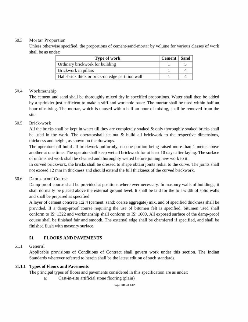
Page 601 of 612
50.3 Mortar Propor tion Unless otherwise specified, the proportions of cement-sand-mortar by volume for various classes of work shall be as under:
Type of work Cement Sand Ordinary brickwork for building 1 5 Brickwork in pillars 1 4 Half-brick thick or brick-on edge partition wall 1 4
50.4 Workmanship The cement and sand shall be thoroughly mixed dry in specified proportions. Water shall then be added by a sprinkler just sufficient to make a stiff and workable paste. The mortar shall be used within half an hour of mixing. The mortar, which is unused within half an hour of mixing, shall be removed from the site.
50.5 Brick-work All the bricks shall be kept in water till they are completely soaked & only thoroughly soaked bricks shall be used in the work. The operatorshall set out & build all brickwork to the respective dimensions, thickness and height, as shown on the drawings. The operatorshall build all brickwork uniformly, no one portion being raised more than 1 meter above another at one time. The operatorshall keep wet all brickwork for at least 10 days after laying. The surface of unfinished work shall be cleaned and thoroughly wetted before joining new work to it. In curved brickwork, the bricks shall be dressed to shape obtain joints redial to the curve. The joints shall not exceed 12 mm in thickness and should extend the full thickness of the curved brickwork.
50.6 Damp-proof Course Damp-proof course shall be provided at positions where ever necessary. In masonry walls of buildings, it shall normally be placed above the external ground level. It shall be laid for the full width of solid walls and shall be prepared as specified. A layer of cement concrete 1:2:4 (cement: sand: coarse aggregate) mix, and of specified thickness shall be provided. If a damp-proof course requiring the use of bitumen felt is specified, bitumen used shall conform to IS: 1322 and workmanship shall conform to IS: 1609. All exposed surface of the damp-proof course shall be finished fair and smooth. The external edge shall be chamfered if specified, and shall be finished flush with masonry surface. 51 FLOORS AND PAVEMENTS
51.1 General Applicable provisions of Conditions of Contract shall govern work under this section. The Indian Standards wherever referred to herein shall be the latest edition of such standards.
51.1.1 Types of Floors and Pavements The principal types of floors and pavements considered in this specification are as under:
a) Cast-in-situ artificial stone flooring (plain)

Page 602 of 612
b) Natural stone slab flooring c) Pre-cast artificial stone flooring (Plain/Textured)
51.2 Mater ials
51.2.1 Cement Ordinary Portland cement and white and colored cement shall conform to IS: 269.
51.2.2 Lime Where lime is required to be used, it shall conform to IS: 712 and slaking of lime shall be done according to IS: 1635.
51.2.3 Aggregates The aggregates shall conform to IS: 383. Fine aggregates shall range in size from 1.5 mm to 6 mm. unless specified otherwise. Not more than 5 percent of grains shall pass IS sieve 15 (0.151 mm mesh) and not more than 10 per cent shall pass IS sieve 30 (0.296 mm mesh). Coarse aggregate shall all pass through 19 mm mesh, unless specified otherwise and shall be graded as directed. The coarse aggregate for concrete pavements for approaches and driveways shall all pass through 25 mm ring and shall be formed by mixing 80% of 25 mm to 12 mm size and 20% of 12 mm to 6 mm size. The above proportion shall be altered to suit workability if so approved.
51.2.4 Natural Stone Slabs The stone slabs if used shall be best quality obtainable from Neemuch, Kotah, Shahabad, Tandur or other places as specified and shall be hard, even durable, uniform in color and free from cracks, flakes and other defects. No stone shall be thinner at its thinnest part than 25 mm. unless otherwise specified; the stones shall be 300 mm x 300 mm in size dressed square and with straight edges. The top surface of stones shall be smooth or polished as specified and edges dressed to a true fir or chisel dressed as directed.
51.2.5 Water Water shall be clean and free from injurious amounts of deleterious materials. As far as possible, water shall be of potable quality.
51.3 Cast in situ Artificial Stone Floor ing Grey and colored artificial stone is to be composed of 4 parts of fine stone chips 12 mm and below 2 parts of sand and properly screened to one part of cement. The topping in all cases and to consist of clean and fine sand and cement (2:1) and sufficient skin thickness to be kept and finally trowelled with neat cement finish perfectly smooth to satisfaction. In the case of dados and skirting the total thickness is to be 19 mm of which the bottom layer is to be 12 mm and the toping 6 mm thick in all cases both the layers are to be laid simultaneously without hiatus so that it will in effect be one complete layer; the mixing be made in two different lots.
51.4 Natural stone slab floor ing The stone slabs shall be evenly and firmly bedded to the required level and slopes as directed. Unless otherwise specified, the thickness of joints shall not exceed 6 mm for unpolished stone slabs and 1 mm for polished stones. The joints shall be raked out to an adequate depth and pointed flush or slightly sunk, as directed, with cement-sand mortar of 1:2 proportions. The stone slabs shall be laid to pattern which

Page 603 of 612
shall be approved prior to ordering the stones. The flooring shall be kept wet with wet sand or water for at least seven days. The flooring shall be well washed and shall be perfectly clean and free from all mortar stains etc. when completed 52 PLASTERING AND POINTING
52.1 General Applicable provisions of Conditions of Contract shall govern work under this section. The Indian Standards wherever referred to herein shall be the latest edition of such Standards.
52.2 Cement Plaster Mater ials o Cement : Cement shall confirm to IS: 269. o Sand : Shall confirm to IS: 1542.
Other materials, tools and Accessories, they shall confirm to relevant IS codes listed above and to the requirements specified in IS: 1661.
52.2.1 Proportioning and thickness of Cement Plasters: The proportions of materials, number of coats and thickness of each coat shall be as a specified or as directed.
52.2.2 Workmanship Unless otherwise specified, all plasterwork shall be carried out as per IS: 1661 “Code of Practice for Cement and Cement-Lime Plaster Finished on Walls and Ceilings”.Special finishing textures to the plaster shall be executed according to Clause 16 of IS: 1661 and/or as directed.
52.2.3 Curing After the completion of the work, the pointed face shall be kept well wetted for at least for 10 days in the case of Cement Pointing. 53 PAINTING AND GLAZING
53.1 General Applicable provisions of Conditions of Contract shall govern work under this section. The Indian Standards wherever referred to herein shall be the latest edition of such standards. Painting of Iron and Steel Work Painting of iron and steel work shall generally be carried out as per IS: 1447 (Part I).
53.2 Preparation of Surfaces: The surface to be painted shall be cleaned free of dirt, oil rust, mill scale and be thoroughly dry before painting. Cleaning, degreasing, and descalling wherever necessary shall be carried out as specified in IS: 1477 (Part I) and the method adopted for surface preparation shall have prior approval.
53.2.1 Primer Coat: Unless otherwise specified, the primer coat for steel and iron work shall be of Red Lead paint, conforming to IS: 102. The Red Lead primer shall be applied by means of approved brushes. The Red Lead paint shall be allowed to dry sufficiently hard before the application of the succeeding coat A red

Page 604 of 612
lead painted surface shall not however be left exposed permanently, as it is liable to heavy chalking. The primer coat shall be applied as specified in IS: 1477 (Part-I) and the number of coats shall be as necessary for as directed.
53.2.2 Finish Coat The type of intermediate and finish coat and the number of coats to be applied shall be as necessary or as directed. Intermediate and finish coats may be oil bound bituminous, aluminum or other types of paints. Aluminum conforms to IS: 165. The intermediate and finish coats for structural steel work, sheet metal work and cast iron work shall be applied as specified in IS: 1477 (Part-I).
53.3 Glazing Mater ials
53.4 Glass All glass used in the work shall be best quality glass free from specks, bubbles, smokes, wanes, air holes and other defects, Unless other-wise specified, sheet glass shall be transparent and of the following weights. For panes up to 600 mm x 600 mm in size, glass weighing not less than 7.97 kg/sq.m. shall be used for panes 750 mm x 750 mm to 900 mm x 900 mm size, the weight of glass shall be 9.76 kg/sq.m. Unless other-wise specified, for sizes of glass above 900 mm x 900, plate glass shall be used.
53.4.1 Putty Putty for use on wooden frames shall conform to IS: 419 and on metal frames to IS: 420.
53.4.2 Workmanship All glass be cut according to the sizes required as per drawings. Glazing of metal doors, windows and ventilators shall conform to IS: 1081 and glazing of timber doors, windows, and ventilators shall conform to IS: 1003, unless specified otherwise. For glazing wooden doors and windows, the wooden frame, particularly the rebate, shall be well oiled to prevent oil from putty being sucked in by wood. The Operator shall thoroughly clean all glass and replace all putty or glass damaged during the work. 54 MISCELLANEOUS STEEL AND IRON WORK
54.1 General Applicable provisions of Conditions of Contract shall govern work under this section. The Indian Standards wherever referred to herein shall be the latest edition of such Standard.
54.2 Iron Gr ills The grills for Windows, verandahs, balconies, etc. shall be of mild steel or wrought iron as specified for the work. The design of grills and shapes and sizes of various components shall be as approved. The edges, angles and corners shall be clean and true to shape. The joints shall be mechanically inter-locked and overlapping areas spot welded in such a way that the grill is rigid. Where moulded grills are specified, the moulded work shall be as approved, and shall have clean, straight and sharply defined profiles. The operatorshall do the necessary cutting, fitting, drilling, tapping, scribing etc. required to fix grills to adjacent surfaces. The grills shall be fixed plumb, in line and level. Unless otherwise specified, grills shall be painted with two coats of red lead paint conforming to IS: 102 before they are fixed.

Page 605 of 612
54.3 Rolling Shutters Rolling shutters, where specified shall be of the size to suit the openings and shall be positioned as shown on the drawings and/or as directed. The rolling shutter shall be fabricated from 18 B.G. Steel and machine rolled with 75 mm rolling contras with effective bridge depth of 12 mm lath sections, interlocked with each other and ends locked with malleable cast iron. The guides shall be either rolled or pressed deep channel sections 75 mm deep and 25 mm wide fitted with necessary fittings and fixtures. The suspension shaft shall be formed from solid drawn seamless tubes 60 mm O.D. of wall thickness of 25 mm in 3 segments coupled 2 with 2 pairs C.I. dog-tailed flange coupling forming one complete unit eliminating deflection in the center to a minimum. The springs shall be imported high tensile English flat springs 50/60 mm breadth and 1.6/1.8 mm thickness hardened and tempered. These shall be fitted inside the fabricated housing on either ends, which counterbalance the shutter curtain. The ball bearings shall be double row self aligning ball bearing fitted inside C.I. housing fixed on side brackets holding the suspension shaft at either end .The suspension of the curtain shall be belted in specially fabricated cages formed from MS flats, and plates all are welded. The hood cover shall be made of 20 gauge G.P. sheets with necessary stiffeners and framework to prevent sag, the bottom lock plate shall be made of 3 mm thick M.S. plate and 95 mm wide reinforced with angle/T iron of suitable section with 6 mm dia. M.S.rivets interlocked with last stride of curtain. The locking arrangement shall consist of hasp and staple on the bottom plate, lockable from both sides. Unless otherwise specified, for overall area of rolling shutters up to 9 sq. m. pull and push type hand-operated shutters shall be used, for area between 9 and 12 sq. m. Pull and Push type shutters shall be provided with ball bearings; for area larger than 12 sq. m. , Mechanical Gear type shutters shall be supplied.
54.4 Collapsible Gates Collapsible gates shall be of the size and type as specified by the Owner’s Engineer. The gates shall be manufactured out of M.S. channel pickets of size 20 mm x 10 mm and flats 20 mm x 6 mm. The top runner flat shall be at least 50 mm x 12 mm in section. The bottom guide shall consist of a channel or two angles of specified size laid in the flooring to guide the free movement of the gate. The gate shall move in the guide channel on rollers of adequate size fixed at the top and bottom of the gate as specified. The gate shall be painted with one coat of red lead paint conforming to IS : 102 before fixing in position. 55 WOODWORK AND JOINARY
55.1 Wood: All wood required to be used, shall be dry, well-seasoned, Bulsar teak wood and shall be free from knots, cracks or any other kind of defects frames for doors and windows.
55.2 Jointing Mater ials: All nails, screws, fixtures shall be of standard quality as approved by the Owner.

Page 606 of 612
55.3 Cutting Edges: Cutting edge for well to be fabricated as per the drawing approved by Owner’s engineer The structural steel to be used, should confirm to IS: 226-1961 and IS: 2062-1962. The steel shall be free from defects as mentioned in IS: 226-1962 and shall have a smooth uniform finish. Material shall be free from loose mile scale, rusting or other defects affecting its strength and durability. The test certificates shall have to be submitted for the structural steel used in cutting edge. ILLUMINATION: All internal and external areas shall be provided with lighting. The illumination levels to be achieved shall be as follows:
AREA LUX
Office and labs 300 Lux
Switchgear Room 200 Lux
Control Room 300 Lux
Pump House 200 Lux
DG set room 200 Lux
Chemical and general store 150 Lux
Chemical Plant room 200 Lux
Other indoor areas 100 Lux
Outdoor plant from and 50 Lux
Building entrance 100 Lux
Indoor Plant Area 200 Lux
Outdoor Plant Area 50 Lux
Transformer Area 100 Lux
Roads 10 Lux
Fluorescent luminaries shall be used primarily for internal lighting. High pressure vapour or metal halide type luminaries shall be used in indoor application where their use is appropriate. If mercury or metal halide is used in indoor then they should be supplemented with fluorescent luminaries to assure that

Page 607 of 612
minimum illumination levels are maintained following momentary power dips. All other internal areas shall be lit with fluorescent luminaries. Where specific recommendations of lux level are not covered above, illumination level in such areas shall be finalized in consultation with Owner. Owner shall be required to measure levels of illumination after completion of lighting installation work and short fall in illumination level shall be made good by the Operator. Complete set of calculations showing, room, index, copy MF shall be given during detailed engineering. Switches / sockets of piano type shall be used in general and in offices of staff, control room, MMI room, decorative modular switches shall be used. Suitable fans shall be provided in rooms/ plant areas as per standards. For exhaust fans it must be provided in panel rooms, pump rooms, chemical rooms, stores, toilets and at least 20 air changes per hour must be maintained. The following type of lighting fixtures shall be proposed:
a) Decorative type 2x36W fixtures for fluorescent luminaries inside office/ administrative buildings and control rooms.
b) Corrosion resistant fixture with canopy made of FRP for fluorescent luminaries for corrosive areas like chlorine handling or chemical store or area with corrosive smell/gases etc.
c) Industrial type vitreous enameled fixture for fluorescent luminaries inside 415V switchgear, MCC room and pump house.
d) In outdoor process areas, lighting fixtures shall be sodium vapour type subjected to minimum of IP protection class.
e) All outside lights as plant field lights, building outside lights, flood lights etc. which are to be switched on only during night hours should be controlled through photo cell/ clock switch installed at a central place. All lights shall have minimum IP65 protection class.
f) Street lighting wiring shall be through buried underground. g) All bulb fittings (except fluorescent lamps) will have screw type caps. h) For outdoor lighting, the lighting feeder shall be operated through a contactor, controlled by photocell/
clock switch and shall also have a manual by pass switch. Luminaries shall be installed to permit ease of maintenance i.e. it shall not be necessary to shut down plant in order to carryout maintenance or to access luminaries located over areas of water etc. The Operator shall provide all equipment necessary to carryout maintenance on the lighting installation and demonstrate its operation to the satisfaction of Owner Indoor lighting circuit will be arranged in such a way that 50% lighting can be put off in each room through switches. All lighting circuits will be wired with 2.5sq.mm. Stranded copper wire or through 2.5 sq.mm. armoured cable laid in cable trays. Sub circuit from switch to fixture could be wired with1.5 sq.mm. stranded copper wire in MS conduits or armoured copper cable of similar size provided total voltage drop in any lighting distribution board to last lighting point shall not exceed 2%. All lighting circuits will have separate neutral, separate earth from Lighting Distribution Board. For illumination of roads, outdoors areas where operation of equipment or units required and sub station area, lighting fixtures of appropriate type (such as street lighting type, flood lighting type, post top lanterns etc.) incorporating high pressure sodium vapour lamps shall be proposed. Street light poles shall not have less than 7500 mm height above the finished road level and the arm shall not project more than 1200 mm along the road width. Poles of bigger heights may also be used if some outdoor areas are to be

Page 608 of 612
illuminated. Poles of 4 / 4.5 Mtrs using post top lantern may be used in gate office walk way or in front of office area. Complete area, streets, lanes, boundary shall be covered with street lighting. Receptacles (Lighting & Small Power) :
d) Decorative and industrial type units of above shall be proposed in all plant areas, offices, stores, workshop, plant room and they shall be located at least two numbers in each room. Distance between two receptacles shall not be more than 8 – 10 mtr. All small 5 amps 5 pin lighting & small power sockets shall be wired by multi stranded copper wire of 2.5 sq. mm laid in rigid MS conduits along with earth wire of1.5 sq.mm flexible copper wire or equivalent size armoured cables. All wiring shall be coded with Red, Yellow, Blue & Black as per the phase used. If required, wiring can be done alternatively through armoured copper cables of similar size laid in MS perforated trays of minimum 2.0 mm thick.
e) Three phase power receptacles (convenience outlets) suitable for operation of 415V,3 Phase 4 wire, 50 Hz power supply shall be proposed. In indoor areas one such unit shall be provided to cover areas of 20 meter radius (or at least one in each room housing plant items ) and in outdoors areas on such unit shall be provided at 50 meter interval. Actual requirement of such units shall be finalized by MMC during detailed engineering. One three phase receptacle shall be provided near entrance of each building for utilities like welding.
f) Single phase 15 Amp 5 Pin / 6 Pin receptacles will be provided in each room and in halls they will be provided in such a way that with 15 meter cord we should reach every place in building. These shall be wired with 4 sq. mm copper earth wire in MS rigid conduits along with 2.5 sq. mm earth wire. Not more than two sockets shall be looped in one circuit. Alternatively they can also be connected through armoured cable of 4 sq. mm running in appropriate cable trays. Separate lighting panels and lighting distribution boards shall be installed and they shall not take tapping for power from motor control centers or power distribution boards.
56 Section IV Electro Mechanical Works
56.1 Technical Specifications for Electr ical Works: All works shall be carr ied out in accordance with the requirements of:
i. IE Rules ii. State Electricity Board iii. Rules and regulations of Local authorities, and iv. The standards in this specification
The Operator is responsible for applying and obtaining necessary statutory approvals and shall ensure workmanship of good quality and shall assign qualified supervisor / engineers and competent labour who are skilled, careful and experienced in carrying out similar works.
56.2 IS codes for electr ical Works:
IS : 10418 Specification for drums of electric cables

Page 609 of 612
IS : 2633 Methods of testing weight, thickness and uniformity of coating on hot dipped galvanized articles
IS : 209 Specifications for Zinc
Code No. Title
IS : 2062 Steel for general structural purposes
IS : 808 Dimensions for hot rolled steel beam, column channel and angle sections
IS : 816
Code of practice for use of metal arc welding for general construction in mild steel
IS : 2629
Hot deep galvanising of iron & steel
IS : 2633
Methods of testing uniformity of coating
IS : 4759 Hot dip zinc coatings on Structural steel and other allied Products
Code No. Title
IS2026/BS171/IEC76
Power Transformer
IS3639 Fittings and Accessories IS1180 Auxiliary Transformer IS6600/BSCP.1010/IEC354
Loading of oil immersed transformer
IS335/BS 148/IEC296
Transformer Oil
IS2099/BS223/IEC137
Bushings for > 1000V, AC
IS7421 Bushings for ≤ 1000V, AC IS13947 (Part 1) / IEC947-1
Degree of Protection
IS3637 Buchholz Relay IS 1271/BS2757/IEC85
Insulation Materials for Electrical Machinery
IS 3202/ Climate Proofing

Page 610 of 612
BSCP1014/ IEC354 IS 1886 Installation & Maintenance of Transformers IS 2705 Current Transformers I.S. 3043 – 1987.
Earth Pits
General Specification for Electrical works Part VII (DG Sets) published by CPWD.
56.3 Specifications for mechanical equipment: Mechanical equipment: will be required for following units
1. Screenchannels,mechanicallycleanedfinescreens. 2. Sluice gates 3. Gritchamberswith mechanical gritremovalequipment 4. Parshallflumes 5. Varioussizesofinterconnectingpiping. 6. Fire-fightingequipmentasper state Government department of Fireservices.
All mechanical equipment such as screens, degritting devices, sluice gates, etc which comes into contact with sewage shall be fabricated in non corrosive materials and metallic parts in contact with sewage shall conform to Stainless steel. All walkways s h a l l b e i n R C C o r s t a i n l e s s s t e e l withs t a i n l e s s s t e e l handrails.Provideappropriateexplosionproofconstructionanddevicesatanyenclosedlocationscomponentswhereincomingsewageisexposedtoatmosphere. Mechanicalscreensshallbeoperated w i t h Shaftlessscrewconveyors t o t ransferscreeningstothescrewcompactortodewaterandcompactthescreenings.Thescreenwillbecontrolledbyatimerasbackuptolevelcontrol,sothat,thecleaningmechanismcanrunatasetinterval. Thedepositedgritwillberemovedfromthegritchambersbyappropriateandefficientremovingmechanism.Gritremovalshallbeaccompaniedwithagritclassifierandgritwashingsystemtoensurethegritisfreefromorganicmatterbeforedisposal. Parshallflumesdownstreamofeachgritchamberstructureshallberequiredwhereanultrasonicflowmeterwillbeinstalledformeasuringandaddingthetotalflowofrawsewageenteringthesite. Isolationweirgates and bye pass shallberequiredtocontroland/orisolateflowtoanyone units
56.4 IS codes for mechanical equipment: IS 6280 – 1971 – Sewage Screens IS 8413 – 1982 – Biological Treatment Equipment – Part II and its modifications IS 10037 – Part I – 1981 & Part II & III – 1983 – Sludge dewatering equipments IS 10261 – Requirements for settling tank for waste water IS 105533 – Part I, II, III – Chlorination Plants IS 5600 – 1970 - Sewage and Drainage Pumps IS 6279 – 1971 – Grit Removal devices

Page 611 of 612
The list is not exclusive and the operator shall be responsible to follow the appropriate standards: Instrumentation,ControlandSCADASystem ASupervisoryControlandDataAcquisition(SCADA)system will be installed in the Sewage Pumping station networkedtothe PLCand shall acquire, display, monitor and issue remote control actions for maintaining the pumps.The SCADA system shall also originatecustomperformancereportsformanagementreporting. Section- V TRAINING AFTER COMMISSIONING & DEFECT LIABILITY PERIOD
57 TRAINING OF OWNER'S PERSONNEL
The Operator shall be responsible to provide practical training in all aspects of the operation,
maintenance, and facilities to all personnel selected by the Owner, who will ultimately be responsible for the operation, maintenance and repair of the system and its facilities after defects liability period.
For this purpose, the Operator shall provide a comprehensive training program for the Owner’s personnel during the entire period of the trial run, and for as long thereafter as may be reasonably required to ensure that the designated personnel are adequately trained to take up their responsibilities.
All costs for the Operator’s personnel and the training facilities required for the training during trial run period, and any incidental training expenses, shall be borne by the Operator.
58 TRIAL RUN OF THE SYSTEM After commissioning of works, the Operator shall maintain the works for 3 (three) months to demonstrate satisfactory performance to the Engineer prior to taking over by the Owner. The cost of electricity, if required for operation & maintenance of works during the period of this trial run will be borne by the Owner. The cost towards Operator’s Engineer and other operating personnel during the said period of trial run, along with cost of tools and spare parts which are required for operation and maintenance of the works and equipment during the trial run period shall be borne by the Operator and shall be included in the quoted bid price. In the event that the system or any of the facilities do not satisfactorily achieve the required performance standards during this period, the trial run period shall be extended until such time as the Operator has satisfactorily rectified any deficiencies as may be necessary to satisfy the performance requirements. No additional compensation will be paid to the Operator for such extension.

Page 612 of 612
Schedule 11
Allowed and Suggested alignments / Locations for design of the I&DWorks
TO (I) DESIGN AND BUILD SEWAGE TREATMENT PLANTOF INSTALLED CAPACITY 32 MLD AND ALL APPURTENANT STRUCTURES AND ALLIED WORKS IN TWO MODULES (16MLD+16MLD);(II) SURVEY, REVIEW THE DESIGNS, REDESIGN WHERE NECESSARY, AND BUILD NEW DIVERSION WORKS WITH INTERCEPTION WITH RISING MAIN 2.3 KM, NEW TAPPINGS OF LENGTH 18.95 KM FOR 39 DRAINS CONTROLLED WITH SCADA INCLUDING SURVEY, DESIGN, CONSTRUCTION OF 5 NO. PUMPING STATIONS AND ALL APPURTENANT STRUCTURES AND ALLIED WORKS; AND CONSTRUCTION OF 31 OUTFALL STRUCTURE WITH SLUICE GATE INCLUDING EFFLUENT CHANNEL (250 MTR) FOR REUSE OF TREATED WASTE WATER (III) OPERATION & MAINTENANCE OF THE COMPLETE WORKS OF SEWAGE TREATMENT PLANT, INTERCEPTION & DIVERSION WORKS AND PUMPING STATIONS FOR A PERIOD OF 15 YEARS IN CHHAPRA TOWN , STATE OF BIHAR , INDIA.