
PHILIPPINE BIDDING DOCUMENTS - Bangko Sentral ng ...
801
1 PHILIPPINE BIDDING DOCUMENTS PROCUREMENT of ONE (1) LOT - HIRING OF GENERAL CONTRACTOR FOR THE PROPOSED OFFICE AND COMMERCIAL BUILDING WITH PARKING AT PHILIPPINE INTERNATIONAL CONVENTION CENTER, AS PER BSP SCOPE OF WORKS, TECHNICAL SPECIFICATIONS, AND BSP APPROVED PLANS AND DRAWINGS BIDS AND AWARDS COMMITTEE - INFORMATION TECHNOLOGY, INFRASTRUCTURE AND OTHER RELATED COMPONENTS 2nd Floor, 5-Storey Bldg., A. Mabini corner P. Ocampo Sr. Sts, Malate, Manila, 1004 PHILIPPINES Phone Nos.: 5306-2798 to 2800 Email Address: [email protected] Sixth Edition July 2020
-
Upload
khangminh22 -
Category
Documents
-
view
3 -
download
0
Transcript of PHILIPPINE BIDDING DOCUMENTS - Bangko Sentral ng ...

1
PHILIPPINE BIDDING DOCUMENTS
PROCUREMENT
of ONE (1) LOT - HIRING OF GENERAL
CONTRACTOR FOR THE PROPOSED
OFFICE AND COMMERCIAL
BUILDING WITH PARKING AT
PHILIPPINE INTERNATIONAL
CONVENTION CENTER, AS PER BSP
SCOPE OF WORKS, TECHNICAL
SPECIFICATIONS, AND BSP
APPROVED PLANS AND DRAWINGS
BIDS AND AWARDS COMMITTEE - INFORMATION TECHNOLOGY,
INFRASTRUCTURE AND OTHER RELATED COMPONENTS
2nd Floor, 5-Storey Bldg., A. Mabini corner P. Ocampo Sr. Sts,
Malate, Manila, 1004 PHILIPPINES
Phone Nos.: 5306-2798 to 2800
Email Address: [email protected]
Sixth Edition
July 2020

2
TABLE OF CONTENTS
GLOSSARY OF ........................................................................................................4
TERMS, ABBREVIATIONS, AND ACRONYMS .........................................................4
SECTION I. INVITATION TO BID ............................................................................6
SECTION II. INSTRUCTIONS TO BIDDERS .......................................................... 11
1. Scope of Bid ............................................................................................................12
2. Funding Information ...............................................................................................12
3. Bidding Requirements .............................................................................................12
4. Corrupt, Fraudulent, Collusive, Coercive, and Obstructive Practices ....................12
5. Eligible Bidders .......................................................................................................13
6. Origin of Associated Goods ....................................................................................13
7. Subcontracts ............................................................................................................13
8. Pre-Bid Conference .................................................................................................14
9. Clarification and Amendment of Bidding Documents............................................14
10. Documents Comprising the Bid: Eligibility and Technical Components ...............14
11. Documents Comprising the Bid: Financial Component .........................................15
12. Alternative Bids ......................................................................................................15
13. Bid Prices ................................................................................................................15
14. Bid and Payment Currencies ...................................................................................15
15. Bid Security .............................................................................................................15
16. Sealing and Marking of Bids...................................................................................16
17. Deadline for Submission of Bids ............................................................................16
18. Opening and Preliminary Examination of Bids ......................................................16
19. Detailed Evaluation and Comparison of Bids .........................................................16
20. Post Qualification ....................................................................................................17
21. Signing of the Contract ...........................................................................................17
SECTION III. BID DATA SHEET ......................................................................... 18
SECTION IV. GENERAL CONDITIONS OF CONTRACT ....................................... 25
1. Scope of Contract ....................................................................................................26
2. Sectional Completion of Works ..............................................................................26
3. Possession of Site ....................................................................................................26
4. The Contractor’s Obligations ..................................................................................26
5. Performance Security ..............................................................................................27
3
6. Site Investigation Reports .......................................................................................27
7. Warranty ..................................................................................................................27
8. Liability of the Contractor .......................................................................................27
9. Termination for Other Causes .................................................................................27
10. Dayworks ................................................................................................................28
11. Program of Work.....................................................................................................28
12. Instructions, Inspections and Audits .......................................................................28
13. Advance Payment....................................................................................................28
14. Progress Payments ..................................................................................................28
15. Operating and Maintenance Manuals......................................................................28
SECTION V. SPECIAL CONDITIONS OF CONTRACT ........................................... 30
SECTION VI. SPECIFICATIONS ........................................................................... 36
SECTION VII. DRAWINGS .................................................................................. 38
SECTION VIII. BILL OF QUANTITIES ................................................................ 39
SECTION IX. CHECKLIST OF ELIGIBILITY (LEGAL, TECHNICAL AND
FINANCIAL DOCUMENTS), FINANCIAL AND OTHER DOCUMENTS ............. 41
CONTRACT FORMS ....................................................................................... 59

4
Glossary of
Terms, Abbreviations, and Acronyms ABC – Approved Budget for the Contract.
ARCC – Allowable Range of Contract Cost.
BAC – Bids and Awards Committee.
Bid – A signed offer or proposal to undertake a contract submitted by a bidder in response to
and in consonance with the requirements of the bidding documents. Also referred to as
Proposal and Tender. (2016 revised IRR, Section 5[c])
Bidder – Refers to a contractor, manufacturer, supplier, distributor and/or consultant who
submits a bid in response to the requirements of the Bidding Documents. (2016 revised IRR,
Section 5[d])
Bidding Documents – The documents issued by the Procuring Entity as the bases for bids,
furnishing all information necessary for a prospective bidder to prepare a bid for the Goods,
Infrastructure Projects, and/or Consulting Services required by the Procuring Entity. (2016
revised IRR, Section 5[e])
BIR – Bureau of Internal Revenue.
BSP – Bangko Sentral ng Pilipinas.
CDA – Cooperative Development Authority.
Consulting Services – Refer to services for Infrastructure Projects and other types of projects
or activities of the GOP requiring adequate external technical and professional expertise that
are beyond the capability and/or capacity of the GOP to undertake such as, but not limited to:
(i) advisory and review services; (ii) pre-investment or feasibility studies; (iii) design; (iv)
construction supervision; (v) management and related services; and (vi) other technical services
or special studies. (2016 revised IRR, Section 5[i])
Contract – Refers to the agreement entered into between the Procuring Entity and the Supplier
or Manufacturer or Distributor or Service Provider for procurement of Goods and Services;
Contractor for Procurement of Infrastructure Projects; or Consultant or Consulting Firm for
Procurement of Consulting Services; as the case may be, as recorded in the Contract Form
signed by the parties, including all attachments and appendices thereto and all documents
incorporated by reference therein.
Contractor – is a natural or juridical entity whose proposal was accepted by the Procuring
Entity and to whom the Contract to execute the Work was awarded. Contractor as used in these
Bidding Documents may likewise refer to a supplier, distributor, manufacturer, or consultant.
CPI – Consumer Price Index.
DOLE – Department of Labor and Employment.
DTI – Department of Trade and Industry.

5
Foreign-funded Procurement or Foreign-Assisted Project – Refers to procurement whose
funding source is from a foreign government, foreign or international financing institution as
specified in the Treaty or International or Executive Agreement. (2016 revised IRR, Section
5[b]).
GFI – Government Financial Institution.
GOCC – Government-owned and/or –controlled corporation.
Goods – Refer to all items, supplies, materials and general support services, except Consulting
Services and Infrastructure Projects, which may be needed in the transaction of public
businesses or in the pursuit of any government undertaking, project or activity, whether in the
nature of equipment, furniture, stationery, materials for construction, or personal property of
any kind, including non-personal or contractual services such as the repair and maintenance of
equipment and furniture, as well as trucking, hauling, janitorial, security, and related or
analogous services, as well as procurement of materials and supplies provided by the Procuring
Entity for such services. The term “related” or “analogous services” shall include, but is not
limited to, lease or purchase of office space, media advertisements, health maintenance
services, and other services essential to the operation of the Procuring Entity. (2016 revised
IRR, Section 5[r])
GOP – Government of the Philippines.
Infrastructure Projects – Include the construction, improvement, rehabilitation, demolition,
repair, restoration or maintenance of roads and bridges, railways, airports, seaports,
communication facilities, civil works components of information technology projects,
irrigation, flood control and drainage, water supply, sanitation, sewerage and solid waste
management systems, shore protection, energy/power and electrification facilities, national
buildings, school buildings, hospital buildings, and other related construction projects of the
government. Also referred to as civil works or works. (2016 revised IRR, Section 5[u])
LGUs – Local Government Units.
NFCC – Net Financial Contracting Capacity.
NGA – National Government Agency.
PCAB – Philippine Contractors Accreditation Board.
PhilGEPS - Philippine Government Electronic Procurement System.
Procurement Project – refers to a specific or identified procurement covering goods,
infrastructure project or consulting services. A Procurement Project shall be described,
detailed, and scheduled in the Project Procurement Management Plan prepared by the agency
which shall be consolidated in the procuring entity's Annual Procurement Plan. (GPPB Circular
No. 06-2019 dated 17 July 2019)
PSA – Philippine Statistics Authority.
SEC – Securities and Exchange Commission.
SLCC – Single Largest Completed Contract.
UN – United Nations.
6
Section I. Invitation to Bid
Notes on the Invitation to Bid
The Invitation to Bid (IB) provides information that enables potential Bidders to decide
whether to participate in the procurement at hand. The IB shall be posted in accordance with
Section 21.2 of the 2016 revised IRR of RA No. 9184.
Apart from the essential items listed in the Bidding Documents, the IB should also indicate
the following:
a. The date of availability of the Bidding Documents, which shall be from the time the
IB is first advertised/posted until the deadline for the submission and receipt of bids;
b. The place where the Bidding Documents may be acquired or the website where it
may be downloaded;
c. The deadline for the submission and receipt of bids; and
d. Any important bid evaluation criteria.
The IB should be incorporated into the Bidding Documents. The information contained in
the IB must conform to the Bidding Documents and in particular to the relevant information
in the Bid Data Sheet.

7
BIDS AND AWARDS COMMITTEE – INFORMATION TECHNOLOGY,
INFRASTRUCTURE AND OTHER RELATED COMPONENTS
INVITATION TO BID
1. The Bangko Sentral ng Pilipinas (BSP), through its Bids and Awards Committee –
Information Technology, Infrastructure and Other Related Components (BAC-ITIO),
invites interested contractors to bid for the project described below:
Name of Requirement
One (1) Lot – Hiring of General Contractor for the Proposed
Office and Commercial Building with Parking at Philippine
International Convention Center, as per BSP Scope of
Works, Technical Specifications, and BSP Approved Plans
and Drawings
Brief Description and
Scope of Work
The BSP intends to repurpose the (former) BSP Museum
building structure, consisting of the structural foundation
and part of the superstructure, including the partially
completed Powerhouse to the Proposed Office and
Commercial Building with Parking (OCBP) all in
accordance with the issued plans/drawings, technical
specifications and other contract documents. The delivered
materials on site before the termination of the contract of
the general contractor which are still in good condition
shall also be considered to be used in the proposed project.
Approved Budget for
the Contract (ABC)
Php224,334,000.00, inclusive of all applicable taxes and
other charges
(Bids received in excess of the above amount shall be
automatically rejected at bid opening, or during bid
evaluation.)
Procurement Project
Identification Number
(PIN)
BAC-ITIO IN No. 2021-0203 dated 04 October 2021
Funding Source BSP Corporate Fund: Approved Budget of Project
Development and Management Department (PDMD) for
Y2021.
Contract Duration/
Completion Period
The Contractor shall complete and turn-over the project in
Two Hundred Forty (240) calendar days inclusive of the
duration required for the application, approval and
submission to the BSP of the approved Building Permit and
necessary documents from the date stipulated in the Notice
to Proceed (NTP) to be issued by PDMD.

8
Description of Eligible
Bidder
Prospective bidders should have a valid PCAB License and
registration for “Building and/or Industrial Plant” (project
kind) with at least “Medium B” (size range) and “A”
(License Category); and Special PCAB License, if bidding
as Joint Venture.
2. Bidders should have a single largest contract similar to the requirement as stated in the
Clause 5.2 of the Bid Data Sheet (BDS) and Item 3 of the Checklist of Requirements
for Bidders (Checklist).
3. The Eligibility Check/Screening and Preliminary Examination of Bids shall use non-
discretionary “pass/fail” criterion as stated in Section 30.1 of the 2016 Revised
Implementing Rules and Regulations of Rep. Act No. 9184 (2016 Revised IRR).
4. Bidding is restricted to Filipino citizens, sole proprietorship, partnership, corporation,
cooperative or organizations with at least sixty percent (60%) interest or outstanding
capital stock belonging to citizens of the Philippines, and to citizens or organizations of
a country the laws or regulations of which grant similar rights or privileges to Filipino
citizens, pursuant to Rep. Act. No. 5183.
5. All particulars and activities regarding the Eligibility of Bidders, Bid Security, Pre-Bid
Conference/s, Evaluation of Bids, Post-qualification, Award of Contract, Performance
Security, procedures and other documents, shall be governed by Rep. Act No. 9184 and
the 2016 Revised IRR.
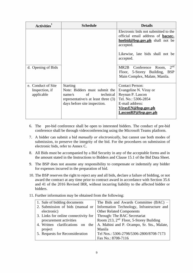
Activities1 Schedule Details
a. Issuance of Bid
Documents
Starting 06 October 2021
(from 9:00 A.M. to 2:00 P.M.
only)
Hard copies of documents are no
longer issued for the duration of
community restrictions.
b. Pre-Bid
Conference
13 October 2021, 9:30 A.M.
(PHILIPPINE TIME)
MR2B Conference Room, 2nd
Floor, 5-Storey Building, BSP
Main Complex, Malate, Manila
(For interested bidders and
observers, see item 6 below.)
c. Deadline for
Submission of
Bids
25 October 2021, 1:00 P.M.
(PHILIPPINE TIME)
Manual submission:
Gate 3 reception lobby, Bangko
Sentral ng Pilipinas, A. Mabini
corner P. Ocampo Sr. Sts., Malate,
Manila.
Electronic submission:2
Email address:
1 See Annexes B and C for the Guidelines in the conduct of Pre-Bid Conference, Submission and Opening of Bids.
2 The BSP system can accommodate attachments with file size limit of up to 100MB.
9
Activities1 Schedule Details
Electronic bids not submitted to the
official email address of bacsec-
[email protected] shall not be
accepted.
Likewise, late bids shall not be
accepted.
d. Opening of Bids MR2B Conference Room, 2nd
Floor, 5-Storey Building, BSP
Main Complex, Malate, Manila.
e. Conduct of Site
Inspection, if
applicable
Starting
Note: Bidders must submit the
name/s of technical
representative/s at least three (3)
days before site inspection.
Contact Person:
Evangeline N. Viray or
Reynan P. Lascon
Tel. No.: 5306-2854
E-mail address:
6. The pre-bid conference shall be open to interested bidders. The conduct of pre-bid
conference shall be through videoconferencing using the Microsoft Teams platform.
7. A bidder can submit a bid manually or electronically, but cannot use both modes of
submission, to preserve the integrity of the bid. For the procedures on submission of
electronic bids, refer to Annex C.
8. All Bids must be accompanied by a Bid Security in any of the acceptable forms and in
the amount stated in the Instructions to Bidders and Clause 15.1 of the Bid Data Sheet.
9. The BSP does not assume any responsibility to compensate or indemnify any bidder
for expenses incurred in the preparation of bid.
10. The BSP reserves the right to reject any and all bids, declare a failure of bidding, or not
award the contract at any time prior to contract award in accordance with Section 35.6
and 41 of the 2016 Revised IRR, without incurring liability to the affected bidder or
bidders.
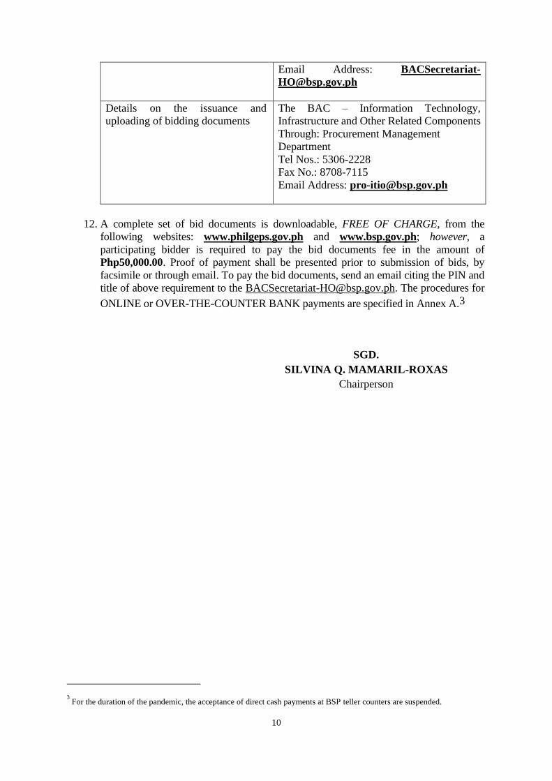
11. Further information may be obtained from the following:
1. Sale of bidding documents
2. Submission of bids (manual or
electronic)
3. Links for online connectivity for
procurement activities
4. Written clarifications on the
project
5. Requests for Reconsideration
The Bids and Awards Committee (BAC) –
Information Technology, Infrastructure and
Other Related Components
Through: The BAC Secretariat
Room 213, 2nd Floor, 5-Storey Building
A. Mabini and P. Ocampo, Sr. Sts., Malate,
Manila
Tel Nos.: 5306-2798/5306-2800/8708-7173
Fax No.: 8708-7116
10
Email Address: BACSecretariat-
Details on the issuance and
uploading of bidding documents
The BAC – Information Technology,
Infrastructure and Other Related Components
Through: Procurement Management
Department
Tel Nos.: 5306-2228
Fax No.: 8708-7115
Email Address: [email protected]
12. A complete set of bid documents is downloadable, FREE OF CHARGE, from the
following websites: www.philgeps.gov.ph and www.bsp.gov.ph; however, a
participating bidder is required to pay the bid documents fee in the amount of
Php50,000.00. Proof of payment shall be presented prior to submission of bids, by
facsimile or through email. To pay the bid documents, send an email citing the PIN and
title of above requirement to the [email protected]. The procedures for
ONLINE or OVER-THE-COUNTER BANK payments are specified in Annex A.3
SGD.
SILVINA Q. MAMARIL-ROXAS
Chairperson
3 For the duration of the pandemic, the acceptance of direct cash payments at BSP teller counters are suspended.

11
Section II. Instructions to Bidders
Notes on the Instructions to Bidders
This Section on the Instruction to Bidders (ITB) provides the information necessary for
bidders to prepare responsive bids, in accordance with the requirements of the Procuring
Entity. It also provides information on bid submission, eligibility check, opening and
evaluation of bids, post-qualification, and on the award of contract.
12
1. Scope of Bid
The Procuring Entity, BANGKO SENTRAL NG PILIPINAS (BSP) invites Bids for One
(1) Lot – Hiring of General Contractor for the Proposed Office and Commercial
Building with Parking at Philippine International Convention Center, as per BSP Scope
of Works, Technical Specifications, and BSP Approved Plans and Drawings, with
Project Identification Number BAC-ITIO IN No. 2021-0203 dated 04 October 2021.
[Note: The Project Identification Number is assigned by the Procuring Entity based on
its own coding scheme and is not the same as the PhilGEPS reference number, which
is generated after the posting of the bid opportunity on the PhilGEPS website.]
The Procurement Project (referred to herein as “Project”) is for the construction of
Works, as described in Section VI (Specifications).
2. Funding Information
2.1. The GOP through the source of funding as indicated below for Y2021 in the
amount of Php224,334,00.00, inclusive of all applicable taxes and other
charges.
2.2. The source of funding is: BSP Corporate Fund: Approved Budget of PDMD for
Y2021.
3. Bidding Requirements
The Bidding for the Project shall be governed by all the provisions of RA No. 9184 and
its 2016 revised IRR, including its Generic Procurement Manual and associated
policies, rules and regulations as the primary source thereof, while the herein clauses
shall serve as the secondary source thereof.
Any amendments made to the IRR and other GPPB issuances shall be applicable only
to the ongoing posting, advertisement, or invitation to bid by the BAC through the
issuance of a supplemental or bid bulletin.
The Bidder, by the act of submitting its Bid, shall be deemed to have inspected the site,
determined the general characteristics of the contracted Works and the conditions for
this Project, such as the location and the nature of the work; (a) climatic conditions;
(b) transportation facilities; (c) nature and condition of the terrain, geological conditions
at the site communication facilities, requirements, location and availability of
construction aggregates and other materials, labor, water, electric power and access
roads; and (d) other factors that may affect the cost, duration and execution or
implementation of the contract, project, or work and examine all instructions, forms,
terms, and project requirements in the Bidding Documents.
4. Corrupt, Fraudulent, Collusive, Coercive, and Obstructive Practices
The Procuring Entity, as well as the Bidders and Contractors, shall observe the highest
standard of ethics during the procurement and execution of the contract. They or
13
through an agent shall not engage in corrupt, fraudulent, collusive, coercive, and
obstructive practices defined under Annex “I” of the 2016 revised IRR of RA No. 9184
or other integrity violations in competing for the Project.
5. Eligible Bidders
5.1. Only Bids of Bidders found to be legally, technically, and financially capable
will be evaluated.
5.2. The Bidder must have an experience of having completed a Single Largest
Completed Contract (SLCC) that is similar to this Project, equivalent to at least
fifty percent (50%) of the ABC adjusted, if necessary, by the Bidder to current
prices using the PSA’s CPI, except under conditions provided for in Section
23.4.2.4 of the 2016 revised IRR of RA No. 9184.
A contract is considered to be “similar” to the contract to be bid if it has the
major categories of work stated in the BDS.
5.3. For Foreign-funded Procurement, the Procuring Entity and the foreign
government/foreign or international financing institution may agree on another
track record requirement, as specified in the Bidding Document prepared for
this purpose.
5.4. The Bidders shall comply with the eligibility criteria under Section 23.4.2 of the
2016 IRR of RA No. 9184.
6. Origin of Associated Goods
There is no restriction on the origin of Goods other than those prohibited by a decision
of the UN Security Council taken under Chapter VII of the Charter of the UN.
7. Subcontracts
7.1. The Bidder may subcontract portions of the Project to the extent allowed by the
Procuring Entity as stated herein, but in no case more than fifty percent (50%)
of the Project.
The Procuring Entity has prescribed that: Subcontracting is allowed.
The portions of Project and the maximum percentage allowed to be
subcontracted are indicated in the BDS, which shall not exceed fifty percent
(50%) of the contracted Works.
7.2. The Supplier may identify its subcontractor during the contract implementation
stage. Subcontractors identified during the bidding may be changed during the
implementation of this Contract. Subcontractors must submit the documentary
requirements under Section 23.1 of the 2016 revised IRR of RA No. 9184 and
comply with the eligibility criteria specified in ITB Clause 5 to the
implementing or end-user unit.

14
7.3. Subcontracting of any portion of the Project does not relieve the Contractor of
any liability or obligation under the Contract. The Supplier will be responsible
for the acts, defaults, and negligence of any subcontractor, its agents, servants,
or workmen as fully as if these were the Contractor’s own acts, defaults, or
negligence, or those of its agents, servants, or workmen.
8. Pre-Bid Conference
The Procuring Entity will hold a pre-bid conference for this Project on the specified
date and time through videoconferencing/webcasting} as indicated in paragraph 6 of
the IB.
9. Clarification and Amendment of Bidding Documents
Prospective bidders may request for clarification on and/or interpretation of any part of
the Bidding Documents. Such requests must be in writing and received by the
Procuring Entity, either at its given address or through electronic mail indicated in the
IB, at least ten (10) calendar days before the deadline set for the submission and receipt
of Bids.
10. Documents Comprising the Bid: Eligibility and Technical
Components
10.1. The first envelope shall contain the eligibility and technical documents of the
Bid as specified in Section IX. Checklist of Technical and Financial
Documents.
10.2. If the eligibility requirements or statements, the bids, and all other documents
for submission to the BAC are in foreign language other than English, it must
be accompanied by a translation in English, which shall be authenticated by the
appropriate Philippine foreign service establishment, post, or the equivalent
office having jurisdiction over the foreign bidder’s affairs in the Philippines.
For Contracting Parties to the Apostille Convention, only the translated
documents shall be authenticated through an apostille pursuant to GPPB
Resolution No. 13-2019 dated 23 May 2019. The English translation shall
govern, for purposes of interpretation of the bid.
10.3. A valid PCAB License is required, and in case of joint ventures, a valid special
PCAB License, and registration for the type and cost of the contract for this
Project. Any additional type of Contractor license or permit shall be indicated
in the BDS.
10.4. A List of Contractor’s key personnel (e.g., Project Manager, Project Engineers,
Materials Engineers, and Foremen) assigned to the contract to be bid, with their
complete qualification and experience data shall be provided. These key
personnel must meet the required minimum years of experience set in the BDS.
10.5. A List of Contractor’s major equipment units, which are owned, leased, and/or
under purchase agreements, supported by proof of ownership, certification of
availability of equipment from the equipment lessor/vendor for the duration of
15
the project, as the case may be, must meet the minimum requirements for the
contract set in the BDS.
11. Documents Comprising the Bid: Financial Component
11.1. The second bid envelope shall contain the financial documents for the Bid as
specified in Section IX. Checklist of Technical and Financial Documents.
11.2. Any bid exceeding the ABC indicated in paragraph 1 of the IB shall not be
accepted.
11.3. For Foreign-funded procurement, a ceiling may be applied to bid prices
provided the conditions are met under Section 31.2 of the 2016 revised IRR of
RA No. 9184.
12. Alternative Bids
Bidders shall submit offers that comply with the requirements of the Bidding
Documents, including the basic technical design as indicated in the drawings and
specifications. Unless there is a value engineering clause in the BDS, alternative Bids
shall not be accepted.
13. Bid Prices
All bid prices for the given scope of work in the Project as awarded shall be considered
as fixed prices, and therefore not subject to price escalation during contract
implementation, except under extraordinary circumstances as determined by the NEDA
and approved by the GPPB pursuant to the revised Guidelines for Contract Price
Escalation guidelines.
14. Bid and Payment Currencies
14.1. Bid prices may be quoted in the local currency or tradeable currency accepted
by the BSP at the discretion of the Bidder. However, for purposes of bid
evaluation, Bids denominated in foreign currencies shall be converted to
Philippine currency based on the exchange rate as published in the BSP
reference rate bulletin on the day of the bid opening.
14.2. Payment of the contract price shall be made in Philippine Pesos.
15. Bid Security
15.1. The Bidder shall submit a Bid Securing Declaration or any form of Bid Security
in the amount indicated in the BDS, which shall be not less than the percentage
of the ABC in accordance with the schedule in the BDS.
15.2. The Bid and bid security shall be valid for ONE HUNDRED TWENTY (120)
CALENDAR DAYS FROM THE DATE OF DEADLINE FOR
16
SUBMISSION OF BIDS. Any bid not accompanied by an acceptable bid
security shall be rejected by the Procuring Entity as non-responsive.
16. Sealing and Marking of Bids
Each Bidder shall submit one copy of the first and second components of its Bid.
The Procuring Entity may request additional hard copies and/or electronic copies of the
Bid. However, failure of the Bidders to comply with the said request shall not be a
ground for disqualification.
If the Procuring Entity allows the submission of bids through online submission to the
given website or any other electronic means, the Bidder shall submit an electronic copy
of its Bid, which must be digitally signed. An electronic copy that cannot be opened or
is corrupted shall be considered non-responsive and, thus, automatically disqualified.
THE GUIDELINES AND PROCEDURES FOR THE PREPARATION AND
SUBMISSION OF MANUAL AND ELECTRONIC BIDS ARE SPECIFIED IN
ANNEX “C”.
17. Deadline for Submission of Bids
The Bidders shall submit on the specified date and time and either at its physical address
or through online submission as indicated in paragraph 7 of the IB.
18. Opening and Preliminary Examination of Bids
18.1. The BAC shall open the Bids in public at the time, on the date, and at the place
specified in paragraph 9 of the IB. The Bidders’ representatives who are present
shall sign a register evidencing their attendance. In case videoconferencing,
webcasting or other similar technologies will be used, attendance of participants
shall likewise be recorded by the BAC Secretariat.
In case the Bids cannot be opened as scheduled due to justifiable reasons, the
rescheduling requirements under Section 29 of the 2016 revised IRR of RA No.
9184 shall prevail.
18.2. The preliminary examination of Bids shall be governed by Section 30 of the
2016 revised IRR of RA No. 9184.
THE GUIDELINES AND PROCEDURES FOR THE OPENING OF BIDS ARE
SPECIFIED IN ANNEX “C”.
19. Detailed Evaluation and Comparison of Bids
19.1. The Procuring Entity’s BAC shall immediately conduct a detailed evaluation of
all Bids rated “passed” using non-discretionary pass/fail criteria. The BAC
shall consider the conditions in the evaluation of Bids under Section 32.2 of
2016 revised IRR of RA No. 9184.
17
19.2. If the Project allows partial bids, all Bids and combinations of Bids as indicated
in the BDS shall be received by the same deadline and opened and evaluated
simultaneously so as to determine the Bid or combination of Bids offering the
lowest calculated cost to the Procuring Entity. Bid Security as required by ITB
Clause 16 shall be submitted for each contract (lot) separately.
19.3. In all cases, the NFCC computation pursuant to Section 23.4.2.6 of the 2016
revised IRR of RA No. 9184 must be sufficient for the total of the ABCs for all
the lots participated in by the prospective Bidder.
20. Post Qualification
Within a non-extendible period of five (5) calendar days from receipt by the Bidder of
the notice from the BAC that it submitted the Lowest Calculated Bid, the Bidder shall
submit its latest income and business tax returns filed and paid through the BIR
Electronic Filing and Payment System (eFPS), and other appropriate licenses and
permits required by law and stated in the BDS.
21. Signing of the Contract
The documents required in Section 37.2 of the 2016 revised IRR of RA No. 9184 shall
form part of the Contract. Additional Contract documents are indicated in the BDS.
18
Section III. Bid Data Sheet
Notes on the Bid Data Sheet
The Bid Data Sheet (BDS) consists of provisions that supplement, amend, or specify in detail,
information, or requirements included in the ITB found in Section II, which are specific to each
procurement.
This Section is intended to assist the Procuring Entity in providing the specific information in
relation to corresponding clauses in the ITB and has to be prepared for each specific
procurement.
The Procuring Entity should specify in the BDS information and requirements specific to the
circumstances of the Procuring Entity, the processing of the procurement, and the bid evaluation
criteria that will apply to the Bids. In preparing the BDS, the following aspects should be
checked:
a. Information that specifies and complements provisions of the ITB must be incorporated.
b. Amendments and/or supplements, if any, to provisions of the ITB as necessitated by the
circumstances of the specific procurement, must also be incorporated.
19
BID DATA SHEET
One (1) Lot - Hiring of General Contractor for the Proposed Office and Commercial Building
with Parking at Philippine International Convention Center, as per BSP Scope of Works,
Technical Specifications, and BSP Approved Plans and Drawings
BAC-ITIO IN No. 2021-0203 dated 04 October 2021
ITB Clause Supplemental Information / Requirements
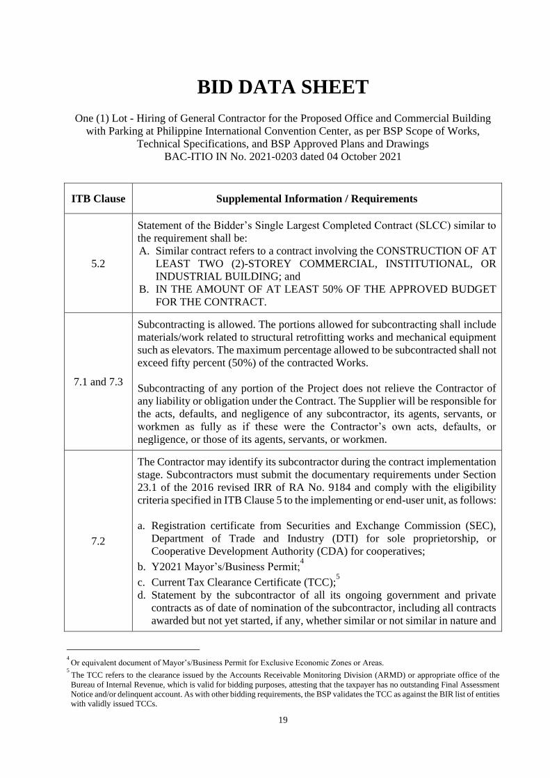
5.2
Statement of the Bidder’s Single Largest Completed Contract (SLCC) similar to
the requirement shall be:
A. Similar contract refers to a contract involving the CONSTRUCTION OF AT
LEAST TWO (2)-STOREY COMMERCIAL, INSTITUTIONAL, OR
INDUSTRIAL BUILDING; and
B. IN THE AMOUNT OF AT LEAST 50% OF THE APPROVED BUDGET
FOR THE CONTRACT.
7.1 and 7.3
Subcontracting is allowed. The portions allowed for subcontracting shall include
materials/work related to structural retrofitting works and mechanical equipment
such as elevators. The maximum percentage allowed to be subcontracted shall not
exceed fifty percent (50%) of the contracted Works.
Subcontracting of any portion of the Project does not relieve the Contractor of
any liability or obligation under the Contract. The Supplier will be responsible for
the acts, defaults, and negligence of any subcontractor, its agents, servants, or
workmen as fully as if these were the Contractor’s own acts, defaults, or
negligence, or those of its agents, servants, or workmen.
7.2
The Contractor may identify its subcontractor during the contract implementation
stage. Subcontractors must submit the documentary requirements under Section
23.1 of the 2016 revised IRR of RA No. 9184 and comply with the eligibility
criteria specified in ITB Clause 5 to the implementing or end-user unit, as follows:
a. Registration certificate from Securities and Exchange Commission (SEC),
Department of Trade and Industry (DTI) for sole proprietorship, or
Cooperative Development Authority (CDA) for cooperatives;
b. Y2021 Mayor’s/Business Permit;4
c. Current Tax Clearance Certificate (TCC);5
d. Statement by the subcontractor of all its ongoing government and private
contracts as of date of nomination of the subcontractor, including all contracts
awarded but not yet started, if any, whether similar or not similar in nature and
4 Or equivalent document of Mayor’s/Business Permit for Exclusive Economic Zones or Areas.
5 The TCC refers to the clearance issued by the Accounts Receivable Monitoring Division (ARMD) or appropriate office of the
Bureau of Internal Revenue, which is valid for bidding purposes, attesting that the taxpayer has no outstanding Final Assessment
Notice and/or delinquent account. As with other bidding requirements, the BSP validates the TCC as against the BIR list of entities
with validly issued TCCs.
20
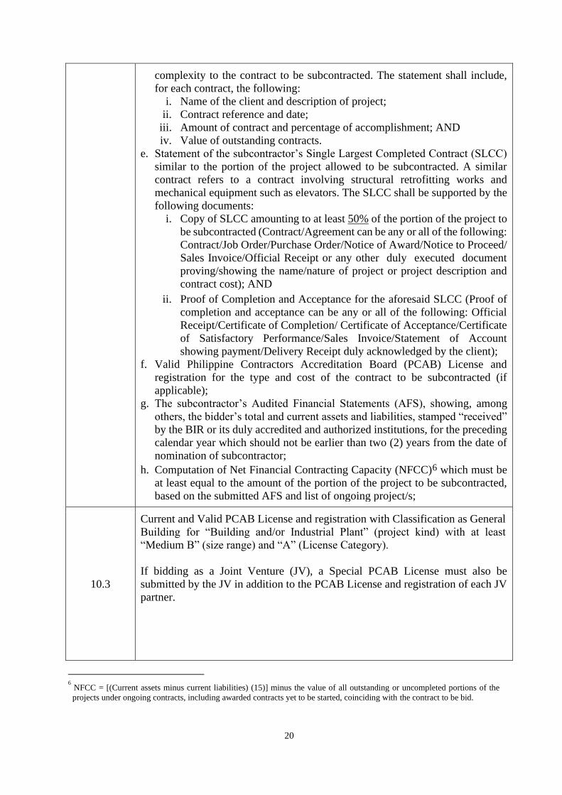
complexity to the contract to be subcontracted. The statement shall include,
for each contract, the following:
i. Name of the client and description of project;
ii. Contract reference and date;
iii. Amount of contract and percentage of accomplishment; AND
iv. Value of outstanding contracts.
e. Statement of the subcontractor’s Single Largest Completed Contract (SLCC)
similar to the portion of the project allowed to be subcontracted. A similar
contract refers to a contract involving structural retrofitting works and
mechanical equipment such as elevators. The SLCC shall be supported by the
following documents:
i. Copy of SLCC amounting to at least 50% of the portion of the project to
be subcontracted (Contract/Agreement can be any or all of the following:
Contract/Job Order/Purchase Order/Notice of Award/Notice to Proceed/
Sales Invoice/Official Receipt or any other duly executed document
proving/showing the name/nature of project or project description and
contract cost); AND
ii. Proof of Completion and Acceptance for the aforesaid SLCC (Proof of
completion and acceptance can be any or all of the following: Official
Receipt/Certificate of Completion/ Certificate of Acceptance/Certificate
of Satisfactory Performance/Sales Invoice/Statement of Account
showing payment/Delivery Receipt duly acknowledged by the client);
f. Valid Philippine Contractors Accreditation Board (PCAB) License and
registration for the type and cost of the contract to be subcontracted (if
applicable);
g. The subcontractor’s Audited Financial Statements (AFS), showing, among
others, the bidder’s total and current assets and liabilities, stamped “received”
by the BIR or its duly accredited and authorized institutions, for the preceding
calendar year which should not be earlier than two (2) years from the date of
nomination of subcontractor;
h. Computation of Net Financial Contracting Capacity (NFCC)6 which must be
at least equal to the amount of the portion of the project to be subcontracted,
based on the submitted AFS and list of ongoing project/s;
10.3
Current and Valid PCAB License and registration with Classification as General
Building for “Building and/or Industrial Plant” (project kind) with at least
“Medium B” (size range) and “A” (License Category).
If bidding as a Joint Venture (JV), a Special PCAB License must also be
submitted by the JV in addition to the PCAB License and registration of each JV
partner.
6 NFCC = [(Current assets minus current liabilities) (15)] minus the value of all outstanding or uncompleted portions of the
projects under ongoing contracts, including awarded contracts yet to be started, coinciding with the contract to be bid.

21
Notes:
i. A special license application for the JV may be accepted, provided that it is
filed at least five (5) working days before the date of bidding. (Resolution No.
186, Series of 2014 issued by the Department of Trade and Industry);
ii. All partners must submit a Valid PCAB license and registration, however,
only one (1) of the JV partners is required to meet the required size range
under said “project kind”.
10.4
List of contractor’s key personnel to be assigned to the contract to be bid,
complete with qualifications and experience data, as follows: (Use BSP-
prescribed form)
Personnel Professional Qualification/s
Project
Manager (PM)
Registered Civil Engineer or Architect with at least ten
(10) years’ experience in the construction industry and
must have managed/ supervised a completed project
involving construction of at least two (2)-storey
commercial, institutional or industrial building costing at
least 50% of the ABC.
Project
Engineer (PE) /
Project-In-
Charge (PIC)
Registered Civil Engineer or Architect with at least five
(5) years’ experience in the construction industry and
must have managed/ supervised a completed project
involving construction of at least two (2)-storey
commercial, institutional or industrial building costing at
least 50% of the ABC.
Safety Officer
(SO)
With at least three (3) years’ experience as Safety Officer
in construction industry. Must submit Certificate/s of
Completion for attending at least forty (40) training hours
on Basic Occupational Safety and Health (BOSH) or
Construction Occupational Health and Safety (COSH) as
provided by Department of Labor and Employment
(DOLE) accredited training centers.
Each of the contractor’s Key Personnel must be supported by the following
documents:
a. Curriculum Vitae;
b. Valid (not expired) Professional Identification Card issued by the
Professional Regulation Commission (PRC) for the PM and PE/PIC;
OR
If for Renewal, submit a copy of the following:
i. Recently expired Professional Identification Card; AND
ii. Proof of payment (e.g., Official Receipt, online payment made
through Paymaya or GCash) for the renewal of PRC ID.
c. Certificate of Training on BOSH and COSH issued by a DOLE accredited
training center/agency for the SO.

22
10.5
List of contractor’s major equipment units, which are owned, leased, and/or under
purchase agreements, supported by proof of ownership, certification of
availability of equipment from the equipment lessor/vendor for the duration of
the project, as the case may be, which must include the following equipment (Use
BSP-prescribed form):
a. Demolition tools/equipment (chipping gun/portable jack hammer and/or
hydraulic hammer): 4 units
b. Dump truck: 1 unit
c. Forklift: 1 unit
d. Loader equipment (e.g., payloader/skid steer loader): 1 unit
e. Excavator equipment (backhoe/mini excavator): 1 unit
f. Compaction equipment (e.g., plate/roller compactor): 1 unit
g. Lifting equipment (e.g., tower/jib/mobile crane): 1 unit
h. Welding equipment (e.g., welding and oxy-acetylene machine): 4 units
i. One-bagger mixer: 3 units
12.0 Not applicable.
15.1
The bid security shall be in the form of a Bid Securing Declaration, or any of the
following forms and amounts:
a. The amount of not less than Php4,486,680.00 [the amount equivalent to two
percent (2%) of ABC], if bid security is in cash, cashier’s/manager’s check,
bank draft/guarantee or irrevocable letter of credit; or
b. The amount of not less than Php11,216,700.00 [the amount equivalent to five
percent (5%) of ABC] if bid security is in Surety Bond.
NOTES:
i. THE SURETY COMPANY SHALL NOT BE INCLUDED IN THE GPPB’S
NEGATIVE LIST OF INSURERS PURSUANT TO GPPB GUIDELINES
FOR THE ESTABLISHMENT OF NEGATIVE LIST OF SURETY
AND/OR INSURANCE COMPANIES [APPENDIX 29 OF THE 2016
REVISED IRR].
ii. BID SECURITY (IN THE FORM OF SURETY BOND) ISSUED BY A
PRIVATE INSURANCE FIRM IS ACCEPTABLE PROVIDED THAT
THE SAID FIRM IS DULY AUTHORIZED BY THE INSURANCE
COMMISSION (IC) TO ISSUE SURETY BONDS AND HAS NOT BEEN
ISSUED A CEASE OR DESIST ORDER FROM THE IC OR IS
CURRENTLY NOT INCLUDED IN THE BLACKLISTED FIRMS.
iii. THE BSP HEREBY REQUESTS THAT THE SUPPLIER OBTAIN ITS
SURETY FROM THE ATTACHED LIST OF EVALUATED SURETY
COMPANIES (SEE ANNEX “B”).
iv. FOR MANUAL BID SUBMISSION:
a. IF BID SECURING DECLARATION:
THE BIDDER IS ALLOWED TO SUBMIT AN UNNOTARIZED BID
SECURING DECLARATION, SUBJECT TO SUBMISSION OF THE
ORIGINAL NOTARIZED BID SECURING DECLARATION DURING
POST-QUALIFICATION STAGE UNDER ENVELOPE NO. 3.
23
b. IF CASH OR CASHIER’S/MANAGER’S CHECK IS POSTED AS BID
SECURITY:
• IT MUST BE DENOMINATED IN PHILIPPINE PESO, PUT IN A
SEPARATE ENVELOPE WITH AMOUNT STATED THEREIN,
SEALED, AND PLACED INSIDE ENVELOPE NO. 1. THE
CASHIER’S/MANAGER’S CHECK MUST BE POSTED IN FAVOR
OF BSP.
• IF BID SECURITY IS PAID THROUGH BSP’S ACCREDITED
COLLECTING AGENTS (i.e., UNION BANK OF THE
PHILIPPINES, AND CHINA BANKING CORPORATION) VIA
OVER-THE-COUNTER BILLS PAYMENT (DEPOSIT SLIP) OR
ONLINE BANKING BILLS PAYMENT (IF BIDDER HAS AN
ACCOUNT WITH BSP’S ACCREDITED COLLECTING AGENT),
OR THROUGH DEBIT/CREDIT/(VISA/MASTER) CARD
FACILITY (ONLINE PAYMENT), A COPY OF THE DEPOSIT SLIP
OR SCREENSHOT OF THE ONLINE PAYMENT SHALL BE
INCLUDED IN ENVELOPE NO. 1.
v. FOR ONLINE OR ELECTRONIC BID SUBMISSION, THE BIDDER IS
ALLOWED TO SUBMIT SCANNED NOTARIZED OR UNNOTARIZED
COPY OF THE BID SECURING DECLARATION OR OTHER
ACCEPTABLE FORMS OF BID SECURITY, AND OFFICIAL
RECEIPT/DEPOSIT/TRANSACTION SLIP IF PAID IN CASH OR
CASHIER’S/MANAGER’S CHECK THROUGH MODES OF PAYMENT
MENTIONED IN MANUAL SUBMISSION, SUBJECT TO SUBMISSION
OF THE ORIGINAL COPY THEREOF (EXCEPT FOR OFFICIAL
RECEIPT/DEPOSIT/TRANSACTION SLIP) DURING POST-
QUALIFICATION STAGE UNDER ENVELOPE NO. 3.
19.2
Partial bid is not allowed. The infrastructure project is packaged in a single lot
and the lot shall not be divided into sub-lots for the purpose of bidding,
evaluation, and contract award.
20.0
Refer to Other Documents in the Checklist of Eligibility (Legal, Technical and
Financial Documents), Financial and Other Documents to be submitted under
Section 34.2 of the Revised IRR, as contained in Envelope No. 3.
21.0
Additional Documents that shall form part of the contract:
1. BSP Scope of Works and Technical Specifications;
2. BSP Approved Plans and Drawings;
3. Winning Bidder’s financial bid, Bill of Quantities, Unit Cost Derivation and
Cash Flow by Quarter
4. Duly signed Construction Schedule, S-Curve and PERT-CPM Network
Diagram;
5. Duly signed Manpower Schedule;
6. Duly signed Construction Methodology in narrative form;
7. Undertaking from the contractor’s key personnel to be assigned to the
contract to be bid;
8. Bid Bulletin/s (if any);

24
9. Certification of Availability of Funds;
10. Instructions to Bidders;
11. Bid Data Sheet;
12. General Conditions of Contract;
13. Special Conditions of Contract;
14. Additional Provisions in the Special Conditions of Contract;
15. Notice of Award;
16. Performance Security;
17. Warranty Security (if applicable); and
18. Contract Agreement
25
Section IV. General Conditions of Contract
Notes on the General Conditions of Contract
The General Conditions of Contract (GCC) in this Section, read in conjunction with the Special
Conditions of Contract in Section V and other documents listed therein, should be a complete
document expressing all the rights and obligations of the parties.
Matters governing performance of the Contractor, payments under the contract, or matters
affecting the risks, rights, and obligations of the parties under the contract are included in the
GCC and Special Conditions of Contract.
Any complementary information, which may be needed, shall be introduced only through the
Special Conditions of Contract.
26
1. Scope of Contract
This Contract shall include all such items, although not specifically mentioned, that can be
reasonably inferred as being required for its completion as if such items were expressly
mentioned herein. All the provisions of RA No. 9184 and its 2016 revised IRR, including
the Generic Procurement Manual, and associated issuances, constitute the primary source
for the terms and conditions of the Contract, and thus, applicable in contract
implementation. Herein clauses shall serve as the secondary source for the terms and
conditions of the Contract.
This is without prejudice to Sections 74.1 and 74.2 of the 2016 revised IRR of RA No.
9184 allowing the GPPB to amend the IRR, which shall be applied to all procurement
activities, the advertisement, posting, or invitation of which were issued after the effectivity
of the said amendment.
2. Sectional Completion of Works
If sectional completion is specified in the Special Conditions of Contract (SCC),
references in the Conditions of Contract to the Works, the Completion Date, and the
Intended Completion Date shall apply to any Section of the Works (other than references
to the Completion Date and Intended Completion Date for the whole of the Works).
3. Possession of Site
3.1. The Procuring Entity shall give possession of all or parts of the Site to the
Contractor based on the schedule of delivery indicated in the SCC, which
corresponds to the execution of the Works. If the Contractor suffers delay or incurs
cost from failure on the part of the Procuring Entity to give possession in accordance
with the terms of this clause, the Procuring Entity’s Representative shall give the
Contractor a Contract Time Extension and certify such sum as fair to cover the cost
incurred, which sum shall be paid by Procuring Entity.
3.2. If possession of a portion is not given by the above date, the Procuring Entity will
be deemed to have delayed the start of the relevant activities. The resulting
adjustments in contract time to address such delay may be addressed through
contract extension provided under Annex “E” of the 2016 revised IRR of RA No.
9184.
4. The Contractor’s Obligations
The Contractor shall employ the key personnel named in the Schedule of Key Personnel
indicating their designation, in accordance with ITB Clause 10.3 and specified in the BDS,
to carry out the supervision of the Works.
The Procuring Entity will approve any proposed replacement of key personnel only if their
relevant qualifications and abilities are equal to or better than those of the personnel listed
in the Schedule.

27
5. Performance Security
5.1. Within ten (10) calendar days from receipt of the Notice of Award from the
Procuring Entity but in no case later than the signing of the contract by both parties,
the successful Bidder shall furnish the performance security in any of the forms
prescribed in Section 39 of the 2016 revised IRR.
5.2. The Contractor, by entering into the Contract with the Procuring Entity,
acknowledges the right of the Procuring Entity to institute action pursuant to RA
No. 3688 against any subcontractor be they an individual, firm, partnership,
corporation, or association supplying the Contractor with labor, materials and/or
equipment for the performance of this Contract.
6. Site Investigation Reports
The Contractor, in preparing the Bid, shall rely on any Site Investigation Reports referred
to in the SCC supplemented by any information obtained by the Contractor.
7. Warranty
7.1. In case the Contractor fails to undertake the repair works under Section 62.2.2 of
the 2016 revised IRR, the Procuring Entity shall forfeit its performance security,
subject its property(ies) to attachment or garnishment proceedings, and perpetually
disqualify it from participating in any public bidding. All payables of the GOP in
his favor shall be offset to recover the costs.
7.2. The warranty against Structural Defects/Failures, except that occasioned-on force
majeure, shall cover the period from the date of issuance of the Certificate of Final
Acceptance by the Procuring Entity. Specific duration of the warranty is found in
the SCC.
8. Liability of the Contractor
Subject to additional provisions, if any, set forth in the SCC, the Contractor’s liability
under this Contract shall be as provided by the laws of the Republic of the Philippines.
If the Contractor is a joint venture, all partners to the joint venture shall be jointly and
severally liable to the Procuring Entity.
9. Termination for Other Causes
Contract termination shall be initiated in case it is determined prima facie by the Procuring
Entity that the Contractor has engaged, before, or during the implementation of the
contract, in unlawful deeds and behaviors relative to contract acquisition and
implementation, such as, but not limited to corrupt, fraudulent, collusive, coercive, and
obstructive practices as stated in ITB Clause 4.
28
10. Dayworks
Subject to the guidelines on Variation Order in Annex “E” of the 2016 revised IRR of RA
No. 9184, and if applicable as indicated in the SCC, the Dayworks rates in the Contractor’s
Bid shall be used for small additional amounts of work only when the Procuring Entity’s
Representative has given written instructions in advance for additional work to be paid for
in that way.
11. Program of Work
11.1. The Contractor shall submit to the Procuring Entity’s Representative for approval
the said Program of Work showing the general methods, arrangements, order, and
timing for all the activities in the Works. The submissions of the Program of Work
are indicated in the SCC.
11.2. The Contractor shall submit to the Procuring Entity’s Representative for approval
an updated Program of Work at intervals no longer than the period stated in the
SCC. If the Contractor does not submit an updated Program of Work within this
period, the Procuring Entity’s Representative may withhold the amount stated in
the SCC from the next payment certificate and continue to withhold this amount
until the next payment after the date on which the overdue Program of Work has
been submitted.
12. Instructions, Inspections and Audits
The Contractor shall permit the GOP or the Procuring Entity to inspect the Contractor’s
accounts and records relating to the performance of the Contractor and to have them audited
by auditors of the GOP or the Procuring Entity, as may be required.
13. Advance Payment
The Procuring Entity shall, upon a written request of the Contractor which shall be
submitted as a Contract document, make an advance payment to the Contractor in an
amount not exceeding fifteen percent (15%) of the total contract price, to be made in lump
sum, or at the most two installments according to a schedule specified in the SCC, subject
to the requirements in Annex “E” of the 2016 revised IRR of RA No. 9184.
14. Progress Payments
The Contractor may submit a request for payment for Work accomplished. Such requests
for payment shall be verified and certified by the Procuring Entity’s Representative/Project
Engineer. Except as otherwise stipulated in the SCC, materials and equipment delivered
on the site but not completely put in place shall not be included for payment.
15. Operating and Maintenance Manuals
15.1. If required, the Contractor will provide “as built” Drawings and/or operating and
maintenance manuals as specified in the SCC.
29
15.2. If the Contractor does not provide the Drawings and/or manuals by the dates stated
above, or they do not receive the Procuring Entity’s Representative’s approval, the
Procuring Entity’s Representative may withhold the amount stated in the SCC from
payments due to the Contractor.
30
Section V. Special Conditions of Contract
Notes on the Special Conditions of Contract
Similar to the BDS, the clauses in this Section are intended to assist the Procuring Entity in
providing contract-specific information in relation to corresponding clauses in the GCC found
in Section IV.
The Special Conditions of Contract (SCC) complement the GCC, specifying contractual
requirements linked to the special circumstances of the Procuring Entity, the Procuring Entity’s
country, the sector, and the Works procured. In preparing this Section, the following aspects
should be checked:
a. Information that complements provisions of the GCC must be incorporated.
b. Amendments and/or supplements to provisions of the GCC as necessitated by the
circumstances of the specific purchase, must also be incorporated.
However, no special condition which defeats or negates the general intent and purpose of the
provisions of the GCC should be incorporated herein.
31
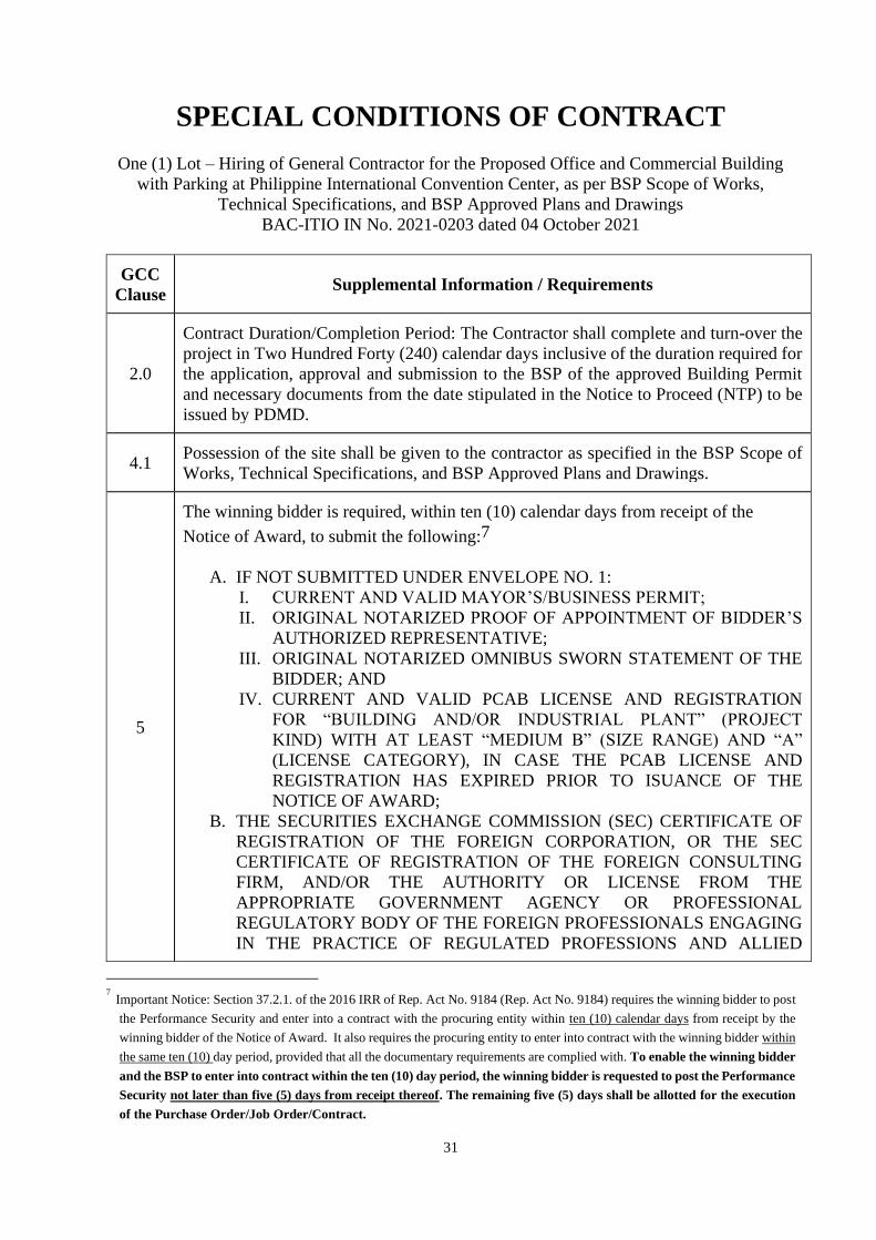
SPECIAL CONDITIONS OF CONTRACT
One (1) Lot – Hiring of General Contractor for the Proposed Office and Commercial Building
with Parking at Philippine International Convention Center, as per BSP Scope of Works,
Technical Specifications, and BSP Approved Plans and Drawings
BAC-ITIO IN No. 2021-0203 dated 04 October 2021
GCC
Clause Supplemental Information / Requirements
2.0
Contract Duration/Completion Period: The Contractor shall complete and turn-over the
project in Two Hundred Forty (240) calendar days inclusive of the duration required for
the application, approval and submission to the BSP of the approved Building Permit
and necessary documents from the date stipulated in the Notice to Proceed (NTP) to be
issued by PDMD.
4.1 Possession of the site shall be given to the contractor as specified in the BSP Scope of
Works, Technical Specifications, and BSP Approved Plans and Drawings.
5
The winning bidder is required, within ten (10) calendar days from receipt of the
Notice of Award, to submit the following:7
A. IF NOT SUBMITTED UNDER ENVELOPE NO. 1:
I. CURRENT AND VALID MAYOR’S/BUSINESS PERMIT;
II. ORIGINAL NOTARIZED PROOF OF APPOINTMENT OF BIDDER’S
AUTHORIZED REPRESENTATIVE;
III. ORIGINAL NOTARIZED OMNIBUS SWORN STATEMENT OF THE
BIDDER; AND
IV. CURRENT AND VALID PCAB LICENSE AND REGISTRATION
FOR “BUILDING AND/OR INDUSTRIAL PLANT” (PROJECT
KIND) WITH AT LEAST “MEDIUM B” (SIZE RANGE) AND “A”
(LICENSE CATEGORY), IN CASE THE PCAB LICENSE AND
REGISTRATION HAS EXPIRED PRIOR TO ISUANCE OF THE
NOTICE OF AWARD;
B. THE SECURITIES EXCHANGE COMMISSION (SEC) CERTIFICATE OF
REGISTRATION OF THE FOREIGN CORPORATION, OR THE SEC
CERTIFICATE OF REGISTRATION OF THE FOREIGN CONSULTING
FIRM, AND/OR THE AUTHORITY OR LICENSE FROM THE
APPROPRIATE GOVERNMENT AGENCY OR PROFESSIONAL
REGULATORY BODY OF THE FOREIGN PROFESSIONALS ENGAGING
IN THE PRACTICE OF REGULATED PROFESSIONS AND ALLIED
7 Important Notice: Section 37.2.1. of the 2016 IRR of Rep. Act No. 9184 (Rep. Act No. 9184) requires the winning bidder to post
the Performance Security and enter into a contract with the procuring entity within ten (10) calendar days from receipt by the
winning bidder of the Notice of Award. It also requires the procuring entity to enter into contract with the winning bidder within
the same ten (10) day period, provided that all the documentary requirements are complied with. To enable the winning bidder
and the BSP to enter into contract within the ten (10) day period, the winning bidder is requested to post the Performance
Security not later than five (5) days from receipt thereof. The remaining five (5) days shall be allotted for the execution
of the Purchase Order/Job Order/Contract.

32
GCC
Clause Supplemental Information / Requirements
PROFESSIONS, WHERE APPLICABLE (REVISED AS PER GPPB
RESOLUTION NO. 25-2019); AND
C. Performance Security in any of the following acceptable forms:
ACCEPTABLE FORMS OF
PERFORMANCE
SECURITY
AMOUNT OF
PERFORMANCE
SECURITY (NOT
LESS THAN THE
REQUIRED
PERCENTAGE OF
THE TOTAL
CONTRACT PRICE)
DETAILS/REMARKS
1. CASH OR
CASHIER’S/MANAGER’
S CHECK ISSUED BY A
UNIVERSAL BANK (UB)
OR COMMERCIAL
BANK (KB).
TEN PERCENT
(10%)
THE POSTED SECURITY
SHALL BE RETAINED
BY BSP FOR THE
DURATION OF THE
CONTRACT UNTIL ITS
COMPLETION. 2. BANK DRAFT /
GUARANTEE OR
IRREVOCABLE LETTER
OF CREDIT ISSUED BY
A UB OR KB:
PROVIDED, HOWEVER,
THAT IT SHALL BE
CONFIRMED OR
AUTHENTICATED BY A
UB OR KB, IF ISSUED
BY A FOREIGN BANK
(FOR A LIST OF UBS/KBS,
REFER TO
HTTP://WWW.BSP.GOV.P
H).
TEN PERCENT
(10%)
VALID FROM THE
DATE OF ISSUANCE
OF PERFORMANCE
SECURITY UNTIL
ISSUANCE OF
CERTIFICATE OF
FINAL ACCEPTANCE
BY THE END-USER.
CONDITIONS:
1. Must be valid until
issuance of the
Certificate of Final
Acceptance by the end-
user department;
2. Must guarantee the
faithful performance
under the contract in
accordance with the
bidding documents;
3. Posted in favor of the
Bangko Sentral ng
Pilipinas (BSP); and
4. Shall be forfeited in
case of default by the
supplier in any of its
obligations under the
contract.
3. SURETY BOND
CALLABLE UPON
DEMAND ISSUED BY A
SURETY OR
INSURANCE COMPANY
DULY AUTHORIZED BY
THE INSURANCE
COMMISSION TO ISSUE
SUCH SECURITY.
NOTES:
a. THE CHECKLIST OF
REQUIREMENTS FOR
SURETY BOND IS
ATTACHED AS ANNEX
“A”.
THIRTY PERCENT
(30%)
33
GCC
Clause Supplemental Information / Requirements
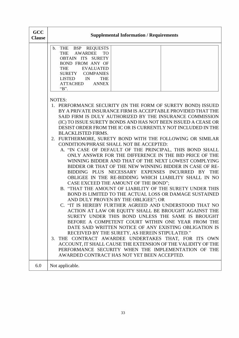
b. THE BSP REQUESTS
THE AWARDEE TO
OBTAIN ITS SURETY
BOND FROM ANY OF
THE EVALUATED
SURETY COMPANIES
LISTED IN THE
ATTACHED ANNEX
“B”.
NOTES:
1. PERFORMANCE SECURITY (IN THE FORM OF SURETY BOND) ISSUED
BY A PRIVATE INSURANCE FIRM IS ACCEPTABLE PROVIDED THAT THE
SAID FIRM IS DULY AUTHORIZED BY THE INSURANCE COMMISSION
(IC) TO ISSUE SURETY BONDS AND HAS NOT BEEN ISSUED A CEASE OR
DESIST ORDER FROM THE IC OR IS CURRENTLY NOT INCLUDED IN THE
BLACKLISTED FIRMS.
2. FURTHERMORE, SURETY BOND WITH THE FOLLOWING OR SIMILAR
CONDITION/PHRASE SHALL NOT BE ACCEPTED:
A. “IN CASE OF DEFAULT OF THE PRINCIPAL, THIS BOND SHALL
ONLY ANSWER FOR THE DIFFERENCE IN THE BID PRICE OF THE
WINNING BIDDER AND THAT OF THE NEXT LOWEST COMPLYING
BIDDER OR THAT OF THE NEW WINNING BIDDER IN CASE OF RE-
BIDDING PLUS NECESSARY EXPENSES INCURRED BY THE
OBLIGEE IN THE RE-BIDDING WHICH LIABILITY SHALL IN NO
CASE EXCEED THE AMOUNT OF THE BOND”;
B. “THAT THE AMOUNT OF LIABILITY OF THE SURETY UNDER THIS
BOND IS LIMITED TO THE ACTUAL LOSS OR DAMAGE SUSTAINED
AND DULY PROVEN BY THE OBLIGEE”; OR
C. “IT IS HEREBY FURTHER AGREED AND UNDERSTOOD THAT NO
ACTION AT LAW OR EQUITY SHALL BE BROUGHT AGAINST THE
SURETY UNDER THIS BOND UNLESS THE SAME IS BROUGHT
BEFORE A COMPETENT COURT WITHIN ONE YEAR FROM THE
DATE SAID WRITTEN NOTICE OF ANY EXISTING OBLIGATION IS
RECEIVED BY THE SURETY, AS HEREIN STIPULATED.”
3. THE CONTRACT AWARDEE UNDERTAKES THAT, FOR ITS OWN
ACCOUNT, IT SHALL CAUSE THE EXTENSION OF THE VALIDITY OF THE
PERFORMANCE SECURITY WHEN THE IMPLEMENTATION OF THE
AWARDED CONTRACT HAS NOT YET BEEN ACCEPTED.
6.0 Not applicable.
34
GCC
Clause Supplemental Information / Requirements
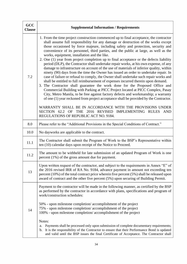
7.2
1. From the time project construction commenced up to final acceptance, the contractor
shall assume full responsibility for any damage or destruction of the works except
those occasioned by force majeure, including safety and protection, security and
convenience of its personnel, third parties, and the public at large, as well as the
works, equipment, installation and the like.
2. One (1) year from project completion up to final acceptance or the defects liability
period (DLP), the Contractor shall undertake repair works, at his own expense, of any
damage to infrastructure on account of the use of materials of inferior quality, within
ninety (90) days from the time the Owner has issued an order to undertake repair. In
case of failure or refusal to comply, the Owner shall undertake such repair works and
shall be entitled to full reimbursement of expenses incurred therein upon demand.
3. The Contractor shall guarantee the work done for the Proposed Office and
Commercial Building with Parking at PICC Project located at PICC Complex, Pasay
City, Metro Manila, to be free against factory defects and workmanship; a warranty
of one (1) year reckoned from project acceptance shall be provided by the Contractor.
WARRANTY SHALL BE IN ACCORDANCE WITH THE PROVISIONS UNDER
SECTION 62.2 OF THE 2016 REVISED IMPLEMENTING RULES AND
REGULATIONS OF REPUBLIC ACT NO. 9184.
8.0 Please refer to the “Additional Provisions in the Special Conditions of Contract.”
10.0 No dayworks are applicable to the contract.
11.1 The Contractor shall submit the Program of Work to the BSP’s Representative within
ten (10) calendar days upon receipt of the Notice to Proceed.
11.2 The amount to be withheld for late submission of an updated Program of Work is one
percent (1%) of the gross amount due for payment.
13
Upon written request of the contractor, and subject to the requirements in Annex “E” of
the 2016 revised IRR of RA No. 9184, advance payment in amount not exceeding ten
percent (10%) of the total contract price wherein five percent (5%) shall be released upon
award of contract and the other five percent (5%) upon securing of Building Permit.
14
Payment to the contractor will be made in the following manner, as certified by the BSP
as performed by the contractor in accordance with plans, specifications and program of
work/construction schedules:
50% - upon milestone completion/ accomplishment of the project
75% - upon milestone completion/ accomplishment of the project
100% - upon milestone completion/ accomplishment of the project
Notes:
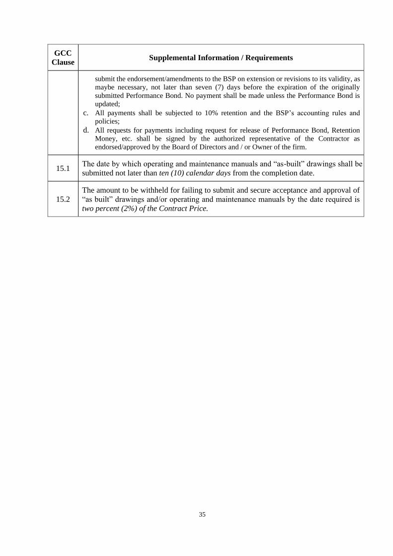
a. Payments shall be processed only upon submission of complete documentary requirements; b. It is the responsibility of the Contractor to ensure that their Performance Bond is updated
and valid until the BSP issues the final Certificate of Acceptance. The Contractor shall
35
GCC
Clause Supplemental Information / Requirements
submit the endorsement/amendments to the BSP on extension or revisions to its validity, as
maybe necessary, not later than seven (7) days before the expiration of the originally
submitted Performance Bond. No payment shall be made unless the Performance Bond is
updated;
c. All payments shall be subjected to 10% retention and the BSP’s accounting rules and
policies; d. All requests for payments including request for release of Performance Bond, Retention
Money, etc. shall be signed by the authorized representative of the Contractor as
endorsed/approved by the Board of Directors and / or Owner of the firm.
15.1 The date by which operating and maintenance manuals and “as-built” drawings shall be
submitted not later than ten (10) calendar days from the completion date.
15.2
The amount to be withheld for failing to submit and secure acceptance and approval of
“as built” drawings and/or operating and maintenance manuals by the date required is
two percent (2%) of the Contract Price.
36
Section VI. Specifications
Notes on Specifications
A set of precise and clear specifications is a prerequisite for Bidders to respond realistically
and competitively to the requirements of the Procuring Entity without qualifying or
conditioning their Bids. In the context of international competitive bidding, the
specifications must be drafted to permit the widest possible competition and, at the same
time, present a clear statement of the required standards of workmanship, materials, and
performance of the goods and services to be procured. Only if this is done will the objectives
of economy, efficiency, and fairness in procurement be realized, responsiveness of Bids be
ensured, and the subsequent task of bid evaluation facilitated. The specifications should
require that all goods and materials to be incorporated in the Works be new, unused, of the
most recent or current models, and incorporate all recent improvements in design and
materials unless provided otherwise in the Contract.
Samples of specifications from previous similar projects are useful in this respect. The use
of metric units is mandatory. Most specifications are normally written specially by the
Procuring Entity or its representative to suit the Works at hand. There is no standard set of
Specifications for universal application in all sectors in all regions, but there are established
principles and practices, which are reflected in these PBDs.
There are considerable advantages in standardizing General Specifications for repetitive
Works in recognized public sectors, such as highways, ports, railways, urban housing,
irrigation, and water supply, in the same country or region where similar conditions prevail.
The General Specifications should cover all classes of workmanship, materials, and
equipment commonly involved in construction, although not necessarily to be used in a
particular Works Contract. Deletions or addenda should then adapt the General
Specifications to the particular Works.
Care must be taken in drafting specifications to ensure that they are not restrictive. In the
specification of standards for goods, materials, and workmanship, recognized international
standards should be used as much as possible. Where other particular standards are used,
whether national standards or other standards, the specifications should state that goods,
materials, and workmanship that meet other authoritative standards, and which ensure
substantially equal or higher quality than the standards mentioned, will also be acceptable.
The following clause may be inserted in the SCC.
Sample Clause: Equivalency of Standards and Codes
Wherever reference is made in the Contract to specific standards and codes to be met by the
goods and materials to be furnished, and work performed or tested, the provisions of the
latest current edition or revision of the relevant standards and codes in effect shall apply,
unless otherwise expressly stated in the Contract. Where such standards and codes are
national, or relate to a particular country or region, other authoritative standards that ensure
a substantially equal or higher quality than the standards and codes specified will be accepted
subject to the Procuring Entity’s Representative’s prior review and written consent.
37
Differences between the standards specified and the proposed alternative standards shall be
fully described in writing by the Contractor and submitted to the Procuring Entity’s
Representative at least twenty-eight (28) days prior to the date when the Contractor desires
the Procuring Entity’s Representative’s consent. In the event the Procuring Entity’s
Representative determines that such proposed deviations do not ensure substantially equal
or higher quality, the Contractor shall comply with the standards specified in the documents.
These notes are intended only as information for the Procuring Entity or the person drafting
the Bidding Documents. They should not be included in the final Bidding Documents.
REFER TO THE ATTACHED BSP SCOPE OF WORKS
AND TECHNICAL SPECIFICATIONS.
38
Section VII. Drawings
REFER TO THE ATTACHED BSP PLANS AND
DRAWINGS.
THE BSP APPROVED PLANS AND DRAWINGS
SHALL BE RELEASED ONLY TO BIDDERS THAT
PURCHASED THE BIDDING DOCUMENTS
39
Section VIII. Bill of Quantities
Notes on the Bill of Quantities
Objectives
The objectives of the Bill of Quantities are:
a. to provide sufficient information on the quantities of Works to be performed to
enable Bids to be prepared efficiently and accurately; and
b. when a Contract has been entered into, to provide a priced Bill of Quantities for use
in the periodic valuation of Works executed.
In order to attain these objectives, Works should be itemized in the Bill of Quantities in
sufficient detail to distinguish between the different classes of Works, or between Works of
the same nature carried out in different locations or in other circumstances which may give
rise to different considerations of cost. Consistent with these requirements, the layout and
content of the Bill of Quantities should be as simple and brief as possible.
Daywork Schedule
A Daywork Schedule should be included only if the probability of unforeseen work, outside
the items included in the Bill of Quantities, is high. To facilitate checking by the Entity of
the realism of rates quoted by the Bidders, the Daywork Schedule should normally comprise
the following:
a. A list of the various classes of labor, materials, and Constructional Plant for which
basic daywork rates or prices are to be inserted by the Bidder, together with a
statement of the conditions under which the Contractor will be paid for work
executed on a daywork basis.
b. Nominal quantities for each item of Daywork, to be priced by each Bidder at
Daywork rates as Bid. The rate to be entered by the Bidder against each basic
Daywork item should include the Contractor’s profit, overheads, supervision, and
other charges.
Provisional Sums
A general provision for physical contingencies (quantity overruns) may be made by
including a provisional sum in the Summary Bill of Quantities. Similarly, a contingency
allowance for possible price increases should be provided as a provisional sum in the
Summary Bill of Quantities. The inclusion of such provisional sums often facilitates
budgetary approval by avoiding the need to request periodic supplementary approvals as the
future need arises. Where such provisional sums or contingency allowances are used, the
SCC should state the manner in which they will be used, and under whose authority (usually
the Procuring Entity’s Representative’s).

40
The estimated cost of specialized work to be carried out, or of special goods to be supplied,
by other contractors should be indicated in the relevant part of the Bill of Quantities as a
particular provisional sum with an appropriate brief description. A separate procurement
procedure is normally carried out by the Procuring Entity to select such specialized
contractors. To provide an element of competition among the Bidders in respect of any
facilities, amenities, attendance, etc., to be provided by the successful Bidder as prime
Contractor for the use and convenience of the specialist contractors, each related provisional
sum should be followed by an item in the Bill of Quantities inviting the Bidder to quote a
sum for such amenities, facilities, attendance, etc.
Signature Box
A signature box shall be added at the bottom of each page of the Bill of Quantities where the
authorized representative of the Bidder shall affix his signature. Failure of the authorized
representative to sign each and every page of the Bill of Quantities shall be a cause for
rejection of his bid.
These Notes for Preparing a Bill of Quantities are intended only as information for the
Procuring Entity or the person drafting the Bidding Documents. They should not be included
in the final documents.
41
Section IX. Checklist of Eligibility (Legal,
Technical and Financial Documents), Financial
and Other Documents
Notes on the Checklist of Technical and Financial Documents
The prescribed documents in the checklist are mandatory to be submitted in the Bid, but
shall be subject to the following:
a. GPPB Resolution No. 09-2020 on the efficient procurement measures during a State
of Calamity or other similar issuances that shall allow the use of alternate documents
in lieu of the mandated requirements; or
b. any subsequent GPPB issuances adjusting the documentary requirements after the
effectivity of the adoption of the PBDs.
The BAC shall be checking the submitted documents of each Bidder against this checklist
to ascertain if they are all present, using a non-discretionary “pass/fail” criterion pursuant to
Section 30 of the 2016 revised IRR of RA No. 9184.
FOR MANUAL SUBMISSION OF BIDS:
SUBMIT TWO (2) SETS (ORIGINAL and PHOTOCOPY) OF ENVELOPE NO. 1,
CONTAINING THE ELIGIBILITY DOCUMENTS: LEGAL, TECHNICAL AND
FINANCIAL) & ENVELOPE NO. 2, CONTAINING THE FINANCIAL BID PROPOSAL.
FOR ELECTRONIC SUBMISSION OF BIDS:
1. Submit ENVELOPE 1 (ELIGIBILITY DOCUMENTS) and ENVELOPE 2
(FINANCIAL BID PROPOSAL) in separate zipped folders with different passwords (ie.
one (1) password for ENVELOPE 1 and another password ENVELOPE 2).
2. Password shall be known only to the bidder or its duly authorized representative/s shall
not be disclosed to any BSP personnel before the opening of bids.
3. Save the documents in compressed or zipped folder (use 7-zip compression tool).
4. Bid submission without electronic key or passwords shall be considered unsealed bid
submission while those which are not compressed is not complying with two-factor
security procedure and hence, shall be rejected during bid opening.
FOR THE DETAILED PROCEDURES, REFER TO ANNEX C. GUIDELINES ON
MANUAL AND ELECTRONIC SUBMISSION OF BIDS.
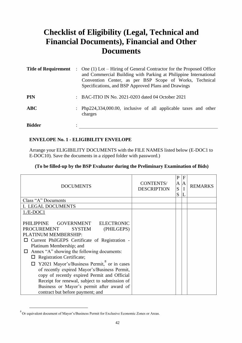
42
Checklist of Eligibility (Legal, Technical and
Financial Documents), Financial and Other
Documents
Title of Requirement : One (1) Lot – Hiring of General Contractor for the Proposed Office
and Commercial Building with Parking at Philippine International
Convention Center, as per BSP Scope of Works, Technical
Specifications, and BSP Approved Plans and Drawings
PIN : BAC-ITIO IN No. 2021-0203 dated 04 October 2021
ABC : Php224,334,000.00, inclusive of all applicable taxes and other
charges
Bidder :
ENVELOPE No. 1 - ELIGIBILITY ENVELOPE
Arrange your ELIGIBILITY DOCUMENTS with the FILE NAMES listed below (E-DOC1 to
E-DOC10). Save the documents in a zipped folder with password.)
(To be filled-up by the BSP Evaluator during the Preliminary Examination of Bids)
DOCUMENTS CONTENTS/
DESCRIPTION
P
A
S
S
F
A
I
L
REMARKS
Class “A” Documents
I. LEGAL DOCUMENTS
1./E-DOC1
PHILIPPINE GOVERNMENT ELECTRONIC
PROCUREMENT SYSTEM (PHILGEPS)
PLATINUM MEMBERSHIP:
Current PhilGEPS Certificate of Registration -
Platinum Membership; and
Annex “A” showing the following documents:
Registration Certificate;
Y2021 Mayor’s/Business Permit,8 or in cases
of recently expired Mayor’s/Business Permit,
copy of recently expired Permit and Official
Receipt for renewal, subject to submission of
Business or Mayor’s permit after award of
contract but before payment; and
8 Or equivalent document of Mayor’s/Business Permit for Exclusive Economic Zones or Areas.
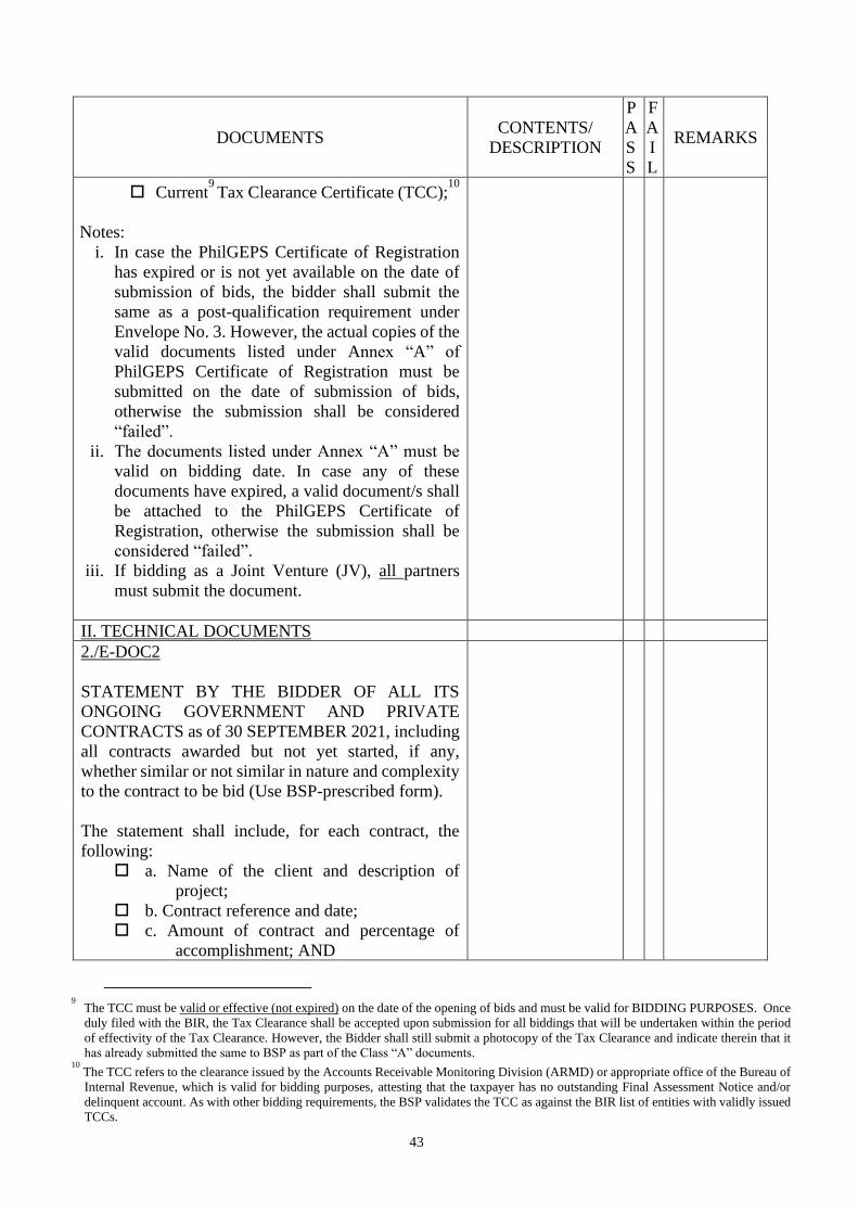
43
DOCUMENTS CONTENTS/
DESCRIPTION
P
A
S
S
F
A
I
L
REMARKS
Current9 Tax Clearance Certificate (TCC);
10
Notes:
i. In case the PhilGEPS Certificate of Registration
has expired or is not yet available on the date of
submission of bids, the bidder shall submit the
same as a post-qualification requirement under
Envelope No. 3. However, the actual copies of the
valid documents listed under Annex “A” of
PhilGEPS Certificate of Registration must be
submitted on the date of submission of bids,
otherwise the submission shall be considered
“failed”.
ii. The documents listed under Annex “A” must be
valid on bidding date. In case any of these
documents have expired, a valid document/s shall
be attached to the PhilGEPS Certificate of
Registration, otherwise the submission shall be
considered “failed”.
iii. If bidding as a Joint Venture (JV), all partners
must submit the document.
II. TECHNICAL DOCUMENTS
2./E-DOC2
STATEMENT BY THE BIDDER OF ALL ITS
ONGOING GOVERNMENT AND PRIVATE
CONTRACTS as of 30 SEPTEMBER 2021, including
all contracts awarded but not yet started, if any,
whether similar or not similar in nature and complexity
to the contract to be bid (Use BSP-prescribed form).
The statement shall include, for each contract, the
following:
a. Name of the client and description of
project;
b. Contract reference and date;
c. Amount of contract and percentage of
accomplishment; AND
9 The TCC must be valid or effective (not expired) on the date of the opening of bids and must be valid for BIDDING PURPOSES. Once
duly filed with the BIR, the Tax Clearance shall be accepted upon submission for all biddings that will be undertaken within the period
of effectivity of the Tax Clearance. However, the Bidder shall still submit a photocopy of the Tax Clearance and indicate therein that it
has already submitted the same to BSP as part of the Class “A” documents. 10
The TCC refers to the clearance issued by the Accounts Receivable Monitoring Division (ARMD) or appropriate office of the Bureau of
Internal Revenue, which is valid for bidding purposes, attesting that the taxpayer has no outstanding Final Assessment Notice and/or
delinquent account. As with other bidding requirements, the BSP validates the TCC as against the BIR list of entities with validly issued
TCCs.
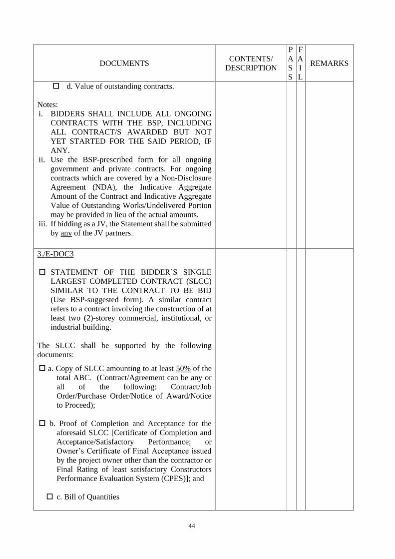
44
DOCUMENTS CONTENTS/
DESCRIPTION
P
A
S
S
F
A
I
L
REMARKS
d. Value of outstanding contracts.
Notes:
i. BIDDERS SHALL INCLUDE ALL ONGOING
CONTRACTS WITH THE BSP, INCLUDING
ALL CONTRACT/S AWARDED BUT NOT
YET STARTED FOR THE SAID PERIOD, IF
ANY.
ii. Use the BSP-prescribed form for all ongoing
government and private contracts. For ongoing
contracts which are covered by a Non-Disclosure
Agreement (NDA), the Indicative Aggregate
Amount of the Contract and Indicative Aggregate
Value of Outstanding Works/Undelivered Portion
may be provided in lieu of the actual amounts. iii. If bidding as a JV, the Statement shall be submitted
by any of the JV partners.
3./E-DOC3
STATEMENT OF THE BIDDER’S SINGLE
LARGEST COMPLETED CONTRACT (SLCC)
SIMILAR TO THE CONTRACT TO BE BID
(Use BSP-suggested form). A similar contract
refers to a contract involving the construction of at
least two (2)-storey commercial, institutional, or
industrial building.
The SLCC shall be supported by the following
documents:
a. Copy of SLCC amounting to at least 50% of the
total ABC. (Contract/Agreement can be any or
all of the following: Contract/Job
Order/Purchase Order/Notice of Award/Notice
to Proceed);
b. Proof of Completion and Acceptance for the
aforesaid SLCC [Certificate of Completion and
Acceptance/Satisfactory Performance; or
Owner’s Certificate of Final Acceptance issued
by the project owner other than the contractor or
Final Rating of least satisfactory Constructors
Performance Evaluation System (CPES)]; and
c. Bill of Quantities
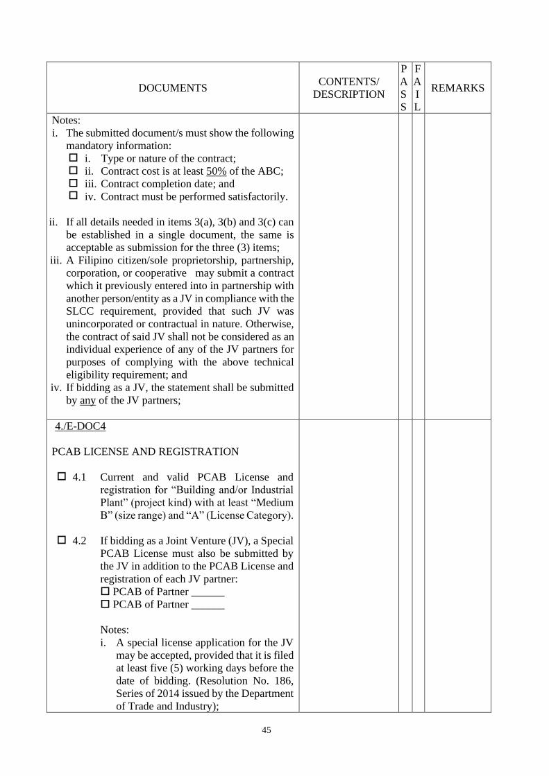
45
DOCUMENTS CONTENTS/
DESCRIPTION
P
A
S
S
F
A
I
L
REMARKS
Notes:
i. The submitted document/s must show the following
mandatory information: i. Type or nature of the contract; ii. Contract cost is at least 50% of the ABC;
iii.
iv.
Contract completion date; and
Contract must be performed satisfactorily.
ii. If all details needed in items 3(a), 3(b) and 3(c) can
be established in a single document, the same is
acceptable as submission for the three (3) items;
iii. A Filipino citizen/sole proprietorship, partnership,
corporation, or cooperative may submit a contract
which it previously entered into in partnership with
another person/entity as a JV in compliance with the
SLCC requirement, provided that such JV was
unincorporated or contractual in nature. Otherwise,
the contract of said JV shall not be considered as an
individual experience of any of the JV partners for
purposes of complying with the above technical
eligibility requirement; and
iv. If bidding as a JV, the statement shall be submitted
by any of the JV partners;
4./E-DOC4
PCAB LICENSE AND REGISTRATION
4.1 Current and valid PCAB License and
registration for “Building and/or Industrial
Plant” (project kind) with at least “Medium
B” (size range) and “A” (License Category).
4.2
If bidding as a Joint Venture (JV), a Special
PCAB License must also be submitted by
the JV in addition to the PCAB License and
registration of each JV partner:
PCAB of Partner ______
PCAB of Partner ______
Notes:
i. A special license application for the JV
may be accepted, provided that it is filed
at least five (5) working days before the
date of bidding. (Resolution No. 186,
Series of 2014 issued by the Department
of Trade and Industry);
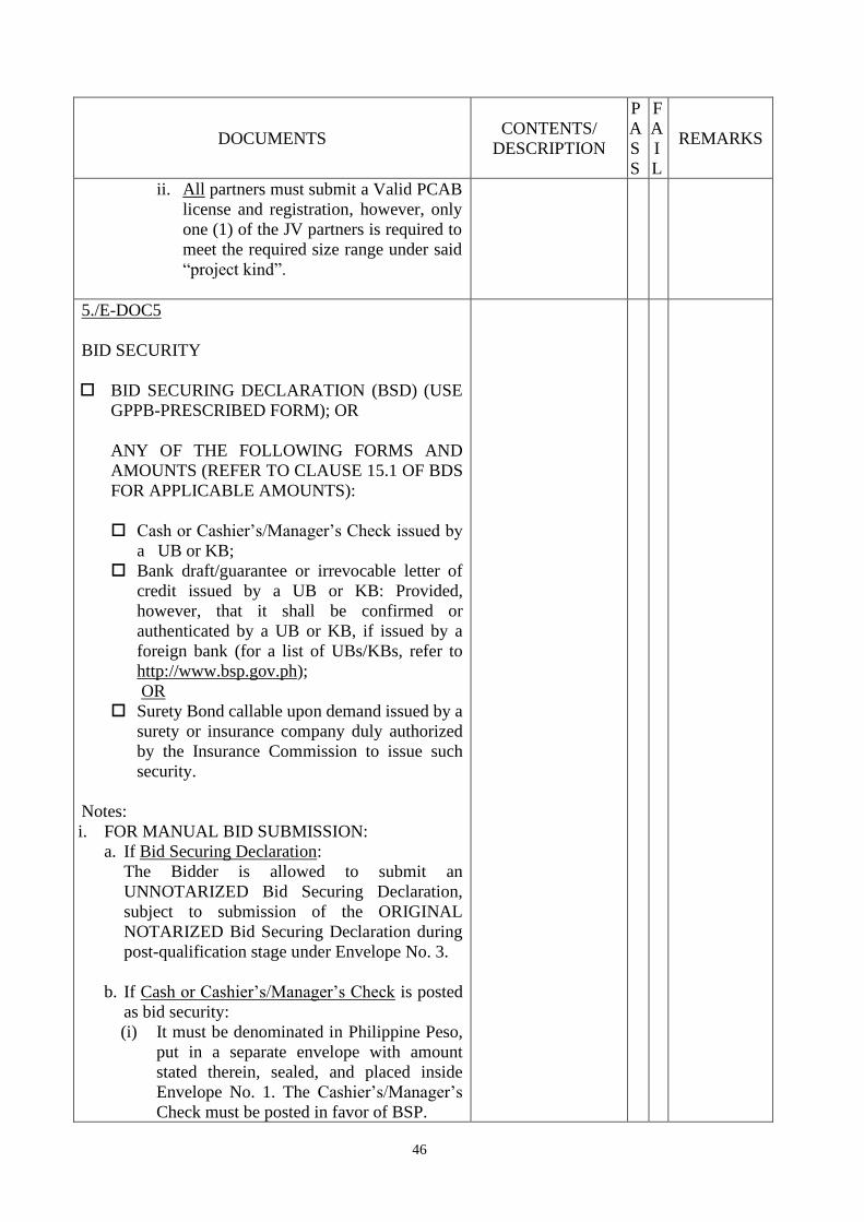
46
DOCUMENTS CONTENTS/
DESCRIPTION
P
A
S
S
F
A
I
L
REMARKS
ii. All partners must submit a Valid PCAB
license and registration, however, only
one (1) of the JV partners is required to
meet the required size range under said
“project kind”.
5./E-DOC5
BID SECURITY
BID SECURING DECLARATION (BSD) (USE
GPPB-PRESCRIBED FORM); OR
ANY OF THE FOLLOWING FORMS AND
AMOUNTS (REFER TO CLAUSE 15.1 OF BDS
FOR APPLICABLE AMOUNTS):
Cash or Cashier’s/Manager’s Check issued by
a UB or KB;
Bank draft/guarantee or irrevocable letter of
credit issued by a UB or KB: Provided,
however, that it shall be confirmed or
authenticated by a UB or KB, if issued by a
foreign bank (for a list of UBs/KBs, refer to
http://www.bsp.gov.ph);
OR
Surety Bond callable upon demand issued by a
surety or insurance company duly authorized
by the Insurance Commission to issue such
security.
Notes:
i. FOR MANUAL BID SUBMISSION:
a. If Bid Securing Declaration:
The Bidder is allowed to submit an
UNNOTARIZED Bid Securing Declaration,
subject to submission of the ORIGINAL
NOTARIZED Bid Securing Declaration during
post-qualification stage under Envelope No. 3.
b. If Cash or Cashier’s/Manager’s Check is posted
as bid security:
(i) It must be denominated in Philippine Peso,
put in a separate envelope with amount
stated therein, sealed, and placed inside
Envelope No. 1. The Cashier’s/Manager’s
Check must be posted in favor of BSP.

47
DOCUMENTS CONTENTS/
DESCRIPTION
P
A
S
S
F
A
I
L
REMARKS
(ii) If BID SECURITY is paid through BSP’s
accredited collecting agents (i.e., Union
Bank of the Philippines, and China Banking
Corporation) via over-the-counter bills
payment (Deposit Slip) or online banking
bills payment (if bidder has an account with
BSP’s accredited collecting agent), or
through Debit/Credit/(Visa/Master) Card
Facility (Online Payment), a copy of the
deposit slip or screenshot of the online
payment shall be included in Envelope No.
1.
ii. FOR ONLINE OR ELECTRONIC BID
SUBMISSION, the bidder is allowed to submit
scanned notarized or unnotarized copy of the bid
securing declaration or other acceptable forms of
bid security, and official receipt/deposit/transaction
slip if paid in Cash or Cashier’s/Manager’s Check
through modes of payment mentioned in manual
submission, subject to submission of the original
copy thereof (except for official
receipt/deposit/transaction slip) during post-
qualification stage under Envelope No. 3.
iii. If bidding as a JV, the document/s shall be
submitted by any of the JV partners.
6./E-DOC6
TECHNICAL REQUIREMENTS
6.1 Organizational chart for the project
6.2 List of contractor’s key personnel to be
assigned to the contract to be bid, complete
with qualifications and experience data, as
follows: (Use BSP-prescribed form)
a. One (1) Project Manager (PM):
Qualifications:
• Registered Civil Engineer or
Architect
• With least ten (10) years’
experience in the construction
industry
• Must have managed/ supervised a
completed project involving
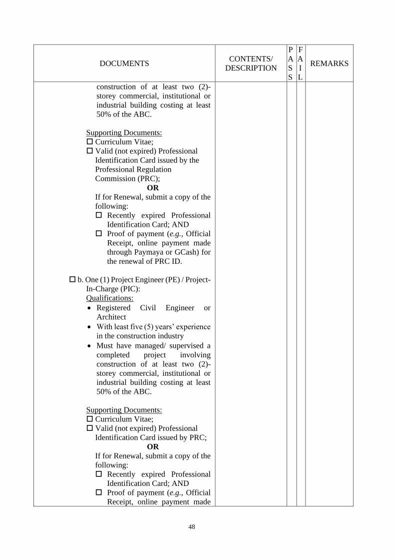
48
DOCUMENTS CONTENTS/
DESCRIPTION
P
A
S
S
F
A
I
L
REMARKS
construction of at least two (2)-
storey commercial, institutional or
industrial building costing at least
50% of the ABC.
Supporting Documents:
Curriculum Vitae;
Valid (not expired) Professional
Identification Card issued by the
Professional Regulation
Commission (PRC);
OR
If for Renewal, submit a copy of the
following:
Recently expired Professional
Identification Card; AND
Proof of payment (e.g., Official
Receipt, online payment made
through Paymaya or GCash) for
the renewal of PRC ID.
b. One (1) Project Engineer (PE) / Project-
In-Charge (PIC):
Qualifications:
• Registered Civil Engineer or
Architect
• With least five (5) years’ experience
in the construction industry
• Must have managed/ supervised a
completed project involving
construction of at least two (2)-
storey commercial, institutional or
industrial building costing at least
50% of the ABC.
Supporting Documents:
Curriculum Vitae;
Valid (not expired) Professional
Identification Card issued by PRC;
OR
If for Renewal, submit a copy of the
following:
Recently expired Professional
Identification Card; AND
Proof of payment (e.g., Official
Receipt, online payment made

49
DOCUMENTS CONTENTS/
DESCRIPTION
P
A
S
S
F
A
I
L
REMARKS
through Paymaya or GCash) for
the renewal of PRC ID.
c. One (1) Safety Officer (SO):
Qualifications:
• With at least three (3) years’
experience as Safety Officer in
construction industry.
Supporting Documents:
Curriculum Vitae
Must submit Certificate/s of
Completion for attending at least
forty (40) training hours on Basic
Occupational Safety and Health
(BOSH) or Construction
Occupational Health and Safety
(COSH) as provided by
Department of Labor and
Employment (DOLE) accredited
training centers.
6.3 List of contractor’s major equipment units,
which are owned, leased, and/or under
purchase agreements, supported by proof of
ownership, certification of availability of
equipment from the equipment lessor/vendor
for the duration of the project, as the case
may be, which must include the following
equipment (Use BSP-prescribed form):
a. Four (4) units Demolition
tools/equipment (chipping
gun/portable jack hammer and/or
hydraulic hammer);
b. One (1) unit Dump truck;
c. One (1) unit Forklift;
d. One (1) unit Loader equipment (e.g.
payloader/skid steer loader);
e. One (1) unit Excavator equipment
(backhoe/mini excavator);
f. One (1) unit Compaction equipment
(e.g. plate/roller compactor);
g. One (1) unit Lifting equipment (e.g.
tower/jib/mobile crane);
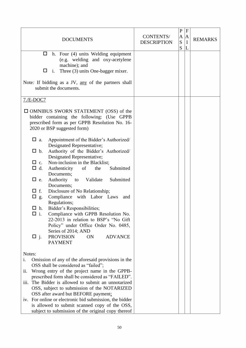
50
DOCUMENTS CONTENTS/
DESCRIPTION
P
A
S
S
F
A
I
L
REMARKS
h. Four (4) units Welding equipment
(e.g. welding and oxy-acetylene
machine); and
i. Three (3) units One-bagger mixer.
Note: If bidding as a JV, any of the partners shall
submit the documents.
7./E-DOC7
OMNIBUS SWORN STATEMENT (OSS) of the
bidder containing the following: (Use GPPB
prescribed form as per GPPB Resolution No. 16-
2020 or BSP suggested form)
a. Appointment of the Bidder’s Authorized/
Designated Representative; b. Authority of the Bidder’s Authorized/
Designated Representative; c. Non-inclusion in the Blacklist; d. Authenticity of the Submitted
Documents; e. Authority to Validate Submitted
Documents; f. Disclosure of No Relationship; g. Compliance with Labor Laws and
Regulations; h. Bidder’s Responsibilities; i. Compliance with GPPB Resolution No.
22-2013 in relation to BSP’s “No Gift
Policy” under Office Order No. 0485,
Series of 2014; AND j. PROVISION ON ADVANCE
PAYMENT
Notes:
i. Omission of any of the aforesaid provisions in the
OSS shall be considered as “failed”;
ii. Wrong entry of the project name in the GPPB-
prescribed form shall be considered as “FAILED”.
iii. The Bidder is allowed to submit an unnotarized
OSS, subject to submission of the NOTARIZED
OSS after award but BEFORE payment;
iv. For online or electronic bid submission, the bidder
is allowed to submit scanned copy of the OSS,
subject to submission of the original copy thereof
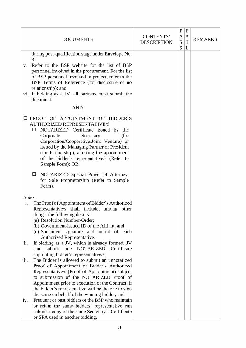
51
DOCUMENTS CONTENTS/
DESCRIPTION
P
A
S
S
F
A
I
L
REMARKS
during post-qualification stage under Envelope No.
3;
v. Refer to the BSP website for the list of BSP
personnel involved in the procurement. For the list
of BSP personnel involved in project, refer to the
BSP Terms of Reference (for disclosure of no
relationship); and
vi. If bidding as a JV, all partners must submit the
document.
AND
PROOF OF APPOINTMENT OF BIDDER’S
AUTHORIZED REPRESENTATIVE/S NOTARIZED Certificate issued by the
Corporate Secretary (for
Corporation/Cooperative/Joint Venture) or
issued by the Managing Partner or President
(for Partnership), attesting the appointment
of the bidder’s representative/s (Refer to
Sample Form); OR
NOTARIZED Special Power of Attorney,
for Sole Proprietorship (Refer to Sample
Form).
Notes:
i. The Proof of Appointment of Bidder’s Authorized
Representative/s shall include, among other
things, the following details:
(a) Resolution Number/Order;
(b) Government-issued ID of the Affiant; and
(c) Specimen signature and initial of each
Authorized Representative.
ii. If bidding as a JV, which is already formed, JV
can submit one NOTARIZED Certificate
appointing bidder’s representative/s;
iii. The Bidder is allowed to submit an unnotarized
Proof of Appointment of Bidder’s Authorized
Representative/s (Proof of Appointment) subject
to submission of the NOTARIZED Proof of
Appointment prior to execution of the Contract, if
the bidder’s representative will be the one to sign
the same on behalf of the winning bidder; and
iv. Frequent or past bidders of the BSP who maintain
or retain the same bidders’ representative can
submit a copy of the same Secretary’s Certificate
or SPA used in another bidding.

52
DOCUMENTS CONTENTS/
DESCRIPTION
P
A
S
S
F
A
I
L
REMARKS
III. FINANCIAL DOCUMENTS
8./E-DOC8
BIDDER’S AUDITED FINANCIAL
STATEMENT (AFS), showing, among others, the
Bidder’s total and current assets and liabilities,
stamped “received” by the BIR or its duly
accredited and authorized institutions, for the
preceding calendar year which should not be earlier
than two (2) years from the date of bid submission.
Notes: i. AFS under Annex “A” of the PhilGEPS Certificate of
Registration is acceptable provided that the same is for
the preceding calendar year which should not be earlier
than 2 years from the date of bid submission.
ii. Electronically filed AFS should be supported by a proof
of confirmation receipt from the BIR.
iii. Submission of a consolidated AFS is allowed, provided,
that the data for the participating Bidder can be
extracted to establish the financial capacity of the
Bidder.
iv. If bidding as a JV, the AFS shall be submitted by any of
the JV partner
9./E-DOC9
COMPUTATION OF NET FINANCIAL
CONTRACTING CAPACITY (NFCC) which
must be at least equal to the ABC, based on
submitted AFS under Annex A of PhilGEPS
Certificate or submitted AFS under item8/E-DOC8,
computed as follows:
NFCC = [(Current assets minus current
liabilities) (15)] minus the value of all
outstanding or uncompleted portions of the
projects under ongoing contracts, including
awarded contracts yet to be started, coinciding
with the contract to be bid.
Notes:
i. The values of the domestic bidder’s current assets
and current liabilities shall be based on the latest
AFS submitted to the BIR; and
ii. If bidding as a JV, the document shall be submitted
by any of the JV partners provided, that the partner
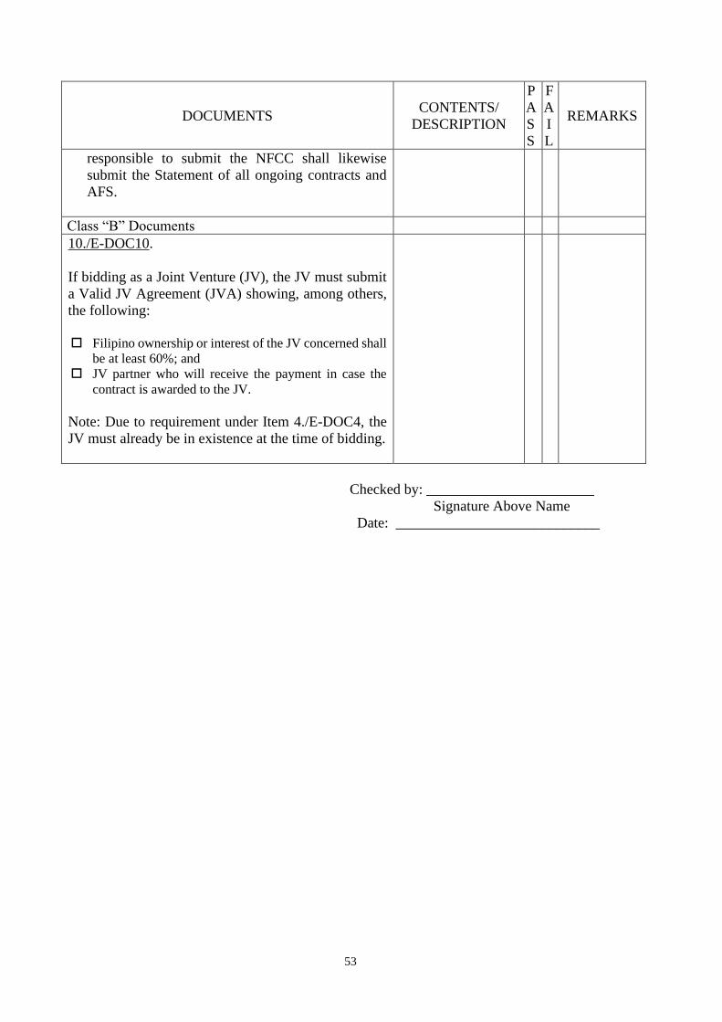
53
DOCUMENTS CONTENTS/
DESCRIPTION
P
A
S
S
F
A
I
L
REMARKS
responsible to submit the NFCC shall likewise
submit the Statement of all ongoing contracts and
AFS.
Class “B” Documents
10./E-DOC10.
If bidding as a Joint Venture (JV), the JV must submit
a Valid JV Agreement (JVA) showing, among others,
the following:
Filipino ownership or interest of the JV concerned shall
be at least 60%; and
JV partner who will receive the payment in case the
contract is awarded to the JV.
Note: Due to requirement under Item 4./E-DOC4, the
JV must already be in existence at the time of bidding.
Checked by: _______________________
Signature Above Name
Date: ____________________________
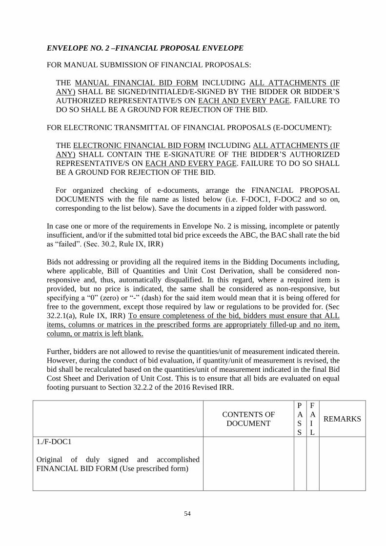
54
ENVELOPE NO. 2 –FINANCIAL PROPOSAL ENVELOPE
FOR MANUAL SUBMISSION OF FINANCIAL PROPOSALS:
THE MANUAL FINANCIAL BID FORM INCLUDING ALL ATTACHMENTS (IF
ANY) SHALL BE SIGNED/INITIALED/E-SIGNED BY THE BIDDER OR BIDDER’S
AUTHORIZED REPRESENTATIVE/S ON EACH AND EVERY PAGE. FAILURE TO
DO SO SHALL BE A GROUND FOR REJECTION OF THE BID.
FOR ELECTRONIC TRANSMITTAL OF FINANCIAL PROPOSALS (E-DOCUMENT):
THE ELECTRONIC FINANCIAL BID FORM INCLUDING ALL ATTACHMENTS (IF
ANY) SHALL CONTAIN THE E-SIGNATURE OF THE BIDDER’S AUTHORIZED
REPRESENTATIVE/S ON EACH AND EVERY PAGE. FAILURE TO DO SO SHALL
BE A GROUND FOR REJECTION OF THE BID.
For organized checking of e-documents, arrange the FINANCIAL PROPOSAL
DOCUMENTS with the file name as listed below (i.e. F-DOC1, F-DOC2 and so on,
corresponding to the list below). Save the documents in a zipped folder with password.
In case one or more of the requirements in Envelope No. 2 is missing, incomplete or patently
insufficient, and/or if the submitted total bid price exceeds the ABC, the BAC shall rate the bid
as “failed”. (Sec. 30.2, Rule IX, IRR)
Bids not addressing or providing all the required items in the Bidding Documents including,
where applicable, Bill of Quantities and Unit Cost Derivation, shall be considered non-
responsive and, thus, automatically disqualified. In this regard, where a required item is
provided, but no price is indicated, the same shall be considered as non-responsive, but
specifying a “0” (zero) or “-” (dash) for the said item would mean that it is being offered for
free to the government, except those required by law or regulations to be provided for. (Sec
32.2.1(a), Rule IX, IRR) To ensure completeness of the bid, bidders must ensure that ALL
items, columns or matrices in the prescribed forms are appropriately filled-up and no item,
column, or matrix is left blank.
Further, bidders are not allowed to revise the quantities/unit of measurement indicated therein.
However, during the conduct of bid evaluation, if quantity/unit of measurement is revised, the
bid shall be recalculated based on the quantities/unit of measurement indicated in the final Bid
Cost Sheet and Derivation of Unit Cost. This is to ensure that all bids are evaluated on equal
footing pursuant to Section 32.2.2 of the 2016 Revised IRR.
CONTENTS OF
DOCUMENT
P
A
S
S
F
A
I
L
REMARKS
1./F-DOC1
Original of duly signed and accomplished
FINANCIAL BID FORM (Use prescribed form)
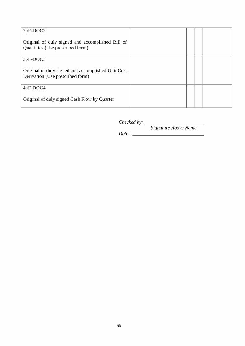
55
2./F-DOC2
Original of duly signed and accomplished Bill of
Quantities (Use prescribed form)
3./F-DOC3
Original of duly signed and accomplished Unit Cost
Derivation (Use prescribed form)
4./F-DOC4
Original of duly signed Cash Flow by Quarter
Checked by: ________________________
Signature Above Name
Date: _____________________________
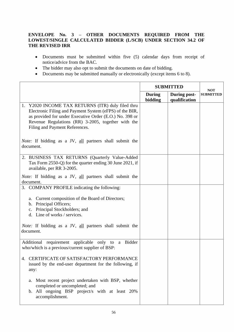
56
ENVELOPE No. 3 – OTHER DOCUMENTS REQUIRED FROM THE
LOWEST/SINGLE CALCULATED BIDDER (L/SCB) UNDER SECTION 34.2 OF
THE REVISED IRR
• Documents must be submitted within five (5) calendar days from receipt of
notice/advice from the BAC.
• The bidder may also opt to submit the documents on date of bidding.
• Documents may be submitted manually or electronically (except items 6 to 8).
SUBMITTED
NOT
SUBMITTED During
bidding
During post-
qualification
1. Y2020 INCOME TAX RETURNS (ITR) duly filed thru
Electronic Filing and Payment System (eFPS) of the BIR,
as provided for under Executive Order (E.O.) No. 398 or
Revenue Regulations (RR) 3-2005, together with the
Filing and Payment References.
Note: If bidding as a JV, all partners shall submit the
document.
2. BUSINESS TAX RETURNS (Quarterly Value-Added
Tax Form 2550-Q) for the quarter ending 30 June 2021, if
available, per RR 3-2005.
Note: If bidding as a JV, all partners shall submit the
document.
3. COMPANY PROFILE indicating the following:
a. Current composition of the Board of Directors;
b. Principal Officers;
c. Principal Stockholders; and
d. Line of works / services.
Note: If bidding as a JV, all partners shall submit the
document.
Additional requirement applicable only to a Bidder
who/which is a previous/current supplier of BSP:
4. CERTIFICATE OF SATISFACTORY PERFORMANCE
issued by the end-user department for the following, if
any:
a. Most recent project undertaken with BSP, whether
completed or uncompleted; and
b. All ongoing BSP project/s with at least 20%
accomplishment.
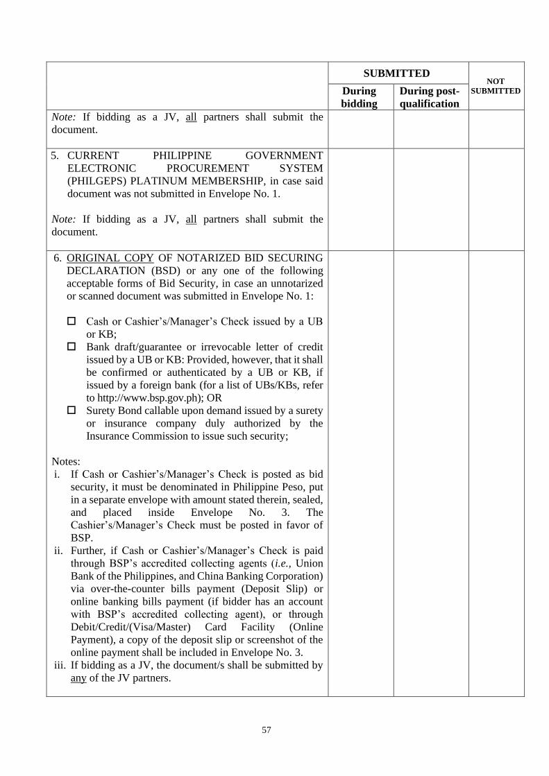
57
SUBMITTED
NOT
SUBMITTED During
bidding
During post-
qualification
Note: If bidding as a JV, all partners shall submit the
document.
5. CURRENT PHILIPPINE GOVERNMENT
ELECTRONIC PROCUREMENT SYSTEM
(PHILGEPS) PLATINUM MEMBERSHIP, in case said
document was not submitted in Envelope No. 1.
Note: If bidding as a JV, all partners shall submit the
document.
6. ORIGINAL COPY OF NOTARIZED BID SECURING
DECLARATION (BSD) or any one of the following
acceptable forms of Bid Security, in case an unnotarized
or scanned document was submitted in Envelope No. 1:
Cash or Cashier’s/Manager’s Check issued by a UB
or KB;
Bank draft/guarantee or irrevocable letter of credit
issued by a UB or KB: Provided, however, that it shall
be confirmed or authenticated by a UB or KB, if
issued by a foreign bank (for a list of UBs/KBs, refer
to http://www.bsp.gov.ph); OR
Surety Bond callable upon demand issued by a surety
or insurance company duly authorized by the
Insurance Commission to issue such security;
Notes:
i. If Cash or Cashier’s/Manager’s Check is posted as bid
security, it must be denominated in Philippine Peso, put
in a separate envelope with amount stated therein, sealed,
and placed inside Envelope No. 3. The
Cashier’s/Manager’s Check must be posted in favor of
BSP.
ii. Further, if Cash or Cashier’s/Manager’s Check is paid
through BSP’s accredited collecting agents (i.e., Union
Bank of the Philippines, and China Banking Corporation)
via over-the-counter bills payment (Deposit Slip) or
online banking bills payment (if bidder has an account
with BSP’s accredited collecting agent), or through
Debit/Credit/(Visa/Master) Card Facility (Online
Payment), a copy of the deposit slip or screenshot of the
online payment shall be included in Envelope No. 3.
iii. If bidding as a JV, the document/s shall be submitted by
any of the JV partners.

58
SUBMITTED
NOT
SUBMITTED During
bidding
During post-
qualification
7. ORIGINAL COPY OF OMNIBUS SWORN
STATEMENT (OSS), in case scanned copy thereof was
submitted in Envelope No. 1 for online or electronic bid
submission.
Notes:
i. Omission of any of the aforesaid provisions in the OSS
shall be considered as “failed;
ii. If bidding as a JV, all partners must submit the document.
8. Construction Schedule, S-Curve and PERT-CPM
Network Diagram.
9. Manpower Schedule.
10. Construction Methodology in narrative form.
11. Undertaking from the contractor’s key personnel to be
assigned to the contract to be bid. (Use BSP form as
guide).
12. Affidavit of Undertaking or Sworn Statement attesting
that it had taken steps to carefully examine and conform
with all the instructions, forms, terms, and project
requirements as stated in the following documents: (Use
BSP-prescribed form):
a. BSP Scope of Works and Technical; and
b. BSP Approved Plans and Drawings.
Received by: _______________________
Signature Above Name
Date: ____________________________
IMPORTANT NOTICE:
1. In case of any inconsistency between the Invitation to Bid (IB) and all other documents, the IB shall
prevail. In case of inconsistency between the listed documents in the Instructions to Bidders (ITB)
and the Bid Data Sheet (BDS) and Checklist of Requirements for Bidders, the ITB and BDS shall
prevail;
2. The scanned actual signature of the authorized representative of the prospective bidder, cropped and
pasted handwritten signatures, adobe-created signatures, unique figures and symbols and stamped
signatures are ACCEPTABLE as e-signatures. However, text-typing the name of the bidder and/or
the words “SGD. or ORIGINAL SIGNED” and the like without distinctive features are NOT
ACCEPTABLE; and
3. An electronically signed document submitted by the bidder shall be presumed to belong to that of
the bidder if signed by its duly authorized representative and sent to the email of the Bid Recipient.
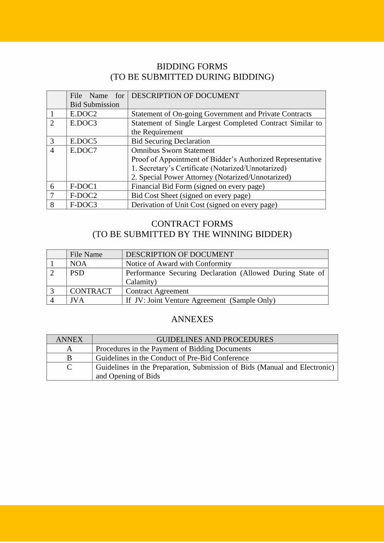
59
BIDDING FORMS
(TO BE SUBMITTED DURING BIDDING)
File Name for
Bid Submission
DESCRIPTION OF DOCUMENT
1 E.DOC2 Statement of On-going Government and Private Contracts
2 E.DOC3 Statement of Single Largest Completed Contract Similar to
the Requirement
3 E.DOC5 Bid Securing Declaration
4 E.DOC7 Omnibus Sworn Statement
Proof of Appointment of Bidder’s Authorized Representative
1. Secretary’s Certificate (Notarized/Unnotarized)
2. Special Power Attorney (Notarized/Unnotarized)
6 F-DOC1 Financial Bid Form (signed on every page)
7 F-DOC2 Bid Cost Sheet (signed on every page)
8 F-DOC3 Derivation of Unit Cost (signed on every page)
CONTRACT FORMS
(TO BE SUBMITTED BY THE WINNING BIDDER)
File Name DESCRIPTION OF DOCUMENT
1 NOA Notice of Award with Conformity
2 PSD Performance Securing Declaration (Allowed During State of
Calamity)
3 CONTRACT Contract Agreement
4 JVA If JV: Joint Venture Agreement (Sample Only)
ANNEXES
ANNEX GUIDELINES AND PROCEDURES
A Procedures in the Payment of Bidding Documents
B Guidelines in the Conduct of Pre-Bid Conference
C Guidelines in the Preparation, Submission of Bids (Manual and Electronic)
and Opening of Bids
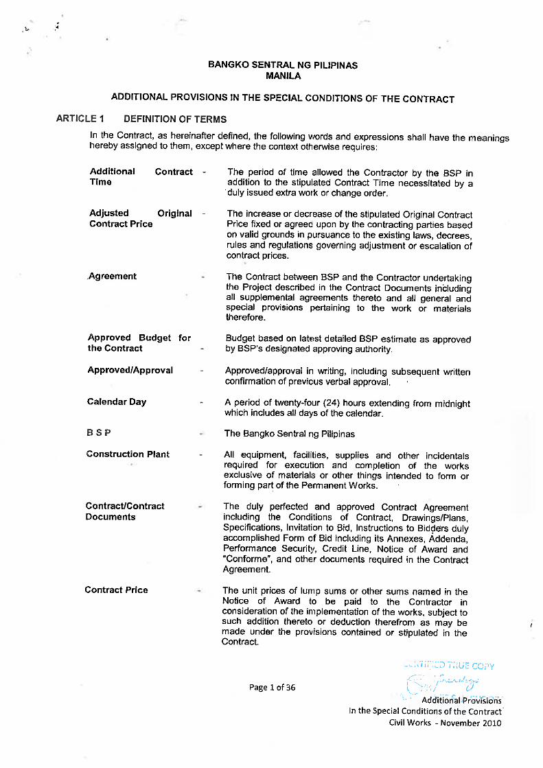
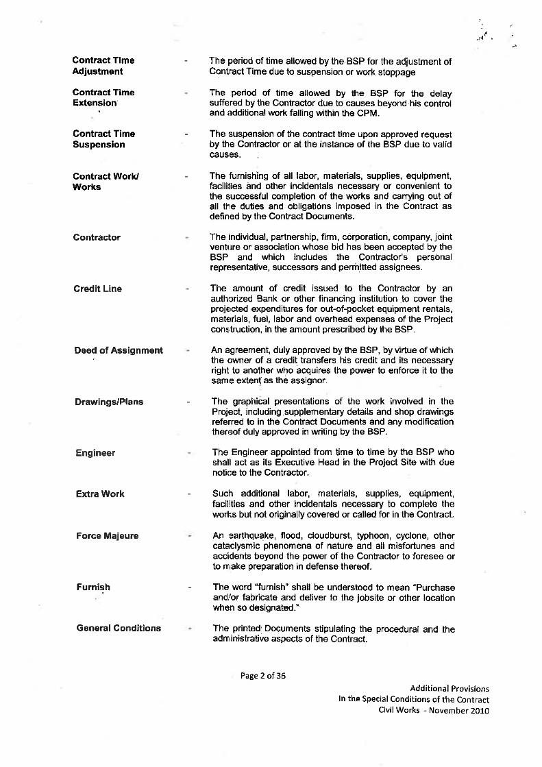
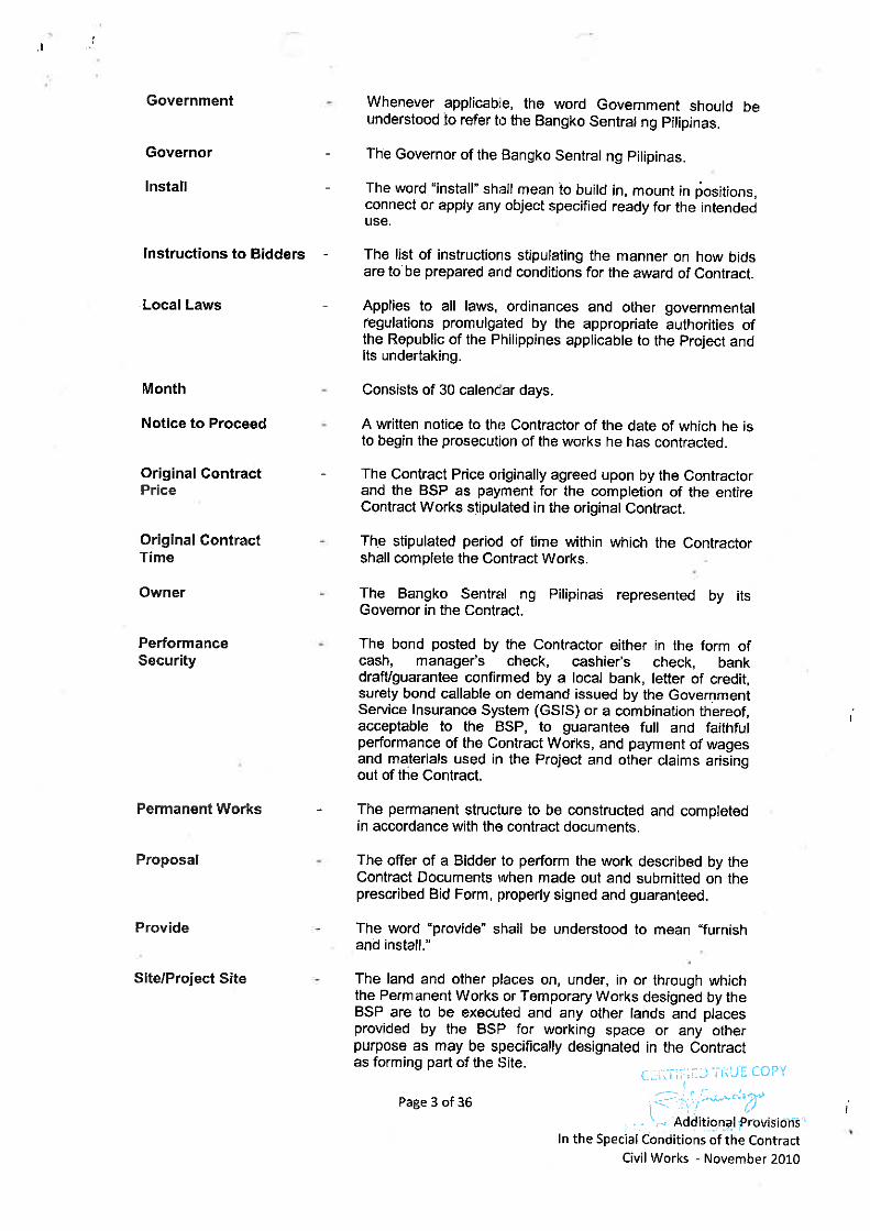


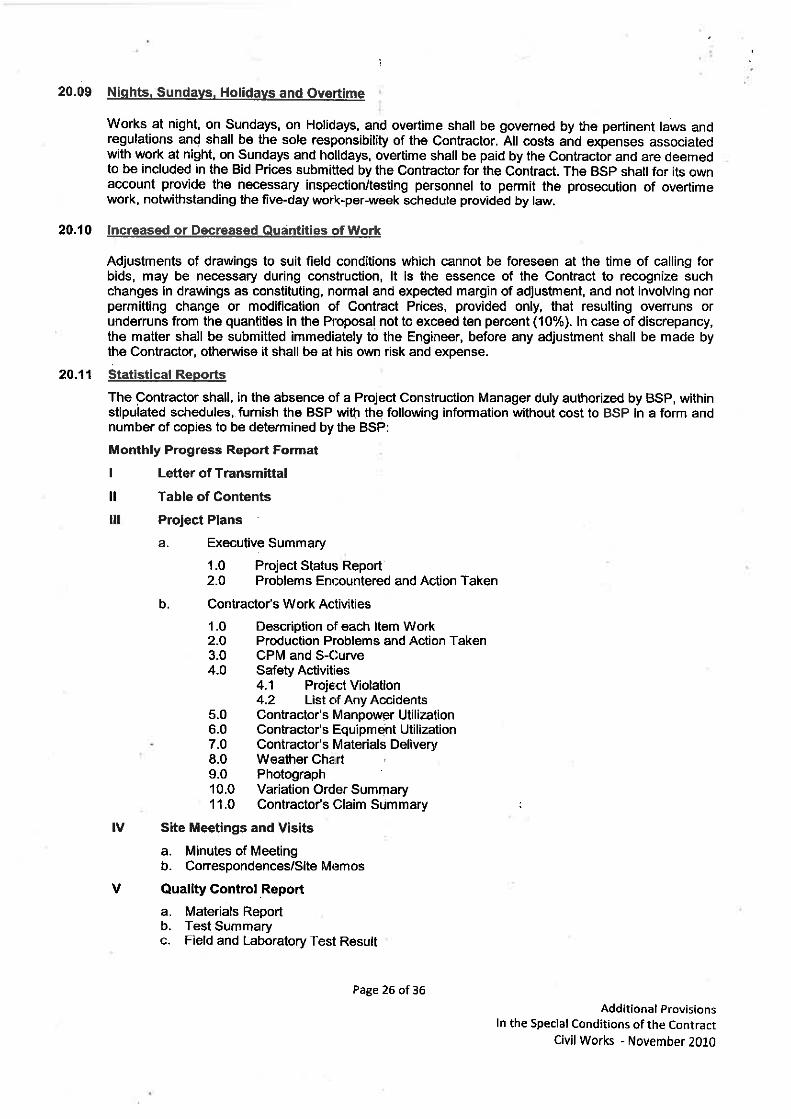
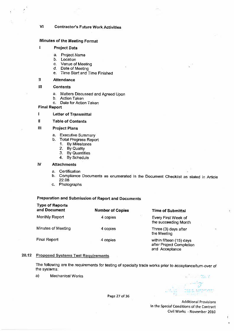
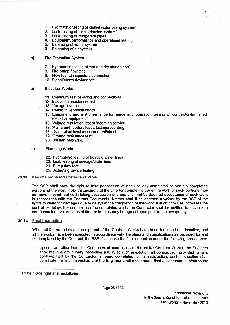
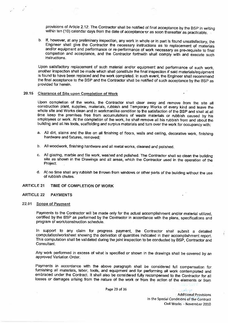

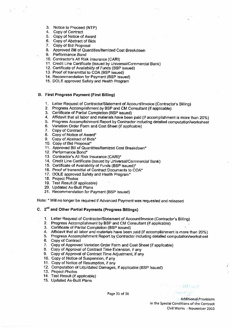

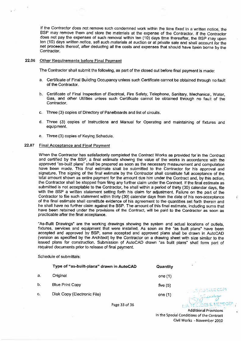
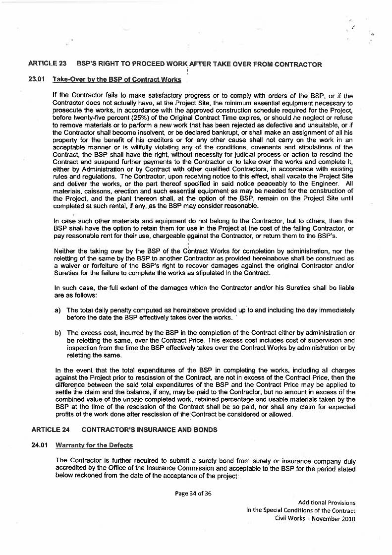
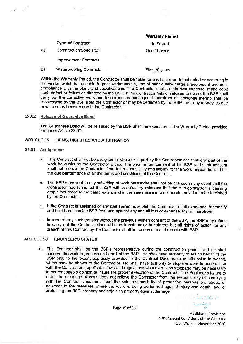
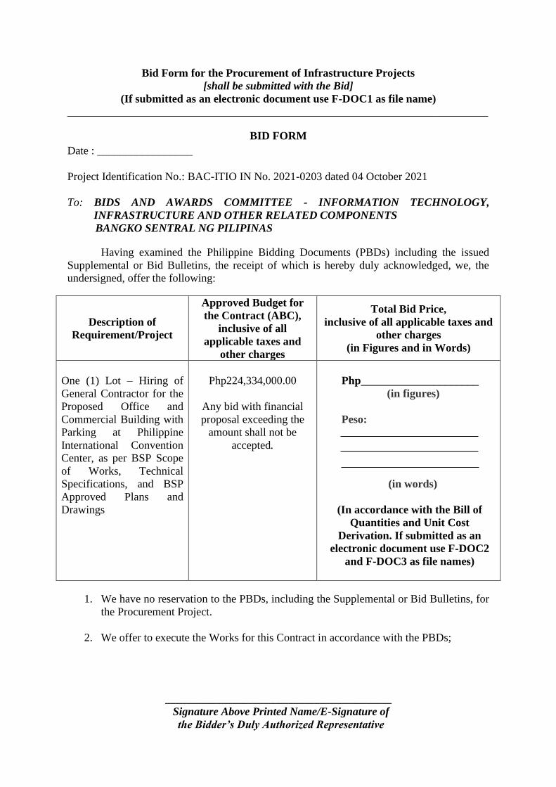
Bid Form for the Procurement of Infrastructure Projects
[shall be submitted with the Bid]
(If submitted as an electronic document use F-DOC1 as file name)
___________________________________________________________________________
BID FORM
Date : _________________
Project Identification No.: BAC-ITIO IN No. 2021-0203 dated 04 October 2021
To: BIDS AND AWARDS COMMITTEE - INFORMATION TECHNOLOGY,
INFRASTRUCTURE AND OTHER RELATED COMPONENTS
BANGKO SENTRAL NG PILIPINAS
Having examined the Philippine Bidding Documents (PBDs) including the issued
Supplemental or Bid Bulletins, the receipt of which is hereby duly acknowledged, we, the
undersigned, offer the following:
Description of
Requirement/Project
Approved Budget for
the Contract (ABC),
inclusive of all
applicable taxes and
other charges
Total Bid Price,
inclusive of all applicable taxes and
other charges
(in Figures and in Words)
One (1) Lot – Hiring of
General Contractor for the
Proposed Office and
Commercial Building with
Parking at Philippine
International Convention
Center, as per BSP Scope
of Works, Technical
Specifications, and BSP
Approved Plans and
Drawings
Php224,334,000.00
Any bid with financial
proposal exceeding the
amount shall not be
accepted.
Php_____________________
(in figures)
Peso:
(in words)
(In accordance with the Bill of
Quantities and Unit Cost
Derivation. If submitted as an
electronic document use F-DOC2
and F-DOC3 as file names)
1. We have no reservation to the PBDs, including the Supplemental or Bid Bulletins, for
the Procurement Project.
2. We offer to execute the Works for this Contract in accordance with the PBDs;
____________________________________________
Signature Above Printed Name/E-Signature of
the Bidder’s Duly Authorized Representative

3. The total bid price includes the cost of all taxes, such as, but not limited to: [specify the
applicable taxes, e.g. (i) value added tax (VAT), (ii) income tax, (iii) local taxes, and
(iv) other fiscal levies and duties], which are itemized herein and reflected in the
detailed estimates;
4. Our Bid shall be valid within the period stated in the PBDs, and it shall remain binding
upon us at any time before the expiration of that period;
5. We undertake, if our Bid is accepted, to provide a performance security in the form,
amounts, and within the times specified in the PBDs;
6. We are not participating, as Bidders, in more than one Bid in this bidding process, other
than alternative offers in accordance with the Bidding Documents;
7. We understand that this Bid, together with your written acceptance thereof included in
your notification of award, shall constitute a binding contract between us, until a formal
Contract is prepared and executed; and
8. We understand that you are not bound to accept the Lowest Calculated Bid or any other
Bid that you may receive.
9. We likewise certify/confirm that the undersigned, is the duly authorized representative
of the bidder, and granted full power and authority to do, execute and perform any and
all acts necessary to participate, submit the bid, and to sign and execute the ensuing
contract for herein project of the Bangko Sentral ng Pilipinas.
10. We acknowledge that failure to sign each and every page of this Bid Form, including
the Bill of Quantities, shall be a ground for the rejection of our bid.
Name/Legal
Capacity/Position:
Signature Above Printed Name/E-Signature of the
Bidder’s Duly Authorized Representative
Duly authorized to
sign Bid for and on
behalf of:
____________________________________________________
(Name of Bidder)
Date:
Address: No. & Street Building/Barangay
City/Town//Province Postal/Zip Code
Telephone No.
Fax No.
Email Address:

Project Title:
Location:
ITEM NO. ITEM DESCRIPTION QUANTITY UNIT UNIT COST TOTAL COST
I General Requirements
I.1 Mobilization 1.00 lot -
I.2 Demobilization 1.00 lot -
I.3 Temporary Facilities 1.00 lot -
I.4 Safety and Permits Requirement 1.00 lot -
Total of Item I - General Requirements -
II Office & Commercial Building
II.A Architectural Works
II.A.1 Masonry & Plastering Works
II.A.1.1CHB Wall 4" (including Mortar, Filling and
Steel Reinforcement)695.96 m² -
II.A.1.2CHB Wall 6" (including Mortar, Filling and
Steel Reinforcement)1,626.26 m² -
II.A.1.3 Plastering Works : To Walls 3,651.61 m² -
II.A.2Wall Finishes (all in accordance with the
Architect's specifications)
II.A.2.1
Aluminum Cladding : To Concrete Hollow
Block, Reinforced Steel with Concrete
Column, Reinforced Concrete Parapet and
Entrance Canopy
992.83 m² -
II.A.2.2Painted Finish : To Exterior Wall Concrete
Hollow Block 2,322.22 m² -
II.A.2.3Painted Finish : To Interior Wall Concrete
Hollow Block 2,322.22 m² -
II.A.2.4Paint Finish : To Interior Reinforced
Concrete Column246.14 m² -
II.A.2.5Porcelain Tile Finish : To Interior Concrete
Hollow Blocks349.60 m² -
II.A.2.6Paint Finish : To Interior Reinforced Shear
Wall113.40 m² -
II.A.2.7Paint Finish : To Exterior Reinforced Shear
Wall88.56 m² -
II.A.2.8 Paint Finish : To Interior Drywall Partition 1,306.64 m² -
II.A.3Floor Finishes (all in accordance with the
Architect's specifications)
II.A.3.1Matte Homogenous Porcelain Tiles : To
General Flooring and Offices994.17 m² -
II.A.3.2Matte Homogenous Porcelain Tiles : To
Toilet and Janitor Room172.23 m² -
II.A.3.3Rough Porcelain Tiles : To Exterior
Entrance Stairs ,Landing and Podium746.71 m² -
II.A.3.4 Epoxy Paint : To Exit Stair Flooring 219.32 m² -
II.A.3.5Epoxy Paint Finish : To Storage and Utility
Room144.96 m² -
II.A.3.6Concrete Flooring with Grooves : To
Ramps35.67 m² -
[ NAME OF BIDDER ]
B I L L O F Q U A N T I T I E S
Proposed Office and Commercial Building with Parking at PICC
PICC Complex, Pasay City
Office and Commercial Building with Parking at PICC Project Bill of Quantities Page 1 of 33
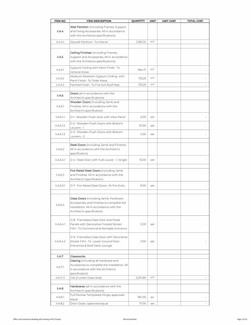
ITEM NO. ITEM DESCRIPTION QUANTITY UNIT UNIT COST TOTAL COST
II.A.4
Wall Partition (including Frames, Support
and Fixing Accessories. All in accordance
with the Architects specifications)
II.A.4.1 Drywall Partition : To Interior 1,290.22 m² -
II.A.5
Ceiling Finishes (including Frames,
Support and Accessories. All in accordance
with the Architects specifications)
II.A.5.1Gypsum Ceiling with Paint Finish : To
General Areas994.17 m² -
II.A.5.2Moisture Resistant Gypsum Ceiling with
Paint Finish : To Toilet Areas172.23 m² -
II.A.5.3 Painted Finish : To Fire Exit Roof Slab 172.23 m² -
II.A.6Doors (all in accordance with the
Architect's specifications)
II.A.6.1
Wooden Doors (including Jamb and
Finishes. All in accordance with the
Architect's specification)
II.A.6.1.1 D-1 : Wooden Flush Door with View Panel 2.00 set -
II.A.6.1.2D-2 : Wooden Flush Doors with Bottom
Louvers - 110.00 set -
II.A.6.1.3D-3 : Wooden Flush Doors with Bottom
Louvers - 25.00 set -
II.A.6.2
Steel Doors (including Jamb and Finishes.
All in accordance with the Architect's
specification)
II.A.6.2.1 D-4 : Steel Door with Fulll Louver - 1, Single 15.00 set -
II.A.6.3
Fire Rated Steel Doors (including Jamb
and Finishes. All in accordance with the
Architect's Specification)
II.A.6.3.1 D-7 : Fire Rated Steel Doors : At Fire Exits 9.00 set -
II.A.6.4
Glass Doors (including Jamb, Hardware,
Accessories, and Finishes to complete the
installation. All in accordance with the
Architect's specification)
II.A.6.4.1
D-8 : Frameless Glass Door and Fixed
Panels with Decorative Frosted Sticker
Film : To Commercial & Rentable Entrance
2.00 set -
II.A.6.4.2
D-9 : Frameless Glass Door with Decorative
Sticker Film : To Lower Ground Floor
Entrances & Roof Deck Lounge
3.00 set -
II.A.7 Glassworks
II.A.7.1
Glazing (including all Hardware and
Accessories to complete the installation. All
in accordance with the Architect's
specification)
II.A.7.1.1 CW (Curtain Glass Wall) 2,210.80 m² -
II.A.8Hardwares (all in accordance with the
Architect's specifications)
II.A.8.1Full Mortise Templated Hinge; approved
equal184.00 pc -
II.A.8.2 Door Closer; approved equal 17.00 set -
Office and Commercial Building with Parking at PICC Project Bill of Quantities Page 2 of 33
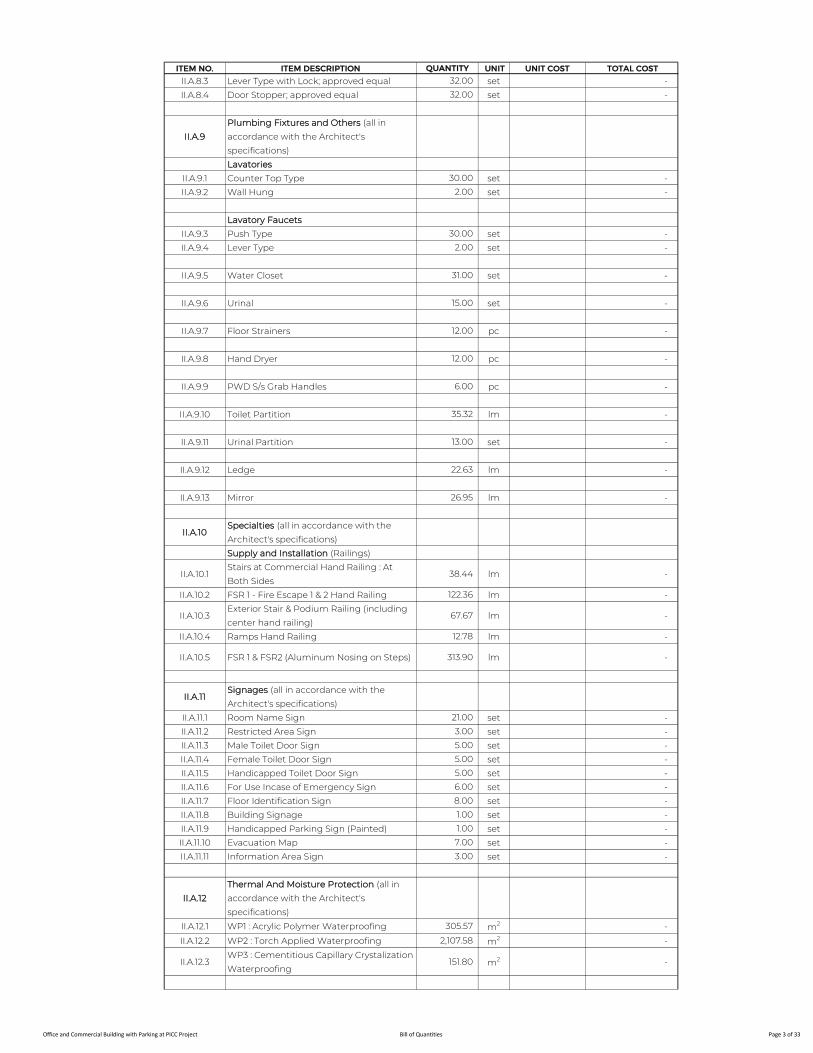
ITEM NO. ITEM DESCRIPTION QUANTITY UNIT UNIT COST TOTAL COST
II.A.8.3 Lever Type with Lock; approved equal 32.00 set -
II.A.8.4 Door Stopper; approved equal 32.00 set -
II.A.9
Plumbing Fixtures and Others (all in
accordance with the Architect's
specifications)
Lavatories
II.A.9.1 Counter Top Type 30.00 set -
II.A.9.2 Wall Hung 2.00 set -
Lavatory Faucets
II.A.9.3 Push Type 30.00 set -
II.A.9.4 Lever Type 2.00 set -
II.A.9.5 Water Closet 31.00 set -
II.A.9.6 Urinal 15.00 set -
II.A.9.7 Floor Strainers 12.00 pc -
II.A.9.8 Hand Dryer 12.00 pc -
II.A.9.9 PWD S/s Grab Handles 6.00 pc -
II.A.9.10 Toilet Partition 35.32 lm -
II.A.9.11 Urinal Partition 13.00 set -
II.A.9.12 Ledge 22.63 lm -
II.A.9.13 Mirror 26.95 lm -
II.A.10Specialties (all in accordance with the
Architect's specifications)
Supply and Installation (Railings)
II.A.10.1Stairs at Commercial Hand Railing : At
Both Sides38.44 lm -
II.A.10.2 FSR 1 - Fire Escape 1 & 2 Hand Railing 122.36 lm -
II.A.10.3Exterior Stair & Podium Railing (including
center hand railing)67.67 lm -
II.A.10.4 Ramps Hand Railing 12.78 lm -
II.A.10.5 FSR 1 & FSR2 (Aluminum Nosing on Steps) 313.90 lm -
II.A.11Signages (all in accordance with the
Architect's specifications)
II.A.11.1 Room Name Sign 21.00 set -
II.A.11.2 Restricted Area Sign 3.00 set -
II.A.11.3 Male Toilet Door Sign 5.00 set -
II.A.11.4 Female Toilet Door Sign 5.00 set -
II.A.11.5 Handicapped Toilet Door Sign 5.00 set -
II.A.11.6 For Use Incase of Emergency Sign 6.00 set -
II.A.11.7 Floor Identification Sign 8.00 set -
II.A.11.8 Building Signage 1.00 set -
II.A.11.9 Handicapped Parking Sign (Painted) 1.00 set -
II.A.11.10 Evacuation Map 7.00 set -
II.A.11.11 Information Area Sign 3.00 set -
II.A.12
Thermal And Moisture Protection (all in
accordance with the Architect's
specifications)
II.A.12.1 WP1 : Acrylic Polymer Waterproofing 305.57 m2 -
II.A.12.2 WP2 : Torch Applied Waterproofing 2,107.58 m2 -
II.A.12.3WP3 : Cementitious Capillary Crystalization
Waterproofing151.80 m2 -
Office and Commercial Building with Parking at PICC Project Bill of Quantities Page 3 of 33
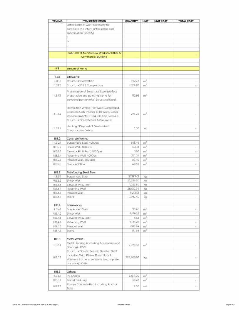
ITEM NO. ITEM DESCRIPTION QUANTITY UNIT UNIT COST TOTAL COST
Other items of work necessary to
complete the intent of the plans and
specification (specify)
a.
b.
c.
Sub-total of Architectural Works for Office &
Commercial Building -
II.B Structural Works
II.B.1 Siteworks
II.B.1.1 Structural Excavation 792.27 m3 -
II.B.1.2 Structural Fill & Compaction 822.40 m3 -
II.B.1.3
Preservation of Structural Steel (surface
preparation and painting works for
corroded portion of all Structural Steel)
712.92 m2 -
II.B.1.4
Demolition Works (For Walls, Suspended
Concrete Slab, Interior CHB Walls, Rebar
Reinforcements, FTB & Pile Cap Forms &
Structural Steel Beams & Columns)
273.20 m3 -
II.B.1.5Hauling / Disposal of Demolished
Conctruction Debris1.00 lot -
II.B.2 Concrete Works
II.B.2.1 Suspended Slab, 4000psi 353.46 m3 -
II.B.2.2 Shear Wall, 4000psi 137.91 m3 -
II.B.2.3 Elevator Pit & Roof, 4000psi 9.63 m3 -
II.B.2.4 Retaining Wall, 4000psi 221.04 m3 -
II.B.2.5 Parapet Wall, 4000psi 60.40 m3 -
II.B.2.6 Stairs, 4000psi 40.59 m3 -
II.B.3 Reinforcing Steel Bars
II.B.3.1 Suspended Slab 27,197.01 kg -
II.B.3.2 Shear Wall 27,236.20 kg -
II.B.3.3 Elevator Pit & Roof 1,059.30 kg -
II.B.3.4 Retaining Wall 28,017.94 kg -
II.B.3.5 Parapet Wall 11,212.01 kg -
II.B.3.6 Stairs 5,697.45 kg -
II.B.4 Formworks
II.B.4.1 Suspended Slab 95.45 m2 -
II.B.4.2 Shear Wall 1,416.25 m2 -
II.B.4.3 Elevator Pit & Roof 6.53 m2 -
II.B.4.4 Retaining Wall 1,123.28 m2 -
II.B.4.5 Parapet Wall 805.74 m2 -
II.B.4.6 Stairs 217.38 m2 -
II.B.5 Metal Works
II.B.5.1Metal Decking (including Accessories and
Shoring) - OSM2,979.58 m2 -
II.B.5.2
Structural Steels (Beams, Elevator Shaft
included. With Plates, Bolts, Nuts &
Washers & other steel items to complete
the work) - OSM
228,909.63 kg -
II.B.6 Others
II.B.6.1 PE Sheets 3,184.00 m2 -
II.B.6.2 Gravel Bedding 30.28 m3 -
II.B.6.3Pumps Concrete Pad Including Anchor
Bolts2.00 set -
Office and Commercial Building with Parking at PICC Project Bill of Quantities Page 4 of 33

ITEM NO. ITEM DESCRIPTION QUANTITY UNIT UNIT COST TOTAL COST
II.B.6.4Jockey Pump Concrete Pad Including
Anchor Bolts2.00 set -
II.B.6.5 Fireproofing of Steel Structure 1,901.59 m2 -
II.B.6.6 Rectification Works for Failed Pile Caps 1.00 lot -
II.B.6.7 Rectification Works for Failed Tie Beams 1.00 lot -
Other items of work necessary to
complete the intent of the plans and
specification (specify)
a.
b.
c
Sub-total of Structural Works for Office &
Commercial Building -
II.C Plumbing & Sanitary Works
II.C.1 Water Distribution System
Cold Water Supply for Toilets and Concessionaires Area
II.C.1.1
Potable Water Line (PWL) (Polypropylene
(PPR) Pipes, including Fittings Transition,
Hangers and Supports and other items to
complete the work)
II.C.1.1.1 63mm Ø GI Pipe 33.00 l.m. -
II.C.1.1.2 50mm Ø PPR Pipe 229.50 l.m. -
II.C.1.1.3 40mm Ø PPR Pipe 88.80 l.m. -
II.C.1.1.4 32mm Ø PPR Pipe 113.55 l.m. -
II.C.1.1.5 25mm Ø PPR Pipe 81.75 l.m. -
II.C.1.1.6 20mm Ø PPR Pipe 110.60 l.m. -
Gate Valve
II.C.1.1.7 40mm Ø 12.00 pc -
II.C.1.1.8 25mm Ø 5.00 pc -
II.C.1.1.9Gate Valve 32mm Ø complete with
Fittings for concessionaires21.00 unit -
II.C.1.1.10 20mm Ø Hose Bibb : At Slop Sink 5.00 pc -
II.C.2 Drainage System
II.C.2.1
Waste and Storm Drainage (UPVC Pipe,
Series 1000 including Fittings, Thrust Block
Supports and other items to complete the
works)
II.C.2.1.1 150mm Ø 185.00 l.m. -
II.C.2.1.2 100mm Ø 166.50 l.m. -
Deck Drain
II.C.2.1.3 150mm Ø 10.00 unit -
II.C.2.1.4 100mm Ø 7.00 unit -
Podium Drain
II.C.2.1.5 100mm Ø 7.00 unit -
II.C.2.2Condensate Drain Pipes and Fitting with
Insulation
II.C.2.2.1 50mm Ø UPVC Pipe w/ Rubber Insulation 76.00 l.m. -
II.C.2.2.2 40mm Ø UPVC Pipe w/ Rubber Insulation 198.00 l.m. -
II.C.2.2.3 32mm Ø UPVC Pipe w/ Rubber Insulation 79.00 l.m. -
II.C.2.2.4 25mm Ø UPVC Pipe w/ Rubber Insulation 62.00 l.m. -
Trench Drain
II.C.2.2.5 75mm Ø 1.00 unit -
Office and Commercial Building with Parking at PICC Project Bill of Quantities Page 5 of 33
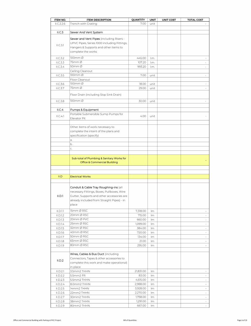
ITEM NO. ITEM DESCRIPTION QUANTITY UNIT UNIT COST TOTAL COST
II.C.2.2.6 Trench with Grating 7.00 unit -
II.C.3 Sewer And Vent System
II.C.3.1
Sewer and Vent Pipes (including Risers -
UPVC Pipes, Series 1000 including Fittings,
Hangers & Supports and other items to
complete the works
II.C.3.2 100mm Ø 445.00 l.m. -
II.C.3.3 75mm Ø 107.20 l.m. -
II.C.3.4 50mm Ø 993.20 l.m. -
Ceiling Cleanout
II.C.3.5 100mm Ø 7.00 unit -
Floor Cleanout
II.C.3.6 100mm Ø 18.00 unit -
II.C.3.7 75mm Ø 29.00 unit -
Floor Drain (including Slop Sink Drain)
II.C.3.8 100mm Ø 30.00 unit -
II.C.4 Pumps & Equipment
II.C.4.1Portable Submersible Sump Pumps for
Elevator Pit4.00 unit -
Other items of work necessary to
complete the intent of the plans and
specification (specify)
a.
b.
c.
Sub-total of Plumbing & Sanitary Works for
Office & Commercial Building -
II.D Electrical Works
II.D.1
Conduit & Cable Tray Roughing-ins (all
necessary Fittings, Boxes, Pullboxes, Wire
Gutter, Supports and other accessories are
already included from Straight Pipes) - in
place
II.D.1.1 15mm Ø RSC 7,318.00 lm -
II.D.1.2 20mm Ø RSC 715.00 lm -
II.D.1.3 20mm Ø PVC 660.00 lm -
II.D.1.4 25mm Ø RSC 1,099.00 lm -
II.D.1.5 32mm Ø RSC 384.00 lm -
II.D.1.6 40mm Ø RSC 720.00 lm -
II.D.1.7 50mm Ø RSC 134.00 lm -
II.D.1.8 65mm Ø RSC 21.00 lm -
II.D.1.9 80mm Ø RSC 295.00 lm -
II.D.2
Wires, Cables & Bus Duct (including
Connectors, Tapes & other accessories to
complete this work and make operational) -
in place
II.D.2.1 3.5mm2 THHN 21,831.00 lm -
II.D.2.2 5.5mm2 FR 83.00 lm -
II.D.2.3 5.5mm2 THHN 4,615.00 lm -
II.D.2.4 8.0mm2 THHN 2,988.00 lm -
II.D.2.5 14mm2 THHN 3,928.00 lm -
II.D.2.6 22mm2 THHN 2,270.00 lm -
II.D.2.7 30mm2 THHN 1,758.00 lm -
II.D.2.8 38mm2 THHN 1,291.00 lm -
II.D.2.9 80mm2 THHN 667.00 lm -
Office and Commercial Building with Parking at PICC Project Bill of Quantities Page 6 of 33

ITEM NO. ITEM DESCRIPTION QUANTITY UNIT UNIT COST TOTAL COST
II.D.2.10 100mm2 THHN 296.00 lm -
II.D.2.11 125mm2 THHN 232.00 lm -
II.D.2.12 200mm2 THHN 2,451.00 lm -
II.D.3
Panelboards - in place (includes other
accessories to complete this work and
make operational)
II.D.3.1 LPLG 1.00 assy -
II.D.3.2 PPC 1.00 assy -
II.D.3.3 LPC 1.00 assy -
II.D.3.4 PPLG 1.00 assy -
II.D.3.5 FPUMP 1.00 assy -
II.D.3.6 WPUMP 1.00 assy -
II.D.3.7 DPUG 1.00 assy -
II.D.3.8 DPC 1.00 assy -
II.D.3.9 DPAC 1.00 assy -
II.D.3.10 PPAC 1.00 assy -
II.D.3.11 DPLG 1.00 assy -
II.D.3.12 DP2F 1.00 assy -
II.D.3.13 DPN 1.00 assy -
II.D.4 ECB - in place
II.D.4.1 ECB 20AT, 2P,230V, NEMA-3R 6.00 assy -
II.D.4.2 ECB 30AT, 2P,230V, NEMA-3R 1.00 assy -
II.D.4.3 ECB 50AT, 3P,400V, NEMA-3R 1.00 assy -
II.D.5
Lighting Fixtures & Wiring Devices
(including necessary Supports, Boxes &
Dropped Flexible Metal Conduit) - in place
II.D.5.1 TFL2 4.00 set -
II.D.5.2 TFL1 231.00 set -
II.D.5.3 DL 235.00 set -
II.D.5.4 Exit Light 16.00 set -
II.D.5.5 Emergency Light 33.00 set -
II.D.6 Electrical Devices- in place
II.D.6.1 Switch (1-gang) 24.00 set -
II.D.6.2 Switch (2-gang) 29.00 set -
II.D.6.3 2-Way Switch(1-gang) 4.00 set -
II.D.6.4 4-Way Switch(1-Gang) 4.00 set -
II.D.6.5 Single Convenience Outlet, 3-prong 31.00 set -
II.D.6.6 Duplex Convenience Outlet, 3-prong 51.00 set -
II.D.6.7Duplex Floor Mounted Convenience
Outlet, 3 prong15.00 set -
II.D.6.8Duplex Convenience Outlet,
Weatherproof, 3-prong1.00 set -
II.D.7 Pullbox - in place
II.D.7.1 PB1(450mmx450mmx450mm) 4.00 set -
II.D.7.2 PB2(350mmx350mmx350mm) 2.00 set -
II.D.7.3 PB3(200mmx200mmx200mm) 11.00 set -
II.D.7.4 PB4(325mmx325mmx325mm) 4.00 set -
II.D.7.5 PB5(250mmx250mmx250mm) 8.00 set -
Other items of work necessary to
complete the intent of the plans and
specification (specify)
a.
b.
c.
Sub-total of Electrical Works for Office &
Commercial Building -
II.E Electronic Works
Office and Commercial Building with Parking at PICC Project Bill of Quantities Page 7 of 33

ITEM NO. ITEM DESCRIPTION QUANTITY UNIT UNIT COST TOTAL COST
II.E.1 Fire Detection & Alarm System
II.E.1.1
Roughing-ins (all necessary Fittings,
Square & Junction Boxes Supports and
other accessories are already included
from Straight Pipes) - in place
II.E.1.1.1 20mm Ø IMC 739.00 lm -
II.E.1.1.2 25mm Ø IMC 246.00 lm -
II.E.1.1.3 50mm Ø IMC 30.00 lm -
II.E.1.1.4 1m Flexible Metal Conduit 94.00 pc -
II.E.1.1.5 Pullbox 34.00 pc -
II.E.1.2 Wires & Cables - in place
II.E.1.2.1 #16 Shielded Twisted TF Wire (Red) 1,036.00 lm -
II.E.1.3Devices & Modules (including all necessary
Boxes & Dropped FMC) - in place
II.E.1.3.1 Smoke Detector w/ Base 85.00 set -
II.E.1.3.2 Heat Detector w/ Base 2.00 set -
II.E.1.3.3 Manual Pull Station 12.00 set -
II.E.1.3.4 Sounder with Strobe Light 12.00 set -
II.E.1.3.5 Control Module 17.00 set -
II.E.1.3.6 Monitor Module 14.00 set -
II.E.1.3.7Fire Alarm Control Panel w/ complete
accessories & Back-Up Batteries1.00 unit -
II.E.1.4Provision (Roughing-ins & Wiring
Connection to Auto Dial to Fire Brigade)1.00 lot -
II.E.1.5Provision (Roughing-ins & Wiring
Connection to HVAC )1.00 lot -
II.E.1.6
Provision (Roughing-ins & Wiring
Connection to Public Address System
EVAC Interface)
1.00 lot -
II.E.1.7Provision (Roughing-ins & Wiring
Connection to Security System Interface)1.00 lot -
II.E.1.8Provision (Roughing-ins & Wiring
Connection to AFSS)1.00 lot -
II.E.1.9 Programming, Testing & Commissioning 1.00 lot -
II.E.2Public Addresss & Background Music
System
II.E.2.1
Roughing-ins (all necessary Fittings,
Square & Junction Boxes Supports and
other accessories are already included
from Straight Pipes) - in place
II.E.2.1.1 20mm Ø IMC 1,087.00 lm -
II.E.2.1.2 25mm Ø IMC 256.00 lm -
II.E.2.1.3 50mm Ø IMC 30.00 lm -
II.E.2.1.4 1m Flexible Metal Conduit 295.00 pc -
II.E.2.1.5 Pullbox 24.00 pc -
II.E.2.2 Wires & Cables- in place
II.E.2.2.1 Audio Cable (#16/2C) TF, Twisted Wire 1,630.00 lm -
II.E.2.2.2 4 pairs # 24 AWG, UTP CAT6 Cables 15.00 lm -
Office and Commercial Building with Parking at PICC Project Bill of Quantities Page 8 of 33

ITEM NO. ITEM DESCRIPTION QUANTITY UNIT UNIT COST TOTAL COST
II.E.2.3Devices Including All Necessary Boxes &
Dropped FMC Conduit - in place
II.E.2.3.1 Speaker, Ceiling Mounted 74.00 unit -
II.E.2.3.2 Back Cover Protection for Speakers 74.00 unit -
II.E.2.3.3 Wall Mounted Speakers 15.00 unit -
II.E.2.3.4 Horn Speakers 17.00 unit -
II.E.2.4 Equipment - in place
II.E.2.4.1 System Management Amplifier 1.00 unit -
II.E.2.4.2 UPS 3KVA 1.00 unit -
II.E.2.4.3 Power Amplifier 6.00 unit -
II.E.2.4.4 Equipment Rack 2.00 unit -
II.E.2.4.5 Remote Paging Microphone 2.00 unit -
II.E.2.5 Programming, Testing & Commissioning 1.00 lot -
II.E.3 Voice & Data System
II.E.3.1
Roughing-ins (all necessary Fittings,
Square & Junction Boxes Supports and
other accessories are already included
from Straight Pipes) - in place
II.E.3.1.1 20mm Ø IMC 1,630.00 lm -
II.E.3.1.2 Cable Tray 296.00 lm -
II.E.3.1.3 25 Pairs Punch Block 4.00 set -
II.E.3.1.4 Pullbox 32.00 pc -
II.E.3.2 Wires & Cables - in place
II.E.3.2.1 4 pairs # 24 AWG, UTP CAT6 Cables 850.00 lm -
II.E.3.2.2 Cat 5e, 25 Pairs Multi Cable for Voice 124.00 lm -
II.E.3.2.3 Fiber Optic Cable 655.00 lm -
II.E.3.2.4 Patch Cord 1m(FD/Equipment) - Data 22.00 pc -
II.E.3.2.5 Patch Cord 3m (Work Area) - Data 20.00 pc -
II.E.3.2.6 FOC Patch Cord LC with LC Connector 16.00 unit -
II.E.3.2.7 Cable Manager 10.00 unit -
II.E.3.3Devices Including All Necessary Boxes &
Wires Extensions - in place
II.E.3.3.1 Duplex Telecoms Outlet w/ Accessories 16.00 set -
II.E.3.4 Equipment - in place
II.E.3.4.1 MTTC Cabinet Rack 3.00 unit -
II.E.3.4.2 Equipment Rack 4.00 set -
II.E.3.4.3Private Automatic Branch Exchange
(PABX) w/ Programming Included1.00 assy -
II.E.3.4.4 Core Network Switch 6.00 set -
II.E.3.4.5 UPS 3KVA 3.00 unit -
II.E.3.4.624 Port Copper Patch Panel Complete w/
Connectors and Accessories12.00 unit -
II.E.3.4.7Fiber Patch Panel Complete with
Connectors & Accessories (loaded)4.00 unit -
II.E.3.5 Testing & Commissioning 1.00 lot -
II.E.4Devices Including All Necessary Boxes &
Wires Extensions - in place
Office and Commercial Building with Parking at PICC Project Bill of Quantities Page 9 of 33
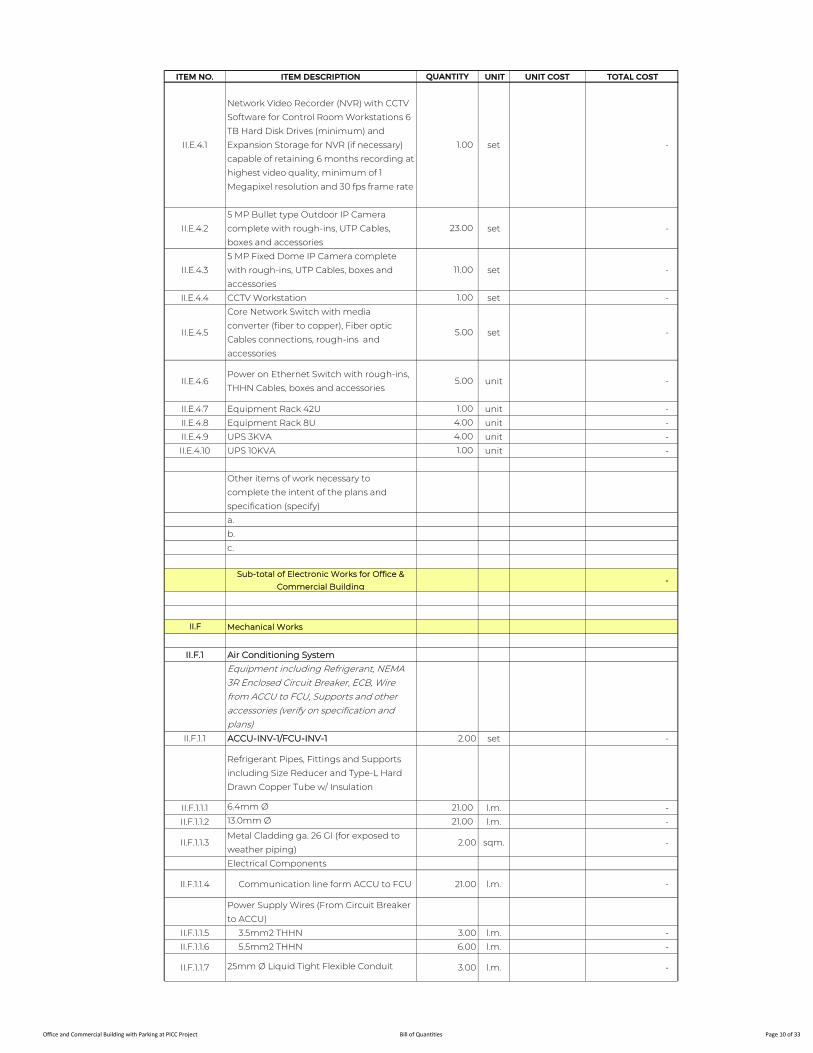
ITEM NO. ITEM DESCRIPTION QUANTITY UNIT UNIT COST TOTAL COST
II.E.4.1
Network Video Recorder (NVR) with CCTV
Software for Control Room Workstations 6
TB Hard Disk Drives (minimum) and
Expansion Storage for NVR (if necessary)
capable of retaining 6 months recording at
highest video quality, minimum of 1
Megapixel resolution and 30 fps frame rate
1.00 set -
II.E.4.2
5 MP Bullet type Outdoor IP Camera
complete with rough-ins, UTP Cables,
boxes and accessories
23.00 set -
II.E.4.3
5 MP Fixed Dome IP Camera complete
with rough-ins, UTP Cables, boxes and
accessories
11.00 set -
II.E.4.4 CCTV Workstation 1.00 set -
II.E.4.5
Core Network Switch with media
converter (fiber to copper), Fiber optic
Cables connections, rough-ins and
accessories
5.00 set -
II.E.4.6Power on Ethernet Switch with rough-ins,
THHN Cables, boxes and accessories5.00 unit -
II.E.4.7 Equipment Rack 42U 1.00 unit -
II.E.4.8 Equipment Rack 8U 4.00 unit -
II.E.4.9 UPS 3KVA 4.00 unit -
II.E.4.10 UPS 10KVA 1.00 unit -
Other items of work necessary to
complete the intent of the plans and
specification (specify)
a.
b.
c.
Sub-total of Electronic Works for Office &
Commercial Building -
II.F Mechanical Works
II.F.1 Air Conditioning System
Equipment including Refrigerant, NEMA 3R Enclosed Circuit Breaker, ECB, Wire from ACCU to FCU, Supports and other accessories (verify on specification and plans)
II.F.1.1 ACCU-INV-1/FCU-INV-1 2.00 set -
Refrigerant Pipes, Fittings and Supports
including Size Reducer and Type-L Hard
Drawn Copper Tube w/ Insulation
II.F.1.1.1 6.4mm Ø 21.00 l.m. -
II.F.1.1.2 13.0mm Ø 21.00 l.m. -
II.F.1.1.3Metal Cladding ga. 26 GI (for exposed to
weather piping)2.00 sqm. -
Electrical Components
II.F.1.1.4 Communication line form ACCU to FCU 21.00 l.m. -
Power Supply Wires (From Circuit Breaker
to ACCU)
II.F.1.1.5 3.5mm2 THHN 3.00 l.m. -
II.F.1.1.6 5.5mm2 THHN 6.00 l.m. -
II.F.1.1.7 25mm Ø Liquid Tight Flexible Conduit 3.00 l.m. -
Office and Commercial Building with Parking at PICC Project Bill of Quantities Page 10 of 33
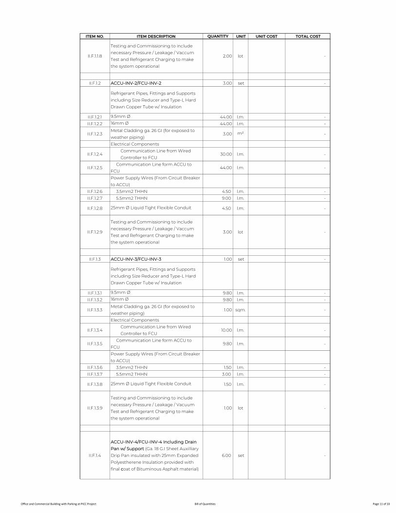
ITEM NO. ITEM DESCRIPTION QUANTITY UNIT UNIT COST TOTAL COST
II.F.1.1.8
Testing and Commissioning to include
necessary Pressure / Leakage / Vaccum
Test and Refrigerant Charging to make
the system operational
2.00 lot -
II.F.1.2 ACCU-INV-2/FCU-INV-2 3.00 set -
Refrigerant Pipes, Fittings and Supports
including Size Reducer and Type-L Hard
Drawn Copper Tube w/ Insulation
II.F.1.2.1 9.5mm Ø 44.00 l.m. -
II.F.1.2.2 16mm Ø 44.00 l.m. -
II.F.1.2.3Metal Cladding ga. 26 GI (for exposed to
weather piping)3.00 m² -
Electrical Components
II.F.1.2.4Communication Line from Wired
Controller to FCU30.00 l.m. -
II.F.1.2.5 Communication Line form ACCU to
FCU44.00 l.m. -
Power Supply Wires (From Circuit Breaker
to ACCU)
II.F.1.2.6 3.5mm2 THHN 4.50 l.m. -
II.F.1.2.7 5.5mm2 THHN 9.00 l.m. -
II.F.1.2.8 25mm Ø Liquid Tight Flexible Conduit 4.50 l.m. -
II.F.1.2.9
Testing and Commissioning to include
necessary Pressure / Leakage / Vaccum
Test and Refrigerant Charging to make
the system operational
3.00 lot -
II.F.1.3 ACCU-INV-3/FCU-INV-3 1.00 set -
Refrigerant Pipes, Fittings and Supports
including Size Reducer and Type-L Hard
Drawn Copper Tube w/ Insulation
II.F.1.3.1 9.5mm Ø 9.80 l.m. -
II.F.1.3.2 16mm Ø 9.80 l.m. -
II.F.1.3.3Metal Cladding ga. 26 GI (for exposed to
weather piping)1.00 sqm. -
Electrical Components
II.F.1.3.4Communication Line from Wired
Controller to FCU10.00 l.m. -
II.F.1.3.5 Communication Line form ACCU to
FCU9.80 l.m. -
Power Supply Wires (From Circuit Breaker
to ACCU)
II.F.1.3.6 3.5mm2 THHN 1.50 l.m. -
II.F.1.3.7 5.5mm2 THHN 3.00 l.m. -
II.F.1.3.8 25mm Ø Liquid Tight Flexible Conduit 1.50 l.m. -
II.F.1.3.9
Testing and Commissioning to include
necessary Pressure / Leakage / Vacuum
Test and Refrigerant Charging to make
the system operational
1.00 lot -
II.F.1.4
ACCU-INV-4/FCU-INV-4 Including Drain
Pan w/ Support (Ga. 18 G.I Sheet Auxilliary
Drip Pan insulated with 25mm Expanded
Polyestherene Insulation provided with
final coat of Bituminous Asphalt material)
6.00 set -
Office and Commercial Building with Parking at PICC Project Bill of Quantities Page 11 of 33
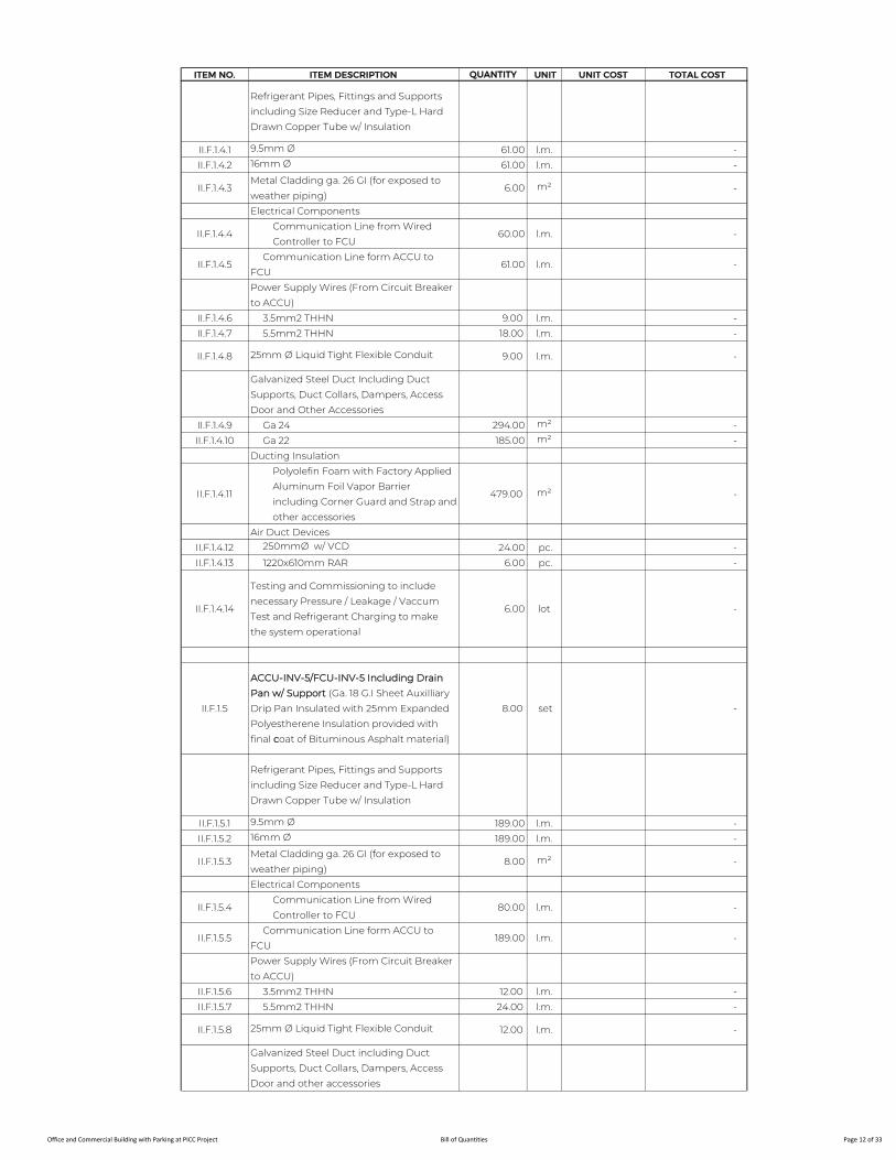
ITEM NO. ITEM DESCRIPTION QUANTITY UNIT UNIT COST TOTAL COST
Refrigerant Pipes, Fittings and Supports
including Size Reducer and Type-L Hard
Drawn Copper Tube w/ Insulation
II.F.1.4.1 9.5mm Ø 61.00 l.m. -
II.F.1.4.2 16mm Ø 61.00 l.m. -
II.F.1.4.3Metal Cladding ga. 26 GI (for exposed to
weather piping)6.00 m² -
Electrical Components
II.F.1.4.4Communication Line from Wired
Controller to FCU60.00 l.m. -
II.F.1.4.5 Communication Line form ACCU to
FCU61.00 l.m. -
Power Supply Wires (From Circuit Breaker
to ACCU)
II.F.1.4.6 3.5mm2 THHN 9.00 l.m. -
II.F.1.4.7 5.5mm2 THHN 18.00 l.m. -
II.F.1.4.8 25mm Ø Liquid Tight Flexible Conduit 9.00 l.m. -
Galvanized Steel Duct Including Duct
Supports, Duct Collars, Dampers, Access
Door and Other Accessories
II.F.1.4.9 Ga 24 294.00 m² -
II.F.1.4.10 Ga 22 185.00 m² -
Ducting Insulation
II.F.1.4.11
Polyolefin Foam with Factory Applied
Aluminum Foil Vapor Barrier
including Corner Guard and Strap and
other accessories
479.00 m² -
Air Duct Devices
II.F.1.4.12 250mmØ w/ VCD 24.00 pc. -
II.F.1.4.13 1220x610mm RAR 6.00 pc. -
II.F.1.4.14
Testing and Commissioning to include
necessary Pressure / Leakage / Vaccum
Test and Refrigerant Charging to make
the system operational
6.00 lot -
II.F.1.5
ACCU-INV-5/FCU-INV-5 Including Drain
Pan w/ Support (Ga. 18 G.I Sheet Auxilliary
Drip Pan Insulated with 25mm Expanded
Polyestherene Insulation provided with
final coat of Bituminous Asphalt material)
8.00 set -
Refrigerant Pipes, Fittings and Supports
including Size Reducer and Type-L Hard
Drawn Copper Tube w/ Insulation
II.F.1.5.1 9.5mm Ø 189.00 l.m. -
II.F.1.5.2 16mm Ø 189.00 l.m. -
II.F.1.5.3Metal Cladding ga. 26 GI (for exposed to
weather piping)8.00 m² -
Electrical Components
II.F.1.5.4Communication Line from Wired
Controller to FCU80.00 l.m. -
II.F.1.5.5 Communication Line form ACCU to
FCU189.00 l.m. -
Power Supply Wires (From Circuit Breaker
to ACCU)
II.F.1.5.6 3.5mm2 THHN 12.00 l.m. -
II.F.1.5.7 5.5mm2 THHN 24.00 l.m. -
II.F.1.5.8 25mm Ø Liquid Tight Flexible Conduit 12.00 l.m. -
Galvanized Steel Duct including Duct
Supports, Duct Collars, Dampers, Access
Door and other accessories
Office and Commercial Building with Parking at PICC Project Bill of Quantities Page 12 of 33

ITEM NO. ITEM DESCRIPTION QUANTITY UNIT UNIT COST TOTAL COST
II.F.1.5.9 Ga 24 192.00 m² -
II.F.1.5.10 Ga 22 246.00 m² -
Ducting Insulation
II.F.1.5.11
Polyolefin Foam with Factory Applied
Aluminum Foil Vapor Barrier
including Corner Guard and Strap and
other accessories
438.00 m² -
Air Duct Devices
II.F.1.5.12 250mmØ w/ VCD 24.00 pc. -
II.F.1.5.13 1220x610mm RAR 8.00 pc. -
II.F.1.5.14
Testing and Commissioning to include
necessary Pressure / Leakage / Vaccum
Test and Refrigerant Charging to make
the system operational
8.00 lot -
II.F.1.6 ACCU-INV-6/FCU-INV-6 4.00 set -
Refrigerant Pipes, Fittings and Supports
including Size Reducer and Type-L Hard
Drawn Copper Tube w/ Insulation
II.F.1.6.1 9.5mm Ø 77.00 l.m. -
II.F.1.6.2 16mm Ø 77.00 l.m. -
II.F.1.6.3Metal Cladding ga. 26 GI (for exposed to
weather piping)4.00 m² -
Electrical Components
II.F.1.6.4 Communication Line form ACCU to
FCU77.00 l.m. -
Power Supply Wires (From Circuit Breaker
to ACCU)
II.F.1.6.5 3.5mm2 THHN 6.00 l.m. -
II.F.1.6.6 5.5mm2 THHN 12.00 l.m. -
II.F.1.6.7 25mm Ø Liquid Tight Flexible Conduit 6.00 l.m. -
II.F.1.6.8
Testing and Commissioning to include
necessary Pressure / Leakage / Vaccum
Test and Refrigerant Charging to make
the system operational
4.00 lot -
II.F.1.7 ACCU-INV-7/FCU-INV-7 2.00 set -
Refrigerant Pipes, Fittings and Supports
including Size Reducer and Type-L Hard
Drawn Copper Tube w/ Insulation
II.F.1.7.1 9.5mm Ø 19.00 l.m. -
II.F.1.7.2 16mm Ø 19.00 l.m. -
II.F.1.7.3Metal Cladding ga. 26 GI (for exposed to
weather piping)2.00 m² -
Electrical Components
II.F.1.7.4Communication Line from Wired
Controller to FCU20.00 l.m. -
II.F.1.7.5 Communication Line form ACCU to FCU 19.00 l.m. -
Power Supply Wires (From Circuit Breaker
to ACCU)
II.F.1.7.6 3.5mm2 THHN 3.00 l.m. -
II.F.1.7.7 5.5mm2 THHN 6.00 l.m. -
II.F.1.7.8 25mm Ø Liquid Tight Flexible Conduit 3.00 l.m. -
II.F.1.7.9
Testing and Commissioning to include
Necessary Pressure / Leakage / Vaccum
Test and Refrigerant Charging to make
the system operational
2.00 lot -
Office and Commercial Building with Parking at PICC Project Bill of Quantities Page 13 of 33
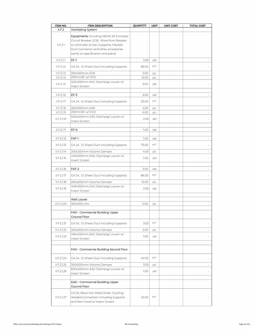
ITEM NO. ITEM DESCRIPTION QUANTITY UNIT UNIT COST TOTAL COST
II.F.2 Ventilating System
II.F.2.1
Equipments including NEMA 3R Enclosed
Circuit Breaker, ECB, Wires from Breaker
to Controller to Fan, Supports, Flexible
Duct Connector and other accessories
(verify on specification and plans)
II.F.2.1.1 EF-1 3.00 set -
II.F.2.1.2 GA 24, GI Sheet Duct Including Supports 86.00 m² -
II.F.2.1.3 300x300mm EAR 3.00 pc. -
II.F.2.1.4 200mmØ w/ VCD 15.00 pc. -
II.F.2.1.5500x300mm EAG Discharge Louver w/
Insect Screen 3.00 set -
II.F.2.1.6 EF-3 2.00 set -
II.F.2.1.7 GA 24, GI Sheet Duct including Supports 53.00 m² -
II.F.2.1.8 300x300mm EAR 4.00 pc. -
II.F.2.1.9 200mmØ w/ VCD 6.00 pc. -
II.F.2.1.10500x400mm EAG Discharge Louver w/
Insect Screen2.00 set -
II.F.2.1.11 EF-6 1.00 set -
II.F.2.1.12 FAF-1 1.00 set -
II.F.2.1.13 GA 24, GI Sheet Duct including Supports 73.00 m² -
II.F.2.1.14 200x200mm Volume Damper 4.00 pc. -
II.F.2.1.15400x300mm EAG Discharge Louver w/
Insect Screen 1.00 set -
II.F.2.1.16 FAF-2 3.00 set -
II.F.2.1.17 GA 24, GI Sheet Duct including Supports 86.00 m² -
II.F.2.1.18 200x200mm Volume Damper 10.00 pc. -
II.F.2.1.19400x300mm EAG Discharge Louver w/
Insect Screen3.00 set -
Wall Louver
II.F.2.1.20 300x300 mm 5.00 pc. -
FAD - Commercial Building Upper
Ground Floor
II.F.2.1.21 GA 24, GI Sheet Duct including Supports 3.00 m² -
II.F.2.1.22 300x300mm Volume Damper 2.00 pc. -
II.F.2.1.23450x450mm EAG Discharge Louver w/
Insect Screen 1.00 set -
FAD - Commercial Building Second Floor
II.F.2.1.24 GA 24, GI Sheet Duct including Supports 45.00 m² -
II.F.2.1.25 300x300mm Volume Damper 3.00 pc. -
II.F.2.1.26600x400mm EAG Discharge Louver w/
Insect Screen 1.00 set -
EAD - Commercial Building Upper
Gournd Floor
II.F.2.1.27
GA 20, Black Iron Metal Sheet Ducting
Welded Connection including Supports
and Rain Hood w/ Insect Screen
33.00 m² -
Office and Commercial Building with Parking at PICC Project Bill of Quantities Page 14 of 33

ITEM NO. ITEM DESCRIPTION QUANTITY UNIT UNIT COST TOTAL COST
II.F.2.1.28Ducting Insulation Mineral Wool Insulation
(Board Type Similar to Rockwool) 33.00 m² -
II.F.2.1.29300x400mm EAG Discharge Louver w/
Rain hood and Insect Screen1.00 set -
EAD - Commercial Building Second Floor
II.F.2.1.2.30
GA 20, Black Iron Metal Sheet Ducting
welded connection including Supports
and Rain hood w/ Insect Screen
72.00 m² -
II.F.2.1.2.31Ducting Insulation Mineral Wool Insulation
(Board Type similar to Rockwool) 72.00 m² -
II.F.2.1.2.32300x400mm EAG Discharge Louver w/
Rain hood and Insect Screen 1.00 set -
Air Vent
II.F.2.1.33 GA 24, GI Sheet Duct inc. supports 1.00 m² -
II.F.2.1.34100x100mm EAG Discharge Louver w/ Rain
Hood and Insect Screen 1.00 set -
II.F.3 Lift System
II.F.3.1
Elevator Equipment - supply, delivery and
installation of Elevator Equipment
complete with ECB and accessories to
make the system operational, Testing and
Commissioning (verify on specification and
plans)
II.F.3.1.1 Passenger Elevator 1,000 kg 2.00 set -
II.F.3.1.2 Passenger Elevator 450 kg 1.00 set -
II.F.3.1.3 Service Elevator 1.00 set -
II.F.4 LPG Piping System
II.F.4.1
Black Iron - B.I. Seamless Pipes - with
Sway Brace, Hanger, Support, Pipe Fitting
and other item necessary to complete the
work make the system operational (verify
on specification and plans)
II.F.4.1.1 50mm Ø B.I Pipe Schd. 40 55.00 l.m. -
II.F.4.1.2 20mm Ø B.I Pipe Schd. 40 30.00 l.m. -
II.F.4.2
Supply and Installation - with Controller,
Valves, Supports, Fittings, accessories and
other item necessary to complete the
work make the system operational (verify
on specification and plans)
II.F.4.2.1 Ball valve 20mm Ø stainless 6000 WOG 10.00 pc. -
II.F.4.2.2 Pressure gauge 7.00 pc. -
II.F.4.2.3 Gas Meter 5.00 pc. -
Other items of work necessary to
complete the intent of the plans and
specification (specify)
a.
b.
c.
Sub-total of Mechanical Works for Office &
Commercial Building -
Office and Commercial Building with Parking at PICC Project Bill of Quantities Page 15 of 33
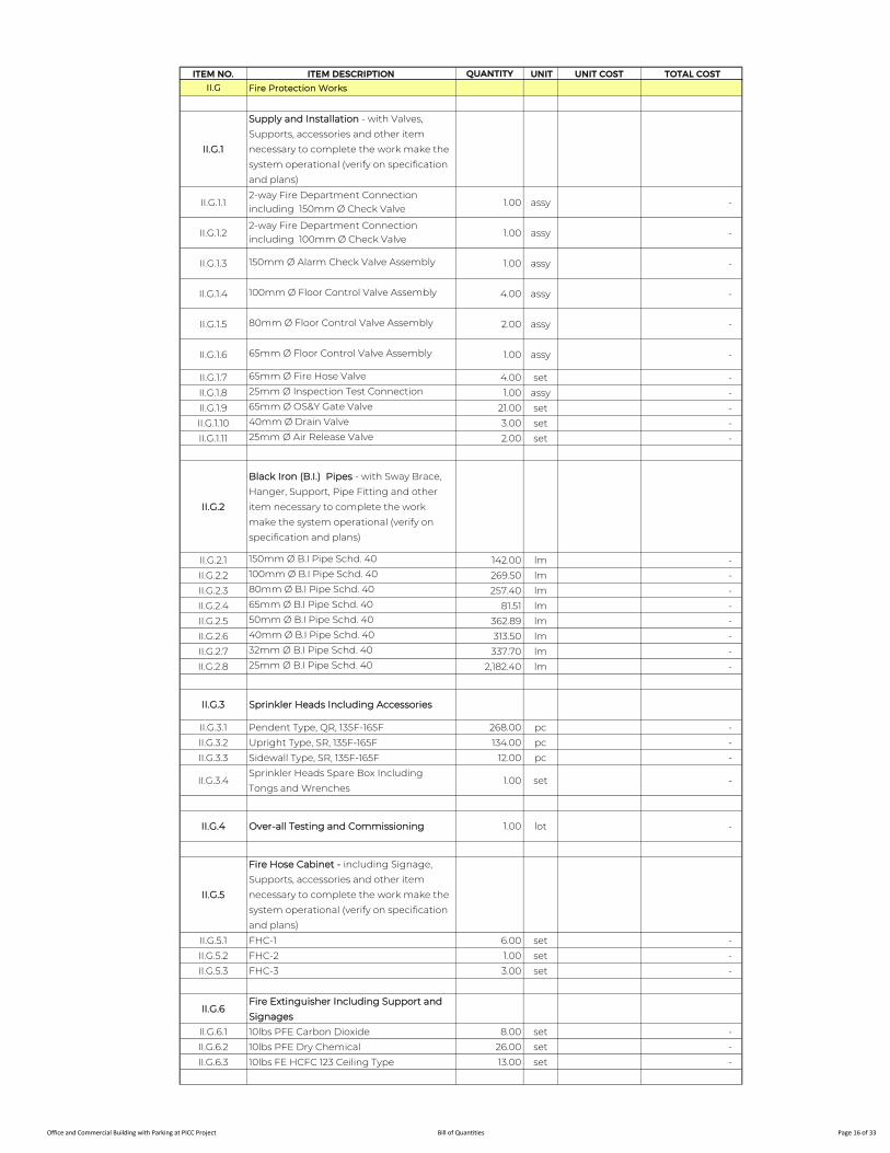
ITEM NO. ITEM DESCRIPTION QUANTITY UNIT UNIT COST TOTAL COST
II.G Fire Protection Works
II.G.1
Supply and Installation - with Valves,
Supports, accessories and other item
necessary to complete the work make the
system operational (verify on specification
and plans)
II.G.1.12-way Fire Department Connection including 150mm Ø Check Valve
1.00 assy -
II.G.1.22-way Fire Department Connection including 100mm Ø Check Valve
1.00 assy -
II.G.1.3 150mm Ø Alarm Check Valve Assembly 1.00 assy -
II.G.1.4 100mm Ø Floor Control Valve Assembly 4.00 assy -
II.G.1.5 80mm Ø Floor Control Valve Assembly 2.00 assy -
II.G.1.6 65mm Ø Floor Control Valve Assembly 1.00 assy -
II.G.1.7 65mm Ø Fire Hose Valve 4.00 set -
II.G.1.8 25mm Ø Inspection Test Connection 1.00 assy -
II.G.1.9 65mm Ø OS&Y Gate Valve 21.00 set -
II.G.1.10 40mm Ø Drain Valve 3.00 set -
II.G.1.11 25mm Ø Air Release Valve 2.00 set -
II.G.2
Black Iron (B.I.) Pipes - with Sway Brace,
Hanger, Support, Pipe Fitting and other
item necessary to complete the work
make the system operational (verify on
specification and plans)
II.G.2.1 150mm Ø B.I Pipe Schd. 40 142.00 lm -
II.G.2.2 100mm Ø B.I Pipe Schd. 40 269.50 lm -
II.G.2.3 80mm Ø B.I Pipe Schd. 40 257.40 lm -
II.G.2.4 65mm Ø B.I Pipe Schd. 40 81.51 lm -
II.G.2.5 50mm Ø B.I Pipe Schd. 40 362.89 lm -
II.G.2.6 40mm Ø B.I Pipe Schd. 40 313.50 lm -
II.G.2.7 32mm Ø B.I Pipe Schd. 40 337.70 lm -
II.G.2.8 25mm Ø B.I Pipe Schd. 40 2,182.40 lm -
II.G.3 Sprinkler Heads Including Accessories
II.G.3.1 Pendent Type, QR, 135F-165F 268.00 pc -
II.G.3.2 Upright Type, SR, 135F-165F 134.00 pc -
II.G.3.3 Sidewall Type, SR, 135F-165F 12.00 pc -
II.G.3.4Sprinkler Heads Spare Box Including
Tongs and Wrenches1.00 set -
II.G.4 Over-all Testing and Commissioning 1.00 lot -
II.G.5
Fire Hose Cabinet - including Signage,
Supports, accessories and other item
necessary to complete the work make the
system operational (verify on specification
and plans)
II.G.5.1 FHC-1 6.00 set -
II.G.5.2 FHC-2 1.00 set -
II.G.5.3 FHC-3 3.00 set -
II.G.6Fire Extinguisher Including Support and
Signages
II.G.6.1 10lbs PFE Carbon Dioxide 8.00 set -
II.G.6.2 10lbs PFE Dry Chemical 26.00 set -
II.G.6.3 10lbs FE HCFC 123 Ceiling Type 13.00 set -
Office and Commercial Building with Parking at PICC Project Bill of Quantities Page 16 of 33
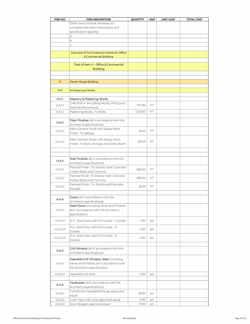
ITEM NO. ITEM DESCRIPTION QUANTITY UNIT UNIT COST TOTAL COST
Other items of work necessary to
complete the intent of the plans and
specification (specify)
a.
b.
c.
Sub-total of Fire Protection Works for Office
& Commercial Building -
Total of Item II - Office & Commercial
Building -
III Power House Building
III.A Architectural Works
III.A.1 Masonry & Plastering Works
III.A.1.1CHB Wall 4" (including Mortar, Filling and
Steel Reinforcement)747.96 m² -
III.A.1.2 Plastering Works : To Walls 1,373.60 m² -
III.A.2Floor Finishes (all in accordance with the
Architect's specifications)
III.A.2.1Plain Cement Finish with Epoxy Paint
Finish : To Hallway16.43 m² -
III.A.2.2Plain Cement Finish with Epoxy Paint
Finish : To Stairs, Storage and Utility Room281.23 m² -
III.A.3Wall Finishes (all in accordance with the
Architect's specifications)
III.A.3.1Painted Finish : To Exterior Wall Concrete
Hollow Block and Columns660.62 m² -
III.A.3.2Painted Finish : To Interior Wall Concrete
Hollow Block and Columns660.62 m² -
III.A.3.3Painted Finish : To Reinforced Concrete
Parapet52.36 m² -
III.A.4Doors (all in accordance with the
Architect's specifications)
III.A.4.1
Steel Doors (including Jamb and Finishes.
All in accordance with the Architect's
specification)
III.A.4.1.1 D-4 : Steel Door with Full Louver - 1, Single 1.00 set -
III.A.4.1.2D-5 : Steel Door with Full Louver - 2,
Double4.00 set -
III.A.4.1.3D-6 : Steel Door with Full Louver - 3,
Double4.00 set -
III.A.5Grill Window (all in accordance with the
Architect's specifications)
III.A.5.1
Operable Grill Window, Steel (including
Jamb and Finishes; all in accordance with
the Architect's specification)
III.A.5.1.1 Operable Grill Door 4.00 set -
III.A.6Hardwares (all in accordance with the
Architect's specifications)
III.A.6.1Full Mortise Templated Hinge; approved
equal36.00 pc -
III.A.6.2 Lever Type with Lock; approved equal 9.00 set -
III.A.6.3 Door Stopper; approved equal 17.00 set -
Office and Commercial Building with Parking at PICC Project Bill of Quantities Page 17 of 33

ITEM NO. ITEM DESCRIPTION QUANTITY UNIT UNIT COST TOTAL COST
III.A.7
Plumbing Fixture and Others (all in
accordance with the Architect's
specifications)
III.A.7.1 Faucet 1.00 set -
III.A.7.2 Floor Strainers 1.00 set -
III.A.8Specialties (all in accordance with the
Architect's specifications)
III.A.8.1 Supply and Installation of Railing
III.A.8.1.1 Interior Stair Railing 1.00 lot -
III.A.9Signages (all in accordance with the
Architect's specifications)
III.A.9.1 Room Name Sign 5.00 set -
III.A.9.2 Restricted Area Sign 2.00 set -
III.A.10
Thermal And Moisture Protection (all in
accordance with the Architect's
specifications)
(Supply and Installation of Waterproofing
System)
III.A.10.1 WP1 : Acrylic Polymer Waterproofing 52.36 m² -
III.A.10.2 WP2 : Torch Applied Waterproofing 157.93 m² -
III.A.10.3WP3 : Cementitious Capillary Crystalization
Waterproofing129.50 m² -
Other items of work necessary to
complete the intent of the plans and
specification (specify)
a.
b.
c.
Sub-total of Architectural Works for Power
House Building -
III.B Structural Works
III.B.1 Siteworks
III.B.1.1 Structural Fill & Compaction 114.00 m3 -
III.B.2 Concrete Works
III.B.2.1 Slab on Grade, 3000psi 54.00 m3 -
III.B.2.2 Equipment Pads, 3000psi 23.00 m3 -
III.B.2.3 Concrete Manhole & Pedestal, 3000psi 12.00 m3 -
III.B.2.4 Ramps, 3000psi 32.00 m3 -
III.B.2.5 Roof Deck Slab, 4000psi 62.00 m3 -
III.B.2.6 Parapet Wall, 3000psi 27.50 m3 -
III.B.3 Reinforcing Steel Bars
III.B.3.1 Slab on Grade 4,050.00 kg -
III.B.3.2 Equipment Pads 1,725.00 kg -
III.B.3.3 Concrete Manhole & Pedestal 900.00 kg -
III.B.3.4 Ramps 2,400.00 kg -
III.B.3.5 Roof Deck Slab 4,650.00 kg -
III.B.3.6 Parapet Wall 2,062.50 kg -
III.B.4 Formworks
III.B.4.1 Slab on Grade 61.00 m² -
III.B.4.2 Equipment Pads 32.00 m² -
III.B.4.3 Concrete Manhole & Pedestal 14.00 m² -
III.B.4.4 Ramps 22.00 m² -
III.B.4.5 Roof Deck Slab 68.00 m² -
Office and Commercial Building with Parking at PICC Project Bill of Quantities Page 18 of 33
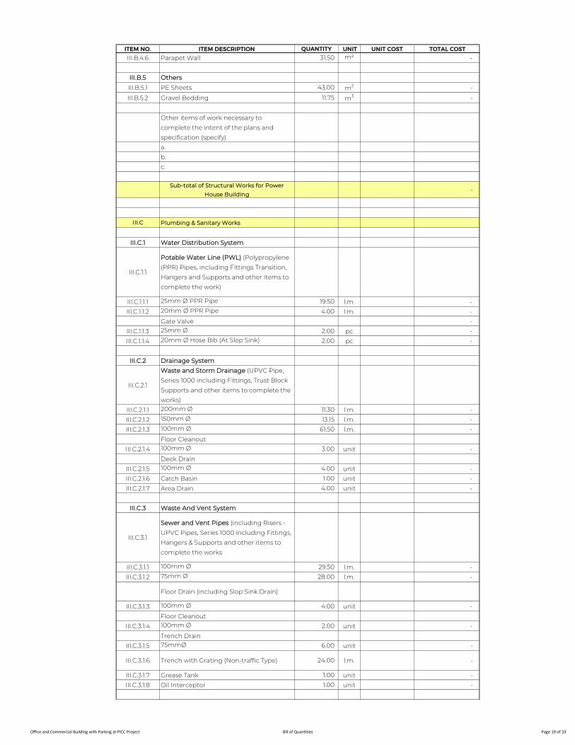
ITEM NO. ITEM DESCRIPTION QUANTITY UNIT UNIT COST TOTAL COST
III.B.4.6 Parapet Wall 31.50 m² -
III.B.5 Others
III.B.5.1 PE Sheets 43.00 m2 -
III.B.5.2 Gravel Bedding 11.75 m3 -
Other items of work necessary to
complete the intent of the plans and
specification (specify)
a.
b.
c.
Sub-total of Structural Works for Power
House Building -
III.C Plumbing & Sanitary Works
III.C.1 Water Distribution System
III.C.1.1
Potable Water Line (PWL) (Polypropylene
(PPR) Pipes, including Fittings Transition,
Hangers and Supports and other items to
complete the work)
III.C.1.1.1 25mm Ø PPR Pipe 19.50 l.m. -
III.C.1.1.2 20mm Ø PPR Pipe 4.00 l.m. -
Gate Valve -
III.C.1.1.3 25mm Ø 2.00 pc -
III.C.1.1.4 20mm Ø Hose Bib (At Slop Sink) 2.00 pc -
III.C.2 Drainage System
III.C.2.1
Waste and Storm Drainage (UPVC Pipe,
Series 1000 including Fittings, Trust Block
Supports and other items to complete the
works)
III.C.2.1.1 200mm Ø 11.30 l.m. -
III.C.2.1.2 150mm Ø 13.15 l.m. -
III.C.2.1.3 100mm Ø 61.50 l.m. -
Floor Cleanout
III.C.2.1.4 100mm Ø 3.00 unit -
Deck Drain
III.C.2.1.5 100mm Ø 4.00 unit -
III.C.2.1.6 Catch Basin 1.00 unit -
III.C.2.1.7 Area Drain 4.00 unit -
III.C.3 Waste And Vent System
III.C.3.1
Sewer and Vent Pipes (including Risers -
UPVC Pipes, Series 1000 including Fittings,
Hangers & Supports and other items to
complete the works
III.C.3.1.1 100mm Ø 29.50 l.m. -
III.C.3.1.2 75mm Ø 28.00 l.m. -
Floor Drain (including Slop Sink Drain)
III.C.3.1.3 100mm Ø 4.00 unit -
Floor Cleanout
III.C.3.1.4 100mm Ø 2.00 unit -
Trench Drain
III.C.3.1.5 75mmØ 6.00 unit -
III.C.3.1.6 Trench with Grating (Non-traffic Type) 24.00 l.m. -
III.C.3.1.7 Grease Tank 1.00 unit -
III.C.3.1.8 Oil Interceptor 1.00 unit -
Office and Commercial Building with Parking at PICC Project Bill of Quantities Page 19 of 33
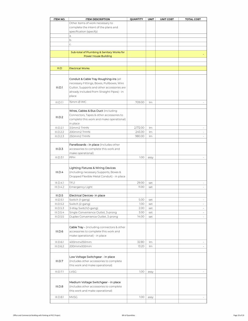
ITEM NO. ITEM DESCRIPTION QUANTITY UNIT UNIT COST TOTAL COST
Other items of work necessary to
complete the intent of the plans and
specification (specify)
a.
b.
c.
Sub-total of Plumbing & Sanitary Works for
Power House Building -
III.D Electrical Works
III.D.1
Conduit & Cable Tray Roughing-ins (all
necessary Fittings, Boxes, Pullboxes, Wire
Gutter, Supports and other accessories are
already included from Straight Pipes) - in
place
III.D.1.1 15mm Ø IMC 709.00 lm -
III.D.2
Wires, Cables & Bus Duct (including
Connectors, Tapes & other accessories to
complete this work and make operational) -
in place
III.D.2.1 3.5mm2 THHN 2,172.00 lm -
III.D.2.2 200mm2 THHN 245.00 lm -
III.D.2.3 250mm2 THHN 980.00 lm -
III.D.3
Panelboards - in place (includes other
accessories to complete this work and
make operational)
III.D.3.1 PPH 1.00 assy -
III.D.4
Lighting Fixtures & Wiring Devices
(including necessary Supports, Boxes &
Dropped Flexible Metal Conduit) - in place
III.D.4.1 TFL1 29.00 set -
III.D.4.2 Emergency Light 11.00 set -
III.D.5 Electrical Devices- in place
III.D.5.1 Switch (1-gang) 5.00 set -
III.D.5.2 Switch (2-gang) 1.00 set -
III.D.5.3 3-Way Switch(1-gang) 2.00 set -
III.D.5.4 Single Convenience Outlet, 3-prong 3.00 set -
III.D.5.5 Duplex Convenience Outlet, 3-prong 14.00 set -
III.D.6
Cable Tray - (including connectors & other
accessories to complete this work and
make operational) - in place
III.D.6.1 400mmx150mm 32.80 lm -
III.D.6.2 200mmx100mm 13.20 lm -
III.D.7
Low Voltage Switchgear - in place
(includes other accessories to complete
this work and make operational)
III.D.7.1 LVSG 1.00 assy -
III.D.8
Medium Voltage Switchgear - in place
(includes other accessories to complete
this work and make operational)
III.D.8.1 MVSG 1.00 assy -
Office and Commercial Building with Parking at PICC Project Bill of Quantities Page 20 of 33

ITEM NO. ITEM DESCRIPTION QUANTITY UNIT UNIT COST TOTAL COST
III.D.9
Transformers - in place (includes other
accessories to complete this work and
make operational)
III.D.9.1 Transformer 1 1.00 assy -
III.D.10
Standby Emergency Generator Sets
(includes other accessories to complete
this work and make operational)
III.D.10.1 Generator Set 1.00 assy -
Other items of work necessary to
complete the intent of the plans and
specification (specify)
a.
b.
c.
Sub-total of Electrical Works for Power House
Building -
III.E Electronic Works
III.E.1 Fire Detection & Alarm System
III.E.1.1
Roughing-ins (all necessary Fittings,
Square & Junction Boxes Supports and
other accessories are already included
from Straight Pipes) - in place
III.E.1.1.1 20mm Ø IMC 54.00 lm -
III.E.1.1.2 25mm Ø IMC 6.00 lm -
III.E.1.1.3 1m Flexible Metal Conduit 11.00 pc -
III.E.1.1.4 Pullbox 1.00 pc -
III.E.1.2 Wires & Cables - in place
III.E.1.2.1 #16 Shielded Twisted TF Wire (Red) 71.00 lm -
III.E.1.3Devices & Modules (including all necessary
Boxes & Dropped FMC) - in place
III.E.1.3.1 Smoke Detector w/ Base 9.00 set -
III.E.1.3.2 Heat Detector w/ Base 3.00 set -
III.E.1.3.3 Manual Pull Station 1.00 set -
III.E.1.3.4 Sounder with Strobe Light 1.00 set -
III.E.1.3.5 Control Module 3.00 set -
III.E.1.3.6 Monitor Module 2.00 set -
III.E.2Public Addresss & Background Music
System
III.E.2.1
Roughing-ins (all necessary Fittings,
Square & Junction Boxes Supports and
other accessories are already included
from Straight Pipes) - in place
III.E.2.1.1 20mm Ø IMC 63.00 lm -
III.E.2.1.2 25mm Ø IMC 6.00 lm -
III.E.2.1.3 1m Flexible Metal Conduit 8.00 pc -
III.E.2.1.4 Pullbox 1.00 pc -
III.E.2.2 Wires & Cables- in place
III.E.2.2.1 Audio Cable (#16/2C) TF, Twisted Wire 94.50 lm -
III.E.2.3Devices Including All Necessary Boxes &
Dropped FMC Conduit - in place
III.E.2.3.1 Wall Mounted Speakers 7.00 unit -
Office and Commercial Building with Parking at PICC Project Bill of Quantities Page 21 of 33
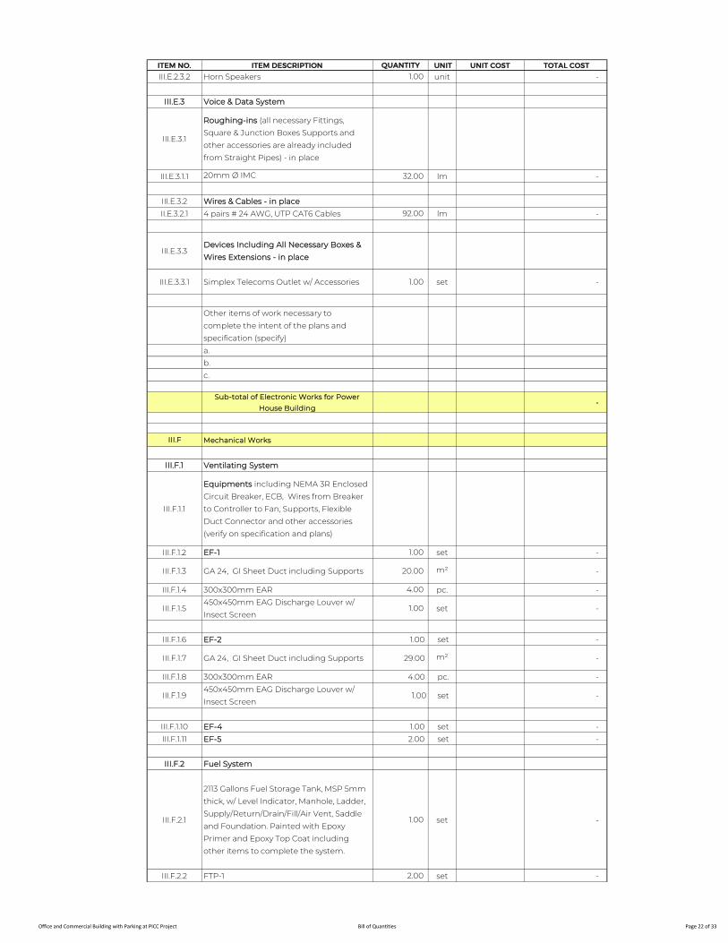
ITEM NO. ITEM DESCRIPTION QUANTITY UNIT UNIT COST TOTAL COST
III.E.2.3.2 Horn Speakers 1.00 unit -
III.E.3 Voice & Data System
III.E.3.1
Roughing-ins (all necessary Fittings,
Square & Junction Boxes Supports and
other accessories are already included
from Straight Pipes) - in place
III.E.3.1.1 20mm Ø IMC 32.00 lm -
III.E.3.2 Wires & Cables - in place
II.E.3.2.1 4 pairs # 24 AWG, UTP CAT6 Cables 92.00 lm -
III.E.3.3Devices Including All Necessary Boxes &
Wires Extensions - in place
III.E.3.3.1 Simplex Telecoms Outlet w/ Accessories 1.00 set -
Other items of work necessary to
complete the intent of the plans and
specification (specify)
a.
b.
c.
Sub-total of Electronic Works for Power
House Building -
III.F Mechanical Works
III.F.1 Ventilating System
III.F.1.1
Equipments including NEMA 3R Enclosed
Circuit Breaker, ECB, Wires from Breaker
to Controller to Fan, Supports, Flexible
Duct Connector and other accessories
(verify on specification and plans)
III.F.1.2 EF-1 1.00 set -
III.F.1.3 GA 24, GI Sheet Duct including Supports 20.00 m² -
III.F.1.4 300x300mm EAR 4.00 pc. -
III.F.1.5450x450mm EAG Discharge Louver w/
Insect Screen1.00 set -
III.F.1.6 EF-2 1.00 set -
III.F.1.7 GA 24, GI Sheet Duct including Supports 29.00 m² -
III.F.1.8 300x300mm EAR 4.00 pc. -
III.F.1.9450x450mm EAG Discharge Louver w/
Insect Screen1.00 set -
III.F.1.10 EF-4 1.00 set -
III.F.1.11 EF-5 2.00 set -
III.F.2 Fuel System
III.F.2.1
2113 Gallons Fuel Storage Tank, MSP 5mm
thick, w/ Level Indicator, Manhole, Ladder,
Supply/Return/Drain/Fill/Air Vent, Saddle
and Foundation. Painted with Epoxy
Primer and Epoxy Top Coat including
other items to complete the system.
1.00 set -
III.F.2.2 FTP-1 2.00 set -
Office and Commercial Building with Parking at PICC Project Bill of Quantities Page 22 of 33
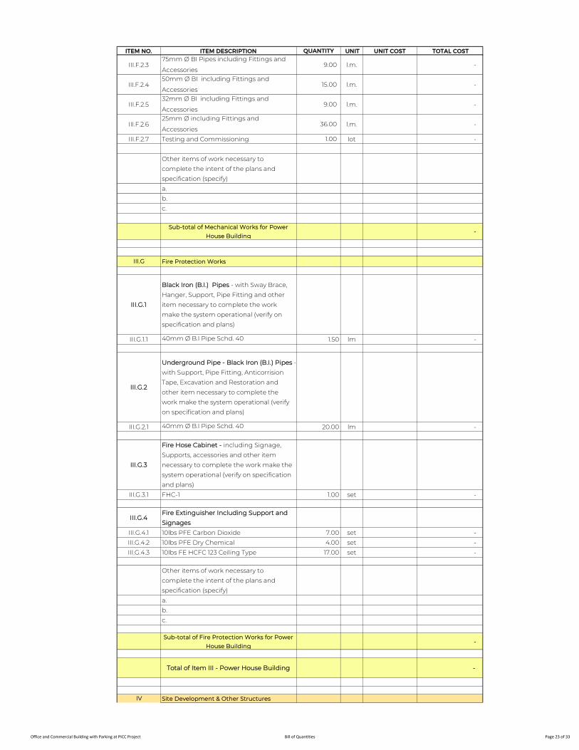
ITEM NO. ITEM DESCRIPTION QUANTITY UNIT UNIT COST TOTAL COST
III.F.2.375mm Ø BI Pipes including Fittings and
Accessories9.00 l.m. -
III.F.2.450mm Ø BI including Fittings and
Accessories15.00 l.m. -
III.F.2.532mm Ø BI including Fittings and
Accessories9.00 l.m. -
III.F.2.625mm Ø including Fittings and
Accessories36.00 l.m. -
III.F.2.7 Testing and Commissioning 1.00 lot -
Other items of work necessary to
complete the intent of the plans and
specification (specify)
a.
b.
c.
Sub-total of Mechanical Works for Power
House Building -
III.G Fire Protection Works
III.G.1
Black Iron (B.I.) Pipes - with Sway Brace,
Hanger, Support, Pipe Fitting and other
item necessary to complete the work
make the system operational (verify on
specification and plans)
III.G.1.1 40mm Ø B.I Pipe Schd. 40 1.50 lm -
III.G.2
Underground Pipe - Black Iron (B.I.) Pipes -
with Support, Pipe Fitting, Anticorrision
Tape, Excavation and Restoration and
other item necessary to complete the
work make the system operational (verify
on specification and plans)
III.G.2.1 40mm Ø B.I Pipe Schd. 40 20.00 lm -
III.G.3
Fire Hose Cabinet - including Signage,
Supports, accessories and other item
necessary to complete the work make the
system operational (verify on specification
and plans)
III.G.3.1 FHC-1 1.00 set -
III.G.4Fire Extinguisher Including Support and
Signages
III.G.4.1 10lbs PFE Carbon Dioxide 7.00 set -
III.G.4.2 10lbs PFE Dry Chemical 4.00 set -
III.G.4.3 10lbs FE HCFC 123 Ceiling Type 17.00 set -
Other items of work necessary to
complete the intent of the plans and
specification (specify)
a.
b.
c.
Sub-total of Fire Protection Works for Power
House Building -
Total of Item III - Power House Building -
IV Site Development & Other Structures
Office and Commercial Building with Parking at PICC Project Bill of Quantities Page 23 of 33
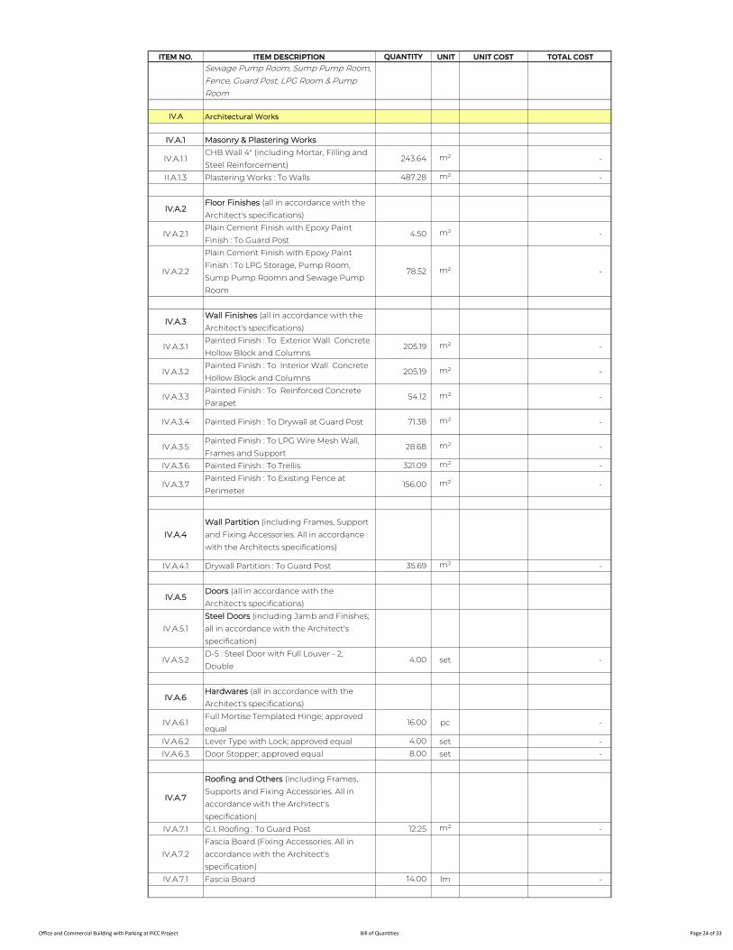
ITEM NO. ITEM DESCRIPTION QUANTITY UNIT UNIT COST TOTAL COST
Sewage Pump Room, Sump Pump Room, Fence, Guard Post, LPG Room & Pump Room
IV.A Architectural Works
IV.A.1 Masonry & Plastering Works
IV.A.1.1CHB Wall 4" (including Mortar, Filling and
Steel Reinforcement)243.64 m² -
II.A.1.3 Plastering Works : To Walls 487.28 m² -
IV.A.2Floor Finishes (all in accordance with the
Architect's specifications)
IV.A.2.1Plain Cement Finish with Epoxy Paint
Finish : To Guard Post4.50 m² -
IV.A.2.2
Plain Cement Finish with Epoxy Paint
Finish : To LPG Storage, Pump Room,
Sump Pump Roomn and Sewage Pump
Room
78.52 m² -
IV.A.3Wall Finishes (all in accordance with the
Architect's specifications)
IV.A.3.1Painted Finish : To Exterior Wall Concrete
Hollow Block and Columns205.19 m² -
IV.A.3.2Painted Finish : To Interior Wall Concrete
Hollow Block and Columns205.19 m² -
IV.A.3.3Painted Finish : To Reinforced Concrete
Parapet54.12 m² -
IV.A.3.4 Painted Finish : To Drywall at Guard Post 71.38 m² -
IV.A.3.5Painted Finish : To LPG Wire Mesh Wall,
Frames and Support28.68 m² -
IV.A.3.6 Painted Finish : To Trellis 321.09 m² -
IV.A.3.7Painted Finish : To Existing Fence at
Perimeter156.00 m² -
IV.A.4
Wall Partition (including Frames, Support
and Fixing Accessories. All in accordance
with the Architects specifications)
IV.A.4.1 Drywall Partition : To Guard Post 35.69 m² -
IV.A.5Doors (all in accordance with the
Architect's specifications)
IV.A.5.1
Steel Doors (including Jamb and Finishes;
all in accordance with the Architect's
specification)
IV.A.5.2D-5 : Steel Door with Full Louver - 2,
Double4.00 set -
IV.A.6Hardwares (all in accordance with the
Architect's specifications)
IV.A.6.1Full Mortise Templated Hinge; approved
equal16.00 pc -
IV.A.6.2 Lever Type with Lock; approved equal 4.00 set -
IV.A.6.3 Door Stopper; approved equal 8.00 set -
IV.A.7
Roofing and Others (including Frames,
Supports and Fixing Accessories. All in
accordance with the Architect's
specification)
IV.A.7.1 G.I. Roofing : To Guard Post 12.25 m² -
IV.A.7.2
Fascia Board (Fixing Accessories. All in
accordance with the Architect's
specification)
IV.A.7.1 Fascia Board 14.00 lm -
Office and Commercial Building with Parking at PICC Project Bill of Quantities Page 24 of 33

ITEM NO. ITEM DESCRIPTION QUANTITY UNIT UNIT COST TOTAL COST
IV.A.8Signages (all in accordance with the
Architect's specifications)
IV.A.8.1 Room Name Sign 8.00 set -
IV.A.8.2 Restricted Area Sign 4.00 set -
IV.A.9
Thermal And Moisture Protection
(including surface preparation. All in
accordance with the Architect's
specification)
IV.A.9.1Supply and Installation (Waterproofing
System)
IV.A.9.1.1 WP1 : Acrylic Polymer Waterproofing 39.27 m2 -
IV.A.9.1.2 WP2 : Torch Applied Waterproofing 162.86 m2 -
IV.A.10Specialties (all in accordance with the
Architect's specifications)
IV.A.10.1Trellis at Open Parking; in Mesh and Steel
Assembly (4 Sets per Column)
IV.A.10.1.1 Trellis - 1 13.00 sets -
IV.A.10.1.2 Trellis - 2 7.00 sets -
IV.A.10.2
Wire Mesh Wall (including Frames and all
Fixing Accessories. All in accordance with
the Architect's specifications)
IV.A.10.2.1 Wire Mesh Wall : To LPG Storage 28.68 m² -
IV.A.10.3
Steel Bollards (including Paintings all in
accordance with the Architect's
specifications)
IV.A.10.3.1 Bollards 22.00 set -
Other items of work necessary to
complete the intent of the plans and
specification (specify)
a.
b.
c.
Sub-total of Architectural Works for Site
Development & Other Structures -
IV.B Civil Works
IV.B.1 Earthworks & Siteworks
IV.B.1.1 Excavation 158.30 m3 -
IV.B.1.2Supply of Fill Materials Including
Compaction341.22 m3 -
IV.B.1.3 PE Sheets 2,928.70 m² -
IV.B.1.4Demolition & Stripping Works (Existing
Concrete Pavements)2,550.18 m² -
IV.B.1.5Demolition Works (Excess Dimension of
Structural Steel Columns for Trellis)21.00 set -
IV.B.1.6Demolition Works (Temporary Facilities :
Perimeter Fence & Barracks)1.00 lot -
IV.B.1.7
Hauling & Disposal of Excess (Stripped
Boulders, Concrete Debris, Site Waste &
Other Demolished Materials)
177.13 m3 -
IV.B.1.8 Soil Treatment & Termite Control 2,958.43 m² -
IV.B.2 Road Pavement and Parking
IV.B.2.1 Base Coarse 534.05 m3 -
Office and Commercial Building with Parking at PICC Project Bill of Quantities Page 25 of 33
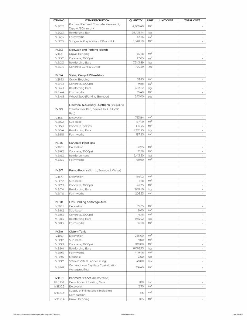
ITEM NO. ITEM DESCRIPTION QUANTITY UNIT UNIT COST TOTAL COST
IV.B.2.2Portland Cement Concrete Pavement,
Type A, 150mm thk4,909.40 m² -
IV.B.2.3 Reinforcing Bar 28,438.14 kg -
IV.B.2.4 Formworks 57.65 m3 -
IV.B.2.5 Subgrade Preparation, 150mm thk 5,340.50 m² -
IV.B.3 Sidewalk and Parking Islands
IV.B.3.1 Gravel Bedding 517.18 m² -
IV.B.3.2 Concrete, 3000psi 155.15 m3 -
IV.B.3.3 Reinforcing Bars 7,343.89 kg -
IV.B.3.4 Concrete Curb & Gutter 770.59 l.m. -
IV.B.4 Stairs, Ramp & Wheelstop
IV.B.4.1 Gravel Bedding 32.95 m² -
IV.B.4.2 Concrete, 3000psi 9.88 m3 -
IV.B.4.3 Reinforcing Bars 467.82 kg -
IV.B.4.4 Formworks 15.40 m² -
IV.B.4.5 Wheel Stop (Parking Bumper) 243.00 set -
IV.B.5
Electrical & Auxiliary Ductbank (including
Transformer Pad, Genset Pad, & LVSG
Pad)
IV.B.5.1 Excavation 753.84 m³ -
IV.B.5.2 Sub-base 167.49 m³ -
IV.B.5.3 Concrete, 1500psi 150.75 m³ -
IV.B.5.4 Reinforcing Bars 5,276.25 kg -
IV.B.5.5 Formworks 187.95 m² -
IV.B.6 Concrete Plant Box
IV.B.6.1 Excavation 22.15 m³ -
IV.B.6.2 Concrete, 3000psi 32.18 m³ -
IV.B.6.3 Reinforcement 2,413.50 kg -
IV.B.6.4 Formworks 160.90 m² -
IV.B.7 Pump Rooms (Sump, Sewage & Water)
IV.B.7.1 Excavation 166.02 m³ -
IV.B.7.2 Sub-base 11.18 m³ -
IV.B.7.3 Concrete, 3000psi 42.35 m³ -
IV.B.7.4 Reinforcing Bars 3,811.50 kg -
IV.B.7.5 Formworks 205.63 m² -
IV.B.8 LPG Holding & Storage Area
IV.B.8.1 Excavation 72.35 m³ -
IV.B.8.2 Sub-base 9.00 m³ -
IV.B.8.3 Concrete, 3000psi 16.75 m³ -
IV.B.8.4 Reinforcing Bars 945.02 kg -
IV.B.8.5 Formworks 86.50 m² -
IV.B.9 Cistern Tank
IV.B.9.1 Excavation 285.00 m³ -
IV.B.9.2 Sub-base 9.00 m³ -
IV.B.9.3 Concrete, 3000psi 100.00 m³ -
IV.B.9.4 Reinforcing Bars 6,065.73 kg -
IV.B.9.5 Formworks 449.46 m² -
IV.B.9.6 Manhole 3.00 set -
IV.B.9.7 Stainless Steel Ladder Rung 48.00 lm -
IV.B.9.8Cementitious Capillary Crystalization
Waterproofing316.40 m² -
IV.B.10 Perimeter Fence (Restoration)
IV.B.10.1 Demolition of Existing Gate 1.00 lot -
IV.B.10.2 Excavation 2.30 m³ -
IV.B.10.3Supply of Fill Materials Including
Compaction1.15 m³ -
IV.B.10.4 Gravel Bedding 0.15 m³ -
Office and Commercial Building with Parking at PICC Project Bill of Quantities Page 26 of 33
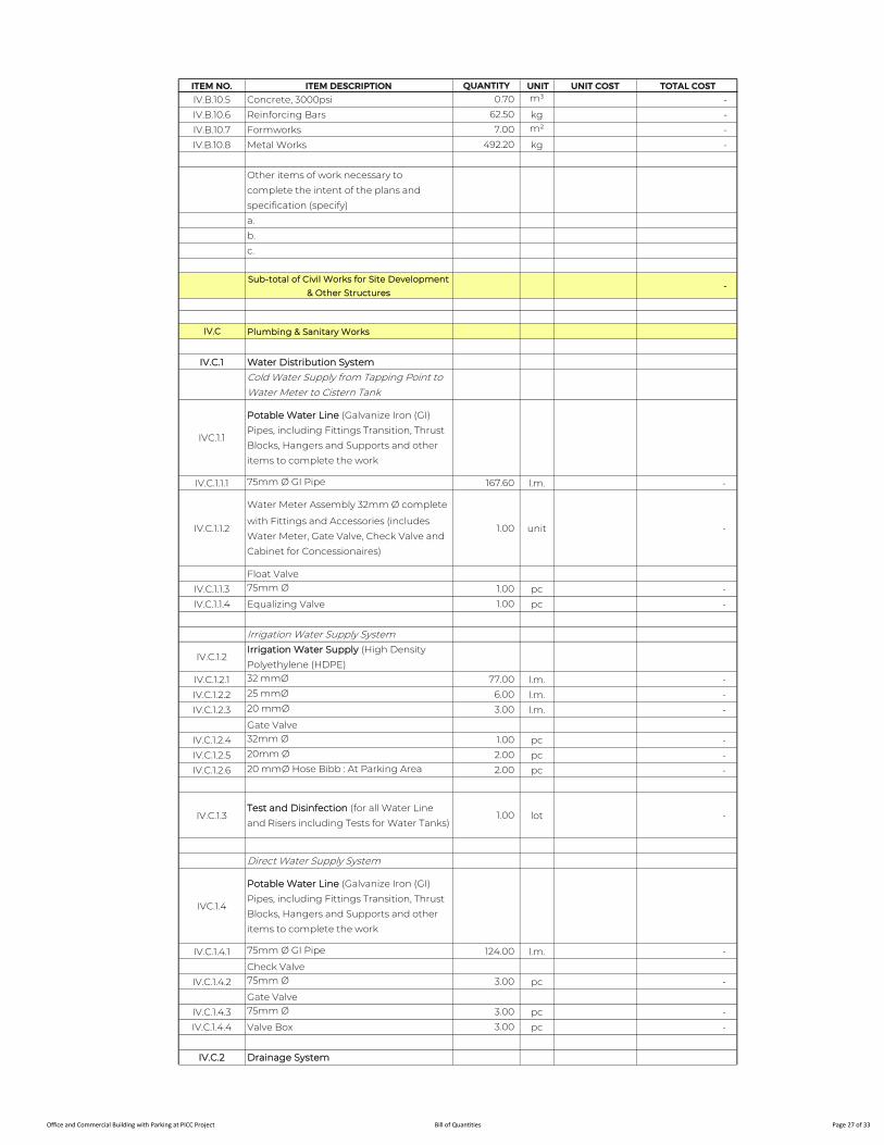
ITEM NO. ITEM DESCRIPTION QUANTITY UNIT UNIT COST TOTAL COST
IV.B.10.5 Concrete, 3000psi 0.70 m³ -
IV.B.10.6 Reinforcing Bars 62.50 kg -
IV.B.10.7 Formworks 7.00 m² -
IV.B.10.8 Metal Works 492.20 kg -
Other items of work necessary to
complete the intent of the plans and
specification (specify)
a.
b.
c.
Sub-total of Civil Works for Site Development
& Other Structures -
IV.C Plumbing & Sanitary Works
IV.C.1 Water Distribution System
Cold Water Supply from Tapping Point to Water Meter to Cistern Tank
IVC.1.1
Potable Water Line (Galvanize Iron (GI)
Pipes, including Fittings Transition, Thrust
Blocks, Hangers and Supports and other
items to complete the work
IV.C.1.1.1 75mm Ø GI Pipe 167.60 l.m. -
IV.C.1.1.2
Water Meter Assembly 32mm Ø complete
with Fittings and Accessories (includes
Water Meter, Gate Valve, Check Valve and
Cabinet for Concessionaires)
1.00 unit -
Float Valve
IV.C.1.1.3 75mm Ø 1.00 pc -
IV.C.1.1.4 Equalizing Valve 1.00 pc -
Irrigation Water Supply System
IV.C.1.2Irrigation Water Supply (High Density
Polyethylene (HDPE)
IV.C.1.2.1 32 mmØ 77.00 l.m. -
IV.C.1.2.2 25 mmØ 6.00 l.m. -
IV.C.1.2.3 20 mmØ 3.00 l.m. -
Gate Valve
IV.C.1.2.4 32mm Ø 1.00 pc -
IV.C.1.2.5 20mm Ø 2.00 pc -
IV.C.1.2.6 20 mmØ Hose Bibb : At Parking Area 2.00 pc -
IV.C.1.3Test and Disinfection (for all Water Line
and Risers including Tests for Water Tanks)1.00 lot -
Direct Water Supply System
IVC.1.4
Potable Water Line (Galvanize Iron (GI)
Pipes, including Fittings Transition, Thrust
Blocks, Hangers and Supports and other
items to complete the work
IV.C.1.4.1 75mm Ø GI Pipe 124.00 l.m. -
Check Valve
IV.C.1.4.2 75mm Ø 3.00 pc -
Gate Valve
IV.C.1.4.3 75mm Ø 3.00 pc -
IV.C.1.4.4 Valve Box 3.00 pc -
IV.C.2 Drainage System
Office and Commercial Building with Parking at PICC Project Bill of Quantities Page 27 of 33
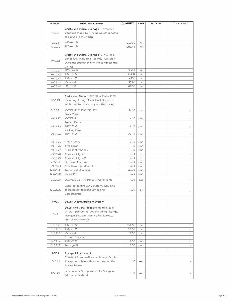
ITEM NO. ITEM DESCRIPTION QUANTITY UNIT UNIT COST TOTAL COST
IV.C.2.1
Waste and Storm Drainage -Reinforced
Concrete Pipe (RCP) including other items
to complete the works
IV.C.2.1.1 450 mmØ 258.36 l.m. -
IV.C.2.1.2 300 mmØ 285.48 l.m. -
IV.C.2.2
Waste and Storm Drainage (UPVC Pipe,
Series 1000 including Fittings, Trust Block
Supports and other items to complete the
works)
IV.C.2.2.1 200mm Ø 70.37 l.m. -
IV.C.2.2.2 150mm Ø 103.81 l.m. -
IV.C.2.2.3 100mm Ø 43.10 l.m. -
IV.C.2.2.4 75mm Ø 22.90 l.m. -
IV.C.2.2.5 50mm Ø 66.00 l.m. -
IV.C.2.3
Perforated Drain (UPVC Pipe, Series 1000
including Fittings, Trust Block Supports
and other items to complete the works)
IV.C.2.3.1 75mm Ø : At Planters Box 19.60 l.m. -
Deck Drain
IV.C.2.3.2 75mm Ø 2.00 unit -
Trench Drain
IV.C.2.3.3 150mm Ø 4.00 unit -
Parking Drain
IV.C.2.3.4 150mm Ø 24.00 unit -
IV.C.2.3.5 Catch Basin 14.00 unit -
IV.C.2.3.6 Area Drain 8.00 unit -
IV.C.2.3.7 Curb Inlet Manhole 2.00 unit -
IV.C.2.3.8 Curb Inlet Type 1 5.00 l.m. -
IV.C.2.3.9 Curb Inlet Type 2 9.00 l.m. -
IV.C.2.3.10 Drainage Manhole 8.00 unit -
IV.C.2.3.11 Area Drainage Manhole 8.00 unit -
IV.C.2.3.12 Trench with Grating 32.00 unit -
IV.C.2.3.13 Sump Pit 1.00 unit -
IV.C.2.3.14 Overflow Box : At Potable Water Tank 1.00 set -
IV.C.2.3.15
Leak Test (entire DWV System. Including
all necessary test on Pumps and
Equipments)
1.00 lot -
IV.C.3 Sewer, Waste And Vent System
IV.C.3.1
Sewer and Vent Pipes (including Risers -
UPVC Pipes, Series 1000 including Fittings,
Hangers & Supports and other items to
complete the works
IV.C.3.1.1 150mm Ø 129.00 l.m. -
IV.C.3.1.2 100mm Ø 20.00 l.m. -
IV.C.3.1.3 75mm Ø 14.00 l.m. -
Ground Cleanout
IV.C.3.1.4 100mm Ø 3.00 unit -
IV.C.3.1.5 Sewage Pit 1.00 unit -
IV.C.4 Pumps & Equipment
IV.C.4.1
Constant Pressure Booster Pumps, Duplex
Pump, complete with accessories (at the
Pump Room)
1.00 set -
IV.C.4.2Submersible Sump Pumps for Sump Pit
(at the Lift Station)1.00 set -
Office and Commercial Building with Parking at PICC Project Bill of Quantities Page 28 of 33
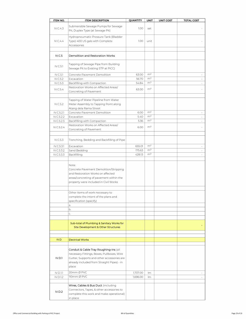
ITEM NO. ITEM DESCRIPTION QUANTITY UNIT UNIT COST TOTAL COST
IV.C.4.3Submersible Sewage Pumps for Sewage
Pit, Duplex Type (at Sewage Pit)1.00 set -
IV.C.4.4
Hydropneumatic Pressure Tank (Bladder
Type) 400 US gals with Complete
Accessories
1.00 unit -
IV.C.5 Demolition and Restoration Works
IV.C.5.1Tapping of Sewage Pipe from Building
Sewage Pit to Existing STP at PICC)
IV.C.5.1 Concrete Pavement Demolition 63.00 m² -
IV.C.5.2 Excavation 56.70 m³ -
IV.C.5.3 Backfilling with Compaction 54.84 m³ -
IV.C.5.4Restoration Works on Affected Areas/
Concreting of Pavement63.00 m² -
IV.C.5.2
Tapping of Water Pipeline from Water
Meter Assembly to Tapping Point along
Atang dela Rama Street
IV.C.5.2.1 Concrete Pavement Demolition 6.00 m² -
IV.C.5.2.2 Excavation 5.40 m³ -
IV.C.5.2.3 Backfilling with Compaction 5.36 m³ -
IV.C.5.2.4Restoration Works on Affected Areas/
Concreting of Pavement6.00 m² -
IV.C.5.3 Trenching, Bedding and Backfilling of Pipe
IV.C.5.3.1 Excavation 655.01 m² -
IV.C.5.3.2 Sand Bedding 175.63 m³ -
IV.C.5.3.3 Backfilling 428.13 m³ -
Note:
Concrete Pavement Demolition/Stripping
and Restoration Works on affected
areas/concreting of pavement within the
property were included in Civil Works
Other items of work necessary to
complete the intent of the plans and
specification (specify)
a.
b.
c.
Sub-total of Plumbing & Sanitary Works for
Site Development & Other Structures -
IV.D Electrical Works
IV.D.1
Conduit & Cable Tray Roughing-ins (all
necessary Fittings, Boxes, Pullboxes, Wire
Gutter, Supports and other accessories are
already included from Straight Pipes) - in
place
IV.D.1.1 20mm Ø PVC 1,737.00 lm -
IV.D.1.2 110mm Ø PVC 1,696.00 lm -
IV.D.2
Wires, Cables & Bus Duct (including
Connectors, Tapes, & other accessories to
complete this work and make operational) -
in place
Office and Commercial Building with Parking at PICC Project Bill of Quantities Page 29 of 33
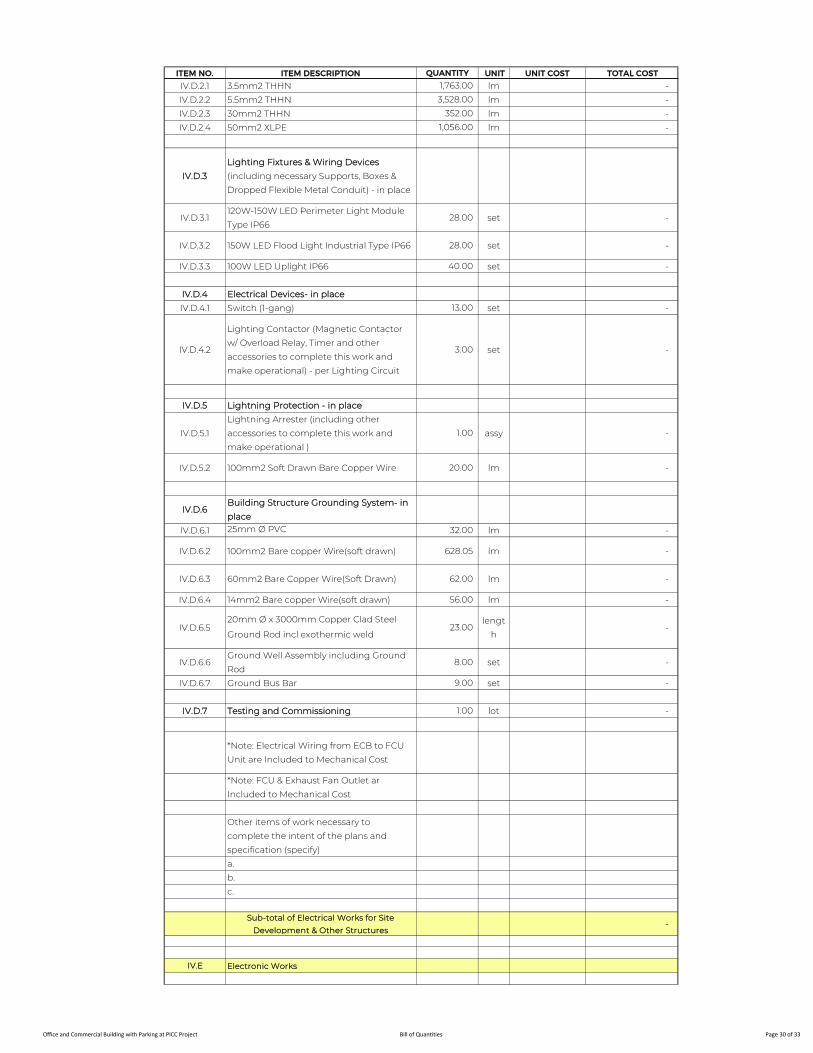
ITEM NO. ITEM DESCRIPTION QUANTITY UNIT UNIT COST TOTAL COST
IV.D.2.1 3.5mm2 THHN 1,763.00 lm -
IV.D.2.2 5.5mm2 THHN 3,528.00 lm -
IV.D.2.3 30mm2 THHN 352.00 lm -
IV.D.2.4 50mm2 XLPE 1,056.00 lm -
IV.D.3
Lighting Fixtures & Wiring Devices
(including necessary Supports, Boxes &
Dropped Flexible Metal Conduit) - in place
IV.D.3.1120W-150W LED Perimeter Light Module
Type IP6628.00 set -
IV.D.3.2 150W LED Flood Light Industrial Type IP66 28.00 set -
IV.D.3.3 100W LED Uplight IP66 40.00 set -
IV.D.4 Electrical Devices- in place
IV.D.4.1 Switch (1-gang) 13.00 set -
IV.D.4.2
Lighting Contactor (Magnetic Contactor
w/ Overload Relay, Timer and other
accessories to complete this work and
make operational) - per Lighting Circuit
3.00 set -
IV.D.5 Lightning Protection - in place
IV.D.5.1
Lightning Arrester (including other
accessories to complete this work and
make operational )
1.00 assy -
IV.D.5.2 100mm2 Soft Drawn Bare Copper Wire 20.00 lm -
IV.D.6Building Structure Grounding System- in
place
IV.D.6.1 25mm Ø PVC 32.00 lm -
IV.D.6.2 100mm2 Bare copper Wire(soft drawn) 628.05 lm -
IV.D.6.3 60mm2 Bare Copper Wire(Soft Drawn) 62.00 lm -
IV.D.6.4 14mm2 Bare copper Wire(soft drawn) 56.00 lm -
IV.D.6.520mm Ø x 3000mm Copper Clad Steel
Ground Rod incl exothermic weld23.00
lengt
h -
IV.D.6.6Ground Well Assembly including Ground
Rod8.00 set -
IV.D.6.7 Ground Bus Bar 9.00 set -
IV.D.7 Testing and Commissioning 1.00 lot -
*Note: Electrical Wiring from ECB to FCU
Unit are Included to Mechanical Cost
*Note: FCU & Exhaust Fan Outlet ar
Included to Mechanical Cost
Other items of work necessary to
complete the intent of the plans and
specification (specify)
a.
b.
c.
Sub-total of Electrical Works for Site
Development & Other Structures -
IV.E Electronic Works
Office and Commercial Building with Parking at PICC Project Bill of Quantities Page 30 of 33
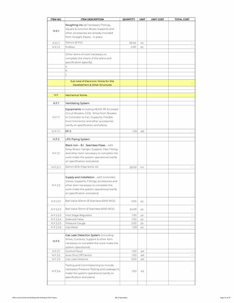
ITEM NO. ITEM DESCRIPTION QUANTITY UNIT UNIT COST TOTAL COST
IV.E.1
Roughing-ins (all necessary Fittings,
Square & Junction Boxes Supports and
other accessories are already included
from Straight Pipes) - in place
IV.E.1.1 110mm Ø PVC 65.00 lm -
IV.E.1.2 Pullbox 4.00 pc -
Other items of work necessary to
complete the intent of the plans and
specification (specify)
a.
b.
c.
Sub-total of Electronic Works for Site
Development & Other Structures -
IV.F Mechanical Works
IV.F.1 Ventilating System
IV.F.1.1
Equipments including NEMA 3R Enclosed
Circuit Breaker, ECB, Wires from Breaker
to Controller to Fan, Supports, Flexible
Duct Connector and other accessories
(verify on specification and plans)
IV.F.1.1.1 EF-5 1.00 set -
IV.F.2 LPG Piping System
IV.F.2.1
Black Iron - B.I. Seamless Pipes - with
Sway Brace, Hanger, Support, Pipe Fitting
and other item necessary to complete the
work make the system operational (verify
on specification and plans)
IV.F.2.1.1 50mm Ø B.I Pipe Schd. 40 20.00 l.m. -
IV.F.2.2
Supply and Installation - with Controller,
Valves, Supports, Fittings, accessories and
other item necessary to complete the
work make the system operational (verify
on specification and plans)
IV.F.2.2.1 Ball Valve 50mm Ø Stainless 6000 WOG 3.00 pc. -
IV.F.2.2.2 Ball Valve 15mm Ø Stainless 6000 WOG 24.00 pc. -
IV.F.2.2.3 First Stage Regulator 1.00 pc. -
IV.F.2.2.4 Solenoid Valve 1.00 pc. -
IV.F.2.2.5 Pressure Gauge 2.00 pc. -
IV.F.2.2.6 Gas Meter 1.00 pc. -
IV.F.3
Gas Leak Detection System (including
Wires, Conduits, Support & other item
necessary to complete the work make the
system operational)
IV.F.3.1 Control Panel 1.00 set -
IV.F.3.2 Auto Shut Off Device 1.00 set -
IV.F.3.3 Gas Leak Detector 3.00 set -
IV.F.3.4
Testing and Commissioning to include
necessary Pressure Testing and Leakage to
make the system operational (verify on
specification and plans)
1.00 lot -
Office and Commercial Building with Parking at PICC Project Bill of Quantities Page 31 of 33
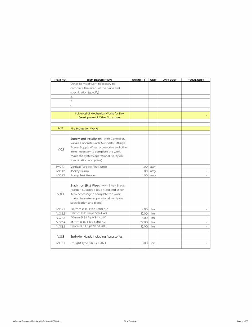
ITEM NO. ITEM DESCRIPTION QUANTITY UNIT UNIT COST TOTAL COST
Other items of work necessary to
complete the intent of the plans and
specification (specify)
a.
b.
c.
Sub-total of Mechanical Works for Site
Development & Other Structures -
IV.G Fire Protection Works
IV.G.1
Supply and Installation - with Controller,
Valves, Concrete Pads, Supports, Fittings,
Power Supply Wires, accessories and other
item necessary to complete the work
make the system operational (verify on
specification and plans)
IV.G.1.1 Vertical Turbine Fire Pump 1.00 assy -
IV.G.1.2 Jockey Pump 1.00 assy -
IV.G.1.3 Pump Test Header 1.00 assy -
IV.G.2
Black Iron (B.I.) Pipes - with Sway Brace,
Hanger, Support, Pipe Fitting and other
item necessary to complete the work
make the system operational (verify on
specification and plans)
IV.G.2.1 200mm Ø B.I Pipe Schd. 40 2.00 lm -
IV.G.2.2 150mm Ø B.I Pipe Schd. 40 12.00 lm -
IV.G.2.3 40mm Ø B.I Pipe Schd. 40 3.00 lm -
IV.G.2.4 25mm Ø B.I Pipe Schd. 40 22.00 lm -
IV.G.2.5 15mm Ø B.I Pipe Schd. 40 12.00 lm -
IV.G.3 Sprinkler Heads Including Accessories
IV.G.3.1 Upright Type, SR, 135F-165F 8.00 pc -
Office and Commercial Building with Parking at PICC Project Bill of Quantities Page 32 of 33
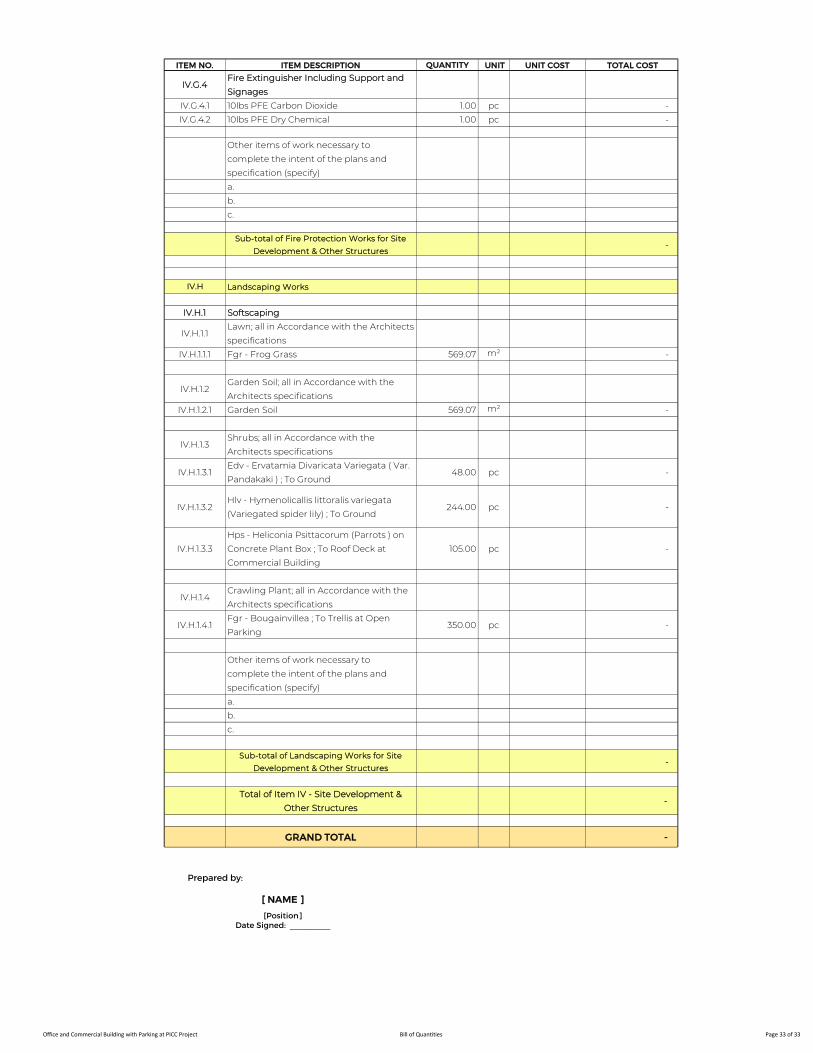
ITEM NO. ITEM DESCRIPTION QUANTITY UNIT UNIT COST TOTAL COST
IV.G.4Fire Extinguisher Including Support and
Signages
IV.G.4.1 10lbs PFE Carbon Dioxide 1.00 pc -
IV.G.4.2 10lbs PFE Dry Chemical 1.00 pc -
Other items of work necessary to
complete the intent of the plans and
specification (specify)
a.
b.
c.
Sub-total of Fire Protection Works for Site
Development & Other Structures -
IV.H Landscaping Works
IV.H.1 Softscaping
IV.H.1.1Lawn; all in Accordance with the Architects
specifications
IV.H.1.1.1 Fgr - Frog Grass 569.07 m² -
IV.H.1.2Garden Soil; all in Accordance with the
Architects specifications
IV.H.1.2.1 Garden Soil 569.07 m² -
IV.H.1.3Shrubs; all in Accordance with the
Architects specifications
IV.H.1.3.1Edv - Ervatamia Divaricata Variegata ( Var.
Pandakaki ) ; To Ground48.00 pc -
IV.H.1.3.2Hlv - Hymenolicallis littoralis variegata
(Variegated spider lily) ; To Ground244.00 pc -
IV.H.1.3.3
Hps - Heliconia Psittacorum (Parrots ) on
Concrete Plant Box ; To Roof Deck at
Commercial Building
105.00 pc -
IV.H.1.4Crawling Plant; all in Accordance with the
Architects specifications
IV.H.1.4.1Fgr - Bougainvillea ; To Trellis at Open
Parking350.00 pc -
Other items of work necessary to
complete the intent of the plans and
specification (specify)
a.
b.
c.
Sub-total of Landscaping Works for Site
Development & Other Structures -
Total of Item IV - Site Development &
Other Structures -
GRAND TOTAL -
Prepared by:
[ NAME ]
[Position]Date Signed: _________
Office and Commercial Building with Parking at PICC Project Bill of Quantities Page 33 of 33
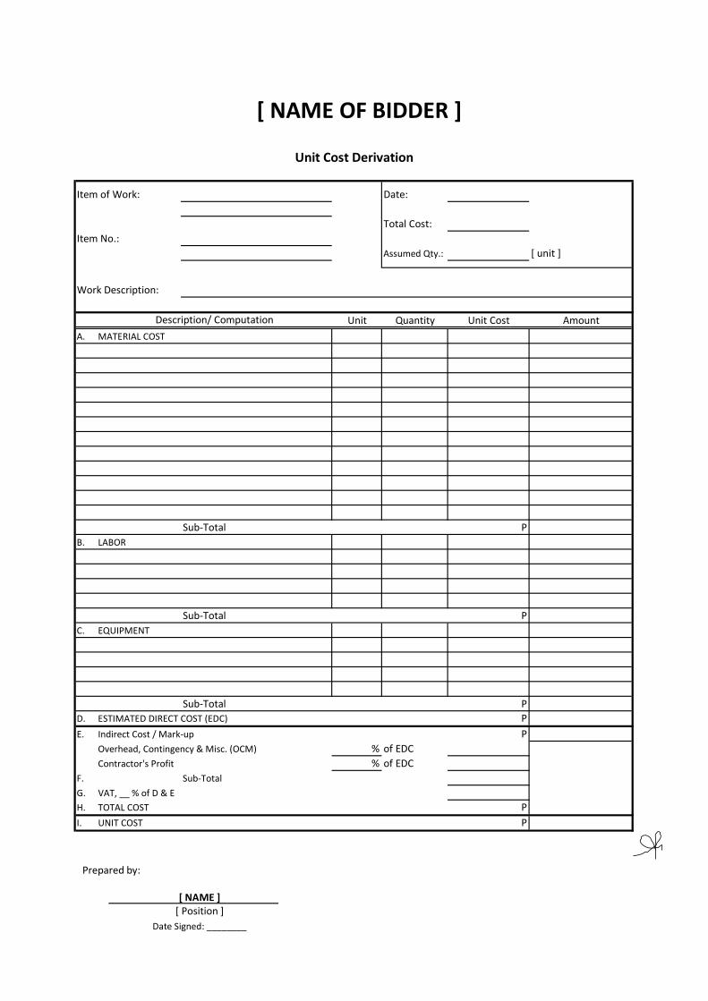
Item of Work: Date:
Total Cost:Item No.:
Assumed Qty.: [ unit ]
Work Description:
Unit Quantity Unit Cost AmountA.
Sub-Total B.
Sub-TotalC.
Sub-Total D. ESTIMATED DIRECT COST (EDC)
E. Indirect Cost / Mark-up POverhead, Contingency & Misc. (OCM) % of EDCContractor's Profit % of EDC
F. Sub-Total G. VAT, __ % of D & EH. TOTAL COST PI. UNIT COST P
Unit Cost Derivation
Description/ ComputationMATERIAL COST
PLABOR
PEQUIPMENT
PP
[ NAME OF BIDDER ]
Prepared by:
[ NAME ][ Position ]
Date Signed: ________

Ref. No. PDMD-202107-____
PROJECT DEVELOPMENT AND MANAGEMENT DEPARTMENT
SCOPE OF WORK
For the
Proposed Office and Commercial Building with Parking at Philippine International Convention Center Project
Prepared by:
EVANGELINE N. VIRAY Bank Officer V
Date: 09 July 2021
Recommending Approval:
FELIX DARWIN E. LAUZON Deputy Director Date:__________
Approved:
VICENTE WILFREDO C. FORMOSO, JR. Director
Date:__________
01 October 2021
01 Oct. 2021
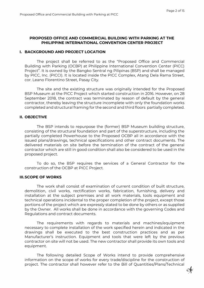
Page 2 of 15 Proposed Office and Commercial Building with Parking at PICC
PROPOSED OFFICE AND COMMERCIAL BUILDING WITH PARKING AT THE PHILIPPINE INTERNATIONAL CONVENTION CENTER PROJECT
I. BACKGROUND AND PROJECT LOCATION
The project shall be referred to as the “Proposed Office and Commercial
Building with Parking (OCBP) at Philippine International Convention Center (PICC) Project”. It is owned by the Bangko Sentral ng Pilipinas (BSP) and shall be managed by PICC, Inc. (PICCI). It is located inside the PICC Complex, Atang Dela Rama Street, cor. Leano Florentino Street, Pasay City.
The site and the existing structure was originally intended for the Proposed
BSP Museum at the PICC Project which started construction in 2016. However, on 28 September 2018, the contract was terminated by reason of default by the general contractor, thereby leaving the structure incomplete with only the foundation works completed and structural framing for the second and third floors partially completed.
II. OBJECTIVE
The BSP intends to repurpose the (former) BSP Museum building structure, consisting of the structural foundation and part of the superstructure, including the partially completed Powerhouse to the Proposed OCBP all in accordance with the issued plans/drawings, technical specifications and other contract documents. The delivered materials on site before the termination of the contract of the general contractor which are still in good condition shall also be considered to be used in the proposed project.
To do so, the BSP requires the services of a General Contractor for the
construction of the OCBP at PICC Project.
III. SCOPE OF WORKS
The work shall consist of examination of current condition of built structure, demolition, civil works, rectification works, fabrication, furnishing, delivery and installation at the subject premises and all work materials, tools equipment and technical operations incidental to the proper completion of the project, except those portions of the project which are expressly stated to be done by others or as supplied by the Owner. All works shall be done in accordance with the governing Codes and Regulations and contract documents.
The requirements with regards to materials and machines/equipment
necessary to complete installation of the work specified herein and indicated in the drawings shall be executed to the best construction practices and as per Manufacturer’s instruction. Equipment and tools that were left by the previous contractor on site will not be used. The new contractor shall provide its own tools and equipment.
The following detailed Scope of Works intend to provide comprehensive
information on the scope of works for every trade/discipline for the construction of project. The contractor shall however refer to the Bill of Quantities/Plans/Technical

Page 3 of 15 Proposed Office and Commercial Building with Parking at PICC
Specifications to determine items that may have been omitted but are necessary to complete the intent of the contract document.
A. GENERAL REQUIREMENTS
1. Mobilization 1.1 Project Identification and signage. 1.2 Security and safety protections, facilities required include but not limited
to: 1.2.1 Temporary Fire Protection. 1.2.2 Personal protective equipment. 1.2.3 Warning signs and lightings. 1.2.4 Medical first aid kit.
1.3 Machines and equipment mobilization, rentals, fuels including its operation personnel.
1.4 Provision for survey equipment and personnel for proper layout and rigid inspection.
1.5 Mobilization of technical staff, safety personnel, and workers who will be assigned on the project.
2. Demobilization
2.1 Demolition and dismantling of temporary facilities/ structures. 2.2 Hauling and disposal of construction debris wastes and unnecessary
materials of site. 2.3 Final cleaning. 2.4 Demobilization of equipment.
3. Temporary Facilities 3.1 Construction of field offices, conference room, workers and staff quarters
and toilets within the premises including proper maintenance. 3.2 Provision of water, power, internet connection and telecommunication
utilities. 3.3 Provision of office supplies, photocopier, scanner, printer and other tools
and equipment necessary for preparation of reports, assessment, and evaluation of the project.
3.4 Construction of temporary storage area and preparation of appropriate stockpile area to orderly store the delivered construction materials including the existing construction materials at the project site.
3.5 Provision of temporary barricade and perimeter lights if necessary, to protect the security and safety of the construction site, storage and stockpile area.
3.6 Provision for adequate sump pumps and temporary drainage system intended to serve the site and facilities/structures especially during rainy season until the permanent drainage system is operational.
4. Safety and Permits Requirements
4.1 Application and securing of Building, Occupational and other necessary
permits from the City of Manila Office of the City Building Official/City Engineer’s Office which has jurisdiction over the project. In addition to the standard obligations of contractors in securing said permits, the
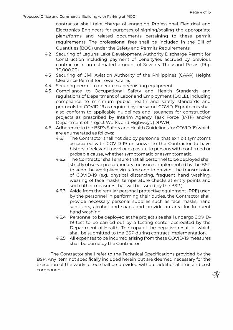
Page 4 of 15 Proposed Office and Commercial Building with Parking at PICC
contractor shall take charge of engaging Professional Electrical and Electronics Engineers for purposes of signing/sealing the appropriate plans/forms and related documents pertaining to these permit requirements. The professional fees shall be included in the Bill of Quantities (BOQ) under the Safety and Permits Requirements.
4.2 Securing of Laguna Lake Development Authority Discharge Permit for Construction including payment of penalty/ies accrued by previous contractor in an estimated amount of Seventy Thousand Pesos (Php 70,000.00).
4.3 Securing of Civil Aviation Authority of the Philippines (CAAP) Height Clearance Permit for Tower Crane.
4.4 Securing permit to operate crane/hoisting equipment. 4.5 Compliance to Occupational Safety and Health Standards and
regulations of Department of Labor and Employment (DOLE), including compliance to minimum public health and safety standards and protocols for COVID-19 as required by the same. COVID-19 protocols shall also conform to applicable guidelines and issuances for construction projects as prescribed by Interim Agency Task Force (IATF) and/or Department of Project Works and Highways (DPWH).
4.6 Adherence to the BSP’s Safety and Health Guidelines for COVID-19 which are enumerated as follows: 4.6.1 The Contractor shall not deploy personnel that exhibit symptoms
associated with COVID-19 or known to the Contractor to have history of relevant travel or exposure to persons with confirmed or probable cause, whether symptomatic or asymptomatic.
4.6.2 The Contractor shall ensure that all personnel to be deployed shall strictly observe precautionary measures implemented by the BSP to keep the workplace virus-free and to prevent the transmission of COVID-19 (e.g. physical distancing, frequent hand washing, wearing of face masks, temperature checks at entry points and such other measures that will be issued by the BSP.)
4.6.3 Aside from the regular personal protective equipment (PPE) used by the personnel in performing their duties, the Contractor shall provide necessary personal supplies such as face masks, hand sanitizers, alcohol and soaps and provide an area for frequent hand washing.
4.6.4 Personnel to be deployed at the project site shall undergo COVID-19 test to be carried out by a testing center accredited by the Department of Health. The copy of the negative result of which shall be submitted to the BSP during contract implementation.
4.6.5 All expenses to be incurred arising from these COVID-19 measures shall be borne by the Contractor.
The Contractor shall refer to the Technical Specifications provided by the BSP. Any item not specifically included herein but are deemed necessary for the execution of the works cited shall be provided without additional time and cost component.

Page 5 of 15 Proposed Office and Commercial Building with Parking at PICC
B. REPURPOSING OF THE BSP MUSEUM BUILDING TO OFFICE AND COMMERCIAL BUILDING 1. Architectural Works
Architectural Works shall include the following provisions complete for the construction of building requirements in accordance to Specifications, Contract Drawings and applicable Codes and Standards:
1.1 Masonry works including CHB, plastering and toppings. 1.2 Drywall Partition as indicated on plans. 1.3 Installation of floor finishing material and toppings. 1.4 Supply and installation of thermal and Moisture protection including
roof material and installations, building insulation, waterproofing and treatments.
1.5 Supply and installation of specialty items such as aluminum cladding and glass works.
1.6 Supply and installation of railings and balustrades for the podium, exterior stairs, main stairs and fire escape stairs and other areas specified on plans.
1.7 Painting works and other wall and ceiling finishes. 1.8 Fabrication and installation of grill works. 1.9 Supply and installation of various doors and windows including framing
and other accessories and finishes to complete the installation. 1.10 Supply and installation of toilet fixtures and accessories, and other
incidental items as specified or as necessary to complete the intent of the plan.
2. Structural/Civil Works
The Civil Works shall include entry platform, ramps, steps, drainage and sanitary systems, electrical and electronic/communication service connection systems, earth fillings, embankments, grading and demolition as indicated in the drawings. The Structural system shall be structural steel framing, reinforced concrete, and board pile footing. The scope of work shall also include the following:
2.1 Provision for building structural system including excavation, backfill,
grading and compacting works. 2.2 Establishment of structural members as designed for on-grade and
suspended slabs, columns, beams, shear wall and supports. 2.3 Concrete and Masonry works, reinforcement, grouting and wall
construction. 2.4 Structural steel, metal fabrications and trims, wall guard, railings,
partitions and enclosures. 2.5 Supply and installation of additional structural steel materials, as
needed, to complete the framing of the building. 2.6 Installation/erection of structural steel beams and columns subject to
reprotection/rectification/retrofitting as deemed necessary by the contractor. For rectification/retrofitting works, the Contractor shall submit shop drawings to the Owner for approval. For structural works using the uninstalled steel already at the project site, accomplishment shall be considered for unit bid cost/s less the cost of materials except for consumables and new miscellaneous materials.
2.7 Demolition of structural elements as shown on Structural Plans.

Page 6 of 15 Proposed Office and Commercial Building with Parking at PICC
2.8 Demolition and rectification works for failed pile cap and tie beam. 2.9 Application of fireproofing materials on steel structure.
Please note the quantity of structural steel and metal decking stated in
BOQ under Metal Works which is included in the Owners Supplied Materials. These materials are already at the project site. A joint quantification will be done after the site is turned over to the Contractor to check the quality and quantity of the materials.
3. Plumbing and Sanitary Works Work included herein shall consist of furnishing all labor, tools, equipment, appliances, and materials necessary for complete installation, testing and operation of the plumbing and sanitary system composed of:
3.1 Soil, waste and vent piping system including fittings, appurtenances
and connection to fixtures and equipment. 3.2 Complete storm drainage system from collection to discharge. 3.3 Water distribution and supply pipes and fittings to the equipment,
fixtures and hose bibs. 3.4 Deck drains, podium drains, trench drain, gratings and clean out,
including appurtenances, with sizes and locations as specified on plans.
3.5 Any and all other works involved in providing the complete plumbing system in accordance with the requirements of all applicable laws of the Philippines and all codes and ordinances of the governing agency.
4. Mechanical Works
Work included herein shall consist of but is not necessarily limited to the following items and shall be in accordance to Specifications, Contract Drawings and applicable Codes and Standards:
4.1 Supply and installation of refrigerant pipes for air conditioning
system including all necessary accessories, fittings, and supports. 4.2 Supply and installation of ducting for air conditioning and ventilating
system including all necessary accessories and supports. 4.3 Supply and installation of diffusers, register grilles, and dampers
including all necessary accessories and supports. 4.4 Supply and Install of air conditioning and ventilation equipment and
other devices. 4.5 Supply and installation of passenger and service elevators including
all necessary accessories. 4.6 Supply and installation of LPG pipeline including all necessary
accessories. 4.7 Conduct testing and commissioning of all the installed materials and
equipment and submission of test result and necessary reports and certificates.
5. Fire Protection
Work included herein shall consist of but is not necessarily limited to the following items and shall be in accordance to Specifications, Contract Drawings and applicable Codes and Standards:
Page 7 of 15 Proposed Office and Commercial Building with Parking at PICC
5.1 Arrange for, obtain and bear the cost of necessary permits, bonds and for the automatic sprinkler work.
5.2 Furnish and install sprinkler system to the entire building as shown in the drawing. System to include all pipes, hanger, sway braces, control valves, drain valves, alarms, alarm bells, water flow switches and control valve monitor switches, sprinkler supervisory control panel, fire pump, jockey pump, drives and controllers and necessary accessories, and accessories, pressure relief valve and other valves except sprinkler head and Fire hose cabinet.
5.3 Furnish and install fire department connections with tag located where shown on the drawings.
5.4 Supply and installation of fire extinguisher and signage including all necessary accessories and supports.
5.5 Testing of all piping work and necessary cleaning of fire protection work. 5.6 Conduct testing and commissioning of all the installed materials and
equipment and submission of test result and necessary reports and certificates.
5.7 Cutting, patching and removing from the jobsites all rubbish and debris resulting from the fire protection work.
6. Electrical Works
Electrical Scope of Work shall include but is not limited to the following principal items:
6.1 Furnish and install all civil work items related to the electrical installation
including concrete pedestal, concrete encasement of conduits, hand holes, equipment pads, trench, metering equipment pedestal, etc.
6.2 Furnish and install all power system feeders, branch circuits and equipment inclusive of all conduits, fittings, wirings and accessories and the termination of the same.
6.3 Furnish and install all auxiliary equipment inclusive of all conduits, fittings, wirings and accessories and the termination of the same to complete the job.
6.4 Furnish and install complete Grounding System as shown in the plans. 6.5 Provide necessary civil and electrical requirements for transformer (c/o
Meralco), concrete pedestal and conduits. 6.6 Furnish and install panel boards, bus bars, disconnect switches and
protective devices as shown on plans and drawings 6.7 Provision of Lightning Arrester. 6.8 Roughing-in of conduits and cable trays to include all necessary fittings,
boxes, pull boxes, wire gutter, supports and all other accessories. 6.9 Supply and installation of wires, cables and, panelboards, enclosed
circuit breakers and all other accessories necessary to complete the work and make it operational.
6.10 Conduct testing and commissioning of all the installed materials and equipment and submission of test result and necessary reports and certificates.
6.11 If anything has been omitted of any item of work, materials, usually furnished which are necessary for the completion of the electrical works as outline herein before, then such items must be and hereby included in this section of work.
Page 8 of 15 Proposed Office and Commercial Building with Parking at PICC
7. Electronics and Communication Engineering Works /Auxiliary System Electronics and communications system shall consist of the provisions for the conduits, fittings, wirings, of the complete auxiliary system of the following items: 7.1 Structured Cabling – Local Area Network 7.2 Public Address and Background Music 7.3 CCTV and Security Surveillance System 7.4 Fire Detection and Alarm system 7.5 Telephone and Auxiliary System
The Contractor shall refer to the Technical Specifications provided by the BSP.
Any item, material, labors not specifically included herein but are deemed necessary component for the execution of the works cited, such item must be included without additional time and cost component.
C. CONTINUATION OF CONSTRUCTION OF THE POWERHOUSE BUILDING 1. Architectural Works
Architectural Works shall include the following provisions complete for the construction of building requirements in accordance to Specifications, Contract Drawings and applicable Codes and Standards 1.1 Laying of concrete hollow blocks including vertical and horizontal
reinforcement bars, and sand cement plaster as indicated on the approved plans.
1.2 Installation of floor finish toppings. 1.3 Plastering works for wall. 1.4 Fabrication and installation of grill works. 1.5 Supply and installation of various doors including jamb, hardware
accessories and finishes to complete the installation. 1.6 Supply and installation of various windows including framing and other
accessories and finishes to complete the installation. 1.7 Supply and installation of plumbing fixtures and accessories, and other
incidental items as specified or as necessary to complete the intent of the plan.
2. Structural Works
2.1 Excavation works and structural fill. 2.2 Fabrication and installation of steel reinforcement, placement of PE
sheets, gravel bedding and concrete pouring for slab on grade. 2.3 Reinforcing steel installation and concrete pouring for suspended slab. 2.4 Reinforcing steel installation and concrete pouring for roofdeck slab. 2.5 Reinforcing steel installation and concrete pouring for the parapet wall. 2.6 Application of fireproofing materials on steel structure.
3. Electrical and Electronics Works
3.1 Roughing-in of conduits and cable trays to include all necessary fittings,
supports and all other accessories. 3.2 Supply and installation of wires, cables and, panelboards, enclosed
circuit breakers and all other accessories necessary to complete the work and make it operational.
Page 9 of 15 Proposed Office and Commercial Building with Parking at PICC
3.3 Delivery and installation of Genset and Transformers with complete accessories as per plan and specifications.
3.4 Conduct testing and commissioning of all the installed materials and equipment and submission of test result and necessary reports and certificates.
3.5 If anything has been omitted of any item of work, materials, usually furnished which are necessary for the completion of the electrical works as outline herein before, then such items must be and hereby included in this section of work.
4. Plumbing and Sanitary Works
4.1 Drain, waste and vent piping system including fittings, appurtenances
and connection to equipment. 4.2 Hose bibs, floor drains, trench drain, gratings and other items
necessary to complete the work. 4.3 Installation of Grease interceptor and Oil Separator as per plans and
specifications. 4.4 Any and all other works involved in providing the complete plumbing
system in accordance with the requirements of all applicable laws of the Philippines and all codes and ordinances of the governing agency.
5. Mechanical Works
Work included herein shall consist of but is not necessarily limited to the following items and shall be in accordance to Specifications, Contract Drawings and applicable Codes and Standards:
5.1 Supply and installation of fuel system including all necessary
accessories and supports. 5.2 Supply and installation of ventilating system including all necessary
accessories and supports. 5.3 Conduct testing and commissioning of all the installed materials and
equipment and submission of test result and necessary reports and certificates.
6. Fire Protection
Work included herein shall consist of but is not necessarily limited to the following items and shall be in accordance to Specifications, Contract Drawings and applicable Codes and Standards:
6.1 Furnishing and installation of pipes, hanger, sway braces, and necessary
accessories, 6.2 Supply and installation of fire hose cabinet, fire extinguisher and signage
including all necessary accessories and supports. 6.3 Testing of all piping work and necessary cleaning of fire protection work. 6.4 Conduct testing and commissioning of all the installed materials and
equipment and submission of test result and necessary reports and certificates.
The Contractor shall refer to the Technical Specifications provided by the BSP. Any item, material, labors not specifically included herein but are deemed necessary component for the execution of the works cited, such item must be included without additional time and cost component.

Page 10 of 15 Proposed Office and Commercial Building with Parking at PICC
D. SITE DEVELOPMENT AND OTHER STRUCTURES
1. Architectural Works
1.1 Masonry works including CHB, plastering and toppings for LPG Room,
and Pump Rooms (Water, Sewage and Sump Pump Rooms). 1.2 Installation of wall and floor finishes to other Site Development Structures
including Guard Houses. 1.3 Doors and window, complete with framing and hardware for intended
uses as required. 1.4 Supply and installation of thermal and Moisture protection including roof
material and installations, building insulation, waterproofing and treatments.
1.5 Fabrication and painting of Trellis. 1.6 Supply and installation of various doors and windows including framing
and other accessories and finishes to complete the installation.
2. Civil Works 2.1 Excavation and supply of fill materials including compaction. 2.2 Demolition and stripping works, hauling and disposal. Demolition works
including excess dimensions of structural steel column for trellis and temporary facilities such as existing gate, perimeter fence and barracks left by the previous contractor.
2.3 Pouring of concrete on road pavement and parking including subgrade preparation.
2.4 Construction of sidewalks and parking islands. 2.5 Construction of plant boxes, stairs, ramps and wheel Stops. 2.6 Concreting of curbs and gutter. 2.7 Construction of LPG, pump rooms, cisterns, and pits. 2.8 Restoration of perimeter fence. A portion of the original PICC fence was
demolished to give access to equipment and material delivery. It shall be restored once it is no longer needed. The whole stretch of the site fence shall be inspected, repaired, and repainted.
2.9 Provision for Soil Treatment and Termite Control under building structures.
3. Plumbing and Sanitary Works 3.1 Provision of Water Distribution System. 3.2 Provision of Water meter assembly, piping connections, fittings,
appurtenances and housing. 3.3 Provision of Storm Drainage System including drainage for plant boxes
and overflow from cistern tanks. 3.4 Provision of Sewer, Waste and Vent System including sewage pit,
fittings and accessories. 3.5 Provision for Grease Tank/Interceptor and Oil Interceptor/Separator. 3.6 Connection of sewer system to PICC Sewage Treatment Plant. 3.7 Delivery and installation of pumps and equipment including
accessories and appurtenances to complete the systems. 3.8 Testing and Commissioning. 3.9 Demolition and restoration work on affected areas due to the provision
of plumbing and sanitary system including civil works (trenching/excavation, bedding, backfilling).
Page 11 of 15 Proposed Office and Commercial Building with Parking at PICC
4. Electrical and Electronics Works
4.1 Supply and installation of conduits for electrical and electrical site works
to include fittings, end bell, sealant, and other accessories to complete the work.
4.2 Supply and installation of wires, cables and including connectors, tapes and other accessories to complete the work.
4.3 Supply and installation of Lightning Protection System to include all wirings and accessories.
5. Mechanical Works
Work included herein shall consist of but not necessarily limited to the following items and shall be in accordance to Specifications, Contract Drawings and applicable Codes and Standards:
5.1 Supply and installation of LPG piping system including all necessary
accessories and supports. 5.2 Supply and installation of ventilating system including all necessary
accessories and supports. 5.3 Provision for Gas Leak Detection System including wires, conduits,
supports and other items necessary to complete the work and make the system functional.
5.4 Conduct testing and commissioning of all the installed materials and equipment and submission of test result and necessary reports and certificates.
6. Fire Protection
Work included herein shall consist of but not necessarily limited to the following items and shall be in accordance to Specifications, Contract Drawings and applicable Codes and Standards:
6.1 Furnishing and installation of pipes, hanger, sway braces, and necessary
accessories, 6.2 Supply and installation of fire hose cabinet, fire extinguisher and signage
including all necessary accessories and supports. 6.3 Testing of all piping work and necessary cleaning of fire protection work. 6.4 Conduct testing and commissioning of all the installed materials and
equipment and submission of test result and necessary reports and certificates.
The Contractor shall refer to the Technical Specifications provided by the BSP.
Any item, material, labors not specifically included herein but are deemed necessary component for the execution of the works cited, such item must be included without additional time and cost component.
E. GENERAL NOTES
1. The contractor shall limit works that generate too much noise from 6:00 p.m.
to 6:00 a.m. in consideration of the neighboring Sofitel Hotel. 2. Materials for approval shall be submitted during the first two (2) months upon
issuance of Notice to Proceed. The contractor may submit up to five (5)
Page 12 of 15 Proposed Office and Commercial Building with Parking at PICC
options for each material submittal. However, upon approval by the BSP of any or all submittals, the contractor may no longer submit additional options.
3. The contractor is required to submit a copy of all Purchase Orders with suppliers for all materials not later than the 3rd month upon issuance of the NTP.
4. The Contractor should comply with field examination requirements under General Conditions of the Contract Documents and Manufacturer’s instructions.
5. Contractor shall visit the site and become familiar with all existing conditions, which will affect construction procedures and scope of works required as part of this section.
6. The contractor shall submit shop drawing, brochures and samples as deemed necessary for approval of concerned trade prior to installation of the same.
7. The Contractor should comply with the required tests and submission of required documents, Warranty and Certificates as stated in the Technical Specifications, Scope of Works and General Conditions of the Contract.
8. At the completion of the project, the Contractor should surrender the necessary documents and items to the BSP and accompany the same for a joint inspection to check if all systems and supplied items are in good working condition.
9. Failure to observe/comply with the provisions of the contract documents including these Scope of Works may be the basis of the BSP to not issue a certificate of satisfactory performance.
F. CONTRACTOR’S RESPONSIBILITIES 1. The Contractor shall take on the responsibility of securing necessary permits
as defined under Section A.4 of this document. 2. The Contractor is required to inspect and examine the site and surroundings
of the proposed project to arrive at an estimate of the labor, materials, equipment, facilities and services necessary to carry out the work. The principal features of the work do not in any way limit the responsibilities of the Contractor to the general description of his scope of work. He shall perform all the works fully to the intent of the plans and specifications.
3. The Contractor shall be responsible for the proper execution and coordination of his work. He shall schedule and program all necessary work activities according to the specified completion period.
4. The Contractor shall observe the required standards of safety and procedures. All workers shall be properly insured against all risks and all equipment and tools’ proper use instructions including the necessary warning signs are installed/posted on conspicuous places.
5. The Contractor’s workers shall be equipped with the necessary Personal Protective Equipment (PPE) during the execution of the work. Cost of PPE shall be included under Safety and Permits.
6. The Contractor shall assign Safety Officer and with at least three (3) years’ experience in the construction industry to observe and to oversee the implementation of safety protocols in the project at all times.
7. The Contractor shall assign a registered Civil Engineer or Architect with at least five (5) years’ experience in project implementation and documentation in the construction industry and must have managed/ supervised a completed project with construction cost of at least 50% of the ABC.
8. In addition to its own temporary field office, the Contractor shall provide temporary offices for the Construction Management (CM) Consultant and BSP representatives with an aggregate floor area of +/-30 sq.m. which should include a storage room for samples and records and a common conference

Page 13 of 15 Proposed Office and Commercial Building with Parking at PICC
room. Said temporary offices shall include electricity, water and internet provisions at no additional cost to the BSP.
9. The Contractor is permitted to erect temporary storage area for materials within the site premises. Locations and plans shall be with approval of the BSP.
10. All workers/Engineers working at site are required to wear company uniforms indicating their company name at all times.
11. The Contractor shall be responsible in maintaining site cleanliness at all times including periodic clearing of grass/vegetation and control of dust and noise pollution.
12. The Contractor should provide adequate lighting at the project site for construction and inspection works.
13. The Contractor shall secure temporary power during construction. 14. The Contractor shall protect adjacent areas against any damage by his
workers, or by his materials, equipment and tools during the execution of the work. Any damaged done by him or his workers shall be repaired or restored to its original condition at his own expense, without additional cost to the BSP.
G. CONTRACT DURATION / COMPLETION TIME
The Contractor shall complete and turn-over the project in Two Hundred Forty (240) calendar days inclusive of the duration required for the application, approval and submission to the BSP of the approved Building Permit and necessary documents from the date stipulated in the Notice To Proceed (NTP) to be issued by the Project Development and Management Department (PDMD).
H. SUBMITTALS
1. Construction schedule
The Contractor shall submit the Project Bar Chart/S-Curve, PERT/CPM Network Diagram and Construction/Installation Methodology for the BSP’s approval within ten (10) days upon receipt of the Notice to Proceed (NTP). The Contractor shall submit to the BSP, the Proposed Delivery of Materials, Equipment and Manpower Schedules for proper project monitoring.
2. Materials samples/brochures
The Contractor shall submit samples and/or technical brochures of all materials to be used in the project within ten (10) calendar days upon receipt of NTP.
3. Purchase Orders for Materials and Equipment to be Supplied by Contractor The contractor is required to submit a copy of all Purchase Orders with suppliers for all materials not later than the 3rd month upon issuance of the NTP
4. Close-Out Documents Submittals
The following documents for project close-out shall be submitted within the respective periods: Within thirty (30) calendar days from date of completion as stated in the Certificate of Completion (COC), as applicable:

Page 14 of 15 Proposed Office and Commercial Building with Parking at PICC
4.1 Certificate of Final Building Occupancy 4.2 Certificate of Final inspection of Electrical, Fire Safety, Sanitary,
Mechanical and other utilities.
Within Thirty (30) calendar days from date of completion as stated in the COC, as applicable: 4.3 As-built drawings (1-set printed in 30” X 40” size tracing paper and 5- sets
in blueprint using an applicable computer-aided design (CAD) software and an editable copy saved in a recordable compact disc (CD-R);
4.4 Directory of panel boards and list of circuits; 4.5 Instructions and Manual for Operations and Maintenance of fixtures and
equipment; 4.6 Keying Schedule; and 4.7 Warranty Certificates for fixtures and equipment.
I. SPECIAL CONDITIONS OF CONTRACT
1. Contractor may be allowed to subcontract a portion of the contract or project
if it is not more than fifty percent (50%) of the total project cost, and with prior consent of the Owner. However, this consent shall not relieve the contractor of any liability or obligation under the contract, as stated in the GPPB Manual of Procedures for the Procurement of Infrastructure Projects.
2. Items to be allowed for subcontracting shall include materials/work related to structural retrofitting works and mechanical equipment such as elevators.
3. The Supplier may identify its subcontractor during the contract implementation stage. Subcontractors identified during the bidding may be changed during the implementation of this Contract. Subcontractors must submit the documentary requirements under Section 23.1 of the 2016 revised IRR of the RA 9184 and comply with eligibility criteria specified in ITB Clause 5 to the implementing or end-user unit.
J. WARRANTY 1. From the time project construction commenced up to final acceptance, the
contractor shall assume full responsibility for any damage or destruction of the works except those occasioned by force majeure, including safety and protection, security and convenience of its personnel, third parties, and the public at large, as well as the works, equipment, installation and the like.
2. One (1) year from project completion up to final acceptance or the defects liability period (DLP), the Contractor shall undertake repair works, at his own expense, of any damage to infrastructure on account of the use of materials of inferior quality, within ninety (90) days from the time the Owner has issued an order to undertake repair. In case of failure or refusal to comply, the Owner shall undertake such repair works and shall be entitled to full reimbursement of expenses incurred therein upon demand.
3. The Contractor shall guarantee the work done for the Proposed Office and Commercial Building with Parking at PICC Project located at PICC Complex, Pasay City, Metro Manila, to be free against factory defects and workmanship; a warranty of one (1) year reckoned from project acceptance shall be provided
Page 15 of 15 Proposed Office and Commercial Building with Parking at PICC
by the Contractor. Form of warranty shall be in accordance with the provision of RA 9184.
K. PAYMENTS 1. The Contractor shall be allowed advance payment up to ten percent (10%) of
the contract amount, wherein five percent (5%) shall be released upon award of contract and the other five percent (5%) upon securing of Building Permit.
2. Payment to the Contractor shall be made in progress payments for 50%, 75% and 100% work accomplishment, certified by the BSP as performed by the Contractor in accordance with the plans, specifications, and program of work/construction schedules.
3. Payments shall be processed only upon submission of complete documentary requirements.
4. It is the responsibility of the Contractor to ensure that their Performance Bond is updated and valid until the BSP issues the final Certificate of Acceptance. The Contractor shall submit the endorsement/amendments to the BSP on extension or revisions to its validity, as maybe necessary, not later than seven (7) days before the expiration of the originally submitted Performance Bond. No payment shall be made unless the Performance Bond is updated.
5. All payments shall be subjected to 10% retention and the BSP’s accounting rules and policies.
6. All requests for payments including request for release of Performance Bond, Retention Money, etc. shall be signed by the authorized representative of the Contractor as endorsed/approved by the Board of Directors and / or Owner of the firm.
--- END ---

Ref. No. PDMD-202107-____
PROJECT DEVELOPMENT AND MANAGEMENT DEPARTMENT
TECHNICAL SPECIFICATION
For the
Proposed Office and Commercial Building with Parking at Philippine International Convention Center Project
Prepared by:
EVANGELINE N. VIRAY Bank Officer V
CHARLOTTE S. GOMEZ Bank Officer V
EUGENE C. ZUNIGA Bank Officer IV
DANA DEE J. ARAOS Bank Officer II
REYNAN P. LASCON Bank Officer II
Recommending Approval:
FELIX DARWIN E. LAUZONDeputy DirectorDate:__________
Approved:
VICENTE WILFREDO C. FORMOSO, JR. Director
Date:__________
YNANANANANANANANANNANANN PPPPPPPPPPP. LALALLLALALLLL SC
NEEEEEEEEEEEEEE C. ZUZZZZZZZZZZZZZZZZZZZZZZZZZZZZZZZZZk OOOOOffice
RLOLLLLLLLLLLLLLLLLLLLLLLLLLLLLLLLLLLLLLLLLLLLLLLLLLLLLLLLLLLLLLLLLLLLLLLLLLLLLLLLLLLLLLLLLLLLLLLLLLLLLLLLLLLLLLLLLLLLLLLLLLLL TTTTTTTTTTTTTTTTTTTTTTTTTTTTTTTTTTTTTTTTTTTTTTTTTTTTTTTTTTTTTTTTTTTTTTTTTTTTTTTTTTTTTTTTTTTTTTTTTTTTTTTTTTTTTTTTTTTTT E S. GGGGGGGGGGGGGGGGGGGGGGGGGGGGGGGGGGGGGGGGGGGGGGGGGGGGGGGGGGGGGGGGGGGGGGGGGGGGGGOOOOOOOOOOOOOOOOOOOOOOOOOOOOOOOOOOOOOOOOOOOOOOOOOOOOOOOOOOOOOB kkkkkkkkkkkkk Offi V
NANANANANAANANANANANANAANANANANANANANANAANANANANNANNANANNANNNNNNN DDDDDDDDDDDDDDDDDDDDDDDDDDDDDDDDDDDDDDDDDDDDDDDDDDDEE J. AR
FEEEEEEEEELILILILILILILILILIL X XXXXXXXXX DADADADADADADADADADARRRRRRRWRRR IN E. LAUZONDeputy Director
09 July 2021
NTE WILFREDO C. FORMOSODirector
BANGKO SENTRAL NG PILIPINAS – Project Development and Management Department
TECHNICAL SPECIFICATIONProposed Office and Commercial Building with
Parking at PICC Project
Page 2 of 5
TABLE OF CONTENTS
DIVISION 1 – GENERAL REQUIREMENTS PAGES
1. SECTION 01 50 00 TEMPORARY FACILITIES AND CONTROLS 13
2. SECTION 01 52 16 FIRST AID FACILITIES 1
3. SECTION 01 54 23 TEMPORARY SCAFFOLDINGS AND PLATFORMS 3
4. SECTION 01 56 26 TEMPORARY FENCING 4
5. SECTION 01 71 13 MOBILIZATION 3
DIVISION 2 – EXISTING CONDITIONS
6. SECTION 02 41 00 BUILDING DEMOLITION 5
DIVISION 3 – CONCRETE
7. SECTION 03 10 00 CONCRTE FORMING AND ACCESSORIES 3
8. SECTION 03 15 00 CONCRETE ACCESSORIES 6
9. SECTION 03 20 00 CONCRETE REINFORCING 4
10. SECTION 03 22 13 GALVANIZED WELDED WIRE FABRIC REINFORCING 5
11. SECTION 03 30 00 CAST-IN-PLACE CONCRETE 11
12. SECTION 03 35 00 CONCRETE FINISHING 4
13. SECTION 03 39 00 CONCRETE CURING 4
14. SECTION 03 53 00 CONCRETE TOPPING 3
15. SECTION 03 60 00 GROUTING 5
DIVISION 4 – MASONRY
16. SECTION 04 22 00 CONCRETE UNIT MASONRY 4
DIVISION 5 – METALS
17. SECTION 05 00 00 METALS 5
18. SECTION 05 12 00 STRUCTURAL STEEL FRAMING 5
19. SECTION 05 52 00 METAL RAILINGS 4
DIVISION 7 – THERMAL AND MOISTURE PROTECTION
20. SECTION 07 13 52 MODIFIED BITUMINOUS SHEET WATERPROOFING (TORCH APPLIED WATERPROOFING)
4
21. SECTION 07 16 13 POLYMER MODIFIED CEMENT WATERPROOFING (ACRYLIC POLYMER WATERPROOFING)
3
22. SECTION 07 16 16 CRYSTALLINE WATERPROOFING (CEMENTITIOUS WATERPROOFING BY CRYSTALLIZATION)
5
23. SECTION 07 21 00 THERMAL INSULATION 3

BANGKO SENTRAL NG PILIPINAS – Project Development and Management Department
TECHNICAL SPECIFICATIONProposed Office and Commercial Building with
Parking at PICC Project
Page 3 of 5
24. SECTION 07 81 29 MINERAL FIBER CEMENT BOARD 4
25. SECTION 07 92 00 JOINT SEALANT 5
DIVISION 8 – OPENINGS
26. SECTION 08 11 00 METAL DOORS, WINDOW AND FRAMES 13
27. SECTION 08 14 16 FLUSH WOOD DOORS 4
28. SECTION 08 42 26 ALL GLASS ENTRANCES 4
29. SECTION 08 70 00 HARDWARES 8
30. SECTION 08 81 00 GLASS GLAZING 5
31. SECTION 08 83 00 MIRRORS 3
DIVISION 9 – FINISHES
32. SECTION 09 21 16 GYPSUM BOARD 8
33. SECTION 09 24 00 PLASTERING 3
34. SECTION 09 30 00 TILES 6
35. SECTION 09 90 00 PAINTS AND COATINGS 10
DIVISION 10 – SPECIALTIES
36. SECTION 10 06 10.16 INTERIOR SINAGE 4
37. SECTION 10 21 00 COMPARTMENT AND CUBICLES 5
38. SECTION 10 28 13 TOILET ACCESSORIES 5
DIVISION 14 CONVEYING EQUIPMENT
39. SECTION 14 21 23.16 ELEVATOR 6
DIVISION 21 – FIRE SUPPRESSION
40. SECTION 21 13 13 WET PIPE SPRINKLER SYSTEM 9
41. SECTION 21 32 13 ELECTRIC DRIVEN, VERTICAL TURBINE FIRE PUMPS 6
42. SECTION 21 41 00 STORAGE TANKS FOR FIRE- SUPPRESSION WATER 3
DIVISION 22 – PLUMBING
43. SECTION 22 05 29 HANGERS & SUPPORTS FOR PLUMBING PIPING & EQUIPMENT
4
44. SECTION 22 07 10 PLUMBING PIPING INSULATION 2
45. SECTION 22 11 16 DOMESTIC WATER PIPING 6
46. SECTION 22 11 23 DOMESTIC WATER PUMPS 4
47. SECTION 22 13 16 SANITARY WASTE & VENT PIPING 10
48. SECTION 22 14 29 SUMP PUMPS 3
DIVISION 23 – HEATING, VENTILATING, AND AIR CONDITIONING
BANGKO SENTRAL NG PILIPINAS – Project Development and Management Department
TECHNICAL SPECIFICATIONProposed Office and Commercial Building with
Parking at PICC Project
Page 4 of 5
49. SECTION 23 05 48 TESTING, ADJUSTING AND BALANCING FOR MVAC 2
50. SECTION 23 06 29 HANGERS & SUPPORTS FOR MVAC PIPING & EQUIPMENT
3
51. SECTION 23 07 19 MVAC PIPING INSULATION 2
52. SECTION 23 12 13 LIQUEFIED – PETROLEUM GAS PIPING 10
53. SECTION 23 31 00 MVAC DUCTS AND CASINGS 4
54. SECTION 23 34 00 MVAC FANS 3
55. SECTION 23 37 13 DIFFUSER, REGISTER AND GRILLE 2
56. SECTION 23 81 29 AIR CONDITIONING EQUIPMENT 7
DIVISION 26 – ELECTRICAL
57. SECTION 26 00 00 ELECTRICAL
58. SECTION 26 05 19 600 VOLTS WIRE AND CABLE 16
59. SECTION 26 05 26 GROUNDING & BONDING FOR ELECTRICAL SYSTEMS 4
60. SECTION 26 05 29 HANGERS AND SUPPORTS FOR ELECTRICAL SYSTEMS
3
61. SECTION 26 05 33 RACEWAY AND BOXES FOR ELECTRICAL SYSTEMS 4
62. SECTION 26 05 33.13 CONDUIT FOR ELECTRICAL SYSTEMS 6
63. SECTION 26 05 36 CABLE TRAYS FOR ELECTRICAL SYSTEMS 8
64. SECTION 26 50 00 LIGHTING FIXTURES AND ACCESSORIES 4
65. SECTION 26 24 16 PANELBOARDS 4
66. SECTION 26 27 26 WIRING DEVICES 3
67. SECTION 26 32 13.13 GENSET 28
68. SECTION 26 23 00 LOW VOLTAGE SWITCHGEAR 5
69. SECTION 26 36 23 AUTOMATIC TRANSFER SWITCHES 2
70. SECTION 26 13 19 MEDIUM VOLTAGE SWITCHGEAR 6
DIVISION 27 – COMMUNICATIONS
71. SECTION 27 10 00A STRUCTURED CABLING SYSTEM 17
72. SECTION 27 10 00B IT ACTIVE EQUIPMENT 16
73. SECTION 27 30 00 PABX SYSTEM 19
74. SECTION 27 50 00 BACKGROUND MUSIC AND PUBLIC ADDRESS SYSTEM
25
DIVISION 28 – ELECTRONIC SAFETY AND SECURITY
75. SECTION 28 00 00A ELECTRONICS GENERAL PROVISIONS 35
76. SECTION 28 00 00B ELECTRONICS BASIC MATERIALS AND METHODS 6
77. SECTION 28 00 00C ELECTRONICS RACEWAYS AND BOXES 10
BANGKO SENTRAL NG PILIPINAS – Project Development and Management Department
TECHNICAL SPECIFICATIONProposed Office and Commercial Building with
Parking at PICC Project
Page 5 of 5
78. SECTION 28 00 00D ELECTRONICS HANGERS AND SUPPORTS 6
79. SECTION 28 00 00E WIRES AND CABLES FOR ELECTRONICS SYSTEMS 11
80. SECTION 28 10 00 CLOSED CIRCUIT TELEVISION (CCTV) 12
81. SECTION 28 20 00 FIRE DETECTION AND ALARM SYSTEM 15
DIVISION 31 – EARHTWORK
82. SECTION 31 11 OO SITE CLEARING 4
83. SECTION 31 30 00 EARTHWORK 4
84. SECTION 31 31 16 TERMITE CONTROL 3
DIVISION 32 – EXTERIOR IMPROVEMENTS
85. SECTION 32 11 00 BASE COURSES 7
86. SECTION 32 11 33.13 PORTLAND CEMENT 20
87. SECTION 32 16 00 CURBS, GUTTER, SIDEWALKS AND DRIVEWAYS 3
88. SECTION 32 31 19 DECORATIVE METAL FENCES AND GATES 2
89. SECTION 32 90 00 PLANTING 18
DIVISION 33 – UTILITIES
90. SECTION 33 40 00 STORM DRAINAGE UTILITIES 3
91. SECTION 33 44 00 STORM UTILITY WATER DRAINS 3
92. SECTION 33 79 00 UNDERGROUND ELECTRICAL WORKS 6
--- END ---
BANGKO SENTRAL NG PILIPINAS – Project Development and Management Department
TECHNICAL SPECIFICATION Proposed Office and Commercial Building with
Parking at PICC Project
015000 / Temporary Facilities and Controls - Page 1 of 14
SECTION 01 50 00
TEMPORARY FACILITIES AND CONTROLS
PART 1 GENERAL
1.1 RELATED DOCUMENTS Drawings and general provisions of the Contract, including General and Supplementary Conditions and other Division 01 Specification Sections, apply to this section.
1.2 SUMMARY 1.2.1 Section includes requirements for temporary utilities, support facilities and
security and protection facilities. 1.2.2 Temporary Facilities shall include but not limited to the following:
a. Temporary water service and distribution.b. Temporary electric power and lighting services.c. Temporary heating, cooling and ventilation.d. Temporary telephone and service data.e. Temporary facilities including drinking water.f. Storm and sanitary sewer.g. Storm water pollution control.
1.2.3 Support facilities include but shall not be limited to the following: a. Field Office – General Contractorb. Storage and Fabrication sheds.c. Dewatering facilities and drains.d. Temporary enclosure.e. Temporary stairs, lifts and hoists.f. Temporary project identification signs.g. Temporary exterior lighting.h. Collection and disposal of waste and clearing.i. Temporary environmental controls.j. Temporary barracks for on-site laborers/man power.
1.2.4 Security and protection facilities include, but not limited to the following: a. Temporary fire protection.b. Security for site and agency.c. Barricades, warning signs and lights.d. Enclosure fence.e. Environmental protection and traffic ways.
1.3 USE CHARGES Installation and removal of and use charges for temporary facilities shall be included in the General Conditions cost unless otherwise indicated. Allow other entities to use temporary services and facilities without cost, including, but not limited to, Owner’s construction forces, Architect, occupants of the project, testing agencies, and authorities having jurisdictions. Hoisting equipment and permanent elevators are exempted from this provision.

BANGKO SENTRAL NG PILIPINAS – Project Development and Management Department
TECHNICAL SPECIFICATION Proposed Office and Commercial Building with
Parking at PICC Project
015000 / Temporary Facilities and Controls - Page 2 of 14
A. Sewer Service: General Contractor will pay sewer-service use charges for sewer usage by all entities for construction operations.
B. Water Service: General Contractor will pay water-service use charges for water used by all entities for construction operations.
C. Electric Power Service: General Contractor will pay electric-power-service use charges for electricity used by all entities for construction operations.
1.4 INFORMATIONAL SUBMITTALS
1.4.1 Site Plan: The contractor shall submit shop drawings showing temporary facilities, utility hookups, staging areas, and parking areas for construction personnel.
1.4.2 Implementation and Termination Schedule: Within twenty-one (21) days of the date established for commencement of the Work, the contractor shall submit a schedule indicating implementation and termination of each temporary utility.
1.4.3 Fire Safety Program: Show compliance with requirements of NFPA 241 and authorities having jurisdiction. Indicate contractor personnel responsible for management of fire-prevention program.
1.4.4 Moisture Protection Plan: Describe procedures and controls for protecting materials and construction from water absorption and damage. a. Describe delivery, handling and storage provisions for materials subject
to water absorption or water damage. b. Indicate procedures for discarding water-damaged materials, protocols
for mitigating water intrusion into completed work, and replacing water-damage work.
c. Indicating sequencing of work that requires water, such as sprayed fire-resistive materials, plastering and describe plans for dealing with water from these operations. Show procedures for verifying that wet construction has dried sufficiently to permit installation of finish materials.
1.4.5 Dust and HVAC-Control Plan: Submit coordination drawing and narrative that indicates the dust and HVAC control measures proposed for use, proposed locations and proposed time frame for their operation. Identify further options if proposed measures are later determined to be inadequate.
1.5 QUALITY ASSURANCE
1.5.1 Regulations: Comply with industry standards and applicable laws and regulations of authorities having jurisdiction including, but not limited to, the following: a. Building and fire code requirements. b. Health and safety regulations. c. Utility company regulations. d. Police, fire department, and rescue squad rules. e. Environmental protection regulations.
1.5.2 Standards: Comply with NFPA 241 "Standard for Safeguarding Construction, Alteration, and Demolition Operations," ANSI A10 Series standards for "Safety Requirements for Construction and Demolition," and NECA 200 "Recommended Practice for Installing and Maintaining Temporary Electric Power at Construction Sites."
BANGKO SENTRAL NG PILIPINAS – Project Development and Management Department
TECHNICAL SPECIFICATION Proposed Office and Commercial Building with
Parking at PICC Project
015000 / Temporary Facilities and Controls - Page 3 of 14
1.5.3 Electrical Service: Comply with NEMA, NECA, and UL standards and regulations for temporary electric service. Install service in compliance with NFPA 70 "National Electric Code."
1.5.4 Inspections: Arrange for authorities having jurisdiction to inspect and test each temporary utility before use. Obtain required certifications and permits.
1.6 PROJECT CONDITIONS 1.6.1 Temporary Utilities: Prepare a schedule indicating dates for implementation
and termination of each temporary utility. At the earliest feasible time, when acceptable to the Owner, the Owner’s Representative will direct the change over from use of temporary service to use of permanent service.
1.6.2 Conditions of Use: Keep temporary services and facilities clean and neat in appearance. Operate in a safe and efficient manner. Relocate temporary services and facilities as the Work progresses. Do not overload facilities or permit them to interfere with progress. Take necessary fire-prevention measures. Do not allow hazardous, dangerous, or unsanitary conditions, or public nuisances to develop or persist on-site.

BANGKO SENTRAL NG PILIPINAS – Project Development and Management Department
TECHNICAL SPECIFICATION Proposed Office and Commercial Building with
Parking at PICC Project
015000 / Temporary Facilities and Controls - Page 4 of 14
PART 2 PRODUCTS
2.1 MATERIALS 2.1.1 General: Provide new materials. If acceptable to the Architect, the General
Contractor may use undamaged, previously used materials in serviceable condition. Provide materials suitable for use intended.
2.1.2 Lumber and Plywood: Comply with requirements in Division 06 Section 06 10 00 "Rough Carpentry."
2.1.3 For signs and directory boards, provide 3/4-inch exterior grade, Grade A-B Fir plywood. Mount sign on preservative treated Fir posts. a. Project sign shall be 4' x 8' painted and supported on 4-inch x 4-inch
posts, of a design to be provided by the Owner via the Project Architect.b. Vision Barriers: Provide minimum 1/2-inch thick exterior plywood.c. For safety barriers, sidewalk bridges, and similar uses, provide minimum
5/8-inch thick exterior plywood.2.1.4 Paint: Comply with requirements of Division 09 Section 099100 "Painting."
a. For sign and directory boards applying graphics, provide exterior-gradealkyd gloss enamel over exterior primer unless otherwise indicated.
2.1.5 Tarpaulins: Provide waterproof, fire-resistant, tarpaulins with flame-spread rating of 15 or less. For temporary enclosures, provide translucent, nylon-reinforced, laminated polyethylene or polyvinyl chloride, fire-retardant tarpaulins.
2.1.6 Water: Provide potable water approved by local health authorities. 2.1.7 Enclosure Fencing: Provide G.A. 26 pre-painted roofing sheets for walls with
100mm diameters G.I. pipe for columns/post coated with water-based epoxy paint.
2.2 EQUIPMENTS 2.2.1 General: Provide new equipment. If acceptable to the Architect, the
Construction Manager may use undamaged, previously used equipment in serviceable condition. Provide equipment suitable for use intended. a. The General Contractor shall furnish tools, apparatus and appliances,
hoists and/or cranes and power for same, scaffolding, runways, ladders,temporary supports and bracing and similar work or material necessary to insure convenience and safety in the execution of the Contractexcept where this is otherwise specified in any Specification Section. Allsuch items shall meet the approval of the Owner but responsibility for design, strength and safety shall remain with the General Contractor.All such items shall comply with local regulations and applicable codes,statutes, rules and regulations, including compliance with therequirements of the Accident Prevention in the Construction under theLabor Code of the Philippines.
b. Staging, exterior and interior, required for the execution of this Contract,shall be furnished, erected, relocated if necessary and removed by theGeneral Contractor. Staging shall be maintained in a safe conditionwithout charge to and for the use of all trades as needed.
2.2.2 Water Hoses: Provide 3/4-inch, heavy-duty, abrasion-resistant, flexible rubber hoses with pressure rating greater than the maximum pressure of the water distribution system. Provide adjustable shutoff nozzles at hose discharge and backflow preventers.
BANGKO SENTRAL NG PILIPINAS – Project Development and Management Department
TECHNICAL SPECIFICATION Proposed Office and Commercial Building with
Parking at PICC Project
015000 / Temporary Facilities and Controls - Page 5 of 14
2.2.3 Electrical Outlets: Provide properly configured, NEMA-polarized outlets to prevent insertion of 110- to 120-Volt plugs into higher voltage outlets. Provide receptacle outlets equipped with ground-fault circuit interrupters, reset button, and pilot light for connection of power tools and equipment.
2.2.4 Electrical Power Cords: Provide grounded extension cords. Use hard-service cords where exposed to abrasion and traffic. Provide waterproof connectors to connect separate lengths of electric cords if single lengths will not reach areas where construction activities are in progress. Do not exceed safe length-voltage ratio.
2.2.5 Lamps and Light Fixtures: Provide general service CFL/Fluorescent lamps of wattage required for adequate illumination. Provide guard cages or tempered-glass enclosures where exposed to breakage. Provide exterior fixtures when exposed to moisture.
2.2.6 Temporary Field Offices: Provide prefabricated or mobile units with lockable entrances, operable windows, and serviceable finishes. Provide heated and air-conditioned units on foundations adequate for normal loading.
2.2.7 Temporary Toilet Units: The Owner will allow the toilets located in [submit shop drawings for approval of location] for General Contractor’s use. If others are needed, provide self-contained, single-occupant toilet units of the chemical, aerated recirculation, or combustion type. Provide units properly vented and fully enclosed with a glass-fiber-reinforced polyester shell or similar nonabsorbent material.
2.2.9 Fire Extinguishers: Provide hand-carried, portable, UL-rated, Class A fire extinguishers for temporary offices and similar spaces. In other locations, provide hand-carried, portable, UL-rated, Class ABC, dry-chemical extinguishers or a combination of extinguishers of NFPA-recommended classes for the exposures. a. Comply with NFPA 10 and NFPA 241 for classification, extinguishing
agent, and size required by location and class of fire exposure. 2.3 TEMPORARY FACILITIES MATERIALS SPECIFICATION 2.3.1 Temporary Field Office
2.3.1.1 Container Van - Shall be 20 ft. x 8ft x 8.6ft container van, elevated from existing natural grade line @ 300mm height (minimum).
2.3.1.2 Windows – Shall be 6mm thick clear annealed sliding glass windows on a tubular type aluminum framing complete with hardware and accessories.
2.3.1.3 Doors – Shall be 800mm x 2100mm steel doors complete with door knob, hardware and accessories.
2.3.1.4 Flooring – Shall be 1.5mm thick x 300mm x 300mm asbestos-free vinyl composition tile made of organic vinyl resins, plasticizers and additives as binders and natural limestone as fillers.
2.3.1.5 Ceiling – Shall be 12mm-13mm thick recessed edge, sag resistant plasterboard, coated with plain, matte finish 100% water-based acrylic latex paint with excellent hiding, durability and dirt pick-up resistance on a light steel framing system. Provide 50mm thick fiberglass insulation.
2.3.1.6 Wall – Shall be G.I. steel plate wall (container van wall) coated with water-based acrylic epoxy paint finish.
BANGKO SENTRAL NG PILIPINAS – Project Development and Management Department
TECHNICAL SPECIFICATION Proposed Office and Commercial Building with
Parking at PICC Project
015000 / Temporary Facilities and Controls - Page 6 of 14
2.3.1.7 Air Conditioning System - Shall be 1Hp, 11,000 BTU/H, wall mounted of quiet operation type, complete with thermostatic controls, vibration isolators and other standard accessories.
2.3.1.8 Lighting Fixtures - Shall be 3 sets of 1-36 watts T-8 daylight linear fluorescent lamp, electronic ballast and lamp holder, energy saving type.
2.3.2 Temporary Toilet Facilities 2.3.1.1 Windows - Shall be 6mm thick clear annealed jalousie glass
windows on aluminum framing complete with hardware and accessories.
2.3.1.2 Doors - Shall be 600mm x 2100mm polyvinyl chloride PVC doors with bottom louvers complete with door knob, hardware and accessories.
2.3.1.3 Flooring – Shall be 7mm thick x 200mm x 200mm ceramic tiles with medium resistance to abrasion.
2.3.1.4 Ceiling - 12mm-13mm thick recessed edge, sag and moisture resistant plasterboard, coated with plain, matte finish 100% water-based acrylic latex paint with excellent hiding, durability and dirt pick-up resistance on a light steel framing system.
2.3.1.5 Wall – Shall be 150mm thick CHB interior cement plaster finish coated semi-gloss latex paint.
2.3.1.6 Roofing – Shall be gauge 24, corrugated G.I. roofing sheet. 2.3.1.7 Lighting Fixture – Shall be surface mounted 15 watts CFL bulb with
ungrounded receptacle. 2.3.1.8 Toilet Fixtures
a. Water Closet - Shall be vitreous porcelain, floor mounted, closed-coupled elongated front single flush button type water closet with seat cover, pre-installed tank fittings and two-bolt caps, complete with anti-bacterial technology fittings and accessories.
b. Urinal - Shall be white vitreous china, washout flush action wall hung urinal with flushing rim extending from wall, back inlet, push button flush valve and widened sides, complete with fittings and accessories.
c. Lavatory - Shall be white vitreous porcelain wall mounted wash basin, regular color, complete with chrome plated brass P-trap, angle valve pop-up drain and faucet.
d. Floor Drain - Shall be 100mm x 100mm Polished Stainless Steel with lift-up cover.
BANGKO SENTRAL NG PILIPINAS – Project Development and Management Department
TECHNICAL SPECIFICATION Proposed Office and Commercial Building with
Parking at PICC Project
015000 / Temporary Facilities and Controls - Page 7 of 14
PART 3 EXECUTION 3.1 INSTALLATION
3.1.1 Use qualified personnel for installation of temporary facilities. Locate facilities where they will serve the Project adequately and result in minimum interference with performance of the Work. Relocate and modify facilities as required.
3.1.2 Provide each facility ready for use when needed to avoid delay. Maintain and modify as required. Do not remove until facilities are no longer needed or are replaced by authorized use of completed permanent facilities.
3.1.3 Storm Water Pollution Control: a. Assume responsibility for storm water pollution control; conform to the
permit requirements. b. Conform to the Storm water Pollution Control Plan included in the
Contract Documents or use another plan, prepared at the General Contractor’s expense, which has been approved by the Owner and the Local Building officer.
c. Sign and cause to be signed by each appropriate subcontractor, the Certification Statement required by the General Permit.
d. Provide, maintain, and monitor a rain gauge on the site; monitoring shall include maintaining a log of the readings. The rain gauge shall remain the property of the General Contractor.
3.2 TEMPORARY UTILITY INSTALLATION
3.2.1 General: Engage the appropriate local utility company to install temporary service or connect to existing service. Where company provides only part of the service, provide the remainder with matching, compatible materials and equipment. Comply with company recommendations. a. Arrange with company and existing users for a time when service can
be interrupted, if necessary, to make connections for temporary services. b. Provide adequate capacity at each stage of construction. Prior to
temporary utility availability, provide trucked-in services. c. Obtain easements to bring temporary utilities to the site where the
Owner's easements cannot be used for that purpose. 3.2.2 Temporary Water Service and Distribution:
a. Install water service and distribution piping of sizes and pressures adequate for construction until permanent water service is in use.
Sterilization: Sterilize temporary water piping prior to use. b. Water for construction purposes may be taken from the existing service.
The General Contractor shall provide connections, approved backflow prevention device, meter and pipe to the water main or nearest hydrant, subject to the approval of the Owner. Upon completion of work, the General Contractor shall remove the temporary connections and backfill if necessary. If new water service is installed before construction is complete, the new system may be used provided it is returned to the Owner in as-new condition. The General Contractor shall pay for the water used, as metered.
c. Connect to existing facilities, through an approved backflow prevention device; extend branch piping with outlets so that water is available by
BANGKO SENTRAL NG PILIPINAS – Project Development and Management Department
TECHNICAL SPECIFICATION Proposed Office and Commercial Building with
Parking at PICC Project
015000 / Temporary Facilities and Controls - Page 8 of 14
use of hoses. The General Contractor shall not waste water or use faulty equipment. The General Contractor shall provide, at his own expense, all connections, extensions and other apparatus required for use of such services. Upon completion of the Contract, the General Contractor shall disconnect temporary extensions and return utility to its original condition.
3.2.3 Temporary Electric Power and Lighting Services: a. Power and lighting may be taken from the power company's nearest
pole with temporary poles, if needed, to extend the line to project. If permanent power lines have been installed before beginning project, then temporary lines can be brought in from the last pole.
b. Provide service required for construction with branch wiring and distribution boxes located to provide power and lighting by construction-type extension cords. Meter shall be provided and installed by the General Contractor.
c. The General Contractor shall pay all costs of temporary power and light. d. Power Distribution System: Install wiring overhead and rise vertically
where least exposed to damage. Where permitted, wiring circuits not exceeding 125 Volts, ac 20 Ampere rating, and lighting circuits may be nonmetallic sheathed cable where overhead and exposed for surveillance.
e. Temporary Lighting: When overhead floor or roof deck has been installed, provide temporary lighting with local switching. Install and operate temporary lighting that will fulfill security and protection requirements without operating the entire system. Provide temporary lighting that will provide adequate illumination for construction operations and traffic conditions.
3.2.4 Temporary Telephone Service and Data: Provide temporary telephone service throughout the construction period for
all personnel engaged in construction activities. Install telephone on a separate line for each temporary office and first aid station. General Contractor shall provide telephone service in his office. It is preferred that the General Contractor use a cellular phone. Basic service and local calls will be paid for by the General Contractor. Toll calls will be paid for by the respective users. a. Separate Telephone Lines: Provide additional telephone lines for the
following: Where an office has more than two (2) occupants, install a telephone
for each additional occupant or pair of occupants. Provide dedicated telephone lines for a separate fax machine. b. At each telephone, post a list of important telephone numbers.
3.2.5 Temporary Sanitary Facilities, Including Drinking Water: Temporary sanitary facilities include temporary toilets, wash facilities, and
drinking-water fixtures. Comply with regulations and health codes for the type, number, location, operation, and maintenance of fixtures and facilities. Install where facilities will best serve the Project's needs. a. Provide toilet tissue, wash basins with water, soap and paper towels,
paper cups, and similar disposable materials for each facility. Provide covered waste containers for used material. The General Contractor shall maintain the facilities in a sanitary condition.
BANGKO SENTRAL NG PILIPINAS – Project Development and Management Department
TECHNICAL SPECIFICATION Proposed Office and Commercial Building with
Parking at PICC Project
015000 / Temporary Facilities and Controls - Page 9 of 14
b. Toilets: Use of pit-type privies will not be permitted. Provide separate facilities for male and female personnel.
3.2.6 Storm and Sanitary Sewer: If sewers are available, provide temporary connections to remove effluent that
can be discharged lawfully. a. Filter out excessive amounts of soil, construction debris, chemicals, oils,
and similar contaminants that might clog sewers or pollute waterways before discharge.
b. Connect temporary sewers to the municipal system, as directed by sewer department officials.
c. Maintain temporary sewers and drainage facilities in a clean, sanitary condition. Following heavy use, restore normal conditions promptly.
3.2.7. Storm Water Pollution Control: Provide earthen embankments and similar barriers in and around excavations and sub-grade construction, sufficient to prevent flooding by runoff of storm water from heavy rains.
3.3 SUPPORT FACILITIES INSTALLATION
3.3.1 General: Locate field offices, storage sheds, and other temporary construction and support facilities in designated area as shown on the Contract Documents. The location of the trailers on the Drawings is diagrammatic in nature. Final placement of the trailers is to be approved by the Owner’s Representative. a. Maintain support facilities until Final Completion. Remove prior to Final
Completion with permission from the Owner. Field Offices: Provide insulated, weather tight temporary offices of
sufficient size to accommodate required office personnel at the Project Site. Keep all offices clean and orderly, sweep weekly and remove rubbish on a daily basis. Furnish and equip offices as follows:
3.3.2 The General Contractor shall provide an office for their own use and a method to contact them by e-mail and telephone at any point and time.
3.3.3 General Contractor Provided Field Offices/Equipment: The General Contractor shall provide an office for their own use and a method to contact them by e-mail and telephone at any point and time. The General contractor shall supply the Owner’s Representative and the Owner office or trailer with a water cooler for hot and cold water.
3.3.4 Storage and Fabrication Sheds: Install storage and fabrication sheds sized, furnished, and equipped to
accommodate materials and equipment involved, including temporary utility service. Sheds may be open shelters or fully enclosed spaces within the building or elsewhere on-site. a. Storage sheds for tools, materials and equipment shall be weather tight
with heat, lighting and ventilation for products requiring controlled conditions.
b. Remove temporary materials, equipment services and construction before Substantial Completion.
c. Clean and repair damage caused by installation or use of temporary facilities. Restore existing facilities used during construction to specified or original condition.
3.3.5 Temporary Roads and Paving: a. Provide paving for pedestrian access and parking for field office.
BANGKO SENTRAL NG PILIPINAS – Project Development and Management Department
TECHNICAL SPECIFICATION Proposed Office and Commercial Building with
Parking at PICC Project
015000 / Temporary Facilities and Controls - Page 10 of 14
b. Coordinate temporary paving development with sub-grade grading, compaction, installation and stabilization of sub-base and installation of base and finish courses of permanent paving.
c. Install temporary paving to minimize the need to rework the installations and to result in permanent roads and paved areas without damage or deterioration when occupied by the Owner.
d. Extend temporary paving in and around the construction area as necessary to accommodate delivery and storage of materials, equipment usage, administration, and supervision.
3.3.6 Dewatering Facilities and Drains: For temporary drainage and dewatering facilities and operations not directly associated with construction activities included under individual Sections, comply with dewatering requirements of applicable Division 31 Sections. Where feasible, utilize the same facilities. Maintain the site, excavations, and construction free of water.
3.3.7 Temporary Enclosures: Provide temporary enclosures for protection of construction, in progress and completed, from exposure, foul weather, other construction operations, and similar activities. a. Install tarpaulins securely, with incombustible wood framing and other
materials. Close openings of 25-sq ft or less with plywood or similar materials.
b. Close openings through floor or roof decks and horizontal surfaces with load-bearing, wood-framed construction.
c. Where temporary enclosure exceeds 100-sq ft in area, use UL-labeled, fire-retardant-treated material for framing and main sheathing.
3.3.8 Temporary Lifts, Hoists and Elevator Use: a. Provide facilities for hoisting materials and employees. Truck cranes
and similar devices used for hoisting materials are considered "tools and equipment" and not temporary facilities.
b. Refer to Division 14 Sections for elevators. 3.3.9 Temporary Project Identification Signs: Prepare project identification and
other signs of size indicated. Install signs where indicated to inform the public and persons seeking entrance to the Project. Support on posts or framing of preservative-treated wood or steel. Do not permit installation of unauthorized signs.
3.3.10 Project Sign: Engage an experienced sign painter to apply graphics. Comply with details to be furnished by the Owner’s Representative. a. Temporary Tripod Frame: For groundbreaking ceremonies only, provide
a temporary tripod for the sign illustrated and described below. Make the tripod of 12 ft long 2" x 4"s (Stud Grade), beveled and bolted at the top. Provide approximately 5-ft between legs at grade. Provide a 6-ft long, 2" x 4" seat for the sign; locate 5-ft above grade and nail in place. Nail sign at four (4) places where edges intersect tripod legs. Drive a 24" long, pointed 2" x 4" stake into the earth next to each leg and nail to legs.
b. Project Sign: The General Contractor shall contact the Owner’s Representative for the proper wording for the project sign.
3.3.11 Temporary Exterior Lighting: Install exterior yard and sign lights so signs are visible when Work is being performed.
3.3.12 Collection and Disposal of Waste and Cleaning:

BANGKO SENTRAL NG PILIPINAS – Project Development and Management Department
TECHNICAL SPECIFICATION Proposed Office and Commercial Building with
Parking at PICC Project
015000 / Temporary Facilities and Controls - Page 11 of 14
a. Collect waste within the contract limit line from construction areas daily. Provide separate containers for proper waste recycling. Comply with requirements of NFPA 241 for removal of combustible waste material and debris. Enforce requirements strictly. Do not hold materials more than seven (7) days during normal weather or three (3) days when the temperature is expected to rise above 80º degrees F. Handle hazardous, dangerous, or unsanitary waste materials separately from other waste by containerizing properly. Dispose of material lawfully.
b. Maintain areas under General Contractor control free of waste materials, debris and rubbish. Maintain in a clean and orderly condition.
c. Remove debris and rubbish from pipe chases, plenums, attics, crawl spaces and other closed or remote spaces before closing the space.
d. Periodically clean interior areas before start of surface finishing and continue cleaning on an as-needed basis.
e. Control cleaning operations so that dust and other particulates will not adhere to wet or newly coated surfaces.
3.3.13 Temporary Environmental Controls: Construction Manager is to provide the following controls. a. Rodent and Pest Control: Before deep foundation work has been
completed, retain a local exterminator or pest control company to recommend practices to minimize attraction and harboring of rodents, roaches, and other pests. Employ this service to perform extermination and control procedures at regular intervals so the Project will be free of pests and their residues at materials.
b. Dust Control (construction and demolition). c. Noise Control. d. Erosion and Sediment Control. e. Pollution Control. f. Traffic Control.
3.3.14 Stairs: Until permanent stairs are available, provide temporary stairs where ladders are not adequate. Cover finished permanent stairs with a protective covering of plywood or similar material so finishes will be undamaged at the time of acceptance.
3.4 SECURITY PROTECTION AND FACILITIES INSTALLATION
3.4.1 Except for use of permanent fire protection as soon as available, do not change over from use of temporary security and protection facilities to permanent facilities until Substantial Completion, or longer, as requested by the Owner.
3.4.2 Temporary Fire Protection: Until fire-protection needs are supplied by permanent facilities, install and maintain temporary fire-protection facilities of the types needed to protect against reasonably predictable and controllable fire losses. Comply with NFPA 10 "Standard for Portable Fire Extinguishers" and NFPA 241 "Standard for Safeguarding Construction, Alterations, and Demolition Operations." a. Provide and locate fire extinguishers where convenient and effective for
their intended purpose, but not less than one extinguisher on each floor at or near each usable stairwell.
b. Store combustible materials in containers in fire-safe locations.
BANGKO SENTRAL NG PILIPINAS – Project Development and Management Department
TECHNICAL SPECIFICATION Proposed Office and Commercial Building with
Parking at PICC Project
015000 / Temporary Facilities and Controls - Page 12 of 14
c. Maintain unobstructed access to fire extinguishers, fire hydrants, temporary fire-protection facilities, stairways, and other access routes for fighting fires. Prohibit smoking in hazardous fire-exposure areas.
d. Provide supervision of welding operations, combustion-type temporary heating units, and similar sources of fire ignition.
e. The General Contractor, during construction, shall be responsible for loss or damage by fire to the work of the Contract until completion. Any fire used within the structure for working purposes shall be extinguished when not in use. Bitumen or tar shall be melted on the ground only. No flammable material shall be stored in the structure in excess of amounts allowed by the authorities. No gasoline shall be stored in or close to the building at any time. The General Contractor shall assign a responsible employee to be in charge of fire protection measures.
f. If an EPDM or other single-ply roof is included in the work that requires cleaning of mating surfaces of laps with gasoline, limit amount of gasoline on roof to two (2) gallons which shall be in UL listed containers. Also provide one 30 B:C fire extinguisher within 75 feet of any point on the roof.
3.4.3 Permanent Fire Protection: At the earliest feasible date in each area of the Project, complete installation of the permanent fire-protection facility, including connected services, and place into operation and use. Instruct key personnel on use of facilities.
3.4.4 Barricades, Warning Signs, and Lights: Comply with standards and code requirements for erection of structurally adequate barricades. Paint with appropriate colors, graphics, and warning signs to inform personnel and the public of the hazard being protected against. Where appropriate and needed, provide lighting, including flashing red or amber lights. a. Provide covered walkways as required by governing authorities for
public rights-of-way and for public access to existing buildings. b. Provide temporary, insulated, weather tight closures at openings to the
exterior to provide acceptable working conditions and protection for materials, to allow for temporary heating and to prevent entry of unauthorized persons. Provide doors with self-closing hardware and locks.
c. Barriers and enclosures shall be in conformance with code requirements. Do not block egress from occupied buildings unless necessary to further the work of the Contract. In this case, secure the Owners approval of an alternate egress plan.
3.4.5 Enclosure Fences: Before excavation begins, install an enclosure fence with lockable entrance gates. Locate where indicated on the Construction Documents, or enclose the entire site or the portion determined sufficient to accommodate construction operations. Install in a manner that will prevent people, dogs, and other animals from easily entering the site, except by the entrance gates.
3.4.6 Security Enclosure and Lockup: Install substantial temporary enclosure of partially completed areas of construction. Provide locking entrances to prevent unauthorized entrance, vandalism, theft, and similar violations of security. Provide keys to the Owner’s Representative.
BANGKO SENTRAL NG PILIPINAS – Project Development and Management Department
TECHNICAL SPECIFICATION Proposed Office and Commercial Building with
Parking at PICC Project
015000 / Temporary Facilities and Controls - Page 13 of 14
a. Storage: Where materials and equipment must be stored, and are of value or attractive for theft, provide a secure lockup. Enforce discipline in connection with the installation and release of material to minimize the opportunity for theft and vandalism.
3.4.7 Protection: a. Protect buildings, equipment, furnishings, grounds and plantings from
damage. Any damage shall be repaired or otherwise made good at no expense to the Owner.
b. Provide protective coverings and barricades to prevent damage. The General Contractor shall be held responsible for, and must make good at his own expense, any water or other type of damage due to improper coverings. Protect the public and building personnel from injury.
c. Provide temporary protection for installed products. Control traffic in immediate area to minimize damage.
d. Provide protective coverings for walls, projections, jambs, sills and soffits of openings. Protect finished floors and stairs from traffic, movement of heavy objects and storage. Prohibit traffic and storage on waterproofed and roofed surfaces and on lawn and landscaped areas.
e. Provide temporary partitions and ceilings to separate work areas from Agency-occupied areas to prevent penetration of dust and moisture into Agency-occupied areas and equipment. Erect framing and sheet materials with closed joints and sealed edges at intersections with existing surfaces.
3.4.8 Environmental Protection: Provide protection, operate temporary facilities, and conduct construction in ways and by methods that comply with environmental regulations, and minimize the possibility that air, waterways, and subsoil might be contaminated or polluted or that other undesirable effects might result.
3.5 OPERATION, TERMINATION AND REMOVAL
3.5.1 Supervision: Enforce strict discipline in use of temporary facilities. Limit availability of temporary facilities to essential and intended uses to minimize waste and abuse.
3.5.2 Maintenance: Maintain facilities in good operating condition until removal. Protect from damage by freezing temperatures and similar elements. a. Maintain operation of temporary enclosures, heating, cooling, humidity
control, ventilation, and similar facilities on a twenty-four (24) hour basis where required to achieve indicated results and to avoid possibility of damage.
b. Protection: Prevent water-filled piping from freezing. Maintain markers for underground lines. Protect from damage during excavation operations.
3.5.3 Termination and Removal: Unless the Architect/OR requests that it be maintained longer, remove each temporary facility when the need has ended, when replaced by authorized use of a permanent facility, or no later than Substantial Completion. Complete or, if necessary, restore permanent construction that may have been delayed because of interference with the temporary facility. Repair damaged Work, clean exposed surfaces, and replace construction that cannot be satisfactorily repaired.
BANGKO SENTRAL NG PILIPINAS – Project Development and Management Department
TECHNICAL SPECIFICATION Proposed Office and Commercial Building with
Parking at PICC Project
015000 / Temporary Facilities and Controls - Page 14 of 14
a. Materials and facilities that constitute temporary facilities are theGeneral Contractor’s property. The Owner reserves the right to takepossession of project identification signs.
b. Remove temporary paving not intended for or acceptable for integration into permanent paving. Where the area is intended for landscape development, remove soil and aggregate fill that do notcomply with requirements for fill or subsoil in the area. Removematerials contaminated with road oil, asphalt and other petrochemicalcompounds, and other substances that might impair growth of plantmaterials or lawns. Repair or replace street paving, curbs, and sidewalksat the temporary entrances, as required by the governing authority.
c. At Substantial Completion, clean and renovate permanent facilitiesused during the construction period including, but not limited to, thefollowing:Replace air filters and clean inside of ductwork and housings.Replace significantly worn parts and parts subject to unusual operatingconditions.Replace lamps burned out or noticeably dimmed by hours of use.
END OF SECTION

BANGKO SENTRAL NG PILIPINAS – Project Development and Management Department
TECHNICAL SPECIFICATION Proposed Office and Commercial Building with Parking at
PICC Project
015216 / First Aid Facilities - Page 1 of 1
SECTION 01 52 16
FIRST AID FACILITIES
PART 1 GENERAL
1.1 RELATED DOCUMENTS Drawings and general provisions of the Contract, including General Conditions and Division 1 Specification sections, apply to work of this section.
1.2 GENERAL REQUIREMENTS
1.2.1 The Contractor shall: Provide at the site and make available to all workers a complete First-Aid kit with medical supplies for the temporary treatment of minorinjuries and equipment necessary to render first aid.Post at contractor's job site telephone the emergency telephonenumbers for doctor, hospital, ambulance service, police and fire fightingservices.Maintain on-site complete information regarding First-Aid proceduresincluding, without being limited to, cardio-pulmonary resuscitation andpoison control treatments. Material Safety Data Sheets for all productson-site shall be available for inspection and use in emergencies andcopies shall be sent to the Project Inspector prior to the products beingdelivered to the site.
PART 2 PRODUCTS (Not Applicable)
PART 3 EXECUTION (Not Applicable)
END OF SECTION
BANGKO SENTRAL NG PILIPINAS – Project Development and Management Department
TECHNICAL SPECIFICATION Proposed Office and Commercial Building with
Parking at PICC Project
015423 / Temporary Scaffoldings and Platforms - Page 1 of 4
SECTION 01 54 23
TEMPORARY SCAFFOLDINGS AND PLATFORMS
PART 1 GENERAL
1.1 FALL PROTECTION The General Contractor shall be aware that while under contract, they will be governed by the Labor Code of the Philippines under the Department of Labor and Employment (DOLE) together with its Occupational Safety and Health Standards and policies. Whereas Fall Protection system, where a person who works from an unguarded structure that is 8 ft. (2.4meters) above the nearest safe level, the employer shall provide a fall protection system. This system shall be provided by the General Contractor.
1.2 DESIGN 1.2.1 All fall protection systems shall be properly engineered and all drawings shall
bear stamp of a Professional Engineer. 1.2.2 Drawing and a written description of the fall protection system shall be
submitted to the Professional within two weeks of award of tender. 1.2.3 The anchor of a fall protection system shall be capable of withstanding a force
of 17.8 kN (4,000lbs). 1.2.4 A person shall be prevented from being subject to a peak fall arrest force
greater than 8 kN (1800lbs) and from falling freely for more than 1.2m (4 ft.). 1.2.5 Fall protection equipment shall be inspected before each use. 1.2.6 Scaffolds shall be designed taking into account the distribution of live loads,
dead loads and wind loads.
1.3 TEMPORARY SCAFFOLDINGS 1.3.1 Every scaffold shall be of good construction of sound materials and strength
for the purpose for which it is intended. 1.3.2 All materials and parts of scaffold not in use or intended for re-use shall be
kept under good condition and separate from other materials unsuitable for scaffolds.
1.3.3 At heights over 20 meters, structural metals should be used designed by a structural engineer and duly approved by the appropriate authority;
1.3.4 Structural steel when used as load bearing members of scaffolding shall be distressed at welded or bent joints and design construction approved by the proper authority.
1.4 PLATFORM, RUNWAYS, RAMPS AND STAIRS 1.4.1 All working platforms, runways and ramps from which workers are liable to fall
a distance of more than 2 m (6ft.) shall be: a. For platform with minimum width of 70 cm the runways and ramp
shall be 45cm and if runways are used for the passage of materials, thewidth shall not be less than 70 cm.
b. Provided with strong guard rails up to a height of 91cm above theworking surface and toeboards of at least 20 cm in height.
BANGKO SENTRAL NG PILIPINAS – Project Development and Management Department
TECHNICAL SPECIFICATION Proposed Office and Commercial Building with
Parking at PICC Project
015423 / Temporary Scaffoldings and Platforms - Page 2 of 4
1.4.2 The following shall be the minimum width of platform for various types of scaffolds: a. When platform is not more than 2m above the ground floor: for
painters, decorators and similar types of workers, 30 cm; for all types of workers and tools 50cm.
b. When platform is more than 2m above the ground or floor: for men, tools and materials 1m; for men, tools, materials and vehicle 1.5m.
1.4.3 Every platform, runway, ramp or stairs shall be kept free from any obstruction, materials, rubbish and projecting nails. When they become slippery due to the nature of work, steps shall be taken by way of sanding, cleaning or by any other means to roughen the surface.
1.4.4 Supporting members used in the construction of platforms, runways, ramp and stairs shall be securely fastened and braced. The supporting members shall be placed in a firm and rigid foundation to prevent lateral displacement.
1.4.5 The uniformly distributed minimum design load of platform, runway, ramp or stair shall be 650 kg./sq.m. (133 lbs./sq. ft.). The stress due to concentrated loads at any point in the floor shall not exceed those caused by the uniformly distributed load used in the design. Planking used shall not be less than 3 cm. thick.
1.4.6 A scaffold platform shall not project beyond its end support to a distance exceeding four (4) times the thickness of the plank, unless secured to prevent tipping.
1.4.7 All planks, platforms, runways and ramps shall be fixed and supported to prevent sagging and moving.
1.4.8 Slope of runway or ramp shall not exceed 2 in 3. 1.4.9 When the slope of runway or ramp requires additional foothold using stepping
laths they shall have: a minimum section 5 x 8 cm placed at maximum intervals of 46 cm on centers; Extend to the full width of the runway or ramp except that they may be interrupted over a width of not more than 10 cm to facilitate the passage of barrows.
BANGKO SENTRAL NG PILIPINAS – Project Development and Management Department
TECHNICAL SPECIFICATION Proposed Office and Commercial Building with
Parking at PICC Project
015423 / Temporary Scaffoldings and Platforms - Page 3 of 4
PART 2 PRODUCTS 2.1 MATERIALS 2.1.1 H-Frame Scaffolds
Shall be made up of standard gauge 1 ¼” BI pipe schedule 20 local, all frames use gravity lock system for cross braces. Stacking pins shall be locked in. The h-frame shall have a height of 1.7m and width of 1.2m, with cross brace length of 2m. One set scaffold shall consist of 2 pcs h-frame, 2 pcs cross brace and 2 pcs stack pin.
2.1.2 Platform Shall be made up of steel matting and angle bar, with length of 1.5m and
width of 0.4m and uses a hook type connection. The steel matting provides slip resistant and prevents ponding water.
2.1.3 Caster Wheel Shall be made up of 3/8 inch thick steel plate with a customized brake pad. 2.1.4 Telescopic U-head Shall be a combination of telescopic and adjustable; The pipe used shall be BI
schedule 40 local with holes at 100mm interval for height adjustment. The U-tip shall have an adjustable screw for minor adjustments and leveling.
2.1.5 Shoring Jack Shall be made up of BI pipe schedule 40 local which conforms to ASTM
specification; The effective height shall be 3.5 meters and base plate shall be 100 by 100 mm.
2.1.6 Base Jack Shall be 1 ¼” diameters shaft with length of 400mm that adds stability on
loose surface and stop sinking. It can also be used to level the h-frame on uneven ground.
2.1.7 Scaffold Ladder Shall be made up of BI schedule 40 local and steel matting; It shall be
inclined at 45 degrees and has seven wide steps for easy climbing and access.

BANGKO SENTRAL NG PILIPINAS – Project Development and Management Department
TECHNICAL SPECIFICATION Proposed Office and Commercial Building with
Parking at PICC Project
015423 / Temporary Scaffoldings and Platforms - Page 4 of 4
PART 3 EXECUTION
3.1 MAINTENANCE OF SCAFFOLDS 3.1.1 All scaffolds shall be properly maintained and every part shall be kept, fixed
and secured in position to prevent displacement. 3.1.2 No partly dismantled scaffold shall be used unless it is rendered stable, strong
safe for the purpose. 3.1.3 Scaffoldings left standing for four months shall not be used until damaged
members are replaced and the whole structure returned to its original strength.
3.2 DISMANTLING AND RELOCATION 3.2.1 When the scaffolding and fall arrest platforms have served their purpose, they
shall be carefully dismantled and removed by the contractor. 3.2.2 The contractor will not be permitted to dismantle and relocate any scaffolding
until such time that: a. Inspector or his representative has conducted an inspection of the
installed work;b. Deficiencies have been corrected by the Contractor;c. Issuances in writing of a “release order” to permit the commencement
of the dismantling and relocation of the scaffolding. 3.2.3 The design of the scaffolding shall ensure that it can be removed safely with
damage to the permanent structure. 3.2.4 All materials associated with the fall arrest shall remain the property of the
Contractor.
END OF SECTION
BANGKO SENTRAL NG PILIPINAS – Project Development and Management Department
TECHNICAL SPECIFICATION Proposed Office and Commercial Building with Parking at
PICC Project
015626 / Temporary Fencing - Page 1 of 4
SECTION 01 56 26
TEMPORARY FENCING
PART 1 GENERAL
1.1 Install temporary fencing in conformance with the city of Pasay and local codes and requirements. Provide vehicular access gate along the access road. Obtain and pay for required applications, permits and inspections.
1.2 REFERENCES 1.2.1 American Society for Testing and Materials (ASTM)
a. C94 Ready Mix concreteb. F626 Fence Fittingsc. F900 Industrial and Commercial Swing Gatesd. F1083 Pipe, steel, Hot-dipped Zinc-coated (Galvanized) Welded for
Fence Structures.e. ASTM-A-792, Standard Specification for Steel Sheet, 55% Aluminum-
Zinc Alloy-Coated by the Hot-Dip Process1.2.2 UL, Underwriters Laboratory
1.3 DESIGN REQUIREMENTS 1.3.1 Structural Engineer shall design footing and structure for gates. Post for gates
shall remain level and plumb for a period of four years with repeated opening and closing of gates every day. Top of gate post shall not deflect more than ½ inch.
1.4 SUBMITTALS 1.4.1 Product data: For each type of product indicated. Include construction details,
material descriptions, dimensions of individual components and profiles and finishes for a G.I. sheet fences and gate. a. Fence and gate posts, rails and fittings.b. Accessoriesc. Gate and Hardwared. Gate operators, including operating instructions.e. Manufacturer’s certifications that complies with the specification.
1.4.2 Shop Drawings: Include plans, elevations, sections, details and attachments to other work; show accessories, hardware, gate operation and operational clearance.
1.4.3 Certification that fence alignment meets requirements of contract documents.
1.5 QUALITY ASSURANCE 1.5.1 Engineer: Drawings and associated calculations required for structural design
shall bear seal and signature of professional engineer registered in the country in which Project is located and is under his direct supervision. Maintain calculations on file and submit to Resident Engineer if requested.
1.5.2 Manufacturer: Fence, gates and accessories shall be products of manufacturer regularly engaged in manufacturing items of type specified.
BANGKO SENTRAL NG PILIPINAS – Project Development and Management Department
TECHNICAL SPECIFICATION Proposed Office and Commercial Building with Parking at
PICC Project
015626 / Temporary Fencing - Page 2 of 4
PART 2 PRODUCTS 2.1 MATERIALS
2.1.1 General: Materials shall conform to ASTM F1083 and ASTM A392 ferrous metals, zinc-coated; and detailed specifications forming the various parts thereto; and other requirements specified herein. Zinc-coated metal members after fabrication shall be reasonably free from excessive roughness, blisters and sal-ammoniac spots.
2.1.2 Steel Roofing Sheets for fence: Shall be 0.50mm thick, gauge 26, 19mm x 1090mm nominal width x 900mm effective coverage pre-painted G.I. roofing sheet made from alloy coating aluminum and zinc which comprises of 55% aluminum, 43.4% zinc and 1.6% silicon coated with 18-20microns regular modified polyester with epoxy primer.
2.1.3 Post and Gates for Fencing and Gate: Shall be ASTM F1083 and ASTM F1184, Grade SK-40A, round zinc coated steel. Dimensions and weights shall conform to the tables in the ASTM specification. Provide post braces and truss rods for each gate, corner pull or end post. Provide truss rods with turnbuckles or other equivalent provisions for adjustment.
2.1.4 Concrete: ASTM C94/C94M, using 19mm maximum size aggregate and having minimum compressive strength of 25 mPa (3000 psig) at 28 days. Non-shrinking grout shall consist of one part Portland Cement to three parts clean, well-graded sand, non-shrinking grout additive and the minimum amount of water to produce a workable mix.
2.1.5 Reinforcing: Provide where indicated; as specified by Professional Engineer. 2.1.6 Accessories: Accessories as necessary for a complete installation including but
not limited to the following: a. Cap, rail and braces ends, wire ties or clips, braces and tension bands,
tension bars truss rods and miscellaneous accessories conforming to ASTM F626.
2.2 Access and Parking Limited parking on site permitted; locations, areas and quantities as directed by the
contracting officer.
BANGKO SENTRAL NG PILIPINAS – Project Development and Management Department
TECHNICAL SPECIFICATION Proposed Office and Commercial Building with Parking at
PICC Project
015626 / Temporary Fencing - Page 3 of 4
PART 3 EXECUTION 3.1 INSTALLATION
3.1.1 Construction Fence: Provide 2,400mm high corrugate sheet fence with gates erected around the property line of the project site. All fencing shall be erected along the perimeter of the property with vehicular gate facing the access road and providing a setback of 610mm along the access road on the inside of all sidewalks to ensure public use of the sidewalks is not affected and any repairs and/or upgrade to the existing sidewalks can be made by the municipality. No fence post, vehicular gate shall be placed on any portion of a public sidewalk or any location that would potentially present a tripping or safety hazard or impede public access and use of any sidewalk. The Contractor shall survey the intended perimeter location of temporary fence line route and make all installation adjustments as required to ensure safe and unimpeded public access on all sidewalks. a. Provide “no trespassing” signs to meet the standard construction
requirements. b. Fence Gates: Gates shall be kept locked by the Contractor at all times.
Provide commercial grade padlocks for each vehicular gate installed. All locks shall be keyed the same, and the contractor shall provide a 3 duplicate copy of keys to the Owner.
3.1.2 Provide services of a Registered Professional Land Surveyor or Registered Civil Engineer to stake out and certify the fence alignment to meet the requirements indicated.
3.1.3 Fence posts shall be properly embedded in a concrete footing to ensure structural support for the corrugated sheet fence. Install fence posts in accordance with ASTM F 567 and ASTMF1184.
3.2 SETTING 3.2.1 Install post plumb and in alignment. Set post in footings as described above.
Thoroughly compact concrete so as it to be free of voids and finished in a slope or dome to divert water running down the post away from the footing. Straight runs between braced posts shall not exceed 500 feet. Cure concrete and grout a minimum of 72 hours before any further work by the manufacturer and as shown.
3.3 POST CAPS
3.3.1 Fit all exposed ends of posts with caps. Provide caps that fit snugly and are weather tight. Where to rail is used, provide caps to accommodate the top rail. Install post caps as recommended by the manufacturer and as shown.
3.4 ACCESSORIES
3.4.1 Supply accessories post braces, truss rods and miscellaneous accessories as required and recommended by the manufacturer, to accommodate the installation of a complete fence with fabric that is taut and attached properly to posts, rails and tension wire.
3.5 GATE INSTALLATION
3.5.1 Install gates according to manufacturer’s written instructions plumb, level and secure for full opening without interference. Set keepers, and other accessories

BANGKO SENTRAL NG PILIPINAS – Project Development and Management Department
TECHNICAL SPECIFICATION Proposed Office and Commercial Building with Parking at
PICC Project
015626 / Temporary Fencing - Page 4 of 4
into concrete as required by the manufacturer. Adjust hardware for smooth operation and lubricate where necessary. Attach hardware using tamper-resistant or concealed means.
3.6 CLEAN-UP AND MATERIAL MOVING 3.6.1 The Contractor and his Sub-Contractors shall do their own clean-up move
materials that are in the way of construction and repair and replace damage they do.
3.6.2 If the above work is not accomplished in a reasonable length of time, the Owner will employ services to do the required work. Cost of the work will be charged to the contractor. After all subcontractors have debris removing during construction in compliance with the above, remaining clean up shall be performed by the Contractor.
3.6.3 Contractor shall do all cleaning of fish surfaces relative to their work prior to acceptance of their work.
END OF SECTION
BANGKO SENTRAL NG PILIPINAS – Project Development and Management Department
TECHNICAL SPECIFICATION Proposed Office and Commercial Building with Parking at
PICC Project
017113 / Mobilization - Page 1 of 3
SECTION 01 71 13
MOBILIZATION
PART 1 GENERAL
Mobilization shall consist of preparatory work and operations, including, but not limited to preparing Project schedules and equipment and materials submittal documents; attending preconstruction meetings; those actions necessary for the movement of personnel, equipment, supplies and incidentals to the Project site; providing and furnishing an engineer’s filed office as described in the General Provisions, establishing of all other facilities necessary for work on the Project; and for all other work and operations which must be performed or costs incurred prior to beginning work on the various site improvements called for in the contract documents.
1.1 MOBILIZATION PHASE Work shall not begin until the items under mobilization have been completed, the construction schedule approved and the Construction Notice to Proceed has been issued. The mobilization phase shall begin immediately upon receipt of the Mobilization Notice to Proceed. The Contractor is solely responsible for delays in Project resulting directly or indirectly from late submissions or resubmission of submittals.
1.2 PRIORITY SUBMITTALS 1.3.1 Priority submittals shall be made within the first ten (10) working days of the
Mobilization phase. Notice to Proceed with construction phases will not be issued until the following priority submittals have been provided to and approved by the Architect/Engineer: a. Project Construction Scheduleb. Storm Drain Pipes and Structuresc. Materials Pre-qualification Submittalsd. Safety Plan Compliance Document
1.3 SUBMITTALS 1.3.1 General: All materials and equipment used to construct the Project shall be
submitted to the Architects for approval prior to ordering the materials or equipment. Submittals shall include reference to applicable specification section(s). Submittals consisting of marked catalog sheets or shop drawings shall be provided. Submittal data shall be presented in a clear precise and thorough manner. Original catalog sheet are preferred. Photocopies are acceptable provided they are of good quality and legible. Any deviations or substitutions from specifications shall be identified, in writing at the time submittals are made. Clearly and boldly mark each copy to identify pertinent products or models applicable to this Project. Indicate all optional equipment and delete non-pertinent data. Submittals for components of electrical equipment and systems shall identify the equipment for which they apply on each submittal sheet. Marking shall be boldly and clearly made with arrows or circles.
BANGKO SENTRAL NG PILIPINAS – Project Development and Management Department
TECHNICAL SPECIFICATION Proposed Office and Commercial Building with Parking at
PICC Project
017113 / Mobilization - Page 2 of 3
The data submitted shall be sufficient, in the opinion of the Architect, to determine compliance with the plans and specifications. The Contractor’s submittal shall be neatly bound in a properly sized 3-ring binder, tabbed by specification sections. The Architect reserves the right to reject any and all equipment, materials or procedures, which, in the architect’s opinion do not meet the system design and the standards and codes specified.
1.3.2 Submit a plan of the proposed layout of the construction site, including fences, roads, parking, buildings, staging, and storage areas, within seven days after the effective date of the Notice to Proceed.
1.4 METHOD OF MEASUREMENT AND PAYMENT
1.4.1 Mobilization will be measured as lump sum item. 1.5 BASIS OF PAYMENT
The contract lump sum price paid for Mobilization will include full compensation for all labor, materials, tools, equipment and incidentals and for doing all the work involved in Mobilization as specified herein. Payments made for Mobilization will be excluded from consideration in determining compensation under changed quantities. Note: D.O. No. 22 Series of 2015 Revised Guidelines in the Preparation of Approved Budget for Contract (ABC) stated that “Mobilization and demobilization shall be treated as a separate pay item. It shall be computed based on the equipment requirements of the project stipulated in the proposal and contract booklet. In no case shall mobilization and demobilization exceed 1% of Estimated Direct Cost (EDC) of civil works items.”
1.6 DELIVERY Delivery to the jobsite of construction tools, equipment, plant, temporary buildings,
materials, and supplies shall be accomplished in conformance with local governing ordinances and regulations.
1.7 TOOLS AND SUPPLIES
1.7.1 Provide construction tools, equipment, materials, and supplies of the types and quantities necessary to facilitate the timely execution of the Work.
1.7.2 Provide personnel, products, construction materials, equipment, tools, and supplies at the jobsite at the time they are scheduled to be installed or utilized.
1.8 DEMOBILIZATION
Upon completion of the Work, remove construction tools, apparatus, equipment mobile units and buildings, unused materials and supplies, plant, and personnel from the jobsite. Restore all areas utilized for mobilization to their original, natural state or, when called for in the Contract Documents, complete such areas indicated.

BANGKO SENTRAL NG PILIPINAS – Project Development and Management Department
TECHNICAL SPECIFICATION Proposed Office and Commercial Building with Parking at
PICC Project
017113 / Mobilization - Page 3 of 3
PART 2 PRODUCTS - not applicable
PART 3 EXECUTION - not applicable
END OF SECTION

BANGKO SENTRAL NG PILIPINAS – Project Development and Management Department
TECHNICAL SPECIFICATIONProposed Office and Commercial Building with Parking at
PICC Project
024100 / Building Demolition - Page 1 of 5
SECTION 02 41 00
BUILDING DEMOLITION
PART 1 GENERAL
1.1 SCOPE OF WORK
1.1.1 This Section specifies the labor, materials, equipment, and incidentals required for the demolition, relocation, and/or storage of all building materials, equipment, and accessories to be removed within the site as shown on the drawings and as specified herein.
1.1.2 There may be existing and active storm water, wastewater, water, and other facilities on site as indicated on the existing floor plans. It is essential that these facilities, when encountered, remain intact and in service during the proposed demolition. Consequently, the Contractor shall be responsible for the protection of these facilities and shall diligently direct all his activities toward maintaining continuous operation of the existing facilities and minimizing operational inconvenience.
1.1.3 Demolition generally includes: a. Complete demolition and removal of manholes, valve vaults, wet wells,
piping, and mechanical and electrical equipment related to the Work as specified herein.
b. Complete demolition and removal of all above and below groundstructures, concrete slabs and foundations, vaults, and underground utilities (water, wastewater, electrical, etc.) as specified herein.
1.1.4 The Contractor shall examine the various Drawings, visit the site, determine the extent of the Work, the extent of work affected therein, and all conditions under which he is required to perform the various operations.
1.1.5 The Contractor shall fill and compact all voids left by the removal of pipe, structures, etc. with materials described herein to a grade that will provide for positive drainage of the disturbed area to drain run-off in direction consistent with the surrounding area. The Contractor shall provide all fill materials to the site as needed. Compaction of fill shall match the compaction of adjacent undisturbed material.
1.2 MATERIAL OWNERSHIP Cleared/salvage materials, except for stripped topsoil or other materials indicated to remain Owner’s property, shall be removed from project site to a designated site/location within Pasay City Metro Manila approved and directed by the Owner.
1.3 QUALITY ASSURANCE 1.3.1 Permits and Licenses: Contractor shall obtain all necessary permits (Demolition
Permit) and licenses for performing the work and shall furnish a copy of same to the owner prior to commencing the Work. The Contractor shall comply with the requirements of the permits.
1.3.2 Notices: Contractor shall issue written notices of planned demolition to companies or local authorities owning utility conduit, wires, or pipes running to or through the project site.
1.3.3 Utility Services: Contractor shall notify utility companies or local authorities furnishing gas, water, electrical, telephone, or sewer service to remove any equipment in the structures to be demolished and to remove, disconnect,

BANGKO SENTRAL NG PILIPINAS – Project Development and Management Department
TECHNICAL SPECIFICATIONProposed Office and Commercial Building with Parking at
PICC Project
024100 / Building Demolition - Page 2 of 5
cap, or plug their services to facilitate demolition. 1.4 SHOP DRAWINGS AND SUBMITTALS
1.4.1 Submit to the Department of the Building Official for their approval, copies of proposed demolition procedure of the existing structure specified below prior to the start of Work. Include in the schedule the coordination of shut-off, capping, and continuation of utility service as required.
1.4.2 Provide a detailed sequence of demolition and removal work to ensure the uninterrupted progress of the building's operations.
1.4.3 Before commencing demolition work, all structure relocation, bypassing, capping, or modifications necessary will be completed. Actual work will not begin until the Building Official has inspected and approved the prerequisite work and authorized commencement of the demolition work.
1.4.4 The above procedure must be followed for each individual demolition operation.
1.5 SITE CONDITIONS 1.5.1 Prior to demolition, the Contractor shall obtain written verification from the
utility owner(s) that the existing utilities, including storm water, wastewater, and/or water facilities, are not operational and are ready for demolition.
1.5.2 The building official assumes no responsibility for the actual condition of the structures to be demolished or relocated.
1.5.3 Conditions existing at the time of inspection for bidding purposes will be maintained by the owner insofar as practicable. However, variations within each site may occur prior to the start of demolition work.
1.5.4 No additional payment will be made for pumping or other difficulties encountered due to water.
1.5.5 Certain information regarding the reputed presence, size, character and location of existing underground structures, pipes and conduit. There is no certainty of the accuracy of this information, and the location of underground structures shown may be inaccurate and other obstructions than those shown may be encountered. The Contractor hereby distinctly agrees that the owner is not responsible for the correctness or sufficiency of the information given; that in no event is this information to be considered as a part of the Contract; that he shall have no claim for delay or extra compensation on account of incorrectness of information regarding obstructions either revealed or not revealed by the Drawings; and that he shall have no claim for relief from any obligation or responsibility under this Contract in case the location, size, or character of any pipe or other underground structure is not as indicated on the Drawings, or in case any pipe or other underground structure is encountered that is not shown on the Drawings.
1.6 RESTRICTIONS 1.6.1 No building, tank or structure, or any part thereof, shall be demolished until an
application has been filed by the Contractor with the Department of Building Official and a permit issued if a permit is required. The fee for this permit shall be the Contractor's responsibility. Demolition shall be in accordance with applicable provisions of the Building Code of the Philippines.
1.6.2 No explosives shall be used at any time during the demolition. No burning of combustible material will be allowed.
1.6.3 Contractor shall notify the Owner prior to beginning any demolition work.
1.7 DISPOSAL OF MATERIALS 1.7.1 The Contractor shall promptly remove all other materials from the site to a
BANGKO SENTRAL NG PILIPINAS – Project Development and Management Department
TECHNICAL SPECIFICATIONProposed Office and Commercial Building with Parking at
PICC Project
024100 / Building Demolition - Page 3 of 5
designated location within Pasay City, approved and directed by the Owner (BSP).
1.7.2 All salvage materials shall be stored on a location given by the Owner and shall remain as property of the Owner.
1.7.3 The on-site storage of removed items is prohibited by the Owner.
1.8 TRAFFIC AND ACCESS 1.8.1 Conduct work to ensure minimum interference with on-site and off-site roads,
streets, sidewalks, and occupied or used facilities. 1.8.2 Special attention is directed towards maintaining safe and convenient access
to the existing facilities remaining in operation by plant personnel and plant associated vehicles, including trucks and delivery vehicles.
1.8.3 Do not close or obstruct streets, sidewalks, or other occupied or used facilities without permission from the Building Official. Provide alternate routes around closed or obstructed traffic in access ways.
1.9 PROTECTION Conduct operations to minimize damage by falling debris or other causes to adjacent buildings, structures, roadways, other facilities, and persons. Provide interior and exterior shoring, bracing, or support to prevent movement or settlement or collapse of structures to be demolished and adjacent facilities to remain.
2.0 DAMAGE Promptly repair damage caused to adjacent facilities by demolition operations as directed by the Owner at no cost to the Owner.
2.1 UTILITIES 2.1.1 Maintain existing utilities as directed by the Owner to remain in service and
protect against damage during demolition operations. 2.1.2 Do not interrupt existing utilities serving occupied or operational facilities,
except when authorized by Owner. Provide temporary services during interruptions to existing utilities as acceptable to the Owner.
2.1.3 The Contractor shall cooperate with the Owner to shut off utilities serving structures of the existing facilities as required by demolition operations.
2.1.4 The Contractor shall be solely responsible for making all necessary arrangements and for performing any necessary work involved in connection with the interruption of all public and private utilities or services.
2.1.5 All utilities being abandoned shall be terminated at the service mains in conformance with the requirement of the utility companies or the city owning or controlling them.
2.2 EXTERMINATION If required, before starting demolition, the Contractor shall employ a certified rodent and vermin exterminator and treat the facilities in accordance with governing health laws and regulations. Any rodents, insects, or other vermin appearing before or during the demolition shall be killed or otherwise prevented from leaving the immediate vicinity of the demolition work.
2.3 POLLUTION CONTROL 2.3.1 For pollution control, use water sprinkling, temporary enclosures, and other
suitable methods as necessary to limit the amount of dust rising and scattering in the air to the lowest level of air pollution practical for the conditions of work. The Contractor shall comply with the governing
BANGKO SENTRAL NG PILIPINAS – Project Development and Management Department
TECHNICAL SPECIFICATIONProposed Office and Commercial Building with Parking at
PICC Project
024100 / Building Demolition - Page 4 of 5
regulations. 2.3.2 Clean adjacent structures and improvements of all dust and debris caused by
demolition operations as directed by the Owner. Return areas to conditions existing prior to the start of Work.
PART 2 PRODUCTS (Not Applicable)
PART 3 EXECUTION
3.1 SEQUENCE OF WORK The sequence of demolition and relocation of existing facilities shall be in accordance with the approved critical path schedule.
3.2 REMOVAL OF EXISTING PROCESS EQUIPMENT, PIPING, AND APPURTENANCES Equipment to be retained by the Owner will be designated for retention by the Owner prior to bidding. Subject to the constraints of maintaining existing facilities in operation, all other process equipment, non-buried valving and piping, and appurtenances shall be removed from the site.
3.3 DEMOLITION PROCEDURES The Contractor shall adhere to the following demolition procedures as referenced on the Drawings: 3.3.1 TO BE DEMOLISHED: Demolition shall be the breaking up, cutting, filling of
any holes resulting, final grading of the area, performing any other operations required, and the removal from the site of all structures and equipment (structures, substructures, floor slabs, equipment, tanks, pipes, fittings, electrical systems, light poles, wiring, underground conduits and wiring, isolated slabs, and sidewalks). All pieces of concrete, metal, and any other demolished material shall be removed to a depth of at least 5-feet below existing grade. Broken pieces of concrete may be size reduced by an on-site crusher, but in any event must be removed from the project site. Before commencing structural demolition, remove all mechanical, electrical, piping, and miscellaneous appurtenances. Completely remove the structure by thoroughly breaking up concrete into pieces no more than 2-feet across the largest dimension.
3.3.2 TO BE REMOVED: The existing structure and equipment shall be completely removed from the site with all associated connecting piping or electrical service. The item shall be taken whole or in parts to be stored on a specific location within Pasay City as directed by the Owner.
3.3.3 PIPING TO BE REMOVED: Pipe (and conduit) shall be drained and the contents properly disposed. The pipe (or conduit) shall then be completely removed from the site, including fittings, valves, and other in-line devices. Connections to existing piping to remain shall be plugged by mechanical means (M.J. plugs, tie-rods, or thrust blocks).
3.3.4 PIPING TO BE ABANDONED: Piping (or conduit) shall be left in place. All such piping shall be drained and the contents properly disposed. The pipe (or conduit) shall then be filled with grout (flowable fill) and each end of the pipe (or conduit) shall be plugged using a concrete plug in a manner acceptable to the Owner.
3.3.5 TO BE PROTECTED: The utility service, fence, structure, tree, or device so designated shall be temporarily protected during the prosecution of the demolition work.
BANGKO SENTRAL NG PILIPINAS – Project Development and Management Department
TECHNICAL SPECIFICATIONProposed Office and Commercial Building with Parking at
PICC Project
024100 / Building Demolition - Page 5 of 5
3.3.6 TO REMAIN: The designated facilities shall remain intact and in service during the prosecution of the demolition work.
3.3.7 DEWATERING OF EXISTING PROCESS UNITS AND DISPOSAL OF RESIDUE The Contractor shall notify the Owner prior to beginning the dewatering work on any existing process units which contain wastewater, grit, or sludge. The Contractor, at his own expense, shall remove the entire contents of each structure and store it to a designated location given by the Owner. The proper transport and site storage of all residues shall remain the responsibility of the Contractor.
END OF SECTION

BANGKO SENTRAL NG PILIPINAS – Project Development and Management Department
TECHNICAL SPECIFICATION Proposed Office and Commercial Building with Parking at
PICC Project
031000 / Concrete Forming and Accessories - Page 1 of 3
SECTION 03 10 00
CONCRETE FORMING AND ACCESSORIES
PART 1 GENERAL
1.1 SCOPE OF WORK This section shall include the following: 1.1.1 Formwork for cast-in place concrete, with shoring, bracing and anchorage. 1.1.2 Form accessories. 1.1.3 Form stripping.
1.2 RELATED REQUIREMENTS 1.2.1 Section 03 20 00 - Concrete Reinforcing. 1.2.2 Section 03 30 00 - Cast-in-Place Concrete.
1.3 REFERENCES The following standards form part of these specifications to the extent referenced, in accordance to the requirements under General Conditions of the Contract Documents and Manufacturer’s instructions: 1.3.1 ACI 117 - Standard Specifications for Tolerances for Concrete Construction
and Materials; 2010. 1.3.2 ACI 301 - Specifications for Structural Concrete for Buildings; American
Concrete Institute; 2010. 1.3.3 DPWH Standard Specification for Building, Ports and harbor, Flood Control
and drainage structures and Water supply systems. Volume III (1995). 1.3.4 Department Order 50: Series of 2006 - DPWH Standard Specifications for
Forms and Falseworks, Item 414
1.4 SUBMITTALS 1.4.1 Submit the following in accordance with the General Conditions of Contract
and requirements specified herein: A. Product Data and Information:
1. Manufacturer’s Data and Specifications: Submit printedmanufacturer’s data and specifications for each item used onthis project.
B. Shop Drawings: 1. Formwork2. Pertinent dimensions, openings, methods of construction, types
of connections, materials, joint arrangement and details, ties andshores, location of framing, studding and bracing, and temporary supports.
3. Means of leakage prevention for concrete exposed to view infinished construction.
4. Sequence and timing of erection and stripping, assumedcompressive strength at time of stripping, height of lift, andheight of drop during placement.
5. Vertical, horizontal, and special loads according to ACI 347, andcamber diagrams when applicable.
BANGKO SENTRAL NG PILIPINAS – Project Development and Management Department
TECHNICAL SPECIFICATION Proposed Office and Commercial Building with Parking at
PICC Project
031000 / Concrete Forming and Accessories - Page 2 of 3
6. Notes to formwork erector showing size and location of conduits and piping embedded in concrete according to ACI 318.
7. Procedure and schedule for removal of formworks. C. Manufacturer's Certificate: Certify that products meet or exceed
specified requirements.
1.5 DELIVERY, STORAGE AND HANDLING 1.5.1 Deliver prefabricated forms and installation instructions in manufacturer's
packaging. 1.5.2 Store prefabricated forms off ground in ventilated and protected manner to
prevent deterioration from moisture. 1.5.3 Protect plastic foam products from damage and exposure to sunlight.
PART 2 PRODUCTS
2.1 FORMWORKS: GENERAL 2.1.1 Provide concrete forms, accessories, shoring, and bracing as required to
accomplish cast-in-place concrete work. 2.1.2 Design and construct to provide resultant concrete that conforms to design
with respect to shape, lines, and dimensions. 2.1.3 Comply with applicable state and local codes with respect to design,
fabrication, erection, and removal of formwork. Formworks: Materials Requirements The materials used for smooth form finish shall be plywood, tempered concrete-form-grade hardboard, metal, plastic, paper or other acceptable materials capable of producing the desired finish for form-facing materials. Form-facing materials shall produce a smooth, uniform texture on the concrete. Form-facing materials with raised grain, torn surfaces, worn edges, patches, dents, or other defects that will impair the texture of concrete surfaces shall not be permitted. No form-facing material shall be specified for rough form finish.
2.2 FORMWORKS ACCESSORIES Formwork accessories that are partially or wholly embedded in concrete, including ties and hangers shall be commercially manufactured. The use of non-fabricated wire form ties shall not be permitted. Where indicated in the Contract, use form ties with integral water barrier plates in walls.
2.3 FORMWORKS RELEASE AGENTS Commercially manufactured formwork release agents shall be used to prevent formwork absorption of moisture, prevent bond with concrete, and hot stain the concrete surfaces.
Capable of releasing forms from hardened concrete without staining or discoloring concrete or forming bugholes and other surface defects, compatible with concrete and form materials, and not requiring removal for satisfactory bonding of coatings to be applied.

BANGKO SENTRAL NG PILIPINAS – Project Development and Management Department
TECHNICAL SPECIFICATION Proposed Office and Commercial Building with Parking at
PICC Project
031000 / Concrete Forming and Accessories - Page 3 of 3
PART 3 EXECUTION
3.1 EXAMINATION Verify lines, levels and centers before proceeding with formwork. Ensure that dimensions agree with drawings.
3.2 ERECTION – FORMWORKS 3.2.1 Erect formwork, shoring and bracing to achieve design requirements, in
accordance with requirements of ACI 301. 3.2.2 Provide bracing to ensure stability of formwork. Shore or strengthen formwork
subject to overstressing by construction loads. 3.2.3 Arrange and assemble formwork to permit dismantling and stripping. Do not
damage concrete during stripping. Permit removal of remaining principal shores.
3.3 APPLICATION OF FORM – RELEASE AGENT Apply form release agent on formwork in accordance with manufacturer's
recommendations.
3.4 FORM REMOVAL Do not remove forms or bracing until concrete has gained sufficient strength to carry its own weight and imposed loads.
END OF SECTION
BANGKO SENTRAL NG PILIPINAS – Project Development and Management Department
TECHNICAL SPECIFICATION Proposed Office and Commercial Building with Parking at
PICC Project
031500 / Concrete Accessories - Page 1 of 6
SECTION 03 15 00
CONCRETE ACCESSORIES
PART 1 GENERAL
1.1 SCOPE OF WORK This section shall include requirements for providing concrete accessories shown and specified herein such as water stops, dovetail anchor slots, cast-in-place reglets, inserts, joint filler, preformed joint seal, joint sealant and neoprene pads.
1.2 REFERENCES The following standards form part of these specifications to the extent referenced, in accordance to the requirements under General Conditions of the Contract Documents and Manufacturer’s instructions: 1.2.1 AASHTO - Standard Specifications for Highway Bridges 1.2.2 ASTM A 240 - Standard Specification for Chromium and Chromium-Nickel
Stainless Steel Plate, Sheet, and Strip for Pressure Vessels and for General Applications
1.2.3 ASTM A 536 - Standard Specifications for Ductile-Iron Castings 1.2.4 ASTM D 412 - Standard Test Methods for Vulcanized Rubber and
Thermoplastic Rubbers and Thermoplastic Elastomers - Tension 1.2.5 ASTM D 2240 - Standard Test Method for Rubber Property - Durometer
Hardness 1.2.6 ASTM D 3545 - Standard Test Methods for Alcohol Content and Purity of
Acetate testers by Gas Chromatography 1.2.7 ASTM D 3575 - Standard Test Methods for Flexible Cellular Materials Made
From Olefin Polymers.
1.3 SUBMITTALS 1.3.1 Submit the following in accordance with the General Conditions of Contract
and requirements specified herein: A. Product Data and Information:
1. Manufacturer’s Data and Specifications: Submit printedmanufacturer’s data and specifications for each item used onthis project.
2. Samples: Provide one sample of each item used.B. Joint Sealant and Preformed Joint Seal: Indicate special procedures,
surface preparation and perimeter conditions requiring special attention. Submit certified material records indicating approval for use with potable water.
1.4 DELIVERY, STORAGE AND HANDLING 1.4.1 Deliver materials in factory sealed and labeled packaging. 1.4.2 Handle all products and materials as specified in Manufacturer’s standard
procedures and instructions. 1.4.3 Store products in factory package to protect from oil, dirt, and prolonged
ultraviolet exposure. Cover materials to protect from moisture that may cause premature swelling.
BANGKO SENTRAL NG PILIPINAS – Project Development and Management Department
TECHNICAL SPECIFICATION Proposed Office and Commercial Building with Parking at
PICC Project
031500 / Concrete Accessories - Page 2 of 6
PART 2 PRODUCTS
2.1 Water stops: Provide water stops made of extruded polyvinyl chloride meeting the requirements and standards unless otherwise shown. 2.1.1 Unless otherwise shown, use water stops for construction joints which are flat,
at least 150mm wide, and not less than 10mm at the thinnest section. Provide these water stops with ribbed longitudinal strips.
2.1.2 Provide stainless steel water stops where shown or specified. Fabricate stainless steel water stops from ASTM A 240 Type 316, gauge 20 stainless steel, conforming to the dimensions and profiles shown. Prefabricate and miter corners and intersections for all stainless steel water stops. Make only butt joints in the field.
2.1.3 Rubber Water stops: Provide rubber water stops where shown or specified. 2.1.4 Provide rubber water stops of either the molded or extruded type, fabricated
from a high grade tread type compound, either SBR or natural rubber, conforming to standards.
2.1.5 Provide water stops for construction joints at least 150mm wide and 10mm thick and with solid end bulbs 20mm in diameter.
2.1.6 Provide water stops for expansion joints 225 inches wide and 10mm thick and with solid end bulbs 25mm in diameter and a hollow center bulb 38mm in diameter with a 20mm diameter center cavity.
2.2 Expansion Joint Filler: Use joint filler for all expansion joints. Provide a closed cell
polyethylene or PVC joint filler of the thickness shown.
2.3 Joint Sealant Requirements: Finish expansion joints with a joint sealant where shown or specified. 2.3.1 Joint sealant materials may be either a single component urethane
compound meeting the requirements or a two component urethane compound meeting the requirements, except as modified in this specification.
2.3.2 Provide the urethane sealant of 100 percent polymer, non-extended, containing no solvent, lime, or coal tar. Color as per Architect’s approved sample. Conform sealant properties to the following:
Property Value Test Method Maximum final cure 3 days -- Minimum tensile strength 140 to 200 psi ASTM D 412
Minimum elongation 400% ASTM D 412 Modulus at 100% elongation 40-60 psi ASTM D 412
Shore A hardness
25-40 ASTM D 2240
Solid content
98-100% --
Minimum recovery
80-90%
2.3.3 Provide primer as recommended by the manufacturer of the sealant, subject to approval.
BANGKO SENTRAL NG PILIPINAS – Project Development and Management Department
TECHNICAL SPECIFICATION Proposed Office and Commercial Building with Parking at
PICC Project
031500 / Concrete Accessories - Page 3 of 6
2.3.4 Provide fillers and backup materials in contact with sealant which are non -impregnated and free from asphalt, creosote, oil or extractable plasticizers. Use a backup material of a closed cell polyethylene foam rod with a diameter larger than the joint width.
2.3.5 Preformed Joint Seal: Provide a preformed joint seal where shown or specified. A. Provide joint material which is resilient, non-extrudable, impermeable,
closed-cell, cross linked, ethylene vinyl acetate, low density, polyethylene ecopolymer, nitrogen blown material which is ultraviolet light, weather and wear resistant, and which is concrete beige in color. Conform material properties with the following:
Property Value Test Method Density, pcf
2.8 to 3.4 ASTM D 3575 Suffix: W, Method A
Water Absorption total immersion 3 months
0.02% by volume
ASTM D 3575 Suffix: L
Tensile Strength
125 psi ASTM D 3575 Suffix: T
Elongation before breaking
255% ASTM D 3575 Suffix: T
Working Temperature
-94 to 160F--
2.4 Neoprene Pads: Use neoprene pads as shown or required where slabs or beams must be prevented from bonding to footings, walls, columns or other rigid parts of the structure. 2.4.1 Use neoprene pads of a structural grade meeting the requirements of
AASHTO, Section 25, Division 2. 2.4.2 Do not use neoprene pads thinner than 6mm.
2.5 Wedge Inserts: Make wedge inserts for 15mm and 19mm bolts of ductile iron conforming to ASTM A 536.
2.6 Dovetail Anchors: Provide dovetail anchors of one of the following types: 2.6.1 Dovetail anchors having a 5mmx25mmx12mm stainless steel dovetail section
with 3/16-inch diameter stainless steel wire. 2.6.2 Dovetail anchor slots of gauge 24 galvanized steel 25mmx25mmx15mm
throat. Fill anchor slots.
2.7 Flashing Reglets: Provide flashing reglets of gauge 24 galvanized steel foam filled reglets.

BANGKO SENTRAL NG PILIPINAS – Project Development and Management Department
TECHNICAL SPECIFICATION Proposed Office and Commercial Building with Parking at
PICC Project
031500 / Concrete Accessories - Page 4 of 6
PART 3 EXECUTION
3.1 All installations shall conform to Manufacturer’s instructions and applicable codes and standards.
3.2 Waterstops: The material, design and location of water stop in joints shall be as indicated in the plans. Each piece of pre-molded waterstop shall be of maximum practicable length in order that the number of end joints will be held to a minimum. 3.2.1 Assembly of Extruded Waterstops: Prefabricate corners and intersections for all waterstops. Make only butt joints
in the field. Miter and assemble corners and intersections with approved equipment, as described for field joints. A. Make field joints by cutting the ends of the sections to be spliced so they
will form a smooth even butt joint. Heat the cut ends with the splicing tool until the plastic melts. Press the two ends together until the plastic cools. Do splicing in a way that limits damage to the continuity of the ribbed strips.
B. Carry waterstops in the walls into lower slabs and join them to the waterstops in the slabs. Make all waterstops continuous. Set waterstops accurately to the position and line shown. Hold edges securely fixed in position at intervals of not more than 24 Inches so that they will not move during the placing of the concrete. Do not drive nails through the waterstops.
3.2.2 Prefabricated Stainless Steel Waterstops: Prefabricate corners and intersections for all stainless steel waterstops. Make
only butt joints in the field. Miter and weld corners and intersections. A. Provide field joints having a nominal 1-inch lap joint, with the exposed
edge welded or brazed on each side. B. Make field joints with PVC waterstops as shown. C. At expansion joints, seal the base of the expansion section of the
waterstop with at least one layer of 2-inch wide duct tape. D. Carry waterstops in the walls into lower slabs and join them to the
waterstops in the slabs. Make all waterstops continuous. Set waterstops accurately to the position and line shown. Hold edges securely fixed in position at intervals of not more than 24 inches so that they will not move during the placing of the concrete. Do not drive nails through the waterstops.
3.2.3 Splices: Use splices made in the manufacturer's plant where possible for rubber waterstops. A. Use a preformed rubber union or fitting and splicing cement as
recommended by the manufacturer when splices are made. B. Carry waterstops in the walls into lower slabs and join them to the
waterstops in the slabs. Make all waterstops continuous. Set waterstops accurately to the position and line shown. Hold edges securely fixed in position at intervals of not more than 24 inches so that they will not move during the placing of the concrete. Do not drive nails through the waterstops.
BANGKO SENTRAL NG PILIPINAS – Project Development and Management Department
TECHNICAL SPECIFICATION Proposed Office and Commercial Building with Parking at
PICC Project
031500 / Concrete Accessories - Page 5 of 6
3.3 Construction Joints: Joints not shown on plans shall be so made and located at least impair the strength of the structure and shall be approved by the Structural Engineer. In general, they shall be located near the quarter spans of slabs, beams and girder unless a beam intersects in a girder at this point, in which case the joint in the girder shall be offset a distance equal to twice the width of the beam. Joints in walls and columns shall be at the underside of floors, slabs, beams, girders and at the tops of footings or floor slab. Beams, girder, brackets column capitalize haunches and drop panels shall be placed at the same time as slabs. Joint shall be perpendicular to main reinforcements. All reinforcements shall be continued across joints. Keys and inclined dowels shall be provided as directed by the Structural Engineer. The surface of the concrete at all joints shall be thoroughly cleaned and all laitance removed prior to placing adjoining concrete.
3.4 Joint Filler Placement: Place joint filler for expansion joints against the completed portion of the work before the concrete for the next section is placed. 3.4.1 Fasten the filler to the hardened concrete with a compatible adhesive in
accordance with manufacturer's instructions. Extend the filler through the thickness of the wall or slab and make it flush with the finished surface, except where a preformed joint seal or joint sealant is shown.
3.4.2 In joints having a waterstop, fit the filler accurately on each side of the waterstop to prevent the intrusion of concrete.
3.5 Preparation of 2-Component Sealants: Mix 2-component joint sealant using a slotted paddle and slow speed mixer for 5 to 8 minutes, continually working paddle from top to bottom until the sealant color is uniform. Scrape down the side of the container and paddle blade several times during the mixing operation to ensure uniform mixing. 3.5.1 Properly prepare joint surfaces by removing all foreign matter and concrete
laitance so that concrete surfaces are structurally sound, clean, dry, and free of all oil, grease, wax, waterproofing compounds or form release materials prior to the application of primer and sealant.
3.5.2 Prime all concrete joint surfaces and all surfaces exposed to water prior to sealing, with no exceptions. Prime all other surfaces as recommended by the manufacturer of the sealant. Provide the prime as recommended by the manufacturer of the sealant, subject to approval. Apply the primer by either brushing or spraying on the joint surfaces. Apply and install the sealant within 2 to 24 hours after the application of primer.
3.5.3 For horizontal joints, install the sealant by pouring directly from a suitable shaped can or by flowing from a bulk-loading gun.
3.5.4 Fill vertical joints from a gun, starting from the bottom, to avoid bridging and the formation of air voids.
3.5.5 Fill overhead joints from a gun, by laying a bead along each side of the joint and then filling the middle. Immediately after installation, tool in the sealant in order to establish firm contact with joint surfaces and to provide a smooth sealant surface. Tool in accordance with the manufacturer's instructions.
3.5.6 Control joint depth with the use of joint fillers and backup materials. Make joint widths and sealant depths as shown. Do not exceed 12mm for sealant depth.
BANGKO SENTRAL NG PILIPINAS – Project Development and Management Department
TECHNICAL SPECIFICATION Proposed Office and Commercial Building with Parking at
PICC Project
031500 / Concrete Accessories - Page 6 of 6
3.6 Preformed Joint Seal Surface Preparation: Properly prepare joint surfaces by
removing all foreign matter and concrete laitance so that concrete surfaces are structurally sound, clean, dry, and free of all oil, grease, wax, water-proofing compounds or form release materials. 3.6.1 Blast clean or saw cut all existing concrete surfaces to expose a clean bare
concrete surface. Allow new concrete to be well cured, and attain a minimum of 80 percent of the specified strength before installing sealant.
3.6.2 Apply bonding adhesive, as recommended by the manufacturer to the concrete surfaces in strict compliance with the manufacturer's recommendations. Install the joint material under a compression of 25 percent and in one continuous operation, in accordance with manufacturer's recommendations. Do all splices and directional changes using heat welding method as recommended by the manufacturer.
3.7 Unbonded Joints: Use unbonded horizontal joints as shown or required where slabs of beams must be prevented from bonding to footings, walls, columns or other rigid parts of the structure. Prevent bonding by use of structural grade neoprene pads placed over the bearing surface of the footing, wall or other supporting part of the structure so as to isolate it from the new concrete being placed.
3.8 Placing embedded items: Expansion joint material, waterstop and other embedded items shall be positioned accurately and supported against displacement. Voids in sleeves, inserts and anchor slots shall be filled temporarily with readily available material to prevent the entry of concrete into the voids.
3.9 Other embedded items: All sleeves, inserts, anchors and embedded items required for adjoining worked or for is support shall be placed prior to concreting.
3.10 Encasing Inserts: Encase wedge inserts, flashing reglets and dovetail anchor slots in the concrete as shown. Take special care to place and maintain them to the proper lines and grades and to compact concrete thoroughly around them to prevent the passage of water. Set these items before placing concrete and thoroughly brace them to prevent movement during the progress of the work. Provide dovetail anchor slots spaced not more than 16 inches apart for all concrete walls faced with masonry.
END OF SECTION
BANGKO SENTRAL NG PILIPINAS – Project Development and Management Department
TECHNICAL SPECIFICATION Proposed Office and Commercial Building with Parking at
PICC Project
032000 / Concrete Reinforcing - Page 1 of 4
SECTION 03 20 00
CONCRETE REINFORCING
PART 1 GENERAL
1.1 SCOPE OF WORK The work to be undertaken under this section shall comprise the furnishing of all labor, materials, equipment, plant and other facilities and the satisfactory performance of all reinforcing steel for use in reinforced concrete necessary to complete work indicated on the drawings and the General Conditions of the Contract Documents, as specified herein.
1.2 REFERENCES The following standards form part of this specification to the extent referenced in accordance to the Contract general provisions: 1.2.1 ACI318 Building Code Requirements for Reinforced Concrete. 1.2.2 ACI 315 Manual Standard Practice for Detailing Reinforced Concrete
Structures. 1.2.3 ACI SP-66 American Concrete Institute – Detailing Manual. 1.2.4 ANSI/ASTM A82 Cold Drawn Steel Wire for Concrete Reinforcement. 1.2.5 ANSI/ASTM A184 Fabricated Deformed Steel Bar Mats for Concrete
Reinforcement. 1.2.6 ANSI/ASTM A185 Welded Steel Wire Fabric for Concrete Reinforcement. 1.2.7 ANSI/ASTM A496 Deformed Steel Wire Fabric for Concrete Reinforcement. 1.2.8 ANSI/ASTM A497 Welded Deformed Steel Wire Fabric for Concrete
Reinforcement. 1.2.9 ANSI/AWS D1.4 Structural Welding Code for Reinforcing Steel. 1.2.10 ANSI/AWS D12.1 Reinforcing Steel Welding Code. 1.2.11 ASTM A615 Deformed and Plain Billet Steel Bars for Concrete
Reinforcement. 1.2.12 ASTM A704 Welded Steel Plain Bar or Rod Mats for Concrete Reinforcement. 1.2.13 ASTM A706 Low-Alloy Steel Deformed Bars for Reinforcement. 1.2.14 AWS D12.1 Welding Reinforcement Steel, Metal Insects and Connections in
Reinforced Concrete Construction. 1.2.15 CRSI Concrete Reinforcing Steel Institute Manual of Practice. 1.2.16 CRSI 63 Recommended Practice for Placing Reinforcing Bars. 1.2.17 CRSI 65 Recommended Practice for Placing Bar Supports, Specifications and
Nomenclature. 1.2.15 ACI 318 Building Code Requirements for Structural Concrete and
Commentary 1.2.16 ACI 301 Specifications for Structural Concrete for Buildings
1.3 QUALITY ASSURANCE 1.3.1 Comply with quality assurance requirements under General Conditions of the
Contract Documents and Manufacturer’s instructions. 1.3.2 Perform work in accordance to ACI 318 and ACI 301. 1.3.3 Mill test certificates for supplied reinforcements, indicating physical and
chemical analysis.
BANGKO SENTRAL NG PILIPINAS – Project Development and Management Department
TECHNICAL SPECIFICATION Proposed Office and Commercial Building with Parking at
PICC Project
032000 / Concrete Reinforcing - Page 2 of 4
1.4 SUBMITTALS
1.4.1 General: All submittals for approval as indicated herein shall be in accordance to the provisions under General Conditions of the Contract Documents.
1.4.2 Product Data: Submit for splice devices and bar supports. A. Certified Mill Test Reports B. Welder qualification 1.4.3 Shop drawings showing fabrication dimensions and locations for placing of
reinforcing steel and accessories shall be submitted for approval by the Structural Engineer. Approval shall be obtained before fabrication. Details of concrete reinforcement accessories not covered herein shall be in accordance with “Manual Standard Practice for Detailing Reinforced Concrete Structures,” ACI 315.
1.5 DELIVERY, STORAGE AND HANDLING
Comply with the provisions under the General Conditions of the Contact Documents. Store and maintain reinforcing steel and bar supports to prevent rusting, contamination or bending.
1.6 COORDINATION 1.6.1 Coordinate Work with the Contract general provisions. 1.6.2 Coordinate with placement of formwork, formed openings and other trades.
PART 2 PRODUCTS
2.1 All reinforcement shall be weldable deformed bars, new and free from rust, oil, defect, grease or kinks. They shall conform to the latest revision of ASTM A615 “SPECIFICATION FOR BILLET STEEL FOR CONCRETE REINFORCEMENT.”
2.2 For Ø 12 bars or small, use grade 40 of Fy = 280 Mpa (40,000 psi) and for bars greater than Ø12, use grade 60 with Fy = 414 Mpa (60,000 psi)
2.3 Welded wire fabric for concrete reinforcement shall conform to ASTM A185 “SPECIFICATIONS FOR WELDED STEEL WIRE FABRIC FOR CONCRETE REINFORCEMENT.
2.4 Tie Wire: Minimum gauge 16 annealed type.
2.5 Chairs, Bolsters, Bar Supports, Spacers: Sized and shaped for strength and support of reinforcement during concrete placement conditions including load bearing pad on bottom to prevent vapor barrier puncture.
2.6 Special Chairs, Bolsters, Bar Supports, Spacers Adjacent to Weather Exposed Concrete Surfaces: Plastic coated steel type; size and shape as required.
BANGKO SENTRAL NG PILIPINAS – Project Development and Management Department
TECHNICAL SPECIFICATION Proposed Office and Commercial Building with Parking at
PICC Project
032000 / Concrete Reinforcing - Page 3 of 4
PART 3 EXECUTION
3.1 Welding: When required or approved, welding of reinforcing steel shall conform to “REINFORCING STEEL WELDING CODE, AWS D12.1. No welding shall be done at the bend in a bar welding of crossing bars (tack welding) shall not be permitted except as authorized or directed by the Structural Engineer: The ASTM Specifications shall be supplemented by requirements assuming satisfactory weldability by this procedure.
3.2 Fabricating and Placing Tolerances: Bars used for concrete reinforcement shall meet the following requirements for fabricating tolerances: 3.2.1 Sheared length - 25 mm 3.2.2 Depth of truss bars - 0,-12 mm 3.2.3 Overall dimensions of stirrups, ties and spirals - + 12 mm 3.2.4 All other bend - + 12 mm 3.2.5 Bars shall be placed to the following tolerances: A. Clear distance to formed surfaces - + 6 mm B. Minimum Spacing between bars - + 6 mm C. Top bars in slabs and beams 1. Members 200 mm deep or less - +6 mm 2. Members more than 200mm but not over 600 mm deeps - +12 mm 3. Members more than 600 mm deep - + 20 mm 4. Crosswise of members: spaced evenly within 50 mm. 5. Lengthwise of members - + 50 mm
3.2.6 Bars maybe moved as necessary to avoid interface with other reinforcing steel conducts or embedded items. If bars are moved more than one bar, it shall be subject to approval by the Structural Engineer.
3.3 Placing: Minimum concrete protective covering for reinforcement shall be as follows: 3.3.1 Concrete deposited against ground- 75mm 3.3.2 Formed surfaces exposed to weather or in contact with ground. A. Bars > ø 20 - 50 mm B. Bars < ø 20 - 35 mm 3.3.3 Interior surfaces A. Beams, girder and columns - 35 mm B. Slab and walls - 20 mm
3.4 All reinforcement shall be supported and fastened together to prevent displacement, construction loads or the placing of concrete beyond the tolerances specified herein. On ground, where necessary, supporting blocks maybe used. Over formwork, concrete, metal, or other approved bars chairs and spacers shall be used.
3.5 Vertical bars in columns shall be offset at least one bar diameter at lap splices. To ensure proper placement, templates shall be furnished for all column. All splices not shown in the plans shall be subject to approval by the Structural Engineer.

BANGKO SENTRAL NG PILIPINAS – Project Development and Management Department
TECHNICAL SPECIFICATION Proposed Office and Commercial Building with Parking at
PICC Project
032000 / Concrete Reinforcing - Page 4 of 4
Mechanical connectors for reinforcing bars maybe used subject to approval of the Structural Engineer.
3.6 Unless permitted by the Structural Engineer reinforcement shall not be bent after being embedded in hardened concrete.
END OF SECTION
BANGKO SENTRAL NG PILIPINAS – Project Development and Management Department
TECHNICAL SPECIFICATION Proposed Office and Commercial Building with Parking at
PICC Project
032213 / Galvanized Welded Wire Fabric Reinforcement - Page 1 of 5
SECTION 03 22 13
GALVANIZED WELDED WIRE REINFORCING
PART 1 GENERAL
1.1 SCOPE OF WORK This section shall include all materials, labor, equipment, tools and services for the furnishing and installation of welded wire reinforcement and accessories as specified herein, in the Drawings and in accordance to the Contract Documents and applicable Codes and Standards.
1.2 REFERENCES Comply with quality assurance requirements under General Conditions of the Contract Documents and Manufacturer’s instructions. Reference the following standards as applicable: 1.2.1 American Concrete Institute, ACI
A. ACI 318 - Building Code Requirements for Structural Concrete 1.2.2 American Society for Testing and Materials (ASTM)
A. ASTM A82 - Standard Specifications for Steel Wire, Plain, for Concrete Reinforcement
B. ASTM A123 - Standard Specifications for Zinc (Hot-Dip Galvanized) Coatings on Iron and Steel Products
C. ASTM A185 - Standard Specifications for Steel Welded Wire Reinforcement, Plain, for Concrete
D. ASTM A496 - Standard Specifications for Steel Wire Reinforcement, Deformed, for Concrete
E. ASTM A497 - Standard Specifications for Welded Wire Reinforcement, Deformed, for Concrete
F. ASTM A525 - Specification for General Requirements for Steel Sheet, Zinc-Coated (Galvanized) by the Hot-Dip Process
G. ASTM A641/A641M-03 Standard Specification for Zinc-Coated (Galvanized) Carbon Steel Wire.
1.2.3 International Building Code, IBC, Chapter 19 Concrete 1.2.4 Concrete Reinforcing Steel Institute, CRSI, Manual of Standard Practice 1.2.5 Wire Reinforcement Institute, WRI, Manual of Standard Practice
1.3 DEFINITIONS 1.3.1 Welded Wire Reinforcement - Welded Wire Reinforcement (WWR) designates
a material composed of cold-worked steel wire, fabricated into sheets by the process of electric resistance welding.
1.3.2 Wire Size - Individual wire size designations are based on the cross-sectional area of a given wire. The "W" and "D" number represents the cross-sectional area of the wire multiplied by 100. The "W" represents a plain wire and the "D" represents a deformed wire. A D10 wire would indicate a deformed wire of 64.52 square millimeters (0.10 square inch).
1.3.3 Wire Spacing - The centerline-to-centerline distance between parallel wires. 1.3.4 Sheet Width - Center to center distance between outside longitudinal wires.
This dimension does not include side overhangs.
BANGKO SENTRAL NG PILIPINAS – Project Development and Management Department
TECHNICAL SPECIFICATION Proposed Office and Commercial Building with Parking at
PICC Project
032213 / Galvanized Welded Wire Fabric Reinforcement - Page 2 of 5
1.3.5 Sheet Length - Tip to tip dimension of longitudinal wires (the length dimension always includes end overhangs).
1.3.6 Side Overhang - Extension of transverse wires beyond centerline of outside longitudinal wires (side overhangs are not included in the sheet width dimension).
1.3.7 Overall Width - Tip to tip dimension of transverse wires (this dimension is the sheet width plus both side overhangs).
1.3.8 End Overhangs - Extension of longitudinal wires beyond centerline of first and last traverse wires (end overhangs are included in the sheet length dimension).
1.4 SUBMITTALS
1.4.1 General: All submittals for approval as indicated herein shall be in accordance to the
provisions under General Conditions of the Contract Documents. 1.4.2 Product Data: Submit product data for welded wire reinforcement, accessory, and other
manufactured product indicated. 1.4.3 Shop drawings For fabrication, bending, and placement of welded wire reinforcement, and
additional reinforcing bars as required. 1.4.4 Material certificates Signed by manufacturer and Contractor certifying that each material complies
with requirements established by this specification.
1.5 QUALITY ASSURANCE 1.5.1 Comply with quality assurance requirements under General Conditions of the
Contract Documents and Manufacturer’s instructions. 1.5.2 Materials shall conform to governing ASTM specifications. 1.5.3 Welded Wire Reinforcement Tolerances
A. Sheet Width: The permissible variation shall not exceed 12mm, center-to-center distance between outside longitudinal wires.
B. Overall Width: The permissible variation shall not exceed 25mm of the overall width (tip-to-tip length of transverse wire).
C. Sheet Length: The overall length may vary by 25mm or 1% whichever is greater.
D. Side Overhang: The permissible variation shall not exceed 12mm. E. Deformed Wire Weight: The weight of any deformed wire is 6%. F. Plain Wire Diameter: The allowable variation in diameter of plain
wire is as follows: Wire Size Diameter Variation Smaller than W5.0 0.076 mm W5.0 to W12.0 0.102 mm W12.1 to W20.0 0.152 mm Over W20 0.203 mm 1.5.4 Prior to placement of concrete, all welded wire reinforcement shall be free of
contaminants that may adversely affect or reduce bond, such as oil or grease. Material will be accepted as being satisfactory without cleaning or brushing provided the dimensions, cross sectional area, and tensile properties of the reinforcement meet the requirements of these specifications.
BANGKO SENTRAL NG PILIPINAS – Project Development and Management Department
TECHNICAL SPECIFICATION Proposed Office and Commercial Building with Parking at
PICC Project
032213 / Galvanized Welded Wire Fabric Reinforcement - Page 3 of 5
1.5.5 Prior to placement of concrete, the Engineer shall inspect all reinforcing materials before and/or after installation to ensure compliance with the Contract Documents. All concrete placed in violation of these provisions shall be rejected and removed.
1.5.6 The Owner can conduct additional tests on the welded wire reinforcement to assure compliance with these specifications. Noncompliance demonstrated by these tests shall be cause for rejection of the material represented by the test samples.
1.6 DELIVERY, STORAGE AND HANDLING
1.6.1 Comply with product delivery requirements under General Conditions of the Contract Documents and Manufacturer’s instructions.
1.6.2 Welded wire reinforcement shall be shipped in bundles, tagged and marked in accordance with the Manufacturer’s instructions and standard practices.
1.6.3 Deliver welded wire reinforcement to project in undamaged condition. Lift welded wire reinforcement using a crane, forklift, or other lifting equipment. A. Loading and unloading material with a crane requires lifting eyes.
Lifting eyes are lengths of wire passing completely through to the underside of the bundle and brought back up to the top and twisted around 3 to 4 times to form an eye.
Lifting eyes are located in the bundle to limit deflecting and bending in the center of the bundle. Typically there are four lifting eyes per bundle located along the outside edge of the sheet.
B. Loading and unloading material with a forklift requires the welded wire reinforcement to be supported by dunnage.
1.6.4 Store welded wire reinforcement in a protected area to limit the potential for injury and surface deterioration caused by prolonged exposure to conditions that accelerate the oxidation of steel.
1.6.5 Store welded wire reinforcement accessories to prevent corrosion and accumulation of dirt and oil.
1.6.6 Protect reinforcement, ties, and metal accessories form permanent distortion and store them off the ground.
PART 2 PRODUCTS
2.1 Plain Welded Wire Reinforcement: ASTM A185, and as follows: 2.1.2 Yield Strength: Provide minimum yield strength of 75,000 psi (515 MPa). 2.1.2 Wire Spacing and Size: Provide wire spacing and size, as calculated to
maintain the specified area of steel as indicated on the contract drawings. 2.1.3 Wire used in the manufacturing of welded wire reinforcement shall conform
to ASTM A82. 2.1.4 Welded Wire Reinforcement shall be furnished in flat sheets or fabricated into
bent sheets as indicated in the contract documents. 2.2 Deformed Welded Wire Reinforcement: ASTM A497, and as follows:
2.2.1 Yield Strength: Provide minimum yield strength of 80,000 psi (550 MPa). 2.2.2 Wire Spacing and Size: Provide wire spacing and size, as calculated to
maintain the specified area of steel as indicated on the contract drawings. 2.2.3 Wire used in the manufacturing of welded wire reinforcement shall conform
to ASTM A496.
BANGKO SENTRAL NG PILIPINAS – Project Development and Management Department
TECHNICAL SPECIFICATION Proposed Office and Commercial Building with Parking at
PICC Project
032213 / Galvanized Welded Wire Fabric Reinforcement - Page 4 of 5
2.2.4 Welded Wire Reinforcement shall be furnished in flat sheets or fabricated into bent sheets as indicated in the contract documents.
2.3 Supports 2.3.1 Plastic or Wire Chairs, Bolsters, Bar Supports, Spacers: Sized and shaped for
strength and support of reinforcement during concrete placement and construction loading conditions as required and as required and as per Structural Engineer’s approval. A. Metal bolsters or chairs which bear against the forms for exposed
surfaces shall be equipped with snug fitting, high density, polyethylene tips which provide 12mm minimum clearance between the metal and any exposed surface.
B. For galvanized reinforcing, chair and bar supports shall be hot-dipped galvanized, after fabrication, in accordance with ASTM A123.
C. Spacing of slab bolster rows and high chair rows for deck slabs shall be as noted in Wire Reinforcement Institute’s "Manual of Standard Practice" and "TF 702, Supporting Welded Wire Reinforcement" unless otherwise directed by the Engineer.
2.3.2 Concrete Blocks: Concrete blocks shall have a minimum bearing area of 50mmx50mm and equal in quality to the concrete specified. Concrete blocks can be used for supporting welded wire reinforcement in footings and slab-on-grades.
2.4 Other Reinforcement 2.4.1 Steel Reinforcing Bars: Reinforcing bars shall consist of deformed bars
meeting the requirements of ASTM A615, Grade 60. 2.4.2 Dowel Bars: Dowel bars shall be round steel bars meeting the requirements
of ASTM A36. 2.4.3 Tie Wire: Shall be 16-gauge G.I. wire conforming to ASTM A641.
2.5 Galvanizing for welded wire reinforcement shall be in accordance with ASTM
A525.
PART 3 EXECUTION
3.1 Examination 3.1.1 Examine conditions for compliance with requirements for installation
tolerances and other specific conditions, and other conditions affecting performance of welded wire reinforcement.
3.1.2 Examine rough-in and built-in construction to verify actual locations of concrete penetrations prior to installation.
3.1.3 Do not proceed until unsatisfactory conditions have been corrected. 3.2 Preparation
3.2.1 Clean all reinforcement by removing mud, oil, or other materials that will adversely affect or reduce bond at the time concrete is placed. Reinforcement with rust and/or mill scale will be accepted, provided the dimensions and weights, including heights or depth of deformations, are not less than required by the ASTM specification covering this reinforcement in this Specification.
3.2.2 Prior to placing welded wire reinforcement, remove laitance, loose materials, and anything that would prevent or hinder the installation of welded wire reinforcement.
BANGKO SENTRAL NG PILIPINAS – Project Development and Management Department
TECHNICAL SPECIFICATION Proposed Office and Commercial Building with Parking at
PICC Project
032213 / Galvanized Welded Wire Fabric Reinforcement - Page 5 of 5
3.3 Installation 3.3.1 Place supports to secure welded wire reinforcement against displacement
caused by construction loads or placing of concrete. Concrete blocks shall be used for supporting welded wire reinforcement in footings and slab-on-grades. For other concrete work, metal or plastic supports, hangers, or spacers maybe used. Layers of welded wire reinforcement shall be separated by chairs or bolsters. Stones, wood blocks, brick chips, etc., shall not be used to support reinforcement.
3.3.2 Place welded wire reinforcement to obtain at least minimum coverage for concrete protection.
3.3.3 Do not displace or damage vapor barrier. 3.3.4 Accommodate placement of formed openings. 3.3.5 Welded wire reinforcement sheets shall have side lap and end laps as called
for on the shop drawings. Laps shall be calculated in accordance with ACI 318 code.
3.3.6 Tie any added rebar with annealed iron wire of not less than gauge 16 or suitable clips. Wire ties shall be cut back so that no metal is within 25mm of the surface when the concrete is exposed to view.
END OF SECTION
BANGKO SENTRAL NG PILIPINAS – Project Development and Management Department
TECHNICAL SPECIFICATION Proposed Office and Commercial Building with Parking at
PICC Project
033000 / Cast-In-Place Concrete - Page 1 of 11
SECTION 03 30 00
CAST-IN-PLACE CONCRETE
PART 1 GENERAL
1.1 SCOPE OF WORK The work to be undertaken under this section shall comprise the furnishing of all labor, materials, equipment, plant and other facilities and the satisfactory performance necessary to complete all cast-in-place concrete placement operations for slabs on grade, slabs on fill, structural building frame, and other concrete components indicated on the drawings and specifications conforming to the Contract Documents provisions. Unless otherwise indicated on the drawings or specified herein, all concrete work shall be done in accordance with the "SPECIFICATIONS FOR CONCRETE AND REINFORCED CONCRETE" as adopted by the National Structural Codes for Buildings, latest edition, and the current American Concrete Institute's "BUILDING CODE REQUIREMENTS FOR REINFORCED CONCRETE" (ACI-318-89) insofar as they do not conflict, or are not inconsistent with the specified provisions herein.
1.2 REFERENCES Comply with quality assurance requirements under General Conditions of the Contract Documents and Manufacturer’s instructions. Reference the following standards as applicable:
1.2.1. American Concrete Institute, ACI 301 - 99
Specifications for Structural Concrete
1.2.2. ACI 347 Recommended Practice for Concrete Formwork
1.2.3. ACI 304 Recommended Practice for Measuring, Mixing, Transporting and Placing Concrete
1.2.4. ACI 318 Building Code Requirements for Reinforced Concrete
1.2.5. ACI SP66 American Concrete Institute – Detailing Manual
1.2.6. ACI 305R Hot Weather Concreting 1.2.7. ACI 306R Cold Weather Concreting 1.2.8. ACI 211.1 Selecting Proportions for Normal,
Heavyweight and Mass Concrete 1.2.9. ACI 211.2 Selecting Proportions for Structural
Lightweight Concrete 1.2.10. ACI 302.1R-96 Concrete Floor and Slab Construction 1.2.11. CRSI – Concrete Reinforcing Steel Institute –
Manual of Practice, CRSI 63 Recommended Practice for Placing Reinforcing Bars.
1.2.12 CRSI 65 Recommended Practice for Placing Bar Supports; Specifications and Nomenclature.

BANGKO SENTRAL NG PILIPINAS – Project Development and Management Department
TECHNICAL SPECIFICATION Proposed Office and Commercial Building with Parking at
PICC Project
033000 / Cast-In-Place Concrete - Page 2 of 11
1.2.13. ASTM A185 American Society for Testing Materials - Welded Steel Wire Fabric for Concrete Reinforcement.
1.2.14. ASTM A615 Deformed and Plain Billet Steel for Concrete Reinforcement.
1.2.15. ASTM C33 Concrete Aggregates. 1.2.16. ASTM C330 Light Weight Aggregates for Structural
Concrete. 1.2.17. ASTM C94 Ready Mixed Concrete. 1.2.18. ASTM C150 Portland Cement 1.2.19. ASTM C260 Air-entraining Admixtures for Concrete. 1.2.20. ASTM C309 Liquid Membrane-Forming Compounds for
Curing Concrete. 1.2.21. ASTM D2103 Polyethylene Film and Sheeting. 1.2.22. FS TT-C-800 Curing Compounds, Concrete for New and
Existing Surfaces. 1.2.23. ASTM D1751 Preformed Expansion Joint Fillers for
Concrete Paving and Structural Construction.
1.2.24. ASTM D1752 Preformed Sponge Rubber and Cork Expansion Joint Fillers for Concrete Paving and Structural Construction.
1.2.25. ASTM D994 Preformed Expansion Joint Filler for Concrete (Bituminous Type).
1.2.26. ASTM C494 Chemical Admixtures for Concrete. 1.2.27. ASTM E1155 Test Method for Determining Floor Flatness
and Levelness using the F Number 1.2.28. American Welding Society, AWS D1.4 –
Structural Welding Code for Reinforcing Steel
1.2.29. Department of Works and Highway, DPWH; Standard Specifications, Volume II, 2004
1.3 SUBMITTALS
1.3.1 General: All submittals for approval as indicated herein shall be in accordance to the provisions under General Conditions of the Contract Documents.
1.3.2 Manufacturer's Installation Instructions: Indicate installation procedures and interface required with adjacent Work.
1.3.3 Provide mix designs as required herein and include laboratory test reports of trial strength and shrinkage tests. Furnish and deliver samples of cement and aggregates as selected by the Engineer for testing and analysis. Submit for the Engineer’s approval the laboratory, ready-mix plant and concrete technologist that the Contractor intends to engage to design the concrete mixes.
1.3.4 Submit a delivery ticket with each batch of concrete delivered to the site in accordance with the requirements of ASTM C94.
1.3.5 Shop Drawings: Indicate reinforcement sizes, spacings, locations and quantities of reinforcing steel and wire fabric, bending and cutting schedules, splicing, and supporting and spacing devices. Include concrete placement schedule, method, sequence, quantities, location, and boundaries

BANGKO SENTRAL NG PILIPINAS – Project Development and Management Department
TECHNICAL SPECIFICATION Proposed Office and Commercial Building with Parking at
PICC Project
033000 / Cast-In-Place Concrete - Page 3 of 11
1.3.6 Provide data on joint devices, expansion and control joint materials, attachment accessories, admixtures, curing and sealing materials. Submit drawings showing proposed locations of control joints in slab-on-grade, where not shown on Drawings.
1.4 DESIGN REQUIREMENTS
1.4.1 Comply with the construction notes and standard details as indicated in Structural Drawing, first page of the drawing, for the design provisions. Use high strength concrete for areas as designated in the construction notes, except, concrete works for slab on grade, curbs and as indicated on Drawings and notes.
1.4.2 Design and construct formwork, shoring and bracing to conform to Code requirements; resultant concrete to conform to required shape, line and dimension.
1.4.3 Provide expansion joints, control joints, construction joints, and isolation joints to prevent uncontrolled stress cracks in the structure and according to the latest engineering standards.
1.5 QUALITY ASSURANCE
1.5.1 Comply with quality assurance requirements under General Conditions of the Contract Documents and Manufacturer’s instructions. Perform work in accordance with ACI301 and applicable referenced documents.
1.5.2 The Contractor shall select a qualified concrete supplier capable of meeting project requirements as specified herein. Concrete supplier shall hold a valid certificate of conformance for concrete production facilities Philippine Concrete Industry Association and/or American Concrete Institute, ACI-RP.
1.5.3 Acquire cement and aggregate from same source for all work. 1.5.4 Conform to ACI 305R or ACI 306R when concreting during hot or cold
weather, as appropriate. 1.5.5 Provide continuous on-site monitoring by a qualified inspection agency during
all phases of construction. Inspection agency shall provide written reports of all inspections. Inspections shall be in conformance with the provisions of the Contract Documents.
1.6 DELIVERY, STORAGE AND HANDLING
1.6.1 Cement shall be stored in weather tight buildings, bins, or silos which will exclude moisture and contaminants.
1.6.2 Aggregate stockpiles shall be arranged and used in a manner to avoid excessive segregation and to prevent contamination with other materials or with other sizes of like aggregates. To ensure that this condition is met, any test for determining conformance to requirements for cleanliness and grading shall be performed on samples secured from the aggregates at the point of batching.
1.6.3 Natural or manufactured sand shall be allowed to drain until it had reached relatively uniform moisture content before it is used.
1.6.4 Admixture shall be stored in such a manner as to avoid contamination evaporation, or danger. For those used in the form of suspension or non-stable solutions, agitating equipment shall be provided to assure thorough distribution of the ingredients. Liquid admixture shall be protected from
BANGKO SENTRAL NG PILIPINAS – Project Development and Management Department
TECHNICAL SPECIFICATION Proposed Office and Commercial Building with Parking at
PICC Project
033000 / Cast-In-Place Concrete - Page 4 of 11
freezing and from temperature changes which would adversely affect their characteristics.
PART 2 PRODUCTS
2.1 Cement. Portland cement shall conform to the "SPECIFICATIONS FOR PORTLAND CEMENT" (ASTM C150 Latest Revision) for Type I Portland Cement.
2.2 Admixture. Admixture to be used in concrete, when required or permitted shall conform to the “SPECIFICATIONS FOR CHEMICALS ADMIXTURES FOR CONCRETE” (ASTM C494) for water-reducing, retarding and accelerating admixture or to the SPECIFICATIONS FOR FLY ASH AND RAW OR CALCINED NATURAL POZZOLANS FOR USE IN PORTLAND CEMENT (ASTM C618) for Pozzolanic admixtures.
2.3 Concrete Aggregates. Concrete aggregates shall be well-graded, clean, hard particles of gravel, or crushed rock conforming to the "SPECIFICATIONS FOR CONCRETE AGGREGATES" (ASTM -C33 Latest Revision).
2.4 Water. Mixing water for concrete shall be clean and free from injurious amount of oil, acids, alkali, organic materials or other substances that maybe deleterious to concrete or steel.
2.5 Reinforcement. Shall be in accordance with Section 032000.
2.6 Accessories. Shall be in accordance with Section 031500.
PART 3 EXECUTION
3.1 Proportioning 3.1.1 General. Concrete for all parts of the work shall be of the specified quality capable of
being placed without excessive segregation. 3.1.2 Strength. The specified compressive strength of the concrete for each portion of the
structure shall be as tabulated on S-1 of the Structural Drawings. 3.1.3 Durability. Cast in place concrete for portions of structures to be watertight shall have a
water- cement ratio not exceeding 0.48.For pre-stressed concrete, it shall be demonstrated by test that the mixing water of the concrete including that contributed by the aggregates and any admixture used, will not contain a deleterious amount of chloride ion.
3.2 Slump. Unless otherwise permitted and specified the concrete shall be proportional
to have following maximum slump:

BANGKO SENTRAL NG PILIPINAS – Project Development and Management Department
TECHNICAL SPECIFICATION Proposed Office and Commercial Building with Parking at
PICC Project
033000 / Cast-In-Place Concrete - Page 5 of 11
100 mm for fc’ = 21 MPa or less 75 mm for fc’ = 28 MPa to 35 MPa 50 mm for fc’ > 35 MPa but not more than 42 MPa
A tolerance of up to 25 mm above the indicated maximum shall be allowed for individual batches provided the average for all batches or the most recent 10 batches tested, whichever is fewer, does not exceed the maximum limit. Concrete of lower than usual slump maybe used provided it is properly placed and consolidated. The slump shall be determined by the “TEST FOR SLUMP OR PORTLAND CEMENT” (ASTM C143).
3.3 Maximum size of concrete aggregates. The nominal size of the aggregates shall not be more than the following:
25 mm ø for footing and tie beams 20 mm ø for slabs, beams, and columns
3.4 Admixtures. If required or permitted, admixtures used shall be subject to the following limitations: 3.4.1 The amount of calcium chloride shall not exceed 2% by weight of cement. 3.4.2 All admixtures shall be used in accordance with the manufacturer’s
instructions except as otherwise specified herein.
3.5 Selection of Proportions. The proportions of ingredients shall be such as to produce a mixture which will work readily into the corners and angles of the forms and around reinforcements by the methods of placing and consolidation employed on the work, but without permitting the materials to segregate in excessive free water to collect on the surface. The proportions of ingredients shall be selected to produce the proper placeability, durability, strength and other required properties. To method of measuring concrete materials shall be such that the proportions can be accurately controlled and checked at any time during the work. Measurements of materials for ready mixed concrete shall conform to the “STANDARD SPECIFICATION FOR READY MIXED CONCRETE (ASTM C194, Latest Revision) above applicable.
3.6 Method of Determination Concrete Strength The Contractor shall submit design mixes from samples made in accordance with ‘STANDARD METHOD OF MAKING AND CURING CONCRETE COMPRESSION AND FLEXURE TEST SPECIMENS IN THE LABORATORY” (ASTM C192, Latest Revision) for each strength required, stating the proposed slump and the proportional weight of cement, saturated surface-dry aggregates and water. Samples shall be tested after 7, 14, and 28 days.
3.7 Formworks
3.7.1 General. Forms shall be used wherever necessary to confine the concrete and shape it to the required dimensions. Forms shall have sufficient strength to withstand the pressure resulting from placement and vibration of the concrete, and shall have sufficient rigidity to maintain specified tolerances. Earth cuts should not be used as forms for vertical surfaces unless required or permitted.
BANGKO SENTRAL NG PILIPINAS – Project Development and Management Department
TECHNICAL SPECIFICATION Proposed Office and Commercial Building with Parking at
PICC Project
033000 / Cast-In-Place Concrete - Page 6 of 11
3.7.2 Design and Installation of Formworks.
A. The design and engineering of the formworks, as well as its construction, shall be the responsibility of the Contractor.
B. Formworks shall be designed for the loads, lateral pressure and allowable stresses outlined in the “RECOMMENDED PRACTICE FOR CONCRETE FORMWORK (ACI 347) and for design consideration, wind load, allowable stresses and other applicable requirements of the local building code.
C. Forms shall be sufficiently tight to prevent loss of mortar from the concrete.
D. To maintain specified tolerances, the formwork shall be cambered to compensate for anticipated deflection in the formworks prior to hardening of concrete.
E. Temporary opening shall be provided at the base of column form and wall forms and at other points where necessary to facilitate cleaning and observation immediately before concrete is placed.
F. Form accessories to be partially or wholly embedded in the concrete such as ties and hangers shall be of commercially manufactured type. Form ties shall be constructed so that the ends or end fastener can be removed without causing appreciable spalling at faces of concrete. After the ends or end fasteners of form ties have been removed, the embedded portion of the ties shall terminate not less than 2 diameters or twice the minimum dimension of the tie from the form surfaces of concrete to be permanently exposed to view except that in no case shall this distance be less than 20 mm. When the formed face of concrete is not permanently exposed to view, form ties maybe cut-off flush with formed surfaces.
G. At construction joints, contact surface of the form sheathing for flush surfaces exposed to view shall overlap the hardened concrete in the previous placement by not more than 25 mm. The forms shall be held against the hardened concrete to prevent offsets or loss of mortar at the construction joint and to maintain a true surface.
H. Formworks shall be so anchored to shore or other supporting surfaces or members that upward or lateral movement of any part of the formwork system during concrete placement is prevented.
I. All formworks shall be made of sheet metal or phenolic board and supported by steel post or equivalent.
3.7.3 Tolerances. Unless otherwise specified, formwork shall be constructed so that the concrete
surfaces shall conform to the following tolerance limits
A. Variation from plumb In the lines and surface of columns and walls: In any 3 meters in length In any story of 6.0 m max In 12.0 meters or more
6 mm 10 mm 12 mm
B. Variation from the level or from the grades indicated on the drawings: a. In slab, soffits, cladding, beam soffit and parapets:
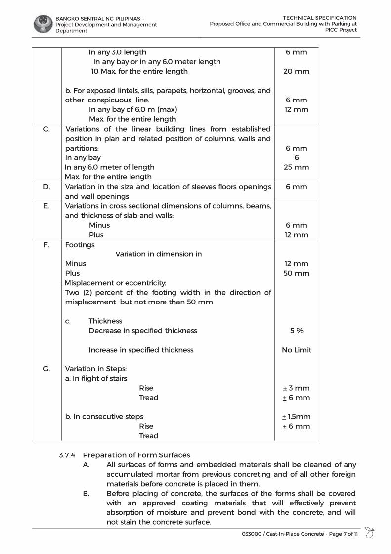
BANGKO SENTRAL NG PILIPINAS – Project Development and Management Department
TECHNICAL SPECIFICATION Proposed Office and Commercial Building with Parking at
PICC Project
033000 / Cast-In-Place Concrete - Page 7 of 11
In any 3.0 length In any bay or in any 6.0 meter length 10 Max. for the entire length b. For exposed lintels, sills, parapets, horizontal, grooves, and other conspicuous line. In any bay of 6.0 m (max) Max. for the entire length
6 mm
20 mm
6 mm 12 mm
C. Variations of the linear building lines from established position in plan and related position of columns, walls and partitions: In any bay In any 6.0 meter of length Max. for the entire length
6 mm 6
25 mm
D. Variation in the size and location of sleeves floors openings and wall openings
6 mm
E. Variations in cross sectional dimensions of columns, beams, and thickness of slab and walls: Minus Plus
6 mm 12 mm
F.
G.
Footings Variation in dimension in
Minus Plus
. Misplacement or eccentricity: Two (2) percent of the footing width in the direction of misplacement but not more than 50 mm
c. Thickness Decrease in specified thickness Increase in specified thickness
Variation in Steps: a. In flight of stairs Rise Tread b. In consecutive steps Rise Tread
12 mm 50 mm
5 %
No Limit
+ 3 mm + 6 mm
+ 1.5mm + 6 mm
3.7.4 Preparation of Form Surfaces
A. All surfaces of forms and embedded materials shall be cleaned of any accumulated mortar from previous concreting and of all other foreign materials before concrete is placed in them.
B. Before placing of concrete, the surfaces of the forms shall be covered with an approved coating materials that will effectively prevent absorption of moisture and prevent bond with the concrete, and will not stain the concrete surface.
BANGKO SENTRAL NG PILIPINAS – Project Development and Management Department
TECHNICAL SPECIFICATION Proposed Office and Commercial Building with Parking at
PICC Project
033000 / Cast-In-Place Concrete - Page 8 of 11
3.7.5 Removal of forms A. When repair of surface defects or finishing is required at an early stage,
forms shall be removed as same as the concrete has hardened sufficiently to resist damage from removal operation.
B. Formworks for columns, walls, sides of beams and other part not supporting the weight of the concrete has hardened sufficiently to resist damages from removal operations.
C. Forms and shoring in the formwork used to support the weight of concrete in beams slabs and other structural members shall remain in place until the concrete has reached the minimum strength specified in the structural drawings for removal of forms and shoring.
3.7.6 Reshoring
A. When reshoring is permitted or required the operations shall be planned in advance and shall be subject to the approval of the Engineer/Architect while reshoring is underway, no live load shall be permitted on the new construction.
B. In no case during reshoring shall concrete in beam, slab, column or any other structural member be subjected to combined dead and construction loads in excess of the loads permitted by the engineer for the developed concrete strength at the time of reshoring.
C. Reshores shall be placed as same as practicable after stripping operations are complete but in no case later than the end of the working day on which stripping occurs.
D. Reshores shall be tightened to carry their respective loads without overstressing the construction.
E. Reshores shall remain in place until the concrete being supported have reached the specified strength.
F. Floors supporting shores under newly placed concrete shall have their original supporting shores left in place or shall be reshored. The reshoring system shall have a capacity sufficient to resist the anticipation loads and in all cases shall have a capacity equal to at least one half of the capacity of the shoring system above. The reshores shall be located directly under a shore position above unless other locations are permitted.
G. The reshoring shall extend over a sufficient number of stories (at least 2 floors) to distribute the weight of the newly placed concrete, forms and construction live loads in such a manner that the design super imposed loads of the floors supporting shores are not excluded.
3.7.7 Removal strength. Formworks or re-shoring can be removed when test cylinders, field cured
along with the concrete they represent have reached the require strength as specified in the construction notes. (S-1)
3.8 Reinforcement and Placing shall be in accordance to Section 03200, Concrete
Reinforcement. 3.9 Joints and Embedded Items. All sleeves, inserts, anchors and embedded items
required for adjoining work or for its support shall be placed prior to concreting in accordance to Section 031500. Expansion joint material, waterstop and other
BANGKO SENTRAL NG PILIPINAS – Project Development and Management Department
TECHNICAL SPECIFICATION Proposed Office and Commercial Building with Parking at
PICC Project
033000 / Cast-In-Place Concrete - Page 9 of 11
embedded items shall be positioned accurately and supported against displacement. Voids in sleeves, inserts and anchor slots shall be filled temporarily with readily available material to prevent the entry of concrete into the voids.
3.10 Production of Concrete 3.10.1 Ready-mixed concrete. Except as otherwise provided in this section, ready
mixed concrete shall be batched, mixed and transported in accordance with “SPECIFICATIONS FOR READY-MIXED CONCRETE” (ASTM C94). Plant equipment and facilities shall conform to the “check list for Certification of Ready-Mixed Concrete Production Facilities” of the National Ready-Mixed Concrete Association.
3.10.2 Site Mixed Concrete. No hand mixing shall be allowed except in case of emergency, such as mixer breakdown during concreting operations and shall stop at the first allowed construction joints. All concrete shall be machine mixed for at least 1-1/2 minutes after all materials including water are in mixing drums.
The mixer shall be of an approved size and type which will guarantee a uniform distribution of material throughout the mass.
3.10.3 Re-tampering of Concrete shall not be permitted. Concrete shall be mixed only in quantities for immediate use. Concrete which has set shall not be retampered but shall be discarded. When concrete arrived at the project with slump below that suitable for placing, as indicated by specifications, water maybe added only if neither maximum permissible water-cement ratio nor the maximum slump is exceeded. The water shall be incorporated by additional mixing equal to at least half of the total mixing required. An addition of water above that permitted by the limitation on water-cement ratio shall be accompanied by a quantity of cement sufficient to maintain the proper water-cement ratio. Such addition shall be authorized by the Engineer/Architect.
3.11 Placing 3.11.1 Preparation before placing. Hardened concrete and foreign materials shall be removed from the inner
surfaces of the conveying equipment. Semi-porous subgrades shall be sprinkled sufficiently to eliminate suction or porous subgrade shall be sealed in an approved manner.
3.11.2 Conveying Concrete shall be handled from the mixers to the place of final deposit as
rapidly as practicable by methods which will prevent segregation or loss of ingredients and in “a manner which will assure that the required quality of the concrete is maintained. Conveying equipment shall be approved and shall be of the size and design such that detachable setting concrete shall not occur before adjacent concrete is placed. Conveying equipment shall be cleaned at the end of each operation or work day. Conveying equipment and operations shall conform to the following additional requirements. A. Truck mixer’s, agitators, and non-agitating units and their manner of
operation shall conform to the applicable requirements of SPECIFICATIONS FOR READY-MIXED CONCRETE” (ASTM C94).
BANGKO SENTRAL NG PILIPINAS – Project Development and Management Department
TECHNICAL SPECIFICATION Proposed Office and Commercial Building with Parking at
PICC Project
033000 / Cast-In-Place Concrete - Page 10 of 11
B. Chutes shall be metal or metal-lined and shall have a slope not exceeding 1 vertical to 2 horizontal and not less than 1 vertical to 3 horizontal. Chutes more than 6.0 m long and chutes not meeting the slope requirement maybe used provided they are discharged into hopper before distribution.
C. Pumping or pneumatic conveying equipment shall be of suitable kind with adequate pumping capacity. Pneumatic placement shall be controlled so that segregation is not apparent in the discharge of concrete. The loss of slump in pumping or pneumatic conveying equipment shall not exceed 50 mm. Concrete shall not be conveyed through pipe made of aluminum or aluminum alloy.
3.11.3 Depositing Concrete shall be deposited continuously, or in layers of such thickness that no
concrete will be deposited on concrete which has hardened sufficiently to cause the formation of seams or planes of weakness within the section. If a section cannot be placed continuously, construction joints shall be located as approved by the Structural Engineer. Placing shall be carried on at such a rate that the concrete which is being integrated with fresh concrete is still plastic. Concrete which has partially hardened or has been contaminated by foreign materials shall not be deposited. Temporary spreader in forms shall be removed when the concrete placing has reached an elevation rendering their service unnecessary. They may receive embedded in the concrete only if made of metal or concrete and if prior approval has been obtained. Placing of concrete in supported elements shall not be started until the concrete previously placed in columns and walls is no longer plastic and has been in place at least two hours. Concrete shall be deposited as nearly as practicable in its final position to avoid segregation due to re-handling or flowing. Concrete shall not be subjected to any procedure which will cause segregation. All concrete shall be consolidated by vibration, spading, rodding or forking so that the concrete is thoroughly worked around the reinforcement, around embedded items, and into corners of forms, eliminating all air or stone pockets which may cause honeycombing, pitting or planes of weakness. Unless adequate protection is provided and approval of the Engineer/Architect is obtained, concrete shall not be placed during rain.
3.11.4 Bonding The hardened concrete of construction joints and of joints between footings
and walls or columns, between walls or columns and beams or flows they supported, joint in unexposed walls and all others not mentioned below shall be dampened (but not saturated) immediately prior to placing of fresh concrete. The hardened concrete of joints in exposed work; joints in the beams, girders, joints, and slabs; and joints in works designed to contain liquid shall be dampened (but not saturated) and then thoroughly covered with a coat of cement grout of similar proportions to the mortar in the concrete. The grout shall be as thick as possible in vertical surfaces and least 12 mm thick in horizontal surfaces. The fresh concrete shall be placed before the grout has attained its initial sets. Joint receiving an adhesive shall have been prepared and adhesive applied in accordance with the Manufacturer’s recommendations prior to placing of fresh concrete.
BANGKO SENTRAL NG PILIPINAS – Project Development and Management Department
TECHNICAL SPECIFICATION Proposed Office and Commercial Building with Parking at
PICC Project
033000 / Cast-In-Place Concrete - Page 11 of 11
3.12 Repair of Surface Defects 3.12.1 General. Surface defects, including holes, unless otherwise specified by the
contract documents shall be repaired immediately after forms are removed. 3.12.2 Repair of Defective Areas. All honeycombed and defective concrete shall be
removed down to sound concrete. If chipping is necessary the edges shall be perpendicular to the surface or slightly undercut. No featheredges shall be permitted. The area to be patched and an area at least 150 mm wide surrounding it shall be dampened to prevent absorption of water from the patching mortar. A bonding grout shall be prepared using a mix of approximately 1 part cement to 1 part fine sand passing a No 30 mess, mixed to the consistency of thick cream and then brushed into the surface. The patching mixture shall be made of the same materials and of approximately the same proportions as used for concrete, except that the coarse aggregate shall be omitted and the mortar shall consist of not more than 1 part cement to 2 1/2 parts and by sand loose volume. White portland cement shall be substituted for a part of the gray portland cement in exposed concrete in order to produce a color matching the color of the surrounding concrete, as determined by trial patch. The quantity of mixing water shall be no more than necessary for handling in advances and allowed to stand with frequent manipulation with a trowel, without addition of water, until it has reached even consistency.
After surface water has evaporated from the area to be patched, the bond coat shall be will brushed unto the surface. When the bond coated begins to lose the water sheen, the provided patching mortar shall be applied. The mortar shall be thoroughly consolidated into place and stuck off so as to leave the patch slightly higher than the surrounding surface. To permit initial shrinkage, it shall be left undisturbed for at least 1 hour before being finally finished. The patched area shall be kept damp for 7 days. Metal toll shall not be used in finishing a patch in formed wall which will be exposed.
END OF SECTION
BANGKO SENTRAL NG PILIPINAS – Project Development and Management Department
TECHNICAL SPECIFICATION Proposed Office and Commercial Building with Parking at
PICC Project
033500 / Concrete Finishing - Page 1 of 4
SECTION 03 35 00
CONCRETE FINISHING
PART 1 GENERAL
1.1 SCOPE OF WORK The work to be undertaken under this section shall comprise the furnishing of all labor, materials, equipment, plant and other facilities and the satisfactory performance necessary to complete concrete finishes which include exposed surfaces of the completed structure or building that requires special concrete materials, formwork, placement or treatment to obtain specified architectural appearance indicated on the drawings and specifications conforming to the Contract Documents provisions.
1.2 REFERENCES Comply with the provisions under General Conditions of the Contract Documents and Manufacturer’s instructions. Reference the following standards as applicable: 1.2.1 ACI 301 - Specifications for Structural Concrete for Buildings 1.2.2 American Concrete Institute ACI 303R Architectural Cast-in-Place Concrete 1.2.3 ASTM C260 Standard Specification for Air-Entraining Admixtures for Concrete 1.2.4 ASTM C494 Chemical Admixtures for Concrete
1.3 SUBMITTALS 1.3.1 General: All submittals for approval as indicated herein shall be in accordance to
the provisions under General Conditions of the Contract Documents. 1.3.2 Shop Drawings: Design and prepare detailed drawings showing the forming
proposed for architectural concrete surfaces. 1.3.3 Mockups: Cast mockup of pour to demonstrate proposed surface finish, texture,
and color. Use job. Maintain sample panel exposed to view for duration of Project, after Architect's the same cement brand, aggregate type and construction methods that will be used on the acceptance of visual qualities.
1.4 QUALITY ASSURANCE 1.4.1 Comply with quality assurance requirements under General Conditions of the
Contract Documents and Manufacturer’s instructions. 1.4.2 ACI Publications: Comply with ACI 301. 1.4.3 Finisher Qualifications: Company specializing in performing the work of this
Section with a minimum of 5-years documented experience or not less than 10 projects with similar quantity of surface area for colored or imprinted concrete.
BANGKO SENTRAL NG PILIPINAS – Project Development and Management Department
TECHNICAL SPECIFICATION Proposed Office and Commercial Building with Parking at
PICC Project
033500 / Concrete Finishing - Page 2 of 4
PART 2 PRODUCTS
2.1 Slip-Resistive Exposed Aggregate Finish: 20mm gravel, coarse seeded application.
2.2 Dry-Shake Floor Hardener: Factory-packaged dry combination of Portland cement, graded quartz aggregate, and plasticizing admixture.
2.3 Concrete Floor Sealer: Clear, water-based, non-yellowing, blush-resistant concrete sealer.
2.4 Epoxy floor coating: high performance, two-component epoxy-based coating with excellent resistance to abrasion, impact and chemicals.
PART 3 EXECUTION
3.1 Finishing Formed Surfaces 3.1.1 Rough-Formed: As-cast texture.
A. The resulting surface shall be true and uniform. All repaired surfaces, the appearance of which is not satisfactory to the Architect/Engineer, shall be "rubbed" as specified herein.
3.1.2 Smooth-Formed Finish: As-cast texture where forms are arranged in an orderly and symmetrical manner with a minimum of seams. A. Apply to concrete surfaces exposed to public view or to be covered
with a coating or covering material applied directly. B. Immediately following the removal of forms, all fins and irregular
projection shall be removed from all surfaces except from those which are not to be exposed or are not to be waterproofed. On all surfaces the cavities produced by form ties and all other holes, honeycomb spots, broken corners or edges and other defects shall be thoroughly cleaned and after having been kept saturated with water for a period of not less than three hours they shall be carefully pointed and made true with a mortar of cement and fine aggregate mixed in the proportions used in the grade of the concrete being finished. Mortar used in pointing shall not be more than one hour old. All construction and expansion joints in the completed work shall be left carefully tooled and free of all mortar and concrete. The joint filler shall be left exposed for its full length with clean and true edges.
3.1.3 Rubbed Finish: Apply the following to smooth-formed finished concrete. Smooth-Rubbed Finish: After removal of forms, the rubbing of concrete shall
be started as soon as its condition will permit. Immediately before starting this work, the concrete shall be kept thoroughly saturated with water for a minimum period of three hours. Sufficient time shall have elapsed before the wetting down to allow the mortar used in the pointing of road holes and defects to thoroughly set. Surfaces to be finished shall be rubbed with a minimum coarse carborandum stone using a small amount of mortar on each face. The mortar shall be composed of cement and fine sand mixed in the proportions used in the concrete being finished. Rubbing shall be continued until all form marks, projections and irregularities have been removed, all voids have been filled, and a uniform surface has been obtained. The face produced by this rubbing shall be left in place at this time. After all concrete above the surface being created has been cast; the final finish shall

BANGKO SENTRAL NG PILIPINAS – Project Development and Management Department
TECHNICAL SPECIFICATION Proposed Office and Commercial Building with Parking at
PICC Project
033500 / Concrete Finishing - Page 3 of 4
be obtained by rubbing with a fine carborandum stone and water. This rubbing shall be continued until the entire surface is of smooth texture and uniform color. After the final rubbing is completed and the surface has dried, it should be rubbed with burlap to remove loose powder and shall be left free from all unsound patches, paste, powder and objectionable marks.
3.1.4 Related Unformed Surfaces: Strike smooth and finish with a texture matching adjacent formed surfaces.
3.2 Finishing Floors and Slabs Note: Refer to Architectural Drawings “Floor Pattern Layout” for floor f inish
requirements, details and layout. Written below are for standard reference only.
3.2.1 Scratch Finish: Texture concrete surface with stiff brushes, brooms, or rakes. Apply to surfaces to receive concrete floor topping or mortar setting beds for ceramic or quarry tile, Portland cement terrazzo, and other bonded cementitious floor finishes.
3.2.2 Trowel Finish: Apply a trowel finish to floor and slab surfaces exposed to view or to be covered with resilient flooring, carpet, ceramic or quarry tile set over a membrane, paint, or another coating system. Finish and measure surface so gap at any point between concrete surface and an unleveled freestanding three (3) meters long straightedge, resting on two (2) high spots and placed anywhere on the surface, does not exceed six (6) meters.
3.2.3 Trowel and Fine-Broom Finish: Apply as lightly scarified fine broom finish to surfaces where ceramic or quarry tile is to be installed.
3.2.4 Broom Finish: Apply a broom finish to exterior concrete platforms, steps, and ramps.
Generally used on interior and exterior concrete treads, pavement, platforms, and ramps subject to moderate foot traffic.
3.2.5 Slip-Resistive Aggregate Finish: Before final floating, apply slip-resistive aggregate finish. A. Spread slip-resistive aggregate at 1kg/sq.m. Tamp flush with surface, but
do no force below surface, then apply a float finish. B. After curing, lightly work surface with a steel wire brush or an abrasive
stone, and water to expose slip-resistive aggregate. 3.2.6 Dry-Shake Floor Hardener Finish: After initial floating, apply mineral dry-
shake materials to surfaces as follows in conformance to Manufacturer’s Instructions: A. Apply mineral dry-shake materials at a rate of 5kg/sq.m. B. Uniformly distribute approximately two-thirds of mineral dry-shake
materials over surface by hand or with mechanical spreader, and embed by power floating. Follow power floating with a second mineral dry-shake application, uniformly distributing remainder of material, and embed by power floating. Coordinate selection of curing compounds for compatibility with dry shake materials and revise lists in part 2 accordingly, if required.
C. After final floating, apply a trowel finish. Cure concrete with curing compound recommended by dry-shake material manufacturer and apply immediately after final finishing.

BANGKO SENTRAL NG PILIPINAS – Project Development and Management Department
TECHNICAL SPECIFICATION Proposed Office and Commercial Building with Parking at
PICC Project
033500 / Concrete Finishing - Page 4 of 4
3.2.7 Floor Sealer Finish: Do not apply sealer to green/fresh concrete. Allow 14 days for concrete to cure, or wait until the concrete is uniform in color. For optimum results, allow concrete to cure in 28 days or as per Manufacturer’s standard application procedures. Apply light uniform coats using an airless sprayer or as per Manufacturer’s recommended tool and equipment. Apply consecutive coats as soon as the surface will readily absorb.
END OF SECTION
BANGKO SENTRAL NG PILIPINAS – Project Development and Management Department
TECHNICAL SPECIFICATION Proposed Office and Commercial Building with Parking at
PICC Project
033900 / Concrete Curing - Page 1 of 4
SECTION 03 39 00
CONCRETE CURING
PART 1 GENERAL
1.1 SCOPE OF WORK The Section shall comprise the furnishing of all labor, materials, equipment, plant and other facilities and the satisfactory performance necessary to complete curing practices for cast-in-place Portland cement concrete as indicated on the drawings and specifications conforming to the provisions of the Contract Documents.
1.2 REFERENCES Comply with the provision under General Conditions of the Contract Documents and Manufacturer’s instructions. Reference the following standards as applicable: 1.2.1 ACI 301: Specifications for Structural Concrete for Buildings 1.2.2 ACI 305: Hot Weather Concreting 1.2.3 ACI 306.1: Cold Weather Concreting 1.2.4 ACI 308R: Guide to Curing Concrete 1.2.5 ASTM C 171: Standard Specification for Sheet Materials for Curing Concreting 1.2.6 ASTM C 1315: Standard Specification for Liquid Membrane-Forming
Compounds Having Special Properties for Curing and Sealing Concreting 1.2.7 AASHTO M-148 Liquid Membrane-Forming Compounds for Curing Concrete
1.3 SUBMITTALS 1.3.1 General: All submittals for approval as indicated herein shall be in accordance
to the General Conditions of the Contract Documents. 1.3.2 Product Data: Submit manufacturer's recommended installation procedures,
catalog and certifications of quality compliance and test reports.
1.4 QUALITY ASSURANCE 1.4.1 Comply with quality assurance requirements under General Conditions of the
Contract Documents and Manufacturer’s instructions. 1.4.2 Workmanship and methodology shall conform to ACI 301, 305, 306.1.
1.5 PRODUCT HANDLING 1.5.1 Protect materials of this section before, during, and after installation. 1.5.2 Protect the work and materials of other trades 1.5.3 In the event of damage, immediately make replacements and repair at no
additional cost to OWNER.
1.6 WEATHER LIMITATIONS A. Above 28 deg. C.; ACI 305 B. Below 13 deg. C.; ACI 306.1
BANGKO SENTRAL NG PILIPINAS – Project Development and Management Department
TECHNICAL SPECIFICATION Proposed Office and Commercial Building with Parking at
PICC Project
033900 / Concrete Curing - Page 2 of 4
PART 2 PRODUCTS
2.1 CURING MATERIALS Evaporation retarder below temporarily reduces moisture loss from concrete surfaces awaiting finishing in hot, dry, and windy conditions. Evaporation retarders are not curing compounds. 2.1.1 Evaporation Retarder: Waterborne, monomolecular film forming,
manufactured for application to fresh concrete. A. Product: Select curing aids and materials from par as below, retaining
optional materials if applicable. 2.1.2 Absorptive Cover: Burlap cloth weighing approximately 9 oz./sq. yd. (300
g/sq.m) dry. 2.1.3 Moisture-Retaining Cover: Polyethylene film or white burlap-polyethylene
sheet. Select curing compounds from the types listed in the 3 categories listed
below. Below is a waterborne curing compound, considered a “straight cure”. It is only a temporary membrane for curing, and will breakdown under exposure to UV light and abrasion. It is usually recommended for exterior applications.
2.1.4 Clear Water-based Membrane-Forming Curing Compound: ASTM C-309, Type 1, Class B. A. Product: Provide long-lasting products for curing and protection of
finished concrete surfaces, recommended for interior applications. It should be a solvent-borne product or a water-borne product.
2.1.5 Clear Solvent-Based Membrane-Forming Curing Compound: ASTM C 309, Type 1, Class B. A. Product: Provide curing compound meeting the material requirement
as per specification. 2.1.6 Clear Waterbased Membrane-Forming Curing Compound: ASTM C 309, Type 1,
Class B. A. Product: Provide clear, non-yellowing, membrane forming cure-and-
seals meeting newer ASTM C-1315 requirements. It should be a solvent-borne product or a water-borne product.
2.1.7 Clear, Solvent-Based, Membrane-Forming Curing and Sealing Compound: ASTM C 1315, Type 1,Class A. A. Product: Provide an approved product with super sealing property
against UV. 2.1.8 Clear, Water-based, Membrane-Forming Curing and Sealing Compound:
ASTM C 1315, Type 1,Class A. A. Product: Provide an approved product with super sealing property
against UV.
BANGKO SENTRAL NG PILIPINAS – Project Development and Management Department
TECHNICAL SPECIFICATION Proposed Office and Commercial Building with Parking at
PICC Project
033900 / Concrete Curing - Page 3 of 4
PART 3 EXECUTION
3.1 CONCRETE CURING 3.1.1 Protect freshly placed concrete from premature drying and excessive cold or
hot temperatures. A. Moist cure or use moisture-retaining covers to cure concrete surfaces to
receive penetrating liquid floor treatments. B. Cure concrete surfaces to receive floor coverings with a curing
compound that the manufacturer recommends for use with floor coverings. If evaporation rate in par below is exceeded, ACI 305R states that plastic shrinkage cracking is probable.
3.1.2 Evaporation Retarder: Apply evaporation retarder to unformed concrete surfaces if hot, dry, or windy conditions cause moisture loss approaching 0.2 lb/sf. x h (1 kg/sq. m x h) before and during finishing operations. Apply according to manufacturer's written instructions after placing, screeding, and bull floating or darbying concrete, but before float finishing.
3.1.3 Formed Surfaces: Cure formed concrete surfaces, including underside of beams, supported slabs, and other similar surfaces. If forms remain during curing period, moist cure after loosening forms. If removing forms before end of curing period, continue curing by one or a combination of the following methods:
3.1.4 Unformed Surfaces: Begin curing immediately after finishing concrete. Cure unformed surfaces, including floors and slabs, concrete floor toppings, and other surfaces, by one or a combination of the following methods:
Select curing method(s) from par as below. Delete options or restrict use of
curing method(s) to specific locations or types of surfaces if required. A. Moisture Curing: Keep surfaces continuously moist for not less than
seven days with absorptive cover, water saturated, and kept continuously wet. Cover concrete surfaces and edges with 12-inch (300-mm) lap over adjacent absorptive covers.
B. Moisture-Retaining-Cover Curing: Cover concrete surfaces with moisture-retaining cover for curing concrete, placed in widest practicable width, with sides and end slapped at least 12 inches (300 mm), and sealed by waterproof tape or adhesive. Cure for not less than seven days. Immediately repair any holes or tears during curing period using cover material and waterproof tape.
C. Curing Compound: Apply uniformly in continuous operation by power spray or roller. Recoat areas subjected to heavy rainfall within three hours after initial application. Maintain continuity of coating and repair damage during curing period. Curing and sealing compound below is usually for floors and slabs and may act as a permanent surface finish.
D. Curing and Sealing Compound: Apply uniformly to floors and slabs indicated in a continuous operation by power spray or roller according to manufacturer's written instructions. Recoat areas subjected to heavy rainfall within three hours after initial application. Repeat process 24 hours later and apply a second coat. Maintain continuity of coating and repair damage during curing period.
BANGKO SENTRAL NG PILIPINAS – Project Development and Management Department
TECHNICAL SPECIFICATION Proposed Office and Commercial Building with Parking at
PICC Project
033900 / Concrete Curing - Page 4 of 4
3.2 LIQUID FLOOR TREATMENTS 3.2.1 Penetrating Liquid Floor Treatment: Prepare, apply, and finish penetrating
liquid floor treatment according to manufacturer's written instructions. A. Remove curing compounds, sealers, oil, dirt, laitance, and other
contaminants and complete surface repairs. B. Apply to concrete that is at least ten days old. C. Apply liquid until surface is saturated, scrubbing into surface until a gel
forms; rewet; and repeat brooming or scrubbing. Rinse with water; remove excess material until surface is dry. Apply a second coat in a similar manner if surface is rough or porous. The following paragraph can be used to improve appearance of an exposed concrete floor. It should be applied just prior to project closeout.
3.2.2 Sealer Coat: Just prior to project end, uniformly apply a sealer coat of cure-and-seal compound to floor slabs that have no other finish flooring. Apply to concrete surfaces by power spray or roller.
END OF SECTION
BANGKO SENTRAL NG PILIPINAS – Project Development and Management Department
TECHNICAL SPECIFICATION Proposed Office and Commercial Building with
Parking at PICC Project
035300 / Concrete Topping - Page 1 of 3
SECTION 03 53 00
CONCRETE TOPPING
PART 1 GENERAL
1.1 RELATED DOCUMENTS Drawings and general provisions of the Contract, including General and Supplementary Conditions and Division 01 Specification Sections, apply to this Section.
1.2 SUMMARY 1.2.1 Section includes concrete floor toppings. Extent of concrete floor toppings
is shown on Drawings and in schedules. 1.2.2 Types of concrete floor toppings include:
a. Standard aggregate toppings.b. Repair of concrete surfaces as necessary to receive finish materials.c. Repair of holes less than 4 inches diameter and cracks in concrete
slabs.
1.3 REFERENCES 1.3.1 Comply with requirements of Section 03 30 00 “Cast-in-Place Concrete” and
as herein specified.
1.4 SUBMITTALS 1.4.1 Furnish data, samples, laboratory test reports, and materials certificates as
specified in Section 03 30 00 “Cast-In-Place Concrete.”
PART 2 PRODUCTS
2.1 CEMENT AND AGGREGATES 2.1.1 Portland Cement: ASTM C 150, Type I or III. 2.1.2 Normal Weight Aggregate: ASTM C 33 and as follows:
Fine aggregate, consisting of sand or crushed stone screenings, clean, hard, free from deleterious matter. Grade by weight to pass sieves as follows: a. 3/8 inch: 100 percent.b. No. 4: 95-100 percent.c. No. 8: 80-90 percent.d. No. 16: 50-75 percent.e. No. 30: 30-50 percent.f. No. 50: 10-20 percent.g. No. 100: 2-5 percent.
2.1.3 Manufacturer: Subject to compliance with requirements, provide factory pre-mixed topping mix with at least ten (10) years of experience in the industry:
2.1.4 Furnish selected aggregates to match Owner’s finish sample.
2.2 TOPPING MIX
BANGKO SENTRAL NG PILIPINAS – Project Development and Management Department
TECHNICAL SPECIFICATION Proposed Office and Commercial Building with
Parking at PICC Project
035300 / Concrete Topping - Page 2 of 3
2.2.1 Standard Topping: Design mix to produce topping material with the following characteristics: a. Compressive Strength: 3500 psi at 28 days. b. Slump: 8 inches maximum at point of placement for concrete
containing high-range water reducing admixture (super-plasticizer) and 3 inches maximum for other concrete.
c. Maximum W/C Ratio: 0.51. 2.3 MIXING
2.3.1 Provide batch type mechanical mixer for mixing topping material at Project site. Equip batch mixer with a suitable charging hopper, water storage tank, and a water-measuring device. Use only mixers that are capable of mixing aggregates, cement, and water into a uniform mix within specified time, and of discharging mix without segregation.
2.3.2 Mix each batch of 2 cu. yds. or less for at least 1-1/2 minutes after ingredients are in mixer. Increase mixing time 15 seconds for each additional cu. yd. or fraction thereof.
2.3.3 Ready-mixed topping may be used when acceptable to Owner. When acceptable, furnish ready-mixed topping complying with requirements of ASTM C 94.
PART 3 EXECUTION 3.1 CONDITION OF SURFACES
3.1.1 Topping Applied to Fresh Concrete: Do not begin placement of topping until water ceases to rise to surface, and water and laitance have been removed from base slab surface.
3.1.2 Topping Applied to Hardened Concrete: Remove dirt, loose material, oil, grease, paint, or other contaminants, leaving a clean surface.
3.1.3 When base slab surface is unacceptable for good bonding, roughen surface by chipping or scarifying before cleaning. Prior to placing topping mixture, thoroughly dampen slab surface but do not leave standing water. Over dampened surface, apply specified bonding compound (re-wettable or non-re-wettable) or epoxy adhesive. Place topping mix after re-wettable bonding compound has dried or while non-rewettable bonding compound or epoxy adhesive is still tacky.
3.1.4 For reinforced toppings, provide necessary supports, and maintain position of reinforcing mesh as shown on Drawings.
3.1.5 Joints: Mark locations of joints in base slab so that joints in top course will be placed directly over them.
3.2 PLACING AND FINISHING
3.2.1 Float Finish: Spread topping mixture evenly over prepared base to the required elevation and strike off. Use highway straightedge, bull float, or darby to level surface. After the topping has stiffened sufficiently to permit the operation, and water sheen has disappeared, float the surface at least twice to a uniform sandy texture. Re straighten where necessary with highway straight edge. The surface shall achieve an F(F) 20/F(L) 17 tolerance when tested in accordance with ASTM E 1155. Uniformly slope surface to drains.
BANGKO SENTRAL NG PILIPINAS – Project Development and Management Department
TECHNICAL SPECIFICATION Proposed Office and Commercial Building with
Parking at PICC Project
035300 / Concrete Topping - Page 3 of 3
3.2.2 Where joints are required, construct to match and coincide with joints in base slab. Provide other joints as shown.
3.2.3 Trowel Finish: After floating, consolidate concrete surface by final hand trowelling operations, free of trowel marks, uniform in texture and appearance, and with a surface plane tolerance not exceeding 1/8 inch in 10 feet when tested with a 10 foot straight edge.
3.2.4 Fill air holes, pits, and other blemishes with cement grout of same materials as used for topping. Spread grout over surface and work into openings with a steel straight edge.
3.3 CURING PROECTION Cure and protect topping applications and finishes. 3.4 PERFORMANCE Failure of concrete topping to bond to substrate (as evidenced by a hollow sound
when tapped), or disintegration or other failure of topping to perform as a floor finish, will be considered failure of materials and workmanship. Repair or replace toppings in areas of such failures, as directed.
END OF SECTION
BANGKO SENTRAL NG PILIPINAS – Project Development and Management Department
TECHNICAL SPECIFICATION Proposed Office and Commercial Building with
Parking at PICC Project
036000 / Grouting - Page 1 of 5
SECTION 03 60 00
GROUTING
PART 1 GENERAL
1.1 RELATED DOCUMENTS 1.1.1 Drawings and general provisions of the Subcontract apply to this Section. 1.1.2 Review these documents for coordination with additional requirements
and information that apply to work under this Section.
1.2 REFERENCES 1.2.1 General:
a. The following documents form part of the Specifications to theextent stated. Where differences exist between codes and standards,the one affording the greatest protection shall apply.
b. Unless otherwise noted, the referenced standard edition is thecurrent one at the time of commencement of the Work.
c. Refer to Division 01 Section "General Requirements" for the list ofapplicable regulatory requirements.
1.2.2 ASTM International: a. ASTM C33 Concrete Aggregatesb. ASTM C40 Organic Impurities in Fine Aggregates for Concretec. ASTM C88 Soundness of Aggregates by Use of Sodium Sulfate or
Magnesium Sulfate d. ASTM C117 Material Finer Than 75μm Sieve in Mineral Aggregates
by Washing e. ASTM C136 Sieve Analysis of Fine and Coarse Aggregatesf. ASTM C150 Portland Cementg. ASTM C289 Potential Reactivity of Aggregates (Chemical Method)h. ASTM C494 Chemical Admixtures for Concretei. ASTM C881 Epoxy-Resin-Base Bonding Systems for Concretej. ASTM D2419 Sand Equivalent Value of Soils and Fine Aggregatek. ASTM E329 Inspection and Testing Agencies for Concrete, Steel,
Bituminous Materials as Used in Construction
1.3 SUBMITTALS 1.3.1 Submit under provisions of Division 01 Section "General Requirements." 1.3.2 Manufacturer's data shall be provided for [bonding compounds] [pressure
grout] [retardants]. 1.3.3 Test reports, accompanied by a manufacturer's statement that previously
tested material is of similar type, quality, and manufacture as that which is proposed for use on this projects, shall be submitted for: a. Cement.b. Aggregates.c. Retardants.d. Bonding compounds.
1.3.4 The subcontractor's testing laboratory shall provide evidence of the most recent inspection of its facilities by the Cement and Concrete Reference
BANGKO SENTRAL NG PILIPINAS – Project Development and Management Department
TECHNICAL SPECIFICATION Proposed Office and Commercial Building with
Parking at PICC Project
036000 / Grouting - Page 2 of 5
Laboratory of the National Bureau of Standards and evidence of correction of deficiencies noted in the inspection report before materials specified in this section are delivered to the job site.
1.4 QUALITY ASSURANCE Conformance with the specified requirements will be demonstrated testing
performed by an independent testing laboratory. PART 2 PRODUCTS
2.1 MATERIALS 2.1.1 Cement: Portland cement shall be ASTM C150 Type II or Type V, containing
less than 0.6 percent alkali. 2.1.2 Aggregate:
a. General: Aggregate shall be non-reactive and shall be washed before use. When sources of aggregate are changed, test reports shall be provided for the material from the new source prior to commencing grout work.
b. Fine Aggregate: Fine aggregate shall be sand or crushed stone conforming to ASTM C33 as modified herein. When tested in accordance with ASTM C136, gradation shall be such that 100 percent by weight passes a standard No. 8 sieve and not less than 45 percent by weight pass a standard No. 40 sieve. Variation from the specified gradation in individual tests will be accepted if the average of three consecutive tests is within the following variation:
Standard Sieve Permissible variation in individual test No. 30 or coarser 2 percent by weight No. 50 or finer 0.5 percent by weight
2.1.3 Admixtures: a. General: Admixtures shall be compatible with the grout and shall
comply with the manufacturer's recommendations. Admixtures shall be added to the grout mix separately.
b. Water Reducing Retarder: Water reducing retarder shall comply with ASTM C494, Type D.
c. Lubricant 2.1.4 Water:
Waste for washing aggregate, for mixing and for curing shall be potable, shall not contain more than 1000 mg/l of chlorides as Cl, nor more than 1300 mg/l of sulfates as SO4, and shall not contain impurities which may change the setting time by more than 25 percent or a reduction of more than 5 percent of the compressive strength of the grout at 14 days when compared to the results for grout made with distilled water.
2.2 GROUTING 2.2.1 Cement Grout:
Cement grout shall be a mixture of one part cement, two parts sand proportioned by volume admixtures for pressure grouting and sufficient water to form a workable mix.
2.2.2 Epoxy Grout for Crack Repair and Dowel Anchorage:
BANGKO SENTRAL NG PILIPINAS – Project Development and Management Department
TECHNICAL SPECIFICATION Proposed Office and Commercial Building with
Parking at PICC Project
036000 / Grouting - Page 3 of 5
a. Except for applications involving pressure grouting or crack injection, epoxy shall be a high modulus, moisture insensitive, two-component, 100 percent solids, thermosetting modified polyamide epoxy compound. The material shall conform to ASTM C881 Type I, Grade 3 which is capable of not sagging in horizontal or overhead anchoring applications.
b. Epoxy for applications involving pressure grouting or crack injection, shall be a high modulus, moisture insensitive, two component, injection grade, 100 percent solids blend of epoxy resin compounds. The material shall conform to ASTM C881 Type I, Grade 1 which is capable of achieving complete penetration of hairline and larger cracks.
2.2.4 Polymer Concrete for Resurfacing and Patching: Polymer concrete shall consist of a liquid binder and dry aggregate mixed
together to make a flowable mortar. The liquid binder shall be a chemical and oil resistant, stress relieved, low modulus, moisture insensitive, two component epoxy resin compound. The binder material shall conform to ASTM C881 Type 3, Grade 1 with a consistency similar to light weight oil for proper mixing with the aggregate. The aggregate shall be oven dry, kept in sealed packages until the time of mixing and be of size and consistency compatible with recommendations of the manufacturer of the liquid binder for the intended application.
2.2.5 Adhesive Resin for Dowel Anchorage: ICC approved, structural epoxy; prepackaged in cartridges for manually or pneumatically operated caulk gun and automatically mixed at nozzle. Subject to compliance with current ICC evaluation report.
2.3 PRESSURE GROUTING EQUIPMENT Pressure grouting equipment shall include a mixer and holdover agitator tanks
designed to place grout at pressures up to 50 psi (0.345 MPa). Gauges indicating grouting pressure shall be provided and the mixer shall be equipped with a meter capable of indicating to within 1/10 cubic foot (0.003 m³) the volume of grout placed.
PART 3 EXECUTION
3.1 GENERAL Bonding compounds for use with grout is specified in [Division 03 Section Cast-in-Place Concrete]. Primer, if required for polymer concrete, is to be provided and installed per the manufacturer's recommendations.
3.2 CEMENT GROUT 3.2.1 Cement grout is to be used for filling nonbearing portions of equipment
pads and pressure grouting. 3.2.2 Except for the specialized requirements for pressure grouting, grout is to be
mixed and placed in the same manner as cast-in-place concrete. Grout is to be mixed for at least one minute and diluted grout to agitated until placed.
3.3 NON SHRINK GROUT
BANGKO SENTRAL NG PILIPINAS – Project Development and Management Department
TECHNICAL SPECIFICATION Proposed Office and Commercial Building with
Parking at PICC Project
036000 / Grouting - Page 4 of 5
3.3.1 Non shrink, nonmetallic aggregate grout is to be used under equipment, bearing plates and column base plates. Non shrink, metallic aggregate grout is to be used under rotating equipment where high strength and fatigue are of concern, to grout anchor bolts and to grout reinforcing steel. Grout is to be placed and cured in accordance with the manufacturer's recommendations.
3.3.2 Holes required for grouting shall be blown clean with compressed air and are to be free of dust or standing water. Horizontal holes for grouting are to be drilled at a slight downward angle and with the inserted dowel or bolt bent to match.
3.4 EPOXY GROUT
3.4.1 Epoxy grout shall be used for repairing cracks by pressure grouting or gravity, repairing structural concrete and may be used for setting dowels or bolts in holes. Concrete is to be primed in accordance with the grout manufacturer's recommendations.
3.4.2 The use of epoxy grout must comply with the following restrictions: a. Limited to areas where exposure, on an intermittent or continuous
basis, to acid, chlorine gas or to machine or diesel oils, is extremely unlikely.
b. Limited to applications where exposure to fire or to concrete temperatures above the product heat deflection temperature or 120 deg F (40 deg C)(whichever is less) is extremely unlikely. Overhead applications are not allowed.
c. Holes for the anchors shall be drilled (not cored), shall be blown clean with compressed air and shall be free of dust or standing water.
d. The anchor type, size and embedment depth shall be as shown on the drawings and the anchor must be installed in accordance with the manufacturer's recommendations.
e. The anchor must not be loaded until after the full curing period has elapsed.
3.5 PRESSURED GROUTING
Prior to grouting, cracks and holes to be grouted shall be washed clean. Washing is not required for grouting soil voids. Once started, grouting shall be continuous until completed. In case of a mechanical failure or other stoppage of the work, the grout equipment shall be washed out sufficiently to ensure that fresh only grout is pumped when the work is restarted.
3.6 FIELD OF QUALITY CONTROL 3.6.1 The Testing Laboratory will:
a. Special Inspect installation of anchors in accordance with applicable ICC Evaluation Report, where special inspection is indicated on Contract Documents or where Subcontractor's design engineer has used ICC anchor capacities that require Special Inspection.
b. Develop and utilize an effective method of field marking anchor and dowel test locations and results.
3.6.2 Testing of grout mixes for conformance to manufacturer’s specified strength: Testing laboratory shall take four test samples of each day's grout
BANGKO SENTRAL NG PILIPINAS – Project Development and Management Department
TECHNICAL SPECIFICATION Proposed Office and Commercial Building with
Parking at PICC Project
036000 / Grouting - Page 5 of 5
mix and test grout mix samples at 7 and 28 days. Test reports shall be submitted to the Architect/Engineer for evaluation and approval.
3.6.3 Test 25 percent of reinforcing steel dowels installed with adhesive resin on a given day in tension using pullout procedure. Test to 80% of specified yield strength of the dowel or 150% of the ICC rated static capacity whichever is the lesser with special inspection. Dowels specifically noted on the drawings as “No test required” do not require tension testing.
3.6.4 If the failure rate of dowels exceeds 10 percent, testing will be increased to 100 percent of that day’s installation of similar anchors or dowels. Testing will be reduced to 25 percent of that day’s installation when the failure rate is reduced to 10 percent or less. Failed dowels will be replaced at no additional cost to the Owner. Subcontractor will reimburse Owner for cost of additional testing.
END OF SECTION
BANGKO SENTRAL NG PILIPINAS – Project Development and Management Department
TECHNICAL SPECIFICATION Proposed Office and Commercial Building with Parking at
PICC Project
042200 / Concrete Unit Masonry - Page 1 of 4
SECTION 04 22 00
CONCRETE UNIT MASONRY
PART 1 GENERAL
1.1 SCOPE OF WORK This section shall include all management, labor, materials, tools, equipment and services required to furnish and install concrete masonry units as specified herein and shown in Drawings required to perform all works in accordance to the General Conditions of the Contract Documents.
1.2 REFERENCES Comply with quality assurance requirements under General Conditions of the Contract Documents and Manufacturer’s instructions. Reference the following standards as applicable: 1.2.1 American Concrete Institute (ACI)/American Society of Civil Engineers
(ASCE)/The Masonry Society (TMS) A. ACI 117 – Standard Specifications for Tolerance for Concrete
Construction and Materials. B. ACI 530.1/ASCE 6/TMS 315 - Specification for Masonry Structures.
1.2.2 American Concrete Institute (ACI) A. ACI 315 – Details and Detailing of Concrete Reinforcement.
1.2.3 American Society for Testing and Materials (ASTM) A. ASTM C 90– Specification for Load bearing Concrete Masonry Units. B. ASTM C 140 – Test Methods for Sampling and Testing Concrete Masonry
Units and Related Units.
1.3 SUBMITTALS 1.3.1 General: All submittals for approval as indicated herein shall be in accordance
to the provisions under General Conditions of the Contract Documents. 1.3.2 Product Data: For each type of concrete masonry unit and accessory
including certifications that each complies with specified requirements. 1.3.3 Shop Drawings:
A. For concrete masonry units, showing sizes, profiles, coursing, bond pattern, special shape locations, joint locations and embedded items.
B. For cast stone trim in form of cutting and setting drawings, showing sizes, profiles and locations of each stone trim unit required.
C. For joint reinforcement and steel reinforcing. Detail fabrication, bending and placement of unit masonry reinforcing bars. Comply with ACI 315 showing reinforcing bar schedules, stirrup spacing, and diagrams of bent bars and arrangement of masonry reinforcing.
D. Shop Drawings and/or manufacturer’s catalog cuts of dovetail slots and other devices, if any, required for anchoring masonry to steel or other materials, including instructions for their proper use.
1.3.4 Samples: Samples for approval for each different type and shape of exposed masonry unit required, showing full range of exposed color, texture and dimensions to be expected in the finished Work. When required by 2.01 B.6, prefaced or
BANGKO SENTRAL NG PILIPINAS – Project Development and Management Department
TECHNICAL SPECIFICATION Proposed Office and Commercial Building with Parking at
PICC Project
042200 / Concrete Unit Masonry - Page 2 of 4
ground face, submit concrete masonry unit samples for color selection or verification. Two sample sections of cast stone sills and coping, if any, showing color and texture of finish. Samples of accessories embedded in masonry.
1.3.5 Quality Control Reports: Submit copies of reports verifying compressive strength requirements of
completed masonry, if required by the Engineer, within 7 calendar days of the date of each completed test.
1.4 QUALITY ASSURANCE
1.4.1 Comply with quality assurance requirements under General Conditions of the Contract Documents and Manufacturer’s instructions.
1.4.2 Manufacturer Qualification shall be at least five (5) years of production experience, whose published literature clearly indicates general compliance of products with requirements of this section.
1.4.3 Single Source Responsibility Obtain exposed masonry units of uniform texture and color from a single
manufacturer for each type of product required. 1.4.4 Mock-ups Where shown on the Contract Drawings, before masonry Work commences,
construct a panel approximately 6 foot long by 4 foot high of each type of exposed concrete masonry unit, as directed by the Engineer, for approval. Use mortar of type and color to be used in the Work. A. Protect mock-ups from the elements with a weather-resistant membrane. B. Retain mock-ups during construction as standards for judging completed
masonry Work. When directed by the Engineer, demolish mock-ups and remove from Authority property.
C. Prepare a list of materials used to construct mock-ups, for information only, for Engineer. Include manufacturer and product names, generic materials, suppliers, colors, identifying lot or batch numbers and design mixes.
D. Where masonry is shown on the Contract Drawings to match existing, construct mock-up panel adjacent to and parallel to existing surfaces to be matched.
1.5 DELIVERY, STORAGE AND HANDLING 1.5.1 Comply with product delivery requirements under General Conditions of the
Contract Documents and Manufacturer’s instructions. 1.5.2 All materials shall be so delivered, stored and handled so as to prevent the
inclusion of foreign materials and damage of materials by water exposure and breakage. In stock piling concrete hollow blocks, measures shall be adopted to prevent the hollow blocks from resting directly on soil surface. These measures may include provision of pallets or bed of sand about 2" thick. Packaged materials shall be delivered and stored in original packages until ready for use. Packages or materials showing evidence of water exposure or other form of damage shall be rejected. All materials shall be of the respective qualities specified herein and packaged materials shall carry the manufacturer's labels thereon to permit identification.
BANGKO SENTRAL NG PILIPINAS – Project Development and Management Department
TECHNICAL SPECIFICATION Proposed Office and Commercial Building with Parking at
PICC Project
042200 / Concrete Unit Masonry - Page 3 of 4
1.6 WARRANTY Special written warranty for each material specified herein shall be submitted by Manufacturer/Contractor without reducing or otherwise limiting any other rights to correction which the Owner may have under the Contract Documents. Failures are defined to include faulty workmanship or faulty materials.
1.7 PROJECT CONDITIONS Comply with field examination requirements under General Conditions of the Contract Documents and Manufacturer’s instructions.
PART 2 PRODUCTS
2.1 Specifications for the following materials are stated under section REINFORCED CONCRETE, and shall apply to this Masonry and Cement Work section as if written out in full.
2.2 Aggregate of different kinds and sizes shall be placed in different stock piles and positive means taken to prevent inclusion of foreign matter.
2.3 All cementitious materials must be kept dry until ready to be used; must be kept off the ground under cover, and away from sweating walls and other damp surfaces.
2.4 Cementitious materials that have hardened or partially set prior to actual use shall be removed from the site.
2.5 Unit Masonry - Concrete hollow block units shall be steam cured-weigh-batched units made. Concrete hollow block units shall be true to size, without cracks, chips, spawns, splits or other defects, which impair their strength or durability. They shall have three holes. All non-bearing type concrete blocks shall have a unit weight not to exceed 60 pcf, for load bearing type concrete blocks, a minimum compressive strength of 7.58 MPA (1,100 psi) shall be developed.
2.6 Steel Reinforcement The minimum steel reinforcement for concrete hollow block walls shall conform to the schedule as given hereunder or as indicated in the construction notes.
Minimum Vertical Reinforcement Horizontal Reinforcement 4" CHB 10mm @ 0.4m 10mm @ 400mm 6" CHB 12mm @ 0.4m 10mm @ 400mm
All cores where vertical or horizontal reinforcements are placed shall be filled with mortar and shall thoroughly be worked inside the core to fill up to voids.
2.7 Tie Wires : Ga. #16 G.I
2.8 Concrete Lintels Lintels for openings shall be the height and thickness of existing hollow block or as detailed in the drawings. The minimum reinforcement shall be that shown in the drawings.
BANGKO SENTRAL NG PILIPINAS – Project Development and Management Department
TECHNICAL SPECIFICATION Proposed Office and Commercial Building with Parking at
PICC Project
042200 / Concrete Unit Masonry - Page 4 of 4
2.9 Mortars Mortar mix shall be 1 part Portland Cement and 3parts white sand. All materials for mortar shall be measured by volume. Sand and cement shall be mixed dry and then water added to bring to proper consistency for use. No mortar that has stood for more than 3/4 of an hour shall be used. Re-tempering of mortar shall not be permitted. Discard mortar which has begun to stiffen.
PART 3 EXECUTION
3.1 Masonry Units 3.1.1 Lay all units plumb, true to line, level and accurately spaced. 3.1.2 Set in place anchors, wall plugs and accessories to masonry as erection
progresses. 3.1.3 Bed solidly each course on Portland cement mortar with vertical joints
breaking halfway over course below. 3.1.4 Remove all loose mortar and thoroughly wet exposed joints not less than one
hour before laying new work.
3.2 Plastering 3.2.1 All works shall be plumb true and accurately done. Use screeds at convenient
intervals to assure even and flat finish. 3.2.2 Scratch coat shall be applied evenly floated to true plumb and correct
planes. 3.2.3 Not less than 24 hours after the application of scratch coat, the second of
finish coat consisting of 1 part Portland cement and 2 parts sand shall be floated, red and finished to a combined finish total of approximately 3/4" for both 2 coats.
3.2.4 All exterior plastering works shall be done with a waterproofing ingredient, mixed with scratch and finish coats in strict accord with the directions of the manufacturer of the waterproofing compound.
3.2.5 Each preceding coat shall be wetted before applying the next coat. 3.2.6 Plaster works for shall not be started until all trades have completed their
work. If this is not possible, the plasterer shall repair the broken and defective plaster ad shall be done so that the finished surface presents an unbroken appearance.
END OF SECTION
BANGKO SENTRAL NG PILIPINAS – Project Development and Management Department
TECHNICAL SPECIFICATION Proposed Office and Commercial Building with
Parking at PICC Project
050000 / Metals - Page 1 of 5
SECTION 05 00 00
METALS
PART 1 GENERAL
1.1 SCOPE OF WORK This section shall include all management, labor, materials, tools, equipment and services required to furnish and install metal materials as specified herein and shown in Drawings required to perform all works in accordance to the General Conditions of the Contract Documents.
1.2 REFERENCES Comply with quality assurance requirements under General Conditions of the Contract Documents and Manufacturer’s instructions. Reference the following standards as applicable: 1.2.1 Steel Shapes, Plates and Bars: ASTM A36 1.2.2 Steel Bar Grating: ASTM A36 or ASTM A569 1.2.3 Structural Steel Sheet: Hot rolled, ASTM A570; or cold rolled, ASTM A611,
Class 1 1.2.4 Steel Pipe: ASTM A53 1.2.5 Steel Tubing: Cold formed ASTM A500; or hot rolled, ASTM A501 1.2.6 Castings: Gray iron, ASTM A48, Class 30; malleable iron, ASTM A47. 1.2.7 Concrete Inserts: Threaded or wedge type, galvanized ferrous castings,
either malleable iron ASTM A47, or cast steel ASTM A27. Provide bolts, washers and shims as required, hot-dip galvanized, ASTM A153.
1.2.8 Grout: Non-shrink meeting ASTM E827
1.3 SUBMITTALS 1.3.1 General: All submittals for approval as indicated herein shall be in
accordance to the provisions under General Conditions of the Contract documents.
1.3.2 Product Data: For each metal components and accessory including certifications that each complies with specified requirements.
1.3.3 Shop Drawings and Sample sections based on the actual field measurements and as per layout and details of the drawings.
Note: All Shop Drawings and Sample Sections shall be submitted prior to purchasing and installing of materials for review and approval of the Architect.
1.4 QUALITY ASSURANCE 1.4.1 Comply with quality assurance requirements under General Conditions of
the Contract Documents and Manufacturer’s instructions. 1.4.2 Manufacturer Qualification shall be at least five (5) years of production
experience, whose published literature clearly indicates general compliance of products with requirements of this section.
1.4.3 Single Source Responsibility
BANGKO SENTRAL NG PILIPINAS – Project Development and Management Department
TECHNICAL SPECIFICATION Proposed Office and Commercial Building with
Parking at PICC Project
050000 / Metals - Page 2 of 5
Obtain structural steel of uniform quality from a single manufacturer for each type of product required.
1.5 DELIVERY, STORAGE AND HANDLING
1.5.1 Comply with product delivery requirements under General Conditions of the Contract Documents and Manufacturer’s instructions.
1.5.2 Deliver, store and handle all materials to prevent damage by breaking, water or moisture and contamination by foreign materials.
1.5.3 Store materials on a clean, dry surface or platform, off ground, covered, separate from each other and protected from deterioration and the elements.
1.6 WARRANTY
Special written warranty for each material specified herein shall be submitted by Manufacturer/ Contractor without reducing or otherwise limiting any other rights to correction which the Owner may have under the Contract Documents. Failures are defined to include faulty workmanship or faulty materials.
1.7 PROJECT CONDITIONS Comply with field examination requirements under General conditions of the Contract Documents and Manufacturer’s instructions.
PART 2 PRODUCTS
2.1 MATERIALS 2.1.1 Steel Shapes, Plates and Bars: ASTM A36
A. Steel Bar Grating: ASTM A36 or ASTM A569. B. Structural Steel Sheet: Hot rolled, ASTMA570; or cold rolled; ASTM
A611, Class 1, of grade required for design loading. C. Steel Pipe: ASTM A53, Type S seamless, grade as selected by
fabricator and as required for design loading; minimum standard weight, STD or Schedule 40.
D. Steel Tubing: Cold formed ASTM A500; or hot rolled, ASTM A501; minimum Grade B; seamless where exposed.
E. Castings: Gray iron, ASTM A48; Class 30; malleable iron, ASTM A47. F. Concrete Inserts: Threaded or wedge type, galvanized ferrous
castings, either malleable iron ASTM A47, or cast steel ASTM A27. Provide bolts, washers and shims as required, hot-dip galvanized, ASTM A153.
G. Grout: Non-shrink meeting ASTM E827, non-metallic, pre-mixed, factory packaged, non-staining, non-corrosive, type.
H. Fasteners and Rough Hardware: Type required for specific usage; provide Zinc-coated fasteners for exterior use or where built into exterior walls.
I. Welding Materials: AWS D1.1 type required for materials being welded.
J. Paint: Provide primers as recommended by paint manufacturers for substrates and paints specified in Division 9 section, titled Painting.
K. Galvanizing Repair Paint: High zinc-dust content paint for galvanizing welds in galvanized steel.
BANGKO SENTRAL NG PILIPINAS – Project Development and Management Department
TECHNICAL SPECIFICATION Proposed Office and Commercial Building with
Parking at PICC Project
050000 / Metals - Page 3 of 5
2.1.2 Aluminum Alloy Frames Shall conform to ASTM B221, Alloy 6063-T5 for extrusions, ASTM B209, alloy
and temper best suited for the purpose for aluminum sheets and strips with hardware and accessories. Design as per Architect’s approved sample. Verify drawings for thickness and finish of aluminum frames.
2.1.3 Hollow Metal Frames (for Steel Doors) Shall be chromate-free electro galvanized steel sheet with zinc coating
layer applied on base metal framing. Complete with hardware and accessories.
2.1.4 Stainless Steel Pipes Shall be Schedule 40 corrosion-resistant Stainless Steel pipe, conforming to
ASTM A167, ASTM A312, ASTM A999, Grade 304, No. 4 and hairline finish. Submit sample for Architect’s approval. Refer to Architectural and Engineering drawings for size and finishes requirements.
2.1.5 Black Iron Pipes Shall be Schedule 20 and Schedule 40 Black Iron pipe conforming to PNS
26 and ASTM A53/A120, coated with high performance water-based epoxy paint finish, complete with accessories.
2.1.6 Galvanized Iron Pipes Shall be Schedule 40 Galvanized Iron pipe conforming to PNS 26 and ASTM
A53/A120, coated with high performance water-based epoxy paint finish, complete with accessories.
2.1.7 Steel Decking Shall be 0.8mm thick zinc-coated cold-rolled steel base metal conforming
to ASTM A653, with Fy equivalent to 551 Mpa. 2.1.8 Light Steel Framing System for Ceilings Shall be BPS (Bureau of Product Standards) certified, 0.60mm thick gauge
24 x 19mm x 50mm galvanized light steel furring channel spaced at 600mm (max.) on both ways with 0.80mm thick gauge 22 x 12mm x 38mm carrying channel spaced at 1200mm (max.) on both ways and 0.40mm thick gauge 26 x 25mm x 25mm metal wall angle and metal angle, attached to slab/roof framing by a suspension clip and 6mm diameter hanger rod joiner spaced at 400mm x 600mm apart. Complete with screws, accessories and 0.40mm thick gauge 26 x 25mm x 25mm corner beads Ceiling Framing System. Submit product catalog and sample for Architect’s approval. Refer to Architectural Drawings – Ceiling Details for layout and details.
2.1.10 Drywall Partition Framing Shall be BPS (Bureau of Product Standards) certified, 0.60mm thick gauge
24 x 35mm x 76mm galvanized light steel top and bottom tracks and 0.60mm gauge 24 x 35mm x 76mm vertical and horizontal studs spaced at 600mm bothways, complete with screws, accessories and 0.40mm GA. 26 x

BANGKO SENTRAL NG PILIPINAS – Project Development and Management Department
TECHNICAL SPECIFICATION Proposed Office and Commercial Building with
Parking at PICC Project
050000 / Metals - Page 4 of 5
25mm x 25mm corner bead. Submit product catalog and sample for Architect’s approval.
2.1.11 Nosing for Fire Exit Stairs Shall be 3mm thick x 50mm x 50mm aluminum nosing with anti-skid
grooves and built-in dowel. Submit sample for Architect’s approval. 2.1.12 Stainless Steel Water Tank Ladder Shall be 20mmø stainless steel rod ladder rung at 300mm on center
embedded to reinforced concrete. 2.1.13 Steel Trench Grates and Covers Shall be machine made/forge welded heavy duty trench gratings, complete
with built-up frames of hot-dip galvanized steel with 7.136 tons per wheel loading capacity. Submit shop drawings and sample material for Architect’s approval.
PART 3 EXECUTION
3.1 Fabrication 3.1.1 Fabricate items with joints neatly fitted and properly secured. 3.1.2 Pre-assemble items in shop to greatest extent possible, minimize field
splicing and assembly, disassemble units only as required for shipping and handling limitations; clearly mark for field assembly.
3.1.3 Weld corners and seams continuously, comply with AWS recommendations; grind exposed welds continuous, smooth and flush with adjacent finished surfaces, and ease exposed edges to approximate 1mm uniform radius.
3.1.4 Exposed Mechanical fastenings: Flush countersunk fasteners unobtrusively located, consistent with design of structure.
3.1.5 Fit and shop assemble in largest practical sections for delivery. 3.1.6 Make exposed joints flush butt type, hairline joints where mechanically
fastened. Fabricate joints exposed to weather in manner to exclude water or provide weep holes where water could accumulate.
3.1.7 Supply components required for proper anchorage of metal fabrications; fabricate anchorage and related components of same material and finish as metal fabrication.
3.1.8 Ladders, Ships Ladders and Cast-in metal ladder rungs: comply with requirements of ANSI A14.3 and local codes.
Rungs: Fit centerline of side rails, plug weld and grind smooth on outer rail faces; provide non-slip surface on top of rung, similar to epoxy resin and aluminum oxide granules surfaces.
3.1.9 Trench Frames and Grated Covers: Provided heavy duty cast iron frames and covers with galvanized steel form pans as indicated.
3.1.10 Finishes: Unless otherwise schedules, galvanize and prime paint interior work, comply with requirements of Division 9 section, titled Painting for preparation and priming. 1. Thoroughly clean surfaces of rust, scale grease and foreign matter
prior to applying finish.
BANGKO SENTRAL NG PILIPINAS – Project Development and Management Department
TECHNICAL SPECIFICATION Proposed Office and Commercial Building with
Parking at PICC Project
050000 / Metals - Page 5 of 5
2. Do not shop prime surfaces in contact with concrete or requiring field welding, shop prime in one coat.
3. Provide minimum ASTM A123 or A525 G90 coating, 0.90 oz/ft galvanized coating (formerly 1.25 Commercial Class) iron and steel hardware galvanized conforming with ASTM A153.
Preparation: SSPC – SP3, Power Tool Cleaning.
3.2 Erection 3.2.1 Obtain Architect’s review prior to site cutting or making adjustments which
are not part of scheduled work. 3.2.2 Perform necessary cutting and alternating for installation and co-ordination
with other work. 3.2.3 Install items square and level, accurately fitted and free from distortion or
defects detrimental to appearance. A. Supply items requiring be casting into or embedding in other
materials to appropriate trades. B. Ensure alignment with adjacent construction; co-ordination with
related work to ensure no interruption in installation. 3.2.4 Make provision for erection stresses by temporary bracing; keep work in
alignment. 3.2.5 Field bolt and weld to match standard of shop bolting and welding; hide
bolts and screws whenever possible, where not hidden, use flush countersunk/ fastenings.
Perform field welding in accordance with AWS D1.1 3.2.6 After installation, touch-up field welds and scratched and damaged
surfaces; use primer consistent with shop coat or recommended for galvanized surfaces, as applicable.
3.2.7 Replace items damaged in course of installation and constructions.
END OF SECTION
BANGKO SENTRAL NG PILIPINAS – Project Development and Management Department
TECHNICAL SPECIFICATION Proposed Office and Commercial Building with Parking at
PICC Project
051200 / Structural Steel Framing - Page 1 of 5
SECTION 05 12 00
STRUCTURAL STEEL FRAMING
PART 1 GENERAL
1.1 SCOPE OF WORK This section shall include all management, labor, materials, tools, equipment and services required to furnish and install structural steel work including anchor bolts, base plates, erection bolts, bracing, beams, girders and steel buoys as specified herein and shown in Drawings required to perform all works in accordance to the General Conditions of the Contract Documents.
1.2 REFERENCES Comply with quality assurance requirements under General Conditions of the Contract Documents and Manufacturer’s instructions. Reference the following standards as applicable: 1.2.1 Handbook of Structural Steel Shapes and section, 1987 1.2.2 National Structural Codes of the Philippines (NSC), 1986 1.2.3 Specification for the Design, Fabrication and Erection of Structural Steel,
American Institute of Steel Construction (AISC), 1983 1.2.4 Structural Welding Code, American Welding Society (AWS), 1977 1.2.5 American Society for Testing and Material, (ASTM)
1.3 SUBMITTALS 1.3.1 General: All submittals for approved as indicated herein shall be in accordance
to the provisions under General Conditions of the Contract Documents. 1.3.2 For each Structural Steel components and accessory including certifications
that each complies with specified requirements: A. Product Data catalogs and sample B. Technical Test Reports C. Certifications for quality compliance
1.4 QUALITY ASSURANCE 1.4.1 Comply with quality assurance requirements under General Conditions of the
Contract documents and Manufacturer’s instructions. 1.4.2 Manufacturer Qualification shall be at least five (5) years of production
experience, whose published literature clearly indicates general compliance of products with requirements of this section.
1.4.3 Single source responsibility: Obtain structural steel of uniform quality from a single manufacturer for each type of product required.
1.5 DELIVERY, STORAGE AND HANDLING 1.5.1 Comply with product delivery requirements under General Conditions of the
Contract Documents and Manufacturer’s instructions. 1.5.2 Deliver, store and handle all materials to prevent damage by breaking, water
or moisture and contamination by foreign materials. 1.5.3 Store materials on a clean, dry surface or platform, off ground, covered,
separate from each other and protected from deterioration of the elements.
BANGKO SENTRAL NG PILIPINAS – Project Development and Management Department
TECHNICAL SPECIFICATION Proposed Office and Commercial Building with Parking at
PICC Project
051200 / Structural Steel Framing - Page 2 of 5
1.6 WARRANTY Special written warranty for each material specified herein shall be submitted by Manufacturer/Contractor without reducing or otherwise limiting any other rights to correction which the Owner may have under the contract Documents. Failures are defined to include faulty workmanship or faulty materials.
1.7 PROJECT CONDITIONS 1.7.1 Comply with field examination requirements under General Conditions of the
Contract Documents and Manufacturer’s instructions. 1.7.2 Comply with products temperature and atmospheric limitations as per
Manufacturer’s Instructions and applicable codes.
PART 2 PRODUCTS
2.1 Structural steel 2.1.1 All structural steel required for this structure shall conform to “Specifications
for Structural Steel” (ASTM A-36, latest revision) for rolled and built-up sections. Verify minimum specified yield strength of structural members as shown in Drawings.
2.1.2 All arc-welding electrodes shall conform to the requirements of American Welding Society SPECIFICATIONS FOR IRON AND STEEL ARC-WELDING ELECTRODES”, latest revision.
2.1.3 Unless otherwise indicated, bolts for connections shall conform to ASTM Designation A325 high strength bolts. For erection or for connections not requiring high strength bolts as shown in the plans, use ASTM A307 bolts.
PART 3 EXECUTION
3.1 Workmanship and fabrication shall be in accordance with AISC Specification for the Design, Fabrication and Erection of Structural Steel, latest revision.
3.2 Connections 3.2.1 All shop and field connections shall be welded unless otherwise indicated in
the plans or on the approved fabrication drawings. 3.2.2 When high strength bolting is specified, only friction type connections shall
be used unless noted on the drawings. 3.2.3 All areas of contact surfaces of friction type connections shall be free of oil,
paint, burrs and loosing scale. 3.2.4 Field bolted connections for main structural members carrying design
stresses shall be a minimum of 22mm (7/8”) diameter high strength bolts, except where otherwise noted on the drawings. Field connections for members not carrying design stresses, such as girts hand rails, etc. shall be a minimum 16mm (5/8”) diameter bolts with washers.
3.2.5 Holes for base plates supported by concrete shall be oversized by the following amounts to allow for erection clearance.0.15mm (3/16”) for 12mm (1/2”) to 22mm (7/8”) diameter bolts. 0.28mm (5/16”) for 25mm (1”) to 35mm (1-3/8”) diameter bolts.0.31mm (3/8”) for 38mm (1 1/2”) to 70mm (2-3/4”) diameter bolts. 0.41mm (1/2”) for 76mm (3”) to 102mm (4”) diameter bolts.
BANGKO SENTRAL NG PILIPINAS – Project Development and Management Department
TECHNICAL SPECIFICATION Proposed Office and Commercial Building with Parking at
PICC Project
051200 / Structural Steel Framing - Page 3 of 5
3.2.6 A minimum of 2 bolts for each bolted connection shall be used (minimum 5 metric tons) per connections.
3.2.7 One sided connections shall not be used unless explicitly indicated on the drawings.
3.2.8 End distance unless shown otherwise shall conform to AISC Specifications, Table 4.16.5.
3.2.9 The contractor shall furnish and install erection angles for fit-up of welded connections.
3.2.10 Ample clearance shall be provided for field erection.
3.3 Splices 3.3.1 Field splices shall not be made in main structural steel members unless
extreme length, depth, or weight would make shipment in one place impossible or undesirable.
3.3.2 Shop splices of main members or parts thereof shall be made with complete penetration butt welds.
3.4 Welding 3.4.1 The technique of welding, the workmanship appearance and quality of welds
used, and the methods used in correcting non-conforming work, shall be in accordance with the Structural Welding Code, AWS D1.1-77, of American Welding Society.
3.4.2 The electrode shall be of classification number ASTM E70xx and shall be suitable for welding position, recommended power supply, type of coating, and other conditions of intended use in accordance with the instruction in each container.
3.4.3 The welding equipment shall be of the type that will produce proper current so that the operator may produce satisfactory welds. The welding machine shall be NEMA rated at 400 AMPS, 25-40 arc-volt capacity.
3.4.4 All fields welding shall be done by direct current. 3.4.5 Surface to be welded shall be free from loose scale, rust, grease, paint, and
other foreign material except that mill scale which stands vigorous wire brushing may remain. A light film of linseed oil may likewise be disregarded. Joint surfaces shall be free from fins and tears.
3.4.6 Finished members shall be true to line and free from twists, bends and open joints.
3.4.7 Welded connections shall be randomly tested by an independent testing company using non- destructive test (ultrasonic or radiographic testing). All expenses for the testing shall be for the account of the contractor.
3.4.8 Welds that do not pass the non-destructive test may be redone at most twice. Should the same fail for the third time, the structural members should be replaced.
3.4.9 The Owner reserves the right to remove test specimens from any portion of the work to verify the quality of welding. The contractor, at his expense, shall repair or replace any base metal or filler metal found to be defective. When a defective area is found, the Owner reserves the right to remove test specimens from both sides of the defective area at the Contractor’s expense.
3.4.10 Structural welds shall be either as defined by AISC or regarded as any weld necessary for the development of strength between adjoining pieces of steel. Structural welds shall be made as shown or noted on the Drawings.
BANGKO SENTRAL NG PILIPINAS – Project Development and Management Department
TECHNICAL SPECIFICATION Proposed Office and Commercial Building with Parking at
PICC Project
051200 / Structural Steel Framing - Page 4 of 5
3.4.11 When required by AWS D4.1, Section 5, Paragraph 4.2, the Contractor shall develop and submit authorization to proceed by the Project Manager, welding procedure designed to produce welds in accordance with the intent of this Specification. In developing these procedures, the contractor shall show that consideration has been given to selection of type and size of the electrode, heat input, inter-pass temperature, pre-heat, bead deposition, technique, and welder qualification.
3.4.12 Welding procedure specifications for pre-qualified joints, AWS D4.1 Appendix “F” Form, shall be submitted by the Contractor, when requested by the Project Manager, for authorization to proceed prior to start of fabrication.
3.4.13 In addition, records of the procedures shall be made available by the Contractor in the shop and/or in the field for the Owner. One Appendix “E” Form, or equivalent, shall be made for each welding process used. Under joint detail, list all prequalified joint that will be used with the specified welding process.
3.4.14 Requested welding procedures submitted to the Owner shall be identified with the specified Item and Purchase Order number.
3.4.15 In addition to meeting the above requirements, the Contractor shall show the applicable welding procedures and non-destructive examination (NDE) on shop drawings. NDE and welding procedure number or identification may be shown either in the fabrication drawing notes or on the applicable weld joint prior to the start of fabrication.
3.4.16 Welder’s qualification records (AWS D4.1, Appendix “E”) shall be made available for the Owner’s authorization to proceed, upon request. All welders and welding operators shall be qualified per AWS D4.1 Section 5, and shall have certificates on file for the Owner’s review any time during fabrication. The Owner reserves the right to require the testing and re-testing of welder’s for qualification in accordance with AWS code, Section 6.4. All costs and material required for the qualification of welders shall be at the contractor’s expense.
3.4.17 Welds made by welders that are not pre-qualified or that have not been properly qualified and had no authorization to proceed shall be rejected and completely removed.
3.5 Welder’s Qualification All welders, welding operator and trackers to be employed shall have been qualified by test locally accredited by TESDA or as prescribed in Section 5 of AWS D4.1 -77 of the American Welding Society.
3.6 Shop Painting and coating 3.6.1 Paint shall be delivers to the shop and job site in original sealed containers,
which shall be clearly marked with the Manufacturer’s name and identifying brand or name. The paint shall be used as prepared by the manufacturer without thinning or other admixture.
3.6.2 All painting shall be done on dry surfaces, free from rust, scale and grease. Steel shall be prepared by following SSPC-SP 9 procedure (Near- White Blast Cleaning) or as per paint manufacturer’s specifications.
3.6.3 Paint shall be delivered to the shop and job site in original sealed containers, which shall be clearly marked with the manufacturer’s name and identifying
BANGKO SENTRAL NG PILIPINAS – Project Development and Management Department
TECHNICAL SPECIFICATION Proposed Office and Commercial Building with Parking at
PICC Project
051200 / Structural Steel Framing - Page 5 of 5
brand or name. The paint shall be used as prepared by the manufacturer without thinning or other admixtures.
3.6.4 Preparation and painting shall preferably be conducted at shop with each coat of different color than the previous coat. Transfer of painted items from shop to job site shall be done in such manner as to avoid abrasions. All field rivets, bolts, field welds and serious abrasion to the shop coat shall be spot painted, with the same materials used for the shop coat.
3.7 Dimension Tolerances 3.7.1 Mill tolerances shall conform to ASTM A36. 3.7.2 Length: A variation of 0.8mm(1/32”) is permissible in the overall length of
members with both ends finished for contract bearing. 3.7.3 The tolerances of welded structural members shall conform to AWS
Standards.
3.8 Erection 3.8.1 General The erection of all structural shall conform to the applicable requirements of
the AISC Specification and AISC Code of Standard Practice. All structural steel work shall be erected accurately to the lines and levels shown on the Drawings. All columns and other vertical members shall be plumb and horizontal members level before permanent connections are made. All temporary bracing, guys and bolts as may be necessary to ensure the safety of the structure until the permanent connections have been made shall be provided by the Contractor. Members shall be connected, as erection progresses, to resist all dead load, wind and erection stresses.
3.8.2 Bolted Connections Meeting faces of friction connections shall be cleaned to bare steel, free from
paint, grease or foreign matter. Field connections shall be accurately fitted up before the bolts are taken up. Drifting shall be only such as will bring the parts into position and shall not be sufficient to enlarge the hole or to distort the metal. All unfair holes shall be drilled or, reamed. After joints are fitted up, bolts shall be tightened by the turn of nut method. Beveled washers shall be installed under the heads of bolts or nuts bearing on the tapered flange of structural members or when such bolts are employed to support equipment. Beveled washers shall also be used where necessary to provide flat bearing for diagonal tie rod bracing. Quantities of both common and high strength bolts shall include 5% extra per size and length, to cover requirements for fit up and erection. The threaded portion of each bolt shall project through the nut at least two threads.
END OF SECTION
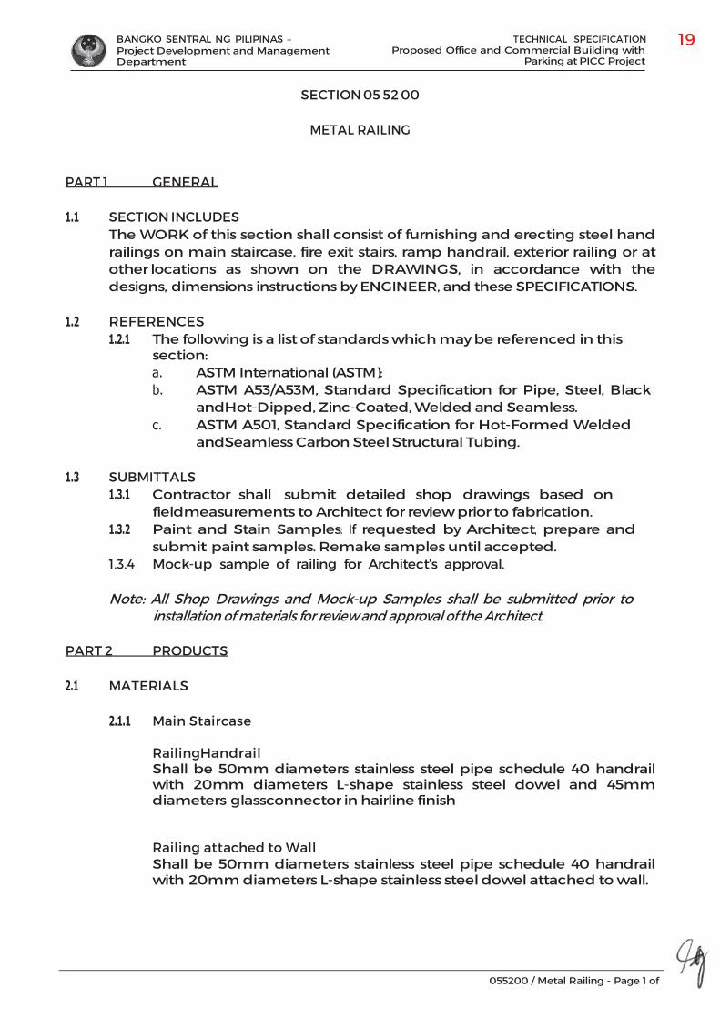
BANGKO SENTRAL NG PILIPINAS – Project Development and Management Department
TECHNICAL SPECIFICATION Proposed Office and Commercial Building with
Parking at PICC Project
055200 / Metal Railing - Page 1 of
SECTION 05 52 00
METAL RAILING
PART 1 GENERAL
1.1 SECTION INCLUDES The WORK of this section shall consist of furnishing and erecting steel hand railings on main staircase, fire exit stairs, ramp handrail, exterior railing or at other locations as shown on the DRAWINGS, in accordance with the designs, dimensions instructions by ENGINEER, and these SPECIFICATIONS.
1.2 REFERENCES 1.2.1 The following is a list of standards which may be referenced in this
section: a. ASTM International (ASTM):b. ASTM A53/A53M, Standard Specification for Pipe, Steel, Black
and Hot-Dipped, Zinc-Coated, Welded and Seamless.c. ASTM A501, Standard Specification for Hot-Formed Welded
and Seamless Carbon Steel Structural Tubing.
1.3 SUBMITTALS 1.3.1 Contractor shall submit detailed shop drawings based on
field measurements to Architect for review prior to fabrication. 1.3.2 Paint and Stain Samples: If requested by Architect, prepare and
submit paint samples. Remake samples until accepted. 1.3.4 Mock-up sample of railing for Architect’s approval.
Note: All Shop Drawings and Mock-up Samples shall be submitted prior to installation of materials for review and approval of the Architect.
PART 2 PRODUCTS
2.1 MATERIALS
2.1.1 Main Staircase
Railing Handrail Shall be 50mm diameters stainless steel pipe schedule 40 handrail with 20mm diameters L-shape stainless steel dowel and 45mm diameters glass connector in hairline finish
Railing attached to Wall Shall be 50mm diameters stainless steel pipe schedule 40 handrail with 20mm diameters L-shape stainless steel dowel attached to wall.

BANGKO SENTRAL NG PILIPINAS – Project Development and Management Department
TECHNICAL SPECIFICATION Proposed Office and Commercial Building with
Parking at PICC Project
055200 / Metal Railing - Page 2 of
Note: Submit shop drawings, mock-up layout and sample for Architect’s approval. Refer to Architectural drawings for layout and details.
2.1.2 Fire Exit Stair Railing and Ramp Railing @ Loading
Dock Handrail Shall be 50mm diameters B.I. pipe, schedule 40 handrail in coated with high performance water-based epoxy paint finish.
Vertical Balustrade Shall be 25mm diameters B.I. pipe, schedule 20 handrail connector with 50m diameters B.I. pipe, schedule 40 vertical support balustrades fully doweled to concrete stair slab, coated with high performance water-based epoxy paint finish
Horizontal Balustrade Shall be 25mm diameters B.I. pipe, schedule 20 horizontal support balustrade coated with high performance water-based epoxy paint finish
Railing attached to Wall Shall be 50mm diameters B.I. pipe, schedule 40 handrail with 20mm diameters B.I. pipe, schedule 20 L-shape connector attached to wall coated with high performance water-based epoxy paint finish.
Note: Submit shop drawings, mock-up layout and sample for Architect’s approval. Refer to Architectural drawings for layout and details.
2.1.3 Exterior Stair Railings
Shall be 50mm diameters, schedule 40 stainless steel handrail in hairline finish, with 50mm diameters, schedule 40, Y-shape stainless steel pipe in hairline finish vertical support balusters; Submit shop drawings and mock- up layout and sample for Architect’s approval Refer to Architectural drawings for layout and details.
2.1.4 Miscellaneous: The contractor shall fabricate plates or structural shapes
as indicated in the drawings. Include welded anchors where detailed and furnish all items to be embedded in concrete or masonry.
2.2 FABRICATION
2.2.1 General: Field measures the headwall, wingwall, or location where the
railing is to be installed, compare to the DRAWINGS, and review with Architect prior to fabrication.
2.2.2 Workmanship: Construct all items of sizes, shape, and materials as CONTRACTOR shall indicate and specify. Fabricate structural steel in accordance with ASTM specifications and additional requirements specified hereafter; perform fabrication and assembly in the shop to the greatest extent possible; form materials well, with sharp angles or lines, free from bends, twists, or open joints; shear and punch clean,

BANGKO SENTRAL NG PILIPINAS – Project Development and Management Department
TECHNICAL SPECIFICATION Proposed Office and Commercial Building with
Parking at PICC Project
055200 / Metal Railing - Page 3 of
true lines and surfaces; thickness of metal and details of assembly and supports shall provide ample strength and rigidity.
2.2.3 Welding: protect adjacent construction and materials against damage; neatly and symmetrically make all welds; fill or grind to a uniform, smooth shape; where required to present uniform appearance, fill space between welds and weld irregularities with suitable metal putty or compound made for this purpose.
2.2.4 Fastenings: CONTRACTOR shall provide concealed fastenings wherever possible; do not use screws or bolts where they can be avoided; where used, heads shall be countersunk, screwed up tight and threads nicked to prevent loosening; and make threaded connections tight so that threads shall be entirely concealed by fittings.
2.2.5 Paint (for B.I. Pipe Railings): All products not specified by name shall be “best grade” or “first line” products available by the manufacturer. Shop clean primer on hollow metal WORK immediately before painting to remove grease and dirt film from surfaces.
2.2.6 Stainless Steel Pipe Finish: stainless steel pipe shall be of schedule 40 and 20 as specified in the requirements and of grade 304 in hairline finish.
PART 3 EXECUTION
3.1 GENERAL 3.1.1 CONTRACTOR shall erect metal railings in accordance with the
specifications with modifications and additional requirements specified hereafter.
3.1.2 Erect all WORK true to lines and planes, with vertical lines plumb and horizontal lines level. Weld or bolt all permanent connections.
3.2 MISCELLANEOUS ANGLES, LINTELS AND EMBEDDED ITEMS
3.2.1 All welds shall develop capacity of members being joined, unless specific length or extent is noted on the DRAWINGS.
3.2.2 Finish all cut ends neatly without irregular torch marks or sharp fins. Grind all cut surfaces to a smooth surface. Clean of all loose mill scale, rust, and foreign matter.
3.2.3 Any shop paint on surfaces adjacent to joints to be field welded shall be wire brushed to reduce the paint film to a minimum. Grind down burrs and sharp ridges at all exposed corners and surfaces of welds prior to field painting. After field welding, welded joints to be field primed.
3.2.4 The expansion bolts shall be installed per manufacturer’s recommendations.
3.3 PAINTING
3.3.1 Inspection: Examine surfaces scheduled to receive paint and finishes for conditions that may adversely affect execution, permanence, or quality of WORK and which cannot be put into an acceptable condition through preparatory WORK as included under Paragraph Preparation.
BANGKO SENTRAL NG PILIPINAS – Project Development and Management Department
TECHNICAL SPECIFICATION Proposed Office and Commercial Building with
Parking at PICC Project
055200 / Metal Railing - Page 4 of
3.3.2 Preparation:
a. Sanding: Sand metal surfaces between coats to ensure smoothness and adhesion of subsequent coats. Use extra fine sandpaper to avoid cutting the edges when sanding. Apply putty or spackling compound after surfaces are primed and primer is dry. Bring material flush with adjoining surfaces.
b. Surface Filling: Surfaces shall be perfectly dry, clean, and smooth before starting WORK. Fill cracks, holes, or scratches full and make smooth before finish is applied to surfaces.
c. Ferrous Metal: Remove foreign material from unprimed metal with wire brush and dust clean.
d. Shop Primed Metals: Touch up shop-primed metals with a primer similar to the existing.
e. Zinc-Coated Metal (Galvanized Surfaces): Wash with mineral spirits and prime as specified.
f. Protection: Furnish and lay drop cloths or mask off areas where finishing is being done to protect floors and other work from damage during the execution of WORK. Where it becomes necessary to remove temporary coverings placed by others, replace same in proper manner.
g. Damage to Work of Others: Be responsible for any damage done to the work of other trades, repairing same to the satisfaction of ENGINEER. Replace any materials damaged to such an extent that they cannot be restored to their original condition.
3.3.3 Workmanship: a. Existing Surfaces: If the surfaces are not in proper shape for
painting, repair, rebuild, or refinish before proceeding with the WORK. CONTRACTOR is responsible for any poor WORK caused by improper surfaces. The application of the first coat does not relieve CONTRACTOR of the responsibility for failure of the base coat. Do not apply any coats on either damp or wet surfaces and in no case until the preceding coat is dry and hard.
b. General: Apply materials evenly without runs or sagging of materials and according to the manufacturer’s requirements. Sand WORK between coats.
3.4 TOUCH-UP PAINTING
CONTRACTOR shall, after erection of steel, apply touch-up paint to field bolt heads and nuts, field welds, and abrasions. When zinc coating has been scratched or removed from surfaces, three (3) coats of zinc rich paint shall be applied over the areas where the coating has been disturbed. Where excessive removal or damage the zinc coating has occurred, replacement of zinc coating by hot dipping in a zinc bath may be necessary at the direction of ARCHITECT.
END OF SECTION
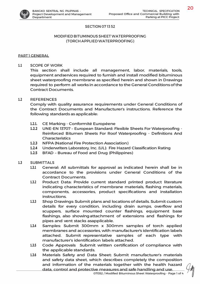
BANGKO SENTRAL NG PILIPINAS – Project Development and Management Department
TECHNICAL SPECIFICATION Proposed Office and Commercial Building with
Parking at PICC Project
071352 / Modified Bituminous Sheet Waterproofing - Page 1 of 4
SECTION 07 13 52
MODIFIED BITUMINOUS SHEET WATERPROOFING (TORCH APPLIED WATERPROOFING)
PART 1 GENERAL
1.1 SCOPE OF WORK This section shall include all management, labor, materials, tools, equipment and services required to furnish and install modified bituminous sheet waterproofing membrane as specified herein and shown in Drawings required to perform all works in accordance to the General Conditions of the Contract Documents.
1.2 REFERENCES Comply with quality assurance requirements under General Conditions of the Contract Documents and Manufacturer’s instructions. Reference the following standards as applicable:
1.2.1. CE Marking - Conformité Européene 1.2.2 UNE-EN 13707 – European Standard: Flexible Sheets For Waterproofing -
Reinforced Bitumen Sheets For Roof Waterproofing - Definitions And Characteristics
1.2.3 NFPA (National Fire Protection Association) 1.2.4 Underwriters Laboratory, Inc. (UL): Fire Hazard Classification Rating 1.2.5 BFAD – Bureau of Food and Drug (Philippines)
1.3 SUBMITTALS 1.3.1 General: All submittals for approval as indicated herein shall be in
accordance to the provisions under General Conditions of the Contract Documents.
1.3.2 Product Data: Provide current standard printed product literature indicating characteristics of membrane materials, flashing materials, components, accessories, product specifications and installation instructions.
1.3.3 Shop Drawings: Submit plans and locations of details. Submit custom details for every condition, including drain sumps, overflow and scuppers, surface mounted counter flashings, equipment base flashings, also showing attachment of extensions and flashings for pipes and vent stacks as applicable.
1.3.4 Samples: Submit 300mm x 300mm samples of torch applied membranes and accessories, with manufacturer's identification labels attached. Submit representative samples of each type with manufacturer’s identification labels attached.
1.3.5 Code Approvals: Submit written certification of compliance with the applicable standards.
1.3.6 Materials Safety and Data Sheet: Submit manufacturer’s materials and safety data sheet, which describes completely the composition and information of the materials together with the health hazard data, control and protective measures and safe handling and use.
BANGKO SENTRAL NG PILIPINAS – Project Development and Management Department
TECHNICAL SPECIFICATION Proposed Office and Commercial Building with
Parking at PICC Project
071352 / Modified Bituminous Sheet Waterproofing - Page 2 of 4
1.3.7 Application Manual: Submit manufacturer's application manual, which describes completely the preparation of surfaces and application of specified materials, including details to suit all conditions.
1.3.8 Test Reports: Submit product test results showing compliance to performance requirements and standards.
1.4 QUALITY ASSURANCE
1.4.1 Comply with quality assurance requirements under General Conditions of the Contract Documents and Manufacturer’s instructions.
1.4.2 Manufacturer’s Qualifications: Provide primary products, including each type of roofing sheet, bitumen, flashings, vapor retarder if any, and cap sheet produced by a single manufacturer.
1.4.3 Installer’s Qualifications: Installer from the same manufacturer shall perform the work of this Section; and shall be a firm with not less than 3 years of successful experience in the installation of roofing systems specified in this section.
1.4.4 Provide the Owner with written certification from the manufacturer of the roofing system certifying that the installer is approved by the manufacturer for installation of the specified waterproofing system. Provide a copy of the certification to the Owner prior to award of the contract.
1.5 DELIVERY, STORAGE AND HANDLING
1.5.1 Comply with product delivery requirements under General Conditions of the Contract Documents and Manufacturer’s instructions.
1.5.2 Manufactured materials shall be delivered in the original packages and containers bearing the name and brand of the manufacturer. Damaged or deteriorated materials shall be removed from the premises.
1.6 WARRANTY
Special written warranty for each material specified herein bearing a minimum of five (5) years warranty shall be submitted by Manufacturer/Contractor without reducing or otherwise limiting any other rights to correction which the Owner may have under the Contract Documents. Failures are defined to include faulty workmanship or faulty materials.
1.7 PROJECT CONDITIONS
1.7.1 Comply with field examination requirements under General Conditions of the Contract Documents and Manufacturer’s instructions.
1.7.2 Weather Condition Limitations: Proceed with roofing work only when existing and forecasted weather conditions will permit work to be performed in accordance with the manufacturer’s recommendations and warranty requirements.
1.7.3 Suspend all application and installation activities during inclement weather. Proceed with roofing work only when weather conditions
BANGKO SENTRAL NG PILIPINAS – Project Development and Management Department
TECHNICAL SPECIFICATION Proposed Office and Commercial Building with
Parking at PICC Project
071352 / Modified Bituminous Sheet Waterproofing - Page 3 of 4
comply with manufacturer’s recommendations. Do not exceedtemperature limitations recommended by the manufacturer.
1.8 PERFORMANCE REQUIREMENTS
Product shall provide for the following minimum performance requirements in compliance to standard tests as shown. Manufacturer may provide for equivalent data based on other standard tests that applies:
For Torch Applied Waterpoofing Membranes: European Standard UNE-EN 13707 - Flexible Sheets For Waterproofing - Reinforced Bitumen Sheets For Roof Waterproofing - Definitions And Characteristics
PART 2 PRODUCTS
2.1 Torch Applied Waterproofing System Shall be a quality torch applied membrane composed of a reinforced polyester felt reinforcement covered on both sides with polymer modified bitumen mastic with mineral protection in light grey color used as a protective.
Areas as designated in Drawings shall be a quality torch applied membrane composed of a reinforced polyester felt reinforcement covered on both sides with polymer modified bitumen mastic with mineral protection in light grey color used as a protective material by “ ”, “ ” or approved equal, water proofing membrane shall have a minimum thickness of 3mm thick for toilets waterproofing and 4mm thick for ACCU deck and roof deck for application. Submit product catalog and shop drawings for Architect’s approval. Follow manufacturer’s standard application procedures.
2.1.1 Recommended Equipment, unless otherwise required by Manufacturer:
A. LP Gas Filled Tank with Regulator and Gauge B. Roofing Torch properly connected to pressure gauge of LPG Tank C. Sharp Cutter or Knife D. Trowel or Spatula with a rounded end to avoid unintentional puncturing of the membrane E. Broom to clean and brush off dust and dirt F. Gloves G. Fire Extinguisher
PART 3 EXECUTION
3.1 Comply with Manufacturer’s Instruction and standard installation procedures. 3.2 Torch Applied Waterproofing System Work Methodology
3.2.1 Area Inspection All areas to be treated with torch applied waterproofing membrane shall be inspected jointly by client and manufacturer’s representative. All deficiencies such as mortar droppings, debris, construction materials, scaffoldings or the like shall be closely coordinated and must be attended immediately by the client to ensure smooth workflow.

BANGKO SENTRAL NG PILIPINAS – Project Development and Management Department
TECHNICAL SPECIFICATION Proposed Office and Commercial Building with
Parking at PICC Project
071352 / Modified Bituminous Sheet Waterproofing - Page 4 of 4
3.2.2 Surface PreparationA. After locating all possible cracks, rout-out all visible cracks.
Minor cracks shall be treated by plugging, using plug and cement, while major cracks with excessive seepages such as construction joints shall be v-cutted up to a depth of a min. of 1” and shall be treated with bituminous sealant and will be restored by a membrane strip.
B. All termination of floor and wall on its entire perimeter shall also be rout-out and be treated with mortar with re-bond. Angle filet must be at least 45 degrees on its surface.
C. All pipe stub-outs shall be treated with bituminous sealant and/or epoxy grout.
D. Clean surface before application. 3.2.3 Application of Primer
A. Application of primer can be done using a roller brush. Apply evenly on surface (one coat only) including the flashing area. Coverage of application per pail will be 40-50 sm.
3.2.4 Installation of Membrane Waterproofing
A. Install all horizontal membranes first, starting with the drains. Always check alignment of membranes before installing it permanently.
B. After all horizontal membranes are installed; proceed with the installation of the flashing or upstand. Standard measurement of upstand will be 0.30m vertical and 0.30m horizontal. Always cut and installed upstand, crosswise and not lengthwise.
C. Always implement a 90 degree cut/lapping joints for all upstand corners.
3.2.5 Quality Inspection
A. Perform a quality inspection first before proceeding with the flood test to ensure all lappings and joints are perfectly torched.
3.2.6 Flood Test
A. When performing flood test, all stub-outs or drains shall be blocked with a piece of PVC pipe or membrane scrap which will serve as over- flow.
B. Area shall be flood tested again on a maximum of 24 hrs. After which the water will be remove and consequently hand-over the project to the owner/contractor for their final acceptance.
END OF SECTION
BANGKO SENTRAL NG PILIPINAS – Project Development and Management Department
TECHNICAL SPECIFICATION Proposed Office and Commercial Building with
Parking at PICC Project
071613 / Polymer Modified Cement Waterproofing - Page 1 of 3
SECTION 07 16 13
POLYMER MODIFIED CEMENT WATERPROOFING (ACRYLIC POLYMER WATERPROOFING)
PART 1 GENERAL
1.1 SCOPE OF WORK This section shall include all management, labor, materials, tools, equipment and services required to furnish and install acrylic polymer waterproofing as specified herein and shown in Drawings required to perform all works in accordance to the General Conditions of the Contract Documents.
1.2 REFERENCES Comply with quality assurance requirements under General Conditions of the Contract Documents and Manufacturer’s instructions.
1.3 SUBMITTALS 1.3.1 General: All submittals for approval as indicated herein shall be in
accordance to the provisions under General Conditions of the Contract Documents.
1.3.2 Submit manufacturer's certification that proposed materials, details and systems as indicated and specified fully comply with manufacturer's details and specifications. If any portions of Contract Documents do not conform to manufacturer's standard recommendations, submit notification of portions of design that are at variance with manufacturer's specifications.
1.3.3 Product Data: Submit manufacturer's descriptive literature and product specifications for each product including laboratory tests.
1.3.4 Submit product sample with sample swatches for Architect’s approval, before purchasing of materials.
1.4 QUALITY ASSURANCE 1.4.1 Comply with quality assurance requirements under General
Conditions of the Contract Documents and Manufacturer’s instructions.
1.5 DELIVERY, STORAGE AND HANDLING 1.5.1 Comply with product delivery requirements under General
Conditions of the Contract Documents and Manufacturer’s instructions.
1.5.2 Delivery: Materials shall be delivered in original sealed containers, clearly marked with brand name and type of materials.

BANGKO SENTRAL NG PILIPINAS – Project Development and Management Department
TECHNICAL SPECIFICATION Proposed Office and Commercial Building with
Parking at PICC Project
071613 / Polymer Modified Cement Waterproofing - Page 2 of 3
1.5.3 Storage: Materials shall be stored at 29.44 degrees Celsius (85 degrees Fahrenheit) with normal handling to prevent damage to container. Do not store for long periods in direct sunlight.
1.6 WARRANTY Special written warranty for each material specified herein bearing a minimum of five (5) years warranty shall be submitted by Manufacturer/Contractor without reducing or otherwise limiting any other rights to correction which the Owner may have under the Contract Documents. Failures are defined to include faulty workmanship or faulty materials.
1.7 PROJECT CONDITIONS
1.7.1 Comply with field examination requirements under General Conditions of the Contract Documents and Manufacturer’s instructions.
1.7.2 Coordinate waterproofing/lining work with work of other trades. Provide materials and accessories in timely manner so as not to delay the Work.
PART 2 PRODUCTS
2.1 Acrylic Polymer Waterproofing
Shall be a specially formulated acrylic polymer designed for compounding with pozzolan or portland cement. Excellent adhesion, water resistance and flexible on thin sections application that eliminates cement plastering defect and water seepage. Submit brochures and sample for Architect’s approval.
PART 3 EXECUTION
3.1 Comply with Manufacturer’s Instruction and standard installation procedures.
3.2 Surface Preparation
All surfaces should be applied on bare concrete, wood, or metal NOT PREVIOUSLY PAINTED. Existing paint should be totally scraped off. New masonry should be allowed to cure at least 14 to 28 days. Surface should be clean, free from oil, grease, dirt, any loose grit or mortar; Wet masonry surfaces first with water before applying the acrylic polymer waterproofing mix to avoid abrupt drying and cracking of the applied modified cement, especially under hot and sunny conditions.
3.3 Verify that the concrete work done under other sections meets the
following requirements: 3.3.1 Concrete surfaces like parapet, roof deck, etc. are free of ridges or
sharp projections. 3.3.2 Concrete must be cured for a minimum of fourteen (14) days or as
specified in Structural Drawings. 3.3.3 All concrete or masonry surfaces shall be cured for a minimum of
seven (7) days or as specified in Structural Drawings. It shall be wood-trowelled smooth, firm, dry, clean and free from rubbish, loose or foreign materials and obstructions.
BANGKO SENTRAL NG PILIPINAS – Project Development and Management Department
TECHNICAL SPECIFICATION Proposed Office and Commercial Building with
Parking at PICC Project
071613 / Polymer Modified Cement Waterproofing - Page 3 of 3
3.3.3 Concrete shall be finished by a power or hand steel trowel followed bysoft hair broom to obtain light texture finish.
3.4 Application Method of application shall be as per manufacturer’s specifications toattain the thickness specified herein. 3.4.1 Acrylic-Polymer Cementitious Waterproofing System
For vertical surfaces: a. Apply 3 coats of the acrylic polymer mixture by brush
while maintaining coverage rate at 5 -6 sq. meters per gallon.
For horizontal surfaces: a. Apply 5 coats by brush. b. Reinforce joints, corners, and active cracks susceptible to
cracking or movement with a strip of fiberglass matting. c. Put on the matting immediately after the second coat,
while the mixture is still wet. The matting should adhere to the mixture.
d. Make sure the acrylic polymer, mix and the matting is completely dry before applying succeeding coats.
e. The matting should be completely covered by the mixture. f. Let dry for one day then apply a bond coat by brushing waterproofing straight from the can prior to laying out mortar topping.
3.5 Field Quality Control
3.5.1 Flood testing: A. Waterproofed areas shall be given a twenty four (24) hours flood
test upon completion of the waterproofing. Allow system to cure forty eight (48) hours prior to flood test, or until dry enough to support foot traffic and test.
B. Plug drains and places barrier to contain the water. C. Repair any leaks that may occur.
3.6 Cleaning. All debris resulting from completion of work shall be removed
from the project site.
END OF SECTION
BANGKO SENTRAL NG PILIPINAS – Project Development and Management Department
TECHNICAL SPECIFICATION Proposed Office and Commercial Building with
Parking at PICC Project
071616 / Crystalline Waterproofing - Page 1 of 5
SECTION 07 16 16
CRYSTALLINE WATERPROOFING (CEMENTITIOUS WATERPROOFING BY CRYSTALLIZATION)
PART 1 GENERAL
1.1 SCOPE OF WORK This section shall include all management, labor, materials, tools, equipment and services required to furnish and install cementitious waterproofing by crystallization and epoxy tank lining as specified herein and shown in Drawings required to perform all works in accordance to the General Conditions of the Contract Documents.
1.2 REFERENCES Comply with quality assurance requirements under General Conditions of the Contract Documents and Manufacturer’s instructions. Reference the following standards as applicable: 1.2.1 ASTM C581 – Chemical Resistance of Thermosetting Resins 1.2.2 ASTM C348 – Flexural Strength 1.2.3 ASTM C190 – Elongation and Tensile Strength 1.2.4 ASTM C882 – Slant Shear Bond Stength 1.2.5 ASTM C39/C78 – Compressive Strength 1.2.6 BFAD – Bureau of Food and Drug (Philippines)
1.3 SUBMITTALS 1.3.1 General: All submittals for approval as indicated herein shall be in
accordance to the provisions under General Conditions of the Contract Documents.
1.3.2 Submit manufacturer's certification that proposed materials, details and systems as indicated and specified fully comply with manufacturer's details and specifications. If any portions of Contract Documents do not conform to manufacturer's standard recommendations, submit notification of portions of design that are at variance with manufacturer's specifications.
1.3.3 Product Data: Submit manufacturer's descriptive literature and product specifications for each product including laboratory tests.
1.4 QUALITY ASSURANCE 1.4.1 Comply with quality assurance requirements under General Conditions of
the Contract Documents and Manufacturer’s instructions. 1.4.2 Manufacturer Qualifications:
Company specializing in manufacturing Products specified in this Section with minimum 10 years documented experience.
1.4.3 Installer Qualifications: Acceptable to manufacturer with documented experience on at least 10 projects of similar nature in past 10 years and/or training provided by the product manufacturer.
BANGKO SENTRAL NG PILIPINAS – Project Development and Management Department
TECHNICAL SPECIFICATION Proposed Office and Commercial Building with
Parking at PICC Project
071616 / Crystalline Waterproofing - Page 2 of 5
1.5 DELIVERY, STORAGE AND HANDLING 1.5.1 Comply with product delivery requirements under General Conditions of
the Contract Documents and Manufacturer’s instructions. 1.5.2 Delivery: Materials shall be delivered in original sealed containers, clearly
marked with brand name and type of materials. 1.5.3 Storage: Materials shall be stored at 29.44 degrees Celsius (85 degrees
Fahrenheit) with normal handling to prevent damage to container. Do not store for long periods in direct sunlight.
1.6 WARRANTY Special written warranty for each material specified herein shall be submitted by
Manufacturer/Contractor without reducing or otherwise limiting any other rights to correction which the Owner may have under the Contract Documents. Failures are defined to include faulty workmanship or faulty materials.
1.7 PROJECT CONDITIONS
1.7.1 Comply with field examination requirements under General Conditions of the Contract Documents and Manufacturer’s instructions.
1.7.2 Coordinate waterproofing/lining work with work of other trades. Provide materials and accessories in timely manner so as not to delay the Work.
PART 2 PRODUCTS 2.1 Cementitious Capillary Crystallization Waterproofing System – for Lower Ground
Floor Waterproofing and Toilets Waterproofing from Upper Ground Floor to Second Floor)
Shall be a cementitious capillary crystallization waterproofing material, consisting of cement, quartz sand and active chemicals that reacts with free lime and moisture present in concrete producing crystals that fills cracks, voids, capillary tracks within the concrete resulting in prevention of water leaks while allowing substrate to breathe; shall be non-toxic, safe to be applied on surfaces in contact with drinking water and foodstuffs, BFAD approved. Submit product catalog and shop drawings for Architect’s approval. Follow manufacturer’s standard application procedures.
2.2 Epoxy Tank Lining for Cistern Tanks Tank lining shall be an epoxy lining material, solvent free, pigmented, two
component preparation of liquid colored epoxy resin with formulated anime hardener. Safe for use on areas in direct contact with potable water or foodstuffs; lead free, food grade when fully cured, non-toxic and BFAD approved. Submit product catalog and shop drawings for Architect’s approval. Follow manufacturer’s standard application procedures.
PART 3 EXECUTION
3.1 Comply with Manufacturer’s Instruction and standard installation procedures.
BANGKO SENTRAL NG PILIPINAS – Project Development and Management Department
TECHNICAL SPECIFICATION Proposed Office and Commercial Building with
Parking at PICC Project
071616 / Crystalline Waterproofing - Page 3 of 5
3.2 Cementitious Waterproofing by Crystallization 3.2.1 Area Inspection All areas to be treated with cementitious waterproofing by crystallization
shall be inspected jointly by client and manufacturer’s representative. All deficiencies such as mortar droppings, debris, construction materials, scaffoldings or the like shall be closely coordinated and must be attended immediately by the client to ensure smooth workflow.
3.2.2 Surface Preparation
A. Remove all forms of scale, oil/form release agents, laitance and any foreign material which will impair the bonding, penetration and performance of the cementitious waterproofing by crystallization system.
B. Perform first a water test or ponding test to qualify and assess the area from possible cracks and/or other construction deficiencies. (applicable to all interior areas, roof decks; not applicable on water tanks)
C. After locating all possible cracks, rout-out all visible cracks. Minor cracks shall be treated by plugging, using plug and cement, while major cracks such as construction joints shall be v-cutted up to a depth of a min. of 1” and shall be treated with polyurethane sealant and to be covered by mortar with rebond (bonding agent).
D. For honeycomb, chipped –off loose concrete up to sound concrete. clean area first prior to epoxy mortar bonding.
E. All termination of floor and wall on its entire perimeter shall also be rout-out and be treated with mortar with rebond.
F. All pipe stub0outs shall be treated with sealant and/or epoxy grout. G. Clean surface before application.
3.2.3 Application A. Using power-sprayer or manually, sprinkle the area first with water to
ensure moisture is present in the concrete to attain maximum chemical penetration.
B. Mixed the cementitious by crystallization waterproofing with water on a proportion of 2:1. Mixing volume should be done proportionate to the number of worker that will do the application. Do not mixed large volume of waterproofing if you can’t have it applied before it meets its initial setting for quality assurance.
C. First coat must be applied on one direction only. The second coat will then be succeeded after 24 hours, and to be applied perpendicular to the first coat.
D. Coverage area per bag of waterproofing is at 25.0 square-meter.
3.2.4 Curing A. Using fine water spray or manually, perform its curing for a period of
2-3 days.
BANGKO SENTRAL NG PILIPINAS – Project Development and Management Department
TECHNICAL SPECIFICATION Proposed Office and Commercial Building with
Parking at PICC Project
071616 / Crystalline Waterproofing - Page 4 of 5
B. For exposed areas such as roof decks, we recommend to perform its curing at least 3 times a day for 2-3 days due to extreme temperature on exposed areas.
3.2.5 Food Testing
A. After curing, waterproofed areas shall be subjected to water test or flood test for 24 hours, before final turnover to client.
B. For water tanks, flood testing shall be optional. Testing will be done by provision of water (to the account of the client) in the tank up to the actual level when the tank will be on commission or they can opt not to flood test it anymore and exercise the given warranty if problem arises.
3.3 Tank Lining Work Methodology 3.3.1 Cleaning and Clearing
A. Area must be cleaned and cleared from any obstruction to qualify the surface subject for application of epoxy coating.
3.3.2 Surface Preparation
A. Removed all excess concrete and other foreign material that will impair the bonding of the epoxy coating.
B. Use a damp sponge mop to remove and extract the dust prior to the application of the base coat.
3.3.3 Moisture Test A. Always perform a random moisture test before proceeding with any
application of epoxy coating. Using a piece of polyurethane sheet an masking tapes, simply patched the plastic on various part of the eare for 24 hours. If moisture appears, it only indicates that the area is not yet ready to accept epoxy coating works. Repeat this procedure until such time the area is already dry and free from moist.
3.3.4 Application of Base Coat
A. When mixing, make sure that all contents of the 2 components are poured in a mixing container. Mixed vigorously the 2 components using a mixing drill or a paddle for at least 2 minutes.
B. Using a paint roller, apply the base coat on a single stroke. Coverage for base coat per gal-set is at 8-10 sm.
C. Interval of coating must not exceed 24 hours to ensure adhesion of the 2 coats.
3.3.5 Application of Top Coat
A. Using the same mixing procedure and standard time interval of application, apply the top coat with coverage of 608 sm/gal-set to attain its desired film or thickness.
B. The surface of the fully cured epoxy coating can be maintained or cleaned by steam jet or mop.
END OF SECTION

BANGKO SENTRAL NG PILIPINAS – Project Development and Management Department
TECHNICAL SPECIFICATION Proposed Office and Commercial Building with
Parking at PICC Project
071616 / Crystalline Waterproofing - Page 5 of 5
BANGKO SENTRAL NG PILIPINAS – Project Development and Management Department
TECHNICAL SPECIFICATION Proposed Office and Commercial Building with
Parking at PICC Project
072100 / Thermal Insulation - Page 1 of 3
SECTION 07 21 00
THERMAL INSULATION
PART 1 GENERAL
1.1 SCOPE OF WORK This section shall include all management, labor, materials, tools, equipment and services required to furnish thermal insulations as specified herein and shown in Drawings required to perform all works in accordance to the General Conditions of the Contract Documents.
1.2 REFERENCES Comply with quality assurance requirements under General Conditions of the Contract Documents and Manufacturer’s instructions. Reference the following standards as applicable: 1.2.1 ASTM C 553 – Mineral Fiber Blanket Thermal Insulation 1.2.2 ASTM E 84 – Surface Burning Characteristics 1.2.3 UL 723 - Test for Surface Burning Characteristics of Building Materials
1.3 SUBMITTALS 1.3.1 General: All submittals for approval as indicated herein shall be in
accordance to the provision under General Conditions of the Contract Documents.
1.3.2 Submit sample of insulation materials for Architect’s approval before purchasing and installation.
1.4 QUALITY ASSURANCE 1.4.1 Comply with quality assurance requirements under General Conditions of
the Contract Documents and Manufacturer’s instructions. 1.4.2 Manufacturer’s Supervision:
A. Obtain manufacturer’s or manufacturer’s representative’s supervision for the following:
B. Provide initial instruction at the start of the Work, to insure that any physical condition which would result in defective Work is properly corrected before the materials are applied. Coordinate works with other trades prior installation.
C. Instruct personnel doing this Work. D. Verify that proper procedures are being followed.
1.5 DELIVERY, STORAGE AND HANDLING 1.5.1 Comply with product delivery requirements under General Conditions of
the Contract Documents and Manufacturer’s instructions. 1.5.2 Deliver materials to the project or place of application in original unopened
containers bearing manufacturer’s name and product designation. Material showing evidence of damage shall be rejected.
1.5.3 Storage of materials shall be so as to prevent inclusion of foreign matter or damage of materials by water or breakage. Procure and store in original
BANGKO SENTRAL NG PILIPINAS – Project Development and Management Department
TECHNICAL SPECIFICATION Proposed Office and Commercial Building with
Parking at PICC Project
072100 / Thermal Insulation - Page 2 of 3
containers until ready to use. Do not subject to temperatures exceeding 32ºC (90ºF).
1.5.4 Do not use materials upon which the shelf life date has expired. Remove these materials promptly from the Project Site. All materials shall be carefully handled and stored to prevent inclusion of foreign materials, or subjected to temperatures exceeding 90ºF. Color of caulking compound shall be gray or aluminum.
1.6 WARRANTY Special written warranty for each material specified herein shall be submitted by
Manufacturer/Contractor without reducing or otherwise limiting any other rights to correction which the Owner may have under the Contract Documents. Failures are defined to include faulty workmanship or faulty materials.
1.7 PROJECT CONDITIONS Comply with field examination requirements under General Conditions of the
Contract Documents and Manufacturer’s instructions. Follow installation limitations of product regarding temperature and atmospheric conditions prior application.
PART 2 PRODUCTS
2.1 MATERIALS
2.1.1 Mineral Rockwool Insulation – (for Pump Room/AHU Room and Dry Wall Partition) Shall be 50mm thick 50 kg. /m³ rock wool blanket insulation. Follow manufacturer’s standard installation procedures. Submit sample for Architect’s approval.
2.1.2 Elastomeric Insulation – (for Pipes) Shall be 25mm nominal thickness x 2000mm length, tube type, black color,
Elastomeric Insulation with high flexibility, high resistance to water vapour transmission and noise reduction, complete with adhesive and accessories. Submit brochures and sample for Architect’s approval.
PART 3 EXECUTION
3.1 Examination 3.1.1 Examine the areas and conditions under which work of this section will be
installed and verify that adjacent materials are dry and ready to receive insulation.
3.1.2 Do not begin installation until substrates have been properly prepared. 3.1.3 If substrate preparation is the responsibility of another installer, notify
Architect of unsatisfactory preparation before proceeding. 3.2 Preparation 3.2.1 Clean surfaces thoroughly prior to installation.
3.2.2 Prepare surfaces using the methods recommended by the manufacturer for achieving the best result for the substrate under the project conditions.
BANGKO SENTRAL NG PILIPINAS – Project Development and Management Department
TECHNICAL SPECIFICATION Proposed Office and Commercial Building with
Parking at PICC Project
072100 / Thermal Insulation - Page 3 of 3
3.3 Installation 3.3.1 Install in accordance with manufacturer's Installation Instructions for roof
and walls. Do not use insulation which is or has been wet. 3.3.2 Maintain thermal performance by tightly abutting adjacent insulation.
Maintain vapor retarder integrity by adhering to the rafters and eave struts in accordance with manufacturer's installation instructions.
3.3.3 Roof Installation: Place insulation with enough drape over the purlins or girts to allow it to recover to its full thickness in the central zone of the purlin or girt space. Do not stretch insulation tightly across the purlins, as this is likely to prevent the material from recovering to its maximum possible thickness and from achieving its maximum possible in-place thermal value.
3.3.4 Wall Installation: Do not stretch the insulation tightly from base angle to eave strut prior to applying the wall panel, as this is likely to prevent the material from recovering to its maximum possible thickness and from achieving its maximum possible in-place thermal value.
3.3.5 Repair punctures or tears in vapor retarder facing by taping or using pieces of the fabric with adhesive. Install in accordance with manufacturer's instructions.
3.4 Protection 3.4.1 Protect installed products until completion of project. 3.4.2 Touch-up, repair or replace damaged products before Substantial
Completion.
END OF SECTION
BANGKO SENTRAL NG PILIPINAS – Project Development and Management Department
TECHNICAL SPECIFICATION Proposed Office and Commercial Building with
Parking at PICC Project
078129 / Mineral Fiber Cement Board - Page 1 of 4
SECTION 07 81 29
MINERAL FIBER CEMENT BOARD
PART 1 GENERAL
1.1 SCOPE OF WORK This section shall include all management, labor, materials, tools, equipment and services required to furnish and install fiber cement board as specified herein and shown in Drawings required to perform all works in accordance to the General conditions of the Contract documents.
1.2 REFERENCES Comply with quality assurance requirements under General Conditions of the Contract Documents and Manufacturer’s instructions. Reference the following standards as applicable: 1.2.1 ASTM C1185-08 Standard Test Methods for sampling and Testing Non-
Asbestos Fiber-Cement Flat Sheet, Roofing and Siding Shingles, and Clapboards.
1.2.2 ASTM C1186-08 - Standard Specifications for Flat fiber Cement Sheets. 1.2.3 AS/NZS 2908.2 – Cellulose Cement Products Fiber Cement Flat Sheets. 1.2.4 ASTM E 84 – Standard Test Method for Surface Burning Characteristics of
Building Materials. 1.2.5 AS 1530 – Methods for Fire Tests on building Materials, Components and
Structures.
1.3 SUBMITTALS 1.3.1 General: All submittals for approval as indicated herein shall be in
accordance to the provisions under General Conditions of the Contract Documents.
1.3.2 Manufacturer’s data sheets: sample and shop drawings on each product to be used, including: A. Preparation instructions and recommendations. B. Storage and handling requirements and recommendations C. Installation methods, including layout and fastening patterns.
1.3.3 Manufacturer’s Certificates and standard test reports: Certify materials and accessory component products meet or exceed specified requirements.
1.4 QUALITY ASSURANCE 1.4.1 Comply with quality assurance requirements under General Conditions of
the Contract Documents and Manufacturer’s instructions. 1.4.2 Manufacturer Qualifications: Company specializing in manufacturing
Products specified in this section with minimum 10 years documented experience.
1.4.3 Installer Qualifications: Acceptable to manufacturer with documented experience on at least 5 projects of similar nature in past 2 years and/or training provided by the product manufacturer.
BANGKO SENTRAL NG PILIPINAS – Project Development and Management Department
TECHNICAL SPECIFICATION Proposed Office and Commercial Building with
Parking at PICC Project
078129 / Mineral Fiber Cement Board - Page 2 of 4
1.5 DELIVERY, STORAGE AND HANDLING 1.5.1 Comply with product delivery, handling and storage requirements under
General Conditions of the Contract Documents and manufacturer’s instructions.
1.5.2 Do not deliver cement panels to site until job is ready for their installation. 1.5.3 Store products in manufacturer’s unopened packaging until ready for
installation. Materials should be off the ground, flat and under cover in a dry place until erection. Store indoors, in a place easily accessible for inspection of the materials prior to installation.
1.6 WARRANTY
Special written warranty for each material specified herein shall be submitted by Manufacturer/Contractor without reducing or otherwise limiting any other rights to correction which the Owner may have under the Contract Documents. Include preliminary material and finish warranties. Failures are defined to include faulty workmanship or faulty materials.
1.7 PROJECT CONDITIONS 1.7.1 Comply with field examination requirements under General Conditions of
the Contract Documents and Manufacturer’s instructions. 1.7.2 Field measurements should be taken by the installer for verification of
dimensional correctness in relationship to original plans. 1.7.3 Maintain environmental conditions (temperature, humidity, and ventilation)
within limits recommended by manufacturer for optimum results. Do not install products under environmental conditions outside manufacturer’s absolute limits.
PART 2 PRODUCTS
2.1 Mineral Fiber Cement Board – (for Pump Room and AHU Room with Heat and Sound Insulation)
Shall be 10mm thick asbestos-free, smooth surface, square edge, fiber cement wall board, resistant to fire, sag, moisture and termite, coated with plain semi-gloss acrylic solvent-based coating, that forms a seamless, non-porous water tight film that repels water and prevent seepage. Excellent adhesion and has long term durability, creates a very tight film, serving moisture sealant for concrete; with the following performance requirements: A. Asbestos (chrysotile fibers) free, (ASTM C1185) B. Resistant to water and decay (AS/NZS 2908.2, ASTM 1185 requirements). C. Resistant to fire (AS 1530, ASTM E 84) D. Resistant to termite
2.2 Framing System for Pump Room/AHU Room Wall with Heat Insulation Framing shall be BPS (Bureau of Product Standards) certified, 0.60mm thick gauge 24 x 35mm x 76mm galvanized light steel top and bottom tracks and 0.60mm gauge 24 x 35mm x 76mm vertical and horizontal studs spaced at 600mm bothways, complete with screws, accessories and 0.40mm GA. 26 x 25mm x 25mm corner bid.

BANGKO SENTRAL NG PILIPINAS – Project Development and Management Department
TECHNICAL SPECIFICATION Proposed Office and Commercial Building with
Parking at PICC Project
078129 / Mineral Fiber Cement Board - Page 3 of 4
2.3 Heat Insulation Shall be 50mm thick 50 kg. /m³ rock wool blanket insulation. Follow
manufacturer’s standard installation procedures. Submit sample for Architect’s approval.
2.4 Fasteners shall be galvanized fiber cement nails and screws as per Manufacturer’s
recommendation, driven flush to board panel, as close as possible to the stud corners to avoid deflection of the stud flange.
2.5 Provide high performance joint compound, sealant and other accessories as per
Manufacturer’s standard installation requirements and Architect’s approval.
2.6 Paint finish – see Division 9 for Paints and Coatings.
PART 3 EXECUTION
3.1 Comply with manufacturer’s installation procedures and applicable codes and standards.
3.2 Coordinate adjacent works involved prior installation of fiber cement board to
prevent delay in construction. Notify the Architect for deficient works that may affect quality of work.
3.3 Ensure frame is square and work from central datum line. Frames must be straight
and true to provide flush to receive the panels. Suggested maximum tolerance shall be between 3 and 4mm in any 3 meter length of frame or as per Manufacturer’s instructions to achieve even surface for board installation.
3.4 Refer to recommended safe working practices before starting any cutting or machining of panels. Use score and snap, fiber shear or standard duct reducing safety tools as per manufacturer’s instruction. Position cutting station in a well-ventilated area and wear protective cover (N95 mask) in conjunction to cutting and sanding practices.
3.5 Install cement boards either parallel or perpendicular to framing as indicated in
approved shop drawings. Spacing of framing members for ceiling applications shall be 400mm maximum on centers or as per manufacturer’s instructions in consideration of high wind loads.
3.6 Holding the board firmly against the framing, begin fastening in the center of the
sheet and moved outward toward ends and edges. Set fasteners heads flush from the surface without breaking the face paper or damaging the gypsum core. Cut openings out of full sheets or lay out joints to fall on the studs.
3.7 Provide joint and fasteners concealment as per manufacturer’s approved material
and installation for embedding compounds for first and secondary coats; and finishing compound for final coat. Spot cover fastener heard with three coats of joint compound applied in different directions until even surface is achieved. The distance between control joints shall not be greater than 15 meters.

BANGKO SENTRAL NG PILIPINAS – Project Development and Management Department
TECHNICAL SPECIFICATION Proposed Office and Commercial Building with
Parking at PICC Project
078129 / Mineral Fiber Cement Board - Page 4 of 4
3.8 Apply finishing paint as per Section 099000 requirements and in accordance to Manufacturer’s instructions.
3.9 Ensure all dirt, dust fingerprints and all foreign marks are immediately removed from the face of the material to avoid from permanent damage. Replace damaged products before substantial completion. Protect installed products until completion of project.
END OF SECTION
BANGKO SENTRAL NG PILIPINAS – Project Development and Management Department
TECHNICAL SPECIFICATION Proposed Office and Commercial Building with
Parking at PICC Project
079200 / Joint Sealant - Page 1 of 5
SECTION 07 92 00
JOINT SEALANT
PART 1 GENERAL
1.1 SCOPE OF WORK 1.1.1 This section shall include all management, labor, materials, tools,
equipment and services required to furnish and install joint sealant as specified herein and shown in Drawings required to perform all works in accordance to the General Conditions of the Contract Documents.
1.1.2 Sealing shall be provided on all open joints exposed to the weather, as indicated or specified, and in all areas normally requiring sealing with caulking or sealant material to provide watertight and weather-tight construction.
1.2 REFERENCES Comply with quality assurance requirements under General Conditions of the Contract Documents and Manufacturer’s instructions. Reference the following standards as applicable: 1.2.1 ASTM C 834-Standard Specification for Latex Sealants. 1.2.2 ASTM C 919-Standard Practice for Use of Sealants in Acoustical
Applications. 1.2.3 ASTM C 920-Standard Specification for Elastomeric Joint Sealants. 1.2.4 ASTM D 1056-Standard Specification for Flexible Cellular Materials-Sponge
or Expanded Rubber.
1.3 SUBMITTALS 1.3.1 General: All submittals for approval as indicated herein shall be in
accordance to the provisions under General Conditions of the Contract Documents.
1.3.2 Submit sample of caulking and sealing work for each type of opening or joints. The samples shall show the materials, workmanship, bond, and color of caulking materials as specified or selected for the work. The material, workmanship, bond, and color of caulking work throughout the project shall match that of the approved sample joint.
1.4 QUALITY ASSURANCE 1.4.1 Comply with quality assurance requirements under General Conditions of
the Contract Documents and Manufacturer’s instructions. 1.4.2 Manufacturer’s Supervision:
A. Obtain manufacturer’s or manufacturer’s representative’s supervision for the following:
B. Provide initial instruction at the start of the Work, to insure that any physical condition which would result in defective Work is properly corrected before the materials are applied. Coordinate works with other trades prior installation.
C. Instruct personnel doing this Work. D. Verify that proper procedures are being followed.
BANGKO SENTRAL NG PILIPINAS – Project Development and Management Department
TECHNICAL SPECIFICATION Proposed Office and Commercial Building with
Parking at PICC Project
079200 / Joint Sealant - Page 2 of 5
1.5 DELIVERY, STORAGE AND HANDLING 1.5.1 Comply with product delivery requirements under General Conditions of
the Contract Documents and Manufacturer’s instructions. 1.5.2 Deliver materials to the project or place of application in original unopened
containers bearing manufacturer’s name and product designation. Material showing evidence of damage shall be rejected.
1.5.3 Storage of materials shall be so as to prevent inclusion of foreign matter or damage of materials by water or breakage. Procure and store in original containers until ready to use. Do not subject to temperatures exceeding 32ºC (90ºF).
1.5.4 Do not use materials upon which the shelf life date has expired. Remove these materials promptly from the Project Site. All materials shall be carefully handled and stored to prevent inclusion of foreign materials, or subjected to temperatures exceeding 90ºF. Color of caulking compound shall be gray or aluminum.
1.6 WARRANTY Special written warranty for each material specified herein shall be submitted by
Manufacturer/Contractor without reducing or otherwise limiting any other rights to correction which the Owner may have under the Contract Documents. Failures are defined to include faulty workmanship or faulty materials.
1.7 PROJECT CONDITIONS Comply with field examination requirements under General Conditions of the
Contract Documents and Manufacturer’s instructions. Follow installation limitations of product regarding temperature and atmospheric conditions prior application.
1.8 TEST REPORTS
Submit the following test report from the sealant manufacturer before any actual application. 1.8.1 Adhesion Test – To check whether the sealant will adhere to the substrates. 1.8.2 Compatibility Test – To check whether the accessories like backing rod,
gaskets, setting blocks, etc., are compatible with the sealant. 1.8.3 Non-staining Test – To check whether the sealant will stain sensitive
substances like granite, etc. PART 2 PRODUCTS
2.1 MATERIALS 2.1.1 Glass and Glazing
A. Dow Corning 791 or approved equal: Silicone weather proofing Sealant – for general glazing
B. Dow Corning 999-a or approved equal: Silicone Building and Glazing Sealant for use on Total Vision System or glacade.
C. Dow Corning 790 or approved equal: Silicone Building Sealant - for use on masonry joints.

BANGKO SENTRAL NG PILIPINAS – Project Development and Management Department
TECHNICAL SPECIFICATION Proposed Office and Commercial Building with
Parking at PICC Project
079200 / Joint Sealant - Page 3 of 5
D. Dow Corning 991 or approved equal: High Performance Silicone sealant – for applications requiring non-staining on sensitive substrates, i.e., granite. Limestone, Natural stones, etc.
E. Dow Corning 795 or approved equal: Silicone sealant for Structural Glazing.
2.1.2 Sealant Materials.
A. SEALANT for building construction perimeter joints such as windows, doors, panels, expansion joints, control joints, coping, etc., should have an ultraviolet resistant characteristic with a minimum joint movement capability of 50% expansion and 50% compression conforming to ASTM C-719. Dow Corning or equivalent.
B. STRUCTURAL SEALANT: Use Dow Corning 795 and DC 995 Silicone building sealant or approved equal, which is a one-part, high performance silicone glazing and waterproofing sealant or approved equivalent. Application is for exterior glass components and structural glazing system. Structural Sealant shall conform to ASTM 920 Type S, Grade NS, and Class 50.
C. COLOR: To be selected by the Architect from the Manufacturer’s standard or Custom Color Range matching color of adjacent materials as closely as possible.
D. PRIMER: Non-Staining product of Sealant Manufacturer. Primer shall be clear based from chlorinated rubber and applied prior to application of sealants.
E. JOINT BACKING: Closed Cell neoprene or polyethylene rod with square cross section. Width of materials shall be thirty (30%) greater than joint width.
F. BOND BREAKER TAPE: Wrinkled or smooth faced masking tape or Polyethylene or other plastic tape or other adhesive faced tape product adaptable to installation in the bottom of a solid-backed joint for breaking bond between the sealant and back of joint.
G. BACKER ROD: Comprehensible rod stock of polyethylene foam, butyl rubber foam or other flexible, non-absorptive material as recommended by sealant manufacturer, size and shape as required to control joint depth for sealant placement.
H. CAULKING COMPOUND: For joints in wood, concrete and masonry shall be acrylic elastomeric or one or two-component silicone rubber.
PART 3 EXECUTION
3.1 Location 3.1.1 Sealant / Caulking Compound shall be installed in the following locations:
A. All exterior joints where air, water, or sound could penetrate. B. Control and Expansion Joints in interior or exterior masonry.
1. All other locations indicated to be sealed. 2. For joints on walls requiring fire-rating, sealants must be fire-
rated.
BANGKO SENTRAL NG PILIPINAS – Project Development and Management Department
TECHNICAL SPECIFICATION Proposed Office and Commercial Building with
Parking at PICC Project
079200 / Joint Sealant - Page 4 of 5
3.2 Method of application shall be as per manufacturer’s instruction and recommendations.
3.3 Surface preparation. Surfaces to be applied shall be clean, dry to the touch, free
from moisture, grease, oil, wax, lacquer, paint, or other foreign matter. All joints shall be enclosed on three sides. Grooves for caulking shall be cleaned out to the depth indicated. All loose particles of mortar shall be cleaned out and primed prior to caulking.
3.4 Backstops. The back or bottom of joints over 20 mm in depth shall be packed tightly with an approved backstop material to the depth indicated for all caulking work of 12 mm in depth - for a synthetic rubber-based type caulking.
3.5 Caulking and sealing compound shall be applied in accordance with the
manufacturer’s printed instructions, using a gun with nozzle of proper size to fit the joint width. The compound shall be forced into grooves with sufficient pressure to fill the grooves solidly. Caulking shall be uniformly smooth and free of wrinkles and, unless indicated otherwise, shall be tooled and left sufficiently convex to result in a flush joint when dry. Where the use of gun is impracticable, approved hand tools may be used. The caulking or sealing compound shall not be used when it becomes too gelled to be discharged in a continuous flow from the gun. Modification of the caulking compound by addition of liquids, solvents, or powders shall not be permitted. Only the amount of caulking which can be installed within four hours shall be mixed, but at no time shall this amount exceed five (5) gallon unit increments. Caulking or sealing around openings shall include entire perimeter of each opening.
3.6 Areas adjacent to joints to be caulked shall be protected from smearing; paper
masking tape may be used for this purpose if removed five (5) to ten (10) minutes after the joint section is filled. Fresh compound that has accidentally been smeared on the masonry shall be scraped off immediately and rubbed clean with methyl ethyl ketone, toluene, or a similar solvent. Upon completion of caulking, all remaining smears, stains, and other soiling resulting there from shall be removed and the work left in a clean and neat condition.
3.7 Do not delay exterior sealant in damp or rainy weather or until surfaces have
thoroughly dried from the effects of such weather. 3.8 Install specified material only after preparatory work has been approved and
when adjoining work is in proper condition to receive it. Apply to masonry joints before they have been treated with a water-repellant or masonry preservative.
3.9 Finish sealant in horizontal and vertical surfaces slightly concave, using tool to
strike off excess material and properly shape bead. 3.10 All joint surfaces must be dry and thoroughly clean. At contractor’s option, sealant
filler back-up material may be placed in exterior joint flush with exposed surfaces to avoid early contamination of joint prior to proper scheduling for sealing of joint and as a temporary weather seal. When sealing of joints take place, the filler shall be recessed into the joint to the proper depth as herein specified. Any damaged back-up material shall be replaced prior to sealing.
BANGKO SENTRAL NG PILIPINAS – Project Development and Management Department
TECHNICAL SPECIFICATION Proposed Office and Commercial Building with
Parking at PICC Project
079200 / Joint Sealant - Page 5 of 5
3.11 Masonry, Concrete Or Other Porous Surfaces: Remove all loose particles, dirt, paint, foreign matter, or curing compound by approved means and prime. Exposed aggregate of concrete surfaces to be sealed.
3.12 Metal or Other Smooth Surfaces: Remove corrosion by wire brush or chemical
cleaners or other approved method. Wipe surface with clean cloth soaked in solvent, such as Tuluol, or Methyl-Ethyl-kethone or other approved solvent, and then wipe surface dry with clean, dry cloth while surface is still wet with solvent.
3.13 Priming: Joint Interfaces to which sealant compounds are applied shall be primed when recommended by the sealant manufacturer. Primers shall be applied in strict accordance with the Sealant Manufacturer’s latest printed instructions and shall be allowed to cure before application of sealant.
3.14 Install backing of type and size specified, at proper depth in joint to provide
specific joint dimension. Sealant shall not be applied without backing. Install bond-breaking tape where back-up is a solid material. Tubular or rod stock backing shall be rolled into the joint to avoid lengthwise stretching and shall not be twisted or braided.
3.15 Sealant Joints: No sealant contacting surfaces shall be less than ¼-inch deep for ¼-
inch wide joints, 3/8-inch deep for 3/8-inch to ½-inch wide joints, unless indicated otherwise by the sealant manufacturer, Force sealant into joint by tooling to insure full contact with side and backing of joint.
3.16 Sealant shall be forced into opening with hand or air-powered sealant gun and
tooled to fill void completely. Gun shall have nozzle of proper size to fit joint. 3.17 Take care not to smear adjoining surfaces with sealant material. Finish exposed
butt joint surfaces slightly concave by tooling unless otherwise indicated or directed by the Architect.
3.18 Sealant shall not be allowed to remain on exposed face of surfaces. 3.19 Repair all defective or damaged work to initial condition. Defective or damaged
items and/or components which cannot be repaired or restored to initial condition shall be removed and replaced at no additional cost to the Owner.
3.20 At the end of each day, installer shall remove from the Project Site accumulated
trash generated by his work. Upon completion of specified work, thoroughly clean all surfaces of sealing materials, masking tape, etc.
END OF SECTION
BANGKO SENTRAL NG PILIPINAS – Project Development and Management Department
TECHNICAL SPECIFICATION Proposed Office and Commercial Building with
Parking at PICC Project
081100 / Metal Doors and Frames - Page 1 of 13
SECTION 08 11 00
METAL DOORS, WINDOWS AND FRAMES
PART 1 GENERAL
1.1 SCOPE OF WORK This section shall include all management, labor, engineering, courier, printing, reproduction, materials, tools, equipment and services required to manufacture, assemble, deliver (including all import and export documents), and install all items necessary for the proper execution and completion of said items of work, as indicated in the General and Special Conditions of the Contract documents, the Drawings, as specified herein, and/or as required by job conditions to provide the complete installation for steel doors and frames.
1.2 REFERENCES Comply with quality assurance requirements under General Conditions of the Contract Documents. The following standards form part of these specifications to the extent referenced: 1.2.1 ANSI A250.4-2001 – Test Procedure and Acceptance Criteria for
Physical Endurance for Steel Doors, Frames and Hardware Reinforcing. 1.2.2 ANSI/NPFA 80-1999 – Standard for Fire Doors and Fire Windows 1.2.3 ANSI/NPFA 252-1999 – Standard Methods of Fire Tests of Door Assemblies 1.2.4 ANSI/UL 10B-2001 – Fire Test of Door Assemblies 9th edition 1.2.5 ANSI/UL 10C-2001 – Positive Pressure Fire test of Door Assemblies 1st edition
1.3 TESTING AND PERFORMANCE 1.3.1 Physical Endurance for Steel Doors and Hardware Reinforcing
a. Cycle Test Acceptance Criteria: ANSI A 250.4-2001 doorsspecified with Ga#16 and thicker face sheets shall be tested to4,000,000 cycles. Door specified with Ga#18 thick face sheetsshall be tested to 1,000,000 cycles level (A).
b. Test Reports or Certificates of compliance shall include adescription of the test specimen; procedures used in testingand indicate compliance with the contract document specifiedacceptance criteria.
1.3.2 Labeled Fire-Rated Doors and Frame Product a. Doors, frames transom frames and sidelight assemblies
provided for openings requiring fire protection, temperature riseand/or smoke and draft control shall be listed and/or classifiedand bear the label of a testing agency having a factoryinspection service. The product shall be tested in accordancewith (ANSI/NFPA 252 or ANSI/UL-10C or
BANGKO SENTRAL NG PILIPINAS – Project Development and Management Department
TECHNICAL SPECIFICATION Proposed Office and Commercial Building with
Parking at PICC Project
081100 / Metal Doors and Frames - Page 2 of 13
UBC 7-2; Part 1) and constructed as listed or classified for labeling. Fire, temperature rise and/or smoke and draft control rating shall be determined and scheduled by the Architect.
b. If any door or frame product specified by the Architect to be fire- rated cannot qualify for labeling because of design, over sizing, hardware or any other reason, the Architect shall be so advised in the submittal documents. If hardware, glazing, or other options affect the fire-rating and are unknown at the time of submittal document preparation, the Architect shall be advised.
c. Provide frames with intumescent strip to prevent penetration of life treating hot smoke and hot gases by expanding at 250°F and filling the gaps around the perimeter of the door once heated. - Intumescent strip is chemically inert, high stable,
expandable graphite strip, unaffected by carbon dioxide and ozone. Self- adhesive acrylic adhesive is applied to one side which is insoluble in water and moisture resistant. Intumescent strip must be paintable to match finish color of frame.
- The frame is provided with recessed strip to protect, conceal the seal and reduce maintenance risk leading to effective and longer use.
d. Use only hardware and accessories that are UL-listed for fire safety. 1.3.3 Environmental Safe
Provide doors and frames that is ecology friendly by restricting the use of certain hazardous substances pertaining to copper, mercury, cadmium, hexavalent and bromine type flame retarding materials.
1.4 SUBMITTALS
1.4.1 General: All submittals for approval as indicated herein shall be in accordance to the provisions under General Conditions of the Contract Documents.
1.4.2 Submit shop drawings, brochures and installation instructions. Clearly show details of each frame type, elevation of each door and window type, conditions and opening with various wall thickness and materials, typical and special details of door construction, methods of assembling sections, location, reinforcements, and installation requirements for hardware, size, shape and thickness of materials.
1.4.3 A sample of door showing edges, top and or bottom construction, insulation, hinge reinforcement and face stiffening shall be submitted.
1.4.4 A sample of typical frame showing welded corner joint, welded hinge reinforcement shall likewise be submitted.
1.4.5 All samples submitted shall be of the production type and shall represent in all aspects the minimum quality of work to be furnished by the manufacturer, No work represented by the samples shall be started until the samples are approved and any downgrading of quality from what was demonstrated by the samples may be cause for rejection of the work.
1.4.6 Submit test reports and certificates for compliance to standards applicable to material quality as specified herein.
BANGKO SENTRAL NG PILIPINAS – Project Development and Management Department
TECHNICAL SPECIFICATION Proposed Office and Commercial Building with
Parking at PICC Project
081100 / Metal Doors and Frames - Page 3 of 13
Note: All Shop Drawings and Sample Sections shall be submitted prior to purchasing and installing of materials for review and approval of the Architect.
1.4 QUALITY ASSURANCE
1.4.1 Comply with quality assurance requirements under General Conditions of the Contract Documents and Manufacturer’s instructions.
1.4.2 Quality Marketing: for fire rated doors, provide certifications indicating product data or attach UL symbol to the door and frame.
1.4.3 Gauge of Components: The inspector shall verify that the steel thickness is specified.
1.4.4 Size of product: The inspector shall verify that the physical size of the doors and frames are as specified.
1.5 DELIVERY, STORAGE AND HANDLING
1.5.1 Comply with product delivery requirements under General Conditions of the Contract Documents and Manufacturer’s instructions.
1.5.2 Correct site storage and protection are essential to proper performance of doors and frame product. The requirements for proper storage are responsibility of the General Contract. However, it is important to recognize that these are not the responsibility of the hollow metal manufacturer. For this reason the requirements for storage and protection of hollow metal doors and frame product should be included in the Section of the specification where installation work is specified.
1.5.3 The Contractor is responsible for receiving hollow metal door and frame product shall remove wraps of covers upon delivery at the building site and shall ensure that any scratches or disfigurement caused by shipping or handling are promptly cleaned and touched up with Manufacturer’s recommended material.
1.5.4 The Contractor is responsible for receiving door and frame product shall ensure that materials are properly stored on planks or in a dry location. Doors and frame products shall be stored in a vertical position, spaced by blocking. Materials shall be covered to protect them from damage but in such a manner as to permit air circulation.
1.6 WARRANTY
Special written warranty for each material specified herein shall be submitted by Manufacturer/Contractor without reducing or otherwise limiting any other rights to correction which the Owner may have under the Contract Documents. Failures are defined to include faulty workmanship or faulty materials.
PART 2 PRODUCTS
2.1 Acceptable Manufacturer shall have at least 10 years reliable and reputable manufacturing experience. Reference manufacturer shall be “ ” or approved equal.

BANGKO SENTRAL NG PILIPINAS – Project Development and Management Department
TECHNICAL SPECIFICATION Proposed Office and Commercial Building with
Parking at PICC Project
081100 / Metal Doors and Frames - Page 4 of 13
2.2 Materials 2.2.1 Chromate – free Steel
A. Electro galvanized steel sheet chromate-free coated with a special coating zinc coating layer applied on the base metal.
B. Hot-Dip Galvanized Steel Sheet Chromate-free coated with a special coating film on hot dip galvanizing applied on the base metal.
2.3 Steel Door
Sizes and details as shown in drawings, dimension, fabrication and installation of Doors shall be based on the actual measurements and conditions of the site.
2.3.1 Door Face Sheet: 1.3mm thick, gauge 18 minimum thickness and shall
be manufactured from cold-rolled steel conforming to ASTM A 1011/A 1011M CS type B. Steel shall be free of scale, pitting, coil breaks or surface blemishes, buckles, waves or other defects.
2.3.2 Hollow Metal Panels: Shall be 45mm nominal thickness, shall be made of same material specified on door face sheet. Provide honeycomb core insulation.
2.3.3 Hollow Metal Frames: Shall be manufactured from cold rolled steel conforming to ASTM A1008/A 1008/M CS type B, or hot-rolled, pickled and oiled (HRPO) steel conforming to ASTM A 1011/A 1011M CS type B. Profiles shall be 1.6mm gauge 16 minimum thickness x 45mm x 140mm (framing size). Frame product shall be 1.7mm minimum thickness for single door openings exceeding to 1,219mm in width and pairs with either door exceeding 1,219mm in width.
2.3.4. Steel Door Finish: Shall be coated with Zinc Phosphate Stoving Primer and finished with semi-gloss polyurethane; submit color swatches and samples for Architect’s approval.
2.3.5 Hardware: Provide UL listed steel door hardware complete with ball bearing hinges, lever type locksets and dummy trim for double door, door closer, deadbolt, door stop and flushbolt (for double doors). See Section 087000 Hardware of the Technical Specification for further details.
2.4 Steel Door with Full Louvers 1
Sizes and details as shown in drawings, dimension, fabrication and installation of Doors shall be based on the actual measurements and conditions of the site.
2.4.1 Door Face sheet: 1.3mm thick, gauge 18 minimum thickness and shall
be manufactured from cold-rolled steel conforming to ASTM A 1011/A 1011M CS type B. Steel shall be free of scale, pitting, coil breaks or surface blemishes, buckles, waves or other defects.
2.4.2 Hollow Metal Panels: Shall be 45mm nominal thickness, shall be made of same material specified on door face sheet.
2.4.3 Steel Louvers: Shall be 1.3mm thick Gauge 18 x 45mm x 75mm Z profile fulllouver blades (see drawings for design and details).
2.4.4 Hollow Metal Frames: Shall be manufactured from cold rolled steel conforming to ASTM A1008/A 1008/M CS type B, or hot-rolled, pickled and oiled (HRPO) steel conforming to ASTM A 1011/A 1011M CS type B.
BANGKO SENTRAL NG PILIPINAS – Project Development and Management Department
TECHNICAL SPECIFICATION Proposed Office and Commercial Building with
Parking at PICC Project
081100 / Metal Doors and Frames - Page 5 of 13
Profiles shall be 1.6mm gauge 16 minimum thickness x 45mm x 140mm (framing size). Frame product shall be 1.7mm minimum thickness for single door openings exceeding to 1,219mm in width and pairs with either door exceeding 1,219mm in width.
2.4.5 Steel Door Finish: Shall be coated with Zinc Phosphate Stoving Primer and finished with semi-gloss polyurethane; submit color swatches and samples for Architect’s approval.
2.4.6 Hardware: Provide UL listed steel door hardware complete with ball bearing hinges, lever type locksets with dummy trims for double door, deadbolt (for Genset Room, Transformer Room, Switch Gear Room, Pump Room only), door stop and flushbolt (for double doors). See Section 087000 Hardware of the Technical Specification for further details.
2.5 Fire-rated Steel Door
Sizes and details as shown in drawings, dimension, fabrication and installation of Doors shall be based on the actual measurements and conditions of the site.
2.5.1 Door Face Sheet: 1.3mm thick, gauge 18 minimum thickness,
manufactured from cold-rolled steel conforming to ASTM A 1011/A 1011M CS type B. Steel shall be free of scale, pitting, coil breaks or surface blemishes, buckles, waves or other defects.
2.5.2 Hollow Metal Panels: Shall be 45mm nominal thickness, shall be made of same material specified on door face sheet.
2.5.3 Insulation: Mineral Rockwool 80kg/cu.m. in-fill honeycomb core insulation.
2.5.4 Hollow Metal Frame: Shall be manufactured from cold rolled steel conforming to ASTM A1008/A 1008/M CS type B, or hot-rolled, pickled and oiled (HRPO) steel conforming to ASTM A 1011/A 1011M CS type B. Profiles shall be 1.6mm gauge 16 minimum thickness x 57mm x 143mm (framing size). Frame product shall be 1.7mm minimum thickness for single door openings exceeding to 1,219mm in width and pairs with either door exceeding 1,219mm in width. Provide recessed type expandable graphite intumescent seal strip applied in between the door panel and framing gap.
2.5.5 Steel Door Finish: Shall be coated with Zinc Phosphate Stoving Primer and finished with semi-gloss polyurethane; submit color swatches and samples for Architect’s approval.
2.5.6 Hardware: Provide UL listed steel door hardware complete with ball bearing hinges, lever type lockset, door closer and recessed type expandable graphite intumescent seal strip applied in between the door panel and framing gap. See Section 087000 Hardware of the Technical Specification for further details.
2.6 Fire-rated Steel Door with Wired Glass View Panel (for Fire Exit Doors)
Sizes and details as shown in drawings, dimension, fabrication and installation of Doors shall be based on the actual measurements and conditions of the site.
2.6.1 Door Face Sheet: 1.3mm thick, gauge 18 minimum thickness (for interior
exits), 1.6mm gauge 16 minimum thickness (for exterior exits) and shall be manufactured from cold-rolled steel conforming to ASTM A 1011/A
BANGKO SENTRAL NG PILIPINAS – Project Development and Management Department
TECHNICAL SPECIFICATION Proposed Office and Commercial Building with
Parking at PICC Project
081100 / Metal Doors and Frames - Page 6 of 13
1011M CS
type B. Steel shall be free of scale, pitting, coil breaks or surface blemishes, buckles, waves or other defects.
2.6.2 Hollow Metal Panels: Shall be 45mm nominal thickness, shall be made of same material specified on door face sheet.
2.6.3 Insulation: Mineral Rockwool 80kg/cu.m. in-fill honeycomb core insulation.
2.6.4 Hollow Metal Frame: Shall be manufactured from cold rolled steel conforming to ASTM A1008/A 1008/M CS type B, or hot-rolled, pickled and oiled (HRPO) steel conforming to ASTM A 1011/A 1011M CS type B. Profiles shall be 1.6mm gauge 16 minimum thickness x 57mm x 143mm (framing size). Frame product shall be 1.7mm minimum thickness for single door openings exceeding to 1,219mm in width and pairs with either door exceeding 1,219mm in width. Provide recessed type expandable graphite intumescent seal strip applied in between the door panel and framing gap.
2.6.5 Vision Panel: Shall 6mm thick x 124mmx 659mm clear wired glass. 2.6.6 Steel Door Finish: Shall be coated with Zinc Phosphate Stoving Primer
and finished with semi-gloss polyurethane; submit color swatches and samples for Architect’s approval.
2.6.7 Hardware: Provide UL listed fire exit steel door hardware complete with butt hinges, panic device with lever trim at the back of the door, door closer and recessed type expandable graphite intumescent seal strip applied in between the door panel and framing gap. See Section 087000 Hardware of the Technical Specification for further details.
Note: Provide Underwriter’s Laboratories (10B & 10C-2001), Positive Pressure Fire Test of Door Assemblies, 1st edition) labeled doors and frames for 3 hours fire rating with 450° F temperature rise.
2.7 Steel Louvers 2.7.1 Window Face sheet: 1.3mm thick, gauge 18 minimum thickness and
shall be manufactured from cold-rolled steel conforming to ASTM A 1011/A 1011M CS type B. Steel shall be free of scale, pitting, coil breaks or surface blemishes, buckles, waves or other defects.
2.7.2 Steel Louvers: Shall be 1.3mm thick Gauge 18 x 50mm x 75mm Z profile full louver blades (see drawings for design and details).
2.7.3 Hollow Metal Frames: Shall be manufactured from cold rolled steel conforming to ASTM A1008/A 1008/M CS type B, or hot-rolled, pickled and oiled (HRPO) steel conforming to ASTM A 1011/A 1011M CS type B. Profiles shall be 1.6mm gauge 16 minimum thickness x 45mm x 140mm (framing size). Frame product shall be 1.7mm minimum thickness for single door openings exceeding to 1,219mm in width and pairs with either door exceeding 1,219mm in width.
2.7.4 Steel Window Finish: Shall be coated with Zinc Phosphate Stoving Primer and finished with semi-gloss polyurethane; submit color swatches and samples for Architect’s approval.
2.8 Door/Window Hardware - Refer to Section 087000, Hardware for further
BANGKO SENTRAL NG PILIPINAS – Project Development and Management Department
TECHNICAL SPECIFICATION Proposed Office and Commercial Building with
Parking at PICC Project
081100 / Metal Doors and Frames - Page 7 of 13
specifications.
2.9 Paint Finish – Refer to Section 099000, Paints and Coating for further specifications.
PART 3 EXECUTION
3.1 Hollow Metal Doors Construction 3.1.1 Doors shall be the types, sizes and construction, in accordance with
the contract documents, and shall meet the performance requirements, prior to shipment mark each door with an identification number as shown on approved submittal drawings.
3.1.2 Door face sheets shall be joined at their vertical edges by a continuous weld extending the full height of the door, with no seams on their faces or vertical edges.
3.1.3 Minimum nominal door thickness shall be 1-3/4 in (44mm). Doors shall be neat in appearance and free from warpage or buckle. Edge bends shall be true and straight and of minimum radius for the thickness of metal used.
3.1.4 Doors shall be stiffened by continuous vertically formed steel sections which, upon assembly shall span the full thickness of the interior space between door faces. These stiffeners shall be 0.026in (0.6mm) minimum thickness, spaced so that the vertical interior webs shall be no more than 6 in. (152mm) apart and securely fastened to both face sheets by spot welds spaced a maximum of 5 in. (127mm) o.c. vertically. Spaces between stiffeners shall be filled with UL approved 12mm impregnated honeycomb core insulation.
3.1.5 The top and bottom edges shall be closed with a continuous steel channel, not less than 0.053 in. (1.3mm) thickness, welded to both face sheets.
3.1.6 Exterior doors, or where otherwise scheduled by the Architect, shall be closed flush at the top edge. Where required for the attachment for weather-stripping, a flush steel closure channel shall of exterior doors to permit the escape of entrapped moisture.
3.1.7 Edge profiles shall be provided on both vertical edge of doors as follows, unless hardware dictates otherwise; a. Single acting doors – beveled 1/8in. (3.1mm) in 2 in. (50.8mm) profile.b. Double acting doors – rounded on 2-1/8 in. (54mm) radius.
3.1.8 Hardware Reinforcement and Preparations a. Doors shall be mortised, reinforced, drilled and tapped at the
factory for template hardware only, in accordance with the approved hardware schedule and templates provided by the hardware supplier. Where surface mounted hardware, anchor hinges, thrust pivot reinforced hinges, or non-template hardware apply, doors shall be reinforced, with drilling and tapping done by others in the field.
b. Minimum steel thickness for hardware reinforcements shall be as follows:
Full mortise hinges and pivots… ................................ 0.0167 in. (4.2mm) Lock fronts, strikes, concealed holders, or surface mounted closers ................................... 0.093 in. (2.3mm)
BANGKO SENTRAL NG PILIPINAS – Project Development and Management Department
TECHNICAL SPECIFICATION Proposed Office and Commercial Building with
Parking at PICC Project
081100 / Metal Doors and Frames - Page 8 of 13
Internal reinforcements for other surface..................................................................................................... applied hardware… 0.067 in. (1.7mm)
c. In cases where electrically or electronically operated hardware is required, and indicated on the approved hardware schedule, conduit, hardware enclosures and/or junction boxes within the door shall be provided. Access plates, where required, shall be the same material and thickness as the door face sheets and shall be fastened with not less than four #3-32 machine screws at a spacing not to exceed 12 in. (305mm) on center. Access plate screws shall be corrosion resistant.
Fire door that are normally held open shall be equipped with a device to automatically close the door in the event of fire.
3.1.9 Glazing Moldings and Stops
a. Where specified or scheduled, door shall be provided with steel holdings to secure glazing materials furnished and installed in the field by others, in accordance with glazing sizes and thickness shown in the contract documents.
b. Fix glass molding shall be welded to the secure side. c. Removable glass stops shall be channel shaped, not less than
0.0032 in. (0.8mm) thickness, with tight fitting butt or mitered corners and secured with #6 minimum, corrosion resistant countersunk sheet metal screws.
d. Metal surfaces to which glazing stops are applied, and the inside of the glazing stops shall be treated for maximum paint adhesion and painted with a rust inhibitive primer prior to installation in the door. Glazing stops fabricated from zinc-coated steel conforming to ASTM A 653/A 653M, A40 (ZF180) or G60 (Z180) for exterior openings need not be primed on the side.
e. Fire rated doors shall be prepared for listed glazing as required in accordance with the door manufacturer’s fire rating procedure.
3.1.10 Where specified in the contract documents, doors shall be provided with louvers. a. Louvers for non-wire rated doors shall be welded inverted V
type, Y type, Z type, face pierced construction or louver inserts are permitted.
b. Inverted V, Y and Z vanes shall be not less than 0.042 in. (1.0mm) thickness.
c. Fire-rated doors shall be prepared for listed, automatic closing, fusible link and fire door louvers.
d. Louvers for exterior doors shall be provided with insect and/or bird screens where shown on the contract documents.
3.2 Hollow Metal Frames Construction
3.2.1 Frame product shall have integral stops and be welded units of the sizes and types shown on approved submittal drawings. Frame product shall be constructed in accordance with the contract

BANGKO SENTRAL NG PILIPINAS – Project Development and Management Department
TECHNICAL SPECIFICATION Proposed Office and Commercial Building with
Parking at PICC Project
081100 / Metal Doors and Frames - Page 9 of 13
documents and meet the performance criteria. Knock down frame are not acceptable. Finished work shall be neat in appearance, square and free of defects, warps and buckles. Pressed steel members shall be straight and of uniform profile throughout their lengths.
3.2.2 Jamb, header, mullion and sill profiles shall be in accordance with the frame schedule and as shown on the approved submittal drawings.
3.2.3 Corner joints shall have all contact edges closed tight with faces mitered and stops either butted or mitered. a. Welding
Perimeter face joints (flush or indented) shall be continuously welded internally or externally. Flush face joints shall be smooth with seamless faces. Rabbets and soffits shall be continuously welded internally. The use of gussets or splice plates as a substitute for welding shall not be acceptable. Internal flush face joints shall be continuously welded and finished smooth with seamless faces. Members at internal indented intersections shall be securely welded to concealed reinforcements and have hairline faces seams.
3.2.4 Minimum height of stops shall be 0.625 in. (15.8mm) 3.2.5 Cut-off, where specified shall be capped at heights as shown on the
approved submittal drawings and jamb joints below cut-off stops shall be welded, filled and ground smooth so that there are no visible seams.
3.2.6 Each door opening shall be prepared for single stud, resilient door silencers, three (3) per strike jamb for single door openings, two (2) per head for pairs, except on gasket or weather stripped frame product. Silencers shall be supplied and installed by others.
3.2.7 When shipping limitations or site access so dictate, or when advised by the contractor responsible for coordination or installation, frame product for large openings shall be fabricated in sections designated for assembly in the field by others. Alignments plates or angle shall be installed at each joint. Such components shall be the same material and thickness as the frame. Field joints shall be made in accordance with approved submittal drawings and shall be field welded by others.
3.2.8 Hardware Reinforcements and Preparations a. Frame product shall be mortised, reinforced drilled and tapped
at the factory for template hardware only, in accordance with the approved hardware scheduled and templates provided by the hardware supplier. Where surface mounted hardware, anchor hinges, thrust pivots, pivot reinforced hinges, or non-templated hardware apply, frame product shall be reinforced with drilling and tapping done by others in the field.
b. Minimum steel thickness of hardware reinforcing shall be as follows:
Full mortised hinges and Pivots… 0.167 in. x 1.25 in. x 10 in. length
(4.2mm x 31.7mm x 254mm)
Strikes………………………………………………0.0093 in. (2.3mm) or 0.053in. (1.3mm)
BANGKO SENTRAL NG PILIPINAS – Project Development and Management Department
TECHNICAL SPECIFICATION Proposed Office and Commercial Building with
Parking at PICC Project
081100 / Metal Doors and Frames - Page 10 of
unitized reinforcement with extruded tapped holes that provide equivalent number of threads as 0.093 in. (2.3mm)
Flush bolts, closers, hold open arms and other surface applied hardware… .............................................. 0.093 in. (2.3mm)
3.2.9 In cases where electrically or electronically operated hardware is required, and indicated on the approved hardware schedule, conduit, hardware enclosure and/or junction boxes shall be provided. Access plates, where required shall be the same material and thickness as the frame product and shall be fastened with not less than four #8-32 machine screws of #6 sheet metal screw at a spacing not to exceed 12 in. (305mm) on center.
3.2.10 Grout guards fabricated in frame product shall be provided with a temporary steel spreader welded the feet of the jambs or mullions to serve as bracing during shipping and handling and which shall not be used for installation.
3.2.11 Removable Glazing Stops a. Where specified, frame product shall be provided with
removable stops to secure glazing material or in-fill panels. Glazing materials shall be furnished and installed in the field by others, in accordance with glazing sizes and thickness shown in the contract documents.
b. Removable steel channel glazing stops shall be butted at corners and secured to the frame section using #16 minimum, corrosion resistant countersunk sheet metal screws.
c. The frame section underneath the glazing stops and the inside of the glazing stops shall be treated for maximum paint adhesion and painted with a rust inhibitive primer prior to installation in the opening. Glazing stops fabricated from zinc-coated steel conforming to ASTM A 653/A 653M, A40 (ZF120) for interior frames, A60 (ZF180) or G60 (Z180) for exterior openings need not be primed on the inside.
3.3 Hardware Locations
3.3.1 The location of hardware on doors and frame product shall be listed below. All dimensions, except the hinge locations are referenced from the floor. a. Hinges – use 125mm x 100mm, 3.4mm thick ball bearing butt hinge.
Top 298mm from underside of frame rabbet at
door opening at door opening to center line top of
hinge. Bottom 330mm from floor to center line bottom of
hinge.Intermediate centered between top and bottom hinges
b. Locks and Latches – 1000mm to centerline of knob of lever
BANGKO SENTRAL NG PILIPINAS – Project Development and Management Department
TECHNICAL SPECIFICATION Proposed Office and Commercial Building with
Parking at PICC Project
081100 / Metal Doors and Frames - Page 11 of
shaft, 70mm backset minimum. c. Deadlocks – 1000mm to centerline of cylinder, 70mm backset
minimum d. Exit Hardware – 1000mm to centerline of cross or as shown
on hardware template. e. Door Pulls – 1200mm to center grip f. Push/pull bars – 1200mm to centerline of bar g. Push Plates – 1200mm to centerline of plate h. Roller latches – 1150mm to centerline of latch
3.4 Finish 3.4.1 After fabrication, all tool marks and surface imperfections shall be filled
and sanded as required to make face sheets, vertical edges and weld joints free from irregularities and dressed smooth.
3.4.2 After appropriate metal preparation, exposed surfaces of doors and frames shall receive a factory applied rust inhibitive primer.
3.4.3 Primer must be fully cured prior to shipment. 3.4.5 Final finish shall be coated with semi-gloss polyurethane paint finish;
submit color swatches and samples for Architect’s approval. 3.5 Manufacturer’s Instruction
Comply with manufacturer’s product technical data, installation procedures and standards as per project.
3.6 Field Examination
Manufacturer and Installer shall conduct actual measurement to verify or supplement dimensions provided and shall be accountable for the accurate fit of work required and shall verify site conditions to be acceptable for product installation in accordance with manufacturer’s instruction.
3.7 Site Storage and Protection of Metals
Note: Correct site storage and protection are essential to proper performance of doors and frame product. The requirements for proper storage are responsibility of the General Contractor. However it is important to recognize that these are not the responsibility of the hollow metal manufacturer. For this reason the requirements for storage and protection of hollow metal doors and frame product should be included in the section of the specification where installation work is specified.
3.7.1 The contractor responsible for receiving hollow metal door and frame product shall remove wraps or covers upon delivery at the building site and shall ensure that any scratches or disfigurement caused by shipping or handling are promptly cleaned and touch up with a rust inhibitive “Direct to Metal” (DTM) primer.
3.7.2 The contractor responsible for receiving hollow metal door and frame product shall ensure that materials are properly stored on planks or dunnage in a dry location. Doors and frame products shall be stored in a vertical position, spaced by blocking. Materials shall be covered to protect them from damage but in such a manner as to permit air circulation.
3.8 Installation
BANGKO SENTRAL NG PILIPINAS – Project Development and Management Department
TECHNICAL SPECIFICATION Proposed Office and Commercial Building with
Parking at PICC Project
081100 / Metal Doors and Frames - Page 12 of
Note: Correct installation is essential to the proper performance of doors and frame product. The requirements for proper installation are given in the following Sections. However it is important to recognize that installation is not the responsibility of the hollow metal manufacturer. For this reason the requirements for installation should be included in the Section of the specifications where installation work is specified. It shall be the responsibility of the general contractor, using experienced personnel, to perform the work outlined below.
3.8.1 Prior to installation, the area of floor on which the frame product is to be installed, and within the path of the door swing, shall be checked for flatness.
3.8.2 Prior to installation, remove temporary spreaders. Doors and frame product shall be checked for correct size, swing fire rating and opening number.
3.8.3 During the setting of frame product checked and correct as necessary for opening width, opening height, squareness, alignment, twist and plumbness. Installation tolerance shall be maintained within the following limits. A. Opening Width – measured from rabbet o rabbet at too, middle and
bottom of frame + 1/16 in. (1.5mm ), - 1/32 in. (0.8mm ) B. Opening Height – measured vertically between the frame head
rabbet and top of floor or bottom of frame minus jamb extensions at each jamb and across the head: + 1/16 in. (1.5mm ), - 1/32 in. ( 0.8mm ).
C. Squareness measure at rabbet on a line from jamb, perpendicular to frame head; not to exceed 1/16 in. ( 1.5mm ).
D. Alignment measured at jambs on a horizontal line parallel to the plane of the face; not to exceed 1/16 in. (1.5mm).
E. Twist measured at the opposite face corners of jambs or parallel lines perpendicular to the plane of the door rabbet; not to exceed 1/16 in. (1.5mm).
F. Plumbness at the jambs on a perpendicular line from the head to the floor; not to exceed 1/16 in. (1.5mm). The above tolerance provide a reasonable guideline for proper installation of hollow metal frame product. However, it should be noted that the cumulative effect of the installation tolerances at or near their maximum levels could result in sufficient misalignment to prevent the door from functioning properly. Installers should be careful not to create a tolerance build-up.
3.8.4 Grout guards and junction boxes are intended to protect hardware mortises and tapped holes from masonry grout of 4 in. (101mm) maximum slump consistency which is hand troweled in place. If a lighter consistency grout (greater than 4 in. (101mm) slump when tested in accordance with ASTM 143/C 143M) is to be used, special precautions must be taken in the field by the installer to protect the aforementioned.
3.8.5 Frame products are not intended or designed to act as forms for grout or concrete. Grouting or hollow metal sections shall be done in “lifts” or precautions shall be otherwise taken by the contractor to ensure that frames are not deformed or damaged by the hydraulic forces that occur during this process.

BANGKO SENTRAL NG PILIPINAS – Project Development and Management Department
TECHNICAL SPECIFICATION Proposed Office and Commercial Building with
Parking at PICC Project
081100 / Metal Doors and Frames - Page 13 of
3.8.6 Hollow metal surfaces shall be kept free from grout, tar and/or other bonding materials or sealers. Grout tar and/or bonding materials or sealers shall be promptly cleaned off frame product and doors.
3.8.7 The installer shall finished and touch-up marks caused by spreader removal.
3.8.8 Exposed hollow metal surfaces which have been scratched or otherwise marred during installation, cleaning and/or field welding, shall promptly be finished smooth, cleaned, treated for maximum paint adhesion and touched up with a rust inhibitive primer comparable to and compatible with the shop applied primer and finish paint.
3.8.9 Labeled fire door and frame product shall be installed in accordance with the terms of their listings, ANSI/NFPA 80, or the local Authority having jurisdiction.
3.8.10 Proper door edge clearances must be maintained except for special conditions otherwise noted. Where necessary, metal hinge shims, furnished by installer, are permitted to maintain clearances.
3.8.11 Hardware shall be applied in accordance with hardware manufacturer’s templates and instructions. Refer to 08700, Hardware.
3.8.12 Finish paint in accordance with Section 09900, Paints and Coating. 3.84.4.13 Install glazing materials. Refer to 08810, Glass.
3.9 Clearance
3.9.1 Edge clearance for swinging hollow metal doors shall be minimum of 1/32 in. (0.8mm) in order to provide for the functional operation of the assembly and shall not exceed the following: A. Between doors and frame product at head and jambs – 3/16 in.
(4.7mm) B. Between edges of pairs of doors – 3/16 in. (4.7mm)
3.9.2 Floor clearance for swinging hollow metal doors shall not exceed the following: A. At bottom of door where threshold in used – 3/8 in. (9.5mm)
from bottom of door to top of threshold. B. At bottom of door where no threshold is used – ¾ in. (19.0mm)
above floor. C. Between bottom of door and nominal surface of floor
coverings at fire-rated openings, as provided in ANSI/NFPA 80-1/2 in. (12.7mm).
END OF SECTION

BANGKO SENTRAL NG PILIPINAS – Project Development and Management Department
TECHNICAL SPECIFICATION Proposed Office and Commercial Building with
Parking at PICC Project
081416 / Flush Wood Door - Page 1 of 4
SECTION 08 14 16
FLUSH WOOD
DOORS
PART 1 GENERAL
1.1 SCOPE OF WORK This section shall include all management, labor, engineering, courier, printing, reproduction, materials, tools, equipment and services required to manufacture, assemble, deliver (including all import and export documents), and install all items necessary for the proper execution and completion of said items of work, as indicated in the General and Special Conditions of the Contract Documents, the drawings, as specified herein, and/or as required by job conditions to provide the complete installation for wooden flush doors and frames.
1.2 REFERENCES Comply with quality assurance requirements under General Conditions of the Contract Documents.
1.3 SUBMITTALS 1.3.1 General: All submittals for approval as indicated herein shall be in
accordance to the provisions under General Conditions of the Contract Documents.
1.3.2 Shop Drawings: Submit shop drawings for door frames/jambs. Drawings shall show all pertinent dimensioning, general construction, component connections, locations, and installation details, types of materials, jointing methods, hardware locations and finishes. Include manufacturer’s technical and structural data and structural calculations to demonstrate that material proposed for use conform to load and deflecting requirements specified and as required by the Building code.
1.3.3 Product Data: Submit selected manufacturer’s literature for Architect’s review.
Note: All Shop Drawings and Sample Sections shall be submitted prior to purchasing and installing of materials for review and approval of the Architect. For varnish and stain finish, submit sample swatches for Architect’s approval, before purchasing and application in wood doors.
1.3 QUALITY ASSURANCE 1.4.1 Comply with quality assurance requirements under General
Conditions of the Contract Documents and Manufacturer’s instructions.

BANGKO SENTRAL NG PILIPINAS – Project Development and Management Department
TECHNICAL SPECIFICATION Proposed Office and Commercial Building with
Parking at PICC Project
081416 / Flush Wood Door - Page 2 of
1.5 DELIVERY, STORAGE AND HANDLING
1.5.1 Comply with product delivery requirements under General Conditions of Contract Documents and Manufacturer’s instructions.
1.5.2 Accept doors on site in manufacturer’s standard packaging. Inspect for damage.
1.5.3 Protect all doors from exposure to natural and artificial light after delivery.
1.6 WARRANTY
Special written warranty for each material specified herein shall be submitted by Manufacturer/Contractor without reducing or otherwise limiting any other rights to correction which the Owner may have under the Contract Documents. Failures are defined to include faulty workmanship or faulty materials.
PART 2 PRODUCTS
2.1 Wooden Flush Doors
Sizes and details as shown in drawings dimension, fabrication and installation of Doors shall be based on the actual measurements and conditions of the site.
2.1.1 Wooden Door Panel: Shall be 44mm thick x 2400mm flush hollow
core door, made of 6mm thick Tanguile ribbon grain plyboard (Class A) with double vacuum treated kiln-dried (TKD) Tanguile wooden framing.
2.1.2 Wooden Door Frame: Shall be 45mm x 140mm treated kiln-dried Tanguile wooden door framing. Provide 6mm x 6mm grooves in between wood door connection and CHB plaster finish.
2.1.3 Wood Door Finish: Shall be coated wood varnish/stain; submit color swatches and sample finish for Architect’s approval.
2.1.4 Hardware: Provide UL listed wood door hardware complete with ball bearing hinges, lever type locksets, door closer and door stop. See “Section 087000 Hardware” of the Technical Specification for further details.
2.2 Wooden Flush Door with Vision Panel
Sizes and details as shown in drawings dimension, fabrication and installation of Doors shall be based on the actual measurements and conditions of the site.
2.2.1 Wooden Door Panel: Shall be 44mm thick x 2400mm flush hollow core door, made of 6mm thick Tanguile ribbon grain plyboard (Class A) with double vacuum treated kiln-dried (TKD) Tanguile wooden framing.
2.2.2 Wooden Door Frame: Shall be 45mm x 140mm treated kiln-dried Tanguile wooden door framing. Provide 6mm x 6mm grooves in between wood door connection and CHB plaster finish.
2.2.3 Fixed Glass Panels: Shall be 6mm thick fixed annealed clear glass with on wood stops nails, flathead, countersunk wood screws, spaced approx. 125mm on center
2.2.4 Wood Door Finish: Shall be coated with wood varnish/stain; submit
BANGKO SENTRAL NG PILIPINAS – Project Development and Management Department
TECHNICAL SPECIFICATION Proposed Office and Commercial Building with
Parking at PICC Project
081416 / Flush Wood Door - Page 3 of
colorswatches and sample finish for Architect’s approval.2.2.5 Hardware: Provide UL listed wood door hardware complete with ball
bearing hinges, push plate, pull handle, kick plate, deadbolt, door closer and door stop. See “Section 087000 Hardware” of the Technical Specification for further details.
2.3 Wooden Flush Door with Bottom Louvers
Sizes and details as shown in drawings dimension, fabrication and installation of Doors shall be based on the actual measurements and conditions of the site.
2.3.1 Wooden Door Panel: Shall be 44mm thick x 2400mm flush hollow
core door, made of 6mm thick Tanguile ribbon grain plyboard (Class A) with double vacuum treated kiln-dried (TKD) Tanguile wooden framing.
2.3.2 Bottom Louver Blades: Shall be 10mm x 100mm treated kiln-dried (TKD) Tanguile wood blade bottom louvers.
2.3.3 Wooden Door Frame: Shall be 45mm x 140mm treated kiln-dried Tanguile wooden door framing. Provide 6mm x 6mm grooves in between wood door connection and CHB plaster finish.
2.3.4 Wood Door Finish Shall be coated with wood varnish/stain; submit color swatches and sample finish for Architect’s approval.
2.3.5 Hardware: Provide UL listed wood door hardware complete with ball bearing hinges, lever type locksets, deadbolt (for All Male and Female Public Toilets and All PWD Toilets only private toilets and janitor room not included) and door stop. See “Section 087000 Hardware” of the Technical Specification for further details.
PART 3 EXECUTION
3.1 Manufacturer’s Instruction Comply with manufacturer’s product technical data, installation
procedures and standards as per project requirement. 3.2 Field Examination
Manufacturer and Installer shall conduct actual measurement to verify or supplement dimensions provided and shall be accountable for the accurate fit of work require and shall verify site conditions to be acceptable for product installation in accordance with manufacturer’s instruction.
3.3 Preparation Adjacent work areas and finished surfaces shall be protected from damage during product installation.
3.4 Inspection 3.4.1 Contractor shall verify all field dimensions and examine the rough
blocking at openings. 3.4.2 The contractor shall verify that the rough blocking is of the correct
type and have been installed as required for proper hanging of doors
frames. 3.4.3 The Contractor shall notify the Architect/ Construction Manager in

BANGKO SENTRAL NG PILIPINAS – Project Development and Management Department
TECHNICAL SPECIFICATION Proposed Office and Commercial Building with
Parking at PICC Project
081416 / Flush Wood Door - Page 4 of
writing of conditions detrimental to the proper and timely
installation until all unsatisfactory conditions have been corrected.
3.4.4 The Contractor shall notify the Architect / Construction Manager in writing to describe work which shall be held back from completion of other trades in order to facilitate the installation of work in this section. Whenever this Contractor elects to exercise this option, he will assume the responsibility of delaying the project for the timely occupancy if the Owner as determined by the Architect. The occupancy date will be determined by the landlord.
3.5 Installation
3.5.1 Do not install doors or door jambs until concrete, masonry, plaster are completed and dried in the areas to receive door jambs.
3.5.2 Door jambs shall be subjected to abnormal heat, dryness or humidity. 3.5.3 Cutting, trimming, fitting and machining of pre-finished doors jambs
or door panels will not be permitted. 3.5.4 Install doors in required openings as shown; install flush panels with
concealed fasteners. Provide pilot holes of proper size for screws into doors. Use manufacturer’s standard hardware as required.
3.5.5 Clearances: Provide clearances of: 3/32” at jambs and heads; 3/32” at meeting stiles, for pairs of doors; and 3/8” from bottom of door to top of decorative floor finish or covering as per manufacturer’s instructions.
3.6 Protection and Cleaning
Protect doors, door frames and hardware during construction. Marked finishes shall be touched-up to perfectly match adjacent surfaces to the satisfaction of the Architect or unit shall be replaced at no cost to the Owner.
END OF SECTION

BANGKO SENTRAL NG PILIPINAS – Project Development and Management Department
TECHNICAL SPECIFICATION Proposed Office and Commercial Building with
Parking at PICC Project
084226/ All Glass Entrances- Page 1 of 4
SECTION 08 42 26
ALL GLASS ENTRANCES
PART 1 GENERAL
1.1 RELATED DOCUMENTS Drawings and general provisions of the Contract, including General and Supplementary Conditions and Division 01 Specification Sections, apply to this Section.
1.2 SUMMARY 1.2.1 Section Includes:
Swinging all-glass entrance doorsSwinging all-glass entrance doors with fixed panels
1.3 SUBMITTALS 1.3.1 Product Data: For each type of product.
Include construction details, material descriptions,dimensions of individual components and profiles, and finishesfor all-glass system.
1.3.2 Shop Drawings: For all-glass entrances. Include plans, elevations, and sections.Include details of fittings and glazing, including isometricdrawings of rail fittings.Door hardware locations, mounting heights, andinstallation requirements.
1.3.3 Samples for Verification: For each type of exposed finish indicated, prepared on Samples of size indicated below.
Glass: 6 inches (150 mm) square, showing exposed-edge finish.Door Hardware: For exposed door hardware of each type, inspecified finish, full size.
1.3.4 Fabrication Sample: Continuous rail fitting made from 12-inch (300-mm) lengths of full-size components and showing details of the following:
Joinery.Anchorage.Glazing.
1.3.5 Entrance Door Hardware Schedule: Prepared by or under supervision of supplier, detailing fabrication and assembly of entrance door hardware, as well as procedures and diagrams. Coordinate final entrance door hardware schedule with doors sidelights, transoms, and related work to ensure proper size, thickness, hand, function, and finish of entrance door hardware.
1.3.6 Delegated-Design Submittal: For all-glass systems indicated to comply with performance requirements and design criteria, including analysis data signed and sealed by the qualified professional engineer responsible for their preparation.
BANGKO SENTRAL NG PILIPINAS – Project Development and Management Department
TECHNICAL SPECIFICATION Proposed Office and Commercial Building with
Parking at PICC Project
084226/ All Glass Entrances- Page 2 of 4
1.4 INFORMATIONAL SUBMITTALS1.4.1 Qualification Data: For Installer.
1.4.2 Product Test Reports: For all-glass systems, for tests performed by a qualified testing agency.
1.4.3 Sample Warranty: For special warranty. 1.5 CLOSEOUT SUBMITTALS
Maintenance Data: For all-glass systems to include in maintenance manuals. 1.6 QUALITY ASSURANCE
1.6.1 Installer Qualifications: Manufacturer's authorized representative who is trained and approved for installation of units required for this Project.
1.6.2 Product Options: Information on Drawings and in Specifications establishes requirements for aesthetic effects and performance characteristics of assemblies. Aesthetic effects are indicated by dimensions, arrangements, alignment, and profiles of components and assemblies as they relate to sightlines, to one another, and to adjoining construction.
Do not change intended aesthetic effects, as judged solely by Architect, except with Architect's approval. If changes are proposed, submit comprehensive explanatory data to Architect for review.
1.7 MOCKUPS
1.7.1 Mockups: Build mockups to verify selections made under Sample submittals and to demonstrate aesthetic effects and set quality standards for fabrication and installation.
Build mockup of typical all-glass system as shown on Drawings. Approval of mockups does not constitute approval of deviations from the Contract Documents contained in mockups unless Architect specifically approves such deviations in writing. Subject to compliance with requirements, approved mockups may become part of the completed Work if undisturbed at time of Substantial Completion.
1.8 WARRANTY
1.8.1 Special Warranty: Manufacturer agrees to repair or replace components of all-glass systems that do not comply with requirements or that fail in materials or workmanship within specified warranty period.
Failures include, but are not limited to, the following: a. Deterioration of metals, metal finishes, and other
materials beyond normal weathering. b. Failure of operating components.
1.8.2 Warranty Period: Two years from date of Completion. Concealed Closers - 10 years from date of Completion.
PART 2 PRODUCTS
2.1 PERFORMANCE REQUIREMENTS
2.1.1 General Performance: Comply with performance requirements
BANGKO SENTRAL NG PILIPINAS – Project Development and Management Department
TECHNICAL SPECIFICATION Proposed Office and Commercial Building with
Parking at PICC Project
084226/ All Glass Entrances- Page 3 of 4
specified, asdetermined by testing of all-glass entrances representing those indicated for this Project without failure due to defective manufacture, fabrication, installation, or other defects in construction.
2.1.2 Structural Loads:
Deflection Limits: Deflection normal to glazing plane is limited to 1 inch (25 mm).
2.1.3 Seismic Performance: All-glass entrances shall withstand the effects of earthquake motions determined according to ASCE/SEI 7.
2.1.4 Thermal Movements: Allow for thermal movements resulting from ambient and surface temperature changes.
Temperature Change: 120 deg F (67 deg C), ambient; 180 deg F (100 deg C), material surfaces.
2.2 MANUFACTURERS
Shall have at least 10 years reliable and reputable manufacturing experience. 2.3 GLASS DOOR ENTRANCES
2.3.1 Frameless Glass Door and Fixed Panels with Decorative Frosted Sticker Film Shall be 12mm thick tempered clear double swing glass doors with “white” decorative frosted sticker film applied on both sides and 12mm thick tempered clear fixed glass panels on an aluminum top and bottom framing system. Provide patch fittings, locks on both panels and 1.2mm thick x 25mm diameters stainless steel vertical pull handle, 1760mm/1800mm high in satin finish, complete with required accessories and hardware (see Division 8.6 Hardware for specifications). Submit product catalog, shop drawings, glass sample and frosted sticker film sample for Architect’s approval. Follow manufacturer’s standard sizes of aluminum framing and standard installation procedure. Refer to Architectural drawings for schedule and details.
2.3.2 Frameless Glass Door with Decorative Frosted Sticker Film
Shall be 12mm thick tempered clear double swing glass door with “white” decorative frosted sticker film applied on both sides; Provide patch fittings, locks on both panels and 1.2mm thick x 25mm diameters stainless steel vertical pull handle, 1760mm/1800mm high in satin finish, complete with required accessories and hardware (see Division 8.6 Hardware for specifications). Submit product catalog, shop drawings, glass sample and frosted sticker film sample for Architect’s approval. Follow manufacturer’s standard installation procedure. Refer to Architectural drawings for schedule and details.
2.4 ENTRANCE DOOR HARDWARE
2.4.1 General: Heavy-duty entrance door hardware units in sizes, quantities, and types recommended by manufacturer for all-glass entrance systems indicated. For exposed parts, match metal and finish of rail fittings.
2.4.2 Concealed Floor Closers and Top Pivots: Center hung; ANSI/BHMA A156.4, Grade 1; including cases, bottom arms, top walking beam pivots, plates,
BANGKO SENTRAL NG PILIPINAS – Project Development and Management Department
TECHNICAL SPECIFICATION Proposed Office and Commercial Building with
Parking at PICC Project
084226/ All Glass Entrances- Page 4 of 4
and accessories required for complete installation.Swing: Single acting. a. Positive Dead Stop: Coordinated with hold-open angle if
any, or at angle selected. Hold Open: Selective.
Opening-Force Requirements: a. Egress Doors: Not more than 15 lbf (67 N) to release the latch
and not more than 30 lbf (133 N)to set the door in motion and not more than 15 lbf (67 N) to open the door to its minimum required width.
2.4.3 Push-Pull Set: Refer to Section 087000 “Hardware” for specifications
2.5 FABRICATION
2.5.1 Provide holes and cutouts in glass to receive hardware, fittings, and accessory fittings before tempering glass. Do not cut, drill, or make other alterations to glass after tempering.
Fully temper glass using horizontal (roller-hearth) process, and fabricate so that when glass is installed, roll-wave distortion is parallel with bottom edge of door or lite.
2.5.2 Factory assembled components and factory installed hardware and fittings to greatest extent possible.
PART 3 EXECUTION
3.1 EXAMINATION 3.1.1 Examine areas and conditions, with Installer present, for compliance
with requirements for installation tolerances and other conditions affecting performance of the Work.
3.1.2 Proceed with installation only after unsatisfactory conditions have been corrected.
3.2 INSTALLATION
3.2.1 Install all-glass systems and associated components accordingto manufacturer's written instructions.
3.2.2 Set units level, plumb, and true to line, with uniform joints. 3.2.3 Maintain uniform clearances between adjacent components. 3.2.4 Lubricate hardware and other moving parts according to
manufacturer's written instructions. 3.2.5 Set, seal, and grout floor closer cases as required to suit hardware
and substrate indicated. 3.3 ADJUSTING AND CLEANING
3.3.1 Adjust all-glass entrance doors and hardware to produce smooth operation and tight fit at contact points and weather stripping.
For all-glass entrance doors accessible to people with disabilities, adjust closers to provide a three-second closer sweep period for doors to move from a 70-degree open position to 3 inches (75 mm) from the latch measured to the leading door edge.
BANGKO SENTRAL NG PILIPINAS – Project Development and Management Department
TECHNICAL SPECIFICATION Proposed Office and Commercial Building with
Parking at PICC Project
084226/ All Glass Entrances- Page 5 of 4
3.3.2 Remove excess sealant and glazing compounds and dirt from surfaces.
END OF SECTION

BANGKO SENTRAL NG PILIPINAS – Project Development and Management Department
TECHNICAL SPECIFICATIONProposed Office and Commercial Building with Parking at
PICC Project
087000 / Hardware - Page 1 of 8
SECTION 08 70 00
HARDWARE
PART 1 GENERAL
1.1 SCOPE OF WORK This section shall include all management, labor, engineering, courier, printing, reproduction, materials, tools, equipment and services required to manufacture, assemble, deliver (including all import and export documents), and install all items necessary for the proper execution and completion of said items of work, as indicated in the General and Special Conditions of the Contract Documents, the Drawings, as specified herein, and /or as required by job conditions to provide the complete installation of hardware.
1.2 REFERENCES Comply with quality assurance requirements under General Conditions of the Contract Documents.
1.3 SUBMITTALS 1.3.1 General: All submittals for approval as indicated herein shall be in
accordance to the provisions under General Conditions of the Contract Documents.
1.3.2 Hardware Schedule: Submit a detailed hardware schedule indicating the following: A. Door and frame types, sizes, door swings. B. Type, Style, function, size and finish of each hardware item. C. Mounting heights, fastenings and other pertinent information. D. Name and manufacturer of each item. E. Location of all hardware items cross-referenced to door numbers indicated on floor plans and in door and frame schedule. F. Explanation of all abbreviations, symbols and codes contained in schedule.
1.3.3 Product Data: Manufacturer’s data sheets on each product to be used, including: A. Manufacturer’s maintenance instructions. B. Complete parts lists. C. Manufacturer’s installation and operation instruction for all operable hardware. D. Keying Schedule.
1.3.4 Submit test reports and certificates for compliance to standards applicable to material quality as specified herein.
1.3.5 Shop Drawings: Manufacturer’s approved shop drawings are required detailing the application of each product specified.
1.3.6 Samples: For each finish products specified, provide sample materials representing actual product, parts, finishes and patterns prior procurement.
1.3.7 After completion of all construction work, certify on a form acceptable to the Owner, that all items of finish hardware have been adjusted and are working properly; and that all hardware on fire rated/labeled doors and
BANGKO SENTRAL NG PILIPINAS – Project Development and Management Department
TECHNICAL SPECIFICATIONProposed Office and Commercial Building with Parking at
PICC Project
087000 / Hardware - Page 2 of 8
special doors conforms to the requirements of Underwriters Laboratories and standards applicable.
1.4 QUALITY ASSURANCE
1.4.1 Comply with quality assurance requirements under General Conditions of the Contract Documents and manufacturer’s instructions.
1.4.2 Provide certifications indicating product data to the door and frame. 1.4.3 Manufacturer Qualifications: All equipment specified in this section will be
provided by a single manufacturer with a minimum of five (5) years experience manufacturing door hardware.
1.4.4 Installer Qualifications: All products listed in this section are to be installed by a single installer with a minimum of five (5) years demonstrated experience in installing products of the same type and scope as specified in accordance to manufacturer’s standard requirements.
1.4.5 Mock-Up: Provide a mock-up for evaluation of surface preparation techniques and application workmanship. A. Finish areas designated by Architect. B. Do not proceed with remaining work until workmanship, color and
sheen are approved by the Architect. C. Refinish mock-up area as required to produce acceptable work.
1.5 DELIVERY, STORAGE AND HANDLING
1.5.1 Comply with product delivery requirements under General Conditions of the Contract Documents and Manufacturer’s instructions.
1.5.2 Deliver hardware required for shop application in ample time so as not to impede the progress of the work.
1.5.3 Deliver finish hardware with all items in individual packages, legibly marked and adequately labeled indicating the part of the work for which it is intended. Include, with each item of hardware the following: A. Screws, bolts and fastenings necessary for installation. B. Installation instructions. C. Special tools required for installation.
1.5.4 Provide a locked storage room with adequate shelving and bin space to properly receive and stock hardware prior to installation as designated by the Architect.
1.5.5 Protect door trims, handles, push plates and pulls with adhesive release paper, of type that is easily removed without marring finish.
1.5.6 For security reasons, forward all keys by hand to the authorized individual only, as designed by the Owner.
1.6 WARRANTY
Special written warranty for each material specified herein shall be submitted by Manufacturer/ Contractor without reducing or otherwise limiting any other rights to correction which the Owner may have under the Contract Documents. Failures are defined to include faulty workmanship or faulty materials.
PART 2 PRODUCTS
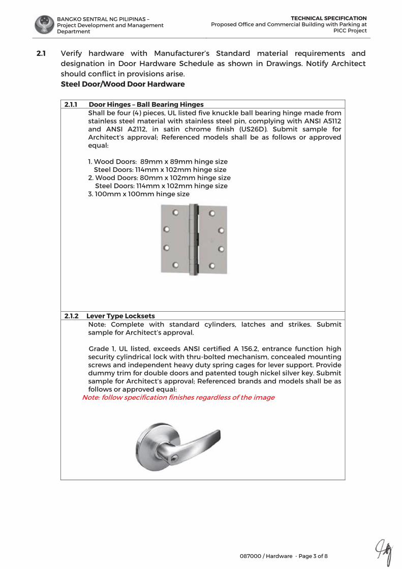
BANGKO SENTRAL NG PILIPINAS – Project Development and Management Department
TECHNICAL SPECIFICATIONProposed Office and Commercial Building with Parking at
PICC Project
087000 / Hardware - Page 3 of 8
2.1 Verify hardware with Manufacturer’s Standard material requirements and designation in Door Hardware Schedule as shown in Drawings. Notify Architect should conflict in provisions arise.
Steel Door/Wood Door Hardware
2.1.1 Door Hinges – Ball Bearing Hinges Shall be four (4) pieces, UL listed five knuckle ball bearing hinge made from stainless steel material with stainless steel pin, complying with ANSI A5112 and ANSI A2112, in satin chrome finish (US26D). Submit sample for Architect’s approval; Referenced models shall be as follows or approved equal: 1. Wood Doors: 89mm x 89mm hinge size Steel Doors: 114mm x 102mm hinge size 2. Wood Doors: 80mm x 102mm hinge size Steel Doors: 114mm x 102mm hinge size 3. 100mm x 100mm hinge size
2.1.2 Lever Type Locksets Note: Complete with standard cylinders, latches and strikes. Submit sample for Architect’s approval. Grade 1, UL listed, exceeds ANSI certified A 156.2, entrance function high security cylindrical lock with thru-bolted mechanism, concealed mounting screws and independent heavy duty spring cages for lever support. Provide dummy trim for double doors and patented tough nickel silver key. Submit sample for Architect’s approval; Referenced brands and models shall be as follows or approved equal:
Note: follow specification finishes regardless of the image

BANGKO SENTRAL NG PILIPINAS – Project Development and Management Department
TECHNICAL SPECIFICATIONProposed Office and Commercial Building with Parking at
PICC Project
087000 / Hardware - Page 4 of 8
Standard Cylinder (for lever type lockset) Grade 1, UL listed, exceeds ANSI certified A 156.2-2003 standard cylinder for lever type lockset, key operated in stain chrome finish.
Latches and Strikes (for lever type lockset) Shall be Grade 1, UL listed, ¾” Throw Anti-Friction Deadlatch in push button release or turning inside lever with Square Corner Box Strike in satin chrome finish.
2.1.3 Door Closer Grade 1, listed, ANSI standard A156.4 or EN 1154, concealed overhead door closer mounted on top jamb made from aluminum alloy bodies with high compression steel springs and steel cams and rollers for door opening upto 130° maximum in aluminum 689 finishes. Door closer shall be non-handed with hold open features adjustable to 80° to 120°. Note: for Fire Exit Doors - door closer shall be self-closing without hold open feature and shall be in accordance to UL10C for positive pressure.
2.1.4 Door Stop for Steel Doors and Flush Wood Doors
UL listed, meets ANSI/BHMA A156.16, casted aluminum in satin chrome finish with rubber tip door stop.
2.1.5 Panic Hardware for Fire Exit Doors Shall be UL listed conforming to ANSI A156.3-2008 Grade 1, 100mm x 1000mm (verify door length) fire exit device/hardware in US26D finish, provide standard lever trim with blank escutcheon (always operable without cylinder) at the back side of the door panel, complete with fasteners, bolts and accessories. Submit sample for Architect’s approval.
Note: Lever Trim will not be provided at the exterior side of the Fire Exit @ Lower Ground Floor.
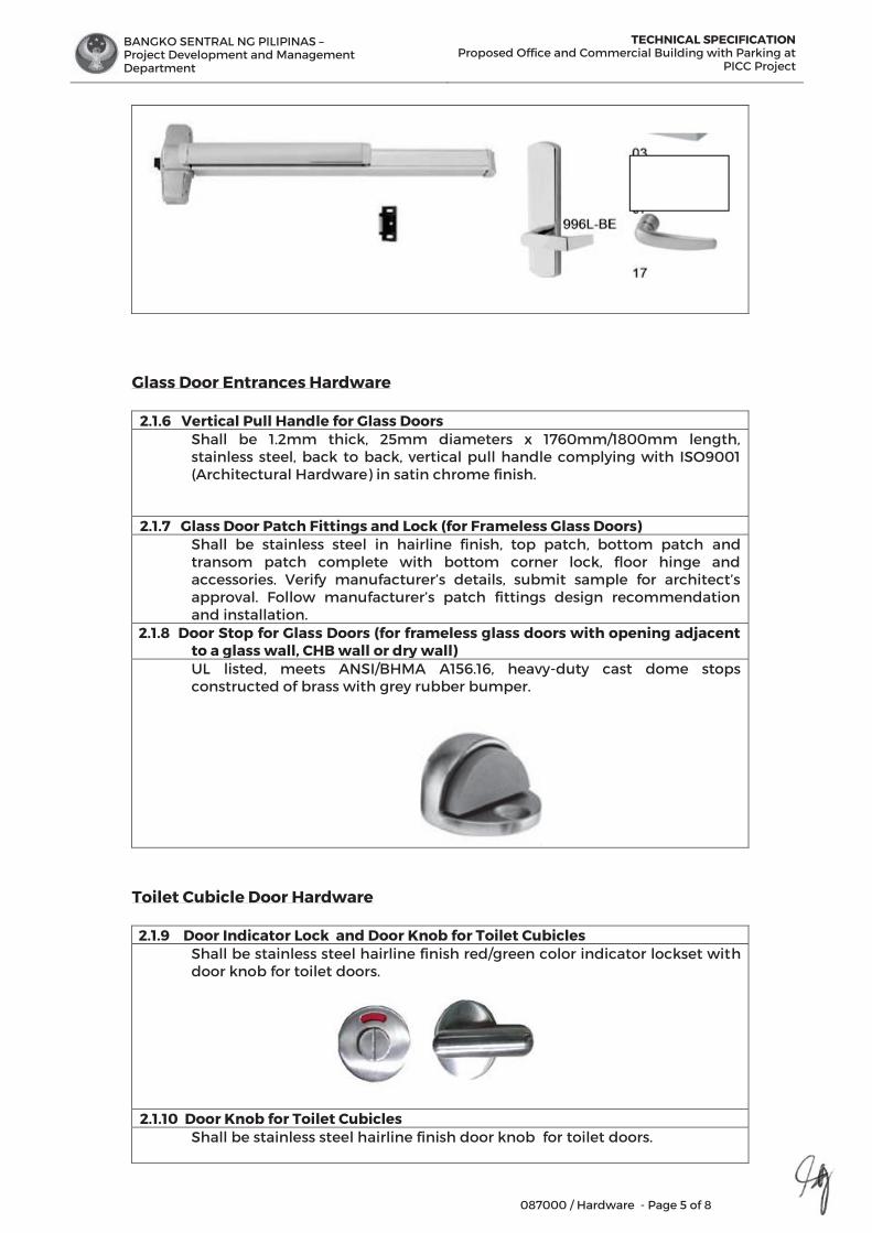
BANGKO SENTRAL NG PILIPINAS – Project Development and Management Department
TECHNICAL SPECIFICATIONProposed Office and Commercial Building with Parking at
PICC Project
087000 / Hardware - Page 5 of 8
Glass Door Entrances Hardware
2.1.6 Vertical Pull Handle for Glass Doors Shall be 1.2mm thick, 25mm diameters x 1760mm/1800mm length, stainless steel, back to back, vertical pull handle complying with ISO9001 (Architectural Hardware) in satin chrome finish.
2.1.7 Glass Door Patch Fittings and Lock (for Frameless Glass Doors) Shall be stainless steel in hairline finish, top patch, bottom patch and transom patch complete with bottom corner lock, floor hinge and accessories. Verify manufacturer’s details, submit sample for architect’s approval. Follow manufacturer’s patch fittings design recommendation and installation.
2.1.8 Door Stop for Glass Doors (for frameless glass doors with opening adjacent to a glass wall, CHB wall or dry wall) UL listed, meets ANSI/BHMA A156.16, heavy-duty cast dome stops constructed of brass with grey rubber bumper.
Toilet Cubicle Door Hardware
2.1.9 Door Indicator Lock and Door Knob for Toilet Cubicles Shall be stainless steel hairline finish red/green color indicator lockset with
door knob for toilet doors.
2.1.10 Door Knob for Toilet Cubicles Shall be stainless steel hairline finish door knob for toilet doors.
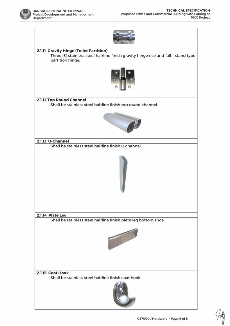
BANGKO SENTRAL NG PILIPINAS – Project Development and Management Department
TECHNICAL SPECIFICATIONProposed Office and Commercial Building with Parking at
PICC Project
087000 / Hardware - Page 6 of 8
2.1.11 Gravity Hinge (Toilet Partition)
Three (3) stainless steel hairline finish gravity hinge rise and fall – stand type partition hinge.
2.1.12 Top Round Channel
Shall be stainless steel hairline finish top round channel.
2.1.13 U-Channel Shall be stainless steel hairline finish u-channel.
2.1.14 Plate Leg Shall be stainless steel hairline finish plate leg bottom shoe.
2.1.15 Coat Hook Shall be stainless steel hairline finish coat hook.
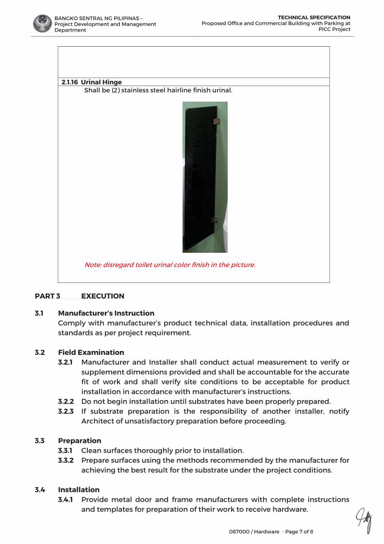
BANGKO SENTRAL NG PILIPINAS – Project Development and Management Department
TECHNICAL SPECIFICATIONProposed Office and Commercial Building with Parking at
PICC Project
087000 / Hardware - Page 7 of 8
2.1.16 Urinal Hinge
Shall be (2) stainless steel hairline finish urinal.
Note: disregard toilet urinal color finish in the picture.
PART 3 EXECUTION 3.1 Manufacturer’s Instruction
Comply with manufacturer’s product technical data, installation procedures and standards as per project requirement.
3.2 Field Examination 3.2.1 Manufacturer and Installer shall conduct actual measurement to verify or
supplement dimensions provided and shall be accountable for the accurate fit of work and shall verify site conditions to be acceptable for product installation in accordance with manufacturer’s instructions.
3.2.2 Do not begin installation until substrates have been properly prepared. 3.2.3 If substrate preparation is the responsibility of another installer, notify
Architect of unsatisfactory preparation before proceeding.
3.3 Preparation 3.3.1 Clean surfaces thoroughly prior to installation.
3.3.2 Prepare surfaces using the methods recommended by the manufacturer for achieving the best result for the substrate under the project conditions.
3.4 Installation
3.4.1 Provide metal door and frame manufacturers with complete instructions and templates for preparation of their work to receive hardware.
BANGKO SENTRAL NG PILIPINAS – Project Development and Management Department
TECHNICAL SPECIFICATIONProposed Office and Commercial Building with Parking at
PICC Project
087000 / Hardware - Page 8 of 8
3.4.2 Install all items according to hardware manufacturer’s instructions and recommendations. Mount at heights and centers according to manufacturer’s instruction and standards.
3.4.3 Install hardware completely to ensure proper fit only finishing of door surfaces is complete.
3.4.4 Drill and countersink units which are prepared for anchorage of fasteners. Space fasteners and anchors to manufacturer’s recommendations. Use only fasteners supplied by hardware manufacturers.
3.4.5 Protect doors and frames from damage due to installation of hardware.
3.5 Instruction 3.5.1 Instruct authorized Owner’s personnel of the following: A. Proper care, cleaning and general maintenance of hardware.
B. Operation of key control system. Make periodic checks during warranty period to ensure functional efficiency of the system.
3.6 Protection 3.6.1 Protect installed products until completion of project. 3.6.2 Touch-up, repair or replace damaged products before Substantial Completion.
END OF SECTION

BANGKO SENTRAL NG PILIPINAS – Project Development and Management Department
TECHNICAL SPECIFICATION Proposed Office and Commercial Building with
Parking at PICC Project
088100 / Glass - Page 1 of 5
SECTION 08 81 00
GLASS GLAZING
PART 1 GENERAL
1.1 SCOPE OF WORK This section shall include all labor, materials, appliances, tools, equipment, facilities, transportation and services necessary for and incidental to performing operations in connections with furnishing, delivery and installing the glass panels as shown and specified.
1.2 SUBMITTALS 1.2.1 General: All submittals for approval as indicated herein shall be in
accordance to the provisions under General Conditions of the Contract Documents.
1.2.2 Shop Drawings: Show complete details of setting methods of materials for each type of glazing material specified.
1.2.3 Samples: Two (2) 300mm square, factory labeled. 1.2.4 Manufacturer’s Data: Include glass manufacturer’s
recommendations for setting and sealing materials and for installation of each type of glazing specified.
1.2.5 Calculations: Submit structural calculations. The manufacturer shall recommend the thickness of the glass, based on their computation.
Note: All Shop Drawings and Sample Sections shall be submitted prior to purchasing and installing of materials for review and approval of the Architect.
1.3 QUALITY ASSURANCE 1.3.1 Conform to the following standards:
A. ANSI Z97.1 Physical Properties 1.3.2 Labeling:
Labels showing glass manufacturer’s identity, type of glass, thickness and quality will be required on each piece of glass. Labels shall remain on glass until it has been set and inspected. When glass is not cut to size by the Manufacturer, and is furnished unlabeled as “stock to cut”, Contractor shall submit an affidavit, or other satisfactory evidence, stating quality thickness, type and manufacturer of glass furnished. Putty and glazing compounds shall arrive at Project Site in labeled containers that have not been opened.
1.3.3 Qualification of Installers: Provide at least one person who shall be thoroughly trained and experienced in the skills required, who shall be completely familiar with the referenced standards and the requirements of his work, and who shall personally direct all installation performed under this Section of the specification.
BANGKO SENTRAL NG PILIPINAS – Project Development and Management Department
TECHNICAL SPECIFICATION Proposed Office and Commercial Building with
Parking at PICC Project
088100 / Glass - Page 2 of
1.4 WARRANTY Special written warranty for each material specified herein shall be submitted by Manufacturer/ Contractor without reducing or otherwise limiting any other rights to correction which the Owner may have under the Contract Documents. Failures are defined to include faulty workmanship or faulty materials.
1.5 DELIVERY, STORAGE AND HANDLING
1.5.1 Comply with product delivery requirements under General Conditions of the Contract Documents and Manufacturer’s instructions.
1.5.2 Store under cover and protect from damage. 1.5.3 Protection and Damaged Work: Protect specified work and adjacent
work and materials against damage during progress of the work. Glass damaged due to improper handling or setting shall be replaced at no extra cost to the Owner.
1.6 PROJECT CONDITIONS
1.6.1 Comply with field examination requirements under General Conditions of the Contract Documents and Manufacturer’s instructions.
1.6.2 Examine work-in-place of which glazing is in any way dependent. Verify actual dimensions before fabrication and installation. Coordinate with the work of other trades. Report in writing, to the Architect any defects, which may influence satisfactory completion and performance of the work. Absence of such notification shall be construed as acceptance of work-in- place. Exterior glazing shall not be installed in damp weather or when ambient temperature is below 4.40 deg. Celsius (40°F).
PART 2 PRODUCTS
2.1 Refer to drawings for sizes and thickness of panels, area of application, tint and texture. Dimension, fabrication and installation of Glass Panels shall be based on the actual measurements and conditions of the site.
2.2 Glass shall be provided in locations as indicated and the corresponding type
specified on architectural drawings. All standard procedure on glass and glazing work must be implemented to ensure correct fitting and glazing in order to preserve the physical strength of the glass when used as intended on any building exterior and interior application.
2.3 Glazing rabbets shall be rigid, true, plumb, square, properly primed, clean, dry
and dust-free before glazing work is started. Protective coating shall be removed from metal rabbets with an approved solvent. Glazing work shall not be performed during damp or rainy weather. Sashes shall be glazed in a closed position and shall not be operated until the glazing compound has set. Glazing materials shall be mixed uniformly without the addition of thinners or other materials, and shall be used while still fresh.
BANGKO SENTRAL NG PILIPINAS – Project Development and Management Department
TECHNICAL SPECIFICATION Proposed Office and Commercial Building with
Parking at PICC Project
088100 / Glass - Page 3 of 5
2.4 The use of non-skinning compounds, non-resilient type preformed sealers, and preformed impregnated type gaskets will not be permitted. Materials used with aluminum frames shall be aluminum colored, non- staining, and do not require painting. Other materials which will be exposed to view and unpainted shall be gray or neutral color. Glazing materials shall be as specified herein and as recommended by the glass the manufacturer as approved.
2.5 Glass Glazing for Doors
2.5.1 Glass Glazing for Steel Door and Wood Door with Vision Panel
Shall be 6mm thick annealed clear glass vision panel.
2.5.2 Glazing for Fixed Glass Panels Shall be 12mm thick fixed tempered clear glass panels. Submit glass sample for Architect’s approval.
2.6 Glass Glazing for Curtain Wall
2.6.1 Glass Glazing for Blast Resistant Curtain Wall and Windows Panels
Shall be 10mm thick tempered clear fixed glass panels. 2.7 Glazing Sealant
Shall be one component, neutral cure, high tensile-strength elastomeric silicone sealant and adhesive for structural bonding glass, metal and building components.
2.8 Glazing accessories
As required to supplement the installation shall be provided on the items to be glazed and provide a complete work. These include glazing points, clips, shim, angles, and beads, setting blocks, edge spacer, back up material, primer and masking tapes. Ferrous metal accessories which will be exposed in the finished work shall have a finish that will not corrode or stain while in service.
2.9 Masking tape
Shall be adhesive paper type and used to prevent contamination of glass or sash during application of primer or filling of sealant, and to maintain neat edge line of sealant.
PART 3 EXECUTION
3.1 Install glass in accordance with manufacturer’s recommended instructions. 3.2 The contractor shall secure an adequate storage space for his materials, tools,
and equipment. Where aluminum is to be installed in contact with masonry or other similar materials, aluminum shall be back-painted with one coat of heavy bonded bituminous paint. All preservations to be applied shall be required quality or correct consistency and of sufficient thickness.
3.3 Verify surfaces and adjacent work prior installation and setting of glass.
Determine the sizes to provide the required edge clearances by measuring
BANGKO SENTRAL NG PILIPINAS – Project Development and Management Department
TECHNICAL SPECIFICATION Proposed Office and Commercial Building with
Parking at PICC Project
088100 / Glass - Page 4 of
the actual to receive the glass. Grind smooth all edges of glass that will beexposed to a finished work. Leave labels in place until the installation is approved. Secure fix movable items or keep in a closed and locked position until glazing compounds has thoroughly set.
3.4 Items to be glazed shall be either shop or field glazed using glass or the
quality and thickness specified or indicated. Handle and install glazing materials in accordance with the manufacturer’s instructions. Use beads or stops, which are furnished with items to be glazed to secure the glass in place.
3.5 Determine actual sizes of glass required by measuring frames to receive
glass at Project Site, or from guaranteed dimensions provided by frame supplier. Dimensions for glass and glass holding surrounds shall be coordinated to provide the following minimum clearances.
3.6 Make edge cuts clean. Do not nip, seam, swipe, stone or strike edges. Do
not knock-off flares. Do not bump, drag, or brush the edges of lites against frame or other hard objects.
3.7 Set glass in rebates using manufacturer’s standard glazing fittings and as
specified herein. Place setting blocks at quarter points of glass panels. Seal exterior side of each glass lite with sealant type specified.
3.8 No attempt shall be made to change size of tempered or laminated glass
units after they leave the factory. Glass panels shall be clean cut. Nipping to remove flares or to reduce oversized dimensions of any type of glass will not be permitted.
3.9 Apply thin layer of putty to rebate and set glass of putty pressing until an even
bed is secured; place spring wire or angle glazing clips and run face putty, remove excess putty from other side flush with edge of rebate.
3.10 Putty shall be neatly run in straight line paralleled with inside of glazing
rebates, corners shall be carefully made and all excess putty shall be removed and surface left clean.
3.11 The contractor shall carry out a water-tightness test upon completion of all installation works under the Supervision of the Architect. The windows shall be hosed under direction of and in a manner approved by the Architect for a period of not less than ten (10) minutes closed state form the exterior of the building. Test shall be made by applying a water spray to all joints and surfaces exposed to the weather, after all caulking and sealing has been completed.
3.12 The water infiltration testing shall be made immediately after the setting or
curing period prescribed for the sealants used. 3.13 Absolute water tightness shall be achieved in the interior of the building in
any case. Should any form of leakage occur, the Contractor shall be responsible for rectifying same at his own expense and retested to the satisfaction of the Architect.
BANGKO SENTRAL NG PILIPINAS – Project Development and Management Department
TECHNICAL SPECIFICATION Proposed Office and Commercial Building with
Parking at PICC Project
088100 / Glass - Page 5 of
3.14 The Contractor shall provide all necessary labor and materials require to carry
out water testing of these frames prior to acceptance. 3.15 The Contractor shall carry out such modifications, as are necessary,
including additional sample frames if required, to these frames to satisfy the Architect that the details for fabrication and installation of all frames will produce a watertight result.
3.16 Attach crossed streamers away from glass face. Do not apply markers to
glass surface. 3.17 Replace damaged glass which is broken, chipped, cracked, abraded or
damaged during construction.
END OF SECTION

BANGKO SENTRAL NG PILIPINAS – Project Development and Management Department
TECHNICAL SPECIFICATION Proposed Office and Commercial Building with
Parking at PICC Project
088300 / Mirrors - Page 1 of 3
SECTION 08 83 00
MIRRORS
PART 1 GENERAL
1.1 RELATED DOCUMENTS Drawings and general provisions of the Contract, including General and Supplementary Conditions and Division 01 Specifications, apply to this section.
1.2 SUBMITTALS 1.2.1 Product Data: For each type of product indicated.
Mirrors, include description of materials and process used to produce each type of silvered flat glass mirror specified that indicates sources of glass, glass coating components, edge sealer and quality-control provisions.
1.2.2 Shop Drawings: Include mirror elevations, edge details, mirror hardware and attachments to other work.
1.2.3 Samples of the required materials.
1.3 INFORMATIONAL SUBMITTALS 1.3.1 Qualification Data: for required installer. 1.3.2 Product certificates: For each type of mirror and mirror mastic from
manufacturer. 1.3.3 Preconstruction Test Reports: From mirror manufacturer indicating
that mirror was tested for compatibility and adhesion with mirror backing paint and substrates on which mirrors are installed.
1.3.4 Warranty: Sample of special warranty.
1.4 QUALITY ASSURANCE 1.4.1 Source Limitation for Mirror Accessories: Obtain mirror glazing
accessories from single source. 1.4.2 Preconstruction Mirror Compatibility Test: Submit mirror mastic
products to mirror manufacturer for testing to determine compatibility of mastic with mirror backing paint and substrates on which mirrors are installed.
1.5 DELIVERY, STORAGE AND HANDLING 1.5.1 Protect mirror according to mirror manufacturer’s written instructions
and as needed to prevent damage to mirrors from moisture, condensation, temperature changes, direct exposure to sun, or other uses.
1.5.2 Comply with mirror manufacturer’s written instructions for shipping, storing and handling mirrors as needed to prevent deterioration of silvering, damage to edges and abrasion of glass surfaces and applied coatings.
1.6 PROJECT CONDITIONS

BANGKO SENTRAL NG PILIPINAS – Project Development and Management Department
TECHNICAL SPECIFICATION Proposed Office and Commercial Building with
Parking at PICC Project
088300 / Mirrors - Page 2 of
Environmental Limitations: Do not install mirrors until ambient temperature and humidity conditions are maintained at levels indicated for final occupancy.
1.7 WARRANTY
1.7.1 Special Warranty: Manufacturer’s standard form which mirror manufacturer agrees to replace mirrors that deteriorate within specified warranty period. Deterioration of mirrors is defined as defects developed from normal use that are not attributed to mirror breakage or to maintaining and cleaning mirrors contrary to manufacturer’s written instructions. Defects include discoloration, black spots and clouding of silver film.
PART 2 PRODUCTS
2.1 MATERIALS
2.1.1 Facial Mirror for Male and Female Toilets (Public Toilets) Shall be 6mm thick frameless, copper free, corrosion resistant, silver-coated float glass mirror with 2mm thick chamfered edges on both sides, glued to 12mm thick marine plywood backing by tile adhesive or mirror mastic with sponge tape on one side, facing wall provide 50mm x 50mm TKD Tanguile back framing for protruded mirrors. Provide screws with expansion shield and chrome-plated screw cap. Submit mirror sample for Architect’s approval. Refer to Architectural Drawing for dimension, layout and design.
2.1.2 Facial Mirror for Male and Female Toilet (Private Toilet with Wall- Hung Lavatory) Shall be 6mm thick frameless, copper free, corrosion resistant, silver-coated float glass mirror with 2mm thick chamfered edges on both sides, glued to 12mm thick marine plywood backing by tile adhesive or mirror mastic with sponge tape on one side. Provide screws with expansion shield and chrome-plated screw cap. Submit mirror sample for Architect’s approval. Refer to Architectural Drawing for dimension, layout and design.
2.2 MISCELLANEOUS MATERIALS
2.2.1 Edge Sealer: Coating compatible with glass coating and approved by mirror manufacturer for use in protecting against silver deterioration and mirror glass edges.
2.2.2 Mirror Mastic: An adhesive setting compound, asbestos-free, produced specifically for setting mirrors and certified by both mirror manufacturer and mastic manufacturer as compatible with glass coating and substrate on which mirror will be installed.
2.2.3 Film backing for Safety Mirrors: Film backing and pressure-sensitive adhesive; both compatible with mirror backing paint as certified by mirror manufacturer.
BANGKO SENTRAL NG PILIPINAS – Project Development and Management Department
TECHNICAL SPECIFICATION Proposed Office and Commercial Building with
Parking at PICC Project
088300 / Mirrors - Page 3 of
PART 3 EXECUTION
3.1 EXAMINATION
3.1.1 Examine substrates, over which mirrors are to be mounted, with installer present, for compliance with installation tolerances, substrate preparation and other conditions affecting performance of the work.
3.1.2 Verify compatibility with and stability of substrates, including compatibility of mirror mastic with existing finishes or primers.
3.1.3 Proceed with installation only after unsatisfactory conditions have been corrected and surfaces are dry.
3.2 PREPARATION
3.2.1 Comply with mastic manufacturer’s written installation instructions for preparation of substrates, including coating substrates with mastic manufacturer’s special bond coating where applicable.
3.3 INSTALLATION
3.3.1 General: Install mirrors to comply with mirror manufacturer’s written instructions. Mount mirrors accurately in place in a manner that avoids distorting reflected images.
3.3.2 Provide a minimum air space of 1/8 inch (3 mm) between back of mirrors and mounting surface for air circulation between back mirrors and face of mounting surface.
3.3.3 Wall-Mounted Mirrors: Install mirrors with mastic and mirror hardware. Attach mirror hardware securely to mounting surfaces with mechanical fasteners installed with anchors or inserts as applicable. Install fasteners so heads do not impose point loads on backs of mirrors.
3.4 CLEANING AND PROTECTION
3.4.1 Protect mirrors from breakage and contaminating substances resulting from construction operations.
3.4.2 Do not permit edges of mirrors to be exposed to standing water. 3.4.3 Maintain environmental conditions that will prevent mirrors from
being exposed to moisture from condensation or other sources for continuous periods of time.
3.4.4 Wash exposed surface of mirrors not more than four days before date scheduled for inspections that establish date of Substantial Completion. Wash mirrors as recommended in writing by mirror manufacturer.
END OF SECTION
BANGKO SENTRAL NG PILIPINAS – Project Development and Management Department
TECHNICAL SPECIFICATION Proposed Office and Commercial Building with
Parking at PICC Project
092116 / Gypsum Boards - Page 1 of 8
SECTION 09 21 16
GYPSUM BOARD
PART 1 GENERAL
1.1 SCOPE OF WORK This section shall include all management, labor, materials, tools, equipment and services required to furnish and install gypsum boards for walls and ceiling as specified herein and shown in Drawings required to perform all works in accordance to the General Conditions of the Contract Documents.
1.2 REFERENCES Comply with quality assurance requirements under General Conditions of the Contract Documents and Manufacturer’s instructions. Referenced the following standards as applicable: 1.2.1 American Society of Testing and Materials (ASTM)
A. ASTM C36 Standard Specification for Gypsum Wallboard
B. ASTM C475 Standard Specification for Joint Compound and Joint Tape for finishing Gypsum
Board C. ASTM C514 Standard Specification for Nails for the
Application of Gypsum board D. ASTM C840 Standard Specification for Application and
Finishing of Gypsum board E. ASTM C1395 Specification for Gypsum Ceiling Board F. ASTM C1396 Standard Specification for Gypsum Board G. ASTM E413 Classification for Rating Sound Insulation H. ASTM E90 Standard Test Method for Laboratory
Measurement of Airborne Sound Transmission Loss of Building Partitions
and Elements
1.3 SUBMITTALS 1.3.1 General: All submittals for approval as indicated herein shall be in
accordance to the provisions under General Conditions of the Contract Documents.
1.3.2 Product Data: Submit product information from manufacturers for each type of product specified to include brochures, catalogs, sample and certificates of tests reports, quality compliance and accreditation from foreign manufacturer for authenticity of local distributed materials.
1.4 QUALITY ASSURANCE 1.4.1 Comply with quality assurance requirements under General Conditions of
the Contract Documents and Manufacturer’s instructions. 1.4.2 Manufacturer Qualification shall be at least five (5) years of production
experience, whose published literature clearly indicates general compliance of products with requirements of this section.
BANGKO SENTRAL NG PILIPINAS – Project Development and Management Department
TECHNICAL SPECIFICATION Proposed Office and Commercial Building with
Parking at PICC Project
092116 / Gypsum Boards - Page 2 of 8
1.4.3 Single Source Responsibility Obtain gypsum boards of uniform quality from a single manufacturer for
each type product required. 1.4.4 Tests: A. Sound Transmission Characteristics (STC): For gypsum board assemblies
with STC Ratings, provide materials and construction identical to those tested in assembly indicated according to ASTM E90 and classified according to ASTM E413.
1.5 DELIVERY, STORAGE AND HANDLING
1.5.1 Comply with product delivery requirements under General Conditions of the Contract Documents and Manufacturer’s instructions.
1.5.2 Deliver materials in manufacturer’s original unopened packages clearly marked with identifying information. Protect materials as recommended by the manufacturer.
1.5.3 Store materials, keep dry, and protect against damage from weather, direct sunlight, surface contamination, corrosion, construction traffic, and other causes. Stack gypsum panels on level surface to prevent sagging.
1.6 WARRANTY
Special written warranty for each material specified herein shall be submitted by Manufacturer/ Contractor without reducing or otherwise limiting any other rights to correction which the Owner may have under the Contract Documents. Failures are defined to include faulty workmanship or faulty materials.
1.7 PROJECT CONDITIONS
1.7.1 Comply with field examination requirements under General Conditions of the Contract Documents and Manufacturer’s instructions.
1.7.2 Environmental Conditions: Establish and maintain environmental conditions for application and finishing of gypsum board to comply with ASTM C840 and with gypsum board manufacturer’s recommendations.
1.7.3 Minimum Room Temperatures: For attachment of gypsum board to framing, maintain not less than 40 degrees F. For finishing of gypsum board, maintain not less than 50 degrees F for 48 hours prior to application, and continuously thereafter until drying is complete.
1.7.4 Ventilation: Ventilate building spaces to remove water not required for drying joint treatment materials. Avoid drafts during dry, hot weather to prevent materials from drying too rapidly.
PART 2 PRODUCTS 2.1 Wallboards
2.1.1 Drywall partitions shall be 100mm thick in 12mm thick x 1200mm x 2400mm standard plasterboard, with acoustic fiberglass insulation on galvanized steel framing by “Boral”, “Gyproc”, or approved equal, coated with water-based white acrylic anti-bacterial and dirt-resisting interior paint. Standard plasterboard shall be composed of 100% recyclable natural gypsum plaster core encased in heavy-duty face and backing linerboard, hazard and toxic-free. Dry wall partition shall be coated with high performance low VOC, odorless, ultra-premium water-based acrylic
BANGKO SENTRAL NG PILIPINAS – Project Development and Management Department
TECHNICAL SPECIFICATION Proposed Office and Commercial Building with
Parking at PICC Project
092116 / Gypsum Boards - Page 3 of 8
coating that gives a cleanable matte finish to walls and ceilings with surface protector and anti-bacterial protection.
2.1.2 Adhesive for joint and fastener concealment shall be of the types recommended in writing by the wallboard manufacturer and as approved for the following uses: A. Embedding compounds for first and second coats. B. Finishing compound for final coat.
2.1.3 Backing board shall be of the grade and form required for the insulation. 2.1.4 Wall and partition metal assemblies shall be as manufactured. Assemblies
shall be as follows: A. Track, top and bottom shall be galvanized steel gauge 22 or 24
and 2.4 or 3.0m long. B. Stud shall be galvanized steel, gauge 22 or 24 and 2.4 or 3.0m long.
2.1.5 Fasteners. A. Bolts and nuts shall be recommended by the framing manufacturer,
steel and zinc-coated. B. Expansion shields shall be of the type and class applicable. C. Powder-driven fasteners as per Architect’s approval.
2.1.6 Screws for board attachment shall be shouldered flat-head design for use with special power-driven tools. A. Wood Screws shall be not less than 15mm (1-1/8 inches) long. B. Metal screws shall be not less than 25mm long with self-tapping
threads and self-drilling points. 2.1.7 Toggle bolts shall be of the type and class best suited for the purpose.
2.2 Ceiling Boards 2.2.1 General Ceilings: Gypsum Boards Ceiling Finish Shall be 12mm-13mm thick recessed edge, sag resistant plasterboard
coated with high performance low VOC, odorless, ultra-premium water-based acrylic coating that gives a cleanable matte finish to walls and ceilings with surface protector and anti-bacterial protection.
Framing system shall be 0.60mm thick gauge 24 x 19mm x 50mm galvanized light steel furring channel spaced at 600mm (max.) on both ways with 0.80mm thick gauge 22 x 12mm x 38mm carrying channel spaced at 1200mm (max.) on both ways and 0.40mm gauge 26 x 25mm x 25mm metal wall angle and metal angle, attached to slab/roof framing by a suspension clip and 6mm diameter hanger rod joiner spaced at 1200mm (max.) on both ways. Complete with screws, accessories and 0.40mm gauge 26 x 25mm x 25mm corner bead Ceiling Framing System with BPS certification by “ ” or approved equal. Submit gypsum board and framing sample for Architect’s approval. Verify drawings for design and details.
Toilet and Bath ceiling shall 12mm-13mm thick recessed edge, moisture
resistant, sag resistant plasterboard. 2.2.2 Board shall be screw-applied to steel members. 2.2.3 Adhesives for joint, fillers and fastener concealment shall be of the types
recommended in writing by the board manufacturer and as approved for the following uses: A. Embedding compounds for first and second coats. B. Finishing compound for final coat.
BANGKO SENTRAL NG PILIPINAS – Project Development and Management Department
TECHNICAL SPECIFICATION Proposed Office and Commercial Building with
Parking at PICC Project
092116 / Gypsum Boards - Page 4 of 8
2.3 Backing Board Shall be of the grade and form required for the installation. 2.4 Ceiling Metal Framing Assemblies Shall be as follows:
2.4.1 Hangers shall be pre-punched, hot-dipped galvanized steel 1.0mm thick. 2.4.2 Suspension rod shall be hot-dipped galvanized steel 6.0mm diameter. 2.4.3 Carrying channel clip shall be spring steel clip 0.60mm thick. 2.4.4 Furring channel joiner and furring clip shall be galvanized steel, gauge 24
thick. 2.4.5 Furring member shall have double cladding, galvanized steel 5.0m long;
0.40mm thick configuration and size as shown hereinafter 2.4.6 Carrying channel and wall angle shall be 5.0m long, gauge 10 and 2.4 or 3.0
meters long, gauge 24, configuration and sizes as shown in drawings.
2.5 Gypsum Board for Drywall and Ceiling Jointing and Putty 2.5.1 Gypsum Board Joint Filler
Shall be coated with powder-type, all-purpose fast setting gypsum-based filler for joints and patching holes. Provide fiber mesh before filling the joints. Submit product catalog for Architect’s approval.
2.5.2 Gypsum Board Putty Shall be coated with asbestos-free formulation, water-based, high quality gypsum putty to be used specifically over joints and patching holes on gypsum boards. Submit product catalog for Architect’s approval.
PART 3 EXECUTION 3.1 General
3.1.1 Examination: Examine areas and substrates, with installer present, and including hollow-metal frames, anchors, and structural and non-structural framing, for compliance with other requirements and other unsatisfactory conditions have corrected.
3.1.2 Steel Framing Installation Standard: Install steel framing to comply with ASTM C754 and with ASTM C840 requirements that apply to framing installation.
3.1.3 Install supplementary framing, blocking and bracing at terminations in the gypsum board assemblies to support fixtures, equipment services, heavy trim, grab bars, toilet accessories, furnishings, and similar construction. Comply with details indicated and with gypsum board manufacturer’s written recommendations.
3.2 Installation for Walls
3.2.1 Walls: Furring channels shall be spaced 0.40m on centers. Furring shall be secured to masonry or concrete with hardened nails, toggle bolts, expansion shields, or other approved method at not more than 0.60m centers staggered in alternate flanges of channel with one fastener located within 150mm of each end. Furring shall be secured to structural framing as shown. Furring shall be set plumb or level and rigid using shims of
BANGKO SENTRAL NG PILIPINAS – Project Development and Management Department
TECHNICAL SPECIFICATION Proposed Office and Commercial Building with
Parking at PICC Project
092116 / Gypsum Boards - Page 5 of 8
galvanized steel wherever necessary to assure a finished wall surface in a true, even plane. Board abutting dissimilar wall or ceiling materials shall have edges finished with casing beads aligned to provide a finished joint.
3.2.2 Steel framing: Non- load bearing walls and partitions shall be framed with 64mm and 92mm steel studs and runners installed as indicated and as hereinafter specified. Studs shall be spaced not more than 0.60m on centers and end studs in adjoining walls shall be interconnected with screws spaced at not more than 0.60m centers.
3.2.3 Application: Wallboard shall be applied with the separate boards in moderate contact but not forced into place. At internal and external corners the cut edges of the boards shall be concealed by the overlapping covered edges of the abutting boards. The boards shall be so staggered that the corners of any board will not meet a common point except in vertical corners. A. Single-ply horizontal application: The long dimension of the panels
shall be placed at right angles to the furring or framing members. End joints, where required, shall be made over furring or framing members.
B. Single-ply vertical application: The long dimension of the panels shall be placed parallel to the furring or framing members. the panels shall be of the length required to reach from the ceiling line to the floor line in one continuous length. Joints shall be made over framing or furring members.
3.2.4 Control Joints: shall be formed of casing bead trim installed back-to-back over separate framing or furring members. A spacing of 3mm shall be maintained between opposite beads. Control joints shall be located as indicated.
3.2.5 Attachment: If the paper surface is broken in nailing or screwing, another nail or screw shall be driven approximately 50mm from the faulty nailing or screwing. Attachment of wallboard to steel furring and steel framing shall be screw fasteners only. Nailing or screw attachment shall proceed from central portion of wallboard toward end and edges.
3.2.6 Joint and fastener concealment: Areas to be treated shall be inspected by the contractor to ascertain that wallboard fits tightly against supporting framework, and these areas shall be heated to not less than 55 degrees F. for 24 hours prior to commencing treatment, during treatment, and until adhesive compounds have dried. Application shall be by machine or hand tool. A minimum drying time of 24 hours shall be allowed between adhesive coats. Additional drying time may be necessary in poorly ventilated areas. A. Embedding compound: Shall be applied to wall board joints and
fastener heads in a thin uniform layer. Compound shall be spread not less than 75mm wide at joints, and reinforcing tape shall be centered on the joint and embedded in the compound. A thin layer of compound shall be spread over the tape. After this treatment has dried, a second coat of embedding compound shall be applied to wallboard joints and fastener heads. Compound shall be spread in a thin uniform coat and not less than 150mm wide at joints. Treated areas shall be sanded to eliminate ridges and high points.
B. Finishing compound: After embedding compound has dried, a coat of finishing compound shall be applied to joints and fastener heads.
BANGKO SENTRAL NG PILIPINAS – Project Development and Management Department
TECHNICAL SPECIFICATION Proposed Office and Commercial Building with
Parking at PICC Project
092116 / Gypsum Boards - Page 6 of 8
Finishing compound applied at joints shall be feathered out to not less than 300mm (12 in) wide. After compound has dried, the treated areas shall be sanded as necessary to obtain uniformly smooth surfaces. Care shall be taken not to scuff the paper surface of the wallboard.
3.2.7 Corner Treatment A. Internal corners: Shall be treated in the manner specified here-in-
before for joints, except that the reinforcing tape shall be folded lengthwise through the middle and fitted neatly into the corner.
B. External corners: Shall have corner bead fitted neatly over the corner and secured with the same type fastener used for applying wallboard. The fastener shall be spaced approximately 150mm on centers and driven through the wallboard into the framing member. After the corner-piece has been secured in place, the corner shall be treated with joint compound and reinforcing tape in the manner here-in-before specified for joints. The joint compound shall be feathered out from 200mm to 250mm, on each side of corner.
3.3 Installation for Ceiling
3.3.1 Ceiling framing systems: Framing for furred ceilings shall be installed at the locations indicated and shall conform to the standards.
3.3.2 Suspended ceilings: Ceiling framing shall consist of 38mm steel main runner channels suspended plumb from structural slab or frame by hanger wires or straps, spaced at not less than 1.20m on centers. Hanger wires shall be wrapped around the reinforcing bars, of the supporting concrete-slab construction with twists before concrete is placed or shall be shaped into a 100mm diameter loops and embedded at least 50mm in the concrete, or shall be attached to approved inserts. Hanger wires shall be looped around bottom chord of open-web steel joist and shall receive three full turns around itself, or around structural steel members or to attached beam clamps and shall receive three full turns around itself. Hanger Strap shall be hung plumb and connected with 10mm galvanized bolts and nuts to anchors made of hanger strap set in the concrete, or shall be looped around structural framing and connected to itself with 10mm galvanized bolts and nuts. Main runner channels shall be located within 150mm of parallel walls and shall be cut short of abutting wall 12mm plus or minus 6mm. Where channels are spliced, the ends shall be overlapped not less than 300mm with flanges of channels interlocked and securely tied near each end of the splice with two loops of 1.0mm tie wire or the ends may be joined by approved standard main runner coupling Splices shall be staggered.
3.3.3 Attached ceilings: Framing is not required for ceilings attached to structural members, except for framing openings as specified. Furring as hereinafter specified shall be attached directly to structural members.
3.3.4 Furring: Steel channels or steel studs shall be provided where steel furring is indicated for screw attachment of boards.
Ceilings: Hat –shaped furring members shall be spaced 0.40m on centers and securely attached across suspended runner channels or structural framing members with wire clips or double-strand of 1.0mm tie wire saddle-tied at each crossing. Ends of wire ties shall receive three full twists. Furring shall be spliced with 0.20m nested laps securely tied near each

BANGKO SENTRAL NG PILIPINAS – Project Development and Management Department
TECHNICAL SPECIFICATION Proposed Office and Commercial Building with
Parking at PICC Project
092116 / Gypsum Boards - Page 7 of 8
end of lap, with two loops of 1.0mm tie wire. Splices shall be staggered. Furring channels shall be located within 50mm of walls. Where board abuts dissimilar wall materials, perimeter of ceilings shall be finished with an edge bead trim strip applied to wall and accurately aligned with the finished ceiling. Board edges adjoining walls shall be laid on the horizontal leg of the trim strip against a continuous bead of approved type sealant.
3.3.5 Steel Framing: Non-load-bearing walls and partitions shall be framed with 64mm and 92mm steel studs and runners installed as indicated and as hereinafter specified. Studs shall be spaced not more than 0.60m on centers and end studs in adjoining walls shall be interconnected with screw spaced at not more than 0.60m on centers. A. Ceiling runners: Shall be accurately aligned and securely attached to
floors and to structural ceilings or roof deck except where partition-ceiling runners are applied directly to finish material of continuous ceilings. Attachment shall be by expansion shields, machine bolts, or other approved method, at not more than 0.60m centers and to furred ceilings by board screws at each furring member. Furring will be provided at ceiling runners oriented parallel to the direction of furring members. Runners shall extend beyond open-end partitions for 0.30m. Upon installation of end studs, runner extensions shall be bent and nested with the stud and attached thereto with two board screws. Runner shall be in the longest possible lengths with butt joints between lengths.
B. Studs: Shall be positioned plumb in ceiling and floor runners and securely attached with not less than one board screw on each side of the stud ends. Stud shall be installed in continuous lengths with no splicing in lengths up to 5m for 92mm studs, 3.5m for 75mm studs, and 3m for 64mm studs.
C. Special framing for beams, columns, soffits, and other special items shall be sized and built to the shapes or forms indicated by rigidly securing each intersection with board screws.
3.3.6 Ceiling openings: Support members shall be provided at ceiling openings such as required for access panels, recessed light fixtures, and for air supply or exhaust. Support members of not less than 38mm main runner channels and suspension wires or straps shall be located to provide at least the minimum support specified herein for furring and board attachment. Intermediate structural members, although not a part of the structural system, shall be provided for attachment or suspension of support members.
3.3.7 Application: Board shall be applied with the separate boards in moderate contact but not forced into place at internal and external corners the cut edges of the boards shall be concealed by the overlapping covered edges of the abutting boards. The boards shall be so staggered that the corners of any boards will not meet a common point except in vertical corners. A. Ceilings: Board shall be applied to the ceilings with the long dimension
of the board, at right angles to the furring members. Board may be applied with the long dimension parallel to furring members that are spaced 0.40m on centers when attachment members are provided at end joints.
BANGKO SENTRAL NG PILIPINAS – Project Development and Management Department
TECHNICAL SPECIFICATION Proposed Office and Commercial Building with
Parking at PICC Project
092116 / Gypsum Boards - Page 8 of 8
3.4 Wall Board and Ceiling Jointing and Putty 1st Coat - Bedding and Tapping
1. Stir lightly if liquid separation is observed. 2. Evenly fill the plasterboard joint recess with Konstrukt® Durafill™ K103 Fast-
Setting Gypsum Compound or approved equal, using a plasterers’ broad knife. (A 3mm gap between boards is recommended to make sure enough material is used.)
3. Center the joint tape and press down into the fresh plaster. Remove excess Konstrukt Durafill™ K103 Fast-Setting Gypsum Compound with a broad knife drawn along the joint at an angle approximately 45 degrees to the plasterboard surface. Care should be taken to ensure no air bubbles remain below the tape. Sufficient putty should be left under and over the tape to ensure a proper bond.
4. When the tape is embedded, apply a thin coat of Konstrukt® Durafill™ K103 Fast-Setting Gypsum Compound or approved equal, over fastener heads.
3.5 Cleaning and Protection
3.4.1 Promptly remove any residual joint compound from adjacent surfaces not indicated to receive texture.
3.4.2 Provide final protection and maintain conditions, in a manner acceptable to Installer, that ensure gypsum board assemblies are without damage or deterioration at the time of construction complete.
END OF SECTION
BANGKO SENTRAL NG PILIPINAS – Project Development and Management Department
TECHNICAL SPECIFICATION Proposed Office and Commercial Building with
Parking at PICC Project
092400 / Plastering - Page 1 of 3
SECTION 09 24 00
PLASTERING
PART 1 GENERAL
1.1 SCOPE OF WORK This section shall include all management, labor, materials, tools, equipment and services required to furnish and install plastering as specified herein and shown in Drawings required to perform all works in accordance to the General Conditions of the Contract Documents. All masonry unit work or concrete work not specifically specified with a finish, exposed to view shall be cement plastered. Plastering work shall be coordinated properly with the work of other trades. The work of other trades shall be protected properly from damage during plastering operations. Floors and finished work shall be properly protected with a covering of polyethylene sheets or heavy kraft waterproof paper, with lapped and sealed joints. Scaffolding shall be amply strong, well braced, tied securely and inspected regularly. Overloading of scaffolding will not be permitted.
1.2 REFERENCES Comply with quality assurance requirements under General Conditions of the Contract Documents and Manufacturer’s instructions. Reference the following standards as applicable: 1.2.1 ASTM C 926-98a Standard Specification for Application of Portland
Cement-Based Plaster 1.2.2 ASTM C 932-02 Standard Specifications for Surface-Applied
Bonding Compounds for Exterior Plastering 1.2.3 ASTN C 1063-o3 Standard Specification for Installation of Lathing
and Furring to receive Interior and Exterior Portland Cement-based Plaster.
1.3 SUBMITTALS All submittals for approval as indicated herein shall be in accordance to the provisions under General Conditions of the Contract Documents.
1.4 QUALITY ASSURANCE Comply with quality assurance requirements under General Conditions of the Contract Documents and Manufacturer’s instructions.
1.5 DELIVERY, STORAGE AND HANDLING 1.5.1 Comply with product delivery requirements under General Conditions of
the Contract Documents and Manufacturer’s instructions. 1.5.2 Manufactured materials shall be delivered in the original packages and
containers bearing the name and brand of the manufacturer. Cement and lime shall be stored off the ground under watertight cover, and away from sweating walls and damp surfaces, until ready for use. Damaged or deteriorated materials shall be removed from the premises.
BANGKO SENTRAL NG PILIPINAS – Project Development and Management Department
TECHNICAL SPECIFICATION Proposed Office and Commercial Building with
Parking at PICC Project
092400 / Plastering - Page 2 of 3
1.6 WARRANTY Special written warranty for each material specified herein shall be submitted by Manufacturer/Contractor without reducing or otherwise limiting any other rights to correction which the Owner may have under the Contract Documents. Failures are defined to include faulty workmanship or faulty materials.
1.7 PROJECT CONDITIONS Comply with field examination requirements under General Conditions of the Contract Documents and Manufacturer’s instructions.
PART 2 PRODUCTS 2.1 Portland Cement: Shall conform to PNS 07-1992, type 1. 2.2 Sand: Shall be clean natural sand or manufactured sand passing a 3mm screen
and retained in a No. 100 mesh sieve. 2.3 Water: For mixing shall be potable. 2.4 Lime: Shall be hydrated lime with the requirement that the free (Unhydrated)
calcium oxide (CaO) and magnesium oxide (MgO) in the hydrated product shall not exceed 8 percent by weight calculated on the “as received” basis.
PART 3 EXECUTION
3.1 Preparation 3.1.1 Mixing of plaster: Except where hand mixing of small patches is approved,
mechanical mixers of an approved type shall be used for the mixing of plaster. Materials shall be accurately measured in a device that will maintain the specified proportions within a plus or minus tolerance not in excess of 5 percent by volume. Caked or lumped materials shall not be used. Mechanical mixers, mixing boxes, and tools shall be cleaned after mixing each batch and kept freely of plaster from previous mixes. Plaster shall be thoroughly mixed with the proper amount of water, until uniform in color and consistency. Re-tempering will not be permitted, and all plaster that has begun to stiffen shall be discarded.
3.1.2 Proportioning of plaster: Portland cement plaster shall be a two-coat application. Each coat shall be proportioned as follows:
One (1) part Portland Cement Three (3) parts Sand; and One-fifth (1/5) part Lime Putty 3.1.3 Application of plaster: Base coats shall be applied with sufficient pressure
and the plaster shall be sufficiently plastic to provide good bonds on masonry or concrete base. Plaster work shall be finished level, plumb, square and true, within a tolerance of 3mm in 3m, without eaves, cracks, blisters, pits, grazing, discoloration, projections or other imperfections. Plasterwork shall have no visible junction marks where one day’s work adjoins another. Finished work shall be covered and protected in an approved manner to prevent damage.
BANGKO SENTRAL NG PILIPINAS – Project Development and Management Department
TECHNICAL SPECIFICATION Proposed Office and Commercial Building with
Parking at PICC Project
092400 / Plastering - Page 3 of 3
3.1.4 Portland Cement Plaster: Shall be applied in two coats double-up method on masonry or concrete to a thickness of not less than 12mm. Base coats shall be applied with sufficient pressure and excessive evaporation during hot or drying weather conditions. Care shall be taken to prevent staining the finished plaster.
3.1.5 Patching and pointing: Upon completion of the building and when directed, all loose, cracked, damaged, or defective plastering shall be cut out and re-patch in a satisfactory and approved manner. All point-patching of plastered surfaces, and plaster work abutting or adjoining any other finish work, shall be done in a neat and workmanlike manner. Plaster droppings or splattering shall be removed from all surfaces. Exposed plastered surfaces shall be left in a clean unblemished condition ready to receive paint or other finish. Protective coverings shall be removed from floors, other surfaces, and all rubbish and debris shall be removed from the building.
END OF SECTION

BANGKO SENTRAL NG PILIPINAS – Project Development and Management Department
TECHNICAL SPECIFICATION Proposed Office and Commercial Building with
Parking at PICC Project
093000 / Tiles - Page 1 of 6
SECTION 09 30 00
TILES
PART 1 GENERAL
1.1 SCOPE OF WORK This section shall include all management, labor, materials, tools, equipment and services required to furnish and install tile works as specified herein and shown in Drawings required to perform all works in accordance to the General Conditions of the contract Documents. The work shall not be started until the roughing-in for plumbing and electrical work has been completed and tested. The work of all other trades in the area where tile work is to be done shall be protected from damage in a skillfully manner and as directed.
1.2 REFERENCES Comply with quality assurance requirements under General Conditions of the Contract Documents and Manufacturer’s instructions. Reference the following standards as applicable: 1.2.1 American National Standards Specifications (ANSI), Standards for Tile
Installation: A. ANSI 108 B. ANSI 118 C. ANSI 136.1 D. ANSI A 137.1
1.2.2 American Society for the Testing of Materials (ASTM), ASTM C 270, Standard Specification of Mortar for Unit Masonry
1.3 SUBMITTALS 1.3.1 General: All submittals for approval as indicated herein shall be in
accordance to the provisions under General Conditions of the Contract Documents.
1.3.2 Manufacturer’s literature: Product data sheets, brochures, catalogs for all tile materials used for the work.
1.3.3 Tile samples of the tile in 10cm x 10cm shall be provided shall be for approval before tile work is started. The finish work shall match the approved samples in color patter, finish and texture.
1.3.4 Tile Adhesive: product catalog and methodology of installing tiles.
1.4 QUALITY ASSURANCE 1.4.1 Comply with quality assurance requirements under General
Conditions of the Contract Documents and Manufacturer’s instructions.
1.4.2 Source Limitations: Obtain all tiles of same type and color or finish tile from one source or producer. Materials shall be of the same production run
BANGKO SENTRAL NG PILIPINAS – Project Development and Management Department
TECHNICAL SPECIFICATION Proposed Office and Commercial Building with
Parking at PICC Project
093000 / Tiles - Page 2 of
and of consistent quality in appearance and physical properties for each contiguous area.
1.4.3 Setting materials such as mortar, adhesive and grout components shall be of uniform quality from a single manufacturer as well as finish treatments for nosing, stone thresholds and metal strips.
1.5 MOCK – UPS
Build mock-ups to verify selection made under sample submittal and to demonstrate aesthetic effects. When completed and approved by the Architect, the mock-up shall be incorporated into the finished Work and become the Standard of quality for the remainder of the Project.
1.6 DELIVERY, STORAGE AND HANDLING
1.6.1 Comply with product delivery requirements under General Conditions of the Contract Documents and Manufacturer’s instructions.
1.6.2 Manufactured materials shall be delivered in the original unbroken packages or containers that are labeled plainly with the manufacturer’s name and brands. Containers for tiles shall be grade sealed.
1.6.3 Store all materials off ground to prevent contamination by mud, dust, or materials likely to cause staining or other defects. Cover material to protect from elements and neglect.
1.7 WARRANTY
Special written warranty for each material specified herein shall be submitted by Manufacturer/ Contractor without reducing or otherwise limiting any other rights to correction which the Owner may have under the Contract Documents. Failures are defined to include faulty workmanship or faulty materials.
1.8 PROJECT CONDITIONS
1.8.1 Comply with field examination requirements under General Conditions of the Contract Documents and Manufactures instructions.
1.8.2 Verify dimensions of concrete substrate by accurate field measurement. Confirm concrete has been in place for at least 28 days prior to commencing tile installation. Do not begin work until deficiencies in the substrate are corrected. Commencement of tile installation indicate Contractor’s acceptance of substrate.
1.8.3 Do not install until construction in spaces is complete and ambient temperature and humidity conditions are maintained at the levels indicated in referenced standards and Manufacturer’s instructions.
1.9 EXTRA MATERIALS
1.9.1 Comply with requirements under General Conditions of the Contract Documents and Manufacturer’s instructions.
1.9.2 Furnish extra materials that match products installed and that are packaged with protective covering for storage with quantity of full size units for tile and trims units equal to two (2) percent of amount installed, for each type, composition, color, pattern and size indicated.

BANGKO SENTRAL NG PILIPINAS – Project Development and Management Department
TECHNICAL SPECIFICATION Proposed Office and Commercial Building with
Parking at PICC Project
093000 / Tiles - Page 3 of
1.10 PERFORMANCE REQUIREMENTS
Materials are to be from an accredited company with accomplished projects similar to the quality of material as specified herein. The Contractor shall submit tile samples to the Architect for approval prior to any installation. Design including texture and pattern shall be kept minimal with neutral color assignment as per Architect’s approved sample. Submit material test reports and certificates acquired by Manufacturer from reputable testing and accreditation agency.
PART 2 PRODUCTS
2.1 Tile Adhesive Shall be cement-based adhesive formulated for installing and fixing ceramic Tiles on horizontal and vertical concrete surfaces for thin-bed or thick-bed application.
2.2 Tile Grout for grouting shall be high performance, waterproof, cement-
based tile adhesive conforming to PNS 53 with early high-strength Characteristics. Color of grout shall match tile material as per Architect’s approved sample.
2.3 Water shall be clean and free from injurious amount of oil, acids, alkali,
organic materials or other substances that maybe deleterious to concrete or steel.
2.4 Floor and Pavement tiles
Rough Finish Porcelain
Tiles Shall be 10mm thick x 800mm x 800mm rough finish anti-stain, homogenous porcelain tiles with heavy resistance to abrasion Class AAA, 7.5 kgs., submit product catalog and sample for Architect’s approval. Provide 2- 3 mm gap in between tile joint during installation. Tile color and design shall be approved first before installation. Refer to Architectural drawings for pattern, layout and details.
General Flooring - Polished Finish Homogenous Porcelain Tiles
Shall be 10mm thick x 600mm x 600mm double polished finish anti-stain, homogenous porcelain tiles with heavy resistance to abrasion Class AAA, 7.5 kgs. submit product catalog and sample for Architect’s approval. Provide 2- 3 mm gap in between tile joint during installation. Tile color and design shall be approved first before installation. Refer to Architectural drawings for pattern, layout and details.
Male and Female, PWD Toilet - Matte Finish Homogenous Porcelain Tiles
Shall be 10mm thick x 600mm x 600mm matte finish anti-stain, homogenous porcelain tiles with heavy resistance to abrasion Class
BANGKO SENTRAL NG PILIPINAS – Project Development and Management Department
TECHNICAL SPECIFICATION Proposed Office and Commercial Building with
Parking at PICC Project
093000 / Tiles - Page 4 of
AAA, 7.5 kgs. Submit product catalog and sample for Architect’sapproval. Provide 2- 3 mm gap in between tile joint during installation. Tile color and design shall be approved first before installation. Refer to Architectural drawings for pattern, layout and details.
2.5 Wall Tile Finishes
2.5.1 Interior Wall Finish - Concrete Hollow Blocks with Homogenous Porcelain Tiles 1 Shall be 150mm thick/100mm thick CHB interior wall with 10mm thick 600mm x 600mm anti-stain, matte finish homogenous porcelain tiles. Submit product catalog and sample for Architect’s approval. Provide 2-3 mm gap in between tile joint during installation.
Verify Toilet Details for provisions and location of plumbing wall.
2.5.2 Interior Wall Finish – Dry Wall Partition with Homogenous Porcelain Tiles 1 Shall be 100mm thick dry wall partition in 12mm to 13mm thick standard plasterboard on 0.60mm thick gauge 24 x 35mm x 76mm galvanized light steel top and bottom tracks and 0.60mm gauge 24 x 35mm x 76mm vertical and horizontal studs spaced at 600mm bothways, complete with screws, accessories and 0.40mm GA. 26 x 25mm x 25mm corner bead with BPS (Bureau of Product Standards) certification.
Provide 10mm thick 600mm x 600mm anti-stain, matte finish homogenous porcelain tiles. Submit product catalog and sample for Architect’s approval. Provide 2-3 mm gap in between tile joint during installation.
2.6 Slop Sink for Utility @ Janitor/Storage Room
Shall be built-up concrete with 7mm thick x 300mm x 300mm vitrified unglazed ceramic tiles, complete with faucet and stainless steel floor drain.
PART 3 EXECUTION
3.1 Comply with Manufacturer’s standard installation procedures and applicable codes. Verify design and layout as approved from shop drawings submitted by Contractor in accordance to Drawings.
3.2 Examine surfaces to receive tile, before tile installation begins. Do not
proceed with installation until adjoining work is satisfactorily protected. Correct the following conditions before proceeding with tile work. 3.2.1 Defects or conditions adversely affecting quality, execution and
permanence of tile installation. 3.2.2 Maximum deviation of surfaces to receive tile:
A. Subfloor surface: ¼ inch in 10 feet B. Vertical surface: ¼ inch in 8 feet
BANGKO SENTRAL NG PILIPINAS – Project Development and Management Department
TECHNICAL SPECIFICATION Proposed Office and Commercial Building with
Parking at PICC Project
093000 / Tiles - Page 5 of
3.3 Condition of surfaces to receive tile shall be firm, dry, clean, and free of oily or
waxy films. Grounds, anchors, lugs, hangers, recess frames, bucks, electrical and
mechanical work in or behind tile to be installed prior to proceeding with tile installation.
3.4 Preparation
Use clean container and tools. Contamination may affect the setting time. Mix by hand or with a power mixer until a lump free homogeneous paste is reached. For best results, stand mixture for 2 minutes before use.
3.5 Installation
1. Mix All-purpose Tile Adhesive 25-kilogram bag with six (6) liters of water 2. Stir with a mixing device until desirable consistency is attained 3. Stand for two (2) minutes prior to use. 4. Wet substrate before application of tile adhesive 5. Use trowel to spread the adhesive per one (1) square meter at a time.
Apply to desired level to smoothen the uneven surface of the flooring 6. Place and align tile by moving it back and forth. 7. Adjust height accordingly by gently tapping the tiles using the
handle of the trowel or hammer. Fix tiles immediately within fifteen (15) minutes open time.
3.6 Grouting and Pointing
The tiles shall be wetted, if they have become dry, before applying grout. Joints of 3mm or less in width shall be routed with a neat white Portland cement
grout of the consistency of thick cream. Other joints shall be pointed with mortar consisting of white Portland cement and two parts pointing sand. The grout or mortar for joints floors, walls and other vertical surfaces shall contain white Portland cement. Grout and pointing mortar shall be forced into joints by using trowel, squeegee, brush, or finger application. Before the grout or mortar sets, the joints of cushion-edge tiles shall be struck or tooled to the depth of the cushion, filling all skips or gaps, and the joints of a square-edge tile shall be filled completely flush with their surface. Dark cement shall not show through grouted white joints. Care shall be taken to avoid scratching glazed finishes. All surplus mortar or grout shall be removed before it has set or hardened.
3.7 Cleaning and Curing
Floors shall be covered with waterproofed paper with all joints lapped at least 100mm and the laps tape-sealed or held down with planks or other weights and allowed to damp-cure for at least 72 hours before foot traffic is permitted thereon. All completed tile work shall be thoroughly sponged and washed diagonally across joints, and finally polished with clean dry cloths. Acid cleaning unglazed tiles, when necessary, shall not be done within ten days after setting tiles. All metal shall be covered with approved grease and the tile wet with clean water before the tile is cleaned with a 10 percent muriatic-acid solution. After acid cleaning, the
BANGKO SENTRAL NG PILIPINAS – Project Development and Management Department
TECHNICAL SPECIFICATION Proposed Office and Commercial Building with
Parking at PICC Project
093000 / Tiles - Page 6 of
tile shall be flushed with clean water, and grease coating on metal removed.Acid cleaners shall not be used on unglazed tiles.
3.8 Protection
Finished tile floors shall be covered with clean building paper before foot traffic is permitted on them. Board walkways shall be placed on floors that are to be continuously used as passageways by workers.
END OF SECTION

BANGKO SENTRAL NG PILIPINAS – Project Development and Management Department
TECHNICAL SPECIFICATION Proposed Office and Commercial Building with
Parking at PICC Project
099000 / Paints and Coating - Page 1 of 10
SECTION 09 90 00
PAINTS AND COATINGS
PART 1 GENERAL
1.1 SCOPE OF WORK This section shall include all management, labor, materials, tools, equipment and services required to furnish and install paints and coatings as specified herein and shown in Drawings required to perform all works in accordance to the General conditions of the Contract Documents.
1.2 REFERENCES Comply with quality assurance requirements under General conditions of the Contract Documents and Manufacturer’s instructions. Reference the following standards as applicable: 1.2.1 ASTM D16-10 Standard Terminology for Paint, Related Coatings,
Materials, and Applications 1.2.2 ASTM D3730-03 – Standard Guide for Testing High-Performance Interior
Architectural Wall Coatings 1.2.3 ASTM D3960-05 – Standard Practice for Determining Volatile Organic
Compound (VOC) Content of Paints and Related Coatings 1.2.4 ASTM D154 – 85(2009) Standard Guide for Testing Varnishes 1.2.5 ASTM D1652-04 Standard Test Method for Epoxy Content of Epoxy Resins 1.2.6 ASTM D3451-06 Standard Guide for Testing Coating Powders and Powder
Coatings 1.2.7 U.S. Environmental Protection Agency (EPA) Reference Test Method 24,
(Determination of Volatile Matter Content, Water Content, Density Volume Solids, and Weight Solids of Surface Coatings), Code of Federal Regulations Title 40, Part 60, Appendix A.
1.3 SUBMITTALS 1.3.1 General: All submittals for approval as indicated herein shall be in
accordance to the provisions under General Conditions of the Contract Documents.
1.3.2 Submit brochures or catalogs for the paint system to be used on the different surfaces to be applied for approval.
1.3.3 Material List: An inclusive list of required coating materials. Indicated each material and cross reference specific coating, finish system, and application. Identify each material by manufacturer’s catalog number and general classification.
1.3.4 Manufacturer’s Information: Manufacturer’s technical information, including label analysis and instructions for handling, storing, and applying each coating material.
1.3.5 Selection Samples: For each finish product specified, two complete sets of color chips representing manufacturer’s full range of available colors and patterns.

BANGKO SENTRAL NG PILIPINAS – Project Development and Management Department
TECHNICAL SPECIFICATION Proposed Office and Commercial Building with
Parking at PICC Project
099000 / Paints and Coating - Page 2 of 10
1.3.6 Verification Samples: For each finish product specified, two samples, minimum size 150 mm square, representing actual product, color, and patterns.
1.4 QUALITY ASSURANCE
1.4.1 Comply with quality assurance requirements under General Conditions of the Contract Documents and Manufacturer’s instructions.
1.4.2 Engage a reputable firm or manufacturer of paints and coatings similar in material, design, and extent to those indicated for this Project, whose work has resulted in applications with a record of successful service performance. Installer shall be trained by the same paint manufacturer or shall have significant experience with the application as specified herein.
1.4.3 Obtain block fillers and primers for each coating system from the same manufacturer as the finish coats.
1.4.4 Mock-up: Provide a mock-up for evaluation of surface preparation techniques and application workmanship. A. Finish areas designated by Architect. B. Do not proceed with remaining work until workmanship, color, and
sheen approved by the Architect. C. Refinish mock-up area as required to produce acceptable work.
1.5 DELIVERY, STORAGE AND HANDLING 1.5.1 Comply with product delivery requirements under General Conditions of
the Contract Documents and Manufacturer’s instructions. 1.5.2 Paints and paint materials shall be delivered in sealed containers that
plainly show the designated name, specification number, batch number, color, date of manufacture, manufacturer’s directions and name of manufacturer. Storage of paints and paint materials and the mixing of paints shall be restricted to the locations directed.
1.5.3 Store materials in a dry, clean, well-ventilated area designated by the Architect for the storage of paint materials and tools. The storage space floor shall be adequately protected from damage and from paint. Paint shall be kept covered at all times and safeguarded to prevent fire.
1.5.4 Protect floors and all adjacent surfaces from paint smears, spatters, and dropping use drop-cloths to protect floors. Cover fixtures and remove hardware not to be painted. Mask off areas where necessary.
1.5.5 For safety precautions, the Contractor shall provide appointed storage room with an ABC fire extinguisher throughout the duration of painting work. Foregoing fire extinguisher shall not be one required elsewhere in these specifications.
1.6 WARRANTY
Special written warranty for each material specified herein shall be submitted by Manufacturer/ Contractor without reducing or otherwise limiting any other rights to correction which the Owner may have under the Contract Documents. Failures are defined to include faulty workmanship or faulty materials.
1.7 PROJECT CONDITIONS
1.7.1 Comply with field examination requirements under General Conditions of the Contract Documents and Manufacturer’s instructions.
BANGKO SENTRAL NG PILIPINAS – Project Development and Management Department
TECHNICAL SPECIFICATION Proposed Office and Commercial Building with
Parking at PICC Project
099000 / Paints and Coating - Page 3 of 10
1.7.2 Maintain environmental conditions (temperature, humidity, and ventilation) within limits recommended by manufacturer for optimum results. Do not install products under environmental conditions outside manufacturer’s absolute limits.
1.8 PERFORMANCE REQUIREMENTS 1.8.1 General: Standard coating terms defined in ASTM D 16 apply to this
Section. A. Flat refers to a lusterless or matte finish with a gloss range below 15
when measured at an 85-degree meter. B. Eggshell refers to low-sheen finish with a gloss range between 5 and 20
when measured at a 60-degree meter. C. Satin refers to low-sheen finish with a gloss range between 15 and 35
when measured at a 60-degree meter. D. Semi-gloss refers to medium-sheen finish with a gloss range between
30 and 65 when measured at a 60-degree meter. E. High gloss refers to high-sheen finish with a gloss range more than 65
when measured at a 60-degree meter. 1.8.2 The VOC concentrations of the product shall not exceed those listed below
as determined by the U.S. Environmental Protection Agency (EPA) Reference Test Method 24 reference standard. Calculation of VOC to exclude water and tinting color added at the point sale.
Interior Coatings: Coating Type VOC weight in grams/liter of product minus
water Non-flat 150 Flat 50 Exterior Coatings: Coating Type VOC weight in grams/liter of product minus
water Non-flat 200 Flat 100 1.8.3 Aromatic Compounds: The product must contain no more than 1.0% by
weight of the sum total of aromatic compounds.
PART 2 PRODUCTS
2.1 General: Comply with Manufacturer’s standard material requirements in conformity to the specifications herein. 2.1.1 Material Compatibility: Provide block fillers, primers, and finish-coat
materials that are compatible with one another and with the substrates indicated under conditions of service and application, as demonstrated by manufacturer instructions based on testing and field experience.
2.1.2 All paints, thinners, linseed oils, and varnishes to be used shall be high quality painting system, except as specified otherwise. All paints shall contain an effective amount of fungicide and mildew-proofing agent that shall prevent the paint from showing a mold growth or shall be inherently fungistatic by the nature of their constituents and shall be non-toxic to person.

BANGKO SENTRAL NG PILIPINAS – Project Development and Management Department
TECHNICAL SPECIFICATION Proposed Office and Commercial Building with
Parking at PICC Project
099000 / Paints and Coating - Page 4 of 10
2.1.3 Acceptable Colors and Finishes: All color and finish selections shall be as specified herein and as approved by the Architect. Use neutral shades and minimal pattern as required.
2.2 Exterior Painting
Exterior Masonry Wall, Reinforced Concrete Wall, Build-up Walls, Columns & Parapet Shall be coated with plain semi-gloss water-based 100% acrylic latex paint with high alkaline resistance and excellent gloss retention, highly resistant to airborne pollutants and dust and has good exterior durability. Painting schedule shall be: a. Prime surface b. Fill hairline cracks and minor surface imperfections c. Spot prime puttied portions. d. Apply 2-3 coats of water-based 100% acrylic latex paint
Follow manufacturer’s standard painting system, surface preparation and methodology. Submit color swatch and mock-up paint sample for Architect’s approval. Final paint finish shall be on a plant-mixed procedure (by the manufacturer) before application. Parking Area @ Lower Ground Floor Reflectorized Traffic Markings
Shall be alkyd-type paint specially develop to resist rigorous environment encountered on parking slots, forms a durable film that offers good wear resistance and better reflective beads retention for safety markings. Painting schedule shall be:
a. Prime surface b. 2 to 3 coats of reflectorized traffic paint.
Follow manufacturer’s standard painting system, surface preparation and methodology. Submit color swatch and mock-up paint sample for Architect’s approval.
2.3 Interior Painting
Interior Masonry, Reinforced Concrete Wall & Slab 1 Shall be coated with high performance low VOC, odorless, ultra-premium water-based acrylic coating that gives a cleanable matte finish to walls and ceilings with Teflon surface protector and Microban anti-bacterial protection. Painting schedule shall be:
a. Primer surface b. Fill hairline cracks and minor surface imperfections c. Spot prime puttied portions. d. Apply 2-3 coats of low VOC ultra-premium water based acrylic paint.
BANGKO SENTRAL NG PILIPINAS – Project Development and Management Department
TECHNICAL SPECIFICATION Proposed Office and Commercial Building with
Parking at PICC Project
099000 / Paints and Coating - Page 5 of 10
Follow manufacturer’s standard painting system, surface preparation and methodology. Submit color swatch and mock-up paint sample for Architect’s approval.
Interior Masonry, Reinforced Concrete Wall & Slab 2 Shall be plain cement smooth trowel finish with concrete hardener coated semi-gloss 100% water-based acrylic latex paint with excellent hiding, durability and dirt pick-up resistance. Submit color swatch and mock-up paint sample for Architect’s approval. Painting schedule shall be:
a. Primer surface b. Fill hairline cracks and minor surface imperfections c. Spot prime puttied portions. d. Apply 2-3 coats of semi-gloss 100% water-based acrylic latex paint.
Follow manufacturer’s standard painting system, surface preparation and methodology. Submit color swatch and mock-up paint sample for Architect’s approval.
Interior Concrete Flooring 1 Shall be plain cement smooth trowel finish with concrete hardener coated
with a high performance, two component water-based acrylic epoxy paint which has a superior chemical, solvent and stain resistance, odorless and UV resistant finish. It has the further excellent of brushability and easy water clean-up. Painting schedule shall be:
a. Prime surface b. When necessary, putty hollow surface c. Finish coat (verify manufacturer’s recommended apply of coatings) of
acrylic epoxy paint. Follow manufacturer’s standard painting system, surface preparation and
methodology. Submit color swatch and mock-up paint sample for Architect’s approval.
2.4 Special Coating
Metals Shall be coated with high performance, two component water-based acrylic epoxy paint which has a superior chemical, solvent and stain resistance, odorless and UV resistant finish. It has further excellent of brushability and easy water clean-up. Painting schedule shall be: a. Primer Red Oxide with 1 part of its curing agent. b. Reducer for Primer c. Topcoat with atleast 2 coats of water-based acrylic epoxy paint.
BANGKO SENTRAL NG PILIPINAS – Project Development and Management Department
TECHNICAL SPECIFICATION Proposed Office and Commercial Building with
Parking at PICC Project
099000 / Paints and Coating - Page 6 of 10
Follow manufacturer’s standard painting system, surface preparation and methodology. Submit color swatch and mock-up paint sample for Architect’s approval.
Paint for Steel Doors
Shall be Zinc Phosphate Stoving Primer 35 microns dry film thickness Rust-inhibitive paint and Oven baked, suitable as a base for specified finish paints. Topcoat finish by a Semi-gloss Polyurethane finish. a. Clean, treat, and paint exposed surfaces of steel door and frame units,
including galvanized surfaces. b. Clean steel surfaces of mill scale, rust, oil, grease, dirt, and other foreign
materials before application of paint. c. Apply shop coat of prime paint of even consistency to provide a
uniformly finished surface ready to receive finish paint. Follow manufacturer’s standard application procedures. Submit color swatch and mock-up paint sample for Architect’s approval.
Aluminum
Shall be coated with solvent-free high ultra-violet resistant polyester powder-coating. Follow manufacturer’s standard application procedures. Color as per Architect’s approved sample.
Water Tank Lining Shall be epoxy lining material, solvent free, pigmented, two component
preparation of liquid colored epoxy resin with formulated anime hardener. Safe for use on areas in direct contact with potable water or foodstuffs; lead free, food grade when fully cured, non-toxic and BFAD approved. Submit product catalog and shop drawings for Architect’s approval. Follow manufacturer’s standard application procedures.
2.5 Concrete and Masonry Skim Coating
Concrete and Masonry Skim Coating Shall be plastered with high performance skim coat made from acrylic
based special bonding paste that is mixed with cement and applied on concrete to correct surface imperfection prior to painting, submit product catalog and sample coating for Architect’s approval. Follow manufacturer’s standard application procedure.
2.7 Miscellaneous for Paint
Masonry Neutralizer: Shall be acid-base concrete surface neutralizer. Patching Compound Powder for sealing concrete and plaster: Shall be
White Decalite type. Sandpaper: Shall be waterproof type. Trisodium Phosphate: Shall be used for removal of dirt, fungus, grease and
oil shall be from concrete and plaster. PART 3 EXECUTION
BANGKO SENTRAL NG PILIPINAS – Project Development and Management Department
TECHNICAL SPECIFICATION Proposed Office and Commercial Building with
Parking at PICC Project
099000 / Paints and Coating - Page 7 of 10
3.1 Comply with Manufacturer’s instructions and standard installation requirements for each type of material.
3.2 Examination
3.2.1 Do not begin installation until substrates have been properly prepared. 3.2.2 If substrates preparation is the responsibility of another installer, notify
Architect of unsatisfactory preparation before proceeding. 3.2.3 Coordination of Work: Review other Sections in which primers are
provided to ensure compatibility of the total system for various substrates. On request, furnish information on characteristics of finish materials to ensure use of compatible primers.
3.2.4 Notify Architect about anticipated problems when using the materials specified over substrates primed by others.
3.2.5 If a potential incompatibility of primers applied by others exists, obtain the following from the primer Applicator before proceeding: A. Confirmation of primer’s suitability for expected service conditions. B. Confirmation of primer’s ability to be top coated with materials
specified.
Concrete Preparation 3.3 Skim Coating Methodology
3.3.1 Using steel trowel, apply the mixture on uneven surfaces initially to surface with deep opening not more than 8mm.
3.3.2 Let it dry for thirty (30) minutes before applying 2nd coat if needed. 3.3.3 For smooth finish, apply skimcoat over renderer. Renderer Application
Using a steel trowel, apply the mixture thinly on the surface by pressing the edge of the trowel firmly on the concrete until all areas are covered. Let it dry for at least 30 minutes before applying the second coat. If trowel marks are visible, let surface dry for at least thirty minutes before sanding to further smooth surfaces. No need to neutralize the surface. Allow sufficient drying time before painitng.
Painting and Coatings 3.4 Material Preparation: Carefully mix and prepare coating materials according to
manufacturer’s written instructions. 3.4.1 Maintain containers used in mixing and applying coatings in a clean
condition, free of foreign materials and residue. 3.4.2 Stir materials before applying to produce a mixture of uniform density. Stir
as required during application. Do not stir surface film into the material. Remove film and, if necessary, strain coating material before using.
3.4.3 Use only the type of thinners approved by manufacturer and only within recommended limits.
3.5 Workmanship shall be first class in every respect. Paint enamel and varnish finish
shall be applied carefully with good clean brushes or approved rollers, or approved spraying equipment, except that the initial coat to be provided on any new or
BANGKO SENTRAL NG PILIPINAS – Project Development and Management Department
TECHNICAL SPECIFICATION Proposed Office and Commercial Building with
Parking at PICC Project
099000 / Paints and Coating - Page 8 of 10
previously unpainted surface shall be painted brush. The work shall be so conducted as to avoid damage to other surfaces and public or private property in the area; any damage thereto shall be made good by the Contractor at his expense.
3.6 Installation: Apply paint according to manufacturer’s written instructions. Use
applicators and techniques best suited for substrate and type of material being applied. 3.6.1 Sufficient time shall be allowed between coat to ensure thorough drying,
and each coat shall be in proper condition before the next coat is applied. Sanding and dusting, as required, to product finishes which are free from visible defects when viewed from a distance of 1.50m shall be performed. Varnish shall be sanded between coats.
3.6.2 Finish coat shall be smooth and free from runs, sags, or other defects. Each coat of paint shall be of sufficient thickness to cover completely the previous coat or surface. Exterior paint shall not be applied during rainy weather; the temperature shall be above 7°C and not over 35°C. Interior paint may be applied at any time provided the surfaces to be painted are dry and the temperature can be kept above 7°C during the application of ordinary paints, and between 18°C and 35°C during the application of enamels and varnishes.
3.6.3 Surfaces to be painted shall be thoroughly cleaned and except for cement-emulsion filler, shall be dry when the paint is applied. Interior areas shall be broom-cleaned and dust-free before and during the application of any painting materials.
3.6.4 Paint colors and finishes not specified shall be as approved. Surfaces which will be inaccessible after erection shall be treated and primed prior to erection, using two coats of the designated primer. Such inaccessible surfaces are defined as those surfaces that are concealed after erection or installation.
3.6.5 Surfaces of steel to be embedded in concrete shall not be painted. Succeeding coats of the same type and/ or color of paint shall vary sufficiently from the color of the preceding coat to permit ready identification. Damaged painting shall be retouched before the succeeding coat is applied. Finish surfaces shall be smooth, even, and free from defects. The number of paint coats specified shall be in addition to the shop priming coats.
3.6.6 Wood surfaces shall be free from dust and in an approved condition to receive the paint or varnish. The use of water on unpainted wood shall be avoided. Knots and resinous wood shall be treated with an application of knot sealer, prior to application of paint. Puttying of cracks and nail holes shall be done after the priming coat has been applied and has dried properly. Sand-papering, when required, shall be done after the undercoats are dry.
3.6.7 Concrete and plaster shall be repaired before painting. Dirt, fungus, grease, and oil shall be removed prior to application of paint by washing the surfaces with a solution composed of from 2 to 8 ounces of tri-sodium phosphate per gallon of hot water and then rinsing thoroughly with fresh water. Efflorescence shall removed from concrete and masonry surfaces by scraping, wire brushing, and washing with a 5 to 10 percent, by weight,

BANGKO SENTRAL NG PILIPINAS – Project Development and Management Department
TECHNICAL SPECIFICATION Proposed Office and Commercial Building with
Parking at PICC Project
099000 / Paints and Coating - Page 9 of 10
solution of muriatic acid and then washing thoroughly with fresh water, removing all traces of the acid. The tri-sodium phosphate and muriatic acid solution shall be within the ranges specified and shall be of strengths to perform their functions properly. Glaze and all loose particles and scale be removed by wire brushing.
3.6.8 Puttying of concrete and plaster surfaces shall be done after the priming coat has been applied and has dried properly. Sand-papering will be required prior to second coat of paint to provide an even and smooth surface.
3.6.9 Metal surfaces to be painted: as mentioned in other section of these specifications including zinc-coated surfaces and unprimed steel and iron surfaces, immediately after being cleaned, shall be given one coat of pre-treatment coating. Primer paint shall be applied over the pre-treatment coating when practicable after the coating has dried. Powder coated installation need no priming as per Manufacturer’s instructions.
3.6.10 Wood, cement board or gypsum surfaces, interior and exterior painted surfaces except otherwise specified shall be given required finish as per Manufacturer’s instructions. Prior to painting application, all nail holes and grains shall be puttied to even surfaces.
3.6.11 Wood finish, interior varnish finishes as indicated. These include plywood. All nail holes and grains shall be applied with one coat of wood filler, and surfaces stained to a uniform color. All nail holes and grains shall be applied with wood filler and surfaces stained to a uniform color as indicated. Finishes shall be three coats of clear flat or clear gloss water resistant varnish applied by spray gun.
3.6.12 Pipe hangers, structural supports, pipe and pipe fittings, conduits and conduit fittings, and miscellaneous steel and iron work shall be painted as specified in accordance to ASME standards. Equipment shall be finished in accordance with the specification for the particular end item. Factory finished surfaces that are damaged during installation shall be restored to their original condition.
3.6.13 Tank Lining Application: A. Water tank shall be pre-applied with waterproofing treatment as
specified prior application of tank lining in accordance to Manufacturer’s instructions. Surface to be coated must be dry and free of oil, dirt, grease, dust, loose particles and other contaminants.
B. Concrete should be neutralized or acid etched and washed thoroughly. Level off uneven surfaces using Manufacturer’s recommended putty and filler.
C. Comply with Manufacturer’s mixing ratio and curing period to produce homogenous compound for application. the applied epoxy tank lining shall be allowed to cure for seven (7) days as necessary to attain chemical resistance.
3.6.14 Other surfaces for which the type of paint has not been specified herein before shall be painted as specified for surfaces having similar conditions or exposure.
3.7 Cleaning
BANGKO SENTRAL NG PILIPINAS – Project Development and Management Department
TECHNICAL SPECIFICATION Proposed Office and Commercial Building with
Parking at PICC Project
099000 / Paints and Coating - Page 10 of 10
3.7.1 After completing painting, clean glass and paint spattered surfaces. Remove spattered paint by washing and scraping without scratching or damaging adjacent finished surfaces.
3.7.2 Wash cured lining using detergents and rinse the thoroughly.
3.8 Protection 3.8.1 Protect work of other trades, whether being painted or not, against
damage from painting. Correct damage by cleaning, repairing or replacing, and repainting, as approved by Architect.
3.8.2 Provide “Wet Paint” signs to protect newly painted finishes. After completing painting operations, remove temporary protective wrappings provided by others to protect their work.
3.8.3 After work of other trades is complete, touch up and restore damaged or defaced painted surfaces.
END OF SECTION
BANGKO SENTRAL NG PILIPINAS – Project Development and Management Department
TECHNICAL SPECIFICATION Proposed Office and Commercial Building with
Parking at PICC Project
100610.16/ Interior Signage - Page 1 of 4
SECTION 10 06 10.16
INTERIOR SIGNAGE (for Reference/Future Use)
PART 1 GENERAL
1.1 SCOPE OF WORK This section shall include all management, labor, materials, tools, equipment and services required to manufacture, assemble, deliver (including all import and export documents), and install all items necessary for the proper execution and completion of interior signage, as indicated in the General and Special Conditions of the Contract Documents, the Drawings, as specified herein, and/ or as required by job conditions.
1.2 REFERENCES The following standards form part of these specifications to the extent referenced, in accordance to the requirements under General Conditions of the Contract documents and Manufacturer’s instructions: 1.2.1 National Building Code, NBC 1.2.2 BP 344 Accessibility Code for mounting and installation standards
1.3 SUBMITTALS Submit the following in accordance with the General Conditions of Contract and Documents and requirements specified herein. 1.3.1 Submit product data for each signage item specified, including
construction details relative to materials, dimensions, gauges, profiles, mounting method, anchoring and fastening details specified options and finishes.
1.3.2 Submit setting drawings where cutouts are required in other work, including templates, substrate preparation instructions, and directions for preparing cutouts and installing anchorage devices. Locate each specified unit in project.
1.3.3 Operation and maintenance data. 1.3.4 Provide a mock-up for evaluation of installation techniques and layout.
Finish areas designated by Architect. Do not proceed with remaining work until workmanship and layout are approved by Architect. Correct mock-up area as required to produce acceptable work.
Note: All Shop Drawings and Sample Finish shall be submitted prior to purchasing and installing of signage for review and approval of the Architect.
1.4 QUALITY ASSURANCE 1.4.1 Comply with quality assurance requirements under General Conditions of
the Contract Documents and Manufacturer’s instructions. 1.4.2 Manufacturer’s Qualification
BANGKO SENTRAL NG PILIPINAS – Project Development and Management Department
TECHNICAL SPECIFICATION Proposed Office and Commercial Building with
Parking at PICC Project
100610.16/ Interior Signage - Page 2 of 4
Manufacturer shall have minimum of five (5) years documented experience producing requirements specified.
1.4.3 Single Source Responsibility Provide products of same manufacturer for each type of accessory unit and
for units exposed to view in same areas, unless otherwise acceptable to Architect.
1.5 DELIVERY, STORAGE AND HANDLING
Comply with the provisions under General Conditions of the Contract Documents and Manufacturer’s instructions. Delivery of materials shall be so scheduled as to allow for immediate installation. Products shall be protected and kept under cover with manufacturer’s standard protective packaging during transit and at the jobsite. Manufactured materials shall be delivered in the manufacturer’s original unbroken packages or containers that are labeled plainly with the manufacturer’s name and brands. Materials shall be stored in any weather-tight enclosures and shall be handled in a manner that will prevent damage until installation.
1.6 WARRANTY Special written warranty for each material specified herein shall be submitted by Manufacturer/ Contractor without reducing or otherwise limiting any other rights to correction which the Owner may have under the Contract Documents. Failures are defined to include faulty workmanship or faulty materials.
1.7 COORDINATION WITH OTHER TRADES Ensure that locating templates and other information required prior installation of materials under this section furnished in time to affected trades to prevent interruption of construction progress.
1.8 PROJECT CONDITIONS Comply with field examination requirements under General Conditions of the Contract Documents and Manufacturer’s instructions. Maintain environmental conditions including temperature, humidity, and ventilation, within limits recommended by manufacturer for optimum results. Do not install products under environmental conditions outside manufacturer’s absolute limits.
PART 2 PRODUCTS
2.1 Comply with standard international symbols and signage as required. Verify sizes and details as indicated in Drawings per room designation. Dimension, fabrication and installation of signage shall be based on the actual measurements and conditions of the site.
2.1.1 S1: Room Signage Shall be 5mm thick opaque acrylic plastic with “3M” sticker for lettering, logo and design, on 1.5mm thick U-shape aluminum top and bottom support with end clips on both sides in hairline finish attached to wall thru a heavy-duty double-sided
BANGKO SENTRAL NG PILIPINAS – Project Development and Management Department
TECHNICAL SPECIFICATION Proposed Office and Commercial Building with
Parking at PICC Project
100610.16/ Interior Signage - Page 3 of 4
adhesive. Refer to Architectural drawings for layout and details. Submit mock-up sample for Architect’s approval. Font style shall be as prescribe by BSP.
2.1.2 S2 : Restricted Area Sign Shall be stainless steel plate with silkscreened text to bear “RESTRICTED AREA”, Refer to Architectural drawings for layout and details Submit full size drawing prior to fabrication and installation for Architect’s approval. Verify standard font style requirements.
2.1.3 S3: Male Toilet Door Sign Shall be 5mm thick opaque acrylic plastic with 3M sticker for symbol design and outline attached to wall thru a heavy-duty double-sided adhesive, refer to Architectural drawings for layout and details Submit full size drawing prior to fabrication and installation for Architect’s approval.
2.1.4 S4: Female Toilet Door Sign Shall be 5mm thick opaque acrylic plastic with 3M sticker for symbol design and outline attached to wall thru a heavy-duty double-sided adhesive, refer to Architectural drawings for layout and details Submit full size drawing prior to fabrication and installation for Architect’s approval.
2.1.5 S5: Handicapped Toilet Door Sign Shall be 5mm thick opaque acrylic plastic with 3M sticker for symbol design and outline attached to wall thru a heavy-duty double-sided adhesive, refer to Architectural drawings for layout and details Submit full size drawing prior to fabrication and installation for Architect’s approval.
2.1.6 S6: For Use In case of Emergency Shall be stainless steel plate with silkscreened text to bear, “FOR USE IN CASE OF EMERGENCY”, Refer to Architectural drawings for layout and details Submit full size drawing prior to fabrication and installation for Architect’s approval. Verify standard font style requirements.
2.1.7 S7: Floor Identification Painted Sign using high performance Acrylic Interior Paint in High Gloss Finish. Color as per Architect’s approval (Painted at Stairs Wall).
2.1.8 S8: Building Signage Built-up concrete wall with Stainless Steel Logo and Lettering.
2.1.9 S9: Handicapped Parking Sign Painted Sign using high performance Acrylic Exterior Paint in High Gloss Finish. Color as per Architect’s approval (Painted at Stairs Wall).
2.1.10 S10: Evacuation Map 6mmThk. Clear Glass on 1.2mm thick Stainless Steel Frame Hairline finish with 3mm thick High Commercial grade Cintra Board showing.
BANGKO SENTRAL NG PILIPINAS – Project Development and Management Department
TECHNICAL SPECIFICATION Proposed Office and Commercial Building with
Parking at PICC Project
100610.16/ Interior Signage - Page 4 of 4
2.1.11 S11: Information Area Sign 5mm thick Opaque Acrylic Plastic with High Quality Sticker for Lettering and
1.5mm thick U-Shape Aluminum Top and Bottom Support with end clips on both sides in hairline finish. Signage fastened to CHB wall.
PART 3 EXECUTION
3.1 Manufacturer’s Instruction Comply with manufacturer’s product technical data, installation procedures and standards as per project requirements. Verify all measurements prior to installation.
3.2 Field Examination 3.2.1 Installer shall examine conditions under which construction activities are
to be performed, then submit written notification if such conditions are unacceptable.
3.2.2 Verify that accessories are installed and in the right location without interference with piping, fittings, fixture and adjoining works.
3.2.3 Surfaces must be clean, dry and free from dust, dirt grease and loose or powdery material. Do not begin installation until substrates have been properly prepared.
3.3 Installation
3.3.1 Install signage in accordance with shop drawings and manufacturer’s printed installation instructions. Installed heights shall be as shown on the drawings and in accordance to the provisions of the Accessibility Code.
3.3.2 Surfaces of fastening devices exposed after installation shall have the same finish as the attached accessory.
3.4 Protection
All installations shall be protected with coverings as per manufacturer’s recommended material. Replace damaged or defective items caused by subsequent construction activities.
3.5 Adjusting and Cleaning Remove temporary labels and protective coatings. Clean and polish exposed surfaces according to manufacturer’s written recommendations.
END OF SECTION
BANGKO SENTRAL NG PILIPINAS – Project Development and Management Department
TECHNICAL SPECIFICATION Proposed Office and Commercial Building with
Parking at PICC Project
102100 / Compartment Cubicles - Page 1 of 5
SECTION 10 21 00
COMPARTMENT AND CUBICLES
PART 1 GENERAL
1.1 SCOPE OF WORK This section shall include all management, labor, materials, tools, equipment and services required to manufacture, assemble, deliver (including all import and export documents), and install all items necessary for the proper execution and completion of toilet compartment and cubicles, as indicated in the General and Special Conditions of the Contract Documents, the drawings, as specified herein, and /or as required by job conditions.
1.2 REFERENCES Comply with quality assurance requirements under General Conditions of the Contract Documents and Manufacturer’s instructions. The following standards form part of these specifications to the extent referenced: 1.2.1 National Building Code, NBC and BP 344 Accessibility Code 1.2.2 ASTM-E84 Standard Test Method for Surface Burning Characteristics of
Building Materials 1.2.3 National Fire Protection Association, NFPA 1.2.4 ASTM B580 – 79 (2009) Standard Specification for Anodic Oxide Coatings
on Aluminum 1.2.5 BS EN 438 & ISO 4586 - High-pressure decorative laminates (HPL). Sheets
based on thermosetting resins (usually called laminates). Compact laminate and HPL composite panels for internal and external wall and ceiling finishes
1.3 SUBMITTALS 1.3.1 General: All submittals for approval as indicated herein shall be in
accordance to the provisions under General Conditions of the Contract Documents.
1.3.2 Submit manufacturer’s data sheet to include, literature indicating typical panel, pilaster, door, hardware and fastening; storage and handling requirements; installation and maintenance methods.
1.3.3 Furnish shop drawings with dimensioned plans indicating the following: A. Detailed layout of toilet partitions to include height of doors, pilasters,
separation partitions, and other components. B. Locations and sizes of openings in compartment for toilet and bathe
accessories to be installed in partitions. C. Floor and Ceiling clearances. D. Details indicating anchoring components and bolt layouts. Indicate
components required for installation, but not supplied by compartment and cubicle manufacturer.
1.3.4 Submit sample material for each finish product specified, one complete set of color guides representing manufacturer’s full range of available colors, textures and patterns for initial selections and two samples

BANGKO SENTRAL NG PILIPINAS – Project Development and Management Department
TECHNICAL SPECIFICATION Proposed Office and Commercial Building with
Parking at PICC Project
102100 / Compartment Cubicles - Page 2 of 5
representing actual product, color, texture and pattern for verification prior approval.
1.3.5 Manufacturer’s Certificates indicating that products meet or exceed specified requirements.
1.4 QUALITY ASSURANCE 1.4.1 Comply with quality assurance requirements under General Conditions of
the Contract Documents and Manufacturer’s instructions. 1.4.2 Manufacturer’s Qualification All primary products specified in this section will be supplied by a single
manufacturer with a minimum of five (5) years-experience. 1.4.3 Installer Qualification All products listed in this section are to be mounted by a single installer
with a minimum of one (1) year demonstrated experience in installing products of the same type and scope as specified.
1.4.4 Single Source Responsibility Provide products of same manufacturer for each type of accessory unit and
for units exposed to view in same areas, unless otherwise acceptable to Architect.
1.4.5 Minimum smoke index of 40 and/or flame spread of 15 or less based on NFPA Standards.
1.5 DELIVERY, STORAGE AND HANDLING Deliver partitions, hardware, and head rail in manufacturer’s original protective
shipping containers or packaging with labels intact and legible. Handle products carefully according to manufacturer’s instruction. Store compartment components until installation in unopened cartons laid flat, with adequate support to ensure flatness and to prevent damage to prefinished surfaces.
1.6 WARRANTY
Special written warranty for each material specified herein shall be submitted by Manufacturer/Contractor without reducing or otherwise limiting any other rights to correction which the Owner may have under the Contract Documents. Failures are defined to include faulty workmanship or faulty materials.
1.7 COORDINATION WITH OTHER TRADES All installation, deliveries and other related works shall be coordinated with other
trades to avoid interference in the construction. 1.8 PROJECT CONDITIONS
1.8.1 Comply with field examination requirements under General Conditions of the Contract Documents and Manufacturer’s instructions.
1.8.2 Field measurements shall be taken prior to preparation of shop drawings and fabrication of toilet partitions to ensure proper fitting of work. Adjustments and enough time shall be allocated for such undertaking and right scheduling shall be made to avoid any delay of work.
1.8.3 Do not install products under environmental conditions outside manufacturer’s absolute limits. Do not deliver materials or begin installation until building is enclosed, with complete protection from outside weather.

BANGKO SENTRAL NG PILIPINAS – Project Development and Management Department
TECHNICAL SPECIFICATION Proposed Office and Commercial Building with
Parking at PICC Project
102100 / Compartment Cubicles - Page 3 of 5
PART 2 PRODUCTS
2.1 Floor Mounted Toilet Cubicle. 2.1.1 Toilet Cubicle Door with Partition Shall be 12mm thick compact laminated board doors and partition with
pilasters resting on a stainless steel hairline finish shoe box support and anchored to the divisional walls by stainless steel hairline finish heavy duty U-channel, corner channel and top round channel, complete with stainless steel in hairline finish accessories (coat hook, door knob, privacy thumb turn, gravity hinge and door indicator lock). Submit sample swatches for Architect’s approval.
2.1.2 Channels, Rails and Brackets shall be heavy-duty stainless steel in hairline
finish 2.1.3 Pilaster Anchor shall be stainless steel hairline finish shoe box support. 2.1.4 Hinges shall be three (3) stainless steel hairline finish units per door. 2.1.5 Coat Hook, door knob, privacy thumb turn shall be of the manufacturer’s
standard design, and system. Accessories shall be in stainless steel hairline finish.
2.2 Urinal Partitions
Shall be 12mm thick compact laminated board urinal partition, anchored to the masonry walls by a stainless steel hairline finish urinal bracket complete with accessories. Submit sample for Architect’s approval, compact laminated board shall be made of phenolic resin impregnated black core, bonded under heat and pressure with edges finished smooth without metal trimmings. Panels shall have integral, decorative surface made of melamine-impregnated sheets resistant to chemicals and scratches. Color and finish shall be selected from manufacturer’s full color palette as approved by the Owner and Architect. Exposed surface, which exhibit pitting, seam marks, roller marks, stain, discolorations, telegraphing of core material or other imperfections, on finished units shall not be accepted.
2.3 Toilet Cubicle Ledge 1 Shall be 200mm width, 12mm thick compact laminated board ledge complete
with 25mm u-channel support and accessories. Submit sample for Architect’s approval.
2.4 Toilet Cubicle Ledge 2 Shall be 20mm thick premium high quality natural granite stone slab with
medium to heavy resistance to abrasion. Submit sample for Architect’s approval before installation of material.
PART 3 EXECUTION 3.1 Manufacturer’s Instructions
Comply with manufacturer’s product technical data, installation procedures and standards as per project requirement.
BANGKO SENTRAL NG PILIPINAS – Project Development and Management Department
TECHNICAL SPECIFICATION Proposed Office and Commercial Building with
Parking at PICC Project
102100 / Compartment Cubicles - Page 4 of 5
3.2 Fabrication 3.2.1 General: All doors, panels, screens, and pilasters shall be furnished and
fabricated to match and fit in partition system, floor anchored or wall mounted of same construction and finish, unless otherwise indicated. Units shall be provided with cutouts, drilled holes and internal reinforcements to fit partition-mounted hardware and accessories. The standard total height of all toilet compartments and privacy screens shall be 1800mm (minimum – refer to toilet details for required height).
3.2.2 Doors: Unless otherwise indicated, standard width opening of door for toilet partition shall be 600mm wide and 900mm wide for toilets with handicap provisions.
3.3 Hardware and Fixing
3.3.1 All edges of doors and pilasters shall be chamfered and finished without any metal trimming.
3.3.2 All pilasters shall rest on a shoe box support in stainless steel hairline finish. 3.3.3 Fixing of pilaster to the wall shall be done with black anodized Heavy Duty
Channel. 3.3.4 Door Indicated Lock - Shall be stainless steel hairline finish red/green color
indicator for toilet doors. 3.3.5 Door Knob and Coat Hook – Shall be stainless steel hairline finish Coat Hook
(for toilet cubicle only). 3.3.6 Urinal Bracket – Shall be stainless steel hairline finish. 3.3.7 Top Round Channel – Shall be stainless steel hairline finish with “U” Channel
support stainless steel or approved equal. 3.3.8 Hinge – Shall be heavy duty stainless steel hairline finish gravity hinge.
3.4 Installation
3.4.1 General: Installation process shall comply with the manufacturer’s recommended procedures and methods. All partitions shall be rigid, straight, plumb and level when installed. Pilasters shall be fixed to the wall by square aluminum channel with stainless screw inserts. Aluminum channels shall be located so that holes for wall anchorages occur in masonry on tile joints. All panels shall be secured in position with the manufacturer’s recommended anchoring devices. All partitions shall be level with each other, and tightened with the proper devices. All doors shall be level with the pilasters when in closed position.
3.4.2 Floor Supported Partitions: Pilasters shall be supported with adjustable legs, with having not more than 25mm penetration into structural floor, unless otherwise recommended by the manufacturer. All adjustable legs shall be fixed to the floor with stainless steel screws.
3.4.3 Screens: All privacy screens shall be attached to the wall with proper anchoring devices to suit supporting structure, as recommended by manufacturer. All units shall provide support and resist lateral impact.
3.5 Adjustment and Cleaning
3.5.1 All hardware shall be adjusted and lubricated for proper operation. Hinges shall be set for swing-in doors to hold approximately 30 degrees from
BANGKO SENTRAL NG PILIPINAS – Project Development and Management Department
TECHNICAL SPECIFICATION Proposed Office and Commercial Building with
Parking at PICC Project
102100 / Compartment Cubicles - Page 5 of 5
closed position when unlatched. Gravity hinges shall be used for swing-outdoors (and entrance swing doors) to return to fully closed position.
3.5.2 Exposed surface of partition system shall be made clean using materials and method recommended by the manufacturer. Protection shall be provided to prevent damage during the remainder of the construction period. END OF SECTION
BANGKO SENTRAL NG PILIPINAS – Project Development and Management Department
TECHNICAL SPECIFICATION Proposed Office and Commercial Building with
Parking at PICC Project
102813 / Toilet Accessories - Page 1 of 5
SECTION 10 28 13
TOILET ACCESSORIES
PART 1 GENERAL
1.1 SCOPE OF WORK This section shall include all management, labor, materials, tools, and equipment and services required to manufacture, assemble, deliver (including all import and export documents), and install all items necessary for the proper execution and completion of toilet accessories, as indicated in the General and Special Conditions of the Contract Documents, the Drawings, as specified herein, and/or as required by job conditions.
1.2 REFERENCES The following standards form part of these specifications to the extent referenced, in accordance to the requirements under General Conditions of the Contract Documents and Manufacturer’s instructions: 1.2.1 National Building Code, NBC 1.2.2 BP 344 Accessibility Code for mounting and installation standards 1.2.3 ASTM F446 – Consumer Safety Specification for Grab Bars and Accessories 1.2.4 ANSI/ ASME A 112.19.2M – American National Standard for Vitreous China
Plumbing Fixtures
1.3 SUBMITTALS Submit the following in accordance with the General Conditions of Contract and requirements specified herein: 1.3.1 Submit product data for each toilet accessory item specified, including
construction details relative to materials, dimensions, gauges, profiles, mounting method, anchoring and fastening details specified options and finishes.
1.3.2 Submit setting drawings where cutouts are required in other work, including templates, substrate preparation instructions, and directions for preparing cutouts and installing anchorage devices. Locate each specified unit in project.
1.3.3 Operation and maintenance data. 1.3.4 Provide a mock-up for evaluation of installation techniques and layout.
Finish areas designated by Architect. Do not proceed with remaining work until workmanship and layout are approved by Architect. Correct mock-up area as required to produce acceptable work.
1.4 QUALITY ASSURANCE 1.4.1 Comply with quality assurance requirements under General Conditions of
the Contract Documents and Manufacturer’s instructions. 1.4.2 Manufacturer’s Qualification
Manufacturer shall have minimum of five (5) years documented experience producing requirements specified.
1.4.3 Single Source Responsibility
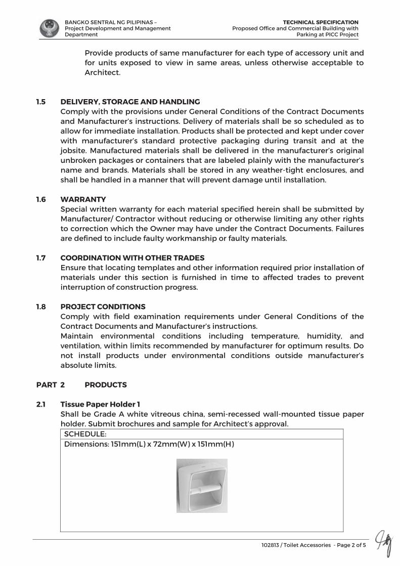
BANGKO SENTRAL NG PILIPINAS – Project Development and Management Department
TECHNICAL SPECIFICATION Proposed Office and Commercial Building with
Parking at PICC Project
102813 / Toilet Accessories - Page 2 of 5
Provide products of same manufacturer for each type of accessory unit and for units exposed to view in same areas, unless otherwise acceptable to Architect.
1.5 DELIVERY, STORAGE AND HANDLING Comply with the provisions under General Conditions of the Contract Documents and Manufacturer’s instructions. Delivery of materials shall be so scheduled as to allow for immediate installation. Products shall be protected and kept under cover with manufacturer’s standard protective packaging during transit and at the jobsite. Manufactured materials shall be delivered in the manufacturer’s original unbroken packages or containers that are labeled plainly with the manufacturer’s name and brands. Materials shall be stored in any weather-tight enclosures, and shall be handled in a manner that will prevent damage until installation.
1.6 WARRANTY Special written warranty for each material specified herein shall be submitted by Manufacturer/ Contractor without reducing or otherwise limiting any other rights to correction which the Owner may have under the Contract Documents. Failures are defined to include faulty workmanship or faulty materials.
1.7 COORDINATION WITH OTHER TRADES Ensure that locating templates and other information required prior installation of materials under this section is furnished in time to affected trades to prevent interruption of construction progress.
1.8 PROJECT CONDITIONS Comply with field examination requirements under General Conditions of the Contract Documents and Manufacturer’s instructions. Maintain environmental conditions including temperature, humidity, and ventilation, within limits recommended by manufacturer for optimum results. Do not install products under environmental conditions outside manufacturer’s absolute limits.
PART 2 PRODUCTS 2.1 Tissue Paper Holder 1
Shall be Grade A white vitreous china, semi-recessed wall-mounted tissue paper holder. Submit brochures and sample for Architect’s approval. SCHEDULE: Dimensions: 151mm(L) x 72mm(W) x 151mm(H)
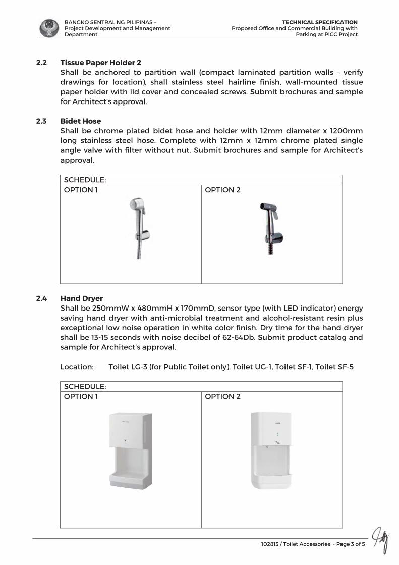
BANGKO SENTRAL NG PILIPINAS – Project Development and Management Department
TECHNICAL SPECIFICATION Proposed Office and Commercial Building with
Parking at PICC Project
102813 / Toilet Accessories - Page 3 of 5
2.2 Tissue Paper Holder 2 Shall be anchored to partition wall (compact laminated partition walls – verify drawings for location), shall stainless steel hairline finish, wall-mounted tissue paper holder with lid cover and concealed screws. Submit brochures and sample for Architect’s approval.
2.3 Bidet Hose Shall be chrome plated bidet hose and holder with 12mm diameter x 1200mm long stainless steel hose. Complete with 12mm x 12mm chrome plated single angle valve with filter without nut. Submit brochures and sample for Architect’s approval. SCHEDULE: OPTION 1
OPTION 2
2.4 Hand Dryer Shall be 250mmW x 480mmH x 170mmD, sensor type (with LED indicator) energy saving hand dryer with anti-microbial treatment and alcohol-resistant resin plus exceptional low noise operation in white color finish. Dry time for the hand dryer shall be 13-15 seconds with noise decibel of 62-64Db. Submit product catalog and sample for Architect’s approval.
Location: Toilet LG-3 (for Public Toilet only), Toilet UG-1, Toilet SF-1, Toilet SF-5
SCHEDULE: OPTION 1
OPTION 2
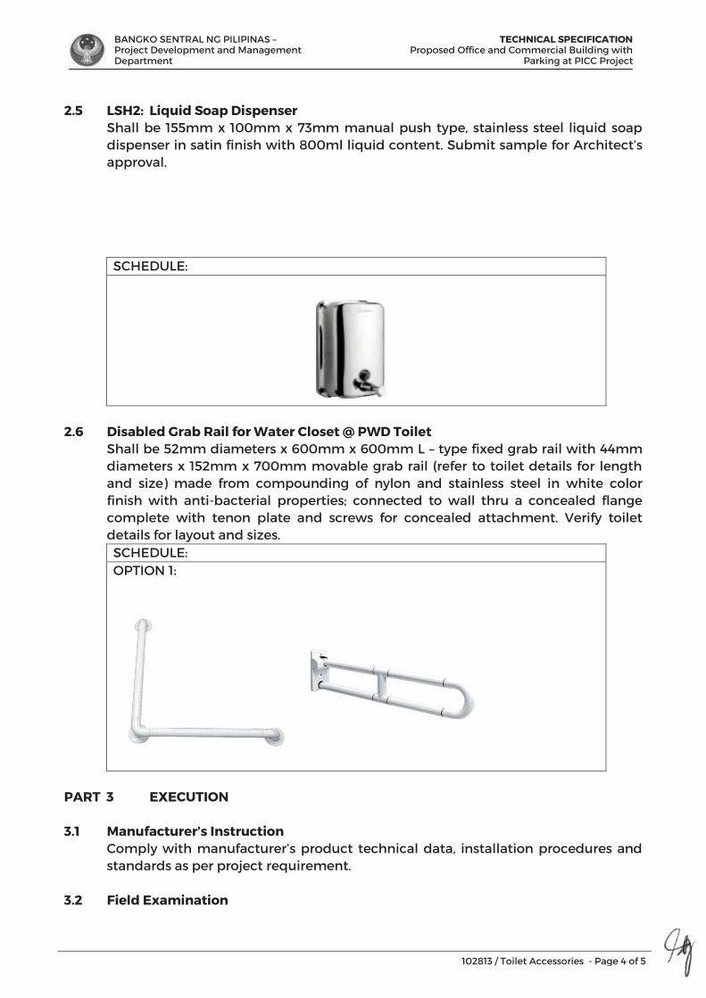
BANGKO SENTRAL NG PILIPINAS – Project Development and Management Department
TECHNICAL SPECIFICATION Proposed Office and Commercial Building with
Parking at PICC Project
102813 / Toilet Accessories - Page 4 of 5
2.5 LSH2: Liquid Soap Dispenser Shall be 155mm x 100mm x 73mm manual push type, stainless steel liquid soap dispenser in satin finish with 800ml liquid content. Submit sample for Architect’s approval.
SCHEDULE:
2.6 Disabled Grab Rail for Water Closet @ PWD Toilet Shall be 52mm diameters x 600mm x 600mm L – type fixed grab rail with 44mm
diameters x 152mm x 700mm movable grab rail (refer to toilet details for length and size) made from compounding of nylon and stainless steel in white color finish with anti-bacterial properties; connected to wall thru a concealed flange complete with tenon plate and screws for concealed attachment. Verify toilet details for layout and sizes. SCHEDULE: OPTION 1:
PART 3 EXECUTION
3.1 Manufacturer’s Instruction Comply with manufacturer’s product technical data, installation procedures and standards as per project requirement.
3.2 Field Examination
BANGKO SENTRAL NG PILIPINAS – Project Development and Management Department
TECHNICAL SPECIFICATION Proposed Office and Commercial Building with
Parking at PICC Project
102813 / Toilet Accessories - Page 5 of 5
3.2.1 Installer shall examine conditions under which construction activities are to be performed, then submit written notification if such conditions are acceptable.
3.2.2 Verify that accessories are installed and in the right location without interference with piping, fittings and fixture.
3.2.3 Surfaces must be clean, dry and free from dust, dirt, grease and loose or powdery material. Do not begin installation until substrates have been properly prepared.
3.3 Installation
3.3.1 Install toilet accessories plumb and level in accordance with shop drawings and manufacturer’s printed installation instructions. Installed heights shall be as shown on the drawings and in accordance to the provisions of the Accessibility Code.
3.3.2 Secure mirrors to walls in concealed, tamper-resistant manner using tile adhesive or mirror mastic with sponge tape. Set units level, plumb, and square at locations indicated, according to manufacturer’s written instructions for substrate indicated.
3.3.3 Surface of fastening devices exposed after installation shall have the same finish as the attached accessory.
3.4 Protection
All installations shall be protected with coverings as per manufacturer’s recommended material. Replace damaged or defective items caused by subsequent construction activities.
3.5 Adjusting and Cleaning 3.5.1 Verify that mechanisms function properly and adjust accessories as per
required installations. 3.5.2 Remove temporary labels and protective coatings. Clean and polish
exposed surfaces according to manufacturer’s written recommendations. END OF SECTION
BANGKO SENTRAL NG PILIPINAS – Project Development and Management Department
TECHNICAL SPECIFICATIONProposed Office and Commercial Building with
Parking at PICC Project
142123.16 / Elevator - Page 1 of 6
SECTION 14 21 23.16
ELEVATORS
PART 1 GENERAL
1.1 SCOPE OF WORK This section shall include all management, labor, materials, tools, equipment and services required to manufacture, assemble, deliver (including all import and export documents), and install all items necessary for the proper execution and completion of a Machine-Room-Less Passenger Elevator AND Service Elevator complete with testing and maintenance guaranty, as indicated in the General and Special Conditions of the Contract Documents, the Drawings, as specified herein, and/ or as required by job conditions.
1.2 REFERENCES The following standards form part of these specifications to the extent referenced, in accordance to the requirements under General Conditions of the Contract Documents and Manufacturer’s instructions: 1.2.1 National building Code of the Philippines, NBC 1.2.2 Underwriters Laboratories, UL 1.2.3 ASME A17 1-2007 Safety Code for Elevators and Escalators
1.3 SUBMITTALS Submit the following in accordance with the General Conditions of Contract and requirements specified herein:
1.3.1 Manufacturer’s data sheets on each product to be used, including documentation within thirty calendar days after award of the purchase order. Indicated in the document will be the type, size, rating, style, catalog number, manufacturer’s names, photos, and/ or catalog data sheets for all items proposed to meet these specifications. The proposed equipment shall be subject to the approval of the Architect/ Engineer and no equipment shall be ordered or installed on the premises without that approval.
1.3.2 Shop Drawings: Indicate dimensions and required tolerances, connection details, anchorage spacing, installation details and special conditions.
1.3.3 Operating and maintenance instruction manuals A. Operating instruction manuals outlining the step-by-step procedures required for the system start-up and operation shall be furnished in triplicate. The instruction shall include the manufacturer’s name, model number, service manual party list and brief description of all equipment and their basic operating features. B. Maintenance instruction manuals outlining maintenance procedures shall be furnished in triplicate. The manual shall include a troubleshooting
guide listing possible breakdown and repairs and a simplified connection wiring diagram for the system as installed.
1.3.4 Performance Test reports
BANGKO SENTRAL NG PILIPINAS – Project Development and Management Department
TECHNICAL SPECIFICATIONProposed Office and Commercial Building with
Parking at PICC Project
142123.16 / Elevator - Page 2 of 6
Upon completion of the installed system, the contractor shall submit in booklet form all field tests performed to prove compliance with the specified performance criteria.
1.3.5 Materials Safety Data Sheet (MSDS) Note: Submit product catalog and shop drawings from the manufacturer’s
standard details and installation for Architect’s approval before construction of elevator shaft’s during the construction.
1.4 QUALITY ASSURANCE
1.4.1 Comply with quality assurance requirements, under General Conditions of the Contract Documents and Manufacturer’s instructions.
1.4.2 Manufacturer’s Qualification: Manufacturer shall have minimum of five (5) years documented experience
producing requirements specified and approved by the Architect/Engineer. Supplier’s and Contractor’s qualifications shall be submitted indicating years in business, service policies, warranty definitions, and with certifications of ISO 9001.
1.4.3 Manufacturers/ Distributors Services: Supervision shall be provided by an authorized factory trained service
technician from the dealer of the elevator equipment. The technician shall have a minimum of one years of service experience in the elevator industry.
1.5 DELIVERY, STORAGE AND HANDLING
Comply with the provisions under General Conditions of the Contract Documents and Manufacturer’s instructions. Delivery of materials shall be so scheduled as to allow for immediate installation. Products shall be protected and kept under cover with manufacturer’s standard protective packaging during transit and at the jobsite. Manufactured materials shall be delivered in the manufacturer’s original unbroken packages or containers that are labeled plainly with the manufacturer’s name and brands. Materials shall be stored in any weather-tight enclosures, and shall be handled in a manner that will prevent damage until installation.
1.6 WARRANTY
Special written warranty for each material specified herein shall be submitted by Manufacturer/ Contractor without reducing or otherwise limiting any other rights to correction which the Owner may have under the contract Documents. Failures are defined to include faulty workmanship or faulty materials.
1.7 COORDINATION WITH OTHER TRADES
Ensure that locating templates and other information required prior installation of materials under this section is furnished in time to affected trades to prevent interruption of construction progress.
1.8 PROJECT CONDITIONS
Comply with field examination requirements under General Conditions of the Contract Documents and Manufacturer’s instructions. Maintain environmental conditions including temperature, humidity, and ventilation, within limits recommended by manufacturer for optimum results. Do not install products under environmental conditions outside manufacturer’s absolute limits
6
BANGKO SENTRAL NG PILIPINAS – Project Development and Management Department
TECHNICAL SPECIFICATIONProposed Office and Commercial Building with
Parking at PICC Project
142123.16 / Elevator - Page 3 of 6
1.9 Acceptance Test
The contractor shall conduct tests in the presence of inspector or authority having jurisdiction for elevator and escalator works. Test certificate shall be filled out and signed by the Owner’s and contractor’s representative. System operations and maintenance chart shall be submitted to the Owners upon completion of the Contract. This shall include, among others the locations of the controls and care of the new equipment.
1.10 Defects Liability Period
During the DLP and Warranty, the contractor shall ensure proper maintenance of the equipment including replacement of any part such as electric motors, hoist, and switches or consumables such as lubricant oil necessary for the proper operation.
The contractor shall check and test the whole system of the elevator every 6 months from the start of the DLP and on the 6th and 11th month of the warranty period.
1.11 Defective Work
If the inspection and test show any defect such defective work or material shall be replaced and the test shall be repeated until such satisfactory to the Owner. All repairs shall be made with new material at the expense of the Contractor.
PART 2 PRODUCTS
2.1 MPE: Main Passenger Elevator (Machine-Room-Less System) @ Office Building) Shall be a Machine-Room-Less System Passenger Elevator with energy saving operation allocation control, car capacity shall be 13 maximum numbers of persons, 1,000 kg rated capacity and 1.0 m/sec rated speed. Car internal dimensions and hoistway internal dimension verify Architectural drawings. Elevator system shall be connected to video surveillance system. Submit product catalog and shop drawings from the manufacturer’s standard details and installation for Architect’s approval, before pouring of elevator shaft’s shear wall in the construction. See Architectural and Structural Drawings for layout and details.
2.1.1 Materials: Basic Finishes Walls and Doors are St43 Stainless, PVC Flooring all Standard.
2.2 MPE: Main Passenger Elevator (Machine-Room-Less System) @ Commercial Building Shall be a Machine-Room-Less System Passenger Elevator with energy saving operation allocation control, car capacity shall be 6 maximum numbers of persons, 450 kg rated capacity and 1.0 m/sec rated speed. Car internal dimensions and hoistway internal dimension verify Architectural drawings. Elevator system shall be connected to video surveillance system. Submit product catalog and shop drawings from the manufacturer’s standard details and installation for Architect’s
6
BANGKO SENTRAL NG PILIPINAS – Project Development and Management Department
TECHNICAL SPECIFICATIONProposed Office and Commercial Building with
Parking at PICC Project
142123.16 / Elevator - Page 4 of 6
approval, before pouring of elevator shaft’s shear wall in the construction. See Architectural and Structural Drawings for layout and details.
2.2.1 Materials: Basic Finishes Walls and Doors are St43 Stainless, PVC Flooring all Standard.
2.3 SPE: Service Passenger Elevator (Machine-Room-Less System) @ Commercial
Building Shall be a Machine-Room-Less System Passenger Elevator with energy saving operation – allocation control, car capacity shall be 800 kg rated capacity and 1.00 m/sec. rated speed. Car internal dimensions and a minimum hoistway internal dimension verify Architectural drawings. Elevator system shall be connected to video surveillance system. Submit product catalog and shop drawings from the manufacturer’s standard details and installation for Architect’s approval, before pouring of elevator shaft’s shear wall in the construction. See Architectural and Structural Drawings for layout and details.
2.3.1 Materials: Basic Finishes Walls and Doors are St43 Stainless, PVC Flooring all Standard.
2.4 Machine-Room-Less System Features
Note: Follow manufacturer’s recommended standard features for the passenger Elevator design.
2.4.1 Emergency Operations and Features A. Emergency Landing Device
Upon power failure, a car equipped with this function automatically moves to and stops at the nearest floor using a rechargeable battery, and the doors open to facilitate the safe evacuation of passengers. (Maximum allowable floor-to-floor distance is 11 meters)
B. Fire emergency Return (FER) Upon activation of a key switch or a building’s fire alarm, all call is
cancelled, all cars immediately return to a specified evacuation floor and the doors open to facilitate the safe evacuation of passenger.
C. Earthquake Emergency Return (EER-P/EER-S) Upon activation of primary and/or secondary wave seismic sensors,
all cars stop at the nearest floor, and park there with the doors open to facilitate the safe evacuation of the passenger.
D. Supervisory Panel (WP) Each elevator’s status and operation can be monitored and
controlled through a panel installed in a building’s supervisory room, etc.
E. Emergency Car Lighting (ECL) Car lighting which turns on immediately when power fails, providing
a minimum level of lighting within the car. (Choice of dry-cell battery or trickle-charge battery)
2.4.2 Door Operation Features A. Automatic Door Speed Control (DSAC)
BANGKO SENTRAL NG PILIPINAS – Project Development and Management Department
TECHNICAL SPECIFICATIONProposed Office and Commercial Building with
Parking at PICC Project
142123.16 / Elevator - Page 5 of 6
Door load on each floor, which can depend on the type of hall door, is monitored to adjust the door speed, thereby making the door speed consistent throughout all floors.
B. Automatic Door-open Time Adjustment (DOT) The time doors are open will automatically be adjusted, depending
on whether the stop was called from the hall or the car, to allow smooth boarding of passengers or loading of baggage.
C. Repeat Door-Close (RDC) Should an obstacle prevent the doors from closing, the doors will
repeatedly open and close until the obstacle is cleared from the doorway.
D. Extended Door-Open Button (DKO-TB) When the button inside a car is pressed, the doors will remain open
longer to allow loading and unloading of baggage, a stretcher, etc. E. Hall Motion Sensor (HMS) Infrared-light is used to scan a 3D area near open doors to detect
passengers or objects. 2.4.3 Operational and Service Features A. Safe Landing (SFL) If a car has stopped between floors due to some equipment
malfunction, the controller checks the cause, and if it is considered safe to move the car, the car will move to the nearest floor at a low speed and the doors will open.
B. Next Landing (NXL) If the elevator doors do not open fully at a destination floor, the doors
close, and the car automatically moves to the next or nearest floor where the doors will open.
C. Overload Holding Stop (OLH) A buzzer sounds to alert the passengers that the car is overloaded.
The doors remain open and the car will not leave that floor until enough passengers exit the car.
D. Automatic Hall Call Registration (FSAT) If one car cannot carry all waiting passengers because it is full,
another car will automatically be assigned for the remaining passengers.
E. Car Fan Shut Off – Automatic (CFO-A) If there are no calls for a specified period, the car ventilation fan will
automatically turn off to conserve energy. F. Car Light Shut Off – Automatic (CLO-A) If there are no calls for a specified period, the car lighting will
automatically turn off to conserve energy. G. Automatic Bypass (ABP) A fully-loaded car bypasses hall calls in order to maintain maximum
operational efficiency. H. Out-of-Service by Hall Key Switch (HOS/HOS-T) For maintenance or energy-saving measures, a car can be taken out
of service temporarily with a key switch (with or without a timer) mounted in a specified hall.
2.4.4 Signal and Display Features A. Basic Announcement (AAN-B)
BANGKO SENTRAL NG PILIPINAS – Project Development and Management Department
TECHNICAL SPECIFICATIONProposed Office and Commercial Building with
Parking at PICC Project
142123.16 / Elevator - Page 6 of 6
A synthetic voice (and/or buzzer) alerts passengers inside a car that elevator operation has been temporarily interrupted due to overloading or a similar cause. (Voice available only in English.)
B. Voice Guidance System Information on elevator service such as the current floor or service
direction is given to the passengers inside a car. (Voice guidance available in English, Chinese and Spanish.)
PART 3 EXECUTION 3.1 Comply with Manufacturer’s standard accessories, space allocation and
installation procedures. Submit shop drawings prior fabrication. 3.2 Consult with adjacent works to avoid delay in the construction. 3.3 Perform test to determine compliance with the specified requirements in the
presence of the Owner’s representative. Test, inspect, and approve operation before finishing.
END OF SECTION

BANGKO SENTRAL NG PILIPINAS – Project Development and Management Department
TECHNICAL SPECIFICATIONProposed Office and Commercial Building with
Parking at PICC Project
211313 / Wet-Pipe Sprinkler System - Page 1 of 9
SECTION 21 13 13
WET PIPE SPRINKLER SYSTEMS
PART 1 GENERAL
1.1 SCOPE OF WORK 1.1.1 Application provisions of the General Conditions of the Contract
Documents govern work under this section.
1.1.2 This section shall include the furnishing of all labor, materials, equipment and service necessary or incidental to the complete installation, testing adjusting, and placing into service of the several systems of fire protection, all as show on the drawings and as herein after specified. Drawings and specifications are considered mutually explanatory and all works called for by one and not the other shall be performed as though called for by both. In cases of conflicting information, the Architect and Engineer shall be notified at once in writing where incidental equipment or appurtenances are required for a complete fire protection system.
1.1.3 Drawings are intended to show general arrangement and approximate physical sizes of equipment diagrammatically. Every bolt, nut, brace, strut, etc. is not necessarily indicated to the proper and dependable operation of each system being a requirement of this contract whether specifically referred to or not, must be supplied.
1.1.4 Work included in this specification shall consist of, but not necessary limited to the following items and shall comply with the General Provisions of the Contract Documents: A. Arrange for, obtain and bear the cost of necessary permits, bonds and
for the automatic sprinkler work. B. All permit fees, private or government shall be for the Contractor. C. Furnish and install sprinkler system to sprinkler the entire building
where shown in the drawing. System to include all pipes, hanger, sway braces, sprinkler heads, control valves, drain valves, alarms, alarm bells, water flow switches and control valve monitor switches, sprinkler supervisory control panel, fire pump, jockey pump, drives and controllers and necessary accessories, fire hose cabinets and accessories, pressure relief valve and other valves.
D. Furnish and install fire department connections located where shown on the drawings.
E. Do the testing of all piping work and necessary cleaning of the fire protection work.
F. Furnish the shop drawings and certificates of inspection. G. Periodically remove from the jobsites all rubbish and debris resulting
from the fire protection work. H. Do all cutting and patching. I. Fire extinguishers shall be furnished by the Contractor based on the fire
department requirements over the above those specified, i.e., fire extinguisher requirements at the different areas and floors.
9
BANGKO SENTRAL NG PILIPINAS – Project Development and Management Department
TECHNICAL SPECIFICATIONProposed Office and Commercial Building with
Parking at PICC Project
211313 / Wet-Pipe Sprinkler System - Page 2 of 9
1.1.5 Work by Others A. Electrical Contractor to wire water flow switches on valves to central
alarm panel. He shall also wire alarm bells. B. Fire reservoir and make-up water piping to water tank shall be done
by others.
1.2 REFERENCES Comply with quality assurance requirements under General Conditions of the Contract Documents and Manufacturer’s instructions. Reference the following standards as applicable:The applicable current standard for the fire protection systems shall be as follows: 1.2.1 National Fire Protection Association (NFPA), NFPA – 13 1.2.2 National Fire Protection Association (NFPA), NFPA - 2001 1.2.3 Philippine Fire Code, P.D. 1185 1.2.4 All other applicable local codes and ordinances as applicable.
1.3 SUBMITTALS 1.3.1 General: All submittals for approval as indicated herein shall be in
accordance to the provisions under General Conditions of the Contract Documents.
1.3.2 Shop Drawings Data A. Before commencing any work or providing any material at the jobsite
for this project, the Fire Protection Contractor shall not proceed with the installation of the work until he has received the Architect’s approval on his shop drawings.
B. The Architect’s approval on shop drawings, catalogue cuts, etc. shall not relieve the Fire Protection Contractor of the responsibility for any errors or omission which may exist in the items submitted nor shall it relieve him from the responsibility for deviations from the contract drawing and specifications. The stamped approval of the shop drawings, catalogue cuts, etc. shall not be construed as a complete check but will indicate only that the general design and method of construction is satisfactory.
C. In the event additional clarifying details shall be prepared and approval of same secured by the Fire Protection Contractor at his expense.
Note: All submitted shop drawings shall be coordinated with other engineering
design and other utility lines during the construction.
1.4 QUALITY ASSURANCE 1.4.1 Comply with quality assurance requirements under General Conditions of
the Contract Documents and Manufacturer’s instructions. 1.4.2 Qualification of Contractors: The Contractor for the fire protection
installation shall be qualified Fire Protection Contractor, regularly engaged in the installation of automatic fire sprinkler systems and other fire protection equipment.
1.4.3 Conduct of work: The fire Protection contractor shall employ on the job at all times a competent superintendent who shall be responsible for the progress and execution of the work.
9
BANGKO SENTRAL NG PILIPINAS – Project Development and Management Department
TECHNICAL SPECIFICATIONProposed Office and Commercial Building with
Parking at PICC Project
211313 / Wet-Pipe Sprinkler System - Page 3 of 9
1.5 DELIVERY, STORAGE AND HANDLING 1.5.1 General: Comply with product delivery requirements under General
Conditions of the Contract Documents and Manufacturer’s instructions. 1.5.2 The Fire Sprinkler Contractor shall be hoisting, rigging and final placement
required for all materials and equipment necessary for the proper completion of his work.
1.5.3 The Fire Sprinkler Contractor shall be allowed, but not guaranteed, on site storage space. The Fire Sprinkler Contractor shall agree the site storage areas in advance of material deliveries to the project, and if necessary, make alternative arrangements for offsite warehouse storage and marshaling at no cost to the Contract.
1.5.4 Store and assemble all equipment and accessories on a specific area as designated by the Construction Manager.
1.5.5 Coordinate the on-site placement of any of his material and/or equipment with Civil Contractor so as not to impede the progress of any other Trade Contractor’s operation who is working concurrently on the site. Such storage place shall be kept neat and clean, and all damages thereto or to its surrounding shall be repaired by the Trade Contractor at no additional cost.
1.5.6 The Fire Sprinkler and Fire Suppression Contractor shall provide all tools and equipment necessary for the carrying out his work; including but not limited to: Artificial lighting necessary for the proper execution of the Works during the general working hours of the Site from time to time, together with supply of electricity from the temporary central power supply at the site.
1.5.7 The Fire Sprinkler and Fire Suppression Contractor has provided for the temporary works relative to the performance of his work such as site office, workshop and storage shades. He shall allow for moving such office, workshop and storage shed, etc. from time to time as may be required to enable the Structural and Partial Architectural Contractor and other trades to proceed with their works in accordance with the program.
1.5.8 Contractor must include as part of his preliminaries the following: A. Removal and disposal of his own share of construction debris and
rubbish in the assigned disposal stations at the project site. B. Connection of his own water supply (if necessary) to the tapping points
assigned by the Structural and Partial Architectural Contractor. C. Site Security for his own warehouse. D. Coordination of the Fire Sprinkler Contractor’s work with other trades for
the successful implementation and completion of the project.
1.6 WARRANTY Special written warranty for each material specified herein shall be submitted by Manufacturer/ Contractor without reducing or otherwise limiting any other rights to correction which the Owner may have under the Contract Documents. Failures are defined to include faulty workmanship or faulty materials.
1.7 PROJECT CONDITIONS
Comply with field examination requirements under General Conditions of the Contract Documents and Manufacturer’s instructions.
9
BANGKO SENTRAL NG PILIPINAS – Project Development and Management Department
TECHNICAL SPECIFICATIONProposed Office and Commercial Building with
Parking at PICC Project
211313 / Wet-Pipe Sprinkler System - Page 4 of 9
PART 2 PRODUCTS 2.1 Basic Materials and Method
2.1.1 Selection of Materials and Equipment A. All materials and equipment furnished under this section shall be new
and listed by Factory Mutual (FM) and/or Underwriter’s Laboratories, Inc. (UL)/American Water Works Association (AWWA) and/or other acceptable standards for fire protection system.
B. The proposal submitted shall include all materials and equipment as specified or shown on the drawings.
2.2 Automatic Sprinkler and Standpipe System Sprinkler heads Shall be automatic standard 15mm dia. orifice, solder fillet type or valve type,
upright, pendent or sidewall heads. Pendent heads shall be provided with aluminum escutcheon or approved equivalent to fit into ceiling boards or ceiling runners, Flush or concealed type pendent units shall be accepted as substitute. Heads shall be FM and/or UL Inc. approved. Submit product catalog and shop drawings for Architect’s approval.
Head Rating and Type:
Kitchen – 175 to 225 degrees F – Chrome Plated Office/Res’l – 135 degrees F (for use in max. ceiling temperature of 100
degrees F) – Chrome plated Parking Areas – 135 degrees F (for use in max. ceiling temperature of 100
degrees F) – Brass, wax Coated.
Pipe thread and Valve seat – 15mm diameter nominal Spare Sprinkler Heads
Pendant Type – 24 pcs Upright - 24 pcs Flushed Type – 24 pcs Sidewall Type – 24 pcs
Sprinkler Tongs – 3 pcs. Required Sprinkler Wrench – 3 pcs required Furnish spare heads as required in the code and maintenance service part list for a period of at least on (1) year reckoned from the date after termination of warranty.
2.3 Fire Hose Cabinets Shall be full flush mounting door with anodized cal-colored aluminum for all glass
plate, frame and box No. 14 gauge steel with interior and red exterior baked enamel finishes over primer. Hose shall be 40mm diameter, 30.0 double jacket, rubberlined with nozzle of combination fog and solid stream, 40mm diameters chrome plated and semi-automatic chrome plated rack. Angle-type pressure reducing valve shall be 40mm diameters, chrome plated polished trim, 110m water pressure with nipple and union patent, set 70 m. water pressure. Hose nipple shall be chrome plated with two universal spanner wrenches. Hose and Valve assembly shall be UL listed and/or FM approved and/or other acceptable
9
BANGKO SENTRAL NG PILIPINAS – Project Development and Management Department
TECHNICAL SPECIFICATIONProposed Office and Commercial Building with
Parking at PICC Project
211313 / Wet-Pipe Sprinkler System - Page 5 of 9
standards for fire protection system. Submit product catalog and shop drawings for Architect’s approval.
2.4 Fire Department Connections (Inlet) Shall be two way inlet connections, 65mm x 65mm x 150mm for Sprinkler system
and 65mm x 65mm x 100mm for Dry standpipe, UL listed and/or FM approved and/or other acceptable standards for fire protection system, vertical cast brass with plug spring check snoots, complete with plugs and chain and cast brass escutcheon lettered “Dry Standpipe”/”AFSS” threads to suit integrated Metropolitan Fire Department specifications.
2.5 Wall Hydrants (Fire Hose Valves) Shall be single outlet type wall mounted with chain connected caps and plugs in
polished brass finish. Threads and type of connection shall match Integrated Metropolitan Fire Department, UL listed and/or FM approved and/or other acceptable standards for fire protection system.
2.6 Portable Fire Extinguishers/ Ceiling Type Fire Extinguisher
Portable fire extinguisher classification and rating system shall have certified by the Bureau of Product Standard, Department of Trade and Industry (DTI). Capacity of extinguisher shall be as indicated.
2.7 Escutcheon Plates Shall be split hinge metal plates for piping entering walls, floors, and ceilings in
exposed spaces. Provide polished stainless steel plates or chromium-plated finish on copper alloy plates in finished spaces. Provide paint finish on metal plates in unfinished spaces.
2.8 Piping Where American Standards are specified, other approved national or local
standards may be acceptable, provided copies of these standard Specifications are forwarded to the Engineer for his written approval.
Black iron, schedule 40 pipes, ASTM A53.
All inside piping shall be installed by means of screwed or flanged fittings. Flanged joint shall be used at all sprinkler risers and provided with 1.6 mm thick long fiber asbestos, cross laminated gasket.
Torch cutting shall not be permitted as means of modifying or repairing sprinkler system.
All welding shall be "shop welding” only and shall be done by a certified TESDA NCII using electric arc welding process. All underground pipes shall be primer coated and wrapped by anticorrosion tape.
9
BANGKO SENTRAL NG PILIPINAS – Project Development and Management Department
TECHNICAL SPECIFICATIONProposed Office and Commercial Building with
Parking at PICC Project
211313 / Wet-Pipe Sprinkler System - Page 6 of 9
2.9 FittingsSprinkler system fitting shall be extra heavy pattern. Whenever a change in pipe size is made, one piece of reducing /increaser fitting shall be used. Provide mechanical grooved couplings at each main feed line of every floor just after the riser and along the ceiling line. All fittings shall be of malleable iron fittings ASME B16.3. Steel pipe flangers mating with steel equipment flangers shall have the same facing as mating flange. Screwed union shall not be used on pipes larger than 50 mm (2"). Couplings and unions of pipes other than screwed type shall be of types approved specifically for sprinkler used.
2.10 Valves 2.10.1 Shall be of the same manufacture for each class of piping and as such as
possible, for the entire project. Valves shall permanently bear affixed stamp or tag indicating manufacturer, catalog number, pressure and temperature ratings of gate valve, angle valves, check valves, pressure relief with all cast iron body with bronze trim.
2.10.2 Furnish all valves and accessories material necessary for piping not shown on drawings as follows: a. Vents and drains for equipment to which piping connections are
made. b. Connections to metering instruments and controls including
pressure gauges, thermometer, controllers, traps and appurtenances required for proper functioning on instruments in controls.
c. Temporary valves and accessories required for placing equipment into initial service.
d. Piping 50mm (2”) and smaller required for proper operation of piping system and equipment, including drain valves required to drain all low points in piping.
2.10.3 Valves seats shall be renewable except for forged steel and high pressure cast steel valves where manufacturer’s standard integral seats.
2.10.4 All valves shall be approved by Factory Manual and/or Underwriters Laboratories, Inc. (UL Listed) and/or other acceptable standards for fire protection system.
2.10.5 Where required and not noted, provided chain-wheel operators, extending chain for chain operated valves to which 1.2 meters of nearest floor or operating platform valves.
2.10.6 Provide floor stand with flanged faces for bolting to floor or platforms and other special devices where specified or noted on drawings.
2.10.7 Provide extension stems, universal joints stem guide bearings and other accessories required to locate floor stands in convenient location with interference with other equipment, piping or building parts.
2.10.8 Floor control valves within the buildings shall be approved indicating wedge with electrical contact and which will open when valve is partially or totally put in close position.

BANGKO SENTRAL NG PILIPINAS – Project Development and Management Department
TECHNICAL SPECIFICATIONProposed Office and Commercial Building with
Parking at PICC Project
211313 / Wet-Pipe Sprinkler System - Page 7 of 9
2.11 Sway Bracing Shall be steel flat bars, structural grade 7mm minimum thickness with corrosion
protection; shape/type as shown on plans. 2.11.1 Sway Bracing Installation
a. Adequate sway bracing shall be provided to oppose longitudinal or transverse pipe movements.
b. Lateral bracings shall withstand a force equal to 50% of the weight of the water contained in piping, valves and fittings.
c. Piping anchorage shall not be secured on two (2) dissimilar parts of the building which will move differently.
2.12 Pipe Hangers Shall be steel flat bars, structural grade 7mm minimum thickness with corrosion
protection shape as shown on plans and 13mm diameters bars with corrosion protection. Reference manufacturer shall be “Fisher” or approved equal.
2.12.1 Hangars Installation
a. Approved inserts may be used for the support of hangers, anchorages in concrete. Expansion shield should be used in a horizontal position on the sides of concrete beams and shall be above the bottom reinforcements.
b. Increase couplings shall be attached immediately adjacent to the expansion shields.
c. When pipes 100mm dia. And larger are supported in the vertical position, the supports shall be at a minimum spacing of 3 meters (10’) on center. Holes in concrete for expansion shield shall be made of the proper size and depth, as specified for the type of shield used, to provide a uniform contact with the shield its entire length and circumference.
d. Maximum distance between hangers shall be 3.65 meters (12’) for sizes 25mm (1”). Provide at least on hanger for each length of branch line, one between each two cross main branches, one hanger for each 4.75 meters (15’) length of feed mains. The distance between the hanger and the center line of upright sprinkler shall be not less than 6mm (3”).
2.13 Supports on Risers Shall be adequately supported either by attachments directly to the riser or by
hangers located on the horizontals connections close to the risers. Supports shall be provided at the ground level and at each third level and at the top most level of the riser. Reference manufacturer shall be “Fisher” or approved equal.
2.14 Pipe Sleeves Shall be cast iron for through footings, cast iron or standard weight iron pipe for
below grade and steel pipe for above grade. 2.14.1 Pipe Sleeves Installation a. Minimum clearance between the pipe and sleeve shall not be less
than 25 mm. (1") for pipes, 25mm. (1") to 89 mm. (3-1/2") and 50 mm. (2") clearance for pipes 100 mm. (4") and larger. The clearance
BANGKO SENTRAL NG PILIPINAS – Project Development and Management Department
TECHNICAL SPECIFICATIONProposed Office and Commercial Building with
Parking at PICC Project
211313 / Wet-Pipe Sprinkler System - Page 8 of 9
between pipes and sleeves shall be filled with non-combustible flexible materials such as asbestos rope and furnished with semi-hardening mastic flush.
b. Floor sleeves shall extend at least 76 mm. (3") above the top of the wearing surface.
c. Drains, fire department connections, test manifolds and other auxiliary piping connected to risers shall not be cemented into walls or floors.
2.15 Pipe Painting Sprinkler heads, valve stems and the like shall not be painted. After installation
and test and before the installation of ceiling fixtures or boards, all piping shall be prime painted and coated with two coats of gloss red quick drying enamel.
2.15 Alarm Check Valves The alarm assemblies shall be constructed and installed, that any flow of water
from the sprinkler system equal to or greater than from a single automatic sprinkler head, will result in an audible and visual alarm bells whether water or electrically actuated shall be capable of being actuated both automatically and annually. Alarm check valve shall be UL Listed and/or FM Approved.
The water actuated alarm check valve assembly shall be complete with all the necessary attachments required to give an alarm and ease in maintenance. The gong shall be installed as indicated in the plans. The alarm check valve shall consist of but not limited to the following:
1. Retard chamber 2. Water motor 3. Weatherproof gong, 300 mm dia. 4. Strainer 5. Pressure gages 6. Drain and attachments 7. Electrically supervised control valves 8. Pressure switches
2.16 Floor Control Valves and Water Flow Switches or Detectors Flow alarm valves with sizes indicated on the plans shall be provided with two (2)
N.O. electrical contacts that will close instantaneously with steady flow of water in the pipe and shall be complete with tamperproof terminal chamber with minimum of 1/2" dia. conduit. False alarm shall be prevented by an adjustable pneumatic device to retard the flow switch operation due to water surges. The switch shall be actuated only by a unidirectional flow of water. Electrical connections from these valves shall be done by the Electrical Contractors.
The alarm apparatus shall be substantially supported, located and installed so that
all parts shall be readily accessible for inspection, removal and repair. An actual water flow, through the use of the test connection, shall be employed to
test the operation of the sprinkler alarm units in each floor or as a whole.

BANGKO SENTRAL NG PILIPINAS – Project Development and Management Department
TECHNICAL SPECIFICATIONProposed Office and Commercial Building with
Parking at PICC Project
211313 / Wet-Pipe Sprinkler System - Page 9 of 9
2.17 Alarm and Supervisory System The supervisory and alarm system shall be integrated with the building Fire Alarm
System. The Fire Alarm System annunciator shall indicate the flow valves, and the valves, and the valve supervisory switches.
2.18 Markers, Instruction and Identification Charts
These signboards shall be made of gauge No. 14 black iron sheet with baked enamel finish and letter instruction as shown on the plans. Additional signboards shall be mounted on the unobstructed for easy identification reading. Paints shall be basically gloss fire red and white.
PART 3 EXECUTION 3.1 All installations shall be done in compliance to the Manufacturer and Fire
Protection Contractor’s standard procedures and applicable Codes as specified herein. 3.1.1 The mechanicals for this work shall cooperate with the mechanics for all
other work in the building. The installation of piping and sprinkler heads shall be coordinated with existing conditions and all other construction, including but not limited to, the ductwork, piping, conduits, lighting fixtures, acoustical ceilings, and building structures. Any conflicts that occur with the work of other trades as a result of the lack of coordination by the installers of the fire protection work shall be adjusted at the expense of the fire protection subcontractor and as required and approved by the Architect.
3.1.2 Arrange with Contractors of other trades for installation of built-in items, blocking and additional necessary supports.
3.1.3 Sleeves shall be furnished and installed wherever pipe passes through walls, partitions or floors, and the space between the pipe and sleeve shall be packed. Provide sleeves having an internal diameter 1” larger (unless specifically indicated otherwise) than the outside diameter of the pipe.
3.1.4 In placing sleeves, inserts, anchor bolts and any other material to be embedded in masonry and concrete or built into the structure, the Contractor shall cooperate with all other trades and shall consult with the Architect in regard to their exact location whenever there is any interference with structural members.
3.1.5 The Contractor will be held responsible for locating and maintaining in proper position, sleeves, inserts and anchor bolts supplied and/ or set in place by him. In the event that failure to do so requires cutting and patching of finished works, it shall be done at the Contractor’s expense.
END OF SECTION
BANGKO SENTRAL NG PILIPINAS – Project Development and Management Department
TECHNICAL SPECIFICATIONProposed Office and Commercial Building with
Parking at PICC Project
213213 / Electric Driven, Vertical Turbine Fire Pump - Page 1 of 6
SECTION 21 32 13
ELECTRIC DRIVEN, VERTICAL TURBINE FIRE PUMPS
PART 1 GENERAL
1.1 SCOPE OF WORK 1.1.1 Application provisions of the General Conditions of the Contract
Documents govern work under this section.
1.1.2 Furnish, install and test a motor-driven fire pump, jockey pump, and controllers in the space provided and as shown in the contract drawings.
1.1.3 Provide pumps, controllers and appurtenances in accordance with this Section, the contract drawings and the Reference Codes and Standards.
1.2 REFERENCES Comply with quality assurance requirements under General Conditions of the
Contract Documents and Manufacturer’s instructions. Reference the following standards as applicable: The applicable current standard for the fire protection systems shall be as follows: 1.2.1 National Fire Protection Association (NFPA), NFPA – 13 1.2.2 National Fire Protection Association (NFPA), NFPA – 20 1.2.3 National Fire Protection Association (NFPA), NFPA - 2001 1.2.4 Philippine Fire Code, R.A. 9514 1.2.5 All other applicable local codes and ordinances as applicable.
1.3 SUBMITTALS AND QUALITY ASSURANCE 1.3.1 General: All submittals for approval as indicated herein shall be in
accordance to the provisions under General Conditions of the Contract Documents.
1.3.2 Manufacturer’s installation drawings shall be submitted together with the proposal. After installation is completed as “as-installed” drawings showing all the field revisions and exact locations/dimensions on reproducible form plus two (2) white print copies shall be submitted to the Owners at the Contractor’s expense.
1.3.3 Pump performances curves shall be submitted together with the proposal. The pump efficiencies at various workloads shall be indicated thereon and properly marked.
1.3.4 Test run shall be performed by the supplier after the installation is completed, to demonstrate conformity to the manufacturer’s specifications. A successful test shall be a condition to the Owner’s acceptance of the installed equipment and to final payment.
1.3.5 A direct statement on the availability of spare parts and maintenance service from pump supplier, for a period of at least three (3) years reckoned from the date of acceptance test shall be submitted.
1.3.6 Submit Materials Safety Data Sheet (MSDS)
Note: All submitted shop drawings shall be coordinated with other engineering design and other utility lines during the construction.
BANGKO SENTRAL NG PILIPINAS – Project Development and Management Department
TECHNICAL SPECIFICATIONProposed Office and Commercial Building with
Parking at PICC Project
213213 / Electric Driven, Vertical Turbine Fire Pump - Page 2 of 6
1.4 WARRANTY Special written warranty for each material specified herein shall be submitted by Manufacturer/ Contractor without reducing or otherwise limiting any other rights to correction which the Owner may have under the Contract Documents. Failures are defined to include faulty workmanship or faulty materials.
1.5 PROJECT CONDITIONS
Comply with field examination requirements under General Conditions of the Contract Documents and Manufacturer’s instructions.
1.6 Defects Liability Period During the DLP and Warranty, the contractor shall ensure proper maintenance of the equipment including replacement of any part such as valves, sprinkler head, gauge and switches or consumables such as packing gland seal, escutcheon plates and other necessary for the proper operation.
PART 2 PRODUCTS
2.1 Basic Materials and Method 2.1.1 Selection of Materials and Equipment
A. All materials and equipment furnished under this section shall be new and listed by Factory Mutual (FM)/Underwriter’s Laboratories, Inc. (UL)/other acceptable standards for fire protection system.
B. The proposal submitted shall include all materials and equipment as specified or shown on the drawings.
2.1.2 Fire Pump, Jockey Pump and Controls A. Fire Pump Assembly: Furnish and install where shown on plans one (1)
Factory Mutual and Underwriters Laboratories Inc. approved fire service pump motors, motor starters, control fittings and other appurtenances and accessories necessary to complete the equipment installation in each respect. Pumps shall be connected as shown in the drawings. Complete installation shall be in accordance with the requirements and meeting with the approval of the NFPA 20 and Bureau of fire.
Parts Frequency of Cleaning/Checking
Fire pump and Controller
Every month from start of the DLP and on the 6th and 11th month of the warranty period. Contractor shall coordinate with
PDMD for the testing of the pumps. Jockey pump and Controller Pipes
Checking for leaks and conduct of flow test through passing of water through test and drain headers. Every 6 months from start of the DLP and on the 6th and 11th month of
the warranty period.
Valves Sprinkler heads accessories Pressure gauges Flow and Supervisory Switch Fire Extinguisher Fire Hose Cabinet

BANGKO SENTRAL NG PILIPINAS – Project Development and Management Department
TECHNICAL SPECIFICATIONProposed Office and Commercial Building with
Parking at PICC Project
213213 / Electric Driven, Vertical Turbine Fire Pump - Page 3 of 6
B. Fire Pumps: The fire pump shall be Electric Motor Driven Vertical Turbine. Pump suction shall be provided with stainless steel strainer NFPA-20. The pump shall be supplied with all accessories to include controllers, circuit breakers, starters, trims and other accessories to complete the works. Fire Pump volumetric capacity @ lower ground level shall be 750 gpm vs. 295 ft tdh (130 psig) approx 90 HP.
Pump Unit Major Accessories:
1. Circulation relief valve 150 mm 2) Vertical suction shaft with foot valve & strainer/ stainless 3) Testing hose valve manifold 4) Flow measuring devices 5) Relief valve and discharge cone 6) Primary connection 7) Capacity plate 8) Automatic air released valve fittings 9) Water level testing device and piping 10) Pressure gage, 100 mm 11) Mercoid/ pressure switches
Electrical Motor Drive:
HP – 90 Hp or per Manufacturer’s recommendation Voltage – 230/380/460 volts (verify EE) Phase - 3 Temperature of Rise - 40 degree Celsius Service Factor - 1.15 (min.) Frequency - 60 Hz
Motor Controller:
1. Type-Combination Circuit Breaker and starter; UL listed or FM Engineering approved: 2. Circuit Breaker-magnetic trip, # phase, 230V (min.) 300 times FLA continuous rating. Interrupting rating not less than 40,000 rms. Symmetrical at 440VAC with external operation handle. 3. Starter – magnetic, wye – delta reduced voltage type, close transition with 3 – O.L. relays and necessary auxiliary contracts. 4. Enclosure-watertight type, NEMA 4 floor mounted.
C. Jockey Pump:
a. One (1) Unit of jockey pump rating shall 20 vs GPM (min) against 130 psig (295 ft.) TDH submersible type pump with electric motor driven attached 1800 rpm complete with control and accessories, 230/380/460 volts, 3-phase, 60 hertz, 3 hp.
b. Jockey Pump Control Panels: Furnish ready for wiring jockey
pump, General electric CRI 35 TYPE “F” with “H-O-Automatic switch and timer run relays with three overload relays. Controller voltage rating, @ 230/460 volts, 3-phase, 60 hertz, 3 Hp.
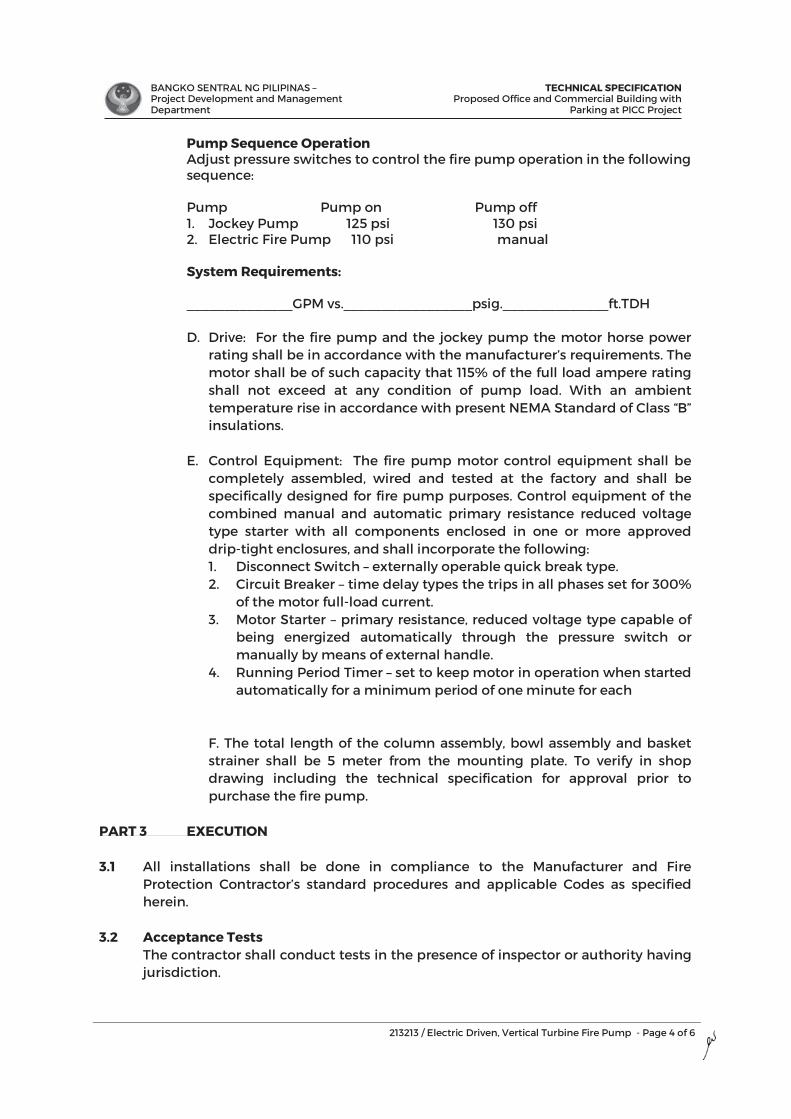
BANGKO SENTRAL NG PILIPINAS – Project Development and Management Department
TECHNICAL SPECIFICATIONProposed Office and Commercial Building with
Parking at PICC Project
213213 / Electric Driven, Vertical Turbine Fire Pump - Page 4 of 6
Pump Sequence Operation Adjust pressure switches to control the fire pump operation in the following sequence: Pump Pump on Pump off 1. Jockey Pump 125 psi 130 psi 2. Electric Fire Pump 110 psi manual
System Requirements: ______________GPM vs._________________psig.______________ft.TDH
D. Drive: For the fire pump and the jockey pump the motor horse power
rating shall be in accordance with the manufacturer’s requirements. The motor shall be of such capacity that 115% of the full load ampere rating shall not exceed at any condition of pump load. With an ambient temperature rise in accordance with present NEMA Standard of Class “B” insulations.
E. Control Equipment: The fire pump motor control equipment shall be
completely assembled, wired and tested at the factory and shall be specifically designed for fire pump purposes. Control equipment of the combined manual and automatic primary resistance reduced voltage type starter with all components enclosed in one or more approved drip-tight enclosures, and shall incorporate the following:
1. Disconnect Switch – externally operable quick break type. 2. Circuit Breaker – time delay types the trips in all phases set for 300%
of the motor full-load current. 3. Motor Starter – primary resistance, reduced voltage type capable of
being energized automatically through the pressure switch or manually by means of external handle.
4. Running Period Timer – set to keep motor in operation when started automatically for a minimum period of one minute for each
F. The total length of the column assembly, bowl assembly and basket strainer shall be 5 meter from the mounting plate. To verify in shop drawing including the technical specification for approval prior to purchase the fire pump.
PART 3 EXECUTION 3.1 All installations shall be done in compliance to the Manufacturer and Fire
Protection Contractor’s standard procedures and applicable Codes as specified herein.
3.2 Acceptance Tests The contractor shall conduct tests in the presence of inspector or authority having
jurisdiction.
BANGKO SENTRAL NG PILIPINAS – Project Development and Management Department
TECHNICAL SPECIFICATIONProposed Office and Commercial Building with
Parking at PICC Project
213213 / Electric Driven, Vertical Turbine Fire Pump - Page 5 of 6
To remove foreign materials which may have entered the piping installation of same flushing or underground connection is required before sprinkler piping is connected.
Hydrostatic Test
a. Test pressure not less than 130 psi on system pressure plus 50 psig for four (4) hours.
b. No visible leakage for inside sprinkler piping will be allowed. For underground mains and lead-ins, exceeding the permissible leakage or joints necessary repair shall be made.
c. All control valve water pressure to insure proper operating tests. Use clean, noncorrosive water.
d. Fire connection shall be tested. e. Water flushing using fire pump after test pressure. f. Used oil filled pressure gauge with calibration certificate during pressure
test. Testing drainage facilities shall be made by opening the main drain valve while the control valve is wide open. Test certificate shall be filled out and signed by the Owner’s and contractor’s representative. System operations and maintenance chart shall be submitted to the Owners upon completion of the Contract. This shall include, among others the locations of the control valves and care of the new equipment. Flush all new pump suction and discharge piping at 150 percent of rated pump capacity. The new pumps may be used to attain the required flushing volume. Continue flushing operations until water is clear, but for not less than 10 minutes. Submit a signed and dated flushing certificate with a request for field testing.
3.3 Minor Modification & Time Completion The plans as drawn should show conditions as accurately as it is possible to
indicate them in scale. The plans are diagrammatical and do not necessarily show all fittings etc. necessary to fit the building conditions. The locations of valves, fittings and fixtures shown on the plans are approximately. The Contractor shall be responsible for the proper location in order to make them fit with architectural details and instructions.
The contractor shall complete the work herein described in accordance with the specific schedules set by the owners in accordance with General Contractor’s Schedule of Work.
3.4 Guarantees The Contractor shall guarantee that the installed sprinkler system complies with
the requirements of the authorities and free from all defective workmanship and materials and will remain so, for a period of one (1) year from the date to final inspection and acceptance of the work. Any defect appearing within one year shall be corrected by the contractor at no additional cost to the Owner.
BANGKO SENTRAL NG PILIPINAS – Project Development and Management Department
TECHNICAL SPECIFICATIONProposed Office and Commercial Building with
Parking at PICC Project
213213 / Electric Driven, Vertical Turbine Fire Pump - Page 6 of 6
3.5 Contractor’s Responsibility The Contractor shall provide temporary fire protection system during the
construction period. This shall be of sufficient capacity to put any fore that may break out at any floors due to construction operations. This is in addition to temporary fire extinguisher required.
The Contractor shall identify and save the Owner, the Architect and the consulting
Engineering harmless from and against all liabilities for damage to property occasioned by any or omission of this Contractor on any of this sub-contractors including any and all expenses, legal or otherwise which may be insured by the Owner, the Architect or the consulting Engineer, in the defense of any claims action or suits.
END OF SECTION
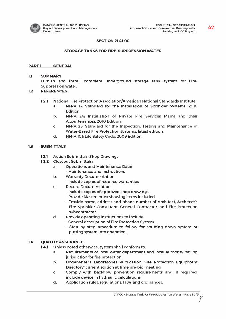
BANGKO SENTRAL NG PILIPINAS – Project Development and Management Department
TECHNICAL SPECIFICATIONProposed Office and Commercial Building with
Parking at PICC Project
214100 / Storage Tank for Fire-Suppression Water - Page 1 of 3
SECTION 21 41 00
STORAGE TANKS FOR FIRE-SUPPRESSION WATER
PART 1 GENERAL
1.1 SUMMARY Furnish and install complete underground storage tank system for Fire-Suppression water.
1.2 REFERENCES
1.2.1 National Fire Protection Association/American National Standards Institute: a. NFPA 13: Standard for the installation of Sprinkler Systems, 2010
Edition.b. NFPA 24: Installation of Private Fire Services Mains and their
Appurtenances, 2010 Edition.c. NFPA 25: Standard for the Inspection, Testing and Maintenance of
Water-Based Fire Protection Systems, latest edition.d. NFPA 101: Life Safety Code, 2009 Edition.
1.3 SUBMITTALS
1.3.1 Action Submittals: Shop Drawings 1.3.2 Closeout Submittals:
a. Operations and Maintenance Data:- Maintenance and Instructions
b. Warranty Documentation:- Include copies of required warranties.
c. Record Documentation:- Include copies of approved shop drawings.- Provide Master Index showing items included.- Provide name, address and phone number of Architect, Architect’s
Fire Sprinkler Consultant, General Contractor, and Fire Protection subcontractor.
d. Provide operating instructions to include:- General description of Fire Protection System. - Step by step procedure to follow for shutting down system or
putting system into operation.
1.4 QUALITY ASSURANCE 1.4.1 Unless noted otherwise, system shall conform to:
a. Requirements of local water department and local authority havingjurisdiction for fire protection.
b. Underwriter’s Laboratories Publication “Fire Protection EquipmentDirectory” current edition at time pre-bid meeting.
c. Comply with backflow prevention requirements and, if required,include device in hydraulic calculations.
d. Application rules, regulations, laws and ordinances.
3
BANGKO SENTRAL NG PILIPINAS – Project Development and Management Department
TECHNICAL SPECIFICATIONProposed Office and Commercial Building with
Parking at PICC Project
214100 / Storage Tank for Fire-Suppression Water - Page 2 of 3
1.4.2 Qualifications: a. Licensed fire protection engineer or fire protection system certified
and engaged in design of fire protection systems. b. Installer: Licensed by jurisdiction over installed fire protection
systems for area of Project. Furnish verified list of similar projects installed during past five years minimum.
PART 2 PRODUCTS 2.1 Underground Cistern Tank Requirements
Refer to Plumbing and Fire Protection Drawings for layouts and details.
2.2 Cistern Tank Waterproofing 2.2.1 Cementitious Capillary Crystallization Waterproofing System
Shall be a cementitious capillary crystallization waterproofing material, consisting of cement, quartz sand and active chemicals that reacts with free lime and moisture present in concrete producing crystals that fills cracks, voids, capillary tracks within the concrete resulting in prevention of water leaks while allowing substrate to breathe; shall be non-toxic, safe to be applied on surfaces in contact with drinking water and foodstuffs,
2.2.2 Water Tank Lining
Tank lining shall be an epoxy lining material, solvent free, pigmented, two component preparation of liquid colored epoxy resin with formulated anime hardener. Safe for use on areas in direct contact with potable water or foodstuffs; lead free, food grade when fully cured, non-toxic and BFAD approved. Submit product catalog and shop drawings for Architect’s approval. Follow manufacturer’s standard application procedures.
2.3 Cistern Tank Materials Refer to Structural and Plumbing/sanitary design for Details and Layout.
PART 3 EXECUTION 3.1 EXAMINATION
3.1.1 Drawings: a. Fire Protection Drawings show general arrangement of piping.
Follow as closely as actual building construction and work of other trades will permit. Install system so it drains.
b. Consider Architectural and Structural Drawings part of this work insofar as these drawings furnish information relating to design and construction of building. These drawings take precedence over Fire Protection Drawings.
c. Because of small scale drawings. It is not possible to indicate all offsets and accessories that may be required. Investigate structural and finish conditions affecting this work and arrange work accordingly, provide such fittings, valves and accessories required to meet conditions and to enable system to drain.
BANGKO SENTRAL NG PILIPINAS – Project Development and Management Department
TECHNICAL SPECIFICATIONProposed Office and Commercial Building with
Parking at PICC Project
214100 / Storage Tank for Fire-Suppression Water - Page 3 of 3
3.2 CLOSE-OUT ACTIVITIES 3.2.1 Instruction of Owner:
a. Instruct Owner’s personnel in operation and maintenance o system utilizing Operation and Maintenance Manual when so doing.
b. Instruction sessions shall occur after Substantial Completion inspection when system is properly working and before final payment is made.
3.2.2 Training:
a. Installer required to provide FM Training from latest version of NFPA 25 with checklist and brief explanation of following inspections:
- Weekly Inspection - Monthly Inspection - Quarterly Inspection - Semi-annual Inspection - Annual Inspection
END OF SECTION
BANGKO SENTRAL NG PILIPINAS – Project Development and Management Department
TECHNICAL SPECIFICATION Proposed Office and Commercial Building with
Parking at PICC Project
220529 / Hangers and Supports for Piping and Equipment - Page 1 of 4
SECTION 22 05 29
HANGERS AND SUPPORTS FOR PLUMBING PIPING AND EQUIPMENT
PART 1 : GENERAL
1.1 SCOPE OF WORK This section includes labor, materials, skills and related services necessary to furnish and install hangers and supports for equipment, materials and related work specified in this Section and shall be coordinated with the applicable provisions of the Contract Documents.
1.2 SUBMITTALS 1.2.1 General: All submittals for approval as indicated herein shall be in accordance
to the provisions under General Conditions of the Contract Documents. 1.2.2 Provide submittal data for the following:
A. Manufacturer’s Instruction, product technical data, certificates for quality control and Operators.
B. Each type of pipe hanger, channel support system component, and thermal-hanged shield insert to be used.
C. Shop Drawings: Signed and sealed by a qualified professional engineer for multiple piping supports and trapeze hangers which exceed prescriptive requirements. Provide point loads of for each designed hanger or support.
1.3 REFERENCES Comply with the provisions under General Conditions of the Contract Documents and Manufacturer’s instructions. Reference the following standards as applicable: 1.3.1 American National Standards Institute or ANSI 1.3.2 American Society for Testing and Materials, ASTM 1.3.3 American Welding Society, AWS 1.3.5 Sheet Metal and Air Conditioning Contractors' National Association, SMACNA
1.4 QUALITY ASSURANCE 1.4.1 Comply with quality assurance requirements under General Conditions of the
Contract Documents and Manufacturer’s instructions. 1.4.2 Qualify processes and installers according to ASME standards for the design
and preparation of shop drawings and calculations for each multiple pipe hangers and support for ductwork, piping and equipment systems.
PART 2 : PRODUCTS
2.1 Hanger and supports components to be used for all systems shall be subject for approval to the Engineer/Architect prior to installation.
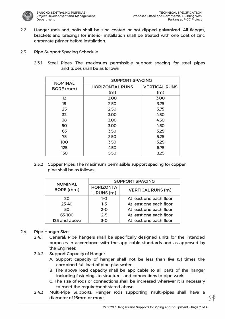
BANGKO SENTRAL NG PILIPINAS – Project Development and Management Department
TECHNICAL SPECIFICATION Proposed Office and Commercial Building with
Parking at PICC Project
220529 / Hangers and Supports for Piping and Equipment - Page 2 of 4
2.2 Hanger rods and bolts shall be zinc coated or hot dipped galvanized. All flanges, brackets and bracings for interior installation shall be treated with one coat of zinc chromate primer before installation.
2.3 Pipe Support Spacing Schedule
2.3.1 Steel Pipes: The maximum permissible support spacing for steel pipes and tubes shall be as follows:
NOMINAL BORE (mm)
SUPPORT SPACING
HORIZONTAL RUNS (m)
VERTICAL RUNS (m)
12 19 25 32 38 50 65 75
100 125 150
2.00 2.50 2.50 3.00 3.00 3.00 3.50 3.50 3.50 4.50 5.50
3.00 3.75 3.75 4.50 4.50 4.50 5.25 5.25 5.25 6.75 8.25
2.3.2 Copper Pipes: The maximum permissible support spacing for copper pipe shall be as follows:
NOMINAL BORE (mm)
SUPPORT SPACING HORIZONTAL RUNS (m)
VERTICAL RUNS (m)
20 25-40
50 65-100
125 and above
1-0 1-5 2-0 2-5 3-0
At least one each floor At least one each floor At least one each floor At least one each floor At least one each floor
2.4 Pipe Hanger Sizes
2.4.1 General: Pipe hangers shall be specifically designed units for the intended purposes in accordance with the applicable standards and as approved by the Engineer.
2.4.2 Support Capacity of Hanger A. Support capacity of hanger shall not be less than five (5) times the
combined full load of pipe plus water. B. The above load capacity shall be applicable to all parts of the hanger
including fastenings to structures and connections to pipe work. C. The size of rods or connections shall be increased wherever it is necessary
to meet the requirement stated above. 2.4.3 Multi-Pipe Supports. Hanger rods supporting multi-pipes shall have a
diameter of 16mm or more.
BANGKO SENTRAL NG PILIPINAS – Project Development and Management Department
TECHNICAL SPECIFICATION Proposed Office and Commercial Building with
Parking at PICC Project
220529 / Hangers and Supports for Piping and Equipment - Page 3 of 4
2.5 Sealing Tape: For threaded connections; use Teflon tape conforming to ASTM D
3308 suitable for temperatures from minus 50 degrees C to 180 degrees C. 2.6 Welding Rod: Welding rods shall comply with AWS A 5.2 or shall be of material and
type compatible with pipe material and welding process used in accordance with ANSI B 3.1.
2.7 PIPE HANGER INSERTS AND SUPPORTS
Horizontal runs of pipe shall be hung with adjustable wrought iron or malleable iron pipe hangers spaced not over 3 m. apart, except hub and spigot soil pipes which shall have hangers spaced not over 1.52 m. apart and located near the hub. Hangers shall have short turnbuckles or other approved means of adjustment. Inserts shall be of cast steel and shall be of type to receive a machine bolt or nut after installation. Wrought iron clamps shall be use to support vertical pipe runs or collars spaced not more than 9 m. apart. Water and Vent Pipes - 65 mm. dia. and larger; band type 6.1 mm x 25 mm flat mild steel or black iron with 15 mm. dia. round rod with plates and nuts; 50 mm. dia. and smaller split ring type with 10 mm. dia. iron rods with inserts plates; toggle bolts, clamps or expansion shield.
2.8 PIPE SLEEVES 2.8.1 Pipe sleeves shall be installed and properly secured in place at all points
where pipes pass through masonry or concrete. 2.8.2 Pipe sleeves shall be of sufficient diameter to provide approximately 6.1 mm
clearance around the pipe of insulation. 2.8.3 Pipe sleeves in walls and partitions shall be of cast iron, wrought iron or steel
pipe. Pipe sleeves in concrete beams or concrete slabs shall be wrought iron or steel pipe.
2.8.4 Pipe sleeves on footings shall be cast iron or steel and shall be not less than 100 mm. dia. larger in diameter than the pipe to be installed.
2.8.5 Where pipes pass through waterproofing membrane, the sleeves shall be provided with an integral flange or clamping device to which a flashing shield can be soldered.
2.8.6 The space between the pipes and sleeves shall be made watertight by inserting a picked oakum gasket and filling the remaining space with poured lead caulking thoroughly.
PART 3 : EXECUTION 3.1 Hangers shall be so located as to properly support pipes; relieve strain on pipe and
fittings; and allow for ample expansion and contraction. Piping smaller than 100mm size shall be hung with individual ring hangers where space prevents use of other type hangers.

BANGKO SENTRAL NG PILIPINAS – Project Development and Management Department
TECHNICAL SPECIFICATION Proposed Office and Commercial Building with
Parking at PICC Project
220529 / Hangers and Supports for Piping and Equipment - Page 4 of 4
3.2 Brackets, Braces and Supports
Furnish and install brackets, braces or reinforcing angles in all partitions not sufficient in themselves to support piping included in this Specification. Bolts shall extend through walls, slab and ceiling, finished on opposite side, secured with nuts and washers.
3.3 Hanger Adjustment Adjust hangers to distribute loads equally on attachments and to achieve indicated slope of pipe as directed by the Engineer/Architect.
END OF SECTION
BANGKO SENTRAL NG PILIPINAS – Project Development and Management Department
TECHNICAL SPECIFICATION Proposed Office and Commercial Building with
Parking at PICC Project
220710 / Plumbing Piping Insulation - Page 1 of 2
SECTION 22 07 10
PLUMBING PIPING INSULATION
PART 1 : GENERAL
1.1 SCOPE OF WORK This section covered by this specification consists of furnishing all labor, equipment, materials and accessories, and performing all operations required for the correct installation of insulated pipe supports for mechanical piping systems and plumbing system.
1.2 REFERENCES Comply with quality assurance requirements under General Conditions of the Contract Documents and Manufacturer’s instructions. Reference the following standards as applicable:
1.2.1 ASTM C534 – Standard Specification for Preformed Flexible Elastomeric Cellular Thermal Insulation in Sheet and Tubular Form.
1.2.2 ASTM E84 – Test method for Surface Burning Characteristics of Building Materials.
1.2.3 ASTM C177 – Standard Test Method for Steady-State Heat Flux Measurements and Thermal Transmission Properties by Means of the Guarded-Hot-Plate Apparatus.
1.2.4 ASTM C518 – Standard Test Method for Steady-State Thermal Transmission Properties by Means of the Heat Flow Meter Apparatus.
1.2.5 ASTM E96 – Standard Test Methods for Water Vapor Transmission of Materials.
1.2.6 MSS SP69 - Manufacturers Standardization Society: Pipe Hangers and Supports- Selection and Application.
1.3 SUBMITTALS 1.3.1 General: All submittals for approval as indicated herein shall be in
accordance to the provisions under General Conditions of the Contract Documents.
1.3.2 Submit Manufacturer’s brochures, catalogs and standard installation procedures. Sample materials shall be subject to the approval Architect and Owner.
1.4 QUALITY ASSURANCE 1.4.1 Pipe supports and insulation inserts that are damaged shall not be
installed. 1.4.2 Material shall be delivered in non-broken, factory furnished packaging
and stored in a clean, dry indoor space that provides protection against the weather.
BANGKO SENTRAL NG PILIPINAS – Project Development and Management Department
TECHNICAL SPECIFICATION Proposed Office and Commercial Building with
Parking at PICC Project
220710 / Plumbing Piping Insulation - Page 2 of 2
1.4.3 Workmanship: All pipe supports to be installed by qualified personnel and installed in accordance with manufacturer’s recommendations. a. All work shall comply with all applicable federal, state, and local codes
and laws having jurisdiction. b. All work shall conform to accepted industry and trade standards for
pipe support. c. Insulation inserts shall not be applied until all surfaces are clean, dry,
and free of dirt, dust, grease, frost, moisture, and other extraneous elements.
PART 2 : PRODUCTS 2.1 Elastomeric Insulation Pipes - Shall be 25mm nominal thickness x 2000mm
length, tube type, black color, Elastomeric Insulation with high flexibility, high resistance to water vapour transmission and noise reduction, complete with adhesive and accessories. Submit brochures and sample for Architect’s approval.
2.2 Accessories:
2.2.1 Adhesive – Shall low viscosity adhesive which ensures a neat secure water vapor resistant bond.
2.2.2 Cleaner – Shall be provided for preparation surfaces prior to installing and for cleaning adhesive from brushes, tolls etc.
2.2.3 CO Paint – Shall be protective water-based white paint for outdoor installation. Provide a flexible film which is resistant to UV radiation, ozone and many aggressive chemicals.
2.2.4 Self-Adhesive Tape – Shall 3mm thick, 50mm wide for insulating fittings and short length of pipes in hard reach.
PART 3 : EXECUTION 3.1 Installation:
3.1.1 Use clamp inserts to prevent compression of insulation at standard split, clevis hangers, strut systems, or other pipe support systems.
3.1.2 Pipe support insulation shall be elastomeric foam with the same or greater thickness than the pipe insulation. All joints shall be sealed with adhesive.
3.1.3 All edges of installed insulation shall be clean cut. Rough or jagged edges of the insulation shall not be permitted. Proper tools such as sharp non-serrated knives must be used.
3.1.4 It is highly recommended for continuous insulation protection to use hanger sizes equal to the outer diameter of the pipe plus insulation thickness.
END OF SECTION
BANGKO SENTRAL NG PILIPINAS – Project Development and Management Department
TECHNICAL SPECIFICATION Proposed Office and Commercial Building with
Parking at PICC Project
221116 / Domestic Water Piping - Page 1 of 6
SECTION 22 11 16
DOMESTIC WATER PIPING
PART 1 : GENERAL
1.1 Unless otherwise specified, the Contractor or his sub-contractor shall furnish all materials, tools, equipment, apparatus, appliances, accessories, transportation, labor and supervision required for the complete installation and testing of the Plumbing System ready for use in accordance with the best practice of the Plumbing Trade as listed herein but not limited to the following:
1.1.1 The Plumbing Contractor is required to refer to all architectural, structural, mechanical, fire protection, electrical and interior designs plus landscape plans and investigate all possible interference and conditions affecting his work.
1.1.2 All work shall comply with the pertinent provisions of the Plumbing Code of the concerned city, the Code on Sanitation of the Phil., and/or the National Plumbing Code of the Philippines.
1.1.3 Tapping from an existing public water main/or deep well of the site distribution to include supply & installation of main water meter and sub-water meters.
1.1.4 Supply and installation of all plumbing fixtures, fittings, trims and accessories.
1.1.5 Testing for leakage of all water supply and distribution system, drains, waste, sewer and venting system plus pressure testing and disinfections of the water supply and distribution system.
1.1.6 Preparation and submittal of two (2) sets of as-built plans.
1.1.7 Furnishing of written, one (1) year warranty on the plumbing system.
1.2 NOTES ON DRAWINGS 1.2.1 The Drawings show the general arrangement all piping. However, where
local and/or actual conditions at the jobsite necessitate a deviation or rearrangement; the Contractor shall prepare and submit the new arrangement for the Architect's approval.
1.2.2 Small scale Drawings do not possibly indicate all offsets, fittings and other parts of the system required. The Contractor shall arrange such work accordingly, furnishing such fittings, traps valves and accessories as may be required to meet such conditions.
1.3 APPLICABLE CODES, ORDINANCES, PERMITS AND FEES The work covered in this contract is to be installed according to the specs, codes, ordinances and requirements of the following:
1.3.1 National Plumbing Code of the Philippines
1.3.2 National Building Code
BANGKO SENTRAL NG PILIPINAS – Project Development and Management Department
TECHNICAL SPECIFICATION Proposed Office and Commercial Building with
Parking at PICC Project
221116 / Domestic Water Piping - Page 2 of 6
1.3.3 NFPA 101 – Life Safety
1.3.4 The Code on Sanitation of the Philippines
1.3.5 Dept. of Environment & Natural Resources
1.3.6 Ordinances of concerned city or municipality
1.3.7 American Society of Plumbing Engineers Manuals
1.3.8 American Society pf Sanitary Enginners Manuals All construction permits and fees required for the work shall be obtained by and at the expense of the contractor. The contractor shall furnish the Owner final certificates of inspection after the completion of the work.
1.4 SUBMITTALS 1.4.1 Product Data: For pipe, tube, fitting and couplings
1.4.2 Field Test Reports: Indicate and interpret test results for compliance with performance requirements.
1.4.3 Certificate of Origin
1.4.4 Materials Data Sheet
1.4.5 The Contractor shall submit to the Owner, in reproducible form plus three (3) sets of white prints, the complete plans of the entire system as actually built. The cost of these shall be borne by the Contractor. Submittal of "AS BUILT" Plans shall be a condition to final payment.
1.5 QUALITY ASSURANCE 1.5.1 Piping materials shall bear label, stamp or other markings of specified
testing agency.
1.5.2 Comply with ASME B 31.9 “Building Services Piping” for materials, products and installation.
1.5.3 Comply with NSF 61 “Drinking Water System Components – Health Effects” Section I through 0 for potable water piping and components.
1.6 WARRANTY All works, equipment and fixtures shall be guaranteed by the Contractor for satisfactory service for a minimum period for one (1) year.
PART 2 : PRODUCTS
2.1 PIPES AND FITTINGS SCHEDULE
2.1.1 Pipes and Fittings for Hot and Cold Waterlines (to Distribution to Riser and Downfeeds and for Roughing-ins)
Shall be high quality Polypropylene Random Co-polymer Resins or PP-R Type 3 made from 100% premium virgin raw-material with fusion welding technology, environmental friendly and has nominal pressure of PN-20 up to 100C temperature tolerance, conforming to “Thermal Stability” by hydrostatic pressure testing test at 110C for 8760 hours. Jointing shall be by socket fusion. Submit sample for Architect’s approval.

BANGKO SENTRAL NG PILIPINAS – Project Development and Management Department
TECHNICAL SPECIFICATION Proposed Office and Commercial Building with
Parking at PICC Project
221116 / Domestic Water Piping - Page 3 of 6
2.1.2 Pipes and Fittings for Waterlines from Tapping Point to Water Meter Shall be galvanized iron (G.I.) pipe, schedule 40, conforming to ASTM A-
120-80. Fittings shall be screwed connection for 65mm diameters and below; and flange connection for 75mm diameters and above. Provide corrosion protection, coated with petroleum based paste and wrapped with petrolatum tape.
2.2 VALVES 2.2.1 Gate valve - For 75 mm. dia. & larger, shall be rising stem, iron body with
bronze trim, flanged connection, min. of 150 psig working pressure. For 65 mm. dia. & smaller, shall be rising stem, all bronze, female threaded, min. of 150 psig working connection.
2.2.2 Check Valve - for booster pumps, 75 mm. dia. & larger shall be iron body with bronze trim, flanged connection, min. of 150 psig working pressure. For 65 mm. dia. & smaller, same except female threaded connection.
2.2.3 Float Valve - Shall be hydraulically operated, diaphragm actuated valve with the pilot control and float mechanism mounted on the cover of the main valve. The float positions the pilot control to close the valves when float contacts the upper stop and to open the valve when the float contacts the lower stop.
2.2.4 Pressure Reducing & Pressure Sustaining Valve – Shall be double chambered, hydraulically operated pilot controlled, diaphragm type globe valve. The control system shall consist of a reducing control sensitive to diaphragm pressure changes and pressure sustaining control that is sensed to the main valve inlet.
2.2.5 Pressure Relief Valve – Shall be a diaphragm type valve to maintain constants upstream pressure to close limits. The valve shall be hydraulically-operated, pilot controlled modulating type, main body at cover to Cast Iron ASTM-A1 with adjustment ranges, 20 to 200 PSIG.
2.3 METERS
2.3.1 Water meters shall be furnished by the Contractor and installed with the proper and complete piping arrangements for the system.
2.3.2 The exact dimensions for setting the meter shall be as per requirements of the MWSI.
2.3.3 Shall be standard B-meter complete with fittings and accessories.
2.4 Hose Bib Shall be 20mm diameter standard hose connection, male tapered threads, polished chromium plated. Hose bibs shall be made of brass with 15mm diameters male inlet threads hexagon shoulders and 20mm diameters connection.
2.5 Jointing and Connection 2.4.1 Cast iron soil and waste pipes & fittings, hubless sleeve type joints.
2.4.2 Centrifugal gray cast iron – Bell and spigot, gasketed sliptite joint
2.4.3 Cast iron - Bell and spigot, lead and oakum
BANGKO SENTRAL NG PILIPINAS – Project Development and Management Department
TECHNICAL SPECIFICATION Proposed Office and Commercial Building with
Parking at PICC Project
221116 / Domestic Water Piping - Page 4 of 6
2.4.4 Galvanized wrought iron or steel piped; screwed or threaded joint; use sealant.
2.4.5 Lead to cast iron pipes; Adaptor fittings, screwed and hubless coupling gasket joints.
2.4.6 Concrete pipes; bell and spigot or tongue and groove.
2.4.7 Polyvinyl chloride (PVC) pipes, socket type with PVC cement.
2.4.8 Polyethylene/Polypropylene pipes, brass fittings and electro fusion or socket fusion joints.
PART 3 : EXECUTION 3.1 IDENTIFICATION AND APPROVAL OF MATERIALS
3.1.1 Each length of pipe, fittings, traps, fixtures, and device used in the Plumbing System shall have cast, tamped or marked on it, the manufacturer's trade mark or name, weight, type and classes of product when so required by the Standard.
3.1.2 Within thirty (30) days after award of the Contract, the Contractor shall submit for the Architect's approval, the names of suppliers and materials proposed including trade names and/or samples of the materials if deemed necessary.
3.1.3 Brand names mentioned in this Specification are only for the purposes of indicating the desired quality and design.
3.2 SUBSTITUTION AND TESTING OF MATERIALS
3.2.1 Intended materials substituted from those originally specified shall be accepted only after a formal request for substitution, accompanied by:
A. Reasons for substitutions;
B. Certificate of test indicating quality, compared to those originally specified.
C. Cost comparisons with material originally specified. Requests shall be submitted to the Architect for evaluation at least 15 working days before installation of subject material is due, or at least 7 days before opening of bids.
3.2.2 Cost of testing of materials, whether on originally specified items or on substitution, shall be to the account of the Contractor.
3.2.3 Results of tests shall be submitted to the Architect for evaluation at least 15 days before the material is due for installation on the job.
3.3 INSTALLATION
3.3.1 The piping shall be extended to all fixtures, outlets and equipment from the gate valves installed in the branch near the riser.
3.3.2 Unions shall be provided where required for disconnection.

BANGKO SENTRAL NG PILIPINAS – Project Development and Management Department
TECHNICAL SPECIFICATION Proposed Office and Commercial Building with
Parking at PICC Project
221116 / Domestic Water Piping - Page 5 of 6
3.3.3 All pipes shall be cut accurately to measurements and shall be worked into place without springing or facing. Care shall be taken so as not to weaken the structural portions of the building.
3.3.4 All service pipes valves and fittings shall be kept at sufficient distance from work to permit finished covering not less than 15 mm from such work or from finished covering on the different service.
3.3.5 Changes in pipes shall be made with reducing fittings.
3.3.6 Accessible Contraction - Expansion joints shall be made wherein necessary. Horizontal runs of pipe over 15 m. in length shall be anchored to wall or the supporting structure about midway on the run to force expansion and contraction equally towards the ends.
3.4 PRESSURE TESTS FOR WATER LINES 3.4.1 After the pipe have been installed, the joints completed and with joints
exposed for examination, all newly installed pipe or any valve section therefore, shall be subjected to hydrostatic pressure 1 1/2 the designed working pressure of the system or as specified by the Architect.
3.4.2 The duration of each pressure test shall be at least 10 minutes unless otherwise specified by the Architect.
3.4.3 Each section of pipeline shall be slowly filled water and the specified test pressure, measured at the point of lowest elevation, shall be applied by means of a pump connected to the pipe in a manner satisfactory to the Architect. During the filling of the pipe and before applying the test pressure, all air shall be expelled from the pipeline. To accomplish this type shall be made, if necessary, at point of highest elevation and after completion of the test the taps shall be tightly plugged unless otherwise specified. During the test, all exposed pipes, fittings, valves, joints and couplings will be carefully examined. Defective materials shall be removed and replaced with sound materials at the Contractor’s expense. The test shall be then repeated until satisfactory results are obtained.
3.5 DEFECTIVE WORK 3.5.1 If the inspection and test show any defect such defective work or material
shall be replaced and the test shall be repeated until such satisfactory to the Owner.
3.5.2 All repairs shall be made with new material at the expense of the Contractor.
3.5.3 No caulking of screwed joints or holes will be accepted. 3.6 PAINTING AND PROTECTION
3.6.1 All exterior of piping to be installed in or through concrete floor or fill floors and underground shall be given one coat of acid resisting paint having a bituminous base.
3.6.2 Pipe hanger, supports and all other iron work in concealed spaces shall be painted with one coat of asphalt.
BANGKO SENTRAL NG PILIPINAS – Project Development and Management Department
TECHNICAL SPECIFICATION Proposed Office and Commercial Building with
Parking at PICC Project
221116 / Domestic Water Piping - Page 6 of 6
3.6.3 Exposed galvanized iron pipes and fittings that are asphalt coated shall be given two coats of shellac prior to application of two coats of oil paint as directed by the Architect or Engineer.
3.7 COLOR CODE FOR EXPOSED PIPES All exposed piping shall be adequately and durably identified by distinctive color
paints as follows: ITEM COLOR CODE Potable water pipe blue Non-potable water pipe blue with band @ 1m O.C. Hot water pipe blue pipe with red band @ 1m O.C. Storm water pipe aluminum
3.8 RESPONSIBILITIES The general Contractor shall be responsible for the coordination among the
different trades on the job in order to finish the work in the least possible time, in strict accordance with the Plans and Specification.
The Sprinkler Contractor shall provide a temporary fire protection system during
the construction period. This shall be of sufficient capacity to put out any fire that may break out at any floors due to construction operations. This is in addition to temporary fire extinguisher required & supplied by the Sprinkler Contractor.
A temporary potable water supply shall be made available to construction
workers at every floor as construction progresses.
END OF SECTION
BANGKO SENTRAL NG PILIPINAS – Project Development and Management Department
TECHNICAL SPECIFICATION Proposed Office and Commercial Building with
Parking at PICC Project
221123 / Domestic Water Pumps - Page 1 of 4
SECTION 22 11 23
DOMESTIC WATER PUMPS
PART 1 : GENERAL
1.1 All requirements shall be supplied from reputable firms engaged in the manufacture of each particular item. The entire assembly as installed shall be given a start-up and test run to prove that all the specifications have been met before acceptance by the Owner. The test duration shall be 24 hours. Submittal of the Certificate of Test to the Owner's shall be a condition of final payment.
1.2 The Specification herein stated are basic guide only. Other items not so indicated but which are obviously necessary for the proper operation of system as intended shall be supplied in accordance with accepted engineering standards.
1.3 The equipment shall be guaranteed for a period of at least one (1) year of trouble free operation. The supplier of equipment shall certify to the availability of spare parts locally and service in case of system breakdowns within a period of at least three (3) years. Manuals of operation and maintenance and lists of spare parts shall be supplied together with the equipment. Submittal of Warranty Certificate shall be on condition to the final payment.
1.4 The supplier shall submit at least two (2) copies of pumps performance curves showing among others, the pump rating and pump efficiency, properly marked thereon.
1.5 Price quoted shall include cost delivery of all quoted items to the jobsite. Pump and motor installation dimension drawings shall be submitted together with the quotation.
1.6 The brands, names, and place of manufacture of pump, motor, valves, controls and all accessories where applicable shall be indicated in the quotation. Also, a description of pump impellers being offered shall be included.
1.7 A metal nameplate indicating in indelible letters the correct specifications of the pump and motor shall be properly attached to the assembly at a location such that the information written thereon can be conveniently read by all concerned.
1.8 A separate price shall be quoted for installation work and preparation submittal of as installed drawing.
1.9 REFERENCES 1.9.1 ASTM International (ASTM) Publications
B36 “Standard Specification for Brass Plate, Sheet, Strip and Roller Bar” B584 “Standard Specification for Copper Alloy Sand Castings for General Applications”
1.9.2 National Fire Protection Association (NFPA)
1.9.3 Underwriter’s Laboratories, Inc. (UL) Standards: 486A “Standard For Wire Connectors and Soldering Lugs for Use with Copper Conductors” 486B “Standard for Wire Connectors for Use with Aluminum Conductors” 778 “Standard for Motor-Operated Water Pumps”

BANGKO SENTRAL NG PILIPINAS – Project Development and Management Department
TECHNICAL SPECIFICATION Proposed Office and Commercial Building with
Parking at PICC Project
221123 / Domestic Water Pumps - Page 2 of 4
1.10 SUBMITTALS 1.10.1 Product Data: Include certified performance curves and rated capacities of selected
models; shipping, installed and operating weights; furnished specialties; and accessories for each type and size of pump specified. Indicate pumps’ operating point on curves.
1.10.2 Maintenance Data: For each pump specified to include in maintenance manuals.
1.10.3 Submit Materials Safety Data Sheet (MSDS)
1.11 RESPONSIBILITIES The general Contractor shall be responsible for the coordination among the different trades on the job in order to finish the work in the least possible time, in strict accordance with plans and specification.
PART 2 : PRODUCTS 2.1 Water Tank & Pump 2.1.1 Constant Pressure Booster Pumps a. Number of Units: 1 set, Triplex Type b. Capacity/Unit: 135 GPM vs. 168 ft. TDH approx. 3 HP each. c. Type: Horizontal centrifugal, end-suction, close coupled to electric
motor on a common base, suitable for pumping domestic water by positive suction with pressure relief valves.
d. Electric Motor Drive: 220/380/440 V, 3-phase, 60 cycles, open drip proof, 3 Hp.
e. Motor Controls: Microprocessors based variable frequency drive and soft motor starter. Designed for controlling and optimizing the speed and power requirement of one (1) electric motor driven pump. Motor control also consist of pressure transducer, speed potentiometer, overload relays, extra quick trip overload current relay, phase failure relay, ground fault relay (liquid sensor type) and alternators. Enclosure shall be NEMA TEFC, IP54.
f. Accessories: Vibration insulating hose connections at suction and discharge lines, electrode type water level control or equal to prevent pumps from running dry.
2.1.2 Hydro pneumatic Pressure Tank (Diaphragm or Bladder Type) a. No. of Units: One (1) unit b. Type: Cylindrical Tank; vertical mounted, diaphragm type. c. Capacity per unit: 400 US gals. d. Operating Pressure: Cut-in 20 psi and cut-off at 40 psi e. Tank Material: Mild steel 3/16” minimum thickness, 40 psi pressure
rating per ASME Code for Unfired Pressure Vessels. Bladder shall be FDA approved.
f. Accessories: Pressure gauge for operating pressure of 0 to 40 psi, dial face
diameter – 100mm
BANGKO SENTRAL NG PILIPINAS – Project Development and Management Department
TECHNICAL SPECIFICATION Proposed Office and Commercial Building with
Parking at PICC Project
221123 / Domestic Water Pumps - Page 3 of 4
Water level gauge consisting of a sight glass in copper tubing with sufficient opening and graduations to indicate the level of water inside pressure tank correct to one (1) mm.
Pressure Relief Valve: To release pressure at 45 psi. Water Drain Valves Pressure switches, to be set at cut-in-20 psi; cut-off-40 psi.
.
2.2 UNDERGROUND POTABLE WATER STORAGE TANKS
Refer to Plumbing Drawings for required details.
2.3 PIPING, FITTINGS AND MISCELLANEOUS METAL WORKS 2.3.1 Furnish and install all pipe fittings, valves, specials, pipe supports,
miscellaneous metal work and all required appurtenances as shown on the plans and as required to make the entire piping system operable.
2.3.2 All materials furnished and installed shall be new and guaranteed free from defect in design, materials and workmanship.
2.3.3 Adequate protective measures shall be provided to project pipes, fittings, valves and all other materials from damage or injury during storage and installation.
2.4 FLANGES, GASKETS, AND BOLTS: 2.4.1 Flanges shall conform in dimensions and drilling to ASA B-16.1 Class 125.
2.4.2 Gaskets shall be ring-type or cranite.
2.4.3 Bolts shall be standard square head machine bolts with heavy, hot, pressed hexagon nuts. Threads shall conform to ASA B-1.1, coarse thread series, Class 2 fit.
2.5 MANHOLE FRAME AND COVER:
2.5.1 All castings for manhole frames shall be tough, gray iron free from warps, cracks, holes, swells and cold shuts, and approximately 3 mm thick.
2.5.2 All casting shall conform to the requirements of ASTM Standard A-48 for gray from castings.
2.6. LADDER RUNGS
Ladder Rungs shall be of 20 mm. diameter round stainless steel bar attached to the walls as shown from castings.
PART 3 : EXECUTION
3.1 TESTS FOR WATER Tightness of Completed Tank - The completed reinforced concrete ground tank and elevated tank shall be tested for water-tightness by filling it up with clean water after cleaning out all dirt and debris inside the tank. The water shall be allowed to stand for a minimum period of 24 hours reckoned from the time the free-board line was reached during filling up. After the 24 hour period there shall

BANGKO SENTRAL NG PILIPINAS – Project Development and Management Department
TECHNICAL SPECIFICATION Proposed Office and Commercial Building with
Parking at PICC Project
221123 / Domestic Water Pumps - Page 4 of 4
be no drop in water level in the tank more than 40 mm, otherwise, the leaks shall be located and plugged properly and the test for water-tightness be repeated.
3.2 DEFECTIVE WORKS 3.2.1 If the inspection and test show any defect such defective work or material
shall be replaced and the test shall be repeated until such satisfactory to the Owner.
3.2.2 All repairs shall be made with new material at the expense of the Contractor.
3.2.3 No caulking of screwed joints or holes will be accepted.
3.3 DISINFECTION OF WATER DISTRIBUTION SYSTEM AND WATER TANKS (AS PER AWWA C-601) 3.3.1 The entire water system shall be thoroughly flushed and disinfected with
chlorine before it is placed on operation. Water tanks shall be washed and swabbed.
3.3.2 Chlorination materials shall be liquid chlorine or hypochlorite, as specified and shall be introduced into the water lines in manner approved by the Engineer. Tanks shall be thoroughly cleaned of all debris, dirt or dust before swabbing.
3.3.3 The chlorine dosage shall be such as to provide not less than fifty parts per million (50ppm.) or available chlorine.
3.3.4 Following a contact period of not less than sixteen (16) hours, the heavily chlorinated water shall be flushed from the system with clean water until the residual chlorine content is not greater than two tenth (0.20 ppm.). All valves in water lines being sterilized shall be opened and closed several times during the 16-hour chlorinating period.
END OF SECTION

BANGKO SENTRAL NG PILIPINAS – Project Development and Management Department
TECHNICAL SPECIFICATION Proposed Office and Commercial Building with
Parking at PICC Project
221316 / Sanitary Waste and Vent Piping - Page 1 of 10
SECTION 22 13 16
SANITARY WASTE AND VENT PIPING
PART 1 : GENERAL
1.1 Unless otherwise specified, the Contractor or his sub-contractor shall furnish all materials, tools, equipment, apparatus, appliances, accessories, transportation, labor and supervision required for the complete installation and testing of the Plumbing System ready for use in accordance with the best practice of the Plumbing Trade as listed herein but not limited to the following:
1.1.1 The Plumbing Contractor is required to refer to all architectural, structural, mechanical, fire protection, electrical and interior designs plus landscape plans and investigate all possible interference and conditions affecting his work.
1.1.2 All work shall comply with the pertinent provisions of the Plumbing Code of the concerned city, the Code on Sanitation of the Phil., and/or the National Plumbing Code of the Philippines.
1.1.3 Tapping from an existing public water main/or deep well of the site distribution to include supply & installation of main water meter and sub-water meters.
1.1.4 Supply and installation of all plumbing fixtures, fittings, trims and accessories. 1.1.5 All building sanitary drains waste and venting systems including floor drains. 1.1.6 Sewage collection and disposal system including sewage pits up to existing
sewage treatment plant at PICC. 1.1.7 Building storm drainage system including deck and gutter drains, podium
drains, plant boxes drains, peripheral drains and building area drains. 1.1.8 Site drainage system including parking drains, trench drains, curb inlets, and
drainage manholes up to the tapping point to the existing drainage system. 1.1.9 Preparation and submittal of two (2) sets of as-built plans.
Furnishing of written, one (1) year warranty on the plumbing system.
1.2 NOTES ON DRAWINGS 1.2.1 The Drawings show the general arrangement all piping. However, where local
and/or actual conditions at the jobsite necessitate a deviation or rearrangement; the Contractor shall prepare and submit the new arrangement for the Architect's approval.
1.2.2 Small scale Drawings do not possibly indicate all offsets, fittings and other parts of the system required. The Contractor shall arrange such work accordingly, furnishing such fittings, traps valves and accessories as may be required to meet such conditions.
1.3 REFERENCES The following standards form part of these specifications to the extent referenced, in accordance to the requirements under General Conditions of the Contract Documents and Manufacturer’s instructions:
BANGKO SENTRAL NG PILIPINAS – Project Development and Management Department
TECHNICAL SPECIFICATION Proposed Office and Commercial Building with
Parking at PICC Project
221316 / Sanitary Waste and Vent Piping - Page 2 of 10
1.3.1 ASTM D2729 - Standard Specification for Polyvinylchloride (PVC) Sewer Pipe and Fittings
1.3.2 ASTM D2564 – Solvent Cements for Polyvinylchloride (PVC) Plastic Piping System
1.3.3 ASTM 3311 – Drain Waste and Vent Plastic Fitting Patterns 1.3.4 ISO 4435 – Plastics Piping Systems for Non-Pressure Underground Drainage
and Sewerage – Unplasticized Polyvinylchloride (PVC-U) 1.3.5 ISO 2505 Thermoplastics Pipes –Longitudinal Reversion 1.3.6 ISO 3472 Unplasticized Polyvinyl Chloride (PVC) Pipes – Specification and
Determination of Resistance to Acetone. 1.3.7 ISO 3127 Thermoplastics pipes – Determination of Resistance to External
Blows-Round-the-Clock Method 1.3.8 ASTM D2241 Standard Specification for Polyvinyl Chloride (PVC) Pressure
Rated Pipe (SDR Series).
1.4 APPLICABLE CODES, ORDINANCES, PERMITS AND FEES 1.4.1 The work covered in this contract is to be installed according to the specs,
codes, ordinances and requirements of the following: a. National Plumbing Code of the Philippines b. National Building Code c. NFPA 101 – Life Safety d. The Code on Sanitation of the Philippines e. Dept. of Environment & Natural Resources f. Ordinances of concerned city or municipality g. American Society of Plumbing Engineers Manuals h. American Society pf Sanitary Enginners Manuals
1.4.2 All construction permits and fees required for the work shall be obtained by and at the expense of the contractor. The contractor shall furnish the Owner final certificates of inspection after the completion of the work.
1.5 SUBMITTALS
1.5.1 Product Data: For pipe, tube, fitting and couplings 1.5.2 Field Test Reports: Indicate and interpret test results for compliance with
performance requirements. 1.5.3 The Contractor shall submit to the Owner, in reproducible form plus three (3)
sets of white prints, the complete plans of the entire system as actually built. The cost of these shall be borne by the Contractor. Submittal of "AS BUILT" Plans shall be a condition to final payment.
1.6 QUALITY ASSURANCE 1.6.1 Piping materials shall bear label, stamp, or other markings of specified testing agency. 1.7 WARRANTY
All works, equipment and fixtures shall be guaranteed by the Contractor for satisfactory service for a minimum period for one (1) year.
PART 2 : PRODUCTS
BANGKO SENTRAL NG PILIPINAS – Project Development and Management Department
TECHNICAL SPECIFICATION Proposed Office and Commercial Building with
Parking at PICC Project
221316 / Sanitary Waste and Vent Piping - Page 3 of 10
2.1 GENERAL
2.1.1 Except as specified, the Contractor shall submit for the Engineer's approval, four (4) copies of a complete list of manufacturer's names of all equipment and materials he proposes to use, within thirty (30) days after award of contract.
2.1.2 The Contractor shall assume the cost of and the entire responsibility for any change in the work as shown on contract drawings, which may be occasioned by approval of materials other than, those specified.
2.2 PIPES AND FITTINGS SCHEDULE
2.2.1 Sewer and Waste Lines (lateral lines) Shall be Polyvinyl Chloride (PVC) conforming to ASTM D2729, ISO 4435, Series 1000 with IZOD impact test of 80 joules (minimum) and tensile strength of 55MPa (minimum), 90% K65 resin by mass, pipes shall be made of virgin PVC resin and compound with cell #12454D. Fittings shall conform to ASTM 3311 pipes and fittings and shall be lead free; jointing shall be solvent cement conforming to ASTM D2564. Verify Plumbing Drawings for sizes of pipes and fittings. Submit brochures and samples for Architect’s approval. Provide 25mm nominal thickness x 2000mm length, tube type, black color, Elastomeric Insulation with high flexibility, high resistance to water vapour transmission and noise reduction, complete with adhesive and accessories for pipes along Offices, Electrical Rooms, and IT Areas.
2.2.2 Sewer and Waste Lines (Stack and Collector) Shall be Polyvinyl Chloride (PVC) conforming to ASTM D2729, ISO 4435, Series 1000 with IZOD impact test of 80 joules (minimum) and tensile strength of 55MPa (minimum), 90% K65 resin by mass, pipes shall be made of virgin PVC resin and compound with cell #12454D. Fittings shall conform to ASTM 3311 pipes and fittings and shall be lead free. Jointing shall be push-on fit with rubber ring made of TPV or EDPM. Verify Plumbing Drawings for sizes of pipes and fittings. Submit brochures and samples for Architect’s approval.
2.2.3 Kitchen Waste Line Shall be polyvinyl chloride (PVC) pipes and fittings, series 1000 II. Jointing shall
be by solvent cement jointing conforming to ASTM D2564. 2.2.4 Downspouts Shall be Polyvinyl Chloride (PVC) conforming to ASTM D2729, ISO 4435, Series
1000 with IZOD impact test of 80 joules (minimum) and tensile strength of 55MPa (minimum), 90% K65 resin by mass, pipes shall be made of virgin PVC resin and compound with cell #12454D. Fittings shall conform to ASTM 3311 pipes and fittings and shall be lead free; jointing shall be solvent cement conforming to ASTM D2564. Verify Plumbing Drawings for sizes of pipes and fittings. Submit brochures and samples for Architect’s approval.
2.2.5 Storm Drainage Collector
BANGKO SENTRAL NG PILIPINAS – Project Development and Management Department
TECHNICAL SPECIFICATION Proposed Office and Commercial Building with
Parking at PICC Project
221316 / Sanitary Waste and Vent Piping - Page 4 of 10
Shall be Polyvinyl Chloride (PVC) conforming to ASTM D2729, ISO 4435, Series 1000 II (high tensile) with IZOD impact test of 80 joules (minimum) and tensile strength of 55MPa (minimum), 90% K65 resin by mass, pipes shall be made of virgin PVC resin and compound with cell #12454D. Fittings shall conform to ASTM 3311 pipes and fittings and shall be lead free; jointing shall be solvent cement conforming to ASTM D2564. Verify Plumbing Drawings for sizes of pipes and fittings. Submit brochures and samples for Architect’s approval.
For outside building shall be concrete drain pipe (CPD), tongue and groove,
mortar joints, reinforced for 300mm diameters and larger. 2.2.6 FCU/AHU Refrigerant Drain Line Shall be Polyvinyl Chloride (PVC) for 50mm diameters and above, conforming
to ASTM D2729, ISO 4435, Series 1000 II (high tensile) with IZOD impact test of 80 joules (minimum) and tensile strength of 55MPa (minimum), 90% K65 resin by mass, pipes shall be made of virgin PVC resin and compound with cell #12454D. Fittings shall conform to ASTM 3311 pipes and fittings and shall be lead free; jointing shall be solvent cement conforming to ASTM D2564. For 40mm diameters and below use Polyvinyl Chloride (PVC) Blue conforming to PNS 65.
Provide 25mm nominal thickness x 2000mm length, tube type, black color, Elastomeric Insulation with high flexibility, high resistance to water vapour transmission and noise reduction, complete with adhesive and accessories. Submit brochures and sample for Architect’s approval.
2.3 OTHER MATERIALS
2.3.1 Floor Drains (for toilets and slop sinks) – Shall be 102mm x 102mm x 57mm, grade 304, polished stainless steel floor drain with lift-up cover and strainer, with high flow rate that increases as water volume increases; has anti clogging effect and anti-odor qualities. Submit product catalog and sample for Architect’s approval.
2.3.2 Deck Drain - Shall be dome type brass finish with cast iron body for 75mm,
100mm and 150mm diameters pipe size. Submit brochures and sample for Architect’s approval.
2.3.3 Fire Stopping Material – Shall be of premium high quality materials for
stopping smoke and toxic gases; brand manufacturer shall be UL listed. 2.3.4 Drainage Junction Box - Shall be 140 kg/sq. c.m. reinforced concrete with
pre-cast reinforced concrete cover. a. Thrust Blocks – 140 kg/sq. c.m. plain concrete. b. Sewer Junction Boxes – 140 kg/sq. c.m. reinforced concrete with C.I.
grating cover. c. Area Drain/Catch Basin – 140 kg/sq. c.m. reinforced concrete with C.I.
grating cover.
2.3.5 Grease Trap - Shall be stainless steel grease traps with 10 GPM (min) to serve pantry sink.
BANGKO SENTRAL NG PILIPINAS – Project Development and Management Department
TECHNICAL SPECIFICATION Proposed Office and Commercial Building with
Parking at PICC Project
221316 / Sanitary Waste and Vent Piping - Page 5 of 10
2.3.6 Oil Interceptor - Shall be reinforced concrete oil interceptor, verify sanitary
drawings for details.
2.4 JOINTING 2.4.1 Flanged Joint Gasket – Shall be of UL listed manufacturer. 2.4.2 Screwed Joints - U.S. Federal Specifications GG-P-251. 2.4.3 PVC Pipes and Fittings - PVC cement or as per the Manufacturer's
recommendations. 2.4.4 Polyethylene/Polypropylene pipes and brass fittings or by fusion welding. 2.4.5 Hubless Cast Iron Soil Pipes - sleeve type coupling & gasket for hubless
pipes, conforming to ASTM Standard C-26. 2.5.5 Centrifugal Gray cast Iron – Bell and Spigot, gasketed sliptite joint 2.5.6 Dissimilar Pipes – Adaptor fittings shall be used. 2.5.7 Concrete Drain Pipe – Cement mortar 2.5.8 Copper Tubing - Soldering
2.5 SOIL AND VENT PIPES 2.5.1 GENERAL
a. Soil, waste and vent pipes and fittings shall be as stated under Part 2 of this Specification.
b. All sewer and drainage pipes shall be pitched 6 mm. per 300 mm. but in no case flatter than 3 mm. per 300 mm.
2.5.2 SUPPORTS a. Horizontal lines shall be supported by well secured length heavy-duty
straphangers or floor chairs as required. Hooks to the building frame shall secure vertical lines strongly and a suitable bracket or chairs shall be provided at the floors from which they start.
b. Cast iron soil pipes in trenches under the ground shall be laid true the line and grade on a stable and suitably prepared foundation, each section of the pipe being properly bedded.
c. In soft ground liable to settlement, a gravel base 300 mm. deep and twice the width of the pipe shall be rolled or tamped. Backfilling shall be carefully placed and tamped for the purpose, in such a manner that the pipe lines or connections are not disturbed.
2.5.3 TRAPS Every plumbing fixture shall be separately trapped by a vented water sealed
trap as close to the fixture outlets as the conditions allow, but in no case at a distance greater than 600 mm. In case of the upper or the only fixture on a soil pipe extended full size through the roof, a vent shall not be required when said fixture has its center stack. Traps shall be of the same diameter as the waste pipes from the fixtures that they shall serve, all traps shall have a water seal of at least 32 mm. with a brass thumbscrew cleanout at the bottom of the seal.
2.5.4 VENT a. Vent shall be taken from the crown of the fixtures, except for water closet
traps, in which case, the branch line shall be vented below and trap and above all small waste inlets, so connected as to prevent obstructions. Each
BANGKO SENTRAL NG PILIPINAS – Project Development and Management Department
TECHNICAL SPECIFICATION Proposed Office and Commercial Building with
Parking at PICC Project
221316 / Sanitary Waste and Vent Piping - Page 6 of 10
vent pipe shall be run separately above the fixtures into the adjacent soil pipes, a distance not more than 1.50 meters. If more than this distance, the vent shall run independently through the roof.
b. A vent line shall be wherever practicable, direct extension of a soil or waste line.
c. Main vent risers at 4.5 meters along or more shall be connected at the foot with the main waste or soil pipes below the lowest vent outlet with a forty-five degree (45) connection.
d. All vertical soil or vent pipes shall be carried up at least 600 mm above the roof of the building and the open side ends are to be entirely and securely covered with ga.16 mesh copper cloth.
e. Vent pipes in roof spaces shall be run as close as possible to the underside of roof with horizontal piping pitched down to stacks without forming traps. Where an end or circuit vent pipes from fixtures it shall be connected into the main vent or vent stack.
2.5.5 ROUGHING - IN
Roughing - in for pipes and fixtures shall be carried along with the building construction. Correctly located openings of proper sizes shall be provided where required in the walls and floors for the passage of pipes all items to be embedded in concrete shall be thoroughly clean & free from all rust, scale & paint.
2.5.6 FITTINGS All changes in pipes sizes on soil, waste and drain lines shall be made with reducing fittings or reducers. All changes in direction shall be made by the appropriated use of forty-five degrees (45) wyes, or long sweep bends, except that sanitary toes may be used on vertical stacks. Short quarter bends or elbows may be used in soil and waste lines where the change in direction is from the horizontal to the vertical and on the discharge from the water closet.
2.5.7 JOINTS AND CONNECTIONS All joints shall be air and watertight. For joining pipes, the following shall be used: 1. Cast iron soil and waste pipes & fittings, hubless sleeve type joints. 2. Centrifugal gray cast iron – Bell and spigot, gasketed sliptite joint 3. Cast iron - Bell and spigot, lead and oakum 4. Galvanized wrought iron or steel piped; screwed or threaded joint; use
sealant. 5. Lead to cast iron pipes; Adaptor fittings, screwed and hubless coupling
gasket joints. 6. Concrete pipes; bell and spigot or tongue and groove. 7. Polyvinyl chloride (PVC) pipes, socket type with PVC cement. 8. Polyethylene/Polypropylene pipes, brass fittings and electro fusion or
socket fusion joints. 2.6 MISCELLANEOUS 2.6.1 CLEANOUTS
Cleanout shall be of the same size as the pipe, the location of which is extended to an easily accessible place.
BANGKO SENTRAL NG PILIPINAS – Project Development and Management Department
TECHNICAL SPECIFICATION Proposed Office and Commercial Building with
Parking at PICC Project
221316 / Sanitary Waste and Vent Piping - Page 7 of 10
2.6.2 TRAPS A. Every plumbing fixture of equipment requiring connections to the
drainage system shall be equipped with a trap. B. Each trap shall be placed as near as possible to the fixture. No fixture shall
be double trapped. 2.6.3 VALVES AND HOSE BIBS
A. Valves shall be provided on all water supplies to fixtures as specified. B. Hose bibbs shall be made of brass with 15 mm. dia. make male inlet
threads hexagon shoulders and 20 mm. dia. connections. 2.6.4 PIPE HANGERS INSERTS AND SUPPORTS
A. Horizontal runs of pipe shall be hung with adjustable wrought iron or malleable iron pipe hangers spaced not over 3 m. apart, except hub and spigot soil pipes which shall have hangers spaced not over 1.52 m. apart and located near the hub.
B. Hangers shall have short turnbuckles or other approved means of adjustment.
C. Inserts shall be of cast steel and shall be of type to receive a machine bolt or nut after installation.
D. Wrought iron clamps shall be use to support vertical pipe runs or collars spaced not more than 9 m. apart.
E. Water and Vent Pipes - 65 mm. dia. and larger; band type 6.1 mm x 25 mm flat mild steel or black iron with 15 mm. dia. round rod with plates and nuts; 50 mm. dia. and smaller split ring type with 10 mm. dia. iron rods with inserts plates; toggle bolts, clamps or expansion shield.
2.6.5 PIPE SLEEVES
A. Pipe sleeves shall be installed and properly secured in place at all points where pipes pass through masonry or concrete.
B. Pipe sleeves shall be of sufficient diameter to provide approximately 6.1 mm clearance around the pipe of insulation.
C. Pipe sleeves in walls and partitions shall be of cast iron, wrought iron or steel pipe. Pipe sleeves in concrete beams or concrete slabs shall be wrought iron or steel pipe. Pipe sleeves in concrete beams or concrete slabs shall be wrought iron or steel pipe.
D. Pipe sleeves on footings shall be cast iron or steel and shall be not less than 100 mm. dia. larger in diameter than the pipe to be installed.
E. Where pipes pass through waterproofing membrane, the sleeves shall be provided with an integral flange or clamping device to which a flashing shield can be soldered.
F. The space between the pipes and sleeves shall be made watertight by inserting a picked oakum gasket and filling the remaining space with poured lead caulking thoroughly.
2.7 GREASE INTERCEPTORS:
2.7.1 Grease Interceptor (tenant supplied) - Furnish and install where indicated on the drawing grease interceptors (traps) with a flow rate of 10 gpm. (min.) to serve a pantry sink and 15 gpm for kitchen sink (restaurants).
2.7.2 Overall efficiency of the interceptor shall not be less than 90% when operating at the specified rate of flow.
2.7.3 Furnish and install central grease tank as required on plans. Verify drawings.
BANGKO SENTRAL NG PILIPINAS – Project Development and Management Department
TECHNICAL SPECIFICATION Proposed Office and Commercial Building with
Parking at PICC Project
221316 / Sanitary Waste and Vent Piping - Page 8 of 10
2.8 TRENCHES
Trenches for all underground pipelines shall be excavated to the required depths and grades. Bell holes shall be provided so that pipe will rest on well-tamped solid ground for its entire length. Where rock is encountered, excavation shall extend to a depth 150 mm below the pipe bottom and other approved filling materials.
2.9 CONCRETE PROTECTION All pipes except concrete pipes and cast iron soil pipes that will run underground
shall be protected with Class B concrete casing, a minimum or 100 mm around the pipe perimeter and 250 mm below the finish grade.
Materials for backfilling shall be free of debris or big rocks. Backfill shall be placed in
horizontal layers, properly moistened and compacted to an optimum density that will prevent excessive settlement and shrinkage.
PART 3 : EXECUTION 3.1 SUBSTITUTION & TESTING OF MATERIALS
3.1.1 Intended materials substituted from those originally specified shall be accepted only after a formal request for substitution, accompanied by: 1. Reasons for substitutions; 2. Certificate of test indicating quality, compared to those originally specified. 3. Cost comparisons with material originally specified. Requests shall be submitted to the Architect for evaluation at least 15 working days before installation of subject material is due, or at least 7 days before opening of bids.
3.1.2 Cost of testing of materials, whether on originally specified items or on substitution, shall be to the account of the Contractor.
3.1.3 Results of tests shall be submitted to the Architect for evaluation at least 15 days before the material is due for installation on the job.
3.2 INSTALLATION
3.2.1 The piping shall be extended to all fixtures, outlets and equipment from the gate valves installed in the branch near the riser.
3.2.2 Unions shall be provided where required for disconnection. 3.2.3 All pipes shall be cut accurately to measurements and shall be worked into
place without springing or facing. Care shall be taken so as not to weaken the structural portions of the building.
3.2.4 All service pipes valves and fittings shall be kept at sufficient distance from work to permit finished covering not less than 15 mm from such work or from finished covering on the different service.
3.2.5 Changes in pipes shall be made with reducing fittings. 3.2.6 Accessible Contraction - Expansion joints shall be made wherein necessary.
Horizontal runs of pipe over 15 m. in length shall be anchored to wall or the supporting structure about midway on the run to force expansion and contraction equally towards the ends.
BANGKO SENTRAL NG PILIPINAS – Project Development and Management Department
TECHNICAL SPECIFICATION Proposed Office and Commercial Building with
Parking at PICC Project
221316 / Sanitary Waste and Vent Piping - Page 9 of 10
3.3 DRAINAGE SYSTEM TESTS 3.3.1 The entire drainage and venting system shall have all necessary openings
which can be plugged to permit the entire system to be filled with water to the level of the highest stack vent / or vent stack above the roof.
3.3.2 The system shall hold this water for a full thirty (30) minutes during which time there shall be no drop more than 100 mm.
3.3.3 Each section of pipeline shall be slowly filled water and the specified test pressure, measured at the point of lowest elevation shall be applied by means of a pump connected to the pipe in a manner satisfactory to the Architect. During the filling of the pipe in and before applying the test pressure, all air shall be expelled from the pipeline. To accomplish this type shall be made, if necessary, at point of highest elevation, and after completion of the test the taps shall be tightly plugged unless otherwise specified.
3.3.4 During the test, all expose pipes, fittings, valves joints and couplings will be carefully examined. Defective materials shall be removed and replaced with sound materials at the Contractor’s expense. The test shall be replaced until a satisfactory result has been obtained.
3.4 DEFECTIVE WORK
3.4.1 If the inspection and test show any defect such defective work or material shall be replaced and the test shall be repeated until such satisfactory to the Owner.
3.4.2 All repairs shall be made with new material at the expense of the Contractor. 3.4.3 No caulking of screwed joints or holes will be accepted.
3.5 IDENTIFICATION AND APPROVAL OF MATERIALS
3.5.1 Each length of pipe, fittings, traps, fixtures, and device used in the Plumbing System shall have cast, tamped or marked on it, the manufacturer's trade mark or name, weight, type and classes of product when so required by the Standard.
3.5.2 Within thirty (30) days after award of the Contract, the Contractor shall submit for the Architect's approval, the names of suppliers and materials proposed including trade names and/or samples of the materials if deemed necessary.
3.5.3 Brand names mentioned in this Specification are only for the purposes of indicating the desired quality and design.
3.6 PAINTING AND PROTECTION
3.6.1 All exterior of piping to be installed in or through concrete floor or fill floors and underground shall be given one coat of acid resisting paint having a bituminous base.
3.6.2 Pipe hanger, supports and all other iron work in concealed spaces shall be painted with one coat of asphalt.
3.6.3 Exposed galvanized iron pipes and fittings that are asphalt coated shall be given two coats of shellac prior to application of two coats of oil paint as directed by the Architect or Engineer.
3.7 COLOR CODE FOR EXPOSED PIPES All exposed piping shall be adequately and durably identified by distinctive color
paints as follows:
BANGKO SENTRAL NG PILIPINAS – Project Development and Management Department
TECHNICAL SPECIFICATION Proposed Office and Commercial Building with
Parking at PICC Project
221316 / Sanitary Waste and Vent Piping - Page 10 of 10
ITEM COLOR CODE Sewage pipe black Vent pipe green Waste pipe gray 3.8 RESPONSIBILITIES The general Contractor shall be responsible for the coordination among the different
trades on the job in order to finish the work in the least possible time, in strict accordance with the Plans and Specification.
Throughout the construction period open ends of all temporary plugs. Drainage lines
shall not be used to conduct dirty construction wash water especially those with cement mixes to avoid possible clogging.
The Contractor shall provide a temporary human excreta disposal system to serve the
workers during the construction period.
END OF SECTION
BANGKO SENTRAL NG PILIPINAS – Project Development and Management Department
TECHNICAL SPECIFICATION Proposed Office and Commercial Building with
Parking at PICC Project
221429 / Sump Pumps - Page 1 of 3
SECTION 22 14 29
SUMP PUMPS
PART 1 : GENERAL
1.1 SUMMARY
1.1.1 Section Includes: Submersible Sump Pumps, Sump-pump basins and basin covers.
1.2 ACTION SUBMITTALS 1.2.1 Product Data: For each type of product indicated. Include rated capacities,
operating characteristics, electrical characteristics and furnished specialties and accessories.
1.2.2 Wiring Diagrams: For power, signal and control wiring.
1.2.3 Submit Materials Safety Data Sheet (MSDS)
1.3 CLOSEOUT SUBMITTALS 1.3.1 Operation and Maintenance Data: For pumps and controls, to include in
operation and maintenance manuals.
1.4 QUALITY ASSURANCE 1.4.1 Electrical Components, Devices and Accessories. Listed and labeled as
defined in NFPA 70, by a qualified testing agency and marked for intended location and application.
1.4.2 UL Compliance: Comply with UL 778 for motor-operated water pumps.
1.5 DELIVERY, STORAGE AND HANDLING 1.5.1 Retain shipping flange protective covers and protective coatings during
storage.
1.5.2 Protect bearing and coupling against damage.
1.5.3 Comply with pump manufacturer’s written rigging instructions for handling.
PART 2 : PRODUCTS
2.1 SUMP PUMP FOR SUMP PIT Number of Units: One (1) set DuplexCapacity of Pump: 450 GPM vs. 65 FT. TDH, 15 HP eachSizes of Sewage Pit: Verify plansType: Submersible, non-clog, suitable for passing solid up to 150 mm dia.for pumping ground storm water, disposing to the rainwater tank atground level.Mounting: Submersible, inside sump pit of the buildings ground as shownon plans.Electric Motor: 400 volts, 3 phase, 60 hertz.

BANGKO SENTRAL NG PILIPINAS – Project Development and Management Department
TECHNICAL SPECIFICATION Proposed Office and Commercial Building with
Parking at PICC Project
221429 / Sump Pumps - Page 2 of 3
Motor Controls: Reduced voltage magnetic starter, H-O-A switches, float type liquid level control, overload and underload current relays, extra quick trip overload current relay, phase failure relay, ground fault relays (liquid sensor type), low and high voltage relays, power surge, unbalance relay, moulded circuit breaker power on-delay and alternators for automatic operation to alternate pump in service and start the second pump if one pump cannot handle the load.
2.2 SEWAGE PUMPS FOR SEWAGE PIT Number of Units: One (1) set Duplex Capacity of Pump: 150 GPM vs. 190 FT. TDH, 5 HP each Sizes of Sewage Pit: Verify plans Type: Submersible, CUTTER EMPELLER type suitable for passing solid up
to 75 mm dia. for pumping ground domestic waste, disposing to the STP at PICC.
Motor Specs: Dry type submersible induction motor, class E, IP68, 3-0 phase, 400 volts , 1800 rpm, 60 hertz
Mounting: With stainless steel guide rail & lifting chain frame support, volts & nuts pump shaft inside sewage pit of the buildings shown on plans.
Bearing: Anti – friction type for thrust and maintenance free Electric Motor: 400 volts, 3 phase, 60 hertz. Motor Controls: Soft starter, IP10 (NEMA 1) for indoor, IP66 (NEMA 4x) for
outdoors, H-O-A switches, float type liquid level control, overload and under load current relays, extra quick trip overload current relay, phase failure relay, ground fault relays (liquid sensor type), low and high voltage relays, power surge, unbalance relay, moulded circuit breaker power on-delay and alternators for automatic operation to alternate pump in.
2.3 SUMP PUMPS FOR ELEVATOR PIT Shall be 4 sets, 20 GPM vs 45 ft. TDH, 1 HP, portable submersible non-clog
elevator sump pit with electric motor capacity of 220/440 volts, single phase 60 Hz. Submit product catalog for Architect’s approval.
PART 3 : EXECUTION 3.1 EARTHWORK
3.1.1 Excavation and filling are specified in Division 31.
3.2 EXAMINATION 3.2.1 Examine roughing-in for plumbing piping to verify actual locations of
storm drainage piping connection before sump pump installation.
3.3 INSTALLATION 3.3.1 Pump Installation Standards: Comply with HI 1.4 for installation of sump
pumps.
BANGKO SENTRAL NG PILIPINAS – Project Development and Management Department
TECHNICAL SPECIFICATION Proposed Office and Commercial Building with
Parking at PICC Project
221429 / Sump Pumps - Page 3 of 3
3.4 CONNECTIONS 3.4.1 Comply with requirements for piping specified in Division 22 Section
“Sanitary Waste and Vent Piping” drawings indicates general arrangement of piping, fittings and specialties.
3.4.1 Install piping adjacent to equipment to allow service and maintenance.
3.5 FIELD OF QUALITY CONTROL 3.5.1 Perform tests and inspections.
3.5.2 Test and Inspection: a. Perform each visual and mechanical inspection.
b. Leak Test: After installation, charge system and test for leaks. Repair leaks and retest until no leaks exist.
c. Operational Test: After electrical circuitry has been energized, start units to confirm proper motor rotation and unit operation.
d. Test and adjust controls and safeties. Replace damaged and malfunctioning controls and equipment.
3.5.3 Pumps and controls will be considered defective if they do not pass tests and inspections.
3.5.4 Prepare test and inspection report.
3.6 STARTUP SERVICE 3.6.1 Perform startup service - Complete installation and startup checks
according to manufacturer’s written instructions. 3.7 ADJUSTING
3.7.1 Adjust pumps to function smoothly, and lubricate as recommended by manufacturer.
3.7.2 Adjust control set points.
3.8 DEMONSTRATION 3.8.1 Train Owner’s maintenance personnel to adjust, operate and maintain
pumps.
END OF SECTION
BANGKO SENTRAL NG PILIPINAS – Project Development and Management Department
TECHNICAL SPECIFICATIONProposed Office and Commercial Building with
Parking at PICC Project
230593 / Testing, Adjusting and Balancing - Page 1 of 3
SECTION 23 05 48
TESTING, ADJUSTING AND BALANCING FOR MVAC
PART 1 GENERAL
1.1 SCOPE OF WORK 1.1.1 Fully examine the Drawings and Specifications for this project and
determine whether or not sufficient volume dampers, balancing valves, thermometers, gauges, pressure and temperature taps, means of determining water flow, and other means of taking data needed for proper water balancing are shown or specified. If in the opinion of the Contractor. Any items have been omitted, notify the Architect/Engineer in writing and receive clarification before submitting a proposal for this project. Tender of a proposal conveys full agreement to the system as designed and the balancing means provided. Provide all items required, but not shown at no additional cost.
1.1.2 Test, adjust, and balance systems to optimize operating and comfort conditions. Record test data as outlined hereinafter. Systems shall be fully tested prior to project acceptance.
1.1.3 Conduct all tests as specified herein and as required by authorities having jurisdiction, including Location Inspection Department, Owner, or Contractor.
1.1.4 Repair or replace all defects discovered or resulting from the required tests to a like new condition.
1.2 QUALITY ASSURANCE 1.2.1 Comply with quality assurance requirements under General Conditions of
the Contract Documents and Manufacturer’s instructions. 1.2.2 Engage qualified personnel and/or agency assigned to perform testing,
adjusting and balancing works for the systems. Provide necessary certificates showing proof of qualification. Qualified firm/agency shall be the single source of responsibility to test, adjust, and balance the building mechanical systems to produce the design requirements. Services shall include checking installations for conformity to design, measurement, and establishment of the fluid quantities of the mechanical systems as required meeting design specifications, recording and reporting the results, and operation of all systems to demonstrate satisfactory performance to the Owner.
1.2.3 The Contractor reserves the right to require that the originally approved personnel be replaced with other qualified personnel if, in his opinion, the original personnel are not qualified, or are not properly conducting the system balancing.
1.3 SUBMITTALS 1.3.1 General: All submittals for approval as indicated herein shall be in
accordance to the provisions under General Conditions of the Contract Documents.
3
BANGKO SENTRAL NG PILIPINAS – Project Development and Management Department
TECHNICAL SPECIFICATIONProposed Office and Commercial Building with
Parking at PICC Project
230593 / Testing, Adjusting and Balancing - Page 2 of 3
1.3.2 Agency Data: Submit proof that the proposed testing, adjusting, and balancing agency meets the qualifications specified below. The firm or individuals performing the work herein specified may not be the installing firm.
1.3.3 Engineer and Technicians Data: Submit proof that the Test and Balance Engineer assigned to supervise the procedures, and the technicians proposed to perform the procedures meet the qualifications specified below.
1.3.4 Procedures and Agenda: Submit a synopsis of the testing, adjusting, and balancing procedures and agenda proposed to be used for this project.
1.3.5 Certified Reports: Submit testing, adjusting, and balancing reports bearing the seal and signature of the Test and Balance Engineer. The reports shall be certified proof that the systems have been tested, adjusted, and balanced in accordance with the referenced standards; are an accurate representation of how the systems have been installed; are a true representation of how the systems are operating at the completion of the testing, adjusting, and balancing procedures; and are an accurate record of all final quantities measured, to establish normal operating values of the systems.
1.3.6 Report Format: Report forms shall be those standard forms prepared by the referenced standard for each respective item and system to be tested, adjusted, and balanced. Bind report forms complete with schematic systems diagrams and other data.
1.3.7 Instrumentation Calibration: Calibrate instruments as required by instrument manufacturer. Keep an updated record of instrument calibration that indicates date of calibration and the name of party performing instrument calibration.
PART 2 PRODUCTS (Not Applicable) PART 3 EXECUTION
3.1 Fans shall be adjusted to the speed indicated by the manufacturer to meet specified conditions. Upon completion of installation and when the system is ready for operation capacity and general operating test shall be conducted by the mechanical contractor. These tests shall demonstrate the specified capacities of the equipment.
3.3 A direct reading velocity instrument that has been recently calibrated shall be
used to show the air flow in the various ducts has been so regulated as to deliver or remove the required capacities of air at their respective supply or exhaust openings. Motor loads and RPM shall be taken and related to specified capacity of the equipment. The mechanical contractor shall furnish all the necessary instruments such as ammeter, voltmeter, tachometer, velometer, anemometer, etc., to carry out the comprehensive test of the equipment and system.
3.4 When simulated loads or false controls inputs to HVAC systems are required to
accomplish the specified AB work, indicate complete procedures to accomplish this.
3
BANGKO SENTRAL NG PILIPINAS – Project Development and Management Department
TECHNICAL SPECIFICATIONProposed Office and Commercial Building with
Parking at PICC Project
230593 / Testing, Adjusting and Balancing - Page 3 of 3
3.5 The Contractor shall prepare a complete log book regarding CFM, pressure, ampere, RPM, temperature, RH, Voltage, cycles, decibels, etc.
3.6 Record test data after all balancing has been completed. Repeat balancing
procedures as required by Contractor to achieve correct test data results. Certify the test and balancing data as being true and correct over the Contractor’s signature and in the presence of the Owner’s representative.
3.7 Following final acceptance of certified reports by the Engineer, the settings of all
HVAC adjustment devices shall be permanently marked by the TAB engineer so that adjustment can be restored if disturbed at any time. Do not mark devices until after final acceptance.
END OF SECTION
3
BANGKO SENTRAL NG PILIPINAS – Project Development and Management Department
TECHNICAL SPECIFICATIONProposed Office and Commercial Building with
Parking at PICC Project
230529 / Hangers and Support - Page 1 of 2
SECTION 23 06 29
HANGERS AND SUPPORTS FOR MVAC PIPING AND EQUIPMENT
PART 1 GENERAL
1.1 SCOPE OF WORK This section includes labor, materials, skills and related services necessary to furnish and install hangers and supports for equipment, materials and related work specified in this Section and shall be coordinated with the applicable provisions of the Contract Documents.
1.2 SUBMITTALS 1.2.1 General: All submittals for approval as indicated herein shall be in
accordance to the provisions under General Conditions of the Contract Documents.
1.2.2 Provide submittal data for the following: A. Manufacturer’s Instruction, product technical data, certificates for
quality control and Operators. B. Each type of pipe hanger, channel support system component, and
thermal-hanged shield insert to be used. C. Shop Drawings: Signed and sealed by a qualified professional engineer
for multiple piping supports and trapeze hangers which exceed prescriptive requirements. Provide point loads of for each designed hanger or support.
1.3 REFERENCES Comply with the provisions under General Conditions of the Contract Documents and Manufacturer’s instructions. Reference the following standards as applicable: 1.3.1 American National Standards Institute or ANSI 1.3.2 American Society of Mechanical Engineers, ASME 1.3.3 American Society for Testing and Materials, ASTM 1.3.4 American Welding Society, AWS 1.3.5 Sheet Metal and Air Conditioning Contractors' National Association,
SMACNA
1.4 QUALITY ASSURANCE 1.4.1 Comply with quality assurance requirements under General Conditions of
the Contract Documents and Manufacturer’s instructions. 1.4.2 Qualify processes and installers according to ASME standards for the design
and preparation of shop drawings and calculations for each multiple pipe hangers and support for ductwork, piping and equipment systems.
PART 2 PRODUCTS
2.1 Hanger and supports components to be used for all systems shall be subject for approval to the Engineer/Architect prior to installation.
2.2 Hanger rods and bolts shall be zinc coated or hot dipped galvanized. All flanges, brackets and bracings for interior installation shall be treated with one coat of zinc chromate primer before installation.
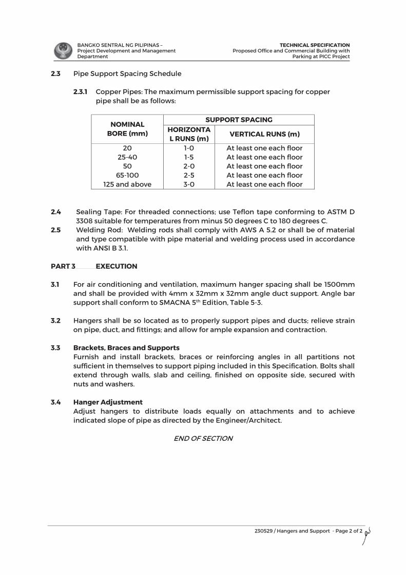
BANGKO SENTRAL NG PILIPINAS – Project Development and Management Department
TECHNICAL SPECIFICATIONProposed Office and Commercial Building with
Parking at PICC Project
230529 / Hangers and Support - Page 2 of 2
2.3 Pipe Support Spacing Schedule
2.3.1 Copper Pipes: The maximum permissible support spacing for copper pipe shall be as follows:
NOMINAL BORE (mm)
SUPPORT SPACING HORIZONTAL RUNS (m)
VERTICAL RUNS (m)
20 25-40
50 65-100
125 and above
1-0 1-5 2-0 2-5 3-0
At least one each floor At least one each floor At least one each floor At least one each floor At least one each floor
2.4 Sealing Tape: For threaded connections; use Teflon tape conforming to ASTM D 3308 suitable for temperatures from minus 50 degrees C to 180 degrees C.
2.5 Welding Rod: Welding rods shall comply with AWS A 5.2 or shall be of material and type compatible with pipe material and welding process used in accordance with ANSI B 3.1.
PART 3 EXECUTION 3.1 For air conditioning and ventilation, maximum hanger spacing shall be 1500mm
and shall be provided with 4mm x 32mm x 32mm angle duct support. Angle bar support shall conform to SMACNA 5th Edition, Table 5-3.
3.2 Hangers shall be so located as to properly support pipes and ducts; relieve strain
on pipe, duct, and fittings; and allow for ample expansion and contraction. 3.3 Brackets, Braces and Supports
Furnish and install brackets, braces or reinforcing angles in all partitions not sufficient in themselves to support piping included in this Specification. Bolts shall extend through walls, slab and ceiling, finished on opposite side, secured with nuts and washers.
3.4 Hanger Adjustment Adjust hangers to distribute loads equally on attachments and to achieve indicated slope of pipe as directed by the Engineer/Architect.
END OF SECTION
2
BANGKO SENTRAL NG PILIPINAS – Project Development and Management Department
TECHNICAL SPECIFICATIONProposed Office and Commercial Building with
Parking at PICC Project
230719 / Piping Insulation - Page 1 of 2
SECTION 23 07 19
HVAC PIPING INSULATION
PART 1 GENERAL
1.1 SCOPE OF WORK This section covered by this specification consists of furnishing all labor, equipment, materials and accessories, and performing all operations required for the correct installation of insulated pipe supports for refrigerant piping systems and condensate pipe.
1.2 REFERENCES Comply with quality assurance requirements under General Conditions of the Contract Documents and Manufacturer’s instructions. Reference the following standards as applicable: 1.2.1 ASTM C534 – Standard Specification for Preformed Flexible Elastomeric
Cellular Thermal Insulation in Sheet and Tubular Form. 1.2.2 ASTM E84 – Test method for Surface Burning Characteristics of Building
Materials. 1.2.3 ASTM C177 – Standard Test Method for Steady-State Heat Flux
Measurements and Thermal Transmission Properties by Means of the Guarded-Hot-Plate Apparatus.
1.2.4 ASTM C518 – Standard Test Method for Steady-State Thermal Transmission Properties by Means of the Heat Flow Meter Apparatus.
1.2.5 ASTM E96 – Standard Test Methods for Water Vapor Transmission of Materials.
1.2.6 MSS SP69 - Manufacturers Standardization Society: Pipe Hangers and Supports- Selection and Application.
1.3 SUBMITTALS 1.3.1 General: All submittals for approval as indicated herein shall be in
accordance to the provisions under General Conditions of the Contract Documents.
1.3.2 Submit Manufacturer’s brochures, catalogs and standard installation procedures. Sample materials shall be subject to the approval Architect and Owner.
1.4 QUALITY ASSURANCE 1.4.1 Pipe supports and insulation inserts that are damaged shall not be
installed. 1.4.2 Material shall be delivered in non-broken, factory furnished packaging and
stored in a clean, dry indoor space that provides protection against the weather.
1.4.3 Workmanship: All pipe supports to be installed by qualified personnel and installed in accordance with manufacturer’s recommendations. a. All work shall comply with all applicable federal, state, and local codes
and laws having jurisdiction.
2
BANGKO SENTRAL NG PILIPINAS – Project Development and Management Department
TECHNICAL SPECIFICATIONProposed Office and Commercial Building with
Parking at PICC Project
230719 / Piping Insulation - Page 2 of 2
b. All work shall conform to accepted industry and trade standards for pipe support.
c. Insulation inserts shall not be applied until all surfaces are clean, dry, and free of dirt, dust, grease, frost, moisture, and other extraneous elements.
PART 2 PRODUCTS 2.1 Elastomeric Insulation Pipes - Shall be 25mm nominal thickness x 2000mm
length, tube type, black color, Elastomeric Insulation with high flexibility, high resistance to water vapour transmission and noise reduction complete with adhesive and accessories. Submit brochures and sample for Architect’s approval.
2.2 Accessories: 2.2.1 Adhesive – Shall low viscosity adhesive which ensures a neat secure water
vapor resistant bond. 2.2.2 Cleaner – Shall be provided for preparation surfaces prior to installing and
for cleaning adhesive from brushes, tolls etc. 2.2.3 CO Paint – Shall be protective water-based white paint for outdoor
installation. Provide a flexible film which is resistant to UV radiation, ozone and many aggressive chemicals.
2.2.4 Self-Adhesive Tape – Shall 3mm thick, 50mm wide for insulating fittings and short length of pipes in hard reach.
Insulation thickness shall be as follows:
Condensate drain piping – 25 mm thick
PART 3 EXECUTION 3.1 Installation:
3.1.1 Use clamp inserts to prevent compression of insulation at standard split, clevis hangers, strut systems, or other pipe support systems.
3.1.2 Pipe support insulation shall be elastomeric foam with the same or greater thickness than the pipe insulation. All joints shall be sealed with adhesive.
3.1.3 All edges of installed insulation shall be clean cut. Rough or jagged edges of the insulation shall not be permitted. Proper tools such as sharp non-serrated knives must be used.
3.1.4 It is highly recommended for continuous insulation protection to use hanger sizes equal to the outer diameter of the pipe plus insulation thickness.
END OF SECTION
BANGKO SENTRAL NG PILIPINAS – Project Development and Management Department
TECHNICAL SPECIFICATIONProposed Office and Commercial Building with
Parking at PICC Projectl i il
231213 / Liquefied Petroleum Gas Piping - Page 1 of 10
SECTION 23 12 13
LIQUEFIED-PETROLEUM GAS PIPING
PART 1 GENERAL
1.1 SCOPE OF WORK
Unless otherwise specified, the Contractor shall furnish all materials, tools, equipment, apparatus, appliances, accessories, transportation, labor and supervision required for the complete installation and testing of the LPG pipeline ready for use in accordance with the best practice of the LPG pipeline Trade as listed herein but not limited to the following: a. The Contractor is required to refer to all architectural, structural,
plumbing/Sanitray, mechanical, electrical and interior designs andinvestigate all possible interference and conditions affecting his work.
b. All work shall comply with the pertinent provisions of the PhilippineMechanical Engineering Code, The Fire Code of the Philippines – RevisedImplementing Rule and Regulation Revised 2019 and all related codesand standards.
c. Supply and installation of all pipes, valves, fittings, hangers, supports andother accessories.
d. Testing and commissioning of all equipment and items installed.
1.2 REFERENCES
Comply with quality assurance requirements under General Conditions of the Contract Documents and Manufacturer’s instructions. Reference the following standards as applicable:
1.2.1 The Philippine Mechanical Engineering Code 1.2.2 The Fire Code of the Philippines 1.2.3 National Fire Protection Association (NFPA) 1.2.4 All other applicable local codes and ordinances as applicable.
1.3 SUBMITTALS
Each submittal is to be complete and in sufficient detail to allow ready determination of compliance with contract requirements. Submit shop drawings, manufacturer’s data and certificates for equipment, materials and
BANGKO SENTRAL NG PILIPINAS – Project Development and Management Department
TECHNICAL SPECIFICATIONProposed Office and Commercial Building with
Parking at PICC Projectl i il
231213 / Liquefied Petroleum Gas Piping - Page 2 of 10
finish, and pertinent details for each system as specified in each individual section, and obtain approval from the Engineer before procurement, fabrication, or delivery to the job site. Approval of submittal shall not relieve the Contractor of the responsibility of inspecting such material or equipment for defects or non-conforming to the specifications. Partial submittals are not acceptable and will be returned without review. Submittals shall include the manufacturer’s name, trade name, catalog model or number, nameplate data, size, layout dimensions, capacity, project specification and paragraph reference, applicable industry, and technical society publication references, years of satisfactory service, and other information necessary to establish contract compliance of each item the Contractor proposes to provide. Photographs of existing installations and data submitted in lieu of catalog data are not acceptable and will be returned without approval.
1.3.1 Shop Drawings: Drawings shall include floor plans, sectional views,
wiring diagrams, and installation details of piping, and spaces identifying and indicating proposed location, layout and arrangement of items of equipment, control panels, accessories, piping, and other items that must be shown to assure a coordinated installation. Drawings shall indicate adequate clearance for operation, maintenance, and replacements of operating equipment devices. If equipment is disapproved, drawings shall be revised to show acceptable equipment and be resubmitted.
1.3.2 Manufacturer’s Data: Submittals for each manufactured item shall be
manufacturer’s descriptive literature of cataloged products, equipment drawings, diagrams, performance and characteristic curves, and catalog cuts. A. Seamless Black Iron Pipe Schedule 40 B. Fittings C. Valves D. Gas Detectors E. Pressure Gauge F. Hanger and Support G. Gas Meter H. HP Regulator
1.3.3 Manufacturer’s Installation Instructions: Where installation procedures or any part thereof are required to in accordance with the recommendations of the manufacturer of the material being installed, printed copies of these recommendations shall be furnished prior to installation. Installation of the item will not be allowed to proceed until the recommendations are received. Failure to furnish these recommendations can be cause for rejection of the material.
0
BANGKO SENTRAL NG PILIPINAS – Project Development and Management Department
TECHNICAL SPECIFICATIONProposed Office and Commercial Building with
Parking at PICC Projectl i il
231213 / Liquefied Petroleum Gas Piping - Page 3 of 10
1.3.4 Field Test Procedure: The content will be the step by step procedure on how the LPG pipeline to be test.
1.4 DELIVERY AND STORAGE
Equipment and materials shall be handled, stored, and protected to prevent damage before and during installation in accordance with the manufacturer’s recommendations. Damaged or defective items shall be replaced.
1.5 STANDARD PRODUCTS/SERVICE AVAILABILITY
1.5.1 Materials and equipment shall be standard products of a manufacturer regularly engaged in the manufacture of such products, which are of similar material design and workmanship. The standard products shall have been in satisfactory commercial or industrial use for two years prior to bid opening.
1.5.2 Service Support: The equipment items shall be supported by service
organizations. The Contractor shall submit a certified list of qualified permanent service organizations for support of the system, which includes their addresses and qualifications. These service organizations shall be reasonably convenient to the equipment installation and able to render satisfactory service to the equipment on a regular and emergency basis during the warranty period of the contract.
1.6 SAFETY REQUIREMENTS
Belts, pulley, chains, gears, couplings, projecting setscrews, keys, rotating parts, and other power transmission apparatus, located so that any person can come in close proximity thereto, shall be fully located or properly guarded. Points of operation, in going nip points, and machinery producing flying chips and sparks shall be guarded.
1.7 RECORD AND AS-BUILT DRAWING
Provide Record Drawings, which clearly show all deviation of installation from contract drawings. Record drawings shall be maintained at the job site. Show all deviations in red ink.
After completion, but before final acceptance of the work, transfer the information from the Record Drawings to As-Built Drawings. Furnish a complete set of As-Built Drawings of each system for record purposes. The As-Built Drawings shall be reproducible and shall be of the same size as the contract drawings.
BANGKO SENTRAL NG PILIPINAS – Project Development and Management Department
TECHNICAL SPECIFICATIONProposed Office and Commercial Building with
Parking at PICC Projectl i il
231213 / Liquefied Petroleum Gas Piping - Page 4 of 10
PART 2. PRODUCTS 2.1 PIPING
Where American Standards are specified, other approved national or local standards may be acceptable, provided copies of these standard Specifications are forwarded to the Engineer for his written approval. LPG pipe line shall be Seamless Black iron schedule 40, 50mm diameter and below jointing shall be welded flanged of screwed taper threads and pipe size 65mm diameter and above shall be welded or flanged joint. Torch cutting shall not be permitted as means of modifying or repairing LPG pipeline. All welding shall be "shop welding” only and shall be done by a certified TESDA NCII using electric arc welding process.
2.2 FITTINGS
LPG pipeline fitting shall be schedule 80. Whenever a change in pipe size is made, one piece of bushing reducing /increaser fitting shall be used. Screwed union shall not be used on pipes larger than 50 mm (2"). Couplings and unions of pipes other than screwed type shall be of types approved specifically for LPG pipeline used.
2.3 VALVES
Shall be of the same manufacture for each class of piping and as such as possible, for the entire project. Valves shall permanently bear affixed stamp or tag indicating manufacturer, catalog number, pressure and temperature ratings of ball valve, regulator, gas shut off valve with all cast iron body with bronze trim. Furnish all valves and accessories material necessary for piping not shown on Drawings. Valves seats shall be renewable except for forged steel and high pressure cast steel valves where manufacturer’s standard integral seats. All valves shall be pressure rated above or equal 6000 psi WOG.
BANGKO SENTRAL NG PILIPINAS – Project Development and Management Department
TECHNICAL SPECIFICATIONProposed Office and Commercial Building with
Parking at PICC Projectl i il
231213 / Liquefied Petroleum Gas Piping - Page 5 of 10
2.4 SWAY BRACING
Shall be steel flat bars, structural grade 7mm minimum thickness with corrosion protection; shape/type. Sway Bracing Installation
a. Adequate sway bracing shall be provided to oppose longitudinal or transverse pipe movements. b. Lateral bracings shall withstand a force equal to 50% of the weight of the gas contained in piping, valves and fittings. c. Piping anchorage shall not be secured on two (2) dissimilar parts of thebuilding which will move differently.
2.5 PIPE HANGERS
Shall be steel flat bars, structural grade 7mm minimum thickness with corrosion protection shape as shown on plans and 13mm diameters bars with corrosion protection. Hangers Installation
a. Approved inserts may be used for the support of hangers, anchorages in concrete Expansion Shield should be used in a horizontal position on the sides of concrete beams and shall be above the bottom reinforcements. b. Increaser couplings shall be attached immediately adjacent to the expansion shields. c. Maximum distance between hangers shall be 3.65 meters (12’) for sizes 25mm (1”). Provide at least on hanger for each length of pipeline. d. All portion of pipes that have contacts to “U” bolt support, the pipe must be wrapped with rubber tape.
2.6 SUPPORT ON RISES
Shall be adequately supported either by attachments directly to the riser or by hangers located on the horizontal’s connections close to the risers. Supports shall be provided at the ground level and at each third level and at the top most level of the riser. All portion of pipes that have contacts to “U” bolt support, the pipe must be wrapped with rubber tape. Every pipe riser shall be provided with bump guard and other means of protection.
BANGKO SENTRAL NG PILIPINAS – Project Development and Management Department
TECHNICAL SPECIFICATIONProposed Office and Commercial Building with
Parking at PICC Projectl i il
231213 / Liquefied Petroleum Gas Piping - Page 6 of 10
2.7 PIPE SLEEVES Shall be cast iron for through footings, cast iron or standard weight iron pipe for below grade and steel pipe for above grade. Minimum clearance between the pipe and sleeve shall not be less than 25 mm. (1") for pipes, 25mm. (1") to 89 mm. (3-1/2") and 50 mm. (2") clearance for pipes 100 mm. (4") and larger. The clearance between pipes and sleeves shall be filled with non-combustible flexible materials such as asbestos rope and furnished with semi-hardening mastic flush. Floor sleeves shall extend at least 76 mm. (3") above the top of the wearing surface.
2.8 PIPE PAINTING, MARK OR LABEL
All pipeline shall be 2 coats of primer and 2 coats Canary Yellow
The gas pipeline shall be mark or label with “LPG” in black background and white font (letter) or black font (letter).
2.9 GAS METER
Installation of Gas Meter including fabrication of housing and supports. Gas Meter shall be located accessible and reachable (within the Gas Farm).
Gas Meter shall be provided with Isolation Valves (Upstream and Downstream) and Y-Strainer upstream. Upstream valve is not readily reachable to discourage frequent open/close of valve.
Each kitchen room should have a different gas meter.
2.10 REGULATOR
Installation of HP Regulator with 2” inlet/outlet connection.
2.11 GAS LEAK DETECTOR
Installation and connection of a 3-channel GLD (Gas Leak Detector) system with 2 or 3 leak detectors.
Auto shut-off device to be installed on the downstream valve of the gas meter.
All Detectors and solenoid valves shall also be explosion proof and shall be certified for use in hazardous area zone 2 environment.
2.12 PRESSURE GAUGE
2.12.1 Pressure gauge shall be Kilopascal and pound per inch reading.

BANGKO SENTRAL NG PILIPINAS – Project Development and Management Department
TECHNICAL SPECIFICATIONProposed Office and Commercial Building with
Parking at PICC Projectl i il
231213 / Liquefied Petroleum Gas Piping - Page 7 of 10
2.12.2 Shall be approved by Factory Mutual and Underwriters Laboratories, Inc. (UL Listed) 2.12.3 With one-year calibration certificate. 2.12.4 Pressure gauge shall be provided with pig tail and isolation valve for easy replacement.
PART 3. EXECUTION 3.1 SUBSTITUTION AND TESTING OF MATERIALS
Intended materials substituted from those originally specified shall be accepted only after a formal request for substitution, accompanied by:
A. Reasons for substitutions; B. Certificate of test indicating quality, compared to those originally
specified. C. Cost comparisons with material originally specified. Requests shall be
submitted to the Architect for evaluation at least 15 working days before installation of subject material is due, or at least 7 days before opening of bids.
Cost of testing of materials, whether on originally specified items or on substitution, shall be to the account of the Contractor. Results of tests shall be submitted to the Architect for evaluation at least 15 days before the material is due for installation on the job.
3.2 SITE CONDITION
The contractor shall be deemed to have visited the site and have acquainted himself with the existing site conditions, means of access and take into account any feature that may affect his tender. Claim for his neglect to do or out of any misunderstanding on his part on these conditions shall not be entertained.
3.3 CONDUCT OF WORK
The contractor shall employ on the job at all times a competent superintendent Licensed Engineer who shall be responsible for the progress and execution of the work.
BANGKO SENTRAL NG PILIPINAS – Project Development and Management Department
TECHNICAL SPECIFICATIONProposed Office and Commercial Building with
Parking at PICC Projectl i il
231213 / Liquefied Petroleum Gas Piping - Page 8 of 10
3.4 INSTALLATION
3.4.1 The mechanicals for this work shall cooperate with the mechanics for all other work in the building. The installation of piping and shall be coordinated with existing conditions and all other construction, including but not limited to, the ductwork, piping, conduits, lighting fixtures, acoustical ceilings, and building structures. Any conflicts that occur with the work of other trades as a result of the lack of coordination by the installers of the LPG system shall be adjusted at the expense of the LPG system contractor and as required and approved by the Engineer/Architect.
3.4.2 Arrange with Contractors of other trades for installation of built-in items, blocking and additional necessary supports.
3.4.3 Sleeves shall be furnished and installed wherever pipe passes through walls, partitions or floors, and the space between the pipe and sleeve shall be packed. Provide sleeves having an internal diameter 1” larger (unless specifically indicated otherwise) than the outside diameter of the pipe.
3.4.4 In placing sleeves, inserts, anchor bolts and any other material to be embedded in masonry and concrete or built into the structure, the Contractor shall cooperate with all other trades and shall consult with the Architect in regard to their exact location whenever there is any interference with structural members.
3.4.5 The Contractor will be held responsible for locating and maintaining in proper position, sleeves, inserts and anchor bolts supplied and/ or set in place by him. In the event that failure to do so requires cutting and patching of finished works, it shall be done at the Contractor’s expense.
3.5 DEFECTIVE WORK If the inspection and test show any defect, such defective work or material shall be replaced and the test shall be repeated until such is satisfactory to the Owner. All repairs shall be made with new material at the expense of the Contractor.
3.6 ACCEPTANCE TEST
The contractor shall conduct tests in the presence of inspector or authority having jurisdiction for LPG pipeline.
BANGKO SENTRAL NG PILIPINAS – Project Development and Management Department
TECHNICAL SPECIFICATIONProposed Office and Commercial Building with
Parking at PICC Projectl i il
231213 / Liquefied Petroleum Gas Piping - Page 9 of 10
PNEUMATIC TEST
Pressure testing of all line using Nitrogen N2 as the medium. Using of any other medium must be consulted first with BSP-PDMD. The contractor must pressure test sectional, especially for those areas that might be close prior to conduct integrated test. Required pressure for the Main Gas Distribution line is 150 psi with holding time of 48 hrs minimum. Gradually induce the pressure into the pipe and monitor pressure gauge. Make sure that pressure gauges are in good working condition. Double or redundant pressure gauge is advisable. Required pressure for the Manifold is 150 psi with holding time of 48hrs. Gradually induce the pressure into the pipe and monitor pressure gauge. Make sure that pressure gauges are in good working condition. Double or redundant pressure gauge is advisable. Use oil filled pressure gauge with calibration certificate valid for one-year. NOTE: Prior to pressure testing of the LPG line, contractor should come up with a checklist to monitor that all stub-out valves and purging points must be closed and “plugged”. Pressure testing shall be witnessed with BSP-PDMD and or Customer representative prior to release the pressure. Note: Appurtenance like regulator, gas meter and other precision devise shall not be included during pneumatic testing. Testing shall be witnessed by BSP-PDMD.
3.7 DEFECTS LIABILITY PERIOD
During the DLP and Warranty, the contractor shall ensure proper maintenance of the equipment including replacement of any part of the system such pipes, valves, detectors and control panel or consumables such as nitrogen gas for flushing as necessary for the proper operation.
The contractor shall check and test the whole system of the LPG System and Gas Leak Detection System every 6 months from the start of the DLP and on the 6th and 11th month of the warranty period.
3.8 WARRANTY
Warrant the system, labor, materials and equipment supplied by the Contractor for a period of One year after completion and acceptance of the system. Should any equipment or material fail within this period, including loss, replace or repair that item at no cost to the Owner.
BANGKO SENTRAL NG PILIPINAS – Project Development and Management Department
TECHNICAL SPECIFICATIONProposed Office and Commercial Building with
Parking at PICC Projectl i il
231213 / Liquefied Petroleum Gas Piping - Page 10 of 10
3.9 GOVERMENTS PERMITS, INSPECTION
The Contractor is responsible for obtaining the necessary government permits and shall pay the corresponding fees.
3.10 ACCEPTNACE OF THE WORK
The BSP-PDMD will witness formal test and approve all system before they are accepted.
END OF SECTION
BANGKO SENTRAL NG PILIPINAS – Project Development and Management Department
TECHNICAL SPECIFICATIONProposed Office and Commercial Building with
Parking at PICC Project
233100 / HVAC Ducts and Coatings - Page 1 of 4
SECTION 23 31 00
MVAC DUCTS AND CASINGS
PART 1 GENERAL
1.1 SCOPE OF WORK This Section specifies the requirements for ductwork, duct cleaning, duct sealing and duct leakage test forming part of the Works in accordance to the general provisions of the Contract Document and related sections as indicated herein.
1.2 REFERENCES Comply with quality assurance requirements under General Conditions of the Contract Documents and Manufacturer’s instructions. Reference the following standards as applicable: 1.2.1 American Society of Mechanical Engineers, ASME 1.2.2 American Society for Testing and Materials, ASTM 1.2.3 American Society of Heating, Refrigerating and Air Conditioning Engineers,
ASHRAE 1.2.4 Sheet Metal and Air Conditioning Contractors National Association,
SMACNA 1.2.5 Underwriter's Laboratories, UL 1.2.6 National Fire Protection Association, NFPA 1.2.7 American Welding Society, AWS 1.2.8 Factory Manual, FM
1.3 SUBMITTALS 1.3.1 General: All submittals for approval as indicated herein shall be in
accordance to the provisions under General Conditions of the Contract Documents.
1.3.2 Submit catalog data for duct materials, flexible duct/connectors and sealing materials. Provide shop drawings indicating duct layout with pressure classification and sizes, fittings, hangers and supports, seam and joint construction, connections to equipment.
1.3.3 Furnish test reports indicating pressure tests performed to include date, section tested, test pressure, and leakage rate, following SMACNA HVAC Air Duct Leakage Test Manual.
1.4 QUALITY ASSURANCE 1.4.1 Comply with quality assurance requirements under General Conditions of
the Contract Documents and Manufacturer’s instructions. 1.4.2 All Ductworks shall be constructed and installed in accordance with
SMACNA - HVAC Duct Construction Standards, ASHRAE and NFPA 90A. Pressure Classifications shall be as specified in SMACNA HVAC Duct Construction Standards Metal and Flexible Tables 1.1 to 1.9 inclusive for rectangular duct. Provide variations in duct size and additional duct fittings as required to clear obstructions and maintain clearances, as approved by the Engineer/Architect at no extra cost.
f 44444444444444444444444
BANGKO SENTRAL NG PILIPINAS – Project Development and Management Department
TECHNICAL SPECIFICATIONProposed Office and Commercial Building with
Parking at PICC Project
233100 / HVAC Ducts and Coatings - Page 2 of 4
1.5 MANUFACTURER’S QUALIFICATION Engage a company specializing in manufacturing products specified in this section with minimum five (3) years-experience. All workmen specializing in performing work of this section shall have minimum three (3) years’ experience approved by Manufacturer.
1.6 ENVIRONMENTAL REQUIREMENTS
Do not install duct sealant when temperatures are less than those recommended by sealant manufacturers. Maintain temperatures during and after installation of duct sealant.
1.7 FIELD MEASUREMENTS Verify field measurements prior to fabrication. Any defective work resulting from negligence in validating site conditions shall be repaired and/or replaced at the Contractor’s expense. Coordinate works to other trades prior installation to avoid delay during construction.
PART 2 PRODUCTS 2.1 DUCTWORK
2.1.1 Ductwork shall be fabricated from zinc-coated iron or steel sheets of the ASTM A653 standards, lock-forming quality, having G90 coating in conformance with ASTM A90. Rectangular ductwork shall be suitable for low velocity system as hereinafter specified. Unless otherwise approved, duct shall conform accurately to the dimensions indicated and shall be straight and smooth on the inside, with joints neatly finished.
2.2 DUCT CONSTRUCTION
Galvanized Steel Sheets: ASTM A527/527M; coating designation G90 construction, metal gauge, hangers and supports, and reinforcements shall conform to SMACNA HVACDCS. Ductwork shall be airtight and shall not vibrate or pulsate when system is in operation Galvanized Steel Hot Dipped After Fabrication: ASTM A123. Black Iron Steel Sheets: for kitchen exhaust duct, the connection shall be welded. Curve Elbows: Make a centerline radius not less than a 1 1/2 time the width diameter of the duct. Short radius elbows are not acceptable. Make airtight. No dust marks from air leaks shall show at duct joint or connections to grilles, registers, and diffusers. Laps: Make laps at joints in the direction of air flow space button-punch or bolt connection in standing seams at fixed centers not greater than 6 inches. Longitudinal locks or seams, known as “button-punch snap-lock “may be used in lieu of Pittsburg Lock. Fittings: Elbows, vaned elbows, take-off, branch connections, transitions, splitters, volume dampers, fire dampers, flexible connections, and access doors shall conform to SMACNA HVACDCS.
4
BANGKO SENTRAL NG PILIPINAS – Project Development and Management Department
TECHNICAL SPECIFICATIONProposed Office and Commercial Building with
Parking at PICC Project
233100 / HVAC Ducts and Coatings - Page 3 of 4
2.3 INSULATION OF AIR CONDITIONING AND EXHAUST AIR DUCTS
Air Conditioning Duct Insulation: All air conditioning ducts shall be insulated with 1 inch-thick, 3 PCF density fire retardant, non-combustible fiberglass. It shall have a flame spread rating of not more than 25 and smoke developed rating of not more than 50 as defined in the Method of Test of Surface Burning Characteristics in the Building Materials List of the National Fire Protection Association. Kitchen exhaust ducts shall be insulated with 2 inch, 3 pounds’ density fire retardant, non-combustible fiberglass. Heat Insulation for the Kitchen exhaust duct: Blanket flexible mineral fiber conforming to ASTM C553, 32 Kg/cu. M (2 pcf) density, 1-inch-thick with integral vapor barrier for location inside the building and 2 inches thick for exterior location. Insulation on exterior shall be provided with cladding suitable for painting.
PART 3 EXECUTION 3.1 EXAMINATION
Verify sizes of equipment connection before fabricating transitions. 3.2 INSTALLATION
3.2.1 Install and support ductwork in accordance with SMACNA HVAC Duct Construction Standards-Metal and Flexible.
3.2.2 During construction, install temporary closures of metal or taped polyethylene on open ductwork to prevent construction dust from entering ductwork system.
3.2.3 Use double nuts and lock washers on threaded rod supports. 3.2.4 Connect flexible ducts to metal ducts with draw bands. 3.2.5 Locate ducts with sufficient space around equipment to allow normal
operating and maintenance activities. 3.2.6 Provide factory fabricated balancing dampers with indicating type locking
quadrant where noted on drawing. 3.2.7 Where indicated, weld or braze duct joints and seams in accordance with
AWS D9.1. 3.2.8 Repair damaged galvanized ductwork surfaces (welds, scratches, etc.) by
applying minimum 2 coats of a zinc base paint. 3.2.9 Provide duct drops to diffuser same size as diffuser neck size. 3.2.10 Provide UL/FM approved through-penetration firestop system when
penetrating fire-rated barriers (i.e., walls, floors, etc). 3.2.11 Secure duct liner with mechanical fasteners and adhesive per SMACNA
duct liner standards and/or manufacturer’s installation specifications. Coat all raw exposed edges per manufacturer’s instructions.
3.3 CLEANING AND PROTECTION
3.3.1 All ductwork shall be fabricated under shelter, delivered to site and stored in a weatherproof and dry area and covered with a plastic sheet or tarpaulin until required for installation.
3.3.2 Prior to and during installation ducts shall be thoroughly cleaned out and shall have all ends covered in an approved manner to prevent ingress of dust and general building debris.
4
BANGKO SENTRAL NG PILIPINAS – Project Development and Management Department
TECHNICAL SPECIFICATIONProposed Office and Commercial Building with
Parking at PICC Project
233100 / HVAC Ducts and Coatings - Page 4 of 4
3.3.3 Ductwork shall not be installed unless adequate cover and protection is available to protect it from possible construction damage and the elements.
3.4 LEAK TEST
3.4.1 Duct leakage testing shall be carried out in accordance with SMACNA HVAC Air Duct Leakage Test Manual.
3.4.2 All leaks, if present, shall be sealed and ducts re-tested for compliance and shall be accepted as per approval from the testing authority, Architect/Engineer and Owner’s Representative.
3.4.3 Notification of tests shall be given at least 48 hours prior to testing of each section so that a representative shall observe the test.
3.4.4 The method of testing, sections of ducts and the test procedure shall be clearly indicated on Construction Drawings.
3.4.5 Ductwork leak test shall be completed with satisfactory results prior to applying insulation to ductwork exterior.
END OF SECTION
4
BANGKO SENTRAL NG PILIPINAS – Project Development and Management Department
TECHNICAL SPECIFICATIONProposed Office and Commercial Building with
Parking at PICC Project
233400 / HVAC Fans - Page 1 of 3
SECTION 23 34 00
MVAC FANS
PART 1 GENERAL
1.1 SCOPE OF WORK This Section specifies the requirements fans and ventilating equipment, materials, controls and installation forming part of the Works in accordance to the general provisions of the Contract Document and related sections as indicated herein.
1.2 REFERENCES Comply with quality assurance requirements under General Conditions of the Contract Documents and Manufacturer’s instructions. Reference the following standards as applicable: 1.2.1 American Society of Mechanical Engineers, ASME 1.2.2 American Society for Testing and Materials, ASTM 1.2.3 American Society of Heating, Refrigerating and Air Conditioning Engineers,
ASHRAE 1.2.4 Sheet Metal and Air Conditioning Contractors National Association,
SMACNA 1.2.5 Underwriter's Laboratories, UL 705 1.2.6 National Fire Protection Association, NFPA
1.3 SUBMITTALS 1.3.1 General: All submittals for approval as indicated herein shall be in
accordance to the provisions under General Conditions of the Contract Documents.
1.3.2 Shop Drawings: Indicate size and configuration of fan assembly, mountings, weights, duct work and accessory connections.
1.3.3 Product Data: Submit data on each type of fan and include accessories, power, RPM, electrical characteristics and connection requirements.
1.3.4 Manufacturer's Installation Instructions: Submit fan manufacturer’s instructions.
1.3.5 Manufacturer's Certificate: Certify products meet or exceed specified requirements.
1.3.6 Operation and Maintenance Data: Submit instructions for lubrication, motor and drive replacement, spare parts list, and wiring diagrams.
1.4 QUALITY ASSURANCE 1.4.1 Comply with quality assurance requirements under General Conditions of
the Contract Documents and Manufacturer’s instructions. 1.4.2 UL Compliance: UL listed and labeled, designed, manufactured, and tested
in accordance with UL 705.
1.5 QUALIFICATIONS Manufacturer: Company specializing in manufacturing products specified in this section with minimum five years documented experience.
3
BANGKO SENTRAL NG PILIPINAS – Project Development and Management Department
TECHNICAL SPECIFICATIONProposed Office and Commercial Building with
Parking at PICC Project
233400 / HVAC Fans - Page 2 of 3
1.6 DELIVERY, STORAGE, AND HANDLING 1.6.1 Comply with product delivery requirements under General Conditions of
the Contract Documents and Manufacturer’s instructions. 1.6.2 Deliver, store, protect, and handle products to site in accordance to the
Manufacturer’s Instruction and under the General Provisions of the Contract Documents. Protect fans and motors from weather and construction dust and shall be provided adequate storage upon delivery.
1.7 FIELD MEASUREMENTS Verify field measurements prior to fabrication. PART 2 PRODUCTS 2.1 Refer to the equipment schedule as indicated in the mechanical drawings, M-1, for
installation details and designation. 2.2 All fans and blowers shall be of the type and capacity indicated and constructed
in accordance with AMCA Standards. Wheels shall be dynamically and statically balanced and free from vibrations and noise. Fan wheels handling outside air shall have factory applied phenolic coating.
2.3 Centrifugal blowers shall be ceiling mounted, ducted type exhaust fans. Propeller
Type Exhaust Fan shall be wall mounted, propeller type exhaust fan complete with backflow damper.
2.4 Disconnect Switch: Cord and plug in housing, or fan mounted toggle switch for
thermal overload protected motor. 2.5 Register grille: Molded white plastic, or aluminum with baked white enamel finish. 2.6 Motor: Open drip proof type with permanently lubricated sealed bearings and
thermal overload protection. 2.7 Accessories:
2.7.1 Wall cap with damper. 2.7.2 Rubber-in-shear vibration isolator. 2.7.3 Fan speed controller. 2.7.4 Time delay relay.
2.8 Performance: As scheduled on Drawings. 2.9 Electrical Characteristics and Components: As scheduled on Drawings. PART 3 EXECUTION 3.1 Examination
Verify wall and ceiling penetrations are installed and dimensions are as shown on shop drawings and in accordance to Manufacturer’s instructions as per Architect’s/Engineer’s approval.
f 3 3333 3 33
BANGKO SENTRAL NG PILIPINAS – Project Development and Management Department
TECHNICAL SPECIFICATIONProposed Office and Commercial Building with
Parking at PICC Project
233400 / HVAC Fans - Page 3 of 3
3.2 Installation 3.2.1 Install Work in accordance with manufacturer’s instructions. 3.2.2 Install flexible connections between fan and ductwork. 3.2.3 Provide back draft dampers on outlet from fans and as indicated on
Drawings. 3.2.4 Provide variable speed control for final air balance.
3.3 Demonstration
Demonstrate fan operation for testing according to manufacturer’s instruction and manual in the presence of Owner’s representative and Architect/Engineer for the approval of works.
3.4 Testing and Adjusting
Start up and adjust fans to insure proper operation. Provide operational tests to demonstrate proper operation and adequate capacity at completion of balancing and adjusting.
3.5 Protection of Finished Work
Do not utilize fans for until ductwork is clean, filters in place, bearings lubricated, and fan has been test run under observation.
END OF SECTION
BANGKO SENTRAL NG PILIPINAS – Project Development and Management Department
TECHNICAL SPECIFICATIONProposed Office and Commercial Building with
Parking at PICC Project
233713/ Diffuser, Registers and Grilles - Page 1 of 2
SECTION 23 37 13
DIFFUSER, REGISTER AND GRILLE
PART 1 GENERAL
1.1 WORK INCLUDED A. Comply with Division 1, General Requirements and all documents referred
to therein. B. Provide all labour, materials, products, equipment and services to provide
air terminals as indicated on the Drawings and specified in this Section of the Specifications.
1.2 REFERENCE STANDARDS A. Meet the noise criteria levels specified in Section 230548. B. ADC 1062 - Certification, Rating and Test Manual. C. AMCA 500 - Test Method for Louvers, Dampers and Shutters. D. ANSI/NFPA 90A - Installation of Air Conditioning and Ventilating Systems. E. ASHRAE STD 70 - Method of Testing for Rating the Air Flow Performance of
Outlets and Inlets. F. SMACNA - Low Pressure Duct Construction Standard.
1.3 QUALITY ASSURANCE A. Test and rate performance of air outlets and inlets in accordance with ADC
Equipment Test Code 1062 and ASHRAE STD 70. B. Test and rate performance of louvres in accordance with AMCA 500. C. Provide air outlets and inlets bearing ADC certified rating seal.
1.4 SHOP DRAWINGS A. As part of air terminal shop drawing submittal, submit a light troffer shop
drawing showing method of connection and compatibility with the light fixture.
1.6 SAMPLES A. Submit air terminal samples when requested by Engineer.
PART 2 PRODUCTS
2.01 GENERAL A. Grilles, diffusers, registers etc. shall be coloured powder-coated finish.
B. Steel parts shall be factory zinc phosphate treated prior to priming and painting or have a baked-on enamel finish. Each ceiling diffuser and register shall have single key opposed blade damper accessible on the room side of the diffuser or register.
2.02 CEILING SUPPLY REGISTERS/GRILLES A. Streamlined and individually adjustable curved blades to discharge air
along face of grille. Double Deflection and as indicated on the drawings.
2
BANGKO SENTRAL NG PILIPINAS – Project Development and Management Department
TECHNICAL SPECIFICATIONProposed Office and Commercial Building with
Parking at PICC Project
233713/ Diffuser, Registers and Grilles - Page 2 of 2
B. Fabricate one-inch margin frame with concealed mounting and gasket. C. Provide integral, gang-operated opposed blade dampers with removable
key operator, operable from face. D. The grilles/registers complete with accessories shall be of aluminium
construction. Finish and colour to be approved by Engineer.
PART 3 EXECUTION 3.01 INSTALLATION
A. Provide air terminals in strict accordance with manufacturer's recommendations and final reflected ceiling plans.
B. Provide plaster frames for units installed in plaster finishes for grilles and diffusers. Fit frames tightly to prevent leakage and smudging.
C. Install items in accordance with manufacturers' instructions. D. Check location of outlets and inlets and make necessary adjustments in
position to conform to Engineering features, symmetry, and lighting arrangement.
E. Install diffusers to ductwork with airtight connection. F. Provide balancing dampers on duct take-off to diffusers, and grilles and
registers, regardless of whether dampers are specified as part of the diffuser, or grille and register assembly.
G. Paint ductwork and air outlets and inlets visible behind air outlets and inlets matte black.
END OF SECTION
2
BANGKO SENTRAL NG PILIPINAS – Project Development and Management Department
TECHNICAL SPECIFICATIONProposed Office and Commercial Building with
Parking at PICC Project
238129 / Air Conditioning System - Page 1 of 7
SECTION 23 81 29
AIR CONDITIONING EQUIPMENT
PART 1 GENERAL
1.1 SCOPE OF WORK This Section specifies the requirements for air-conditioning condenser units, fan/coil units, equipment, materials, controls requirements and installation forming part of the Works in accordance to the general provisions of the Contract Document and related sections as indicated herein.
1.2 REFERENCES Comply with quality assurance requirements under General Conditions of the Contract Documents and Manufacturer’s instructions. Reference the following standards as applicable: 1.2.1 American Society of Mechanical Engineers, ASME 1.2.2 American Society for Testing and Materials, ASTM 1.2.3 American Society of Heating, Refrigerating and Air Conditioning Engineers,
ASHRAE 1.2.4 Sheet Metal and Air Conditioning Contractors National Association,
SMACNA 1.2.5 Underwriter's Laboratories, UL 1.2.6 National Fire Protection Association, NFPA
1.3 SUBMITTALS 1.3.1 General: All submittals for approval as indicated herein shall be in
accordance to the provisions under General Conditions of the Contract Documents.
1.3.2 Product Data: Submit manufacturer's technical product data including rated capacities of selected equipment clearly indicating weight, installation and start-up instructions, furnished specialties and accessories. Manufacturer shall include certificates of quality compliance and product testing documents relevant to the project specifications.
1.3.3 Shop Drawings: Submit manufacturer's assembly type shop drawings indicating dimensions, weight loadings, required clearances, diagrams and methods of assembly of components.
1.3.4 Submittals: Submit Operating and Maintenance (O&M) data and parts lists for each item of equipment, control, and accessory; including "trouble-shooting" maintenance guide. Include chemical data and material data safety sheets. Include this data, submittal data, product data, shop drawings, and wiring diagrams in maintenance manual, in accordance with the Contract Document requirements.
1.3.5 Materials and Equipment Schedule As soon as practicable, after date of award of the contract and prior to ordering of materials and equipment a complete schedule of the materials and equipment proposed for the installation shall be submitted for the approval of the Owner, Architect and his Engineer together with his
7
BANGKO SENTRAL NG PILIPINAS – Project Development and Management Department
TECHNICAL SPECIFICATIONProposed Office and Commercial Building with
Parking at PICC Project
238129 / Air Conditioning System - Page 2 of 7
drawings, showing dimensions and arrangement of equipment, necessary clearances and total floor space required. The schedule shall include catalog cuts, diagrams, drawings and other descriptive data as may be required by the Architect or the Engineer. In the event any item of materials or equipment contained in the schedule fail to comply with the specifications, such item may be rejected.
1.3.6 Capacity Information Prior to installation, the mechanical contractor shall furnish the Owner,
Architect or the Engineer with manufacturers’ published capacity information including tables, curves and other data that may be required in order to determine the capacity of the equipment under the designed conditions as indicated on the equipment schedule.
1.3.7 Record Drawings A complete and accurate report and record of all deviations from the
drawings and specifications shall be maintained to indicate the work as actually installed. The information shall be recorded on a print of the drawings affected or in the specifications with supplementary notes. The record set of prints and specifications shall be kept at the job site for inspection by the Architect or his designated representative.
1.3.8 Contractor Shop Drawings Detailed shop drawings with dimensions for the installation of the system
shall be prepared and submitted for approval. These drawings with the dimensions for the installation shall not be reproductions or tracing shop drawings. Establish lines and levels for the work specified and check the drawings to avoid interference with structural features and the work of the other trades. Immediately call the attention of the Architect with the Owner consent any interference for clarification in writing.
1.4 QUALITY ASSURANCE
1.4.1 Comply with quality assurance requirements under General Conditions of the Contract Documents and Manufacturer’s instructions.
1.4.2 Engage competent workmen with significant experience similar to the project requirements. Materials and equipment shall be from a reputable manufacturer with ISO certification and shall be factory-tested before delivery to the site. All installations shall be done with the Manufacturer’s standard procedures and applicable codes and standards.
1.5 WARRANTY
Special written warranty for each material specified herein shall be submitted by Manufacturer/Contractor without reducing or otherwise limiting any other rights to correction which the Owner may have under the Contract Documents. Failures are defined to include faulty workmanship or faulty materials. The manufacturer shall furnish a written copy of warranty for each unit from date of "start-up". "Start-up" date shall be recorded on each warranty certificate.
1.6 SITE CONDITIONS 1.6.1 Comply with field examination requirements under General Conditions of
the Contract Documents and Manufacturer’s instructions.
7
BANGKO SENTRAL NG PILIPINAS – Project Development and Management Department
TECHNICAL SPECIFICATIONProposed Office and Commercial Building with
Parking at PICC Project
238129 / Air Conditioning System - Page 3 of 7
1.6.2 Contractors shall visit the site and become familiar with all existing conditions, which will affect construction procedures and scope of work required as part of this Section.
1.7 DESIGN CRITERIA AND COOLING LOAD COMPUTATIONS
The mechanical contractor shall guarantee that the equipment supplied and installed by him be set to maintain conditions as follows. Above room temperature shall be controlled and maintained by a room thermostat installed at a location that is most suitable and effective for the purpose. 1.7.1 Outside Conditions 95oF DB, 82oF WB
80% ± 5% R 1.7.2 Inside Conditions 76oF DB ± 2oF DB 55% ± 5% RH 1.7.3 Load Densities for Cooling Load Calculations
A. Occupancies a. Common Areas/Lobby 3.00m2 or 30ft2/person
B. Electrical Loads a. Office spaces 55 watts/m2 or5 watts/ft2
C. Outside Air a. Common Areas and Lobby 15 cfm/person
1.8 SPACE TEMPERATURE AND CONDITION GUARANTEE:
The mechanical contractor shall guarantee that the equipment supplied and installed by him be set to maintain conditions as follows: 76ºF bulb plus or minus 2ºF 55% relative humidity plus or minus 5% Above room temperature shall be controlled and maintained by a room thermostat installed at a location that is most suitable and effective for the purpose.
1.9 GUARANTEE AND PREVENTIVE MAINTENANCE: The mechanical contractor shall guarantee the air conditioning and ventilating
system, equipment furnished and installed for a period of one (1) year from date of acceptance thereof and materials and equipment furnished under this contract shall be free from defects in the material, workmanship and design. At any time within one (1) year after acceptance and upon notice to the contractor by the Owner, the contractor shall rectify any and all deficiencies including replacement of parts or entire unit without additional cost to the owner if such deficiencies have been caused directly or indirectly by inferior materials, faulty workmanship and or defective design of parts.
During the guarantee period, the mechanical contractor shall perform free
monthly inspection and maintenance service and make adjustment if necessary for proper and efficient operation of the system.
During the DLP and Warranty, the contractor shall ensure proper maintenance of the equipment including replacement of any part such as electric motors, coils,
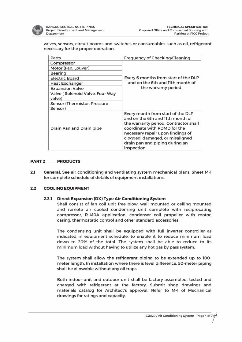
BANGKO SENTRAL NG PILIPINAS – Project Development and Management Department
TECHNICAL SPECIFICATIONProposed Office and Commercial Building with
Parking at PICC Project
238129 / Air Conditioning System - Page 4 of 7
valves, sensors, circuit boards and switches or consumables such as oil, refrigerant necessary for the proper operation.
PART 2 PRODUCTS 2.1 General. See air conditioning and ventilating system mechanical plans, Sheet M-1
for complete schedule of details of equipment installations. 2.2 COOLING EQUIPMENT
2.2.1 Direct Expansion (DX) Type Air Conditioning System Shall consist of fan coil unit free blow, wall mounted or ceiling mounted
and remote air cooled condensing unit complete with reciprocating compressor, R-410A application, condenser coil propeller with motor, casing, thermostatic control and other standard accessories.
The condensing unit shall be equipped with full inverter controller as
indicated in equipment schedule, to enable it to reduce minimum load down to 20% of the total. The system shall be able to reduce to its minimum load without having to utilize any hot gas by pass system.
The system shall allow the refrigerant piping to be extended up to 100-
meter length. In installation where there is level difference, 50-meter piping shall be allowable without any oil traps.
Both indoor unit and outdoor unit shall be factory assembled, tested and
charged with refrigerant at the factory. Submit shop drawings and materials catalog for Architect’s approval. Refer to M-1 of Mechanical drawings for ratings and capacity.
Parts Frequency of Checking/Cleaning Compressor
Every 6 months from start of the DLP and on the 6th and 11th month of
the warranty period.
Motor (Fan, Louver) Bearing Electric Board Heat Exchanger Expansion Valve Valve ( Solenoid Valve, Four Way valve) Sensor (Thermistor, Pressure Sensor)
Drain Pan and Drain pipe
Every month from start of the DLP and on the 6th and 11th month of the warranty period. Contractor shall coordinate with PDMD for the necessary repair upon findings of clogged, damaged, or misaligned drain pan and piping during an inspection.
7

BANGKO SENTRAL NG PILIPINAS – Project Development and Management Department
TECHNICAL SPECIFICATIONProposed Office and Commercial Building with
Parking at PICC Project
238129 / Air Conditioning System - Page 5 of 7
2.2.2 Refrigerant Piping
Material and dimensional requirements for piping, valves, fittings and accessories shall conform to ASHRAE 15 and ANSI B31.5. Refrigerant piping shall be cleaned, dehydrated, charged and sealed. Refrigerant piping shall be type L, soft annealed copper tubing where bending is required and hard drawn where no bending is required. Soft annealed copper tubing shall not be used in sizes larger than 1-3/8 inches. Joints shall be brazed except that joints on lines 7/8 inch and smaller may be flared.
PART 3 EXECUTION 3.1 Manufacturer's Written Installation Instructions
3.1.1 All materials shall be installed as recommended by manufacturer. Nothing in these specifications shall be construed to vary from manufacturer's written installed instructions without written approval from manufacturer.
3.1.2 It shall be the responsibility of this Contractor to coordinate with the other trades for clearance, elevations, etc., before the installation of any material. Where conflicts exist the Architect shall be notified before installing material. Changes required in work specified in this Section caused by neglect to do so shall be made at no cost to the Owner.
3.1.3 Arrange with Contractors of other trades for installation of built-in items, blocking and additional necessary supports.
3.2 Field Quality Control
All units shall be started up, checked out, and adjusted by Manufacturer's authorized factory trained service mechanic. Mechanic shall use check-out sheet provided by Manufacturer, complete and shall sign all items on sheet, and submit to Architect.
3.3 Commissioning Following Site Tests and prior to taking-over of the Works by the Employer, the air-
conditioning system shall be balanced by use of the control equipment so as to give the required room temperature, refrigerant flow rates and pressure in all sections of the system served by the said system. The complete air-conditioning system shall be commissioned as a whole. When the system has been balanced to the satisfaction of the Engineer/Architect, it shall be run under complete automatic control for 24 hours continuous operation to ascertain any faults in operation before acceptance and take-over. Any faults discovered during this time shall be corrected and a further test or tests of 24 hours duration shall be carried out to ensure satisfactory operation, all at the expense of the Contractor.
3.4 Noise and Vibration
It is the specific intent of these specifications and design conditions that the system including equipment, piping and other parts, shall be noiseless and free of vibration as a result of the new installation in the building. It shall be the responsibility of this Contractor to correct these conditions at no cost to the Owner.
7
BANGKO SENTRAL NG PILIPINAS – Project Development and Management Department
TECHNICAL SPECIFICATIONProposed Office and Commercial Building with
Parking at PICC Project
238129 / Air Conditioning System - Page 6 of 7
3.5 Wiring Diagrams Furnish complete wiring diagrams for all equipment furnished by this Contractor. Submit wiring diagrams to Architect with equipment submittals for approval.
3.6 Electrical Works
All motors, combination manual or automatic starters, remote push buttons and protective, signal or control devices required for the operation of all equipment herein specified shall be furnished. Wiring to all electrical equipment including motors, together with all connections to all related control and protective equipment shall be accomplished as a part of the air conditioning, ventilating and exhaust system including all required interlocks for proper operations of the systems. Motors driving indoor equipment shall be of the open drip proof type unless otherwise specified. Motors driving equipment installed outdoor shall be totally enclosed fan cooled construction. Where motor driven equipment through pulleys and belts, belt guards shall be provided. The belt guards shall be suitable frames covering the motor pulleys, belt and driven sheaves with access plates for tachometer reading. All electric power and control wiring necessary shall be accomplished in accordance with the requirements of the electrical plans and specifications.
3.7 Motor Controllers All motor starters shall be magnetic type complete with overload units and relays
manufactured in accordance with NEMA standards. Starters installed indoors shall have general purpose enclosure and starters installed outdoors shall have airtight enclosure. Circuits breakers shall operate on the thermal magnetic principle. Aside from serving as disconnecting means they shall afford protection against single phasing and circuit faults. They shall be provided with enclosure suitable for the service.
3.8 Clean-up
Upon completion of work under this Section, all unnecessary equipment, materials, rubbish, etc., shall be removed from project site and surrounding are leaving site in a safe and cleared condition.
3.9 Cutting, Patching and Piercing
Obtain written permission of the Architect before cutting or piercing structural members. If, in the process of the mechanical work, ducts, piping or equipment need to be installed in an area after it has been completed, the area shall be left in the same condition it was originally. Patching and/or refinishing will be determined by the Architect.
3.10 Access
Equipment and devices shall be mounted in a manner which provides adequate maintenance, inspection access and work space. Where access is required for adjustment, cleanout, inspection of maintenance and such access is not otherwise available; access panels shall be furnished and installed. Panels shall be selected by the Architect.
BANGKO SENTRAL NG PILIPINAS – Project Development and Management Department
TECHNICAL SPECIFICATIONProposed Office and Commercial Building with
Parking at PICC Project
238129 / Air Conditioning System - Page 7 of 7
3.11 Building Openings for Admission or Installation of Equipment The Contractor shall ascertain from his examination of the Architectural and Structural Drawing whether any special temporary or permanent openings in the building for the admission or installation of apparatus furnished under this Contract will be necessary and he shall notify the General Contractor accordingly. He shall pay all cost of making such openings in case of failure to give this notification in time for the General Contractor to arrange for same during construction.
3.12 Works and Materials by Others: Performance of certain work by others have been provided for under these specifications and shall consist of: 3.12.1 Power supply source. 3.12.2 Drain and fresh water facilities to air conditioning machine room. Actual
connection to equipment shall be done by the mechanical contractor to and from these facilities in a manner which shall result in optimum length of pipe runs.
3.12.3 All boring holes through slabs, wall partitions, roofs, ceiling and patching of the same after installation.
3.12.4 Necessary machine room with sufficient and proper ventilating and water proofing provisions.
3.12.5 Insulation of G.I. roofing for the conditioned spaces. END OF SECTION
7

BANGKO SENTRAL NG PILIPINAS – Project Development and Management Department
TECHNICAL SPECIFICATIONProposed Office and Commercial Building with
Parking at PICC Project
260000/ Electrical- Page 1 of 16
SECTION 26 00 00
ELECTRICAL
PART 1 GENERAL
1.1 DESCRIPTION The General and Supplementary Conditions are a part of the requirements for the work under this Division of the Specifications.
1.2 WORK INCLUDED
A. Provide labor and materials required to install, test and place into operation the electrical systems as called for in the Contract Documents, and in accordance with applicable codes and regulations.
B. Provide labor, materials, and accessories required to provide complete, operating electrical systems. Labor, materials or accessories not specifically called for in the Contract Documents, but required to provide complete, operating electrical systems shall be provided without additional cost to the Owner.
1.3 QUALITY ASSURANCE
A. Comply with the current applicable codes, ordinances, and regulations of the authority or authorities having jurisdiction, the rules, regulations and requirements of the utility companies serving the project and the Owner’s insurance underwriter.
B. Drawings, specifications, codes and standards are minimum requirements. Where requirements differ, the more stringent apply.
C. Should any change in drawings or specifications be required to comply with the governing regulations, notify the Engineer prior to submitting bid.
D. All equipment and installations shall meet or exceed minimum requirements of PS, PEC, ANSI, ASTM, IEC, IEEE, IES, ETL, NEC, NEMA, NFPA, SMACNA, UL, ICAO and The Fire Marshal.
E. Execute work in strict accordance with the best practices of the trades in a thorough, (substantial, workmanlike manner by competent workmen. Provide a competent, experienced, full-time Superintendent who is authorized to make decisions on behalf of the Contractor).
1.4 ABBREVIATIONS AND DEFINITIONS
A. Abbreviations: 1. PS Philippines Standard 2. PEC Philippines Electrical Code 3. ANSI American National Standards Institute 4. ASTM American Society for Testing and Materials 5. ETL Electrical Testing Laboratories 6. ICAO International Civil Aviation Organization 7. IEC International Electrotechnical Committee 8. IEEE Institute of Electrical and Electronic Engineers 9. IES Illuminating Engineering Society
g
BANGKO SENTRAL NG PILIPINAS – Project Development and Management Department
TECHNICAL SPECIFICATIONProposed Office and Commercial Building with
Parking at PICC Project
260000/ Electrical- Page 2 of 16
10. IPCEA International Power Cable Engineers Association 11. NEC National Electrical Code 12. NEMA National Electrical Manufacturer’s Association 13. NFPA National Fire Protection Association 14. SMACNA Sheet Metal and Air Conditioning Contractors National
Association 15. UL Underwriters Laboratory
B. Definitions
1. Where it is stated in this specification to submit to Engineer for review, refer to Architectural General and Special Conditions for proper procedures.
2. FURNISH means to supply all materials, labor, equipment, testing apparatus, controls, tests, accessories, and all other items customarily required for the proper and complete application.
3. INSTALL means to join, fasten, link, attach, set up or otherwise connect together before testing and turning over to Owner, complete and ready for regular operation.
4. PROVIDE means to FURNISH and INSTALL. 5. AS DIRECTED means as directed by the Engineer, or his
representative. 6. CONCEALED means embedded in masonry or other construction,
installed behind wall furring or within drywall partitions, or installed within hung ceilings.
7. SUBMIT means submit to Engineer for review. 1.5 GUARANTEE
Submit a single guarantee stating that the work is in accordance with the Contract Documents. Guarantee work against faulty and improper material and workmanship for a period of one year from the date of final acceptance by the Owner, except that where guarantees or warranties for longer terms are provided or specified herein, the longer term shall apply. Correct any deficiencies which occur during the guarantee period, within 24 hours of notification, without additional cost to the Owner, to the satisfaction of the Owner. Obtain similar guarantees from subcontractors, manufacturers, suppliers and subtrade specialists.
PART 2 PRODUCTS 2.1 EQUIPMENT AND MATERIALS
A. Provide products and materials that are new, clean, free of defects, and free of damage and corrosion.
B. Products and materials shall not contain asbestos, PCB, or any other material which is installed considered hazardous by the authority having jurisdiction.
C. Replace materials of less than specified quality and relocate work incorrectly installed as directed by the Engineer.
D. Provide name/data plates on major components of equipment with manufacturer’s name. Model number, serial number, capacity data and
age 2 of 16
BANGKO SENTRAL NG PILIPINAS – Project Development and Management Department
TECHNICAL SPECIFICATIONProposed Office and Commercial Building with
Parking at PICC Project
260000/ Electrical- Page 3 of 16
electrical characteristics attached in a conspicuous place. E. Install materials and equipment with qualified trades people. F. Maintain uniformity of manufacturer for equipment used in similar
application and sizes. G. Fully lubricate equipment where required. H. Follow manufacturer’s instructions for installing, connecting, and adjusting
equipment. Provide a copy of such instructions at the equipment during installation.
I. Where factory testing of equipment is required to ascertain performance and attendance by the Owner’s representative is required to witness such tests, associated travel costs and subsistence shall be paid for by the Contractor.
J. Equipment capacities, ratings, etc., are scheduled or specified for job site operating conditions. Equipment sensitive to altitude shall be derated with the method of derating identified on the submittals.
K. Enclosures for electrical equipment installed in mechanical equipment rooms shall be NEMA type 1 gasketed. Enclosures for electrical equipment installed outdoors shall be NEMA type 3R.
L. Energy consuming equipment shall meet local energy ordinances. PART 3 EXECUTION 3.1 FEES AND PERMITS
A. Pay all required fees and obtain all required permits related to the electrical installation.
B. Pay royalties or fees required in connection with the use of patented devices and systems.
C. Provide controlled inspection where required by authorities having jurisdiction or by these specifications.
3.2 SUBMITTALS AND REVIEWS
A. Submit shop drawings, manufacturer’s product data sheets, samples, and test reports as specified.
B. After issuance of notice to proceed by the Owner or Owner’s Representative, or after execution of Owner/Contractor Agreement, submit a complete typed list of all electrical equipment of manufacturer’s and materials suppliers for the equipment proposed to be provided on this project, as well as names of all subcontractors.
C. After issuance of notice to proceed by the Owner or Owner’s Representative, or after execution of Owner/Contractor Agreement, prepare an index of all submittals for the project. Include a submittal identification number, a cross-reference to the Specification sections or Drawings number, and an item description. Prefix the submittal identification number by the Specification sections to which they apply. Indicate on each submittal, the submittal identification number in addition to the other data specified. All subcontractors shall utilize the assigned identification number.
D. After the Contract is awarded, obtain complete shop drawings, product data and samples from the manufacturer, suppliers, vendors, and all
g
BANGKO SENTRAL NG PILIPINAS – Project Development and Management Department
TECHNICAL SPECIFICATIONProposed Office and Commercial Building with
Parking at PICC Project
260000/ Electrical- Page 4 of 16
subcontractors, for all materials and equipment as specified. Submit data and details of such materials and equipment for review. Prior to submissions, certify that the shop drawings, product data and samples are in compliance with the Contract Documents. Check all materials and equipment upon their arrival on the job site and verify their compliance with the Contract Documents. Modify any work which proceeds prior to receiving accepted shop drawings as required to comply with the Contract Documents and the shop drawings.
E. Review of submittals is for general compliance with the design concept and contract documents. Comments or absence of comments shall not relieve solely responsible for details and accuracy, for confirming and correlating all quantities and dimensions, for selecting fabrication processes, for techniques of construction, for performing the work in a safe manner, and for coordinating the work with that of other trades.
F. No part of the work shall be started in the shop or in the field until the shop drawings and samples for that portion of the work have been submitted and accepted.
G. A minimum period ten working days, exclusive of transmittal time, will be required in the Engineer’s office each time a shop drawing, product data and/or samples are submitted for review. This time period must be considered by the Contractor in the scheduling of the work.
H. Submit one sepia transparency and two blue line prints of all items shop drawings. Submit six copies of manufacturer’s product submittals.
I. Submittals will be stampled as follows:
STAMP Interpretation Unaltered Fabrication, manufacture, or
construction may proceed providing submittal complies with the Contract Documents.
For corrections as noted prior to general issue
Fabrication, manufacture, or construction may proceed providing submittal complies with the Contract Documents and the Engineer’s notation are complied with.
For Re-submission The submittal does not comply with the Contract Documents; do not proceed with fabrication, manufacture, or construction. The work and shop drawings are not permitted at the job site. Re-submit appropriate shop drawings.
J. Submit materials and equipment by manufacturer, trade name, and model
number. Include copies of applicable brochure or catalog material. Maintenance and operating manuals are not acceptable substitutes for shop drawings.
BANGKO SENTRAL NG PILIPINAS – Project Development and Management Department
TECHNICAL SPECIFICATIONProposed Office and Commercial Building with
Parking at PICC Project
260000/ Electrical- Page 5 of 16
K. Identify each sheet of printed submittal pages (using arrows, underlining or circling) to show applicable sizes, types, model numbers, ratings, capacities and options actually being proposed. Cross out non-applicable information. Note specified features such as materials or paint finishes.
L. Include dimensional data for roughing in and installation and technical data sufficient to verify that equipment meets the requirements of the Contract Documents. Include wiring, piping and service connection data.
M. Maintain a complete set of reviewed and stamped shop drawings and product data and samples and on site.
N. For each room or area of the building containing electrical equipment, submit the following: 1. Floor Plans: Plan and evaluation layout drawings indicating the
equipment in the exact location in which it is intended to be installed. These plans shall be of a scale not less than 1:50. They shall be prepared in the following manner:
Indicate the physical boundaries of the space including door swings and ceiling heights and ceiling types (as applicable).
a. Illustrate all electrical equipment proposed to be contained
therein. Include top & bottom elevation of all electrical equipment. The drawings shall be prepared utilizing the dimensions contained in the individual equipment submittals. Indicate code and manufacturer’s required clearances.
b. Illustrate all other equipment therein such as conduits, detectors, luminaires, ducts, registers, pull boxes, wireway, structural elements, etc.
c. Indicate the operating weight of each piece of equipment. d. Indicate the heat release from each piece of electrical
equipment in terms of BTU per hour. This information shall be that which is supplied by the respective manufacturers.
e. Illustrate concrete pads, curbs, etc. f. Indicate dimensions to confirm compliance with code
required clearances. g. Indicate maximum normal allowable operating temperature
for each piece of equipment (as per each respective manufacturer’s recommendations).
h. Equipment removal routes.
O. The work described in shop drawings submission shall be carefully checked by all trades for clearances (including those required for maintenance and servicing), field conditions, maintenance of architectural conditions and coordination with other trades on the job. Each submitted shop drawing shall include a certification that related job conditions have been checked by the Contractor and each Subcontractor and that conflicts do not exist.
P. The Contractor is not relieved of the responsibility for dimensions or errors that may be contained on submissions, or for deviations from the requirements of the Contract Documents. The noting of some errors but
g
BANGKO SENTRAL NG PILIPINAS – Project Development and Management Department
TECHNICAL SPECIFICATIONProposed Office and Commercial Building with
Parking at PICC Project
260000/ Electrical- Page 6 of 16
overlooking others does not grant the shop drawings, product to proceed in error. Regardless any information contained in and are neither waived nor superseded in any way by the review of shop drawings, product data and samples.
Q. Inadequate or incomplete shop drawings, product data and/or samples will not be reviewed and will be returned to the Contractor for resubmittal.
R. Indicate the following on the lower right hand corner of each shop drawing and on the front cover of each product data brochure cover. The submittal identification number; title of the sheet or brochure; name and location of the Product; names of the Architect, Engineer, Contractor, Subcontractor, manufacturer, supplier, and vendor; the date of submittal; and the date of each correction, version and revision. Number all pages and drawings in product data brochures consecutively from beginning to end. Unless the above information is included, the submittal will be returned for resubmission. Resubmittals of product data or brochures shall include a cover letter summarizing the corrections made in response to the review comments.
S. The distribution equipment, short circuit and coordination study, and room layout submittals shall be submitted concurrently. Failure to submit concurrently may result in the immediate return of the submittal marked FOR RESUBMISSION.
3.3 COORDINATION OF WORK
A. Contract documents establish scope, materials and quality but are not detailed installation instruction. Drawings are diagrammatic.
B. Coordinate work with related trades and furnish, in writing, any information necessary to permit the work of related trades to be installed satisfactorily and with the least possible conflict or delay.
C. The electrical drawings show the general arrangement of equipment and appurtenances. Follow these drawings as closely as the actual construction and the work of other trades will permit. Provide off-sets, fittings, and accessories which may be required but not shown on the drawings. Investigate the site, and review drawings of other trades to determine conditions affecting the work, and provide such work and accessories as may be required to accommodate such conditions.
D. The locations of lighting fixtures, outlets, panels and other equipment indicated on the drawings are approximately correct, but they are understood to be subject to such revision as may be found necessary or desirable at the time the work is installed in consequence of increase or reduction of the number of outlets, or in order to meet field conditions, or to coordinate with modular requirements of ceilings, or to simplify the work, or for other legitimate causes.
E. Exercise particular caution with reference to the location of panels, outlets, switches, etc., and have the precise and definite locations accepted by the Engineer before proceeding with the installation.
F. The drawings show only the general run of raceways and approximate location of outlets. Any significant changes in location of outlets, cabinets, etc., necessary in order to meet field conditions shall be brought to the
g
BANGKO SENTRAL NG PILIPINAS – Project Development and Management Department
TECHNICAL SPECIFICATIONProposed Office and Commercial Building with
Parking at PICC Project
260000/ Electrical- Page 7 of 16
determine attention of the Engineer for review before such alterations are made. Modifications shall be made at no additional to the Owner.
G. Verify with the Engineer the exact location and mounting height of outlets and equipment not dimensionally located on the drawings.
H. Circuit tags in the form of numbers are used where shown to indicate the circuit designation numbers in electrical panels. Show he actual circuit numbers on the as built Record Drawings and on the associated typed panelboard directory card. Where circuiting is not indicated, provide required circuiting in accordance with the loading indicated on the drawings and/or as indicated.
I. The drawings generally do not indicate the number of wires in conduit for the branch circuit wiring of fixtures and outlets, or the actual circuiting. Provide the correct wire size and quantity as required by the indicated circuiting and/or circuit numbers indicated, the control intent, referenced wiring diagrams (if any), the specified voltage drop or maximum distance limitations, and 5% maximum for feeders and branches (3% maximum on either feeder or branch).
J. Carefully check space requirements with other trades to ensure that equipment can be installed in the space allotted.
K. Wherever work interconnects with work of other trades, coordinate with other trades to insure that they have the information necessary so that they may properly install the necessary connections and equipment. Identify items (remote ballast, pull boxes, etc.) requiring access in order that the Ceiling Trade will know where to install access doors and panels.
L. Consult with other trades regarding equipment so that, wherever possible, motor controls and distribution equipment are of the same manufacturer.
M. Furnish and set sleeves for passage of electrical risers through structural masonry and concrete walls and floors and elsewhere as required for the proper protection of each electrical riser passing through building surfaces.
N. Provide firestopping around all pipes, conduits, ducts, sleeves, etc. Which pass through electrical work.
O. Provide detailed information on openings and holes required in precast members for electrical work.
P. Provide required supports and hangers for conduit and equipment, designed so as not to exceed allowable loadings of structures.
Q. Examine and compare the contract drawings and specifications with the drawings and specifications of other trades, and report any discrepancies between them to the Engineer and obtain written instructions for changes necessary in the work. Install and coordinate the work in cooperation with other related trades. Before installation, make proper provisions to avoid interferences.
R. Wherever the work is of sufficient complexity, prepare additional detail drawings top scale to coordinate the work with the work of other trades. Detailed work shall be clearly identified on the drawings as to the area to which it applies. Submit these drawings to the Engineer for review. At complexion include a set of these drawings with each set of record drawings.
S. Furnish services of an experienced Superintendent, who shall be in
g
BANGKO SENTRAL NG PILIPINAS – Project Development and Management Department
TECHNICAL SPECIFICATIONProposed Office and Commercial Building with
Parking at PICC Project
260000/ Electrical- Page 8 of 16
constant charge of all work, and who shall coordinate work with the work of other trades. No work shall be installed without coordinating with other trades.
T. Coordinate with the local electric utility company and local telephone company their requirements for service connections and provide all necessary metering provisions, grounding, materials, equipment, labor, testing, and appurtenances.
U. Before commencing work, examine adjoining work on which this work is in any way affected and report conditions which prevent performance of the work. Become thoroughly familiar with actual existing conditions to which connections must be made or which must be changed or altered.
V. Adjust location of conduits, panels, equipment, etc., to accommodate the work to prevent interferences, both anticipated and encountered. Determine the exact route and location of each conduit prior to fabrication.
1. Right-of-Way: Lines which pitch have the right-of-way over
those which do not pitch. For example: coordinate, steam, and plumbing drains normally have right-of-way. Lines whose elevations cannot be changed have right-of-way over lines whose elevations can be changed.
2. Provide offsets, transitions and changes in direction of conduit as
required to maintain proper head room and pitch on sloping lines.
W. In cases of doubt as to the work intended, or in the event of need for explanation, request supplementary instructions from the Engineer.
3.4 EXAMINATION OF SITE
A. Prior to the re-submitting of bids, visit the project site and become familiar with all conditions affecting the proposed installation and make provisions as to the cost thereof.
B. The Contract Documents do not make representations regarding the character or extent of the subsoils, water levels, existing structural, mechanical and electrical installations, above or below ground, or other sub-surface conditions which may be encountered during the work, based on examination of the site or other information. Failure to examine the drawings or other information does not relieve the Contractor of responsibility for satisfactorily completion of the work.
3.5 EXCAVATION AND BACKFILL
A. Provide excavation for the work of this Division. Excavate all material encountered, to the depths indicated on the drawings or as required. Remove from the site excavated materials not required or suitable for backfill. Provide grading as may be necessary to prevent surface water from flowing into trenches or other excavations. Remove any water which accumulates. Provide sheeting and shoring as may be necessary for the protection of the work and for the safety of personnel.
g
BANGKO SENTRAL NG PILIPINAS – Project Development and Management Department
TECHNICAL SPECIFICATIONProposed Office and Commercial Building with
Parking at PICC Project
260000/ Electrical- Page 9 of 16
B. Provide trenches of widths necessary for the proper execution of the work. Grade bottom of the trenches accurately to provide uniform bearing and support the work on undisturbed soil at every point along its entire length. Except where rock is encountered, do not excavate below the depths indicated. Where rock excavations are required, excavate rock to a minimum overdepth of four inches below the trench depths indicated on the drawings or required. Backfill overdepths in the rock excavation and unauthorized overdepths with loose, granular, moist earth, thoroughly machine tamped to a compaction level of at least 95% to standard proctor density or 75% relative density or as specified by the Engineer. Wherever unstable soil that is incapable of properly supporting the work is encountered in the bottom of the trench, remove soil to a depth required and backfill the trench to the proper grade with coarse sand, fine gravel or other suitable material.
C. Excavate trenches for utilities that will provide the following minimum depths of cover from existing grade or from indicated finished grade, whichever is lower, unless otherwise specifically shown.
1. Electric service: 70 cm minimum 2. Telephone service: 70 cm minimum
D. Trenches should not be placed within 3 meters of foundation or soil
surfaces which must be resist horizontal forces. E. Do not backfill until all required test have been performed and installation
observed by the Engineer. Comply with the requirements of other sections of the specifications. Backfill shall consist of non-expansive soil with limited porosity. Deposit in 15 cm layers and thoroughly and carefully tamp until the work has a cover of not less than 30 cm. Backfill and tamp remainder of trench at 30 cm intervals until complete. Uniformly grade the finished surface.
3.6 CUTTING AND PATCHING
A. Where cutting, channeling, chasing or drilling of floors, walls, partitions, ceilings or other surfaces is necessary for the proper installation, support or anchorage of conduit or other equipment, layout the work carefully in advance. Repair any damage to the building, piping, equipment or defaced finish plaster, woodwork, metalwork, etc., using skilled tradespeople of the trades required at no additional cost to the Owner.
B. Do not cut, channel, chase or drill unfinished masonry, tile, etc., unless permission from the Engineer is obtained. If permission is granted, perform this work in a manner acceptable to the Engineer.
C. Where conduit or equipment are mounted on a painted finished surface, or a surface to be painted, paint to match the surface. Cold galvanize bare metal whenever support channels are cut.
D. Provide slots, chases, openings and recesses through floors, walls, ceilings, and roofs as required. Where these openings are not provided, provide cutting and patching to accommodate penetrations at no additional cost to the Owner.
g
BANGKO SENTRAL NG PILIPINAS – Project Development and Management Department
TECHNICAL SPECIFICATIONProposed Office and Commercial Building with
Parking at PICC Project
260000/ Electrical- Page 10 of 16
3.7 SEALING OF PENETRATIONS
A. Air Tight Seals 1. All penetrations through the building fabric subject to suction or
pressurization shall be sealed airtight. B. Holes in Roof
1. Roof penetrations for passage of conduits or circular PVC and PVC Cables shall be sealed watertight using a flexible polypropylene conical sleeve designed to seal the pop or cable and to the roof structure, regardless of the roof profile. Flashings to the roof strictly in accordance with the manufacturer’s instructions.
2. All sharp metal edges, which may come in contact with the cable, shall be suitably bushed.
C. Fire Rated Penetrations 1. Where services penetrate any fire rated barrier, the Contractor shall
seal the penetration with the use of an appropriate material to ensure the integrity of the fire barrier.
2. The Contractor shall seal the cable enclosures through fire rated barriers to ensure the integrity and rating of the fire barrier.
D. Acoustic Penetrations 1. Where services penetrate acoustic barriers, sealant shall be
supplied and installed to maintain the acoustic separation at least equal to the barrier penetration.
3.8 MOUNTING HEIGHTS
A. Verify exact locations and mounting heights with the Engineer before installation.
3.9 CLEANING UP
A. Avoid accumulation of debris, boxes, loose materials, crates, etc., resulting from the installation of this work. Remove from the premises each day all debris, boxes, etc., and keep the premises clean and free of dust and debris.
B. Clean all fixtures and equipment at the completion of the project. Wipe clean exposed lighting fixture reflectors and trim pieces with a non-abrasive just prior to occupancy.
C. All electrical equipment shall be thoroughly vacuumed and wiped clean prior to energization and at the completion of the project. Equipment shall be opened for observation by the Engineer as required.
3.10 WATERPROOFING
A. Avoid, if possible, the penetration of any waterproof membranes such as roofs, machine room floors, basement walls, and the like. If such penetration is necessary, make penetration prior to the waterproofing and furnish all sleeves or pitch-pockets required. Advise the Engineer and obtain written permission before penetrating any waterproof membrane, even where such penetration is shown on the Drawings.
B. Restore waterproof integrity of walls or surfaces after they have been
g
BANGKO SENTRAL NG PILIPINAS – Project Development and Management Department
TECHNICAL SPECIFICATIONProposed Office and Commercial Building with
Parking at PICC Project
260000/ Electrical- Page 11 of 16
penetrated without additional cost to the Owner.
3.11 SUPPORTS A. Support work in accordance with the best industry practice. Provide
supports, hangers, auxiliary structural members and supplemental hardware required for support of the work.
B. Provide supporting frames or racks extending from floor slab to ceiling slab for work indicated as being supported from walls where the walls are incapable of supporting the weight. In particular, provide such frames or racks in electric closets and mechanical equipment room.
C. Provide supporting frames or racks for equipment which is installed in a free standing position.
D. Supporting frames or racks shall be of standard angle, standard channel or specialty support system steel members, rigidly bolted or welded together and adequately braced to form a substantial structure. Racks shall be of ample size to assure a workmanlike arrangement of all equipment mounted on them.
E. Adequate support of equipment (including outlet, pull and junction boxes and fittings) shall not depend on electric conduits, raceways, or cables for support.
F. Electrical equipment shall not reset on or depend for support on suspended ceiling media (tiles, lath, plaster, as well as splines, runners, bars and the like in the plane of the ceiling). Provide independent support of electrical equipment. Do not attach to supports provided for ductwork, piping or work of other trades.
G. Provide required supports and hangers for conduit, equipment, etc., so that loading will not exceed allowable loadings of structure. Electrical equipment and supports shall not come in contact with work of other trades.
3.12 FASTENINGS
A. Fasten equipment to building in accordance with the best industry practice.
B. Where weight applied to the attachment points is 45 kg or less, conform to the following as a minimum:
1. Wood : Wood screws 2. Concrete and solid masonry : Bolts and expansion shields 3. Solid metal : Machine screws in tapped holes or
with welded studs 4. Steel decking or sub-flood : Fastenings as specified below for
applied weights in excess of 45 kg.
C. Where weight applied to the building attachment points exceeds 45 kg, but it 135 kg or less, conform to the following as a minimum:
1. At concrete slabs provide 60 cm x 60 cm x 13 cm steel fishplates on
top with through bolts. Fishplate assemblies shall be chased in and grouted flush with the top slabs screed line, where no fill is to be
g
BANGKO SENTRAL NG PILIPINAS – Project Development and Management Department
TECHNICAL SPECIFICATIONProposed Office and Commercial Building with
Parking at PICC Project
260000/ Electrical- Page 12 of 16
applied. 2. At steel decking or subfloor for all fastenings, provide through bolts
and threaded rods. The tops of bolts and rods shall be set at least one inch below the top fill screed line and grouted in. Suitable washers shall be used under bolt heads or nuts. In cases where the decking or subfloor manufacturer produces specialty hangers to work with his decking or subfloor such hangers shall be provided.
D. Where weight applied to building attachment points exceeds 135 kg, coordinate with and obtain the approval of Engineer and conform to the following as a minimum: 1. Provide suitable auxiliary channel or angle iron bridging between
building structural steel elements to establish fastening points. Bridging members shall suitably welded or clamped to building steel. Provide threaded rods or bolts to attach to briding members.
E. For items which are shown as being ceiling mounted at locations where fastening to the building construction element above is not possible, provide suitable auxiliary channel or angle iron bridging tying to the building structural elements.
F. Wall mounted equipment may be directly secured to wall by means of steel bolts. Groups or arrays of equipment may be mounted on adequately sized steel angles, channels, or bars. Prefabricated steel channels.
3.13 IDENTIFICATION
A. Identify electrical equipment with permanently attached black phenolic nameplates with 13 mm high white engraved lettering. Identification shall include equipment name or load served as appropriate. Nameplates for equipment connected to the emergency power system shall be red white lettering. Nameplates shall be attached with cadmium plated screws; peel and stick tape or glue on type nameplates are unacceptable.
B. Cable tags shall be flameproof secured with flameproof non-metallic cord. C. Provide an engraved nameplate for each switch controlling loads which
are not local to the switch. D. Wherever raceways for future use are terminated outside of the building,
stake the location with a 60 cm long, 25 mm x 25 mm wooden stake. E. See individual section for additional identification requirements.
3.14 PROHIBITED LABELS AND IDENTIFICATIONS
A. In all public areas, tenant areas, and similar locations within the project, the inclusion or installation of any equipment or assembly which bears on any surface any name, trademark, or other insignia which is intended to identify the manufacturer, the vendor, or other source(s) from which such object has been obtained, is prohibited.
B. Required UL labels shall not be removed nor shall identification specifically required under the various technical sections of the Specifications be removed.
g
BANGKO SENTRAL NG PILIPINAS – Project Development and Management Department
TECHNICAL SPECIFICATIONProposed Office and Commercial Building with
Parking at PICC Project
260000/ Electrical- Page 13 of 16
3.15 EQUIPMENT PADS AND ANCHOR BOLTS A. Provide concrete pads under all floor mounted electrical equipment.
Equipment pads shall conform to the shape of the piece of equipment it serves with a minimum 25 mm margin around the equipment 28 day, 175 kgs/square cm concrete reinforced with 15 cm x 15 cm welded wire mesh. Trowel tops and sides of pad to smooth finishes, equal to those of the floors, with all external corners bull nosed to a 20 mm radius. Shop drawings stamped UNALTERED shall be used for dimensional guidance in sizing pads.
B. Provide galvanized anchor bolts for all equipment placed on concrete equipment pads, inertia blocks, or on concrete slabs. Provide bolts of the size and number recommended by the manufacturer of the equipment and locate by means of suitable templates. Equipment installed on vibration isolators shall be secured to the isolator. Secure the isolator to the floor, pad, or support as recommended by the vibration isolation manufacturer.
C. Where equipment is mounted on gypsum board partitions, the mounting screws shall pass through the gypsum board and securely attach to the partition studs. As an attached to 15 cm square, galvanized metal back plates which are attached to the gypsum board with an approved non-flammable adhesive. Toggle bolts installed in gypsum board partitions are not acceptable.
3.16 DELIVERY, DRAYAGE AND HAULING
A. Provide drayage, hauling, hoisting, shoring and placement in the building of equipment specified and be responsible for the timely delivery and installation of equipment as required by the construction schedule. If any item of equipment is received prior to the time it is required, the Contractor shall be responsible for its proper storage and protection until the time it is required. Pay for all costs of demurrage or storage.
B. If equipment is not delivered or installed at the project site in a timely manner as required by the project construction schedule, the Contractor shall be responsible for resulting disassembly, re-assembly, manufacturer’s supervision, shoring, general construction modification, delays, overtime cost, etc., at no additional cost to the Owner.
3.17 EQUIPMENT AND MATERIAL PROTECTION
A. Protect the work, equipment, and material of other trades from damage by work or workmen of this trade, and correct damage caused without additional cost of the Owner.
B. Take responsibility for work, materials, and equipment until finally inspected, tested and accepted. Protect work against theft, injury, or damage, and carefully store material and equipment received on site which is not immediately installed. Close open ends of work with temporary covers or plugs during construction to prevent entry of obstructing material. Cover and protect equipment and materials from damage due to water, spray-on fireproofing, construction debris, etc. Store equipment subject to moisture damage in dry, heated spaces.
C. Provide adequate means for fully protecting finished parts of materials
BANGKO SENTRAL NG PILIPINAS – Project Development and Management Department
TECHNICAL SPECIFICATIONProposed Office and Commercial Building with
Parking at PICC Project
260000/ Electrical- Page 14 of 16
and equipment against damage from whatever cause during the progress of the work until final acceptance. Protect materials and equipment in storage and during construction in such a manner that no finished surfaces will be damaged or marred, and moving parts are kept clean and dry. Do not install damaged items; take immediate steps to obtain replacement or repair.
D. Lighting fixture troffers with parabolic reflectors shall be installed with factory mounted plastic protective bags around parabolic reflector assembly. Remove protective bags just prior to occupancy.
3.18 TESTING OF ELECTRICAL SYSTEMS
A. Comply with the project construction schedule for the date of final performance and acceptance testing, and complete work sufficiently in advance of the Contract completion date to permit the execution of the testing prior to occupancy and Contract closeout. Complete any adjustments and/or alterations which the final acceptance tests indicate as necessary for the proper functioning of all equipment prior to the completion date. See individual sections for extend of testing required.
B. Provide a detailed schedule of completion indicating when each system is to be completed and outlining when field testing will be performed. Submit completion schedule for review within six (6) months after the notice to proceed by Owner or Owner’s Representative has been given. Update this schedule periodically as the project progresses.
3.19 OPERATING INSTRUCTIONS
A. Provide the services of factory trained specialists to provide an operating instructions seminar for equipment and systems. The seminar shall be conducted over a five day (consecutive) period. Instruction time is defined as straight time working hours and does not include nights, weekends or travel time to and from the project.
B. Submit seminar agenda, schedule and list of representatives to the Owner for approval thirty (30) days prior to suggested date of seminar. Do not commence seminar until the Owner has issued a written acceptance of the starting time and attendees. Confirm attendance of seminar by written notification to participants.
C. Instruct Owner’s operating personnel in proper starting sequences, operation, shutdown, general maintenance and preventative maintenance procedures, including normal and emergency procedures.
D. Submit final copies of record drawings and operating and maintenance manuals to Owner at Seminar.
E. Submit a written record of minutes and attendees of the seminar to the Owner.
3.20 OPERATING AND MAINTENANCE MANUALS
A. Provide Operating and Maintenance Manuals for equipment and materials furnished under this Division.
B. Submit three final copies of Operating and Maintenance Manuals for review at least ten weeks before the completion date. Assemble data in a completely indexed volume or volumes in three-ring binders and identify
ge 14 of 16
BANGKO SENTRAL NG PILIPINAS – Project Development and Management Department
TECHNICAL SPECIFICATIONProposed Office and Commercial Building with
Parking at PICC Project
260000/ Electrical- Page 15 of 16
the size, model, and features indicated for each item. Print the project name on the outside of the binders.
C. Maintenance manuals shall include complete cleaning and servicing data compiled in a clear and easily understandable format. Show model numbers of each piece of equipment, complete lists of replacement parts, capacity ratings, and actual loads.
D. Provide the following where applicable: 1. Identifying name and mark number 2. Locations (where several similar items are used, provide a list) 3. Complete nameplate data 4. Certified Record Drawings and Final Reviewed submittals 5. Parts list 6. Performance curves and data 7. Wiring diagrams 8. Manufacturer’ recommended operating and maintenance
instructions with all non applicable information deleted. 9. List of spare parts recommended for normal service requirements 10. Assembly and disassembly instructions for normal service
requirements. 11. Test reports 12. Trouble shooting diagnostics instructions where applicable.
3.21 RECORD DRAWINGS
A. Maintain on a daily at the project site a complete set of Record Drawings, reflecting an accurate dimensional record of deviations between work shown on Drawings and that actually installed.
B. Record dimensions clearly and accurately to delineate the work as installed; suitably identify locations of all equipment by at least two dimensions to permanent structures. In addition, mark the Record Drawings to show the precise location of concealed work and equipment, including concealed or embedded raceways and cables and all changes and deviations in the electrical work form that shown on the Contract Documents. This requirement shall not be construed as authorization to make changes in the layout or work.
C. Upon completion of the installation obtain from the Engineer, a complete set of mylar transparencies on heavy gauge film with professional’s seal and firm name removed. In a neat and accurate manner, provide a complete record of all revisions of the original changes shall be actually installed. The cost for transparencies and for making required revised transparencies for review. After review, make necessary changes to reviewed for accuracy nor will the Engineer assume any responsibility for accuracy or completeness.
D. Submit in electronic form (cd or usb) a copy of the approved AS BUILT DRAWINGS.
3.22 FINAL PUNCHLIST
A. Prior to the Final Punchlist, certify that systems and equipment are complete, operational, and are in compliance with the Contract Documents.
g

BANGKO SENTRAL NG PILIPINAS – Project Development and Management Department
TECHNICAL SPECIFICATIONProposed Office and Commercial Building with
Parking at PICC Project
260000/ Electrical- Page 16 of 16
B. During the final punchlist, provide personnel with access keys, hand held radios, and necessary expertise to operate each system and piece of equipment to demonstrate operational compliance with the Contract Documents.
C. Any deficiencies noted on the Final Punchlist shall be expeditiously corrected and certified in writing.
END OF SECTION
BANGKO SENTRAL NG PILIPINAS – Project Development and Management Department
TECHNICAL SPECIFICATIONProposed Office and Commercial Building with
Parking at PICC Project
260519/ 600 Volts Wire and Cable- Page 1 of 4
SECTION 26 05 19
600 VOLTS WIRE AND CABLE
PART 1 GENERAL
1.1 DESCRIPTION Provide 600 volt Wire and Cable in accordance with the Contract Documents.
1.2 STANDARDS Comply with the provisions under General Conditions of the Contract Documents and to the following standards as applicable: 1.2.1 Philippine Standard, PS 1.2.2 Philippine Electrical Code, PEC (Part 1:2000, Part 2: 2000) 1.2.3 Rubber Insulated Wire and Cables: IPCEA S – 19-81, NEMA WC 3, and UL
44 1.2.4 Thermoplastic Insulated Wire and Cables: IPCEA S – 61-402, NEMA WC 3,
and UL8 1.2.5 Annealed Copper Wire for Conductors: ASTM B-3 1.2.6 Terminal Blocks: UL 1059
1.3 QUALITY ASSURANCE 1.3.1 Comply with quality assurance requirements under General Conditions of
the Contract Documents and Manufacturer’s instructions. 1.3.2 Wires and cables shall be of the same manufacturer.
1.4 SUBMITTALS 1.4.1 General: All submittals for approval as indicated herein shall be in
accordance to the provisions under General Conditions of the Contract Documents.
1.4.2 Manufacturer’s product data sheet showing each cable type and rating. 1.4.3 Samples 1.4.4 Field Test Reports/ Factory Test Reports
1.5 FIELD TESTING 1.5.1 Comply with the provisions under General Conditions of the Contract. 1.5.2 Inspect splices and terminations and make mechanically and electrically
tight prior to final acceptance of the work. 1.5.3 Feeder and branch circuit insulation shall be tested after installation, and
before connection to fixtures and appliances. A. Tests shall be performed with a 1000 Volt-Megger, and conductors
shall test free from short circuits and grounds. Submit calibrate certificate of instrument to be based prior to testing for Engineers approach.
B. Conductors shall be tested phase-to-phase and phase-to-ground.
1.5.4 Demonstration: Subsequent to wire and cable installation and connection, energize circuits and demonstrate functioning in accordance with

BANGKO SENTRAL NG PILIPINAS – Project Development and Management Department
TECHNICAL SPECIFICATIONProposed Office and Commercial Building with
Parking at PICC Project
260519/ 600 Volts Wire and Cable- Page 2 of 4
contract requirements. Correct deficiencies and retest to demonstrate compliance.
PART 2 PRODUCTS 2.1 ACCEPTABLE MANUFACTURERS Shall have at least 25 years reliable and reputable manufacturing experience and
shall be Certified by ISO as wires and cables Manufacturer. 2.2 Wires and Cable 2.2.1 General: A. 600V minimum insulation rating. 2.2.2 Conductor:
A. Electrical grade, annealed copper, tinned if rubber insulated, and fabricated in accordance with ASTM and IPCEA Standards. Minimum size number 3.5 mm².
B. Aluminum conductors are not permitted. 2.2.3 Standing and Number of Conductors:
A. Size 3.5 mm² and 5.5 mm² stranded. B. Larger than 8.0mm² and larger, stranded ASTM Class B. C. Control wires stranded in accordance with ASTM Class B stranding
designations. D. Cables for low voltage systems shall be multi conductor type unless
otherwise noted. 2.2.4 Insulated Single Conductors
A. Type THWN – Flame retardant, moisture and heat resistant thermoplastic with nylon jacket or equivalent, maximum operating, temperature 90°C. Thermoplastic insulation suitable for use in wet locations up to 90°C.
2.2.5 Color coding: A. Wiring shall be color coded as follows: 1 Phase, 2 wire + Ground Phase-Red, Yellow or Blue Neutral-White
Ground-Green 3 Phase, 4 wire + Ground Phase A - Red
Phase B - Yellow Phase C - Blue
Neutral - White Ground - Green
B. Color code for isolated power system wiring shall be in accordance with the PEC 2009.
C. Control wiring shall be color coded in accordance with manufacturer’s recommendations.
D. For modifications and additions to existing wiring systems, color coding shall conform to the existing wiring system.
2.2.6 All cable glands shall be manufactured and tested to the requirements of relevant standard requirements.
BANGKO SENTRAL NG PILIPINAS – Project Development and Management Department
TECHNICAL SPECIFICATIONProposed Office and Commercial Building with
Parking at PICC Project
260519/ 600 Volts Wire and Cable- Page 3 of 4
2.2.7 All cable glands shall be manufactured from updated brass complying with the requirements of relevant standard requirements.
2.2.8 Cable glands for armored cables shall be accurately machined and have water-tight seals between outer sheath and gland, and between inner sheath and thread fixing component, with electric bond for metallic inner sheath. The brass gland nut shall incorporate a cone-grip armor clamp which shall be designed to ensure that each armor wire contributes equally to the conductance of the bonding connection. Cable glands for non-armored cables shall be accurately machined and have water-tight seals on outer and inner sheath.
2.2.9 Each cable gland shall be supplied with a brass gland locknut, plain brass slip-on earth tag and flame retardant and termite repellant PVC outer gland shroud. The earth tag shall be flat circular right type and placed between the gland and the apparatus into which it is screwed to ensure metal to metal contact between equipment/ earth tag and gland. The thread engagement shall not be reduced to below the limits as specified in BS 4683 or BS 550A: Part 5 where appropriate. The PVC shroud shall totally enclose the gland body and form an effective seal down onto the cable’s sheathing overall.
2.2.10 The body of cable glands shall be stamped with identification for the size, type and manufacturer.
2.2.11 For cables which are protected by ACBs or MCCBs, an integrally cast earth lug shall be provided at the entry portion of cable gland for armor clamp. The lug shall be completed with zinc bolt for earthing the armor to the main earth system at the supply end.
2.2.12 All cable glands, cable seals, cable clips, cable joints, connectors, etc. specified herein shall be supplied by the same manufacturer of the cables.
2.2.13 Cable glands shall be compression type brass glands for connecting the cables to equipment and switchgear. The gland shall consist of a gland body, compression ring and back nut to provide water-tight seal between the cable sheath and gland as well as good earth continuity.
2.2.14 Cable seals shall be screw-on type seal with brass pots, caps insulating sleeving and compound suitable for continuous operation at 10°C. Alternatively, for sealing of large single core cables, heat shrinkable seals using irradiated cross-linked semi-rigid polyolefin seal tubing and conductor sleeving may be used.
2.2.15 Where it is necessary to join the cables, standard straight through joints shall be used. Each joint shall consist of an internally screwed brass sleeve, cable seals and glands at both ends with compression connectors or tinned soldering ferrules for each conductor, where appropriate.
2.2.16 Cables saddles and clips shall be of copper with plaster cover, and shall be secured by means of brass screws.
2.2.17 For conductor sizes of 6 sq. m and above, lug type cone grip cable sockets shall be used for conductor termination. Crimp type conductor ferrules shall be used for conductor size below 6 sq.m.
PART 3 EXECUTION
g

BANGKO SENTRAL NG PILIPINAS – Project Development and Management Department
TECHNICAL SPECIFICATIONProposed Office and Commercial Building with
Parking at PICC Project
260519/ 600 Volts Wire and Cable- Page 4 of 4
3.1 GENERAL 3.1.1 Provide minimum 5.5 mm² wiring for 220 volt 20A, branch circuits
exceeding 30 meters in length from panel board to furthest outlet. 3.1.2 Do not install wire until raceway systems are complete. 3.1.3 Provide cable supports e.g. cable wedge for feeders in conduits (vertical
risers). 3.1.4 Wire size shall be uniform for the entire length of the circuit unless noted
otherwise. 3.1.5 Do not splice feeders or dedicated branch circuits unless otherwise
indicated. 3.1.6 Make connections, splices, taps and joints with solder less devices,
mechanically and electrically secure. Splice cables and wires only in outlet boxes, junction boxes, pull boxes, manholes or hand holes. No splices shall be made within equipment enclosure.
3.1.7 Lubricate cables to facilitate pulling. Lubrication materials shall be inert to cable and raceways.
3.1.8 Install compression connectors with hydraulic die, embossing die code into connector. Connector bus with Belleville type washers for positive pressure over complete contact area. Insulate with heat shrink tubing.
3.1.9 For panel boards, cabinets, wire ways, switches, and equipment assemblies, neatly forms, train and tie the cables in individual circuits.
3.2 FEEDER IDENTIFICATION
3.2.1 In each interior, pull box and junction box; install metal tags on each circuit cables and wires to clearly designate their circuit identification and voltage.
3.2.2 In manholes and hand holes, provide tags of the embossed brass type, and also shown the cable type and voltage rating. Attach the tags to the cables with slip-free plastic cable lacing units.
END OF SECTION
g
BANGKO SENTRAL NG PILIPINAS – Project Development and Management Department
TECHNICAL SPECIFICATIONProposed Office and Commercial Building with
Parking at PICC Project
260526/ Groundiing and Bonding for Electrical System- Page 1 of 3
SECTION 26 05 26
GROUNDING AND BONDING FOR ELECTRICAL SYSTEMS
PART 1 - GENERAL
1.1 DESCRIPTION
A. Provide grounding system in accordance with the Contract Documents.
1.2 QUALITY ASSURANCE
A. Utility company and authority having jurisdiction approval of grounding installation.
1.3 STANDARDS
A. PS B. PEC C. UL 467 D. ANSI C-1 E. IEEE 142 F. Utility company and authority having jurisdiction requirements
1.4 SUBMITTALS
A. Field test report.
1.5 FIELD TESTING
A. Continuity and resistance testing of all grounding leads and connections to each grounding bus electrical equipment frames raceways, enclosures.
1.6 IDENTIFICATION
A. Provide an identification nameplate for each ground bus cabinet.
PART 2 PRODUCTS
2.1 GENERAL
A. Grounding connections shall be brazed molded exothermic welded, bolted clamp terminal, or pressure connector type.
2.2 GROUNDING ELECTRODE SYSTEM
A. The grounding electrode system shall be the existing base building earthing electrode system.
2.3 GROUNDING BUS CABINETS
A. Provide a grounding bus cabinet in locations shown on the Drawings. B. Grounding bus cabinets shall be NEMA 1 enclosure with drilled copper bus
on stand-off insulators.
BANGKO SENTRAL NG PILIPINAS – Project Development and Management Department
TECHNICAL SPECIFICATIONProposed Office and Commercial Building with
Parking at PICC Project
260526/ Groundiing and Bonding for Electrical System- Page 2 of 3
PART 3 EXECUTION 3.1 GENERAL A. Metallic raceways, cable trays, cable armor, cable sheath, enclosures,
equipment frames, fittings, and other metallic non-current carrying equipment parts and surfaces shall be effectively bonded to the grounding system. Nonconductive paint, enamel, or similar coating shall be removed at threads and contact surfaces to preserve grounding continuity or fittings shall be provided to make such removal unnecessary.
B. Neutral wiring shall be grounded at the system point of origin only and shall be isolated from downstream grounding systems.
C. Provide an insulated, isolated grounding conductor for branch circuits serving isolated ground and isolated ground surge suppressor type receptacles. Isolated grounding conductors shall be isolated from other grounding systems back to the system point of origin.
D. Provide an insulated grounding conductor for all segments of branch circuits serving motors controlled by variable frequency drive controllers.
E. Bond interior metal piping systems the grounding electrode system. Where metallic piping and duct systems are rendered metallically non continuous by non-conductive couplings, provide bonding jumpers restore grounding continuity.
F. Receptacles and lighting fixtures shall be grounded to the outlet box by means of a bonding jumper between the outlet box and the receptacle or lighting fixture grounding terminal.
G. Feeders and branch circuits shall be provided with an insulated grounding conductor run with the circuit conductors. This grounding conductor shall be in addition to the ground path provided by the continuously grounded metallic raceway system that encloses the phase and neutral conductors.
H. Provide bolted clamp terminal connectors where connected to removable equipment.
I. Ground shields of any shielded power cable at each splice or termination as recommended by the many manufacturer. Ground shields of any control cables in accordance with the details shown in the drawings.
J. When making exothermic welds, wire brush or file the point of contact to a bare metal surface. Use cartridges and molds in accordance with the manufacturer’s recommendations. After welds have been made and cooled, brush slag from the weld area and thoroughly clean the joint.
K. For compression connectors, use homogenous copper, anticorrosion, surface treatment compound at connectors in accordance with connector manufacturer’s recommendations. Use connectors of proper size for conductors and ground rods specified. Use connector manufacturer’s compression tool. Notify Engineer prior to back filling any ground connections
L. Provide equipment earthing (grounding) connections for UPS and Structured Cabling Systems as required.
3.2 FIELD QUALITY CONTROL A. Inspect grounding and bonding system conductors and connections for
g

BANGKO SENTRAL NG PILIPINAS – Project Development and Management Department
TECHNICAL SPECIFICATIONProposed Office and Commercial Building with
Parking at PICC Project
260526/ Groundiing and Bonding for Electrical System- Page 3 of 3
tightness and proper installation. B. Test in the Project Manager’s presence the continuity and resistance of the
grounding system. Ensure that all the protective grounding and bonding conductors are all electrically safe and correctly connected.
C. Test all ground fault circuit interrupter GFCI receptacles, relays, alarm systems, and circuit breakers for proper connection and operation with methods and instruments prescribed by the manufacturer.
D. Include reports of all grounding system tests in operation and maintenance manuals and for review by the Project Manager.
END OF SECTION
BANGKO SENTRAL NG PILIPINAS – Project Development and Management Department
TECHNICAL SPECIFICATIONProposed Office and Commercial Building with
Parking at PICC Project
260529/ Hanger and Support for Electrical System- Page 1 of 4
SECTION 26 05 29
HANGERS AND SUPPORTS FOR ELECTRICAL SYSTEMS
PART 1 GENERAL
1.1 SUMMARY 1.1.1 Section Includes: Hangers and supports for electrical equipment and
systems. 1.1.2 Construction requirements for concrete bases.
1.2 PERFORMANCE REQUIREMENTS 1.2.1 Delegated Design: Design supports for multiple raceways, including
comprehensive engineering analysis by a qualified professional engineer, using performance requirements and design criteria indicated.
1.2.2 Design supports for multiple raceways capable of supporting combined weight of supported systems and its contents.
1.2.3 Design equipment supports capable of supporting combined operating weight of supported equipment and connected systems and components.
1.2.4 Rated Strength: Adequate in tension shear and pullout force to resist maximum loads calculated or imposed for this project with a minimum structural safety factor of five times the applied force.
1.3 ACTION SUBMITTALS 1.3.1 Product Data: For steel slotted support systems. 1.3.2 Shop Drawings: Show fabrication and installation details and include
calculations for the following: a. Trapeze hangers. Include product data for components.b. Steel slotted channel systems. Include Product Data forcomponents. c. Equipment supports.
1.4 INFORMATIONAL SUBMITTALS 1.4.1 Welding Certificates.
1.5 QUALITY ASSURANCE 1.5.1 Welding: Qualify procedures and personnel according to AWS D1.1/D1.1M
“Structural Welding Code – Steel”. 1.5.2 Comply with NFPA 70.
PART 2 PRODUCTS
2.1 Support, Anchorage and Attachment Components 2.1.1 Steel Slotted Support systems: Comply with MFMA-4, Factory-fabricated
components for field assembly. 2.1.2 Raceway and cable supports: As described in NECA 1 and NECA 101
BANGKO SENTRAL NG PILIPINAS – Project Development and Management Department
TECHNICAL SPECIFICATIONProposed Office and Commercial Building with
Parking at PICC Project
260529/ Hanger and Support for Electrical System- Page 2 of 4
2.1.3 Conduit and Cable Support Devices: Steel and malleable-iron hangers, clamps, and associated fittings, designed for types and sizes of raceway or cable to be supported.
2.1.4 Support for Conductors in Vertical conduit: Factory-fabricated assembly consisting of threaded body and insulating wedging plug or plugs for non-armored electrical conductors or cables in riser conduits. Plugs shall have number, size and shape of conductor gripping pieces as required to suit individual conductors or cables supported. Body shall be malleable iron.
2.1.5 Structural Steel for Fabricated Supports and Restraints: ASTM A 36/A 36M steel plates, shapes and bars; black and galvanized.
2.1.6 Mounting, anchoring and attachment components: Items for fastening electrical items or their supports to building surfaces include the following: a. Powder-Actuated Fasteners: Threaded-steel stud, for use in
hardened Portland cement concrete, steel, or wood with tension, shear and pullout capacities appropriate for supported loads and building materials where used.
b. Mechanical-Expansion Anchors: Insert-wedge-type, zinc-coated steel, for use in hardened Portland cement with tension, shear and pullout capacities appropriate for supported loads and building materials in which used.
c. Concrete Inserts: Steel or malleable-iron, slotted support system units similar to MSS Type 18; complying with MFMA-4 or MSS SP-58.
d. Clamps for attachment to steel structural elements: MSS SP-58, type suitable for attached structural element.
e. Through Bolts: All steel springhead type. f. Hanger Rods: Threaded Steel.
2.2 Fabricated Metal Equipment Support Assemblies Description: Welded or bolted, structural-steel shapes, shop or field fabricated to
fit dimensions of supported equipment.
PART 3 EXECUTION 3.1 APPLICATION
3.1.1 Comply with NECA 1 and NECA 101 for application of hangers and supports for electrical equipment and systems except if requirements in this Section are stricter.
3.1.2 Maximum Support Spacing and Minimum Hanger Rod Size for Raceway: Space supports for EMT, IMC, and RMC as scheduled in NECA 1, where its Table 1 lists maximum spacing less than stated in NFPA 70. Minimum rod size shall be 1/4 inch in diameter.
3.1.3 Multiple Raceways or Cables: Install trapeze-type supports fabricated with steel slotted or other support system, sized so capacity can be increased by at least 25 percent in future without exceeding specified design load limits. a. Secure raceways and cables to these supports with two-bolt
conduit clamps.
g
BANGKO SENTRAL NG PILIPINAS – Project Development and Management Department
TECHNICAL SPECIFICATIONProposed Office and Commercial Building with
Parking at PICC Project
260529/ Hanger and Support for Electrical System- Page 3 of 4
3.1.4 Spring-steel clamps designed for supporting single conduits without bolts may be used for 1-1/2-inch and smaller raceways serving branch circuits and communication systems above suspended ceilings and for fastening raceways to trapeze supports.
3.2 SUPPORT INSTALLATION
3.2.1 Comply with NECA 1 and NECA 101 for installation requirements except as specified in this Article.
3.2.1 Raceway Support Methods: In addition to methods described in NECA 1, EMT, IMC, and RMC may be supported by openings through structure members, as permitted in NFPA 70.
3.2.3 Strength of Support Assemblies: Where not indicated, select sizes of components so strength will be adequate to carry present and future static loads within specified loading limits. Minimum static design load used for strength determination shall be weight of supported components plus 200 lb.
3.2.4 Mounting and Anchorage of Surface-Mounted Equipment and Components: Anchor and fasten electrical items and their supports to building structural elements by the following methods unless otherwise indicated by code: a. To Wood: Fasten with lag screws or through bolts. b. To New Concrete: Bolt to concrete inserts. c. To Masonry: Approved toggle-type bolts on hollow masonry units
and expansion anchor fasteners on solid masonry units. d. Instead of expansion anchors, powder-actuated driven threaded
studs provided with lock washers and nuts may be used in existing standard-weight concrete 4 inches thick or greater. Do not use for anchorage to lightweight-aggregate concrete or for slabs less than 4 inches thick.
e. To Steel: Welded threaded studs complying with AWS D1.1/D1.1M, with lock washers and nuts Beam clamps (MSS Type 19, 21, 23, 25, or 27) complying with MSS SP-69 and Spring-tension clamps.
f. To Light Steel: Sheet metal screws. g. Items Mounted on Hollow Walls and Nonstructural Building
Surfaces: Mount cabinets, panelboards, disconnect switches, control enclosures, pull and junction boxes, transformers, and other devices on slotted-channel racks attached to substrate by means that meet seismic-restraint strength and anchorage requirements.
3.2.5 Drill holes for expansion anchors in concrete at locations and to depths that avoid reinforcing bars.
3.3 INSTALLATION OF FABRICATED METAL SUPPORTS
3.3.1 Cut, fit, and place miscellaneous metal supports accurately in location, alignment, and elevation to support and anchor electrical materials and equipment.
3.3.2 Field Welding: Comply with AWS D1.1/D1.1M. 3.4 CONCRETE BASES
g
BANGKO SENTRAL NG PILIPINAS – Project Development and Management Department
TECHNICAL SPECIFICATIONProposed Office and Commercial Building with
Parking at PICC Project
260529/ Hanger and Support for Electrical System- Page 4 of 4
3.4.1 Construct concrete bases of dimensions indicated but not less than 4 inches larger in both directions than supported unit, and so anchors will be a minimum of 10 bolt diameters from edge of the base.
3.4.2 Use 3000-psi, 28-day compressive-strength concrete. Concrete materials, reinforcement, and placement requirements are specified
3.4.3 Anchor equipment to concrete base. a. Place and secure anchorage devices. Use supported equipment
manufacturer's setting drawings, templates, diagrams, instructions, and directions furnished with items to be embedded.
b. Install anchor bolts to elevations required for proper attachment to supported equipment.
c. Install anchor bolts according to anchor-bolt manufacturer's written instructions.
3.5 PAINTING
3.5.1 Touchup: Clean field welds and abraded areas of shop paint. Paint exposed areas immediately after erecting hangers and supports. Use same materials as used for shop painting. Comply with SSPC-PA 1 requirements for touching up field-painted surfaces. a. Apply paint by brush or spray to provide minimum dry film
thickness of 2.0 mils. 3.5.2 Touchup: Comply with requirements in Painting and Coating Specification
Sections for cleaning and touchup painting of field welds, bolted connections, and abraded areas of shop paint on miscellaneous metal.
3.5.3 Galvanized Surfaces: Clean welds, bolted connections, and abraded areas and apply galvanizing-repair paint to comply with ASTM A 780.
END OF SECTION

BANGKO SENTRAL NG PILIPINAS – Project Development and Management Department
TECHNICAL SPECIFICATIONProposed Office and Commercial Building with
Parking at PICC Project
260533/ Raceways and Boxes for Electrical System- Page 1 of 6
SECTION 26 05 33
RACEWAYS AND BOXES FOR ELECTRICAL SYSTEMS
PART 1 GENERAL
1.1 DESCRIPTION Provide raceways and boxes in accordance with the Contract Documents.
1.2 STANDARDS A. PS B. PEC C. ANSI D. UL E. NEMA
1.3 SUBMITTALS A. Conduit, Boxes, Wireways and Auxiliary Gutters:
1. Manufacturer’s product data sheets2. Samples
1.4 IDENTIFICATION A. Mark junction box covers with permanent stencil identification of panel
board and circuit numbers of wiring contained within. B. Paint fire alarm and life safety system boxes red.
PART 2 PRODUCTS
2.1 ACCEPTABLE MANUFACTURERS Shall have at least 10 years reliable and reputable manufacturing experience.
2.2 CONDUIT AND FITTINGS A. Intermediate Metal Conduit:
1. Rigid conduit, heavy wall, hot dipped galvanized inside and out,threaded ends.
2. Threaded type fittings.B. Flexible Steel Conduit:
1. Single strip, continuous, flexible interlocked double-wrapped steel,hot dip galvanized inside and out forming smooth internal wiringchannel.
2. Steel, compression type fittings.C. Liquid Tight Flexible Conduit:
1. Same as flexible steel conduit except with tough, inert, watertightplastic outer jacket.
2. Fittings shall be cast malleable iron body and gland nut, cadmiumplated with one-piece brass grounding bushings threaded to interiorof conduit. Spiral molded vinyl sealing ring between gland nut andbushing and nylon insulated throat.
BANGKO SENTRAL NG PILIPINAS – Project Development and Management Department
TECHNICAL SPECIFICATIONProposed Office and Commercial Building with
Parking at PICC Project
260533/ Raceways and Boxes for Electrical System- Page 2 of 6
D. Rigid Non-metallic Conduit: 1. Schedule 40 polyvinyl chloride suitable for 90 C. 2. Solvent cemented type fittings. E. Cable Tray/Trunking/Ladder: 1. Cable tray systems shall consist of straight sections, fittings, and
required and classified as equipment grounding conductors. Provide radiused elbows, tees, crosses, splice plates, wall and overhead supports, and other fittings necessary for a complete, continuously grounded system.
2. Pre-Galvanized Steel: Straight sections and fitting side rails and rungs shall be made from steel meeting the minimum mechanical properties of ASTM A446, Grade A and mill galvanized in accordance with ASTM A525, Coating Designation G90. Splice plates shall be manufactured from high strength steel, using ribbed carriage bolts and serrated flange locknuts.
3. Ladder: Ladder type trays shall consist of two longitudinal members (side rails) with transverse members (rungs) welded to the side rails. Rungs shall be spaced 15 cm on center. Rung spacing in radiused fittings shall be 22 cm measured at the center of the trays width. Rungs shall have a minimum cable bearing surface of 20 mm with radiused edges. No portion of the rungs shall protrude below the bottom plane of the side rails.
F. Loading capacity shall meet include weight of cables installed plus a safety factor of 1.5
2.3 WIREWAYS AND AUXILIARY GUTTERS A. Sizes and shapes as indicated and/or as required. Gauge 16 minimum. B. Provide necessary elbows, tees, connectors, adapters, etc. C. Continuous removable cover secured with screws and keyhole slots. Hinged
cover where installed above suspended ceiling. D. Provide wire retainers at not greater than 30 cm on centre. 2.4 OUTLET, JUNCTION, AND PULL BOXES A. Cast Type Boxes: 1. Ferrous alloy box with inside threaded hubs for rigid steel conduit. 2. Aluminum box with inside threaded hubs for rigid aluminum conduit. 3. Ferrous alloy box with compression or inside threaded hubs with
adapter for electrical metallic tubing. 4. Cast raised cover, size matched to contour of box. 5. Tapered threads for hubs.
B. Galvanized Pressed Steel Type Boxes: 1. General:
a. Pressed steel, galvanized or cadmium-plated, 10 cm minimum deep type octagonal or square with galvanized cover or extension ring as required. Gauge 16 minimum.
2. Concrete Box: a. 10 cm minimum octagonal with removable back-plate. Depth
of box shall allow for minimum of 25 mm of concrete to be poured around the backplate.
g
BANGKO SENTRAL NG PILIPINAS – Project Development and Management Department
TECHNICAL SPECIFICATIONProposed Office and Commercial Building with
Parking at PICC Project
260533/ Raceways and Boxes for Electrical System- Page 3 of 6
3. Lighting Fixture Box: a. 10 cm minimum deep type octagon. Gauge 16 minimum. b. Where fixtures are mounted on or in an accessible type ceiling
and a modular wiring system is not used, provide a junction box and extend flexible steel conduit to each fixture.
4. Provide 10 mm no bolt fixture studs where required. C. Sheet Steel Boxes: 1. No. 12 gauge sheet steel for boxes with maximum side less than 1
meter, and maximum area not exceeding 6,500 square cm; riveted or welded 20 mm flanges at exterior corners.
2. No. 10 gauge sheet steel for boxes with maximum side 1 meter to 1.5 meters, and maximum area 6,500 to 10,000 square cm; riveted or welded 20 mm flanges at exterior corners.
3. No. 10 gauge sheet steel riveted or welded to 40 mm x 40 mm x 6 mm welded angle iron framework for boxes with maximum side exceeding 1.5 meter and more than 10,000 square cm in area.
4. Covers: a. Same gauge steel as box. b. Subdivided single covers so no section of cover exceeds 23 kg. c. Machine bolts or machine screws threaded into tapped holes. 5. Paint: a. Rust inhibiting primer, ANSI 61 gray enamel finish coat. PART 3 EXECUTION 3.1 GENERAL A. Provide raceways for all systems. Provide insulated grounding conductor in
metallic or non-metallic raceways. Minimum conduit size shall be 15 mm. Wiring of each type and system shall be installed in separate raceways.
B. Branch circuit conduits or wiring device conduits for miscellaneous systems shall not be installed below slab on grade or embedded within floor slabs in tenant areas.
C. Locate raceways so that the integrity of structural members is not affected and they do not conflict with the services of other trades. Draw up couplings and fittings full and tight. Protect threads from corrosion after installation with zinc chromate or equivalent protection.
D. Conceal raceways except at surface mounted cabinets and freestanding equipment. Provide flashing and counter-flashing for waterproofing of raceways which penetrate the roof. Route exposed raceways and raceways above suspended ceilings parallel or perpendicular to building lines with right angle turns and symmetrical bends. Provide sleeves in concrete walls, floor slabs and partitions. Waterproof sleeved raceways where required.
E. Provide raceway expansion joints for exposed and concealed raceways at expansion joints and between structures to compensate for differential movement. Provide bonding conductor.
F. Provide one empty 20 mm inch raceway for each three spare unused poles or spaces of flush-mounted panelboards. Terminate conduit in an accessible location for future extension.
g
BANGKO SENTRAL NG PILIPINAS – Project Development and Management Department
TECHNICAL SPECIFICATIONProposed Office and Commercial Building with
Parking at PICC Project
260533/ Raceways and Boxes for Electrical System- Page 4 of 6
G. Provide raceways with appropriate seal-offs, explosion-proof fittings, etc. in special occupancy areas as required. Provide conduit seal-offs where portions of an interior raceway system pass through walls, ceiling or floors which separate adjacent rooms having substantially different maintained temperatures, refrigeration, or cold storage rooms.
H. Provide pull cord in empty raceways. Tag both ends noting destination. I. Clear raceway of all obstructions and dirt prior to pulling in wires or cables.
Use ball mandrel (diameter approximately 85% of conduit inside diameter) followed by close fitting wire brush and wad of felt or similar material. This assembly may be pulled with, but ahead of cable being installed. Clean empty raceways similarly. Clear or replace any raceway which rejects ball mandrel.
J. Secure raceway clamps or supports to masonry materials with toggle bolts, expansion bolts, or steel inserts. Install raceway on steel construction with approved clamps which do not depend on friction or set-screw pressure alone.
K. Raceways Above Suspended Ceilings: 1. Single runs of 15 mm or 20 mm raceways may be supported from
ceiling support wires where permitted by the rating of the ceiling system.
2. Provide independent support of raceways larger than 20 mm. Provide independent support of multiple raceways (more than one). Provide uni-strut support and threaded rod to structure above. Attachment to ceiling support wires is not permitted.
3. Provide independent support of raceways installed above fire rated ceilings. Attachment to ceiling support wires is not permitted.
4. Install conduit 30 cm minimum above top of ceiling. L. Conduit connected to rotating or vibrating equipment shall be flexible metal
conduit or liquid tight flexible conduit.
3.2 WIREWAYS AND AUXILIARY GUTTERS A. Install wirewayS above suspended ceilings such that cover will hinge
upward from side. B. Provide 30 mm clear from wireway cover when in open position. 3.3 CABLE TRAY/TRUNKING/LADDER A. Cable Raceway shall be supported at a maximum of 1.5 meters centers and
at each bend, tee, cross, and elbow fitting. Supports shall be threaded rod trapeze style hangers or wall brackets. Side rails shall bear on the supports; rungs shall not bear on the supports.
B. Cable Raceway shall be installed level. Manufactured offsets shall be used to change height or direction.
C. Coordinate location of cable raceway with other trades to avoid conflicts and maintain accessibility. Where installed above a ceiling, cable trays shall be not less than 30 cm above the bottom of the finished ceiling. Vertical clearance above the tray shall be a minimum of 30 cm.
D. Cable Raceway shall be continuous. Where cable raceway run is interrupted at a fire rated wall, provide three 10 cm sleeves in fire rated wall. Provide
g

BANGKO SENTRAL NG PILIPINAS – Project Development and Management Department
TECHNICAL SPECIFICATIONProposed Office and Commercial Building with
Parking at PICC Project
260533/ Raceways and Boxes for Electrical System- Page 5 of 6
bonding jumpers where cable trays are interrupted at fire rated walls and floors or are otherwise rendered electrically discontinuous.
E. Cable raceway installed in an environmental air plenum shall be solid bottom with continuous cover, rated for installation in an environmental air plenum.
3.4 OUTLET, JUNCTION, AND PULL BOXES A. Provide outlet, junction, and pull boxes as indicated and as required for a
complete installation and to facilitate proper pulling of wires and cables. Boxes shall be sized per electrical code as minimum. Plug open knock outs.
B. The exact location of outlets and equipment is governed by field conditions. Where necessary, relocate outlets so that fixtures and equipment are symmetrically located in accordance with the room layout and will not interfere with other work or equipment. Verify final location of outlets, fixtures, and equipment with Architect.
C. Back-to-back outlets in the same wall or "through-wall" type boxes are not permitted. Provide 30 mm minimum spacing for outlets shown on opposite sides of a common wall. Provide acoustical potting compound on outlet boxes installed in private offices and conference rooms.
D. Fit outlet boxes in finished ceilings or wall with appropriate covers, set flush with the finished surface. Where more than one switch or device is located at one point, use multiple gang boxes and covers. Provide tile box or a 10 mm square box with tile ring in masonry walls not plastered or furred. Where drywall material is utilized, provide plaster ring. Provide outlet boxes of type and size suitable for the specific application. Provide barriers where required for voltage or systems separation.
E. Provide pull boxes so that an individual run of conduit does not contain more than the equivalent of 4 ninety degree bends (360 degrees total).
3.5 APPLICATION OF RACEWAYS
A. Intermediate Metal Conduit: General purpose feeders and branch circuits for power and lighting
B. Flexible Steel Conduit: 1. Dry locations only. 2. Connections for wiring feed to furniture wiring management system. 3. Connections to lighting fixtures in suspended ceilings. 4. Connections to equipment installed suspended ceilings. 5. Transformer connections. 6. Connections to equipment where vibration isolation is needed. 7. Maximum length shall be 1000mm. 8. Busway plug in units. C. Liquid Tight Flexible Steel Conduit:
1. Same as flexible steel conduit in damp or wet locations. 2. Motor connections. 3. Raceway system under raised floor of computer/server rooms
D. Wireways and Auxiliary Gutters: 1. Where indicated. 2. Above and below panelboards, lighting relay cabinets, and terminal
cabinets to accommodate large concentrations of wires.
age 5 of 6
BANGKO SENTRAL NG PILIPINAS – Project Development and Management Department
TECHNICAL SPECIFICATIONProposed Office and Commercial Building with
Parking at PICC Project
260533/ Raceways and Boxes for Electrical System- Page 6 of 6
E. Cable Trays/Trunking/Ladder: 1. Low Voltage Feeders. 2. Medium Voltage cable feeders. 3. Exposed and accessible locations shall be solid bottom type cable tray. 4. Structured Cabling System 3.6 APPLICATION OF BOXES OUTLET, JUNCTION AND PULL BOXES A. Cast Type Boxes:
1. Where connected to rigid steel, intermediate metal, rigid aluminum conduit and liquid tight flexible conduit, 30 mm and smaller.
2. Exposed conduit installations within 3 meters above finished floor. 3. Where exposed to moisture and outdoors. B. Galvanized Pressed Steel Type Boxes:
1. Where connected to electrical metallic tubing and flexible steel conduit, 30 mm and smaller.
2. Dry locations. 3. Where concealed in walls and above suspended ceilings. C. Sheet Steel Boxes: 1. Where connected to conduit larger than 32mmØ. 3.7 SLEEVES A. Sleeves shall be 10 cm rigid steel nipples. Extend floor sleeves a minimum of
10 cm above and below finished floor. Extend wall sleeves a minimum of 10 cm on either side of wall. Sleeve ends shall be threaded.
B. Provide sleeves between floors of telecommunication closets as in quantities and locations shown on the Drawings.
C. Fire seal floor sleeves and sleeves in fire rated walls to maintain fire rating of wall after telephone cables are installed.
END OF SECTION
g
BANGKO SENTRAL NG PILIPINAS – Project Development and Management Department
TECHNICAL SPECIFICATIONProposed Office and Commercial Building with
Parking at PICC Project
260533.13/ Conduits for Electrical System- Page 1 of 8
SECTION 26 05 33.13
CONDUIT FOR ELECTRICAL SYSTEMS
PART 1 GENERAL
1.1 SUMMARY 1.1.1 The Contractor shall be responsible for coordination with the Agency and
Others for proper handling, transfer, and storage of products supplied by theirs.
1.1.2 The Contractor shall be responsible for coordination with the Agency and Others for proper handling, transfer, and storage of products supplied by Others.
1.2 REFERENCES 1.2.1 American National Standard Institute (ANSI).
a. C80.1 Specifications for Rigid Steel Conduit, Zinc coated;b. C80.3 Specifications for Electrical Metallic Conduit.c. National Electrical Manufacturers Association (NEMA)
1.2.2 National Fire Protection Association (NFPA). 1.2.3 National Electrical Code (NEC).
1.3 DEFINITIONS 1.3.1 Conduit (General) – A rigid or flexible tubular raceway of circular cross
section with associated couplings, fabricated from moisture and corrosive resistant material, designed for the purpose of housing and protecting electrical conductors between locations as well as plumbing applications.
1.3.2 Conduit Fittings – Devices used to connect to each other, to enclosures, manholes, pull boxes, or other devices.
1.4 SUBMITTALS 1.4.1 Refer to Section 01 33 01, Submittals and the Contract Documents. Submit
catalog cuts on the following: a. Conduits.b. Fittings.c. Metallic joint compounds, caulking and sealing compounds.d. Pull cords.e. Conduits tags and labels.f. Conduit mandrels and brushes.g. Warning tape.h. Conduit end caps and plugs.
1.4.2 Submit mandrel log sheets upon installation. 1.4.3 Submit Red-Line Markups depicting the actual location of conduit route
including depth of underground installations (noted every ten feet on the plan). Include conduit numbering and descriptive name to identify the system it serves and protects. Schematic representation of the conduit route is not acceptable.
g
BANGKO SENTRAL NG PILIPINAS – Project Development and Management Department
TECHNICAL SPECIFICATIONProposed Office and Commercial Building with
Parking at PICC Project
260533.13/ Conduits for Electrical System- Page 2 of 8
1.4.4 Submit Material Design Data and Certificate of Compliance. Submit Manufacturer’s Installation Instructions
1.5 WARRANTY
1.5.1 Refer to Section 01 78 01, Warranty and Bonds, for general requirements and procedures.
1.5.2 Provide minimum one (1) year warranty on defective workmanship and material.
1.6 SYSTEM START-UP
1.6.1 Contractor shall not install any conduit, fittings, or support until approved by the Engineer.
1.6.2 Conduits must be labeled and inspected prior to System Startup. Failure to provide labels, tags, and red-line markups may delay System Startup.
PART 2 PRODUCTS 2.1 MANUFACTURERS
2.1.1 Conduit, fittings, and labels shall be produced by established Manufacturers in the regular business of producing such products as specified.
2.1.2 Conduits shall be listed and labeled by a nationally recognized electrical safety testing organization.
2.2 PRODUCTS
2.2.1 Conduits provided shall be of common sizes with available fittings. 2.2.2 Contractor shall notify the Project Manager of any long lead time products
affecting delivery of the Work.
2.3 MATERIALS 2.3.1 Galvanized Rigid Steel (GRS) conduits
a. Provide GRS conduits conforming to ANSI C80.1, hot-dip galvanized inside and out. Threaded ends to be galvanized using a zinc metalizing process which sprays or blasts molten or semi-molten zinc on the threaded area. Minimum size to be ¾ inch, unless otherwise indicated in the Contract Documents.
2.4 ACCESSORIES 2.4.1 GRS Conduit Fittings
a. Provide conduit fittings fabricated from steel, which is hot-dip or mechanically galvanized.
b. Provide bushings and grounding bushings with molded phenolic or "Nylon" insulating collars. Grounding bushings to have a "lay-in" tin-plated copper lug.
c. Provide expansion fittings for exposed conduit runs of the weatherproof type with external bonding jumper, providing up to inches longitudinal movement with bushed conduit ends.
d. Provide watertight split couplings or three-piece couplings.

BANGKO SENTRAL NG PILIPINAS – Project Development and Management Department
TECHNICAL SPECIFICATIONProposed Office and Commercial Building with
Parking at PICC Project
260533.13/ Conduits for Electrical System- Page 3 of 8
e. Provide locknuts two inches and smaller of galvanized steel. Provide locknuts larger than two inches of galvanized malleable iron. 6. Provide hubs of galvanized steel or galvanized malleable iron, with insulating inserts and sealing rings. Hubs to provide watertight conduit connections to boxes and enclosures.
f. Provide conduit outlet bodies cast ferrous alloy, with gasketed ferrous alloy cover, hot-dip or mechanically galvanized.
2.4.2 Flexible Metal Conduit Fittings a. Flexible Metal Conduit Fittings. Galvanized malleable iron or steel
squeeze-type, setscrew fittings with insulated throat. b. Liquidtight Flexible Metal Conduit Fittings. Galvanized steel
compression fittings, watertight and oil-tight, with O-ring, conduit ferrule, and insulated throat.
2.4.4 Conduit Tags and Labels a. Provide tags and labels made from nonferrous metals with raceway
designations on all conduits and stamped by steel dies. 2.4.5 Conduit Mandrels and Brushes
a. Use conduit brushes with round wire bristles for maximum cleaning of sand, grit, and obstructions from the conduit. Provide a pulling eye on one end and a smaller twisted eye on the other end, allowing for bi-directional pulling.
b. Provide conduit mandrels of the flexible type for cleaning out mud, dirt, and light obstacles from ducts before the installation of cable and for pulling around tight bends. Use a tapered profile, which allows pulling in either direction. Provide pulling eyes on each end. Fabricate the mandrel from polyurethane, or an approved equal material not to damage conduit inner walls.
c. Conduit mandrels and brushes not to damage any conduit interior coating.
d. Conduit brushes and mandrels to be manufactured for the purpose by a company regularly engaged in the production of electrical equipment. Mandrels not to be fabricated by the Contractor in the shop or field.
2.4.6 Warning Tape Provide warning tape made of heavy-gauge, yellow, plastic resistant to
corrosive soil and suitable for direct burial, six inch minimum width for use in trenches containing electric and power circuits. Tape to have printed warning that an electric circuit is located below the tape.
2.4.7 Pull Cord Provide pull cord of ¼ inch diameter twisted or braided nylon cordage in
each active and spare conduit with a minimum tensile strength of 1000 pounds.
2.5 MIXES Contractor shall not mix different conduit materials through the use of adaptors
or connectors.
2.6 FABRICATION 2.6.1 Provide an equal number of spare conduits as quantity installed.
BANGKO SENTRAL NG PILIPINAS – Project Development and Management Department
TECHNICAL SPECIFICATIONProposed Office and Commercial Building with
Parking at PICC Project
260533.13/ Conduits for Electrical System- Page 4 of 8
2.6.2 Conduit shall be limited to a maximum of 270 degrees of bend. No single bend point shall be greater than 90 degrees.
2.6.3 Bends shall have a radius (measured to the inside curvature of the conduit) no less than the following requirements:
2.7 FINISHES Exposed metal conduit at Transfer Centers that can’t be effectively concealed shall be painted to match existing finish as directed by the Project Manager.
2.8 SOURCE OF QUALITY CONTROL
2.8.1 Refer to Section 01 45 01, Quality Control, for general requirements and procedures.
2.8.2 Conduits provided shall be listed and labeled by a nationally recognized electrical safety testing organization.
PART 3 EXECUTION 3.1 INSTALLERS EXAMINATION
3.1.1 Contractor shall verify site conditions and be responsible for coordinating and implementing the Work.
3.2 PREPARATION
3.2.1 Conduit types for specific locations to be as indicated in the Contract Documents. Where conduit types are not indicated, the type to be as indicated herein; Conduits are considered “subject to damage” in any of the following locations: a. Exposed installations within 48 inches of finished floor or final
grade; b. Exposed installations where the area is subject to vehicular traffic,
within 4 feet of established drive lanes or parking areas unless the area is protected by bollards or other structure. Height of affected area to be 8 feet or maximum height of vehicles whichever is greater;
BANGKO SENTRAL NG PILIPINAS – Project Development and Management Department
TECHNICAL SPECIFICATIONProposed Office and Commercial Building with
Parking at PICC Project
260533.13/ Conduits for Electrical System- Page 5 of 8
c. Exposed installations where the area is subject to maintenance activity, including electrical and mechanical equipment rooms. Height of affected area to be eight feet above finished floor.
d. For interior, dry installations above ground, exposed or concealed in construction, and where subject to damage, provide uncoated galvanized rigid steel conduits. For equipment requiring flexible connections, provide flexible metal conduits;
e. For interior, wet or damp installations above ground, provide EMT conduit colored gray. For equipment requiring flexible connections, provide liquid-tight flexible metal conduits;
f. For exterior wet, damp, or dry installations, exposed four feet above ground, whether or not subject to damage, provide FRE conduit colored gray. For equipment requiring flexible connections, provide liquid-tight flexible metal conduits;
g. For exterior exposed conduits below four feet, use super strength ¼ inch wall thickness FRE conduit.
3.2.2 Sleeves Provide all sleeves of the GRS types unless otherwise indicated.
a. Install, in advance of pouring concrete, all sleeves where indicated. b. Terminate sleeves flush with the surface of the concrete with a
coupling.
3.3 ERECTION 3.3.1 Contractor shall provide structural design calculations for proposed
surface mounting of conduit support system. 3.3.2 Conduits Stubbed-up through floors, walls, footings or foundations
a. Install at such depth that the exposed conduit is vertical, and no curved section of the elbow is visible.
b. Provide GRS conduits for stub-up through floors, walls, footings, or foundations unless otherwise indicated in the Contract Documents.
3.4 INSTALLATION
3.4.1 Conduit size shall not exceed 40% fill or the fill requirements of NESC and PEC, whichever is most restrictive.
3.4.2 Certain conduits will remain empty with conductors to be installed at a later date. Provide all conduits for future use with a nylon pull-cord secured at each end with slack placed inside empty conduit and plug.
3.4.3 Install conduits with not more than a total of 270 degrees of bend, in each run between pull boxes and raceway terminations.
3.4.4 Provide minimum conduit size of 1 inch for inside buildings or in a building slab, and one inch for underground conduits.
3.4.5 Install all conduits concealed unless otherwise indicated. 3.4.6 Cut conduit ends square, deburr and extend maximum distance into all
couplings and connectors. Tighten all fittings securely. 3.4.7 Ensure that metallic conduit joints be electrically continuous by use of
conductive joint compounds. 3.4.8 Install manufactured end caps or plugs on all conduit ends immediately
after installation to prevent the entrance of liquids or foreign materials.
g
BANGKO SENTRAL NG PILIPINAS – Project Development and Management Department
TECHNICAL SPECIFICATIONProposed Office and Commercial Building with
Parking at PICC Project
260533.13/ Conduits for Electrical System- Page 6 of 8
3.4.9 Bends in GRS, EMT and FRE conduits to be factory ells or field bent. Perform field bending using one-shot or segment benders which do not decrease the conduit cross-section void of kinks and sharp bends in accordance with manufacturer’s instructions.
3.4.10 Unless otherwise indicated, perform minimum bend radius for conduits within structures in accordance with Table 346-10 in the National Electrical Code. National Electrical Code Table 346-10, Exception, not to be used to determine conduit bend radius for any part of this Contract unless approved by the Agency.
3.4.11 Route conduits to avoid structural obstructions and to minimize crossovers. Should any core drilling or installation of sleeves not indicated be desired by the Contractor, the Contractor to submit such proposed concrete penetrations to the Agency for approval prior to any core drilling or sleeving.
3.4.12 Install expansion fittings complete with grounding jumpers where conduits cross expansion joints, construction joints, and saw joints, and where indicated.
3.4.13 Make all connections watertight except for non-liquid tight flexible metal conduit.
3.4.14 Route all exposed conduits installed in buildings and canopies parallel or perpendicular to building lines except where otherwise indicated. Form bends in adjacent conduits to match radius and center of bends.
3.4.15 Install all ground bushings and incidentals. 3.4.16 EMT and GRS conduits and fittings require special installation methods.
Install in strict accordance with the manufacturer's instructions. Provide boot to cover all exposed threads. Touch-up minor slice, nick, or abrasion damages to the coatings with patching compound approved by the conduit manufacturer. Slices more than ten mils in depth, and nicks and abrasions more than ten mils in depth or ¼ inch in diameter are considered major damage. Patching compound shall not be used to correct major damage. Replace conduits and fittings with major damage. The Agency will be the sole judge of whether coating damage is minor or major.
3.4.17 Install feeder conduits flush with the catenary foundation. Trim and grout around conduits to provide an acceptable installation.
3.5 APPLICATION
3.5.1 Communications a. Use Liquid tight flexible conduit between equipment junction
boxes. b. All fiber-optic jumpers installed within a communication, electrical,
or equipment room must be encased in non-metallic flexible inner-duct.
3.6 CONSTRUCTION
3.6.1 Contractor shall be responsible for coordination of the Work at point of interface with other construction.
3.6.2 Conduits Installed Underground

BANGKO SENTRAL NG PILIPINAS – Project Development and Management Department
TECHNICAL SPECIFICATIONProposed Office and Commercial Building with
Parking at PICC Project
260533.13/ Conduits for Electrical System- Page 7 of 8
a. Slope conduits entering pull boxes and handholes to drain towards them. Slope conduits to drain away from buildings.
b. Install conduits a minimum of 4 feet below final grade unless otherwise indicated.
c. Dewater all excavations and conduits in accordance with Section 31 23 19 Dewatering.
d. If the trench is not backfilled the same day conduit is installed, leave one end of the conduit free until backfilling is restarted, or install an expansion joint in the conduit run.
e. Install yellow warning tape in accordance with Paragraph 2.4, F of this Section.
f. Encase and embed direct buried conduits with 4 inches of clean sharp sand on all sides of the conduit.
3.6.3 Sealing Conduit Penetrations a. Exterior wall surfaces above grade: Seal around all penetrations
with silicone caulking. For concrete construction above ground level, cast conduit penetrations in wall.
b. Exterior surfaces below grade: Cast conduit into wall, (or floor) or if core drilling or sleeves are used for conduit penetrations, install a thruwall and floor seal fitting.
c. Fire rated floors, walls, ceilings/roofs: In concrete or masonry, seal around conduit penetration with Dow Corning 3-6548 silicone.
d. Where conduits are installed in other openings or blockouts, hard pack with mortar made of a mixture of equal parts of sand and cement.
3.6.4 Conduit Mandrelling and Cleaning a. Maintain a log of all conduits mandrelled with the following
information in tabular format for each conduit mandrelled: - Conduit designation; - Conduit endpoints; - Conduit size; - Date mandrelled;
- Pass/fail for specified mandrel. b. After final assembly is in place, thoroughly clean and mandrel all
conduits smaller than 2 inches as follows: - Pulling through the conduits a wire brush and mandrel sized
¼ inch maximum less than the inside diameter of the conduit for 1-1/2, 1-1/4 and 1 inch conduits;
- Pulling through the conduits a cloth rag or conductor bundle sized ¼ inch maximum less than the inside diameter of the conduit for 1-1/2, 1-1/4 and 1 inch conduits;
- At the completion of cleaning and mandrelling, and before final acceptance, install pull cord (in accordance with Paragraph 2.03.O) in each empty conduit. The pull cord to remain accessible from each end at all times.
c. Unless otherwise indicated, cleaning and mandrelling to be done in the presence of the Agency. Notify the Agency 7 days in advance of mandrelling.
g

BANGKO SENTRAL NG PILIPINAS – Project Development and Management Department
TECHNICAL SPECIFICATIONProposed Office and Commercial Building with
Parking at PICC Project
260533.13/ Conduits for Electrical System- Page 8 of 8
d. Where conduits are stubbed and capped, extend the pull cord through a drilled hole in the cap.
e. Conduits which cannot meet the requirements for mandrelling to be deemed defective and to be replaced as directed by the Agency.
3.6.5 Labeling a. Identify each exposed conduit at each end with tags inscribed or
stamped with the conduit number. Attach the tag to the conduit with a sunlight-resistant nylon tie.
3.7 REPAIR/RESTORATION Contractor shall replace any repair loose or damaged conduits and cables that
directly result from workmanship, inadequate support systems, or material defect within the Warranty period. Unless otherwise specified, the Warranty period shall be one year from the date of substantial completion.
3.8 REINSTALLATION Contractor shall replace conduits that fail mandrel testing. 3.9 CLEANING Contractor shall clean conduits around glued couplings for a neat appearance
and as well as remove mud, glue, debris from final installation providing clean appearance.
3.10 DEMONSTRATION
3.10.1 Provide testing reports as indicated in Section 01 33 01, Submittals, Section 01 45 01, Quality Control, and the Contract Documents.
3.10.2 Contractor shall certify all conduits were successfully mandreled and sealed in accordance with installation requirements.
3.11 PROTECTION Protect field cut threads and reamed ends in metallic conduit protected from
corrosion immediately after cutting, reaming, and cleaning by application of a zinrich coating.
3.12 SCHEDULES
3.12.1 Contractor shall submit red-line markup schedule of conduits installed including the following details: a. Conduit designation b. Conduit endpoints c. Conduit size E
END OF SECTION
BANGKO SENTRAL NG PILIPINAS – Project Development and Management Department
TECHNICAL SPECIFICATIONProposed Office and Commercial Building with
Parking at PICC Project
2605336/ Cable Trays for Electrical System- Page 1 of 4
SECTION 26 05 36
CABLE TRAYS FOR ELECTRICAL SYSTEMS
PART 1 GENERAL
1.1 RELATED DOCUMENTS 1.1.1 Drawings and general provisions of the Contract, including General and
Supplementary Conditions and Division 01 Specification Sections, apply to this Section.
1.2 SUBMITTALS 1.2.1 Product Data: Include data indicating dimensions and finishes for each
type of cable tray indicated. 1.2.3 Shop Drawings: For each type of cable tray.
a. Show fabrication and installation details of cable tray, includingplans, elevations, and sections of components and attachments toother construction elements. Designate components andaccessories, including clamps, brackets, hanger rods, splice-plateconnectors, expansion-joint assemblies, straight lengths, andfittings.
1.2.4 Operation and Maintenance Data: For cable trays to include in emergency, operation, and maintenance manuals.
1.3 QUALITY ASSURANCE 1.3.1 Source Limitations: Obtain cable tray components through one source
from a single manufacturer. 1.3.2 Electrical Components, Devices, and Accessories: Listed and labeled as
defined in NFPA 70, Article 100, by a testing agency acceptable to authorities having jurisdiction, and marked for intended use.
1.3.3 Comply with NEMA VE 1 section 4, "Metal Cable Tray Systems". D. Comply with NFPA 70.
1.4 COORDINATION 1.4.1 Coordinate layout and installation of cable trays and suspension system
with other construction that penetrates ceilings or is supported by them, including light fixtures, HVAC equipment, fire-suppression system, and partition assemblies.
PART 2 PRODUCTS
2.1 MATERIALS 2.1.1 Material: Carbon steel wire, ASTM A 510, Grade 1008. Wire welded,
formed, and then surface treated. 2.1.2 Finish: Finish applied after welding and bending of mesh 1. Electro-Plated
Zinc Galvanizing: ASTM B 633, Type III, SC-1. 2.1.3 Fittings: Field Fabricated in accordance with manufacturer’s instructions
from straight sections.
BANGKO SENTRAL NG PILIPINAS – Project Development and Management Department
TECHNICAL SPECIFICATIONProposed Office and Commercial Building with
Parking at PICC Project
2605336/ Cable Trays for Electrical System- Page 2 of 4
2.1.4 Hardware: Hardware, including splice connectors and support components available from manufacturer.
2.2 CABLE TRAY ACCESSORIES
2.2.1 Grounding: Grounding clip for continuous ground of cable tray, as recommended by manufacturer.
2.2.2 Fittings: Tees, crosses, risers, elbows, and other fittings as required, of same materials and finishes as cable tray, field cut as necessary.
2.2.3 Cable tray supports and connectors as recommended by cable tray manufacturer.
2.3 SOURCE OF QUALITY CONTROL 2.3.1 Perform design and production tests according to NEMA VE 1, Section 4. PART 3 EXECUTION 3.1 EXAMINATION
3.1.1 Examine substrates, areas, and conditions for compliance with requirements for installation tolerances and other conditions affecting performance.
3.1.2 Proceed with installation only after unsatisfactory conditions have been corrected.
3.2 CABLE TRAY INSTALLATION
3.2.1 Comply with recommendations in NEMA VE 1, Section 4. Install as a complete system, including all necessary fasteners, grounding clips, splice-plate support systems, barrier strips, hinged horizontal and vertical splice plates, elbows, reducers, tees, and crosses.
3.2.2 Remove burrs and sharp edges from cable trays. 3.2.3 Fasten cable tray supports to building structure.
a. Design each fastener and support to carry the maximum rated load listed by the manufacturer.
b. Place supports so that spans do not exceed maximum spans on schedules.
c. Construct supports from channel members, threaded rods, and other appurtenances furnished by cable tray manufacturer. Arrange supports in trapeze or wall-bracket form as required by application.
d. Support bus assembly to prevent twisting from eccentric loading. e. Manufacture center-hung support, designed for 60 percent versus
40 percent eccentric loading condition, with a safety factor of 3. 3.2.4 Install expansion connectors where cable tray crosses building expansion
joint and in cable tray runs that exceed 90 feet. 3.2.5 Make changes in direction and elevation using standard fittings. 3.2.6 Make cable tray connections using standard fittings. 3.2.7 Locate cable tray above piping unless accessibility to cable tray is required
or unless otherwise indicated. 3.2.8 Seal penetrations through fire and smoke barriers according to Division 7
Section "Through-Penetration Firestop Systems."

BANGKO SENTRAL NG PILIPINAS – Project Development and Management Department
TECHNICAL SPECIFICATIONProposed Office and Commercial Building with
Parking at PICC Project
2605336/ Cable Trays for Electrical System- Page 3 of 4
3.2.9 Sleeves for Future Cables: Install capped sleeves for future cables through firestop-sealed cable tray penetrations of fire and smoke barriers.
3.2.10 Workspace: Install cable trays with sufficient space to permit access for installing cables.
3.3 CABLE INSTALLATION
3.3.1 Install cables only when cable tray installation has been completed and inspected.
3.3.2 On vertical runs, fasten cables to tray every 18 inches 3.3.3 In existing construction, remove inactive or dead cables from cable tray.
3.4 CONNECTION 3.4.1 Ground cable trays according to manufacturer's written instructions. 3.4.2 Bond cable tray sections and fittings, so entire cable tray system is
grounded. 3.4.2 Tighten electrical connectors and terminals according to manufacturer's
published torque-tightening values. If manufacturer's torque values are not indicated, use those specified in UL 486A and UL 486B.
3.5 FIELD QUALITY CONTROL
3.5.1 After installing cable trays and after electrical circuitry has been energized, survey for compliance with requirements. Perform the following field quality-control survey: a. Verify that there is no intrusion of such items as pipe, hangers, or
other equipment that could damage cables. b. Remove deposits of dust, industrial process materials, trash of any
description, and any blockage of tray ventilation. c. Visually inspect each cable tray joint and each ground connection
for mechanical continuity. Check bolted connections between sections for corrosion. Clean and re-torque in suspect areas.
d. Check for missing or damaged bolts, bolt heads, or nuts. When found, replace with specified hardware.
e. Perform visual and mechanical checks for adequacy of cable tray grounding; verify that all takeoff raceways are bonded to cable tray.
f. Provide additional supports where eccentric loading of cables has caused cable tray twisting.
g. Measure ground resistance of each system of cable tray from the most remote element to the point where connection is made to service disconnect enclosure grounding terminal. Record resistance in ohms.
3.5.2 Report results in writing.
3.6 PROTECTION 3.6.1 Provide final protection and maintain conditions, in a manner acceptable
to manufacturer and Installer that ensure cable tray is without damage or deterioration at time of Substantial Completion. a. Repair damage to galvanized finishes with zinc-rich paint
recommended by cable tray manufacturer.
BANGKO SENTRAL NG PILIPINAS – Project Development and Management Department
TECHNICAL SPECIFICATIONProposed Office and Commercial Building with
Parking at PICC Project
2605336/ Cable Trays for Electrical System- Page 4 of 4
b. Repair damage to PVC or paint finishes with matching touchup coating recommended by cable tray manufacturer.
END OF SECTION
g
BANGKO SENTRAL NG PILIPINAS – Project Development and Management Department
TECHNICAL SPECIFICATIONProposed Office and Commercial Building with
Parking at PICC Project
265000/Lighting Fixtures and Accessories- Page 1 of 5
SECTION 26 50 00
LIGHTING FIXTURES AND ACCESSORIES
PART 1 GENERAL
1.1 DESCRIPTION Provide luminaries and accessories in accordance with the Contract Documents.
1.2 QUALITY ASSURANCE 1.2.1 Comply with quality assurance requirements under General Conditions of
the Contract Documents and Manufacturer’s instructions. 1.2.2 Lamps shall be of the same manufacturer. 1.2.3 Ballasts shall be the same manufacturer. 1.2.4 Occupancy sensors shall be certified for operation with specific ballasts
utilized in controlled lighting fixtures. 1.2.5 Equipment shall meet local energy ordinances.
1.3 STANDARDS 1.3.1 HEE – ELI Manual of Practice or Efficiency Lighting 1.3.2 General: PS, PEC (PART 1: 2000, PART: 2000) 1.3.3 Ballasts: ANSI C82.2 and UL 935 and 1029 1.3.4 Cords: UL 62 1.3.5 Exit Signs and Emergency Luminaires: NFPA 70 and UL 101 and 924 1.3.6 Hazardous Locations: UL 506, 844, 886, 1203, and 1225 1.3.7 Lamp Holders and Starters: UL 496, 542 and 879 1.3.8 Luminaires: UL 57, 676, 1570, 1571, and 1572 1.3.9 Metal Halide and Mercury Vapor Lamps: Federal Standard 21
CFR 1040.30 1.3.10 Photometric Data: Independent Testing Laboratory certified
1.4 SUBMITTALS 1.4.1 General: All submittals for approval as indicated herein shall be in
accordance to the provisions under General Conditions of the Contract Documents.
1.4.2 Manufacturer’s product data sheets for each luminaire indicating luminaire type, ballasts quantity and type, lamp quantity and type, photometric data, materials, finishes, accessories, voltage, input watts, CFM data and photographic image of luminaire.
1.4.3 Manufacturer’s data sheets for each ballasts type, power factor, input voltage, input watts, and ballasts factor.
1.4.4 Scaled and dimensioned detail plan and elevation drawings of custom and continuous row type luminaires.
1.5 EXTRA STOCK
BANGKO SENTRAL NG PILIPINAS – Project Development and Management Department
TECHNICAL SPECIFICATIONProposed Office and Commercial Building with
Parking at PICC Project
265000/Lighting Fixtures and Accessories- Page 2 of 5
1.5.1 Lamps: 1 percent of quantity furnished; minimum of 2 of each size and type.
1.5.2 Lenses/ Louvers: 1 percent of quantity furnished; minimum of 2 of each size and type.
1.5.3 Ballasts: 0.25 percent of quantity furnished; minimum of 2 of each size and type.
PART 2 PRODUCTS
2.1 LED TROFFER LIGHT 2x40 watts
Operating voltage: 200 – 300 VAC Power Consumption: 2x40 watts Color temperature: Day Light (5,500 – 6,000 K) Construction: 300mm x 1200mm powder coated white finish steel sheet,
Parabolic mirrorized aluminum reflector with profiled lamellae
Light Source: Chip On Board 2x40W T8 LED lamps Mounting: Recessed Mount Wiring Connection: Double End Power Factor: > 90% Certification: UL or CE, RoHS
2.2 LED TROFFER LIGHT 1x40 watts
Operating voltage: 200 – 300 VAC Power Consumption: 1x40 watts Color temperature: Day Light (5,500 – 6,000 K) Construction: 300mm x 1200mm powder coated white finish steel sheet,
Parabolic mirrorized aluminum reflector with profiled lamellae
Light Source: Chip On Board 1x40W T8 LED lamps Mounting: Surface Mount Wiring Connection: Double End Power Factor: > 90% Certification: UL or CE, RoHS
2.3 LED WEATHERPROOF LIGHTING FIXTURE 1X40 watts
Operating voltage: 200 – 300 VAC Power Consumption: 1x40watts Color Temperature: Day Light (5,500 – 6,000 K) Construction: ABS Plastic body with Clear PC Cover and
Mirror finish reflector
Light Source: Chip On Board 1x40 W LED lamp Power Factor: > 90% Certification: UL or CE, RoHS IP66
2.4 LED DOWNLIGHT FIXTURE, RECESSED
Operating voltage: 200 – 300 VAC
BANGKO SENTRAL NG PILIPINAS – Project Development and Management Department
TECHNICAL SPECIFICATIONProposed Office and Commercial Building with
Parking at PICC Project
265000/Lighting Fixtures and Accessories- Page 3 of 5
Power Consumption: 18watts Output Lumens: 950 lumens minimum Color Temperature: 5,500 – 6500 K Color Rendering Index: 80 minimum Light source: Chip on Board High Brightness LED Construction: Aluminum body with polycarbonate or heavy duty
plastic diffuser, frosted.
Compliance with standards: UL or CE, RoHS
2.5 LED EMERGENCY LIGHT
Operating voltage: 200 – 300 VAC Power Consumption: 2x3W LED indicator light with push-to-test switch. Compliance with standards: UL, CE, PEC, NFPA Two fully adjustable, glare-free LED lighting heads NiCad Battery that provides a minimum emergency duration of 90 minutes.
Recharge time of the battery is 24hours. Operational temperature range is 00C to 400C.
Compliance with standards: UL or CE, RoHS
2.6 LIGHTED EXIT SIGN
Operating voltage: 200 – 300 VAC Power Consumption: 5W Test switch and charge rate indicator on battery backup models Aluminum housing with high grade acrylic face. Compliance with standards: UL, CE, PEC, NFPA NiCad Battery that provides a minimum emergency duration of 90 minutes.
Recharge time of the battery is 24hours. Operational temperature range is 00C to 400C.
2.7 LED FLOOD LIGHT
Operating voltage: 200 – 300 VAC Power Consumption: 100watts Output Lumens: 10000 lumens minimum Color Temperature: 5,500 – 6500 K Color Rendering Index: 80 minimum Light source: Chip on Board High Brightness LED Construction: Aluminum body with tempered glass, heavy duty
bracket, IP 66.
Compliance with standards: UL or CE, RoHS Beam angle: 120 degrees.
2.8 LED STREET LIGHT MODULE TYPE
Operating voltage: 200 – 300 VAC Power Consumption: 120watts Output Lumens: 14000 lumens minimum Color Temperature: 5,500 – 6500 K

BANGKO SENTRAL NG PILIPINAS – Project Development and Management Department
TECHNICAL SPECIFICATIONProposed Office and Commercial Building with
Parking at PICC Project
265000/Lighting Fixtures and Accessories- Page 4 of 5
Color Rendering Index: 80 minimum Light source: 3 Layer of High Brightness LED SMD Construction: Die Cast Aluminum Alloy, IP 66. Compliance with standards: UL or CE, RoHS Light Angle: 150 degrees
2.9 LED UPLIGHT MULTI COLOR LIGHTS
Operating voltage: 200 – 300 VAC Power Consumption: 15-100watts Output Lumens: 14000 lumens minimum Color Temperature: 5,500 – 6500 K Color Rendering Index: 80 minimum Light source: LED Construction: Die Cast Aluminum Alloy, IP 66. Compliance with standards: UL or CE, RoHS Light Angle: 150 degrees SPECIAL FEATURES: Dimmable, Strobe, Fade, Time Setting Control: Remote Controlled
PART 3 EXECUTION 3.1 GENERAL
3.1.1 Luminaires locations as indicated on the Drawings are general and approximate. Verify exact location of luminaires with Architect prior to installation. Verify adequacy of clearance with other equipment such as ducts, pipes, conduit, or structural elements. Bring conflicts to Architects attention before proceeding with work.
3.1.2 Verify ceiling construction and furnish appropriate luminaire mounting supports, hardware, trim and accessories for each luminaire.
3.1.3 Install luminaires in mechanical equipment rooms after ductwork and piping installation. Locate and mount luminaires as indicated on Drawings unless mechanical equipment prohibits or makes it impractical to do so. In such cases, chain or wall mount luminaires so that serviceable equipment its illuminated.
3.1.4 Luminaires shall be installed free of light leaks, warps, dents, or other irregularities. Light leaks are not acceptable.
3.1.5 Install reflectors cones, aperture plates, lenses, diffusers, louvers, and decorative elements of luminaires after completion of wet work, plastering, painting, and general clean up in the area of the luminaires. Provide final focusing and adjusting shall be performed under the Architect’s supervision after normal working hours.
3.1.6 Parabolic luminaires shall be installed with mylar cover over louvers. Cover shall be UL listed for temporary lighting. Upon completion of work, remove mylar cover with white gloves.
3.1.7 Visible hanging devices shall be finished to match the luminaire finish, unless otherwise noted. Suspended fixtures shall hang level and aligned when installed in rows.

BANGKO SENTRAL NG PILIPINAS – Project Development and Management Department
TECHNICAL SPECIFICATIONProposed Office and Commercial Building with
Parking at PICC Project
265000/Lighting Fixtures and Accessories- Page 5 of 5
3.1.8 Provide fire rated enclosures around recessed luminaires that are installed in fire rates ceilings.
3.1.9 Provide attachment devices, brackets, plaster rings, saddle hanger and tie bars made of formed, rolled, or cast metal shapes with the requisite rigidity and strength to maintain continuous alignment and support of installed luminaires.
3.1.10 Luminaires mounted in suspended ceilings shall be attached to the main runners of the ceiling system with appropriate mounting hardware. Provide independent 45° slack cables from corners of luminaires to structure above.
3.1.11 Provide at least two supports for single fluorescent luminaires. Where luminaires are continuously mounted in rows, provide supports at maximum intervals of 2400mm, or closer if necessary to prevent visible deflection.
3.1.12 Equipment requiring access for service and maintenance shall be installed so that components requiring access are readily accessible.
3.1.13 Immediately prior to occupancy clean reflectors, reflector cones, aperture plates, lenses, trim rings, faceplates, louvers, lamps and decorative elements.
3.1.14 Replace burnt outer lamps and noisy or defective ballasts. 3.1.15 Provide 3 years warranty on defective led uplight multi-color lights
materials.
END OF SECTION

BANGKO SENTRAL NG PILIPINAS – Project Development and Management Department
TECHNICAL SPECIFICATIONProposed Office and Commercial Building with
Parking at PICC Project
262416/ Panelboards- Page 1 of 4
SECTION 26 24 16
PANELBOARDS
PART 1 GENERAL
1.1 DESCRIPTION
A. Provide panelboards in accordance with the Contract Documents. B. Panelboards include both branch panelboards and distribution panels.
1.2 QUALITY ASSURANCE
A. Panelboards shall be the same manufacturer as the switchboards. B. Provide sizes rated overcurrent protection devices where required by
results of short circuit study.
1.3 STANDARDS
A. Panelboards 1. PS2. PEC3. IEC4. NEMA PB-15. UL 50 and 67 formed
B. Circuit Breakers: 1. PS2. PEC3. IEC4. NEMA AB-15. UL 489
1.4 SUBMITTALS
A. General: 1. Manufacturers product data sheets, electrical ratings, coordination
of tripping curves between main & branches circuit breaker, andinstallation instructions.
2. Support locations and types.
B. Branch Panelboards: 1. Detailed description and layout of each panelboard, showing
physical dimensions, circuit breaker ratings and layout,identification nameplate, and cable lugs.
C. Distribution Panels: 1. Dimensioned layout and elevation drawings showing physical
overcurrent protection housekeeping pads2. Detailed description each distribution panel, showing overcurrent
protection device ratings and layout, identification nameplate, andcable lugs, and fuse clip sizes.

BANGKO SENTRAL NG PILIPINAS – Project Development and Management Department
TECHNICAL SPECIFICATIONProposed Office and Commercial Building with
Parking at PICC Project
262416/ Panelboards- Page 2 of 4
D. Seismic restraint calculations. E. Manufacturer Certification of Busbar Current Density.
1.5 IDENTIFICATION
A. Provide an identification nameplate for each panelboard, each main, and each feeder overcurrent protection device. The nameplate should include voltage and source of power for each panel.
B. Provide a typewritten directory card indicating load served by type and location for each branch circuit in each branch panelboard. Mount directory in frame on inside of branch panelboard door.
C. Panelboard series connected ratings shall be displayed and current ratings of overcurrent protection devices shall be displayed on the device.
PART 2 – PRODUCTS 2.1 ACCEPTABLE MANUFACTURERS Shall have at least 10 years reliable and reputable manufacturing experience.
Reference manufacturer shall be “Square D”, “G.E.”, “Siemens”, “Merlin Gerin” or approved equal.
2.2 RATINGS
A. Panelboards shall be of the ratings and configurations of 22 KAIC mains and 10 KAIC branches. Panel board shall be gauge 18 G.I. powder-coated finish oven-baked metal casing with lock and catch key handles for panel board doors.
B. Panelboards and overcurrent protection devices shall have a minimum short circuit rating as specified herein or greater where indicated on the Electrical Drawings.
C. Branch Panelboards: 1. Branch panelboards are identified with the prefix LP as shown on
the Drawings. 2. Maximum allowable physical dimensions: 50cm wide by 15 cm
deep. 3. Branch panelboards (LP): 10,000 RMS symmetrical amperes
minimum interrupting capacity, unless noted otherwise. D. Distribution Panels:
1. Distribution panels are identified with the prefix DP as shown on the Drawings.
2. Maximum allowable physical dimensions: 50 cm wide by 20 cm deep.
3. Distribution panel (DP): 25,000 RMS symmetrical amperes minimum interrupting capacity, unless noted otherwise.
2.3 CONSTRUCTION
A. Enclosures shall be corrosion resistant galvanized (zinc finished) sheet steel. Fronts shall be cold rolled steel, finish coated with ANSI 61 grey enamel over a rust inhibitor. Panels locks shall be keyed alike. Recessed flush mounted panels shall have overlapping front.
BANGKO SENTRAL NG PILIPINAS – Project Development and Management Department
TECHNICAL SPECIFICATIONProposed Office and Commercial Building with
Parking at PICC Project
262416/ Panelboards- Page 3 of 4
B. Panelboards to be installed indoor should be NEMA 1 or 2 while outdoor type panelboards shall be NEMA 3R (IP-65).
C. Doors for branch panelboards shall be onepiece bolt on front with a lockable hinged door over the overcurrent protection devices.
D. Space for future devices shall include all necessary bus, supports and connections.
2.4 OVERCURRENT PROTECTION DEVICES
A. Overcurrent protection types: 1. Branch panelboards (LP): Molded case circuit breakers. 2. Distribution panels (DP): Molded case circuit breakers.
B. Molded case circuit breakers: 1. Completely sealed enclosure. Bolt-on type Toggle type operating
handle. Trip ampere rating and ON/OFF indication clearly visible. 2. Thermal-magnetic trip-free, trip-indicating, quick-make, quick-
break, with inverse time characteristic. Single-handle and common tripping on multiple breakers. External handle shall be suitable for locking in the OFF position.
3. Silver alloy contacts with auxiliary arc-quenching devices. 4. Breakers for lighting circuits shall be SWD rated. 5. Provide main breakers in panelboards served from transformers
unless separate transformer secondary protection is provided. 6. Shunt trip breakers shall be supplied with 220V AC coils.
C. Ground Fault Interrupters
Ground fault interrupter branch circuit breakers shall be as indicated on the Drawings. Circuit breakers shall be circuit interrupting which will operate manually for normal switching functions and automatically under overload, short circuit, and 0.005 amp line-to-ground fault conditions. The operating mechanism shall be entirely trip-free so that contact cannot be held close against an abnormal overcurrent, short circuit, or ground fault condition. The device shall be bolt-on type with insulated case construction and shall be interchangeable with standard single pole breakers utilized in the panelboard.
PART 3 EXECUTION 3.1 INSTALLATION
A. Mount panels 1.8 meters above finished floor to top unless otherwise noted.
B. Connect feed-through panels to main feeder by insulated parallel gutter taps.
C. Where panelboards are mounted recessed flush in wall, maintain fire integrity of wall. Provide one empty 20 mm IMC conduit stubbed up into nearest accessible ceiling location for every three spare or space positions.
D. Neatly arrange wiring and tie together in each gutter with nylon tie wraps at minimum 10 cm intervals.
E. Provide plugs on open knockouts. F. Provide filler plates for unused spaces in panelboards.
g
BANGKO SENTRAL NG PILIPINAS – Project Development and Management Department
TECHNICAL SPECIFICATIONProposed Office and Commercial Building with
Parking at PICC Project
262416/ Panelboards- Page 4 of 4
G. Provide cabinet lock with key. All panelboards shall be keyed alike. 3.2 TOUCH UP AND CLEANING
A. Backboxes shall be clean, dry, and free of construction debris and fireproofing overspray prior to installation of panelboard interior.
B. Vacuum backboxes clean of debris after installation and wiring of branch circuits.
C. Repair and touch up paint damaged surfaces. 3.3 FIELD QUALITY CONTROL
A. Measure steady state load current at each panelboard feeder. Should the difference at any panelboard between phases exceed 10 percent, rearrange circuits in the panelboard to balance the phase loads within 10 percent. However, proper phasing for multi-wire branch circuits should be maintained.
B. Inspect for physical damage, proper alignment, anchorage and grounding. Check proper installation and tightness of connection for circuit breakers, fusible switches and fuses.
END OF SECTION
BANGKO SENTRAL NG PILIPINAS – Project Development and Management Department
TECHNICAL SPECIFICATIONProposed Office and Commercial Building with
Parking at PICC Project
262726/ Wiring Devices- Page 1 of 3
SECTION 26 27 26
WIRING DEVICES
PART 1 – GENERAL
1.1 DESCRIPTION A. Provide wiring devices in accordance with the Contract Documents.
1.2 QUALITY ASSURANCE A. Switches and receptacles shall be of the same manufacturer.
1.3 STANDARDS
A. PS B. PEC C. Switches and Receptacles: NEMA WD-1, and UL 498. D. Ground Fault Interrupter Receptacles: UL 943 Class A.
1.4 SUBMITTALS
A. Manufacturer's product data sheets. B. Sample for each wiring device and cover plate.
1.5 COLORS A. Device and cover plate color shall be as selected by Engineer.
PART 2 PRODUCTS
2.1 ACCEPTABLE MANUFACTURERS Shall have reliable and reputable manufacturing experience;
2.2 CONVENIENCE OUTLETS Shall be 16A rated, universal grounding type, wide series with metallic black or metallic gray finish plate cover conforming to IEC/PNS standards. Mounting heights shall be 300mm from the center of device to floor finished level for wall outlets. Install duplex convenience outlets in horizontal position, adjacent to voice/data ports.
Floor mounted convenience outlets shall be waterproof, pop-up type, flush mounted, duplex grounding type.
2.3 SWITCHES Shall be wide series with metallic black or metallic gray finish plate cover conforming to IEC/PNS standards for 1 gang, 2 gang and 3 gang switches, submit product catalog and sample for Architect’s approval. Mounting height shall be 1375mm from center of device to floor finish level.
2.3 SWITCHES MATERIAL
A. General: 1. Switches shall be of the type indicated on the Drawings.2. Switches shall be commercial specification grade, 10A, 220V, back
and side wired, silent handle operation.B. Lighting Switches:
g
BANGKO SENTRAL NG PILIPINAS – Project Development and Management Department
TECHNICAL SPECIFICATIONProposed Office and Commercial Building with
Parking at PICC Project
262726/ Wiring Devices- Page 2 of 3
1. Rocker handle type: a. Single pole b. Double pole c. 3 way d. 4 way C. Illuminated Handle Switches: 1. Rocker handle type: a. Single pole. b. 3 way. D. Transfer Fan Switches: 1. Rocker handle type, single pole: Coverplate engraved FAN. E. Momentary Contact Switches: 1. Rocker handle type, center off. F. Pilot Light Switches: 1. Rocker handle type, single pole, neon pilot light. G. Key Switches: 1. Single pole. H. Weatherproof Switches: 1. Weatherproof handle/coverplate. I. Spring Wound Timer Switches: 1. 30minute maximum time cycle. 2.4 RECEPTACLES A. General: 1. Receptacles shall be of the type indicated on the Drawings. 2. Receptacles shall be commercial specification grade, 220V,
grounding type, back and side wired. B. Receptacles: 1. Single, 15A. 2. Duplex, 15A. C. Isolated Ground Receptacles: 1. Single, 15A. 2. Duplex, 15A. D. Isolated Ground Surge Suppressor Receptacles: 1. Single, 15A. 2. Duplex, 15A. E. Ground Fault Interrupter Receptacles: 1. Single, 15A. 2. Duplex, 15A. F. Special purpose receptacles: Rating as indicated on the Drawings. G. Clock Receptacles: 1. Single, 15A. H. Weatherproof Receptacles: 1. Duplex, weatherproof coverplate with hinged door. 2.5 COVERPLATES A. Provide thermoplastic cover plates for wiring devices. Provide multiple
gang cover plates where multiple devices are installed in a common location.
BANGKO SENTRAL NG PILIPINAS – Project Development and Management Department
TECHNICAL SPECIFICATIONProposed Office and Commercial Building with
Parking at PICC Project
262726/ Wiring Devices- Page 3 of 3
PART 3 EXECUTION 3.1 GENERAL A. General: 1. Verify the exact location of wiring devices with the Engineer. 2. Devices mounted above counters shall be 1 cm above the top of the
backsplash to the bottom of the coverplate. 3. Provide an individual grounding conductor from the device
grounding terminal to the panelboard ground bus. B. Switches: 1. Mount switches vertically with the ON position on top. 2. Mount switches on the strike side of doors. C. Receptacles: 1. Mount receptacles vertically with the grounding pin on bottom. D. Cover plates: 1. Install device plates in full contact with wall surface. Plates shall not
project out from the wall. 2. Cover plates for multiple gang wall dimmers shall be continuous
flush type tailored to match wall dimmer physical dimensions. 3. Provide stainless steel, smooth face coverplates in equipment
rooms. Provide thermoplastic, smooth face coverplates in all other spaces.
4. Colour of cover plates should be referred to Engineer for approval.
END OF SECTION
BANGKO SENTRAL NG PILIPINAS – Project Development and Management Department
TECHNICAL SPECIFICATIONProposed Office and Commercial Building with
Parking at PICC Project
26321.13/Generator Set- Page 1 of 28
SECTION 26 32 13.13
PRIME RATED DIESEL ELECTRIC GENERATOR
PART 1 GENERAL
1.1 GENERAL REQUIREMENTS 1.1.1 Provide and install diesel electric generating unit with accessories,
auxiliary equipment, including testing, commissioning, and associated work as specified.
1.2 SUBMITTAL 1.2.1 General: All submittals for approval as indicated herein shall be in
accordance to the provisions under General Conditions of the Contract Documents.
1.2.2 Furnish certificate(s) within 30 days after delivery of the unit certifying that not less than two engines of identical number of cylinders and cylinder size, identical rotative speed, and identical or higher BMEP, and of the same basic configuration (in-line or Vee) as the engine to be furnished, shall have driven generators which have produced in satisfactory operation not less than 1200 kW hours of electricity for each kW of generator nameplate capability within a two year period. Certificate(s) shall include: A. A list of at least single engine installation meeting the experience
requirements set forth in paragraph entitled "Operating Experience Requirements."
B. Owner and location of each such installation. C. Date of initial operation at each such installation. D. Number of kW hours produced per kW of generator rated capability
of each installation. E. Horsepower rating, kW rating, and rotative speed of each unit. F. Brake mean effective pressure rating of each engine. G. Design characteristics of each unit, such as bore and stroke, number
of cylinders, and configuration (in-line or Vee).
1.2.3 Factory Tests and Inspections Perform factory tests and inspections on each diesel engine, and generator and switchgears and all related electrical equipment prior to shipment. Provide certified copies of all manufacturer's test data and results. Notify Owner before performing tests. Test procedures shall conform to ASME, IEEE, and ANSI Standards, and to DEMA standard practices section on testing, as appropriate and applicable. The manufacturer conducting the tests shall provide equipment necessary for the tests, and all measuring and indicating devices shall be certified

BANGKO SENTRAL NG PILIPINAS – Project Development and Management Department
TECHNICAL SPECIFICATIONProposed Office and Commercial Building with
Parking at PICC Project
26321.13/Generator Set- Page 2 of 28
correct or correction data furnished for the device. Tests shall indicate satisfactory operation and attainment of guarantees and specified performance. If satisfactory, equipment tested will be given a tentative approval. Following installation of all permanent equipment within the power plant, perform further tests to insure satisfactory operation. Contractor shall not ship equipment without approval by the Owner of the shop test reports.
1.2.4 Generating Unit Shop Tests Perform customary commercial factory tests on each engine, including,
but not necessarily limited to, the following:
A. Perform hydrostatic test on water jackets to assure that water seals and water jackets are watertight. Test report shall indicate pressure at which test was made and the results.
B. Place generating unit in continuous operation without stoppage for a period of not less than 8 hours. Operate notless than one hour at each load point (½, 3/4, and full load) and 2 hours at 110 percent of rated load at either 0.80 or 1.0 power factor. If stoppage becomes necessary during this period, repeat the 8-hour run. Also record the following data at the start, at 15-minute intervals, and at the end of each load run. Fuel consumption (correct fuel consumption results to guarantee conditions); exhaust temperatures; and jacket water temperatures, lube oil temperature and pressures, crankcase vacuum, and any other data of importance.
1.2.5 Generator Tests Temperature tests on the generator shall be performed by the
manufacturer of that equipment in his plant prior to installation on the generating unit-mounting base. Temperature tests shall be in accordance with IEEE 115. Generator tests shall include insulation resistance, dielectric resistance, open circuit saturation, short circuit saturation, zero power factor, 60 Hz saturation curve, direct-axis transient reactance, negative sequence reactance tests. All test data shall be submitted to the Owner. Calculations of the sub transient reactance using test values shall be included in the test report.
1.2.6 Shop Drawings As soon as practicable, after notice to proceed and before
commencement of placement of orders for materials and equipment, submit shop drawings listed below. A. Drawings pertaining to the diesel-generating unit and auxiliary
equipment, including the following:
BANGKO SENTRAL NG PILIPINAS – Project Development and Management Department
TECHNICAL SPECIFICATIONProposed Office and Commercial Building with
Parking at PICC Project
26321.13/Generator Set- Page 3 of 28
a. Certified outline, general arrangement (setting plan), and anchor bolt details. Drawings shall show the total weight and center of gravity of the assembled equipment on mounting skid.
b. General arrangement and detail piping of exhaust and air intake-piping systems.
c. Dimensional drawings of exhaust silencers. d. General arrangement drawings location of all auxiliary equipment in
relation to the diesel-generating unit. e. Piping schematics for fuel oil, lubricating oil, jacket water, and
cooling water. B. Drawings for general arrangement, and anchoring detail drawings,
electrical elemental, schematics and wiring diagrams.
1.2.7 Manuals Provide three (3) sets of operation and maintenance manuals for
equipment as listed. Identification symbols for all replaceable parts and assemblies shall be included. Information in manuals shall be comprehensive and specific. Provide manuals for the following equipment:
a. Diesel-electric generating units and associated equipment. Manual
shall include fuel adjustment procedure and maximum tolerances of wear on bearings and other rubbing surfaces that will require corrective measures.
b. Battery Charger c. Battery Inspection and Maintenance
1.2.8 Factory Test Reports Submit within 10 days after completion of tests. 1.2.9 Tools, Testing Equipment, and Spare Parts Submit a recommended list for each item of equipment. Include all special
tools and wrenches required for erection, maintenance, and operation of the equipment, and the necessary testing equipment to perform routine tests on lubricating oil for acidity, viscosity, and dirt. The list shall consider the total number of identical items of equipment in the plant, location of the plant, and availability of spares from the factory. Include part number, drawings number, current unit prices, and source of supply. The foregoing shall not relieve the Contractor of any responsibilities under the guarantee.
1.2.10 Posted Operating Instructions Shall be laminated between matter-surface thermoplastic sheets and placed adjacent to applicable equipment.
BANGKO SENTRAL NG PILIPINAS – Project Development and Management Department
TECHNICAL SPECIFICATIONProposed Office and Commercial Building with
Parking at PICC Project
26321.13/Generator Set- Page 4 of 28
1.2.11 Proposal Data Sheets Submit the following performance data and guarantees pertaining to each
engine and to the auxiliary equipment proposed to be furnished: 1.2.12 Diesel Generating Unit Data:
a. Make of engine __________________ b. Type or model of engine __________________ c. Gross bhp rating of engine __________________ d. Net bhp rating of engine __________________ e. Strokes per cycle __________________ f. Number of cylinders __________________ g. Bore and stroke, inches __________________ h. Engine speed, rpm __________________ i. Piston speed, fpm __________________ j. Brake mean effective pressure __________________ at full load k. KW rating of generator __________________ l. kVA rating of generator __________________ m. Gross kW rating of generating unit __________________ n. Net kW rating of generating unit __________________ o. Make of turbocharger/s __________________ Gross rating shall be the total rated power output before deducting power requirements of any electric motor-driven equipment. Net ratings shall be equal to gross ratings minus the total power requirements of electric motor-driven accessories normally constituting part of "Engine Assembly" as defined in DEMA Standard Practices.
1.2.13 Diesel Generating Unit Guarantees
(Fractional loads shall be calculated on basis of net ratings unless otherwise called for.) a. Fuel Consumption at 0.80 pf (Btu per net kWh):
1/2 Load _________________ 3/4 Load _________________ Full Load _________________
b. Fuel Consumption at 1.00 pf (Btu per net kWh): 1/2 Load _________________ 3/4 Load _________________ Full Load _________________
c. Fuel Consumption (Btu per gross bhp-hr): 1/2 Load _________________ 3/4 Load _________________ Full Load _________________
d. Generator Efficiency (%) At 0.80 power factor:
1/2 of net rated load _________________ 3/4 of net rated load _________________ Full net rated load _________________
At 1.00 power factor: 1/2 of net rated load _________________ 3/4 of net rated load _________________ Full net rated load _________________
1.2.10 Diesel Engine Data a. Indicated hp at full load ________________ b. Mechanical efficiency at full load (%) ________________ c. Minimum cylinder pressure, psig ________________ d. Starting air pressure, (psig) ________________
BANGKO SENTRAL NG PILIPINAS – Project Development and Management Department
TECHNICAL SPECIFICATIONProposed Office and Commercial Building with
Parking at PICC Project
26321.13/Generator Set- Page 5 of 28
e. Approximate exhaust temperature (F) 25% Load ________________ 50% Load ________________ 75% Load ________________ Full Load ________________ 110% Load ________________
f. Weight of exhaust gas at full load (1B OER hr) ________________
g. Weight of intake air at full load (1b per hr) ________________
h. Total heat rejected at full load (Btu per hr) ________________ 1. To jacket water systems ________________ 2. To lubricating oil systems ________________ 3. To intercooler system ________________ 4. Total to cooling system ________________
i. Optimum jacket water temperature ________________ to engine (°F) at 100% load
j. Optimum jacket water temperature ________________ from engine (°F) at 100% load
k. Maximum safe jacket water ________________ temperature from engine (°F)
l. Optimum lubricating oil ________________ temperature to engine (°F) at 100% load
m. Optimum lubricating oil ________________ temperature from engine (°F) at 100% load
n. Maximum safe lubricating oil ________________ temperature from engine (°F)
o. Lubricating oil flow through ________________ lubricating oil heat exchanger at 110% rated full load at _____°F to heat exchanger, ______°F from heat exchanger (gpm)
p. Head loss through lubricating oil ________________ heat exchanger at flow listed above in o (psi)
q. Cooling water flow through lubricating ________________ oil heat exchanger at 110% rated full load at _____°F to heat exchanger _____°F from heat exchanger (gpm)
r. Head loss through lubricating ________________ oil heat exchanger at flow listed above in q (psi)
s. Jacket water flow through ________________ engine at full load at _____ °F to engine, _____ °F from engine (gpm)
t. Head loss through engine at flow ________________ listed above in s (psi)
u. Cooling water flow through ________________ intercooler (gpm)
v. Lubricating oil consumption in ________________ gallons per hour at full load (estimated)
w. Recommended grade and type of ________________ lubricating oil
1.2.11 Generator and Exciter Data: a. Make of generator proposed ________________ b. Generator short circuit ratio ________________ c. Generator over speed limit (%) ________________ d. Generator flywheel effect (1b-ft2) ________________
BANGKO SENTRAL NG PILIPINAS – Project Development and Management Department
TECHNICAL SPECIFICATIONProposed Office and Commercial Building with
Parking at PICC Project
26321.13/Generator Set- Page 6 of 28
e. Test Voltage: 1. Generator stator ________________ 2. Generator rotor ________________
3. Exciter ________________ 1.3 SAFETY REQUIREMENTS Comply with ANSI B15.1. 1.4 DELIVERY AND STORAGE
Deliver paints and paint material in original sealed containers plainly showing designated name, specification number, batch number, color, and date of manufacture, manufacturer's directions, and name of manufacturer. Store paint at project site in sealed and labeled containers, or segregate at the source of supply, and make available for sampling not less than 30 days in advance or required approval for use to allow sufficient time for testing.
1.5 Warranty
1.5.1 Equipment Warranty Supplier should provide a 24 months or 1000 service hours whichever comes first upon commissioning, this shall cover the any manufacturer’s defect, materials and workmanship.
1.5.2 Service Warranty After turnover to end-user, supplier should regularly visit the supplied unit quarterly with free check-ups of equipment within warranty period. Also supplier should be available on call during equipment trouble.
PART 2 PRODUCTS 2.1 MATERIALS
2.1.1 Standard Products Use materials and equipment essentially the standard cataloged products
of manufacturers regularly engaged in production of such materials or equipment and the manufacturer's latest standard design that complies with specification requirements. Where two units of the same class of equipment are required, these units shall be products of a single manufacturer; however, component parts of the system need not be products of the same manufacturer. Each major component of equipment shall have manufacturer's name address, and model and serial number on a nameplate securely affixed in a conspicuous place; nameplate of the distributing agent will not be acceptable.
2.1.2 Materials and Equipment Furnish new material of high quality, which will give long life and reliable
operation. Equipment shall not have been in prior service except as
BANGKO SENTRAL NG PILIPINAS – Project Development and Management Department
TECHNICAL SPECIFICATIONProposed Office and Commercial Building with
Parking at PICC Project
26321.13/Generator Set- Page 7 of 28
required by factory tests. Workmanship shall be of highest quality in every detail.
2.2 DIESEL-ELECTRIC GENERATING UNITS AND AUXILIARY EQUIPMENT The generating unit shall consist of a diesel engine direct-connected to an
alternating current generator with brushless revolving field solidstate excitation system and all necessary accessories and auxiliary equipment resulting in complete self-contained unit.
2.2.1 Equipment Rating and Capability The diesel-electric generating unit shall have a 1 Units, prime rating of 1200
KW, 1500KVA, silent type, 3 phase, 60Hz, 0.80 power factor, 1800 RPM diesel engine generator with high speed water-cooled, 4 stroked engine. Gross KW rating of each diesel-generating unit shall be not more than the figure obtained by multiplying the delivered shaft horsepower rating of the engine by 0.746 and by the over-all efficiency of the generator at the corresponding load. The over-all efficiency of the generator shall allow for power required to operate the exciter, including power consumed in losses and in windings and friction for generator and rotating exciter. Rated net capacity of the generating unit is defined as gross electrical power output of the generator minus total electrical power requirements of electric motor driven engine accessories normally constituting part of "engine assembly" as defined in DEMA publication "Standard Practices for Stationary Diesel and Gas Engines"." All auxiliary equipment furnished shall be designed for continuous duty at 110 percent of rated net capacity of the generating unit.
2.2.2 Critical Speeds The diesel-electric generating unit shall be free of critical speeds of either
a major or minor order that will endanger satisfactory operation of the unit, or cause undue vibration in any part of plant equipment or structure. Satisfactory operation will be considered endangered if torsional vibration stresses exceed 5,000 psi within 10 percent above or below rated engine speed. Submit copies of a summary of computations on critical speeds to the Owner.
2.2.3 Mounting Base Factory mount diesel generating unit and its auxiliaries, except the fuel oil
day tank and exhaust silencer on a common base fabricated of structural steel sections. The structural base shall be of the skid type and shall have adequate strength and rigidity to maintain alignment of the equipment mounted thereon without dependence on a concrete foundation. Field erect exhaust silencer as indicated. Provide all necessary piping, etc., to make a complete installation. Steel used in fabrication of the mounting base shall be free from sharp bend and corners. Provide base with suitable lifting attachments. Locate attachments so that, when the equipment is
BANGKO SENTRAL NG PILIPINAS – Project Development and Management Department
TECHNICAL SPECIFICATIONProposed Office and Commercial Building with
Parking at PICC Project
26321.13/Generator Set- Page 8 of 28
hoisted, adequate clearance will exist between lifting slings and all exterior parts of the equipment. A diagram showing the lifting attachments shall be inscribed in a copper or zinc base alloy plate securely fastened to the outside of the unit with the lifting capacity of each attachment marked thereon. Provide a silhouette of the equipment showing the center of gravity. Provide foundation for permanently installed generating units. Fuel day tank capacity shall be with a liters capacity of 8 hours running time. Verify Manufacturer’s product dimensions and details.
2.2.4 Diesel Engines and Accessories Engines, 4-cycle, turbo-charged, after cooled, vertical "V" type. Design and construct each engine so as to eliminate undue heating, vibration, and
wear. Engines shall be capable of burning diesel fuel oil. Characteristics of the engine shall be as follows: a. Brake mean effective pressure, 226 psi: 1558.2 kPa; b. Engine speed, rpm: 1,800; c. Piston speed, 9.1m/s; d. Number of cylinders: Minimum 12; Maximum 16. Base the rating of
each engine on plant site elevation of 100 meter above mean sea level and an atmospheric temperature of 40°C.
2.2.5 General Construction Construct the engine rigid, neat in appearance, and allow easy access to
various parts for maintenance purposes. Frame shall be heavy construction. Enclose all parts to prevent throwing or dripping oil. Main bearings and connecting rod bearings shall be of ample size and shall have removable shells. Where design permits, provide removable oil proof covers to permit access to bearings. Crank shaft shall have a rigid or flexible coupling for connection to the fly wheel and/or generator. Provide adequate crank case explosion relief doors. Arrange pistons for oil cooling. Flywheel shall be solid-type, arranged to facilitate barring over the engine if not located in the generator.
2.2.6 Assembly Completely shop assembled of the engine. Mount turbocharger,
intercooler and all piping integral with the engine, on the engine. 2.2.7 Turbocharger Turbine-type driven by exhaust gas from engine cylinders, and direct-
connected to blower supplying air to the engine intake manifold. Turbocharger shall be pressure-lubricated. Provide all necessary supports and connections.
2.2.8 Intercoolers
BANGKO SENTRAL NG PILIPINAS – Project Development and Management Department
TECHNICAL SPECIFICATIONProposed Office and Commercial Building with
Parking at PICC Project
26321.13/Generator Set- Page 9 of 28
Tubular heat exchanger type for cooling intake air from turbochargers. Limit capacity and size to capability of the cooling water system provided. Cooling water may be engine jacket water obtained from the radiator if design permits or may be a separate closed system utilizing a separate section in the radiator to obtain cooling water. The circulating water pump shall be a built-on pump driven from the engine crankshaft or camshaft. Provide all necessary intercooling equipment, including valves, controls, and integral piping.
2.2.9 Engine Lubricating Oil System Provide engine with a full pressure lubricating oil system arranged to
distribute oil to all moving parts of the engine and to cool the pistons. Systems shall include a positive displacement pump, pressure regulating valves, oil filter, oil level indicator, and crankcase ventilator if design requires, and the necessary piping and fittings. Provide all necessary stop, check, pressure relief, and pressure control valves. Maintain temperature of lubricating oil entering the engine distribution system at the optimum value as recommended by the engine manufacturer for the best engine life with the engine operating continuously at any load within the engine rating and under the conditions specified herein. System shall include the following major items of equipment, all mounted on the engine or on the mounting base. All equipment complete with stop valves, check valve, pressure and temperature control valves as required for a complete system shall be included and pre-piped as an integral system prior to shipment. Blank off connections for external piping with wood blind flanges or plugs.
a. Lubricating oil circulation pump shall be driven from the engine
crankshaft or camshaft and shall be of positive displacement type. Pump shall have ample capacity to circulate the amount of lubricating oil and cooling oil required by the engine. Equip pump with a bypass relief valve.
b. Lubricating Oil Filtration: Provide each engine with a full flow filter and a full flow strainer.
1. Full Flow Strainer: Shall be provided in the piping downstream from the full flow filter and immediately ahead of the engine bearing supply
header. Strainer baskets shall be 300-mesh having free area not less than four times the area of its body piping connections. 2. Lubricating Oil Filter: Shall be of base mounted spin-on design with integral full flow, throw-away type element. Filter assembly shall be capable of passing the full flow engine circulating rate and removing not less than 90 percent of the particles 10
BANGKO SENTRAL NG PILIPINAS – Project Development and Management Department
TECHNICAL SPECIFICATIONProposed Office and Commercial Building with
Parking at PICC Project
26321.13/Generator Set- Page 10 of 28
microns and larger. Provide two spare sets of replacement elements for each filter with each unit.
c. Lubricating Oil Cooler: Provide one cooler for each engine. Cooler shall have ample capacity to remove the total amount of heat rejected to the lubricating oil from the engine at 110 percent rated full load. Cooler shall limit the temperature of the lubricating oil entering the engine to the optimum temperature recommended by the engine manufacturer when supplied with engine jacket cooling medium from the radiator. Temperature rise of the engine jacket cooling medium across the cooler shall be limited so that temperature of the cooling medium leaving the cooler will not be higher than the optimum temperature as recommended by the engine manufacturer for water to the engine water jackets. Coolers shall be single or multiple passes, shell, and tube heat exchangers of the channel type. Design the cooler for engine jacket cooling medium through the tubes. Pressure drop across the cooler on either the tube side or shell side shall not exceed 10 psi.
d. Thermostatic Control Valve: Provide valve in the lubricating oil system to maintain a constant lubricating oil temperature to the engine. Valve shall be modulating type utilizing self-contained thermostats equipped with three-way valve action. Valve shall be capable of passing the total lubricating oil flow requirement of the engine as determined by the engine manufacturer with a pressure drop across the valve not to exceed 5 psi. Provide valve with one or more interchangeable thermostatic elements. Thermostat shall be non-adjustable type and factory-set at the temperature recommended by the engine manufacturer. Design valve to fail-safe, permitting oil flow through the engine. Thermostat housings shall be all-bronze construction.
2.2.10 Engine Fuel Oil System Shall conform to NFPA 30 and 37 and the requirements herein. Employ a
mechanical fuel injection system using a common rail system or an individual pump system. Injection pumps shall be an integral part of the engine and shall be operated by the engine camshaft. Provide suitable adjustments for timing and for balancing of cylinder pressures.
a. Fuel Oil Supply Pump: Provide a built-on positive displacement
pump driven from the engine crankshaft or camshaft. Pump capacity shall suit engine requirements under the maximum load condition.
b. Fuel Oil Priming Pump: Provide a suitable positive displacement pump for priming the fuel system, if required, to assure quick starting, and arranged to operate with the automatic starting system.
BANGKO SENTRAL NG PILIPINAS – Project Development and Management Department
TECHNICAL SPECIFICATIONProposed Office and Commercial Building with
Parking at PICC Project
26321.13/Generator Set- Page 11 of 28
c. Fuel Oil Filters: Provide and install a filter in the piping ahead of the injection pumps. Provide generator units with a parallel filter arrangement having built-in changeover valves allowing either filter to be used independently and designed to allow changeover to be made during operation. Filter arrangement shall be such as to allow replacement of elements in one filter while the other filter is in operation.
2.2.11 Engine Starting System Shall be of the type, which will enable instantaneous starting of the diesel
engine with ambient temperatures between 29.4 and 34.4°C. Arrange system to automatically start the engine and be integrated in sequence with the automatic controls. The starting system shall be of the following:
a. Electric Starting System: Shall utilize a 24-volt direct current electric
circuit, with negative polarity grounded, energized by storage batteries. Cranking motor shall be heavy-duty type with adequate capacity to crank the engine repeatedly to start within 5 minutes in an ambient temperature of 34.4°C (94°F). Design the drive mechanisms for engaging the starting motor with the engine flywheel to inherently engage and release without binding.
1. Engine Starting Battery: Batteries shall be provided, per ARP
1817-84, adequate to supply the engine starting system. Battery shall be heavy-duty industrial type. Battery shall have a voltage rating of not less than 24 volts and shall employ the multi-tubular positive plat construction. The voltage and ampere- hour rating of the battery shall be sufficient to provide not less than 5 minutes of cranking at 34.4°C (94°F) while retaining a battery voltage of 1.0 volt or more per cell. Specific gravity shall not exceed 1.250. Battery shall be complete with connectors and cable terminals and shall be firmly anchored in racks in a battery compartment. Racks and compartment shall be finished in a manner to permanently resist acid corrosion. Insulate compartment. Provide all electrical wiring, cable, and wiring accessories as necessary to interconnect the dc apparatus to the batteries. The engine starting battery shall not be used for governor control, switchgear control, alarm system and similar devices.
2. Battery Charger: The engine starting battery charger shall be enclosed, wall-mounted, constant-voltage, heavy- duty, industrial type designed for operation from a 240-volt, single-phase, 60-hertz, a.c. supply. Charger shall be suitable for keeping the diesel engine starting batteries in a charged condition during periods when the engine is idle. Rectifier
BANGKO SENTRAL NG PILIPINAS – Project Development and Management Department
TECHNICAL SPECIFICATIONProposed Office and Commercial Building with
Parking at PICC Project
26321.13/Generator Set- Page 12 of 28
elements shall be silicon diodes capable of continuous operation at full rated load (12amperes) with convection cooling in ambient temperatures up to 120°F. Control the chargeroutput by a magnetic amplifier or semiconductor devices which shall maintain 2.20 volts per cell within plus or minus one percent, from zero to full load current, when operating at the float voltage setting, and during variations in supply voltage of plus or minus 10 percent. Charger output shall be continuously adjusted automatically from zero to 12 amperes, depending on state of charge of battery. Provide voltmeter and ammeter to show charger output. Voltmeter dial shall have red markings to show lower and upper limits of the normal operating range. Provide a 0-24 hour range timer for equalizing charges. When timer is manually turned on, charger output shall be automatically adjusted to 2.33 volts per cell. When timer runs out, charger output shall be automatically restored to normal floating voltage. Equip charger with protective relays to be interlocked with engine starting circuit, to disconnect the ac supply to the charger during engine cranking and to ensure against charger failure upon resumption of charging following a cranking operation. Charger enclosure shall be of corrosion-resistant material.
2.2.12 Engine Cooling System Shall be a closed system including an engine driven jacket water pump,
radiator, expansion tank, thermostatic control valve and all piping valves, and fittings necessary for interconnecting all items of equipment.
a. Jacket Water Pump: Shall be centrifugal type built-on the engine and
driven from the engine crankshaft or camshaft. Pump shall have ample capacity to circulate the required flow of engine jacket water through the radiator to remove the total heat rejected from the engine to the jacket water, lubricating oil and intercooler at 110 percent rated load while maintaining the optimum jacket water temperature leaving and entering the engine as recommended by the engine manufacturer.
b. Intercooler Water Pump: Shall be as specified for jacket water pump except capacity shall be that required to circulate the required flow from the radiator through the intercooler to remove the total heat rejected from the intercooler to the circulating water at 110 percent rated load.
c. Radiator: Provide engine sub base mounted radiators of the forced draft type with horizontal air discharge as standard with the engine manufacturer. The radiator shall be in accordance with the engine manufacturer's standard design for the engine furnished except

BANGKO SENTRAL NG PILIPINAS – Project Development and Management Department
TECHNICAL SPECIFICATIONProposed Office and Commercial Building with
Parking at PICC Project
26321.13/Generator Set- Page 13 of 28
that the tube cores shall be non-ferrous metal other than aluminum. Radiator unit shall have ample capacity to remove not less than the total Btu per hour of heat rejected by its respective engine at 110 percent full-rated load to the jacket water, lubricating oil, and intercooler systems. Rate radiator capacity of optimum temperature of the cooling medium leaving the engine as recommended by the engine manufacturer with a dry bulb air temperature of 34°C (94°F) and at a plant elevation of 100 meter above mean sea level. Sizing shall be based on water as the cooling medium. Pressure drop through the radiator shall not exceed 0.56 kg/sq.cm. when circulating the maximum required water flow.
d. Thermostatic Control Valve: Provide valve for installation in the jacket water system of the engine to maintain constant jacket water temperature to the engine. Thermostatic valve shall be modulating type utilizing self-contained thermostats without use of external bulb, and equipped with three-way valve action. Valve shall be capable of passing water flow as, determined by the engine manufacturer, with a reasonable pressure drop across the valve. Provide valve with one or more interchangeable thermostatic elements. Thermostat shall be non-adjustable type and operating temperature factory-set at the temperature recommended by the engine manufacturer. Design valve so that in event of thermostatic element failure it will fail-safe, permitting water flow through the engine. Thermostat housings shall be all-bronze construction.
e. Expansion Tank: Provide separate expansion tank of adequate size if the radiator does not contain adequate provisions to handle the amount of expansion of the cooling water in the system, which will be experienced from a cold start to normal operating condition. Construct tank of not lessthan 4.7 mm steel plates with welded joints and necessary stiffeners. Provide tank with a gage glass and petcock assembly.
f. Flexible Connectors: Flexible hose for connecting piping to radiator shall be same size as the connecting pipe. Hose shall be non-collapsible type when under a vacuum and suitable for maximum working pressure of 50 psig with water at temperature of 180°F. Inside face of the hose shall be non-porous rubber and smooth. Outer cover shall be tough fabric, which resists aging, sun-checking, and moderate abrasion. Provide ends of flexible hose with steel pipe nipples, flanges, and clamps to suit type of connections on radiator and connecting piping.
2.2.13 Governing System Provide the diesel-electric generating unit with a speed governing system
and an independently driven overspeed limit engine shutdown device. Provide an electronic type governor and shall maintain specified stability
BANGKO SENTRAL NG PILIPINAS – Project Development and Management Department
TECHNICAL SPECIFICATIONProposed Office and Commercial Building with
Parking at PICC Project
26321.13/Generator Set- Page 14 of 28
without hunting, cycling, or other irregularities. Governor shall include provisions for adjusting speed droop, and speed while unit is in operation. Governor characteristics shall conform to the following:
a. Minimum range of speed changer (expressed as percent of rated
speed): -15 to +5. b. Observed speed band shall not exceed (expressed as percent
deviation of rated speed): ± 0.25. c. Transient speed deviation shall not exceed (expressed as percent
deviation for sudden addition or removal of 25 percent load): ± 3.0. d. Time to return to limits of (b) above must not exceed (after sudden
load change of (c) above): 3 sec. e. Minimum manual speed regulation range adjustment (expressed as
percent of rated speed): 0 to 5. 2.2.14 Engine Protective Devices Provide the engine with protective devices as follows:
a. Engine Shutdown: Equip the engine with shutdown devices as listed herein. These devices shall shut down engine by shutting off the fuel supply to the engine. Shutdown devices shall be positive and direct in action and independent of the governor. Shutdown devices shall also actuate a shutdown relay on the switchgear, which shall disable the engine starting circuit until manually reset. Shutdown devices shall have adjustable set points and shall be equipped with auxiliary electrical contacts, which close when the device operates. Auxiliary contacts shall be suitable for 24-volt D.C. service and shall be used for opening the generator main circuit breaker. Provide the following shutdown devices:
1. Overspeed device that operates if engine speed exceeds
normal synchronous speed by 10 percent. Device shall require manual reset.
2. Pressure switch, which operates if lubricating oil pressure to turbocharger, drops below a preset value.
3. Pressure switch, which operate if lubricating oil pressure, drops below a preset value.
4. Temperature switch, which operates if jacket water temperature exceeds a preset value.
5. Other shutdown devices as recommended by the engine manufacturer.
b. Electrical Interlocks: Equip throttle valve or starting mechanism with two sets of auxiliary contacts for interlocking with generator main breaker control circuit. With throttle value open, one set of auxiliary contacts shall be open and one set closed. Auxiliary contacts shall be suitable for 24-volt D.C. service.
2.2.15 Engine Alarm Contact Devices

BANGKO SENTRAL NG PILIPINAS – Project Development and Management Department
TECHNICAL SPECIFICATIONProposed Office and Commercial Building with
Parking at PICC Project
26321.13/Generator Set- Page 15 of 28
Equip the engine with alarm devices, relays, and auxiliary contacts, as required, to actuate alarm system on the associated generator switchgear panel. Auxiliary contacts shall be suitable for 24-volt D.C. service. Alarm devices shall have adjustable set points. Provide the following alarm contact devices: a. Pressure switch in engine lubricating oil system from engine to
operate if pressure drops below a preset value. b. Pressure switch in turbocharger lubricating oil system piping to
operate if pressure drops below a preset value. c. Temperature switch in the jacket water discharge piping from the
engine to operate if temperature exceeds a preset a preset value. Device shall have an adjustable range between 100° and 212°F.
d. Temperature switch in lubricating oil-piping manifold leaving the engine to operate if temperature exceeds a preset value.
e. Low-level switch in the engines' day tank. f. Other alarm devices as recommended by the engine manufacturer.
2.2.16 Engine Accessories Provide the following accessories for the engine where design permits:
a. Anchor bolts, nuts, and vibration isolators for mounting the generating unit mounting skid to a concrete sub-base.
b. Exhaust manifold c. Air intake manifold d. All necessary piping normally attached to the engine. e. Indicating thermometers on cooling water inlet to engine and outlet
from engine. f. Hand operated barring gear in accordance with DEMA Standard. g. Indicating thermometers on lubricating oil inlet and outlet. h. Indicating thermometer on turbocharger lubricating oil outlet.
2.2.17 Air Intake and Exhaust Systems Provide the engine with air intake and exhaust systems. Include piping,
fittings, and expansion joints necessary to interconnect equipment with the engine. a. Air Intake Filter: Provide the engine with dry type filter. Filter shall
be capable of removing dirt and abrasives from intake air to the degree of cleanliness required by the engine. Size the filter to suit engine requirements at 110 percent of rated full load. Design unit to permit easy access to the filter for maintenance purposes. Connection on the engine shall be suitable for engine mounted filter remote installation of filter.
b. Air Intake Silencers: Provide the engine, if required, to limit noise of intake air system to a level below the audible mechanical noise level of the engine. Silencers shall be as recommended by the silencer manufacturer for the engine furnished.
BANGKO SENTRAL NG PILIPINAS – Project Development and Management Department
TECHNICAL SPECIFICATIONProposed Office and Commercial Building with
Parking at PICC Project
26321.13/Generator Set- Page 16 of 28
c. Exhaust Silencers: Provide industrial grad silencers. d. Expansion Joints: Provide suitable sections of multiply corrugated
stainless steel expansion joints with liner in the engine exhaust piping for each engine to absorb expansion strains and vibration in the piping. Air intake expansion joints shall be as specified for the exhaust or may be metal reinforced rubber type. Joints shall be of the same size as the pipe.
2.2.18 Piping Requirements Piping integral with the engine shall be of the material normally utilized by
the engine manufacturer. Piping required to connect auxiliary equipment into the engine fuel oil, cooling water, and lubricating oil system shall be steel, Schedule 40 conforming to ASTM A53, Grade A. Except for lubricating oil service, fittings 50 mm or smaller shall be of malleable iron conforming to ANSI B16.3, 136 kg standard threaded type. Fittings 50 mm or smaller for fuel oil and lubricating oil service shall B 136 kg forged steel socket welding, conforming to ANSI B16.11. Fittings larger than 50 mm shall be ANSI 68 kg standard steel butt-welding, conforming to ANSI B16.9. Flanges shall be ANSI 68 kg standard slip-on welding flanges material conforming to ASTM A181. Gate valves 50 mm and smaller shall be double disk, rising stem, inside screw type, 68 kg class bronze gate larger than 50 mm shall be double disk, parallel seat type, hydraulic-rated, 14 kg/cm² class, outside screw and yoke type with flanged ends and brass trim. Globe valves 50 mm and smaller shall be 57 kg class bronze valves, larger than 50 mm shall be 57 kg class cast iron, flanged ends, and bronze trim. All globe valves shall have renewable composition discs suitable for the service encountered. Check valves shall be swing check type. Plug valves shall be lubricated taper plug type, 57 kg class. All plug valves shall be wrench operated. Plug valves one inch and smaller shall have screwed ends, larger than one inch shall have flanged ends. Piping for instruments shall be copper tubing suitable for solder type or flared-tube fittings. Fittings shall be wrought copper type. Valves shall be ANSI 57 kg standard brass with screwed-ends. Use flexible pipe, or other approved means, to connect system piping from auxiliary equipment to the engine to minimize transmission of vibration.
2.2.19 Engine Gage Panel Provide panel complete with cabinet and accessories for the engine.
Cabinet shall be enclosed type fabricated of not lighter than 11-gage sheet steel. Construct cabinet with angle iron framework, if required, for proper stiffness and support. Size the cabinet to accommodate the equipment specified herein when arranged in an orderly and approved manner. Factory-mount gage panel on the engine unit base. Use isolation mounting material between the base and the control panel to isolate the panel from engine vibrations. Provide all panel-mounted instruments and
BANGKO SENTRAL NG PILIPINAS – Project Development and Management Department
TECHNICAL SPECIFICATIONProposed Office and Commercial Building with
Parking at PICC Project
26321.13/Generator Set- Page 17 of 28
gages with suitable nameplates of laminated black gloss-finished plastic with white engraved lettering. Provide piping and tubing as required to connect gages. Furnish and install the following apparatus on the gage panel:
a. Pressure Gages: ANSI B40.1, and have the pressure detecting class, 114
mm nominal diameter, with silver or white dials and black markings. Duplex gages shall be of the two Bourdon tube style; gages for all other services shall be single Bourdon tube style. Provide gages with shutoff needle valves and suitable pressure snubbers. Provide gages for the following instructions:
1. Fuel oil pressure to engine (duplex gage across the duplex filter); 2. Jacket water pressure to engine. 3. Lubricating oil pressure to engine (duplex gage across the full flow filter) 4. Lubricating oil pressure to turbocharger
b. Indicating Tachometer: Shall be driven by the crankshaft through a flexible shaft. Indicator shall be direct-reading type with 100 mm diameter dial and graduated in revolutions per minute. Instrument shall be accurate within 2 percent plus or minus over the entire range of engine speed permitted by the governor. Tachometer face shall be marked to indicate the synchronous rpm.
2.3 Generator, Excitation and Voltage Regulation Systems:
2.3.1 Generator Provide synchronous, ac, brushless-excited, revolving field, aircooled,
self-ventilated unit. Generator speed shall be that of the engine. Generator shall be capable of carrying continuously a 0.80 power-factorload equal to the gross kW rating of the diesel generating unit, and a 0.80 power-factor load 10 percent in excess of the gross kW rating of the diesel generating unit for2 continuous hours out of any period of 24 consecutive hours at normal voltage with temperature rise of not more than 80°C as measured by resistance and based on 40°C ambient temperature. Enclosures shall be general-purpose open type with ventilating openings covered with removable screen having a mesh not larger than ½ inch. Generator shall conform to ANSI C50.10, ANSI C50.13, and to NEMA MG-1. Generator shall have form-wound coils and Class H insulation. Arrange nstator winding for "wye" connection, with both line and neutral leads of each of the three phase windings brought out of the bottom of the generator frame, and the neutral ungrounded. Mount the generator rotor on an extended shaft coupled rigidly to the engine crankshaft. Mount impellers on rotor for cooling the generator. Rotor shall be capable of safe operation at a speed 25 percent in excess of its rated synchronous speed. Generator armature, field, and ground leads shall have clamp or crimp-type lugs or connectors
BANGKO SENTRAL NG PILIPINAS – Project Development and Management Department
TECHNICAL SPECIFICATIONProposed Office and Commercial Building with
Parking at PICC Project
26321.13/Generator Set- Page 18 of 28
for electrical connections. Terminal markings shall conform to NEMA MG-1.
2.3.2 Excitation and Voltage Regulation Systems Comply with IEEE 421.1. Parallel
operation with other exciters shall not be utilized. Excitation system shall be designed to provide a continuous current rating of not less than the generator's excitation current required when the generator operates at 105 percent rated voltage under the continuous rating condition requiring maximum field current. Match the voltage rating of the system generator field. Provide an excitation system response ratio of not less than 0.5 and a ceiling voltage of not less than 120 percent of rated voltage.
2.3.4 Exciter Integral with the generator and of the synchronous, rotating armature,
rotating rectifier type. Exciter field shall be stationary. Provide a permanent magnet generator (PMG) type pilot exciter with a rotating permanent magnet field on the generator shaft and with a stationary ac winding. Exciter ac output shall be three-phase and shall be rectified by full-wave solid-state rotating rectifier mounted on the generator shaft. Rotating rectifier shall consist of hermetically sealed diodes connected between exciter and generator field without intervening brushes, slip rings, or commutators. Electrically isolate the exciter field from the rest of the generator. Provide a device or relay to monitor the excitation and de-energize the exciter field, if the field current is maintained at a level, which would damage the machine. The acceptable ratio of exciter ceiling voltage to exciter nominal voltage shall be not less than three to two. Exciter shall be equipped with surge protection devices.
2.3.4 Semiconductor Devices Semiconductor device used to supply dc power to the alternator field shall
be designed to provide a peak inverse voltage rating of not less than 10 times the rated dc nominal generator field voltage which is the dc field voltage applied at the normal ambient temperature of the generator stabilized at rated output. Utilize 3-phase full-wave solid-state rectifier bridge devices and provide surge voltage protection.
2.3.5 Voltage Regulator, IEEE Device 90 Provide a completely solid-state voltage regulator for control of the
generator voltage by control of the exciter field. No vacuum tubes or electromechanical relays shall be used in the voltage regulator. Regulator shall be designed for three-phase voltage sensing from two switchgear-mounted dedicated voltage transformers. Parallel provisions shall be an inherent part of the regulator and the unit shall be wired for the crosscurrent compensation mode. Provide overload protection for power semiconductors in the regulator and for regulator accessories.

BANGKO SENTRAL NG PILIPINAS – Project Development and Management Department
TECHNICAL SPECIFICATIONProposed Office and Commercial Building with
Parking at PICC Project
26321.13/Generator Set- Page 19 of 28
a. Regulator Control Features: Control generator exciter field as
required maintaining a constant and stable generator output voltage within plus or minus 1/2 of one percent of nominal for steady-state loads from no-load to full-load including a 5 percent variation in frequency and the effects of field heating. Regulator response time shall be less than 17 milliseconds Regulator drift shall be less than plus or minus ½ percent for 40 degrees C temperature change including warm up. The PMG pilot exciter in conjunction with the voltage regulator shall provide 300 percent rated generator current for at least 10 seconds to provide short-circuit current adequate to operate circuit protective devices.
b. Regulator Accessories: Provide the following regulator accessories
manufactured or approved for associated use by the regulator manufacturer. Accessories may be integral with the regulator or in a separate module as appropriate or as standard with the manufacturer. Mount devices along with the voltage regulator in the generator switchgear, unless noted otherwise.
1. Provide two dedicated voltage transformers constructed to
withstand under frequency/over voltage operation encountered in the generator.
2. Provide equipment to protect against under frequency/over-voltage conditions by reducing the regulator output during under-speed warm-up or prime mover maintenance periods and to automatically remove power input to the voltage regulator, whenever the voltage exceeds 140 percent of nominal voltage.
3. Provide one dedicated current transformer to permit parallel reactive load division. 4. Provide a manual voltage setting control system with a manual
voltage adjusting rheostat or variable autotransformer and a manual-automaticoff switch. Install devices on the control switchboard.
2.3.6 Low-Voltage Engine-Generator Unit Protection and Support Provide an engine generator microprocessor based control system. 2.3.7 Engine Generator Control Panel Provide on enclosed panel fabricated of not lighter than 14-gage sheet
steel in compliance with NEMA 250, Type 12. Construct cabinet with angle iron framework, if required, for proper stiffness and support. Size the cabinet to accommodate the equipment specified herein. Panel shall be factory-mounted on the engine unit sub base. Use isolation mounting material between the sub base and the panel to isolate the panel from engine vibrations. Provide panel-mounted,devices with suitable
BANGKO SENTRAL NG PILIPINAS – Project Development and Management Department
TECHNICAL SPECIFICATIONProposed Office and Commercial Building with
Parking at PICC Project
26321.13/Generator Set- Page 20 of 28
nameplates of laminated black gloss-finished plastic with white engraved lettering. Provide connecting piping, tubing, and wiring installed in conduit where not otherwise enclosed.
2.3.8 Engine Control Panel Provide devices of the type standard with the manufacturer utilizing
minimum 50 mm (2 inch) nominal diameter gages. Instruments subject to rapid pressure surges shall be provided with dampening devices to give a steady reading. Provide the following panel-mounted devices as a minimum:
a. Engine Controls: Engine controls shall be installed on the generator
control panel. b. Engine Instrumentation:
1. Fuel oil pressure gage; 2. Lube oil pressure gage; 3. Coolant temperature gage; 4. Elapsed time meter.
c. Engine Safety Circuit Devices: Provide the following devices to stop the engine-generator set and to simultaneously open the engine-generator set main circuit breaker. Stop switch may be connected to safety circuit if recommended by the manufacturer. Source of energy for the engine safety circuit devices shall be the starting battery.
d. Engine Instrumentation: 1. Over cranking; 2. Overspeed; 3. Excessive coolant temperature; 4. Dangerously low lubricating oil pressure.
2.3.9 Generator Control Panel Install these controls in the engine-generator control panel Generator
controls and instrumentation shall be provided as follows. a. Generator Controls:
1. Voltage regulator and associated controls; and 2. Governor remote control switch.
b. Generator Instrumentation and Metering: 1. Voltmeter and control switch; and 2. Ammeter and control switch; 3. Wattmeter. 4. Watt-hour meter; 5. Three current and three voltage potential transformers.
c. Engine starting and Stopping Controls and Protective Equipment 1. Engine starting switch. 2. Engine cranking relay; 3. Engine shutdown relay.

BANGKO SENTRAL NG PILIPINAS – Project Development and Management Department
TECHNICAL SPECIFICATIONProposed Office and Commercial Building with
Parking at PICC Project
26321.13/Generator Set- Page 21 of 28
d. Local Alarm Panel: Provide a microprocessor based local alarm panel suitable for operation on the starting battery voltage. Provide with pre-alarm and shutdown alarms in accordance with NFPA 99. Provide the following alarms with pre-alarms provided only for temperature and pressure conditions and shutdown alarms for all conditions.
1. High jacket coolant temperature; 2. High lubricating oil temperature; 3. Low lubricating oil pressure; 4. Low fuel oil pressure; 5. Engine shutdown due to overspeed; 6. Engine starting failure 7. Normal voltage supply failure; 8. Restoration of normal supply voltage; 9. Control battery summary alarm; 10.Other engine-generator set abnormal conditions as
recommended by the manufacturer.
Note: Generator Set shall be ready and has connection for a computer-based system – Building Management System.
2.4 FUEL STORAGE TANK
2.4.1 General: Provide a packaged design fuel bulk storage tank with 10,000 liters capacity. Tank shall be made of 4mm thick fully-bunded, heavygauge pressure tested steel of double cylinder construction with the following components:
A. Welded steel channel base suitable for bolt attachment to concrete
pad with lifting eyes or forklift pockets. B. A removable manway to provide access for access into inner tank. C. Interior of tank shall have corrosion inhibitor to deter corrosion prior
to installation and use. Apply heavy-duty industrial anti-corrosion coating for tank exterior as per Manufacturer’s instructions.
D. Provide schedule 40, ASTM A 53, black iron pipe connections to day tank and fuel refilling stub-out as shown in Drawings and as per Manufacter’s standard requirement. Make all connections to fixed installed pipe with pipe unions to facilitate tank service/removal.
E. Fuel oil level gauge sensors and switches to activate the transfer pump. Fire rated shutoff ball valves on pump inlets.
F. Pump to be directly driven, positive displacement, internal gear type with mechanical shaft seal and cast iron body, machined steel gears as
per Manufacturer’s requirement. G. Pump check valve, spring-type, cast iron construction. H. Refer to dimension and details of fuel storage tank as shown in
drawings.
BANGKO SENTRAL NG PILIPINAS – Project Development and Management Department
TECHNICAL SPECIFICATIONProposed Office and Commercial Building with
Parking at PICC Project
26321.13/Generator Set- Page 22 of 28
PART 3 EXECUTION 3.1 General
All installation shall conform to the requirements of the Code and manufacturer’s standard procedures.
3.2 Installation
Use cribbing and shoring as required, to protect construction from moving-in damage. Protect flooring and finished surfaces by heavy planking. Obtain approval of methods and materials used from the Contracting Officer before moving equipment across shored floors. After equipment has been moved in, remove shoring and repair damage to floors and other parts of the building. Furnish the services of one or more diesel-generator representative or technicians, experienced in the installation and operation of the type of systems being provided, to supervise the installation. 3.2.1 Mechanical Equipment Installation shall be in accordance with manufacturer's instructions.
Furnish a competent and experienced erecting engineer to directly supervise unloading, moving, and erection of equipment. Provide labor, tools, and equipment, for erection and installation of the equipment.
3.2.1.1 Erection of Engine-Generator Units/ Sub base Mounting Erect sub base-mounted engine-generator units on concrete
foundation, utilizing isolators specified. Carefully level structural sub base isolators prior to grouting in accordance with both the engine manufacturer's and the vibration isolator manufacturer's recommendations.
3.2.1.2 Equipment Supports Provide devices to support equipment, not supported on concrete
foundations, in the indicated position. Fabricate the required supports of structural steel sections, plates, or rods; and arrange to provide rigid and sturdy support. Provide connections and fasteners required between equipment supports and building structures.
3.2.1.3 Anchor Bolts and Sleeves Provide anchor bolts and sleeves for equipment installed on
concrete foundations or concrete bases. Anchor bolts and sleeves shall be type, size, and metallurgy recommended by the manufacturer of equipment. Placement of anchor bolts and sleeves for the engine generator unit shall be in strict accordance with details provided by the manufacturer of the engine.
3.2.1.4 Equipment Cleaning Before assembly or erection, thoroughly clean equipment. Remove
temporary protective coatings and foreign materials. After erection of equipment, clean external surfaces. Remove
oil, grease, dirt, and foreign material. Touch up shop paint as necessary.
3.2.1.5 Grouting: a. Engine-Generator Unit: Provide epoxy resin compound mixture of
the type recommended by the engine manufacturer for grouting
BANGKO SENTRAL NG PILIPINAS – Project Development and Management Department
TECHNICAL SPECIFICATIONProposed Office and Commercial Building with
Parking at PICC Project
26321.13/Generator Set- Page 23 of 28
the engine rails, generator sole plate, and outboard bearing support. Mix and apply grout in accordance with instructions provided by
the grout manufacturer. b. Other Equipment: Grout equipment bedplates or bases on the
foundations with a non shrink Portland cement grout. Grout shall have a minimum thickness of 25 mm one inch. Mix grout in accordance with the manufacturer's instructions and apply in a manner to ensure complete filling of spaces between the foundation and equipment base plates.
3.2.1.6 Instruction of Operators During the period of erection, inform plant superintendent and
operators as to placement and assembly of equipment. After equipment is ready to be placed in service, fully instruct plant operators in operation and maintenance of the equipment.
3.2.2 Piping Fabricate, assemble, weld, solder, braze and visually examine piping to
ensure that piping work conforms to ASME B31.1. Shop fabrication of piping 100 mm and larger is permitted. If shop fabrication is chosen, provide detailed fabrication drawings or isometrics and submit for approval before work is started. Field erect fabricated piping to provide a workable arrangement, with convenient access to valves and specialty items. Maintain adequate clearance between runs of piping to permit access around adjacent pipe for dismantling, repair, and maintenance of valves. Piping shall be straight, plumb, and run direct as possible. Locate groups of pipes parallel to each other, with adequate spacing. Do not install piping over electrical equipment. Competent and skilled workmen shall install piping. 3.2.2.1 Identification of Materials Paint identifying numbers on sections of prefabricated piping
corresponding to identifying numbers shown on shop fabrication detail drawings.
3.2.2.2 Shop Fabrication Shop fabricate pipe in the largest sections practical for shipping and
field assembly. After fabrication, remove loose scale, sand, weld spatter, cutting chips, and other foreign materials by mechanically driven cleaning tools or wire brush. Before shipment, apply one coat of paint to shop fabrications, valves, fittings, and flanges using painting materials of metallic pigment type free of asphalt base. Plug ends of piping and openings prior to shipment to plant site.
3.2.2.3 Welding Preparing, bending and cleaning and welding of joints in piping shall
conform to ASME B31.1. Welds shall be visually examined and meet acceptance standards of ASME B31.1
3.2.2.4 Taps Taps for thermometer separable sockets shall be in locations which
permit installation of thermometers for convenient observation from the floor or platform elevations and which minimize obstruction of the flow in the pipe. Make taps before fitting main piping in place. Burning of holes after piping is fitted is prohibited.
3.2.2.5 Field Cleaning
BANGKO SENTRAL NG PILIPINAS – Project Development and Management Department
TECHNICAL SPECIFICATIONProposed Office and Commercial Building with
Parking at PICC Project
26321.13/Generator Set- Page 24 of 28
Before placing in position, clean the inside of black steel pipe by rapping along its full length to loosen sand, mill scale, and other foreign matter. Pipe, 50 mm and larger, shall have a wire brush of a diameter larger than that of the inside of the pipe drawn through its entire length several times. Before final connections are made to apparatus, wash out interior of piping with water, except air, fuel, and lubricating oil lines. Blow out air, fuel, and lubricating oil lines with 551-to 689-kPa psi dry air or nitrogen. Sterilize potable-water piping by means of liquid chlorine or lime in accordance with AWWA C651 before being placed in service.
3.2.2.6 Pickled Piping Clean steel lubricating oil and fuel oil piping and pickl internally by
chemical cleaning. Cleaning process shall remove grease, oil, dirt, mill scale, lacquer, and corrosion products. Clean piping either by circulating the cleaning solution through the completed piping systems or by soaking prefabricated piping sections in a tank of the solution. Provide and remove after use, pumps, temporary piping connections, tanks, heaters, and other equipment required accomplishing cleaning of piping. After completing cleaning, thoroughly flush, drain, and dry piping and take precautions to prevent re-rusting before pipe is used. While cleaning, remove or isolate instrumentation, valves, and equipment installed in the piping, which contain bronze or brass. Cleaning solution shall not come in contact with bronze or brass. Cleaning solution shall not be circulated through the engine, engine lubricating-oil sump, lubricating oil cooler, or pumps in the oil piping systems. Provide cleaning solution of the type recommended by a reputable chemical manufacturer for the specific purpose.
3.2.2.7 Provisions for Expansion Provide for expansion of piping subject to temperature change by
using compatible expansion joints, bends, ball joints, offsets, and loops in a manner that shall prohibit development of excessive stresses between anchor points or at equipment connections. Use bends, loops, and offsets wherever practical to prevent overstressing of piping systems due to thermal expansion and to provide adequate flexibility. A piping system may be cold sprung by an amount no greater than 50 percent of the total linear expansion to alleviate end thrusts and moments. Method of cold springing shall be as approved.
3.2.2.8 Connections to Equipment Make piping connections to equipment shown and provide
reducers, increasers, unions, valves, and strainers required to make a complete installation. Make connections to equipment with unions or flanged joints. Valves shall be the same size as the piping in which installed.
3.2.2.9 Joints a. Flanged Joints: Face pipe flanges true to line and clean before
assembly. Gasket faces shall be free of burrs or bruises. Make up flanged joints prior to completing the last weld in connecting piping. Coat bolt threads with a mixture of equal parts of graphite and boiled linseed oil or with an approved commercial coating.
BANGKO SENTRAL NG PILIPINAS – Project Development and Management Department
TECHNICAL SPECIFICATIONProposed Office and Commercial Building with
Parking at PICC Project
26321.13/Generator Set- Page 25 of 28
b. Screwed Joints: Use graphite pipe-joint compound; apply to male threads only. Red or white lead and zinc compound may be used, except lead compounds are prohibited in potable water lines. Piping shall be free of fins and burrs. Ream pipe ends or file out to size of bore; remove chips.
3.2.2.10 Pipe Sleeves Provide where pipes and tubing pass through masonry or concrete
walls, floors, roofs, and partitions. Provide galvanized steel pipe sleeves in outside walls above grade, in floor, or in roof slabs. Sleeves in partitions shall be zinc-coated sheet steel having a nominal weight of not less than 4.42 kg per square meter. Space between pipe, tubing, or insulation and the sleeve shall be not less than 6.35 mm, except sleeves in the plant operating floor shall be 50 mm larger in diameter than the pipe. Hold sleeves securely in proper position and location before and during construction. Sleeves shall be of sufficient length to pass through entire thickness of walls, partitions, or slabs. Sleeves in floor slabs shall extend 75 mm above the finished floor. Firmly pack space between the pipe or tubing and the sleeve with oakum and calk on both ends of the sleeve with elastic cement, except for sleeves in the plant-operating floor, which shall be free of packing and elastic cement. Where piping passes through steel grating, band the opening with 25 by 3 mm thick steel edge bands welded to the grating bars.
3.2.2.11 Wall Pipes Provide cast-iron wall pipes for piping passing through
underground exterior walls and install in a manner to ensure a watertight connection between the wall and casting. Wall pipes for use with salt water shall be cement lined. Wall pipes shall have flanged ends conforming to ASME/ANSI B16.1, Class 125. Extend flanged ends beyond wall to permit bolting of flanges to connecting piping.
3.2.2.12 Flashing Flashing for pipes passing through exterior walls above ground and
through roof shall conform to details as indicated. 3.2.2.13 Anchors, Guides, and Supports Anchor and support piping in a manner such that expansion and
contraction shall take place in the desired direction. Prevent vibration by use of vibration dampers and prevent undue strains on equipment served. Hangers used for support of piping of 50 mm nominal pipe size and larger shall be the type permitting adequate adjustment after erection while still supporting the load. Use wall brackets where pipes are adjacent to walls or to other vertical surfaces, which may be used for supports. Provide supports to adequately carry weight of lines and to maintain proper alignment. Provide inserts and sleeves for supports in concrete where necessary, and in new construction place before concrete is poured. Provide insulated piping with a pipe-covering protection saddle at each support. Provide auxiliary structural steel members, other than building structural steel, required for supporting or anchoring piping and accessories. Provide longitudinal and lateral seismic sway bracing to restrain piping when subjected to the lateral forces generated by the seismic zone involved. In accordance with
BANGKO SENTRAL NG PILIPINAS – Project Development and Management Department
TECHNICAL SPECIFICATIONProposed Office and Commercial Building with
Parking at PICC Project
26321.13/Generator Set- Page 26 of 28
procedures approved by the Contracting Officer, drill holes, provide bolting materials, and perform welding to fasten auxiliary structural steel to building steel. Provide pipe guides and anchors of approved type at points where necessary to keep pipes in accurate alignment, to direct expansion movement, and to prevent buckling and swaying and undue strain. Provide pipe guides for alignment of pipe connected to free, unanchored end of each expansion joint. Support pipe rollers in concrete trenches by manufactured preformed steel hanger units. Hanger units, supports, hangers, inserts, rollers, and similar items shall be hot-dipped galvanized after fabrication. Space pipe supports to provide adequate support.
3.2.3.14 Electrical Equipment Install equipment in accordance with the standards, and codes, and
in conformance with manufacturer's instructions and recommendations.
3.3 Painting Ensure that manufacturer paints equipment and equipment assemblies specified
under this section before factory testing. Ensure that the manufacturer cleans and retouches as required after factory testing and before shipment. The Contractor shall retouch damaged painted surfaces after field installation and testing. Retouching shall be done with the exact color and type of paint used by the manufacturer.
3.4 Field Tests and Inspections Perform all field tests and trial operations, and conduct all field inspections
(except final field inspection). Provide all labor, equipment, and incidentals required for the tests, including water, fuel, and lubricants. Submit prior to the test, the manner and procedure of testing, list of testing equipment, and the list personnel involved of the test. Owner will witness all field tests and trial operations and will conduct final field inspections. Give the Owner ample notice of the dates and times scheduled for tests, trial operations, and inspections which requires the presence of the Owner. All deficiencies found shall be rectified and work affected by such deficiencies shall be completely retested at the Contractor's expense. 3.4.1 Piping Tests Test piping systems after lines have been cleaned and before any
insulation covering has been applied. Test piping systems at a pressure of one-half times the design working pressure, and in no case less than 50 psig. Test oil, and gas lines with clean, dry air. In all tests, remove gages, traps, and other apparatus that may be damaged by the test pressure, or valve off before the tests are made. Install a calibrated test pressure gage in the system to observe any loss in pressure. Brush all joints in piping systems tested with air with a soapy water solution to check for leaks. Maintain the required test pressure for a minimum of one hour to enable inspection of all joints and connections. Rectify all defects that will be
BANGKO SENTRAL NG PILIPINAS – Project Development and Management Department
TECHNICAL SPECIFICATIONProposed Office and Commercial Building with
Parking at PICC Project
26321.13/Generator Set- Page 27 of 28
develop during testing, and retest piping system until they show no defect or weakness and are tight.
3.4.2 Preliminary Operation Place into operation all equipment provided and installed, except as
specifically noted otherwise. Make all necessary adjustments to equipment to ensure proper operation as instructed by the manufacturers of the equipment. Lubricate equipment prior to operation in accordance with the manufacturer's instructions. The Owner will provide lubricants. Dry out all motors before operation as required to develop and maintain proper and constant insulation resistance. Upon approval by the Owner or his authorized representative, operate diesel electric generating units under the supervision of the supervising erector at varying loads throughout the load range for a sufficient time to demonstrate that operation is proper and that all pressures and temperatures are normal and within the specified limits. Operate engine for a period of time sufficient to assure that the unit is ready to carry the test loads specified in paragraph entitled "Diesel Generating Unit Acceptance Tests" without damage to any of the engine parts. During this preliminary operation, check the operation of all auxiliary equipment furnished under this contract to determine that it is functioning properly, and make necessary adjustments to all equipment to place it in first-class operating condition in conformance with the contract requirements.
3.4.3 Electrical Equipment and Materials Tests Except as specified otherwise, test procedures, inspections, and sampling
shall be as specified in the specifications referenced herein, and as noted below: a. Phase Relationship Tests: Check connections to all equipment for proper phase relationship.
During such check, disconnect all devices, which could be damaged by the application of voltage or reserved phase sequence.
b. Insulation Resistance Tests: Perform on cables and equipment as listed herein. Make tests with
motor-driven or rectifier type insulation resistance testers having ranges of 500 and 2,500 volts D.C. Disconnect all solid-state and other equipment, which may be damaged by such tests before tests are made. Tests shall measure insulation resistance from line to ground. Test 600-volt class circuits and equipment, including current transformer and potential transformer secondary circuits and equipment, with the 500-volt tester range. Minimum acceptable values of insulation resistance of circuits and equipment shall be as recommended by the manufacturer. Provide for the Owner or his authorized representative, test reports listing test

BANGKO SENTRAL NG PILIPINAS – Project Development and Management Department
TECHNICAL SPECIFICATIONProposed Office and Commercial Building with
Parking at PICC Project
26321.13/Generator Set- Page 28 of 28
equipment used, person or persons performing the tests date tested, circuits or equipment tested, and results of all tests.
3.4.4 Diesel Generating Unit Acceptance Tests When installation is complete and in first-class operating condition,
notifies the Owner in writing that the generating units and auxiliary equipment are ready for final field tests. The Owner or his authorized representative will witness final acceptance tests. Perform other tests as necessary or desirable to make certain that all equipment is functioning properly. Test shall include the following:
a. Submitted copy of the standard test performed by the
Manufacturer shall be submitted. b. Local factory test (to be witnessed by BSP representative/s):
Operational test of one (1) hour each at 50%, 75%, 100%, 110%. c. On site test: Field test on site after installation shall be made at
varying loads of the facility for at least eight (8) hours of operation to include two (2) hours at 100% of the facility load. Fuel required for these tests shall be shouldered by the Contractor.
3.4.5 Test Reruns If the specified performance is not indicated by these tests, make such
adjustments and changes, as necessary, and conduct additional tests, as necessary, to further check the performance of the equipment. Contractor shall bear all costs of such additional tests, including cost of fuel used.
Failure to Meet Requirements in the event any of the equipment fails to meet specified performance or fails to operate satisfactorily, the Owner shall have the right to operate the equipment until the defects have been corrected. Any equipment proved to be faulty and inadequate for the service specified would be rejected, the Owner shall have the right to operate the rejected equipment until such time as new equipment is provided by the Supplier to replace the equipment rejected.
END OF SECTION
BANGKO SENTRAL NG PILIPINAS – Project Development and Management Department
TECHNICAL SPECIFICATIONProposed Office and Commercial Building with
Parking at PICC Project
262300/Low Voltage Switchgear- Page 1 of 5
SECTION 26 23 00
LOW VOLTAGE SWITCHGEAR
PART1 GENERAL
Under this section of the specifications, the contractor shall supply the low voltage switchgear as described herein and as shown in the drawings.
1.1 REFERENCES
Comply with quality assurance requirements under General Conditions of the Contract Documents and Manufacturer's instructions. Reference the following standards as applicable:
1.1.1 National Electrical Manufacturers Association, NEMA1.1.2 National Electrification Administration, NEA 1.1.3 American National Standard Institute, ANSI 1.1.4 Philippine Standard, PS 1.1.5 Philippine Electrical Code 2009
1.2 QUALITY ASSURANCE 1.2.1 Comply with quality assurance requirements under General Conditions of the Contract Documents and Manufacturer's instructions.
1.2.2 All workmanship shall be in accordance with the required and advisory provisions of NFPA 70. 1.2.3 Manufacturer for Low Voltage Switchgear shall be a public listed company and shall have a. Certificate as ISO 9001 certified company.
1.3 SUBMITTALS
1.3.1 GENERAL: All submittals for approval as indicated herein shall be in accordance to the provisions under General Conditions of the Contract Documents.
1.3.2 MANUFACTURER'S DATA: A. Low Voltage Switchgear B. Circuit Breakers (moulded case and air circuit breakers.) C. Ammeter, Voltmeter, Watt hour meter with Demand Register, Watt Meter, Power Factor Meter, etc.
1.3.3 SHOP DRAWINGS:Furnish drawings for the low v oltage switchgear including, but not
limited to the following:A. Overall dimensions, front view and sectional views. B. Bus arrangement including dimensions and ampere ratings for all bus bar C. Type and spacing of bus supports D. Maximum short circuit bracing
BANGKO SENTRAL NG PILIPINAS – Project Development and Management Department
TECHNICAL SPECIFICATIONProposed Office and Commercial Building with
Parking at PICC Project
262300/Low Voltage Switchgear- Page 2 of 5
E. Elementary diagrams and wiring diagram with all terminals identified and indicating pre wired interconnections between items of equipment and the interconnection between the items
F. One-line diagram 1.3.4 In addition, submit the manufacturer's published time-current curves on
full size logarithmic paper on main circuit breaker and branches to allow designer to provide settings which will insure that proper protection and coordination will be achieved.
1.3.5 SPARE PARTS DATA: As soon as practical after approval of materials and equipment, furnish spare parts data for each different item of equipment listed. The data shall include a complete list of parts and supplies, and source of supply.
1.4 WARRANTY
Special written warranty for each material specified herein shall be submitted by Manufacturer/ Contractor without reducing or otherwise limiting any other rights to correction which the Owner may have under the Contract Documents. Failures are defined to include faulty workmanship or faulty materials.
PART 2 PRODUCTS
2.1. The low voltage switchgear shall be metal enclosed indoor assembly rated 600 volts AC and arrange for service on a 400/230 volts, 3 Ø, 60 Hz, 3 wire + ground + neutral bus on free standing assembly, NEMA-1. LVSG shall be as manufactured by manufacturer with at least 10 years reliable and reputable manufacturing experience.
2.2 Construction
2.2.1 The low voltage switchgear section shall consist of completely enclosed, self-supporting vertical structures bolted together to form one sheet metal enclosure. It shall be provided with front and rear channels. The ends, top and rear shall be covered with removable, screw-on-steel plates not less than 12 gauge. Switchgear shall include all protective devices and equipment as listed with necessary interconnection and control wiring, terminal blocks, and mechanical type solder less connector for terminals.
2.2.2 Protective devices shall be individual drawers or compartments, and necessary bus connection straps. Devices shall be modular sized and so arranged as to be individually removable and readily interchangeable. Each device shall be provided with cardholder and card for identification.
2.2.3 Bus bar shall be copper with ampere rating not lower than the main breaker ampere rating. It shall be mounted on insulator supports on high impact, non-tracking, high quality insulation material and adequately braced to withstand the mechanical forces exerted during short circuit conditions. Branch circuit bushing shall connect directly
g
BANGKO SENTRAL NG PILIPINAS – Project Development and Management Department
TECHNICAL SPECIFICATIONProposed Office and Commercial Building with
Parking at PICC Project
262300/Low Voltage Switchgear- Page 3 of 5
to bus structure. All bushings shall be arranged so as not to obstruct straight-in wiring to the protective devices. All bus work shall consist of sufficient copper to limit temperature rise to 60 degrees C at ambient of 40 degrees C temperature. Bus bar shall be insulated from the devices so that only exposed parts will be at point of connection to devices.
2.2.4 Bus bar shall be arranged to permit future. It shall be mounted on insulation supports on high impact, non-tracking, high quality insulation material and adequately braced to withstand the mechanical forces exerted during short circuit conditions up to 75,000 amperes RMS symmetrical short circuit at 400 volts. Branch circuit bushing shall connect directly to bus structure. All bushings shall be arranged so as not to obstruct straight-in wiring to the protective devices.
2.2.5 Small wiring, necessary fuse blocks and terminal blocks within each vertical structure shall be furnished as needed. All control and metering conductors shall be marked and color coded for proper identification.
2.2.6 All hard wares shall have suitable protective finish. 2.2.7 Metal surfaces shall be chemically cleaned and treated. Chemical
treatment shall provide a bond between paint and metal surfaces and help prevent entrance of moisture and formation of rust under the paint film. The vertical structure shall be finished in ASA No. 49 medium light-gray, the hinged doors over the protective devices in ASA No. 61 light grey. Switchgear shall be completely assembled and wired at the factory. Rigid inspection by BSP's representative/s before and after assembly shall assure correctness of design and workmanship. All groups of control wires leaving equipment shall be provided with terminal blocks with suitable numbering strips.
2.2.8 Switchgear supports for anchoring and for providing proper alignment shall be furnished and installed on the floor or par by others.
2.2.9 A ground bus shall be furnished secured to each vertical structures and shall extend the entire length of the low voltage switchgear. Grounding terminals shall be provided.
2.2.10 Where space provisions only for future breaker is called for, all studs, copper work and provisions for mounting the breaker shall be provided so that when breaker is added, no additional parts or changes to the structure on bus work is required.
2.2.11 Switchgear outgoing and incoming feeders shall be bottom exit. 2.2.12 Engraved metal nameplates shall be provided for each device. The
letters or numerals on the nameplate shall be a minimum of 5mm in height with light colored, enameled characters on a dark background. The legend on the strips shall be so composed as to clearly indicate the name of the feeder and/or equipment served by the protective devices, etc.
2.2.13 Bases, frames and channels of the switchgear which come in contact with concrete shall be corrosion resistant and shall be fabricated of in hot dipped galvanized steel.
2.2.14 Allocate future provision for Power Factor Correction.
g
BANGKO SENTRAL NG PILIPINAS – Project Development and Management Department
TECHNICAL SPECIFICATIONProposed Office and Commercial Building with
Parking at PICC Project
262300/Low Voltage Switchgear- Page 4 of 5
2.3 CIRCUIT BREAKERS2.3.1 The branch circuit breakers shall be molded case type. Cases for
molded case circuit breakers are constructed of a glass-reinforced material that provide high dielectric strength. Ratings of circuit breakers including spaces shall be as indicated in the drawings. All protective devices shall meet NEMA and Underwriter's Laboratories, Inc. specifications.
2.3.2 Circuit breakers shall consist of a quick-make, quick-break type entirely trip-free operating mechanism with contacts, ARC-interrupter, and thermal magnetic trip unit for each pole. The thermal magnetic trip shall provide time delayed or short circuit current in any one pole. It also equipped with a Push-To-Trip button to manually trip the circuit breaker. It can be mounted and operated in any position. The thermal magnetic trip unit shall provide time-delayed or short circuit current in any one pole.
2.3.3 Thermal-magnetic circuit breakers have a permanent trip unit that contains a factory preset thermal trip element and a magnetic trip element to each pole. The thermal trip element is sensing. In circuit breaker with frame sizes greater than 100A, the magnetic trip element is field adjustable. A single adjustment simultaneously adjusts the instantaneous trip point in each pole.
2.3.4 All factory installed mechanical type lugs are UL Listed to accept solid or stranded conductors and can be used with wire rated at 60 degrees C, 75 degrees C and 90 deg C.
2.3.5 Testing of circuit breakers shall comply with UL 489 test procedures.
2.3.6 The main circuit breaker of LVSG shall be power circuit breaker, draw- out type, electrically and mechanically operated, 100% duty-rated.
2.3.7 Branch circuit breaker shall be molded case type. 2.4 OWNER METERING
2.4.1 Provide microprocessor based control system for digital metering with the following components: A. Enclosure: IP54 Protection Code with screw clamp terminals. B. Display parameters: L1, L2, L3 and system, Voltage L1-L2, L2-L3, L3-
L1 and system (3 Wire) with High Contrast Custom LCD.C. System: Three phase - Three wire, Frequency at 45-66 Hz D. Current: 5 Amps, Standard E. Accuracy: Voltage Current ±1.5% of Nominal, Temperature Coefficient
0.013%/degree Celsius typical F. Flexibility of programming different current transformer
ratios (8000A maximum).
PART3 EXECUTION
3.1 INSTALLATION
3.1.1 Install the switchgear as indicated on the project drawings, the approved shop drawings and as specified here in the presence of the equipment supplier representatives.
BANGKO SENTRAL NG PILIPINAS – Project Development and Management Department
TECHNICAL SPECIFICATIONProposed Office and Commercial Building with
Parking at PICC Project
262300/Low Voltage Switchgear- Page 5 of 5
3.2 FIELD TEST AND INSPECTION3.2 .1 ACCEPTANCE CHECKS, SETTINGS AND TEST
Perform all tests and inspections with the presence of BSPs representative/s in accordance with the manufacturer's recommendation and the latest IEEE standards unless specified otherwise. Perform work in a careful and safe manner so as not to endanger personnel or equipment. Perform tests in such a way as to obtain information about the performance of the breakers and wiring together as a unit, as well as separately. Except where specified otherwise give the BSP's representative/s at least five (5) working cays advance notice of the dates and times for all checks, settings, inspections and tests.
3.2 .2 ACCEPTANCE CHECKS AND TESTS REQUIREMENTS
A. Compare actual connections and wiring diagrams. If differences are found, determine if error in diagram or in actual wiring and correct as necessary.
B. Inspect all devices, equipment, and other materials for damage or maladjustment caused by shipment or installation.
C. Assure that tightness of bolted bus joint are in accordance with manufacturer's recommendations (use calibrated torque wrench).
D. Perform all mechanical operator and contact alignment tests in breakers and operating mechanisms in accordance with manufacturer's recommendations. Make adjustment as necessary.
E. Measure breaker contact resistance and perform minimum pick-up voltage tests on all trip and closing coils. Make adjustments as necessary to stay within manufacturer's acceptable range.
F. Remove wedges, ties, and blocks installed by the manufacturer to prevent damage during shipment.
G. Check all circuit breakers in accordance with manufacturer's instruction. H. Verify minimum resistance to ground of all grounding systems.
I. Verify meter connections and ensure calibration.
3.2 .3 FOLLOW-UP VERIFICATION Upon completion of all acceptance checks, settings, and tests, the Contractor shall show by demonstration in service that all circuits and devices performing their intended function. Circuit breakers shall be tripped by operation of each protective devices. Test shall be such that each item will perform its function not less than three (3) times.
END OF SECTION
BANGKO SENTRAL NG PILIPINAS – Project Development and Management Department
TECHNICAL SPECIFICATIONProposed Office and Commercial Building with
Parking at PICC Project
263623/Automatic Transfer Switch- Page 1 of 2
SECTION 26 36 23
AUTOMATIC TRANSFER SWITCHES
PART 1 GENERAL
1.1 GENERAL REQUIREMENTS 1.1.1 Provide Automatic Transfer Switches (ATS) for generator power supply
system with accessories, auxiliary equipment and associated work as specified and in accordance to the General Conditions of the Contract Documents.
1.1.2 All materials and parts of the ATS shall be new and unused. Each component shall be a current manufacture from a firm regularly engaged in the design and production of such equipment.
1.1.3 The system shall be designed, assembled, tested and shipped by one manufacturer as the generator set and automatic synchronizing panel so that there is one source of supply and responsibility on all components supplied in the system.
1.2 STANDARDS All equipment shall be designed, assembled and tested to conform to applicable standards of UL, ASA, ASME, NEA, and NEMA or VDE and DIN.
1.3 SUBMITTALS 1.3.1 General
All submittals for approval as indicated herein shall be in accordance to the provisions under General Conditions of the Contract Documents.
1.3.2 Manufacturer’s Data Automatic Transfer Switch (ATS)
1.3.3 Shop Drawings and Calculations Electrical elements. Schematic wiring and diagram, including details of the interlocking system.
1.3.4 Certified Test Reports A. Component Shop Test B. System Operation and Control Tests
1.4 WARRANTY Special written warranty for each material specified herein shall be submitted by Manufacturer/ Contractor without reducing or otherwise limiting any other rights to correction which the Owner may have under the Contract Documents. Failures are defined to include faulty workmanship or faulty materials.
PART 2 PRODUCTS
2.1 The Automatic Transfer Switch shall be coordinated with manufacturer of the prime duty AC power generator to maintain system compatibility and local service responsibility for the complete prime duty power system.

BANGKO SENTRAL NG PILIPINAS – Project Development and Management Department
TECHNICAL SPECIFICATIONProposed Office and Commercial Building with
Parking at PICC Project
263623/Automatic Transfer Switch- Page 2 of 2
2.2 The Automatic Transfer Switch (ATS) shall be mounted/built-in low voltage switchgear suitable for use on all types of load.
2.3 Transfer Switch shall have withstand, closing and interrupting ratings sufficient for the voltage employed and the available short circuit at the point of application.
2.4 Automatic Transfer Switch shall be AIR CIRCUIT BREAKER type, draw-out type, mechanically and electrically interlocked, 100% DUTY RATED.
PART 3 EXECUTION 3.1 INSTALLATION Installation shall conform to the requirements of Philippine Electrical Code and
manufacturer’s recommendations. 3.2 FIELD TESTS AND INSPECTION The Contractor shall furnish labor, equipment and incidentals for, and shall
perform all field tests. The Contractor shall give the Owner seven (7) calendar days-notice of the times scheduled for tests so that the Owner may be present.
Work affected by deficiencies shall be completely retested at the Contractor’s expense. The manufacturer’s factory representative shall assist the Contractor with the field test and inspection. Field tests shall include the following: 3.2.1 Simulate power failure and demonstrate complete ATS operation.
Contractor shall show by demonstration in service that the ATS are in good operating condition, and function not less than five times.
3.2.2 Conduct 3-hour load run utilizing plant loads with each power source as follows:
A. One-half load : One (1) hour B. Full load : Two (2) hours
END OF SECTION

BANGKO SENTRAL NG PILIPINAS – Project Development and Management Department
TECHNICAL SPECIFICATIONProposed Office and Commercial Building with
Parking at PICC Project
261319/Medium Voltage Switchgear- Page 1 of 6
SECTION 26 13 19
MEDIUM VOLTAGE SWITCHGEAR
PART1 GENERAL
1.1 RELATED DOCUMENTS: The Conditions of the Contract and applicable requirements of Divisions O and 1 and Section 26 00 00, "Electrical" general provisions, governs this Section.
1.2 DESCRIPTION OF WORK: A. Work Included: Provide switchgear work as shown, scheduled,
indicated, and as specified on Electrical drawings. Switchgear and relaying shall be submitted to the Power Company for approval.
B. Types: The types of switchgear required for the project include, but are not limited to the required metal enclosed power distribution switchgear.
1.3 STANDARDS: Products shall be designed, manufactured, tested, and installed in compliance with the following standards: 1. ANSI C12 Code for Electricity Metering.2. ANSI C39.1 Requirements for Electrical Analog Indicating Instruments.3. ANSI C57.13 Requirements for Instrument Transformers.4. ANSI C37.90a Surge Withstand Capability Test.5. ANSI 37.20 Metal Clad Switchgear Assemblies.6. ANSI C37.54 Conformance Test Procedures of A.C. High Voltage CircuitBreakers. 7. ANSI C37.55 Conformance Test Procedures of Metal-Clad SwitchgearAssemblies. 8. NFPA-7Q Medium Voltage Switchgear. 9. UL1670 High Voltage AC Breakers and Metal Clad Switchgear.
1.4 QUALITY ASSURANCE: 1.4.1 Manufacturers: Provide products complying with these
specifications and produced by one of the following or approved equal: "ABB", "Elimsan", "Cosine Indusrties"
1.4.2 NEMA Compliance: Comply with applicable National Electrical Manufacturers' Association (NEMA) Standards.
1.4.3 Interrupting Ratings: Short circuit analysis and coordination study shall be completed and submitted with switchboard submittal to confirm interrupting rating of submitted equipment is adequate for the point of application in the electrical distribution.
1.4.4 UL Labels: Provide switchgear which has been UL-labeled for service entrance.
BANGKO SENTRAL NG PILIPINAS – Project Development and Management Department
TECHNICAL SPECIFICATIONProposed Office and Commercial Building with
Parking at PICC Project
261319/Medium Voltage Switchgear- Page 2 of 6
1.4.5 Manufacturer for Medium Voltage Switchgear shall be a public listed company and shall have a Certificate as ISO 9001 certified company.
1.5 SUBMITTALS:
Shop drawings submittals shall include, but not be limited to, the following: 1.5.1 Manufacturer's product data of metal enclosed switchgear and all related components. 1.5.1 Dimensioned drawings of metal enclosed switchgear showing accurately scaled basic units including, but not necessarily limited to, auxiliary compartments, unit components and combination units. 1.5.2 Schematics and wiring diagrams for metering and controls. 1.5.3 Furnish, upon request, manufacturer's certification of rating of the basic breaker, switch and fusing components and the integrated metal-enclosed interrupter switchgear assembly. 1.5.4 Short circuit analysis and coordination study, shall be completed and submitted with switchboard submittal to confirm interrupting rating of submitted equipment is adequate for the point of application in the electrical distribution. 1.5.5 Short circuit analysis and coordination study, shall be completed and submitted with switchboard submittal to confirm interrupting rating of submitted equipment is adequate for the point of application in the electrical distribution. 1.5.6 Additional information on PRODUCT DELIVERY, STORAGE AND HANDLING:
A. Deliver switchgear in factory-fabricated water resistant wrapping. B. Maintain factory-wrapping or provide an additional heavy canvas or
plastic cover.
C. Store switchgear in a clean and dry space and protected from weather.
D. Handle switchgear carefully to avoid damage to material components, enclosure and finish.
1.6 WARRANTY
Special written warranty for each material specified herein shall be submitted by Manufacturer/ Contractor without reducing or otherwise limiting any other rights to correction which the Owner may have under the Contract Documents. Failures are defined to include faulty workmanship or faulty materials.
PART2 PRODUCTS
2.1 MATERIALS AND COMPONENTS: General: Except as otherwise indicated, provide switchgear manufacturer's standard materials and components as indicated by his published product information, designed and constructed as recommended by the manufacturer, and as required for a complete installation.
BANGKO SENTRAL NG PILIPINAS – Project Development and Management Department
TECHNICAL SPECIFICATIONProposed Office and Commercial Building with
Parking at PICC Project
261319/Medium Voltage Switchgear- Page 3 of 6
2.2 MEDIUM VOLTAGE SWITCHGEAR:
Indicating Instruments: Provide indicating instruments as specified, scheduled, or as shown on the Drawings. 2.2.1 Electronic Metering Device: Provide electronic metering devices to meter the main [bus] [device] [and branch devices] as scheduled or shown on the Drawings. The unit shall be Underwriters' Laboratory listed per UL508.
a. The electronic metering device shall have a six digit LED readout which will allow local display of the following electricalparameters:
1) Voltmeter, phase to phase and phase to neutral. 2) Current, per phase RMS and 3 phase average. 3) Demand current, per phase. 4) Power factor, per phase and 3 phase total. 5) Real power, 3 phase total. 6) Reactive power, 3 phase total. 7) Apparent power, 3 phase total. 8) Energy (MWH). 9) Reactive Energy (MVARH).
10) Frequency. 11) Average demand real power.
b. The electronic metering device shall have the following additional features and characteristics.
1) Built-in communications capability which will allow multipoint communication to a remote PC via an RS 485/RS 422 communications port.
2) Adjustable demand interval (5 60 minutes). 3) Nonvolatile memory for storing all historical data. 4) [A "waveform capture" function to store voltage and
current waveforms in memory for analysis via the communications port]
c. Setup of the electronic metering device shall be accomplished from the front of the device. It shall not be necessary to open the front of the enclosure to reach rear-mounted dip-switches. Setup parameters shall include CT ratio, PT ratio, system type (3 wire or 4 wire) and demand interval.
d. All setup and reset functions shall be key switch or password protected to prevent unauthorized or accidental change of value.
e. The accuracy of the electronic metering device in percent of full scale for various readouts shall be as follows:
1) Current and voltage measurements p1%. 2) Power and energy p2%. 3) Frequency p0.5%.

BANGKO SENTRAL NG PILIPINAS – Project Development and Management Department
TECHNICAL SPECIFICATIONProposed Office and Commercial Building with
Parking at PICC Project
261319/Medium Voltage Switchgear- Page 4 of 6
4) Power factor p4%. 5) Data update time 0.817 S (4 wire).
f. External contact monitoring shall be provided for [four] [eight] digital contact inputs. Contacts shall be factory-wired to monitor main and tie breaker position. The remaining contacts shall be spare for future use.
g. The electronic metering device shall be monitored by the Building Control and Automation System (BCAS) provided under Division [15] [17] via the unit RS 485 port. Monitoring shall include analog kWh usage, analog demand, digital position of main and tie breakers, and digital alarms. The BCAS PC interface shall also be able to access the metering device waveform capture and analysis functions.] (2, 3, 4 and 5 not required with electronic metering device.]
2.2.2 Ammeters: ANSI C39.1; indicating ammeter with 4.5" square recessed case and 250 degree scale, white dial with black figures and pointer, 5 amperes, 60 Hz movement, one percent accuracy. Full scale shall be consistent with equipment bus capacity. 2.2.3 Voltmeters: ANSI C39.1; indicating voltmeter with 4.5" square recessed case and 250 degree scale, white dial with black figures and pointer, 120 volt, 60 Hz movement, one percent accuracy. Full scale shall be next standard rating above equipment voltage. 2.2.4 Ammeter Transfer Switch: Rotary multistage snap-action type with 600 volt ac de silver-plated contracts, engraved escutcheon plate, oval type handle, and four positions including "OFF". 2.2.5 Voltmeter Transfer Switch: Rotary multistage snap-action type with 600 volt ac-dc silver-plated contacts, engraved escutcheon plate, oval type handle, and seven positions including "OFF". 2.2.6 Watthour Meter: Kilowatt-hour demand meter with dial integrating demand register with electronic pulse initiator as indicated on drawings. Demand interval to be 15 minutes. 2.2.7 Lightning Arrestors: Provide distribution class lightning arrestors mounted in the switchgear enclosure and connected to the incoming service leads. 2.2.8 Interlocks: Provide [kirk-key] [electrical] interlock on circuit breakers as indicated. [Provide one key for locks.] [Use auxiliary contacts located on circuit breakers for interlock.]
2.2.9 Control Wiring: The switchgear shall be wired with Type SIS #14AWG, except where larger size wire is required. The switchgear shall be provided with terminal blocks for outgoing control connections. 2.2.10 Space Heaters: Provide space heaters in all outdoor metal-clad switchgear to prevent condensation.
2.3 FACTORY TESTING General: The switchgear including overcurrent devices, relays, meters, controls, and interlocks shall be factory-tested to certify proper operation.
BANGKO SENTRAL NG PILIPINAS – Project Development and Management Department
TECHNICAL SPECIFICATIONProposed Office and Commercial Building with
Parking at PICC Project
261319/Medium Voltage Switchgear- Page 5 of 6
2.4 OVERCURRENT DEVICE CONFIGURATIONGeneral Purpose Feeder (GPF): The metal clad switchgear for control of a feeder circuit shall include, but not be limited to: 1. One [4160 volt] [7200 volt] [12,470 volt] [13,800 volt] [vacuum] or [SF6]
power circuit breaker, [1200] [2000] amperes continuous [60] [95] kV BIL, [250] [500] [750] MVA interrupting capacity, 3 pole, with electrically-operated, stored-energy mechanism.
2. One set of insulated bus, 3 phase, 3 wire, [1200] [2000] [3000] amperes. 3. Three relays, phase overcurrent, [General Electric Type IFC], Westinghouse
Type CO-9 or Basler solid state or equal approved by the Engineer and Power Company.
4. Three [single] [multi-ratio] secondary current transformers with rated current: 5 ratio.
5. One breaker control switch. 6. Two indicating lamps, breaker open-close, red and green. 7. One breaker closing 2 pole pull-out type fuse block. 8. One breaker tripping 2 pole pull-out type fuse block. 9. One provision for power conductor terminations as shown on the Drawings. 10. One time-delay type ground sensor overcurrent relay with accuracy class
C100 or better.
11. One current test block.
12. One voltage test block. 13. One breaker disagreement indicating lamp. 14. One ground sensor current transformer with 50:5 ratio. 15. Three surge arresters. 16. One voltage/current circuit monitor. 17. One ammeter transfer switch. 18. One ammeter. 19. One electronic metering device.
PART3 EXECUTION
3.1 INSTALLATION OF SWITCHGEAR: 3.1.1 General: Install switchgear where shown, in accordance with the
manufacturer's written instructions and recognized industry practices, to ensure that the switchgear complies with the requirements and serves the intended purposes.
3.1.2 Standards: Comply with the requirements of NEMA and NEC standards and applicable portions of NECA's "Standard of Installation", for installation of switchgear.
3.1.3 1ightness: Torque bus connections and tighten mechanical fasteners. 3.1.4 Fuses: Install fuses, of the ratings shown, in each load interrupter
switch. 3.1.5Concrete Pads: Install switchgear on a reinforced concrete housekeeping
pad. The housekeeping pad shall extend 3" beyond the housing of the switchgear unless shown otherwise. Furnish the exact position of any
BANGKO SENTRAL NG PILIPINAS – Project Development and Management Department
TECHNICAL SPECIFICATIONProposed Office and Commercial Building with
Parking at PICC Project
261319/Medium Voltage Switchgear- Page 6 of 6
block outs, dimensions, and location of the housekeeping pads in a timely manner so as to prevent delay of the concrete work. Pad shall be configured for use of a portable breaker lifting device.
3.1.6 Adjustment: Adjust operating mechanisms for free mechanical movement.
3.2 TESTING:
3.2.1 Pre-energization Checks: Prior to energization, check switchgear for continuity of circuits and for short circuits.
3.2.2 Switchgear Insulation Resistance Test: Each switchgear line up bus shall have its insulation resistance tested after the installation is complete except for line and load side connections. Tests shall be made using a Biddle Megger Earth Tester or equivalent test instrument at a voltage of not less than 1000 volts de. Resistance shall be measured from phase to-phase and from phase to-ground.
3.2.3 Overcurrent and Ground Fault Protection System Test: Following completion of the construction work and prior to final acceptance testing, the overcurrent ground fault protection systems shall be field-tested with a test-set checking the calibration of each relay and reset to the manufacturer's settings for both current and time by a representative of the manufacturer's engineering service department. Manufacture shall furnish a time current coordination study. Submit the results on a 11" x 17" log- log paper showing coordination with down-stream devices. Contractor shall submit two copies to the power company for their use. Contractor shall notify the Engineer one week in advance of the test so that the Engineer may be present. Coordinate final overcurrent and time setting with the Power Company.
3.2.4 Submittals: Contractor shall furnish all instruments and personnel required for tests. Submit four copies of certified test results to Engineer for review. Test reports shall include switchboard tested, date and time of test, relative humidity, temperature, and weather conditions.
3.2.5 Thermographic Testing
3.3 IDENTIFICATION: General: nameplates, identification and warning signs.
END OF SECTION
BANGKO SENTRAL NG PILIPINAS – Project Development and Management Department
TTECHNICAL SPECIFICATION Proposed Office and Commercial Building with
Parking at PICC Project
271000A/Structured Cabling- Page 1 of 17
SECTION 27 10 00A
STRUCTURED CABLING SYSTEM
PART 1 – GENERAL
1.1 DESCRIPTION OF WORK
A. The work to be done under this section of the specification shall consist of the furnishing and installation of Structured Cabling System of the Proposed BSP Museum Project.
B. The materials to be used shall be new, tested, labeled and approved by the appropriate industry standards.
C. The complete Structured Cabling System shall consist of the following:
1. Administration/Equipment Room Subsystem, Main DistributionFrame (MDF) / Intermediate Distribution Frame (IDF)/ConsolidationPoint (CP)
2. Riser Backbone Subsystem3. Entrance Facilities4. Cabling Containment System
E. The horizontal subsystem provides connection from the IDF/Hub Rooms to the information outlets (IO’s) in the work areas. It consists of the horizontal cable, the associated connecting hardware terminating this cable IO’s and equipment cords in the work area.
F. The Administration Subsystem are the Main Cross-connect (MC)/MDF within the MDF Room. The Intermediate Cross-connect (IC)/IDF and the Horizontal Cross-connects (HC’s)/CP within the Telecom Rooms distributed on different floors links the Horizontal and Backbone Subsystem. It consists of wiring blocks and distribution wire panels for termination of copper cables, labeling hardware for providing circuit identification and patch cords or jumper wire used for creating circuit connections and Cable Management System.
G. The main routes within the building is the Riser Backbone. They link all the Telecom Rooms of the buildings to the Main Cross-connect/Data Center. It consists of the backbone cable between these locations and the associated connecting hardware terminating this media.
H. The Cabling Containment System supports and protects horizontal and backbone cabling. It consists of raceways, fittings, and boxes.
I. All the passive components of this structured cabling system shall be in compliance with the existing industry standards on the latest performance parameters.
J. Review shop drawings, systems schematics and network diagrams submitted under this and other Specifications, to ensure coordination between works required among different trades. Coordinate the installation

BANGKO SENTRAL NG PILIPINAS – Project Development and Management Department
TTECHNICAL SPECIFICATION Proposed Office and Commercial Building with
Parking at PICC Project
271000A/Structured Cabling- Page 2 of 17
sequence with other Contractors to avoid conflicts and to provide the fastest overall installation schedule. Coordinate installation with Architectural and Structural features, and equipment installed under other parts of the Specifications.
K. The following work shall be carried out by others:
1. Other building auxiliary systems 2. Data Network Equipment 3. File Servers, Network OS and Application software
1.2 RELATED WORK
A. All work specified herewith is subject to the provisions of Electronics
General Provisions
1.3 QUALITY ASSURANCE A. Comply with relevant portions of the Philippine Electrical Code (PEC) as
applicable to communications systems.
B. Comply with EIA/TIA-568-B, BICSI, or ISO/IEC 11801 standards pertaining to structured cabling installations.
1.4 STANDARDS
A. ANSI/TIA/EIA -568B - Commercial Building Telecommunications Cabling
B. ISO/IEC 11801 - Generic Cabling for Customer Premises
C. Underwriter’s Laboratories (UL)
1.5 SUBMITTALS A. Make submittals for the Structured Cabling System in accordance with the
requirements of Electronics General Provisions.
B. Submit manufacturer’s data of all proposed equipment and materials. C. Shop drawings shall include, but not be limited to, the following:
1. System Diagram 2. Floor plan layouts, sectional view and installation details 3. Rack details
D. Submit samples of rack, cabinet, patch panel/punch block, terminal block, faceplate, outlet/jack, cables and other applicable connectors.
E. Submit As-Built Drawings to include the following information:
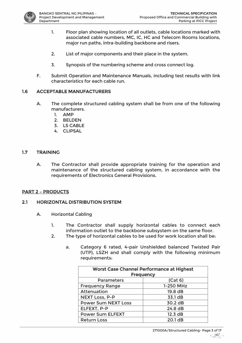
BANGKO SENTRAL NG PILIPINAS – Project Development and Management Department
TTECHNICAL SPECIFICATION Proposed Office and Commercial Building with
Parking at PICC Project
271000A/Structured Cabling- Page 3 of 17
1. Floor plan showing location of all outlets, cable locations marked with associated cable numbers, MC, IC, HC and Telecom Rooms locations, major run paths, intra-building backbone and risers.
2. List of major components and their place in the system.
3. Synopsis of the numbering scheme and cross connect log.
F. Submit Operation and Maintenance Manuals, including test results with link characteristics for each cable run.
1.6 ACCEPTABLE MANUFACTURERS
A. The complete structured cabling system shall be from one of the following manufacturers.
1. AMP 2. BELDEN 3. LS CABLE 4. CLIPSAL
1.7 TRAINING
A. The Contractor shall provide appropriate training for the operation and maintenance of the structured cabling system, in accordance with the requirements of Electronics General Provisions.
PART 2 – PRODUCTS
2.1 HORIZONTAL DISTRIBUTION SYSTEM
A. Horizontal Cabling
1. The Contractor shall supply horizontal cables to connect each information outlet to the backbone subsystem on the same floor.
2. The type of horizontal cables to be used for work location shall be:
a. Category 6 rated, 4-pair Unshielded balanced Twisted Pair (UTP), LSZH and shall comply with the following minimum requirements:
Worst Case Channel Performance at Highest
FFrequency Parameters (Cat 6)
Frequency Range 1-250 MHz Attenuation 19.8 dB NEXT Loss, P-P 33.1 dB Power Sum NEXT Loss 30.2 dB ELFEXT, P-P 24.8 dB Power Sum ELFEXT 12.3 dB Return Loss 20.1 dB
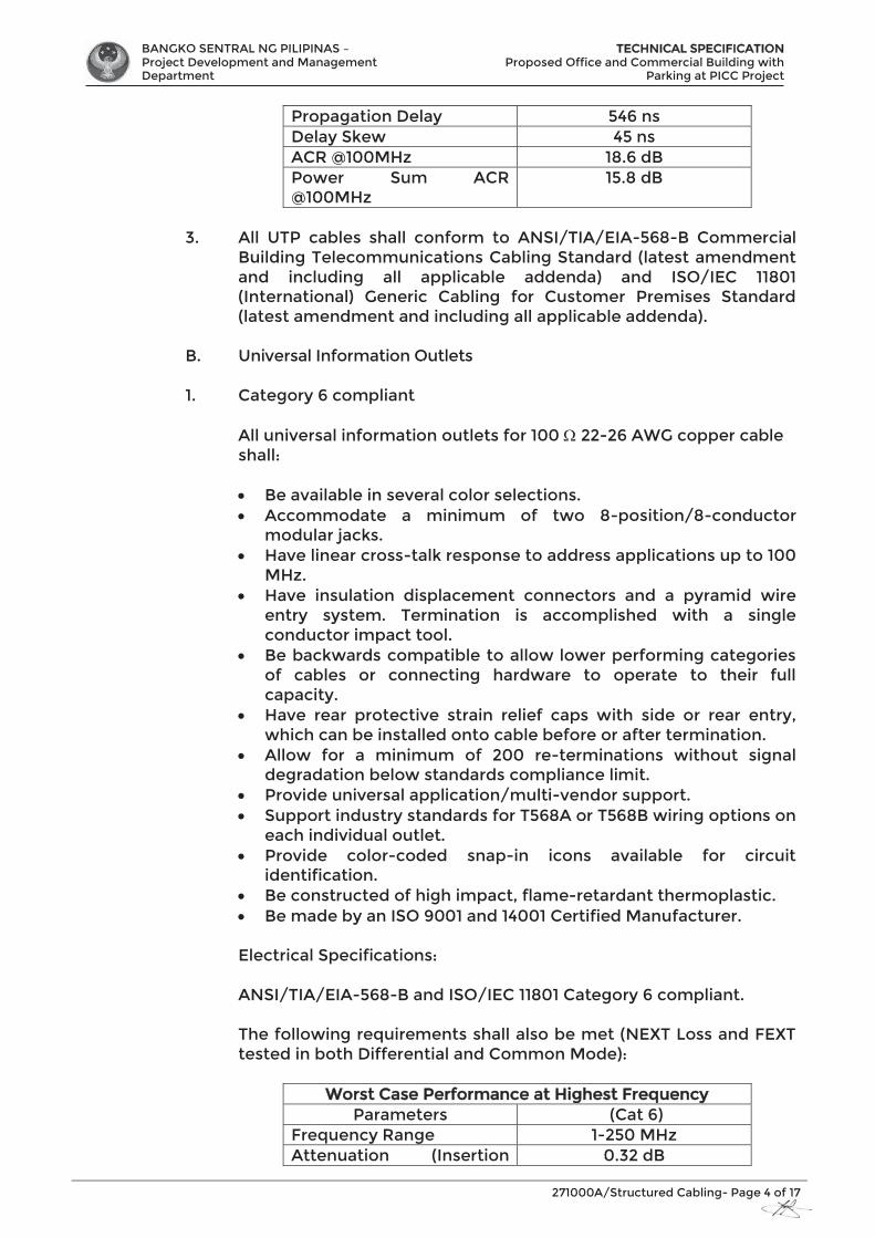
BANGKO SENTRAL NG PILIPINAS – Project Development and Management Department
TTECHNICAL SPECIFICATION Proposed Office and Commercial Building with
Parking at PICC Project
271000A/Structured Cabling- Page 4 of 17
Propagation Delay 546 ns Delay Skew 45 ns ACR @100MHz 18.6 dB Power Sum ACR @100MHz
15.8 dB
3. All UTP cables shall conform to ANSI/TIA/EIA-568-B Commercial
Building Telecommunications Cabling Standard (latest amendment and including all applicable addenda) and ISO/IEC 11801 (International) Generic Cabling for Customer Premises Standard (latest amendment and including all applicable addenda).
B. Universal Information Outlets
1. Category 6 compliant
All universal information outlets for 100 22-26 AWG copper cable shall:
Be available in several color selections. Accommodate a minimum of two 8-position/8-conductor modular jacks. Have linear cross-talk response to address applications up to 100 MHz. Have insulation displacement connectors and a pyramid wire entry system. Termination is accomplished with a single conductor impact tool. Be backwards compatible to allow lower performing categories of cables or connecting hardware to operate to their full capacity. Have rear protective strain relief caps with side or rear entry, which can be installed onto cable before or after termination. Allow for a minimum of 200 re-terminations without signal degradation below standards compliance limit. Provide universal application/multi-vendor support. Support industry standards for T568A or T568B wiring options on each individual outlet. Provide color-coded snap-in icons available for circuit identification. Be constructed of high impact, flame-retardant thermoplastic. Be made by an ISO 9001 and 14001 Certified Manufacturer.
Electrical Specifications: ANSI/TIA/EIA-568-B and ISO/IEC 11801 Category 6 compliant. The following requirements shall also be met (NEXT Loss and FEXT tested in both Differential and Common Mode):
Worst Case Performance at Highest Frequency Parameters (Cat 6)
Frequency Range 1-250 MHz Attenuation (Insertion 0.32 dB
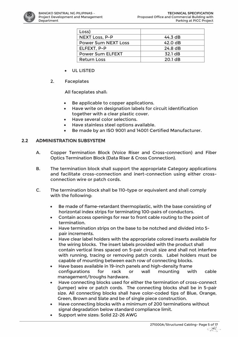
BANGKO SENTRAL NG PILIPINAS – Project Development and Management Department
TTECHNICAL SPECIFICATION Proposed Office and Commercial Building with
Parking at PICC Project
271000A/Structured Cabling- Page 5 of 17
Loss) NEXT Loss, P-P 44.3 dB Power Sum NEXT Loss 42.0 dB ELFEXT, P-P 24.8 dB Power Sum ELFEXT 32.1 dB Return Loss 20.1 dB
UL LISTED
2. Faceplates
All faceplates shall:
Be applicable to copper applications. Have write on designation labels for circuit identification
together with a clear plastic cover. Have several color selections. Have stainless steel options available. Be made by an ISO 9001 and 14001 Certified Manufacturer.
2.2 ADMINISTRATION SUBSYSTEM
A. Copper Termination Block (Voice Riser and Cross-connection) and Fiber Optics Termination Block (Data Riser & Cross Connection).
B. The termination block shall support the appropriate Category applications and facilitate cross-connection and inert-connection using either cross-connection wire or patch cords.
C. The termination block shall be 110-type or equivalent and shall comply with the following:
Be made of flame-retardant thermoplastic, with the base consisting of horizontal index strips for terminating 100-pairs of conductors. Contain access openings for rear to front cable routing to the point of termination. Have termination strips on the base to be notched and divided into 5- pair increments. Have clear label holders with the appropriate colored inserts available for the wiring blocks. The insert labels provided with the product shall contain vertical lines spaced on 5-pair circuit size and shall not interfere with running, tracing or removing patch cords. Label holders must be capable of mounting between each row of connecting blocks. Have bases available in 19-inch panels and high-density frame configurations for rack or wall mounting with cable management/troughs hardware. Have connecting blocks used for either the termination of cross-connect (jumper) wire or patch cords. The connecting blocks shall be in 5-pair size. All connecting blocks shall have color-coded tips of Blue, Orange, Green, Brown and Slate and be of single piece construction. Have connecting blocks with a minimum of 200 terminations without signal degradation below standard compliance limit. Support wire sizes: Solid 22-26 AWG

BANGKO SENTRAL NG PILIPINAS – Project Development and Management Department
TTECHNICAL SPECIFICATION Proposed Office and Commercial Building with
Parking at PICC Project
271000A/Structured Cabling- Page 6 of 17
Be made by an ISO 9001 and 14001 Certified Manufacturer. UL LISTED
D. Category 6 Modular Patch Panel
The panel shall: 1. Be made of black anodized aluminum, in 24 and 48-port
configurations. 2. Accommodate at least 24 ports for each rack mount unit. 3. Have circuit boards tested in both directions as required by
ANSI/TIA/EIA-568-B and ISO/IEC 11801. 4. Have linear crosstalk response to address applications up to 250
MHz. 5. Have insulation displacement connectors with a pyramid wire entry
system. 6. Have termination accomplished with a single conductor impact
tool. 7. Be backwards compatible to allow lower performing categories of
cables or connecting hardware to operate to their full capacity. 8. Support industry standards for T568A or T568B wiring options on
each individual outlet. 9. Allow for a minimum of 200 re-terminations without signal
degradation below standards compliance limit. 10. Have a rear cable management bar for cable strain relief. 11. Have port identification numbers on both the front and rear of the
panel. 12. Have optional adhesive circuit identification and color-coding
designation strips provided with the panel. 13. Provide self-adhesive, clear label holders and white designation
labels with the panel, with optional color labels available. 14. Be made by an ISO 9001 and 14001 Certified Manufacturer. 15. ANSI/TIA/EIA-568-B and ISO/IEC 11801 Category 6 compliant. 16. The following requirements shall also be met (NEXT Loss and FEXT
tested in both Differential and Common Mode):
Worrst Case Performance at Highest Frequency Parameters (Cat 6)
Frequency Range 1-250 MHz Attenuation (Insertion Loss)
0.32 dB
NEXT Loss, P-P 44.3 dB Power Sum NEXT Loss 42.0 dB ELFEXT, P-P 35.1 dB Power Sum ELFEXT 32.1 dB Return Loss 16.0 dB
17. Be currently pending UL VERIFIED for TIA/EIA-B Category 6
electrical performance. 18. UL LISTED
E. Rack-Mounted, High Density Fiber Interconnect Center
The high density, rack mounted fiber interconnect center shall:
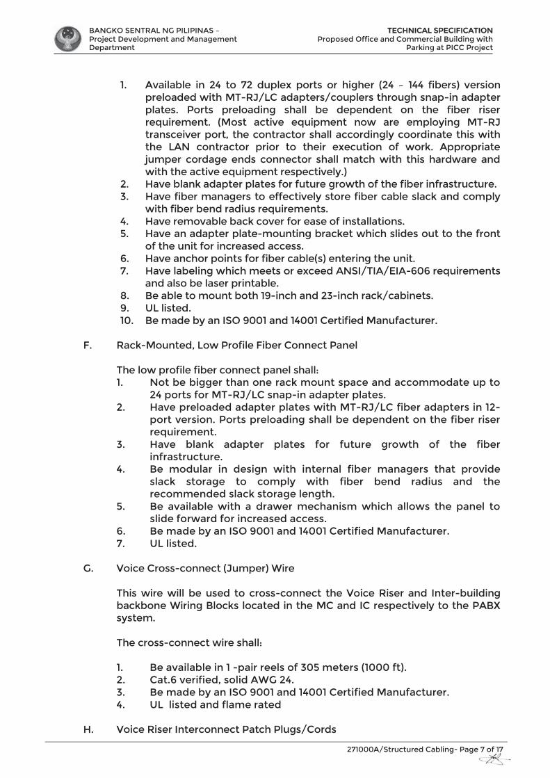
BANGKO SENTRAL NG PILIPINAS – Project Development and Management Department
TTECHNICAL SPECIFICATION Proposed Office and Commercial Building with
Parking at PICC Project
271000A/Structured Cabling- Page 7 of 17
1. Available in 24 to 72 duplex ports or higher (24 – 144 fibers) version
preloaded with MT-RJ/LC adapters/couplers through snap-in adapter plates. Ports preloading shall be dependent on the fiber riser requirement. (Most active equipment now are employing MT-RJ transceiver port, the contractor shall accordingly coordinate this with the LAN contractor prior to their execution of work. Appropriate jumper cordage ends connector shall match with this hardware and with the active equipment respectively.)
2. Have blank adapter plates for future growth of the fiber infrastructure. 3. Have fiber managers to effectively store fiber cable slack and comply
with fiber bend radius requirements. 4. Have removable back cover for ease of installations. 5. Have an adapter plate-mounting bracket which slides out to the front
of the unit for increased access. 6. Have anchor points for fiber cable(s) entering the unit. 7. Have labeling which meets or exceed ANSI/TIA/EIA-606 requirements
and also be laser printable. 8. Be able to mount both 19-inch and 23-inch rack/cabinets. 9. UL listed. 10. Be made by an ISO 9001 and 14001 Certified Manufacturer.
F. Rack-Mounted, Low Profile Fiber Connect Panel
The low profile fiber connect panel shall: 1. Not be bigger than one rack mount space and accommodate up to
24 ports for MT-RJ/LC snap-in adapter plates. 2. Have preloaded adapter plates with MT-RJ/LC fiber adapters in 12-
port version. Ports preloading shall be dependent on the fiber riser requirement.
3. Have blank adapter plates for future growth of the fiber infrastructure.
4. Be modular in design with internal fiber managers that provide slack storage to comply with fiber bend radius and the recommended slack storage length.
5. Be available with a drawer mechanism which allows the panel to slide forward for increased access.
6. Be made by an ISO 9001 and 14001 Certified Manufacturer. 7. UL listed.
G. Voice Cross-connect (Jumper) Wire
This wire will be used to cross-connect the Voice Riser and Inter-building backbone Wiring Blocks located in the MC and IC respectively to the PABX system.
The cross-connect wire shall: 1. Be available in 1 -pair reels of 305 meters (1000 ft). 2. Cat.6 verified, solid AWG 24. 3. Be made by an ISO 9001 and 14001 Certified Manufacturer. 4. UL listed and flame rated
H. Voice Riser Interconnect Patch Plugs/Cords
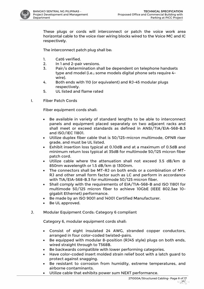
BANGKO SENTRAL NG PILIPINAS – Project Development and Management Department
TTECHNICAL SPECIFICATION Proposed Office and Commercial Building with
Parking at PICC Project
271000A/Structured Cabling- Page 8 of 17
These plugs or cords will interconnect or patch the voice work area horizontal cable to the voice riser wiring blocks wired to the Voice MC and IC respectively. The interconnect patch plug shall be: 1. Cat6 verified. 2. In 1 and 2-pair versions. 3. Pair/s determination shall be dependent on telephone handsets
type and model (i.e.; some models digital phone sets require 4-wire).
4. Both ends with 110 (or equivalent) and RJ-45 modular plugs respectively.
5. UL listed and flame rated
I. Fiber Patch Cords Fiber equipment cords shall:
Be available in variety of standard lengths to be able to interconnect panels and equipment placed separately on two adjacent racks and shall meet or exceed standards as defined in ANSI/TIA/EIA-568-B.3 and ISO/IEC 11801. Utilize duplex fiber cable that is 50/125-micron multimode, OFNR riser grade, and must be UL listed. Exhibit insertion loss typical at 0.10dB and at a maximum of 0.5dB and minimum return loss typical at 35dB for multimode 50/125 micron fiber patch cord. Utilize cable where the attenuation shall not exceed 3.5 dB/km @ 850nm wavelength or 1.5 dB/km @ 1300nm. The connectors shall be MT-RJ on both ends or a combination of MT-RJ and other small form factor such as LC and perform in accordance with TIA/EIA-568-B.3 for multimode 50/125 micron fiber. Shall comply with the requirements of EIA/TIA-568-B and ISO 11801 for multimode 50/125 micron fiber to achieve 10GbE (IEEE 802.3ae 10-gigabit Ethernet) performance. Be made by an ISO 9001 and 14001 Certified Manufacturer. Be UL approved.
J. Modular Equipment Cords: Category 6 compliant Category 6, modular equipment cords shall:
Consist of eight insulated 24 AWG, stranded copper conductors, arranged in four color-coded twisted-pairs. Be equipped with modular 8-position (RJ45 style) plugs on both ends, wired straight through to T568B. Be backwards compatible with lower performing categories. Have color-coded insert molded strain relief boot with a latch guard to protect against snagging. Be resistant to corrosion from humidity, extreme temperatures, and airborne contaminants. Utilize cable that exhibits power sum NEXT performance.
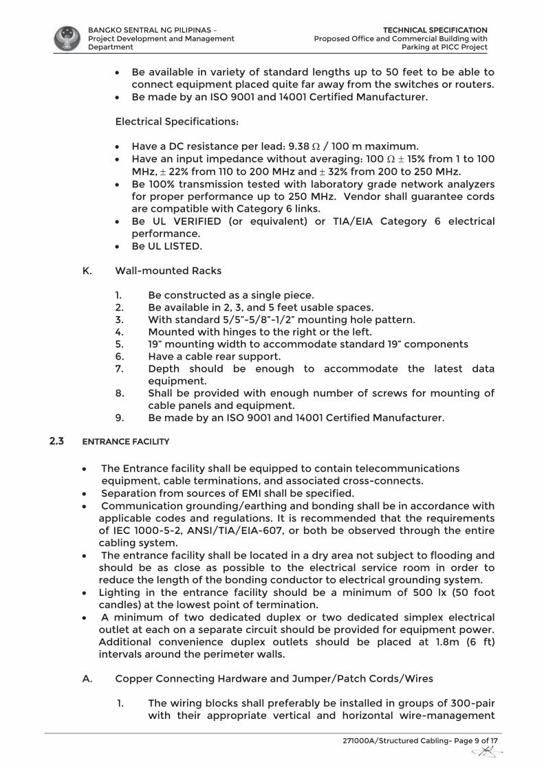
BANGKO SENTRAL NG PILIPINAS – Project Development and Management Department
TTECHNICAL SPECIFICATION Proposed Office and Commercial Building with
Parking at PICC Project
271000A/Structured Cabling- Page 9 of 17
Be available in variety of standard lengths up to 50 feet to be able to connect equipment placed quite far away from the switches or routers. Be made by an ISO 9001 and 14001 Certified Manufacturer.
Electrical Specifications:
Have a DC resistance per lead: 9.38 / 100 m maximum. Have an input impedance without averaging: 100 15% from 1 to 100 MHz, 22% from 110 to 200 MHz and 32% from 200 to 250 MHz. Be 100% transmission tested with laboratory grade network analyzers for proper performance up to 250 MHz. Vendor shall guarantee cords are compatible with Category 6 links. Be UL VERIFIED (or equivalent) or TIA/EIA Category 6 electrical performance. Be UL LISTED.
K. Wall-mounted Racks
1. Be constructed as a single piece. 2. Be available in 2, 3, and 5 feet usable spaces. 3. With standard 5/5”-5/8”-1/2” mounting hole pattern. 4. Mounted with hinges to the right or the left. 5. 19” mounting width to accommodate standard 19” components 6. Have a cable rear support. 7. Depth should be enough to accommodate the latest data
equipment. 8. Shall be provided with enough number of screws for mounting of
cable panels and equipment. 9. Be made by an ISO 9001 and 14001 Certified Manufacturer.
2.3 ENTRANCE FACILITY
The Entrance facility shall be equipped to contain telecommunications equipment, cable terminations, and associated cross-connects. Separation from sources of EMI shall be specified. Communication grounding/earthing and bonding shall be in accordance with applicable codes and regulations. It is recommended that the requirements of IEC 1000-5-2, ANSI/TIA/EIA-607, or both be observed through the entire cabling system. The entrance facility shall be located in a dry area not subject to flooding and should be as close as possible to the electrical service room in order to reduce the length of the bonding conductor to electrical grounding system. Lighting in the entrance facility should be a minimum of 500 lx (50 foot candles) at the lowest point of termination. A minimum of two dedicated duplex or two dedicated simplex electrical outlet at each on a separate circuit should be provided for equipment power. Additional convenience duplex outlets should be placed at 1.8m (6 ft) intervals around the perimeter walls.
A. Copper Connecting Hardware and Jumper/Patch Cords/Wires
1. The wiring blocks shall preferably be installed in groups of 300-pair with their appropriate vertical and horizontal wire-management
BANGKO SENTRAL NG PILIPINAS – Project Development and Management Department
TTECHNICAL SPECIFICATION Proposed Office and Commercial Building with
Parking at PICC Project
271000A/Structured Cabling- Page 10 of 17
hardware for jumper wires arrangement and easy transitions from and to blocks.
2. 23” mounting metal frame shall be provided for mounting of these hardware to standard 23” rack or using a product specific frame mounting method to handle large quantity of cables and wiring blocks.
3. Cables that exits the frame shall be wired using overhead and suspended cable ladder or tray and should be securely tied and neatly arranged.
4. The sufficient number of wiring blocks for each system shall be provided in accordance with its requirement. There should be separate wiring blocks for termination of Local Lines from the PABX system, for termination of Telephone Lines (Trunks/CO, Direct Lines, Leased/DSL, etc.) from the entrance cable protector terminal and for termination of all the Voice Riser and Inter-building Backbone cable that will serve the Telecom rooms distributed on different floors of the two buildings.
5. All wiring blocks shall be accordingly labeled and designated.
B. Other requirements shall be coordinated with the local Telco requirements.
2.5 CABLING CONTAINMENT SYSTEM
A. All structured cabling and accessories shall be installed in a raceway system as indicated on the Drawings.
B. Raceways used for the structured cabling installation shall comply with Electronics General Provisions..
2.6 PRODUCT DELIVERY AND STORAGE A. Deliver and store structured cabling system equipment in undamaged
factory packaging according to the requirements of Electronics General Provisions.
B. Store structured cabling system equipment on elevated platforms in a clean, dry location. Protect from dirt, water, construction debris, and traffic.
PART 3 – EXECUTION
3.1 GENERAL INSTALLATION
A. Install the system in accordance with the Plans and Specifications, all Local and National Applicable Codes, PEC Wiring Criteria, ANSI/EIA/TIA-568-B series Commercial Building Wiring Standards and the Manufacturer’s recommendations.
B. The Contractor shall provide any necessary screws, anchors, clamps, tie
wraps, distribution rings, wire raceways, miscellaneous grounding and
BANGKO SENTRAL NG PILIPINAS – Project Development and Management Department
TTECHNICAL SPECIFICATION Proposed Office and Commercial Building with
Parking at PICC Project
271000A/Structured Cabling- Page 11 of 17
support hardware, etc. necessary to facilitate the installation of the system.
C. It shall be the responsibility of the Contractor to furnish any special
installation equipment or tools necessary to properly complete the system. This may include, but is not limited to, tools for terminating cables and testing equipment for copper cables, communication devices, jack stands for cable reels.
D. The Contractor shall be responsible for printed labels for all cables and cords, distribution frames, and outlet locations.
E. The Contractor shall not place any distribution cabling alongside or near power lines, or share the same conduit, channels or sleeve with electrical apparatus.
F. The Contractor shall ensure that the maximum pulling tensions of the
specified distribution cables are not exceeded and cable bends maintain the proper radius during the placement of the facilities.
G. The Contractor shall be responsible for providing approved grounding at
all newly installed Telecom/Equipment Rooms. The Contractor shall also be responsible for ensuring ground continuity by properly bonding all appropriate cabling, closures, cabinets, service boxes and framework.
All grounds shall consist of Nº6 AWG copper wire and shall be supplied
from an approved building ground and bonded to the main electrical ground.
3.2 CABLE ROUTING
A. All horizontal cables, regardless of media type, shall not exceed 90 m (295 ft) from the telecommunications outlets in the work area to the horizontal cross connect.
B. The combined length of jumpers, or patch cords and equipment cables in the telecommunications room/closet and the work area should not exceed 10m (33 ft) unless used in conjunction with a multi-user telecommunications outlet.
C. Horizontal pathways shall be installed or selected such that the minimum bend radius of horizontal cables is kept within manufacturer specifications both during and after installation.
D. In open ceiling cabling, cable supports shall be provided by means that is structurally independent of the suspended ceiling, its framework, or supports. These supports shall be spaced no more than 1.5m (5 ft) apart.
E. Telecommunications pathways, spaces and metallic cables, which run parallel with electric power or lighting, which is less than or equal to 480 Vrms, shall be installed with a minimum clearance of 50 mm (2 in).
BANGKO SENTRAL NG PILIPINAS – Project Development and Management Department
TTECHNICAL SPECIFICATION Proposed Office and Commercial Building with
Parking at PICC Project
271000A/Structured Cabling- Page 12 of 17
F. The installation of telecommunications cabling shall maintain a minimum clearance of 3 m (10 ft) from power cables in excess of 480 Vrms.
G. No telecommunications cross-connects shall be physically located within 6 m (20 ft) of electrical distribution panels, step down devices, or transformers, which carry voltages in excess of 480 Vrms.
H. For voice or data applications, 4-pair UTP or other cables shall be run using
a star topology from the telecommunications room/closet serving that floor to every individual information outlet. The customer prior to installation of the cabling shall approve all cable routes.
I. The Contractor shall observe the bending radius and pulling strength requirements of the 4-pair UTP and fiber optic cable during handling and installation.
J. Each run of UTP cable between horizontal portions of the cross-connect in the telecommunication closet and the information outlet shall not contain splices.
K. In the telecommunications room/closet where cable trays or cable racking are used, the contractor shall provide appropriate means of cable management such as reusable color-coded hook and loop cable managers (ties) to create a neat appearance and practical installation.
L. In a false ceiling environment, a minimum of 3 inches (975 mm) shall be observed between the cable supports and the false ceiling.
M. Continuous conduit runs installed by the contractor should not exceed 30.5 m (100 ft) or contain more than two (2) 90 degree bends without utilizing appropriately sized pull boxes.
N. All horizontal pathways shall be designed, installed and grounded to meet applicable local and national building and electrical codes.
O. The number of horizontal cables placed in a cable support or pathway
shall be limited to a number of cables that will not cause a geometric shape of the cables.
P. Maximum conduit pathway capacity shall not exceed a 40% fill. However, Perimeter and Furniture fill is limited to 60% fill for move and changes.
Q. Horizontal distribution cables shall not be exposed in the work area or other locations with public access.
R. Cables routed in a suspended ceiling shall not be draped across the ceiling tiles. Cable supports shall be mounted a minimum of 75 mm (3 in) above the ceiling grid supporting the tiles.
3.3 WORK AREA TERMINATION
A. All UTP cables wired to the telecommunication outlet/connector, should have 4-pairs terminated in eight-position modular outlets in the work area. All pairs shall be terminated.
BANGKO SENTRAL NG PILIPINAS – Project Development and Management Department
TTECHNICAL SPECIFICATION Proposed Office and Commercial Building with
Parking at PICC Project
271000A/Structured Cabling- Page 13 of 17
B. The telecommunications outlet/connector shall be securely mounted at
planned locations. C. The height of the telecommunications faceplates shall be to applicable
codes and regulations.
3.4 PULLING TENSION
A. The maximum cable pulling tensions shall not exceed manufacturer’s specifications.
3.5 BEND RADIUS
A. The maximum cable bend radii shall not exceed manufacturer’s specifications.
B. In spaces with UTP cable terminations, the maximum bend radius for 4-
pair cable shall not exceed four times the outside diameter of the cable and ten times for multi-pair cable. This shall be done unless this violates manufacturer specifications.
C. During the actual installation, bend radius on 4-pair cable shall not exceed
eight times the outside diameter of the cable and ten times for multi-pair cable. This shall be done unless this will violate manufacturer specifications.
3.6 SLACK
A. In the work area, a minimum of 300 mm (12 in) should be left for UTP cables.
B. In telecommunications room/closets a minimum of 3 m (10 ft) of slack
should be left for all cable types. This slack must be neatly managed on trays or other support types.
3.7 CABLE TIE WRAPS
A. Tie wraps shall be used at appropriate intervals to secure cable and to provide strain relief at termination points. These wraps shall not be over tightened to the point of deforming or crimping the cable sheath.
B. Hook and loop cable managers should be used in the closet where
reconfiguration of cables and terminations may be frequent.
3.8 GROUNDING
A. All grounding/earthing and bonding shall be done in accordance with applicable codes and regulations.
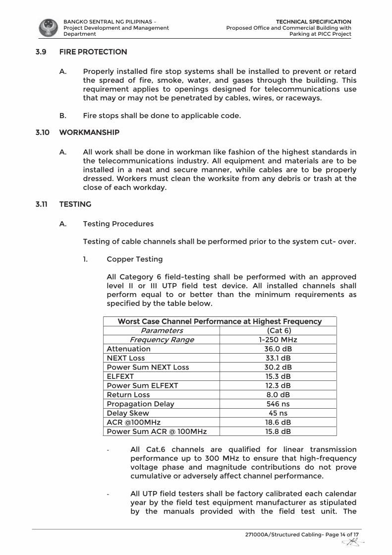
BANGKO SENTRAL NG PILIPINAS – Project Development and Management Department
TTECHNICAL SPECIFICATION Proposed Office and Commercial Building with
Parking at PICC Project
271000A/Structured Cabling- Page 14 of 17
3.9 FIRE PROTECTION
A. Properly installed fire stop systems shall be installed to prevent or retard the spread of fire, smoke, water, and gases through the building. This requirement applies to openings designed for telecommunications use that may or may not be penetrated by cables, wires, or raceways.
B. Fire stops shall be done to applicable code.
3.10 WORKMANSHIP
A. All work shall be done in workman like fashion of the highest standards in the telecommunications industry. All equipment and materials are to be installed in a neat and secure manner, while cables are to be properly dressed. Workers must clean the worksite from any debris or trash at the close of each workday.
3.11 TESTING
A. Testing Procedures Testing of cable channels shall be performed prior to the system cut- over.
1. Copper Testing
All Category 6 field-testing shall be performed with an approved level II or III UTP field test device. All installed channels shall perform equal to or better than the minimum requirements as specified by the table below.
Worst Case Channel Performance at Highest Frequency Parameters (Cat 6)
Frequency Range 1-250 MHz Attenuation 36.0 dB NEXT Loss 33.1 dB Power Sum NEXT Loss 30.2 dB ELFEXT 15.3 dB Power Sum ELFEXT 12.3 dB Return Loss 8.0 dB Propagation Delay 546 ns Delay Skew 45 ns ACR @100MHz 18.6 dB Power Sum ACR @ 100MHz 15.8 dB - All Cat.6 channels are qualified for linear transmission
performance up to 300 MHz to ensure that high-frequency voltage phase and magnitude contributions do not prove cumulative or adversely affect channel performance.
- All UTP field testers shall be factory calibrated each calendar
year by the field test equipment manufacturer as stipulated by the manuals provided with the field test unit. The
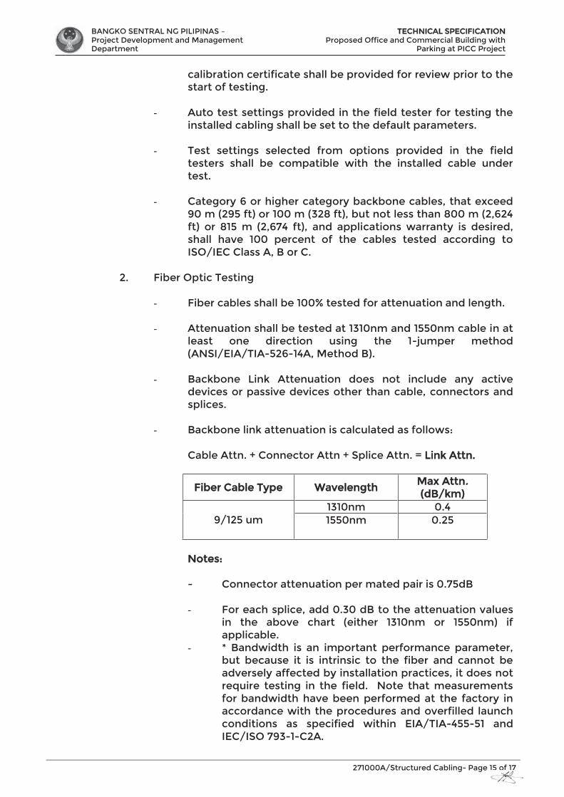
BANGKO SENTRAL NG PILIPINAS – Project Development and Management Department
TTECHNICAL SPECIFICATION Proposed Office and Commercial Building with
Parking at PICC Project
271000A/Structured Cabling- Page 15 of 17
calibration certificate shall be provided for review prior to the start of testing.
- Auto test settings provided in the field tester for testing the installed cabling shall be set to the default parameters.
- Test settings selected from options provided in the field testers shall be compatible with the installed cable under test.
- Category 6 or higher category backbone cables, that exceed 90 m (295 ft) or 100 m (328 ft), but not less than 800 m (2,624 ft) or 815 m (2,674 ft), and applications warranty is desired, shall have 100 percent of the cables tested according to ISO/IEC Class A, B or C.
2. Fiber Optic Testing
- Fiber cables shall be 100% tested for attenuation and length.
- Attenuation shall be tested at 1310nm and 1550nm cable in at least one direction using the 1-jumper method (ANSI/EIA/TIA-526-14A, Method B).
- Backbone Link Attenuation does not include any active devices or passive devices other than cable, connectors and splices.
- Backbone link attenuation is calculated as follows:
Cable Attn. + Connector Attn + Splice Attn. = LLink Attn.
Fiber Cable Type Wavelength Max Attn.. ((dB/km)
9/125 um 1310nm 0.4 1550nm
0.25
Notes: - Connector attenuation per mated pair is 0.75dB
- For each splice, add 0.30 dB to the attenuation values
in the above chart (either 1310nm or 1550nm) if applicable.
- * Bandwidth is an important performance parameter, but because it is intrinsic to the fiber and cannot be adversely affected by installation practices, it does not require testing in the field. Note that measurements for bandwidth have been performed at the factory in accordance with the procedures and overfilled launch conditions as specified within EIA/TIA-455-51 and IEC/ISO 793-1-C2A.
BANGKO SENTRAL NG PILIPINAS – Project Development and Management Department
TTECHNICAL SPECIFICATION Proposed Office and Commercial Building with
Parking at PICC Project
271000A/Structured Cabling- Page 16 of 17
- ** The protocol pertinent to the transmission distances as noted is Gigabit Ethernet per IEEE 802.3z and 802.3ae (10Gbe).
3.12 ADMINISTRATION DOCUMENTATION
A. Labeling
1. Cables Horizontal and backbone cables shall be labeled at each end. The cable or its label shall be marked with its identifier.
2. Faceplates A unique identifier shall be marked on each faceplate to identify it as connecting hardware. Each port in the faceplate shall be labeled with its identifier.
3. Racks, Panels, Blocks A unique identifier shall be marked on each piece of connecting hardware to identify it as connecting hardware. Each port on the connecting hardware shall be labeled with its identifier.
B. Drawings
As-built drawing shall be supplied by the contractor showing the locations of and identifiers for all: 1. Horizontal cable routing and terminations 2. Telecommunications outlets/connectors 3. Backbone cable routing and terminations
C. Records
All records shall be created by the installation contractor and turned over at the completion of work. The format shall be computer based and both soft copies and hard copies shall be part of the As-built package. The minimum requirements include: 1. Cable records must contain the identifier, cable type, termination
positions at both ends, splice information as well as any damaged pairs/conductors.
2. Connecting hardware and connecting hardware position records must contain the identifier, type, damaged position numbers, and references to the cable identifier attached to it.
3. Test documentation on all cable types shall be included as part of the As-built package.
D. Reports
All reports shall be generated from the computer-based program used to create the records above. These reports should include but not limited to;
1. Cable Reports 2. Cross-connect Reports
BANGKO SENTRAL NG PILIPINAS – Project Development and Management Department
TTECHNICAL SPECIFICATION Proposed Office and Commercial Building with
Parking at PICC Project
271000A/Structured Cabling- Page 17 of 17
3. Connecting Hardware Reports
3.13 WARRANTY
Either a basic link or channel model configuration may be applied to the horizontal and/or backbone sub-systems of the structured cabling system. Applications assurance is only applied to a channel model configuration.
A. System Warranty A twenty (20) year warranty available for Category 6 structured cabling system shall be provided for an end-to-end channel model installation which covers applications assurance, cable, connecting hardware and the labor cost for the repair or replacement thereof.
B. Product Warranty The manufacturer of passive telecommunications equipment used in a manner not associated with the Systems Warranty must have a minimum twenty (20) year Component Warranty on all its product. The Products Warranty covers the components against defects in material under normal and proper use.
D. Applications Supported Existing and future applications supported for a channel model warranty include those approved by the Institute of Electronic and Electrical Engineer (IEEE), the Asynchronous Transfer Mode (ATM) Forum, the American National Standards (ISO) that specify compatibility with the cable referenced herein. Additional applications that are covered by this warranty include those under development for use on Gigabit Ethernet (IEEE 802.3z, 802.3ab, 802.3ae) and 622 Mb/s ATM.
END OF SECTION
BANGKO SENTRAL NG PILIPINAS – Project Development and Management Department
TTECHNICAL SPECIFICATION Proposed Office and Commercial Building with
Parking at PICC Project
271000B/IT Active Equipment- Page 1 of 16
SECTION 27 10 00B
IT ACTIVE EQUIPMENT
PART 1 – GENERAL
1.1 INTRODUCTION A. The work covered in this Section of the Specification includes the
furnishing of all labor, equipment, materials and performance of all operations associated with the installation of IT Active Equipment as shown on the drawings and as herein specified.
1.2 SCOPE OF WORK A. The scope of work includes:
1. Supply of all DC elements and components2. Installation of all DC elements and components3. Supervision of own work and full Quality Control4. Testing, commissioning and documentation of the installed solution
1.3 CODES AND STANDARDS A. All rules, regulations, standards, codes and recommendations referred to
in this document, shall be the basis for the design and installation work by the Contractor for the IT & LAN cabling system in the respective buildings.
. 1.4 SUBMITTALS
A. The specific requirements for the submittals in connection with the Server Room are described in the General Requirements General Electronics Provisions.
.
PART 2 – PRODUCTS SPECIFICATION
2.1 ACCEPTABLE MANUFACTURERS
A. Acceptable Manufacturers and Specified Supplier and/or System Integrator: Subject to compliance with requirements, provide or comparable product by one of the following: 1. CISCO2. ALLIED TELESIS
2.1 CORE SWITCHES A. MANAGEMENT: Remote intelligent mirroring: mirrors selected
ingress/egress traffic based on ACL, port, MAC address, or VLAN to a local or remote 8200zl/6200yl/5400zl/3500yl switch anywhere on the network. • RMON, XRMON, and sFlow: provide advanced monitoring and
reporting capabilitie for statistics, history, alarms, and events• IEEE 802.1AB Link Layer Discovery Protocol (LLDP): automated
device discovery protocol for easy mapping by networkmanagement applications
BANGKO SENTRAL NG PILIPINAS – Project Development and Management Department
TTECHNICAL SPECIFICATION Proposed Office and Commercial Building with
Parking at PICC Project
271000B/IT Active Equipment- Page 2 of 16
• Command authorization: leverages RADIUS to link a custom list of CLI commands to individual network administrator's login; also provides an audit trail
• Friendly port names: allow assignment of descriptive names to ports
• Dual flash images: provides independent primary and secondary OS files for backup while Upgrading
• Multiple configuration files: multiple config files can be stored to the flash image
• Uni-Directional Link Detection (UDLD): monitors a link between two switches and blocks the ports on both ends of the link if the link goes down at any point between the two devices
• Management simplicity: common networking features and CLI implementation (common across zl and yl switches)
B. CONNECTIVITY
Jumbo frames: on Gigabit and 10-Gigabit ports, allow high performance remote backup and disaster-recovery service IPv6; IPv6 Host: the switches can be managed and deployed at the edge of IPv6 networks Dual Stack (IPv4/IPv6): provides transition mechanism from IPv4 to IPv6; supports connectivity for both protocols MLD Snooping: forwards IPv6 multicast traffic to the appropriate interface; prevents IPv6 multicast traffic from flooding the network IPv6 ready: the switch hardware can support IPv6 QoS, ACL, routing, tunneling, and security; these features will be available when enabled via software update in follow-on releases
C. PPERFORMANCE
Architecture: 115 Gbps backplane speed with up to 36 million pps throughput on purpose-built ProVision ASIC Selectable queue configurations: increase performance by selecting the number of queues and associated memory buffering that best meet the requirements of your network applications Resiliency and high availability Router redundancy: VRRP allows groups of two routers to dynamically back each other up to create highly available routed environments IEEE 802.1s Multiple Spanning Tree Protocol: provides high link availability in multiple VLAN environments by allowing multiple spanning trees; encompasses IEEE 802.1D Spanning Tree Protocol and IEEE 802.1w Rapid Spanning Tree Protocol IEEE 802.3ad Link Aggregation Control Protocol (LACP) and trunking: support up to 36 trunks, each with up to 8 links (ports) per trunk; trunking across modules is supported.
D. SSECURITY
Switch CPU protection: provides automatic protection against malicious network traffic trying to shut down the switch
BANGKO SENTRAL NG PILIPINAS – Project Development and Management Department
TTECHNICAL SPECIFICATION Proposed Office and Commercial Building with
Parking at PICC Project
271000B/IT Active Equipment- Page 3 of 16
Virus throttling: detects traffic patterns typical of WORM-type viruses and either throttles or entirely prevents the ability of the virus to spread across the routed VLANs without requiring external appliances ICMP throttling: defeats ICMP denial-of-service attacks by enabling any switch port to automatically throttle ICMP traffic. Multiple user authentication methods: - IEEE 802.1X: industry standard way of user authentication using an IEEE 802.1X supplicant on the client in conjunction with a RADIUS server- Web-based authentication: authenticates from Web browser for clients that do not support802.1X supplicant; customized remediation can be processed on an external Web server- MAC-based authentication: client is authenticated with the RADIUS server based on client's MAC address. Authentication flexibility: - Multiple IEEE 802.1X users per port: provides authentication
of multiple IEEE 802.1X users per port; prevents user "piggybacking" on another user's IEEE 802.1X authentication
- Concurrent IEEE 802.1X and Web or MAC authentication schemes per port: switch port will accept any of IEEE 802.1X and either Web or MAC authentications.
Access control lists (ACLs): provide filtering based on the IP field, source/destination IP address/subnet, and source/destination TCP/UDP port number on a per-VLAN or per-port basis. Identity-driven ACL: enables implementation of a highly granular and flexible access security policy specific to each authenticated network user. DHCP protection: blocks DHCP packets from unauthorized DHCP servers, preventing denial-of-service attacks. BPDU port protection: blocks Bridge Protocol Data Units (BPDUs) on ports that do not require BPDUs, preventing forged BPDU attacks\ Dynamic IP lockdown: works with DHCP protection to block traffic from unauthorized host, preventing IP source address spoofing Dynamic ARP protection: blocks ARP broadcasts from unauthorized hosts, preventing ICMP throttling: defeats ICMP denial-of-service attacks by enabling any switch port to automatically throttle ICMP traffic

BANGKO SENTRAL NG PILIPINAS – Project Development and Management Department
TTECHNICAL SPECIFICATION Proposed Office and Commercial Building with
Parking at PICC Project
271000B/IT Active Equipment- Page 4 of 16
Multiple user authentication methods: - IEEE 802.1X: industry-standard way of user authentication using
an IEEE 802.1X supplicant on the client in conjunction with a RADIUS server
- Web-based authentication: authenticates from Web browser for clients that do not support802.1X supplicant; customized remediation can be processed on an external Web server
- MAC-based authentication: client is authenticated with the RADIUS server based on client's MAC address
Authentication flexibility: - Multiple IEEE 802.1X users per port: provides authentication of
multiple IEEE 802.1X users per port; prevents user "piggybacking" on another user's IEEE 802.1X authentication
- Concurrent IEEE 802.1X and Web or MAC authentication schemes per port: switch port will accept any of IEEE 802.1X and either Web or MAC authentications
Access control lists (ACLs): provide filtering based on the IP field, source/destination IP address/subnet, and source/destination TCP/UDP port number on a per-VLAN or per-port basis Identity-driven ACL: enables implementation of a highly granular and flexible access security policy specific to each authenticated network user DHCP protection: blocks DHCP packets from unauthorized DHCP servers, preventing denial-of-service attacks BPDU port protection: blocks Bridge Protocol Data Units (BPDUs) on ports that do not require BPDUs, preventing forged BPDU attacks Dynamic IP lockdown: works with DHCP protection to block traffic from unauthorized host, preventing IP source address spoofing Dynamic ARP protection: blocks ARP broadcasts from unauthorized hosts, preventing STP Root Guard: protects Root Bridge from malicious attack or configuration mistakes
E. CONVERGENCE IP multicast routing: includes PIM Sparse and Dense modes to route IP multicast traffic IP multicast snooping (data-driven IGMP): automatically prevents flooding of IP multicast traffic LLDP-MED (Media Endpoint Discovery): a standard extension of LLDP that stores values for parameters such as QoS and VLAN to automatically configure network devices such as IP phones
F. QUALITY OF SERVICE (QoS) Layer 4 prioritization: enables prioritization based on TCP/UDP port numbers Traffic prioritization: allows real-time traffic classification into 8 priority levels mapped to 8 queues Bandwidth shaping:
- Port-based rate limiting: per-port ingress/egress enforced maximum bandwidth
g
BANGKO SENTRAL NG PILIPINAS – Project Development and Management Department
TTECHNICAL SPECIFICATION Proposed Office and Commercial Building with
Parking at PICC Project
271000B/IT Active Equipment- Page 5 of 16
- Classifier-based rate limiting: use ACL to enforce maximum bandwidth for ingress traffic on each port
- Guaranteed minimum: per-port, per-queue egress-based guaranteed minimum bandwidth Class of Service (CoS): sets the IEEE 802.1p priority tag based on IP address, IP Type of Service (ToS), L3 protocol, TCP/UDP port number, source port, and DiffServ
G. PHYSICAL SPECIFICATIONS
Ports
1 open module slot 24 open mini-GBIC (SFP) slots Supports a maximum of 4 10-GbE ports, with optional module
Physical characteristics
Dimensions 15.43(d) x 17.44(w) x 1.73(h) in. (39.2 x 44.3 x 4.4 cm) (1U height) Weight 14.11 lb. (6.4 kg) Memory and processor Processor Freescale PowerPC 8540 @ 666 MHz, 4 MB flash, 256 MB DDR SDRAM Mounting Mounts in an EIA-standard 19 in. telco rack or equipment cabinet (hardware included); horizontal surface mounting only
Performance 1000 Mb Latency < 3.7 μs (FIFO 64-byte packets) 10 Gbps Latency < 2.1 μs (FIFO 64-byte packets) Throughput up to 74 million pps Routing/Switching capacity 101 Gbps Switching capacity 115 Gbps Routing table size 10000 entries
Environment
Operating temperature 32ºF to 131ºF (0ºC to 55ºC); 32°F to 104°F (40°C) when used with any X2 10-GbE Operating relative humidity 15% to 95% @ 104ºF (40ºC), non-condensing Non-operating/Storage temperature -40ºF to 158ºF (-40ºC to 70ºC) Non-operating/Storage relative humidity 15% to 95% @ 149ºF (65ºC), non-condensing Altitude up to 15000 ft. (4.6 km) Acoustic Power: 55.1 dB; DIN 45635T.19 per ISO 7779
Electrical characteristics
Description: The switch automatically adjusts to any voltage between 100-127 and 200-240 volts and either 50 or 60 Hz
e 5 of 16
BANGKO SENTRAL NG PILIPINAS – Project Development and Management Department
TTECHNICAL SPECIFICATION Proposed Office and Commercial Building with
Parking at PICC Project
271000B/IT Active Equipment- Page 6 of 16
Maximum heat dissipation: 829 BTU/hr (875 kJ/hr) Voltage: 100-127 / 200-240 VAC Current: 1.8 / 0.9 A Power consumption: 243 W Frequency 50 / 60 Hz Safety: CSA 22.2 No. 60950; UL 60950; IEC 60950; EN 60950 Emissions: FCC Class A; VCCI Class A; EN 55022/CISPR 22 Class A Immunity: EN 55024, CISPR 24
2.2 LAYER 2 SWITCHES A. MANAGEMENT
Remote intelligent mirroring: mirrors ingress/egress ACL-selected traffic from a switch port or VLAN to a local or remote 8200zl/6200yl/5400zl/3500yl switch port anywhere on the network RMON, XRMON, and sFlow v5: provide advanced monitoring and reporting capabilities for statistics, history, alarms, and events IEEE 802.1AB Link Layer Discovery Protocol (LLDP): automated device discovery protocol for easy mapping by network management applications Command authorization: leverages RADIUS to link a custom list of CLI commands to individual network administrator's login; also provides an audit trail. Friendly port names: allow assignment of descriptive names to Ports. Dual flash images: provides independent primary and secondary OS files for backup while upgrading. Multiple configuration files: multiple config files can be stored to flash image. USB support: - File copy: allows users to copy switch files to/from an USB
flash drive Uni-Directional Link Detection (UDLD): monitors a link between two switches and blocks the ports on both ends of the link if the link goes down at any point between the two devices Management simplicity: -common networking features and CLI implementation (common across zl and yl switches)
B. CONNECTIVITY IEEE 802.3af Power over Ethernet: provides up to 15.4 W per port to IEEE 802.3af compliant PoE powered devices such as IP phones, wireless access points, and security cameras Pre-standard PoE support: detects and provides power to pre-standard PoE devices; Jumbo frames: on Gigabit and 10-Gigabit ports, allow high-performance remote backup and disaster-recovery services /IEEE Auto-MDIX: automatically adjusts for straight-through or crossover cables on all 10/100/1000 ports
g
BANGKO SENTRAL NG PILIPINAS – Project Development and Management Department
TTECHNICAL SPECIFICATION Proposed Office and Commercial Building with
Parking at PICC Project
271000B/IT Active Equipment- Page 7 of 16
IPv6 ready: switch hardware is capable of supporting IPv6 host, routing, and filtering with the ProVision ASIC; IPv6 operation and deployment will be available when enabled via a software update at a later date Performance 5400zl/3500yl architecture: 115 to 692 Gbps crossbar switching fabric provides intra- and inter-module switching with 36 to 428 million pps throughput on the purpose-built ProVision ASICs Selectable queue configurations: increase performance by selecting the number of Queues and associated memory buffering that best meet the requirements of your network applications
C. RESILIENCY AND HIGH AVAILABILITY Virtual Router Redundancy Protocol (requires Premium license): VRRP allows groups of two routers to dynamically back each other up to create highly available routed environments IEEE 802.1s Multiple Spanning Tree Protocol: provides high link availability in multiple VLAN environments by allowing multiple spanning trees; encompasses IEEE 802.1D Spanning Tree Protocol and IEEE 802.1w Rapid Spanning Tree Protocol IEEE 802.3ad Link Aggregation Control Protocol (LACP) and trunking: support up to 36 trunks, each with up to 8 links (ports) per trunk; trunking across modules is supported Hot-swappable modules (5400zl series): permits modules, mini-GBICs, and power supplies in a redundant power supply configuration to be added or swapped without interrupting the network Optional redundant power supply (5400zl series): provides uninterrupted power and allows hot-swapping of the redundant power supplies when installed Sparing simplicity: zl-common accessories (interface modules, power supplies)
D. SECURITY Switch CPU protection: provides automatic protection against malicious network traffic trying to shut down the switch Virus throttle: detects traffic patterns typical of WORM-type viruses and either throttles or entirely prevents the ability of the virus to spread across the routed VLANs or bridged interfaces, without requiring external appliances ICMP throttling: defeats ICMP denial-of-service attacks by enabling any switch port to automatically throttle ICMP traffic Multiple user authentication methods:
- IEEE 802.1X: industry-standard way of user authentication using an IEEE 802.1X supplicant on the client in conjunction with a RADIUS server
- Web-based authentication: similar to IEEE 802.1X, provides a browser-based environment to authenticate clients that do not support the IEEE 802.1X supplicant
BANGKO SENTRAL NG PILIPINAS – Project Development and Management Department
TTECHNICAL SPECIFICATION Proposed Office and Commercial Building with
Parking at PICC Project
271000B/IT Active Equipment- Page 8 of 16
- MAC-based authentication: client is authenticated with the RADIUS server based on the MAC address of the client Authentication flexibility:
- Multiple IEEE 802.1X users per port: provides authentication of multiple IEEE 802.1X users per port; prevents user "piggybacking" on another user's IEEE 802.1X authentication
- Concurrent IEEE 802.1X and Web or MAC authentication schemes per port: switch port will accept any of IEEE 802.1X and either Web or MAC authentications Access control lists (ACLs): provide filtering based on the IP field, source/destination IP address/subnet, and source/destination TCP/UDP port number on a per-VLAN or per-port basis Identity-driven ACL: enables implementation of a highly granular and flexible access security policy specific to each authenticated network user DHCP protection: blocks DHCP packets from unauthorized DHCP servers, preventing denial-of-service attacks BPDU port protection: blocks Bridge Protocol Data Units (BPDU) on ports that do not require BPDUs, preventing forged BPDU attacks Dynamic IP lockdown: works with DHCP protection to block traffic from unauthorized host, preventing IP source address spoofing Dynamic ARP protection: blocks ARP broadcasts from unauthorized hosts, preventing eavesdropping or data theft of network data Detection of malicious attacks: monitors 10 types of network traffic and sends a warning when an anomaly that potentially can be caused by malicious attacks is detected Port security: allows access only to specified MAC addresses, which can be learned or specified by the administrator MAC address lockout: prevents configured particular MAC addresses from connecting to the network Source-port filtering: allows only specified ports to communicate with each other TACACS+: eases switch management security administration by using a password authentication server Secure Shell (SSHv2): encrypts all transmitted data for secure, remote command-line interface (CLI) access over IP networks Secure Sockets Layer (SSL): encrypts all HTTP traffic, allowing secure access to the browser-based management GUI in the switch Secure FTP: allows secure file transfer to/from the switch; protects against unwanted file downloads or unauthorized copying of switch configuration file Secure management access: all access methods--CLI, GUI, or MIB--are securely encrypted through SSHv2, SSL, and/or SNMPv3 Switch management logon security: can require either RADIUS or TACACS+ authentication for secure switch CLI logon Security banner: displays a customized security policy when users log in to the switch
BANGKO SENTRAL NG PILIPINAS – Project Development and Management Department
TTECHNICAL SPECIFICATION Proposed Office and Commercial Building with
Parking at PICC Project
271000B/IT Active Equipment- Page 9 of 16
E. CONVERGENCE IP multicast routing (Premium License): includes PIM Sparse and Dense modes to route IP multicast traffic IP multicast snooping (data-driven IGMP): automatically prevents flooding of IP multicast traffic LLDP-MED (Media Endpoint Discovery): a standard extension of LLDP that stores values for parameters such as QoS and VLAN to automatically configure network devices such as IP phones
F. QUALITY OF SERVICE (QoS) Layer 4 prioritization: enables prioritization based on TCP/UDP port numbers Traffic prioritization: allows real-time traffic classification into 8 priority levels mapped to 8 queues Bandwidth shaping: - Rate limiting: per-port ingress/egress enforced maximum bandwidth - Guaranteed minimum: per-port, per-queue egress-based guaranteed minimum bandwidth Class of Service (CoS): sets the IEEE 802.1p priority tag based on IP address, IP Type of Service (ToS), L3 protocol, TCP/UDP port number, source port, and DiffServ
G. PHYSICAL SPECIFICATIONS
Specifications 1 open module slot 1 open module slot 6 open module slots 20 auto-sensing 10/100/1000 ports (IEEE 802.3 Type 10Base-T, IEEE 802.3u Type 100Base-TX, IEEE 802.3ab Type 1000Base-T); Media Type: IEEE Auto-MDIX; Duplex: 10Base-T/100Base-TX: half or full; 1000Base-T: full only 44 auto-sensing 10/100/1000 ports (IEEE 802.3 Type 10Base-T, IEEE 802.3u Type 100Base-TX, IEEE 802.3ab Type 1000Base-T); Media Type: IEEE Auto-MDIX; Duplex: 10Base-T/100Base-TX: half or full; 1000Base-T: full only 1 RS-232C DB-9 console port 1 RS-232C DB-9 console port 1 RS-232C DB-9 console port 4 dual-personality ports; each port can be used as either an RJ-45 10/100/1000 port (IEEE 802.3 Type 10Base-T; IEEE 802.3u Type 100Base-TX; IEEE 802.3ab 1000Base-T Gigabit Ethernet) with PoE or an open mini-GBIC slot (for use with mini-GBIC transceivers) 4 dual-personality ports; each port can be used as either an RJ-45 10/100/1000 port (IEEE 802.3 Type 10Base-T; IEEE 802.3u Type 100Base-TX; IEEE 802.3ab 1000Base-T Gigabit Ethernet) with PoE or an open mini-GBIC slot (for use with mini-GBIC transceivers) Supports a maximum of 4 10-GbE ports Supports a maximum of 4 10-GbE ports
BANGKO SENTRAL NG PILIPINAS – Project Development and Management Department
TTECHNICAL SPECIFICATION Proposed Office and Commercial Building with
Parking at PICC Project
271000B/IT Active Equipment- Page 10 of 16
Supports a maximum of 144 auto-sensing 10/100/1000 ports or 24 10-GbE ports or 144 mini-GBICs, or a combination Power supplies: open power supply slots
Physical characteristics Dimensions: 15.43(d) x 17.44(w) x 1.73(h) in. (39.2 x 44.3 x 4.4 cm) (1U height) 16.93(d) x 17.44(w) x 1.73(h) in. (43.0 x 44.3 x 4.4 cm) (1U height) 17.75(d) x 17.5(w) x 6.9(h) in. (45.09 x 44.45 x 17.53 cm) (4U height) Weight: 14.11 lb. (6.4 kg) 16.09 lb. (7.3 kg) 23.55 lb. (10.68 kg)
Memory and processor 10G Module ARM9 @ 200 MHz; packet buffer size: 36 Mb QDR SDRAM ARM9 @ 200 MHz; packet buffer size: 36 Mb QDR SDRAM Management Module Stackable memory and processor: Freescale PowerPC 8540 @ 666 MHz, 4 MB flash, 128 MB compact flash, 256 MB DDR SDRAM Stackable memory and processor: Freescale PowerPC 8540 @ 666 MHz, 4 MB flash Mb, 128 MB compact flash, 256 MB DDR SDRAM Freescale PowerPC 8540 @ 666 MHz, 4 MB flash Mb, 128 MB compact flash, 256 MB DDR SDRAM Gigabit Module ARM9 @ 200 MHz; packet buffer size: 144 Mb QDR SDRAM
Mounting Mounts in an EIA-standard 19 in. telco rack or equipment cabinet (hardware included); Horizontal surface mounting only Mounts in an EIA-standard 19 in. telco rack or equipment cabinet (hardware included); horizontal surface mounting only Mounts in an EIA-standard 19 in. telco rack or equipment cabinet (hardware included); horizontal surface mounting only.
BANGKO SENTRAL NG PILIPINAS – Project Development and Management Department
TTECHNICAL SPECIFICATION Proposed Office and Commercial Building with
Parking at PICC Project
271000B/IT Active Equipment- Page 11 of 16
2.3 SERVER
A. Enterprise Grade Virtualization with 4-5 Virtualization.
B. Specifications Specifications
Regulatory Standards Compliance
Safety and EMC
Regulatory compliance Products should comply with CE Markings according to directives 2004/108/EC and 2006/108/EC Safety
UL 60950-1 CAN/CSA-C22.2 No. 60950-1 EN 60950-1 IEC 60950-1 AS/NZS 60950-1 GB4943
EMC: Emissions
47 CFR Part 15 (CFR 47) Class A AS/NZS CISPR22 Class A CISPR2 2 Class A EN55022 Class A ICES003 Class A VCCI Class A EN61000-3-2 EN61000-3-3 KN22 Class A
EMC: Immunity
EN50082-1 EN61000-6-1 EN55024 CISPR24 EN300386 KN 61000-4 Series
2.4 NETWORK ACCESS STORAGE
A. Interface: ETHERNET B. Number of Drive Bays: 8 hot-swappable 3.5-inch SATA II/SATA III C. Memory: 4GB ECC DDR III D. Processor: Dual-core 2.3GHz Intel® 64-bit processor E. Networking: Two (2) 10/100/1000 Base-TX (Gigabit Ethernet) F. External Ports:
One (1) USB 2.0 (front) Two (2) USB 2.0 (rear) One (1) VGA (rear) One (1) PS/2 keyboard (rear) One (1) PS/2 mouse (rear) Male DE-9 serial (rear)
G. Hard Drive Capacity: 3.5-inch HDD 2TB, 3TB, 4TB for preconfigured models H. Power: 100V to 240V AC, 50/60Hz, dual 250W redundant power supplies I. Power Supply and Power Management:
Redundant hot-swap PSU

BANGKO SENTRAL NG PILIPINAS – Project Development and Management Department
TTECHNICAL SPECIFICATION Proposed Office and Commercial Building with
Parking at PICC Project
271000B/IT Active Equipment- Page 12 of 16
Sleep mode for power saving Scheduled power on/off Wake-on-LAN
J. Cooling Management: Three (3) hot-swappable fans K. Transfer Rate: 200MB/s reads and writes or better L. Network Protocols and Services: CIFS/SMB, NFS v3, AFP, HTTP(s), FTP,
sFTP, iSCSI, Print server, failover and load balancing (LACP 802.3ad), Wuala file system integration (W:/ network drive), Active Directory™
M. Certifications: VM Ware Ready N. Raid:
RAID 0, 1, 5, 6, 10 Hot spare SimplyRAID™ technology with mixed capacity support, volume expansion and migration
O. Management: Web-based interface through http/https Hardware monitoring (S.M.A.R.T., casing cooling and temperature, CPU and RAM load) Log management and email notification NAS OS Installer for diskless setup, data recovery and restore to factory settings Product discovery with Seagate Network Assistant
P. Media Streaming: UPnP DLNA A/V media adapter-compatible Photo browser and audio streaming through Web interface iTunes™ (DAAP) server
Q. Back-Up Solution PC to NAS: using client software (Time Machine™, Windows®
Backup, etc.) NAS to DAS: scheduled, automatic, and restore NAS to NAS: scheduled, encrypted, compressed, and automatic to local or remote NAS
R. Remote Access: Web-based Android and iOS app Wuala Secure Cloud Service: Manage cloud, remote, and local storage from a single interface; secure remote access from PC, Mac, iOS, Android
S. Client OS Supported: Windows 8 (32-bit/64-bit) Windows 7 (32-bit/64-bit) Windows Vista (32-bit/64-bit) Windows XP Windows Server 2012 Windows Server 2008 R2 Windows Server 2008 Mac OS 10.6 and later
BANGKO SENTRAL NG PILIPINAS – Project Development and Management Department
TTECHNICAL SPECIFICATION Proposed Office and Commercial Building with
Parking at PICC Project
271000B/IT Active Equipment- Page 13 of 16
T. Browser Supported: Latest version of Chrome, Firefox and Safari; Internet Explorer 8, 9, and 10
U. With Back-Up system Software V. Language: English
2.5 MISCELLANEOUS
A. Other accessories: 1. All necessary screws, nuts, and bolts, etc. to build and maintain the full offered solution shall be part of the deliverables.
B. Materials: 1. All material and equipment to be provided shall be handled and
processed for delivery, storage and service according to Manufacturers specifications.
2. All items and equipment shall be and unused at delivery, except for
factory testing and shall be in compliance with the requirements given in this specification document and in relevant codes and standards.
C. Electromagnetic Capability (EMC) The EMC recommendations shall be followed.
1. The design shall minimize any emissions that could affect other systems.
2. The design shall minimize any external electromagnetic disturbances. High frequency electric fields and large peak pulse powers in a wide zone. Shielding of the room is described in the Architectural specification under TIA 942.
2.6 DOCUMENTATION A. Refer to document Electronics General Provisions.
2.7 ALTERNATIVE SOLUTIONS OFFERED A. Refer to document Electronics General Provisions.
2.8 SPARE PARTS A. Refer to document Electronics General Provisions.
2.9 WARRANTY A. Refer to document Electronics General Provisions.
PART 3– EXECUTION
3.1 INSTALLATION REQUIREMENTS FOR THE DATA CENTER CABLING SYSTEM
A. During the installation phase, the Contractor shall ensure a proper and efficient corporation with other contractors in the respective work areas. Several interfaces exist for the Data Center, and these interfaces shall be handled by the Contractor during the installation phase.
13 of 16
BANGKO SENTRAL NG PILIPINAS – Project Development and Management Department
TTECHNICAL SPECIFICATION Proposed Office and Commercial Building with
Parking at PICC Project
271000B/IT Active Equipment- Page 14 of 16
3.2 RACKS IN THE SERVER ROOMS
A. The primary function of the Server room is to host the Server Equipment, Aggregation Equipment, Access Equipment, Core Equipment and required IT Passive Infrastructure racks. The build-up of all racks in the Server room is basically the same with few differences based on type of equipment: 1. Server Equipment racks, active and passive components 2. Aggregation Equipment racks, active and passive components 3. Access Equipment racks, active and passive components 4. Core Equipment racks, active and passive components 5. IT Passive Infrastructure racks, only passive components
B. It is the responsibility of the Contractor to ensure a proper build-up of the racks for optimal operation and maintenance. The Contractor shall ensure that the passive components follow the principle build-ups as shown on the Engineer’s typical rack elevation drawings. It is also the responsibility of the Contractor to design the build-up in close coordination with the Engineer with regards to the active components that shall be installed in the racks.
3.3 Rack Installation Requirements
A. The following requirements are mandatory for the Contractor to follow both with regards to the racks inside the IT-Cabling entrance rooms, IT Cabling patch rooms and the Server rooms: 1. The Contractor shall install the racks in full coordination with the
other contractors that provide services for the Data Center cabling system.
2. All cabling to/from the racks in vertical arrangements and horizontal distribution shall be covered to prevent unintended damage on the cables.
3. Cables entering the racks shall be mounted in such a way that the possibility of cable damage is minimized, i.e. exclude sharp edges; provide appropriate bending radius, etc. in the cabinets/racks.
4. The Contractor shall make sure the complete installation meets the EMC requirements.
5. Cabinet shall be bonded and cable shields of multi pair shielded cables shall be bonded to the cabinet, ref. 3.7.1.
6. The Contractor shall ground all installed equipment to eliminate all shock hazards and minimize all ground loops, common mode returns, noise pickup, cross talk etc. An isolated ground bar with test clamp shall be installed in each cabinet and connected to the TGB.
7. Cable shield of multi pair shielded cables shall be insulated from each other, i.e. faceplates, equipment racks, etc.

BANGKO SENTRAL NG PILIPINAS – Project Development and Management Department
TTECHNICAL SPECIFICATION Proposed Office and Commercial Building with
Parking at PICC Project
271000B/IT Active Equipment- Page 15 of 16
3.4 Patch cabling
A. The Contractor is responsible for delivering all required patch cables. The patch cabling shall be in the same brand and product line as the permanent link cabling. It is the responsibility of the Contractor to patch in all Access & Distribution rooms based on the Manufacturer’s documentation. Length of the patch cabling shall be calculated based on the rack elevation drawings and be coordinated and approved by the Engineer.
3.5 OTHER REQUIREMENTS
A. Earthing and bonding: The telecommunication earthing (grounding) and bonding subsystem installation comply with the standards:
ANSI J/STD-607-A Applicable BICSI best practices as specified in the BICSI TDMM ver.11
1. Inside the IT-Cabling entrance rooms and IT-Cabling patch rooms
the Contractor shall establish the Telecommunication Grounding Bus bar (TGB) and the earthing to be used for establishment of the bonding connection and earthing of the racks.
2. Inside the Server room the Contractor shall establish a grounding
grid under the raised floor. It is the responsibility of the Contractor to ensure correct bonding is installed i.e. for surge protectors, trays, ladders, cable sheaths, conduits, cabinets/racks, etc.
3. For performance and testing purposes the Contractor shall have the
sole responsibility for the performance and testing of telecommunications earthing (grounding) and bonding subsystem inside the building.
B. Fire stopping
1. If it is necessary to penetrate a fire barrier, the fire barrier shall be repaired by the Contractor to at least the same fire rating as the existing fire stopping. The Contractor shall use Manufacturer approved methods to restore the original rating of the fire rated architectural structures and assemblies after any penetrations made during the installation and any holes created by the removal of existing penetrations.
C. Labeling
1. All components (cables, racks, patch panels etc.) shall be labeled according to the "Tag numbering system” which is developed for

BANGKO SENTRAL NG PILIPINAS – Project Development and Management Department
TTECHNICAL SPECIFICATION Proposed Office and Commercial Building with
Parking at PICC Project
271000B/IT Active Equipment- Page 16 of 16
the Manila Bay Resorts, refer to do IT Passive Infrastructure, Particular Specification.
END OF SECTION
BANGKO SENTRAL NG PILIPINAS – Project Development and Management Department
TTECHNICAL SPEECIFICATION Proposed Office and Commercial Building with
Parking at PICC Project
273000/IP PABX SYSTEM- Page 1 of 19
SECTION 27 30 00
TELEPHONE & PRIVATE AUTOMATIC BRANCH EXCHANGE (IP PABX) SYSTEM
PART 1 – GENERAL
1.1 DESCRIPTION OF WORK A. The Works to be executed under this Contract comprise, without limitation:
1. The design, procurement, manufacture, supply, delivery, installation,testing, commissioning and defects liability maintenance of the IPTelephone and IP PABX System.
2. Obtaining all Relevant Authorities’ approvals and consents in respect ofthe Works.
B. The complete IP Telephone and IP PABX System shall include the following: 1. IP Private Automatic Branch Exchange (IP PABX) complete with
distribution frame.2. End User Handsets (IP Type)3. Operator’s desk consoles4. Operator’s headsets5. Cross connections, jumpers, cabling and connectors7. Radio Telephone interconnect terminal8. Diagnostic facilities, development and commissioning of software9. Grounding and necessary work and materials associated with efficient
operation of the telephone system10. Uninterrupted Power Supply (UPS) System11. Transient Voltage Surge Suppressor (TVSS) provision for the protection
against current fluctuation.C. Furnish all labor, materials, supplies, equipment, devices, appliances and
perform all operations necessary for the installation of the complete IP PABX System.
D. Any equipment not specifically mentioned in the Specifications or not shown on the Contract Drawings, but deemed necessary for the satisfactory operation of the system, shall be provided. All cost of such equipment shall be included in the bid price.
E. All circuit wiring shall be continuously supervised from open or short circuit and connection to earth and the system shall be able to detect tampering.
F. During bid stage, the Contractor shall adequately and accurately describe the proposed system at the time of bidding.
G. The Contractor shall provide written statements compliance for the equipment offered, from the equipment manufacturer.
1.2 RELATED DOCUMENTS
A. All work specified in this Specification is subject to the provisions of Electronics General Provision.

BANGKO SENTRAL NG PILIPINAS – Project Development and Management Department
TTECHNICAL SPEECIFICATION Proposed Office and Commercial Building with
Parking at PICC Project
273000/IP PABX SYSTEM- Page 2 of 19
1.3 QUALITY ASSURANCE The entire IP PABX system installation shall be carried out in accordance with the Philippine Electronics Code, PEC, The Fire Code of the Philippines & Regulations, NFPA, EIA/TIA, BICSI, ISO/IEC and applicable local ordinances of the City having jurisdiction. The Supplier shall have ten (10) years minimum experience and with twenty-four (24) hours service department.
1.4 SUBMITTALS A. Make submittals for the IP PABX system in accordance with the
requirements of Electronics General Provisions Specification. B. The Contractor shall supply a full set of drawings, specifications and
catalogue sheets describing the various components belonging to the offered system.
C. The following list of equipment does not require samples but shall have specification sheets and catalogues, with sufficient details of mounting in control consoles, submitted before installation. Logo of UL listings shall be clearly indicated. 1. Equipment cabinets and panels / Control Consoles 2. Security computer 3. Computer software 4. Visual software 5. Visual display terminals (VDTs) 6. Printers
D. The following shop drawings are required as minimum: 1. System Block Diagram 2. Cabling & Wiring Diagrams 3. Connection Diagrams 4. Floor Plans & Sectional installation details including control console 5. Function Diagrams for all functions of the System and for the interfaces
to Systems provided by others. E. Submit O&M manuals, including test results.
1.5 TRAINING A. The Contractor shall provide appropriate training for the operation and
maintenance of the IP PABX system, in accordance with the requirements of Electronics General Provisions.
PART 2 – PRODUCTS
2.1 DESIGN CRITERIA
A. The design criteria for the proposed BSP Museum project is as follows:
1. The Main Incoming Telephone Lines shall be the distributed into many different users groups. They shall be generally classified as follows and shall be used as reference only:
a. Administration, Facilities and Back-of-the House

BANGKO SENTRAL NG PILIPINAS – Project Development and Management Department
TTECHNICAL SPEECIFICATION Proposed Office and Commercial Building with
Parking at PICC Project
273000/IP PABX SYSTEM- Page 3 of 19
b. Offices c. Government Offices such as Fire Department, National Disaster
Coordinating Council, Local Civil Defense and Police Department. These shall have dedicated set of direct lines from the MDF.
2. IP PABX Design Criteria: a. GENERAL
1.1 IP Private Automatic Branch Exchange equipment shall be fully digital communication system and be able to provide ultimate flexibility of the telephone communication networks.
1.2 The IP PABX equipment shall be expandable by adding standard modules and cubicles in future without the necessity of changing or replacing any installed components and interruption of operation. The type of system offered shall have capacity for up to 20% expansion to the present required capacity.
b. OPERATING CONDITIONS The IP PABX equipment shall be suitable for continuous operation
at 240V, 60Hz AC electrical supply, ambient temperature at 15ºC to 40ºC and relative humidity of up to 100%.
c. SYSTEM CAPACITY The IP PABX equipment be capable of handling minimum 10
incoming lines and 100 local lines. d. The IP PABX system provided shall be able to interface to the
public automatic telephone network of Philippines and shall function satisfactorily with telephone instruments for the extensions provided by Public Telephone Network Provider (PTNP).
e. The IP PABX system provided shall allow integrated Service Digital Network (ISDN) access from a Dual Tone Multiple Frequency (DTMF) Terminals.
f. All the equipment cabinets shall be of the latest design and completely sealed against entry of dust, moisture and vermin. The design shall allow easy access for maintenance purposes.
g. The IP PABX shall be designed based on the modular concept. This will afford a cost effective and systematic means for future expansion.
h. All equipment and circuit interfaces shall be compatible with PTNP public exchange network and shall conform to ITU recommendations. The IP PABX equipment shall be able to accept “Line Tone Reversal” signal from PTNP without additional hardware.
i. UPS Battery back-up shall be rated for 4 hours at busy hour load. j. All frames shall be sized to the number of lines and extensions
needed for the covered area and have 25% of spare capacity for future expansion.
k. All termination for external extension lines shall be equipped with gas-discharge protectors for surge protection.
l. Operations and Maintenance Design Criteria

BANGKO SENTRAL NG PILIPINAS – Project Development and Management Department
TTECHNICAL SPEECIFICATION Proposed Office and Commercial Building with
Parking at PICC Project
273000/IP PABX SYSTEM- Page 4 of 19
1.1 All cable plant or telecom room shall be designed to permit simple and economic operation and maintenance.
1.2 All cable plant or telecom room shall be designed to include
self-diagnostic functions to facilitate rapid location of faulty components or replaceable modules. Replacement of failed components or modules shall be easily undertaken with minimum reference to the Operation and Maintenance Manuals.
2.2 SYSTEM DESCRIPTION
The system shall be distributed throughout the proposed BSP Museum project.
Provision at the MC or MDF will be made for up to two Public Telephone Network Providers (PTNP) to interface with.
There will be one entrance facility and equipment room provided for use by the two PTNP’s.
In the normal daily operation, incoming calls to the Office shall be answered by either the user (depending on the class of service and location) or by an operator who will then forward the call to the appropriate person or function.
There shall be direct lines dedicated to the In-house security office room for use by firemen, security, and communications hotline systems.
The telephone system shall have the following minimum features: 1. Class of Service Distinction 2. Automatic Call Distribution
i. Flexible Numbering System ii. System Park
3. Trunk Barring Service Classes 4. Night Routing Restriction 5. Add On Conference 6. Abbreviated Dialing 7. Automatic Call Forwarding 8. Automatic Ring Back 9. Distinctive Tones 10. Data Transmission 11. Tie Line Access 12. Call Forward 13. Hunting On Free 14. Call Waiting (Camp-on) 15. Call Pick-up 16. Call Transfer 17. Line Lockout 18. International Dialing 19. Access To Operator
BANGKO SENTRAL NG PILIPINAS – Project Development and Management Department
TTECHNICAL SPEECIFICATION Proposed Office and Commercial Building with
Parking at PICC Project
273000/IP PABX SYSTEM- Page 5 of 19
20.Extension Hunting 21. Music on Hold/Camp-on 22. Call Back 23. Call Accounting 24. Caller ID Capability
The master control panel shall comply with the following requirements:
The Control Panel shall contain a microprocessor based CPU, IIP Based. It shall be modular in construction, programmable on site and equipped with LCD keypad that can be directly mounted on the panel or remotely located from the panel. The control panel shall provide intelligent, stand- alone control of access and security functions including integration to the Building Management System. It shall contain clock/ calendar, EEPROM, RAM, ROM, communication ports for communication to printers, modems, terminals and other third party devices. The Master Control Panel shall perform access and security functions, control peripheral devices, and coordinate communications to other controllers in the network. It shall contain control programs in a combination of EPROM and battery backed-up RAM. A minimum of 8 Mb of Ram shall be provided for Ethernet based controllers and 2Mb for ARCNet-based controllers. Each controller shall contain a minimum of 1 Mb of ROM memory for the system firmware. Firmware shall be socketable to allow for future upgrades. LAN based controllers shall provide communication to both the high speed LAN and the field bus. A minimum of 1-RS232 or RS485 port shall be provided for connection to a workstation or laptop service tool. Any RS232C ports shall also be useable for connection to matrix switches, fire alarm panels, and other microprocessor based devices which communicate in ASCII. The Master Control panel shall be able to exchange information with other controllers over high speed LAN. The network structure shall be transparent such that each controller may store and reference any global variables available in the network for use in the controller’s calculations or programs. The system shall also be protected from voltage surges or line transients including RFI and EMI. A standby power pack shall be provided which shall be capable of operating the system continuously for 24 hours minimum without recharging. A charging circuit shall be provided in the pack to recharge the batteries after each use and to maintain the batteries in a fully charged condition. Input power shall be 220V, 1 , 60 Hz.
BANGKO SENTRAL NG PILIPINAS – Project Development and Management Department
TTECHNICAL SPEECIFICATION Proposed Office and Commercial Building with
Parking at PICC Project
273000/IP PABX SYSTEM- Page 6 of 19
2.3 WORK BY OTHERS AND INTERFACES
A. Interface with Public Telephone Network Providers B. Interface with Trunked Radio System C. Power supply requirements
2.4 TECHNICAL SPECIFICATIONS
A. Telephone System 1. The IP PABX equipment shall be solid state, stored program controlled,
and time-division-switching system complete with on-line automatic, self-diagnostic maintenance features.
2. The signaling techniques used by the IP PABX equipment shall conform to the requirements of public carrier and otherwise with the Common Channel Signaling Scheme No. 7 as defined by CCITT/ITU.
3. The IP PABX equipment shall be based on a modular and interactive design in order to facilitate simple installation, expansion and maintenance.
4. Standalone IP PABX equipment cabinets shall be of the expandable type with interchangeable plug-in control cards, telephone line cards, external line cards and assemblies. The central processing equipment shall be designed with non-volatile memory and for DC operation.
5. The IP PABX, including any cabinets, shall be capable of future expansion with respect to the number of trunk lines, extensions and internal connecting links without causing interruption to normal operations being provided to existing users.
6. To permit maximum flexibility of operation, all extension telephone features between extensions shall be made through the IP PABX by software assignment. Hardware assignment of features shall not be acceptable.
7. Hardware equipment and software utilities shall be provided for the re-starting of the IP PABX. Upon resumption of power supply following a long term power failure, re-starting of the IP PABX shall be initiated automatically without manual intervention.
8. All IP PABX control and switching circuits shall utilize solid state, processor based technology and shall be stored-program controlled and shall be designed for 24 hours per day continuous operation and with a design life of at least 10 years.
9. All Printed Circuit Board’s shall be modular in construction and be arranged such that interconnection between different units can be achieved by means of prefabricated connectors.
10. The system memory shall have sufficient expansion capability not only to allow for the ultimate design capacity of the system but also to allow for new options and customized software utilities besides the standard packages required in this ER Specification.
11. Semiconductor memories used for controlling vital system functions, which are necessary for the system to operate, and set ups shall retain their stored data, resident in the semiconductor memory, for a period of
BANGKO SENTRAL NG PILIPINAS – Project Development and Management Department
TTECHNICAL SPEECIFICATION Proposed Office and Commercial Building with
Parking at PICC Project
273000/IP PABX SYSTEM- Page 7 of 19
at least 8 hours when the power supply has been cut off. 12. Secondary memory storage shall be provided for administration,
maintenance and statistical purposes in the form of either high-speed tape or disk. The storage capacity shall be capable of storing all software programs and 6 months operational and accounting data for administration, maintenance and statistics during normal operation.
B. Standard Extensions – IP Based Phones 1. Extension circuits (ports) to support system integral handsets capable of
multi-line / multifunction operation. 2. Protocol shall support the IP and ISDN Basic Rate interface operation. 3. The circuits shall be capable of handling handset operation using the
Unshielded Twisted Pair (UTP) category 6 cable.
C. Links to Other Telephone System 1. Links shall be required to other telephone systems. The telephone
system shall be capable of connection to these other telephone systems providing a level of facilities transparency utilizing a recognized protocol.
D. Power Fail Extensions 1. In the event of a loss of DC power or if a IP PABX has a major failure (e.g.
central processors), the telephone system shall ‘switch’ to analogue outgoing exchange lines, nominated analogue extension telephones. The switching shall take place automatically in the event of loss of DC power; otherwise it shall be capable of being initialized manually.
E. Operator Console Facilities 1. The consoles shall as a minimum include a digital keypad with DTMF
facilities to signal numerical codes for initiating calls to extensions, exchange lines and tie lines as well as for other miscellaneous functions.
2. Access shall be available to the common store of the abbreviated dialing facility.
3. The console shall also include other single-function or multiple-function keys or buttons, visual display and audible alarms as are detailed below and necessary to facilitate the speedy handling of calls.
F. Public Exchange Connections 1. Integrated Service Digital Network (ISDN) Primary Rate Links
a. The predominant connection to Philippine Public Network service or equivalent shall be via an ISDN based service.
b. The telephone system shall be capable of full operation with the public network service providers and the derived circuits shall be capable of being configured flexibly or used flexibly as incoming (with inward dialing) or outgoing circuits.
c. In particular, for outgoing calls, the telephone system shall be capable of detecting the called party answer to enable, accurate timing and therefore costing of chargeable calls.
BANGKO SENTRAL NG PILIPINAS – Project Development and Management Department
TTECHNICAL SPEECIFICATION Proposed Office and Commercial Building with
Parking at PICC Project
273000/IP PABX SYSTEM- Page 8 of 19
G. Alternate Routing 1. The telephone system shall be programmable such that alternate
routing can be provided automatically for public network access, or tie lines.
H. System Traffic Handling Capacity 1. The telephone system must be equipped with sufficient internal traffic
dependent and handling devices to satisfy a grade of service (GOS) of 0.001 bases on:
a. the extension and exchange line levels and operation as per the wired for capacities given in the appended facilities schedule; and
b. an average traffic level of 0.1E (Erlang) per extension with average call hold time of 3 minutes (average of 2 calls/extension/hour);
I. Handsets 1. The Contractor shall be responsible for the initial physical programming,
installation and operational testing of all multi-function buttons and general handset functions on each system integral handset, in accordance with the programming data provided as advised by the Employers Representative.
2. The Digital handsets shall possess the following facilities:
a. Keypad Dialing – 12 keys, 0 to 9 and # and * which, when touched/depressed, communicated to the IP PABX the digit associated with the key.
b. Recall Button – When the button is depressed, the telephone system recall occurs.
c. Ringing Volume Control – The loudness or volume of the ringing signal shall be adjusted from no signal through to a high volume signal of 75 dB (A) at 0.5 meters (preferably continuously adjustable across the range).
d. * and # Keys – If either of the * or # keys are depressed, the associated DTMF code set shall be transmitted directly to the telephone system, and not be utilized within the handset to operate specific handset facilities such as to access or to store abbreviated dialing code sets. These shall be provided so that the telephone system facility codes can be accessed via * and # codes.
e. Line Powering – The handset shall not require external AC mains supply for operation.
f. Ringer ‘Tone’ Control – The tone (as distinct from volume) of the ringing signal shall be adjustable. At least three different settings shall be provided.
g. Adjustable Volume Control for the Receiver/Loudspeaker – The received level shall be able to be adjusted (increased / decreased) in volume.
h. On-hook Dialing – Using this facility, provision shall be made to enable the dialing of a number without removing the handset from
BANGKO SENTRAL NG PILIPINAS – Project Development and Management Department
TTECHNICAL SPEECIFICATION Proposed Office and Commercial Building with
Parking at PICC Project
273000/IP PABX SYSTEM- Page 9 of 19
its cradle, with monitoring of call progress (tones etc) via the loudspeaker.
i. Loud-speaking / Hands-free Operation with Mute Facility – This facility enables two-way conversation with the handset ‘on-hook’; the telephone is equipped with a loudspeaker for receipt of incoming speech and an in-built microphone to transmit speech; provision shall be made to enable, by button action, the muting the microphone whilst still receiving the incoming speech.
j. Intercom Calling Facilities – To a definable group of system integral handset users, provision shall be made to enable operation as an intercom station.
k. Hold Key – Operation of the hold key shall place the current call ‘on hold’ and enable selection of another line for answering or making a call. Operation of the line key associated with the call ‘on-hold’ shall return the connection to that call.
l. Single Key Access – Handsets shall allow single key access to the following telephone system facilities: a. memory for stored numbers (minimum 5 numbers); b. call transfer; c. last number redial; d. automatic callback on no answer and busy; e. call forwarding; f. group call pick-up; and g. hotline facility.
m. Number of Pairs – All telephone shall be a maximum of 2 pairs.
n. Function/Line Keys – The handset shall be equipped with a minimum of eight or more programmable function keys and associated lamps, programmable for access to line terminations or telephone system facilities.
o. Visual Display – A visual display which shall show: the duration of calls in progress; the extension number of a calling party; the number dialed when making a call; indication of called extension status; group call pick-up; and message waiting indication.
J. Station Message Detail Recording (SMDR) Analysis 1. The IP PABX shall provide the necessary equipment and software to
analyze call patterns and system resources to allow for tuning of the IP PABX System (e.g. adding PNTP lines, tie lines, hardware and software resources).
K. Battery System The battery system shall include batteries, cables, do battery charges and control equipment and associated cables, supports and enclosures. They shall be located in the IP PABX cubicle. The dc power system shall be as required by the system. The maximum voltage of dc supply at the point of connection to dc submains shall be 116%
BANGKO SENTRAL NG PILIPINAS – Project Development and Management Department
TTECHNICAL SPEECIFICATION Proposed Office and Commercial Building with
Parking at PICC Project
273000/IP PABX SYSTEM- Page 10 of 19
of nominal volts under all conditions of battery operation or charge. The minimum end voltage of the dc supply at the point of connection to dc submains shall be 85% minimum of nominal volts or higher as required by the IP PABX equipment after supplying the full rated load for a period of twenty minutes without any power available from any source other than the batteries. Provide a battery cut off circuit to disconnect the load from the battery after the 20 minutes discharge period to prevent total discharge of the battery. Provide a set of voltage battery disconnect has occurred: - The batteries shall be nickel cadmium type. - Batteries shall be with a nominal lift of 10 years. - The battery system shall be capable of the performance specified
without sustaining damage. - Batteries shall be of the translucent case type to permit easy
identification of electrolyte levels. - Filing, siphoning and testing equipment shall be supplied. - Battery links shall be copper busbars. - All joints shall be treated with a corrosion inhibiting compound. Batteries shall be mounted on treated wooden or reinforced fiberglass stands with removable reinforced fiberglass drip trays under each rack of cells. The battery charger shall be mounted in a separate, fully enclosed, well ventilated metal cubicle. The charger shall be designed to float charge the batteries continuously and boost charge automatically from a fully discharged conditions to a fully charged condition within 15 hours whilst maintaining any standing loads. In addition, the battery charger shall be sized to maintain the full dc load where ac supply is available to the charger. Under such conditions the batteries shall not be discharging. All necessary regulator shall be built into the control cubicle. The voltage regulator shall be current rated at not less than the maximum charger output and system output and shall be capable of maintaining the dc supply voltage within the tolerances specified irrespective of the voltage required for boost or float charging the battery.
PART 3 – EXECUTION
3.1 INSTALLATION
BANGKO SENTRAL NG PILIPINAS – Project Development and Management Department
TTECHNICAL SPEECIFICATION Proposed Office and Commercial Building with
Parking at PICC Project
273000/IP PABX SYSTEM- Page 11 of 19
A. System Installation 1. After award of contract, and within the time period specified in the
contract, the Contractor shall deliver the total system in a manner that fully complies with the requirements of this specification. The Contractor shall make no substitutions or changes in the system without written approval from the PDMD/CM Consultant.
2. The Contractor shall install all equipment and systems in a manner that complies with accepted industry standards of good practice, the requirements of this specification, and in a manner which does not constitute a safety hazard. The Contractor shall insure that all installation personnel understands and complies with all the requirements of this specification.
3. All passive equipment shall be connected according to the OEM's specifications to insure correct termination, isolation, impedance match and signal level balance at each telephone/data outlet.
5. Where telephone/data outlets are installed adjacent to each other, install one outlet for each instrument.
6. All lines shall be terminated in a suitable manner to facilitate future expansion of the system.
7. All vertical and horizontal copper and fiber optic lines shall be terminated so shall require modifications of the system IP PABX or signal closet equipment only.
8. Terminating resistors or devices shall be used to terminate all unused branches, outlets, equipment ports of the system, and shall be devices designed for the purpose of terminating fiber optic or twisted pair cables carrying telephone and data.
9. Equipment installed outdoors shall be weatherproof or installed in weatherproof enclosures with hinged doors and locks with two keys.
10. Equipment installed indoors shall be installed in metal cabinets with hinged doors and locks with two keys.
B. Equipment Assembly
1. Consoles and Cabinets
a. Each console or cabinet (here-in-after referred to as ““enclosure”) shall have OEM produced top, bottom and side panels; except, enclosures mounted sided by side, where only two outside panels shall be included.
Each enclosure shall be: Floor or wall mounted with standard
knockout holes for conduit connection or cable entrance; provide for ventilation of the equipment; have front and rear locking doors (except, wall mounted cabinets that require only a front locking door is required - but, the entire enclosure shall be hinged at the wall anchor point to allow access to its inside); power outlet strip(s), bulkhead connector and patch panel(s).
b. Rack mounted equipment shall be installed on the enclosure’s equipment adjustable mounting racks with equipment normally requiring adjustment or observation mounted so operational
BANGKO SENTRAL NG PILIPINAS – Project Development and Management Department
TTECHNICAL SPEECIFICATION Proposed Office and Commercial Building with
Parking at PICC Project
273000/IP PABX SYSTEM- Page 12 of 19
adjustment(s) can be conveniently made. Heavy equipment shall be mounted with rack slides or rails allowing servicing from the front of the enclosure. Heavy equipment shall not depend only upon front panel mounting screws for support. Equipment shall be provided with sufficient cable slack to permit servicing by removal of the installed equipment from the front of the enclosure. A color matched blank panel (spacer) of 1.75 inches high, shall be installed between each piece of equipment (active or passive) to insure adequate air circulation. The enclosure shall be designed for efficient equipment cooling and air ventilation. Each console or cabinet shall be equipped with a quiet fan and non disposable air filter.
c. Enclosures and stand-alone radio relay racks shall be installed plumb and square. Each shall be permanently attached to the building structure and held firmly in place. Fifteen inches of front vertical space opening shall be provided for additional equipment with appropriate color matched blank panels installed to cover unused enclosure openings.
d. Signal connector, patch, and bulkhead panels (I.e.: audio, data, control, RF, TV, etc.) shall be connected so that output for from each source, device or system component shall enter the panel at the top row of jacks, beginning left to right as viewed from the front, which will be called "input". Each connection to a load, device or system component shall exit the panel at the bottom row of jacks, beginning left to right as viewed from the front, which will be called "output".
(1) Equipment installed indoors shall be installed in metal racks
or enclosures with hinged doors so as to be accessible for maintenance without interference to other nearby equipment.
(2) Cables shall enter the equipment racks or enclosures in such a manner that all doors or access panels shall open and close without disturbing or damaging the cables.
(3) All distribution hardware shall be securely mounted in a manner that shall provide access to the connections for testing and allow sufficient cable room for the doors or access panels to open and close without disturbing the cables.
2. Installation of the IP PABX
a. General (1) The IP PABX installation shall comply with all laws and codes
applying to interconnected telephone installations in effect. (2) In the absence of specifications regarding details implies that
best general industry practices shall prevail and that first quality material and workmanship shall be provided.
BANGKO SENTRAL NG PILIPINAS – Project Development and Management Department
TTECHNICAL SPEECIFICATION Proposed Office and Commercial Building with
Parking at PICC Project
273000/IP PABX SYSTEM- Page 13 of 19
(3) All material, provided by the Contractor, shall be new and thoroughly tested. All installation shall be carried out in a professional manner.
(4) The Contractor shall provide a triplex outlet with modular jacks with cover plate for each telephone outlet as shown on the drawings. The Contractor shall provide the appropriate modular jack (single or triplex) with appropriate cover plate for each 'OUTLET' location identified and verified on the drawings.
(5) The Contractor shall install all patient and wall telephone instruments on a single modular jack designed for wall telephone instruments and patient wall or PBPU installations.
(6) All permanent telephone cables and wires shall be installed in conduit or an enclosed duct system or be of the type approved for installation, as determined by Owner requirements, without conduit or enclosed duct system.
(7) Where cable and wire penetrate through fire/smoke partitions, firewalls, or floors, the Contractor shall provide fire/smoke stopping around the outside of any installed conduit/cable tray. The Contractor shall provide and install fire stopping material, type approved by the PDMD/CM Consultant, inside the provided conduit/cable tray after installation is complete.
b. The Contractor shall
(1) Install the equipment in accordance with the specifications for the IP PABX as specified and recommended by the OEM.
(2) Provide a fulltime on-site Project Manager (contractor side) effective with issuance of the notice to proceed. The Project Manager shall be responsible to fully coordinate and supervise all contractor/sub-contractor personnel in all phases of the installation, training, inspection, cutover, and final acceptance of the system. The Project Manager shall be provided a complete copy of these specifications to include all amendments prior to start of installation of the telephone system.
(3) Coordinate and conduct the IP PABX data base survey with a member of the consultant. The Contractor is responsible for identifying all programming of features, classes of service, and equipment to be installed by types and physical locations as specified in this document and all attachments thereto. After the survey is completed, a complete list of equipment shall be provided to the PDMD/CM Consultant ffor approval prior to start of installation.
(4) Be responsible for the removal and replacement of damaged ceiling tiles during installation and maintenance service of the cable and wire distribution system. The Contractor shall be responsible for restoring immediate areas (that is approximately three foot in diameter) that were damaged
BANGKO SENTRAL NG PILIPINAS – Project Development and Management Department
TTECHNICAL SPEECIFICATION Proposed Office and Commercial Building with
Parking at PICC Project
273000/IP PABX SYSTEM- Page 14 of 19
during the system installation and maintenance service. (5) Run all cross connects to established circuits during
installation and maintenance service for the contract life. (6) Remove, on a daily basis, all debris and scrap generated in
the conduct of work. (7) Provide Contractor personnel (switch technicians, installers,
trainers, and the project manager, etc.) on premise for seven consecutive days after cutover to clear any malfunctions which may develop, to assign/reassign any software features/COS, and conduct any additional training as required.
(8) Ensure that the Project Manager and sufficient skilled personnel remain on premise until all items on the punch list, developed during inspection, cut-over, and acceptance testing of the system are completed, inspected, and accepted by the Consultant.
(9) Be responsible for any and all coordination with the local Telephone Company relative to interface with the commercial telephone system. The Contractor shall also be responsible for the removal of all voice and/or data equipment and cabling abandoned by the local Telephone Company, or other organizations and not retained for exclusive use by Owner as a result of this installation
(10) Connect all telephone equipment located in the equipment room to a common provided ground buss. The common system ground shall be in all telephone closets and the IP PABX switch room.
(11) Provide IP PABX ground between IP PABX and all interfaced systems such as dictation equipment chassis, radio page equipment chassis, etc.
(12) Ensure that other dedicated telecommunications systems applications within the Facility (i.e., pay stations, electro-writing equipment, facsimile etc.) that require space within switch room/telephone closets, conduits, and cable pair are accommodated. Coordination between applicable parties will be necessary to ensure accommodation of these systems. It shall be the responsibility of the bidders to determine the requirements and include them in his proposal.
(13) All portions of the system installation shall conform to local building and fire codes.
(14) The Contractor shall not use gasoline, benzene, alcohol, naphtha, carbon tetrachloride, or turpentine for cleaning any part of the equipment. Flammable materials shall be kept in suitable places outside the building. OSHA safety standards and local Facility safety standards shall prevail.
C. Conduit, Cables and Wiring, Cable Tray, Raceways, Signal Ducts, etc.
1. General
BANGKO SENTRAL NG PILIPINAS – Project Development and Management Department
TTECHNICAL SPEECIFICATION Proposed Office and Commercial Building with
Parking at PICC Project
273000/IP PABX SYSTEM- Page 15 of 19
a. The Contractor shall employ the latest installation practices and materials.
b. All cables shall be installed in conduit and/or signal ducts
3.2 Proof Of Performance Tests
A. Acceptance Testing
1. The system shall be tested to verify that the system meets all the requirements of this document under operating conditions, and complies with all system performance standards listed herein. The Contractor shall give at least 20 working days advance notice, in writing to the consultant, stating the tentative date(s) for conducting testing that will certify proof of performance of the system.
2. Test Procedure: The test shall be performed on a "go-no-go" basis. Only those operator
adjustments required to show proof of performance shall be allowed. The test shall demonstrate and verify that the installed system complies with the operational and technical requirements of this specification under operating conditions.
a. Documentation Review: All system manuals, as-installed drawings, pretest form(s),
computerized signal surveys, cabinet pictorial(s), outlets, distribution system details, etc., shall be reviewed at this time.
b. Mechanical and Physical Inspection: Tour all areas the system is provided to insure that all systems and
subsystems are installed in place. An inventory may be taken at this time.
c. Subsystem Functional Test: After the above inspection, functional and operational testing shall
commence in the following manner:
(1) First: The Contractor shall perform an operational test of each subsystem to verify that all equipment is properly connected, interfaced and is functionally operational to meet the requirements of this document. If any subsystem is not functionally ready, that subsystem shall be declared unacceptable and all testing shall be terminated. At this point, the Contractor shall be permitted one hour to correct the deficiencies.
(2) Second: It may be mutually agreed upon, at this time, to wait one hour or to commence testing of the next subsystem.
(3) Third: Repeated failures of subsystem testing or total system testing, which results in a cumulative time of four hours to

BANGKO SENTRAL NG PILIPINAS – Project Development and Management Department
TTECHNICAL SPEECIFICATION Proposed Office and Commercial Building with
Parking at PICC Project
273000/IP PABX SYSTEM- Page 16 of 19
effect repairs, shall be grounds for declaring the entire system unacceptable and all testing to be terminated.
d. Subsystem Performance Test: After the functional test, each subsystem shall be checked to verify
that all performance requirements and standards are met. The performance requirements shall be verified using the necessary test equipment. A spectrum analyzer, signal level meter and BERT shall be used to verify there are no visible signal distortions, such as intermodulation, beats, etc. appearing on any received or generated telephone or data channel.
e. Total System Test: The testing shall proceed until the system and subsystems are
functionally tested and accepted. The total system tests shall verify that the requirements have been met for all system signals as described herein.
(1) LEC Point of Debarkation: The system output(s) shall be checked to verify that all
performance requirements are met (2) IP PABX:
This test shall be conducted within 30 days following successful pre-testing of the IP PABX. In addition to compliance with the technical characteristics and quantities of equipment specified herein, the Final Acceptance Test shall contain the provision that 30 continuous days uninterrupted telephone service, must be completed prior to the Contractor being deemed to be in compliance with the contract.
4. Test Conclusion:
a. At the conclusion of the Acceptance Test, the Project Manager and the Contractor shall jointly agree to the results of the test, and reschedule testing on deficiencies and shortages, if any, with the Consultant. Any retests that are needed to reach agreement on the results of these tests or to later establish compliance with these specifications will be done at the Contractor's expense.
b. If the system is declared unacceptable without conditions, all
rescheduled retest expenses will be borne by the Contractor as described herein.
END USERS SHOULD NOT BE PERMITTED TO USE THE FACILITY WHERE PROJECT MANAGER HAS NOT ACCEPTED THE TELEPHONE IP PABX SYSTEM.
3.3 System Guaranty
BANGKO SENTRAL NG PILIPINAS – Project Development and Management Department
TTECHNICAL SPEECIFICATION Proposed Office and Commercial Building with
Parking at PICC Project
273000/IP PABX SYSTEM- Page 17 of 19
A. Contractor’s Responsibility The Contractor shall guarantee that all installed material and equipment will be free from defects, workmanship, and will remain so for a period of one year from date of final acceptance of the system by Project Manager. The Contractor shall provide OEM’s equipment warranty documents, to the RE, certifying that all equipment installed under this document conforms to its published specifications.
B. The Contractor shall provide a written commitment from the system equipment OEM to the supply of parts and on-site engineering support services for the one year guaranty service (materials and labor) in the event of default or unsatisfactory service by the Contractor.
1. The OEM certification shall describe, in the event of default or unsatisfactory service by the Contractor, the OEM or an authorized distributor shall fully support the contract (initial installation, guaranty service for the one year warranty period of the contract).
2. The system equipment OEM’s signatory of the certified written commitment must be of an individual who has the full authority to obligate the OEM to this commitment. Names, corporate addresses, and telephone numbers of the individuals who have this authority shall be provided as a part of the commitment.
C. The Contractor's maintenance personnel shall have the ability to contact
the Contractor and OEM's central emergency assistance maintenance center and request remote diagnostic testing and assistance in resolving technical problems at any time, 365 days a year. The Contractor via a business telephone line at no additional cost shall provide this contact capability to Owner. Each Contractor maintenance and supervisor individual shall be fully qualified by the OEM and provide the RE with copies of current and qualified OEM training certificates.
D. Additionally, defining the FAR’s warranty outlines concerning this system,
the Contractor shall accomplish the following minimum requirements during the one year warranty period:
1. Response time during the one year warranty period
a. The Contractor shall respond on-site, during the standard work
week, to a routine trouble call within 24 hours of its report. A routine trouble is considered a trouble that causes a subsystem to be inoperable.
b. The Contractor shall respond on-site to an emergency trouble call
within eight hours of its report. An emergency trouble is considered a trouble that causes a system to be inoperable at any time.
BANGKO SENTRAL NG PILIPINAS – Project Development and Management Department
TTECHNICAL SPEECIFICATION Proposed Office and Commercial Building with
Parking at PICC Project
273000/IP PABX SYSTEM- Page 18 of 19
(1) An emergency trouble call shall be deemed appropriate when a failure involves more than 20 voice and/or data circuits.
(2) In addition, the failure of a common control unit, power supply, signal generating device or attendant console shall also be deemed as an emergency maintenance call.
c. The Contractor shall respond on-site to a catastrophic trouble call within four hours of its report. A catastrophic trouble call is considered a IP PABX failure.
(1) If a IP PABX failure cannot be corrected within six hours, the Contractor shall be responsible for providing an alternate CSU equipped for a minimum of 100 main station lines, l0 CO trunks, l0 FTS access lines and two operator's console.
(2) This alternate system shall be operational within 12 hours (to commence at the end of the six-hour trouble shooting period) and shall provide emergency service to critical areas as determined by the Director.
(3) The alternate system shall be a programmable system and a pre-written program tape shall be provided to the Engineer prior to cut-over of the main telephone system.
d. Failures affecting operation of critical emergency health care facilities (i.e., cardiac arrest teams, intensive care units, etc.) shall also be deemed as a catastrophic trouble call if so determined by the Facility Director. The Project Manager shall notify the Contractor of this type of trouble call at the direction of the Facility Director.
e. The Contractor shall respond on-site to installation of station or equipment requests or service within:
(1) Eight hours for emergency installations designated by the
Project Manager, and (2) Three working days for routine installations designated by
the Project Manager.
f. A standard workweek is considered 8:00 A.M. to 5:00 P.M., Monday
through Friday exclusive of Holidays. If any trouble cannot be corrected within one working day, the Contractor shall furnish and install compatible substitute equipment returning the system or subsystem to full operational capability, as described herein, until repairs are complete.
g. The Consultant and/or Project Manager are the Contractor’s reporting and contact officials for system trouble calls, during the guaranty period.
BANGKO SENTRAL NG PILIPINAS – Project Development and Management Department
TTECHNICAL SPEECIFICATION Proposed Office and Commercial Building with
Parking at PICC Project
273000/IP PABX SYSTEM- Page 19 of 19
2. Required on-site visits during the one year warranty period
a. The Contractor shall visit, on-site, for a minimum of eight hours, once every two weeks, during the guaranty period, to perform system preventive maintenance, equipment cleaning and operational adjustments to maintain the system according the descriptions identified in this SPECS.
(1) The Contractor shall arrange all Facility visits with the Project
Manager prior to performing the required maintenance visits. (2) The Contractor in accordance with the OEM’s recommended
practice and service intervals shall perform preventive maintenance during non-busy time agreed to by the Project Manager and Contractor.
(3) The preventive maintenance schedule shall be provided to and approved by the Consultant and Project Manager.
(4) Provide on-site a stock of replacement spare parts and equipment, plus test equipment, as specified herein, ensuring they meet the OEM’s minimum recommended spare parts stock sizing requirements for this specific system.
b. The Contractor shall provide the Project Manager a type written
report itemizing each deficiency found and the corrective action performed during each required visit or official reported trouble call. The Project Manager shall provide Owner, copies of these reports for evaluation.
(1) The Project Manager shall ensure copies of these reports are
entered into the system’s official acquisition documents. (2) The Project Manager shall ensure copies of these reports are
entered into the system’s official technical as-installed documents.
END OF SECTION
BANGKO SENTRAL NG PILIPINAS – Project Development and Management Department
TTECHNICAL SPECIFICATION Proposed Office and Commercial Building with
Parking at PICC Project
275000/Background Music and Public Address System- Page 1 of 25
SECTION 27 50 00
BACKGROUND MUSIC AND PUBLIC ADDRESS SYSTEM
PART 1 – GENERAL
1.1 WORK INCLUDED
A. Furnish and install a complete and functional Background Music (BGM) and Public Address (PA) System integrated to the Fire Alarm System.
1.2 RELATED WORK
A. All work specified in this specification is subject to the provisions of the Electronics General Provisions.
B. Refer to the following specifications for related work in connection with the Background Music and Paging System.
Firestopping Materials Fire Detection and Alarm System
1.3 SCOPE OF THE SPECIFICATION
A. The specification covers the provision, installation and maintenance of the Background Music & Public Address System (BGM/PA) which includes various functional requirements of the system. The specification covers all the emergency requirements under IEC60849 and other emergency requirements enforce in various other countries. The specific requirements for digital announcements and chimes are also part of this specification.
B. Selection and combination of the required system units shall provide the specific functions needed in any individual situation. The system can be extended in functionality and size by adding the required number of compatible units, thereby providing simple and cost effective solutions.
1.4 SYSTEM DESCRIPTION
A. The work covered in this Specification includes the furnishing of all labor, equipment, materials and performance of all operations associated with the installation of the background music and paging system as shown on the drawings and as herein specified.
B. The Contractor shall be capable of providing comprehensive sound matrix zone set-up and control.
BANGKO SENTRAL NG PILIPINAS – Project Development and Management Department
TTECHNICAL SPECIFICATION Proposed Office and Commercial Building with
Parking at PICC Project
275000/Background Music and Public Address System- Page 2 of 25
C. All works shall be in accordance with governing Codes and Standards, Drawings, Specifications and all related Bid Documents. If a discrepancy is noted between the documents, this shall be notified to the Project Manager in writing and further clarification shall be given.
D. Any equipment/components not specifically mentioned in the specifications or not shown on the Contract Drawings but deemed necessary for the satisfactory operation of the system shall be provided. All cost for such shall be included in the bid price.
E. All major equipment and materials used for the installation shall be of the same make and type to ensure uniformly of standard and composition. All equipment and components shall be new and the manufacturer’s current model.
F. All materials, appliances, equipment, and devices shall be tested, used, and listed by Underwriters Laboratory (UL).
G. All equipment shall be mounted on standard equipment racks.
H. The system shall be provided to perform the following functions:
1. Distribute paging system or announcement that is selectable per zone from the paging microphones.
2. Distribute background music to any combination or individual speaker, either in a single or multiple channels that could be selected locally.
3. Override distributed background music to some areas with the public address & emergency announcement and automatically return to the background music after the announcement.
4. Distribute program material from a radio tuner as part of the multiple channel distribution to selected areas only.
5. Permit distribution of an emergency announcement to select all zones regardless of the volume controller, program selector or source selector settings.
6. Sound pressure level of music shall be 6dB above background noise level and paging system shall be 10dB above background noise level.
I. The Contractor shall submit a detailed schematic wiring diagram showing all component units with type references, gain or loss, designed to operate to give the system performance as specified.
J. The Contractor shall submit a fully technical and mechanical description of every piece of equipment and cables used, including manufacturer’s technical literature.
K. The work specified herein shall be coordinated with other trades involved in the construction. All work shall be carefully laid out in advance,
BANGKO SENTRAL NG PILIPINAS – Project Development and Management Department
TTECHNICAL SPECIFICATION Proposed Office and Commercial Building with
Parking at PICC Project
275000/Background Music and Public Address System- Page 3 of 25
coordinating system feature with Electrical, Mechanical, Architectural and Structural features of construction.
L. Overall System Summary: 1. The BGM/PA system shall provide digital audio signal processing
and transmission of audio signals via a simple system. The system shall be tested and certified to compliant to the IEC60849 specification.
2. The public address and emergency sound system range shall include matrix controllers, power amplifiers, call stations, audio expanders and both high-and-low lever interfaces for connection to external systems. The system shall be able to monitor all equipment in the system and report faults to the matrix controller. Each audio input or output equipment shall have a headphone socket for audio monitoring. The matrix control shall have a loudspeaker, which can be used for audio monitoring.
3. The PA system has various functions, the most important of which are as below:
a. The PA system is the medium to make public broadcasts of routine, situational, important and emergency announcements.
b. The PA system shall provide simultaneous broadcasting of different calls to different locations.
c. The PA system is also the medium to broadcast background music to all or selected locations.
d. The PA system shall provide an automatic announcement facility for making routine, situational and emergency announcements.
4. All the main functions shall be provided by the system. The system shall be simple and logical to operate for anyone. The system shall provide a means to give customized indications for the selection buttons of the call stations.
M. System Functions:
1. The system in its complete configuration shall provide the following functions: a. Routing of audio from any input to any output. The system
shall be freely programmable. b. Routing of multiple background music to different zones or
audio outputs. c. A minimum of 28 simultaneous audio channels shall be
available for communication. d. The system shall satisfy the emergency specification
IEC60849 and shall be tested and certified to be compliant to IEC60849.
BANGKO SENTRAL NG PILIPINAS – Project Development and Management Department
TTECHNICAL SPECIFICATION Proposed Office and Commercial Building with
Parking at PICC Project
275000/Background Music and Public Address System- Page 4 of 25
e. The system shall be configurable using the configuration software supplied.
f. The system shall control and execute calls and other activities according to priority settings.
g. The system shall monitor the correct operational status of the amplifiers and shall change over to a spare power amplifier in case of a fault.
h. The loudspeaker lines shall be monitored for short circuit, open circuit and short to ground. The loudspeaker line itself shall be communication medium for the end-of-line unit to the power amplifier.
i. The system shall include very user-friendly call stations at which the operator can easily determine whether the selected outputs are occupied by higher-or-lower-priority calls. The operator shall also have the option of listening to the chime/pre-recorded announcements via the loudspeaker in the call station.
j. Each part of the system from the call station microphone capsule to the end of the loudspeaker line shall be monitored. Any faults detected shall be reported to the network controller.
k. The power amplifier channels shall be provided with digital delay for audio outputs..
N. Compliance: The system shall be certified to be compliant to IEC60849 and compliant to other relevant local standards.
O. System Configuration:
The PA system shall be configured with the following system configuration:
1. Matrix controller, which controls and monitors all activities in the system.
2. Call stations, which can initiate any actions in the system. 3. Automatic messages stored in the matrix controller shall be able to
be activated by any of the control inputs or call stations. 4. The amplifier channels shall provide 100V, 70V or 50V audio
outputs. 5. The power amplifier types can be 1 x 1000W, 1 x 500W, 4 x 240W or 4
x 60W. 6. Audio expander for providing additional audio inputs, audio
outputs, control inputs and control outputs. 7. The system shall have the possibility to provide custom-made call
stations using the standard available hardware. 8. The system shall have audio outputs, which can be used for
recording of emergency announcements.
BANGKO SENTRAL NG PILIPINAS – Project Development and Management Department
TTECHNICAL SPECIFICATION Proposed Office and Commercial Building with
Parking at PICC Project
275000/Background Music and Public Address System- Page 5 of 25
P. System Installation and Interconnection:
The following aspects must be taken into account in the installation of the PA/emergency system:
1. The whole building is divided into various functional zones. A functional zone consists of single or multiple public address and emergency sound system zones.
2. The cable connections between the system units shall be arranged in a loop so that in case of a single interruption in the loop the system will still operate normally. The system cable fault shall be reported at the matrix controller.
Q. Functional Specification:
1. The whole building shall be divided into various emergency zones. Shall be per area or per floor depending on the classification of area and their need for music or public address.
2. Some of the zones shall be designed to have dedicated local music sources. These music sources shall also be located at the zones where the music has to be broadcast.
3. It shall be possible to inject power to the system at any part of the system cabling using the network splitter.
4. The matrix controller, power amplifiers and audio expander shall have a 2 x 16 LCD display to show their own settings.
5. The system shall be able to perform monitoring of all equipment and cabling. Any faults in the system shall be reported to the matrix controller.
6. The system shall be able to make emergency calls (all calls) even if the matrix controller has failed.
7. It shall be possible to enable and disable any of the system’s inputs and outputs.
8. The power switch of the power amplifiers shall be at the rear of the unit so that accidental switching is avoided.
9. The individual zones shall be able to have different volume settings using a two-time slot. The volume settings shall be different for background music and call.
10. The fans in the units shall be temperature controlled. 11. Is shall be possible to have one start chime and an end chime for a
call. 12. The system shall have an internal real time clock. 13. The matrix controller shall have automatic message storage, with an
audio storage capacity depending only on the memory size of the flash card. The message player shall be able to play 4 audio messages simultaneously. The audio messages shall be monitored for presence.
14. The matrix controller shall be able to route up to 28 audio channels simultaneously through the network using dynamic channel allocation to avoid/minimize any call conflicts in the system.
BANGKO SENTRAL NG PILIPINAS – Project Development and Management Department
TTECHNICAL SPECIFICATION Proposed Office and Commercial Building with
Parking at PICC Project
275000/Background Music and Public Address System- Page 6 of 25
15. The matrix controller shall store the last 200 fault messages in the system.
16. It shall be possible to assemble customized call stations using standard hardware from the system.
17. The background music volume shall be able to be controlled from a call station, for zones, which are pre-assigned to the call station.
18. The control input shall be able to monitor the cable connected to it. 19. The characteristics of the control input shall be configurable for
momentary or toggle. 20. The system shall have distributed control outputs, which shall be
freely programmable for faults or calls. 21. The power amplifiers shall be able to be placed anywhere in the
system as long as the unit address matches with the hardware connections.
22. The power amplifiers shall be provided with control outputs, which can be locked to the amplifier channels (zones) so that these can be used for amplifier channel-related functions such as volume control override.
23. The power amplifiers shall have the provision to connect a 24V DC supply, and the availability of the 24V DC supply shall be monitored.
24. The power amplifiers temperature shall be measured, if the temperature rises above the normal operating level it shall be reported to the network controller.
25. It shall be possible to configure the system in off-line mode. This will allow any modifications in the system configuration to be made in advance and downloaded when there is no activity in the system to avoid disturbances in the system.
26. The operating status of the call station microphone capsule shall be monitored.
27. It shall be possible to monitor the audio output of the power amplifier using the headphone socket of the power amplifier. This display shall show the VU meter reading of all the amplifier channels in the default mode.
28. Faults in the system shall be acknowledged to mute a sounder connected to the audible alarm relay. The fault status shall be set automatically to resolve after the fault has been resolved, then the fault can be reset.
29. The call station shall be able to make a partial call. If a call is partially interrupted by a call with higher priority, the call shall be broadcast to the available zones without any interruption.
30. The call station keypad address shall be assigned with a switch so that in case of any fault the keypad can be replaced without any programming.
31. If a call macro is selected using a keypad key, the call macro associated with the press-to talk button shall be overruled by the selected call macro.
32. It shall be possible to recall the last call with a recall key. 33. The user shall be able to give names to pre-recorded messages. The
pre-recorded messages shall be stored as a set of wav files.
BANGKO SENTRAL NG PILIPINAS – Project Development and Management Department
TTECHNICAL SPECIFICATION Proposed Office and Commercial Building with
Parking at PICC Project
275000/Background Music and Public Address System- Page 7 of 25
34. It shall be possible to allocate multiple pre-recorded messages to a selection key, together with the outputs and press-to-talk functions.
35. It shall be possible to create a call macro which is a combination of call activities, properties and destinations that can be used by any call station or control input.
36. The audio input type (line/mic.) shall be assigned in the configuration software.
37. It shall be possible to set the background music volume for individual zones.
38. All calls shall be logged with date, time, initiating unit, key details and destinations in the PC log file.
39. The emergency call station shall be able to add zones to a running call.
40. It shall be possible to make emergency announcements even if the matrix controller is faulty.
1.5 QUALITY ASSURANCE
A. Electronic Components: Comply with latest applicable standards of EIA; Electronics Code of the Philippines; standard industry grade; types and ratings commonly available in local distributor without prior written approval from the Project Manager.
B. Entire system, including mounting, installing, connecting, aligning, testing, and adjusting, to be the responsibility of one Contractor.
1.6 SUBMITTALS
A. The Contractor shall submit a fully technical and mechanical description of every piece of equipment and cables to be used, including manufacturer’s technical literature.
B. The Contractor shall provide a description of the methods proposed to show that the actual performance will be in accordance with the specifications for technical performance, including necessary test methods, procedures, and equipment that will be used.
Submit shop drawings to include the following: 1. System diagram 2. Floor plan layouts, sectional view and installation details.
C. Submit samples of cables and other components as required.
D. Submit as-built drawings to include the following 1. Floor plan layouts, sectional view and installation details. 2. List of major components and their place in the system 3. Synopsis of the numbering scheme and cross connect log.
BANGKO SENTRAL NG PILIPINAS – Project Development and Management Department
TTECHNICAL SPECIFICATION Proposed Office and Commercial Building with
Parking at PICC Project
275000/Background Music and Public Address System- Page 8 of 25
E. Submit O&M manuals, including test results.
1.7 TRAINING
The Contractor shall provide appropriate training for the operation and maintenance of the background music and paging system in accordance with the requirements of Electronics General Provision.
1.8 PRODUCT DELIVERY AND STORAGE A. Deliver and store background music & public address system equipment
in undamaged factory packaging according to the requirements of Electronics General Provision.
B. Store background music & public address system equipment on elevated platforms in a clean, dry location. Protect from dirt, water, construction debris, and traffic.
PART 2 – PRODUCTS
2.0 ACCEPTABLE BRAND/MANUFACTURER: 1. TOA 2. BOSCH 3. EV
2.1 RADIO TUNER
A. Radio tuners shall have digitally synthesized tuning system and can receive both AM and FM signals. The tuner shall meet or exceed the following characteristics:
Frequency Range : 520-1610Khz (AM) 88-108 MHz (FM)
Useable Sensitivity : 10.8 dBf (mono)
Signal strength required : 15.9 dBf (mono) 50 dB quieting 37.3 dBf (stereo)
Capture Ratio : 1.0 dB AM Suppression 65 dB Alternate Channel Selectivity : 80 dB Stereo Separation 60 dB at 1 KHz
Total Harmonic Distortion : 0.05 % (mono) 0.08 % (stereo) At 1 KHz
Signal to Noise Ratio : 85 dB (mono) 81 dB (stereo)
BANGKO SENTRAL NG PILIPINAS – Project Development and Management Department
TTECHNICAL SPECIFICATION Proposed Office and Commercial Building with
Parking at PICC Project
275000/Background Music and Public Address System- Page 9 of 25
2.2 DVD/CD PLAYER
A. The DVD/CD Player at least 10 units shall have magazine, or separate tray to hold at least 5 disc at a time.
B. It shall at least have 18-bit, 8 x over sampling rate D/A converter and 3-beam laser pick-up.
C. The disc player shall include, but not limited to the following features: 1. Disc play mode (single disc play/5-disc play) switch 2. Shuffle play (shuffle with 1 disc, shuffle with next random selected
disc, etc). 3. 32-Random music selection (from 1-5 discs) 4. 5-way repeat mode (all disc/one disc/one selection/RMS/shuffle) 5. 6 mode time
D. The compact disc player shall meet or exceed the following electrical characteristics: Frequency Response (Hz) : 20-20,000 (+ 0.5 dB) Signal-to-noise ratio (dB) : 100 min. Harmonic Distortion (% at 1 KHz) : 0.05 max. Dynamic Range (dB) : 88 min. Channel Separation (dB at 1 KHz) : 90 min. Output Level : 2 Vrms at 50K ohm
2.3 AUDIO MATRIX
The audio expander shall be able to insert external audio signals to the system and extract audio signals from the system. This unit shall be provided with control inputs and control outputs for external interfacing. The audio inputs can be routed to any of the zones or other audio outputs permanently or conditionally. The routing condition can be configured using the configuration software. The audio output can be programmed for extracting audio from any of the audio inputs. The unit shall be certified to be compliant to IEC60849 and compliant to other relevant local standards.
The equipment can be used as tabletop or 19" rack mounting.
The audio expander shall have analogue audio inputs. These inputs shall be selectable between microphone and line. The other inputs shall be fixed as line inputs. There shall be control inputs, which are freely programmable. These can be programmed for actions to be done in the system and assigned priorities. The audio expander shall have analogue audio line outputs The audio line outputs shall have a selectable 20kHz monitoring signal. It shall have control outputs, which are freely programmable for faults and calls.

BANGKO SENTRAL NG PILIPINAS – Project Development and Management Department
TTECHNICAL SPECIFICATION Proposed Office and Commercial Building with
Parking at PICC Project
275000/Background Music and Public Address System- Page 10 of 25
It shall be possible to use the microphone/line input like a call station input if it is programmed conditionally to any control input. The 2 x 16-character display and rotary control shall provide the possibility to carry out status enquiries belonging to that particular unit. The display shall show the VU meter reading when the audio monitoring mode is selected. The audio output can be monitored by connecting a headphone to the headphone socket. The fault status of the unit shall be monitored continuously and reported back to the network controller. The control input shall be programmable for momentary or toggle operation. This selection can be made in the configuration software. Each control input shall have the ability to monitor the cable between the control input and the external switch for open and short circuits. The control output shall have break and make contacts. The audio expander shall be designed for redundant network wiring.
A. Interfaces 1. System network connection.
B. Indications and Controls 1. 2 x 16-character LCD display for status display. 2. Rotary control for selection of system enquiry mode and change in
volume for the headphone or internal speaker. 3. Power supply ON/OFF switch and indication.
C. Inputs 1. Control inputs 2. Selectable analogue audio inputs between line and mic. 3. Analogue line level audio inputs
D. Outputs 1.Control outputs 2. Analogue line level audio outputs 3. Headphone output
2.4 POWER AMPLIFIERS
A. Power amplifier(500W) The main function of the power amplifier is the amplification of audio signals for the loudspeakers. It shall be possible to select the output voltage between 100V, 70V or 50V by changing jumpers. The power amplifiers are provided with a 2 x 16-character display for status display. The unit shall be certified to be compliant to IEC60849 and compliant to other relevant local standards.
The equipment can be used as tabletop or 19" rack mounting.
The power amplifiers shall have auxiliary audio inputs.

BANGKO SENTRAL NG PILIPINAS – Project Development and Management Department
TTECHNICAL SPECIFICATION Proposed Office and Commercial Building with
Parking at PICC Project
275000/Background Music and Public Address System- Page 11 of 25
The audio input of the power amplifier can be selected as automatic volume control input. The control inputs are freely programmable. These can be programmed for actions to be initiated in the system and can be assigned with priorities. The control output shall be freely programmable and can be programmed for faults and calls. The 2 x 16-character display and rotary control on the front panel are used for status enquiries and monitoring functions. The display shall show the VU meter reading when the audio monitoring mode is selected. The audio output can be monitored by connecting a headphone to the headphone socket. Status changes of the unit shall be monitored continuously and reported to the network controller for fault/status reporting. The control input can be programmed for momentary or toggle operation. This selection can be made in the configuration software. The control input shall have the ability to monitor the cable between the control input and the external switch against open and short circuits. The power amplifier shall be designed for redundant network wiring. The amplifier monitoring and changeover facility shall be incorporated in the power amplifier. The changeover relays shall be included in the unit. The unit shall incorporate digital audio processing possibilities for parametric equalization and of shelving equalization and audio delay.
1. Interfaces a. System network connection.
2. Indications and Controls a. 2 x 16-character LCD display for status display b. Rotary control for selection of system enquiry mode and
change in volume for the headphone c. Power supply ON/OFF switch on the back
3. Inputs a. Control inputs b. Audio inputs
4. Outputs a. Selectable 100V, 70V or 50V outputs for each power
amplifier. An additional fixed 50V output shall be provided for each amplifier channel.
b. Control output c. Amplifier channel outputs d. Headphone output
B. Power Amplifier (250W)

BANGKO SENTRAL NG PILIPINAS – Project Development and Management Department
TTECHNICAL SPECIFICATION Proposed Office and Commercial Building with
Parking at PICC Project
275000/Background Music and Public Address System- Page 12 of 25
The main function of the power amplifier is the amplification of audio signals for the loudspeakers. It shall be possible to select the output voltage between 100V, 70V or 50V by changing jumpers. The power amplifiers are provided with a 2 x 16-character display for status display. The unit shall be certified to be compliant to IEC60849 and compliant to other relevant local standards.
The equipment can be used as tabletop or 19" rack mounting.
The power amplifiers shall have auxiliary audio inputs with microphone/line level selection. The audio input of the power amplifier can be selected as automatic volume control input. The control inputs are freely programmable. These can be programmed for actions to be initiated in the system and can be assigned with priorities. The control outputs shall be freely programmable and can be programmed for faults and calls. The 2 x 16-character display and rotary control on the front panel are used for status enquiries and monitoring functions. The display shall show the VU meter reading when the audio monitoring mode is selected. The audio output can be monitored by connecting a headphone to the headphone socket. Status changes of the unit shall be monitored continuously and reported to the network controller for fault/status reporting. The control input can be programmed for momentary or toggle operation. This selection can be made in the configuration software. The control input shall have the ability to monitor the cable between the control input and the external switch against open and short circuits. The power amplifier shall be designed for redundant network wiring. The amplifier monitoring and changeover facility shall be incorporated in the power amplifier. The changeover relays shall be included in the unit. The unit shall incorporate digital audio processing possibilities for parametric equalization and of shelving equalization and audio delay.
1. Interfaces a. System network connection
2. Indications and Controls a. 2 x 16-character LCD display for status display b. Rotary control for selection of system enquiry mode and
change in volume for the headphone c. Power supply ON/OFF switch on the back
3. Inputs
BANGKO SENTRAL NG PILIPINAS – Project Development and Management Department
TTECHNICAL SPECIFICATION Proposed Office and Commercial Building with
Parking at PICC Project
275000/Background Music and Public Address System- Page 13 of 25
a. Control inputs b. Audio inputs
4. Outputs a. Selectable 100V, 70V or 50V outputs for each amplifier
channel. An additional fixed 50V output shall be provided for each amplifier channel.
b. Control outputs c. Amplifier channel outputs d. Headphone output
C. Power Amplifier (125W) The main function of the power amplifier is the amplification of audio signals for the loudspeakers. It shall be possible to select the output voltage between 100V, 70V or 50V by changing jumpers. The power amplifiers are provided with a 2 x 16-character display for status display. The unit shall be certified to be compliant to IEC60849 and compliant to other relevant local standards.
The equipment can be used as tabletop or 19" rack mounting.
The power amplifiers shall have auxiliary audio inputs with microphone/line level selection. The audio input of the power amplifier can be selected as automatic volume control input. The control inputs are freely programmable. These can be programmed for actions to be initiated in the system and can be assigned with priorities. The control outputs shall be freely programmable and can be programmed for faults and calls. The 2 x 16-character display and rotary control on the front panel are used for status enquiries and monitoring functions. The display shall show the VU meter reading when the audio monitoring mode is selected. The audio output can be monitored by connecting a headphone to the headphone socket. Status changes of the unit shall be monitored continuously and reported to the network controller for fault/status reporting. The control input can be programmed for momentary or toggle operation. This selection can be made in the configuration software. The control input shall have the ability to monitor the cable between the control input and the external switch against open and short circuits. The power amplifier shall be designed for redundant network wiring. The amplifier monitoring and changeover facility shall be incorporated in the power amplifier. The changeover relays shall be included in the unit. The unit shall incorporate digital audio processing possibilities for parametric equalization and of shelving equalization and audio delay.
BANGKO SENTRAL NG PILIPINAS – Project Development and Management Department
TTECHNICAL SPECIFICATION Proposed Office and Commercial Building with
Parking at PICC Project
275000/Background Music and Public Address System- Page 14 of 25
1. Interfaces a. System network connection
2. Indications and Controls a. 2 x 16-character LCD display for status display b. Rotary control for selection of system enquiry mode and
headphone volume c. Power supply ON/OFF switch on the back
3. Inputs a. Control inputs b. Audio inputs
4. Outputs a. Selectable 100V, 70V or 50V outputs for each amplifier
channel. An additional fixed 50V output shall be provided for each amplifier channel
b. Control outputs c. Amplifier channel outputs d. Headphone output
D. Power Amplifier (60W) The main function of the power amplifier is the amplification of audio signals for the loudspeakers. It shall be possible to select the output voltage between 100V, 70V or 50V by changing jumpers. The power amplifiers are provided with 2 x 16-character display for status display. The unit shall be certified to be compliant to IEC60849 and compliant to other relevant local standards.
The equipment can be used as tabletop or 19" rack mounting
The power amplifiers shall have auxiliary audio inputs with microphone/line level selection. The audio input of the power amplifier can be selected as automatic volume control input. The control inputs are freely programmable. These can be programmed for actions to be initiated in the system and can be assigned with priorities. The control outputs shall be freely programmable and can be programmed for faults and calls. The 2 x 16-character display and rotary control on the front panel are used for status enquiries and monitoring functions. The display shall show the VU meter reading when the audio monitoring mode is selected. The audio output can be monitored by connecting a headphone to the headphone socket. Status changes of the unit shall be monitored continuously and reported to the network controller for fault/status reporting. The control input can be programmed for momentary or toggle operation. This selection can be made in the configuration software.
BANGKO SENTRAL NG PILIPINAS – Project Development and Management Department
TTECHNICAL SPECIFICATION Proposed Office and Commercial Building with
Parking at PICC Project
275000/Background Music and Public Address System- Page 15 of 25
The control input shall have the ability to monitor the cable between the control input and the external switch against open and short circuits. The power amplifier shall be designed for redundant network wiring. The amplifier monitoring and changeover facility shall be incorporated in the power amplifier. The changeover relays shall be included in the unit. The unit shall incorporate digital audio processing possibilities for 3 sections of parametric equalization and 2 sections of shelving equalization and audio delay.
1. Interfaces a. System network connection.
2. Indications and Controls a. 2 x 16-character LCD display for status display. b. Rotary control for selection of system enquiry mode and
change in volume for the headphone. c. Power supply ON/OFF switch on the back.
3. Inputs a. Control inputs b. Audio inputs
4. Outputs a. Selectable 100V, 70V or 50V outputs for each amplifier
channel. An additional fixed 50V output shall be provided for each amplifier channel.
b. Control outputs c. Amplifier channel outputs d. Headphone output
2.5 CALL STATION BASIC
The call station is used for making a manual or pre-recorded call to any pre-assigned zones or executing a predefined action. The call station shall have one key. The call station shall have a fixed microphone to transmit speech over the network and a press-to-talk key. The call station shall also have a headset socket. Once the headset is connected the microphone will be muted. The unit shall be certified to be compliant to IEC60849 and compliant to other relevant local standards.
The call station shall have a speech filter with a cut-off frequency at 340Hz to improve intelligibility and prevent clipping of the audio input on low-frequency signals.

BANGKO SENTRAL NG PILIPINAS – Project Development and Management Department
TTECHNICAL SPECIFICATION Proposed Office and Commercial Building with
Parking at PICC Project
275000/Background Music and Public Address System- Page 16 of 25
The call station unit can be connected with a maximum of 16 call station keypad units via serial data communication links. The power supply to the call station keypad units shall be provided from the call station. The call station shall have a volume control for the monitoring loudspeaker at the call station. The volume control shall also control the volume of the headset. The call station shall be programmable for momentary actions on make contact and toggle actions without repeat on make contact. It shall be possible to assign 256 priorities. Analogue-to-digital audio conversion shall be performed at the call station. The call station shall also have a digital signal processor, which can be used for audio processing. It can be used to adjust sensitivity, limiter and parametric equalizer. The monitoring loudspeaker shall be on when that particular call station activates a chime or pre-recorded message, and will be switched off when its own live audio channel is open.
A. Interfaces
1. System network connection 2. Serial data and power supply interfaces for call station keypad units 3. Headset socket
a. Number of connectors: 1 or 2 b. Position: Front c. Type: 3.5mm jack d. Maximum cable length: 1.5m e. Audio: Mono microphone signal, mono earphone signal
B. Indications and Controls
1. The call station has three 2-color LEDs. These LEDs are used for the following indications: a. Power on and no system/call station fault b. Power not available c. Fault in the system and power on d. Call station fault and power on e. Chime on or pre-recorded message f. Ready to talk/live speech g. No call status to display h. Emergency announcement is on in the system. Possible to
make normal calls to the zones which are not involved (emergency) indication has priority over other indications)
i. Lower-priority calls are on or reserved (to all or some of the pre-assigned zones of the PTT key of the call station and selected zones of the call station keypad unit if installed)
j. Calls with higher or the same priority (not emergency) are on or reserved (to all or some of the pre-assigned zones of the PTT key of the call station and selected zones of the call

BANGKO SENTRAL NG PILIPINAS – Project Development and Management Department
TTECHNICAL SPECIFICATION Proposed Office and Commercial Building with
Parking at PICC Project
275000/Background Music and Public Address System- Page 17 of 25
station keypad unit if installed) k. No predefined or selected zones are in use or reserved by the
system, nor is an emergency announcement being made
2. Volume control for loudspeaker/headset
2.6 CALL STATION KEYPAD
The call station keypad is used in combination with the call station basic unit for making a manual or pre-recorded call to any pre-assigned zones or executing a predefined action. The call station keypad shall have 8 keys (minimum). The unit shall be certified to be compliant to IEC60849 and compliant to other relevant local standards.
The call station keypad keys can be programmed for the following actions:
Control system functions: recall of selection, live speech call, cancel selection, BGM off, BGM volume control, programmable key for any action. Select resources: BGM selection, pre-recorded message selection, attention and alarm tone selection. Zone selection, system control output
Each key at the call station keypad shall have 2 colour LEDs.
The call station keypad shall be provided with in and out connections for serial data and power supply. The keys are to be provided with a label slot for indicating the name of the action assigned to that particular key The power supply for the call station keypad shall be provided from the call station basic unit. The call station keypad key can be programmed for momentary or toggle operation.
A. Interfaces
1. Serial data and power supply interfaces for call station keypad units/call station basic.
B. Indications and Controls The call station keypad has one 2-color LED per key. These LEDs are used for the following indications:
1. INDICATION 1..8 a. The selected resources are occupied by a lower-priority call b. The selected resources are occupied by a call with higher or
equal priority. c. The selected resources are available/reserved for executing
an action from that particular station

BANGKO SENTRAL NG PILIPINAS – Project Development and Management Department
TTECHNICAL SPECIFICATION Proposed Office and Commercial Building with
Parking at PICC Project
275000/Background Music and Public Address System- Page 18 of 25
2. KEY 1..8 a. Nothing is active, no LED indication. A function is still active,
LED indication is still on. b. Function(s) is(are) activated, LED indication goes on.
2.7 CALL STATION KIT
The call station kit is used for making custom-made (emergency) call stations. The call station kit shall be suitable for making manual or pre-recorded calls to any pre-assigned zones or executing predefined actions. The call station kit shall have one control input and a headset socket. Once the headset is connected the microphone input will be muted. It shall be possible to connect an external power supply to the call station kit. The unit shall be certified to be compliant to IEC60849 and compliant to other relevant local standards.
The call station kit shall have a speech filter with a cut-off frequency at 340Hz to improve intelligibility and prevent clipping of the audio input on low-frequency signals. The call station kit can be connected with a maximum of 16 call station keypads or keypad kits via serial data communication links. The power supply to the call station keypad (kit) units shall be provided from the call station. The call station kit shall have a volume control input, and the volume control shall apply to both the monitoring loudspeaker and the headset. The call station kit control input shall be programmable for momentary or toggle. It shall be possible to assign 256 priorities. Analogue-to-digital audio conversion shall be performed at the call station kit. The call station kit shall also have a digital signal processor, which can be used for audio processing. It can be used to adjust sensitivity, limiter and parametric equalizer.
A. Interfaces 1. System network connection 2. Serial data and power supply interfaces for call station keypad units 3. Headset socket
a. Number of connectors : 1 or 2 b. Position : Front c. Type : 3.5 mm jack d. Maximum cable length : 1.5m e. Audio : Mono microphone signal, mono earphone signal
4. Backup supply input 5. Control inputs.
B. Indications and Controls
BANGKO SENTRAL NG PILIPINAS – Project Development and Management Department
TTECHNICAL SPECIFICATION Proposed Office and Commercial Building with
Parking at PICC Project
275000/Background Music and Public Address System- Page 19 of 25
1. The call station kit has five colour LED outputs. These LED outputs are used for the following indications. a. Power on, no system/call station tool kit b. Power not available c. Fault in the system and power on d. Call station kit error and power on e. No error status f. Chime on or pre-recorded message playing g. Ready to talk/live speech h. No call status to display i. Emergency announcement is on in the system. Possible to
make normal calls to the zones which are not involved (emergency indication has precedence over other indications)
j. Lower-priority calls are on to all or some of the pre-assigned zones of the PTT key of the call station and selected zones of the call station extension unit, if installed)
k. Calls with higher or the same priority (not emergency) are on (to all or some of the pre-assigned zones of the PTT key of the call station and selected zones of the call station extension unit, if installed)
l. No calls are being made to the predefined zones (nor are emergency announcements being made)
2. Volume control for loudspeaker/headset 3. Connection for the control input
2.8 CALL STATION KEYPAD KIT
The call station keypad kit is used in combination with a call station kit or call station a predefined action. The call station keypad has 8 input connections and 16 output connections. The input and outputs are freely programmable. The unit shall be certified to be compliant to IEC60849 and compliant to other relevant local standards.
The call station keypad kit keys can be programmed for the following actions: Control system functions: recall of selection, live speech call, cancel selection, BGM off, BGM volume control, programmable key for any action. Select resources: BGM selection, pre-recorded message selection, attention and alarm tone selection. Zone selection, system control output selection
Each key at the call station keypad kit shall have two related contacts. The call station keypad kit shall be provided with input and outputs for the serial connection. The power supply for the call station keypad kit can be provided from the call station. The call station keypad kit key can be programmed for momentary or toggle operation.
BANGKO SENTRAL NG PILIPINAS – Project Development and Management Department
TTECHNICAL SPECIFICATION Proposed Office and Commercial Building with
Parking at PICC Project
275000/Background Music and Public Address System- Page 20 of 25
A. Interfaces 1. System network connection 2. Serial data and power supply interfaces for call station keypad units
B. Indications and Controls 1. The call station keypad shall have 16 control outputs, which are
programmable for any zone status, function status or faults. 2. The input to the call station can be programmed for all the
functions specified for the call station keypad. 3. Call macros can be assigned to any of the inputs of the call station
keypad kit. 4. Once the control input is used for any function, the control output
will be linked to the specific action to be initiated by that input.
2.9 LINE SUPERVISION SET
The system shall use the same loudspeaker line for communicating with the end-of- loudspeaker-line unit. The monitoring principle shall not be based on DC current or impedance measurement.
The line monitoring unit shall be incorporated in the power amplifier unit itself to avoid any non-monitored parts of the cable. Loudspeaker line monitoring shall be provided without any additional wiring. The tone generator for loudspeaker monitoring shall be incorporated in the amplifier so that a single failure of the tone generator will not affect the monitoring of other amplifier channels. Loudspeaker line monitoring can be switched on/off from the configuration software. The power for the end-of-line monitoring units shall be supplied from the power amplifier.
2.10 TERMINAL BLOCKS
A. Cable terminal blocks shall be arranged in accordance with the group of speakers, areas and function. These shall be capable of terminating 1.5mm copper wires and shall be conveniently located in the upper or lower portion of the rack.
2.11 POWER SUPPLY A. The main power supply provided to the Equipment Rack for use of the
Public Address and Background Music System shall be as follows:
Voltage : 220V 6% single phase 2 wire, 60Hz
Power Supply : 4 No 13A switched socket outlets Frequency Characteristics : 20 – 20,000Hz
g

BANGKO SENTRAL NG PILIPINAS – Project Development and Management Department
TTECHNICAL SPECIFICATION Proposed Office and Commercial Building with
Parking at PICC Project
275000/Background Music and Public Address System- Page 21 of 25
B. The Contractor shall make due allowance by providing all necessary power supply units, voltage regulators, spike eliminators, step down transformers, rectifiers, relays, radio suppresser, converters, etc. to ensure that all his equipment will perform completely and satisfactorily.
C. All necessary power supply required for the operation of amplifiers, speaker, sound equipment, devices, controls etc. after the main power supply point, shall be supplied and installed by the Contractor.
2.12 EQUIPMENT RACK
A. All equipment such as power amplifiers, DVD/CD Player, tuner, etc. shall be mounted onto a standard equipment rack.
B. All inputs shall be of an interchangeable modular type such that the individual modules can be mounted in mixer frames, or in mixed power amplifiers.
C. All system and peripheral units shall be properly matched with the equipment rack and provided compact neat installation.
D. Forced ventilation fans shall be incorporated for the equipment rack.
E. All wiring within the rack shall be fixed securely without strain. For the purpose of certification, all wires shall be numbered and/or color-coded. The wiring shall be formed in a neat and systematic manner, with cable supported clear of panels and without crossovers.
F. All incoming and outgoing signal sources from the equipment racks to the microphone station and speaker zone shall be inter-connected via approved type of plugs and sockets.
2.13 CEILING MOUNTED LOUDSPEAKERS
A. All ceiling mounted loudspeakers shall be suitable for both voice and music broadcasting and shall be recess mounted in the false ceiling. Where there is no false ceiling, surface type shall be provided.
B. The loudspeakers shall be 150mm diameter in public areas having viscous-damped cone and ceramic magnet.
C. They shall have at least a frequency range of 100 Hz to 16,000 Hz at rated output.
D. Flux density shall be at least 10,000 gauss.
E. The loudspeakers shall have an output impedance of 8 ohms and power output tappings of 1.5, 3 and 6 watts (max.)
BANGKO SENTRAL NG PILIPINAS – Project Development and Management Department
TTECHNICAL SPECIFICATION Proposed Office and Commercial Building with
Parking at PICC Project
275000/Background Music and Public Address System- Page 22 of 25
F. The sound pressure level shall be at least 90 dB at 1w, 1m.
G. Each loudspeaker shall be equipped with a line-matching transformer. Transformer shall be provided for each speaker with power tap settings for 100V lines. Insertion loss of the transformers shall not exceed 1 dB.
H. Circular and recessed baffle grilles with torsion spring mounted shall be provided for each loudspeaker in public areas. Construction shall be a minimum of 2mm steel with a white finish trim, matt black baffle grilles and acoustic enclosure. A sample shall be submitted to the Project Manager for the approval of the Consultant.
2.14 WALL MOUNTED BOX SPEAKER
A. The wall mounted box speaker shall come complete with matching transformer, connector and necessary mounting brackets. All metal parts shall be protected against rust and corrosion.
B. The finishing color of the box speaker shall be able to match with the wall and shall be approved by the Engineer.
C. The technical performance of the speaker shall meet the following: 91 dB Sound Pressure Level : 1 Watt, 1 Meter
Coverage Angle : 180o Frequency Response : 100 Hz - 10,000 Hz Power Output (max.) : 10-12W
Output Voltage : 100V
2.15 VOLUME CONTROL (Wherever applicable)
A. Volume control shall be provided with appropriate wall plates, flush mounting over standard utility box and appropriate size of junction box.
B. Irrespective of the control position, it shall be capable to make the impedance of the circuit constant.
C. Where common line transformer shall be required, the volume control capacity shall be suitable for each speaker or group of speakers for adjustment of the volume from zero to full load as required for the room or area in question.
2.16 WIRING
1. Wiring shall be in accordance with National Codes (e.g. NEC Article 760) and as recommended by the manufacturer of the system. All wires and cables shall comply with the requirements of the Underwriters
g
BANGKO SENTRAL NG PILIPINAS – Project Development and Management Department
TTECHNICAL SPECIFICATION Proposed Office and Commercial Building with
Parking at PICC Project
275000/Background Music and Public Address System- Page 23 of 25
Laboratories, the ASTM and ICEA or local agencies responsible. The size of conductor shall not be less 1.25 mm2 as indicated on the plans.
2. Wiring and terminals cabinets shall be permanently tagged and identified with metal phenolic tags attached by nylon ties.
PART 3 – EXECUTION
3.1 INSTALLATION
A. General 1. An authorized representative of the manufacturer of the system shall
install and be responsible for the satisfactory operation and certification of the complete system
2. Properly co-ordinate services of the various trades, carefully co-ordinate levels, work sequence, accessibility of various services.
3. All works shall be conducted under the supervision of company trained personnel, and shall be responsible for supervising the installation to the endorsement of the Project Manager.
4. All wirings inside panels and trunkings are to be properly grouped, strapped and fixed in location by endorsed type cable strap.
5. All wiring to be labeled with numbering markers on both ends which correspond to the numbering scheme of the shop drawings. All edges of the panel, support, frame etc. to be properly rounded off to prevent damage to the insulation. All wiring shall be terminated.
6. Proper segregation shall be maintained throughout for cable wiring carrying different voltage range. All signal and power cables shall be furnished with cable markers for distinguishing from other cables.
B. Electrical Power 1. Fabricate and install 3-wire isolated ground AC power strips in all
floor mounted equipment racks, each with an adequate number of receptacles for all equipment served plus two additional utility receptacles. Provide separate 20A circuits for signal processing equipment and power amplifiers, distributing power amplifier loads such that no circuit draws more than 12A maximum under full power conditions.
2. Provide isolated ground receptacles for all power strips. Isolate AC power grounds from the power strip ducting and equipment racks, gather all grounds to a common 8mm2 bus, and terminate the ground bus to the equipment rack unipoint ground busbar with an 8mm2 minimum insulated cable.
C. Cabling:
1. Provide identical conductor color coding for all cables furnishing identical functions throughout the systems, isolate all audio and

BANGKO SENTRAL NG PILIPINAS – Project Development and Management Department
TTECHNICAL SPECIFICATION Proposed Office and Commercial Building with
Parking at PICC Project
275000/Background Music and Public Address System- Page 24 of 25
video lines from the conduit systems. Insulate shield drain wires with insulating heat-sink tubing.
2. All cables shall be run in conduits. The space factor for cables installed in conduit shall not exceed 40%.
D. Labeling:
1. Labels in general shall be made from white “Traffolite” laminated white/black/white and suitably engraved with black lettering in English.
2. Labels shall be fixed by screws. 3. Each of the sound rack, wall plate and interfacing termination
cabinet shall be labeled on the front cover indicating the field equipment controlled by the unit.
4. Cables shall be labeled at appropriate locations for identification. 5. All equipment items, device plates, equipment rack panels, devices,
controls, receptacles, and cables shall be labeled as to the function performed and the area served. Exact dimension of the lettering shall suit particular item of the equipment and shall be submitted to the Project Manager for approval.
E. Equipment Racks
1. Arrange equipment to prevent temperatures form rising above 37.7oC with ambient room temperature of 21oC. Mount perforated ventilation panels above, below and between each power amplifier and at top and bottom of each equipment rack.
2. Locate equipment having operator employed controls and indicators centered at 150mm above the floor. Locate patch panels at least 75cm above the floor.
3. Install equipment to provide free access to all equipment terminations. Installation requiring the de-mounting or de-energizing of equipment for access to terminations is not acceptable.
4. Install hinges on any chassis over which mounts wired components for contractor fabricated equipment items. Dress and secure associated wiring.
5. Ventilation slots covered by vermin proof mesh shall be provided between each equipment for adequate ventilation.
6. Allow sufficient space for cooling of power amplifier heat sink.
3.2 TESTING AND COMMISSIONING
A. Perform loop continuity test and megger test on all single core and multicore cable with electronic components and equipment removed.
B. Test all equipment and system according to manufacturer’s recommended procedure.
BANGKO SENTRAL NG PILIPINAS – Project Development and Management Department
TTECHNICAL SPECIFICATION Proposed Office and Commercial Building with
Parking at PICC Project
275000/Background Music and Public Address System- Page 25 of 25
C. Check proper connection and labeling of all system wiring.
D. For main background music equipment rack, adjust the system to proper condition and output levels. Check operation of all equipment. Check and adjust output levels of all pre-amp and amplifiers so that they are not operated in saturation conditions.
E. Check that all connectors and plugs are compatible and the complete microphone cassette player, amplifier and speaker can operate in harmony without mismatch.
F. Check zoning operation of speaker system under emergency override conditions.
At the final inspection, a factory-trained representative of the manufacturer of the major equipment shall repeat all the above tests. In addition, the representative shall demonstrate that the systems function properly in every respect. The demonstration shall be made in the presence of the Project Manager
END OF SECTION

BANGKO SENTRAL NG PILIPINAS – Project Development and Management Department
TTECHNICAL SPECIFICATION Proposed Office and Commercial Building with
Parking at PICC Project
280000A/Electronics General Provision- Page 1 of 18
SECTION 28 00 00A
ELECTRONICS GENERAL PROVISIONS
PART 1 – GENERAL
1.1 DESCRIPTION
A. The General and Supplementary Conditions are a part of the requirements for the work under this Specifications.
1.2 WORK INCLUDED
A. Provide labor and materials required to install, test and place into operation the ELECTRONICS systems as called for in the Contract Documents, and in accordance with applicable codes and regulations.
B. Provide labor, materials, and accessories required to provide complete, operating ELECTRONICS systems. Labor, materials or accessories not specifically called for in the Contract Documents, but required to provide complete operating Electronics systems shall be provided without additional cost to the Owner.
C. Under this specifications, provide all materials and equipment and perform all the work necessary for the complete execution of all the Electronics Works as shown on the Electronics Drawings, and on the General Construction Drawings, as herein specified, or both, except as otherwise excluded, and which w/o excluding the generality of the foregoing, shall include but not limited to the following principal items of work.
1. Fire Detection and Alarm System - FDAS2. Background Music and Public Address System – BGM/PA3. Structured Cabling System – SCS4. Closed Circuit Televison (IP-CCTV) System5. Access Control System - ACS6. Guard Tour System7. Audio-Visual System - AV8. Building Management System – BMS9. Painting of electronics work (roughing-ins/containment systems,
etc.) and equipment10. Firestopping of openings in floors and walls after all conduits or
pipes or ducts are in place and sealing of all such openings if notused.
11. Coordination with other trades especially coordinating provisionsfor openings, chases, inserts, etc. at site and to warn the builder ofany corresponding construction error. No extra claim will beentertained due to contractor’s failure to provide the above onitem.
12. Provision of as-built drawings, operating instructions andmaintenance manuals and training of employer’s staff.

BANGKO SENTRAL NG PILIPINAS – Project Development and Management Department
TTECHNICAL SPECIFICATION Proposed Office and Commercial Building with
Parking at PICC Project
280000A/Electronics General Provision- Page 2 of 18
13. Anything that has been omitted if any item of work or materials usually furnished which are necessary for the completion of the electronics work.
1.3 QUALITY ASSURANCE
A. Comply with the current applicable codes, ordinances, and regulations of the authority or authorities having jurisdiction, the rules, regulations and requirements of the utility companies serving the project and the Owner’s insurance underwriter.
B. Drawings, specifications, codes and standards are minimum requirements. Where requirements differ, the more stringent apply.
C. Should any change in drawings or specifications be required to comply with the governing regulations, notify the Project Manager prior to submitting bid.
D. All equipment and installations shall meet or exceed minimum requirements of the Standards and Codes listed under item 1.4.
E. Execute work in strict accordance with the best practices of the trades in a thorough, substantial, workmanlike manner by competent workmen. Provide a competent, experienced, full-time Superintendent who is authorized to make decisions on behalf of the Contractor.
F. Engineer In-Charge supervising the work shall be a duly registered
Electronics Engineer under the supervision of a Professional Electronics Engineer as required by RA 9292 and the revised IRR of The National Building Code of the Philippines.
1.4 ABBREVIATIONS AND DEFINITIONS
A. Abbreviations:
1. PS - Philippine Standard 2. PECE - Philippine Electronics Code 3. PEC - Philippine Electrical Code 4. ANSI - American National Standards Institute 5. ASTM - American Society for Testing and Materials 6. ETL - Electrical Testing Laboratories 7. NETA - International Electrical Testing Association 8. IEC - International Electro-Technical Committee 9. IEEE - Institute of Electrical and Electronic Engineers 10. IES - Illuminating Engineering Society 11. NEC - National Electrical Code 12. NEMA - National Electrical Manufacturer’s Association 13. NFPA - National Fire Protection Association 14. UL - Underwriters’ Laboratories Inc. 15. ISO - International Standard Organization
BANGKO SENTRAL NG PILIPINAS – Project Development and Management Department
TTECHNICAL SPECIFICATION Proposed Office and Commercial Building with
Parking at PICC Project
280000A/Electronics General Provision- Page 3 of 18
16. EITC - Design Guidelines for Telecommunication Infrastructure
17. EIA/TIA - Building Telecommunications Wiring Standards 18. BTFSM - Building Telephone Facilities Standards Manual 19. BICSI - Telecommunications Distribution Methods
Manual 20. FCC - Federal Communication Commission 21. R.A 9514 - The Revised Fire Code of the Philippines 2008
and its Implementing Rules and Regulations 22. Other International Accepted Standards.
B. Definitions
1. Where it is stated in these specifications to submit to Engineer for review, refer to Architectural General and Special Conditions for proper procedures.
2. FURNISH means to supply all materials, labor, equipment, testing apparatus, controls, tests, accessories, and all other items customarily required for the proper and complete application.
3. INSTALL means to join, fasten, link, attach, set up or otherwise connect together before testing and turning over to Owner, complete and ready for regular operation.
4. PROVIDE means to FURNISH and INSTALL. 5. AS DIRECTED means as directed by the Project Manager, or his
representative. 6. CONCEALED means embedded in masonry or other construction,
installed behind wall furring or within drywall partitions, furniture wiring management or installed within hung ceilings.
7. SUBMIT means submit to Project Manager for review. 8. “Architect”, “Project Manager/Engineer”, “Owner”, the Party or
Parties responsible for interpreting, accepting and otherwise ruling on the performance under “this Contract”.
1.5 GUARANTEE
A. Submit a single guarantee stating that the work is in accordance with the Contract Documents. Guarantee work against faulty and improper material and workmanship for a period of one year from the date of final acceptance by the Owner, except that where guarantees or warranties for longer terms are provided or specified herein, the longer term shall apply. Correct any deficiencies which occur during the guarantee period, within 24 hours of notification, without additional cost to the Owner, to the satisfaction of the Owner. Obtain similar guarantees from subcontractors, manufacturers, suppliers and sub-trade specialists.
1.6 PROPOSED SEPARATION OF WORK BETWEEN THE TRADES:
A. The specifications describe in detail the proposed work included for each trade when the Main Contractor divides the work among their Sub-Contractors. The following summary is an outline of the work to be “Provided”, “Furnished” or “Installed” by each of the trades included in the contract, i.e., Plumbing and Sprinkler, HVAC, Electrical, Electronics, IT and Building Management System and other trades.
BANGKO SENTRAL NG PILIPINAS – Project Development and Management Department
TTECHNICAL SPECIFICATION Proposed Office and Commercial Building with
Parking at PICC Project
280000A/Electronics General Provision- Page 4 of 18
B. In the absence of more detailed information, consider the list as specific instructions to include such work in the named contract.
C. Abbreviations are as follows:
1. “OD” - By other specialists (or contract) 2. “Plb” - Plumbing 3. “Spr” - Sprinkler 4. “Mech” - Mechanical 5. “Elec” - Electrical and Electronics 6. “BMS” - Building Management System, 7. “f” - Furnished 8. “I” - Installed 9. “p” - Provided (Furnished and Installed)
D. Each Discipline is required to supply all necessary supervision and coordination information to any other Discipline supplying work to accommodate that Discipline.
E. For items which are to be installed but not furnished as part of this Discipline, the electrical and electronics work includes:
1. Coordination of their delivery. 2. Unloading from delivery trucks driven into any point on the
property line at grade level. 3. Safe handling/keeping and field storage up to the time of
permanent placement in the project. 4. Correction of any damage, defacement or corrosion to which they
may have been subjected. 5. Field make-up and internal wiring as indicated for their proper
operation. 6. Mounting in place. 7. Connection to building wiring, including the purchase and
installation of all termination junction boxes necessary to adapt and connect them to this wiring.
PART 2 – PRODUCTS
2.1 EQUIPMENT AND MATERIALS
A. Provide products and materials that are new, clean, free of defects, and free of damage and corrosion.
B. Products and materials shall not contain asbestos or any other material which is installed considered hazardous by the authority having jurisdiction.
C. Replace materials of less than specified quality and relocate work incorrectly installed as directed by the Project Manager.
D. Provide name/data plates on major components of equipment with manufacturer’s name. Model number, serial number, capacity data and electrical or electronics characteristics attached in a conspicuous place.
BANGKO SENTRAL NG PILIPINAS – Project Development and Management Department
TTECHNICAL SPECIFICATION Proposed Office and Commercial Building with
Parking at PICC Project
280000A/Electronics General Provision- Page 5 of 18
E. Install materials and equipment with qualified trades people.
F. Maintain uniformity of manufacturer for equipment used in similar application and sizes.
G. Fully lubricate equipment where required.
H. Follow manufacturer’s instructions for installing, connecting, and adjusting equipment. Provide a copy of such instructions at the equipment during installation.
I. Where factory testing of equipment is required to ascertain performance, and attendance by the Owner’s representative is required to witness such tests, associated travel costs and subsistence shall be paid for by the Contractor.
J. Equipment capacities, ratings, etc., are scheduled or specified for job site operating conditions. Equipment sensitive to altitude shall be derated with the method of derating identified on the submittals.
K. Enclosures for Electrical and Electronic equipment installed in mechanical equipment rooms shall be NEMA type 1 gasketed. Enclosures for electrical and electronics equipment installed outdoors shall be NEMA type 4 or greater required.
L. Energy consuming equipment shall meet local energy ordinances.
PART 3 – EXECUTION
3.1 FEES AND PERMITS
A. Pay all required fees and obtain all required permits/right of ways related to the ELECTRONICS installation.
B. Pay royalties or fees required in connection with the use of patented devices and systems.
C. Provide controlled inspection where required by authorities having
jurisdiction or by these specifications.
3.2 SUBMITTALS AND REVIEW
General:
A. Submit shop drawings, manufacturer’s product data sheets, samples, and test reports as specified.
B. Within two months after notice to proceed by the Project Managers, or after execution of Owner/Contractor Agreement, submit a complete typed list of all ELECTRONICS equipment manufacturer’s and materials suppliers for the equipment proposed to be provided on this project, as well as names of all subcontractors.
BANGKO SENTRAL NG PILIPINAS – Project Development and Management Department
TTECHNICAL SPECIFICATION Proposed Office and Commercial Building with
Parking at PICC Project
280000A/Electronics General Provision- Page 6 of 18
C. Within four months after notice to proceed issued by the Project Managers, or after execution of Owner/Contractor Agreement, prepare an index of all submittals for the project. Include a submittal identification number, a cross-reference to the Specification sections or Drawings number, and an item description. Prefix the submittal identification number by the Specification sections to which they apply. Indicate on each submittal, the submittal identification number in addition to the other data specified. All subcontractors shall utilize the assigned identification number.
D. After the Contract is awarded, obtain complete shop drawings, product data and samples from the manufacturer, suppliers, vendors, and all subcontractors, for all materials and equipment as specified. Submit data and details of such materials and equipment for review. Prior to submissions, certify that the shop drawings, product data and samples are in compliance with the Contract Documents. Check all materials and equipment upon their arrival on the job site and verify their compliance with the Contract Documents. Modify any work which proceeds prior to receiving accepted shop drawings as required to comply with the Contract Documents and the shop drawings.
E. Review of submittals is for general compliance with the design concept and contract documents. Comments or absence of comments shall not relieve the Contractor from compliance with the full scope and requirements of the Contract Documents. The Contractor remains solely responsible for details and accuracy, for confirming and correlating all quantities and dimensions, for selecting fabrication processes, for techniques of construction, for performing the work in a safe manner, and for coordinating the work with that of other trades.
F. No part of the work shall be started in the shop or in the field until the shop drawings and samples for that portion of the work have been submitted and accepted as well as No equipment shall be procured nor delivered to the job site unless a shop drawing for the same has been submitted and accepted or approved or similar words.
G. A minimum period three working days, exclusive of transmittal time, will be required in the Engineer’s office each time a shop drawing, product data and/or samples are submitted for review. This time period must be considered by the Contractor in the scheduling of the work.
H. Submit five (5) copies or as per Project Manager’s requirement items, shop drawings, and manufacturer’s product submittals.
I. Submittals will be stampled as follows:
STTAMP Interpretation Approved as Submitted Fabrication, manufacture, or
construction may proceed providing submittal complies with the Contract Documents.
Approved with Comments Fabrication, manufacture, or construction may proceed

BANGKO SENTRAL NG PILIPINAS – Project Development and Management Department
TTECHNICAL SPECIFICATION Proposed Office and Commercial Building with
Parking at PICC Project
280000A/Electronics General Provision- Page 7 of 18
providing submittal complies with the Contract Documents and the Engineer’s notation are complied with.
Revise/Re-submit The submittal does not comply with the Contract Documents; do not proceed with fabrication, manufacture, or construction. The work and shop drawings are not permitted at the job site but requires revision. Revise and Re-submit appropriate shop drawings.
Dis-Approved/Re-submit The submittal is not Approve to comply with the Contract Documents; do not proceed with fabrication, manufacture, or construction .The work and shop drawings are not permitted at the job site. Re-submit appropriate shop drawings.
Noted Fabrication, manufacture, or construction may proceed if the owner or representative approves it without the Consultant’s consent.
J. Submit materials and equipment by manufacturer, trade name, and model number. Include copies of applicable brochure or catalog material. Maintenance and operating manuals are not acceptable substitutes for shop drawings.
K. Identify each sheet of printed submittal pages (using arrows, underlining or circling) to show applicable sizes, types, model numbers, ratings, capacities and options actually being proposed. Cross out non-applicable information. Note specified features such as materials or paint finishes.
L. Include dimensional data for roughing in and installation and technical data sufficient to verify that equipment meets the requirements of the Contract Documents. Include wiring, piping and service connection data.
M. Maintain a complete set of reviewed and stamped shop drawings, product data and samples on site.
N. For each room or area of the building containing ELECTRONICS
equipment, submit the following:
1. Floor Plans: Plan and elevation layout drawings indicating the equipment in the exact location in which it is intended to be installed. These plans shall be of a scale not less than 1:50. They shall be prepared in the following manner:
BANGKO SENTRAL NG PILIPINAS – Project Development and Management Department
TTECHNICAL SPECIFICATION Proposed Office and Commercial Building with
Parking at PICC Project
280000A/Electronics General Provision- Page 8 of 18
Indicate the physical boundaries of the space including door swings and ceiling heights and ceiling types (as applicable).
a. Illustrate all ELECTRONICS equipment proposed to be contained therein. Include top & bottom elevation of all ELECTRONICS equipment. The drawings shall be prepared utilizing the dimensions contained in the individual equipment submittals. Indicate code and manufacturer’s required clearances.
b. Illustrate all other equipment therein such as panels, racks, conduits, detectors, luminaries, ducts, registers, pull boxes, wire-way, structural elements, etc.
c. Indicate the operating weight of each piece of equipment. d. Indicate the heat release from each piece of Electronics
equipment in terms of BTU per hour. This information shall be that which is supplied by the respective manufacturers.
e. Illustrate concrete pads, curbs, etc. f. Indicate dimensions to confirm compliance with code
required clearances. g. Indicate maximum normal allowable operating temperature
for each piece of equipment (as per each respective manufacturer’s recommendations).
h. Equipment removal routes.
O. The work described in shop drawings submission shall be carefully checked by the Contractor for clearances (including those required for maintenance and servicing), field conditions, maintenance of architectural conditions and coordination with other trades on the job. Each submitted shop drawing shall include a certification that related job conditions have been checked by the Contractor and each Subcontractor and that conflicts do not exist.
P. The Contractor is not relieved of the responsibility for dimensions or errors
that may be contained on submissions, or for deviations from the requirements of the Contract Documents. The noting of some errors but overlooking others does not grant the Contractor permission to proceed in error. Regardless of any information contained in the Shop Drawings, product data and samples, the Contract Documents govern the work and are neither waived nor superseded in any way by the review of Shop Drawings, product data and samples.
Q. Inadequate or incomplete shop drawings, product data and/or samples
will not be reviewed and will be returned to the Contractor for re-submittal.
R. Indicate the following on the lower right hand corner of each shop drawing and on the front cover of each product data brochure cover. The submittal identification number; title of the sheet or brochure; name and location of the Product; names of the Architect, Engineer, Contractor, Subcontractor, manufacturer, supplier, and vendor; the date of submittal; and the date of each correction, version and revision. Number all pages and drawings in product data brochures consecutively from beginning to end. Unless the above information is included, the submittal will be returned for resubmission. Re-submittals of product data or brochures
BANGKO SENTRAL NG PILIPINAS – Project Development and Management Department
TTECHNICAL SPECIFICATION Proposed Office and Commercial Building with
Parking at PICC Project
280000A/Electronics General Provision- Page 9 of 18
shall include a cover letter summarizing the corrections made in response to the review comments.
3.3 COORDINATION OF WORK
A. Contract documents establish scope, materials and quality but are not detailed installation instruction. Drawings are diagrammatic.
B. Coordinate work with related trades and furnish in writing, any information necessary to permit the work of related trades to be installed satisfactorily and with the least possible conflict or delay.
C. The ELECTRONICS drawings show the general arrangement of equipment and appurtenances. Follow these drawings as closely as the actual construction and the work of other trades will permit. Provide off- sets, fittings, and accessories which may be required but not shown on the drawings. Investigate the site, and review drawings of other trades to determine conditions affecting the work, and provide such work and accessories as may be required to accommodate such conditions.
D. It shall be understood that the final location of outlets, smoke detectors, and other electronics devices or equipment, may be moved in the field by a distance of 4.57 meters (15 ft.) from the location shown without extra cost, provided such notice is given prior to installation.
E. Exercise particular caution with reference to the location of panels, outlets, switches, etc., and have the precise and definite locations accepted by the Project Manager before proceeding with the installation.
F. The drawings show only the general run of utilities and approximate location of outlets. Any significant changes in location of outlets, cabinets, etc., necessary in order to meet field conditions shall be brought to the determine attention of the Project Manager for review before such alterations are made. Modifications shall be made at no additional cost to the Owner.
G. Circuit tags in the form of numbers are used where shown to indicate the circuit designation numbers in electronics or electrical panels. Show the actual circuit numbers on the as built Record Drawings and on the associated typed panelboard directory card. Where circuiting is not indicated, provide required circuiting in accordance with the loading indicated on the drawings and/or as indicated.
H. The drawings generally do not indicate the number of wires in conduit for the branch circuit wiring of fixtures and outlets, or the actual circuiting. Provide the correct wire size and quantity as required by the indicated circuiting and/or circuit numbers indicated, the control intent, referenced wiring diagrams (if any), the specified voltage drop or maximum distance limitations, and 5% maximum for feeders and branches (3% maximum on either feeder or branch).
I. Carefully check space requirements with other trades to ensure that equipment can be installed in the space allotted.
BANGKO SENTRAL NG PILIPINAS – Project Development and Management Department
TTECHNICAL SPECIFICATION Proposed Office and Commercial Building with
Parking at PICC Project
280000A/Electronics General Provision- Page 10 of 18
J. Wherever work interconnects with work of other trades, coordinate with other trades to ensure that they have the information necessary so that they may properly install the necessary connections and equipment. Identify items (remote ballast, pull boxes, etc.) requiring access in order that the Ceiling Trade will know where to install access doors and panels.
K. Consult with other trades regarding equipment so that, wherever possible, motor controls and distribution equipment are of the same manufacturer.
L. Furnish and set sleeves for passage of Electrical and Electronics risers through structural masonry and concrete walls and floors and elsewhere as required for the proper protection of each Electronics riser passing through building surfaces.
M. Provide fire stopping of approved materials around all pipes, conduits, ducts, sleeves.
N. Provide detailed information on openings and holes required in pre-cast members for ELECTRONICS utilities.
O. Provide required supports and hangers for conduit and equipment, designed so as not to exceed allowable loading of structures.
P. Examine and compare the contract drawings and specifications with the drawings and specifications of other trades, and report any discrepancies between them to the Project Manager and obtain written instructions for changes necessary in the work. Install and coordinate the work in cooperation with other related trades. Before installation, make proper provisions to avoid interference.
Q. Wherever the work is of sufficient complexity, prepare additional detail drawings scaled to coordinate the work with the work of other trades. Detailed work shall be clearly identified on the drawings as to the area to which it applies. Submit these drawings to the Architect for review. At completion include a set of these drawings with each set of record drawings.
R. Furnish services of an experienced Superintendent, who shall be in constant charge of all work, and who shall coordinate work with the work of other trades. No work shall be installed without coordinating with other trades.
S. Before commencing work, examine adjoining work on which this work is in any way affected and report conditions which prevent performance of the work. Become thoroughly familiar with actual existing conditions to which connections must be made or which must be changed or altered.
T. Adjust location of conduits, panels, equipment, etc., to accommodate the work to prevent interference, both anticipated and encountered. Determine the exact route and location of each conduit prior to fabrication.
1. Right-of-Way: Lines which pitch have the right-of-way over those which do not pitch. For example: coordinate, steam, and
BANGKO SENTRAL NG PILIPINAS – Project Development and Management Department
TTECHNICAL SPECIFICATION Proposed Office and Commercial Building with
Parking at PICC Project
280000A/Electronics General Provision- Page 11 of 18
plumbing drains normally have right-of-way. Lines whose elevations cannot be changed have right-of-way over lines whose elevations can be changed.
2. Provide offsets, transitions and changes in direction of conduit as required to maintain proper head room and pitch on sloping lines.
U. In cases of doubt as to the work intended, or in the event of need for
explanation, request supplementary instructions from the Project Manager.
3.4 EXAMINATION OF SITE
A. Prior to the re-submitting of bids, visit the project site and become familiar with all conditions affecting the proposed installation and make provisions as to the cost thereof.
B. The Contract Documents do not make representations regarding the character or extent of the existing structural installations which will be encountered during the work, based on examination of the site or other information. Failure to examine the drawings or other information does not relieve the Contractor of responsibility for satisfactorily completion of the work.
3.5 EXCAVATION AND BACK FILL
A. Provide excavation for the work of this Division. Excavate all material encountered, to the depths indicated on the drawings or as required. Remove from the site excavated materials not required or suitable for backfill. Provide grading as may be necessary to prevent surface water from flowing into trenches or other excavations. Remove any water which accumulates. Provide sheeting and shoring as may be necessary for the protection of the work and for the safety of personnel.
B. Provide trenches of widths necessary for the proper execution of the work. Grade bottom of the trenches accurately to provide uniform bearing and support the work on undisturbed soil at every point along its entire length. Except where rock is encountered, do not excavate below the depths indicated. Where rock excavations are required, excavate rock to a minimum overdepth of four inches below the trench depths indicated on the drawings or required. Backfill overdepths in the rock excavation and unauthorized overdepths with loose, granular, moist earth, thoroughly machine tamped to a compaction level of at least 95% to standard proctor density or 75% relative density or as specified by the Architect. Wherever unstable soil that is incapable of properly supporting the work is encountered in the bottom of the trench, remove soil to a depth required and backfill the trench to the proper grade with coarse sand, fine gravel or other suitable material.
C. Excavate trenches for utilities that will provide the following minimum depths of cover from existing grade or from indicated finished grade, whichever is lower, unless otherwise specifically shown.
1. Telephone service: 70 cm minimum
BANGKO SENTRAL NG PILIPINAS – Project Development and Management Department
TTECHNICAL SPECIFICATION Proposed Office and Commercial Building with
Parking at PICC Project
280000A/Electronics General Provision- Page 12 of 18
D. Trenches should not be placed within 3 meters of foundation or soil surfaces which must be resist horizontal forces.
E. Do not backfill until all required tests have been performed and installation observed by the Project Manager. Comply with the requirements of other sections of the specifications. Backfill shall consist of non-expansive soil with limited porosity. Deposit in 15 cm layers and thoroughly and carefully tamp until the work has a cover of not less than 30 cm. Backfill and tamp remainder of trench at 30 cm intervals until complete. Uniformly grade the finished surface.
3.6 CUTTING AND PATCHING
A. Where cutting, channeling, chasing or drilling of floors, walls, partitions, ceilings or other surfaces is necessary for the proper installation, support or anchorage of conduit or other equipment, layout the work carefully in advance. Repair any damage to the building, piping, equipment or defaced finish plaster, woodwork, metalwork, etc., using skilled trades people of the trades required at no additional cost to the Owner.
B. Do not cut, channel, chase or drill unfinished masonry, tile, etc., unless permission from the Project Manager is obtained. If permission is granted, perform this work in a manner acceptable to the Project Manager.
C. Where conduit or equipment are mounted on a painted finished surface, or a surface to be painted, paint to match the surface. Cold galvanize bare metal whenever support channels are cut.
D. Provide slots, chases, openings and recesses through floors, walls, ceilings, and roofs as required. Where these openings are not provided, provide cutting and patching using appropriate Trade Contractor to accommodate penetrations at no additional cost to the Owner.
3.7 SEALING OF PENETRATIONS
A. Holes in Roof 1. Roof penetrations for passage of conduits or circular PVC and PVC
Cables shall be sealed watertight using a flexible polypropylene conical sleeve designed to seal the pop or cable and the roof structure, regardless of the roof profile. Flashings to the roof strictly in accordance with the manufacturer’s instruction.
2. All sharp metal edges, which may come in contact with the cable, shall be suitably bushed.
B. Air Tight Seals 1. All penetrations through the building fabric subject to suction or
pressurization shall be sealed airtight.
C. Fire Rated Penetrations
1. Where services penetrate any fire rated barrier, the Contractor shall seal the penetration with the use of an appropriate material to ensure the integrity of the fire barrier.
BANGKO SENTRAL NG PILIPINAS – Project Development and Management Department
TTECHNICAL SPECIFICATION Proposed Office and Commercial Building with
Parking at PICC Project
280000A/Electronics General Provision- Page 13 of 18
2. The Contractor shall seal the cable enclosures through fire rated
barriers to ensure the integrity and rating of the fire barrier.
D. Acoustic Penetrations
1. Where services penetrate acoustic barriers, sealant shall be supplied and installed to maintain the acoustic separation at least equal to the barrier penetration.
3.8 MOUNTING HEIGHTS
A. Mounting height of equipment listed below is from finished floor to center line of equipment unless specified or indicated otherwise.
1. Pull Boxes: 1800 mm to top. 2. Telephone and data outlets above floor: 300mm vertically 3. Fire alarm pull stations: 1200mm 4. Fire alarm speaker/strobes: 2100mm 5. Power outlets above floor: 300mm
B. If mounting height of equipment is not indicated, verify with Architect’s representative before proceeding with installation.
3.9 CLEANING UP A. Avoid accumulation of debris, boxes, loose materials, crates, etc., resulting
from the installation of this work. Remove from the premises each day all debris, boxes, etc., and keep the premises clean and free of dust and debris.
B. Clean all fixtures and equipment at the completion of the project. Wipe clean exposed lighting fixture reflectors and trim pieces with a non-abrasive just prior to occupancy.
C. All Electrical and Electronics equipment shall be thoroughly vacuumed and wiped clean prior to energization and at the completion of the project. Equipment shall be opened for observation by the Project Manager as required.
3.10 WATER PROOFING A. Restore waterproof integrity of walls or surfaces after they have been
penetrated without additional cost to the Owner.
3.11 SUPPORTS A. Support work in accordance with the best industry practice. Provide
supports, hangers, auxiliary structural members and supplemental hardware required for support of the work.
B. Provide supporting frames or racks extending from floor slab to ceiling slab for work indicated as being supported from walls where the walls are incapable of supporting the weight. In particular, provide such frames or racks in electronics and electrical closets and mechanical equipment room.
BANGKO SENTRAL NG PILIPINAS – Project Development and Management Department
TTECHNICAL SPECIFICATION Proposed Office and Commercial Building with
Parking at PICC Project
280000A/Electronics General Provision- Page 14 of 18
C. Provide supporting frames or racks for equipment which is installed in a free standing position.
D. Supporting frames or racks shall be of standard angle, standard channel or specialty support system steel members, rigidly bolted or welded together and adequately braced to form a substantial structure. Racks shall be of ample size to assure a workmanlike arrangement of all equipment mounted on them.
E. Adequate support of equipment (including outlet, pull and junction boxes and fittings) shall not depend on piping, electric conduits, raceways, or cables for support.
F. Any equipment shall not rest on or depend for support on suspended ceiling media (tiles, lath, plaster, as well as splines, runners, bars and the like in the plane of the ceiling). Provide independent support for ELECTRONICS equipment. Do not attach to supports provided for ductwork, piping or work of other trades.
G. Provide required supports and hangers for conduit, equipment, etc., so that loading will not exceed allowable loadings of structure. ELECTRONICS equipment and supports shall not come in contact with work of each other’s trades.
3.12 FASTENING A. Fasten equipment to building in accordance with the best industry
practice.
B. Where weight applied to the attachment points is 45 kg or less, conform to the following as a minimum:
1. Wood : Wood screws 2. Concrete and solid masonry : Bolts and expansion shields 3. Solid metal : Machine screws in tapped holes or with welded studs 4. Steel decking or sub-floor : Fastenings as specified
below for applied weights in excess of 45 kg.
C. Where weight applied to the building attachment points exceeds 45 kg,
but is 135 kg or less, conform to the following as a minimum:
1. At concrete slabs provide 60 cm x 60 cm x 13 cm steel fishplates on top with through bolts. Fishplate assemblies shall be chased in and grouted flush with the top slabs screed line, where no fill is to be applied.
2. At steel decking or sub-floor for all fastenings, provide through
bolts and threaded rods. The tops of bolts and rods shall be set at least one inch below the top fill screed line and grouted in. Suitable washers shall be used under bolt heads or nuts. In cases where the decking or sub-floor manufacturer produces specialty hangers to work with its decking or sub-floor such hangers shall be provided.
BANGKO SENTRAL NG PILIPINAS – Project Development and Management Department
TTECHNICAL SPECIFICATION Proposed Office and Commercial Building with
Parking at PICC Project
280000A/Electronics General Provision- Page 15 of 18
D. Where weight applied to building attachment points exceeds 135 kg, coordinate with and obtain the approval of Project Manager and conform to the following as a minimum:
1. Provide suitable auxiliary channel or angle iron bridging between building structural steel elements to establish fastening points. Bridging members shall be suitably welded or clamped to building steel. Provide threaded rods or bolts to attach to bridging members.
E. For items which are shown as being ceiling mounted at locations where
fastening to the building construction element above is not possible, provide suitable auxiliary channel or angle iron bridging tying to the building structural elements.
F. Wall mounted equipment may be directly secured to wall by means of steel bolts. Groups or arrays of equipment may be mounted on adequately sized steel angles, channels, or bars. Prefabricated steel channels as manufactured by Hilti or Unistrut or Eristrutt are acceptable.
G. Where equipment is mounted on gypsum board partitions, the mounting screws shall pass through the gypsum board and securely attach to the partition studs. As an alternative the mounting screws may pass through the gypsum board and be securely attached to 15 cm square, galvanized metal backplates which are attached to the gypsum board with an approved non-flammable adhesive. Toggle bolts installed in gypsum board partitions are not acceptable.
3.13 IDENTIFICATION A. Identify ELECTRONICS equipment with permanently attached black
phenolic nameplates with 13 mm high white engraved lettering. Identification shall include equipment name or load served as appropriate. Nameplates for equipment connected to the emergency power system shall be red white lettering. Nameplates shall be attached with cadmium plated screws; peel and stick tape or glue on type nameplates are unacceptable.
B. Cable tags shall be nameplate secured with nameplate nonmetallic cord.
C. Wherever raceways for future use are terminated outside of the building, stake the location with a 60 cm long, 25 mm x 25 mm wooden stake.
D. See individual section for additional identification requirements.
3.14 PROHIBITED LABES AND IDENTIFICATIONS A. In all public areas, tenant areas, and similar locations within the project,
the inclusion or installation of any equipment or assembly which bears on any surface any name, trademark, or other insignia which is intended to identify the manufacturer, the vendor, or other source(s) from which such object has been obtained, is prohibited.
B. Required UL labels shall not be removed nor shall identification specifically required under the various technical sections of the Specifications be removed.
BANGKO SENTRAL NG PILIPINAS – Project Development and Management Department
TTECHNICAL SPECIFICATION Proposed Office and Commercial Building with
Parking at PICC Project
280000A/Electronics General Provision- Page 16 of 18
3.15 DELIVERY, DRAYAGE AND HAULING A. Provide drayage, hauling, hoisting, shoring and placement in the building
of equipment specified and be responsible for the timely delivery and installation of equipment as required by the construction schedule. If any item of equipment is received prior to the time it is required, the Contractor shall be responsible for its proper storage and protection until the time it is required. Pay for all costs of demurrage or storage.
B. If equipment is not delivered or installed at the project site in a timely manner as required by the project construction schedule, the Contractor shall be responsible for resulting disassembly, re-assembly, manufacturer’s supervision, shoring, general construction modification, delays, overtime cost, etc., at no additional cost to the Owner.
3.16 EQUIPMENT AND MATERIAL PROTECTION A. Protect the work, equipment, and material of other trades from damage
by work or workmen of this trade, and correct damage caused without additional cost of the Owner.
B. Take responsibility for work, materials, and equipment until finally
inspected, tested and accepted. Protect work against theft, injury, or damage, and carefully store material and equipment received on site which is not immediately installed. Close open ends of work with temporary covers or plugs during construction to prevent entry of obstructing material. Cover and protect equipment and materials from damage due to water, spray-on fireproofing, construction debris, etc. Store equipment subject to moisture damage in dry, heated spaces.
C. Provide adequate means for fully protecting finished parts of materials
and equipment against damage from whatever cause during the progress of the work until final acceptance. Protect materials and equipment in storage and during construction in such a manner that no finished surfaces will be damaged or marred, and moving parts are kept clean and dry. Do not install damaged items; take immediate steps to obtain replacement or repair.
D. Lighting fixture, Smoke Detectors, Strobe Lights and Manual Pull stations, Field Sensors, troffers with parabolic reflectors shall be installed with factory mounted plastic protective bags around parabolic reflector assembly. Remove protective bags just prior to occupancy.
3.17 TESTING OF ELECTRONICS SYSTEMS A. Comply with the project construction schedule for the date of final
performance and acceptance testing, and complete work sufficiently in advance of the Contract completion date to permit the execution of the testing prior to occupancy and Contract closeout. Complete any adjustments and/or alterations which the final acceptance tests indicate as necessary for the proper functioning of all equipment prior to the completion date. See individual sections for extent of testing required.
B. Provide a detailed schedule of completion indicating when each system is to be completed and outlining when field testing will be performed. Submit completion schedule for review within one week after the notice
BANGKO SENTRAL NG PILIPINAS – Project Development and Management Department
TTECHNICAL SPECIFICATION Proposed Office and Commercial Building with
Parking at PICC Project
280000A/Electronics General Provision- Page 17 of 18
to proceed by Owner or Owner’s Representative has been given. Update this schedule periodically as the project progresses.
3.18 OPERATING INSTRUCTIONS A. Provide the services of factory trained specialists to provide an operating
instructions seminar for equipment and systems. The seminar shall be conducted over a five days (consecutive) period. Instruction time is defined as straight time working hours and does not include nights, weekends or travel time to and from the project.
B. Submit seminar agenda, schedule and list of representatives to the Owner for approval one week prior to suggested date of seminar. Do not commence seminar until the Owner has issued a written acceptance of the starting time and attendees. Confirm attendance of seminar by written notification to participants.
C. Instruct Owner’s operating personnel in proper starting sequences, operation, shutdown, general maintenance and preventative maintenance procedures, including normal and emergency procedures. Obtain signatures of Owner’s attendees.
D. Submit final copies of record drawings and operating and maintenance manuals to Owner at Seminar.
E. Submit a written record of minutes and attendees of the seminar to the Owner.
3.19 OPERATING AND MAINTENANCE MANUALS A. Provide Operating and Maintenance Manuals for equipment and materials
furnished.
B. Submit five copies of Operating and Maintenance Manuals for review at least one week before the completion date. Assemble data in a completely indexed volume or volumes in three-ring binders and identify the size, model, and features indicated for each item. Print the project name on the outside of the binders.
C. Maintenance manuals shall include complete cleaning and servicing data compiled in a clear and easily understandable format. Show model numbers of each piece of equipment, complete lists of replacement parts, capacity ratings, and actual loads.
D. Provide the following where applicable: 1. Identifying name and mark number 2. Locations (where several similar items are used, provide a list) 3. Complete nameplate data 4. Certified Record Drawings and Final Reviewed submittals 5. Parts list 6. Performance curves and data 7. Wiring diagrams 8. Manufacturer’ recommended operating and maintenance
instructions with all non-applicable information deleted. 9. List of spare parts recommended for normal service requirements
BANGKO SENTRAL NG PILIPINAS – Project Development and Management Department
TTECHNICAL SPECIFICATION Proposed Office and Commercial Building with
Parking at PICC Project
280000A/Electronics General Provision- Page 18 of 18
10. Assembly and disassembly instructions for normal service requirements.
11. Test reports 12. Trouble shooting diagnostics instructions where applicable. 13. Address of service organization including phone and fax numbers.
3.20 RECORD DRAWINGS A. Maintain on a daily basis at the project site a complete set of Record
Drawings, reflecting an accurate dimensional record of deviations between work shown on Drawings and that actually installed.
B. Record dimensions clearly and accurately to delineate the work as installed; suitably identify locations of all equipment by at least two dimensions to permanent structures. In addition, mark the Record Drawings to show the precise location of concealed work and equipment, including concealed or embedded raceways and cables and all changes and deviations in the Electronics work from that shown on the Contract Documents. This requirement shall not be construed as authorization to make changes in the layout or work.
C. Upon completion of the installation, obtain from the Architect’s representative, a complete set of discs of architectural drawings. In a neat and accurate manner, provide a complete record of all revisions of the original changes as actually installed. The cost for transparencies and for making required changes shall be included in the contract. Submit one set of black line prints of those revised transparencies for review. After the review, make the necessary changes for accuracy or the Engineer will not assume responsibility in any of its inaccuracy or incompleteness.
D. All record drawings should be in Autocad 2004(minimum) or the latest version of Autocad. Both prints (5 sets) and a disc file of those record drawings should be submitted to the Owner after approval.
3.21 FINAL PUNCHLISTS A. Prior to the Final Punchlist, certify that systems and equipment are
complete, operational, and are in compliance with the Contract Documents.
B. During the final punchlist, provide personnel with access keys, hand held radios, and necessary expertise to operate each system and piece of equipment to demonstrate operational compliance with the Contract Documents.
C. Any deficiencies noted on the Final Punchlist shall be expeditiously
corrected and certified in writing.
END OF SECTION
BANGKO SENTRAL NG PILIPINAS – Project Development and Management Department
TTECHNICAL SPECIFICATION Proposed Office and Commercial Building with
Parking at PICC Project
a
280000B/ Electronics Basic Materials and Methods - Page 1 of 6
SECTION 28 00 00B
ELECTRONICS BASIC MATERIALS AND METHODS
PART 1 - GENERAL
1.1 DESCRIPTION
A. This Section, Basic Methods and Requirements applies to all and Electronics Plan.
B. Furnish and install Electronics wiring, systems, equipment and accessories in accordance with the specifications and drawings.
C. Wiring ampacities specified or shown on the drawings are based on copper conductors, with the conduit and raceways accordingly sized. Aluminum conductors are prohibited.
1.2 MINIMUM REQUIREMENTS
A. References to the Philippine Electrical Code (PEC), Philippine Electronics Code (PECE), Underwriters Laboratories, Inc. (UL) and National Fire Protection Association (NFPA) National Electrical Code (NEC) are minimum installation requirement standards.
B. Drawings and other specification sections shall govern in those instances where requirements are greater than those specified in the above standards.
1.3 TEST STANDARDS
A. All materials and equipment shall be listed, labeled or certified by a nationally recognized testing laboratory to meet Underwriters Laboratories, Inc., standards where test standards have been established. Evidence of compliance shall include certified test reports and definitive shop drawings.
B. Definitions:
1. Listed; equipment or device of a kind mentioned which:
a. Is published by a nationally recognized laboratorywhich makes periodic inspection of production of suchequipment.
b. States that such equipment meets nationallyrecognized standards or has been tested and foundsafe for use in a specified manner.
2. Labeled; equipment or device is when:a. It embodies a valid label, symbol, or other identifying
mark of a nationally recognized testing laboratory suchas Underwriters Laboratories, Inc.
BANGKO SENTRAL NG PILIPINAS – Project Development and Management Department
TTECHNICAL SPECIFICATION Proposed Office and Commercial Building with
Parking at PICC Project
a
280000B/ Electronics Basic Materials and Methods - Page 2 of 6
b. The laboratory makes periodic inspections of the production of such equipment.
c. The labeling indicates compliance with nationally recognized standards or tests to determine safe use in a specified manner.
3. Certified; equipment or product is which:
a. Has been tested and found by a nationally recognized
testing laboratory to meet nationally recognized standards or to be safe for use in a specified manner.
b. Production of equipment or product is periodically inspected by a nationally recognized testing laboratory.
c. Bears a label, tag, or other record of certification.
4. Nationally recognized testing laboratory; laboratory which is approved, in accordance with OSHA regulations.
1.4 QUALIFICATIONS (PRODUCTS AND SERVICES)
A. Manufacturers Qualifications: The manufacturer shall regularly and
presently produce, as one of the manufacturer's principal products, the equipment and material specified for this project, and shall have manufactured the item for at least ten years.
B. Product Qualification:
1. Manufacturer's product shall have been in satisfactory operation, on
three installations of similar size and type as this project, for approximately fifteen (15) years unless noted otherwise.
2. The Owner reserves the right to require the Contractor to submit a list of installations where the products have been in operation before approval.
C. Service Qualifications: There shall be a permanent service organization
maintained or trained by the manufacturer which will render satisfactory service to this installation within four hours of receipt of notification that service is needed. Submit name and address of service organizations.
1.5 MANUFACTURED PRODUCTS
A. Materials and equipment furnished shall be of current production by
manufacturers regularly engaged in the manufacture of such items, for which replacement parts shall be available.
B. When more than one unit of the same class of equipment is required, such
units shall be the product of a single manufacturer. C. Equipment Assemblies and Components:
1. Components of an assembled unit need not be products of the same manufacturer. 2. Manufacturers of equipment assemblies, which include
BANGKO SENTRAL NG PILIPINAS – Project Development and Management Department
TTECHNICAL SPECIFICATION Proposed Office and Commercial Building with
Parking at PICC Project
a
280000B/ Electronics Basic Materials and Methods - Page 3 of 6
components made by others, shall assume complete responsibility for the final assembled unit. 3. Components shall be compatible with each other and with the total assembly for the intended service. 4. Constituent parts which are similar shall be the product of a single manufacturer.
D. Factory wiring shall be identified on the equipment being furnished and
on all wiring diagrams. E. When Factory Testing Is Specified:
1. The Owner/Engineer shall have the option of witnessing factory
tests. The contractor shall notify the Owner through the Engineer a minimum of 15 working days prior to the manufacturers making the factory tests.
2. Four copies of certified test reports containing all test data shall be furnished to the Engineer prior to final inspection and not more than 90 days after completion of the tests.
3. When equipment fails to meet factory test and re-inspection is required, the contractor shall be liable for all additional expenses, including expenses of the Owner/Engineer.
1.6 EQUIPMENT PROTECTION
Equipment and materials shall be protected during shipment and storage
against physical damage, dirt, moisture, cold and rain. A. During installation, enclosures, equipment, controls, controllers, circuit
protective devices, and other like items, shall be protected against entry of foreign matter; and be vacuum cleaned both inside and outside before testing and operating and repainting if required.
B. Damaged equipment shall be, as determined by the Engineer, placed in
first class operating condition or be returned to the source of supply for repair or replacement.
C. Painted surfaces shall be protected with factory installed removable heavy
kraft paper, sheet vinyl or equal. D. Damaged paint on equipment and materials shall be refinished with the
same quality of paint and workmanship as used by the manufacturer so repaired areas are not obvious.
1.7 WORK PERFORMANCE
A. Coordinate location of equipment and conduit with other trades to
minimize interferences.
1.8 EQUIPMENT INSTALLATION AND REQUIREMENTS A. Equipment location shall be as close as practical to locations shown on the
drawings.

BANGKO SENTRAL NG PILIPINAS – Project Development and Management Department
TTECHNICAL SPECIFICATION Proposed Office and Commercial Building with
Parking at PICC Project
a
280000B/ Electronics Basic Materials and Methods - Page 4 of 6
B. Working spaces shall not be less than specified in the PEC for all voltages specified.
C. Inaccessible Equipment:
1. Where the Engineer determines that the Contractor has installed
Equipment not conveniently accessible for operation and maintenance, the equipment shall be removed and reinstalled as directed at no additional cost to the Owner.
2. "Conveniently accessible" is defined as being capable of being reached without the use of ladders, or without climbing or crawling under or over obstacles such as, but not limited to, motors, pumps, belt guards, transformers, piping, ductwork, conduit and raceways.
1.9 EQUIPMENT IDENTIFICATION
A. In addition to the requirements of the NEC, install an identification sign
which clearly indicates information required for use and maintenance of items such as full boxes, cabinets and other significant equipment.
B. Nameplates shall be laminated black phenolic resin with a white core with
engraved lettering, a minimum of 6 mm (1/4-inch) high. Secure nameplates with screws. Nameplates that are furnished by manufacturer as a standard catalog item, or where other method of identification is herein specified, are exceptions.
1.10 SUBMITTALS
A. The Owner's approval shall be obtained for all equipment and material
before delivery to the job site. Delivery, storage or installation of equipment or material which has not an approval from the engineer will not be permitted at the job site.
B. All submittals shall include adequate descriptive literature, catalog cuts,
shop drawings and other data necessary for the Owner to ascertain that the proposed equipment and materials comply with specification requirements. Catalog cuts submitted for approval shall be legible and clearly identify equipment being submitted.
C. The submittals shall include the following:
1. Information that confirms compliance with contract requirements.
Include the manufacturer's name, model or catalog numbers, catalog information, technical data sheets, shop drawings, pictures, nameplate data and test reports as required
2. Elementary and interconnection wiring diagrams for
communication and signal systems, control system and equipment assemblies. All terminal points and wiring shall be identified on wiring diagrams.
3. Parts list which shall include those replacement parts
recommended
BANGKO SENTRAL NG PILIPINAS – Project Development and Management Department
TTECHNICAL SPECIFICATION Proposed Office and Commercial Building with
Parking at PICC Project
a
280000B/ Electronics Basic Materials and Methods - Page 5 of 6
by the equipment manufacturer, quantity of parts, current price and availability of each part.
D. Manuals:
1. Maintenance and Operation Manuals: Submit as required for
systems and equipment specified in the technical sections. Furnish eight copies, (One Original Copy), bound in hardback binders, (manufacturer's standard binders) or an approved equivalent. Furnish one complete manual as specified in the technical section but in no case later than prior to performance of systems or equipment test, and furnish the remaining manuals prior to contract completion.
2. Inscribe the following identification on the cover: the words
"MAINTENANCE AND OPERATION MANUAL," the name and location of the system, equipment, building, name of Contractor, and contract number. Include in the manual the names, addresses, and telephone numbers of each subcontractor installing the system or equipment and the local representatives for the system or equipment.
3. Provide a "Table of Contents" and assemble the manual to conform to the table of contents, with tab sheets placed before instructions covering the subject. The instructions shall be legible and easily read, with large sheets of drawings folded in.
4. The manuals shall include:
a. Internal and interconnecting wiring and control diagrams with
data to explain detailed operation and control of the equipment.
b. A control sequence describing start-up, operation, and shutdown.
c. Description of the function of each principal item of equipment.
d. Installation and maintenance instructions. e. Safety precautions. f. Diagrams and illustrations. g. Testing methods. h. Performance data. i. Pictorial "exploded" parts list with part numbers. Emphasis
shall be placed on the use of special tools and instruments. The list shall indicate sources of supply, recommended spare parts, and name of servicing organization.
j. Appendix; list qualified permanent servicing organizations for support of the equipment, including addresses and certified qualifications.
E. Approvals will be based on complete submission of manuals together with
shop drawings. F. After approval and prior to installation, furnish the Engineer with one
sample of each of the following:

BANGKO SENTRAL NG PILIPINAS – Project Development and Management Department
TTECHNICAL SPECIFICATION Proposed Office and Commercial Building with
Parking at PICC Project
a
280000B/ Electronics Basic Materials and Methods - Page 6 of 6
1. A 300 mm (12 inch) length of each type and size of wire and cable
along with the tag from the coils of reels from which the samples were taken.
2. Each type of conduit coupling, bushing and termination fitting. 3. Conduit hangers, clamps and supports. 4. Duct sealing compound. 5. Each type of detector, manual pull station, strobe light, field
sensors, receptacle, toggle switch, outlet box, manual motor starter, device plate, engraved nameplate, wire and cable splicing and terminating material and single pole molded case circuit breaker.
6. Each type of light fixture specified in Section or shown on the drawings.
1.11 SINGULAR NUMBER Where any device or part of equipment is referred to in these specifications in
the singular number (e.g., "the switch"), this reference shall be deemed to apply to as many such devices as are required to complete the installation as shown on the drawings.
END OF SECTION

BANGKO SENTRAL NG PILIPINAS – Project Development and Management Department
TTECHNICAL SPECIFICATION Proposed Office and Commercial Building with
Parking at PICC Project
280000C/ Electronics Raceways and Boxes - Page 1 of 10
SECTION 28 00 00C
ELECTRONICS RACEWAYS AND BOXES
PART 1 – GENERAL
1.1 DESCRIPTION
A. Provide raceways and boxes in accordance with the Contract Documents.
1.2 STANDARDS
A. American Society for Testing and Materials (ASTM):
ASTM A 446 - Steel Sheet Zinc-Coated (Galvanized) by the Hot Dip Process, Structural Physical Quality
ASTM A 525 - Steel Sheet Zinc-Coated, Galvanized by the Hot Dip Process
B. American National Standards Institute (ANSI):
ANSI 61 - Gray Enamel Finish Coat.
ANSI C80.1 - Rigid Steel Conduit, Zinc-Coated.
ANSI C80.3 - Electrical Metallic Tubing, Zinc- Coated.
ANSI/NEMA FB 1- Fittings, Cast Metal Boxes, and Conduit Bodies for Conduit and Cable Assemblies
C. National Electrical Manufacturer’s Association (NEMA):
NEMA OS 1 - Sheet -Steel Outlet Boxes, Device Boxes, Covers and Box Supports.
NEMA VE 1 - Metallic Cable Tray Systems
D. Philippine Electrical Code (PEC):
PEC 2000 (PART 1:2000)
1.3 SUBMITTALS
A. Conduit, Boxes, Wireways, Manholes, Handholes and Auxiliary Gutters:
1. Manufacturer’s product data sheets2. Samples
B. Shop Drawings:
1. Size and location of main feeders. Size and location of panels andpull boxes. Layout or required conduit penetrations throughstructural elements.
BANGKO SENTRAL NG PILIPINAS – Project Development and Management Department
TTECHNICAL SPECIFICATION Proposed Office and Commercial Building with
Parking at PICC Project
280000C/ Electronics Raceways and Boxes - Page 2 of 10
2. The specific item proposed and its area of application shall be marked
on the catalog cuts.
1.4 IDENTIFICATIONS
A. Mark junction box covers with permanent stencil identification of panelboard and circuit numbers of wiring contained within.
B. Paint fire alarm and life safety system boxes and conduits red.
C. Paint boxes and conduits of other auxiliary systems in a color coding system or provide color bonding for system every after 5m.
PART 2 – PRODUCTS
2.1 ACCEPTABLE MANUFACTURERS
A. Conduit
1. Metal Conduit: Matsushita/Panasonic, Smart Tube by Anako 2. PVC Conduit: Neltex, Emerald, or Moldex, Atlanta
B. Wireways and Auxiliary Gutters:
1. Gentec, RS Thomas, Versa Trunk
C. Manhole or Handhole Cover & Cast Iron Gutters Iron boxes: 1. Crouse - Hinds or Makati Foundry
2.2 CONDUIT AND FITTINGS
A. Intermediate Metal Conduit:
1. Mild steel conduit, heavy wall, hot dipped galvanized inside and out, threaded ends.
2. ANSI/NEMA FB1 – Threaded type fittings.
B. Electrical Metallic Tubing:
1. ANSI C80.3; continuous, seamless steel tubing galvanized or sherardized on exterior, coated on interior with smooth hard finish of lacquer, varnish or enamel.
2. NEMA FB1; Steel, set screw or compression type fittings. Provide concrete type fittings where required.
C. Flexible Steel Conduit:
BANGKO SENTRAL NG PILIPINAS – Project Development and Management Department
TTECHNICAL SPECIFICATION Proposed Office and Commercial Building with
Parking at PICC Project
280000C/ Electronics Raceways and Boxes - Page 3 of 10
1. Single strip, continuous, flexible interlocked double-wrapped steel, hot dip galvanized inside and out forming smooth internal wiring channel.
2. NEMA FB 1; Steel, compression type fittings.
D. Liquid Tight Flexible Conduit:
1. Same as flexible steel conduit except with tough, inert, watertight plastic outer jacket.
2. NEMA FB1; Fittings shall be cast malleable iron body and gland nut, cadmium plated with one-piece brass grounding bushings threaded to interior of conduit. Spiral molded vinyl sealing ring between gland nut and bushing and nylon insulated throat.
E. Polyvinylchloride (PVC) Conduit:
1. Schedule 40 polyvinyl chloride suitable for 90 C. 2. Solvent cemented type fittings.
20 mm. Minimum.
F. Cable Tray /Trunking/Ladder:
1. Cable raceway systems shall consist of straight sections, fittings, and required and classified as equipment grounding conductors. Provide radiused elbows, tees, crosses, splice plates, wall and overhead supports, and other fittings necessary for a complete, continuously grounded system.
2. Pre-Galvanized Steel: Straight sections and fitting siderails and rungs shall be made from steel meeting the minimum mechanical properties of ASTM A446, Grade A and mill galvanized in accordance with ASTM A525, Coating Designation G90. Splice plates shall be manufactured from high strength steel, using ribbed carriage bolts and serrated flange locknuts.
3. Ladder: Ladder type trays shall consists of two longitudinal members (siderails) with transverse members (rungs) welded to the siderails. Rungs shall be spaced 15 cm on center. Rung spacing in radiused fittings shall be 22 cm measured at the center of the trays width. Rungs shall have a minimum cable bearing surface of 20 mm with radiused edges. No portion of the rungs shall protrude below the bottom plane of the siderails.
4. Trunking: Formed sheet steel, heavy duty type, standard baked enamel over lead primer finish. 1.6mm minimum thickness.
G. Loading capacity shall meet include weight of cables installed plus a safety factor of 1.5.
2.3 WIREWAYS AND AUXILIARY GUTTERS
A Sizes and shapes as indicated and/or as required. B. Provide necessary elbows, tees, connectors, adapters, etc.
3 of 10

BANGKO SENTRAL NG PILIPINAS – Project Development and Management Department
TTECHNICAL SPECIFICATION Proposed Office and Commercial Building with
Parking at PICC Project
280000C/ Electronics Raceways and Boxes - Page 4 of 10
C. Continuous removable cover secured with screws and keyhole slots. Hinged
cover were installed above suspended ceiling.
D. Provide wire retainers at not greater than 30 cm on center. Outlet, Junction, and Pull Boxes
E. Cast Type Boxes: NEMA FB1
1. Ferrous alloy box with inside threaded hubs for rigid steel conduit. 2. Aluminum box with inside threaded hubs for rigid aluminum conduit. 3. Ferrous alloy box with compression or inside threaded hubs with
adapter for electrical metallic tubing. 4. Cast raised cover; size matched to contour of box. 5. Tapered threads for hubs.
F. Galvanized Pressed Steel Type Boxes: NEMA OS 1
1. General: Pressed steel, galvanized or cadmium-plated, 10 cm minimum octagonal or square with galvanized cover or extension ring as required.
2. Provide 10 mm bolt fixture studs where required.
G. Sheet Steel Boxes: NEMA OS 1:
1. No. 12 gauge sheet steel for boxes with maximum side less than 1 meter, and maximum area not exceeding 6,500 square cm; riveted or welded 20 mm flanges at exterior corners.
2. No. 10 gauge sheet steel for boxes with maximum side 1 meter to 1.5 meters, and maximum area 6,500 to 10,000 square cm; riveted or welded 20 mm flanges at exterior corners.
3. No. 10 gauge sheet steel riveted or welded to 40 mm x 40 mm x 6 mm welded angle iron framework for boxes with maximum side exceeding 1.5 meter and more than 10,000 square cm in area.
4. Covers:
a. Same gauge steel as box. b. Subdivided single covers so no section of cover exceeds 23 kg. c. Machine bolts or machine screws threaded into tapped holes.
5. Paint:
a. Rust inhibiting primer, ANSI 61 gray enamel finish coat.
BANGKO SENTRAL NG PILIPINAS – Project Development and Management Department
TTECHNICAL SPECIFICATION Proposed Office and Commercial Building with
Parking at PICC Project
280000C/ Electronics Raceways and Boxes - Page 5 of 10
PART 3 – EXECUTION
3.1 GENERAL
A. Provide raceways for all systems. Complete runs before pulling in cables or wires. Provide insulated grounding conductor in metallic or non-metallic raceways. Minimum conduit size shall be 25 mm. Wiring of each type and system shall be installed in separate raceways.
B. Protect metallic raceway in earth or fill from corrosion with two coats of corrosion resistant paint or tape wrap.
C. Elbows for the connection of an exposed steel conduit above grade to the
conduit installed below grade or embedded within floor slabs shall be rigid steel conduit with two coats of corrosion resistant paint or tape wrap.
D. Branch circuit conduits or wiring device conduits for miscellaneous systems
shall not be installed below slab on grade or embedded within floor slabs in tenant areas.
E. Locate raceways so that the integrity of structural members is not
affected and they do not conflict with the services of other trades. Draw up couplings and fittings full and tight. Protect threads from corrosion after installation with zinc chromate or equivalent protection.
F. Conceal raceways except at surface mounted cabinets and freestanding
equipment. Provide flashing and counter-flashing for waterproofing of raceways which penetrate the roof. Route exposed raceways and raceways above suspended ceilings parallel or perpendicular to building lines with right angle turns and symmetrical bends. Provide sleeves in concrete walls, floor slabs and partitions. Waterproof sleeved raceways where required.
G. Provide raceway expansion joints for exposed and concealed raceways at
expansion joints and between structures to compensate for differential movement. Provide bonding conductor.
H. Provide one empty 20 mm inch raceway for each three spare unused
poles or spaces of flush-mounted panelboards. Terminate conduit in an accessible location for future extension.
I. Provide raceways with appropriate seal-offs, explosion-proof fittings, etc.
in special occupancy areas as required. Provide conduit seal-offs where portions of an interior raceway system pass through walls, ceiling or floors which separate adjacent rooms having substantially different maintained temperatures, refrigeration, or cold storage rooms.
J. Provide pull cord in empty raceways. Tag both ends noting destination. K. Clear raceway of all obstructions and dirt prior to pulling in wires or cables.
Use ball mandrel (diameter approximately 85% of conduit inside diameter) followed by close fitting wire brush and wad of felt or similar material. This assembly may be pulled with, but ahead of cable being installed. Clean empty raceways similarly. Clear or replace any raceway which rejects ball mandrel.

BANGKO SENTRAL NG PILIPINAS – Project Development and Management Department
TTECHNICAL SPECIFICATION Proposed Office and Commercial Building with
Parking at PICC Project
280000C/ Electronics Raceways and Boxes - Page 6 of 10
L. Secure raceway clamps or supports to masonry materials with toggle
bolts, expansion bolts, or steel inserts. Install raceway on steel construction with approved clamps which do not depend on friction or set-screw pressure alone.
M. Install exterior underground conduits 60 cm minimum below finished grade. Do not penetrate waterproof membranes unless proper seal is provided.
N. Raceways above Suspended Ceilings:
1. Single runs of 15 mm or 20 mm raceways may be supported from ceiling support wires where permitted by the rating of the ceiling system.
2. Provide independent support of raceways larger than 20 mm. Provide independent support of multiple raceways (more than one). Provide unistrut support and threaded rod to structure above. Attachment to ceiling support wires is not permitted.
3. Provide independent support of raceways installed above fire rated ceilings. Attachment to ceiling support wires is not permitted.
4. Install conduit 30 cm minimum above top of ceiling.
O. Conduit connected to rotating or vibrating equipment shall be flexible metal conduit or liquid tight flexible conduit.
P. Raceways Embedded in Floor Slabs:
1. Raceways shall not be installed in slab without the approval of the Structural Engineer.
2. Raceways shall not interfere with placement of floor slab reinforcement components.
3. Install raceways between the upper and the lower layers of reinforcing steel. Space raceways not less than 200mm on centers except where they converge at panels or junction boxes. Raceways running parallel to slabs supports, such as beams, columns and structural walls, shall be installed not less than 300mm from such supporting elements.
Q. Non-Metallic Raceway Installations:
1. Joints shall be made using the material recommended by the raceway manufacturer. Components shall be cleaned prior to assembly.
2. Raceway cutoffs shall be square and shall not deform conduit. Ream rough surfaces.
3. Provide male box adapters to terminate raceways. 4. Where separable terminations are required, provide PVC threaded
adapters with locknuts or bushings. Provide “O” rings for watertight installations.
5. Bends shall be made by methods that do not deform or damage the conduit.
6. Provide expansion fittings where required.
BANGKO SENTRAL NG PILIPINAS – Project Development and Management Department
TTECHNICAL SPECIFICATION Proposed Office and Commercial Building with
Parking at PICC Project
280000C/ Electronics Raceways and Boxes - Page 7 of 10
7. Raceway supports shall be installed to allow the non-metallic conduit to slide through the supports.
8. Non-metallic raceway is not permitted within the building.
R. Underground Duct Banks: 1. Provide underground duct banks as indicated. Provide concrete
encasement of power systems duct banks except where duct banks run beneath building slab on grade. Provide concrete encasement of duct bank elbows for all systems. Provide steel reinforcing bars for concrete encased duct banks. Provide spacers to permit concrete to completely surround and encase each conduit. Concrete strength shall be 200 kgs/square meter. Provide red dye inhibiting agent in concrete mix.
2. Pitch conduit down and away where duct bank enters the building or equipment.
3. Support raceways installed in duct banks every 1.5 meters to assure correct alignment prior to placing concrete.
4. Terminate raceways with flared end bells. Clear raceway terminations of burrs and rough edges.
S. Conductors serving electric fire pumps shall be either in conduit encased in a minimum of 75 mm of concrete (concrete encasement is not required within fire pump room and electrical room where service originates), in conduit run beneath the slab on grade, or fire rated cable.
T. Raceways and fittings installed in hazardous (classified locations shall conform to local electrical code requirements for the associated Class and Division.
3.2 WIREWAYS AND AUXILIARY Gutters
A. Install wireways above suspended ceilings such that cover will hinge upward from side.
B. Provide 30 mm clear from wireway cover when in open position.
3.3 CABLE TRAY/TRUNKING/LADDER
A. Cable Raceway shall be supported at a maximum of 1.5 meters on centers and at each bend, tee, cross, and elbow fitting. Supports shall be threaded rod trapeze style hangers or wall brackets. Side rails shall bear on the supports; rungs shall not bear on the supports.
B. Cable Raceway shall be installed level. Manufactured offsets shall be used
to change height or direction.
C. Coordinate location of cable raceway with other trades to avoid conflicts and maintain accessibility. Where installed above a ceiling, cable trays shall be not less than 30 cm above the bottom of the finished ceiling. Vertical clearance above the tray shall be a minimum of 30 cm.
D. Cable Raceway shall be continuous. Where cable raceway run is interrupted at a fire rated wall, provide three 10 cm sleeves in fire rated wall. Provide
BANGKO SENTRAL NG PILIPINAS – Project Development and Management Department
TTECHNICAL SPECIFICATION Proposed Office and Commercial Building with
Parking at PICC Project
280000C/ Electronics Raceways and Boxes - Page 8 of 10
bonding jumpers where cable trays are interrupted at fire rated walls and floors or are otherwise rendered electrically discontinuous.
E. Cable raceway installed in an environmental air plenum shall be solid bottom with continuous cover, rated for installation in an environmental air plenum.
F. The thickness of material of metal trunking shall be as the following table:
Nominal Size (mm)
Min. Thickness of Body MMaterial (mm)
50 x 50 1.0 75 x 50 1.2 75 x 75 1.2 100 x 75 1.2 100 x 100 1.4 150 x 100 1.4 150 x 150 1.6
Covers of the cable trunkings shall be of the quick fix pattern with center captive screw. Other fixing arrangement will not be accepted.
G. Cable trunkings in vertical runs shall be fitted with pin racks inside the
trunkings to support the weight of the cables, and to enable the cables to be secured during installation. These pin racks shall consist of steel pins sheathed with insulating materials and shall be mounted on backing-plates at intervals of 3 meters.
H. Cable trunking shall be terminated with end flanges; which shall be bolted
directly to distribution boards, or apparatus. Connecting pieces shall be used and bolted with cadmium-plated mushroom head steel screws, nuts and vibration resistant locking washers.
I. Each trunking joint shall have a tinned copper bond bolted to each adjacent trunking to ensure electrical continuity.
3.4 OUTLET, JUNCTION, AND PULL BOXES
A. Provide outlet, junction, and pull boxes as indicated and as required for a complete installation and to facilitate proper pulling of wires and cables. Boxes shall be sized per electrical code as minimum. Plug open knock outs.
B. The exact location of outlets and equipment is governed by field conditions. Where necessary, relocate outlets so that fixtures and equipment are symmetrically located in accordance with the room layout and will not interfere with other work or equipment. Verify final location of outlets, fixtures, and equipment with Architect.
C. Back-to-back outlets in the same wall, or “through-wall” type boxes are not permitted. Provide 30 mm minimum spacing for outlets shown on opposite sides of a common wall. Provide acoustical potting compound on outlet boxes installed in private offices and conference rooms.
BANGKO SENTRAL NG PILIPINAS – Project Development and Management Department
TTECHNICAL SPECIFICATION Proposed Office and Commercial Building with
Parking at PICC Project
280000C/ Electronics Raceways and Boxes - Page 9 of 10
D. Fit outlet boxes in finished ceilings or wall with appropriate covers, set flush with the finished surface. Where more than one switch or device is located at one point, use multiple gang boxes and covers. Provide tile box or a 10 mm square box with tile ring in masonry walls not plastered or furred. Where drywall material is utilized, provide plaster ring. Provide outlet boxes of type and size suitable for the specific application. Provide barriers where required for voltage or systems separation.
E. Provide pull boxes so that an individual run of conduit does not contain more than the equivalent of 4 ninety degree bends (360 degrees total).
F. All boxes and conduit accessories shall be fully weather-proof when used in outdoor locations, weatherproof boxes and conduit accessories shall also be used in locations other than outdoors when so specified on the Drawings.
G. Provide nameplate/identification
3.5 APPLICATION OF RACEWAYS
A. Intermediate Metal Conduit 1. Where exposed to physical damage. 2. Indoors were exposed to moisture. 3. Where required by code. 4. Exposed indoor installations within 3000mm above finished floor. 5. Exposed outdoor installations.
6. Systems higher than 600 volts. 7. General purpose feeders, power and lighting branch circuits, auxiliary
systems, telephone system except where another conduit type is specifically required.
B. Electrical Metallic Tubing: 1. General purpose feeders and branch circuits, except where another
conduit type is specifically required.
C. Flexible Steel Conduit: 1. Dry locations only. 2. Connections for wiring feed to furniture wiring management system. 3. Connections to lighting fixtures in suspended ceilings. 4. Connections to equipment installed suspended ceilings. 5. Transformer connections. 6. Connections to equipment where vibration isolation is needed. 7. Maximum length shall be 1000mm. 8. Busway plug in units. D. Liquid Tight Flexible Steel Conduit: 1. Same as flexible steel conduit in damp or wet locations. 2. Motor connections.
E. Rigid Steel Conduit 1. Same application as intermediate metal conduit.
F. Wireways and Auxiliary Gutters: 1. Where indicated
BANGKO SENTRAL NG PILIPINAS – Project Development and Management Department
TTECHNICAL SPECIFICATION Proposed Office and Commercial Building with
Parking at PICC Project
280000C/ Electronics Raceways and Boxes - Page 10 of 10
2. Above and below panelboards, lighting relay cabinets, and terminal cabinets to accommodate large concentrations of wires.
G. Cable Trays/Trunking/Ladder: 1. Low Voltage Feeders 2. Medium Voltage armoured cable feeders. 3. Exposed and accessible locations shall be solid bottom type cable tray. 4. Communication System
H. Polyvinylchloride (PVC) Conduit 1. Underground duct banks 2. Below slab on grade 3. Embedded in floor slabs
3.6 APPLICATION OF BOXES OUTLET, JUNCTION AND PULL BOXES
A. Cast Type Boxes:
1. Where connected to rigid steel, intermediate metal, rigid aluminum conduit and liquid tight flexible conduit, 30 mm and smaller.
2. Exposed conduit installations within 3 meters above finished floor. 3. Where exposed to moisture and outdoors.
B. Galvanized Pressed Steel Type Boxes:
1. Where connected to electrical metallic tubing and flexible steel conduit, 30 mm and smaller.
2. Dry locations. 3. Where concealed in walls and above suspended ceilings.
C. Sheet Steel Boxes:
1. Where connected to conduit larger than 32 mm Ø.
3.7 SLEEVES
A. Sleeves shall be 10 cm rigid steel nipples. Extend floor sleeves a minimum of 10 cm above and below finished floor. Extend wall sleeves a minimum of 10 cm on either side of wall. Sleeve ends shall be threaded.
B. Provide sleeves between floors of telecommunication closets as in quantities and locations shown on the Drawings.
C. Fire seal floor sleeves and sleeves in fire rated walls to maintain fire rating of wall after telephone cables are installed.
END OF SECTION

BANGKO SENTRAL NG PILIPINAS – Project Development and Management Department
TTECHNICAL SPECIFICATION Proposed Office and Commercial Building with
Parking at PICC Project
280000D/ Electronics Hangers and Supports - Page 1 of 6
SECTION 28 00 00D
ELECTRONICS HANGERS AND SUPPORTS
PART 1 - GENERAL
1.1 SUMMARY
A. Section includes: 1. Hangers and supports for electrical and electronics equipment and
systems.
1.2 PERFORMANCE REQUIREMENTS
A. Delegated Design: Design supports for multiple raceways, including comprehensive engineering analysis by a qualified professional engineer, using performance requirements and design criteria indicated.
B. Design supports for multiple raceways capable of supporting combined weight of supported systems and its contents.
C. Design equipment supports capable of supporting combined operating weight of supported equipment and connected systems and components.
D. Rated Strength: Adequate in tension, shear, and pullout force to resist maximum loads calculated or imposed for this Project, with a minimum structural safety factor of five (5) times the applied force.
1.3 SUBMITTALS
A. Product Data: For steel slotted support systems.
B. Retain first paragraph and subparagraphs below if supporting systems are required to withstand specific design loads and Architect either has delegated design responsibility to Contractor or wants to review structural data as another way to verify supporting system's compliance with performance requirements. Professional engineer qualifications.
C. Shop Drawings: [Signed and sealed by a qualified professional engineer.] Show fabrication and installation details and include calculations for the following: 1. Trapeze hangers. Include Product Data for components.2. Steel slotted channel systems. Include Product Data for
components.3. Equipment supports.
D. Welding certificates.
1.4 QUALITY ASSURANCE
A. Welding: Qualify procedures and personnel according to AWS D1.1/D1.1M, "Structural Welding Code - Steel."

BANGKO SENTRAL NG PILIPINAS – Project Development and Management Department
TTECHNICAL SPECIFICATION Proposed Office and Commercial Building with
Parking at PICC Project
280000D/ Electronics Hangers and Supports - Page 2 of 6
B. Comply with NFPA 70.
PART 2 – PRODUCTS
2.1 SUPPORT, ANCHORAGE, AND ATTACHMENT COMPONENTS A. Steel Slotted Support Systems: Comply with MFMA-4, factory-fabricated
components for field assembly.
1. See Editing Instruction No. 1 in the Evaluations for cautions about naming manufacturers and products. Retain one of two subparagraphs and list of manufacturers below.
2. Available Manufacturers: Subject to compliance with requirements, manufacturers offering products that may be incorporated into the Work include, but are not limited to, the following:
3. Manufacturers: Subject to compliance with requirements, provide products by one of the following: a. GENTEC b. Allied Tube & Conduit. c. Cooper B-Line, Inc.; a division of Cooper Industries. d. ERICO International Corporation. e. GS Metals Corp. f. Thomas & Betts Corporation. g. Unistrut; Tyco International, Ltd. h. Wesanco, Inc. i. R. S. Thomas j. Versatrunk
4. Metallic Coatings: Hot-dip galvanized after fabrication and applied according to MFMA-4.
5. Nonmetallic Coatings: Manufacturer's standard PVC, polyurethane, or polyester coating applied according to MFMA-4.
6. Painted Coatings: Manufacturer's standard painted coating applied according to MFMA-4.
7. Channel Dimensions: Selected for applicable load criteria.
B. Raceway and Cable Supports: As described in NECA 1 and NECA 101.
C. Conduit and Cable Support Devices: Steel and malleable-iron, hangers, clamps, and associated fittings, designed for types and sizes of raceway or cable to be supported.
D. Support for Conductors in Vertical Conduit: Factory-fabricated assembly consisting of threaded body and insulating wedging plug or plugs for non-armored electrical conductors or cables in riser conduits. Plugs shall have number, size, and shape of conductor gripping pieces as required to suit individual conductors or cables supported. Body shall be malleable iron.
E. Structural Steel for Fabricated Supports and Restraints: ASTM A 36/A 36M, steel plates, shapes, and bars; black and galvanized.
F. Mounting, Anchoring, and Attachment Components: Items for fastening electrical items or their supports to building surfaces include the following:

BANGKO SENTRAL NG PILIPINAS – Project Development and Management Department
TTECHNICAL SPECIFICATION Proposed Office and Commercial Building with
Parking at PICC Project
280000D/ Electronics Hangers and Supports - Page 3 of 6
1. Powder-Actuated Fasteners: Threaded-steel stud, for use in
hardened portland cement concrete, steel, or wood, with tension, shear, and pullout capacities appropriate for supported loads and building materials where used.
a. Available Manufacturers: Subject to compliance with requirements, manufacturers offering products that may be incorporated into the Work include, but are not limited to, the following:
b. Manufacturers: Subject to compliance with requirements, provide products by one of the following: 1) Hilti Inc. 2) ITW Ramset/Red Head; a division of Illinois Tool Works,
Inc. 3) MKT Fastening, LLC. 4) Simpson Strong-Tie Co., Inc.; Masterset Fastening
Systems Unit. 5) Fischer/ E.C. Daughson
2. Mechanical-Expansion Anchors: Insert-wedge-type, zinc-coated
stainless steel, for use in hardened portland cement concrete with tension, shear, and pullout capacities appropriate for supported loads and building materials in which used. a. Available Manufacturers: Subject to compliance with
requirements, manufacturers offering products that may be incorporated into the Work include, but are not limited to, the following:
b. Manufacturers: Subject to compliance with requirements, provide products by one of the following: 1) Cooper B-Line, Inc.; a division of Cooper Industries. 2) Empire Tool and Manufacturing Co., Inc. 3) Hilti Inc. 4) ITW Ramset/Red Head; a division of Illinois Tool Works,
Inc. 5) MKT Fastening, LLC. 6) Fischer/ E.C. Daughson
3. Concrete Inserts: Steel or malleable-iron, slotted support system
units similar to MSS Type 18; complying with MFMA-4 or MSS SP-58.
4. Clamps for Attachment to Steel Structural Elements: MSS SP-58, type suitable for attached structural element.
5. Through Bolts: Structural type, hex head, and high strength. Comply with ASTM A 325.
6. Toggle Bolts: All-steel springhead type. 7. Hanger Rods: Threaded steel.
2.2 FABRICATED METAL EQUIPMENT SUPPORT ASSEMBLIES A. Description: Welded or bolted, structural-steel shapes, shop or field
fabricated to fit dimensions of supported equipment.
e

BANGKO SENTRAL NG PILIPINAS – Project Development and Management Department
TTECHNICAL SPECIFICATION Proposed Office and Commercial Building with
Parking at PICC Project
280000D/ Electronics Hangers and Supports - Page 4 of 6
B. Materials: Comply with requirements for steel shapes and plates.
PART 3 – EXECUTION
3.1 APPLICATION A. Comply with NECA 1 and NECA 101 for application of hangers and supports
for electrical and electronics equipment and systems except if requirements in this Section are stricter.
B. In first paragraph below, support spacings in NECA 1, Table 1, are more
detailed and specific and generally stricter than those permitted by NFPA 70 for EMT, IMC, and RMC. Revise to suit Project, and consider retaining reference to NECA table for critical projects.
C. Maximum Support Spacing and Minimum Hanger Rod Size for Raceway:
Space supports for EMT, IMC, and RMC shall be 1200mm interval minimum. Minimum rod size shall be 1/4 inch (6 mm) in diameter.
D. Multiple Raceways or Cables: Install trapeze-type supports fabricated with steel slotted support system, sized so capacity can be increased by at least 25 percent in future without exceeding specified design load limits. 1. Secure raceways and cables to these supports with two-bolt
conduit clamps.
E. Spring-steel clamps designed for supporting single conduits without bolts may be used for 1-1/2-inch (38-mm) and smaller raceways serving branch circuits and communication systems above suspended ceilings and for fastening raceways to trapeze supports.
3.2 SUPPORT INSTALLATION A. Comply with NECA 1 and NECA 101 for installation requirements except as
specified in this Article.
B. Retain first paragraph below to permit raceways running perpendicular to bar joists and trusses to be supported by letting them rest within the joist or truss openings. NECA 1 does not mention this method. If seismic design requirements apply, consult structural engineer or authorities having jurisdiction before permitting this support method and specify seismic requirements.
C. Raceway Support Methods: In addition to methods described in NECA 1, EMT, IMC, and RMC may be supported by openings through structure members, as permitted in NFPA 70.
D. Strength of Support Assemblies: Where not indicated, select sizes of components so strength will be adequate to carry present and future static loads within specified loading limits. Minimum static design load used for strength determination shall be weight of supported components plus 200 lb (90 kg).
BANGKO SENTRAL NG PILIPINAS – Project Development and Management Department
TTECHNICAL SPECIFICATION Proposed Office and Commercial Building with
Parking at PICC Project
280000D/ Electronics Hangers and Supports - Page 5 of 6
E. Mounting and Anchorage of Surface-Mounted Equipment and Components: Anchor and fasten electrical items and their supports to building structural elements by the following methods unless otherwise indicated by code: 1. To Wood: Fasten with lag screws or through bolts. 2. To New Concrete: Bolt to concrete inserts. 3. To Masonry: Approved toggle-type bolts on hollow masonry units
and expansion anchor fasteners on solid masonry units. 4. To Existing Concrete: Expansion anchor fasteners. 5. Instead of expansion anchors, powder-actuated driven threaded
studs provided with lock washers and nuts may be used in existing standard-weight concrete 4 inches (100 mm) thick or greater. Do not use for anchorage to lightweight-aggregate concrete or for slabs less than 4 inches (100 mm) thick.
6. To Steel: Welded threaded studs complying with AWS D1.1/D1.1M, with lock washers and nuts, Beam clamps (MSS Type 19, 21, 23, 25, or 27) complying with MSS SP-69, Spring-tension clamps.
7. To Light Steel: Sheet metal screws. 8. Items Mounted on Hollow Walls and Nonstructural Building
Surfaces: Mount cabinets, panelboards, disconnect switches, control enclosures, pull and junction boxes, transformers, and other devices on slotted-channel racks attached to substrate by means that meet seismic-restraint strength and anchorage requirements.
F. Drill holes for expansion anchors in concrete at locations and to depths that avoid reinforcing bars.
3.3 INSTALLATION OF FABRICATED METAL SUPPORTS
A. Comply with installation requirements for site-fabricated metal supports.
B. Cut, fit, and place miscellaneous metal supports accurately in location,
alignment, and elevation to support and anchor electrical materials and equipment.
C. Field Welding: Comply with AWS D1.1/D1.1M.
3.4 CONCRETE BASES A. Construct concrete bases of dimensions indicated but not less than 4
inches (100 mm) larger in both directions than supported unit, and so anchors will be a minimum of 10 bolt diameters from edge of the base. Use 3000-psi (20.7-MPa), 28-day compressive-strength concrete. Concrete materials, reinforcement and placement requirements.
B. Anchor equipment to concrete base.
1. Place and secure anchorage devices. Use supported equipment manufacturer's setting drawings, templates, diagrams, instructions, and directions furnished with items to be embedded.
2. Install anchor bolts to elevations required for proper attachment to supported equipment.
e 5 of 6
BANGKO SENTRAL NG PILIPINAS – Project Development and Management Department
TTECHNICAL SPECIFICATION Proposed Office and Commercial Building with
Parking at PICC Project
280000D/ Electronics Hangers and Supports - Page 6 of 6
3. Install anchor bolts according to anchor-bolt manufacturer's written instructions.
3.5 PAINTING A. Touchup: Clean field welds and abraded areas of shop paint. Paint
exposed areas immediately after erecting hangers and supports. Use same materials as used for shop painting. Comply with SSPC-PA 1 requirements for touching up field-painted surfaces. 1. Apply paint by brush or spray to provide minimum dry film
thickness of 2.0 mils (0.05 mm).
B. Touchup: Comply with requirements for cleaning and touchup painting of field welds, bolted connections, and abraded areas of shop paint on miscellaneous metal.
C. Galvanized Surfaces: Clean welds, bolted connections, and abraded areas and apply galvanizing-repair paint to comply with ASTM A 780.
END OF SECTION
e
BANGKO SENTRAL NG PILIPINAS – Project Development and Management Department
TTECHNICAL SPECIFICATION Proposed Office and Commercial Building with
Parking at PICC Project
280000E/ Wires and Cables for Electronics System- Page 1 of 11
SECTION 28 00 00E
WIRES AND CABLES FOR ELECTRONICS SYSTEMS
PART 1 – GENERAL
1.1 RELATED DOCUMENTS A. Drawings and general provisions of the Contract, including General and
Supplementary Conditions and apply to this Specification.
1.2 SUMMARY A. Specification Includes:
1. UTP cabling.2. Coaxial cabling.3. RS-232 cabling.4. RS-485 cabling.5. Low-voltage control cabling.6. Control-circuit conductors.7. Fire alarm wire and cable.8. Identification products.
1.3 DEFINITIONS A. BICSI: Building Industry Consulting Service International. B. EMI: Electromagnetic interference. C. IDC: Insulation displacement connector. D. Low Voltage: As defined in NFPA 70 for circuits and equipment operating
at less than 50 V or for remote-control and signaling power-limited circuits.
E. Open Cabling: Passing telecommunications cabling through open space (e.g., between the studs of a wall cavity).
1.4 PERFORMANCE REQUIREMENTS A. Seismic Performance: Pathways shall withstand the effects of earthquake
motions determined according to ASCE/SEI 7. 1. The term "withstand" means "the unit will remain in place without
separation of any parts from the device when subjected to the seismic forces specified and the unit will be fully operational after the seismic event."
1.5 SUBMITTALS A. Product Data: For each type of product indicated.
1. For coaxial cable, include the following installation data for eachtype used: a. Nominal OD.b. Minimum bending radius.c. Maximum pulling tension.
B. Shop Drawings: Cable tray layout, showing cable tray route to scale, with relationship between the tray and adjacent structural, electrical, and mechanical elements. Include the following: 1. Vertical and horizontal offsets and transitions.2. Clearances for access above and to side of cable trays.

BANGKO SENTRAL NG PILIPINAS – Project Development and Management Department
TTECHNICAL SPECIFICATION Proposed Office and Commercial Building with
Parking at PICC Project
280000E/ Wires and Cables for Electronics System- Page 2 of 11
3. Vertical elevation of cable trays above the floor or bottom of ceiling structure.
C. Qualification Data: For qualified layout technician, installation supervisor, and field inspector.
D. Seismic Qualification Certificates: For pathways, accessories, and components, from manufacturer. 1. Basis for Certification: Indicate whether withstand certification is
based on actual test of assembled components or on calculation. 2. Dimensioned Outline Drawings of Equipment Unit: Identify center
of gravity and locate and describe mounting and anchorage provisions.
3. Detailed description of equipment anchorage devices on which the certification is based and their installation requirements.
E. Source quality-control reports. F. Field quality-control reports. G. Operation and Maintenance Data: For wire and cable to include in
operation and maintenance manuals. In addition include the following: 1. Allowable pulling tension of cable. 2. Cable connectors and terminations recommended by the
manufacturer.
1.6 QUALITY ASSURANCE A. Surface-Burning Characteristics: As determined by testing identical
products according to ASTM E 84 by a qualified testing agency. Identify products with appropriate markings of applicable testing agency. 1. Flame-Spread Index: 25 or less. 2. Smoke-Developed Index: 50 or less.
B. Electrical Components, Devices, and Accessories: Listed and labeled as defined in NFPA 70, by a qualified testing agency, and marked for intended location and application.
1.7 DELIVERY, STORAGE, AND HANDLING A. Test cables upon receipt at Project site.
1. Test optical fiber cable to determine the continuity of the strand end to end. Use optical-fiber flashlight or optical loss test set.
2. Test optical fiber cable on reels. Use an optical time domain reflectometer to verify the cable length and locate cable defects, splices, and connector; include the loss value of each. Retain test data and include the record in maintenance data.
3. Test each pair of UTP cable for open and short circuits.
1.8 PROJECT CONDITIONS A. Do not install conductors and cables that are wet, moisture damaged, or
mold damaged. 1. Indications that wire and cables are wet or moisture damaged
include, but are not limited to, discoloration and sagging of factory packing materials.
B. Environmental Limitations: Do not deliver or install UTP, optical fiber, and coaxial cables and connecting materials until wet work in spaces is complete and dry, and temporary HVAC system is operating and maintaining ambient temperature and humidity conditions at occupancy levels during the remainder of the construction period.

BANGKO SENTRAL NG PILIPINAS – Project Development and Management Department
TTECHNICAL SPECIFICATION Proposed Office and Commercial Building with
Parking at PICC Project
280000E/ Wires and Cables for Electronics System- Page 3 of 11
PART 2 - PRODUCTS
2.1 UUTP CABLE A. Manufacturers: Subject to compliance with requirements, available
manufacturers offering products that may be incorporated into the Work include, but are not limited to, the following: 1. AMP 2. Belden 3. LS Cable 4. Clipsal
B. Description: 100-ohm, 4-pair UTP, covered with a thermoplastic jacket. 1. Comply with ICEA S-90-661 for mechanical properties. 2. Comply with TIA/EIA-568-B.1 for performance specifications. 3. Comply with TIA/EIA-568-B.2, Category 5e or Category 6. 4. Listed and labeled by an NRTL acceptable to authorities having
jurisdiction as complying with UL 444 and NFPA 70 for the following types: a. Communications, General Purpose: Type CM, CMG or LSZH. b. Communications, Plenum Rated: Type CMP complying with
NFPA 262. c. Communications, Riser Rated: Type CMR complying with
UL 1666. d. Communications, Limited Purpose: Type CMX. e. Multipurpose: Type MP or MPG. f. Multipurpose, Plenum Rated: Type MPP, complying with
NFPA 262. g. Multipurpose, Riser Rated: Type MPR complying with UL 1666.
2.2 UTP CABLE HARDWARE
A. Manufacturers: Subject to compliance with requirements, available manufacturers offering products that may be incorporated into the Work include, but are not limited to, the following: 1. AMP 2. Belden 3. LS Cable 4. Clipsal
B. UTP Cable Connecting Hardware: IDC type, using modules designed for punch-down caps or tools. Cables shall be terminated with connecting hardware of the same category or higher.
C. Connecting Blocks: 110-style for Category 5e 110-style for Category 6. Provide blocks for the number of cables terminated on the block, plus 25 percent spare. Integral with connector bodies, including plugs and jacks where indicated.
2.3 OPTICAL FIBER CABLE A. Manufacturers: Subject to compliance with requirements, available
manufacturers offering products that may be incorporated into the Work include, but are not limited to, the following: 1. AMP 2. Belden 3. LS Cable 4. Clipsal
B. Description: Single-mode, 9/125-micrometer, as per plan-fiber, nonconductive, tight buffer, optical fiber cable.
g
BANGKO SENTRAL NG PILIPINAS – Project Development and Management Department
TTECHNICAL SPECIFICATION Proposed Office and Commercial Building with
Parking at PICC Project
280000E/ Wires and Cables for Electronics System- Page 4 of 11
1. Comply with ICEA S-83-596 for mechanical properties. 2. Comply with TIA/EIA-568-B.3 for performance specifications. 3. Comply with TIA-492AAAB or TIA-492AAAA-A for detailed
specifications. 4. Listed and labeled by an NRTL acceptable to authorities having
jurisdiction as complying with UL 444, UL 1651, and NFPA 70 for the following types: a. General Purpose, Nonconductive: Type OFN or OFNG. b. Plenum Rated, Nonconductive: Type OFNP, complying with
NFPA 262. c. Riser Rated, Nonconductive: Type OFNR complying with
UL 1666. d. General Purpose, Conductive: Type OFC or OFCG. e. Plenum Rated, Conductive: Type OFCP complying with
NFPA 262. f. Riser Rated, Conductive: Type OFCR complying with UL 1666.
5. Conductive cable shall be steel armored type. 6. Maximum Attenuation: 3.50 dB/km at 850 nm; 1.5 dB/km at 1300
nm. 7. Minimum Modal Bandwidth: 160 MHz-km at 850 nm; 500 MHz-km
at 1300 nm. C. Jacket:
1. Jacket Color: Aqua for 9/125-micrometer cable. 2. Cable cordage jacket, fiber, unit, and group color shall be according
to TIA-598-C. 3. Imprinted with fiber count, fiber type, and aggregate length at
regular intervals not to exceed 40 inches (1000 mm).
2.4 OPTICAL FIBER CABLE HARDWARE A. Manufacturers: Subject to compliance with requirements, available
manufacturers offering products that may be incorporated into the Work include, but are not limited to, the following: 1. AMP 2. Belden 3. LS Cable 4. Clipsal
B. Cable Connecting Hardware: Meet the Optical Fiber Connector Intermate ability Standards (FOCIS) specifications of TIA-604-2-B, TIA-604-3-B, and TIA/EIA-604-12. Comply with TIA/EIA-568-B.3. 1. Quick-connect, simplex and duplex, connectors. Insertion loss not
more than 0.75 dB. 2. Type SFF connectors may be used in termination racks, panels, and
equipment packages.
2.5 RS-232 CABLE A. Standard Cable: NFPA 70, Type CM or LSZH.
1. Paired, 2 pairs, No. 22 AWG, stranded (7x30) tinned copper conductors.
2. Polypropylene insulation. 3. Individual aluminum foil-polyester tape shielded pairs with 100
percent shield coverage. 4. PVC jacket. 5. Pairs are cabled on common axis with No. 24 AWG, stranded (7x32)
tinned copper drain wire.
e 4 of 11

BANGKO SENTRAL NG PILIPINAS – Project Development and Management Department
TTECHNICAL SPECIFICATION Proposed Office and Commercial Building with
Parking at PICC Project
280000E/ Wires and Cables for Electronics System- Page 5 of 11
6. Flame Resistance: Comply with UL 1581.
B. Plenum-Rated Cable: NFPA 70, Type CMP.
2.6 RS-485 CABLE A. Standard Cable: NFPA 70, Type CM or CMG or LSZH.
1. Paired, 2 pairs, twisted, No. 22 AWG, stranded (7x30) tinned copper conductors.
2. PVC insulation. 3. Unshielded. 4. PVC jacket. 5. Flame Resistance: Comply with UL 1581.
B. Plenum-Rated Cable: NFPA 70, Type CMP or LSZH. 1. Paired, 2 pairs, No. 22 AWG, stranded (7x30) tinned copper
conductors. 2. Fluorinated ethylene propylene insulation. 3. Unshielded. 4. Fluorinated ethylene propylene jacket. 5. Flame Resistance: NFPA 262, Flame Test.
2.7 LOW-VOLTAGE CONTROL CABLE
A. Paired Cable: NFPA 70, Type CMG or LSZH. 1. 1 pair, twisted, No. 16 AWG, stranded (19x29) and No. 18 AWG,
stranded (19x30) tinned copper conductors. 2. PVC insulation. 3. Unshielded. 4. PVC jacket. 5. Flame Resistance: Comply with UL 1581.
2.8 CONTROL-CIRCUIT CONDUCTORS
A. Class 1 Control Circuits: Stranded copper, Type THHN-THWN, complying with UL 83, in raceway.
B. Class 2 Control Circuits: Stranded copper, Type THHN-THWN, complying with UL 83, in raceway.
C. Class 3 Remote-Control and Signal Circuits: Stranded copper, Type TW or TF, complying with UL 83.
2.9 FIRE ALARM WIRE AND CABLE A. Manufacturers: Subject to compliance with requirements, available
manufacturers offering products that may be incorporated into the Work include, but are not limited to, the following: 1. BELDEN New Generation Cables 2. Comtran Corporation. 3. Draka Cableteq USA. 4. Genesis Cable Products; Honeywell International, Inc. 5. Rockbestos-Suprenant Cable Corp.
B. General Wire and Cable Requirements: NRTL listed and labeled as complying with NFPA 70, Article 760.
C. Signaling Line Circuits: Twisted, shielded pair, not less than No. 18 AWG or size as recommended by system manufacturer. 1. Circuit Integrity Cable: Twisted shielded pair, NFPA 70, Article 760,
Classification CI, for power-limited fire alarm signal service
e 5 of 11
BANGKO SENTRAL NG PILIPINAS – Project Development and Management Department
TTECHNICAL SPECIFICATION Proposed Office and Commercial Building with
Parking at PICC Project
280000E/ Wires and Cables for Electronics System- Page 6 of 11
Type FPL. NRTL listed and labeled as complying with UL 1424 and UL 2196 for a 22-hour rating.
D. Non-Power-Limited Circuits: Solid-copper conductors with 600-V rated, 75 deg C, color-coded insulation. 1. Low-Voltage Circuits: No. 16 AWG, minimum. 2. Line-Voltage Circuits: No. 12 AWG, minimum. 3. Multiconductor Armored Cable: NFPA 70, Type MC, copper
conductors, Type TFN/THHN conductor insulation, copper drain wire, copper armor with outer jacket with red identifier stripe, NTRL listed for fire alarm and cable tray installation, plenum rated, and complying with requirements in UL 2196 for a 22-hour rating.
2.10 IDENTIFICATION PRODUCTS A. Manufacturers: Subject to compliance with requirements, available
manufacturers offering products that may be incorporated into the Work include, but are not limited to, the following: 1. Brady Corporation. 2. HellermannTyton. 3. Kroy LLC.
B. Comply with UL 969 for a system of labeling materials, including label stocks, laminating adhesives, and inks used by label printers.
2.11 SOURCE QUALITY CONTROL A. Factory test UTP and optical fiber cables on reels according to TIA/EIA-
568-B.1. B. Factory test UTP cables according to TIA/EIA-568-B.2. C. Factory test multimode optical fiber cables according to TIA-526-14-A
and TIA/EIA-568-B.3. D. Factory sweep test coaxial cables at frequencies from 5 MHz to 1 GHz.
Sweep test shall test the frequency response, or attenuation over frequency, of a cable by generating a voltage whose frequency is varied through the specified frequency range and graphing the results.
E. Cable will be considered defective if it does not pass tests and inspections.
F. Prepare test and inspection reports.
PART 3 - EXECUTION
3.1 INSTALLATION OF PATHWAYS A. Cable Trays: Comply with NEMA VE 2 and TIA-569-B. B. Comply with TIA-569-B for pull-box sizing and length of conduit and
number of bends between pull points. C. Comply with requirements in Specification "Raceways and Boxes" for
installation of conduits and wireways. D. Install manufactured conduit sweeps and long-radius elbows whenever
possible. E. Pathway Installation in Equipment Rooms:
1. Position conduit ends adjacent to a corner on backboard where a single piece of plywood is installed or in the corner of room where multiple sheets of plywood are installed around perimeter walls of room.
2. Install cable trays to route cables if conduits cannot be located in these positions.
3. Secure conduits to backboard when entering room from overhead. 4. Extend conduits 3 inches (75 mm) above finished floor.
e 6 of 11111111111

BANGKO SENTRAL NG PILIPINAS – Project Development and Management Department
TTECHNICAL SPECIFICATION Proposed Office and Commercial Building with
Parking at PICC Project
280000E/ Wires and Cables for Electronics System- Page 7 of 11
5. Install metal conduits with grounding bushings and connect with grounding conductor to grounding system.
F. Backboards: Install backboards with 96-inch (2440-mm) dimension vertical. Butt adjacent sheets tightly, and form smooth gap-free corners and joints.
3.2 INSTALLATION OF HANGERS AND SUPPORTS A. Comply with requirements in Specification "Hangers and Supports for
Electronic Systems" for installation of supports for pathways, conductors and cables.
3.3 WIRING METHOD A. Install wiring in metal raceways and wireways. Conceal raceway except
in unfinished spaces and as indicated. Minimum conduit size shall be 3/4 inch (21 mm). Control and data transmission wiring shall not share conduit with other building wiring systems.
B. Install wiring in raceways except in accessible indoor ceiling spaces and in interior hollow gypsum board partitions where cable may be used. Conceal raceways and wiring except in unfinished spaces and as indicated. Minimum conduit size shall be 3/4 inch (21 mm). Control and data transmission wiring shall not share conduit with other building wiring systems.
C. Install cable, concealed in accessible ceilings, walls, and floors when possible.
D. Wiring within Enclosures: Bundle, lace, and train conductors to terminal points. Use lacing bars and distribution spools. Separate power-limited and non-power-limited conductors as recommended in writing by manufacturer. Install conductors parallel with or at right angles to sides and back of enclosure. Connect conductors that are terminated, spliced, or interrupted in any enclosure associated with intrusion system to terminal blocks. Mark each terminal according to system's wiring diagrams. Make all connections with approved crimp-on terminal spade lugs, pressure-type terminal blocks, or plug connectors.
3.4 INSTALLATION OF CONDUCTORS AND CABLES A. Comply with NECA 1. B. Conductors: Size according to system manufacturer's written
instructions unless otherwise indicated. C. General Requirements for Cabling:
1. Comply with TIA/EIA-568-B.1. 2. Comply with BICSI ITSIM, Ch. 6, "Cable Termination Practices." 3. Terminate all conductors; no cable shall contain unterminated
elements. Make terminations only at indicated outlets, terminals, and cross-connect and patch panels.
4. Cables may not be spliced. Secure and support cables at intervals not exceeding 30 inches (760 mm) and not more than 6 inches (150 mm) from cabinets, boxes, fittings, outlets, racks, frames, and terminals.
5. Bundle, lace, and train conductors to terminal points without exceeding manufacturer's limitations on bending radii, but not less than radii specified in BICSI ITSIM, "Cabling Termination Practices" Chapter. Install lacing bars and distribution spools.
6. Do not install bruised, kinked, scored, deformed, or abraded cable. Do not splice cable between termination, tap, or junction points.
e 7 of 11
BANGKO SENTRAL NG PILIPINAS – Project Development and Management Department
TTECHNICAL SPECIFICATION Proposed Office and Commercial Building with
Parking at PICC Project
280000E/ Wires and Cables for Electronics System- Page 8 of 11
Remove and discard cable if damaged during installation and replace it with new cable.
7. Cold-Weather Installation: Bring cable to room temperature before dereeling. Heat lamps shall not be used for heating.
8. Pulling Cable: Comply with BICSI ITSIM, Ch. 4, "Pulling Cable." Monitor cable pull tensions.
D. UTP Cable Installation: Install using techniques, practices, and methods that are consistent with Category 5e or Category 6 rating of components and that ensure Category 5e or Category 6 performance of completed and linked signal paths, end to end. 1. Comply with TIA/EIA-568-B.2. 2. Install 110-style IDC termination hardware unless otherwise
indicated. 3. Do not untwist UTP cables more than 1/2 inch (12 mm) from the
point of termination to maintain cable geometry. E. Open-Cable Installation:
1. Install cabling with horizontal and vertical cable guides in telecommunications spaces with terminating hardware and interconnection equipment.
2. Suspend copper cable not in a wireway or pathway a minimum of 8 inches (200 mm) above ceilings by cable supports not more than 60 inches (1525 mm) apart.
3. Cable shall not be run through structural members or in contact with pipes, ducts, or other potentially damaging items.
F. Installation of Cable Routed Exposed under Raised Floors: 1. Install plenum-rated cable only. 2. Install cabling after the flooring system has been installed in raised
floor areas. 3. Coil cable 72 inches (1830 mm) long shall be neatly coiled not less
than 12 inches (300 mm) in diameter below each feed point. G. Separation from EMI Sources:
1. Comply with BICSI TDMM and TIA-569-B recommendations for separating unshielded copper voice and data communication cable from potential EMI sources, including electrical power lines and equipment.
2. Separation between open communications cables or cables in nonmetallic raceways and unshielded power conductors and electrical equipment shall be as follows: a. Electrical Equipment Rating Less Than 2 kVA: A minimum of 5
inches (127 mm). b. Electrical Equipment Rating between 2 and 5 kVA: A minimum
of 12 inches (300 mm). c. Electrical Equipment Rating More Than 5 kVA: A minimum of
24 inches (600 mm). 3. Separation between communications cables in grounded metallic
raceways and unshielded power lines or electrical equipment shall be as follows: a. Electrical Equipment Rating Less Than 2 kVA: A minimum of
2-1/2 inches (64 mm). b. Electrical Equipment Rating between 2 and 5 kVA: A minimum
of 6 inches (150 mm). c. Electrical Equipment Rating More Than 5 kVA: A minimum of
12 inches (300 mm).

BANGKO SENTRAL NG PILIPINAS – Project Development and Management Department
TTECHNICAL SPECIFICATION Proposed Office and Commercial Building with
Parking at PICC Project
280000E/ Wires and Cables for Electronics System- Page 9 of 11
4. Separation between communications cables in grounded metallic raceways and power lines and electrical equipment located in grounded metallic conduits or enclosures shall be as follows: a. Electrical Equipment Rating Less Than 2 kVA: No requirement. b. Electrical Equipment Rating between 2 and 5 kVA: A minimum
of 3 inches (75 mm). c. Electrical Equipment Rating More Than 5 kVA: A minimum of
6 inches (150 mm). 5. Separation between Cables and Electrical Motors and
Transformers, 5 kVA or HP and Larger: A minimum of 48 inches (1200 mm).
6. Separation between Cables and Fluorescent Fixtures: A minimum of 5 inches (127 mm).
3.5 FIRE ALARM WIRING INSTALLATION A. Comply with NECA 1 and NFPA 72 B. Wiring Method:
1. Install plenum cable in environmental air spaces, including plenum ceilings.
2. Fire alarm circuits and equipment control wiring associated with the fire alarm system shall be installed in a dedicated raceway system. This system shall not be used for any other wire or cable.
C. Wiring Method: 1. Cables and raceways used for fire alarm circuits, and equipment
control wiring associated with the fire alarm system, may not contain any other wire or cable.
2. Fire-Rated Cables: Use of 2-hour, fire-rated fire alarm cables, NFPA 70, Types MI and CI, is permitted.
3. Signaling Line Circuits: Power-limited fire alarm cables shall not be installed in the same cable or raceway as signaling line circuits.
D. Wiring within Enclosures: Separate power-limited and non-power-limited conductors as recommended by manufacturer. Install conductors parallel with or at right angles to sides and back of the enclosure. Bundle, lace, and train conductors to terminal points with no excess. Connect conductors that are terminated, spliced, or interrupted in any enclosure associated with the fire alarm system to terminal blocks. Mark each terminal according to the system's wiring diagrams. Make all connections with approved crimp-on terminal spade lugs, pressure-type terminal blocks, or plug connectors.
E. Cable Taps: Use numbered terminal strips in junction, pull, and outlet boxes, cabinets, or equipment enclosures where circuit connections are made.
F. Color-Coding: Color-code fire alarm conductors differently from the normal building power wiring. Use one color-code for alarm circuit wiring and another for supervisory circuits. Color-code audible alarm-indicating circuits differently from alarm-initiating circuits. Use different colors for visible alarm-indicating devices. Paint fire alarm system junction boxes and covers red.
G. Risers: Install at least two vertical cable risers to serve the fire alarm system. Separate risers in close proximity to each other with a minimum one-hour-rated wall, so the loss of one riser does not prevent the receipt or transmission of signals from other floors or zones.
H. Wiring to Remote Alarm Transmitting Device: 1-inch (25-mm) conduit between the fire alarm control panel and the transmitter. Install number
e 9 of 11
BANGKO SENTRAL NG PILIPINAS – Project Development and Management Department
TTECHNICAL SPECIFICATION Proposed Office and Commercial Building with
Parking at PICC Project
280000E/ Wires and Cables for Electronics System- Page 10 of 11
of conductors and electrical supervision for connecting wiring as needed to suit monitoring function.
3.6 POWER AND CONTROL-CIRCUIT CONDUCTORS A. 220-V Power Wiring: Install according to Specification "Wires and
Cables" unless otherwise indicated. B. Minimum Conductor Sizes:
1. Class 1 remote-control and signal circuits, No. 14 AWG. 2. Class 2 low-energy, remote-control and signal circuits, No. 16 AWG. 3. Class 3 low-energy, remote-control, alarm and signal circuits, No. 12
AWG.
3.7 CONNECTIONS A. Comply with requirements in "Fire Detection and Alarm System"
Specification for connecting, terminating, and identifying wires and cables.
B. Comply with requirements in "Public Address System" Specification for connecting, terminating, and identifying wires and cables.
C. Comply with requirements in “Building Management System“ Specification for connecting, terminating, and identifying wires and cables.
D. Comply with requirements in “Access Control System” Specification for connecting, terminating, and identifying wires and cables.
3.8 FIRESTOPPING A. Comply with TIA-569-B, "Firestopping" Annex A. B. Comply with BICSI TDMM, "Firestopping Systems" Article.
3.9 GROUNDING
A. For communications wiring, comply with ANSI-J-STD-607-A and with BICSI TDMM, "Grounding, Bonding, and Electrical Protection" Chapter.
B. For low-voltage wiring and cabling, comply with requirements in "Grounding and Bonding” in Electrical Specifications.
3.10 IDENTIFICATION A. Identify system components, wiring, and cabling complying with
TIA/EIA-606-A. Comply with requirements for identification specified in "Electronics Identification."
3.11 FFIELD QUALITY CONTROL A. Perform tests and inspections. B. Tests and Inspections:
1. Visually inspect UTP and optical fiber cable jacket materials for NRTL certification markings. Inspect cabling terminations to confirm color-coding for pin assignments, and inspect cabling connections to confirm compliance with TIA/EIA-568-B.1.
2. Visually inspect cable placement, cable termination, grounding and bonding, equipment and patch cords, and labeling of all components.
3. Test UTP cabling for DC loop resistance, shorts, opens, intermittent faults, and polarity between conductors. Test operation of shorting bars in connection blocks. Test cables after termination but not cross connection.
BANGKO SENTRAL NG PILIPINAS – Project Development and Management Department
TTECHNICAL SPECIFICATION Proposed Office and Commercial Building with
Parking at PICC Project
280000E/ Wires and Cables for Electronics System- Page 11 of 11
a. Test instruments shall meet or exceed applicable requirements in TIA/EIA-568-B.2. Perform tests with a tester that complies with performance requirements in "Test Instruments (Normative)" Annex, complying with measurement accuracy specified in "Measurement Accuracy (Informative)" Annex. Use only test cords and adapters that are qualified by test equipment manufacturer for channel or link test configuration.
4. Optical Fiber Cable Tests: a. Test instruments shall meet or exceed applicable requirements
in TIA/EIA-568-B.1. Use only test cords and adapters that are qualified by test equipment manufacturer for channel or link test configuration.
b. Link End-to-End Attenuation Tests: 1) Multimode Link Measurements: Test at 850 or 1300 nm in
1 direction according to TIA-526-14-A, Method B, One Reference Jumper.
2) Attenuation test results for links shall be less than 2.0 dB. Attenuation test results shall be less than that calculated according to equation in TIA/EIA-568-B.1.
C. Document data for each measurement. Print data for submittals in a summary report that is formatted using Table 10.1 in BICSI TDMM as a guide, or transfer the data from the instrument to the computer, save as text files, print, and submit.
D. End-to-end cabling will be considered defective if it does not pass tests and inspections.
E. Prepare test and inspection reports.
END OF SECTION
BANGKO SENTRAL NG PILIPINAS – Project Development and Management Department
TTECHNICAL SPECIFICATION Proposed Office and Commercial Building with
Parking at PICC Project
281000/ Closed Circuit Television (CCTV)- Page 1 of 12
SECTION 28 10 00
CLOSED CIRCUIT TELEVISION (CCTV) SYSTEM
PART 1 - GENERAL
1.1 RELATED DOCUMENTS A. Drawings and general provisions of the Contract, including Electronics
General Provisions, apply to this Specification.
1.2 SUMMARY A. This Specification includes a closed circuit television system consisting of
IP cameras, Network Video Recorder, gigabit PoE switch, data transmission wiring, and a control station with its associated equipment.
1.3 DEFINITIONS A. AGC: Automatic gain control. B. BNC: Bayonet Neill-Concelman - type of connector. C. B/W: Black and white. D. CCD: Charge-coupled device. E. FTP: File transfer protocol. F. IP: Internet protocol. G. LAN: Local area network. H. MPEG: Moving picture experts group. I. NTSC: National Television System Committee. J. PC: Personal computer. K. PTZ: Pan-tilt-zoom. L. RAID: Redundant array of independent disks. M. TCP: Transmission control protocol - connects hosts on the Internet. N. UPS: Uninterruptible power supply. O. WAN: Wide area network.
1.4 PERFORMANCE REQUIREMENTS A. Seismic Performance: Video surveillance system shall withstand the
effects of earthquake motions determined according to ASCE/SEI 7. 1. The term "withstand" means "the unit will remain in place without
separation of any parts from the device when subjected to theseismic forces specified and the unit will be fully operational afterthe seismic event."
1.5 SUBMITTALS A. Product Data: For each type of product indicated. Include dimensions
and data on features, performance, electrical characteristics, ratings, and finishes.
B. Shop Drawings: For video surveillance. Include plans, elevations, sections, details, and attachments to other work.

BANGKO SENTRAL NG PILIPINAS – Project Development and Management Department
TTECHNICAL SPECIFICATION Proposed Office and Commercial Building with
Parking at PICC Project
281000/ Closed Circuit Television (CCTV)- Page 2 of 12
1. Detail equipment assemblies and indicate dimensions, weights, loads, required clearances, method of field assembly, components, and location and size of each field connection.
2. Functional Block Diagram: Show single-line interconnections between components for signal transmission and control. Show cable types and sizes.
3. Dimensioned plan and elevations of equipment racks, control panels, and consoles. Show access and workspace requirements.
4. UPS: Sizing calculations. 5. Wiring Diagrams: For power, signal, and control wiring.
C. Equipment List: Include every piece of equipment by model number, manufacturer, serial number, location, and date of original installation. Add pretesting record of each piece of equipment, listing name of person testing, date of test, set points of adjustments, name and description of the view of preset positions, description of alarms, and description of unit output responses to an alarm.
D. Seismic Qualification Certificates: For video surveillance, cameras, camera-supporting equipment, accessories, and components, from manufacturer. 1. Basis for Certification: Indicate whether withstand certification is
based on actual test of assembled components or on calculation. 2. Dimensioned Outline Drawings of Equipment Unit: Identify center of
gravity and locate and describe mounting and anchorage provisions. 3. Detailed description of equipment anchorage devices on which the
certification is based and their installation requirements. E. Field quality-control reports. F. Operation and Maintenance Data: For cameras, power supplies, infrared
illuminators, monitors, videotape recorders, digital video recorders, gigabit switches, video switches, and control-station components to include in emergency, operation, and maintenance manuals. 1. Lists of spare parts and replacement components recommended to
be stored at the site for ready access. G. Warranty: Sample of special warranty.
1.6 QUALITY ASSURANCE A. Electronics Components, Devices, and Accessories: Listed and labeled as
defined in NFPA 70, by a qualified testing agency, and marked for intended location and application.
B. Products referenced under this Specifications establish the minimum acceptable standards of products quality, features and performance. 1. Codes
a. Philippine Electrical Code (Latest Edition) b. Philippine Electronics Code (PECE) Vol. 1 and 2 c. Philippine Fire Code-IRR no.9514 (PFC Revised Edition) d. National Fire Protection Code (NFPC) e. Applicable Local Ordinances f. National Building Code of the Philippines (Latest Edition)
2. Standards
BANGKO SENTRAL NG PILIPINAS – Project Development and Management Department
TTECHNICAL SPECIFICATION Proposed Office and Commercial Building with
Parking at PICC Project
281000/ Closed Circuit Television (CCTV)- Page 3 of 12
a. Underwriter’s Laboratory (UL) b. American Society of Testing and Materials (ASTM) c. National Electrical Manufacturers Association d. National Fire Protection Association (NFPC) e. Institute of Electrical and Electronics Engineers (IEEE) f. American National Standards Institute (ANSI) g. International Electro-Technical Commission (IEC) h. Factory Mutual – Building Insurers (FM Global) i. International Standard Organization (ISO: 9000) j.Other Internationally Accepted Standards
C. Engineer In-Charge shall be a duly registered Electronics Engineer under the supervision of a Professional Electronics Engineer as required by RA 9292 and the revised National Building Code.
1.7 PROJECT CONDITIONS
A. Environmental Conditions: Capable of withstanding the following environmental conditions without mechanical or electrical damage or degradation of operating capability: 1. Control Station: Rated for continuous operation in ambient
temperatures of 60 to 85 deg F (16 to 29 deg C) and a relative humidity of 20 to 80 percent, noncondensing.
2. Interior, Controlled Environment: System components, except central-station control unit, installed in air-conditioned temperature-controlled interior environments shall be rated for continuous operation in ambient temperatures of 36 to 122 deg F (2 to 50 deg C) dry bulb and 20 to 90 percent relative humidity, noncondensing. Use NEMA 250, Type 1 enclosures.
3. Interior, Uncontrolled Environment: System components installed in non-air-conditioned temperature-controlled interior environments shall be rated for continuous operation in ambient temperatures of 0 to 122 deg F (minus 18 to plus 50 deg C) dry bulb and 20 to 90 percent relative humidity, noncondensing. Use NEMA 250, Type 3R enclosures.
4. Exterior Environment: System components installed in locations exposed to weather shall be rated for continuous operation in ambient temperatures of minus 30 to plus 122 deg F (minus 34 to plus 50 deg C) dry bulb and 20 to 90 percent relative humidity, condensing. Rate for continuous operation when exposed to rain as specified in NEMA 250, winds up to 85 mph (137 km/h). Use NEMA 250, Type 3R enclosures.
5. Hazardous Environment: System components located in areas where fire or explosion hazards may exist because of flammable gases or vapors, flammable liquids, combustible dust, or ignitable fibers shall be rated, listed, and installed according to NFPA 70.
6. Corrosive Environment: System components subject to corrosive fumes, vapors, and wind-driven salt spray in coastal zones. Use NEMA 250, Type 6P enclosures.
7. Security Environment: Camera housing for use in high-risk areas where surveillance equipment may be subject to physical violence.
BANGKO SENTRAL NG PILIPINAS – Project Development and Management Department
TTECHNICAL SPECIFICATION Proposed Office and Commercial Building with
Parking at PICC Project
281000/ Closed Circuit Television (CCTV)- Page 4 of 12
8. Warranty Period: 2 years from date of Substantial Completion.
PART 2 - PRODUCTS
2.1 SYSTEM REQUIREMENTS
A. Video resolution format shall be compatible with HD or Full HD. B. Surge Protection: Protect components from voltage surges originating
external to equipment housing and entering through power, communication, signal, control, or sensing leads. Include surge protection for external wiring of each conductor's entry connection to components. 1. Minimum Protection for Power Connections 120 V and More:
Auxiliary panel suppressors complying with requirements in Electrical Specifications on "Transient Voltage Suppression."
2. Minimum Protection for Communication, Signal, Control, and Low-Voltage Power Connections: Comply with requirements in Electrical Specifications "Transient Voltage Suppression" as recommended by manufacturer for type of line being protected.
C. Tamper Protection: Tamper switches on enclosures, control units, pull boxes, junction boxes, cabinets, and other system components shall initiate a tamper-alarm signal when unit is opened or partially disassembled. Control-station, control-unit alarm display shall identify tamper alarms and indicate locations.
2.2 STANDARD CAMERAS A. Manufacturers: Subject to compliance with requirements, provide products by one of the following: B. Color Camera: (IP)
1. Comply with UL 639. 2. Open IP standards. 3. Power Over Ethernet: IEEE 802.3af compliant 4. Video Resolution: HDTV 1080p, 25/30 FPS. 5. Video Compression: H.264, MPEG-4 and/or Motion JPEG. 6. Storage: Capable of SD card recording. 7. Signal-to-Noise Ratio: Not less than 50 dB, with camera AGC off. 8. With AGC, manually selectable on or off. 9. Sensitivity: Camera shall provide usable images in low-light
conditions, delivering an image at a scene illumination of 0.59 lux (color) and/or 0.08 lux (B/W).
10. Sensitivity: Camera shall deliver 1-V peak-to-peak video signal at the minimum specified light level. Illumination for the test shall be with lamps rated at approximately 2500-K color temperature, and with camera AGC off.
11. Manually selectable modes for backlight compensation or normal lighting.
12. Scanning Synchronization: Determined by external synch over UTP 4-pair cable.
13. White Balance: Auto-tracing white balance, with manually settable fixed balance option.
BANGKO SENTRAL NG PILIPINAS – Project Development and Management Department
TTECHNICAL SPECIFICATION Proposed Office and Commercial Building with
Parking at PICC Project
281000/ Closed Circuit Television (CCTV)- Page 5 of 12
14. Tampering alarm enabled. C. Automatic Color Dome Camera (IP): Assembled and tested as a
manufactured unit, containing dome assembly, color camera, motorized pan and tilt, zoom lens, and receiver/driver.
1. Comply with UL 639. 2. Open IP standards. 3. Video Resolution: HDTV 1080p, 25/30 FPS. 4. Video Compression: H.264, MPEG-4 and/or Motion JPEG. 5. Storage: Capable of SD card recording. 6. Signal-to-Noise Ratio: Not less than 50 dB, with camera AGC off. 7. With AGC, manually selectable on or off. 8. Sensitivity: Camera shall provide usable images in low-light
conditions, delivering an image at a scene illumination of 1 lux (color) and/or 0.3 lux (B/W).
9. Sensitivity: Camera shall deliver 1-V peak-to-peak video signal at the minimum specified light level. Illumination for the test shall be with lamps rated at approximately 2500-K color temperature, and with camera AGC off.
10. Manually selectable modes for backlight compensation or normal lighting.
11. Pan and Tilt: Direct-drive motor, 360-degree rotation angle, and 180-degree tilt angle. Pan-and-tilt speed shall be controlled by operator. Movement from preset positions shall be not less than 300 degrees per second.
12. Preset Positioning: Eight user-definable scenes, each allowing 16-character titles. Controls shall include the following:
a. In "sequence mode," camera shall continuously sequence through preset positions, with dwell time and sequencing under operator control.
b. Up to four preset positions may be selected to be activated by an alarm. Each of the alarm positions may be programmed to output a response signal.
13. Scanning Synchronization: Determined by external synch over UTP 4-pair cable. Camera shall revert to internally generated synchronization on loss of external synch signal.
14. White Balance: Auto-tracing white balance, with manually settable fixed balance option.
15. Tampering alarm enabled.
2.3 REINFORCED DOME CAMERAS A. Manufacturers: Subject to compliance with requirements: B. Camera (IP): Designed for high-abuse locations, with a weathertight
surface mounting, impact-resistance polycarbonate dome, and heavy-gage, 6061 T6 aluminum body. 1. Suitable for exterior environment, rated for continuous operation in
ambient temperatures of -40oF to +122oF (-40oC to +50oC) dry bulb and up to 85 percent relative humidity.
2. Open IP standards. 3. Power Over Ethernet: IEEE 802.3af compliant
5 of 12
BANGKO SENTRAL NG PILIPINAS – Project Development and Management Department
TTECHNICAL SPECIFICATION Proposed Office and Commercial Building with
Parking at PICC Project
281000/ Closed Circuit Television (CCTV)- Page 6 of 12
4. Video Resolution: HDTV 1080p, 25/30 FPS. 5. Video Compression: H.264, MPEG-4 and/or Motion JPEG. 6. Storage: Capable of SD card recording. 7. Signal-to-Noise Ratio: Not less than 50 dB, with camera AGC off. 8. With AGC, manually selectable on or off. 9. Sensitivity: Camera shall provide usable images in low-light
conditions, delivering an image at a scene illumination of 6 lux at f/2.0.
10. Scanning Synchronization: Determined by external synch over the coaxial cable. Camera shall revert to internally generated synchronization on loss of external synch signal.
11. White Balance: Auto-tracing white balance. 12. Tampering alarm enabled.
2.4 LENSES A. Manufacturers: Subject to compliance with requirements:
B. Description: Optical-quality coated lens, designed specifically for video-
surveillance applications and matched to specified camera. Provide color-corrected lenses with color cameras. 1. Auto-Iris Lens: Electrically controlled iris with circuit set to maintain
a constant video level in varying lighting conditions. 2. Fixed Lens: With calibrated focus ring. 3. Zoom Lens: Motorized, remote-controlled unit, rated as "quiet
operating." Features include the following: a. Electrical Leads: Filtered to minimize video signal interference. b. Motor Speed: Variable. c. Lens shall be available with preset positioning capability to
recall the position of specific scenes.
2.5 CAMERA-SUPPORTING EQUIPMENT A. Manufacturers: Subject to compliance with requirements: B. Minimum Load Rating: Rated for load in excess of the total weight
supported times a minimum safety factor of two. C. Pan Units: Motorized automatic-scanning units arranged to provide
remote-controlled manual and automatic camera panning action, and equipped with matching mounting brackets. 1. Scanning Operation: Silent, smooth, and positive. 2. Stops: Adjustable without disassembly, to limit the scanning arc.
D. Pan-and-Tilt Units: Motorized units arranged to provide remote-controlled aiming of cameras with smooth and silent operation, and equipped with matching mounting brackets. 1. Panning Rotation: 0 to 355 degrees, with adjustable stops. 2. Tilt Movement: 90 degrees, plus or minus 5 degrees, with adjustable
stops. 3. Speed: 12 degrees per second in both horizontal and vertical planes. 4. Wiring: Factory prewired for camera and zoom lens functions and
pan-and-tilt power and control.

BANGKO SENTRAL NG PILIPINAS – Project Development and Management Department
TTECHNICAL SPECIFICATION Proposed Office and Commercial Building with
Parking at PICC Project
281000/ Closed Circuit Television (CCTV)- Page 7 of 12
5. Built-in encoders or potentiometers for position feedback, and thermostat-controlled heater.
6. Pan-and-tilt unit shall be available with preset positioning capability to recall the position of a specific scene.
E. Mounting Brackets for Fixed Cameras: Type matched to items supported and mounting conditions. Include manual pan-and-tilt adjustment.
F. Protective Housings for Fixed and Movable Cameras: Steel or 6061 T6 aluminum enclosures with internal camera mounting and connecting provisions that are matched to camera/lens combination and mounting and installing arrangement of camera to be housed. 1. Tamper switch on access cover sounds an alarm signal when unit is
opened or partially disassembled. Central-control unit shall identify tamper alarms and indicate location in alarm display.
2. Camera Viewing Window: Polycarbonate or Lexan window, aligned with camera lens.
3. Duplex Receptacle: Internally mounted. 4. Alignment Provisions: Camera mounting shall provide for field
aiming of camera and permit removal and reinstallation of camera lens without disturbing camera alignment.
5. Built-in, thermostat-activated heater and blower units. Units shall be automatically controlled so the environmental limits of the camera equipment are not exceeded.
6. Sun shield shall not interfere with normal airflow around the housing. 7. Mounting bracket and hardware for wall or ceiling mounting of the
housing. Bracket shall be of same material as the housing; mounting hardware shall be stainless steel.
8. Finish: Housing and mounting bracket shall be factory finished using manufacturer's standard finishing process suitable for the environment.
9. Enclosure Rating: NEMA 3R
2.6 MONITORS A. Manufacturers: Subject to compliance with requirements: B. Color:
1. Metal cabinet units designed for continuous operation. 2. Screen Size (Diagonal Dimension): 21” minimum 3. Resolution: up to 1080p HD. 4. Minimum Front Panel Devices and Controls: Power switch; power-
on indicator; and brightness, contrast, color, and tint controls. 5. Degaussing: Automatic. 6. Mounting: Single, 14-inch (356-mm), vertical, EIA 19-inch (483-mm)
electronic equipment rack or cabinet complying with CEA 310-E. 7. Electrical: 220-V ac, 60 Hz.
2.7 NETWORK VIDEO RECORDER A. Manufacturers: Subject to compliance with requirements: B. Description: Digital, time-lapse type, full-frame, with removable hard
drive. 1. Recording: minimum of 90 days retention at 30 fps
BANGKO SENTRAL NG PILIPINAS – Project Development and Management Department
TTECHNICAL SPECIFICATION Proposed Office and Commercial Building with
Parking at PICC Project
281000/ Closed Circuit Television (CCTV)- Page 8 of 12
2. Resolution: 1080p 3. Camera Capacity: can support minimum of 100 cameras. 4. VMS Capable, can support unlimited license. 5. Storage: must be able to extend storage up to 190TB for future
expansion 6. Compression: H.264 or MPEG-4. 7. Time and Date Generator: Records time (hr:min:sec) and date legend
of each frame. 8. Audio Recording: 70 to 7000 Hz. Phone and microphone input;
phone output. 9. Mounting: Standard 19-inch (483-mm) rack complying with CEA 310-
E. 10. Must have the capability to access NVR video feed using web base,
IOS devices and android devices. 11. For Windows Network Video Management server, the system must
run on Windows 2008 server.
2.8 NETWORK SWITCHES A. Manufacturers: Subject to compliance with requirements. B. Acceptable Manufacturers: Subject to compliance with requirements,
provide or comparable product by one of the following: 1. HP 2. Allied Telesis 3. Cisco 4. D-Link
C. Device Performance: Provides Gigabit Uplink Connectivity and IEEE 802.3af compliant for PoE camera availability. 1. Ports:
a. Auto-sensing 10/100 ports (IEEE 802.3 Type 10Base-T, IEEE 802.3u Type 100Base-TX); Media Type; Auto-MDIX; Duplex, half or full only.
b. RJ45 serial console. c. Auto-sensing 10/100/1000 ports (IEEE 802.3 Type 10Base-T,
IEEE 802.3u Type 100Base-TX, IEEE 802.3ab Type 1000Base-T); Duplex: 10Base-T/100Base-TX: half or full; 1000Base-T: full only.
d. Open mini-GBIC (SFP) slots. 2. Processor: 300 MHz, 16MB flash, 128MB SDRAM; packet buffer size: 1
MB. 3. Performance: Up to 13.0 million pps throughput, 17.6 Gbps
routing/switching capacity, table size for 8000 entries. 4. Mounting: Standard 19-inch (483-mm) rack complying with CEA 310-
E. D. Architectural:
1. Each Camera and each Relay Server shall have an IP address on a
Network (i.e. LAN, WAN, VPN). 2. All control commands shall be transmitted over the network using
TCP/IP protocol.
BANGKO SENTRAL NG PILIPINAS – Project Development and Management Department
TTECHNICAL SPECIFICATION Proposed Office and Commercial Building with
Parking at PICC Project
281000/ Closed Circuit Television (CCTV)- Page 9 of 12
3. Video shall be transmitted over the network from each Camera to a Relay Server, where it shall be relayed to Viewers.
4. Control commands shall be communicated over the network to the Relay Server using a single set of commands made available in a fully documented HTTP API.
5. Relay Server shall translate HTTP API commands to the required protocol for designated devices and send these commands to these devices.
6. Video temporarily and/or permanently saved shall be stored on one or more disk drives in the Relay Server, on cameras in the system, or on other computers or storage devices with mapped drives on the network.
7. The video system shall be scalable from one to hundreds of cameras by adding Relay Servers.
8. System administration functions must be achieved from a web browser from either local or remote locations.
9. Viewing of video shall be through a PC or other client device accessing a Relay Server.
2.9 CONTROL STATIONS A. Manufacturers: Subject to compliance with requirements. B. Description: Heavy-duty, freestanding, modular, metal furniture units
arranged to house electronic equipment. Coordinate component arrangement and wiring with components and wiring of other systems.
C. Equipment Mounting: Standard 19-inch (483-mm) rack complying with CEA 310-E.
D. Normal System Power Supply: 220 V, 60 Hz, through a locked disconnect device and an isolation transformer in central-station control unit. Central-station control unit shall supply power to all components connected to it unless otherwise indicated.
E. Power Continuity for Control Station: Batteries in power supplies of central-station control units and individual system components shall maintain continuous system operation during outages of both normal and backup ac system supply. 1. Batteries: Rechargeable, valve-regulated, recombinant, sealed, lead-
acid type with nominal 10-year life expectancy. Capacity adequate to operate portions of system served including audible trouble signal devices for up to four hours and audible and visual alarm devices under alarm conditions for an additional 10 minutes.
2. Battery Charger: Solid-state, fully automatic, variable-charging-rate type. Charger shall recharge fully discharged battery within 24 hours.
Annunciation: Indicate change in system condition and switching of system or component to backup power.
2.10 SIGNAL TRANSMISSION COMPONENTS
A. The type of horizontal cables to be used for work location shall be minimum of Cat5e, 4-pair Unshielded balanced Twisted Pair (UTP), LSZH using RJ-45 for connectors.
BANGKO SENTRAL NG PILIPINAS – Project Development and Management Department
TTECHNICAL SPECIFICATION Proposed Office and Commercial Building with
Parking at PICC Project
281000/ Closed Circuit Television (CCTV)- Page 10 of 12
PART 3 - EXECUTION
3.1 EXAMINATION A. Examine pathway elements intended for cables. Check raceways and
other elements for compliance with space allocations, installation tolerance, hazards to camera installation, and other conditions affecting installation.
B. Examine roughing-in for LAN, WAN, and IP network before device installation considering 40% fill.
C. Proceed with installation only after unsatisfactory conditions have been corrected.
3.2 WIRING
A. Comply with requirements in "Raceways and Boxes Specifications." B. Wiring Method: Install cables in raceways unless otherwise indicated.
1. Except raceways are not required in accessible indoor ceiling spaces and attics.
2. Except raceways are not required in hollow gypsum board partitions. 3. Conceal raceways and wiring except in unfinished spaces.
C. Wiring within Enclosures: Bundle, lace, and train conductors to terminal points with no excess and without exceeding manufacturer's limitations on bending radii. Provide and use lacing bars and distribution spools.
D. Splices, Taps, and Terminations: For power and control wiring, use numbered terminal strips in junction, pull, and outlet boxes; terminal cabinets; and equipment enclosures. Tighten electrical connectors and terminals according to manufacturer's published torque-tightening values. If manufacturer's torque values are not indicated, use those specified in UL 486A-486B.
E. For LAN connection and fiber-optic and copper communication wiring, comply with Structured Cabling Specifications."
F. Grounding: Provide independent-signal circuit grounding recommended in writing by manufacturer.
3.3 VIDEO SURVEILLANCE SYSTEM INSTALLATION
A. Install cameras and infrared illuminators level and plumb. B. Install cameras with 84-inch (2134-mm-) minimum clear space below
cameras and their mountings. Change type of mounting to achieve required clearance.
C. Set pan unit and pan-and-tilt unit stops to suit final camera position and to obtain the field of view required for camera. Connect all controls and alarms, and adjust.
D. Install power supplies and other auxiliary components at control stations unless otherwise indicated.
E. Install tamper switches on components indicated to receive tamper switches, arranged to detect unauthorized entry into system-component enclosures and mounted in self-protected, inconspicuous positions.
F. Avoid ground loops by making ground connections only at the control station.
BANGKO SENTRAL NG PILIPINAS – Project Development and Management Department
TTECHNICAL SPECIFICATION Proposed Office and Commercial Building with
Parking at PICC Project
281000/ Closed Circuit Television (CCTV)- Page 11 of 12
1. For 12- and 24-V dc cameras, connect the coaxial cable shields only at the monitor end.
G. Identify system components, wiring, cabling, and terminals according to Labels and Identifications
3.4 FIELD QUALITY CONTROL
A. Manufacturer's Field Service: Engage a factory-authorized service representative to inspect, test, and adjust components, assemblies, and equipment installations, including connections.
B. Perform tests and inspections. 1. Manufacturer's Field Service: Engage a factory-authorized service
representative to inspect components, assemblies, and equipment installations, including connections, and to assist in testing.
C. Tests and Inspections: 1. Inspection: Verify that units and controls are properly installed,
connected, and labeled, and that interconnecting wires and terminals are identified.
2. Pretesting: Align and adjust system and pretest components, wiring, and functions to verify that they comply with specified requirements. Conduct tests at varying lighting levels, including day and night scenes as applicable. Prepare video-surveillance equipment for acceptance and operational testing as follows: a. Prepare equipment list described in "Submittals" Article. b. Verify operation of auto-iris lenses. c. Set back-focus of fixed focal length lenses. At focus set to
infinity, simulate nighttime lighting conditions by using a dark glass filter of a density that produces a clear image. Adjust until image is in focus with and without the filter.
d. Set back-focus of zoom lenses. At focus set to infinity, simulate nighttime lighting conditions by using a dark glass filter of a density that produces a clear image. Additionally, set zoom to full wide angle and aim camera at an object 50 to 75 feet (17 to 23 m) away. Adjust until image is in focus from full wide angle to full telephoto, with the filter in place.
e. Set and name all preset positions; consult Owner's personnel. f. Connect and verify responses to alarms. g. Verify operation of control-station equipment.
3. Test Schedule: Schedule tests after pretesting has been successfully completed and system has been in normal functional operation for at least 14 days. Provide a minimum of 10 days' notice of test schedule.
4. Operational Tests: Perform operational system tests to verify that system complies with Specifications. Include all modes of system operation. Test equipment for proper operation in all functional modes.
D. Video surveillance system will be considered defective if it does not pass tests and inspections.
E. Prepare test and inspection reports.
BANGKO SENTRAL NG PILIPINAS – Project Development and Management Department
TTECHNICAL SPECIFICATION Proposed Office and Commercial Building with
Parking at PICC Project
281000/ Closed Circuit Television (CCTV)- Page 12 of 12
3.5 ADJUSTING A. Occupancy Adjustments: When requested within 12 months of date of
Substantial Completion, provide on-site assistance in adjusting system to suit actual occupied conditions. Provide up to two visits to Project during other-than-normal occupancy hours for this purpose. Tasks shall include, but are not limited to, the following: 1. Check cable connections. 2. Check proper operation of cameras and lenses. Verify operation of auto-iris lenses and adjust back-focus as needed. 3. Adjust all preset positions; consult Owner's personnel. 4. Recommend changes to cameras, lenses, and associated equipment to improve Owner's use of video surveillance system. 5. Provide a written report of adjustments and recommendations.
3.6 CLEANING A. Clean installed items using methods and materials recommended in
writing by manufacturer. B. Clean video-surveillance-system components, including camera-housing
windows, lenses, and monitor screens.
3.7 DEMONSTRATION A. Owner's maintenance personnel to adjust, operate, and maintain video- surveillance equipment.
3.8 WARRANTY
A. Special Warranty: Manufacturer's standard form in which manufacturer agrees to repair or replace components of cameras, equipment related to camera operation, and control-station equipment that fail in materials or workmanship within specified warranty period.
END OF SECTION
BANGKO SENTRAL NG PILIPINAS – Project Development and Management Department
TTECHNICAL SPECIFICATION Proposed Office and Commercial Building with
Parking at PICC Project
282000/ Fire Detection and Alarm System- Page 1 of 15
SECTIONS 28 20 00
FIRE DETECTION AND ALARM SYSTEM
PART 1 - GENERAL
1.1 DESCRIPTION
A. Provide fire detection and alarm system in accordance with the Contract Documents.
B. The fire detection and alarm system shall be a stand-alone system operating independently of other control systems. It shall have an automatic dial-up feature to the BFP Fire Station.
C. Related work specified in other divisions of these specifications: 1. Sprinkler water flow and tamper switches.2. Magnetic door holders and electric door locking hardware.3. Public Address Emergency Announcement4. Life Safety Equipment Interfaces
1.2 RELATED DOCUMENTS
A. All work specified in this specification is subject to the provisions of Electronics General Provisions.
B. Refer to the following specification of related work in connection with the: 1. Fire Detection and Alarm System2. Background Music (BGM) and Public Address (PA) System3. Access Control System (ACS)4. Building Management System (BMS)
1.3 QUALITY ASSURANCE
A. Fire Department approval of fire detection and alarm system. B. Manufacturer and equipment supplier shall have a minimum of ten (10)
years experience as contractor of fire detection and alarm system and shall have at least five (5) completed or on-going FDAS installation in the Philippines.
C. Equipment supplier shall have twenty four (24) hour parts and labor service available with a maximum four (4) hour response time.
D. Prior to making required submittals, system supplier shall meet with the Fire Department and make an informal presentation of the fire alarm and detection system. Meeting minutes shall be issued and comments incorporated into the required submittals.
E. Engineer In-Charge supervising the work shall be a duly registered Electronics Engineer supervised by a Professional Electronics Engineer as required by RA 9292 and the revised IRR of The National Building Code of the Philippines.
BANGKO SENTRAL NG PILIPINAS – Project Development and Management Department
TTECHNICAL SPECIFICATION Proposed Office and Commercial Building with
Parking at PICC Project
282000/ Fire Detection and Alarm System- Page 2 of 15
1.4 STANDARDS
A. Fire Department Requirements B. National Building Code of the Philippines C. National Fire Protection Association (NFPA 72, 101, 5000) D. RA 9514 Revised Fire Code of the Philippines of 2008 and its IRR
1.5 ABBREVIATIONS
A. FACP Fire Alarm Control Panel B. FTS Firefighter’s Telephone System C. FCC Fire Command Center
1.6 SUBMITTALS
A. Minutes of system supplier's meeting with the Fire Department. B. Manufacturer's product data sheets for equipment including Fire Marshal
listing numbers. C. Floor plans (minimum 1:100 scale) showing device locations and
interconnecting conduit and wire. Floor plan (minimum 1:25 scale) of the FCC indicating fire management system equipment, equipment furnished by others, tables, plan racks, and required clearances. Elevations (minimum 1:25 scale) of each wall of the FCC.
D. Riser diagram showing devices, equipment, and interconnecting conduit and wire. Indicate points of connection to other equipment such as fire pump controllers, dry pipe sprinkler systems, elevator machine rooms and shafts and kitchen hood fire protection systems.
E. Scaled detail drawings of FACP F. Wiring diagram for each device. G. Wiring diagrams for smoke control sequence. H. Voltage drop calculations. I. Interface installation shop drawing for magnetic door holders, and electric
door locking hardware. J. List of all devices with address identification. K. Seismic restraint calculations. L. Layout of Fire Alarm Sub-panels.
1.7 FIELD TESTING
A. Wiring shall be inspected and tested for continuity and short circuits. The minimum allowable resistance between any two conductors or between conductors and ground is ten mega ohms measured with a 500 volt megger.
B. Field Test Reports:
1. Certification that equipment has been properly installed and is in satisfactory operating condition.
2. Sensitivity settings for smoke detectors.

BANGKO SENTRAL NG PILIPINAS – Project Development and Management Department
TTECHNICAL SPECIFICATION Proposed Office and Commercial Building with
Parking at PICC Project
282000/ Fire Detection and Alarm System- Page 3 of 15
3. Detailed operational test report in matrix form indicating each initiating device, each signaling device, each communication device, and each control and indicating light on each piece of equipment. Report shall certify the following:
a. Successful operation of each alarm and supervisory initiating device.
b. Successful operation of each signaling device. c. Successful operation of automatic smoke control sequences. d. Successful operation of FACP f. Successful operation of Firemans Telephone Systems g. Successful operation of line supervision devices. i. Successful operation of offsite alarm monitoring system
connection (optional). j. Successful operation of unlocking electronically locked doors.
1.8 IDENTIFICATION
A. Provide an identification nameplate for each equipment cabinet.
1.9 SEQUENCE OF OPERATION
A. A computerized intelligent addressable, non-coded, two stage evacuation system complete with integrated emergency voice two way communication system will be provided. The system will be designed using National Building Code and Fire Code of the Philippines and other related standards such as NFPA as reference.
B. The main design principle of the proposed system is to provide localized microprocessor based intelligent Fire Alarm Control Panel, FACP with Emergency Voice Evacuation System, Detectors and system are able to identify maintenance points, malfunctioning and line discontinuity.
C. The primary means of detection/suppression will be a system of smoke detectors integrated with the automatic sprinkler system. Smoke detectors will be provided in all areas of the building to comply with local codes, and will be supplemented by the following types of early warning detection.
D. All detectors and zone control and monitor modules will be connected on an addressable loop and will each posses a unique address to allow specific identification in the case of alarm or malfunction and environmental sensitivity adjustment.
E. Upon activation of any alarm, initiating devices the system will send signal to:
1. Transmit an evacuation broadcast to the fire floor, floor below, and
floor above. 2. Transmit an alert broadcast, IF:
a. Fire alarm within the floor is not acknowledged within 5 minutes.
b. Manual pull station is activated within the fire alarm floor. c. Sprinkler flow switch/ supervisory switch is activated. d. Another detector is triggered/ activated within the floor.
BANGKO SENTRAL NG PILIPINAS – Project Development and Management Department
TTECHNICAL SPECIFICATION Proposed Office and Commercial Building with
Parking at PICC Project
282000/ Fire Detection and Alarm System- Page 4 of 15
3. Automatically stop at respective building floors recirculating air handling systems (fans).
4. Automatically start all smoke removal and pressurization fan systems as well as open/close appropriate dampers during General Alarm.
5. Activate all fire shutters to stage position. 6. Release all secured door magnetic locks. 7. Annunciate all functions at the Fire Alarm Control Panel at the
Ground Floor. 8. Should the initial alarm is not acknowledged within five minutes, an
evacuation broadcast will be transmitted to the entire building complex.
9. Transmit signal to the local fire department. 10. A hard copy printout to be initiated at the printer.
F. A selective paging system will be integrated with the signaling system to
allow authorized announcements. G. An integrated UL or equivalent listed dedicated two way fire fighter’s
telephone system will be provided at each exit stair entry to allow direct communication between the fire fighters and the Fire Command Center.
H. The main control panel will consist of a central processing unit, printer and color LCD unit annunciator with a complete graphics package identifying all fire zone status.
I. The printer shall be as an event and status printer, it shall be laserjet type with a minimum speed of 200 characters per second at 10 characters per inch.
1.10 SYSTEM ZONING (To be further coordinated with the fire and life safety
consultant) A. Firefighter's Telephone System:
1. Plug in jacks: Each stairwell shall be a separate, individual zone. 2. Emergency telephones: Each stairwell shall be a separate, individual
zone. 3. Each bank of elevator cabs shall be a separate, individual zone. 4. Each elevator lobby bank riser shall be a separate, individual zone.
B. Damper Override Control and Status Indication: 1. Separate zone for each damper actuator.
Damper switches each with open close and auto functions as well as positive indication shall be provided at each floor and are to be provided at the main control panel.
1.11 SCOPE The scope of work under this head shall include design, supply, and installation of additional Fire Alarm System devices to the whole building complex. The work under this system shall consist of supply, installation, testing, training & handing over of all materials, equipment’s and appliances and labor necessary to commission the said system, complete with Addressable fire alarm system for all common areas. The system shall comprise of Smoke Detectors, Heat Detectors, Alarm Notification Devices, Manual Pull Stations, Modules, and Relays
BANGKO SENTRAL NG PILIPINAS – Project Development and Management Department
TTECHNICAL SPECIFICATION Proposed Office and Commercial Building with
Parking at PICC Project
282000/ Fire Detection and Alarm System- Page 5 of 15
for interfacing with other systems. It shall also include laying of cabling, necessary for installation of the system as indicated in the specification and Bill of Quantities. Any openings/chasing in the wall/ceiling required to be made for the installation shall be made good in appropriate manner.
1.12 OTHER APPROVALS The system shall have proper listing and/or approval from the following nationally recognized agencies: UL Underwriters Laboratories Inc ULC Underwriters Laboratories Canada FM Factory Mutual MEA Material Equipment Acceptance (NYC) CSFM California State Fire Marshal
PART 2 - PRODUCTS
2.1 ACCEPTABLE MANUFACTURERS
A. Fire Alarm and Detection System components shall be of the same manufacturer, unless otherwise noted.
B. Contractor must have at least ten (10) years of experience and existence. C. Specified Brand Supplier and System Integrator
1. Protec Fire Detection 2. Notifier 3. Esser by Honeywell 4. Bosch 5. EST – Edwards System Technologies
2.2 GENERAL
A. Alarm and trouble signals shall be digitally encoded by listed electronic devices onto a NFPA Style 6 or 7 (Class A) looped multiplex communication system.
B. Alarm and trouble signals from all addressable devices shall be digitally encoded NFPA Style 6 or 7 (Class A) signaling line conduit.
C. Digitized electronic signals shall employ check digits or multiple polling. D. Response time between alarm initiation and recording is not to exceed five
(5) seconds. E. The fire alarm control panel (FACP) shall consist of low current, solid-state
integrated circuits, and shall be powered from centralized emergency power line source and centralized standby battery power source.
F. Power for initiating and signaling devices may be from the fire alarm control panel to which they are connected.
G. A single ground or open on any system signaling line circuits, i.e., communication network (multiplex loop) shall not cause system malfunction or loss of operating power.
H. Alarm signals arriving at the FACP shall not be lost following a power failure (or outage) until the alarm signal is transmitted and recorded.
BANGKO SENTRAL NG PILIPINAS – Project Development and Management Department
TTECHNICAL SPECIFICATION Proposed Office and Commercial Building with
Parking at PICC Project
282000/ Fire Detection and Alarm System- Page 6 of 15
I. Speaker circuits shall be electrically supervised for open and short circuit per smoke zone.
J. Two-way telephone communication circuits shall be arranged so as to allow communication between the fire command center and remote telephone locations.
K. It shall be possible to connect the telephone circuits to the speaker circuits to allow voice communication over the speaker circuit from a telephone handset.
2.3 LINE SUPERVISION
A. All system equipment and wiring shall be supervised. B. Style 7 wiring shall be arranged so that the system shall not be affected by a
single open, short, or ground condition. Report trouble condition and automatically switch over to alternate wiring path.
C. Style Y wiring shall utilize end of line resistors. D. Addressable Channel Wiring: Style 6. E. Multiplex Channel Wiring: Style 7. F. Non-Addressable Initiating Device Wiring: Style Y. G. VCS and FTS Device Wiring: Style Y.
2.4 STANDBY BATTERIES
A. Provide sufficient battery (NiCd) capacity to operate the entire system upon loss of power under maximum normal load for a minimum period of 24 hours with a minimum of 5 minutes of alarm operation at the end of this period.
B. The system shall automatically transfer to the standby batteries upon power failure. Battery charging and recharging shall be automatic.
2.5 FIRE ALARM CONTROL PANEL (FACP)
A. Solid state, microprocessor based, modular design, fully supervised. Steel enclosure in standard finish, with hinged, locking door. Integral power supply, standby batteries, and battery charger.
B. Provide power on LED, power failure LED, system trouble LED, system reset switch, alarm silence switch, trouble silence switch, manual evacuation switch, alarm acknowledge switch, trouble acknowledge switch, supervisory service acknowledge switch, lamp test button, tone alert, battery supervision LED, auxiliary relays, and other system indicators and controls necessary for processing alarm and signaling functions. Indicating lamps shall be LED type.
C. Provide appropriate permanent identification labeling of control and indicating functions.
D. Annunciation: Serial annunciator with back lit, alphanumeric, 80 character liquid crystal display indicating clear language information as to the type of alarm (device type), point status (alarm or trouble), number of alarms on the system, and a custom location label. Ability to scroll back through prior system actions.
e 6 of 15
BANGKO SENTRAL NG PILIPINAS – Project Development and Management Department
TTECHNICAL SPECIFICATION Proposed Office and Commercial Building with
Parking at PICC Project
282000/ Fire Detection and Alarm System- Page 7 of 15
E. System shall utilize analog type smoke detection with alarm verification, self-test feature, individual sensor automatic timed sensitivity adjustment, individual smoke sensor field adjustable sensitivity set from FACP, and automatic maintenance alarm feature.
F. Provide at least one (1) spare loop for maintenance purposes. G. Networking Capable Panel (for FACP Interconnection) for integration with
other building facilities, for future expansion or for addition of initiating and notification devices during fit-out.
2.6 FIRE ALARM INITIATING DEVICES
A. General: 1. Intelligent Addressable type.
2. Provide auxiliary relays where required to satisfy system operational requirements.
3. Smoke detectors shall be intelligent analog type. B. Manual Pull Stations:
1. Furnish and install where indicated on plan. 2. All manual pull station shall be single action non-coded break glass
type. 3. Manual station shall be constructed of Die Cast Metal or Lexan with
clearly visible operating instruction. 4. Station shall be suitable for surface mounting on matching back box. 5. Pulling the alarm handle shall activate the toggle switch which shall
cause the station n alarm position. 6. Push button type manual station shall not be acceptable.
C. Smoke and Heat Detectors: 1. Photoelectric smoke detector (Addressable):
a. LED light source, silicon photodiode receiving element. Line filter and time delay circuitry to prevent transient false alarms.
b. 360o smoke entry, locking tamper screw, pulsating on power LED indicator, UL 268.
c. Adjustable obscuration/smoke detection levels. d. Provides maintenance identification alarm. e. Provides two LED function/working indication. f. The Detector shall have UL/FM/EN approval.
2. Photoelectric smoke detector (Conventional): a. The detector shall be able to send detection signal to the
zone input module where this will give the zone address to FACP.
b. This conventional optical smoke detector provides efficient reliable detection utilizing the light scatter sensing principle with rapid response to a fire signal.
c. LED light source, silicon photodiode receiving element. Line filter and time delay circuitry to prevent transient false alarms.
d. 360o smoke entry, locking tamper screw, pulsating on power LED indicator, UL 268.
e. Adjustable obscuration/smoke detection levels.
BANGKO SENTRAL NG PILIPINAS – Project Development and Management Department
TTECHNICAL SPECIFICATION Proposed Office and Commercial Building with
Parking at PICC Project
282000/ Fire Detection and Alarm System- Page 8 of 15
f. Provides maintenance identification alarm. g. Provides two LED function/working indication. h. The Detector shall have UL/FM/EN approval.
3. Heat detector: a. 135oF to 194oF Combination fixed temperature and rate of rise
heat detector b. Locking tamper screw, UL 521.
c. Provides maintenance identification alarm. d. Provides two LED function/working indication. e. The Detector shall have UL/FM/EN approval.
4. Detector Base: a. All detector base shall fit into a common standard type base.
Every base shall have a built-in option allowing mechanical locking of the detector head to prevent unauthorized removal or tampering.
b. Detector insertion and removal shall be by simple push-twist movement through the use of an extended tool by one person at the floor level with the detector mounting height up to 7 meter even with the mechanical locking device activated.
c. The base shall be equipped with screw-less terminals capable of securely retaining wires up to 1.5 sq.mm. The base shall be suitable for use for both Class A & Class B wiring.
d. The standard base shall consist of a sealing plate to prevent dirt, dust, condensation or water from the conduit reaching the terminals or detector contact points.
e. The standard base shall be supplied with a removable base cover to protect the contact area during installation stage and to allow checking and commissioning of the individual loops before insertion of the detectors. The dust cover shall be removable by an extended tool up to 7 meters from the floor level.
f. Special base assemblies with sounders from the same manufacturer shall have minimum of 75dBA output.
D. Device Monitoring Module
1. The device monitoring module shall permit the use of conventional detecting devices including sprinkler flow switches and supervisory switches on the addressable system. The module can be mounted together in the fire alarm cabinet or be in the standard outlet boxes located near the device being monitored.
E. Control Module
1. Interfaces a controlled device to the addressable system, This
enables the fire alarm panel to direct an instruction only to the intended device by addressing to its control module.
e
BANGKO SENTRAL NG PILIPINAS – Project Development and Management Department
TTECHNICAL SPECIFICATION Proposed Office and Commercial Building with
Parking at PICC Project
282000/ Fire Detection and Alarm System- Page 9 of 15
2.7 FIRE ALARM NOTIFICATION APPLIANCE
A. Speaker- Strobes
1. Fire lights shall be a xenon-strobe type or equivalent. It shall be low-voltage (24VDC). a. The maximum pulse duration shall be 2/10ths of one second
(0.2 second with a maximum duty cycle of 40%). A pulse duration is defined as the time interval between initial and final points of 10% of maximum signal.
b. The intensity shall be minimum of 75 candela. c. The flash rate shall be minimum of 1Hz and a maximum of
3Hz.
2. The color shall be clear or nominal white (i.e. unfiltered or clear filtered white light).
3. Electric, utilizing solid state electronic technology operating on a nominal 24 VDC, with a nominal rating of 82 dBA at 3m.
B. Annunciator Panel- Back Lit Graphic Type 1. Graphic annunciator showing the site plan, and access way shall be
provided and installed in FCC room and every Elevator lobby in each floor.
2. Indicating Lamps a. Provide supervised light emitting diodes (LED’s) for indication.
2.8 FIREFIGHTER’S TELEPHONE SYSTEM (FTS) A. Solid state, microprocessor based, modular design, fully supervised. Steel
enclosure in standard finish, with hinged, locking door. Integral power supply, standby batteries, and battery charger. Wall mount in FCC Room.
B. Two-way voice communication between the FCC Room firefighter's phone jacks and emergency telephones. Selective zone paging to all or any combination of telephone zones. Provide sound powered type system where required by the Fire Department, otherwise, provide electrical type system.
C. Each telephone zone shall have a manual selection switch, red LED to indicate active zone, and yellow LED to indicate speaker zone trouble.
D. Acknowledge switch, system trouble, reset, and lamp test switch.

BANGKO SENTRAL NG PILIPINAS – Project Development and Management Department
TTECHNICAL SPECIFICATION Proposed Office and Commercial Building with
Parking at PICC Project
282000/ Fire Detection and Alarm System- Page 10 of 15
E. Red telephone handset.
F. Provide a remote handset in a lockable recessed cabinet.
G. Auxiliary Devices: 1. Firefighter's phone jack: Recessed wall mounted telephone jack, stainless steel faceplate engraved FIRE EMERGENCY PHONE. 2. Emergency telephone: Recessed wall mounted cabinet, hinged locking door engraved LOCAL FIRE EMERGENCY PHONE, permanent handset with armored cable, and bread red glass. 3. Telephone handset cabinet: Surface mounted cabinet in FCR. Provide plug in type phones with coil cord and jack, quantity as required by the
Fire Department.
H. Provide a dedicated telephone outlet with a direct line for fireman connection.
2.9 EMERGENCY VOICE EVACUATION PANEL (EVAC)
A. A fully automatic combination voice communication and fire fighters intercom system which provides automatic and alarm signaling per the NFPA 72.
B. One or two-way communications system for relocation/evacuation of building personnel and assisting fire-fighting efforts in controlling smoke and fire.
C. “ALL-CALL” tone and Voice Signaling. D. Selective Tone and Voice Signaling with Redundant tone generators. E. Module removal supervision
F. Service Diagnostic Center. G. “ALARM/RESOUND/RESTORE” Feature
H. Short Circuit Speaker Disconnect
I. “On/Normal/Off” Auxiliary controls J. Local annunciation with Time-out of selective alarm signal to general alarm
“ALL-CALL” K. Fully integrable with any Public Address system.
BANGKO SENTRAL NG PILIPINAS – Project Development and Management Department
TTECHNICAL SPECIFICATION Proposed Office and Commercial Building with
Parking at PICC Project
282000/ Fire Detection and Alarm System- Page 11 of 15
2.10 CABLES
A. Refer to Wires and Cables Specifications for approved brand of cables. B. Cabling between UPS point to the controllers/devices shall be in the
scope of the Vendor. All PVC insulated copper, multi strand, FRLS, Twisted Pair, Shielded cables shall be 650V grades and shall generally confirm to IS –1554 – 1988 and meet the signal cabling requirement of the system manufacturer.
C. The strands of cable shall not be cut to accommodate & connect the terminals. Terminals shall have sufficient cross sectional area to take in all the strands. Cables shall be laid by skilled and experienced workmen. Great care shall be taken while laying cables to avoid kinks. At all changes in directions (vertical & horizontal planes) the cables shall be bent smooth with a radius as recommended by the manufacturers.
2.11 SHORT CIRCUIT ISOLATOR
A. This unit shall be placed on the loop preferably after every 20 devices and shall be able to isolate electrical short circuit in the wiring. All the other detectors shall remain functional because of the Class A wiring of the loop
B. Isolator modules/Base shall be provided to automatically isolate wire-to-wire short circuits on an SLC Class A or Class B branch. The isolator module shall limit the number of modules or detectors that may be rendered inoperative by a short circuit fault on the SLC loop segment or branch. At least one isolator module shall be provided for each floor or protected zone of the building.
C. If a wire-to-wire short occurs, the isolator module / Base shall automatically open-circuit (disconnect) the SLC. When the short circuit condition is corrected, the isolator module shall automatically reconnect the isolated section. The isolator module / Base shall not require any address-setting, and its operations shall be totally automatic. It shall not be necessary to replace or reset an isolator module after its normal operation.
D. It shall provide a single LED that shall flash to indicate that the isolator is operational and shall illuminate steadily to indicate that a short circuit condition has been detected and isolated. The Isolator shall have UL approval.
2.12 OPERATOR WORKSTATION
The network reporting terminal shall be a high performance desktop computer with printer located in the FCC Room. The system shall be capable of supporting simultaneous operator workstation connections using A TCP/IP local area network (LAN) subject to hardware capacity on the server computer. The high-performance desktop computer shall consist of the following as a
11 of 15
BANGKO SENTRAL NG PILIPINAS – Project Development and Management Department
TTECHNICAL SPECIFICATION Proposed Office and Commercial Building with
Parking at PICC Project
282000/ Fire Detection and Alarm System- Page 12 of 15
minimum requirement: A. - Intel Core i5 3.0 GHz Processor or higher
- 4 GB DDR2 RAM - 1GB VRAM (Video Adaptor Card) - 1TB HDD - Keyboard; mouse and CD Rom Drive - Latest Windows Operating System and Fire Alarm System Software. - 21’ Color LCD Monitor
B. Provide HP Laserjet Color Printer
2.13 BATTERY AND CHARGER
A. Battery: Nickel cadmium (NiCd) type, 24 volt nominal with sufficient capacity to power the fire alarm system for not less than twenty four (24) hours upon a normal AC power failure.
B. Charger: Automatic with constant potential charger maintaining the battery fully charged under all service conditions. Charger will operate at 230 volt, 60 Hz source.
2.14 PRINTER
Printer shall be of the automatic type with code, time date, location, category and condition. System printer shall be of high a reliability digital input device, UL approved, for fire alarm applications. The printer will operate at a minimum speed of 30 characters per second.
2.15 SYSTEM SOFTWARE
A. Automatic detector addressing and status indication. B. Secure signal transmission on unshielded cables.
C. Intelligence distributed across the detectors and the fire control panel.
D. Drag & drop graphics and GUI interface.
E. Graphic screens are created with a built-in drawing utility of the protected area and are linked to fire alarm devices.
F. Should a device got to alarm, the appropriate graphic floor plan is displayed along with operator instructions.
G. History manager which tracks and stores events.
BANGKO SENTRAL NG PILIPINAS – Project Development and Management Department
TTECHNICAL SPECIFICATION Proposed Office and Commercial Building with
Parking at PICC Project
282000/ Fire Detection and Alarm System- Page 13 of 15
H. Must be able to control and monitor the system. I. Must be able to connect to other networks using TCP/IP Local Area
Network (LAN)
2.16 SPECIAL DETECTION SYSTEM AND DEVICES
Where specified, special detection system, addressable and non-addressable type, such as beam detectors, linear detector, aspirating smoke detection system, gas detector, etc. shall be used. The detection system shall be of a type approved by Bureau of Fire Department/Authorities Having Jurisdiction and shall be suitable for a particular application, environmental condition and hazard. The Contractor shall submit detailed equipment catalogue, description, technical data and test certificate for approval. The Contractor shall submit information proving the suitability of the special detection system and devices for a particular application and hazard for approval. Where detection system is required in open-air/outdoor applications, the Contractor shall use and submit suitable detection system approved by Bureau of Fire Department/Authorities Having Jurisdiction for approval. Special detection system shall also be used where necessary to avoid unwanted alarm.
PART 3 - EXECUTION
3.1 GENERAL
A. All equipment shall be installed and connected in accordance with the manufacturer's recommendations. Following the required specifications indicated here.
B. Wiring shall be color coded, and in accordance with the manufacturer's recommendations and Fire Department requirements. Install wiring in an independent, dedicated metallic raceway system.
C. Connections to devices installed in accessible tile ceilings shall be in flexible conduit. Device back boxes shall be securely attached to framing members.
D. Provide wireways above and/or below equipment cabinets to accommodate large concentrations of wiring. Conductors within equipment cabinets shall be carefully formed and harnessed.
E. Connect equipment to emergency power system.
F. Furnish a fire alarm speaker and a firefighter's plug in jack for each elevator. Coordinate installation with elevator equipment supplier.
G. FCIP and smoke control sequence wiring shall be dedicated and
BANGKO SENTRAL NG PILIPINAS – Project Development and Management Department
TTECHNICAL SPECIFICATION Proposed Office and Commercial Building with
Parking at PICC Project
282000/ Fire Detection and Alarm System- Page 14 of 15
independent from other systems. H. Provide a 25 mm empty conduit from the FACP to the nearest telecom
terminal backboard. I. Speaker circuits on individual floor are to be wired in alternate pattern e.g.
‘a’-‘b’-‘a’-‘b’-‘a’.
3.2 TESTING AND COMMISSIONING
A. Provide the service of a competent factory-trained engineer or technical authorized by the manufacturer of the fire detection and alarm system equipment to technically supervise and participate during all of the adjustments and tests for the system. Make all adjustments and tests in the presence of the Project Manager.
B. When the system has been completed, and prior to the final inspection, furnish testing equipment and perform the following tests in the presence of the Engineer and the Local authority having jurisdiction. 1. Check installation, supervision and operation to ascertain that they
will function as specified. 2. When any defects are detected, make repairs or install replacement
components, and repeat the test.
C. At the final inspection, a factory-trained representative of the manufacturer of the major equipment shall perform the required test. In addition, the representative shall demonstrate that the systems function properly in every respect. The demonstration shall be made in the presence of the Owner’s Representative, Project Manager, Consultant and the local authority having jurisdiction.
3.3 ADDRESSABLE FIRE ALARM TESTING
The correctness of cabling with continuity as per the approved shop drawings. System design & configuration check, Access Control & P.A System integration test A. PHOTOELECTRIC SMOKE DETECTOR
The testing shall be carried out for each loop / zone, initially one detector in a zone and subsequently 2 or more are disassociated detectors in each zone with time lapse between the detectors to test for Alarm Priority, Alarm Queuing and Call Logging. An identified detector will be subjected to smoke aspiration from burning paper/cigarette puffs, rubber and other materials which give dense smoke held at 0.3 M distance from the detector. The FACP should indicate increased analogue output for that address and after the programmed delay
14 of 15

BANGKO SENTRAL NG PILIPINAS – Project Development and Management Department
TTECHNICAL SPECIFICATION Proposed Office and Commercial Building with
Parking at PICC Project
282000/ Fire Detection and Alarm System- Page 15 of 15
time, a fire alarm signal shall be indicated. This delay shall be utilized for alarm verification.
The same test shall be carried out for two detectors in the same Loop but in different rooms. The FACP shall indicate Pre Alarm higher analogue levels for both detectors in its display with separate identification for both fires. One of the detectors in question be subjected to higher and longer levels of smoke aspiration. The FACP should give priority alarm for this address. The printout shall indicate individual addresses of the detectors with achieved analogue values and the time of event. This test shall be carried out for different Loops as well as for 2 Loops simultaneously. One detector of each type will be disconnected and subjected to slow dust build - up by means as desired by the Bidder and again connected in the circuit. The FACP shall indicate the changed ambient levels and automatically adjust the analogue values for the same. These Detectors shall then be replaced by new Detectors of identical type and the FACP shall then be programmed accordingly and checked. The Bidder will take custody of the removed detectors without additional cost to the Owner.
B. MANUAL PULL STATION
Manual Pull Station in each area is opened & tested for its alarm. Every manual call point will be actuated in every zone in all locations to check for the alarm response. One half of the testing shall be made on a stand by battery power.
C. LOOP
Any part of the Loop shall be short circuited. The FACP shall indicate the communication failure of all the devices connected in the short circuited segment. After the short circuit is corrected, the Fault Isolator shall return to its normal status automatically, this being reflected in the FACP. The Loop shall then be in normal operation again. Any part of the Loop shall be de wired and tested as given above.
Any other test that is required for checking the quality & performance of the system and all other tests as required by the client at the time of handing over.
END OF SECTION

BANGKO SENTRAL NG PILIPINAS – Project Development and Management Department
TECHNICAL SPECIFICATION Proposed Office and Commercial Building with Parking at
PICC Project
311100/ Site Clearing - Page 1 of 4
SECTION 31 11 00
SITE CLEARING
PART 1 GENERAL
1.1 SCOPE OF WORK This item shall consist of clearing, grubbing, removing and disposing all vegetable and debris as designated on the contract except those objects that are designated to remain in place or are to be removed in consonance with the General Conditions of the Contract Document and as specified herein. The work shall also include the preservation from injury or defacement of all objects designated to remain.
1.2 MATERIAL OWNERSHIP Except for stripped topsoil or other materials indicated to remain Owner’s property, cleared materials shall become Contractor’s property and shall be removed from Project site.
1.3 CONSTRUCTION REQUIREMENTS 1.3.1 The Engineer/Architect will establish the limits of work and designate all trees,
shrubs, plants and other things to remain. The Contractor shall preserve all objects designated to remain. Paint required for cut or scarred surface of trees or shrubs selected for retention, if applicable, shall be an approved asphalt base paint prepared especially for tree surgery.
1.3.2 Streets, walks or other adjacent occupied or used facilities should not be closed or obstructed without permission from Owner and Authorities having jurisdiction. Interference with adjoining roads, streets, walks and other adjacent occupied or used facilities during site-clearing operations should be reduced. If such obstruction cannot be avoided, provide for alternate routes as approved by Authorities having jurisdiction.
1.3.3 In case of local utility service present in the project site, advise the Owner and local service provider before site clearing.
1.3.4 Owner shall notify the Contractor for known existence of hazardous material in the site. Such discovery of any hazardous material shall be reported immediately to the Owner. Contractor is responsible for approvals, removals, disposal and certification as required is responsible for approvals, removals, disposal and certification as required by law.
PART 2 PRODUCTS Refer to Structural/Civil Works Plans, notes and details as indicated.
PART 3 EXECUTION
3.1 PREPARATION 3.1.1 Refers to Structural/Civil Works Plans before preparation and execution 3.1.2 Protect and maintain benchmarks and survey control points from
disturbance during construction. 3.1.3 Locate and clearly flag trees and vegetation to remain or to be relocated, if
applicable.
BANGKO SENTRAL NG PILIPINAS – Project Development and Management Department
TECHNICAL SPECIFICATION Proposed Office and Commercial Building with Parking at
PICC Project
311100/ Site Clearing - Page 2 of 4
3.2 TEMPORARY EROSION AND SEDIMENTATION CONTROL
3.2.1 Provide temporary erosion and sedimentation control measures to prevent soil erosion and discharge of soil-bearing water runoff or airborne dust to adjacent properties and walkways.
3.2.2 Inspect, repair and maintain erosion and sedimentation control measures during construction until permanent vegetation has been established.
3.2.3 Remove erosion and sedimentation controls and restore and stabilize areas disturbed during removal.
3.3 UTILITIES
Consult local/private utility to coordinate the protection and relocation of existing power and telecommunication service poles as encountered during site cleaning and grading. Utilities shall be disconnected at the points directed. Where such disconnection will interrupt the utility services to an area not included in the contract, arrangements for such interruption shall be made with the Engineer/architect at least twenty-four (24) hours in advance of the interruption.
3.4 PROTECTION OF TREES
3.4.1 Erect and maintain temporary fencing around tree protection zones before starting site clearing as applicable. Remove fence when construction is complete.
3.4.2 Do not excavate within tree protection zones, unless otherwise indicated. 3.4.3 Protect existing trees and other vegetation indicated to remain in place again
unnecessary cutting, breaking or skinning of roots, skinning or bruising of bark, smothering of trees by stockpiling construction materials or excavated materials within the drip line, excess foot or vehicular traffic, or parking of vehicles within drip line.
3.4.4 Repair or replace trees and vegetation indicated to remain that are damaged by construction operations, in a manner approved by Architect.
3.5 CLEARING AND GRUBBING
3.5.1 Remove obstructions, wood, metal, trees, shrubs, grass, vegetation and other deleterious material to permit installation of new construction. Removal includes digging out stumps and obstructions and grubbing roots.
3.5.2 Removal of undisturbed stumps and roots and non-perishable solid objects with a minimum of 900mm (36 inches) below sub-grade or slope of embankments will not be required.
3.5.3 In areas outside of the grading limits of cut and embankment areas, stumps and non-perishable solid objects shall be cut off not more than 150mm (6 inches) above the ground line or low water level.
3.5.4 In areas to be rounded at the top of cut slopes, stumps shall be cut off flush with or below the surface of the final slope line.
3.5.5 Grubbing of pits, channel changes and ditches will be required only to the depth necessitated by the proposed excavation within such areas.
3.5.6 Place fill material in horizontal layers not exceeding a loose depth of 8 inches, and compact each layer to a density equal to adjacent original ground. Refer to Geotechnical Report for Governing Specifications.
3.5.7 Except in areas to be excavated, stump holes and other holes from which obstruction are removed shall be backfilled with suitable material and
BANGKO SENTRAL NG PILIPINAS – Project Development and Management Department
TECHNICAL SPECIFICATION Proposed Office and Commercial Building with Parking at
PICC Project
311100/ Site Clearing - Page 3 of 4
compacted to the required density. Place and compact satisfactory soil materials in 6-inch thick layers to density of surrounding original ground.
3.5.8 Perishable materials may be disposed-off by methods and at locations approved by the Engineer/Architect, on or off the Project Site. If the disposal is by burying, the debris shall be placed with the material so disturbed so as to avoid nesting. The top layer of material buried shall be covered with at least 300mm (12 inches) of earth or other approved material and shall be graded, shaped and compacted to present a pleasing appearance. If the disposal location is off the Project Site the Contractor shall make all necessary arrangements with property owners in writing for obtaining suitable disposal locations which are outside the limits of view from the Project Site. The cost involved shall be included in the unit bid price. A copy of such agreement shall be furnished to the Engineer/Architect. The disposal areas shall be seeded, fertilized, and mulched at the Contractor’s expense.
3.5.9 Woody material may be disposed-off by chipping. The wood chips may be used for mulch, slope erosion control, or may be uniformly spread over selected areas as directed by the Engineer / Architect. Wood chips not designated for use under other sections shall be spread over the designated areas in layers not to exceed 75mm (3 inches) loose thickness. Diseased trees shall be buried or disposed off as directed by the Engineer / Architect.
3.5.10 All merchantable timber in the cleaning area that has not been removed from the right of way prior to the beginning of construction shall become the property of the Owner, unless otherwise provided.
3.5.11 Low hanging branches and unsound or unsightly branches on trees or shrubs designated to remain shall be trimmed as directed. Branches of trees extending over the road bed shall be trimmed to give a clear height of 6m (20 ft) above the road bed surface. All trimming shall be done by skilled workmen and in accordance with good tree surgery practices.
3.5.12 Timber cut inside the area staked for cleaning shall be felled within the area to be cleared.
3.5.13 Individual trees or stumps designated by the Engineer/Architect for removal and located in areas other than those established for clearing, grubbing and roadside clean-up shall be removed and disposed off as specified herein except trees removed shall be cut as nearly flush with the ground as practicable without removing stumps.
3.6 TOPSOIL STRIPPING AND STOCKPILING
3.6.1 Remove underbrush and grass before stripping topsoil. 3.6.2 Strip topsoil to whatever depths are encountered in a manner to prevent
intermingling with underlying subsoil or other waste materials. 3.6.3 Stockpile topsoil materials that will be reused in the work away from edge of
excavations without intermixing with subsoil. Grade and shape stockpiles to drain surface water. Cover to prevent windblown dust.
3.7 DUST CONTROL
The amount of dust resulting from the salvage and removal operations shall be controlled to prevent the spread of dust occupied portions of the building and to avoid creation of a nuisance in the surrounding area.
BANGKO SENTRAL NG PILIPINAS – Project Development and Management Department
TECHNICAL SPECIFICATION Proposed Office and Commercial Building with Parking at
PICC Project
311100/ Site Clearing - Page 4 of 4
3.8 USE OF EXPLOSIVES The use of explosives will not be permitted. 3.9 BURNING The use of burning at the Project Site for the disposal of refuse and debris will not be
permitted. 3.10 DEMOLITION All obstruction shall be demolished as specified by the Engineer. All existing
structures which need to be demolished and visible through ocular inspection shall be conducted at the expense of the Contractor following safe procedures approved by the Engineer/Architect/ Underground structures which are pre-determined through available plans or record shall likewise be conducted at the expense of the Contractor. 3.10.1 Remove existing above-and-below-grade improvements as indicated and as
necessary to facilitate new construction. 3.10.2 All concrete pavement, base course, sidewalks, curbs, gutters, etc., designated
for removal shall be: A. Broken into pieces and used for riprap on the Project Site, or; B. Broken into pieces, the size of which shall not exceed 300mm (12 inches)
in any dimension and stockpiled at designated locations on the Project Site for use by the Proponent or otherwise disposed off as directed.
3.11 DISPOSAL OF EXCESS MATERIALS
3.11.1 Any excess material resulting from the finish grading and demolition operations, not required or unsuitable for fill or back fill shall be disposed by the Contractor at his expense.
3.11.2 Remove surplus soil material, unsuitable topsoil, obstructions, demolished materials, and waste materials including trash and debris, and legally dispose of them off Owner’s property.
3.11.3 Burning waste material on site is not permitted.
END OF SECTION
BANGKO SENTRAL NG PILIPINAS – Project Development and Management Department
TECHNICAL SPECIFICATION Proposed Office and Commercial Building with Parking at
PICC Project
313000/ Earthwork - Page 1 of 4
SECTION 31 30 00
EARTHWORK
PART 1 GENERAL
1.1 SCOPE OF WORK The work to be undertaken under this section shall include furnishing of all labor, equipment, materials and performing all operations in connection with the excavation and the removal from the site of all surplus excavated materials and debris, in strict accordance with the requirements under General Conditions of the Contract Documents, drawings and as specified herein including: 1.1.1 Preparing sub-grades for slabs-on-grade, walks, pavements, lawns and grasses
and exterior plants. 1.1.2 Excavating and backfilling for buildings and structures. 1.1.3 Drainage course for slabs-on-grade. 1.1.4 Sub-base course for concrete walks and pavements. 1.1.5 Excavating and backfilling for utility trenches.
PART 2 PRODUCTS
2.1 Soil Materials 2.1.1 Refer to Geotechnical Report for soil specifics. If discrepancies exist, the
Geotechnical Report shall govern. 2.1.2 Provide borrow soil materials when sufficient satisfactory soil materials are not
available from excavations with the directed by the Engineer/ Architect. 2.1.3 Satisfactory soils shall conform to ASTM D 2487 Soil Classification Groups GW,
GP, GM, SW, SP, and SM; free of rock or gravel larger than 2 inches in any dimension, debris, waste, vegetation, and other deleterious matter.
2.1.4 Unsatisfactory soils shall be categorized under ASTM D 2940 Soil Classification Groups GC, SC, CL, ML, OL,CH, MH, OH, and PT. Unsatisfactory soils also include satisfactory soils not maintained within 2 percent of optimum moisture content at time of compaction.
2.1.5 Sub-base Material are naturally or artificially graded mixture of natural or crushed gravel, crushed stone, and natural or crushed sand; ASTM D 2940; with at least 90 percent passing a 1 ½ -inch sieve and not more than 12 percent passing a N0. 200 sieve.
2.1.6 Base Course are naturally graded mixture of natural or crushed gravel, crushed stone, and natural or crushed sand; ASTM D 2940; with at least 95 percent passing a 1 ½ - inch sieve and not more than 8 percent passing a No. 200 sieve.
2.1.7 Bedding Course are Sub-Base materials with 100 percent passing a 1-inch sieve and not more than 8 percent passing a No. 200 sieve.
2.1.8 Drainage Fill are washed, evenly graded mixture of crushed stone, or crushed or uncrushed gravel, ASTM D 448, Size 57, with 100 percent passing a 1 ½ inch sieve and not more than 5 percent passing a No. 8 sieve.
BANGKO SENTRAL NG PILIPINAS – Project Development and Management Department
TECHNICAL SPECIFICATION Proposed Office and Commercial Building with Parking at
PICC Project
313000/ Earthwork - Page 2 of 4
PART 3 EXECUTION 3.1 Stakes and Batter Boards
3.1.1 The Contractor shall stake out the building accurately and shall establish grades, after which the approval by the Owner or the Project Manager shall be secured before any excavation work is commenced.
3.1.2 Basic batter boards and basic reference marks as directed by the Project Manager shall be erected at such places where they will not be disturbed during construction.
3.2 Excavations
3.2.1 All excavation shall be unclassified and shall include clay, silt, sand, gravel, hardpan, loose shale, loose stone in masses and any other materials of any character found within the excavation area.
3.2.2 The Contractor shall make the necessary excavation for foundations to lines
and grades indicated in the drawings. Structural excavations shall be to be depths indicated reckoned either from the natural ground line or the finished grade, whichever is lower. The indicated depth is the minimum requirement for excavation. However, if in the opinion of the Engineer, the soil bearing pressure not attained at the indicated depth, the Contractor shall extend the excavations until the required soil bearing pressure is obtained. All excavations extended down to two (2) feet or less from the indicated depths shall be at the Contractor’s expense. Excavations in excess of the two (2) feet limit shall be considered as extra work, whereby equitable adjustment in the contract price shall be made on the unit bid price of the item involved. No extra excavations shall be done without the written approval of the Engineer in no case shall footings rest on fill.
3.2.3 Machine foundations shall rest on compacted base coarse conforming to the
requirements of DPWH Standard Specifications, 1988 or as per details indicated on the plans and specifications.
3.2.4 Where concrete for walls or footings is to be placed without forms, trench
sides shall be sharp and true. 3.2.5 If soil condition necessitates installation of side forms, all structural
excavations shall be to a sufficient distance from walls and footings to allow for the proper erection and dismantling of forms, installation of service lines and for inspection.
3.2.6 In case suitable materials are encountered at elevations other than those
specified or shown in the drawings, the Engineer at his discretion may direct in writing the variation of excavation depth above or below those indicated in the drawings. All excavation shall be inspected and approved by the Engineer or his representative before pouring any concrete, laying underground services or placing backfill materials.
3.2.7 The Contractor shall control the grading in the vicinity of all excavated areas
to prevent surface drainage running into excavations. Adequate provisions
BANGKO SENTRAL NG PILIPINAS – Project Development and Management Department
TECHNICAL SPECIFICATION Proposed Office and Commercial Building with Parking at
PICC Project
313000/ Earthwork - Page 3 of 4
shall be made for the prompt removal of water accumulated from any source whatsoever in the excavated portions of the site by the installation of adequate pumping facilities during the entire course of the Contract. Water which accumulates in excavated areas shall be removed before filling or pouring concrete.
3.2.8 Shoring and sheet piling, if required during excavation to protect banks,
adjacent paving, structures and utilities shall be installed by the Contractor. Sketches of proposed shoring shall be submitted for approval to the Project Manager and no shoring work shall proceed until the Project Manager has granted approval of such sketches. Approval by the Project Manager, however, shall not be construed as to relieve the Contractor of the responsibility for the adequacy of the shoring and sheeting. It shall be the responsibility of the Contractor to ensure that the adjacent properties are not in any way damaged by these excavations. It shall be the Contractor’s responsibility to repair any damage and/or compensate the owner of the adjacent properties should they suffer any damage whatsoever.
3.2.9 Trenches excavation for utilities shall be along the alignments and grade
indicated on the drawings. Width of trenches shall be adequate to permit proper installation of utility lines. Where rock or any undesirable materials are encountered, it shall be removed to a depth of not less than 6 inches below trench bottom and the space filled with the select material tamped and graded until uniformity is obtained.
3.2.10 Excavations for underground tanks, manholes and other similar structures shall be sufficient to leave between their outer surfaces and the embankment or shoring which may be used. Whenever unsuitable soil that it is incapable of supporting the structure is encountered at the bottom of the excavation, such soil shall be removed to the depth necessary to obtain proper bearing. Unauthorized over excavation in unsuitable soil shall be filled with specified backfill materials to be supplied at the Contractor’s cost.
3.3 Backfilling and Grading
3.3.1 After the forms have been removed from the footings, piers, foundation walls, etc., and when the concrete is hard enough to resist pressure from resulting fill, all trash, wood chips and other debris shall be removed from areas to be back filled.
3.3.2 No back fill shall be placed until proper inspection and authorization has been obtained from the Engineer. Trenches shall not be back filled until lines have been tested and approved by the Engineer.
3.3.3 Back fill materials shall consist of approved materials and shall be free from brush, roots, adobe and other undesirable materials which would be detrimental to compaction requirements. The material from excavation may be used for back filling provided they are of approved granular materials.
3.3.4 Before placing materials, the surface upon which it will be placed shall be cleared of all bushes, roots, vegetable matters and debris, scarified and thoroughly wetted to insure good bonding between the ground and the fill materials. Fill in contact with the new concrete work shall not be placed until at least 48 hours after removal of forms, or as directed by the Engineer.
BANGKO SENTRAL NG PILIPINAS – Project Development and Management Department
TECHNICAL SPECIFICATION Proposed Office and Commercial Building with Parking at
PICC Project
313000/ Earthwork - Page 4 of 4
3.3.5 The filling shall be placed in horizontal layers not exceeding 150mm in thickness, each layer being thoroughly compacted and rammed by wetting, tamping or rolling until at least 90% of maximum density optimum moisture as determined by modified AASTHO method is reached.
3.3.6 The Contractor shall fill and grade the whole area around the structure to the indicated sub-grade elevation as directed by the Engineer. The contractor shall verify the finish grade elevations of the proposed pavements around the structure. Prior to grading operations, the area shall be cleared of all heavy growth of vegetation stumps, roots cables, wires, rocks and other debris. The finished sub-grade shall be reasonably smooth and compacted and ready to receive the base course for the proposed pavements.
END OF SECTION
BANGKO SENTRAL NG PILIPINAS – Project Development and Management Department
TECHNICAL SPECIFICATION Proposed Office and Commercial Building with Parking at
PICC Project
313116/ Termite Control - Page 1 of 3
SECTION 31 31 16
TERMITE CONTROL
PART 1 GENERAL
1.1 SCOPE OF WORK The work covered by this section of the specifications consists of furnishing all plant equipment, appliances, materials and labor in performing all operation in connection with the preventive termite control work, complete and in strict accord with this section of the specifications and subject to the terms and conditions of the Contract Documents.
1.2 REFERENCES Comply with quality assurance requirements under General Conditions of the Contract Documents and Manufacturer’s instructions. The following issuing authorities are indicated herein as reference to the extent specified but shall not delimit other International Standards for the evaluation of termiticides as applicable: 1.2.1 Philippine Fertilizer and Pesticide Authority (FPA) Approved List of Termiticide. 1.2.2 US Environmental Protection Agency (EPA) Approved List of Termiticide.
1.3 SUBMITTALS 1.3.1 General: All submittals for approval as indicated herein shall be in
accordance to the provisions under General conditions of the Contract Documents.
1.3.2 The Manufacturer shall submit technical data, application instructions and certificates of product compliance as per project requirement and safety standards.
1.4 QUALITY ASSURANCE 1.4.1 Comply with quality assurance requirements under General Conditions of the
Contract Documents and Manufacturer’s instructions. 1.4.2 Comply with the Manufacturer’s instructions and recommendations for work,
including preparation of structure and areas of application. Engage a professional pest control operator trained in the application of the termiticide treatment solution to be used.
1.5 WARRANTY Special written warranty for each material specified herein shall be submitted by Manufacturer/Contractor without reducing or otherwise limiting any other rights to correction which the Owner may have under the Contract Documents. If infestation of termites shall occur during the warrant period, the Contractor shall re-treat the structure and repair all damages caused by termite infestation.
BANGKO SENTRAL NG PILIPINAS – Project Development and Management Department
TECHNICAL SPECIFICATION Proposed Office and Commercial Building with Parking at
PICC Project
313116/ Termite Control - Page 2 of 3
PART 2 PRODUCTS 2.1 Soil Poisoning
Shall be soil-applied, environmental friendly pyrethroid termiticide that contains 250 grams “Alphacypermethrin” (active ingredient) in a water-based (suspension concentrate formulation). Termiticide shall be a green label brand which belongs to the least toxic category among pesticides and odorless formulation. Follow manufacturer’s recommendation and standard procedures.
PART 3 EXECUTION 3.1 Site Preparation. Remove foreign matter that could decrease thoroughness of treatment away from
treatment surfaces. Move building materials that block or prevent product application to required treatment areas.
3.2 Preventive Termite Control. For effective control and prevention of termites, the following should be followed for
soil poisoning treatment: 3.2.1 Soil Poisoning works shall not begin until all preparation for slab placements
have been completed. 3.2.2 Soil poisons shall not be applied when soil is excessively wet. 3.2.3 After grading and leveling the soil in the ground and layers of gravel laid
preparatory to the pouring of concrete, flood or soak every square meter floor area with twenty four (24) liters of soil poison working solution.
3.2.4 Thoroughly drench and saturate every linear meter excavation for footings, retaining walls and other foundations work with 6 liters of soil poison working solution before pouring of concrete.
3.2.5 Provide termiticide treatment by label directions and as per Manufacturer’s recommendation. Apply two gallons of soil poison working solution using or approved equivalent per 1.50 linear meters below expansion joints. Control joints and all areas where slab will be penetrated by pipes, ducts and other construction features.
3.2.6 Hollow masonry walls resting on grades shall have its voids treated with one (1) gallon of soil poisons poured directly into the hollow spaces.
3.2.7 Prior to landscaping of the lawn, saturate every linear meter perimeter of the building about three (3) meters wide with 2 ½ liter of soil poison working solution.
3.2.8 Treat earth thoroughly. As soon as fill is packed and developed, drench every one (1) square meter area with soil poison working solution.
3.2.9 For post-construction treatment, apply six (6) liters solution per linear meter of trench 1- 2 feet deep and 300mm width, around building being treated. However, consult manufacturer’s instruction if the actual depth of treatment shall vary depending on soil type, degree of compaction and location of termite activity.
3.2.10 Retreatment shall be performed when there is a clear evidence of re-infestation or disruption of the barrier subsequent to the initial treatment due to construction, excavation, landscaping or a disruption of the chemical barrier in the soil. The timing and type of these re-treatments shall vary depending on factors such as termite pressure, soil types, soil conditions

BANGKO SENTRAL NG PILIPINAS – Project Development and Management Department
TECHNICAL SPECIFICATION Proposed Office and Commercial Building with Parking at
PICC Project
313116/ Termite Control - Page 3 of 3
and other factors which may reduce the effectiveness of the termiticide solution.
END OF SECTION
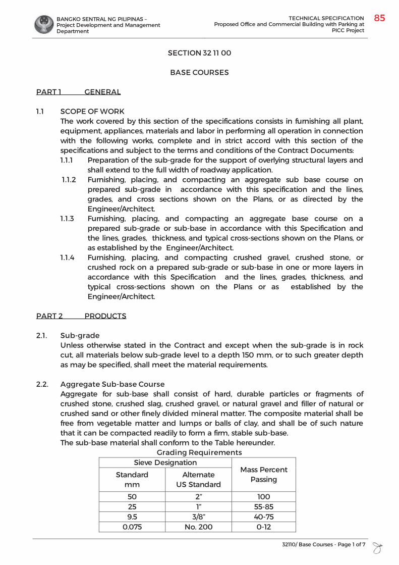
BANGKO SENTRAL NG PILIPINAS – Project Development and Management Department
TECHNICAL SPECIFICATION Proposed Office and Commercial Building with Parking at
PICC Project
32110/ Base Courses - Page 1 of 7
SECTION 32 11 00
BASE COURSES
PART 1 GENERAL
1.1 SCOPE OF WORK The work covered by this section of the specifications consists in furnishing all plant, equipment, appliances, materials and labor in performing all operation in connection with the following works, complete and in strict accord with this section of the specifications and subject to the terms and conditions of the Contract Documents: 1.1.1 Preparation of the sub-grade for the support of overlying structural layers and
shall extend to the full width of roadway application. 1.1.2 Furnishing, placing, and compacting an aggregate sub base course on
prepared sub-grade in accordance with this specification and the lines, grades, and cross sections shown on the Plans, or as directed by the Engineer/Architect.
1.1.3 Furnishing, placing, and compacting an aggregate base course on a prepared sub-grade or sub-base in accordance with this Specification and the lines, grades, thickness, and typical cross-sections shown on the Plans, or as established by the Engineer/Architect.
1.1.4 Furnishing, placing, and compacting crushed gravel, crushed stone, or crushed rock on a prepared sub-grade or sub-base in one or more layers in accordance with this Specification and the lines, grades, thickness, and typical cross-sections shown on the Plans or as established by the Engineer/Architect.
PART 2 PRODUCTS
2.1. Sub-grade Unless otherwise stated in the Contract and except when the sub-grade is in rock cut, all materials below sub-grade level to a depth 150 mm, or to such greater depth as may be specified, shall meet the material requirements.
2.2. Aggregate Sub-base Course Aggregate for sub-base shall consist of hard, durable particles or fragments of crushed stone, crushed slag, crushed gravel, or natural gravel and filler of natural or crushed sand or other finely divided mineral matter. The composite material shall be free from vegetable matter and lumps or balls of clay, and shall be of such nature that it can be compacted readily to form a firm, stable sub-base. The sub-base material shall conform to the Table hereunder.
Grading Requirements Sieve Designation
Mass Percent Passing
Standard mm
Alternate US Standard
50 2” 100 25 1” 55-85 9.5 3/8” 40-75
0.075 No. 200 0-12
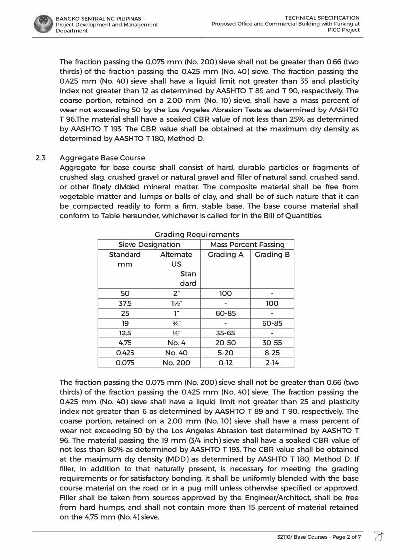
BANGKO SENTRAL NG PILIPINAS – Project Development and Management Department
TECHNICAL SPECIFICATION Proposed Office and Commercial Building with Parking at
PICC Project
32110/ Base Courses - Page 2 of 7
The fraction passing the 0.075 mm (No. 200) sieve shall not be greater than 0.66 (two thirds) of the fraction passing the 0.425 mm (No. 40) sieve. The fraction passing the 0.425 mm (No. 40) sieve shall have a liquid limit not greater than 35 and plasticity index not greater than 12 as determined by AASHTO T 89 and T 90, respectively. The coarse portion, retained on a 2.00 mm (No. 10) sieve, shall have a mass percent of wear not exceeding 50 by the Los Angeles Abrasion Tests as determined by AASHTO T 96.The material shall have a soaked CBR value of not less than 25% as determined by AASHTO T 193. The CBR value shall be obtained at the maximum dry density as determined by AASHTO T 180, Method D.
2.3 Aggregate Base Course Aggregate for base course shall consist of hard, durable particles or fragments of crushed slag, crushed gravel or natural gravel and filler of natural sand, crushed sand, or other finely divided mineral matter. The composite material shall be free from vegetable matter and lumps or balls of clay, and shall be of such nature that it can be compacted readily to form a firm, stable base. The base course material shall conform to Table hereunder, whichever is called for in the Bill of Quantities.
Grading Requirements Sieve Designation Mass Percent Passing
Standard mm
Alternate US
Standard
Grading A Grading B
50 2” 100 - 37.5 1½” - 100 25 1” 60-85 - 19 ¾” - 60-85
12.5 ½” 35-65 - 4.75 No. 4 20-50 30-55
0.425 No. 40 5-20 8-25 0.075 No. 200 0-12 2-14
The fraction passing the 0.075 mm (No. 200) sieve shall not be greater than 0.66 (two thirds) of the fraction passing the 0.425 mm (No. 40) sieve. The fraction passing the 0.425 mm (No. 40) sieve shall have a liquid limit not greater than 25 and plasticity index not greater than 6 as determined by AASHTO T 89 and T 90, respectively. The coarse portion, retained on a 2.00 mm (No. 10) sieve shall have a mass percent of wear not exceeding 50 by the Los Angeles Abrasion test determined by AASHTO T 96. The material passing the 19 mm (3/4 inch) sieve shall have a soaked CBR value of not less than 80% as determined by AASHTO T 193. The CBR value shall be obtained at the maximum dry density (MDD) as determined by AASHTO T 180, Method D. If filler, in addition to that naturally present, is necessary for meeting the grading requirements or for satisfactory bonding, it shall be uniformly blended with the base course material on the road or in a pug mill unless otherwise specified or approved. Filler shall be taken from sources approved by the Engineer/Architect, shall be free from hard humps, and shall not contain more than 15 percent of material retained on the 4.75 mm (No. 4) sieve.
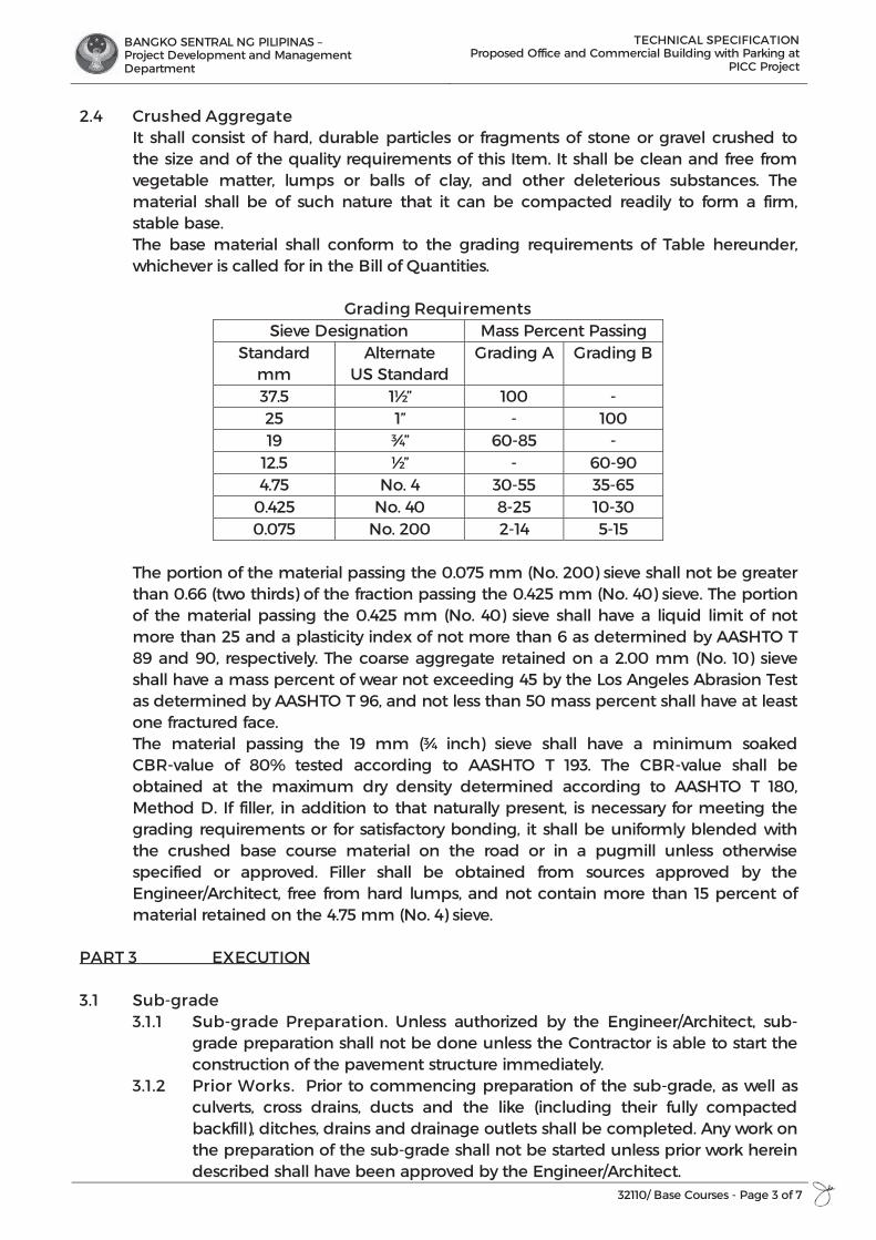
BANGKO SENTRAL NG PILIPINAS – Project Development and Management Department
TECHNICAL SPECIFICATION Proposed Office and Commercial Building with Parking at
PICC Project
32110/ Base Courses - Page 3 of 7
2.4 Crushed Aggregate It shall consist of hard, durable particles or fragments of stone or gravel crushed to the size and of the quality requirements of this Item. It shall be clean and free from vegetable matter, lumps or balls of clay, and other deleterious substances. The material shall be of such nature that it can be compacted readily to form a firm, stable base. The base material shall conform to the grading requirements of Table hereunder, whichever is called for in the Bill of Quantities.
Grading Requirements Sieve Designation Mass Percent Passing
Standard mm
Alternate US Standard
Grading A Grading B
37.5 1½” 100 - 25 1” - 100 19 ¾” 60-85 -
12.5 ½” - 60-90 4.75 No. 4 30-55 35-65
0.425 No. 40 8-25 10-30 0.075 No. 200 2-14 5-15
The portion of the material passing the 0.075 mm (No. 200) sieve shall not be greater than 0.66 (two thirds) of the fraction passing the 0.425 mm (No. 40) sieve. The portion of the material passing the 0.425 mm (No. 40) sieve shall have a liquid limit of not more than 25 and a plasticity index of not more than 6 as determined by AASHTO T 89 and 90, respectively. The coarse aggregate retained on a 2.00 mm (No. 10) sieve shall have a mass percent of wear not exceeding 45 by the Los Angeles Abrasion Test as determined by AASHTO T 96, and not less than 50 mass percent shall have at least one fractured face. The material passing the 19 mm (¾ inch) sieve shall have a minimum soaked CBR-value of 80% tested according to AASHTO T 193. The CBR-value shall be obtained at the maximum dry density determined according to AASHTO T 180, Method D. If filler, in addition to that naturally present, is necessary for meeting the grading requirements or for satisfactory bonding, it shall be uniformly blended with the crushed base course material on the road or in a pugmill unless otherwise specified or approved. Filler shall be obtained from sources approved by the Engineer/Architect, free from hard lumps, and not contain more than 15 percent of material retained on the 4.75 mm (No. 4) sieve.
PART 3 EXECUTION
3.1 Sub-grade 3.1.1 Sub-grade Preparation. Unless authorized by the Engineer/Architect, sub-
grade preparation shall not be done unless the Contractor is able to start the construction of the pavement structure immediately.
3.1.2 Prior Works. Prior to commencing preparation of the sub-grade, as well as culverts, cross drains, ducts and the like (including their fully compacted backfill), ditches, drains and drainage outlets shall be completed. Any work on the preparation of the sub-grade shall not be started unless prior work herein described shall have been approved by the Engineer/Architect.
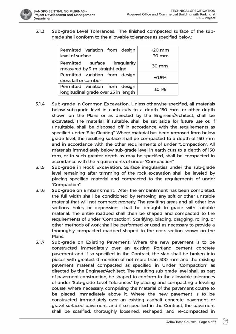
BANGKO SENTRAL NG PILIPINAS – Project Development and Management Department
TECHNICAL SPECIFICATION Proposed Office and Commercial Building with Parking at
PICC Project
32110/ Base Courses - Page 4 of 7
3.1.3 Sub-grade Level Tolerances. The finished compacted surface of the sub-grade shall conform to the allowable tolerances as specified below:
Permitted variation from design level of surface
+20 mm -30 mm
Permitted surface irregularity measured by 3-m straight edge
30 mm
Permitted variation from design cross fall or camber
±0.5%
Permitted variation from design longitudinal grade over 25 in length
±0.1%
3.1.4 Sub-grade in Common Excavation. Unless otherwise specified, all materials
below sub-grade level in earth cuts to a depth 150 mm, or other depth shown on the Plans or as directed by the Engineer/Architect, shall be excavated. The material, if suitable, shall be set aside for future use or, if unsuitable, shall be disposed off in accordance with the requirements as specified under “Site Clearing”. Where material has been removed from below grade level, the resulting surface shall be compacted to a depth of 150 mm and in accordance with the other requirements of under “Compaction”. All materials immediately below sub-grade level in earth cuts to a depth of 150 mm, or to such greater depth as may be specified, shall be compacted in accordance with the requirements of under “Compaction”.
3.1.5 Sub-grade in Rock Excavation. Surface irregularities under the sub-grade level remaining after trimming of the rock excavation shall be leveled by placing specified material and compacted to the requirements of under “Compaction”.
3.1.6 Sub-grade on Embankment. After the embankment has been completed, the full width shall be conditioned by removing any soft or other unstable material that will not compact properly. The resulting areas and all other low sections, holes, or depressions shall be brought to grade with suitable material. The entire roadbed shall then be shaped and compacted to the requirements of under “Compaction”. Scarifying, blading, dragging, rolling, or other methods of work shall be performed or used as necessary to provide a thoroughly compacted roadbed shaped to the cross-section shown on the Plans.
3.1.7 Sub-grade on Existing Pavement. Where the new pavement is to be constructed immediately over an existing Portland cement concrete pavement and if so specified in the Contract, the slab shall be broken into pieces with greatest dimension of not more than 500 mm and the existing pavement material compacted as specified in Under “Compaction” as directed by the Engineer/Architect. The resulting sub-grade level shall, as part of pavement construction, be shaped to conform to the allowable tolerances of under “Sub-grade Level Tolerances” by placing and compacting a leveling course, where necessary, comprising the material of the pavement course to be placed immediately above it. Where the new pavement is to be constructed immediately over an existing asphalt concrete pavement or gravel surfaced pavement, and if so specified in the Contract, the pavement shall be scarified, thoroughly loosened, reshaped, and re-compacted in
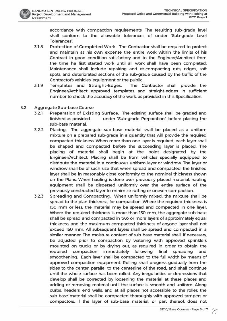
BANGKO SENTRAL NG PILIPINAS – Project Development and Management Department
TECHNICAL SPECIFICATION Proposed Office and Commercial Building with Parking at
PICC Project
32110/ Base Courses - Page 5 of 7
accordance with compaction requirements. The resulting sub-grade level shall conform to the allowable tolerances of under “Sub-grade Level Tolerances”.
3.1.8 Protection of Completed Work. The Contractor shall be required to protect and maintain at his own expense the entire work within the limits of his Contract in good condition satisfactory and to the Engineer/Architect from the time he first started work until all work shall have been completed. Maintenance shall include repairing and re-compacting ruts, ridges, soft spots, and deteriorated sections of the sub-grade caused by the traffic of the Contractor's vehicles, equipment or the public.
3.1.9 Templates and Straight-Edges. The Contractor shall provide the Engineer/Architect approved templates and straight-edges in sufficient number to check the accuracy of the work, as provided in this Specification.
3.2 Aggregate Sub-base Course
3.2.1 Preparation of Existing Surface. The existing surface shall be graded and finished as provided under “Sub-grade Preparation”, before placing the sub-base material.
3.2.2 Placing. The aggregate sub-base material shall be placed as a uniform mixture on a prepared sub-grade in a quantity that will provide the required compacted thickness. When more than one layer is required, each layer shall be shaped and compacted before the succeeding layer is placed. The placing of material shall begin at the point designated by the Engineer/Architect. Placing shall be from vehicles specially equipped to distribute the material in a continuous uniform layer or windrow. The layer or windrow shall be of such size that when spread and compacted, the finished layer shall be in reasonably close conformity to the nominal thickness shown on the Plans. When hauling is done over previously placed material, hauling equipment shall be dispersed uniformly over the entire surface of the previously constructed layer to minimize rutting or uneven compaction.
3.2.3 Spreading and Compacting. When uniformly mixed, the mixture shall be spread to the plan thickness, for compaction. Where the required thickness is 150 mm or less, the material may be spread and compacted in one layer. Where the required thickness is more than 150 mm, the aggregate sub-base shall be spread and compacted in two or more layers of approximately equal thickness, and the maximum compacted thickness of anyone layer shall not exceed 150 mm. All subsequent layers shall be spread and compacted in a similar manner. The moisture content of sub-base material shall, if necessary, be adjusted prior to compaction by watering with approved sprinklers mounted on trucks or by drying out, as required in order to obtain the required compaction immediately following final spreading and smoothening. Each layer shall be compacted to the full width by means of approved compaction equipment. Rolling shall progress gradually from the sides to the center, parallel to the centerline of the road, and shall continue until the whole surface has been rolled. Any irregularities or depressions that develop shall be corrected by loosening the material at these places and adding or removing material until the surface is smooth and uniform. Along curbs, headers, end walls, and at all places not accessible to the roller, the sub-base material shall be compacted thoroughly with approved tampers or compactors. If the layer of sub-base material, or part thereof, does not
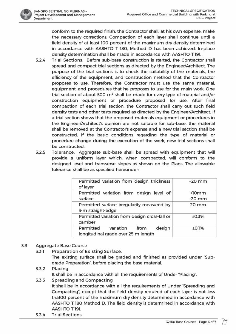
BANGKO SENTRAL NG PILIPINAS – Project Development and Management Department
TECHNICAL SPECIFICATION Proposed Office and Commercial Building with Parking at
PICC Project
32110/ Base Courses - Page 6 of 7
conform to the required finish, the Contractor shall, at his own expense, make the necessary corrections. Compaction of each layer shall continue until a field density of at least 100 percent of the maximum dry density determined in accordance with AASHTO T 180, Method D has been achieved. In-place density determination shall be made in accordance with AASHTO T 191.
3.2.4 Trial Sections. Before sub-base construction is started, the Contractor shall spread and compact trial sections as directed by the Engineer/Architect. The purpose of the trial sections is to check the suitability of the materials, the efficiency of the equipment, and construction method that the Contractor proposes to use. Therefore, the Contractor must use the same material, equipment, and procedures that he proposes to use for the main work. One trial section of about 500 m2 shall be made for every type of material and/or construction equipment or procedure proposed for use. After final compaction of each trial section, the Contractor shall carry out such field density tests and other tests required as directed by the Engineer/Architect. If a trial section shows that the proposed materials equipment or procedures in the Engineer/Architect's opinion are not suitable for sub-base, the material shall be removed at the Contractor's expense and a new trial section shall be constructed. If the basic conditions regarding the type of material or procedure change during the execution of the work, new trial sections shall be constructed.
3.2.5 Tolerance. Aggregate sub-base shall be spread with equipment that will provide a uniform layer which, when compacted, will conform to the designed level and transverse slopes as shown on the Plans. The allowable tolerance shall be as specified hereunder:
Permitted variation from design thickness of layer
+20 mm
Permitted variation from design level of surface
+10mm -20 mm
Permitted surface irregularity measured by 3-m straight-edge
20 mm
Permitted variation from design cross-fall or camber
±0.3%
Permitted variation from design longitudinal grade over 25 m length
±0.1%
3.3 Aggregate Base Course 3.3.1 Preparation of Existing Surface. The existing surface shall be graded and finished as provided under “Sub-
grade Preparation”, before placing the base material. 3.3.2 Placing It shall be in accordance with all the requirements of Under “Placing”. 3.3.3 Spreading and Compacting It shall be in accordance with all the requirements of Under “Spreading and
Compacting”, except that the field density required of each layer is not less tha100 percent of the maximum dry density determined in accordance with AASHTO T 180 Method D. The field density is determined in accordance with AASHTO T 191.
3.3.4 Trial Sections
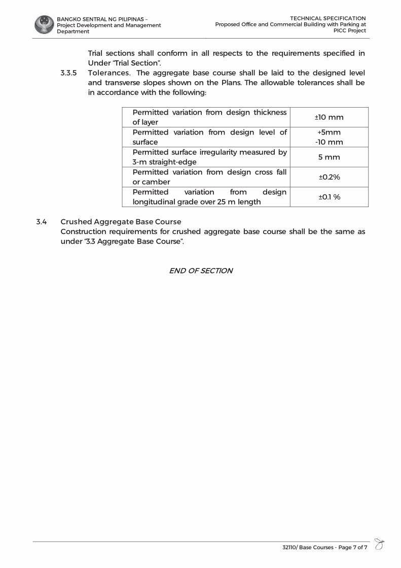
BANGKO SENTRAL NG PILIPINAS – Project Development and Management Department
TECHNICAL SPECIFICATION Proposed Office and Commercial Building with Parking at
PICC Project
32110/ Base Courses - Page 7 of 7
Trial sections shall conform in all respects to the requirements specified in Under “Trial Section”.
3.3.5 Tolerances. The aggregate base course shall be laid to the designed level and transverse slopes shown on the Plans. The allowable tolerances shall be in accordance with the following:
Permitted variation from design thickness of layer
±10 mm
Permitted variation from design level of surface
+5mm -10 mm
Permitted surface irregularity measured by 3-m straight-edge
5 mm
Permitted variation from design cross fall or camber
±0.2%
Permitted variation from design longitudinal grade over 25 m length
±0.1 %
3.4 Crushed Aggregate Base Course
Construction requirements for crushed aggregate base course shall be the same as under “3.3 Aggregate Base Course”.
END OF SECTION

BANGKO SENTRAL NG PILIPINAS – Project Development and Management Department
TECHNICAL SPECIFICATION Proposed Office and Commercial Building with Parking at
PICC Project
321133.13/ Portland Cement - Page 1 of 21
SECTION 32 11 33.13
PORTLAND CEMENT
PART 1 GENERAL
1.1 SCOPE OF WORK This item shall consists all the labor, materials, equipment and installation of Portland Cement Concrete Pavement, with or without reinforcement, constructed on the prepared base in accordance with this Specification, General Conditions of the Contract and in conformity with the lines, grades, thickness, and typical cross-sections shown on the Plans.
1.2 REFERENCES Comply with quality assurance requirements under General Conditions of the Contract Documents and Manufacturer’s instructions. Reference the following standards as applicable: 1.2.1 American Concrete Institute, ACI 1.2.2 American Society for Testing Materials, ASTM 1.2.3 American Association of State Highway and Transportation Officials, AASHTO 1.2.4 Department of Public Works and Highways, DPWH, Volume II
1.3 SUBMITTALS 1.3.1 General: All submittals for approval as indicated herein shall be in accordance
to the provisions under General Conditions of the Contract Documents. 1.3.2 The Contractor shall furnish the Engineer/Architect a Quality Control Plan
detailing his production control procedures and the type and frequency of sampling and testing to insure that the concrete he produces complies with the Specifications. The Engineer/Architect shall be provided free access to recent plant production records, and if requested, informational copies of mix design, materials certifications and sampling and testing reports.
1.4 QUALITY ASSURANCE 1.4.1 Comply with quality assurance requirements under General Conditions of the
Contract Documents and Manufacturer’s instructions. 1.4.2 Qualification of Workmen
Experienced and qualified personnel shall perform all batching or mixing operations for the concrete mix. They shall be present at the plant and job site to control the concrete productions whenever the plant is in operation. They shall be identified and duties defined as follows: A. Concrete Batcher
The person performing the batching or mixing operation shall be capable of accurately conducting aggregate surface moisture determinations and establishing correct scale weight for concrete materials. He shall be capable of assuring that the proportioned batch weights of materials are in accordance with the mix design.
B. Concrete Technician The person responsible for concrete production control and sampling and testing for quality control shall be proficient in concrete technology and
BANGKO SENTRAL NG PILIPINAS – Project Development and Management Department
TECHNICAL SPECIFICATION Proposed Office and Commercial Building with Parking at
PICC Project
321133.13/ Portland Cement - Page 2 of 21
shall have a sound knowledge of the Specifications as they relate to concrete production. He shall be capable of conducting tests on concrete and concrete materials in accordance with the Specifications. He shall be capable of adjusting concrete mix designs for improving workability and Specification compliance and preparing trial mix design. He shall be qualified to act as the concrete batcher in the batcher's absence.
1.5 DELIVERY, STORAGE AND HANDLING 1.5.1 Comply with product delivery requirements under General Conditions of the
Contract Documents and Manufacturer’s instructions. 1.5.2 All cement shall be stored immediately upon delivery at the Site in a
weatherproof building that will protect the cement from dampness. The floor shall be raised from the ground. The buildings shall be placed in locations approved by the Engineer/Architect. Provisions for storage shall be ample and the shipments of cement as received shall be stored separately in such a manner as to allow the earliest deliveries to be used first and to provide easy access for identification and inspection of each shipment. Storage buildings shall have capacity for storage of a sufficient quantity of cement to allow sampling at least twelve days before the cement is to be used. Bulk cement, if used, shall be transferred to elevated air-tight and weatherproof bins. Stored cement shall meet the test requirements at any time after shortage when the Engineer/Architect orders a retest. At the time of use, all cement shall be free flowing and free of lumps. The handling and storing of concrete aggregate shall be such as to prevent segregation or the inclusion of foreign materials. The Engineer/Architect may require that aggregates be stored on separate platforms at satisfactory locations. In order to secure greater uniformity of concrete mix, the Engineer/Architect may require that the coarse aggregate be separated into two or more sizes. Different sizes of aggregates shall be stored in separate bins or in separate stock piles sufficiently removed from each other to prevent the material at the edges of the piles from becoming intermixed.
PART 2 PRODUCTS
2.1 Portland Cement. It shall conform to the applicable requirements of Hydraulic Cement. Only Type I Portland Cement shall be used unless otherwise provided for in the Special Provisions. Different brands or the same brands from different mills shall not be mixed nor shall they be used alternately unless the Engineer/Architect approves the mix. Cement which for any reason has become partially set or which contains lumps of caked cement will be rejected. Cement salvaged from discarded or used bags shall not be used. Samples of cement shall be obtained in accordance with AASHTO T 127.
2.2 Fine Aggregates. They shall consist of natural sand, stone screenings, or other inert materials with similar characteristics, or combinations thereof, having hard, strong, and durable particles approved by the Engineer/Architect. Fine aggregate from different sources of supply shall not be mixed or stored in the same pile nor used alternately in the same class of concrete without the approval of the Engineer/Architect. It shall not contain more than three mass percent of material
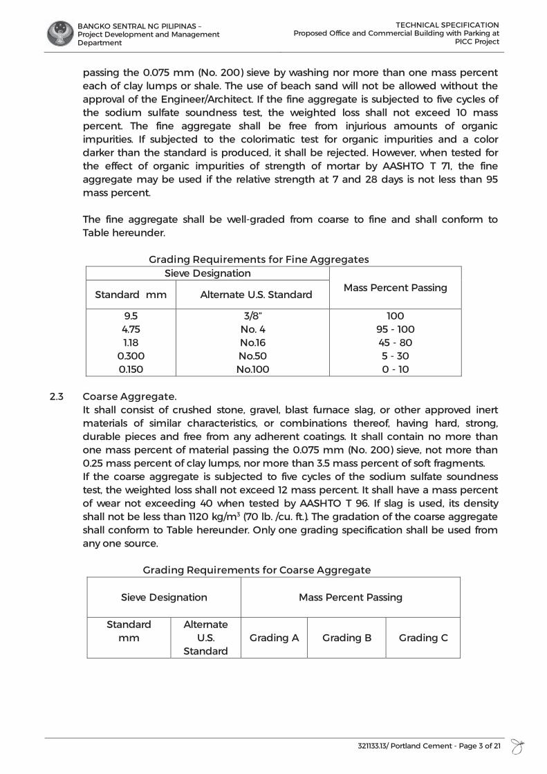
BANGKO SENTRAL NG PILIPINAS – Project Development and Management Department
TECHNICAL SPECIFICATION Proposed Office and Commercial Building with Parking at
PICC Project
321133.13/ Portland Cement - Page 3 of 21
passing the 0.075 mm (No. 200) sieve by washing nor more than one mass percent each of clay lumps or shale. The use of beach sand will not be allowed without the approval of the Engineer/Architect. If the fine aggregate is subjected to five cycles of the sodium sulfate soundness test, the weighted loss shall not exceed 10 mass percent. The fine aggregate shall be free from injurious amounts of organic impurities. If subjected to the colorimatic test for organic impurities and a color darker than the standard is produced, it shall be rejected. However, when tested for the effect of organic impurities of strength of mortar by AASHTO T 71, the fine aggregate may be used if the relative strength at 7 and 28 days is not less than 95 mass percent.
The fine aggregate shall be well-graded from coarse to fine and shall conform to Table hereunder.
Grading Requirements for Fine Aggregates Sieve Designation
Mass Percent Passing Standard mm Alternate U.S. Standard
9.5 4.75 1.18
0.300 0.150
3/8” No. 4 No.16 No.50 No.100
100 95 - 100 45 - 80 5 - 30 0 - 10
2.3 Coarse Aggregate. It shall consist of crushed stone, gravel, blast furnace slag, or other approved inert materials of similar characteristics, or combinations thereof, having hard, strong, durable pieces and free from any adherent coatings. It shall contain no more than one mass percent of material passing the 0.075 mm (No. 200) sieve, not more than 0.25 mass percent of clay lumps, nor more than 3.5 mass percent of soft fragments. If the coarse aggregate is subjected to five cycles of the sodium sulfate soundness test, the weighted loss shall not exceed 12 mass percent. It shall have a mass percent of wear not exceeding 40 when tested by AASHTO T 96. If slag is used, its density shall not be less than 1120 kg/m3 (70 lb. /cu. ft.). The gradation of the coarse aggregate shall conform to Table hereunder. Only one grading specification shall be used from any one source.
Grading Requirements for Coarse Aggregate
Sieve Designation
Mass Percent Passing
Standard mm
Alternate U.S.
Standard
Grading A
Grading B
Grading C
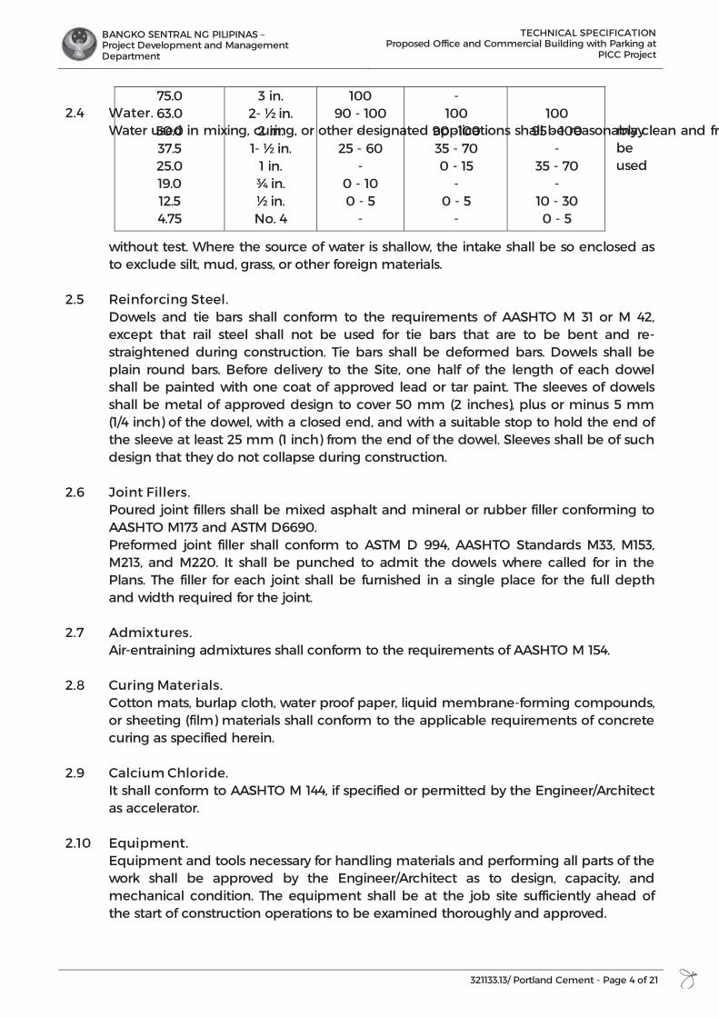
BANGKO SENTRAL NG PILIPINAS – Project Development and Management Department
TECHNICAL SPECIFICATION Proposed Office and Commercial Building with Parking at
PICC Project
321133.13/ Portland Cement - Page 4 of 21
2.4 Water. Water used in mixing, curing, or other designated applications shall be reasonably clean and fremay
be used
without test. Where the source of water is shallow, the intake shall be so enclosed as to exclude silt, mud, grass, or other foreign materials.
2.5 Reinforcing Steel. Dowels and tie bars shall conform to the requirements of AASHTO M 31 or M 42, except that rail steel shall not be used for tie bars that are to be bent and re-straightened during construction. Tie bars shall be deformed bars. Dowels shall be plain round bars. Before delivery to the Site, one half of the length of each dowel shall be painted with one coat of approved lead or tar paint. The sleeves of dowels shall be metal of approved design to cover 50 mm (2 inches), plus or minus 5 mm (1/4 inch) of the dowel, with a closed end, and with a suitable stop to hold the end of the sleeve at least 25 mm (1 inch) from the end of the dowel. Sleeves shall be of such design that they do not collapse during construction.
2.6 Joint Fillers. Poured joint fillers shall be mixed asphalt and mineral or rubber filler conforming to AASHTO M173 and ASTM D6690. Preformed joint filler shall conform to ASTM D 994, AASHTO Standards M33, M153, M213, and M220. It shall be punched to admit the dowels where called for in the Plans. The filler for each joint shall be furnished in a single place for the full depth and width required for the joint.
2.7 Admixtures. Air-entraining admixtures shall conform to the requirements of AASHTO M 154.
2.8 Curing Materials.
Cotton mats, burlap cloth, water proof paper, liquid membrane-forming compounds, or sheeting (film) materials shall conform to the applicable requirements of concrete curing as specified herein.
2.9 Calcium Chloride. It shall conform to AASHTO M 144, if specified or permitted by the Engineer/Architect as accelerator.
2.10 Equipment. Equipment and tools necessary for handling materials and performing all parts of the work shall be approved by the Engineer/Architect as to design, capacity, and mechanical condition. The equipment shall be at the job site sufficiently ahead of the start of construction operations to be examined thoroughly and approved.
75.0 63.0 50.0 37.5 25.0 19.0 12.5 4.75
3 in. 2- ½ in.
2 in. 1- ½ in.
1 in. ¾ in. ½ in. No. 4
100 90 - 100
- 25 - 60
- 0 - 10 0 - 5
-
- 100
90 -100 35 - 70 0 - 15
- 0 - 5
-
100
95 - 100 -
35 - 70 -
10 - 30 0 - 5

BANGKO SENTRAL NG PILIPINAS – Project Development and Management Department
TECHNICAL SPECIFICATION Proposed Office and Commercial Building with Parking at
PICC Project
321133.13/ Portland Cement - Page 5 of 21
2.10.1 Batching Plant and Equipment A. General The batching plant shall include bins, weighing hoppers and scales for the
fine aggregate and for each size of coarse aggregate. If cement is used in bulk, a bin, a hopper, and separate scale for cement shall be included. The weighing hopper shall be properly sealed and vented to preclude dusting operation. The batch plant shall be equipped with a suitable non-resetable batch counter, which will correctly indicate the number batches proportioned.
B. Bins and Hoppers Bins with adequate separate compartments for fine aggregate and for
each size of coarse aggregate shall be provided in the batching plant. C. Scales Scales for weighing aggregates and cement shall be of either the beam
type or the springless-dial type. They shall be accurate within one-half percent (0.5%) throughout the range of use. Poises shall be designed to be locked in any position and to prevent unauthorized change. Scales shall be inspected and sealed as often as the Engineer/Architect may deem necessary to assure their continued accuracy.
D. Automatic Weighing Devices Unless otherwise allowed on the Contract, batching plants shall be
equipped with automatic weighing devices of an approved type to proportion aggregates and bulk cement.
2.10.2 Mixers A. General Concrete may be mixed at the Site of construction or at a central plant, or
wholly or in part in truck mixers. Each mixer shall have a manufacturer's plate attached in a prominent place showing the capacity of the drum in terms of volume of mixed concrete and the speed of rotation of the mixing drum or blades.
B. Mixers at Site of Construction Mixing shall be done in an approved mixer capable of combining the
aggregates, cement, and water into a thoroughly mixed and uniform mass within the specified mixing as well as discharging and distributing the mixture without segregation on the prepared grade. The mixer shall be equipped with an approved timing device which will automatically lock the discharge lever when the drum has been charged and release it at the end of the mixing period. In case of failure of the timing device, the mixer may be used for the balance of the day while it is being repaired, provided that each batch is mixed 90 seconds. The mixer shall be equipped with a suitable non-resettable batch counter, which shall correctly indicate the number of batches mixed.
C. Truck Mixer and Truck Agitators Truck mixers used for mixing and hauling concrete and truck agitators
used for hauling centrally-mixed concrete shall conform to the requirements of AASHTO M 157.
D. Non-Agitator Trucks
BANGKO SENTRAL NG PILIPINAS – Project Development and Management Department
TECHNICAL SPECIFICATION Proposed Office and Commercial Building with Parking at
PICC Project
321133.13/ Portland Cement - Page 6 of 21
Bodies of non-agitating hauling equipment for concrete shall be smooth, mortar-tight metal containers and shall be capable of discharging the concrete at a satisfactory controlled rate without segregation.
2.10.3 Paving and Finishing Equipment The concrete shall be placed with an approved paver designed to spread,
consolidate, screed, and float finish the freshly placed concrete in one complete pass of the machine in such a manner that a minimum of hand finishing will be necessary to provide a dense and homogeneous pavement in conformance with the Plans and Specifications. The finishing machine shall be equipped with at least two oscillating type transverse screeds. Vibrators shall operate at a frequency of 8,300 to 9,600 impulses per minute under load at a maximum spacing of 60 cm. A. Concrete Saw The Contractor shall provide sawing equipment in adequate number of
units and power to complete the sawing with a water-cooled diamond edge saw blade or an abrasive wheel to the required dimensions and at the required rate. He shall provide at least one stand-by saw in good working condition and with an ample supply of saw blades.
B. Forms Forms shall be of steel, of an approved section, and of a depth equal to
the thickness of the pavement at the edge. The base of the forms shall be of sufficient width to provide necessary stability in all directions. The flange braces must extend outward on the base to not less than 2/3 the height of the form. All forms shall be rigidly supported on a bed of thoroughly compacted material during the entire operation of placing and finishing the concrete. Forms shall be provided with adequate devices for secure setting so that when in place, they will withstand without visible spring or settlement, the impact and vibration of the consolidating and finishing or paving equipment.
PART 3 EXECUTION
3.1 General The Contractor shall be responsible for the quality control of all materials during the handling, blending, mixing, and placement operations.
3.2 Proportioning, Consistency, and Strength of Concrete The Contractor shall prepare the design mix based on the absolute volume method as outlined in the American Concrete Institute (ACI) Standard 211.1, "Recommended Practice for Selecting Proportions for Normal and Heavyweight Concrete". It is the intent of this Specification to require approximately 9.0 bags of cement per cubic meter of concrete based on a 40-kg bag of cement. However, leaner or richer mixes may be used in order to meet the minimum strength requirements. The Engineer/Architect shall determine from laboratory tests of the materials to be used, the cement content and the proportions of aggregate and water that will produce a workable concrete having a slump of between 40 and 75 mm (1½ and 3 inches) if not vibrated, or between 10 and 40 mm (½ and 1½ inches) if vibrated, and a flexural strength of not less than 3.8 MPa (550 psi) when tested by the third-point method or 4.5 MPa (650 psi) when tested by the mid-point method; or a compressive strength of
BANGKO SENTRAL NG PILIPINAS – Project Development and Management Department
TECHNICAL SPECIFICATION Proposed Office and Commercial Building with Parking at
PICC Project
321133.13/ Portland Cement - Page 7 of 21
24.1 MPa (3,500 psi) when tested at fourteen days in accordance with AASHTO T 97, T 177 or T 24, respectively. Slump shall be determined using AASHTO T 199.The designer shall consider the use of lean concrete (econo-concrete) mixtures using local materials or specifically modified conventional concrete mixes in the base course and in the lower course of composite, monolithic concrete pavements using a minimum of 75 mm (3 inches) of conventional concrete as the surface course. The mix design shall be submitted to the Engineer/Architect for approval and shall be accompanied with certified test data from an approved laboratory demonstrating the adequacy of the mix design. A change in the source of materials during the progress of work may necessitate a new design mix.
3.3 Quality Control Testing. The Contractor shall perform all sampling, testing and inspection necessary to assure quality control of the component materials and the concrete. The Contractor shall be responsible for determining the gradation of fine and coarse aggregates and for testing the concrete mixture for slump, air content, water-cement ratio, and temperature. He shall conduct his operations so as to produce a mix conforming to the approved mix design.
3.4 Documentation. The Contractor shall maintain adequate records of all inspections and tests. The records shall indicate the nature and number of observations made, the number and type of deficiencies found, the quantities approved and rejected, and nature of any corrective action taken. The Engineer/Architect may take independent assurance samples at random locations for acceptance purposes, as he deems necessary.
3.5 Preparation of Grade. After the sub-grade or base has been placed and compacted to the required density, the areas which will support the paving machine and the grade on which the pavement is to be constructed shall be trimmed to the proper elevation by means of a properly designed machine extending the work at least 60 cm beyond each edge of the proposed concrete pavement. If loss of density results from the trimming operations, it shall be restored by additional compaction before concrete is placed. If any traffic is allowed to use the prepared sub-grade or base, the surface shall be checked and corrected immediately ahead of the placing concrete. The sub-grade or base shall be uniformly moist when the concrete is placed.
3.6 Setting of Forms 3.6.1 Base Support. The foundation under the forms shall be hard and true to grade so that the
form when set will be firmly in contact for its whole length and at the specified grade. Any roadbed, which at the form line is found below established grade, shall be filled with approved granular materials to grade in lifts of three cm or less, and thoroughly rerolled or tamped. Imperfections or variations above grade shall be corrected by tamping or by cutting as necessary.
3.6.2 Form Setting. Forms shall be set sufficiently in advance of the point where concrete is being
placed. After the forms have been set to the correct grade, the base shall be thoroughly tamped, mechanically or by hand, at both the inside and
BANGKO SENTRAL NG PILIPINAS – Project Development and Management Department
TECHNICAL SPECIFICATION Proposed Office and Commercial Building with Parking at
PICC Project
321133.13/ Portland Cement - Page 8 of 21
outside edges of the base of the forms. The forms shall not deviate from true line by more than one cm at any point.
3.6.3 Grade and Alignment. The alignment and grade elevations of the forms shall be checked and
corrections made by the Contractor immediately before placing the concrete. Testing as to crown and elevation, prior to placing of concrete can be made by means of holding an approved template in a vertical position and moved backward and forward on the forms. When any form has been disturbed or any grade has become unstable, the form shall be reset and rechecked.
3.6.4 Conditioning of Sub-grade or Base Course. When side forms have been securely set to grade, the sub-grade or base
course shall be brought to the proper cross-section. High areas shall be trimmed to the proper elevation. Low areas shall be filled and properly compacted. The finished grade shall be maintained in a smooth and compacted condition until the pavement is placed. Unless waterproof sub-grade or base course cover material is specified, the sub-grade or base course shall be uniformly moist when the concrete is placed. If it subsequently becomes too dry, the sub-grade or base course shall be sprinkled, but the method of sprinkling shall not be such as to form mud or pools of water.
3.6.5 Handling, Measuring, and Batching Materials. The batch plant site, layout, equipment, and provisions for transporting
material shall be such as to assure a continuous supply of material to the work. Stockpiles shall be built up in layers of not more than one meter in thickness. Each layer shall be completely in place before beginning the next, which shall not be allowed to "cone" down over the next lower layer. Aggregates from different sources and of different gradings shall not be stockpiled together. All washed aggregates and aggregates produced or handled by hydraulic methods, shall be stockpiled or binned for draining at least twelve hours before being batched. When mixing is done at the site of the work, aggregates shall be transported from the batching plant to the mixer in batch boxes, vehicle bodies, or other containers of adequate capacity and construction to carry the required volume properly. Partitions separating batches shall be adequate and effective to prevent spilling from one compartment to another while in transit or being dumped. When bulk cement is used, the Contractor shall use a suitable method of handling the cement from the weighing hopper to the transporting container or into the batch itself for transportation to the mixer, with chute boot or other approved device, to prevent loss of cement, and to provide positive assurance of the actual presence in each batch of the entire cement content specified. Bulk cement shall be transported to the mixer in tight compartments, carrying the full amount of cement required for the batch. However, if allowed in the Special Provisions, it may be transported between the fine and coarse aggregate. When cement is placed in contact with the aggregates, batches may be rejected unless mixed within 1½ hours of such contact. Cement in original shipping packages may be transported on top of the aggregates, each batch containing the number of sacks required by the job mix. The mixer shall be charged without loss of cement. Batching shall be so as to result in the weight to each material required within a tolerance of one percent for cement and two percent for aggregates. Water may be measured either by volume or by weight. The accuracy of measuring the water shall be
BANGKO SENTRAL NG PILIPINAS – Project Development and Management Department
TECHNICAL SPECIFICATION Proposed Office and Commercial Building with Parking at
PICC Project
321133.13/ Portland Cement - Page 9 of 21
within a range of error of not over one percent. Unless the water is to be weighed, the water measuring equipment tank shall be equipped with an outside tap and valve to provide for checking the setting, unless other means are provided for readily and accurately determining the amount of water in the tank.
3.7 Mixing Concrete. The concrete may be mixed at the Site in a central mix plant or in truck mixers. The mixer shall be of an approved type and capacity. Mixing time will be measured from the time all materials, except water, are in the drum. Ready-mixed concrete shall be mixed and delivered in accordance with requirements of AASHTO M 157, except that the minimum required revolutions at the mixing speed for transit-mixed concrete may be reduced to not less than that recommended by the mixer manufacturer. The number of revolutions recommended by the mixer manufacturer shall be indicated on the manufacturer's serial plate attached to the mixer. The Contractor shall furnish test data acceptable to the Engineer/Architect verifying that the make and model of the mixer will produce uniform concrete conforming to the provisions of AASHTO M 157 at the reduced number of revolutions shown on the serial plate. When mixed at the Site or in a central mixing plant, the mixing time shall not be less than fifty seconds nor more than ninety seconds; unless mixer performance tests prove adequate mixing of the concrete is a shorter time period. Four seconds shall be added to the specified mixing time if timing starts the instant the skip reaches its maximum raised position. Mixing time ends when the discharge chute opens. Transfer time in multiple drum mixers is included in mixing time. The contents of an individual mixer drum shall be removed before a succeeding batch is emptied therein. The mixer shall be operated at the drum speed as shown on the manufacturer's name plate attached on the mixer. Any concrete mixed less than the specified time shall be discarded and disposed off by the Contractor at his expense. The volume of concrete mixed per batch shall not exceed the mixer's nominal capacity in cubic meters, as shown on the manufacturer's standard rating plate on the mixer, except that an overload up to ten percent above the mixer's nominal capacity may be permitted provided concrete test data for strength, segregation, and uniform consistency are satisfactory, and provided no spillage of concrete takes place. The batches shall be so charged into the drum that a portion of the mixing water shall enter in advance of the cement and aggregates. The flow of water shall be uniform and all water shall be in the drum by the end of the first fifteen seconds of the mixing period. The throat of the drum shall be kept free of such accumulations as may restrict the free flow of materials into the drum. Mixed concrete from the central mixing plant shall be transported in truck mixers, truck agitators or non-agitating trucks specified in Subsection “Equipment”. The time elapsed from the time water is added to the mix until the concrete is deposited in place at the Site shall not exceed forty-five minutes when the concrete is hauled in non-agitating trucks, nor 90 minutes when hauled in truck mixers or truck agitators, except that in hot weather or under other conditions contributing to quick hardening of the concrete, the maximum allowable time may be reduced by the Engineer/Architect. Retempering concrete by adding water or by other means shall not be permitted, except that when concrete is delivered in truck mixers, additional water may be added to the batch materials and additional mixing performed to increase the slump to meet the specified requirements, if permitted by the Engineer/Architect, provided all these operations are performed within forty-five minutes after the initial
BANGKO SENTRAL NG PILIPINAS – Project Development and Management Department
TECHNICAL SPECIFICATION Proposed Office and Commercial Building with Parking at
PICC Project
321133.13/ Portland Cement - Page 10 of 21
mixing operation and the water-cement ratio is not exceeded. Concrete that is not within the specified slump limits at the time of placement shall not be used. Admixtures for increasing the workability or for accelerating the setting of the concrete will be permitted only when specifically approved by the Engineer/Architect.
3.8 Limitation of Mixing. No concrete shall be mixed, placed, or finished when natural light is insufficient, unless an adequate and approved artificial lighting system is operated. During hot weather, the Engineer/Architect may require that steps be taken to prevent the temperature of mixed concrete from exceeding a specified maximum temperature of 90ºF(32ºC). Concrete not in place within ninety minutes from the time the ingredients were charged into the mixing drum or that has developed initial set shall not be used. Retempering of concrete or mortar that has partially hardened, that is remixing with or without additional cement, aggregate, or water, shall not be permitted. In order that the concrete may be properly protected against the effects of rain before the concrete is sufficiently hardened, the Contractor will be required to have available at all times materials for the protection of the edges and surface of the unhardened concrete.
3.9 Placing Concrete. Concrete shall be deposited in such a manner to require minimal rehandling. Unless truck mixers or non-agitating hauling equipment are equipped with means to discharge concrete without segregation of the materials, the concrete shall be unloaded into an approved spreading device and mechanically spread on the grade in such a manner as to prevent segregation. Placing shall be continuous between transverse joints without the use of intermediate bulkheads. Necessary hand spreading shall be done with shovels, not rakes. Workmen shall not be allowed to walk in the freshly mixed concrete with boots or shoes coated with earth or foreign substances. Where concrete is to be placed adjoining a previously constructed lane and mechanical equipment will be operated upon the existing lane, that previously constructed lane shall have attained the strength for 14-day concrete. If only finishing equipment is carried on the existing lane, paving in adjoining lanes may be permitted after three days. Concrete shall be thoroughly consolidated against and along the faces of all forms and along the full length and on both sides of all joint assemblies by means of vibrators inserted in the concrete. Vibrators shall not be permitted to come in contact with a joint assembly, the grade, or a side form. In no case shall the vibrator be operated longer than 15 seconds in any one location. Concrete shall be deposited as near as possible to the expansion and contraction joints without disturbing them, but shall not be dumped from the discharge bucket or hopper into a joint assembly unless the hopper is well centered on the joint assembly. Should any concrete material fall on or be worked into the surface of a complete slab, it shall be removed immediately.
3.10 Test Specimen. As work progresses, at least one set consisting of three concrete beam test specimens, 150 mm x 150 mm x 525 or 900 mm shall be taken from 330 m2 of pavement, 230 mm depth, or fraction thereof placed each day. Test specimens shall be made under the supervision of the Engineer/Architect. The Contractor shall provide all concrete and other facilities necessary in making the test specimens and

BANGKO SENTRAL NG PILIPINAS – Project Development and Management Department
TECHNICAL SPECIFICATION Proposed Office and Commercial Building with Parking at
PICC Project
321133.13/ Portland Cement - Page 11 of 21
shall protect them from damage by construction operations. The beams shall be made, cured, and tested in accordance with AASHTO T 23 and T 97.
3.11 Strike-off of Concrete and Placement of Reinforcement. Following the placing of the concrete, it shall be struck off to conform to the cross-section shown on the Plans and to an elevation such that when the concrete is properly consolidated and finished, the surface of the pavement will be at the elevation shown on the Plans. When reinforced concrete pavement is placed in two layers, the bottom layer shall be struck off and consolidated to such length and depth that the sheet of fabric or bar mat may be laid full length on the concrete in its final position without further manipulation. The reinforcement shall then be placed directly upon the concrete, after which the top layer of the concrete shall be placed, struck off and screeded. Any portion of the bottom layer of concrete which has been placed more than thirty minutes without being covered with the top layer shall be removed and replaced with freshly mixed concrete at the Contractor's expense. When reinforced concrete is placed in one layer, the reinforcement may be firmly positioned in advance of concrete placement or it may be placed at the depth shown on the Plans in plastic concrete, after spreading by mechanical or vibratory means. Reinforcing steel shall be free from dirt, oil, paint, grease, mill scale, and loose or thick rust that could impair bond of the steel with the concrete.
3.12 Joints. Joints shall be constructed of the type and dimensions, and at the locations required by the Plans or Special Provisions. All joints shall be protected from the intrusion of injurious foreign material until sealed. 3.12.1 Longitudinal Joint. Deformed steel tie bars of specified length, size, spacing, and materials shall
be placed perpendicular to the longitudinal joints. They shall be placed by approved mechanical equipment rigidly secured by approved supports to prevent displacement. Tie bars shall not be painted or coated with asphalt or other material, or enclosed in tubes or sleeves. When shown on the Plans and when adjacent lanes of pavement are constructed separately, steel side forms shall be used which will form a keyway along the construction joint. Tie bars, except those made of rail steel, may be bent at right angles against the form of the first lane constructed and straightened into final position before the concrete of the adjacent lane is placed, or in lieu of bent tie bars, approved two-piece connectors may be used. Longitudinal formed joints shall consist of a groove or cleft, extending downward from and normal to the surface of the pavement. These joints shall be effected or formed by an approved mechanically or manually operated device to the dimensions and lines indicated on the Plans and while the concrete is in a plastic state. The groove or cleft shall be filled with either a pre molded strip or poured material as required. The longitudinal joint shall be continuous there shall be no gaps in either transverse or longitudinal joints at the intersection of the joints. Longitudinal sawed joints shall be cut by means of approved concrete saws to the depth, width and lines shown on the Plans. Suitable guide lines or devices shall be used to assure cutting the longitudinal joint on the true line. The longitudinal joint shall be sawed before the end of the curing period or shortly thereafter and before any equipment or vehicles are allowed on the pavement. The sawed area shall be thoroughly cleaned and, if required, the

BANGKO SENTRAL NG PILIPINAS – Project Development and Management Department
TECHNICAL SPECIFICATION Proposed Office and Commercial Building with Parking at
PICC Project
321133.13/ Portland Cement - Page 12 of 21
joint shall immediately be filled with sealer. Longitudinal pavement insert type joints shall be formed by placing a continuous strip of plastic material which will not react adversely with the chemical constituent of the concrete.
3.12.2 Transverse Expansion Joint. The expansion joint filler shall be continuous from form to form shaped to the
subgrade and to the keyway along the form. Preformed joint filler shall be furnished in lengths, equal to the pavement width or equal to the width of one lane. Damaged or repaired joint filler shall not be used. The expansion joint filler shall be held in a vertical position. An approved installing bar, or other device, shall be used if required to secure preformed expansion joint filler at the proper grade and alignment during placing and finishing of the concrete. Finished joint shall not deviate more than 6 mm from a straight line. If joint fillers are assembled in sections, there shall be no offsets between adjacent units. No plugs of concrete shall be permitted anywhere within the expansion space.
3.12.3 Transverse Contraction Joint. When shown on the Plans, it shall consist of planes of weakness created by
forming or cutting grooves in the surface of the pavement and shall include load transfer assemblies. It shall be formed by installing a parting strip to be left in place as shown on the Plans. A. Formed Groove. It shall be made by depressing an approved tool or
device into the plastic concrete. The tool or device shall remain in place at least until the concrete has attained its initial set and shall then be removed without disturbing the adjacent concrete, unless the device is designed to remain in the joint.
B. Sawed Contraction Joint. It shall be created by sawing grooves in the surface of the pavement of the width, depth, and at the spacing and lines shown on the Plans, with an approved concrete saw. After each joint is sawed, it shall be thoroughly cleaned including the adjacent concrete surface. Sawing of the joints shall commence as soon as the concrete has hardened sufficiently to permit sawing without excessive raveling, usually within twenty-four hours. All joints shall be sawed before uncontrolled shrinkage cracking takes place. The sawing of any joint shall be omitted if cracks occur at or near the joint location prior to the time of sawing. Sawing shall be discounted when a crack develops ahead of the saw. In general, all joints should be sawed in sequence. If extreme conditions exist which make it impractical to prevent erratic cracking by early sawing, the contraction joint groove shall be formed prior to initial set of concrete as provided above.
3.12.4 Transverse Construction Joint. It shall be constructed when there is an interruption of more than thirty
minutes in the concreting operation. No transverse joint shall be constructed within 1.50 m of an expansion joint, contraction joint, or plane of weakness. If sufficient concrete has been mixed at the time of interruption to form a slab of at least 1.50 m long, the excess concrete from the last preceding joint shall be removed and disposed off as directed.
3.12.5 Load transfer Device. Dowels, when used shall be held in position parallel to the surface and center
line of the slab by a metal device that is left in the pavement. The portion of each dowel painted with one coat of lead or tar, in conformance with the
BANGKO SENTRAL NG PILIPINAS – Project Development and Management Department
TECHNICAL SPECIFICATION Proposed Office and Commercial Building with Parking at
PICC Project
321133.13/ Portland Cement - Page 13 of 21
requirements of Item 404, Reinforcing Steel, shall be thoroughly coated with approved bituminous materials, e.g., MC-70, or an approved lubricant, to prevent the concrete from binding to that portion of the dowel. The sleeves for dowels shall be metal designed to cover 50 mm plus or minus 5 mm (¼ inch) of the dowel, with a watertight closed end and with a suitable stop to hold the end of the sleeves at least 25 mm (1 inch) from the end of the dowel. In lieu of using dowel assemblies at contraction joints, dowels may be placed in the full thickness of pavement by a mechanical device approved by the Engineer/Architect.
3.13 Final Strike-Off (Consolidation and Finishing) 3.13.1 Sequence. The sequence of operations shall be the strike-off and consolidation, floating
and removal of laitance, straight-edging and final surface finish. Work bridges or other devices necessary to provide access to the pavement surface for the purpose of finishing straight-edging, and making corrections as hereinafter specified, shall be provided by the Contractor. In general, the addition of water to the surface of the concrete to assist in finishing operations will not be permitted. If the application of water to the surface is permitted, it shall be applied as fog spray by means of approved spray equipment.
3.13.2 Finishing at Joints. The concrete adjacent to joints shall be compacted or firmly placed without
voids or segregation against the joint material as well as under and around all load transfer devices, joint assembly units, and other features designed to extend into the pavement. Concrete adjacent to joints shall be mechanically vibrated as required in Subsection “Placing Concrete”. After the concrete has been placed and vibrated adjacent to the joints as required in Subsection “Placing Concrete” the finishing machine shall be brought forward, operating in a manner to avoid damage or misalignment of joints. If uninterrupted, operation of the finishing machine to, over, and beyond the joints causes segregation of concrete, damage to, or misalignment of the joints, the finishing machine shall be stopped when the front screed is approximately 20 cm (8 inches) from the joint. Segregated concrete shall be removed from in front of and off the joint. The front screed shall be lifted and set directly on top of the joint and the forward motion of the finishing machine resumed. When the second screed is close enough to permit the excess mortar in front of it to flow over the joint, it shall be lifted and carried over the joint. Thereafter, the finishing machine may be run over the joint without lifting the screeds, provided there is no segregated concrete immediately between the joint and the screed or on top of the joint.
3.13.3 Machine Finishing A. Non-vibratory Method. The concrete shall be distributed or spread as soon
as placed. As soon as the concrete has been placed, it shall be struck off and screeded by an approved finishing machine. The machine shall go over each area of pavement as many times and at such intervals as necessary to give the proper compaction and leave a surface of uniform texture. Excessive operation over a given area shall be avoided. The tops of the forms shall be kept clean by an effective device attached to the machine and the travel of the machines on the forms shall be maintained true without wobbling or other variation tending to affect the
BANGKO SENTRAL NG PILIPINAS – Project Development and Management Department
TECHNICAL SPECIFICATION Proposed Office and Commercial Building with Parking at
PICC Project
321133.13/ Portland Cement - Page 14 of 21
precision finish. During the first pass of the finishing machine, a uniform ridge of concrete shall be maintained ahead of the front screed in its entire length.
B. Vibratory Method. When vibration is specified, vibrators for full width vibration of concrete paving slabs shall meet the requirements in Subsection “Equipment”. If uniform and satisfactory density of the concrete is not obtained by the vibratory method at joints, along forms, at structures, and throughout the pavement, the Contractor will be required to furnish equipment and a method which will produce pavement conforming to the Specifications. All the provisions in item (a) above not in conflict with the provisions for the vibratory method shall govern.
3.13.4 Hand Finishing. Hand finishing methods may only be used under the following Conditions:
A. In the event of breakdown of the mechanical equipment, hand methods may be used to finish the concrete already deposited on the grade.
B. In narrow widths or areas of irregular dimensions where operations of the mechanical equipment are impractical, hand methods may be used. Concrete shall be struck off and screeded as soon as it is placed. An approved portable screed shall be used. A second screed shall be provided for striking off the bottom layer of concrete if reinforcement is used. The screed for the surface shall be at least 60 cm (2 feet) longer than the maximum width of the slab to be struck off. It shall be of approved design, sufficiently rigid to retain its shape and constructed either of metal or other suitable material shod with metal. Consolidation shall be attained by the use of a suitable vibrator or other approved equipment. In operation, the screed shall be moved forward on the forms with a combined longitudinal and transverse shearing motion, moving al-ways in the direction in which the work is progressing and so manipu-lated that neither end is raised from the side forms during the striking off process. If necessary, this shall be repeated until the surface is of uniform texture, true to grade and cross-section, and free from porous areas.
3.13.5 Floating After the concrete has been struck off and consolidated, it shall be further
smoothed, trued, and consolidated by means of a longitudinal float, either by hand or mechanical method. A. Hand Method. The hand-operated longitudinal float shall be not less than
265 cm (12 feet) in length and 15 cm (6 inches) in width, properly stiffened to prevent flexibility and warping. The longitudinal float, operated from foot bridges resting on the side forms and spawning but not touching the concrete, shall be worked with a sawing motion while held in a floating position parallel to the road center line, and moving gradually from one side of the pavement to the other. Movement ahead along the centerline of the pavement shall be in successive advances of not more than one-half (½) the length of the float. Any excess water or soupy material shall be wasted over the side forms on each pass.
B. Mechanical Method. The mechanical longitudinal float shall be of a design approved by the Engineer/Architect, and shall be in good working condition. The tracks from which the float operates shall be accurately adjusted to the required crown. The float shall be accurately adjusted and coordinated with the adjustment of the transverse finishing machine so
BANGKO SENTRAL NG PILIPINAS – Project Development and Management Department
TECHNICAL SPECIFICATION Proposed Office and Commercial Building with Parking at
PICC Project
321133.13/ Portland Cement - Page 15 of 21
that a small amount of mortar is carried ahead of the float at all times. The forward screed shall be adjusted so that the float will lap the distance specified by the Engineer/Architect on each transverse trip. The float shall pass over each area of pavement at least two times, but excessive operation over a given area will not be permitted. Any excess water or soupy material shall be wasted over the side forms on each pass.
C. Alternative Mechanical Method. As an alternative, the Contractor may use a machine composed of a cutting and smoothing float or floats suspended from and guided by a rigid frame. The frame shall be carried by four or more visible wheels riding on, and constantly in contact with the side forms. If necessary, following one of the preceding methods of floating, long handled floats having blades not less than 150 cm (5 feet) in length and 15 cm (6 inches) in width may be used to smooth and fill in open-textured areas in the pavement. Long-handled floats shall not be used to float the entire surface of the pavement in lieu of or supplementing one of the preceding methods of floating. When strike off and consolidation is done by the hand method and the crown of the pavement will not permit the use of the longitudinal float, the surface shall be floated transversely by means of the long-handled float. Care shall be taken not to work the crown out of the pavement during the operation. After floating, any excess water and laitance shall be removed from the surface of the pavement by a straight-edge at least 3 m long. Successive drags shall be lapped one-half the length of the blade.
3.13.6 Straight-Edge Testing and Surface Correction After the floating has been completed and the excess water removed, but
while the concrete is still plastic, the surface of the concrete shall be tested for trueness with a 300-cm long straight-edge. For this purpose, the Contractor shall furnish and use an accurate 300-cm straight-edge swung from handles 100 cm (3 feet) longer than one-half the width of the slab. The straight-edge shall be held in contact with the surface in successive positions parallel to the road center line and the whole area gone over from one side of the slab to the other as necessary. Advances along the road shall be in successive stages of not more than one-half the length of the straight-edge. Any depressions found shall be immediately filled with freshly mixed concrete, struck off, consolidated and refinished. Special attention shall be given to assure that the surface across joints meets the requirements for smoothness. Straightedge testing and surface corrections shall be continued until the entire surface is free from observable departures from the straight--edge and the slab conforms to the required grade and cross-section.
3.13.7 Final Finish If the surface texture is broom finished, it shall be applied when the water
sheen has practically disappeared. The broom shall be drawn from the center to the edge of the pavement with adjacent strokes slightly overlapping. The brooming operation should be executed so that the corrugations produced in the surface shall be uniform in appearance and not more than 1.5 mm in depth. Brooming shall be completed before the concrete is in such condition that the surface will be unduly roughened by the operation. The surface thus finished shall be free from tough and porous areas, irregularities, and depressions resulting from improper handling of the broom. Brooms shall be of the quality, size, and construction and be operated so as to

BANGKO SENTRAL NG PILIPINAS – Project Development and Management Department
TECHNICAL SPECIFICATION Proposed Office and Commercial Building with Parking at
PICC Project
321133.13/ Portland Cement - Page 16 of 21
produce a surface finish meeting the approval of the Engineer/Architect. Subject to satisfactory results being obtained and approval of the Engineer/Architect, the Contractor will be permitted to substitute mechanical brooming in lieu of the manual brooming as described herein. If the surface texture is belt finished, when straight-edging is complete and the water sheen has practically disappeared and just before the concrete becomes non-plastic, the surface shall be belted with a 2-ply canvass belt not less than 20 cm wide and at least 100 cm longer than the pavement width. Hand belts shall have suitable handles to permit controlled, uniform manipulation. The belt shall be operated with short strokes transverse to the center line and with a rapid advance parallel to the center line. If the surface texture is drag finished, a drag shall be used which consists of a seamless strip of damp burlap or cotton fabric, which shall produce a uniform of gritty texture after dragging it longitudinally along the full width of pavement. For pavements 5 m or more in width, the drag shall be mounted on a bridge which travels on the forms. The dimensions of the drag shall be such that a strip of burlap or fabric at least 100 cm wide is in contact with the full width of pavement surface while the drag is used. The drag shall consist of not less than 2 layers of burlap with the bottom layer approximately 15 cm wider than the layer. The drag shall be maintained in such condition that the resultant surface is of uniform appearance and reasonably free from grooves over 1.5 mm in depth. Drag shall be maintained clean and free from encrusted mortar. Drags that cannot be cleaned shall be discarded and new drags shall be substituted. Regardless of the method used for the final finish, the hardened surface of the pavement shall have a coefficient of friction of 0.25 or more. Completed pavement that is found to have a coefficient of friction less than 0.25 shall be grounded or scored by the Contractor at his expense to provide the required coefficient of friction.
3.13.8 Edging at Forms and Joints. After the final finish, but before the concrete has taken its initial set the edges
of the pavement along each side of each slab as well as on each side of transverse expansion joints, formed joints, transverse construction joints, and emergency construction joints, it shall be worked with an approved tool and rounded to the radius required by the Plans. A well-defined and continuous radius shall be produced and a smooth, dense mortar finish obtained. The surface of the slab shall not be unduly disturbed by tilling the tool during the use. At all joints, any tool marks appearing on the slab adjacent to the joints shall be eliminated by brooming the surface. In doing this, the rounding of the comer of the slab shall not be disturbed. All concrete on top of the joint filler shall be completely removed. All joints shall be tested with a straight-edge before the concrete has set and correction made if one edge of the joint is higher than the other one.
3.13.9 Surface Test. As soon as the concrete has hardened sufficiently, the pavement surface shall
be tested with a 3-m straight-edge or other specified device. Areas showing high spots of more than 3 mm but not exceeding 12 mm in 3 m shall be marked and immediately ground down with an approved grinding tool to an elevation where the area or spot will not show surface deviations in excess of 3 mm when tested with 3 m straight-edge. Where the departure from correct cross-section exceeds 12mm, the pavement shall be removed and replaced
BANGKO SENTRAL NG PILIPINAS – Project Development and Management Department
TECHNICAL SPECIFICATION Proposed Office and Commercial Building with Parking at
PICC Project
321133.13/ Portland Cement - Page 17 of 21
by and at the expense of the Contractor. Any area or section so removed shall be not less than 1.5m in length and not less than the full width of the lane involved. When it is necessary to remove and replace a section of pavement, any remaining portion of the slab adjacent to the joints that is less than 1.5 m in length, shall also be removed and replaced.
3.13.10 Curing. Immediately after the finishing operations have been completed and the
concrete has sufficiently set, the entire surface of the newly placed concrete shall be cured in accordance with either one of the methods described herein. Failure to provide sufficient cover material of whatever kind the Contractor may elect to use, or lack of water to adequately take care of both curing and other requirements, shall be cause for immediate suspension of concreting operations. The concrete shall not be left exposed for more than ½ hour between stages of curing or during the curing period. A. Cotton or Burlap Mats. The surface of the pavement shall be entirely
covered with mats. The mats used shall be of such length (or width) that as laid they will extend at least twice the thickness of the pavement beyond the edges of the slab. The mat shall be placed so that the entire surface and the edges of the slab are completely covered. Prior to being placed, the mats shall be saturated roughly with water. The mat shall be placed and weighed down so as to cause them to remain in intimate contact with the surface covered. The mats shall be maintained fully wetted and in position for seventy-two hours unless otherwise specified.
B. Waterproof Paper. The top surface and sides of the pavement shall be entirely covered with waterproof paper, the units shall be lapped at least 45 cm. The paper shall be placed and weighed down so as to cause it to remain in intimate contact with the surface covered. The paper shall have such dimensions but each unit as laid will extend beyond the edges of the slab at least twice the thickness of the pavement, or at pavement width and 60 cm strips of paper for the edges. If laid longitudinally, paper not manufactured in sizes which will provide this width shall be securely sewed or cemented together, the joints being securely sealed in such a manner that they do not open up or separate during the curing period. Unless otherwise specified, the covering shall remain in place for seventy-two hours after the concrete has been placed. The surface of the pavement shall be thoroughly wetted prior to the placing of the paper.
C. Straw Curing. When this type of curing is used, the pavement shall be cured initially with burlap or cotton mats, until after final set of the concrete or, in any case, for twelve hours after placing the concrete. As soon as the mats are removed, the surface and sides of the pavement shall be thoroughly wetted and covered with at least 20 cm of straw or hay, the thickness of which is to be measured after wetting. If the straw or hay covering becomes displaced during the curing period, it shall be replaced to the original depth and saturated. It shall be kept thoroughly saturated with water for seventy-two hours and thoroughly wetted down during the morning of the fourth day, and the cover shall remain in place until the concrete has attained the required strength.
D. Impervious Membrane Method. The entire surface of the pavement shall be sprayed uniformly with white pigmented curing compound immediately after the finishing of the surface and before the set of the
BANGKO SENTRAL NG PILIPINAS – Project Development and Management Department
TECHNICAL SPECIFICATION Proposed Office and Commercial Building with Parking at
PICC Project
321133.13/ Portland Cement - Page 18 of 21
concrete has taken place, or if the pavement is cured initially with jute or cotton mats, it may be applied upon removal of the mats. The curing compound shall not be applied during rain. Mechanical sprayers shall apply the curing compound under pressure at the rate 4 L to not more than 14 m2. The spraying equipment shall be equipped with a wind guard. At the time of use, the compound shall be in a thoroughly mixed condition with the pigment uniformly dispersed throughout the vehicle. During application, the compound shall be stirred continuously by effective mechanical means. Hand spraying of odd widths or shapes and concrete surface exposed by the removal of forms will be permitted. Curing compound shall not be applied to the inside faces of joints to be sealed, but approved means shall be used to insure proper curing at least seventy-two hours and to prevent the intrusion of foreign material into the joint before sealing has been completed. The curing compound shall be of such character that the film will harden within thirty minutes after application. Should the film be damaged from any cause within the 72-hour curing period, the damaged portions shall be repaired immediately with additional compound.
E. White Polyethylene Sheet. The top surface and sides of the pavement shall be entirely covered with polyethylene sheeting. The units used shall be lapped at least 45 cm. The sheeting shall be so placed and weighted down so as to cause it to remain in intimate contact with the surface covered. The sheeting as prepared for use shall have such dimensions that each unit as laid will extend beyond the edges of the slab at least twice the thickness of the pavement. Unless otherwise specified, the covering shall be maintained in place for seventy two hours after the concrete has been placed.
3.14 Removal of Forms. Forms for concrete shall remain in place undisturbed for not less than twenty-four hours after concrete pouring. In the removal of forms, crowbars should be used in pulling out nails and pins. Care should be taken so as not to break the edges of the pavement. In case portions of the concrete are spalled, they shall be immediately repaired with fresh mortar mixed in the proportion of one part of Portland cement and two parts fine aggregates. Major honeycombed areas will be considered as defective work and shall be, removed and replaced at the expense of the Contractor. Any area or section so removed shall not be less than the distance between weakened plane joint nor less than the full width of the lane involved.
3.15 Scaling Joints. Joints shall be sealed soon after completion of the curing period and before the pavement is opened to traffic, including the Contractor's equipment. Just prior to sealing, each joint shall be thoroughly cleaned of all foreign materials including membrane curing compound and the joint faces shall be clean and surface dry when the seal is applied. The sealing material shall be applied to each joint opening to conform to the details shown on the Plans or as directed by the Engineer/Architect. Materials for seal applied when hot shall be stirred during heating so that localized overheating does not occur. The pouring shall be done in such a manner that the material will not be spilled on the exposed surfaces of the
BANGKO SENTRAL NG PILIPINAS – Project Development and Management Department
TECHNICAL SPECIFICATION Proposed Office and Commercial Building with Parking at
PICC Project
321133.13/ Portland Cement - Page 19 of 21
concrete. The use of sand or similar material as a cover for the seal will not be permitted. Preformed elastomeric gaskets for sealing joints shall be of the cross-sectional dimensions shown on the Plans. Seals shall be installed by suitable tools, without elongation and secured in place with an approved lubricant adhesive that shall cover both sides of the concrete joints. The seals shall be installed in a compressive condition and shall at time of placement be below the level of the pavement surface by approximately 6 mm. The seals shall be in one piece for the full width of each transverse joint.
3.16 Protection of Pavement. The Contractor shall protect the pavement and its appurtenances against both public traffic and traffic caused by his own employees and agents. This shall include watchmen to direct traffic and the erection of and maintenance of warning signs, lights, pavement bridges or crossovers, etc. The Plans or Special Provisions will indicate the location and type of device or facility required to protect the work and provide adequately for traffic. Any damage to the pavement occurring prior to final acceptance shall be repaired or the pavement shall be replaced.
3.17 Concrete Pavement-Slip Form Method. If the Contract calls for the construction of pavement without the use of fixed forms, the following provisions shall apply: 3.17.1 Grade. After the grade or base has been placed and compacted to the required
density, the areas that will support the paving machine shall be cut to the proper elevation by means of a properly designed machine. The grade on which the pavement is to be constructed shall then be brought to the proper profile by means of properly designed machine. If the density of the base is disturbed by the grading operation, it shall be corrected by additional compaction before concrete is placed. The grade should be constructed sufficiently in advance of the placing of the concrete. If any traffic is allowed to use the prepared grade, the grade shall be checked and corrected immediately before the placing of concrete.
3.17.2 Placing Concrete. The concrete shall be placed with an approved slip-form paver designed to
spread, consolidate, screed, and float-finish the freshly placed concrete in one complete pass of the machine in such a manner that a minimum of hand finishing will be necessary to provide a dense and homogenous pavement in conformance with the Plans and Specifications. The machine shall vibrate the concrete for the full width and depth of the strip of pavement being placed. Such vibration shall be accompanied with vibrating tubes or arms working in the concrete or with a vibrating screed or pan operating on the surface of the concrete. The sliding forms shall be rigidly held together laterally to prevent spreading of the forms. The forms shall trail behind the paver for such a distance that no appreciable slumping of the concrete will occur, and that necessary final finishing can be accomplished while the concrete is still within the forms. Any edge slump of the pavement, exclusive of edge rounding, in excess of 6 mm shall be corrected before the concrete has hardened. The concrete shall be held at a uniform consistency, having a slump of not more

BANGKO SENTRAL NG PILIPINAS – Project Development and Management Department
TECHNICAL SPECIFICATION Proposed Office and Commercial Building with Parking at
PICC Project
321133.13/ Portland Cement - Page 20 of 21
than 40 mm (1½ inches). The slip form paver shall be operated with as nearly as possible a continuous forward movement and that all operations of mixing, delivering and spreading concrete shall be coordinated so as to provide uniform progress with stopping and starting of the paver held to a minimum. If, for any reason, it is necessary to stop the forward movement of the paver the vibratory and tamping elements shall also be stopped immediately. No tractive force shall be applied to the machine, except that which is controlled from the machine.
3.17.3 Finishing. The surface smoothness and texture shall meet the requirements of “Final
Strike-off” and “Surface Test”. 3.17.4 Curing. Unless otherwise specified, curing shall be done in accordance with one of
the methods included in “Curing”. The curing media shall be applied at the appropriate time and shall be applied uniformly and completely to all surfaces and edges of the pavement.
3.17.5 Joints. All joints shall be constructed in accordance with Subsection “Joints”.
3.18 Protection against Rain. In order that the concrete may be properly protected against rain before the concrete is sufficiently hardened, the Contractor will be required to have available at all times, materials for the protection of the edges and surface of the unhardened concrete. Such protective materials shall consist of standard metal forms or wood planks having a normal thickness of not less than 50 mm (2 inches) and a minimal width of not less than the thickness of the pavement at its edge for the protection of the pavement edges, and covering material such a burlap or cotton mats, or curing paper or plastic sheeting material for the protection of the surface of the pavement. When rain appears imminent, all paving operations shall stop and all available personnel shall begin placing forms against the sides of the pavement and covering the surface of the unhardened concrete with the protective covering.
3.19 Acceptance of Concrete. The strength level of concrete will be considered satisfactory if the averages of all sets of three consecutive strength test results equal or exceed the specified strength, f’c and no individual strength test result is deficient by more than 15% of the specified strength, f’c. Concrete deemed to be not acceptable using the above criteria may be rejected unless the Contractor can provide evidence, by means of core tests, that the, quality of concrete represented by failed test results is acceptable in place. At least three representative cores shall be taken from each member or area of concrete in place that is considered deficient. The Engineer/Architect shall determine the location of cores so that there will be least impairment of the strength of the structure. The obtaining and testing of drilled cores shall be in accordance with AASHTO T 24.Concrete in the areas represented by the cores will be considered adequate if the average strength of the cores is equal to at least 85% of, and if no single core is less than 75% of the specified strength, f’c.
3.20 Opening to Traffic.
BANGKO SENTRAL NG PILIPINAS – Project Development and Management Department
TECHNICAL SPECIFICATION Proposed Office and Commercial Building with Parking at
PICC Project
321133.13/ Portland Cement - Page 21 of 21
The Engineer/Architect will decide when the pavement may be opened to traffic. The road will not be opened to traffic until test specimens molded and cured in accordance with AASHTO T 23 have attained the minimum strength requirements in Subsection “Strike-off of Concrete and Placement of Reinforcement”. If such tests are not conducted prior to the specified age the pavement shall not be opened to traffic until fourteen days after the concrete was placed. Before opening to traffic, the pavement shall be cleaned and joint sealing completed. 3.20.1 Tolerance and Pavement Thickness
A. General. The thickness of the pavement will be determined by measurement of cores from the completed pavement in accordance with AASHTO T 148. The completed pavement shall be accepted on a lot basis. A lot shall be considered as 1000 linear meters of pavement when a single traffic lane is poured or 500 linear meters when two lanes are poured concurrently. The last unit in each slab constitutes a lot in itself when its length is at least ½ of the normal lot length. If the length of the last unit is shorter than ½ of the normal lot length, it shall be included in the previous lot. Other areas such as intersections, entrances, crossovers, ramps, etc., will be grouped together to form a lot. Small irregular areas may be included with other unit areas to form a lot. Each lot will be divided into five equal segments and one core will be obtained from each segment in accordance with AASHTO T 24.
B. Pavement Thickness. It is the intent of this Specification that the pavement has a uniform thickness as called for on the Plans for each lot as defined. After the pavement has met all surface smoothness requirements, cores for thickness measurements will be taken. The Engineer/Architect shall evaluate the deficient areas and shall be removed and replaced by the Contractor with pavement of the specified thickness at his entire expense.
END OF SECTION
BANGKO SENTRAL NG PILIPINAS – Project Development and Management Department
TECHNICAL SPECIFICATION Proposed Office and Commercial Building with Parking at
PICC Project
321600 / Curbs, Gutters, Sidewalks, and Driveways - Page 1 of 3
SECTION 32 16 00
CURBS, GUTTER, SIDEWALKS & DRIVEWAYS
PART 1 GENERAL
1.1 SCOPE OF WORK This section shall consist of all the labor, materials, equipment and construction of Portland cement concrete curbs, gutter, sidewalks and driveways in accordance with this Specification, General Conditions of the Contract and as indicated in the Drawings.
1.2 STANDARDS Comply with quality assurance requirements under General Conditions of the Contract Documents and Manufacturer’s instructions. Reference the following standards as applicable: 1.2.1 American Concrete Institute, ACI 117, Standard Specifications for Tolerances
for Concrete Construction Materials 1.2.2 ACI 301, Standard Specifications for Structural Concrete 1.2.3 ACI 318, Building Code Requirements for Reinforced Concrete 1.2.4 American Society for Testing Materials, ASTM A615, Specification for Deformed
and Plain Billet Steel Bars for Concrete Reinforcement
PART 2 MATERIALS
2.1 Portland Cement Concrete. The cement concrete shall be Class A as specified in Concrete Section.
2.2 Sidewalks, Curbs and Gutter Shall be class A concrete pavement with plain cement smooth trowel finish. Provide 6mm x 6mm expansion grooves spaced at every 1200mm O.C. Refer to Architectural/Civil Works drawings for layout and details.
2.3 Driveway Shall be class A asphalt concrete with aggregate of mineral retained on the No. 4 sieve. Shall be free from clay conglomerate vegetative matter and other deleterious material that meets requirements of AASHTO M-320, Performance Grade of Asphalt Binder PG 64-28, AASHTO-T-3, ASTM D-58 01, and ASTM D-5801.
2.4 Expansion Joint Filler. Unless otherwise ordered, the preformed joint filler shall have a thickness of 5 mm and shall conform to the requirements of Portland Cement Concrete Pavement Section.
2.5 Forms. Forms shall be of wood or metal as approved by the Engineer/Architect and shall extend to the full depth of the concrete. All forms shall be straight, free from warps, and of adequate strength to resist distortion.
BANGKO SENTRAL NG PILIPINAS – Project Development and Management Department
TECHNICAL SPECIFICATION Proposed Office and Commercial Building with Parking at
PICC Project
321600 / Curbs, Gutters, Sidewalks, and Driveways - Page 2 of 3
2.6 Bed Course Material. Bed course material shall consist of cinders, sand, slag, gravel, crushed stone, or other
approved permeable granular material of such grading that all particles shall pass a 12.5-mm (1/2-inch) sieve.
2.7 Finishes. Provide in accordance with related Sections as specified in the Contract Documents
and true to the lines, grades, levels, pattern and dimensions shown on the Plans. PART 3 EXECUTION
3.1 Excavation shall be made to the depth and width required that will permit the
installation and bracing of the forms. The foundation shall be shaped and compacted to a firm and even surface conforming to the section shown on the Plans.
3.2 All materials from soft areas shall be removed and replaced with suitable materials. The bed course material shall be placed in accordance with Aggregate Sub-base Course Section.
3.3 All forms shall be staked securely in position at the correct lines and levels. Preformed joint filler shall be set in position as shown on the Plans before placing of concreting starts. The top of the joint filler shall be placed 5 mm below the top surface of the finished sidewalk.
3.4 The mixing, placing, finishing, and curing of concrete shall be as specified under Concrete Works. The Portland cement concrete shall be placed to the total depth shown on the Plans.
3.5 The surface shall be cut through to a depth of 6mm x 6mm with a trowel at intervals of 1 meter or, where required, in straight lines perpendicular to the edge of the sidewalk. The surface shall be brushed and shall undergo a second trowelling while plastic enough to receive fine broom texture finish which will not slick when wet. The edges of the sidewalk and the transverse cuts shall be shaped with a suitable tool so formed as to round the edges to a radius of 15 mm and shall be completed with final pattern and/or layout as indicated in detail drawings.
3.6 For exposed aggregate installation, hand-seed the aggregate mixture uniformly in the concrete surface to provide uniform maximum coverage, immediately after the surface of the concrete has been screeded and floated and surface water has been removed. The aggregate mix shall be lightly hand-tamped to a point where a minimum of the aggregate is embedded below the concrete surface. The final aggregate surface shall be brought to a true plane in any direction. Apply concrete retarder with a low-pressure sprayer as per manufacturers’ requirements Protect all curbs, borders, adjacent stones, pavers, etc. that are not to receive retarded finish prior to application of retarders. Do not delay the application of the surface retarder beyond the loss of the initial bleed water. Wash with water rinse/light broom or pressure wash with hose or power equipment within 6– 24 hours after the retarder is applied.
3.7 Surfaces to receive paving installations shall be coordinated with trades involve for the completion of works and shall execute in accordance to paving manufacturer’s instructions.
3.8 Keep working area clean and remove debris from the site after completion of works. Secure installations properly until sidewalk is ready for use.
BANGKO SENTRAL NG PILIPINAS – Project Development and Management Department
TECHNICAL SPECIFICATION Proposed Office and Commercial Building with Parking at
PICC Project
321600 / Curbs, Gutters, Sidewalks, and Driveways - Page 3 of 3
END OF SECTION
BANGKO SENTRAL NG PILIPINAS – Project Development and Management Department
TECHNICAL SPECIFICATION Proposed Office and Commercial Building with Parking at
PICC Project
323119 / Decorative Metal Fences and Gates - Page 1 of 2
SECTION 32 31 19
DECORATIVE METAL FENCES AND GATES (for Reference/Future Use)
PART 1 GENERAL
1.1 SUMMARY 1.1.1 Section Includes:
a. Provision of Security Steel Gate – Man Entranceb. Provision of Manually Operated Swing Gatec. Provision of Steel Fence
1.2 ACTION SUBMITTALS 1.2.1 Product Data: For each type of product indicated. 1.2.2 Shop Drawings: For fence and gate with hinges. Include plans, elevations,
sections, details and attachments to other work. 1.2.3 Samples: For each type of material and for each color specified, including
hardware locking mechanism.
1.3 INFORMATIONAL SUBMITTALS 1.3.1 Product Test Reports: Based on evaluation of comprehensive tests performed
by a qualified testing agency, for decorative steel tubular fence and gate including finish, indicating compliance with referenced standard.
1.4 CLOSEOUT SUBMITTALS 1.4.1 Operation and maintenance data.
PART 2 PRODUCTS
2.1 Steel Fence Shall be 100mm diameters B.I. pipe, schedule 40 vertical posts on concrete base pedestal connected to 20mm x 20mm B.I. square bars vertical slots and 10mm x 38mm B.I. flat bars horizontal slots. Fence finish shall be coated with high performance water-based black epoxy paint finish. Refer to Architectural drawings for layout, details and correct spacing. Submit shop drawings for Architect’s approval.
Note: Fence shall be of finish with the existing fence inside the PICC compound.
2.2 Manually Operated Steel Sliding Gate Shall be manually operated steel sliding gate and fixed fence made from 100mm diameters B.I. pipe, schedule 40 gate framing with 20mm x 20mm B.I. square bars vertical slots and 10mm x 38mm B.I. flat bars horizontal slots, spaced as specified in the drawings, coated with high performance water-based acrylic black epoxy paint finish.
Provide 75mm diameters engineered plastic rollers with 12mm thick metal plate casing, coated with high performance water-based black epoxy paint, anchored to reinforced concrete column, complete with heavy duty gate wheel and angle bar track anchored to concrete driveway.

BANGKO SENTRAL NG PILIPINAS – Project Development and Management Department
TECHNICAL SPECIFICATION Proposed Office and Commercial Building with Parking at
PICC Project
323119 / Decorative Metal Fences and Gates - Page 2 of 2
Refer to Architectural drawings for layout, details. Submit shop drawings for Architect’s approval.
PART 3 EXECUTION
3.1 GATE INSTALLATION 3.1.1 Install gates according to plans, level, plumbed and secure for full opening
without interference. Attach tubular pipes as for fencing; attached hardware using tampered resistant or concealed means. Adjust hardware for smooth operation and lubricate where necessary.
3.1.2 Adjust gates to operate smoothly, easily and quietly, free of blinding warp, excessive deflection, distortion, non-alignment, misplacement, disruption or malfunction throughout the operational range. Confirm that latches and locks engage accurately and securely without forcing or binding.
3.2 GROUNDING AND BONDING
3.2.1 Bonding Method for Gates: Connect bonding jumper between gate post and gate frame.
3.2.2 Connections: Make connections so possibility of galvanic action or electrolysis is minimized. Select connectors, connection hardware, conductors and connection methods so metals in direct contact will be galvanically compatible.
END OF SECTION
BANGKO SENTRAL NG PILIPINAS – Project Development and Management Department
TECHNICAL SPECIFICATION Proposed Office and Commercial Building with
Parking at PICC Project
329000 / Planting - Page 1 of 18
SECTION 32 90 00
PLANTING
PART 1 GENERAL
1.1 SCOPE OF WORK 1.1.1 The project will be divided onto several stages as determined by the Client.
The Scope of Works in this Contract will include the provision of all labor, materials, equipment and all other necessary tools, appliances to complete said contract items;
Supply, delivery, and storage of planting material needed for theimplementation and completion of soft landscape as prescribed andshown on the working drawings and specificationsThe Contractor shall be responsible to the site clearance and sitepreparation, each grading, leveling, soil formations according toplans and details as directed by the Client work supervision authority.
1.1.2 Implementation of all soft Landscape works shall include the following: Transporting of all specified materials to site;Lifting of all materials to the correct locations for installations;Installation of gravel drainage layer, filter membrane, and soilmixture to planters, including subsoil drainage;Pruning of all existing planted trees and Removing any deadcreepers or parasites as directed by the Landscape Architect or SiteOfficers;All other works which are deemed necessary but which are notproperly specified and described in this scope and specifications forproper completion of the Soft Landscape Works.
1.2 MAINTENANCE 1.2.1 In addition to the Contractor’s obligation during the defects liability period,
the Contractor shall be responsible in maintaining all plantings for a period of six (6) months or to be advised from the date of practical completion and acceptance of works which include watering, cultivating, fertilizing, weeding, pruning, wound dressing, disease and pest control, and prevention, protective spraying, replacement of dead plants, removal of unaccepted plants & materials, straightening of plants, moving of plants and other procedures necessary to ensure vigorous and healthy growth of all plants and other operations directed by the Landscape Architect.
1.2.2 For all existing plants and turfing areas within the extent of maintenance, including debris from existing and adjacent planting areas, etc.
1.2.3 The Contractor is to notify the Employer of any unhealthy plants and existing plants which have died, before proceeding with the maintenance work. In addition, these plants will be replaced at his own cost.
1.2.4 During the maintenance period, the Contractor will be required to replace any dying or vandalized plants to the original sizes, true to the type at his own expense. Until it is handled over to the Client after the maintenance period expires, it is to the Contractor’s responsibility for safe custody of all the trees, shrubs & ground covers, plants, etc.
BANGKO SENTRAL NG PILIPINAS – Project Development and Management Department
TECHNICAL SPECIFICATION Proposed Office and Commercial Building with
Parking at PICC Project
329000 / Planting - Page 2 of 18
1.2.5 The Client shall deduct proportionally (the maintenance fee of the Contractor or with the Landscape Architect recommended) a reasonable amount if plantings are found unsatisfactorily maintained.
The Contractor shall station 2-workers at the site during the maintenance period. An attendance logbook shall be lodged at the Client’s property.
1.3 SITE CONDITIONS The Contractor shall be expected to have visited the site so as to take into
consideration the existing conditions, facilities of access, nature of soil, local conditions as to the supply of labor, materials, plants, etc., weather conditions, flood water, etc., and other site conditions that may affect the work conditions. No claims will be allowed on the grounds of ignorance of existing site condition under which the Contractor works will be executed.
1.4 DISCREPANCIES IN DRAWINGS
1.4.1 The Contractor shall be responsible for checking all drawings issued to him; and if he finds any discrepancies in the Landscape Drawing including discrepancies with other trade of works such as Architectural, other A&E Consultants’ drawings, he shall, before proceeding with such work, inform the Landscape Architect of such discrepancies.
1.4.2 No claims by the Contractor, for any extra costs incurred as a result of discrepancies in the drawings, will be entertained if he fails to inform the Landscape Architect of such discrepancies before proceeding with works.
1.4.3 Any decisions by the Landscape Architect regarding the discrepancies shall be final.
1.5 SUPERVISION
The Landscape Architect or his authorized representative/s will supervise the implementation of landscape works for the proposed project while they are in progress.
1.6 WORKMENS COMPENSATION INSURANCE 1.6.1 The Contractor shall insure all workers against all claims in respect of injury
in the performance of work, to the public or to any property/ies arising out of or caused by the commissioning of his job.
1.6.2 The Client shall be free from any liabilities in respect to any claim/s by any and every workman employed in and for the performance of the contract for payment of compensation under or by virtue of Workmen’s Compensation law or any other Law amending from all costs and expenses incidental or consequential thereto. The Contractor shall identify the Employer against all liabilities arising out of the claims and the performance of this contract.
1.6.3 The amount insured shall not be less than 30% of the total construction costs.
1.6.4 The insurance policy taken out of the above shall be deposited with the Client. The Contractor shall maintain it in full force and effect, by payment of the premiums from time to time on the first day on which the same ought to be paid and until the completion of the contract and upon demand. The contractor shall produce to the Client the last receipt for payment of such premiums.
BANGKO SENTRAL NG PILIPINAS – Project Development and Management Department
TECHNICAL SPECIFICATION Proposed Office and Commercial Building with
Parking at PICC Project
329000 / Planting - Page 3 of 18
1.7 SITE MEETINGS
1.1.7 The Contractor or his authorized representative shall attend the site meetings fortnightly or at intervals as directed by the Landscape Architect.
1.8 LIASONS WITH OTHER TRADE WORK
1.1.8 The Contractor’s attention is drawn to the fact that there are other Contractors working at other trades of work, the Contractor shall liaise with other site Contractors so as not to cause interference, interruption, or delay in his performance of duty and such no claim on the grounds of hindrance or obstruction experienced due to the presence of other Contractors working on the site.
1.9 WORKMANSHIP
1.9.1 Skilled workmen shall perform the work described in this scope of works and all works shall be executed in a workmanlike manner so as to present a neat and finishing appearance.
1.9.2 The Landscape Architect shall decide whether or not the finished piece of work is satisfactory. If in his opinion, any work which have not been properly and satisfactorily executed and finished, the Contractor shall replace/ repair and reinstall the material in a manner entirely satisfactorily and without additional cost to the Employer.
1.20 TEMPORARY FACILITIES 1.20.1 The Contractor shall provide a temporary bunkhouse for its workers, a
warehouse for materials storage and a site office during the execution of works and such will be removed upon successful completion of the project.
1.20.2 The Contractor shall also provide temporary utilities such as water and electricity. Adequate supply of water including piping systems and storage shall be provided.
1.20.3 Payments for these utilities shall be borne by the Contractor.
1.21 PROGRAMME CHART 1.21.1 The Contractor shall submit for approval a detailed Programme of Work
showing the time and sequence of works he proposes to complete the job. 1.21.2 Notwithstanding the submission and approval of the works programme,
the Contractor is in no way relieved form his responsibility to complete the Extension of time granted in accordance with the Conditions of Contract. The Contract shall remain responsible and liable to the Employer with regards to his time performance.
1.21.3 The Contractor shall liaise with other trade operations and execution of the Landscape works will in no way delay the works.
1.22 INSPECTION OF WORKS 1.22.1 The Contractor is required to notify the Landscape Architect of the progress
of the works at least once a week and before any inspection is carried out. In the event of the installation of part thereof, failing to pass inspection, the Contractor shall at his own expense, take immediate action to replace and rectify.
BANGKO SENTRAL NG PILIPINAS – Project Development and Management Department
TECHNICAL SPECIFICATION Proposed Office and Commercial Building with
Parking at PICC Project
329000 / Planting - Page 4 of 18
1.23 DEFECTS LIABILITY PERIOD 1.23.1 Defects liability period will be 12 months after the final date of practical
Completion and Acceptance Certified by the Architect.
1.24 VARIATION ORDER 1.24.1 The Contractor shall note that should the quantity and quality of the work
be varied, the valuation of variations shall be made in accordance with the Conditions of Contract.
1.24.2 The Contractor shall note that no payment shall be made for the execution of works which involve variation unless and until the Landscape Architect has issued an official variation order and written instruction and to this end, the Contractor shall be responsible to ensure that all verbal instruction shall be entertained for failure to comply with this requirement.
1.25 CLEANING UP OF WORKS 1.25.1 The Contractor shall also allow in his prices for any further facilities that he
may require in addition to those specially mentioned above. 1.26 AS BUILT DRAWINGS 1.26.1 On completion of the works the Contractor is to prepare three (3) sets of As-
built Drawings (in tracing paper) covering all areas installed. These drawing shall be at the same scale as the original planting plans and shall contain the accurate position of all planting installed. These drawings and quantities shall be approved by the Landscape Architect before being signed and stamped by the Contractor’s Managing Director.
1.27 RECORD DRAWING 1.27.1 The Contractor shall prepare accurate records of those planting areas and
part of the works that will become hidden by further progress. Such records shall be checked and verified by the Landscape Architect while the work is open for inspection and to be handed to the Landscape Architect from time to time as the works proceed.
PART 2 PRODUCTS
2.1 EARTHWORKS 2.1.1 Materials
Existing Subsoil Existing subsoil generally been derived from original deposits on site. Existing DG as Planting Medium Soil for planting and grassing have, in certain areas, been roughly spread by others, and has been derived from original deposits on the Site and consists mainly of granular DG. This material is the basic constituent of soil to be mixed with soil conditioner to form the soil medium for planting areas at existing ground levels, and areas already made up. Generally, the final mixture shall comprise 3 parts of accepted DG by volume and mixed with 1 part of approved soil conditioner by volume to form a friable, evenly textured, free draining material to the Architect’s Approval. The Sub-Contractor shall ensure that the final mixture to be of a sandy loam character and contains no foreign materials or stones larger then 50 mm diameter. When it is necessary, the Sub-Contractor should ensure that sufficient amount of calcium oxide
BANGKO SENTRAL NG PILIPINAS – Project Development and Management Department
TECHNICAL SPECIFICATION Proposed Office and Commercial Building with
Parking at PICC Project
329000 / Planting - Page 5 of 18
should be added to adjust the pH value of the final mixture. The final mixture shall be evenly textured, fertile and meet all the nutrients and organic content requirements as specified in the following. Nutrient and organic status of topsoil shall be as follows: Organic matter not less than 7.5% Nitrogen (N) a minimum of 0.1% Available 6.9 to 9.2mg/ 100 Phosphate (P2O5) gms of open dry soil Exchangeable 14.1 to 28.2 mg/ Potassium (K2O) 100 gms of open soil pH between 5.5 and 7.0 Total soluble salts not more than 0.01% Mechanical sand 76% + 3% Properties silt 18% + 3% Clay 6% + 3% The Sub-Contractor shall arrange for chemical analysis of soil samples from each source and from each suspected variation within each source. Testing shall be carried out at a testing station to be approved by the Architect prior to the submission of any samples. Testing shall be for pH, Nitrogen, Phosphate, and Potassium levels, salinity, and organic content. Results shall be given to the Architect for approval prior to the commencement of any soiling operations. A sample of 2.0 kg shall be submitted to the Architect before application. Existing Soils The Sub-Contractor in tendering is assumed to have inspected the existing subsoil and topsoil and DG and satisfied himself that it is acceptable for the work specified herein. No claims shall subsequently be considered in respect of these materials which would relieve the Sub-Contractor of his responsibilities. Soil Binding Agent Shall be an Approved binding medium applied in an aqueous suspension by spraying onto the surface of the soil to prevent short term erosion and not to be injurious to plant growth. Soil Conditioner Soil Conditioner shall be peat moss or approved properly composed organic material free from impurity containing no substance injurious to plants. It shall have all the following properties: a) Properly composted organic material; b) Fine free flowing consistency; c) Free from impurities; d) Stable Composition; e) Not capable of raising the temperature of the treated soil for more than 5°C above the temperature of the untreated soil; f) Not made with materials that are known to contain pathogens or other injurious or toxic materials to plants, humans, or animals; g) Not give off toxic nor obnoxious fumes; h) pH between 4.0 and 7.0; i) Moisture content when saturated of 30-50% (by weight); j) Organic matter content, not less than 85% (dry matter) k) Carbon : Nitrogen ration between 20 and 55 Prior to first use and for every 300 cu m delivered to the Site, produce Certificates of Analysis of the Soil Conditioner, from an Approved Laboratory within 14 calendar days of taking samples. Each Certificate is to state the following:
a) pH Value b) Moisture content; c) Organic matter content (dry weight); d) Organic matter content e) Nitrogen content f) Carbon : Nitrogen ratio
Imported Topsoil Mix The topsoil-mix shall be a mixture of friable, completely decomposed rock [Completely decomposed granite

BANGKO SENTRAL NG PILIPINAS – Project Development and Management Department
TECHNICAL SPECIFICATION Proposed Office and Commercial Building with
Parking at PICC Project
329000 / Planting - Page 6 of 18
(CDG) and Completely decomposed volcanic (CDV)] (3 parts by volume) and soil conditioner (1 part by volume). Soil-mix shall be free from grass or weed growth of any kind: sticky clays, salt, stones larger than 25mm in diameter, or other foreign material. A sample of 2.0 kg shall be submitted to the Architect before importation and use. Topsoil mix shall meet all the nutrient and organic content requirements as specified in the following. Nutrient and organic status of topsoil shall be as follows: Organic matter not less than 7.5% Nitrogen (N) a minimum of 0.1% Available 6.9 to 9.2mg/ 100 g Phosphate (P2O5) of open dry soil Exchangeable 14.1 to 28.2 mg/100 g Potassium (K2O) of open soil pH between 5.5 and 7.0 Total soluble salts not more than 0.01% The Sub-Contractor shall arrange for the chemical analysis of soil samples from each source and from each suspected variation within each source or as directed by the Architect. Testing shall be carried out at a testing station to be approved by the Architect prior to the submission of any samples. Testing shall be for pH, Nitrogen, Phosphate, and Potassium levels, salinity, and organic content. Results shall be given to the Architect for approval, prior to the commencement of any soiling operations. Fabricated Soil Fabricated soil must consist of a mixture of 3 parts existing DG as Clauses 2.1.2 with the following: 1 part Soil Conditioner as Clause 2.1.05 Sand to be clean, sharp agricultural sand 4mm down to dust. Compost to be Soil Conditioner as Clause 2.1.5, or compost to be fully mature animal manure compost. Certificate of Analysis must be produced in accordance with Clause 2.1.5. Alginate Soil Improver Approved alginate improver shall be Incorporated either in the top 150 mm of soil or mixed into backfill for fit planting at the rates of 1.5 kg/ cu. m. or as recommended by the manufacturer.
2.2 DRAINAGE FOR PLANTING WORKS 2.2.1 Materials
Aggregate must be clean, rounded stone, 25-50 mm in diameter. Filter Layer is to be permeable, non-woven, thermally bonded geotextile, which is not affected by acids alkalis, bacteria, humidity, or rotting. e.g. “Terram 500”or “Fibertex G100” material or approved equal. River Washed Pebbles River washed round pebbles shall be clean 15-20 mm diameter in size.
2.3 PLANTING 2.3.1 Materials
Plants All plant materials, grass and seeds shall be true to the species; plants shall be healthy, with habit, and growth of the plant specified. Plants and seeds shall be free from pests, diseases, parasites, discoloration, and mechanical damage. All plants shall be obtained from a recognized cultivated source and not form the wild.
BANGKO SENTRAL NG PILIPINAS – Project Development and Management Department
TECHNICAL SPECIFICATION Proposed Office and Commercial Building with
Parking at PICC Project
329000 / Planting - Page 7 of 18
Plant Habit All plants shall have a vigorous fibrous root system, and be well-developed shaped for the species specified. Plant Name In the event of there being discrepancy between the Botanical Name, English Common Name specified, the Botanical Name shall prevail. Substitutions If the Sub-Contractor is unable to supply any of the specified plant species, he may propose substitutions. These shall be clearly identified in a schedule submitted and shall make reference to the drawings and locations of the proposed substitutions. No substitution shall be made at any time without prior approval in any case, substitution will only be considered if they offer the same flowering form and growth habit of the required plant species. Slow Release Fertilizer Slow release fertilizer to be granular NPK (Pre-Planting Fertilizer) chemical fertilizer with a minimum four- (4) month release period at 32C with the following formula: 14 – 18 parts N (Nitrogen) 7 – 18 parts P (Phosphorus) 12 – 18 parts K (Potassium) 1 – 3 parts MgO (Magnesium Oxide) Plus other trace elements. Quick Release Fertilizer Quick release fertilizer to be granular NPK chemical fertilizer with a minimum two (2) week release period at 32C with the following formula: 14 – 16 parts N (Nitrogen) 14 – 16 parts P (Phosphorus) 14 – 16 parts K (Potassium). Restriction in the Peanut Cake is not to be used as this has of Fertilizer been shown to encourage vermin. Mulch shall be fully composted, stable organic material, comprising a mixture of shredded bark, wood chips, rice straw, decomposed leaf. Litter or similar approved, in any combination. Mulch shall be free from impurities and heavy enough to prevent dispersal by wind. It shall contain material with a particle volume greater than 500mm3 comprising at least 50% by volume of the mix Wood chips (as opposed to bark) shall not exceed 50mm particle size in any dimensions. Any wood content shall be inserted and free of resinous toxins. The pH of the Mulch shall range between 5.0 and 6.5. Composting shall entail that the material is held at 60C for a period of at least six weeks, kept moist and turned regularly. The architect shall be invited to inspect the production and supplier’s facilities of the mulch, prior to any approval. One quarter of a cubic meter of mulch shall be submitted to the architect for inspection before approval and before it is imported for use on site. Temporary Protective Fencing Protective fencing to be 900mm, as specified, proprietary make bamboo fence of 10-20 mm diameter bamboo railing fastened together at joint with galvanized material staples and washers, which when erected forms a framework with palings at 150mm centers. The fences to be fixed with rot proof wire to vertical stakes comprising 1500 mm long for 900 mm high fence, 50 mm diameter bamboo or 30 mm mild steel angle posts, driven 600 mm into the ground at 200 mm centers. Wound Sealant to be Oil Tar or “Arbex” or approved equal. Spray on material is not acceptable. Peat moss shall be of partially decomposed fibrous cellular stems and leaves of Sphagnum Moss having a porous fibrous texture, fairly
BANGKO SENTRAL NG PILIPINAS – Project Development and Management Department
TECHNICAL SPECIFICATION Proposed Office and Commercial Building with
Parking at PICC Project
329000 / Planting - Page 8 of 18
elastic and substantially homogenous with a pH value of not less than 4.5 and not greater than 6.0. It shall be baled and free of decomposed colloidal residue, wood, sulfur, and iron, be brown in color and finely shredded and suitable for horticultural purposes. Shredded particles shall not exceed 6 mm in size. Root Activator Root activator shall be a chemical which contains plant hormones GA and IAA and which can activate root growth or equal and approved.
2.6 PLANTING – GRASS 2.6.1 Materials
Certificates Provide a certificate of testing for each species of Grass Seed, stating: a) Grass species, both Botanical and; b) Date of tests (should not be more than 12 months prior to sowing); c) Percentage germination; d) Percentage purity. Germination The germination capacity of each constituent of a Grass Seed Mix to be at least 80%. Purity The purity of each constituent of the Grass Seed Mix to be greater than 90%. Total pernicious weed seed content to be less than 1.0% Grass Seed Mix Grass Seed Mix to consist of the following species and proportions: Botanical Name % by weight (English Name)
- Axonopus compressus 20 - Cynodon dactylon 20 - Paspalum conjugatum 50 Zoysia japonica 10
Storing Store seed on boards off the ground in a clean, dry place free from vermin. Pre-seeding Fertilizer Pre-seeding Fertilizer to be a Quick Release Fertilizer. Mulch to be organic material such as fine ground tree, Soil Conditioner as Clause 2.1 bullet no. 5 or approved equal. Mulch for hyrdoseeding shall be applied at minimum rate of 200%g/m°. Top-dressing Top-dressing to be 50% finely sifted Imported Topsoil Mix as Clause 2.1 bullet no. 6. (Carpet Grass) (Bermuda grass) (Carabao grass) thoroughly mixed with 25% fine river sand and 25% ash. Hyrdroseeding is the application by high pressure spraying of the specified mixture of Grass Seed, Fertilizer Mulch and other addictives in aqueous suspension. Hydroseeding Seed Mix to be: Botanical Name Rate (English Name) Paspalum rotatum 10gms/m2 Cynodon dactylon 15gms/m2 Paspalum conjugatum 5gms/m2 If sown during the months September to March inclusive, substitute Loloum perenne (Manhattan Rye Grass) for Paspalum conjugatum.
BANGKO SENTRAL NG PILIPINAS – Project Development and Management Department
TECHNICAL SPECIFICATION Proposed Office and Commercial Building with
Parking at PICC Project
329000 / Planting - Page 9 of 18
Hydroseeding solution to consist of: Ingredient Rate Seed Mix (as Clause 7.1.10) 30gms/m2 Mulch 100gms/m2 (as Clause 7.1.07) Fertilizer (as Clause 7.1.06) 60gms/m2 Soil Binding Agent 25gms/m2 ‘YATAKARON’118’ or equal and approved, as Clause 2.1 bullet no. 4. Biodegradable Protective Layer Protective Layer to be non-toxic, Biodegradable porous, translucent and be 1 mm or less thick or ‘Bem-net’ cellulose netting or approved equal. Sprigs to be stoloniferous grass with blades at least 150 mm long and a vigorous root system at least 100 mm long. (Bahia grass) (Bermuda grass) (Carabao grass) Sprig Species Unless otherwise specified, Sprig Species to be one or a mixture of the following species: Botanical Name (English Name): Axonopus compressus (Carpet Grass) Cynodon dactylon (Bermuda Grass) Turf to be free from weeds, impurities, pests and diseases. The grass to be of even density, green color and capable of healthy growth. It is to have a sufficiently fibrous root system to hold together when handled. Turfs to be 500x300x400 mm thick. 7.1.17 Turf Species Mix Turfs to consist of the grass species: Botanical Name (English Name) Zoysia japonica
2.7 PLANTING – HERBACEOUS 2.7.1 Materials:
Herbaceous Ground Cover Plants Herbaceous Ground Cover plants to have all the following characters: a) At least ten (10) shoots; b) Strong vigorous growth; c) Strong vigorous root system but not pot bound; d) Grown in a pot 150 mm diameter and 100 mm deep; e) Minimum size not less than 750 mm high Seasonal Flowering Plants Seasonal flowering plants are to be
annual-type plants grown from seed. Such plants are to be suitable for bedding purposes.
2.8 PLANTING EXISTING VEGETATION TREATMENT 2.8.1 Materials:
The existing vegetation, in the whole or in part, is in a poor condition, with weed and creeper growth affecting the area, and individual plants requiring treatment, in fill planting and/or transplanting.
It is notes that existing vegetation that is in poor condition, particularly woodland undergrowth, will be required to be cleared, the ground to be prepared and new in fill planting be put in. The Sub-Contractor in tendering is assumed to have inspected the existing vegetation and site condition, and the drawings and have satisfied himself that the treatment and maintenance works required can be properly carried out.
BANGKO SENTRAL NG PILIPINAS – Project Development and Management Department
TECHNICAL SPECIFICATION Proposed Office and Commercial Building with
Parking at PICC Project
329000 / Planting - Page 10 of 18
Tools and Equipment Tools and Equipment to be sharp and appropriate for the treatment works required.
2.9 PLANTING ESTABLISHMENT WORKS 2.9.1 Materials:
Establishment Works are those works to establish the plants and to be carried out during Establishment Period. These works are treated as outstanding works under the terms of the “said Conditions” and are to be carried out in accordance with this part of the PS. The Establishment Period extends for twelve (12) months from the date of the completion of the Works certified by the Architect in accordance with the “said Conditions” and runs concurrent with the Maintenance Period. Dead Plant Replace at own expense, any plant which in the opinion of the Architect dies, is seen to be dying, or is ailing, during this period as a result of bad material or neglect. Replacement Planting Replace dead or ailing plants or plants no longer conforming to these specifications within two (2) weeks of being identified unless otherwise instructed by the Architect. Carry out all replacement planting, irrespective of responsibility. In accordance with these specifications. Damaged Plants due to Vandalism The Sub-Contractor is not responsible for replacing the dead or damaged stock resulting from the Sub-Contractor to prove that death or damage was so caused by circumstances beyond his control and in any event, no claim shall be considered unless submitted in writing to the Architect within three working days of the event happening. Damaged Plants due to Typhoon Within 48 hours Typhoon Signal no. 8 or above being lowered, replant all plants blown over, firm up all other plants, carry out all necessary tree surgery, provide the Architect with all with a photographic record of the Site, and prepare a detailed report of all plants which have suffered structural damage. As soon as practical thereafter remove dead plants and clear the Site off all debris. Providing the replanting works are carried out satisfactorily the Sub-Contractor shall not be held responsible for dead or dying plants recorded one month after the typhoon, excepting those plants recorded as being dead or dying prior to the typhoon. Thereafter, responsibility reverts to the Sub-Contractor shall be held responsible for all plant replacements. All replacement planting which is not the responsibility of the Sub-Contractor shall be carried out at the Contract rates. The Sub-Contractor shall repot to the Architect’s office before and after carrying out the day’s maintenance work and make a countersigned record of the work carried out available for inspection at the office. A standard form for this purpose will be provided and the Sub-Contractor is required to indicate the percent (5) completed for each operation. Every attempt will be made to provide or supply water at a water point within the Site. However, this cannot be guaranteed. Import nontoxic water during periods of restriction on the use of main water
BANGKO SENTRAL NG PILIPINAS – Project Development and Management Department
TECHNICAL SPECIFICATION Proposed Office and Commercial Building with
Parking at PICC Project
329000 / Planting - Page 11 of 18
Maintenance Operations The number of operations as specified is based on an assessment of the work required. Additional operations may only be implemented after authorization by the Architect. Seek authorization from the Architect at least three weeks prior to any additional operations being required. Parasitic Plants which become evident during the first four months of Maintenance Period are deemed to have been brought in on plants or soil delivered to the Site.
PART 3 EXECUTION
3.1 EARTH WORK 3.1.1 Workmanship:
Ripping Rip existing soil at 500 mm centres to depth of 300 mm. Remove from Site all obstructions to cultivation, or deleterious material brought to the surface. Backfilled with Imported Topsoil Mix, any voids left by this operation as approved by the Architect. Fabricated Soil Mix On all areas where the finished levels comprise Existing DG as Planting Medium, mix existing DG with soil conditioner to form a fabricated Soil to the required depths according to different species during pit planting operation. 3 Final Grading Grade all areas to free flowing contours and free from humps and water collecting hollows. Slightly mound plant beds except when specified otherwise. Finish soil levels immediately behind retaining walls, 75 mm below the top of the wall after settlement. Finish flush with adjacent paving on plant beds at ground level or as indicated otherwise on the Landscape planting plans and drawings. Topsoil Backfilling in Raised Planters Spread 100 mm deep drainage layer in the bottom of the raised planter. Place Filter layer Aggregate. Fill the raised planter to 75 mm below the top wall with Imported Topsoil Mix as Clause 2.1.06 in 250 mm thick layers lightly consolidating each layer before spreading the next layer. Leave the surface smooth and level to receive plants. Compost Mix in Raised Planters Mix 50 mm thick layer of Compost thoroughly into the top 150 mm of Topsoil in raised planters. Topsoil and Sand Filling in Lawn Area Lawn area has been spread with original deposits on site to 150 mm below finished level. Clean and cultivate the existing soil to a depth of 125 mm and bring 125 mm deep fine tilth by approved mechanical means or by hand rack. Carry out regarding the surface to conform to the prescribed finished levels and create flowing contours free from hump and water collecting hollows. Obtain approval of the subsoil operations and spread 150 mm deep imported topsoil mix. The loose depth of topsoil should be sufficient to allow the area to conform the specified levels after natural settlement has taken place. Spread and level 20 mm thick fine, clean, sand, which is free from salt, to the regarded surface in lawn area for turfing. Prepare and lay approved quality turfing as specified, including top dressed with finely sifted topsoil mix and through
BANGKO SENTRAL NG PILIPINAS – Project Development and Management Department
TECHNICAL SPECIFICATION Proposed Office and Commercial Building with
Parking at PICC Project
329000 / Planting - Page 12 of 18
watering on completion of top dressing. The completed level of turfing shall be 25mm above all adjoining kerbs, footpath levels, manhole cover, and the like and/or the finished level as stated in the grading plan.
3.2 DRAINAGE FOR PLATING 3.2.1 Workmanship:
In-Situ Raised Planters provide drainage comprised of aggregates, along the back of perimeter walls to allow free drainage through weep holes. Filter Layer Application Cover all drainage Aggregates, Clause 3.1.01 with Filter Layer, with minimum 0.03 cu. M. in volume on the back of every weep hole. River Washed Round Pebbles Cover the top of the tree pit in paved areas, with 75-150 mm depth of River Washed round pebbled.
3.3 PLANTING – GENERAL 3.3.1 Workmanship:
Planting Screen No planting shall take place between 1st December and the end of February, without prior Approval from the Architect. Clean all areas to be planted free of rubbish, weeds, deleterious matter, and stones larger than 50mm in any dimension, and remove all such matter from site. Programming Where trees are planted in grass or shrub areas, plant trees before seeding/grassing or shrub planting operations. Where shrubs are planted in grass areas, plant the shrubs before the seeding/ grassing operations. Plant Lifting Carry out root pruning and under-cutting of the root system of the rootballed stock twelve (12) months prior to lifting from the nursery. Water plants grown in open ground prior to lifting and carefully lift to ensure the specified root ball is obtained. Wrap rootballs in moist hessian sacking, or equal and Approved protective wrapping. Adequately wrap and protect all plants to prevent mechanical damage during lifting and transportation. Protect all plants against excessive sunlight, wind, and drought. Keep plants moist at all times. Plants all plants in their final positions within two (2) days upon receiving Approval. Plants w/o Approval No plant shall be planted prior to being inspected and Approval. Storage on Site Stand upright all plants being stored on level ground, (trees may be stored at an angle greater than 45° to the horizontal). Protect, maintain in good condition, and keep plants moist at all times. 09 Plant Storage In the case of trees and shrubs delivered to the site with shoots and branches bundled, remove all tying materials immediately to prevent heating up and subsequent defoliation. Removal of Rejected Plants Remove all unapproved/ rejected plants off site within three days of rejection for planting.
BANGKO SENTRAL NG PILIPINAS – Project Development and Management Department
TECHNICAL SPECIFICATION Proposed Office and Commercial Building with
Parking at PICC Project
329000 / Planting - Page 13 of 18
Before Planting cut loose and remove all wrapping materials round roots containers. Trim any broken roots with secateurs or sharp knife. Brush paint with Sealant large cut roots greater than 20 mm diameter. Watering before planting Thoroughly soak all plants before planting. If rootballs or containers are very dry, immerse the roots in water until air bubbles cease to rise from them. Planting Carry out all planting works in accordance with good horticultural practice and the relevant BS requirements. Finished Soil Levels Ensure that the finished soil level round the plants is the same as that in which the plant was growing in the nursery or container, i.e. the root collar is to be ground level. Rake planted areas through one completion of planting to leave the topsoil clean and tidy. After Planting Keep weeds from all planted areas, and maintain all plants in grass areas in accordance, during the Contract Period. Watering In Immediately after planting and before mulching, thoroughly water all plants to settle the soil around the roots (At least 10 liters per sq.m. is recommended.) Continuous Watering Continue water as necessary so as to maintain a moist soil at all times during the Contract Period. Water Frequency As guide it is considered normal to water all planted areas in everyday that the rainfall isles than 5 mm per day following a day that rainfall exceeding 20 mm per day or when the soil is saturated. This applies equally during the Contract Period and Maintenance Period. Use of Chemicals Do not use chemicals without prior Approval. Do not use chemicals that are toxic to humans, birds, or animals. Store, mix, and apply in accordance with manufacturer’s instructions. Afterwards properly dispose of all product containers. Transplantation All planting operation for the transplanting materials to be the same in the Particular Specification. All transplanting materials after being lifted up should be transplanted to the new location immediately. Parasitic Plants Parasitic plants, including Cuscuta chinensis (Chinese Dodder, yellow-colored thread) and Cassytha filliformis (Green color thread) are not to be present in any form on any plant or soil brought on site.,In the event of Parasitic plants, being inadvertently brought on to the site, take the following as instructed by the Architect: a) If the host plant is not badly affected, remove all parts of the
Parasitic Plant and burn off site, and cultivate the soil in the vicinity of the host plant by turning it over to a depth of 100 mm to prevent germination of the parasitic plant seeds.
b) If the host plant is badly affected remove the host plant and burn off the site, cultivate the soil in the vicinity as in (a) above.
c) If the infestation is extensive, them clean the whole area of all plants, burn off site, and cultivate the area as in (a) above,
Peat Moss Approved peat moss shall be spread and firmed to a thickness of 75 mm over all planting beds. Use of peat moss over all

BANGKO SENTRAL NG PILIPINAS – Project Development and Management Department
TECHNICAL SPECIFICATION Proposed Office and Commercial Building with
Parking at PICC Project
329000 / Planting - Page 14 of 18
planting beds shall be applied after planting initial watering have taken place.
3.6 PLANTING – GRASS
3.6.1 Workmanship General: Programming Where trees and/or shrubs are planted in the grass areas, carry out all tree and/or shrub planting prior to any grassing operations, except for grassing operations, except for hydroseeding which shall be carried out and 90% established prior to any planting. Cultivation for Grass Areas Cultivate areas less steep than 1:2 to a depth of 125 mm and bring to a 25 mm deep fine tilth by Approved mechanical means or by hand raking. If necessary, carry out regarding the surface to conform to the prescribed finished levels and create free flowing contours free from humps and water collecting hollows. The final level to be 25 mm above any adjacent hard surface. Cultivation for Embankments On embankments with slopes of 1:2 or steeper, do not cultivate the existing soil, so as to ensure that the slope remains stable and to prevent erosion. Stone Pocking Remove all stones larger than 30 mm in any dimension and removal of stones will affect the stability of the slope. Finished Levels Finish levels to the levels indicated, creating free flowing contours, free from water collecting hollows, and 25 mm above adjoining hard surfaces. Watering Water immediately prior to the first grass cut, roll the area with a 250 kg roller. 7.2.07 Rolling When specified immediately prior to the first cut grass, rill the area with 250 kg roller. First cut make the first cut when the grass sward is 75 mm high and reduce the sward to 25 mm high. Subsequent Cuts Make subsequent cuts as soon as the grass sward is 50 mm high and reduce the sward to 25 mm high.
3.6.2 Workmanship:
Pre- seeding Fertilizer Apply evenly 40 gm per sq. m. of Pre-seeding Fertilizer as Clause 3.6.1 bullet no. 6 and lightly rake into soil, 4 to 7 days prior Broadcast Sowing. Broadcast Sowing Evenly broadcast Grass Seed Mix, at half the specified rate in two equal sowing at right angles to each other by hand or by an Approved mechanical drill. Post-seeding Fertilizer Ten days after Broadcast Sowing, apply evenly 20 gm per sq. m. of Slow Release Fertilizer. Programming, Hydroseeding Carry out hydroseeding during damp overcast conditions, but not during rain or periods of strong wind. Pre-watering, Hydroseeding Thoroughly moisten the previously prepared soil as Clauses 7.2.02 and 7.2.03 prior to Hyrdroseeding, and use a fine spray hose attachment, to avoid soil erosion and run-off. Hydroseeding Mix To form the Hyrdroseeding Mix, thoroughly mix all ingredients and blend in water at the rate of 5 liters per sq. m. to
BANGKO SENTRAL NG PILIPINAS – Project Development and Management Department
TECHNICAL SPECIFICATION Proposed Office and Commercial Building with
Parking at PICC Project
329000 / Planting - Page 15 of 18
form an aqueous gel solution. Spray the solution by high-pressure pump to evenly cover the area at the rates previously specified, and to avoid excessive run off and erosion of the soil. Protection of Hyrdroseeding Following Hydroseeding, cover the area with Protective Layer and fix securely with 100 mm long staples at 1000 mm staggered centers. Germination of Broadcast Sown Where grass areas do not show 90% Hydroseed Areas germination twenty-eight (28) days after sowing, immediately re-cultivate and re-sow the area, whether this date occurs in the Contact Period or Maintenance Period.
3.8 PLANTING –EXISTING VEGETATION TREATMENT 3.8.1 Workmanship:
Site Clearance Clear all existing vegetated areas of rubbish, waste materials, and felled timber. Clear each part of the Site at times and to the extent required and Approved. Remove materials so cleared from the Site to a properly designated tip. Vegetation Treatment Works Vegetation Treatment works involve undergrowth cutting, creeper clearance, tree surgery, and tree felling works, as specified and/or as instructed on Site by the Architect. Existing Trees, Palms, & Bamboos Preserve and protect all bamboos, palm trees with a stem diameter over 25 mm when measured at a point one meter above the root color except when specified otherwise or when instructed on Site by the Architect to be pruned or felled. Undergrowth Cutting Carry out a complete undergrowth cut and clear scrub bushes by hand or mechanical means as Approved extent and as instructed on Site by the Architect. Creeper Clearances Completely clear wild creepers twining over existing trees and shrubs. Remove creepers above ground and uproot the entire root system. Tree Surgery Works Carry out Tree Surgery Work and comply with the following: a) Tree Surgery work involves the removal of dead, dying and
diseased branches and stumps, cleaning out cavities, raising and thinning the crown and generally improving the shape of existing trees, as specified or as instructed on Site by the Architect.
b) All too roots shall be as Clause 3.9.1 bullet no. 2. c) Initially reduce limbs to be removed, longer than 1000 mm to
3000 mm in length. d) To prevent tearing the bark, cut limbs in two operations, Cut
initially from the underside approximately 1/3 the way through the branch. Make the second cut from above the at a point 25 mm further away from trunk.
e) The final cut should leave a small collar at the base of the branch to allow for the formation of callous.
f) Carefully lover all cut branches. g) Cleanly cut back damaged back to firm healthy bark. h) Brush paint all open wounds with Sealant as Clause 3.3.1 bullet no.
10, within 20mins. of making the final cut.

BANGKO SENTRAL NG PILIPINAS – Project Development and Management Department
TECHNICAL SPECIFICATION Proposed Office and Commercial Building with
Parking at PICC Project
329000 / Planting - Page 16 of 18
i) In cavities, clean out rotten wood, leaving clean healthy wood and cauterize prior to brush painting with Sealant as Clause 3.3.1 bullet no. 10. Drill a 25mm diameter hole from the base of the cavity at the angle of 45° downward from the base of the cavity so as that no water will collect in the cavity.
j) Repair any additional damage to existing trees, caused by these operations during this Contract, as instructed by the Architect.
Tree Felling Fell diseased and/or dead damage to existing trees as specified or as instructed on Site by Architect. Completely remove the trees which includes removing the strump to the extent of the depth of the root system below ground, by hand, machine hacking or grubbing out. Carefully take down in sections any larger trees in confined spaces or near other trees which are to be retained; and seal wounds of any stumps or root remaining with Sealant. Backfilling Excavating Pits Backfilling holes or pits lift by any of the above operations with surplus soil as approved and compacted to prevent erosion. Erosion Carry out all the above operations and take precautions to prevent erosion and slippage of slopes.
3.9 PLANTING –ESTABLISHMENT WORKS 3.9.1 Workmanship
Watering All trees, shrubs, grass and other plants shall be watered so as to maintain a moist soil adequate to ensure satisfactory establishment. Watering Frequency Carry out watering in accordance with Clause 3.3.1 bullet no. 18. Watering Time of Day Carry out watering either early morning or late afternoon or both as the case may be. Weeding All planted areas shall be kept weed-free. Undertake a weeding operation at least once a month. Replace any Mulch or soil disturbed or removed during the process. Keep plants in grass areas with a grass-free circle to be 200 mm greater than the diameter of the plant’s stem. Weed Disposal Collect and remove weeds and remove during these operations from the Site to a properly designated tip. Firming Up Firming up of plants and tree stakes from time to time during the period and particularly after heavy rain and/or wind. Tree Ties Tighten slacken Tree Ties as necessary for the healthy growth of the tree, and adjust or replace the protective pad as necessary to prevent chafing of the bark. Pruning Carry out pruning once, except when specified otherwise, during the Establishment Period to encourage bushy growth and improve flowering. Remove dead, damaged, or crossing branches and dead flower heads. Pruning Period Carry out pruning gat the appropriate time of the year for each species. 10 Pruning Flowering Shrubs Prune flowering shrubs by removing the flowering shoots and/or the new growth dependent on species.
BANGKO SENTRAL NG PILIPINAS – Project Development and Management Department
TECHNICAL SPECIFICATION Proposed Office and Commercial Building with
Parking at PICC Project
329000 / Planting - Page 17 of 18
11 Pruning Method Carry out pruning using a sharp knife or secateurs to give a clean cut, free from ragged edges. Ensure cuts slope away from an outward facing bud. Pruning Prune back branches, all in accordance with Clause 3.9.1 bullet no. 6. Sealant Seal all cuts larger than 30 mm diameter with Sealant as Clause 3.3.1 bullet no. 10. Fertilizing Carry out two (2) applications of Slow Release Fertilizer as Clause 3.3.1 bullet no. 5, one during early Summer and one during late Summer as directed by the Architect, at the following rates: a) 250 gm per semi-mature trees; b) 200 gm per heavy standard tree plam and large conifer; c) 100 gm per standard tree large, medium size palm and medium
size conifer. d) 50 gm per seedling tree, whip, small palm, small conifer, shrub,
climbing plant and bamboo; e) 25 gm per sq. m. for grass areas, ground cover planted areas, and
herbaceous plants Grass Cutting Cut Grass at least once per month during the main growing period (April to October) by hand or machine. Grass Cutting in Dry Season Cut Grass twice, at equal intervals, during the dry season Grass Cutting Disposal Rake up and remove all cutting from site, to a properly designed tip. Thinning Before the end of the Maintenance Period, it may be necessary to reduce the number of plants due to overcrowding. Dig up shrubs, carry to another part of the Site as directed by the Architect and replant in agreed positions, Fertilize and Water, all in accordance with these Specifications. Reinstate all disturbed areas to acceptable conditions. Aeration During the final month of the Maintenance Period and prior to the application of the mulch, cultivate all shrub areas to a depth of 75 m of Mulch and 50 mm in ground cover areas. Pests and Fungal Growth Regularly check for any insect attack or fungus infestation particularly during known periods of activity. Report to the Architect any such occurrence and carry out remedial measures by use of sprayed infective Approved insecticide or fungicide in strict accordance with the manufacturer’s instructions. Take due care and have regard to the safety and convenience of the general public and carefully control the spraying to avoid unnecessary dispersion. Temporary Protective Fencing Regularly check the Temporary Protective Fencing and immediately carry out all necessary repairs to ensure that the fence is maintained in good condition at all times. Temporary Protective Remove only when instructed by the Fencing Removal Architect, temporary Protective Fencing at the end of the Maintenance Period. Final Handover At the end of the Maintenance Period, the works hall be inspected and a formal check carried out jointly by the Sub-Contractor and the Architect. On satisfactory completion of any

BANGKO SENTRAL NG PILIPINAS – Project Development and Management Department
TECHNICAL SPECIFICATION Proposed Office and Commercial Building with
Parking at PICC Project
329000 / Planting - Page 18 of 18
outstanding defective and replacement work, Maintenance Certificate will be issued in accordance with the Condition of the Contract.
END OF SECTION
BANGKO SENTRAL NG PILIPINAS – Project Development and Management Department
TECHNICAL SPECIFICATION Proposed Office and Commercial Building with
Parking at PICC Project
334000 / Storm Drainage Utility - Page 1 of 3
SECTION 33 40 00
STORM DRAINAGE UTILITIES
PART 1 : GENERAL
1.1 SCOPE OF WORK This section shall include all management, labor, materials, tools, equipment and services required to furnish and install storm drainage system as specified herein and shown in drawings required to perform all works in accordance to the General Conditions of the Contract Documents.
1.2 REFERENCES Comply with standard requirements under General Conditions of the Contract Documents and Manufacturer’s instructions. Reference the following standards as applicable: 1.2.1 ASTM C478 – 09 Standard Specifications for Precast Reinforced Concrete
Manhole Sections 1.2.2 ASTM C76 – 10a-Standard Specification for Reinforced Concrete Culvert,
Storm Drain and Sewer Pipe 1.2.3 ASTM C14/ AASHTO M 86 – Concrete Sewer, Storm Drain and Culvert Pipe 1.2.4 AASHTO M 170 – Reinforced Concrete Culvert, Storm Drain and Sewer Pipe 1.2.5 ASTM A36 – Specifications for Structural Steel 1.2.6 ASTM A153 – Specifications for Zinc Coating (Hot-Dip) on Iron and Steel
Products 1.2.7 ASTM A536 – 84(2009) – Standard Specification for Ductile Iron Castings
1.3 SUBMITTALS General: All submittals for approval as indicated herein shall be in accordance to the provisions under General Conditions of the Contract Documents. 1.3.1. Submittals: Coordination Drawings showing piping profiles and elevations in
horizontal and vertical scale. Refer to Civil Works Drawings and Notes and Geotechnical Report for this section.
1.3.2. Product Data: Submit brochures, catalogs, samples, certificates of quality compliance and Manufacturer’s Instructions for fabricated materials.
1.4 QUALITY ASSURANCE 1.4.1 Comply with quality assurance requirements under General Conditions of the
Contract Documents and Manufacturer’s instructions. 1.4.2 All work shall be proved to be in the first class condition and constructed
properly in accordance with the drawings. No piping shall be buried, covered, or concealed until it has been inspected, tested, and approved. Water for testing shall be furnished by the Contractor.
1.4.3 Manufacturer and Installer Qualifications: Shall be from a reputable company with accomplishments similar to the project requirements.
1.5 DELIVERY, STORAGE AND HANDLING 1.5.1 Comply with product delivery requirements under General Conditions of the
Contract Documents and Manufacturer’s instructions.

BANGKO SENTRAL NG PILIPINAS – Project Development and Management Department
TECHNICAL SPECIFICATION Proposed Office and Commercial Building with
Parking at PICC Project
334000 / Storm Drainage Utility - Page 2 of 3
1.5.2 Manufactured materials shall be delivered in the original unbroken packages or containers that are labeled plainly with the manufacturer’s name and brands. Containers for tiles shall be grades sealed. Materials shall be stored in any weather tight enclosures, and shall be handled in a manner that will prevent damage by wear or dampness.
1.6 WARRANTY
Special written warranty for each material specified herein shall be submitted by Manufacturer/Contractor without reducing or otherwise limiting any other rights to correction which the Owner may have under the Contract Documents. Failures are defined to include faulty workmanship or faulty materials.
1.7 PROJECT CONDITIONS 1.7.1 Comply with field examination requirements under General Conditions of the
Contract Documents and Manufacturer’s instructions. 1.7.2 Conduct actual site measure of fabricated materials and pipe work layout.
Verify adjacent works affected to give further notice prior installation. Failure to check deficiencies caused by other trades during installation shall be replaced and/or repaired at the Contractor’s expense.
PART 2 : PRODUCTS 2.1 Materials shall conform to the respective specifications and other requirements
specified below. 2.1.1 Culvert piping shall be reinforced concrete tongue and groove, and shall be
standard strength conforming to ASTM C76, class II. Sizes and layout as shown in Drawings.
2.1.2 Drainage piping unless specified in the approved drawings, drainage piping shall be non-reinforced concrete with tongue and groove and of standard strength. Pipes larger than 270mm shall be reinforced. Sizes and layout as shown in Drawings.
2.1.3 Storm drain and drain inlet manhole: Storm drain and drain inlet manhole shall be constructed of concrete as specified in Section 03300, Cast-In-Place concrete.
2.1.4 The invert channels shall be smooth and semi-circular in shape conforming to the inside of the adjacent sewer section. Changes in direction of flow shall be made with a smooth curve of as large a radius as the size of the manhole will permit. The invert channel shall be formed directly in the concrete of the manhole base and shall be constructed laying full section sewer pipe through the manhole and breaking out the top half after the surrounding concrete has hardened. The floor of the manhole and storm drain inlet outside the channels shall be smooth and shall slope towards and channels not less than 25mm per foot nor more than 50mm per foot.
2.1.5 Manhole cover: cover shall be pre-cast concrete. The letter “SD” at least 50mm high, shall be marked or cast into cover so as to be plainly visible.
2.1.6 Drain inlet frame cover: frame and cover shall be cast-iron casting or prefabricated, forge welded heavy duty gratings of size and type required as shown on plans.
BANGKO SENTRAL NG PILIPINAS – Project Development and Management Department
TECHNICAL SPECIFICATION Proposed Office and Commercial Building with
Parking at PICC Project
334000 / Storm Drainage Utility - Page 3 of 3
PART 3 : EXECUTION 3.1 Comply with Manufacturer’s Instruction and standard installation procedures. 3.2 Pipe shall be protected during handling against impact shock, free fall and breakage.
The pipe interior shall also be free of extraneous materials. 3.3 Pipe laying shall proceed upgrade with the tongue ends of tongue and groove pipe
pointing in the direction of the flow. Each pipe shall be laid accurately to the line and grade shown on the drawings. Pipe shall be laid and centered so that the sewer has a uniform invert. As the work progresses, the interior of the drainage shall be cleared of all superfluous materials.
3.4 Before making pipe joints all surfaces of the portions of the pipe to be joined shall be cleaned and dry. The joints shall then be placed, fitted, and adjusted so as to obtain the degree of water tightness required.
3.5 Mortar shall be a mixture of Portland cement, sand, and water mixed in the proportion by volume of one (1) part Portland cement to two (2) parts of clean sand. Water in the mix shall not exceed six (6) gallons per sack of cement. Water shall be clean and free of injurious acids, alkalis, and organic impurities. Mortar shall be used within thirty (30) minutes from the time the ingredients are mixed with water.
3.6 Joints in concrete pipe. Tongue and groove ends of abutting pipe shall be cleaned with a wet brush before placing mortar. Mortar shall be placed in sufficient quantities so that when the pipe id inserted into the line, the joint space will be completely filled and a bead of mortar will be formed on the outside. The interior of each joint shall be cleaned of surplus mortar and finished flush with the interior surfaces of the pipe. The outside of each joint shall be kept damp until just prior to backfilling.
3.7 Trenches shall be kept free of water and as dry as possible during bedding, laying, and jointing and for as long as period as required. When work is not in progress, open ends of pipe and fittings shall be satisfactorily closed with wood blocks or bulkheads so that no trench water or other material will enter the pipe or fittings.
3.8 As soon as possible after the joint is made, sufficient backfill material shall be placed along the pipe to prevent pipe movement off line or grade. Refer to Section 02300, Earthwork.
3.9 Upon completion of the construction of the drainage and sanitary sewer, the Contractor shall remove all surplus construction materials and debris.
END OF SECTION
BANGKO SENTRAL NG PILIPINAS – Project Development and Management Department
TECHNICAL SPECIFICATION Proposed Office and Commercial Building with
Parking at PICC Project
334400 / Storm Utility Water Drains - Page 1 of 3
SECTION 33 44 00
STORM UTILITY WATER DRAINS
PART 1 : GENERAL
1.1 SUMMARY 1.1.1 Section Includes: Surface drainage, including precast trench drain systems. 1.1.2 Related Sections: Section(s) related to this section include:
a. Division 22 Section: Facility Storm Drainage.b. Division 31 Section: Earthwork.
1.2 ACTION SUBMITTALS 1.2.1 Deutsches Institut fur Normung e.V. (German Standards Institute) (DIN):
a. DIN 19580 Dec 1988; Surface Water Drainage Channels for Traffic Areas;Classification, Design, Marking, Classes A15 to F900.
1.2.2 American Society of Mechanical Engineers (ASME): b. ASME A112.21.1M Floor Drains.
1.3 SYSTEM DESCRIPTION 1.3.1 Performance Requirements: Provide trench drain system which has been
manufactured and installed to withstand loads and to maintain performance criteria stated by manufacturer without defects, damage or failure.
1.4 SUBMITTALS 1.4.1 General: Submit listed submittals in accordance with Conditions of the
Contract and Division 01 Submittal Procedures Section. 1.4.2 Product Data: Submit product data and installation instructions including
manufacturer's SPEC-DATA product sheet, for specified products. 1.4.3 Shop Drawings: Submit shop drawings showing layout, profiles and product
components, including anchorage, accessories, finish colors, patterns and textures.
1.4.4 Samples: Submit selection and verification samples for finishes, colors and textures.
1.4.5 Quality Assurance Submittals: Submit the following: a. Test Reports: Certified test reports showing compliance with specified
performance characteristics and physical properties.b. Certificates: Product certificates signed by manufacturer certifying
materials comply with specified performance characteristics andcriteria and physical requirements.
c. Manufacturer's Field Reports: Manufacturer's field reports specifiedherein.
1.4.6 Closeout Submittals: Submit the following: a. Warranty: Warranty documents specified herein.
1.5 QUALITY ASSURANCE
BANGKO SENTRAL NG PILIPINAS – Project Development and Management Department
TECHNICAL SPECIFICATION Proposed Office and Commercial Building with
Parking at PICC Project
334400 / Storm Utility Water Drains - Page 2 of 3
1.5.1 Installer Qualifications: Installer experienced in performing work of this section who has specialized in installation of work similar to that required for this project.
1.5.2 Pre-installation Meetings: Conduct pre-installation meeting to verify project requirements, substrate conditions, manufacturer's installation instructions and manufacturer's warranty requirements.
1.6 DELIVERY, STORAGE AND HANDLING
1.6.1 General: Comply with Division 01 Product Requirements Sections. 1.6.2 Ordering: Comply with manufacturer's ordering instructions and lead time
requirements to avoid construction delays. 1.6.3 Delivery: Deliver materials in manufacturer's original, unopened, undamaged
containers with identification labels intact. 1.6.4 Storage and Protection: Store materials protected from exposure to harmful
weather conditions and at temperature and humidity conditions recommended by manufacturer.
1.7 PRODUCT CONDITIONS
1.7.1 Field Measurements: Verify actual measurements/openings by field measurements before fabrication; show recorded measurements on shop drawings. Coordinate field measurements and fabrication schedule with construction progress to avoid construction delays.
1.8 WARRANTY
1.8.1 Project Warranty: Refer to Conditions of the Contract for project warranty provisions.
1.8.2 Manufacturer's Warranty: Submit, for Owner's acceptance, manufacturer's standard warranty document executed by authorized company official. Manufacturer's warranty is in addition to, and not a limitation of, other rights Owner may have under Contract Documents. a. Warranty Period: 12 months commencing on Date of Substantial
Completion or 24 months from date of purchase, whichever is sooner. PART 2 : PRODUCTS 2.1 Utility Area Drain and Catch Basin Shall be reinforced concrete area drain/catch basin with mild steel grating cover. 2.2 Utility Trench Drain Shall be 150mm to 300mm width x 300mm depth reinforced concrete utility trench
drain with machine made/forge welded heavy duty trench gratings, complete with built-up frames of hot-dip galvanized steel with 7.136 tons per wheel loading capacity. Submit shop drawings and sample material for Architect’s approval.
Note: See Structural and Plumbing Drawings for Additional Storm Water Utility Drains
materials included. PART 3 : EXECUTION
BANGKO SENTRAL NG PILIPINAS – Project Development and Management Department
TECHNICAL SPECIFICATION Proposed Office and Commercial Building with
Parking at PICC Project
334400 / Storm Utility Water Drains - Page 3 of 3
3.1 MANUFACTURER’S INSTRUCTIONS
3.1.1 Comply with manufacturer's product data, including product technical bulletins, product catalog, installation instructions and installation section drawings.
3.2 EXAMINATIONS
3.2.1 Site Verification of Conditions: Verify that conditions of substrates previously installed under other sections are acceptable for product installation in accordance with manufacturer's instructions.
3.3 PREPARATION 3.3.1 Surface Preparation: Ensure ground conditions are suitable. Poor site
conditions require engineering advice. 3.4 INSTALLATION
3.4.1 Precast Trench Drain System Installation: Ensure channels are surrounded on all 3 sides by concrete of minimum 3000 psi (20,670 kPa) compressive strength. Check relevant installation section drawings for dimensions required.
3.4.2 Related Products Installation: Refer to other sections in Related Sections paragraph herein for related products installation.
3.5 FIELD OF QUALITY CONTROL
3.5.1 Site Tests [Installation and Post-Installation Testing]: [Specify applicable test requirements to be performed during and/or after product installation].
3.5.2 Inspection: a. Ensure grates are in correct position and captive. b. Ensure pipe and outlet connections are cleared and checked.
3.5.3 Manufacturer's Field Services: Upon Owner's request, provide manufacturer's field service consisting of product use recommendations and periodic site visit for inspection of product installation in accordance with manufacturer's instructions.
3.6 CLEANING 3.6.1 Cleaning: Remove temporary coverings and protection of adjacent work areas.
Repair or replace damaged installed products. Clean installed products in accordance with manufacturer's instructions prior to Owner's acceptance. Remove construction debris from project site and legally dispose of debris.
3.7 PROTECTION
3.7.1 Protection: Protect installed product and finish surfaces from damage during subsequent construction.
END OF SECTION
BANGKO SENTRAL NG PILIPINAS – Project Development and Management Department
TECHNICAL SPECIFICATIONProposed Office and Commercial Building with
Parking at PICC Project
337900/ Underground Electrical Work- Page 1 of 6
SECTION 33 79 00
UNDERGROUND ELECTRICAL WORK
PART 1 GENERAL
1.1 GENERAL REQUIREMENTS The work to be done under this Section shall consist of the fabrication, furnishing, delivery and installation, complete in all details of the Underground Electrical Work, at the subject premises and all work materials incidental to the proper completion of the installation, except those portions of the work which are expressly stated to be done by others. The requirements with regards to materials, and appliances necessary for complete installation of the work specified herein and indicated in the drawings. Section 16000, Electrical General Requirements applies to this section with additions and modifications specified herein.
1.2 Submittals 1.2.1 General:
All submittals for approval as indicated herein shall be in accordance to the provision under General Conditions of the Contract Documents.
1.2.2 Manufacturer's Data and Shop Drawings: A. Conduit PVC sched.40 B. 600-volt cable; C. Insulating Tape; D. Splice kits, low voltage; E. Cable lubricants; F. Sealing Material for Manhole and Handhole Joints; G. Poured in Place Handholes; H. Handhole Frame and Cover;
1.2.3 Manufacturer’s Instructions: A. Manufacturer’s directions for use of ground megger with proposed
method indicated; B. Terminator manufacturer’s installation instructions.
PART 2 PRODUCTS
2.1 Materials and Equipment Materials and equipment shall conform to the respective specifications and standards and to the specifications herein. Electrical ratings shall be as indicated. 2.1.1 Conduit:
A. Rigid Plastic Conduit PVC conduit shall be thick wall, Sched.40. Type I Grade I, with a Cell Classification of 12454 as defined in ASTM D1784, trade name designation H707 PVC.
2.1.2 Tape
92
BANGKO SENTRAL NG PILIPINAS – Project Development and Management Department
TECHNICAL SPECIFICATIONProposed Office and Commercial Building with
Parking at PICC Project
337900/ Underground Electrical Work- Page 2 of 6
Plastic insulating tape shall be capable of performing in a continuous temperature environment of 80 C.
2.1.3 Power Wire and Cable A. Wire and Cable Conductor Sizes
Wire and cable conductor sizes are designated by Square Millimeter (mm²). Conductors shall be copper. Insulated conductors shall bear the date of manufacture imprinted on the wire insulation with other identification. Wire and cable manufactured more than 6 months before deliver to the job site shall not be used. Provide conductor identification within each enclosure where a tap, a splice or a termination is made.
B. 600 Volt Wires and Cables Conductor sizes are indicated by Square Millimeter (mm2) for copper conductors. Insulated wires and cables manufactured more than six months prior to delivery shall not be used.
C. Wire Conformation Provide wires with type THHN/ THWN designation. Only wires with "W" designation shall be used in wet or damp locations
D. 600 Volt Wire Connector and Terminals Shall provide a uniform compression over the entire contact surface. Solderless terminal lugs shall be used on stranded conductors.
E. 600 Volt Splices Provide splices with a compression connector on the conductor and by insulating and waterproofing using one of the following methods, which are suitable for continuous submersion in water and comply with ANSI C119.1. a. Provide cast-type splice insulation by means of molded
casting process employing a thermosetting epoxy resin insulating material applied by a gravity poured method or by a pressure injected method. Provide component materials of the resin insulation in a packaged form ready for convenient mixing without removing from the package.
b. Gravity poured method shall employ materials and equipment contained in an approved commercial splicing kit, which includes a mold suitable for the cables to be spliced. When the mold is in place around the joined conductors, prepare the resin mix and pour into the mold.
c. Provide heavy wall heat shrinkable splice insulation by means of a thermoplastic adhesive sealant material, which shall be applied by a clean burning propane gas torch.
d. Provide a cold-shrink rubber splice, which consists of an EPDM rubber tube, which has been factory stretched onto a spiraled core, which is removed during splice installation. The installation shall not require heat or flame, or any additional materials such as covering or adhesive. It shall
BANGKO SENTRAL NG PILIPINAS – Project Development and Management Department
TECHNICAL SPECIFICATIONProposed Office and Commercial Building with
Parking at PICC Project
337900/ Underground Electrical Work- Page 3 of 6
be designed for use with inline compression type connectors, or indoor, outdoor, direct-burial or submerged locations.
2.1.4 Pull Wire Pull wire shall be 2.0 mm² hot-dip galvanized steel or plastic having minimum tensile strength of 91 kilograms in each empty duct. Minimum 305 mm of slack shall be left at each end of pull wires.
2.1.5 Buried Warning and Identification Tape Provide detectable aluminum foil plastic-backed tape or detectable magnetic plastic tape manufactured specifically for warning and identification of buried cable and conduit. Tape shall be detectable by an electronic detection instrument. Provide tape in rolls, 50 mm minimum width, color coded for the utility involved with warning and identification imprinted in bold black letter continuously and repeatedly over entire tape length. Warning and identification shall be CAUTION BURIED ELECTRIC
2.1.6 Grounding and Bonding Equipment Shall conform to UL requirements.
2.1.7 Underground Structures Cast-in-place trenches and handholes. Cast-in-place concrete hand holes shall have a smooth trowel finish for floors and horizontal surfaces. Construct walls on a footing of cast-in-place concrete. Top, walls, and bottom shall consist of reinforced concrete. Walls and bottom shall be of monolithic concrete construction. Duct entrances and windows shall be located near the corners of structures to facilities cable racking. Covers shall fit the frames without undue play. Steel and iron shall be formed to shape and size with sharp lines and angles. Castings shall be free from warp and blow holes that may impair their strength or appearance. Exposed metal shall have a smooth finish and sharp lines and arises. Provide all necessary lugs, rabbets, and brackets. Set pulling-in irons and other built-in items in place before depositing concrete. A pulling-in iron shall be installed in the wall opposite each duct line entrance. The word "ELECTRICAL” shall be cast in the top face of all power and telephone handhole covers, respectively. Cable racks, including rack arms and insulators, shall be adequate to accommodate the cable.
2.1.8 Drainage Pipe and Fittings Cast-iron, extra strength. Drain shall be cast-iron, coated or uncoated, plain pattern, bottom outlet with perforated or slotted hinged cover.
PART 3 EXECUTION 3.1 Installation Underground cable installation shall conform to Philippine Electrical Code, 2009 edition. 3.1.1 Concrete
Unless indicated on plans, concrete for electrical requirements shall be at least 211 kg per square centimeter concrete with 2.54 cm maximum aggregate.
g

BANGKO SENTRAL NG PILIPINAS – Project Development and Management Department
TECHNICAL SPECIFICATIONProposed Office and Commercial Building with
Parking at PICC Project
337900/ Underground Electrical Work- Page 4 of 6
3.1.2 Earthwork Excavation, backfilling, and pavement repairs for electrical requirements shall conform to the requirements of Civil Works Specifications.
3.1.3 Underground Duct with Concrete Encasement Construct underground duct lines of individual conduits encased in concrete. Except where rigid galvanized steel conduit is indicated or specified, the conduit shall be of Schedule 40 PVC. Do not mix the kind of conduit used in any one duct bank. Ducts shall not be smaller than 102mm in diameter unless otherwise indicated. The concrete encasement surrounding the bank shall be rectangular in cross-section and shall provide at least 76 mm of concrete cover ducts. Separate conduits by a minimum concrete thickness of 50 mm, except separate light and power conduits from control and signal/telecomm, conduits by a minimum concrete thickness of 76 mm. A. The top of the concrete envelope shall not be less than 0.46 m
below grade except that under roads and pavement it shall be not less than 0.60m below grade.
B. Duct lines shall have a continuous slope downward toward manholes/handholes and away from buildings with a pitch of not less than 76 mm in 30 m. Except at conduit risers, accomplish changes indirection of runs exceeding a total of 10 degrees, either vertical or horizontal, by long sweep bends having a minimum radius of curvature of 7.6 m. Sweep bends may be made up of one or more curved or straight sections or combinations thereof. Manufactured bends shall have a minimum radius of 0.46 m for use with conduits of less than 76 mm in diameter and a minimum radius of 0.91 m for ducts of 76 mm in diameter and larger.
C. Terminate conduits in end-bells where duct lines enter and exit manholes/handholes. Separators shall be of pre-cast concrete. Stagger the joints of the conduits by rows and layers so as to provide a duct line having the maximum strength. During construction, protect partially completed duct lines from the entrance of debris such as mud, sand and dirt by means of suitable conduit plugs. As each section of a duct line is completed from manholes/handhole to manholes/handhole, draw a brush through having the diameter of the duct, and having stiff bristles until the conduit is clear of all particles of earth, sand, and gravel; then immediately install conduit plugs.
3.1.4 Cast-in-Place Handholes Provide cast-in-place handholes as indicated.
3.1.5 Ground Rods In each electric handhole, at a convenient point close to the wall, a 20 mm by 3048 mm copper-clad steel ground rod shall be driven into the earth before the floor is poured so that approximately 100 mm of the ground rod will extend above the trench and handhole floor. When precast concrete handholes are used, the top of the ground rod may be below the floor and a 50 mm tinned ground conductor brought into the handhole through a watertight sleeve in the handhole wall.
3.1.6 Cable Pulling
g
BANGKO SENTRAL NG PILIPINAS – Project Development and Management Department
TECHNICAL SPECIFICATIONProposed Office and Commercial Building with
Parking at PICC Project
337900/ Underground Electrical Work- Page 5 of 6
Test duct lines with a mandrel and thoroughly swab out to remove foreign material before the pulling of cables. Pull cables down grade with the feed-in-point at the junction box or buildings of the highest elevation. Use flexible cable feeds to convey cables through the manholes/handholes opening and into the duct runs. Cable slack shall be accumulated at each manholes/handhole or junction box where space permits by training the cable around the interior to form one complete loop. Minimum allowable bending radii shall be maintained in forming such loops. A. Lubricants for assisting in the pulling of jacketed cables shall be
those specifically recommended by the cable manufacturer. Cable lubricants shall be soapstone, graphite, or talc for rubber or plastic jacketed cables. The lubricant shall not be deleterious to the jacket or outer coverings.
B. Cable pulling tensions shall not exceed the maximum pulling tension recommended by the cable manufacturer.
3.1.7 Grounding Non-current carrying metallic parts associated with electrical equipment shall have a maximum resistance to “solid” earth ground not exceeding the following values: A. Generating and control equipment 1000 volts and over: 1 ohm B. Pad-mounted transformers without protective fences: 5 ohms; C. Ground in, handholes, and vaults: 5 ohms; D. Grounding other metal enclosures of primary voltage electrical and
electrically-operated equipment: 5 ohms; E. Grounded secondary distribution system neutral and noncurrent-
carrying metal parts associated with distribution systems and grounds not otherwise covered: 5 ohms; when work in addition to that indicated or specified is directed in order to obtain the specified ground resistance, the provisions of the contract covering “Changes” shall apply.
F. Grounding electrodes Provide cone pointed driven ground rods driven full depth plus 150
mm, installed to provide an earth ground of the appropriate value for the particular equipment being grounded.
G. Make grounding connections which are buried or otherwise normally inaccessible, and excepting specifically those connections for which access for periodic testing is required by exothermic type process. Make fusion-welding process strictly in accordance with the weld manufacturer’s written recommendations. Welds which have “puffed up” or which show convex surfaces indicating improper cleaning is not acceptable. No mechanic connector is required at thermic weldments.
H. In lieu fusion-welding process, a compression ground grid connector of a type, which uses hydraulic compression tool to provide the correct circumferential pressure, may be used. Tools and dies shall be as recommended by the manufacturer. An embossing die code or other standard method shall provide visible indication that a connector has been adequately compressed on the ground wire.
BANGKO SENTRAL NG PILIPINAS – Project Development and Management Department
TECHNICAL SPECIFICATIONProposed Office and Commercial Building with
Parking at PICC Project
337900/ Underground Electrical Work- Page 6 of 6
I. Grounding conductors shall be bare soft-drawn copper wire 14 mm2 minimum unless otherwise indicated or specified.
J. Connect copper-clad steel ground rods only to insulated THW copper ground conductor and weld the connection. Insulate the entire area of the rod in the vicinity of the weld and the connecting wire and seal against moisture penetration.
3.1.8 Provide all empty conduits with a 2.0 mm zinc coated steel wire or a plastic rope having a breaking strength of at least 90 kgs. Leave 610 mm of spare at each end of the pull.
3.2 Field Tests
As an exception to requirements that may be stated elsewhere in the contract, the Owner shall be given 4 working days notice prior to each test.
3.2.1 Distribution Conductors 600 Volt Class Test all 600-volt class conductors to verify that no short circuits or accidental grounds exist. Make tests using an instrument, which applies a voltage of approximately 500 volts to provide a direct reading in resistance.
3.2.2 Ground Rods Test ground rods for ground resistance value before any wire is connected. Use a portable ground testing megger to test each ground or group of grounds. The instrument shall be equipped with a meter reading directly in ohms or fractions thereof to indicate the ground value of the ground electrode under test. Provide one copy of the megger manufacturer's directions for use of the ground megger indicating the method to be used.
3.2.3 Test Report A. 600-volt cables (identify each cable & test result). B. Grounding Electrodes & Systems (identify electrodes and systems,
each test).
END OF SECTION
Revised as of 05 August 2021
ANNEX “A”
PROCEDURES IN THE PAYMENT OF BIDDING DOCUMENTS
BIDDING DOCUMENTS FEE
A complete set of Bidding Documents may be acquired by Interested Bidders 1 by sending an e-mail request to [email protected] and [email protected] or it may also be downloaded from the websites of the Philippine Government Electronic Procurement System (www.philgeps.gov.ph) and the Bangko Sentral ng Pilipinas (www.bsp.gov.ph).
PAYMENT OPTIONS/INTRUCTIONS
Note: PAYMENT SHALL BE MADE NOT LATER THAN THE DATE AND TIME OF BID SUBMISSION AND OPENING. However, prospective bidders are encouraged to pay the bid documents fee at least one (1) day before the deadline for submission and opening of bids.
STEP 1 :
Request for “Order of Payment” (OP) from the BAC Secretariat at [email protected] and indicate the following:
Company Name (Bidder) Valid Email Address Valid Phone Number Tax Identification Number (TIN) Project Name (that the bidder will participate in). If bidding for several lot
items, please indicate the specific lots that the bidder will participate in.
STEP 2:
An email notification and copy of the OP will be received through the provided email address or you may contact the BAC-Secretariat at (632)(5)306-2798/2800/3075) or send an email at [email protected] for the OP details. Verify all the details in the received OP copy/email notification and take note of the PAYMENT DUE DATE.
1 For new bidders, please submit clear photocopies of the following documents:
i. Business Registration with SEC/DTI/Other Government Agency, whichever is applicable; and
ii. BIR Certificate of Registration (BIR Form No. 2303), if applicable.
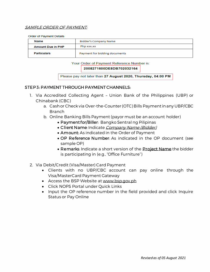
Revised as of 05 August 2021
SAMPLE ORDER OF PAYMENT:
STEP 3: PAYMENT THROUGH PAYMENT CHANNELS:
1. Via Accredited Collecting Agent – Union Bank of the Philippines (UBP) or Chinabank (CBC)
a. Cash or Check via Over-the-Counter (OTC) Bills Payment in any UBP/CBC Branch
b. Online Banking Bills Payment (payor must be an account holder) • Payment for/Biller: Bangko Sentral ng Pilipinas • Client Name: Indicate Company Name (Bidder) • Amount: As indicated in the Order of Payment • OP Reference Number: As indicated in the OP document (see
sample OP) • Remarks: Indicate a short version of the Project Name the bidder
is participating in (e.g., “Office Furniture”)
2. Via Debit/Credit (Visa/Master) Card Payment • Clients with no UBP/CBC account can pay online through the
Visa/MasterCard Payment Gateway • Access the BSP Website at www.bsp.gov.ph • Click NOPS Portal under Quick Links • Input the OP reference number in the field provided and click Inquire
Status or Pay Online
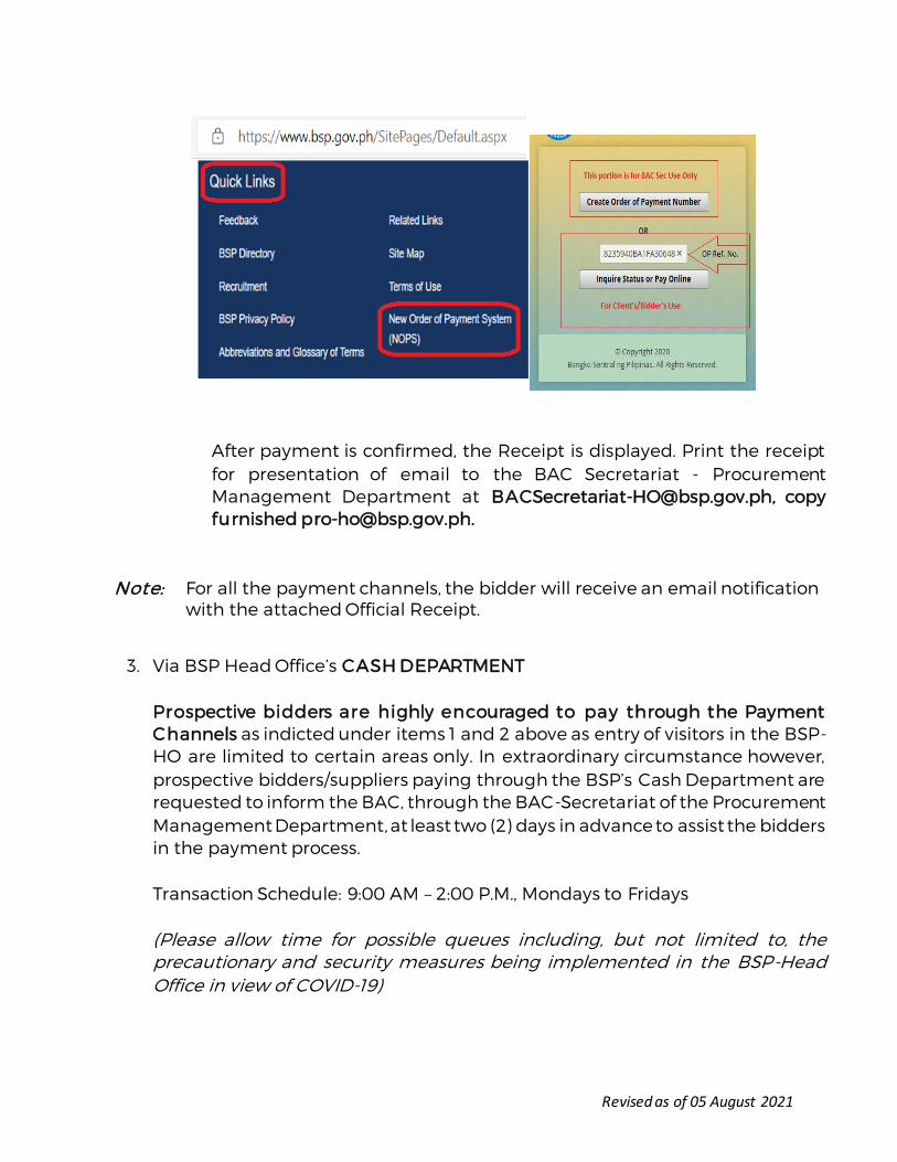
Revised as of 05 August 2021
After payment is confirmed, the Receipt is displayed. Print the receipt for presentation of email to the BAC Secretariat - Procurement Management Department at [email protected], copy furnished [email protected].
Note: For all the payment channels, the bidder will receive an email notification with the attached Official Receipt.
3. Via BSP Head Office’s CASH DEPARTMENT Prospective bidders are highly encouraged to pay through the Payment Channels as indicted under items 1 and 2 above as entry of visitors in the BSP-HO are limited to certain areas only. In extraordinary circumstance however, prospective bidders/suppliers paying through the BSP’s Cash Department are requested to inform the BAC, through the BAC-Secretariat of the Procurement Management Department, at least two (2) days in advance to assist the bidders in the payment process. Transaction Schedule: 9:00 AM – 2:00 P.M., Mondays to Fridays (Please allow time for possible queues including, but not limited to, the precautionary and security measures being implemented in the BSP-Head Office in view of COVID-19)
Revised as of 05 August 2021
STEP 4:
Submit a copy of proof of payment (i.e., Bills Payment Slip, screenshot of proof of online/mobile payment, or copy of the Official Receipt) to the BAC Secretariat prior to or together with the submission of bidding documents.
OTHER REMINDERS
1. The BSP does not issue Certification on the conduct of Conferences/Meetings and/or Submission and Opening of Bids for purposes of Checkpoint clearance. Prospective bidders may print the Invitation to Bid/Bid Bulletins/Advisories/Notices issued by the BSP showing the scheduled activities.
2. Additional queries, especially with regard to the procedures for the Microsoft Teams connection, may be submitted in advance to the BAC-Secretariat at [email protected], to allow BSP’s IT Group to respond accordingly.
ANNEX B
GUIDELINES IN THE CONDUCT OF PRE-BID CONFERENCE
1. With due observance of social distancing measures, when necessary, Pre-bid Conferences, whenever scheduled, shall refer to the conduct of face-to-face pre-bid conference, online
teleconferencing or videoconferencing. The date, time and online platform shall be stated in the procurement opportunity (i.e., Invitation to Bid, Request for Expression of Interest, etcetera) or in duly issued Bid Bulletin.
2. Prior to the scheduled pre-bid conference, prospective bidders shall signify their intention to participate in the scheduled pre-bid conference by submitting/registering their contact information and e-mails where the online invitation to participate shall be sent.
Prospective bidders who fail to participate in the pre-bid conference shall not be disqualified.
3. Participating bidders are highly encouraged to download the bidding documents from the BSP or PhilGEPS websites.
4. For expedient conduct of the Conference/Meeting, the bidders shall be expected to have read and sufficiently understood the issued bidding documents and requirements prior to the scheduled Conference/Meeting. Bidders may send their questions or requests for
clarification in advance at least one (1) day prior to the date of Pre-bid Conference/Meeting to [email protected] and to [email protected]. Participating bidders may also use the online messaging facility during the meeting, which
shall form part of the Minutes. The discussions will focus on the documentary requirements that need emphasis, as deemed necessary, and on the queries/clarifications received from the prospective bidders.
5. Those who were not able to participate in the pre-bid conference may still submit manual or electronic bids.
6. The minutes of the pre-bid conference shall be made available to the prospective bidders
not later than five (5) calendar days after the pre-bid conference, upon written request. The same shall likewise be posted in the website of the BSP.
INSTRUCTIONS ON CONNECTION TO MICROSOFT TEAMS
1. The conduct of Pre-bid Conference/Pre-Eligibility/Preliminary Meeting shall be through
online teleconferencing or videoconferencing using the Microsoft Teams platform. Please
be guided by the following:
Instructions to Participating Suppliers/Bidders
Participating bidders are requested to submit their contact information and email addresses to be used for the videoconferencing to [email protected], at least one (1) day before the conduct of activity for the sending of meeting invitation.
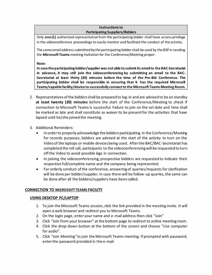
Instructions to Participating Suppliers/Bidders
Only one (1) authorized representative from the participating bidder shall have access privilege
in the videoconference proceedings to easily monitor and facilitate the conduct of the activity.
The same email address submitted by the participating bidder shall be used by the BSP in sending the Microsoft Teams meeting invitation for the Conference/Meeting proper.
Note: In case the participating bidder/supplier was not able to submit its email to the BAC-Secretariat in advance, it may still join the videoconferencing by submitting an email to the BAC-Secretariat at least thirty (30) minutes before the time of the Pre-Bid Conference. The participating bidder shall be responsible in ensuring that it has the required Microsoft Teams/capable facility/device to successfully connect to the Microsoft Teams Meeting Room.
2. Representatives of the bidders shall be prepared to log-in and are advised to be on standby
at least twenty (20) minutes before the start of the Conference/Meeting to check if
connection to Microsoft Teams is successful. Failure to join on the set date and time shall be marked as late and shall constitute as waiver to be present for the activities that have lapsed until he/she joined the meeting.
3. Additional Reminders:
• In order to properly acknowledge the bidders participating in the Conference/Meeting for records purposes, bidders are advised at the start of the activity to turn on the
Video of the laptops or mobile devices being used. After the BAC/BAC-Secretariat has completed the roll call, participants to the videoconferencing will be requested to turn off the Video to avoid possible lags in connection.
• In joining the videoconferencing, prospective bidders are requested to indicate their respective full/complete name and the company being represented.
• For orderly conduct of the conference, answering of queries/requests for clarification will be done per bidder/supplier. In case there will be follow-up queries, the same can be done after all the bidders/suppliers have been called.
CONNECTION TO MICROSOFT TEAMS FACILITY
USING DESKTOP PC/LAPTOP
1. To join the Microsoft Teams session, click the link provided in the meeting invite. It will open a web browser and redirect you to Microsoft Teams.
2. On the login page, enter your name and e-mail address then click “Join”
3. Click “Join from your browser” at the bottom page to redirect to online meeting room. 4. Click the drop-down button at the bottom of the screen and choose “Use computer
for audio”.
5. Click “Join Meeting” to join the Microsoft Teams meeting. If prompted with password, enter the password provided in the e-mail.
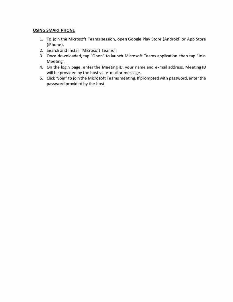
USING SMART PHONE
1. To join the Microsoft Teams session, open Google Play Store (Android) or App Store (iPhone).
2. Search and Install “Microsoft Teams”. 3. Once downloaded, tap “Open” to launch Microsoft Teams application then tap “Join
Meeting”.
4. On the login page, enter the Meeting ID, your name and e-mail address. Meeting ID will be provided by the host via e-mail or message.
5. Click “Join” to join the Microsoft Teams meeting. If prompted with password, enter the password provided by the host.

ANNEX C
GUIDELINES IN THE SUBMISSION OF BIDS (MANUAL AND ELECTRONIC) AND OPENING OF BIDS
Prospective bidders have the option to submit their bids MANUALLY (physical or hard copy) OR ELECTRONICALLY (online transmittal). However, bidders cannot avail of both methods. MANUAL SUBMISSION OF BIDS:
1. The address for submission of hard copy of bids is at Gate 3, Bangko Sentral ng Pilipinas, A. Mabini, corner P. Ocampo Sr. Sts., Malate, Manila. Bid boxes are situated at the reception area of Gate 3 where bids can be dropped.
2. As precautionary measure, participating bidders are strongly advised to wrap/enclose their
respective bidding documents with plastic, preferably clear, to facilitate
disinfection/sanitation and quick evaluation on the proper sealing and marking of bid envelopes.
3. The schedule of the submission of bidding documents/eligibility documents/BAFO shall be
on the date and time as indicated in the Invitation to Bid/Request for Expression of Intere st or Bid Bulletins issued. Bidders are advised to submit their documents at least thirty (30) minutes before the scheduled deadline of submission to allow time for possible queuing due
to conduct of thermal scanning, and for sanitation of the bid envelope(s) and transit of the documents to the designated bidding room.
4. As social distancing measure, Bid Box(es) will be strategically placed at Gate 3 of BSP-HO for dropping/submission of bid documents.
5. The representative of the bidder or courier service provider shall fill-up the Bid Submission Form available at the reception area at Gate 3 which shall be attached to the bid documents to be submitted.
6. The procedures on the submission of bids under the 2016 Revised Implementing Rules and
Regulations of Republic Act No. 9184 (2016 Revised IRR) shall continue to be observed.
Note: Pursuant to Section 25.9 of the 2016 Revised IRR of RA No. 9184, Unsealed and/or Unmarked bids shall be rejected.
ELECTRONIC SUBMISSION OF BIDS
A. ELECTRONIC SUBMISSION (E-DOCUMENTS) COMPRISING THE BID
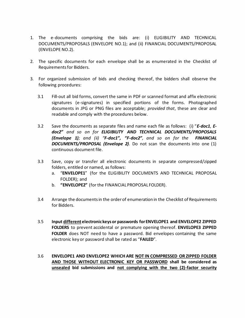
1. The e-documents comprising the bids are: (i) ELIGIBILITY AND TECHNICAL
DOCUMENTS/PROPOSALS (ENVELOPE NO.1); and (ii) FINANCIAL DOCUMENTS/PROPOSAL (ENVELOPE NO.2).
2. The specific documents for each envelope shall be as enumerated in the Checklist of Requirements for Bidders.
3. For organized submission of bids and checking thereof, the bidders shall observe the
following procedures: 3.1 Fill-out all bid forms, convert the same in PDF or scanned format and affix electronic
signatures (e-signatures) in specified portions of the forms. Photographed documents in JPG or PNG files are acceptable; provided that, these are clear and readable and comply with the procedures below.
3.2 Save the documents as separate files and name each file as follows: (i) “E-doc1, E-
doc2” and so on for ELIGIBILITY AND TECHNICAL DOCUMENTS/PROPOSALS
(Envelope 1); and (ii) “F-doc1”, “F-doc2”, and so on for the FINANCIAL DOCUMENTS/PROPOSAL (Envelope 2). Do not scan the documents into one (1) continuous document file.
3.3 Save, copy or transfer all electronic documents in separate compressed/zipped
folders, entitled or named, as follows: a. “ENVELOPE1” (for the ELIGIBILITY DOCUMENTS AND TECHNICAL PROPOSAL
FOLDER); and b. “ENVELOPE2” (for the FINANCIAL PROPOSAL FOLDER).
3.4 Arrange the documents in the order of enumeration in the Checklist of Requirements for Bidders.
3.5 Input different electronic keys or passwords for ENVELOPE1 and ENVELOPE2 ZIPPED FOLDERS to prevent accidental or premature opening thereof. ENVELOPE3 ZIPPED
FOLDER does NOT need to have a password. Bid envelopes containing the same electronic key or password shall be rated as “FAILED”.
3.6 ENVELOPE1 AND ENVELOPE2 WHICH ARE NOT IN COMPRESSED OR ZIPPED FOLDER AND THOSE WITHOUT ELECTRONIC KEY OR PASSWORD shall be considered as unsealed bid submissions and not complying with the two (2)-factor security

procedure,2 and hence, shall be rejected during the opening of bids. However, bid envelopes that are not properly compressed and password-protected, as required in the Bidding Documents, shall be accepted, provided that the bidder or its duly authorized representative shall acknowledge such condition of the bid as submitted.
The BAC shall assume no responsibility for the misplacement of the contents of the
improperly compressed or password-protected folder, or for its premature opening.3
3.7 Zipped electronic bid folders to be submitted can be opened using the 7-zip compression tool.
3.8 Ensure that the bid envelopes are compressed and password-protected. In case the submitted electronic bid envelopes are not in compressed format and/or not password protected, the bidder may submit new electronic bid envelopes which shall
be considered as “modification” of bids, following the procedures under Section 7.6 of herein Guidelines.
3.9 Compressed or zipped folder and password protected electronic bid documents should be submitted to [email protected] prior to the time of bid opening. Bidders are encouraged to submit the electronic bid documents at least
two (2) hours prior to the time of bid opening in order to ensure receipt of documents by the BAC-Secretariat within the deadline set for the submission of bids
3.10 The bidder should receive an Electronic Acknowledgement Receipt (EAR) in every successful submission of electronic bid documents as proof that its bid/s had/have been received by the Bid Recipient. Kindly contact the Bid Recipient (BAC Secretariat)
in case no EAR was received within thirty (30) minutes from sending.
3.11 In case of email bounce or quarantine notification, the bidder shall immediately send an email to the BAC Secretariat (as indicated in the Bid Data Sheet), with the subject
matter – SENDING BOUNCED; SENDING QUARANTINED – (name of bidder) and append a screen shot of the notification or forward the message indicating that the email had not been received.
2 As required under GPPB Resolution No. 09-2020, Section 4.2 which provides:
“Bid submission may be done through any electronic means available to the [Procuring Entities], provided that the same:
a. Uses a two-factor security procedure consisting of an archive format compression and password protection to ensure the security,
integrity and confidentiality of the bids submitted; xxx. 3 Pursuant to GPPB-Resolution No. 09-2020, which revised Section 25.9 of the 2016 Revised IRR.

For inquiries on the submission and dropping of bids/eligibility documents/BAFO, the BAC-Secretariat may be reached at (632)(5)306-2798/2800/3075.
B. ELECTRONIC SIGNATURE
1. Whenever required in specified portions of the response or bid forms, particularly in the
FINANCIAL PROPOSAL E-DOCUMENTS, the e-signature of the Bidder or the Bidder’s
Authorized Representative shall be affixed in the document. 2. The scanned actual signature of the authorized representative of the prospective bidder,
cropped and pasted handwritten signatures, adobe-created signatures, unique figures and symbols and stamped signatures are ACCEPTABLE as e-signatures. Provided, that original documents not using digital signatures shall be transmitted during contract execution.
However, text-typing the name of the bidder and/or the words “SGD. or ORIGINAL SIGNED” and the like without distinctive features are NOT ACCEPTABLE.
3. An electronically signed document submitted by the bidder shall be presumed to belong to that of the bidder if signed by its duly authorized representative and sent to the e -mail of
the Bid Recipient. C. TIME AND MANNER OF SENDING AND RECEIPT OF E-DOCUMENTS
1. The deadline for the submission of bids shall observe the time indicated in the official
website of BSP.
2. The actual time of bid submission shall be the “time received” by the Bid Recipient as
indicated in the Electronic Acknowledgment Receipt (EAR). In case of delayed time stamp in
the EAR, the bidder shall inform the BAC- Secretariat that the e-mail was sent before the deadline for submission of bids. The Bid Recipient shall seek the assistance of the BSP-Information Technology (BSP-IT) in validating the actual time of receipt by the BSP e-mail gateway server. The bidder may also call/inquire with the BAC-Secretariat to confirm if
sending has been successful in case no EAR has been received within thirty (30) minutes from sending.
3. The designated Bid Recipient shall have an EAR to document official receipt of the bid submission. The EAR or e-mail acknowledgment shall serve as proof by the bidder that its bid had been received by the Bid Recipient. Without an EAR, the bidder shall immediately
contact the Bid Recipient or the BAC Secretariat. The EAR shall be evidence ONLY of the electronic bid submission and receipt thereof, and NOT of the completeness, correctness and veracity of the contents of the electronic bid, which shall be determined during
preliminary examination of bids, bid evaluation and/or post-qualification. It is also the responsibility of the bidder to ensure that the e-mail to be sent contains the required attachments.
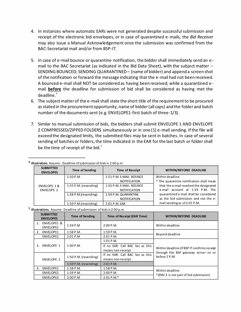
4. In instances where automatic EARs were not generated despite successful submission and receipt of the electronic bid envelopes, or in case of quarantined e -mails, the Bid Receiver
may also issue a Manual Acknowledgement once the submission was confirmed from the BAC-Secretariat mail and/or from BSP-IT.
5. In case of e-mail bounce or quarantine notification, the bidder shall immediately send an e-mail to the BAC Secretariat (as indicated in the Bid Data Sheet), with the subject matter – SENDING BOUNCED; SENDING QUARANTINED – (name of bidder) and append a screen shot of the notification or forward the message indicating that the e-mail had not been received.
A bounced e-mail shall NOT be considered as having been received; while a quarantined e -mail before the deadline for submission of bid shall be considered as having met the
deadline.4
6. The subject matter of the e-mail shall state the short title of the requirement to be procured as stated in the procurement opportunity, name of bidder (all caps) and the folder and batch
number of the documents sent (e.g. ENVELOPE1-first batch of three-1/3).
7. Similar to manual submission of bids, the bidders shall submit ENVELOPE 1 AND ENVELOPE
2 COMPRESSED/ZIPPED FOLDERS simultaneously or in one (1) e-mail sending. If the file will exceed the designated limits, the submitted files may be sent in batches. In case of several sending of batches or folders, the time indicated in the EAR for the last batch or folder shall
be the time of receipt of the bid.5
4 Illustration. Assume: Deadline of submission of bids is 2:00 p.m.
SUBMITTED
ENVELOPES Time of Sending Time of Receipt WITHIN/BEYOND DEADLINE
ENVELOPE 1 & ENVELOPE 2
1:50 P.M. 1:51 P.M. E-MAIL BOUNCE
NOTIFICATION
Within deadline
* The quarantine notification shall mean
that the e-mail reached the designated e-mail account at 1:59 P.M. The
quarantined e-mail shall be considered
as the bid submission and not the e-
mail sending as of 2:01 P.M.
1:55 P.M. (resending) 1:55 P.M. E-MAIL BOUNCE
NOTIFICATION
1:58 P.M.(resending) 1:59 P.M. QUARANTINE
NOTIFICATION
1:59 P.M.(resending) 2:01 P.M. EAR
5 Illustrations. Assume: Deadline of submission of bids is 2:00 p.m.
SUBMITTED ENVELOPES
Time of Sending Time of Receipt (EAR Time) WITHIN/BEYOND DEADLINE
1. ENVELOPE1 & ENVELOPE2
1:59 P.M 2:00 P.M. Within deadline
2. ENVELOPE1 1:58 P.M. 1:59 P.M. Beyond deadline
ENVELOPE2 2:01 P.M 2:01 P.M.
3. ENVELOPE 1 1:00 P.M.
1:01 P.M.
Within deadline (if BSP IT confirms receipt
through the BSP gateway server on or before 2 P.M.
If no EAR: Call BAC Sec as this
means non-receipt
ENVELOPE 2 1:50 P.M. (resending)
If no EAR: Call BAC Sec as this
means non-receipt
1:59 P.M. (resending) 2:01 P.M.
4. ENVELOPE1 1:58 P.M. 1:58 P.M. Within deadline
*(ENV.3 is not part of bid submission) ENVELOPE2 1:59 P.M. 2:00 P.M.
ENVELOPE3 2:00 P.M 2:01 P.M.*
8. To avoid the tampering or alteration of electronic documents, files shall be sent as
attachment/s to the e-mail and not through a file sharing link. All eligibility and technical documents/proposals bid documents must be submitted as one file including the required brochures, manuals, etc., unless such submission will exceed the file size limit.
9. The BSP system can accommodate attachments with file size limit of up to 100MB. If the
bidder’s e-mail has a smaller file size limit (e.g., in case of free mails, such as gmail and yahoomail), it may send files in batches.
10. Bidders shall submit their bids to the e-mail of Bid Recipient as indicated in the posted
procurement opportunity. It is encouraged that submissions be made at least two (2) hours
prior to the time of bid opening in order to ensure receipt of documents by the Bid Recipient within the deadline set for the submission of bids.
D. MODIFICATION AND WITHDRAWAL OF BIDS
1. As with manual submission, bidders may modify or withdraw their bid at any time before
the deadline for the submission and receipt of bids. Where a bidder modifies its bid, it shall not be allowed to retrieve its original bid and shall only be allowed to submit another. For electronic bid submission, bidders shall send another bid equally secure d, properly identified, and labelled as a “modification” of the one previously submitted. The time
indicated in the latest electronic acknowledgment receipt (EAR) shall be the official time of submission. Bids submitted after the deadline shall not be accepted.
2. In modifying the bid, the bidder may send the ENTIRE FILE/S or FOLDER/S or the particular document being modified. Bidders modifying their bids shall still observe the manner of submission of the original bid or particular document being modified.
3. Bid documents submitted electronically can only be modified electronically. In the same
manner, bids submitted manually can only be modified manually. Manual bid modification
shall follow the procedures provided for under Section 26 of Rep. Act No. 9184 and its IRR.
4. For various sending or re-sending of electronic bids from the same bidder or from different Bidder’s Authorized Representatives, the LATEST SENDING meeting the deadline for the submission of bids shall be construed as the submitted bid, it being the manifestation of
the latest intent of the bidder.
OPENING OF BIDS
A. ATTENDANCE AND PRELIMINARIES 1. Bidders shall be prepared to login in the tele/videoconferencing facility of the BSP at least
twenty (20) minutes before the scheduled deadline and opening of bids. Failure to join on
the set date and time shall be marked as late and shall constitute a waiver to be present for the activities that have lapsed until he/she joined the meeting.
2. Only one (1) bidder’s authorized representative shall have access privilege to participate in
the tele/videoconference proceedings. However, depending on the nature of item being
procured, additional representatives may be allowed (e.g., when local and principal firms will be attending the pre-bid conference or in case of joint ventures).
3. Representatives of the bidders shall be prepared to login and are advised to be on standby
at least twenty (20) minutes before the scheduled deadline and opening of bids to check if connection to Microsoft Teams is successful. Failure to join on the set date and time shall be marked as late and shall constitute a waiver to be present for the activities that have
lapsed until he/she joined the meeting. The bidder cannot question activities that were conducted in his/her absence.
4. Immediately after the stated deadline for submission of bids, but before the opening thereof, the Bid Recipient shall provide access to the electronic documents submitted by all bidders to the account processor/s who had been designated as the Bid Opener/s. To
facilitate the conduct of the opening of electronic bid documents and to address access issues by the Bid Opener/s, if any, access may also be given to the Bid Opener/s thirty (30) minutes before the schedule of opening of bids.
5. The BAC Secretariat shall proceed with the roll call to record the attendance and determine
the presence of a quorum.
6. Thereafter, the BAC shall officially announce the start of the bid opening.
B. INSTRUCTIONS ON CONNECTION TO MICROSOFT TEAMS PLATFORM
1. The conduct of opening of bids/eligibility documents/BAFO shall be through
videoconferencing using the Microsoft Teams platform. Please be guided by the following:
Instructions to Participating Suppliers/Bidders
Participating bidders are requested to submit their contact information and email addresses to be used for the videoconferencing to [email protected] at least one (1) day before the scheduled meeting necessary for the sending of meeting invitation. Only one (1) authorized representative from the participating bidder shall have access privilege in the videoconference proceedings to easily monitor and facilitate the conduct of the activity. The same email address submitted by the participating shall be used by the BSP in sending the Microsoft Teams meeting invitation for the Opening of Bids proper.
Instructions to Participating Suppliers/Bidders
Note: In case the participating bidder/supplier was not able to submit its email to the BAC-Secretariat in advance, it may still join the videoconferencing by submitting an email to the BAC-Secretariat at least thirty (30) minutes before the time of the Opening of Bids. The participating bidder shall be responsible in ensuring that it has the required Microsoft Teams application/capable facility/device to successfully connect to the Microsoft Teams Meeting Room.
C. CONNECTION TO MICROSOFT TEAMS PLATFORM
USING DESKTOP PC/LAPTOP
a. To join the Microsoft Teams session, click the link provided in the meeting invite. It
will open a web browser and redirect you to Microsoft Teams. b. On the login page, enter your name and e-mail address then click “Join”
c. Click “Join from your browser” at the bottom page to redirect to online meeting room.
d. Click the drop-down button at the bottom of the screen and choose “Use computer
for audio”. e. Click “Join Meeting” to join the Microsoft Teams meeting. If prompted with
password, enter the password provided in the e-mail.
USING SMART PHONE
a. To join the Microsoft Teams session, open Google Play Store (Android) or App Store (iPhone).
b. Search and Install “Microsoft Teams”.
c. Once downloaded, tap “Open” to launch Microsoft Teams application then tap “Join Meeting”.
d. On the login page, enter the Meeting ID, your name and e-mail address. Meeting ID will be provided by the host via e-mail or message.
e. Click “Join” to join the Microsoft Teams meeting. If prompted with password, enter the password provided by the host.
D. OPENING OF ELIGIBILITY AND TECHNICAL DOCUMENTS (Envelope No. 1)
1. The BAC Secretariat shall announce the list of participating bidders and their respective
mode of submission of bids, i.e., electronic or manual. Manually submitted bids shall be opened first before the electronically submitted bids.
2. The BAC Chairperson shall then motion to open and conduct eligibility check, examination of technical documents and recording of the manually submitted bid/s, if any.
3. While opening of manually submitted bids is ongoing, the BAC Chairperson shall give the
go-signal for sending of the password for “ENVELOPE1” by the online bidders, through
online chat or thru e-mail directly to the BAC, BAC Secretariat and Bid Opener/s.
4. After receipt of the password for “ENVELOPE1”, the electronic documents shall be opened. If ENVELOPE1 cannot be opened by anyone, the bidder shall be permitted to re -submit its password up to a maximum of three (3) chances, WITHOUT SENDING ANOTHER FILE and
only while the proceeding for opening of ENVELOPE NO. 1 is still ongoing.
5. Electronic bid folders shall automatically undergo virus or malware scanning. If “cleaning” of the electronic documents by the existing BSP anti-virus system is successful, the said documents can be accepted and opened. Otherwise, the bid shall be declared as
“FAILED”. Disqualification of the bid shall also apply for those bid submissions which already have undergone “cleaning” but certain pages turned-out to be corrupted. Thus, if the e-document could not be opened, is corrupted or truncated or infected by a virus or
malware even if scanned, the e-document shall be rated as “FAILED”.
6. The Bid Opener/s shall confirm receipt of particular e-documents by enumerating them in the order that they are received. The bidders shall have the opportunity to confirm or raise questions on the enumeration of documents.
7. In order to ensure that the electronic bid envelopes submitted through e -mail are the
same electronic bid envelopes being opened, the file properties of the bid envelopes may be shown to the bidders before the actual opening thereof.
8. Thereafter, the checking of eligibility and technical documents and recording of e -documents shall be undertaken by the Bid Opener/s in accordance with the procedure for preliminary examination of bids under Section 30 of the IRR.
9. As similarly observed during the manual submission of bids, Bid Opener/s shall indicate
his/her readiness to make a presentation of the opened eligibility and technical documents and be allowed by the BAC Chairperson to proceed.
10. Details of each document received shall be read by the Bid Opener and flashed on screen. Bidders may raise questions on the documents.
11. The BAC Chairperson shall announce the names of the bidders whose bids have been rated
as “PASSED”. Bidders whose eligibility and technical documents/proposals have been rated “PASSED” shall be on stand-by for the opening of the Financial Documents. Bidders whose eligibility documents were rated “FAILED” may remain as observers.

E. OPENING AND EVALUATION OF FINANCIAL DOCUMENTS (Envelope No. 2)
1. Manually submitted financial proposals shall be opened first before electronically submitted proposals.
2. The BAC Chairperson shall then motion to open and conduct preliminary evaluation and
recording of the manually submitted financial proposal, if any.
3. The eligible bidders shall then send the password for “ENVELOPE2” in the same manner
that passwords were sent for “ENVELOPE1”.
4. After receipt, the Bid Opener/s shall then proceed to open the Financial Proposals of the
eligible bidders.
5. The same procedures in “ENVELOPE1” shall be observed in the presentation or reading of
“ENVELOPE2”.
6. After each presentation, the Bid Opener shall enumerate and present the submitted financial proposals of the Bidders from the lowest to the highest bid.
7. If there are no issues involved, the BAC Chairperson shall adjourn the conduct of examination of bids and excuse the participating bidders. The Abstract of Bids as read, and the minutes of the bid opening shall be prepared and be made available to the
participating bidders and the public upon written request.
8. The BAC may proceed with the conduct of detailed evaluation of bids on the same day as the bid opening date, or set the conduct of bid evaluation to another date and time pursuant to Sections 32 and 33 of the 2016 Revised IRR.
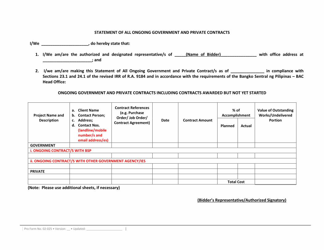
Pro Form No. 02-025 • Version: __ • Updated: ______________________ ]
STATEMENT OF ALL ONGOING GOVERNMENT AND PRIVATE CONTRACTS
I/We _____________________, do hereby state that:
1. I/We am/are the authorized and designated representative/s of _____(Name of Bidder)________________ with office address at ______________________; and
2. I/we am/are making this Statement of All Ongoing Government and Private Contract/s as of _______________ in compliance with
Sections 23.1 and 24.1 of the revised IRR of R.A. 9184 and in accordance with the requirements of the Bangko Sentral ng Pilipinas – BAC Head Office:
ONGOING GOVERNMENT AND PRIVATE CONTRACTS INCLUDING CONTRACTS AWARDED BUT NOT YET STARTED
Project Name and Description
a. Client Name b. Contact Person; c. Address; d. Contact Nos.
(landline/mobile number/s and email address/es)
Contract References
(e.g. Purchase Order/ Job Order/
Contract Agreement)
Date
Contract Amount
% of
Accomplishment
Value of Outstanding Works/Undelivered
Portion Planned
Actual
GOVERNMENT
i. ONGOING CONTRACT/S WITH BSP
ii. ONGOING CONTRACT/S WITH OTHER GOVERNMENT AGENCY/IES
PRIVATE
Total Cost
(Note: Please use additional sheets, if necessary)
(Bidder’s Representative/Authorized Signatory)
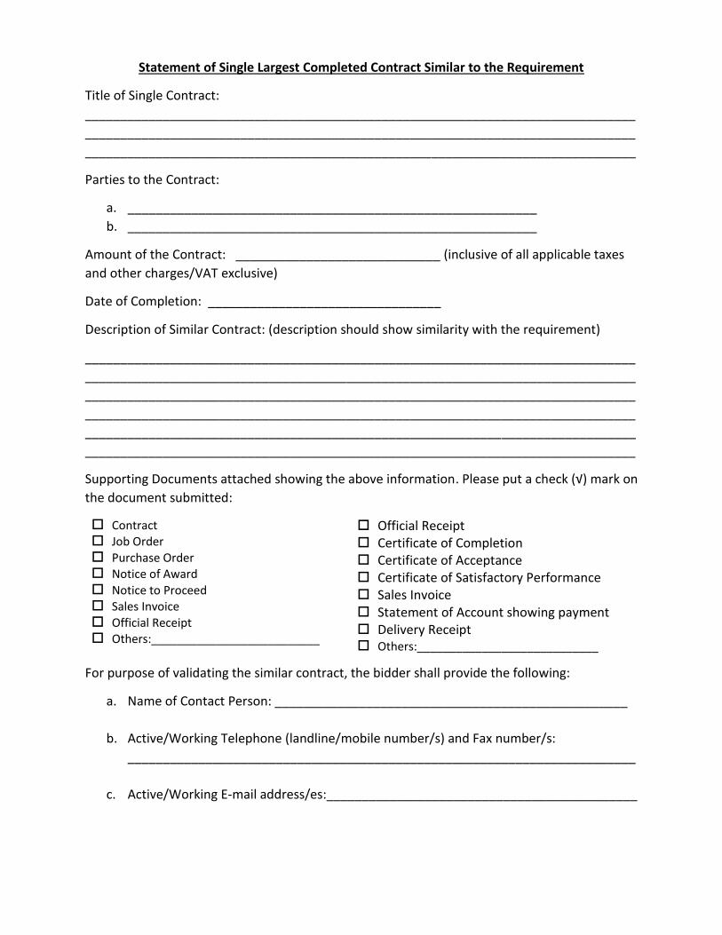
Statement of Single Largest Completed Contract Similar to the Requirement
Title of Single Contract:
______________________________________________________________________________
______________________________________________________________________________
______________________________________________________________________________
Parties to the Contract:
a. __________________________________________________________
b. __________________________________________________________
Amount of the Contract: _____________________________ (inclusive of all applicable taxes
and other charges/VAT exclusive)
Date of Completion: _________________________________
Description of Similar Contract: (description should show similarity with the requirement)
______________________________________________________________________________
______________________________________________________________________________
______________________________________________________________________________
______________________________________________________________________________
______________________________________________________________________________
______________________________________________________________________________
Supporting Documents attached showing the above information. Please put a check (√) mark on
the document submitted:
Contract Job Order Purchase Order Notice of Award Notice to Proceed Sales Invoice Official Receipt Others:__________________________
Official Receipt Certificate of Completion Certificate of Acceptance Certificate of Satisfactory Performance Sales Invoice Statement of Account showing payment Delivery Receipt Others:____________________________
For purpose of validating the similar contract, the bidder shall provide the following:
a. Name of Contact Person: __________________________________________________
b. Active/Working Telephone (landline/mobile number/s) and Fax number/s:
________________________________________________________________________
c. Active/Working E-mail address/es:____________________________________________
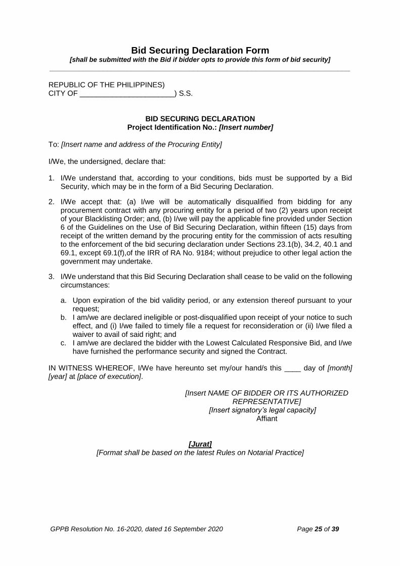
GPPB Resolution No. 16-2020, dated 16 September 2020 Page 25 of 39
Bid Securing Declaration Form [shall be submitted with the Bid if bidder opts to provide this form of bid security]
_________________________________________________________________________
REPUBLIC OF THE PHILIPPINES) CITY OF _______________________) S.S.
BID SECURING DECLARATION Project Identification No.: [Insert number]
To: [Insert name and address of the Procuring Entity] I/We, the undersigned, declare that:
1. I/We understand that, according to your conditions, bids must be supported by a Bid Security, which may be in the form of a Bid Securing Declaration.
2. I/We accept that: (a) I/we will be automatically disqualified from bidding for any procurement contract with any procuring entity for a period of two (2) years upon receipt of your Blacklisting Order; and, (b) I/we will pay the applicable fine provided under Section 6 of the Guidelines on the Use of Bid Securing Declaration, within fifteen (15) days from receipt of the written demand by the procuring entity for the commission of acts resulting to the enforcement of the bid securing declaration under Sections 23.1(b), 34.2, 40.1 and 69.1, except 69.1(f),of the IRR of RA No. 9184; without prejudice to other legal action the government may undertake.
3. I/We understand that this Bid Securing Declaration shall cease to be valid on the following circumstances:
a. Upon expiration of the bid validity period, or any extension thereof pursuant to your request;
b. I am/we are declared ineligible or post-disqualified upon receipt of your notice to such effect, and (i) I/we failed to timely file a request for reconsideration or (ii) I/we filed a waiver to avail of said right; and
c. I am/we are declared the bidder with the Lowest Calculated Responsive Bid, and I/we have furnished the performance security and signed the Contract.
IN WITNESS WHEREOF, I/We have hereunto set my/our hand/s this ____ day of [month] [year] at [place of execution].
[Insert NAME OF BIDDER OR ITS AUTHORIZED REPRESENTATIVE]
[Insert signatory’s legal capacity] Affiant
[Jurat] [Format shall be based on the latest Rules on Notarial Practice]
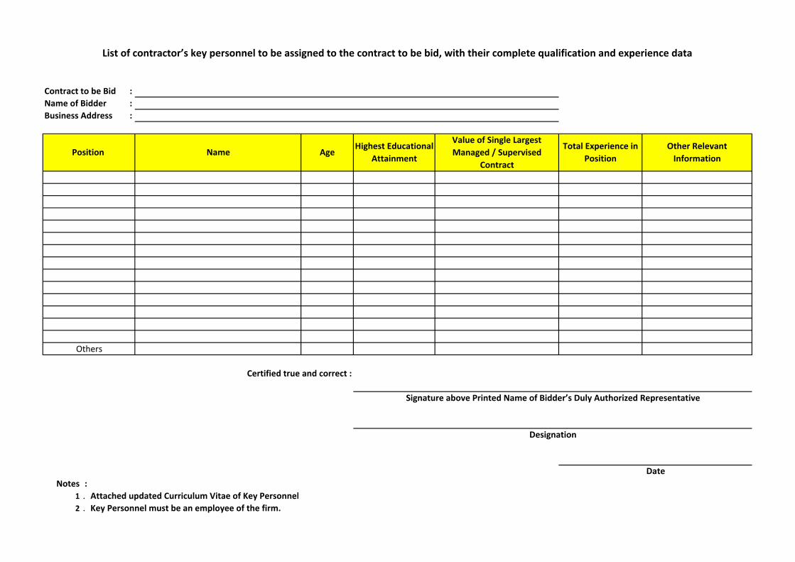
Contract to be Bid :
Name of Bidder :
Business Address :
:
1 . Attached updated Curriculum Vitae of Key Personnel
2 . Key Personnel must be an employee of the firm.
Position
List of contractor’s key personnel to be assigned to the contract to be bid, with their complete qualification and experience data
Value of Single Largest
Managed / Supervised
Contract
Total Experience in
Position
Notes
Other Relevant
InformationName Age
Highest Educational
Attainment
Certified true and correct :
Date
Others
Signature above Printed Name of Bidder’s Duly Authorized Representative
Designation
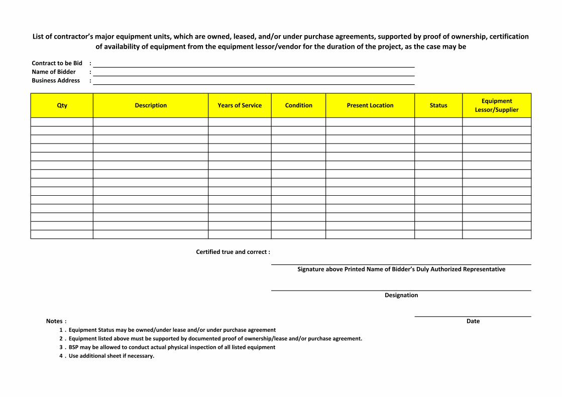
Contract to be Bid :
Name of Bidder :
Business Address :
:
1 . Equipment Status may be owned/under lease and/or under purchase agreement
2 . Equipment listed above must be supported by documented proof of ownership/lease and/or purchase agreement.
3 . BSP may be allowed to conduct actual physical inspection of all listed equipment
4 . Use additional sheet if necessary.
Present Location StatusEquipment
Lessor/SupplierDescription Years of Service ConditionQty
List of contractor’s major equipment units, which are owned, leased, and/or under purchase agreements, supported by proof of ownership, certification
of availability of equipment from the equipment lessor/vendor for the duration of the project, as the case may be
Notes
Signature above Printed Name of Bidder’s Duly Authorized Representative
Certified true and correct :
Designation
Date
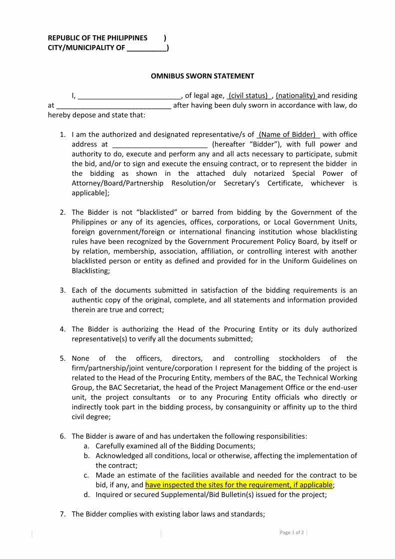
Page 1 of 2
Pro Form No. 02-026 • Version: 0 • Updated: 29 June 2012
REPUBLIC OF THE PHILIPPINES ) CITY/MUNICIPALITY OF __________)
OMNIBUS SWORN STATEMENT
I, __________________________, of legal age, (civil status) , (nationality) and residing at _____________________________ after having been duly sworn in accordance with law, do hereby depose and state that:
1. I am the authorized and designated representative/s of (Name of Bidder) with office address at ________________________ (hereafter “Bidder”), with full power and authority to do, execute and perform any and all acts necessary to participate, submit the bid, and/or to sign and execute the ensuing contract, or to represent the bidder in the bidding as shown in the attached duly notarized Special Power of Attorney/Board/Partnership Resolution/or Secretary’s Certificate, whichever is applicable];
2. The Bidder is not “blacklisted” or barred from bidding by the Government of the Philippines or any of its agencies, offices, corporations, or Local Government Units, foreign government/foreign or international financing institution whose blacklisting rules have been recognized by the Government Procurement Policy Board, by itself or by relation, membership, association, affiliation, or controlling interest with another blacklisted person or entity as defined and provided for in the Uniform Guidelines on Blacklisting;
3. Each of the documents submitted in satisfaction of the bidding requirements is an
authentic copy of the original, complete, and all statements and information provided therein are true and correct;
4. The Bidder is authorizing the Head of the Procuring Entity or its duly authorized representative(s) to verify all the documents submitted;
5. None of the officers, directors, and controlling stockholders of the firm/partnership/joint venture/corporation I represent for the bidding of the project is related to the Head of the Procuring Entity, members of the BAC, the Technical Working Group, the BAC Secretariat, the head of the Project Management Office or the end-user unit, the project consultants or to any Procuring Entity officials who directly or indirectly took part in the bidding process, by consanguinity or affinity up to the third civil degree;
6. The Bidder is aware of and has undertaken the following responsibilities:
a. Carefully examined all of the Bidding Documents; b. Acknowledged all conditions, local or otherwise, affecting the implementation of
the contract; c. Made an estimate of the facilities available and needed for the contract to be
bid, if any, and have inspected the sites for the requirement, if applicable; d. Inquired or secured Supplemental/Bid Bulletin(s) issued for the project;
7. The Bidder complies with existing labor laws and standards;
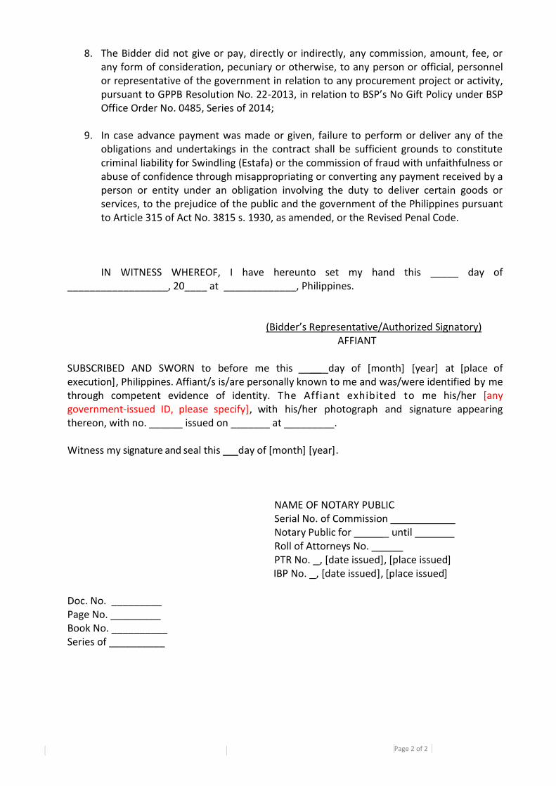
Page 2 of 2
Pro Form No. 02-026 • Version: 0 • Updated: 29 June 2012
8. The Bidder did not give or pay, directly or indirectly, any commission, amount, fee, or any form of consideration, pecuniary or otherwise, to any person or official, personnel or representative of the government in relation to any procurement project or activity, pursuant to GPPB Resolution No. 22-2013, in relation to BSP’s No Gift Policy under BSP Office Order No. 0485, Series of 2014;
9. In case advance payment was made or given, failure to perform or deliver any of the obligations and undertakings in the contract shall be sufficient grounds to constitute criminal liability for Swindling (Estafa) or the commission of fraud with unfaithfulness or abuse of confidence through misappropriating or converting any payment received by a person or entity under an obligation involving the duty to deliver certain goods or services, to the prejudice of the public and the government of the Philippines pursuant to Article 315 of Act No. 3815 s. 1930, as amended, or the Revised Penal Code.
IN WITNESS WHEREOF, I have hereunto set my hand this _____ day of __________________, 20____ at _____________, Philippines. (Bidder’s Representative/Authorized Signatory) AFFIANT SUBSCRIBED AND SWORN to before me this __ day of [month] [year] at [place of execution], Philippines. Affiant/s is/are personally known to me and was/were identified by me through competent evidence of identity. The Affiant exhibited to me his/her [any government-issued ID, please specify], with his/her photograph and signature appearing thereon, with no. ______ issued on _______ at _________. Witness my signature and seal this day of [month] [year].
NAME OF NOTARY PUBLIC Serial No. of Commission Notary Public for _ until Roll of Attorneys No. PTR No. , [date issued], [place issued] IBP No. , [date issued], [place issued]
Doc. No. _________ Page No. _________ Book No. __________ Series of __________
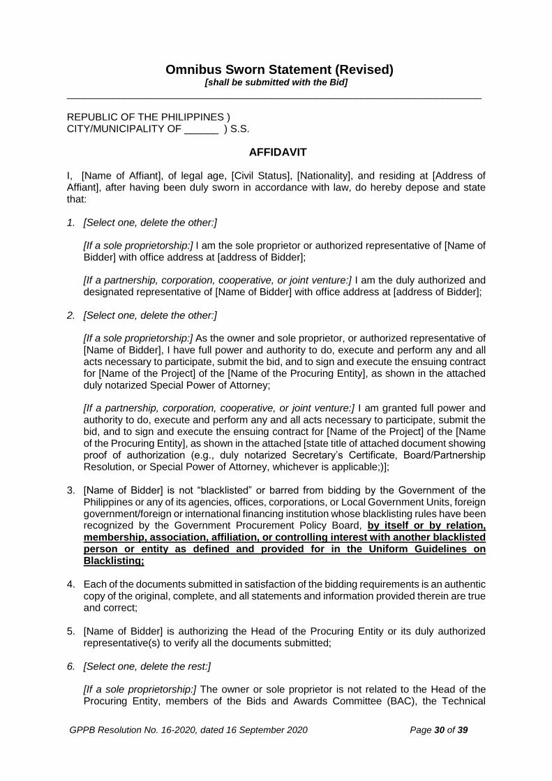
GPPB Resolution No. 16-2020, dated 16 September 2020 Page 30 of 39
Omnibus Sworn Statement (Revised) [shall be submitted with the Bid]
_________________________________________________________________________ REPUBLIC OF THE PHILIPPINES ) CITY/MUNICIPALITY OF ______ ) S.S.
AFFIDAVIT
I, [Name of Affiant], of legal age, [Civil Status], [Nationality], and residing at [Address of Affiant], after having been duly sworn in accordance with law, do hereby depose and state that: 1. [Select one, delete the other:]
[If a sole proprietorship:] I am the sole proprietor or authorized representative of [Name of Bidder] with office address at [address of Bidder];
[If a partnership, corporation, cooperative, or joint venture:] I am the duly authorized and designated representative of [Name of Bidder] with office address at [address of Bidder];
2. [Select one, delete the other:]
[If a sole proprietorship:] As the owner and sole proprietor, or authorized representative of [Name of Bidder], I have full power and authority to do, execute and perform any and all acts necessary to participate, submit the bid, and to sign and execute the ensuing contract for [Name of the Project] of the [Name of the Procuring Entity], as shown in the attached duly notarized Special Power of Attorney;
[If a partnership, corporation, cooperative, or joint venture:] I am granted full power and authority to do, execute and perform any and all acts necessary to participate, submit the bid, and to sign and execute the ensuing contract for [Name of the Project] of the [Name of the Procuring Entity], as shown in the attached [state title of attached document showing proof of authorization (e.g., duly notarized Secretary’s Certificate, Board/Partnership Resolution, or Special Power of Attorney, whichever is applicable;)];
3. [Name of Bidder] is not “blacklisted” or barred from bidding by the Government of the Philippines or any of its agencies, offices, corporations, or Local Government Units, foreign government/foreign or international financing institution whose blacklisting rules have been recognized by the Government Procurement Policy Board, by itself or by relation, membership, association, affiliation, or controlling interest with another blacklisted person or entity as defined and provided for in the Uniform Guidelines on Blacklisting;
4. Each of the documents submitted in satisfaction of the bidding requirements is an authentic copy of the original, complete, and all statements and information provided therein are true and correct;
5. [Name of Bidder] is authorizing the Head of the Procuring Entity or its duly authorized representative(s) to verify all the documents submitted;
6. [Select one, delete the rest:]
[If a sole proprietorship:] The owner or sole proprietor is not related to the Head of the Procuring Entity, members of the Bids and Awards Committee (BAC), the Technical

GPPB Resolution No. 16-2020, dated 16 September 2020 Page 31 of 39
Working Group, and the BAC Secretariat, the head of the Project Management Office or the end-user unit, and the project consultants by consanguinity or affinity up to the third civil degree;
[If a partnership or cooperative:] None of the officers and members of [Name of Bidder] is related to the Head of the Procuring Entity, members of the Bids and Awards Committee (BAC), the Technical Working Group, and the BAC Secretariat, the head of the Project Management Office or the end-user unit, and the project consultants by consanguinity or affinity up to the third civil degree;
[If a corporation or joint venture:] None of the officers, directors, and controlling stockholders of [Name of Bidder] is related to the Head of the Procuring Entity, members of the Bids and Awards Committee (BAC), the Technical Working Group, and the BAC Secretariat, the head of the Project Management Office or the end-user unit, and the project consultants by consanguinity or affinity up to the third civil degree;
7. [Name of Bidder] complies with existing labor laws and standards; and
8. [Name of Bidder] is aware of and has undertaken the responsibilities as a Bidder in compliance with the Philippine Bidding Documents, which includes: a. Carefully examining all of the Bidding Documents; b. Acknowledging all conditions, local or otherwise, affecting the implementation of the
Contract; c. Making an estimate of the facilities available and needed for the contract to be bid, if
any; and d. Inquiring or securing Supplemental/Bid Bulletin(s) issued for the [Name of the
Project].
9. [Name of Bidder] did not give or pay directly or indirectly, any commission, amount, fee, or any form of consideration, pecuniary or otherwise, to any person or official, personnel or representative of the government in relation to any procurement project or activity.
10. In case advance payment was made or given, failure to perform or deliver any of the
obligations and undertakings in the contract shall be sufficient grounds to constitute criminal liability for Swindling (Estafa) or the commission of fraud with unfaithfulness or abuse of confidence through misappropriating or converting any payment received by a person or entity under an obligation involving the duty to deliver certain goods or services, to the prejudice of the public and the government of the Philippines pursuant to Article 315 of Act No. 3815 s. 1930, as amended, or the Revised Penal Code.
IN WITNESS WHEREOF, I have hereunto set my hand this __ day of ___, 20__ at ____________, Philippines.
[Insert NAME OF BIDDER OR ITS AUTHORIZED REPRESENTATIVE]
[Insert signatory’s legal capacity] Affiant
[Jurat] [Format shall be based on the latest Rules on Notarial Practice]
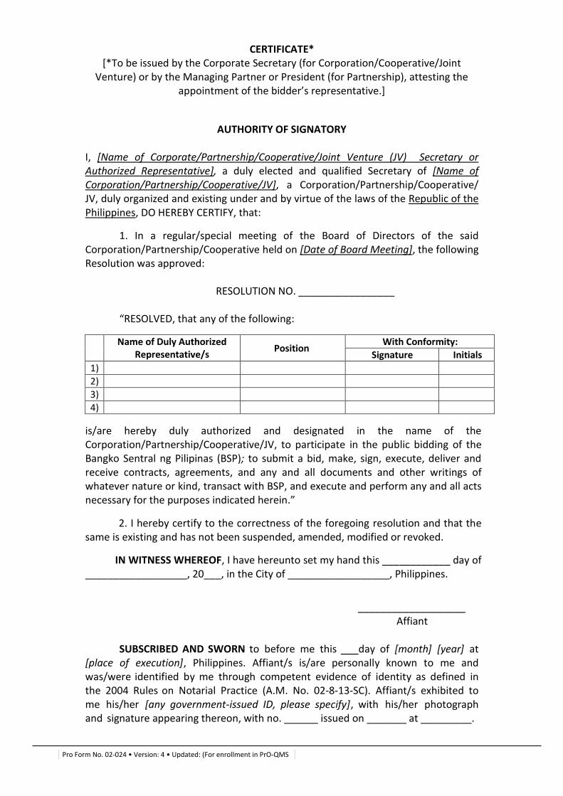
Pro Form No. 02-024 • Version: 4 • Updated: (For enrollment in PrO-QMS
CERTIFICATE* [*To be issued by the Corporate Secretary (for Corporation/Cooperative/Joint
Venture) or by the Managing Partner or President (for Partnership), attesting the appointment of the bidder’s representative.]
AUTHORITY OF SIGNATORY
I, [Name of Corporate/Partnership/Cooperative/Joint Venture (JV) Secretary or Authorized Representative], a duly elected and qualified Secretary of [Name of Corporation/Partnership/Cooperative/JV], a Corporation/Partnership/Cooperative/ JV, duly organized and existing under and by virtue of the laws of the Republic of the Philippines, DO HEREBY CERTIFY, that:
1. In a regular/special meeting of the Board of Directors of the said Corporation/Partnership/Cooperative held on [Date of Board Meeting], the following Resolution was approved:
RESOLUTION NO. _________________
“RESOLVED, that any of the following:
Name of Duly Authorized Representative/s
Position With Conformity:
Signature Initials
1)
2)
3)
4)
is/are hereby duly authorized and designated in the name of the Corporation/Partnership/Cooperative/JV, to participate in the public bidding of the Bangko Sentral ng Pilipinas (BSP); to submit a bid, make, sign, execute, deliver and receive contracts, agreements, and any and all documents and other writings of whatever nature or kind, transact with BSP, and execute and perform any and all acts necessary for the purposes indicated herein.”
2. I hereby certify to the correctness of the foregoing resolution and that the same is existing and has not been suspended, amended, modified or revoked.
IN WITNESS WHEREOF, I have hereunto set my hand this ____________ day of __________________, 20___, in the City of __________________, Philippines.
___________________
Affiant SUBSCRIBED AND SWORN to before me this day of [month] [year] at
[place of execution], Philippines. Affiant/s is/are personally known to me and was/were identified by me through competent evidence of identity as defined in the 2004 Rules on Notarial Practice (A.M. No. 02-8-13-SC). Affiant/s exhibited to me his/her [any government-issued ID, please specify], with his/her photograph and signature appearing thereon, with no. ______ issued on _______ at _________.
Pro Form No. 02-024 • Version: 4 • Updated: (For enrollment in PrO-QMS
Witness my hand and seal this day of [month] [year].
Name of Notary Public Serial No. of Commission____ Notary Public for _________ until ___ Roll of Attorneys No. __________
PTR No. , [date issued], [place issued] IBP No. , [date issued], [place issued]
Doc. No. _______ Page No. _______ Book No. _______ Series of _______.
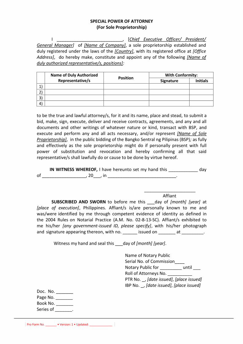
Pro Form No. _______ • Version: 1 • Updated: ______________
SPECIAL POWER OF ATTORNEY (For Sole Proprietorship)
I ___________________________, [Chief Executive Officer/ President/
General Manager] of [Name of Company], a sole proprietorship established and duly registered under the laws of the [Country], with its registered office at [Office Address], do hereby make, constitute and appoint any of the following [Name of duly authorized representative/s, positions]:
Name of Duly Authorized
Representative/s Position
With Conformity:
Signature Initials
1)
2)
3)
4)
to be the true and lawful attorney/s, for it and its name, place and stead, to submit a bid, make, sign, execute, deliver and receive contracts, agreements, and any and all documents and other writings of whatever nature or kind, transact with BSP, and execute and perform any and all acts necessary, and/or represent [Name of Sole Proprietorship], in the public bidding of the Bangko Sentral ng Pilipinas (BSP); as fully and effectively as the sole proprietorship might do if personally present with full power of substitution and revocation and hereby confirming all that said representative/s shall lawfully do or cause to be done by virtue hereof.
IN WITNESS WHEREOF, I have hereunto set my hand this ____________ day of __________________, 20___, in ____________________________.
_____________________ Affiant SUBSCRIBED AND SWORN to before me this day of [month] [year] at
[place of execution], Philippines. Affiant/s is/are personally known to me and was/were identified by me through competent evidence of identity as defined in the 2004 Rules on Notarial Practice (A.M. No. 02-8-13-SC). Affiant/s exhibited to me his/her [any government-issued ID, please specify], with his/her photograph and signature appearing thereon, with no. ______ issued on _______ at _________.
Witness my hand and seal this day of [month] [year].
Name of Notary Public Serial No. of Commission____ Notary Public for _________ until ___ Roll of Attorneys No. __________
PTR No. , [date issued], [place issued] IBP No. , [date issued], [place issued]
Doc. No. _______ Page No. _______ Book No. _______ Series of _______.
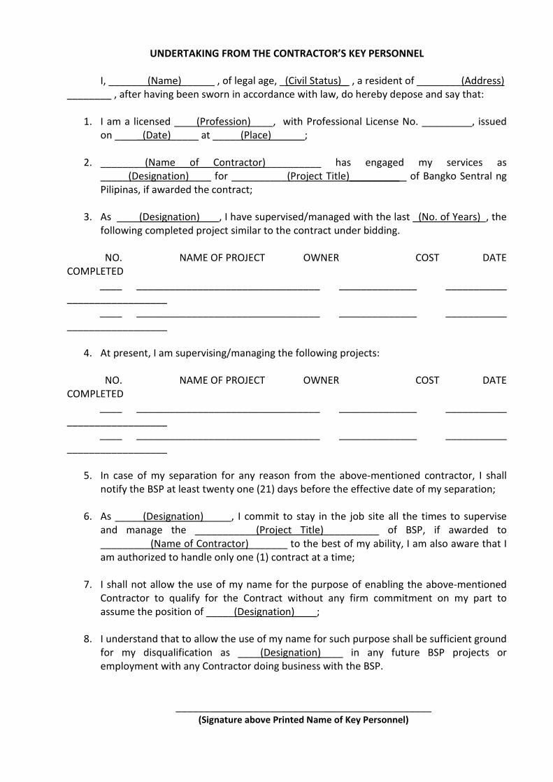
UNDERTAKING FROM THE CONTRACTOR’S KEY PERSONNEL
I, _______(Name)______ , of legal age, _(Civil Status)_ , a resident of ________(Address)
________ , after having been sworn in accordance with law, do hereby depose and say that:
1. I am a licensed ____(Profession)____, with Professional License No. _________, issued
on _____(Date)_____ at _____(Place)______;
2. ________(Name of Contractor)__________ has engaged my services as
_____(Designation)____ for __________(Project Title)_________ of Bangko Sentral ng
Pilipinas, if awarded the contract;
3. As ____(Designation)___ , I have supervised/managed with the last _(No. of Years)_, the
following completed project similar to the contract under bidding.
NO. NAME OF PROJECT OWNER COST DATE
COMPLETED
____ _________________________________ ______________ ___________
__________________
____ _________________________________ ______________ ___________
__________________
4. At present, I am supervising/managing the following projects:
NO. NAME OF PROJECT OWNER COST DATE
COMPLETED
____ _________________________________ ______________ ___________
__________________
____ _________________________________ ______________ ___________
__________________
5. In case of my separation for any reason from the above-mentioned contractor, I shall
notify the BSP at least twenty one (21) days before the effective date of my separation;
6. As _____(Designation)_____, I commit to stay in the job site all the times to supervise
and manage the ___________(Project Title)__________ of BSP, if awarded to
_________(Name of Contractor)_______ to the best of my ability, I am also aware that I
am authorized to handle only one (1) contract at a time;
7. I shall not allow the use of my name for the purpose of enabling the above-mentioned
Contractor to qualify for the Contract without any firm commitment on my part to
assume the position of _____(Designation)____;
8. I understand that to allow the use of my name for such purpose shall be sufficient ground
for my disqualification as ____(Designation)____ in any future BSP projects or
employment with any Contractor doing business with the BSP.
______________________________________________
(Signature above Printed Name of Key Personnel)
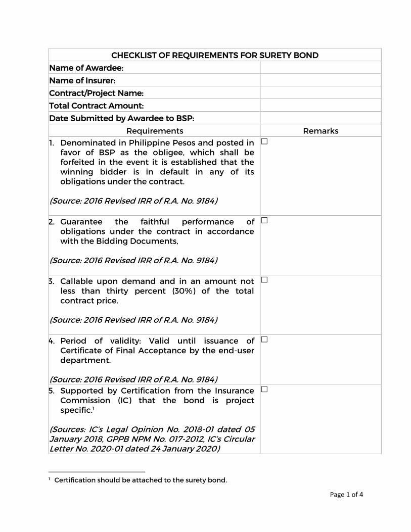
Page 1 of 4
CHECKLIST OF REQUIREMENTS FOR SURETY BOND
Name of Awardee:
Name of Insurer:
Contract/Project Name:
Total Contract Amount:
Date Submitted by Awardee to BSP:
Requirements Remarks 1. Denominated in Philippine Pesos and posted in
favor of BSP as the obligee, which shall be forfeited in the event it is established that the winning bidder is in default in any of its obligations under the contract.
(Source: 2016 Revised IRR of R.A. No. 9184)
2. Guarantee the faithful performance of obligations under the contract in accordance with the Bidding Documents,
(Source: 2016 Revised IRR of R.A. No. 9184)
3. Callable upon demand and in an amount not less than thirty percent (30%) of the total contract price.
(Source: 2016 Revised IRR of R.A. No. 9184)
4. Period of validity: Valid until issuance of Certificate of Final Acceptance by the end-user department.
(Source: 2016 Revised IRR of R.A. No. 9184)
5. Supported by Certification from the Insurance Commission (IC) that the bond is project specific.1
(Sources: IC’s Legal Opinion No. 2018-01 dated 05 January 2018, GPPB NPM No. 017-2012, IC’s Circular Letter No. 2020-01 dated 24 January 2020)
1 Certification should be attached to the surety bond.
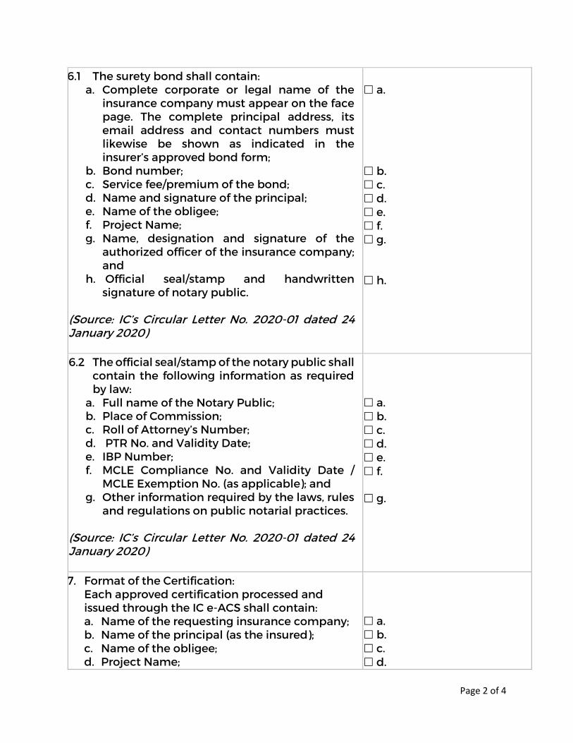
Page 2 of 4
6.1 The surety bond shall contain: a. Complete corporate or legal name of the
insurance company must appear on the face page. The complete principal address, its email address and contact numbers must likewise be shown as indicated in the insurer’s approved bond form;
b. Bond number; c. Service fee/premium of the bond; d. Name and signature of the principal; e. Name of the obligee; f. Project Name; g. Name, designation and signature of the
authorized officer of the insurance company; and
h. Official seal/stamp and handwritten signature of notary public.
(Source: IC’s Circular Letter No. 2020-01 dated 24 January 2020)
a. b. c. d. e. f. g. h.
6.2 The official seal/stamp of the notary public shall contain the following information as required by law:
a. Full name of the Notary Public; b. Place of Commission; c. Roll of Attorney’s Number; d. PTR No. and Validity Date; e. IBP Number; f. MCLE Compliance No. and Validity Date /
MCLE Exemption No. (as applicable); and g. Other information required by the laws, rules
and regulations on public notarial practices. (Source: IC’s Circular Letter No. 2020-01 dated 24 January 2020)
a. b. c. d. e. f. g.
7. Format of the Certification: Each approved certification processed and issued through the IC e-ACS shall contain: a. Name of the requesting insurance company; b. Name of the principal (as the insured); c. Name of the obligee; d. Project Name;
a. b. c. d.
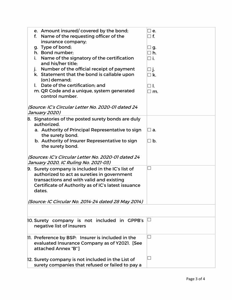
Page 3 of 4
e. Amount insured/ covered by the bond; f. Name of the requesting officer of the
insurance company; g. Type of bond; h. Bond number; i. Name of the signatory of the certification
and his/her title; j. Number of the official receipt of payment k. Statement that the bond is callable upon
(on) demand; l. Date of the certification; and m. QR Code and a unique, system generated
control number. (Source: IC’s Circular Letter No. 2020-01 dated 24 January 2020)
e. f. g. h. i. j. k. l. m.
8. Signatories of the posted surety bonds are duly authorized. a. Authority of Principal Representative to sign
the surety bond. b. Authority of Insurer Representative to sign
the surety bond. (Sources: IC’s Circular Letter No. 2020-01 dated 24 January 2020, IC Ruling No. 2021-03)
a. b.
9. Surety company is included in the IC’s list of authorized to act as sureties in government transactions and with valid and existing Certificate of Authority as of IC’s latest issuance dates.
(Source: IC Circular No. 2014-24 dated 28 May 2014)
10. Surety company is not included in GPPB’s negative list of insurers
11. Preference by BSP: Insurer is included in the evaluated Insurance Company as of Y2021. [See attached Annex “B”]
12. Surety company is not included in the List of
surety companies that refused or failed to pay a

Page 4 of 4
claim of the BSP upon written demand or has a pending dispute with BSP [refer to Annex “B” for the suggested insurance companies]
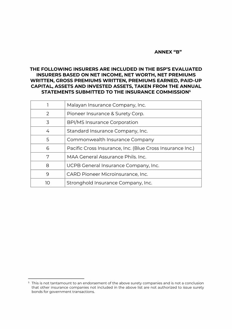
File/Ref. No. PrMD-202109-0039e-PAG Page 8 of 11
ANNEX “B” THE FOLLOWING INSURERS ARE INCLUDED IN THE BSP’S EVALUATED
INSURERS BASED ON NET INCOME, NET WORTH, NET PREMIUMS WRITTEN, GROSS PREMIUMS WRITTEN, PREMIUMS EARNED, PAID-UP CAPITAL, ASSETS AND INVESTED ASSETS, TAKEN FROM THE ANNUAL
STATEMENTS SUBMITTED TO THE INSURANCE COMMISSION5
1 Malayan Insurance Company, Inc.
2 Pioneer Insurance & Surety Corp.
3 BPI/MS Insurance Corporation
4 Standard Insurance Company, Inc.
5 Commonwealth Insurance Company
6 Pacific Cross Insurance, Inc. (Blue Cross Insurance Inc.)
7 MAA General Assurance Phils. Inc.
8 UCPB General Insurance Company, Inc.
9 CARD Pioneer Microinsurance, Inc.
10 Stronghold Insurance Company, Inc.
5 This is not tantamount to an endorsement of the above surety companies and is not a conclusion
that other insurance companies not included in the above list are not authorized to issue surety bonds for government transactions.
Page 1 of 5
Pro Form No. 02-026 • Version: 1 • Updated: 25 June 2014
REPUBLIC OF THE PHILIPPINES ) CITY/MUNICIPALITY OF __________)
AFFIDAVIT OF UNDERTAKING
I, __________________________, of legal age, (civil status), (nationality). and residing at _____________________________ after having been duly sworn in accordance with law, do hereby depose and state that:
1. I am the authorized and designated representative/s of (Name of Bidder) with office address at ________________________;
2. I had taken steps to carefully examine and conform with all the instructions, forms, terms, and project requirements as stated in the following documents:
A. BSP Supplied Scope of Works and Technical Specifications:
PAGES
0. TITLE PAGE AND TABLE OF CONTENTS 5
DIVISION 1 – GENERAL REQUIREMENTS
1. SECTION 01 50 00 TEMPORARY FACILITIES AND CONTROLS 14
2. SECTION 01 52 16 FIRST AID FACILITIES 1
3. SECTION 01 54 23 TEMPORARY SCAFFOLDINGS AND PLATFORMS 4
4. SECTION 01 56 26 TEMPORARY FENCING 4
5. SECTION 01 71 13 MOBILIZATION 3
DIVISION 2 – EXISTING CONDITIONS
6. SECTION 02 41 00 BUILDING DEMOLITION 5
DIVISION 3 – CONCRETE
7. SECTION 03 10 00 CONCRTE FORMING AND ACCESSORIES 3
8. SECTION 03 15 00 CONCRETE ACCESSORIES 6
9. SECTION 03 20 00 CONCRETE REINFORCING 4
10. SECTION 03 22 13 GALVANIZED WELDED WIRE FABRIC REINFORCING
5
11. SECTION 03 30 00 CAST-IN-PLACE CONCRETE 11
12. SECTION 03 35 00 CONCRETE FINISHING 4
13. SECTION 03 39 00 CONCRETE CURING 4
14. SECTION 03 53 00 CONCRETE TOPPING 3
15. SECTION 03 60 00 GROUTING 5
DIVISION 4 – MASONRY
16. SECTION 04 22 00 CONCRETE UNIT MASONRY 4
DIVISION 5 – METALS
Page 2 of 5
Pro Form No. 02-026 • Version: 1 • Updated: 25 June 2014
17. SECTION 05 00 00 METALS 5
18. SECTION 05 12 00 STRUCTURAL STEEL FRAMING 5
19. SECTION 05 52 00 METAL RAILINGS 4
DIVISION 7 – THERMAL AND MOISTURE PROTECTION
20. SECTION 07 13 52 MODIFIED BITUMINOUS SHEET WATERPROOFING (TORCH APPLIED WATERPROOFING)
4
21. SECTION 07 16 13 POLYMER MODIFIED CEMENT WATERPROOFING (ACRYLIC POLYMER WATERPROOFING)
3
22. SECTION 07 16 16 CRYSTALLINE WATERPROOFING (CEMENTITIOUS WATERPROOFING BY CRYSTALLIZATION)
5
23. SECTION 07 21 00 THERMAL INSULATION 3
24. SECTION 07 81 29 MINERAL FIBER CEMENT BOARD 4
25. SECTION 07 92 00 JOINT SEALANT 5
DIVISION 8 – OPENINGS
26. SECTION 08 11 00 METAL DOORS, WINDOW AND FRAMES 13
27. SECTION 08 14 16 FLUSH WOOD DOORS 4
28. SECTION 08 42 26 ALL GLASS ENTRANCES 5
29. SECTION 08 70 00 HARDWARES 8
30. SECTION 08 81 00 GLASS GLAZING 5
31. SECTION 08 83 00 MIRRORS 3
DIVISION 9 – FINISHES
32. SECTION 09 21 16 GYPSUM BOARD 8
33. SECTION 09 24 00 PLASTERING 3
34. SECTION 09 30 00 TILES 6
35. SECTION 09 90 00 PAINTS AND COATINGS 10
DIVISION 10 – SPECIALTIES
36. SECTION 10 06 10.16 INTERIOR SINAGE 4
37. SECTION 10 21 00 COMPARTMENT AND CUBICLES 5
38. SECTION 10 28 13 TOILET ACCESSORIES 5
DIVISION 14 CONVEYING EQUIPMENT
39. SECTION 14 21 23.16 ELEVATORS 6
DIVISION 21 – FIRE SUPPRESSION
40. SECTION 21 13 13 WET PIPE SPRINKLER SYSTEM 9
41. SECTION 21 32 13 ELECTRIC DRIVEN, VERTICAL TURBINE FIRE PUMPS
6
42. SECTION 21 41 00 STORAGE TANKS FOR FIRE- SUPPRESSION WATER
3

Page 3 of 5
Pro Form No. 02-026 • Version: 1 • Updated: 25 June 2014
DIVISION 22 – PLUMBING
43. SECTION 22 05 29 HANGERS & SUPPORTS FOR PLUMBING PIPING & EQUIPMENT
4
44. SECTION 22 07 10 PLUMBING PIPING INSULATION 2
45. SECTION 22 11 16 DOMESTIC WATER PIPING 6
46. SECTION 22 11 23 DOMESTIC WATER PUMPS 4
47. SECTION 22 13 16 SANITARY WASTE & VENT PIPING 10
48. SECTION 22 14 29 SUMP PUMPS 3
DIVISION 23 – HEATING, VENTILATING, AND AIR CONDITIONING
49. SECTION 23 05 48 TESTING, ADJUSTING AND BALANCING FOR MVAC
3
50. SECTION 23 06 29 HANGERS & SUPPORTS FOR MVAC PIPING & EQUIPMENT
2
51. SECTION 23 07 19 MVAC PIPING INSULATION 2
52. SECTION 23 12 13 LIQUEFIED – PETROLEUM GAS PIPING 10
53. SECTION 23 31 00 MVAC DUCTS AND CASINGS 4
54. SECTION 23 34 00 MVAC FANS 3
55. SECTION 23 37 13 DIFFUSER, REGISTER AND GRILLE 2
56. SECTION 23 81 29 AIR CONDITIONING EQUIPMENT 7
DIVISION 26 – ELECTRICAL
57. SECTION 26 00 00 ELECTRICAL 16
58. SECTION 26 05 19 600 VOLTS WIRE AND CABLE 4
59. SECTION 26 05 26 GROUNDING & BONDING FOR ELECTRICAL SYSTEMS
3
60. SECTION 26 05 29 HANGERS AND SUPPORTS FOR ELECTRICAL SYSTEMS
4
61. SECTION 26 05 33 RACEWAY AND BOXES FOR ELECTRICAL SYSTEMS
6
62. SECTION 26 05 33.13 CONDUIT FOR ELECTRICAL SYSTEMS 8
63. SECTION 26 05 36 CABLE TRAYS FOR ELECTRICAL SYSTEMS 4
64. SECTION 26 50 00 LIGHTING FIXTURES AND ACCESSORIES 5
65. SECTION 26 24 16 PANELBOARDS 4
66. SECTION 26 27 26 WIRING DEVICES 3
67. SECTION 26 32 13.13 GENSET 28
68. SECTION 26 23 00 LOW VOLTAGE SWITCHGEAR 5
69. SECTION 26 36 23 AUTOMATIC TRANSFER SWITCHES 2
70. SECTION 26 13 19 MEDIUM VOLTAGE SWITCHGEAR 6
DIVISION 27 – COMMUNICATIONS
Page 4 of 5
Pro Form No. 02-026 • Version: 1 • Updated: 25 June 2014
71. SECTION 27 10 00A STRUCTURED CABLING SYSTEM 17
72. SECTION 27 10 00B IT ACTIVE EQUIPMENT 16
73. SECTION 27 30 00 PABX SYSTEM 19
74. SECTION 27 50 00 BACKGROUND MUSIC AND PUBLIC ADDRESS SYSTEM
25
DIVISION 28 – ELECTRONIC SAFETY AND SECURITY
75. SECTION 28 00 00A ELECTRONICS GENERAL PROVISIONS 18
76. SECTION 28 00 00B ELECTRONICS BASIC MATERIALS AND METHODS 6
77. SECTION 28 00 00C ELECTRONICS RACEWAYS AND BOXES 10
78. SECTION 28 00 00D ELECTRONICS HANGERS AND SUPPORTS 6
79. SECTION 28 00 00E WIRES AND CABLES FOR ELECTRONICS SYSTEMS 11
80. SECTION 28 10 00 CLOSED CIRCUIT TELEVISION (CCTV) 12
81. SECTION 28 20 00 FIRE DETECTION AND ALARM SYSTEM 15
DIVISION 31 – EARHTWORK
82. SECTION 31 11 OO SITE CLEARING 4
83. SECTION 31 30 00 EARTHWORK 4
84. SECTION 31 31 16 TERMITE CONTROL 3
DIVISION 32 – EXTERIOR IMPROVEMENTS
85. SECTION 32 11 00 BASE COURSES 7
86. SECTION 32 11 33.13 PORTLAND CEMENT 21
87. SECTION 32 16 00 CURBS, GUTTER, SIDEWALKS AND DRIVEWAYS 3
88. SECTION 32 31 19 DECORATIVE METAL FENCES AND GATES 2
89. SECTION 32 90 00 PLANTING 18
DIVISION 33 – UTILITIES
90.
SECTION 33 40 00 STORM DRAINAGE UTILITIES 3
91. SECTION 33 44 00 STORM UTILITY WATER DRAINS 3
92. SECTION 33 79 00 UNDERGROUND ELECTRICAL WORKS 6 TOTAL 615
B. BSP Supplied Plans and Drawings:
ARCHITECTURAL: Sheet Nos. Pages 1. OCBP Architectural Plans (A-0 to A-54) 55
CIVIL WORKS: 2. OCBP Civil Works Plans (CW-1 to CW-12) 12
STRUCTURAL: 3. OCBP Structural Plans (ST-1 to ST-20) 20
Page 5 of 5
Pro Form No. 02-026 • Version: 1 • Updated: 25 June 2014
C. I undertake to return said documents, if declared as Lowest Calculated Bidder,
together with the other documents required under Envelope No. 3, within five (5) calendar days from receipt of notice from the Bids and Awards Committee – Corporate Services Sector (BAC-CSS);
D. I am executing this affidavit of undertaking in accordance with the requirements
of the Bangko Sentral ng Pilipinas – BAC-ITIO. IN WITNESS WHEREOF, I have hereunto set my hand this _____ day of __________________, 20____ at _____________, Philippines.
(Bidder’s Representative/Authorized Signatory) AFFIANT
SUBSCRIBED AND SWORN to before me this day of [month] [year] at [place of execution], Philippines. Affiant/s is/are personally known to me and was/were identified by me through competent evidence of identity as defined in the 2004 Rules on Notarial Practice (A.M. No. 02-8-13-SC). Affiant/s exhibited to me his/her [any government-issued ID, please specify], with his/her photograph and signature appearing thereon, with no. ______ issued on _______ at _________.
Witness my hand and seal this day of [month] [year].
NAME OF NOTARY PUBLIC Serial No. of Commission Notary Public for _ until Roll of Attorneys No. PTR No. , [date issued], [place issued] IBP No. , [date issued], [place issued]
Doc. No. _________ Page No. _________ Book No. __________ Series of __________
MECHANICAL 4. OCBP Mechanical Plans (M-1 to M-20) 20
ELECTRICAL: 5. OCBP Electrical Plans (EE-1 to EE-22) 22
ELECTRONICS 6. OCBP Electronics Plans (EC-0 TO EC-38) 39
SANITARY/PLUMBING 7. OCBP Sanitary/Plumbing Plans (P-1 to P-22) 22
FIRE PROTECTION: 8. OCBP Fire Protection Plans (FP-1 to F-14) 14
LANDSCAPE 9. OCBP Landscape Plan (L-1) 1
TOTAL 205