
BIDDING DOCUMENT - Ceylon Fishery Harbours Corporation
320
DEMOCRATIC SOCIALISTREPUBLIC OF SRILANKA State Ministry of Ornamental Fish, Inland Fish & Prawn Farming, Fishery Harbour Development, Multiday Fishing Activities and Fish Exports REACTIVATION AND RECONSTRUCTION OF MYLIDDY FISHERY HARBOUR IN NORTHERN PROVINCE-PHASE II CONTRACT NO: CFHC/SD/MPC/Phase II/My/2021/01 BIDDING DOCUMENT EMPLOYER State Ministry of Ornamental Fish, Inland Fish & Prawn Farming, Fishery Harbour Development, Multiday Fishing Activities and Fish Exports , New Secretariat , Maligawatta, Colombo 10. May 2021
-
Upload
khangminh22 -
Category
Documents
-
view
0 -
download
0
Transcript of BIDDING DOCUMENT - Ceylon Fishery Harbours Corporation

DEMOCRATIC SOCIALISTREPUBLIC OF SRILANKA
State Ministry of Ornamental Fish, Inland Fish & Prawn Farming,
Fishery Harbour Development, Multiday Fishing Activities and
Fish Exports
REACTIVATION AND RECONSTRUCTION OF MYLIDDY
FISHERY HARBOUR IN NORTHERN PROVINCE-PHASE II
CONTRACT NO: CFHC/SD/MPC/Phase II/My/2021/01
BIDDING DOCUMENT
EMPLOYER
State Ministry of Ornamental Fish, Inland Fish & Prawn Farming, Fishery
Harbour Development, Multiday Fishing Activities and Fish Exports ,
New Secretariat ,
Maligawatta,
Colombo 10.
May 2021

Reactivation and Reconstruction of Myliddy Fishery Harbour in Northern Province - Phase II
TABLE OF CONTENTS
Invitation for Bids
Volume -1
Section 01 - Instructions to Bidders ............................................................................ 1|1-1/2
Section 03- Conditions of Contract ............................................................................. 3|1-3/2
Section 05 - Standard Forms (Contract) ...................................................................... 5|1-5/5
Volume -2
Section 02 - Bidding Data ........................................................................................... 2|1-2/6
Section 04 - Contract Data .......................................................................................... 4|1-4/5
Section 06 - Specifications ...................................................................................... 6|1-6/133
Section 07 - Form of Bid .............................................................................................. 7|1-7/2
Section 08 - Bills of Quantities ............................................................................... 8|1-8/109
Section 09 - Schedules ............................................................................................... 9|1-9/13
Section 10 - Drawings ............................................................................................. 10|1-10/2
Section 11 - Standard Forms (Bid) .......................................................................... 11|1-11/2

Ceylon FisheryHarbours Corporation
Bid No. CFHC/SD/ MPC/PHASE II/MY/2021/01
REACTIVATION AND RECONSTRUCTION OF MYLIDDY FISHERY HARBOUR IN
NORTHERN PROVINCE – PHASE II
1. The Chairman Ministry Procurement Committee (M
Harbours Corporation invites sealed bids from eligible and qualified bidders for
and Reconstruction of Myliddy
below and estimated to cost
Contingencies).
2. Source of funds : GOSL
3. Location of the Project: Myliddy, Jaffna
4. Description of Project:
The work consists of Reactivation and Reconstruction of Myliddy
Northern Province – Phase IIcomplete as per the specifications, Drawings and Bill of Quantities
given.The Contract Period is Three Hundred Sixty Five (365
5. Bidding will be conducted through National Competitive Bidding (NCB)
qualification criteria given below.
The Contract will be on Measure and Pay Basis.
6. To be eligible for contract award, the successful bidder shall not have been blacklisted and
shall have valid registration in
under Construction Industry Development Authority (CIDA) (Former ICTAD)
7. As per Public Finance Circular No.03/2020 (I) 5% Special Preference will be given for public
enterprises for financial evaluation.
8. Qualification requirements to qualify for contract award shall be,
ICTAD/CIDA registration,
Registration No: ………………………….
Grade: ……………………………………
Specialty: ………………………………...
Expiry Date: ……………………………...
VAT Registration No: ……………………….
Attach construction
INVITATION FOR BIDS (IFB)
Ceylon FisheryHarbours Corporation
Bid No. CFHC/SD/ MPC/PHASE II/MY/2021/01
REACTIVATION AND RECONSTRUCTION OF MYLIDDY FISHERY HARBOUR IN
PHASE II
inistry Procurement Committee (MPC) on behalf of the Ceylon Fishery
Corporation invites sealed bids from eligible and qualified bidders for
and Reconstruction of Myliddy Fishery Harbour in Northern Province - Phase II
below and estimated to cost approximately Rupees 197 million (without VAT and
Myliddy, Jaffna District
Reactivation and Reconstruction of Myliddy Fishery Harbour
complete as per the specifications, Drawings and Bill of Quantities
eriod is Three Hundred Sixty Five (365) calendar days.
ducted through National Competitive Bidding (NCB) Procedure with post
qualification criteria given below.
The Contract will be on Measure and Pay Basis.
To be eligible for contract award, the successful bidder shall not have been blacklisted and
shall have valid registration in Grade C3 or Above in the field of Maritime
under Construction Industry Development Authority (CIDA) (Former ICTAD)
As per Public Finance Circular No.03/2020 (I) 5% Special Preference will be given for public
enterprises for financial evaluation.
Qualification requirements to qualify for contract award shall be,
ICTAD/CIDA registration,
Registration No: ………………………….
Grade: ……………………………………
Specialty: ………………………………...
Expiry Date: ……………………………...
VAT Registration No: ……………………….
Attach construction program.
REACTIVATION AND RECONSTRUCTION OF MYLIDDY FISHERY HARBOUR IN
PC) on behalf of the Ceylon Fishery
Corporation invites sealed bids from eligible and qualified bidders for Reactivation
Phase II as described
million (without VAT and
Fishery Harbour in
complete as per the specifications, Drawings and Bill of Quantities
Procedure with post-
To be eligible for contract award, the successful bidder shall not have been blacklisted and
Maritime Construction
under Construction Industry Development Authority (CIDA) (Former ICTAD)
As per Public Finance Circular No.03/2020 (I) 5% Special Preference will be given for public

Attach legal status (Sole proprietor,Partnership,Company etc.).
Attach authentication for signatory (written power of attorney).
Total monetary value of construction work performed for each of the last 05 years.
Experience in works of a similar nature and size for each of the last 05 years.
Construction equipment details.
Staffing details with qualification.
Attach construction work program and construction methodology.
Details of principal place of business……………………
Attach audited financial reports for last 05 years.
Evidence of adequacy of working capital to execute and complete this contract.
The Bidder shall possess a valid certificate issued by the Registrar of Public
Contract in accordance with the Section 8 of Public Contracts Act No 03 of 1987
for every Bid which exceeds tenderable amount of Rs. 5 million.This will be a
qualification for award of the Contrct.
9. Pre - Bid meeting
Pre - Bid meeting will be held at,
Date:08th
July 2021
Time:10.00 A.M
Venue: Conference Hall, Ceylon Fishery HarboursCorporation,No15,Rock House Lane,
Colombo 15
10. Interested bidders may obtain further information from Procurement Manager, Ceylon
Fishery Harbours Corporation, Rock House Lane, Colombo 15 and inspect the bidding
documents at the same address from 09.00 hrs. to 15.00 hrs. on any working day
startingfrom28th
June 2021 to 19th
July 2021. Contact Numbers - Tele: 0112525063, Fax:
0112520577, Email address: [email protected]
11. A complete set of Bidding Documents in English language may be purchased by interested
bidders on the submission of a written application to the Manager Procurement, Ceylon
Fishery Harbours Corporation, Rock House Lane, Colombo 15 from28th
June 2021 to
19th
July 2021from 9.00 hrs. to 15.00 hrs.
12.Bid Documents relating to above matter can be downloaded from the official web site of the
corporation (www.cfhc.gov.lk) The deposit fee should be credited to the corporation’s bank
account No. 1446 at the Bank of Ceylon, Corporate Branch and the copy of the deposit slip
cash payment of Rs. 20,000.00 for the Tender Document set as an Non-Refundable fee.The
Copy of the deposit slip should be attached along with the bid document and if bidder unable to
submit deposit slip the bid will be rejected.

13. Bids shall be delivered with Duplicate addressed to the Manager Procurement, Ceylon
Fishery Harbours Corporation, Rock House Lane, Colombo 15on or before 14.00hrs
on 20th
July 2021. Late bids will be rejected. Bids will be opened soon after closing in the
presence of the representatives of the bidders who choose to attend
14. Bids shall be valid up to 20th
October 2021( 91 days).
15.The Bidder shall seal the Original and the Copy of the bid in two inner separate envelops and
one outer envelope, duly making the inner envelops as “ORIGINAL” and “COPY”.
16.The Original and the Copy of the bid ( Form of Bid) shall be typed or written in indelible ink
and shall be signed by a person or persons duly authorized to sign on behalf of the bidder
with Company Seal.
17. .All bids shall be accompanied with a bid security of Rupees Two Million
(Rs.2,000,000.00)valid up to 16th
November 2021 (119 days)which shall be in the form
included in section 11 – Standard forms (Bid) drawn in favor of Chairman,Ceylon Fishery
Harbours Corporation, Rock House Lane, Colombo 15. Bid security shall be obtained
from the Commercial Banks operating in Sri Lanka and approved by the Central Bank of Sri
Lanka.
18 .All bidders are kindly requested to read carefully ITB of ICTAD/SBD/02 Second Edition –
January 2007 and addendums issued on October 2009 and February 2011 before submission
of bid to avoid discrepancies.
Chairman,
Ministry Procurement Committee,
No.15,
Rock House Lane,
Colombo 15

Reactivation and Reconstruction of Myliddy Fishery Harbour in Northern Province - Phase II
VOLUME - 1

Reactivation and Reconstruction of Myliddy Fishery Harbour in Northern Province - Phase II Page 1 | 1
SECTION 1
INSTRUCTIONS TO BIDDERS

Reactivation and Reconstruction of Myliddy Fishery Harbour in Northern Province - Phase II Page 1 | 2
INSTRUCTIONS TO BIDDERS
The text of this ‘Instructions to Bidders is found in the “Standard Bidding Document Procurement of
Works”, ICTAD Publication No. ICTAD/SBD/02 – Second Edition – January 2007and addendum 1
issued in October 2009.
This publication is copyright and bidders, if they do not already possess a copy, may obtain it from:
Construction Industry Development Authority (CIDA)
‘Savsiripaya’
123, Wijerama Mawatha
Colombo-07

Reactivation and Reconstruction of Myliddy Fishery Harbour in Northern Province - Phase II Page 3 | 1
SECTION 3
CONDITIONS OF CONTRACT

Reactivation and Reconstruction of Myliddy Fishery Harbour in Northern Province - Phase II Page 3 | 2
CONDITIONS OF CONTRACT
The text of this Conditions of Contract is found in the “Standard Bidding Document
Procurement of Works”, ICTAD Publication No. ICTAD/SBD/02 – Second Edition – January
2007and addendum 1 issued in October 2009.
This publication is copyright and bidders, if they do not already possess a copy, may obtain it
from:
Construction Industry Development Authority (CIDA)
‘Savsiripaya’
123, Wijerama Mawatha
Colombo-07.

Reactivation and Reconstruction of Myliddy Fishery Harbour in Northern Province - Phase II Page 5 | 1
SECTION 5
STANDARD FORMS (CONTRACT)
Letter of Acceptance
Agreement
Performance Security
Advance Payment Security

Reactivation and Reconstruction of Myliddy Fishery Harbour in Northern Province - Phase II Page 5 | 2
FORM OF LETTER OF ACCEPTANCE
[Letter head paper of the employer]
........................................... [date]
[LETTER HEADING PAPER OF THE PROCURING ENTITY]
To: ...................................................................... [name and address of the Contractor]
.....................
This is to notify you that your bid dated ............................[ insert date] for the construction and
remedying defects of the .................... [name of the Contract and identification number] for the
Contract price of ........................ [name of currency] ............................................ [amount in
figures and words] as corrected in accordance with Instructions to Bidders and/ or modified by a
Memorandum of understanding, is hereby accepted.
You are hereby instructed to proceed with the execution of the said Works in accordance with
the Contract documents.
The Commencement Date shall be: .............................. (fill the date as per Clause 8.1 of
Conditions of Contract).
The amount of Performance Security is: .................................. (fill the amount as per Clause 4.2
of Conditions of Contract).
The Performance Security shall be submitted on or before .............................................. (fill the
date as per Clause 4.2 of Conditions of Contract).
Authorized Signature : .......................................................
Name and title of Signatory : ...............................................................................................

Reactivation and Reconstruction of Myliddy Fishery Harbour in Northern Province - Phase II Page 5 | 3
FORM OF AGREEMENT
This Agreement made the .................... [day] of ................................. [month] 20..... [year],
between .......................................... [name and address of Employer] (hereinafter called and
referred to as “the Employer”), of the one part, and ................................................... [name and
address of Contractor] (hereinafter called and referred to as “the Contractor”), of the other part:
Whereas the Employer desires that the Contractor execute ...................................[name and
identification no of Contract](hereinafter called and referred to as “the Works”) and the
Employer has accepted the Bid by the Contractor for the execution and completion of such
Works and remedying of any defects therein.
The Employer and the Contractor agree as follows:
1. In this Agreement words and expressions shall have the same meanings as are respectively
assigned to them in the Contract.
2. In consideration of the payments to be made by the Employer to the Contractor as indicated in
this Agreement, the Contractor hereby covenants with the Employer to execute and complete the
Works and remedy any defects therein in conformity in all respects with the provisions of the
Contract.
3.The Employer hereby covenants to pay the Contractor in consideration of the execute and
complete the Works and remedy any defects therein, the Contract Price or such other sum as
may become payable under the provisions of the Contract at the times and in the manner
prescribed by the Contract.
In Witness whereof the parties hereto have caused this Agreement to be executed the day and
year aforementioned in accordance with laws of Sri Lanka.
........................................................ ..........................................................
Authorised signature of Contractor Authorised signature of
Employer
COMMON SEAL COMMON SEAL
In the presence of witnesses:
1. Name and NIC No...............................................................................
Signature ............................................................................................
Address ...............................................................................................
2. Name and NIC No ...............................................................................
Signature ............................................................................................
Address ...............................................................................................

Reactivation and Reconstruction of Myliddy Fishery Harbour in Northern Province - Phase II Page 5 | 4
FORM OF PERFORMANCE SECURITY
(Unconditional)
_________________ [Issuing Agency’s Name, and Address of Issuing Branch or Office]
_________________
Beneficiary: Secretary, State Ministry of Ornamental Fish, Inland Fish & Prawn
Farming, Fishery Harbour Development, Multiday Fishing Activities and Fish Exports
,New Secretariat Maligawatta, Colombo 10.
Date: ____________________
PERFORMANCE GUARANTEE NO: _________________________
We have been informed that ____________________________ [name of the contractor]
(hereinafter called “the Contractor”) has entered into Contract No. ______________________
[reference number of the Contract] dated ___________________ with you, for the
___________________________________ [insert “construction”] of
__________________________ [name of Contract and brief description of Works] (hereinafter
called “the Contract”).
Furthermore, we understand that, according to the Conditions of the Contract, a performance
guarantee is required.
At the request of the Contractor, we _______________[name of Agency] hereby irrevocably
undertake to pay you any sum or sums not exceeding in total an amount of
_______________________ [name in figures](
_________________________________________ ) [amount in words], upon receipt by us of
your first demand in writing accompanied by a written statement stating that the Contractor is in
breach of its obligation(s) under the Contract, without your needing to prove or to show grounds
for your demand or the sum specified therein.
This guarantee shall expire, no later than the ……day of ……..., 20…. [insert date, 28 days
beyond the time for Completion of Defects Notification Period] and any demand for payment
under it must be received by us at this office on or before that date.
____________________________
[signature(s)]

Reactivation and Reconstruction of Myliddy Fishery Harbour in Northern Province - Phase II Page 5 | 5
FORM OF ADVANCE PAYMENT SECURITY
.....................[Name and address of Agency, and Address of Issuing Branch or Office].................
Beneficiary: Secretary, State Ministry of Ornamental Fish, Inland Fish & Prawn
Farming, Fishery Harbour Development, Multiday Fishing Activities and Fish Exports
,New Secretariat Maligawatta, Colombo 10.
Date: .........................................
ADVANCE PAYMENT GUARANTEE No: .................................................
We have been informed that ............................[name of Contractor] (hereinafter called “the
Contractor”) has entered into Contract No. ............................ [reference number of the
contract] dated ......................................... with you, for the .................................construction of
......................................... [name of contract and brief description](hereinafter called “the
Contract”).
Furthermore, we understand that, according to the conditions of the Contract, an advance
payment in the sum .........................[amount in figures] (..........................) [amount in words] is
to be made against an advance payment guarantee.
At the request of the Contractor, we ...................................[name of issuing agency] hereby
irrevocably undertake to pay you any sum or sums not exceeding in total an amount of
.............................. [amount in figures] (....................) [amount in words] upon receipt by us of
your first demand in writing accompanied by a written statement stating that the Contractor is
in breach of its obligation in repayment of the Advance Payment under the Contract.
The maximum amount of this guarantee shall be progressively reduced by the amount of the
advance payment repaid by the Contractor.
This guarantee shall expire on ...............................[insert the date, 28 days beyond the Time of
Completion]
Consequently, any demand for payment under this guarantee must be received by us at this
office on or before that date.
.......................................................................
[signature(s)]

Reactivation and Reconstruction of Myliddy Fishery Harbour in Northern Province - Phase II
VOLUME - 2

Reactivation and Reconstruction of Myliddy Fishery Harbour in Northern Province - Phase II Page 2 | 1
SECTION 2
BIDDING DATA

Reactivation and Reconstruction of Myliddy Fishery Harbour in Northern Province - Phase II Page 2 | 2
BIDDING DATA
Instructions to
Bidders Clause
Reference
Entry
1.1
Employer's Name and Address
Name: Secretary,
Address: State Ministry of Ornamental Fish, Inland Fish & Prawn
Farming, Fishery Harbour Development, Multiday Fishing
Activities and Fish Exports ,New Secretariat Maligawatta,
Colombo 10.
Scope of Works;
The aim of the project is to revive the Myliddy Fishery Harbour in the Jaffna
district, which had been under the control of the Ministry of Defence during
the time of conflict and therefore unused by fishermen for fishery activities.
This harbour, which has now been released for the use of fishermen, needs
extensive development or modification of existing offshore and onshore
structures and construction of new facilities if necessary. This will inevitably
boost the existing potential for fishing industry in the area. Hence, to identify
the development options for upgrading the Myliddy fishery harbour is the
primary objective of the project. Therefore, the planning and designing of
fishery harbour have been carried out to:
a. ensure the safe navigation and year round access by upgrading and
providing suitable marine structures (Breakwater, Quay wall etc.)
b. provide an adequate basin area & navigational facilities
c. provide the shore facilities ..
The main works taken up for construction under this contract package for
(i) Construction/Modification of damage length (221 m) of main
breakwater and repair the core at main and secondary breakwater
(ii) New Quay Wall
(iii) Construction of basic shore facilities as mentioned below
Manager's Quarters for HM & DHM
Bachelor’s Quarters
External Work
Location: Myliddy, Jaffna District.
1.2 Time for Completion :The Time for Completion for the whole of works shall
be ;365 Calendar days.

Reactivation and Reconstruction of Myliddy Fishery Harbour in Northern Province - Phase II Page 2 | 3
2.1 Source of funds :The source of funds is Consolidated Funds of Government
of Sri Lanka (GOSL).
4.1 Qualification Information
The following information shall be provided in Section 9 - Schedules:
ICTAD/ CIDA registration
Registration number; ………………………….
Grade; ……………...…………………………
Specialty; ……………...…………………………
Expiry date……………………………………
VAT registration number; …………………………….
Attach construction program.
Attach legal status (Sole proprietor, Partnership, Company etc.)
Attach authentication for signatory (written power of attorney).
Total monetary value of construction work performed for each of the
last 05 years
Experience in works of a similar nature and size for each of the last five
years.
Construction equipment details.
Staffing details with qualification.
Attach construction work program and construction methodology.
Details of Principal place of business……………………………
Attach audited financial reports for last 05 years.
Evidence of adequacy of working capital to execute and complete this
contract.
The Bidder shall possess a valid certificate issued by the Registrar of
Public Contract in accordance with the Section 8 of Public Contracts Act
No 03 of 1987 for every Bid which exceeds tenderable amount of Rs. 5
million.This will be a qualification for award of the Contrct.
● As per Public Finance Circular No.03/2020 (I) 5% Special Preference will be
given for public enterprises for financial evaluation.
4.2 (a) ICTAD/ CIDA registration
The registration is required:
a) Specialty- Grade C3 or above in the field of Maritime
Construction .
4.2 (b) Average annual volume of construction work performed in last five
years
Average annual volume of construction work performed in last five years
shall least Rs 296 Million.

Reactivation and Reconstruction of Myliddy Fishery Harbour in Northern Province - Phase II Page 2 | 4
4.2 (c) Successful completion as main contractor of a construction project of similar
nature and complexity ( Breakwater) with a project value at least Rs. 138
Million for Maritime Construction completed within 12 months, or a higher
project value completed within a proportionate time period as a main
contractor during last ten (10) years.
4.2 (d) Essential equipment/Machinery
Proposals for the timely acquisition (own, lease, hire, etc.) of the following
essential equipment shall be:
Type No. Capacity
1. Long Arm Excavator 1 Similar to PC400
2. Long Arm Excavator 1 Similar to PC 300
3. Long Arm Excavators 2 Similar to PC 200
4. Wheel Loader 3 2m3
5. Off Road Dump Trucks 5 20Ton
4.2 (e) Qualifications and experience of the Contract Management staff
Project Manager (1 No) B.Sc. (Civil Engineering) with minimum
10 years’ Construction experience
including 1 year Marine construction
experience.
Site Engineer ( 1 No) B.Sc (Civil Engineering+ 3 years
Experience/NVQ 6 with 4 years experience
including 01 year marine construction
Quantity Surveyor (1 No) B.Sc. (QS) + 2years experience /NVQ 6
with 3 years’ experience / Technical
Member of IQSSL with 2 years’ experience
/ NCT (QS) + 10 years’ experience
Technical Officer (1 Nos) NDT or equivalent + 4 years’ experience /
NCT + 10 years’ experience
4.2 (f) Liquid assets and /or credit facilities required
The minimum amount of liquid assets and/or credit facilities, net of other
contractual commitments and exclusive of any advance payments which
may be made under the Contract, shall not be less than Rs. 49 million.
Bidders shall submit documentary evidence to prove the availability of liquid
assets.
10.1 Clarification of Bidding Documents
Employer’s address for clarification of bidding documents is
Procurement Manager,
Ceylon Fishery Harbours Corporation ,No 15, Rock House Lane,
Colombo-15
Tel :. 011 2525063

Reactivation and Reconstruction of Myliddy Fishery Harbour in Northern Province - Phase II Page 2 | 5
Facsimile : 0112520577
Email address ; [email protected]
13.1(A) (j) Documents comprising the Bid As per the ITB of the ICTAD Publication
No. ICTAD/SBD/02-Second Edition-January 2007
13.1(B) (d) Additional information is As per the ITB of the ICTAD Publication
No.ICTAD/SBD/02-Second Edition-January 2007 with addendum issued on
October 2009
14.4 Adjustments for change in cost
The Contract is subjected to price adjustment
16.1 Period of Bid validity
The Bid shall be valid up to 20th
October 2021 from the date of closing of the
bid. (91 days)
17.1 The amount of Bid Security
The Amount of Bid Security is Sri Lankan Rupees Two Million
(Rs.2,000,000.00) only.
17.2 Validity of Bid Security
The Bid Security shall be unconditional on demand guarantee, valid
up 16th
November 2021(119 days) from the date of closing of bids
,issued by an agency acceptable to Employer. The agencies acceptable
to Employer and Treasury approved Commercial banks operating in
Sri Lanka .
19.1 Pre-Bid meeting
Pre Bid meeting will be held at
Date :08 th
July 2021
Time : 10.00 am
Venue: Conference Hall, Ceylon Fishery Harbours Corporation,
No15, Rock House Lane, Colombo-15
21.2 (a) Employer's Address for Bid submission
Employer’s address for the purpose of bid submission is
Chairman,
Ministry Procurement Committee
Procurement Division,
Ceylon Fishery Harbours Corporation, No 15, Rock House Lane
Colombo 15.
Phone : 0112525063 Facsimile: 0112520577

Reactivation and Reconstruction of Myliddy Fishery Harbour in Northern Province - Phase II Page 2 | 6
21.2 (b) Identification number of Contract
Identification Number of the Contract is:
CFHC/SD/MPC/Phase 11/My/2021/01
22.1 Deadline for submission of Bids
The deadline for submission of Bids on or before 14.00 hrs on 20th
July 2021
25.1 Bid opening
Venue:
Procurement Division, Ceylon Fishery Harbours
Corporation, No 15, Rock House Lane Colombo 15.
Time:
14.00 hrs on 20th
July 2021(Bids will be opened soon after
closing in the presence of bidder’s representative)
35.1 Amount of Performance Security
The Standard Form of Performance Security acceptable to the Employer shall
be a unconditional, on demand Guarantee from any Commercial Bank
operating in Sri Lanka and approved by Central Bank of Sri Lanka.
The amount of Performance Security is 5% of the Initial Contract Price. The
performance Security Shall be valid until 28 days beyond the expected
completion date of the Defect Liability Period
37
Dispute Adjudication Board (DAB)
The Adjudicator proposed by the Employer is
Construction Industry Development Authority (CIDA) (Former ICTAD)
Fees and type of reimbursable expenses to be paid to the Adjudicator shall be on a
case to case basis and shall be equally shared by the contractor and the Employer.

Reactivation and Reconstruction of Myliddy Fishery Harbour in Northern Province - Phase II Page 4 | 1
SECTION 4
CONTRACT DATA

Reactivation and Reconstruction of Myliddy Fishery Harbour in Northern Province - Phase II Page 4 | 2
CONTRACT DATA
Conditions of
Contract Clause
Number/s
1.1.2.2,&1.3. Employer's Name and Address
Secretary .State Ministry of Ornamental Fish, Inland
Fish & Prawn Farming, Fishery Harbour Development,
Multiday Fishing Activities and Fish Exports ,New
Secretariat Maligawatta, Colombo 10
Employer's Authorized Representative
Chairmen,
Ceylon Fishery Hrbours Corporation, No 15, Rock House Lane,
Colombo-15
Phone: 0112525065
Facsimile: 0112522947
1.3 Contractor's Name and Address
Name: ………………………………….
Address:…………………………….........
……………………………………
1.1.2.4 & 1.3 Engineer's name and Address
DGM (Engineering),
Ceylon Fishery Hrbours Corporation, No 15, Rock House Lane,
Colombo-15 Tel :. 011 2527439
Facsimile: 0112520268
1.1.3.3 Time for Completion of Work
Time for completion is 365 Calendar Days.
1.1.3.7 Defects Notification Period
Defect Notification Period is 365 Days
2.1 Right to access to the Site
14 Days after Letter of Acceptance `
3.1 Engineer's Duties and Authority
The Engineer shall obtain the specific approval of the Employer
before taking action under the following.
Sub-Clause of these Conditions:
a. Clause 13. 3 - Variation Procedure
Ordering any variation, if the value of such
variation is likely to exceed 5% of the sum
named in the Letter of .

Reactivation and Reconstruction of Myliddy Fishery Harbour in Northern Province - Phase II Page 4 | 3
b. Clause 4.4 - Subcontractors
c. Clause 5.0 - Nominated Subcontractors
d. Clause 8.4 - Extension of Time for
Completion
e. Clause 8.8 - Suspension of Work
f. Clause 8.11 – Prolonged Suspension
g. Clause 10 - Employer’s Taking Over
h. Clause 11.3 – Extension of Defects Notification
Period
i. Clause 11.8 - Performance Certificate
j. Clause 13.6 - Adjustments in Changes in
Legislation
k. Clause 16.4 - Payment on Termination
Notwithstanding any obligations set out elsewhere in this Contract to
obtain approval from the Employer, if, in the opinion of the Engineer,
an emergency occurs affecting the safety of life or of the Works or of
adjoining property, he may, without relieving the Contractor of any
of his duties or responsibilities under the Contract, instruct the
Contractor to execute all such work or to do such things as may, in
the opinion of the Engineer, be necessary to abate or reduce the risk.
The Contractor shall forthwith comply, despite the absence of
approval of the Employer, with any such instruction of the Engineer.
The Engineer shall determine an addition to the Contract Price, in
respect of such instruction, in accordance with Clause 13 and shall
notify the Contractor accordingly, with a copy to the Employer.
4.2 Amount of Performance Security
The Performance Security acceptable to the Employer shall be a
unconditional, on demand Guarantee from any Commercial Bank
operating in Sri Lanka and approved by Central Bank of Sri Lanka.
The amount of Performance Security is 5% of the Initial Contract Price.
The performance Security Shall be valid until 28 days beyond the
expected completion date of the Defect Liability Period.
8.7 Liquidated damages for the works
0.05% of the Initial Contract Price per Day.
8.7 Maximum amount of liquidated damages
10 % of the Initial Contract Price
12.2 (b) Method of Measurements
As stated in the preambles to the Bill of Quantities. ( Measure and Pay )
12.3 Delete Clause 12.3 and add this
The quantities in the BOQ are provisional. The rates of BOQ items shall
Reactivation and Reconstruction of Myliddy Fishery Harbour in Northern Province - Phase II Page 4 | 4
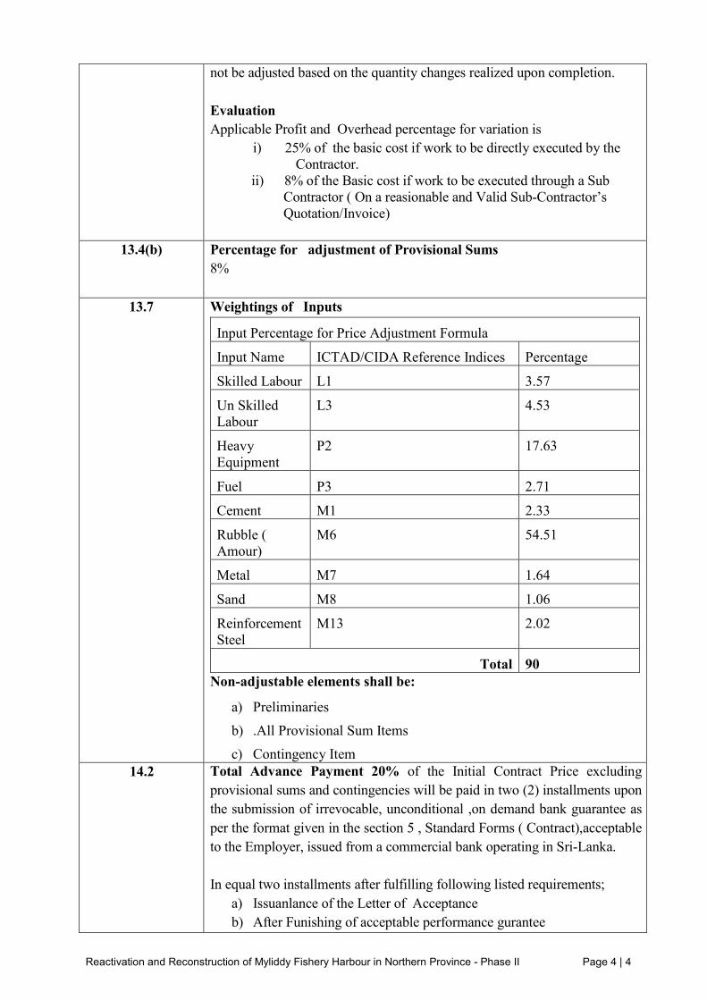
not be adjusted based on the quantity changes realized upon completion.
Evaluation
Applicable Profit and Overhead percentage for variation is
i) 25% of the basic cost if work to be directly executed by the
Contractor.
ii) 8% of the Basic cost if work to be executed through a Sub
Contractor ( On a reasionable and Valid Sub-Contractor’s
Quotation/Invoice)
13.4(b) Percentage for adjustment of Provisional Sums
8%
13.7 Weightings of Inputs
Input Percentage for Price Adjustment Formula
Input Name ICTAD/CIDA Reference Indices Percentage
Skilled Labour L1 3.57
Un Skilled
Labour
L3 4.53
Heavy
Equipment
P2 17.63
Fuel P3 2.71
Cement M1 2.33
Rubble (
Amour)
M6 54.51
Metal M7 1.64
Sand M8 1.06
Reinforcement
Steel
M13 2.02
Total 90
Non-adjustable elements shall be:
a) Preliminaries
b) .All Provisional Sum Items
c) Contingency Item
14.2 Total Advance Payment 20% of the Initial Contract Price excluding
provisional sums and contingencies will be paid in two (2) installments upon
the submission of irrevocable, unconditional ,on demand bank guarantee as
per the format given in the section 5 , Standard Forms ( Contract),acceptable
to the Employer, issued from a commercial bank operating in Sri-Lanka.
In equal two installments after fulfilling following listed requirements;
a) Issuanlance of the Letter of Acceptance
b) After Funishing of acceptable performance gurantee

Reactivation and Reconstruction of Myliddy Fishery Harbour in Northern Province - Phase II Page 4 | 5
c) After furnishing of and acceptble Advance Payment Gurantee ( for
1st Installment)
Second Installment shall released after the fulfillment of all of the following
requirements;
a) After signing the Contract Agreement
b) After furnishing of Acceptable Advence Payment Guarantee,( for
Second Installment)
c) After full completion of mobilization including but not limited to
Engineer’s Facilities,Contractor’s Facilities, services,machineries
and equipment for the use of Works at the sole discretion of the
Engineer.
10% will be released after the award of the contract and balance 10% after
fully mobilization.
14.3(c) Percentage of Retention
10% of value of Work done
14.3(c) Limit of Retention Money
5% of the Contract Price
14.5 Minimum amount Of interim payment Certificates
Rs. 10,000,000.00 (Rupees Ten million
14.8 Alternative method for payment of retention
Not Applicable for this Contract
18.2 Third Party Insurance
The Amount of insurance per occurrence is: Rupees Rs. 1,000,000.00. The
insurance policy shall be structured to include Insurance for Employer’s and
Engineer’s personals.
19.2 If the Employer and the Contractor do not agree on the appointment of the
Adjudicator prior to the signing of the agreement, the Adjudicator shall be
appointed by the Institute of Engineers- Sri Lanka.

Reactivation and Reconstruction of Myliddy Fishery Harbour in Northern Province - Phase I Page 6 | 1
SECTION 6
SPECIFICATIONS

Reactivation and Reconstruction of Myliddy Fishery Harbour in Northern Province - Phase I Page 6 | 2
Part 1 - Standard Specifications
The Standard Specifications also referred to as General Specifications for this Contract are;
Specifications for Building Works”, Volume I ICTAD Publication No. SCA/4/1, 3rd
Edition July 2004
Specifications for Building Works”, Volume II ICTAD Publication No. SCA/4/2, 2nd
Edition October 2001
Specifications for Coastal and Harbour Engineering Works”, ICTAD Publication No.
SCA/6, 2nd
Edition (Revised) June 2008.
Specifications for Water Supply Sewerage and Storm Water Drainage ICTAD
Publication No. SCA/3/2, 2nd
edition(Revised) April 2002)
Standard Specification for Construction and Maintenance of Roads and Bridges, ICTAD
Publication No. SCA/5, 2nd
Edition June 2009
Specifications for Reclamation Works”, ICTAD Publication No. SCA/3/3, 2nd
Edition
(Revised) December 1999.
Electrical & Mechanical Works, ICTAD Publication No. SCA/8, 2nd
Edition (Revised)
August 2000
These standard specifications can be purchased from Construction Industry Development
Authority, CIDA (formally Institute for Construction Training and Development (ICTAD)),
“Sausiripaya”, 123, Wijerama Mawatha, Colombo 7, Sri Lanka.
Part 2 – Particular Specifications
The “Particular Specifications” also referred as “Technical Specifications” and also referred to
as “Special Provisions” contained herein shall be read in conjunction with the Standard
Specification and shall supplement, replace or supersede the Standard Specifications as
appropriate. Where there is an ambiguity or discrepancy between the Standard Specifications
and the Particular Specifications, the Particular Specifications shall have preference and shall
govern.

Reactivation and Reconstruction of Myliddy Fishery Harbour in Northern Province - Phase I Page 6 | 3
TABLE OF CONTENTS
100. GENERAL REQUIREMENTS ..........................................................................................11
101. GENERAL ..................................................................................................................................... 11
101.1. SCOPE OF WORKS AND BACKGROUND ......................................................................... 11
101.2. ORGANIZATION AND INTERPRETATION OF CONTRACT DOCUMENTS ................. 12
101.3. DESCRIPTION OF PROJECT ................................................................................................ 12
102. CONTROL OF WORKS ............................................................................................................... 13
102.1. EXECUTION SEQUENCE ..................................................................................................... 13
102.2. FISH HARBOUR OPERATIONS AND CONTRACTORS WORK ...................................... 13
102.3. CONTRACTORS WORKING AREAS .................................................................................. 13
102.4. CLEARING OF SITE .............................................................................................................. 14
102.5. WORK EXECUTED BY OTHERS ......................................................................................... 14
103. SITE ACCESS ............................................................................................................................... 14
103.1. CONTRACTOR‟S STAFF ACCESS ...................................................................................... 14
103.2. LAND ACCESS ....................................................................................................................... 14
103.3. MARINE ACCESS .................................................................................................................. 15
104. FACILITIES FOR THE ENGINEER ............................................................................................ 15
104.1. ENGINEER'S OFFICE ............................................................................................................ 15
104.2. HOUSING FOR THE ENGINEER'S STAFF .......................................................................... 17
104.3. TRANSPORT FOR ENGINEER‟S (CONSULTANT‟S) STAFF ........................................... 19
104.4. CLERICAL AND OFFICE SUPPORT STAFF ....................................................................... 20
104.5. TESTING LABORATORY ..................................................................................................... 20
104.6. SURVEY ASSISTANCE ......................................................................................................... 21
104.7. SAFETY GEAR ....................................................................................................................... 22
105. CODE OF PRACTICE & STANDARDS ..................................................................................... 22
105.1. GENERAL ............................................................................................................................... 22
106. INTERFERENCE WITH EXISTING ACTIVITIES .................................................................... 23
107. ENVIRONMENTAL COMPLIANCE MEASURES .................................................................... 23
107.1. EARTHWORK AND SOIL CONSERVATION ..................................................................... 24
107.2. WATER–PROTECTION OF WATER QUALITY ................................................................. 26
107.3. AIR POLLUTION .................................................................................................................... 28
107.3.1. GENERATION OF DUST ....................................................................................................... 28
107.3.2. EMISSION FROM CONSTRUCTION EQUIPMENT, MACHINERY AND FACILITIES . 28
107.3.3. ODOUR AND OFFENSIVE SMELLS ................................................................................... 29
107.4. NOISE POLLUTION AND VIBRATION .............................................................................. 29
107.4.1. NOISE FROM VEHICLES, PLANTS AND EQUIPMENT ................................................... 29
Reactivation and Reconstruction of Myliddy Fishery Harbour in Northern Province - Phase I Page 6 | 4
107.4.2. VIBRATION ............................................................................................................................ 29
107.4.3. NOISE FROM BLASTING OR PRE-SPLITTING OPERATIONS ....................................... 30
107.5. IMPACT ON FLORA AND FAUNA ...................................................................................... 30
107.5.1. LOSS OR DAMAGE TO FLORA AND FAUNA................................................................... 30
107.5.2. CHANCE FOUND IMPORTANT FLORA OR FAUNA ....................................................... 30
107.6. DISRUPTION TO USERS ....................................................................................................... 30
107.6.1. LOSS OF ACCESS .................................................................................................................. 30
107.7. ENVIRONMENTAL MITIGATION REQUIREMENTS ....................................................... 31
107.7.1. TURBIDITY CURTAIN .......................................................................................................... 31
108. HEALTH AND SAFETY REQUIREMENTS .............................................................................. 32
108.1. GENERAL ............................................................................................................................... 32
108.2. SAFETY PROGRAM .............................................................................................................. 32
108.3. TRAINING ............................................................................................................................... 32
109. PROTECTION OF THE WORKS ................................................................................................ 33
110. PROJECT SIGN BOARDS ........................................................................................................... 33
110.1. DESCRIPTION ........................................................................................................................ 33
111. SUBMITTALS .............................................................................................................................. 34
111.1. GENERAL ............................................................................................................................... 34
111.2. SUBMITTAL PROCEDURES ................................................................................................ 34
111.3. SHOP DRAWINGS ................................................................................................................. 35
111.4. SAMPLES ................................................................................................................................ 36
111.5. QUALITY CONTROL SUBMITTALS................................................................................... 37
111.6. ADMINISTRATIVE SUBMITTALS ...................................................................................... 37
111.7. RECORD CONTRACT DRAWINGS ..................................................................................... 38
111.8. CONSTRUCTION PHOTOGRAPHS ..................................................................................... 38
111.9. CONTRACT CLOSEOUT SUBMITTALS ............................................................................. 38
112. QUALITY PROGRAM ................................................................................................................. 38
112.1. CONTRACTOR‟S OBLIGATION .......................................................................................... 38
112.2. COORDINATION MEETING ................................................................................................. 39
112.3. CONTENT OF QUALITY ASSURANCE PROGRAM ......................................................... 39
112.4. QUALITY ASSURANCE AND QUALITY CONTROL ORGANIZATION ........................ 39
112.5. QUALITY TESTS .................................................................................................................... 40
112.6. PARTIAL COMPLETION INSPECTIONS ............................................................................ 43
112.7. FINAL INSPECTION OF CONSTRUCTION WORK ........................................................... 43
112.8. QUALITY ASSURANCE DOCUMENTATION .................................................................... 44
112.9. NOTIFICATION OF NONCOMPLIANCE ............................................................................ 44
112.10. QUALITY ASSURANCE AND CONTROL .......................................................................... 45

Reactivation and Reconstruction of Myliddy Fishery Harbour in Northern Province - Phase I Page 6 | 5
113. CONTRACT CLOSEOUT ............................................................................................................ 45
113.1. GENERAL ............................................................................................................................... 45
113.2. FINAL SUBMITTALS ............................................................................................................ 45
113.3. RELEASE OF LIENS OR CLAIMS ........................................................................................ 45
113.4. FINAL CLEANING ................................................................................................................. 45
113.5. FINAL INSPECTION .............................................................................................................. 46
200. BREAKWATERS ................................................................................................................47
201. GENERAL DESCRIPTION .......................................................................................................... 47
202. REFERENCES .............................................................................................................................. 47
203. ROCK MATERIALS ..................................................................................................................... 48
203.1. SOURCES OF ROCK MATERIALS ...................................................................................... 48
203.2. ROCK PROPERTIES .............................................................................................................. 48
203.3. CLASSIFICATION .................................................................................................................. 49
203.4. DELIVERY OF STONE MATERIALS .................................................................................. 49
204. CONSTRUCTION ......................................................................................................................... 50
204. 1. BREAKWATERS .................................................................................................................... 50
205. FINAL INSPECTIONS AND SURVEYS .................................................................................... 51
300. QUAY WALLS ....................................................................................................................53
301. SCOPE OF WORK ........................................................................................................................ 53
302. REFERENCES .............................................................................................................................. 53
303. MATERIALS ................................................................................................................................. 54
303.1. CONCRETE FOR MARITIME STRUCTURES ..................................................................... 54
303.2. GABIONS ................................................................................................................................ 54
303.3. EXPANSION JOINT FILLERS ............................................................................................... 54
303.4. FILTER FABRIC BEHIND QUAY WALLS (GEOTEXTILES) ........................................... 55
304. CONSTRUCTION ......................................................................................................................... 55
305. WORKMANSHIP ......................................................................................................................... 56
305.1. SHOP DRAWINGS ................................................................................................................. 56
305.2. WELDING ............................................................................................................................... 56
305.3. BOLTING ................................................................................................................................. 57
305.4. CORROSION PROTECTION OF STEEL .............................................................................. 57
500. CONCRETE .........................................................................................................................58
501. INTRODUCTION ...................................................................................................................... 58
502. REFERENCES .............................................................................................................................. 58
503. MATERIALS ................................................................................................................................. 59
503.1. GENERAL ............................................................................................................................... 59

Reactivation and Reconstruction of Myliddy Fishery Harbour in Northern Province - Phase I Page 6 | 6
503.2. CEMENT .................................................................................................................................. 59
503.3. AGGREGATES ....................................................................................................................... 59
503.4. MIXING WATER .................................................................................................................... 61
503.5. ADMIXTURES ........................................................................................................................ 61
503.6. REINFORCEMENT ................................................................................................................. 62
504. CONCRETE COMPOSITION ...................................................................................................... 62
504.1. MIX PROPORTIONS .............................................................................................................. 62
504.2. PROPERTIES OF FRESH CONCRETE ................................................................................. 62
504.3. CONCRETE TRIALS .............................................................................................................. 63
505. PRODUCTION OF CONCRETE .................................................................................................. 63
505.1. GENERAL ............................................................................................................................... 63
505.2. PRODUCTION PROGRAM .................................................................................................... 63
505.3. EQUIPMENT ........................................................................................................................... 63
505.4. DELIVERY AND STORAGE OF MATERIALS ................................................................... 64
505.5. BATCHING ............................................................................................................................. 64
505.6. MIXING ................................................................................................................................... 64
505.7. TRANSPORT ........................................................................................................................... 64
506. INSPECTION AND TESTING ..................................................................................................... 64
506.1. GENERAL ............................................................................................................................... 64
506.2. TESTING OF MATERIALS.................................................................................................... 65
506.3. TESTING OF COMPOSITION ............................................................................................... 65
506.4. CONCRETE TRIALS AND TESTING OF STRENGTH ....................................................... 66
506.5. TRIAL POUR ........................................................................................................................... 66
506.6. CONCRETE DEEMED NOT TO COMPLY .......................................................................... 66
506.7. DATA AND INSPECTION ..................................................................................................... 67
507. FORMWORK ................................................................................................................................ 67
507.1. GENERAL ............................................................................................................................... 67
507.2. DESIGN AND CONSTRUCTION .......................................................................................... 67
507.3. CLEANING AND TREATMENT ........................................................................................... 67
507.4. CONSTRUCTION TOLERANCES ........................................................................................ 68
507.5. INSPECTION AND APPROVAL ........................................................................................... 68
507.6. STRIKING OF FORMWORK ................................................................................................. 68
508. REINFORCEMENT ...................................................................................................................... 68
508.1. GENERAL ............................................................................................................................... 68
508.2. HANDLING, CUTTING AND BENDING ............................................................................. 68
508.3. PLACING AND FIXING ......................................................................................................... 69
508.4. WELDING ............................................................................................................................... 69

Reactivation and Reconstruction of Myliddy Fishery Harbour in Northern Province - Phase I Page 6 | 7
508.5. LAPS ........................................................................................................................................ 69
508.6. EMBEDDED ITEMS ............................................................................................................... 69
508.7. DELAYS DUE TO REJECTION OF REINFORCEMENT .................................................... 69
509. CONCRETE PLACEMENT.......................................................................................................... 70
509.1. PLACING ................................................................................................................................. 70
509.2. COMPACTION ........................................................................................................................ 70
509.3. CONSTRUCTION JOINTS ..................................................................................................... 71
509.4. UNDERWATER CONCRETE ................................................................................................ 71
510. TREATMENT AND CURING ..................................................................................................... 71
510.1. UPPER SURFACES ................................................................................................................ 71
510.2. MOIST CURING ..................................................................................................................... 72
510.3. PROTECTION ......................................................................................................................... 72
510.4. PROVISIONS AGAINST EARLY THERMAL CRACKING ................................................ 72
510.5. HOT WEATHER REQUIREMENTS ...................................................................................... 72
510.6. HARDENED CONCRETE ...................................................................................................... 73
510.7. CONCRETE DEEMED NOT TO COMPLY .......................................................................... 73
510.8. DELAYS DUE TO UNSATISFACTORY TREATMENT & CURING OF CONCRETE ..... 73
600. MASONRY, TILING & PAINTING .................................................................................74
601. MASONRY .................................................................................................................................... 74
601.1. GENERAL ............................................................................................................................... 74
601.2. CEMENT .................................................................................................................................. 74
601.3. SOLID BLOCKS ...................................................................................................................... 74
602. PLASTERING ............................................................................................................................... 76
602.1. GENERAL ............................................................................................................................... 76
602.2. MATERIALS AND STORAGE .............................................................................................. 76
602.3. GENERAL PREPARATION ................................................................................................... 77
602.4. EXTERNAL PLASTERING .................................................................................................... 77
602.5. INTERNAL PLASTERING ..................................................................................................... 78
602.6. EXTERNAL RENDERING ..................................................................................................... 78
602.7. PLASTIC MESH REINFORCING / REINFORCEMENT FOR PLASTERED COATINGS 79
603. TILING .......................................................................................................................................... 80
603.1. GENERAL ............................................................................................................................... 80
603.2. CERAMIC AND VITREOUS TILE MATERIALS ................................................................ 80
603.3. INSTALLATION REQUIREMENTS ..................................................................................... 80
603.4. DEFECT AND GUARANTEES .............................................................................................. 82
604. PAINTING ..................................................................................................................................... 82
604.1. DEFINITION OF TERMINOLOGY ....................................................................................... 82

Reactivation and Reconstruction of Myliddy Fishery Harbour in Northern Province - Phase I Page 6 | 8
604.2. PAINT FINISH SYMBOLS ..................................................................................................... 83
604.3. MATERIALS ........................................................................................................................... 83
604.4. PREPARATION OF PAINT .................................................................................................... 83
604.5. PROCEDURE OF PAINTING ................................................................................................ 84
605. CEMENT RENDERING ............................................................................................................... 87
605.1. CEMENT .................................................................................................................................. 87
605.2. INTERNAL RENDERING ...................................................................................................... 87
605.3. EXTERNAL RENDERING ..................................................................................................... 88
700. WOOD FABRICATION .....................................................................................................89
701. ALUMINIUM FABRICATION .................................................................................................... 89
701.1. DRAWINGS & MATERIALS ................................................................................................. 89
701.2. DOORS & WINDOWS ............................................................................................................ 89
701.3. DOORS, WINDOWS & PARTITIONS .................................................................................. 91
701.4. PUSH UP ROLLER SHUTTERS ............................................................................................ 91
701.5. TOP HUNG WINDOWS, VENTILATORS & SIDE HUNG DOORS ................................... 92
701.6. LOUVERS ................................................................................................................................ 93
701.7. INSTALLATION ..................................................................................................................... 93
701.8. SEALING JOINTS ................................................................................................................... 94
701.9. GLASS INSTALLATION ....................................................................................................... 94
701.10. GLAZED/NON GLAZED PARTITIONS ............................................................................... 95
702. STRUCTURAL TIMBER FABRICATION.................................................................................. 95
702.1. GENERAL ............................................................................................................................... 95
702.2. FABRICATION ....................................................................................................................... 97
703. DOOR & WINDOW FABRICATION .......................................................................................... 98
704. ROOF INSTALLATION ............................................................................................................... 98
704.1. DESIGN CONSIDERATIONS ................................................................................................ 98
704.2. ROOF CLADDING .................................................................................................................. 99
704.3. RIDGE CAPPING & FLASHING ........................................................................................... 99
704.4. WORKMANSHIP .................................................................................................................. 100
704.5. WATER PROOFING OF CONCRETE ROOF SLABS ........................................................ 101
800. WATER SUPPLY & DRAINAGE ...................................................................................102
801. GENERAL REQUIREMENTS ................................................................................................... 102
801.1. GENERAL ............................................................................................................................. 102
801.2. RO WATER TREATMENT PLANT .................................................................................... 102
801.3. PROVISION OF DRAWINGS & MANUALS ..................................................................... 103
801.4. RECORD OF DRAWINGS ................................................................................................... 104
801.5. OPERATING AND MAINTENANCE MANUAL ............................................................... 104

Reactivation and Reconstruction of Myliddy Fishery Harbour in Northern Province - Phase I Page 6 | 9
801.6. TEST REQUIREMEMS......................................................................................................... 104
802. WATER SUPPLY INSTALLATIONS ....................................................................................... 105
802.1. MATERIALS ......................................................................................................................... 105
802.2. SAMPLES .............................................................................................................................. 105
802.3. EXCAVATION ...................................................................................................................... 105
802.4. PIPING ................................................................................................................................... 106
803. DRAINAGE INSTALLATIONS ................................................................................................ 107
803.1. MATERIALS ......................................................................................................................... 107
803.2. LAYING OF PIPES ............................................................................................................... 107
804. SANITARY FITTINGS &ACCESSORIES ................................................................................ 109
804.1. FITTINGS .............................................................................................................................. 109
804.2. FIXTURES & ACCESSORIES ............................................................................................. 109
804.3. WASH BASINS& MIRRORS ............................................................................................... 109
805. WATER TANK & PUMPING SYSTEM ................................................................................... 109
805.1. HEAD TANKS ....................................................................................................................... 109
805.2. WATER PUMP ...................................................................................................................... 110
805.3. PUMP SYSTEM REQUIREMENTS ..................................................................................... 110
806. SEPTIC TANK & SOAKAGE PIT ............................................................................................. 110
806.1. SEPTICTANK ........................................................................................................................ 110
900 ELECTRICAL INSTALLATION & EQUIPMENT ......................................................111
901. GENERAL REQUIREMENTS ................................................................................................... 111
902. L.V. MAIN SWITCH BOARDS AND SUB DISTRIBUTION BOARDS ................................. 115
902.1. GENERAL ............................................................................................................................. 115
903. FINAL DISTRIBUTION BOARD .............................................................................................. 117
903.1. GENERAL ............................................................................................................................. 119
904. LV CABLES ................................................................................................................................ 119
904.1. GENERAL ............................................................................................................................. 119
905. TERMINATION & STRAIGHT JOINTS ................................................................................... 119
906. STREET LIGHTING COLUMNS .............................................................................................. 120
906.1. DESCRIPTION ...................................................................................................................... 120
906.2. SHOP DRAWINGS ............................................................................................................... 120
906.3. MASTS FOR STREET LIGHTING ...................................................................................... 121
906.4. DETAILED DESIGNS AND SUBMITTALS ....................................................................... 121
907. CONDUIT INSTALLATIONS ................................................................................................... 121
907.1. GENERAL ............................................................................................................................. 121
907.2. INSTALLATION ................................................................................................................... 122
907.3. CONDUIT FITTINGS ........................................................................................................... 122
Reactivation and Reconstruction of Myliddy Fishery Harbour in Northern Province - Phase I Page 6 | 10
908. GENERAL LIGHTING AND POWER INSTALLATIONS ...................................................... 123
908.1. GENERAL ............................................................................................................................. 123
908.2. INSTALLATION ................................................................................................................... 123
908.3. LIGHTING FITTINGS .......................................................................................................... 124
908.4. RECESSED FLORESCENT LIGHT FITTINGS .................................................................. 124
908.5. MATERIAL & FINISH.......................................................................................................... 125
908.6. INSTALLATION & MOUNTING ........................................................................................ 125
908.7. LIGHT FIXTURES ................................................................................................................ 125
908.8. CEILING FANS ..................................................................................................................... 126
908.9. LIGHTING SWITHES ........................................................................................................... 127
908.10. SWITCH SOCKET OUTLETS .............................................................................................. 127
909. EARTHING SYSTEM ................................................................................................................ 127
909.1. GENERAL ............................................................................................................................. 128
909.2. EARTHING EQUIPMENT .................................................................................................... 128
910. LIGHTNING PROTECTION SYSTEM ..................................................................................... 130
910.1. GENERAL ............................................................................................................................. 130
1000 MISCELLANEOUS ITEMS............................................................................................132
1001. WEIGH BRIDGE ................................................................................................................... 132
1002 BOLLARDS ........................................................................................................................... 132
1003. FENDERS .............................................................................................................................. 132
1004. BEACONS (NAVIGATION LIGHT) .................................................................................... 133
1004.1 REFERENCES ....................................................................................................................... 133

Reactivation and Reconstruction of Myliddy Fishery Harbour in Northern Province - Phase I Page 6 | 11
PARTICULAR SPECIFICATIONS
100. GENERAL REQUIREMENTS
101. GENERAL
101.1. SCOPE OF WORKS AND BACKGROUND
This section describes the background information, the project and the work to be performed
under this Contract. Detailed requirements and extent of work are stated in applicable
Conditions of Contract, Specifications and shown on the drawings.
The aim of the project is to revive the Myliddy Fishery Harbour in the Jaffna district, which had
been under the control of the Ministry of Defense during the time of conflict and therefore
unused by fishermen for fishery activities. This harbour, which has now been released for the
use of fishermen, needs extensive development or modification of existing offshore and onshore
structures and construction of new facilities if necessary. This will inevitably boost the existing
potential for fishing industry in area. Hence, to identify the development options for upgrading
the Myliddy fishery harbor is the primary objective of the project. Therefore, the planning and
designing of fishery harbor have been carried out to:
a. ensure the safe navigation and year round access by upgrading and providing suitable
marine structures
b. provide an adequate basin area & navigational facilities
c. provide the shore facilities such as auction hall, net mending hall, canteen, office rooms,
accommodations, and other required facilities.
The project will be carried out in two phases (Phase I and Phase II) as per the funds availability.
The phase 1 has been completed now.
The main works taken up for construction under this contract package for the Phase II are as
follows:-
(i) Construction/Modification of damage length (200 m) of main breakwater and
repair the core at main breakwater
(ii) New Quay Wall
(iii) Construction of basic shore facilities as mentioned below
(ii) Construction of basic shore facilities as mentioned below
Manager's Quarters for HM & DHM
Bachelor‟s Quarters
External Works

Reactivation and Reconstruction of Myliddy Fishery Harbour in Northern Province - Phase I Page 6 | 12
101.2. ORGANIZATION AND INTERPRETATION OF CONTRACT DOCUMENTS
Specifications and Drawings included in these Contract Documents establish the performance
quality requirement, location and general arrangement of materials and equipment, and establish
the acceptable standards for quality of workmanship and appearance.
Specification sections have not been divided into groups for work of separate Contractors, sub-
Contractors, or various trades. There should be questions concerning the applicability or
interpretation of a particular section or part of a section or Drawing, such questions shall be
directed to the Employer for resolution. Work show on the Drawings is intended to be depictive,
is not exact and is not intended to show the complete representation of the actual finished work,
even though some items may not be specifically shown on the Drawings.
A part of the work that is necessary or required to complete the work for its intended purpose,
even though it is not specifically included in the Specifications or on the Drawings, shall be
performed as incidental work as if it were described in the Specification and shown on the
Drawings.
The Contractor shall perform all Works under this Contract; the Contractor shall ensure that the
construction is completed in accordance with the Contract and approved designs.
101.3. DESCRIPTION OF PROJECT
The fishery harbour has been proposed to develop with the basin area of 3.8 Ha and the entrance
channel width of 60m. The works consist of rehabilitation of 200m length of the main
breakwater mentioned in Drawing No. LHI/ML/LO/1and providing the shore facilities as
mentioned in Section 101.1.
All necessary shore facilities are shown in the Drawing No. LHI/ML/LO/1General Layout and
some of them were provided at the Phase I. The facilities need to be provided in the shore area
includes buildings for auction hall, coast guard office and accommodations, storage rooms for
boat engine, administration building including shops and the security office and managers
quarters for HM & DHM under this Phase II contract and those items are separately listed in
LHI/ML/LO/1. Further this contract will includes the supping the water and electricity facilities
as well as the landscaping (Drawing No.LHI/ML/LS/LO/1) for the entire harbour.
101.3.1. PRIMARY WORK
The Work is to be performed under these Contract Documents.
101.3.2. COMPLEMENTARY WORK
Complementary work covered by these Contract Documents includes, but is not necessarily
limited to, the following:
Conduct the Work in a safe manner with zero safety incidents by providing training to
construction personnel in conducting work safely and with sound construction methods.
Construction Risk Management Plan (CRMP) to be developed, maintained and implemented
throughout the period of construction.(as described in sub-clause 103.2 below)
Provide training to local personnel in sound construction methods.

Reactivation and Reconstruction of Myliddy Fishery Harbour in Northern Province - Phase I Page 6 | 13
101.3.3. OTHER PROJECT DESCRIPTION CONSIDERATIONS
Upon successful completion and adherence to all Conditions of Contract, Specifications and
Drawing requirements, the final Works shall be turned over to the Ceylon Fishery Harbour
Corporation (CFHC). All works will be carried out in a safe and secure manner and follow the
safety and security plan established by the Contractor for these works.
Work shall be conducted to minimize disruption of the harbor operations as required in the
Contract.
The Contractor shall, except as otherwise specifically stated in applicable parts of these Contract
documents, provide and pay for all labor, materials, equipment, tools, construction equipment,
design and construction facilities, and services necessary for proper execution, testing and
completion of the work.
The Contractor shall take all necessary cautions and provisions to handle any debris or
obstructions within the fish harbor properties when performing the Works.
102. CONTROL OF WORKS
102.1. EXECUTION SEQUENCE
The Contractor shall program the construction sequences for the fishery harbor and submit a
written statement thereof for the approval of the Employer and in accordance with project
control procedures. The construction sequence shall consider, as a minimum, each phase of the
construction activities at fishery harbor with respect to submittal reviews, existing fish harbor
operations, environmental compliance, and the effects on the competed Works.
The control of traffic during the construction will be in accordance with the Specification.
Where the construction sequence has been agreed in accordance with the Contract, the
Contractor shall follow the sequence of construction submitted. Any deviation shall be pre-
approval prior to commencement.
The Contractor may propose an alternative construction sequence provided he can demonstrate,
in a written statement, that the sequence is not detrimental to the Works or fish harbor operations
users in any way. No construction work shall commence at a fish harbor until the written consent
to the construction sequence has been given by the Employer in compliance the General
Conditions of Contract.
102.2. FISH HARBOUR OPERATIONS AND CONTRACTORS WORK
Myllidy is actively fishing operation area in which the livelihood of the fishermen is maintained.
The Contractor shall conduct all Works in such manner to minimize any impacts to the fishing
operations. The Contractor shall not allow equipment traffic or the construction operations
within the Fish Harbor at or near the fish harbor auction selling activities during peak time
periods of fishing activities, shall be incidental to the Work and shall not be allowed for
additional cost or time extension to the Contract.
102.3. CONTRACTORS WORKING AREAS
The Contractor shall demarcate by fencing the essential work areas in consultation with the
Engineer and shall be responsible for safety and security of the works and contractor's property.
The Contractor shall organize his construction work in close coordination with the Engineer,

Reactivation and Reconstruction of Myliddy Fishery Harbour in Northern Province - Phase I Page 6 | 14
client and the local authorities and ensure all normal harbor operations and construction works
are not disturbed.
The Contractor shall make his own arrangements with property owners, to obtain necessary
areas and facilities outside the harbor area where necessary and shall include all costs in the
respective items. Unless otherwise agreed with the property owners (public and private), the
working areas at end of contract shall be brought back to the original conditions.
102.4. CLEARING OF SITE
The Contractor upon completion of work, shall clear all work sites and staging area(s) and labor
camps of all debris, garbage, and other waste. Also, all temporary structures constructed shall be
cleared from the harbor premises. All such material and waste shall be taken away from the
harbor premises. Any disposal of waste shall be carried out both environmentally and legally
acceptable manner.
102.5. WORK EXECUTED BY OTHERS
The Employer and the Ceylon Fishery Harbors Corporation (CFHC) reserves the right to
execute, on the Site, works not included in the Contract and to employ for this purpose either his
own employees or other Contractors (see General Conditions of Contract).
The Contractor shall ensure that neither his own operations nor the actions of his employees
shall interfere with the operations of the Employer or his Contractors or CFHC‟s Contractors on
such works and the same obligations shall be imposed on the Employer or Contractors in respect
of work being executed under the Contract.
The Contractor shall provide by mutual arrangement, unhindered access to all parts of the Site to
the Employer and authorized representatives of the Employer and of public bodies and
corporations and to Contractors employed by the Employer and he shall make available to such
authorized persons the use of all temporary access tracks in or about the Site.
103. SITE ACCESS
103.1. CONTRACTOR’S STAFF ACCESS
The Contractor shall submit all Contractors‟ staff identification and requested information to
meet all clearance regulations to allow entrance to the harbor as requested by the authorities. A
list of Contractor‟s staff meeting all clearance regulations will be maintained at the fishery
harbor gate. Contractor‟s staff shall sign in and out at the harbor.
103.2. LAND ACCESS
The access to the respective harbors and haulage routes from quarries to the harbors shall be
along the existing public roads (major and minor), or existing tracks and passages.
The Contractor shall make his own arrangements for the use of the roads he chooses, with the
relevant authorities responsible for maintenance of the roads including the culverts and bridges.
All necessary improvements, maintenance during construction and reinstatement at the end of
the Contract, will be the responsibility of the Contractor, and shall be to the satisfaction of the
relevant authorities.

Reactivation and Reconstruction of Myliddy Fishery Harbour in Northern Province - Phase I Page 6 | 15
103.3. MARINE ACCESS
The Contractor‟s access to the working areas from the seaside and loading and unloading points
and stockpile areas hall be arranged with the Engineer/Employer and shall not interfere with the
existing traffic, including fishing activities.
104. FACILITIES FOR THE ENGINEER
104.1. ENGINEER'S OFFICE
The Contractor shall provide and maintain a site office for the sole use of Engineer / Engineer‟s
Representative (Consultant) and Staff. The site office shall be made available from the
commencement to the completion of the work.
The office facility with furnishing and equipment shall remain the property of the Contractor and
shall be returned to him with no compensation for fair wear, tear or breakage. It shall be fully
functional and available for the Engineer's use within 14 days from the award of the Contract and
until a date to be instructed by the Engineer, but not longer than to the end of the first calendar
month after the date of the Taking-Over Certificate.
The office shall be located in the working area in the proximity of the contractor's site office and as
approved by the Engineer.
The office shall be of good quality, well insulated and supplied with clean portable water,
electrical lights and fans, telephone and fax, Internet facility, air conditioning, water closet,
furniture, equipment and other facilities as described below. The office shall be provided with all
weather road access and covered vehicle parking space for three vehicles. The office area shall be
suitably graded and drained and provided with security fencing and entrance gate.
The Contractor shall make the necessary provision for the proper discharge of sewage and wastes.
The cost of providing, maintaining, cleaning and washing the office and equipment and cost of
water, Internet and electricity consumed, shall be included in the prices inserted against the
appropriate item in the Bills of Quantities. A provisional sum item has been provided in the Bills
of Quantities, for reimbursement of cost of all telephone charges consumed by the Engineer and
his staff.
The site office shall include the rooms listed below and can be contained in a building of minimum
30 m² in floor area. Rooms required and minimum areas are:
Resident Engineer and General use of supervisory and office staff 20 m2
Store, tea room and toilet 10 m2
The toilet shall be equipped with WC inclusive of accessories for hand washing and shower. The
installations shall be connected to an emergency water tank of minimum 500 l. All rooms shall be
accessible internally through an inter-connecting corridor. All doors shall be lockable. The office
building shall have overhanging eaves and shall be liberally provided with windows. Windows
shall be fitted with clear glass and mosquito netting and shall be capable of being open with either
hinged frames or louver type ad shall be fitted with security grills.
The proposed layout and construction of the Engineer's office shall be submitted to the Engineer
for approval immediately after the acceptance of the Contractor's tender. The office shall be
erected within three weeks from the time of mobilization on Site.

Reactivation and Reconstruction of Myliddy Fishery Harbour in Northern Province - Phase I Page 6 | 16
The following furniture/equipment and facilities shall be provided to the Engineer's approval:
ITEM DESCRIPTION NUMBER
Senior Executive Tables 0.9m x 1.8m with 4 Drawers with senior executive
type rotating chair 1
Executive Tables 0.75m x1.5m with 2 Drawers on either side, with a
junior executive type rotating chair 3
Typist/Secretary Tables 0.9m x1.8m with 2 Drawers on one side and table top
provision for FAX machine, Main telephone etc.
with rotating chair
1
Computer Tables Purpose made with rotating chair 2
Conference Table 1.2m x2.0m with 06 Nos. Chairs 1
Visitors chair On MS frame with cushion seat and back rest 8
Steel Lockable book
shelves 2m x 1m x 0.35m (H,W,D) with shelves and 2 doors 1
Steel Filing Cabinet with 4 drawers 1
Book Shelves 1m x2m x0.3 3 shelves 3
Bullet 1
Stapler No. 56 Heavy Duty 1
Puncher 2 - holes Heavy duty for punching up to 50 papers of
80 gsm rating 1
Pencil Sharpener Table type 1
Water Dispenser Water dispenser with matching stand to provide cold
water and regular supply of bottled potable water
with spare bottles
1
Computer Desktop
Intel core i7 6th
generation or higher Processor (Quad
core ,6MB,4T,3.2GHz,65W), with 8GB RAM or
higher, 1TB 7200rpm Hard Disk, DVD +/-RW,
Operating system Windows 10 Professional 64bit,
17" LED Monitor With UPS
1
Software for computers MS Office 2016 Professional Full Package, 2016
Adobe Acrobat Professional Writer and AutoCAD
2016
Multipurpose Printer (A4) Printer, A4 Copier and A4 Fax 1
Telephones CDMA phone registered in all regions.
1
Mobile phone registered in all regions.
2
Fire Extinguishers Based on area of facility and as approved by local
regulation 1
First Aid Box As approved by Engineer – office 1
Waste paper basket 4
Tea Service Complete set for 12 - Persons 1
Electric Kettle 2 liter capacity. 1
Refrigerator 120 liter capacity 1
Doormats Complete Set 1
Curtains Complete Set 1

Reactivation and Reconstruction of Myliddy Fishery Harbour in Northern Province - Phase I Page 6 | 17
Cleaning Equipment
Toilet
Complete Set 1
Cleaning Equipment
Kitchen Complete Set 1
Cleaning Equipment
General Complete Set 1
All items provided shall be new and all software shall be originals. Contractor shall submit all
details of equipment for the approval of the Engineer before purchase. All expensive
equipments shall have full two year warranties and shall be immediately replaced at the request
of the Engineer, if not operable.
The Contractor shall supply writing/typing paper, pads, scientific calculators, scale rules,
compasses, pencils, pens, toners for printers, and similar stationery items. The Contractor shall
also supply and regularly replenish stock of consumable items such as toilet paper, hand wash,
soap etc., tea and coffee bottled distinguisher and all items of a minor nature to permit the efficient
functioning of the office. Daily cleaning shall be provided.
The contractor shall make arrangement with relevant authorities to obtain telephone, internet,
water and electricity services to the office.
Day and Night Watchmen and a full-time tea-boy shall be provided.
104.2. HOUSING FOR THE ENGINEER'S STAFF
The Contractor shall provide and maintain one house fully furnished with a minimum plinth area
of 180m2 for accommodation of the Engineer‟s staff. The accommodation with its furniture and
utensils shall be fully functional and available from not later than 30days after award of the
Contract and until a date to be instructed by the Engineer, but not longer than to the end of the first
calendar month after the date of the Taking-Over Certificate. Until the accommodation is fully
functional and available, contractor to provide the hotel accommodation for Engineer/Engineer
representative (Engineer).The furniture and utensils shall remain the property of the Contractor
and shall be returned to him with no compensation for fair wear, tear or breakage.
It shall have a minimum of 3 bedrooms each having a floor area approximately 14 m2, a living
and a dining room, a kitchen, a store, a minimum of two toilets (one should be attached to the
Master bedroom), a servant‟s toilet and an enclosed garage to park 1 vehicle. The walls and
windows shall be permanent with doors lockable from both sides and the windows from inside
only. The floor shall be brick paved and cement rendered (minimum) with cement floating.
The building shall have electricity supply, clean portable water supply and drainage facilities.
The building shall have adequate electrical lighting, 5 A socket outlets for each of the bedrooms,
living, dining and kitchen. In addition, the kitchen shall be provided with a 15 A socket outlet. A
ceiling fan or a standing revolving fan should be available for each bedroom, living room and
dining room. Each of the toilets shall be equipped with a WC with a low level flushing cistern, a
wash basin, a mirror complete with all other fittings and accessories.
A stainless steel kitchen sink, pantry cupboards or other suitable furniture should be available for
the kitchen.
The premises where the building is located shall have either a masonry parapet wall or a suitable
fence (barbed wire/chain link) around with a lockable gate of minimum width of 3.25 meters.

Reactivation and Reconstruction of Myliddy Fishery Harbour in Northern Province - Phase I Page 6 | 18
The premises shall be within 2 km radius from the work site and subject to the approval of the
Engineer.
The following items of furniture and utensils are to be provided by the Contractor for the houses
of Engineer‟s staff. The items of furniture and utensils supplied shall be new subject to the
Engineer‟s approval. Items to be provided are to be decided by the Engineer and details of the
type and manufacture of the various items shall be submitted to the Engineer for his approval
prior any order being placed by the Contractor.
4 Nos. Verandah chairs
1 set Drawing Room suite comprising 1 settee, 2 armchairs, 1 centre table and 2 drinking
stools
1 No. Dining Table for 6 persons, 6‟ x 3‟ table top 6 Nos. Dining Chairs cushioned
1 No. Bookshelf (2 shelves) 1200mm x 300mm x 800mm
1 No. Senior executive table with 2 or 3 lockable drawers on either side 5‟x5‟ table top steel
4 Nos. Armchairs of which 2 nos. to be in the Master bedroom
4 Nos. Single beds 1980 x 900mm complete with 100mm thick mattresses of which 2 nos. to
be in the Master bedroom
1 No. Steel Almirah (Cupboard) approx.1000mm side 500mm deep and 1800mm high
2 Nos. Dressing Table with mirror and shelf
2 Nos. Clothes stand of which 1 no. to be in the Master bedroom
1 No. 1500w or more Electric Iron and Ironing Board
1 No. Water Dispenser- Water dispenser with matching stand to provide cold water and
regular supply of bottled potable water with spare bottles
1 No. Kitchen cupboard
1 No. Gas cooker 2 burner table model complete with hose and regulator
1 No. Cooking Gas Cylinder 13 kg
1 No. Electric Kettle
1 No. Kitchen table 1200 x 900mm
1 No. Electric Refrigerator capacity 8 cu.ft.
4 Nos. Doormats
1 Set stainless Cutlery for 6 persons
1 set Ceramic Tea Set for 6 persons
1 set Ceramic Dinner Set for 6 persons
1 No. Rice Cooker 2 litre or above
1 set non stick Saucepans 6 pieces
6 Nos. Drinking Glasses
1 No. Executive table with 2 lockable drawers for the Master bedroom, 5‟x 3‟

Reactivation and Reconstruction of Myliddy Fishery Harbour in Northern Province - Phase I Page 6 | 19
Table top steel
4 Nos. Mosquito Nets – double bed of which 2 Nos. to be in the Master bedroom
A full time house boy shall be provided
104.3. TRANSPORT FOR ENGINEER’S (CONSULTANT’S) STAFF
104.3.1. VEHICLES
The Contractor shall provide at site with the engineer‟s approval, fully functional and available
for the exclusive use of Engineer and Engineer Staff a reconditioned vehicle of not older than
2016 registration, and of approved manufacture, registered in the Contractor's name:
1 No. Diesel powered, four-wheel-drive vehicle, twin cab pickup with fiber glass lockable
canopy, of engine capacity of not less than 2800cc equipped with air conditioning;
The Contractor shall keep clean and maintain the vehicles in first class condition. He shall
provide all fuel, spare parts, consumable store and oil necessary and shall keep the vehicle
insured under a fully comprehensive policy with an insurance company approved by the
Engineer.
The Contractor shall provide and approved by Engineer an experienced, full-time driver for the
vehicle and bear all costs of drivers including salaries, overtime, subsistence etc.
104.3.2. FLOATING CRAFT OR BOAT
The Contractor shall provide and maintain motorized boats with boat operators for the use of the
Employer and his staff to access work site during Contractor work operations for any purpose at
all times, seven days per week.
For boat, the Contractor shall provide a competent, qualified boat operator, with a minimum of 5
years of boat operation experience. All boat operators shall follow standard safety guidelines,
the Contractor‟s Safety Program. All boats shall meet the safety requirements of the Contract
and of the fish harbors. All boat operators shall have mobile phones provided by the Contractor.
The boats shall be suitable for sea travel safely inside and outside of the harbor. The boats shall
have adequate seating area for a minimum of 8, covered area, emergency flotation devices for all
passengers, first aid kit, tool kit and be of standard approved by the Engineer. The boats shall be
provided no later than 30days from the Commencement Date.
104.3.3. FLOATING CRAFT/ BOAT SAFETY REQUIREMENTS
The Contractor shall ensure the safe mooring of all the floating craft engaged by him for the
works during normal times, rough weather and storms. The moorings shall be located so as not
to interfere with any traffic in the area at any time.
All floating craft shall be provided with sufficient, proper and efficient life saving, fire fighting
and first aid appliances which shall be available for use at all times.
For all the craft sea worthy certificates shall be obtained from appropriate authorities as
applicable.
Buoys, moorings and fastenings for securing the Contractors floating craft during the
continuance of the Contract shall be provided and maintained by the Contractor and he shall be

Reactivation and Reconstruction of Myliddy Fishery Harbour in Northern Province - Phase I Page 6 | 20
responsible for any accident of damage caused by the failure of such moorings and fastenings
and drifting of the buoys and the floating craft.
The liability of the Contractor shall be the same as aforesaid even if he is allowed, at his own
request, the use of the Employers buoys, moorings and fastenings, it being understood that the
Contractor has investigated the suitability of such facilities of the Employer before using them.
The Contractor shall also provide and maintain such mark buoys with adequate lighting as may
be deemed necessary by the Engineer to warn vessels of the existence of any obstacles as a result
of the Contractors work.
104.4. CLERICAL AND OFFICE SUPPORT STAFF
The Contractor shall provide the Engineer with staff to assist in the site office administration and
execution of the Works. The staff provided shall be experienced and be capable of performing
their allotted duties.
The staff shall include an Administrator/Clerk at the site office of the Engineer with a minimum
of 3 years of similar experience and shall be experienced in using computers/word processors,
spreadsheets and be capable of using the latest version of Microsoft Office computer software,
conversant with the use of standard office equipment and have a good command of the English
Language. The staff shall also include a Draughtsman with minimum 3 years experience with
NCT or equivalent qualification including quantity surveying.
The Engineer shall select the persons from those offered by the Contractor by following a
suitable screening process. The Contractor shall ensure the continuity of the services of the
selected personnel, payment of their salaries and emoluments in accordance with the applicable
local regulations and shall also be provided with appropriate accommodations and transport to
and from the project location and project site. These staff shall not have access to the
Employer‟s/ Engineer‟s accommodations nor transportation vehicles.
The Contractor will be obliged to pay for overtime or leave in accordance with the applicable
local regulations for the staff. The Contractor shall hire these staff such that all costs by the
Contractor will be inclusive of any accommodations and transport required by the staff.
104.5. TESTING LABORATORY
The Contractor shall have access to a laboratory for the testing of materials, concrete, soil,
pavement, etc. in accordance with the requirements in the Specifications. Third party laboratory
was selected and submitted by the Contractor to Engineer for his approval with profile and other
relevant documents. The laboratory shall be equipped with all necessary apparatus, electricity,
water supply, and portable gas supply.
The laboratory shall be staffed with qualified technicians capable of carrying out tests, making and
keeping record of tests. The technicians shall be experienced in concrete testing and soil
mechanics techniques, etc.
The Engineer reserves the right to supervise the testing.
Laboratory equipment shall cover, but shall not be limited to, the following tests:
(a) Testing of Concrete
Equipment for sampling fresh concrete for all required tests in accordance with BS 1881, Part
101 (*)

Reactivation and Reconstruction of Myliddy Fishery Harbour in Northern Province - Phase I Page 6 | 21
Equipment for testing fresh concrete in accordance with BS 1881. Reference is made to Parts of
BS 1881
Slump Test: Part 102
Air Content: Part 106;
Equipment for making, curing and testing strength of concrete cube specimens in accordance
with BS 1881, Parts 108 and 111 (*);
Equipment for testing saturated and dry densities of concrete specimens in accordance with BS
1881, Part 114 (*);
Suitable thermometer for determination of temperature of concrete samples.
(b) Testing of Fill
Equipment for determination of particle size distribution in accordance with BS 1377 (*)
Equipment for execution of compaction tests in accordance with BS 1377
(c) Welds and Coatings
Equipment for inspection of welds for surface flaws (magnetic particle techniques) in
accordance with BS 5500, clause 5.6 (*)
Equipment for inspection of coating thickness in accordance with ISO/DIS Standard 2178 (*)
To the extent the Contractor can make arrangement with existing local laboratory facilities
acceptable to the Engineer for the prompt and reliable execution of tests marked with an asterisk
(*), he need not include the corresponding equipment in his laboratory.
104.6. SURVEY ASSISTANCE
The Contractor shall during the period of the Contract, provide and maintain for the sole use of
the Engineer‟s Representative and his staff, the following survey equipment at the site.
1 no. Total Station complete with additional tripods, prism holders and prisms (can be
share with contractor)
1 no. automatic level instrument with tripod
1 no. optical squares
2 no. aluminum leveling staves 3m with splits
8 nos. ranging rods, 2m long
1 no. steel tape 50m long
1 no. linen tape, 30m long
2 nos. pocket tapes, 5m long
1 no. lead line with decimeter marks
2 nos. hammers, 2kg
Umbrella for survey equipment
Survey books

Reactivation and Reconstruction of Myliddy Fishery Harbour in Northern Province - Phase I Page 6 | 22
DGPS, Echo sounding equipments and other hydrographic equipments need to be available
when required.
Pegs, nails, paint, brushes etc., shall be provided on an “as required” basis.
During the period of construction, the Contractor shall also provide chainmen, survey labors and
other assistants as required by the Engineer‟s Representative as well as their transport.
The survey equipment shall revert to the Contractor on completion of the Contract.
104.7. SAFETY GEAR
The Contractor shall provide and maintain the following safety gear for the Engineer's
Representative and staff during the execution of the contract.
4 pairs Safety Shoes
4 pairs Rubber Boots
4 Nos. Rain Coats
4 Nos. of safety Jackets (floating)
4 Nos. Helmets
5 Nos. Helmets and 5 Nos. Safety jackets(floating) for visitors
Dust masks
105. CODE OF PRACTICE & STANDARDS
105.1. GENERAL
In the absence of any definite provisions in the Specifications on any particular issue on the
Standards, reference shall be made to the latest Codes of SLS, BS/BSEN, ISO, USACE,
CIRIA/CUR ASTM or ICTAD in this order of sequence. Where these are unhelpful for the
execution and completion of the Works, the relevant tests shall conform to sound Engineering
practice and, in case of any dispute arising out of the interpretation of the above, the decision of
the Employer shall be final and binding on the Contractor.
Where BS Tests are stipulated in the Specifications, the equivalent ASTM test method may be
substituted as directed by the Employer.
The abbreviations ITCAD, ASTM, BS, ISO and SLS shall be considered to have the following
meaning:-
ICTAD : Institute for Construction Training and Development
ASTM : American Society for Testing and Materials
BS/BSEN : British Standards Institution / British European Standards
ISO : International Organization for Standardization
SLS : Sri Lanka Standards Institution
USACE : United States Army Corp of Engineers
CIRIA/CUR : Construction Industry Research and Information Association

Reactivation and Reconstruction of Myliddy Fishery Harbour in Northern Province - Phase I Page 6 | 23
All the Codes of Practice, Standards and Specification applicable for the Works shall be the
latest edition with all corrections and incorporations as at 28 days before the closing date for
Tender submission. Any subsequent versions may be applied during the Construction by mutual
consent.
106. INTERFERENCE WITH EXISTING ACTIVITIES
All operations carried out by the Contractor during the continuance of the Contract shall be
conducted in such a manner as to avoid any interference with traffic both by land and by sea and
any commercial or traditional activities (E.g.: fishing) in the area . In the event that such
interference cannot be totally avoided the Contractor shall come into agreement with the
Engineer and/orEmployer for suitable arrangements acceptable to both parties before
commencement of the work.
The Contractor shall under no circumstances dispose of any material outside the authorized
disposal area. Should the Contractor during the continuance of the work lose, dump, throw
overboard, sink or misplace any material, plant, machinery, floating craft or appliance which is
in the opinion of the Engineer may be dangerous and/ or obstruct navigation, or any other
activity, the Contractor shall recover and remove the same with the utmost urgency. The
Contractor shall give immediate notice with description and location of such obstruction to the
Engineer and when required shall mark appropriately with buoys the position of such
obstructions until the same are removed.
107. ENVIRONMENTAL COMPLIANCE MEASURES
All work shall be in compliance with various relevant environmental requirements from
Government of Sri Lanka (GOSL). This specification extends the requirements of the GOSL,
and applies to all Works carried out by the Contractor regarding environmental compliance
including construction of any temporary or permanent structures. The environmental compliance
is for the protection and mitigation of impacts to the environment of surroundings at and near the
Limits of Work.
All items presented here shall be included in the Contractor‟s Environmental Compliance Plan,
which shall be submitted to the Engineer for approval prior to starting the works. The
Contractor‟s Environmental Compliance Plan shall be submitted no later than 45 days after the
Commencement Date.
The contractor shall carry out all his work pertaining to this contract in full compliance with the
Environmental Compliance Measures set out in this section. Contractor shall comply with all
statutory environmental requirements of GOSL regardless of whether these requirements are
explicitly included in this section. Environmental requirements in this contract means all
Environmental Compliance Measures listed in this Section and all statutory environmental
requirements of GOSL. Compliance with environmental requirements is mandatory and applies
for construction of all permanent and temporary works.
These environmental requirements are equally applicable to all sub-contractors including
nominated sub-contractors, if any. The contractor is responsible for the full compliance with
these requirements by sub-contractors including nominated sub-contractors. The contractor is
solely responsible for the compliance of environmental requirements. In order to achieve this
contractor shall prove that the contractor has a satisfactory plan for an Environmental

Reactivation and Reconstruction of Myliddy Fishery Harbour in Northern Province - Phase I Page 6 | 24
Management System to put in place by submitting an Environmental Compliance Plan (ECP)
within 45 days from the date of award of the contract for Engineer‟s approval.
The Contractor‟s Environmental Compliance Plan shall provide adequate resources for
implementation of ECP throughout the period of this contract. In addition to the compliance and
monitoring reports that the contractor agrees to provide to the Engineer as part of agreed upon
ECP, the Engineer retains the right to access the internal documents maintained by the contractor
such as “complaints register” with regard to environmental compliance by notifying the
Contractor‟s Environmental Manager verbally or in writing.
Engineer will monitor the adequacy of the contractor‟s environmental management system and
instruct the contractor in writing on how to improve the system in order to achieve the
environmental requirements. Contractor shall implement Engineer‟s instructions within 5
working days from the date of receipt of instruction, unless the contractor requests in writing for
a change or a waiver of the Engineer‟s instruction in writing within 3 days from the date of
receipt of such instructions.
Contractor shall immediately rectify any non-compliance of ECP if notified by the Engineer.
107.1. EARTHWORK AND SOIL CONSERVATION
107.1.1. DISPOSAL OF DEBRIS AND SPOIL
a. All debris and residual spoil material shall be disposed only at locations approved by the
engineer for such purpose.
b. If directed by the Engineer, the Contractor shall obtain the approval from the relevant Local
Authority for disposal of debris and spoil at the specified location.
c. The debris and spoil shall be disposed in such a manner that: (i) waterways and drainage
paths are not blocked; (ii) the disposed material will not be washed away by floods; and (iii)
it does not pose a nuisance to the public.
d. The debris and residual spoil material, including any left earth, shall be used to fill the
borrow areas as directed by the Engineer.
e. If approved by the Engineer, the Contractor may dispose the debris and spoil as a filling
material provided that the Contractor can ensure that such material is used for legally
acceptable purposes with disposal conducted in an environmentally acceptable manner and
in compliance with all relevant environmental regulations.
107.1.2. PROTECTION OF GROUND COVER AND VEGETATION
a. Construction vehicles, machinery and equipment shall be used and stationed only in the
areas of work and in any other areas designated by the Engineer.
b. The Contractor shall provide necessary instructions to drivers and operators not to destroy
ground vegetation unnecessarily.
107.1.3. BORROWING OF EARTH
a. Contractor shall comply with any environmental requirements/guidelines issued by the
Coast Conservation Department (CCD) and the respective Local Authority in regards to
locating borrow areas, and with regard to all operations related to excavation and
transportation of earth from such sites, as well as rehabilitation at the end of their use.

Reactivation and Reconstruction of Myliddy Fishery Harbour in Northern Province - Phase I Page 6 | 25
b. Borrow areas shall not be opened without the permission of the Engineer. The location,
depth of excavation and the extent of the pit or open cut area shall be as approved by the
Engineer.
107.1.4. PREVENTION OF SOIL EROSION AND SOIL FAILURES
a. The work, permanent or temporary, shall consist of measures to control soil erosion,
sedimentation and water pollution to the satisfaction of the Engineer. Typical measures
include the use of beams, dikes, sediment basins, fibber mats, mulches, grasses, slope
drains and other devices
b. The Contractor shall take all necessary steps to ensure the stability of slopes, including
those related to temporary works and borrow pits.
c. Embankment slopes, slopes of cuts, etc., shall not be unduly exposed to erosive forces.
These exposed slopes shall be graded and covered by grass.
107.1.5. CONTAMINATION OF SOIL BY FUEL AND LUBRICANTS
a. Vehicle/machinery and equipment servicing and maintenance work shall be carried out
only in designated locations/service stations approved by the Engineer. The Contractor will
avoid sensitive locations such as streams; areas just upstream of wells and springs used by
the community; and areas of flooding.
b. Waste oil, other petroleum products and untreated wastewater shall not be discharged on
the ground or into any water body. Adequate measures shall be taken against pollution of
soil by spillage of petroleum/oil products from storage tanks and containers. All waste
petroleum products shall be disposed of in accordance with any guidelines issued by CCD
or the Employer. The Contractor is responsible for obtaining the necessary disposal permit
from the Local Authority through the Employer.
c. Any site used for vehicle and plant service and maintenance shall be restored back to its
initial status. Site restoration will be considered as incidental to work.
107.1.6. DISPOSAL OF HARMFUL CONSTRUCTION WASTES
a. Prior to the commencement of work, the Contractor shall provide a list of hazardous
chemicals and/or material that will be used in the project work to the Engineer.
b. New disposal sites shall not be created as part of this project. Disposal of such waste shall
be to the sites proposed by the Contractor and approved by the Local Authority and the
Engineer. The Contractor shall also provide the list of places where such
chemicals/materials or their containers or other harmful materials have been dumped as
waste at the end of the project.
c. The Contractor shall clean up any area including water bodies affected/contaminated by
harmful construction wastes (if any) as directed by the Engineer at his own cost.
107.1.7. PROCUREMENT AND TRANSPORT OF MATERIALS
a. Rock quarries from where aggregate and/or Rock material for the marine structures is
obtained shall have approval from the relevant local authority and shall possess a current
Environmental Protection License.
b. The maintenance and rehabilitation of the access route including roads, culverts and
bridges in the event of damage by the Contractor‟s operations shall be a responsibility of

Reactivation and Reconstruction of Myliddy Fishery Harbour in Northern Province - Phase I Page 6 | 26
the Contractor, and shall be repaired to a suitable condition approved by the Engineer.
c. Pre-cast components shall be procured or manufactured in accordance with the laws and
regulations of the relevant country and location. If cast in Sri Lanka, the facility and
operations shall be in compliance with all national and local laws and regulations,
including those relating to protection of the environment.
107.1.8. BLOCKAGE OF DRAINAGE PATHS AND DRAINS
a. The Contractor shall not close or block existing canals and streams permanently. If
diversion, closure or blocking of canals and streams is required for execution of work, the
Contractor shall obtain the Engineer‟s prior approval. The Contractor shall carry out an
investigation and report to the Engineer, if an investigation is requested by the Engineer.
Contractor shall also obtain the approval from the relevant Government of Sri Lanka
(GoSL) agency prior to such action being taken. Contractors shall restore the drainage path
back to its original status once the need for such diversion or closure or blockage is no
longer required.
b. The Contractor‟s activities shall not lead to flooding conditions as a result of blocked
drainage paths and drains. The Contractor shall take all measures necessary or as directed
by the Engineer to keep all drainage paths and drains clear of blockage at all times.
c. If flooding or stagnation of water is caused by Contractor‟s activities, the Contractor shall
provide suitable means to: (a) prevent loss of access to any land or property; and (b)
prevent damage to land and property. The Contractor shall compensate for any loss of
income or damage as a result of any such activity by the Contractor.
d. The Contractor shall take measures to prevent materials, chemicals, or other items from
being washed away by rainfall. When working in periods of heavy rain and rough sea
conditions, the Contractor shall avoid storing materials, chemicals and other items of work
in areas where they can be washed away by floods or wave action.
107.2. WATER–PROTECTION OF WATER QUALITY
107.2.1. SILTATION OF HARBOR BASIN AND OTHER WATER BODIES
a. Water quality of the harbor basin within 50m of construction operations shall be monitored
during all construction activities including dredging. This measure is described in further
detail below.
b. The Contractor shall take measures necessary to prevent increase in turbidity of the harbor
basin and siltation of water bodies as a result of his work including construction of
temporary or permanent devices to prevent water pollution due to siltation and increase of
turbidity.
c. The Construction materials containing chemicals, small/fine particles and/or leachable
materials shall be stored in places not subject to flooding and in such a manner that these
materials will not be washed away by runoff.
107.2.2. CONTAMINATION OF WATER FROM CONSTRUCTION WASTES
a. The work shall be carried out in such a manner that pollution of the beach, harbor basin
natural watercourses, ponds, tanks and reservoirs is avoided. Measures shall be taken to
prevent the wastewater produced in construction from entering directly into the harbor

Reactivation and Reconstruction of Myliddy Fishery Harbour in Northern Province - Phase I Page 6 | 27
basin, beach streams, water bodies and/or irrigation systems.
b. Construction work close to streams or water bodies shall be avoided to the extent possible
during heavy rain and /or monsoon periods.
c. The discharge standards promulgated under the National Environmental Act shall be
strictly adhered to. All waste arising from the project is to be disposed in a manner that is
acceptable to the Engineer and as per any guidelines or instructions issued by the Local
Authority or CCD.
107.2.3. CONTAMINATION OF WATER FROM FUEL AND LUBRICANTS
All vehicle and plant maintenance and servicing stations shall be located and operated as per the
conditions and/or guidelines issued by the CCD or as approved by the Engineer. In general these
shall be located away from the beach and other water bodies and wastewater shall not be
disposed without meeting the disposal standards of the CCD. Wastewater from vehicle and plant
maintenance and servicing stations shall be removed of oil and grease and other contaminants to
meet the relevant standards before discharging to the environment.
107.2.4. LOCATING SANITATION AND WASTE DISPOSAL IN CONSTRUCTION
CAMPS
a. Sitting of labour camps shall have the Engineer‟s approval and comply with any guidelines
or recommendations issued by the CCD and/or Local Authority and/or Engineer regarding
proximity to environmentally or culturally sensitive areas. Construction labourers‟ camps
shall not be located within 50m of waterways, within an area coming under the purview of
the Department of Wildlife Conservation or Department of Forestry, near to a site or
premises of religious, cultural or archaeological importance, or schools.
b. Labour camps shall be provided with adequate and appropriate facilities for disposal of
sewerage and solid waste. The sewage systems shall be properly designed, built and
operated so that no pollution to ground or adjacent water bodies/watercourses takes place
and that no odor is generated by the facilities. Garbage bins shall be provided in the camps
and regularly emptied. Garbage shall be disposed off in a hygienic manner, to the
satisfaction of the relevant norms and regulations. Compliance with the relevant
regulations and any guidelines issued by the Local Authority or CCDshall be strictly
adhered to.
c. The Contractor shall ensure that all camps are kept clean and hygienic. Necessary
measures shall be taken to prevent breeding of vectors.
d. The Contractor shall immediately report any outbreak of infectious disease of importance
in a labour camp to the Engineer and the local Medical Officer of Health or to the Public
Health Inspector. The Contractor shall carry out all instructions issued by those authorities,
if any.
e. The Contractor shall adhere to any CCD recommendations, if any, on disposal of
wastewater. Wastewater shall not be discharged to the ground or waterways in a manner
that may cause unacceptable surface or ground water pollution.
f. The Contractor shall remove the labour camps fully after their need is over. Additionally,
the Contractor shall empty or close septic tanks, as instructed by the Employer, and shall
remove all garbage, debris and clean and restore the area back to its former condition.

Reactivation and Reconstruction of Myliddy Fishery Harbour in Northern Province - Phase I Page 6 | 28
107.2.5. WASTAGE OF WATER AND WASTE MINIMIZATION
a. The Contractor shall minimize wastage of water in the construction process/operations.
b. The Contractor shall educate and make employees aware measures for water conservation,
waste minimization and safe disposal of waste.
107.2.6. EXTRACTION OF WATER
a. Extraction of water by the Contractor for project purposes shall comply with the guidelines
and instructions issued by the CCD. The Contractor shall not extract water from
groundwater or from surface water-bodies without permission from the Engineer.
b. The Contractor may use the natural sources of water subject to these specifications and the
provision that any claim arising out of conflicts with other users of said natural sources of
water shall be made good entirely by the Contractor.
107.3. AIR POLLUTION
107.3.1. GENERATION OF DUST
a. The Contractor shall effectively manage dust generating activities such as topsoil removal
during periods of high winds or when winds are directed towards adjacent residences and
other facilities.
b. All stockpiles shall be located sufficiently away from sensitive receptors.
c. All vehicles delivering materials shall be covered to avoid spillage and dust emission.
d. The Contractor shall avoid, where possible and take suitable action to prevent dirt and mud
being carried to the roads (particularly following wet weather).
e. The Contractor shall enforce vehicle speed limits to minimize dust generation.
f. The Contractor shall employ a water truck for dust suppression on all exposed areas as
required (note: the use of waste water / waste oil for dust suppression is prohibited).
g. All existing highways and roads used by the Contractor‟s vehicles, or those belonging to
any of his sub-Contractors, or supplies of materials or plant and similarly roads which are
part of the works shall be kept clean and clear of all dust/mud or other extraneous materials
dropped by such vehicles or their tires.
h. All crushers used in construction shall conform to relevant dust emissions levels as
stipulated in the relevant environmental regulations. A sprinkler system for dust
suppression shall be installed with the use of any crusher.
107.3.2. EMISSION FROM CONSTRUCTION EQUIPMENT, MACHINERY AND
FACILITIES
a. The emission standards promulgated under the National Environment Act shall be strictly
adhered to.
b. All vehicles, equipment and machinery used for construction shall be regularly serviced
and well maintained to ensure that emission levels comply with the relevant standards.
c. Any batching plants shall be sited in accordance with CCD guidelines, Batching plants and
crushers shall be located sufficiently away from sensitive receptors such as vulnerable
habitats, religious, cultural and archaeological sites, residential areas, schools and
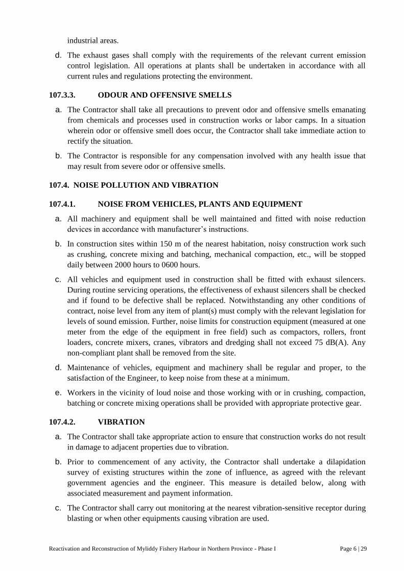
Reactivation and Reconstruction of Myliddy Fishery Harbour in Northern Province - Phase I Page 6 | 29
industrial areas.
d. The exhaust gases shall comply with the requirements of the relevant current emission
control legislation. All operations at plants shall be undertaken in accordance with all
current rules and regulations protecting the environment.
107.3.3. ODOUR AND OFFENSIVE SMELLS
a. The Contractor shall take all precautions to prevent odor and offensive smells emanating
from chemicals and processes used in construction works or labor camps. In a situation
wherein odor or offensive smell does occur, the Contractor shall take immediate action to
rectify the situation.
b. The Contractor is responsible for any compensation involved with any health issue that
may result from severe odor or offensive smells.
107.4. NOISE POLLUTION AND VIBRATION
107.4.1. NOISE FROM VEHICLES, PLANTS AND EQUIPMENT
a. All machinery and equipment shall be well maintained and fitted with noise reduction
devices in accordance with manufacturer‟s instructions.
b. In construction sites within 150 m of the nearest habitation, noisy construction work such
as crushing, concrete mixing and batching, mechanical compaction, etc., will be stopped
daily between 2000 hours to 0600 hours.
c. All vehicles and equipment used in construction shall be fitted with exhaust silencers.
During routine servicing operations, the effectiveness of exhaust silencers shall be checked
and if found to be defective shall be replaced. Notwithstanding any other conditions of
contract, noise level from any item of plant(s) must comply with the relevant legislation for
levels of sound emission. Further, noise limits for construction equipment (measured at one
meter from the edge of the equipment in free field) such as compactors, rollers, front
loaders, concrete mixers, cranes, vibrators and dredging shall not exceed 75 dB(A). Any
non-compliant plant shall be removed from the site.
d. Maintenance of vehicles, equipment and machinery shall be regular and proper, to the
satisfaction of the Engineer, to keep noise from these at a minimum.
e. Workers in the vicinity of loud noise and those working with or in crushing, compaction,
batching or concrete mixing operations shall be provided with appropriate protective gear.
107.4.2. VIBRATION
a. The Contractor shall take appropriate action to ensure that construction works do not result
in damage to adjacent properties due to vibration.
b. Prior to commencement of any activity, the Contractor shall undertake a dilapidation
survey of existing structures within the zone of influence, as agreed with the relevant
government agencies and the engineer. This measure is detailed below, along with
associated measurement and payment information.
c. The Contractor shall carry out monitoring at the nearest vibration-sensitive receptor during
blasting or when other equipments causing vibration are used.

Reactivation and Reconstruction of Myliddy Fishery Harbour in Northern Province - Phase I Page 6 | 30
d. The Contractor shall modify the method of construction until compliance with the criteria
is reached, if vibration levels exceed the relevant vibration criteria.
e. The Contractor shall pay due consideration to vibration impacts of blasting on adjoining
structures. Explosive loads shall be determined so that excessive vibration can be avoided
and blasts shall be controlled blasting in nature. Notwithstanding these provisions, the
Contractor is liable for any damage caused by blasting work.
107.4.3. NOISE FROM BLASTING OR PRE-SPLITTING OPERATIONS
a. Blasting shall be carried out only with permission of the Engineer. All statutory laws,
regulators, rules, etc., pertaining to acquisition, transport, storage, handling and use of
explosives shall be strictly followed.
b. Blasting shall be carried out during fixed hours (preferably during mid-day), as permitted
by the Engineer. The timing shall be made known to all the people within 500m (200m for
pre-splitting) from the blasting site in all directions. People, except those who are actually
involved in the blasting activities shall be excluded from the area of 200m (50m for pre-
splitting) from the blasting site in all directions at least 10 minutes before the blasting takes
place.
107.5. IMPACT ON FLORA AND FAUNA
107.5.1. LOSS OR DAMAGE TO FLORA AND FAUNA
a. All works shall be carried out in such a manner that the destruction of flora and fauna is
minimized. Trees and vegetation shall be felled / removed only if they impinge directly on
the permanent works or necessary temporary works. In all such cases the Contractor shall
obtain prior approval from the Engineer
b. The Contractor‟s employees and employees of any Sub-contractor(s) shall be instructed to
protect fauna including wild animals and aquatic life as well as their habitats. Hunting,
pouching and unauthorized fishing by project workers is not allowed.
c. Soil and/or sand needed for construction shall be obtained from nearby areas to the extent
possible to minimize risk of transport of invasive species to the construction area.
107.5.2. CHANCE FOUND IMPORTANT FLORA OR FAUNA
During construction, if a rare/threatened/endangered flora of fauna species is found, it shall be
immediately informed to the Employer. The Contractor shall carry out all activities and plans as
instructed by the Employer to conserve such flora and/or fauna and/or its habitat.
107.6. DISRUPTION TO USERS
107.6.1. LOSS OF ACCESS
a. At all times, the Contractor shall provide safe and convenient passage for vehicles,
pedestrians and livestock to and from side roads and property access roads intersecting the
project road. Work that affects the use of side roads and existing accesses shall not be
undertaken without providing adequate provisions to the prior satisfaction of the Engineer.
b. The works shall not interfere unnecessarily or improperly with the convenience of public
or the access to, use and occupation of public or private roads, railways and any other

Reactivation and Reconstruction of Myliddy Fishery Harbour in Northern Province - Phase I Page 6 | 31
access footpaths to or of properties, whether public or private.
c. On completion of the works, all temporary obstructions, including rubbish and piles of
debris that obstruct access, shall be cleared to the satisfaction of the Engineer.
107.7. ENVIRONMENTAL MITIGATION REQUIREMENTS
The following requirements are for specific environmental protection and mitigation measures of
the environment surroundings at and near the Limits of Work. All requirements below shall
require detailed all shop drawings, material data sheets, vendor information, samples, etc to be
submitted to the Engineer for approval. No work shall be implemented without an approved
submittal of these requirements.
107.7.1. TURBIDITY CURTAIN
At the instructions of the Engineer, the Contractor shall furnish and place a turbidity curtain
totally enclosing the dredging area of the harbor basin to confine sedimentation within the
construction area. The turbidity curtain shall be a pre-assembled system, and shall be a system of
adequate capability, appropriate for the site conditions, including depth, current, and
wind/waves. Turbidity curtain placement and removal shall not proceed without the Employer‟s
approval.
Components of the turbidity curtain include the following materials:
a. Geosynthetic. The geosynthetic shall be composed of at least 95% by mass of
polypropylene, polyethylene, polyester, or other synthetic polymers, excluding
polyamides. Geotextiles shall contain stabilizers or inhibitors, if necessary, to make the
filaments resistant to deterioration by excessive ultraviolet (UV) light and heat exposure.
Geotextile shall be resistant to acid and alkali action and shall be unaffected by micro-
organisms and insects. Geosynthetic may be polymer impregnated to negate permittivity
and opening size requirements. Hemmed pockets shall be sewn or heat bonded for flotation
devices and bottom weights. Panel ends shall have metal grommets placed through a
reinforced hem. Connections between panels shall be tightly tied with synthetic or wire
rope to prevent flow through the joint.
b. Flotation. Flotation devices shall be closed-cell polystyrene. The buoyancy (volume)
required will depend upon site conditions; however, sufficient freeboard shall be provided
to prevent overtopping.
c. Stakes. Stakes, when used to assist in maintaining alignment of the curtain, shall be
hardwood or steel with sufficient length and cross-section to support the curtain. External
supports may be used; however, embedment depth shall not be less than 0.5 meters.
d. Hardware. All hardware such as stakes, ballast chain, connection bolts, reinforcement
plates, and tension cables shall be galvanized, stainless steel, otherwise corrosion resistant
(refer relevant sections for further clarification). The ballast chain shall have sufficient
mass to maintain the geosynthetic in a vertical position.
The turbidity curtain shall be placed according to locations and depths as directed by the
Engineer. The turbidity curtain system shall be designed to handle site-specific drainage or flow
appurtenances. The Contractor shall be responsible to provide and maintain sufficient anchors,
tie-downs, or other mechanisms to insure proper position and performance of the turbidity
curtain. Any visible plume of cloudy water outside the protected construction area shall

Reactivation and Reconstruction of Myliddy Fishery Harbour in Northern Province - Phase I Page 6 | 32
constitute inadequate performance of the turbidity curtain. The Contractor shall immediately
modify, adjust, or repair any portion of the turbidity curtain to correct inadequate performance.
The Contractor shall maintain the turbidity curtain until the construction activity within the
watercourse is complete and the turbidity is reduced to acceptable levels as approved by the
Engineer. Maintaining shall include keeping a tight alignment around the work area or shoreline.
108. HEALTH AND SAFETY REQUIREMENTS
108.1. GENERAL
The importance of the safety of all personnel on the Project shall be recognized by Contractor,
and accident prevention shall be an integral part of Contractor‟s operations. Contractor shall
take all precautions necessary and shall bear sole responsibility for the safety of the Work, the
workers, and the safety and adequacy of the methods and means it employs in performing the
Work.
108.2. SAFETY PROGRAM
Contractor must provide a written safety program to Engineer prior to mobilization on the
project. The purpose of such safety program shall be to maintain a safe work place and to ensure
compliance with the local governing safety regulations, standards and all other applicable rules
and regulations required to maintain a safe and healthy working environment. The safety
program shall also include the GOSL Department of Labor Occupational Safety and Health
requirements as outlined in “The Factories Ordinance No. 45 of 1942”.
The safety program must include, at a minimum, the following components of Training, Safety
officer, Personal Protective Equipments, Substance Abuse Program, Incident Investigation,
Emergency Procedures, First Aid/Medical Services. Task Hazard Analysis, Daily Safety Plans,
etc.
108.3. TRAINING
Contractors are responsible for the safety education of their employees. The training must
comply with all local laws and standards and include additional training for site supervision.
Training must continue through the life of the Contract, Contractor shall provide copies of
training certificates to the Employer for all operations, which require such training. These
documents must be submitted prior to mobilization and prior to commencement of Work. As a
minimum, the following training is required:
Supervisor/Foreman Safety Training – must cover recordkeeping, incident investigation, and
regulatory inspections. H&S documentation requirements and a minimum of 10 hours of safety
training applicable to the Contractor‟s hazardous operations construction.
Competent person Training – each person designated as a competent person shall attend training
on that particular operation. Operations requiring a competent person include, but are not
limited to, cranes, launching & lifting, marine floating barges and vessels, trenching and
excavation, fall protection, scaffolds, confined space entry, and rigging.
Employee Orientation Training – must cover the various safety policies, safety manuals, first aid
availability, and accident reporting procedures, safety meeting participation, personal protective
equipment and enforcement procedures.

Reactivation and Reconstruction of Myliddy Fishery Harbour in Northern Province - Phase I Page 6 | 33
Emergency Procedures – must cover notification procedures, evacuation routes, mustering
points, and accountability.
Safety Meetings – must be conducted weekly with all onsite personnel. Documentation
detailing the subject discussed and signatures of all participants must be kept for each meeting.
Hazard Communication – must cover the MSDS, handling, labeling and storage of applicable
hazardous chemicals.
Lockout/Tag out – must cover each individual piece of machinery or equipment that is to be
serviced or altered during this project.
109. PROTECTION OF THE WORKS
The Contractor shall take necessary precautions to properly protect work, the work of others and
adjacent property from damage caused by Contractor‟s operations, and shall identify such
precautions in the Safety Plan as appropriate. Should the Contractor cause damage to the work
or property of CFHC, employers or others, Contractor shall promptly notify the Employer and
shall remedy such damage to the satisfaction of the Employer.
Employer retains the right to remedy the damage and deduct its cost from any amounts due or to
became due Contractor, unless such costs are recovered under applicable properly insurance.
110. PROJECT SIGN BOARDS
110.1. DESCRIPTION
The Contracts shall erect where directed at the entrance of the Fishery Harbour a Project Sign
Board in accordance the requirements of the Section 6 Particular Conditions of the Contract.
The Contractor shall conform to the layout presented below in color and shall submit the board
layout to the Employer for approval prior to construction. The Project Sign boards shall be
installed and in place no later than 45 days after the Commencement Date. At the end of the
Contract all such signs shall be removed and the ground reinstated to the approval of the
Employer.
The Contractor shall provide and erect the Project Sign Boards at all ends of the project of site
approx. 2,50m wide by 1.80m high with the wording in Sinhalese, Tamil and English lettering
readable from a distance of 30m.
The board is to be made of galvanized steel: the lettering and border are to be in black on off-
white edge of the board shall be at approx: 2.20m above adjacent ground and shall be mounted
on suitable posts with struts on concrete foundations. The paint to be use shall be sunshine
resistant paint.
The Contractor will be responsible for the repair and maintenance of the signboard up to the
completion of all construction works and for its removal on completion of the work.
The Engineer will direct the location and placing of the signboards. The following lettering may
be used as guidance and the final test shall be subject to Engineer‟s approval.
The Contractor shall manufacture, install and construct a Project Plaque in accordance with the
requirements of the Section 6 Particular Conditions of the Contract. The Contractor shall submit
the Plaque layout to the Employer for approval by the Employer, and CFHC prior construction.

Reactivation and Reconstruction of Myliddy Fishery Harbour in Northern Province - Phase I Page 6 | 34
The Project Plaque shall be installed and in place no later than 30 days after the issuance of the
Taking Over Certificate of the Works.
111. SUBMITTALS
111.1. GENERAL
The following Section provides the requirements and procedures necessary for scheduling,
preparation and submission submittals. All inquires shall be directed to Employer regarding
procedure, purpose, or extent of Submittal.
Individual Specification Section in these Contract Documents contains additional and special
submittal requirements. Individual Sections shall take precedence in the event of a conflict with
this Section.
Review, acceptance, or approval of substitutions, schedules, shop drawings, lists of materials,
and procedures submitted or requested by Contractor shall not add to the Contract amount.
Additional costs which may result from the above shall be solely the obligation of Contractor.
Employer is not responsible to provide Engineering or other services to protect Contractor from
additional costs accruing from such approvals.
111.2. SUBMITTAL PROCEDURES
Make submission of Submittals in accordance with the Schedule of Submittal Submission and
the requirements of individual Specification Sections, sequenced such as to cause no delay in
Work.
Submittals shall include the following:
A Transmittal of Contractor‟s Submittal Form for each Submittal complete with Contractor
name, signature, date of submission, Sub-Contractor or supplier name and manufacturer as
appropriate.
A sequential tracking number for each Submittal, Resubmission of a Submittal will have
original number with a sequential alphabetic suffix.
All Submittals shall be in orderly, indexed with labeled tab dividers.
Identify, as applicable, the Contract Document Section and paragraph to which Submittal
applies.
Identify the Submittal type and submit only one type in each Submittal package.
Identify and indicate each deviation or variation from Contract Documents.
For resubmissions, clearly identify each correction or change made.
All Submittals shall be four in hard copy and one electronic copy.
All Submittals shall be thoroughly checked by the Contractor for compliance with the Contract
for compliance with the Contract Documents before submitting them to the Engineer for review
and shall bear the Contractor‟s stamp of approval certifying that they have been so checked.
Any Submittal submitted without this stamp of approval and certification, which are incomplete,
contain numerous errors or have not been checked or only checked superficially, will be returned
unchecked by the Engineer for resubmission by the Contractor. The Contractor shall certify:
“This Submittal has been thoroughly checked and complies with the Documents”.

Reactivation and Reconstruction of Myliddy Fishery Harbour in Northern Province - Phase I Page 6 | 35
Non-specified Submittal submission not required under these Contract Documents will not be
reviewed and will be returned to Contractor.
The Employer will review Submittals for the intent and compliance with Documents and general
methods of construction and detailing. Review of Submittals by the Engineer shall not be
construed as a complete check nor assume responsibility for errors or omissions and non-
compliance nor shall review relieve the Contractor from responsibility for any departures or
deviations from the requirements of the Contract Documents unless he has, in writing, explicitly
notified the Engineer of any such deviations at the time of submission, nor shall review relieve
the Contractor from responsibility for errors of any sort in the Submittals or schedules, nor from
responsibility for proper fitting of the Work, nor from the necessity of furnishing all work
required by the Contract Documents which may not be indicated in the Submittal.
Review of Contractor‟s Submittals will be completed by the Employer with a response to the
Contractor not later than 30 days after receipt, unless otherwise specified. Re-submittals will be
subject to same review time. Detailed design submittals must be approved prior to the
commencement of construction related to the design submittal.
Schedule extensions and Contract Price increases will not be allowed due to delays in progress
of Work caused by rejection and subsequent resubmission of Submittals, including multiple
resubmissions.
111.3. SHOP DRAWINGS
The Contractor shall submit to the Engineer for review and or approval of shop drawings as
required in the Contract Documents. These shall include, but not be limited to surveys,
fabrication drawings, layout drawings, installation drawings, material data, performance data,
catalogue cuts, test data, brochures, and illustrations. Shop Drawings shall be submitted in
sufficient time prior to any activity as noted in this Section.
Shop drawings, shall show locations, dimensions, details, connections, and all other data
necessary to insure proper connections with adjoining work in detail. Where adjoining work
requires shop drawings, such drawings shall be submitted for review at the same time.
In checking shop drawings, the Contractor shall verify all dimensions and field conditions and
shall check and coordinate the shop drawings of any Section or trade with the requirements of all
other Sections, adjoining materials or trades whose work is related thereto, as required for the
proper and completion of the Work.
If shop drawings show variations from the Contract requirements because of standard shop
practice or for other reasons, the Contractor shall explicitly describe such variations in his letter
of transmittal. If acceptable, the engineer may indicate “No Exceptions Noted” to any or all
such variations subject to proper adjustment in the Contract requirements. If the Contractor fails
to explicitly describe such variations, he shall not be relieved of the responsibility for execution
of the Work in accordance with the Contract, even though such drawings have been reviewed.
Shop drawings shall establish the actual detail of all manufactured or fabricated items, indicate
proper relation to adjoining work, amplify design details of mechanical and electrical equipment
in the physical spaces in any structure and incorporate minor changes of design or construction
details to suit actual conditions.
The Contractor shall check all Sub-Contractors‟ shop drawings regarding measurements, size of
members, materials, and details to satisfy himself that they conform to the intent of the Contract

Reactivation and Reconstruction of Myliddy Fishery Harbour in Northern Province - Phase I Page 6 | 36
Documents and Specifications. Drawings found to be inaccurate or otherwise in error shall be
returned to the Sub-Contractors for correction before submission to the Engineer.
When submitting shop drawings for review by the Engineer, the following procedure shall
apply.
Within 28 days after the Commencement Date, and prior to the submittal of any shop drawings,
the Contractor shall submit a schedule of proposed shop drawings transmittals. The schedule
shall identify the subject matter of each transmittal, the corresponding specification Section
number and the proposed date of submission. During the progress of the Work the schedule shall
be revised and resubmitted as necessary. The Contractor shall be responsible for the prompt and
timely submittal of all shop and working drawings so that there shall be no delay to the Work
due to the absence of such drawings. The Contractor shall furnish specific design data as
required in the detailed Specifications or as directed by the Engineer and technical literature
covering all fabricated materials in sufficient detail to indicate full compliance with the Contract
Documents.
Shop drawings resubmitted for further review will be reviewed for response to previous
notations only and the Contractor, by such resubmission, shall be held to have represented that
such shop drawings contain no other alteration, additions or deletions, unless the Contractor (in
writing) directs the Engineer‟s specific attention to same. Should the Contractor question, or
dissent, from such notations or comments, he shall request further clarification before
resubmitting.
Regardless of corrections made in or “No Exceptions Noted” given to such Drawings by the
Engineer, the Contractor will nevertheless be responsible for the accuracy of such shop drawings
and for their conformity to the Contract Documents, unless the Contractor states otherwise as
prescribed.
Comments on shop drawings are not orders for Variations. Should the Contractor construe such
“No Exceptions Noted” or comments as requiring in addition to the Contract Price he shall
immediately, before any manufacture, procurement or acquisition of material and/or equipment,
or fabrication and/or installation of the work, notify the Engineer in writing of his intention to
claim extra payment or a varied rate of price.
111.4. SAMPLES
Where required in the Contract Documents and as determined necessary by Engineer, submit
test specimens or samples of materials to be used in connection with the work. The Contractor
shall include information as to their sources and submit such quantities and sizes for proper
examination and tests to establish the quality or equality thereof, as applicable.
Submit samples and test specimens in ample time to enable Engineer to make tests or
examinations necessary, without delay to the work.
Submit additional samples as required by Engineer to ensure equality with the original approved
sample and/or for determination of Specification compliance. Laboratory tests and examinations
that Employer elects to make in its own laboratory will be made at Employer‟s cost except that,
if a sample of any material or equipment proposed for use by Contractor fails to meet the
Specifications Contractor shall bear cost of testing subsequent samples.
Tests, required by the Specifications to be performed by an independent laboratory, shall be
made by a laboratory licensed or certified in accordance with the appropriate statues and

Reactivation and Reconstruction of Myliddy Fishery Harbour in Northern Province - Phase I Page 6 | 37
approved by the Engineer in accordance with the Contractor‟s QAP. Submit certified test results
of specified tests in duplicate to Engineer. Test results shall include all relevant information,
including date of test, location, material type, Contract Document specification, etc.
Samples will not be returned, however, if returned the Contractor shall dispose of appropriately.
Samples and laboratory services shall be at the expense of Contractor and included in the prices
bid for the associated work.
The Contractor shall not commence any work related to the Shop Drawing until the Shop
Drawing has been approved.
111.5. QUALITY CONTROL SUBMITTALS
As part of the Contractor‟s Quality Assurance Program, a Submittal Register shall be maintained
by the Contractor and submitted to the Employer bi-monthly. This Submittal Register shall
track all submittals and current disposition. The Employer will review the Submittal Register to
ensure no outstanding reviews are pending.
Where specified, furnish certification of compliance for products specified to a recognized
standard or code prior to the use of such products in the work.
Engineer may permit use of certain materials or assemblies prior to sampling and testing if
accompanied by a certification of compliance.
Certifications shall be signed by the manufacturer of the product; state that the components
involved comply in all respects with the requirements of the Specifications. Furnish certification
of compliance with each lot delivered to the jobsite and clearly identify the lot so certified.
Materials used on the basis of a certification of compliance may be sampled and tested at any
time. The fact that materials are used on the basis of a certification of compliance shall not
relieve Contractor of responsibility for incorporating materials in the work which conform to
requirements of the Contract Documents. Materials not conforming to such requirements will be
subject to rejection whether in-place or not. Engineer reserves the right to refuse permission for
material placement on the basis of a certification of compliance.
111.6. ADMINISTRATIVE SUBMITTALS
Provide administrative submittals required by the Contract Documents including Volume I
requirements and as may be specifically required in other parts of the Contract Documents.
Submittals that are not Shop Drawings or Samples, or that do not reflect quality of product or
method of construction. May include, but not limited to those Submittals identified below.
Applications for Payment meet requirements of the General Conditions and Particular
Conditions of Contract.
Construction Photographs
Coordination requirements as required in the Contract Documents
Project Control Submittals including Schedules, Progress Reports, Quantity Charts, etc.,
Record Drawings

Reactivation and Reconstruction of Myliddy Fishery Harbour in Northern Province - Phase I Page 6 | 38
111.7. RECORD CONTRACT DRAWINGS
Prior to final payment, the Contractor shall furnish to the engineer one reproductive set and one
electronic version in AutoCAD of record Contract drawings all clearly revised, completed and
brought up-to-date showing the permanent construction as actually made. Good quality, legible,
copies on plastic stock are acceptable. Record copies of shop drawings of temporary facilities,
or manufacturers‟‟ catalogue cuts are not required.
111.8. CONSTRUCTION PHOTOGRAPHS
Provide photographs in color showing the preconstruction site, construction progress, and the
post-construction site and property adjacent to the site as required in the Specifications and as
part of the Construction Risk Management Plan. Particular emphasis shall be directed to
structures both inside and outside the Limits of Work boundary, or as directed by Engineer,
Photos shall be printed in color and indicate on the front of each print the date, job title, and brief
description of the photograph and location where the photograph was taken. Deliver to engineer
two sets of four 7.5 x 12.5cm (3-inch by 5-inch) glossy prints of each photo with electronic CD
of all exposures. Coordinate this work with the Dilapidation Survey and Conditional Survey.
111.9. CONTRACT CLOSEOUT SUBMITTALS
The Contract shall provide all necessary closeout submittals per the Contract Documents
inclusive of Record Drawings. Throughout the project, maintain a current complete set of
project drawings with all variations plainly marked.
112. QUALITY PROGRAM
This Section covers the Contractor‟s Quality Program, inclusive of all quality assurance and
quality control, and the general requirements of quality designs, quality inspection and testing
requirements for this Contr4act. Specific inspection and testing requirements for specific work
shall be in accordance with technical specification.
112.1. CONTRACTOR’S OBLIGATION
The Contractor shall within 28 days of the Commencement Date furnish for approval by the
Employer, a detailed Contractor‟s Quality Program (CQP) which it proposes to implement. The
CQP shall identify personnel, procedures, instruction, records, and forms to be used. No design
submittals will be accepted and no construction work shall begin on the Site until the CQP has
been accepted by the Employer.
The CQM shall within 28 days of the Commencement Date furnish for approval by the
Employer, a detailed Contractor‟s Quality Program (CQP) which it proposes to implement. The
Contractor shall hire a full time Contractor‟s Quality Assurance and Control Manager (CQM) to
develop and implement the CQP. The CQP shall identify personnel, procedures, instruction,
records, and forms to be used. No design submittals will be accepted and no construction work
shall begin on the site until the CQP has been accepted by the Employer.
The CQM shall ensure the implementation of the CQP which shall contain as a minimum
implementing procedures, quality control, and organizational chart describing qualifications,
duties and responsibilities of the CQM staff. An outline of the CQP shall be submitted with the
technical proposal in coordination with the Contractor‟s work plan and schedule.

Reactivation and Reconstruction of Myliddy Fishery Harbour in Northern Province - Phase I Page 6 | 39
The Contractor is responsible for detailed design, control of its work, workmanship and the work
performed by its sub Contractors and suppliers and for assuring that the specified quality is
achieved.
112.2. COORDINATION MEETING
No later than 14 days after the Commencement Date, The Employer shall meet with the
Contractor and discuss the CQP, During the meeting, a mutual understanding of the CQP details
shall be developed, including quality design procedures, forms for recording the Construction
Quality operations, assurance measures, control activities, testing, administration of the CQP for
both onsite and offsite work and the interrelationship of the CQM‟s inspection and control with
the Employer‟s inspection. Minutes of the meeting shall be prepared and signed by the PM, and
signed Engineer and/or the Employer. The minutes shall become a part of the Contract file.
There may also be occasions when subsequent conferences will be called to reconfirm mutual
understandings.
112.3. CONTENT OF QUALITY ASSURANCE PROGRAM
The CQP shall include, as minimum, the following:
A description of the quality assurance and quality control organization, including chart showing
lines of authority and acknowledgement of CQM, staff to conduct construction inspections and
testing for all aspects of the Work.
The name, qualifications, duties, responsibilities and authority of each person within the CQP
organization are to be included.
Procedures for scheduling and managing test submittals, including shop testing submittals from
sub Contractors, suppliers and purchasing agents; on-site field inspection reports; and onsite and
offsite testing laboratory results.
Control testing procedures for each specific test for materials and equipment, including a listing
of the type and number/frequency of each control test and identification of the laboratory or
testing services that will perform the test. (All laboratory facilities and testing services shall be
approved by the Employer).
Reporting procedures are including proposed reporting formats, samples of proposed quality
control records, testing forms, reporting forms, and the Submittal Register log.
All aspects of the quality program shall be identified by work area and specification division.
The CQP shall be accepted by the Employer prior to the start of Contractor‟s permanent works.
Acceptance will be conditional and will be predicated on satisfactory performance during the
construction. The Employer reserves the right to require the CQM to make changes in its CQP
and operations as necessary to obtain the quality specified. The CQP shall be compliant with the
ISO 9000 systems or in any other manner acceptable to the Employer.
112.4. QUALITY ASSURANCE AND QUALITY CONTROL ORGANIZATION
The Construction Project Manager shall be in charge and responsible of the onsite and offsite
quality control of the Work and the overall Quality Assurance and Quality Control (QA/QC)
Organization. The PM shall have the authority to act in all quality matters independently to
ensure proper workmanship is obtained. The individual designated as Engineer shall be
approved by the Employer.

Reactivation and Reconstruction of Myliddy Fishery Harbour in Northern Province - Phase I Page 6 | 40
The PM shall sufficient experienced staff to execute all quality requirements of the project. This
staff shall be maintained under the direction of the PM to perform all quality activities. The
actual size of the staff during any specific work period may vary to cover work phase needs,
shifts and rates of Works placement. The personnel of the PM staff shall be fully qualified by
experience and technical training to perform their assigned responsibilities. The QA/QC
personnel shall, in general, have a minimum of 5 years experience in their field of expertise. All
quality QA/QC personnel must have fluency in the English language.
Submittals of all quality control tests and reports shall be as specified and shall be in accordance
with the Submittals Section. The PM shall be responsible for certifying that all quality control
submittals are in compliance with the Contract Documents.
CQP is the means by which the Contractor assures itself the Employer that the services and
Work supplied by the Contractor comply with the requirements of the Contract. The controls
shall be adequate to cover all operations, including both onsite and offsite work and shall be
keyed to the proposed construction schedule sequence.
The PM shall notify the Contractor and the Employer immediately about all defective work.
The Contractor shall submit in writing, a proposed remedy for the defective work to the
Employer for approval. The Employer shall notify the Contractor in writing within 14 days of
any objections to the proposed remedy. If the Contractor does propose a remedy upon
notification of defective work, a non-conformance report will be immediately issue by the
Employer. Remedies which are approved by the Employer shall be performed by the Contractor
at no additional cost to the Employer, The Contractor will not be paid for remediation of
defective work.
The Employer/Engineer will review the construction quality assurance PM quality control
reports, perform surveillance of the CQ testing and inspection procedure and laboratory testing
procedures and perform such inspections as deemed necessary in accordance with the
Conditions of Contract. No actions of the Employer shall be construed to relieve the Contractor
of their responsibility to inspect and certify the work as being in complete compliance with the
Contract Documents.
112.5. QUALITY TESTS
The Contractor under the CQP shall perform tests required to verify that control measures are
adequate to provide Work which conforms to Contract Documents. The PM shall procure the
services of one or more Employer-approved testing laboratories or the CQM may establish and
approved testing laboratory at the Site. A list of tests which the Contractor understands it is to
perform shall be furnished as a part of the CQP to the Employer. The list shall provide the test
name, specification paragraph containing the test requirements, and the personnel and laboratory
responsible for each type of test. The PM shall, with the full cooperation of the Contractor,
coordinate all quality control testing, monitor all quality control testing, and shall record and
provide the following data:
Verify that testing procedures comply with Contract Documents.
Verify the facilities and testing equipment are available and comply with testing standards
approved by the Employer.
Check test instrument calibration data against certified standards.

Reactivation and Reconstruction of Myliddy Fishery Harbour in Northern Province - Phase I Page 6 | 41
Verify that recording forms, including all of the test documentation requirements, have been
prepared.
The testing laboratory shall submit testing results to the CQM, to be certified and submitted to
the Employer.
112.5.1. LABORATORY TESTING FACILITIES
All tests which require the services of a laboratory to determine compliance with the Contract
Documents shall be performed by independent commercial testing laboratory employed by the
Contractor and acceptable to the Engineer/Employer or the Contractor may establish an
Engineer/Employer approved testing laboratory on site. The laboratory shall be staffed with
experienced technicians, properly equipped, and fully qualified to perform the tests in
accordance with the specified standards.
Unless otherwise specified, the Contractor shall be responsible for all testing laboratory services
in connection with concrete materials and mix designs, the design of asphalt mixtures, gradation
tests for all backfill, and dredge materials, backfill materials, and all other tests and Engineering
data required for the Employer‟s review of materials proposed to be used in the Work. The
Contractor shall obtain the Employer‟s acceptance of the testing laboratory before having
services performed.
The Contractor as part of the CQP shall perform all quality control tests in the field or laboratory
on all materials, inclusive but not limited to steel piles, concrete, asphalt mixtures, rock
armour/stones, moisture-density (Proctor) and relative density tests on sand fill, gravel fill,
hydraulic dredge fill and other back fill materials, in-place field density tests on all structural
dredge fills and earthwork backfills and other materials, and after their incorporation in the
Work. Field sampling and testing will be performed under the direct supervision of the CQM, in
the general manner indicated in the specifications, with minimum interference with construction
operations. The CQM shall determine the exact time and location of field sampling and testing,
and may required such additional sampling and testing as necessary to determine that materials
and equipment conform with data previously furnished by Contractor and with the Contract
Documents
Arrangements for delivery of samples and test specimens to the testing laboratory will be made
by the Contractor. The Contractor shall perform all laboratory tests within a reasonable time
consistent with the specified standards and shall furnish a written report of each test.
Contractor shall furnish all sample materials and cooperate in the sampling and field testing
activities, interrupting the Work when necessary.
The Contractor shall not retain any testing laboratory against which the Employer has reasonable
objection, and if at any time during the construction process the services become unacceptable to
the Employer, the Employer may request in writing that such services be terminated. The
request must be supported with evidence of improper testing. If the Employer determines that
sufficient cause exists, the Contractor shall terminate the services and engage a different testing
laboratory.
Written reports of testing and Engineering data furnished by the Contractor for the Employer's
review of materials and equipment proposed to be used in the Work shall be submitted as
specified for Shop Drawings.
Reactivation and Reconstruction of Myliddy Fishery Harbour in Northern Province - Phase I Page 6 | 42
The testing laboratory shall furnish four copies of a written report of each test performed by
laboratory personnel in the field or laboratory. Distribution shall be two copies of each test
report to the Employer's Representative, one copy to the Contractor, and one copy to the CQM
within three days after each test is completed.
112.5.2. QUALITY OF MATERIALS
Unless otherwise specified, all materials and equipment furnished for permanent installation in
the Work shall conform to applicable standard specifications and shall be new, unused, and free
from defects and imperfections, when installed or otherwise incorporated in the Work. No such
material or equipment shall be used by the Contractor for any purpose other than that intended or
specified unless such use is authorized by the Employer.
Where so specified, products or workmanship shall also conform to the additional prescriptive or
performance requirements included within the Contract Documents to establish a higher or more
stringent standard or quality than that required by the referenced standard.
For permanent materials to be incorporated in the Works, including but not limited to concrete
(cement, sand, gravel) bitumen, rolled steel Sections, galvanization of steel, mild steel deformed
bars, high tensile steel, prestressing materials, bearings, and similar other materials the
Contractor shall furnish the manufactures test certificates to the Employer. When required by
the Employer to carry out some essential tests at the manufactures‟ plants or at laboratories other
than the site laboratory, the cost of samples, sampling, testing and furnishing of test certificates
shall be borne by the Contractor.
The method of sampling and all testing results of material types and placement as required in the
relevant Clauses in these Specifications and as stipulated in the referenced standards shall be
submitted to the Employer for approval. Any materials or permanent Works that fail test results
shall be removed, replaced or reconstructed to the satisfaction of the Employer and at no
additional cost to the Employer.
112.5.3. TESTING BY ENGINEER/EMPLOYER
The Engineer/Employer will have the right to check laboratory equipment in the proposed
laboratory for compliance with the standards in the Contract Documents and to check the
laboratory technician's testing procedures and techniques.
If the selected laboratory fails the capability check, Contractor will be assessed a charge to
reimburse the Employer for the Employer's full cost of each succeeding recheck of the
laboratory or the checking of a subsequently selected laboratory. Such costs will be deducted
from the Contract Price due the Contractor.
The Engineer/ Employer will have the right to utilize quality control testing laboratory and
equipment to make assurance tests and to check Contractor's testing procedures, techniques, and
test results at no cost to the Employer.
The Engineer/Employer shall have authority to require additional tests to verify the quality of
the Work or materials. If results from any additional test required by the Engineer/Employer
show the materials, equipment, or workmanship not in accordance with the Contract Documents,
or if such tests are required because of previous failure of the test to comply with the Contract
Documents, then the cost of the additional test will be borne by the Contractor. Costs for
additional tests required by the Employer which meet the requirements of the Contract
Documents will be borne by the Employer.

Reactivation and Reconstruction of Myliddy Fishery Harbour in Northern Province - Phase I Page 6 | 43
112.5.4. OFFSITE INSPECTION AND TESTING
Offsite inspection shall be inspected at the point of manufacture of the various products which
are shipped to the Site. The Contract includes offsite testing and inspection for all materials
identified in the Specifications. Offsite testing and inspection is the responsibility of and shall
be conducted by the Contractor under the guidance of the CQM.
When the specifications require inspection and/testing of materials during the production,
manufacturing, or fabricating process, and before shipment, such services shall be performed by
the CQM, an independent testing laboratory, or inspection organization acceptable to Employer.
All offsite testing and inspection shall be completed to the satisfaction of the Employer prior to
shipment from the factory to the Site. As part of the offsite testing and inspection requirements,
the CQM shall review and approve all off-site testing and inspection results prior to submittal to
the Employer and prior to shipment to the site.
The Employer may observe offsite testing and inspection as appropriate. The Contractor shall
give appropriate written notice to the Employer not less than 28 days before offsite
fabrication/production to allow inspection services as deemed necessary by the Employer, and
shall provide for the producer, manufacturer, or fabricator to furnish safe access and proper
facilities and to cooperate with inspecting personnel in the performance of their duties.
The Contractor shall be responsible for providing all transportation, accommodations, meals and
reasonable incidentals for any requested and/or required offsite inspection by the Employer as
set forth in the measurement and payment.
112.6. PARTIAL COMPLETION INSPECTIONS
At the completion of each task or any increment thereof established by a completion time stated
in the Bid Documents, the Employer shall conduct a partial completion inspection of the Work
in company with the Contractor, the CQM, and the Employer. The Contractor shall notify the
Employer at least 14 days prior to the proposed inspection. The actual date of the inspection
shall be established by the Employer after consulting with Employer. During the inspection the
Employer shall develop a "punch list" of items which do not conform to the Contract
Documents. The punch list shall include the estimated date when the deficiencies will be
corrected.
After the Employer determines all deficiencies on the "punch list" have been corrected, the
Employer shall conduct a final partial completion inspection of the Work in company with the
Contractor, the CQM, and the Employer. The Contractor shall notify the Employer at least 14
days prior to the proposed inspection. The actual date of the final partial completion inspection
shall be established by the Employer after consulting with the Engineer.
The completion inspection and any deficiency corrections required by this paragraph shall be
accomplished within the time stated for completion of the entire task or any particular increment
thereof.
112.7. FINAL INSPECTION OF CONSTRUCTION WORK
Final inspection of all stages of construction Work shall be conducted by the CQM and
Employer as specified in Contract Documents.

Reactivation and Reconstruction of Myliddy Fishery Harbour in Northern Province - Phase I Page 6 | 44
112.8. QUALITY ASSURANCE DOCUMENTATION
The CQM shall maintain current records of quality control operations, activities, and tests
performed including the work of suppliers and Subcontractors on a QA/QC Daily Report Form
acceptable to the Employer. These records shall include factual evidence that required activities
or tests have been performed, including but not limited to, the following:
Type and number of control activities and tests involved.
Results of control activities or tests
Nature of defects causes for rejection, etc.
Proposed remedial action
Corrective actions taken
These records shall cover both conforming and defective or deficient features and shall include a
statement that supplies and materials incorporated in the Works comply with the Contract
Documents.
The daily records of inspection and testing will be used as the basis for a Weekly Quality
Control Report. Four copies of the report shall be submitted to the Employer in an approved
form. This report will summarize all quality control inspections and tests performed over the
previous seven days.
The Weekly Quality Control Report shall include all work performed under the Contractor‟s
CQP as certified by the CQM, with all sample numbers assigned in a sequential and consecutive
order and details of the sample or test to which each number has been assigned. The Weekly
Quality Control Report shall also summarize all inspection reports and any Certificates of Non-
Compliance issued or remedied that week for the Work.
On a monthly basis, all test data shall be summarized in tabular and graphical form in a manner
which best illustrates the trends, specific results, and specification requirements and shall be
submitted to the Employer in a Monthly Quality Control Report. Where tests do not meet
specification requirements, full explanations shall be provided to show what action was taken
(i.e., rejection of the work, retest, etc.). Based on the inspection and testing reports, the CQM
shall clearly indicate in the Monthly Quality Control Report what elements of Work are
completed and recommended by the Contractor for acceptance by the Employer. Four copies of
this report shall be submitted to the Employer.
A separate report shall contain a forecast of Work to be performed during the next seven days
and a description of planned inspection and testing.
112.9. NOTIFICATION OF NONCOMPLIANCE
The Employer will notify the Contractor and the CQM of any non-compliance with the
foregoing requirements. The Contractor and the CQM shall, after receipt of such notice
immediately take corrective action. Such notice, when delivered to the Contractor at the Site of
the Work, shall be deemed sufficient for the purpose of notification. If the Contractor fails or
refuses to comply promptly, the Employer may make a recommendation to the Employer that
the Employer issue an order stopping all or part of the Work until satisfactory corrective action
has been taken. No part of the time lost due to any such stop orders shall be made the subject of
a claim for extension of time or for excess costs or damages by the Contractor.

Reactivation and Reconstruction of Myliddy Fishery Harbour in Northern Province - Phase I Page 6 | 45
112.10. QUALITY ASSURANCE AND CONTROL
The Contractor shall establish and maintain a Quality Management System (QMS) based on the
ISO 9000 systems or in any other manner acceptable to the Employer.
For tendering, the Contractor shall prepare the outline of the Quality Assurance Plan (QAP) and
during mobilization; the Contractor shall finalize a QAP acceptable to the Employer. This plan
may be prepared based on work group and list out the specific testing, test procedures, records
and documentation requirement for assuring fulfillment of quality of individual work item.
These shall include but not limiting to testing, surveying, investigations, reviewing, evaluating
involving materials, geometric measurements and process control.
The work as a whole and separated in the individual structures or parts of the work shall be
carried out with quality control so that the Contractor through quality assurance can document
that the works conform to the specifications and the drawings. All quality assurance plan
requirements, including quality control testing will be essential and part of the overall
Contractor‟s work.
Contractor shall implement the QAP which defines how an assurance of quality will be obtained.
For temporary measures, the Contractor shall document that the re-establishment is carried out
to the Employer‟s satisfaction.
113. CONTRACT CLOSEOUT
113.1. GENERAL
This Section includes procedures to be followed in closing out the Contract in additional to the
conditions prescribed in the General Conditions and Particular Conditions of Contract.
113.2. FINAL SUBMITTALS
The Contract will not be finalized until all of the following have been submitted as required in
the Submittals Section:
1 Project Completion report including construction photographs,
2 As-Built Drawings
3 Quality Control Results and Reports
4 Final Submittals required by Contract Requirements
The Contract will not be finalized until all guarantees, bonds, certifications, licenses, and
affidavits required for work or equipment as specified are satisfactorily filed with the Employer.
113.3. RELEASE OF LIENS OR CLAIMS
The Contract will not be finalized until satisfactory evidence of release of liens has been
submitted to Employer as required by the Conditions of Contract.
113.4. FINAL CLEANING
At completion of work and immediately prior to final inspection, clean entire project according
to the following provisions:

Reactivation and Reconstruction of Myliddy Fishery Harbour in Northern Province - Phase I Page 6 | 46
Clean, sweep, and wash work provided under the Contract. Leave all facilities and structures
and the site in a complete and finished condition to the satisfaction of the Employer. Remove
debris including dirt, sand, and gravel from all the area.
Should Contractor not remove rubbish or debris or not clean the facilities and site as specified
above, the Employer reserves the right to have final cleaning done at the sole expense of the
Contractor.
The Contractor shall remove all temporary structures and materials, equipment, and
appurtenances not required as part of, the completed work to the satisfaction of the Employer.
113.5. FINAL INSPECTION
After final cleaning and upon written notice from Contractor that Work is completed, the
Employer will make preliminary inspection with the CFHC and Contractor present. Upon
completion of preliminary inspection, Employer will notify Contractor in writing of particulars
in which the completed Work is defective or incomplete.
Upon receiving written notice from Employer, the Contractor shall immediately undertake work
required to remedy defects and complete the work to the satisfaction of Employer.
After the items as listed in Employer‟s written notice are corrected or completed, Contractor
shall inform Employer in writing that required work has been completed. Upon receipt of this
notice and in the presence of Employer, CFHC and the Contractor, a final inspection of the
project will be completed.
Should the Employer find all work satisfactory at the time of final inspection, Contractor will be
allowed to make application for final payment in accordance with provisions of the Conditions
of Contract. Should Employer still find deficiencies in the Work, the Employer will notify
Contractor in writing of deficiencies and will not approve Contractor's request for final payment
until such time as Contractor has satisfactorily completed the project.

Reactivation and Reconstruction of Myliddy Fishery Harbour in Northern Province - Phase I Page 6 | 47
200. BREAKWATERS
201. GENERAL DESCRIPTION
The specification consists of rehabilitation of a breakwater at Myllidy fishery harbour. The
construction material shall be rock armours. Work, in general, includes construction of the
following major components.
Breakwater
Core (Quarry run having a gradation of 1-100kg)
Under layer (Rock armour having a gradation in range of 0.1T-0.2T)
Primary layer (Rock armour having a gradation in range of 1.0T-2.0T)
The works includes all post and pre construction surveys and inspections as required in the
Technical Specification. The construction work requires supply and installation of materials and
the provision of all labor, plant and equipment and quality control for the proper execution and
completion of the works. This chapter shall be need in conjunction with the other chapters of the
specification and the drawings.
Drawing No LHI/ML/LO/1 shows the general layout plan of breakwater while drawing No
LHI/ML/BW1 shows the section details together with armour sizes of breakwater.
Flowing activities are proposed for the breakwater rehabilitation.
1. Removal of residual materials (core materials and main armours) at the damaged portion
shall be done.
2. Reshaping of the core up to the +1.4 m MSL shall be done crushed excess materials and
1-100kg rock materials.
3. At least 0.6 m width of 0.1T-0.2T rocks materials shall be provided as the filter layer.
4. Rehabilitation shall be done to achieve the proposed section given in Drawing
LHI/ML/BW1
202. REFERENCES
5. CIRIA, 2007, Manual on the use of Rock in Coastal and Shoreline Engineering
6. 1991, BS 6349 - Part VII
7. U.S. Army Coastal Engineering Research centre, 1977, Shore Protection Manual (SPM) -
Volume III
8. U.S. Army Corps of Engineers, 2001, Coastal Engineering Manual (CEM), Part VI,
Draft.
9. W. Van Der Meer, 1992, Conceptual Design of Rubble Mound Breakwaters

Reactivation and Reconstruction of Myliddy Fishery Harbour in Northern Province - Phase I Page 6 | 48
203. ROCK MATERIALS
203.1. SOURCES OF ROCK MATERIALS
The Contractor shall select the source or sources of obtaining quarry rock and shall be
responsible for quarrying, supply, transport and temporary storage at the site of suitable rock in
sufficient quantities.
The Contractor shall be solely responsible for all arrangements with quarry owners and to obtain
all approvals from relevant authorities for his activities in connection with the supply and
transport of rock material and in accordance with all environmental and Safety requirements in
this Contract.
The source(s) of materials selected by the Contractor shall be submitted to the Engineer for
approval at least 3 weeks in advance of the time when the materials are planned to be used for
the permanent works. The approval shall be based on adequate representative sampling and
testing of properties by approved testing agents. However, such approval does not mean that all
materials from the approved source are automatically approved.
203.2. ROCK PROPERTIES
All materials of rock shall be quarry material obtained from approved sources and shall be
sound, compact, hard, durable, resistant to action of sea water and free of cracks and fissures
detrimental for the proper performance of the material.
Properties of rock refer to tests on samples taken in accordance with test specifications of Ref
(1) or similar test specifications acceptable to the Engineer.
203.2.1. DENSITY
The average density of quarry rock used for the works must be at least 2600 kg/m3.
203.2.2. WATER ABSORPTION
The average water absorption of quarry stone shall be less than 2% and the water absorption of
nine out of ten of the individual stones less than 2.5%
203.2.3. RESISTANCE TO WEATHERING
The loss for magnesium sulphate soundness test shall be less than 12% for all rock.
Deleterious secondary minerals shall not be present. For all rock types, this is taken to be
indicated by Methylene Blue absorption values of less than 0.7 (g/100 g).
203.2.4. RESISTANCE TO ABRASION
The mill abrasion resistance index shall be less than 0.004. Alternatively, the Los Angeles
Abrasion test value shall be maximum 35%.
203.2.5. BLOCK INTEGRITY
Blocks from heavy grading shall be free from visually observable cracks, veins, fissures, shale
layers, styolite seams, laminations, foliation planes, cleavage planes, unit contacts or other such
flaws which could lead to breakage during loading, unloading or placing.

Reactivation and Reconstruction of Myliddy Fishery Harbour in Northern Province - Phase I Page 6 | 49
203.2.6. IMPURITIES
Quarried rock shall not contain visually observable or chemically detectable impurities or
foreign matters in such quantities that these are damaging for the constructive application of the
quarried stone or for the environment in which the quarried stone is applied.
203.2.7. SHAPE OF ARMOUR AND FILTER STONE MATERIALS
For armour stones and filter stones, the following requirements shall apply:
The stones shall be rough and angular in shape, as "cubic" as possible. Stones showing clear
signs of significant edge or corner wear or of severe rounding shall not be accepted.
The length-to-thickness ratio, measured in accordance with the CIRIA Model Specification,
shall not exceed 2.5 for any stone in armour layers or 3.0 for any stone in filter layers.
203.3. CLASSIFICATION
203.3.1. ROCK ARMOURS
The following classifications shall apply for rock armours
NLL - Nominal Lower Limit. The class of rock shall not contain more than 10% rocks (by
weight) below the lower limit.
NUL - Nominal Upper Limit. The class of rock shall not contain more than 30% rocks (by
weight) above the upper limit.
ELL* - Extreme Lower Limit. The class of rock shall not contain more than 5% rocks (by
weight) below the extreme lower limit.
EUL - Extreme Upper Limit. The class of rock shall not contain more than 3% rocks (by
weight) above the extreme upper limit.
Range Nominal(T) WNLL (T) WNUL (T) WELL (T) WEUL (T)
1.0T-2.0T 1.5 1.0 2.0 0.42 3.22
0.1T-0.2T 0.15 0.1 0.2 0.02 0.42
203.3.2. CORE MATERIAL
Gradation of the core material shall be 1-100kg.
203.4. DELIVERY OF STONE MATERIALS
Quarried rock shall be transported and handled in such a manner as to avoid contamination,
segregation and mechanical damage to the rock.
Each load delivered to the site shall be accompanied by a Delivery Note stating:
project title;
date of delivery;
name of vessel or registration number of vehicle bringing the load;

Reactivation and Reconstruction of Myliddy Fishery Harbour in Northern Province - Phase I Page 6 | 50
name of producer;
designation of the grading with reference to this Specification;
name and location of the quarry or other source where the grading has been produced;
the weight of the load;
signature of person preparing the Delivery Note;
signature of the Contractor's staff receiving the Delivery Note on site.
The signed certificate shall be submitted to the Engineer on the day of delivery.
204. CONSTRUCTION
Construction shall proceed based on the approved detailed construction drawings and in
accordance with the Technical Specifications. All modification during construction shall be
subject to the approval of the Engineer.
The Contractor shall establish and maintain fixed marker poles and templates for the different
stages of the specified profiles. The spacing of marker poles and templates along the structures
shall not exceed 20m.Any such marker poles and templates shall be removed after completion
and acceptance of the works.
204. 1. BREAKWATERS
204.1.1. CONSTRUCTION OF CORE
The core of the breakwater shall be made up of crushed existing breakwater primary armour and
core. The exiting primary armour shall be crushed and crushed material should not be larger than
300mm. The crushed material shall be well mixed at the site before placing. The specified rock
material shall be placed in the balanced part.
The core material shall be placed to the lines and levels indicated in the drawing.
The placing of the core material shall be done by any method acceptable to the Engineer. The
grading of the material shall be confirmed by the Engineer.
During the progress of the work the Contractor shall carry out hydrographic or lead sounding
surveys as appropriate to determine the section of the core. Armour rock layers shall not be
placed until the required lines and levels are obtained for the core and approved by the Engineer
as satisfactory.
However, the Engineer may permit the progressive placement of the armour rock layers, giving
due regards to the prevailing weather conditions, which may disturb the core material.
Such permission shall not absolve the Contractor of his responsibility to construct the
breakwater to the required lines and levels indicated in the drawings.
204.1.2. PLACING OF PRIMARY ARMOUR ROCK
The primary armour rock of specified weight shall be placed individually in an interlocking
manner so that they may not be dislodged by wave action. Necessary precautions shall be taken
to ensure that the specified number of primary armour rocks is placed per 100 square meter of
surface of the breakwater.

Reactivation and Reconstruction of Myliddy Fishery Harbour in Northern Province - Phase I Page 6 | 51
204.1.3. CONTRACTORS RESPONSIBILITY IN PLACING ROCK
The breakwater has been designed to withstand the extreme wave condition in the area and the
grading of rock in the different sections of the breakwater has been selected to ensure that there
will be no loss of core material through the different layers of rock.
The Contractor shall take full responsibility in the method of placing of rocks, notwithstanding
approval by the Engineer of such methods, to ensure that no material in the inner layers of the
breakwater is exposed or dislodged with time.
They shall be placed in the structure in properly interlocking positions to achieve stable and
smooth profiles shown in drawings and as approved by the Engineer. When placing stones to the
theoretical plane defined in the drawings the Contractor shall aim at having stones protrude over
one third of the area
204.1.4. CREST OF BREAKWATER
The crest of the breakwater shall be finished to a level within + 10cm of the specified level.
The voids between the rocks on the crest of the breakwater shall be filled with the specified
quarry material to form an even surface.
The surface shall thereafter be paved to the thickness and width indicated in the drawings with
the specified material.
204.1.5. DISTURBANCE AND PROTECTION OF PLACED MATERIALS
The Contractor shall take all reasonable care to avoid disturbance of previously placed and
trimmed layers by avoiding dropping or other potentially disturbing placing methods and
optimization of the construction schedule to minimize the exposure of smaller fractions to waves
and currents.
Material eroded by wave action or other cause shall be made good before placing the appropriate
protective layer.
205. FINAL INSPECTIONS AND SURVEYS
The contractor shall perform intermediate out surveys and final out survey for checking the
profiles of all layers of the structure and underwater inspections with divers or any other means
acceptable to the Engineer. In addition underwater photographs together with records of placing
of material shall be submitted to demonstrate to the satisfaction of the Engineer that the work
has been carried out as indicated in the detailed construction drawings and to the required
specifications.
Measurement profiles shall be made at intervals along the length of the structures as approved by
the engineer. These will generally be on average every 10m, but in transition zones and at curves
at every 5m. Measurements shall be carried out at fixed intervals across the measurement
profile. The fixed intervals shall be as follows
- On core materials: 1.0m
- On amour and under layer materials: 0.75 x Dn50

Reactivation and Reconstruction of Myliddy Fishery Harbour in Northern Province - Phase I Page 6 | 52
A subsequent layer shall not be placed until the documentation of the profile of the former layer
has been submitted and approved by the Engineer‟s Representative. Measurement of rock slopes
other than core material shall be carried out using probe with a spherical end of diameter equal
to 0.5X Dn50. The as built profile is defined by the bottom of the spherical end. Final surveys
shall be supplemented by using side-scan sonar or other methods proposed by the Contractor and
approved by the Engineer to demonstrate satisfactory completion of the underwater work

Reactivation and Reconstruction of Myliddy Fishery Harbour in Northern Province - Phase I Page 6 | 53
300. QUAY WALLS
301. SCOPE OF WORK
The works specified in this section of the specification cover the supply and installation of
gabions for quay walls, including preparation of shop drawings.
Before ordering any materials for construction of the quay structures the contractor shall obtain
the approval of the Engineer of the sources of supply, quality of materials, shop drawings etc.
The work consists of the following:
Construction of a gabion type quay wall having top level of +1.5m, and starts from the
existing pier andextend 50m towards secondary breakwater
Construction of a gabion type quay wall having top level of +1.5m, and starts from the
above quay wall and expanded along the beach up to the halfway of beach area to a length
of 59m ( as per the drawings)
302. REFERENCES
The following Standards and Codes of Practice are referred to in this specification and fully or
partly incorporated herein as specified:
Designation Title of Standards/Code of Practice
BS 6349 British Standard Code of Practice for Maritime Structures
BS 6349, Parts 2 Design of Quay walls, Jetties and Dolphins
BS 6349, Parts 4 Design of Fendering and Mooring Systems
BS 8110 Code of Practice for Design and Construction-Structural use of
Concrete – 1997
BS 8004 British Standard Code of Practice for Foundations
U.S Army Corps of Engineers Design of Coastal Revetments, Seawalls and Bulkheads
Military Handbook of Sea walls Bulkheads and Quay walls
Roads, Railways, Bridges and Tunnel Engineering by B. L. Gupta and Amit Gupta 1985 ed
Design concepts for Quay walls for large vessels by Werner Richwien, Institute of Soil
Mechanics and Foundation Engineering, University Duisburg-
Essen, Essen
A Reference Guide for the Designing of Mass Gravity Gabion Walls (Vol. 1) by Enviromesh
(Cerana Ltd.) Registered in England No 5065615
Analysis of Gravity Quay walls by Bahaa El-Sharnou by, Hamdy El-Kamhawy and Mahdi Al-
Yami Civil Eng. Dept., Faculty of Eng., Alexandra University,
Alexandra, Egypt.

Reactivation and Reconstruction of Myliddy Fishery Harbour in Northern Province - Phase I Page 6 | 54
303. MATERIALS
303.1. CONCRETE FOR MARITIME STRUCTURES
Maritime works are particularly sensitive to adverse weather conditions. Material and
Workmanship for concrete should comply with BS 8110: 1985. In maritime conditions where
necessary are given in BS 6549: Part 1:1984 Clause 58. Requirements of appropriate Sri Lanka
and British Standards for concrete in detail shall be in ICTAD Publication No. SCA/4.
303.1.1. GRADE OF CONCRETE
Grade of concrete shall comply with the requirement in Table 1.
303.2. GABIONS
MANUFACTURE: Gabions shall be manufactured from double twist hexagonal woven wire
mesh in accordancewith BS EN 10223-3:1998.Diaphragms to be at nominal1m centres on the
unit length, except for 1.5m longgabions which have no internal diaphragm.
MESH SIZE: The mesh openings shall be hexagonal and of a nominal dimension of 80mm
x100mm.
MESH WIRE: The nominal wire mesh diameter for the body of the gabion shall be 2.70mm in
diameter and of a nominal 3.40mm for the edge selvedge wire. All wire shall be in accordance
with BS EN 10218-2:1997.The tensile strength falls within a range of 350 to 575 N/mm2.
CORROSION PROTECTION: Wire shall be zinc coated to BS EN10244-2: 2001
JOINTING: Gabions shall be provided with lacing wire or „C‟ rings for site assembly. The
lacing wire shall be of a nominal wire diameter of 2.2mm (all in accordance with the
corrosionprotection specified) for final jointing.
ROCKFILL: Gabion fill shall be a hard durable and non frost susceptible (rock or stone
type)having a minimum dimension not less than the mesh opening and a maximumdimension of
200mm.
PLACING AND FILLING:Gabions shall be soundly bedded on fill surfaces or previously
placed gabions to the satisfaction of the Engineer, and all voids and over breakage shall be
tightly packed with the approved filling.
On forming the gabions the wire mesh shall be tight and the selvedge wires shall be laced
together leaving the lid open. Adjacent cages shall be laced continuously along all edges by
means of alternating single and double loops at 100mm maximum spacing. The cages shall be
stretched and held tight with rods and wires or other approved means during the placing of
natural stonework.
Outside compartments of gabions should be filled on-third full initially braced internally to keep
the face even and free from bulging, and then filled two-thirds full and again braced. On
completion of the filling the rock fill should be 25mm to 50mm above the top of the cage to
allow for settlement. The lid shall be securely laced in position using a purpose made tool to
draw the lid and the side panel selvedges together.
303.3. EXPANSION JOINT FILLERS
Details shall be specified in drawings

Reactivation and Reconstruction of Myliddy Fishery Harbour in Northern Province - Phase I Page 6 | 55
303.4. FILTER FABRIC BEHIND QUAY WALLS (GEOTEXTILES)
The geotextile shall be woven or non-woven polypropylene or polyester fabric with the
following properties:
The apparent opening size of the geotextile shall be less than d50 (max 0.43 mm).
The minimum allowable geotextile permeability is selected as 10-3 m/s.
Required grab strength of 0.1 m long sample = 700 N (elongation > 50%)
Required puncture strength = 1375N
The geotextile shall not be adversely affected in any manner by sea water. The material shall be
resistant to naturally occurring soil alkalis, acids and bacteria. Further, the material shall be
resistant to the effects of sunlight if exposed for less than 2 1/2 months. Until the geotextile is
placed in the permanent works, it shall be stored and protected from direct or indirect sunlight.
The geotextile shall be delivered with a certificate from the manufacturer.
303.4.1. METHOD OF LAYING
The filter fabric shall be laid on the shore face of Revetments and over the rock backfill behind
quay walls as shown in the Drawings. It should be clear of any obstruction, which may cause
damage of any form.
In all cases the filter fabric shall be laid so that the joints lie perpendicular to the length of
embankment. The minimum lap at joints shall be 0.75m.
The fabric shall be held in position by means of sand bags or rock.
304. CONSTRUCTION
Contractor shall proceed with the construction as per approved detailed designs, working
drawings and Technical Specifications etc.
In connection with the construction of the quay wall it is required that several surveys be made,
e.g. surveys to establish the exact location and alignment of structures, surveys to establish the
existing surface of ground or sea bed and formation levels and surveys for the purpose of
checking the partly or wholly completed structures.
The contractor shall carry out a survey of the existing round and sea bed by carrying out
levelling in a 5m by 5m grid, or at some other appropriate spacing as approved by the Engineer.
The area of survey shall extend at least 10m from either side of the quay wall and shall cover the
area behind the quay wall up to a distance of 8m from the centre line of the quay wall to either
side of it.
The survey shall be carried out so that it could be conveniently supervised by members of the
Engineer's construction supervision team. A description of the method of survey including
positioning as well as a description of the equipment and instruments and construction method
statement planned to be used shall be submitted to the Engineer or his Representative for his
approval at least two weeks prior to the execution of the actual survey and construction.
Based on the survey results, the Contractor shall prepare and deliver to the Engineer or his
Representative, the following:

Reactivation and Reconstruction of Myliddy Fishery Harbour in Northern Province - Phase I Page 6 | 56
(a) A chart showing the location and level (relative to the datum used in the project) of all
points measured, as well as contour lines per 0.5m.
The scale of chart 1:500 or any other appropriate scale as approved by the Engineer.
(b) Cross sections at every 5m interval perpendicular to the centre line of the quay wall.
Linear interpolation may be used between measured points.
Scale: horizontal 1: 1000, vertical 1: 100 or any other appropriate scale as approved by the
Engineer.
Based on the chart and cross sections, the Engineer or his Representative may amend the setting
out details of the quay wall and jetty and will issue the final construction drawings.
For checking the partly or wholly completed quay wall and sand filling behind the quay wall and
for the purpose of interim payments, cross section levelling across these structures shall be
carried out during construction. Such surveys shall be executed under the supervision of the
Engineer or his Representative. The spacing between the lines and the number of levels
measured in each line will be determined by the Engineer or his Representative after
consultation with the Contractor.
305. WORKMANSHIP
305.1. SHOP DRAWINGS
The Contractor shall prepare and submit the following material to the Engineer for acceptance
before materials are ordered.
(a) Provisional shop drawings with final indication of joint positions in the assembly, and also
the material distribution
(b) General information about the welding and assembly procedures in the workshop, including
information about welding methods, joining principles, etc.
The position of joints and the materials distribution shall have been accepted and the
arrangements mentioned under (b) in principle have been accepted by the Engineer before final
order of materials.
For each type of welding joint, a written instruction for work shall be produced.
The shop drawings shall include all provisional reinforcements and attachments, etc., which
result from the Contractor's project for execution. As a rule, such provisional parts shall be
removed after final use. Reinforcements and attachments welded on may only remain
permanently in the structure if accepted by the Engineer.
305.2. WELDING
Stray arching away from the weld preparation is not permitted. Assembly welding may only be
performed to the extent shown on the construction drawings.
Intermittent welds are only allowed in so far as shown on the drawings.
After the completion of the welding work, all weld spatter as well as all slag shall be carefully
removed from the structure.

Reactivation and Reconstruction of Myliddy Fishery Harbour in Northern Province - Phase I Page 6 | 57
305.3. BOLTING
Washers shall be used underneath all bolt heads and nuts. Washers may only be omitted under
bolt heads where the surface is steel.
Bolt washers shall fit closely on the entire surface as well as on the surface of the nuts and bolt
heads. If necessary wedge shaped washers shall be used.
Welding or tack welding is not allowed on bolt items.
Bolts, which have been tightened up and subsequently, loosened must not be re-used.
The nuts of all bolts shall be effectively locked by approved method after they have been finally
tightened.
305.4. CORROSION PROTECTION OF STEEL
General
All steel shall be surface treated as specified and called for on the Drawings or as it has been
directed by the Engineer.
Hot-dip Galvanising
Hot-dip galvanising shall be carried out according to BS 729.
Hot-dip galvanising of steel members which will be partly embedded in concrete shall be carried
out only to about 5 cm inside the surface of the concrete.
The Contractor will not be permitted to clean the threads of bolts by cutting with a die-nut after
they have been hot-dip galvanised. This restriction does not apply to nuts.
Unless otherwise noted or directed the zinc coat can be approved if:
(a) Minimum average thickness is 100 micron (corresponding to a weight of approx. 700
g/m²), and
(b) Minimum thickness of a single probing is 85 micron
Repair of Hot-Dip Galvanised Steel
Scratches need not be repaired. Other damages e.g. areas along weldments, shall be repaired by
the following procedure:
(i) The damaged area shall be cleaned to bare steel by sandblasting to SA 2
(ii) The cleaned area shall be painted with one layer of zinc rich epoxy
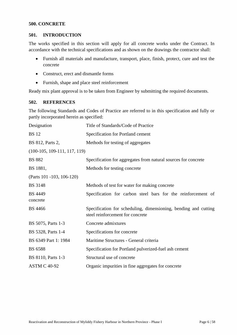
Reactivation and Reconstruction of Myliddy Fishery Harbour in Northern Province - Phase I Page 6 | 58
500. CONCRETE
501. INTRODUCTION
The works specified in this section will apply for all concrete works under the Contract. In
accordance with the technical specifications and as shown on the drawings the contractor shall:
Furnish all materials and manufacture, transport, place, finish, protect, cure and test the
concrete
Construct, erect and dismantle forms
Furnish, shape and place steel reinforcement
Ready mix plant approval is to be taken from Engineer by submitting the required documents.
502. REFERENCES
The following Standards and Codes of Practice are referred to in this specification and fully or
partly incorporated herein as specified:
Designation Title of Standards/Code of Practice
BS 12 Specification for Portland cement
BS 812, Parts 2, Methods for testing of aggregates
(100-105, 109-111, 117, 119)
BS 882 Specification for aggregates from natural sources for concrete
BS 1881, Methods for testing concrete
(Parts 101 -103, 106-120)
BS 3148 Methods of test for water for making concrete
BS 4449 Specification for carbon steel bars for the reinforcement of
concrete
BS 4466 Specification for scheduling, dimensioning, bending and cutting
steel reinforcement for concrete
BS 5075, Parts 1-3 Concrete admixtures
BS 5328, Parts 1-4 Specifications for concrete
BS 6349 Part 1: 1984 Maritime Structures - General criteria
BS 6588 Specification for Portland pulverized-fuel ash cement
BS 8110, Parts 1-3 Structural use of concrete
ASTM C 40-92 Organic impurities in fine aggregates for concrete

Reactivation and Reconstruction of Myliddy Fishery Harbour in Northern Province - Phase I Page 6 | 59
503. MATERIALS
503.1. GENERAL
The Contractor shall provide information and get the Engineer‟s approval on the origin of all
materials incorporated in the works.
503.2. CEMENT
The cement used for all reinforced concrete works shall be:
- A low heat Portland pulverized fuel ash cement complying with BS 6588 or
Equivalent cement suitable for the marine environment shall be subject to the Engineer‟s
approval.
The cement used for lean concrete may be ordinary Portland cement complying with BS 12.
High early strength cement shall not be used unless specifically approved by the Engineer in
each and every case.
All cement shall be supplied with proper certificates by the manufacturer and be complying with
the requirements of the relevant standards.
At least 6 weeks before placing an order for purchase the Contractor shall satisfy the Engineer
that his source or sources of supply is able to deliver cement complying to the relevant standard
and with proper certificates.
Having obtained the Engineer‟s approval of the source of supply, transport storage and
certification of the cement, the Contractor shall not modify or change the agreed arrangements
without first having obtained the Engineer‟s permission.
The cement shall be delivered to the site of the Works in sound and properly sealed bags and
while being loaded and during transit to the concrete mixers, whether conveyed in vehicles or by
mechanical means, must be protected from the weather by effective coverings.
The cement shall be stored in approved weatherproof and well ventilated sheds with a raised
floor of timber or concrete.
All cement shall be used within six months of the date of manufacture.
No cement shall be used in the Works until it has been passed as satisfactory by the Engineer,
and all unsatisfactory cement shall be promptly removed from the Site at the Contractor‟s
expense.
503.3. AGGREGATES
Coarse and fine aggregates shall conform to BS 882.
Fine aggregate < 5mm < Coarse aggregate
Coarse aggregate for reinforced concrete shall be clean, sharp under composed gneiss or other
approved metamorphic or igneous rock having clean, hard dense and durable fragments.
All materials used as aggregates shall be obtained from an approved source producing
aggregates suitable for concrete in the respective class and shall be hard, durable, clean, free
from adhering coatings, be chemically inert and of limited porosity with a density not less than
2600 kg/m3. (2400 kg/m
3 for unreinforced concrete)

Reactivation and Reconstruction of Myliddy Fishery Harbour in Northern Province - Phase I Page 6 | 60
Fine aggregate for concrete shall be clean sand.
Crushed sand may be added to natural sand in order to achieve the required grading. Crushed
sand alone may only be used with the approval by the Engineer.
Aggregates shall be cleaned by washing if the content of clay or fines < 0.075 mm, exceeds 1%
(weight).
Aggregates shall be free of organic impurities - measured and interpreted according to ASTM C
40-73 or other matter which may cause corrosion of steel or otherwise impair the strength of
durability of the concrete.
Marine aggregates or other aggregates containing salt shall not be used in the concrete if
desalted satisfactorily to meet the maximum allowed chloride content presented in BS 5328, Part
1, clause 4.2. Chloride salt content shall be tested according to BS 812, Part 117. For the purpose
of calculation the chloride iron content may be taken as the equivalent sodium chloride content
divided by 1.6
The total sulphate content shall not exceed 4.0% by weight of cement including the sulphate
present in the cement.
The coarse and fine aggregates shall when mixed produce a well graded mixture from the largest
to the smallest size specified.
(a) Coarse aggregate - from 5 mm to 20 mm or from 5 mm to 40 mm - shall be graded
aggregate complying with BS 882, Table 3
(b) Fine aggregate - mainly smaller than 5 mm - shall be graded aggregate co m plying with
the overall limits given in BS 882, Table 4. Additionally, not more than one in ten
consecutive samples shall have a grading outside the limits for grading C cf. BS 882,
Clause 5.2.1
All-in aggregate is not allowed.
The Contractor shall not later than 30 (thirty) days before the planned commencement of any
works submit to the Engineer for his approval, representative samples of the fine and coarse
aggregates intended to be used in the works.
The samples shall have been obtained from sources requested to be approved and shall be
accompanied by test certificates from an independent laboratory giving all information on
relevant properties of the aggregates, according to BS 812.
Criteria for acceptance of aggregates - during execution of the works - are given in summary in
the Table below.

Reactivation and Reconstruction of Myliddy Fishery Harbour in Northern Province - Phase I Page 6 | 61
Name and location of source Yes
Sieve analysis BS 812
Coarse aggregate BS 882, Table 3
Fine aggregate BS 882, Grading C
Fines BS 882, Clause 5.4
Ten percent fines valve Mm. 100 kN
Chloride content BS 5328, Part 1, Clause 4.2.2
TABLE: Criteria for acceptance of aggregates
Approved samples of aggregates will at all time during the course of the Contract be kept in the
Engineer‟s site office and all concrete aggregates shall comply with such approved samples or
shall whenever required by the Engineer be tested by the Contractor for compliance with these
Specifications.
All sand and aggregate for concrete shall be stored on close filling timber, steel or concrete
stages of approved design with drainage slopes or in bins of substantial construction in such a
manner as to prevent jumbling or segregation of sizes and to avoid the inclusion of dirt and other
foreign materials in the concrete. All such bins shall be emptied and cleaned at intervals as
instructed by the Engineer. Each size of aggregate shall be stored separately.
At no time shall aggregate for use in concrete be allowed to dry out completely and freshwater
shall from time to time be sprinkled lightly on the stored aggregates.
503.4. MIXING WATER
Mixing water shall be fresh water and be clean, free from harmful matter and from any unusual
proportion of dissolved salts.
Water used for concrete in reinforced structures shall have maximum permissible water -soluble
chloride content of 0.05%. Water shall be sampled and tested at maximum 4 weeks intervals
decided by the Engineer.
503.5. ADMIXTURES
Plasticisers shall normally be used to achieve the required workability of high quality concrete.
When minimum air content is specified for the concrete an air -entraining admixture shall be
used.
No admixture will be considered for approval that is not being commercially used with
satisfactory service and supplied with a detailed declaration of constituents. All requests for
approval of admixtures shall be submitted to the Engineer at least 30 (thirty) days before it is
intended to use the admixture. The Contractor shall submit with his request independent test data
and adequate samples of the proposed admixture cf. BS 8110, Part 1, clause 6.1.5. and BS 5328,
Part 1, clause 3.4.
Air-entraining admixture, if added, shall be added during mixing in proper amount to give the
approved air content.
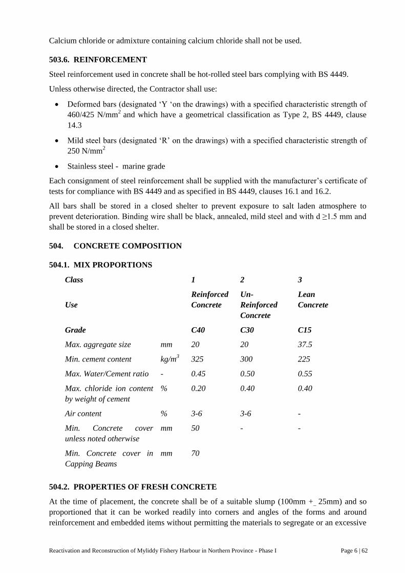
Reactivation and Reconstruction of Myliddy Fishery Harbour in Northern Province - Phase I Page 6 | 62
Calcium chloride or admixture containing calcium chloride shall not be used.
503.6. REINFORCEMENT
Steel reinforcement used in concrete shall be hot-rolled steel bars complying with BS 4449.
Unless otherwise directed, the Contractor shall use:
Deformed bars (designated „Y „on the drawings) with a specified characteristic strength of
460/425 N/mm2
and which have a geometrical classification as Type 2, BS 4449, clause
14.3
Mild steel bars (designated „R‟ on the drawings) with a specified characteristic strength of
250 N/mm2
Stainless steel - marine grade
Each consignment of steel reinforcement shall be supplied with the manufacturer‟s certificate of
tests for compliance with BS 4449 and as specified in BS 4449, clauses 16.1 and 16.2.
All bars shall be stored in a closed shelter to prevent exposure to salt laden atmosphere to
prevent deterioration. Binding wire shall be black, annealed, mild steel and with d ≥1.5 mm and
shall be stored in a closed shelter.
504. CONCRETE COMPOSITION
504.1. MIX PROPORTIONS
Class 1 2 3
Use
Reinforced
Concrete
Un-
Reinforced
Concrete
Lean
Concrete
Grade C40 C30 C15
Max. aggregate size mm 20 20 37.5
Min. cement content kg/m3 325 300 225
Max. Water/Cement ratio - 0.45 0.50 0.55
Max. chloride ion content
by weight of cement
% 0.20 0.40 0.40
Air content % 3-6 3-6 -
Min. Concrete cover
unless noted otherwise
mm 50 - -
Min. Concrete cover in
Capping Beams
mm 70
504.2. PROPERTIES OF FRESH CONCRETE
At the time of placement, the concrete shall be of a suitable slump (100mm +_ 25mm) and so
proportioned that it can be worked readily into corners and angles of the forms and around
reinforcement and embedded items without permitting the materials to segregate or an excessive

Reactivation and Reconstruction of Myliddy Fishery Harbour in Northern Province - Phase I Page 6 | 63
amount of free water to collect on the surface of the concrete - taking into account the
requirements for placing and compaction.
The detailed requirements shall be established on the basis of concrete trials.
504.3. CONCRETE TRIALS
At least 30 days before any concrete is placed in the Works the Contractor shall submit mix
design to the Engineer for his approval full details of the mixes, he proposes to use for each
grade of concrete together with their anticipated average strength. These mixes shall be based on
the results of trial mixes as specified in BS 8110, Clause 6.4.1.The program of trial mixes shall
be subject to approval by the Engineer, and the Engineer shall be kept informed on the progress
of the tests.
The mixes shall be designed with due regard for the workability necessary to allow the
Contractor to place and compact the concrete with the equipment he proposes to use in any
particular situation.
Before any change to materials or mix proportions is introduced the Contractor shall provide all
evidence to the satisfaction of the Engineer that the new mix will meet this Specification.
505. PRODUCTION OF CONCRETE
505.1. GENERAL
Production of concrete shall be in accordance with BS 8110 Clause 6.4.
The Contractor shall use a modern and reliable plant for a thorough mixing of the aggregates,
cement, admixtures and water into a uniform mass within appropriate time and capable of
discharging the mix without segregation.
505.2. PRODUCTION PROGRAM
One week before any major concrete pouring the Contractor shall present a detailed activity
program with indication of personnel, equipment (including spare equipment), materials, control
activities and provisions for treatment of concrete after pouring.
The program shall include the following inspections before commencement of concrete
production:
Check and re-calibration of each scale and other measuring devices from zero to full
capacity of the scale
Check of the efficiency of the mixer by wet screening of fresh concrete.
505.3. EQUIPMENT
The Contractor shall submit within 45 days after award of the Contract information on the
proposed plant for batching and mixing the concrete.
Those surfaces of the measuring, mixing and transporting equipment that will be in contact with
concrete shall be clean at the commencement of the mixing operation.
Before each pouring the Contractor shall check the performance of his equipment and the
accuracy of scales etc.

Reactivation and Reconstruction of Myliddy Fishery Harbour in Northern Province - Phase I Page 6 | 64
505.4. DELIVERY AND STORAGE OF MATERIALS
All concrete materials shall be stored and handled with care to avoid any pollution or unintended
mixing of different materials.
All bins and containers with materials shall be unambiguously marked.
505.5. BATCHING
The materials shall be so measured out as to give the required mix proportions in accordance
with BS 5328, Part 3. Cement and aggregate shall be batched by weight - where aggregate may
be weighed cumulatively - and water shall be batched by weight or by volume. Admixtures shall
be batched using suitable dispenser. The Contractor shall measure the moisture content of the
aggregate in accordance with BS 812, Part 109 as frequently as required and at least once a day
during times of concrete production, and he shall adjust the quantity of mixing water according
to the results of these tests if required.
Delivery of materials from the batching equipment shall be within the following limits of
accuracy:
Cement, water and aggregates: ±3%
Admixtures: ±5%
All batching shall be recorded with indication of achieved as well as intended quantities.
The records shall also include general information about the weather, about the progress in
placing the concrete and about any difficulties in producing or placing concrete whether due to
breakdown of equipment or any other cause. The Contractor shall furnish to the Engineer one
copy of all these records not later than two days after the event took place.
505.6. MIXING
The concrete shall be mixed in the mixer until the materials are uniformly distributed and shall
be discharged completely before the mixer is recharged.
The operator of the mixer shall currently be able to make a visual assessment of the concrete
properties as well as the achieved discharge of concrete from the mixer.
The net mixing time, measured from batching of the last component, shall be recorded.
505.7. TRANSPORT
The concrete shall be transported from the mixer to the place of final deposit by means which
will prevent segregation or loss of materials and not permit the concrete to stiffen.
The means and duration of transport shall be subject to approval by the Engineer.
506. INSPECTION AND TESTING
506.1. GENERAL
Control tests on concrete shall be carried out in accordance with test methods as specified in BS
8110 and related standards or other test method representing the „state of the art‟ subject to the
approval by the Engineer.

Reactivation and Reconstruction of Myliddy Fishery Harbour in Northern Province - Phase I Page 6 | 65
The properties of the concrete shall be tested and evaluated in accordance with BS 8110, clause
6.4, BS 5328 and BS 1881.
Pre-testing shall be made for the necessary documentation of compliance with the specified
requirements to:
- materials
- composition
- strength
- work execution
before or in connection with concrete trials.
Control-testing shall be made concurrently with the concrete production on:
- materials
- composition
- strength
- work execution
any significant change to the said items shall be preceded by renewed pre-testing and concrete
trials.
506.2. TESTING OF MATERIALS
Cement
All relevant properties of the supplied cement shall be stated in detail in the certificate from the
supplier, for check of compliance with the relevant standards.
Aggregates
Gradation tests and description of the nature of the aggregates including content of harmful
matters for which limits are specified in this document or pertaining standards shall be made
prior to the concrete trials.
Additional control testing shall be made in case of changes or as specified.
Water
The specified requirements shall be documented.
Admixtures
Pre-testing shall include a verification of the content of the declarations of the materials. The
suitability of the admixtures shall be tested in connection with the concrete trials.
506.3. TESTING OF COMPOSITION
After the approval of documentation of materials the composition of the concrete shall be fixed
and documentation of the following properties established by calculation:
- water/cement ratio
- content of cement and their constituents
- content of fines

Reactivation and Reconstruction of Myliddy Fishery Harbour in Northern Province - Phase I Page 6 | 66
- air content
- saturated and dry density
- content of chlorides and possible other harmful matters.
506.4. CONCRETE TRIALS AND TESTING OF STRENGTH
A visual inspection shall be made of the storage conditions of materials and the equipment
available. The accuracy of the batching shall be established.
The duration of batching and the succession of materials added to the mixer shall be recorded.
The time for mixing shall be recorded.
The time for mixing shall be recorded.
The achieved properties of the fresh concrete shall be tested by slump tests, air content tests and
by screening of samples of the fresh concrete.
The concrete strength shall be determined by compression tests of concrete cubes in accordance
with BS 8110, clause 6.4, and BS 5328 and with rates of sampling and testing as BS 5238, Part
1, clause 8.2, as follows:
- minimum one sampling per 10 m3
or 10 batches for concrete Classes I and 2
- minimum one sampling per 20 m3
or 20 batches for concrete Class 3
The sampling, storage and testing shall be carried out to BS 1881.
From each trial mix a minimum of three specimens for the 28 days test and one specimen for the
7 days test shall be prepared unless otherwise directed by the Engineer.
506.5. TRIAL POUR
A trial pour shall be made for concrete Classes I and 2, the details of which shall be mutually
agreed upon between the Contractor and the Engineer.
The following points shall be observed and recorded
Transport of fresh concrete
Pouring
Treatment of non-hardened surfaces
Curing and protection and actual weather conditions
Temperature development and gradients in the concrete during setting
Cracks or other defects in the concrete when hardened.
506.6. CONCRETE DEEMED NOT TO COMPLY
In any case where the test results for strength do not comply with the requirements remedial
measures shall be decided by the Engineer. Any remedial work or demolition and reconstruction
of rejected work shall be carried out on the Contractor‟s own account.
Cored samples shall be extracted at locations approved by the Engineer and treated and tested in
accordance with BS 1881 Part 120.

Reactivation and Reconstruction of Myliddy Fishery Harbour in Northern Province - Phase I Page 6 | 67
Where the Engineer permits non-destructive tests, such as the Schmidt (Rebound) Hammer Test,
or ultrasonic tests, the relevant criteria for accepting or rejecting the concrete concerned shall be
subject to approval by the Engineer and cost to be born by the contractor.
506.7. DATA AND INSPECTION
The Engineer shall be furnished one copy of all test results without delay and within 2 working
days. Also the Engineer shall be free to inspect at any time during working hours all equipment
used and all records made for the verification of these requirements.
507. FORMWORK
507.1. GENERAL
Formwork shall be such that the finished surface of all concrete work shall be sound, solid and
free from honeycombing, protuberances and blemishes.
The Contractor will be responsible for the design and execution of all formwork. Drawings and
calculations shall be prepared and presented to the Engineer at least 2 weeks before the
commencement of formwork.
507.2. DESIGN AND CONSTRUCTION
The design and construction of formwork shall be in accordance with BS 8110, clause 6.9.1.
All formwork and false work shall be adequately designed, built and maintained to be tight, to
sustain construction loads and be so rigid that no displacements will occur.
All forms shall be treated with approved oil and wooden forms shall be thoroughly drenched
with water immediately before placing concrete.
Only form-clamps of reputable makes and proper steel form ties and spacers shall be used. Form
ties shall remain embedded in the concrete and they shall terminate not less than 50 mm inside
the formed face of the concrete. The fasteners on the ends of form ties shall be such that their
removal will leave holes of regular shape. These holes shall be dry-packed subject to the
Engineer‟s approval.
Panels shall have true edges to permit accurate alignment and provide a neat line with adjacent
panels and at all construction joints. All panels shall be fixed with their joints either vertically or
horizontally.
Formwork below or between tides shall be so fitted and caulked that the ingress of water is
prevented. Further the formwork shall be supported in a way, which prevents deflection due to
water pressure.
507.3. CLEANING AND TREATMENT
Before concrete is placed, forms shall be cleaned and treated as specified in BS 8110, clause
6.9.2.
Discoloration or any other harm from the use of release agents shall be prevented.

Reactivation and Reconstruction of Myliddy Fishery Harbour in Northern Province - Phase I Page 6 | 68
507.4. CONSTRUCTION TOLERANCES
Tolerances for formed surfaces of in- situ and pre-cast reinforced concrete are:
a. Cross-sectional dimensions of beams, slabs, walls etc.: 0 mm to + 20 mm
b. Longitudinal dimensions less than 30 m of same members: ± 20 mm
c. Size and location of penetrations, recesses, etc.: ± 5 mm
d. Location of in-situ structure generally, relative to established reference lines, module lines
and levels: ± 20 mm
e. Holding down bolts etc. as group : ± 5 mm
f. Inserts, brackets, steel members etc. to be embedded and which on the drawings are shown
to be flush with the concrete surface : ± 1 mm
g. Or as otherwise specified
507.5. INSPECTION AND APPROVAL
The Engineer shall be given adequate notice and time - min. 24 hours or as otherwise agreed
with the Contractor - for inspection of all formwork, including steel reinforcement, prior to
placing of concrete.
507.6. STRIKING OF FORMWORK
The striking of formwork shall be carried out in accordance with BS 8110, clause 6.9.3 or as
otherwise agreed with and approved by the Engineer. Form work must not be struck less than 48
hours after casting, but in any case no sooner than determined by the Engineer.
No striking of formwork must be made until compliance with the specified requirements to
temperature and moisture in the concrete has been met.
508. REINFORCEMENT
508.1. GENERAL
The Contractor shall furnish, cut, bend and place all steel reinforcement.
The Contractor shall provide at his own cost and to the approval by the Engineer working
drawings of all reinforcement accompanied by bending schedules.
The working drawings and bending schedules shall be submitted to the Engineer at least 14 days
prior to commencing actual work. The Engineer‟s approval of working drawing and bending
schedules shall in no way relieve the Contractor of the responsibility for the correctness of same.
508.2. HANDLING, CUTTING AND BENDING MODULE LINES AND
The steel shall be decently stored on the work site in shelter as to avoid contamination by sea
spray and/or corrosion to the extent possible. Reinforcements effected by severe rust or sea spray
will be rejected.
The reinforcement shall to be cut and bent according to BS 8110, clause 7.2, according to BS
4466 and according to the approved bending schedules.

Reactivation and Reconstruction of Myliddy Fishery Harbour in Northern Province - Phase I Page 6 | 69
508.3. PLACING AND FIXING
At the time concrete is placed, reinforcement shall be free from loose rust or loose mill scale,
dirt, mortar spillage, salt, oil, grease or other coating which might destroy or impair the bond
between the concrete and the reinforcement. Rust will not be considered loose if, on rubbing
with a finger, it leaves only a stain thereon.
All reinforcement is to be sized, shaped and placed in exact accordance with the Drawings
provided by the Contractor and approved by the Engineer and kept in the correct position in the
forms without displacement during the process of vibrating, tamping and ramming the concrete
in place.
The Contractor shall provide all necessary distance pieces and space bars to maintain the
reinforcement in the correct position. Spacers shall be of such materials and design as will be
durable, not lead to corrosion of the reinforcement and not cause spalling of the concrete cover.
Any ties, links or stirrups connecting the bars shall be taut so that the bars are properly braced,
and the inside of their curved parts shall be in actual contact with the bars around which they are
intended to fit. Bars shall be bound together, in at least every other point of intersection, with
best black annealed mild steel wire or other approved binders. Binding wire shall be bent
inwards.
Unless specified otherwise the minimum cover to reinforcement, as measured to the outside of
stirrups or outer bars, shall be 50 mm, with a tolerance of -0 mm +10 mm for all faces.
Bars shall not be displaced laterally from the specified position by more than half a bar spacing
nor into the specified cover zone in order to clear embedded items or penetrations unless
permitted by the Engineer.
All reinforcement steel shall be furnished in full lengths. Splicing will generally not be
permitted.
508.4. WELDING
Welding of rebars is generally not permitted and shall in all case be subject to the Engineer‟s
approval.
508.5. LAPS
Lapping of bars where necessary shall be staggered. Lap length in main reinforcement shall be
40 times diameter of the bar and in secondary reinforcement 40 times diameter of the bar.
508.6. EMBEDDED ITEMS
All embedded items such as inserts, holding-down bolts, frames, sleeves, pipes and conduits
shall be placed accurately and secured against displacement before concreting commences, and
voids formed shall be protected from being clogged with concrete.
508.7. DELAYS DUE TO REJECTION OF REINFORCEMENT
The Employer will not be held liable or responsible for any delay in completion of the work
under this contract which may occur due to any rejection of reinforcement which does not
conform to the required standards in consequence of the contractor‟s operations.
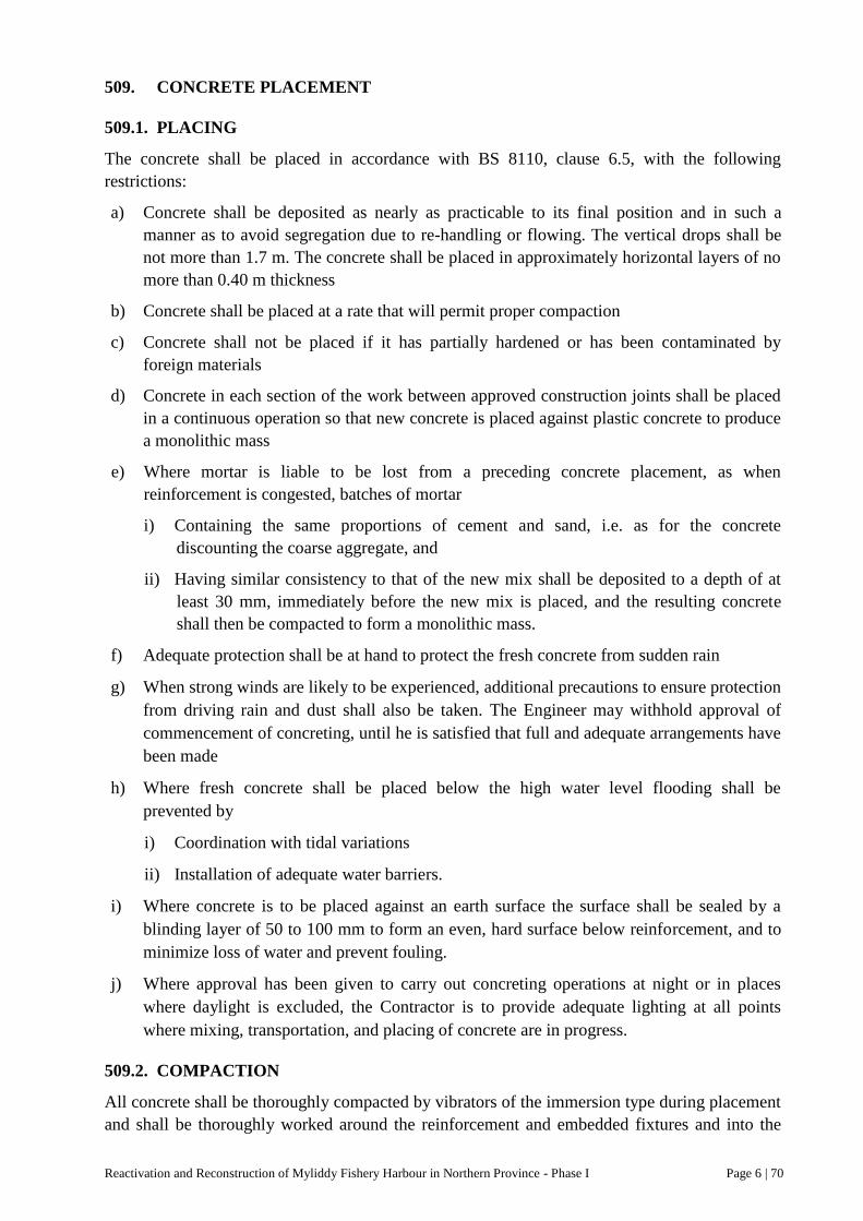
Reactivation and Reconstruction of Myliddy Fishery Harbour in Northern Province - Phase I Page 6 | 70
509. CONCRETE PLACEMENT
509.1. PLACING
The concrete shall be placed in accordance with BS 8110, clause 6.5, with the following
restrictions:
a) Concrete shall be deposited as nearly as practicable to its final position and in such a
manner as to avoid segregation due to re-handling or flowing. The vertical drops shall be
not more than 1.7 m. The concrete shall be placed in approximately horizontal layers of no
more than 0.40 m thickness
b) Concrete shall be placed at a rate that will permit proper compaction
c) Concrete shall not be placed if it has partially hardened or has been contaminated by
foreign materials
d) Concrete in each section of the work between approved construction joints shall be placed
in a continuous operation so that new concrete is placed against plastic concrete to produce
a monolithic mass
e) Where mortar is liable to be lost from a preceding concrete placement, as when
reinforcement is congested, batches of mortar
i) Containing the same proportions of cement and sand, i.e. as for the concrete
discounting the coarse aggregate, and
ii) Having similar consistency to that of the new mix shall be deposited to a depth of at
least 30 mm, immediately before the new mix is placed, and the resulting concrete
shall then be compacted to form a monolithic mass.
f) Adequate protection shall be at hand to protect the fresh concrete from sudden rain
g) When strong winds are likely to be experienced, additional precautions to ensure protection
from driving rain and dust shall also be taken. The Engineer may withhold approval of
commencement of concreting, until he is satisfied that full and adequate arrangements have
been made
h) Where fresh concrete shall be placed below the high water level flooding shall be
prevented by
i) Coordination with tidal variations
ii) Installation of adequate water barriers.
i) Where concrete is to be placed against an earth surface the surface shall be sealed by a
blinding layer of 50 to 100 mm to form an even, hard surface below reinforcement, and to
minimize loss of water and prevent fouling.
j) Where approval has been given to carry out concreting operations at night or in places
where daylight is excluded, the Contractor is to provide adequate lighting at all points
where mixing, transportation, and placing of concrete are in progress.
509.2. COMPACTION
All concrete shall be thoroughly compacted by vibrators of the immersion type during placement
and shall be thoroughly worked around the reinforcement and embedded fixtures and into the

Reactivation and Reconstruction of Myliddy Fishery Harbour in Northern Province - Phase I Page 6 | 71
corners of the forms. The use of external vibrators is not permitted. Vibrators shall be of
approved type and design. Spare vibrators shall always be available at the site of casting.
The vibration shall continue until the air bubbles cease to appear on the concrete surface and
stop immediately with the appearance of bleeding and not carried on to a degree that may cause
segregation of the concrete. The working of the concrete by vibrators to make it flow laterally is
not permitted, and vibrators shall always be extracted slowly to prevent forming of voids.
509.3. CONSTRUCTION JOINTS
Construction joints shall be executed in accordance with BS 8110, clause 6.12 with the
following restrictions:
(a) Construction joints shall be located and shaped as shown on the drawings. The location
and method concerned for other construction joints, desired by the Contractor, shall be
subject to the Engineer‟s approval
(b) Before fresh concrete is placed against a hardened concrete surface at a construction
joint, the surface shall be roughened and cleaned so that all loose or soft material, free
water, foreign matter and cement skin are removed, while at the time of the replacement
the surface shall be damp
(c) projecting reinforcement and embedded items, such as water-stops, dowels, inserts,
fabricated steel members and pipes shall be carefully located, fixed and sealed in the
form of the construction joints
(d) Kickers, i.e. starter stubs for walls and columns, shall not used unless approved by the
Engineer and in any case shall be poured integrally with the concrete poured first
(e) The formwork shall be tightly secured against previously cast or hardened concrete to
prevent stepping or ridges to exposed surfaces
(f) All construction joints between existing and new concrete shall be treated for prevention
of possible water penetration/seepage through the joint.
Treatment by application of a suitable water repellent product shall be made on the
exposed surface in the entire length of the joint and the covering at least 50mm to each
side of the joint.
The water repellent product shall provide a durable and whether resistant lining of the
pores and shall be colourless or only slightly deviating in appearance from the adjoining
concrete. The product shall become subject to the Engineers approval based on
comprehensive documentation provided by the Contractor.
509.4. UNDERWATER CONCRETE
Underwater concrete shall be carried out as per BS 6349 Part 1: Maritime structures.
510. TREATMENT AND CURING
510.1. UPPER SURFACES
The upper surface of concrete structures shall be adjusted to the required shape and tolerance by
application of a board. The necessary surface adjustment of slabs shall be made with a beam
vibrator.

Reactivation and Reconstruction of Myliddy Fishery Harbour in Northern Province - Phase I Page 6 | 72
510.2. MOIST CURING
All concrete must be moist cured for a period of time equivalent to 7 days by a suitable method.
Alternatively the forms shall remain in place for this period of time.
The curing shall be commenced no later than one hour from the time of pouring.
510.3. PROTECTION
During the curing period the concrete shall be protected from the harmful effects of sunshine,
drying winds, cold, rain, wave action, or running water. The protection shall be applied as soon
as practicable after completion of placing.
Also during the curing period, the concrete shall be protected from damaging mechanical
disturbance, such as load stresses, heavy shock, and excessive vibration.
All finished concrete surfaces shall be protected from damage caused by construction
equipment, materials or methods, by spraying with water colder than the concrete, by application
of adverse curing procedures and by rain or running water.
Self-supporting structures shall not be loaded in such a way as to overstress the concrete.
510.4. PROVISIONS AGAINST EARLY THERMAL CRACKING
The curing process shall be designed so as to avoid early thermal cracking due to internal
temperature differences over cross sections or excessive external restraint during cooling of
structural units.
510.5. HOT WEATHER REQUIREMENTS
The following requirements shall apply when concreting in hot weather:
(a) Precautions shall be taken to avoid premature stiffening of the fresh mix and to reduce
water absorption and evaporation losses
(b) If the temperature of the surrounding air is between 32° and 35° C the following shall
apply unless otherwise directed by the Engineer:
(i) The formwork shall be continuously sprayed with cold freshwater in advance of the
concreting and excess water shall be removed from the inside of the forms
immediately prior to the placement of concrete
(ii) The reinforcement, and the form work if metal forms are used, shall be protected from
the effects of hot winds and direct sunlight
(iii) Suitable barriers shall be provided to protect the freshly placed concrete from wind,
until the concrete has hardened sufficiently to allow it to be covered according to
paragraph (v) below
(vi) The concrete shall be mixed, transported, placed and compacted as rapidly as possible,
and shall then be covered with:
A. an impervious membrane, or
B. hessian, kept wet, until moist curing begins
(c) Concreting when the surrounding air temperature exceeds 35° C shall be with the
Engineer‟s approval only.

Reactivation and Reconstruction of Myliddy Fishery Harbour in Northern Province - Phase I Page 6 | 73
510.6. HARDENED CONCRETE
The Contractor shall immediately notify the Engineer if, by the removal of formwork, faults or
adverse geometry is revealed.
Patching, plastering or cement washing of defective areas such as honeycombs and cracks shall
not be permitted except with the approval by the Engineer. However, such approval is not
required for the repair of holes left by the extraction of form ties or cored samples.
510.7. CONCRETE DEEMED NOT TO COMPLY
In any case where test results or the quality of hardened surfaces do not comply with the
requirements remedial measures shall be decided by the Engineer on the basis of the
Contractor‟s proposal.
Any remedial work or demolition and reconstruction of rejected work shall be carried out on the
Contractor‟s account.
510.8. DELAYS DUE TO UNSATISFACTORY TREATMENT & CURING OF
CONCRETE
The Employer will not be held liable or responsible for any delay in completion of the works
under this contract which may occur due to any rejection of concrete which does not conform to
the required standards in the treatment & curing of concrete in consequence of the contractor‟s
operations.

Reactivation and Reconstruction of Myliddy Fishery Harbour in Northern Province - Phase I Page 6 | 74
600. MASONRY, TILING & PAINTING
601. MASONRY
601.1. GENERAL
Materials used in the Works shall be new, of the qualities and kinds specified herein and equal to
the approved samples. Delivery shall be made sufficiently in advance to enable samples to be
taken and tested if required. No materials shall be used until approved and materials not
approved shall be immediately removed from the Works.
Materials shall be transported, handled and stored on the site or elsewhere in such a manner to
prevent damage, deterioration or contamination.
601.2. CEMENT
Cement shall be Ordinary Portland cement of an approved brand.
Cement shall conform to BS 12.
Cement shall be of recent manufacturer, used within 6 months of manufactured date and
free of any lumping or coalescing.
Check tests will be required by the Engineer. These tests shall be carried out at the
Contractor‟s expense.
601.3. SOLID BLOCKS
Masonry work shall be done with solid blocks of approved quality unless specified
otherwise.
Blocks shall be of standard quality, low permeability blocks with no defects and sample
shall be submitted for approval of the Engineer.
Blocks shall be cement / sand. Block thickness shall be 150 mm thick for all full height
walls The average compression strength should be not less than 2.8N/mm and shall
comply with the relevant British Standard.
The blocks shall be free from excessive amounts of salt or other impurities, and shall be
inspected and approved by the Engineer.
Work shall be complied with this specification unless otherwise stated In particular
Specification or Drawings. Any work not specified shall be discussed and directed by the
Engineer.
Stake-board shall be provided at each 5m in length, and shall be inspected by the Engineer
for the accuracy and firmness. However, suitable ruler, plumb bob and leveler shall be
provided for minor performance of cement block.
Care shall be taken for damage during transportation of materials, and any defect of
natural finished concrete blocks shall be rejected.
Any shock or load shall not be applied until concrete mortar or other fills hardened.
Corner projection and top of cement block work shall be protected from rain, dryness,
damage and stain by covering.

Reactivation and Reconstruction of Myliddy Fishery Harbour in Northern Province - Phase I Page 6 | 75
Void between blocks shall not be intruded by rainwater.
Cement blocks shall be saturated with water and joint shall be cleaned.
A layer or bed of damp proof membrane shall be placed on to the ground slab and the first
course of blocks placed onto this layer. The damp proof mortar shall consist of a
sand:cement ratio of 1:4, and an approved water proof additive (material specification to
be approved by Engineer prior to use).
Bonding mortar shall be used immediately after mix, and mixed mortar left for more than
one hour shall be rejected.
Vertical and horizontal joint of blocks shall be filled completely, and suitable with mortar
on line, shall not be moved or rearranged. Joint and surface of block of exposed finished
block wall shall be cleaned immediately after joint is filled.
Mortar for joint shall be touched with steel trowel before hardened, and exposed joint
shall be finished with uniform width and planned without roughness or cavity.
Height for placing block per day shall be maximum 1.2m unless otherwise specified.
Ties to columns must be provided every three course of block work. The ties are to be
galvanized steel and a material sample is to be provided prior to purchasing for the
project.
The thickness of joints shall not exceed 10mm, and the joints shall be raked (13mm dup.)
when the mortar is still fluid, so as to provide for proper bond for the plaster. Any mortar,
which falls on the floor from these joints or removed due to raking of joints, shall not be
reused.
Lintel shall be reinforced concrete as approved or directed by the Engineer.
Main reinforcing bar shall be anchored more than 40D (40 x diameter of the bar) at both
ends.
In case lintel is prefabricated, shop drawing shall be submitted for approval of the
Engineer.
In case frame is temporarily installed before placing of blocks, frame shall be firmly
placed and joiner shall be bonded with mortar as placing each block at side and top of
frame.
In case frame is installed after placing of blocks, joiner shall be bonded with additional
mortar at space or every two blocks or more.
Back of frame shall be filled and compacted with mortar by providing shuttering board.
Wood plug and anchor bolt shall be covered with mortar or concrete.
Principally, piping shall not be placed in block wall unless piping block is in use.
In case chipping and piping on face of blocks is unavoidable, performance shall confirm
to instruction of the Engineer.
Joiner and supporter for exposed piping shall be buried at joint which back is filled or
otherwise approved by the Engineer.

Reactivation and Reconstruction of Myliddy Fishery Harbour in Northern Province - Phase I Page 6 | 76
602. PLASTERING
602.1. GENERAL
All masonry walls shall have smooth finished cement plaster on internal side and rough finished
for outer sides. Surface setting coat of neat cement applied within an hour of the completion of
rendering in floor.
602.2. MATERIALS AND STORAGE
Plaster materials which are affected by moisture such as plaster and cement shall be stored
properly.
Cement used for plastering shall conform to those of Section 701.2 – Masonry Works.
Grading of sand, however, shall be as in table below.
Grading of Sand Mortar Plastering Plastering
5mm sifting through 100%
0.15mm sifting less than 10%
For first coat
For finish coat
For first coat and dubbing
out
2.5mm sifting through 100%
0.15mm sifting less than 10%
For finish coat For second coat
White cement or filler or similar shall confirm to the requirements of Portland cement,
British Standard BS 12.
The use of mixtures shall be approved by the Engineer. The amount of admixture shall be
such that it affects mortar strength very little. An approved admixture, or proprietary
product, shall be used to reduce shrinkages and for external rendering to improve water
proofing.
Mixing volume ratio of mortar shall be as in Table below:
Base Area of Application First coat
cement: sand
Dabbing out
cement: sand
Finish coat
cement:
sand
Masonry
blocks
Floor
Interior wall
Exterior wall
-
1:4
1:4
-
1:4
1:4
1:4
1:3
1:3
Standard thickness of coating (mm) shall be as in Table below:
Base Area of
Application
First
Coat
Dubbing
Out
Second
Coat
Finis
h
Coat
Tot
al
Masonr
y blocks
Floor 10 10 10 20

Reactivation and Reconstruction of Myliddy Fishery Harbour in Northern Province - Phase I Page 6 | 77
Interior wall
Exterior wall
10
10
10
10
10
10
20
20
Thickness of coating shall be standard thickness of coating unless otherwise indicated on
the Drawings.
Type of finish and work schedule shall be as in Table below:
Type Work Schedule Notes
1. Semi rough
power trowel finish
1. Shall be applied flat by
metal trowel.
2. Shall be finished by
pressing with the trowel.
Before applying second coat,
corner and edge shall be screed
well.
602.3. GENERAL PREPARATION
Remove efflorescence, laitance, dirt and other loose material by thoroughly dry brushing.
Remove all traces of paint, grease, dirt and other materials incompatible with coating, by
scrubbing with water containing detergent and washing off with plenty applying coatings
unless specified otherwise.
In Situ Concrete Surfaces: Scrub with water containing detergents to ensure complete
removal of mould oil, surface retarders and other materials in compatible with coating.
Rinse with clean water and allow to dry unless specified otherwise.
Organic Growths: Treat with fungicide to manufacturer‟s recommendations and bush off.
Hacking for Key: Roughen specified surfaces thoroughly and evenly by removing the
entire surface to a depth of 3mm by scrubbing, bush hammering or abrasive blasting.
Clean surfaces by washing and brushing.
Smooth Concrete Surfaces: Where no keying or mix or bonding agent is specified, wet
smooth concrete surfaces immediately before plastering.
602.4. EXTERNAL PLASTERING
Dissimilar Solid Backgrounds for Plastering: Where plaster is to be continued without
break across joints between dissimilar solid backgrounds which are rigidly bonded
together, cover the joints with a 200mm wide mesh strip (backgrounds in the same plane)
or with the corner mesh (internal angle) fixed at not more than 600mm centers along both
edges, unless specified otherwise.
Dissimilar Solid Backgrounds for Plaster: Where plaster is to be continued without break
and without change of plane across the face of a 300mm and rigidly bonded to the
background.
Overlay with expanded plastic reinforcing mesh 50mm beyond the edges of the paper, and
securely fixed with masonry nails at not less than 100mm centers along both edges.
Alternatively, an approved paper and mesh lathing may be used.

Reactivation and Reconstruction of Myliddy Fishery Harbour in Northern Province - Phase I Page 6 | 78
Dissimilar Solid Backgrounds for Rendering: Where rendering is to be continued without
break across joints between dissimilar solid backgrounds which are in the same plane and
rigidly bounded together, cover joints with a 150mm wide strip of building paper overlaid
with 300mm wide plastic reinforcing metal fixed at not more than 600mm centers along
both edges unless specified otherwise.
Service Chases: Cover with plastic reinforcing mesh strip fixed at not more than 600mm
centers along both edges.
Conduits bedded in under coat to be covered with 90mm wide jute scrim bedded in
finishing coat mix, pressed flat and toweled in. Do not lap ends of scrim.
602.5. INTERNAL PLASTERING
Accuracy of plaster 25mm maximum permissible gap between a 1800mm straight edge
and any point on the surface to be 3mm.
Dubbing Out: If necessary to correct inaccuracies, dub out in thickness of not more than
10mm is same mix as first coat. Allow each coat to set before the first is applied. Cross
scratch surface of each dubbing out coat immediately after set.
Plastic Reinforcing Mesh: Work undercoat well into interstices to obtain maximum key.
Under Coats: Generally to be not less than 12mm with thickness greater than 20mm
applied as two coats. Rule to an even surface and cross scratch – end coat to provide a key
for the next hand applied coat.
Dissimilar Backgrounds: Where scrim or lathing or beads are not specified, cut through
plaster with a fine blade in a neat, straight line at junctions of:
(a) Plastered rigid sheet and plastered solid backgrounds
(b) Dissimilar solid backgrounds.
Smooth Finish: Trowel or float to product a tight matt, smooth surface with no hollows
abrupt change of level or trowel marks. Do not use water brush and avoid excessive
toweling and over polishing.
602.6. EXTERNAL RENDERING
Dubbing Out: If necessary to correct inaccuracies, dub out in thicknesses of not more than
10mm in same mix as first coat. Allow each coat to dry before the next is applied. Cross
scratch surface of each dubbing out coat immediately after set.
Undercoats for Hand Applied Finishes: Apply first undercoat or dubbing out coat by
throwing from a trowel. Coats to be no less than 12mm thick with thickness greater than
20mm applied as two coats. On weak backgrounds, first undercoat to be not less than
12mm thick. Brush down each undercoat to remove dust and loose particles and wet
thoroughly before application of next coat. Cross scratch undercoat without penetrating
the coat, to provide key for the following coats.
Drying: Keep each coat damp for the first three days by covering with polythene sheet and
/ or spraying with water. Thereafter, prevent from drying out rapidly. Work in shade
whenever possible.

Reactivation and Reconstruction of Myliddy Fishery Harbour in Northern Province - Phase I Page 6 | 79
Allow each coat to dry out thoroughly to ensure that drying shrinkage is substantially
complete before applying next coat.
Laying Floated Finish: Finish with wood or other suitably faced float to give an even
texture.
Do not draw excessive laitance to surfaces.
602.7. PLASTIC MESH REINFORCING / REINFORCEMENT FOR PLASTERED
COATINGS
Plastic mesh reinforcement is to be used as reinforcement for plastering in columns, walls
or as specified in drawings.
Products: Plain expanded plastic reinforcing mesh is to be used. The Contractor is to
submit a sample and specification prior to including in the works.
Wire Ties: Unless other specified, annealed iron, galvanized to B.S. 443.
Clout Nails: Galvanized steel or stainless steel nails to B.S. 1202: Part 1, Table 3.
Staples: Galvanized steel wire staples to B.S. 1494: Part 2.
Workmanship
Framing: Fix securely and accurately to help ensure that coatings on lathing, when
finished, are true to line and level, within specified tolerances and free from cracks,
rippling, hollows, ridges and sudden changes of levels.
Runners / Bearers spanning between concrete beams / ribs: Fix with 3mm wire ties twisted
around 38mm x 10 gauge screws driven well into fixing blocks or plugs in sides of beams/
ribs.
Wire Ties: Twisted ends, tightly together, cut off surplus and bend ends of wire away from
face of coating.
Plastic Reinforcement Mesh
Stretch mesh and fix securely in accordance with manufacturers recommendations to give
a taut, firm base for plaster / rendering.
Fix with the long way of the mesh at right angles to supports and with all strands sloping in
the same direction.
Lap side edges not less than 25mm. Lap ends 50mm at supports and 75mm between
supports. Laps must not occur within 100mm of angles or bends
Render Finish Colour
Where floor plastering finishing detail specifies coloured render, a dry cement colour,
chemically inert, non fading, alkali fast, mineral pigment as approved shall be used. The
colour scheme to be used is to be approved by the Engineer prior to purchasing products.
The Contractor is also to submit a specification for the dry cement colouring for approval.
Reactivation and Reconstruction of Myliddy Fishery Harbour in Northern Province - Phase I Page 6 | 80
603. TILING
603.1. GENERAL
Glazed Ceramic Tile shall comply with British Standard Specification No.1281 and shall
be approved sizes as shown on Drawings, and the product of a reputable manufacturer
approved by the Engineer.
Unglazed Ceramic Tile shall comply with the requirements of British Standard No.1286,
and shall be of approved sizes as shown on the drawings, and the product of a reputable
manufacturer.
Coloured tiles will be used unless otherwise specified, and designs and sample will have
to be approved by the Engineer/ Client.
603.2. CERAMIC AND VITREOUS TILE MATERIALS
Ceramic and Vitreous Clay Wall Tiles:
All tiles for wall installation shall have cushion edge, impervious porcelain and highly glazed
surface. Colours shall be as selected by the Engineer and shall include trimmers, corner pieces,
bull nose and all other special shapes indicated or required. All this shall be free from flaws,
cracks and crazing.
Floor Ceramic and Vitreous Tiles
Non-slip ceramic tile shall be used on all floor locations. Floor tiles shall be specially prepared
for floor use, but shall have all the qualities of ceramic tiles listed above for wall use.
Mortar Materials
Standard brand of light gray or white Portland Cement as specified in drawings, conforming to
current British Standard specifications, shall be used.
Sand: shall be clean, sharp river sand conforming to British Standard Specifications and graded
fine to coarse within the following limits: 100% passing 8 sieve, 90% to 100% passing 16 sieve,
60% to 90% passing 30 sieve, 25% to 55% passing 50 sieve and 0% to 15% passing 100 sieve.
Cement Color
Dry cement color, chemically inert, non fading, alkali fast, mineral pigment, as approved shall
be used wherever refinished.
Waterproofing
Floors of toilet areas, corridors, terraces and planter boxes shall be treated with an appropriate
water proofing coating, approved by the Engineer.
603.3. INSTALLATION REQUIREMENTS
As far as possible, tile layout work should be in such ways that no tile less than half size occurs.
Align joints in wall tile vertically and horizontally except where other patterns are shown
or specified. Align joints in floor tiles at right angles to each other straight with walls to
conform to the patterns selected.

Reactivation and Reconstruction of Myliddy Fishery Harbour in Northern Province - Phase I Page 6 | 81
Verify locations of accessories before installing tiles. Work shall be coordinated with
plumbing and other trades before starting of tile work.
Installation of ceramic and vitreous tile shall be in accordance with manufacturer‟s
instructions.
Floor Tile Installation
All ceramic and vitreous clay tile floors shall be in Portland cement setting beds. Concrete
surfaces shall be cleaned and surface of concrete shall be wetted prior to placing of setting bed
mortar. Tiles shall be immersed in water for minimum of 4 hours before laying.
Setting Bed Mortar Mix: shall consist of one (1) part Portland cement and two (3) parts dry sand,
by volume, to which not more than 1/10 part of hydrated lime may be added.
When mixed with water, the mortar mix shall be of such consistency and workability as
to produce maximum density. Determine consistency by stroking the mortar surface
with a trowel whereof when correct, the trowelled surface readily assumes a smoothed,
silken appearance.
Spread setting bed mortar and screed to provide smooth, dense beds with true planes
pitched to drains. The thickness of bed shall be such that the floor tile will finish flush
with adjacent finished flooring, but bedding shall have average thickness of 38mm.
After bed has set sufficiently to be worked over, trowel or brush a thin layer, 3mm in
thickness of neat Portland cement paste over the surface of the back of tile.
Do not prepare larger setting bed than can be covered with tile before the mortar sets.
Press tile firmly into the bed tapping with wood blocks to obtain firm bedding of total tile
area and a smooth top surface.
All tiles shall be properly aligned with straight joints in even widths. Joints width shall
be determined by spacers on ceramic tiles. Tamping shall be completed within one (1)
hour after placing tile. Adjust work out of line within this period.
Tiles shall be fitted closely around pipes running through walls and floors. Pitch floors
to drains.
Wall Tile Installation
Base Plaster 13mm thick applied to masonry wall shall be one-part Portland cement,
three-parts or river sand by volume. Where additional thickness build-up is required to
conform to indicated lines, apply as separate coat at no cost to employer.
Setting bed of tiles shall be done with cement slurry. The thickness of slurry bed shall be
3mm thick minimum for setting tiles and walls.
Installation of tiles shall be in accordance with standards and applicable requirements
previously specified for floor tile.
Tiles shall be installed in perfect vertical plumb and as per the pattern and joints as
shown on drawings.

Reactivation and Reconstruction of Myliddy Fishery Harbour in Northern Province - Phase I Page 6 | 82
Grouting
Grouting shall not commence for at least 24 hours after placing of tiles. Grout for floor and wall
ceramic and vitreous tiles shall be waterproof, neat white Portland cement with dry cement
colour added as directed by the Engineer. If white grout is selected, cement shall be white.
Grout mixed to a creamy consistency in accordance with manufacturer‟s directions, shall be
used for joint filling.
Maximum width of joints shall be 3mm. Force maximum grout into the joints with trowel.
Before grout sets, strike or tool joints to base of cushion and fill all skips and gaps. Do not
permit setting bed materials to show through grouted joints. Cure grout joints by maintaining
damp condition for three (3) days by sponging down, or other methods approved by the
Engineer. Allow floors to set 48 hours before permitting ordinary foot traffic.
603.4. DEFECT AND GUARANTEES
Defects in Tiles and Tile Laying
The surface of all tiled floors shall be perfectly in level and shall be executed by experienced
workers in the field of tile laying. A sample panel of laid tiles of each type shall be approved by
the Engineer before commencement of tile laying. Chipped or damages tiles installed by the
Contractor shall be rejected and shall have to be replaced by the Contractor at his own cost and
risk.
Guarantees
Manufacturer shall provide the relevant standard guarantees for work under this section.
However, such guarantees shall be in addition to not in lieu of all other liabilities which
manufacturers and Contractor may have by other provisions of the Contract Documents.
604. PAINTING
604.1. DEFINITION OF TERMINOLOGY
Surface Sealing: Surface to be painted shall be sealed to have uniform suction and prevent
dye from oozing out.
Spot Puttying: All cracks and depressions shall be filled flush with putty.
Puttying: All surfaces to be painted shall be puttied uniformly flat surface.
Spot Painting: Spot puttied area shall be touched up by paint.
Touch-up: Any damaged area after the prime coat has been applied shall be touched up.
Drying Hour: The drying time of double-coated paint shall be measured under controlled
conditions of temperature of 200C and humidity of 70%.
Paint Spread: The amounts shall be standard amount of paint itself not including thinner. It
shall increase or decrease depending on shape and surface condition in the process of
painting.

Reactivation and Reconstruction of Myliddy Fishery Harbour in Northern Province - Phase I Page 6 | 83
604.2. PAINT FINISH SYMBOLS
OP – Synthetic resin mix paint finish
EP – Polyvinyl acetate resin emulsion paint finish
AEP – Synthetic resin emulsion paint finish
604.3. MATERIALS
All paints shall be approved by the Engineer for colour, quality and type. All painting
work shall be carried out in accordance with the paint manufacturer‟s specifications
unless otherwise directed by the Engineer.
All paints and finishes used for the project shall be proprietary manufactured under
license by local firms who conform to consistent / quality as set out in the document.
Paint shall be ready mixed and all paints, varnishes, enamels, lacquer stains, paste fillers
and similar materials shall be delivered to the site in the original containers with the seals
unbroken and labels intact. Each container shall give the manufacturer‟s name, type of
paint, colour of paint and instructions for reducing. Thinning shall be done only in
accordance with the manufacturer‟s directions.
Use of product by the same manufacturer shall e a general rule in each stage of work in
this Specification. However, any other purpose made paint for special use of better
proven performance could be used with prior written approval of the Engineer.
Weather shield paint will be used for external walls.
Colour, luster, colour scheme, finish shall be decided by the Engineer after checking
sample paint test.
The painting shall be performed by experienced and competent painter.
Where walls are specified to be painted, all columns arises, groove, rough surfaces,
reveals, soffits and returns etc., shall be included and no extra shall be payable.
604.4. PREPARATION OF PAINT
Mixing: Paint content with pigment shall be thoroughly stirred to make a uniform consistency.
Thinning: Portable water shall be used for thinning of emulsion paint and water soluble paint
proper thinner, product of the same manufacturer as paint, as a rule, shall be used for other types
of painting. Percentage of thinning and viscosity shall be conducted with direction of
manufacturer or catalogue as they vary with the method of painting, temperature, type of
material to be painted.
Allowable Period of Use: Paint mixed with more than 2 types shall be used with direction of a
manufacturer or catalogue as allowable period of use, mixing ratio and mixing method vary the
paint which has passed allowable period of use shall not be used.

Reactivation and Reconstruction of Myliddy Fishery Harbour in Northern Province - Phase I Page 6 | 84
Conditions of Painting
Work shall not be executed in the following situations:
When humidity is above 85 percent
When raining or it is forecast
When dusts are present
When temperature of surface is high under hot weather, and bubbles are likely to develop
on the surface.
Conditions of Surface to be painted: work shall not be executed or proper means shall be
taken in the following situations.
When surface is damp and wet.
When condensation is likely to develop on the surface.
All nail holes on veneer, board etc., shall be covered with proper rust-proof paint before
the subsequent painting is applied in accordance with this specification.
Performance
Paint shall be evenly and uniformed applied on the surface. Areas of difficult application
such as pointed out, internal angle, welded part etc., shall be thoroughly painted and
double coated as necessary to deep uniform coating thickness.
Painting shall be properly done by carefully selecting the painting method by the texture of
surface and types of paint.
Dangerous material such as paint, thinner etc., excluding emulsion paint and water soluble
paint shall be kept in accordance with regulations concerned.
604.5. PROCEDURE OF PAINTING
Coating Process No. 1 No. of
Coats
Type of Paint Drying
Hour
Amount
(kg/m2)
Surface Preparation 1 Dry, clean and free from
impurities.
Surface Sealing 1 Sealer for emulsion paint. Longer than
4 hours
Grinding Grind with proper grinding
tool.
Apply waterproof sealant
onto external wall surface
prior to painting.
Contractor to provide
specification of suitable
paint system to Engineer.
Longer than
4 hours
Spot painting Synthetic resin emulsion
paint.

Reactivation and Reconstruction of Myliddy Fishery Harbour in Northern Province - Phase I Page 6 | 85
Second Coating 1 Synthetic resin emulsion
paint.
Longer than
4 hours
0.10-0.13
Synthetic resin emulsion
paint.
Longer than
4 hours
0.10-0.13
Notes:
Degree of dryness on the surface to be painted shall be kept under 6% in water content
and below PH 9.5.
Puttying and sanding process shall be allowed to omit depending on the conditions of the
surface.
Drying time of putty shall be long enough for sanding to proceed.
Amount of sealer for surface sealing shall be adjusted with direction of the Engineer as it
varies with the surface conditions.
Interior – Mortar, Plaster, Concrete etc.
Polyvinyl acetate resin emulsion paint finish (matt)
Coating Process No. 2
No. of
Coats
Type of Paint Drying
Hour
Amount
(kg/m2)
Surface Preparation Dry, clean and free from
impurities.
Surface Sealing 1 Sealer for emulsion paint Longer than
4 hours
Puttying 2 Putty for emulsion paint.
Grinding Grind with proper
grinding tool.
Spot Painting Polyvinyl acetate resin
emulsion paint.
Second Coating 1 Polyvinyl acetate resin
emulsion paint.
Longer than
4 hours
0.11-0.13
Finish Coating 1 Polyvinyl acetate resin
emulsion paint.
Longer than
4 hours
0.11-0.13
Notes:
Degree of dryness on the surface to be painted shall be kept under 6% in water content and
below PH 9.5
Puttying and sanding process shall be allowed to omit depending on the conditions of the
surface.
Drying time of putty shall be long enough for sanding to proceed.

Reactivation and Reconstruction of Myliddy Fishery Harbour in Northern Province - Phase I Page 6 | 86
Amount of sealer for surface sealing shall be adjusted with direction of the Engineer as it
varies with the surface conditions.
Exterior – Iron Products in General
OP – Synthetic resin mix paint
Coating Process No. 3
No.
of
Coats
Type of Paint Drying
Hour
Amount
(kg/m2)
Surface Preparation Completely remove rust,
moisture, oil and other
impurities by sander, cleaner
and surface.
First Coating 24 hours 1 Rust proof oil paint Longer than
24 hours
0.13-0.15
Touch-up Touch-up rustproof oil paint
First Coating 1 Rustproof oil paint Longer than
24 hours
0.13-0.15
Second Coating 1 Synthetic resin mix paint Longer than
15 hours
0.11-0.15
Finish Coating 1 Synthetic resin mix paint Longer than
15 hours
0.11-0.15
Note: Paint for touch-up painting shall be the same as used for first coat in process No.2.
Exterior – Wood
OP – Synthetic resin mix paint finish
Coating Process
No. 4
No. of
Coats
Type of Paint Drying
Hour
Amount
(kg/m2)
Surface Preparation Clean and sand to plain
surface
Knot Treatment 1-2 Lacquer varnish Longer than
24 hours
First Coating 1 First coat paint of oil mix
paint.
Longer than
24 hours
0.13-0.15
Second Coating 1 Oil mix paint. Longer than
24 hours
0.11-0.13
Finish Coating 1 Oil mix paint. Longer than
24 hours
0.11-0.13

Reactivation and Reconstruction of Myliddy Fishery Harbour in Northern Province - Phase I Page 6 | 87
Note:
Puttying and sanding shall be done after process No.2 when there are cracks etc., on the surface,
putty shall be oil putty, but drying time shall vary depending on conditions.
Painting of Prefabricated Steel Components
For the painting requirements for prefabricated steel components, refer to Section on “Steel
Fabrication” for details.
605. CEMENT RENDERING
605.1. CEMENT
The cement used for mortar, rendering grout, screeding and other constructional work shall be in
accordance with that specified in the Section dealing with concrete.
605.2. INTERNAL RENDERING
Rendering to internal walls shall consist of two coats of cement and sand mortar to a finished
thickness of 20 mm. The mix is to be of 1 part Portland cement to 4 parts sand by volume.
Hydrated lime may be added to provide a workable mix. The proportion by volume of hydrated
lime to cement shall not exceed 10%.
The undercoat shall have a thickness of 12 mm and shall stand firm before being combed or
cross scratched as a key for the setting coat.
Time shall be allowed for thoroughly drying out to allow for complete shrinkage before the
application of the setting coat. Rapid drying out shall be avoided by periodic wetting of the
surface.
The surface of the undercoat shall be dry brushed and then damped down before application of
the setting coat. The setting coat shall be applied with a skimming float and transverse with a
floating rule to a true and even surface. The setting coat shall be kept damp for at least 7 days
after its application.
Beveled or struck edges shall be worked where the rendering finishes against joinery work, fair
faced concrete, etc.
All water pipes, electrical conduits and other services, soil, waste and anti-syphon age pipes
shall be fixed in position, and when necessary securely fixed in chases or recesses, before the
execution of any rendering or other similar work. Metal pipe fixing or untreated steel are to be
suitably protected from contact with the cement rendering, either by painting with bitumen or by
an approved wrapping.
The contractor shall ensure that all surrounding building work and paving is protected from
cement splashes.
All rendering materials shall be measured in a proper gauge box and mixed in a clean container
on a clean board or in an approved machine. All material shall be used within one hour of the
addition of cement. Partly set or dried material shall be discarded.
All rendering work shall be protected from direct sunlight during execution and curing.

Reactivation and Reconstruction of Myliddy Fishery Harbour in Northern Province - Phase I Page 6 | 88
605.3. EXTERNAL RENDERING
All external rendering shall, unless otherwise stated, have a rough finish. The rendering shall
consist of three coat work built up to a total thickness of 20 mm.
The first coat shall consist of one part Portland cement to two parts sand by volume mixed with
water to thick slurry. The slurry shall be applied by throwing to cover the work with a thin
knobbly layer. The slurry is not to be trowelled and shall stand at least 24 hours before
application of the second coat.
The second coat shall consist of one part cement, one part lime and six parts sharp washed sand
by volume in one coat 13 mm thick brought to a level finish. The second coat shall be left at
least three days before applying the third coat, and must offer adequate suction.
The third coat shall be Tyrolean finish. The aggregate for Tyrolean finish shall consist of one
part "Colour-crete" cement mixed with 2 parts by volume of white, washed sand, constant in
colour and of a grading to pass through a No. 25 B.S. Sieve. The dry materials are to be
thoroughly mixed together on a clean board and then mixed with water in a larger container, in
the proportion of 2 parts cement and sand mix to 1 part of water, by volume.
The mixture is to be flicked on in three layers to a total thickness of 6 mm to give an approved
honeycombed texture. The Contractor is to ensure that the laying of the mixture is continuous
and is to safeguard against the drying out of the previous layers. The mixture is to be flicked on
with a Tyrolean machine of approved manufacture.
The Contractor shall provide all necessary edge boards to the panels at expansion joints etc. and
all necessary masking to adjacent surfaces and shall remove upon completion. Where possible
complete panels shall be rendered in one operation, work left off shall be left in even layers to
avoid joint marks.
The bottom edge of Tyrolean panels shall be finished with a projecting edge. The curing of
Tyrolean finish shall commence as soon as a water spray can be applied to the surface without
causing damage; and shall be continued at frequent intervals for as long as is necessary to
prevent cracks appearing in the finished surface.

Reactivation and Reconstruction of Myliddy Fishery Harbour in Northern Province - Phase I Page 6 | 89
700. WOOD FABRICATION
701. ALUMINIUM FABRICATION
701.1. DRAWINGS & MATERIALS
Tender Drawings are intended to give a basic guide to the manufacturer / contractor as to the
requirements in respect to the different types of work. They shall not be considered as final
drawings. Builders working drawings shall be prepared by the Contractor indicating all details
and fitments and approval obtained before assembly of the different items. Before
commencement of manufacture of equipment, three copies of Working Drawings along with
brochures, trade literature and photographs etc., properly marked to identify the specific items,
shall be submitted for approval by the Engineer.
Drawings shall be prepared to acceptable standards showing construction details, materials to be
used and all other details, dimensions, clearances etc., for proper manufacture of the items,
properly labeled and dated with references for easy identification. Note that samples of the
doors and windows will require approval by the Engineer.
Dimensions
The drawings shall be taken as diagrammatic only, indicating the general sizes, arrangement and
extent of work. The dimensions shall be checked against actual site measurements and exact
relationship of the adjacent structures, services etc., and if any errors are found in position,
levels, dimensions, alignments etc., such errors shall be brought to the notice of the Engineer and
necessary amendments made accordingly.
Materials
All materials and equipment shall always be new and delivered on site with marker
identification labels intact. Where no specific kind or quality of material has been specified,
materials and equipment of highest quality and most suited for the application concerned, and
available at time shall be supplied. When called for by the Engineer, samples of the materials
(for material and workmanship) shall be submitted for prior approval of its suitability and
application for the works undertaken.
701.2. DOORS & WINDOWS
All windows and doors are to be constructed by approved specialist suppliers of medium section
to the particular requirements noted on the drawings as to weight and profile. All sections shall
generally conform to relevant Sri Lanka Standard Specifications.
All frames should be made to fit the actual openings with a 3mm clearance all around.
Discrepancies in overall width or height exceeding 3mm will not allowed, and the frames will be
rejected in such cases. Any small discrepancies shall have the gaps suitably backed and filled
with gun-applied water repellant mastic sealant.
All sections shall be extruded from AA 6063 aluminium alloy, and sections shall be designed to
give rebated internal and external faces. Aluminium sections for mull tons, frames, transoms,
heads and the sills and the other members should strictly comply with the requirements laid
down in the following British Standard.
B.S. 1161: 1977 (1991): Specification for aluminium alloy sections for structural
purpose.

Reactivation and Reconstruction of Myliddy Fishery Harbour in Northern Province - Phase I Page 6 | 90
B.S. 1470: (1987): Wrought aluminium and aluminium alloys plate, sheet and strip.
B.S. 1474: (1987): Wrought aluminium and aluminium alloys for general engineering
purposes, and external architectural application bars, extruded down tubes and sections.
All aluminium sections shall present clear, straight and sharply defined lines. They shall be free
from defects impairing strength, appearance, durability and shall be designed to suit the required
standard.
All aluminium extrusions shall be powder coated (approval for colour to be get from employer)
to a thickness of minimum 70-75 microns, All sealants used in the assembly of, and in the fixing
of cladding and window framing, shall be non-setting to allow thermal movement without
detriment to those joint sealants used for peripheral caulking and shall be one part silicone
sealant, and shall conform to BS 4245.
All spliced joints between mullions should be sealed with an approved silicone product,
compatible with other sealants and packing used.
The auxiliary components in sashes as locks, pivots, sliding gear etc., shall comprise of stainless
steel or resisting materials (All the accessories to be approved by Engineer and sampled to be
kept at the engineer‟s office).
The tolerances are to be as follows:`
Inside width of frame 3mm maximum
Inside height of frame 3mm maximum
Depth of frame 2mm maximum
Opposite side, inside distance 2mm maximum
The performance – associated requirements are:
Strength (resistance to wind pressure and other forces applied in use)
Air tightness or ability to cut out drafts
Water – tightness against rain or dew
Sound arresting effect (to shut off noise from outside as well as inside).
All surfaces shall have an anodized protective surface layer of minimum 25 micron thickness.
Glazing shall be done as specified by the Engineer. Glass shall be clear glass, or as specified in
the drawings. Thickness shall be according to the size of panels as given hereunder.
Not exceeding 0.09m2 2mm
Exceeding 0.09m2 but not exceeding 0.18m
2 3mm
Exceeding 0.18m2 but not exceeding 0.36m
2 4mm
Exceeding 0.36m2 but not exceeding 0.54m
2 5mm
Exceeding 0.54m2 6mm

Reactivation and Reconstruction of Myliddy Fishery Harbour in Northern Province - Phase I Page 6 | 91
Prior to import and / or purchase of the doors and windows, the relevant specification of
the manufacturer, along with samples has to be submitted to the Engineer for approval.
This clause shall not be contravened on any account.
The fitting shall be done with utmost care not to spoil the finishes given by the
manufacturers, and any cleaning done shall be done with cleaners etc., as specified by the
manufacturers.
The Contractor shall provide all items, articles, materials, operations mentioned or
scheduled on the drawings, including all the labour materials, including fixing devices,
equipment and incidentals necessary as required for their completion.
The Contractor shall submit shop drawings and / or samples of each type of doors,
windows, railings and other items of metal work to the Engineer for approval. The shop
drawings shall show full size sections of doors and windows etc., thickness of metal,
details of construction hardware as well as connection of windows, doors and other metal
work to adjacent work.
Doors and shutters shall be manufactured by an approved manufacturer and shall be of
sections, sizes combination and details shown on the drawings.
Glazing for doors and windows shall be of specified thickness and of approved quality, and
shall conform to specification of glazing. Fixing for glazing shall be done with aluminium
Snap-on beading as per detail drawing and instructions. Necessary continuous rubber
gaskets of approved make shall be provided.
Color for doors and windows shall be approved the Engineer/ Employer.
701.3. DOORS, WINDOWS & PARTITIONS
Frame and / or sash sections shall be of extruded 6063-T5 Aluminium Alloy having a
nominal thickness of 1.575mm (accepted commercial tolerance of ± 0.15mm shall apply).
Doors: Frame members shall not be less than 50mm in depth, and sash members shall not
be less than 30mm in depth.
Windows: Frame members shall not be less than 50mm in depth, and sash members shall
not be less than 20mm in depth.
Partitions: Frame members shall not be less than 50mm in depth.
Frame and Sash corners in general, shall be cut neatly using special purpose made cutters /
saws, and neatly fitted together in such a manner as to form a weather tight joint, and be
secured with stainless steel screw nails.
In the case of windows and external doors, the frame sill shall have a sloping base with
provision for drainage. Sashes are to be designed for outside glazing with snap-in
aluminium glazing bead after sashes are assembled.
701.4. PUSH UP ROLLER SHUTTERS
The shutter curtain shall be constructed from cold rolled galvanised concave steel laths
(76mm x 22swg). Each lath is retained by a nylon end lock fixed with galvanised steel
rivets.

Reactivation and Reconstruction of Myliddy Fishery Harbour in Northern Province - Phase I Page 6 | 92
A rigid inverted L or T section bottom rail, formed from a cold rolled galvanised section.
Constructed from mild steel tube of suitable outside diameter and wall thickness to suit the
shutter application. The barrel encases helical springs, which are securely fitted inside the
barrel, and are supported by purpose made cast iron or sg. iron castings. The springs
counter-balance the shutter.
Manually push up and pull down with a pull down pole for taller applications.
Guide locks come as standard. Bottom rail locks are available at additional cost.
Side guides, support angles and door curtains come galvanised as standard. Flat 50mm
orders will come primer painted as standard. Powder Coated finish is required.
Coil casings or fascias shall be supplied at additional cost and are supplied galvanised as
standard unless specified otherwise.
Perforated Laths shall be supplied at additional cost and are supplied galvanised as
standard unless specified otherwise.
701.5. TOP HUNG WINDOWS, VENTILATORS & SIDE HUNG DOORS
All windows and doors should be weather stripped. The weather protection should be
achieved by a positive compressive action against the section and should not depend on
external contact. At every contact between two profiles, two weather stripping sections
should be provided to complete weather protection.
The bottom section for hinges must be capable of being adjusted vertically if necessary.
The gap between section and the floor should be covered with a pair of special splay-tube
sections.
The shutters of the windows and doors should be assembled with stainless steel pins and
nylon washers. Handles shall be anodized aluminium finished to match the aluminium
sections and mounted with self-lubricating nylon washers.
A mortise cylinder rim automatic deadlock of high quality with double pin tumbler shall be
used.
Windows shall have anodized aluminium handles, color as framing and a latching
mechanism securing the shutter to the frame both at the top and bottom.
Operating window sashes shall be equipped with easily adjustable spiral sash valances
which will hold the sash stationary in any open position. Windows shall have continuous
extruded lift on sash as an integral part of the section. Sash shall be equipped with die-cast
cam action sash locks at the center of the meeting rail.
Sliding Windows: The frame shall have a sloping base with drainage slots in sliding sash tracks
to provide complete drainage. Frame sill shall include trap for condensation which may occur
on inside of sash. Sliding sashes shall be equipped with nylon wheels which roll on sill track for
free and easy operation. Wheels shall be mounted in nylon housing. The vertical sash meeting
rails shall be on interlocking design for their full length.

Reactivation and Reconstruction of Myliddy Fishery Harbour in Northern Province - Phase I Page 6 | 93
Sliding windows shall have continuous extruded finger pull on sashes as an integral part of the
section. Operating sashes shall be equipped with die cast cam action sash locks and keepers at
meeting rails. When closed and locked, sashes shall not be movable.
Side Hung Windows: Outer frame and sash members shall be properly machined to permit easy
assembly and to form weather tight joints when caulked. Sash panels shall be properly weather
stripped and designed for virgin vinyl channel type glazing. This shall include for members of
head, bottom sill and side jambs, stainless steel butt hinges, sash locks etc accordance with BS
EN 12209: 2003 and BS EN 1906.
Side Hung Doors: Outer frame and sash members shall be properly machined to easy assembly,
and to form weather-tight joints when caulked. Door panels shall be properly weather stripped
and designed for virgin vinyl channel type glazing. This shall include for members of head,
bottom sill and side jambs, stainless steel butt hinges or floor springs, sash locks, stainless steel
flush bolts where necessary it shall be accordance with BS EN 12209: 2003 and BS EN
1906.(for two sash doors etc).
Required fittings:
(a) Single action door closer concealed in the head bar of the outer frame and mounted on an
adjacent pivot at the threshold and deadlock fitted.
(b) The left hand leaf of double doors with flush bolts at head and sill with deadlock fitted to
the right hand leaf.
(c) Escape doors to have panic bolts.
701.6. LOUVERS
Samples shall be submitted for approval.
All metal louvers shall be installed according to manufacturer‟s instructions.
All units shall be installed plumb, well fitted and securely attached to supporting frames.
701.7. INSTALLATION
Door/window work shall be installed, adjusted and glazed by experienced workmen all in
accordance with the manufacturer‟s installation instructions and in full conformity with the
approved shop drawings, samples and other submitted data. Under no circumstances shall
materials be installed on surfaces that contain condensation, dirt, grease or other foreign
encountered materials that would hinder or prevent proper installation and functioning for
the use intended.
Door/window work shall be carefully and accurately assembled with proper and approved
provision for contraction and expansion, and set in correct locations as per approved
detailed shop drawings, all level, square, plumb and aligned with other work. All joints
between framing and structural building shall be sealed in order to be watertight and
weatherproof, and to satisfy all other requirements of the Engineer.
Frames shall be designed and manufactured with a maximum 2.5mm tolerance around the
opening in the structure. These joints are to be finished by applying an approved sealant
into a polystyrene foam backing strip.

Reactivation and Reconstruction of Myliddy Fishery Harbour in Northern Province - Phase I Page 6 | 94
All door/window works are to be fully protected for the duration of the Contract from
damage by other trades. The Engineer shall approve the method of protection.
If for any reason final finishes become scratched, abraded or damaged during transport,
delivery, storage or erection, it shall be the Contractor‟s responsibility to remove or repair
those defective areas or components as directed, and to the complete satisfaction of the
Engineer.
Repair work shall be identical to the manufacturer‟s applied finish with regard to gloss,
finish and visual appearance. Field touch up of painted doors/windows is permitted only
with the written permission of the Engineer. Where touch up is not an authorized means of
repair, the damaged materials must be replaced by new.
Upon completion of work, all protective coverings from all exposed surfaces shall be
removed. All surfaces shall be cleaned using soap or detergents as recommended by the
door/window manufacturers to remove sealants, discoloration and any other foreign
material. Defection of any type determined by the Engineer shall be repaired at the
Contractor‟s expense.
Extreme care shall be taken when cleaning the exterior portion to protect all other adjacent
works.
701.8. SEALING JOINTS
The Contractor shall ensure that joints are dry and remove all loose material, dust and
grease.
Joints shall be prepared in accordance with sealant manufacturer‟s recommendations using
recommended solvents and primers where necessary.
Adjoining surfaces which would be impossible to clean if smeared with sealant, shall be
masked.
Backing strips shall be inserted in all joints to be pointed with sealant. When using
backing strips, the Contractor shall not leave gaps and shall not reduce depth of joint for
sealant to less than the minimum recommended by the manufacturer.
Cavities shall be filled and jointed with sealant in accordance with the manufacturer‟s
recommendations. Sealant shall be tooled to form a smooth flat bead.
Excess sealant shall be removed from adjoining surfaces using cleaning materials
recommended by the sealant manufacturer, and shall be left clean.
701.9. GLASS INSTALLATION
Workmanship shall generally be in accordance with CP 152 and respective British
Standards.
The glass is to be delivered to the site with adequate protection to prevent damage, and
where possible it is to be fixed in position immediately after delivery. When fixed, the
Contractor is to take all necessary precautions to prevent damage during succeeding
building operations, and will be entirely responsible for the replacement of any broken or
damaged glass at his own cost.

Reactivation and Reconstruction of Myliddy Fishery Harbour in Northern Province - Phase I Page 6 | 95
The Contractor is to be solely responsible for determining the exact sizes of glass required,
including a tolerance of 2mm to each edge and he is recommended to check the necessary
dimensions on site.
No glazing is to be carried out until rebates have been painted with primer. Glazing beads
as applicable are also to be primed before fixing.
All mastic is to be neatly struck off to agree exactly with site lines inside and out.
Pricing to include for all necessary springs, clips, setting blocks, location blocks and
distance pieces and for taking off and later re-fixing loose beads.
Glass apertures in timber doors are to be bedded in chamois leather glazing strip, black
ribbon velvet or PVC glazing strip to the approval of the Engineer.
701.10. GLAZED/NON GLAZED PARTITIONS
Fully Glazed Partitions – The frames shall be properly machined to permit easy assembly
and to form weather tight joints when caulked, and shall be properly weather stripped and
designed for virgin vinyl channel type glazing.
Glazed Paneled Partitions – The frames shall be properly machined to permit easy
assembly and to form weather tight joints when caulked. The top panel/s, as shown in
drawings shall be properly weather stripped and designed for virgin vinyl channel type
glazing. The bottom panel shall consist of PVC laminated Gypsum Board panels, on both
sides, inserted with special snap-in aluminium bead after the partition is assembled.
Non Glazed Partitions – The frames shall be properly machined to permit easy assembly
and to form weather tight joints when caulked. Panels shall consist of PVC laminated
Gypsum Board panels, on both sides, inserted with special snap aluminium bead after the
partition is assembled.
702. STRUCTURAL TIMBER FABRICATION
702.1. GENERAL
Timber for constructional purposes shall be of the approved species and of the best quality,
thoroughly seasoned, sawn squire, and free from sap, shakes, cracks and waney edges. It shall
be free from decay and insect attack it shall not contain loose or dead knots and other defects.
Sound knots, if they exist, shall be of such size and location as will be permissible for the
relevant structural or joinery work.
The species recommended for use the forest department. Where a choice of more than one
species is allowed, only one variety shall be used for any particular class of work.
The density of timber used for building purposes should not, in general, be less than 640kg/m3
(40lb/ft3) at 12% moisture content.
In general, the quality of building timber shall conform to SLS 26. The sizes of structural and
non-structural timber components shall be as specified. The sizes as recommended by SLS 263.
Any timber brought to the site, which in the opinion of the officer-in-charge does not conform to
the required standard, shall be rejected and shall then be removed from the site by the Contractor
at his own cost within 24 hours of notice to do so.

Reactivation and Reconstruction of Myliddy Fishery Harbour in Northern Province - Phase I Page 6 | 96
Dimensions
All rot timber is to be sawn, planed, drilled or otherwise machined or worked to the correct size
and shapes shown in the drawings or specified.
The Tolerances: for dimensions of timber both sawn (unplanned) and shall conform to Clause 4
of SLS 263 (1974).
Grain Slope: in structural timber, the slope of the grain shall not exceed 1 in 8.
Moisture Content and Seasoning of Timber
The timber seasoned under controlled conditions shall be used. The moisture content of air
seasoned timber shall be not more than 15% and the kiln seasoned timber not more than 12%.
702.2. FABRICATION
Structural timber and timber roof work shall be fabricated in accordance with detailed drawing
and shall generally conform to BS 5268: Part 2 in regard to workmanship.
The Contractor shall provide details of the work as necessary to help ensure coordination with
related building elements and services. He shall provide fabrication/installation drawings and
obtain approval before starting fabrication. Where directed, he shall provide samples for
intended connection before commencing actual fabrication.
The sizes of timber sections unless otherwise stated are basic (nominal) sizes. Mating and
bearing surfaces shall be finished to ensure close contact over the whole area. These surfaces
shall have a good sawn or planed finish and treated with the specified preservative. Bearing
surfaces of notches and other cutting shall be true and smooth, and in appropriate relation to the
other surfaces of the piece.
Proprietary products shall be used to manufacturer‟s recommendations.
Joinery
Joinery work shall consist of the manufacturer to the site, and fixing in the building of all joinery
described in the specifications and shown on the drawings including the supply and fixing of
(a) Material straps, lugs ad dowels
(b) All iron mongery specified or shown in the drawings.
The joinery work shall be of the workmanship confirming generally to BS 1186 Part 2.
Joints
The joinery shall be constructed as shown in the details drawings. Joints are not specifically
indicated they shall be the recognized forms of joints for each position. The joints shall be made
so as to comply with BS 1186: Part 2. Glued joints shall be used where provision.
Nailed Joints: Wire nails shall be of the gauge shown in the drawings and at least 20mm longer
than the full thickness of the assembly to be secured, the projecting portion shall be clinched
over at right angles to the grain to resist withdrawal.

Reactivation and Reconstruction of Myliddy Fishery Harbour in Northern Province - Phase I Page 6 | 97
Screwed Joints: Lead holes shall be used in making screwed joints, the diameter of the hole for
the shank shall be equal to the diameter of the shank, for the threaded portion, the diameter of
the root of the screw thread.
Bolted Joints: Bolt holes shall be drilled to diameters as close as possible to the nominal
diameter of the bolt, but not more than 2mm larger than the bolt diameter.
Laminating Roof Trusses: Unless otherwise specified, all members of laminated roof trusses
shall be connected with wire nails with a washer at each end of the nails.
A washer shall be fitted under the head of each bolt and under each nut.
Structural connections using steel plates, split, rings etc., shall be as per BS 5268: Part 2.
Fasteners
Wire nails, wood screws, black bolts etc., washers shall be used.
Steel gussets manufactured as conforming to BS 4360 shown on drawings in shape, thickness
and finish.
Other Fixing Devices
Expanding bolts and nuts, joint hangers, framing anchors, tie down straps, anchor bolts etc.,
shall be specified in respect of material, size, gauges and the finish accordance with BS EN
12209: 2003 and BS EN 1906.
Adhesives
B.S.1444 Cold setting casein glue for wood
B.S. 1203 Synthetic resin adhesive (phenolic and amino plastic for plywood)
B.S. 1204 Synthetic resin adhesive (phenolic and amino plastic for wood)
Exposed Faces
All timber that is to be exposed in the finished surfaces of joinery works shall be wrote on the
appropriate faces unless otherwise specified.
Natural Finish
When natural finish or finish for staining, clear polishing or varnishing is specified, the timber in
adjacent pieces shall be matched for color and grain. The surface finish shall be as specified.
Shrinkage
The arrangement, jointing and fixing of joinery works shall be such that shrinkage in any part
and in any direction shall not impair the strength and appearance of the finished work, and shall
not cause damage to contiguous materials or structures.
Preservative Treatment of Cut Surface
Cutting of timber after preservative treatment shall be avoided. However, when it is
unavoidable, a liberal application of preservative shall be made to the cut surfaces.

Reactivation and Reconstruction of Myliddy Fishery Harbour in Northern Province - Phase I Page 6 | 98
Assembly of Structural Units
Assembly of structural units shall be down on a level bed and in such a way as to avoid damage
to any of the members. The finished structural units shall confirm to drawings and
specifications. Twisted or damaged members shall be replaced before erection of the site.
Transport
All materials and assemblies shall be protected from the weather, and suitable measures shall be
taken to protect the surfaces during hoisting and fixing.
Handling, Hoisting and Fixing
The over-stressing of members during handling shall be avoided. In the case of framed arches,
portal frames, trusses etc., special care shall be taken to avoid distortion in hoisting from the
horizontal to the vertical position; guidance shall be sought from the officer-in-charge. On
completion of erection, all joints shall be inspected.
Testing and Acceptance
When testing of a timber structure or component becomes necessary due to doubt about the
adequacy in designing, quality of material etc., the test and acceptance criteria shall be as per
section 8 of BS 5268: Part 2.
Fabrication
All metal plates, screws, nails and other fixing that may be directed by the officer-in-charge or
that may be necessary for the proper execution of the joinery works specified, shall be the
responsibility of the Contractor. All works necessary for the proper construction of all framing,
linings etc., and for their support and fixing in the building shall be carried out to approval.
703. DOOR & WINDOW FABRICATION
General
Timber frames shall be rot, framed and fixed in position as specified in drawings of specified
timber, shall be planed smooth and accurate to the dimensions shown in drawings. Rebates,
rounding and moulding shall be made before assembly patching or plugging of any kind shall
not be permitted except as specified. Tolerance on sectional dimensions of timber shall confirm
to requirements of section.
704. ROOF INSTALLATION
This section deals with the roofing system including guttering.
704.1. DESIGN CONSIDERATIONS
Wind Suction Loaded: Calculate in accordance with CP3: Chapter 5: Part 2, making due
allowance for any internal pressure. Basic wind speed: 45 m/sec Topography factor S1:1.0
ground roughness, building size and height factor (S2) as determined from CP3: Chapter 5: Part
2, Table 3, statistical factor (S3): 1.0.
Imposed loads other than wind and maintenance load, 1.5 KN/m2 concentrated on 300mm
whichever produces the greater stress. Maintenance point load 0.9 KN concentrated on any
125mm2.

Reactivation and Reconstruction of Myliddy Fishery Harbour in Northern Province - Phase I Page 6 | 99
Dead Load: allow for self weight of sheeting.
Roof Pitch: as indicated on drawings.
Distance between not less than 900mm or as indicated on the drawings.
704.2. ROOF CLADDING
The metal sheeting is to be Zinc Alum alloy sheets made from cold rolled coil conforming to
Australian Standard AS: 1397 or the latest revision thereof and having a Grade 550 with a
minimum yield strength of 555 N/mm2, unless specified otherwise. The sheets shall have a
nominal total coated thickness of 0.47mm and be clean and free from defects. The sheets shall
be hot dipped coated with 55% aluminium and zinc alloy and silicone having a coating class of
AZ 200 with a minimum coating mass of 200 grams / m2 in total both surfaces. Structural
supports will be as per drawings.
Fastening: No.12-14x45mm hexagonal head self drilling and tapping screw seal. Mild steel
screws shall not be used.
End laps of not less than 150mm and side laps of one corrugation shall be provided where the
pitch of the roof is not less than 15 degrees. In the case where the pitch is less than 15 degrees,
the end laps shall be a minimum 225mm. An approved sealant is to be used at the laps for
pitches below 7 degrees.
Where the sheeting rests on steel purlins, the sheet should be painted with two coats of a Zinc
Chromate or Barium Chromate based paint. Alternatively the painting may be done with two
coats of bitumen paint or with two coats of zinc rich paint.
The overhangs at the eaves for corrugated profile shall not exceed 200mm in the case of un-
stiffened and 350mm in the case of stiffened. The sheets shall be so fixed as to close on the
ridges and hips.
The Contractor is to submit color samples of the roof sheeting. The Engineer shall determine the
final roof color.
704.3. RIDGE CAPPING & FLASHING
Ridge Capping: The ridge capping shall be formed with 0.47mm total coated thickness, G550
zinc/aluminium sheets. The joints of the capping shall be lapped against the weather for not less
than 100mm and ends of capping shall be stopped. The capping shall be securely fastened at
intervals not exceeding 900mm to resist thermal and wind forces. The ridge capping shall
overlap the rood sheeting on each side by not less than 150mm.
Flashing: Shall be formed from 0.47mm total coated thickness, G550 zinc/aluminium sheets.
Flashing dimensions should allow for the covering of two corrugations at the edge of the roof
sheeting, and extend down the gable end not less than 250mm. If attached to the gable wall, the
flashing should be fixed to a mounting board.
Longitudinal flashing and capping for ridged sheets are usually notched out and turned down
along their lower edge to match the sheet profile.
Traverse flashing and capping for ridged sheets are usually notched out and turned down along
their lower edge to match the sheet profile. Where possible, traverse flashing and capping
should be fastened in common with the sheeting by the normal sheet fasteners into the top purlin
or support.

Reactivation and Reconstruction of Myliddy Fishery Harbour in Northern Province - Phase I Page 6 | 100
704.4. WORKMANSHIP
Select types and location of fastenings to meet the following requirements.
Accessories: Flashing, trims, filler pieces, spacers, tapes, sealant etc., where not specified to be
the types recommended by the sheet manufacturer.
Quality of Work: Handle and store to preserve surface using clean dry gloves. Do not slide
sheets over rough surface or each other. Packs of all sheet must be kept dry in transit and stored
clear of the ground under cover to prevent water and / or condensation being trapped between
adjacent surfaces. If packs become wet, sheets should be separated, wiped with a clean cloth
without delay and placed so that air calculation completes the drying process.
Structure: Check that structure is in a suitable state to receive sheets before commencing fixing.
Contractor must confirm acceptance to Engineer. Do not fix profiled sheeting until final coats of
paints have been applied to outer surfaces of supporting structure.
Isolating Tape: Apply to those surfaces of supports, which would otherwise be in contact with
sheeting or accessories after fixing.
Fasteners shall be positioned in the centre of the corrugation or rib and shall be driven
perpendicular to the support.
Side roofing fasteners shall be used to hold the side laps of roofs and wall cladding firmly
together and maintain completely weatherproof joints. The side lap fastening shall be
recommended to roof sheets which may be subjected to occasional roof traffic. Maximum
spacing of side lap fasteners should be 900mm for roof cladding.
Fasteners shall be made of hot dipped galvanized zinc coating applied minimum coating
thickness having full capability with zinc/alum coated steel sheets. The fasteners shall be self
driving and have EPDM washers. The fasteners shall not be over tightened and shall only be
driven until the sealer grips onto the sheet.
Cutting and Drilling
Cuts sheets accurately with clean, true lines and no distortion with a power saw with abrasive
cutting disc.
Cut openings in sheet for outlets, vent pipes, flues etc., to the minimum size necessary.
Reinforce edges of openings with structural members.
Drill all holes where self fastening screws not used. Position at regular intervals in straight lines.
Holes for primary fastenings to be 1.5mm larger than the diameter of fastening unless self
drilling type is used.
Remove burrs, drilling swarf, lubricant, dust and any other foreign matter before finally fixing
sheets into position.
Direction of Laying: Lay sheets with exposed joints of side lap away from prevailing wind.
End laps to be fully supported.
Reactivation and Reconstruction of Myliddy Fishery Harbour in Northern Province - Phase I Page 6 | 101
Sealant
Install to manufacturers recommendation.
Position in straight, unbroken lines parallel to edges of sheets. Placed into corrugation.
Do not allow to sag into position.
Ensure continuity and effectiveness of seal, especially at corners of sheets.
Do not over compress.
Fitting and Features
Profile Fillers: Use where specified and wherever necessary to close off corrugation cavities
from the outside and inside of the building. Position on the line of, or above, fastening and
ensuring a tight fit and leaving no gaps. Where sealed laps are specified, bed profile fillers in
sealant on top and bottom surface, but do not obstruct channels for ventilation or condensation
drainage.
Gutter
The Contractor is to submit samples, material specification and manufacturer‟s data sheet to the
Engineer for approval prior to purchasing. Color options are also to be submitted to the
Engineer. The decision on color shall be made by the Employer.
Ensure that gutters are fully supported at each joint and at intermediate position not more than
900mm apart. Fix with spigot ends up the slope and make all the joints fully watertight.
Position sheeting to leave a clear width across the gutter of not less than 230mm.
704.5. WATER PROOFING OF CONCRETE ROOF SLABS
All exposed roof slabs must be adequately water proofed and insulated to prevent rainwater from
leaking into the slab, and provide an effective solution to enhance the indoor thermal comfort by
reducing the transfer of heat from the roof slab. Materials that are proposed should be from a
reputed manufacturer of water proofing and insulating systems. The Contractor shall submit
shop drawings to propose the system and showing slopes and indicating draining outlets to down
pipes for the approval of the Engineer before commencing any work. The Contractor shall
submit literature on specifications and methodology of the water proofing and insulating system
from the manufacturer of the materials for the approval of the Engineer.

Reactivation and Reconstruction of Myliddy Fishery Harbour in Northern Province - Phase I Page 6 | 102
800. WATER SUPPLY & DRAINAGE
801. GENERAL REQUIREMENTS
801.1. GENERAL
The materials used and workmanship shall be of highest quality and grade unless otherwise
specified shall conform to the latest specifications of Sri Lanka Standards and Codes of Practice
for Water Supply. Sanitary, Pipe Work, and Building Drainage and applicable to details and
work indicated on the drawing. In case of any discrepancy I ambiguity the decision of the
Engineer shall be final and the Contractor will act and perform accordingly.
The contractor shall provide a production well or a shallow well as instructed by the Engineer
and as per specifications. The contractor shall provide two separate water connection for
drinking and washing. The water using for drink shall be treated by RO plant and water quality
shall be within drinking standards. All work required for the well and testing of the quality of
water will be provided by the Contractor.
The Contractor shall be responsible for obtaining the necessary approvals and test
certificates from the relevant Sri Lankan authorities
Plumbing work shall be carried out by licensed plumbers The Contractor shall produce a
copy of licenses along with the tenders, to be approved by the Engineer
Any damage done by the Contractor to any existing work during the course of his work
shall be made good by him at his own cost.
The Contractor shall be responsible for the watch and ward of all fittings until the Works
is fully completed and handed over to the owner with the levels, measurements and other
information concerning the existing site as shown on the drawings.
The Contractor shall provide a temporary inspection opening to ground level on each
effluent pipe at the boundary and shall connect the drainage to the secured main if
available and obtain the necessary approvals and certificates from the relevant Sri Lankan
authorities.
The Engineer shall instruct the Contractor to purchase and use such materials of particular
make or from particular sources as may, in his opinion, be necessary for proper and
reasonable compliance with the specification and execution of the Works.
After all plumbing fixtures and equipment have been set ready for use, and before the
Contractor leaves the job, he shall thoroughly clean all fixtures installed by him, removing
all plaster, stickers, rust stains and other foreign matter of discoloration on fixtures,
leaving every part in acceptable condition and ready for use to the satisfaction of the
Engineer.
801.2. RO WATER TREATMENT PLANT
The contractor shall provide following component and need to get the approval from the
engineer.
Sand Filter – Capacity – 1000 lph, Media – Sand / Pebbles, MOC – FRP / Composite,
Backwash : Automatic, Multiport valve : Timer based with 3 cycle backwash sequence,
Pressure gauge and fittings – 1 set.

Reactivation and Reconstruction of Myliddy Fishery Harbour in Northern Province - Phase I Page 6 | 103
Activated Carbon Filter – Capacity : 1000 lph, Media : Carbon ID 900, MOC : FRP /
Composite, Make: Pentair / equal, Backwash : Automatic, Multiport valve : Timer based
with 3 cycle backwash sequence, Pressure gauge and settings : 1 set
Water softner – Capacity : 1000 lph, Media : Ion exchange resins ( ion exchange /
thermax or equivalent), Regeneration: Automatic, Multiport valve : Timer based with 3
cycle backwash/regeneration sequence, Pressure gauge and settings : 1 set
MEMBRANE ELEMENTS – Sufficient quantity and arrays to satisfy the output
condition of 500 LPH at 50-75% rejection for the given water quality.
Antiscalent dosing system: Capacity: 3 lph, MOC: PP, Dosing tank: 50 ltrs, Level switch
and fittings – 1 set.
UV Lamp with SS 304 Housing with quartz reflectors. Flow rate 500 LPH
801.3. PROVISION OF DRAWINGS & MANUALS
The Contractor shall submit one set of originals and further two copies of layout drawings to the
Engineer after completion of the Works. These drawings must give the following information:
Run of all piping and diameter on all floors and vertical stacks .
Location and sizes of all control valves, access panels and other equipment
Location of all manholes and their sizes
No completion certificate will be issued until the drawings are submitted and approved.
The Contractor shall submit to the Engineer for approval, samples, shop drawings,
manufacturer's drawings, equipment characteristics and capacity data etc. of all equipment,
accessories devices etc. that he proposes to use in the installation.
Design Drawings
The plumbing drawings are diagrammatic, but shall be followed as closely as possible.
The Contractor shall submit detailed shop drawings of plumbing details for the Engineers
approval. All deviations from drawings required to conform to the building construction
shall be made by the Contractor at his own expense.
Large size details shall take precedence over small size drawings The special dimensions
in the specifications or schedule of quantities or instructions of the Engineer shall
supersede the drawings. The Contractor shall verify all dimensions at site.
The recommended position of fittings, fixtures, control valves, tanks etc. as shown on the
drawings will be adhered to as far as practicable.
Drawings and Information Required
The Contractor shall submit shop drawing for the entire installation including installation
details for all items required or asked for approval of the Engineer.
The Contractor shall ensure that the final layout and levels of the sewer pipes and septic
tank systems result in the minimum depth of the effluent pipes from the systems at the
boundary. The maximum depth to the invert of the sewer pipe at the boundary should be
no more than 400mm If this is the case the Contractor is to liaise with the Engineer to
ensure that a connection can be achieved with the sewer main.
Approval by the Engineer of shop drawing for any material, apparatus, devices and
layout, shall not relieve the Contractor from the responsibility of furnishing same of
proper dimension, size, quantity and all performance characteristic to efficiently perform

Reactivation and Reconstruction of Myliddy Fishery Harbour in Northern Province - Phase I Page 6 | 104
the requirements and intent of the Contract Documents Such approval shall not relieve
the Contractor from responsibility for errors of any sort in the shop drawing
If the shop drawings deviate from the Contract Documents the Contractor shall advise
the Engineer of the deviations in writing accompanying the shop drawings including the
reasons for the deviations. At the start of the Project the Contractor shall periodically and
thereafter submit to the Engineer list of all shop drawings, which will be submitted in the
course of the project. The list shall show the disposition of each item including date of
submission approval etc. The list shall be kept up to date through the entire course of
construction.
801.4. RECORD OF DRAWINGS
During Construction the Contractor shall keep an accurate record of all deviations between the
work as shown on the Contract Drawings and that which is actually installed.
The Contractor shall secure from the Engineer after approval of his Shop Drawings a
complete set of drawing and note changes thereon in ink.
The Contractor shall make a complete record of all changes and revisions in the original
design, which exist, in the completed work. .
The cost of furnishing above prints and preparing these for record " shall be included in
the tendered cost and its effects spread over other items of work, and as such item shall
not be subject to payment". When all revisions showing the work as finally installed and
have been completed three (3) copies the corrected Original Transparencies shall be
submitted to the Engineer before final payment for the completed work will be made.
As built Drawings
The Plumbing Contractor shall mark down with red pencil on two sets of plumbing plans all the
revisions, omissions and/or additions to the various plumbing installation drawings as the
construction progress. Three (3) copies of the plans as marked shall be submitted to the Engineer
after completion of the work.
801.5. OPERATING AND MAINTENANCE MANUAL
Three (3) sets of operating and maintenance manuals including plans for all equipment, but not
limited to, RO plant, plumbing equipment, controls, heaters, pumps, switch boards, float
switches, valves, tanks and fittings etc. shall be submitted to the Engineer prior to completion of
the Works. The operating and maintenance instructions are to be presented in a folder, or
manual, format.
801.6. TEST REQUIREMEMS
The entire system of drains, waste and vent piping inside and outside the building shall be tested
by the Contractor under a water test, which shall include the entire system from the lowest point
to the highest pipes above the roof.
The water test shall be made in accordance with all local requirements. Every portion of the
system shall be tested to a hydrostatic pressure equivalent to at least 12.5m head of water. After
filling, the Contractor shall shut off water supply and shall allow it to stand 24 hours under test
during which time there shall be no loss or leakage.

Reactivation and Reconstruction of Myliddy Fishery Harbour in Northern Province - Phase I Page 6 | 105
The Contractor shall furnish and pay for device, material supplies, labor and power required for
all tests. All tests shall be made in the presence and to the satisfaction of Engineer
Defects disclosed by the test shall be repaired or if required by the Engineer defective work shall
be replaced with new work without any extra charge to the Owner. Test shall be operated as
directed until the work is proved satisfactory.
Fixture shall be tested for soundness, stability of Support and satisfactory sustained operation
The Contractor shall notify the Engineer atleast one week in advance of making the required
test, so that arrangements may be made for their presence to witness the test.
Equipment shall be tested in service and the Contractor shall demonstrate that the equipment
performs the work intended. and that it complies with the requirement of specifications for such
equipment, to the satisfaction of Engineer.
The pricing shall include for all costs associated with tests.
802. WATER SUPPLY INSTALLATIONS
The Contractor shall co-ordinate with the machinery equipment installation contractors in
providing the required water or drainage supply outlet fittings that might be necessary during the
installations. The positions of these supply outlets may differ from what is indicated in the
drawings and the Contractor shall shin the positions as instructed by the Engineer at no extra
cost if the changes are within the same room or location and the specifications of the supply1
outlets fittings remain unchanged.
802.1. MATERIALS
Allcold water pipes and fittings shall be uPVC.
All hot water pipes and fittings shall be Poly Butylenes type conforming to
manufacturers specifications and approved by the Employer
Piping material shall comply with requirements of water supply and sewerage and other
relevant authorities
Materials for the piping and service requirements shall basically conform to the service
pressures encountered.
Pipes, joints and fittings for water supply work shall be high pressure PVC
Materials and workmanship shall comply with the local water supply authority
requirements and/or British Standards.
802.2. SAMPLES
The Contractor shall provide samples of all sanitary fittings, pipes and specialist manhole covers
and frames, gratings and water supply pipes and fittings etc. and shall be deposited with the
Engineer (which will be returned to the Contractor at the completion of the Works) and shall
obtain approval from the Engineer before using in the Works. Any material rejected by the
Engineer shall be removed from the site within 24hours of rejection.
802.3. EXCAVATION
All excavations shall be timbered (if necessary) to the satisfaction of the Engineer and the
Type of timber shall be suitable to the kind of earth encountered. Fixing of timber and
removal after completion of work shall be done as directed by the Engineer.

Reactivation and Reconstruction of Myliddy Fishery Harbour in Northern Province - Phase I Page 6 | 106
Should any water accumulate in the trenches, headings or other excavation, the
Contractor shall do such work as may be necessary to drain away the accumulated water
and shall install pumps as may be required to keep the excavation and trenches dry The
Contractor shall ensure that the flow water in trenches or excavation does not injure or
remove cement or aggregate of any concrete that has not set. No subsoil water shall be
discharged into open drains or sewer at the site. .
In refilling trenches after excavation this should be done in layers of 150mm after
compacting each layer. Special care shall be to see that the earth is packed uniformly and
no injury to the pipe.
Pricing for excavation should include backfilling in consolidated layers where necessary
and as directed by the Engineer.
802.4. PIPING
The Contractor shall, as soon as possible after the award of the Contract, prepare and
submit to the Engineer for approval, working drawings showing exact locations and pipe
runs for all pipe work, the layout and setting up of equipment and the connection of
piping to the equipment Such drawings shall include details and methods of supports,
anchors and sleeves etc.
All pipes, fittings etc. shall be kept closed against moisture and foreign matters when
stored at site and during installation.
All pipes shall be fixed clear of one another and be so arranged as to provide easy access
for maintenance and repair.
All plumbing work shall be carried out by suitably qualified plumbers in accordance with
the British Code of Practice and Regulations and requirements of related Authorities.
Materials for the piping and service requirements shall basically conform to the service
pressures encountered
Each part of the installation of the plumbing work shall be completed in all details as
shown in the drawings or as specified and provided with all necessary control valves, etc.
that will be necessary for their satisfactory operation.
All piping shall be run plumb, and straight and parallel to walls, except drain line which
shall pitch 6mm per 300mm in the direction of flow.
Pockets, unnecessary traps, turns and offsets shall be avoided When traps or pockets are
unavoidable they shall be valved drains
Piping installed on the concrete slab shall be firmly fixed or anchored to the floor with
packing to prevent damage to pipes. Pipes shall not be bent with bender where crossing
other pipe or change to upward.
Where pipes are to be laid directly in the ground, bed shall be sufficiently compacted;
necessary protection for piping shall be taken. And hunching effected at all critical
points.
Backfill shall be done after the approval of the Engineer in such a manner not to damage
the pipeline and shall be restored to the original state.
Where pipes penetrate through waterproof part or fire partition or fire wall, pipe sleeves
shall be provided and clearance between pipe sleeve and pipe shall be filled with
caulking material approved by the Engineer
Pipes, fittings, valves, and accessories shall be thoroughly cleaned, both internally and
externally, before installation and shall be cleaned before putting into service.

Reactivation and Reconstruction of Myliddy Fishery Harbour in Northern Province - Phase I Page 6 | 107
Plumbing work shall be completed in accordance with the details shown on the Drawings
or as specified and provided with all necessary control valves, etc., that will be necessary
for their satisfactory operation.
All pipes shall be cut square axis by means of suitable tools without reducing pipe
diameter and cut ends shall be finished smooth. Before making connections, chips, dirt
and other foreign matter shall be removed from inside interior of each pipe. Fixing of
hangars and embedding of pipe sleeves shall be carried out without delay along with the
progress of the work where required.
Pipe connections for the water supply system shall be by UPVC high' pressure. Jointing
shall be generally by means of solvent cement according to manufacturer's instructions.
Support spacing for UPVC pipes shall be as follows:
Nominal Dia up to 40 more than 50
Space (m) 1.2 1.5
803. DRAINAGE INSTALLATIONS
803.1. MATERIALS
All drainage pipes and fittings shall be uPVC, conforming to local standards and
specifications.
Joints shall be made by the cold-jointing method, and the pipe interior shall have no
offset at the joint interfering with the flow. Joint adhesive shall be good quality and shall
not be affected by heat and shock.
Where horizontal drain branch joins the main, such branch shall be connected to the main
in a substantially horizontal position and at an acute angle of not more than 45 degree to
the main in all cases.
Vent Stack Pipes
Vent pipe shall be vertically branched out upward from a horizontal drain branch pipe or
other appropriate point. Horizontal branching of the vent pipe shall be done on approval
of the Engineer.
Where vent pipes on each floor are to be connected to the vent stack, all connections
shall be made at least 150mm above the respective overflow edges of fixture on that
floor.
The provision of the preceding item shall also apply to the connection of vent stack vent
pipe.
Vent stack shall be connected to the waste stack or soil stack at the lowest part of stack
pipe.
Where vent pipe is to be connected to the horizontal drain pipe, such angle shall be more
than 45 degree to upward. –
Vent stack shall be extended 600mm from the top of the roof or lead to the wall and top
of pipe shall be covered with vent cap.
803.2. LAYING OF PIPES
The pipes shall be laid to proper lines and levels as shown in the plans and directed by the
Engineer, as the main is laid, the front pipes in the trench shall always be closed with a plug

Reactivation and Reconstruction of Myliddy Fishery Harbour in Northern Province - Phase I Page 6 | 108
either of iron or wood and security fastened. The plug shall not be removed except when Pipe
laying is resumed or for purposes of testing
Bends and Other Specials
In fixing bends care shall be taken to see that the axis of the bend is truly vertical or horizontal
as, the case may be and the spigot of the bend is well in the socket of the pipe with which a joint
has to be formed. The Contractor shall be called on to replace any faulty work at his own
expense.
Supports for UPVC Pipes
When UPVC pipe lines incorporate metal valves or other heavy fittings, it is essential to support
the valves directly rather than allowing their weight to be carried by the UPVC pipe and support
shall be placed on either side of the fittings. Moulded plastic fittings also should be supported.
Maximum allowable horizontal support distance for UPVC are given below.
Nominal
bore
12mm
(1/2”)
18mm
(3/8”)
25mm
(1”)
32mm
(1 1/4”)
38mm
(1 1/2”)
50mm
(2”)
Support
distance
533 mm
(1'9")
616 mm
(2'0")
686 mm
(2'3")
764 mm
(2'6")
840 mm
(2'9")
915 mm
(3'0")
Nominal
bore
75mm
(3")
100 mm
(4")
Support
distance
1220mm
(4'0")
1290mm
(4'6")
For vertical installation supports, distances shall be doubled.
Sewer Pipes
All „P‟, 'S',.'I' junctions bends etc, required shall be furnished and set without extra charge and
shall conform to the pipe specifications as to quality
Air Valves
These valves to be fitted as per drawings and Bill of Quantities shall be tested and accompanied
by certifying their efficiency.
The floating ball in the valve shall be suitable metal or vulcanite or rubber specially
manufactured for tropical conditions.
Scour Washout Valve
These shall be provided at portions shown in place and shall contain in one unit a flanged scour
valve with short connection pieces, cast iron bend and T pieces for connection to main pipe.
The rate shall also provide for short length of straight pipe to a convenient spot as per details
complete with covers and surface boxes.

Reactivation and Reconstruction of Myliddy Fishery Harbour in Northern Province - Phase I Page 6 | 109
Foot Valves and Strainers
Foot valve and strainers should be of reputable manufacture approved by the Engineer and shall
be fitted with flushing lever attachment where specified. The foot valves are to be fitted with
strainers and be manufactured from either brass or stainless steel Materials to be approved by the
Engineer prior to installation.
Pressure Reducers
Pressure reducing valves shall be of the equilibrium type of approved manufacture and capable
of reducing the pressure to the valve required as per plan and Bill of Quantities.
Equilibrium Ball Valves
These should be of reputable manufacture approved by the Engineer and be of the angle pattern
with gun metal valve seats guide bush, copper float with wrought Iron lever and links with
bronze pins
804. SANITARY FITTINGS &ACCESSORIES
804.1. FITTINGS
All sanitary pipes, gullies, water closets/bidets, squatting basins, sinks etc. to be of approved
design and to be obtained from approved Manufacture and to be of the best stoneware, glazed
inside and outside, with burnt hard and sound, free from flaws, blisters, cracks and other
imperfections and best quality commonly called 'Firsts'.
All pipes, fittings, flushing cisterns, valves, stop cocks, taps, tanks, surface boxes, etc., to be of
the best of their kinds and in addition to complying with previous clauses to be from approved
Manufacturers and all taps, cocks, valves, etc., to be screwed down pipe. Taps to be of
brass/nickel coated and valves to be of gunmetal. All tanks shall be made fly-proof to the
complete satisfaction of the Engineer. All the items should be follow the BS EN 1057: 2006
(pipes) and BS EN 1254: 1998/BS EN274-1 2002 (fittings)
804.2. FIXTURES & ACCESSORIES
All sanitary wares shall be manufactured by reputed manufacturers All toilet cisterns shall be
low volume, dual flush, units All taps to hand basins and drinking fountains to be spring loaded
taps. All the items should be follow the BS EN 1254: 1998/BS EN274-1 2002.
804.3. WASH BASINS& MIRRORS
Wash basin locations are shown on the drawings. Wash basins will be pedestal type. Mirrors
above wash basins should have a width of 600 mm & minimum height of 3ftfrom the top of the
wash basin. The Contractor shall provide shop drawings showing all fixing details and specify
details of materials that are to be used for approval by the Engineer before commencing any
work.
805. WATER TANK & PUMPING SYSTEM
805.1. HEAD TANKS
Water storage head tanks are to be located (see drawings for location, sizing and number). The
tanks are to be high strength UPVC and of the size specified in the drawings. Steel ladders are to

Reactivation and Reconstruction of Myliddy Fishery Harbour in Northern Province - Phase I Page 6 | 110
be provided by the Contractor to access the overhead tank slab at all project site locations. The
Contractor is to submit details and specifications of the tanks to the Engineer for approval prior
to purchasing.
Tank Overflow
The tanks are to have overflow pipes that are to discharge at ground level. The overflow pipe
shall have capacity to discharge the water delivery from the supply pumps. The slab is also to
have a drain that deposits water to ground level. The Contractor is to submit working drawings
to the Engineer for approval prior to commencing work.
805.2. WATER PUMP
The specification herein stated is basic guides only. Other items not so indicated but
which are obviously necessary for the proper operation of the system as intended shall be
supplied and installed, in accordance with accepted Engineering standard.
Manuals of operation and maintenance and list of spare parts shall be supplied together
with the equipment (three sets).
The Contractor shall submit three (3) copies of pump performance curves and
specifications showing among others, the pump rating and efficiency, properly marked
out.
A metal name plate indication in indelible letters for the correct specification of the pump
and motor shall be properly attached to the assembly at a location such that the
information written thereon can be conveniently read by all concerned.
805.3. PUMP SYSTEM REQUIREMENTS
Water pumps are required for pumping water from sump to the head tanks. Both pumps to
be the same type, electric operated, three phase and self priming. The pump rating curves
and specifications are to be submitted to the Engineer for approval prior to purchase.
Two pumps are to be installed in parallel and water pump rating requirements are included
in the drawings.
Float switches are to be installed in the head tanks and sump to control water levels and
pump operation
A pump control panel is to be housed in the pump shed.
The Contractor is to submit working drawings for the pump systems to the Engineer for
approval prior to purchasing components.
The water pumps shall be housed in a pump shed in the location shown in the Services
Drawings. The dimensions of the pump shed shall be as shown on the drawings.
806. SEPTIC TANK & SOAKAGE PIT
806.1. SEPTICTANK
The septic tank & Soakage pit shall be as per the design drawings. The work shall include all
items for construction and commissioning the tank including, but not limited to, excavation, all
materials, construction, labor and equipment, testing and licensing (if required). The outlet from
the septic system at the plot boundary should not be deeper that 400mm to the invert.

Reactivation and Reconstruction of Myliddy Fishery Harbour in Northern Province - Phase I Page 6 | 111
900 ELECTRICAL INSTALLATION & EQUIPMENT
901. GENERAL REQUIREMENTS
This specification includes the supply, erection, testing and commissioning of the electrical
items to the specification laid herein. The electrical equipment includes but is not limited to the
distribution system, power generation, lighting system, earthen system, lightning system, low
voltage system and wiring from the metering point and connections to the main power supply of
the Ceylon Electricity Board (CEB) and up to the final equipment termination points and
commissioning of the installation.
It will be the responsibility of the Contractor to coordinate, obtain all permits, and ensure
completion of the electricity supply from the Ceylon Electricity Board (CEB) or Lanka
Electricity Company (LECO) to the site. TheContractor will subcontract with CEB or LECO for
the complete Transformer,High Voltage Cable installation and all other connection charges
inclusive of thework under the appropriate Designated Provision Sum. Prior to the
finalsubcontract with CEB or LECO, the Contractor will submit the overall power supply plan
from CEB or LECO to the Employer for approval to purchase: The contractor will be
responsible for all other connections and materials from the Transformer to the site as part of
their incidental work.
The Transformer Capacity and Cable size shall be according to the CEB / LECO requirement to
supply 160kva.
The items specified in this section are applicable to all sections of this specification.
Abbreviatiom:
LV - Low Voltage
HV - High Voltage
ELW - Extra Low Voltage
PF - Power Factor
HDHC - Hard-Drawn High Conductivity
MCCB - Moulded Case Circuit Breakers
MCB - Miniature Circuit Breaker
RCCB - Residual Current Circuit Breaker
EFR - Earth Fault Relays
PFR - Phase Failure Relay
CT - Current Transformer
CFL - Compact Fluorescent Lamps
THD - Total Harmonic Distortion
ESE - Early Streamer Emission
LI - Live to Earth
TT - Terra Terra Earthing System
LT - Low Tension
Quality of Material and Equipment
The Contractor shall supply all equipment to be used under the scope of this Contract with a
proven quality. The Contractor shall furnish maintenance and operational instructions manuals

Reactivation and Reconstruction of Myliddy Fishery Harbour in Northern Province - Phase I Page 6 | 112
for each facility where component items of mechanical and/or electrical are furnished under this
Contract in accordance with the following clauses.
Manufacturer's Literature
The Contractor shall submit to the Engineer the manufacturer's descriptive literature in English
for each and every item of equipment supplied by the Contractor, with the bid for the approval
of the Engineer.
Equipment Operation
The Contractor shall furnish maintenance and operating instructions manuals for each facility
where component items of mechanical and/or electrical equipment is furnished and/or installed
and in accordance with the following:
The draft of manuals for every item of equipment supplied by the Contractor shall be submitted
to the Engineer for approval before finally printing the copy for the owners. The manual shall be
prompted on good quality paper and be bound in hard covers
Operation and Maintenance Charts
The Contractor shall furnish three (03) copies of the final approved operation and maintenance
instruction chart, which will incorporate applicable comprehensive descriptive instructions,
layouts, diagrams or any other information that will be necessary, and/or of value to the
operating and maintenance personnel.
Operation and Maintenance Manuals
The Contractor shall furnish three (03) copies of an operation and maintenance manual, which
shall contain complete instructions for overall operation, and maintenance of the facility and its
component parts. The manual shall also contain the operating and maintenance instruction charts
as specified above.
Adequacy of Information Submitted
The Engineer/Consultant reserves the right to determine whether the above specified information
as furnished by the Contractor is adequate and complete and to require such additional
submission by the Contractor as necessary to ensure the satisfactory operation of the various
items of equipment and to fulfill the intent of the specifications.
Materials, Fittings and Accessories
Tenderers are specifically cautioned to the following minimum considerations, which will be
reviewed by the Engineer/Consultant prior to approving any materials, item of equipment or
assembly of construction.
Full conformance with engineering design criteria, design concepts and performance
requirements
Physical dimension requirements to satisfy the space limitations, indicated on the
drawings.
Static and dynamic weight limitations
Interchangeability of parts and component
Accessibility for preventive maintenance, possible removal and replacement
Compatibility for preventive maintenance, possible removal and replacement

Reactivation and Reconstruction of Myliddy Fishery Harbour in Northern Province - Phase I Page 6 | 113
Compatibility with other materials, assemblies and components
Full compliance with all applicable test requirements.
Full compliance with guarantee requirements
Although these designs are mainly based on British Standards and IEE regulations, equipment
designed according to other internationally recognized standards and satisfying the design
criteria and performance requirements mentioned therein will be acceptable if proved equal or
better.
Contractor shall provide all materials locally available and of standard quality. The
Vendors/suppliers shall minimum five (5) years established business and has proven ability of
after sales parts and service
Un-Proven Products
Materials, equipment, fixtures, apparatus, appliances, accessories and similar manufactured
products supplied without a manufacturer's name or without a trade name of the manufacturer,
shall include catalogue numbers or similar descriptive data indicating clearly that the products
comply with all requirements of the specification and the appropriate drawings.
Products which deviate in minor respects from those specified may be proposed after the award
of Contract; providing that the proposal is accompanied by a document and drawings of
deviation clearly Stating all deviations Supplying and installing approved deviations shall be
executed at no additional cost.
Drawings
The Contractor shall carefully investigate the structural and finish conditions affecting all work
and shall arrange such work accordingly. He shall if necessary furnish additional items, not
shown on the drawings but necessary for the Works to meet the specifications and/or conditions.
It is the responsibility of the Contractor to coordinate with the other Contractors to carry out the
electrical installation in time up to the completion.
The Contractor shall co-ordinate with the machinery & equipment installation contractors in
providing the required power outlets or lighting that might be necessary during the installations.
The positions of these outlets may differ from what is indicated in the drawings and the
Contractor shall shift the positions as instructed by the Engineer at no extra cost if the changes
are within the same room or location and the capacities of the outlets or fittings remain
unchanged.
Verification of Dimensions
The Contractor shall check all drawings and the site conditions to. Familiarize him self
thoroughly with all details of the work and working conditions and verify all dimensions in the
field; and shall advise the Engineer/Consultant in writing on any discrepancy or deviation. If
discrepancies or deviations are submitted to the Engineer/Consultant, the Contractor shall wait
for judgment and explanation in writing from the Engineer/Consultant before performing any
work.
Cutting and Repairing
The work shall be carefully laid-out in advance and no cutting of the structure will be permitted.
Damage to buildings and technical installations as a result of cutting for installation shall be
repaired by persons skilled in the trade involved at no additional cost to the satisfaction of the

Reactivation and Reconstruction of Myliddy Fishery Harbour in Northern Province - Phase I Page 6 | 114
Engineer/Consultant. If inspection or tests show defects, such defective work or material shall be
replaced or repaired as necessary and inspection and tests shall be repeated at no extra cost.
Repairs shall be made with new materials
Safeguarding the Fixtures, Materials and Equipment during the Installation will be the
responsibility of the Contractor pipe and Ducts openings shall be closed with caps or plugs
during installation for protection against mechanical damage.
All materials and equipment shall be properly and adequately protected by the Contractor
before, during, and after installation. Material or Equipment damaged due to inadequate
attention of the Contractor shall not be accepted and the Engineer reserves the right to request
replacements for such equipment at the handing over. Replacement of items damaged due to
unavoidable circumstances during removal shall be paid on measure and pay basis.
It is the responsibility of the Contractor to clean the work area at close of work every day and
also to hand over a clean and neat installation at completion
Contractor shall not leave any/job work area unattended at any time. All areas presenting any
hazard must be fenced/ blocked off.
As-Built Drawings
The Contractor shall maintain a complete set of drawings at the site on which as built condition
shall be marked with exact locations of all mechanical, electrical and control systems complete
with dimensions taken from column center lines. The crossings of other services, the termination
and equipment layout shall be marked during the installation and the Contractor shall obtain the
approval of such sketches and hand over to the Engineer for the preparation of As-Built
Drawings.
Samples
Samples of all electrical, materials, fittings and accessories should be handed over to the
Engineer/Consultant and approval obtained before commencing the work. The work shall be
carried out using such fittings and accessories.
Access Openings
The Contractor shall provide all access, openings required for inspection and maintenance of the
installations.
Language
All information, communications and correspondence shall be in the English Language.
Codes and Standards
All equipment, materials and workmanship shall be In conformity with relevant and applicable
British Standards and codes of practice where available and currently valid.
Inspection and Testing
Prior to covering any installation the contractor shall have the work inspected and approved.
Appropriate notice for such inspection shall be provided
The Contractor shall perform all tests as directed by the Engineer/Consultant and shall
demonstrate the proper operation of all systems. All labor materials and equipment required for
tests shall be provided by the Contractor at no extra cost. Defective equipment, materials and

Reactivation and Reconstruction of Myliddy Fishery Harbour in Northern Province - Phase I Page 6 | 115
workmanship shall be replaced, repaired or corrected by the Contractor and re-tested and re-
demonstrated for proper operation.
An Inspection and Testing certificate of the electrical installation conforming to the 16th edition
of the IEE regulations (BS: 7671) should be obtained from a Charted Engineer before handing
over of the installation for relevant authority for approval. If any defects were detected at this
stage Contractor shall rectify the defect or replace the defected items and re-test if necessary.
902. L.V. MAIN SWITCH BOARDS AND SUB DISTRIBUTION BOARDS
902.1. GENERAL
Scope covers the fabrication, supply, erection and commission of the Main Switchboard and Sub
Distribution Boards inclusive of mounting cable connections, site tests and commissioning.
LV Main Switch Boards and Sub Switch Boards specified in this section shall apply to all
sections of these specifications.
Applicable Publications
Refer Section: General Requirements
Applicable Standards
BS EN 60439 - 1, 1994: Low voltage switchgear and (IEC 439-1 1992) control
assemblies.
IEC 446, 1989: Identification of conductors by colors and numerals.
IEC 529. 1989 : Degree of protection (IP Code)
IEC 664-1, 1992 : Insulation co-ordination of low voltage switchgear and control -gear
IEE Regulations 16th
Edition: Wiring regulations.
Operating Parameters and Conditions
System voltage: 400/230 V, 50 Hz, 3 phase. 4 wire system.
Type of Earthing : TT system (IEE Regulations)
Installation type : Indoor/Outdoor
Degree of protection of cubicles: (IEC 529) IP 44. Natural ventilation or forced
ventilation.
Maximum Ambient Temperature: 40°C.
Insulation level : Between live parts and earth
LI -6 kV
PF, 50 Hz-2 5 kV
: Between phases
LI -7.5 kV
PF, 50 Hz- 4 kV'

Reactivation and Reconstruction of Myliddy Fishery Harbour in Northern Province - Phase I Page 6 | 116
Fault level at the transformer LT terminals. 10-kA
Pollution category: 1 (IEC 439-1)
Installation Guidelines
Switch boards shall be wall mounted type. The incoming cable entries shall be from the bottom
of the switchboard and the other outgoing shall be from the top entering to the cable ladder I
tray. The switchboards shall be constructed in accordance with 0.5. 5486 for operation in a 400
Volts 3 phase, 4-wire 50 Hz system.
All outdoor type switchboards (Feeder pillars) shall be of weatherproof type, complying with IP
65.
Generally, the switchboards shall be capable, as a whole of withstanding without damage the
electrical, mechanical and thermal stresses produced under short Circuit conditions.
Special attention shall be given to insulation and finish of all items and no hygroscopic material
shall be used in any position, and all components shall have a good finish and perform at 40 C
and 90%.R.H.
Construction
Each cubicle framework shall be fabricated from rolled steel angle sections and shall be self-
supporting when assembled and of standard size, uniform in height and depth. The cubicle
panels and doors shall be fabricated from minimum 14SWG sheet steel to provide a clean, flush
and rigid construction without welded cross struts. The cubicle shall be strengthened by
horizontal and vertical folded channels and corner gussets. Full access shall be provided to
control equipment inside cubicles by means of suitable hinged doors secured with an approved
locking device. All doors shall be provided with approved type of gasket. The cubicles
framework shall be manufactured from electro-zinc plated sheet steel, and finished with electro
statically applied epoxy powder paint with a thickness lot less than 80 microns. The epoxy
powder paint shall be grey in color unless otherwise specified by the Engineer/Consultant.
Bus Bars
The main bus bars shall be arranged horizontally. In the case of wall mounted switch boards
vertical bus arrangements are accepted. The bus bars shall be of adequate cross sectional area for
the current ratings as shown in the drawings, after allowing for all necessary de-rating factors.
The main bus bars shall comprise of four rectangular section bars of equal cross sectional areas
(i.e. full size neutral) fabricated from hard-drawn high conductivity (HDHC) copper, electro-
tinned for the entire length, rigidly mounted on proprietary made non hygroscopic insulators. All
connectors from the bus bars to the circuit breakers shall be identified by means of colored PVC
sleeves to indicate the phases.
Bus Bar insulators shall be selected for BIL of 6kV, impulse withstand voltage of 1-2/50 ms
impulse, and power frequency withstand for 1 minute of 2.5kV at 80kPa and in dry condition.
Switch Board Arrangement
The Contractor shall provide the proposed switchboard layout drawings for the Engineer's
approval before fabrication of switchboards. Switch Boards shall be arranged to suit the space
available.

Reactivation and Reconstruction of Myliddy Fishery Harbour in Northern Province - Phase I Page 6 | 117
Earthing
A suitable earthing terminal shall be provided on the frame of each section of the switchboard
for connection to earth. An electro tinned HDHC copper earth bar equal to the width of the
switchboard shall be provided in each switchboard for earthing of all outgoing circuits and
equipment frames.
Earth Fault Relays
Earth fault relays to be of the core balance type with adjustable sensitivity and shall be fully
tropical zed. All over-current and earth fault relays shall be tested and calibrated to the
satisfaction of the engineer and all costs connected with this shall be deemed to have been
included in the tender price.
Current Transformers
All current transformers used for metering and protection shall comply with B.S. 3938: 1973 and
they shall be properly selected for which it is used. They shall have adequate VA rating to match
the burdens of the connected load without exceeding its accuracy limits. Provide minimum 50
percent higher VA rating for future updating of relays and the protection scheme and
automation.
Current transformers connected to protection relays shall be class 5P10 while that connected. to
measuring instruments shall be class 1M5. Current transformers shall be provided with adequate
support to prevent movement during short circuit condition and shall be so installed to permit
easy access for replacement.
Indicating Instruments (Meters)
Electricity kW Meter: The buildings shall include an electricity kW meter. The meter shall be
as per that requested for Sri Lankan regulations and be certified by the Ceylon Electricity Board
(CEB).
Identification &Labels
All cubicle doors shall be appropriately labeled to indicate the service. Labels shall also be
provided to identify all items of equipment, circuits, cables and where applicable current ratings
of circuit breakers and setting of relays. Details of the labels shall be submitted to the
Engineer/Consultant for approval prior to manufacture.
903. FINAL DISTRIBUTION BOARD
903.1. GENERAL
Scope covers the supply, installation and commissioning of the Final Distribution Boards and
AC Distribution boards as per the drawings. The location of the distribution board is indicated in
the drawing.
Distribution boards specified in this section shall apply to all sections of these specifications.
Applicable Publications
Refer to section: General Requirements
Applicable Standards

Reactivation and Reconstruction of Myliddy Fishery Harbour in Northern Province - Phase I Page 6 | 118
All MCCB, disconnecting devices shall conform to IEC 947-2, IEC 947-3
The contact separation shall confirm to table 14 of IEC 439-1
All MCB shall confirm to IEC 898
All RCCB shall confirm to BSEN 61008
Construction
It shall be of a reputed make conforming to BS 5486 or equlvalenl flush mounted
suitable for4001230 Volts 3 phase or s~ngle phase 50Hz supply The breakers shall be
"DIN" rall mounted type complete wlth bus bars, neutral and earth bars.
Distribution boards shall be completely enclose in dust, insect and vermin proof units
housing MCB's, MCCB's contactors, and all necessary items of equipment whether
specified herein or not.
It shall be suitable for indoor service in ambient temperature of up to 40°C with 90%
relative humidity at maximum continuous rating without exceeding the maximum
temperature permitted by the relevant B.S. specifications.
All distribution boards shall be manufactured to withstand as a whole the electrical,
mechanical and thermal stress that could be produced by the prospective fault levels at
their respective points of application.
Special Attention shall be given to insulation and finishes of all items and no
hygroscopic materials shall be used in. any all components shall have a clean finish.
Each distribution board shall be so arranged that all connections are easily accessible
from the front of board Adequate space shall be provided for outgoing circuit wiring so
that the cable will not be required to pass between the back of the enclosure and the
circuit breakers.
All cables shall be bundled by means of nylon self-locking cable t~es and fixed in a neat
and systematic manner
Each distribution board shall be provided with a label of laminated plastic black,
engraved in white with the words DB, followed by the reference designation.
Earth Leakage Circuit Breakers (ELCBIRCCB).
Earth leakage circuit breakers shall be the current operated type 2 or 4 pole as shown on
the drawings, suitable for operation on 2301400 volts, 50Hz A.C. system and
manufactured to comply with the relevant British standards, BSEN 61008.
The earth leakage circuit breakers shall be the high sensitivity type with tripping currents
as shown, and shall be so designed that the tripping action is completely independent of
the supply voltage. The rupturing capacity of the earth leakage circuit breakers shall be
adequate to withstand the prospective fault level at the respective points of application.
G.I. Conduit to Boundary
A 50 millimeters diameter G.I. conduit is to be installed from the road boundary up to the Main
switchboard to allow incoming power cables. The rate is to include installation of the conduit,
materials, labour and transport. The location of the conduit is to be installed at a location to be
confirmed by the Engineer.

Reactivation and Reconstruction of Myliddy Fishery Harbour in Northern Province - Phase I Page 6 | 119
904. LV CABLES
904.1. GENERAL
Supply, laying, termination, and commissioning of the cables shall be as per the drawings. All
cables shall be laid, clipped to the walls or slabs, or laid in buried conduit or enclosed in
conduits clipped on to the wall or slab as specified in the drawings.
LV Cabling specified in this section shall apply to all section of these specifications.
Applicable Publications
Refer to Section: General Requirement
Applicable Standards:
BS 951: 1986 Specification for clamps for earthing and bonding purposes
BS 6346 : 1989 Specification for PVC insulated cables for electricity supply.
Ail multi core cable up to sub distribution boards shall be as indicated in the drawings. The
single coreltwo core cables running in conduit shall be PVC insulated with or without PVC
sheath. All cables shall be with high conductivity stranded copper conductors and sizes shall be
as indicated in the Contract drawings.
Cable Codes
The following cable codes are used throughout and as called for by this specification and
drawings
PVC: Polyvinyl chloride insulated. .
PVCIPVC: Polyvinyl chloride insulated and Polyvinyl Chloride sheathed.
PVCISWNPVC: Polyvinyl chloride insulated steel wire armored and polyvinyl chloride
sheathed.
XLPEIPVC: Cross linked polyethylene insulated and polyvinyl chloride sheathed . PVC,
PVCIPVC, PVCISWNPVC CABLES
PVC. PVCIPVC, PVCISWNPVC Cables shall be of 6OOllOOO volts grade with high
conductivity stranded copper conductors of sizes as shown in the drawings.
The cables shall be manufactured to B.S. 6004 or B.S. 6376 as appropriate. Insulation colors can
be in accordance with current editions of British IEE wiring regulations.
XLPE/PVC CABLES: Cross linked polyethylene insulated cables shall be of 600/1000 volts
grade comprising high conductivity 'stranded copper conductors manufactured to B.S. 5467 and
finished with an extruded black PVC over sheath.
905. TERMINATION & STRAIGHT JOINTS
End Joints
The contractor is to be wholly responsible for the sealing and all cables erected under this
Contract.
The Contractor shall terminate all cable ends and shall make final connection to all sub
switchboards. The specified sub main cable cross-sections may have been oversized to

Reactivation and Reconstruction of Myliddy Fishery Harbour in Northern Province - Phase I Page 6 | 120
minimize voltage drop over long runs. Where these cables are too large for termination
within the distribution board terminal, blocks, isolating switches, etc., suitable reducing
terminating tags shall be used.
Cable sealing and termination is to be in accordance with the best current practice and of
first class workmanship. Where cable sheaths are used, as earth continuity conductor
glands are to have the necessary contact surfaces or straps to provide a lowresistance
path under fault conditions.
Compression type glands shall be used for the termination of underground cables. The
design of compression glands to be such that the cable is not twisted when the gland is
tightened.
Appropriate bending radius depending on the cross sectional area of the cable shall be
provided so that the cable insulation is not subjected to stress or damages due to bending
of the cable.
Straight Joints
Straight joints in any of the cables installed under this Contract will only be permitted in
very exceptional circumstances and only with the Engineer's/Consultant's approval in
writing. The cost of such straight joints, if permitted by the Engineer/Consultant shall be
borne by the Contractor.
All joints, which are buried in the ground, shall be compound filled. The design of the
box and the composition shall provide an effective seal to prevent moisture-gaining
access to the conductor ferrules and Armour clamps.
A suitable Contract joint marker to the Engineer's/ Consultant's approval shall be placed
above each underground cable joint to mark its position. The depth of burial of the cable
joint shall be indicated on the joint marker.
906. STREET LIGHTING COLUMNS
906.1. DESCRIPTION
This work shall consist of furnishing, assembling and erecting standard 10m high new street
lighting columns with street lighting fittings including necessary switchgear, electrical
connections and commissioning as specified herein at the locations directed by the Engineer.
The lighting columns will be required on top of breakwaters quay walls, and along roads inside
the harbor premises at locations shown on the drawings and decided by the Engineer.
The work shall include all necessary foundations, excavations, backfill, anchorages, fixtures and
fastening, brackets, lighting units and finishes, testing and all necessary processes to complete
the work.
906.2. SHOP DRAWINGS
Shop Drawings shall be submitted giving all details of design and construction.

Reactivation and Reconstruction of Myliddy Fishery Harbour in Northern Province - Phase I Page 6 | 121
906.3. MASTS FOR STREET LIGHTING
These masts should be of a standard manufacturing program of a reputed supplier/ manufacturer
of same and should conform strictly to the standards of the Ceylon Electricity Board and the
requirements of the CFHC.
The following requirements must be satisfied:
- The structural material of the mast shall be RC or pre-stressed concrete.
- All fasteners of same should be of stainless steel. Different types of steel shall have an
ionic separator.
- The Contractor must submit calculations to show the mast conforms structurally, for a
lamp fitting weight loading with an extra 25% of same and wind loading calculated for
a 100km/h wind speed.
- The mast cross-section should becontinuously tapering from its roots to the extreme tip
of same.
- The mast shall generally be of a planted root type with a minimum provision of 150
mm by 75 mm for cable entry set 300mm below ground level and chamber of
supporting electrical control equipment. The access for same to be by a standard
window with vandal proof fastenings.
- The buried portion of the mast below ground level should be minimum of 1200mm
906.3.1. ERECTION OF MASTS
Planted Type
The masts shall be planted vertically to a minimum depth decided by the Engineer. Footing shall
be strengthened with a concrete infill round the dug hole and compacted and as directed by the
Engineer. The Contractor shall install temporary supports as may be required to hold the masts
in proper position, until such time as the concrete has set sufficiently to hold the masts.
906.4. DETAILED DESIGNS AND SUBMITTALS
The Contractor shall submit specifications of the proposed equipment, detailed proposals for
erections for approval of the Engineer.
907. CONDUIT INSTALLATIONS
907.1. GENERAL
All conduits (except where GI conduits are specified), fittings and accessories shall be PVC and
shall comply with British standards. Conduits shall be concealed in walls, columns and floors
unless otherwise shown or called for in this specification and drawings.
All the non-armored cables and cable bunches shall be installed in PVC conduits structure to
place the conduits. The conduit runs shall be installed in the way that minimum damage and
necessity of re-plastering etc. is applicable.
Conduit installation specified In this section shall apply to all sections of these specifications.

Reactivation and Reconstruction of Myliddy Fishery Harbour in Northern Province - Phase I Page 6 | 122
Applicable Publications
Refer Section: General Requirements
Applicable Standards
BS 6053: 1991 Specification for outside diameter of conduits for electrical installations
and threads for conduits and fittings
BS 6099, Conduits for electrical installations
907.2. INSTALLATION
All concealed conduits shall be arranged with an adequate number of boxes accessible
for the life of the installation so as to allow easy draw in or draw out of any cables at any
time. Conduits size shall not in any circumstances be less than 20mm diameter. Cables
drawn in shall not be greater than permitted by in IEE wiring regulation 1 6th
edition.
Cables for low voltage circuits shall not be drawn into the same conduit for extra low
voltage systems for three phase circuits all 3 phases and neutral of any circuit should be
drawn into the same conduit. Wiring lighting shall be run exclusively in separate
conduits. In general no more than three (3) phase conductors, neutral and earthing
conductor shall be installed in one conduit. Where more conductors are pulled in the
same conduit they shall be de-rated as per NEC.
Where a large group of cables run, those may be put in a metal conduit trunking, In
which a false ceiling or a false wall covering shall be used to cover such trunking or
surface conduits. All surface wiring for the final circuits shall be in PVC casings of white
color.
Where condensation is likely to occur in surface conduits they shall be laid to a slope so
as to drain off condensed moisture without entry into termination.
Immediately on completion of installation of conduits during building construction, all
exposed conduits and boxes shall be plugged effectively against the ingress of water and
dirt particularly where concrete will be poured.
Such seals shall be maintained in good order for such time as is necessary to complete
wiring and connection of fittings and switches.
On completion of erection, the Engineer/Consultant will inspect the conduits before any
wire is drawn in. All conduits shall be swabbed out and free from moisture or debris to
the Engineer's/Consultant's satisfaction, before wiring is commenced.
907.3. CONDUIT FITTINGS
At every lighting outlet points the conduit shall terminate into a PVC junction box either one
way or multi-way as required. These boxes shall be suitable for flush mounting. At every switch
position, conduits shall terminate in an 86mm x 86mm or 186mm x 148mm injection moulded
PVC box. At every socket outlet, telephone, TV or bell position, conduits shall terminate similar
to switch position and shall be attached to the boxes using the clip-in adaptors and suitably
glued.

Reactivation and Reconstruction of Myliddy Fishery Harbour in Northern Province - Phase I Page 6 | 123
Conduits shall be installed with junction boxes, end boxes, draw wires, etc., such that the cables
can be drawn in after the installation has been completed without damage to cables and their
installation.
No more three 90 degrees bends will be permitted without adding a junction box.
908. GENERAL LIGHTING AND POWER INSTALLATIONS
908.1. GENERAL
Scope covers the supply, install, wire and commission of all light fittings, wall switches, socket
outlets and isolators as per the drawings. The locations of each point are given in the drawing.
However exact locations shall be verified from the Engineer.
General lightning and power installation specified in this section shall apply to all sections of
these specifications.
Applicable Publications
Refer to section General Requirements
Applicable Standards
Each light fitting for interior use shall be design, manufacture and tested in accordance with he
appropriate section of BS 4533:102.1/EN 605982.1 and together with all components shall be
suitable for service and operation in the local climatic conditions. Louvers shall comply with
ClBSE LG3 VDT recommendations. The luminaries shall be class 1 electrical.
All other accessories shall conform to following specifications
Fluorescent tubes BS 1853
Chokes BS 2818
Capacitors BS4017
Starters BS 3772
Lamp Holder and Starter Holder BS 5042
908.2. INSTALLATION
The Contractor shall supply, install, wire and connect all lighting fittings as shown on the
drawings. The exact location of all lighting fittings must be checked on the architectural
detailed drawings before installation is commenced. The Contractor to examine the
architectural floor plans and ceiling details in order to fully familiarize with the type of
ceilings and surfaces into and upon which lighting fittings are to be installed.
The Contractor shall supply all fixing, brackets anglesetc, necessary to fix the lighting
fittings in the locations shown.
The numbers of lighting fittings for the different areas of the building have been
calculated using the photometric data equivalent to Phillips, Thorn, Thorlux or Fitzgerald
Lighting Fittings and GE, Osram and Phillips lamps. If the Contractor is offering
fitting/lamps different to the above, he shall provide the calculations to prove the

Reactivation and Reconstruction of Myliddy Fishery Harbour in Northern Province - Phase I Page 6 | 124
required numbers of lighting fitting using the photometric data of the lamp offered to the
satisfaction of the Engineer/Consultant.
Care must be taken to ensure that other services such as air conditioning, water piping
etc., are properly coordinated and the Contractor is required to maintain close liaison
with other Contractors in this respect.
All lighting fittings shall be earthed.
908.3. LIGHTING FITTINGS
The types of lighting fittings to be provided are shown on the drawings and described in
the accompanied schedule of lighting fittmgs.
All lighting fittings shall be supplied complete with lamp, control gears and power factor
correction capacitor
At every light fitting, an approved type-earthing terminal shall be provided for
connection to the earth continuity conductor of the final sub-circuit.
Plastic diffusers where used, shall be of non-deteriorating and ultra-violet stabilized
material and shall not change in shape and color with time or due to handling. Plastic
diffusers shall be washed with a detergent solution and drip-dried immediately prior to
installation to restrict electrostatic dust adhesion.
Fittings and accessories for external use shall be of weatherproof construction specially
treated for corrosion for use in salt laden atmosphere. Totally enclosed fittings shall have
sealing gaskets and shall be insect-proof.
Cables within the lighting fittings shall be neatly bundled by nylon self-locking cable
ties. Wiring shall be properly routed and secured away from heat generating accessories
like control gear etc.
Each light fitting for interior use shall be design, manufacture and tested in accordance
with the appropriate section of BS 4533:lOZ.IlEN 605982.1 and together with all
components shall be suitable for service and operation in the local climatic conditions. It
is the Contractor's responsibility to get the approval from the Engineer/Consultant for all
light fittings before the installation.
All lamp holders shall be brass with porcelain sockets or an approved thermosetting
plastic with brass insert.
908.4. RECESSED FLORESCENT LIGHT FITTINGS
The lighting fitting shall be surface mounted or hung modular luminaries, having low brightness
reflectors categorized to ClBSE LG3 Category 2 texture bright as per VDT recommendations.
Module Size: 600x600 millimeter
Number of lamp per fitting: 4 x 18 Watts TB linear fluorescent tubes
The luminaire shall be double parabolic reflector louver type fitting.
Lamps

Reactivation and Reconstruction of Myliddy Fishery Harbour in Northern Province - Phase I Page 6 | 125
The fluorescent lamp shall be manufactured and tested in accordance with the BS 1853,
IEC 81 and shall be bi-pin types with following details.
Diameter: 26millimeter
Length: 600millimeter
Initial Lumen output:1450
Light Color: Neutral white
Color Rendering Index: 80-90
Control Gear
The control gear shall be switch start and shall incorporate high power factor and interference
suppression capacitors and shall be quick or resonant start type. Choke shall be impregnated and
solidly filled with polyester resin or their approved high melting compound and shall be
manufactured to restrict the third harmonic content to less than 10% of the uncorrected current
value and shall be silent in operation.
908.5. MATERIAL & FINISH
Body shall be white stove enameled steel. The louvers shall be specular and semi-specular
aluminum with low iridescent finish. The louver shall be hinged on one side and latched on the
other side.
All fittings shall confirm to BS 4533 and shall be of approved design and of a reputed make and
shall be made with M.S. Sheet not less than 24 SWG and painted with one coat of anti-corrosive
paint and finished with white stove enameled. Capacitors shall be parallel connected. All
accessories shall conform to the following specifications.
908.6. INSTALLATION & MOUNTING
The installation shall be parallel to the ceiling grid. The luminaries shall be self
supported and shall be complete with wire suspension and adjusting facilities to ensure
correct leveling. The suspension wire or chin shall GI and shall be galvanized.
The light fitting shall be connected via suitable length of supply wire so that it can be
moved ether sides of the ceiling aperture depending on the floor partitioning, Installation
locations are as per the drawing.
Surface mounted suspended Fluorescent Lamp Fitting
The lighting in the service areas and car park shall be surface mounted I suspended type
fluorescent luminaries to be used in outside security rooms and the ancillary building.
Fitting Size: 1200 millimeter
Number of lamp per fitting 1x36 Watts ln AC Service Room, and
Number of lamp per fitting 2x36 Watts in Car Park
The lamp shall be completed with polished aluminum reflector with switch start control
gear.
Reactivation and Reconstruction of Myliddy Fishery Harbour in Northern Province - Phase I Page 6 | 126
908.7. LIGHT FIXTURES
Down Lights -Recessed
Recessed Down Light of 10118W Compact Fluorescent Lamps (CFL) switch start shall be
installed in the corridors, toilets and other locations as per the drawing. CFL shall have the Total
Harmonic Distortion (T.H.D) less than 20%. The reflector shall be aluminium with anodized
finish. Body shall be galvanized steel or polycarbonate. The light shall be neutral white.
The installation shall be with adjustable fixing clips suitable for ceiling system and shall support
the body.
Down Light - Decorative
The down light shall be circular/eyeball type, fully adjustable round fitting, with anodized
aluminium reflector and die-cast aluminium body with contrast color surface. Mounting shall be
flush to the ceiling with a suitable locking device. The installation location shall be as per the
drawing.
Wall light - Outdoor
The outdoor type wall light shall be wall bracket mounting type. The wall light body shall be
cast aluminium painted white and silver grey and opal glass lamp enclosure unless specified by
the consultant. The lamp shall be 24Wl30 W 4-pin cap type compact fluorescent with warm
white light color.
Perimeter Lamp - Outdoor
The lighting fitting shall be cobra head or similar design suitable for outdoor installation.
The fitting shall have hinged top canopy for easy control gear access and one-piece bowl for
unproved sealing and maintenance requirements The lamp shall be 70W High Pressure Sodium.
The Fitting body shall be Al alloy or suitable material. The bowl shall be with a diffuser of clear
UV resistant high Impact acrylic. The lantern gasket shall be silicone. The lighting fitting shall
be installed as per the drawing. The fitting shall be designed and manufactured to BS EN 60598.
Lamp Terminal Box
Each perimeter lamps shall be fed from the lamp terminal box as per the drawing. The box shall
flush mounted and suitable for outdoors installation confirm to IP65. The box shall be completed
with copper terminal bar of suitable cross section, fuse etc.
908.8. CEILING FANS
The ceiling fans shall be three bladed type 1400 mm sweep. The ceiling fans shall be complete
with inductive type regulator conforming to BS 5060. The motor shall be single-phase 230V,
50Hz totally enclosed capacitor type with grease packed ball bearing. The terminal block on the
fan as well as the capacitor and the fan hook shall be provided with removable covers.
Fan hook shall be made with 12mm diameter. MS Rod and rust protected and be of approved
pattern by the Engineer/Consultant. When the fan is installed, the blades shall be at an
approximate height of 27m from the finished floor level. Rate quoted shall include the cost of
extending the fan rod where necessary. Fan and the regulator shall be earthed. Porcelain

Reactivation and Reconstruction of Myliddy Fishery Harbour in Northern Province - Phase I Page 6 | 127
connectors to be used for all connections. A separate 5Amp switch to be provided in series with
each fan regulator.
Ceiling Roses
Ceiling Roses shall be three-pole type conforming to 8567 Connections to all lamps and ceiling
fans shall be given through a ceiling rose
Screw and Panel Pins
All screws and panel pins shall be brass. Br&s plated items shall not be used. Junction boxes,
switch boxes for socket outlets etc., shall be of injection moulded PVC. These shall be to the
approval of the Engineer/Consultant. Timber boxes shall not be used.
908.9. LIGHTING SWITHES
Sub-circuit switches unless otherwise shown on the drawings shall be single pole,quick
make and slow-break silent switch action type with solid silver alloycontacts the totally
enclosed switch action for flush wall mounting.
They should be housed in injection moulded PVC boxes completed with conduit
knockouts and made up Into slngle or multi-gang units.
Switches associated with essential supply shall be provided with red toggles
Switches shall conform to BS 3676 and shall be rated 5 Amps110 Amps or 15 Amps as
determined as circuit load suitable for use in A.C. inductive circuits or fluorescent lamp
circuits.
Single pole switches shall be connected to break the phase wire of the supply. The
neutral wire shall not be routed through switch boxes.
For group switching, switches of appropriate loading shall be used. In case if the switch
body is metallic, an earthing shall be continued at every switch point. This is not
necessary if insulation of switch body is ensured according to the class-2 insulation.
908.10. SWITCH SOCKET OUTLETS
Switch socket outlets shall be to B S 1363 single pole - 13 Amp 3 rectangular pin, switch
shuttered outlets, one or two gaig for indoor service except as otherwise shown on the
drawings and either surface or flush mounting according to location.
Switch socket outlets for indoor use shall be housed in suitable injection moulded PVC
boxes to B.S. 4662 with conduit knockouts.
5 Amp socket outlets shall be 3 pin round type to B.S. 546 shuttered of a finished similar
to 13 Amp. Switch socket outlets and mounted in flush PVC conduit boxes.
909. EARTHING SYSTEM
909.1. GENERAL
Earthing systems, testing L.V. equipment specified in this section shall apply to all sections of
these specifications.
Reactivation and Reconstruction of Myliddy Fishery Harbour in Northern Province - Phase I Page 6 | 128
Earthing system and lighting protection for each building shall include ground rods, cable-
accessories, devices and other items necessary for the complete and satisfactory installation and
operation of all equipment
Applicable Publications
Refer to Section General Requirements
909.2. EARTHING EQUIPMENT
All exposed metalwork of all electrically operated equipment, metal cable trays and other
exposed (un-insulated) metal work of all electrical services shall be earthed by cables and
conductors of adequate sizes as given in the regulations. All cables above 6mm2 in size shall be
connected by nuts and bolts as relevant with pressure cable connections of appropriate size.
Conductors
All earthing and earth continuity conductors shall be installed in strict conformity with the I.E.E.
regulations and British standard codes of practice.
Cables and conductors shall be sized In accordance with BS table D2M, with the exception that
the smallest size of conductor IS 2 5mm2
This cable or conductor shall be identified by green/yellow insulation. All earthing bars shall be
identified by green/yellow color codes.
Socket Outlets
From each socket outlet-earthing terminal a wire shall be provided. The wire shall be connected
to the earthing terminal in the outlet box, or junction box.
Switches
From each switch earthing terminal a wire shall be provided. The wire shall be connected to the
earthing terminal in the outlet box, or junction box. The terminal in turn will be connected to the
building earthing system.
Luminaire
From each luminaire (lighting fixture) earthing terminal wire shall be provided. The wire shall
be connected to the earthing terminal in the outlet box. The terminal in turn will be connected to
the building earthing system.
Motor
From the connection box mounted to the motor, an earthing wire shall be provided. Where
separate motor starters are provided the earthing wire shall be connected to the motor and to the
motor starter panel. The wire shall be connected to the earthing bus bar in the distribution panel.
Distribution Boards
From the earthing bar in the distribution boards earthing wires shall be provided to the
equipment as cable trays, outlet boxes etc., as specified.
Distribution System
Provide separate green or green-yellow insulated equipment earthing for each single or three-
phase circuit. The required earthing conductor shall be installed in the common conduit or cable

Reactivation and Reconstruction of Myliddy Fishery Harbour in Northern Province - Phase I Page 6 | 129
with the related phase and/or neutral conductors. Single-phase sub circuits required for 230 volts
lighting, socket outlets and motors shall consist of phase, neutral and earth conductors. Neutral
conductors shall not be used as ground or vice versa.
Panel Boards
The Contractor shall determine the number and size of pressure connectors to be provided on all
equipment-grounding bars required in panel boards and other electrical equipment for the
termination of equipment grounding conductors. In addition to the active circuits, provide
pressure connectors for all three-phase spare circuits.
Earth Electrodes
Earth electrodes shall be of earth copper clad rod, earth rod connected to the ground grid of
buried conductors to the area covering not less than lm2 at the building close to the sub-stations.
The incoming cable from the main distribution board shall be connected to the earth electrode.
The earth electrode and the conductors shall be sized to the full short circuit current value of the
sub-station or incoming supply cables as relevant.
The grounding grid shall be of soft annealed high conductivity copper strip of area not less than
100 square meters and will be installed at a depth of 2m or more in the ground. The distance
between copper strips shall not less than 2000millimeter. The earth electrode resistance shall be
less than 5 ohms tested on a dry day.
Conductors
All cables and conductors shall be of copper. Joints in copper tape shall be braced. No joints are
allowed in sub circuit cables.
Earth Leakage Protection
Socket outlets shall have earth leakage protection provided with earth leakage circuit breakers
(ELCB) 30 mA sensitivity of the current operated type. The breakers shall be suitable for
operation on a 4001230V level at a frequency of 50Hz.
Earth Loop Impedance and Earth Resistance Tests
The entire installation shall be tested for Ohmic resistance as given in regulation E.3 and
Appendix 6 of the IEE regulations. The installation shall be tested to the requirements of
regulation E4of the regulations. The test results shall be submitted to the Engineer/Consultant
for approval. The engineer or his representative shall be present at the testing.
Earthing L.V. Equipment
All equipment shall be earthed by connection (via green/yellow covered earth wire) to a
common LV inter connected earthing terminal in the Power Room in accordance with the
following: -
The earth resistance of the complete earthing system including all connections between
equipment and earth shall not exceed 5 ohm.
All parts of the earthing system, which may carry low voltage currents I shall be so
designed and constructed that damage does not result from the passage of such currents
The minimum size of the LV earthing conductor shall be as follows: -

Reactivation and Reconstruction of Myliddy Fishery Harbour in Northern Province - Phase I Page 6 | 130
In circuits with live conductors not larger than 16mm2 the minimum size of the earthing
conductor shall be not smaller than the live conductor.
In circuits with live conductors exceeding 16 mm2 and less than 35mm
2, the minimum
size of the earth conductor shall be not smaller than 16mm2.
In circuits with live conductor-exceeding 35mm2 and above; the minimum size of the
earth conductor shall be not smaller than half the size of the live conductor.
All earth conductors shall be covered by a green/yellow PVC sheath. Green-Yellow shall
not be used for any active, neutral, switch or control wiring and shall be used solely for
earth connection.
910. LIGHTNING PROTECTION SYSTEM
910.1. GENERAL
For protection of the entire building from direct lightning strokes, an effective lightning
protection system should be provided. The system shall be an Early Streamer Emission (ESE)
type Air Terminal located on the rooftop of the building. The ESE terminal shall be mounted on
a hot dip galvanized steel pole fixed on the roof.
From the ESE terminal, copper down tapes of adequate size shall run through the electrical riser
and be connected to an earth electrode located in the ground. The down conductor should be
attached firmly to the steel pole. The copper strip of not less than 25mmx4mm shall be installed
along the ridge and the perimeter of the roof structure and connected to the down conductor.
The lightning preventing system shall protect entire building premises.
Air Terminal
The air terminal shall be of Early Streamer Emission type, which is equipped with a lower series
of energy collecting electrodes and upper series of spark generating electrodes. The triggering
device of the ESE air terminal shall be sealed in a stainless steel housing fixed at the center of its
central rod.
The air terminal shall be fixed on the top of a freestanding roof top mounted support tower. The
supplier shall specify the height of the tower and obtain the approval of the Engineer prior to
installation. Guy wires must not be used to support the tower. The tower shall be capable of
withstanding wind up to 100 km/hr and gust up to160 km/hr without excessive movement or
permanent deformation.
Down Conductor
Each ESE air terminal shall be connected to at least two down conductor on opposite sides of the
building.
The down conductors shall be high conductivity round or flat solid copper conductor with
minimum size 50 sq. mm. The down conductor should be fixed to the structure by means of 3
fasteners per meter.
The down conductor shall be connected to the air terminal by a metallic adapter located on the
ESE air terminal. The down conductor shall run down as straight as possible taking the shortest
direct route down to the earth termination network avoiding any sharp bends or upturn thereby

Reactivation and Reconstruction of Myliddy Fishery Harbour in Northern Province - Phase I Page 6 | 131
providing a low impedance path from the air terminal to its earth termination system. The radius
of curvature shall be maintained less than 40cm.
Any metallic object located less than one (1) meter from the down conductor shall be connected
to the latter.
A six digit Lighting Flash Counter shall be installed in order to count the actual lighting strikes
on the ESE air terminal.
The down conductor shall be chosen in such a way as to avoid proximity to the crossing
electrical wiring. As far as possible the down conductors should be located away from the doors
and access to the buildings.
A test clamp shall be installed two (2) meters above ground level so that the down conductor can
be disconnected from the earth termination system for regular checks of the earth termination
resistance value. This test clamp shall be grounded to an inspection pit.
The base of the down conductor shall be protected from accidental knocks and other damages by
means of a galvanized steel guard.
Earth Termination System
Each down conductor shall be connected to its own earth termination system using a crows-foot
or triangular earth termination. The crows-foot earthing shall be made of conductors of the same
material and cross sectional area as the down conductors of the installation and arranged in
crows-foot fashion (three 7-8 meters long conductors buried horizontally). A copper earth rod
should be added at the end of each horizontal copper length.
The triangular earthing system shall be made of a set of three vertical copper clad steel earth
rods totaling a minimum length of six meters arranged as a triangle and separated from each
other by a distance at least equal to the driven depth and interconnected by a conductor which is
identical to the down conductor of the installation.
The resistance value of each earth termination system shall be five (5) ohms or less.
Each earth conductor and rod connection shall be housed in a proprietary concrete or PVC pit in
order to facilitate inspection. The pit shall be complete with a lid and the assembly shall be
installed flush with ground level.
The lightning conductors earth termination systems shall be connected through a 25mmx4mm
high conductivity copper conductor to the Main earth system of the building in order to achieve
an equip potential earth network. This connection shall be equipped with a disconnecting clamp
housed in a concrete or PVC inspection pit.
Exothermic joints shall be used as far as possible except for the test joints and the tape to plate.

Reactivation and Reconstruction of Myliddy Fishery Harbour in Northern Province - Phase I Page 6 | 132
1000 MISCELLANEOUS ITEMS
1001. WEIGH BRIDGE
The weigh bridge shall be 9m long and 3m wide with capacity of 40 T, 5kg accuracy, working on
230V 50Hz domestic power supply and of pitless type suitable for weighing loaded trucks. It shall
have a digital weight indicator and a printer for individual and collective printouts. All components
shall be corrosion resistance and suitable for operations in coastal environment. work shall include
the construction of civil works including structure ramp ( as per weigh bridge manufactures
requirements and Engineers approval)and permanent building for weigh bridge equipments.
The contractor shall provide details of supplier including manufacture‟s literature, certificate of
conformity to BS or equivalent, method of installation details of civil and electrical works, and all
other details for approval of the Engineer
1002. BOLLARDS
Contractor shall supply and install bollards complete with bollard supports, bolts nuts and
washers with capability to anchor up to a 35T fishing boat as specified on drawings.
The bollards shall be of Cast Iron BS 1452 Grade 10, blast cleaned using grit abrasive and coal
tar epoxy painted before installation, nuts, bolts and washers shall be of stainless steel. The safe
working load of bollards shall be 90kN. The holding down bolts to be embedded in the concrete
shall be kept firmly in their correct position during concrete works by templates and in
accordance with the manufacturer's instructions. Welding on holding down bolts shall not be
permitted.
The Contractor shall submit the specifications, test certificates for each bollard showing the
appropriate loading and installation methods of the bollards for approval of the Engineer. The
bollards shall be obtained from a reputed manufacturer. Required test has to be done after
manufacturing and after installation of bollards.
1003. FENDERS
The Contractor shall supply and install fenders as indicated on drawings complete with holding
bars chains and shackles.
Fenders will be used rubber tyres of size shown in the drawings and should not have visible
defects that reduce the strength of the tyre. Tyres shall be purchased by the Contractor from the
Sri Lanka Transport Board or other organizations. Fender fixing nuts, bolts and washers,
anchorage bars and shackles shall all be of stainless steel Grade 316 S33 ( marine grade)
(Universal No SS2343) to BS 970 Part 1 or Number 1.4436 to BS EN 10095 1:1999 and BS EN
10088 -3:1995. Fender chain shall be of stainless steel of same grade as above and of dimensions
shown in the drawings

Reactivation and Reconstruction of Myliddy Fishery Harbour in Northern Province - Phase I Page 6 | 133
1004. BEACONS (NAVIGATION LIGHT)
1004.1 REFERENCES
Approach Channels - A Guide for Design, Permanent International Association of
Navigation Congress (PIANC), Bulletin No 95, June 1997.
The Contractor shall detail design, supply and install navigation light systems and
projection systems on the breakwater heads at the harbor entrance as indicated on the
Drawings. The light beacons shall be installed on concrete foundation on suitable masts
which can withstand in marine environment ,complete with bird repellers and fence
system. The Contractor shall detailed design the complete navigation light system,
included the beacon light, light support structure, reinforced concrete pad, security fence,
accessories, and details of installation and submits for approval by the Engineer. Beacon
lights should be powered by Solar Power.
Unless otherwise directed by the Employer the characteristics of the beacon light shall
be:
Capable of producing any of 256 IALA recommended flash characters field adjustable
without the need for ancillary equipment
Period of 2 seconds, with 0.5 s red flash and 1.5 s darkness ,designated F.L.R 2 s,
Period of 2 seconds, with 0.5 s green flash and 1.5 s darkness ,designated F.L.R 2 s,
In darkness the luminous range of the beacon as specified will be about 6.0 nautical
miles.
The beacon shall be equipped with radar reflectors.
Further a set of spare parts if recommended by the manufacture for three years ( 03) operation
shall be supplied by the Contractor.
After Installation, the operating characteristic of the Beacon shall be fully tested as
recommended by the manufacturer and as required by the CFHC to assure that they are
operating as specified.
Such navigation aids shall meet the specification guidelines of PINAC ( Ref /1/)and IALA
(International Association for Lighthouse Authorities )recommendations and are subject to the
permission and approval of the Ceylon Fishery Harbours Corporation ( CFHC)

Reactivation and Reconstruction of Myliddy Fishery Harbour in Northern Province - Phase II Page 7 | 1
SECTION 7
FORM OF BID

Reactivation and Reconstruction of Myliddy Fishery Harbour in Northern Province - Phase II Page 7 | 2
FORM OF BID
Name of Contract:Reactivation and Reconstruction of Myliddy Fishery Harbour in Northern
Province – Phase II
Contract No : CFHC/SD/MPC/Phase II/My/2021/01
To:
Chairman, Ministry Procurement Committee ,State Ministry of Ornamental Fish, Inland
Fish & Prawn Farming, Fishery Harbour Development, Multiday Fishing Activities and
Fish Exports, New Secretariat, Maligawatta, Colombo 10
Ggentlemen,
1. Having examined the Standard Bidding Document-Procurement of Works-Major Contracts
[ICTAD/SBD/02 – Second Edition, January 2007] and addenda, Specifications, Drawings and
Bills of Quantities and Addenda for the execution of the above-named Works, we the
undersigned, offer to execute and complete such Works and remedy any defect therein in
conformity with the aforesaid Conditions of Contract, Specifications, Drawings, Bills of
Quantities and addenda for the sum ofSriLankan
Rupees...............................................................................................................................................
..........................................................................................................................................................
..................................................................................................................................................(Rs.
…………………………….) or such other sums as may be ascertained in accordance with the
said Conditions.
2. We acknowledge that the Contract Data will form a part of our Bid.
3. We undertake, if our Bid is accepted, to commence the Works as soon as is reasonably possible
after the receipt of the Engineer's notice to commence, and to complete the whole of the Works
comprised in the Contract within the time stated in the Contract Data.
4. We agree to abide by this Bid until 91 days from the date of closing of the bidand it shall remain
binding upon us and may be accepted at any time before that date.
5. Unless and until a formal Agreement is prepared and executed this Bid, together with our
written acceptance thereof, shall constitute a binding Contract between us.
6. We understand that you are not bound to accept the lowest or any bid you may receive.
7. We certify/confirm that we comply with the eligibility requirements as per ITB Clause 3 of the
bidding documents.
Dated this .......................................... day of2021
Signature ........................................... in the capacity of ……………………………
duly authorized to sign bids for and on behalf of
……………………………………………………………………………………..
[in block capitals or typed]
Address: …………………………………………………………………………………..
Witness:……………………………………………………………………………

Reactivation and Reconstruction of Myliddy Fishery Harbour in Northern Province - Phase II Page 8 | 1
SECTION 8
PREAMBLES AND BILL OF QUANTTIES
Preambles to BOQ
BOQ

Reactivation and Reconstruction of Myliddy Fishery Harbour in Northern Province - Phase II Page 8 | 2
PREAMBLES – Bill NO 1
Bill No.1 – Preliminaries
Item No. 1.01 - Provision of Performance Bond
Allow Provisional sum for provision of Performance Bond as required in Clause 4.2 of the
Conditions of Contract.
Payment for this item will be certified when the Performance Security or Guarantee in the
specified format has been provided and accepted by the Employer.
Item No.1.02- Other security bonds
Allow Provisional sum for provision of Other Security Bonds as required in Clause 4.2 of the
Conditions of Contract
Payment for each bond or guarantee will be certified in accordance with the agreed breakdown
when the individual bond or guarantee other than specified under item 1.02 that has been
submitted to and approved by the Engineer.
Item No.1.03 and 1.04- Provision of Insurance
Allow Provisional sum for provision of Insurance as required.
Payment for each insurance will be certified in accordance with the agreed breakdown, when the
individual insurance policies together with proof of full payment of its premium has been
submitted to and approved by the Engineer. Insurance policies at least cover all the required
insurance stated in the contract. If any policies not provided as per his breakdown, payment will
be deducted according to the breakdown, but if he not provided one of the insurance policy
which state in the contract then all amount will be deducted.
Item No. 1.05 - Allow for taking all necessary precautionary action for Environmental impact
mitigation due to project implementation inclusive of appointment of Environmental officer,
monitoring environmental measures requested by Engineer and Environmental protection and
impact mitigation measures complying with applicable CEA regulations. The bidder should
submit his comprehensive environmental plan with description and number in each activity
proposed
Item 1.05 shall be certified for Payment on a monthly basis based on progress payments.
Item No. 1.06 - Preparation and submission of Maintenance and Operation Manuals, As-built
drawings, Quality Assurance documentation, Material Certificates, Technical Brochures etc… as
directed by the Engineer
Item 1.06 shall be certified for payment when all required documentation has been provided
upon completion of the works. If any document not submitted, payment will be deducted
according to the breakdown.
Prepare and issue the Contractors monthly progress reports as specified
Payment shall be made on submission of each monthly report in the required number of copies.

Reactivation and Reconstruction of Myliddy Fishery Harbour in Northern Province - Phase II Page 8 | 3
Item No.1.07- Establish and later remove Engineer's office with all furnishing and equipment as
specified
Item 1.07 shall be certified for payment with 75% upon the facility being fully established
according to Engineer‟s satisfaction, specification and ready to use. The balance of 25% shall be
certified for payment when the facility has been fully removed or decommissioned, whichever
may be agreed by the Engineer.
Item No. 1.08 - Maintain and supply the Engineer's Office with all consumables, services,
utilities, day & night watchman and full-time tea-boy, etc., as specified, including consumption
of power and water
Item 1.08 shall be included in the monthly measurements, counting from the time when the
Contractor gives notice that the facility is fully established and ready to use. Payment will be
made on monthly basis upon satisfaction of the Engineer and if Engineer not satisfies the
services or any deficiencies in the service, after informing to the Contractor, Engineer may
permanently deduct the payment up to 50%.The time shall count until the Engineer has fully
abandoned the facility and handed it back with notice to the Contractor.
Item No. 1. 09- Provisional sum against charges for Engineer's telecommunication. (Land and
mobile)
Item 1.09 shall be included in the monthly measurements against the Contractor‟s receipt for
paid invoice from the telecommunications company for all subscription fees and actual
consumption of telephone, fax and internet access, provided that such use has been clearly
recorded individually for units to which the Engineer has sole access. Payment shall be
considered only for telecommunication charges with respect to those incurred in connection with
the contract.
Item No. 1.10 and 1.11–Establish, maintain and later remove or decommission the Housing for
RE & Engineer's Staff with all furnishings and equipment as specified in the specifications
including fulltime housing attendant
Item No 1.10 shall be certified for payment with 75% upon the facility being fully established
according to Engineer‟s satisfaction, specification and ready to use. Percentages payments will
not be made in the event of partially fulfill the specification requirement. The balance of 25%
shall be certified for payment when the facility has been fully removed or decommissioned,
whichever may be agreed by the Engineer.
Item 1.10 shall be included in the monthly measurements, counting from the time when the
Contractor gives notice that the facility is fully established and ready to use. Payment will be
made on monthly basis upon satisfaction of the Engineer and if Engineer not satisfies the
services or any deficiencies in the service, after informing to the Contractor, Engineer may
permanently deduct the payment up to 50%. The time shall count until the Engineer has fully
abandoned the facility and handed it back with notice to the Contractor.

Reactivation and Reconstruction of Myliddy Fishery Harbour in Northern Province - Phase II Page 8 | 4
Maintain and supply the Housing for RE & Engineer's Staff as specified, including consumption
of power and water
Item No. 1.12 - Maintain and operate one Vehicle as the Contractor's property full time at the
site for the sole use of the Engineer and Engineer's staff complete with all insurances, licences
and statuary requirements, a full time driver for vehicle, consumables, services, utilities, etc., as
specified, including consumption of fuel and oil
Item 1.12 shall be included in the monthly measurements, counting from the day required by the
Engineer when vehicle is registered and fully operational and the Contractor has given notice
about this to the Engineer. The stated rate includes all costs for maintaining and operating the
vehicle. In case of vehicle breakdown Contractor to provide with the same type of vehicle for
Engineer‟s use and if not amount will be permanently deducted prorate basis. If Engineer
dissatisfied with the service or condition of the vehicle percentage will be permanently deducted
by the Engineer.
Item No. 1.13 - Provide and keep available survey equipment and survey assistance to sole use
of the Engineer as specified in specifications
Item 1.13 shall be included in the monthly measurements, counting from the time all such
specified equipment and assistance is brought on site and the Contractor has notified that it is
available to the Engineer, and until the time when the Engineer notifies the Contractor ultimately
that it shall no longer be needed by the Engineer. Payment will be made according to the days in
which equipment and assistance sole available to the Engineer and if not payment will be
deducted according to prorate basis.
Item No. 1.15 - Carry out pre construction, post construction and interim bathymetric surveys
covering the lagoon entrance, Breakwater, other Marine Construction area of permanent works.
The survey shall be carried out by a qualified hydrographic surveyor approved by the Engineer
to the specifications provided and jointly with the Engineer and survey shall be approved by the
Survey Department of Sri Lanka.
Item 1.15 shall be certified for Payment as per approved Contractor proposed schedule.
Contractor should submit detailed breakdown of Lump sum for Engineer‟s approval
Item No. 1.16 - Setting out of Works in accordance with the drawings, and other written instructions
given by the Engineer. Establish and maintain permanent benchmarks of the setting out. MSL and
Coordinates referenced to the National Grid at the site premises (to be obtained from the Survey
Department)
Item 1.16 shall be certified for Payment as per approved Contractor proposed schedule. Contractor should
submit detailed breakdown of Lump sum for Engineer‟s approval
Item No. 1.19 - Improvement, maintenance and reinstatement on all existing access roads,
internal roads including structures and bridges used for the contract as access and haul roads
Item 1.19 has been provided for improvement, maintenance and reinstatement on all existing

Reactivation and Reconstruction of Myliddy Fishery Harbour in Northern Province - Phase II Page 8 | 5
access roads, internal roads including structures and bridges used for the contract as access and
haul roads
Payment shall be made on a monthly basis up to 60 % of the Lump Sum Bid based on progress
payments of items in Bill No 2, and balance 40 % would be paid on reinstatement of the roads
used for the works at the completion of the contract.
Construction, maintenance and removal of all new access roads, including structures and bridges
as access and haul roads has been provided for the construction, maintenance and removal of all
new access roads, including structures and bridges as access and haul roads.
Payment shall be made on the following basis. 40 % of the Lump Sum Bid on completion of
new access roads, up to 30 % of the Lump Sum Bid on a monthly basis based on progress
payments of items in Bill No 1, and the balance 30 % on removal of the roads at the completion
of the contract.
Item No. 1.20 - Provide, erect, maintain and later remove signboards of minimum 3m2 each,
with details of the Employer, Engineer, Funding agent the project the Contractor and other
details to be specified by the Engineer/ Client. (one at main road) and approved by relevant
authority
Item 1.20 shall be certified for payment as per the unit rate when erected
Item No. 1.21 - Mobilisation and demobilisation of Contractor's major construction plant
Item 1.21shall be certified for payment in accordance with the agreed breakdown with 75% of
the value when the equipment has arrived at site and been commissioned, ready for use. The
remaining 25% will be certified for payment when the taking-over certificate has been signed
and the equipment has been removed from site
The Contractor shall submit with his tender a breakdown with costs specified for each individual
piece of equipment that he may wish to be paid under this Lump Sum.
Item No. 1.26, 1.27, 1.28, 1.29, 1.30 and 1.31 - Establishment and removal of the Contractor's
facilities, incl. fencing, offices, workshops, etc…
Item No. 1.26, 1.27, 1.28, 1.29, 1.30 and 1.31will be certified for payment with 75% when the
planned facilities have been fully established and the balance of 25% when they have been
removed after completion of the works.

Reactivation and Reconstruction of Myliddy Fishery Harbour in Northern Province - Phase II Page 8 | 6
Bill No.2 - Breakwater, Dredging & Rock blasting
Item Nos. 2.1.1 to 2.1.3– Supply and place rock material
Supply of Rock Materials
Supply of different classes of rock materials, for use in breakwater. The rates for these items
shall also include the costs of, but not limited to, the following, unless expressly stated in other
items:
i. Procurement of rock material from approved existing quarries with necessary permits and
licenses or production of required material at approved quarry sites including cost of
obtaining required licenses. EIA approvals and payment of rates to local authorities for the
use of quarry and the roads for transportation of the rock material.
ii. Haul from quarry sites to the harbor construction sites and stockpiling after selecting and
grading of the rock material
iii. Testing of rocks etc
Construction of Breakwaters
Placing different classes of rock material in the breakwater for the construction. The rates for
these items shall also include costs of, but not limited to the following, unless expressly stated in
other items:
i. Pre-construction surveys and preparation of detailed construction drawings as specified in
the Technical Specifications
ii. Transport of rock material from stockpiles, supplied under the respective items, from the
respective stockpiles and placing in position as Toe material and Armor
iii. Post construction surveys as specified in the Technical Specifications
The unit of measurement is cubic meter shall be as measured from the detailed construction
drawings prepared by the Contractor and approved by the Engineer. The area of placement on
the slope shall be measured as the slope area.
Approval should be sought from Engineer to proceed with the construction of breakwater and
approval process need to be repeated in following interval and sections.
Longitudinal direction, Cross sections - at 5m intervals
Along a cross section spot levels - at 1m intervals
The all levels should be within the limits acceptable to Engineer and approval should be taken
for each layer (before starting to lay core material, before laying secondary armour stones, after
placing of secondary armour, after placing of primary armour) before moving to the successive
layer. No additional payment will be made to the quantity of any filling below the payment
limits due to scour.
The unit of measurement is cubic meter. Quantity shall be taken from the actual cross sectional
Drawing. Bulk density shall maintain as 1600kg/m3.

Reactivation and Reconstruction of Myliddy Fishery Harbour in Northern Province - Phase II Page 8 | 7
PREAMBLES – Bill NO 3-6
GENERAL
A. The method of measurement applicable for this contract shall be Method of Measurement
of Building Works (First revision) published by Sri Lanka Standards Institution, Sri
Lanka (SLS 573: 1999). In case of ambiguity between SLS 573: 1999 and this preamble
or Notes or description in the Bill of Quantities, this preamble or Notes or description in
the Bill of Quantities shall prevail.
B. The rates for each item must be comprehensive and must include for complying in all
respects with the requirements of the specifications cover all the obligations under the
Contract, and all matters and things necessary for the proper construction, completion
and maintenance of the works. No claims for additional payment will be allowed for any
error or misunderstanding by the contractor of the work involved.
C. Where prime cost rates (P.C. Rate) are included in the description of items in these Bills
of Quantities, these prime cost rates are for the material cost (including all taxes
excluding VAT) of that item only and the Contractor should allow in addition for
transport, loading/unloading, all waste, fixing, all ancillary materials required for fixing
such as mortar for bedding and jointing and all other similar items of a like nature and
the overheads and profits component (mark-up).
The Contract rate will be adjusted (increase or decrease as the case may be) by the net
difference plus mark up between the P.C. Rate stated in the BOQ and the actual purchase
price at the time of making payments for such items specified by a PC Rate.
D. The rate for each item shall include the following, otherwise given separately:
I. Labour and all other costs in connection.
II. Materials and goods including all costs in connection.
III. Samples to be given for approval
IV. As built drawings unless otherwise included in preliminary bill
V. Setting out of works and preparatory works
VI. Fittings and fixing materials and goods in position including hoisting to any
height or lowering to any depth and all temporary works, tools equipment and
plant
VII. Handling of materials and working in situation where there is very restricted
working space or no working space
VIII. Square cutting and waste of materials,
IX. Testing and furnishing of test reports.

Reactivation and Reconstruction of Myliddy Fishery Harbour in Northern Province - Phase II Page 8 | 8
X. Protection and cleaning of works during construction as may be required and on
completion
XI. Establishment charges, overheads and profit.
XII. Attendance on subcontractors works unless otherwise separately priced.
E. Where the word „allow‟ occurs, the cost of the items shall be at the risk of the
contractors.
F. RateshallincludeforprovidingnecessaryscaffoldingsforallcivilandM&Eworkswhenever
necessary.
G. All the quantities are the net measurement as fixed in position. The contractor must
allow in his rates for laps waste and any trade or traditional allowances.
H. The expression „fix only‟ as used hereinafter in connection with goods or materials
supplied by Employer or Nominated Suppliers or others shall be deemed to include on
the part of the contractor taking delivery, loading and transporting to site, unloading,
getting in stacking or storing under cover where the nature of the materials is such they
may be damaged by exposure to the weather, carriage from store, distributing to job,
handling and hoisting. Upon accepting delivery the contractor must allow for the full
cost of replacing items that are damaged, broken, lost or stolen, in accordance with his
obligation under the contract.
I. Unless otherwise specifically mentioned, the specifications of works that should be used
is the „Specifications of Building Works‟ published by „Institute of Construction
Training and Development.
J. (ICTAD/CIDA) Sri Lanka‟ as indicated under the General Specifications and the
Particular Specifications in the Bidding Document.
K. Contractor shall provide to Engineer with manufacturers specification and
recommendations for the alternative materials he intends to use in the contract prior to
the commencement of the contract.
L. Where a Note is given preceding a section or an item, cost implications arising on such
Notes should be included in the relevant rates.
M. Attendance to Sub-contractor shall include for, but not limited to temporary lighting,
water, site perimeter security, scaffoldings (Except day toady work platforms) and
builders work, etc. in connection with the Sub-contract Works.
N. Rate shall include for all items shown in drawings and specifications. Contractor should
attend to all the sub items of each item shown in the drawings, even if it is not described
in the Bill of Quantities.

Reactivation and Reconstruction of Myliddy Fishery Harbour in Northern Province - Phase II Page 8 | 9
O. Rates for all items shall include for perfection of the Works as necessary during the
construction and for handing over the work in a clean and undamaged condition to the
satisfaction of the Engineer.
P. The common abbreviations used in the BOQ as follows;
m – meter
m2 - square meter
m3 - cubic meter
mm – millimetre
t – tonne
nr- Number
Kg – Kilograms
H – hour
Ltr – liters
PS – Provisional Sum
PC – Prime Cost

Reactivation and Reconstruction of Myliddy Fishery Harbour in Northern Province - Phase II Page 8 | 10
DEMOLITION/ALTERATION/REPAIR AND MAINTENANCE
DEMOLITIONS
(1) Demolitions are deemed to include:
(a) Disposal of materials other than those remaining the property of Employer.
(b) Temporary support incidental to demolitions, which is at the discretion of the
contractor.
ALTERATION
(1) Shoring & scaffolding incidental to the work disturbed by such shoring and scaffolding is
deemed to be included within each item.
(2) Alterations are deemed to include;
(a) Disposal of materials other than those remaining the property of the employer or
those for reuse.
(b) Work incidental to alterations
(c) All new fixing or joining materials required
REPAIR AND MAINTENANCE
(1) Shoring & scaffolding incidental to the work and making good all work disturbed by such
shoring and scaffolding is deemed to be included
(2) Items are deemed to include:
(a) Disposal of materials
(b) Incident works
(c) Cutting out defective concrete is deemed to be included formwork and making good
to match existing.
(d) Work is deemed to include making good to match existing.
(e) Re-pointing is deemed to include making good to adjoining work.
(f) Plastering old walls/ceilings, etc. is deemed to include hacking, preparing of and
grubbing out where required and making good.
EXCAVATION & EARTHWORKS
(1) Site preparation is deemed to include:
(a) Grubbing up roots
(b) Disposal of materials
(c) Filling voids with imported materials
(2) Excavation is deemed to include:
(a) Trimming sides, keeping clean and consolidating bottom of basement, sumps, pits
and trenches
(b) Excavating by whatever means are necessary including excavation done manually or
by machine in any type of ground including ground with boulders (except rock
required blasting) and excavation around existing foundations.
(c) Backfilling and disposal of surplus excavated materials as specified and directed

Reactivation and Reconstruction of Myliddy Fishery Harbour in Northern Province - Phase II Page 8 | 11
unless otherwise measured separately.
(d) Bulking after excavation
(e) Necessary Planking and strutting
(f) Working space if required. Working space allowance to excavations is deemed to
include additional earthwork support, disposal, back filing work below ground water
level and breaking out. Keeping excavations free from water shall be deemed to
include pumping and temporary drainage for disposal of water.
(g) The rates for filling are to include for all costs incurred in obtaining material from
approved sources, handling, loading transporting, unloading, tipping, placing,
bringing up in stages and spreading and compacting as specified, trimming, grading
to falls, grading to cambers, blinding and compacting and all other labours necessary
to ensure that the filling material is correctly placed to level and profile to the
required degree of compaction.
CONCRETE WORKS
CONCRETE
(1) Concrete is deemed to include finishing as struck from basic finish formwork or with a
non –mech. tamped finish unless otherwise required under worked finish / cutting.
(2) Concrete work is deemed to include for mixing, depositing, handling, hoisting, placing,
vibrating, curing and making good after removal of formwork. Formed joints are deemed
to include formwork.
(3) Angles and inter-section in water stops are deemed to be included. Sealants work is
deemed to include preparation, cleaners, primers and sealers.
(4) Rates for plain and reinforced concrete shall include for all necessary samples, apparatus
and for testing, for hoisting to any height or lowering to any depth, for formation of
construction joints, hold pipes, ducts, pipe sleeves etc. and making good concrete in
connection with holes and mortises.
FORMWORK
Formwork is deemed to include for;
(a) Fabricating setting up and erection at any height or depth
(b) Strutting, supporting through lower floors and supporting at any level, including
additional propping, strutting and supporting decks
(c) Coating with shuttering oil and or lining
(d) Easing, striking and removing
(e) Removal when no longer required
(f) Props, stays, struts, wedges, bolts, incidental items and materials such as nails,
screws, anchors, hooks etc.
(g) All overlaps and passing at angles
(h) Labour at intersections and narrow widths
(i) Rubbing down and making concrete surface good after removal of formwork

Reactivation and Reconstruction of Myliddy Fishery Harbour in Northern Province - Phase II Page 8 | 12
(j) Providing samples as required by the Engineer of the different formed finishes
specified
(k) Formwork to beam column and casings is deemed to include ends.
(l) Rates for curved formwork shall include for formwork to curved, conical, spherical,
elliptical and other surfaces curved to one or more radius or any radius.
REINFORCEMENT
Reinforcement is deemed to include for;
(a) Preparation of bar bending schedules
(b) Straightening as required and cleaning of bars
(c) Cutting, bending and binding
(d) Hoisting and placing in position at any height or depth
(e) Binding wires, and cover blocks
(f) Necessary supports such as chairs and spacers
(g) Aligning and supporting in position during concreting
(h) All necessary temporary fixing & supports unless otherwise stated separately.
(i) Fabric reinforcement is deemed to include laps, tying wire all cuttings & bending and
spacers and chairs which are at the discretion of the contractor.
(j) Rates for fabric reinforcement laid in separate layers shall include for all additional
distance blocks, chairs and spacers.
(k) Nominal Weight (Kg/ m) of reinforcement are as follows in order to calculate the
reinforcement weight for payments
MASONRY WORKS
BRICK WORK/BLOCK WORK
(1) Brickwork and block work are deemed to include:
(a) Extra materials for curved work
(b) All rough and fair cutting
(c) Forming rough and fair groves, throats, matrices, chases rebates and holes, stops and
meters.
(d) Raking out joints to form key labours in eaves filing
(e) Labours in returns ends and angles
(f) Cantering
Size (mm) Nominal Weight (Kg/ m)
6
8
10
12
16
20
25
32
0.222
0.395
0.617
0.888
1.579
2.467
3.854
6.315

Reactivation and Reconstruction of Myliddy Fishery Harbour in Northern Province - Phase II Page 8 | 13
(2) Infill block work is deemed to include for infill material
(3) Flue linings are deemed to include:
(a) Cutting to form seating
(b) Cutting to form bends and walls around linings
STONE WORK
(1) The work is deemed to include:
(a) Extra stone for joints
(b) Extra materials for curved work
(c) Mortises (others than linear item) holes, stops and arises
(d) Raking out joints to form key
(e) Labours in eaves filing
(f) Labours in returns, ends and angles
(g) Dressed margins to rubble work
(h) Levelling uncaused work
(i) Rough and fair square cutting
(j) Centring
(k) Battering and tapering walls are deemed to include the extra materials required
(2) Work is deemed to include extra materials for bonding
(3) Carvings and sculptures are deemed to include:
(a) Selecting blocks of stone for size and quality
(b) Boasting for carving
(c)
ACCESSORIES/ SUNDRY ITEMS FOR BRICK / BLOCK / STONE WALLING
Accessories are deemed to include:
(a) Rough and fair cutting on walls around accessories
(b) Bedding and pointing accessories
(c) Extra materials for curved work
(d) Fillets are deemed to include ends and angles.
(e) Pointing in flashings is deemed to include cutting or forming grooves and chases.
(f) Joints work is deemed to include Preparation, cleaners, primers and sealers.
(g) Air bricks, ventilating of gratings and the like are deemed to include any necessary
forming of openings, liners cavity closers and damp proof courses.
WATER PROOFING
(1) Contractor for water proofing is required to furnish a guarantee for a period of ten (10)
years from the date of handing over of the works. The tenderer must give a written
undertaking to furnish the said guarantee in the form required by the Employer.

Reactivation and Reconstruction of Myliddy Fishery Harbour in Northern Province - Phase II Page 8 | 14
(2) Rates for water proofing shall include for 1:3 cement and sand plaster to receive water
proofing / level the floor and protection screed if required by the manufactures
specifications.
(3) Water proofing work is deemed to include:
(a) Cutting to line, notching, bending and extra material for lapping
(b) Working into recessed duct covers, shaped inserts, outlet pipes and the like
(c) Work to falls and cross falls
(d) Temporary screeds
(4) Tanking & damp proofing is deemed to include:
(a) Internal and external angles
(b) Angle fillets
(c) Arises
(d) Edges
(e) Intersections on work to cross falls
(f) Skirting, coves turn –ups are deemed to include edges , drips, arises angle fillets,
turning ribs into grooves , stopped ends fair ends and extra materials for turning into
grooves.
(g) Linings to gutters channels, valley & covering to kerbs are deemed to include edges,
arises, internal angle fillets, tilting fillets, turning ribs into grooves, ends angles
intersection, outlets & extra materials for turning into grooves.
(h) Collars around pipes, standards and the like are deemed to include arises and
internal angle fillets.
(i) Lining to cesspools, sumps, manholes and the like are deemed to include arises,
internal angle fillets and outlets.

Reactivation and Reconstruction of Myliddy Fishery Harbour in Northern Province - Phase II Page 8 | 15
WOOD WORK
CARPENTRY
(1) All sizes given are finished sizes after planning unless otherwise stated.
(2) The work is deemed to include;
(a) Any type of cutting required, sawing, notching, drilling, trimming, framing, jointing,
splayed edges and the like, hoisting and fixing in position with nails, spikes, plugs,
screws, and gluing and priming to joints and ends.
(b) Forming splayed edge, grooves, chamfers, scribed and rounded edge, bevelling,
moulding and the like.
(c) Plugging, wedging, nuts and washers with bolts, sprockets and pins and the like.
(d) Protection and keeping clean for staining, polishing or painting where applicable.
(e) Painting as specified.
(f) Cleats, packers of timber & the like are deemed to be included with structural
timbers.
(g) Roof trusses is deemed to include webs, gussets and the like.
(h) Straps, nail plates, bolts, metal connector are deemed to include all labour in
fabricating and fixing & to include all accessories.
JOINERY
(1) All sizes given are finished sizes after planning unless otherwise stated.
(2) Rates for doors & windows shall include;
(a) Locks, which shall be as specified or approved equivalent.
(b) Sub-frames, sills, & the like where part of the component
(c) All necessary ironmongery unless otherwise measured separately
(d) Glazing
(e) Fixing & fastening
(f) Furnishing shop drawings
(g) Sampling and submission of test reports to the engineer as directed
(h) Painting as specified
(i) Ironmongery including pulls, locks, catches, hinges, sliding or hanging or hanging
devices and the like are deemed to be included.
(3) The rates for all joinery work shall include for raking, curved or splayed cutting, mitres
and ends to all members, for all joints in members over 200mm wide or for obtaining
timbers in one width, notching rounded curves, splayed edges, extra timber in joints,
horns, etc. all dowels and cramps and holes for pipe, tubes, bars, cables, conduits,
ducting and the like.
IRONMONGERY
(1) Fixing with screws to match is deemed to be included with the items.
(2) Preparing timbers to receive ironmongery is deemed to be included with the items.
Reactivation and Reconstruction of Myliddy Fishery Harbour in Northern Province - Phase II Page 8 | 16
(3) Removing during decoration, re-fixing after decoration, leaving oiled and in proper
working order on completion and supplying and labelling all keys and handing over to
Employer deemed to be included with the items.
CLADDINGS
(1) Work is deemed to include raking cutting, curved cutting.
(2) Walling work is deemed to include securing to wood unless otherwise stated.
(3) Weathering, flashings & fixing members are deemed to be included Stop ends, mitres
and corners.
(4) Curtain walling is deemed to include all cleats brackets, bolts and fixing.
(5) Items include:
(a) Doors where supplied with the unit
(b) Architraves, trims and the like where part of the component
(c) Ironmongery, where supplied with the component
(d) Fixing and fastenings
(e) Finishes where part of the component as delivered
(f) Mastic / sealants unless executed by a specialist
(g) Ventilators/sheet with louver blades, translucent sheets are deemed to include
forming voids
PARTITIONS/LININGS/SUSPENDED CEILINGS
(1) Work is deemed to include:
(a) Fair joints
(b) Additional labour for overhead work
(c) Plaster for touching up
(d) Trims and beads
(2) Pattered work is deemed to include all extra work involved.
(3) Partitions linings are deemed to include the following where part of the partition system,
where not part of the partition system; they are measured in accordance with appropriate
work section rules:
(a) Heard and sole plats
(b) Studs, stiffening sections, firings and channels
(c) Metal resilient bars
(d) joining bars
(e) insulation and barriers
(f) Fillets, battens and the like
(4) Partitions are deemed to include all integral components, holes and the like performed at
factory.
(5) Openings are deemed to include additional include additional integral components.

Reactivation and Reconstruction of Myliddy Fishery Harbour in Northern Province - Phase II Page 8 | 17
(6) Openings are deemed to include ironmongery, glass linings and the like.
(7) Cubical partitions are deemed to include framing, stiffening, connecting and fixing
devises, supporting legs and brackets.
(8) Suspended ceilings etc. are deemed to include:
(a) Working over and around obstructions
(b) Support work and accessories for fittings
(c) Suspension and framed members
(d) Cutting
(e) Work incorporating integral fittings is deemed to include additional hangers,
framing and the like.
(f) Access panels are deemed to include edge trim and fixings
(g) Bridging is deemed to include additional fixings
PLUMBING AND DRAINAGE WORK
(1) Unless otherwise stated, rates for the items following shall be for P. V.C. piping type
1000 for water service, type 600 soil and waste water pipes and vent pipe which shall
comply with the S.L.S. 147. 1983.
(2) All fittings and specials used in the Plumbing Installation shall be moulded and suitable
in all respects to the pipe line to which these fittings and specials are fixed. Fabricated
fittings and specials shall not be used.
(3) Rates for pipes shall include for;
(a) screws, nails, pipe hooks, saddles, brackets, sockets, connections, lagging short
lengths, bowknots nipple joints, concrete blocks and the like and all holes,
chasing etc., and making good in other trades such as plaster and painter.
(b) The fittings including bends, tees, collars, reducers elbows, valve sockets,
junctions, caps and the like for pipe unless otherwise measured separately.
(c) All builders works such as chasing and forming holes through brick work block
work foundations and concrete slabs beams columns floor slabs manholes and
like and making good all damages
(d) Short lengths, joints connections and couplers in running length
(e) Jointing compound, solvent cement and incidental materials and labour
(f) Connecting pipes to sanitary' fixtures and appliances
(g) All testing
(4) Rates for pipes laid underground shall include for necessary excavation to required
gradient, backfilling, embedding in concrete and disposal of surplus excavated material
as directed, any special protection to pipes if necessary etc.
(5) The diameter of piping shall be the nominal internal bore of the pipe.
(6) Preamble notes to all other trades shall apply to this trade as well.

Reactivation and Reconstruction of Myliddy Fishery Harbour in Northern Province - Phase II Page 8 | 18
(7) Rate for piping for plumbing and drainage work shall be up to the fixing of the sanitary
fitting.
(8) Rates for sanitary fittings shall include for;
(a) Fittings such as taps, waste water outlet, flushing cistern, internal overflows and
the like and supporting brackets, incidental materials for fixing.
(b) Assembling, jointing together, fixing components parts and jointing to pipes
including necessary coupling and for leaving perfectly clean undamaged and in
perfect working order as on completion.
(c) Jointing and or connecting pipes to sanitary fittings.
ROOF COVERING/ROOF PLUMBING
ROOF FRAME
(1) The work is deemed to include labours on items of timber except as otherwise required.
(2) Timber shall be deemed to be fixed with nails except as otherwise stated.
(3) Cleats, packers of timber & the like are deemed to be included with structural timbers.
(4) Roof trusses are deemed to include webs, gussets and the like.
(5) Straps, nail plates, bolts, metal connector are deemed to include all labour in fabricating
and fixing & to include all accessories.
(6) he rates for all carpentry work shall include for all raking and circular cutting, joints in
continuous lengths of timber or for providing timbers of any lengths, for all joints, for
notching and fitting and of timbers to metal sections, shoes and heads, meters, ends and
intersections on all members, holes for pipes, tubes, bars, cables, conduits, ducting,
trunking and the like and for pads, slips and wedges built or wedged in.
ROOF COVERING
(1) Work is deemed to include raking cutting, curved cutting
(2) Work is deemed to include:
(a) Cutting to line
(b) Cutting, notching bending and extra material for lapping the underlay
(c) Work to falls and cross falls
(3) Labour and material in turning ups or turn–downs, cutting ends, angles intersections,
bending, turning into grooves, wedging, dressing, trimming and dressing over angle
fillets are deemed to be include with the items.
(4) Internal angle fillets are deemed to include ends and angles.
(5) Coverings are deemed to include work in forming voids 0.10m2 other than holes.

Reactivation and Reconstruction of Myliddy Fishery Harbour in Northern Province - Phase II Page 8 | 19
(6) Ridges, hips, abutments, eaves are deemed to include cutting bedding, painting ends,
angles and intersections.
(7) Skylights, ventilators are deemed to include forming voids.
(8) Sheet roof coverings are deemed to include:
(a) Work to falls and cross falls
(b) Underlay in contract with the covering
(c) Work in forming voids 0.10m2 other than holes
(d) Dressing/wedging into grooves, hollows, recesses
(e) Cutting laps and the like
(9) Ridges, hips, flashings, aprons, sills are deemed to include:
(a) laps, seams and ends
(b) angles and intersections
(c) rolls
(d) up stands and down stands
(e) dressing /wedging into grooves, hollows, recesses and the like
(f) Gutters are deemed to include joints in the running length and brackets
(g) Cutting and jointing gutters to fittings is deemed to be included
(h) Down pipes are deemed to include brackets, joints and cuttings and the like
MECHANICAL INSTALLATIONS
(1) Provision of tools and spares as specified is deemed to be included.
(2) Training of personnel in operation of completed installation
(3) Testing & commissioning is deemed to be included for provision of electricity and other
supplies.
(4) Testing & commissioning is deemed to be included for provision of test certificate
(5) Ventilation & air conditioning units are deemed to be included for providing everything
necessary for jointing. Ventilation & air conditioning units are deemed to be included
plates, discs and labels for identification provided with the equipment
(6) Ancillaries are deemed to be included jointing ancillaries to equipment
(7) Ducting is deemed to be included:
(a) joints in the running length
(b) stiffeners
(c) Access openings, nozzle outlets and test holes are deemed to include the stiffing
of openings
(d) Lining, ducting is deemed to be included cutting and jointing ducts to fittings
(8) Ancillaries are deemed to be included cutting and jointing ducts to ancillaries Insulation
is deemed to include:
(a) Smoothing the materials and working around supports
(b) Working around pipe flanges
(c) Working around fittings excluding metal clad facing insulates

Reactivation and Reconstruction of Myliddy Fishery Harbour in Northern Province - Phase II Page 8 | 20
ELECTRICAL INSTALLATIONS
(1) Providing everything necessary for jointing is deemed to be included.
(2) Patterns, moulds templates and the like are deemed to be included.
(3) Conduit is deemed to include:
(a) Bedding, cutting screwing, jointing and all conduits
(b) Clip and saddles
(c) Forming holes for conduit entry
(d) Draw wires, cables and the like
(e) Components for earth continuity
(4) Cutting and jointing conduit boxes is deemed to be included
(5) Trunking is deemed to include components for earth continuity
(6) Cutting and jointing trunking to fittings is deemed to be included
(7) Cables are deemed to be included:
(a) Wall, floor and ceiling plates
(b) Cable sleeves
(8) Final circuit point wiring is deemed to be included:
(a) Switches & socket outlets
(b) Conduits, accessories including conduit boxes required for the particular type of
installation
(c) Fixing, bending cutting, screwing and jointing
(d) Determining routes
(e) Lamps and tubes are to include fixing into light fittings
(f) Bells, clocks, alarms and like are deemed to be included plates, discs, and labels
for identification
(9) Transformers, generators, motors, fans, washing machines, cookers and refrigerators
are deemed to be included accepting delivery, storing and handling.
(10) Testing & commissioning are deemed to be included provision of electricity and other
supplies and test certificates
FLOOR/ WALL/ CEILING FINISHES
FLOOR FINISHES
In-situ floor finishes
(1) Patterned work is deemed to include all extra work involved
(2) Bonding agents where included with the work is deemed to be included
(3) In-situ floor finishes shall deemed to include dividing strips where applicable
(4) In-situ floor finishes shall deemed to include fair joints, out-lets, working over and

Reactivation and Reconstruction of Myliddy Fishery Harbour in Northern Province - Phase II Page 8 | 21
around abstractions, forming shallow channels.
(5) Treads and risers are deemed to include fair edges, internal and external angles
(6) Strings and aprons are deemed to include ends, angles, ramped & wreathed covers
(7) Linings to channels are deemed to include arises, covers, ends, angles and outlets
(8) Skirting kerbs and edges of floor are deemed to include fair edges, rounded edges,
covered junction, angles and the like.
(9) Rate to include expansion joints at perimeters and between bays where directed by the
Engineer
Granite/ceramic/cay, terrazzo/tiles, mosaic/woodblocks parquet flooring, concrete slabs
(1) Rate is deemed to include:
(a) cutting
(b) bedding mortars and adhesives
(c) grouting
(d) cleaning, sealing and polishing
(2) Work to tread and risers are deemed to include fair edges, internal and external angles
(3) String and aprons are deemed to include fair edges, ends, angles and ramps
(4) Lining to channels are deemed to include arises, coves, ends, angles, intersection and
outlets
(5) Skirting and kerbs are deemed to include fair edges, rounded edges, ends, angles and
ramps
Plastics/carpet tiling/ sheeting
(1) Rate is deemed to include:
(a) fair joints
(b) working over and around destructions into recess and shaped inserts
(c) additional labour for overhead work
(d) fixing at perimeter
(e) Strings, aprons are deemed to include ends, angles.
(f) Treads and risers are deemed to include fair edges, internal and external angles
(2) Work to skirting and kerbs is deemed to included fair edges, rounded edges, moulded
edges curved functions, ends ,angles and ramps
(3) Lining to channels are deemed to include arises, covers ends, angles intersection and
outlets
(4) Noising are deemed to include working finishing there to
(5) Nosing, dividing strip, movement joist are deemed to be included mitred regular and
irregular angles
WALL AND CEILING FINISHES
Plastered/rendered/rough cast coatings, mineral coatings, sprayed or special work, etc.
(1) The work is deemed to include:
(a) fair joints
(b) outlets, working over and around obstructions, pipes and the like into recesses
and shaped inserts

Reactivation and Reconstruction of Myliddy Fishery Harbour in Northern Province - Phase II Page 8 | 22
(c) bonding agents where included with the work
(2) Unless otherwise stated door / window jams and narrow widths are not measured
separately.
(3) Patterned work is deemed to include all extra work involved
(4) Work to walls, ceilings, beams and columns is deemed to include internal angles and
external angles and intersections
(5) Angles, mitres, intersections and the like, are deemed to be included
(6) Rate shall include to forming joints between brick & concrete works and brickwork &
existing surfaces of any material, with G.I mesh as required and all chases in walls to be
covered with cement mortar with G.I mesh before plastering.
(7) Rate shall include for preparation of existing surface for proper bonding.
(8) Glazed/ceramic tiling/mosaic, terrazzo/granite tiles, boards, other
(9) Rate is deemed to include:
(a) cutting
(b) bedding mortars and adhesives
(c) grouting
(d) cleaning, sealing
(e) fair joints
(f) working over and around obstruction
Decorative papers/ fabrics/plastics
(1) Rate is deemed to include cutting or fitting around obstruction intrusions and projections.
(2) Joint strips are deemed to include mitres, corners, matrices & intersection
GLAZING/INFILL PANELS
(1) Glazing is deemed to include raking and curved cutting
(2) Normal edges one deemed to include with the glazing
(3) Infill panels are deemed to include sealants, mastic, setting blocks and fixing
PAINTING
(1) The work is deemed to include for;
(a) Preparation of surfaces, cleaning down, smoothing knotting
(b) Protection of floors, walls and fittings etc.
(c) Submission of samples for the approval of the Engineer
(d) Working to returns, painting in any colour, multi- colour works, cutting into line
at junctions of different colours at angles or plain surfaces, painting in small
quantities
(e) Cleaning down upon completion
(2) Unless otherwise stated door / window jams and narrow widths are not measured
separately.
(3) Rates for work to pipes and conduits (which shall include trunking, ducting and the like)
shall include for all work on hangers, supports, brackets and the like.

Reactivation and Reconstruction of Myliddy Fishery Harbour in Northern Province - Phase II Page 8 | 23
(4) Rates for work to glazed general surfaces, glazed windows and the like (measured both
sides, flat over glass, irrespective of size and panes) shall include for work to edges and
glazing rebates, returns and mouldings of frames, mullions, transoms, architraves and the
like.
FIRE FIGHTING & FIRE PROTECTION SYSTEM
The contractor shall refer to & study all drawings and the specifications attached to the tender
document & base his bid on the measurements and specials as indicated in these drawings.
Where “Item” is used to describe a quantity it is deemed that all works required to complete &
commission the service is included & as such no re-measurement will be permitted on such
items.
Rates shall allow for the chipping of concrete where necessary for the passage of pipes through
floor slabs etc.
The contractor shall submit charts/lists indicating the country of origin & performance of all
equipment offered by him. He shall also provide two (2) copies of as built drawings on
completion of the said works.
All equipment offered shall comply with the requirements of the CMC fire department in respect
to coupling, standards etc. Fire sump-10m3 taken under builders wok.
Note general preambles are provided, bidder to ignore any item/ items if it is not applicable to
particular project.
Day works are included in the Bill of Quantities for use when work is executed on a day work
basis in accordance with the General Conditions of Contract Sub-Clause 13.6. Work shall not be
executed as day work except by written order of the Engineer.
i. Labour
Payment in respect of labour used in the execution of the day works shall be at the hourly rate
stated in the Day Work Bill. No separate payment shall be made in respect of the amount of
wages of the Contractor‟s Site Supervisory and Administrative Staff.
The inserted rates for labour shall cover all bonuses and statutory charges and all other charges
and costs in respect of or incidental to the employment of the said labour of a day work basis,
except only the cost of materials and Construction Plant. The rate shall all include the costs in
respect of portable tools such as picks, shovels, barrows, trowels, ladders, hand-saws, buckets,
trestles, hammers, chisels and all items of a like nature, which for the purpose of work executed
on a day work basis shall not be considered as Constructional Plant.
ii. Materials and Goods
Payment in respect of materials or goods used in the execution of work on a day work basis shall
be net cost of materials or goods plus the required percentage addition entered in the Bill of
Schedules.

Reactivation and Reconstruction of Myliddy Fishery Harbour in Northern Province - Phase II Page 8 | 24
The “net cost of materials” means the net cost of such materials or goods delivered by the
supplier to store or stockpile on the site.
The inserted percentage additional shall cover the costs of taking delivery and putting into the
store or stockpile, storage, overheads and all other charges and costs in respect of or incidental to
the procurements and handling of such materials or goods.
The cost of taking the materials from the store or stock pile on the Site to the place where they
are used shall be paid for at the appropriate day work rates for labour and Construction Plant.
iii. Constructional Plant
The inserted rate for Constructional Plant shall be paid for the plant when actually employed and
working directly in the execution of the work on a day work basis, excluding any travelling time
or associated movement on the site with a prime mover. The rate shall include the following:
The cost of Constructional Plant including maintenance and spares, fuel and fuel
distribution, oil grease, and any other consumables.
The cost of crews, drivers and attendants.
All overheads, profits and other costs associated with the plant being required to work on
a day work basis.
The idling rate for the construction plant when not working but required to be available for day
works will be taken as 50% of the working rate.
Navigation Lights
Item 2.3.1 has been provided for Supply and Installation of Navigation lights. The rates for these
items shall also include the cost of but not limited to the followings
i Supply of Navigation Beacon Lights with all accessories including spare parts as required in
the Technical Specifications.
ii Installation of Navigation Lights complete with reinforced concrete base , security fence, and
all accessories at all locations shown in the Drawings or as approved by the Engineer as
recommended by the Supplier.
iii Operation and Testing
Payment shall be made based on the Number of Navigation Lights supplied and installed and
commissioned.

REACTIVATION AND RECONSTRUCTION
OF
MYLIDDY FISHERIES HARBOUR
PHASE II
Bill Of Quantities

MAIN SUMMARY
Bill Section Amount (LKR)
BILL NO. 1 Preliminaries
BILL NO. 2 Breakwater Rehabilitation
BILL NO. 3 New Quay Wall
BILL NO. 4
BILL NO. 5
BILL NO. 6
BILL NO. 7 1,290,000.00
BILL NO. 8
Sub Total 1
REACTIVATION AND RECONSTRUCTION OF MYLIDDY FISHERIES HARBOUR – PHASE II
BILL OF QUANTTIES
Add ; Day Works
Add; Contingencies (10% )
DDT- Discount if Any (…...…%)
Sub Total 2
Add; Provisional Sum
TOTAL BID PRICE, CARRIED FORWARDED TO FORM OF BID
Add; Price Contingencies (5% )
Description
Manager's Quarters
Bachelor's Quarters
External works
Sub Total 3
Total Bid Price (Amount in Words) -……………………………………………………………
…………………………………………………………………………………………………
……………………………………………………………………………………………………
Contractor' Name: ………………………………………………………………………………
Address: ……………………………………………………………………………………
Date:………………..………………………………..
Signature: ……………………………………………
TOTAL INCLUDING VAT
Value Added Tax (VAT) Provision - 8%
Page8/25

REACTIVATION AND RECONSTRUCTION OF MYLIDDY FISHERIES HARBOUR – PHASE II
BILL OF QUANTTIES
Bill N0 - 01 PRILIMINARIES
ITEM
NOITEM DESCRIPTION QTY UNIT
RATE
Rs.
AMOUNT
Rs.
This Bill provides for the typical general items
complimentary to the works which are required to be
provided by the Contractor in compliance with the
Conditions of Contract and Contract Data and in the
execution of the works according to the Contract. Any
items not listed here are deemed include in the rates
and prices quoted by the Contractor.
Notes
Setting out of the Works in accordance with the
Drawings , the Contractor is required to coordinate
with the Employer to establish site boundaries and
shall obtain relevant approvals from the Authorities .
Notes
Shall be an special attention to prevent Dengi and
Covid 19 epidemsim in Construction site, Querry and
other relevent places etc
Notes
Contractual requirements
1.01 Allow provisional sum for providing performance
guarantee as per the contract.
1.0 PS 250,000.00 300,000.00
1.02 Allow provisional sum for providing advance payment
guarantee as per the contract.
1.0 PS 1,000,000.00 600,000.00
1.03 Allow provisional sum for providing contractor's all
risk policy and third party insurance policy as per the
contract.
1.0 PS 300,000.00 250,000.00
1.04 Allow provisional sum for providing workman
compensation insurance policy as per the contract.
1.0 PS 50,000.00 200,000.00
1.05 Allow lump sum for providing three (03) copies of
"As Built " drawings and Operating and Maintenance
manuals. Quality Assurance documentation, Material
Certificates, Technical Brochures etc.… as directed by
the Engineer.
1.0 Item
Page8/26

REACTIVATION AND RECONSTRUCTION OF MYLIDDY FISHERIES HARBOUR – PHASE II
BILL OF QUANTTIES
Bill N0 - 01 PRILIMINARIES
ITEM
NOITEM DESCRIPTION QTY UNIT
RATE
Rs.
AMOUNT
Rs.
Engineer's facilities
1.06 Allow for construct and removal at end of contract ,
temporary building to Engineers office including
sanitary facilities , having area of 30m2, to
accommodate Four officers , with conference table
and chair for 8 persons including all new furniture and
office equipment such as d drawing racks, lockable
cupboards, water filter, electric kettle, including 2 No
Desk Top Computers , 1 No A3 Size Photocopy
Machine (Black and white ), internet facilities.
1.0 Item
1.07 Maintaining Engineer's Office and sanitary facilities
with all consumables , services , utilities , day and
night watchman and full time tea boy.
12.0 month
1.08 Allow for providing telecommunication facilities for
the Engineer office ( 1 land line and 2 mobile phones)
; ( monthly allowance shall be Rs. 7,500.00).
12.0 month
1.09 Establish, and later remove or decommission the
housing for Resident Engineer & Resident Engineer's
Staff with all furnishers and equipment as specified in
the specifications including fulltime housing attendant.
1.0 Item
1.10 Allow for the maintenance of housing for Resident
Engineer & Resident Engineer's Staff
12.0 month
1.11 Maintain and operate one vehicle , a four wheel
double cab as the Contractor's property ,full time at the
site for the sole use of the Engineer and Engineer's
staff complete with all insurances, licenses and
statutory requirements, a full time driver for vehicle,
consumables, services, utilities, etc., as specified,
including consumption of fuel and oil to complete.
12.0 month
1.12 Provide , maintain and keep available survey
equipment and survey assistancefor the Engineer as
required
1.0 Item
Page8/27

REACTIVATION AND RECONSTRUCTION OF MYLIDDY FISHERIES HARBOUR – PHASE II
BILL OF QUANTTIES
Bill N0 - 01 PRILIMINARIES
ITEM
NOITEM DESCRIPTION QTY UNIT
RATE
Rs.
AMOUNT
Rs.
1.13 Provide , maintain and keep available a boat, boat
operator and safety equipment for the Engineer as
required
6.0 month
Testing
1.14 Allow lump sum for supplying specimens ,samples of
materials used and carrying out tests etc. confirm to
relevant British Standards as directed by the Engineer.
1.0 Item
Surveying
1.15 Carry out pre-construction, post construction and
interim surveys for breakwater other marine
construction area of permanent works. The survey
shall be carried out by a qualified hydrographic
surveyor approved by the Engineer according to the
1.0 Item
surveyor approved by the Engineer according to the
specification provided and jointly with the Engineer
and the survey shall be approved by the Survey
Department, Sri Lanka.Rate shall include for
Transferring of Mean Sea Level to the site from
Survey Department Bench Mark location and provide
certificate from survey department.
1.17 Supply, installation and measuring tide levels and
wind (speed and Direction) during the construction
period and handed over the data monthly to the
Project management unit.
6.0 month
Temporary works
1.18 Allow lump sum for supplying, installation ,
maintenance and removal of weigh bridge with all
necessary items as per the Engineer's instruction to
complete.
1.0 Item
1.19 Maintain stock piles yards and allocate a store keeper
as per the Engineer's instructions
1.0 Item
Page8/28

REACTIVATION AND RECONSTRUCTION OF MYLIDDY FISHERIES HARBOUR – PHASE II
BILL OF QUANTTIES
Bill N0 - 01 PRILIMINARIES
ITEM
NOITEM DESCRIPTION QTY UNIT
RATE
Rs.
AMOUNT
Rs.
1.20 Improvement, maintenance and reinstatement on all
access roads, internal roads including structures and
bridges used for the contract as access and haul roads
under the inspection of the relevant authorities (Rate
shall include for maintaining road surface until
handling over to RDA/ Provincial Road Authorities
with certificate of satisfaction from relevant
authorities.)
1.0 Item
1.21 Provide lump sum for manufacture ,erection and
maintenance of Name Board to the Approvals of the
Employer (Size 3600mm x1800mm)
1.0 Item
Method related works
1.22 Allow lump sum for mobilization and demobilization
of all plants and machineries including heavy
machineries etc.
1.0 Item
machineries etc.
1.23 Provide for provision of photographs , progress charts
, progress records , schedule of working / shop
drawings , bar schedule, monthly progress reports
complete as specified etc.
12.0 month
1.24 Provide lump sum for necessary protective fencing ,
hoarding etc. complete as specified.
1.0 Item
1.25 Provide lump sum for necessary warning notices ,
adequate night lighting etc.
1.0 Item
1.26 Provide lump sum for removal of all rubbish & debris
and clearing up site on completion, leaving all in good
order and handing over.
1.0 Item
Contractor' facilities
1.27 Provide lump sum for construct, maintain and removal
of Contractor' s office.includng sanitary facilities.
1.0 Item
Page8/29

REACTIVATION AND RECONSTRUCTION OF MYLIDDY FISHERIES HARBOUR – PHASE II
BILL OF QUANTTIES
Bill N0 - 01 PRILIMINARIES
ITEM
NOITEM DESCRIPTION QTY UNIT
RATE
Rs.
AMOUNT
Rs.
1.28 Provide lump sum for construct, maintain and removal
of Contractor' s staff accommodation.
1.0 Item
1.29 Provide lump sum for construct, maintain and removal
of Contractor' s labour accommodation including
sanitary facilities.
1.0 Item
1.30 Provide lump sum to construct ,maintain and removal
of protection and storage of materials and plant.
1.0 Item
1.31 Provide lump sum to construct , maintain and removal
of for workshops.
1.0 Item
1.32 Allow for providing safety and health facilities for
Contractors staff and labour.
12.0 month
Services
1.33 Provide lump sum for temporary electricity supply for
the Works including all necessary distribution within
the site and back up generator complete as specified.
1.0 Item
1.34 Provide lump sum for temporary water supply and all
necessary distribution within the site .
1.0 Item
1.35 Allow lump sum for obtaining all necessary approvals
from local authorities for proper execution and
completion of Works.
1.0 Item
1.36 Provide security and safeguarding the Works,
Material and Plant against damage, vandalism, and
trespass.
12.0 month
TOTAL CARRIED TO MAIN SUMMARY
Page8/30

Bill N0 - 02 BREAKWATER REHABILITATION
ITEM
NOITEM DESCRIPTION UNIT QTY
RATE
Rs.
AMOUNT
Rs.
General
The bidder shall read, understand and acquaint
himself with the requirements in the Conditions of
Contract, Contract Data, Instruction to Bidders,
Bidding Data, Form of Bid, General Specifications,
Particular Specifications of Works, Drawings,
General Notes, Pricing Preambles, and other
relevant documents of local statutory requirements
prior to pricing each of the following items. It is the
bidder's responsibility to see that his price includes
for complying with all the above requirements
whether specifically referred to in this Bill of
Quantities or otherwise.
Note
As per the Cabinet Decision dated 14 12.2020 for
the Cabinet Memorandum No.
CM/20/1852/317/012 " Solution for Quarrying
Note
REACTIVATION AND RECONSTRUCTION OF MYLIDDY FISHERIES HARBOUR – PHASE II
BILL OF QUANTTIES
CM/20/1852/317/012 " Solution for Quarrying
Industry carried out in Government Lands" dated
13.11.2020 ,the Caninet of Minsters has granted the
approval to obtain pre-data of the lands which are
recommended for the excavation of granite,at the
same timeof calling application for the procurement
of granite for large scale development projects.
2.1 MAIN BREAKWATER
2.1.1 Supply and place rock, as core material, grading
class 1kg to 100kg; all in accordance with drawings
and specifications
m3 4800
2.1.2 Supply and place rock, under layer material, grading
class 0.1t to 0.2t; all in accordance with drawings
and specifications
m3 3500
2.1.3 Supply and place rock , Primary materials, grading
class 1t to 2 t; all in accordance with drawings and
specifications
m3 8600
Page 8/31

Bill N0 - 02 BREAKWATER REHABILITATION
ITEM
NOITEM DESCRIPTION UNIT QTY
RATE
Rs.
AMOUNT
Rs.
REACTIVATION AND RECONSTRUCTION OF MYLIDDY FISHERIES HARBOUR – PHASE II
BILL OF QUANTTIES
2.2 SECONDRY BREAKWATER
2.2.1 Supply and place rock, under layer material, grading
class 1kg to 25kg; all in accordance with drawings
and specifications
m3 300
2.3 NAVIGATION LIGHT
2.3.1 Supply and Install Beacon (Navigation) lights (as
per specifications) at harbour entrance on support
structure and surrounding lockable chain linked
fence as shown in drawings. Rate shall include all
necessary accessories, all civil works related to
construction of supporting structure and lockable
gate & fence, required spare parts for 3 years
complete as directed.
nr 2
Total of Bill No. 2 Carried to Summary
Page 8/32

BILL OF QUANTTIES
Bill N0 - 03 NEW QUAY WALL CONSTRUCTION
ITE
M ITEM DESCRIPTION UNIT QTY
RATE
Rs.
AMOUNT
Rs.
General
The bidder shall read, understand and acquaint
himself with the requirements in the Conditions of
Contract, Contract Data, Instruction to Bidders,
Bidding Data, Form of Bid, General Specifications,
Particular Specifications of Works, Drawings,
General Notes, Pricing Preambles, and other relevant
documents of local statutory requirements prior to
pricing each of the following items. It is the bidder's
responsibility to see that his price includes for
complying with all the above requirements whether
specifically referred to in this Bill of Quantities or
otherwise.
Note
3 EARTHWORKS
Reclamation
REACTIVATION AND RECONSTRUCTION OF MYLIDDY FISHERIES HARBOUR – PHASE II
Reclamation
3.1 Transporting, placing and compacting of suitable
dredged material from Karainagar complete all in
accordance with the Drawings and Specifications .(
Provisional)
m3 500
3.2 Filling in general, compaction using dredged martial
; all in accordance with drawings and specifications
m3 1320
IN SITU CONCRETE
Concrete
Grade 15 (20mm) screed concrete; all in accordance
with drawings and specifications.
3.3 100mm thick under deck slab m3 12.0
3.4 50mm thick under drain m3 0.8
Page8/33

BILL OF QUANTTIES
Bill N0 - 03 NEW QUAY WALL CONSTRUCTION
ITE
M ITEM DESCRIPTION UNIT QTY
RATE
Rs.
AMOUNT
Rs.
REACTIVATION AND RECONSTRUCTION OF MYLIDDY FISHERIES HARBOUR – PHASE II
Grade 25 (20mm) mass concrete; all in accordance
with drawings and specifications.
3.5 Deck slab, 350mm thick m3 35
Grade 40 (20mm) reinforced concrete; all in
accordance with drawings and specifications.
3.6 Deck slab, 200mm thick, to slope m3 44
3.7 Capping beam m3 14
3.8 Wall, 150mm thick m3 2
3.9 Drain base and wall, 100mm thick m3 4
FormworkFormwork
Formwork; all in accordance with drawings and
specifications
3.10 Sides of capping beams m2 38
3.11 Sides of walls m2 14
3.12 Sides of drain walls m2 39
Reinforcement
High Yield Tor steel/ mild steel bar reinforcement;
all in accordance with drawings and specifications
3.13 Deck slab t 6.0
3.14 Capping beam t 1.0
3.15 Walls t 1.0
3.16 Drain base and wall t 0.4
Page8/34

BILL OF QUANTTIES
Bill N0 - 03 NEW QUAY WALL CONSTRUCTION
ITE
M ITEM DESCRIPTION UNIT QTY
RATE
Rs.
AMOUNT
Rs.
REACTIVATION AND RECONSTRUCTION OF MYLIDDY FISHERIES HARBOUR – PHASE II
Joints
3.17 Expansion joint including steel bars, steel shamper,
joint filling to complete; all in accordance with
drawings and specifications
m 30
PRECAAST CONCRETE
3.18 Precast concrete slab, size 2100x1250xx250mm
fixed in position including all the accessories; all in
accordance with drawings and specifications
nr 14
QUAY FURNITURE
Bollard, cat iron, 3 t, including footing,
reinforcement holding down bolts, washers, nuts and
all other accessories to complete; all in accordance all other accessories to complete; all in accordance
with drawings and specifications
3.19 Quay walls nr 10
Tyre fenders, 900 mm diameter, including chains ,
pipes, hooks, nut and bolts fixed in position to
complete; all in accordance with drawings and
specifications
3.20 To new quay wall nr 20
MISCELLANEOUS WORK
Gabion foundation
3.21Supply and place rock , grading class 10 to 600kg;
all in accordance with drawings and specificationsm3 180
Page8/35

BILL OF QUANTTIES
Bill N0 - 03 NEW QUAY WALL CONSTRUCTION
ITE
M ITEM DESCRIPTION UNIT QTY
RATE
Rs.
AMOUNT
Rs.
REACTIVATION AND RECONSTRUCTION OF MYLIDDY FISHERIES HARBOUR – PHASE II
Gabion wall
Gabion boxes with cages, rock filling, fixed in
position to complete ; all in accordance with
drawings and specifications
3.22 Size 1.0m x 1.0m x 0.5m nr 130.00
3.23 Size 2.0m x 1.0m x 0.5m nr 259.00
3.24 Size 0.75m x 1.0m x 0.5m nr 130.00
Filter fabric
3.25 Geotextile in gabion wall fixed in position to
complete ; all in accordance with drawings and
specifications
m2 158.00
Drain coverDrain cover
3.26 6mm thickx300 mm wide cheeker plate drain cover
with hot dipped galvanized steel framem 30.00
Dowels
3.27 20mm diameter hot dipped galvanized dowels fixed
in positionnr 150
Total of Bill No. 3 Carried to Summary
Page8/36

REACTIVATION AND RECONSTRUCTION OF MYLIDDY FISHERIES HARBOUR – PHASE II
ITEM DESCRIPTION UNIT QTY RATE AMOUNT (LKR)
SUB - SUMMARY
04A EXCAVATION AND EARTH WORK
04B CONCRETE WORK
04C MASONRY WORK
04D WATERPROOFING
04E WOOD WORK
04F ROOF COVERING & ROOF PLUMBING
04GPLUMBING AND SANITARY INSTALLATION
04 HAIR-CONDITIONING INSTALLATION
BILL NO 04 - MANAGER'S QUARTERS
BILL OF QUANTTIES
04J INTERNAL FIRE PROTECTION AND
DETECTION SYSTEM
04K ELECTRICAL INSTALLATION
04L FLOOR, WALL AND CEILING FINISHES
04M PAINTING AND DECORATION
TOTAL CARRIED TO MAIN SUMMARY
Page 8/37

REACTIVATION AND RECONSTRUCTION OF MYLIDDY FISHERIES HARBOUR – PHASE II
ITEM DESCRIPTION UNIT QTY RATE AMOUNT (LKR)
BILL NO 04 - MANAGER'S QUARTERS
BILL OF QUANTTIES
General
The bidder shall read, understand and acquaint
himself with the requirements in the Conditions of
Contract, Contract Data, Instruction to Bidders,
Bidding Data, Form of Bid, General Specifications,
Particular Specifications of Works, Drawings,
General Notes, Pricing Preambles, and other relevant
documents of local statutory requirements prior to
pricing each of the following items. It is the bidder's
responsibility to see that his price includes for
complying with all the above requirements whether
specifically referred to in this Bill of Quantities or
otherwise.
Note
04A EXCAVATION & EARTH WORK04A EXCAVATION & EARTH WORK
Site clearing / preparation
04A.1 Clearing site from all debris and removal of top soil
up to 150mm including all bushes and other
vegetation away from the site (Measured building
perimeter area only); all in accordance with drawings
and specifications and pricing preambles
m2 115
Excavating
Excavation, any material excluding rock requiring
blasting, back filling using selected excavated
materials and compactions, levelling and compacting
the bottom of excavation and earth work supports ; all
in accordance with drawings and specifications.
04A.2 For reduce level , 100mm thick m3 5
04A.3 For column pits m3
28
04A.4 For foundation trench m3
15
Page 8/38

REACTIVATION AND RECONSTRUCTION OF MYLIDDY FISHERIES HARBOUR – PHASE II
ITEM DESCRIPTION UNIT QTY RATE AMOUNT (LKR)
BILL NO 04 - MANAGER'S QUARTERS
BILL OF QUANTTIES
Filling
Imported hard earth filling, well rammed and
consolidated to achieve 95% maximum dry density.
04A.5 To make up levels, under ground slab, 300mm layers m3 10
Surface Treatment
04A.6 Anti termite treatment "Biflex, John piper, lankem" or
equivalent shall be in accordance with the
manufacturers specifications by an approved
specialist pest control contractor and pest control
contractor shall submit a guarantee for a minimum of
10 years from the date of handing over of the project.
The said guarantee certificate must be in the name of
m2 115
The said guarantee certificate must be in the name of
the employer. (method statement, technical literature,
specimen warrantee to be submitted with the bid)
TOTAL FOR EXCAVATION AND EARTH
WORK CARRIED TO SUMMARY
Page 8/39

REACTIVATION AND RECONSTRUCTION OF MYLIDDY FISHERIES HARBOUR – PHASE II
ITEM DESCRIPTION UNIT QTY RATE AMOUNT (LKR)
BILL NO 04 - MANAGER'S QUARTERS
BILL OF QUANTTIES
04B CONCRETE WORK
IN SITU CONCRETE
Work up to the structural floor level of ground
floor
Mass Concrete poured in to ground.
50mm thick, Grade 15 blinding concrete in the
followings
04B.1 Under column footing m2 16
04B.2 Under wall foundation m2 61
Reinforced concrete
Grade 30 reinforced concrete in the followingsGrade 30 reinforced concrete in the followings
04B.3 In column footing m3 4
04B.4 In retaining wall m3 10
04B.5 In column shaft m3 1
04B.6 In tie beams m3 5
04B.7 In stair case m3 0.50
Work above structural floor level of ground floor
Rate shall include for BRC mesh Note
04B.8 In beds - Ground floor m3 17.90
Page 8/40

REACTIVATION AND RECONSTRUCTION OF MYLIDDY FISHERIES HARBOUR – PHASE II
ITEM DESCRIPTION UNIT QTY RATE AMOUNT (LKR)
BILL NO 04 - MANAGER'S QUARTERS
BILL OF QUANTTIES
From Ground floor
Grade 30 reinforced concrete in the followings
04B.9 In Ground Floor columns m3 5
04B.10 In First Floor columns m3 5
04B.11 Slab on ground floor, 100 mm thick, to slope m3 12
04B.12 Slab on first floor, 100 mm thick, to slope m3 13
04B.13 In first floor beams m3 8
04B.14 In roof beam m3 6
04B.15 In Lintels m3 0.50
04B.16 in stair case m3 2.50
FORMWORK
FORMWORK to receive smooth concrete surface on
removal of the formwork unless specified elsewhere.Note
Work up to the structural floor level of ground
floor
Sides of Foundation, plain vertical
04B.17 In column footing m2 67
04B.18 In column shaft m2 11
04B.19 In wall foundation m2 81
04B.20 In tie beams m2 59
04B.21 in stair case m2 2
Page 8/41

REACTIVATION AND RECONSTRUCTION OF MYLIDDY FISHERIES HARBOUR – PHASE II
ITEM DESCRIPTION UNIT QTY RATE AMOUNT (LKR)
BILL NO 04 - MANAGER'S QUARTERS
BILL OF QUANTTIES
Work above structural floor level of ground floor
From Ground floor
04B.22 In sides of columns m2 92
04B.23 In roof beam m2 44
04B.24 in first floor slab m2 106
04B.25 first floor beam m2 33
04B.26 In toilet wall kicker m2 10
04B.27 In lintels m2 21
04B.2804B.28 stair case m2 12
REINFORCEMENT
Rates shall include for cutting, bending, fabricating,
placing in position, holding and supporting including
temporary fixing supports, hangers and binding wire.Note
Work up to the structural floor level of ground
floor
Tor/Mild steel reinforcements bars to the followings.
04B.29 In column footing Kg 136
04B.30 In column shaft Kg 375
04B.31 In tie beams Kg 512
04B.32 In retaining wall Kg 660
Page 8/42

REACTIVATION AND RECONSTRUCTION OF MYLIDDY FISHERIES HARBOUR – PHASE II
ITEM DESCRIPTION UNIT QTY RATE AMOUNT (LKR)
BILL NO 04 - MANAGER'S QUARTERS
BILL OF QUANTTIES
Work above structural floor level of ground floor
From Ground floor
Tor / Mild steel reinforcements bars to the
followings.
04B.33 In columns Kg 1,440
04B.34 In beams Kg 910
04B.35 In slab Kg 1,102
04B.36 In roof beam Kg 925
04B.37 In lintels Kg 200
04B.38 In stair case Kg 150
TOTAL FOR CONCRETE WORK CARRIED
TO SUMMARY
Page 8/43

REACTIVATION AND RECONSTRUCTION OF MYLIDDY FISHERIES HARBOUR – PHASE II
ITEM DESCRIPTION UNIT QTY RATE AMOUNT (LKR)
BILL NO 04 - MANAGER'S QUARTERS
BILL OF QUANTTIES
04C MASONRY WORKS
Masonry wall rates shall include for stiffer columns
and beams as specified in the Drawings,
Specifications and applicable standards Note
Work up to the structural floor level of ground
floor
Rubble work
04C.1 Random rubble masonry work in cement and sand 1:5
mortar in ramp, steps foundation.
m3 31
Block Walls
04C.2 100 mm thick vertical hollow block work in cement
and sand 1:5 mortar as per the Drawings and
Specifications.
m2 355
TOTAL OF MASONRY WORKS CARRIED TO
SUMMARY
Page 8/44

REACTIVATION AND RECONSTRUCTION OF MYLIDDY FISHERIES HARBOUR – PHASE II
ITEM DESCRIPTION UNIT QTY RATE AMOUNT (LKR)
BILL NO 04 - MANAGER'S QUARTERS
BILL OF QUANTTIES
04D WATER PROOFING
Up to Ground level
1000 gauge damp proof polythene membrane under
floors and where excavated surfaces are in contact,
with minimum 150 mm end and side laps, measured
net to the followings.
04D.1 Below base slabs m2 95
Waterproofing system by an approved specialist sub
contractor and waterproofing application strictly in
accordance with the manufacturers specifications.
04D.2 Toilet floors m2 14
04D.3 Toilet walls , 1500mm high m2 45
TOTAL FOR WATER PROOFING WORK
CARRIED TO SUMMARY
Page 8/45

REACTIVATION AND RECONSTRUCTION OF MYLIDDY FISHERIES HARBOUR – PHASE II
ITEM DESCRIPTION UNIT QTY RATE AMOUNT (LKR)
BILL NO 04 - MANAGER'S QUARTERS
BILL OF QUANTTIES
04E WOOD WORK
Carpentry
Roof frameworks
Hardwood timber,Class 01 ( shall approved by the
Engineer) including wood preservatives, treatments,
plates, nails, fixing, fittings fixed in position to
complete; all in accordance with drawings and
specifications (Sizes shown are finish sizes). Rate
shall include for Prepare and apply One primenr coat
and two coats of enamel paint to exposed roof timber.
04E.1 100x150 mm timber hip rafter m 26
04E.2 200x100 timber ridge plate m 6
04E.3 100x150 mm timber purlin m 25
04E.4 75x100 timber wall plate m 42
04E.5 25x50 mm timber reapers m 420
04E.6 50x100 mm timber rafters m 180
04E.7 225x25 mm valance / barge board with painting m 42
Page 8/46

REACTIVATION AND RECONSTRUCTION OF MYLIDDY FISHERIES HARBOUR – PHASE II
ITEM DESCRIPTION UNIT QTY RATE AMOUNT (LKR)
BILL NO 04 - MANAGER'S QUARTERS
BILL OF QUANTTIES
Doors
Supply and installation of Class 01 (shall approved by
the Engineer) timber doors with solid timber
framework, solid timber door, louver panels including
all accessories and assemblies in the followings as per
the Drawings , Specifications and Pricing
preambles.Rate shall include for Prepare and apply
One primenr coat and two coats of enamel paint to
timber members.
04E.8 Type D1, overall size 900 x 2100mm nr 9
04E.9 Type D2, overall size 750 x 2100mm nr 4
04E.10 Type D, overall size 1050 x 2775mm nr 2
Windows
Supply and installation of class 01(shall approved by
the Engineer) timber window with solid timber
framework, solid timber louver panels including all
accessories and assemblies in the followings as per
the Drawings and Specifications and Pricing
preambles.Rate shall include for Prepare and apply
One primenr coat and two coats of enamel paint to
timber members.
04E.11 Type W1, overall size 1200mm x1800 nr 12
04E.12 Type FL, size 600mm x1200mm with hard wood
timber framed fan light
nr 4
TOTAL FOR WOOD WORK CARRIED TO
SUMMARY
Page 8/47

REACTIVATION AND RECONSTRUCTION OF MYLIDDY FISHERIES HARBOUR – PHASE II
ITEM DESCRIPTION UNIT QTY RATE AMOUNT (LKR)
BILL NO 04 - MANAGER'S QUARTERS
BILL OF QUANTTIES
04F ROOF COVERING & ROOF PLUMBING
Roof Covering
04F.1 Calicut tile roofing laid on timber framework
(measured separately) all other accessories required to
complete; all in accordance with
drawings,specifications and pricing preambles
m2 148
Roof insulation
04F.2 Roof insulation, 6mm thick double side aluminium
foil all other accessories required to complete; all in
accordance withdrawings,specifications and pricing
preambles
m2 148
Roof ceiling
04F.3 Roof ceiling, asbestos free cement fibre board angle m2 148 04F.3 Roof ceiling, asbestos free cement fibre board angle
ceiling including painting, all other accessories
required to complete; all in accordance
withdrawings,specifications and pricing preambles
m2 148
Ridge / hip covering
04F.4 Ridge /hip covering with Calicut pattern tiles bedded
in cement & sand mortar 1:4 and coloured to match
the tiles.
m 32
Eave Gutters
04F.5 Supply and fix uPVC eave gutter, size 150x150mm,
and end caps with brackets at suitable centres' and all
necessary gutter fittings as shown in the detail
drawings
m 42
Down Pipes
04F.6 Supply and fix DN 90 rain water down pipes to wall
with P.V.C. clips @ 1200mm c/c including necessary
sockets, bends, elbows.
m 84
TOTAL FOR ROOF COVERING AND ROOF
PLUMBING CARRIED TO SUMMERY
Page 8/48

REACTIVATION AND RECONSTRUCTION OF MYLIDDY FISHERIES HARBOUR – PHASE II
ITEM DESCRIPTION UNIT QTY RATE AMOUNT (LKR)
BILL NO 04 - MANAGER'S QUARTERS
BILL OF QUANTTIES
04G PLUMBING,SANITARY INSTALLATION AND
DRAINAGE WORK
COLD WATER SUPPLY SYSTEM
All uPVC shall be TYPE 1000, SLS 147 Note
Rates for all pipes shall include for pipes supports,
saddles, clips, screws, nails, hardware fixing, jointing,
materials cutting holes, chasing in brick work,
concrete etc., and making good the same in all trades
and under ground piping all necessary excavation,
backfilling, planking and strutting, concrete bedding
and hunching, dewatering and disposal of surplus
material as directed. The proposal for pipe fixing
method to be submitted for prior approval of
Engineer.
Note
All the valves and controllers to be Approved
according to the relevant drawings & specifications.Note
All the brass gate valves to be Approved equivalent
according to the relevant drawings & specificationsNote
Rate shall include vertical/horizontal bedded or
clipped to wall or buried in floor or under ground or
extra over.
Note
External services
04G.1 Connection to existing overhead water tank from
water supply network including piping, bracketing,
chasing to wall where necessary, fittings, valves,
chambers etc. to complete the work
Item 1
Page 8/49

REACTIVATION AND RECONSTRUCTION OF MYLIDDY FISHERIES HARBOUR – PHASE II
ITEM DESCRIPTION UNIT QTY RATE AMOUNT (LKR)
BILL NO 04 - MANAGER'S QUARTERS
BILL OF QUANTTIES
Main Distribution pipes
uPVC, Type 1000, pipes including fittings , bends,
branches, joints, ancillaries sleeves insulations and
fixing; as specified all in accordance with the
drawings and specifications.
04G.2 DN 50 pipes, below ground m 6
04G.3 DN 40 pipes, below ground m 10
04G.4 DN 32 pipes, below ground m 12
04G.5 DN 32 pipes, chased in wall m 4
04G.6 DN 25 pipes, chased in wall m 8
04G.7 DN 20 pipes, chased in wall m 3
Sanitary fixtures and Fittings
All types of sanitary fixtures and fittings should be
suitable for the marine environment as per the
specifications
04G.8Supply and Installation of pedestal type Wash hand
basin complete with cold water tap with waste
coupling and 40mm dia: plastic bottle trap, 20mm dia.
chromium plated flexible connection, 20mm dia angle
valve, etc. all completed to working order. (
Prime cost Rs 25,000.00/nr)
nr 2
04G.9 Supply and Installation of stainless steel, single bowl,
single drain pantry sink complete with cold water
tap and 50mm pop-up waste, 50mm dia plastic bottle
trap, 20mm dia, angle valve, etc.all in accordance
with drawings and specifications
nr 2
Page 8/50

REACTIVATION AND RECONSTRUCTION OF MYLIDDY FISHERIES HARBOUR – PHASE II
ITEM DESCRIPTION UNIT QTY RATE AMOUNT (LKR)
BILL NO 04 - MANAGER'S QUARTERS
BILL OF QUANTTIES
04G.10 Supply and Installation of closed coupled Water
Closet complete with cistern fittings, seat cover, WC
connector, 20mm dia: chromium plated flexible
connection, 20mm dia: angle valve and plastic
anchors and brass screws etc. all completed to
working order. ( Prime cost Rs 42,000.00/nr)
nr 2
04G.11 Squtting toilet pan 'S or P' (accordingly) traps and
cistern of approved make and inclusive of all
connections angle valves and accessories to the work
in order ; all in accordance with drawings and
specifications
nr 2
04G.12 Bidet spray with flexible connection, angle valve to
complete work in order ; all in accordance with
drawings and specifications
nr 2
04G.13 Bib tap with angle valve to complete work in order ;
all in accordance with drawings and specifications
nr 4
04G.14 Shower with approved make including rain shower
head, concealed valves, taps and accessories ; all in
accordance with drawings and specifications
nr 4
04G.15 Sink tap with angle valve to complete work in order ;
all in accordance with drawings and specifications
nr 2
04G.16 Toilet paper holders ; all in accordance with drawings
and specifications
nr 4
Valves and Associated Fittings
Valves shall be KITZ, PEX or approved equivalent as
per Specifications. Rates shall include for all bolts,
nuts, gaskets, couplings etc. fixed into positions
Page 8/51

REACTIVATION AND RECONSTRUCTION OF MYLIDDY FISHERIES HARBOUR – PHASE II
ITEM DESCRIPTION UNIT QTY RATE AMOUNT (LKR)
BILL NO 04 - MANAGER'S QUARTERS
BILL OF QUANTTIES
Main Distribution system
50mm dia. brass gate valve nr 1
04G.17 32mm dia. Brass gate valve nr 2
04G.18 25mm dia. Brass gate valve nr 2
DRAINAGE WORKS
Sewer and Waste Water Disposal System
Pipes and fittings shall be UPVC T/600 to SLS 147, Note
04G.19 DN 110 pipes , below ground m 16
04G.20 DN 63 pipes , below ground m 9
04G.21 DN 50 pipes , below ground m 7
04G.22 DN 110 pipes , within floor m 3
04G.23 DN 40 pipes , within floor m 3
04G.24 DN 50 pipes , Below bench m 1
Interceptor manhole
04G.25 450x450mm interceptor manhole , depth not
exceeding 600mm complete to working order as per
detail drawing , specification and pricing preambles.
nr 1
Sewer manholes
04G.26 450x450mm sewer manhole (MH) , depth not
exceeding 600mm; complete to working order as per
detail drawing , specification and pricing preambles.
nr 1
Page 8/52

REACTIVATION AND RECONSTRUCTION OF MYLIDDY FISHERIES HARBOUR – PHASE II
ITEM DESCRIPTION UNIT QTY RATE AMOUNT (LKR)
BILL NO 04 - MANAGER'S QUARTERS
BILL OF QUANTTIES
Gullies
04G.27 150 x 150mm floor trap gullies (TFG) ; complete to
working order as per detail drawing , specification
and pricing preambles.
nr 4
04G.28 Construction of trapped gully (TG), size: 300 x 300
mm. Rate shall include for excavation, concrete,
formwork, piping, Grating, haunching,benching, and
all completed complete to working order as per detail
drawing , specification and pricing preambles. ( depth
not exceeding 600mm; as per details and
specification)
nr 1
04G.29Construction of Gully(G), size: 300 x 300 mm. Rate
shall include for excavation, concrete, formwork,
nr 2
shall include for excavation, concrete, formwork,
reinforcement, piping, hunching, benching, cover and
all complete to working order as per detail drawing ,
specification and pricing preambles.
Septic tank
04G.30 Pre cast septic tank , rectangular type, internal size
1400mm X 2400mm ; complete to working order all
as per drawings and specifications pricing preambles.
nr 1
Soakage pit
04G.31 Pre cast soakage pit , 1200mm dia. , depth not
exceeding 2m , with 450 X 450mm openable cover ,
surrounded with rubble packing ; all as complete to
working order as per detail drawing , specification
and pricing preambles.
nr 2
TOTAL FOR PLUMBING, SANITARY
INSTALLATION AND DRAINAGE WORK
CARRIED TO SUMMARY
Page 8/53

REACTIVATION AND RECONSTRUCTION OF MYLIDDY FISHERIES HARBOUR – PHASE II
ITEM DESCRIPTION UNIT QTY RATE AMOUNT (LKR)
BILL NO 04 - MANAGER'S QUARTERS
BILL OF QUANTTIES
04 H AIR-CONDITIONING INSTALLATION
The Bidder is requested to refer the Bill of Quantities,
General Note, Pricing Preambles, Drawing,
Specification, Conditions of Contract, Special
Conditions of Contract and other relevant documents
prior to pricing of items in this trade
Note
Rates shall include for supply, installation,
commissioning and maintaining of the following
items according to drawings, specifications and
complete to working order with all connections to the
approval of the consultant, Fire Department and other
relevant authorities.
Note
The rates shall include for providing insurance during
handling, rehandling, transport, storage until ready
installation, delivery of equipment up to the point of
installation and until handling over.
Note
All equipment shall be guaranteed for a period of 12
months from the date of commissioning.
Note
The bidder shall provide all dimension, technical
information of all necessary builders work to the
consultant in advance in relation with the programme
of work.
Note
Rates for all pipes shall include for all pipe supports,
hangers, saddles, brackets, screws, nails, tees, bends,
sockets, reducers and the like and fixing material,
cutting holes and chases in concrete brick/block work,
etc., any builders work require and making good in all
Note
All valves and fittings approved quality European or
Japanese only
Note
Page 8/54

REACTIVATION AND RECONSTRUCTION OF MYLIDDY FISHERIES HARBOUR – PHASE II
ITEM DESCRIPTION UNIT QTY RATE AMOUNT (LKR)
BILL NO 04 - MANAGER'S QUARTERS
BILL OF QUANTTIES
Testing & Commissioning of Air Conditioning and
Ventilation System is responsibility of the Contractor
Note
All pipes in and out to the building shall have flexible
connection to accommodate moment due to any
structural settlements to avoid any cracks
Note
Rate of pipe shall include fire barriers, sleeves &
other material as specified when passing through wall
or met with an other services.
Note
Bidder shall verify the quantities prior to order by
consultant
Note
Fans
All Fans Noise Level shall not be exceeded 55 dB NoteAll Fans Noise Level shall not be exceeded 55 dB
when operate the fan.
Note
All Exhaust Fans shall be made of corrosive resistant
materials including brackets
Toilet Exhaust Fans shall be complete with gravity
back draft shutter, S/S insect screen and weather
resistance louver.
Note
Toilet Exhaust Fans below 100 l/s shall be integrated
with toilet light on/off switch & separate on/off
switch shall be provided for larger Toilet Exhaust
Fans
Note
Separate on/off switch shall be provided for all
Exhaust Fans
Note
Supply, installation of Wall Mounted Exhaust Fans
including gravity back draft shutter, S/S insect screen
and weather resistance louver, electrical supply,
fixing accessories, hangers, supports, etc.
Page 8/55

REACTIVATION AND RECONSTRUCTION OF MYLIDDY FISHERIES HARBOUR – PHASE II
ITEM DESCRIPTION UNIT QTY RATE AMOUNT (LKR)
BILL NO 04 - MANAGER'S QUARTERS
BILL OF QUANTTIES
04H/1 Supply and installation of 25 l/s flow rate Wall
Mounted Exhaust Fans
nr 4.00
04H/2 Supply and installation of 50 l/s flow rate Wall
Mounted Exhaust Fans
nr 2.00
TOTAL FOR AIR-CONDITIONING
INSTALLATION CARRIED TO SUMMARY
Page 8/56

REACTIVATION AND RECONSTRUCTION OF MYLIDDY FISHERIES HARBOUR – PHASE II
ITEM DESCRIPTION UNIT QTY RATE AMOUNT (LKR)
BILL NO 04 - MANAGER'S QUARTERS
BILL OF QUANTTIES
04J INTERNAL FIRE PROTECTION AND
DETECTION SYSTEM
The bidder is requested to refer the Bill of Quantities,
general note, pricing preambles, drawing,
specification, Conditions of Contract, special
conditions of contract and other relevant documents
prior to pricing of items in this trade
Note
Rates shall include for supply, installation,
commissioning and maintaining of the following
items according to drawings, specifications and
complete to working order with all connections to the
approval of the consultant, Fire Department and other
relevant authorities.
Note
All materials and installation shall be comply to the Note
requirements of the Fire Services Department of
Colombo Municipality, ICTAD Fire regulations
ICTAD/DEV/14 and ICTAD Specification for fire
detection, protection and suppression system
CIDA/SCA/9 in addition to the specified standards.
The rates shall include for providing insurance during
handling, rehandling, transport, storage until ready
installation, delivery of equipment up to the point of
installation and until handling over.
Note
All equipment shall be guaranteed for a period of 12
months from the date of commissioning.
Note
Page 8/57

REACTIVATION AND RECONSTRUCTION OF MYLIDDY FISHERIES HARBOUR – PHASE II
ITEM DESCRIPTION UNIT QTY RATE AMOUNT (LKR)
BILL NO 04 - MANAGER'S QUARTERS
BILL OF QUANTTIES
The bidder shall provide all dimension, technical
information of all necessary builders work to the
consultant in advance in relation with the programme
of work.
Note
Rates for all pipes shall include for all pipe supports,
hangers, saddles, brackets, screws, nails, tees, bends,
sockets, reducers and the like and fixing material,
cutting holes and chases in concrete brick/block work,
etc., any builders work require and making good in all
trades unless otherwise measured separately.
Note
All valves and fittings approved quality European or
Japanese onlyNote
All pipes in and out to the building shall have flexible
connection to accommodate moment due to any Noteconnection to accommodate moment due to any
structural settlements to avoid any cracks
Note
Rate of pipe shall include fire barriers, sleeves &
other material as specified when passing through wall
or met with an other services.
Note
Water connection to water /fire sump has been
measured in separatelyNote
Bidder shall verify the quantities prior to order by
consultant
Page 8/58
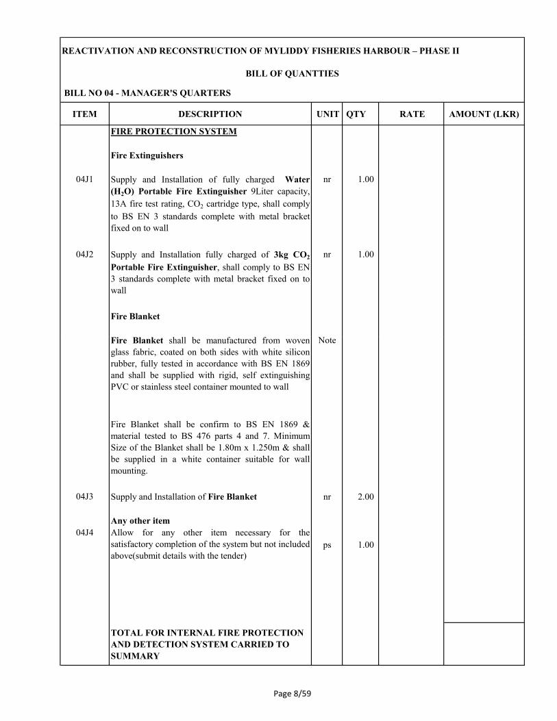
REACTIVATION AND RECONSTRUCTION OF MYLIDDY FISHERIES HARBOUR – PHASE II
ITEM DESCRIPTION UNIT QTY RATE AMOUNT (LKR)
BILL NO 04 - MANAGER'S QUARTERS
BILL OF QUANTTIES
FIRE PROTECTION SYSTEM
Fire Extinguishers
04J1 Supply and Installation of fully charged Water
(H2O) Portable Fire Extinguisher 9Liter capacity,
13A fire test rating, CO2 cartridge type, shall comply
to BS EN 3 standards complete with metal bracket
fixed on to wall
nr 1.00
04J2 Supply and Installation fully charged of 3kg CO2
Portable Fire Extinguisher, shall comply to BS EN
3 standards complete with metal bracket fixed on to
wall
nr 1.00
Fire Blanket
Fire Blanket shall be manufactured from woven NoteFire Blanket shall be manufactured from woven
glass fabric, coated on both sides with white silicon
rubber, fully tested in accordance with BS EN 1869
and shall be supplied with rigid, self extinguishing
PVC or stainless steel container mounted to wall
Note
Fire Blanket shall be confirm to BS EN 1869 &
material tested to BS 476 parts 4 and 7. Minimum
Size of the Blanket shall be 1.80m x 1.250m & shall
be supplied in a white container suitable for wall
mounting.
04J3 Supply and Installation of Fire Blanket nr 2.00
Any other item
04J4 Allow for any other item necessary for the
satisfactory completion of the system but not included
above(submit details with the tender)
ps 1.00
TOTAL FOR INTERNAL FIRE PROTECTION
AND DETECTION SYSTEM CARRIED TO
SUMMARY
Page 8/59

REACTIVATION AND RECONSTRUCTION OF MYLIDDY FISHERIES HARBOUR – PHASE II
ITEM DESCRIPTION UNIT QTY RATE AMOUNT (LKR)
BILL NO 04 - MANAGER'S QUARTERS
BILL OF QUANTTIES
04 K ELECTRICAL INSTALLATION
The Bidder is requested to refer the General Note,
Pricing preambles, Drawings, Specifications,
Conditions of Contract and other relevant documents
prior to pricing of the following items.
Note
For the full description of materials and workmanship
refer specifications, drawings and preamble notes
Note
A - PREAMBLE NOTES
EXTENT OF WORK
The extent of work covered in this Bill of Quantities
shall consists of all the items covered under the
Note
shall consists of all the items covered under the
specifications.
Rates for all items shall be inclusive of the following.
a) Provisions of holes, chases….etc.
b) All necessary scaffoldings
c) Contractor's overheads & profits
MAIN SERVICE CONNECTION
It shall be the responsibility of the Contractor to do all
the necessary co-ordination work with regards to
obtaining of the electrical power connections from the
Relevant Authorities .
Note
Page 8/60

REACTIVATION AND RECONSTRUCTION OF MYLIDDY FISHERIES HARBOUR – PHASE II
ITEM DESCRIPTION UNIT QTY RATE AMOUNT (LKR)
BILL NO 04 - MANAGER'S QUARTERS
BILL OF QUANTTIES
WIRING IN GENERAL
All the wiring work done under this contract shall
conform to BS 7671: 2008 - IEE wiring regulations-
17th Edition and any other regulations stipulated by
the Relevant Authorities.
Note
Rate for point wiring shall include for all the
conduits, conduit fittings, casings, fixing material,
switches, wiring and terminations, holders for light
fittings and socket outlets for power points.
Note
As a standard of quality for switches and socket
outlets, the contractor may use Clipsal, ABB,
Siemens, orange or an equivalent make.
Note
LIGHT FITTINGSLIGHT FITTINGS
The light fittings supplied and installed under this
contract shall be in every respect suitable for the
intended purpose.
Note
Each fitting shall include bulbs, internal wiring,
hanging and fixing material and be complete without
any additional item/material being required to make it
so.
Note
PANEL BOARDS AND SWITCHGEAR
The metal clad panel boards supplied and installed
under this contract shall be complete with all the
requires accessories such as neutral bars, earth bars,
fixing material……etc.as per the specification.
Note
The following may be used as a standard of quality
expected in this project.
Enclosures - ' ELSTEEL' or equivalent
MCCBs - 'ABB/TEMBREAK' or equivalent Note
Page 8/61

REACTIVATION AND RECONSTRUCTION OF MYLIDDY FISHERIES HARBOUR – PHASE II
ITEM DESCRIPTION UNIT QTY RATE AMOUNT (LKR)
BILL NO 04 - MANAGER'S QUARTERS
BILL OF QUANTTIES
EARTHING
Rates for the earthing system shall include for all the
wiring from individual DBs to a common earth bar
and from there to the earth pit including construction
of the pit, concrete cover…….etc.
Note
04 K 11X2CX6mm² Cu/PVC/PVC (from meter to DB-MQ) m 18
04 K.21C x 16mm2 CU/ECC cable from DB-MQ- to
Earthingm 6
04 K.3
To supply and install IP 54 enclosed Distribution
Board including following accessories as per the
drawings & specifications.drawings & specifications.
1x 32A/2P/MCB
1x 40A/DP/ RCD(30mA) nr 2
5 x 16A/SP/MCB
3 x 6A/SP/MCB
Phase indicator
Surge Protective Device
Wall mounting enclosed distribution board with
Earth bar & mounting accessories.
Power
Final Sub-Circuits including all necessary conduits,
trunking, cables and wires, terminations, fittings,
04 K.4 13Amp Switched socket outlet nr 26
04 K.5 13Amp Switched socket outlet at High Level nr 4
04 K.6 5A Switched socket outlet nr 2
Page 8/62

REACTIVATION AND RECONSTRUCTION OF MYLIDDY FISHERIES HARBOUR – PHASE II
ITEM DESCRIPTION UNIT QTY RATE AMOUNT (LKR)
BILL NO 04 - MANAGER'S QUARTERS
BILL OF QUANTTIES
Light fittings and fans
04 K.7 Wall mounted outdoor type light (IP65) nr 5
04 K.8 Wall mounted indoor type light (IP54) nr 3
04 K.9 Surface/Pendent type down light (IP54) nr 34
04 K.10 Aluminium blade wall fan nr 2
04 K.11 Aluminium blade ceiling fan nr 6
TOTAL FOR ELECTRICAL INSTALLATION
CARRIED TO SUMMARY
Page 8/63

REACTIVATION AND RECONSTRUCTION OF MYLIDDY FISHERIES HARBOUR – PHASE II
ITEM DESCRIPTION UNIT QTY RATE AMOUNT (LKR)
BILL NO 04 - MANAGER'S QUARTERS
BILL OF QUANTTIES
04L FLOOR /WALL FINISHES
Floor finishes
600 X 600 mm homogenous ceramic floor tiles in an
approved color and quality including 25 mm thick 1:3
cement sand bedding and pointing with recommended
tile adhesives and grout to match the color of tiles
laid; all in accordance with drawings and
specifications (PC rate for 600x600mm tile Rs.
1200.00)
04L.1 To floor m2 180
Homogeneous ceramic tiles, size 600x300mm in
approved color and quality including 18mm thick 1:3
cement and sand bedding and pointing (P.C - Rs.
750.00 per 600x300mm tile); all in accordance with750.00 per 600x300mm tile); all in accordance with
drawings and specifications
04L.2 To Toilet floors m2 12
Skirting
homogeneous floor tile skirting ; all as per drawings
04L.3 100mm high m 120
Wall Finishes
Internal Finishes
20mm thk. cement and sand 1:3 mortar finished
smooth with wood float on internal walls; all in
accordance with drawings and specifications
04L.4 To walls m2 300
Page 8/64

REACTIVATION AND RECONSTRUCTION OF MYLIDDY FISHERIES HARBOUR – PHASE II
ITEM DESCRIPTION UNIT QTY RATE AMOUNT (LKR)
BILL NO 04 - MANAGER'S QUARTERS
BILL OF QUANTTIES
Homogeneous ceramic tiles, size 600x300mm in
approved color and quality including 18mm thick 1:3
cement and sand bedding and pointing (P.C - Rs.
750.00 per 600x300mm tile); for all in accordance
with drawings and specifications
04L.5 To Toilet walls m2 42
300mm X 300mm size tiles , 1:3 cement sand
bedding , jointing and pointing; all in accordance with
drawings and specifications (PC rate for 300x300mm
tile Rs. 300.00)
04L.6 To vanity tops m2 2
External Finishes
20mm thk. cement and sand 1:3 mortar finished semi20mm thk. cement and sand 1:3 mortar finished semi
rough with wood float on external walls; all in
accordance with drawings and specifications
04L.7 To walls m2 248
TOTAL FOR FLOOR, WALL AND FINISHES
CARRIED TO SUMMARY
Page 8/65

REACTIVATION AND RECONSTRUCTION OF MYLIDDY FISHERIES HARBOUR – PHASE II
ITEM DESCRIPTION UNIT QTY RATE AMOUNT (LKR)
BILL NO 04 - MANAGER'S QUARTERS
BILL OF QUANTTIES
04M PAINTING WORK
Internal
Prepare surface and finish smooth with wall putty,
apply one coats of alkali resistant primer and two
coats of emulsion paint ; all in accordance with
drawings and specifications
04M.1 Plastered walls m2 300
External
Prepare surface and apply two coats of wall filler and
two coats of weather shield paint ; all in accordance
with drawings and specifications
04M.2 Plastered walls m2 248
TOTAL FOR PAINTING WORK CARRIED TO
SUMMARY
Page 8/66

ITEM DESCRIPTION UNIT QTY RATE AMOUNT (LKR)
05A/ EXCAVATION AND EARTH WORK
05B/ CONCRETE WORK
05C/ MASONRY WORK
05/D WATERPROOFING
05E/ WOOD WORKS
05F/ ROOF COVERING AND PLUMBING
05G/ PLUMBING AND DRAINAGE SYSTEM
05H/ AIR-CONDITIONING INSTALLATION
BILL NO 05 - BACHELOR'S QUARTERS
REACTIVATION AND RECONSTRUCTION OF MYLIDDY FISHERIES HARBOUR – PHASE II
BILL OF QUANTTIES
05H/ AIR-CONDITIONING INSTALLATION
05J/ INTERNAL FIRE PROTECTION AND
DETECTION SYSTEM
05K/ ELECTRICAL INSTALLATION
05L/
FLOOR, WALL AND CEILING FINISHES
05M/ PAINTING AND DECORATION
TOTAL CARRIED TO MAIN SUMMARY
Page 8/67

ITEM DESCRIPTION UNIT QTY RATE AMOUNT (LKR)
BILL NO 05 - BACHELOR'S QUARTERS
REACTIVATION AND RECONSTRUCTION OF MYLIDDY FISHERIES HARBOUR – PHASE II
BILL OF QUANTTIES
General
The bidder shall read, understand and acquaint
himself with the requirements in the Conditions of
Contract, Contract Data, Instruction to Bidders,
Bidding Data, Form of Bid, General
Specifications, Particular Specifications of Works,
Drawings, General Notes, Pricing Preambles, and
other relevant documents of local statutory
requirements prior to pricing each of the following
items. It is the bidder's responsibility to see that his
price includes for complying with all the above
requirements whether specifically referred to in
this Bill of Quantities or otherwise.
Note
05A/ EXCAVATION & EARTH WORK
Site clearing / preparation
05A/.1 Clearing site from all debris and removal of top
soil up to 150mm including all bushes and other
vegetation away from the site (Measured building
perimeter area only); all in accordance with
drawings and specifications.
m2 50
Excavation
Excavation, any material excluding rock requiring
blasting, back filling using selected excavated
materials and compactions, levelling and
compacting the bottom of excavation and earth
work supports ; all in accordance with drawings
and specifications.
05A/.2 For reduce level , 100mm thick m3 8
05A/.3 For column pits m3 15
05A/.4 For foundation trench m3 12
Page 8/68

ITEM DESCRIPTION UNIT QTY RATE AMOUNT (LKR)
BILL NO 05 - BACHELOR'S QUARTERS
REACTIVATION AND RECONSTRUCTION OF MYLIDDY FISHERIES HARBOUR – PHASE II
BILL OF QUANTTIES
Filling
Imported hard earth filling, well rammed and
consolidated to achieve 95% maximum dry
density.
05A/.5 To make up levels, under ground slab, 300mm
layersm
3 12
Surface Treatment
05A/.6 Anti termite treatment "Biflex, John piper, lankem"
or equivalent shall be in accordance with the
manufacturers specifications by an approved
specialist pest control contractor and pest control
contractor shall submit a guarantee for a minimumcontractor shall submit a guarantee for a minimum
of 10 years from the date of handing over of the
project. The said guarantee certificate must be in
the name of the employer. (method statement,
technical literature, specimen warrantee to be
submitted with the bid)
m2 50
TOTAL FOR EXCAVATION AND EARTH
WORK CARRIED TO SUMMARY
Page 8/69

ITEM DESCRIPTION UNIT QTY RATE AMOUNT (LKR)
BILL NO 05 - BACHELOR'S QUARTERS
REACTIVATION AND RECONSTRUCTION OF MYLIDDY FISHERIES HARBOUR – PHASE II
BILL OF QUANTTIES
05B/ CONCRETE WORK
IN SITU CONCRETE
Work up to the structural floor level of ground
floor
Mass Concrete poured in to ground.
Insitu mass concrete (15 N/mm2-20mm) screed,
poured into ground; all in accordance with
drawings and specifications
05B/.1 50mm thick, column footing, masonry foundation
and tie beams m2 31
Insitu reinforced concrete (30 N/mm2- 20mm)
poured into formwork; all in accordance withpoured into formwork; all in accordance with
drawings and specifications
05B/.2 Slab on ground, 100 mm thick, to slope m3 5
05B/.3 Column bases m3 3
05B/.4 Column up to tie beams m3 1
05B/.5 Tie beams m3 3
Insitu reinforced concrete (30 N/mm2- 20mm)
poured into formwork; all in accordance with
drawings and specifications
05B/.6 Columns up to Beams m3 2
05B/.7 Beams m3 3
05B/.8 Columns in the upper floor m3 2
Page 8/70

ITEM DESCRIPTION UNIT QTY RATE AMOUNT (LKR)
BILL NO 05 - BACHELOR'S QUARTERS
REACTIVATION AND RECONSTRUCTION OF MYLIDDY FISHERIES HARBOUR – PHASE II
BILL OF QUANTTIES
05B/.9 First floor m3 8
05B/.10 Roof beamsm
3 2
stair case
05B/.11 Base of the stair casem3 1
05B/.12 steps m3 2
05B/.13 Landing beam with landing step m3 1
FORMWORK
Plain plywood formwork; all in accordance with
drawings and specifications
05B/.14 Sides of column bases m2 12
05B/.15 Sides of columns up to tie beams m2 11
05B/.16 Sides of tie beam m2 18
Plain plywood formwork; all in accordance with
drawings and specifications
05B/.17 Sides of columns m2 62
05B/.18 sides of beams m2 36
05B/.19 Soffit of slab m2 64
05B/.20 Sides of roof beams m2
15
05B/.21 staircase m2 11
Page 8/71

ITEM DESCRIPTION UNIT QTY RATE AMOUNT (LKR)
BILL NO 05 - BACHELOR'S QUARTERS
REACTIVATION AND RECONSTRUCTION OF MYLIDDY FISHERIES HARBOUR – PHASE II
BILL OF QUANTTIES
REINFORCEMENT
High yield and mild steel reinforcement bars; all
in accordance with drawings and specifications
05B/.22 In slab on ground Kg 102
05B/.23 In column bases Kg 104
05B/.24 In columns up to tie beams Kg 127
05B/.25 In tie beams Kg 168
05B/.26 stairs foundation Kg 21
High yield and mild steel reinforcement bars; all
in accordance with drawings and specifications
05B/.27 In columns Of first floor Kg 205
05B/.28 in columns of second floor Kg 208
05B/.29 In lintels Kg 100
05B/.30 In beams Kg 498
05B/.31 In slab of first floor Kg 678
05B/.32 In roof beams Kg 168
05B/.33 Stair case Kg 110
05B/.34 In vanities Kg 50
TOTAL FOR CONCRETE WORK CARRIED
TO SUMMARY
Page 8/72

ITEM DESCRIPTION UNIT QTY RATE AMOUNT (LKR)
BILL NO 05 - BACHELOR'S QUARTERS
REACTIVATION AND RECONSTRUCTION OF MYLIDDY FISHERIES HARBOUR – PHASE II
BILL OF QUANTTIES
05C/ MASONRY WORKS
Rubble work
05C/.1 Random rubble (150 x 225mm size) masonry wall
foundation in cement and sand 1:5 mortar ; all in
accordance with drawings and specifications. m3 12
Block work
05C/.2 150mm thick cement hollow block wall in cement
and sand 1:5 mortar ; all in accordance with
drawings and specificationsm
2 240
TOTAL OF MASONRY WORKS CARRIED
TO SUMMARY
05/D WATER PROOFING
Damp proof membrane; all in accordance with
drawings and specifications
05/D.1 Polythene, 1000 gauge m2 46
Waterproofing system by an approved specialist
sub contractor and waterproofing application
strictly in accordance with the manufacturers
specifications.
05/D.2 Toilet floors m2 7
05/D.3 Toilet walls , 1500mm high m2 22
05/D.4 Balconys / Terrace m2 7
TOTAL FOR WATER PROOFING WORK
CARRIED TO SUMMARY
Page 8/73

ITEM DESCRIPTION UNIT QTY RATE AMOUNT (LKR)
BILL NO 05 - BACHELOR'S QUARTERS
REACTIVATION AND RECONSTRUCTION OF MYLIDDY FISHERIES HARBOUR – PHASE II
BILL OF QUANTTIES
05E/ WOOD WORKS
Carpentry
Roof frameworks
Hardwood timber,Class 01 ( shall approved by the
Engineer) including wood preservatives,
treatments, plates, nails, fixing, fittings fixed in
position to complete; all in accordance with
drawings and specifications (Sizes shown are
finish sizes). Rate shall include for Prepare and
apply One primenr coat and two coats of enamel
paint to exposed roof timber.
05E/.1 200x100 timber ridge plate m 11
05E/.2 75x100 timber wall plate m 22
05E/.3 50x100 timber rafters m 135
05E/.4 225x25 mm valance / barge board with painting m 22
05E/.5 200x100 timber studs m 2
Doors
Supply and installation of Class 01 (shall approved
by the Engineer) timber doors with solid timber
framework, solid timber door, louver panels
including all accessories and assemblies in the
followings as per the Drawings , Specifications
and Pricing preambles.Rate shall include for
Prepare and apply One primenr coat and two coats
of enamel paint to timber members.
05E/.6 Single sash timber door D, Overall size
1050mmx2775mm nr 1
Page 8/74

ITEM DESCRIPTION UNIT QTY RATE AMOUNT (LKR)
BILL NO 05 - BACHELOR'S QUARTERS
REACTIVATION AND RECONSTRUCTION OF MYLIDDY FISHERIES HARBOUR – PHASE II
BILL OF QUANTTIES
05E/.7 Single sash timber door D1, overall size
900mmx2100mm nr 3
05E/.8 Single sash timber door D2 overall size
750mmx2100mm) nr 3
Windows
Supply and installation of class 01(shall approved
by the Engineer) timber window with solid timber
framework, solid timber louver panels including all
accessories and assemblies in the followings as per
the Drawings and Specifications and Pricing
preambles.Rate shall include for Prepare and apply
One primenr coat and two coats of enamel paint to
timber members.
05E/.9 Type W1, overall size 1200mm x 1800mm with
hard wood timber framed glazed window
nr 5
05E/.10 Type FL, overall size 600mm x 1200mm with had
wood timber framed fan light
nr 2
05E/.11 Type FW1, overall size 1500mm x2775mm, Two
Bay floor window with had wood timber
nr 2
05E/.12 Type LP1, overall size 750mm x1200mm, Two
Bay floor window with had wood timber
nr 1
TOTAL FOR WOOD WORKS CARRIED TO
SUMMARY
Page 8/75

ITEM DESCRIPTION UNIT QTY RATE AMOUNT (LKR)
BILL NO 05 - BACHELOR'S QUARTERS
REACTIVATION AND RECONSTRUCTION OF MYLIDDY FISHERIES HARBOUR – PHASE II
BILL OF QUANTTIES
05F/ ROOF COVERING & ROOF PLUMBING
Roof Covering
05F/.1 Calicut tile roofing laid on timber framework
(measured separately) all other accessories
required to complete; all in accordance with
drawings,specifications and pricing preambles
m2 84
Roof insulation
05F/.2 Roof insulation, 6mm thick double side aluminium
foil all other accessories required to complete; all
in accordance withdrawings,specifications and
m2 84
in accordance withdrawings,specifications and
pricing preambles
Roof ceiling
05F/.3 Roof ceiling, asbestos free cement fibre board
angle ceiling including painting, all other
accessories required to complete; all in accordance
withdrawings,specifications and pricing preambles
m2 84
TOTAL FOR ROOF COVERING AND
PLUMBING CARRIED TO SUMMARY
Page 8/76

ITEM DESCRIPTION UNIT QTY RATE AMOUNT (LKR)
BILL NO 05 - BACHELOR'S QUARTERS
REACTIVATION AND RECONSTRUCTION OF MYLIDDY FISHERIES HARBOUR – PHASE II
BILL OF QUANTTIES
05G/
PLUMBING AND DRAINAGE SYSTEM
COLD WATER SUPPLY SYSTEM
All uPVC shall be TYPE 1000, SLS 147 Note
Rates for all pipes shall include for pipes supports,
saddles, clips, screws, nails, hardware fixing,
jointing, materials cutting holes, chasing in brick
work, concrete etc., and making good the same in
all trades and under ground piping all necessary
excavation, backfilling, planking and strutting,
concrete bedding and hunching, dewatering and
Note
concrete bedding and hunching, dewatering and
disposal of surplus material as directed. The
proposal for pipe fixing method to be submitted for
prior approval of Engineer.
All the valves and controllers to be Approved
according to the relevant drawings &
specifications.
Note
All the brass gate valves to be Approved
equivalent according to the relevant drawings &
specifications
Note
Rate shall include vertical/horizontal bedded or
clipped to wall or buried in floor or under ground
or extra over.
Note
External services
05G/.1 Connection to existing overhead water tank from
water supply network including piping, bracketing,
chasing to wall where necessary, fittings, valves,
chambers etc. to complete the work
Item 1
Page 8/77

ITEM DESCRIPTION UNIT QTY RATE AMOUNT (LKR)
BILL NO 05 - BACHELOR'S QUARTERS
REACTIVATION AND RECONSTRUCTION OF MYLIDDY FISHERIES HARBOUR – PHASE II
BILL OF QUANTTIES
Pipes in trenches ground floor
05G/.2 Supply and install 50 mm dia uPVC pipe m 15
05G/.3 Supply and install 40 mm dia uPVC pipe m 35
05G/.4 Supply and install 32 mm dia uPVC pipe m 8
05G/.5 Supply and install 20 mm dia uPVC pipe m 16
05G/.6 Supply and install of water meter nr 1
Internal services
05G/.7 Supply and install 20 mm dia uPVC pipe m 22 05G/.7 Supply and install 20 mm dia uPVC pipe m 22
05G/.8 Supply and install 25 mm dia uPVC pipe m 8
05G/.9 Supply and install 32 mm dia uPVC pipe m 8
Valves and ancillaries
05G/.10 Supply and install of 50mm" dia: brass gate valve
with valve chamber all completed as per detailed
standard drawing and as directed.
nr 1
05G/.11 Supply and install of 20mm" dia: angle valve with
all completed as per detailed standard drawing and
as directed.
nr
14
Page 8/78

ITEM DESCRIPTION UNIT QTY RATE AMOUNT (LKR)
BILL NO 05 - BACHELOR'S QUARTERS
REACTIVATION AND RECONSTRUCTION OF MYLIDDY FISHERIES HARBOUR – PHASE II
BILL OF QUANTTIES
Sanitary fittings and accessories
Supply and install sanitary fittings and accessories
complete with Traps, flow regulators, CP Angle
valves, flexible connections, Plumbing Accessories
inclusive of all connections to drainage, in
accordance with specifications and drawings.
Note
05G/.12 Supply and Installation of closed coupled Water
Closet complete with cistern fittings, seat cover,
WC connector, 20mm dia: chromium plated
flexible connection, 20mm dia: angle valve and
plastic anchors and brass screws etc. all completed
to working order. ( Prime cost Rs 42,000.00/nr)
nr 2
05G/.13Supply and Installation of pedestal type Wash
hand basin complete with cold water tap with
waste coupling and 40mm dia: plastic bottle trap,
20mm dia. chromium plated flexible connection,
20mm dia angle valve, etc. all completed to
working order. ( Prime cost Rs 25,000.00/nr)
nr 2
05G/.14 Supply and Installation of stainless steel, single
bowl, single drain pantry sink complete with cold
water tap and 50mm pop-up waste, 50mm dia
plastic bottle trap, 20mm dia, angle valve, etc. all
completed to working order.
nr 1
05G/.15Supply and installation of shower head, including
bath mixture all completed to working order.
nr 2
Accessories
05G/.16 Supply and Installation of bidet spray with 25mm"
dia chromium plated angle valve
nr 2
Page 8/79

ITEM DESCRIPTION UNIT QTY RATE AMOUNT (LKR)
BILL NO 05 - BACHELOR'S QUARTERS
REACTIVATION AND RECONSTRUCTION OF MYLIDDY FISHERIES HARBOUR – PHASE II
BILL OF QUANTTIES
05G/.17Supply and Installation of chromium plated soap
tray fixed with chromium plated brass screws
nr 4
05G/.18Supply and Installation of chromium plated toilet
paper holders with chromium plated brass screws
nr 2
05G/.19 Supply and Installation of mirror, size:
600x900mm
nr 2
05G/.20 Supply and Installation of chromium plated bid
tap with chromium plated brass screws
nr 4
Soil, waste and storm water systemSoil, waste and storm water system
Pipes and fittings shall be UPVC T/600 to SLS
147, Make S-Lon, Anton or
equivalent.horizontal,including supports and
fitting; all in accordance with drawings and
specifications.
Note
Internal system
05G/.21 Supply and install 40 mm dia uPVC pipe m 8
05G/.22 Supply and install 50 mm dia uPVC pipe m 8
05G/.23 Supply and install 63 mm dia uPVC pipe m 4
05G/.24 Supply and install 110 mm dia uPVC pipe m 8
05G/.25Supply and install inlet & outlet four way PVC
trapped floor gully complete with PVC grating. nr 8
Page 8/80

ITEM DESCRIPTION UNIT QTY RATE AMOUNT (LKR)
BILL NO 05 - BACHELOR'S QUARTERS
REACTIVATION AND RECONSTRUCTION OF MYLIDDY FISHERIES HARBOUR – PHASE II
BILL OF QUANTTIES
External system
05G/.26 Connecting Sewer & waste water system to main
sewer & waste water network.Item 1
Pipes in trenches
05G/.27 Supply and install 50 mm dia uPVC pipe m 8
05G/.28 Supply and install 63 mm dia uPVC pipe m 24
05G/.29 Supply and install 90 mm dia uPVC pipe m 2
05G/.30 Supply and install 110 mm dia uPVC pipe m 56
Manholes and gulliesManholes and gullies
05G/.31Construction of manhole, size: 600 x 600 mm.
Rate shall include for excavation, concrete,
formwork, reinforcement, piping, hunching,
benching, cover and all completed as per detailed
standard drawing and as directed.
nr 5
05G/.32 Construction of trapped gully for waste water,
size: 300 x 300 mm. Rate shall include for
excavation, concrete, formwork, piping, "P" Trap ,
GI Grating, haunching,benching, and all
completed as per detailed standard drawing and as
directed.
nr 2
05G/.33Construction of catch pit for waste water, size:
300 x 300 mm. Rate shall include for excavation,
concrete, formwork, piping, "P" Trap , GI Grating,
haunching,benching, and all completed as per
detailed standard drawing and as directed.
nr 2
Page 8/81

ITEM DESCRIPTION UNIT QTY RATE AMOUNT (LKR)
BILL NO 05 - BACHELOR'S QUARTERS
REACTIVATION AND RECONSTRUCTION OF MYLIDDY FISHERIES HARBOUR – PHASE II
BILL OF QUANTTIES
Extra over fittings for all floors
05G/.34 Supply and installation of 110mm dia bend nr 8
05G/.35 Supply and installation of 63mm dia bend nr 4
05G/.36 Supply and installation of 110mm dia Tee nr 3
05G/.37 Supply and installation of 63mm dia Tee nr 3
Storm water disposal system
05G/.38 Supply and installation of 100x75mm uPVC storm
water gutter, with brackets, bends, joints with all
accessories and fittings as specified and to the
approval of the Engineer.
m
46
approval of the Engineer.
05G/.39 Supply and installation of 100x75mm uPVC storm
water downpipes, with brackets, bends, joints with
all accessories and fittings as specified and to the
approval of the Engineer.
m
48
05G/.40 Supply and fixing of 300 x 300 cast iron storm
water side roof outlet
nr 2
05G/.41 Construction of rain water shoe drain as per the
detail drawings and specifications. Rate shall
include for forming the drain as per the drawing,
mass concrete fill, formwork, necessary filing and
compaction.
m
75
TOTAL FOR PLUMBING AND DRAINAGE
CARRIED TO SUMMARY
Page 8/82

ITEM DESCRIPTION UNIT QTY RATE AMOUNT (LKR)
BILL NO 05 - BACHELOR'S QUARTERS
REACTIVATION AND RECONSTRUCTION OF MYLIDDY FISHERIES HARBOUR – PHASE II
BILL OF QUANTTIES
05H/ AIR-CONDITIONING INSTALLATION
The Bidder is requested to refer the Bill of
Quantities, General Note, Pricing Preambles,
Drawing, Specification, Conditions of Contract,
Special Conditions of Contract and other relevant
documents prior to pricing of items in this trade
Note
Rates shall include for supply, installation,
commissioning and maintaining of the following
items according to drawings, specifications and
complete to working order with all connections to
the approval of the consultant, Fire Department
and other relevant authorities.
Note
and other relevant authorities.
The rates shall include for providing insurance
during handling, rehandling, transport, storage
until ready installation, delivery of equipment up to
the point of installation and until handling over.
Note
All equipment shall be guaranteed for a period of
12 months from the date of commissioning.Note
The bidder shall provide all dimension, technical
information of all necessary builders work to the
consultant in advance in relation with the
programme of work.
Note
Rates for all pipes shall include for all pipe
supports, hangers, saddles, brackets, screws, nails,
tees, bends, sockets, reducers and the like and
fixing material, cutting holes and chases in
concrete brick/block work, etc., any builders work
require and making good in all trades unless
otherwise measured separately.
Note
All valves and fittings approved quality European
or Japanese onlyNote
Page 8/83

ITEM DESCRIPTION UNIT QTY RATE AMOUNT (LKR)
BILL NO 05 - BACHELOR'S QUARTERS
REACTIVATION AND RECONSTRUCTION OF MYLIDDY FISHERIES HARBOUR – PHASE II
BILL OF QUANTTIES
All pipes in and out to the building shall have
flexible connection to accommodate moment due
to any structural settlements to avoid any cracksNote
Rate of pipe shall include fire barriers, sleeves &
other material as specified when passing through
wall or met with an other services.
Note
Bidder shall verify the quantities prior to order by
consultantNote
Fans
All Fans Noise Level shall not be exceeded 55 dB
when operate the fan. Note
All Exhaust Fans shall be made of corrosive
resistant materials including brackets
Toilet Exhaust Fans shall be complete with gravity
back draft shutter, S/S insect screen and weather
resistance louver.
Note
Toilet Exhaust Fans below 100 l/s shall be
integrated with toilet light on/off switch & separate
on/off switch shall be provided for larger Toilet
Exhaust Fans
Note
Separate on/off switch shall be provided for all
Exhaust Fans
Note
Page 8/84

ITEM DESCRIPTION UNIT QTY RATE AMOUNT (LKR)
BILL NO 05 - BACHELOR'S QUARTERS
REACTIVATION AND RECONSTRUCTION OF MYLIDDY FISHERIES HARBOUR – PHASE II
BILL OF QUANTTIES
Exhaust Fan
Supply, installation of Wall Mounted Exhaust
Fans including gravity back draft shutter, S/S
insect screen and weather resistance louver,
electrical supply, fixing accessories, hangers,
supports, etc.
05H/.1 Supply and installation of 25 l/s flow rate Wall
Mounted Exhaust Fansnr 4
05H/.2 Supply and installation of 50 l/s flow rate Wall
Mounted Exhaust Fansnr 2
TOTAL FOR AIR-CONDITIONING TOTAL FOR AIR-CONDITIONING
INSTALLATION CARRIED TO SUMMARY
05J/ INTERNAL FIRE PROTECTION AND
DETECTION SYSTEM
The bidder is requested to refer the Bill of
Quantities, general note, pricing preambles,
drawing, specification, Conditions of Contract,
special conditions of contract and other relevant
documents prior to pricing of items in this trade
Note
Rates shall include for supply, installation,
commissioning and maintaining of the following
items according to drawings, specifications and
complete to working order with all connections to
the approval of the consultant, Fire Department
and other relevant authorities.
Note
Page 8/85

ITEM DESCRIPTION UNIT QTY RATE AMOUNT (LKR)
BILL NO 05 - BACHELOR'S QUARTERS
REACTIVATION AND RECONSTRUCTION OF MYLIDDY FISHERIES HARBOUR – PHASE II
BILL OF QUANTTIES
All materials and installation shall be comply to the
requirements of the Fire Services Department of
Colombo Municipality, ICTAD Fire regulations
ICTAD/DEV/14 and ICTAD Specification for fire
detection, protection and suppression system
CIDA/SCA/9 in addition to the specified
standards.
Note
The rates shall include for providing insurance
during handling, rehandling, transport, storage
until ready installation, delivery of equipment up to
the point of installation and until handling over.
Note
All equipment shall be guaranteed for a period of
12 months from the date of commissioning.
Note
12 months from the date of commissioning.
The bidder shall provide all dimension, technical
information of all necessary builders work to the
consultant in advance in relation with the
programme of work.
Note
Rates for all pipes shall include for all pipe
supports, hangers, saddles, brackets, screws, nails,
tees, bends, sockets, reducers and the like and
fixing material, cutting holes and chases in
concrete brick/block work, etc., any builders work
require and making good in all trades unless
otherwise measured separately.
Note
All valves and fittings approved quality European
or Japanese only
Note
All pipes in and out to the building shall have
flexible connection to accommodate moment due
to any structural settlements to avoid any cracks
Note
Page 8/86

ITEM DESCRIPTION UNIT QTY RATE AMOUNT (LKR)
BILL NO 05 - BACHELOR'S QUARTERS
REACTIVATION AND RECONSTRUCTION OF MYLIDDY FISHERIES HARBOUR – PHASE II
BILL OF QUANTTIES
Rate of pipe shall include fire barriers, sleeves &
other material as specified when passing through
wall or met with an other services.
Note
Water connection to water /fire sump has been
measured in separately
Note
Bidder shall verify the quantities prior to order by
the Engineer.
FIRE PROTECTION SYSTEM
Fire Extinguishers
05J/.1 Supply and Installation of fully charged Water nr 1 05J/.1 Supply and Installation of fully charged Water
(H2O) Portable Fire Extinguisher 9Liter
capacity, 13A fire test rating, CO2 cartridge type,
shall comply to BS EN 3 standards complete with
metal bracket fixed on to wall
nr 1
05J/.2 Supply and Installation fully charged of 3kg CO2
Portable Fire Extinguisher, shall comply to BS
EN 3 standards complete with metal bracket fixed
on to wall
nr 1
Fire Blanket
Fire Blanket shall be manufactured from woven
glass fabric, coated on both sides with white
silicon rubber, fully tested in accordance with BS
EN 1869 and shall be supplied with rigid, self
extinguishing PVC or stainless steel container
mounted to wall
Note
Page 8/87

ITEM DESCRIPTION UNIT QTY RATE AMOUNT (LKR)
BILL NO 05 - BACHELOR'S QUARTERS
REACTIVATION AND RECONSTRUCTION OF MYLIDDY FISHERIES HARBOUR – PHASE II
BILL OF QUANTTIES
Fire Blanket shall be confirm to BS EN 1869 &
material tested to BS 476 parts 4 and 7. Minimum
Size of the Blanket shall be 1.80m x 1.250m &
shall be supplied in a white container suitable for
wall mounting.
05J/.3 Supply and Installation of Fire Blanket nr 2
Any other item
05J/.4 Allow for any other item necessary for the
satisfactory completion of the system but not
included above(submit details with the tender)
Item 1
TOTAL FOR INTERNAL FIRE
PROTECTION AND DETECTION SYSTEM
CARRIED TO SUMMARY
Page 8/88

ITEM DESCRIPTION UNIT QTY RATE AMOUNT (LKR)
BILL NO 05 - BACHELOR'S QUARTERS
REACTIVATION AND RECONSTRUCTION OF MYLIDDY FISHERIES HARBOUR – PHASE II
BILL OF QUANTTIES
05K/ ELECTRICAL INSTALLATION
The tenderer is requested to refer the General
Note, Pricing preambles, Drawings, Specifications,
Conditions of Contract and other relevant
documents prior to pricing of the following items.
Note
For the full description of materials and
workmanship refer specifications, drawings and
preamble notes
Note
A - PREAMBLE NOTES
EXTENT OF WORK
The extent of work covered in this Bill of
Quantities shall consists of all the items covered
under the specifications.
Note
Rates for all items shall be inclusive of the
following. Note
a) Provisions of holes, chases….etc.
b) All necessary scaffoldings
c) Contractor's overheads & profits
d) All tax, levy or duty
MAIN SERVICE CONNECTION
It shall be the responsibility of the Contractor to do
all the necessary co-ordination work with regards
to obtaining of the electrical power connections
from the Relevant Authorities .
Note
WIRING IN GENERAL
All the wiring work done under this contract shall
conform to BS 7671: 2008 - IEE wiring regulations-
17th Edition and any other regulations stipulated
by the Relevant Authorities.
Note
Page 8/89

ITEM DESCRIPTION UNIT QTY RATE AMOUNT (LKR)
BILL NO 05 - BACHELOR'S QUARTERS
REACTIVATION AND RECONSTRUCTION OF MYLIDDY FISHERIES HARBOUR – PHASE II
BILL OF QUANTTIES
Rate for point wiring shall include for all the
conduits, conduit fittings, casings, fixing material,
switches, wiring and terminations, holders for light
fittings and socket outlets for power points.
Note
As a standard of quality for switches and socket
outlets, the contractor may use Clipsal, ABB,
Siemens, orange or an equivalent make.
Note
LIGHT FITTINGS
The light fittings supplied and installed under this
contract shall be in every respect suitable for the
intended purpose.
Note
Each fitting shall include bulbs, internal wiring, Note Each fitting shall include bulbs, internal wiring,
hanging and fixing material and be complete
without any additional item/material being required
to make it so.
Note
PANEL BOARDS AND SWITCHGEAR
The metal clad panel boards supplied and installed
under this contract shall be complete with all the
requires accessories such as neutral bars, earth
bars, fixing material……etc.as per the
specification.
Note
The following may be used as a standard of quality
expected in this project.
Enclosures - ' ELSTEEL' or equivalent
MCCBs - 'ABB/TEMBREAK' or equivalent Note
EARTHING
Rates for the earthing system shall include for all
the wiring from individual DBs to a common earth
bar and from there to the earth pit including
construction of the pit, concrete cover…….etc.
Note
Page 8/90

ITEM DESCRIPTION UNIT QTY RATE AMOUNT (LKR)
BILL NO 05 - BACHELOR'S QUARTERS
REACTIVATION AND RECONSTRUCTION OF MYLIDDY FISHERIES HARBOUR – PHASE II
BILL OF QUANTTIES
SUB MAIN CABLING
05K/.1Supply, Installation and termination of 1 x 2C x
6mm2 Cu/PVC/PVC + 1C x 6mm2 CU/ECC cable
from MDB - Quarters to DB/1
m 12
05K/.2Supply, Installation and termination of 1 x 2C x
6mm2 Cu/PVC/PVC + 1C x 6mm2 CU/ECC cable
from MDB - Quarters to DB/2
m
12
05K/.3 Supply, Installation and termination of 1C x
16mm2 CU/ECC cable from MDB - Quarters to
Earthing
m
10
MAIN DISTRIBUTION SYSTEM
05K/.4Main Distribution Board - MDB- Quarters
nr 1
To supply and install IP 54 enclosed Distribution
Board including following accessories as per the
drawings & specifications.
1x 63A/2P/MCB
1 x 40A/2P/RCD(30mA)
3 x 32A/SP/MCB
3 x 6A/SP/MCB
Phase indicator
Power Analyzer
Surge Protective Device
63A TPN & Earth Copper Bus bar System
Complete set of cable Glands for incoming and
outgoing cables
Wall mounting enclosed distribution board with
Earth bar & mounting accessories, as per IEE
Specifications.
Page 8/91

ITEM DESCRIPTION UNIT QTY RATE AMOUNT (LKR)
BILL NO 05 - BACHELOR'S QUARTERS
REACTIVATION AND RECONSTRUCTION OF MYLIDDY FISHERIES HARBOUR – PHASE II
BILL OF QUANTTIES
05K/.5 DISTRIBUTION BOARD - DB/1
To supply and install IP 54 enclosed Distribution
Board including following accessories as per the
drawings & specifications.
nr 1
1 x 32A / 2P / MCB
2 x 40A/DP/ RCD(30mA
2 x 20A/SP/MCB
7 x 16A/SP/MCB
5 x 6A/SP/MCB
Wall mounting enclosed distribution board with
Earth bar & mounting accessories, as per IEE
Specifications.
05K/.6 DISTRIBUTION BOARD - DB/2
nr 1 To supply and install IP 54 enclosed Distribution
Board including following accessories as per the
drawings & specifications.
nr 1
1 x 32A / 2P / MCB
2 x 40A/DP/ RCD(30mA
2 x 20A/SP/MCB
7 x 16A/SP/MCB
5 x 6A/SP/MCB
Wall mounting enclosed distribution board with
Earth bar & mounting accessories, as per IEE
Specifications.
Page 8/92

ITEM DESCRIPTION UNIT QTY RATE AMOUNT (LKR)
BILL NO 05 - BACHELOR'S QUARTERS
REACTIVATION AND RECONSTRUCTION OF MYLIDDY FISHERIES HARBOUR – PHASE II
BILL OF QUANTTIES
FINAL SUB CIRCUIT POINT WIRING
Rates for point wiring shall include for all cables,
switches(1 way or 2 way as necessary) junction
boxes, conduits, pull boxes, clips, earth cables,
draw wires, wiring accessories, screws, nails,
hardware, fixing and insulating materials, cutting
holes, chases, make good the same in all trades,
holders, ceiling boxes, flexible codes and any other
wiring accessories require up to the final fixing
point where ever necessary and complete with a
holder and bulb.
Note
All switches for lamp points to be Orange /Clipsal
or equivalent make in acceptable range suitable for
Note
or equivalent make in acceptable range suitable for
luxury interior. All socket outlets shall be
Orange/Clipsal or equivalent make with a
indicating bulb. All junction boxes shall be
injection moulded type. All conduits shall be in
reputed manufacture having SLS certification
acceptable to the Engineer.
All ceiling fans points wiring to be also completed
with fan hooks excluding fan and shall carry out
the mega test and any other tests with a temporary
switch and bulb with a holder at ceiling fan points
and other similar items wherever necessary. The
contractor shall forward the conduit layout plan
for prior approval of the Engineer.
Note
All lamp point wiring shall be in 2 X 1Cx1 mm2
Cu/PVC/PVC cable and 1Cx2.5mm2 protective
earth in PVC conduits including all accessories
Note
Page 8/93

ITEM DESCRIPTION UNIT QTY RATE AMOUNT (LKR)
BILL NO 05 - BACHELOR'S QUARTERS
REACTIVATION AND RECONSTRUCTION OF MYLIDDY FISHERIES HARBOUR – PHASE II
BILL OF QUANTTIES
GROUND FLOOR
05K/.7 Supply and wiring of 12W(950lm) LED down light
type 02 with high efficiency electronic control
gear and required all other accessories.
nr 2
05K/.8 Supply and wiring of 12W(910lm) LED down light
type 04 with high efficiency electronic control
gear and required all other accessories.
nr 4
05K/.9 Supply and wiring of 10W(600lm) LED down light
type 05 with high efficiency electronic control
gear and required all other accessories(IP65).
nr 4
05K/.10 Supply and wiring of 12W(910lm) LED type 06
with high efficiency electronic control gear and
required all other accessories.(IP65)
nr 6
05K/.11 Supply and wiring of 12W(950lm) wall mounted
indoor type LED light type 09 with high efficiency
electronic control gear and required all other
accessories.(IP20)
nr 8
05K/.12 Supply and wiring of type 10 wall mounted indoor
type die-cast construction, polycarbonate diffuser
suitable for use with 57W halogen (IP20.)
nr 4
05K/.13 Supply and wiring of type 11 halogen 35W metal
halide chandelier lamp made with polished
aluminum housing and canopy, stainless steel
adjustable suspension and clear acrylic rods.
nr 4
05K/.14 Supply and wiring of type 12 Decorative box
shaped pendant luminaire with powder coated steel
suspension rod suitable for use with 18W CFL
(IP20.)
nr 4
Page 8/94

ITEM DESCRIPTION UNIT QTY RATE AMOUNT (LKR)
BILL NO 05 - BACHELOR'S QUARTERS
REACTIVATION AND RECONSTRUCTION OF MYLIDDY FISHERIES HARBOUR – PHASE II
BILL OF QUANTTIES
05K/.15 Supply and wiring of 44W(3800lm) 1200mm LED
light type 14 with high efficiency electronic
control gear and required all other
accessories(IP20).
nr 2
Switch socket outlet.
05K/.16Supply & install all accessories and wire with 2 x
1C x 2.5mm2 + 1C x 2.5mm2 E for 250 V, 13A
Wall mounted PN+E switch socket outlet for
general purpose use should complain to BS 1363
nr 24
05K/.17 Supply & install all accessories and wire with 2 x
1C x 2.5mm2 + 1C x 2.5mm2 E for 250 V, 13A
twin type Wall mounted PN+E switch socket
nr 4
twin type Wall mounted PN+E switch socket
outlet for general purpose use should complain to
BS 1363
05K/.18 Supply & install all accessories and wire with 2 x
1C x 2.5mm2 + 1C x 2.5mm2 E for 250 V, 13A
mounted at high level for A/C units shall be switch
by 20A /DP/switch; PN+E switch socket outlet for
general purpose use should complain to BS 1363
nr 4
05K/.19 Supply & install all accessories and wire with 2 x
1C x 2.5mm2 + 1C x 2.5mm2 E for 250 V, 13A
mounted PN+E switch socket outlet for exhaust
fan. Socket outlet shall be switched toilet light
switch.
nr 6
05K/.20 Supply & install all accessories and wire with 2 x
1C x 2.5mm2 + 1C x 2.5mm2 E for 250 V,
mounted PN+E shaver switch socket outlet with
inbuilt isolation transformer.
nr 4
Page 8/95
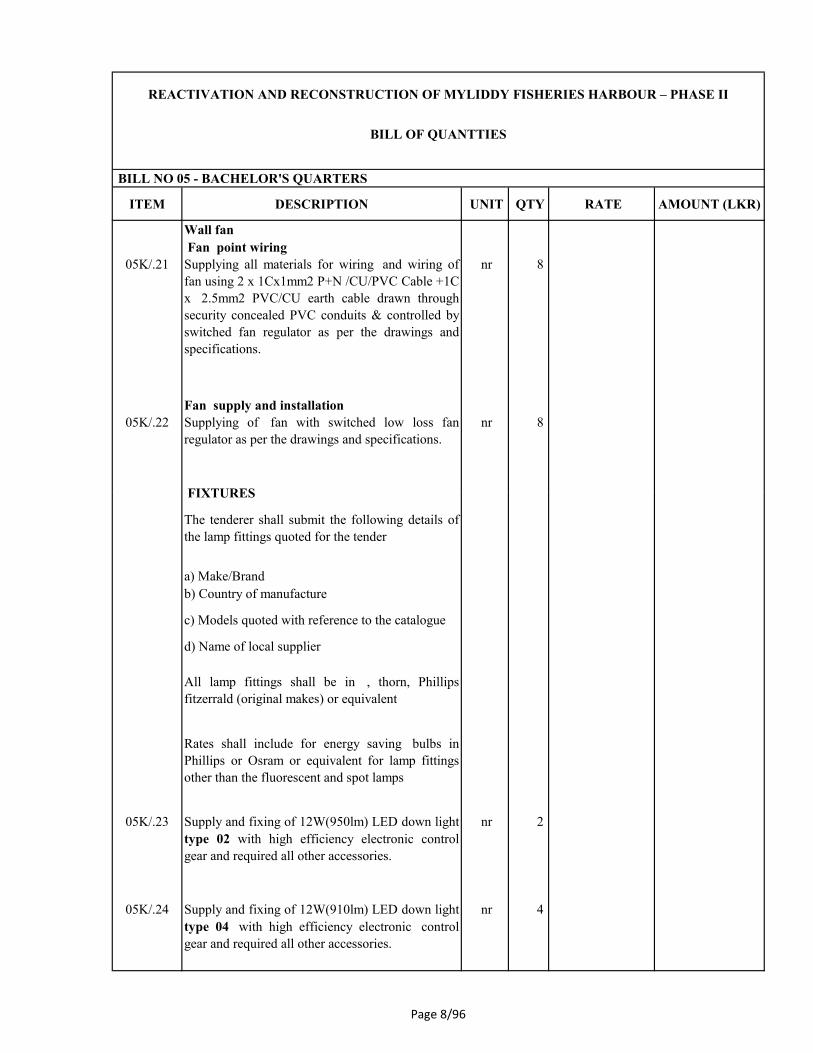
ITEM DESCRIPTION UNIT QTY RATE AMOUNT (LKR)
BILL NO 05 - BACHELOR'S QUARTERS
REACTIVATION AND RECONSTRUCTION OF MYLIDDY FISHERIES HARBOUR – PHASE II
BILL OF QUANTTIES
Wall fan
Fan point wiring
05K/.21 Supplying all materials for wiring and wiring of
fan using 2 x 1Cx1mm2 P+N /CU/PVC Cable +1C
x 2.5mm2 PVC/CU earth cable drawn through
security concealed PVC conduits & controlled by
switched fan regulator as per the drawings and
specifications.
nr 8
Fan supply and installation
05K/.22 Supplying of fan with switched low loss fan
regulator as per the drawings and specifications.
nr 8
FIXTURES FIXTURES
The tenderer shall submit the following details of
the lamp fittings quoted for the tender
a) Make/Brand
b) Country of manufacture
c) Models quoted with reference to the catalogue
d) Name of local supplier
All lamp fittings shall be in , thorn, Phillips
fitzerrald (original makes) or equivalent
Rates shall include for energy saving bulbs in
Phillips or Osram or equivalent for lamp fittings
other than the fluorescent and spot lamps
05K/.23 Supply and fixing of 12W(950lm) LED down light
type 02 with high efficiency electronic control
gear and required all other accessories.
nr 2
05K/.24 Supply and fixing of 12W(910lm) LED down light
type 04 with high efficiency electronic control
gear and required all other accessories.
nr 4
Page 8/96

ITEM DESCRIPTION UNIT QTY RATE AMOUNT (LKR)
BILL NO 05 - BACHELOR'S QUARTERS
REACTIVATION AND RECONSTRUCTION OF MYLIDDY FISHERIES HARBOUR – PHASE II
BILL OF QUANTTIES
05K/.25 Supply and fixing of 10W(600lm) LED down light
type 05 with high efficiency electronic control
gear and required all other accessories(IP65).
nr 4
05K/.26 Supply and fixing of 12W(910lm) LED type 06
with high efficiency electronic control gear and
required all other accessories.(IP65)
nr 6
05K/.27 Supply and fixing of 12W(950lm) wall mounted
indoor type LED light type 09 with high efficiency
electronic control gear and required all other
accessories.(IP20)
nr 6
05K/.28 Supply and fixing of 12W(950lm) wall mounted nr 2 05K/.28 Supply and fixing of 12W(950lm) wall mounted
indoor type LED light type 09 with high efficiency
electronic control gear and required all other
accessories.(IP20) Emergency fitting with three
hours battery backup
nr 2
05K/.29 Supply and fixing of type 10 wall mounted indoor
type die-cast construction, polycarbonate diffuser
suitable for use with 57W halogen (IP20.)
nr
4
05K/.30 Supply and fixing of type 11 halogen 35W metal
halide chandelier lamp made with polished
aluminum housing and canopy, stainless steel
adjustable suspension and clear acrylic rods.
nr 4
05K/.31 Supply and fixing of type 12 Decorative box
shaped pendant luminaire with powder coated steel
suspension rod suitable for use with 18W CFL
(IP20.)
nr 4
05K/.32 Supply and fixing of 44W(3800lm) 1200mm LED
light type 14 with high efficiency electronic
control gear and required all other
accessories(IP20).
nr 2
Page 8/97

ITEM DESCRIPTION UNIT QTY RATE AMOUNT (LKR)
BILL NO 05 - BACHELOR'S QUARTERS
REACTIVATION AND RECONSTRUCTION OF MYLIDDY FISHERIES HARBOUR – PHASE II
BILL OF QUANTTIES
Direct Lightning Protection system
Supply , Installation & Testing of complete
lightning protection system for the building as
specified and complying with (IEC
62305/2010,SLSI 1261/2004).
Note
Air Terminals
05K/.33 Supply & Installation of solid copper vertical air
finial of minimum 8mm diameter & 900 mm length
with a base.
nr 1
Roof Conductors
05K/.34 Supply & Installation of annealed copper tape of
minimum 25 mm wide x minimum 3 mm thick
using copper tape clip support at 500 mm intervals
along the roof and connect to the down conductors
m 5
along the roof and connect to the down conductors
as shown in the drawings (Rate shall include all
required exothermic joints, clamps, bonds and
fixing accessories.)
Installation arrangement of copper tapes on roof
shall be submitted with the bid.
Down Conductors
05K/.35 Supply & Installation of 16mm dia mild steel rods
as down conductor in side the selected columns as
shown in the drawing (Rate shall include all
required exothermic joints, clamps, bonds and
fixing accessories.)
m 7
05K/.36 Supply & Installation of Oblong Test Clamp
mounted in an enclosure for down conductors at
1.5m above ground level.
nr 1
Earth Termination
Rate shall include the cost for all fixing
accessories, backfilling and surface finishing
required for completion of work.
Final earth resistance value shall be less than 10
Ohms, of an individual earth rods tasted in a dry
day.
Page 8/98

ITEM DESCRIPTION UNIT QTY RATE AMOUNT (LKR)
BILL NO 05 - BACHELOR'S QUARTERS
REACTIVATION AND RECONSTRUCTION OF MYLIDDY FISHERIES HARBOUR – PHASE II
BILL OF QUANTTIES
05K/.37 Supply & Installation of one number copper clad
steel earth electrode of minimum 16mm dia. and
length 1.2 m.Rate shall include rod to tape clamp
& all required accessories.
nr 1
05K/.38 Provide an earth pit of 300mm x 300mm x 200mm
with a 50mm thick removable concrete lid for each
down conductor. Rate shall include all required
accessories.
nr 1
Details of pit construction shall be submitted with
bid.
Rate shall include for installation of parallel rods
to achieve earth resistance less than 10 Ohms
where necessary.
Earth Electrode
05K/.39 Supply & Installation of one number copper clad
steel earth electrode of minimum 16mm dia. and
length 1.2 m.Rate shall include rod to tape clamp
& all required accessories.
Item 1
05K/.40 Provide an earth pit of 300mm x 300mm x 200mm
with a 50mm thick removable concrete lid for each
down conductor. Rate shall include all required
accessories.
nr 1
Details of pit construction shall be submitted with
bid.
Rate shall include for installation of parallel rods
to achieve earth resistance less than 5 Ohms where
necessary.
TOTAL FOR ELECTRICAL
INSTALLATION CARRIED TO SUMMARY
Page 8/99

ITEM DESCRIPTION UNIT QTY RATE AMOUNT (LKR)
BILL NO 05 - BACHELOR'S QUARTERS
REACTIVATION AND RECONSTRUCTION OF MYLIDDY FISHERIES HARBOUR – PHASE II
BILL OF QUANTTIES
05L/ FLOOR /WALL /CEILING FINISHES
Floor finishes
600 X 600 mm homogenous ceramic floor tiles in
an approved color and quality including 25 mm
thick 1:3 cement sand bedding and pointing with
recommended tile adhesives and grout to match the
color of tiles laid; all in accordance with drawings
and specifications (PC rate for 600x600mm tile Rs.
1200.00)
05L/.1 To floor m2 90
05L/.2 to steps m2 12
SkirtingSkirting
homogeneous floor tile skirting ; all as per
drawings
05L/.3 100mm high to floor m 65
05L/.4 100mm high to staircase m 10
Wall Finishes
Internal Finishes
finished smooth with Cement plaster and wall
putty on internal walls; all in accordance with
drawings and specifications
05L/.5 To walls m2 240
05L/.6 Sides of the staircase m2 1
Page 8/100

ITEM DESCRIPTION UNIT QTY RATE AMOUNT (LKR)
BILL NO 05 - BACHELOR'S QUARTERS
REACTIVATION AND RECONSTRUCTION OF MYLIDDY FISHERIES HARBOUR – PHASE II
BILL OF QUANTTIES
Installation of wall tiles , 300mm X 300mm size ,
1:3 cement sand bedding , jointing and pointing; all
in accordance with drawings and specifications
(PC rate for 300x300mm tile Rs. 300.00)
05L/.7 To wall m2 24
External Finishes
20mm thk. cement and sand 1:3 mortar finished
semi rough with wood float on internal walls; all in
accordance with drawings and specifications
05L/.8 To walls m2 165
TOTAL FOR FLOOR, WALL AND CEILING
FINISHES CARRIED TO SUMMARY
Page 8/101

ITEM DESCRIPTION UNIT QTY RATE AMOUNT (LKR)
BILL NO 05 - BACHELOR'S QUARTERS
REACTIVATION AND RECONSTRUCTION OF MYLIDDY FISHERIES HARBOUR – PHASE II
BILL OF QUANTTIES
05M/ PAINTING AND DECORATION
Internal
05M/.1Internal paint emulsion in an approved
manufacture finish with two coats of wall putty
and apply one coat of acrylic filler and two coats
of emulsion paint to uniform colour to architect's
approved colours to the followings.
m2 610
05M/.2 Internal paint emulsion in an approved
manufacture finish with two coats of weather
shield paint including suitable primer for walls
paint to uniform colour to architect's approved
colours to the followings.
m2 86
External
05M/.3 External paint with Approved primer and three
coats of weather proof paint as per the Drawings
and Specifications
m2 344
Ceiling
05M/.4Internal paint in one coat of acrylic filler and two
coats of weather shield emulsion paint to uniform
color. as per the drawings and specifications
m2 13
05M/.5Internal paint to one coats of acrylic filler & two
coats of weather shield emulsion paint as per the
Drawings and Specifications in the followings
m2 392
05M/.6 Soffit painting with one coat of wall primer and
two coats of emulsion paint as approved by the
architect.
m2 37
TOTAL FOR PAINTING AND
DECORATION CARRIED TO SUMMARY
Page 8/102

ITEM
NO
ITEM DESCRIPTION UNIT QTY RATE
Rs.
AMOUNT
Rs.
SUMMARY
06A/ EXTERNAL WORKS
TOTAL CARRIED TO MAIN SUMMARY
06A/ EXTERNAL WORKS
Preparation of site
06A/.1 Allow for clearing site from all debris and removal of
top soil upto 150mm including all bushes and other
vegetation away from the site - building area
Item 1.00
Chain link fence
06A/.2 Construction of 1950mm high boundry fence m 500.00
BILL NO 06- EXTERNAL WORKS
REACTIVATION AND RECONSTRUCTION OF MYLIDDY FISHERIES HARBOUR – PHASE II
BILL OF QUANTTIES
06A/.2 Construction of 1950mm high boundry fence
comprising with chian link mesh fixed to 50mm dia
hot dipped GI frame colour to be approved by the
client on top of 150mm block wall as per the detail
drawing.Rate shall include excavation
,foundation,stiffner column with footing,wall plaster
and painting etc.
m 500.00
Page 8/103

ITEM
NO
ITEM DESCRIPTION UNIT QTY RATE
Rs.
AMOUNT
Rs.
BILL NO 06- EXTERNAL WORKS
REACTIVATION AND RECONSTRUCTION OF MYLIDDY FISHERIES HARBOUR – PHASE II
BILL OF QUANTTIES
Metal work
Main gate ( Gate 01)
06A/.3 Supply and fix Main Gate overall size
6000x2100mm, comprising with 100mmx100mm hot
dipped GI heavy duty box bar outer frame and
25x25mm hot dipped GI heavy duty box bar grills at
100mm Centers including 0.47mm thick Zn/Al colour
sheet at bottom complete as per the drawings.Rate to
include all necessary hardware for fixing and preapre
and apply one marine primer paint and two coats of
approved colour marine finishing coat compete to
suite with the marine environment .Rate shall include
for construction of columns including including
moulding , plastering and painting all complete as per
the detail drawing number LH!/ML/SF/EX/02
Item 1.00
Pedestrian gate
06A/.4 Supply and fix Pedestrian Gate ,overall size,
1400x2100mm comprising with 50mmx50mm hot
dipped GI heavy duty box bar outer frame and
25x25mm hot dipped GI , heavy duty box bar grills at
100mm Centers including 0.47mm thick Zn/Al
colour sheet at bottom complete as per the
drawings.Rate to include all necessary hardware for
fixing and preapre and apply one marine primer paint
and two coats of approved colour marine finishing
coat compete to suite with the marine environment
.Rate shall include for construction of columns
including including moulding , plastering and painting
all complete as per the detail drawing number ........
Item 1.00
Other entrance gates
Fixing gates for service entrance near water tank and
nce near Coast guard office (GATE 2 & GATE 5)
Page 8/104

ITEM
NO
ITEM DESCRIPTION UNIT QTY RATE
Rs.
AMOUNT
Rs.
BILL NO 06- EXTERNAL WORKS
REACTIVATION AND RECONSTRUCTION OF MYLIDDY FISHERIES HARBOUR – PHASE II
BILL OF QUANTTIES
06A/.5 Supply and fix Gate Number 2 and 5 overall size
6000x2100mm, comprising with 100mmx100mm hot
dipped GI heavy duty box bar outer frame and
25x25mm hot dipped GI heavy duty box bar grills at
100mm Centers including 0.47mm thick Zn/Al colour
sheet at bottom complete as per the drawings.Rate to
include all necessary hardware for fixing and preapre
and apply one marine primer paint and two coats of
approved colour marine finishing coat compete to
suite with the marine environment .Rate shall include
for construction of columns including including
moulding , plastering and painting all complete as per
the detail drawing number LHI/ML/SF/EX/02
Item 2.00
Fixing gates for entrance near Quarters (GATE 3 &
GATE 4)GATE 4)
06A/.6 Supply and fixing of Gate Number 3 and 4 ,overall
size 3600x2100mm, comprising with
100mmx100mm hot dipped GI heavy duty box bar
outer frame and 25x25mm hot dipped GI heavy duty
box bar grills at 100mm Centers including 0.47mm
thick Zn/Al colour sheet at bottom complete as per
the drawings.Rate to include all necessary hardware
for fixing and preapre and apply one marine primer
paint and two coats of approved colour marine
finishing coat compete to suite with the marine
environment .Rate shall include for construction of
columns including including moulding , plastering
and painting all complete as per the detail drawing
number LHI/ML/SF/EX/02
Item 2.00
Barrier
06A/.7 Construction of steel boom gate as shown in the
drawing at main entrance including steel pipes, base
anchoring , ball bearing etc. to complete the work in
order. Rate to include oil primer and two coats of
marine paint.
Item 1.00
Page 8/105

ITEM
NO
ITEM DESCRIPTION UNIT QTY RATE
Rs.
AMOUNT
Rs.
BILL NO 06- EXTERNAL WORKS
REACTIVATION AND RECONSTRUCTION OF MYLIDDY FISHERIES HARBOUR – PHASE II
BILL OF QUANTTIES
Retaining Wall
All the works accordance with the drawings and
specifications. Rates include site clearences, filling,
levelling and compacting material. Suitable retaining
wall shall be decide by the contractor as per
instruction by the Engineer as per site conditions.
06A/.8 Excavation for retaining wall foundations, minimum
depth 0.6m commencing from existing ground level
m3 177.50
06A/.9 Grade 20 concrete In retaining wall m3 77.50
06A/.10 Form work In sides of retaining walls m2 150.00
06A/.11 Random rubble masonry work maximum height of
2.0m in cement and sand 1:5 mortar in retaining wall
foundation including weep hole and metal packing.
m3 195.00
TOTAL FOR EXTERNAL WORKS CARRIED
TO SUMMARY
Page 8/106

ITEM
NOITEM DESCRIPTION UNIT QTY
RATE
Rs.
AMOUNT
Rs.
7A/ Provisional Sums
All Prime Costs and Provisional sums stated below are
subject to adjustment and can be deducted in whole or
in part from the contract at the discretion and direction
of the Engineer, without the contractor having any
claim for loss of profit
Note
Any percentage or lump sum addition, which is made
hereunder by the Contractor for any prime cost item,
shall be adjusted on a pro-rata basis on the actual
amount expended for that PC Sum in the final account
Note
7A/.1 Allow Provisional Sum for supply and planting of
trees and landscaping works.
PS 550,000.00
7A/.2 Allow Provisional Sum for special additional tests and
Quality checking ordered by the Engineer
PS 240,000.00
7A/.3 Allow Provisional sum for the Employer's 50% share
of fees and expenses for the Dispute Adjudication
Board.
PS 500,000.00
Total of Bill No. 7 Carried to Main Summary 1,290,000.00
BILL NO 07 - PROVISIONAL SUMS
REACTIVATION AND RECONSTRUCTION OF MYLIDDY FISHERIES HARBOUR – PHASE II
BILL OF QUANTTIES
Page8/107

REACTIVATION AND RECONSTRUCTION OF MYLIDDY FISHERIES HARBOUR – PHASE II
BILL OF QUANTTIES
LABOUR
item Description Unit Nominal Quantity Rate (LKR)
8A
8A/1 Unskilled Labour day 25
8A/2 Driver day 15
Plant Operator (Equipment) day 15
8A/4 Plant Operator (Machineries) day 15
8A/5 Mason day 15
8A/6 Carpenter & Joiner day 15
8A/7 Plumber day 15
8A/8 Mechanic day 25
8A/9 Welder day 25
8A/10 Fitter day 10
8A/11 Diver team including equipment day 5
MATERIALS
Bill N0 -8 Day Works
Amount (LKR)
Labour
Total for Day works : Labour
MATERIALS
item Description Unit Nominal Quantity Rate (LKR)
8B Materials
8B/1 Timber ( Class III) m2 50
8B/2 Portland Cement (50kg bags) nr 50
8B/3 Coarse aggregates for concrete (19mm) m3 42
8B/4 Fine aggregates for concrete m3 42
8B/5 Reinforcing steel t 1
8B/6 Core material m3 150
8B/7 Secondary armour m3 200
8B/8 Primary armour m3 200
Amount (LKR)
Total for Day works : Material
Page 8/108

REACTIVATION AND RECONSTRUCTION OF MYLIDDY FISHERIES HARBOUR – PHASE II
BILL OF QUANTTIES
PLANT
item Description Unit Nominal Quantity Rate (LKR)
8C Constructional Plant*
8C/1 Front end loaders hr 100
8C/2 Back Hoe/Excavators hr. 100
8C/3 Long arm excavator hr. 100
8C/4 Bull Dozers hr. 100
8C/5 Dump trucks hr. 100
8C/6 Lorries hr. 100
8C/7 Farm Tractors hr. 100
8C/8 Concrete mixer & vibrator hr. 100
* The capacity of the plant to be indicated by bidder
Amount (LKR)
8A
Amount (LKR)
Total Day works: Labour
Total for Day works : Plant
Day work Summary
8A
8B
8C
Total Day works: Labour
Total Day works: Materials
Total Day works: Contractor s Equipment
Total for Day works (Provisional Sum) (carried
forward to Summary of Bills)
Page 8/109

Reactivation and Reconstruction of Myliddy Fishery Harbour in Northern Province - Phase II Page 9 | 1
SECTION 9
SCHEDULES

Reactivation and Reconstruction of Myliddy Fishery Harbour in Northern Province - Phase II Page 9 | 2
SCHEDULE 1.1 - GENERAL INFORMATION
(SOLE PROPPRIETORS)
(1) If pre-qualification is done the bidders are required to include information subsequent to
that submitted with the pre- qualification application.
ITB Clause
Reference Description
Information
(to be filled by Bidder)
Remarks
4.1(a) Legal Status Provide certified copies
of Business Registration
Written power of attorney to the
signatory to the bid
Provide original or certified copy of the power of
attorney attested by a Notary and Label as
attachment to Clause 4.1(a)
4.2 (a) ICTAD Registration Provide certified copies
and label as attachment to
Clause 4.2 (a) Registration number
Grade
Specialty
Expiry Date

Reactivation and Reconstruction of Myliddy Fishery Harbour in Northern Province - Phase II Page 9 | 3
SCHEDULE 1.2 - GENERAL INFORMATION
(PARTNERSHIPS)
(1) If pre-qualification is done the bidders are required to include information subsequent to
that submitted with the pre- qualification application.
(2) For Joint Ventures, each joint venture partner shall furnish information separately.
ITB Clause
Reference Description
Information
(to be filled by Bidder)
Remarks
4.1(a) Legal Status Provide certified copies
of Business Registration
Written power of attorney to the
signatory to the bid
Provide original or certified copy of the power of
attorney attested by a Notary and Label as
attachment to Clause 4.1(a)
If a Joint Venture, names and
addresses of Joint Venture
partners
1……………………. Provide draft copy of the
Joint Venture Agreement
or alternatively the
memorandum of
understanding
2…………………….
3……………………..
If a Joint Venture, name of the
Lead Partner
For Joint Ventures, each joint venture partner shall furnish legal status separately
Name (lead partner) Provide certified copies
and label as attachment
to Clause 4.1(a) Legal status
Place of registration
Principle place of business
Written power of attorney of the
signatory to the Bid
Provide original or certified copy of the power of
attorney attested by a Notary and Label as
attachment to Clause 5.1
VAT Registration Number
Name (Partner 2) Provide certified copies
and label as attachment to
Clause 4.1(a) Legal status

Reactivation and Reconstruction of Myliddy Fishery Harbour in Northern Province - Phase II Page 9 | 4
Place of registration
Principal place of business
Written power of attorney of the
signatory to the Bid
Provide original or certified copy of the Power of
Attorney attested by a Notary and label as attachment
to Clause 4.1 (a)
VAT Registration Number
Name (Partner 3) Provide certified copies and
label as attachment to
Clause 4.1(a) Legal status
Place of registration
Principle place of business
Written power of attorney of the
signatory to the Bid
Provide original or certified copy of the Power of
Attorney attested by a Notary and Label as attachment
to Clause 4.1 (a)
VAT Registration No.
4.2 (a) ICTAD Registration Provide certified copies and
label as attachment to
Clause 4.2 (a) Registration number
Grade
Specialty
Expiry Date

Reactivation and Reconstruction of Myliddy Fishery Harbour in Northern Province - Phase II Page 9 | 5
SCHEDULE 1.3 - GENERAL INFORMATION
(COMPANYS)
(1) If pre-qualification is done the bidders are required to include information subsequent to that
submitted with the pre- qualification application.
ITB Clause
Reference Description
Information
(to be filled by Bidder)
Remarks
4.1(a) Legal Status Provide certified copies of
Business Registration
Written power of attorney to the
signatory to the bid
Provide original or certified copy of the power of
attorney attested by a Notary and Label as attachment
to Clause 4.1(a)
4.2 (a) ICTAD Registration Provide certified copies and
label as attachment to
Clause 4.2 (a) Registration number
Grade
Specialty
Expiry Date

Reactivation and Reconstruction of Myliddy Fishery Harbour in Northern Province - Phase II Page 9 | 6
Schedule 2 – Annual Turn-over Information
(Construction only - Last five years)
(1) If pre-qualification is done the bidders are required to include information subsequent to that
submitted with the pre-qualification application
(2) For joint ventures, each partner shall submit the information separately
Year Turnover Remarks
1
Attach audited reports and label
as attachment to Clause 4.2
2
3
4
5

Reactivation and Reconstruction of Myliddy Fishery Harbour in Northern Province - Phase II Page 9 | 7
Schedule 3 – Adequacy of Working Capital
If pre-qualification is done the bidders are required to include information subsequent to that submitted
with the pre-qualification application
Source of Credit Line Amount Remarks
Provide documentary evidence
and label as attachment to Clause
4.2
Total

Reactivation and Reconstruction of Myliddy Fishery Harbour in Northern Province - Phase II Page 9 | 8
Schedule 4 – Construction Experience in last five years
(1) If pre-qualification is done the bidders are required to include information subsequent to that
submitted with the pre-qualification application.
(2) For joint ventures, each joint venture partner shall furnish information separately.
Year Employer Description of
Works Amount
Contractor’s
Responsibility
(%)
Total
Provide documentary evidence and label as attachment to Clause 4.2

Reactivation and Reconstruction of Myliddy Fishery Harbour in Northern Province - Phase II Page 9 | 9
Schedule 5 – Major Items of Construction Equipment Proposed
Type Capacity

Reactivation and Reconstruction of Myliddy Fishery Harbour in Northern Province - Phase II Page 9 | 10
Sch
edu
le 6
– C
on
stru
ctio
n M
an
ag
emen
t S
taff
A:
Key
Pro
fess
ion
als
T
ask
B:S
up
po
rt S
taff
T
ask
Po
siti
on
Po
siti
on
Nam
e
Nam
e

Reactivation and Reconstruction of Myliddy Fishery Harbour in Northern Province - Phase II Page 9 | 11
Sch
edu
le 7
– T
ime
Sch
edu
le f
or
Key
Sta
ff
Mo
nth
s( i
n t
he
form
of
a B
ar
Ch
art
)
Nu
mb
er o
f
Mo
nth
s
24
23
-
-
11
10
Par
t T
ime:
……
……
……
……
.
9
8
7
6
5
4
3
Fu
ll T
ime:
- :
……
:……
……
……
……
..
2
1
Act
ivit
ies
Po
siti
on
Na
me

Reactivation and Reconstruction of Myliddy Fishery Harbour in Northern Province - Phase II Page 9 | 12
Sch
edu
le 8
- W
ork
Pro
gra
mm
e
Sh
eet
1 o
f ....
....
..
[1st,
2n
d,
etc,
are
mo
nth
s fr
om
th
e Sta
rt D
ate
.]
24
th
23
rd
11
th
1
0th
9th
8th
7th
6th
5th
4th
3rd
2n
d
1st
Co
nst
ruct
ion
A
ctiv
ity

Reactivation and Reconstruction of Myliddy Fishery Harbour in Northern Province - Phase II Page 9 | 13
Schedule 9
Method Statement
The Bidder shall provide a method statement describing the methodology proposed to be adopted in
the execution of the contract. Method statement shall include methodology and/ or information for:
(i) Contractor’s Mobilization ,Demobilization and arrangement of the facilities for the
Engineer.
(ii) Environmental and Social Protection during Construction.
(iii) Construction
(a) Pre and Post survey including setting out
(b) Material
Details of Specifications of the Sullpy Materials
Transport , Storage and handling of Construction materials
Manpower . Equipment and tools
Safetyt Measures
Quality Control and assurence including Testing
(c) Any other details as applicable for entire Work

Reactivation and Reconstruction of Myliddy Fishery Harbour in Northern Province - Phase II Page 10 | 1
SECTION 10
DRAWINGS
(Attached Separately)

Reactivation and Reconstruction of Myliddy Fishery Harbour in Northern Province - Phase II Page 10 | 2
Volume 2 A: Offshore Structures
No Drawing Title Drawing Number
General Notes LHI/ML/SF/GN/01
M-1 Harbour Layout and Onshore Facilities (Overall) LHI/ML/LO/1
M-2 Proposed Section-Breakwater Rehabilitation LHI/ ML /BW/1
M-3 Modification on Damaged Section-Main Breakwater LHI/ ML /BW/2
M-4 Modification on Damaged Section- Main Breakwater LHI/ ML /BW/3
M-5 New Quay Wall General Details LHI/ ML /QW/4
M-6 New Quay Wall Elevation LHI/ ML /QW/5
M-7 New Quay Wall R/F details LHI/ ML /QW/6
M-8 New Quay Bollard and Fender details LHI/ ML /BF/2
M-9 Building 17- Bachelors Quarters LHI/ ML /B17/BQ1
M-10 Building 17- Bachelors Quarters LHI/ ML /B17/BQ2
M-11 Building 17- Bachelors Quarters Foundation Layout and
Foundation Details LHI/ ML /B17/BQ/S1
M-12 Building 17- Bachelors Quarters General Arrangement of
First Floor and R/F Details of Slab and Column Details LHI/ ML /B17/BQ/S2
M-13 Building 17- Bachelors Quarters Roof Details LHI/ ML /B17/BQ/S3
M-14 Building 17- Bachelors Quarters Stair Case Details LHI/ ML /B17/BQ/S4
M-15 Building 17- Bachelors Quarters Sewer and Waste Water
details LHI/ ML /B17/BQ/DR-01
M-16 Building 17- Bachelors Quarters Water Supply details LHI/ ML /B17/BQ/WS-01
M-17 Building 17- Bachelors Quarters Strom Water Disposal
Layout LHI/ ML /B17/BQ/SWD-01
M-18 Building 17- Bachelors Quarters Electrical Layout LHI/ ML /B17/BQ/E1
M-19 Building 17- Bachelors Quarters Single Line Diagram LHI/ ML /B17/BQ/E2
M-20 Building 16- Manager Quarters- Architectural Details LHI/ ML /B16/MQ/01
M-21 Building 16- Manager Quarters- Architectural Details LHI/ ML /B16/MQ/02
M-22 Building 16- Manager Quarters- Foundation Layout,
Foundation Details LHI/ ML /B16/MQ/S1
M-23 Building 16- Manager Quarters- Footing Details and
Column Details LHI/ ML /B16/MQ/S2
M-24 Building 16- Manager Quarters- General Arrangement of
First Floor R/F Details of Slab and Column Details LHI/ ML /B16/MQ/S3
M-25 Building 16- Manager Quarters- Roof Details LHI/ ML /B16/MQ/S4
M-26 Building 16- Manager Quarters- Staircase Details LHI/ ML /B16/MQ/S5
M-27 Section for Retaining Wall LHI/ ML /SF/EX/01
M-28 Fence and Gate Details LHI/ ML /SF/EX/02
M-29 Fence and Gate Details- Typical Column and Footing
Details LHI/ ML /SF/EX/03

LANKA HYDRAULIC INSTITUTE LTD.
Prepared for:
2A - OFFSHORE STRUCTURES
PAGENUMBER DESCRIPTION
DRAWINGNUMBER
DEMOCRATIC SOCIALIST REPUBLIC OF SRI LANKA
STATE MINISTRY OF ORANAMENTAL FISH,
IMLAND FISH & PRAWN FRAMING, FISHERIES
HARBOUR DEVELOPMENT, MULTIDAY FISHING
ACTIVITIES AND FISH EXPORTS.


Naval Detachment
Arulmegu Murukaiyan Kovil
E
x
is
tin
g
R
o
a
d
Proposed Onshore & Offshore Facilities :-
1 -
Auction Hall
2 -
Net Mending,FI Office & Accomadation
Radio Room & Rest Room,Community Hall
3 -
Fuel Office
4 -
Coast Guard Office and Accommodations
5 -
Toilet Block 1 & 2 (8x6m)
6 -
Diesel & Kerosene Tanks
7 -
Fuel Dispenser Unit
8 -
9 -
10 -
11 -
13 -
14 -
Security Office
15 -
Weigh Bridge & Control Room
16 -
Manager's Quarters( Two Story)
17 -
Bachelor's Quarters( Two Story)
18 -Canteen
Dredging Area = 1.29Ha. (-2.5m Depth)
1
2
7
Water sump, Pump Room, Over
Head Tank
Storage Rooms for Boat Engines
Treatment Plant ( Waste water and
solid waste )
Provision for Cold Room
12 -Administration Building
Generator Room
Beacon Light
Beacon Light
Dredging Line
Beach Landing Area
Basin Area = 3.65Ha.
1
2
1
6
17
5
1
5
11
Existing Huts
Lanka Hydraulic Institute Ltd.
177, John Rodrigo Mawatha,
Katubedda, Moratuwa
SRI LANKA
Consultant:
PROJECT:
TITLE:
CHECKED: APPROVED:
SCALE:PROJECT NO: REV. NO:DRG. NO:
DRAWN: DESIGN:
Rev: Date: Description: CHKD: APPD:
DATE: SIZE:
Client:
HARBOUR LAYOUT AND ONSHORE FACILITIES (OVERALL)
7
P
r
o
p
o
s
e
d
R
o
a
d
Main Breakwater
(Existing)
1
8
3
Secondary Breakwater
(Existing)
LHI/ML/LO/1
REACTIVATION AND RECONSTRUCTION OF MYLIDDY FISHERIESHARBOUR IN THE NORTHERN PROVINCE - PHASE II
Quay W
all (8
0x8m
)
Quay Wall
Breakwater Rehabilitation
Dredging
Beacon Light
8
5
422900 E
811075 N
1:1250
30m
+1.5m MSL
+0.8m
+1.5m(Extension of Quaywall as Phase 1)
R
e
c
l
a
m
a
t
i
o
n
A
r
e
a
14m
8
New
Quay
wall
Plaque
2 - Phase I
12 - Phase II
9
9
9
3
.6
m
w
id
e
r
o
a
d
fo
r
q
u
a
r
te
r
s
Main Breakwater
(Proposed)
Main Breakwater
(Existing)
Pavement
Generator room
(Existing Depth -2.5m )
( Existing Depth -1.0m)
810900 N
422800 E
423000 E
811000 N
811075 N
810800 N
6
Diesel
6
Kero
sene
Retaining Wall
Retaining
Wall
8
Parkin
g
Interlock pavings
Asphalt (Internal roads)
concrete finish.
Gate 1
Gate 2
Gate 3Gate 4
Gate 5
Power trowel concrete finishfor parking area at Auction hall
Fence
C
h
.2
0
m
C
h
.4
0
m
C
h
.
6
0
m
C
h
.
8
0
m
C
h
.1
0
0
m
C
h
.1
2
0
m
C
h
.1
4
0
m
C
h.160m
C
h.180m
C
h.200m
C
h.220m
C
h.240m
C
h.260m
C
h.280m
C
h.300m
C
h.320m
C
h.340m
C
h
.0
m
20m
Step
s
Retaining Wall
Ministry of Agriculture, Irrigation andFisheries & Aquatic Resources DevelopmentNew Secretariat, Maligawatta,
Colombo 10,
SRI LANKA

HARBOUR SIDE SEA SIDE
PROPOSED BREAKWATER SECTION
℄
Lanka Hydraulic Institute Ltd.
177, John Rodrigo Mawatha,
Katubedda, Moratuwa
SRI LANKA
PROJECT:
TITLE:
CHECKED: APPROVED:
SCALE:PROJECT NO: REV. NO:DRG. NO:
DRAWN: DESIGN:
Rev: Date: Description: CHKD: APPD:
DATE: SIZE:
Client:
PROPOSED SECTION - BREAKWATER REHABILITATION
LHI/ML/BW/1
REACTIVATION AND RECONSTRUCTION OF MYLIDDY FISHERIESHARBOUR IN THE NORTHERN PROVINCE - PHASE II
1:1001802
JP IK PR KR May 2019 A3
Beacon Light
Beacon Light
Secondary Breakwater
(Existing)
Main Breakwater (Proposed)
Main Breakwater (Existing)
A
B
C
D
A
B
C
D
State Ministry of Oranamental Fish, Imland Fish &Prawn Framing, Fisheries Harbour Development,Multiday Fishing Activities and Fish Exports.New Secretariat, Maligawatta, Colombo 10,
SRI LANKA
Ceylon Fishery Harbours Corporation
Design Consultant:

HARBOUR SIDE SEA SIDE
BREAKWATER SECTION NO. C - C
℄
Lanka Hydraulic Institute Ltd.
177, John Rodrigo Mawatha,
Katubedda, Moratuwa
SRI LANKA
PROJECT:
TITLE:
CHECKED: APPROVED:
SCALE:PROJECT NO: REV. NO:DRG. NO:
DRAWN: DESIGN:
Rev: Date: Description: CHKD: APPD:
DATE: SIZE:
Client:
MODIFICATION ON DAMAGED SECTION - MAIN BREAKWATER
LHI/ML/BW/2
REACTIVATION AND RECONSTRUCTION OF MYLIDDY FISHERIESHARBOUR IN THE NORTHERN PROVINCE- PHASE II
1:100
℄HARBOUR SIDE SEA SIDE
1802
JP IK PR KR May 2019 A3
BREAKWATER SECTION NO. D - D
LEGEND:-
Beacon Light
Beacon Light
Secondary Breakwater
(Existing)
Main Breakwater (Proposed)
Main Breakwater (Existing)
C
C
D
D
A
B
A
B
(80m Chainage)
(160m Chainage)
State Ministry of Oranamental Fish, Imland Fish &Prawn Framing, Fisheries Harbour Development,Multiday Fishing Activities and Fish Exports.New Secretariat, Maligawatta, Colombo 10,
SRI LANKA
Ceylon Fishery Harbours Corporation
Design Consultant:

HARBOUR SIDE SEA SIDE℄
HARBOUR SIDE SEA SIDE℄
Lanka Hydraulic Institute Ltd.
177, John Rodrigo Mawatha,
Katubedda, Moratuwa
SRI LANKA
PROJECT:
TITLE:
CHECKED: APPROVED:
SCALE:PROJECT NO: REV. NO:DRG. NO:
DRAWN: DESIGN:
Rev: Date: Description: CHKD: APPD:
DATE: SIZE:
Client:
LHI/ML/BW/3
REACTIVATION AND RECONSTRUCTION OF MYLIDDY FISHERIESHARBOUR IN THE NORTHERN PROVINCE- PHASE II
1:1001802
JP IK PR KR May 2019 A3
BREAKWATER SECTION NO. A - A
BREAKWATER SECTION NO. B - B
Beacon Light
Beacon Light
Secondary Breakwater
(Existing)
Main Breakwater (Proposed)
Main Breakwater (Existing)
A
B
C
D
LEGEND:-
A
B
C
D
MODIFICATION ON DAMAGED SECTION - MAIN BREAKWATER
(345m Chainage)
(247m Chainage)State Ministry of Oranamental Fish, Imland Fish &Prawn Framing, Fisheries Harbour Development,Multiday Fishing Activities and Fish Exports.New Secretariat, Maligawatta, Colombo 10,
SRI LANKA
Ceylon Fishery Harbours Corporation
Design Consultant:

MSL
GABION WALL,QUAY WALL DECK R/F &CAPPING BEAM R/F DETAILS)Scale 1:50
Scale 1:100
1
1
22
PLAN VIEW OF QUAY WALL
3 3
7
7
+0.8
m M
SL
+1.5
m M
SL
(Exte
nsio
n o
f Quayw
all a
s P
hase 1
)
Steps
New
Q
uayw
all
LAYOUTScale 1:750
S
e
c
o
n
d
a
r
y
B
r
e
a
k
w
a
t
e
r
(
E
x
is
t
in
g
)
3
6
Diesel
6
Kero
sene
A
A
Existing Ground
+1.50 MSL
+0.80 MSL
R/F Concrete Quay Wall
Deck Slab
Masonry Steps
50 mm Thk. Cpncrete
Topping
R/F Concrete Quay Wall
Deck Slab
100 mm Thk. Screed
Concrete
100 mm Thk. Screed
Concrete
Compacted Back Fill
200
Scale 1:25
SECTION A-ASTAIRCASE DETAIL
Lanka Hydraulic Institute Ltd.
177, John Rodrigo Mawatha,
Katubedda, Moratuwa
SRI LANKA
1802 LHI/ML/QW/4
PROJECT:
TITLE:
CHECKED: APPROVED:
SCALE:PROJECT NO: REV. NO:DRG. NO:
DRAWN: DESIGN:
Rev: Date: Description: CHKD: APPD:
DATE: SIZE:
Client:
NEW QUAY WALL - GENERAL DETAILS
REACTIVATION AND RECONSTRUCTION OF MYLIDDY FISHERIESHARBOUR IN THE NORTHERN PROVINCE - PHASE II
JP IK PR KR May 2019 A3
As Shown
State Ministry of Oranamental Fish, Imland Fish &Prawn Framing, Fisheries Harbour Development,Multiday Fishing Activities and Fish Exports.New Secretariat, Maligawatta, Colombo 10,
SRI LANKA
Ceylon Fishery Harbours Corporation
Design Consultant:

ELEVATION OF THE QUAY
MSL MSL
Scale 1:100
MSL
Lanka Hydraulic Institute Ltd.
177, John Rodrigo Mawatha,
Katubedda, Moratuwa
SRI LANKA
1802 LHI/ML/QW/5
PROJECT:
TITLE:
CHECKED: APPROVED:
SCALE:PROJECT NO: REV. NO:DRG. NO:
DRAWN: DESIGN:
Rev: Date: Description: CHKD: APPD:
DATE: SIZE:
Client:
NEW QUAY WALL - ELEVATION
REACTIVATION AND RECONSTRUCTION OF MYLIDDY FISHERIESHARBOUR IN THE NORTHERN PROVINCE - PHASE II
JP IK PR KR May 2019 A3
As Shown
State Ministry of Oranamental Fish, Imland Fish &Prawn Framing, Fisheries Harbour Development,Multiday Fishing Activities and Fish Exports.New Secretariat, Maligawatta, Colombo 10,
SRI LANKA
Ceylon Fishery Harbours Corporation
Design Consultant:

Scale 1:25SECTION 2-2
SECTION 3-3(DETAILS OF EXPANSION JOINT)Scale 1:10
PRE CAST SLAB(2100*1250*250)Scale 1:50
350
SECTION 1-1QUAY WALL DECK& CAPPING BEAM R/F DETAILSScale 1:25
PRE CAST SLABR/F DETAILScale 1:50
T12@200
40
0
2100
12
50
NOTES
Concrete Mixes
1. Lean concrete shall be of 15 N/mm2.
2. Characteristic strength of concrete (fcu) for all other concrete shall be 40 N/mm2.
3. Nominal Maximum size of aggregate shall be 20mm
4. Minimum cement content for all other mix shall be 340 kg/m3.
5. Water Cement Ratio of any mix shall not exceeded 0.5
Reinforcement
1. Minimum Cover to all reinforcement shall be 75 mm
2. Main reinforcement - High Yield Steel with Characteristic Strength (fy) 460 N/mm2
3. Links - Mild Steel with Characteristic Strength (fy) 250 N/mm2.
Reinforcement Bar Notation.
T - High Yield Steel, R - Mild Steel.
T10 @100B1 (Type of Steel / Bar Diameter/ Spacing/Position)
4. Lap and Anchorage length to be = 50 x Diameter of the smaller bar,
where not shown in the drawings.
Lanka Hydraulic Institute Ltd.
177, John Rodrigo Mawatha,
Katubedda, Moratuwa
SRI LANKA
1802 LHI/ML/QW/6
PROJECT:
TITLE:
CHECKED: APPROVED:
SCALE:PROJECT NO: REV. NO:DRG. NO:
DRAWN: DESIGN:
Rev: Date: Description: CHKD: APPD:
DATE: SIZE:
Client:
NEW QUAY WALL - R/F DETAILS
REACTIVATION AND RECONSTRUCTION OF MYLIDDY FISHERIESHARBOUR IN THE NORTHERN PROVINCE - PHASE II
JP IK PR KR May 2019 A3
As Shown
State Ministry of Oranamental Fish, Imland Fish &Prawn Framing, Fisheries Harbour Development,Multiday Fishing Activities and Fish Exports.New Secretariat, Maligawatta, Colombo 10,
SRI LANKA
Ceylon Fishery Harbours Corporation
Design Consultant:

B
Scale : 1:10Plan
B
Scale : 1:10Section B - B
Ø
Detail " A "Scale : 1:5
A
Elevation
Plan
Elevation
Ø150
DETAIL B: BOLLARDScale 1:10
Lanka Hydraulic Institute Ltd.
177, John Rodrigo Mawatha,
Katubedda, Moratuwa
SRI LANKA
1802 LHI/ML/BF/2
PROJECT:
TITLE:
CHECKED: APPROVED:
SCALE:PROJECT NO: REV. NO:DRG. NO:
DRAWN: DESIGN:
Rev: Date: Description: CHKD: APPD:
DATE: SIZE:
Client:
NEW QUAY WALL - BOLLARD AND FENDER DETAILS
REACTIVATION AND RECONSTRUCTION OF MYLIDDY FISHERIESHARBOUR IN THE NORTHERN PROVINCE - PHASE II
JP IK PR KR May 2019 A3
As Shown
State Ministry of Oranamental Fish, Imland Fish &Prawn Framing, Fisheries Harbour Development,Multiday Fishing Activities and Fish Exports.New Secretariat, Maligawatta, Colombo 10,
SRI LANKA
Ceylon Fishery Harbours Corporation
Design Consultant:

38
38
3000
27
00
1500
Bed roomB/ room
Bed room
DN
1800
40
00
4650
12
00
toilet
S/ room
Pantry
Living / Dining
Terrace
balcony
balcony
37501050
19
00
27
00
30
00
2095
11
50
55
50
2705
24
00
12
00
52
70
11775
2170 2930 1575 3150 1950 1050
39
90
39
85
38
4027
00
Bed roomB/ room
Bed room
UP
parking 02
parking 01
verandah
39
90
39
85
40
00
3000
12
00
toilet
verandah
S/ room
Pantry
Living / Dining
19
00
27
00
30
00
82
00
2100 2552
4650
9900
2705
55
50
11
50
12
00
105019503150
MANAGER'S QUARTERS
29302170
3000
11775
1800
MANAGER'S QUARTERS
1500
1575
1050 3750
13
15
13
15
2095
A
A
A
A
Lanka Hydraulic Institute Ltd.
177, John Rodrigo Mawatha,
Katubedda, Moratuwa
SRI LANKA
0 AS SHOWN
MANGALASYNERGO A2
PROJECT:
TITLE:
CHECKED: APPROVED:
SCALE:PROJECT NO: REV. NO:DRG. NO:
DRAWN: DESIGN:
Rev: Date: Description: CHKD: APPD:
DATE: SIZE:
Client:
MALINDA Apr. 2019
BUILDING 16 - MANAGER'S QUARTERSARCHITECTURAL DETAIL
LHI/ML/SF/B16/MQ/01
SKF
1802
REACTIVATION AND RECONSTRUCTION OF MYLIDDY FISHERIESHARBOUR IN THE NORTHERN PROVINCE
State Ministry of Oranamental Fish, Imland Fish &Prawn Framing, Fisheries Harbour Development,Multiday Fishing Activities and Fish Exports.New Secretariat, Maligawatta, Colombo 10,
SRI LANKA
Ceylon Fishery Harbours Corporation
Design Consultant:

+300 +300Bed roomBed room
Bed roomBed room
30
00
30
00
86
60
53
60
30
00
30
00
33
00
30
00
23
60
86
60
balcony
Ridge tile
25x225 mm class 1timbervalance board
100x75 mm class 1timber wall plate
Asbestos free fiber cement board ceiling
Timber Reepers -Spacing According tothe requiremet of Tiles
Calicut tile roof(angle 23 )200x100 mm class 1 timber ridge plate
200x100 Timber Stud
50x100 (finished size)Timber Rafters @600 mm c/c
23
60
1050
2775
75 75
ELEVATION
600
2100
100X75 Timber frame
150
100
100
32mm Tk. TimberSash
Timber louvers
PLAN
IN
OUT
750
2100
100X75 Timber frame
32mm Tk.Timber
Sash
PLAN
ELEVATION
PLANPLAN
75 75
2100
ELEVATION
100X75 Timber frame
32mm Tk. TimberSash
IN
OUT
100m
m
75mm
37.5mm(finished thickness)
25m
m
IN
OUT
100
100
900
75 75
90
0
ELEVATION
PLAN
5mm clearfloat Glass
100X75 Timber frame
12
00
15
00
60
06
00
PLAN
ELEVATION
100X75 Timber frame
5mm clearfloat Glass
27
75
27
75
6001200
Timber louvers
60
0
Timber trelis
Lanka Hydraulic Institute Ltd.
177, John Rodrigo Mawatha,
Katubedda, Moratuwa
SRI LANKA
0 AS SHOWN
MANGALASYNERGO A2
PROJECT:
TITLE:
CHECKED: APPROVED:
SCALE:PROJECT NO: REV. NO:DRG. NO:
DRAWN: DESIGN:
Rev: Date: Description: CHKD: APPD:
DATE: SIZE:
Client:
MALINDA Apr. 2019
BUILDING 16 - MANAGER'S QUARTERSARCHITECTURAL DETAIL
LHI/ML/SF/B16/MQ/02
SKF
1802
REACTIVATION AND RECONSTRUCTION OF MYLIDDY FISHERIESHARBOUR IN THE NORTHERN PROVINCE
State Ministry of Oranamental Fish, Imland Fish &Prawn Framing, Fisheries Harbour Development,Multiday Fishing Activities and Fish Exports.New Secretariat, Maligawatta, Colombo 10,
SRI LANKA
Ceylon Fishery Harbours Corporation
Design Consultant:

39
90
39
85
10501950315029302170
11775
15753
98
5
F1C3 C3 C3 C1 C1
C4C1C2C2C2C3
C4
C4
F3
F3
F2
F1
F1F1F1
F1 F1 F1 F1 F1
C4C1C1C1C1
WF3
WF0
WF2
WF2
WF2 WF2
WF2
WF2
WF2 WF1
WF1
RW RW RWWF0
WF2 WF2 WF2 WF2
WF1 WF1 WF1 WF1 WF1
WF2
WF3
WF3
RW
WF0
Refer to (LHI/ML/SF/B16/MQ/S5)for stair case foundation details
70
3
C2
C3
+1.0 MSL 250
SFL=+3.200 MSL
1000 gauge polythene
Well Compacted approvedquality backfill material
450
1800
225
T12@150 B1T10@150 B2
T10@150 T2
T12@150 T1
T10@150
T12@150
T12@150"U" Bar
T10@150
300
TYPICAL RETAINING WALL DETAILSSCALE 1:20
TB0
R6@200 B/W
+1.50 MSL
500
(Min
.)
50mm thk.ScreedConcrete
T12@150
100
300
(Min
.)
EGL
Well Compacted approvedquality backfill material300
R6@200 B/W
150
Random RubbleMasonry with 1;5
Cement Sand Mortar50mm thk.ScreedConcrete
600(M
in.)
1000 gauge polythene
100
300
(Min
.)+2.90 MSL
TB2
WALL FOUNDATION - (WF3)
SFL =+3.200 MSL
Brick / Block wall
EGL
450
1000 gauge polythene
600(M
in.)
WALL FOUNDATION - (WF1)
R6@200 B/W
SFL =+3.20 MSL
+2.90 MSL
TB1
100
Brick / Block wall
300
(Min
.)
Well Compacted approvedquality backfill material
50mm thk.ScreedConcrete
450
1000 gauge polythene600(M
in.)
Random RubbleMasonry with 1;5
Cement Sand Mortar
R6@200 B/W
SFL =+3.200TB1 1
00
300
(Min
.)
Well Compacted approvedquality backfill material
50mm thk.ScreedConcrete
50
WALL FOUNDATION - (WF2)
450
1000 gauge polythene
600(M
in.)
Random RubbleMasonry with 1;5
Cement Sand Mortar
WALL FOUNDATION - (WF0)
R6@200 B/W
SFL =+3.20 MSL
SCALE 1:20
+2.90 MSL
TB0
100
Brick / Block wall
300
(Min
.)
Well Compacted approvedquality backfill material
50mm thk.ScreedConcrete
50
SCALE 1:20
Random RubbleMasonry with 1;5
Cement Sand Mortar
EGL
Brick / Block wall
EGL
R6@150
225
2T12
225
TB1
2T12
SCALE 1:20TIE BEAM DETAILS
R6@100
225
2T16
225
TB0
2T16
150 6mm"S" Links
@200
2T10
300
TB2
Lanka Hydraulic Institute Ltd.
177, John Rodrigo Mawatha,
Katubedda, Moratuwa
SRI LANKA
1802 0 AS SHOWN
A2
PROJECT:
TITLE:
CHECKED: APPROVED:
SCALE:PROJECT NO: REV. NO:DRG. NO:
DRAWN: DESIGN:
Rev: Date: Description: CHKD: APPD:
DATE: SIZE:
Client:
Apr. 2019
LHI/ML/SF/B16/MQ/S1
BUILDING 16 - MANAGER'S QUARTERSFOUNDATION LAYOUT, WALL FOUNDATION DETAILS ANDRETAINING WALL DETAILS
NUPP JKPR
REACTIVATION AND RECONSTRUCTION OF MYLIDDY FISHERIESHARBOUR IN THE NORTHERN PROVINCE- PHASE II
State Ministry of Oranamental Fish, Imland Fish &Prawn Framing, Fisheries Harbour Development,Multiday Fishing Activities and Fish Exports.New Secretariat, Maligawatta, Colombo 10,
SRI LANKA
Ceylon Fishery Harbours Corporation
Design Consultant:

h
1200m
m (m
in.)
For w, h and R/F refer footing shedule
Existing Ground
L
W
R/F in B1 Layer
R/F in B2 Layer
TYPICAL FOOTING DETAIL
SECTION
PLAN
450
+2.90 MSL
100mm Floor Concrete
100m
m
Stirrups
SFL =+ 3.200MSL
1000 gauge polythene
Well Compacted approvedquality backfill material
300(m
in.)
Column Starters
TB
SCALE 1:20
L
R6@200 C/C
50mm thk.ScreedConcrete
L(mm) B1
FOOTING SHEDULE
h(mm)
F1 1000 T10@150
TYPESIZE REINFORCEMENT
B2
T10@150
F2 250 T10@150 T10@150
F3 750 250 T10@150 T10@150
1575
T1
T10@150
T2
T10@150
w(mm)
1000
750
1000
250
h
1200m
m M
in.
Existing Ground 225
Main R/F
Main R/F
Main R/F
R6@
150
R6@
150
additional links@ Main R/f Laps
Additional links@ Main R/f Laps
TYPICAL COLUMN DETAIL
11
22
R6@200B/W
50mm thk.ScreedConcrete
SCALE 1:20
100mm Floor Concrete
100m
m
GFL =+ 3.2 MSL
1000 gauge polythene
Well Compactedapproved quality backfillmaterial
300m
in.
w
225
RB
+2.9 MSL
33
Roof Level
R6@
150
First Floor Level+6.2 MSL
additional links@ Main R/f Laps
TB
FB
1st Floor+6.2 MSL
Ground Floor+3.2 MSL
Roof Level+9.2 MSL
Roof Level+10.8 MSL
(TERMINATED BELOW)
AS BELOW (TERMINATED BELOW)
AS BELOW AS BELOW AS BELOW(TERMINATED BELOW)
225
225
2T16
(225x225)4T16
R6@150
2T16225
225
2T16
(225x225)4T16
R6@150
2T16225
225
2T16
(225x225)4T16
R6@150
2T16225
225
COLUMN SCHEDULE(Section 1-1, Section 2-2 and Section 3-3)
Foundation Level
(TERMINATED BELOW)
225
225
2T12
2T12
(225x225)4T12
R6@1502T12
2T12
(225x225)4T12
R6@150
225
225
2T16
(225x225)4T16
R6@150
2T16225
225
2T16
(225x225)4T16
R6@150
2T16225
225
2T16
(225x225)4T16
R6@150
2T16225
225
C1 C2 C3 C47Nos 4Nos 5Nos 4Nos
C51Nos
2T12
2T12
(225x225)4T12
R6@150
Lanka Hydraulic Institute Ltd.
177, John Rodrigo Mawatha,
Katubedda, Moratuwa
SRI LANKA
1802 0 AS SHOWN
A2
PROJECT:
TITLE:
CHECKED: APPROVED:
SCALE:PROJECT NO: REV. NO:DRG. NO:
DRAWN: DESIGN:
Rev: Date: Description: CHKD: APPD:
DATE: SIZE:
Client:
Apr. 2019
LHI/ML/SF/B16/MQ/S2
BUILDING 16 - MANAGER'S QUARTERSFOOTING DETAILS AND COLUMN DETAILS
NUPP JKPR
REACTIVATION AND RECONSTRUCTION OF MYLIDDY FISHERIESHARBOUR IN THE NORTHERN PROVINCE- PHASE II
State Ministry of Oranamental Fish, Imland Fish &Prawn Framing, Fisheries Harbour Development,Multiday Fishing Activities and Fish Exports.New Secretariat, Maligawatta, Colombo 10,
SRI LANKA
Ceylon Fishery Harbours Corporation
Design Consultant:

39
90
39
85
105019503150157529302170
FB2
- (2
25
x35
0)
FB2
FB1 FB1- (225x350)
FB4- (225x350)
150mm thk. Slab+6.200 MSL
150mmdrop
13
15
150mm thk. Slab+6.050 MSL
150mm thk. Slab+6.200 MSL
150mm thk. Slab+6.200 MSL
150mm thk. Slab+6.200 MSL
150mm thk. Slab+6.200 MSL
150mm thk. Slab+6.200 MSL
150mm thk. Slab+6.200 MSL
150mm thk. Slab+6.200 MSL
150mm thk. Slab+6.200 MSL
150mm thk. Slab+6.200 MSL
150mm thk. Slab+6.200 MSL
C1
C5
C3 C3 C3 C1 C1
C1C1C2C2C2
C1 C1 C1 C1C1
FB1 FB1 FB1
FB2
FB2
FB2
FB2
FB2
FB2
- (2
25
x35
0)
FB2
FB2
FB2
FB1 FB1 FB1 FB1FB1- (225x350)
FB1 FB1 FB1 FB1
FB3
FB3
FB3
FB3
FB3
C3
C2
3990
3985
105019503150157529302170
1315
600
T10@
200B1
600
T10@200B2
900
900 600
T10@
200B1
600
450
450
T10@200B2
600 900T1
0@
200T1
450
450
450
T10@
200B1
T10@
200B1
600
T10@200B2
600
T10@
200B1
600
T10@
200B1
450 450
900 900
T10@200T2
900 900
900
900
T10@200B2
T10@
200B1
T10@
200T1
T10@200T2
600
T10@200B2
T10@
200T1
Note:Distribution steel where not shown-T10@200
225
350
2T16
BEAM DETAILSSCALE 1:20
FB1- (225x350)
3T12
R8@125
225
350
2T16
FB2- (225x350)
3T12
R8@125
225
350
FB3- (225x350)
3T12
R8@125
225
350
2T16
FB4- (225x350)
2T16,1T12
R8@125
2T16,1T12
STIFFNER BEAM DETAIL(Window sill level/top level)
R6mm "S" Links@2001
00
150 or(wall thickness)
SCALE 1:20
2T10
LINTOL BEAM DETAIL(Above doors and window)
R6mm "S" Links@2001
00
150 or(wall thickness)
SCALE 1:20
2T10
Lanka Hydraulic Institute Ltd.
177, John Rodrigo Mawatha,
Katubedda, Moratuwa
SRI LANKA
1802 0 AS SHOWN
A2
PROJECT:
TITLE:
CHECKED: APPROVED:
SCALE:PROJECT NO: REV. NO:DRG. NO:
DRAWN: DESIGN:
Rev: Date: Description: CHKD: APPD:
DATE: SIZE:
Client:
Apr. 2019
LHI/ML/SF/B16/MQ/S3
BUILDING 16 - MANAGER'S QUARTERSGENERAL ARRANGEMENT OF FIRST FLOOR,SLAB REINFORCEMENT DETAILS AND BEAM DETAILS
NUPP JKPR
REACTIVATION AND RECONSTRUCTION OF MYLIDDY FISHERIESHARBOUR IN THE NORTHERN PROVINCE- PHASE II
State Ministry of Oranamental Fish, Imland Fish &Prawn Framing, Fisheries Harbour Development,Multiday Fishing Activities and Fish Exports.New Secretariat, Maligawatta, Colombo 10,
SRI LANKA
Ceylon Fishery Harbours Corporation
Design Consultant:

3990
3985
10501950315029302170
11775
1575
RB1 RB1 RB1 RB1 RB1
RB2 RB2 RB2
RB1
RB1
RB1 RB1 RB1 RB1 RB1
RB1
RB1
C1
C5
C3 C3 C3 C1 C1
C1C2C2C2
C1 C1 C1 C1
C3
C2
3T12
R6@150
350
225
SCALE 1:20
RB1
3T12
3T12
R6@150
350
2253T12
3T12
R6@150225
2253T12
ROOF BEAM DETAILS
RB2RB3
2170 2930 1575 3150 1950 1050
3990
3985
RB1(225x350)
RB1(225x350)
RB2(225x350)RB1
(22
5x3
50
)
RB1
(22
5x3
50
)
RB1(225x350)
Timber Reepers -SpacingAccording to therequirement of Tiles
200x100 Timber Studs(to provide Architecturalview as well)
50x100 (finished size)Timber Rafters @600 mm c/c
200x100 Timber Ridge Plate(Finished Size)
100x150 Timber Hip Rafters
100x150 Timber Purlin
100x75 Timber Wall Plate
X
X
3985
3000
RB3(225x225)
RB3(225x225)
RB3
(22
5x2
25
)
Timber Reepers -SpacingAccording to therequirement of Tiles
100x75 Timber Wall Plate
150x50 Timber Ridge Plate(Finished Size)
50x100 (finished size)Timber Rafters @600 mm c/c
100x75 Timber Wall Plate
1St Floor Level+6.20 MSL
RB1
Ridge tile
25x225 mm class 1timbervalance board
100x75 mm class 1timber wall plate
Asbestos free fiber cement board ceiling
Timber Reepers -Spacing According tothe requiremet of Tiles
Calicut tile roof(angle 23 )200x100 mm class 1 timber ridge plate
200x100 Timber Stud
RB1
100x150 timber purling
50x100 (finished size)Timber Rafters @600 mm c/c
RB2
3000
Lanka Hydraulic Institute Ltd.
177, John Rodrigo Mawatha,
Katubedda, Moratuwa
SRI LANKA
1802 0 AS SHOWN
A2
PROJECT:
TITLE:
CHECKED: APPROVED:
SCALE:PROJECT NO: REV. NO:DRG. NO:
DRAWN: DESIGN:
Rev: Date: Description: CHKD: APPD:
DATE: SIZE:
Client:
Apr. 2019
LHI/ML/SF/B16/MQ/S4
BUILDING 16 - MANAGER'S QUARTERSROOF DETAILS
NUPP JKPR
REACTIVATION AND RECONSTRUCTION OF MYLIDDY FISHERIESHARBOUR IN THE NORTHERN PROVINCE- PHASE II
State Ministry of Oranamental Fish, Imland Fish &Prawn Framing, Fisheries Harbour Development,Multiday Fishing Activities and Fish Exports.New Secretariat, Maligawatta, Colombo 10,
SRI LANKA
Ceylon Fishery Harbours Corporation
Design Consultant:

1950
FB2- (225x350)
FB1- (2
25
x35
0)
FB1- (2
25
x35
0)
UP
C1
C1C1
C2
3990
1 2 3 4 5 6 7 8 9 10 11
15
16
17
18
1920
14
13
12
12
34
56
78
93000
FLIGHT - 1
11
FLIGHT - 2
203
10
1213
1415
1617
1819
20
3990
650
175
250
GFL =+3.2 MSL
EGL =+2.9 MSL
600m
m (M
in.)
First Floor Level=+6.2 MSL
FB1(225x350)
LB1(225x350)
FB1(225x350)
175
FB2- (225x350)
Y Y
3T12
R6@125
350
225
SCALE 1:20DETAILS OF LANDING BEAM (LB1)
3T12
3990
Landing BeamLB1(225x350)
T12@125 c/cT12@125 c/c
R6@125
T10@125
T10@125 "U" Bar
01
05
1000
T10@250
T10-01-125
05
T10-05-125
1000
T10@250
T10-03-125
03
04
T10@250
02
01
T10-02-125
T10-02-125
R/F DETAIL - FLIGHT -1SCALE 1:20
3990
FB2(225x350)
Landing BeamLB1(225x350)
10
1000
1000
T10-12-125
Refer to (LHI/ML/SF/B16/BQ/S3)for slab reinforcement details
450
T10@250
T10-07-12507
06/09
T10-06-125
T10@250
10
T10-10-125
09
06
T10-09-125
T10@250
T10-11-125
10
11
R/F DETAIL - FLIGHT -2SCALE 1:20
07/08
50mm thk.ScreedConcrete
0403
02
T10-04-125
First Floor Level=+6.200
GFL =+3.2 MSL
EGL =+2.9 MSL
T10-08-125
08
07
Lanka Hydraulic Institute Ltd.
177, John Rodrigo Mawatha,
Katubedda, Moratuwa
SRI LANKA
1802 0 AS SHOWN
A2
PROJECT:
TITLE:
CHECKED: APPROVED:
SCALE:PROJECT NO: REV. NO:DRG. NO:
DRAWN: DESIGN:
Rev: Date: Description: CHKD: APPD:
DATE: SIZE:
Client:
Apr. 2019
LHI/ML/SF/B16/MQ/S5
BUILDING 16 - MANAGER'S QUARTERSSTAIRCASE DETAILS
NUPP JKPR
REACTIVATION AND RECONSTRUCTION OF MYLIDDY FISHERIESHARBOUR IN THE NORTHERN PROVINCE- PHASE II
State Ministry of Oranamental Fish, Imland Fish &Prawn Framing, Fisheries Harbour Development,Multiday Fishing Activities and Fish Exports.New Secretariat, Maligawatta, Colombo 10,
SRI LANKA
Ceylon Fishery Harbours Corporation
Design Consultant:

DB/MQ-G
1,1 1,2
41,3
1,4
1,5
1,6
1,7
1,8
1,9
2,10
2,1
2,32,2
2,4
2,5
2,6
2,7
2,8
2,9
3,1
3,2
3,3
3,4
3,5
3,63,7
3,8
3,9
3,11
3,10
44
4 4
5
55
5
5
6
6
78
1,1 1,2
4
1,3
1,4
1,5
1,6
1,7
1,8
1,9
3,4
2,1
2,32,2
2,4
2,5
2,6
2,7
2,8
2,9
2,10
2,11
44
4 4
5
55
5
5
6
6
78
3,3
3,1
3,2
DB/MQ-U
Bed roomB/ room
Bed room
DN
toilet
S/ room
Pantry
Living / Dining
Terrace
balcony
balcony
Bed roomB/ room
Bed room
UP
parking 02
parking 01
verandah
toilet
verandah
S/ room
Pantry
Living / Dining
MANAGER'S QUARTERS MANAGER'S QUARTERS
1,10 1,10
Lanka Hydraulic Institute Ltd.
177, John Rodrigo Mawatha,
Katubedda, Moratuwa
SRI LANKA
0 AS SHOWN
A3
PROJECT:
TITLE:
CHECKED: APPROVED:
SCALE:PROJECT NO: REV. NO:DRG. NO:
DRAWN: DESIGN:
Rev: Date: Description: CHKD: APPD:
DATE: SIZE:
Client:
May 2019
BUILDING 16 - MANAGER'S QUARTERSELECTRICAL LAYOUT
LHI/ML/SF/B16/MQ/E11802
REACTIVATION AND RECONSTRUCTION OF MYLIDDY FISHERIESHARBOUR IN THE NORTHERN PROVINCE - PHASE II
SYNERGOTRCA HMSIW
State Ministry of Oranamental Fish, Imland Fish &Prawn Framing, Fisheries Harbour Development,Multiday Fishing Activities and Fish Exports.New Secretariat, Maligawatta, Colombo 10,
SRI LANKA
Ceylon Fishery Harbours Corporation
Design Consultant:

1
MCBSP6A
1X
2C
X1
.0m
m2
Cu/P
VC
/PV
C1
CX
2.5
mm
2 C
u/E
art
hLIG
HTIN
G +
FA
N
MCBSP6A
1X
2C
X1
.0m
m2
Cu/P
VC
/PV
C1
CX
2.5
mm
2 C
u/E
art
hLIG
HTIN
G +
FA
N
2
MCBSP6A
1X
2C
X1
.0m
m2
Cu/P
VC
/PV
C1
CX
2.5
mm
2 C
u/E
art
hLIG
HTIN
G +
FA
N
3
MCBSP
4 5
MCBSP
1X
2C
X2
.5m
m2
Cu/P
VC
/PV
C1
CX
2.5
mm
2 C
u/E
art
h16A
13
A S
OC
KE
T O
UTLE
TS
6
MCBSP16A
RCCB40A/DP30mA
32A/2P/MCB
DB/MQ-G & DB/MQ-U
1X
2C
X2
.5m
m2
Cu/P
VC
/PV
C1
CX
2.5
mm
2 C
u/E
art
h1
3A
SO
CK
ET O
UTLE
TS
7
MCBSP
1X
2C
X2
.5m
m2
Cu/P
VC
/PV
C1
CX
2.5
mm
2 C
u/E
art
h
16A
13
A S
OC
KE
T O
UTLE
T
8
MCBSP16A
1X
2C
X2
.5m
m2
Cu/P
VC
/PV
C1
CX
2.5
mm
2 C
u/E
art
h1
3A
SO
CK
ET O
UTLE
T
1X
2C
X2
.5m
m2
Cu/P
VC
/PV
C1
CX
2.5
mm
2 C
u/E
art
h
16A
13
A S
OC
KE
T O
UTLE
TS
1X
2C
X6
.0m
m2
Cu/P
VC
/PV
C
kWh 1phase meter
1CX6.0mm2 Cu/Earth
From Overhead bundle cable
Lanka Hydraulic Institute Ltd.
177, John Rodrigo Mawatha,
Katubedda, Moratuwa
SRI LANKA
1802 0 AS SHOWN
A3
PROJECT:
TITLE:
CHECKED: APPROVED:
SCALE:PROJECT NO: REV. NO:DRG. NO:
DRAWN: DESIGN:
Rev: Date: Description: CHKD: APPD:
DATE: SIZE:
Client:
May 2019
LHI/ML/SF/B16/MQ/E2
BUILDING 16 - MANAGER'S QUARTERSSINGLE LINE DIAGRAMS
REACTIVATION AND RECONSTRUCTION OF MYLIDDY FISHERIESHARBOUR IN THE NORTHERN PROVINCE - PHASE II
SYNERGOTRCA HMSIW
State Ministry of Oranamental Fish, Imland Fish &Prawn Framing, Fisheries Harbour Development,Multiday Fishing Activities and Fish Exports.New Secretariat, Maligawatta, Colombo 10,
SRI LANKA
Ceylon Fishery Harbours Corporation
Design Consultant:

29
87 Bed room 1
15
00
Pantry / DiningToilet 1
3650
3600 1850 3600
58
00
3525
1625
29
87
50
00
3525
1625Bed room 2
Bed room 3Toilet 2
31
00
19
00
BACHELOR'S QUARTERS BACHELOR'S QUARTERS
31
00
19
00
3600 1850 3600
UP
19
00
28
75
9050
27
00
28
75
29
88
18
38
1800
A
A
A
A
DN
Balcony Balcony
Balcony
12
00
1850
27
00
80
0
80
0Lanka Hydraulic Institute Ltd.
177, John Rodrigo Mawatha,
Katubedda, Moratuwa
SRI LANKA
1802 0 AS SHOWN
A2
PROJECT:
TITLE:
CHECKED: APPROVED:
SCALE:PROJECT NO: REV. NO:DRG. NO:
DRAWN: DESIGN:
Rev: Date: Description: CHKD: APPD:
DATE: SIZE:
Client:
Apr. 2019
LHI/ML/SF/B17/BQ/01
BUILDING 17 - BACHELOR'S QUARTERS
SYNERGOTRCA HMSIW
REACTIVATION AND RECONSTRUCTION OF MYLIDDY FISHERIESHARBOUR IN THE NORTHERN PROVINCE
Design Consultant:State Ministry of Oranamental Fish, ImlandFish & Prawn Framing, Fisheries HarbourDevelopment, Multiday Fishing Activitiesand Fish Exports.New Secretariat, Maligawatta, Colombo 10,
SRI LANKA
Ceylon Fishery Harbours Corporation

48
10
31
50
30
00
33
00
31
50
16
60
81
10
Toilet 1Lobby
Toilet 1Lobby
+300
43
30
33
00
30
00
18
10
81
102
70
0
Ridge tile
25x225 mm class 1timbervalance board
75x100 mm class 1timber wall plate50x100 mm class 1 timber rafters @ 600 c/cAsbestos free fiber cement board ceiling
Timber Reepers -Spacing According tothe requiremet of Tiles
Calicut tile roof(angle 28 )
200x100 mm class 1 timber ridge plate
1050
2775
75 75
ELEVATION
600
2100
100X75 Timber frame
150
100
100
32mm Tk. TimberSash
Timber louvers
PLAN
IN
OUT
7502100
100X75 Timber frame
32mm Tk.Timber
Sash
PLAN
ELEVATION
PLANPLAN
75 75
2100
ELEVATION
100X75 Timber frame
32mm Tk. TimberSash
IN
OUT
100m
m
75mm
37.5mm(finished thickness)
25m
m
IN
OUT
100
100
900
75 75
900
ELEVATION
PLAN
5mm clearfloat Glass
100X75 Timber frame
1200
1500
600
600
PLAN
ELEVATION
100X75 Timber frame
5mm clearfloat Glass
2775
2775
6001200
Timber louvers
600
Timber trelis
ELEVATION
PLAN
100X75 Timber frame
2025
1200
Timber louvers
750
Lanka Hydraulic Institute Ltd.
177, John Rodrigo Mawatha,
Katubedda, Moratuwa
SRI LANKA
1802 0 AS SHOWN
A2
PROJECT:
TITLE:
CHECKED: APPROVED:
SCALE:PROJECT NO: REV. NO:DRG. NO:
DRAWN: DESIGN:
Rev: Date: Description: CHKD: APPD:
DATE: SIZE:
Client:
Apr. 2019
LHI/ML/SF/B17/BQ/02
BUILDING 17 - BACHELOR'S QUARTERS
SYNERGOTRCA HMSIW
REACTIVATION AND RECONSTRUCTION OF MYLIDDY FISHERIESHARBOUR IN THE NORTHERN PROVINCE
Design Consultant:State Ministry of Oranamental Fish, ImlandFish & Prawn Framing, Fisheries HarbourDevelopment, Multiday Fishing Activitiesand Fish Exports.New Secretariat, Maligawatta, Colombo 10,
SRI LANKA
Ceylon Fishery Harbours Corporation

3600 1850 3600
58
00 3
10
01
90
0
F1
F2
F1
F1
F1F1F1
F1
F1F1 F1
WF1
WF1 WF1
WF1
WF1
WF1
WF1
WF1
C1C1 C1
C1
C1
C1C1
C1
C1C1
C1
WF2
WF3
WF3WF2 WF2
Refer to (LHI/ML/SF/B17/BQ/S4)for stair case foundation details
C1 C1F2
80
0
WF1
WF1
WF1
h
1200m
m (m
in.)
For w, h and R/F refer footing shedule
Existing Ground
W
L
.
R/F in B1 Layer
R/F in B2 Layer
TYPICAL FOOTING DETAIL
50mm thk.screed
SECTION
PLAN
450
+0.00
100mm Floor Concrete
100m
m
Stirrups
SFL =+ 0.300
1000 gauge polythene
Well Compacted approvedquality backfill material
300(m
in.)
Column Starters
TB1
SCALE 1:20
w
450
450
1000 gauge polythene
600(M
in.)
Random RubbleMasonry with 1;5
Cement Sand Mortar
R6@200 B/W
SFL =+0.300TB1 1
00
300
(Min
.)
Well Compacted approvedquality backfill material
50mm thk.ScreedConcrete
WALL FOUNDATION - (WF2)
EGL
Brick / Block wall
EGL
450
1000 gauge polythene
600(M
in.)
WALL FOUNDATION - (WF1)
R6@200 B/W
SFL =+0.300
SCALE 1:20
+0.00
TB1
100
Brick / Block wall
300
(Min
.)
Well Compacted approvedquality backfill material
50mm thk.ScreedConcrete
50
Random RubbleMasonry with 1;5
Cement Sand Mortar
Well Compacted approvedquality backfill material350
EGL
R6@200 B/W
150
Random RubbleMasonry with 1;5
Cement Sand Mortar50mm thk.ScreedConcrete
600 (M
in.)
1000 gauge polythene
100
300
(Min
.)
+0.00
TB2
WALL FOUNDATION - (WF3)
SFL =+0.300
Brick / Block wall
w(mm) Bottom(B1/B2)
FOOTING SHEDULE
L(mm)
F1 1000 T10@150
TYPE
SIZE REINFORCEMENT
F2 1000 1325 T10@150 T10@150
h(mm)
250
250
1000
Top(T1/T2)
150 6mm"S" Links
@200
2T10
350
R6@150
225
2T12
225
TB1 TB2
2T12
SCALE 1:20TIE BEAM DETAILS
Lanka Hydraulic Institute Ltd.
177, John Rodrigo Mawatha,
Katubedda, Moratuwa
SRI LANKA
1802 0 AS SHOWN
A2
PROJECT:
TITLE:
CHECKED: APPROVED:
SCALE:PROJECT NO: REV. NO:DRG. NO:
DRAWN: DESIGN:
Rev: Date: Description: CHKD: APPD:
DATE: SIZE:
Client:
Apr. 2019
LHI/ML/SF/B17/BQ/S1
BUILDING 17 - BACHELOR'S QUARTERSFOUNDATION LAYOUT AND FOUNDATION DETAILS
NUPP JKPR
REACTIVATION AND RECONSTRUCTION OF MYLIDDY FISHERIESHARBOUR IN THE NORTHERN PROVINCE- PHASE II
Design Consultant:State Ministry of Oranamental Fish, ImlandFish & Prawn Framing, Fisheries HarbourDevelopment, Multiday Fishing Activities andFish Exports.New Secretariat, Maligawatta, Colombo 10,
SRI LANKA
Ceylon Fishery Harbours Corporation

h
1200m
m M
in.
Existing Ground 225
2T16
2T16
2T16
R6@
150
R6@
150
additional links@ Main R/f Laps
Additional links@ Main R/f Laps
TYPICAL COLUMN DETAIL-C1
11
22
225
225
SECTION 1-1
2T16
225
225
SECTION 2-2
R6@150
R6@200B/W
50mm thk.ScreedConcrete
SCALE 1:20
R6@150
100mm Floor Concrete
100m
m
GFL =+ 0.300
1000 gauge polythene
Well Compactedapproved quality backfillmaterial
300m
in.
w
300
225
RB1
+0.00
2T16
2T16
2T16
33
Roof Level
R6@
150
First Floor Level+3.300
additional links@ Main R/f Laps
225
225
SECTION 3-3
R6@1502T16
2T16
TB1
350
FB
3600 1850 3600
50
00
31
00
19
00
150mmdrop
FB1- (225x350)
FB1- (225x350)
Secondary Fill
100mm thk. Slab+3.300
C1
C1
C1 C1
C1
C1C1
C1C1C1
C1 C1
150mm thk. Slab+3.300
150mm thk. Slab+3.300
150mm thk. Slab+3.150
100mm thk. Slab+3.300
100mm thk. Slab+3.300
100mm thk. Slab+3.300
FB3
- (2
25
x35
0)
FB2
- (2
25
x35
0)
FB2
- (2
25
x35
0)
FB3
- (2
25
x35
0)
FB2
- (2
25
x35
0)
FB2
- (2
25
x35
0)
FB1- (225x350)
FB1- (225x350) FB1- (225x350) FB1- (225x350)
FB1- (225x350)
FB2
- (2
25
x35
0)
FB2
- (2
25
x35
0)
FB2
- (2
25
x35
0)
FB2
- (2
25
x35
0)
FB2
- (2
25
x35
0)
FB2
- (2
25
x35
0)
FB1- (225x350)
C1 C1FB1
80
03600 1850 3600
50
00
31
00
19
00
C1
C1
Note:Distribution steel where not shown-T10@200
60
0
600 600
60
0
60
0
600
600
60
0
60
04
50
600
600
450450
45
04
50
45
0
T10@200B1
T10
@2
00
B2
T10@200B1
T10
@2
00
B1
T10@200B2
T10
@2
00
B2
T10@200B1
T10@200B1
T10@200B1
T10
@2
00
B2
T10@200B1
T10
@2
00
B2
T10
@2
00
B2
T10
@2
00
B2
T10@200T1
60
06
00
80
0
225
350
2T16
BEAM DETAILS
R6@125
FB1
SCALE 1:20
FB1- (225x350)
3T12
R8@125
225
350
2T16
R6@125
FB2
FB2- (225x350)
3T12
R8@125
225
350
2T16
R6@125
FB3
FB3- (225x350)
3T12
R8@125
1T12
STIFFNER BEAM DETAIL(Window sill level/top level)
R6mm "S" Links@2001
00
150 or(wall thickness)
SCALE 1:20
2T10
LINTOL BEAM DETAIL(Above doors and window)
R6mm "S" Links@2001
00
150 or(wall thickness)
SCALE 1:20
2T10
Lanka Hydraulic Institute Ltd.
177, John Rodrigo Mawatha,
Katubedda, Moratuwa
SRI LANKA
1802 0 AS SHOWN
Consultant:
A2
PROJECT:
TITLE:
CHECKED: APPROVED:
SCALE:PROJECT NO: REV. NO:DRG. NO:
DRAWN: DESIGN:
Rev: Date: Description: CHKD: APPD:
DATE: SIZE:
Client:
Apr. 2019
LHI/ML/SF/B17/BQ/S2
BUILDING 17 - BACHELOR'S QUARTERSGENERAL ARRANGEMENT OF FIRST FLOOR,REINFORCEMENT DETAILS OF SLAB AND COLUMN DETAILS
NUPP JKPR
REACTIVATION AND RECONSTRUCTION OF MYLIDDY FISHERIESHARBOUR IN THE NORTHERN PROVINCE- PHASE II
Design Consultant:State Ministry of Oranamental Fish, ImlandFish & Prawn Framing, Fisheries HarbourDevelopment, Multiday Fishing Activities andFish Exports.New Secretariat, Maligawatta, Colombo 10,
SRI LANKA
Ceylon Fishery Harbours Corporation

X
31
00
19
00
3600
Timber Reepers -SpacingAccording tothe requirement of Tiles
100x50 (finished size)Timber Rafters @600 mm c/c
200x100 Timber Ridge Plate(Finished Size)
RB1(225x300) RB1(225x300)
RB1(225x300) RB1(225x300)
C1
100x75 Timber Wall Plate
100x75 Timber Wall Plate
X
1850 3600
C1 C1 C1 C1
C1
C1C1
C1C1C1
C1
RB1(225x300)
RB1(225x300)
RB1
(22
5x3
00
)
RB1
(22
5x3
00
)
200x100 (Timber Studs)
975975
97
59
75
3150
1St Floor Level+3.300
RB1 RB1RB1(225x300)
Ridge tile
25x225 mm class 1timbervalance board
75x100 mm class 1timber wall plate50x100 mm class 1 timber rafters @ 600 c/cAsbestos free fiber cement board ceiling
Timber Reepers -Spacing According tothe requiremet of Tiles
Calicut tile roof(angle 28 )
200x100 mm class 1 timber ridge plate
200x100 Timber Stud
3T12
R6@150
300
225
SCALE 1:20ROOF BEAM DETAILS - RB1
3T12
RB1(225x300)
1850
C1 C1
RB1
(22
5x3
00
)
RB1
(22
5x3
00
)
125mm thk. Slab
RB1(225x300)
80
0
T10@250B1
T10
@2
50
B2
Note:Distribution steel where not shown-T10@250
Lanka Hydraulic Institute Ltd.
177, John Rodrigo Mawatha,
Katubedda, Moratuwa
SRI LANKA
1802 0 AS SHOWN
A2
PROJECT:
TITLE:
CHECKED: APPROVED:
SCALE:PROJECT NO: REV. NO:DRG. NO:
DRAWN: DESIGN:
Rev: Date: Description: CHKD: APPD:
DATE: SIZE:
Client:
Apr. 2019
LHI/ML/SF/B17/BQ/S3
BUILDING 17 - BACHELOR'S QUARTERSROOF DETAILS
NUPP JKPR
REACTIVATION AND RECONSTRUCTION OF MYLIDDY FISHERIESHARBOUR IN THE NORTHERN PROVINCE- PHASE II
Design Consultant:State Ministry of Oranamental Fish, ImlandFish & Prawn Framing, Fisheries HarbourDevelopment, Multiday Fishing Activities andFish Exports.New Secretariat, Maligawatta, Colombo 10,
SRI LANKA
Ceylon Fishery Harbours Corporation

19
00
12
34
56
78
9 30
00
175
600 17
5
250
FLIGHT - 1
11
FLIGHT - 2
175
10
1213
1415
1617
1819
20
3600
UP
1234567891011
12
15
16
17
18
19 20
14
13 21
FB1- (225x300)
FB1- (225x300)
FB2
- (2
25
x30
0)
FB2
- (2
25
x30
0)
C1C1
C1 C1
GFL =+0.300
21
First Floor Level=+3.300
EGL =+0.000
60
0m
m (M
in.)
15
0
300
FB2(225x350)
LB1(225x350)
300
15
0
FB2(225x350)
3600
1000
1000
T10@250
T10-05-125
R6@125
T10@125
T10@125 "U" Bar
GFL =+0.300
EGL =+0.000
T12@125 c/cT12@125 c/c
T10-01-125
T10@250
T10-02-125
T10@250
T10-03-125
T10-04-125
Landing BeamLB1(225x350)
3600
R/F DETAIL - FLIGHT -1SCALE 1:20
02
0304
02
0104
03
05
01
05
1000
T10@250
T10@250
T10-03-125
T10-07-125
T10@250
T10-09-125
T10-08-125
T10-06-125
T10-11-125FB2(225x350)
450
1000
Refer to (LHI/ML/SF/B2/BQ/03)for slab reinforcement details
First Floor Level=+3.300
3600
R/F DETAIL - FLIGHT -2SCALE 1:20
08
0609
07
06/08
09
1011
07/10
3T12
R6@125
350
225
SCALE 1:20DETAILS OF LANDING BEAM (LB1)
3T12
Lanka Hydraulic Institute Ltd.
177, John Rodrigo Mawatha,
Katubedda, Moratuwa
SRI LANKA
1802 0 AS SHOWN
A2
PROJECT:
TITLE:
CHECKED: APPROVED:
SCALE:PROJECT NO: REV. NO:DRG. NO:
DRAWN: DESIGN:
Rev: Date: Description: CHKD: APPD:
DATE: SIZE:
Client:
Apr. 2019
LHI/ML/SF/B17/BQ/S4
BUILDING 17 - BACHELOR'S QUARTERSSTAIRCASE DETAILS
NUPP JKPR
REACTIVATION AND RECONSTRUCTION OF MYLIDDY FISHERIESHARBOUR IN THE NORTHERN PROVINCE- PHASE II
Design Consultant:State Ministry of Oranamental Fish, ImlandFish & Prawn Framing, Fisheries HarbourDevelopment, Multiday Fishing Activities andFish Exports.New Secretariat, Maligawatta, Colombo 10,
SRI LANKA
Ceylon Fishery Harbours Corporation

BACHELOR'S QUARTERS BACHELOR'S QUARTERS
Bed room 1 Pantry / Dining
Toilet 1
UP
Bed room 2
Bed room 3
Toilet 2
DN
Balcony Balcony
Balcony
Lanka Hydraulic Institute Ltd.
177, John Rodrigo Mawatha,
Katubedda, Moratuwa
SRI LANKA
0 1:100
HMSSYNERGOTRCA A3
PROJECT:
TITLE:
CHECKED: APPROVED:
SCALE:PROJECT NO: REV. NO:DRG. NO:
DRAWN: DESIGN:
Rev: Date: Description: CHKD: APPD:
DATE: SIZE:
Client:
IW
BUILDING 17 - BACHELOR'S QUARTERS
May 2019
LHI/ML/SF/B17/BQ/DR-01
REACTIVATION AND RECONSTRUCTION OF MYLIDDY FISHERIESHARBOUR IN THE NORTHERN PROVINCE - PHASE II
State Ministry of Oranamental Fish, Imland Fish &Prawn Framing, Fisheries Harbour Development,Multiday Fishing Activities and Fish Exports.New Secretariat, Maligawatta, Colombo 10,
SRI LANKA
Ceylon Fishery Harbours Corporation
Design Consultant:

BACHELOR'S QUARTERS BACHELOR'S QUARTERS
Bed room 1 Pantry / Dining
Toilet 1
UP
Bed room 2
Bed room 3
Toilet 2
DN
Balcony Balcony
Balcony
Lanka Hydraulic Institute Ltd.
177, John Rodrigo Mawatha,
Katubedda, Moratuwa
SRI LANKA
0 1:100
HMSSYNERGOTRCA
Consultant:
A3
PROJECT:
TITLE:
CHECKED: APPROVED:
SCALE:PROJECT NO: REV. NO:DRG. NO:
DRAWN: DESIGN:
Rev: Date: Description: CHKD: APPD:
DATE: SIZE:
Client:
IW
Ministry of Fisheries and AquaticResources DevelopmentNew Secretariat,Maligawatta,Colombo 10, Sri Lanka
BUILDING 17 - BACHELOR'S QUARTERSSTORM WATER DISPOSAL LAYOUT
May 2019
LHI/ML/SF/B17/BQ/SWD-01
REACTIVATION AND RECONSTRUCTION OF MYLIDDY FISHERIESHARBOUR IN THE NORTHERN PROVINCE - PHASE II

BACHELOR'S QUARTERS BACHELOR'S QUARTERS
Bed room 2
Bed room 3
Toilet 2
DN
Balcony Balcony
Balcony
Bed room 1 Pantry / Dining
Toilet 1
UP
Lanka Hydraulic Institute Ltd.
177, John Rodrigo Mawatha,
Katubedda, Moratuwa
SRI LANKA
0 1:100
HMSSYNERGOTRCA A3
PROJECT:
TITLE:
CHECKED: APPROVED:
SCALE:PROJECT NO: REV. NO:DRG. NO:
DRAWN: DESIGN:
Rev: Date: Description: CHKD: APPD:
DATE: SIZE:
Client:
IW
BUILDING 17 - BACHELOR'S QUARTERS
May 2019
LHI/ML/SF/B17/BQ/WS-01
REACTIVATION AND RECONSTRUCTION OF MYLIDDY FISHERIESHARBOUR IN THE NORTHERN PROVINCE - PHASE II
State Ministry of Oranamental Fish, Imland Fish &Prawn Framing, Fisheries Harbour Development,Multiday Fishing Activities and Fish Exports.New Secretariat, Maligawatta, Colombo 10,
SRI LANKA
Ceylon Fishery Harbours Corporation
Design Consultant:


Chain link fence
3000 6000
500
0
Barrier gate
Pedestrian gate
Chain link fence
10W Out door LEDspot light for Name board(2 No.s)
Rough plaster andpaint.
Pedestrian gate
75
Flower trough
300 X 300 mmRCC Column
Space forname board
Plant trough
1500
100
3200
Name board
6000
100 X 100 MM hot dippedGI Box bar frame.25 X 25 mm hot dipped GIbox bar at 100 mm c /cRCC Gate post semi roughplastered & painted.
.47 MM Color bondedZn / Al sheet
eqeq
75
Pintle hinges8mm x 100 mm flat iron bar.
8mm x 100 mm flat iron bar.25 X 25 mm hot dipped GIbox bar at 100 mm c /c
210
0
186
7
6000
210
0
6000
100 X 100 MM hot dippedGI Box bar frame.25 X 25 mm hot dipped GIbox bar at 100 mm c /cRCC Gate post semi roughplastered & painted.
.47 MM Color bondedZn / Al sheet
eqeq
75
Pintle hinges8mm x 100 mm flat iron bar.
8mm x 100 mm flat iron bar.25 X 25 mm hot dipped GIbox bar at 100 mm c /c
Two sash openable gate withbottom rail
45
0
3600
210
0
3600
100 X 100 MM hot dippedGI Box bar frame.25 X 25 mm hot dipped GIbox bar at 100 mm c /cRCC Gate post semi roughplastered & painted.
.47 MM Color bondedZn / Al sheet
eqeq
75
8mm x 100 mm flat iron bar.
8mm x 100 mm flat iron bar.25 X 25 mm hot dipped GIbox bar at 100 mm c /c
Slide
45
0
3000
150
0
150 mm TkCement block wall
250 X 250 mmRCC Columns at 3000 mm C/C
Chain link mesh fixedto 50 mm Dia. Hot dippedGI frame.Color to be approvedby the client.
A
A
Chain link mesh fixedto 50 mm Dia. Hot dippedGI frame.Color to be approvedby the client.
150
04
50
450
Lanka Hydraulic Institute Ltd.
177, John Rodrigo Mawatha,
Katubedda, Moratuwa
SRI LANKA
1802 LHI/ML/SF/EX/02
PROJECT:
TITLE:
CHECKED: APPROVED:
SCALE:PROJECT NO: REV. NO:DRG. NO:
DRAWN: DESIGN:
Rev: Date: Description: CHKD: APPD:
DATE: SIZE:
Client:
FENCE AND GATES DETAILS
REACTIVATION AND RECONSTRUCTION OF MYLIDDY FISHERIESHARBOUR IN THE NORTHERN PROVINCE - MFARD/PIMU/2018/MPC/003
JP NU PR KR May 2019 A3
1:100
NOTE:-For the Locations of Fence and GatesRefer the Dwg. No. LHI/ML/LO/1
State Ministry of Oranamental Fish, Imland Fish &Prawn Framing, Fisheries Harbour Development,Multiday Fishing Activities and Fish Exports.New Secretariat, Maligawatta, Colombo 10,
SRI LANKA
Ceylon Fishery Harbours Corporation
Design Consultant:

For w, h and R/F refer footing shedule
W
W
.
R/F in B1 Layer
R/F in B2 Layer
TYPICAL COLUMN AND FOOTING DETAIL OF GATE POSTS
SECTION
PLAN
w(mm) B1
FOOTING SHEDULE
h(mm)
F1 1000 250 T10@150
TYPE
SIZE REINFORCEMENT
B2
T10@150
SCALE 1:20
+0.00
h
1200m
m (m
in.)
E.G.L.
50mm thk.screed
450
R6@150
Column Starters
w
2100m
m
R6@150
11
22
SECTION 2-2
300
300
SECTION 1-1
R6@1502T16
2T16
300
300
R6@1502T16
2T16
E.G.L.
500
600(M
in.)
Random RubbleMasonry with 1;5Cement Sand Mortar
TYPICAL WALL FOUNDATION(For chain link fence)SCALE 1:20
+0.00
TB1
50mm thk.ScreedConcrete
50
R6@150
175
2T10200
2T10
SCALE 1:20TIE BEAM DETAIL (TB1)
STIFFNER COLUMN DETAIL(At 3m interval)SCALE 1:20
R6@150
175
2T10
175
F.F.L.
350
450
450
Var
ies
Var
ies
4T16
2T10
NOTE:
01. The retaining walls at boundary line is also act as a wall foundation for
chain link fence together with tie beam construction.
Lanka Hydraulic Institute Ltd.
177, John Rodrigo Mawatha,
Katubedda, Moratuwa
SRI LANKA
1802 0 AS SHOWN
JKNUPP A2
PROJECT:
TITLE:
CHECKED: APPROVED:
SCALE:PROJECT NO: REV. NO:DRG. NO:
DRAWN: DESIGN:
Rev: Date: Description: CHKD: APPD:
DATE: SIZE:
Client:
PR June 2019
LHI/ML/SF/EX/03
TYPICAL COLUMN AND FOOTING DETAILS FORGATE POSTS AND CHAIN LINK FENCE
REACTIVATION AND RECONSTRUCTION OF MYLIDDY FISHERIESHARBOUR IN THE NORTHERN PROVINCE- PHASE II
State Ministry of Oranamental Fish, Imland Fish &Prawn Framing, Fisheries Harbour Development,Multiday Fishing Activities and Fish Exports.New Secretariat, Maligawatta, Colombo 10,
SRI LANKA
Ceylon Fishery Harbours Corporation
Design Consultant:

Reactivation and Reconstruction of Myliddy Fishery Harbour in Northern Province - Phase I Page 11 | 1
SECTION 11
STANDARD FORMS (BID)

Reactivation and Reconstruction of Myliddy Fishery Harbour in Northern Province - Phase I Page 11 | 2
FORM OF BID SECURITY
[This Guarantee form shall be filled in accordance with the instructions indicated in brackets]
………………………………………………………….[insert issuing agency’s name, and address of
issuing branch or office]
Beneficiary: Secretary, State Ministry of Ornamental Fish, Inland Fish & Prawn Farming,
Fishery Harbour Development, Multiday Fishing Activities and Fish Exports ,New Secretariat
Maligawatta, Colombo 10.
Date: …………………………….[insert (by issuing agency) date]
BID GUARANTEE No.: …………………………….[insert (by issuing agency) number]
We have been informed that ………………………………………………….[insert (by issuing agency)
name of the Bidder] ( hereinafter called “the Bidder”) has submitted to you its bid dated
……………………. [insert (by issuing agency) date] (hereinafter called “the Bid”) for the execution of
.........................................................[insert name of Contract]under Invitation for Bids No. ...... (insert
IFB number) (“the IFB”).
Furthermore, we understand that, according to your conditions, Bids must be supported by a Bid
Guarantee.
At the request of the Bidder, we …………………………………………….[insert name of issuing
agency] hereby irrevocably undertake to pay you any sum or sums not exceeding in total an amount of
……………………………[insert amount in figures] ……………………………..[insert amount in
words] upon receipt by us of your first demand in writing accompanied by a written statement stating
that the Bidder is in breach of its obligation(s) under the bid conditions, because the Bidder:
(a) has withdrawn its Bid during the period of bid validity specified; or
(b) does not accept the correction of errors in accordance with the Instructions to Bidders
(hereinafter “the ITB”) of the IFB or
(c) having been notified of the acceptance of its Bid by the Employer/Purchaser during the period
of bid validity, (i) fails or refuses to execute the Contract Form, if required, or (ii) fails or
refuses to furnish the Performance Security, in accordance with the ITB.
This Guarantee shall expire: (a) if the Bidder is the successful bidder, upon our receipt of copies of the
Contract signed by the Bidder and of the Performance Security issued to you by the Bidder; or (b) if the
Bidder is not successful bidder, upon the earlier of (i) the successful bidder furnishing the performance
security, otherwise it will remain in force up to ……………………..(insert date56
)
Consequently, any demand for payment under this Guarantee must be received by us at the office on or
before that date...............................