7. REFERENCE INFORMATION FOR BIDDING AND ...
216
7. REFERENCE INFORMATION FOR BIDDING AND CONSTRUCTION
-
Upload
khangminh22 -
Category
Documents
-
view
0 -
download
0
Transcript of 7. REFERENCE INFORMATION FOR BIDDING AND ...

7. REFERENCE INFORMATION FOR
BIDDING AND CONSTRUCTION

-1- eH104-3 Rev. 04/17
Requirements of Chapter 104, HRS Wages and Hours of Employees on Public Works Law Chapter 104, HRS, applies to every public works construction project over $2,000, regardless of the method of procurement or financing (purchase order, voucher, bid, contract, lease arrangement, warranty, SPRB). Rate of Wages for Laborers and Mechanics • Minimum prevailing wages (basic hourly rate plus fringe benefits), as determined by the Director of Labor and Industrial
Relations and published in wage rate schedules, shall be paid to the various classes of laborers and mechanics working on the job site. [§104-2(a), (b), Hawaii Revised Statutes (HRS)]
• If the Director of Labor determines that prevailing wages have increased during the performance of a public works contract,
the rate of pay of laborers and mechanics shall be raised accordingly. [§104-2(a) and (b), HRS; §12-22-3(d) Hawaii Administrative Rules (HAR)]
Overtime • Laborers and mechanics working on a Saturday, Sunday, or a legal holiday of the State or more than eight hours a day on any
other day shall be paid overtime compensation at not less than one and one-half times the basic hourly rate plus the cost of fringe benefits for all hours worked. If the Director of Labor determines that a prevailing wage is defined by a collective bargaining agreement, the overtime compensation shall be at the rates set by the applicable collective bargaining agreement [§§104-1, 104-2(c), HRS]
Weekly Pay • Laborers and mechanics employed on the job site shall be paid their full wages at least once a week, without deduction or
rebate, except for legal deductions, within five working days after the cutoff date. [§104-2(d), HRS] Posting of Wage Rate Schedules • Wage rate schedules with the notes for prevailing wages and special overtime rates, shall be posted by the contractor in a
prominent and easily accessible place at the job site. A copy of the entire wage rate schedule shall be given to each laborer and mechanic employed under the contract, except when the employee is covered by a collective bargaining agreement. [§104-2(d), HRS]
Withholding of Accrued Payments • If necessary, the contracting agency may withhold accrued payments to the contractor to pay to laborers and mechanics
employed by the contractor or subcontractor on the job site any difference between the wages required by the public works contract or specifications and the wages received. [§104-2(e), HRS]
Certified Weekly Payrolls and Payroll Records • A certified copy of all payrolls shall be submitted weekly to the contracting agency. • The contractor is responsible for the submission of certified copies of the payrolls of all subcontractors. The certification
shall affirm that the payrolls are correct and complete, that the wage rates listed are not less than the applicable rates contained in the applicable wage rate schedule, and that the classifications for each laborer or mechanic conform with the work the laborer or mechanic performed. [§104-3(a), HRS]
• Payroll records shall be maintained by the contractor and subcontractors for three years after completion of construction.
The records shall contain: [HAR §12-22-10] • the name and home address of each employee • weekly straight time and overtime earnings • the employee's correct classification • amount and type of deductions • rate of pay (basic hourly rate + fringe benefits) • actual wages paid • itemized list of fringe benefits paid • date of payment • daily and weekly hours worked
• Records shall be made available for inspection by the contracting agency, the Department of Labor and Industrial Relations,
and any of its authorized representatives, who may also interview employees during working hours on the job. [§104-3(b), HRS]

-2- eH104-3 Rev. 04/17
Termination of Work on Failure to Pay Wages • If the contracting agency finds that any laborer or mechanic employed on the job site by the contractor or any subcontractor
has not been paid prevailing wages or overtime, the contracting agency may, by written notice to the contractor, terminate the contractor's or subcontractor's right to proceed with the work or with the part of the work in which the required wages or overtime compensation have not been paid. The contracting agency may complete this work by contract or otherwise, and the contractor or contractor's sureties shall be liable to the contracting agency for any excess costs incurred. [§104-4, HRS]
Apprentices and Trainees • In order to be paid apprentice or trainee rates, apprentices and trainees must be parties to an agreement either registered with
or recognized as a USDOL nationally approved apprenticeship program by the Department of Labor and Industrial Relations, Workforce Development Division, (808) 586-8877. [§12-22-6(1), HAR]
• The number of apprentices or trainees on any public work in relation to the number of journeyworkers in the same craft
classification as the apprentices or trainees employed by the same employer on the same public work may not exceed the ratio allowed under the apprenticeship or trainee standards registered with or recognized by the Department of Labor and Industrial Relations. A registered or recognized apprentice receiving the journeyworker rate will not be considered a journeyworker for the purpose of meeting the ratio requirement. [§12-22-6(2), HAR]
Enforcement • To ensure compliance with the law, DLIR and the contracting agency will conduct investigations of contractors and
subcontractors. If a contractor or subcontractor violates the law, the penalties are:
First Violation Equal to 25% of back wages found due or $250 per offense up to $2,500, whichever is greater. Second Violation Equal to amount of back wages found due or $500 for each offense up to $5,000, whichever is greater. Third Violation Equal to two times the amount of back wages found due or $1,000 for each offense up to $10,000,
whichever is greater; and Suspension from doing any new work on any public work of a governmental contracting agency for three years.
A violation would be deemed a second violation if it occurs within two years of the first notification of violation, and a third violation if it occurs within three years of the second notification of violation.
Suspension: For a first or second violation, the department shall immediately suspend a contractor who fails to pay wages or penalties until all wages and penalties are paid in full. For a third violation, the department shall penalize and suspend the contractor as described above, except that if the contractor continues to violate the law, then the department shall immediately suspend the contractor for a mandatory three years. The contractor shall remain suspended until all wages and penalties are paid in full. [§§104-24, 104-25]
• Suspension: Any contractor who fails to make payroll records accessible or provide requested information within 10 days,
or fails to keep or falsifies any required record, shall be assessed a penalty including suspension as provided in Section 104-22(b) and 104-25(a)(3), HRS. [§104-3(c)]
• If any contractor interferes with or delays any investigation, the contracting agency shall withhold further payments until the
delay has ceased. Interference or delay includes failure to provide requested records or information within ten days, failure to allow employees to be interviewed during working hours on the job, and falsification of payroll records. The department shall assess a penalty of $10,000 per project, and $1,000 per day thereafter, for interference or delay. [§104-22(b)]
• Failure by the contracting agency to include in the provisions of the contract or specifications the requirements of Chapter 104,
HRS, relating to coverage and the payment of prevailing wages and overtime, is not a defense of the contractor or subcontractor for noncompliance with the requirements of this chapter. [§104-2(f)]
For additional information, visit the department's website at http://labor.hawaii.gov/wsd or contact any of the following DLIR offices:
Oahu (Wage Standards Division) ................................. (808) 586-8777 Hawaii Island ................................................................ (808) 322-4808 Kauai ............................................................................. (808) 274-3351 Maui .............................................................................. (808) 243-5322

State of Hawai‘i
DEPARTMENT OF LABOR AND INDUSTRIAL RELATIONS
Princess Ruth Ke‘elikolani Building
830 Punchbowl Street
Honolulu, Hawai‘i 96813
February 19, 2018
WAGE RATE SCHEDULE BULLETIN NO. 491
This schedule of wage rates contained herein is recognized by
the Director of Labor and Industrial Relations to be prevailing on
public construction work for the purposes of Chapter 104, Hawai‘i
Revised Statutes. The schedule of wage rates determines the
applicable wage determination for each classification and does not
impose any staffing requirements for any classification. The schedule
of wage rates is applicable only to those laborers and mechanics
employed at the site of work.
As required by law, future wage rates for laborers and
mechanics are incorporated into this bulletin based on available
information and are subject to change. Whenever the Director
determines that the prevailing wage has increased as shown in the
wage rate schedule, the contractor must increase the wages
accordingly during the performance of the contract. For addenda or
additional wage rate schedules, please consult the Internet at
http://labor.hawaii.gov/rs.
The Apprentice Schedule is available on the Internet or upon
request from the Research and Statistics Office. Pursuant to Section
12-22-6 (1), Hawai‘i Administrative Rules, the Apprentice Schedule
is applicable only to apprentices who are parties to apprenticeship
agreements registered with or recognized by the Department of Labor
and Industrial Relations.
Questions on the schedule should be referred to the Research
and Statistics Office at (808) 586-9005.
The next regular schedule will be issued on or about
September 15, 2018.
LEONARD HOSHIJO
Director
STATE OF HAWAI‘I
DAVID Y. IGE, Governor
DEPARTMENT OF LABOR AND INDUSTRIAL RELATIONS
LEONARD HOSHIJO, Director
RESEARCH AND STATISTICS OFFICE
PHYLLIS DAYAO, Research & Statistics Officer
OPERATIONS MANAGEMENT INFORMATION STAFF
Janet Kaya, Supervisor
Zachariah Wadsack, Research Statistician
Elienne Yoshida, Research Statistician
In cooperation with:
WAGE STANDARDS DIVISION
PAMELA MARTIN, Administrator


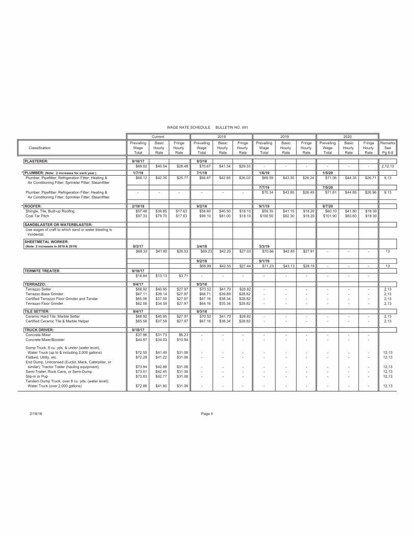


A. Two times the basic hourly rate, plus the hourly cost of required fringe.
Three times the basic hourly wage, plus the hourly cost of required fringe on Labor Day.

Federal Labor Standards Provisions U.S. Department of Housing and Urban Development Office of Labor Relations
Previous editions are obsolete
Page 1 of 5
form HUD-4010 (06/2009) ref. Handbook 1344.1
Applicabil ity
The Project or Program to which the construct ion work covered by this contract pertains is being assisted by the United States of America and the fol lowing Federal Labor Standards Provisions are included in this Contract pursuant to the provisions appl icable to such Federal assistance.
A. 1. (i ) Minimum Wages. All laborers and mechanics employed or working upon the site of the work, wi l l be paid uncondit ional ly and not less often than once a week, and without subsequent deduct ion or rebate on any account (except such payrol l deduct ions as are permit ted by regulat ions issued by the Secretary of Labor under the Copeland Act (29 CFR Part 3), the fu l l amount of wages and bona f ide fr inge benefi ts (or cash equivalents thereof) due at t ime of payment computed at rates not less than those contained in the wage determinat ion of the Secretary of Labor which is attached hereto and made a part hereof, regardless of any contractual relat ionship which may be al leged to exist between the contractor and such laborers and mechanics. Contribut ions made or costs reasonably ant ic ipated for bona f ide fr inge benef i ts under Sect ion l(b)(2) of the Davis-Bacon Act on behalf of laborers or mechanics are considered wages paid to such laborers or mechanics, subject to the provisions of 29 CFR 5.5(a)(1)(iv); also, regular contribut ions made or costs incurred for more than a weekly period (but not less often than quarterly) under plans, funds, or programs, which cover the part icular weekly period, are deemed to be construct ively made or incurred during such weekly period.
Such laborers and mechanics shal l be paid the appropriate wage rate and fr inge benefi ts on the wage determinat ion for the classif icat ion of work actual ly performed, without regard to ski l l , except as provided in 29 CFR 5.5(a)(4). Laborers or mechanics performing work in more than one classif icat ion may be compensated at the rate specif ied for each classif icat ion for the t ime actual ly worked therein: Provided, That the employer’s payrol l records accurately set forth the t ime spent in each classif icat ion in which work is performed. The wage determinat ion (including any addit ional c lassif icat ion and wage rates conformed under 29 CFR 5.5(a)(1)(i i ) and the Davis-Bacon poster (WH-1321) shal l be posted at al l t imes by the contractor and i ts subcontractors at the site of the work in a prominent and accessible, place where i t can be easi ly seen by the workers.
(i i ) (a) Any class of laborers or mechanics which is not l isted in the wage determinat ion and which is to be employed under the contract shal l be classif ied in conformance with the wage determinat ion. HUD shal l approve an addit ional c lassif icat ion and wage rate and fr inge benefi ts therefor only when the fol lowing cri ter ia have been met:
(1) The work to be performed by the classif icat ion requested is not performed by a classif icat ion in the wage determinat ion; and
(2) The classif icat ion is ut i l ized in the area by the construct ion industry; and
(3) The proposed wage rate, including any bona f ide fr inge benefi ts, bears a reasonable relat ionship to the wage rates contained in the wage determinat ion.
(b) I f the contractor and the laborers and mechanics to be employed in the classif icat ion (i f known), or their representat ives, and HUD or i ts designee agree on the classif icat ion and wage rate (including the amount designated for fr inge benefi ts where appropriate), a report of the act ion taken shal l be sent by HUD or i ts designee to the Administrator of the Wage and Hour Divis ion, Employment Standards Administrat ion, U.S. Department of Labor, Washington, D.C. 20210. The Administrator, or an authorized representat ive, wi l l approve, modify, or disapprove every addit ional c lassif icat ion act ion within 30 days of receipt and so advise HUD or i ts designee or wi l l not i fy HUD or i ts designee within the 30-day period that addit ional t ime is necessary. (Approved by the Off ice of Management and Budget under OMB control number 1215-0140.)
(c) In the event the contractor, the laborers or mechanics to be employed in the classif icat ion or their representat ives, and HUD or i ts designee do not agree on the proposed classif icat ion and wage rate (including the amount designated for f r inge benefi ts, where appropriate), HUD or i ts designee shal l refer the quest ions, including the views of al l interested part ies and the recommendation of HUD or i ts designee, to the Administrator for determinat ion. The Administrator, or an authorized representat ive, wi l l issue a determinat ion within 30 days of receipt and so advise HUD or i ts designee or wi l l not i fy HUD or i ts designee within the 30-day period that addit ional t ime is necessary. (Approved by the Off ice of Management and Budget under OMB Control Number 1215-0140.)
(d) The wage rate (including fr inge benefi ts where appropriate) determined pursuant to subparagraphs (1)(i i ) (b) or (c) of this paragraph, shal l be paid to al l workers performing work in the classif icat ion under th is contract from the f irst day on which work is performed in the classif icat ion.
(i i i ) Whenever the minimum wage rate prescribed in the contract for a class of laborers or mechanics includes a fr inge benefi t which is not expressed as an hourly rate, the contractor shal l ei ther pay the benefi t as stated in the wage determinat ion or shal l pay another bona f ide fr inge benefi t or an hourly cash equivalent thereof.
(iv) I f the contractor does not make payments to a trustee or other third person, the contractor may consider as part

Previous editions are obsolete Page 2 of 5
form HUD-4010 (06/2009) ref. Handbook 1344.1
of the wages of any laborer or mechanic the amount of any costs reasonably ant ic ipated in providing bona f ide fr inge benefi ts under a plan or program, Provided, That the Secretary of Labor has found, upon the writ ten request of the contractor, that the appl icable standards of the Davis-Bacon Act have been met. The Secretary of Labor may require the contractor to set aside in a separate account assets for the meeting of obl igat ions under the plan or program. (Approved by the Off ice of Management and Budget under OMB Control Number 1215-0140.)
2. Withholding. HUD or i ts designee shal l upon i ts own act ion or upon writ ten request of an authorized representat ive of the Department of Labor withhold or cause to be withheld from the contractor under this contract or any other Federal contract with the same prime contractor, or any other Federal ly-assisted contract subject to Davis-Bacon prevai l ing wage requirements, which is held by the same prime contractor so much of the accrued payments or advances as may be considered necessary to pay laborers and mechanics, including apprent ices, trainees and helpers, employed by the contractor or any subcontractor the ful l amount of wages required by the contract In the event of fai lure to pay any laborer or mechanic, including any apprent ice, trainee or helper, employed or working on the site of the work, al l or part of the wages required by the contract, HUD or i ts designee may, after wr i t ten not ice to the contractor, sponsor, appl icant, or owner, take such act ion as may be necessary to cause the suspension of any further payment, advance, or guarantee of funds unt i l such violat ions have ceased. HUD or i ts designee may, after wri t ten not ice to the contractor, disburse such amounts withheld for and on account of the contractor or subcontractor to the respect ive employees to whom they are due. The Comptrol ler General shal l make such disbursements in the case of direct Davis-Bacon Act contracts.
3. (i) Payrolls and basic records. Payrol ls and basic records relat ing thereto shal l be maintained by the contractor during the course of the work preserved for a period of three years thereafter for al l laborers and mechanics working at the si te of the work. Such records shal l contain the name, address, and social secur i ty number of each such worker, his or her correct c lassif icat ion, hourly rates of wages paid (including rates of contribut ions or costs ant ic ipated for bona f ide fr inge benefi ts or cash equivalents thereof of the types described in Sect ion l (b)(2)(B) of the Davis-bacon Act), dai ly and weekly number of hours worked, deduct ions made and actual wages paid. Whenever the Secretary of Labor has found under 29 CFR 5.5 (a)(1)(iv) that the wages of any laborer or mechanic include the amount of any costs reasonably ant ic ipated in providing benefi ts under a plan or program described in Sect ion l(b)(2)(B) of the Davis-Bacon Act, the contractor shal l maintain records which show that the commitment to provide such benefi ts is enforceable, that the plan or program is f inancial ly responsible, and that the plan or program has been
communicated in writ ing to the laborers or mechanics affected, and records which show the costs ant ic ipated or the actual cost incurred in providing such benefi ts. Contractors employing apprent ices or trainees under approved programs shal l maintain wr it ten evidence of the registrat ion of apprent iceship programs and cert i f icat ion of trainee programs, the registrat ion of the apprent ices and trainees, and the rat ios and wage rates prescribed in the appl icable programs. (Approved by the Off ice of Management and Budget under OMB Control Numbers 1215-0140 and 1215-0017.)
(i i ) (a) The contractor shal l submit weekly for each week in which any contract work is performed a copy of al l payrol ls to HUD or i ts designee i f the agency is a party to the contract, but i f the agency is not such a party, the contractor wi l l submit the payrol ls to the appl icant sponsor, or owner, as the case may be, for transmission to HUD or i ts designee. The payrol ls submitted shal l set out accurately and completely al l of the information required to be maintained under 29 CFR 5.5(a)(3)(i) except that ful l social securi ty numbers and home addresses shal l not be included on weekly transmittals. Instead the payrol ls shal l only need to include an individual ly ident i fying number for each employee (e.g., the last four digits of the employee’s social securi ty number). The required weekly payrol l information may be submitted in any form desired. Optional Form WH-347 is avai lable for th is purpose from the Wage and Hour Divis ion Web site at http:/ /www.dol.gov/esa/whd/forms/wh347instr.htm or i ts successor site. The prime contractor is responsible for the submission of copies of payrol ls by al l subcontractors. Contractors and subcontractors shal l maintain the ful l social securi ty number and current address of each covered worker, and shal l provide them upon request to HUD or i ts designee i f the agency is a party to the contract, but i f the agency is not such a party, the contractor wi l l submit the payrol ls to the appl icant sponsor, or owner, as the case may be, for transmission to HUD or i ts designee, the contractor, or the Wage and Hour Divis ion of the Department of Labor for purposes of an invest igat ion or audit of compliance with prevai l ing wage requirements. I t is not a violat ion of this subparagraph for a prime contractor to require a subcontractor to provide addresses and social securi ty numbers to the prime contractor for i ts own records, without weekly submission to HUD or i ts designee. (Approved by the Off ice of Management and Budget under OMB Control Number 1215-0149.)
(b) Each payrol l submitted shal l be accompanied by a “Statement of Compliance,” s igned by the contractor or subcontractor or his or her agent who pays or supervises the payment of the persons employed under the contract and shal l cert i fy the fol lowing:
(1) That the payrol l for the payrol l period contains the information required to be provided under 29 CFR 5.5 (a)(3)(i i ), the appropriate information is being maintained under 29 CFR 5.5(a)(3)(i), and that such information is correct and complete;

Previous editions are obsolete Page 3 of 5
form HUD-4010 (06/2009) ref. Handbook 1344.1
(2) That each laborer or mechanic (including each helper, apprent ice, and trainee) employed on the contract during the payrol l period has been paid the ful l weekly wages earned, without rebate, either di rect ly or indi rect ly, and that no deduct ions have been made either di rect ly or indirect ly from the ful l wages earned, other than permissible deduct ions as set forth in 29 CFR Part 3;
(3) That each laborer or mechanic has been paid not less than the appl icable wage rates and fr inge benefi ts or cash equivalents for the classif icat ion of work performed, as specif ied in the appl icable wage determinat ion incorporated into the contract.
(c) The weekly submission of a properly executed cert i f icat ion set forth on the reverse side of Optional Form WH-347 shal l sat isfy the requirement for submission of the “Statement of Compliance” required by subparagraph A.3.(i i )(b).
(d) The fals i f icat ion of any of the above cert i f icat ions may subject the contractor or subcontractor to civi l or c riminal prosecut ion under Sect ion 1001 of Tit le 18 and Sect ion 231 of Tit le 31 of the United States Code.
(i i i ) The contractor or subcontractor shal l make the records required under subparagraph A.3.(i) avai lable for inspect ion, copying, or transcript ion by authorized representat ives of HUD or i ts designee or the Department of Labor, and shal l permit such representat ives to interview employees during working hours on the job. I f the contractor or subcontractor fai ls to submit the required records or to make them avai lable, HUD or i ts designee may, after wri t ten not ice to the contractor, sponsor, appl icant or owner, take such act ion as may be necessary to cause the suspension of any further payment, advance, or guarantee of funds. Furthermore, fai lure to submit the required records upon request or to make such records avai lable may be grounds for debarment act ion pursuant to 29 CFR 5.12.
4. Apprentices and Trainees.
(i ) Apprentices. Apprent ices wil l be permit ted to work at less than the predetermined rate for the work they performed when they are employed pursuant to and individual ly registered in a bona f ide apprent iceship program registered with the U.S. Department of Labor, Employment and Training Administrat ion, Off ice of Apprent iceship Training, Employer and Labor Services, or with a State Apprent iceship Agency recognized by the Off ice, or i f a person is employed in his or her f i rst 90 days of probat ionary employment as an apprent ice in such an apprent iceship program, who is not individual ly registered in the program, but who has been cert i f ied by the Off ice of Apprent iceship Training, Employer and Labor Services or a State Apprent iceship Agency (where appropriate) to be el igible for probat ionary employment as an apprent ice. The al lowable rat io of apprent ices to journeymen on the job site in any craft c lassif icat ion shal l not be greater than the rat io permit ted to the contractor as to the ent ire work force under the registered program. Any worker l isted on a payrol l at an apprent ice wage rate, who
is not registered or otherwise employed as stated above, shal l be paid not less than the appl icable wage rate on the wage determinat ion for the classif icat ion of work actual ly performed. In addit ion, any apprent ice performing work on the job site in excess of the rat io permit ted under the registered program shal l be paid not less than the appl icable wage rate on the wage determinat ion for the work actual ly performed. Where a contractor is performing construct ion on a project in a local i ty other than that in which i ts program is registered, the rat ios and wage rates (expressed in percentages of the journeyman’s hourly rate) specif ied in the contractor’s or subcontractor’s registered program shal l be observed. Every apprent ice must be paid at not less than the rate specif ied in the registered program for the apprent ice’s level of progress, expressed as a percentage of the journeymen hourly rate specif ied in the appl icable wage determinat ion. Apprent ices shal l be paid fr inge benefi ts in accordance with the provisions of the apprent iceship program. I f the apprent iceship program does not specify fr inge benefi ts, apprent ices must be paid the ful l amount of f r inge benefi ts l isted on the wage determinat ion for the appl icable classif icat ion. I f the Administrator determines that a dif ferent pract ice prevai ls for the appl icable apprent ice classif icat ion, fr inges shal l be paid in accordance with that determinat ion. In the event the Off ice of Apprent iceship Training, Employer and Labor Services, or a State Apprent iceship Agency recognized by the Off ice, withdraws approval of an apprent iceship program, the contractor wi l l no longer be permit ted to ut i l ize apprent ices at less than the appl icable predetermined rate for the work performed unt i l an acceptable program is approved.
(i i ) Trainees. Except as provided in 29 CFR 5.16, trainees wil l not be permitted to work at less than the predetermined rate for the work performed unless they are employed pursuant ‘ , to and individual ly registered in a program which has received prior approval, evidenced by formal cert i f icat ion by the U.S. Department of Labor, Employment and Training Administrat ion. The rat io of t rainees to journeymen on the job site shal l not be greater than permit ted under the plan approved by the Employment and Training Administrat ion. Every trainee must be paid at not less than the rate specif ied in the approved program for the trainee’s level of progress, expressed as a percentage of the journeyman hourly rate specif ied in the appl icable wage determinat ion. Trainees shal l be paid fr inge benefi ts in accordance with the provisions of the trainee program. I f the trainee program does not mention fr inge benefi ts, t rainees shal l be paid the ful l amount of f r inge benefi ts l isted on the wage determinat ion unless the Administrator of the Wage and Hour Divis ion determines that there is an apprent iceship program associated with the corresponding journeyman wage rate on the wage determinat ion which provides for less than ful l f r inge benefi ts for apprent ices. Any employee l isted on the payrol l at a trainee rate who is not registered and part ic ipat ing in a training plan approved by

Previous editions are obsolete Page 4 of 5
form HUD-4010 (06/2009) ref. Handbook 1344.1
the Employment and Training Administrat ion shal l be paid not less than the appl icable wage rate on the wage determinat ion for the work actual ly performed. In addit ion, any trainee performing work on the job site in excess of the rat io permit ted under the registered program shal l be paid not less than the appl icable wage rate on the wage determinat ion for the work actual ly performed. In the event the Employment and Training Administrat ion withdraws approval of a tra ining program, the contractor wi l l no longer be permit ted to ut i l ize trainees at less than the appl icable predetermined rate for the work performed unt i l an acceptable program is approved.
(i i i ) Equal employment opportunity. The ut i l izat ion of apprent ices, trainees and journeymen under 29 CFR Part 5 shal l be in conformity with the equal employment opportunity requirements of Execut ive Order 11246, as amended, and 29 CFR Part 30.
5. Compliance with Copeland Act requirements. The contractor shal l comply with the requirements of 29 CFR Part 3 which are incorporated by reference in this contract
6. Subcontracts. The contractor or subcontractor wi l l insert in any subcontracts the clauses contained in subparagraphs 1 through 11 in th is paragraph A and such other clauses as HUD or i ts designee may by appropr iate instruct ions require, and a copy of the appl icable prevai l ing wage decision, and also a clause requiring the subcontractors to include these clauses in any lower t ier subcontracts. The prime contractor shal l be responsible for the compliance by any subcontractor or lower t ier subcontractor with al l the contract c lauses in this paragraph.
7. Contract termination; debarment. A breach of the contract c lauses in 29 CFR 5.5 may be grounds for terminat ion of the contract and for debarment as a contractor and a subcontractor as provided in 29 CFR 5.12.
8. Compliance with Davis-Bacon and Related Act Requirements.
All rul ings and interpretat ions of the Davis-Bacon and Related Acts contained in 29 CFR Parts 1, 3, and 5 are herein incorporated by reference in this contract
9. Disputes concerning labor standards. Disputes aris ing out of the labor standards provisions of this contract shal l not be subject to the general disputes clause of this contract. Such disputes shal l be resolved in accordance with the procedures of the Department of Labor set forth in 29 CFR Parts 5, 6, and 7. Disputes within the meaning of this c lause include disputes between the contractor (or any of i ts subcontractors) and HUD or i ts designee, the U.S. Department of Labor, or the employees or their representat ives.
10. (i) Certification of Eligibil ity. By entering into th is contract the contractor cert i f ies that neither i t (nor he or she) nor any person or f i rm who has an interest in the contractor’s f i rm is a person or f i rm inel igible to be awarded Government contracts by virtue of Sect ion 3(a) of the Davis-Bacon Act or 29 CFR 5.12(a)(1) or to be
awarded HUD contracts or part ic ipate in HUD programs pursuant to 24 CFR Part 24.
(i i ) No part of this contract shal l be subcontracted to any person or f i rm inel igible for award of a Government contract by virtue of Sect ion 3(a) of the Davis-Bacon Act or 29 CFR 5.12(a)(1) or to be awarded HUD contracts or part ic ipate in HUD programs pursuant to 24 CFR Part 24.
(i i i ) The penalty for making false statements is prescribed in the U.S. Criminal Code, 18 U.S.C. 1001. Addit ional ly, U.S. Criminal Code, Sect ion 1 01 0, Tit le 18, U.S.C., “Federal Housing Administrat ion transact ions”, provides in part : “Whoever, for the purpose of . . . inf luencing in any way the act ion of such Administrat ion.. . . . makes, utters or publ ishes any statement knowing the same to be false. . . . . shal l be f ined not more than $5,000 or imprisoned not more than two years, or both.”
11. Complaints, Proceedings, or Testimony by
Employees. No laborer or mechanic to whom the wage, salary, or other labor standards provisions of this Contract are appl icable shal l be discharged or in any other manner discriminated against by the Contractor or any subcontractor because such employee has f i led any complaint or inst i tuted or caused to be inst i tuted any proceeding or has test i f ied or is about to test i fy in any proceeding under or relat ing to the labor standards appl icable under this Contract to his employer.
B. Contract Work Hours and Safety Standards Act. The provisions of this paragraph B are applicable where the amount of the prime contract exceeds $100,000. As used in this paragraph, the terms “laborers” and “mechanics” include watchmen and guards.
(1) Overtime requirements. No contractor or subcontractor contracting for any part of the contract work which may require or involve the employment of laborers or mechanics shall require or permit any such laborer or mechanic in any workweek in which the individual is employed on such work to work in excess of 40 hours in such workweek unless such laborer or mechanic receives compensation at a rate not less than one and one-half times the basic rate of pay for all hours worked in excess of 40 hours in such workweek.
(2) Violation; l iabil ity for unpaid wages; l iquidated
damages. In the event of any violat ion of the clause set forth in subparagraph (1) of this paragraph, the contractor and any subcontractor responsible therefor shal l be l iable for the unpaid wages. In addit ion, such contractor and subcontractor shal l be l iable to the United States (in the case of work done under contract for the District of Columbia or a terri tory, to such District or to such terri tory), for l iquidated damages. Such l iquidated damages shal l be computed with respect to each individual laborer or mechanic, including watchmen and guards, employed in violat ion of the clause set forth in subparagraph (1) of this paragraph, in the sum of $10 for each calendar day on which such individual was required or permitted to work in excess of the standard workweek of 40 hours without payment of the overtime wages required by the clause set forth in sub paragraph (1) of this paragraph.

Previous editions are obsolete Page 5 of 5
form HUD-4010 (06/2009) ref. Handbook 1344.1
(3) Withholding for unpaid wages and l iquidated
damages. HUD or i ts designee shal l upon i ts own act ion or upon writ ten request of an authorized representat ive of the Department of Labor withhold or cause to be withheld, from any moneys payable on account of work performed by the contractor or subcontractor under any such contract or any other Federal contract with the same prime contract, or any other Federal ly-assisted contract subject to the Contract Work Hours and Safety Standards Act which is held by the same prime contractor such sums as may be determined to be necessary to sat isfy any l iabi l i t ies of such contractor or subcontractor for unpaid wages and l iquidated damages as provided in the clause set forth in subparagraph (2) of this paragraph.
(4) Subcontracts. The contractor or subcontractor shal l insert in any subcontracts the clauses set forth in subparagraph (1) through (4) of this paragraph and also a clause requiring the subcontractors to include these clauses in any lower t ier subcontracts. The prime contractor shal l be responsible for compliance by any subcontractor or lower t ier subcontractor with the clauses set forth in subparagraphs (1) through (4) of this paragraph.
C. Health and Safety. The provisions of this paragraph C are applicable where the amount of the prime contract exceeds $100,000.
(1) No laborer or mechanic shal l be required to work in surroundings or under working condit ions which are unsanitary, hazardous, or dangerous to his health and safety as determined under construct ion safety and heal th standards promulgated by the Secretary of Labor by regulat ion.
(2) The Contractor shal l comply with al l regulat ions issued by the Secretary of Labor pursuant to Tit le 29 Part 1926 and fa i lure to comply may result in imposit ion of sanct ions pursuant to the Contract Work Hours and Safety Standards Act, (Publ ic Law 91-54, 83 Stat 96). 40 USC 3701 et seq.
(3) The contractor shal l include the provisions of this paragraph in every subcontract so that such provisions wi l l be binding on each subcontractor. The contractor shal l take such act ion with respect to any subcontractor as the Secretary of Housing and Urban Development or the Secretary of Labor shal l di rect as a means of enforcing such provisions.
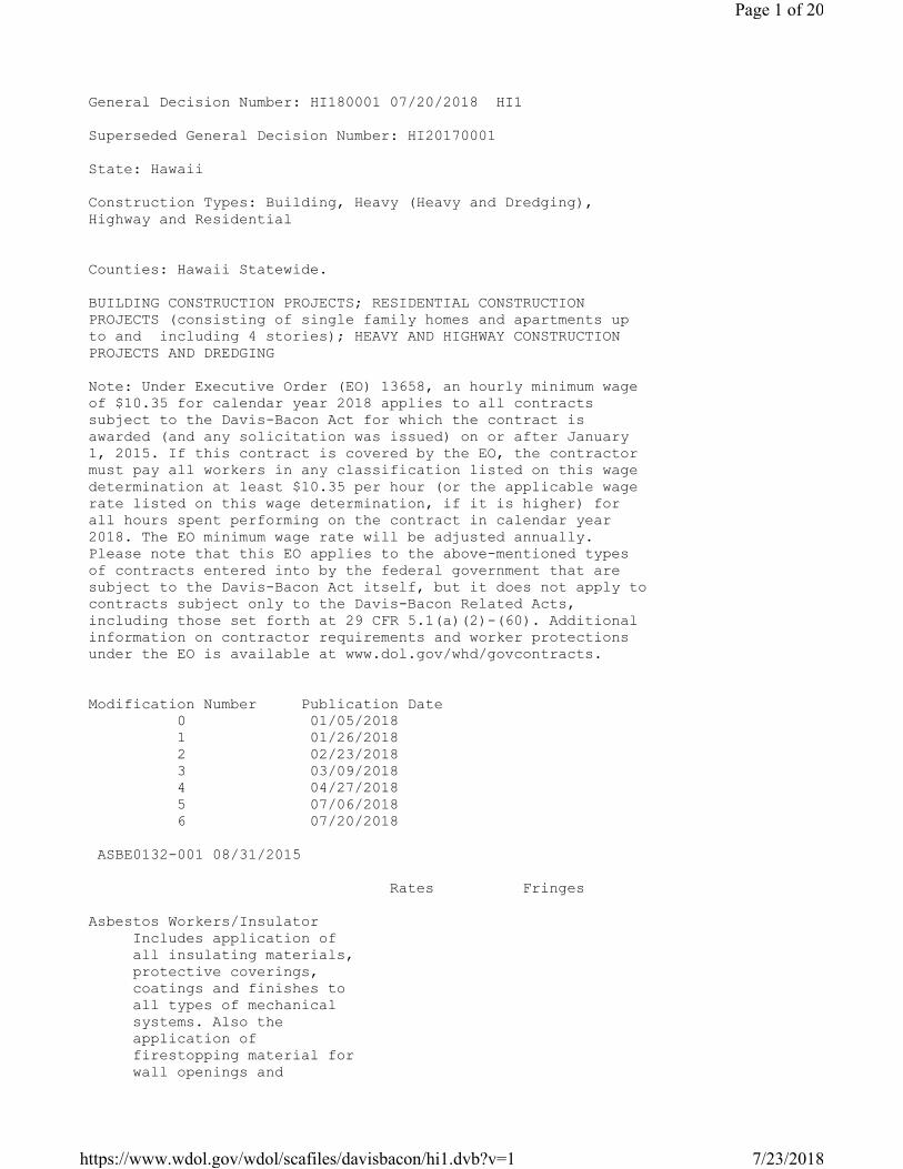
General Decision Number: HI180001 07/20/2018 HI1
Superseded General Decision Number: HI20170001
State: Hawaii
Construction Types: Building, Heavy (Heavy and Dredging),
Highway and Residential
Counties: Hawaii Statewide.
BUILDING CONSTRUCTION PROJECTS; RESIDENTIAL CONSTRUCTION
PROJECTS (consisting of single family homes and apartments up
to and including 4 stories); HEAVY AND HIGHWAY CONSTRUCTION
PROJECTS AND DREDGING
Note: Under Executive Order (EO) 13658, an hourly minimum wage
of $10.35 for calendar year 2018 applies to all contracts
subject to the Davis-Bacon Act for which the contract is
awarded (and any solicitation was issued) on or after January
1, 2015. If this contract is covered by the EO, the contractor
must pay all workers in any classification listed on this wage
determination at least $10.35 per hour (or the applicable wage
rate listed on this wage determination, if it is higher) for
all hours spent performing on the contract in calendar year
2018. The EO minimum wage rate will be adjusted annually.
Please note that this EO applies to the above-mentioned types
of contracts entered into by the federal government that are
subject to the Davis-Bacon Act itself, but it does not apply to
contracts subject only to the Davis-Bacon Related Acts,
including those set forth at 29 CFR 5.1(a)(2)-(60). Additional
information on contractor requirements and worker protections
under the EO is available at www.dol.gov/whd/govcontracts.
Modification Number Publication Date
0 01/05/2018
1 01/26/2018
2 02/23/2018
3 03/09/2018
4 04/27/2018
5 07/06/2018
6 07/20/2018
ASBE0132-001 08/31/2015
Rates Fringes
Asbestos Workers/Insulator
Includes application of
all insulating materials,
protective coverings,
coatings and finishes to
all types of mechanical
systems. Also the
application of
firestopping material for
wall openings and
Page 1 of 20
7/23/2018https://www.wdol.gov/wdol/scafiles/davisbacon/hi1.dvb?v=1

penetrations in walls,
floors, ceilings and
curtain walls...............$ 39.65 23.50
----------------------------------------------------------------
BOIL0627-005 01/01/2013
Rates Fringes
BOILERMAKER......................$ 35.20 27.35
----------------------------------------------------------------
BRHI0001-001 09/04/2017
Rates Fringes
BRICKLAYER
Bricklayers and Stonemasons.$ 44.55 23.22
Pointers, Caulkers and
Weatherproofers.............$ 45.01 23.22
----------------------------------------------------------------
BRHI0001-002 09/04/2017
Rates Fringes
Tile, Marble & Terrazzo Worker
Terrazzo Base Grinders......$ 44.54 22.72
Terrazzo Floor Grinders
and Tenders.................$ 42.99 22.72
Tile, Marble and Terrazzo
Workers.....................$ 46.35 22.72
----------------------------------------------------------------
CARP0745-001 09/04/2017
Rates Fringes
Carpenters:
Carpenters; Hardwood Floor
Layers; Patent Scaffold
Erectors (14 ft. and
over); Piledrivers;
Pneumatic Nailers; Wood
Shinglers and Transit
and/or Layout Man...........$ 47.45 21.66
Millwrights and Machine
Erectors....................$ 47.70 21.66
Power Saw Operators (2
h.p. and over)..............$ 47.60 21.66
----------------------------------------------------------------
CARP0745-002 09/04/2017
Rates Fringes
Drywall and Acoustical
Workers and Lathers..............$ 47.70 21.66
----------------------------------------------------------------
ELEC1186-001 02/18/2018
Rates Fringes
Electricians:
Cable Splicers..............$ 53.68 28.79
Page 2 of 20
7/23/2018https://www.wdol.gov/wdol/scafiles/davisbacon/hi1.dvb?v=1

Electricians................$ 48.80 28.64
Telecommunication worker....$ 28.44 11.94
----------------------------------------------------------------
ELEC1186-002 02/18/2018
Rates Fringes
Line Construction:
Cable Splicers..............$ 53.68 28.79
Groundmen/Truck Drivers.....$ 36.60 28.28
Heavy Equipment Operators...$ 43.92 28.50
Linemen.....................$ 48.80 28.64
Telecommunication worker....$ 28.44 11.94
----------------------------------------------------------------
ELEV0126-001 01/01/2018
Rates Fringes
ELEVATOR MECHANIC................$ 57.36 32.65
a. VACATION: Employer contributes 8% of basic hourly rate for
5 years service and 6% of basic hourly rate for 6 months to
5 years service as vacation pay credit.
b. PAID HOLIDAYS: New Year's Day, Memorial Day, Independence
Day, Labor Day, Veterans' Day, Thanksgiving Day, the Friday
after Thanksgiving Day and Christmas Day.
----------------------------------------------------------------
ENGI0003-002 09/04/2017
Rates Fringes
Diver (Aqua Lung) (Scuba))
Diver (Aqua Lung) (Scuba)
(over a depth of 30 feet)...$ 65.00 30.93
Diver (Aqua Lung) (Scuba)
(up to a depth of 30 feet)..$ 55.63 30.93
Stand-by Diver (Aqua Lung)
(Scuba)....................$ 46.25 30.93
Diver (Other than Aqua Lung)
Diver (Other than Aqua
Lung).......................$ 65.00 30.93
Diver Tender (Other than
Aqua Lung)..................$ 43.22 30.93
Stand-by Diver (Other than
Aqua Lung)..................$ 46.25 30.93
Helicopter Work
Airborne Hoist Operator
for Helicopter..............$ 44.80 30.93
Co-Pilot of Helicopter......$ 44.94 30.93
Pilot of Helicopter.........$ 45.11 30.93
Power equipment operator -
tunnel work
GROUP 1....................$ 41.24 30.93
GROUP 2....................$ 41.35 30.93
GROUP 3....................$ 41.52 30.93
GROUP 4....................$ 41.79 30.93
GROUP 5....................$ 42.10 30.93
GROUP 6....................$ 42.75 30.93
Page 3 of 20
7/23/2018https://www.wdol.gov/wdol/scafiles/davisbacon/hi1.dvb?v=1

GROUP 7....................$ 43.07 30.93
GROUP 8....................$ 43.18 30.93
GROUP 9....................$ 43.29 30.93
GROUP 9A...................$ 43.52 30.93
GROUP 10....................$ 43.58 30.93
GROUP 10A...................$ 43.73 30.93
GROUP 11....................$ 43.88 30.93
GROUP 12....................$ 44.24 30.93
GROUP 12A...................$ 44.60 30.93
Power equipment operators:
GROUP 1....................$ 40.94 30.93
GROUP 2....................$ 41.05 30.93
GROUP 3....................$ 41.22 30.93
GROUP 4....................$ 41.49 30.93
GROUP 5....................$ 41.80 30.93
GROUP 6....................$ 42.45 30.93
GROUP 7....................$ 42.77 30.93
GROUP 8....................$ 42.88 30.93
GROUP 9....................$ 42.99 30.93
GROUP 9A...................$ 43.22 30.93
GROUP 10....................$ 43.28 30.93
GROUP 10A...................$ 43.43 30.93
GROUP 11....................$ 43.58 30.93
GROUP 12....................$ 43.94 30.93
GROUP 12A...................$ 44.30 30.93
GROUP 13....................$ 41.22 30.93
GROUP 13A...................$ 41.49 30.93
GROUP 13B...................$ 41.80 30.93
GROUP 13C...................$ 42.45 30.93
GROUP 13D...................$ 42.77 30.93
GROUP 13E...................$ 42.88 30.93
POWER EQUIPMENT OPERATORS CLASSIFICATIONS
GROUP 1: Fork Lift (up to and including 10 tons); Partsman
(heavy duty repair shop parts room when needed).
GROUP 2: Conveyor Operator (Handling building material);
Hydraulic Monitor; Mixer Box Operator (Concrete Plant).
GROUP 3: Brakeman; Deckhand; Fireman; Oiler;
Oiler/Gradechecker; Signalman; Switchman; Highline Cableway
Signalman; Bargeman; Bunkerman; Concrete Curing Machine
(self-propelled, automatically applied unit on streets,
highways, airports and canals); Leveeman; Roller (5 tons
and under); Tugger Hoist.
GROUP 4: Boom Truck or dual purpose "A" Frame Truck (5 tons
or less); Concrete Placing Boom (Building Construction);
Dinky Operator; Elevator Operator; Hoist and/or Winch (one
drum); Straddle Truck (Ross Carrier, Hyster and similar).
GROUP 5: Asphalt Plant Fireman; Compressors, Pumps,
Generators and Welding Machines ("Bank" of 9 or more,
individually or collectively); Concrete Pumps or Pumpcrete
Guns; Lubrication and Service Engineer (Grease Rack);
Screedman.
GROUP 6: Boom Truck or Dual Purpose "A"Frame Truck (over 5
tons); Combination Loader/Backhoe (up to and including 3/4
Page 4 of 20
7/23/2018https://www.wdol.gov/wdol/scafiles/davisbacon/hi1.dvb?v=1

cu. yd.); Concrete Batch Plants (wet or dry); Concrete
Cutter, Groover and/or Grinder (self-propelled unit on
streets, highways, airports, and canals); Conveyor or
Concrete Pump (Truck or Equipment Mounted); Drilling
Machinery (not to apply to waterliners, wagon drills or
jack hammers); Fork Lift (over 10 tons); Loader (up to and
including 3 and 1/2 cu. yds); Lull High Lift (under 40
feet); Lubrication and Service Engineer (Mobile); Maginnis
Internal Full Slab Vibrator (on airports, highways, canals
and warehouses); Man or Material Hoist; Mechanical Concrete
Finisher (Large Clary, Johnson Bidwell, Bridge Deck and
similar); Mobile Truck Crane Driver; Portable Shotblast
Concrete Cleaning Machine; Portable Boring Machine (under
streets, highways, etc.); Portable Crusher; Power Jumbo
Operator (setting slip forms, etc., in tunnels); Rollers
(over 5 tons); Self-propelled Compactor (single engine);
Self-propelled Pavement Breaker; Skidsteer Loader with
attachments; Slip Form Pumps (Power driven by hydraulic,
electric, air, gas, etc., lifting device for concrete
forms); Small Rubber Tired Tractors; Trencher (up to and
including 6 feet); Underbridge Personnel Aerial Platform
(50 feet of platform or less).
GROUP 7: Crusher Plant Engineer, Dozer (D-4, Case 450, John
Deere 450, and similar); Dual Drum Mixer, Extend Lift;
Hoist and/or Winch (2 drums); Loader (over 3 and 1/2 cu.
yds. up to and including 6 yards.); Mechanical Finisher or
Spreader Machine (asphalt), (Barber Greene and similar)
(Screedman required); Mine or Shaft Hoist; Mobile Concrete
Mixer (over 5 tons); Pipe Bending Machine (pipelines only);
Pipe Cleaning Machine (tractor propelled and supported);
Pipe Wrapping Machine (tractor propelled and supported);
Roller Operator (Asphalt); Self-Propelled Elevating Grade
Plane; Slusher Operator; Tractor (with boom) (D-6, or
similar); Trencher (over 6 feet and less than 200 h.p.);
Water Tanker (pulled by Euclids, T-Pulls, DW-10, 20 or 21,
or similar); Winchman (Stern Winch on Dredge).
GROUP 8: Asphalt Plant Operator; Barge Mate (Seagoing);
Cast-in-Place Pipe Laying Machine; Concrete Batch Plant
(multiple units); Conveyor Operator (tunnel); Deckmate;
Dozer (D-6 and similar); Finishing Machine Operator
(airports and highways); Gradesetter; Kolman Loader (and
similar); Mucking Machine (Crawler-type); Mucking Machine
(Conveyor-type); No-Joint Pipe Laying Machine; Portable
Crushing and Screening Plant; Power Blade Operator (under
12); Saurman Type Dragline (up to and including 5 yds.);
Stationary Pipe Wrapping, Cleaning and Bending Machine;
Surface Heater and Planer Operator, Tractor (D-6 and
similar); Tri-Batch Paver; Tunnel Badger; Tunnel Mole
and/or Boring Machine Operator Underbridge Personnel Aerial
Platform (over 50 feet of platform).
GROUP 9: Combination Mixer and Compressor (gunite); Do-Mor
Loaderand Adams Elegrader; Dozer (D-7 or equal); Wheel
and/or Ladder Trencher (over 6 feet and 200 to 749 h.p.).
GROUP 9A: Dozer (D-8 and similar); Gradesetter (when required
by the Contractor to work from drawings, plans or
specifications without the direct supervision of a foreman
Page 5 of 20
7/23/2018https://www.wdol.gov/wdol/scafiles/davisbacon/hi1.dvb?v=1

or superintendent); Push Cat; Scrapers (up to and including
20 cu. yds); Self-propelled Compactor with Dozer;
Self-Propelled, Rubber-Tired Earthmoving Equipment (up to
and including 20 cu. yds) (621 Band and similar); Sheep's
Foot; Tractor (D-8 and similar); Tractors with boom (larger
than D-6, and similar).
GROUP 10: Chicago Boom; Cold Planers; Heavy Duty Repairman or
Welder; Hoist and/or Winch (3 drums); Hydraulic Skooper
(Koehring and similar); Loader (over 6 cu. yds. up to and
including 12 cu. yds.); Saurman type Dragline (over 5 cu.
yds.); Self-propelled, rubber-tired Earthmoving Equipment
(over 20 cu. yds. up to and including 31 cu. yds.) (637D
and similar); Soil Stabilizer (P & H or equal); Sub-Grader
(Gurries or other automatic type); Tractors (D-9 or
equivalent, all attachments); Tractor (Tandem Scraper);
Watch Engineer.
GROUP 10A: Boat Operator; Cable-operated Crawler Crane (up to
and including 25 tons); Cable-operated Power Shovel,
Clamshell, Dragline and Backhoe (up to and including 1 cu.
yd.); Dozer D9-L; Dozer (D-10, HD41 and similar) (all
attachments); Gradall (up to and including 1 cu. yd.);
Hydraulic Backhoe (over 3/4 cu. yds. up to and including 2
cu. yds.); Mobile Truck Crane Operator (up to and including
25 tons) (Mobile Truck Crane Driver Required);
Self-propelled Boom Type Lifting Device (Center Mount) (up
to and including 25 tons) (Grove, Drott, P&H, Pettibone and
similar; Trencher (over 6 feet and 750 h.p. or more); Watch
Engineer (steam or electric).
GROUP 11: Automatic Slip Form Paver (concrete or asphalt);
Band Wagon (in conjunction with Wheel Excavator);
Cable-operated Crawler Cranes (over 25 tons but less than
50 tons); Cable-operated Power Shovel, Clamshell, Dragline
and Backhoe (over 1 cu. yd. up to 7 cu. yds.); Gradall
(over 1 cu. yds. up to 7 cu. yds.); DW-10, 20, etc.
(Tandem); Earthmoving Machines (multiple propulsion power
units and 2 or more Scrapers) (up to and including 35 cu.
yds.," struck" m.r.c.); Highline Cableway; Hydraulic
Backhoe (over 2 cu. yds. up to and including 4 cu. yds.);
Leverman; Lift Slab Machine; Loader (over 12 cu. yds);
Master Boat Operator; Mobile Truck Crane Operator (over 25
tons but less than 50 tons); (Mobile Truck Crane Driver
required); Pre-stress Wire Wrapping Machine; Self-propelled
Boom-type Lifting Device (Center Mount) (over 25 tons
m.r.c); Self-propelled Compactor (with multiple-propulsion
power units); Single Engine Rubber Tired Earthmoving
Machine (with Tandem Scraper); Tandem Cats; Trencher
(pulling attached shield).
GROUP 12: Clamshell or Dipper Operator; Derricks; Drill Rigs;
Multi-Propulsion Earthmoving Machines (2 or more Scrapers)
(over 35 cu. yds "struck"m.r.c.); Operators (Derricks,
Piledrivers and Cranes); Power Shovels and Draglines (7 cu.
yds. m.r.c. and over); Self-propelled rubber-tired
Earthmoving equipment (over 31 cu. yds.) (657B and
similar); Wheel Excavator (up to and including 750 cu. yds.
per hour); Wheel Excavator (over 750 cu. yds. per hour).
Page 6 of 20
7/23/2018https://www.wdol.gov/wdol/scafiles/davisbacon/hi1.dvb?v=1

GROUP 12A: Dozer (D-11 or similar or larger); Hydraulic
Excavators (over 4 cu. yds.); Lifting cranes (50 tons and
over); Pioneering Dozer/Backhoe (initial clearing and
excavation for the purpose of providing access for other
equipment where the terrain worked involves 1-to-1 slopes
that are 50 feet in height or depth, the scope of this work
does not include normal clearing and grubbing on usual
hilly terrain nor the excavation work once the access is
provided); Power Blade Operator (Cat 12 or equivalent or
over); Straddle Lifts (over 50 tons); Tower Crane, Mobile;
Traveling Truss Cranes; Universal, Liebher, Linden, and
similar types of Tower Cranes (in the erection,
dismantling, and moving of equipment there shall be an
additional Operating Engineer or Heavy Duty Repairman);
Yo-Yo Cat or Dozer.
GROUP 13: Truck Driver (Utility, Flatbed, etc.)
GROUP 13A: Dump Truck, 8 cu.yds. and under (water level);
Water Truck (up to and including 2,000 gallons).
GROUP 13B: Water Truck (over 2,000 gallons); Tandem Dump
Truck, over 8 cu. yds. (water level).
GROUP 13C: Truck Driver (Semi-trailer. Rock Cans, Semi-Dump
or Roll-Offs).
GROUP 13D: Truck Driver (Slip-In or Pup).
GROUP 13E: End Dumps, Unlicensed (Euclid, Mack, Caterpillar
or similar); Tractor Trailer (Hauling Equipment); Tandem
Trucks hooked up to Trailer (Hauling Equipment)
BOOMS AND/OR LEADS (HOURLY PREMIUMS):
The Operator of a crane (under 50 tons) with a boom of 80
feet or more (including jib), or of a crane (under 50 tons)
with leads of 100 feet or more, shall receive a per hour
premium for each hour worked on said crane (under 50 tons)
in accordance with the following schedule:
Booms of 80 feet up to but
not including 130 feet or
Leads of 100 feet up to but
not including 130 feet 0.50
Booms and/or Leads of 130 feet
up to but not including 180 feet 0.75
Booms and/or Leads of 180 feet up
to and including 250 feet 1.15
Booms and/or Leads over 250 feet 1.50
The Operator of a crane (50 tons and over) with a boom of 180
feet or more (including jib) shall receive a per hour
premium for each hour worked on said crane (50 tons and
over) in accordance with the following schedule:
Booms of 180 feet up to
and including 250 feet 1.25
Booms over 250 feet 1.75
Page 7 of 20
7/23/2018https://www.wdol.gov/wdol/scafiles/davisbacon/hi1.dvb?v=1

----------------------------------------------------------------
ENGI0003-004 09/04/2017
Rates Fringes
Dredging: (Boat Operators)
Boat Deckhand...............$ 41.22 30.93
Boat Operator...............$ 43.43 30.93
Master Boat Operator........$ 43.58 30.93
Dredging: (Clamshell or
Dipper Dredging)
GROUP 1.....................$ 43.94 30.93
GROUP 2.....................$ 43.28 30.93
GROUP 3.....................$ 42.88 30.93
GROUP 4.....................$ 41.22 30.93
Dredging: (Derricks)
GROUP 1.....................$ 43.94 30.93
GROUP 2.....................$ 43.28 30.93
GROUP 3.....................$ 42.88 30.93
GROUP 4.....................$ 41.22 30.93
Dredging: (Hydraulic Suction
Dredges)
GROUP 1.....................$ 43.58 30.93
GROUP 2.....................$ 43.43 30.93
GROUP 3.....................$ 43.28 30.93
GROUP 4.....................$ 43.22 30.93
GROUP 5.....................$ 37.88 26.76
Group 5.....................$ 42.88 30.93
GROUP 6.....................$ 37.77 26.76
Group 6.....................$ 42.77 30.93
GROUP 7.....................$ 36.22 26.76
Group 7.....................$ 41.22 30.93
CLAMSHELL OR DIPPER DREDGING CLASSIFICATIONS
GROUP 1: Clamshell or Dipper Operator.
GROUP 2: Mechanic or Welder; Watch Engineer.
GROUP 3: Barge Mate; Deckmate.
GROUP 4: Bargeman; Deckhand; Fireman; Oiler.
HYDRAULIC SUCTION DREDGING CLASSIFICATIONS
GROUP 1: Leverman.
GROUP 2: Watch Engineer (steam or electric).
GROUP 3: Mechanic or Welder.
GROUP 4: Dozer Operator.
GROUP 5: Deckmate.
GROUP 6: Winchman (Stern Winch on Dredge)
GROUP 7: Deckhand (can operate anchor scow under direction of
Deckmate); Fireman; Leveeman; Oiler.
DERRICK CLASSIFICATIONS
GROUP 1: Operators (Derricks, Piledrivers and Cranes).
GROUP 2: Saurman Type Dragline (over 5 cubic yards).
GROUP 3: Deckmate; Saurman Type Dragline (up to and
including 5 yards).
GROUP 4: Deckhand, Fireman, Oiler.
Page 8 of 20
7/23/2018https://www.wdol.gov/wdol/scafiles/davisbacon/hi1.dvb?v=1

----------------------------------------------------------------
ENGI0003-044 09/04/2017
Rates Fringes
Power Equipment Operators
(PAVING)
Asphalt Concrete Material
Transfer....................$ 41.92 30.53
Asphalt Plant Operator......$ 42.35 30.53
Asphalt Raker...............$ 40.96 30.53
Asphalt Spreader Operator...$ 42.44 30.53
Cold Planer.................$ 42.75 30.53
Combination Loader/Backhoe
(over 3/4 cu.yd.)...........$ 40.96 30.53
Combination Loader/Backhoe
(up to 3/4 cu.yd.)..........$ 39.98 30.53
Concrete Saws and/or
Grinder (self-propelled
unit on streets, highways,
airports and canals)........$ 41.92 30.53
Grader......................$ 42.75 30.53
Laborer, Hand Roller........$ 40.46 30.53
Loader (2 1/2 cu. yds. and
under)......................$ 41.92 30.53
Loader (over 2 1/2 cu.
yds. to and including 5
cu. yds.)...................$ 42.24 30.53
Roller Operator (five tons
and under)..................$ 40.69 30.53
Roller Operator (over five
tons).......................$ 42.12 30.53
Screed Person...............$ 41.92 30.53
Soil Stabilizer.............$ 42.75 30.53
----------------------------------------------------------------
IRON0625-001 09/01/2017
Rates Fringes
Ironworkers:.....................$ 39.00 34.65
a. Employees will be paid $.50 per hour more while working in
tunnels and coffer dams; $1.00 per hour more when required to
work under or are covered with water (submerged) and when they
are required to work on the summit of Mauna Kea, Mauna Loa or
Haleakala.
----------------------------------------------------------------
LABO0368-001 09/04/2017
Rates Fringes
Laborers:
Driller.....................$ 37.40 19.26
Final Clean Up..............$ 27.80 15.14
Gunite/Shotcrete Operator
and High Scaler.............$ 36.90 19.26
Laborer I...................$ 36.40 19.26
Laborer II..................$ 33.80 19.26
Mason Tender/Hod Carrier....$ 36.90 19.26
Powderman...................$ 37.40 19.26
Window Washer (bosun chair).$ 35.90 19.26
Page 9 of 20
7/23/2018https://www.wdol.gov/wdol/scafiles/davisbacon/hi1.dvb?v=1

LABORERS CLASSIFICATIONS
Laborer I: Air Blasting run by electric or pneumatic
compressor; Asphalt Laborer, Ironer, Raker, Luteman, and
Handroller, and all types of Asphalt Spreader Boxes;
Asphalt Shoveler; Assembly and Installation of Multiplates,
Liner Plates, Rings, Mesh, Mats; Batching Plant (portable
and temporary); Boring Machine Operator (under streets and
sidewalks); Buggymobile; Burning and Welding; Chainsaw,
Faller, Logloader, and Bucker; Compactors (Jackson Jumping
Jack and similar); Concrete Bucket Dumpman; Concrete
Chipping; Concrete Chuteman/Hoseman (pouring concrete) (the
handling of the chute from ready-mix trucks for such jobs
as walls, slabs, decks, floors, foundations, footings,
curbs, gutters, and sidewalks); Concrete Core Cutter
(Walls, Floors, and Ceiling); Concrete Grinding or Sanding;
Concrete: Hooking on, signaling, dumping of concrete for
treme work over water on caissons, pilings, abutments,
etc.; Concrete: Mixing, handling, conveying, pouring,
vibrating, otherwise placing of concrete or aggregates or
by any other process; Concrete: Operation of motorized
wheelbarrows or buggies or machines of similar character,
whether run by gas, diesel, or electric power; Concrete
Placement Machine Operator: operation of Somero Hammerhead,
Copperheads, or similar machines; Concrete Pump Machine
(laying, coupling, uncoupling of all connections and
cleaning of equipment); Concrete and/or Asphalt Saw
(Walking or Handtype) (cutting walls or flatwork) (scoring
old or new concrete and/or asphalt) (cutting for expansion
joints) (streets and ways for laying of pipe, cable or
conduit for all purposes); Concrete Shovelers/Laborers (Wet
or Dry); Concrete Screeding for Rough Strike-Off: Rodding
or striking-off, by hand or mechanical means prior to
finishing; Concrete Vibrator Operator; Coring Holes: Walls,
footings, piers or other obstructions for passage of pipes
or conduits for any purpose and the pouring of concrete to
secure the hole; Cribbers, Shorer, Lagging, Sheeting, and
Trench Jacking and Bracing, Hand-Guided Lagging Hammer
Whaling Bracing; Curbing (Concrete and Asphalt); Curing of
Concrete (impervious membrane and form oiler) mortar and
other materials by any mode or method; Cut Granite Curb
Setter (setting, leveling and grouting of all precast
concrete or stone curbs); Cutting and Burning Torch
(demolition); Dri Pak-It Machine; Environmental Abatement:
removal of asbestos, lead, and bio hazardous materials (EPA
and/or OSHA certified); Falling, bucking, yarding, loading
or burning of all trees or timber on construction site;
Forklift (9 ft. and under); Gas, Pneumatic, and Electric
tools; Grating and Grill work for drains or other purposes;
Green Cutter of concrete or aggregate in any form, by hand,
mechanical means, grindstone or air and/or water; Grout:
Spreading for any purpose; Guinea Chaser (Grade Checker)
for general utility trenches, sitework, and excavation;
Headerboard Man (Asphalt or Concrete); Heat Welder of
Plastic (Laborers' AGC certified workers) (when work
involves waterproofing for waterponds, artificial lakes and
reservoir) heat welding for sewer pipes and fusion of HDPE
pipes; Heavy Highway Laborer (Rigging, signaling, handling,
and installation of pre-cast catch basins, manholes, curbs
Page 10 of 20
7/23/2018https://www.wdol.gov/wdol/scafiles/davisbacon/hi1.dvb?v=1

and gutters); High Pressure Nozzleman - Hydraulic Monitor
(over 100# pressure); Jackhammer Operator; Jacking of slip
forms: All semi and unskilled work connected therewithin;
Laying of all multi-cell conduit or multi-purpose pipe;
Magnesite and Mastic Workers (Wet or Dry)(including mixer
operator);Mortar Man; Mortar Mixer (Block, Brick, Masonry,
and Plastering); Nozzleman (Sandblasting and/or Water
Blasting): handling, placing and operation of nozzle;
Operation, Manual or Hydraulic jacking of shields and the
use of such other mechanical equipment as may be necessary;
Pavement Breakers; Paving, curbing and surfacing of
streets, ways, courts, under and overpasses, bridges,
approaches, slope walls, and all other labor connected
therewith; Pilecutters; Pipe Accessment in place, bolting
and lining up of sectional metal or other pipe including
corrugated pipe; Pipelayer performing all services in the
laying and installation of pipe from the point of receiving
pipe in the ditch until completion of operation, including
any and all forms of tubular material, whether pipe, HDPE,
metallic or non-metallic, conduit, and any other
stationary-type of tubular device used for conveying of any
substance or element, whether water, sewage, solid, gas,
air, or other product whatsoever and without regard to the
nature of material from which tubular material is
fabricated; No-joint pipe and stripping of same,
Pipewrapper, Caulker, Bander, Kettlemen, and men applying
asphalt, Laykold, treating Creosote and similar-type
materials (6-inch) pipe and over); Piping: resurfacing and
paving of all ditches in preparation for laying of all
pipes; Pipe laying of lateral sewer pipe from main or side
sewer to buildings or structure (except Contactor may
direct work be done under proper supervision); Pipe laying,
leveling and marking of the joint used for main or side
sewers and storm sewers; Laying of all clay, terra cotta,
ironstone, vitrified concrete, HDPE or other pipe for
drainage; Placing and setting of water mains, gas mains and
all pipe including removal of skids; Plaster Mortar
Mixer/Pump; Pneumatic Impact Wrench; Portable Sawmill
Operation: Choker setters, off bearers, and lumber handlers
connected with clearing; Posthole Digger (Hand Held, Gas,
Air and Electric); Powderman's Tender; Power Broom Sweepers
(Small); Preparation and Compaction of roadbeds for
railroad track laying, highway construction, and the
preparation of trenches, footings, etc., for cross-country
transmission by pipelines, electrical transmission or
underground lines or cables (by mechanical means); Raising
of structure by manual or hydraulic jacks or other methods
and resetting of structure in new locations, including all
concrete work; Ramming or compaction; Rigging in connection
with Laborers' work (except demolition), Signaling
(including the use of walkie talkie) Choke Setting, tag
line usage; Tagging and Signaling of building materials
into high rise units; Riprap, Stonepaver, and Rock Slinger
(includes placement of stacked concrete, wet or dry and
loading, unloading, signaling, slinging and setting of
other similar materials); Rotary Scarifier (including
multiple head concrete chipping Scarifier); Salamander
Heater, Drying of plaster, concrete mortar or other
aggregate; Scaffold Erector Leadman; Scaffolds: (Swing and
hanging) including maintenance thereof; Scaler; Septic
Page 11 of 20
7/23/2018https://www.wdol.gov/wdol/scafiles/davisbacon/hi1.dvb?v=1

Tank/Cesspool and Drain Fields Digger and Installer;
Shredder/Chipper (tree branches, brush, etc.); Stripping
and Setting Forms; Stripping of Forms: Other than panel
forms which are to be re-used in their original form, and
stripping of forms on all flat arch work; Tampers (Barko,
Wacker, and similar type); Tank Scaler and Cleaners;
Tarman; Tree Climbers and Trimmers; Trencher (includes
hand-held, Davis T-66 and similar type); Trucks (flatbed up
to and including 2 1/2 tons when used in connection with
on-site Laborers'work; Trucks (Refuse and Garbage Disposal)
(from job site to dump); Vibra-Screed (Bull Float in
connection with Laborers' work); Well Points, Installation
of or any other dewatering system.
Laborer II: Asphalt Plant Laborer; Boring Machine Tender;
Bridge Laborer; Burning of all debris (crates, boxes,
packaging waste materials); Chainman, Rodmen, and Grade
Markers; Cleaning, clearing, grading and/or removal for
streets, highways, roadways, aprons, runways, sidewalks,
parking areas, airports, approaches, and other similar
installations; Cleaning or reconditioning of streets, ways,
sewers and waterlines, all maintenance work and work of an
unskilled and semi-skilled nature; Concrete Bucket Tender
(Groundman) hooking and unhooking of bucket; Concrete
Forms; moving, cleaning, oiling and carrying to the next
point of erection of all forms; Concrete Products Plant
Laborers; Conveyor Tender (conveying of building
materials); Crushed Stone Yards and Gravel and Sand Pit
Laborers and all other similar plants; Demolition, Wrecking
and Salvage Laborers: Wrecking and dismantling of buildings
and all structures, with use of cutting or wrecking tools,
breaking away, cleaning and removal of all fixtures, All
hooking, unhooking, signaling of materials for salvage or
scrap removed by crane or derrick; Digging under streets,
roadways, aprons or other paved surfaces; Driller's Tender;
Chuck Tender, Outside Nipper; Dry-packing of concrete
(plugging and filling of she-bolt holes); Fence and/or
Guardrail Erector: Dismantling and/or re-installation of
all fence; Finegrader; Firewatcher; Flagman (Coning,
preparing, stablishing and removing portable roadway
barricade devices); Signal Men on all construction work
defined herein, including Traffic Control Signal Men at
construction site; General Excavation; Backfilling, Grading
and all other labor connected therewith; Digging of
trenches, ditches and manholes and the leveling, grading
and other preparation prior to laying pipe or conduit for
any purpose; Excavations and foundations for buildings,
piers, foundations and holes, and all other construction.
Preparation of street ways and bridges; General Laborer:
Cleaning and Clearing of all debris and surplus material.
Clean-up of right-of-way. Clearing and slashing of brush or
trees by hand or mechanical cutting. General Clean up:
sweeping, cleaning, wash-down, wiping of construction
facility and equipment (other than "Light Clean up
(Janitorial) Laborer. Garbage and Debris Handlers and
Cleaners. Appliance Handling (job site) (after delivery
unlading in storage area); Ground and Soil Treatment Work
(Pest Control); Gunite/Shotcrete Operator Tender; Junk Yard
Laborers (same as Salvage Yard); Laser Beam "Target Man" in
connection with Laborers' work; Layout Person for Plastic
Page 12 of 20
7/23/2018https://www.wdol.gov/wdol/scafiles/davisbacon/hi1.dvb?v=1

(when work involves waterproofing for waterponds,
artificial lakes and reservoirs); Limbers, Brush Loaders,
and Pilers; Loading, Unloading, carrying, distributing and
handling of all rods and material for use in reinforcing
concrete construction (except when a derrick or outrigger
operated by other than hand power is used); Loading,
unloading, sorting, stockpiling, handling and distribution
of water mains, gas mains and all pipes; Loading and
unloading of all materials, fixtures, furnishings and
appliances from point of delivery to stockpile to point of
installation; hooking and signaling from truck, conveyance
or stockpile; Material Yard Laborers; Pipelayer Tender;
Pipewrapper, Caulker, Bander, Kettlemen, and men applying
asphalt, Laykold, Creosote, and similar-type materials
(pipe under 6 inches); Plasterer Laborer; Preparation,
construction and maintenance of roadbeds and sub-grade for
all paving, including excavation, dumping, and spreading of
sub-grade material; Prestressed or precast concrete slabs,
walls, or sections: all loading, unloading, stockpiling,
hooking on of such slabs, walls or sections; Quarry
Laborers; Railroad, Streetcar, and Rail Transit Maintenance
and Repair; Roustabout; Rubbish Trucks in connection with
Building Construction Projects (excluding clearing,
grubbing, and excavating); Salvage Yard: All work connected
with cutting, cleaning, storing, stockpiling or handling of
materials, all cleanup, removal of debris, burning,
back-filling and landscaping of the site; Sandblasting
Tender (Pot Tender): Hoses and pots or markers; Scaffolds:
Erection, planking and removal of all scaffolds used for
support for lathers, plasters, brick layers, masons, and
other construction trades crafts; Scaffolds: (Specially
designed by carpenters) laborers shall tend said carpenter
on erection and dismantling thereof, preparation for
foundation or mudsills, maintenance; Scraping of floors;
Screeds: Handling of all screeds to be reused; handling,
dismantling and conveyance of screeds; Setting, leveling
and securing or bracing of metal or other road forms and
expansion joints; Sheeting Piling/trench shoring (handling
and placing of skip sheet or wood plank trench shoring);
Ship Scalers; Shipwright Tender; Sign Erector (subdivision
traffic, regulatory, and street-name signs); Sloper; Slurry
Seal Crews (Mixer Operator, Applicator, Squeegee Man,
Shuttle Man, Top Man); Snapping of wall ties and removal of
tie rods; Soil Test operations of semi and unskilled labor
such as filling sand bags; Striper (Asphalt, Concrete or
other Paved Surfaces); Tool Room Attendant (Job Site);
Traffic Delineating Device Applicator; Underpinning,
lagging, bracing, propping and shoring, loading, signaling,
right-of-way clearance along the route of movement, The
clearance of new site, excavation of foundation when moving
a house or structure from old site to new site; Utilities
employees; Water Man; Waterscape/Hardscape Laborers; Wire
Mesh Pulling (all concrete pouring operations); Wrecking,
stripping, dismantling and handling concrete forms an false
work.
----------------------------------------------------------------
LABO0368-002 09/04/2017
Rates Fringes
Page 13 of 20
7/23/2018https://www.wdol.gov/wdol/scafiles/davisbacon/hi1.dvb?v=1

Landscape & Irrigation
Laborers
GROUP 1.....................$ 24.85 11.97
GROUP 2.....................$ 25.65 11.97
GROUP 3.....................$ 20.65 11.97
LABORERS CLASSIFICATIONS
GROUP 1: Installation of non-potable permanent or temporary
irrigation water systems performed for the purposes of
Landscaping and Irrigation architectural horticultural
work; the installation of drinking fountains and permanent
or temporary irrigation systems using potable water for
Landscaping and Irrigation architectural horticultural
purposes only. This work includes (a) the installation of
all heads, risers, valves, valve boxes, vacuum breakers
(pressure and non-pressure), low voltage electrical lines
and, provided such work involves electrical wiring that
will carry 24 volts or less, the installation of sensors,
master control panels, display boards, junction boxes,
conductors, including all other components for controllers,
(b) and metallic (copper, brass, galvanized, or similar)
pipe, as well as PVC or other plastic pipe including all
work incidental thereto, i.e., unloading, handling and
distribution of all pipes fittings, tools, materials and
equipment, (c) all soldering work in connection with the
above whether done by torch, soldering iron, or other
means; (d) tie-in to main lines, thrust blocks (both
precast and poured in place), pipe hangers and supports
incidental to installation of the entire irrigation system,
(e) making of pressure tests, start-up testing, flushing,
purging, water balancing, placing into operation all
irrigation equipment, fixtures and appurtenances installed
under this agreement, and (f) the fabrication, replacement,
repair and servicing oflandscaping and irrigation systems.
Operation of hand-held gas, air, electric, or self-powered
tools and equipment used in the performance of Landscape
and Irrigation work in connection with architectural
horticulture; Choke-setting, signaling, and rigging for
equipment operators on job-site in the performance of such
Landscaping and Irrigation work; Concrete work (wet or dry)
performed in connection with such Landscaping and
Irrigation work. This work shall also include the setting
of rock, stone, or riprap in connection with such
Landscape, Waterscape, Rockscape, and Irrigation work;
Grubbing, pick and shovel excavation, and hand rolling or
tamping in connection with the performance of such
Landscaping and Irrigation work; Sprigging, handseeding,
and planting of trees, shrubs, ground covers, and other
plantings and the performance of all types of gardening and
horticultural work relating to said planting; Operation of
flat bed trucks (up to and including 2 1/2 tons).:
GROUP 2. Layout of irrigation and other non-potable
irrigation water systems and the layout of drinking
fountains and other potable irrigation water systems in
connection with such Landscaping and Irrigation work. This
includes the layout of all heads, risers, valves, valve
boxes, vacuum breakers, low voltage electrical lines,
Page 14 of 20
7/23/2018https://www.wdol.gov/wdol/scafiles/davisbacon/hi1.dvb?v=1

hydraulic and electrical controllers, and metallic
(coppers, brass, galvanized, or similar) pipe, as well as
PVC or other plastic pipe. This work also includes the
reading and interpretation of plans and specifications in
connection with the layout of Landscaping, Rockscape,
Waterscape, and Irrigation work; Operation of
Hydro-Mulching machines (sprayman and driver), Drillers,
Trenchers (riding type, Davis T-66, and similar) and fork
lifts used in connection with the performance of such
Landscaping and Irrigation work; Tree climbers and chain
saw tree trimmers, Sporadic operation (when used in
connection with Landscaping, Rockscape, Waterscape, and
Irrigation work) of Skid-Steer Loaders (Bobcat and
similar), Cranes (Bantam, Grove, and similar), Hoptos,
Backhoes, Loaders, Rollers, and Dozers (Case, John Deere,
and similar), Water Trucks, Trucks requiring a State of
Hawaii Public Utilities Commission Type 5 and/or type 7
license, sit-down type and "gang" mowers, and other
self-propelled, sit-down operated machines not listed under
Landscape & Irrigation Maintenance Laborer; Chemical
spraying using self-propelled power spraying equipment (200
gallon capacity or more).
GROUP 3: Maintenance of trees, shrubs, ground covers, lawns
and other planted areas, including the replanting of trees,
shrubs, ground covers, and other plantings that did not
"take" or which are damaged; provided, however, that
re-planting that requires the use of equipment, machinery,
or power tools shall be paid for at the rate of pay
specified under Landscape and Irrigation Laborer, Group 1;
Raking, mowing, trimming, and runing, including the use of
"weed eaters", hedge trimmers, vacuums, blowers, and other
hand-held gas, air, electric, or self-powered tools, and
the operation of lawn mowers (Note: The operation of
sit-down type and "gang" mowers shall be paid for at the
rate of pay specified under Landscape & Irrigation Laborer,
Group 2); Guywiring, staking, propping, and supporting
trees; Fertilizing, Chemical spraying using spray equipment
with less than 200 gallon capacity, Maintaining irrigation
and sprinkler systems, including the staking, clamping, and
adjustment of risers, and the adjustment and/or replacement
of sprinkler heads, (Note: the cleaning and gluing of pipe
and fittings shall be paid for at the rate of pay specified
under Landscape & Irrigation Laborer(Group 1); Watering by
hand or sprinkler system and the peformance of other types
of gardening, yardman, and horticultural-related work.
----------------------------------------------------------------
LABO0368-003 09/04/2017
Rates Fringes
Underground Laborer
GROUP 1.....................$ 37.00 19.26
GROUP 2.....................$ 38.50 19.26
GROUP 3.....................$ 39.00 19.26
GROUP 4.....................$ 40.00 19.26
GROUP 5.....................$ 40.35 19.26
GROUP 6.....................$ 40.60 19.26
GROUP 7.....................$ 41.05 19.26
Page 15 of 20
7/23/2018https://www.wdol.gov/wdol/scafiles/davisbacon/hi1.dvb?v=1

GROUP 1: Watchmen; Change House Attendant.
GROUP 2: Swamper; Brakeman; Bull Gang-Muckers, Trackmen;
Dumpmen (any method); Concrete Crew (includes rodding and
spreading); Grout Crew; Reboundmen
GROUP 3: Chucktenders and Cabletenders; Powderman (Prime
House); Vibratorman, Pavement Breakers
GROUP 4: Miners - Tunnel (including top and bottom man on
shaft and raise work); Timberman, Retimberman (wood or
steel or substitute materials thereof); Blasters, Drillers,
Powderman (in heading); Microtunnel Laborer; Headman;
Cherry Pickerman (where car is lifted); Nipper; Grout
Gunmen; Grout Pumpman & Potman; Gunite, Shotcrete Gunmen &
Potmen; Concrete Finisher (in tunnel); Concrete Screed Man;
Bit Grinder; Steel Form Raisers & Setters; High Pressure
Nozzleman; Nozzleman (on slick line); Sandblaster-Potman
(combination work assignment interchangeable); Tugger
GROUP 5: Shaft Work & Raise (below actual or excavated ground
level); Diamond Driller; Gunite or Shotcrete Nozzleman;
Rodman; Groundman
GROUP 6: Shifter
GROUP 7: Shifter (Shaft Work & Raiser)
----------------------------------------------------------------
* PAIN1791-001 07/01/2018
Rates Fringes
Painters:
Brush.......................$ 37.35 27.85
Sandblaster; Spray..........$ 37.35 27.85
----------------------------------------------------------------
PAIN1889-001 07/01/2018
Rates Fringes
Glaziers.........................$ 38.00 31.78
----------------------------------------------------------------
PAIN1926-001 02/26/2017
Rates Fringes
Soft Floor Layers................$ 33.00 27.73
----------------------------------------------------------------
PAIN1944-001 01/01/2018
Rates Fringes
Taper............................$ 42.10 24.25
----------------------------------------------------------------
PLAS0630-001 09/04/2017
Rates Fringes
Page 16 of 20
7/23/2018https://www.wdol.gov/wdol/scafiles/davisbacon/hi1.dvb?v=1

PLASTERER........................$ 40.54 28.23
----------------------------------------------------------------
PLAS0630-002 09/04/2017
Rates Fringes
Cement Masons:
Cement Masons...............$ 39.70 29.38
Trowel Machine Operators....$ 39.85 29.38
----------------------------------------------------------------
PLUM0675-001 01/07/2018
Rates Fringes
Plumber, Pipefitter,
Steamfitter & Sprinkler Fitter...$ 44.89 25.77
----------------------------------------------------------------
ROOF0221-001 11/05/2017
Rates Fringes
Roofers (Including Built Up,
Composition and Single Ply)......$ 39.85 17.66
----------------------------------------------------------------
SHEE0293-001 09/03/2017
Rates Fringes
Sheet metal worker...............$ 41.80 26.53
----------------------------------------------------------------
SUHI1997-002 09/15/1997
Rates Fringes
Drapery Installer................$ 13.60 1.20
FENCE ERECTOR (Chain Link
Fence)...........................$ 9.33 1.65
----------------------------------------------------------------
WELDERS - Receive rate prescribed for craft performing
operation to which welding is incidental.
================================================================
Note: Executive Order (EO) 13706, Establishing Paid Sick Leave
for Federal Contractors applies to all contracts subject to the
Davis-Bacon Act for which the contract is awarded (and any
solicitation was issued) on or after January 1, 2017. If this
contract is covered by the EO, the contractor must provide
employees with 1 hour of paid sick leave for every 30 hours
they work, up to 56 hours of paid sick leave each year.
Employees must be permitted to use paid sick leave for their
own illness, injury or other health-related needs, including
preventive care; to assist a family member (or person who is
like family to the employee) who is ill, injured, or has other
health-related needs, including preventive care; or for reasons
resulting from, or to assist a family member (or person who is
like family to the employee) who is a victim of, domestic
violence, sexual assault, or stalking. Additional information
Page 17 of 20
7/23/2018https://www.wdol.gov/wdol/scafiles/davisbacon/hi1.dvb?v=1

on contractor requirements and worker protections under the EO
is available at www.dol.gov/whd/govcontracts.
Unlisted classifications needed for work not included within
the scope of the classifications listed may be added after
award only as provided in the labor standards contract clauses
(29CFR 5.5 (a) (1) (ii)).
----------------------------------------------------------------
The body of each wage determination lists the classification
and wage rates that have been found to be prevailing for the
cited type(s) of construction in the area covered by the wage
determination. The classifications are listed in alphabetical
order of "identifiers" that indicate whether the particular
rate is a union rate (current union negotiated rate for local),
a survey rate (weighted average rate) or a union average rate
(weighted union average rate).
Union Rate Identifiers
A four letter classification abbreviation identifier enclosed
in dotted lines beginning with characters other than "SU" or
"UAVG" denotes that the union classification and rate were
prevailing for that classification in the survey. Example:
PLUM0198-005 07/01/2014. PLUM is an abbreviation identifier of
the union which prevailed in the survey for this
classification, which in this example would be Plumbers. 0198
indicates the local union number or district council number
where applicable, i.e., Plumbers Local 0198. The next number,
005 in the example, is an internal number used in processing
the wage determination. 07/01/2014 is the effective date of the
most current negotiated rate, which in this example is July 1,
2014.
Union prevailing wage rates are updated to reflect all rate
changes in the collective bargaining agreement (CBA) governing
this classification and rate.
Survey Rate Identifiers
Classifications listed under the "SU" identifier indicate that
no one rate prevailed for this classification in the survey and
the published rate is derived by computing a weighted average
rate based on all the rates reported in the survey for that
classification. As this weighted average rate includes all
rates reported in the survey, it may include both union and
non-union rates. Example: SULA2012-007 5/13/2014. SU indicates
the rates are survey rates based on a weighted average
calculation of rates and are not majority rates. LA indicates
the State of Louisiana. 2012 is the year of survey on which
these classifications and rates are based. The next number, 007
in the example, is an internal number used in producing the
wage determination. 5/13/2014 indicates the survey completion
date for the classifications and rates under that identifier.
Survey wage rates are not updated and remain in effect until a
new survey is conducted.
Page 18 of 20
7/23/2018https://www.wdol.gov/wdol/scafiles/davisbacon/hi1.dvb?v=1

Union Average Rate Identifiers
Classification(s) listed under the UAVG identifier indicate
that no single majority rate prevailed for those
classifications; however, 100% of the data reported for the
classifications was union data. EXAMPLE: UAVG-OH-0010
08/29/2014. UAVG indicates that the rate is a weighted union
average rate. OH indicates the state. The next number, 0010 in
the example, is an internal number used in producing the wage
determination. 08/29/2014 indicates the survey completion date
for the classifications and rates under that identifier.
A UAVG rate will be updated once a year, usually in January of
each year, to reflect a weighted average of the current
negotiated/CBA rate of the union locals from which the rate is
based.
----------------------------------------------------------------
WAGE DETERMINATION APPEALS PROCESS
1.) Has there been an initial decision in the matter? This can
be:
* an existing published wage determination
* a survey underlying a wage determination
* a Wage and Hour Division letter setting forth a position on
a wage determination matter
* a conformance (additional classification and rate) ruling
On survey related matters, initial contact, including requests
for summaries of surveys, should be with the Wage and Hour
Regional Office for the area in which the survey was conducted
because those Regional Offices have responsibility for the
Davis-Bacon survey program. If the response from this initial
contact is not satisfactory, then the process described in 2.)
and 3.) should be followed.
With regard to any other matter not yet ripe for the formal
process described here, initial contact should be with the
Branch of Construction Wage Determinations. Write to:
Branch of Construction Wage Determinations
Wage and Hour Division
U.S. Department of Labor
200 Constitution Avenue, N.W.
Washington, DC 20210
2.) If the answer to the question in 1.) is yes, then an
interested party (those affected by the action) can request
review and reconsideration from the Wage and Hour Administrator
(See 29 CFR Part 1.8 and 29 CFR Part 7). Write to:
Wage and Hour Administrator
U.S. Department of Labor
200 Constitution Avenue, N.W.
Washington, DC 20210
Page 19 of 20
7/23/2018https://www.wdol.gov/wdol/scafiles/davisbacon/hi1.dvb?v=1

The request should be accompanied by a full statement of the
interested party's position and by any information (wage
payment data, project description, area practice material,
etc.) that the requestor considers relevant to the issue.
3.) If the decision of the Administrator is not favorable, an
interested party may appeal directly to the Administrative
Review Board (formerly the Wage Appeals Board). Write to:
Administrative Review Board
U.S. Department of Labor
200 Constitution Avenue, N.W.
Washington, DC 20210
4.) All decisions by the Administrative Review Board are final.
================================================================
END OF GENERAL DECISION
Page 20 of 20
7/23/2018https://www.wdol.gov/wdol/scafiles/davisbacon/hi1.dvb?v=1

FRINGEBENEFIT
HOURLY RATE
Hrs 1st 2nd 3rd 4th 5th 6th 7th 8th 9th 10th Total
* BOILERMAKER 1000 $25.50 $27.32 $29.14 $30.96 $32.78 $34.60 $29.45 10
CARPENTER Indentured Prior to 9/1/02 1000 $18.98 $12.52 1,10 " 1000 $21.35 $23.73 $28.47 $33.22 $37.96 $42.71 $45.08 $21.66 1,10
Indentured After 9/1/02 1000 $18.98 $8.52 1,10 " 1000 $21.35 $12.96 1,10 " 1000 $23.73 $28.47 $15.46 1,10 " 1000 $33.22 $37.96 $17.46 1,10 " 1000 $42.71 $45.08 $19.46 1,10(Effective 9/3/18)
* CARPENTER Indentured Prior to 9/1/02 1000 $19.78 $12.77 1,10 " 1000 $22.25 $24.73 $29.67 $34.62 $39.56 $44.51 $46.98 $21.91 1,10
Indentured After 9/1/02 1000 $19.78 $8.77 1,10 " 1000 $22.25 $13.21 1,10 " 1000 $24.73 $29.67 $15.71 1,10 " 1000 $34.62 $39.56 $17.71 1,10 " 1000 $44.51 $46.98 $19.71 1,10
CEMENT FINISHER Indentured Prior to 9/1/03 1000 $19.55 $9.37 2,10 " 1000 $21.51 $23.46 $27.37 $29.33 $31.28 $33.24 $35.19 $28.48 2,10
Indentured On or After 9/1/03 1000 $19.55 $21.51 $23.46 $27.37 $29.33 $31.28 $33.24 $35.19 $15.08 2,10(Effective 9/3/18)
* CEMENT FINISHER Indentured Prior to 9/1/03 1000 $19.90 $9.77 2,10 " 1000 $21.89 $23.88 $27.86 $29.85 $31.84 $33.83 $35.82 $29.33 2,10
Indentured On or After 9/1/03 1000 $19.90 $21.89 $23.88 $27.86 $29.85 $31.84 $33.83 $35.82 $15.93 2,10
CONSTRUCTION EQUIPMENT OPERATOR Indentured On or After 9/1/02 1000 $21.61 $8.00 3,10 " 1000 $23.77 $18.65 3,10 " 1000 $25.93 $19.62 3,10 " 1000 $30.25 $21.56 3,10 " 1000 $34.58 $23.49 3,10 " 1000 $38.90 $25.43 3,10
APPRENTICE SCHEDULE BULLETIN NO. 491 February 19, 2018Rates are applicable only to apprentices who are parties to agreements registered with the Department of Labor
and where the journeyworker to apprentice ratio is met.
B A S I C H O U R L Y R A T E
Apprentice Classifications IntervalRemarks
See Pg 10-11
Page 1

FRINGEBENEFIT
HOURLY RATE
Hrs 1st 2nd 3rd 4th 5th 6th 7th 8th 9th 10th Total
APPRENTICE SCHEDULE BULLETIN NO. 491 February 19, 2018Rates are applicable only to apprentices who are parties to agreements registered with the Department of Labor
and where the journeyworker to apprentice ratio is met.
B A S I C H O U R L Y R A T E
Apprentice Classifications IntervalRemarks
See Pg 10-11
DRYWALL INSTALLER Indentured Prior to 9/1/02 1000 $19.08 $12.52 10 " 1000 $21.47 $23.85 $28.62 $33.39 $38.16 $42.93 $45.32 $21.66 10
Indentured After 9/1/02 1000 $19.08 $8.52 10 " 1000 $21.47 $12.96 10 " 1000 $23.85 $28.62 $15.46 10 " 1000 $33.39 $38.16 $17.46 10 " 1000 $42.93 $45.32 $19.46 10(Effective 9/3/18)
* DRYWALL INSTALLER Indentured Prior to 9/1/02 1000 $19.88 $12.77 10 " 1000 $22.37 $24.85 $29.82 $34.79 $39.76 $44.73 $47.22 $21.91 10
Indentured After 9/1/02 1000 $19.88 $8.77 10 " 1000 $22.37 $13.21 10 " 1000 $24.85 $29.82 $15.71 10 " 1000 $34.79 $39.76 $17.71 10 " 1000 $44.73 $47.22 $19.71 10
* DRYWALL TAPERS/FINISHERS 1000 $16.84 $18.94 $21.05 $23.15 $25.26 $9.901000 $27.36 $10.401000 $31.57 $35.78 $13.90
ELECTRICIAN (WIRE & LINE INSTALLER) 1000 $17.08 $9.57 10 " " 1000 $19.52 $9.91 10 " " 1000 $21.96 $16.36 4,10 " " 1000 $24.40 $17.37 4,10 " " 1000 $26.84 $18.39 4,10 " " 1000 $29.28 $19.39 4,10 " " 1000 $31.72 $20.39 4,10 " " 1000 $34.16 $21.40 4,10 " " 1000 $39.04 $23.43 4,10 " " 1000 $43.92 $25.46 4,10
ELECTRICIAN: Continued on Next Page
Page 2

FRINGEBENEFIT
HOURLY RATE
Hrs 1st 2nd 3rd 4th 5th 6th 7th 8th 9th 10th Total
APPRENTICE SCHEDULE BULLETIN NO. 491 February 19, 2018Rates are applicable only to apprentices who are parties to agreements registered with the Department of Labor
and where the journeyworker to apprentice ratio is met.
B A S I C H O U R L Y R A T E
Apprentice Classifications IntervalRemarks
See Pg 10-11
(Effective 8/26/18)* ELECTRICIAN (WIRE & LINE INSTALLER) 1000 $17.43 $9.62 10
" " 1000 $19.92 $9.96 10 " " 1000 $22.41 $16.53 4,10 " " 1000 $24.90 $17.55 4,10 " " 1000 $27.39 $18.58 4,10 " " 1000 $29.88 $19.62 4,10 " " 1000 $32.37 $20.64 4,10 " " 1000 $34.86 $21.68 4,10 " " 1000 $39.84 $23.73 4,10 " " 1000 $44.82 $25.78 4,10
* ELEVATOR CONSTRUCTOR 850 $28.68 - 10 " 850 $31.55 $32.645 10 " 1700 $37.28 $40.15 $45.89 $32.645 10FLOOR LAYER Indentured After 2/27/94 1000 $14.85 $16.50 $18.48 10 " " 1000 $18.15 $19.80 $23.48 10 " " 1000 $21.45 $23.10 $26.40 $29.70 $27.73 10(Effective 3/4/18)FLOOR LAYER Indentured after 2/27/94 1000 $15.37 $17.08 $19.32 10 " " 1000 $18.78 $20.49 $24.32 10 " " 1000 $22.20 $23.91 $27.32 $30.74 $29.32 10GLAZIER Indentured On or After 7/1/99 1000 $16.55 $27.90 5,10 " 1000 $18.39 $28.14 5,10 " 1000 $20.23 $28.38 5,10 " 1000 $22.07 $28.62 5,10 " 1000 $25.75 $29.10 5,10 " 1000 $27.59 $29.34 5,10 " 1000 $29.42 $29.58 5,10 " 1000 $31.26 $29.82 5,10 " 1000 $33.10 $30.06 5,10 " 1000 $34.94 $30.30 5,10
Page 3

FRINGEBENEFIT
HOURLY RATE
Hrs 1st 2nd 3rd 4th 5th 6th 7th 8th 9th 10th Total
APPRENTICE SCHEDULE BULLETIN NO. 491 February 19, 2018Rates are applicable only to apprentices who are parties to agreements registered with the Department of Labor
and where the journeyworker to apprentice ratio is met.
B A S I C H O U R L Y R A T E
Apprentice Classifications IntervalRemarks
See Pg 10-11
HEAVY DUTY REPAIRER & WELDERIndentured on or after 9/1/02 1000 $21.61 $8.00 3,10 " 1000 $23.77 $18.65 3,10 " 1000 $25.93 $19.62 3,10 " 1000 $30.25 $21.56 3,10 " 1000 $34.58 $23.49 3,10 " 1000 $36.74 $24.47 3,10 " 1000 $38.90 $25.43 3,10 " 1000 $41.06 $26.41 3,10
INSULATOR Indentured After 5/3/95 2000 $19.95 $7.80 6,10 " 2000 $19.95 $18.01 6,10 " 2000 $23.94 $18.35 6,10 " 2000 $27.93 $18.70 6,10 " 2000 $31.92 $19.04 6,10(Effective 9/2/18)
* INSULATORIndentured After 5/3/95 2000 $20.20 $7.80 6,10 " 2000 $20.20 $18.21 6,10 " 2000 $24.24 $18.55 6,10 " 2000 $28.28 $18.90 6,10 " 2000 $32.32 $19.24 6,10IRONWORKER (REINFORCING & STRUCTURAL) Indentured After 10/31/93 1000 $19.50 $26.42 7,10 " 1000 $21.45 $26.99 7,10 " 1000 $23.40 $27.56 7,10 " 1000 $27.30 $28.71 7,10 " 1000 $31.20 $29.85 7,10 " 1000 $35.10 $31.01 7,10(Effective 9/1/18)
* IRONWORKER (REINFORCING & STRUCTURAL) Indentured After 10/31/93 1000 $20.13 $27.37 7,10 " 1000 $22.14 $27.96 7,10 " 1000 $24.15 $28.55 7,10 " 1000 $28.18 $29.73 7,10 " 1000 $32.20 $30.92 7,10 " 1000 $36.23 $32.11 7,10
Page 4

FRINGEBENEFIT
HOURLY RATE
Hrs 1st 2nd 3rd 4th 5th 6th 7th 8th 9th 10th Total
APPRENTICE SCHEDULE BULLETIN NO. 491 February 19, 2018Rates are applicable only to apprentices who are parties to agreements registered with the Department of Labor
and where the journeyworker to apprentice ratio is met.
B A S I C H O U R L Y R A T E
Apprentice Classifications IntervalRemarks
See Pg 10-11
* LABORER I (Effective 9/4/17)
* CONSTRUCTION CRAFT Indentured On or After 9/3/02 1000 $18.20 $7.55 1,10 " 1000 $21.84 $25.48 $29.12 $14.20 1,10 (Effective 9/3/18)
* CONSTRUCTION CRAFT Indentured On or After 9/3/02 1000 $18.70 $8.10 1,10 " 1000 $22.44 $26.18 $29.92 $14.90 1,10
(Effective 2/19/18)* HAZARDOUS WASTE MATERIAL TECHNICIAN
" 1000 $18.20 $6.15 1,10 " 1000 $21.84 $25.48 $29.12 $12.30 1,10 (Effective 9/3/18)
* HAZARDOUS WASTE MATERIAL TECHNICIAN " 1000 $18.70 $6.70 1,10 " 1000 $22.44 $26.18 $29.92 $13.00 1,10
LANDSCAPER 1000 $16.15 $6.15 " 1000 $17.40 $18.64 $19.88 $9.82
(Effective 9/3/18)* LANDSCAPER 1000 $16.58 $6.70
" 1000 $17.85 $19.13 $20.40 $10.43
MASON BRICKLAYER Indentured prior to 9/1/03 1000 $19.88 $9.12 2,10
1000 $21.87 $23.86 $27.83 $29.82 $31.81 $33.80 $35.78 $28.47 2,10
Indentured On or After 9/1/03 1000 $19.88 $21.87 $23.86 $27.83 $29.82 $31.81 $33.80 $35.78 $15.87 2,10
STONE MASON Indentured On or After 9/1/03 1000 $21.87 $23.86 $25.84 $27.83 $29.82 $31.81 $33.80 $35.78 $15.87 2,10
POINTER-CAULKER-WEATHERPROOFER Indentured On or After 9/1/03 1000 $20.01 $22.01 $24.01 $28.01 $32.01 $36.01 $15.87 2,10
Page 5

FRINGEBENEFIT
HOURLY RATE
Hrs 1st 2nd 3rd 4th 5th 6th 7th 8th 9th 10th Total
APPRENTICE SCHEDULE BULLETIN NO. 491 February 19, 2018Rates are applicable only to apprentices who are parties to agreements registered with the Department of Labor
and where the journeyworker to apprentice ratio is met.
B A S I C H O U R L Y R A T E
Apprentice Classifications IntervalRemarks
See Pg 10-11
PAINTER 1000 $16.81 $9.25 " 1000 $18.68 $20.54 $22.41 $24.28 $12.75 " 1000 $26.15 $13.75 " 1000 $28.01 $31.75 $14.50
(Effective 7/1/18)* PAINTER 1000 $17.03 $9.25
" 1000 $18.93 $20.82 $22.71 $24.60 $12.75 " 1000 $26.50 $13.75 " 1000 $28.39 $32.17 $14.50
PAVING EQUIPMENT OPERATOR 1000 $23.06 $8.00 10 " 1000 $29.34 $19.10 10 " 1000 $33.54 $22.14 10 " 1000 $37.73 $26.17 10
PLASTERER Indentured On or After 9/1/03 1000 $16.22 $18.24 $20.27 $22.30 $24.32 $28.38 $32.43 $36.49 $15.08 2,10
(Effective 9/3/18)* PLASTERER
Indentured On or After 9/1/03 1000 $16.54 $18.60 $20.67 $22.74 $24.80 $28.94 $33.07 $37.21 $15.93 2,10
PLUMBER: PLUMBER; FIRE SPRINKLER FITTER; REFRIGERATION AIR CONDITIONING; STEAMFITTER-WELDER Indentured On or After 9/2/85 1000 $17.02 $6.94 8,10 " 1000 $17.02 $6.99 8,10 " 1000 $20.12 $9.37 8,10 " 1000 $20.12 $9.37 8,10 " 1000 $23.29 $10.09 8,10 " 1000 $23.29 $10.09 8,10 " 1000 $27.53 $10.97 8,10 " 1000 $27.53 $10.97 8,10 " 1000 $31.76 $11.62 8,10 " 1000 $31.76 $11.62 8,10
PLUMBER: Continued on Next Page
Page 6

FRINGEBENEFIT
HOURLY RATE
Hrs 1st 2nd 3rd 4th 5th 6th 7th 8th 9th 10th Total
APPRENTICE SCHEDULE BULLETIN NO. 491 February 19, 2018Rates are applicable only to apprentices who are parties to agreements registered with the Department of Labor
and where the journeyworker to apprentice ratio is met.
B A S I C H O U R L Y R A T E
Apprentice Classifications IntervalRemarks
See Pg 10-11
(Effective 7/1/18)* PLUMBER:
PLUMBER; FIRE SPRINKLER FITTER; REFRIGERATION AIR CONDITIONING; STEAMFITTER-WELDER Indentured On or After 9/2/85 1000 $17.23 $6.94 8,10 " 1000 $17.23 $6.99 8,10 " 1000 $20.35 $9.97 8,10 " 1000 $20.35 $9.97 8,10 " 1000 $23.57 $10.70 8,10 " 1000 $23.57 $10.70 8,10 " 1000 $27.85 $11.61 8,10 " 1000 $27.85 $11.61 8,10 " 1000 $32.14 $12.27 8,10 " 1000 $32.14 $12.27 8,10
* ROOFER Indentured Prior to 11/1/98 1000 $17.93 $19.93 $23.91 $13.38 9 " 1000 $27.90 $31.88 $35.87 $37.86 $17.63
Indentured On or After 11/1/98 and Prior to 11/4/12 1000 $17.93 $19.93 $23.91 $13.38 9 " 1000 $27.90 $31.88 $33.87 $35.87 $37.86 $17.63
Indentured On or After 11/4/12 2000 $17.93 $23.91 $13.38 9 " 2000 $31.88 $35.87 $17.63 9
(Effective 9/2/18)* ROOFER
Indentured Prior to 11/1/98 1000 $18.23 $20.25 $24.30 $13.85 9 " 1000 $28.35 $32.40 $36.45 $38.48 $18.10
Indentured On or After 11/1/98 and Prior to 11/4/12 1000 $18.23 $20.25 $24.30 $13.85 9 " 1000 $28.35 $32.40 $34.43 $36.45 $38.48 $18.10
Indentured On or After 11/4/12 2000 $18.23 $24.30 $13.85 9 " 2000 $32.40 $36.45 $18.10 9
Page 7

FRINGEBENEFIT
HOURLY RATE
Hrs 1st 2nd 3rd 4th 5th 6th 7th 8th 9th 10th Total
APPRENTICE SCHEDULE BULLETIN NO. 491 February 19, 2018Rates are applicable only to apprentices who are parties to agreements registered with the Department of Labor
and where the journeyworker to apprentice ratio is met.
B A S I C H O U R L Y R A T E
Apprentice Classifications IntervalRemarks
See Pg 10-11
SHEETMETAL WORKER 1000 $16.72 $11.93 10 " 1000 $18.81 $12.12 10 " 1000 $20.90 $21.32 10 " 1000 $22.99 $21.83 10 " 1000 $25.08 $22.35 10 " 1000 $27.17 $22.88 10 " 1000 $29.26 $23.40 10 " 1000 $31.35 $23.93 10 " 1000 $33.44 $24.44 10 " 1000 $35.53 $24.96 10
(Effective 3/4/18)SHEETMETAL WORKER 1000 $16.88 $12.07 10 " 1000 $18.99 $12.27 10 " 1000 $21.10 $21.74 10 " 1000 $23.21 $22.27 10 " 1000 $25.32 $22.80 10 " 1000 $27.43 $23.33 10 " 1000 $29.54 $23.86 10 " 1000 $31.65 $24.39 10 " 1000 $33.76 $24.92 10 " 1000 $35.87 $25.44 10(Effective 9/2/18)
* SHEETMETAL WORKER " 1000 $17.02 $12.20 10 " 1000 $19.15 $12.40 10 " 1000 $21.28 $22.09 10 " 1000 $23.40 $22.63 10 " 1000 $25.53 $23.15 10 " 1000 $27.66 $23.69 10 " 1000 $29.79 $24.23 10 " 1000 $31.91 $24.77 10 " 1000 $34.04 $25.30 10 " 1000 $36.17 $25.83 10
Page 8

FRINGEBENEFIT
HOURLY RATE
Hrs 1st 2nd 3rd 4th 5th 6th 7th 8th 9th 10th Total
APPRENTICE SCHEDULE BULLETIN NO. 491 February 19, 2018Rates are applicable only to apprentices who are parties to agreements registered with the Department of Labor
and where the journeyworker to apprentice ratio is met.
B A S I C H O U R L Y R A T E
Apprentice Classifications IntervalRemarks
See Pg 10-11
TELECOMMUNICATION WORKER 1000 $17.06 $10.00 10 (TECHNICIAN I / SPLICER) 1000 $18.49 $10.24 10 " " 1000 $19.91 $10.49 10 " " 1000 $21.33 $10.72 10 " " 1000 $22.75 $10.97 10 " " 1000 $25.60 $11.44 10
TILE SETTER CERAMIC & HARD TILE Indentured Prior to 9/1/03 1000 $20.48 $9.17 2,10 " 1000 $22.52 $24.57 $28.67 $30.71 $32.76 $34.81 $36.86 $27.97 2,10
Indentured On or After 9/1/03 1000 $20.48 $22.52 $24.57 $28.67 $30.71 $32.76 $34.81 $36.86 $15.42 2,10
(Effective 9/3/18)* TILE SETTER
CERAMIC & HARD TILE Indentured Prior to 9/1/03 1000 $20.85 $9.57 2,10 " 1000 $22.94 $25.02 $29.19 $31.28 $33.36 $35.45 $37.53 $28.82 2,10
Indentured On or After 9/1/03 1000 $20.85 $22.94 $25.02 $29.19 $31.28 $33.36 $35.45 $37.53 $16.27 2,10
* Indicates a wage, fringe benefit, remark, or title change from the previous bulletin.
Page 9

Rev. 11.9.17
Page 1
STATE OF HAWAII
DEPARTMENT OF LABOR AND INDUSTRIAL RELATIONS
List of Construction Trades in Registered Apprenticeship Programs Apprenticeship programs for the following construction trades were approved and registered by the State Department of Labor and Industrial Relations in accordance with Chapter 372, Hawaii Revised Statutes, and Title 12, Chapter 30, Hawaii Administrative Rules. Union and non-union programs are listed separately. The minimum requirements are not exclusive as a program sponsor may add other requirements in their selection procedures.
Trade Sponsor
Union Non-Union
Date of Approval/
Registration
No. of Hours of
On-the-Job Training
Minimum Requirements Contact Information
Boilermaker
Western States Area Joint Apprenticeship Committee
(International Brotherhood of
Boilermakers, Iron Ship Builders, Blacksmith, Forgers, and Helpers and Subordinate, Lodge No. 627, AFL-CIO, and the Western States Joint Apprenticeship Committee,
and Association of Boilermaker
Employers)
x 03/18/1991 6,000 ● At least 18 years old ● High school graduate or GED
equivalent
Coordinator Address: PO Box 1612 Page, Arizona 86040 Phone: (928)645-0277 Website: http://www/westermstatesjac/org/ *No training staff currently based in Hawaii
Bricklayer-Mason
Joint Apprenticeship Committee for Bricklayer-Mason
(Masonry Contractors Association of
Hawaii and Other Signatory Employers and
Local 1 of Hawaii of the Bricklayers and Allied Craftsmen International
Union, AFL-CIO)
x 02/10/1964 8,000
● At least 16 years old
● High school graduate or
GED equivalent ● Physically able to perform
duties of the trade
Director of Training or
Training Coordinator Address: Hawaii Masons & Plasterers Training 1188 Sand Island Parkway Honolulu, HI 96819 Phone: (808) 848-0565 Fax: (808) 847-7068 Website: http://www.bacweb.org

Rev. 11.9.17
Page 2
Trade Sponsor
Union Non-
Union
Date of Approval/
Registration
No. of Hours of
On-the-Job Training
Minimum Requirements Contact Information
Carpenter
Carpenters Joint Apprenticeship Committee
aka Hawaii Carpenters Apprenticeship and Training
Program
(General Contractors Association of Hawaii and Building Industry Labor
Association and Other Signatory Contractors and the
United Brotherhood of Carpenters and Joiners of America, Local 745
AFL-CIO)
x 04/01/1964 8,000
● At least 17 years old ● High school diploma or
equivalent education, or equivalent work experience
● Pass basic math test ● Complete questionnaire ● Able to lift 75 lbs.
Director of Training Address: 1311 Houghtailing Street Room 201 Honolulu, HI 96817 Phone: (808) 848-0794 Ext. 5 Fax: (808) 841-5961 (808) 841-0300 Website: http://www.carpenters.org/
Carpenter Associated Builders and Contractors
Apprenticeship Committee x 02/08/1990 8,000
● At least 18 years old ● High school diploma or
GED ● Full-time employee of a
member company for a period of not less than six continuous weeks
● Legally able to work ● Physically able to perform
duties of the trade
Director of Training Address: 1375 Dillingham Blvd. Suite 200 Honolulu, HI 96817 Phone: (808) 845-4887 Fax: (808) 847-7876 Website: http://www.abchawaii.org/
Cement Finisher
Joint Apprenticeship Committee for Cement Finishers
(Operative Plasterers and Cement
Finishers International Association, Local 630, AFL-CIO, and
Local 1 of the International Union of Bricklayers and Allied Craftsmen,
AFL-CIO)
x 04/01/1961 8,000 ● At least 16 years old ● Physically able to perform
duties of the trade
Director of Training
or Training Coordinator
Address: Hawaii Masons & Plasterers Training 1188 Sand Island Parkway Honolulu, HI 96819 Phone: (808) 848-0565 Fax: (808) 847-7068 Website: http://www.opcmia.org/ http://www.bacweb.org

Rev. 11.9.17
Page 3
Trade Sponsor
Union Non-
Union
Date of Approval/
Registration
No. of Hours of
On-the-Job Training
Minimum Requirements Contact Information
Construction Craft Laborer
Hawaii Laborers’ Joint Apprenticeship Committee
(International Union of North
America, Local 368, and Signatory Contractors Association)
x 02/11/2000 4,000
● At least 18 years old ● High school diploma or
GED ● Driver’s license ● Successfully complete Pre-
Construction Apprentice Evaluation Course
Director of Training Address: 96-138 Farrington Hwy. Pearl City, HI 96782 Phone: (808) 455-7979 Fax: (808) 456-8689 Website: http://www.liuna.org/
Construction Equipment Operator
Hawaii Joint Apprenticeship Committee for
Operating Engineers
(General Contractors Labor Association and the Building
Industry Labor Association and International Union of Operating
Engineers, Local Union #3, AFL-CIO)
x 11/14/1967 6,000
● At least 18 years old ● High school diploma or
GED or C-based test ● Physically able to perform
duties of the trade ● School transcripts ● Driver’s license ● Current State DOT PUC
physical ● Pass industry or general
knowledge test ● Have reliable transportation
State Administrator Address: P.O. Box 428 Kahuku, HI 96731-0428 Phone: (808) 232-2001 Fax: (808) 232-2217 Website: http://oe3.org/training/
Drywall, Acoustic and Lather Installer
Carpenters Joint Apprenticeship Committee
aka Hawaii Carpenters Apprenticeship and Training
Program
(General Contractors Association of Hawaii and Building Industry Labor
Association and Other Signatory Contractors and the
United Brotherhood of Carpenters and Joiners of America, Local 745,
AFL-CIO)
x 04/06/1988 8,000
● At least 17 years old ● High school diploma or
GED ● Complete questionnaire ● Pass basic math test ● Able to lift 100 lbs.
Director of Training
Address: 1311 Houghtailing Street Room 201 Honolulu, HI 96817 Phone: (808) 848-0794 Ext. 5 Fax: (808) 848-5961 (808) 841-0300 Website: http://www.carpenters.org/

Rev. 11.9.17
Page 4
Trade Sponsor
Union Non-
Union
Date of Approval/
Registration
No. of Hours of
On-the-Job Training
Minimum Requirements Contact Information
Electrical Wireperson
PECA-HEW Joint Apprenticeship Committee
(Pacific Electrical Contractors
Association and the Hawaii Electrical Workers
Division of Laborers International, Local 368)
x 11/20/1991 10,000
● At least 18 years old ● High school diploma or
GED ● Pass color code test ● Pass aptitude test ● Transcript of high school
or post high school courses
● Pass one-year high school Algebra 1 (not pre-Algebra) or higher
● Valid driver’s license
Training Coordinator Address: 1617 Palama Street Honolulu, HI 96817 Phone: (808) 841-5877 Ext 234 Fax: (808) 847-7829 Website: N/A
Electrician Associated Builders and Contractors
Apprenticeship Committee x 02/08/1990 10,000
● At least 18 years old ● High school diploma or
GED ● Full-time employee of a
member company for a period of not less than six continuous weeks
● Legally able to work ● Physically able to perform
duties of the trade ● Pass eye examination for
color blindness ● Completed one-year high
school algebra (not pre-algebra)
Director of Training Address: 1375 Dillingham Blvd. Suite 200 Honolulu, HI 96817 Phone: (808) 845-4887 Fax: (808) 847-7876 Website: http://www.abchawaii.org/
(Electrician) Wireperson
Hawaii Electricians Joint Apprenticeship Committee
(International Brotherhood of
Electrical Workers (IBEW) Local 1186, AFL-CIO, and
Signatory Employers)
x 04/08/1947 10,000
● At least 18 years old ● High school diploma or
GED ● Complete the National Joint
Apprenticeship and Training Committee Math Course or one-year high school Algebra 1
● Transcript of high school or post high school
Apprenticeship or Training Coordinator Address: 1935 Hau Street Room 301 Honolulu, HI 96819 Phone: (808) 847-0629 Fax: (808) 843-8818 Website: http://www.njatc.org/

Rev. 11.9.17
Page 5
Trade Sponsor
Union Non-
Union
Date of Approval/
Registration
No. of Hours of
On-the-Job Training
Minimum Requirements Contact Information
courses ● Pass industry aptitude test
to qualify for oral interview ● Application fee (non-
refundable)
Elevator Constructor
International Union of Elevator Constructors Local 126 Joint Apprenticeship Committee
(International Union of Elevator
Constructors, Local 126 and Signatory Employers)
x 03/27/2003 6,800
● At least 18 years old ● High school diploma or
GED ● School transcripts ● Pass aptitude test (math,
reading) ● Pass medical exam ● Physically able to perform
duties of the trade
Business Representative Address: 707 Alakea Street Room 314 Honolulu, HI 96813 Phone: (808) 536-8653 Fax: (808) 537-3779 Website: http://iuec.org/
Fire Sprinkler Fitter
Honolulu Joint Apprenticeship and Training Committee for the Plumbing
and Pipefitting Industry aka JATC of UA Plumbers and
Fitters, Local 675, AFL-CIO, and PAMCAH
(Plumbing and Mechanical
Contractors Association of Hawaii and
United Association of Plumbers and Pipefitters Local 675, AFL-CIO)
x 10/19/1992 10,000
● At least 17 years old ● High school diploma or
GED ● School transcripts ● Pass placement evaluation
with minimum score of 70% ● Driver’s license
Training Coordinator
Address: 720 Iwilei Road, Suite 222
Honolulu, HI 96817 Phone: (808) 456-0585 Fax: (808) 456-7131 Website: http://www.ua.org/
Floor Layer
Joint Apprenticeship and Training Committee for Floor Layers
(Hawaii Floor Covering Association
and Carpet, Linoleum, and Soft Tile Union Local 1926, AFL-CIO)
x 02/17/1966 8,000
● At least 18 years old ● Driver’s license ● Distinguish colors ● High school diploma or
equivalent ● Physically able to perform
duties
Training Coordinator Address: 2240 Young Street Honolulu, HI 96826 Phone: (808) 942-3988 Fax: (808) 946-6667 Website: http://www.iupat.org/
Glazier
Joint Apprenticeship Committee for Glaziers, Architectural Metal and
Glassworkers Industry aka Glaziers, Architectural Metal and
Glassworkers JATC
(Glass/Metal Contractors Association of Hawaii and
x 04/01/2001 10,000
● At least 18 years old ● High school diploma or
GED ● Driver’s license ● Physically able to perform
duties of the trade
Training Coordinator
Address: 2240 Young Street Honolulu, HI 96826 Phone: (808) 942-3988 Fax: (808) 946-6667 Website: http://www.iupat.org/

Rev. 11.9.17
Page 6
Trade Sponsor
Union Non-
Union
Date of Approval/
Registration
No. of Hours of
On-the-Job Training
Minimum Requirements Contact Information
Other Signatory Contractors and the Glaziers, Architectural Metal and
Glassworkers Union Local 1889, AFL-CIO)
Hazardous Waste Material Technician
Hawaii Laborers; Union Local 368 x 9/19/2017 4000
· At least 18 years old
· High School Diploma or GED
· Possess a Valid Driver’s License
· Pass a Pre-Evaluation course
· Physical abilities to perform duties of the trade
96-138 Farrington Highway Pearl City, Hawaii 96782
Phone (808) 455-7979
Heat and Frost Insulator
Honolulu Joint Apprenticeship Committee for the
Heat and Frost Asbestos Insulator Trade
(Heat and Frost Insulators and
Asbestos Workers, Local 132, and Signatory Participating Employers)
x 07/23/1971 10,000
● At least 18 years old ● High school diploma or
GED ● Physically able to perform
duties of the trade
Training Coordinator Address: 1019 Lauia Street Bay #4 Kapolei, HI 96707 Phone: (808) 521-6405 Fax: (808) 523-9861 Website: http://www.insulators.org/
Heavy Duty Repairman and Welder
Hawaii Joint Apprenticeship Committee for
Operating Engineers
(General Contractors Labor Association and the Building
Industry Labor Association and International Union of Operating
Engineers, Local Union #3, AFL-CIO)
x 11/14/1967 8,000
● At least 18 years old ● High school diploma or
GED or C-based test ● Physically able to perform
duties of the trade ● School transcripts ● Driver’s license ● Current State DOT PUC
physical ● Ranked on general
knowledge and hands on test
● Have reliable transportation
State Administrator Address: P.O. Box 428 Kahuku, HI 96731-0428 Phone: (808) 232-2001 Fax: (808) 232-2217 Website: http://oe3.org/training/
Ironworker Shop Fabricator / Welder
Hawaii Shopmen’s Local 803 Joint Apprenticeship and Training
Committee
(International Association of Bridge,
x 12/31/1963 8,000
● At least 18 years old ● High school diploma or
GED ● Physically able to perform
duties of the trade
Training Coordinator Address: 94-497 Ukee Street Waipahu, HI 96797 Phone: (808) 671-4344

Rev. 11.9.17
Page 7
Trade Sponsor
Union Non-
Union
Date of Approval/
Registration
No. of Hours of
On-the-Job Training
Minimum Requirements Contact Information
Structural and Ornamental Ironworkers, Local 803, AFL-CIO,
and Participating Employers)
● Must be sponsored by employer who is signatory to the Shopmen’s Local 803 collective bargaining agreement
Fax: (808) 676-1144 Website: http://www.ironworkers.org/
Ironworker (Reinforcing)
Joint Apprenticeship Committee for Ironworker (Reinforcing) aka Ironworkers Joint
Apprenticeship Committee (Reinforcing)
(International Association of Bridge,
Structural and Ornamental Ironworkers, Local 625, AFL-CIO and
Participating Employers)
x 06/26/1953 6,000 ● At least 16 years old ● Physically able to perform
duties of the trade
Training Coordinator Address: 94-497 Ukee Street Waipahu, HI 96797 Phone: (808) 671-8225 Fax: (808) 676-1144 Website: http://www.ironworkers.org/

Rev. 11.9.17
Page 8
Trade Sponsor
Union Non-
Union
Date of Approval/
Registration
No. of Hours of
On-the-Job Training
Minimum Requirements Contact Information
Ironworker (Structural)
Joint Apprenticeship Committee for Ironworker (Structural) aka Ironworkers Joint
Apprenticeship Committee (Structural)
(International Association of Bridge,
Structural and Ornamental Ironworkers, Local 625, AFL-CIO and
Participating Employers)
x 03/01/1961 6,000 ● At least 16 years old ● Physically able to perform
duties of the trade
Training Coordinator Address: 94-497 Ukee Street Waipahu, HI 96797 Phone: (808) 671-8225 Fax: (808) 676-1144 Website: http://www.ironworkers.org/
Landscape and Irrigation Laborer
Hawaii Laborers Union Local 368 x 03/30/2016 4,000
● At least 18 years old
● High school diploma or GED or 10th grade education
● Valid driver’s license ● Complete and pass the Pre-
Landscape and Irrigation Apprentice Evaluation Course
Director of Training Address: 96-138 Farrington Hwy. Pearl City, HI 96782 Phone: (808) 455-7979 Fax: (808) 456-8689 Website: http://www.liuna.org/
Painter
Joint Apprenticeship and Training Committee for Painters
(Painting and Decorating
Contractors of Hawaii (PDCA) and the International Union of
Painters and Allied Trades (IUPAT) Local 1791, AFL-CIO)
x 09/01/1961 8,000
● At least 18 years old ● High school diploma or
GED ● Driver’s license ● Physically able to perform
the duties of the trade ● Pass color code vision test ● Pass entry level test of
math and vocabulary
Training Coordinator Address: 2240 Young Street Honolulu, HI 96826 Phone: (808) 947-6606 Fax: (808) 942-0195 Websites: http://www.dc50.org/ http://www.iupat.org/
Painter Associated Builders and Contractors
Apprenticeship Committee x 05/02/1990 8,000
● At least 18 years old ● Full-time employee of a
member company for a period of not less than six continuous weeks
● Legally able to work ● Physically able to perform
duties of the trade ● Pass physical examination
if required by Committee
Director of Training Address: 1375 Dillingham Blvd. Suite 200 Honolulu, HI 96817 Phone: (808) 845-4887 Fax: (808) 847-7876 Website: http://www.abchawaii.org/

Rev. 11.9.17
Page 9
Trade Sponsor
Union Non-
Union
Date of Approval/
Registration
No. of Hours of
On-the-Job Training
Minimum Requirements Contact Information
Painter Color Dynamics, Inc. x 12/01/1989 8,000
● At least 16 years old ● Physically fit to perform
duties of the trade ● Must not be color blind
President Address: 816 Gulick Avenue Honolulu, HI 96819 Phone: (808) 848-7000 Fax: (808) 842-0800 Website: http://www.colordynamics.com
Painter Kawika’s Painting x 10/01/1984 8,000
● At least 16 years old ● Physically fit to perform
duties of the trade ● Must not be color blind
President Address: 2147 Eluwene Street Honolulu, HI 96819 Phone: (808) 848-0003 Fax: (808) 842-1908 Website: http://www.kawikaspainting.com
Paving Equipment Operator
Hawaii Joint Apprenticeship Committee for Operating Engineers
(General Contractors Labor
Association and the Building Industry Labor Association and International Union of Operating
Engineers, Local Union #3, AFL-CIO)
x
04/29/2010 4,000
● At least 18 years old ● High school diploma or
GED or C-based test ● Physically able to perform
duties of the trade ● School transcripts ● Driver’s license showing
address in HI ● Current State DOT PUC
physical ● Ranked on general
knowledge and hands on test
● Have reliable transportation
State Administrator Address: P.O. Box 428 Kahuku, HI 96731-0428 Phone: (808) 232-2001 Fax: (808) 232-2217 Website: http://oe3.org/training/
Plasterer
Joint Apprenticeship Committee for Plasterers
(Pacific Bureau for Lathing and
Plastering and the
Operative Plasterers and Cement Finishers Association of the U.S. and
x 06/30/1959 8,000 ● At least 16 years old ● Physically able to perform
duties of the trade
Director of Training or
Training Coordinator Address: Hawaii Masons & Plasterers Training 1188 Sand Island Parkway Honolulu, HI 96819

Rev. 11.9.17
Page 10
Trade Sponsor
Union Non-
Union
Date of Approval/
Registration
No. of Hours of
On-the-Job Training
Minimum Requirements Contact Information
Canada, Local 630, AFL-CIO) Phone: (808) 848-0565 Fax: (808) 847-7068 Website: http://www.opcmia.org/ http://www.bacweb.org
Plumber
Honolulu Joint Apprenticeship and Training Committee for the Plumbing
and Pipefitting Industry aka JATC of UA Plumbers and
Fitters, Local 675, AFL-CIO, and PAMCAH
(Plumbing and Mechanical
Contractors Association of Hawaii and
United Association of Plumbers and Pipefitters Local 675, AFL-CIO)
x 11/14/1952 10,000
● At least 17 years old ● High school diploma or
GED ● School transcripts ● Pass placement evaluation
with a minimum score of 70%
● Driver’s license
Training Coordinator
Address: 720 Iwilei Road, Suite 222
Honolulu, HI 96817 Phone: (808) 456-0585 Fax: (808) 456-7131 Website: http://www.ua.org/
Plumber Associated Builders and Contractors
Apprenticeship Committee x 02/02/1999 10,000
● At least 18 years old ● Full-time employee of a
member company for a period of not less than six continuous weeks
● Legally able to work ● Physically able to perform
duties of the trade ● Pass physical examination
if required by Committee
Director of Training Address: 1375 Dillingham Blvd. Suite 200 Honolulu, HI 96817 Phone: (808) 845-4887 Fax: (808) 847-7876 Website: http://www.abchawaii.org/
Pointer-Caulker-Weatherproofer
Joint Apprenticeship Committee for Pointer-Caulker-Weatherproofer
(Pointing, Caulking and
Weatherproofing Contractors and the
International Union of Bricklayers and Allied Crafts, Local 1, AFL-CIO)
x 08/23/1995 6,000
● At least 16 years old
● High school graduate or
GED equivalent ● Physically able to perform
duties of the trade
Director of Training
or Training Coordinator
Address: Hawaii Masons & Plasterers Training 1188 Sand Island Parkway Honolulu, HI 96819

Rev. 11.9.17
Page 11
Trade Sponsor
Union Non-
Union
Date of Approval/
Registration
No. of Hours of
On-the-Job Training
Minimum Requirements Contact Information
Phone: (808) 848-0565 Fax: (808) 847-7068 Website: http://www.bacweb.org
Refrigeration Air-Conditioning
Honolulu Joint Apprenticeship and
Training Committee for the Plumbing and Pipefitting Industry
aka JATC of UA Plumbers and Fitters, Local 675, AFL-CIO, and
PAMCAH
(Plumbing and Mechanical Contractors Association of Hawaii
and United Association of Plumbers and
Pipefitters Local 675, AFL-CIO)
x 09/04/1962 10,000
● At least 17 years old ● High school diploma or
GED ● School transcripts ● Pass placement evaluation
with a minimum score of 70%
● Driver’s license
Training Coordinator
Address: 720 Iwilei Road, Suite 222
Honolulu, HI 96817 Phone: (808) 456-0585 Fax: (808) 456-7131 Website: http://www.ua.org/
Roofer
Joint Apprenticeship and Training Committee for Roofers
(United Union of Roofers,
Waterproofers and Allied Workers, AFL-CIO, Local 221, and
All Participating Employers)
x 01/13/1968 8,000
● At least 16 years old ● High school diploma or
GED ● Driver’s license ● Physically able to perform
duties of the trade ● Able to lift 100 lbs.
Training Director Address: 2045 Kamehameha IV Rd. Room 203 Honolulu, HI 96819 Phone: (808) 847-5757 Fax: (808) 848-8707 Website: http://www.unionroofers.com

Rev. 11.9.17
Page 12
Trade Sponsor
Union Non-
Union
Date of Approval/
Registration
No. of Hours of
On-the-Job Training
Minimum Requirements Contact Information
Roofer Associated Builders and Contractors
Apprenticeship Committee x 01/09/1996 7,000
● At least 18 years old ● Full-time employee of a
member company for a period of not less than six continuous weeks
● Legally able to work ● Physically able to perform
duties of the trade ● Pass physical examination
if required by Committee
Director of Training Address: 1375 Dillingham Blvd. Suite 200 Honolulu, HI 96817 Phone: (808) 845-4887 Fax: (808) 847-7876 Website: http://www.abchawaii.org/
Sheet Metal Worker
Hawaii Joint Apprenticeship Committee for the
Sheet Metal Industry
(Sheet Metal Contractor’s Association and
Sheet Metal Workers’ International Association, Local 293)
x 01/02/1958 10,000
● At least 18 years old ● High school diploma or
GED ● Complete industry test ● Driver’s license ● Physically able to perform
work
Apprenticeship Coordinator Address: 1405 North King Street Room 403 Honolulu, HI 96817 Phone: (808) 841-6106 Fax: (808) 841-1842 Website: http://www.smwia.org/
Steamfitter/ Welder
Honolulu Joint Apprenticeship and Training Committee for the Plumbing
and Pipefitting Industry aka JATC of UA Plumbers and
Fitters, Local 675, AFL-CIO, and PAMCAH
(Plumbing and Mechanical
Contractors Association of Hawaii and
United Association of Plumbers and Pipefitters Local 675, AFL-CIO)
x 02/05/2002 10,000
● At least 17 years old ● High school diploma or
GED ● School transcripts ● Pass placement evaluation
with a minimum score of 70%
● Driver’s license
Training Coordinator
Address: 720 Iwilei Road, Suite 222
Honolulu, HI 96817 Phone: (808) 456-0585 Fax: (808) 456-7131 Website: http://www.ua.org/
Stone Mason
Joint Apprenticeship Committee for Stone Mason Industry
(Masonry Contractors Association of
Hawaii and Local 1 of Hawaii of the Bricklayers and Allied Craftsmen International
Union, AFL-CIO, and Other Signatory Employers)
x 02/10/1964 8,000
● At least 16 years old
● High school graduate or
GED equivalent ● Physically able to perform
duties of the trade
Director of Training or
Training Coordinator Address: Hawaii Masons & Plasterers Training 1188 Sand Island Parkway Honolulu, HI 96819

Rev. 11.9.17
Page 13
Trade Sponsor
Union Non-
Union
Date of Approval/
Registration
No. of Hours of
On-the-Job Training
Minimum Requirements Contact Information
Phone: (808) 848-0565 Fax: (808) 847-7068 Website: http://www.bacweb.org
Taper
Joint Apprenticeship Committee for Tapers
(Gypsum Drywall Contractors Association of Hawaii and the International Brotherhood of
Painters and Allied Trades Tapers Local
Union 1944, AFL-CIO)
x 09/01/1967 8,000
● At least 18 years old ● Physically able to perform
duties of the trade ● Driver’s license ● High school diploma or
equivalent
Training Coordinator Address: 2240 Young Street Honolulu, HI 96826 Phone: (808) 941-0991 Fax: (808) 946-6623 Website: http://www.dc50.org/
Telecommunication /
CATV Installer Technician
Hawaii Electricians Joint Apprenticeship Committee
aka
Joint Apprenticeship Committee for Telecommunications
(International Brotherhood of
Electrical Workers Local Union 1186, AFL-CIO, and
Signatory Employers)
x 09/16/1998 6,000
● At least 18 years old ● High school diploma or
GED ● Complete the National Joint
Apprenticeship and Training Committee Math Course or one-year high school Algebra 1
● Transcript of high school or post high school courses
● Pass industry aptitude test to qualify for oral interview
● Application fee (non-refundable)
Apprenticeship or Training Coordinator Address: 1935 Hau Street Room 301 Honolulu, HI 96819 Phone: (808) 847-0629 Fax: (808) 843-8818 Website: http://www.njatc.org/
Tile Setter
Joint Apprenticeship Committee for Tile Setters
(Tile, Marble and Terrazo
Contractors Association of Hawaii and
Local 1 of Hawaii of the Bricklayers, and
Allied Craftsmen International Union of America, AFL-CIO)
x 06/24/1958 8,000
● At least 16 years old
● High school graduate or
GED equivalent ● Physically able to perform
duties of the trade
Director of Training or
Training Coordinator Address: Hawaii Masons & Plasterers Training 1188 Sand Island Parkway Honolulu, HI 96819 Phone: (808) 848-0565 Fax: (808) 847-7068 Website: http://www.bacweb.org

Rev. 11.9.17
Page 14
Trade Sponsor
Union Non-
Union
Date of Approval/
Registration
No. of Hours of
On-the-Job Training
Minimum Requirements Contact Information
Truck Operator and Driver
Hawaii Joint Apprenticeship Committee for
Operating Engineers
(General Contractors Labor Association and the Building
Industry Labor Association and International Union of Operating
Engineers, Local Union #3, AFL-CIO)
x 03/01/91 2,000
● At least 18 years old ● High school diploma or
GED or C-based test ● Physically able to perform
duties of the trade ● School transcripts ● Driver’s license ● Current State DOT PUC
physical ● Ranked on general
knowledge and hands on test
● Have reliable transportation
State Administrator Address: P.O. Box 428 Kahuku, HI 96731-0428 Phone: (808) 232-2001 Fax: (808) 232-2217 Website: http://oe3.org/training/

SCS Project Number 2207-AMP-1
AN ARCHAEOLOGICAL MONITORING PLAN FOR THE DEPARTMENT OF HAWAIIAN HOMELANDS
ANAHOLA FARM LOTS WATER SYSTEM, PWS NO. 432 - PHASE I AND PHASE II IMPROVEMENTS
ANAHOLA AHUPUA‘A, KAWAIHAU DISTRICT, ISLAND OF KAUA‘I, HAWAI‘I TMK: (4) 4-8 var.
Prepared by: Alexander D. Hazlett, Ph.D.,
and Michael F. Dega, Ph.D.
March 2018 DRAFT
Prepared for: Oceanit
8 28 Fort Street Mall. Suite 600 Honolulu, Hawaii 9681
On behalf of:
State of Hawai‘i Department of Hawaiian Home Lands
P.O. Box 1879 Honolulu, I-II 96805

ii
TABLE OF CONTENTS
TABLE OF CONTENTS ................................................................................................................ II
LIST OF FIGURES ........................................................................................................................ II
INTRODUCTION .......................................................................................................................... 1
ENVIRONMENTAL SETTING .................................................................................................... 6 PROJECT AREA SOILS .................................................................................................... 7 PROJECT AREA VEGETATION ..................................................................................... 9
TRADITIONAL AND HISTORIC SETTING ............................................................................... 9 TRADITIONAL PERIOD .................................................................................................. 9 HISTORIC PERIOD ......................................................................................................... 11 THE GREAT MĀHELE ................................................................................................... 11
PREVIOUS ARCHAEOLOGY.................................................................................................... 12
EXPECTED FINDINGS WITHIN THE PROJECT AREA ........................................................ 14
MONITORING CONVENTIONS AND METHODOLOGY ...................................................... 14
LABORATORY ANALYSIS ...................................................................................................... 16
CURATION .................................................................................................................................. 17
REPORTING ................................................................................................................................ 17
REFERENCES .............................................................................................................................. A
LIST OF FIGURES Figure 1: Portion of USGS 1998 Anahola Quadrangle Showing Project Area Location. .............. 2 Figure 2: Tax Map Key [TMK (4) 4-8-003 Showing Project Area Location. ................................ 3 Figure 3: Aerial Photograph (Source: Google Earth, accessed 8 March 2018) Showing Project
Area Location. ................................................................................................................ 4 Figure 4: Client-provided Plan Showing the Project Area in the Vicinity of the Water Tank. ...... 5 Figure 5: USDA NRCS Soil Map (accessed 8 March 2018) Showing Soil Types within the
Project Corridor. ............................................................................................................. 8

1
INTRODUCTION
At the request of Oceanit, on behalf of the State of Hawai‘i Department of Hawaiian
Home lands (DHHL), Scientific Consultant Services, Inc. (SCS) has prepared this
Archaeological Monitoring Plan (AMP) for the Anahola Farm Lots Water System, PWS No. 432
- Phase I and Phase II Improvements Project, located within portions of TMK: (4) 4-8 var. in
Anahola Ahupua'a, Kawaihau District, Island of Kaua'i, Hawai`i (Figures 1 through 3), that is
proposed for noncontiguous portions of the 350-acre DHHL subject property, including work
within the 15,000-sq.ft. (0.34-acres) water system reservoir facility (Figure 4) and installation of
approximately 8000-ft of new piping. The project area also encompasses individual service
meters and backflow preventers throughout the subject property, PRV valves makai of Kuhio
Highway, and existing interties with the County of Kauai, Department of Water system.
The proposed improvements include water distribution systems, PRV station
replacement, abandonment in place of approximately 6,500 linear feet of existing Asbestos
Concrete piping and installation of 8,000 feet of new piping, new well pump systems, a new
booster pump, and a new disinfection system, rehabilitation of back flow preventers, demolition
and replacement of 0.5MG steel tank with 0.44MG concrete tank, and with electrical and
metering improvements.
Phase 1 improvements include replacement of all existing Asbestos Cement (A C)
distribution pipes with 8-inch diameter County Standard pipes, replacement of back flow
preventers, service laterals and meters as well as pressure reducing valve improvements and
security improvements to the intertie with Kauai Department of Water waterlines.
Phase II improvements involves rehabilitation within the existing 15 ,000-ft2 water
reservoir facility, including replacement of the existing 0.5MG steel water tank with a 0.44MG
concrete tank, replacement of well pumps, improvements to the water disinfection system,
installation of a temporary 0.1 MG metal water tank to maintain water service, installation of
diesel generator, installation of booster pumps and construction of a concrete retaining wall.
Archaeological Monitoring will ensure that any significant cultural resources identified
during the current project are sampled, documented, and evaluated for their historical
significance in accordance with State Historic Preservation Division (SHPD rules and
regulations. This Monitoring program will also ensure that if human skeletal remains are
inadvertently identified during subsurface work, appropriate and lawful protocol concerning the
Inadvertent Discovery of Human Remains (pursuent to 13-300-40a, b, c, HAR) is followed.

2
Figure 1: Portion of USGS 1998 Anahola Quadrangle Showing Project Area Location.

3
Figure 2: Tax Map Key [TMK (4) 4-8-003 Showing Project Area Location.

4
Figure 3: Aerial Photograph (Source: Google Earth, accessed 8 March 2018) Showing Project Area Location.

5
Figure 4: Client-provided Plan Showing the Project Area in the Vicinity of the Water Tank.

Pursuant to HAR §13-279-4(b), “an archaeological monitoring plan shall be reviewed
and approved by the SHPD prior to the monitoring project, unless otherwise agreed to by the
SHPD”. In a Chapter 6E-8 and National Historic Preservation Act (NHPA), Section 106 Review
Letter for the Anahola Farm Lots Water System, PWS No. 432 - Phase I and Phase II
Improvements Project, dated January 30, 2018, (Log No. 2017.02592, Doc No. 1801GC10),
SHPD stipulated that an accepted archaeological monitoring plan is not required for this project,
and instead stipulated that archaeological monitoring for the subject project shall be guided by a
list of provisions which are included in the Monitoring Conventions and Methodology section of
this archaeological monitoring plan.
ENVIRONMENTAL SETTING
Kaua`i, the oldest and fourth largest of the eight main Hawaiian Islands (with land area
equaling approximately 1,432 square kilometers), was formed from one great shield volcano
(Macdonald et al. 1983:458-461). At one time, this vast volcano supported the largest caldera in
the islands, horizontally extending 15 to 20 kilometers across. Mt. Wai`ale`ale, forming the
central hub of the island, extends 1,598 meters (above mean sea level) amsl. Topographically,
Kaua`i is a product of heavy erosion with broad, deep valleys and large alluvial plains. The
current project area lies within the ahupua‘a of Anahola, in the District of Kawaihau, on the
northeast side of Kaua‘i.
The Anahola Farm Lots Public Water System currently serves 45 agricultural lessees and
30 residential lots covering approximately 350 acres north of Anahola Stream on the windward
side of Kaua'i. The water system's reservoir, well, pump, pump house and disinfection system are
located within a 15,000-square foot fenced area at the end of a short access road connected to
Hokualele Road. Approximately 90 percent of the fenced area is located on parcel 448005037
which belongs to DHHL. The remaining 10 percent is located on parcel 448001001; which
belongs to the Department of Lund and Natural Resources (DLNR). The water tank, located at
the mauka border of the fenced area, straddles the boundary between DHHL and DLNR land;
with approximately 40 percent of the tank on DHHL land and 60 percent of the lank on DLNR
land. Based on the relationship and history between the two departments, it is anticipated proper
access to the land will be negotiated between DHHL and DLNR quickly and easily. Ground-
disturbing work required for the proposed improvements will take place both within the 350-
acres of DHHL/DLNR land and along Hokualele Road and Kamalomaloo Place..
The area in which the project area lies is the semi-wet eastern region of Kauai. Rainfall
indicators, according to Price (1983:62), show that the project area could receive up to 10 inches

7
during the winter months of December through March. Higher elevations within Anahola
Ahupua`a are prone to receive more precipitation due to increased rainfall, fog drip, and lower
temperature climates. The frequency of the project area receiving much upland runoff appears
intermittent, given the lack of streams directly emptying onto the project area.
PROJECT AREA SOILS
The soils within the project corridor are predominately Lihue silty clay loam (Lh). Other
soils within the project area are Kalapa silty clay (Kd) and Mokuleia fine sandy loam (Mr)
(Figure 5).
Lihue silty clay loam (Lh) soils developed in material weathered from basic igneous rock.
They are gently sloping to steep. Elevations range from nearly sea level to 800 feet. The annual
rainfall amounts to 40 to 60 inches. The mean annual soil temperature is 73° F. These soils are
used for irrigated sugarcane, pineapple, pasture, truck crops, orchards, wildlife habitat,
woodland, and homesites. The natural vegetation consists of lantana, guava, koa haole, joee,
kikuyu grass, molasses grass, guinea grass, Bermuda grass, and Java plum (Foote et al. 1972:82).
Lihue silty clay, 8 to 15 percent slopes [LhC].On this soil, runoff is slow and the erosion hazard
is slight. Lihue silty clay, 15 to 25 percent slopes [LhD]. On this soil, runoff is medium and the
erosion hazard is moderate. Lihue silty clay, 25 to 40 percent slopes, eroded [LhE2]. This soil is
similar to Lihue silty clay, 0 to 8 percent slopes, except that the surface layer is thin. Runoff is
rapid, and the erosion hazard is severe (Foote et al. 1972:83).
The Kalapa Series (Kd) consists of well-drained soils at the base of slopes on the island
of Kauai. These soils developed in material weathered from basic igneous rock and in colluvium.
They are moderately sloping to very steep. Elevations range from 200 to 1,200 feet. The annual
rainfall amounts to 60 to 100 inches. The mean annual soil temperature ranges from 69° to 74° F.
The natural vegetation consists of guava, lantana, joee, sensitive plant, pilipiliula, ohia, Japanese
tea, and ferns (Foote et al. 1972:55). Kalapa silty clay, 8 to 20 percent slopes (KdD]. On this soil,
runoff is medium and the erosion hazard is moderate. Kalapa silty clay, 20 to 40 percent slopes
(KdE].-On this soil, runoff is rapid and the erosion hazard is severe (Foote et al. 1972:56).
The Mokuleia series (Mr) consists of well-drained soils along the coastal plains on the
islands of Oahu and Kauai. These soils formed in recent alluvium deposited over coral sand.
They are shallow and nearly level. Elevations range from nearly sea level to 100 feet. The annual
rainfall amounts to 50 to 100 inches. The mean annual soil temperature is 74° F. Mokuleia fine
sandy loam [Mr]. This soil occurs on the eastern and northern coastal plains of Kauai. It is nearly
level. Runoff is very slow, and the erosion hazard is no more than slight. (Foote et al. 1972:95).

Figure 5: USDA NRCS Soil Map (accessed 8 March 2018) Showing Soil Types within the Project Corridor.

9
PROJECT AREA VEGETATION
Project ground disturbance will be confined to the excavations along along Hokualele
Road and Kamalomaloo Place and within the 15,000-square foot fenced area around the existing
water tank, wellhead, and associated machinery. The segments along the road will take place
within the roadway itself where there is no vegetation. Vegetation within the fenced area consists
of grass and weeds.
TRADITIONAL AND HISTORIC SETTING
Kaua`i is justifiably famous as the first landing place of Captain James Cook in January
of 1778. Cook estimated a total population of the island of approximately 30,000, but this figure
has been questioned by some (e.g., Bennett 1931) as probably too high. Later estimates, based on
U.S. Census data, put the early 19th century population of Kaua`i at approximately 10,000. In
any case, compared with the other large islands, Kaua`i has witnessed relatively modest growth
and development, with a modern population (c. 50,000) not much larger than these original
figures.
Until very recently, the island has survived primarily on an agricultural economy, with
commercial sugarcane, rice, and other crops supplanting the traditional taro in historic times. A
concomitant influx of many diverse ethnic groups (including Japanese, Filipino, Chinese, and
Euro-American) has also added to the modern character of the island. Much of the knowledge of
traditional land use patterns is based on what was recorded at the time of, and shortly after,
western Contact, in 1778. Early records, such as journals kept by travelers and missionaries,
documented Hawaiian traditions that had survived long enough to be written down.
Archaeological investigations have also assisted in understanding the past, written records and
the archaeological record being necessarily utilized together when studying the past of the
Hawaiian Islands.
TRADITIONAL PERIOD
The project area is located in the Kawaihau District, formerly known as Ko`olau District.
The Kawaihau District is a roughly triangular area bordered on the northwest by the moku
(district) of Halele`a and on the south and southwest by the moku of Puna. The irregular
boundaries were formed by the upland mountain ranges that physically separate the Kawaihau
District from the Halele`a District, and the flat plateau lands of Anahola Ahupua`a that separate
the Kawaihau District from the Puna District. The coastline occurs on the northeast side of
Kawaihau District.

10
The traditional Hawaiian economy was based on agricultural production, marine
exploitation, animal husbandry, and wild plant and bird collecting. Coastal zones were utilized
for marine resources, habitation, burials, and ceremonial structures often associated with fishing
(Bennett 1931). Extended household groups settled in various ahupua`a, (i.e., smaller land
divisions within a district), which customarily extended inland from the ocean. Ideally, this
situation allowed each ahupua`a to be self-sufficient by supplying needed resources from
different environmental zones (Lyons 1875:111). Typically, river valleys were defined by
cultivation occurring in lower valley sections and on bends in the stream where alluvial terraces
could be modified to take advantage of the stream flow (Kirch and Sahlins Vol.2 1992:59; Earle
1978:31, 155). In ahupua`a such as Kamalomalo, table lands or slopes were often cultivated in
addition to the major farming areas on the broader alluvial flat lands situated in lower portions of
valleys. This pattern of cultivation was seen throughout Hawai`i in similar environmental zones,
such as the North Kohala coast of Hawai`i Island and the north shore of O`ahu (Earle 1978;
Tomonari-Tuggle 1988:19; Kirch and Sahlins Vol.2 1992:59).
During the pre-Contact Period, impressive irrigation systems were built to transport
stream water to agricultural fields (Earle 1978:67–9; Handy and Handy 1972:405). Dole (1892)
described ancient agricultural resources still functioning on Kaua`i by referring to Kapa`a. Mr.
Dole stated: "great engineering enterprises were undertaken, such as irrigation systems of
Wahiawa, Kapa`a, and Kilauea on the island of Kaua`i.” Many streams and river valleys in the
various ahupua`a contained agricultural features (structures such as terraces, alignments, walls,
and `auwai or ditches), which occurred in lower valley reaches near meanders in streams. The
meanders consist of alluvial flood plains and terraces that could be modified to take advantage of
the stream flow to bring fresh water to adjacent agricultural fields (Kirch 1985; Earle 1978:31,
155). In such a setting, the majority of farming activities (e.g., taro cultivation) presumably
occurred in lower portions of the valleys (such as Papa`a Valley north of the project area) where
the broad alluvial flats provided more land amenable to cultivation. Habitation most likely
occurred on an alluvial, coastal plain in close proximity to both agricultural fields and marine
resources. That habitation structures and agricultural fields were integrated is not unprecedented
on Kaua`i (see Kirch 1985:101, 104).
Habitation was also likely to occur directly adjacent to the coastline, within sandy
deposits, as has been previously documented for the Hā`ena area of Kaua`i (Griffin et al. 1977;
Hammatt et al. 1978; Griffin 1984). Although coastlines were the first settled areas within the
Hawaiian Islands (see Kirch 1985:71) and also the location of major habitation centers (see
Davis 1984), inland areas were settled in at least a limited temporary fashion. Later in the

11
culture historical sequence, during the so-called Expansion Period (c. A.D. 1100–1650), people
may have engaged in more intensive habitation activities within inland locales (Kirch 1985: 303–
306). Dryland cultivation (e.g., taro, sweet potato) presumably occurred just inland of dune
deposits (c.f. Earle 1978), and in colluvial areas further inland, near the base of valley walls and
on lower valley slopes (Bennett 1931:130; see also Green 1970, 1980).
HISTORIC PERIOD Immense changes began to occur to Hawaiian traditional society with the intrusion of
foreign lifestyles, first introduced on January 19, 1778 with the arrival, albeit briefly, of Captain
James Cook on Kaua`i. Much of the knowledge of traditional land use patterns is based on
journals recorded at the time of, and shortly after, western Contact. Early records, such as
journals kept by travelers and missionaries, and surviving Hawaiian traditions, as well as
archaeological investigations, have assisted in understanding the past. In 1835, the newspaper
Ke Kumu reported 80 adults and 11 children living in the Kahili-Kilauea area. The 1847 census
reported an increase in the population of northern Kaua`i with a total of 240 individuals living
within the Kahili-Kilauea area (Schmitt 1969).
One of the first written descriptions of the northeastern side of the island was written in
1849 by William DeWitt Alexander while on tour of Kaua`i. He traveled by horseback from the
eastern side of the island, eventually arriving in Hanalei. There, he wrote about his observations
of Kilauea Stream, among other places that may relate to Anahola as well:
…But the beauty of the country was the abundance of water. Every valley, large or small had its stream. About five miles from Anahola we crossed Molowa (Moloaa) valley a most beautiful spot. There is a village here … The country near this place has been lately burnt over, but the vegetation is springing up anew. A ride of five miles from this valley over hill, and dale, brought us to a grove of venerable kukui trees … A little farther on we entered groves of hala, through which we continued to ride during the rest of our journey. We turned from the road to see the 4 falls of the Kahili river. Though not large they are beautiful. Here the river falls in a jet of foam over a precipice of about 40 feet into a broad clear basin below. [Kauai Historical Society 1991]
THE GREAT MĀHELE In the 1840s traditional land tenure changed drastically with the introduction of private
land ownership based on Western la. While it is a complex issue, many scholars believe that in
order to protect Hawaiian sovereignty from foreign powers, Kauikeaouli (Kamehameha III) was
forced to establish laws changing the traditional Hawaiian society to that of a market economy
(Daws 1968:111; Kuykendall Vol. I 1938:145 footnote 47, 152, 165-6, 170: Kame`eleihiwa
1992:169-70, 176; Kelly 1983:45, 1998).

12
Among other things, the foreigners demanded private ownership of land to secure their
island investments (Kuykendall Vol. I, 1938:138, 145, 178, 184, 202, 206, 271; Kame`eleihiwa
1992: 178). The Māhele of 1848 divided Hawaiian lands between the king, chiefs, government,
and began the process of private ownership of lands. Once lands were made available and
private ownership was instituted, the maka`ainana (commoners), if they had been made aware of
the procedures, were able to claim the plots on which they had been cultivating and living.
These claims, however, could not include any previously cultivated or presently fallow land,
stream fisheries, or many other resources traditionally necessary for survival (Kelly 1983;
Kame`eleihiwa 1992:295; Kirch and Sahlins 1992). This land division, called the Māhele, was
primarily enacted and commenced in 1848. The subsequently awarded parcels were called Land
Commission Awards (LCA). If occupation could be established through the testimony of two
witnesses, the petitioners were awarded the claimed LCA and issued a Royal Patent after which
they could then take possession of the property (Chinen 1961:16).
Land Commission Award (LCA) data shows that Anahola Ahupua`a was clearly a rich,
and heavily utilized land in the historic period. While the subject land parcel on which the
project area is situated has no LCAs, the ahupua`a of Anahola contains 87 Land Commission
Awards (Waihona `Aina 2006). Most of the LCAs in the Anahola Ahupua`a are located below
Kuhio Highway near the Anahola Stream and on the floodplains. The neighboring ahupua`a to
the north (Aliomanu Ahupua`a) contains only six LCAs, while the ahupua`a to the south
(Kamalomaloo) has none. This disparity may be interpreted as evidence that a large settlement
(population) was established in the Anahola area. Maka`ainana (commoners) were able to claim
plots on which they had been cultivating and living. However, these claims could not include
ocean or stream fisheries or other resources traditionally necessary for survival, explaining the
absence of LCAs in the coastal vicinity.
The general area of Anahola has primarily been utilized for sugar cane cultivation from
the late nineteenth century by the Makee Sugar Co. This plantation was then bought by the
Lihue Plantation in 1933. Cultivation ceased in the late 1980s. The northern portion of the
Ahukini Terminal & Railway Co. passed through this area.
PREVIOUS ARCHAEOLOGY
Since early spring 2016, DHHL has been in contact with Mary Jane Naone, SHPD Lead
Archeologist for the island of Kaua'i about the project and various aspects of the proposed water
system improvements as they relate to historic and cultural resources. Ms. Naone identified three
archeological reports conducted on sites near the project area.

13
According to a memorandum dated August 3, 1983 from Ms. Georgiana K. Padeken,
then Chairman of the Hawaiian Homeland Commission, to Mr. Roy Sue, then Administrator of
the State Parks, Outdoor Recreation and Historic Sites Division of the Department of Land and
Natural Resources, a rock wall was identified in a field near what is today curve number 5 of
Hokualele Road. The wall was found in April 1979 by consultants for the Hokualele Road
construction project. Based on the proposed design of the road project it was determined that the
corner of the wall was located approximately seven feet outside of the project excavations.
In a memorandum from Mr. Susumu Ono, then Chairperson and State Historic
Preservation Officer, to Ms. Georgiana K. Padeken, dated August 17, 1983, the State Parks
archaeologists who visited the road project site on July 31,1983 concurred that the wall did lie 7
feet outside of the project excavations and that the road construction had not impacted the wall
foundation. Mr. Ono's memo went on to state the rock wall was believed to be part of a site
identified in 1929 as a possible animal enclosure; rather than a heiau (as described by William
Bennett in 1931).
In 1983, William Kikuchi conducted a cursory site survey of agricultural terraces at the
reservoir site for the Anahola Farm Plots, slope 340 feet above sea level, located to the west and
southwest of the Anahola Farm plots. Kikuchi identified five small stone terraces, 4 to 5 feet
wide, 3 to 4 feet long, and 1 to 2 stones high, and a C-shaped structure approximately 15 feet
wide and 12 feet deep. According to Kikuchi the C-shaped structure and associated terraces
were most likely used for agricultural functions; the terraced areas served as tiny plots which
were irrigated via subsurface moisture and the C-shaped structure would have served as
temporary habitation for formers tending their upland plants for days at a time (Kikuchi
1963:4).
In 2009, Scientific consultant Services (SCS) conducted archaeological monitoring on a
2.754-acre project area which contained an existing water tank belonging to the County of Kauai
(landowner) Department of Water, as part of slope control measures following heavy rains that
caused erosion immediately west of the water tank (Tome and Dega 2009:ii). That portion of the
slope included the agricultural terraces and C-shape surveyed by Kikuchi in 1983 During
Monitoring, one previously unrecorded archaeological site was identified within the area slated
for construction of slope control measures. The site, a pre-Contact Period site consisting of 15
features related to habitation and agriculture, was designated as State Site 50-30-04-5026.
Cultural materials obtained from testing included three basalt artifacts, a core, one scraper, and a
single waste flake (debitage). The site measured approximately 88 feet by 195 feet with its long

14
axis oriented southeast/northwest (160/340" magnetic) and was located approximately 44 feet
west of the water tank and 32 feet west of the subsequently constructed CMU slope retaining
wall. The site was interpreted as an agricultural complex with temporary habitation features.
EXPECTED FINDINGS WITHIN THE PROJECT AREA
Based on historical documents and available previous archaeological research the most
likely site type that would be have been present in the vicinity of the project area would be
Traditional-type agricultural remnants and Traditional-type habitation features where caretakers
of agricultural systems would occupy during their day. Traditional-type ceremonial structures
might accompany an agricultural complex, and human burials be interred “under house floors”
given that there might be habitation features (e.g., enclosures, platforms). No archaeological or
cultural sites have been identified within the current project area, and previous construction
associated with the construction of the existing well head, water tank and its associated structures
as well as previous excavations for the construction of Hokualele Road and Kamalomaloo Place
have not revealed any subsurface historical or cultural resources. Nevertheless, DHHL will
ensure precautionary monitoring is conducted during all excavation and ground disturbance in
order to ensure proper handling of any unanticipated discovery.
MONITORING CONVENTIONS AND METHODOLOGY
In their Chapter 6E-8 and National Historic Preservation Act (NHPA), Section 106 Review
Letter for the Anahola Farm Lots Water System, PWS No. 432 - Phase I and Phase II
Improvements Project, dated January 30, 2018, (Log No. 2017.02592, Doc No. 1801GC10),
SHPD stipulated that the archaeological monitoring for this project shall be guided by the
following provisions:
Following selection of the archaeological firm, the DHHL project manager and the archaeological principal investigator and the archaeological monitor(s) shall consult with our office regarding the monitoring provisions;
The archaeological principal investigator shall meet Secretary of Interior (SOI) professional qualifications and Hawaii Administrative Rules (HAR) professional qualifications specified in HAR §13-281-3 and, per HAR §13-279-5, shall prepare the archaeological monitoring report;
The archaeological monitor(s) shall have a minimum of 1 year of full-time professional field experience in Hawaii;
The archaeological principal investigator and monitor(s) shall conduct a pre-construction coordination briefing with all project personnel (DHHL, contractors, etc.);

15
The archaeological monitor(s) will conduct a 100% surface pedestrian survey prior to initiation of any project work involving ground disturbance;
On-site archaeological monitoring shall be conducted during all ground disturbing activities;
Photographic documentation shall be completed both pre- and post- excavations; In the event that non-burial historic properties are identified, SHPD shall be notified of
the find and consulted regarding documentation, assessment of significance, and treatment, and that all documentation shall be in compliance with HAR §13-279 and HAR §13-280;
Documentation of non-burial cultural deposits shall include: recordation of stratigraphy using USDA soil descriptions (and shall include profiles at least 2 m in length); recordation of feature contents through excavation, screening and/or sampling of features; a minimum of two representative scaled profile drawings (if no historic properties are identified); photo documentation of project work and individual trenches or profiles with scale and N arrow; and appropriate laboratory analysis of collected samples and artifacts. Laboratory analysis may include but not be limited to artifact analysis, wood taxa identification, radiocarbon dating, pollen analysis, and invertebrate and vertebrate identification. Charcoal samples shall be submitted for wood taxa identification prior to radiocarbon dating.
If human remains are identified, work will cease in the vicinity, SHPD shall be notified, and compliance with procedures outlined in HRS 6E-43, HAR §13-300-40, and SHPD directives shall be followed;
An archaeological monitoring report meeting the reporting requirements of HAR §13-279-5 shall be prepared and submitted to SHPD for review within 30 days of completion of archaeological monitoring;
Final curation and archiving of any collections shall be determined in consultation with the SHPD and the landowner; and
Departure from these provisions shall occur only in consultation with and written concurrence from SHPD.
This AMP has been prepared in accordance with DLNR-SHPD rules governing standards
for Archaeological Monitoring (13-279). In addition to the provisions listed above,
archaeological monitors will adhere to the following guidelines during monitoring:
1. If significant deposits or features are identified and additional field personnel are required,
the archaeological consultants conducting the monitoring will notify the
contractor/representatives and the SHPD before additional personnel are brought to the site.
2. One archaeological monitor will be assigned to each piece of machinery conducting ground
altering activities within the project area at all times while in operation.
3. If non-burial cultural deposits and/or features are identified during Monitoring, the on-site
archaeologist will have the authority to temporarily suspend construction activities at the find
location, so the deposits or features may be identified, documented, and assessed for

16
significance. SHPD will be immediately consulted regarding appropriate documentation and
assessment. Construction work and/or back-filling of excavation pits or trenches will occur in
the location of find only after all archaeological documentation has been completed and
approved by the SHPD.
4. Stratigraphy will also be recorded and photographed with north arrow and scale at selected
locations to provide representative stratigraphic data across the project area. Again, the
profiles will measure a minimum of 1 m across. Both vertical and horizontal scales will be
recorded.
5. The archaeologist will provide all coordination with the contractor, SHPD, and any other
groups involved in the project. The archaeologist will coordinate all monitoring and sampling
activities with the safety officers for the contractors to ensure that proper safety regulations
and protective measures meet compliance. Close coordination will also be maintained with
construction representatives in order to adequately inform personnel of the possibility that
open archaeological units or trenches may occur in the project area.
9. As necessary, verbal and/or written reports will be made to SHPD and any other agencies as
requested. As part of the general conditions of any County permit, the SHPD maintains the
right to inspect the project area at any time to ensure the provisions of this AMP are being
met.
LABORATORY ANALYSIS
All non-burial artifacts and samples collected during the project will undergo analysis at
the SCS laboratory in Honolulu. Photographs, illustrations, and all paper and electronic
documents accumulated during the project will be curated at the laboratory of the archaeological
consultants conducting the monitoring. All collected artifacts and midden samples will be
cleaned, sorted, counted, weighed (metric), and analyzed (both qualitative and quantitative data),
with all data recorded on standard laboratory forms. Midden samples will be minimally
identified to major class (e.g., bivalve, gastropod mollusk, echinoderm, fish, bird, and mammal).
Digital photographs with scales will be taken of a representative sample of the diagnostic
artifacts. Tables and text discussing the artifact and sample results will be provided in the report,
along with appropriate digital photographs.
Samples (wood charcoal, shell, non-human bone, kukui nut) identified as potentially
suitable for dating from an undisturbed context (e.g., cultural layer, pit feature) shall be
considered for radiocarbon dating in consultation with SHPD and the landowner. Prior to
submittal, potential wood charcoal samples shall first be submitted to International

17
Archaeological Research Institute, Inc. (IARII) for wood taxa identification. Only samples
identified as short-lived endemic or Polynesian-introduced species will be selected for dating
purposes.
All stratigraphic profiles and plan view maps of identified historic properties (e.g., sites,
cultural layers, features) shall be drafted for presentation in the final report. Photographs of
project work, including overviews, and of individual profiles, cultural layers, and features shall
also be included in the final report.
CURATION
If requested by the landowner, all collected non-burial materials will be curated in the
laboratory of the archaeological consultants conducting the Monitoring until a final disposition
repository location is determined in consultation with the landowner and the SHPD.
REPORTING
All historic properties (non-burial and burial) identified and/or further documented during
archaeological monitoring (e.g., cultural layer, pit features, buried walls) shall be assessed for
site significance per HAR §13-284-6, Criteria a through e and an effect determination will be
made. This information shall be included in the final report, along with an appropriate
recommendation for future mitigation.
An archaeological monitoring report meeting the reporting requirements of HAR §13-
279-5 shall be prepared and submitted to SHPD for review within 30 days of completion of
archaeological monitoring. The final SHPD-accepted AMR shall be distributed to SHPD and the
landowner. If the project continues beyond a 6 month period, the contracting archaeologist will
update the SHPD with a written summary as to progress of the work and any finds identified
during monitoring. This will occur at the 180 days mark of monitoring, should work continue
beyond this time frame.

AA
REFERENCES Alexander, W.D.
1882 A Brief History of Land Titles in the Hawaiian Kingdom. P.C. Advertiser Co. Steam Print, Honolulu.
Bennett, W.C.. 1931 Archaeology of Kauaʻi. B.P. Bishop Museum Bulletin No. 80. Honolulu.
Chinen, J.
1961 Original Land Titles in Hawaii. Library of Congress Catalogue Card No. 61-17314.
Daws, G.
1982 Shoal of Time: History of the Hawaiian Islands. University of Hawai`i Press, Honolulu.
Dole, S.B.
1892 “Evolution of Hawaiian land tenure.” Hawaiian Historical Society Papers. No. 3. Honolulu.
Earle, T.
1978 “Economic ad Social Organization of a Complex Chiefdom: The Halele`a District, Kaua`i, Hawaii.” Anthropological Papers No. 63. University of Michigan, Ann Arbor, Michigan.
Foote, D.E., E. Hill, S. Nakamura, and F. Stephens
1972 Soil Survey of the Islands of Oahu, Maui, Molokai, and Lanai, State of Hawaii. U.S. Department of Agriculture Soil Conservation Service, Washington, D.C.
Griffin, P.B.
1984 “Where Lohi`au Ruled: Excavations at Ha`ena, Halele`a, Kaua`i.” Hawaiian Archaeology 1:1–18.
Griffin, P.B., R. Bordner, H.H. Hammatt, M. Morgenstein, and C. Strauder 1977 Preliminary Archaeological Investigations at Ha`ena, Halele`a, Kaua`i Island. Typescript, Archaeological Research Center Hawai`i. Lawa`i, Kaua`i.
Handy, E.S. Craighill, and Elizabeth G. Handy
1972 Native Planters in Old Hawaii: Their Life, Lore, and Environment, Bishop Museum Press Bulletin 233, Honolulu.
Kame`eleihiwa, L.
1992 Native Land and Foreign Desires: Pehea La E Pono Ai? Bishop Museum Press, Honolulu.

AB
Kaua`i Historical Society 1991 The Kauai Papers. Kauai Historical Society, Lihue. Kelly, M. 1983 Nā Māla o Kona: Gardens of Kona. Dept. of Anthropology Report Series 83-2.
Bishop Museum, Honolulu. Kikuchi, William A.
1983 Cursory Survey of Agricultural Terraces at the Reservoir Site, Anahola Farm Plots, Anahola, District of Kawaihau, Island of Kaua‘i.
Kirch, P.V. 1985 Feathered Gods and Fishhooks: An Introduction to Hawaiian Archaeology and
Prehistory. University of Hawaii Press, Honolulu.
Kirch, P.V. and M. Sahlins 1992 Anahulu. Vol. 1 and 2. University of Chicago Press, Chicago.
Kuykendall, R.S. 1938 The Hawaiian Kingdom. Vol. 1. University of Hawai`i Press. Honolulu.
Lyons, C.J. 1875 Land Matters in Hawaii. The Islander, Vol.1. Honolulu. Macdonald, G. A., Abbott, A. T. & Peterson, F. L.
1983 Volcanoes in the Sea: The Geology of Hawaii (2nd Ed) (Univ. of Hawaii Press, Honolulu.
Ono, Susumu
1983, August 17 Memorandum to the Honorable Georgiana K. Padeken regarding the Anahola Farm Lots Subdivision Project Anahola, Kauai.
Padeken, Georgiana K.
1983, August 3 Memorandum to the Mr. Roy Sue regarding the Location of Rock Wall at Anahola Farm Lots Subdivision Project Anahola, Kauai, Hawaii.
Price, S.
1983 “Climate.” In Atlas of Hawaii (2nd edition), ed. By R.W. Armstrong. University of Hawaii Press, Honolulu.
Soil Survey Staff, Natural Resources Conservation Service, United States Department of Agriculture. Web Soil Survey. Available online. Accessed [2/15/2018]. Tome, Guerin, and Michael Dega
2009 An Archaeological Monitoring Report For Construction On 2.754-Acres Of Land In Anahola, Anahola Ahupua‘a, Kawaihau District, Island Of Kaua`i,

AC
Hawai`i. [TMK (4) 4-8-001: 001 (POR.) AND (4) 4-8-005: 037 (POR.)]. Scientific Consultant Services, Honolulu.
Tomonari-Tuggle, M.J.
1988 North Kohala Perception of a Changing Community, a Cultural Resources Study. Division of State Parks, Outdoor Recreation and Historic Sites. Department of Land and Natural Resources, Honolulu.
U.S. Geological Survey 2013 Kapaa quadrangle, Hawaii-Kaua`i Co. [map]. 1:24,000. 7.5 Minute Series. Reston, VA: United States Department of the Interior, USGS.
Wall, W.E. (Surveyor)
1923 Portion of Hanamā`ulu Showing L.C. Awards Puna, Kaua`i. Hawaii Territory Survey Plat 3046 traced from Registered Map 2142.

200 Kohola Street, Hilo, Hawaii, USA 96720 • 808.935.8727 99-1046 Iwaena Street, Suite 210A, Aiea, Hawaii, USA 96701 • 808.484.9214
HAZARDOUS MATERIAL SURVEY AND LIMITED SOIL TESTING FOR ANAHOLA FARM LOTS WATER SYSTEM IMPROVEMENTS ANAHOLA, ISLAND OF KAUAI, 96703 TMK (4)-4-8-05:37 MNA PROJECT 01840_2 MAY 22, 2015
Environmental Studies and Consulting Services

This survey report is prepared for:
Oceanit Laboratories, Inc.828 Fort Street Mall, Suite 600Honolulu, Hawaii 96813
HAZARDOUS MATERIALS SURVEY
AND LIMITED SOIL TESTING
FOR
ANAHOLA FARM LOTS WATER SYSTEM IMPROVEMENTS
ANAHOLA, ISLAND OF KAUAI, 96703TMK: (4)-4-8-05:37
MNA Project 01840_2
May 22, 2015
Adam CusterBuilding Inspector (HIASB-3042)
Myounghee Noh, CIHPrincipal
Myounghee Noh & Associates, L.L.C.Environmental Studies and Consulting Services99-1046 Iwaena Street, Suite 210A, Aiea, HI 96701Tel (808) 484-9214www.noh-associates.com

Oceanit Laboratories, Inc. – Hazmat Survey and Soil ReportAnahola Farm Lots Water System Improvements, Anahola, Island of Kauai
01840_2 iii Myounghee Noh & Associates, L.L.C.
TABLE OF CONTENTS
EXECUTIVE SUMMARY ...........................................................................................................v
1.0 INTRODUCTION..................................................................................................................1
2.0 SAMPLING AND SURVEY METHODS ...........................................................................1
2.1 Identifying Homogeneous Materials....................................................................................3
2.2 Building Material Sampling.................................................................................................3
2.3 Soil Sampling.......................................................................................................................4
3.0 LABORATORY INFORMATION ......................................................................................4
4.0 ASBESTOS RESULTS..........................................................................................................6
5.0 LEAD RESULTS ...................................................................................................................6
6.0 ARSENIC RESULTS ............................................................................................................7
7.0 SOIL RESULTS.....................................................................................................................7
8.0 SUMMARY OF SURVEY RESULTS.................................................................................8
9.0 RECOMMENDATIONS FOR RENOVATION AND CONSTRUCTION WORK .......8
9.1 Asbestos-Containing Materials............................................................................................9
9.2 Lead-Containing Paints........................................................................................................9
9.3 Arsenic-Containing Materials............................................................................................10
9.4 Soil .....................................................................................................................................10
10.0 LIMITATIONS....................................................................................................................10
FIGURESFigure 1. Vicinity Map ............................................................................................................... 2Figure 2. Soil Sampling Locations and Results ......................................................................... 5
TABLESTable 1. Anticipated Project Scope of Work ............................................................................ 1Table 2. Summary of Sampling and Results ............................................................................. 3Table 3. Lead-Containing Paint Determination ........................................................................ 7
APPENDICESAppendix A Inspector Certifications Appendix B Homogeneous Materials Identified and Sample Types CollectedAppendix C Sample Location DrawingsAppendix D PhotographsAppendix E Laboratory Analytical Reports

Oceanit Laboratories, Inc. – Hazmat Survey and Soil ReportAnahola Farm Lots Water System Improvements, Anahola, Island of Kauai
01840_2 iv Myounghee Noh & Associates, L.L.C.
CONTRIBUTORSInspector Adam CusterData Reviewers Adam Custer, Kristin CabanilaDraft/Illustrator Kristin CabanilaReport Writer Adam CusterEditor/QC Jessica Walsh

Oceanit Laboratories, Inc. – Hazmat Survey and Soil ReportAnahola Farm Lots Water System Improvements, Anahola, Island of Kauai
01840_2 v Myounghee Noh & Associates, L.L.C.
EXECUTIVE SUMMARY
In August 2014, Myounghee Noh & Associates, L.L.C. (MNA), was retained by Oceanit Laboratories,
Inc., to survey the existing conditions in support of the tank rehabilitation design for the Department of
Hawaiian Home Lands (DHHL) source water facility at the Anahola Farm Lots, Anahola, Island of
Kauai. The survey included those areas anticipated to be disturbed during the planned 500,000 gallon
steel tank rehabilitation project, including the tank and the soil surrounding it.
The objective of the survey was to identify the existence (if any), extent, and condition of
hazardous materials present in areas anticipated to be disturbed by the planned rehabilitation work.
Targeted Hazardous Material Survey.
No asbestos-containing materials (ACM) were identified in the targeted area.
MNA conducted the survey on April 15, 2015. The
MNA inspector identified a total of seven suspect building materials. Based on the analysis of
three asbestos samples and 12 lead samples, MNA provides the following summary:
Five lead-containing paints (LCP) were identified, all on the exterior of the water tank (Table 3). Four of the LCP were lead-based paint (LBP), exceeding the 5,000 milligram per kilogram (mg/kg) threshold: o Dark green paint in good condition on metal pipe and valve, 280 mg/kg and 710
mg/kg, approximately 10 square feet. o Light green paint in fair condition on metal ladder, pipes, top, and walls, 110
mg/kg and 5,600 mg/kg, approximately 8,000 square feet. o Light gray paint in fair condition on metal wall, 13,000 mg/kg and 17,000 mg/kg,
approximately 1,500 square feet. o Off-white paint in poor condition on metal electrical box, 47,000 mg/kg and 50,000
mg/kg, approximately 5 square feet. o Black paint in fair condition on metal vent, 23,000 mg/kg and 36,000 mg/kg,
approximately 10 square feet.
No suspect arsenic-containing materials were identified in the targeted areas.
Limited Soil Testing.
On April 15, 2015, two composite soil samples were collected from within 1 foot of the eastern
vegetated perimeter of the water tank foundation. The samples were collected from the surface
soil, 0 to 6 inches below grass cover, and each sample combined ten 30 gram subsamples. Soil
The objective of the soil sampling was to identify if levels of heavy metal
lead were present in the soil that may pose a potential risk to construction workers and facility
users during the planned rehabilitation work.
Oceanit Laboratories, Inc. – Hazmat Survey and Soil ReportAnahola Farm Lots Water System Improvements, Anahola, Island of Kauai
01840_2 vi Myounghee Noh & Associates, L.L.C.
samples were analyzed for lead using EPA method 3051m/7100Bm. All results were below the
Hawaii Department of Health Tier 1 Environmental Action Level for unrestricted (residential)
land use above a drinking water resource.
Conclusion.
The contractor must verify the location and volumes of hazardous materials and determine the
appropriate dust and hazard control measures based on the area and material to be disturbed.
Quantities of hazardous materials provided in this report are based on visual approximations only
during the survey.
Based on the sampling and analysis of suspect paints, bulk materials, and soil,
special hazard control measures are warranted for work involving LCP and LBP. These control
measures are briefly described in Section 9 Recommendations for Renovation and Construction
Work. General dust and runoff controls are also warranted.

Oceanit Laboratories, Inc. – Hazmat Survey and Soil ReportAnahola Farm Lots Water System Improvements, Anahola, Island of Kauai
01840_2 1 Myounghee Noh & Associates, L.L.C.
1.0 INTRODUCTION
Myounghee Noh & Associates, L.L.C. (MNA), under an agreement with Oceanit Laboratories,
Inc., conducted a hazardous materials survey of the 500,000 gallon steel water tank at the
Anahola Farm Lots, Anahola, Island of Kauai (Figure 1).
MNA’s hazardous material survey was conducted in support of the planned water tank
rehabilitation project. Included in this survey were those areas anticipated to be disturbed by the tank
rehabilitation project (Table 1).
Anahola Farm Lots Steel Water TankApril 2015
Table 1. Anticipated Project Scope of WorkArea Work AnticipatedInterior Recoat all surfacesExterior Remove all paint and repaint all surfaces, fix any cracks or leaks
The survey targeted the following materials:
Hazardous building materials due to the potential presence of asbestos, lead, or arsenic.
Soil from vegetated area within a 1 foot perimeter of the water tank concrete foundation, for the potential presence of lead.
2.0 SAMPLING AND SURVEY METHODS
On April 15, 2015, State of Hawaii-certified building inspector, Adam Custer, conducted the
hazardous material survey. The inspector completed a visual assessment of the areas expected to
be disturbed by the planned rehabilitation project, identified materials suspected of containing
asbestos, lead, or arsenic, and collected samples of these materials. Inspector certifications are
presented in Appendix A.

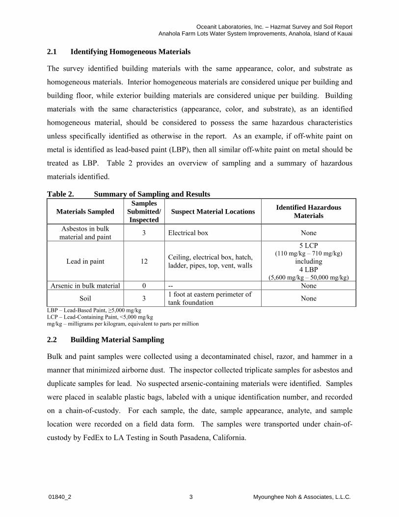
Oceanit Laboratories, Inc. – Hazmat Survey and Soil ReportAnahola Farm Lots Water System Improvements, Anahola, Island of Kauai
01840_2 3 Myounghee Noh & Associates, L.L.C.
2.1 Identifying Homogeneous Materials
The survey identified building materials with the same appearance, color, and substrate as
homogeneous materials. Interior homogeneous materials are considered unique per building and
building floor, while exterior building materials are considered unique per building. Building
materials with the same characteristics (appearance, color, and substrate), as an identified
homogeneous material, should be considered to possess the same hazardous characteristics
unless specifically identified as otherwise in the report. As an example, if off-white paint on
metal is identified as lead-based paint (LBP), then all similar off-white paint on metal should be
treated as LBP. Table 2 provides an overview of sampling and a summary of hazardous
materials identified.
Table 2. Summary of Sampling and Results
Materials SampledSamples
Submitted/Inspected
Suspect Material Locations Identified Hazardous Materials
Asbestos in bulk material and paint
3 Electrical box None
Lead in paint 12Ceiling, electrical box, hatch, ladder, pipes, top, vent, walls
5 LCP(110 mg/kg – 710 mg/kg)
including 4 LBP
(5,600 mg/kg – 50,000 mg/kg)Arsenic in bulk material 0 -- None
Soil 31 foot at eastern perimeter of tank foundation
None
LBP – Lead-Based Paint, LCP – Lead-Containing Paint, <5,000 mg/kgmg/kg – milligrams per kilogram, equivalent to parts per million
2.2 Building Material Sampling
Bulk and paint samples were collected using a decontaminated chisel, razor, and hammer in a
manner that minimized airborne dust. The inspector collected triplicate samples for asbestos and
duplicate samples for lead. No suspected arsenic-containing materials were identified. Samples
were placed in sealable plastic bags, labeled with a unique identification number, and recorded
on a chain-of-custody. For each sample, the date, sample appearance, analyte, and sample
location were recorded on a field data form. The samples were transported under chain-of-
custody by FedEx to LA Testing in South Pasadena, California.

Oceanit Laboratories, Inc. – Hazmat Survey and Soil ReportAnahola Farm Lots Water System Improvements, Anahola, Island of Kauai
01840_2 4 Myounghee Noh & Associates, L.L.C.
2.3 Soil Sampling
MNA collected composite soil samples from 0-2 inches below grass cover, within 1 foot around
the vegetated eastern perimeter of the water tank foundation (Figure 2). Each composite soil
sample combined ten 30 gram of subsamples. The 10 subsamples were collected using a Terra-
core® sampler and placed into a 16-ounce glass jar. No odors or discolorations were observed in
the soil samples.
Soil samples were transported under chain-of-custody for analysis to Curtis & Tompkins, Ltd., in
Berkeley, California.
3.0 LABORATORY INFORMATION
LA Testing analyzed the samples as follows:
Asbestos samples by polarized light microscopy using the Environmental Protection
Agency (EPA) Method 600/R-93/116.
Lead samples by flame atomic absorption spectroscopy using the EPA Method SW 846
3050B/7000B.
LA Testing is certified by:
National Voluntary Laboratory Accreditation Program, certification 200232-0.
State of Hawaii Department of Health (HDOH), certification L-01-034.
American Industrial Hygienist Association Environmental Lead Laboratory Accreditation
Program, certification 102814.
Hawaii Analytical Laboratory, L.L.C., analyzed the soil samples for lead by EPA Method
3051m/7000Bm. Hawaii Analytical Laboratory is certified by the American Association for
Laboratory Accreditation, certification 101812.


Oceanit Laboratories, Inc. – Hazmat Survey and Soil ReportAnahola Farm Lots Water System Improvements, Anahola, Island of Kauai
01840_2 6 Myounghee Noh & Associates, L.L.C.
4.0 ASBESTOS RESULTS
Materials determined to contain greater than, or equal to, 1% asbestos fibers are considered regulated
asbestos-containing material (ACM) under the National Emission Standards for Hazardous Air
Pollutants (NESHAP) as specified in 40 Code of Federal Regulations (CFR) Part 61 Subpart M. The
U.S. Occupational Safety and Health Administration (OSHA) Asbestos General Industry and
Construction Standards also define ACM as 1% or more by volume under 29 CFR 1910.1001 and 29
CFR 1926.1101, respectively. However, OSHA considers any measurable level of asbestos fibers to
be a health concern.
One homogeneous material suspected of containing asbestos was identified and sampled,
generating three samples for analysis. The suspected ACM was approximately 5 linear feet of off-
white wrap with yellow mastic in fair condition on an exterior metal electrical box. Laboratory
analytical results indicated no measurable levels of asbestos in the samples. Therefore, it is
concluded that no ACM are present in the area anticipated to be disturbed.
The suspected ACM description and identifier is provided in Appendix B. Sample location
drawings are provided in Appendix C. A photograph of the suspected material is presented in
Appendix D. The laboratory analytical report, chain-of-custody, and field data form is provided in
Appendix E.
5.0 LEAD RESULTS
The U.S. Department of Housing and Urban Development (HUD) and the EPA define paint
containing 5,000 milligrams per kilogram (mg/kg), or 0.5% by weight, or more of lead to be
LBP. OSHA considers paint containing any measurable concentration of lead to be lead-
containing paint (LCP) and a health concern. When lead is detected in a multi-layer sample, it is
assumed that all layers represented by the sample contain lead at the same concentration.
Six paints suspected of containing lead were identified and sampled, generating 12 paint
samples. Five LCP were identified in the survey area, with sample results ranging from 110
mg/kg to 50,000 mg/kg. Four of those LCP were identified as LBP, exceeding 5,000 mg/kg, the
threshold for LBP (Table 3).
Suspect LCP descriptions and identifiers are provided in Appendix B. Lead sample and
hazardous material location drawings are provided in Appendix C. Photographs of suspect

Oceanit Laboratories, Inc. – Hazmat Survey and Soil ReportAnahola Farm Lots Water System Improvements, Anahola, Island of Kauai
01840_2 7 Myounghee Noh & Associates, L.L.C.
materials are presented in Appendix D. Laboratory analytical reports, chain-of-custody, and
field data forms are provided in Appendix E.
Table 3. Lead-Containing Paint Determination
Area Locations HMID
Material Color Substrate Result
(mg/kg) ConditionEstimated Quantity(sq. ft.)
InteriorCeiling, hatch, ladder, walls
1 Black Metal <100 Good 9,000
Exterior Ladder, pipes, top, walls 2 Lt. green Metal LBP 110 - 5,600 Fair 8,000
Exterior Walls 3 Lt. gray Metal LBP 13,000 -17,000 Fair 1,500
Exterior Pipe, valve 4 Dk. green Metal LCP 280 - 710 Good 10
Exterior Electrical box 5 Off-white Metal LBP 47,000 -
50,000 Poor 5
Exterior Vent 6 Black Metal LBP 23,000 -36,000 Fair 10
Bold values indicate results above the detection limit.Good – Material is in an "as installed" condition. It is usable as is and may show cosmetic wear and tear or fading.Fair – Material is functional for its installed purpose but shows initial signs of deterioration beyond the cosmetic.Poor – Material shows significant deterioration and may not be functional for its installed purpose. Paint is bubbling or peeling over 20% or more of surface area and no longer protects the substrate.
Dk. – Dark Lt. – LightAbbreviations and Acronyms
HM ID – Hazardous Material Identifier mg/kg – milligrams per kilogram, equivalent to parts per millionLBP – Lead-Based Paint, sq. ft. – Square FeetLCP – Lead-Containing Paint, <5,000 mg/kg
6.0 ARSENIC RESULTS
The disturbance of arsenic-containing materials is regulated by the OSHA Inorganic Arsenic
General Industry Standard under 29 CFR 1910.1018.
No suspected arsenic-containing materials were identified; therefore, no samples were collected
during this survey of the facility.
7.0 SOIL RESULTS
The analytical results were compared to the HDOH Tier 1 Environmental Action Level (EAL)
for lead in soil for unrestricted (residential) land use above a drinking water source and located
greater than 150 meters from surface water.
One soil sample analyzed, 1840-DU1B, resulted in a detectable level of lead, 43 mg/kg. The
second soil sample, 1840-DU1A, did not have any measurable level of lead, <40mg/kg. Sample
results were below the HDOH Tier I EAL, 200 mg/kg. The complete laboratory report is
provided in Appendix E.

Oceanit Laboratories, Inc. – Hazmat Survey and Soil ReportAnahola Farm Lots Water System Improvements, Anahola, Island of Kauai
01840_2 8 Myounghee Noh & Associates, L.L.C.
8.0 SUMMARY OF SURVEY RESULTS
On April 15, 2015, MNA conducted a hazardous material survey at the Department of Hawaiian
Home Lands source water facility at the Anahola Farms Lots, Anahola, Island of Kauai. This
survey was conducted in support of the planned steel tank rehabilitation project.
Based on the analysis of three asbestos samples, 12 lead samples, and two soil samples, MNA
provides the following summary:
No ACM were identified during the survey.
Five LCP were identified during the survey, all on the exterior of the water tank (Table 3). Four of the identified LCP were LBP, exceeding the 5,000 mg/kg threshold. The identified LCP were: o Dark green paint in good condition on metal pipe and valve, 280 mg/kg and 710
mg/kg, approximately 10 square feet.
The identified LBP were:o Light green paint in fair condition on metal ladder, pipes, top, and walls, 110
mg/kg and 5,600 mg/kg, approximately 8,000 square feet. o Light gray paint in fair condition on metal walls, 13,000 mg/kg and 17,000 mg/kg,
approximately 1,500 square feet. o Off-white paint in poor condition on metal electrical box, 47,000 mg/kg and 50,000
mg/kg, approximately 5 square feet. o Black paint in fair condition on metal vent, 23,000 mg/kg and 36,000 mg/kg,
approximately 10 square feet.
No suspect arsenic-containing materials were identified in the targeted areas.
No lead-contaminated soil was identified in the areas anticipated to be disturbed by the rehabilitation project.
9.0 RECOMMENDATIONS FOR RENOVATION AND CONSTRUCTION WORK
It is required that only properly trained employees perform construction work and renovation
that disturbs hazardous materials, in a manner protective of the site workers, the public, and the
environment. The following recommendations address OSHA and other applicable federal
requirements. These recommendations provide guidance for the management of hazardous
building materials and control of occupational and environmental hazards associated with
operations, maintenance, renovation, and demolition. These recommendations are based on
information gathered during the hazardous materials survey. These recommendations are not
intended to constitute a formal work plan but are intended to provide a starting point for the
development of a work plan.

Oceanit Laboratories, Inc. – Hazmat Survey and Soil ReportAnahola Farm Lots Water System Improvements, Anahola, Island of Kauai
01840_2 9 Myounghee Noh & Associates, L.L.C.
9.1 Asbestos-Containing Materials
No ACM were identified in the targeted areas during this survey. Therefore, no special control
measures are warranted.
9.2 Lead-Containing Paints
Employees involved in renovation or construction activities that disturb LCP or LBP must
conduct work in accordance with 29 CFR 1926.62, the OSHA Lead Construction Standard and
40 CFR 745 EPA Renovation, Repairs, and Painting Program. Work practices that would trigger
these requirements include, but are not limited to, sanding, blasting, welding, cutting, or
scraping. For each project, the contractor must determine the appropriate safety measures based
on the area to be disturbed, the lead concentration, and the paint condition. Applicable work
practice guidelines involving the disturbance of LCP or LBP are summarized, but are not limited
to:
Employees must utilize appropriate engineering controls and personal protective equipment
(PPE). The PPE includes disposable coveralls, gloves, eye protection, steel-toed boots, a
hard hat, and a National Institute for Occupational Safety and Health (NIOSH)-approved
appropriate respirator.
Employees must utilize respiratory protection until the initial air monitoring assessment
documents safe working levels of airborne lead (29 CFR 1926.62[d][1] and [2][i][A]).
An exposure assessment should be carried out when employees are disturbing LCP or LBP to
ensure that they are not exposed to airborne lead concentrations greater than the Permissible
Exposure Limit (PEL) of 50 micrograms per cubic meter (μg/m3) averaged over an 8-hour
period. Additional periodic exposure monitoring may be required if the lead OSHA Action
Level of 30 μg/m3 averaged over an 8-hour period is exceeded.
Employees must implement stringent dust control procedures to prevent lead in any airborne
dust.
Employees must clean the work area thoroughly using wet methods and a high-efficiency
particulate air (HEPA) vacuum. Dry sweeping or air blowing of lead debris and dust must be
avoided.
Lead-containing debris should be segregated from other wastes, collected, and containerized.
Wastes should be fully characterized, including a determination of the waste as hazardous or

Oceanit Laboratories, Inc. – Hazmat Survey and Soil ReportAnahola Farm Lots Water System Improvements, Anahola, Island of Kauai
01840_2 10 Myounghee Noh & Associates, L.L.C.
non-hazardous. Lead-containing waste should be disposed of in accordance with applicable
requirements.
Visually inspect and verify the work area to ensure all lead-containing debris and dust has
been properly removed and the project site is free of lead hazard.
Conduct clearance in accordance with contract specifications.
9.3 Arsenic-Containing Materials
No arsenic-containing materials were identified in the targeted areas during this survey.
Therefore, no special control measures are warranted.
9.4 Soil
Soil samples that were collected and analyzed for lead were below the HDOH Tier 1 EAL for
unrestricted land use above a drinking water resource and greater than 150 meters from surface
water. However, there were measurable levels of lead in the soil. Therefore, for worker and
environmental protection, applicable work practice guidelines involving the disturbance of the
soil bordering the steel tank are summarized, but are not limited to:
Lead metal levels found in the soil did not exceed the current HDOH EAL. Therefore, off-
site soil disposal is not required.
Excess soil that may be transported off-site for re-use must be sampled and tested to ensure
compliance with the recipient guidelines and requirements.
Best Management Practices (BMP) such as soil erosion/runoff control or dust control must
be implemented during the earthwork.
The information provided in this report is for the Contractor’s information only, and is not
guaranteed to fully represent all surface/subsurface soil conditions. The Contractor must
perform all necessary due diligence at his expense.
10.0 LIMITATIONS
Every reasonable effort was made to identify suspect building materials during the survey.
However, this does not imply a guarantee that all suspect building materials were identified by
this assessment because certain building materials and/or surfaces may be hidden by walls,
flooring, partitions, or other building components. If suspect materials previously unknown
become uncovered, additional survey may be required prior to the planned rehabilitation project.

Oceanit Laboratories, Inc. – Hazmat Survey and Soil ReportAnahola Farm Lots Water System Improvements, Anahola, Island of Kauai
01840_2 11 Myounghee Noh & Associates, L.L.C.
Material quantities provided in this report are based on visual approximations taken at the time
of the survey only. It is the Contractor’s responsibility to determine the material quantities and
volume of waste.

Oceanit Laboratories, Inc. – Hazmat Survey and Soil ReportAnahola Farm Lots Water System Improvements, Anahola, Island of Kauai
01840_2 A Myounghee Noh & Associates, L.L.C.
APPENDIX A
INSPECTOR CERTIFICATIONS
Adam Custer


Oceanit Laboratories, Inc. – Hazmat Survey and Soil ReportAnahola Farm Lots Water System Improvements, Anahola, Island of Kauai
01840_2 B Myounghee Noh & Associates, L.L.C.
APPENDIX B
HOMOGENEOUS MATERIALS IDENTIFIED
AND SAMPLE TYPES COLLECTED

Hom
ogen
eous
Mat
eria
ls I
dent
ifie
d an
d Sa
mpl
e T
ypes
Col
lect
ed
Oce
anit
Labo
rato
ries,
Inc.
- H
azm
at S
urve
y an
d S
oil R
epor
tA
naho
la F
arm
Lot
s W
ater
Sys
tem
Impr
ovem
ents
, Ana
hola
, Isl
and
of K
auai
HM ID
Lo
cati
on
sM
ater
ial
Co
lor
Mat
eria
lS
ub
stra
teA
sbP
bR
esu
lt
1C
eilin
g, h
atch
, lad
der,
wal
lsB
lack
Pai
ntM
etal
X<
100
mg/
kg2
Lad
der
, pip
es, t
op
, wal
lsL
t. g
reen
Pai
nt
Met
alX
LB
P 1
10 -
5,6
00 m
g/k
g3
Wal
lsL
t. g
ray
Pai
nt
Met
alX
LB
P 1
3,00
0 -
17,0
00 m
g/k
g4
Pip
e, v
alve
Dk.
gre
enP
ain
tM
etal
XL
CP
280
- 7
10 m
g/k
g5
Ele
ctri
cal b
ox
Off
-wh
ite
Pai
nt
Met
alX
LB
P 4
7,00
0 -
50,0
00 m
g/k
g6
Ven
tB
lack
Pai
nt
Met
alX
LB
P 2
3,00
0 -
36,0
00 m
g/k
g
7E
lect
rical
box
Off
-whi
teY
ello
wW
rap
Mas
ticM
etal
XN
D
Bo
ld v
alu
es in
dic
ate
resu
lts
abo
ve t
he
rep
ort
ing
lim
it.
All
mat
eria
ls a
re lo
cate
d on
the
exte
rior
of th
e re
serv
oir.
Abb
revi
atio
ns a
nd A
cron
yms
Asb
- A
sbes
tos
HM
ID -
Hom
ogen
eous
Mat
eria
l Ide
ntifi
erLB
P -
Lea
d-B
ased
Pai
nt
5,00
0 m
g/kg
LCP
- L
ead-
Con
tain
ing
Pai
nt <
5,00
0 m
g/kg
ND
- N
ot D
etec
ted
Pb
- Le
ad

Oceanit Laboratories, Inc. – Hazmat Survey and Soil ReportAnahola Farm Lots Water System Improvements, Anahola, Island of Kauai
01840_2 C Myounghee Noh & Associates, L.L.C.
APPENDIX C
SAMPLE LOCATION DRAWINGS
Table of ContentsAsbestos Sample Locations Exterior C-1Lead Paint Sample and Hazardous Material Locations Interior and Exterior C-2

Myounghee N
oh &
Asso
cia
tes,
L.L
.C.
Sheet
Num
ber
C -
1
Asbesto
s S
am
ple
Locations
Anahola
Farm
Lots
Subdiv
isio
n
Reserv
oir
Exte
rior
HM
ID
- H
om
ogeneous M
ate
rial Id
entifier
ND
- N
one D
ete
cte
d
Lege
nd a
nd N
otes
Sca
le
10 f
eet
Reserv
oir
1840-A
1A
: N
D
1840-A
1B
-Wra
p:
ND
1840-A
1B
-Mastic:
ND
1840-A
1C
: N
D
HM
ID
: 7
(E
lectr
ica
l b
ox)

Myounghee N
oh &
Asso
cia
tes,
L.L
.C.
Sheet
Num
ber
C -
2
Lead P
ain
t S
am
ple
and H
azard
ous
Mate
rial Locations
Anahola
Farm
Lots
Subdiv
isio
n
Reserv
oir I
nte
rior
and E
xte
rior
HM ID
Lo
ca
tio
ns
Co
lor
Su
bs
tra
teR
es
ult
s
(mg
/kg
)
2Ladder,
pip
es,
top,
walls
Lt.
gre
en
Meta
lL
BP
110
- 5
,60
0
3W
alls
Lt.
gra
yM
eta
lL
BP
13,0
00 -
17,0
00
4P
ipe,
valv
eD
k.
gre
en
Meta
lL
CP
280 -
710
5E
lectr
ical box
Off
-wh
ite
Meta
lL
BP
47,0
00 -
50,0
00
6V
ent
Bla
ck
Meta
lL
BP
23,0
00 -
36,0
00
Sca
le
10 f
eet
Reserv
oir
1840-P
1A
: <
100 m
g/k
g
1840-P
1B
: <
100 m
g/k
g
HM
ID
: 1 (
Ceili
ng)
1840-P
2A
: L
CP
110 m
g/k
g
HM
ID
: 2
(W
all
)
1840-P
2B
: L
BP
5,6
00 m
g/k
g
HM
ID
: 2
(P
ipe
)
1840-P
3A
: L
BP
17,0
00 m
g/k
g
HM
ID
: 3
(W
all
)
1840-P
3B
: L
BP
13,0
00 m
g/k
g
HM
ID
: 3
(W
all
)
1840-P
4A
: L
CP
280 m
g/k
g
1940-P
4B
: L
CP
710 m
g/k
g
HM
ID
: 4
(P
ipe
)
1840-P
5A
: L
BP
50,0
00 m
g/k
g
1840-P
5B
: L
BP
47,0
00 m
g/k
g
HM
ID
: 5
(E
lec
tric
al
bo
x)
1840-P
6A
: L
BP
36,0
00 m
g/k
g
1840-P
6B
: L
BP
23,0
00 m
g/k
g
HM
ID
: 6
(V
en
t)
Bo
ld v
alu
es i
nd
icate
resu
lts a
bo
ve t
he d
ete
cti
on
lim
it.
HM
ID
- H
azard
ous M
ate
rial Id
entifier
LB
P -
Lead-B
ased P
ain
t ≥
5,0
00 m
g/k
g
LC
P -
Lead-C
onta
inin
g P
ain
t <
5,0
00 m
g/k
g
mg/k
g -
mill
igra
ms p
er
kilo
gra
m (
equiv
ale
nt
to p
pm
- part
s p
er
mill
ion)
Vis
ual
Exte
nt
of
Lead
-Based
Pain
t
Lege
nd a
nd N
otes
Vis
ua
l E
xte
nt
of
Le
ad
-Co
nta
inin
g P
ain
t

Oceanit Laboratories, Inc. – Hazmat Survey and Soil ReportAnahola Farm Lots Water System Improvements, Anahola, Island of Kauai
01840_2 D Myounghee Noh & Associates, L.L.C.
APPENDIX D
PHOTOGRAPHS

Oceanit Laboratories, Inc. – Hazmat Survey and Soil Report Anahola Farm Lots Water System Improvements, Anahola, Island of Kauai
01840_2 D-1 Myounghee Noh & Associates, L.L.C.
HM ID: 1
InteriorBlack paint on metal wall.
Non-LCP1840-P1A: <100 mg/kg 1840-P1B: <100 mg/kg
HM ID: 2
ExteriorLight green paint on metal wall.
LBP1840-P2A: 110 mg/kg 1840-P2B: 5,600 mg/kg
HM ID: 3
ExteriorLight gray paint on metal wall.
LBP1840-P3A: 17,000 mg/kg 1840-P3B: 13,000 mg/kg

Oceanit Laboratories, Inc. – Hazmat Survey and Soil Report Anahola Farm Lots Water System Improvements, Anahola, Island of Kauai
01840_2 D-2 Myounghee Noh & Associates, L.L.C.
HM ID: 4
ExteriorDark green paint on metal pipe.
LCP1840-P4A: 280 mg/kg 1840-P4B: 710 mg/kg
HM ID: 5
ExteriorOff-white paint on metal electrical box.
LBP1840-P5A: 50,000 mg/kg 1840-P5B: 47,000 mg/kg
HM ID: 6
ExteriorBlack paint on metal vent.
LBP1840-P6A: 36,000 mg/kg 1840-P6B: 23,000 mg/kg

Oceanit Laboratories, Inc. – Hazmat Survey and Soil Report Anahola Farm Lots Water System Improvements, Anahola, Island of Kauai
01840_2 D-3 Myounghee Noh & Associates, L.L.C.
HM ID: 7
ExteriorOff-white wrap and mastic on metal electrical box.
Non-ACM1840-A1A: ND 1840-A1B-Wrap: ND 1840-A1B-Mastic: ND 1840-A1C: ND

Oceanit Laboratories, Inc. – Hazmat Survey and Soil ReportAnahola Farm Lots Water System Improvements, Anahola, Island of Kauai
01840_2 E Myounghee Noh & Associates, L.L.C.
APPENDIX E
LABORATORY ANALYTICAL REPORTS

LA Testing520 Mission Street, South Pasadena, CA 91030
Phone/Fax: (323) 254-9960 / (323) 254-9982
http://www.LATesting.com [email protected]
321508986
CustomerID: 32MYOU50
CustomerPO:
ProjectID:
LA Testing Order:
Attn: Adam Custer
Myounghee Noh & Associates, LLC
99-1046 Iwaena Street
Suite 210A
Aiea, HI 96701
Received: 04/21/15 9:10 AM
1890_2 OCEANIT ANAHOLA
Fax:
Phone: (808) 484-9214
Project:
4/23/2015Analysis Date:
Collected:
Sample Description Appearance % Type
AsbestosNon-Asbestos
% Fibrous % Non-Fibrous
Test Report: Asbestos Analysis of Bulk Materials via EPA 600/R-93/116 Method using
Polarized Light Microscopy
1840-A 1A
321508986-0001
7 White None Detected
Fibrous
Homogeneous
Glass98% Non-fibrous (other)2%
1840-A 1B-Wrap
321508986-0002
7 White None Detected
Fibrous
Homogeneous
Glass98% Non-fibrous (other)2%
1840-A 1B-Mastic
321508986-0002A
7 Yellow None Detected
Non-Fibrous
Homogeneous
Non-fibrous (other)100%
1840-A 1C
321508986-0003
7 White None Detected
Fibrous
Heterogeneous
Glass98% Non-fibrous (other)2%
1THIS IS THE LAST PAGE OF THE REPORT.Test Report PLM-7.28.9 Printed: 4/23/2015 3:01:27 PM
Jerry Drapala Ph.D, Laboratory Manageror other approved signatory
Analyst(s)
EMSL maintains liability limited to cost of analysis. This report relates only to the samples reported and may not be reproduced, except in full, without written approval by EMSL. EMSL bears no
responsibility for sample collection activities or analytical method limitations. Interpretation and use of test results are the responsibility of the client. This report must not be used by the client to claim
product certification, approval, or endorsement by NVLAP, NIST or any agency of the federal government. Non-friable organically bound materials present a problem matrix and therefore EMSLrecommends gravimetric reduction prior to analysis. Samples received in good condition unless otherwise noted. Estimated accuracy, precision and uncertainty data available upon request. Unless
requested by the client, building materials manufactured with multiple layers (i.e. linoleum, wallboard, etc.) are reported as a single sample. Reporting limit is 1%
Samples analyzed by LA Testing South Pasadena, CA NVLAP Lab Code 200232-0, CA ELAP 2283
Initial report from 04/23/2015 15:01:27
Julie Vong (3)Rosa Mendoza (1)

OrderID: 321508986
Page 1 Of 3
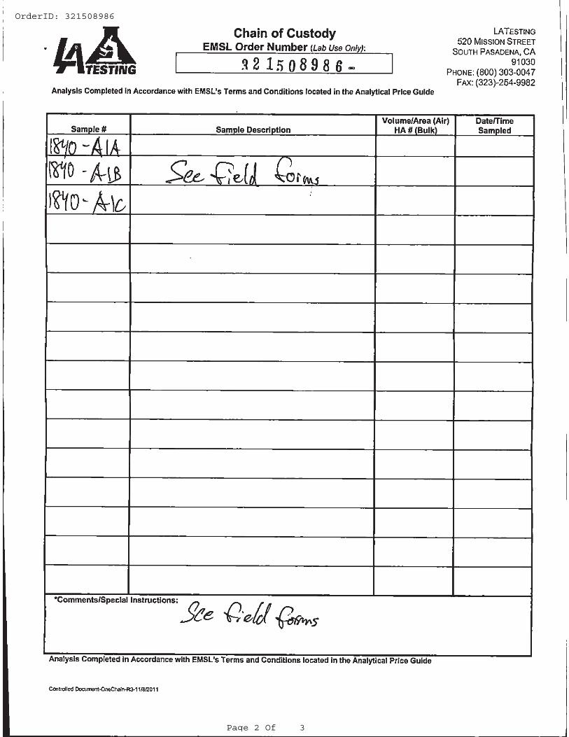
OrderID: 321508986
Page 2 Of 3

OrderID: 321508986
Page 3 Of 3

Client Sample Description ConcentrationLab ID AnalyzedLead
Collected
LA Testing520 Mission Street, South Pasadena, CA 91030
Phone/Fax: (323) 254-9960 / (323) 254-9982
http://www.LATesting.com [email protected]
Attn: Adam Custer
Myounghee Noh & Associates, LLC
99-1046 Iwaena Street
Suite 210A
Aiea, HI 96701
Received: 04/21/15 9:10 AM
1840_2 Oceanit Anahola
Fax:
Phone: (808) 484-9214
Project:
Collected:
Test Report: Lead in Paint Chips by Flame AAS (SW 846 3050B/7000B)*
321508766
CustomerID: 32MYOU50
CustomerPO:
ProjectID:
LA Testing Order:
Site: 1
321508766-00011840-P1A <100 ppm4/21/2015
Site: 1
321508766-00021840-P1B <100 ppm4/21/2015
Site: 2
321508766-00031840-P2A 110 ppm4/21/2015
Site: 2
321508766-00041840-P2B 5600 ppm4/21/2015
Site: 3
321508766-00051840-P3A 17000 ppm4/21/2015
Site: 3
321508766-00061840-P3B 13000 ppm4/21/2015
Site: 4
321508766-00071840-P4A 280 ppm4/21/2015
Site: 4
321508766-00081840-P4B 710 ppm4/21/2015
Site: 5
321508766-00091840-P5A 50000 ppm4/21/2015
Site: 5
321508766-00101840-P5B 47000 ppm4/21/2015
Site: 6
321508766-00111840-P6A 36000 ppm4/21/2015
Site: 6
321508766-00121840-P6B 23000 ppm4/21/2015
Page 1 of 1
Jerry Drapala Ph.D, Laboratory Manageror other approved signatory
Test Report ChmSnglePrm/nQC-7.32.3 Printed: 4/21/2015 12:55:01 PM
*Analysis following Lead in Paint by EMSL SOP/Determination of Environmental Lead by FLAA. Reporting limit is 0.010 % wt based on the minimum sample weight per our SOP. Unless noted, results in
this report are not blank corrected. This report relates only to the samples reported above and may not be reproduced, except in full, without written approval by EMSL. EMSL bears no responsibility for
sample collection activities. Samples received in good condition unless otherwise noted. "<" (less than) result signifies that the analyte was not detected at or above the reporting limit. Measurement ofuncertainty is available upon request. The QC data associated with the sample results included in this report meet the recovery and precision requirements established by the AIHA-LAP, unless specifically
indicated otherwise.
Samples analyzed by LA Testing South Pasadena, CA CA ELAP 2283, AIHA-LAP, LLC ELLAP 102814
Initial report from 04/21/2015 12:55:01

OrderID: 321508766
Page 1 Of 4

OrderID: 321508766
Page 2 Of 4

OrderID: 321508766
Page 3 Of 4

OrderID: 321508766
Page 4 Of 4

GEOTECHNICAL ENGINEERING EXPLORATION
ANAHOLA FARM LOTS
WATER SYSTEM IMPROVEMENTS
ANAHOLA, KAUAI, HAWAII
W.O. 7534-00 OCTOBER 25, 2017
Prepared for
OCEANIT
GEOLABS, INC. Geotechnical Engineering and Drilling Services


GEOLABS, INC. Geotechnical Engineering and Drilling Services
2006 Kalihi Street • Honolulu, Hawaii 96819 Phone: (808) 841-5064 • Facsimile: (808) 847-1749 • E-mail: [email protected] Hawaii • California
June 13, 2018 W.O. 7534-00(Add.) Mr. Jeremy Michelson Oceanit 828 Fort Street Mall, Suite 600 Honolulu, HI 96813 Subject: Amendment to Geotechnical Report dated October 25, 2017 Anahola Farm Lots Water System Improvements Anahola, Kauai, Hawaii Reference: Report by Geolabs, Inc. dated October 25, 2017 entitled “Geotechnical Engineering Exploration, Anahola Farm Lots Water System Improvements Anahola, Kauai, Hawaii"
Dear Mr. Michelson:
This amendment provides a change to the recommended minimum compaction of the fill materials below the reservoir tank and Control Building foundations provided in our report entitled "Geotechnical Engineering Exploration, Anahola Farm Lots Water System Improvements, Anahola, Kauai, Hawaii", dated October 25, 2017. A corrected minimum compaction of 95 percent relative compaction is recommended for the fill material below the reservoir tank and Control Building foundations.


W.O. 7534-00 GEOLABS, INC. Page i Hawaii • California
GEOTECHNICAL ENGINEERING EXPLORATION
ANAHOLA FARM LOTS
WATER SYSTEM IMPROVEMENTS
ANAHOLA, KAUAI, HAWAII
W.O. 7534-00 OCTOBER 25, 2017
TABLE OF CONTENTS
Page
SUMMARY OF FINDINGS AND RECOMMENDATIONS .............................................. iii
1. GENERAL ............................................................................................................ 1
1.1 Project Considerations ............................................................................... 1
1.2 Purpose and Scope ................................................................................... 2
2. SITE CHARACTERIZATION ................................................................................ 4 2.1 Regional Geology ...................................................................................... 4 2.2 Existing Site Conditions ............................................................................. 5
2.3 Subsurface Conditions ............................................................................... 6 2.4 Seismic Design Considerations ................................................................. 7
2.4.1 Earthquakes and Seismicity ............................................................ 7 2.4.2 Soil Profile Type for Seismic Design ............................................... 8 2.4.3 Liquefaction ..................................................................................... 9
3. DISCUSSION AND RECOMMENDATIONS ...................................................... 11
3.1 Reservoir Tank Foundations .................................................................... 13 3.2 Control Building Addition Foundations ..................................................... 15 3.3 Slabs-On-Grade ....................................................................................... 16
3.4 Retaining Structures ................................................................................ 18 3.4.1 Retaining Structure Foundations ................................................... 18
3.4.2 Lateral Earth Pressures ................................................................ 18 3.4.3 Drainage ....................................................................................... 20
3.5 Site Grading ............................................................................................. 20 3.5.1 Site Preparation ............................................................................ 21 3.5.2 Fills and Backfills ........................................................................... 22 3.5.3 Fill Placement and Compaction Requirements ............................. 22 3.5.4 Excavations ................................................................................... 23
3.5.5 Cut and Fill Slopes ........................................................................ 23 3.6 Pavement Design .................................................................................... 24
3.7 Underground Utility Lines ......................................................................... 26 3.8 Drainage .................................................................................................. 26 3.9 Design Review ......................................................................................... 27 3.10 Post-Design Services/Services During Construction ............................... 27
4. LIMITATIONS ..................................................................................................... 29
CLOSURE ..................................................................................................................... 31

TABLE OF CONTENTS
Page
W.O. 7534-00 GEOLABS, INC. Page ii Hawaii • California
PLATES Project Location Map .................................................................................. Plate 1 Site Plan ..................................................................................................... Plate 2
APPENDIX A Field Exploration ...................................................................... Pages A-1 and A-2 Soil Log Legend .................................................................................... Plate A-0.1 Soil Classification Log Key ................................................................... Plate A-0.2 Rock Log Legend ................................................................................. Plate A-0.3 Logs of Borings ..................................................................... Plates A-1.1 thru A-3
APPENDIX B Seismic Shear Wave Velocity Test .......................................................... Page B-1 Data Plot of Seismic Shear Wave Velocity Test Results .... Plates B-1.1 thru B-1.3 Seismic Shear Wave Velocity Test Results ........................................... Plate B-1.4
APPENDIX C Laboratory Tests ...................................................................................... Page C-1 Laboratory Test Data ............................................................... Plates C-1 thru C-9
APPENDIX D Photographs of Core Samples ................................................. Plates D-1 thru D-4

W.O. 7534-00 GEOLABS, INC. Page iii Hawaii • California
GEOTECHNICAL ENGINEERING EXPLORATION
ANAHOLA FARM LOTS
WATER SYSTEM IMPROVEMENTS
ANAHOLA, KAUAI, HAWAII
W.O. 7534-00 OCTOBER 25, 2017
SUMMARY OF FINDINGS AND RECOMMENDATIONS
Our field exploration generally encountered a pavement structure consisting of
about 1.5 inches of asphaltic concrete and 4 inches of granular fill material overlying medium stiff to hard saprolitic soils and medium hard to hard basalt rock formation to the maximum depth explored of about 102 feet below the existing ground surface. The saprolitic soils encountered generally consisted of medium stiff to hard silty clay with varying amounts of sand and weathered gravel and were encountered in our borings to depths ranging from about 18 to 23 feet below the existing ground surface.
A transition zone of extremely weathered basalt rock was encountered between the saprolitic soils and basalt rock formation and generally consisted of medium dense to very dense silty sand with weathered gravel. Medium hard to hard basalt rock formation was encountered underlying this transition zone in Boring No. 1 at a depth of about 21 feet below the existing ground surface. We did not encounter groundwater in the borings at the time of our field exploration. However, it should be noted that groundwater levels are subject to change due to rainfall, time of year, seasonal precipitation, surface water runoff, and other factors.
Based on the subsurface conditions encountered, we recommend utilizing shallow spread and continuous strip footings, such as perimeter wall footings and isolated interior spread footings, to support the new reservoir structures planned at the project site. In order to provide a uniform bearing surface, we recommend providing a minimum 24-inch thick layer of aggregate subbase material below the footings and concrete/finished floor of the proposed new 0.5 MG and temporary 0.1 MG reservoir tank structures. The aggregate subbase should extend beyond the edges of the reservoir structures by at least 24 inches. An allowable bearing pressure of up to 3,500 psf may be utilized for design of shallow foundations bearing on the aggregate subbase material placed over the on-site clayey soils at the project site.
We understand that the settlement for the new 0.5 MG reservoir tank structure should be minimized; therefore, we recommend incorporating two layers of triaxial geogrid, such as Tensar TriAx Grid TX7, into the 24-inch thick layer of aggregate subbase material beneath the footings and interior concrete floor of the new 0.5 MG reservoir tank structure to spread the load and reduce the loading on the underlying subgrade soils. We recommend placing the two layers of triaxial geogrid within the 24-inch thick aggregate subbase material at 6 and 18 inches above the bottom of the footing subgrade. Due to the temporary nature of the 0.1 MG reservoir tank structure, we believe the two layers of triaxial geogrid may be omitted beneath the footings of this temporary structure.

SUMMARY OF FINDINGS AND RECOMMENDATIONS
W.O. 7534-00 GEOLABS, INC. Page iv Hawaii • California
Prior to placing the aggregate subbase material, a non-woven geotextile fabric, such as Mirafi 180N or equivalent, should be provided below and along the sides of the over-excavation for the footings. Placement of the non-woven geotextile fabric at the bottom and along the sides of the over-excavation would provide separation and reduce the potential for penetration of the aggregate subbase material into the moist soils underlying the project site.
We also recommend supporting the control building addition on a shallow foundation system consisting of spread and/or strip footings. However, due to the relatively light structural loads anticipated for the control building addition, we believe that the 24-inch layer of aggregate subbase material recommended below the reservoir tank foundations may be omitted for the control building foundations. Instead, the footings may bear directly on the on-site soils that are recompacted to a firm and unyielding surface prior to the placement of reinforcing steel or concrete. An allowable bearing pressure of 2,500 psf may be utilized for the design of the control building addition foundations bearing on the recompacted on-site clayey soils.
Based on the results of our field exploration and laboratory testing, the on-site clayey soils exhibit moderate expansion potential when subjected to moisture fluctuations. Therefore, we recommend placing a minimum 18-inch thick layer of aggregate subbase material below the control building slab-on-grade to reduce moisture changes in the slab subgrade soils. Placement of the aggregate subbase layer would reduce the potential for future distress to the slabs-on-grade resulting from shrinking and swelling of the on-site soils due to changes in the moisture content.
Conventional earthwork and construction methods may be used for the proposed project grading. Based on the anticipated grading and our field exploration, this project will generally consist of excavations for foundation construction and infrastructure installation. Some of the excavations may encounter boulders, clusters of cobbles, and hard basalt rock formation. It is anticipated that most of the material may be excavated with normal heavy excavation equipment. However, deep excavations, excavations into basalt rock formation, and excavations encountering boulders may require the use of hoerams.
The text of this report should be referred to for detailed discussions and specific geotechnical recommendations.
END OF SUMMARY OF FINDINGS AND RECOMMENDATIONS

W.O. 7534-00 GEOLABS, INC. Page 1 Hawaii • California
SECTION 1. GENERAL
This report presents the results of our geotechnical engineering exploration
performed for the Anahola Farm Lots Water System Improvements project in the
Anahola area on the Island of Kauai, Hawaii. The project location and general vicinity
are shown on the Project Location Map, Plate 1.
This report summarizes the findings and geotechnical recommendations resulting
from our field exploration, laboratory testing, and engineering analyses for the project.
These findings and geotechnical recommendations are intended for the design of
foundations, slabs-on-grade, retaining structures, site grading, underground utilities, and
pavements only. The findings and recommendations presented herein are subject to the
limitations noted at the end of this report.
1.1 Project Considerations
The project generally consists of improvements to the existing Anahola Farm
Lots Water System in Anahola on the Island of Kauai, Hawaii. Based on the information
provided, improvements to the existing farm lots water system will generally consist of
the following:
• Replacement of an existing 0.5 million-gallon (MG) steel reservoir tank with a new concrete reservoir tank of similar size
• Temporary 0.1 MG steel reservoir tank
• New in-line booster pump assembly
• New emergency generator and fuel tank
• Addition to existing Control Building
• Related underground utilities such as water and drain lines
• New asphaltic concrete pavements
We understand the new 0.5 MG concrete reservoir tank will have an outside
diameter of about 48 feet and will be about 40 feet tall. Based on information provided
by the project structural engineer, the maximum column and wall loads anticipated for
the new 0.5 MG concrete reservoir tank are approximately 85 kips and 15 kips per foot,

SECTION 1. GENERAL
W.O. 7534-00 GEOLABS, INC. Page 2 Hawaii • California
respectively. In addition, the slab-on-grade of the new reservoir tank will be subjected to
approximately 2.8 kips per square foot of pressure.
We understand the temporary 0.1 MG steel reservoir tank will have a diameter of
about 30 feet and will be about 21.5 feet tall. Based on information provided by the
project structural engineer, maximum anticipated wall load for the temporary 0.1 MG
steel reservoir tank is approximately 750 pounds per foot. We understand an interior
tank liner will be used for this temporary reservoir tank structure in lieu of a concrete
slab-on-grade or metal tank bottom.
Based on the information provided, we anticipate minimal fills will be required for
this water system improvements project. We anticipate the majority of site grading will
generally consist of excavations and backfills related to foundation construction and
infrastructure installation. However, cuts up to about 6 feet are anticipated for a
retaining wall planned for grade separation on the western side of the temporary 0.1 MG
steel reservoir tank.
1.2 Purpose and Scope
The purpose of our exploration was to obtain an overview of the surface and
subsurface conditions to develop an idealized soil/rock data set to formulate
geotechnical engineering recommendations for the design of the project. The work was
performed in general accordance with our revised fee proposal dated
September 22, 2016. The scope of work for this exploration included the following tasks
and work efforts:
1. Research and review of available in-house soils boring data and other geologic information for the project.
2. Mobilization and demobilization of a truck-mounted drill rig and two operators to the project site and back.
3. Drilling and sampling of three borings extending to depths ranging from about 16.5 to 102 feet below the existing ground surface. In addition, collection of one bulk sample of the near-surface soils for California Bearing Ratio (CBR) testing.
4. Performance of shear wave velocity testing within the boring drilled to about 100 feet below the existing ground surface.

SECTION 1. GENERAL
W.O. 7534-00 GEOLABS, INC. Page 3 Hawaii • California
5. Coordination of the field exploration and logging of the borings by our geologist.
6. Laboratory testing of selected soil samples obtained during the field exploration as an aid in classifying the materials and evaluating their engineering properties.
7. Analyses of the field and laboratory data to formulate geotechnical engineering recommendations for the design of the project.
8. Preparation of this report summarizing our work and presenting our findings and geotechnical recommendations.
9. Coordination of our overall work on the project by our engineer.
10. Quality assurance of our work and client/design team consultation by our principal engineer.
11. Miscellaneous work efforts, such as drafting, word processing, and clerical support.
Detailed descriptions of our field exploration methodology and the Logs of
Borings are presented in Appendix A. Results of the seismic shear wave velocity testing
are presented in Appendix B. Results of the laboratory tests performed on selected soil
samples are presented in Appendix C. Photographs of the core samples are presented
in Appendix D.
END OF GENERAL

W.O. 7534-00 GEOLABS, INC. Page 4 Hawaii • California
SECTION 2. SITE CHARACTERIZATION
2.1 Regional Geology
The Island of Kauai is composed of a single dissected basaltic shield volcano
built by the extrusion of lavas of the Waimea Canyon Volcanic Series beginning about
5 to 6 million years ago. The eruption of the Waimea Volcanic Series ended about
2½ million years ago and was followed by a long period of erosion. Following the
cessation of this main volcano shield-building phase, about 1½ million years ago, there
was renewed volcanic activity with the extrusion of basaltic lavas of the post-erosional
Koloa Volcanic Series and the concurrent deposition of the thick alluvial sediments of
the Palikea Formation.
Rock formations of the Koloa Volcanic Series are generally characterized as
thick lava flows composed of dense basalt extruded from groups of vents aligned in
north-south trends at various locales. Associated with the Koloa Volcanic Series lava
flows are some deposits of pyroclastic materials (volcanic ash and cinders), which
usually form cinder cones surrounding the vent. Rock formations of the Koloa Volcanic
Series cover most of the eastern half of the Island of Kauai, including the project site.
During the Pleistocene Epoch, many sea level changes occurred as a result of
widespread glaciation in the continental areas of the world. As the great continental
glaciers accumulated, the level of the ocean fell since less water was available to fill the
oceanic basins. Conversely, as the glaciers receded or melted, global sea levels rose
because more water was available. The landmass of Kauai remained essentially stable
during these changes, and the fluctuations were eustatic in nature. These
glacio-eustatic fluctuations resulted in stands of the sea, which were both higher and
lower relative to the present sea level of the Island of Kauai.
The project area is generally composed of basaltic rock built by extrusion of the
lavas of the Koloa Volcanic Series. The basalt rock formation observed in the Anahola
area appear to be representative of the pahoehoe lava flow type, which spread and
ponded as it approached the ocean from inland areas. Pahoehoe lavas are typically

SECTION 2. SITE CHARACTERIZATION
W.O. 7534-00 GEOLABS, INC. Page 5 Hawaii • California
characterized by a smoother, billowy surface and internal structure of vesicular (porous)
rock with limited clinker materials.
In some places, in-situ chemical weathering of the Koloa lava flows has formed a
mantle of residual and saprolitic soils. In general, saprolite is composed mainly of silty
material while residual soils are more clayey. Both residual and saprolitic soils are
typical of the tropical weathering of volcanic rocks. The residual and saprolitic soils
grade to basaltic rock formation with increased depth. Agricultural development within
the last 100 years has brought the area to its present form.
2.2 Existing Site Conditions
The project site is located off the western side of Hokualele Road in Anahola on
the Island of Kauai, Hawaii. The site is accessed via a roughly 150-foot long asphaltic
concrete access road off the western side of Hokualele Road. The site is generally
bordered by Kalalea Mountain to the north, south, and west, and Hokualele Road to the
east.
At the time of our field exploration, the site was occupied by an existing 0.5 MG
steel reservoir tank and a one-story CMU control building structure on the western and
eastern portions of the site, respectively. An asphaltic concrete access road was
observed leading to the control building and surrounding the existing tank structure.
Mown lawn grass was observed surrounding the asphaltic concrete access road. An
approximate 6-foot high chain link fence with barbed wire was observed around the
perimeter of the site.
Based on our site observations and topographic survey map provided, the project
site generally slopes down from west to east with ground surface elevations ranging
from about +352 feet Mean Sea Level (MSL) near the existing 0.5 MG steel reservoir
tank to about +344 feet MSL on the eastern side of the existing control building. In
addition, the ground surface elevation at the bottom of the existing access road is about
+330 feet MSL. At the time of our field exploration, a 4.5-foot tall slope with an
inclination of about two horizontal to one vertical (2H:1V) was observed on the eastern
side of the existing 0.5 MG steel reservoir tank.

SECTION 2. SITE CHARACTERIZATION
W.O. 7534-00 GEOLABS, INC. Page 6 Hawaii • California
2.3 Subsurface Conditions
We explored the subsurface conditions at the project site by drilling and sampling
three borings, designated as Boring Nos. 1 through 3, extending to depths of about
16.5 to 102 feet below the existing ground surface. In addition, one bulk sample of the
near-surface soils, designated as Bulk-1, was obtained to evaluate the pavement
support characteristics of the near-surface soils. The approximate boring and bulk
sample locations are shown on the Site Plan, Plate 2.
Our borings generally encountered a pavement structure consisting of about
1.5 inches of asphaltic concrete and 4 inches of granular fill material overlying medium
stiff to hard saprolitic soils and medium hard to hard basalt rock formation to the
maximum depth explored of about 102 feet below the existing ground surface. It should
be noted that a pavement structure was not encountered in Boring No. 3 since it was
located in a grassed area.
The saprolitic soils encountered generally consisted of medium stiff to hard silty
clay with varying amounts of sand and weathered gravel and were encountered in our
borings to depths ranging from about 18 to 23 feet below the existing ground surface. A
transition zone of extremely weathered basalt rock was encountered between the
saprolitic soils and basalt rock formation and generally consisted of medium dense to
very dense silty sand with weathered gravel. Medium hard to hard basalt rock formation
was encountered underlying this transition zone in Boring No. 1 at a depth of about
21 feet below the existing ground surface.
We did not encounter groundwater in the borings at the time of our field
exploration. However, it should be noted that groundwater levels are subject to change
due to rainfall, time of year, seasonal precipitation, surface water runoff, and other
factors.
Detailed descriptions of our field exploration methodology and the Logs of
Borings are presented in Appendix A. Seismic Shear Wave Velocity test results are
presented in Appendix B. Results of the laboratory tests performed on selected soil

SECTION 2. SITE CHARACTERIZATION
W.O. 7534-00 GEOLABS, INC. Page 7 Hawaii • California
samples are presented in Appendix C. Photographs of the core samples are presented
in Appendix D.
2.4 Seismic Design Considerations
Based on the International Building Code, 2006 Edition (IBC 2006) as amended,
the project site may be subject to seismic activity and seismic design considerations will
need to be addressed. The following sections provide discussions on the seismicity, soil
profile type for seismic design, and the potential for liquefaction at the project site.
2.4.1 Earthquakes and Seismicity
In general, earthquakes throughout the world are caused by shifts in the tectonic
plates. In contrast, earthquake activity in Hawaii is primarily linked to volcanic
activity; therefore, earthquake activity in Hawaii generally occurs before or during
volcanic eruptions. In addition, earthquakes may result from the underground
movement of magma that comes close to the surface but does not erupt. The
Island of Hawaii experiences thousands of earthquakes each year, but most are so
small that they can be detected only by sensitive instruments. However, some of
the earthquakes are strong enough to be felt, and a few cause minor to moderate
damage.
In general, earthquakes associated with volcanic activity are most common on the
Island of Hawaii. Earthquakes that are directly associated with the movement of
magma are concentrated beneath the active Kilauea and Mauna Loa Volcanoes on
the Island of Hawaii. Because the majority of earthquakes in Hawaii
(over 90 percent) are related to volcanic activity, the risk of seismic activity and
degree of ground shaking diminishes with increased distance from the Island of
Hawaii. The Island of Hawaii has experienced numerous earthquakes greater than
Magnitude 5 (M5+); however, earthquakes are not confined only to the Island of
Hawaii.
To a lesser degree, the Island of Maui has experienced several earthquakes
greater than Magnitude 5. Therefore, moderate to strong earthquakes have
occurred in the County of Maui. The effects of earthquakes occurring on the Islands

SECTION 2. SITE CHARACTERIZATION
W.O. 7534-00 GEOLABS, INC. Page 8 Hawaii • California
of Hawaii and Maui may be felt on the Island of Oahu. For example, small
landslides occurred on the Island of Oahu as a result of the Maui Earthquake of
1938 (M6.8). Some houses on the Island of Oahu were reportedly damaged as a
result of the Lanai Earthquake of 1871 (M7+).
Seismic hazards on the Island of Kauai generally are considered to be low.
Earthquakes with a magnitude greater than 5 have not been recorded on the
Island of Kauai.
2.4.2 Soil Profile Type for Seismic Design
Seismic shear wave velocity profiling using seismic cone penetration testing
(SCPT) equipment was performed in an effort to more closely analyze the seismic
design considerations for the project site. Seismic shear wave velocity testing was
performed in Boring No. 1 to a depth of about 100 feet below the existing ground
surface.
Based on the seismic shear wave velocity test results, the weighted average shear
wave velocity for the materials within the upper 100 feet of the soil profile is on the
order of about 4,883 feet per second at the test location. Results of the seismic
shear wave velocity test are provided in Appendix B.
Based on the subsurface materials encountered at the project and the shear wave
velocity profiling performed, we believe the project site may be classified from a
seismic analysis standpoint as being a “Rock” site corresponding to a Site Class B
soil profile type based on the International Building Code (Table No. 1613.5.2),
2006 Edition. Based on Site Class B, the following seismic design parameters were
estimated and may be used for seismic analysis for this project.
SEISMIC DESIGN PARAMETERS
Parameter Value
Mapped MCE Spectral Response Acceleration, SS 0.237g
Mapped MCE Spectral Response Acceleration, S1 0.065g
Site Class “B”
Site Coefficient, Fa 1.000

SECTION 2. SITE CHARACTERIZATION
W.O. 7534-00 GEOLABS, INC. Page 9 Hawaii • California
SEISMIC DESIGN PARAMETERS
Parameter Value
Site Coefficient, Fv 1.000
Adjusted MCE Spectral Response Acceleration, SMS 0.237g
Adjusted MCE Spectral Response Acceleration, SM1 0.065g
Design Spectral Response Acceleration, SDS 0.158g
Design Spectral Response Acceleration, SD1 0.043g
Peak Bedrock Acceleration, PBA (Site Class B) 0.101g
Peak Ground Acceleration, PGA (Site Class B) 0.067g
2.4.3 Liquefaction
Based on the International Building Code, the project site may be subjected to
seismic activity and should be evaluated for soil liquefaction potential.
Soil liquefaction is a condition where saturated cohesionless soils near the ground
surface undergo a substantial loss of strength due to the build-up of excess pore
water pressures resulting from cyclic stress applications induced by earthquakes. In
this process, when the loose saturated sand deposit is subjected to vibration (such
as during an earthquake), the soil tends to densify and decrease in volume causing
an increase in pore water pressure. If drainage is unable to occur rapidly enough to
dissipate the build-up of pore water pressure, the effective stress (internal strength)
of the soil is reduced. Under sustained vibrations, the pore water pressure build-up
could equal the overburden pressure, essentially reducing the soil shear strength to
zero and causing it to behave as a viscous fluid. During liquefaction, the soil
acquires a mobility sufficient to permit both horizontal and vertical movements, and
if not confined, will result in significant deformations.
Soils most susceptible to liquefaction are loose, uniformly graded, fine-grained
sands and loose silts with little cohesion. It is generally acknowledged that
liquefaction will not occur if the deposit is greater than 40 to 50 feet below the
ground surface. In deeper deposits, the greater overburden pressure is generally
sufficient to prevent liquefaction from occurring. The major factors affecting the
liquefaction characteristics of a soil deposit are as follows:

SECTION 2. SITE CHARACTERIZATION
W.O. 7534-00 GEOLABS, INC. Page 10 Hawaii • California
FACTORS LIQUEFACTION SUSCEPTIBILITY
Grain Size Distribution Fine and uniform sands and silts are more susceptible to liquefaction than coarse or well-graded sands.
Initial Relative Density
Loose sands and silts are most susceptible to liquefaction. Liquefaction potential is inversely proportional to relative density.
Magnitude and Duration of Vibration Liquefaction potential is directly proportional to the magnitude and duration of the earthquake.
Based on the subsurface conditions encountered consisting of stiff silty clay and
basalt rock formation, the phenomenon of soil liquefaction is not a design
consideration for this project site. The risk for potential liquefaction is non-existent
based on the subsurface conditions encountered.
END OF SITE CHARACTERIZATION

W.O. 7534-00 GEOLABS, INC. Page 11 Hawaii • California
SECTION 3. DISCUSSION AND RECOMMENDATIONS
In general, our field exploration encountered a pavement structure consisting of
about 1.5 inches of asphaltic concrete and 4 inches of granular fill material overlying
medium stiff to hard saprolitic soils and medium hard to hard basalt rock formation to
the maximum depth explored of about 102 feet below the existing ground surface. We
did not encounter groundwater in the borings at the time of our field exploration.
However, it should be noted that groundwater levels are subject to change due to
rainfall, time of year, seasonal precipitation, surface water runoff, and other factors.
In general, we believe that the primary geotechnical considerations for the project
include the following:
• Adequate foundation support for the planned reservoir tank structures
• Adequate foundation support for the planned control building addition
• Slabs-on-grade and pavement design with respect to the expansive soil conditions
Based on the subsurface conditions encountered at the site, we believe that
shallow continuous footings, such as perimeter ring footings, and isolated interior
spread footings may be used to support the proposed new 0.5 MG and temporary
0.1 MG reservoir structures. In order to provide a uniform bearing surface for the
footings and interior concrete floor of the reservoir structures, we recommend providing
a minimum 24-inch thick layer of compacted aggregate subbase material below the
footings and concrete/finished floor of the reservoir tank structures. The 24-inch thick
aggregate subbase layer should also extend beyond the edges of the reservoirs by at
least 24 inches. The aggregate subbase layer should be compacted to a minimum of
90 percent relative compaction.
We understand that the settlement for the new 0.5 MG reservoir tank structure
should be minimized; therefore, we recommend incorporating two layers of triaxial
geogrid, such as Tensar TriAx Grid TX7, into the 24-inch thick layer of aggregate
subbase material beneath the footings and interior concrete floor of the new 0.5 MG
reservoir tank structure to spread the load and reduce the loading on the underlying
subgrade soils. We recommend placing the two layers of triaxial geogrid within the

SECTION 3. DISCUSSION AND RECOMMENDATIONS
W.O. 7534-00 GEOLABS, INC. Page 12 Hawaii • California
24-inch thick aggregate subbase material at 6 and 18 inches above the bottom of the
footing subgrade. Due to the temporary nature of the 0.1 MG reservoir tank structure,
we believe the two layers of triaxial geogrid may be omitted beneath the footings of this
temporary structure.
Prior to placing the aggregate subbase material and triaxial geogrid, a
non-woven geotextile fabric, such as Mirafi 180N or equivalent, should be provided
below and along the sides of the over-excavation for the footings. Placement of the
non-woven geotextile fabric at the bottom and along the sides of the over-excavation
would provide separation and reduce the potential for penetration of the aggregate
subbase material into the moist subgrade soils underlying the project site.
We also recommend supporting the control building addition on a shallow
foundation system consisting of spread and/or strip footings. However, due to the
relatively light structural loads anticipated for the control building addition, we believe
that the 24-inch layer of aggregate subbase material recommended below the reservoir
tank foundations may be omitted for the control building foundations. Instead, the
footings may bear directly on the on-site soils that are recompacted to a firm and
unyielding surface prior to the placement of reinforcing steel or concrete. All footings,
including the reservoir tank footings, should be embedded a minimum of 24 inches
below the lowest adjacent finished grades.
Based on the results of our field exploration and laboratory testing, the on-site
clayey soils exhibit moderate expansion potential when subjected to moisture
fluctuations. Therefore, we recommend placing a minimum 18-inch thick layer of
aggregate subbase material below the control building slab-on-grade to reduce moisture
changes in the slab subgrade soils. Placement of the aggregate subbase layer would
reduce the potential for future distress to the slabs-on-grade resulting from shrinking
and swelling of the on-site soils due to changes in the moisture content.
Detailed discussions and recommendations for these items and other
geotechnical aspects of the project are presented in the following sections.

SECTION 3. DISCUSSION AND RECOMMENDATIONS
W.O. 7534-00 GEOLABS, INC. Page 13 Hawaii • California
3.1 Reservoir Tank Foundations
Based on the subsurface conditions encountered, we recommend utilizing
shallow spread and continuous strip footings, such as perimeter wall footings and
isolated interior spread footings, to support the new reservoir structures planned at the
project site. In order to provide a uniform bearing surface, we recommend providing a
minimum 24-inch thick layer of aggregate subbase material below the footings and
concrete floor of the proposed new 0.5 MG and temporary 0.1 MG reservoir tank
structures. This 24-inch thick layer of aggregate subbase material should also be
provided beneath the bottom of the temporary 0.1 MG reservoir tank floor, which we
understand consists of a liner in lieu of a concrete slab-on-grade or metal tank bottom.
The aggregate subbase should extend beyond the edges of the reservoir
structures by at least 24 inches. The aggregate subbase should be placed in level lifts
not exceeding 8 inches in loose thickness, moisture-conditioned to above the optimum
moisture content, and compacted to at least 90 percent relative compaction.
As mentioned above, we understand that the settlement for the new 0.5 MG
reservoir tank structure should be minimized; therefore, we recommend incorporating
two layers of triaxial geogrid, such as Tensar TriAx Grid TX7, into the 24-inch thick layer
of aggregate subbase material beneath the footings and interior concrete floor of the
new 0.5 MG reservoir tank structure to spread the load and reduce the loading on the
underlying subgrade soils. We recommend placing the two layers of triaxial geogrid
within the 24-inch thick aggregate subbase material at 6 and 18 inches above the
bottom of the footing subgrade. Due to the temporary nature of the 0.1 MG reservoir
tank structure, we believe the two layers of triaxial geogrid may be omitted beneath the
footings of this temporary structure.
Prior to placing the aggregate subbase material and triaxial geogrid, a
non-woven geotextile fabric, such as Mirafi 180N or equivalent, should be provided
below and along the sides of the over-excavation for the footings. Placement of the
non-woven geotextile fabric at the bottom and along the sides of the over-excavation
would provide separation and reduce the potential for penetration of the aggregate
subbase material into the moist soils underlying the project site.

SECTION 3. DISCUSSION AND RECOMMENDATIONS
W.O. 7534-00 GEOLABS, INC. Page 14 Hawaii • California
An allowable bearing pressure of up to 3,500 pounds per square foot (psf) may
be utilized for design of shallow foundations bearing on the aggregate subbase material
placed over the on-site medium stiff to hard clayey soils at the project site. This bearing
value is for supporting dead-plus-live loads and may be increased by one-third (⅓) for
transient loads, such as those caused by wind or seismic forces. For design of the
reservoir concrete floors, a modulus of subgrade reaction of up to 200 pounds per
square inch per inch of deflection (pci) may be used for the compacted aggregate
subbase.
Footing subgrades should be recompacted to a firm and unyielding surface prior
to the placement of reinforcing steel or concrete. Soft and/or loose materials
encountered at the bottom of footing excavations should be over-excavated to expose
the underlying firm materials. The over-excavation should be backfilled with fill materials
compacted to a minimum of 90 percent relative compaction, or the footing may be
deepened to bear on the underlying firm materials.
In general, the perimeter wall footings should be embedded a minimum of
24 inches below the lowest adjacent finished grade. Footings constructed near tops of
slopes, such as the eastern side of the existing reservoir tank structure, or on sloping
ground should be embedded deep enough to provide a minimum horizontal setback
distance of 6 feet measured from the outside edge of the footings to the slope face.
Foundations next to utility trenches should be embedded below a one horizontal
to one vertical (1H:1V) imaginary plane extending upward from the bottom edge of the
utility trench, or the foundation should be extended to a depth as deep as the inverts of
the utility lines. This requirement is necessary to avoid surcharging adjacent
below-grade structures with additional structural loads and to reduce the potential for
appreciable foundation settlement.
If foundations are designed and constructed in strict accordance with our
recommendations, we estimate total settlements of the foundations to be less than
0.5 inch. Differential settlements between adjacent footings supported on similar
materials may be on the order of ¼-inch or less.

SECTION 3. DISCUSSION AND RECOMMENDATIONS
W.O. 7534-00 GEOLABS, INC. Page 15 Hawaii • California
Lateral loads acting on the reservoir tank structures may be resisted by friction
between the base of the foundation and the bearing materials and by passive earth
pressure developed against the near-vertical faces of the embedded portion of
foundations. A coefficient of friction of 0.40 may be used for footings bearing directly on
the aggregate subbase materials. Resistance due to passive earth pressure may be
estimated using an equivalent fluid pressure of 300 pounds per square foot per foot of
depth (pcf) assuming that the soils around the footings are well compacted. Unless
covered by pavements or slabs, the passive pressure resistance in the upper 12 inches
below the finished grade should be neglected.
A Geolabs representative should observe the footing excavations prior to placing
the aggregate subbase material, reinforcing steel, and/or concrete to confirm the
foundation bearing conditions and the required embedment depths.
3.2 Control Building Addition Foundations
Based on the subsurface conditions encountered, we recommend utilizing
shallow spread and/or continuous strip footings to support the new control building
addition structure planned at the project site. An allowable bearing pressure of
2,500 pounds per square foot (psf) may be utilized for the design of the control building
addition foundations bearing on the recompacted on-site clayey soils. This bearing
value is for supporting dead-plus-live loads and may be increased by one-third (1/3) for
transient loads, such as those caused by wind or seismic forces.
Footing subgrades should be recompacted to a firm and unyielding surface prior
to the placement of reinforcing steel or concrete. Soft and/or loose materials
encountered at the bottom of footing excavations should be over-excavated to expose
the underlying firm materials. The over-excavation should be backfilled with fill materials
compacted to a minimum of 90 percent relative compaction, or the footing may be
deepened to bear on the underlying firm materials.
In general, footings should be embedded a minimum of 24 inches below the
lowest adjacent finished grades. Footings constructed near tops of slopes or on sloping
ground should be embedded deep enough to provide a minimum horizontal set-back

SECTION 3. DISCUSSION AND RECOMMENDATIONS
W.O. 7534-00 GEOLABS, INC. Page 16 Hawaii • California
distance of 6 feet measured from the outside edge of the footings to the slope face.
Footings adjacent to planned (or existing) retaining walls should be embedded deep
enough to avoid surcharging the retaining wall foundations.
Foundations next to utility trenches should be embedded below a one horizontal
to one vertical (1H:1V) imaginary plane extending upward from the bottom edge of the
utility trench, or the foundation should be extended to a depth as deep as the inverts of
the utility lines. This requirement is necessary to avoid surcharging adjacent
below-grade structures with additional structural loads and to reduce the potential for
appreciable foundation settlement.
If foundations are designed and constructed in strict accordance with our
recommendations, we estimate total settlements of the foundations to be less than
1 inch. Differential settlements between adjacent footings supported on similar materials
may be on the order of 0.5 inch or less.
Lateral loads acting on the control building addition structure may be resisted by
friction between the base of the foundation and the bearing materials and by passive
earth pressure developed against the near-vertical faces of the embedded portion of
foundations. A coefficient of friction of 0.30 may be used for footings bearing directly on
the on-site clayey soils or new compacted fills. Resistance due to passive earth
pressure may be estimated using an equivalent fluid pressure of 300 pounds per square
foot per foot of depth (pcf) assuming that the soils around the footings are well
compacted. Unless covered by pavements or slabs, the passive pressure resistance in
the upper 12 inches below the finished grade should be neglected.
A Geolabs representative should observe the footing excavations prior to placing
reinforcing steel and/or concrete to confirm the foundation bearing conditions and the
required embedment depths.
3.3 Slabs-On-Grade
Based on the results of our field exploration and laboratory testing, the
near-surface clayey soils exhibit moderate expansion potential when subjected to
moisture fluctuations. Therefore, we recommend placing a minimum 18 and 24-inch

SECTION 3. DISCUSSION AND RECOMMENDATIONS
W.O. 7534-00 GEOLABS, INC. Page 17 Hawaii • California
thick layer of aggregate subbase material below the planned concrete slabs-on-grade
for the control building addition and reservoir tank structures, respectively, to reduce
moisture changes in the slab subgrade soils. Placement of the aggregate subbase layer
would reduce the potential for future distress to the slabs-on-grade resulting from
shrinking and swelling of the on-site soils due to changes in the moisture content. The
aggregate subbase material should be compacted to a minimum of 90 percent relative
compaction.
We anticipate that a floor covering will not be used for the control building
addition. If a floor covering is used, a minimum 4-inch layer of cushion fill consisting of
open-graded gravel (ASTM C33, No. 67 gradation) should be used below the concrete
slab to serve as a capillary moisture break. To reduce the potential for future moisture
infiltration through the slab and subsequent damage to floor coverings, an impervious
moisture barrier is recommended on top of the gravel cushion fill layer.
Prior to placing the aggregate subbase material, we recommend scarifying the
subgrade soils to a depth of about 8 inches, moisture-conditioning the soils to at
least 2 percent above the optimum moisture content, and compacting to a minimum of
90 percent relative compaction. The underlying subgrade soils and aggregate subbase
material should be wetted and kept moist until the final placement of slab concrete.
Where shrinkage cracks are observed after compaction of the subgrade, we
recommend preparing the soils again as recommended. Saturation and subsequent
yielding of the exposed subgrade due to inclement weather and poor drainage may
require over-excavation of the soft areas and replacement with engineered fill.
We anticipate exterior concrete walkways may be required for the proposed
project. We recommend supporting concrete walkways on a minimum 18 inches of
aggregate subbase material. The aggregate subbase material should be compacted to
at least 90 percent relative compaction. Control joints should be provided at intervals
equal to the width of the walkways with expansion joints at right-angle intersections. The
thickened edges of slabs adjacent to unpaved areas should be embedded at least
12 inches below the lowest adjacent grade.

SECTION 3. DISCUSSION AND RECOMMENDATIONS
W.O. 7534-00 GEOLABS, INC. Page 18 Hawaii • California
It should be emphasized that the areas adjacent to the slab edges should be
backfilled tightly against the edges of the slabs with relatively impervious soils. These
areas should also be graded to divert water away from the slabs and to reduce the
potential for water ponding around the slabs.
3.4 Retaining Structures
Based on the information provided, we understand that retaining structures up to
about 6 feet in height are anticipated for grade separation on the western side of the
temporary 0.1 MG steel reservoir tank. Based on the subsurface conditions
encountered, the following general guidelines may be used for design of the retaining
walls at the project site.
3.4.1 Retaining Structure Foundations
In general, we believe retaining structure foundations may be designed in
accordance with the recommendations and parameters presented in the “Control
Building Addition Foundations” section herein. In addition, retaining wall
foundations should be at least 18 inches wide and should be embedded a
minimum of 24 inches below the lowest adjacent finished grades. For sloping
ground conditions, the footing should extend deeper to obtain a minimum 6-foot
setback distance measured horizontally from the outside edge of the footing to
the face of the slope. Wall footings oriented parallel to the direction of the slope
should be constructed in stepped footings.
3.4.2 Lateral Earth Pressures
Retaining structures should be designed to resist lateral earth pressures due to the
adjacent soils and surcharge effects caused by loads adjacent to the walls. The
recommended lateral earth pressures for design of the retaining structures,
expressed in equivalent fluid pressures of pounds per square foot per foot of
depth (pcf), are presented in the following table.

SECTION 3. DISCUSSION AND RECOMMENDATIONS
W.O. 7534-00 GEOLABS, INC. Page 19 Hawaii • California
LATERAL EARTH PRESSURES FOR DESIGN OF RETAINING STRUCTURES
Backfill Condition
Earth Pressure Component
Active (pcf)
At-Rest
(pcf)
Level Backfill
Horizontal 36 54
Vertical None None
Maximum 2H:1V Sloping Backfill
Horizontal 55 71
Vertical 28 35
The values provided above assume that on-site soils will be used to backfill
behind the retaining structures. It is assumed that the backfill behind the retaining
structures will be compacted to between 90 and 95 percent relative compaction
per ASTM D1557. Over-compaction of the retaining structure backfill should be
avoided.
In general, an active condition may be used only for gravity walls or walls that are
free to deflect by as much as 0.5 percent of the structure height. If the tops of
structures are not free to deflect beyond this degree, or are restrained, the
structures should be designed for the at-rest condition. These lateral earth
pressures do not include hydrostatic pressures that might be caused by
groundwater trapped behind the structures.
Surcharge stresses due to areal surcharges, line loads, and point loads within a
horizontal distance equal to the depth of the structure should be considered in
the design. For uniform surcharge stresses imposed on the loaded side of the
structure, a rectangular distribution with a uniform pressure equal to 35 percent
of the vertical surcharge pressure acting over the entire height of the wall, which
is free to deflect (cantilever), may be used in the design. For walls that are
restrained, a rectangular distribution equal to 52 percent of the vertical surcharge
pressure acting over the entire height of the structure may be used for design.
Additional analyses during design may be needed to evaluate the surcharge
effects of point loads and line loads.

SECTION 3. DISCUSSION AND RECOMMENDATIONS
W.O. 7534-00 GEOLABS, INC. Page 20 Hawaii • California
3.4.3 Drainage
The retaining walls should be well drained to reduce the potential for build-up of
hydrostatic pressures. A typical drainage system would consist of a 12-inch wide
zone of permeable material, such as No. 3B Fine gravel (ASTM C33, No. 67
gradation), placed directly around a perforated pipe (perforations facing down) at
the base of the wall discharging to an appropriate outlet or weep holes. As an
alternative, a prefabricated drainage product, such as MiraDrain or EnkaDrain, may
be used instead of the drainage material. The prefabricated drainage product also
should be hydraulically connected to a perforated pipe at the base of the wall.
The backfill from the bottom of the wall to the bottom of the perforated pipe or weep
hole should consist of relatively impervious materials to reduce the potential for
significant water infiltration into the subsurface. In addition, the upper 12 inches of
the retaining structure backfill should consist of relatively impervious materials to
reduce the potential for significant water infiltration behind the retaining structure
unless covered by concrete slabs at the surface.
3.5 Site Grading
Based on the information provided, we anticipate the majority of site grading will
generally consist of excavations and backfills related to foundation construction and
infrastructure installation. Minimal fills are anticipated for this water system
improvements project. However, cuts up to about 6 feet are anticipated for a retaining
wall planned for grade separation on the western side of the temporary 0.1 MG steel
reservoir tank. The following grading items are addressed in the succeeding
subsections:
1. Site Preparation 2. Fills and Backfills 3. Fill Placement and Compaction Requirements 4. Excavations 5. Cut and Fill Slopes
A Geolabs representative should monitor site grading operations to observe
whether undesirable materials are encountered during the site preparation and

SECTION 3. DISCUSSION AND RECOMMENDATIONS
W.O. 7534-00 GEOLABS, INC. Page 21 Hawaii • California
excavation, and to confirm whether the exposed soil conditions are similar to those
assumed herein.
3.5.1 Site Preparation
At the on-set of earthwork, the area within the contract grading limits should be
cleared and grubbed thoroughly. Vegetation, debris, deleterious materials,
existing structures and pavements to be demolished, and other unsuitable
materials should be removed and disposed of properly off-site or in a designated
area to reduce the potential for contamination of the excavated materials.
Soft and yielding areas encountered during clearing and grubbing below areas
designated to receive fill and/or future improvements should be over-excavated
to expose firm material, and the resulting excavation should be backfilled with
well-compacted fill. The excavated soft soils should not be re-used as fill
materials and should be properly disposed of off-site or in landscaped areas, if
appropriate.
Slabs and foundations of the existing reservoir tank structure, pavements, and
walkways to be demolished should be completely removed. Over-excavations
resulting from the demolition operations should be backfilled with well-compacted
general fill material.
Existing underground utilities to be abandoned should be removed, and the
resulting excavation should be properly backfilled with the excavated on-site
materials. The on-site materials should be moisture-conditioned to about
2 percent above the optimum moisture content, placed in 8-inch level loose lifts,
and compacted to a minimum of 90 percent relative compaction. Utilities to be
abandoned in-place should be backfilled by pumping lean concrete or CLSM
(Controlled Low Strength Material) under low pressure.
After clearing, grubbing, and demolition, areas to receive fills and finished
subgrades in cut areas should be scarified to a depth of 8 inches,
moisture-conditioned to at least 2 percent above the optimum moisture content,
and compacted to a minimum of 90 percent relative compaction.

SECTION 3. DISCUSSION AND RECOMMENDATIONS
W.O. 7534-00 GEOLABS, INC. Page 22 Hawaii • California
Where shrinkage cracks are observed after the subgrade compaction, we
recommend preparing the subgrade soil again as recommended above.
Saturation and subsequent yielding of the exposed subgrade due to inclement
weather and poor drainage may require over-excavating the soft areas and
replacing these areas with engineered fill. A Geolabs field representative should
evaluate the need for over-excavation due to soft subgrade soil conditions.
3.5.2 Fills and Backfills
In general, the on-site soils may be re-used as a source of general fill material,
provided they are free of vegetation, deleterious materials, and rock fragments
greater than 3 inches in maximum dimension. Imported fill materials should
consist of non-expansive, select granular materials such as crushed basalt or
coral. Select granular fill, if required, should be well-graded from coarse to fine
with particles no larger than 3 inches in largest dimension and should contain
between 10 and 30 percent particles passing the No. 200 sieve. The material
should have a laboratory CBR value of 20 or more and should have a maximum
swell of less than 1 percent when tested in accordance with ASTM D1883.
Aggregate base course and subbase course materials should consist of crushed
basaltic aggregates and should conform to the State of Hawaii, Standard
Specifications for Road and Bridge Construction (2005). Imported fill materials
should be tested for conformance with these recommendations prior to delivery
to the project site for the intended use.
3.5.3 Fill Placement and Compaction Requirements
General fills and backfills should be moisture-conditioned to about 2 percent above
the optimum moisture, placed in level lifts not exceeding 8 inches in loose
thickness, and compacted to at least 90 percent relative compaction. The finished
subgrades of future pavement areas should be compacted to a minimum of
95 percent relative compaction.
Aggregate base course and aggregate subbase materials should be
moisture-conditioned to above the optimum moisture content, placed in level lifts

SECTION 3. DISCUSSION AND RECOMMENDATIONS
W.O. 7534-00 GEOLABS, INC. Page 23 Hawaii • California
not exceeding 8 inches in loose thickness, and compacted to a minimum of
95 percent relative compaction.
Relative compaction refers to the in-place dry density of soil expressed as a
percentage of the maximum dry density as determined by ASTM D1557. Optimum
moisture is the water content (percentage by dry weight) corresponding to the
maximum dry density. Compaction of fill materials should be accomplished by
sheepsfoot rollers, vibratory rollers, or other types of acceptable compaction
equipment. Water tamping, jetting, or ponding should not be allowed to compact the
fills.
3.5.4 Excavations
Based on the anticipated grading and our field exploration, this project will
generally consist of excavations for foundation and infrastructure installation.
Some of the excavations may encounter boulders, clusters of cobbles, and hard
basalt rock formation. It is anticipated that most of the materials may be
excavated with normal heavy excavation equipment. However, deep
excavations, boulder excavations, and excavations into the underlying basalt
rock formation may require the use of hoerams.
The above discussions regarding the rippability of the subsurface materials are
based on field data from the borings drilled at the site. Contractors should be
encouraged to examine the site conditions and the subsurface data to make their
own reasonable and prudent interpretation.
3.5.5 Cut and Fill Slopes
We envision that cut slopes at the project site generally will expose the medium
stiff to very stiff saprolitic soils encountered in the drilled borings. In general, cut
slopes and permanent fill slopes constructed of the on-site soils may be designed
with a slope inclination of 2H:1V or flatter. Fills placed on slopes steeper than
5H:1V should be keyed and benched into the existing slope to provide stability of
the new fill embankment against sliding. The filling operations should start at the

SECTION 3. DISCUSSION AND RECOMMENDATIONS
W.O. 7534-00 GEOLABS, INC. Page 24 Hawaii • California
lowest point and continue up in level horizontal compacted layers in accordance
with the above general fill placement recommendations.
Fill slopes should be constructed by overfilling and cutting back to the design
slope ratio to obtain a well-compacted slope face. Surface water should be
diverted away from the tops of slopes, and slope planting should be provided as
soon as possible to reduce the potential for erosion of the finished slopes.
3.6 Pavement Design
We understand new flexible asphaltic concrete pavements are being considered
for the access road at the project site. In general, we anticipate that vehicle loading for
the pavements would be light and would primarily consist of passenger vehicles with
some light trucks only. Therefore, we have assumed generally light traffic loading
conditions for pavement design purposes.
We have assumed that the pavement subgrade soils will be similar to the clayey
soils generally encountered during our field exploration. Based on the site conditions
encountered and the above assumptions, we recommend using the following pavement
section for preliminary design purposes:
Flexible Pavement for Access Road
2.0-Inch Asphaltic Concrete 6.0-Inch Aggregate Base Course (95 Percent Relative Compaction) 6.0-Inch Aggregate Subbase Course (95 Percent Relative Compaction) 14.0-Inch Total Pavement Thickness on Moist Compacted Subgrade
The pavement subgrade soils should be scarified to a minimum depth of about
8 inches, moisture-conditioned to at least 2 percent above the optimum moisture
content, and compacted to not less than 95 percent relative compaction. The subgrade
soils should be thoroughly moistened and kept moist until covered by the pavement
structural section. We recommend performing CBR and density tests on the actual
subgrade soils encountered during pavement construction to confirm the adequacy of
the above section. The recommended section also assumes that adequate drainage will
be provided for the paved areas.

SECTION 3. DISCUSSION AND RECOMMENDATIONS
W.O. 7534-00 GEOLABS, INC. Page 25 Hawaii • California
Where minor shrinkage cracks are observed after subgrade preparation, we
recommend thoroughly moistening the soil to close the cracks prior to re-compacting.
Saturation and subsequent yielding of the exposed subgrade due to inclement weather
and poor drainage may require over-excavation of the soft areas and replacement with
well-compacted fill.
As an additional check for stability and uniform compaction, we recommend
proof-rolling the subgrade prior to placing the aggregate subbase and base course
materials using a pneumatic-tired vehicle with a gross vehicle weight of at least
30,000 pounds, such as a fully-loaded water truck. The equipment used for proof-rolling
should be operated at a speed of about 300 feet per minute and make at least two
passes over each area designated for proof-rolling. Proof-rolling should also be
performed on successive lifts of aggregate subbase and base course materials. Areas
with excessive rutting and/or pumping should be over-excavated to expose firm
material, and the resulting excavation should be backfilled with either well-compacted fill
or aggregate base/subbase material.
Aggregate base course and subbase course materials should consist of crushed
basaltic aggregates and should conform to the State of Hawaii, Standard Specifications
for Road and Bridge Construction (2005).
The aggregate base and subbase course materials should be
moisture-conditioned to above the optimum moisture content and compacted to a
minimum of 95 percent relative compaction. Relative compaction refers to the in-place
dry density of soil expressed as a percentage of the maximum dry density as
determined by ASTM D1557. Optimum moisture is the water content (percentage by
dry weight) corresponding to the maximum dry density.
Paved areas should be sloped, and drainage gradients should be maintained to
carry surface water off-site. Surface water ponding should not be allowed on the site
during or after construction. A subdrain system is recommended to collect the excess
water from landscaping irrigation.

SECTION 3. DISCUSSION AND RECOMMENDATIONS
W.O. 7534-00 GEOLABS, INC. Page 26 Hawaii • California
3.7 Underground Utility Lines
We anticipate that underground utilities may be required for the project. In
general, good construction practices should be utilized for the installation and backfilling
of the trenches for the new utilities. The contractor should determine the method and
equipment to be used for trench excavation, subject to practical limits and safety
considerations. In addition, the excavations should comply with the applicable federal,
state, and local safety requirements. The contractor should be responsible for trench
shoring design and installation.
In general, we recommend providing granular bedding consisting of 6 inches of
open-graded gravel (ASTM C33, No. 67 gradation) under the pipes for uniform support.
Free-draining granular materials, such as open-graded gravel (ASTM C33, No. 67
gradation), also should be used for the initial trench backfill up to about 12 inches above
the pipes to provide adequate support around the pipes. It is critical to use this
free-draining material to reduce the potential for formation of voids below the haunches
of pipes and to provide adequate support for the sides of the pipes. Improper trench
backfill could result in backfill settlement and pipe damage.
The upper portion of the trench backfill from the level 12 inches above the pipes
to the top of the subgrade or finished grade may consist of the excavated on-site soils
or select granular fill material. The backfill should be placed in maximum 8-inch level
loose lifts and mechanically compacted to not less than 90 percent relative compaction
to reduce the potential for appreciable future ground subsidence. The upper 2 feet
below the finished grade in areas subjected to vehicular traffic should be compacted to
a minimum of 95 percent relative compaction. Relative compaction refers to the in-place
dry density of soil expressed as a percentage of the maximum dry density of the same
soil determined in accordance with ASTM D1557.
3.8 Drainage
The finished grades outside the reservoir tanks, control building addition, and
other structures should be sloped to shed water away from the foundations and slabs
and to reduce the potential for ponding. In addition, it is advised to install roof gutter
systems around the buildings and to divert the discharge away from the foundation and

SECTION 3. DISCUSSION AND RECOMMENDATIONS
W.O. 7534-00 GEOLABS, INC. Page 27 Hawaii • California
slab areas. Excessive landscape watering near the foundations and slabs also should
be avoided.
The foundation excavations should be backfilled properly against the walls or
slab edges immediately after setting of the concrete to reduce the potential for
appreciable water infiltration into the subsurface. In addition, drainage swales should be
provided as soon as possible and should be maintained to drain surface water runoff
away from the foundations and slabs.
3.9 Design Review
Preliminary and final drawings and specifications for the project should be
forwarded to Geolabs for review and written comments prior to bid solicitation for
construction. This review is necessary to evaluate conformance of the plans and
specifications with the intent of the foundation and earthwork recommendations
provided herein. If this review is not made, Geolabs cannot be responsible for
misinterpretation of our recommendations.
3.10 Post-Design Services/Services During Construction
Geolabs should be retained to provide geotechnical engineering services during
construction. The critical items of construction monitoring that require "Special
Inspection" include the following:
• Observation of shallow foundation excavations
• Observation of subgrade preparation
• Observation of fill and backfill placement
A Geolabs representative also should monitor other aspects of earthwork
construction to observe compliance with the design concepts, specifications, or
recommendations and to expedite suggestions for design changes that may be required
in the event that subsurface conditions differ from those anticipated at the time this
report was prepared. Geolabs should be accorded the opportunity to provide
geotechnical engineering services during construction to confirm our assumptions in
providing the recommendations presented herein.

SECTION 3. DISCUSSION AND RECOMMENDATIONS
W.O. 7534-00 GEOLABS, INC. Page 28 Hawaii • California
If the actual exposed subsurface conditions encountered during construction
differ from those assumed or considered herein, Geolabs should be contacted to review
and/or revise the geotechnical recommendations presented herein.
END OF DISCUSSION AND RECOMMENDATIONS

W.O. 7534-00 GEOLABS, INC. Page 29 Hawaii • California
SECTION 4. LIMITATIONS
The analyses and recommendations submitted herein are based in part upon
information obtained from the field borings and bulk sample. Variations of the
subsurface conditions between and beyond the field borings and bulk sample may
occur, and the nature and extent of these variations may not become evident until
construction is underway. If variations then appear evident, it will be necessary to
re-evaluate the recommendations presented herein.
The field boring and bulk sample locations indicated herein are approximate,
having been estimated by taping from visible features shown on the Site Plan
transmitted by Oceanit on May 30, 2017. Elevations of the borings were estimated from
spot elevations shown on the same plan. The field boring locations and elevations
should be considered accurate only to the degree implied by the methods used.
The stratification breaks shown on the graphic representations of the borings
depict the approximate boundaries between soil types and, as such, may denote a
gradual transition. We did not encounter groundwater in the borings at the time of our
field exploration. However, it must be noted that fluctuation may occur due to variation
in seasonal rainfall, and other factors. These data have been reviewed and
interpretations made in the formulation of this report.
This report has been prepared for the exclusive use of Oceanit and their project
consultants for specific application to the design of the Anahola Farm Lots Water
System Improvements project in accordance with generally accepted geotechnical
engineering principles and practices. No warranty is expressed or implied.
This report has been prepared solely for the purpose of assisting the architect
and design engineers in the design of the project. Therefore, this report may not contain
sufficient data, or the proper information, to serve as a basis for detailed construction
cost estimates.
The owner/client should be aware that unanticipated soil conditions are
commonly encountered. Unforeseen subsurface conditions, such as perched
SECTION 4. LIMITATIONS
W.O. 7534-00 GEOLABS, INC. Page 30 Hawaii • California
groundwater, soft deposits, hard layers or cavities, may occur in localized areas and
may require additional probing or corrections in the field (which may result in
construction delays) to attain a properly constructed project. Therefore, a sufficient
contingency fund is recommended to accommodate these possible extra costs.
This geotechnical engineering exploration conducted at the project site was not
intended to investigate the potential presence of hazardous materials existing at the
project site. It should be noted that the equipment, techniques, and personnel used to
conduct a geo-environmental exploration differ substantially from those applied in
geotechnical engineering.
END OF LIMITATIONS


PLATES


APPENDIX A

W.O. 7534-00 GEOLABS, INC. OCTOBER 2017 Page A-1 Hawaii • California
A P P E N D I X A
Field Exploration
We explored the subsurface conditions at the project site by drilling and sampling three borings, designated as Boring Nos. 1 through 3, extending to depths of about 16.5 to 102 feet below the existing ground surface. In addition, one bulk sample of the near-surface soils, designated as Bulk-1, was obtained to evaluate the pavement support characteristics of the near-surface soils. The approximate boring and bulk sample locations are shown on the Site Plan, Plate 2. The borings were drilled using a truck-mounted drill rig with continuous flight augers and coring tools.
Our geologist classified the materials encountered in the borings by visual and textural examination in the field in general accordance with ASTM D2488, Standard Practice for Description and Identification of Soils, and monitored the drilling operations on a near-continuous (full-time) basis. These classifications were further reviewed visually and by testing in the laboratory. Soils were classified in general accordance with ASTM D2487, Standard Practice for Classification of Soils for Engineering Purposes (Unified Soil Classification System), as shown on the Soil Log Legend, Plate A-0.1. Deviations made to the soil classification in accordance with ASTM D2487 are described on the Soil Classification Log Key, Plate A-0.2. Graphic representations of the materials encountered are presented on the Logs of Borings, Plates A-1.1 through A-3.
Relatively “undisturbed” soil samples were obtained in general accordance with ASTM D3550 Ring-Lined Barrel Sampling of Soils, by driving a 3-inch OD Modified California sampler with a 140-pound hammer falling 30 inches. In addition, some samples were obtained from the drilled borings in general accordance with ASTM D1586, Penetration Test and Split-Barrel Sampling of Soils, by driving a 2-inch OD standard penetration sampler using the same hammer and drop. The blow counts needed to drive the sampler the second and third 6 inches of an 18-inch drive are shown as the “Penetration Resistance” on the Logs of Borings at the appropriate sample depths. The penetration resistance shown on the Logs of Borings indicates the number of blows required for the specific sampler type used. The blow counts may need to be factored to obtain the Standard Penetration Test (SPT) blow counts.
Pocket penetrometer tests were performed on selected cohesive soil samples retrieved in the field. The pocket penetrometer test provides an indication of the unconfined compressive strength of the sample. Pocket penetrometer test results are summarized on the Logs of Borings at the appropriate sample depths.
Core samples of the rock materials encountered at the project site were obtained by using diamond core drilling techniques in general accordance with ASTM D 2113, Diamond Core Drilling for Site Investigation. Core drilling is a rotary drilling method that uses a hollow bit to cut into the rock formation. The rock material left in the hollow core of the bit is mechanically recovered for examination and description. Rock cores were described in general accordance with the Rock Description System, as shown on the

Appendix A Field Exploration
W.O. 7534-00 GEOLABS, INC. OCTOBER 2017 Page A-2 Hawaii • California
Rock Log Legend, Plate A-0.3. The Rock Description System is based on the publication “Suggested Methods for the Quantitative Description of Discontinuities in Rock Masses” by the International Society for Rock Mechanics (March 1977).
Recovery (REC) is used as a subjective guide to the interpretation of the relative quality of rock masses. Recovery is defined as the actual length of material recovered from a coring attempt versus the length of the core attempt. For example, if 3.7 feet of material is recovered from a 5.0-foot core run, the recovery would be 74 percent and would be shown on the Logs of Borings as REC = 74%.
The Rock Quality Designation (RQD) is also a subjective guide to the relative quality of rock masses. RQD is defined as the percentage of the core run in rock that is sound material in excess of 4 inches in length without discontinuities, discounting drilling induced fractures or breaks. If 2.5 feet of sound material is recovered from a 5.0-foot core run in rock, the RQD would be 50 percent and would be shown on the Logs of Borings as RQD = 50%. Generally, the following is used to describe the relative quality of the rock, based on the "Practical Handbook of Physical Properties of Rocks and Minerals."
Rock Quality RQD (%)
Very Poor 0 – 25
Poor 25 – 50
Fair 50 – 75
Good 75 – 90
Excellent 90 – 100
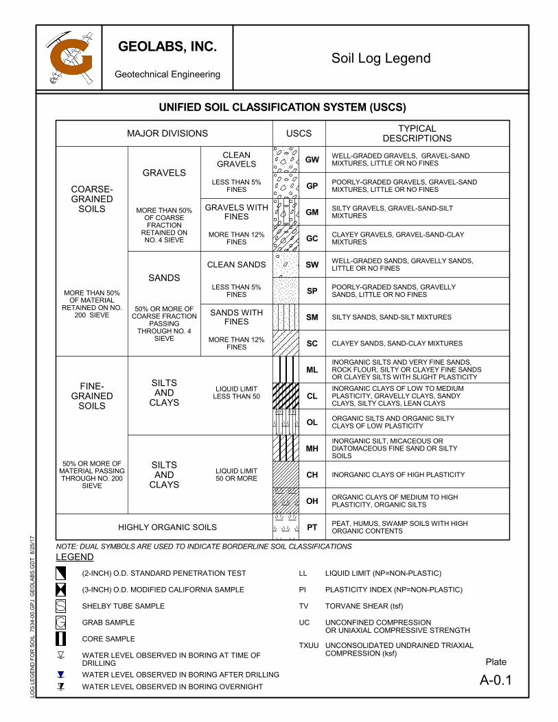
A-0.1
UNCONSOLIDATED UNDRAINED TRIAXIALCOMPRESSION (ksf)
MORE THAN 50%OF COARSEFRACTION
RETAINED ONNO. 4 SIEVE
50% OR MORE OFCOARSE FRACTION
PASSINGTHROUGH NO. 4
SIEVE
MORE THAN 50%OF MATERIAL
RETAINED ON NO.200 SIEVE
50% OR MORE OFMATERIAL PASSINGTHROUGH NO. 200
SIEVE
TORVANE SHEAR (tsf)
(2-INCH) O.D. STANDARD PENETRATION TEST
(3-INCH) O.D. MODIFIED CALIFORNIA SAMPLE
INORGANIC SILTS AND VERY FINE SANDS,ROCK FLOUR, SILTY OR CLAYEY FINE SANDSOR CLAYEY SILTS WITH SLIGHT PLASTICITY
POORLY-GRADED GRAVELS, GRAVEL-SANDMIXTURES, LITTLE OR NO FINES
CLAYEY GRAVELS, GRAVEL-SAND-CLAYMIXTURES
WELL-GRADED SANDS, GRAVELLY SANDS,LITTLE OR NO FINES
POORLY-GRADED SANDS, GRAVELLYSANDS, LITTLE OR NO FINES
SILTY SANDS, SAND-SILT MIXTURES
CLAYEY SANDS, SAND-CLAY MIXTURES
LIQUID LIMIT50 OR MORE CH
NOTE: DUAL SYMBOLS ARE USED TO INDICATE BORDERLINE SOIL CLASSIFICATIONS
MH
SILTSAND
CLAYS
SILTSAND
CLAYS
LIQUID LIMITLESS THAN 50
USCS TYPICALDESCRIPTIONS
GW
MORE THAN 12%FINES
WATER LEVEL OBSERVED IN BORING OVERNIGHT
HIGHLY ORGANIC SOILS
SILTY GRAVELS, GRAVEL-SAND-SILTMIXTURES
OL
PEAT, HUMUS, SWAMP SOILS WITH HIGHORGANIC CONTENTS
INORGANIC CLAYS OF LOW TO MEDIUMPLASTICITY, GRAVELLY CLAYS, SANDYCLAYS, SILTY CLAYS, LEAN CLAYS
Soil Log Legend
ORGANIC CLAYS OF MEDIUM TO HIGHPLASTICITY, ORGANIC SILTS
SC
Plate
GM
FINE-GRAINED
SOILS
COARSE-GRAINED
SOILS
CLEAN SANDS
SANDS WITHFINES
SP
SANDS
GRAVELS
WELL-GRADED GRAVELS, GRAVEL-SANDMIXTURES, LITTLE OR NO FINES
ML
CL
OH
LESS THAN 5%FINES
GRAVELS WITHFINES
CLEANGRAVELS
GRAB SAMPLE
PLASTICITY INDEX (NP=NON-PLASTIC)
TV
LEGEND
WATER LEVEL OBSERVED IN BORING AT TIME OFDRILLING
WATER LEVEL OBSERVED IN BORING AFTER DRILLING
SM
MAJOR DIVISIONS
GP
MORE THAN 12%FINES
PT
LESS THAN 5%FINES
UNIFIED SOIL CLASSIFICATION SYSTEM (USCS)
ORGANIC SILTS AND ORGANIC SILTYCLAYS OF LOW PLASTICITY
SW
GC
INORGANIC SILT, MICACEOUS ORDIATOMACEOUS FINE SAND OR SILTYSOILS
INORGANIC CLAYS OF HIGH PLASTICITY
PI
LL
TXUU
UNCONFINED COMPRESSIONOR UNIAXIAL COMPRESSIVE STRENGTH
CORE SAMPLE
SHELBY TUBE SAMPLE
LIQUID LIMIT (NP=NON-PLASTIC)
UC
GEOLABS, INC.
Geotechnical Engineering
LOG
LE
GE
ND
FO
R S
OIL
753
4-00
.GP
J G
EO
LAB
S.G
DT
8/2
5/1
7

A-0.2
Gravel
#10 to #40 (2-mm to 0.425-mm)
#40 to #200 (0.425-mm to 0.075-mm)
3 to 12 inches (75-mm to 305-mm)
Description
PP Readings(tsf)
2.0 - 4.0
> 4.0
N-Value (Blows/Foot)MCS
0 - 4
RELATIVE DENSITY / CONSISTENCY
GRAIN SIZE DEFINITION
ABBREVIATIONS
N-Value (Blows/Foot)
0 - 7
Dry: Absence of moisture, dry to the touch
Moist: Damp but no visible water
Wet: Visible free water, usually soil is below water table
WOH: Weight of Hammer
WOR: Weight of Drill Rods
SPT: Standard Penetration Test Split-Spoon Sampler
MCS: Modified California Sampler
PP: Pocket Penetrometer
4 - 7
7 - 15
15 - 27
27 - 55
SPT
0 - 2
> 55> 30
4 - 8
Medium Sand
Fine Sand
#4 to #200 (4.75-mm to 0.075-mm)
#4 to #10 (4.75-mm to 2-mm)
> 12 inches (305-mm)
3-inch to #4 (75-mm to 4.75-mm)
Sieve Number and / or Size
15 - 30
MOISTURE CONTENT DEFINITIONS
SPT
0 - 4
4 - 10
10 - 30
30 - 50
> 50
MCS
Loose
EXAMPLE: Soil Containing 60% Gravel, 25% Sand, 15% Fines. Described as: SILTY GRAVEL with some sand
Plate
GRANULAR SOIL (- #200 <50%)
2 - 4
8 - 15
RelativeDensity
Very Loose
Dense
Very Dense
COHESIVE SOIL (- #200 50%)
PRIMARY constituents are composed of the largestpercent of the soil mass. Primary constituents arecapitalized and bold (i.e., GRAVEL, SAND)
PRIMARY constituents are based on plasticity. Primaryconstituents are capitalized and bold (i.e., CLAY, SILT)
SECONDARY constituents are composed of apercentage less than the primary constituent. If the soilmass consists of 12 percent or more fines content, acohesive constituent is used (SILTY or CLAYEY);otherwise, a granular constituent is used (GRAVELLYor SANDY) provided that the secondary constituentconsists of 20 percent or more of the soil mass.Secondary constituents are capitalized and bold (i.e.,SANDY GRAVEL, CLAYEY SAND) and precede theprimary constituent.
SECONDARY constituents are composed of apercentage less than the primary constituent, but morethan 20 percent of the soil mass. Secondary constituentsare capitalized and bold (i.e., SANDY CLAY, SILTYCLAY, CLAYEY SILT) and precede the primaryconstituent.
Sand
Boulders
Cobbles
Coarse Gravel 3-inch to 3/4-inch (75-mm to 19-mm)
Fine Gravel 3/4-inch to #4 (19-mm to 4.75-mm)
GEOLABS, INC. CLASSIFICATION*
Granular Soils Cohesive Soils
Consistency
accessory descriptions compose of the following:with some: >12%with a little: 5 - 12%with traces of: <5%accessory descriptions are lower cased and follow thePrimary and Secondary Constituents(i.e., SILTY CLAY with some sand)
Very Soft
Soft
Medium Stiff
Stiff
Very Stiff
Hard
< 0.5
0.5 - 1.0
1.0 - 2.0
7 - 18
18 - 55
55 - 91
> 91
Medium Dense
Coarse Sand
(with deviations from ASTM D2488)Soil Classification Log Key
*Soil descriptions are based on ASTM D2488-09a, Visual-Manual Procedure, with theabove modifications by Geolabs, Inc. to the Unified Soil Classification System (USCS).
accessory descriptions compose of the following:with some: >12%with a little: 5 - 12%with traces of: <5%accessory descriptions are lower cased and follow thePrimary and Secondary Constituents(i.e., SILTY GRAVEL with a little sand)
SO
IL_C
LAS
S_L
OG
_KE
Y 7
534-
00.
GP
J G
EO
LAB
S.G
DT
8/2
5/1
7
GEOLABS, INC.
Geotechnical Engineering

A-0.3
ROCK DESCRIPTIONS
Plate
BRECCIA
CLINKER
COBBLES
CORAL
BASALT
ROCK DESCRIPTION SYSTEM
Greater than 24 inches apart
12 to 24 inches apart
6 to 12 inches apart
3 to 6 inches apart
Less than 3 inches apart
Rock shows no sign of discoloration or loss of strength.
Slight discoloration inwards from open fractures.
Discoloration throughout and noticeably weakened though not able to break by hand.
Most minerals decomposed with some corestones present in residual soil mass. Can be broken by hand.
Saprolite. Mineral residue completely decomposed to soil but fabric and structure preserved.
The following terms describe general fracture spacing of a rock:
The following terms describe the chemical weathering of a rock:
ROCK FRACTURE CHARACTERISTICS
DEGREE OF WEATHERING
HARDNESS
BOULDERS
VOID/CAVITY
TUFF
SILTSTONE
LIMESTONE
Unweathered:
Slightly Weathered:
Moderately Weathered:
Highly Weathered:
Extremely Weathered:
Very Hard:
Hard:
Medium Hard:
Soft:
Very Soft:
SANDSTONE
Massive:
Slightly Fractured:
Moderately Fractured:
Closely Fractured:
Severely Fractured:
Rock Log Legend
The following terms describe the resistance of a rock to indentation or scratching:
Specimen breaks with difficulty after several "pinging" hammer blows.Example: Dense, fine grain volcanic rock
Specimen breaks with some difficulty after several hammer blows.Example: Vesicular, vugular, coarse-grained rock
Specimen can be broked by one hammer blow. Cannot be scraped by knife. SPT may penetrate by~25 blows per inch with bounce.Example: Porous rock such as clinker, cinder, and coral reef
Can be indented by one hammer blow. Can be scraped or peeled by knife. SPT can penetrate by~100 blows per foot.Example: Weathered rock, chalk-like coral reef
Crumbles under hammer blow. Can be peeled and carved by knife. Can be indented by fingerpressure.Example: Saprolite
CONGLOMERATE
GEOLABS, INC.
Geotechnical Engineering
LOG
LE
GE
ND
FO
R R
OC
K 7
534-
00.
GP
J G
EO
LAB
S.G
DT
8/2
5/1
7

46
53
42
45
44
15
29
27
75
72
72
GPCH
CH
SM
0
0
15
2.5
3.5
13
7
15
12
37
52/6"+34/2"Ref.
34/6"+25/3"Ref.
103/6"
67
89
83
LL=78PI=45
Consol.
Sieve- #200 =74.5%
Sieve- #200 =31.4%
2-inch ASPHALTIC CONCRETEBrownish gray SANDY GRAVEL with a little silt,
medium dense, moist (fill)Brown with multi-color mottling SILTY CLAY with
some weathered gravel (basaltic), medium stiff,moist (saprolite)
grades with sand at 3 feet
Grayish brown SILTY CLAY with a little sand andtraces of gravel (basaltic), stiff, moist (saprolite)
grades with more sand, very stiff
Gray with tan mottling SILTY SAND with someweathered gravel (basaltic), very dense, moist(weathered basalt)
Brownish gray vesicular BASALT, closely toseverely fractured, moderately to highlyweathered, medium hard (basalt formation)
Dark gray with light gray mottling vesicularBASALT, severely fractured, moderately tohighly weathered, medium hard to hard (basaltformation)
grades to severely to closely fractured
Log ofBoring
Date Started:
Date Completed:
Logged By:
Total Depth:
Work Order:
Oth
er T
ests
Plate
Poc
ket P
en.
(tsf
)
MOBILE B-80
4" Solid Stem Auger & HQ Coring
140 lb. wt., 30 in. drop
5
10
15
20
25
30
35
Gra
phic
Drill Rig:
Drilling Method:
Driving Energy:
Pen
etra
tion
Res
ista
nce
(blo
ws/
foot
)
Approximate Ground SurfaceElevation (feet MSL): 351.5 *
Sam
ple
Moi
stur
eC
onte
nt (
%)
1
Dry
Den
sity
(pcf
)
Description
Laboratory
RQ
D (
%)
Cor
eR
ecov
ery
(%
)
July 10, 2017
July 10, 2017
N. Vaiana
102 feet
7534-00
US
CS
Dep
th (
fee
t)
Water Level:
Field
A - 1.1(Energy Transfer Ratio = 44.9%)
GEOLABS, INC.
Geotechnical Engineering
ANAHOLA FARM LOTSWATER SYSTEM IMPROVEMENTS
ANAHOLA, KAUAI, HAWAII
BO
RIN
G_L
OG
75
34-0
0.G
PJ
GE
OLA
BS
.GD
T 9
/19/
17
Not Encountered

23
83
75
92
50
75
67
95
100
100
100
100
100
100
UC=2110 psi
UC=1120 psi
Gray BASALT, slightly fractured, moderatelyweathered, hard (basalt formation)
grades to closely to moderately fractured
Log ofBoring
Date Started:
Date Completed:
Logged By:
Total Depth:
Work Order:
Oth
er T
ests
Plate
Poc
ket P
en.
(tsf
)
MOBILE B-80
4" Solid Stem Auger & HQ Coring
140 lb. wt., 30 in. drop
40
45
50
55
60
65
70
Gra
phic
Drill Rig:
Drilling Method:
Driving Energy:
Pen
etra
tion
Res
ista
nce
(blo
ws/
foot
)
Sam
ple
Moi
stur
eC
onte
nt (
%)
1
Dry
Den
sity
(pcf
)
Description
Laboratory
RQ
D (
%)
Cor
eR
ecov
ery
(%
)
(Continued from previous plate)
July 10, 2017
July 10, 2017
N. Vaiana
102 feet
7534-00
US
CS
Dep
th (
fee
t)
Water Level:
Field
A - 1.2(Energy Transfer Ratio = 44.9%)
GEOLABS, INC.
Geotechnical Engineering
ANAHOLA FARM LOTSWATER SYSTEM IMPROVEMENTS
ANAHOLA, KAUAI, HAWAII
BO
RIN
G_L
OG
75
34-0
0.G
PJ
GE
OLA
BS
.GD
T 9
/19/
17
Not Encountered
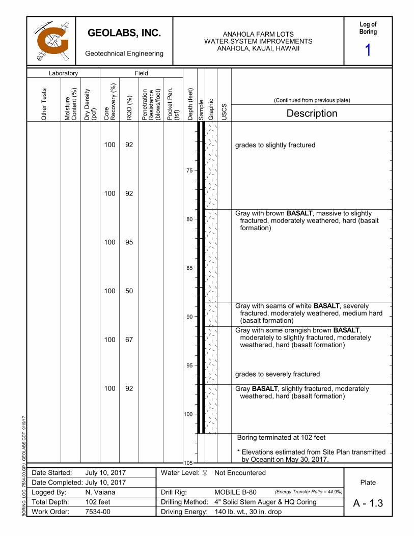
92
92
95
50
67
92
100
100
100
100
100
100
grades to slightly fractured
Gray with brown BASALT, massive to slightlyfractured, moderately weathered, hard (basaltformation)
Gray with seams of white BASALT, severelyfractured, moderately weathered, medium hard(basalt formation)
Gray with some orangish brown BASALT,moderately to slightly fractured, moderatelyweathered, hard (basalt formation)
grades to severely fractured
Gray BASALT, slightly fractured, moderatelyweathered, hard (basalt formation)
Boring terminated at 102 feet
* Elevations estimated from Site Plan transmittedby Oceanit on May 30, 2017.
Log ofBoring
Date Started:
Date Completed:
Logged By:
Total Depth:
Work Order:
Oth
er T
ests
Plate
Poc
ket P
en.
(tsf
)
MOBILE B-80
4" Solid Stem Auger & HQ Coring
140 lb. wt., 30 in. drop
75
80
85
90
95
100
105
Gra
phic
Drill Rig:
Drilling Method:
Driving Energy:
Pen
etra
tion
Res
ista
nce
(blo
ws/
foot
)
Sam
ple
Moi
stur
eC
onte
nt (
%)
1
Dry
Den
sity
(pcf
)
Description
Laboratory
RQ
D (
%)
Cor
eR
ecov
ery
(%
)
(Continued from previous plate)
July 10, 2017
July 10, 2017
N. Vaiana
102 feet
7534-00
US
CS
Dep
th (
fee
t)
Water Level:
Field
A - 1.3(Energy Transfer Ratio = 44.9%)
GEOLABS, INC.
Geotechnical Engineering
ANAHOLA FARM LOTSWATER SYSTEM IMPROVEMENTS
ANAHOLA, KAUAI, HAWAII
BO
RIN
G_L
OG
75
34-0
0.G
PJ
GE
OLA
BS
.GD
T 9
/19/
17
Not Encountered

43
33
37
51
46
72
70
67
GPCH
CH
3.0
2.3
2.5
17
8
12
9
25
Sieve- #200 =80.7%
DirectShear
LL=80PI=48
2-inch ASPHALTIC CONCRETEBrownish gray SANDY GRAVEL with a little silt,
medium dense, moist (fill)Brown with multi-color mottling SILTY CLAY with
some weathered gravel (basaltic), stiff, moist(saprolite)
grades to medium stiff
Grayish brown SILTY CLAY with a little sand andgravel (basaltic), stiff, moist (saprolite)
grades with more weathered gravel (basaltic)
Boring terminated at 16.5 feet
Log ofBoring
Date Started:
Date Completed:
Logged By:
Total Depth:
Work Order:
Oth
er T
ests
Plate
Poc
ket P
en.
(tsf
)
MOBILE B-80
4" Solid Stem Auger
140 lb. wt., 30 in. drop
5
10
15
20
25
30
35
Gra
phic
Drill Rig:
Drilling Method:
Driving Energy:
Pen
etra
tion
Res
ista
nce
(blo
ws/
foot
)
Approximate Ground SurfaceElevation (feet MSL): 350 *
Sam
ple
Moi
stur
eC
onte
nt (
%)
2
Dry
Den
sity
(pcf
)
Description
Laboratory
RQ
D (
%)
Cor
eR
ecov
ery
(%
)
July 13, 2017
July 13, 2017
N. Vaiana
16.5 feet
7534-00
US
CS
Dep
th (
fee
t)
Water Level:
Field
A - 2(Energy Transfer Ratio = 44.9%)
GEOLABS, INC.
Geotechnical Engineering
ANAHOLA FARM LOTSWATER SYSTEM IMPROVEMENTS
ANAHOLA, KAUAI, HAWAII
BO
RIN
G_L
OG
75
34-0
0.G
PJ
GE
OLA
BS
.GD
T 9
/19/
17
Not Encountered

21
32
36
45
36
42
29
39
82
83
74
80
CH
CH
CH
CH
SM
4.3
2.8
34
15
33
9
49
13
27
17
TXUUSu=3.9 ksf
LL=106PI=72
Orangish brown SILTY CLAY with some sandand gravel (basaltic), very stiff, moist (saprolite)
Dark orangish brown SILTY CLAY, hard, moist(saprolite)
grades with sand
Brownish gray with multi-color mottling SILTYCLAY with some sand, weathered gravel, andcobbles (basaltic), very stiff, moist (saprolite)
Dark brown with gray mottling SILTY CLAY withsome sand and weathered gravel (basaltic), stiff,moist (saprolite)
grades with seems of gray clay
Dark gray with tan mottling SILTY SAND withsome weathered gravel (basaltic), mediumdense, moist (weathered basalt)
Boring terminated at 31.5 feet
Log ofBoring
Date Started:
Date Completed:
Logged By:
Total Depth:
Work Order:
Oth
er T
ests
Plate
Poc
ket P
en.
(tsf
)
MOBILE B-80
4" Solid Stem Auger
140 lb. wt., 30 in. drop
5
10
15
20
25
30
35
Gra
phic
Drill Rig:
Drilling Method:
Driving Energy:
Pen
etra
tion
Res
ista
nce
(blo
ws/
foot
)
Approximate Ground SurfaceElevation (feet MSL): 345.5 *
Sam
ple
Moi
stur
eC
onte
nt (
%)
3
Dry
Den
sity
(pcf
)
Description
Laboratory
RQ
D (
%)
Cor
eR
ecov
ery
(%
)
July 13, 2017
July 13, 2017
N. Vaiana
31.5 feet
7534-00
US
CS
Dep
th (
fee
t)
Water Level:
Field
A - 3(Energy Transfer Ratio = 44.9%)
GEOLABS, INC.
Geotechnical Engineering
ANAHOLA FARM LOTSWATER SYSTEM IMPROVEMENTS
ANAHOLA, KAUAI, HAWAII
BO
RIN
G_L
OG
75
34-0
0.G
PJ
GE
OLA
BS
.GD
T 9
/19/
17
Not Encountered

APPENDIX B

W.O. 7534-00 GEOLABS, INC. OCTOBER 2017 Page B-1 Hawaii • California
A P P E N D I X B
Seismic Shear Wave Velocity Test
Seismic shear wave velocity profiling of the subsurface materials at the project site was performed using Seismic Cone Penetration Testing (SCPT) equipment. The purpose of the seismic shear wave velocity profiling of the subsurface materials was to more closely analyze the seismic design considerations for the project. Shear wave velocity testing using seismic cone penetration test equipment was performed at a selected boring location, designated as [B-1(SW)] on the Site Plan (Plate 2). The seismic shear wave velocity profiling was performed to a depth of about 100 feet below the existing pavement surface.
In order to conduct the seismic shear wave velocity test in the boring, the test boring was advanced utilizing rotary coring methods to the maximum depth of the boring. Log of the materials encountered in the boring are presented in the Logs of Borings in Appendix A. After the boring was advanced to the maximum depth of the borehole, the bored hole was backfilled with 0.25-inch diameter coated bentonite pellets. The temporary casing from the coring operations was used as a tremie pipe to place the bentonite pellets starting from the bottom and advancing upward. When the bentonite pellets are in contact with the groundwater in the borehole, the pellets start to hydrate slowly. As the bentonite pellets hydrate, they swell and soften. The probe was then pushed through the softened bentonite extending to a depth of about 100 feet below the existing ground surface using seismic piezocone testing equipment (SCPTU).
The seismic shear wave velocity test consists of hydraulically pushing a 10-ton steel electronic subtraction cone with an apex angle of 60 degrees and a projected surface area of 1.55 square inches (10 square centimeters) into the bored hole. The cone carries a uniaxial horizontal accelerator geophone to detect the arrival of a shear wave generated and propagated from the ground surface. The seismic measurements were made when the SCPT had stopped and a shear wave was sent into the subsurface. A shear wave was generated at the surface by striking a loaded plank with a switched hammer. The propagation time of the wave from the hammer blow to the cone was measured at each discrete depth interval. The vector difference of these depths divided by the time difference for the shear wave to arrive at the various depths have provided the average shear wave velocity over the depth interval.
The seismic shear wave velocities measured and the weighted average seismic shear wave velocity calculated for the top 100 feet of the soil profile at the boring location are presented on Plates B-1.1 through B-1.4 in Appendix B. The weighted average shear wave velocity was calculated based on the average shear wave velocity method described in Section 1615.1.5 of the International Building Code (2006 Edition).

13
7
15
12
37
52/6"+34/2"Ref.
34/6"+25/3"Ref.
103/6"
2.5
3.5
GPCH
CH
SM
67
89
83
630
600
690
1660
970
1100
1590
2100
3850
3830
5390
1.5-inch ASPHALTIC CONCRETEBrownish gray SANDY GRAVEL with a little silt,
medium dense, moist (fill)Brown with multi-color mottling SILTY CLAY with
some weathered gravel (basaltic), medium stiff,moist (saprolite)
grades with sand at 3 feet
Grayish brown SILTY CLAY with a little sand andtraces of gravel (basaltic), stiff, moist (saprolite)
grades with more sand, very stiff
Gray with tan mottling SILTY SAND with someweathered gravel (basaltic), very dense, moist(weathered basalt)
Brownish gray vesicular BASALT, closely toseverely fractured, moderately to highlyweathered, medium hard (basalt formation)
Dark gray with light gray mottling vesicularBASALT, severely fractured, moderately tohighly weathered, medium hard to hard (basaltformation)
grades to severely to closely fractured
Plate
Date Started:
Date Completed:
Logged By:
Total Depth:
Work Order:
Drill Rig:
Drilling Method:
Driving Energy:
July 10, 2017
July 10, 2017
N. Vaiana
102 feet
7534-00
Water Level:
Dep
th (
feet
)
Poc
ket P
en.
(tsf
)SHEAR WAVE
VELOCITY(feet/sec)
Cor
eR
ecov
ery
(%
)
MOBILE B-80
4" Solid Stem Auger & HQ Coring
140 lb. wt., 30 in. drop
US
CS
5
10
15
20
25
30
35
B - 1.1
Approximate Ground SurfaceElevation (feet MSL): 351.5 *
Description
Pen
etra
tion
Res
ista
nce
(blo
ws/
foot
)
Sam
ple
Gra
phic
1000 2000 3000 4000
Data Plot ofBoring
1
SH
EA
R_W
AV
E_P
LOT
753
4-0
0.G
PJ
GE
OLA
BS
.GD
T 9
/20
/17
Not Encountered
GEOLABS, INC.
Geotechnical Engineering
ANAHOLA FARM LOTSWATER SYSTEM IMPROVEMENTS
ANAHOLA, KAUAI, HAWAII

95
100
100
100
100
100
100
5080
9110
7350
4080
5100
4640
7090
Gray BASALT, slightly fractured, moderatelyweathered, hard (basalt formation)
grades to closely to moderately fractured
Plate
Date Started:
Date Completed:
Logged By:
Total Depth:
Work Order:
Drill Rig:
Drilling Method:
Driving Energy:
July 10, 2017
July 10, 2017
N. Vaiana
102 feet
7534-00
Water Level:
Dep
th (
feet
)
Poc
ket P
en.
(tsf
)SHEAR WAVE
VELOCITY(feet/sec)
Cor
eR
ecov
ery
(%
)
MOBILE B-80
4" Solid Stem Auger & HQ Coring
140 lb. wt., 30 in. drop
US
CS
40
45
50
55
60
65
70
(Continued from previous plate)
B - 1.2
Description
Pen
etra
tion
Res
ista
nce
(blo
ws/
foot
)
Sam
ple
Gra
phic
1000 2000 3000 4000
Data Plot ofBoring
1
SH
EA
R_W
AV
E_P
LOT
753
4-0
0.G
PJ
GE
OLA
BS
.GD
T 9
/20
/17
Not Encountered
GEOLABS, INC.
Geotechnical Engineering
ANAHOLA FARM LOTSWATER SYSTEM IMPROVEMENTS
ANAHOLA, KAUAI, HAWAII

100
100
100
100
100
100
7210
5620
8440
5420
7540
grades to slightly fractured
Gray with brown BASALT, massive to slightlyfractured, moderately weathered, hard (basaltformation)
Gray with seams of white BASALT, severelyfractured, moderately weathered, medium hard(basalt formation)
Gray with some orangish brown BASALT,moderately to slightly fractured, moderatelyweathered, hard (basalt formation)
grades to severely fractured
Gray BASALT, slightly fractured, moderatelyweathered, hard (basalt formation)
Boring terminated at 102 feet
* Elevations estimated from Site Plan transmittedby Oceanit on May 30, 2017.
Plate
Date Started:
Date Completed:
Logged By:
Total Depth:
Work Order:
Drill Rig:
Drilling Method:
Driving Energy:
July 10, 2017
July 10, 2017
N. Vaiana
102 feet
7534-00
Water Level:
Dep
th (
feet
)
Poc
ket P
en.
(tsf
)SHEAR WAVE
VELOCITY(feet/sec)
Cor
eR
ecov
ery
(%
)
MOBILE B-80
4" Solid Stem Auger & HQ Coring
140 lb. wt., 30 in. drop
US
CS
75
80
85
90
95
100
105
(Continued from previous plate)
B - 1.3
Description
Pen
etra
tion
Res
ista
nce
(blo
ws/
foot
)
Sam
ple
Gra
phic
1000 2000 3000 4000
Data Plot ofBoring
1
SH
EA
R_W
AV
E_P
LOT
753
4-0
0.G
PJ
GE
OLA
BS
.GD
T 9
/20
/17
Not Encountered
GEOLABS, INC.
Geotechnical Engineering
ANAHOLA FARM LOTSWATER SYSTEM IMPROVEMENTS
ANAHOLA, KAUAI, HAWAII

SHEAR WAVE VELOCITY TEST RESULTS
Anahola Farm Lots Water System ImprovementsAnahola, Kauai, Hawaii
Depth Depth Layer Thickness
Estimated Shear
Wave Velocity
Average Travel
Time
(From) (To) (d i ) (V si ) (d i /V si )
(feet) (feet) (feet) (feet/second) (milliseconds)
0.0 2.2 2.2 634 3.46
2.2 4.2 2.0 598 3.36
4.2 7.4 3.2 690 4.66
7.4 10.6 3.2 1,658 1.92
10.6 13.8 3.2 967 3.32
13.8 17.2 3.3 1,103 3.03
17.2 20.4 3.2 1,586 2.03
20.4 23.6 3.2 2,098 1.52
23.6 26.8 3.2 3,848 0.84
26.8 30.1 3.3 3,834 0.87
30.1 33.3 3.2 5,385 0.60
33.3 36.5 3.2 5,083 0.63
36.5 39.7 3.2 9,111 0.35
39.7 42.9 3.2 7,349 0.43
42.9 49.3 6.4 4,078 1.57
49.3 55.7 6.4 5,096 1.26
55.7 62.3 6.6 4,637 1.42
62.3 68.7 6.4 7,088 0.90
68.7 75.8 7.1 7,214 0.98
75.8 82.1 6.4 5,622 1.13
82.1 88.7 6.6 8,440 0.78
88.7 95.3 6.6 5,415 1.21
95.3 100.0 4.8 7,542 0.63
TOTAL 100.0 36.89
Standard Weighted Average 4,883 feet/second
Computed Vs100' Using IBC Formula 2,711 feet/second
W.O. 7543‐00 GEOLABS, INC. PLATE B‐1.4Hawaii California
B‐1

APPENDIX C

W.O. 7534-00 GEOLABS, INC. OCTOBER 2017 Page C-1 Hawaii • California
A P P E N D I X C
Laboratory Tests
Moisture Content (ASTM D2216) and Unit Weight (ASTM D2937) determinations were performed on selected samples as an aid in the classification and evaluation of soil properties. The test results are presented on the Logs of Borings at the appropriate sample depths.
Three Atterberg Limits tests (ASTM D4318) were performed on selected soil samples to evaluate the liquid and plastic limits. The test results are summarized on the Logs of Borings at the appropriate sample depths. Graphic presentation of the test results is provided on Plate C-1.
Three Sieve Analysis tests (ASTM C117 & C136) were performed on selected soil samples to evaluate the gradation characteristics of the soils and to aid in soil classification. Graphic presentation of the grain size distributions is provided on Plate C-2.
Four One-Inch Ring Swell tests were performed on relatively undisturbed and remolded samples to evaluate the swelling potential of the on-site soils. The test results are summarized on Plate C-3.
One Consolidation test was performed on a selected soil sample to evaluate the compressibility characteristic of the on-site soils. The test was performed in accordance with ASTM D2435, and the test results are plotted on Plate C-4.
One Direct Shear test (ASTM D3080) was performed on a selected sample to evaluate the shear strength characteristics of the material tested. The test results are presented on Plate C-5.
One Triaxial Unconsolidated Undrained Compression (TXUU) test was performed on a selected in-situ soil sample in accordance with ASTM D2850 to evaluate the undrained shear strength of the soils. The approximate in-situ effective overburden pressure was used as the applied confining pressure for the “undisturbed” sample. The test results and the stress-strain curve are presented on Plate C-6.
Two Uniaxial Compressive Strength tests (ASTM D7012) were performed on selected rock cores to evaluate their unconfined compressive strength of the rock formation encountered. Test results are presented on Plate C-7.
One Modified Proctor compaction test (ASTM D1557) was performed on a bulk sample of the near-surface soils to evaluate the dry density and moisture content relationships. The test results are presented on Plate C-8.
One laboratory California Bearing Ratio test (ASTM D1883) was performed on a bulk sample of the near-surface soils to evaluate the pavement support characteristics of the soils. The test results are presented on Plate C-9.

0
10
20
30
40
50
60
70
80
90
100
0 20 40 60 80 100 120
ML or OLCL-ML
CL or OL CH or OH
C - 1
MH or OH
LIQUID LIMIT
PLA
ST
ICIT
Y I
ND
EX
ATTERBERG LIMITS TEST RESULTS - ASTM D4318
PIDepth (ft)Sample LL PL Description
B-1
B-2
B-3
2.5-4.0
10.0-11.5
20.0-21.5
78
80
106
33
32
34
45
48
72
Brown with multi-color mottling silty clay (CH) with some gravel
Grayish brown silty clay (CH) with a little sand and gravel
Dark brown silty clay (CH) with some sand and gravel
NP = NON-PLASTIC
4
7
Plate
W.O. 7534-00
GEOTECHNICAL ENGINEERING
GEOLABS, INC.ANAHOLA FARM LOTS
WATER SYSTEM IMPROVEMENTSANAHOLA, KAUAI, HAWAII
G_A
TT
ER
BE
RG
_PI-
100_
LL-
120
753
4-00
.GP
J G
EO
LAB
S.G
DT
9/1
9/1
7

0
5
10
15
20
25
30
35
40
45
50
55
60
65
70
75
80
85
90
95
100
0.0010.010.1110100
1.268
C - 2
coarse
11.53 2 40
Depth (ft)
%Gravel
0.0
26.9
4.2
25.5
41.7
15.1
%Sand
COBBLES
Sample D30 (mm)
14020
HYDROMETER
3
GRAIN SIZE IN MILLIMETERS
PE
RC
EN
T F
INE
R B
Y W
EIG
HT
100
coarse
1/2
Sample Cu
GRAVEL
U.S. SIEVE NUMBERS
D10 (mm)
16
fine
2
37.5
19
Cc
3/4
fineSILT OR CLAY
medium
GRAIN SIZE DISTRIBUTION - ASTM C117 & C136
SAND
%Fine
604 30 20046
74.5
31.4
80.7
Depth (ft)
LL
Grayish brown silty clay (CH) with some sand
Gray with tan mottling silty sand (SM) with some gravel
Brown with multi-color mottling silty clay (CH) with some sand
810 14
50
U.S. SIEVE OPENING IN INCHES
6
D60 (mm)D100 (mm)
B-1
B-1
B-2
15.0-16.5
20.0-21.2
1.0-2.5
15.0-16.5
20.0-21.2
1.0-2.5
B-1
B-1
B-2
3/8
PL PIDescription
Plate
W.O. 7534-00
GEOTECHNICAL ENGINEERING
GEOLABS, INC.ANAHOLA FARM LOTS
WATER SYSTEM IMPROVEMENTSANAHOLA, KAUAI, HAWAII
G_G
RA
IN_S
IZE
_MO
D 7
534-
00.G
PJ
GE
OLA
BS
.GD
T 9
/19/
17

B-1* 1.0 - 2.5 Brown with multi-color mottling silty clay withsome weathered gravel 70.1 45.3 39.0 50.7 1.7
B-2** 2.5 - 4.0 Brown with multi-color mottling silty clay withsome weathered gravel 89.6 30.9 27.8 45.8 10.6
B-3* 1.0 - 2.5 Orangish brown silty clay with some sandand gravel 70.9 32.4 28.3 48.4 6.7
B-3** 2.5 - 4.0 Orangish brown silty clay with some sandand gravel 89.1 31.3 27.8 36.8 14.9
Moisture ContentsLocation
SUMMARY OF RING SWELL TESTS
C - 3
NOTE:
Relatively Undisturbed*Remolded
Samples tested were either relatively undisturbed or remolded in 2.4-inch diameter by 1-inch high rings.They were air-dried overnight and then saturated for 24 hours under a surcharge pressure of 55 psf.
Depth
(feet)
Soil Description
(%)Initial Air-Dried Final
RingSwell
(pcf) (%) (%) (%)
DryDensity
**
Plate
W.O. 7534-00
GEOTECHNICAL ENGINEERING
GEOLABS, INC.ANAHOLA FARM LOTS
WATER SYSTEM IMPROVEMENTSANAHOLA, KAUAI, HAWAII
G_R
ING
_SW
ELL
_TE
ST
75
34-0
0.G
PJ
GE
OLA
BS
.GD
T
9/19
/17

0
1
2
3
4
5
6
7
8
9
100.1 1 10 100
Initial Final
Dry Density, pcf:
95.3
0.9328
100.0
1.301 1.301
Degree of Saturation, %
Void Ratio
Water Content, %Sample: B-1
Depth: 5.0 - 6.5 feet
Description: Brown with multi-color mottling siltyclay with some weathered gravel
Liquid Limit = Plasticity Index =
CO
NS
OLI
DA
TIO
N %
NORMAL PRESSURE, ksf
C - 4
52.0 54.5
64.764.7
Sample Height, inchesN/A N/A
CONSOLIDATION TEST - ASTM D2435
1.0000
Plate
W.O. 7534-00
GEOTECHNICAL ENGINEERING
GEOLABS, INC.ANAHOLA FARM LOTS
WATER SYSTEM IMPROVEMENTSANAHOLA, KAUAI, HAWAII
G_C
ON
SO
L 7
534
-00.
GP
J G
EO
LAB
S.G
DT
9/1
9/1
7

0
500
1,000
1,500
2,000
2,500
3,000
0 500 1,000 1,500 2,000 2,500 3,000NORMAL STRESS, psf
SH
EA
R S
TR
ES
S,
psf
INIT
IAL Moisture Content, %
Moisture Content, %
Dry Density, pcf
110 psf
33 degrees
853 1238 2158
0.0025 0.0021 0.0022
2.42 2.42 2.42
59.8 62.9 62.8
59.8 61.7 62.4
Cohesion:
0.43 0.41 0.43
0.999 0.981 0.995Height, inches
Diameter, inches
Peak Shear Stress, psf
Shear Displacement, inches
Brown with multi-colormottling silty clay with somegravel
1.00 1.00 1.00Height, inches
C - 5
64.7 61.2 60.9
FIN
AL
Dry Density, pcf
Normal Stress, psf
Sample: B-2
5.0 - 6.5 feetDepth:
Description:
57.6 57.4 58.1
Sample#1
Sample#2
Sample#3
Deformation Rate, inch/minute
Friction Angle:
1000 2000 3000
DIRECT SHEAR TEST - ASTM D3080
Plate
W.O. 7534-00
GEOTECHNICAL ENGINEERING
GEOLABS, INC.ANAHOLA FARM LOTS
WATER SYSTEM IMPROVEMENTSANAHOLA, KAUAI, HAWAII
G_D
IRE
CT
_SH
EA
R 7
534
-00
.GP
J G
EO
LAB
S.G
DT
9/
19/1
7

0
1
2
3
4
5
6
7
8
0 2 4 6 8 10
Location:
Sample Diameter (inches)
Sample Height (inches)
DE
VIA
TO
R S
TR
ES
S,
ksf
Max. Deviator Stress (ksf):
Confining Stress (ksf):
AXIAL STRAIN, %
0.6
7.8
Dry Density (pcf)
Moisture (%)
Axial Strain at Failure (%) Strain Rate (% / minute)
36.4
82.9
7.8
Dark orangish brown silty clay
5.0 - 6.5 feet
Description:
Depth:
B-3
TRIAXIAL UU COMPRESSION TEST - ASTM D2850
Test Date:
4.953
2.373
1.02
C - 6
7/25/2017
Plate
W.O. 7534-00
GEOTECHNICAL ENGINEERING
GEOLABS, INC.ANAHOLA FARM LOTS
WATER SYSTEM IMPROVEMENTSANAHOLA, KAUAI, HAWAII
G_T
XU
U 7
534-
00.G
PJ
GE
OLA
BS
.GD
T 9
/19/
17

B-1 37 - 42 4.520 2.410 1.88 150.2 9,630 2,110
B-1 42 - 47 4.550 2.400 1.90 125.5 5,050 1,120
C - 7
DepthLocation Length DiameterLength/
DiameterRatio
(feet) (inches) (inches) (pcf) (psi)
Density CompressiveStrengthLoad
UNIAXIAL COMPRESSIVE STRENGTH TEST
ASTM D7012 (METHOD C)
(lbs)
Plate
W.O. 7534-00
GEOTECHNICAL ENGINEERING
GEOLABS, INC.ANAHOLA FARM LOTS
WATER SYSTEM IMPROVEMENTSANAHOLA, KAUAI, HAWAII
G_R
OC
K_U
C_T
ES
T_P
OR
TR
AIT
753
4-0
0.G
PJ
GE
OLA
BS
.GD
T 9
/19/
17

75
80
85
90
95
100
105
110
115
120
125
130
135
0 10 20 30 40
94.0
31.5
DR
Y D
EN
SIT
Y,
pcf
Optimum Moisture Content:
Sample:
Depth:
TEST RESULTS
MOISTURE CONTENT, %
Description:
%
pcfMaximum Dry Density:
Brown silty clay
C - 8
3.20
3.10
3.00
2.90
2.80
2.70
2.60
1.0 - 3.0 feet
BULK-1
MOISTURE-DENSITY RELATIONSHIP - ASTM D1557 A
Test Date: July 27, 2017
Plate
W.O. 7534-00
GEOTECHNICAL ENGINEERING
GEOLABS, INC.ANAHOLA FARM LOTS
WATER SYSTEM IMPROVEMENTSANAHOLA, KAUAI, HAWAII
G_C
OM
PA
CT
ION
753
4-0
0.G
PJ
GE
OLA
BS
.GD
T 9
/19/
17

0
50
100
150
200
250
300
350
400
450
0 0.10 0.20 0.30 0.40 0.50 0.60
Sample:
Corr. CBR @ 0.1"
Depth:
Corr. CBR @ 0.2"
No. of Layers
CALIFORNIA BEARING RATIO - ASTM D1883
Description:
Days Soaked 5
BULK-1Swell (%) 1.96
16.4
16.4
Molding Dry Density (pcf)
ST
RE
SS
, ps
i
1.0 - 3.0 feet
No. of Blows
30.4
91.3
Molding Moisture (%)
Hammer Wt. (lbs)
Hammer Drop (inches)
PENETRATION, inches
Brown silty clay
18
56
10
5Aggregate
C - 9
3/4 inch minus
Plate
W.O. 7534-00
GEOTECHNICAL ENGINEERING
GEOLABS, INC.ANAHOLA FARM LOTS
WATER SYSTEM IMPROVEMENTSANAHOLA, KAUAI, HAWAII
G_C
BR
753
4-00
.GP
J G
EO
LAB
S.G
DT
9/1
9/1
7

APPENDIX D

Anahola Farm Lots Water System Improvements Anahola, Kauai, Hawaii
W.O. 7534‐00 GEOLABS, INC. PLATE D‐1 Hawaii • California
B‐1 22.0’ TO 53.5’

Anahola Farm Lots Water System Improvements Anahola, Kauai, Hawaii
W.O. 7534‐00 GEOLABS, INC. PLATE D‐2 Hawaii • California
B‐1 53.5’ TO 70.5’

Anahola Farm Lots Water System Improvements Anahola, Kauai, Hawaii
W.O. 7534‐00 GEOLABS, INC. PLATE D‐3 Hawaii • California
B‐1 70.5’ TO 95.5’

Anahola Farm Lots Water System Improvements Anahola, Kauai, Hawaii
W.O. 7534‐00 GEOLABS, INC. PLATE D‐4 Hawaii • California
B‐1 95.5’ TO 102.0’

DAVID Y. IGEGOVERNOR OF HAWAII
STATE OF HAWAIIDEPARTMENT OF HEALTH
P. 0. BOX 3378HONOLULU, HI 96801-3378
September 28, 2018
The Honorable William Aila, Jr.Deputy to the ChairmanDepartment of Hawaiian Home LandsPO Box 1879Honolulu, Hawaii 96813
Attention: Mr. Stewart MatsunagaMaster-Planned Community Development Manager
Dear Mr. Aila:
BRUCE S. ANDERSON, Ph.D.DIRECTOR OF HEALTH
In reply, please refer to:EMD/CWB
R10F642.FNL.18
Subject: NOTICE OF GENERAL PERMIT COVERAGE (NGPC)National Pollutant Discharge Elimination System (NPDES)Anahola Farm Lots Subdivision Water System Improvements Phase IIAnahola, Island of Kauai, HawaiiFile No. HI R10F642
This NGPC supersedes the document R10F594.FNL, dated July 26, 2018.
This letter is to notify you that the DEPARTMENT OF HAWAIIAN HOME LANDS,LAND DEVELOPMENT DIVISION (hereinafter PERMITTEE) is now covered under theNPDES General Permit authorizing discharges of storm water associated withconstruction activities. Coverage under this general permit authorizes you to dischargeonly storm water to the receiving State waters discharge point(s) from the projectlocation(s) identified in the Notice of Intent (N01), dated August 28, 2018, provided thatyou comply with Hawaii Administrative Rules (HAR) 11-54; HAR 11-55; HAR 11-55,Appendix A; HAR 11-55, Appendix C; and the information submitted in the NOI.Discharges of non-storm water, toxics, and other water pollutants to State waters arenot authorized by this NPDES General Permit. HAR 11-54 and 11-55 are available onthe Department of Health (DOH), Clean Water Branch (CWB) website at:http://health.hawaii.qov/cwb/.

The Honorable William Aila, Jr.September 28, 2018Page 2
R10F642.FNL.18
This NGPC will take effect on the date of this notice. This NGPC will expireat midnight, December 5, 2018, or when amendments to HAR, Chapter 11-55,Appendix C, are adopted, whichever occurs first. Failure to comply withHAR 11-54; HAR 11-55; HAR 11-55, Appendix A; HAR 11-55, Appendix C; andinformation provided in the NOI is an enforceable violation and your NGPCmay be terminated. If you violate Hawaii Revised Statutes (HRS), Chapter 342D,you may be subject to penalties of up to $25,000 per violation per day andup to two (2) years in jail.
Falsification of information, including providing information in the NOI thatdoes not match what is actually occurring at the project site/facility and failureto prepare the Storm Water Pollution Prevention Plan (SWPPP) prior to NOIsubmission, may result in criminal penalties for the Permittee and theirauthorized representative as provided in Clean Water Act, Section 309 andHRS, Section 342D-35.
As a reminder, this general permit requires the Permittee to:1. Notify DOH of the construction start date within seven (7) calendar days before
the start of construction activities.2. Complete and submit the Solid Waste Disclosure Form for Construction Sites to
the DOH, Solid and Hazardous Waste Branch, Solid Waste Section, as specifiedon the form at least 30 calendar days before the start of the constructionactivities. The form can be downloaded at:https://health.hawaii.qov/shwb/files/2018/04/swdiscformapr2018.pdf.
3. Implement the SWPPP in accordance with HAR 11-55, Appendix C. TheDirector reserves the right to require the Permittee to modify the SWPPP.
4. Submit a new NOI with filing fee and obtain a new NGPC for any revisions tothe information submitted in the NOI (with the exception of changes to contactperson information for non-transfer of ownerships and changes to the SWPPP).This NGPC cannot be modified.
5. Complete and submit the Notice of Cessation (NOC) within seven (7) calendar daysafter the end of the month that the subject project was completed.
All NGPC compliance submittals, including the NOC shall be submitted on the CWBCompliance Submittal Form for Individual NPDES Permits and NGPCs. This form shallbe completed on the e-Permitting Portal located at:https://eha-cloud.doh.hawaii.qov/epermit/.
The Permittee is responsible for obtaining other Federal, State, or localauthorizations as required by law.

The Honorable William Aila, Jr.September 28, 2018Page 3
R10F642.FNL.18
Please complete the DOH Customer Satisfaction Survey regarding your request forGeneral Permit coverage. This brief survey is available on the e-Permitting Portallocated at: https://eha-cloud.doh.hawaii.gov/epermitt. Please use the ApplicationFinder button and search for the "Customer Satisfaction Survey."
If you have any questions, please contact the Enforcement Section or Mr. Glenn Haaeof the Engineering Section, CWB, at (808) 586-4309.
Sincerely,
cig1-zt,(64k,
forBRUCE S. ANDERSON, Ph.D.Director of Health
c: Mr. Stewart Matsunaga, DHHL[via e-mail Stewart.T.Matsunacia hawaii.gov only]Mr. Jeremy Michelson, Oceanit [via e-mail imichelson oceanit.com only]Mr. Jordan Moniuszko, Oceanit [via e-mail imoniuszko oceanit.com only]CWB, Kauai District Health Office [via e-mail only]

All sections of this form MUST be completed for National Pollutant Discharge Elimination System (NPDES) General Permit compliance.
C.1 – General Information You are required to fulfill all requirements and check the box below. If you do not check the box, your NOI will be considered incomplete, and the CWB may deny your request for NPDES permit coverage with prejudice. ☒ I certify that:
• I prepared a Storm Water Pollution Prevention Plan (SWPPP) in accordance with HAR, Chapter 11-55, Appendix C, Section 7 prior to submitting this NOI.
• I will comply with all terms, conditions, and requirements in HAR Chapter 11-55, Appendix C.
• I will implement, operate, and maintain my SWPPP to ensure that storm water discharges associated with construction activities will not violate HAR, Chapter 11-54; HAR, Chapter 11-55; and HAR, Chapter 11-55, Appendix C.
C.2 - Existing Pollution Sources/ History of Land Use Describe the history of land use at the existing Facility/Project site: Water storage tank site and agricultural lots. Determine if the existing Facility/Project site may contain any existing pollution source(s) by using the following references. Place a check next to all references you utilized to determine existing pollution source(s). You are required to check at least one reference. ☐ a. DOH, Solid and Hazardous Waste Branch-Hawaii Underground Storage Tank- Leaking
Underground Storage Tank database ☐ b. DOH, Hazard Evaluation and Emergency Response Office records ☐ c. Phase I and/or Phase II Environmental Site Assessments, as applicable ☐ d. Recent site inspections ☒ e. Past land use history
State of Hawaii, Department of Health, Clean Water Branch
NOI Form C
NOI for HAR, Chapter 11-55, Appendix C - NPDES General Permit Authorizing Discharges of Storm Water Associated With Construction Activities (as defined in 40 CFR §§122.26(b)(14)(x) and 122.26(b)(15)(i))

NOI Form C
NOI Form C Page 2 of 7 Rev. 8/20/2013
☐ f. Soil sampling data, if available ☐ g. Other (specify): Describe any existing pollution source(s) identified in the references you checked above: None Describe any corrective measures that have been undertaken for any existing pollution source(s):
C.3 - Construction Site Estimates Please provide the following estimates for the construction site.
Total project area including areas to be left undisturbed: 8.2 acres
Construction site area to be disturbed including storage and staging areas: 4.1 acres
Impervious area before construction: 0.9 acres
Impervious area after construction: 0.9 acres
C.4 - Quantity of Storm Water Runoff
Estimate the quantity of storm water runoff during construction when the greatest and/or maximum area of disturbance occurs. Provide the supporting calculations in an attachment or insert in this section.
4.94 Mgd Millions of Gallons per Day (MGD) or 9.18 cfs Cubic Feet per Second (CFS)
Q = CIA where, Q = Storm runoff rate (cfs) C = Runoff coefficient I = Rainfall intensity (i) corrected for a duration equal to the time of concentration (Tc) A = Drainage Area (acres) Storm recurrence interval (Tm) = 2 year, 1-hr storm Intensity of 1-hr rainfall (i) = 2.7 in/hr (Plate 3) Drainage Area 1 C for pavement, 2 year 0.87 From Table 1 County of Kauai C for roofs, 2 year 0.80 From Table 1 County of Kauai C for lawns, clayey soil 0.20 From Design and Construction of Sanitary and Storm Sewers, ASCE, Heavy soil, 2-7% slope

NOI Form C
NOI Form C Page 3 of 7 Rev. 8/20/2013
C for forest 0.15 From McCuen, 2004, Hydrologic Soil Group C, 2-6% slope Total Area (A) 3.00 ac Area of pavement 8375 sf, 6.4% of total area Area of roofs 2331 sf, 1.8% of total area Area of lawns, clayey soil 3590 sf, 2.8% of total area Area of forest 116,384 sf, 89% of total area Weighted Runoff Coefficient (C) = 6.4% pavement * (C=0.87) + 1.8% roofs * (C=0.8) + 2.8% lawns * (C= 0.20) + 89% forest * (C= 0.15) = Weighted Runoff Coefficient (C) 0.21 Corrected Intensity (I) 7.56 in/hr Q = CIA 4.75 cfs Drainage Area 2 (C) for lawns, clayey soil 0.20 From Design and Construction of Sanitary and Storm Sewers, ASCE, Heavy soil, 2-7% slope Total Area (A) 0.93 ac Corrected Intensity (I) 7.56 in/hr Q = CIA 1.41 cfs Drainage Area 3 (C) for lawns, clayey soil 0.20 From Design and Construction of Sanitary and Storm Sewers, ASCE, Heavy soil, 2-7% slope Total Area (A) 1.00 ac Corrected Intensity (I) 7.56 in/hr Q = CIA 1.51 cfs Drainage Area 4 (C) for lawns, clayey soil 0.20 From Design and Construction of Sanitary and Storm Sewers, ASCE, Heavy soil, 2-7% slope Total Area (A) 1.00 ac Corrected Intensity (I) 7.56 in/hr Q = CIA 1.51 cfs Total Quantity of Storm Water Runoff 9.18 cfs
C.5 - Soil Characterization Describe the nature of the soil on the project site (including the potential to encounter contaminated soil) and the nature of the fill material to be used: Based on soil maps, soils to be encountered will mostly consist of silty clay. Based on past land use the chances of encountering contaminated soil are unlikely.
C.6 - Nature and Sequence of Construction Activity What is the function of the construction activity (Please check all applicable activity(ies))?

NOI Form C
NOI Form C Page 4 of 7 Rev. 8/20/2013
☐ Residential ☐ Commercial ☐ Industrial ☐ Road Construction ☒ Linear Utility ☒ Other (please specify): Water Tank
What is being constructed? Water tank, pumps, lines, and appurtenances Describe the scope of work and major construction activities you wish to be covered in this NOI, including baseyards and staging areas. You may only include project areas where the locations of impervious structures are known; project areas where the final grades are known; and work areas that will be performed by one (1) general contractor. A separate NOI will be required for all other project areas. Phase II of the project involves replacement of the 0.5 MG water storage tank and appurtenances, installation of a temporary 0.1 MG water storage tank, 1,036 lf of water and drain pipe including fittings and appurtenances, well pump replacement, booster pump, emergency generator, control building expansion, retaining wall, installation of fencing surrounding the water tank site, chlorination and flushing, select site demolition, electrical work, and restoration of 795 square yards of asphaltic pavement. There will be staging three areas available mauka and makai of Kuhio Highway. The water tank lot may also provide areas for staging.
C.7 - Existing or Pending Permits, Licenses, or Approvals Place a check next to all applicable Federal, State, or County permits, Licenses, or approvals for the project and specify the permit number. ☒ Other NPDES Permit or NGPC File No.: NPDES/NOI-F (Hydrotesting), by contractor ☐ Department of the Army Permit (Section 404):
If your project requires work in, above, under or adjacent to State waters, please contact the Army Corps of Engineers (COE) Regulatory Branch at (808) 438-9258 regarding their permitting requirements. Provide a copy of the COE permitting jurisdictional determination (JD) or the JD with COE Person’s Name, Phone Number, and Date Contacted.
☐ Facility on SARA 313 List (identify SARA 313 chemicals on project site: ☐ RCRA Permit (Hazardous Wastes): ☐ Section 401 Water Quality Certification: ☒ Other (Specify): SHPD Clearance for Section 106 County-approved Erosion and Sediment Control Plan and/or Grading Permit
a. Is a County-approved Erosion and Sediment Control Plan and/or Grading Permit, where applicable for the activity and schedule for implementing each control, required? ☐ Yes. Please complete Section C.7.b below and skip Section C.7.c. ☒ No. Please complete Section C.7.c below and skip Section C.7.b.

NOI Form C
NOI Form C Page 5 of 7 Rev. 8/20/2013
b. Is a copy County-approved Erosion and Sediment Control Plan and/or Grading Permit, as appropriate for the activity and schedule for implementing each control, attached? ☐ Yes, see Attachment ☐ No, the County-approved Erosion and Sediment Control Plan and/or Grading Permit, as appropriate for the activity and schedule for implementing each control, will be submitted at least 30 calendar days before the start of construction activities.
c. Please select and complete at least one (1) of the following items to demonstrate that a County-approved Erosion and Sediment Control Plan and/or Grading Permit, as appropriate for the activity and schedule for implementing each control, is not required. ☐ See Attachment for the County written determination. ☒ Provide the County contact person information (Name, Department, Phone Number,
and Date Contacted): Stanford Iwamoto, County of Kauai DPW Engineering, (808) 241-4896, August 8, 2017
☐ The project is a Federal Project and does not require County approval. ☐ Other (specify):
C.8 - Project Site Maps and Construction Plans/Drawings Attach, title, and identify all maps (pdf - minimum 300 dpi) listed below, in Attachment A.
Please reference which maps account for the features listed below.
a. Island on which the project is located. Attachment A Figure 1 b. Vicinity of the project on the island. Attachment A Figure 1 c. Legal boundaries of the project. Attachment A Figure 2, TMKs 4-8-005:030, 4-8-005:037,
4-8-005:016, 4-8-018:011, & 4-8-001:001 d. Receiving State water(s) from Section 6 of e-Permitting form and receiving separate
drainage system(s) from Section 7 of e-Permitting form, identified and labeled. Attachment A Figure 3
e. Location of ALL discharge points from Section 6 of e-Permitting form with identification numbers. Attachment A Figure 3
f. Boundaries of 100-Year flood plans. Attachment A Figure 4 g. Areas of soil disturbance. Attachment A Figure 5 h. Location(s) of impervious structures (including buildings, roads, parking lots, etc.) after
construction is completed. Attachment A Figure 6 i. Pre-Construction Topography including approximate slopes and drainage patterns for the
entire Facility/Project site to the receiving storm water drainage system (if applicable) or to the receiving State water(s) (with flow arrows). Attachment A Figure 7

NOI Form C
NOI Form C Page 6 of 7 Rev. 8/20/2013
j. During-Construction Topography (after major grading activities) including approximate slopes and drainage patterns for the entire Facility/Project site to the receiving storm water drainage system (if applicable) or to the receiving State water(s) (with flow arrows). Attachment A Figure 3
k. Post-Construction Topography including approximate slopes and drainage patterns for the entire Facility/Project site to the receiving storm water drainage system (if applicable) or to the receiving State water(s) (with flow arrows). Attachment A Figure 6
C.9 - Construction Schedule Provide the following estimated dates: The date when construction activity will begin. January 2019__________________________ The date when each major construction activity begins. Well pump replacement: April 2019, Temporary Tank Installation: August 2019, Water Tank Construction: January 2020 The date when the Notice of Cessation form will be submitted. February 2021______________

NOI Form C
NOI Form C Page 7 of 7 Rev. 8/20/2013
Site Specific BMPs Plan Attachments
Attachment A - Project Site Maps and Construction Plans/Drawings (Section C.8)
PROJECT SITE MAPS, CONSTRUCTION PLANS/DRAWINGS
Figure 1: Vicinity Map Figure 2: Location Map Figure 3: Receiving Waters and Flow Chart Figure 4: Boundaries of 100-Year Floodplain Figure 5: Grading Plan Figure 6: General Site Plan (Final Condition) Figure 7: Existing Site, Demolition and Erosion Control Plan Figure 8: Erosion Control Typical Details


jmoniuszko
Typewritten Text
Figure 2


jmoniuszko
Rectangle
jmoniuszko
Typewritten Text
Figure 5

jmoniuszko
Rectangle
jmoniuszko
Typewritten Text
Figure 6

jmoniuszko
Rectangle
jmoniuszko
Typewritten Text
Figure 7

jmoniuszko
Rectangle
jmoniuszko
Typewritten Text
Figure 8