Problem transformations in solving the Package Router Control problem
38
ISSN 1744-1986 Technical Report N o 2006/07 Problem transformations in solving the Package Router Control problem Dr Lucia Rapanotti Dr Jon Hall Michael Jackson 5 th July 2006 Department of Computing Faculty of Mathematics and Computing The Open University Walton Hall, Milton Keynes MK7 6AA United Kingdom http://computing.open.ac.uk
-
Upload
independent -
Category
Documents
-
view
0 -
download
0
Transcript of Problem transformations in solving the Package Router Control problem
ISSN 1744-1986
T e c h n i c a l R e p o r t N o 2 0 0 6 / 0 7
Problem transformations in solving the Package Router Control problem
Dr Lucia Rapanotti Dr Jon Hall
Michael Jackson
5th July 2006
Department of Computing Faculty of Mathematics and Computing The Open University Walton Hall, Milton Keynes MK7 6AA United Kingdom http://computing.open.ac.uk
Problem transformations in solving
the Package Router Control problem
Lucia Rapanotti Jon G. Hall Michael A. Jackson
Centre for Research in Computing
The Open University
{L.Rapanotti, J.G.Hall}@open.ac.uk, [email protected]
July 4, 2006
Abstract
The paper describes a problem analysis, from early requirements through to design, to devise a controller
for a package router. The analysis is based on the representation and systematic transformation of the problem
and its parts. The intent of the paper is to provide an example of detailed and systematic analysis by using a
problem-oriented approach that brings together ideas from the original problem frames approach with subsequent
elaboration and extensions by the authors.
1 Introduction
Problem-oriented approaches to Requirements Engineering (RE) are gaining interest as a way of developing the re-
quirements for software intensive systems. The foundations of problem-oriented RE have been laid over a number
of years [16, 17, 18], problem frames [18] being the most complete presentation. Problem-oriented RE encourages
the developer to focus on developing their understanding of a problem first, avoiding premature software design
and implementation. In this view, a problem is seen as a requirement in a real-world context for which a soft-
ware solution is sought. The process of requirements analysis is then seen as a problem solving process, leading
ultimately, in hope, to a software specification which can be argued to satisfy the requirement in its context.
The approach is gaining popularity (see [7] for an overview of recent research and practice) and complements
other approaches in RE such as goal-oriented [38, 37] and scenario-based [33, 1, 6] ones. Most current research
into problem-oriented RE is based on problem frames.
Problem-oriented RE has many advantages. It has a principled basis [39, 10, 13], which allows for adequacy
argumentation and rich traceability [14] from requirements to specifications. It embodies a discipline of descrip-
tions [19] for the capture of the relevant properties of the real-world context, while being sufficiently flexible to
allow for informality [12]. It supports reuse of expertise through the identification of recurrent problem classes
[18]. However, it suffers from being difficult to combine with models of software system development that iterate
between problem and solution domains. For instance, Bass, Clement and Kazman observe that early trade-offs
between qualities need to be made if a system architecture is to be chosen, with that choice of architecture being
1
a driver in the way in which the system’s requirements can be further determined. Other authors [22, 35, 29, 13]
make similar observations.
In previous work of the authors, explicit consideration has been given to problem and solution spaces as ‘equal
partners’ in software engineering [12, 4, 31, 11]. This view raises the issue of which is the most appropriate
way to relate them and has lead us to the developments of a conceptual framework for problem-oriented Software
Engineering (SE) [12]. The framework is a reflection of the fact that SE includes the identification and clarification
of system requirements, the understanding and structuring of the problem world, the structuring and specification
of a hardware/software machine that can ensure satisfaction of the requirements in the problem world, and the
construction of adequacy arguments, convincing both to developers and to customers, users and other interested
parties, that the system will provide what is needed.
Note that these activities are much concerned with non-formal domains of reasoning: the physical and human
world, requirements expressed in natural language, the capabilities of human users and operators, and the identifi-
cation and resolution of apparent and real conflicts between different needs. In a software-intensive system these
informal domains interact with the essentially formal hardware/software machine: an effective approach to system
development must therefore deal adequately with the informal, the formal, and the relationships between them.
As Turski has pointed out [36]:
There are two fundamental difficulties involved in dealing with non-formal domains (also known as
the real world):
1. Properties they enjoy are not necessarily expressible in any single linguistic system.
2. The notion of mathematical (logical) proof does not apply to them.
These difficulties, which are well known in the established branches of engineering, have sometimes led to a
harmful dichotomy in approaches to software development: some approaches address only the formal concerns,
usually in a single formal language; others address only the informal concerns, using several, often incommensu-
rable, languages. The aim of the framework proposed in [12] is to bring both non-formal and formal aspects of
software development together in a single framework. The framework is intended to provide a structure within
which the results of different development activities can be combined and reconciled. Essentially the structure is
the structure of the progressive solution of a system development problem; it is also the structure of the adequacy
argument that must eventually justify the developed system. The framework does not prescribe any particular
development process, but rather identifies discrete steps of development and their connections, which may be
accommodated within the chosen development process.
In this paper we provide an example of a detailed and systematic development of a problem based on the
proposed framework. The problem is drawn from the literature, but the analysis presented here is new. The
notation adopted for problem representation is largely that of problem frames rather than the formal notation of
[12], and we assume that the reader is familiar with this notation.
2
2 The Problem-oriented framework
The framework of [12] can be regarded as the definition of a Gentzen-style sequent calculus [21] for manipulating
software problems, with sequents representing problems rather than the traditional logical statements. The basis
of a Genzten-style sequent calculus is a sequent. A sequent is, simply, some well-formed formula which in the
framework defines a problem. The point of a sequent is to have it transformed into another sequent that is, in some
sense, easier to work with, or will lead to something that is easier to work with. The point of the Genzten system
is to provide (always sensible) manipulations of sequents; many useful logical systems – such as the propositional
calculus, natural deduction, predicate calculus – have Gentzen-style sequent encodings with useful properties, such
as being amenable to computer supported transformation (for instance, [3, 8, 2, 5]). In the framework the sequents
represent problems, and that is what we manipulate. Hence, the aim of the framework is to allow the description of
problems as sequents and to characterise the sensible manipulations of problems. In the remainder of this section
we recall the main elements of the framework.
2.1 Software problems
A (software) problem is regarded as a requirement in a real-world context. A context is a set of (possibly) inter-
acting domains (D1, . . . ,Dn ) described in terms of their indicative properties; each domain encapsulates a part of
the real-world which is of interest in the problem; a requirement (R) is a statement of what we would like to be
true of the context given a solution to the problem, i.e., an optative statement. A solution (S ) is simply a domain,
representing a machine whose behaviour is constrained by a developed program, and that solves the problem by
interacting with other domains. Interactions between domains is through shared phenomena, which are either con-
trolled or observed by each domain. Thus, a software problem challenges us to find the solution that, in the given
context, guarantees satisfaction of the requirement.
Within a problem representation, a domain description indicates the possible values and/or states that a domain
can occupy, how their values change over time, and which events may occur and when. Such a description is in
terms of the domain’s private phenomena and those it shares with other domains. Given a domain D , its sets of
phenomena are indicated as D(p)co , where d is the set of its private phenomena, c, the set of phenomena D controls
and shared with other domains, and o the set of phenomena that D observes, but are controlled by other domains.
A phenomenon is controlled exactly by one domain; a decoration is omitted when the corresponding set is empty.
A requirement description indicates the values or states that that a domain should occupy, how their values should
change over time, which events should occur and when. Such a description is also in terms of phenomena, which
the requirement description either referred to or constrains. In formal notation, we write Rconsref to indicate that
cons is the set of phenomena constrained by R and ref the set of phenomena referred to by R. Again, decorations
are omitted when corresponding sets are empty.
Hence a problem is represented in the framework as the sequent:
D1(p1)c1o1, . . . ,Dn(pn)cnon ,S cs
oS ` Rconsref
where ` indicates entailment. By convention, the problem solution S is always positioned immediately to the
3
left-hand side of `.
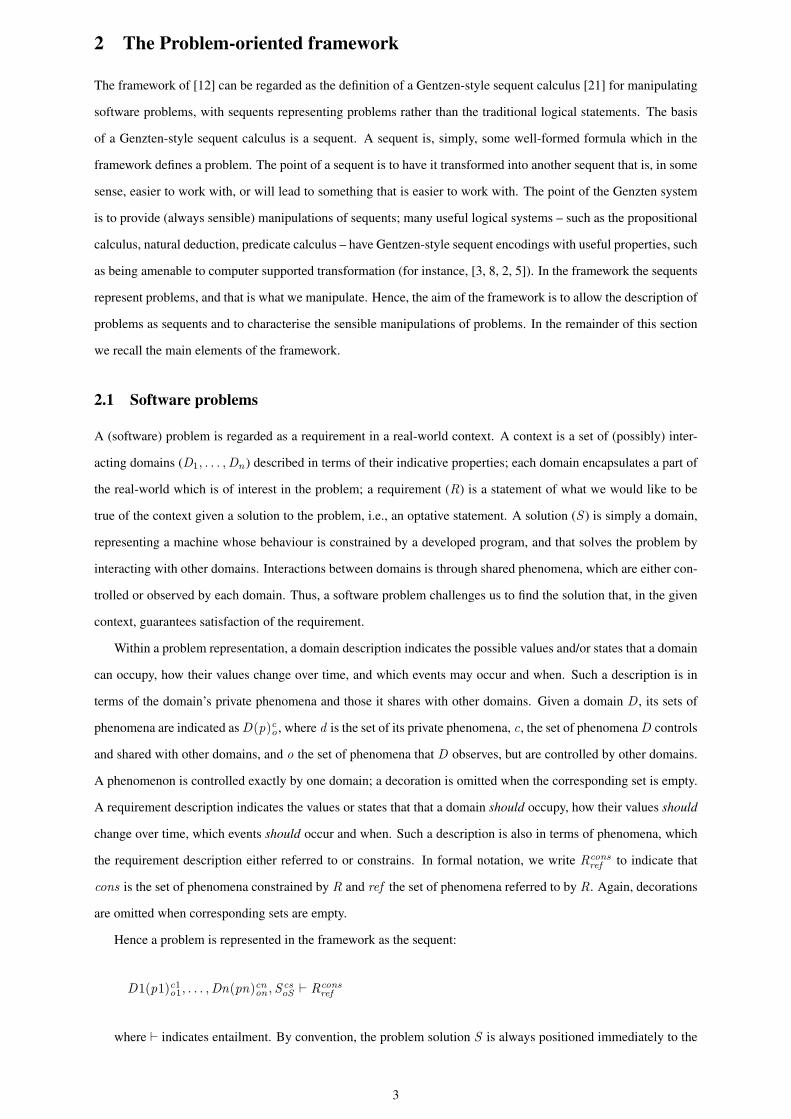
Conceptually, this view of a problem is shared by problem frames, and in this paper we will adopt the problem
frames notation of context and problem diagrams for the representation of problems, rather than the formal notation
of [12] just described. For instance, given the following problem, its corresponding problem diagram is given in
Figure 1:
Operatoron,off ,Device(Stopped ,Working)a on,a off ,Controllera on,a offon,off ` Obey commandStopped,Working
on,off
There are slight differences between the two notations. In problem frames, the ‘!’ sign indicates control:
in Figure 1, O !{on, off } indicates that the operator (shortened to O) controls (in this case issues) commands
on and off . We abuse the notation slightly by using the same sign to identify phenomena constrained by the
requirement: in the figure, !{Stopped ,Working} indicates that the (private) states of the device are constrained
by Obey command. In problem frames notation, the sharing of phenomena between two domains is indicated by
a line which links the (boxes representing the) domains, annotated by the phenomena which are shared, with an
indication of which domain controls them. In the formal notation, this is achieved by stating explicitly both sets
of controlled and observed phenomena for each domain. Also, private phenomena are not represented explicitly
in problem frames notation, unless they are referred to or constrained by the requirement, while they are always
stated in the formal framework as part of the decoration of a domain.
O!{on, off}
C!{a_on, a_off}
Obey command
{on, off}
!{Stopped, Working}Device
Operator
Controller
Figure 1: Example of problem frames notation
The language in which a domain or requirement description is written is not prescribed: all is asked is that
meaning1 can be assigned to statements in the language. Indeed, it would be typical for different stake-holders to
have different languages for expressing their understanding of domain descriptions and requirements. Also, there
is no assumption of precision or lack of ambiguity in any description; a floor manager’s description of a press that
appears in a manufacturing plant might simply be:
The press was installed three years ago.
Through descriptions, understanding of a domain and/or requirement is transferred between customer and de-
veloper; for instance, a developer working on the design of a press controller might interpret the floor manager’s
statement as identifying the press as the PVert model. The mechanisms of interpretation are complex, ranging
from “guessing” to “knowing,” and may be influenced by other factors, such as experience or direct inspection of
the press. Interpretation is more or less precise too, and is often in need of validation through, for instance, contin-
ued interaction between the stake-holders as development proceeds. The mechanisms by which such interaction
1I.e., some formal or informal understanding.
4
is conducted are important, but not part of the framework, which makes use only of the outcomes of it, when they
serve as justification of the steps taken towards solution.
2.2 Solutions and adequacy arguments
A software solution is simply a domain that solves a problem. Its description can take many forms, including
specifications relating inputs to outputs, or detailed program code in some programming language.
In parallel with, or perhaps following somewhat behind, the search for a solution is the construction of an argu-
ment that justifies the fitness-for-purpose of a found solution with respect to the problem. Actually, the argument
the developer will have to construct expresses the adequacy of the solution with respect to a number of criteria
including those of fitness-for-purpose as a customer might see it, design rationale, traceability and trade-offs. The
construction of the adequacy argument is step-wise, and follows the application of problem transformations. We
will illustrate how an adequacy argument is built in the development of the case study.
2.3 Problem Transformations
Problem transformations capture discrete steps in the solution process. Many classes of transformations are recog-
nised in the framework, reflecting a variety of practices reported in the literature or observed elsewhere.
For instance, one type of transformation, called problem reduction, captures the idea of transforming problems
which appears in [18, Page 103]. There, a transformation of requirements keeps a problem’s solution invariant
while domains are removed from the problem. More recently, Hall and Rapanotti et al. [12, 32], Li et al. [27, 28],
and Seater et al. [34] have explored what the detail of such transformations would look like. Indeed transformations
of requirements to derive specifications are not limited to problem-oriented approaches: in goal-based approaches,
for instance [38, 37], high-level goals, which may be regarded as requirements deep in the world, are successively
decomposed and refined until technical requirements are specified for a machine to satisfy. Similarly, in scenario-
based approaches [33, 1, 6] refinement is often required in the move from from high-level scenarios, often capturing
business processes within an organisation, through to low-level scenarios expressing the direct interaction between
a software system and its actors.
Another source of problem transformations is the consideration of solution architectures during the analysis
process. As already mentioned, in problem frames, with their focus on the problem domain, the choices available
to the developer are those that exist in the problem domain, and so useful solution notions, such as architecture, are
only implicit. Hall et al. add a notion of architectural service [11] and Rapanotti et al. [31] a notion of architectural
decomposition into problem frames to allow solution options to be explored. The framework simultaneously gen-
eralises and simplifies these earlier approaches through the definition of a basic rule, called architectural expansion
that allows the solution space structure to influence the problem space.
Problem transformations transform descriptions and their interrelations as problems in a way that respects
solution adequacy. This does not mean that in the framework transformations are sound in any formal sense — the
informality of the subject matter precludes fully formal treatment of some transformations. The meaning of ‘sound’
here is not necessarily ‘formal’, or ‘formalisable’, although it could be the case that formality is appropriate; instead
soundness is fitness-for-purpose of a solution. A Justification of sound application obligation (shortly, justification)
5
is therefore attached to each problem transformation. An adequacy argument is then a by-product of the sequence
(linearization of a tree) of problem transformations that are the designer’s path to solution.
In [12], Problem transformation schemata define classes of problem transformation. They all conform to the
following general form of problem transformation:
That a problem transformation transforms a single problem P to a set of problems Pi , i = 1, ...,n ,
with justification J , means that under the transformation, S is a solution of P with adequacy argument
(A1 ∧ ... ∧ An) ∧ J whenever S1, ...,Sn are solutions of P1, ...,Pn , with adequacy arguments
A1, ...,An , respectively.
Note that, in general, J will express and justify the relation between the parts of P and those of of P1, ...,Pn .
As a result, through the linearization of the tree, we also obtained a structuring of S . Of course, such relations
could be arbitrarily complex, so that there is no general form for S .
3 The Case Study
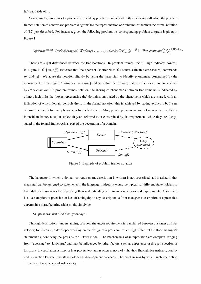
We consider the following problem from [18] (in turn, adapted from [35]):
A package router is a large machine used by delivery companies to sort packages into bins according to bar-coded
destination labels affixed to the packages. Each bin corresponds to a regional area. Packages slide by gravity
through a tree of pipes and binary switches. The bins are at the leaves of this tree.
The problem is to control the operation of the package router so that packages are routed to their appropriate
bins, obeying the operators commands to start and stop the conveyor, and reporting any misrouted packages.
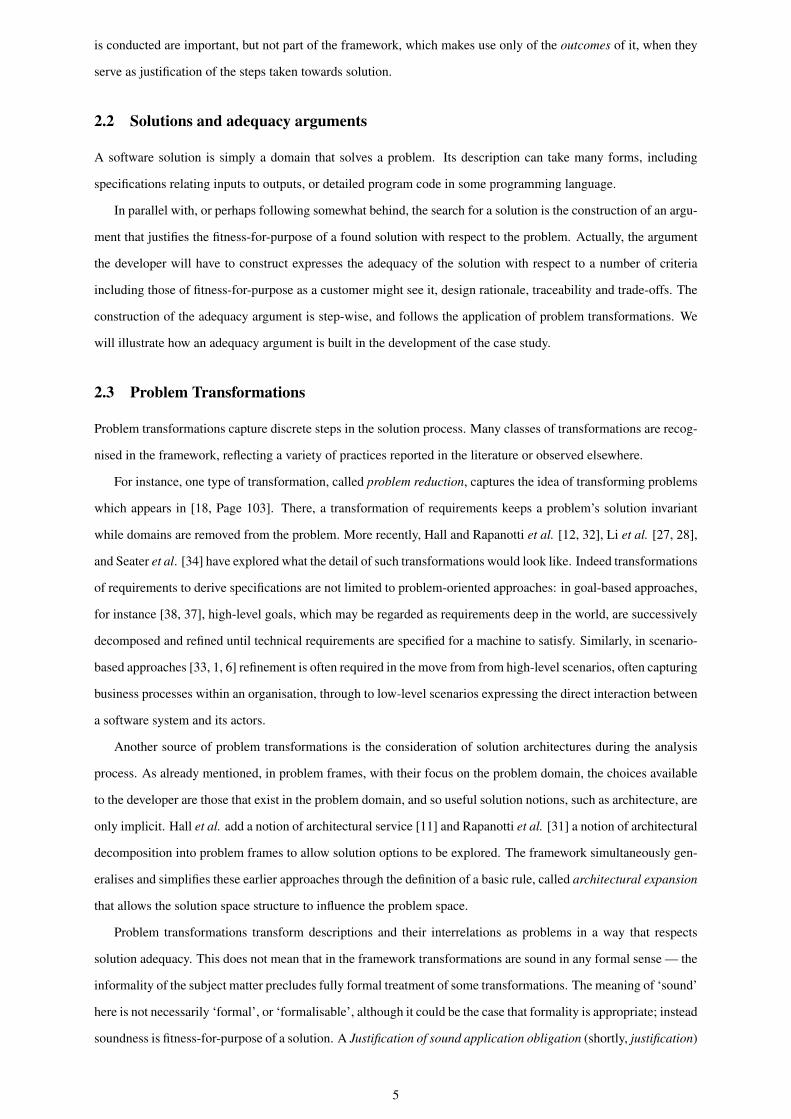
A schematic of the package router is given in Figure 2; the details of the pipes and switches appear in Figure 3.
controlcomputer
(whichwe mustbuild)
misroutingdisplay
conveyor on/off buttons
conveyormotor
operator
computer isconnectedto display,buttons,motor,readingstation,sensors &switches
Figure 2: Schematic of the problem (based on [18])
3.1 The initial problem context
In order to provide a problem-oriented representation of the problem, the elements of the schematic must be con-
sidered and modelled as domains and phenomena. One possible approach is to map each element of the schematic
6
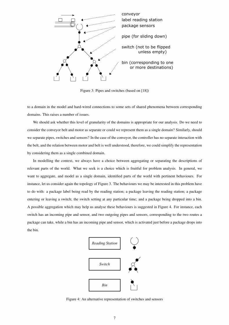
conveyorlabel reading stationpackage sensors
pipe (for sliding down)
switch (not to be flipped unless empty)
bin (corresponding to one or more destinations)
Figure 3: Pipes and switches (based on [18])
to a domain in the model and hard-wired connections to some sets of shared phenomena between corresponding
domains. This raises a number of issues.
We should ask whether this level of granularity of the domains is appropriate for our analysis. Do we need to
consider the conveyor belt and motor as separate or could we represent them as a single domain? Similarly, should
we separate pipes, switches and sensors? In the case of the conveyor, the controller has no separate interaction with
the belt, and the relation between motor and belt is well understood, therefore, we could simplify the representation
by considering them as a single combined domain.
In modelling the context, we always have a choice between aggregating or separating the descriptions of
relevant parts of the world. What we seek is a choice which is fruitful for problem analysis. In general, we
want to aggregate, and model as a single domain, identified parts of the world with pertinent behaviours. For
instance, let us consider again the topology of Figure 3. The behaviours we may be interested in this problem have
to do with: a package label being read by the reading station; a package leaving the reading station; a package
entering or leaving a switch; the switch setting at any particular time; and a package being dropped into a bin.
A possible aggregation which may help us analyse these behaviours is suggested in Figure 4. For instance, each
switch has an incoming pipe and sensor, and two outgoing pipes and sensors, corresponding to the two routes a
package can take, while a bin has an incoming pipe and sensor, which is activated just before a package drops into
the bin.
Switch
Bin
Reading Station
Figure 4: An alternative representation of switches and sensors
7
Hard-wired phenomena, such as the connections shown in Figure 2, are certainly a good starting point to look
for shared phenomena. For instance, we know that sensor information is sent to the control computer as well as
readings from the reading station. However, other shared phenomena arise from transient interactions between
domains. This is the case, for instance, of the operator pushing the on/off conveyor buttons or using the display to
read information about misrouting.
For bins, switches and packages an identity concern [18] arises: we need to be able to identify the individual
switches through which a particular package is routed, and the particular bin in which it falls. Notationally, this is
indicated in a context diagram by indexing the corresponding domains and phenomena.
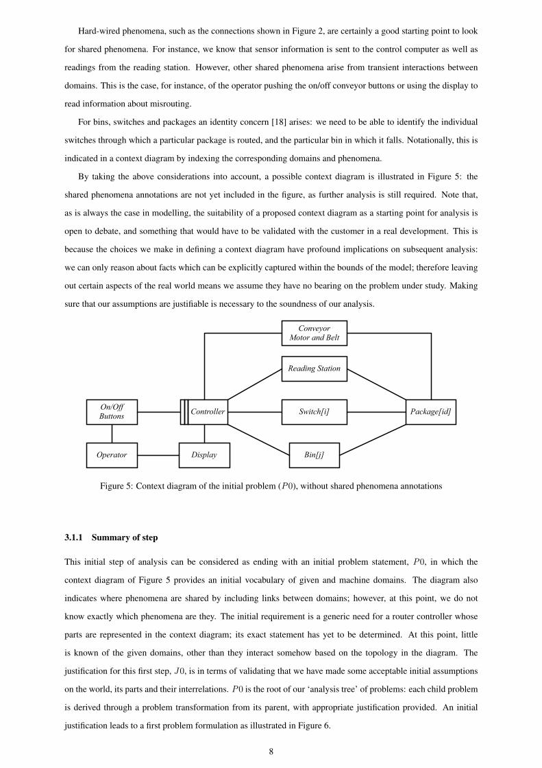
By taking the above considerations into account, a possible context diagram is illustrated in Figure 5: the
shared phenomena annotations are not yet included in the figure, as further analysis is still required. Note that,
as is always the case in modelling, the suitability of a proposed context diagram as a starting point for analysis is
open to debate, and something that would have to be validated with the customer in a real development. This is
because the choices we make in defining a context diagram have profound implications on subsequent analysis:
we can only reason about facts which can be explicitly captured within the bounds of the model; therefore leaving
out certain aspects of the real world means we assume they have no bearing on the problem under study. Making
sure that our assumptions are justifiable is necessary to the soundness of our analysis.
Controller Switch[i]
Bin[j]
Reading Station
On/OffButtons
Operator Display
Package[id]
ConveyorMotor and Belt
Figure 5: Context diagram of the initial problem (P0), without shared phenomena annotations
3.1.1 Summary of step
This initial step of analysis can be considered as ending with an initial problem statement, P0, in which the
context diagram of Figure 5 provides an initial vocabulary of given and machine domains. The diagram also
indicates where phenomena are shared by including links between domains; however, at this point, we do not
know exactly which phenomena are they. The initial requirement is a generic need for a router controller whose
parts are represented in the context diagram; its exact statement has yet to be determined. At this point, little
is known of the given domains, other than they interact somehow based on the topology in the diagram. The
justification for this first step, J0, is in terms of validating that we have made some acceptable initial assumptions
on the world, its parts and their interrelations. P0 is the root of our ‘analysis tree’ of problems: each child problem
is derived through a problem transformation from its parent, with appropriate justification provided. An initial
justification leads to a first problem formulation as illustrated in Figure 6.
8
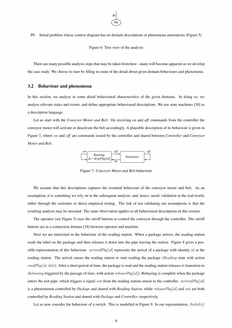
P0
J0
P0 Initial problem whose context diagram has no domain descriptions or phenomena annotations (Figure 5)
Figure 6: Tree view of the analysis
There are many possible analysis steps that may be taken from here - many will become apparent as we develop
the case study. We choose to start by filling in some of the detail about given domain behaviours and phenomena.
3.2 Behaviour and phenomena
In this section, we analyse in some detail behavioural characteristics of the given domains. In doing so, we
analyse relevant states and events, and define appropriate behavioural descriptions. We use state machines [30] as
a description language.
Let us start with the Conveyor Motor and Belt. On receiving on and off commands from the controller the
conveyor motor will activate or deactivate the belt accordingly. A plausible description of its behaviour is given in
Figure 7, where on and off are commands issued by the controller and shared between Controller and Conveyor
Motor and Belt.
Runningdo / dropPkg[id] Stationary
off
on
on off
Figure 7: Conveyor Motor and Belt behaviour
We assume that this descriptions captures the essential behaviour of the conveyor motor and belt. As an
assumption, it is something we rely on in the subsequent analysis, and, hence, needs validation in the real-world,
either through the customer or direct empirical testing. The risk of not validating our assumptions is that the
resulting analysis may be unsound. The same observation applies to all behavioural descriptions in this section.
The operator (see Figure 5) uses the on/off buttons to control the conveyor through the controller. The on/off
buttons act as a connection domain [18] between operator and machine.
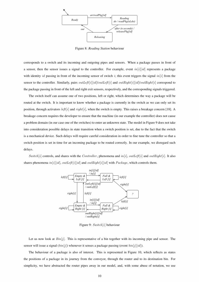
Next we are interested in the behaviour of the reading station. When a package arrives, the reading station
reads the label on the package and then releases it down into the pipe leaving the station. Figure 8 gives a pos-
sible representation of this behaviour. arrivedPkg [id ] represents the arrival of a package with identity id at the
reading station. The arrival causes the reading station to start reading the package (Reading state with action
readPkg(id , dst)). After a short period of time, the package is read and the reading station releases it (transition to
Releasing triggered by the passage of time, with action releasePkg [id ]). Releasing is complete when the package
enters the exit pipe, which triggers a signal out from the reading station sensor to the controller. arrivedPkg [id ]
is a phenomenon controlled by Package and shared with Reading Station, while releasePkg [id ] and out are both
controlled by Reading Station and shared with Package and Controller, respectively.
Let us now consider the behaviour of a switch. This is modelled in Figure 9. In our representation, Switch[i ]
9
Readingdo / readPkg(id,dst)
arrivedPkg[id]
after (n seconds) / releasePkg[id]
Ready
Releasing
out
Figure 8: Reading Station behaviour
corresponds to a switch and its incoming and outgoing pipes and sensors. When a package passes in front of
a sensor, then the sensor issues a signal to the controller. For example, event in[i ][id ] represents a package
with identity id passing in front of the incoming sensor of switch i ; this event triggers the signal in[i ] from the
sensor to the controller. Similarly, pairs outLeft [i ][id ]/outLeft [i ] and outRight [i ][id ]/outRight [i ] correspond to
the package passing in front of the left and right exit sensors, respectively, and the corresponding signals triggered.
The switch itself can assume one of two positions, left or right, which determines the way a package will be
routed at the switch. It is important to know whether a package is currently in the switch as we can only set its
position, through activators left [i ] and right [i ], when the switch is empty. This raises a breakage concern [18]. A
breakage concern requires the developer to ensure that the machine (in our example the controller) does not cause
a problem domain (in our case one of the switches) to enter an unknown state. The model in Figure 9 does not take
into consideration possible delays in state transition when a switch position is set, due to the fact that the switch
is a mechanical device. Such delays will require careful consideration in order to fine tune the controller so that a
switch position is set in time for an incoming package to be routed correctly. In our example, we disregard such
delays.
Switch[i ] controls, and shares with the Controller , phenomena and in[i ], outLeft [i ] and outRight [i ]. It also
shares phenomena in[i ][id ], outLeft [i ][id ] and outRight [i ][id ] with Package , which controls them.
Empty & Left [i]
Full & Left [i]
in[i][id]/ in[i]
?right[i]
Empty & Right [i]
Full & Right [i]
outLeft[i][id]/ outLeft[i]
in[i][id]/ in[i]
outRight[i][id]/ outRight[i]
left[i]
left[i]
left[i] left[i]
right[i] right[i]
right[i]
Figure 9: Switch[i ] behaviour
Let us now look at Bin[j ]. This is representative of a bin together with its incoming pipe and sensor. The
sensor will issue a signal (bin[j ]) whenever it senses a package passing (event bin[j ][id ]).
The behaviour of a package is also of interest. This is represented in Figure 10, which reflects as states
the positions of a package in its journey from the conveyor, through the router and to its destination bin. For
simplicity, we have abstracted the router pipes away in our model, and, with some abuse of notation, we use
10
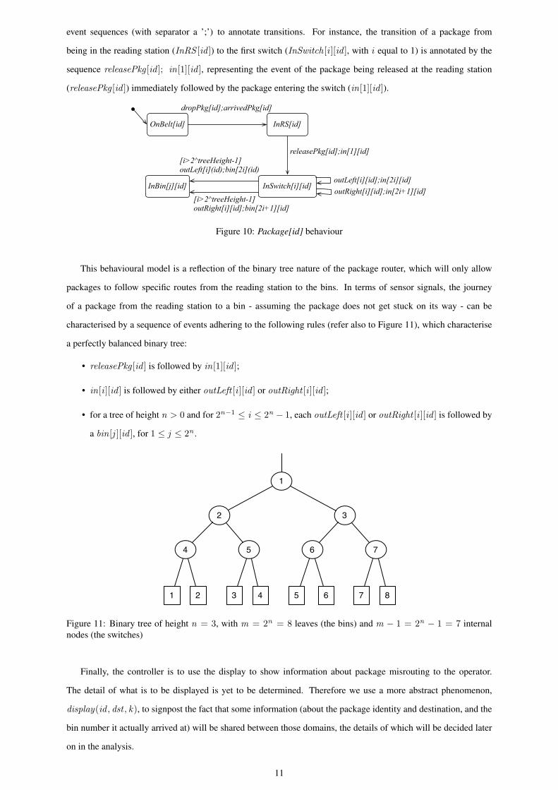
event sequences (with separator a ’;’) to annotate transitions. For instance, the transition of a package from
being in the reading station (InRS [id ]) to the first switch (InSwitch[i ][id ], with i equal to 1) is annotated by the
sequence releasePkg [id ]; in[1][id ], representing the event of the package being released at the reading station
(releasePkg [id ]) immediately followed by the package entering the switch (in[1][id ]).
OnBelt[id] InRS[id]
dropPkg[id];arrivedPkg[id]
InBin[j][id] InSwitch[i][id]
releasePkg[id];in[1][id]
outLeft[i][id];in[2i][id]
[i>2^treeHeight-1]outLeft[i](id);bin[2i](id)
outRight[i][id];in[2i+1][id][i>2^treeHeight-1]outRight[i][id];bin[2i+1][id]
Figure 10: Package[id] behaviour
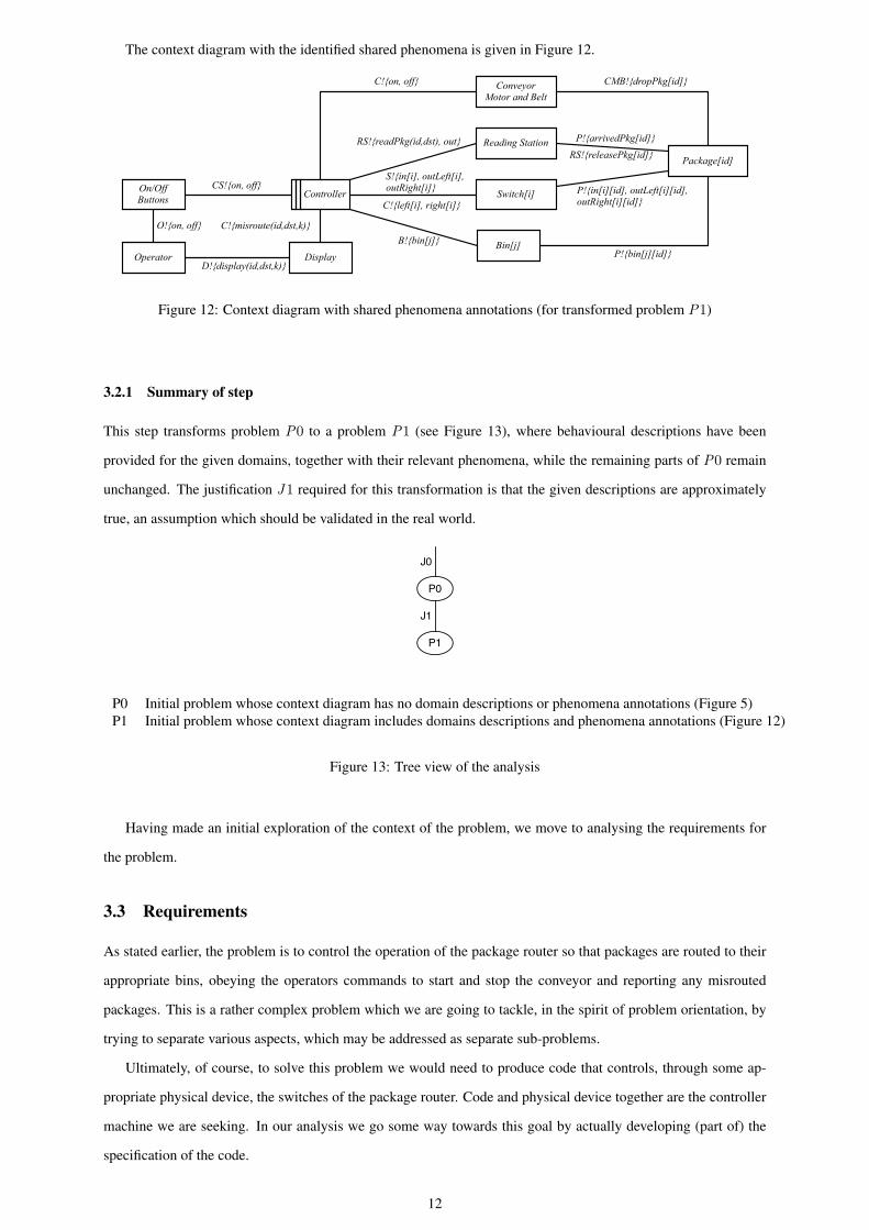
This behavioural model is a reflection of the binary tree nature of the package router, which will only allow
packages to follow specific routes from the reading station to the bins. In terms of sensor signals, the journey
of a package from the reading station to a bin - assuming the package does not get stuck on its way - can be
characterised by a sequence of events adhering to the following rules (refer also to Figure 11), which characterise
a perfectly balanced binary tree:
• releasePkg [id ] is followed by in[1][id ];
• in[i ][id ] is followed by either outLeft [i ][id ] or outRight [i ][id ];
• for a tree of height n > 0 and for 2n−1 ≤ i ≤ 2n − 1, each outLeft [i ][id ] or outRight [i ][id ] is followed by
a bin[j ][id ], for 1 ≤ j ≤ 2n .
1
2 3
4 5 6 7
1 2 3 54 6 7 8
Figure 11: Binary tree of height n = 3, with m = 2n = 8 leaves (the bins) and m − 1 = 2n − 1 = 7 internalnodes (the switches)
Finally, the controller is to use the display to show information about package misrouting to the operator.
The detail of what is to be displayed is yet to be determined. Therefore we use a more abstract phenomenon,
display(id , dst , k), to signpost the fact that some information (about the package identity and destination, and the
bin number it actually arrived at) will be shared between those domains, the details of which will be decided later
on in the analysis.
11
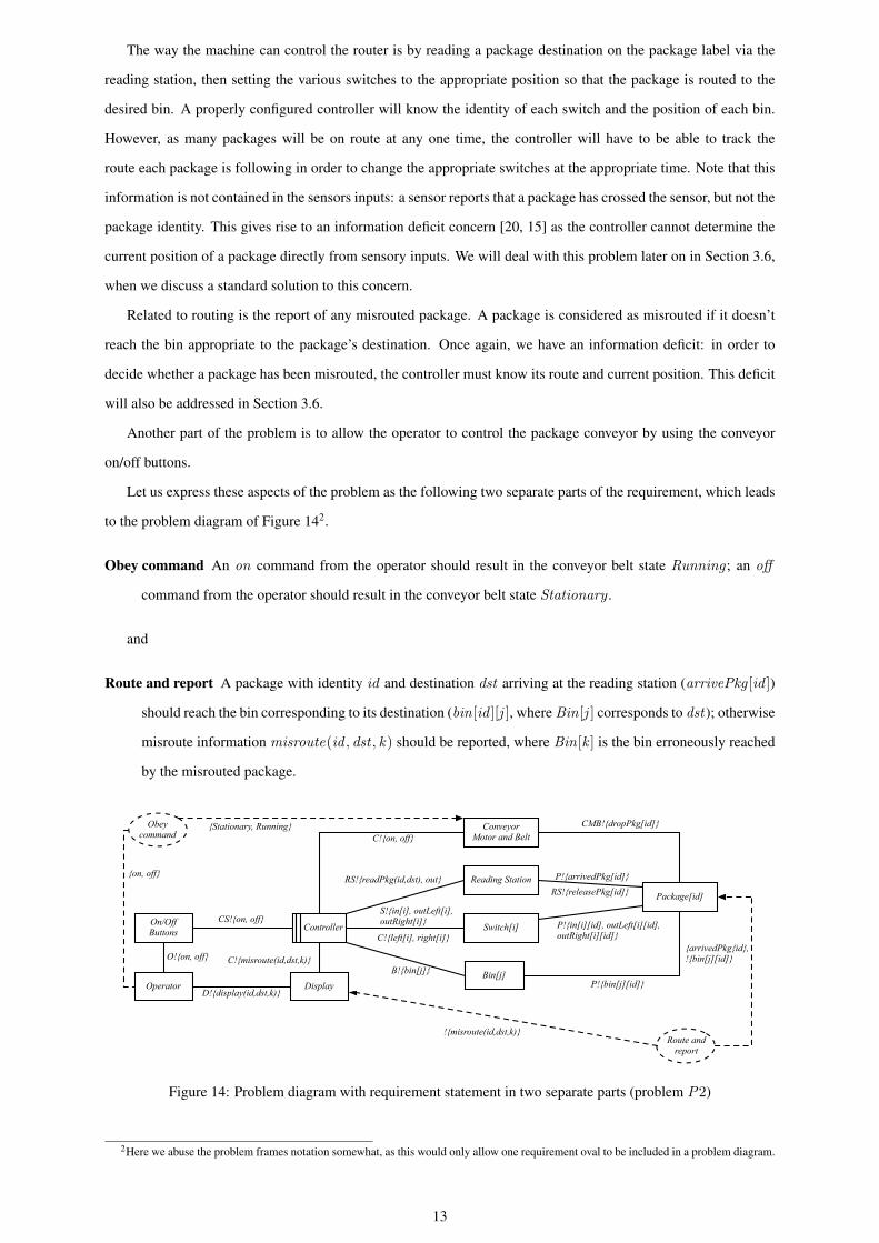
The context diagram with the identified shared phenomena is given in Figure 12.
Controller
ConveyorMotor and Belt
Switch[i]
Bin[j]
Reading Station
On/OffButtons
Operator Display
O!{on, off}
CMB!{dropPkg[id]}
RS!{readPkg(id,dst), out}
S!{in[i], outLeft[i], outRight[i]}
C!{left[i], right[i]}
B!{bin[j]}
Package[id]
P!{arrivedPkg[id]}
P!{bin[j][id]}
C!{on, off}
CS!{on, off}
C!{misroute(id,dst,k)}
D!{display(id,dst,k)}
RS!{releasePkg[id]}
P!{in[i][id], outLeft[i][id], outRight[i][id]}
Figure 12: Context diagram with shared phenomena annotations (for transformed problem P1)
3.2.1 Summary of step
This step transforms problem P0 to a problem P1 (see Figure 13), where behavioural descriptions have been
provided for the given domains, together with their relevant phenomena, while the remaining parts of P0 remain
unchanged. The justification J1 required for this transformation is that the given descriptions are approximately
true, an assumption which should be validated in the real world.
P0
P1
J1
J0
P0 Initial problem whose context diagram has no domain descriptions or phenomena annotations (Figure 5)P1 Initial problem whose context diagram includes domains descriptions and phenomena annotations (Figure 12)
Figure 13: Tree view of the analysis
Having made an initial exploration of the context of the problem, we move to analysing the requirements for
the problem.
3.3 Requirements
As stated earlier, the problem is to control the operation of the package router so that packages are routed to their
appropriate bins, obeying the operators commands to start and stop the conveyor and reporting any misrouted
packages. This is a rather complex problem which we are going to tackle, in the spirit of problem orientation, by
trying to separate various aspects, which may be addressed as separate sub-problems.
Ultimately, of course, to solve this problem we would need to produce code that controls, through some ap-
propriate physical device, the switches of the package router. Code and physical device together are the controller
machine we are seeking. In our analysis we go some way towards this goal by actually developing (part of) the
specification of the code.
12
The way the machine can control the router is by reading a package destination on the package label via the
reading station, then setting the various switches to the appropriate position so that the package is routed to the
desired bin. A properly configured controller will know the identity of each switch and the position of each bin.
However, as many packages will be on route at any one time, the controller will have to be able to track the
route each package is following in order to change the appropriate switches at the appropriate time. Note that this
information is not contained in the sensors inputs: a sensor reports that a package has crossed the sensor, but not the
package identity. This gives rise to an information deficit concern [20, 15] as the controller cannot determine the
current position of a package directly from sensory inputs. We will deal with this problem later on in Section 3.6,
when we discuss a standard solution to this concern.
Related to routing is the report of any misrouted package. A package is considered as misrouted if it doesn’t
reach the bin appropriate to the package’s destination. Once again, we have an information deficit: in order to
decide whether a package has been misrouted, the controller must know its route and current position. This deficit
will also be addressed in Section 3.6.
Another part of the problem is to allow the operator to control the package conveyor by using the conveyor
on/off buttons.
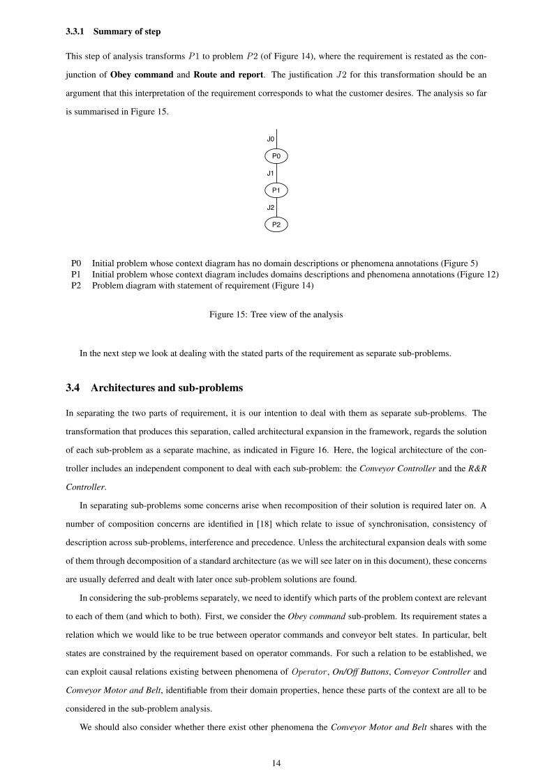
Let us express these aspects of the problem as the following two separate parts of the requirement, which leads
to the problem diagram of Figure 142.
Obey command An on command from the operator should result in the conveyor belt state Running ; an off
command from the operator should result in the conveyor belt state Stationary .
and
Route and report A package with identity id and destination dst arriving at the reading station (arrivePkg [id ])
should reach the bin corresponding to its destination (bin[id ][j ], where Bin[j ] corresponds to dst); otherwise
misroute information misroute(id , dst , k) should be reported, where Bin[k ] is the bin erroneously reached
by the misrouted package.
Controller
ConveyorMotor and Belt
Switch[i]
Bin[j]
Reading Station
On/OffButtons
Operator Display
O!{on, off}
S!{in[i], outLeft[i], outRight[i]}
C!{left[i], right[i]}
B!{bin[j]}
Package[id]
C!{on, off}
CS!{on, off}
Obey command
{on, off}
{Stationary, Running}
Route and report
{arrivedPkg{id},!{bin[j][id]}
!{misroute(id,dst,k)}
CMB!{dropPkg[id]}
P!{arrivedPkg[id]}
P!{bin[j][id]}
RS!{releasePkg[id]}
P!{in[i][id], outLeft[i][id], outRight[i][id]}
RS!{readPkg(id,dst), out}
C!{misroute(id,dst,k)}
D!{display(id,dst,k)}
Figure 14: Problem diagram with requirement statement in two separate parts (problem P2)
2Here we abuse the problem frames notation somewhat, as this would only allow one requirement oval to be included in a problem diagram.
13
3.3.1 Summary of step
This step of analysis transforms P1 to problem P2 (of Figure 14), where the requirement is restated as the con-
junction of Obey command and Route and report. The justification J2 for this transformation should be an
argument that this interpretation of the requirement corresponds to what the customer desires. The analysis so far
is summarised in Figure 15.
P0
P1
P2
J1
J2
J0
P0 Initial problem whose context diagram has no domain descriptions or phenomena annotations (Figure 5)P1 Initial problem whose context diagram includes domains descriptions and phenomena annotations (Figure 12)P2 Problem diagram with statement of requirement (Figure 14)
Figure 15: Tree view of the analysis
In the next step we look at dealing with the stated parts of the requirement as separate sub-problems.
3.4 Architectures and sub-problems
In separating the two parts of requirement, it is our intention to deal with them as separate sub-problems. The
transformation that produces this separation, called architectural expansion in the framework, regards the solution
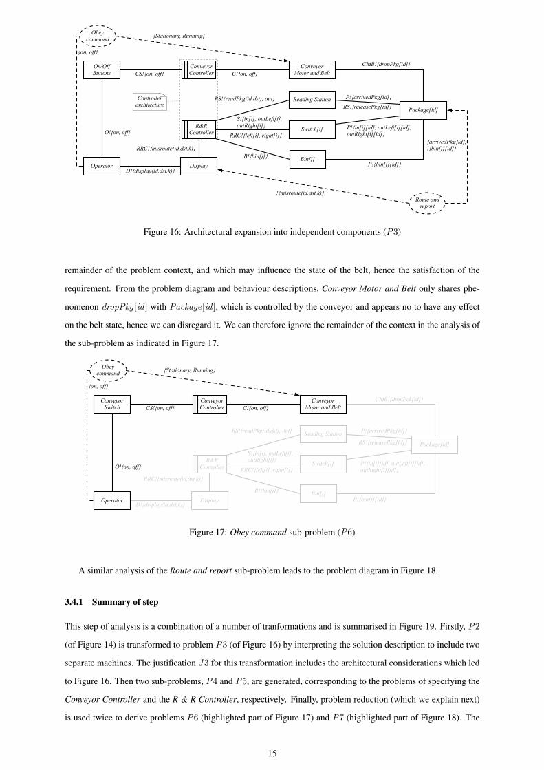
of each sub-problem as a separate machine, as indicated in Figure 16. Here, the logical architecture of the con-
troller includes an independent component to deal with each sub-problem: the Conveyor Controller and the R&R
Controller.
In separating sub-problems some concerns arise when recomposition of their solution is required later on. A
number of composition concerns are identified in [18] which relate to issue of synchronisation, consistency of
description across sub-problems, interference and precedence. Unless the architectural expansion deals with some
of them through decomposition of a standard architecture (as we will see later on in this document), these concerns
are usually deferred and dealt with later once sub-problem solutions are found.
In considering the sub-problems separately, we need to identify which parts of the problem context are relevant
to each of them (and which to both). First, we consider the Obey command sub-problem. Its requirement states a
relation which we would like to be true between operator commands and conveyor belt states. In particular, belt
states are constrained by the requirement based on operator commands. For such a relation to be established, we
can exploit causal relations existing between phenomena of Operator , On/Off Buttons, Conveyor Controller and
Conveyor Motor and Belt, identifiable from their domain properties, hence these parts of the context are all to be
considered in the sub-problem analysis.
We should also consider whether there exist other phenomena the Conveyor Motor and Belt shares with the
14
R&RController
ConveyorMotor and Belt
Switch[i]
Bin[j]
Reading Station
On/OffButtons
Operator Display
O!{on, off}
S!{in[i], outLeft[i], outRight[i]}
RRC!{left[i], right[i]}
B!{bin[j]}
Package[id]
C!{on, off}CS!{on, off}
Obey command
{on, off}
{Stationary, Running}
Route and report
Conveyor Controller
Controllerarchitecture
{arrivedPkg{id},!{bin[j][id]}
CMB!{dropPkg[id]}
P!{arrivedPkg[id]}
P!{bin[j][id]}
RS!{releasePkg[id]}
P!{in[i][id], outLeft[i][id], outRight[i][id]}
RS!{readPkg(id,dst), out}
RRC!{misroute(id,dst,k)}
D!{display(id,dst,k)}
!{misroute(id,dst,k)}
Figure 16: Architectural expansion into independent components (P3)
remainder of the problem context, and which may influence the state of the belt, hence the satisfaction of the
requirement. From the problem diagram and behaviour descriptions, Conveyor Motor and Belt only shares phe-
nomenon dropPkg [id ] with Package[id ], which is controlled by the conveyor and appears no to have any effect
on the belt state, hence we can disregard it. We can therefore ignore the remainder of the context in the analysis of
the sub-problem as indicated in Figure 17.
R&RController Switch[i]
Bin[j]
Reading Station
ConveyorSwitch
Display
O!{on, off}
RS!{readPkg(id,dst), out}
S!{in[i], outLeft[i], outRight[i]}
RRC!{left[i], right[i]}
B!{bin[j]}
Package[id]
C!{on, off}CS!{on, off}
RRC!{misroute(id,dst,k)}
D!{display(id,dst,k)}
Obey command
{on, off}
{Stationary, Running}
Conveyor Controller
ConveyorMotor and Belt
Operator
CMB!{dropPck[id]}
P!{arrivedPkg[id]}
P!{in[i][id], outLeft[i][id],outRight[i][id]}
P!{bin[j][id]}
RS!{releasePkg[id]}
Figure 17: Obey command sub-problem (P6)
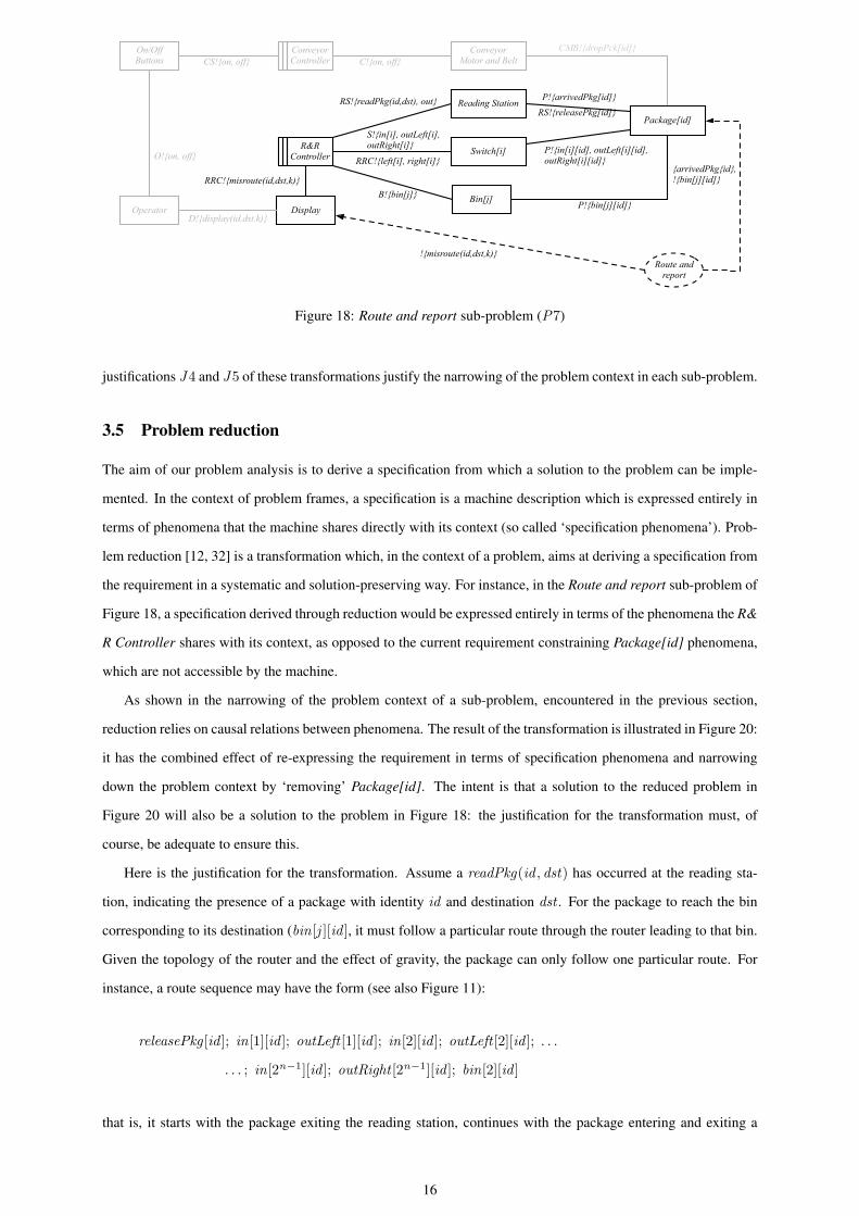
A similar analysis of the Route and report sub-problem leads to the problem diagram in Figure 18.
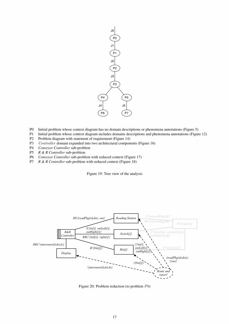
3.4.1 Summary of step
This step of analysis is a combination of a number of tranformations and is summarised in Figure 19. Firstly, P2
(of Figure 14) is transformed to problem P3 (of Figure 16) by interpreting the solution description to include two
separate machines. The justification J3 for this transformation includes the architectural considerations which led
to Figure 16. Then two sub-problems, P4 and P5, are generated, corresponding to the problems of specifying the
Conveyor Controller and the R & R Controller, respectively. Finally, problem reduction (which we explain next)
is used twice to derive problems P6 (highlighted part of Figure 17) and P7 (highlighted part of Figure 18). The
15
R&RController
ConveyorMotor and Belt
Switch[i]
Bin[j]
Reading Station
On/OffButtons
Operator Display
O!{on, off}
S!{in[i], outLeft[i], outRight[i]}
RRC!{left[i], right[i]}
B!{bin[j]}
Package[id]
C!{on, off}CS!{on, off}
D!{display(id.dst.k)}
Route and report
Conveyor Controller
{arrivedPkg{id},!{bin[j][id]}
P!{arrivedPkg[id]}
P!{bin[j][id]}
RS!{releasePkg[id]}
P!{in[i][id], outLeft[i][id], outRight[i][id]}
CMB!{dropPck[id]}
RS!{readPkg(id,dst), out}
RRC!{misroute(id,dst,k)}
!{misroute(id,dst,k)}
Figure 18: Route and report sub-problem (P7)
justifications J4 and J5 of these transformations justify the narrowing of the problem context in each sub-problem.
3.5 Problem reduction
The aim of our problem analysis is to derive a specification from which a solution to the problem can be imple-
mented. In the context of problem frames, a specification is a machine description which is expressed entirely in
terms of phenomena that the machine shares directly with its context (so called ‘specification phenomena’). Prob-
lem reduction [12, 32] is a transformation which, in the context of a problem, aims at deriving a specification from
the requirement in a systematic and solution-preserving way. For instance, in the Route and report sub-problem of
Figure 18, a specification derived through reduction would be expressed entirely in terms of the phenomena the R&
R Controller shares with its context, as opposed to the current requirement constraining Package[id] phenomena,
which are not accessible by the machine.
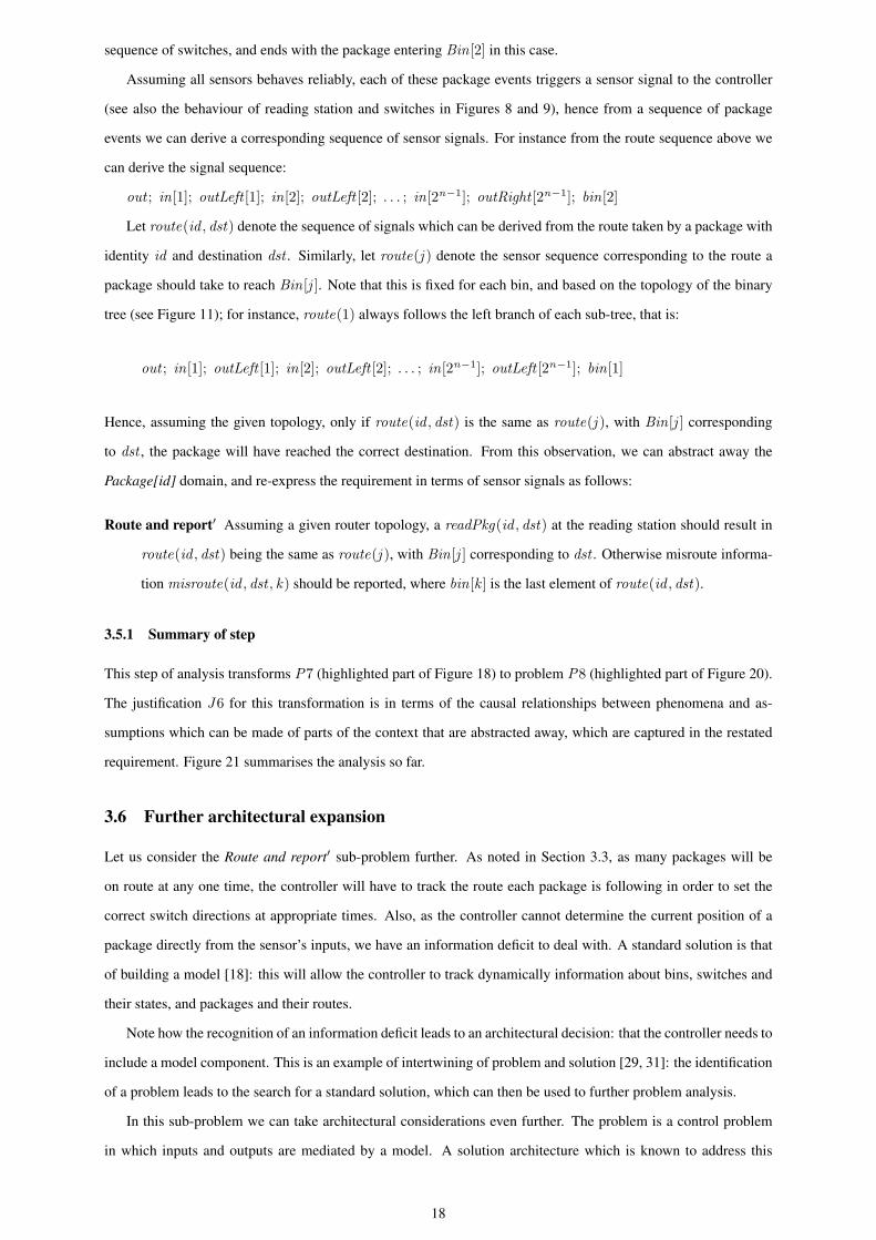
As shown in the narrowing of the problem context of a sub-problem, encountered in the previous section,
reduction relies on causal relations between phenomena. The result of the transformation is illustrated in Figure 20:
it has the combined effect of re-expressing the requirement in terms of specification phenomena and narrowing
down the problem context by ‘removing’ Package[id]. The intent is that a solution to the reduced problem in
Figure 20 will also be a solution to the problem in Figure 18: the justification for the transformation must, of
course, be adequate to ensure this.
Here is the justification for the transformation. Assume a readPkg(id , dst) has occurred at the reading sta-
tion, indicating the presence of a package with identity id and destination dst . For the package to reach the bin
corresponding to its destination (bin[j ][id ], it must follow a particular route through the router leading to that bin.
Given the topology of the router and the effect of gravity, the package can only follow one particular route. For
instance, a route sequence may have the form (see also Figure 11):
releasePkg [id ]; in[1][id ]; outLeft [1][id ]; in[2][id ]; outLeft [2][id ]; . . .
. . . ; in[2n−1][id ]; outRight [2n−1][id ]; bin[2][id ]
that is, it starts with the package exiting the reading station, continues with the package entering and exiting a
16
P0
P1
P3
P4 P5
J1
J2
J0
P2
J3
P6
J4
P7
J5
P0 Initial problem whose context diagram has no domain descriptions or phenomena annotations (Figure 5)P1 Initial problem whose context diagram includes domains descriptions and phenomena annotations (Figure 12)P2 Problem diagram with statement of requirement (Figure 14)P3 Controller domain expanded into two architectural components (Figure 16)P4 Conveyor Controller sub-problemP5 R & R Controller sub-problemP6 Conveyor Controller sub-problem with reduced context (Figure 17)P7 R & R Controller sub-problem with reduced context (Figure 18)
Figure 19: Tree view of the analysis
R&RController Switch[i]
Display
S!{in[i], outLeft[i], outRight[i]}
RRC!{left[i], right[i]}
B!{bin[j]}
Route and report'
!{bin[j]}{readPkg(id,dst)}, !{out}
!{!in[i], outLeft[i], outRight[i]}
Package[id]
Bin[j]
Reading Station P!{arrivedPkg[id]}
P!{bin[j][id]}
RS!{releasePkg[id]}
P!{in[i][id], outLeft[i][id], outRight[i][id]}
RS!{readPkg(id,dst), out}
RRC!{misroute(id,dst,k)}
!{misroute(id,dst,k)}
Figure 20: Problem reduction (to problem P8)
17
sequence of switches, and ends with the package entering Bin[2] in this case.
Assuming all sensors behaves reliably, each of these package events triggers a sensor signal to the controller
(see also the behaviour of reading station and switches in Figures 8 and 9), hence from a sequence of package
events we can derive a corresponding sequence of sensor signals. For instance from the route sequence above we
can derive the signal sequence:
out ; in[1]; outLeft [1]; in[2]; outLeft [2]; . . . ; in[2n−1]; outRight [2n−1]; bin[2]
Let route(id , dst) denote the sequence of signals which can be derived from the route taken by a package with
identity id and destination dst . Similarly, let route(j ) denote the sensor sequence corresponding to the route a
package should take to reach Bin[j ]. Note that this is fixed for each bin, and based on the topology of the binary
tree (see Figure 11); for instance, route(1) always follows the left branch of each sub-tree, that is:
out ; in[1]; outLeft [1]; in[2]; outLeft [2]; . . . ; in[2n−1]; outLeft [2n−1]; bin[1]
Hence, assuming the given topology, only if route(id , dst) is the same as route(j ), with Bin[j ] corresponding
to dst , the package will have reached the correct destination. From this observation, we can abstract away the
Package[id] domain, and re-express the requirement in terms of sensor signals as follows:
Route and report′ Assuming a given router topology, a readPkg(id , dst) at the reading station should result in
route(id , dst) being the same as route(j ), with Bin[j ] corresponding to dst . Otherwise misroute informa-
tion misroute(id , dst , k) should be reported, where bin[k ] is the last element of route(id , dst).
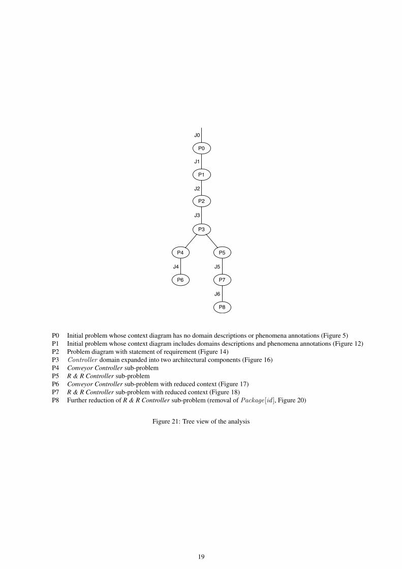
3.5.1 Summary of step
This step of analysis transforms P7 (highlighted part of Figure 18) to problem P8 (highlighted part of Figure 20).
The justification J6 for this transformation is in terms of the causal relationships between phenomena and as-
sumptions which can be made of parts of the context that are abstracted away, which are captured in the restated
requirement. Figure 21 summarises the analysis so far.
3.6 Further architectural expansion
Let us consider the Route and report′ sub-problem further. As noted in Section 3.3, as many packages will be
on route at any one time, the controller will have to track the route each package is following in order to set the
correct switch directions at appropriate times. Also, as the controller cannot determine the current position of a
package directly from the sensor’s inputs, we have an information deficit to deal with. A standard solution is that
of building a model [18]: this will allow the controller to track dynamically information about bins, switches and
their states, and packages and their routes.
Note how the recognition of an information deficit leads to an architectural decision: that the controller needs to
include a model component. This is an example of intertwining of problem and solution [29, 31]: the identification
of a problem leads to the search for a standard solution, which can then be used to further problem analysis.
In this sub-problem we can take architectural considerations even further. The problem is a control problem
in which inputs and outputs are mediated by a model. A solution architecture which is known to address this
18
P0
P1
P3
P4 P5
J1
J2
J0
P2
J3
P6
J4
P7
J5
P8
J6
P0 Initial problem whose context diagram has no domain descriptions or phenomena annotations (Figure 5)P1 Initial problem whose context diagram includes domains descriptions and phenomena annotations (Figure 12)P2 Problem diagram with statement of requirement (Figure 14)P3 Controller domain expanded into two architectural components (Figure 16)P4 Conveyor Controller sub-problemP5 R & R Controller sub-problemP6 Conveyor Controller sub-problem with reduced context (Figure 17)P7 R & R Controller sub-problem with reduced context (Figure 18)P8 Further reduction of R & R Controller sub-problem (removal of Package[id ], Figure 20)
Figure 21: Tree view of the analysis
19
type of problem is a variant of the Model View Controller (MVC) architecture. Originally introduced for software
applications with graphical user interfaces [23], an MVC architecture includes controller (C ) components which
receive user inputs and update a model (M ) component accordingly; changes in M are communicated to its
dependents, called view (V ) components, which interpret them and generate user outputs appropriately. Variants
of this MVC architecture have been adopted in control applications, such as avionics [26]. Here, instead of user
inputs, environmental sensor information is received by the controller and used to update the model, while the
view generates outputs based on changes in the model’s state. Outputs are either user outputs to a display (as in
the traditional MVC) or actuator signals through which the controller influences the environment. It is this variant
of the MVC which is discussed here.
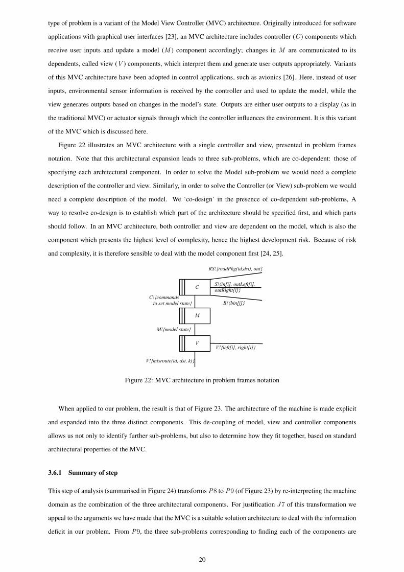
Figure 22 illustrates an MVC architecture with a single controller and view, presented in problem frames
notation. Note that this architectural expansion leads to three sub-problems, which are co-dependent: those of
specifying each architectural component. In order to solve the Model sub-problem we would need a complete
description of the controller and view. Similarly, in order to solve the Controller (or View) sub-problem we would
need a complete description of the model. We ‘co-design’ in the presence of co-dependent sub-problems, A
way to resolve co-design is to establish which part of the architecture should be specified first, and which parts
should follow. In an MVC architecture, both controller and view are dependent on the model, which is also the
component which presents the highest level of complexity, hence the highest development risk. Because of risk
and complexity, it is therefore sensible to deal with the model component first [24, 25].
C!{commands to set model state}
M!{model state}
S!{in[i], outLeft[i], outRight[i]}
V!{left[i], right[i]}
B!{bin[j]}
C
V
M
RS!{readPkg(id,dst), out}
V!{misroute(id, dst, k)}
Figure 22: MVC architecture in problem frames notation
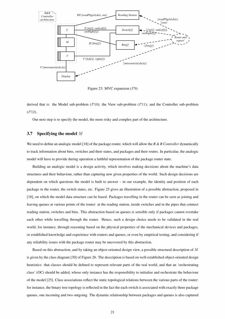
When applied to our problem, the result is that of Figure 23. The architecture of the machine is made explicit
and expanded into the three distinct components. This de-coupling of model, view and controller components
allows us not only to identify further sub-problems, but also to determine how they fit together, based on standard
architectural properties of the MVC.
3.6.1 Summary of step
This step of analysis (summarised in Figure 24) transforms P8 to P9 (of Figure 23) by re-interpreting the machine
domain as the combination of the three architectural components. For justification J7 of this transformation we
appeal to the arguments we have made that the MVC is a suitable solution architecture to deal with the information
deficit in our problem. From P9, the three sub-problems corresponding to finding each of the components are
20
Switch[i]
Bin[j]
Reading Station
Display
S!{in[i], outLeft[i], outRight[i]}
V!{left[i], right[i]}
B!{bin[j]}
C
V
R&RController
architecture
Route and report'M
!{bin[j]}
{readPkg(id,dst)}, !{out}
!{!in[i], outLeft[i],outRight[i]}
RS!{readPkg(id,dst), out}
V!{misroute(id,dst,k)}!{misroute(id,dst,k)}
Figure 23: MVC expansion (P9)
derived that is: the Model sub-problem (P10); the View sub-problem (P11); and the Controller sub-problem
(P12).
Our next step is to specify the model, the more risky and complex part of the architecture.
3.7 Specifying the model M
We need to define an analogic model [18] of the package router, which will allow the R & R Controller dynamically
to track information about bins, switches and their states, and packages and their routes. In particular, the analogic
model will have to provide during operation a faithful representation of the package router state.
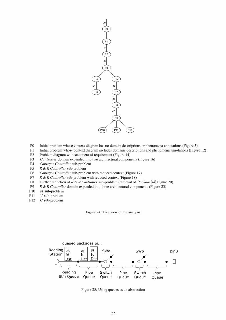
Building an analogic model is a design activity, which involves making decisions about the machine’s data
structures and their behaviour, rather than capturing new given properties of the world. Such design decisions are
dependent on which questions the model is built to answer – in our example, the identity and position of each
package in the router, the switch states, etc. Figure 25 gives an illustration of a possible abstraction, proposed in
[18], on which the model data structure can be based. Packages travelling in the router can be seen as joining and
leaving queues at various points of the router: at the reading station, inside switches and in the pipes that connect
reading station, switches and bins. This abstraction based on queues is sensible only if packages cannot overtake
each other while travelling through the router. Hence, such a design choice needs to be validated in the real
world, for instance, through reasoning based on the physical properties of the mechanical devices and packages,
or established knowledge and experience with routers and queues, or even by empirical testing, and considering if
any reliability issues with the package router may be uncovered by this abstraction.
Based on this abstraction, and by taking an object-oriented design view, a possible structural description of M
is given by the class diagram [30] of Figure 26. The description is based on well-established object-oriented design
heuristics: that classes should be defined to represent relevant parts of the real world, and that an ‘orchestrating
class’ (OC) should be added, whose only instance has the responsibility to initialise and orchestrate the behaviour
of the model [25]. Class associations reflect the static topological relations between the various parts of the router:
for instance, the binary tree topology is reflected in the fact the each switch is associated with exactly three package
queues, one incoming and two outgoing. The dynamic relationship between packages and queues is also captured
21
P9
J7
P10 P12P11
P0
P1
P3
P4 P5
J1
J2
J0
P2
J3
P6
J4
P7
J5
P8
J6
P0 Initial problem whose context diagram has no domain descriptions or phenomena annotations (Figure 5)P1 Initial problem whose context diagram includes domains descriptions and phenomena annotations (Figure 12)P2 Problem diagram with statement of requirement (Figure 14)P3 Controller domain expanded into two architectural components (Figure 16)P4 Conveyor Controller sub-problemP5 R & R Controller sub-problemP6 Conveyor Controller sub-problem with reduced context (Figure 17)P7 R & R Controller sub-problem with reduced context (Figure 18)P8 Further reduction of R & R Controller sub-problem (removal of Package[id ],Figure 20)P9 R & R Controller domain expanded into three architectural components (Figure 23)P10 M sub-problemP11 V sub-problemP12 C sub-problem
Figure 24: Tree view of the analysis
23/03/06 PgkRtr1 - 25
Which Package Is Now At Sensor[s]?
! No overtaking: packages queue in pipes and switches
! Each queue associated with its entry point e " {sensor}#RS
• Each package first enters the Reading Station queue
• Packages queue in switches: only one exit active at once
! The machine can maintain a dynamic model of these queues
• Queued elements pi are pairs (Id, Destination)
• p(ID,Destination) represents the package in the model
SWa SWbReadingStation
ReadingSt’n Queue
PipeQueue
SwitchQueue
PipeQueue
SwitchQueue
PipeQueue
BinBpkIdDst
queued packages pi...
pjIdDst
piIdDst
Figure 25: Using queues as an abstraction
22
by an association: each package can be at most in one queue at any one time.
SwitchQueue
in();outLeft();outRight();
Packageid: Identity;dst: Destination;
RSQueue
out();
Binno: Number;bin();
Queue
add(Package);remove(): Package;
ReadingStation
read(Identity, Destination);
Switchno: Number;state: SwitchStateleft();right();
1
1
0..1
0..1
13 0..1
1
currentQueue0..1
*
1
1
PipeQueue
OC
init();<< signal >> read(Identity, Destination);<<signal>> out(();<<signal>> in_i();<<signal>> outLeft_i();<<signal>> outRight_i();<<signal>> bin_j();
1
1 1
*
*
1
<<enumeration>>SwitchState
Left;Right;
value {ordered}
Figure 26: Structural description of M
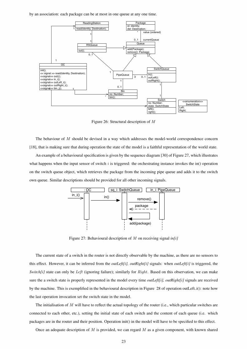
The behaviour of M should be devised in a way which addresses the model-world correspondence concern
[18], that is making sure that during operation the state of the model is a faithful representation of the world state.
An example of a behavioural specification is given by the sequence diagram [30] of Figure 27, which illustrates
what happens when the input sensor of switch i is triggered: the orchestrating instance invokes the in() operation
on the switch queue object, which retrieves the package from the incoming pipe queue and adds it to the switch
own queue. Similar descriptions should be provided for all other incoming signals.
in_i()remove()
package
sq_i: SwitchQueue in_i: PipeQueue
add(package)
: OC
in()
Figure 27: Behavioural description of M on receiving signal in[i]
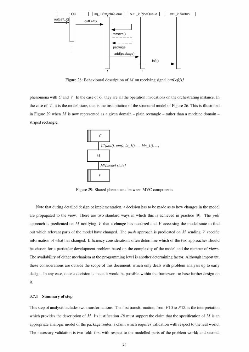
The current state of a switch in the router is not directly observable by the machine, as there are no sensors to
this effect. However, it can be inferred from the outLeft[i], outRight[i] signals: when outLeft[i] is triggered, the
Switch[i] state can only be Left (ignoring failure); similarly for Right . Based on this observation, we can make
sure the a switch state is properly represented in the model every time outLeft[i], outRight[i] signals are received
by the machine. This is exemplified in the behavioural description in Figure 28 of operation outLeft i(): note how
the last operation invocation set the switch state in the model.
The initialisation of M will have to reflect the actual topology of the router (i.e., which particular switches are
connected to each other, etc.), setting the initial state of each switch and the content of each queue (i.e. which
packages are in the router and their position. Operation init() in the model will have to be specified to this effect.
Once an adequate description of M is provided, we can regard M as a given component, with known shared
23
outLeft_i()
add(package)
sq_i: SwitchQueue outL_i: PipeQueue
remove()
: OC
outLeft()
package
swL_i: Switch
left()
Figure 28: Behavioural description of M on receiving signal outLeft[i]
phenomena with C and V . In the case of C , they are all the operation invocations on the orchestrating instance. In
the case of V , it is the model state, that is the instantiation of the structural model of Figure 26. This is illustrated
in Figure 29 when M is now represented as a given domain – plain rectangle – rather than a machine domain –
striped rectangle.
C!{init(), out(), in_1(), ..., bin_1(), ...}
M!{model state}
C
V
M
Figure 29: Shared phenomena between MVC components
Note that during detailed design or implementation, a decision has to be made as to how changes in the model
are propagated to the view. There are two standard ways in which this is achieved in practice [9]. The pull
approach is predicated on M notifying V that a change has occurred and V accessing the model state to find
out which relevant parts of the model have changed. The push approach is predicated on M sending V specific
information of what has changed. Efficiency considerations often determine which of the two approaches should
be chosen for a particular development problem based on the complexity of the model and the number of views.
The availability of either mechanism at the programming level is another determining factor. Although important,
these considerations are outside the scope of this document, which only deals with problem analysis up to early
design. In any case, once a decision is made it would be possible within the framework to base further design on
it.
3.7.1 Summary of step
This step of analysis includes two transformations. The first transformation, from P10 to P13, is the interpretation
which provides the description of M . Its justification J8 must support the claim that the specification of M is an
appropriate analogic model of the package router, a claim which requires validation with respect to the real world.
The necessary validation is two fold: first with respect to the modelled parts of the problem world; and second,
24
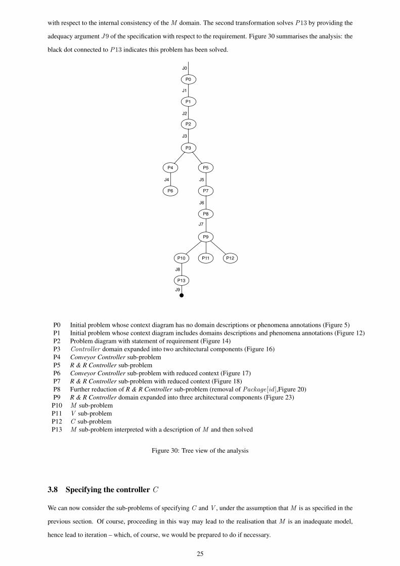
with respect to the internal consistency of the M domain. The second transformation solves P13 by providing the
adequacy argument J9 of the specification with respect to the requirement. Figure 30 summarises the analysis: the
black dot connected to P13 indicates this problem has been solved.
P9
J7
P10 P12P11
P0
P1
P3
P4 P5
J1
J2
J0
P2
J3
P6
J4
P7
J5
P8
J6
P13
J8
J9
P0 Initial problem whose context diagram has no domain descriptions or phenomena annotations (Figure 5)P1 Initial problem whose context diagram includes domains descriptions and phenomena annotations (Figure 12)P2 Problem diagram with statement of requirement (Figure 14)P3 Controller domain expanded into two architectural components (Figure 16)P4 Conveyor Controller sub-problemP5 R & R Controller sub-problemP6 Conveyor Controller sub-problem with reduced context (Figure 17)P7 R & R Controller sub-problem with reduced context (Figure 18)P8 Further reduction of R & R Controller sub-problem (removal of Package[id ],Figure 20)P9 R & R Controller domain expanded into three architectural components (Figure 23)P10 M sub-problemP11 V sub-problemP12 C sub-problemP13 M sub-problem interpreted with a description of M and then solved
Figure 30: Tree view of the analysis
3.8 Specifying the controller C
We can now consider the sub-problems of specifying C and V , under the assumption that M is as specified in the
previous section. Of course, proceeding in this way may lead to the realisation that M is an inadequate model,
hence lead to iteration – which, of course, we would be prepared to do if necessary.
25
By assuming M , the specification of C becomes simple: C is entirely decoupled from V and only responsible
for translating inputs from the environment into operation invocations on the only instance of the orchestrating
class OC of M . The correspondence between its inputs and outputs is rather trivial: by following our naming con-
vention, on receiving signal in[i], C will invoke operation in i(); on receiving, outLeft[i], C will invoke operation
outLeft i(); etc.
3.8.1 Summary of step
This analysis step produces a solution for P8, the sub-problem of specifying the C component of the architecture.
As for M , solving a problem is regarded as a problem transformation whose justification J10 is the adequacy
argument that the specification of C satisfies the requirement of a controller which modifies the model’s state
consistently with inputs from the environment. The solution assumes as given the specification of M of the
previous section.
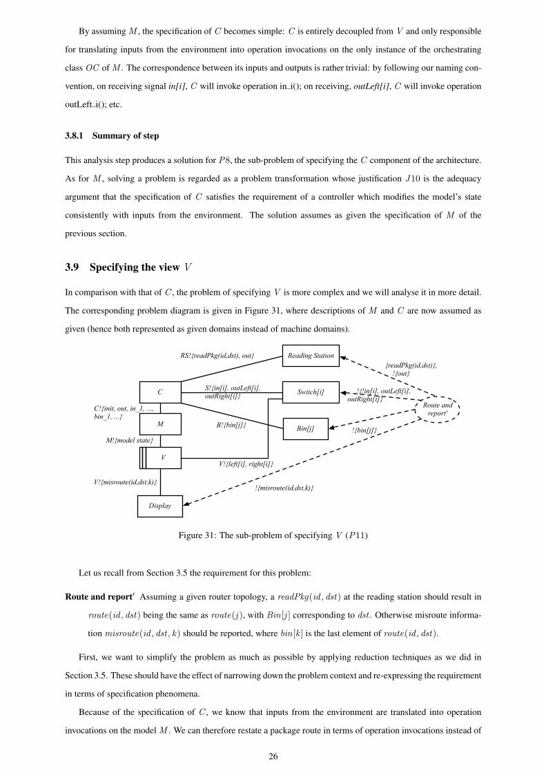
3.9 Specifying the view V
In comparison with that of C , the problem of specifying V is more complex and we will analyse it in more detail.
The corresponding problem diagram is given in Figure 31, where descriptions of M and C are now assumed as
given (hence both represented as given domains instead of machine domains).
Switch[i]
Bin[j]
Reading Station
Display
S!{in[i], outLeft[i], outRight[i]}
V!{left[i], right[i]}
B!{bin[j]}
C
M
V
Route and report'C!{init, out, in_1, ...,
bin_1, ...}
M!{model state}!{bin[j]}
{readPkg(id,dst)}, !{out}
!{!in[i], outLeft[i],outRight[i]}
RS!{readPkg(id,dst), out}
!{misroute(id,dst,k)}V!{misroute(id,dst,k)}
Figure 31: The sub-problem of specifying V (P11)
Let us recall from Section 3.5 the requirement for this problem:
Route and report′ Assuming a given router topology, a readPkg(id , dst) at the reading station should result in
route(id , dst) being the same as route(j ), with Bin[j ] corresponding to dst . Otherwise misroute informa-
tion misroute(id , dst , k) should be reported, where bin[k ] is the last element of route(id , dst).
First, we want to simplify the problem as much as possible by applying reduction techniques as we did in
Section 3.5. These should have the effect of narrowing down the problem context and re-expressing the requirement
in terms of specification phenomena.
Because of the specification of C , we know that inputs from the environment are translated into operation
invocations on the model M . We can therefore restate a package route in terms of operation invocations instead of
26
sensor signals (see Section 3.5) and re-express the requirement accordingly. For instance, route
out ; in[1]; outLeft [1]; in[2]; outLeft [2]; . . . ; in[2n−1]; outRight [2n−1]; bin[2]
can be restated as
out(); in 1(); outLeft 1(); in 2(); outLeft 2(); . . . ; in 2n−1(); outRight 2n−1(); bin 2()
Because we have a description of M , we know the effect of operation invocations on the model state which
is shared with V . For instance, the execution of operation outLeft i() will result in switch i having state Left.
Therefore, the route above can also be restated in terms of switch states as follows, where Left i indicates state
Left of switch i (similarly for Right i ):
Left 1; Left 2; . . . ; Right 2n−1
Let route ′(id , dst) denote the route of a package when restated in terms of switch states (similarly, for the
route to a bin). By assuming the available descriptions of all physical domains, and of C and M , we can rewrite
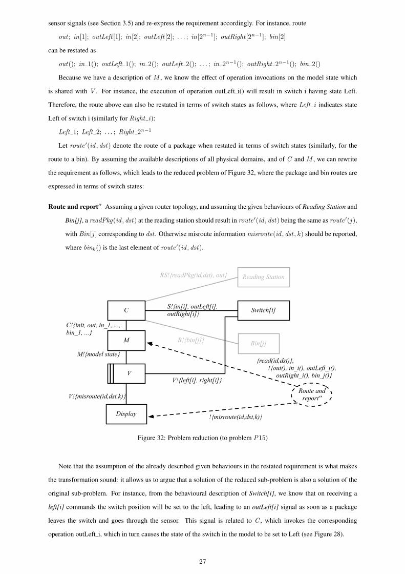
the requirement as follows, which leads to the reduced problem of Figure 32, where the package and bin routes are
expressed in terms of switch states:
Route and report′′ Assuming a given router topology, and assuming the given behaviours of Reading Station and
Bin[j], a readPkg(id , dst) at the reading station should result in route ′(id , dst) being the same as route ′(j ),
with Bin[j ] corresponding to dst . Otherwise misroute information misroute(id , dst , k) should be reported,
where bink () is the last element of route ′(id , dst).
Switch[i]
Bin[j]
Reading Station
Display
RS!{readPkg(id,dst), out}
S!{in[i], outLeft[i], outRight[i]}
V!{left[i], right[i]}
B!{bin[j]}
C
C!{init, out, in_1, ..., bin_1, ...}
M!{model state}
Route and report''
{read(id,dst)}, !{out(), in_i(), outLeft_i(), outRight_i(), bin_j()}V
M
!{misroute(id,dst,k)}
V!{misroute(id,dst,k)}
Figure 32: Problem reduction (to problem P15)
Note that the assumption of the already described given behaviours in the restated requirement is what makes
the transformation sound: it allows us to argue that a solution of the reduced sub-problem is also a solution of the
original sub-problem. For instance, from the behavioural description of Switch[i], we know that on receiving a
left[i] commands the switch position will be set to the left, leading to an outLeft[i] signal as soon as a package
leaves the switch and goes through the sensor. This signal is related to C , which invokes the corresponding
operation outLeft i, which in turn causes the state of the switch in the model to be set to Left (see Figure 28).
27
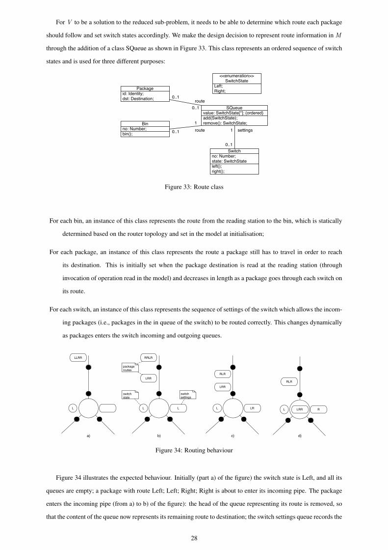
For V to be a solution to the reduced sub-problem, it needs to be able to determine which route each package
should follow and set switch states accordingly. We make the design decision to represent route information in M
through the addition of a class SQueue as shown in Figure 33. This class represents an ordered sequence of switch
states and is used for three different purposes:
Packageid: Identity;dst: Destination;
Binno: Number;bin();
SQueuevalue: SwitchState[*]; {ordered}add(SwitchState);remove(): SwitchState;
<<enumeration>>SwitchState
Left;Right;
0..1
0..1
1
0..1route
route
Switchno: Number;state: SwitchStateleft();right();
0..1
1 settings
Figure 33: Route class
For each bin, an instance of this class represents the route from the reading station to the bin, which is statically
determined based on the router topology and set in the model at initialisation;
For each package, an instance of this class represents the route a package still has to travel in order to reach
its destination. This is initially set when the package destination is read at the reading station (through
invocation of operation read in the model) and decreases in length as a package goes through each switch on
its route.
For each switch, an instance of this class represents the sequence of settings of the switch which allows the incom-
ing packages (i.e., packages in the in queue of the switch) to be routed correctly. This changes dynamically
as packages enters the switch incoming and outgoing queues.
L
LLRR
L
RRLR
LRR
L LR
RLR
LRR
L R
RLR
LRRL
package routes
switch settings
switch state
a) b) d)c)
Figure 34: Routing behaviour
Figure 34 illustrates the expected behaviour. Initially (part a) of the figure) the switch state is Left, and all its
queues are empty; a package with route Left; Left; Right; Right is about to enter its incoming pipe. The package
enters the incoming pipe (from a) to b) of the figure): the head of the queue representing its route is removed, so
that the content of the queue now represents its remaining route to destination; the switch settings queue records the
28
required setting of the switch for the package to be routed correctly; the switch state remains set to Left; a second
package, with route Right; Right; Left; Right is about to enter the incoming pipe. The second package joins the
incoming queue (from b) to c) of the figure): its remaining route is adjusted; the switch settings queue records the
required setting for this package to be routed correctly; the switch state remains set to Left as the previous package
still requires it. The first package enters the switch (part d) of the figure): the switch setting queue is adjusted to
record the next state required.
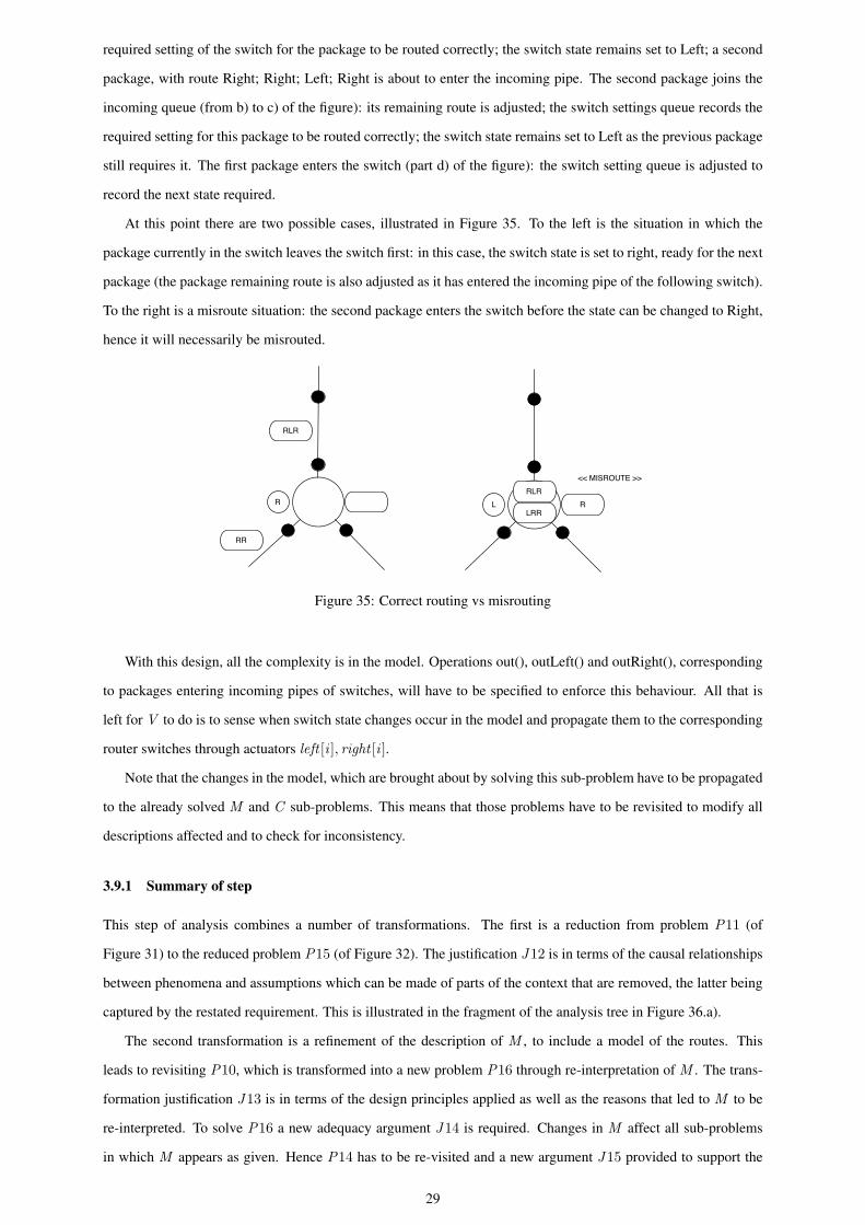
At this point there are two possible cases, illustrated in Figure 35. To the left is the situation in which the
package currently in the switch leaves the switch first: in this case, the switch state is set to right, ready for the next
package (the package remaining route is also adjusted as it has entered the incoming pipe of the following switch).
To the right is a misroute situation: the second package enters the switch before the state can be changed to Right,
hence it will necessarily be misrouted.
R
RLR
RR
L RRLR
LRR
<< MISROUTE >>
Figure 35: Correct routing vs misrouting
With this design, all the complexity is in the model. Operations out(), outLeft() and outRight(), corresponding
to packages entering incoming pipes of switches, will have to be specified to enforce this behaviour. All that is
left for V to do is to sense when switch state changes occur in the model and propagate them to the corresponding
router switches through actuators left [i ], right [i ].
Note that the changes in the model, which are brought about by solving this sub-problem have to be propagated
to the already solved M and C sub-problems. This means that those problems have to be revisited to modify all
descriptions affected and to check for inconsistency.
3.9.1 Summary of step
This step of analysis combines a number of transformations. The first is a reduction from problem P11 (of
Figure 31) to the reduced problem P15 (of Figure 32). The justification J12 is in terms of the causal relationships
between phenomena and assumptions which can be made of parts of the context that are removed, the latter being
captured by the restated requirement. This is illustrated in the fragment of the analysis tree in Figure 36.a).
The second transformation is a refinement of the description of M , to include a model of the routes. This
leads to revisiting P10, which is transformed into a new problem P16 through re-interpretation of M . The trans-
formation justification J13 is in terms of the design principles applied as well as the reasons that led to M to be
re-interpreted. To solve P16 a new adequacy argument J14 is required. Changes in M affect all sub-problems
in which M appears as given. Hence P14 has to be re-visited and a new argument J15 provided to support the
29
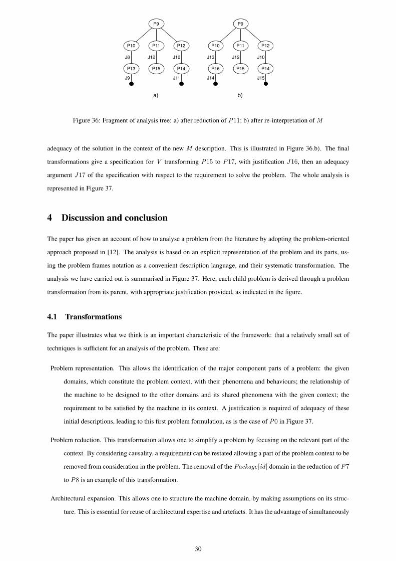
P9
P10 P12P11
P13
J8
J9
P15 P14
J10
J11
J12
P9
P10 P12P11
P16
J13
P15 P14
J10J12
J14 J15
a) b)
Figure 36: Fragment of analysis tree: a) after reduction of P11; b) after re-interpretation of M
adequacy of the solution in the context of the new M description. This is illustrated in Figure 36.b). The final
transformations give a specification for V transforming P15 to P17, with justification J16, then an adequacy
argument J17 of the specification with respect to the requirement to solve the problem. The whole analysis is
represented in Figure 37.
4 Discussion and conclusion
The paper has given an account of how to analyse a problem from the literature by adopting the problem-oriented
approach proposed in [12]. The analysis is based on an explicit representation of the problem and its parts, us-
ing the problem frames notation as a convenient description language, and their systematic transformation. The
analysis we have carried out is summarised in Figure 37. Here, each child problem is derived through a problem
transformation from its parent, with appropriate justification provided, as indicated in the figure.
4.1 Transformations
The paper illustrates what we think is an important characteristic of the framework: that a relatively small set of
techniques is sufficient for an analysis of the problem. These are:
Problem representation. This allows the identification of the major component parts of a problem: the given
domains, which constitute the problem context, with their phenomena and behaviours; the relationship of
the machine to be designed to the other domains and its shared phenomena with the given context; the
requirement to be satisfied by the machine in its context. A justification is required of adequacy of these
initial descriptions, leading to this first problem formulation, as is the case of P0 in Figure 37.
Problem reduction. This transformation allows one to simplify a problem by focusing on the relevant part of the
context. By considering causality, a requirement can be restated allowing a part of the problem context to be
removed from consideration in the problem. The removal of the Package[id ] domain in the reduction of P7
to P8 is an example of this transformation.
Architectural expansion. This allows one to structure the machine domain, by making assumptions on its struc-
ture. This is essential for reuse of architectural expertise and artefacts. It has the advantage of simultaneously
30
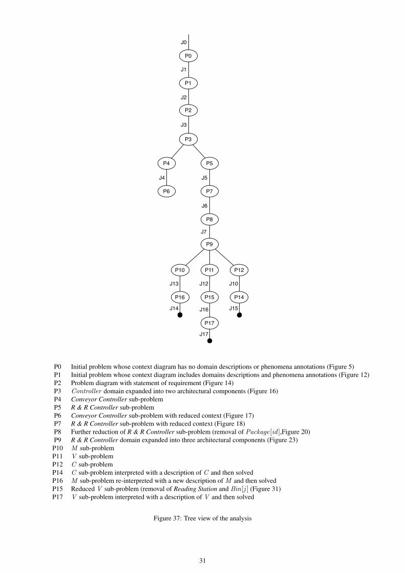
J7
P0
P1
P3
P4 P5
J1
J2
J0
P2
J3
P6
J4
P7
J5
P8
J6
P9
P10 P12P11
P16
J13
P15 P14
J10J12
J14 J15
P17
J16
J17
P0 Initial problem whose context diagram has no domain descriptions or phenomena annotations (Figure 5)P1 Initial problem whose context diagram includes domains descriptions and phenomena annotations (Figure 12)P2 Problem diagram with statement of requirement (Figure 14)P3 Controller domain expanded into two architectural components (Figure 16)P4 Conveyor Controller sub-problemP5 R & R Controller sub-problemP6 Conveyor Controller sub-problem with reduced context (Figure 17)P7 R & R Controller sub-problem with reduced context (Figure 18)P8 Further reduction of R & R Controller sub-problem (removal of Package[id ],Figure 20)P9 R & R Controller domain expanded into three architectural components (Figure 23)P10 M sub-problemP11 V sub-problemP12 C sub-problemP14 C sub-problem interpreted with a description of C and then solvedP16 M sub-problem re-interpreted with a new description of M and then solvedP15 Reduced V sub-problem (removal of Reading Station and Bin[j ] (Figure 31)P17 V sub-problem interpreted with a description of V and then solved
Figure 37: Tree view of the analysis
31
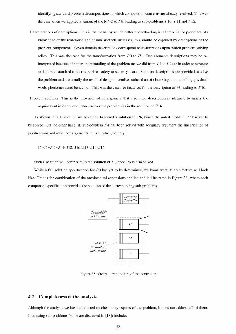
identifying standard problem decompositions in which composition concerns are already resolved. This was
the case when we applied a variant of the MVC to P8, leading to sub-problems P10, P11 and P12.
Interpretations of descriptions. This is the means by which better understanding is reflected in the probolem. As
knowledge of the real-world and design artefacts increases, this should be captured by descriptions of the
problem components. Given domain descriptions correspond to assumptions upon which problem solving
relies. This was the case for the transformation from P0 to P1. Requirements descriptions may be re-
interpreted because of better understanding of the problem (as we did from P1 to P2) or in order to separate
and address standard concerns, such as safety or security issues. Solution descriptions are provided to solve
the problem and are usually the result of design inventive, rather than of observing and modelling physical-
world phenomena and behaviour. This was the case, for instance, for the description of M leading to P16.
Problem solution. This is the provision of an argument that a solution description is adequate to satisfy the
requirement in its context, hence solves the problem (as in the solution of P16.
As shown in in Figure 37, we have not discussed a solution to P6, hence the initial problem P7 has yet to
be solved. On the other hand, its sub-problem P4 has been solved with adequacy argument the linearization of
justifications and adequacy arguments in its sub-tree, namely:
J6∧J7∧J13∧J14∧J12∧J16∧J17∧J10∧J15
Such a solution will contribute to the solution of P0 once P6 is also solved.
While a full solution specification for P0 has yet to be determined, we know what its architecture will look
like. This is the combination of the architectural expansions applied and is illustrated in Figure 38, where each
component specification provides the solution of the corresponding sub-problems.
C
V
R&RController
architecture
M
Conveyor Controller
Controllerarchitecture
Figure 38: Overall architecture of the controller
4.2 Completeness of the analysis
Although the analysis we have conducted touches many aspects of the problem, it does not address all of them.
Interesting sub-problems (some are discussed in [18]) include:
32
destination-bin mapping: such a mapping must be established for the controller to route the packages correctly.
A decision has to be made as to whether this mapping could change dynamically or should be fixed at
initialisation. Including this new aspect of the requirement in the analysis would require a re-interpretation
of the requirement statement followed by either an architectural expansion to include a new component and
corresponding sub-problem, or a re-interpretation of existing components to include some extra functionality
to deal with it.
extending the router layout: it is possible the router layout may be extended over time, for instance to deal with
a larger number of destinations. To preserve the binary tree structure of the tree, its depth would have to be
increased in order to increase the number of bins available. The model would then have to be reconfigured
accordingly, something which is permissible under the proposed specification of M . The treatment of this
problem within the framework would be similar to that of the destination-bin mapping problem.
packages too close together at the reading station: as we do not know what happens if a package arrives while
the reading station is already reading or releasing a package, a possible breakage concern may arise. The
reading station may enter an unknown state should another package arrive at the reading station before the
currently read package has been released. Although the controller has not direct control of the reading
station, it does control the conveyor belt; therefore, indirectly, it may be able to control the rate at which
packages are dropped from the conveyor belt onto the reading station. This would require that packages are
positioned on the conveyor belt at a particular distance, something the controller cannot influence, but that
could be expected, for instance, of a human operator. If that were the case, a domain re-interpretation would
be required to add such an assumption and eliminating the possibility of breakage.
packages jammed in pipes or switches: it is of course possible for packages to get jammed within pipes and
switches and a careful consideration of their physical properties would be required to establish, for instance,
some limits within which a package’s dimensions should fall for the package to be sorted by the router.
A description of such properties would augment domain descriptions, hence lead to re-interpretation. Of
course, it may be the case that even perfectly dimensioned package may still get jammed. In this case a
decision would be required as to how to deal with the problem. It would be possible for the solution not
to be technical at all, but, for instance, by requiring the operator to stop the conveyor manually and recover
the jammed packages (of course, this would add the further problem of alerting the operator of when it is
appropriate to do so to minimise misroute of packages already travelling in the router). Tackling this problem
would require some negotiation with the customer and a decision as to how the requirement or given domain
descriptions should be re-interpreted.
A related issue would be to deal with the following overrun concern [18]: as the packages slide in the pipes
independently of each other, a significant issue arises as to whether the machine’s is able to respond sufficiently
quickly in the situation that two packages arrive almost together. Here, our software problem analysis must move
into the area of real-time systems, and we would suggest that the various strategies that appear in that subject
would be appropriate to discharge this concern: one such is to consider a solution without timing concerns, and
then conduct a worst case timing analysis (wcta) of the ability of the solution to cope with package arrival. Should
33
such a wcta successfully validate the solution’s ability to cope, the solution could be accepted as a solution for the
larger real-time problem. We see no difficulties in applying our framework in this case.
4.3 Reflection on the initial problem representation
A difficulty which arises in the initial characterisation of a problem is deciding which descriptions should be
included as part of a problem context. Some choices were discussed in Section 3.1, where, for instance, we
decided to aggregate the description of a switch with those of the sensors on its incoming and outgoing pipes. Of
course, other choices would have been possible, from separating sensors and switches, to aggregating all router
components into a single domain description.
As a rule of the thumb, separate descriptions should be made only when they add value. For instance, some
parts of the environment may have the only purpose of connecting two others. This is the case of the on/off buttons
in our example between the operator and the controller (this type of domain is known as a connection domain
[18]). In this case, when the operator presses a button, a corresponding command is sent to the controller. An
identity relation could be establish between pairs of phenomena issued by the operator and the switch. If we could
ascertain that the buttons reliably convey operator’s presses to the controller in a timely fashion, we could ignore
the on/off buttons and assume that operator and controller share phenomena directly. This is because an explicit
consideration of this domain wouldn’t make any difference to the problem or its solution. On the other hand,
should the buttons be unreliable, then their inclusion in the analysis may be significant. This is certainly the case,
for instance, in a safety-critical system, where the failure modes of a switch may contribute to the overall safety
assessment of the system.
4.4 Reflection on architectural expansion
In applying architectural expansion in the example, we have assumed we are free to choose the software archi-
tecture with no constraints from the available hardware on which the solution should ultimately be implemented.
This is, of course, not always the case – in mobile devices and embedded controllers hardware capabilities may be
restricted in many ways. The consideration of the relation between software and hardware architectures, and any
required trade-off, is, of course, an important one in design and implementation. It is, however, outside the scope
of this paper, in which we have made the simplifying assumption that the target hardware should be capable of
supporting any chosen software architecture. In a real development such an assumption would have to be validated,
for instance, by consulting a hardware manual.
Usually architectural expansion leads to a number of sub-problems, each corresponding to a part of the archi-
tecture to be (co-)designed. This transformation will often be combined with problem reduction to identify and
separate the relevant parts of each sub-problem. Reduction includes both removing part of the context and rein-
terpreting the requirement. Note that while architectural expansion is always possible – we can always choose an
number of components to make up an architecture – the resulting sub-problems may not necessarily be separable
through reduction like the ConveyorController and R&RController sub-problems of the example. In such cases,
composition concerns need addressing explicitly. The risk of non-separable sub-problems is mitigated when stan-
dard architectures are applied, like the MVC in the example, where the separation the architecture affords already
34
resolves (some of) the composition concerns.
Acknowledgements
We are pleased to acknowledge the financial support of IBM, under the Eclipse Innovation Grants, and the EPSRC,
Grant number EP/C007719/1. Thanks also go to our colleagues in the Centre for Research in Computing at The
Open University.
References
[1] I. Alexander and N. Maiden, editors. Scenarios, stories, use cases through the systems development life-cycle.
Wiley, 2004.
[2] M. Beeson. Some applications of Gentzen’s proof theory in automated deduction. In Proceedings of the
international workshop on Extensions of logic programming, pages 101–156, New York, NY, USA, 1991.
Springer-Verlag New York, Inc.
[3] Y. Bertot, G. Kahn, and L. Thery. Proof by pointing. Theoretical Aspects of Computer Science (TACS), 1994.
[4] J. Brier, L. Rapanotti, and J. G. Hall. Problem frames for socio-technical systems: predictability and change.
In Proceedings of 1st International Workshop on Applications and Advances of Problem Frames, pages 21–
25. IEEE CS Press, 2004.
[5] A. Bundy. A survey of automated deduction. In M. Wooldridge and M. Veloso, editors, Artificial Intelligence
Today, volume 1600 of LNAI, pages 153–174. Springer-Verlag Berlin Heidelberg, 1999.
[6] A. Cockburn. Writing Effective Use Cases. Addison-Wesley, 2001.
[7] K. Cox, J. G. Hall, and L. Rapanotti. Editorial: A roadmap of problem frames research. Journal of Informa-
tion and Software Technology, 47(14):891–902, 2005.
[8] W. M. Farmer, J. D. Guttman, and F. J. Thayer. Imps: An interactive mathematical proof system. Journal of
Automated Reasoning, 11(2), 1993.
[9] M. Fowler. Patterns of Enterprise Application Architecture. Addison-Wesley Professional, 2002.
[10] C. A. Gunter, E. L. Gunter, M. Jackson, and P. Zave. A reference model for requirements and specifications.
IEEE Software, 17(3):37–43, 2000.
[11] J. G. Hall, M. Jackson, R. C. Laney, B. Nuseibeh, and L. Rapanotti. Relating software requirements and ar-
chitectures using problem frames. In 10th Anniversary IEEE Joint International Conference on Requirements
Engineering (RE 2002), pages 137–144, Essen, Germany, 2002. IEEE Computer Society.
[12] J. G. Hall and L. Rapanotti. A framework for software problem analysis. Technical Report 2005/05, Depart-
ment of Computing, The Open University, 2005.
35
[13] J. G. Hall, L. Rapanotti, and M. Jackson. Problem frame semantics for software development. Journal of
Software and Systems Modeling, 4(2):189 – 198, 2005.
[14] J. Hammond, R. Rawlings, and A. Hall. Will it work? In The proceedings of the 5th IEEE International
Symposium on Requirements Engineering., 2001.
[15] M. Jackson. Problem frames and software engineering. Information and Software Technology, 47(14):903–
912, 2005.
[16] M. A. Jackson. Software Requirements & Specifications: a lexicon of practice, principles and prejudices.
ACM Press. Addison-Wesley Publishing Company, 1995.
[17] M. A. Jackson. Problem analysis using small problem frames. South African Computer Journal 22: Special
Issue on WOFACS98, pages 47–60, 1998.
[18] M. A. Jackson. Problem Frames: Analyzing and Structuring Software Development Problem. Addison-
Wesley Publishing Company, 1st edition, 2001.
[19] M. A. Jackson. Some basic tenets of description. Software and Systems Modeling, 1(1):59, 2002.
[20] M. A. Jackson. Why software writing is difficult and will remain so. Information Processing Letters, 88(1-
2):13–15, 2003.
[21] S. C. Kleene. Introduction to Metamathematics. Van Nostrand, Princeton, NJ., 1964.
[22] A. Krabbel, I. Wetzel, and H. Zullighoven. On the inevitable intertwining of analysis and design: developing
systems for complex cooperations. In DIS ’97: Proceedings of the conference on Designing interactive
systems, pages 205–213, New York, NY, USA, 1997. ACM Press.
[23] G. E. Krasner and S. T. Pope. A cookbook for using the model-viewcontroller user interface paradigm in
smalltalk-80. Journal of Object-Oriented Programming, 1(3):26–49, August 1988.
[24] P. Kruchten. The Rational Unified Process: An Introduction, volume 2nd Edition of Object Technology
Series. Addison-Wesley, 2000.
[25] C. Larman. Applying UML and patters. Prentice Hall, 2nd edition, 2002.
[26] D. Lea. Design patterns for avionics control systems. Technical Report DSSA Adage Project ADAGE-OSW-
94-01, State University of New York, November 1994.
[27] Z. Li, J. G. Hall, and L. Rapanotti. A constructive approach to problem frame semantics. Technical Report
2004/26, Computing Department, The Open University, 2005. Submitted to FASE’05.
[28] Z. Li, J. G. Hall, and L. Rapanotti. From requirements to specification: a formal perspective. In J. G. Hall,
L. Rapanotti, K. Cox, and Z. Jin, editors, Proceedings of the 2nd International Workshop on Advances and
Applications of Problem Frames. ACM, 2006. To appear.
[29] B. Nuseibeh. Weaving together requirements and architectures. IEEE Computer, 34(3):115–117, 2001.
36
[30] OMG. Unified Modeling Language (UML), version 2.0. http://www.omg.org/technology/documents/formal/uml.htm.
[31] L. Rapanotti, J. G. Hall, M. Jackson, and B. Nuseibeh. Architecture-driven problem decomposition. In
12th IEEE International Conference on Requirements Engineering (RE 2004), pages 80–89. IEEE Computer
Society, 2004.
[32] L. Rapanotti, J. G. Hall, and Z. Li. Problem reduction: a systematic technique for deriving specifications
from requirements. Technical Report 2006/02, Centre for Research in Computing, 2006.
[33] S. Robertson and J. Robertson. Mastering the Requirements Process. Addison Wesley, Harlow, England.,
1999.
[34] R. Seater and D. Jackson. Problem frame transformations: Deriving specifications from requirements. In 2nd
International Workshop on Advances and Applications of Problem Frames, 2006.
[35] W. Swartout and R. Balzer. On the inevitable intertwining of specification and implementation. Commununi-
cations of ACM, 25(7):438–440, 1982.
[36] W. M. Turski. And no philosophers’ stone, either. INFORMATION PROCESSING, 86, 1986.
[37] A. van Lamsweerde. Requirements engineering in the year 00: a research perspective. In International
Conference on Software Engineering, pages 5–19, 2000.
[38] E. S. Yu. Modeling organizations for information systems requirements engineering. In Proceedings 1st
IEEE International Symposium on Requirements Engineering, pages 34–41, 1993.
[39] P. Zave and M. A. Jackson. Four dark corners of requirements engineering. ACM Transactions on Software
Engineering and Methodology, 6(1), 1997.
37