Problem Oriented Software Engineering: Solving the Package Router Control Problem
48
ISSN 1744-1986 Technical Report N o 2006/10 Problem-oriented software engineering Jon G Hall Lucia Rapanotti Michael Jackson 12 th October 2006 Department of Computing Faculty of Mathematics and Computing The Open University Walton Hall, Milton Keynes MK7 6AA United Kingdom http://computing.open.ac.uk
-
Upload
independent -
Category
Documents
-
view
2 -
download
0
Transcript of Problem Oriented Software Engineering: Solving the Package Router Control Problem
ISSN 1744-1986
T e c h n i c a l R e p o r t N o 2 0 0 6 / 1 0
Problem-oriented software engineering
Jon G Hall Lucia Rapanotti Michael Jackson
12th October 2006
Department of Computing Faculty of Mathematics and Computing The Open University Walton Hall, Milton Keynes MK7 6AA United Kingdom http://computing.open.ac.uk
A CONCEPTUAL FRAMEWORK 1
Problem-oriented software engineering
Jon G. Hall Lucia Rapanotti Michael Jackson
Centre for Research in Computing, The Open University, UK
October 12, 2006 DRAFT
Abstract
This paper introduces a formal conceptual framework for software development, based on a
problem-oriented perspective that stretches from requirements engineering through to program code.
In a software problem the goal is to develop a machine—that is, a computer executing the software
to be developed—that will ensure satisfaction of the requirement in the problem world.
We regard development steps as transformations by which problems are moved towards software
solutions. Adequacy arguments are built as problem transformations are applied: adequacy arguments
both justify proposed development steps and establish traceability relationships between problems
and solutions.
The framework takes the form of a sequent calculus. Although itself formal, it can accommodate
both formal and informal steps in development. A number of transformations are presented, and
illustrated by application to small examples.
Index Terms
Software engineering, problem-orientation, problem world, sequent calculus, solution, transfor-
mation
I. INTRODUCTION
“We can start with the obvious statement that engineering is a problem solving
activity.” (Walter G. Vincenti, [44])
The problem-oriented approach to requirements engineering is becoming well established,
especially for software intensive systems. The foundation of problem-oriented approaches
has been laid in recent years, the most complete presentation being given in [25]. Software
development is viewed as a problem, the solution being a machine—that is, a program running
in a computer—that will ensure satisfaction of the requirement in the given problem world
or environment. Because the requirement typically concerns properties and behaviours that
are located in the problem world at some distance from its interface with the machine,
requirements are distinguished from specifications.
A. Requirements and Specifications
A specification describes the behaviour of the machine at its interface with the problem
world, while a requirement describes the effects that must be ensured, directly or indirectly,
by that behaviour. To derive a specification from a requirement it is necessary to analyse
2

the given structure and properties of the problem world that will both constrain and enable
satisfaction of the requirement. The ultimate justification of a proposed solution must be a
convincing argument that the following proposition is true:
“If a machine satisfying the specification S is installed in the given problem world
having the given properties W, then running that machine will ensure that the
problem world satisfies the requirement R.”
or, more tersely, W, S ` R. The entailment denotes a problem in which S and R are given
and the solution task is to obtain an S satisfying the entailment.
For any realistic problem a solution must be approached by a number of development
steps: an initially vague R or W must be clarified and made more exact; a complexity may
be addressed by decomposition; a known pattern of solution may be brought to bear where
it is applicable; or the impact of some part of the problem world may be carefully analysed
and encapsulated so that it need not be considered in later steps. We regard all of these steps,
and others, as transformations of problems.
B. Transformations
There is a substantial body of work on development approaches based on transformation
of problem or solution or both. Some transformations of the kind we define in this paper are
found in such formal approaches as the development of program code from specifications
in the refinement calculi of Morgan [31] and Back [2]. Some earlier work, for example the
work of Burstall and Darlington [14] and Partsch [4], used transformations of program texts
to improve efficiency. All these approaches focus on the later stages of development, being
concerned with problems that are already cast in the form of program specifications.
Our own focus is wider. We are concerned not only with requirements engineering, where
the problem-oriented approach has its origins, but more generally with software engineering.
In our view, software engineering includes the identification and clarification of system
requirements, the identification, structuring and analysis of the problem world, the struc-
turing and specification of a hardware/software machine that can ensure satisfaction of the
requirements in the problem world, the creation of the software product, and the construction
of arguments, convincing to developers, customers, users and other interested people, that
the system will satisfy its requirements.
Our conceptual framework takes the form of a Gentzen-style calculus [26] for software
problems. The basis of a Genzten-style calculus is a sequent: a sequent is, simply, some well-
3

formed formula (wff). In the calculus a sequent can be transformed into one or more other
sequents that advance the calculation towards its desired conclusion, or are, in some sense,
easier to work with. The essence of a Genzten-style system is to define the set of permissible
transformations on sequents, and the conditions under which each can be applied. Many
logical frameworks—such as the propositional and predicate calculi—have Gentzen-style
sequent encodings that, in turn, have useful properties, such as being amenable to computer
supported transformation (for instance, [6], [17], [5], [13]).
In our framework the sequents are software problems cast in the general form W, S `
R. The paper shows how to represent problems as sequents, and characterises problem
transformations and the conditions for their applicability.
C. Formal and Non-Formal
For software-intensive systems, development is unavoidably concerned with non-formal
domains of reasoning. These include: the physical and human world; requirements loosely
expressed in natural language; the capabilities of human users and operators; and the identi-
fication and resolution of apparent and real conflicts between different needs. In a software-
intensive system these informal domains interact with the essentially formal hardware/software
machine: an effective approach to system development must therefore deal adequately with
the informal, the formal, and the relationships between them.
As Turski has pointed out [42]:
There are two fundamental difficulties involved in dealing with non-formal domains
(also known as the real world):
1. Properties they enjoy are not necessarily expressible in any single linguistic
system.
2. The notion of mathematical (logical) proof does not apply to them.
These difficulties, well known in the established branches of engineering, have sometimes led
to a harmful dichotomy in approaches to software development. Some approaches address
only the formal concerns, usually in a single formal language; others address only the informal
concerns, using several, often incommensurable, languages; few address both in an effective
way.
The aim of the work reported here is to bring both non-formal and formal aspects of
development together in a single framework. The framework is intended to provide a structure
within which the results of different development activities can be combined and reconciled.
4

Essentially the structure is the structure of the progressive solution of a system development
problem; it is also the structure of the argument that must eventually justify the adequacy
of the developed system. The framework is itself formal, but it is designed to accommodate
both formal and informal descriptions of machines, problem domains and requirements, and
also formal and informal arguments justifying claimed relationships between development
artefacts. To capture the informal nature of such arguments and the relationships they justify,
we distinguish between a transformation rule and the justification of its applicability to the
case in hand.
In a calculus of fully formal sequents, application of a permissible transformation is
guarded by the syntactic form of the sequents involved. In our framework, the application of
a transformation rule is guarded, but not necessarily by conditions requiring formal proof.
Some transformations have formal guards, but some have guards that ask only for justification
that the application is adequate. For example, a transformation in which a loosely-stated
requirement is clarified may be justified by appealing to an informal statement by the
customer. A transformation which depends on a behavioural property of some part of the
problem world might be justified by testing. Testing is, of course, a standard way of checking
functional adequacy, and serves a useful purpose in real-world software engineering: that we
can use it, and other informal techniques, as justification is an important characteristic of our
framework.
D. Structure of the Paper
The paper is organised in six further sections. In Section II-C, we introduce the basis of
the framework, the problem, defining it and discussing their characteristics, with examples. In
Section III we discuss the way in which problem can be related, and the role of justification
in that relationship. In Section IV, we define a number of problem transformation schemata—
rules that characterise class of problem transformation that can be used in the problem
solving involved in software engineering. In the case study of SectionV we show software
development problem can progress in our framework. There is a discussion of related work
in Section VI, and we conclude the paper with discussion, conclusions, and ideas about the
future of the framework in Section VII.
II. SOFTWARE PROBLEMS
5

We define a (software) problem as requirements in a real-world context. A context is a
collections of domains D1, ..., Dn described in terms of their known, i.e., indicative, properties
and interacting through the sharing of phenomena; the requirements R1, ..., Rm are statements
of what we would like to be true of the context given a solution to the problem, i.e., optative
statements. Thus, a software problem challenges us to find the solution that, in the given
context, brings about the requirements. Fuller descriptions of these elements of software
problems, leading to a formal definition, are given below.
A. Phenomena and Domains
In previous work, Jackson [25] describes six kinds of phenomena in two categories:
• the individual phenomena that include events, entities and values;
• the relations that include states, truths and roles.
This richness is representative of the richness found in development, and so will be useful
to us.
A domain is a set of related phenomena that are usefully treated as a behavioural unit for
some purpose. A domain has a name and a description that indicates the possible values and/or
states that that domain’s phenomena can occupy, how those values and states change over
time, and which phenomena – shared or unshared – are produced and when. The description
may be more or less precise, but should always be interpreted as in the indicative mood,
i.e., as expressing fact. That domain named N has description E is written N : E. The name
allows a domain to be referred to and enhances traceability through a development.
Associated with each domain D = N : E there are three alphabets:
• the controlled alphabet: the phenomena shared with other domains, and controlled by
D;
• the observed alphabet: the phenomena shared with other domains, and observed by D.
• the unshared alphabet: all phenomena of D that are not shared with another domain.
That D(= N : E) has unshared alphabet u, controlled alphabet c and observed alphabet o is
written as D(u)co (or, sometimes, as N(u)c
o, when convenient).
More or less may be known about a domain and its alphabets, and the knowledge of a
domain’s description may affect what can be described of it. A domain that has been named,
but of which nothing more is known has null description.
6

The language in which a description is written is not prescribed by our framework1;
however, it should be possible for sense to be made of statements in the language. There is
no a priori assumption of precision or lack of ambiguity or completeness in a description; a
farmer’s initial description of a sluice gate that appears in a field might simply be:
The sluice gate was installed three years ago.
If a richer description is required to allow a problem to be solved, then it will have to be
found as part of the development. For instance, a developer with knowledge of sluice gates
working on a controller for the farmer’s sluice gate may be able to interpret the farmer’s
statement as identifying the SGVert model of sluice gate. The rule that accommodates such
‘sense-making’ is Interpretation; see Section IV-A.
1) Solution domains: A (software) solution domain S = N : E is, simply, a named domain
that solves (or is intended to solve) a problem. Within our framework, the solution’s domain
description stands for a physical software solution: as such it may have one of many forms,
ranging from a high-level specification, a description written in Z [40], through to program
code in some programming language. As a domain, a solution has controlled, observed and
unshared phenomena; the union of the controlled and observed sets are called the specification
phenomena for the problem.
As with other domains, more or less can be known about the solution domain, including
the phenomena it shares with its context. Typically, of course, problem solving leads us to
the discovery of the solution domain’s description (including the phenomena it shares with
its context).
B. Requirements
A requirement states how a solution domain should be assessed as the solution to a problem.
Like a domain, a requirement is a named description, R = N : E. We may know more or
less about a requirements description, again using null when we know nothing of it. A
requirements description should always be interpreted in the optative mood, i.e., expressing
a wish.
For a requirement R, there are two alphabets:
1It may also be the case that two (or more) stake-holders assign different descriptions of what is, ostensibly, the same
domain. In this case, a domain will be further identified with its description ‘owner’, as well as the name. However, we do
not pursue this complication in this paper.
7
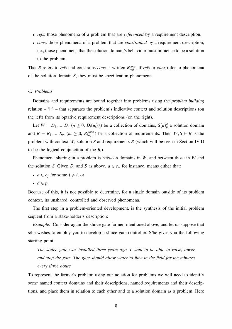
• refs: those phenomena of a problem that are referenced by a requirement description.
• cons: those phenomena of a problem that are constrained by a requirement description,
i.e., those phenomena that the solution domain’s behaviour must influence to be a solution
to the problem.
That R refers to refs and constrains cons is written Rconsrefs . If refs or cons refer to phenomena
of the solution domain S, they must be specification phenomena.
C. Problems
Domains and requirements are bound together into problems using the problem building
relation – ‘`’ – that separates the problem’s indicative context and solution descriptions (on
the left) from its optative requirement descriptions (on the right).
Let W = D1, ..., Dn (n ≥ 0, Di(ui)cioi
) be a collection of domains, S(u)dp a solution domain
and R = R1, ..., Rm (m ≥ 0, Riconsirefsi
) be a collection of requirements. Then W, S ` R is the
problem with context W, solution S and requirements R (which will be seen in Section IV-D
to be the logical conjunction of the Ri).
Phenomena sharing in a problem is between domains in W, and between those in W and
the solution S. Given Di and S as above, a ∈ ci, for instance, means either that:
• a ∈ oj for some j 6= i, or
• a ∈ p.
Because of this, it is not possible to determine, for a single domain outside of its problem
context, its unshared, controlled and observed phenomena.
The first step in a problem-oriented development, is the synthesis of the initial problem
sequent from a stake-holder’s description:
Example: Consider again the sluice gate farmer, mentioned above, and let us suppose that
s/he wishes to employ you to develop a sluice gate controller. S/he gives you the following
starting point:
The sluice gate was installed three years ago. I want to be able to raise, lower
and stop the gate. The gate should allow water to flow in the field for ten minutes
every three hours.
To represent the farmer’s problem using our notation for problems we will need to identify
some named context domains and their descriptions, named requirements and their descrip-
tions, and place them in relation to each other and to a solution domain as a problem. Here
8

is a possible interpretation as a problem:
Farmer(raise, lower, stop)fc: wants
be able to raise, lower and stop the
Gate
Gate(gp)cg: installed three years ago
Controllercgfc : null
`
Reqraise,lower,stop: The Farmer should
be able to raise, lower and stop the
Gate. The Gate should allow water to
flow in the field for ten minutes every
three hours.
Here we assume that:
• the Farmer controls phenomena fc that are shared with the Controller, the solution to
be found;
• the Controller controls the Gate through the phenomena cg.
The farmer’s initial description lacks detail, and so to present their description as a problem
we have ‘guessed’ some of the details. These details include, for instance, precisely which
domains are involved in the problem context along with which phenomena are shared. In
any serious development context, such decisions will need validating. We will show how
validation can be done within the framework later in the paper.
Other problems are not so difficult to capture:
1) The null problem: The null problem is the problem of which we know nothing:
Context : null, Solution : null ` Requirements : null
Here, null is used as Context, Requirement and Solution description to indicate that nothing
is known about them. The null problem has a distinguished place in problem-oriented engi-
neering; it can be thought of as the starting point of all problem-oriented development, with
context, requirement and solution description being developed therefrom. We show how this
might be done in Section III.
2) Specification problems: A specification problem is a problem that has an empty context
(∅), a solution Solution, of which more or less is known of its description DescS, and a
single, fully known requirement, with description DescR, that references and constrains only
specification phenomena (those phenomena shared with the machine).
Context : ∅, Solutionab : DescS ` Requirementa
b : DescR
Example: Specification problems are typical in formal refinement settings, such as those
of Morgan [31] and Back [2]. The following problem (P1) is adapted from [32]
P1 : ∅, Solnrtsq : null ` Specrt
sq : rt = b√sqc (1)
9
in this case the requirement, Spec, constrains the value of rt to be the greatest integer less
than the square root of sq. rt and sq are specification phenomena.
D. Candidate solutions and solved problems
In parallel with, or perhaps following somewhat behind, the search for a solution to a
problem is the construction of an argument that justifies the fitness-for-purpose of the found
solution with respect to the problem’s context and requirements. Actually, the argument the
developer will have to construct expresses the adequacy of a candidate solution with respect
to a number of criteria including, but not limited to, those of fitness-for-purpose as a customer
might see it; by the same token, a presented argument might be a portion of that the developer
has produced. We will see how an adequacy argument is built in the next section.
Even to be considered a candidate solution, a solution domain must be compatible with
its problem context, in the following sense. Let a, b, c, d, o, refs and cons be sets of
phenomena with c∩a = ∅. Any candidate solution S(u)ab to a software problem with context
W = D1, ..., Dn, with W(d)co, and requirements R = R1, ..., Rm, with Rcons
refs , must be such that
cons ∪ refs ⊆ o ∪ c ∪ a ∪ b ∪ d.
For a problem to be solved, the customer2 must be convinced that a candidate solution is
adequate in meeting their needs, as expressed through their requirements in context, so that it
can be accepted as a solution. The conceptual framework provides guidance for constructing
adequacy arguments, built step-wise during development, that can be exposed to the customer
to convince them of solution-hood. The actual notion of adequacy depends on the context of
the development. For example, in safety-critical development, it may be that the appropriate
level is somewhere close to formal mathematical proof; should the development be mission-
critical, it may be that rigourous testing will be the appropriate level; should the development
be entirely informal, it may be that no justification is required. This context dependence of
the system we define – that adequacy of a rule application depends upon the development
context – is a radical departure from traditional Gentzen-style sequent calculi.
Example: Specification problems are easy to solve within the framework, (but only if one
is content with a non-computational solution specification). Consider, again, the specification
problem, P1, defined above. To solve P1, one can simply write (cf., [32]):
∅, Solnrtsq : rt := b√sqc ` Specrt
sq : rt = b√sqc
2And/or other stake-holders.
10

and call the problem solved. That a specification is its own solution follows from the fact
that Spec satisfies Spec, for any Spec.
It is worth noting that, although in this case solution and requirement descriptions are the
same, the solution description is indicative while the requirement description is optative. So,
although descriptions may, themselves, often be expressed in indicative or optative mood, it
is actually their position in the problem that defines the actual mood in which the description
should be read: indicative on the left and optative on the right of the problem builder.
Returning to problem P1, if one needs a code solution for a problem, one must work
harder:
Example: Consider again the formal specification example above; we may also write:
P2 : ∅, Solnrtsq :
|[var ru; rt, ru := 0, sq + 1;
do rt + 1 6= ru →
|[var rm; rm := (rt + ru)/2;
if rm2 ≤ sq → rt := rm
else rm2 > sq → ru := rm
fi ]|
od ]|
` Specrtsq : rt = b√sqc (2)
with P2 giving an (essentially) executable solution for problem P1. The justification is:
This solution is constructed by formal refinement, the complete development (with
proofs) being contained in [32]; we note, however, that as the value of rt changes
throughout the execution of the code, this computation must be execute atomically
for correctness.
This justification would be adequate for even the most safety-critical of safety-critical devel-
opments.
III. SOFTWARE PROBLEM TRANSFORMATION
Problem P2 is related to problem P1 in that, in it, there is a detailed description of the
Soln for P1. Moreover, this relationship is justified by an argument of the formal correctness
of the solution, so that we can say P1 is solved.
We would like to make this relationship formal so that, in this case, P2 is justified as P1
transformed, capturing the progression of P1’s development. Software problem transforma-
tions capture and formalise such relationships: a software problem transformation transforms
11

a single problem – the conclusion – to a set of problems – the premises – and records an
argument – the adequacy argument step – that justifies the relationship of the premises to
the conclusion.
Suppose we have problems W, S ` R, Wi, Si ` Ri, i = 1, ..., n, (n ≥ 0) and adequacy
argument step J, then we will write:
W1, S1 ` R1 ... Wn, Sn ` Rn〈〈J〉〉
W, S ` R(3)
to mean that:
S is a solution of W, S ` R with adequacy argument (CA1∧ ...∧CAn)∧J whenever
S1, ..., Sn are solutions of W1, S1 ` R1, ..., Wn, Sn ` Rn, with adequacy arguments
CA1, ..., CAn, respectively.
The search for a solution extends the tree upwards and, as in other Gentzen-style sequent
calculi, problem transformation applications cascade with transformations lower in the tree
producing premise problems (those above the line) that transformations at the next level up
use as conclusion problems (those below the line). When there are no premise problems
(n = 0 in the above definition) we have reached a ‘leaf’ node of the tree, and upwards
development is complete for that part of the problem.
As the tree grows, the adequacy argument is constructed. The reader will note that we
make no requirement of formality in the adequacy argument step nor, therefore, in the
adequacy argument; the informality of the subject matter precludes fully formal treatment of
some transformations. Indeed, in the worst case, a software problem transformation may be
applied without any justification, whence we have no adequacy argument for the development
as those for the premises, i.e., the CAi, cannot be extended to the conclusion. Of course,
that no justification has been given does not mean that it cannot be retrospectively added.
However, a problem transformation that happens with no justification incurs the risk that no
justification – and therefore no adequacy argument – will be possible. Attitudes to risk may
thus influence the application of rules, and thus software development within the framework.
The justification of a problem transformation is, however, necessary if we wish to argue the
adequacy of a solution resulting from the development, even if the strongest possible (or
practical) justification may still be quite weak.
Example: Unit testing, also called software component testing, represents the “Lowest level
of testing that an AUT [Application Under Test] can undergo” [45]. Integration testing, on the
other hand, demonstrates that (unit tested) software components work together in ‘a correct,
12

stable, and coherent manner’ [45]. The relationship of unit tests to integration test illustrates
the relationship represented in the rule above: suppose the Si are software components such
that W, Si ` Ri is solved, unit testing being the appropriate ‘correctness argument,’ CAi. Let
S be the structure in which the software components are intended to work together3 with
R the requirement of their composition. Then J, the adequacy argument step, is integration
testing; the (full) adequacy argument for S is simply the conjunction of integration testing of
the composition together with unit testing of the individual components.
Example: We should write:
∅, Solnrtsq :
|[var ru; rt, ru := 0, sq + 1;
do rt + 1 6= ru →
|[var rm; rm := (rt + ru)/2;
if rm2 ≤ sq → rt := rm
else rm2 > sq → ru := rm
fi ]|
od ]|
` Specrtsq : rt = b√sqc
〈〈This solution is constructed by formal
refinement, the complete development
(with proofs) being contained in [32];
we note, however, that as the value of rt
changes throughout the execution of the
code, this computation must be execute
atomically for correctness.〉〉∅, Solnrtsq : null ` Specrt
sq : rt = b√sqc
to capture the relationship between P1 and P2 described above. Note that, as the justification
of the premise problem is missing, we do not have the adequacy argument for the whole tree.
The Problem Solved Rule (SectionIV-B.3) provides the required justification, as we shall see.
IV. PROBLEM TRANSFORMATION SCHEMATA
Equation 3 (page 12) presents the generic form of a transformation. Problem transformation
schemata capture classes of problem transformations in named rules. In a problem transfor-
mation schema schema variables, here written in calligraphic font, are bound to patterns that
can occur both in the conclusion of the rule and its premises, thereby indicating relationships
between parts of the premises and the conclusion.
In the following sections we define a number of problem transformation schemata.
A. Problem Interpretation
1) Domain description interpretation: (shortly, domain interpretation) is the Problem
Transformation Schemata (shortly, rule) by which a (non-solution) domain description is
3We will see in Section IV-B.3 how such structures are represented in our framework.
13

interpreted, i.e., re-expressed in some way to make it more suitable for problem solving.
It may be that the intention of the interpretation is to clarify a description, to introduce a
domain’s shared or unshared phenomena, to make it more formal, to disambiguate it, or any
other of a multitude of interpretations. The rule is:
W ,N : E ′,S ` R [Domain Interpretation]〈〈J : Explanation of why E ′ is better than E for the purpose in hand〉〉W ,N : E ,S ` R
in which E ′ is the interpretation of E , the original description of the domain named N . The
justification, J , for domain interpretation must argue that an ‘adequate’ interpretation has
been found; the meaning of adequate will, in general, be defined by context. The name of
the rule is written above the justification.
Example: Consider again the sluice gate problem. We will assume that the developer wishes
to change the Gate’s description to one that is more effective for subsequent development.
To do this, they apply the domain interpretation rule, with W bound to Farmer, N to Gate,
E to the description ‘installed three years ago’, E ′ to the description ‘the SGVert model’, S
to Controller, and R to Req. Whence, with changes emboldened, the rule application gives:
Farmer: wants be able to
raise, lower and stop the
Gate
Gate: the SGVert model
Controller: null
`
Req: The Farmer should be
able to raise, lower and stop
the Gate. The Gate should
allow water to flow in the
field for ten minutes every
three hours.[Domain Interpretation]〈〈The SGVert was the onlymodel of sluice gate produced3 years ago. It will be easier towork with this description as amanual describing its detailedoperation exists.〉〉
Farmer: wants be able to
raise, lower and stop the
Gate
Gate: installed three years
ago
Controller: null
`
Req: The Farmer should be
able to raise, lower and stop
the Gate. The Gate should
allow water to flow in the
field for ten minutes every
three hours.
We note the first part of the adequacy argument step given–that relating to the installation
date of the Gate–is relatively weak: if, for instance, the Gate was not installed from new, the
adequacy argument step may be broken. A much stronger adequacy argument step for this
domain interpretation is that
14
The sluice gate model has been confirmed by field inspection as the SGVert model.
which provides validation for this particular development step.
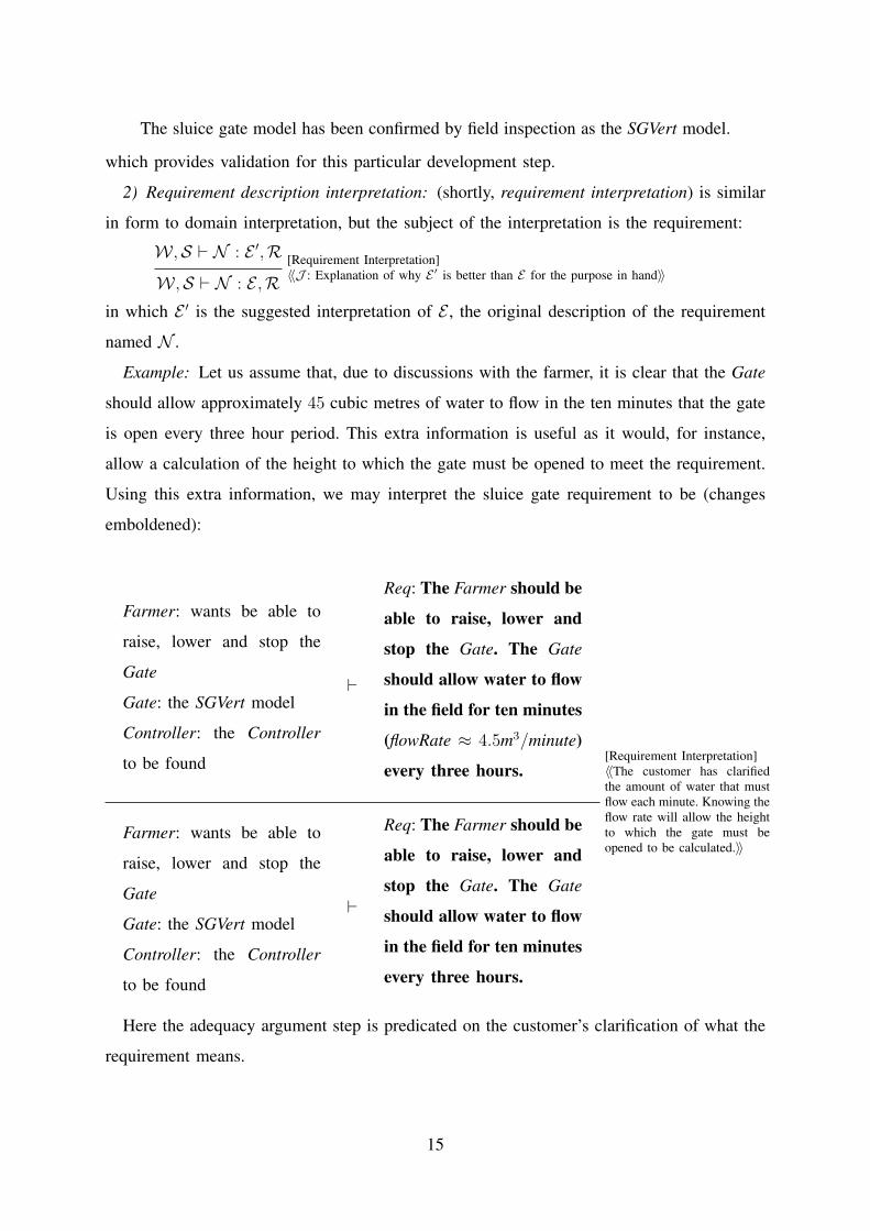
2) Requirement description interpretation: (shortly, requirement interpretation) is similar
in form to domain interpretation, but the subject of the interpretation is the requirement:
W ,S ` N : E ′,R [Requirement Interpretation]〈〈J : Explanation of why E ′ is better than E for the purpose in hand〉〉W ,S ` N : E ,R
in which E ′ is the suggested interpretation of E , the original description of the requirement
named N .
Example: Let us assume that, due to discussions with the farmer, it is clear that the Gate
should allow approximately 45 cubic metres of water to flow in the ten minutes that the gate
is open every three hour period. This extra information is useful as it would, for instance,
allow a calculation of the height to which the gate must be opened to meet the requirement.
Using this extra information, we may interpret the sluice gate requirement to be (changes
emboldened):
Farmer: wants be able to
raise, lower and stop the
Gate
Gate: the SGVert model
Controller: the Controller
to be found
`
Req: The Farmer should be
able to raise, lower and
stop the Gate. The Gate
should allow water to flow
in the field for ten minutes
(flowRate ≈ 4.5m3/minute)
every three hours.[Requirement Interpretation]〈〈The customer has clarifiedthe amount of water that mustflow each minute. Knowing theflow rate will allow the heightto which the gate must beopened to be calculated.〉〉
Farmer: wants be able to
raise, lower and stop the
Gate
Gate: the SGVert model
Controller: the Controller
to be found
`
Req: The Farmer should be
able to raise, lower and
stop the Gate. The Gate
should allow water to flow
in the field for ten minutes
every three hours.
Here the adequacy argument step is predicated on the customer’s clarification of what the
requirement means.
15

3) Solution description interpretation: (shortly, solution interpretation) is, again, similar
in form to domain interpretation, but the subject of the interpretation is the solution:
W ,S : E ′ ` R [Solution Interpretation]〈〈J : Explanation of why E ′ is better than E for the purpose in hand〉〉W ,N : E ` R
in which E ′ is the suggested interpretation of E , the original description of solution N . The
adequacy argument step, J , for an application of the solution interpretation rule must again
argue that an ‘adequately correct’ interpretation has been found.
Example: Revisiting the formal refinement above, we note that problems P1 and P2 are
related through the solution interpretation rule, i.e.:
∅, Solnrtsq :
|[var ru; rt, ru := 0, sq + 1;
do rt + 1 6= ru →
|[var rm; rm := (rt + ru)/2;
if rm2 ≤ sq → rt := rm
else rm2 > sq → ru := rm
fi ]|
od ]|
` Specrtsq : rt = b√sqc
[Solution Interpretation]〈〈The solution is a formal refinementof the specification, see [32]; wenote, however, that as the value of rtchanges throughout the execution ofthe code, this computation must beexecute atomically for correctness.〉〉
∅, Solnrtsq : null ` Specrt
sq : rt = b√sqc
B. Problem Expansion
Our framework introduces a standard notation for the initial interpretation of the compo-
nents of a problem, useful for quickly filling out the detail of a null description.
1) Context expansion: works in a problem’s context to combine, in a given topology,
a number of problem domains. The vehicle for introducing the new domains is a Context
Structure, or CStruct. A CStruct is named, and contains the domains that will populate the
context. Let Ci = Ni : Descicioi
be domains, with the ci pairwise disjoint, and let c and o be
such that⋃
ci \⋃
oi ⊆ c ⊆⋃
i ci and⋃
oi \⋃
ci ⊆ o ⊆⋃
i oi4. Then:
CStructName[C1, ..., Cm]co
is a CStruct with name CStructName.
When a CStruct appears as the description of a context domain, introduced through an
application of the domain interpretation rule, the problem can be rewritten as shown in
4I.e., a superset of the ‘dangling’ phenomena.
16
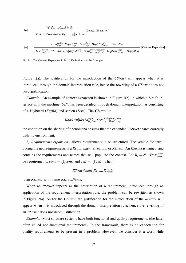
(a)W, C1, ..., Cm,S ` R
[Context Expansion]W,N : CStructName[C1, ..., Cm],S ` R
(b)UserkeyPrs
dsply , KeybdinputkeyPrs, Scrndsply
sigs , DsplySyssigsinput ` DsplyReq
[Context Expansion]UserkeyPrs
dsply , UIF : KbdScrn[KeybdinputkeyPrs, Scrndsply
sigs ]input,dsplykeyPrs,sigs, DsplySyssigs
input ` DsplyReq
Fig. 1. The Context Expansion Rule: a) Definition, and b) Example
Figure 1(a). The justification for the introduction of the CStruct will appear when it is
introduced through the domain interpretation rule, hence the rewriting of a CStruct does not
need justification.
Example: An example of context expansion is shown in Figure 1(b), in which a User’s in-
terface with the machine, UIF, has been detailed, through domain interpretation, as consisting
of a keyboard (KeyBd) and screen (Scrn). The CStruct is:
KbdScrn[KeybdinputkeyPrs, Scrndsply
sigs ]input,dsplykeyPrs,sigs
the condition on the sharing of phenomena ensures that the expanded CStruct shares correctly
with its environment.
2) Requirements expansion: allows requirements to be structured. The vehicle for intro-
ducing the new requirements is a Requirement Structure, or RStruct. An RStruct is named, and
contains the requirements and names that will populate the context. Let Ri = Ni : Desciconsirefsi
be requirements, cons =⋃
i consi and refs =⋃
i refsi. Then:
RStructName[R1, ..., Rm]consrefs
is an RStruct with name RStructName.
When an RStruct appears as the description of a requirement, introduced through an
application of the requirement interpretation rule, the problem can be rewritten as shown
in Figure 2(a). As for the CStruct, the justification for the introduction of the RStruct will
appear when it is introduced through the domain interpretation rule, hence the rewriting of
an RStruct does not need justification.
Example: Most software systems have both functional and quality requirements (the latter
often called non-functional requirements). In the framework, there is no expectation for
quality requirements to be present in a problem. However, we consider it a worthwhile
17

(a)W ,S ` R1, ...,Rm,R
[Requirement Expansion]W ,S ` R : RStructName[R1, ...,Rm],R
(b)Context, S ` Requirements : null, Qualities : null
[Requirement Expansion]Context, S ` Req : R&Q[Requirements : null, Qualities : null]
Fig. 2. The Requirement Expansion Rule (a) Definition, and (b) example application
heuristic to use the following RStruct as the initial requirements interpretation in each problem
development, precisely so that any quality requirements are properly recorded:
R&Q[Requirements : null, Qualities : null]
with justification that most developments have both forms of requirement. Note that the
RStruct makes no assumptions about how the respective requirement and quality description
will be written, but alerts the developer that one form is missing. If there are no quality
requirements, this can be recorded explicitly through further development from this rule.
Given this RStruct, an example of its application is shown in Figure 2(b).
3) Solution expansion: Within our framework, an Architectural Structure, or AStruct com-
bines, in a given topology, a number of extant (solution) domains with domains yet to be
found. An AStruct can be named. For domains Ci = Ni : Descicioi
, and solution domains Sjdjpj ,
with the ci and dj pairwise disjoint, let c and o be such that
• (⋃
ci ∪⋃
dj) \ (⋃
oi ∪⋃
pj) ⊆ c ⊆ (⋃
i ci ∪⋃
dj); and
• (⋃
oi ∪⋃
pj) \ (⋃
ci ∪⋃
dj) ⊆ o ⊆ (⋃
i oi ∪⋃
pj).
Then:
AStructName[C1, ..., Cm](S1, ..., Sn)co (4)
is an AStruct with name AStructName.
In essence, by application of an architectural structure to a solution domain, we are
identifying the internal structure of the solution together with some of its behaviour. There
will be more or less known about the extant components, the Ci, that make up the architecture.
Solution expansion assumes that the software structure defined therein has already been
identified as adequate, through solution interpretation, so that the application of solution
expansion does not require any justification. Solution expansion simply moves the already
18

W , C1, ..., Cm,S2 : null, ...,Sn : null,S1 ` R...
W , C1, ..., Cm,S1 : null, ...,Sj− 1 : null,Sj + 1 : null, ..,Sn : null,Sj ` R...
W , C1, ..., Cm,S1 : null, ...,Sn− 1 : null,Sn ` R[Solution Expansion]
W , S : AStructName[C1, ..., Cm](S1, ...,Sn) ` R
Fig. 3. The Solution Expansion Rule
defined domains Ci to the environment, by expanding the problem context, whilst simul-
taneously refocussing the problem to be that of finding the descriptions of the domains Sj
that remain. The requirement and context of the original problem is propagated to all sub-
problems. The rule is shown in Figure 3.
Solution expansion is more complex than the other rules as it creates a number of premise
problems, each of which requires solving, and each of which contributes its solution to the
other premise problems.
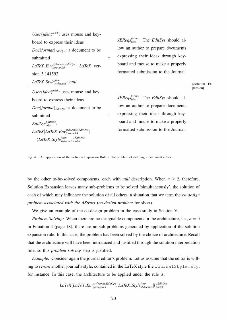
Example: Consider a journal editor’s problem of producing an editing tool (EditTool) to
assist a User, working with a mouse and keyboard (m&k) to express their ideas, to prepare a
document Doc to a specific format (form) for a journal. For the purposes of the example, we
will assume that a decision has been taken to base the Editor on a current LaTeX system.
We will assume, therefore, that the LaTeX system has architectural structure description:
LaTeX[LaTeX Envstylecmds,EditOpsform,m&k ](LaTeX Styleform
stylecmds)EditOpsm&k
whereLaTeX Envstylecmds,EditOps
form,m&k : LaTeX version 3.141592
LaTeX Styleformstylecmds : null
The transformation of the architecture under the Solution Expansion rule is shown in Figure 4.
Through it, the editor’s original problem is reduced to the simpler problem of developing
a style file that captures the journal’s format for use in an expanded context in which the
LaTeX Env appears.
Co-design: Application of the solution expansion rule produces one sub-problem for each
to-be-found component in the AStruct. When n ≥ 2, each of the sub-problems has a different
to-be-found solution domain as the solution domain, with the original context augmented
19
User(idea)m&k: uses mouse and key-
board to express their ideas
Doc(format)EditOps: a document to be
submitted
LaTeX Envstylecmds,EditOpsform,m&k : LaTeX ver-
sion 3.141592
LaTeX Styleformstylecmds: null
`
JEReqsformatidea : The EditSys should al-
low an author to prepare documents
expressing their ideas through key-
board and mouse to make a properly
formatted submission to the Journal.
[Solution Ex-pansion]
User(idea)m&k: uses mouse and key-
board to express their ideas
Doc(format)EditOps: a document to be
submitted
EditSysEditOpsm&k :
LaTeX[LaTeX Envstylecmds,EditOpsform,m&k ]
(LaTeX Styleformstylecmds)
EditOpsm&k
`
JEReqsformatidea : The EditSys should al-
low an author to prepare documents
expressing their ideas through key-
board and mouse to make a properly
formatted submission to the Journal.
Fig. 4. An application of the Solution Expansion Rule to the problem of defining a document editor
by the other to-be-solved components, each with null description. When n ≥ 2, therefore,
Solution Expansion leaves many sub-problems to be solved ‘simultaneously’, the solution of
each of which may influence the solution of all others, a situation that we term the co-design
problem associated with the AStruct (co-design problem for short).
We give an example of the co-design problem in the case study in Section V.
Problem Solving: When there are no designable components in the architecture, i.e., n = 0
in Equation 4 (page 18), there are no sub-problems generated by application of the solution
expansion rule. In this case, the problem has been solved by the choice of architecture. Recall
that the architecture will have been introduced and justified through the solution interpretation
rule, so this problem solving step is justified.
Example: Consider again the journal editor’s problem. Let us assume that the editor is will-
ing to re-use another journal’s style, contained in the LaTeX style file JournalStyle.sty,
for instance. In this case, the architecture to be applied under the rule is:
LaTeX[LaTeX Envstylecmds,EditOpsform,m&k , LaTeX Styleform
stylecmds]()EditOpsm&k
20

[Solution Expansion]
User(idea)m&k, Doc(format)EditOps,
EditSysEditOpsm&k : LaTeX[LaTeX Envstylecmds,EditOps
form,m&k , LaTeX Styleformstylecmds]()
EditOpsm&k
` JEReqsformatidea
Fig. 5. An application of the Architectural Expansion Rule to the problem of defining a document editor: a complete
LaTeX solution is chosen
withLaTeX Env LaTeX version 3.141592
LaTeX Style JournalStyle.sty
The resulting problem transformation is shown in Figure 5.
Separable problems: A problem P = W, S ` R is said to be n-separable if there
are partitions of W into Wicioi
, i = 1, ..., n, and R into Riconsirefsi
, i = 1, ..., n, with the sets
(ci∪oi∪consi∪refsi) pair-wise disjoint. In this case P consists of n independent sub-problems,
each of which is therefore independently solvable. In this case, the AStruct
nSep[](S1d1p1
, ..., Sndnpn
), with the sets (di ∪ pi) pair-wise disjoint
is a suitable solution interpretation. For the nSep AStruct, solution expansion reduces to:
W1, S1 ` R1 ... Wn, Sn ` Rn[Separable Problem]
W, S : nSep[](S1d1p1
, ..., Sndnpn
) ` R
One must, of course, be careful that there is no surreptitious sharing of phenomena—
one might say covert channels—between the partitions of W; if such covert channels exist,
separation will not necessarily be justified. This is not, of course, the case with the solution
expansion rule.
The case study in Section V contains an example of a 2-separable problem.
C. Problem progression
Problem progression transforms requirements on domains that are ‘deep in the world’ [25]
into requirements on domains that are ‘closer to the machine’. The idea behind problem
progression is to remove a domain (that we refer to as the to-be-progressed domain) from
the context of a problem, simultaneously rewriting a requirement description that refers to
21

(a)W ,D(a, b) : DescD,S ` R′
1, ...,R′m
[Sharing Removal]W ,Da
b : DescD,S ` R1, ...,Rm
(b)W ,S ` R1, ...,Rm
[Domain Removal]W ,D∅
∅,S ` R1, ...,Rm
Fig. 6. (a) Making an assumption in the requirement equivalent to the constraints a domain, D, places on some of its
shared phenomena, a and b; requirement Riconsirefsi
, becomes Ricons′i∪a∪brefs′i
with DescR′i
being “Assuming a, b constrained by
DescD , DescRi ”. Shared phenomena previously bound by a and b are, after transformation, constrained by the rewritten
requirement. (b) A domain that shares nothing is removable from the context of a problem.
or constrains it to compensate. In effect, we want to define rules that allow the following
transformation:
D1, ..., Dn−1, S ` R′
[Problem Progression]D1, ..., Dn−1, Dn, S ` R
in which a solution to the premise problem is a solution to the conclusion problem. Here, we
have removed a context domain, the to-be-progressed domain, rewriting the requirements to
compensate. As there are a finite number of domains in the context of a problem, exhaustive
application of such a rule – should this be possible – will eventually end with the progressing
requirement being attached to the machine, i.e., it will become a specification.
The implementation of this rules is done in two steps, as shown in Figure 6:
• in the first, shown in Figure 6(a), we ‘unshare’ phenomena by internalising them into
the to-be-progressed domain, D, making an assumption in the requirement equivalent to
the constraints that the to-be-progressed domain places on its shared phenomena a and
b;
• in the second, shown in Figure 6(b), a domain that shares no phenomena may be removed
from the context of a problem.
Example: Consider the problem of developing a software system for an automated car
body press. The problem you are given is as follows:
Barrierpos, Operator(safe)pos,cmnds, Pressactivate, Controlleractivatecmnds ` Safe Operationsafe,activate
cmnds
which includes a safety barrier, Barrier, designed to keep the Operator at a safe distance
from the press. It does this by constraining the Operator’s position, pos, in the following
way:
22

Barrier: Constrains the operator’s position, pos, to be a safe distance from the press
during press operation.
The problem requirement states that:
Safe Operation: The press should respond to the commands of the operator. The
operator should be kept safe at all times.
We wish to remove the Barrier domain from the problem context, to make the problem
easier to solve. We note that the Barrier cannot simply be removed from the context of a
problem (whilst retaining the same requirement) as doing so would lead us to the problem:
Operator(safe, pos)cmnds, Pressactivate, Controlleractivatecmnds ` Safe Operationsafe,activate
cmnds
which is a very much more difficult problem to solve in software!
Instead, through the Sharing Removal rule, the requirement must be rewritten to remove
the shared phenomena between the Operator and Barrier giving:
Barrier(pos), Operator(safe, pos)cmnds, Pressactivate, Controlleractivatecmnds ` Safe Operation′safe,activate,pos
cmnds
in which
Safe Operation′: Assuming the Operator is at a safe distance from the Press, the
press should respond to the commands of the operator. The operator should be kept
safe at all times.
As Barrier no longer shares phenomena with other domains, it can be removed, thus:
Operator(safe, pos)cmnds, Pressactivate, Controlleractivatecmnds ` Safe Operation′safe,activate,pos
which, through requirement interpretation, can be rewritten as:
Operator(safe, pos)cmnds, Pressactivate, Controlleractivatecmnds ` Safe Operation′′safe,activate,pos
with
Safe Operation′′: The press should respond to the commands of the operator.
leaving a much simpler problem to solve. The last requirement interpretation is justified by
the fact that the barrier always keeps the operator at a safe distance from the press.
23

D. Other Rules
1) Requirements conjunction: The ‘,’ on the right of the turnstile, i.e., between require-
ments, is essentially equivalent to conjunction as captured by the rule:
W ,S ` R1 : DescR1 , R2 : DescR2 ,R============================ [Conjunction Introduction on the right]W ,S ` R1&R2 : DescR1 ∧ DescR2 ,R
where R1&R2 is the name of the conjoined requirements, and DescR1 ∧ DescR2 is the
(logical) conjunction of their descriptions. The double bar means that the rule can be used
in both directions, both to introduce a conjunction and to split a conjunction.
Note that, in the propositional calculus, ’,’ on the right is usually equivalent to disjunction,
so that P ` Q, R and P ` Q ∨ R are equivalent. In the propositional calculus, equivalence
derives from the negation elimination rules, one of which is:
Γ,¬P ` ∆¬-elimination on the right
Γ,` P, ∆
For us, the left- and right-hand sides of the turnstile denote indicative and optative,
respectively, and movement left to right is only through the sharing removal rule, whence an
assumption is added on the right.
V. SOFTWARE DEVELOPMENT UNDER THE CONCEPTUAL FRAMEWORK
As stated earlier, the aim of the work reported here is to bring both non-formal and formal
aspects of development together in a single framework. The framework provides a structure
within which the results of different development activities can be combined and reconciled.
The structure is the structure of the progressive solution of a system development problem;
it is also the structure of the adequacy argument that must eventually justify the developed
system. Each is constructed in a step-wise manner: problems form the nodes in a tree with
transformations extending the tree upwards from an initial problem description. This is the
general form of a Genzten-style sequent calculus. The tree branches through the application
of architectural expansion that allows many sub-problems to be discovered from the problem
that is its conclusion. Another effect of rule application is that symbols are shared between
the conclusion and premisses of a rules application; in essence, the symbols used in a problem
development exist within a single name-space.
Software development under the framework proceeds by the application of problem trans-
formations each of which develops some aspect of a software problem’s description. Transfor-
mation under the framework in general allows detail of the software problem to be discovered
24

– the context and requirements are more known, and more is known about the structure
of the solution. The choice of which problem transformation to apply at any point in a
software problem development application is, however, ‘tentative’ as each transformation
must be justified as adequate before the step can be accepted as contributing correctly to the
development. Because of this, and as in mathematical proof in Gentzen-style sequent calculi,
problem transformation application does not always lead to solution; step-wise transformation
is prone to the discovery of ‘blind alleys’, entered by a poor choice of application of a
particular transformation. This reflects the nature of problem solving in that, in its general
form, it is exploratory of the problem and solution spaces. All that is needed, of course, is
an iterative process that, given the realisation that a particular transformation (or sequence
of transformations) has lead to a dead-end (or sub-optimal solution), can backtrack past the
problem branches, leaving the development in a better state.
The exploration of design choices, and subsequent backtracking on failure, is a valuable
component of rationale for a particular development; it can, for instance, help to prevent
re-exploration of designs that did not work. For this reason, and unlike mathematical proof,
we counsel that as part of the justification of the particular rule application at a point in
development the reason for that choice is recorded: i.e., it is the initial choice or has been
chosen because some other choice did not work. The case study illustrates how this may be
done.
Of course, it is not our intention to suggest that all software developments take place
within the framework; for a start, the rules as defined capture the smallest possible steps in a
development. A similar situation exists within mathematics where little, if any, serious proof
development work is undertaken within the confines of Genzten’s systems. Even in systems
in which formal proof is important – e.g., in some safety critical software development – it
is often sufficient to rely on the judgement that all large steps taken could be expanded, in
principle, to those existing in a Gentzen’s system.
Our example, the development of part of a Package Router controller (adapted from [25],
in turn adapted from [41]) illustrates the application of the conceptual framework from
early requirements through to detailed design of a moderately sized example. The example’s
development is also used as a vehicle to discuss where larger steps can and should be taken,
and numerous other issues.
A. The Package Router Problem
25

A package router is a large machine used by delivery companies to sort packages into bins
according to bar-coded destination labels affixed to the packages. Each bin corresponds to
a regional area. Packages slide from a conveyor belt under gravity through a tree of pipes
and binary switches. The bins are at the leaves of this tree. The problem is to control the
operation of the package router’s switches so that packages are routed to their appropriate
bins, obeying the operator’s commands to start and stop the conveyor, and reporting any
misrouted packages.
We will illustrate how the elements of the conceptual framework can fit together, and how a
problem-oriented approach can lead to adequacy arguments on the package router. The order
of rule application in the case study is not meant to suggest a canonical order of application.
control
computer
(which
we must
build)
misrouting
display
conveyor
on/off
buttons
conveyor
motor
operator
computer is
connected
to display,
buttons,
motor,
reading
station,
sensors &
switches
Figure 1: Schematic of the problem (based on [19])
conveyor
label reading station
package sensors
pipe (for sliding down)
switch (not to be flipped
unless empty)
bin (corresponding to one
or more destinations)
Figure 2: Pipes and switches (based on [19])
6
Fig. 7. The Package Router Schematic
1) The null Package Router Problem: As mentioned earlier, all problem-oriented analyses
should, notionally, begin from the null problem. Our starting point is, therefore, the null
problem (relabelled for the Package Router PR):
Pnull : PRContext : null, PRSoln : null ` PRReq : null
2) Developing the null problem: From the null problem, problem-oriented analysis con-
tinues with an analysis of the customer provided documentation. Here we assume this to
consist of the schematic shown in Figure 7 and some other natural language description
(shown later). We will consider the elements of this schematic to indicate what needs to be
considered as the domains and phenomena of the problem. The schematic must be understood
as a proposed arrangement, and perhaps even to be approximate; for instance, there are only
three switches, four bins and two packages indicated, which is unlikely for a real system. We
26

must, therefore, recognise that any early analysis will be no more than an initial attempt at
capturing the problem, with iteration being possible should it not lead to a suitable problem
expression. Our approach is simply to consider each element of the schematic as one or
more domains of the problem, and to take the hard-wired connections as indicative of the
connectivity, i.e., the shared phenomena, between domains.
Of course, making this decision raises a number of issues: in modelling the context we
always have a choice between aggregating or separating the descriptions of relevant parts
of the world; but which is the most fruitful choice for problem analysis? In general, we
want to aggregate and model as a single domain identified parts of the world with pertinent
behaviours, unless such parts are causally independent. For instance, through aggregation,
we would consider the conveyor belt together with the motor. The question here is not
one of the correctness of the captured problem – whether separate or joint need not affect
the correctness of the description(s) – but complexity: a joint domain description may, for
instance, lead to simpler analysis by ignoring, or rather the coalescing of, the failure modes of
each component. When reliability, safety, etc, of the system are not issues, then, aggregation
of causally related domains may be preferable.
Secondly, an issue arises in that a language for the description of domains should be found.
Initially, it may be sufficient to consider iconic representations of domains, as is done below;
this choice may have some advantages:
• icons may be accessible both to customer and developer;
• icons may be a good starting point for traceability throughout the development process.
Working from the schematic, we propose (a) the following CStruct as representative of
the problem’s context:
PackageRouterCStruct[Operator, Display, On/Off Buttons,
Bin[1], ..., Bin[#bins], Switch[1], ..., Switch[#sw], Reading Station,
Conveyor Motor and Belt, Package[1], ..., Package[#pks]]
with domain descriptions being shown in the first column of Figure 8, and the inferred sharing
27
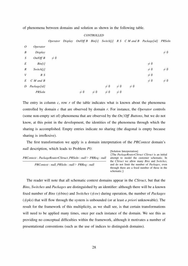
of phenomena between domains and solution as shown in the following table.
CONTROLLED
Operator Display On/Off B Bin[i] Switch[j] R S C M and B Package[id] PRSoln
O Operator
B Display 6= ∅
S On/Off B 6= ∅
E Bin[i] 6= ∅
R Switch[j] 6= ∅ 6= ∅
V R S 6= ∅
E C M and B 6= ∅ 6= ∅
D Package[id] 6= ∅ 6= ∅ 6= ∅
PRSoln 6= ∅ 6= ∅ 6= ∅ 6= ∅
The entry in column c, row r of the table indicates what is known about the phenomena
controlled by domain c that are observed by domain r. For instance, the Operator controls
(some non-empty set of) phenomena that are observed by the On/Off Buttons, but we do not
know, at this point in the development, the identities of the phenomena through which the
sharing is accomplished. Empty entries indicate no sharing (the diagonal is empty because
sharing is irreflexive).
The first transformation we apply is a domain interpretation of the PRContext domain’s
null description, which leads to Problem P0:
PRContext : PackageRouterCStruct, PRSoln : null ` PRReq : null
[Solution Interpretation]〈〈The PackageRouterCStruct CStruct is an initialattempt to model the customer schematic. Inthe CStruct we allow many Bins and Switches,and do not limit the number of Packages, eventhrough there are a fixed number of these in theschematic.〉〉
PRContext : null, PRSoln : null ` PRReq : null
The reader will note that all schematic context domains appear in the CStruct, but that the
Bins, Switches and Packages are distinguished by an identifier: although there will be a known
fixed number of Bins (#bins) and Switches (#sw) during operation, the number of Packages
(#pks) that will flow through the system is unbounded (or at least a priori unknowable). The
result for the framework of this multiplicity, as we shall see, is that certain transformations
will need to be applied many times, once per each instance of the domain. We see this as
providing no conceptual difficulties within the framework, although it motivates a number of
presentational conventions (such as the use of indices to distinguish domains).
28

P0 descriptions P1 descriptions
Operator
control
computer
(which
we must
build)
misrouting
display
conveyor
on/off
buttons
conveyor
motor
operator
computer is
connected
to display,
buttons,
motor,
reading
station,
sensors &
switches
Figure 1: Schematic of the problem (based on [19])
conveyor
label reading station
package sensors
pipe (for sliding down)
switch (not to be flipped
unless empty)
bin (corresponding to one
or more destinations)
Figure 2: Pipes and switches (based on [19])
6
“The operator uses the on/off buttons to control the conveyor through
the controller.”
Display
control
computer
(which
we must
build)
misrouting
display
conveyor
on/off
buttons
conveyor
motor
operator
computer is
connected
to display,
buttons,
motor,
reading
station,
sensors &
switches
Figure 1: Schematic of the problem (based on [19])
conveyor
label reading station
package sensors
pipe (for sliding down)
switch (not to be flipped
unless empty)
bin (corresponding to one
or more destinations)
Figure 2: Pipes and switches (based on [19])
6
“The display indicates the state of the system.”
On/Off Buttons
control
computer
(which
we must
build)
misrouting
display
conveyor
on/off
buttons
conveyor
motor
operator
computer is
connected
to display,
buttons,
motor,
reading
station,
sensors &
switches
Figure 1: Schematic of the problem (based on [19])
conveyor
label reading station
package sensors
pipe (for sliding down)
switch (not to be flipped
unless empty)
bin (corresponding to one
or more destinations)
Figure 2: Pipes and switches (based on [19])
6
“The on/off buttons connect the Operator to the machine.”
Bin[j]
1 ≤ j ≤ #bins
We should ask whether this level of granularity provides an appropriate level of abstraction for our analysis.
Do we need consider the conveyor belt and motor as separate or could we represent them as a single domain?
Similarly, should we separate pipes, switches and sensors? In the case of the conveyor, the controller has no
separate interaction with the belt, and the relation between motor and belt is well understood, therefore, we could
simplify the representation by considering them as a single combined domain.
Related to the above is the type of aggregation of parts of the world which is fruitful for problem analysis.
In general, we want to aggregate, and model as a single domain, identified parts of the world with pertinent
behaviours. For instance, let us consider again the topology of Figure 2. The behaviours we may be interested in
in this problem have to do with: a package label being read by the reading station; a package leaving the reading
station; a package entering or leaving a switch; the switch setting at any particular time; and a package being
dropped into a bin. A possible aggregation which may help us analyse these behaviours is suggested in Figure 3.
For instance, each switch has an incoming pipe and sensor, and two outgoing pipes and sensors, corresponding to
the two routes a package can take, while a bin has an incoming pipe and sensor, which is activated just before a
package drops into the bin.
Switch
Bin
Reading Station
Figure 3: An alternative representation of switches and sensors
Another issue is whether physical connections are sufficient to capture all relevant shared phenomena. They
are certainly a good starting point to look for shared phenomena. For instance, we know that sensor information
is sent to the control computer as well as readings from the reading station. However, there are other phenomena
which arise from interactions of otherwise unconnected domains. This is the case, for instance, of the operator
toggling the conveyor switch or using the display to read information about misrouting.
For bins, switches and packages an identity concern [19] arises: we need to be able to identify the individual
switches through which a particular package is routed, and the particular bin in which it falls. Notationally, this is
indicated in a context diagram by indexing the corresponding domain phenomena.
By taking the above considerations into account, a possible context diagram is illustrated in Figure 4. Note
that, as is always the case in modelling, that this is a sensible starting point for analysis is open to debate, and
something that would have to be validated with the customer in a real development. This is because the choice
we make in defining a context diagram have profound implications on subsequent analysis: we can only reason
about facts which are explicitly captured in the model; therefore leaving out certain aspects of the real world means
we assume they have no bearing on the problem under study. Making sure that our assumption are justifiable is
necessary to the soundness of our analysis.
7
“Bin[j] has a sensor that fires when a package enters it.”
Switch[i]
1 ≤ i ≤ #sw
We should ask whether this level of granularity provides an appropriate level of abstraction for our analysis.
Do we need consider the conveyor belt and motor as separate or could we represent them as a single domain?
Similarly, should we separate pipes, switches and sensors? In the case of the conveyor, the controller has no
separate interaction with the belt, and the relation between motor and belt is well understood, therefore, we could
simplify the representation by considering them as a single combined domain.
Related to the above is the type of aggregation of parts of the world which is fruitful for problem analysis.
In general, we want to aggregate, and model as a single domain, identified parts of the world with pertinent
behaviours. For instance, let us consider again the topology of Figure 2. The behaviours we may be interested in
in this problem have to do with: a package label being read by the reading station; a package leaving the reading
station; a package entering or leaving a switch; the switch setting at any particular time; and a package being
dropped into a bin. A possible aggregation which may help us analyse these behaviours is suggested in Figure 3.
For instance, each switch has an incoming pipe and sensor, and two outgoing pipes and sensors, corresponding to
the two routes a package can take, while a bin has an incoming pipe and sensor, which is activated just before a
package drops into the bin.
Switch
Bin
Reading Station
Figure 3: An alternative representation of switches and sensors
Another issue is whether physical connections are sufficient to capture all relevant shared phenomena. They
are certainly a good starting point to look for shared phenomena. For instance, we know that sensor information
is sent to the control computer as well as readings from the reading station. However, there are other phenomena
which arise from interactions of otherwise unconnected domains. This is the case, for instance, of the operator
toggling the conveyor switch or using the display to read information about misrouting.
For bins, switches and packages an identity concern [19] arises: we need to be able to identify the individual
switches through which a particular package is routed, and the particular bin in which it falls. Notationally, this is
indicated in a context diagram by indexing the corresponding domain phenomena.
By taking the above considerations into account, a possible context diagram is illustrated in Figure 4. Note
that, as is always the case in modelling, that this is a sensible starting point for analysis is open to debate, and
something that would have to be validated with the customer in a real development. This is because the choice
we make in defining a context diagram have profound implications on subsequent analysis: we can only reason
about facts which are explicitly captured in the model; therefore leaving out certain aspects of the real world means
we assume they have no bearing on the problem under study. Making sure that our assumption are justifiable is
necessary to the soundness of our analysis.
7
Empty & Left [i]
Full & Left [i]
in[i][id]/ in[i]
?right[i]
Empty & Right [i]
Full & Right [i]
outLeft[i][id]/ outLeft[i]
in[i][id]/ in[i]
outRight[i][id]/ outRight[i]
left[i]
left[i]
left[i] left[i]
right[i] right[i]
right[i]
Reading Station
We should ask whether this level of granularity provides an appropriate level of abstraction for our analysis.
Do we need consider the conveyor belt and motor as separate or could we represent them as a single domain?
Similarly, should we separate pipes, switches and sensors? In the case of the conveyor, the controller has no
separate interaction with the belt, and the relation between motor and belt is well understood, therefore, we could
simplify the representation by considering them as a single combined domain.
Related to the above is the type of aggregation of parts of the world which is fruitful for problem analysis.
In general, we want to aggregate, and model as a single domain, identified parts of the world with pertinent
behaviours. For instance, let us consider again the topology of Figure 2. The behaviours we may be interested in
in this problem have to do with: a package label being read by the reading station; a package leaving the reading
station; a package entering or leaving a switch; the switch setting at any particular time; and a package being
dropped into a bin. A possible aggregation which may help us analyse these behaviours is suggested in Figure 3.
For instance, each switch has an incoming pipe and sensor, and two outgoing pipes and sensors, corresponding to
the two routes a package can take, while a bin has an incoming pipe and sensor, which is activated just before a
package drops into the bin.
Switch
Bin
Reading Station
Figure 3: An alternative representation of switches and sensors
Another issue is whether physical connections are sufficient to capture all relevant shared phenomena. They
are certainly a good starting point to look for shared phenomena. For instance, we know that sensor information
is sent to the control computer as well as readings from the reading station. However, there are other phenomena
which arise from interactions of otherwise unconnected domains. This is the case, for instance, of the operator
toggling the conveyor switch or using the display to read information about misrouting.
For bins, switches and packages an identity concern [19] arises: we need to be able to identify the individual
switches through which a particular package is routed, and the particular bin in which it falls. Notationally, this is
indicated in a context diagram by indexing the corresponding domain phenomena.
By taking the above considerations into account, a possible context diagram is illustrated in Figure 4. Note
that, as is always the case in modelling, that this is a sensible starting point for analysis is open to debate, and
something that would have to be validated with the customer in a real development. This is because the choice
we make in defining a context diagram have profound implications on subsequent analysis: we can only reason
about facts which are explicitly captured in the model; therefore leaving out certain aspects of the real world means
we assume they have no bearing on the problem under study. Making sure that our assumption are justifiable is
necessary to the soundness of our analysis.
7
Readingdo / readPkg(id,dst)
arrivedPkg[id]
after (n seconds) / releasePkg[id]
Ready
Releasing
out
Conveyor Motor
and Belt
control
computer
(which
we must
build)
misrouting
display
conveyor
on/off
buttons
conveyor
motor
operator
computer is
connected
to display,
buttons,
motor,
reading
station,
sensors &
switches
Figure 1: Schematic of the problem (based on [19])
conveyor
label reading station
package sensors
pipe (for sliding down)
switch (not to be flipped
unless empty)
bin (corresponding to one
or more destinations)
Figure 2: Pipes and switches (based on [19])
6
Runningdo / dropPkg[id] Stationary
off
on
on off
Package[id]
1 ≤ id ≤ #pks
control
computer
(which
we must
build)
misrouting
display
conveyor
on/off
buttons
conveyor
motor
operator
computer is
connected
to display,
buttons,
motor,
reading
station,
sensors &
switches
Figure 1: Schematic of the problem (based on [19])
conveyor
label reading station
package sensors
pipe (for sliding down)
switch (not to be flipped
unless empty)
bin (corresponding to one
or more destinations)
Figure 2: Pipes and switches (based on [19])
6
OnBelt[id] InRS[id]
InBin[j][id] InSwitch[i][id]left[i]right[i]
"eventually"
dropPkg[id]
PRSoln null null
PRReq null null
Fig. 8. P0 and P1: The iconic (column 1) and accumulated (column 2) domain interpretations for the Package Router
problem
29

3) Further problem-oriented analysis: To be able to further understand the problem, it
is important to have more detailed descriptions. In this section, we show how such analysis
could be conducted within the framework focussing, for brevity, on the behaviours of the
Operator, the Conveyor Motor and Belt and the Package domains. (A more complete analysis
of the other domains is given in [36].)
Throughout the development, the domain description languages we use are English and
the UML 2.0 variant of statecharts [34].
a) Operator: We will suppose that the customer has described the behaviour of the
Operator as follows:
“The operator uses the on/off buttons to control the conveyor through the controller.”
That this description is not formal does not pose any problems, and although it would
not be difficult for a formal description of the Operator’s behaviour to be developed–
perhaps as a simple statechart–such formalisation adds little to the development while possibly
detracting from the traceability and accessibility of other non-technical stake-holders. We will
therefore work with this informal description, as far as possible. Other domains, viz. Display,
On/Off Buttons, and Bins, will similarly be informally expressed.
Using domain interpretation, we may replace the iconic representation of the Operator
in P0 with the natural language description (the result being shown in the third column of
Figure 8), update the table of phenomena to reflect the new knowledge of the phenomena
shared between the Operator and the On/Off Buttons (by adding ono, offo phenomena), and
provide the following adequacy argument step for the transformation:
J1.Operator: The customer has described the Operator in this way.
b) Conveyor Motor and Belt description: In contrast to the human Operator, we will
describe the causal domain Conveyor Motor and Belt more formally. The knowledge for a
semi-formal description might be available in a manual of operation, for instance. Suppose the
manual contains the (semi-)formal description of the Conveyor belt and Motor’s behaviour
shown in Figure 9, where on and off are commands controlled by the PRSoln solution
domain and observed by the Conveyor Motor and Belt domain, then a domain interpretation
application can be made.
The justification for applying the domain interpretation rule using the statechart of Figure 9
is:
J1.CMB: for this interpretation step, we have provided a description of the Conveyor
Motor and Belt domain.
30

Runningdo / dropPkg[id] Stationary
off
on
on off
Fig. 9. Conveyor Motor and Belt behaviour.
c) The Package Domains: The Package domains also need to be described as does their
interaction with other domains. The description of the package labelled id, Package[id], is,
simply, that it comes from the conveyor belt into the reading station and slides, under gravity,
through the switches until it eventually comes to rest in one of the bins. The statechart of
Figure 10 shows this behaviour and, for instance, identifies dropPkg[id] as the event that
accompanies the drop a package from the conveyor into the reading station.
OnBelt[id] InRS[id]
InBin[j][id] InSwitch[i][id]left[i]right[i]
"eventually"
dropPkg[id]
Fig. 10. The behaviour of Package[id].
Aside: An approach to development risk: The description for a package has been
arrived at through an analysis of the problem; there has been, for instance, no customer
input. During development, we could simply assume that the description in Figure 10 is
adequate in capturing the essential behaviour of the domain and leave the analysis at that.
However, we may also wish to consider that subsequent development may commit resources
– developer time, for instance – on the adequacy of this description, that such resources have
an opportunity cost, and so one would wish that such a description was more than just a
guess. Dealing with risk is properly part of development processes, and so should have a
place within our framework.
We cannot, of course, mitigate development risks through the application of the ideas of
the framework. However, that risk has been considered is properly a part of the adequacy
argument for a development, and we can record its consideration (and the steps (if any) that
have been taken to mitigate it) in the adequacy argument.
31
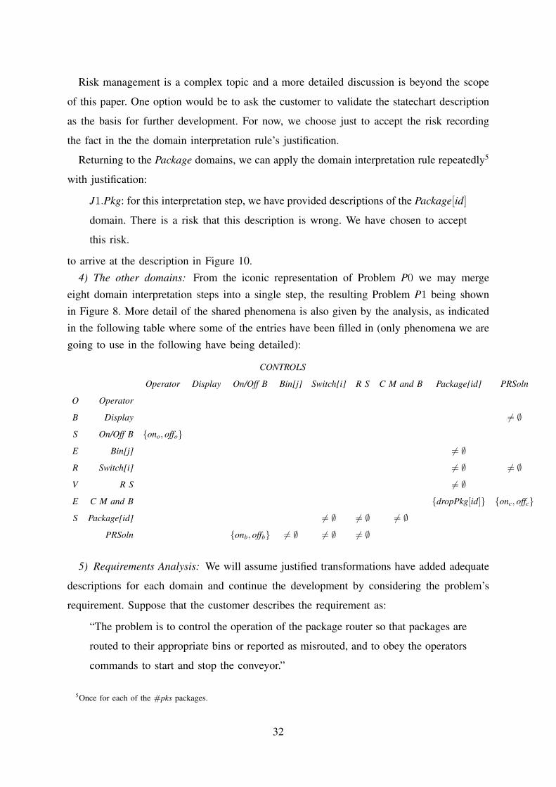
Risk management is a complex topic and a more detailed discussion is beyond the scope
of this paper. One option would be to ask the customer to validate the statechart description
as the basis for further development. For now, we choose just to accept the risk recording
the fact in the the domain interpretation rule’s justification.
Returning to the Package domains, we can apply the domain interpretation rule repeatedly5
with justification:
J1.Pkg: for this interpretation step, we have provided descriptions of the Package[id]
domain. There is a risk that this description is wrong. We have chosen to accept
this risk.
to arrive at the description in Figure 10.4) The other domains: From the iconic representation of Problem P0 we may merge
eight domain interpretation steps into a single step, the resulting Problem P1 being shownin Figure 8. More detail of the shared phenomena is also given by the analysis, as indicatedin the following table where some of the entries have been filled in (only phenomena we aregoing to use in the following have being detailed):
CONTROLS
Operator Display On/Off B Bin[j] Switch[i] R S C M and B Package[id] PRSoln
O Operator
B Display 6= ∅
S On/Off B {ono, offo}
E Bin[j] 6= ∅
R Switch[i] 6= ∅ 6= ∅
V R S 6= ∅
E C M and B {dropPkg[id]} {onc, offc}
S Package[id] 6= ∅ 6= ∅ 6= ∅
PRSoln {onb, offb} 6= ∅ 6= ∅ 6= ∅
5) Requirements Analysis: We will assume justified transformations have added adequate
descriptions for each domain and continue the development by considering the problem’s
requirement. Suppose that the customer describes the requirement as:
“The problem is to control the operation of the package router so that packages are
routed to their appropriate bins or reported as misrouted, and to obey the operators
commands to start and stop the conveyor.”
5Once for each of the #pks packages.
32
so that, using the requirements interpretation rule, the null requirement description of Prob-
lem P1 can be interpreted by this description with justification:
J2.Req: This is the initial customer-provided description.
leaving us with Problem P2 derived from Problem P1:
...
PRReq : The problem is to control the operation of the package router so
that packages are routed to their appropriate bins or reported as
misrouted, and to obey the operators commands to start and stop
the conveyor...
Now, let us suppose that further discussion with the customer reveals that this requirement
has two components:
Obey Operator: the controller should obey the operator’s commands: an ono com-
mand from the operator should result in the conveyor belt state Running; an offo
command from the operator should result in the conveyor belt state Stationary.
and
Route & Report: the controller should control the package router so that packages
are routed to their appropriate bins or reported as misrouted: a package with identity
id and destination dst arriving at the reading station (arrivePkg[id]) should reach
the bin corresponding to its destination (bin[id][j], where Bin[j] corresponds to dst);
otherwise misroute information message
“misroute of package id”
should be displayed.
We may encode these requirement parts as the RStruct:
RStruct[Obey OperatorRunning,Stationaryon,off , Route and Reportbin[id][j]
dst ]
and interpret the current requirement accordingly, leading to a new Problem P3, with justi-
fication:
J3.ReqSplit: Obey Operator and Route and Report have been identified and vali-
dated by the customer as the requirements for the system.
33
applying it through the RStruct rule (no justification necessary) to give problem:
P4 :
Operator, Display, On/Off Buttons,
Bin[1], ..., Bin[m], Switch[1], ..., Switch[n], Reading Station,
Conveyor Motor and Belt, Package[1], ..., Package[k], PRSoln
` Obey Operator, Route and Report
An aside on quality requirements: It is worth noting at this point that there are no quality
requirements for this problem. In a mission critical situation, such as our imagined problem
context, quality requirements for system availability, for instance, would typically be made
and the lack might alert the developer to the need for a discussion with the customer of their
availability requirements. It may be that there are requirements of “high availability”, perhaps
“5 9s available” (i.e., 99.999% availability or, maximum, 5 minutes per year downtime).
QR1: The system should be 5 9s available.
There are two parts to the justification of the interpretation that adds QR1 to the require-
ments. The first is shared with all interpretations, i.e., that the description is an adequate
description of what the customer wanted, which can be validated in consultations with the
customer. This is simply associated with the step and can be ignored when validation is
provided.
The second part stems from the fact that it cannot be known whether the solution satisfies
a functional or a quality requirement until the solution is built. Hence, at this point in the
development, the best we can do is to ensure that future design choices, such as the choice of
high-level architecture or components, do not make it impossible to satisfy such requirements.
A simple example of what we mean is that one should not choose a processor that is known
to be very unreliable as the basis of the system, as such a processor is unlikely to meet the
quality requirement; however, even the choice of a very reliable processor does not guarantee
that the quality requirements will be met, as there are many other choices that could impact
the satisfaction of the quality requirements.
Many techniques exist to help with such requirements; for instance, in the safety-critical
context, it may be appropriate to conduct a preliminary safety analysis (PSA) on a step [30].
A PSA can help identify that a design choice will lead to an unsatisfiable safety requirement.
Although quality requirements are very important for the development of systems, for
brevity, we suppose that there are no quality requirements related to our problem.
6) Separating problems: At this point we note that the requirement description we have
arrived at has two parts that only interact through phenomena shared between the Conveyor
34
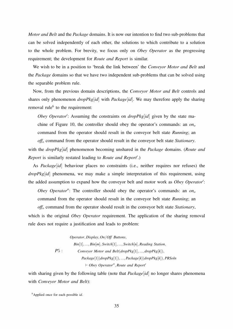
Motor and Belt and the Package domains. It is now our intention to find two sub-problems that
can be solved independently of each other, the solutions to which contribute to a solution
to the whole problem. For brevity, we focus only on Obey Operator as the progressing
requirement; the development for Route and Report is similar.
We wish to be in a position to ‘break the link between’ the Conveyor Motor and Belt and
the Package domains so that we have two independent sub-problems that can be solved using
the separable problem rule.
Now, from the previous domain descriptions, the Conveyor Motor and Belt controls and
shares only phenomenon dropPkg[id] with Package[id]. We may therefore apply the sharing
removal rule6 to the requirement:
Obey Operator′: Assuming the constraints on dropPkg[id] given by the state ma-
chine of Figure 10, the controller should obey the operator’s commands: an ono
command from the operator should result in the conveyor belt state Running; an
offo command from the operator should result in the conveyor belt state Stationary.
with the dropPkg[id] phenomenon becoming unshared in the Package domains. (Route and
Report is similarly restated leading to Route and Report′.)
As Package[id] behaviour places no constraints (i.e., neither requires nor refuses) the
dropPkg[id] phenomena, we may make a simple interpretation of this requirement, using
the added assumption to expand how the conveyor belt and motor work as Obey Operator′:
Obey Operator′′: The controller should obey the operator’s commands: an ono
command from the operator should result in the conveyor belt state Running; an
offo command from the operator should result in the conveyor belt state Stationary,
which is the original Obey Operator requirement. The application of the sharing removal
rule does not require a justification and leads to problem:
P5 :
Operator, Display, On/Off Buttons,
Bin[1], ..., Bin[m], Switch[1], ..., Switch[n], Reading Station,
Conveyor Motor and Belt(dropPkg[1], ..., dropPkg[k]),
Package[1](dropPkg[1]), ..., Package[k](dropPkg[k]), PRSoln
` Obey Operator′′, Route and Report′
with sharing given by the following table (note that Package[id] no longer shares phenomena
with Conveyor Motor and Belt):
6Applied once for each possible id.
35
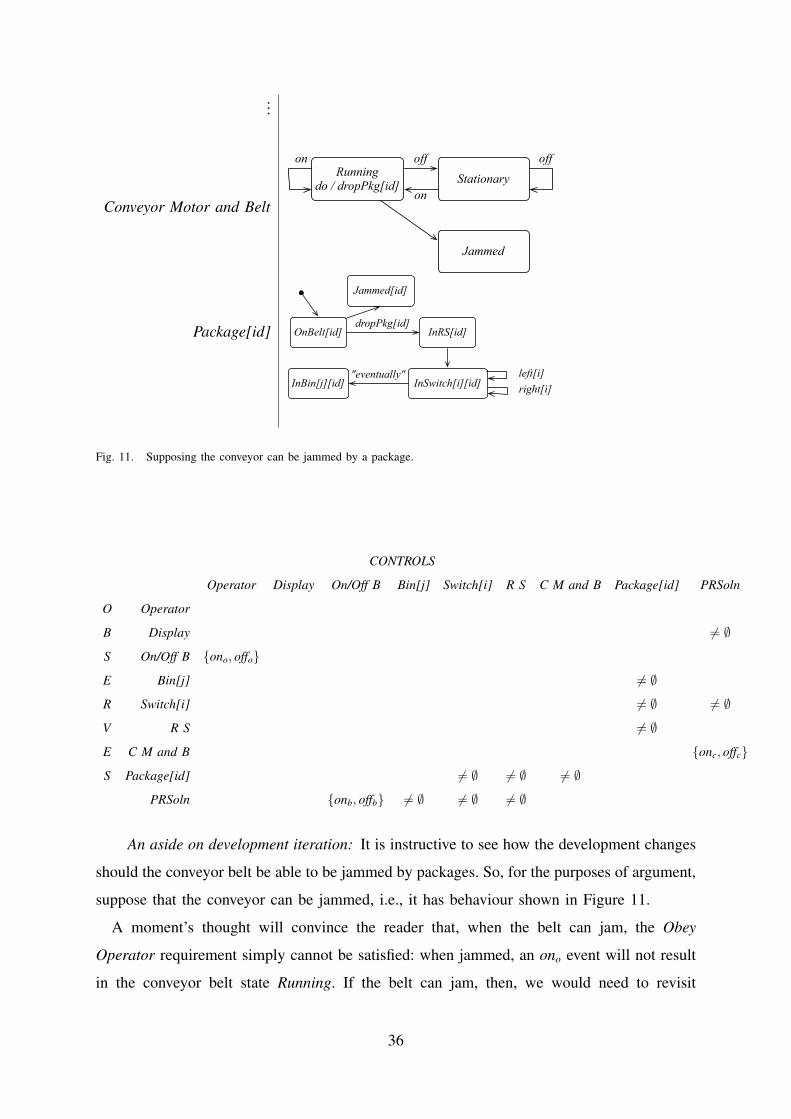
...
Conveyor Motor and Belt
Runningdo / dropPkg[id] Stationary
off
on
on off
Jammed
Package[id] OnBelt[id] InRS[id]
InBin[j][id] InSwitch[i][id]left[i]right[i]
"eventually"
Jammed[id]
dropPkg[id]
Fig. 11. Supposing the conveyor can be jammed by a package.
CONTROLS
Operator Display On/Off B Bin[j] Switch[i] R S C M and B Package[id] PRSoln
O Operator
B Display 6= ∅
S On/Off B {ono, offo}
E Bin[j] 6= ∅
R Switch[i] 6= ∅ 6= ∅
V R S 6= ∅
E C M and B {onc, offc}
S Package[id] 6= ∅ 6= ∅ 6= ∅
PRSoln {onb, offb} 6= ∅ 6= ∅ 6= ∅
An aside on development iteration: It is instructive to see how the development changes
should the conveyor belt be able to be jammed by packages. So, for the purposes of argument,
suppose that the conveyor can be jammed, i.e., it has behaviour shown in Figure 11.
A moment’s thought will convince the reader that, when the belt can jam, the Obey
Operator requirement simply cannot be satisfied: when jammed, an ono event will not result
in the conveyor belt state Running. If the belt can jam, then, we would need to revisit
36

the requirement – by consulting with the customer – finding a more permissive (original)
requirement description, such as:
No Jam Obey Operator: When not jammed, the controller should obey the operator’s
commands: an ono command from the operator should result in the conveyor belt
state Running; an offo command from the operator should result in the conveyor
belt state Stationary.
In this case, replaying the sharing removal above gives:
No Jam Obey Operator′: Assuming the behaviour given by the state machine of Fig-
ure 11, when not jammed, the controller should obey the operator’s commands: an
ono command from the operator should result in the conveyor belt state Running; an
offo command from the operator should result in the conveyor belt state Stationary.
or, more simply
No Jam Obey Operator: When not jammed, the controller should obey the operator’s
commands: an ono command from the operator should result in the conveyor belt
state Running; an offo command from the operator should result in the conveyor
belt state Stationary.
as the assumption is made redundant by the ‘When not jammed’ guard.
We return to the original problem.
7) Choosing a solution architecture: In separating the requirement into two parts, it is our
intention to deal with them as separate sub-problems. To do this, we introduce an architecture
for the solution, through solution interpretation using an AStruct, and expand it using solution
expansion. Here, as there are two independent sub-problems, the PRSoln AStruct is
2Sep[](CCccccco, RRCrcc
rco)ccco
such that:
• the Conveyor Controller CC is the solution component for the Obey Operator′′ require-
ment; and
• the Route and Report Controller RRC is the solution component for the Route and
Report′ requirement.
The justification for this choice of architecture needs to argue that the architecture is
adequate:
J6.Architecture: This architecture is adequate as there are two independent sub-
problems.
37
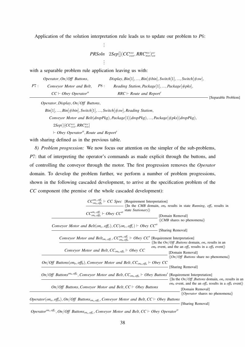
Application of the solution interpretation rule leads us to update our problem to P6:...
PRSoln 2Sep[](CCccccco, RRCrcc
rco)ccco
...
with a separable problem rule application leaving us with:
P7 :
Operator, On/Off Buttons,
Conveyor Motor and Belt,
CC ` Obey Operator′′
P8 :
Display, Bin[1], ..., Bin[#bin], Switch[1], ..., Switch[#sw],
Reading Station, Package[1], ..., Package[#pks],
RRC ` Route and Report′[Separable Problem]
Operator, Display, On/Off Buttons,
Bin[1], ..., Bin[#bin], Switch[1], ..., Switch[#sw], Reading Station,
Conveyor Motor and Belt(dropPkg), Package[1](dropPkg), ..., Package[#pks](dropPkg),
2Sep()[CCccccco, RRCrcc
rco]
` Obey Operator′′, Route and Report′
with sharing defined as in the previous table.
8) Problem progression: We now focus our attention on the simpler of the sub-problems,
P7: that of interpreting the operator’s commands as made explicit through the buttons, and
of controlling the conveyor through the motor. The first progression removes the Operator
domain. To develop the problem further, we perform a number of problem progressions,
shown in the following cascaded development, to arrive at the specification problem of the
CC component (the premise of the whole cascaded development):
CConc,offconb,offb ` CC Spec [Requirement Interpretation]
〈〈In the CMB domain, onb results in state Running, offo results instate Stationary〉〉
CConc,offconb,offb ` Obey CC′′
[Domain Removal]〈〈CMB shares no phenomena〉〉
Conveyor Motor and Belt(onc, offc), CC(onc, offc) ` Obey CC′′
[Sharing Removal]
Conveyor Motor and Beltonc,offc , CConc,offconb,offb ` Obey CC′ [Requirement Interpretation]
〈〈In the On/Off Buttons domain, ono results in anonb event, and the an offo results in a offb event〉〉
Conveyor Motor and Belt, CConb,offb ` Obey CC [Domain Removal]〈〈On/Off Buttons share no phenomena〉〉
On/Off Buttons(onb, offb), Conveyor Motor and Belt, CConb,offb ` Obey CC[Sharing Removal]
On/Off Buttonsonb,offb , Conveyor Motor and Belt, CConb,offb ` Obey Buttons′ [Requirement Interpretation]〈〈In the On/Off Buttons domain, ono results in anonb event, and the an offo results in a offb event〉〉
On/Off Buttons, Conveyor Motor and Belt, CC ` Obey Buttons [Domain Removal]〈〈Operator shares no phenomena〉〉
Operator(ono, offo), On/Off Buttonsono,offo , Conveyor Motor and Belt, CC ` Obey Buttons[Sharing Removal]
Operatorono,offo , On/Off Buttonsono,offo , Conveyor Motor and Belt, CC ` Obey Operator′′
38

where
Obey Operator The controller should obey the operator’s commands: an ono command from the operator
should result in the conveyor belt state Running; an offo command from the operator
should result in the conveyor belt state Stationary
Obey Buttons Assuming ono/offo events occur, an ono should result in the conveyor belt state Running;
an offo button press should result in the conveyor belt state Stationary
Obey Buttons′ An onb event should result in the conveyor belt state Running; an offb event should result
in the conveyor belt state Stationary
Obey CC Assuming onb/offb event occur, an onb should result in the conveyor belt state Running;
an offb button press should result in the conveyor belt state Stationary
Obey CC′ An onb event should result in the conveyor belt state Running; an offb event press should
result in the conveyor belt state Stationary
Obey CC′′ Assuming the Conveyor Belt and Motor state results in Running when an onc is received,
and results in Stationary when a onc events is received, an onb event should result in the
conveyor belt state Running; an offb event press should result in the conveyor belt state
Stationary
CC Spec onb event should result in onc; an offb event should result in offc.
It would be a simple matter to apply the solution interpretation rule to complete the
development of the CC component: this interpretation could provide code or, more simply,
use CC Spec as a solution description of CC. In the latter case, the justification would be
trivial: as discussed earlier on, a specification always satisfies itself.
The solution of the other architectural component, RRC, would, clearly, be more involved,
and we do not do it here.
B. The Software Development Structure
We have solved the problem down to the specification of one of the two architectural
components, at this point it is worth considering the design process that has led us here.
The steps we have performed, arranged as a tree, are shown in Figure 12. The traditional
Genzten-style presentation is textual, as in the above cascaded rule application. The tree
presentation clarifies the structure of the development and its argument by abstracting the
details of the transformation. The tree consists of a number of nodes, the named problems
we have derived, and arcs representing how those problems are related. One node is inverted
to indicate a solved problem. The tree branches because we have argued that the solution
should consist of two components.
39

P0
P1
P2
P6
P7 P8
Domain Interpretation
Requirement Interpretation
Solution Interpretation
Separable Problem
Problem Progression ...
Pnull
Domain Interpretation
P3
Requirement Interpretation
P4
Requirement Expansion
P5
Sharing removal
P9
P10Solution Interpretation
Fig. 12. The structure of the Package Router Problem solving process: P6 is solved.
This form of representation is reminiscent of statecharts, showing the flow of development
and the steps taken, and suggests that the structure of development—the relationship between
the steps, rather than the steps themselves—is worthy of record. We say more about this
observation in Section VII.
Of the development itself; in the case study we focussed on the design of the simplest
component. More work would be necessary for the very detailed step-by-step presentation,
but we would hope that higher-level abstractions are possible that would mitigate the need
for extreme detail.
VI. RELATED WORK
The notion of problem on which our framework is based derives from the reinterpretation
of a proof obligation in [24], [47], there used as one of the criteria for the completeness of
requirements engineering: being able to discharge the obligation W, S ` R determines that a
solution specification S has been found that, in the context W, provably satisfies requirement
40

R. For our framework, we identify and separate out this ‘problem component’ of the proof
obligation, re-expressing it in a proof-theoretic form to give our syntactic problem sequent
W, S ` R. This is our point of departure from the work reported in [24], [47]. Whereas in
that work, W, S ` R is an end point in some process leading to context, requirement and
solution description, in our approach we wish to synthesise W, S ` R problem sequents, and
to base design and development processes on their synthesis. A problem sequent W, S ` R
has first class status within our Gentzen-style sequent calculus: it is the object manipulated
by the calculus.
Our framework shares much with the conceptual basis of [47]. First, it allows for de-
scription grounded in the language of the domain. In particular, it does not prescribe a
single description language in which designations are expressed. Second, the control of
phenomena is an important part of our framework: a solution machine must correctly control
and observe the phenomena that its environment exposes. Our framework assumes that within
each problem each phenomenon has a single controller (either in the environment or the
machine).
Other related work is the Problem Frames approach, sketched in [24] and more fully
developed in [25]. This approach provides the developer of a software intensive system with
a focus that remains for as long as possible in the problem domain, rather than allowing it
to move early to the solution domain. The modelling of the intellectual tools that Problem
Frames provide to the developer has also motivated our work. However, with the Problem
Frame focus on the problem world, the developer’s choices are limited to those that exist
there: useful solution notions, such as architecture, are therefore missing or at best treated
only implicitly.
The idea of transforming requirements through to specification appears in many approaches:
in goal-based approaches, for instance [46], [43], high-level goals, which may be regarded as
requirements deep in the world, are successively decomposed and refined until operationalised
requirements are specified for a machine or other agent to satisfy. Similarly, in scenario-based
approaches [38], [1], [16] refinement is often required in the move from high-level scenarios,
often capturing business processes within an organisation, through to low-level scenarios
expressing the direct interaction between a software system and its actors. Our problem
progression rule is based on idea expressed in [25, Page 103]. There, a transformation of
requirements is hypothesised to exist that will keep a problem’s solution invariant while
domains are removed from the problem. More recently, the authors (with others) [22], [37],
41
Li et al. [29], and Seater et al. [39] have explored what the detail of such a transformation
would look like.
Transformations of the nature we define here are often found in the formal approaches to
software development, such as the transformation of specifications through to program code in
the refinement calculi of Morgan [31] and Back [2] mentioned earlier. We illustrate how such
formal approaches might be included within our framework in Section IV-A.3. Another aspect
of these formal refinements is shared by our framework: the partiality of their application. For
instance, the refinement of the specification w : [pre, post] by the specification w : [pre′, post]
is only possible when the condition pre ⇒ pre′ is satisfied – this is precisely the weaken
precondition refinement rule ([32]) that guarantees a correct refinement only when the refining
specification has a weaker precondition.
Approaches to software and software development based on logics and calculi have been
the subject of computer science for many years, and much has been learned about the logics,
calculi, and their derivatives, that are best suited to describe software. The many notable
examples include Floyd-Hoare logic [23], the Refinement Calculi [32], [2], the Temporal
Logic of Actions [28], and the Duration Calculus [15]. We hope that, with this work, we add
something to this list that stretches someway further towards the customer.
VII. DISCUSSION AND CONCLUSIONS
The main contribution of this research is a framework for software problem analysis that
allows software problems to be described, and software solutions and adequacy arguments to
be incrementally built. We have shown how various formal and informal elements of software
development fit into the framework and how they are related therein. This has included:
• the identification and clarification of system requirements;
• the understanding and structuring of the problem world;
• the structuring and specification of a hardware/software machine that can ensure satis-
faction of the requirements in the problem world; and
• the construction of adequacy arguments that show (but, in general, do not prove) the
system will satisfy its requirements.
Problem-oriented approaches to requirements engineering have suffered from being difficult
to combine with models of software system development that iterate between problem and
solution domains. Bass, Clement and Kazman [3], for instance, observe that early trade-offs
between qualities must be made if a system architecture is to be chosen, with the choice
42
of architecture driving the discovery of other system requirements. Other authors [27], [41],
[33], [20] make similar observations. This is an important issue, and one that we have tried
to address in our framework.
In previous work of the authors and their colleagues, explicit consideration has been given
to problem and solution spaces as ‘equal partners’ in software engineering [21], [12]. Hall et al
add to the Problem Frames approach a notion of architectural service [19], and Rapanotti et al
[37] add a notion of architectural decomposition, to allow solution options to be explored. This
view, balancing problem and solution, raises the question of the most appropriate way to relate
the spaces and has led us to the conceptual framework, discussed in this paper, for problem-
oriented software engineering. Here we have simultaneously generalised and simplified these
earlier approaches through the definition of a basic rule: we allow the application of an
architectural structure in the solution space structure to influence the problem space quite
directly.
The system we have defined is a Gentzen-style sequent calculus. Proof in Gentzen-style
sequent calculi appears to lend itself to computer support. PVS [35] is a good example.
Work on capturing proof patterns in Gentzen-style sequent calculi has produced the important
class of tactic languages, that includes that of PVS and [18]. Does our Gentzen-style sequent
calculus have an associated tactic language? If so, it would be a language for capturing
patterns of software design steps. This deserves investigation.
As to the Four Dark Corners paper [47], although the precise nature of the relationship
between the two approaches can only be clear when we have finalised the details of our
approach, we are led naturally to the conjecture that whenever (all) the conditions of [47]
hold for W, S |= R then W, S ` R will be derivable within our framework. This result will,
most likely, be our aim for arguments of soundness of our framework7. At some point we
hope also to consider completeness; but we believe that this must depend on a more exact
notion of adequacy than we have so far been able to formulate.
Of the relationship in the opposite direction, that a solution is found within our framework
does not necessarily mean that it will satisfy the conditions of [47], because:
• we do not limit ourselves to the development of solution specifications, i.e., the relation-
ships between events at the machine interface that mediate problem and solution spaces;
7And, although the arguments may not be trivial, our ‘problem solved’ rule in Section IV-B.3 goes most of the way, we
think.
43

rather our scope spans the full problem and solution space, including computational
artefacts such as code; and
• we ask only for solution adequacy, not a proof of correctness.
Finally, we note that our concept of problem has no inherent bias towards software as
a solution, although it is entirely appropriate for it. Bleistein et al. [7], [11], [8], [9], [10]
apply the problem-oriented approach to modelling and tracing from business strategy thorough
to concrete system requirements, introducing process models in the form of Role Activity
Diagrams. This leads us to conjecture an extension of problem-orientation to other areas of
problem solving and thus, following Vincenti’s observation quoted earlier, to other areas of
engineering.
ACKNOWLEDGEMENTS
We are pleased to acknowledge the financial support of IBM, under the Eclipse Innovation
Grants, and the EPSRC, Grant number EP/C007719/1. Thanks also go to our colleagues
in the Centre for Research in Computing in The Open University and elsewhere, including
Maciej Koutny, Andrew Martin and Brian Wichmann.
44

REFERENCES
[1] I. Alexander and N. Maiden, editors. Scenarios, stories, use cases through the systems development life-cycle. Wiley,
2004.
[2] R.-J. Back and J. von Wright. Trace refinement of action systems. In International Conference on Concurrency
Theory, pages 367–384, 1994.
[3] L. Bass, P. Clements, and R. Kazman. Software Architecture in Practice. Addison Wesley Longman, Inc., 1999.
[4] F. Bauer, H. Ehler, R. Horsch, B. Moller, H. Partsch, O. Paukner, and P. Pepper. The Munich Project CIP. Vol. II: The
Transformation System CIP-S, LNCS 292, volume II. Springer Verlag, Berlin, Heidelberg, New York, Berlin, 1987.
[5] M. Beeson. Some applications of Gentzen’s proof theory in automated deduction. In Proceedings of the international
workshop on Extensions of logic programming, pages 101–156, New York, NY, USA, 1991. Springer-Verlag New
York, Inc.
[6] Y. Bertot, G. Kahn, and L. Thery. Proof by pointing. Theoretical Aspects of Computer Science (TACS), 1994.
[7] S. Bleistein, K. Cox, and J. Verner. Modeling Business Strategy in e-Business Systems Requirements Engineering.
In Proceedings of the 5th International Workshop on Conceptual Modeling Approaches for e-Business, Lecture Notes
in Computer Science, Shanghai, China, 2004. 9th November 2004.
[8] S. Bleistein, K. Cox, and J. Verner. RE Approach for e-Business Advantage. In Proceedings of Requirements
Engineering: Foundations of Software Quality (REFSQ’04), Riga, Latvia, 2004. 6–7 June 2004.
[9] S. Bleistein, K. Cox, and J. Verner. Requirements Engineering for e-Business Systems: Intergrating Jackson Context
Diagrams with Goal Modelling and BPM. In Proceedings of the 11th International Asia-Pacific Software Engineering
Conference (APSEC 2004), pages 410–417, Busan, Korea, 2004. IEEE. 30th November–3rd December 2004.
[10] S. Bleistein, K. Cox, and J. Verner. Strategic alignment in requirements analysis for organizational IT: an integrated
approach. In Proceedings of the 20th ACM Symposium on Applied Computing, Santa Fe, USA, 2005. 13–17 March
2005, to appear.
[11] S. Bleistein, K. Cox, and N. Verner. Problem frames approach for e-business systems. In K. Cox, J. Hall, and
L. Rapanotti, editors, 1st International Workshop on Advances and Applications of Problem Frames, pages 7–15,
Edinburgh, 2004. IEE.
[12] J. Brier, L. Rapanotti, and J. G. Hall. Problem frames for socio-technical systems: predictability and change. In
Proceedings of 1st International Workshop on Applications and Advances of Problem Frames, pages 21–25. IEEE CS
Press, 2004.
[13] A. Bundy. A survey of automated deduction. In M. Wooldridge and M. Veloso, editors, Artificial Intelligence Today,
volume 1600 of LNAI, pages 153–174. Springer-Verlag Berlin Heidelberg, 1999.
[14] R. M. Burstall and J. Darlington. A transformation system for developing recursive programs. Journal of the ACM,
24(1):44–67, 1977.
[15] Z. Chaochen, C. A. R. Hoare, and A. P. Ravn. A calculus of durations. Inf. Process. Lett., 40(5):269–276, 1991.
[16] A. Cockburn. Writing Effective Use Cases. Addison-Wesley, 2001.
[17] W. M. Farmer, J. D. Guttman, and F. J. Thayer. Imps: An interactive mathematical proof system. Journal of Automated
Reasoning, 11(2), 1993.
[18] A. Gardiner P. Martin and J. Woodcock. A tactic calculus. Formal Aspects of Computing, 8(E):244–285, 1996.
[19] J. G. Hall, M. Jackson, R. C. Laney, B. Nuseibeh, and L. Rapanotti. Relating software requirements and architectures
using problem frames. In 10th Anniversary IEEE Joint International Conference on Requirements Engineering (RE
2002), pages 137–144, Essen, Germany, 2002. IEEE Computer Society.
45
[20] J. G. Hall, I. Mistrik, B. Nuseibeh, and A. Silva, editors. IEE Proceedings – Software: Special Issue on Relating
Requirements and Architectures, volume 152. IEE, 2005.
[21] J. G. Hall and L. Rapanotti. Problem Frames for Socio-Technical Systems. In J. Mate and A. Silva, editors,
Requirements Engineering for Socio-Technical Systems. Idea Group, Inc., 2004.
[22] J. G. Hall, L. Rapanotti, and M. Jackson. Problem frame semantics for software development. Journal of Software
and Systems Modeling, 4(2):189 – 198, 2005.
[23] C. A. R. Hoare. An axiomatic basis for computer programming. Commun. ACM, 12(10):576–580, 1969.
[24] M. Jackson. Software Requirements & Specifications. Addison-Wesley, ACM Press, Reading, England, 1995.
[25] M. A. Jackson. Problem Frames: Analyzing and Structuring Software Development Problem. Addison-Wesley
Publishing Company, 1st edition, 2001.
[26] S. C. Kleene. Introduction to Metamathematics. Van Nostrand, Princeton, NJ., 1964.
[27] A. Krabbel, I. Wetzel, and H. Zullighoven. On the inevitable intertwining of analysis and design: developing systems
for complex cooperations. In DIS ’97: Proceedings of the conference on Designing interactive systems, pages 205–213,
New York, NY, USA, 1997. ACM Press.
[28] L. Lamport. Tla in pictures. IEEE Trans. Software Eng., 21(9):768–775, 1995.
[29] Z. Li, J. G. Hall, and L. Rapanotti. A constructive approach to problem frame semantics. Technical Report 2004/26,
Computing Department, The Open University, 2005. Submitted to FASE’05.
[30] D. Mannering, J. G. Hall, and L. Rapanotti. Relating safety requirements and system design through problem oriented
software engineering, 2006.
[31] C. Morgan. Programming from Specifications. Prentice Hall International Series in Computer Science. Prentice-Hall
International, 1994.
[32] C. Morgan and T. Vickers, editors. On the Refinement Calculus. Springer-Verlag New York, Inc., Secaucus, NJ, USA,
1992.
[33] B. Nuseibeh. Weaving together requirements and architectures. Computer, 34(3):115–119, 2001. TY - JOUR.
[34] OMG. Unified Modeling Language: Superstructure. Number 2.0. OMG, 2005. formal/05-07-04.
[35] S. Owre, J. Rushby, and N. Shankar. PVS: A prototype verification system. In D. Kapur, editor, 11th International
Conference on Automated Deduction (CADE), volume 607 of Lecture Notes in Artificial Intelligence. Springer-Verlag,
1992.
[36] L. Rapanotti, J. G. Hall, and M. Jackson. Problem-oriented software engineering: solving the package router control
problem. Technical Report TR2006/07, Centre for Research in Computing, The Open University, 2006.
[37] L. Rapanotti, J. G. Hall, M. Jackson, and B. Nuseibeh. Architecture-driven problem decomposition. In 12th IEEE
International Conference on Requirements Engineering (RE 2004), pages 80–89. IEEE Computer Society, 2004.
[38] S. Robertson and J. Robertson. Mastering the Requirements Process. Addison Wesley, Harlow, England., 1999.
[39] R. Seater and D. Jackson. Problem frame transformations: Deriving specifications from requirements. In International
Workshop on Advances and Applications of Problem Frames, 2006.
[40] J. .Spivey. The Z Notation. Prentice-Hall International, 1988.
[41] W. Swartout and R. Balzer. On the inevitable intertwining of specification and implementation. Commun. ACM,
25(7):438–440, 1982.
[42] W. M. Turski. And no philosophers’ stone, either. INFORMATION PROCESSING, 86, 1986.
[43] A. van Lamsweerde. Requirements engineering in the year 00: a research perspective. In International Conference
on Software Engineering, pages 5–19, 2000.
[44] W. G. Vincenti. What Engineers Know and how they know it: Analytical studies from Aeronautical History. The
Johns Hopkins University Press, 1990.
46

[45] J. Watkins. Testing IT: An off-the-shelf software testing process. Cambridge University press, 2001.
[46] E. S. Yu. Modeling organizations for information systems requirements engineering. In Proceedings 1st IEEE
International Symposium on Requirements Engineering, pages 34–41, 1993.
[47] P. Zave and M. A. Jackson. Four dark corners of requirements engineering. ACM Transactions on Software Engineering
and Methodology, 6(1):1–30, 1997.
47