PressureMAT™ System User Guide Model PMAT1 Model ...
29
PressureMAT™ System User Guide Model PMAT1 Model PMAT2 Model PMAT3 Model PMAT4A Model PMAT4R Revision 0 www.pendotech.com
-
Upload
khangminh22 -
Category
Documents
-
view
0 -
download
0
Transcript of PressureMAT™ System User Guide Model PMAT1 Model ...

PressureMAT™
System User Guide
Model PMAT1 Model PMAT2
Model PMAT3 Model PMAT4A Model PMAT4R
Revision 0
www.pendotech.com

PressureMAT User Guide Revision 0
Page 2/29
PressureMAT System User Guide Model PMAT1 Model PMAT2 Model PMAT3
Model PMAT4A Model PMAT4R
Revision 0
Copyright © 2008, PendoTECH All rights reserved. No part of this publication may be reproduced, stored in an electronic retrieval system, or transmitted, in any form or by any means, whether electronic, mechanical, by photocopying, or otherwise, without the written consent of PendoTECH. The information in this User Guide is believed to be accurate and reliable for use and operation of the control system, however, PendoTECH assumes no responsibility for the use of this product except for what is covered in the Limited Warranty and Terms and Condition of Sale. PressureMAT is a Trademark of PendoTECH Used throughout this guide: WARNING: “WARNING” is used to indicate the presence of a hazard which can cause severe personal injury, death, or substantial property damage if the warning is ignored Note: “Note” is used to notify the user of installation or operation information which is important but not hazard related.
WARNING: DANGEROUS VOLTAGE INSIDE THE CONTROL BOX. CONTROL BOX ONLY TO BE OPENED BY PENDOTECH OR AUTHORIZED REPRESENTATIVE. NO USER SERVICEABLE PARTS INSIDE.
WARNING: POTENTIAL SHOCK HAZARD. UNLESS PROPERLY PANEL MOUNTED, DO NOT USE THIS PRODUCT NEAR WATER OR IF YOU ARE WET. DO NOT SUBMERGE THIS PRODUCT. USE ONLY IN A GROUNDED ELECTRICAL OUTLET. UNLESS PROPERLY PANEL MOUNTED, UNPLUG THE PRODUCT FROM THE OUTLET BEFORE CLEANING WITH ANY LIQUIDS. INSTALL SECURELY ON A STABLE SURFACE. INSTALL IN A LOCATION WHERE NO ONE CAN STEP ON OR TRIP OVER THE POWER CORD AND WHERE THE POWER CORD WILL NOT BE DAMAGED.
WARNING: GOODS AND SOFTWARE ARE NOT DESIGNED, INTENDED OR AUTHORIZED FOR USE AS COMPONENTS IN LIFE SUPPORT OR MEDICAL DEVICES. THEY ARE NOT DESIGNED FOR ANY APPLICATION IN WHICH THE FAILURE OF THE PRODUCT COULD RESULT IN PERSONAL INJURY, DEATH OR PROPERTY DAMAGE.

PressureMAT User Guide Revision 0
Page 3/29
Table of Contents
1. Overview of PendoTECH PressureMAT ................................................................................4
1.1. Control System .........................................................................................................................4 1.2. Control System Details.............................................................................................................5 1.2.1. Hardware Details ..................................................................................................................5 1.2.2. Specifications........................................................................................................................9 1.2.3. Software Details .................................................................................................................10
2. Using the System...................................................................................................................20 2.1. System Setup ..........................................................................................................................20 2.2. Using the System....................................................................................................................21
3. Cable Information..................................................................................................................22 3.1. Cable for Pressure Inputs........................................................................................................22
APPENDIX A: PRODUCT WARRANTY..................................................................................23 APPENDIX B: PendoTECH Single Use Pressure Sensors..........................................................24 APPENDIX C: Data Collection to a PC via WinWedge Software ..............................................25 APPENDIX D: Panel Mount of System.......................................................................................26 APPENDIX F: Pinch Valve Box Accessory (PDKT-PVE) .........................................................28

PressureMAT User Guide Revision 0
Page 4/29
1. Overview of PendoTECH PressureMAT The PressureMAT is a monitor, alarm, and transmitter system designed for use with Single Use Pressure Sensors from PendoTECH. It is comprised of the control system box with user interface and the connectors on the back panel where input and output components can be interfaced. If equipped, the alarm output function includes a dry contact relay output. The transmitter function delivers an analog 4 – 20 milliamp output signal corresponding to the pressure reading on the display. There are numerous applications in biopharmaceutical production processes where the system can be used. The four available models are as follows: Model Number Number of
Inputs Number of
Outputs Outputs
PMAT1 1 2 1 Relay /1 Analog PMAT2 2 4 2 Relays / 2 Analogs or 4 Relays PMAT3 3 4 3 Analogs / 1 Relay (for all sensors) PMAT4A 4 4 4 Analogs PMAT4R 4 4 4 Relays System Components Supplied:
• Control system • Cable(s) for connection of pressure sensors to the control system • Connectors for cable for each output • 4 Screws for mounting hardware • Power supply • RS-232 cable for data output to a PC (if ordered with the system)
1.1. Control System
The control system with its user interface is used to display pressure readings, zero calibrate the pressure sensor, and to access the program menus to edit the alarm high and low set point values and other tasks.

PressureMAT User Guide Revision 0
Page 5/29
The process pressure is displayed on the LCD display for each input channel. High and low alarm pressure set points are entered on the keypad for each channel and if the process pressure goes below the low setting or above the high setting, the system will go into alarm state. The alarm function includes activation of the dry contact relay output, a flashing “ALARM>” indication on LCD on the same line as the pressure input channel in the alarm state, and an audible tone for 30 seconds. When an alarm condition goes away, all indicators automatically go back to normal (unless the optional alarm latching function is turned on which requires STOP to be pressure to clear the alarm). The alarm functions are always active for all channels.
1.2. Control System Details
1.2.1. Hardware Details There is no power switch so the system cannot be accidentally turned off. When the wall power supply is connected to the system and plugged into a wall outlet, the system will turn ON. Instructions to power down the system without unplugging are in Section 1.2.3. The Front and Back Panels details are as shown: FRONT PANEL:
Note: If a pressure sensor is not connected or is disconnected during operation of the system, the pressure will go to a value greater than 75psi/5.17 bar and an alarm condition will occur. Associated relays will switch and the analog output will send 20mA.
LCD BACKLIT DISPLAY
KEYPAD

PressureMAT User Guide Revision 0
Page 6/29
BACK PANEL CONFIGURATIONS: Two Input Unit (if two relays for each channel, 4-20mA will be labeled OUTPUT RELAY):
Three Input Unit:
PressureMAT User Guide Revision 0
Page 7/29
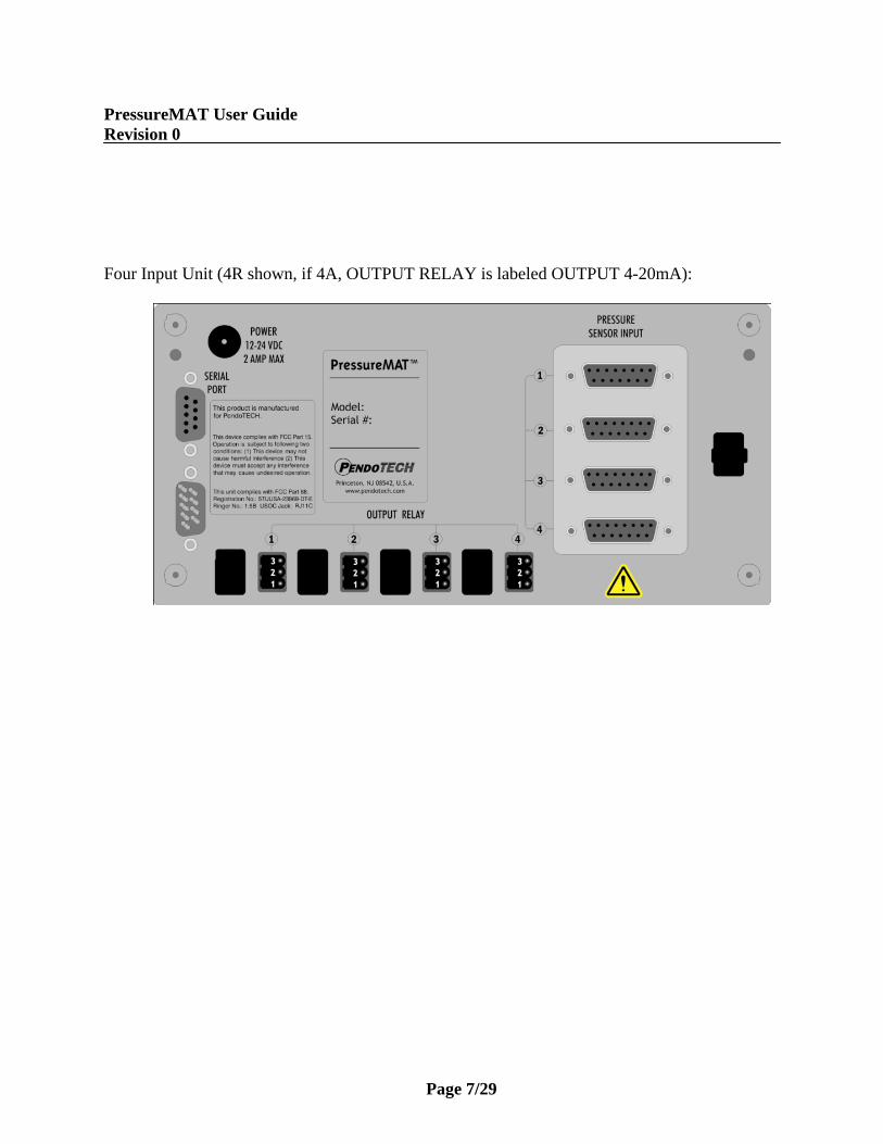
Four Input Unit (4R shown, if 4A, OUTPUT RELAY is labeled OUTPUT 4-20mA):

PressureMAT User Guide Revision 0
Page 8/29
CONNECTIONS: The external connections to the back panel are as shown below.
1. POWER SUPPLY connected to the power inlet connector 2. The PRESSURE SENSOR INPUTS connected via the DB15 connector 3. The OUTPUT RELAY:
a. NORMALLY OPEN- wired to terminals S and T via supplied connector (will switch to CLOSED position with alarm condition)
b. NORMALLY CLOSED- wired to terminals R and T via supplied connector (will switch to OPEN position with alarm condition)
c. POWER REMOVED- OPEN (S and T position) is the condition for relay(s) 4. The 4-20mA ANALOG OUTPUTS are wired to terminals S and T via supplied connector as
shown.
External Cable Connections to Back Panel
To Power Inlet Connector
___________________
Panel Connector
_____________________
To Pressure Sensor Inputs
(DB15)
Wire here for Normally CLOSED
Wire here for Normally OPEN
PressureMAT User Guide Revision 0
Page 9/29
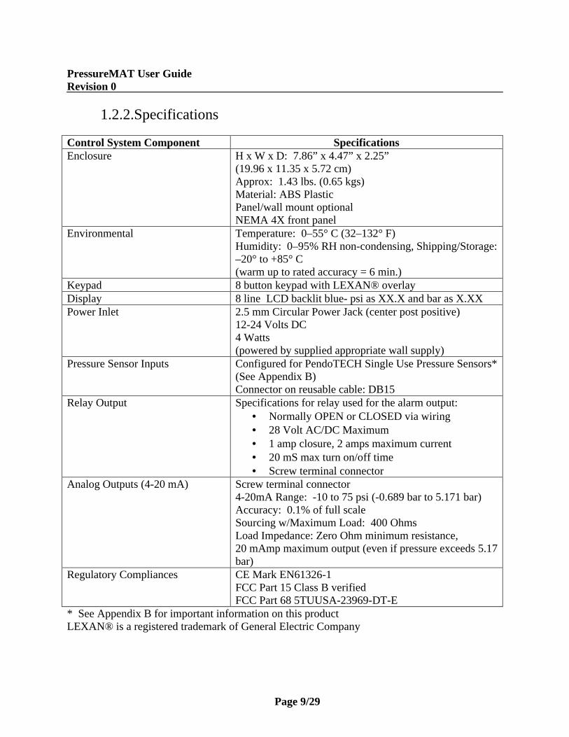
1.2.2.Specifications Control System Component Specifications Enclosure H x W x D: 7.86” x 4.47” x 2.25”
(19.96 x 11.35 x 5.72 cm) Approx: 1.43 lbs. (0.65 kgs) Material: ABS Plastic Panel/wall mount optional NEMA 4X front panel
Environmental Temperature: 0–55° C (32–132° F) Humidity: 0–95% RH non-condensing, Shipping/Storage: –20° to +85° C (warm up to rated accuracy = 6 min.)
Keypad 8 button keypad with LEXAN® overlay Display 8 line LCD backlit blue- psi as XX.X and bar as X.XX Power Inlet 2.5 mm Circular Power Jack (center post positive)
12-24 Volts DC 4 Watts (powered by supplied appropriate wall supply)
Pressure Sensor Inputs Configured for PendoTECH Single Use Pressure Sensors* (See Appendix B) Connector on reusable cable: DB15
Relay Output Specifications for relay used for the alarm output: • Normally OPEN or CLOSED via wiring • 28 Volt AC/DC Maximum • 1 amp closure, 2 amps maximum current • 20 mS max turn on/off time • Screw terminal connector
Analog Outputs (4-20 mA) Screw terminal connector 4-20mA Range: -10 to 75 psi (-0.689 bar to 5.171 bar) Accuracy: 0.1% of full scale Sourcing w/Maximum Load: 400 Ohms Load Impedance: Zero Ohm minimum resistance, 20 mAmp maximum output (even if pressure exceeds 5.17 bar)
Regulatory Compliances CE Mark EN61326-1 FCC Part 15 Class B verified FCC Part 68 5TUUSA-23969-DT-E
* See Appendix B for important information on this product LEXAN® is a registered trademark of General Electric Company

PressureMAT User Guide Revision 0
Page 10/29
1.2.3. Software Details
The software interface consists of the keypad (shown below) and the 8 line LCD backlit display. The program/firmware is stored in memory in the control system and cannot be edited by users. Only settings in the software menus can be changed. The system does not store any data.
There is no power switch so the system cannot be accidentally turned off. When the wall power supply is connected to the system and plugged into a wall outlet, the welcome screen will appear momentarily followed by 2 beeps then the HOME screen will appear.
Home Screen
When the system is powered on, the following HOME screen appears after the welcome screen with pressures 1 through 4 shown depending on the model number (with X.XX bar or XX.X psi as designated):
HOME Screen:
1 Pressure . . . . . . 0.0 psi 2 Pressure . . . . . . 0.0 psi 3 Pressure . . . . . . 0.0 psi 4 Pressure . . . . . . 0.0 psi

PressureMAT User Guide Revision 0
Page 11/29
Keypad
KEY
Function
HOME/START Dual Purpose: 1- Used to return to the HOME screen from the
program menus 2- Used to power on the system if turned off
STOP Used to reset alarms (if optional alarm is latching turned On)
LEFT ARROW Dual Purpose: 1- Used when in the program menu to scroll
the cursor left 2- Zero pressure sensor of selected channel
when on the HOME screen RIGHT ARROW Used when in the program menu to scroll the cursor
left UP ARROW Three Purposes:
1- When on the HOME screen used to select different input channels
2- In the program menus, used to select different sub-menus
3- Within a program menu, used to change a selected value
DOWN ARROW Three Purposes: 1- When on the HOME screen used to select
different input channels 2- In the program menus, used to select
different sub-menus 3- Within a program menu, used to change a
selected value SELECT/PROG Used to enter the program menu for the selected
channel or for the selected menu BACK Dual Purpose:
1- Used to return to the previous screen when in a program menu
2- Can be pressed three times to access the GLOBAL SETTINGS menu

PressureMAT User Guide Revision 0
Page 12/29
Navigation Between Pressure Sensor Input Channels At the HOME screen, the UP/DOWN arrows are used to change the selected pressure input channel.
Zero Calibration for Pressure Sensors
1. Select the desired input using the UP/DOWN buttons 2. With a pressure sensor connected to the system and EXPOSED ONLY TO
ATMOSPHERIC PRESSURE, press the LEFT ARROW button on the keypad 3. The display should read 0.0 psi / 0.00 bar 4. If 0.0 psi / 0.00 bar is not on the display, press the ZERO TARE button on the keypad
again Note: a minus sign may appear on the display when it reads 0.0 psi / 0.00 bar; this is normal as the pressure measured by the system may be a value such as -0.001 but displayed as -0.0 psi / -0.00 bar. Alarm Function If any channel has an alarm, the alarm function includes:
a. A dry contact relay associated with that channel will switch (i.e., if wired as normally CLOSED, it will OPEN)
b. The display screen will blink “ALARM>” on the channel with the alarm c. An audible tone for 30 seconds during the present alarm (it is reset for a new alarm
condition) When an alarm condition goes away, all indicators automatically go back to normal (unless the optional alarm latching function is turned on). If a sensor is inadvertently not connected or becomes accidentally disconnected during a process and stops monitoring pressure, there will be a high pressure alarm notification that pressure is not being monitored.
Program Menu To access the program menu for a pressure sensor, press the PROG key on the keypad with the desired input channel selected. The program menu is mainly used for setting of the high and low alarm set points and alarm detect delay. After pressing the PROG key, the following screen appears with X indicating selected channel:
Channel X > Input Viewing Output Viewing Input Programming Output Programming

PressureMAT User Guide Revision 0
Page 13/29
At the program menu, the BACK button may be pressed to return to the HOME screen or SELECT/PROG button pressed with the desired menu selected. The appearance and functions of the menus are as follows: Input Viewing At this screen the UP/DOWN arrows are used to select what value is displayed on the HOME screen. Press the SELECT/PROG button to select what value appears on the home screen for the respective channel. The “*” appears next to the current selection for HOME screen display. In most case this will remain as the Pressure value. The Service Time is the number of hours the system has been in service. Pressing the SELECT/PROG button will confirm a change- UNTIL THIS IS DONE, A SETTING CHANGE IS NOT CONFIRMED. Pressing the HOME or BACK button before confirming a setting change with the SELECT/PROG button will escape from that program menu without saving changes made before confirming the entry.
Channel X Input Viewing > * Pressure 0.0 psi Service Time XXXX hrs [SELECT] home display value
Output Viewing At this screen the UP/DOWN arrows are used to select what value is displayed on the HOME screen. Press the SELECT/PROG button to select what value appears on the home screen on the line under the respective channel. The “*” appears next to the current selection for HOME screen display. The SP Signal is the milliamp output corresponding to the pressure reading. Name which by default is blank can be programmed in the in the output programming menu. Pressing the SELECT/PROG button will confirm a change- UNTIL THIS IS DONE, A SETTING CHANGE IS NOT CONFIRMED. Pressing the HOME or BACK button before confirming a setting change with the SELECT/PROG button will escape from that program menu without saving changes made before confirming the entry.
Channel X Output Viewing SP Signal 20.000 mA > * Name [SELECT] home display value

PressureMAT User Guide Revision 0
Page 14/29
Input Programming At this screen the UP/DOWN arrows are used to select what function to program. Press the SELECT/PROG button to program the function. The setting or digit of a setting that can be changed with the UP/DOWN arrows blinks. If there is more than one digit in a setting, use the RIGHT/LEFT arrows to scroll within the possible digit locations within a setting. Pressing the SELECT/PROG button will confirm a change- UNTIL THIS IS DONE, A SETTING CHANGE IS NOT CONFIRMED. Pressing the HOME or BACK button before confirming a setting change with the SELECT/PROG button will escape from that program menu without saving changes made before confirming the entry.
Channel X Input Programming > Low Alarm 0.00 bar High Alarm 0.00 bar Alarm Valid 000 sec Comm Port Off Time Alarm 0000 hrs [SELECT] home display value
After 30 seconds of inactivity in the program menu, the selected setting to change stops blinking and the value before the setting was selected is restored.
Changing the Low Pressure Alarm Point- Press the SELECT/PROG with Low Alarm selected Use the RIGHT ARROW button on the keypad until you get to the digit that you want to change. Use the DOWN ARROW/UP ARROW buttons on the keypad to change the values. Note the location of the minus sign is the furthest to the left and the easiest way to access this is by scrolling to the right until the cursor appears on the far left. To change a digit from a numerical value to zero, change the value to a zero. When the correct value has been selected, press the SELECT/PROG button and the value will be confirmed. To escape from this menu without changing the value, press the BACK button and the main channel menu will appear. Changing the High Pressure Alarm Point- Press the SELECT/PROG with High Alarm selected Use the RIGHT ARROW button on the keypad until you get to the digit that you want to change. Use the DOWN ARROW/UP ARROW buttons on the keypad to change the values. Note the location of the minus sign is the furthest to the left and the easiest way to access this is by scrolling to the right until the cursor appears on the far left. To change a digit from a numerical value to zero, change the value to a zero. When the correct value has been selected, press the SELECT/PROG button and the value will be confirmed. To escape from this menu without changing the value, press the BACK button and the main channel menu will appear.
Note: If the High or Low Pressure Alarm Points are set to 0.00 then there will be no alarm setting and an alarm will only occur if a sensor is disconnected

PressureMAT User Guide Revision 0
Page 15/29
Alarm Valid- This value is set to a default of 2 seconds. This is the amount of time an alarm condition must be present for an actual alarm to occur. In certain processes with rapidly changing pressures, this value can be changed to prevent undesired false alarms. Press the SELECT/PROG with Alarm Valid selected. Use the RIGHT ARROW button on the keypad until you get to the digit that you want to change. Use the DOWN ARROW/UP ARROW buttons on the keypad to change the values. To change a digit from a numerical value to zero, change the value to a zero. When the correct value has been selected, press the SELECT/PROG button and the value will be confirmed. To escape from this menu without changing the value, press the BACK button and the main channel menu will appear.
Comm Port- Indicates data output function. There are several settings but the only active settings are Off and Serial Report (Sio Report). If Off is selected, no data for the selected channel is sent out the Serial Port. If Sio Report is selected, data is sent out the Serial RS232 port at the frequency programmed in the Global Settings Menu (contact PendoTECH for more details on data collection from the PressureMAT). Press the SELECT/PROG with Comm Port selected. Use the DOWN ARROW/UP ARROW buttons on the keypad to change the settings. When the correct setting has been selected, press the SELECT/PROG button and the value will be confirmed. To escape from this menu without changing the value, press the BACK button and the main channel menu will appear. Note: See Appendix C on Data Collection to a PC Time Alarm- This value is set to a default of 000 hours. This can be set to trigger an alarm in a set period of time and most likely will remain at 000 hours which indicates it is not active. Press the SELECT/PROG with Alarm Valid selected. Use the RIGHT ARROW button on the keypad until you get to the digit that you want to change. Use the DOWN ARROW/UP ARROW buttons on the keypad to change the values. To change a digit from a numerical value to zero, change the value to a zero. When the correct value has been selected, press the SELECT/PROG button and the value will be confirmed. To escape from this menu without changing the value, press the BACK button and the main channel menu will appear.

PressureMAT User Guide Revision 0
Page 16/29
Output Programming At this screen the UP/DOWN arrows are used to select what function to program. The only function active is the Name. The Port Type can be selected and changed but no changes will be confirmed and will revert to the default setting.
Channel X Output Programming Port Type Out 0-20mA > Name
Press the SELECT/PROG button to program a name that appears on the line under the line where the pressure value is displayed for the selected channel (if Name is selected on the Output Viewing menu). A wide range of alpha-numeric digits can be selected. Use the RIGHT ARROW button on the keypad until you get to the digit that you want to change. Use the DOWN ARROW/UP ARROW buttons on the keypad to change the values. The “*” character indicates a space. Pressing the SELECT/PROG button will confirm a change- UNTIL THIS IS DONE, A SETTING CHANGE IS NOT CONFIRMED. Pressing the HOME or BACK button before confirming a setting change with the SELECT/PROG button will escape from that program menu without saving changes made before confirming the entry.

PressureMAT User Guide Revision 0
Page 17/29
Global Settings Menu The Global Settings menu can be used to program settings for the system that impacts all channels or turn ON or OFF features or view system information. To access the Global Settings menu press the BACK button three times in rapid succession. The following screen appears:
GLOBAL SETTINGS > Information System Power Control Service Communication Date and Time
At this screen the UP/DOWN arrows are used to select the Global Setting. HOME/START can be pressed at any time to return to the HOME screen. Information If SELECT/PROG button pressed, system information including firmware version is displayed. Press the BACK button to return to the main menu. System Power If SELECT/PROG button pressed, the system power is removed. Press the HOME/START to restore power. Control Service If SELECT/PROG button pressed, the following sub-menu appears with the following default settings:
CONTROL SERVICE > Alarm Latch Off Backlight High Audio Beep On Keypad Secure Off
At this screen the UP/DOWN arrows are used to select the Control Service setting.
Alarm Latch If turned on, alarm conditions will remain after an alarm state occurred but is no longer present until the STOP button is pressed

PressureMAT User Guide Revision 0
Page 18/29
Backlight Can be set to High, Medium or Low Audio Beep Can be turned Off. Keypad Secure If turned On, the function to zero the sensor with the left arrow is disabled.
Communications Displays setting not used in the unit at the present time. DO NOT CHANGE SETTINGS Date and Time If SELECT/PROG button pressed, the following sub-menu appears:
DATE and TIME > Date-Time DDMMMYY HH:MM:SS Next Report DDMMMYY HH:MM:SS Report Start DDMMMYY HH:MM:SS Report Rate 000 hrs Daylight Save Off
This menu is used mainly for controlling data output to a PC. Note: See Appendix C on Data Collection to a PC At this screen the UP/DOWN arrows are used to select the setting.
Date-Time Used to set the current time. Use the RIGHT/LEFT ARROW button on the keypad until you get to the digit that you want to change. Use the DOWN ARROW/UP ARROW buttons on the keypad to change the values. To change a digit from a numerical value to zero, change the value to a zero. When the correct value has been selected, press the SELECT/PROG button and the value will be confirmed. To escape from this menu without changing the value, press the BACK button and the main channel menu will appear. Next Report Indicates the next data report time. A report of the current system data is sent out the serial port with the RS232 protocol and can be captured into a PC program or other device.

PressureMAT User Guide Revision 0
Page 19/29
Report Start Report start is used to set time of the next data report. Use the RIGHT/LEFT ARROW button on the keypad until you get to the digit that you want to change. Use the DOWN ARROW/UP ARROW buttons on the keypad to change the values. To change a digit from a numerical value to zero, change the value to a zero. When the correct value has been selected, press the SELECT/PROG button and the value will be confirmed. To escape from this menu without changing the value, press the BACK button and the main channel menu will appear. The report start time must be set later than the current time for data output to commence. Report Rate Report rate is used to set the frequency of data report. The frequency (sec, min, hours, days or months may be selected). Use the RIGHT/LEFT ARROW button on the keypad until you get to the digit that you want to change. Use the DOWN ARROW/UP ARROW buttons on the keypad to change the values. To change a digit from a numerical value to zero, change the value to a zero. When the correct value has been selected, press the SELECT/PROG button and the value will be confirmed. To escape from this menu without changing the value, press the BACK button and the main channel menu will appear. Daylight Save Since the clock is used only to generate data reports that can be time stamped by the receiving device, it is recommended to keep this in the Off selection.

PressureMAT User Guide Revision 0
Page 20/29
2. Using the System 2.1. System Setup 1. Connect the pressure sensor cables to the back panel. If a pressure sensor is not connected
when power is supplied to the system, the pressure will go to a value greater than 5.3 bar and an high pressure alarm condition will occur on the respective channel(s). If a sensor is inadvertently disconnected during a process and stops monitoring pressure, there will be an alarm notification. The associated relay will switch and the analog output will send 20mA.
2. Connect the analog and relay outputs, if required as shown in Section 1.2.1 3. Connect the pressure sensor(s) to the cable(s) connected to the system. 4. Connect system to appropriate power source. Note: If a pressure sensor is not connected when power is supplied to the system, the pressure will go to a value greater than 75 psi / 5.17 bar and a high pressure alarm condition will occur on the respective channel(s) and the relay will switch to the alarm position and the analog output will send 20mA. If a sensor is inadvertently disconnected during a process and stops monitoring pressure, there will be an alarm notification. Also, a new sensor that has not been zero-calibrated can bypass an alarm set-point triggering an alarm condition. 5. Using the instructions from the previous section 1.2.3 and while the sensor(s) is at atmospheric
pressure, zero calibrate the sensor(s) being used (if not reading 0.0 psi / 0.00 bar when installed) by pressing the LEFT ARROW button with the proper channel selected.

PressureMAT User Guide Revision 0
Page 21/29
2.2. Using the System
1. Using the instructions from the previous section 1.2.3, set the appropriate high and low alarm pressure settings for each channel. These are the set-points that will trigger an alarm condition. High and low pressure settings are entered on the key pad and if the process pressure goes below the low setting or above the high setting, the system will go into alarm state. The alarm function includes:
a. The alarm function includes activation of the dry contact relay output, a flashing “ALARM>” indication on LCD on the same line as the pressure input channel in the alarm state,
b. An audible tone for 30 seconds, c. The associated relay will switch
When an alarm condition goes away, all indicators automatically go back to normal (unless the optional alarm latching function is turned on which requires the STOP button to be pressed to clear the alarms). If the alarm settings are set to 0.00, then no alarm conditions are monitored, however, if a sensor is disconnected, an alarm will still occur.
2. If a pressure sensor is not connected or disconnected during operation of the system, the pressure will go to a value greater than 77 psi / 5.3 bar and an alarm condition will occur. If a sensor becomes accidentally disconnected during a process and stops monitoring pressure, there will be a high pressure alarm notification (and a 20mA signal will be transmitted from the analog output).
3. The HOME screen will display pressure from the sensors that are connected.

PressureMAT User Guide Revision 0
Page 22/29
3. Cable Information
3.1. Cable for Pressure Inputs 12 feet (3.7 m) in length with a 4 pin connector to connect a pressure sensor on one end and a male DB 15connector to connect to the control system on the other end (DB15 connector connected to PendoTECH Part Number PDKT-650-000) Wiring:
DB15 Pins: 2: WHITE 7: GREEN 9: RED 12: BLACK
PressureMAT User Guide Revision 0
Page 23/29
APPENDIX A: PRODUCT WARRANTY LIMITED WARRANTY: Except as otherwise expressly provided herein, Seller warrants that the Software will execute the programming instructions provided by Seller, and that the Goods manufactured by Seller will be free from defects in materials or workmanship under normal use and service until the expiration of the earlier of twelve (12) months from the date of initial installation or eighteen (18) months from the date of shipment by Seller. Expendable items are warranted to be free from defects in material and workmanship under normal use and service for a period of ninety (90) days from the date of shipment by Seller. Products purchased by Seller from a third party for resale to Buyer (“Resale Products”) shall carry only the warranty extended by the original manufacturer. Buyer agrees that Seller has no liability for Resale Products beyond making a reasonable commercial effort to arrange for procurement and shipping of the Resale Products. If, within thirty (30) days after Buyer’s discovery of any warranty defects during the applicable warranty period, Buyer notifies Seller thereof in writing, Seller shall, at its option and as Buyer’s sole and exclusive remedy hereunder, promptly correct any errors that are found by Seller to exist in the Software, or repair or replace F.O.B. point of manufacture, that portion of the Goods or Software found by Seller to be defective. All replacements or repairs necessitated by inadequate preventive maintenance, or by normal wear and usage, or by fault of Buyer, or by unsuitable power sources or by attack or deterioration under unsuitable environmental conditions, or by abuse, accident, alteration, misuse, improper installation, modification, repair, storage or handling, or any other cause not the fault of Seller are not covered by this limited warranty, and shall be at Buyer’s expense. Seller shall not be obligated to pay any costs or charges incurred by Buyer or any other party except as may be agreed upon in writing in advance by an authorized Seller representative. All costs of dismantling, reinstallation and freight and the time and expenses of Seller’s personnel for site travel and diagnosis under this warranty clause shall be borne by Buyer unless accepted in writing by Seller. Failure by Buyer to give such written notice of defects within the applicable time period shall be deemed an absolute and unconditional waiver of Buyer’s claim for such defects. Goods repaired and parts replaced during the warranty period shall be in warranty for the remainder of the original warranty period or ninety (90) days, whichever is longer. This limited warranty is the only warranty made by Seller and can be amended only in a writing signed by an authorized representative of Seller. Except as otherwise expressly provided in the Agreement, there are no representations or warranties of any kind, express or implied, as to merchantability, fitness for particular purpose, or any other matter with respect to any of the goods or software. LIMITATION OF REMEDY AND LIABILITY: SELLER SHALL NOT BE LIABLE FOR DAMAGES CAUSED BY DELAY IN PERFORMANCE. THE SOLE AND EXCLUSIVE REMEDY FOR BREACH OF WARRANTY HEREUNDER SHALL BE LIMITED TO REPAIR, CORRECTION OR REPLACEMENT UNDER THE LIMITED WARRANTY. IN NO EVENT, REGARDLESS OF THE FORM OF THE CLAIM OR CAUSE OF ACTION (WHETHER BASED IN CONTRACT, INFRINGEMENT, NEGLIGENCE, STRICT LIABILITY, OTHER TORT OR OTHERWISE), SHALL SELLER’S LIABILITY TO BUYER AND/OR ITS CUSTOMERS EXCEED THE PRICE TO BUYER OF THE SPECIFIC GOODS MANUFACTURED BY SELLER GIVING RISE TO THE CLAIM OR CAUSE OF ACTION. BUYER AGREES THAT IN NO EVENT SHALL SELLER’S LIABILITY TO BUYER AND/OR ITS CUSTOMERS EXTEND TO INCLUDE INCIDENTAL, CONSEQUENTIAL OR PUNITIVE DAMAGES. THE TERM “CONSEQUENTIAL DAMAGES” SHALL INCLUDE, BUT NOT BE LIMITED TO, LOSS OF ANTICIPATED PROFITS, LOSS OF USE, LOSS OF REVENUE AND COST OF CAPITAL.

PressureMAT User Guide Revision 0
Page 24/29
APPENDIX B: PendoTECH Single Use Pressure Sensors PendoTECH’s Single Use Pressure Sensors are a low-cost solution for use with tubing and bioprocess containers and are compatible with both gamma and ETO sterilization. They can be integrated for pressure measurement and control. The sensors are designed for use with products offered by PendoTECH. Other sensor monitors must be tested for compatibility and PendoTECH assumes no responsibility of compatibility of performance with other instruments. WARNING: EACH PROSPECTIVE USER MUST TEST THE SENSOR FOR ITS PROPOSED APPLICATION TO DETERMINE ITS SUITABILITY FOR THE PURPOSE INTENDED PRIOR TO INCORPORATING THE SENSOR TO ANY PROCESS OR APPLICATION. THE SENSORS ARE NOT INTENDED FOR USE AS COMPONENTS IN LIFE SUPPORT. THE SENSORS ARE NOT DESIGNED FOR ANY APPLICATION IN WHICH THE FAILURE OF THE PRODUCT COULD RESULT IN PERSONAL INJURY OR DEATH.
- THEY ARE NOT DESIGNED FOR USE ABOVE 75 PSI (5.2 BAR) - THEY ARE NOT DESIGNED FOR STEAM STERILIZATION
The millivolt output of the sensors becomes non-linear above 22 psi (1.5 bar) and the PressureMAT system offered by PendoTECH uses a polynomial equation to give the best accuracy in the range from 22 to 75 psi.

PressureMAT User Guide Revision 0
Page 25/29
APPENDIX C: Data Collection to a PC via WinWedge Software The PressureMAT has RS232 serial data output to a PC and we recommend the following software to streamline data collection to Excel: Winwedge Standard Edition available at: http://www.taltech.com/products/winwedge.html Instructions 1. Connect the data output cable to the serial port on the back panel of the PressureMAT 2. Connect to your PC via serial port or to a USB port via adapter cable. 3. In the Global Settings menu, set the clock in the PressureMAT and set next report time after the current time and set report frequency 4. Install WinWedge software 5. Open WinWedge file attached called PressureMAT4.sw3 (this file is available from PendoTECH) 6. Select port / settings and select the COM port (if not sure of COM port number, Open PC Control Panel and select System/Hardware/Device Manager/Ports and the COM port number should be evident) 7. Select File/Save in Winwedge 8. In WinWedge, select Activate/Test mode and pressure data should appear in the table 9. Close the WinWedge window 10. Select Activate Normal Mode but in the future open the PressureMAT4.sw3 file by double-clicking (this file is available from PendoTECH) 11. Using the Input Programming menu in the PressureMAT, select the Comm Port setting in all channels of data to be collect to Sio Reports 12. Open the PressureMAT4.xls Excel spreadsheet (this file is available from PendoTECH) and Enable Macros if asked 13. In cell D1, select the same COM port as selected in WinWedge and data should appear at the freq set in the PressureMAT. Cell D2 can be used to change the frequency of readings recorded in Excel coming from the PressureMAT. 14. The Excel spreadsheet can be saved as a different file name so it is suggested that a master copy is kept and use "Save As" for new projects. For collection to software besides Excel- The data from each channel is output and the pressure reading is the 6th field in each row. At the beginning of each report, there is a triangle turned on its side then a heart. At the end there is a triangle turned on its side then a smiling face: ••AZ,00000.01,1, 0.00, 0.00,- 0.1 ,- 0.1 ,00026,X,X,X,X,X,F0 AZ,00000.03,1, 0.00, 0.00, 0.0 , 0.0 ,00010,X,X,X,X,X,11 AZ,00000.05,1, 0.00, 0.00,- 0.0 ,- 0.0 ,00010,X,X,X,X,X,F5 AZ,00000.07,1, 0.00, 0.00,- 0.0 ,- 0.0 ,00010,X,X,X,X,X,F3 ••

PressureMAT User Guide Revision 0
Page 26/29
APPENDIX D: Panel Mount of System
All dimensions in inches, +/- 0.015
PressureMAT

PressureMAT User Guide Revision 0
Page 27/29
APPENDIX E: EC Declaration of Conformity
EC Declaration of Conformity The undersigned, representing the following supplier: PendoTECH 66 Witherspoon Street Princeton, NJ 08542 USA Here with declare that the Information technology equipment devices for
measurement, monitoring, controlling and communicating for commercial and light industrial application
Product Identification (brand models)
PressureMAT Monitor, Alarm and Transmitter (PMAT1, PMAT2, PMAT3, PMAT4A, PMAT4R) with PendoTECH Single Use Pressure Sensors
are in conformity with the provisions of the following EC Directive(s) when installed in accordance with the instructions contained in supplied product documentation: 89/336/EEC EMC Directive as amended by 92/31/EEC and 93/68/EEC 73/23/EEC Low voltage Directive as amended by 93/68/EEC and the standards and/or technical specifications for EN 61326: 2002, based on IEC 61326: 1997 with Amendment 1: 1998, and Amendment 2: 2000, International EMI and EMC standards family applied and referenced as follows: IEC 61000-4-2: 1995, IEC 61000-4-3: 1995, IEC 61000-4-4: 1995, IEC 61000-4-5: 1995, IEC 61000-4-6:1996, IEC 61000-4-8: 1993, IEC 61000-4-11: 1994, IEC 61000-3-2: 2000, IEC 61000-3-3: 1994 CISPR 22: 1997, CISPR 11: 1990, all inclusive. Year of CE Marking 2008
Supplier:
Signature On file Name: James Furey Position: General Manager Date: 11-Mar-2008

PressureMAT User Guide Revision 0
Page 28/29
APPENDIX F: Pinch Valve Box Accessory (PDKT-PVE) Overview One to four pinch valves can be in each device. The cable to the associated PressureMAT relays must be wired the normally OPEN configuration (wired to S and T as shown in Section 1.2.1). The valves are normally closed and when there is NO POWER to the valve box or to the PressureMAT, the valves will be closed. When power is supplied to the valve box (the green LED will illuminates when power is supplied to the valve box). When there is an alarm condition on the PressureMAT, the PressureMAT relay will close and the valve will open. Each valve is in the following configuration relative to the alarm signal on the PressureMAT System.
PressureMAT Condition
Position LED (AMBER)
Normally Closed Pinch Valve
No Alarm Signal OFF CLOSED Alarm Signal ON OPEN Note: When the power supply is removed from the power inlet connector or the power supply is unplugged from the wall, the valve will be in the “No Alarm Signal” position independent of PressureMAT condition.
Device Component
Specifications
Enclosure Material: ABS Plastic, top and bottom pieces of box sealed with gasket seal rated to IP66. Note: Hole where is valve is mounted is not water tight.
Pinch Valves
- BioChem Valve Series 100P (http://www.bio-chemvalve.com/Pinch_Valves.pdf ) - Pinch valve catalog number set for specific size tubing and noted on device
Relay Signal Input
Connexal PN 6282-2SG-3XX supplied with mating connector and 12 foot cable with two wire leads for connection to PressureMAT. Connexal pin 1 power (plus, pin with raised dot) for connection to PressureMAT pin “S”; Connexal pin 2 (minus) connected to PressureMAT pin “T”.
Power Input - 24 Volts DC - 0.5 amp max per valve
WARNING- THE PINCH VALVE WILL CLOSE WHEN THE ALARM SIGNAL IS REMOVED FROM THE VALVE. MAKE SURE NO FINGERS OR OBJECTS EXCEPT TUBING ARE INSERTED INTO THE PINCH VALVE WHEN THE VALVE CLOSES. WARNING: IF A PRESSURE SENSOR IS NOT CONNECTED WHEN POWER IS SUPPLIED TO THE SYSTEM, THE PRESSURE WILL GO TO A VALUE GREATER THAN 77 PSI / 5.3 BAR AND A HIGH PRESSURE ALARM CONDITION WILL OCCUR ON THE RESPECTIVE CHANNEL(S) AND THE RELAY WILL SWITCH TO THE ALARM SIGNAL. IF A SENSOR IS INADVERTENTLY DISCONNECTED DURING A PROCESS AND STOPS MONITORING PRESSURE, THERE WILL BE AN ALARM SIGNAL. ALSO, A NEW SENSOR THAT HAS NOT BEEN ZERO-CALIBRATED CAN BYPASS AN ALARM SET-POINT TRIGGERING AN ALARM SIGNAL.

PressureMAT User Guide Revision 0
Page 29/29