VGADVI Broadcaster™ User Guide - AV-iQ
126
Epiphan Technical Documentation ©2013 Epiphan Systems Inc. All Rights Reserved February 2013 VGADVI Broadcaster™ User Guide www.epiphan.com
-
Upload
khangminh22 -
Category
Documents
-
view
1 -
download
0
Transcript of VGADVI Broadcaster™ User Guide - AV-iQ

Epiphan Technical Documentation ©2013
Epiphan Systems Inc.
All Rights Reserved
February 2013
VGADVI Broadcaster™
User Guide
www.epiphan.com

Thank you for choosing Epiphan!
At Epiphan Systems Inc. (“Epiphan”), product function and quality are our top priority. We make every effort to make sure that our products exceed our customers’ expectations.
Product Feedback
We regularly contact our customers to ensure product performance and reliability. We strive to continually enhance our products to accommodate your needs. We welcome your feedback and suggestions for product improvements. You can email your comments to [email protected].
Specifications
You can go to the Broadcasting page of the Epiphan website to get information about the VGADVI Broadcaster.
Warranty
All Epiphan Systems products are provided with a 100% return to depot warranty for one year from the date of purchase.
Technical Support
Epiphan is staffed by a professional support team. If, after checking the FAQs for your product on the Epiphan website and re-installing the Epiphan driver software (where applicable), you continue to have outstanding issues, email a problem report to [email protected]. To help us solve the problem efficiently, include the following info:
Your VGADVI Broadcaster serial number.
The behavior of your VGADVI Broadcaster LED indicators.
Technical description of the signal source including resolution, refresh rate, synchronization, type of hardware.
Complete description of the problem you are experiencing. Copyright © 2013 Epiphan Systems Inc. All Rights Reserved.
<Table of Contents
ii VGADVI Broadcaster User Guide
Terms and Conditions
This document, the Epiphan web site, and the information contained therein, including but not limited to the text, videos and images as well as Epiphan Systems Inc's trademarks, trade names and logos are the property of Epiphan Systems Inc and its affiliates and licensors, and are protected from unauthorized copying and dissemination by Canadian copyright law, United States copyright law, trademark law, international conventions and other intellectual property laws. Epiphan, Epiphan Systems, Epiphan Systems Inc., and Epiphan logos are trademarks or registered trademarks of Epiphan Systems Inc., in certain countries. All Epiphan product names and logos are trademarks or registered trademarks of Epiphan. All other company and product names and logos may be trademarks or registered trademarks of their respective owners in certain countries.
Copyright © 2013 Epiphan Systems Inc. All Rights Reserved.
THE SOFTWARE LICENSE AND LIMITED WARRANTY FOR THE ACCOMPANYING PRODUCT ARE SET FORTH IN THE INFORMATION PACKET OR PRODUCT INSTALLATION SOFTWARE PACKAGE THAT SHIPPED WITH THE PRODUCT AND ARE INCORPORATED HEREIN BY REFERENCE. IF YOU ARE UNABLE TO LOCATE THE SOFTWARE LICENSE OR LIMITED WARRANTY, CONTACT YOUR EPIPHAN REPRESENTATIVE FOR A COPY. PRODUCT DESCRIPTIONS AND SPECIFICATIONS REGARDING THE PRODUCTS IN THIS MANUAL ARE SUBJECT TO CHANGE WITHOUT NOTICE. EPIPHAN PERIODICALLY ADDS OR UPDATES THE INFORMATION AND DOCUMENTS ON ITS WEB SITE WITHOUT NOTICE. ALL STATEMENTS, INFORMATION AND RECOMMENDATIONS ARE BELIEVED TO BE ACCURATE AT TIME OF WRITING BUT ARE PRESENTED WITHOUT WARRANTY OF ANY KIND, EXPRESS OR IMPLIED. USERS MUST TAKE FULL RESPONSIBILITY FOR THEIR APPLICATION OF ANY PRODUCTS. LIMITATION OF LIABILITY UNDER NO CIRCUMSTANCES SHALL EPIPHAN BE LIABLE FOR ANY INCIDENTAL, SPECIAL, CONSEQUENTIAL, EXEMPLARY OR OTHER INDIRECT DAMAGES THAT RESULT FROM THE USE OF, OR THE INABILITY TO USE, THIS PRODUCT OR THE INFORMATION CONTAINED ON THIS DOCUMENT OR PROVIDED ON EPIPHAN’S WEB SITE, EVEN IF EPIPHAN HAS BEEN ADVISED OF THE POSSIBILITY OF SUCH DAMAGES. IN NO EVENT SHALL EPIPHAN'S TOTAL LIABILITY TO YOU FOR ALL

<Table of Contents
iii VGADVI Broadcaster User Guide
DAMAGES, LOSSES, AND CAUSES OF ACTION RESULTING FROM YOUR USE OF THIS PRODUCT, WHETHER IN CONTRACT, TORT (INCLUDING, BUT NOT LIMITED TO, NEGLIGENCE) OR OTHERWISE, EXCEED THE AMOUNTS YOU PAID TO EPIPHAN DURING THE MOST RECENT THREE-MONTH PERIOD IN CONNECTION WITH AMOUNTS WHICH YOU PAID FOR USING THIS PRODUCT.
INFORMATION AND DOCUMENTS, INCLUDING PRODUCT SPECIFICATIONS, PROVIDED IN THIS DOCUMENT OR THE EPIPHAN WEB SITE ARE PROVIDED "AS IS." SPECIFICALLY, BUT WITHOUT LIMITATION, EPIPHAN DOES NOT WARRANT THAT: (i) THE INFORMATION IS CORRECT, ACCURATE, RELIABLE OR COMPLETE; (ii) THE FUNCTIONS CONTAINED ON THE EPIPHAN WEB SITE WILL BE UNINTERRUPTED OR ERROR-FREE; (iii) DEFECTS WILL BE CORRECTED, OR (iv) THIS WEB SITE OR THE SERVER(S) THAT MAKES IT AVAILABLE ARE FREE OF VIRUSES OR OTHER HARMFUL COMPNENTS. EPIPHAN SPECIFICALLY DISCLAIMS ALL REPRESENTATIONS, WARRANTIES AND CONDITIONS, EITHER EXPRESS, IMPLIED, STATUTORY, BY USAGE OF TRADE OR OTHERWISE INCLUDING BUT NOT LIMITED TO ANY IMPLIED WARRANTIES OF MERCHANTABILITY, NON-INFRINGEMENT, TITLE, SATISFACTORY QUALITY OR FITNESS FOR A PARTICULAR PURPOSE.
For additional terms and conditions, please refer to additional sections in this document.

1 Table of Contents 1 Table of Contents ........................................................................................ 1 2 Overview ..................................................................................................... 5
2.1 Introduction............................................................................................ 5 3 Physical Attributes ...................................................................................... 6
3.1 System Hardware Features .................................................................... 6 3.2 Cables, Connectors and Adapters ........................................................ 10
3.2.1 3.5 mm Mini-jack ................................................................................. 10 3.2.2 VGA to DVI Cable ................................................................................. 11 3.2.3 DVI to DVI Cable ................................................................................... 11 3.2.4 S-Video Cable ....................................................................................... 13 3.2.5 Composite to S-Video Cable ................................................................. 13 3.2.6 HDMI to DVI Adapter ........................................................................... 14 3.2.7 RJ-45 Male ............................................................................................ 14 3.2.8 Power over Ethernet (PoE) Injector ..................................................... 15
4 Getting Started .......................................................................................... 15 4.1 Supplying Power to the VGADVI Broadcaster ...................................... 15 4.2 Confirm Input Signals are Received ...................................................... 16
4.2.1 Checking the Signal from a DVI/VGA or HDMI Input source ................ 16 4.2.2 Checking the Signal from an S-Video or Composite Source ................. 16 4.2.3 Checking the Analog Audio Signal ........................................................ 16
4.3 Network Connections ........................................................................... 17 4.4 Logging into the Web Admin Interface ................................................ 17
4.4.1 Access through Service Discovery ........................................................ 17 4.4.2 Epiphan’s Network Discovery Utility. ................................................... 18 4.4.3 Logging into the Web Admin Interface Using a Web Browser and the IP Address of the VGADVI Broadcaster .................................................................. 18
4.5 Users Logging ....................................................................................... 19 4.5.1 The Administrator User ........................................................................ 19 4.5.2 The Operator User ............................................................................... 19 4.5.3 The Viewer User ................................................................................... 20
4.6 Web Admin Interface ........................................................................... 20 5 Signal Flow Diagrams ................................................................................. 23 6 Video Formats and Standards .................................................................... 24 7 Signal Capture ........................................................................................... 25
7.1 Connecting Input Sources .................................................................... 25 7.1.1 Connecting DVI, VGA or HDMI Input Sources ...................................... 25 7.1.2 Connecting Analog Video Input Sources .............................................. 26 7.1.3 Connecting Audio Input Sources .......................................................... 26
7.2 Frame Grabber Adjustments ................................................................ 26 8 Channel Setup ........................................................................................... 30
8.1.1 Video channel setup ............................................................................ 31 8.1.2 DVI channel setup ................................................................................ 33
8.2 Audio Configuration ............................................................................. 35 8.3 Picture In Picture Layouts ..................................................................... 36 8.4 Select Video Codec ............................................................................... 36

<Table of Contents
2 VGADVI Broadcaster User Guide
8.5 Set Video Encoding Constraints/Parameters ....................................... 38 8.6 Select Audio Format ............................................................................. 39
9 Streaming .................................................................................................. 40 9.1 HTTP or RTSP Streaming ....................................................................... 42 9.2 Using a Content Distribution Network ................................................. 42
9.2.1 Using Epiphan.tv Portal for Streaming ................................................. 44 9.2.2 Using Epiphan’s Partners as CDN Providers for Streaming .................. 47 9.2.3 Setting up Multicast from Publish Stream ........................................... 48
9.3 Viewing Streaming Video ..................................................................... 50 9.3.1 Retrieving the Stream’s URL for Broadcasting ..................................... 50 9.3.2 Using the Web Admin Interface’s Info Page ........................................ 50 9.3.3 Using the Web Admin Interface’s Live View Feature ........................... 52
9.4 Viewing a Broadcast with a Browser .................................................... 52 9.5 Viewing a Broadcast with a Media Player ............................................ 53 9.6 Compatibility Information .................................................................... 54
10 Recording .................................................................................................. 55 10.1 User Viewing Experience: Single Channel Stream vs. Independent Streams 55 10.2 Selecting Recording File Format ........................................................... 56 10.3 Changing Time and Size Limits ............................................................. 57 10.4 Starting and Stopping Recording .......................................................... 58 10.5 Viewing the Current Recording ............................................................ 59 10.6 Recording a Stream on iPad, iPhone and iTouch ................................. 59 10.7 Recorded Files ...................................................................................... 59
10.7.1 Downloading Recordings ................................................................. 60 10.7.2 Deleting Files ................................................................................... 60 10.7.3 Renaming Files ................................................................................. 61 10.7.4 Viewing Completed Recording Files ................................................ 61
10.8 File Transfer of Recorded Files ............................................................. 62 10.8.1 Copying Recorded Files to a USB Flash Drive .................................. 62
10.9 Automatic File Upload .......................................................................... 64 10.9.1 Configuring Automatic File uploads................................................. 66 10.9.2 Configuring a CIFS Client .................................................................. 67 10.9.3 Configuring an RSync Client ............................................................. 69 10.9.4 Configuring an FTP Client................................................................. 70 10.9.5 Testing the Automatic File Upload .................................................. 71
10.10 FTP Server ............................................................................................. 71 11 Networking................................................................................................ 72
11.1 Connecting Directly to the System ....................................................... 72 11.1.1 Rescue Settings ................................................................................ 73 11.1.2 Connecting Directly to the VGADVI Broadcaster ............................. 73
11.2 Network Discovery of the VGADVI Broadcaster ................................... 74

<Table of Contents
3 VGADVI Broadcaster User Guide
11.2.1 Epiphan’s Network Discovery Utility ............................................... 74 11.2.2 Epiphan’s EpiphanTouch App for iPad, iPhone, iTouch ................... 75
11.3 Setting IP Address ................................................................................. 77 11.3.1 Set the VGADVI Broadcaster to use a static IP address ................... 77 11.3.2 Set the VGADVI Broadcaster to use a DHCP server ......................... 78 11.3.3 Performing Network Diagnostics ..................................................... 80
12 System Administration .............................................................................. 81 12.1 Setting the Date and Time .................................................................... 81 12.2 Configuring Administrator Access ........................................................ 84
12.2.1 To add or change the Administrator password ............................... 84 12.2.2 Deleting the Administrator password ............................................. 85
12.3 Configuring Operator Access ................................................................ 85 12.3.1 To add or change the Operator password ....................................... 85 12.3.2 Delete the Operator Password ........................................................ 86
12.4 Configuring Viewer Access ................................................................... 86 12.4.1 To add or change the viewer password ........................................... 87 12.4.2 Configuring IP-based Authentication for Viewers ........................... 87 12.4.3 Delete the Viewer Password ........................................................... 89
12.5 Upgrading the System Firmware .......................................................... 89 12.5.1 Installing new firmware ................................................................... 89
12.6 Maintenance Controls .......................................................................... 90 12.6.1 Restoring the VGADVI Broadcaster Default Factory Configuration . 91 12.6.2 Rebooting or Restarting VGADVI Broadcaster ................................. 91 12.6.3 Backing up Current Configuration ................................................... 92 12.6.4 Restoring Configuration from File ................................................... 92 12.6.5 Shutting down the VGADVI Broadcaster ......................................... 92
12.7 VGADVI Broadcaster System Information ............................................ 92 13 Serial Port Configuring ............................................................................... 95 14 Customizing Presentation and Web Content ............................................. 96 15 Configuring Remote Support ..................................................................... 97 16 Disk Check ............................................................................................... 100 17 Disk Status Information ........................................................................... 101 18 Configuring using a Third-Party Application ............................................. 102
18.1 Serial Port Configuration .................................................................... 102 18.2 RS-232 Commands ............................................................................. 102 18.3 Syntax for HTTP API Commands ......................................................... 104 18.4 Keys for HTTP API Commands ............................................................ 105 18.5 Device Info Keys ................................................................................. 105 18.6 Broadcasting Setup Keys .................................................................... 105 18.7 ASF Encoder Keys ............................................................................... 107 18.8 RTP Unicast Keys ................................................................................ 107 18.9 Recorder Keys ..................................................................................... 108

<Table of Contents
4 VGADVI Broadcaster User Guide
18.10 Examples ............................................................................................ 108 19 Sample Configurations ............................................................................ 109 20 Troubleshooting ...................................................................................... 113 21 Table of Figures ....................................................................................... 115 22 Configuration Worksheet ........................................................................ 120

Overview
5 VGADVI Broadcaster User Guide
2 Overview
2.1 Introduction Epiphan’s VGADVI Broadcaster™ is a compact, portable solution combining both
Ethernet-based audio-video broadcast streaming and recording functionalities. The VGADVI Broadcaster is ideal for educational and training institutions, creating sales and marketing videos and technical support, how to demonstrations that require the ability to stream/record/synchronize a computer display along with live video. It transfers up to 30 frames per second of visual and audio information with resolution up to 1920x1200. Input sources can be:
a DVI/VGA/HDMI display or camera source,
an analog camera (S-Video or composite) source, and
an analog audio source. This flexibility of input sources gives the VGADVI Broadcaster the capability of synchronizing a high quality audio stream with a corresponding video stream. Streams can be encoded with Motion JPEG, MPEG4 or H.264 video compression. When video from the two input sources is being used for either broadcasting or broadcasting and recording simultaneously the following format choices are available:
1. Independent Channel Stream, streams the video from the two input sources using two separate URLs. Recordings consist of a single multi-track file with two video tracks and one audio track. In this mode you cannot publish both streams through CDN or set up two multicast RTP streams.
2. Single Channel Stream, combines the input from the two video input sources using one URL and various picture in picture layouts. Recordings consist of one video track and one audio track.
The VGADVI Broadcaster is connected to a network with an Ethernet connection. Depending on settings, the VGADVI Broadcaster can be automatically assigned an appropriate IP address and connected to a network in the case where the network uses DHCP addressing. Once connected to the network, it can be configured and operated through an easy-to-use web interface. Each channel which is being streamed is automatically assigned a unique URL. Viewers are simply provided with the required URL in order for them to watch the

Physical Attributes
6 VGADVI Broadcaster User Guide
desired broadcast stream. Additionally, the VGADVI Broadcaster allows content producers to also record the broadcast to .AVI or .MOV formatted files. When configured for dual streaming, the VGADVI Broadcaster is being used for the simultaneous broadcasting from both a DVI/VGA/HDMI input source and either a composite or S-Video analog input source if this is not the case of publishing stream or multicast RTP stream. In addition to a single URL showing both streams, viewers may obtain two different URLs one for each of the input sources making up the broadcast. However, when the VGADVI Broadcaster is also recording a broadcast consisting of video input from its two video sources, it always records both video input sources into a single multi-track AVI and MOV file. Whether this multi-track file consists of one or two video tracks depends upon whether the recording is being done using the Single Channel Stream configuration or the Independent Channel Stream configuration. When recording broadcasts, recorded video files are stored in internal solid-state memory. Recorded video files can be archived to a network storage device such as a FTP server or copied to an inserted USB drive. When using FTP to transfer recorded files, the internal memory is used to provide buffering such that in the event the network is experiencing slow transfer rates, no captured data will be lost.
3 Physical Attributes
3.1 System Hardware Features The VGADVI Broadcaster device is a 202mmx105mmx35mm (7.95”x4.13”x1.38”) unit.

Physical Attributes
7 VGADVI Broadcaster User Guide
Figure 1 Front View of the VGADVI Broadcaster
Below is a table summarizing the connectors and indicators found on the front panel of the VGADVI Broadcaster. Table 1 Summary of the Front Panel's connectors and Indicators
Number Name Description
1 Factory Reset Button
Resets the VGADVI Broadcaster back to its factory configuration defaults. In order to avoid accidentally resetting the device, a special sequence is required:
disconnect power to the device,
press and hold the Reset button as you reconnect the power.
the blue LED lights up.
keep pressing the Reset button until the blue LED turns off and the green LED lights up.
release the Reset button.
Refer to the Restoring the VGADVI Broadcaster Default Factory Configuration section.
2 Record Stop/Start Toggle
Record on/off: toggles the recording on/off status.
3 Power and Capture LEDS
Red LED: During operation the red LED blinks each time
the VGADVI Broadcaster captures an image. The red
LED can be used as an indicator that the VGADVI

Physical Attributes
8 VGADVI Broadcaster User Guide
Broadcaster is capturing images. When the input
signal(s) stop(s) sending images, the red LED stops
blinking. Green and blue LEDs: When the VGADVI Broadcaster device first starts up, the blue LED lights up. A few seconds later the green LED lights up. After about another 20 seconds the blue LED turns off, leaving the green LED on indicating that the VGADVI Broadcaster has started up and can start capturing images. During operation the blue LED blinks during video signal test operation and when the system tunes video parameters (e.g. VGA parameters). Blue LED: The blue LED blinks to indicate that the VGADVI Broadcaster is recording received images. If the files are not being recorded, the blue LED remains off. Note: Sometimes it may take more than 20 minutes to power up the device. During this time the blue LED is on and the green LED is blinking. It means that the Check disk function started automatically when the device powered up.
4 USB port This expansion port allows the connecting of any of the following to the VGADVI Broadcaster: an external HDD, a USB flash drive, a remote mouse control for the starting/stopping of a recording, or an RS-232 serial port for remote controls. It is important to note that due to resource constraints, simultaneous usage of multiple USB devices can seriously affect the performance of the VGADVI Broadcaster.
5 S-Video input Use this port to connect an S-Video source. To connect a composite video source, use a Composite to S-Video adapter which is included in the standard VGADVI Broadcaster package.
6 DVI In
Connects a DVI source to the VGADVI Broadcaster using the included DVI cable. To connect a VGA source, use the included VGA to DVI adapter. To connect an HDMI source (non-copy protected content) use the included HDMI to DVI adapter.
7 Audio In Connects a microphone or audio source. The input can be mic or line.

Physical Attributes
9 VGADVI Broadcaster User Guide
The back panel is illustrated below.
Figure 2 Rear View of the VGADVI Broadcaster
Below is a chart detailing the connectors found on the rear panel. Table 2 Summary of Connectors on the Rear Panel
Number Connector Description
8 Audio Out Connects audio equipment, such as headphones or speakers, to confirm whether the audio stream is currently being captured by the VGADVI Broadcaster.
9 DVI Out Used to verify and confirm that the connected video source from DVI In port is being received. A DVI monitor or projector can be used with this port using the included DVI to DVI cable. Alternatively, if the device to be used to confirm the receiving DVI input signal is a VGA monitor, use the included DVI to VGA cable. This output can also act as a converter. For example if a VGA signal is on the input, the output can be provided as DVI or VGA. Note: To confirm that the connected video source from S-Video port is being received, please refer to the Troubleshooting chapter.
10 USB port This is an additional USB expansion port as described above.

Physical Attributes
10 VGADVI Broadcaster User Guide
11 RJ45 Ethernet Primary 10/100 Base-T RJ-45 Ethernet network port to connect the VGADVI Broadcaster to an Ethernet network. The VGADVI Broadcaster’s Ethernet port is auto-sensing. Power over Ethernet is used to power the VGADVI Broadcaster. If the intended network connection does not provide power over Ethernet, use the Power over Ethernet Injector and this port in order to power the device.
3.2 Cables, Connectors and Adapters The VGADVI Broadcaster can be connected to a number of different types of equipment using a variety of cables, and adapters. This section describes a subset of connectors, cables and adapters that are known to be compatible with the VGADVI Broadcaster.
3.2.1 3.5 mm Mini-jack A 3.5mm mini jack connector is used to carry audio signals. It can be connected to VGADVI Broadcaster to either its Audio In port or its Audio Out port. Figure 3 3.5mm Mini-jack

Physical Attributes
11 VGADVI Broadcaster User Guide
3.2.2 VGA to DVI Cable Connects a VGA source to either of the VGADVI Broadcaster’s DVI ports. This cable is included with the VGADVI Broadcaster. Figure 4 VGA to DVI cable
3.2.3 DVI to DVI Cable Connects a DVI source to either of the VGADVI Broadcaster’s DVI ports. This cable is included with the VGADVI Broadcaster.

Physical Attributes
12 VGADVI Broadcaster User Guide
Figure 5 DVI to DVI cable

Physical Attributes
13 VGADVI Broadcaster User Guide
3.2.4 S-Video Cable Connects an S-Video output analog source to the VGADVI Broadcaster’s S-Video port.
Figure 6 S-Video cable
3.2.5 Composite to S-Video Cable Connects a composite output analog video source to the VGADVI Broadcaster’s S-Video port. This cable is included with the VGADVI Broadcaster.

Physical Attributes
14 VGADVI Broadcaster User Guide
Figure 7 Composite to S-Video cable
3.2.6 HDMI to DVI Adapter
Connects an HDMI source to either of the VGADVI Broadcaster’s DVI ports. This adapter is included with the VGADVI Broadcaster. Figure 8 HDMI to DVI adapter
3.2.7 RJ-45 Male Connects the VGADVI Broadcaster to an Ethernet network.

Getting Started
15 VGADVI Broadcaster User Guide
Figure 9 RJ-45 Male cable
3.2.8 Power over Ethernet (PoE) Injector The VGADVI Broadcaster incorporates a Power over Ethernet (PoE) technology. PoE delivers both data and electrical power to an Ethernet enabled device using a single Ethernet cable. This eliminates the need for the VGADVI Broadcaster to be situated close to a power outlet. This allows more freedom in its placement. PoE injectors supply or inject direct current (DC) power through network cables to power network devices.
4 Getting Started
4.1 Supplying Power to the VGADVI Broadcaster To provide power to the VGADVI Broadcaster, plug the provided PoE adapter into a 10/100Base-T Ethernet network using an Ethernet cable. This network must be running the TCP/IP protocol. If your network does not provide Power over Ethernet, connect the VGADVI Broadcaster to an AC power outlet with the PoE adapter/injector connected to an Ethernet cable and plugged into the VGADVI Broadcaster’s RJ45 Ethernet port.

Getting Started
16 VGADVI Broadcaster User Guide
Regardless of the power source once connected, the VGADVI Broadcaster now powers up. Its power and activity LEDs will now light up following their start up sequence.
4.2 Confirm Input Signals are Received Confirming that the input signals are being received by the VGADVI Broadcaster can be done once the VGADVI Broadcaster has been powered on and the input sources have been started. First, check that the VGADVI Broadcaster’s red LED is blinking. A blinking LED indicates that the VGADVI Broadcaster is capturing images. If the red LED does not start flashing, check the input sources to ensure that they are transmitting a signal. Additionally, check that all cables from the input sources to the VGADVI Broadcaster are connected correctly. Depending on the input source, the VGADVI Broadcaster’s output signal ports can be used to confirm that data from specific input sources are being captured
4.2.1 Checking the Signal from a DVI/VGA or HDMI Input source The VGADVI Broadcaster has a DVI output port that is used to confirm that the signal from any of the above sources is being captured. In order to perform this verification ensure that there is an input source streaming to the VGADVI Broadcaster using its DVI input port. If yes, then connect a monitor to the VGADVI Broadcaster using the DVI output port and the appropriate DVI cable. The monitor will then display any data being captured by the VGADVI Broadcaster via its DVI input port.
4.2.2 Checking the Signal from an S-Video or Composite Source The VGADVI Broadcaster does not come equipped with a mechanism to confirm the quality of the video input being received via its S-Video input video source. However, you can trouble shoot by this source by connecting an S-Video or composite receiver such as a TV or monitor to confirm that a high quality signal is being generated by the video source prior to connecting the S-Video or composite source to the VGADVI Broadcaster.
4.2.3 Checking the Analog Audio Signal As with any input source plugged into the VGADVI Broadcaster’s DVI input port, any audio input being sent to the VGADVI Broadcaster via its Analog Audio input port

Getting Started
17 VGADVI Broadcaster User Guide
can be verified. To listen to the audio being captured by the VGADVI Broadcaster, plug in a stereo speaker or headsets into the Analog Audio out port.
4.3 Network Connections Please to refer to the Networking chapter for the instructions on direct System’s connection to the Ethernet, discovering the System on the network, IP address settings and other details.
4.4 Logging into the Web Admin Interface The Web admin Interface is accessible by logging into it using one of the following methods.
4.4.1 Access through Service Discovery The simplest way to access Web Admin interface of your VGADVI Broadcaster in the local network is to type the following string in the address bar of your web browser: <serial>.local where <serial> is the serial number of your VGADVI Broadcaster. For example: http://92185.local To access the device as described the following conditions should be met depending on your OS: Microsoft Windows – install either Safari or iTunes on your workstation. MacOS X – Bonjour software which is used for service discovery comes built-in with Mac OS. Therefore VGADVI Broadcaster device can be accessed without any additional installations. Linux – the Avahi implementation used for service discovery is shipped with most Linux distributions. Therefore most probably your device will be accessed without any additional installations. However you are recommended to address your administrator for the details first.

Getting Started
18 VGADVI Broadcaster User Guide
4.4.2 Epiphan’s Network Discovery Utility. The Epiphan Network Discovery Utility can be installed and executed from a workstation running Windows XP, Vista or Windows 7. Follow the following steps to access the Web admin Interface through this utility:
1. Start the Epiphan Network Discovery Utility tool. 2. Click Search to find all of the Epiphan devices on the network and select the
desired VGADVI Broadcaster. 3. Click Web config. 4. A web browser starts and you are prompted for the VGADVI Broadcaster’s
administrator user name and password. 5. Enter the following information:
User Name: admin Password: configured password<return>, there is no default password so unless a password has been configured, just hit <return>
The Web admin interface opens. Alternatively the Network Discovery Utility can be used to retrieve the VGADVI Broadcaster’s IP address and access to the Web admin Interface will be done using a browser.
4.4.3 Logging into the Web Admin Interface Using a Web Browser and the IP Address of the VGADVI Broadcaster
The web browser can be running on Windows, Mac OS X, Linux or any other operating system.
1. Start a web browser on any workstation connected to the same network as the VGADVI Broadcaster.
2. Browse to the VGADVI Broadcaster. http://<ip address of the VGADVI Broadcaster>/admin The IP address of the VGADVI Broadcaster can be obtained using any of the following methods:
a. The Epiphan Network Utility b. The EpiphanTouch app c. From the network administrator d. Using the Factory Default static IP address. Only if the steps in
section, Connecting Directly to the VGADVI Broadcaster, are followed
3. Log in as the VGADVI Broadcaster’s administrator user User Name: admin

Getting Started
19 VGADVI Broadcaster User Guide
Password: configured password<return>, there is no factory default password so unless a password has been configured, just hit <return>
The Web admin Interface opens.
4.5 Users Logging The VGADVI Broadcaster comes with three pre-configured users which are used to log in the control interface. The first is the administrator user, its user name is admin. The second is the operator user, its user name is operator. The third is the viewer user, its user name is viewer. Each can be assigned a password but their user names cannot be altered. It is not possible to create new log in users.
4.5.1 The Administrator User The administrator user is used to log into the VGADVI Broadcaster and perform any of the following functions:
1. Perform configuration changes to the VGADVI Broadcaster. 2. Manage the current broadcast. This can include the starting or stopping of the
recording of the broadcast. 3. Manage previously recorded broadcasts. Including the archiving of recordings. 4. System monitoring. This would involve retrieving any system statuses and
retrieving the solid state memory status. 5. Upgrading the System Firmware from Epiphan Support. New firmware is
released to fix known problems or to add new features.
As a default factory setting, the administrator user does not come with a password but it is recommended that a password is configured as early as possible for security reasons.
4.5.2 The Operator User The operator password is used to log in to manage broadcast recordings, configure audio and frame grabber settings, and access the recorded files. As a default, the operator user does not come with a factory configured password. Configuring an operator password is optional.

Getting Started
20 VGADVI Broadcaster User Guide
4.5.3 The Viewer User The viewer password is used to log in to view broadcasts and does not have any administrative ability. As a default, the viewer user does not come with a factory configured password. Configuring a viewer password is optional.
4.6 Web Admin Interface In this section you can see a diagram showing the Web admin Interface’s main menu. It is located on the left side of the screen.

Getting Started
21 VGADVI Broadcaster User Guide
Figure 10 Web Admin Interface's Main Menu
The following table briefly describes each of the options on the Web admin Interface’s main menu.

Getting Started
22 VGADVI Broadcaster User Guide
Table 3 Web admin Interface’s Main Menu Options
Stream Setup Change the stream settings.
Publish Stream Sends the stream to a remote streaming server such as a Content Distribution Network service provider (CDN) or Epiphan.tv portal
Frame Grabber Make frame grabber image adjustments.
Audio Change and adjust the audio input and headphone output.
Automatic File Upload
Set up automatic files uploading from the VGADVI Broadcaster device to a network storage device.
FTP Server Configure FTP access settings to connect to the VGADVI Broadcaster internal solid state memory using an FTP client and the administrator, operator or viewer account.
Network Change the VGADVI Broadcaster network configuration.
Date and Time Change VGADVI Broadcaster date and time settings.
Access passwords
Change the admin, viewer and operator account password.
Serial Port Integrate the VGADVI Broadcaster with other equipment featuring an RS-232 port and control your device over the RS-232 connection.
Branding Customize design of the browser where the broadcast is viewed.
Maintenance
Reboot or shut down the VGADVI Broadcaster device. Restore factory configuration.
Disk Check Set a Maintenance Schedule for checking the VGADVI Broadcaster solid-state memory for errors.
Firmware Upgrade
Upgrade the VGADVI Broadcaster firmware.
Info Display information about the VGADVI Broadcaster Firmware and hardware, broadcasting and recording status, available streams, input video signal.
Disk Status View the total solid state memory in GB, the used and available hard solid state memory in GB, and also the amount used as a percentage of the total solid state memory.

Signal Flow Diagrams
23 VGADVI Broadcaster User Guide
5 Signal Flow Diagrams A series of diagrams below depicts how signal capture, encoding, streaming and recording is performed. Figure 11 Data Capture Flow in case of Single Stream Mode
Figure 12 Data Capture Flow in case of Independent Stream Mode

Video Formats and Standards
24 VGADVI Broadcaster User Guide
Figure 13 Data Streaming Flow
6 Video Formats and Standards The VGADVI Broadcaster supports broadcasting of various standards and formats. The choice of video format will depend on the broadcast content and performance requirements. For example, Motion JPEG does not support audio from an external source. It also depends on how the intended viewers are planning to receive and play the broadcast. Keep in mind that browser viewer capabilities and compatibilities are subject to change. With the VGADVI Broadcaster, video codec for streaming is selected by an administrator. After this action the system creates a list of available streaming formats for this codec. Users can view the broadcast in any available format depending on their preference. Moreover, multiple users can view the same broadcast in different formats. The list of formats available for the selected combination of video and audio codecs displays on the Info page of the Web admin interface. The VGADVI Broadcaster can stream video using Flash (H.264), ASF (MPEG4 or H.264 codecs), Motion JPEG or RTSP (MPEG4 or H.264 codecs). A quick definition of these video streaming methods and the type of application that a viewer would use to watch that particular video stream is now provided.

Signal Capture
25 VGADVI Broadcaster User Guide
The Adobe Flash Video file type is proprietary but is supported on most web browsers and on many media players including the VLC Media Player. This file type supports the H.264 standard. This video supports analog audio from an external source. The Advanced System Format (ASF) file type also called Advanced Streaming format, can be viewed with the Windows Media Player or the VLC Media Player. Additional codecs may need to be installed to view ASF files. This file type supports H.264 and MPEG4 standards. This video supports analog audio from an external source. The Motion JPEG file type records each frame in the video in JPEG format and can be viewed using most web browsers. This video format does not support analog audio from an external source. The RTSP type supports many media players including QuickTime and MPlayer. This file type supports H.264 and MPEG4 standards. This video supports analog audio from an external source. Note: Media Player, browser, viewer capabilities and compatibilities are subject to change.
7 Signal Capture
7.1 Connecting Input Sources
It is recommended that prior to powering up the VGADVI Broadcaster, the input sources are connected first. This input source can be a DVI, VGA or HDMI source. Any one of these sources would be connected to the VGADVI Broadcaster using its DVI input port. Alternatively or additionally, it can be an S-Video or composite video source using the VGADVI Broadcaster’s S-Video port. Audio input will be connected to the VGADVI Broadcaster’s Audio in port.
7.1.1 Connecting DVI, VGA or HDMI Input Sources All DVI, VGA or HDMI input sources are connected to the VGADVI Broadcaster using the DVI input port. How this connection is made and using which cable is dependent on the input source.

Signal Capture
26 VGADVI Broadcaster User Guide
DVI input sources are connected using the DVI to DVI cable, Figure 5 DVI to DVI cable. VGA input sources are connected using the VGA to DVI cable, Figure 4 VGA to DVI cable. HDMI input sources are connected using the HDMI to DVI cable, Figure 8 HDMI to DVI adapter. These sources should only be non-copy protected content. Note that an HDMI signal containing audio will not be captured.
7.1.2 Connecting Analog Video Input Sources When using an S-Video input source with the VGADVI Broadcaster, the connection between this input source and the VGADVI Broadcaster is done using the S-Video Cable, Figure 6 S-Video cable and the VGADVI Broadcaster’s S-Video input port. For all composite video input sources, the connection is made using the Composite to S-Video cable, Figure 7 Composite to S-Video cable.
7.1.3 Connecting Audio Input Sources All audio sources are connected to the VGADVI Broadcaster using the audio input port.
7.2 Frame Grabber Adjustments A frame grabber is an electronic device that captures individual still frames from an analog video signal or a digital video stream and transmits them in a digital form. An Epiphan frame grabber is a subsystem component in the VGADVI Broadcaster and can be configured separately. From the Web admin interface, select Frame Grabber from the main menu to configure Frame Grabber adjustments. The VGADVI Broadcaster automatically adjusts image capture settings every time it starts up. The automatic image adjustment is repeated every 60 seconds during operation. The interval between automatic adjustments can be changed to have them occur more or less often. The capture settings attempt to produce the best quality captured image for the equipment being used. Normally, making manual image adjustments should not be necessary. This means that there are no default Frame Grabber adjustment settings. However, special requirements may exist that produce image quality problems that can only be fixed by making image adjustments.

Signal Capture
27 VGADVI Broadcaster User Guide
The Frame Grabber adjustments page within the Web admin interface contains most of the information needed to make image adjustments. This includes a brief description of the effect created as a result of each adjustment and the adjustment range. To make an adjustment, add a value to one or more fields and select Apply. To clear any adjustments, delete the value from one or more fields and select Apply.

Signal Capture
28 VGADVI Broadcaster User Guide
Figure 14 Frame Grabber Adjustments

Signal Capture
29 VGADVI Broadcaster User Guide
The table below discusses all options found on the Frame Grabber Adjustment page. Table 4 Frame Grabber Adjustment Options
Interval between VGA signal autoadjustments, sec
Change the interval between automatic adjustments if you want them to occur more or less often. To suspend automatic adjustments, enter 0.
Vertical shift Configure the vertical shift to offset the captured image’s position. For example, a captured image that is shifted slightly downward or vertically can be corrected with minor adjustments to the vertical shift settings.
Increasing or decreasing the value entered in the Vertical Shift field shifts the image up or down.
Horizontal shift Configure the horizontal shift to offset the captured image’s position. For example, a captured image that is shifted slightly to the right or horizontally can be corrected with minor adjustments to the horizontal shift settings.
Increasing or decreasing the value entered in the Horizontal Shift field shifts the image to the right or left.
Phase Configuring the phase, or sampling phase as it is also known, adjusts the horizontal resolution of the image. An improperly adjusted phase will result in a fuzzy image. Adjust the sampling phase in small steps until a sharper image is displayed.
PLL adjustment Configuring the PLL adjusts the vertical synchronization properties of the image. The PLL adjustment may need to be changed when there is a repetitive distortion or blurriness on the horizontal axis of the image. Adjust the PLL setting in small steps until a sharper image is displayed.
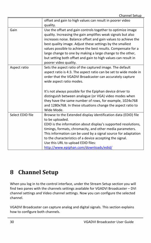
Offset Use the offset and gain controls together to optimize image quality. Increasing the offset reduces background noise but also reduces the overall signal. Balance offset and gain values to achieve the best quality image. Adjust these settings by the smallest values possible to achieve the best results. Compensate for a large change to one by making a large change to the other, but setting both
Channel Setup
30 VGADVI Broadcaster User Guide
offset and gain to high values can result in poorer video quality.
Gain Use the offset and gain controls together to optimize image quality. Increasing the gain amplifies weak signals but also increases noise. Balance offset and gain values to achieve the best quality image. Adjust these settings by the smallest values possible to achieve the best results. Compensate for a large change to one by making a large change to the other, but setting both offset and gain to high values can result in poorer video quality.
Aspect ratio Sets the aspect ratio of the captured image. The default aspect ratio is 4:3. The aspect ratio can be set to wide mode in order that the VGADVI Broadcaster can accurately capture wide aspect ratio modes.
It's not always possible for the Epiphan device driver to distinguish between analogue (or VGA) video modes when they have the same number of rows, for example, 1024x768 and 1280x768. In these situations change the aspect ratio to Wide Mode.
Select EDID file Browse to the Extended display identification data (EDID) file to be uploaded. EDID is the information about display’s supported resolutions, timings, formats, chromacity, and other media parameters. This information can be used by a signal source for adaptation to the characteristics of a device accepting the signal. Use this URL to upload EDID files: http://www.epiphan.com/downloads/edid/
8 Channel Setup When you log in to the control interface, under the Stream Setup section you will find two panes with the channels settings available for VGADVI Broadcaster – DVI channel settings and Video channel settings. Now you can configure the selected channel. VGADVI Broadcaster can capture analog and digital signals. This section explains how to configure both channels.

Channel Setup
31 VGADVI Broadcaster User Guide
8.1.1 Video channel setup The following settings can be made for the video channel on the Stream Setup page from the Web admin interface’s main page. Figure 15 Video Channel Settings
The table below outlines the video channel video configurable options. Table 5 Video Channel Settings
Enable video channel Select this checkbox to enable the recording of the video signal from the analog video source.
Picture-in-picture layout Use these radio buttons to specify how the DVI/VGA and S-Video/composite video sources are streamed when both are being used. These settings are explained in the Picture In Picture Layouts section.

Channel Setup
32 VGADVI Broadcaster User Guide
Video signal type Select the video signal type coming from the S-Video source:
- S-Video - Composite
Frame size Select a Frame size from the drop-down list to limit the width and height of the video image. If the analog video source is sending resolutions larger than the resolution limit they will be scaled to the resolution limit. Limiting the frame resolution can help to reduce bandwidth usage.
Show time label If the analog video needs to be time labeled, use this parameter to specify how the date and time will be displayed. Use the Format substitutions commands to select the necessary date and time format. The commands are described in table 7. Note: This option is available in the Independent Streams mode only.
Key frame interval Controls the number of seconds between key frames. Note: This option is available in the Independent Streams mode only.
Limit frame rate Enter a value in terms of frames per second. This field is used to set a frame rate that is lower than the maximum frame rate at which the VGADVI Broadcaster can capture images. Reducing the frame rate reduces the number of images being captured by the device. Decreasing the frame rate can help to reduce bandwidth usage. Note: This option is available in the Independent Streams mode only.
Bitrate Enter the signal bitrate. A lower bitrate produces lower quality videos and smaller file sizes. A higher bitrate produces better quality videos and larger file sizes. Note: This option is available in the Independent Streams mode only. Please refer to the following diagrams:

Channel Setup
33 VGADVI Broadcaster User Guide
Figure 65 Correlation Between FPS and Bitrate Values at Resolution 1280x720 Figure 66 Correlation Between FPS and Bitrate Values at Resolution 1920x1080 Figure 67 Correlation Between FPS and Bitrate Values at Resolution 640x480
8.1.2 DVI channel setup The following settings can be made for the DVI channel: Figure 16 DVI Channel Settings
Below is a table showing the DVI source settings that are configurable. Table 6 DVI Channel settings
Show time label If the video needs to be time labeled or timestamped, this parameter allows how the date and time will be displayed. Click on Show substitutions and use the Format substitutions commands to select the desired date and time format. The commands are described in table 7 below. If time labeling is not required, leave this field blank.
Frame size Select a frame size from the drop down list to limit the width and height of the video image. If the video source is sending resolutions larger than the resolution limit configured, the video image will be scaled to the

Channel Setup
34 VGADVI Broadcaster User Guide
resolution limit. Limiting the frame resolution can help to reduce bandwidth usage. Note that the final frame size can be larger in case the Picture in Picture layouts are used. For the Side-by-Side and Video-outside-DVI/VGA modes the largest height from both resolutions is used. The resulting width is equal to the total width amount for both resolutions.
Key frame interval Controls the number of frames. Key frames define the starting and ending points of any smooth transition.
Limit frame rate Enter a value in terms frames per second. This field is used to set a frame rate that is lower than the maximum frame rate at which the VGADVI Broadcaster can capture images. Reducing the frame rate reduces the number of images being captured by the device. Decreasing the frame rate can help to reduce bandwidth usage.
Bitrate Enter a DVI signal bitrate. A lower bitrate produces lower quality videos and smaller file sizes. A higher bitrate produces better quality videos and larger file sizes. Please refer to the following diagrams: Figure 65 Correlation Between FPS and Bitrate Values at Resolution 1280x720 Figure 66 Correlation Between FPS and Bitrate Values at Resolution 1920x1080 Figure 67 Correlation Between FPS and Bitrate Values at Resolution 640x480
Quality parameter (for MJPEG only)
This parameter is similar to Bitrate. Use bigger values to improve the quality of the broadcast.
Table 7 Format Substitutions Commands
Command Value Example (27/09/2012 10:50:45.378)
date %F 2012-09-27
year %G 2012
month (as 01) %m 09
month (as Jan)
%b Sep
month (as January)
%B September

Channel Setup
35 VGADVI Broadcaster User Guide
day of month %d 27
weekday (as Thu)
%a Thu
weekday (as Thursday)
%A Thursday
time %T 10:50:45
hour %k 10
minute %M 50
second %S 45
ms %#m 378
8.2 Audio Configuration Use the Audio section of the Web admin interface to configure the audio settings that control the audio input. All available video formats support audio except Motion JPEG. Figure 17 Audio Configurable Options
Table 8 Audio Configurable Options
Input Source Select the input source Line Mic (pre-amplified signal)
Input Amplifier Volume Reduce the input volume if the line in signal volume is too high for the VGADVI Broadcaster’s line in amplifier. The default input amplifier volume setting is 30%. If the

Channel Setup
36 VGADVI Broadcaster User Guide
input volume is too high, change the setting to between 5% and 90% to reduce the input volume.
8.3 Picture In Picture Layouts If you are capturing video from two video sources, you can create a layout for the recording/broadcast, i.e. specify how two videos are positioned on a screen relative to each other. Please keep in mind that the final frame size can be larger (particularly for the Video outside DVI/VGA layouts). Bitrate, limit frame rate and key frame interval values are taken from the DVI channel settings. To create a layout for the videos from two sources:
1. Connect two video sources to the device
2. Select Stream Setup section in the Web admin interface.
3. Select the Enable video channel check box.
4. Select the Picture-in-picture layout radio button, either Video inside DVI/VGA or Video outside DVI/VGA, with the required position of the inset window. - Video inside DVI/VGA – the DVI/VGA stream is displayed on the full screen
at the same time as the analogue stream is displayed in the left or right inset window. The streams are superimposed.
- Video outside DVI/VGA - the DVI/VGA stream is displayed in the bigger screen at the same time as the analogue stream is displayed in the smaller screen. The streams are not superimposed.
8.4 Select Video Codec Before starting the video recording or broadcasting process, you have to specify the video codec for encoding. It can be selected on the Stream Setup section of the channel’s page. To select the video codec:
1. Select the required channel.
2. Click the Stream Setup option.
3. Click an arrow in the Codec field.
4. Select the required codec from the drop-down list. The following values are available for selection:

Channel Setup
37 VGADVI Broadcaster User Guide
H.264 MPEG4 Motion JPEG
After you have specified required video and audio codecs (as described in this section and in the Select Audio Format section), click the Info menu option of the Web Admin interface to see available broadcasting formats for your settings and obtain the IP addresses for the broadcast.
Figure 18 Stream Settings
Table 9 Stream Setup settings
Video encoding preset Defines how a video stream should be encoded: - at a high quality - at a high speed - according to the default system settings.
Video encoding profile Select one of the following encoding profiles that target
specific classes of applications: 1. Baseline: for applications requiring additional
data loss robustness, e.g. videoconferencing 2. Main: for standard-definition broadcasts
3. High: for broadcast and disc storage applications
This parameter can be set for the H.264 codec only.

Channel Setup
38 VGADVI Broadcaster User Guide
Enhanced compatibility mode (h.264 slicing for RTP)
This parameter provides operating stability if the transmitted video/audio stream is not quite supported by the viewer’s equipment. When this parameter is activated, each picture is subdivided into one or more slices. The slice is given increased importance in H.264 as the basic spatial segment that is independent from its neighbours. Thus, errors or missing data from one slice cannot propagate to any other slice within the picture.
8.5 Set Video Encoding Constraints/Parameters The following common parameters can be additionally specified: Table 10 Common settings
Rate control mode Used for H.264 and MPEG4 codecs. It specifies the
bitrate encoding for the signal. Select one of the
following:
- Low Delay Means Constant Bitrate Encoding (CBR) will be used. CBR is useful for streaming multimedia content on limited capacity channels since it is the maximum bit rate that matters, not the average. Therefore, CBR would be used to take advantage of all of the channel capacity.
- Storage Means Variable Bitrate Encoding (VBR) will be used. This produces a better quality-to-space ratio compared to a CBR file of the same data. VBR files vary the amount of output data per time segment and the FPS value may be lower.
Stream port The number of the port being used to stream the broadcast. This value would be used along with the URL to access the broadcast. In the case where there are two streams because Independent streaming is being used, this value remains the same for both of the URLs being

Channel Setup
39 VGADVI Broadcaster User Guide
used. In case of RTSP streaming this value is not considered.
Figure 19 Common Settings
The Page refresh time parameter in the MJPEG webpage section is available if the Motion JPEG codec is selected.
Page refresh time Specify how often the browser updates the visual information coming from the VGADVI Broadcaster. In other words, how often the page is refreshed
8.6 Select Audio Format The Audio settings pane in the control interface can be accessed by clicking the Stream Setup option from the menu. Select the Enable audio checkbox and specify the audio signal parameters. Table 11 Audio settings
Enable audio Select this checkbox to enable audio for the broadcast.
Audio format You can select the following audio formats:
MP3 – a common audio format for consumer audio storage
Raw PCM (Pulse Code Modulation) – a standard form for digital audio in computers as well as other uses such as digital telephone systems
G.711 – an ITU-T standard for audio companding. It is a very commonly used waveform codec.
o μ-law is used primarily in North America o A-law is in use in most other countries outside

Streaming
40 VGADVI Broadcaster User Guide
North America
AAC - a standardized, lossy compression and encoding scheme for digital audio. AAC generally achieves better sound quality than MP3 at similar bit rates.
Audio channels Select either mono (1 channel) or stereo (2 channels) sound.
Audio bitrate Select the audio bitrate value for the broadcast.
Figure 20 Audio Settings
9 Streaming There are several decisions that need to be made when planning the creation of a broadcast, besides its exact content of the broadcast. Will the broadcast include an audio component coming from an analog audio source? What video format to use, what video standard to use, how to stream the broadcast are all questions that have to be answered when creating a broadcast. Most of the answers depend on the intended audience of the broadcast, how are the viewers going to view the broadcast, and how many simultaneous viewers are expected to view the broadcast? Where are the viewers located in relation to the where the broadcast is being streamed? What are the performance expectations? These are the types of questions that will determine the overall design of the broadcast. This chapter outlines how a suitable design of a broadcast can be architected based on these types of questions and their resulting answers and how the System can be used in this design. The VGADVI Broadcaster supports streaming of various standards and formats. The choice of video format will depend on the broadcast content and performance requirements. For example, Motion JPEG does not support audio from an external

Streaming
41 VGADVI Broadcaster User Guide
source. It also depends on how the intended viewers are planning to receive and play the broadcast. Keep in mind that browser viewer capabilities and compatibilities are subject to change. With the VGADVI Broadcaster, video codec for streaming is selected by an administrator. After this action the system creates a list of available streaming formats for this codec. The figure below is representation of the protocol stack diagram showing how the video data is processed. Figure 21 Protocol Stack Diagram
How the broadcast will be delivered to its viewers depends on the number of intended viewers and where the viewers are in relation to where the broadcast is originating. Are they on the same LAN or will they be accessing the broadcast from an external network? The answers to the above questions will help decide the delivery method of the broadcast. The VGADVI Broadcaster can support streaming over HTTP, RTSP, peer-to-peer RTP connection, multicast RTP and a Content Distribution Network (CDN) broadcast network. Each broadcast delivery method will be now discussed in more detail.

Streaming
42 VGADVI Broadcaster User Guide
9.1 HTTP or RTSP Streaming For HTTP or RTSP streaming the only information required to view the broadcast is the URL of the broadcast. The VGADVI Broadcaster is ready to go straight out of the box, without any additional settings. If your broadcast needs to be accessed by many clients, use a Content Distribution Network as explained in the Using a Content Distribution Network section.
9.2 Using a Content Distribution Network
A content delivery network (CDN) is a system of computers or servers that ingest an incoming stream source and rapidly provides this content to numerous users by duplicating the content on multiple servers and directing the content to users.
CDN distributes a heavy load of traffic to multiple locations in order to avoid congestion on a network that could impact a user’s Internet experience. A CDN is highly scalable and can make financial sense to website owners as you will not need to pay for additional server hardware or routing should your website traffic start to increase or even decrease. The use of CDN technology has obvious advantages to those users whose broadcasts have large audiences from locations all over the world. If dozens or hundreds of viewers happen to select the same Web page or content simultaneously, the CDN sends the content to each of them without delay or time-out.
To stream to multiple users, the System can be configured as a client to CDN. Please click http://epiphan.tv/cdn-partners.php to view the list of CDN providers preferred by Epiphan. By connecting to a CDN server, the broadcast from the System can be streamed to multiple viewers. By using a CDN, the maximum number of concurrent clients is increased, while at the same time reducing the load on the uplink internet connection. CDN streaming is a very effective approach when you are broadcasting streams from the Epiphan solutions and want to add scalability to your broadcast. The System features the Publish Stream functionality that enables you to stream the broadcast either via Epiphan’s portal or CDN providers to multiple viewers. You must use the H.264 codec for CDN streaming. Using CDN it is possible to set a user name and a password for the broadcast. Each viewer will have to request it from you before viewing the broadcast. This function

Streaming
43 VGADVI Broadcaster User Guide
allows you to manage access to your content ensuring visibility only to the appropriate and authorized viewers. Figure 22 Using a CDN Service Increases Scalability of Concurrent Viewers
The Publish Stream functionality allows for directing captured video and audio to servers or clients using one of the available stream modes. The following options are available:
- Disabled. If this option is enabled, you cannot send multicast RTP stream, perform CDN broadcasting or stream video to Epiphan’s portal.
- to xxxxx.epiphan.tv. This option allows for streaming video to the Epiphan’s portal.
- using RTSP announce. This option allows for connecting to CDN server.
- using RTP/UDP push. This option allows for IP multicast broadcasting. These options and settings to be performed are discussed further. In the Independent Channel Stream mode it is not possible to publish both input sources using any of the Publish Stream options. Whether you need to send multicast RTP stream or publish video through CDN, it can be done only for the DVI input source.

Streaming
44 VGADVI Broadcaster User Guide
The Publish Stream functionality is available only for the H.264 video codec.
9.2.1 Using Epiphan.tv Portal for Streaming To set up and perform streaming via Epiphan.tv portal:
1. Click the Publish Stream option in the main menu of the control interface. 2. Select to xxxxx.epiphan.tv from the Publish drop-down list where xxxxx is
the unique serial number of the VGADVI Broadcaster. 3. Select Enable publishing and click Apply. The system informs you that
stream will be available on the Epiphan’s portal and provides a link.
Figure 23 URL to Epiphan Server
4. Click this link and access the portal where the stream is being broadcast in
a new window. 5. In case you have selected a codec other than H.264 for streaming (MPEG4
or Motion JPEG), the system will give you a warning (see Figure 24 System Message in Case of Excessive Bitrate Speed). Click on fix by setting H.264 codec. The codec will be set to H.264 automatically.
6. In case the bitrate of your broadcast exceeds 500 kbit/s, the system will give you a warning (see Figure 24 System Message in Case of Excessive Bitrate Speed). Click on fix by reducing bitrate to 500 kbit/s. The bitrate will be set to 500 kbit/s automatically. Note: Epiphan.tv is a demonstration service to help customers experiment with publishing streams to content distribution networks. Therefore certain bandwidth and performance limits are applied. To upgrade to a full service please select one of Epiphan’s CDN partners.

Streaming
45 VGADVI Broadcaster User Guide
Figure 24 System Message in Case of Excessive Bitrate Speed
Figure 25 System Message after Setting H.264 codec and Reducing Bitrate
Now connection through the media tunnel is established. The VGADVI Broadcaster starts streaming to the Epiphan’s portal – epiphan.tv. It is required to set up audio format as MP3 when streaming through the epiphan.tv. This setting is performed in the control interface’s Stream Setup section (see Select Audio Format).
There are several buttons available at the bottom of the epiphan.tv portal page (see Figure 26 Epiphan’s Portal):
Switch to
Click this button to select a plugin which will be used for viewing the stream. Refer to Figure 27 Plugins Available for Selection on the Portal. The following plugins are available:
- Flash RTMP
- Flash HTTP
- QuickTime
- VLC Player
Embed Displays a code that allows you to embed video stream into your web page. Refer to Figure 28 Code for Stream Embedding.
Direct URL Displays a list of URLs for different types of broadcasting. Refer to Figure 29 Listing of Direct URLs.

Streaming
46 VGADVI Broadcaster User Guide
7. Click Switch to button and select a plugin for viewing the stream. 8. If you need to embed the stream into your web page, click Embed to
obtain the code. 9. Click Direct URL to obtain the list of URLs for different types of
broadcasting.
Figure 26 Epiphan’s Portal
Figure 27 Plugins Available for Selection on the Portal

Streaming
47 VGADVI Broadcaster User Guide
Figure 28 Code for Stream Embedding
Figure 29 Listing of Direct URLs
Alternatively you can configure VGADVI Broadcaster to stream their content through epiphan.tv directly on the portal. To view the stream directly on the portal:
1. Type http://epiphan.tv in the address bar of your browser.
2. Enter serial number of VGADVI Broadcaster. It is displayed in the Info section of the Web admin interface.
3. Click the Go! button.
9.2.2 Using Epiphan’s Partners as CDN Providers for Streaming Use this option if you need to perform streaming on a remote streaming server other than epiphan.tv. Please contact CDN support to request the list of supported audio codecs and perform the required setting in the control interface’s Stream Setup section (see Select Audio Format). To use this option:
1. Select RTSP Announce from the drop-down list.

Streaming
48 VGADVI Broadcaster User Guide
2. Enter the host/server name. For example, 172.20.1.50.
3. Enter the number of port which is used for streaming to server. Usually for RTSP streaming it is port 554.
4. In the Mount point field enter the full path to locate an SDP file on server. This path is provided by the CDN provider.
5. The RTSP protocol uses UDP or TCP as transport layers. If your CDN service requires TCP as a transport layer, select the Use TCP for RTP stream check box.
6. If necessary, enter the user and password information.
7. Click Apply. Figure 30 RTSP Announce Functionality
9.2.3 Setting up Multicast from Publish Stream A multicast RTP stream provides a one-to-many broadcasting framework. In a multicast RTP configuration, the VGADVI Broadcaster sends a packet only once to a router that supports multicasting. This router then distributes the packets to all intended viewer nodes using a multicast protocol. A multicast address is associated with a group of interested receivers. In IPv4, addresses 224.0.0.0 through 239.255.255.255 (the former Class D addresses) are designated as multicast addresses.

Streaming
49 VGADVI Broadcaster User Guide
Sending multicast streams requires equipment that supports multi-casting, configuring your network and enabling specific multicasting features on the VGADVI Broadcaster. Multicast architectures are used predominantly within a high bandwidth corporate LAN and not on Internet based architectures. Multicast RTP streaming is not usually propagated outside the LAN though it may be propagated through VPNs connecting several LANs. Multicast transmission is available during RTP streaming. In the Independent Channel Stream mode it is not possible to set up multicast for streaming video from both sources. You are able to operate only the stream coming from the DVI input. The system provides a URL only for this stream even if the sources are connected to both DVI and S-Video inputs. RTP/UDP Push streaming allows you to direct video to a server or client and generates an SDP file containing the stream description. SDP files can be stored on a streaming server, or opened by video players. To use this option:
1. Select Publish Stream from the main menu.
2. Select RTP/UDP Push from the drop-down list.
3. Enter a destination multicast IP address. At this target point the broadcast will be viewed.
4. Specify the numbers of the video and audio ports where the broadcast will be received.
5. Click Apply.
6. An SDP file is now generated. It is available in the Info section of the Web Admin interface. You can either save an SDP file on your local machine or provide the link to SDP file to your audience.

Streaming
50 VGADVI Broadcaster User Guide
Figure 31 RTP/UDP Push Functionality
9.3 Viewing Streaming Video The VGADVI Broadcaster may capture audio and video at resolutions up to 1920 x 1200. The resolution of the broadcast may exceed this value, for example, in case of analog video broadcasting. Viewers can access the broadcasted video streams with a web browser that supports Motion JPEG, MPEG4 or Flash Video/H.264 compression or with a media player that is compatible with the stream format being transmitted. The available video stream formats is determined by selected video codec. Audio is available for all formats except from Motion JPEG.
9.3.1 Retrieving the Stream’s URL for Broadcasting In order for viewers to log in and view a stream, the administrator must release the URL(s) of the stream. The administrator is able to provide separate URLs for the stream coming in from the VGADVI Broadcaster’s video input ports and audio input ports. Alternatively, one URL can be provided that includes all the streams from all input sources. The administrator can retrieve the appropriate stream URL or URLs as explained below.
9.3.2 Using the Web Admin Interface’s Info Page The following indicates where each URL for the broadcast can be found on that page: Live broadcast is the URL for the simultaneous broadcast from both video sources and the one audio port. If the Single Channel Stream mode is enabled (see User Viewing Experience: Single Channel Stream vs. Independent Streams), this URL is
Streaming
51 VGADVI Broadcaster User Guide
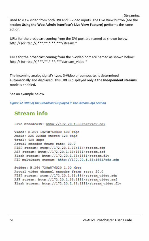
used to view video from both DVI and S-Video inputs. The Live View button (see the section Using the Web Admin Interface’s Live View Feature) performs the same action. URLs for the broadcast coming from the DVI port are named as shown below: http:// (or rtsp://)***.**.*.**:***/stream.* URLs for the broadcast coming from the S-Video port are named as shown below: http:// (or rtsp://)***.**.*.**:***/stream_video.* The incoming analog signal’s type, S-Video or composite, is determined automatically and displayed. This URL is displayed only if the Independent streams mode is enabled. See an example below. Figure 32 URLs of the Broadcast Displayed in the Stream Info Section

Streaming
52 VGADVI Broadcaster User Guide
9.3.3 Using the Web Admin Interface’s Live View Feature The second method for retrieving the desired broadcast URLs is to use the Web Admin interface’s Live View Feature. This feature not only shows the current broadcast to the administrator but also provides the broadcast URLs. By clicking on the Live View button from the main menu, a preview of the current broadcast’s videos appear in the web browser. Under each of the broadcast screens the system displays the URL of that broadcast. For an example refer to the following figure:
Figure 33 A Broadcast with its URL Displayed Under the Broadcast Image
9.4 Viewing a Broadcast with a Browser If the administrator has configured a viewer password, participants must obtain the password in order to log in. The administrator will also provide the IP Address or the URL to be used by the viewer’s browser.

Streaming
53 VGADVI Broadcaster User Guide
To log in to view the broadcast using a browser: 1. Start any web browser. 2. Browse to the IP address of the VGADVI Broadcaster‘s broadcast stream.
For example, if the IP address of the VGADVI Broadcaster’s broadcast is 172.20.1.33, then browse to: http:// 172.20.1.33
3. Enter the following: User Name: viewer Password: (enter the viewer password).
4. Press Enter. 5. The broadcast begins to play within the viewer’s browser.
Figure 34 Viewing a Broadcast Using a Web Browser
9.5 Viewing a Broadcast with a Media Player If the administrator has configured a Viewer password, participants must obtain the password in order to log in. The administrator will also provide the IP Address or the URL to use within the media player. To log in to view a stream using a media player:
1. Launch the media player.

Streaming
54 VGADVI Broadcaster User Guide
2. Use the Menu bar to open the URL dialog box and enter the URL address of the stream.
3. When prompted, enter the following: a. User name: viewer b. Password: enter the viewer password. c. Press Enter.
4. The stream begins to play within the viewer’s player.
9.6 Compatibility Information This section provides information on compatibility of video streaming formats and player which is necessary for streaming video. The VGADVI Broadcaster can stream video using Flash (H.264), ASF (MPEG4 or H.264 codecs), Motion JPEG or RTSP (MPEG4 or H.264 codecs). A quick definition of these video streaming methods and the type of application that a viewer would use to watch that particular video stream is now provided. The Adobe Flash Video file type is proprietary but is supported on most web browsers and on many media players including the VLC Media Player. This file type supports the H.264 standard. This video supports analog audio from an external source. The Advanced System Format (ASF) file type also called Advanced Streaming format, can be viewed with the Windows Media Player or the VLC Media Player. Additional codecs may need to be installed to view ASF files. This file type supports H.264 and MPEG4 standards. This video supports analog audio from an external source. The Motion JPEG file type records each frame in the video in JPEG format and can be viewed using most web browsers. This video format does not support analog audio from an external source. The RTSP type supports many media players including QuickTime and MPlayer. This file type supports H.264 and MPEG4 standards. This video supports analog audio from an external source.

Recording
55 VGADVI Broadcaster User Guide
10 Recording The VGADVI Broadcaster captures video and audio data which can be encapsulated in a file or files and recorded. The Web admin interface provides the administrator and operator users with the ability to start, stop and configure the recording. Additionally, recorded video files might need to be downloaded or copied to another device for archiving purposes; also they might need to be deleted in order to manage disk space on the VGADVI Broadcaster. For organizing, recorded video files may need to be renamed. All of these management tasks are available via the VGADVI Broadcaster’s Web admin Interface.
10.1 User Viewing Experience: Single Channel Stream vs. Independent Streams
Streaming and recording of all synchronized input sources can be performed in either of the following modes:
Single Channel Stream
Both video sources are combined into one and streamed to a common URL. Both video tracks and the audio track are combined and recorded to one video track and one audio track. The viewer is enabled to watch two different video sources at the same time and specify whether both streams are superimposed or not. To enable Single Channel Stream Mode: 1. Select the Stream Setup menu option. 2. Select the Enable video channel check box. 3. Select either Video inside DVI/VGA or Video outside DVI/VGA radio buttons
(Picture-in-picture layout field) in the Video channel pane.
Independent Channel Stream In this mode each video source is streamed to a distinct URL. Both video tracks and the audio track are recorded to a multi-track file. Independent streams can be viewed in the separate windows of a browser or a media player. In this mode you should select the H.264 codec with Video encoding profile set as Main or High (refer to Select Video Codec).

Recording
56 VGADVI Broadcaster User Guide
In this mode you are unable to publish both streams using the Publish Stream function. Also note that in this mode only a URL for the broadcast coming from the DVI input can be used for publish streaming.
To decide which mode to select you need to know how you will use the VGADVI Broadcaster. For example, the Single Channel Stream mode is ideal to deliver presentation material while the narrator is giving his comments. It is an effective way to create movies in sign language. As for the Independent Channel Stream mode, it is appropriate when a viewer does not need to watch both video streams simultaneously. If you are streaming both video sources and an audio source using this mode, note that audio will be available with a DVI/VGA stream only. To enable Independent Channel Stream Mode: 1. Select the Stream Setup menu option. 2. Select the Enable video channel check box. 3. Select the Independent streams radio button (Picture-in-picture layout
field).
10.2 Selecting Recording File Format The format of the record is specified using the Recorded Files button of the Web admin interface. Figure 35 Select Recording Format
1. Use the File Type drop-down list to select the recording format (MOV or
AVI).

Recording
57 VGADVI Broadcaster User Guide
2. Click Apply.
10.3 Changing Time and Size Limits
The VGADVI Broadcaster can record the channel to one or more files according to time and file size limit parameters. It will automatically create and start recording to a new file whenever either limit is reached. To specify the time and file size limit parameters:
1. Click the change command. 2. Select the parameters values from the drop-down list (see Figure 36
Changing Time Limit and Size Limit).
Figure 36 Changing Time Limit and Size Limit
3. Click Apply.
Table 12 Time and file size limit parameters
Time limit Specify the maximum amount of time to record to a file. When either the time limit or the size limit is exceeded, the system starts recording data to a new file.
Size limit Specify the maximum size of the recorded file. When either the time limit or the size limit is exceeded, the system starts recording data to a new file.

Recording
58 VGADVI Broadcaster User Guide
10.4 Starting and Stopping Recording The recorder status is shown in the Web Admin interface. It is located on the left hand side of the screen above the Web Admin interface’s main menu. The ability to manage a recording with the Web Admin interface is done using these buttons. Note that the format of the recorded file is specified clicking the Recorded Files button and selecting the required File Type value. Figure 37 Recorder Status
To start a recording, click the Start button in the Recorder status section of the main menu. To stop a recording, click the Stop button in the Recorder status section of the main menu. To close the file being recorded and start recording to a new file, click the Reset button. Or, alternatively click Stop and click the Start button again. It is possible to specify whether the recording is stopped in case there is no signal. To enable this parameter, click the Recorded Files button of the Web admin interface and select the Stop recording in the absence of VGA/DVI and video signals check box. Note that in case both signals are streamed via DVI and video ports, recording will be stopped only if streaming through both ports is interrupted. If either video signal is continued, recording will be continued too.

Recording
59 VGADVI Broadcaster User Guide
10.5 Viewing the Current Recording Viewing the broadcast as it is being recorded is performed by doing the following: Select Live View from the Web Admin Interface’s main menu. A preview of the broadcast that is currently being recorded appears in the web browser. The preview is exactly the same as what is being recorded. If the broadcast is coming from two sources through the DVI and S-Video connectors, both will be seen. Under the broadcast screen the system displays the broadcasts' URLs. Figure 38 Broadcasts Coming from Two Input Sources (Independent Streams Mode)
10.6 Recording a Stream on iPad, iPhone and iTouch You can record a stream on iDevices using EpiphanTouch™. This discovery and remote control application is available as a free download from iTunes and the App store. It allows you to log into the device as the administrator user. Refer to Epiphan’s EpiphanTouch App for iPad, iPhone, iTouch section for details.
10.7 Recorded Files The Recorded Files section lists all of the video files recorded by the VGADVI Broadcaster and that are saved on it. It is accessed by clicking the Recorded Files button from the Web admin interface’s main menu.

Recording
60 VGADVI Broadcaster User Guide
If the signals are captured from two input sources, both streams are overlaid during recording. Therefore both input sources will be recorded to one file. For each file, the list includes the name of the file, start and end times, duration, and size in MB. Each recording file listing also includes icons that can be used to download, delete, or rename the file. Figure 39 Recorded Files
10.7.1 Downloading Recordings Download recordings to either save or view them. Also you can download a single file or multiple files as a single .zip file.
1. Click Recorded Files. 2. Click the file you want to download. To download multiple files, select the
checkboxes beside all of them and then select the Download Selected button at the bottom of the file list.
3. Follow the instructions to download the file or files.
If you select the Download Selected button, all of the files that you have selected are downloaded in a single zip file. You must unzip this file to view the individual video files. If you have downloaded multiple files, select Continue to return to the previous page.
10.7.2 Deleting Files The administrator and operator users can delete files from the VGADVI Broadcaster to free up space on the solid state memory. Files can be selected one at a time, or

Recording
61 VGADVI Broadcaster User Guide
multiple files can be selected to be deleted. Alternatively there is a Delete All button that allows deleting all files that have been previously downloaded. This can be a time-consuming operation.
1. Click Recorded Files.
2. To delete individual recordings, select the Delete File icon
beside the file you want to delete. To delete multiple
files, select the checkbox beside the files you want to delete
and then select Delete Selected.
3. Follow the instructions to delete the file or files. The files are
deleted from the solid state memory.
10.7.3 Renaming Files The administrator and operator users can rename one file at a time. Again, this function is done by going to the Recorded Files section from the Web admin interface main menu. To rename a file:
1. Click Recorded Files.
2. Select the rename file icon .
3. Enter the new name for the file.
4. Select Submit.
10.7.4 Viewing Completed Recording Files As broadcasts are being recorded into the file, they can be viewed using the Live View button in the Web Admin interface. Closed recordings can be viewed using a compatible media player. The instructions below explain how to view a closed recording file using the default media player installed on a computer. These instructions will only work when using the default player. To view a closed recording file using another player the closed file will need to be downloaded or copied to a location that is accessible by the player. The recorded file will then be opened from within the player itself.

Recording
62 VGADVI Broadcaster User Guide
1. Once the recording is completed, log into the Web Admin interface. 2. Click Recorded Files in the main menu and click the file that is to be
viewed. 3. The system will suggest you to open the file with the computer’s
configured default player. For example, for systems running Windows, the default player is the Windows Media Player.
4. The player opens the window with the recording. If you have recorded streams from the two sources in the Independent Stream mode (see User Viewing Experience: Single Channel Stream vs. Independent Streams mode), the player will display them in separate windows. If you have recorded streams from the two sources in the Single Channel Stream mode, the player will display both streams in one common window.
10.8 File Transfer of Recorded Files The VGADVI Broadcaster provides several options to automatically copy recordings to a network storage location, or a USB flash drive. This is a great feature for professional AV service providers that want to provide a copy of the presentation to the speaker before they leave the presentation venue.
10.8.1 Copying Recorded Files to a USB Flash Drive The VGADVI Broadcaster is equipped with USB ports that can be used to copy recorded data from the VGADVI Broadcaster to an external USB flash drive formatted with one partition in one of the following file systems: FAT32, ext3, ext2, ISO 9660, HFS. This is a great feature for professional AV service providers that want to provide a copy of the presentation to the speaker before they leave the presentation venue.

Recording
63 VGADVI Broadcaster User Guide
Figure 40 A USB Flash Drive Connected to a USB port Receives Recorded Data
A flash drive can be connected to the VGADVI Broadcaster any time. Stick a flash drive into a USB port on the device and press lightly. The stick fits into the port only one way. After inserting, the VGADVI Broadcaster will recognize the stick, however, this occurs without any user notification whatsoever.
Figure 41 Insert a USB Flash Disk
The VGADVI Broadcaster copies to the inserted USB flash drive, only files recorded before inserting the flash drive, starting from the oldest record to the newest. The

Recording
64 VGADVI Broadcaster User Guide
flash drive’s LED (if any) will be blinking indicating data transfer. The VGADVI Broadcaster can copy maximum 100 recorded files to the flash drive. If you are making new recordings during copying data to the flash drive, these new recordings will not be copied. Due to speed limitations flash drives are not capable of recording data on the fly. This means that while the previously recorded data captured by the VGADVI Broadcaster on its internal solid state memory will be copied to the flash drive, the currently opened recording file cannot be copied until the file is closed. Once closed, it is then available for copying. Once the data has been copied, safely remove the flash drive. To check its free storage, files that have been copies and their size, insert the drive into a computer and see its properties.
10.9 Automatic File Upload The automatic file upload feature will automatically copy recorded video files from the VGADVI Broadcaster to another device on your network. This feature’s page is reached from the Web admin interface’s main menu by clicking on Automatic File Upload. By uploading recorded broadcast files to another network device, these broadcasts become available to be viewed from other device besides the VGADVI Broadcaster. This feature also provides a method of automatically archiving recorded broadcast files after they are closed. Note that the files that are currently being copied to another device on your network, have an extension .part. The image below is a screenshot from the user’s PC. There is a folder where the files are being copied from the VGADVI Broadcaster. Copying is enabled. One file with the extension .part is now being copied from VGADVI Broadcaster.

Recording
65 VGADVI Broadcaster User Guide
Figure 42 This File is Being Copied Now
Table 13 Automatic File Upload Configurable Options
Enable Automatic File Upload Check this box to enable this feature, uncheck this box to disable this feature.
Protocol Select the upload client.
How often Select how often video files are to be uploaded. By selecting On file rotation, the VGADVI Broadcaster uploads each video file after it stops recording the current video file and starts recording the next one. You can also configure the VGADVI Broadcaster to upload all video files every 1, 6, 12, or 24 hours.
Remote path The path on the upload server to upload the video files to. This path must match an actual path on the server. If a path is not entered, the files are uploaded to the root location.
Remove after upload If you select this checkbox, the video files will be deleted on VGADVI Broadcaster after uploading. In case the check box is not selected, the

Recording
66 VGADVI Broadcaster User Guide
system check if there is enough place for a new file based on the size limit value (please refer to Changing Time and Size). If there is not enough place, the system deletes the oldest files.
Mark file as downloaded Select the checkbox to keep the files on VGADVI Broadcaster after uploading copies to the server. The filenames before uploading are displayed in blue. The filenames after uploading are displayed in purple.
Show log of automatic file upload Use this command to display the log of file uploads
Figure 43 Configuring the Automatic File Upload Feature
10.9.1 Configuring Automatic File uploads Recorded files can be uploaded to a CIFS server (a Windows share), an RSync server, or an FTP server.
1. Select Enable Automatic File Upload. 2. Set Protocol to FTP Client, RSync Client, or CIFS client depending on what
upload server is being used. 3. If the How often option is set to On file rotation, the VGADVI Broadcaster
will upload each video file after it stops recording to it. Alternatively, the

Recording
67 VGADVI Broadcaster User Guide
VGADVI Broadcaster can be set to upload all video files every 1, 6, 12, or 24 hours.
4. Set Remote Path to the path on the upload server to upload the video files to. This path must match an actual path on the server. If a path is not provided, the files are uploaded to the root location.
5. Select the Remove after upload checkbox to delete all video files on the VGADVI Broadcaster after uploading them.
6. Select Mark file as downloaded to keep the files on the VGADVI Broadcaster device after uploading copies to the server. The filenames before uploading are displayed in blue. The filenames after uploading are displayed in purple. Note: In case you select both checkboxes (Remove after upload and Mark file as downloaded) the files uploaded to server will be removed from the device.
7. Configure the appropriate client for the designated upload server:
If the upload server is a CIFS server (for example, a Windows shared folder), select and configure the CIFS Client. See Configuring a CIFS Client.
If the upload server is an RSync server, select and configure the RSync client. See Configuring an RSync Client.
If the upload server is an FTP server, select and configure the FTP Client. See Configuring an FTP Client.
8. Click Apply.
The first copy is made after the time period set in how often expires. For example, if the VGADVI Broadcaster is set to upload files every hour, the first set of files is uploaded after one hour. If five video files are saved in the first hour, those five video files are uploaded. One hour later, all of the video files saved since the start of that hour are uploaded.
Video files saved before you selected Apply are not uploaded. For files saved before Automatic File upload is configured, a manual upload process will have to be done.
10.9.2 Configuring a CIFS Client Use the CIFS client configuration to have the VGADVI Broadcaster device behave as a CIFS client connecting to a CIFS server (such as a Windows shared folder) when uploading broadcast files. Different networks may have different CIFS server

Recording
68 VGADVI Broadcaster User Guide
configurations. If required, contact your network administrator for assistance with getting the VGADVI Broadcaster to connect to the server. Depending on your CIFS server configuration you may not have to enter information in every field shown in the following diagram. Figure 44 Configuring a CIFS Client
To configure the CIFS client:
1. Select CIFS Client in the Protocol field. 2. Enter the Server port if the CIFS server uses a non-standard port. If your
CIFS server uses standard ports you should not have to add any information to this field. If your server uses non-standard ports or looks for a non-standard port first, enter the port number in this field.
3. Enter the Server address. This can be the numeric IP address or fully qualified domain name of the CIFS server.
4. Enter Server share. This is the CIFS share name or the name of the Windows shared folder on the CIFS server.
5. If required, enter the name of the CIFS Domain. The Domain can be a Windows Domain or Work Group name.
6. Enter the Login and Password required to authenticate with the CIFS server to connect to the server share.
7. Select the Use temp file check box to upload a temporary file. This prevents you from using a file which is not fully uploaded yet. After the file is uploaded, it is renamed to its original name.

Recording
69 VGADVI Broadcaster User Guide
8. Select Apply.
The VGADVI Broadcaster will then attempt to connect to the CIFS server. To view messages about whether the VGADVI Recorder is able to connect to the CIFS server and the status of the connection, click Show log of automatic file upload (Figure 43 Configuring the Automatic File Upload Feature).
10.9.3 Configuring an RSync Client Use the RSync client configuration to have the VGADVI Broadcaster act as an RSync client connecting to an RSync server. Different networks may have different Rsync server configurations. If required, contact your network administrator for assistance with getting the VGADVI Broadcaster to connect to the server. Figure 45 Configuring an RSync Client
To configure the RSync client:
1. Select RSync Client in the Protocol field. 2. Enter the Server address. 3. Enter Server module which is a directory on the RSync server. 4. Enter the Login and Password required to authenticate with the RSync
server to connect to the server share. 5. Select the Checksum checkbox to enable computing checksums algorithm
applied during file synchronization between sender and recipient servers. 6. Select Apply.

Recording
70 VGADVI Broadcaster User Guide
The VGADVI Broadcaster will then attempt to connect to the RSync server. To view messages about whether the VGADVI Recorder is able to connect to the RSync server and the status of the connection, click Show log of automatic file upload (Figure 43 Configuring the Automatic File Upload Feature).
10.9.4 Configuring an FTP Client Use the FTP client configuration to have the VGADVI Broadcaster act as an FTP client to an FTP server to upload broadcast files. Different networks may have different FTP server configurations. If required, contact your network administrator for assistance with getting the VGADVI Broadcaster to connect to the server. Figure 46 Configure an FTP Client
To configure the FTP client:
1. Select FTP Client in the Protocol field. 2. Enter the Server port if the FTP server uses a non-standard port. The
standard FTP port is TCP 21. 3. Enter the Server IP address. 4. Enter the Login and Password required to authenticate with the FTP server
to connect to the server. 5. Select the Use temp file check box to upload a temporary file. This
prevents you from using a file which is not fully uploaded yet. After the file is uploaded, it is renamed to its original name.
6. Select Apply.

Recording
71 VGADVI Broadcaster User Guide
The VGADVI Broadcaster will then attempt to connect to the FTP server. To view messages about whether the VGADVI Recorder is able to connect to the FTP server and the status of the connection, click Show log of automatic file upload (Figure 43 Configuring the Automatic File Upload Feature).
10.9.5 Testing the Automatic File Upload Test the automatic file upload to ensure all settings are correct. To test automatic file upload:
1. Confirm that the upload server is operating. 2. Start recording the stream. 3. Log into the Web admin interface. 4. Select Automatic File Upload, from the main menu. 5. Set the How Often setting to On file rotation. 6. Click the Reset button in the main menu. The file currently being recorded
will be closed and saved. 7. The recording will then be uploaded to the configured remote path using
the configured client. 8. Check the server to confirm that the most recently saved video file has
been uploaded to it and it is in the proper path location on that server.
If the file is not uploaded, click Show log of automatic file upload to view the log. Verify that the client configuration and Automatic File Upload configuration settings are correct. Check the remote device’s root path, if the remote path is incorrectly configured, the broadcast file will be uploaded to that location. Check the Recorded Files page from the Web admin interface: If the Remove after upload checkbox is selected, the uploaded file should have been deleted from the Recorded Files section.
10.10 FTP Server An FTP server can be configured on the VGADVI Broadcaster to enable a FTP client to connect to the VGADVI Broadcaster’s internal solid state memory. An FTP client can be used to manually download video files from the VGADVI Broadcaster. FTP access can also be given permission to delete video files remotely from the VGADVI Broadcaster.

Networking
72 VGADVI Broadcaster User Guide
The FTP access options are accessible from the Web admin interface’s main menu, FTP Server. Figure 47 FTP Server Options
Enable FTP Access Enables FTP access to the VGADVI Broadcaster.
FTP user name Select one of the following users as the FTP client:
admin
operator
viewer
Enable FTP DELETE command
Select this option to grant the FTP client the ability to delete videos from the VGADVI Broadcaster internal memory.
11 Networking
11.1 Connecting Directly to the System This section discusses how to directly connect to the VGADVI Broadcaster using the factory default network settings. This method must be used if the network where the VGADVI Broadcaster resides does not have a DHCP server, you have lost the correct network settings or it is desired to simply connect a capture workstation and the VGADVI Broadcaster without a router, by simply using a direct connect Ethernet cable. The next section discusses tools that can be used to discover the VGADVI Broadcaster that has been plugged into the local network and been assigned an

Networking
73 VGADVI Broadcaster User Guide
appropriate IP address for the given network by a DHCP server. This network discovery also applies if the device was assigned a static IP. Either method, connecting directly or connecting using network discovery, is required to access the VGADVI Broadcaster to allow for further configuring of the device.
11.1.1 Rescue Settings The VGADVI Broadcaster comes with the following static address settings:
IP: 192.168.255.250 (this special IP address is permanent to improve safety).
Netmask: 255.255.255.252
User Name: admin (no password)
For more information on the admin user, see the section Configuring Administrator Access .
11.1.2 Connecting Directly to the VGADVI Broadcaster Using the default network settings, perform the following steps:
1. Record the network settings of the workstation being used to connect to the VGADVI Broadcaster so that they can be restored later if needed.
2. Temporarily change the network configuration on the workstation to the following:
a. Static IP assignment b. IP address: 192.168.255.249 c. Subnet mask: 255.255.255.252
3. Establish an Ethernet connection between the VGADVI Broadcaster and the workstation by one of the following methods:
a. Connect the VGADVI Broadcaster’s Ethernet port to the same Ethernet network as the workstation
b. Connect the VGADVI Broadcaster’s Ethernet port to an Ethernet network switch and connect the workstation’s Ethernet to that same switch.
c. Connect the VGADVI Broadcaster’s Ethernet port directly to the workstation’s Ethernet port using either a regular or a crossover Ethernet cable.
4. Start a web browser on the workstation and browse to: http://192.168.255.250/admin/
5. Log in as the administrator user: User Name: admin

Networking
74 VGADVI Broadcaster User Guide
Password:<return> 6. The VGADVI Broadcaster’s Web admin interface opens. See the chapter,
Web Admin Interface, for more details on using the Web admin Interface to configure the VGADVI Broadcaster.
7. Restore the previously save network configurations on the workstation.
11.2 Network Discovery of the VGADVI Broadcaster Instead of connecting directly as described in the previous section, to the VGADVI Broadcaster, the VGADVI Broadcaster can be discovered on the network and its IP address can be obtained. You can easily access the VGADVI Broadcaster in the network using service discovery tools. Please refer to Access through Service Discovery section. When the VGADVI Broadcaster device is configured for DHCP and has been plugged into a network with a DHCP server, the DHCP server automatically assigns an IP address to the VGADVI Broadcaster relevant to the network. Determining the IP address assigned to the VGADVI Broadcaster is required to access the VGADVI Broadcaster to allow for further configuring of the device. There are tools that will return the VGADVI Broadcaster’s IP address. Epiphan provides two such tools and they are described in the following section. Alternatively, contact the relevant network administrator to retrieve the VGADVI Broadcaster’s IP address. Regardless of the method used to obtain the VGADVI Broadcaster’s IP address, its assigned IP address is required to allow for any further configuring.
11.2.1 Epiphan’s Network Discovery Utility Epiphan’s Network Discovery Utility runs on a Windows based PC. It finds the VGADVI Broadcaster device on the network and displays its assigned IP address. The Network Discovery Utility can also be used to connect to the VGADVI Broadcaster Web admin interface tool.

Networking
75 VGADVI Broadcaster User Guide
11.2.1.1 To install Epiphan’s Network Discovery Utility Tool 1. Find the latest Network Discovery Utility on the website’s download page
(http://www.epiphan.com/downloads/). 2. Select Download Network Discovery Utility. Ensure to note the download
destination folder. 3. Run NetworkDiscovery.exe from the above noted download destination
folder. 4. Select Search to find the Epiphan devices connected to the network.
The Network Discovery Utility can only find the Epiphan devices on the same network as the Windows PC that is running this utility.
11.2.2 Epiphan’s EpiphanTouch App for iPad, iPhone, iTouch EpiphanTouch™ is a discovery and remote control application available as a free download from iTunes and the App store. EpiphanTouch finds, provides the IP address, and can be used as a remote control to start and stop broadcastings and recordings on the VGADVI Broadcaster. It will list all Epiphan devices including the VGADVI Broadcaster operating on the same network as the iPhone, iTouch, or iPad that is running the EpiphanTouch application.
11.2.2.1 To install and use EpiphanTouch from iTunes:
1. Either follow the URL to go directly to the EpiphanTouch page in the App store:http://itunes.apple.com/pk/app/epiphantouch/id424405619?mt=8# or search for the EpiphanTouch application in the App Store using the Search field.

Networking
76 VGADVI Broadcaster User Guide
Figure 48 Search for EpiphanTouch in the App Store
2. Install the EpiphanTouch App on your iDevice. 3. The EpiphanTouch will discover all Epiphan devices. The IP addresses of all
devices will be displayed. Record the IP address corresponding to the VGADVI Broadcaster you want to configure. If there is more than one Epiphan device on the network, you can identify your VGADVI Broadcaster by the serial number displayed.
4. To use EpiphanTouch’s remote control feature, select the desired VGADVI Broadcaster and log into the device as the administrator user. See section The Administrator User for more details about logging into the VGADVI Broadcaster.

Networking
77 VGADVI Broadcaster User Guide
Figure 49 Log into the VGADVI Broadcaster as the Administrator
5. Start or stop video capturing and recording.
11.3 Setting IP Address Changing the network configuration involves setting how the VGADVI Broadcaster receives an IP address. IP Addresses can be assigned statically or dynamically with the use of a DHCP server. For network configuration changes to take effect, the VGADVI Broadcaster device must be rebooted after making the changes, refer to the section Rebooting or Restarting VGADVI Broadcaster. If the IP address is changed, the VGADVI Broadcaster must be removed from the Network Discovery Utility and then re-discovered by selecting Search. Additionally, the VGADVI Broadcaster’s MAC address is displayed on the Network Configuration page. Providing the MAC address to your network administrator may be helpful for managing your network.
11.3.1 Set the VGADVI Broadcaster to use a static IP address
1. Log into the Web admin interface.

Networking
78 VGADVI Broadcaster User Guide
2. Select Network from the main menu.
3. Select Use static address.
Enter an IP Address, Network Mask, Default Gateway, and DNS Server that are valid for your network. Ensure that this gateway setting is the gateway of your local LAN, i.e. the local router. Contact your network administrator if you are not sure what information to use. The IP address, Network Mask, Default Gateway, and DNS Server assigned must be compatible with your network.
4. Select Apply to save these changes.
5. Select Maintenance.
6. Select Reboot Now.
7. It takes a few minutes for the VGADVI Broadcaster device to reboot.
8. After a few minutes log into the Web admin interface. Logging into the
Web admin interface can be done by:
a. Using a browser and browsing to the new IP address assigned to
the VGADVI Broadcaster.
b. Using the Network Discovery Utility, see section Logging into the
Web Admin Interface for more details.
9. Re-log into the Web admin interface using the administrator username and
password.
11.3.2 Set the VGADVI Broadcaster to use a DHCP server By default, the VGADVI Broadcaster is configured to connect to a network using a DHCP server, the DHCP server will automatically configure the network settings and assign a relevant IP address to the VGADVI Broadcaster. This section describes how to re-enable DHCP settings if they have been disabled.
1. Log into the Web admin interface.
2. Select Network from the main menu.
3. Select Use DHCP.
4. If required, in the MTU Size field specify the largest packet size permitted
for Internet transmission. If this value is too large for the connection, it

Networking
79 VGADVI Broadcaster User Guide
may result in packet loss or dropping Internet connection.
5. The other fields can be left as is.
6. Select Apply to save these changes.
7. Select Maintenance.
8. Select Reboot Now. It takes a few minutes for the VGADVI Broadcaster
device to reboot.
9. After a few minutes log into the Web admin interface. Logging into the
Web admin interface can be done by:
a. See the section Network Discovery of the VGADVI Broadcaster on
how to obtain the IP address for VGADVI Broadcaster
b. Using a browser and browsing to the new IP address assigned to
the VGADVI Broadcaster.
c. Using the Network Discovery Utility, see section Logging into the
Web Admin Interface for more details.
10. Re-log into the Web admin interface using the administrator username and
password.
The following diagram shows the network page from the Web admin interface and enabling DHCP.

Networking
80 VGADVI Broadcaster User Guide
Figure 50 Enabling DHCP
11.3.3 Performing Network Diagnostics
A tool in the Network section of the web interface combines the functionality of the
traceroute and ping programs in a single network diagnostic tool.
Traceroute is a computer network diagnostic tool for displaying the route or path
and measuring transit delays of packets across an Internet Protocol (IP) network. Ping is a computer network administration utility used to test the reachability of a host on an IP network and to measure the round-trip time for messages sent from the originating host to a destination computer.
This tool investigates the network connection between the host that the VGADVI
Broadcaster runs on and a user-specified destination host. After entering the URL or

System Administration
81 VGADVI Broadcaster User Guide
IP address, click either ping or traceroute. If ping is clicked, the tool determines the
reachability of the user-specified host. If traceroute is clicked, the route and
measures transit delays of packets is displayed. As it does this, the tool displays
statistics about each machine.
Figure 51 Statistics displayed by the diagnostics tool after using the Ping utility
Figure 52 Statistics displayed by the diagnostics tool after using the Traceroute utility
12 System Administration
12.1 Setting the Date and Time The date and time can be set manually or Time synchronization can be enabled on the VGADVI Broadcaster. Configuring how the date and time is managed on the VGADVI Broadcaster is done by selecting Date and Time from the Web admin interface’s main menu.

System Administration
82 VGADVI Broadcaster User Guide
Clicking Enable Time Synchronization on the Date and Time page, results in the date and time being received from a public network time protocol (NTP) server. This is done by having the VGADVI Broadcaster connect to the server over the Internet. NTP uses UDP and port 123. The default NTP server is time.nrc.ca. This should be changed to a NTP server that is recommended for your location. This information should be available from your network administrator. For more information about NTP, including a list of recommended NTP servers, refer to the following webpage: The NTP Public Services Project. To get the correct time from the NTP server, ensure that the correct Time Zone for the location of the VGADVI Broadcaster is selected. If the VGADVI Broadcaster device cannot connect to the Internet and there is an RDATE server on the network, you can set time synchronization to use RDATE (as defined by RFC 868). Contact your network administrator for the address of the RDATE server and enter the RDATE server IP address into the Server IP Address field. In both cases, how often the date and time is updated can be configured. The Time Update interval can be every 1, 6, 12, or 24 hours.

System Administration
83 VGADVI Broadcaster User Guide
Figure 53 Setting the Date and Time
The following table summarizes the configurable options for setting the date and time. Table 14 Date and Time Configurable Options
Time Zone Select the appropriate time zone
Enable time synchronization
This parameter enables time synchronization with a NTP or RDATE server
Protocol Select the time protocol

System Administration
84 VGADVI Broadcaster User Guide
Server IP Address
Enter the IP address of the NTP or RDATE server
Update interval Specify the frequency of time synchronization
Set time manually
This parameter enables manual time setting
Date (yyyy-mm-dd)
Specify the date
Time (hh:mm:ss) Specify the time
RTC calibration: (-31..+31).
This field allows RTC calibration, the slowing or speeding the clock up to 10 sec/day. Negative numbers slow the clock down up to 5 seconds a day and positive numbers speed up the clock up to 5 seconds a day.
12.2 Configuring Administrator Access Initial factory settings provide no password for the administrator user. For security reasons, a password to control access to the administration functions should be added. The administrator user’s password can be added or changed at any time in the Access Passwords section of the Web Admin interface. If you lose or forget the admin password you can reset the device to its factory default setting. See Restoring the VGADVI Broadcaster Default Factory Configuration in order to reset the device to factory defaults.
12.2.1 To add or change the Administrator password 1. Log into the Web admin interface.
2. Select Access Passwords.
3. Enter the new password in the New administrator password field. The
password is case sensitive and can include up to 255 ASCII characters.
4. Repeat the password using the Retype administrator password field.
5. Select Apply. The Web admin interface will log off the current
administrator user.
6. When prompted, re-log into the Web admin interface with the admin user

System Administration
85 VGADVI Broadcaster User Guide
name and the new password.
Figure 54 Adding or Changing the Administrator's Password
12.2.2 Deleting the Administrator password
The administrator password can be deleted if it is not required. However, by removing the administrator password, it makes it easier for unauthorized users to change the VGADVI Broadcaster’s configuration.
1. Log into the Web admin interface 2. Select Access Passwords. 3. Select Apply leaving the administrator password fields blank. 4. When prompted, re-log in leaving the password field blank.
12.3 Configuring Operator Access An operator‘s role allows you to grant particular rights to some users. They are able to have access to the recorded files and can adjust frame grabber and audio settings. It is highly recommended to set a password for the operator’s role.
12.3.1 To add or change the Operator password 1. Log into the Web admin interface. 2. Select Access passwords. 3. Enter the password in the New operator password field 4. Repeat the new password in the Retype operator password field. The password
is case sensitive and can include up to 255 ASCII characters. 5. Select Apply.
6. Distribute or communicate the operator access password to authorized operators of the broadcast.

System Administration
86 VGADVI Broadcaster User Guide
Figure 55 Changing the Operator password
12.3.2 Delete the Operator Password The operator password can be deleted if operators are not required to enter a password to access the broadcast. 1. Log into the Web admin interface. 2. Select Access Passwords. The password fields should be blank. 3. Select Apply without adding characters to the password fields. The password is
deleted.
12.4 Configuring Viewer Access Controlling viewer access to a broadcast can be done in two different ways. The first is to assign a password to the VGADVI Broadcaster’s viewer password and the second is to enable IP Address based authentication. By default the viewer user does not have a password to control access and no IP Address based authentication is enabled. Viewers have access only to Live View functionality in browser or direct streams in player. Figure 56 Changing the Viewer Password

System Administration
87 VGADVI Broadcaster User Guide
12.4.1 To add or change the viewer password Used to add or change the password associated with the viewer user. The viewer access password is the same for all viewers until it is changed. Any viewer that knows the password will continue to have access until the password is changed. It is good practice to change the password each time there is a change in the users that should be authorized to access the broadcast. Please contact your network security administrator with respect to password management required for your applications. Once a viewer password is configured, participants must obtain the current viewer password in order to log in. The user name is always the same: viewer. It cannot be changed. If the viewer password is changed during a broadcast, the broadcast is interrupted and all viewers will be required to re-log in using the new viewer password in order to continue receiving the broadcast. Depending on how the viewer is receiving the broadcast, this will involve clicking the refresh button in the viewer’s browser or clicking on the play button in the viewer’s media player.
1. Log into the Web admin interface. 2. Select Viewer Access. 3. Enter and repeat the new password. The password is case sensitive and can
include up to 255 ASCII characters. 4. Select Apply.
5. Distribute or communicate the viewer access password to authorized viewers of the broadcast.
12.4.2 Configuring IP-based Authentication for Viewers This function allows the option of providing access to the broadcast to a large number of users without having each individual user log in with the viewer username and password. This is done by configuring individual IP addresses or a range of IP addresses that are either granted access or denied access to the broadcast. Once set up, users can access the broadcast just by clicking on a supplied link. The administrator for the broadcast would continue to access the Web admin interface using the administrator user credentials to access all features. Figure 57 IP-based Authentication

System Administration
88 VGADVI Broadcaster User Guide
If any addresses are specified in the Allow IP’s field, access to the broadcast will be allowed only for these addresses. If any addresses are specified in the Deny IP’s field, access to the broadcast will be forbidden for these addresses and allowed for all other addresses. The list of denied IP addresses has a higher priority over the list of allowed IP addresses. An example of how this is implemented would be the following:
1. In the Deny IP’s field enter 172.20.1.20-172.20.1.30. 2. In the Allow IP’s field enter 172.20.1.22, 172.20.1.33.
Access to the broadcast will be forbidden for the entire subset of addresses - 172.20.1.20-30. The set of users must have a fixed IP address or a range of IP addresses through which they connect to the internet. Individual computers may have dynamic server-assigned addresses but as long as they use a gateway with a static address to access the internet, this feature can be configured IP authentication is primarily about convenience, rather than extra security. The level of security is comparable with that of a password-based authentication. Bear in mind that anyone who has access to a computer within the specified range will be able to access the broadcast without having to provide log in credentials. Also it is probably not possible to restrict access to a single computer since in most networks a number of computers share a single gateway to the internet. The table below shows the fields used in configuring IP-based authentication for viewers.
Deny IP’s Enter individual IP addresses separated by a comma or a range of IP addresses that are denied access to the broadcast. To specify a range of addresses, use a hyphen (-).
Example 1: 172.20.1.20, 172.20.1.32
Example 2: 172.20.1.1-100
Allow IP’s Enter individual IP addresses separated by a comma or a subset of IP addresses that are granted access to the broadcast. To specify a range of addresses, use a hyphen (-).

System Administration
89 VGADVI Broadcaster User Guide
12.4.3 Delete the Viewer Password The viewer password can be deleted if viewers are not required to enter a password to access the broadcast.
1. Log into the Web admin interface. 2. Select Viewer Access. The password fields should be blank. 3. Select Apply without adding characters to the password fields. The
password is deleted.
12.5 Upgrading the System Firmware New firmware is released to fix known problems or to add new features. When available, new firmware versions can be obtained from Epiphan Support. Installing new firmware can take several minutes. Once a firmware upgrade is started, the VGADVI Broadcaster cannot broadcast or record streams until the firmware upgrade is complete. Note that no passwords are set in the new firmware. However when you upgrade the existing firmware, the administrator’s password is the same as the operator’s password.
12.5.1 Installing new firmware Do not interrupt or power down the VGADVI Broadcaster device during the firmware update. 1. Log into the Web admin interface.
2. Select Firmware Upgrade from the main menu.
3. Click the Check for updates command. The system will indicate whether any
updates are available. If updates are available, select Browse and then select
the downloaded firmware file.
4. Select Apply. The firmware file is uploaded to the VGADVI Broadcaster. It then
unpacks the firmware file, verifies the contents and then upgrades the
firmware.
5. To complete the firmware upgrade you must reboot the VGADVI Broadcaster.
Refer to the section, Rebooting or Restarting VGADVI Broadcaster.

System Administration
90 VGADVI Broadcaster User Guide
6. Log into the Web admin interface and confirm that the VGADVI Broadcaster is
now running the new firmware version by selecting Info from the main menu
and by viewing the firmware version.
Should the firmware update fail, restore to the default factory configuration. Refer to the section Restoring the VGADVI Broadcaster Default Factory Configuration.
Figure 58 Firmware Upgrade
12.6 Maintenance Controls From the Web admin interface’s main menu, select Maintenance to perform operations such as restoring the factory configuration, and rebooting the VGADVI Broadcaster.

System Administration
91 VGADVI Broadcaster User Guide
Figure 59 Maintenance Options
12.6.1 Restoring the VGADVI Broadcaster Default Factory Configuration Select Restore beside Restore Factory Configuration to reset the stream and frame grabber settings back to the default factory configuration. The default factory configuration is the configuration that the VGADVI Broadcaster had when it was received from Epiphan. It can be useful to return the VGADVI Broadcaster to this configuration if a number of configuration changes have been made that need to be reversed. Note that restoring default factory configuration also restores default network configuration (DHCP settings are enabled by default). Pressing the Reset button on the VGADVI Broadcaster will also perform a reset to the default factory configuration. See the section, System Hardware Features , for information on the location of the reset button and the proper steps that need to be followed to perform a hardware based factory reset.
12.6.2 Rebooting or Restarting VGADVI Broadcaster Many VGADVI Broadcaster configuration changes require you to reboot the VGADVI Broadcaster in order to have these changes come into effect, the following outlines the steps to reboot the VGADVI Broadcaster.

System Administration
92 VGADVI Broadcaster User Guide
1. Log into the Web admin interface.
2. Select Maintenance.
3. Beside Reboot select Reboot now.
The reboot process is not lengthy and once completed, the VGADVI Broadcaster will resume normal operation.
12.6.3 Backing up Current Configuration Use this functionality to ensure that you have a backup version of your current configuration on your local machine. It is helpful, for example, when you need to set up multiple devices using the same parameters. Note that you should not store any passwords in the configuration file since it has plain text format and all passwords will be visible.
1. Log into the Web admin interface. 2. Select Maintenance. 3. Beside Backup current configuration select Backup.
12.6.4 Restoring Configuration from File 1. Select Maintenance. 2. Click Browse near Restore configuration from file and select the
configuration file. 3. Click Restore.
12.6.5 Shutting down the VGADVI Broadcaster To shut down VGADVI Broadcaster you need to disconnect power. It is not possible to shut down the device from the Web Interface.
12.7 VGADVI Broadcaster System Information To display the following system information, select Info from the Web admin interface’s main menu:
1. The current firmware version, revision and date. 2. The services status.

System Administration
93 VGADVI Broadcaster User Guide
3. The information about the broadcast characteristics, encoder’s frame rate and the IP addresses of the broadcast in all possible formats. Please refer to Using the Web Admin Interface’s Info Page.
4. Active connections. 5. Resolution of the connected video source and other VGA mode
information. 6. The hardware platform information.
This page is also displayed when you first log into the Web admin interface.

System Administration
94 VGADVI Broadcaster User Guide
Figure 60 VGADVI Broadcaster Information

Serial Port Configuring
95 VGADVI Broadcaster User Guide
13 Serial Port Configuring The VGADVI Broadcaster can be integrated with control equipment that uses an RS-232 interface. This RS-232 interface is used to trigger the device to perform various actions by sending a command over the RS-232 connection, refer to the RS-232 Commands chapter for more information about these commands. To connect your control equipment to the VGADVI Broadcaster, use a standard RS-232 null-modem cable. Then an RS-232 serial adapter is connected to the RS-232 null-modem cable before inserting it into one of the two USB ports on the VGADVI Broadcaster. The standard VGADVI Broadcaster package does not include an RS-232 serial adapter but one can be purchased from Epiphan as an optional accessory. Flow control is the only configurable item for this feature. This is done by navigating to the Serial Port section of the Web admin interface. Table 15 Configuring the Serial Port Feature
Flow control Flow control means the ability to slow down the flow of bytes in a wire. For serial ports this means the ability to stop and then restart the flow without any loss of bytes. Specify by what means this control will be performed:
Hardware
Software
None

Customizing Presentation and Web Content
96 VGADVI Broadcaster User Guide
Figure 61 Configuring the Serial Port Feature
14 Customizing Presentation and Web Content This feature allows the customizing of the viewer’s Web browser’s display of the broadcast. For example, the event’s name, company logos and other pertinent data can be displayed to the viewer. Note that this feature affects only viewers who are connecting to the broadcast via Live View (please refer to Using the Web Admin Interface’s Live View Feature). To use this option, select Branding from the Web admin interface’s main menu. To customize the design you need to create an .xsl file using XML document formatting. The creation of this file is beyond the scope of this document. Figure 62 Customizing Web Content

Configuring Remote Support
97 VGADVI Broadcaster User Guide
The table below outlines how to select and upload the necessary files to customize the viewing browser. Table 16 Web Content Configurable Options
Templates Available template files are displayed. To select a template, click a radio button near its name. Then click Apply.
Other files Files that were uploaded and used during template creation are displayed.
Upload files/templates Browse to the template or file you need to upload and click Upload.
15 Configuring Remote Support The VGADVI Broadcaster uses remote support settings to communicate with the Epiphan maintenance server. When enabled, communicating with the maintenance server allows Epiphan to review the device configuration, firmware version, and other basic operating parameters. If you contact Epiphan Support for help with the VGADVI Broadcaster, the support team can use this maintenance information to help remotely troubleshoot the problem. The VGADVI Broadcaster device does not send private information to the Epiphan maintenance server, just basic operation and configuration information. The amount of traffic sent to the Epiphan maintenance server is small and should not affect the network or Internet throughput. By default, communication with the Epiphan maintenance server uses TCP port 30. The default address of the Epiphan maintenance server is epiphany.epiphan.com. The VGADVI Broadcaster must be able to find a DNS server to resolve the default address and then must be able to connect to this address on the Internet using TCP port 30. If the VGADVI Broadcaster’s network settings are set to use DHCP, it gets the address of the DNS server from the DHCP server. If network settings are set to use a static IP address, the IP address of the DNS server must be entered. This IP address can be retrieved from your network administrator. If you have a firewall or some other device protecting the network from the Internet and you would like to enable remote support, the configuration of this device may have to be changed for the VGADVI Broadcaster to connect to the Epiphan maintenance server. Contact your network administrator for assistance.

Configuring Remote Support
98 VGADVI Broadcaster User Guide
Remote support is enabled by default. Use the Maintenance section in the Web admin interface to access the remote support settings and refer to the following diagram and table for more details on how to configure this feature.

Configuring Remote Support
99 VGADVI Broadcaster User Guide
Figure 63 Remote Support Configuration
Table 17 Remote Configuration Options
Enable Remote Support Allow Epiphan Support to log into the VGADVI Broadcaster with special access privileges to troubleshoot problems.
Enable connection to maintenance server
The VGADVI Broadcaster establishes an outgoing TCP connection to the Epiphan maintenance server using TCP port 30. Using this connection, the device sends information to the Epiphan maintenance server and Epiphan Support can use this connection to remotely log into the device.
Server Address The address of the Epiphan maintenance server. This address is usually epiphany.epiphan.com. Only change this address if required, and only if recommended by Epiphan Support. For example, this might be changed to a numeric IP address if the VGADVI Broadcaster cannot connect to a DNS server.
Server Port The Epiphan maintenance server’s port number.
You can enable and disable remote support and the connection to the maintenance server independently. The following table describes the results of different configurations:

Disk Check
100 VGADVI Broadcaster User Guide
Table 18 Different Results by enabling/disabling Remote Support and Connection to the Maintenance Server
Enable Remote Support
Enable Connection to Maintenance
Server
Result
Yes Yes The VGADVI Broadcaster connects to the Epiphan maintenance server. If required, Epiphan Support can remotely connect to the device with special access privileges.
No Yes The VGADVI Broadcaster connects to the Epiphan maintenance server. Epiphan Support can remotely connect to the Web admin interface with the same access privileges as an administrator.
Yes No The VGADVI Broadcaster does not connect to the Epiphan maintenance server. If required, Epiphan Support can remotely connect to the device with special access privileges. Contact Epiphan Support for assistance.
Please contact your network security administrator to review your security settings for the VGADVI Broadcaster.
16 Disk Check A disk maintenance schedule can be set up for checking the VGADVI Broadcaster’s hard disk for errors. The hard disk maintenance schedule includes running a disk check after either a configured number of device restarts or after a configured number of months of operation. This is configured on the Disk Check page which is opened by selecting Disk Check from the Web admin interface’s main menu. This page allows the number of the Recorder restarts before a disk check is to be performed and the number of months to lapse prior to a disk check to be configured. The system will trigger a disk check based on these values and based on whichever event occurs first. The actual disk check process will be run the next time the VGADVI Broadcaster restarts. The disk check occurs during system startup and can cause a lengthy delay in starting up the device.

Disk Status Information
101 VGADVI Broadcaster User Guide
Alternatively on the same page, select Check disk now to immediately perform the disk check. Clicking this button causes the device to stop recording and to check the disk immediately. The disk check process can take a few minutes. The VGADVI Broadcaster automatically resumes recording after the disk check is complete. Results of the disk check are not displayed unless errors that cannot be corrected are found. Figure 64 Configuring the Disk Maintenance Schedule
17 Disk Status Information In the Disk status section of the Web admin interface’s main menu, the total amount of space available on the VGADVI Broadcaster’s solid state memory in GB is listed. Additionally, the used and available space in GB, and the amount used as a percentage of the total amount of space on the disk is displayed for quick reference. If the VGADVI Broadcaster is running low on disk space the administrator can delete files. The administrator can also configure automatic file uploads to keep the VGADVI Broadcaster from running out of disk space. The VGADVI Broadcaster stops recording if there is less disk space available than the amount required saving a broadcast file.

Configuring using a Third-Party Application
102 VGADVI Broadcaster User Guide
18 Configuring using a Third-Party Application The VGADVI Broadcaster can be configured and managed with the third-party applications or with a script that sends commands to the VGADVI Broadcaster as URLs. Please contact Epiphan for the most recent updates to the API. This chapter describes:
- Serial port configuration; - RS-232 commands; - Syntax for HTTP API Commands; - Keys for HTTP API Commands; - and finally provides some examples.
18.1 Serial Port Configuration
The VGADVI Broadcaster’s serial port configuration has the following settings:
Parameter Value
Speed 19200 bps
Data bits 8
Parity None
Stop bits 1
Flow control Hardware
18.2 RS-232 Commands The VGADVI Broadcaster implements an RS-232 interface allowing for the easy integration with existing control room and board room equipment. Some of the commands require channel name as an argument. Channel name should be separated from the command name by a period – “.”. Either a channel name or a channel index can be specified. An empty channel name can be provided for some commands. In this case this setting is interpreted as all channels. If more than one channel has the same name the command will apply only to one channel, so the channel index should be used instead.

Configuring using a Third-Party Application
103 VGADVI Broadcaster User Guide
Table 19 Serial Interface commands and Status Report commands and description
STOP.<channel>
Stop recording for the channel by setting rec_enabled to "". This has the same effect as SET.<channel>.rec_enabled="" SAVECFG.
STOP Stop recording for all channels
START.<channel>
Start recording for the channel by setting rec_enabled to "on". This has the same effect as SET.<channel>.rec_enabled=on SAVECFG.
START Start recording on all channels
SNAPSHOT.<channel>
Take snapshot on the specified channel (must be MJPEG)
SNAPSHOT Take snapshot on all channels (must be MJPEG)
GET.<channel>.<key>
Get value of a broadcasting parameter <key>. Please refer to section Broadcasting Setup Keys for details.
SET.<channel>.<key>=<value>
Set value of a broadcasting parameter. Parameter values containing spaces must be enclosed in quotation marks (either single or double). New values might not take effect immediately and will be lost after the reboot unless SAVECFG command is issued later.
SAVECFG Save parameters values modified by SET command.
STATUS.<channel>
Report status of recording service for the channel. Status values are: "Running", "Stopped", "Uninitialized ".
STATUS Report status of recording service for all channels.
FREESPACE Report free space on the data partition, in bytes.
RECTIME.<channel>
Report elapsed time for the current file being recorded.
RECTIME
Report elapsed time for the current recording file for all channels.
If any of the START commands are given while a recording is already in progress, the current recording will be stopped and a recording with the new settings will be started. The VGADVI Broadcaster periodically reports its status back using the following messages:

Configuring using a Third-Party Application
104 VGADVI Broadcaster User Guide
Status Line Value RECTL STATUS {UP <time>|DOWN <time>|UNKNOWN} Status of the recording RECTL MICVOLUME <0-100> Level of line-in amplification (percents) RECTL PCMVOLUME <0-100> Level of line-out amplification (percents) Each status line is terminated with an LF (ASCII code 10) character.
18.3 Syntax for HTTP API Commands
Use the following syntax to get configuration settings: http://<address>/admin/get_params.cgi?key
Use the following syntax to set or change the configuration: http://<address>/admin/set_params.cgi?key=value
In this example <address> is the IP address or name you use to connect to the System admin interface. E.g., if you log into the VGADVI Broadcaster’s Web admin interface using http://192.30.23.45/admin, then <address> would be 192.30.23.45. Key is the name of the object of the VGADVI Broadcaster to be viewed or changed. See the next section for more information on the valid values for key. Value is the value to be set. Some values include spaces, for example, the frame size can be 1024 x 768. Use %20 for spaces, for example: framesize=1024%20x%201068 You can include multiple <key>or <key>=<value>statements in one URL. Separate the statements with &. For example: • To get the product name and firmware version:

Configuring using a Third-Party Application
105 VGADVI Broadcaster User Guide
http://<address>/admin/get_params.cgi?product_name&firmware_version • To set the stream type to ASF and bit rate to 256000: http://<address>/admin/set_params.cgi?streamtype=2&vbitrate=256K For third party applications like wget, you should always include the admin username and password to change the VGADVI Broadcaster configuration. The syntax for using wget to enter URLs is:
18.4 Keys for HTTP API Commands This section lists and describes all of the keys that can be used in HTTP API commands to view or change the VGADVI Broadcaster configuration. These keys are broken into the following types:
Device Info Keys Broadcasting Setup Keys ASF Encoder Keys RTP Unicast Keys
18.5 Device Info Keys These keys are used for getting information about the device. Table 20 Device Information Keys
Key Description
vendor Name of a vendor. The value is always "Epiphan Systems Inc.”
product name Name of a product.
firmware_version Firmware version.
mac_address MAC address.
18.6 Broadcasting Setup Keys These keys are used for getting or setting the broadcasting setup.

Configuring using a Third-Party Application
106 VGADVI Broadcaster User Guide
Table 21 Broadcasting Setup Keys
Key Description
framesize Get or change the frame size in pixels, for example 1024 x 768. Use %20 for spaces.
htmlrefresh Get or change the Flash/MJPEG webpage page refresh time in seconds. The range is 0 to inf (infinite). 0 means that page will not refresh.
streamport Get or change the stream port number. The range is 1000 to 65535. You cannot use port 5557 because this port is used for network discovery.
streamtype Get or change the stream type:
0 - Flash
1 - Flash+H.264
2 - ASF
3 - ASF+H.264
4 - MJPEG
5 – RTSP
vbitrate Get or change the video bit rate in kbit/s, for example vbitrate=65536. You can use short forms such as vbitrate=64K and vbitrate=1M.
bcast_disabled Possible values are 'on' or empty. Broadcasting will be disabled if the value is 'on'.
audio Possible values are 'on' or empty. Enables broadcasting of audio signal.
usenosignal Possible values are 'on' or empty. Displays “No signal” image if the signal is off.
vbufmode Use this key to define compression level of the broadcast. E.g., in the Strong mode the broadcast parameter strictly correspond to the specified bitrate.
Select the level:
Relaxed
Balanced
Strong
fastvideo Enables fast video.

Configuring using a Third-Party Application
107 VGADVI Broadcaster User Guide
Possible values are 'on' or empty
timelabel Enables time labeling functionality. Possible values:
'none'
'date'
'hms'
'date_hms'
'hms_ms'
'date_hms_ms'
vgopsize Minimum interval between key frames.
fpslimit Video frame rate limit.
18.7 ASF Encoder Keys These keys are used for getting or setting ASF encoder settings. You can change ASF encoder settings when stream type is set to ASF stream. Table 22 ASF Encoder Keys
Key Description
title Add a title for the video being broadcast. Use %20 for spaces.
author Add the name of the author of the video being broadcast. Use %20 for spaces.
copyright Add copyright information for the video being broadcast. Use %20 for spaces.
comment Add a title for the video being broadcast. Use %20 for spaces.
18.8 RTP Unicast Keys These keys are used for getting or setting RTP unicast settings. You can change these settings when stream type is set to RTP.
Table 23 RTP Unicast Keys
Key Description
unicast_enabled Enable RTP unicast. Possible values are 'on' or empty.
unicast_address Get or change the unicast address.
unicast_aport Get or change the unicast a port.
unicast_vport Get or change the unicast v port.

Configuring using a Third-Party Application
108 VGADVI Broadcaster User Guide
18.9 Recorder Keys These keys are used to enable or disable the recording of a broadcast.
Table 24 Recorder Keys
Key Description
rec_enabled Enables recording functionality. Possible values are 'on' or empty.
18.10 Examples For a VGADVI Broadcaster device with an IP address of 192.30.23.45, and admin password of pass123, one can use wget to do the following:
Enter the following command to view the broadcasting stream type and frame size:
wget --http-user=admin --http-passwd=pass123 "http://192.30.23.45/admin/get_params.cgi?streamtype&framesize"
Enter the following command to set the broadcasting stream type to ASF, add the title “VGADVI Broadcaster Stream”, and enable recording audio. wget --http-user=admin --http-passwd=pass123 "http://192.30.23.45/admin/set_params.cgi?streamtype=2 &title= VGADVI Broadcaster %20Stream&audio=on"

Sample Configurations
109 VGADVI Broadcaster User Guide
19 Sample Configurations This chapter describes video and audio parameters recommended for performing slides and video recording from PC, Mac and iPad.
PC with video
Codec H.264 codec
Video encoding preset High Speed
Video encoding profile Main
Enhanced compatibility mode (h.264 slicing for RTP)
OFF
Key frame interval 2 sec
Limit frame rate 30
Bitrate 2000 kbits for ~ HD; 4000 kbits for ~ Full HD
Rate control mode Low delay
Audio format PCM 44 kHz
Audio channels Stereo
Mac with video
Codec (H.264 codec
Video encoding preset High Speed
Video encoding profile Main
Enhanced compatibility mode (h.264 slicing for RTP)
ON
Key frame interval 2 sec
Limit frame rate 30
Bitrate 2000 kbits for ~ HD; 4000 kbits for ~ Full HD
Rate control mode Low delay
Audio format PCM 44 kHz
Audio channels Stereo
PC with slides
Codec H.264 codec
Video encoding preset High Quality
Video encoding profile High

Sample Configurations
110 VGADVI Broadcaster User Guide
Enhanced compatibility mode (h.264 slicing for RTP)
OFF
Key frame interval 2 sec
Limit frame rate 15
Bitrate 1000 kbits for ~ HD; 2000 kbits for ~ Full HD
Rate control mode Storage
Audio format PCM 44 kHz
Audio sample rate (Hz) Stereo
Mac with slides
Codec H.264
Video encoding preset High Quality
Video encoding profile High
Enhanced compatibility mode (h.264 slicing for RTP)
ON
Key frame interval 2 sec
Limit frame rate 15
Bitrate 1000 kbits for ~ HD; 2000 kbits for ~ Full HD
Rate control mode Storage
Audio format PCM 44 kHz
Audio sample rate (Hz) Stereo
iPad with slides
Codec Motion JPEG
Video encoding preset High Quality
Limit frame rate 15
Quality parameter 80 — for MJPEG only
iPad with video
Codec Motion JPEG
Video encoding preset High Speed
Limit frame rate 30
Quality parameter 40 — for MJPEG only
The diagrams below illustrate how the FPS and bitrate parameters correlate at different resolutions during the broadcast. These diagrams may be useful if you need to select optimal FPS and bitrate values and avoid possible broadcast issues.

Sample Configurations
111 VGADVI Broadcaster User Guide
Figure 65 Correlation Between FPS and Bitrate Values at Resolution 1280x720
Figure 66 Correlation Between FPS and Bitrate Values at Resolution 1920x1080

Sample Configurations
112 VGADVI Broadcaster User Guide
Figure 67 Correlation Between FPS and Bitrate Values at Resolution 640x480

Troubleshooting
113 VGADVI Broadcaster User Guide
20 Troubleshooting In this chapter you will find some solutions to some of the more common situations and issues you may come across.
Observation Corrective action
I have connected a video source to the VGADVI Broadcaster’s DVI In or S-Video ports but I am not sure whether the connected source is being received from the incoming ports
For the DVI In port: 1. Connect a DVI or VGA monitor to a
VGADVI Broadcaster’s DVI Out port (use DVI-VGA adapter if necessary) and view the stream on the monitor.
For the S-Video port:
1. Unplug a cable from a DVI In port (if any).
2. Ensure that the video channel is enabled on the Stream Setup page in Web Admin Interface.
3. Look at the red LED. If it is blinking, the signal is being received from the S-Video port.
No sound is coming from an audio source
Verify the Input Source parameter value in the Audio menu item of the web interface. It should correspond to the selected source type (Line or Microphone).
Too much noise on audio Verify the Input Amplifier Volume parameter value in the Audio menu item of the web interface. It is recommended to select 40% in this field.
Insufficient image quality To provide better productivity and higher image quality:
1. Make sure that the source resolution matches the resolution of the recorded image. Ensure that the Frame size parameter value in the Stream Setup menu item of the web interface equals the frame size of the source image.
Example: If the source video resolution is 720p, set the Frame size to 1280x720

Troubleshooting
114 VGADVI Broadcaster User Guide
2. Increase the Bitrate value and/or decrease the Limit frame rate value in the Stream Setup menu item.
Low fps Increase the Limit frame rate value and/or decrease the Bitrate value in the Stream Setup menu item. Refer to Streaming for details. Alternatively, enter low negative value (-5) in the Frame Grabber’s Vertical Shift field.
I cannot play the broadcast in my media player/browser
First, check the LEDs activity on the VGADVI Broadcaster. Normally during the broadcast the green LED lights up while the Red LED is blinking. If the broadcast is being recorded, the blue LED is blinking too. Further, verify whether the Stream Type parameter in the Stream Setup corresponds to the media player being used. Refer to Video Formats and Standards for details. If the issue is not solved, disable all firewalls (Windows). If the suggested steps do not solve your issue, please contact Epiphan Support.
The broadcast interrupts or the image breaks up
Verify the Stream Setup settings as described above in “Insufficient image quality”. If the issue is not solved, verify your network connections as well as network filters, routers and applications settings. Packet loss may result in broadcast failure.
Record issues If the record does not start up, view the Disk Status Information and check whether there is enough disk space for a new file of desired size. If the issue is not solved, perform a Disk Check and start the record again.
Firmware upgrade If you are unable to upgrade firmware manually, i.e. upload firmware to the device from your working station, reboot the device and retry.

Table of Figures
115 VGADVI Broadcaster User Guide
21 Table of Figures Figure 1 Front View of the VGADVI Broadcaster ......................................................... 7 Figure 2 Rear View of the VGADVI Broadcaster........................................................... 9 Figure 3 3.5mm Mini-jack .......................................................................................... 10 Figure 4 VGA to DVI cable .......................................................................................... 11 Figure 5 DVI to DVI cable ........................................................................................... 12 Figure 6 S-Video cable ............................................................................................... 13 Figure 7 Composite to S-Video cable ......................................................................... 14 Figure 8 HDMI to DVI adapter.................................................................................... 14 Figure 9 RJ-45 Male cable .......................................................................................... 15 Figure 10 Web Admin Interface's Main Menu ........................................................... 21 Figure 11 Data Capture Flow in case of Single Stream Mode .................................... 23 Figure 12 Data Capture Flow in case of Independent Stream Mode ......................... 23 Figure 13 Data Streaming Flow .................................................................................. 24 Figure 14 Frame Grabber Adjustments...................................................................... 28 Figure 15 Video Channel Settings .............................................................................. 31 Figure 16 DVI Channel Settings .................................................................................. 33 Figure 17 Audio Configurable Options ....................................................................... 35 Figure 18 Stream Settings .......................................................................................... 37 Figure 19 Common Settings ....................................................................................... 39 Figure 20 Audio Settings ............................................................................................ 40 Figure 21 Protocol Stack Diagram .............................................................................. 41 Figure 22 Using a CDN Service Increases Scalability of Concurrent Viewers ............. 43 Figure 23 URL to Epiphan Server ............................................................................... 44 Figure 24 System Message in Case of Excessive Bitrate Speed ................................. 45 Figure 25 System Message after Setting H.264 codec and Reducing Bitrate ............ 45 Figure 26 Epiphan’s Portal ......................................................................................... 46 Figure 27 Plugins Available for Selection on the Portal ............................................. 46 Figure 28 Code for Stream Embedding ...................................................................... 47 Figure 29 Listing of Direct URLs ................................................................................. 47 Figure 30 RTSP Announce Functionality .................................................................... 48 Figure 31 RTP/UDP Push Functionality ...................................................................... 50 Figure 32 URLs of the Broadcast Displayed in the Stream Info Section ..................... 51 Figure 33 A Broadcast with its URL Displayed Under the Broadcast Image .............. 52 Figure 34 Viewing a Broadcast Using a Web Browser ............................................... 53 Figure 35 Select Recording Format ............................................................................ 56 Figure 36 Changing Time Limit and Size Limit............................................................ 57 Figure 37 Recorder Status .......................................................................................... 58 Figure 38 Broadcasts Coming from Two Input Sources (Independent Streams Mode) ................................................................................................................................... 59 Figure 39 Recorded Files ............................................................................................ 60

Table of Figures
116 VGADVI Broadcaster User Guide
Figure 40 A USB Flash Drive Connected to a USB port Receives Recorded Data ....... 63 Figure 41 Insert a USB Flash Disk ............................................................................... 63 Figure 42 This File is Being Copied Now .................................................................... 65 Figure 43 Configuring the Automatic File Upload Feature ........................................ 66 Figure 44 Configuring a CIFS Client ............................................................................ 68 Figure 45 Configuring an RSync Client ....................................................................... 69 Figure 46 Configure an FTP Client .............................................................................. 70 Figure 47 FTP Server Options ..................................................................................... 72 Figure 48 Search for EpiphanTouch in the App Store ................................................ 76 Figure 49 Log into the VGADVI Broadcaster as the Administrator ............................ 77 Figure 50 Enabling DHCP............................................................................................ 80 Figure 51 Statistics displayed by the diagnostics tool after using the Ping utility ..... 81 Figure 52 Statistics displayed by the diagnostics tool after using the Traceroute utility .......................................................................................................................... 81 Figure 53 Setting the Date and Time ......................................................................... 83 Figure 54 Adding or Changing the Administrator's Password ................................... 85 Figure 55 Changing the Operator password .............................................................. 86 Figure 56 Changing the Viewer Password.................................................................. 86 Figure 57 IP-based Authentication ............................................................................ 87 Figure 58 Firmware Upgrade ..................................................................................... 90 Figure 59 Maintenance Options ................................................................................ 91 Figure 60 VGADVI Broadcaster Information .............................................................. 94 Figure 61 Configuring the Serial Port Feature ........................................................... 96 Figure 62 Customizing Web Content ......................................................................... 96 Figure 63 Remote Support Configuration .................................................................. 99 Figure 64 Configuring the Disk Maintenance Schedule ........................................... 101 Figure 65 Correlation Between FPS and Bitrate Values at Resolution 1280x720 ... 111 Figure 66 Correlation Between FPS and Bitrate Values at Resolution 1920x1080 .. 111 Figure 67 Correlation Between FPS and Bitrate Values at Resolution 640x480 ...... 112

Table of Figures
117 VGADVI Broadcaster User Guide
Environmental Information
The equipment that you bought has required the extraction and use of natural
resources for its production. It may contain hazardous substances that could impact
health and the environment.
In order to avoid the dissemination of those substances in our environment and to
diminish the pressure on the natural resources, we encourage you to use the
appropriate take-back systems. Those systems will reuse or recycle most of the
materials of your end life equipment in a sound way.
The crossed-out wheeled bin symbol invites you to use those systems. If you need
more information about collection, reuse and recycling systems, please contact your
local or regional waste administration. You can also contact us for more information on
the environmental performance of our products.
FCC & CE Compliance Statement
This device complies with Part 15 of the FCC Rules. Operation is subject to the
following two conditions:
(1) This device may not cause harmful interference
(2) This device must accept any interference received, including interference that may
cause undesired operation.
Marking by the symbol indicates compliance of this device with EMC directive of
the European Community and meets or exceeds the following technical standard.
EN 55022 - Limits and Methods of Measurement of Radio Interference Characteristics
of Information Technology Equipment.

Table of Figures
118 VGADVI Broadcaster User Guide
Other Jurisdictional Issues
Epiphan makes no representation that its products or information in this document or
its web site is appropriate or available for use in your jurisdiction. Those who choose
to access the Epiphan web site or use Epiphan products do so on their own initiative
and are responsible for compliance with local laws, if and to the extent local laws are
applicable.
Submissions to Epiphan and Affiliated Servers
Any information, including but not limited to remarks, suggestions, ideas, graphics, or
other submissions, communicated to Epiphan through their Epiphan web site is the
exclusive property of Epiphan. Epiphan is entitled to use any information submitted for
any purpose, without restriction (except as stated in Epiphan's Privacy Statement) or
compensation to the person sending the submission. The user acknowledges the
originality of any submission communicated to Epiphan and accepts responsibility for
its accuracy, appropriateness, and legality.
Third Parties and Links to Third-Party Web Sites
Mention of non-Epiphan Systems Inc. products or services on their website, or this
document site is for informational purposes and does not constitute an endorsement
or recommendation.
This document may contain links to non-Epiphan web sites. These links are provided
to you as a convenience, and Epiphan is not responsible for the content of any linked
web site. Any outside web site accessed from the Epiphan web site is independent
from Epiphan, and Epiphan has no control over the content of that web site. In
addition, a link to any non-Epiphan web site does not imply that Epiphan endorses or
accepts any responsibility for the content or use of such a web site.
In no event shall any reference to any third party or third party product or service be
construed as an approval or endorsement by Epiphan of that third party or of any

Table of Figures
119 VGADVI Broadcaster User Guide
product or service provided by a third party.
Miscellaneous
It is the user's responsibility to ascertain whether any information downloaded from the
Epiphan web site or other websites is free of viruses, worms, trojan horses, or other
items of a potentially destructive nature.
Enforcement of Terms and Conditions
These Terms and Conditions for use of this document and the associated Epiphan
Product are governed and interpreted pursuant to the laws of the province of Ontario,
Canada, notwithstanding any principles of conflicts of law.
All disputes arising out of or relating to these Terms and Conditions shall be finally
resolved by arbitration conducted in the English language in Ottawa, Ontario, Canada
under the commercial arbitration rules of the Canada. The parties shall appoint as sole
arbitrator a retired judge who presided in the province of Ontario. The parties shall
bear equally the cost of the arbitration (except that the prevailing party shall be entitled
to an award of reasonable attorneys' fees incurred in connection with the arbitration in
such an amount as may be determined by the arbitrator). All decisions of the arbitrator
shall be final and binding on both parties and enforceable in any court of competent
jurisdiction. Notwithstanding this, application may be made to any court for a judicial
acceptance of the award or order of enforcement. Notwithstanding the foregoing,
Epiphan shall be entitled to seek injunctive relief, security, or other equitable remedies
from any court of competent jurisdiction.
If any part of these terms is unlawful, void, or unenforceable, that part will be deemed
severable and will not affect the validity and enforceability of the remaining provisions.
Epiphan may, at its sole discretion and without notice, revise these terms at any time
by updating this posting.
Copyright © 2013 Epiphan Systems Inc.
All Rights Reserved.

Configuration Worksheet
120 VGADVI Broadcaster User Guide
22 Configuration Worksheet
Use this worksheet to keep necessary information about the VGADVI Broadcaster
installation, settings etc.
Parameter (IP address, DNS
server, SSID…)
Value
Notes:
Copyright © 2013 Epiphan Systems Inc.
All Rights Reserved

Configuration Worksheet
121 VGADVI Broadcaster User Guide

Configuration Worksheet
122 VGADVI Broadcaster User Guide