TAINY iQ - Sagemcom
154
TAINY IQ-LTE TAINY IQ-LTE 6E User Manual
-
Upload
khangminh22 -
Category
Documents
-
view
1 -
download
0
Transcript of TAINY iQ - Sagemcom

TAINY IQ-LTE
TAINY IQ-LTE 6E
User Manual
Copyright Statement
The articles published in this publication are protected by copyright. Translations, reprinting, duplication and storage in data processing systems require the express authorisation of Sagemcom Dr. Neuhaus GmbH.
© 2019 Sagemcom Dr. Neuhaus GmbH
All rights reserved.
Sagemcom Dr. Neuhaus GmbH
Papenreye 65
22453 Hamburg
Germany
Internet: www.neuhaus.de
Internet: www.sagemcom.com/de/smart-city/dr-neuhaus/
Subject to technical modification.
TAINY is a registered trademark of Sagemcom Dr. Neuhaus GmbH. All other trademarks and product names are trademarks, registered trademarks or product names belonging to the respective owner.
All deliveries and services are provided by Sagemcom Dr. Neuhaus GmbH on the basis of the General Terms and Conditions of Sagemcom Dr. Neuhaus GmbH in the respective valid version. All information is based on manufacturer's specifications. No guarantee or liability is assumed for incorrect entries or omissions. The descriptions of specifications in this manual do not represent a contract.
Product no.: 3202
Doc. no.: 3202AD010 Version 1.10 / November 2019
Compatible: with Firmware Version 3.007 and higher

Table of Contents
1 INTRODUCTION .............................................................................................................................. 5
1.1 Product Overview ..................................................................................................................... 5 1.2 Terms ....................................................................................................................................... 6 1.3 Possible Applications ............................................................................................................... 8 1.4 Controls .................................................................................................................................. 12 1.5 Function Overview ................................................................................................................. 12
2 INSTRUCTIONS AND SAFETY INFORMATION .......................................................................... 16
2.1 Intended Use .......................................................................................................................... 16 2.2 Unintended Use ..................................................................................................................... 16 2.3 Qualified Personnel ................................................................................................................ 16 2.4 Classification of safety instructions ........................................................................................ 17 2.5 Safety Instructions .................................................................................................................. 18
3 INSTALLATION ............................................................................................................................. 24
3.1 Step by step ........................................................................................................................... 24 3.2 Preconditions and Information ............................................................................................... 25 3.3 Connection to 24V/0V power supply ...................................................................................... 26 3.4 Ethernet Ports (ETH0, ETH1, ETH2, ETH3, ETH4, ETH5) ................................................... 27 3.5 Ethernet Ports (ETH0 and ETH1) .......................................................................................... 27 3.6 Antenna socket ...................................................................................................................... 27 3.7 Digital Input / Output .............................................................................................................. 28 3.8 Serial RS232 interface ........................................................................................................... 30 3.9 Signal lamps ........................................................................................................................... 30 3.10 Service button ........................................................................................................................ 32 3.11 SIM card holder ...................................................................................................................... 33 3.12 Mounting ................................................................................................................................ 34
4 CONFIGURATION ......................................................................................................................... 36
4.1 Overview Screens .................................................................................................................. 36 4.2 Overview ................................................................................................................................ 37 4.3 Valid characters for user names, passwords and other inputs .............................................. 38 4.4 Establishing a configuration connection ................................................................................. 38 4.5 Terminating a configuration connection (Logging out) ........................................................... 40
5 STATUS OVERVIEW..................................................................................................................... 41
5.1 Get a Status Overview ........................................................................................................... 41 5.2 Get the Cellular Network Status ............................................................................................. 43 5.3 Get the DSL/Cable Status ...................................................................................................... 45 5.4 Get the VPN Status ................................................................................................................ 47 5.5 Get the LAN Status ................................................................................................................ 48
6 WAN SETTINGS ............................................................................................................................ 49
6.1 Select the Default WAN Setup ............................................................................................... 49 6.2 List, Add, Delete WAN Setups ............................................................................................... 50 6.3 Configure Rules for WAN Setup Operations.......................................................................... 52 6.4 Configure the WAN Cellular Network Interface ..................................................................... 57 6.5 Configure the WAN DSL/Cable Interface............................................................................... 62 6.6 Configure Dynamic Multipoint VPN (DM VPN) ...................................................................... 68 6.7 Configure IPsec for Dynamic Multipoint VPN ........................................................................ 71 6.8 Configure IPsec Tunnels ........................................................................................................ 72 6.9 Configure User defined WAN Routes and RIPv2 .................................................................. 77 6.10 Configure the NTP Time Synchronization.............................................................................. 78 6.11 Configure the Connection Check ........................................................................................... 79 6.12 Assign Hostnames to remote IP Addresses .......................................................................... 80 6.13 DynDNS Service (DDNS)....................................................................................................... 81
7 FIREWALL SETTINGS .................................................................................................................. 82
Introduction
Page 4 of 154 TAINY iQ
7.1 Configure the Packet Filter .................................................................................................... 82 7.2 Configure Remote Access ..................................................................................................... 86 7.3 Configure the Port Forwarding ............................................................................................... 89 7.4 Configure the MAC Table....................................................................................................... 91
8 LAN SETTINGS TAINY IQ-LTE 6E ............................................................................................... 92
8.1 Configure the Physical Network Interfaces / Create VLANs .................................................. 92 8.2 Configure the Logical Network Interfaces / Address Assignment (DHCP) ............................ 94 8.3 Configure VRRP ..................................................................................................................... 96
9 LAN SETTINGS TAINY IQ-LTE .................................................................................................... 97
9.1 Configure the LAN Interface/DHCP/VRRP Settings .............................................................. 97 9.2 Configure VRRP ................................................................................................................... 100 9.3 Using ETH0 as a LAN Port .................................................................................................. 102
10 UART ........................................................................................................................................ 105
10.1 UART-Universal Asynchronous Receiver Transmitter ......................................................... 105
11 NETWORK TOOLS .................................................................................................................. 106
11.1 Network Tool Ping ................................................................................................................ 106 11.2 Network Tools Traceroute .................................................................................................... 106 11.3 Network Tool NSlookup ....................................................................................................... 107
12 LOGBOOK ............................................................................................................................... 108
12.1 Read the Logbook ................................................................................................................ 108 12.2 Configure the Logbook Function .......................................................................................... 108 12.3 Export the Logbook .............................................................................................................. 109 12.4 System Logs ........................................................................................................................ 110
13 MANAGE USERS, ENABLE/DISABLE SNMP ACCESS ....................................................... 111
13.1 Configure Operator and Guests Access Rights ................................................................... 113 13.2 Configure TACACS+ ............................................................................................................ 114 13.3 Configure RADIUS ............................................................................................................... 115
14 CERTIFICATES ........................................................................................................................ 117
14.1 Device Certificates ............................................................................................................... 117 14.2 Remote Certificates .............................................................................................................. 123
15 SYSTEM ................................................................................................................................... 125
15.1 Select the System Language ............................................................................................... 125 15.2 Enter manually Date and Time ............................................................................................ 126 15.3 Force a Factory Reset, Manage Device Configuration ........................................................ 126 15.4 Device Management ............................................................................................................ 128 15.5 Perform Software Updates ................................................................................................... 129 15.6 Retrieve Device Information ................................................................................................. 130 15.7 Force a Reboot .................................................................................................................... 131
16 MAINTENANCE ....................................................................................................................... 132
16.1 Maintenance ......................................................................................................................... 132 16.2 Troubleshooting ................................................................................................................... 132
17 TRANSPORT, STORAGE AND DISPOSAL ........................................................................... 134
17.1 Transport .............................................................................................................................. 134 17.2 Storage ................................................................................................................................. 134 17.3 Disposal ............................................................................................................................... 134
18 GLOSSARY .............................................................................................................................. 135
19 TECHNICAL DATA .................................................................................................................. 151
20 SIMPLIFIED EU DECLARATION OF CONFORMITY ............................................................. 154
Introduction
TAINY iQ Page 5 of 154
1 Introduction
1.1 Product Overview
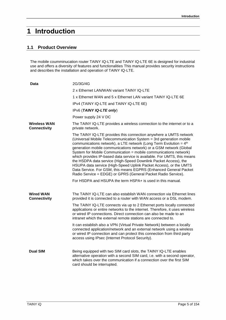
The mobile coumminucation router TAINY IQ-LTE and TAINY IQ-LTE 6E is designed for industrial use and offers a diversity of features and functionalities This manual provides security instructions and describes the installation and operation of TAINY IQ-LTE.
Data 2G/3G/4G
2 x Ethernet LAN/WAN variant TAINY IQ-LTE
1 x Ethernet WAN and 5 x Ethernet LAN variant TAINY IQ-LTE 6E
IPv4 (TAINY IQ-LTE and TAINY IQ-LTE 6E)
IPv6 (TAINY IQ-LTE only)
Power supply 24 V DC
Wireless WAN Connectivity
The TAINY IQ-LTE provides a wireless connection to the internet or to a private network.
The TAINY IQ-LTE provides this connection anywhere a UMTS network (Universal Mobile Telecommunication System = 3rd generation mobile communications network), a LTE network (Long Term Evolution = 4th generation mobile communications network) or a GSM network (Global System for Mobile Communication = mobile communications network) which provides IP-based data service is available. For UMTS, this means the HSDPA data service (High-Speed Downlink Packet Access), the HSUPA data service (High-Speed Uplink Packet Access), or the UMTS Data Service. For GSM, this means EGPRS (Enhanced General Packet Radio Service = EDGE) or GPRS (General Packet Radio Service).
For HSDPA and HSUPA the term HSPA+ is used in this manual.
Wired WAN Connectivity
The TAINY IQ-LTE can also establish WAN connection via Ethernet lines provided it is connected to a router with WAN access or a DSL modem.
The TAINY IQ-LTE connects via up to 2 Ethernet ports locally connected applications or entire networks to the internet. Therefore, it uses wireless or wired IP connections. Direct connection can also be made to an intranet which the external remote stations are connected to.
It can establish also a VPN (Virtual Private Network) between a locally connected application/network and an external network using a wireless or wired IP connection and can protect this connection from third party access using IPsec (Internet Protocol Security).
Dual SIM Being equipped with two SIM card slots, the TAINY IQ-LTE enables alternative operation with a second SIM card, i.e. with a second operator, which takes over the communication if a connection over the first SIM card should be interrupted.

Introduction
Page 6 of 154 TAINY iQ
1.2 Terms
This section briefly explains the terms most frequently used in this manual.
APN
INTERNET
Router/
Firewall
Wireless IP connection
via HSPA+, UMTS, (E-)GPRS
Local networkExternal network
Local
application
Admin PC
Local
application
Admin PC
External
remote
station
LTE, HSPA+,
UMTS
(E-)GPRS
TAINY
APN
INTERNET
Router/
Firewall
Wireless IP connection
via HSPA+, UMTS, (E-)GPRS
Local networkExternal network
Local
Application
Admin PC
Local
application
Admin PC
External
remote
station
LTE, HSPA+,
UMTS
(E-)GPRS
TAINY
Local network Network connected to the local interface of the TAINY IQ-LTE. The local network contains at least one local application.
Local interfaces ETH 0, ETH 1 (10/100-Base-T)
Interfaces of the TAINY IQ-LTE for connection of the local network. The interfaces are marked on the device as ETH 0 to ETH 1 (10/100 Base-T). The Ethernet interfaces have data transfer rates of 10 MBits or 100 MBits (auto-sensing function MDI / MDIX). You can use ETH0 and ETH1 as separate LAN network interfaces, or ETH0 as a wired WAN connection (see chapter 6.5). Between the network on ETH0 (for instance 192.168.2.1) and ETH1 (for instance 192.168.1.1) is internally routed.
Lokale Schnittstellen ETH 0, ETH 1, ETH 2, ETH 3, ETH 4, ETH 5 (10/100-Base-T)
Interfaces of the TAINY IQ-LTE 6E for connection of the local network. The interfaces are marked on the device as ETH 0 to ETH 5 (10/100 Base-T). The Ethernet interfaces have data transfer rates of 10 MBits or 100 MBits (auto-sensing function MDI / MDIX). While the router function of ETH 0 is directly connected to TAINY iQ 6E, ETH 1 to ETH 5 are connected to the router function via a switch. You can send data between ETH 0 and all other ports (see chapter 9.3) or you use ETH 0 as a wired WAN connection (siehe Kapitel 6.5). ETH 1 to ETH 5 can be grouped to VLANs.
Local application Local applications are network components of the local network, for example a programmable controller, a machine with an Ethernet interface for remote monitoring, or a notebook or desktop PC or the Admin PC.
Introduction
TAINY iQ Page 7 of 154
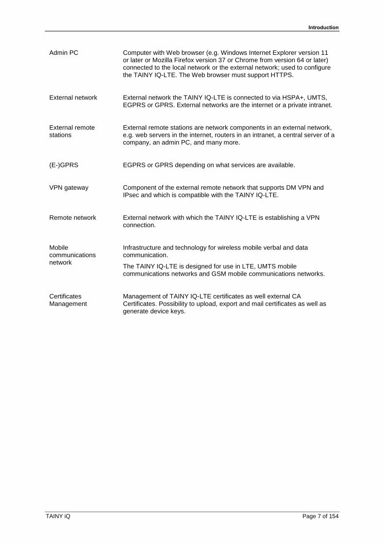
Admin PC Computer with Web browser (e.g. Windows Internet Explorer version 11 or later or Mozilla Firefox version 37 or Chrome from version 64 or later) connected to the local network or the external network; used to configure the TAINY IQ-LTE. The Web browser must support HTTPS.
External network External network the TAINY IQ-LTE is connected to via HSPA+, UMTS, EGPRS or GPRS. External networks are the internet or a private intranet.
External remote stations
External remote stations are network components in an external network, e.g. web servers in the internet, routers in an intranet, a central server of a company, an admin PC, and many more.
(E-)GPRS EGPRS or GPRS depending on what services are available.
VPN gateway Component of the external remote network that supports DM VPN and IPsec and which is compatible with the TAINY IQ-LTE.
Remote network External network with which the TAINY IQ-LTE is establishing a VPN connection.
Mobile communications network
Infrastructure and technology for wireless mobile verbal and data communication.
The TAINY IQ-LTE is designed for use in LTE, UMTS mobile communications networks and GSM mobile communications networks.
Certificates Management
Management of TAINY IQ-LTE certificates as well external CA Certificates. Possibility to upload, export and mail certificates as well as generate device keys.
Introduction
Page 8 of 154 TAINY iQ
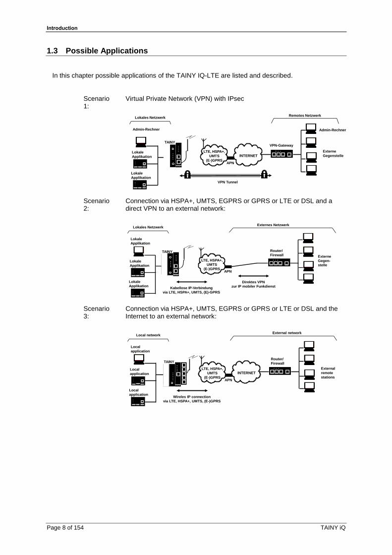
1.3 Possible Applications
In this chapter possible applications of the TAINY IQ-LTE are listed and described.
Scenario 1:
Virtual Private Network (VPN) with IPsec
APN
LTE, HSPA+,
UMTS
(E-)GPRS
INTERNET
VPN-Gateway
Lokales NetzwerkRemotes Netzwerk
Lokale
Applikation
Admin-Rechner
Lokale
Applikation
Admin-Rechner
Externe
Gegenstelle
VPN Tunnel
TAINY
Scenario 2:
Connection via HSPA+, UMTS, EGPRS or GPRS or LTE or DSL and a direct VPN to an external network:
Externe
Gegen-
stelle
APN
Lokale
Applikation
Router/
Firewall
Kabellose IP-Verbindung
via LTE, HSPA+, UMTS, (E)-GPRS
Direktes VPN
zur IP mobiler Funkdienst
Lokale
Applikation
Lokale
Applikation
Lokales NetzwerkExternes Netzwerk
LTE, HSPA+,
UMTS
(E-)GPRS
TAINY
Scenario 3:
Connection via HSPA+, UMTS, EGPRS or GPRS or LTE or DSL and the Internet to an external network:
APN
INTERNET
Router/
Firewall
Wireles IP connection
via LTE, HSPA+, UMTS, (E-)GPRS
Local networkExternal network
Local
application
Local
application
Local
application
External
remote
stations
LTE, HSPA+,
UMTS
(E-)GPRS
TAINY

Introduction
TAINY iQ Page 9 of 154
Scenario 4:
Connection via DSL and the Internet to an external network.
APN
INTERNET
Router/
Firewall
IP connection
via DSL
Local networkExternal network
Local
application
Local
application
Local
application
External
remote
stations
TAINY Router/
Firewall
Local applications could be, for example, a programmable controller, a machine with an Ethernet interface for remote monitoring, or a notebook or desktop PC. These applications use the TAINY IQ-LTE to access an external network just as if they had a direct, local connection to the external network.
Scenario 5 Connection via DSL and/or mobile communication via the internet o an external network or redundancy by VRRP.
INTERNET
Router/
Firewall
IP connection
via DSL & Cellular net
Local networkExternal network
Local
application
Local
application
Local
application
External
remote
stations
TAINY
TAINY
Router/
Firewall
Router/
Firewall
DSL
DSL
UMTS
LTE
VRRP
Offers maximum reliability:
Scenario 6:
INTERNET
Router/
Firewall
IP connection
via DSL & Cellular net
Local networkExternal network
Automation device
Local
application
External
remote
station
TAINY Router/
Firewall
DSL
UMTS
LTE
RS232 for serial
communication
process control system
with connection to the
automation device
Serial Communication

Introduction
Page 10 of 154 TAINY iQ
Scenario 7:
Connection via IPsec- to VPN
Router/
Firewall
Local networkExternal network
Local
application
Local
application
Local
application
External
remote
station
Router/
FirewallService
remote
station
VPN Tunnel
Service VPN Tunnel (deactivatable)
ON
OFF
VPN-
switch
VPN-
signal indicator
VPN-
notificationINTERNET
TAINY Router/
Firewall
DSL
LTE
Service technician:
Maintenance / Accident
IPsec-VPN: Constant VPN-connection and disengageable VPN service access (switchable via digital input and messaging by email and signal lamp)
Scenario 8:
Virtual Private Network (VPN) mit IPsec
APN
LTE, HSPA+,
UMTS
(E-)GPRS
INTERNET
VPN-Gateway
Local networkRemote network
Local
Application
Admin PC
Local
Application
Admin PC
External
remote
station
VPN Tunnel
TAINY
Scenario 9:
Connection via HSPA +, UMTS, EGPRS or GPRS or LTE or DSL and a direct VPN to the external network
External
remote
station
APN
Local
application
Router/
Firewall
Wireless IP connection
via LTE, HSPA+, UMTS, (E)-GPRS
Direct VPN
to IP cellular service
Local
application
Local
application
Local NetworkRemote network
LTE, HSPA+,
UMTS
(E-)GPRS
TAINY

Introduction
TAINY iQ Page 11 of 154
Scenario 10:
Connection via HSPA +, UMTS, EGPRS or GPRS or LTE or DSL and the Internet to the external network
APN
INTERNET
Router/
Firewall
Wireless IP connection
via LTE, HSPA+, UMTS, (E-)GPRS
Local networkExternal network
Local
application
Local
application
Local
application
External
remote
station
LTE, HSPA+,
UMTS
(E-)GPRS
TAINY
Scenario 11:
Connection via DSL and Internet to an external network
APN
INTERNET
Router/
Firewall
IP connection
via DSL
Local networkExternal network
Local
application
Local
application
Local
application
External
remote
station
TAINY Router/
Firewall
Local applications could be, for example, a programmable controller, a machine with Ethernet interface for remote monitoring or a notebook or computer. These applications use TAINY iQ to gain access to an external network as if they were connected directly to the external network.
Introduction
Page 12 of 154 TAINY iQ
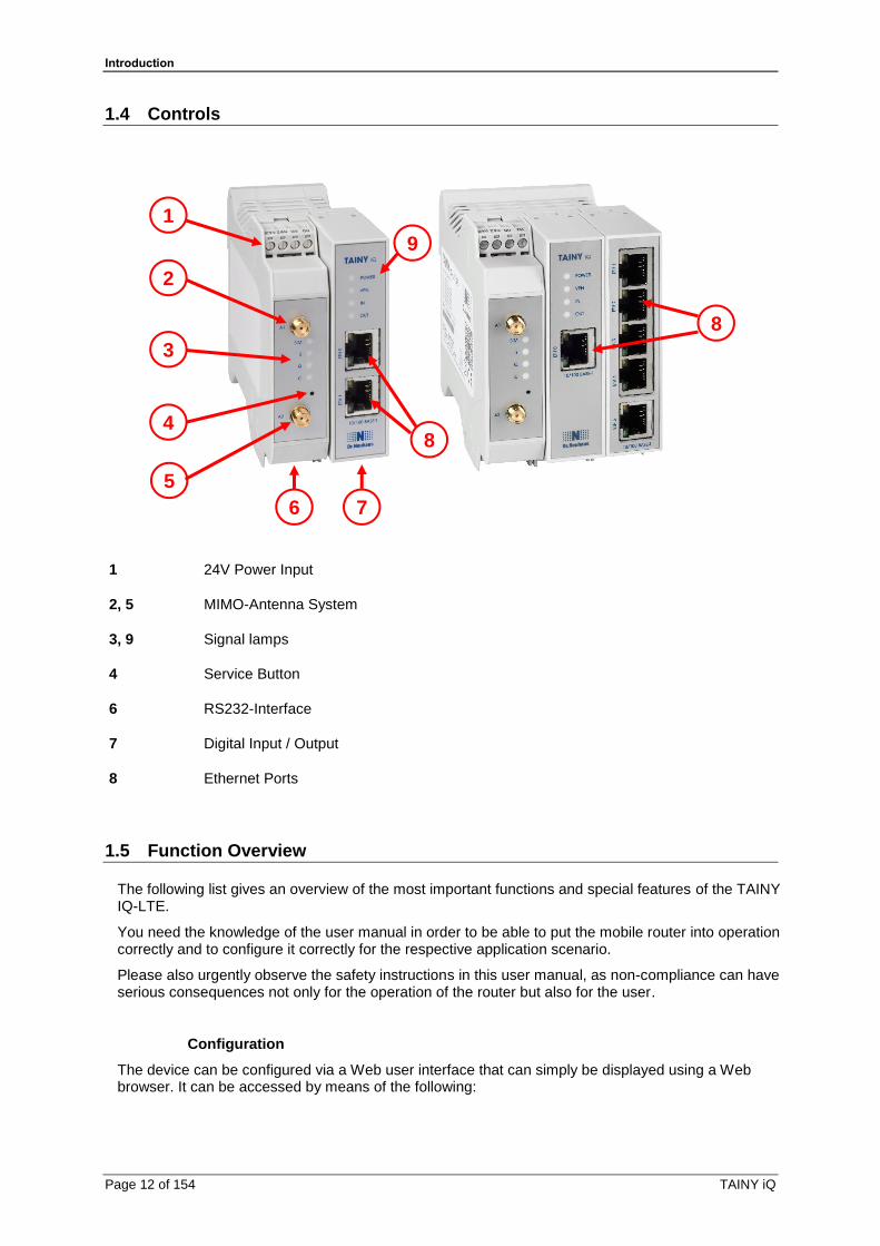
1.4 Controls
1
2
3
4
5
8
8
9
6 7
1 24V Power Input
2, 5 MIMO-Antenna System
3, 9 Signal lamps
4 Service Button
6 RS232-Interface
7 Digital Input / Output
8 Ethernet Ports
1.5 Function Overview
The following list gives an overview of the most important functions and special features of the TAINY IQ-LTE.
You need the knowledge of the user manual in order to be able to put the mobile router into operation correctly and to configure it correctly for the respective application scenario.
Please also urgently observe the safety instructions in this user manual, as non-compliance can have serious consequences not only for the operation of the router but also for the user.
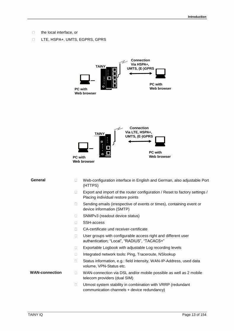
Configuration
The device can be configured via a Web user interface that can simply be displayed using a Web browser. It can be accessed by means of the following:
Introduction
TAINY iQ Page 13 of 154
the local interface, or
LTE, HSPA+, UMTS, EGPRS, GPRS
Connection
Via HSPA+,
UMTS, (E-)GPRS
PC with
Web browser
PC with
Web browser
TAINY
Connection
Via LTE, HSPA+,
UMTS, (E-)GPRS
PC with
Web browser
PC with
Web browser
TAINY
General Web-configuration interface in English and German, also adjustable Port
(HTTPS)
Export and import of the router configuration / Reset to factory settings /
Placing individual restore points
Sending emails (irrespective of events or times), containing event or
device information (SMTP)
SNMPv3 (readout device status)
SSH-access
CA-certificate und receiver-certificate
User groups with configurable access right and different user
authentication; “Local”, “RADIUS”, “TACACS+”
Exportable Logbook with adjustable Log recording levels
Integrated network tools: Ping, Traceroute, NSlookup
Status information, e.g.: field intensity, WAN-IP-Address, used data
volume, VPN-Status etc.
WAN-connection WAN-connection via DSL and/or mobile possible as well as 2 mobile
telecom providers (dual SIM)
Utmost system stability in combination with VRRP (redundant
communication channels + device redundancy)

Introduction
Page 14 of 154 TAINY iQ
LAN-features Allocation of multiple LAN-IP-Addresses possible (also various
networks)
Modus: "Automatic", "10M / Half duplex", “10M / Full duplex”, “100M /
Half duplex”, “100M / Full duplex”
DNS-Server
DHCP-Server
Dynamic IP-address-range
Static DHCP-allocation
DHCP-Relay
VRRP (Virtual Router Redundancy Protocol) for the use of redundancy
devices
VRRP-ID-allocation
static/dynamic VRRP-Priorities
VPN-features IPsec IKEv1 (max. 10 simultaneous tunnel connections guaranteed)
Server or Client
Main- & Aggressive-Mode
Authentication-Modi: "Pre-Shared-Key", "Receiver certificate",
"CA-certificate"
Cryptographic technique: "3DES", "AES-128", "AES-192",
"AES-256"
HASH-technique: "MD5", "SHA-1", "SAH-256", "SAH-384",
"SAH-512"
NAT-Traversal
Dead Peer Detection (DPD)
DM-VPN (Dynamic Multipoint VPN)
GRE
NHRP
Firewall-features Package filter rules individual adjustable for LAN-, WAN-, VPN-
interfaces
Random number of filter rules
Data packages of address ranges/individual addresses
accept/discard/reject
Classification of filter rules according to protocol:
TCP/UDP/ICMP
Rules for remote access individual adjustable for WAN-, VPN-interfaces
Remote access of address ranges/individual addresses
accepted/ discarded/ rejected
Classification of the remote accesses according to service:
HTTPS/SNMP/SSH/ICMP
Port forwarding
Port forwarding of address ranges/individual addresses to
destination address
Port-implementation oder transfer

Introduction
TAINY iQ Page 15 of 154
Classification of Port forwarding according to protocol:
TCP/UDP
Unknown data traffic can be forwarded to a defined destination
addres (Exposed Host)
MAC-Tables
MAC-Address can be allocated to a defined Ethernet-Port
Logging in a separate Firewall-Log (analysis of the entire data traffic)
Instructions and Safety Information
Page 16 of 154 TAINY iQ
2 Instructions and Safety Information
The product TAINY IQ-LTE complies with the European standard EN 62368-1, Safety of Information Technology Equipment.
For a safe commissioning, please refer to the current data sheet and the documentation of your product.
You can view all the relevant documentation and additional information on your product at www.sagemcom.com
2.1 Intended Use
The device may only be used as described in this manual and in accordance with the technical data as mentioned in the data sheets. The device may only be used for intended application in the data sheets and in this document. Proper transport, storage, set-up and assembly, as well as careful operation and service are prerequisite for a fault-free and safe operation of the product.
2.2 Unintended Use
Do not use TAINY IQ-LTE without a secure backup in any application which malfunctions could lead to property damage, fatal injuries or death.
2.3 Qualified Personnel
This device may only be installed, operated, commissioned and decommissioned by an electrically skilled person. An electrically skilled person provides sufficient knowledge and experience due to technical training to:
Turn on, turn off, disconnect, ground and short-circuit electric circuits and devices,
Duly apply and maintain safety guards in accordance with effective safety requirements,
Take emergency care of injured
Instructions and Safety Information
TAINY iQ Page 17 of 154
2.4 Classification of safety instructions
This manual contains instructions which you must follow for your own personal safety and to prevent property damage. A warning triangle is provided to draw your attention to instructions for your personal safety; no warning triangle is provided for instructions for general property damage. Warning notices are provided in the following sequence according to the decreasing severity of the hazard.
Danger
Indicates a hazardous situation that, if not avoided, will result in death or serious injury.
Warning
Indicates a hazardous situation that, if not avoided, could result in death or serious injury.
Caution
Indicates a hazardous situation that, if not avoided, will result in minor or moderate injury.
Caution
Indicates a hazardous situation, that if not avoided could result in property damage or loss.
Attention
Indicates that an undesired result could occur, if the given instructions are not followed.
Note
Indicates help and advice to improve the operation or set up process.
In the event of multiple hazard levels simultaneously, the warning notice of the highest respective level always applies. If a warning of personal injury is provided in a warning notice with a warning triangle, a warning of property damage can also be added.
Instructions and Safety Information
Page 18 of 154 TAINY iQ
2.5 Safety Instructions
The product TAINY IQ-LTE complies with the European standard DIN EN 62368-1, Audio and Video Information and Communication technology equipment – part1: Safety requirement.
Read the installation and user instructions carefully before installing and using the device.
Read the installation instructions carefully before using the device.
General
Danger
Risk of fatal injury by electric shock
• Never install or operate a damaged device.
• Never install or operate if the cables connected to the device are damaged.
• Never connect the device to damaged cables.
• Do not install or operate device outdoors.
• Do not install or operate device in a damp environment.
• Never use device for any other then the intended use.
• Keep device out of reach of children.
Qualified personnel
Danger
Risk of fatal injury by electric shock due to lack of knowledge
• Installation and operation must be carried out by skilled personnel only.
• Also the installation of joining devices such as the antenna must be carried out by skilled personnel only.
• Read manual carefully before installation and operation.
• Follow the safety instructions at all times.
• Make sure the device is electrically isolated before inserting the SIM card.
Intended use

Instructions and Safety Information
TAINY iQ Page 19 of 154
Warning
Risk of injury or damaged device
• Only use device for its intended purpose.
• Operate the device in accordance with the electrical data as stated in the data sheet.
• Only assemble and disassemble device as described in the manual.
• Transport and store device with great care.
Handling cables
Warning
Risk of electric shock due to wrong handling of cables
• Never remove the plug from the socket by pulling the cable, always pull the plug.
• Never route cables over sharp edges or corners without an edge guard.
• Ensure sufficient strain relief for the cable.

Instructions and Safety Information
Page 20 of 154 TAINY iQ
Antenna assembly
Attention
Risk of diminished transmission and reception
• Mind the bending radii when routing the antenna cable.
• The minimum bending radius of the cable may not exceed:
o statically 5 times its diameter
o dynamically 15 times its diameter
HF exposure
Warning
Risk of interference and damage of other devices due to radio transmitters
• Never use the device in an environment in which the operation of radio equipment is prohibited.
• People with hearing aids or pacemakers may not get near the device. If in doubt ask a medical doctor or the manufacturer of medical device for advice.
• The internal/external antennas of this device must always be placed and operated at least 20 cm away from people.
Warning
Risk of property damage due to demagnetization
• Do not store diskettes, credit cards or any other magnetic data carrier in the vicinity of the device
Caution
Risk of breach legal regulations and interference with other transmitters
• Mind the limit of public exposure to electromagnetic fields (0 hertz to 300 gigahertz) when using a directional antenna. See the council recommendation 199/519/EG dated July, 12, 1999 for details.
• The internal/external antennas of this device must always be placed and operated at least 20 cm away from people
• The antennas must be commissioned and operated in a way they could not interact with other antennas or transmitters.
Warning
Risk of data loss due to demagnetization
• Do not store diskettes, credit cards or any other magnetic data carrier in the vicinity of the device.
Instructions and Safety Information
TAINY iQ Page 21 of 154
External Power Supply
Warning
Risk of damaging the device due to false voltage
• Use only power supplies that are conforming with the DIN EN 62368-1 Annex Q standard.
• The output voltage of the supply must not exceed 60 V DC.
• The output of the external power supply must be short circuit proofed.
Warning
Risk of damaging the device due false battery connection
• Ensure that an all-pole disconnecting device (battery main switch) with sufficient disconnecting capacity and fuse with sufficient disconnecting capacity (fuse set 32 V, 3A) is provided between the device and the battery or rechargeable battery.
Warning
Risk of damaging the device due to false supply
• Use only power supplies that are conform to the standard IEV/EN 62368-1 Annex Q “Limited Power Source”.
• The external power supply must also comply with the requirements for NEC Class 2 circuit as defined in the National Electric Code (ANSI/NFPA 70).
In port and switching output
Warning
Risk of property damage or injuries due to false voltage
• The in port and switching output are both galvanic insulated against all other terminals of the TAINY IQ-LTE. If the external installation being connected to the TAINY IQ-LTE connects a signal of the in port and switching output galvanically to a power supply signal of the TAINY IQ-LTE, the voltage between each signal of the in port and switching output and each signal of the power supply may not exceed 60V.

Instructions and Safety Information
Page 22 of 154 TAINY iQ
Caution: Costs
Caution
Risk of additional financial costs
• Bear in mind that the exchange of data packages is subject to charges whether a connection to a remote station is maintained or re-established.
• Unsuccessful attempts to connect to incorrect addresses or switch off remote stations are subject to charges.
Instructions and Safety Information
TAINY iQ Page 23 of 154
Firmware with open source GPL/LGPL
The firmware for TAINY IQ-LTE contains open source software under GPL/LGPL conditions. We provide you with the source code in accordance with Section 3b of GPL and Section 6b of LGPL. You can find the source code on our webpage, www.neuhaus.de.
As an alternative, you can also request the source code from us on CD-ROM. Send your email to [email protected]. Please enter "Open Source iQ" in the subject line of your email so that we can easily filter out your message.
The license conditions for the open source software can be found in the source code on the product CD.
Firmware with OpenBSD
The firmware of the TAINY IQ-LTE contains parts from the OpenBSD software. Whenever OpenBSD software is used, the following copyright note must be reproduced:
* Copyright (c) 1982, 1986, 1990, 1991, 1993
* The Regents of the University of California. All rights reserved.
*
* Redistribution and use in source and binary forms, with or without
* modification, are permitted provided that the following conditions
* are met:
* 1. Redistributions of source code must retain the above copyright
* notice, this list of conditions and the following disclaimer.
* 2. Redistributions in binary form must reproduce the above copyright
* notice, this list of conditions and the following disclaimer in the
* documentation and/or other materials provided with the distribution.
* 3. All advertising materials mentioning features or use of this software
* must display the following acknowledgement:
* This product includes software developed by the University of
* California, Berkeley and its contributors.
* 4. Neither the name of the University nor the names of its contributors
* may be used to endorse or promote products derived from this software
* without specific prior written permission.
*
* THIS SOFTWARE IS PROVIDED BY THE REGENTS AND CONTRIBUTORS ``AS IS'' AND
* ANY EXPRESS OR IMPLIED WARRANTIES, INCLUDING, BUT NOT LIMITED TO, THE
* IMPLIED WARRANTIES OF MERCHANTABILITY AND FITNESS FOR A PARTICULAR
* PURPOSE
* ARE DISCLAIMED. IN NO EVENT SHALL THE REGENTS OR CONTRIBUTORS BE LIABLE
* FOR ANY DIRECT, INDIRECT, INCIDENTAL, SPECIAL, EXEMPLARY, OR
* CONSEQUENTIAL
* DAMAGES (INCLUDING, BUT NOT LIMITED TO, PROCUREMENT OF SUBSTITUTE GOODS
* OR SERVICES; LOSS OF USE, DATA, OR PROFITS; OR BUSINESS INTERRUPTION)
* HOWEVER CAUSED AND ON ANY THEORY OF LIABILITY,
* WHETHER IN CONTRACT, STRICT
* LIABILITY, OR TORT (INCLUDING NEGLIGENCE OR OTHERWISE) ARISING IN ANY WAY
* OUT OF THE USE OF THIS SOFTWARE, EVEN IF ADVISED OF THE POSSIBILITY OF
* SUCH DAMAGE.

Installation
Page 24 of 154 TAINY iQ
3 Installation
3.1 Step by step
Please always also refer to the mentioned chapter. This is not to be seen as a brief instruction and replacement for this manual. The TAINY IQ-LTE is set up by the following steps:
Step
Chapter
1. First familiarise yourself with the preconditions for operating the TAINY IQ-LTE.
1
2. Read the safety instructions and other instructions at the beginning of this user manual very carefully and make sure to understand and follow them.
2,3
3. Also familiarise yourself with the control elements, connections and operating state indicators of the TAINY IQ-LTE before installation.
1
4. Disconnect the TAINY IQ-LTE from the power supply.
3
5. Connect the web browser of your pc to the local interface (10/100 BASE-T) of the TAINY IQ-LTE.
4
6. Enter the PIN(s) –personal identification number – of the SIM card(s) into the web user interface of TAINY IQ-LTE.
7
7. Insert the SIM card(s) into the device.
4
8. Connect the antenna-system.
4
9. Connect the TAINY IQ-LTE to a power supply.
3.3
10. Set up the TAINY IQ-LTE according to your requirements.
4 to 15
11. Connect your local application.
4

Installation
TAINY iQ Page 25 of 154
3.2 Preconditions and Information
To operate the TAINY IQ-LTE, the following information must be on hand and the following preconditions must be fulfilled:
Antenna-System
One or two antennas as described in chapter 3.6.
Power supply A 24 V installation. See chapter 3.3.
SIM card A SIM card from the chosen GSM network operator.
PIN The PIN for the SIM card.
HSPA+ / UMTS EGPRS / GPRS activation
The services LTE, HSPA+, UMTS data and / or EGPRS or GPRS must be enabled on the SIM card by your mobile communications network provider.
The access data must be known:
Access Point Name (APN)
User name
Password

Installation
Page 26 of 154 TAINY iQ
3.3 Connection to 24V/0V power supply
Please read the safety instruction carefully before installation.
The TAINY IQ-LTE operates with direct current of from 12-60 V DC, nominally 24 V DC.
The external power supply is connected at the screw terminals on the left-hand side of the device.
The current consumption is round about 450 mA at 12 V and 100 mA at 60 V (IBurst>1.26 A)
Warning
Risk of injuries or property damage due to false voltage
• The In port and switching output are both galvanically insulated
against all other terminals of the TAINY IQ-LTE. If the external
installation being connected to the TAINY IQ-LTE connects a signal
of the In port and switching output galvanically to a power supply
signal of the TAINY IQ-LTE, the voltage between each signal of the
In port and switching output and each signal of the power supply
may not exceed 60V.
Terminals
Cross-section rigid/flexible 0,2-2,5 mm²
AWG 24-14
Isolation stripped length L 7 mm
Locked torque 0,5-0,6 Nm / 4,4-5,3 lb in
To ensure a reliable and finger-safe connection, strip the isolations as written in the table above and use end sleeves for flexible cables. Close unused terminals.
The maximum valid cross-section of flexible cables using end sleeves without plastic shells is 2,5 mm².
The maximum valid cross-section for flexible cables using end sleeves with plastic shells is 0,25 mm².
Installation
TAINY iQ Page 27 of 154
3.4 Ethernet Ports (ETH0, ETH1, ETH2, ETH3, ETH4, ETH5)
The Ethernet Ports ETH1 to ETH5 (10/100 Base-T) are used to connect the local network with local applications e.g. a programmable controller, a machine with an Ethernet interface for remote monitoring, or a notebook or desktop PC.
The TAINY iQ acts as a switch between the available interfaces.
To set up the TAINY iQ, connect the Admin PC with Web browser here.
The Ethernet Ports ETH0 is dedicated to establish wired WAN-DSL/LAN connections, however it can also be used as an additional port to connect the local network with local applications. See chapter 0
CAT5 cables shall be used. All interfaces supports auto negotiation. It is thus detected automatically whether a transmission speed of 10 Mbit/s or 100 Mbit/s is used on the Ethernet. It is also automatically detected whether cross-over or one-to-one cables are used.
3.5 Ethernet Ports (ETH0 and ETH1)
The Ethernet Port ETH1 (10/100 Base-T) is used to connect the local network with local applications e.g. a programmable controller, a machine with an Ethernet interface for remote monitoring, or a notebook or desktop PC.
The TAINY IQ-LTE acts as a switch between the available interfaces.
To set up the TAINY IQ-LTE, connect the Admin PC with Web browser here.
The Ethernet Ports ETH0 is dedicated to establish wired WAN-DSL/LAN connections, however it can also be used as an additional port to connect the local network with local applications. See chapter 0
CAT5 cables shall be used. All interfaces supports auto negotiation. It is thus detected automatically whether a transmission speed of 10 Mbit/s or 100 Mbit/s is used on the Ethernet. It is also automatically detected whether cross-over or one-to-one cables are used.
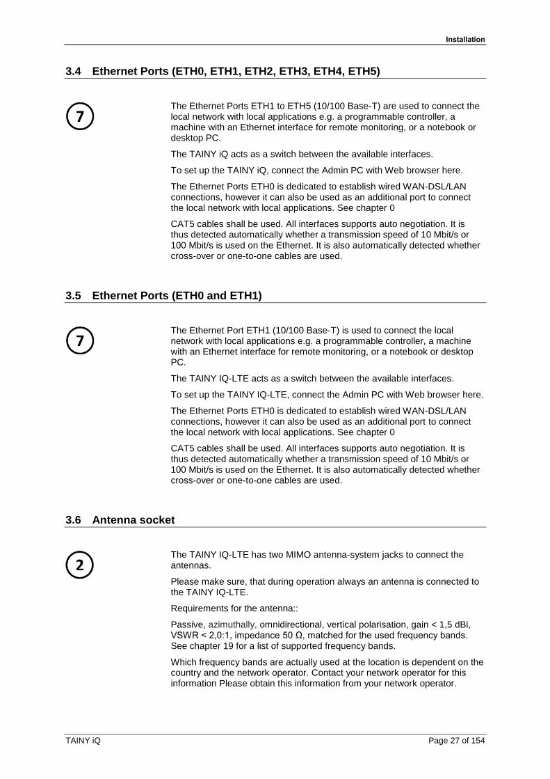
3.6 Antenna socket
The TAINY IQ-LTE has two MIMO antenna-system jacks to connect the antennas.
Please make sure, that during operation always an antenna is connected to the TAINY IQ-LTE.
Requirements for the antenna::
Passive, azimuthally, omnidirectional, vertical polarisation, gain < 1,5 dBi, VSWR < 2,0:1, impedance 50 Ω, matched for the used frequency bands. See chapter 19 for a list of supported frequency bands.
Which frequency bands are actually used at the location is dependent on the country and the network operator. Contact your network operator for this information Please obtain this information from your network operator.
Installation
Page 28 of 154 TAINY iQ
Caution
Risk of property damage and interference with other devices
• Please use only antennas from the accessories line for TAINY IQ-LTE. These antennas have been tested by us and guarantee the described product features.
Attention
Risk of diminished transmission and reception
• When installing the antenna, a sufficiently good signal quality must be ensured (CSQ > 11).
• Use the signal lamps of the TAINY IQ-LTE which show the signal quality or the webpage Status Overview, see chapter 4.1.
• Make sure that there are no large metal objects (e.g. reinforced concrete) close to the antenna.
• Read the antenna’s installation and user guide before operating it.
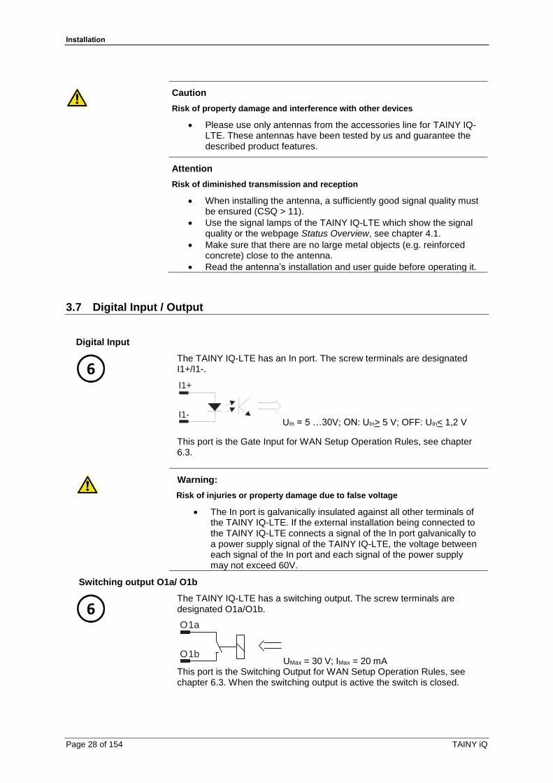
3.7 Digital Input / Output
Digital Input
The TAINY IQ-LTE has an In port. The screw terminals are designated I1+/I1-.
UIn = 5 …30V; ON: UIn> 5 V; OFF: UIn< 1,2 V
This port is the Gate Input for WAN Setup Operation Rules, see chapter 6.3.
Warning:
Risk of injuries or property damage due to false voltage
• The In port is galvanically insulated against all other terminals of the TAINY IQ-LTE. If the external installation being connected to the TAINY IQ-LTE connects a signal of the In port galvanically to a power supply signal of the TAINY IQ-LTE, the voltage between each signal of the In port and each signal of the power supply may not exceed 60V.
Switching output O1a/ O1b
The TAINY IQ-LTE has a switching output. The screw terminals are designated O1a/O1b.
UMax = 30 V; IMax = 20 mA This port is the Switching Output for WAN Setup Operation Rules, see chapter 6.3. When the switching output is active the switch is closed.
O1a
O1b
I1+
I1-

Installation
TAINY iQ Page 29 of 154
Warning
Risk of injuries or property damage due to false voltage
• The switching output is galvanically insulated against all other terminals of the TAINY IQ-LTE. If the external installation being connected to the TAINY IQ-LTE connects a signal of the switching output galvanically to a power supply signal of the TAINY IQ-LTE, the voltage between each signal of the switching output and each signal of the power supply may not exceed 60V.

Installation
Page 30 of 154 TAINY iQ
3.8 Serial RS232 interface
RS232
5
TAINY IQ-LTE has an RS232 interface with the following connector assignment:
TX Transmit Data Line for outgoing (DTE sent) data (negative logic)
RX Receive Data Line for incoming (to be received by DTE) data (negative logic)
A- Data (A-) RS485 interface! This feature is currently not supported
B+ Data (B+) RS485 interface! This feature is currently not supported
GND Ground Common ground connection
3.9 Signal lamps
Signal lamps The TAINY IQ-LTE is equipped with a set of signal lamps for display of the operating status.
Power Supply Signal
LED Status Meaning
POWER Always OFF No supply voltage available or defect.
Always ON In operation

Installation
TAINY iQ Page 31 of 154
WAN Status Signals
LED Status Meaning
SIM 1 Constantly OFF No SIM active
Constantly ON
Flashing
SIM 1 active
SIM 2 active
S (Status) Flashing Not registered to mobile net
Constantly ON WAN IP connection available (Cellular or Ethernet)
Q (Quality) Flashing slowly Logging into the GSM network
Flash 1 time with interval Field strength poor
Flash 2 times with interval Field strength moderate
Flash 3 times with interval Field strength good
Constantly ON Field strength very good
Constantly OFF Field strength info not available
C (Connect) Always OFF No connection
Flash 1 time with interval GPRS/EDGE connection
Flash 2 times with interval LTE/UMTS connection
Flash 3 times with interval LAN connection
VPN and IO Status Signals
LED Status Meaning
VPN Constantly OFF No VPN tunnel established
Constantly ON One or more VPN tunnel established
IN Constantly OFF Input not active
Constantly ON Input active
Out Constantly OFF Output not active
Constantly ON Output active
Installation
Page 32 of 154 TAINY iQ
Ethernet Ports Status Signals
Each Ethernet Port ETH is equipped with a yellow and green LED which indicates the operational status of the port.
LED Status Meaning
Green Constantly ON Link established
Constantly Off No link established
Yellow Flashing Data transfer
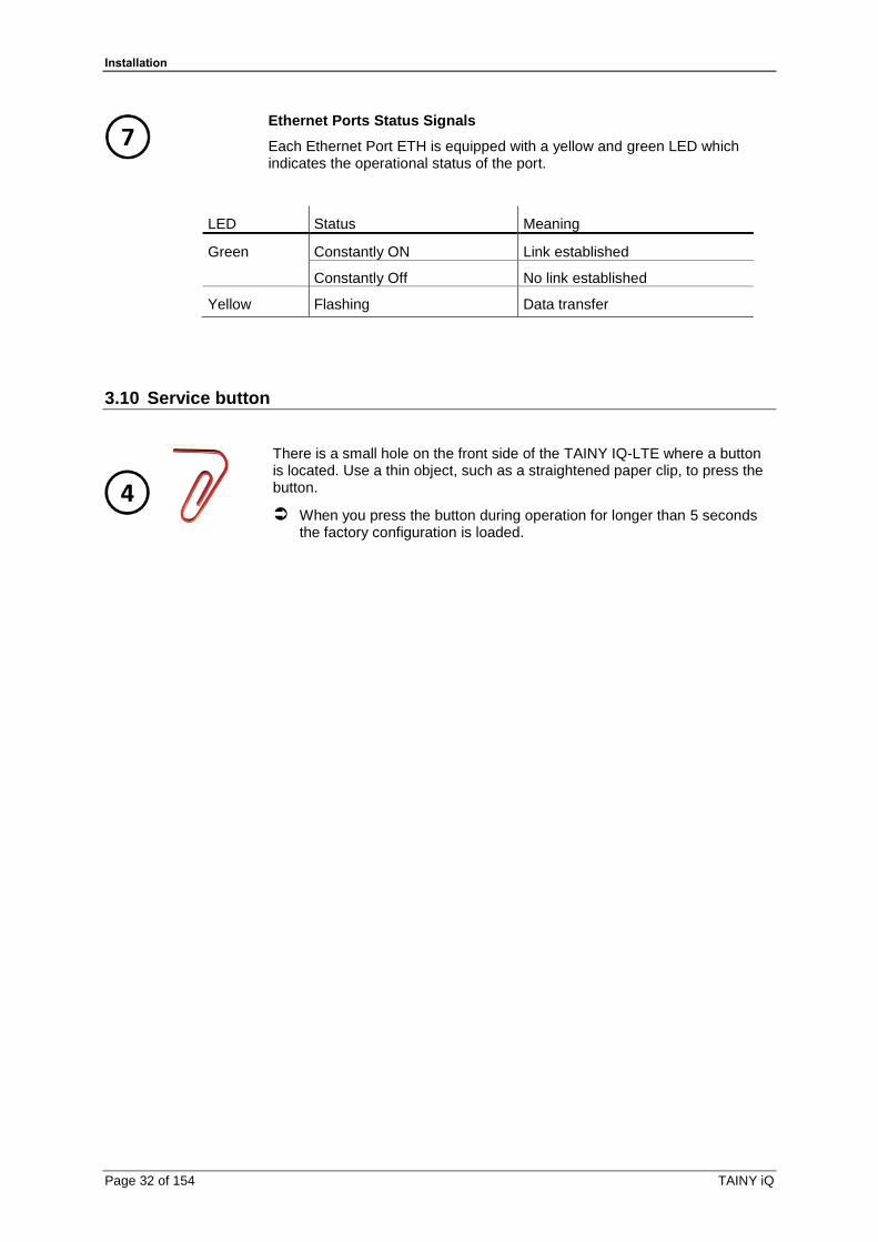
3.10 Service button
There is a small hole on the front side of the TAINY IQ-LTE where a button is located. Use a thin object, such as a straightened paper clip, to press the button.
When you press the button during operation for longer than 5 seconds the factory configuration is loaded.

Installation
TAINY iQ Page 33 of 154
3.11 SIM card holder
Attention
Before inserting a SIM card, enter the PIN of the SIM card in the TAINY IQ-LTE via the Web user interface. See Chapter 6.4
1.
After you have entered the PIN of the SIM card, disconnect the TAINY IQ-LTE completely from the power supply.
2. The drawer(s) for the SIM card(s) is located on the back of the device. Right next to each drawer for the SIM card in the housing aperture there is a small yellow button. Press on this button with a pointed object, for example a pencil.
When the button is pressed the SIM card drawer comes out of the housing.
3. Place the SIM card in the drawer so that its gold-plated contacts remain visible.
4. Then push the drawer with the SIM card completely into the housing and repower the Device.
Caution
Risk of damage or loss of SIM card or the entire device
• Do not under any circumstances insert or remove the SIM card during operation.

Installation
Page 34 of 154 TAINY iQ
3.12 Mounting
The TAINY IQ-LTE is suitable for mounting on cap rails in accordance with DIN EN 50022 (3.5mm x 7.5mmm). The corresponding mount is located on the rear side of the device.
Warning
Risk of injury and property loss due to touching voltage-carrying parts
• After installation, the TAINY IQ-LTE, especially the screw terminal area (Digital Input / Output terminal or 24V terminal) must be covered to avoid accidental touch of voltage-carrying parts.
• Prohibit the intrusion of foreign bodies, e.g. screws, paper clips or other metal parts.
At the rear side the TAINY IQ-LTE has a notch (D) to hook it at the top of the cap rail. One metal spring fastener (C) locks the TAINY IQ-LTE at the bottom of the cap rail. It can be released again by pulling the down with a screw driver.
Mounting:
Hook the TAINY IQ-LTE at the cap rail (A) and push the lower part of the TAINY IQ-LTE carefully in direction to the cap rail (B) until it snap-in the cap rail.

Installation
TAINY iQ Page 35 of 154
Unmounting:
Use a flat-head screw driver to pull down the cap rail fixation (C) until the TAINY IQ-LTE is detached.
Mounting:
Position of the cap rail:
[mm]

Configuration
Page 36 of 154 TAINY iQ
4 Configuration
4.1 Overview Screens
The settings for TAINY IQ-LTE are configured on various tabs. All tabs consist of a tab bar (1) at the top, a menu (3) on the left and the dialog box (2).
For illustration purposes the tab bar as shown in the left text column throughout this manual only reflects the tab in question.
Please also bear in mind that not all tabs of all TAINY IQ-LTE types contain the same information or configuration possibilities in the dialog box. Again see the left text column of this manual for the corresponding device types.
Note
Please remember that the names you enter for a new network i.e. in the entry field “Name” might not exceed 20 digits.
Configuration
TAINY iQ Page 37 of 154
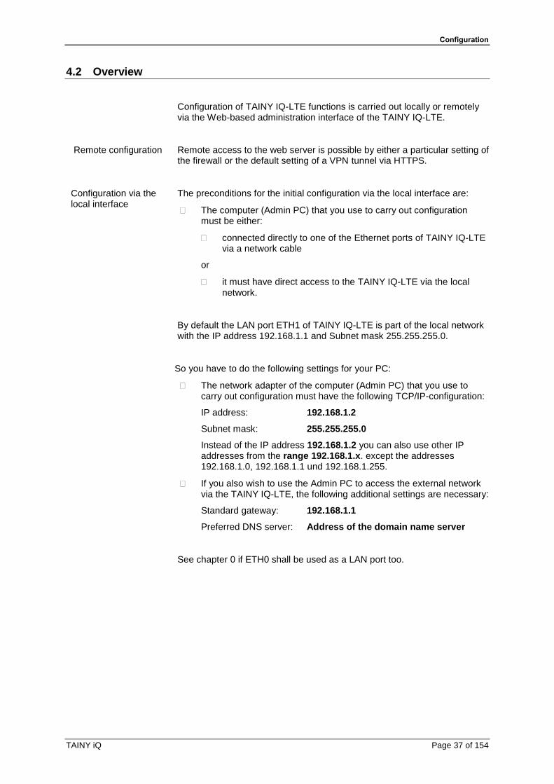
4.2 Overview
Configuration of TAINY IQ-LTE functions is carried out locally or remotely via the Web-based administration interface of the TAINY IQ-LTE.
Remote configuration
Remote access to the web server is possible by either a particular setting of the firewall or the default setting of a VPN tunnel via HTTPS.
Configuration via the local interface
The preconditions for the initial configuration via the local interface are:
The computer (Admin PC) that you use to carry out configuration must be either:
connected directly to one of the Ethernet ports of TAINY IQ-LTE via a network cable
or
it must have direct access to the TAINY IQ-LTE via the local network.
By default the LAN port ETH1 of TAINY IQ-LTE is part of the local network with the IP address 192.168.1.1 and Subnet mask 255.255.255.0.
So you have to do the following settings for your PC:
The network adapter of the computer (Admin PC) that you use to carry out configuration must have the following TCP/IP-configuration:
IP address: 192.168.1.2
Subnet mask: 255.255.255.0
Instead of the IP address 192.168.1.2 you can also use other IP addresses from the range 192.168.1.x. except the addresses 192.168.1.0, 192.168.1.1 und 192.168.1.255.
If you also wish to use the Admin PC to access the external network via the TAINY IQ-LTE, the following additional settings are necessary:
Standard gateway: 192.168.1.1
Preferred DNS server: Address of the domain name server
See chapter 0 if ETH0 shall be used as a LAN port too.
Configuration
Page 38 of 154 TAINY iQ
4.3 Valid characters for user names, passwords and other inputs
Valid characters For user names, passwords, host names, APN and PIN the following ASCII characters may be used:
usernames and passwords
# @ ~ % $ , * ' = ! + - \ / ? ( ) . : ; [ ] _ | 0 1 2 3 4 5 6 7 8 9 A B C D E F G H I J K L M N O P Q R S T U V W X Y Z a b c d e f g h i j k l m n o p q r s t u v w x y z
hostnames and APN
. -
0 1 2 3 4 5 6 7 8 9 A B C D E F G H I J K L M N O P Q R S T U V W X Y Z a b c d e f g h i j k l m n o p q r s t u v w x y z
PIN PINs support numeric characters only 0 1 2 3 4 5 6 7 8 9
Some parameters accept additional special characters.
4.4 Establishing a configuration connection
Set up a Web browser
Open the start page of the TAINY IQ-LTE
Proceed as follows:
Launch the Web browser (e.g. MS Internet Explorer version 11 or later or Mozilla Firefox version 37 or later, Chrome version x or later).
Enter the full TAINY IQ-LTE address in the address line of the browser.
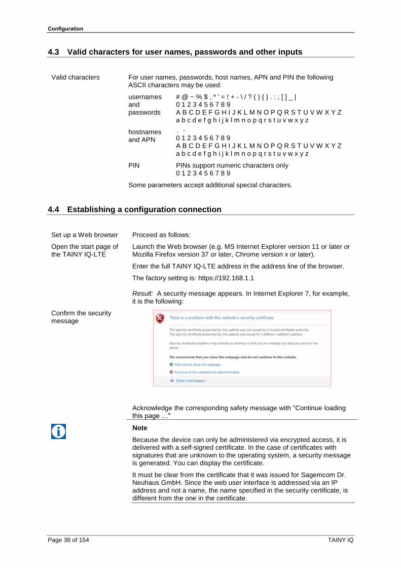
The factory setting is: https://192.168.1.1 Result: A security message appears. In Internet Explorer 7, for example, it is the following:
Confirm the security message
Acknowledge the corresponding safety message with "Continue loading this page …"
Note
Because the device can only be administered via encrypted access, it is delivered with a self-signed certificate. In the case of certificates with signatures that are unknown to the operating system, a security message is generated. You can display the certificate.
It must be clear from the certificate that it was issued for Sagemcom Dr. Neuhaus GmbH. Since the web user interface is addressed via an IP address and not a name, the name specified in the security certificate, is different from the one in the certificate.

Configuration
TAINY iQ Page 39 of 154
You will be asked to enter the user name and the password:
Enter the user name and password
The factory settings are:
User name: admin
Password: <serial number of the device>
Example 15044201
Note
You should change the password in any event. The factory settings are
general knowledge and do not provide sufficient protection. Refer to
chapter 13 on how to change the password.
Open the start page by clicking on “Log In”.
Note
To register successfully on the TAINY IQ-LTE activate the cookies in your browser.
Note
The registration screen will open a selection menu, in which the registration can be made via TACACS+/RADIUS or the normal, local registration. The initial local registration process is described below, which is used when commissioning the device. For further information on registration via TACACS+, see chapter 13.2 and the Glossary as well as.chapter 13.3
The start page is displayed
After entering the user name and password the start page of the TAINY IQ-LTE appears in the Web browser. It provides an overview of the operating state, see Chapter 5.

Configuration
Page 40 of 154 TAINY iQ
4.5 Terminating a configuration connection (Logging out)
Log Out Click the Log Out button at the top right of the screen to sign out manually. This will terminate the configuration connection to TAINY IQ-LTE. The webserver will return to the start screen.
In order to re-establish the configuration connection, you have to enter your user name and password again.
Please refer to chapter 4.4.

Status overview
TAINY iQ Page 41 of 154
5 Status overview
5.1 Get a Status Overview
Overview
Click on the Status tab and select “Overview” to open the screen.
After a successful log-in to the TAINY IQ-LTE’s web user interface select “Status” from the menu bar at the top left. An overview of the current
operating status of TAINY IQ-LTE appears. It displays the status of the:
• WAN connection • DSL/Cable Interface
• Cellular Interface • Active LAN Interface
• Data Volume Consumption
Note
The displayed values are automatically refreshed by the TAINY IQ-LTE.
Status overview
Page 42 of 154 TAINY iQ
Signal strength: Indicates the strength of the received signal of
cellular network as a CSQ value (see Glossary) and a RSSI value.
Bytes Received / Bytes Sent: Indicates the number of received or
sent bytes since the connection has been established. They will be reset when the connection is re-established.
IPv4 and IPv6 addresses: Displays the IPv4 provided by the provider
and, if assigned, the IPv6 address
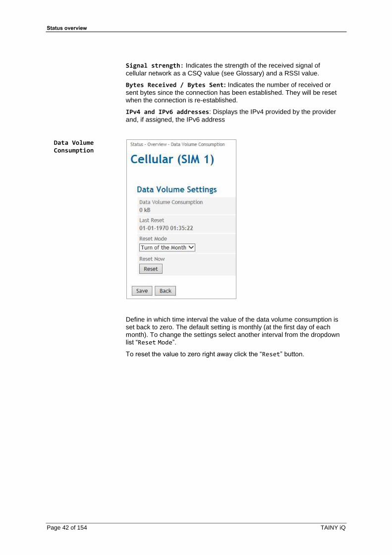
Data Volume Consumption
Define in which time interval the value of the data volume consumption is set back to zero. The default setting is monthly (at the first day of each month). To change the settings select another interval from the dropdown list “Reset Mode”.
To reset the value to zero right away click the “Reset” button.
Status overview
TAINY iQ Page 43 of 154
5.2 Get the Cellular Network Status
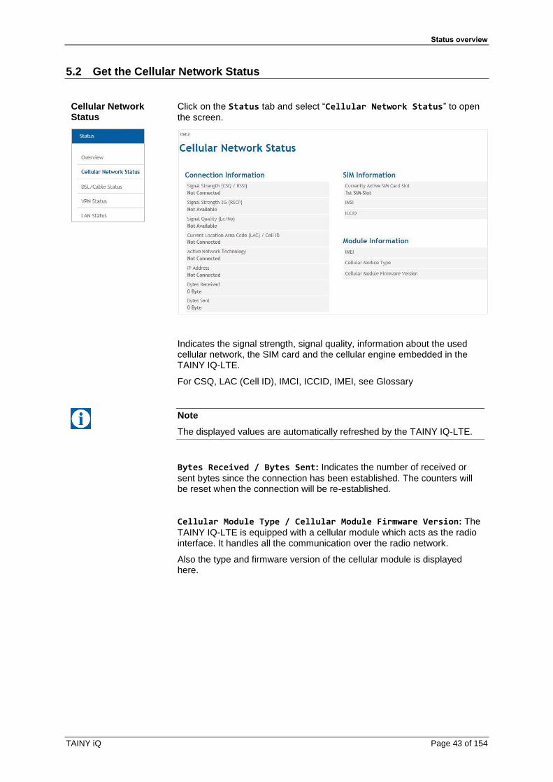
Cellular Network Status
Click on the Status tab and select “Cellular Network Status” to open
the screen.
Indicates the signal strength, signal quality, information about the used cellular network, the SIM card and the cellular engine embedded in the TAINY IQ-LTE.
For CSQ, LAC (Cell ID), IMCI, ICCID, IMEI, see Glossary
Note
The displayed values are automatically refreshed by the TAINY IQ-LTE.
Bytes Received / Bytes Sent: Indicates the number of received or
sent bytes since the connection has been established. The counters will be reset when the connection will be re-established.
Cellular Module Type / Cellular Module Firmware Version: The
TAINY IQ-LTE is equipped with a cellular module which acts as the radio interface. It handles all the communication over the radio network.
Also the type and firmware version of the cellular module is displayed here.

Status overview
Page 44 of 154 TAINY iQ
Example presentation of the mobile status
IP information
Network IPv4 addresses and network IPv6 addresses:
The IPv4 address provided by the provider and, if assigned, the IPv6 address with the associated name servers for IPv4 and IPv6 are displayed.
Note
The allocation of an IPv6 address depends on whether the Internet provider used supports the assignment of IPv6 addresses in the mobile data network.
Accessibility with IPv6 from the Internet depends on the mobile operator and the contract with the operator. Mobile operators may require private access point name (APN) for the use of outgoing and incoming IPv6 connections.
In addition, the mobile radio settings IPv6 support must be activated.
With the request IPv6 address from provider request this function is provided.
If no IPv6 address was obtained, the display for IPv6 address is omitted.

Status overview
TAINY iQ Page 45 of 154
The provider must support the assignment of IPv6 addresses!
5.3 Get the DSL/Cable Status
DSL/Cable Status
Click on the Status tab and select “DSL/Cable Status” to open the
screen.
Indicates the status and settings of the WAN connection, if it is established over a wired DSL/Cable connection.
IP information
Network IPv4 addresses and network IPv6 addresses:
The IPv4 address provided by the provider and, if assigned, the IPv6 address with the associated name servers for IPv4 and IPv6 are displayed
Bytes Received / Bytes Sent: Indicates the number of received or
sent bytes since the connection has been established. The counters will be reset when the connection is re-established.
IP addresses: Displays the IPv4 provided by the provider and, if
assigned, the IPv6 address
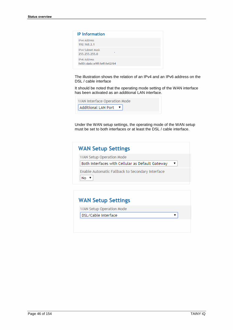
Example display with reference to an IPv6 address on the DSL / cable interface:
Status overview
Page 46 of 154 TAINY iQ
The illustration shows the relation of an IPv4 and an IPv6 address on the DSL / cable interface
It should be noted that the operating mode setting of the WAN interface has been activated as an additional LAN interface.
Under the WAN setup settings, the operating mode of the WAN setup must be set to both interfaces or at least the DSL / cable interface.

Status overview
TAINY iQ Page 47 of 154
5.4 Get the VPN Status
VPN Status
Click on the Status tab and select “VPN Status” to open the screen.
Displays a list of the existing ISAKMP SAs (Security Associations).
Remote IP: IP address of the other (opposite) party.
Connected: “Yes” connection is established or “No” connection is not
established.
SA Type: Defines the convention (connection) two communicating entities
use within a secure network.
Static: Indicates a connection that is configured and established
by TAINY IQ-LTE.
Dynamic: Indicates a connection that is established externally by
the other entity.
Connected Since: Displays the timestamp of the connection.
Remote ID: Identifier of the other party/entity.
Status overview
Page 48 of 154 TAINY iQ
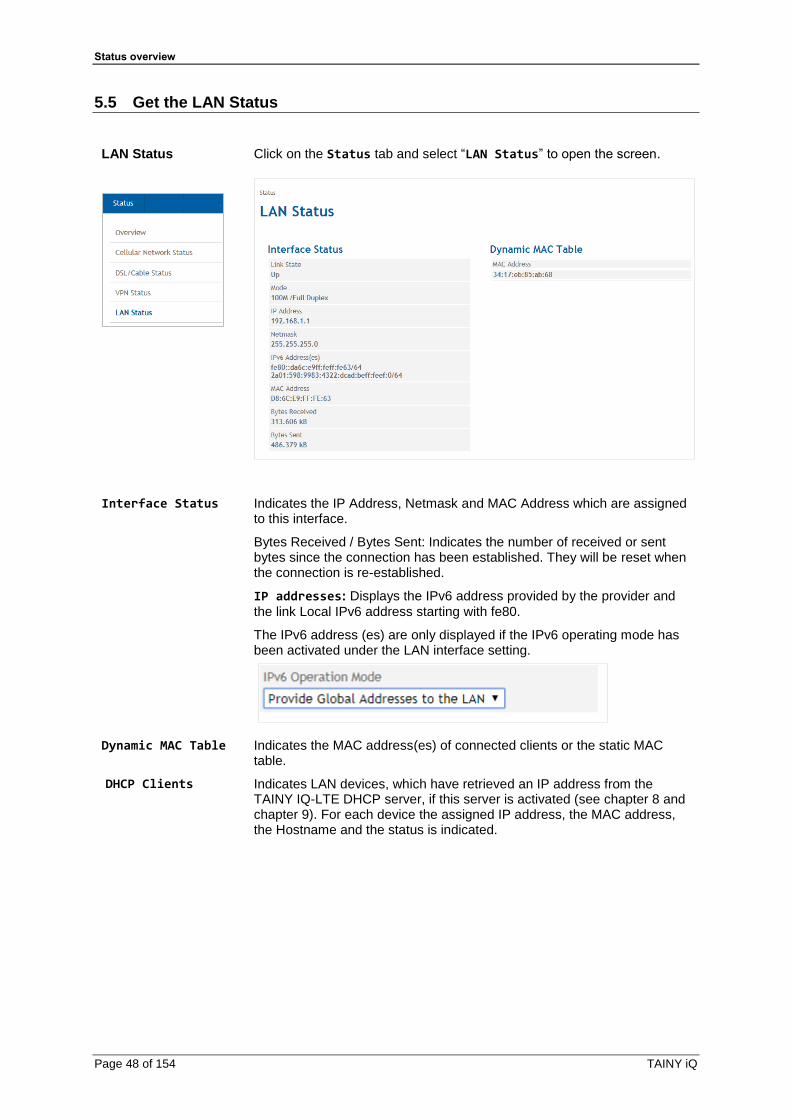
5.5 Get the LAN Status
LAN Status
Click on the Status tab and select “LAN Status” to open the screen.
Interface Status Indicates the IP Address, Netmask and MAC Address which are assigned to this interface.
Bytes Received / Bytes Sent: Indicates the number of received or sent bytes since the connection has been established. They will be reset when the connection is re-established.
IP addresses: Displays the IPv6 address provided by the provider and
the link Local IPv6 address starting with fe80.
The IPv6 address (es) are only displayed if the IPv6 operating mode has been activated under the LAN interface setting.
Dynamic MAC Table Indicates the MAC address(es) of connected clients or the static MAC table.
DHCP Clients
Indicates LAN devices, which have retrieved an IP address from the TAINY IQ-LTE DHCP server, if this server is activated (see chapter 8 and chapter 9). For each device the assigned IP address, the MAC address, the Hostname and the status is indicated.

WAN Settings
TAINY iQ Page 49 of 154
6 WAN Settings
6.1 Select the Default WAN Setup
WAN Settings A WAN setup, e.g. Setup 1 comprises a group of WAN interface related settings. See figure below.
Setup 1
Settings for Setup 1
- Cellular Network- DSL / Cable- DM VPN- Routing- Time Sync.- Connection Check- Hostnames
Settings for My Setup 2
- Cellular Network- DSL / Cable- DM VPN- Routing- Time Sync.- Connection Check- Hostnames
Settings for My Setup n
- Cellular Network- DSL / Cable- DM VPN- Routing- Time Sync.- Connection Check- Hostnames
My Setup 2 My Setup n
You may organize several WAN setups with different settings and select one of it as the default setting.
Click on the WAN tab and select “WAN Settings” to open the screen.
Reset WAN Connection
This configuration page provides options to create different WAN Setups, select the default WAN Setup and reset a WAN Connection.
General WAN Settings
In the “General WAN Settings” column you select the “Current Default WAN Setup”. The selected WAN Setup will be used once you
start-up the TAINY IQ-LTE.
To change the current WAN Setup you select the desired setup from the list of “Current Default WAN Setups” and click the “Save” button below.
The newly selected WAN Setup is immediately active.
On how to create new WAN Setups see chapter 6.2.
WAN Settings
Page 50 of 154 TAINY iQ
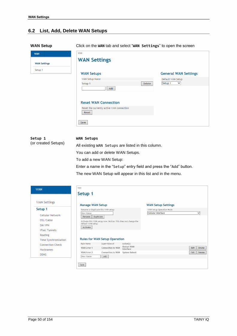
6.2 List, Add, Delete WAN Setups
WAN Setup
Click on the WAN tab and select “WAN Settings” to open the screen
Setup 1
(or created Setups)
WAN Setups
All existing WAN Setups are listed in this column.
You can add or delete WAN Setups.
To add a new WAN Setup:
Enter a name in the “Setup” entry field and press the “Add” button.
The new WAN Setup will appear in this list and in the menu.
WAN Settings
TAINY iQ Page 51 of 154
Manage WAN-Setup In this section you can rename, duplicate and activate the setups.
Rename
To change the name of an existing Setup, select the desired setup in the menu. Enter the new name under Manage WAN Setup and confirm with
Duplicate.
Duplicate
To create a new setup, which settings should concede with those of an already existing setup, select this setup in the menu. Enter the name of the new setup in the section Manage WAN Setups and confirm with
„Duplicate“.
The new setup appears in the menu on the left. You can alter the settings for this setup as described in this manual.
Activate
To activate a WAN Setup select the desired setup in the menu and confirm with „Activate“.
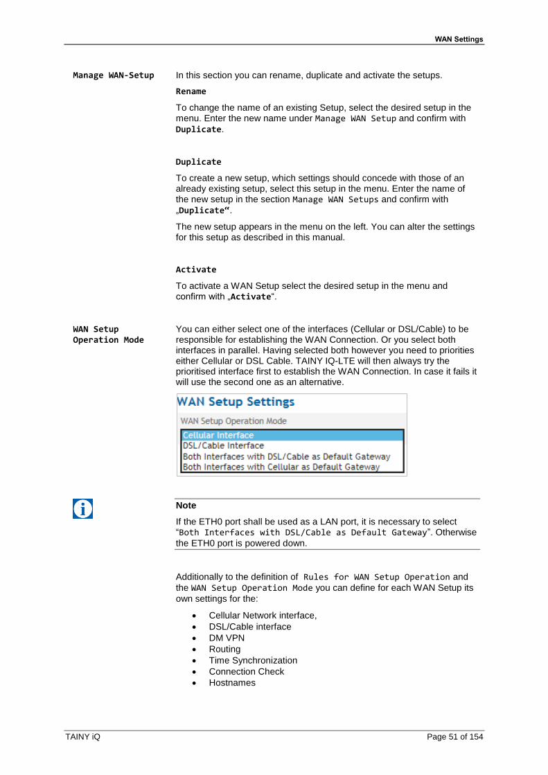
WAN Setup Operation Mode
You can either select one of the interfaces (Cellular or DSL/Cable) to be responsible for establishing the WAN Connection. Or you select both interfaces in parallel. Having selected both however you need to priorities either Cellular or DSL Cable. TAINY IQ-LTE will then always try the prioritised interface first to establish the WAN Connection. In case it fails it will use the second one as an alternative.
Note
If the ETH0 port shall be used as a LAN port, it is necessary to select “Both Interfaces with DSL/Cable as Default Gateway”. Otherwise
the ETH0 port is powered down.
Additionally to the definition of Rules for WAN Setup Operation and
the WAN Setup Operation Mode you can define for each WAN Setup its
own settings for the:
• Cellular Network interface,
• DSL/Cable interface
• DM VPN
• Routing
• Time Synchronization
• Connection Check
• Hostnames
WAN Settings
Page 52 of 154 TAINY iQ
6.3 Configure Rules for WAN Setup Operations
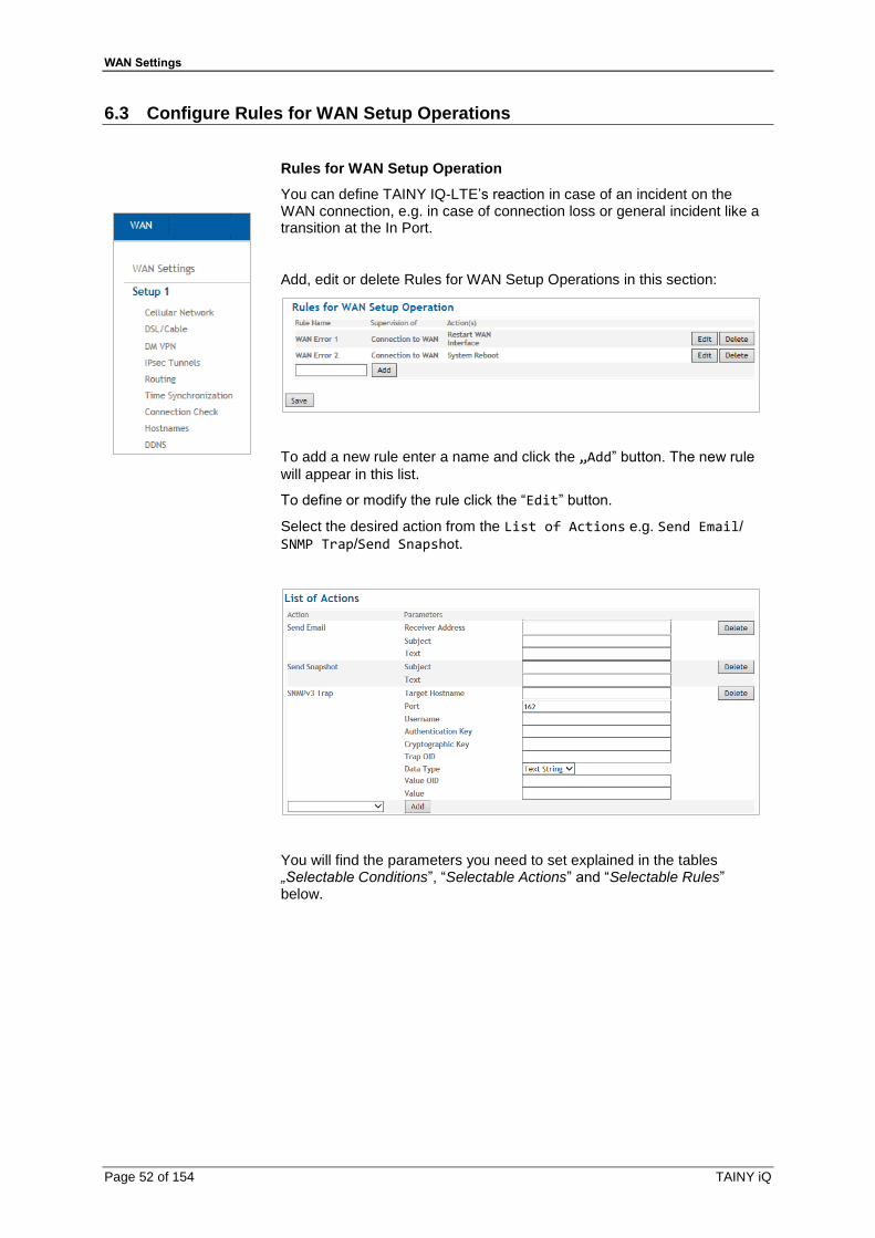
Rules for WAN Setup Operation
You can define TAINY IQ-LTE’s reaction in case of an incident on the WAN connection, e.g. in case of connection loss or general incident like a transition at the In Port.
Add, edit or delete Rules for WAN Setup Operations in this section:
To add a new rule enter a name and click the „Add” button. The new rule
will appear in this list.
To define or modify the rule click the “Edit” button.
Select the desired action from the List of Actions e.g. Send Email/
SNMP Trap/Send Snapshot.
You will find the parameters you need to set explained in the tables „Selectable Conditions”, “Selectable Actions” and “Selectable Rules” below.
WAN Settings
TAINY iQ Page 53 of 154
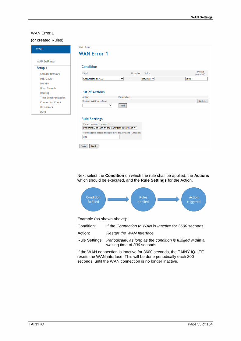
WAN Error 1
(or created Rules)
Next select the Condition on which the rule shall be applied, the Actions which should be executed, and the Rule Settings for the Action.
Conditionfulfilled
Rulesapplied
Actiontriggered
Example (as shown above):
Condition: If the Connection to WAN is Inactive for 3600 seconds.
Action: Restart the WAN Interface
Rule Settings: Periodically, as long as the condition is fulfilled within a waiting time of 300 seconds
If the WAN connection is inactive for 3600 seconds, the TAINY IQ-LTE resets the WAN interface. This will be done periodically each 300 seconds, until the WAN connection is no longer inactive.
WAN Settings
Page 54 of 154 TAINY iQ
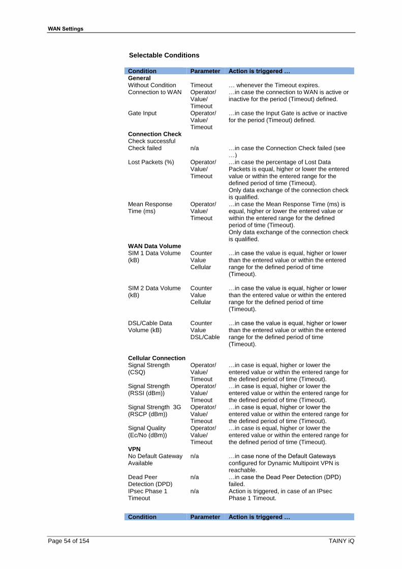
Selectable Conditions
Condition Parameter Action is triggered … General Without Condition Timeout … whenever the Timeout expires. Connection to WAN Operator/
Value/ Timeout
…in case the connection to WAN is active or inactive for the period (Timeout) defined.
Gate Input Operator/ Value/ Timeout
…in case the Input Gate is active or inactive for the period (Timeout) defined.
Connection Check Check successful Check failed n/a …in case the Connection Check failed (see
…) Lost Packets (%) Operator/
Value/ Timeout
…in case the percentage of Lost Data Packets is equal, higher or lower the entered value or within the entered range for the defined period of time (Timeout). Only data exchange of the connection check is qualified.
Mean Response Time (ms)
Operator/ Value/ Timeout
…in case the Mean Response Time (ms) is equal, higher or lower the entered value or within the entered range for the defined period of time (Timeout). Only data exchange of the connection check is qualified.
WAN Data Volume SIM 1 Data Volume (kB)
Counter Value Cellular
…in case the value is equal, higher or lower than the entered value or within the entered range for the defined period of time (Timeout).
SIM 2 Data Volume (kB)
Counter Value Cellular
…in case the value is equal, higher or lower than the entered value or within the entered range for the defined period of time (Timeout).
DSL/Cable Data Volume (kB)
Counter Value DSL/Cable
…in case the value is equal, higher or lower than the entered value or within the entered range for the defined period of time (Timeout).
Cellular Connection Signal Strength (CSQ)
Operator/ Value/ Timeout
…in case is equal, higher or lower the entered value or within the entered range for the defined period of time (Timeout).
Signal Strength (RSSI (dBm))
Operator/ Value/ Timeout
…in case is equal, higher or lower the entered value or within the entered range for the defined period of time (Timeout).
Signal Strength 3G (RSCP (dBm))
Operator/ Value/ Timeout
…in case is equal, higher or lower the entered value or within the entered range for the defined period of time (Timeout).
Signal Quality (Ec/No (dBm))
Operator/ Value/ Timeout
…in case is equal, higher or lower the entered value or within the entered range for the defined period of time (Timeout).
VPN No Default Gateway Available
n/a …in case none of the Default Gateways configured for Dynamic Multipoint VPN is reachable.
Dead Peer Detection (DPD)
n/a …in case the Dead Peer Detection (DPD) failed.
IPsec Phase 1 Timeout
n/a Action is triggered, in case of an IPsec Phase 1 Timeout.
Condition Parameter Action is triggered …

WAN Settings
TAINY iQ Page 55 of 154
Connection to VPN Operator/ Value/ Timeout
Action is triggered, in case the connection to VPN is active or inactive for the period (Timeout) defined.
Time System Uptime (Seconds)
n/a …in case the System Uptime is equal, higher or lower the entered value or within the entered range for the defined period of time (Timeout).
Time of Day Value …at the entered moment of time (hh:mm:ss) Reliable Time Base Operator/
Value/ Timeout
…in case the Reliable Time Base of the TAINY IQ-LTE is active or inactive for the period (Timeout) defined. The Reliable Time Base is active as long as the latest successful NTP Synchronization is not older than 48h
LAN Link State ETH 1 connected n/a ...in case a network cable is plugged into
ETH1 interface. ETH 1 disconnected n/a ...in case a network cable is removed from
ETH1 interface. Counters Influenced by Rules Counter 1 …5 Operator/
Value/ Timeout
...in case the Counter is equal, higher or lower the entered value or within the entered range for the defined period of time (Timeout).
Selectable Actions
Action Parameter Description System Reboot n/a The TAINY IQ-LTE performs a
system reboot Changeover WAN Setup WAN Setup Name The TAINY IQ-LTE switches to
the WAN Setup determined by the parameter.
Restart WAN Interface n/a The WAN interface will be restarted and the connection will be established again according to the default WAN setup.
Restart VPN n/a The VPN service will be restarted; the VPN connections are dropped and established again according to the setup.
Log Entry Log Level Event Text
A Log Entry with configured text and Log Level will be generated.
SNMPv3 Trap Destination Address/ Destination/ Username/ Password/ Authentication key/ Cryptography key/ Trap-OID/ Datatype/ Value-OID/Value
A SNMPv3 trap is sent in case one of the above described conditions applied. Note: The receiver address is configured on the System tab, submenu Device Information

WAN Settings
Page 56 of 154 TAINY iQ
Action Parameter Description Send Email Recieveraddress/
Subject/Text An Email is sent
Send Snapshot Subject/Text A snapshot is sent by email. Note: The receiver address is configured on the System tab, submenu Device Information
Switching Output Output State The Switching Output will be set to the state as configured by the parameter.
Increase Counter Counter The selected Counter (1..5) will be increased by 1.
Decrease Counter Counter The selected Counter (1..5) will be decreased by 1.
Set Counter Counter Value
The selected Counter (1..5) will set to the value, determined by the value parameter.
Selectable Rules
Rule Parameter Description Every time the condition is fulfilled
n/a The action will be performed when the condition switches from not fulfilled to fulfilled.
The first time the condition is fulfilled
n/a The action will be performed the first time after start-up or after saving the rule.
Periodically, as long as the condition is fulfilled
Waiting time The action is performed periodically as long as the conditions are fulfilled. The next execution of the action is locked until the Waiting time is expired.
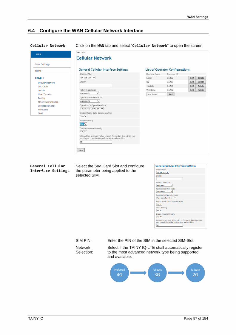
WAN Settings
TAINY iQ Page 57 of 154
6.4 Configure the WAN Cellular Network Interface
Cellular Network
Click on the WAN tab and select “Cellular Network” to open the screen
General Cellular Interface Settings
Select the SIM Card Slot and configure the parameter being applied to the selected SIM.
SIM PIN: Enter the PIN of the SIM in the selected SIM-Slot.
Network Selection:
Select if the TAINY IQ-LTE shall automatically register to the most advanced network type being supported and available:
Preferred
4GFallback
3GFallback
2G

WAN Settings
Page 58 of 154 TAINY iQ
Operator Selection Mode:
Select the list of allowed network operators, that shall be applied searching for a network:
Automatic: TAINY IQ-LTE searches automatically for the best network option and tries to register to it.
SIM Card List: TAINY IQ-LTE attaches only networks of operators stored at the SIM card.
User Defined List: TAINY IQ-LTE attaches only networks of operators entered in the List of Permitted Operators. You may enter here the preferred operators. The first entry in the list is tried first. You can move the ranking by pressing the „Up” button.
Operator Configuration Mode:
Select if the access parameter shall be selected automatically according to an Operator-ID stored at the used SIM card (see Automatic Operator Configuration) or manually (see Manual Operator Configuration) according to fixed settings.
Enable Mobile Data Com-munication:
Enable / Disable the communication with this SIM via the cellular interface. The device registers into network but does not attach to the data service.
Allow Roaming:
Enable / Disable roaming.
Intervall for network status refresh
Intervall for refreshing of the quality data of the radio connection (value range: 5 – 300 seconds)
List of Operator Configurations
The list is only visible, if the Operator Configuration Mode is set to
Automatic Selection
The list shows which access configurations for which network operators are stored on TAINY IQ-LTE.
To add a new operator configuration, enter the name of the desired operator into the entry field and click the “Add” button.
To view or modify an existing configuration click the “Edit” button.
To delete an existing configuration click the “Delete” button in the
corresponding line of “Operator Name”.
Operator Configuration (for Automatic Selection)
Only applicable, if the Operator Configuration Mode is set to Automatic Selection
The TAINY IQ-LTE reads from the active SIM card the Operator-ID and selects the corresponding Operator Configuration that has been predefined for the Operator-ID.

WAN Settings
TAINY iQ Page 59 of 154
The Operator Configuration is required to access the IP data service (GPRS, EDGE or HSPA+).
Operator-ID: This ID is used to assign the right Operator Configuration to the used SIM Card. The TAINY IQ-LTE reads the Operator-ID from the SIM Card (part of the IMSI) and searches the List of Operator Configuration for a matching entry.
When the Operator IDs of SIM and Operator List match, the corresponding Operator Configuration is used to attach to the IP data service.
Note
The Operator-ID consists of the first five digits of the IMSI can be found on Celluar Network Status page provided the SIM-card is inserted or in the information documents of your UMTS or GSM/GPRS provider or on the provider’s homepage. You can also ask the provider’s hotline (Kwan Interface keyword: MCC/MNC).
Operator Configuration (for Manual Configuration)
Only applicable, if the Operator Configuration Mode is set to Manual Configuration.
The Operator Configuration is required to access the IP data service (GPRS, EDGE or HSPA+).
Independent of the Operator-ID at the SIM card, the entered Operator Configuration is applied.
Parameter for Operator Configuration
Enter the APN, the Username and the Password. You can find the APN, Username and Password in your mobile radio network operator's documentation, on your operator's Website, or ask your operator's hotline.
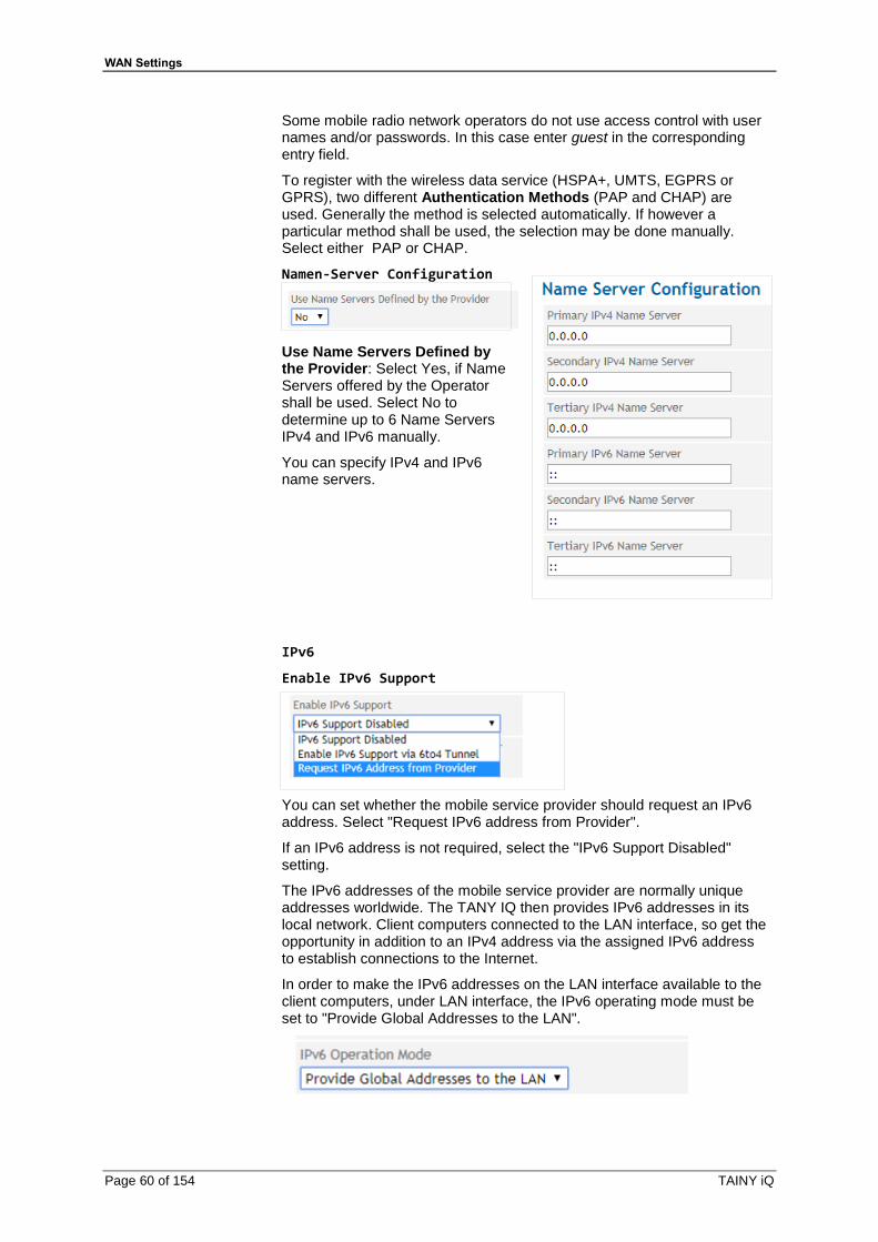
WAN Settings
Page 60 of 154 TAINY iQ
Some mobile radio network operators do not use access control with user names and/or passwords. In this case enter guest in the corresponding entry field.
To register with the wireless data service (HSPA+, UMTS, EGPRS or GPRS), two different Authentication Methods (PAP and CHAP) are used. Generally the method is selected automatically. If however a particular method shall be used, the selection may be done manually. Select either PAP or CHAP.
Namen-Server Configuration
Use Name Servers Defined by the Provider: Select Yes, if Name Servers offered by the Operator shall be used. Select No to determine up to 6 Name Servers IPv4 and IPv6 manually.
You can specify IPv4 and IPv6 name servers.
IPv6
Enable IPv6 Support
You can set whether the mobile service provider should request an IPv6 address. Select "Request IPv6 address from Provider".
If an IPv6 address is not required, select the "IPv6 Support Disabled" setting.
The IPv6 addresses of the mobile service provider are normally unique addresses worldwide. The TANY IQ then provides IPv6 addresses in its local network. Client computers connected to the LAN interface, so get the opportunity in addition to an IPv4 address via the assigned IPv6 address to establish connections to the Internet.
In order to make the IPv6 addresses on the LAN interface available to the client computers, under LAN interface, the IPv6 operating mode must be set to "Provide Global Addresses to the LAN".
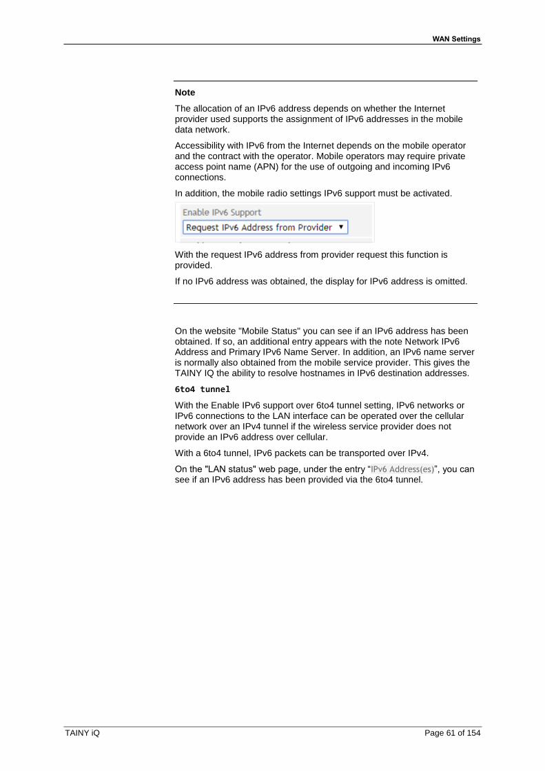
WAN Settings
TAINY iQ Page 61 of 154
Note
The allocation of an IPv6 address depends on whether the Internet provider used supports the assignment of IPv6 addresses in the mobile data network.
Accessibility with IPv6 from the Internet depends on the mobile operator and the contract with the operator. Mobile operators may require private access point name (APN) for the use of outgoing and incoming IPv6 connections.
In addition, the mobile radio settings IPv6 support must be activated.
With the request IPv6 address from provider request this function is provided.
If no IPv6 address was obtained, the display for IPv6 address is omitted.
On the website "Mobile Status" you can see if an IPv6 address has been obtained. If so, an additional entry appears with the note Network IPv6 Address and Primary IPv6 Name Server. In addition, an IPv6 name server is normally also obtained from the mobile service provider. This gives the TAINY IQ the ability to resolve hostnames in IPv6 destination addresses.
6to4 tunnel
With the Enable IPv6 support over 6to4 tunnel setting, IPv6 networks or IPv6 connections to the LAN interface can be operated over the cellular network over an IPv4 tunnel if the wireless service provider does not provide an IPv6 address over cellular.
With a 6to4 tunnel, IPv6 packets can be transported over IPv4.
On the "LAN status" web page, under the entry “IPv6 Address(es)”, you can see if an IPv6 address has been provided via the 6to4 tunnel.
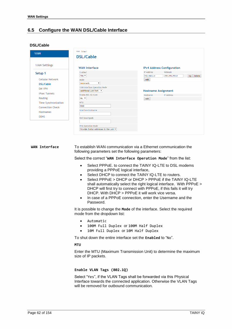
WAN Settings
Page 62 of 154 TAINY iQ
6.5 Configure the WAN DSL/Cable Interface
DSL/Cable
WAN Interface
To establish WAN communication via a Ethernet communication the following parameters set the following parameters:
Select the correct “WAN Interface Operation Mode” from the list:
• Select PPPoE. to connect the TAINY IQ-LTE to DSL modems providing a PPPoE logical interface,
• Select DHCP to connect the TAINY IQ-LTE to routers.
• Select PPPoE > DHCP or DHCP > PPPoE if the TAINY IQ-LTE shall automatically select the right logical interface. With PPPoE > DHCP will first try to connect with PPPoE, if this fails it will try DHCP. With DHCP > PPPoE it will work vice versa.
• In case of a PPPoE connection, enter the Username and the Password.
It is possible to change the Mode of the interface. Select the required
mode from the dropdown list:
• Automatic
• 100M Full Duplex or 100M Half Duplex
• 10M Full Duplex or 10M Half Duplex
To shut down the entire interface set the Enabled to “No”.
MTU
Enter the MTU (Maximum Transmission Unit) to determine the maximum size of IP packets.
Enable VLAN Tags (802.1Q)
Select “Yes”, if the VLAN Tags shall be forwarded via this Physical
Interface towards the connected application. Otherwise the VLAN Tags will be removed for outbound communication.

WAN Settings
TAINY iQ Page 63 of 154
IPv6-Operation Mode
IPv6 im lokalen Netzwerk
You can specify whether the global IPv6 address from the mobile service provider or the 6to4 tunnel should be made available to the local network at the LAN interface.
If IPv6 addresses are to be made available on the LAN interface, select the setting "Provide global addresses to the LAN". With this setting, computers using Neighbor Discovery Protocol connected to the TAINY IQ LAN can obtain globally unique IPv6 addresses from the TAINY IQ.
If an IPv6 address is not required, select the IPv6 Disabled setting.
With the setting "Only Link-Local Address" the local network at the LAN interface only displays the Link-Local Address of the TAINY IQ valid within closed network segments.
The format prefix of the link-local address is "fe80 :: / 64"
On the "LAN status" web page you can see under the entry “IPv6
Address(es)”, which IPv6 address (es) has been set.
DHCP Settings
DHCP Operation
The TAINY IQ-LTE provides a DHCP server function or a DHCP relay function.
If the DHCP server function is activated, the TAINY IQ-LTE itself assigns IP addresses to applications connected to the LAN interface. Define the range of address the assigned IP addresses shall be taken from and/or static IP leases.
If the DHCP relay function is activated, the TAINY IQ-LTE routes the DHCP requests of applications connected to the LAN interface to a remote DHCP relay server which provides the IP addresses. Enter the hostname or the IP address of the DHCP Relay Server.

WAN Settings
Page 64 of 154 TAINY iQ
Virtual Router ID
ID for the group of utilised TAINY IQ-LTEs.
VRRP Priority
Defines, which TAINY acts as master and which as the backup. The TAINY IQ-LTE which has the highest priority acts as the master. Enter values between 1 (lowest prio) and 254 (highest prio). The VRRP priority can be adjusted automatically to a new value
Adjusted VRRP Priority
In case of an active WAN or VPN connection
VRRP IP Address List
IP addresses of the VRRP (TAINY IQ-LTEs)
IP Address Configuration/ Hostname Assignment
Hostname, IP Address: The TAINY IQ-LTE allows assigning IP
addresses of remote stations to hostnames. Using this function, applications connected to TAINY IQ-LTE’s LAN interfaces address these remote stations by the entered hostnames. TAINY IQ-LTE functions (e.g. NTP) also use this feature.
DSL/Cable
Click on the WAN tab and select “DSL/Cable” to open the screen

WAN Settings
TAINY iQ Page 65 of 154
WAN Interface
To establish the WAN communication via a wired Ethernet connection, the following parameters need to be set.
Select the correct “WAN Interface Operation Mode” from the list:
To connect the TAINY IQ-LTE to DSL modems providing a PPPoE logical interface, select PPPoE.
To connect the TAINY IQ-LTE to routers, select DHCP.
If the TAINY IQ-LTE shall automatically select the right logical interface, select PPPoE > DHCP or DHCP > PPPoE. With PPPoE > DHCP will first try to connect with PPPoE, if this fails it will try DHCP. With DHCP > PPPoE it will work vice versa.
In case of a PPPoE connection, enter the Username and the Password.
Click button “Save”.
WAN Interface Operation Mode
Manual configuration
For manual configuration, select the setting under Operating mode of the WAN interface "Manual configuration".
Here you have the possibility to manually configure the WAN interface:
Enable IPv6 Support “No"

WAN Settings
Page 66 of 154 TAINY iQ
IPv4 Adress Enter an IPv4 address for the WAN interface
IPv4 Subnet Mask Enter an IPv4 subnet mask for the WAN interface
IPv4 Default Gateway
Enter here the IPv4 gateway address via the TAINY IQ forwards the IPv4 data packets
MTU Here, changes to the maximum transmission unit (MAC layer) can be made if necessary.
IPv6 Support
Here you have the possibility to configure IPv6 in addition to the IPv4 configuration. To do this, select "Yes" in the "Enable IPv6 support" menu.
Enable IPv6 Support “Yes"
IPv4 Adress Enter an IPv4 address for the WAN interface
IPv4 Subnet Mask Enter an IPv4 subnet mask for the WAN interface
IPv4 Default Gateway
Enter here the IPv4 gateway address via the TAINY IQ forwards the IPv4 data packets
IPv6 Adress Enter an IPv6 address for the WAN interface
IPv6 Prefix Enter the IPv6 prefix length here. For example, 64
IPv6 Gateway Enter here the IPv6 gateway address via the TAINY IQ forwards the IPv6 data packets
IPv4 Name Server Enter an IPv4 name server for the resolution of hostnames to IPv4 addresses

WAN Settings
TAINY iQ Page 67 of 154
IPv6 Name Server Enter an IPv6 name server for the resolution of hostnames to IPv6 addresses
MTU Here, changes to the maximum transmission unit (MAC layer) can be made if necessary.
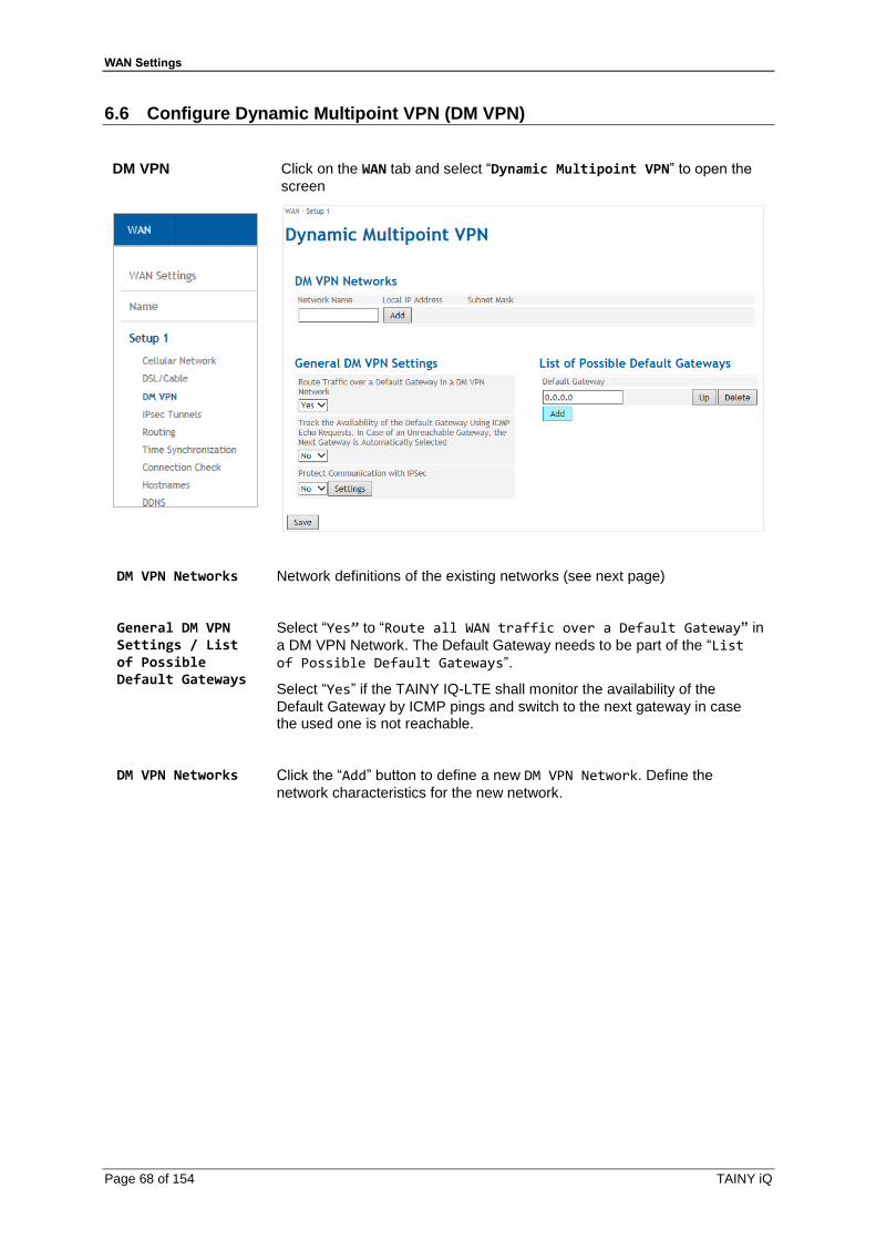
WAN Settings
Page 68 of 154 TAINY iQ
6.6 Configure Dynamic Multipoint VPN (DM VPN)
DM VPN
Click on the WAN tab and select “Dynamic Multipoint VPN” to open the
screen
DM VPN Networks Network definitions of the existing networks (see next page)
General DM VPN Settings / List of Possible Default Gateways
Select “Yes” to “Route all WAN traffic over a Default Gateway” in
a DM VPN Network. The Default Gateway needs to be part of the “List of Possible Default Gateways”.
Select “Yes” if the TAINY IQ-LTE shall monitor the availability of the
Default Gateway by ICMP pings and switch to the next gateway in case the used one is not reachable.
DM VPN Networks
Click the “Add” button to define a new DM VPN Network. Define the
network characteristics for the new network.
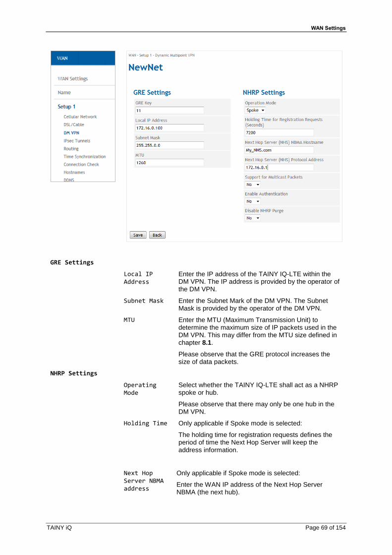
WAN Settings
TAINY iQ Page 69 of 154
GRE Settings
Local IP Address
Enter the IP address of the TAINY IQ-LTE within the DM VPN. The IP address is provided by the operator of the DM VPN.
Subnet Mask Enter the Subnet Mark of the DM VPN. The Subnet Mask is provided by the operator of the DM VPN.
MTU Enter the MTU (Maximum Transmission Unit) to determine the maximum size of IP packets used in the DM VPN. This may differ from the MTU size defined in chapter 8.1.
Please observe that the GRE protocol increases the size of data packets.
NHRP Settings
Operating Mode
Select whether the TAINY IQ-LTE shall act as a NHRP spoke or hub.
Please observe that there may only be one hub in the DM VPN.
Holding Time Only applicable if Spoke mode is selected:
The holding time for registration requests defines the period of time the Next Hop Server will keep the address information.
Next Hop Server NBMA address
Only applicable if Spoke mode is selected:
Enter the WAN IP address of the Next Hop Server NBMA (the next hub).

WAN Settings
Page 70 of 154 TAINY iQ
Next Hop Server Protocol address
Only applicable if Spoke mode is selected:
Enter the DM VPN IP address of the Next Hop Server NBMA (the next hub).
Support for Multicast Packets
Enables / Disables distribution of Multicast Packets in the DM VPN.
Enable Authentication
Select “Yes” if the TAINY IQ-LTE shall authenticate itself
at the remote NHRP station. In this case enter an authentication key.
Disable NHRP Purge
If “No” is selected the TAINY IQ-LTE in Spoke mode
sends after a (re-) registration a request to the hub to clean-up formerly stored routing data of the TAINY (standard implementation).
If “Yes” is selected the request is not sent.
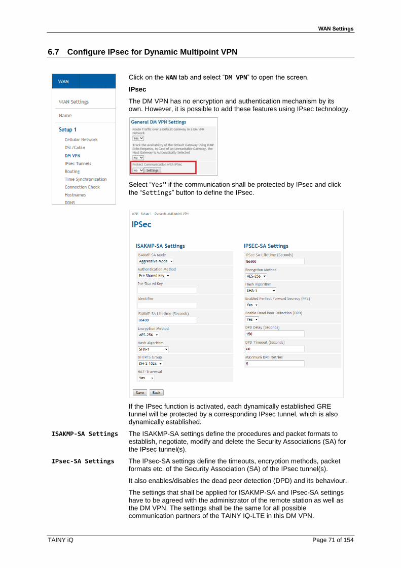
WAN Settings
TAINY iQ Page 71 of 154
6.7 Configure IPsec for Dynamic Multipoint VPN
Click on the WAN tab and select “DM VPN” to open the screen.
IPsec
The DM VPN has no encryption and authentication mechanism by its own. However, it is possible to add these features using IPsec technology.
Select “Yes” if the communication shall be protected by IPsec and click
the “Settings” button to define the IPsec.
If the IPsec function is activated, each dynamically established GRE tunnel will be protected by a corresponding IPsec tunnel, which is also dynamically established.
ISAKMP-SA Settings The ISAKMP-SA settings define the procedures and packet formats to establish, negotiate, modify and delete the Security Associations (SA) for the IPsec tunnel(s).
IPsec-SA Settings The IPsec-SA settings define the timeouts, encryption methods, packet formats etc. of the Security Association (SA) of the IPsec tunnel(s).
It also enables/disables the dead peer detection (DPD) and its behaviour.
The settings that shall be applied for ISAKMP-SA and IPsec-SA settings have to be agreed with the administrator of the remote station as well as the DM VPN. The settings shall be the same for all possible communication partners of the TAINY IQ-LTE in this DM VPN.
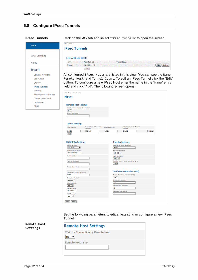
WAN Settings
Page 72 of 154 TAINY iQ
6.8 Configure IPsec Tunnels
IPsec Tunnels
Click on the WAN tab and select “IPsec Tunnels” to open the screen.
All configured IPsec Hosts are listed in this view. You can see the Name,
Remote Host and Tunnel Count. To edit an IPsec Tunnel click the “Edit”
button. To configure a new IPsec Host enter the name in the “Name” entry
field and click “Add”. The following screen opens.
Set the follwoing parameters to edit an exsisting or configure a new IPsec Tunnel:
Remote Host Settings

WAN Settings
TAINY iQ Page 73 of 154
If you set the parameter Wait for Connections by Remote Host to
“Yes” make sure the remote station is available continuously and must
answer pings.
Enter the name of the host station in the Remote Hostname entry field.
Tunnel Settings
View, add or delete tunnels settings.
To add new tunnel settings the following parameters are required:
IPs of the Local Network and Subnet Mask of the Local Network
that TAINY uses to establish a connection to the remote network
The actual IPs of the Remote Network and Subnet Mask of the Remote Network.
You could leave these fields empty.
ISAKMP-SA Settings
ISAKMP SA Mode
ISAKMP (Internet Security Association and Key Management) establishes the SA (Security Association) for the key exchange between TAINY IQ-LTE and the VPN gateway of the opposite network.
Select either Main Mode or Aggressive Mode.
Main Mode protects the identified peers in any case whereas the Aggressive Mode will not protect the identified peers.
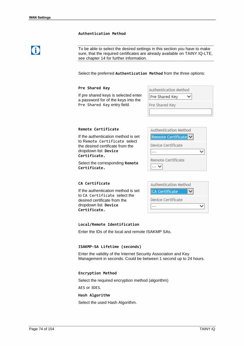
WAN Settings
Page 74 of 154 TAINY iQ
Authentication Method
To be able to select the desired settings in this section you have to make sure, that the required certificates are already available on TAINY IQ-LTE, see chapter 14 for further information.
Select the preferred Authentication Method from the three options:
Pre Shared Key
If pre shared keys is selected enter a password for of the keys into the Pre Shared Key entry field.
Remote Certificate
If the authentication method is set to Remote Certificate select
the desired certificate from the dropdown list Device Certificate.
Select the corresponding Remote Certificate.
CA Certificate
If the authentication method is set to CA Certificate select the
desired certificate from the dropdown list Device Certificate.
Local/Remote Identification
Enter the IDs of the local and remote ISAKMP SAs.
ISAKMP-SA Lifetime (seconds)
Enter the validity of the Internet Security Association and Key Management in seconds. Could be between 1 second up to 24 hours.
Encryption Method
Select the required encryption method (algorithm)
AES or 3DES.
Hash Algorithm
Select the used Hash Algorithm.

WAN Settings
TAINY iQ Page 75 of 154
DH/PFS Group
Select the DH (Dynamic Host)/PFS (Perfect Forward Secrecy) - group that has been agreed on with the administrator of the opposite network for the exchange of keys.
NAT-Traversal
Select:
“Yes” – The use of NAT-Traversal could be arranged when the
connecting is established
“No” - The use of NAT-Traversal could not be arranged when the
connection is established.
“Force” – NAT-Traversal is used in any case
IPsec-SA Settings
IPsec (Internet Protocol Security) establishes the actual SA (Security Association) for the connection between the TAINY and the opposite network.
IPsec-SA Lifetime (seconds)
Enter the validity of the Internet Protocol Security in seconds. Could be between 1 second up to 24 hours.
Encryption Method
Select the required encryption method (algorithm)
“AES” or “3DES”.
Hash Algorithm
Select the used Hash Algorithm.
Enable Perfect Forward Secrecy (PFS)
If set to “Yes” a new session key will be generated (DH-Key-Exchange),
once the ISAKMP-SA is arrange for IPsec-SA.
If set to “No” the ISAKMP-SA is used again.

WAN Settings
Page 76 of 154 TAINY iQ
Dead Peer Detection (DPD)
The Dead Peer Detection identifies whether the IPsec connection between two networks is still valid or if the connection has to be re-established. This function presumes though that it is supported on both sides.
Caution
Risk of additional costs
Due to sending DPD request as well as the use of NAT-T the number of
send and receive data will increase. Depending on the selected settings
the additional data volume might be 5 MB or more per month. This could
lead to additional costs.
Enable Dead Peer Detection
Select “Yes” to use the function. TAINY IQ-LTE will now identify the
validity of the connection irrespectively data transmission.
Select “No” to switch the function off.
DPD Delay
Lapse of time in seconds the DPD-requests are send.
DPD Timeout
Lapse of time (in seconds) after which the DPD-request is considered failed if no answer is received. This is also the interval after which the next request is send until the connection is finally interrupted.
Maximum DPD Retries
Number of permitted retries until the IPsec connection is considered interrupted.

WAN Settings
TAINY iQ Page 77 of 154
6.9 Configure User defined WAN Routes and RIPv2
Routing
Click on the WAN tab and select “Routing” to open the screen.
User Defined WAN Routes
Select the logical interface which shall be used to route data traffic from/to a remote station via the WAN:
• Route over Cable/DSL Connection
• Route over Cellular Connection
• Route over IP Gateway
Enter the IP address of the remote station as well as a corresponding netmask.
RIPv2 Settings The RIPv2 protocol is used to transmit the configured LAN routing tables repeatedly in fixed intervals to a remote station.
If two routers (e.g. TAINY IQ-LTE) provide the same route, you can prioritize one of the routers by entering a lower value for the Networks Costs. This router will be prioritised.
Select Yes if only RIP neighbours behind the active default gateway shall be used. The TAINY IQ-LTE will transmit the routing tables only via the default gateway.
RIPv2 Neighbour IP Addresses
Enter the IP address of the remote station the routing tables shall be sent to.
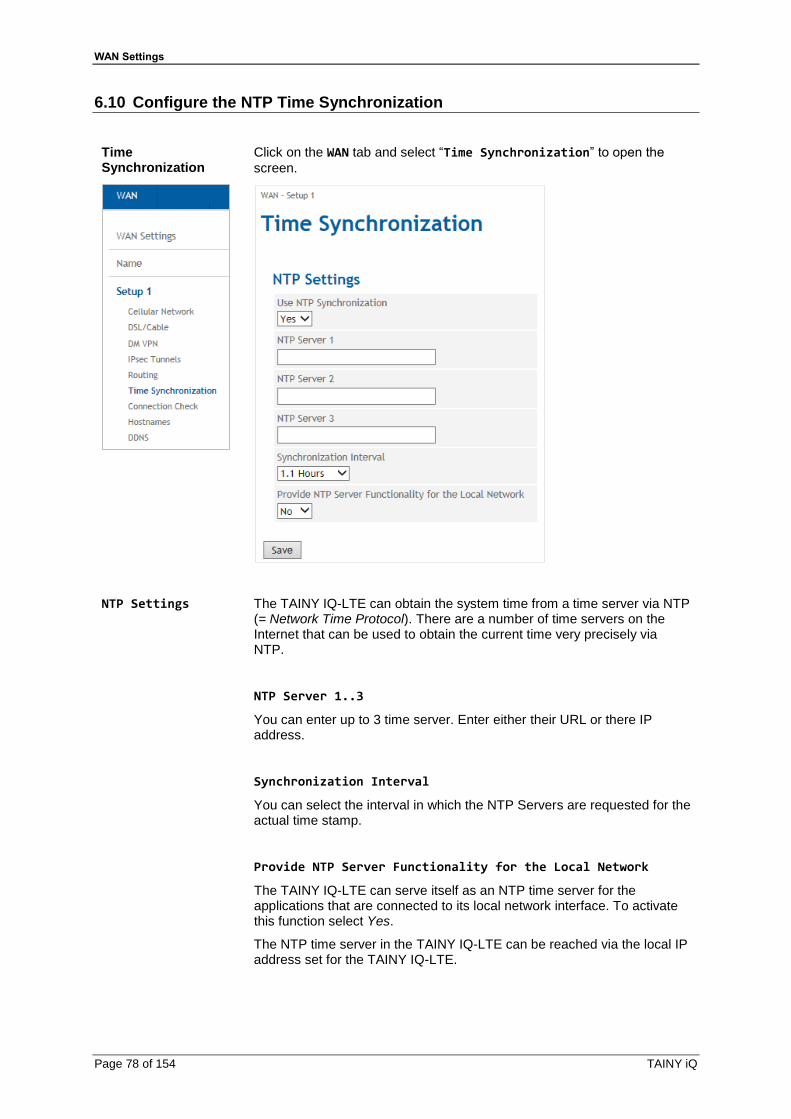
WAN Settings
Page 78 of 154 TAINY iQ
6.10 Configure the NTP Time Synchronization
Time Synchronization
Click on the WAN tab and select “Time Synchronization” to open the
screen.
NTP Settings The TAINY IQ-LTE can obtain the system time from a time server via NTP (= Network Time Protocol). There are a number of time servers on the Internet that can be used to obtain the current time very precisely via NTP.
NTP Server 1..3
You can enter up to 3 time server. Enter either their URL or there IP address.
Synchronization Interval
You can select the interval in which the NTP Servers are requested for the actual time stamp.
Provide NTP Server Functionality for the Local Network
The TAINY IQ-LTE can serve itself as an NTP time server for the applications that are connected to its local network interface. To activate this function select Yes.
The NTP time server in the TAINY IQ-LTE can be reached via the local IP address set for the TAINY IQ-LTE.

WAN Settings
TAINY iQ Page 79 of 154
6.11 Configure the Connection Check
Connection Check
Click on the WAN tab and select “Connection Check” to open the screen.
With the function Connection Check the TAINY IQ-LTE checks its connection to UMTS/GPRS and to the connected external networks, such as the internet or an intranet. To do this, the TAINY IQ-LTE sends ping packets (ICMP) to up to four remote stations at regular intervals.
Connection Check Settings
Enable the WAN Connection Check
Select Yes to activate the Connection Check
Check Interval (Seconds)
Defines the Interval in which the Connection Check shall be performed.
Response Timeout (Seconds)
Defines the Reponse Timeout. If the TAINY IQ-LTE receives within this period of time the ICMP ping answers from the remote stations, the check was successful.
Number of retries until an error is detected
Defines the number of retries until an error is detected. In case the TAINY IQ-LTE does not receive ICMP ping answers within the Response Timeout, the check will be repeated the entered number of retries. If all retries fails, the connection check is failed.
Retry Delay
Defines the delay between retries.
Sample Count for Statistics Calculation
Defines the number of samples used to calculate a mean value.
Hostnames for ICMP Echo Requests (Ping)
First … Fourth Hostname
Enter up to four remote stations that the TAINY IQ-LTE can ping. The remote stations must be available continuously and must answer pings.
Note
Make sure that the selected remote stations will not feel "harassed".

WAN Settings
Page 80 of 154 TAINY iQ
Note
If the connection check is used for checking a VPN-tunnel, only the VPN-host should be entered as ICMP target. By entering further hosts, which will answer to the ICMP requests, a termination of the VPN-tunnel will not be detected.
6.12 Assign Hostnames to remote IP Addresses
Hostnames
Click on the WAN tab and select “Hostnames” to open the screen.
This function allows assigning IP- addresses of remote stations to hostnames. Using this function, applications connected to TAINY IQ-LTE’s LAN interfaces can address these remote stations by the entered hostnames. TAINY IQ-LTE functions (e.g. NTP) can also use this feature.
Hostnames configured here are valid only for the selected WAN setup. Hostnames that are independent of the WAN setup can be entered in the LAN section, see 8.1.

WAN Settings
TAINY iQ Page 81 of 154
6.13 DynDNS Service (DDNS)
DDNS
Click on the WAN tab and select “Hostnames” to open the screen.
The TAINY IQ-LTE can use DynDNS services to be addressable via a DynDNS hostname. You can enable/disable this function.
Dynamic DNS Service
Chose one of the three supported function:
Username, Password
Enter the username and password to access the selected DynDNS service.
Dynamic DNS Hostname
Enter the hostname on which the TAINY IQ-LTE can be addressed (provided by the DynDNS service).
Enable SSL Select if the connection to the DynDNS service shall be SSL-protected.
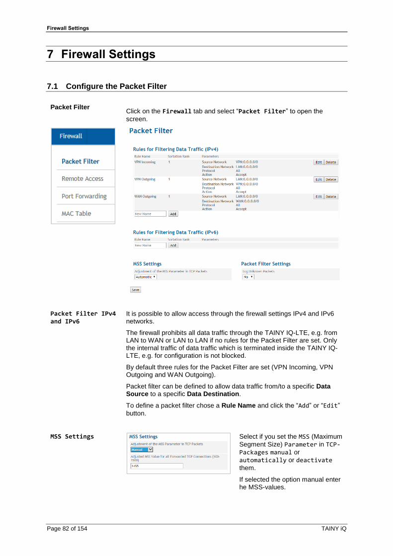
Firewall Settings
Page 82 of 154 TAINY iQ
7 Firewall Settings
7.1 Configure the Packet Filter
Packet Filter
Click on the Firewall tab and select “Packet Filter” to open the
screen.
Packet Filter IPv4 and IPv6
It is possible to allow access through the firewall settings IPv4 and IPv6 networks.
The firewall prohibits all data traffic through the TAINY IQ-LTE, e.g. from LAN to WAN or LAN to LAN if no rules for the Packet Filter are set. Only the internal traffic of data traffic which is terminated inside the TAINY IQ-LTE, e.g. for configuration is not blocked.
By default three rules for the Packet Filter are set (VPN Incoming, VPN Outgoing and WAN Outgoing).
Packet filter can be defined to allow data traffic from/to a specific Data Source to a specific Data Destination.
To define a packet filter chose a Rule Name and click the “Add” or “Edit”
button.
MSS Settings
Select if you set the MSS (Maximum
Segment Size) Parameter in TCP-Packages manual or
automatically or deactivate
them.
If selected the option manual enter he MSS-values.
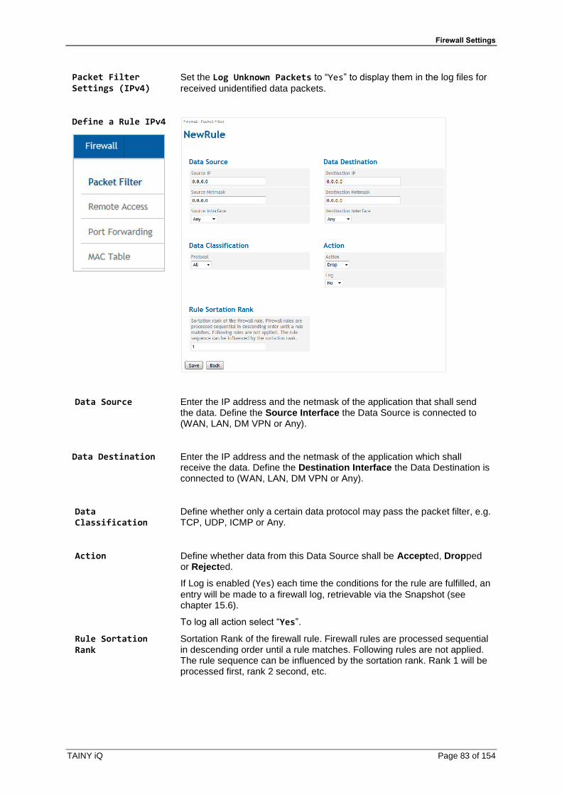
Firewall Settings
TAINY iQ Page 83 of 154
Packet Filter Settings (IPv4)
Set the Log Unknown Packets to “Yes” to display them in the log files for
received unidentified data packets.
Define a Rule IPv4
Data Source
Enter the IP address and the netmask of the application that shall send the data. Define the Source Interface the Data Source is connected to (WAN, LAN, DM VPN or Any).
Data Destination Enter the IP address and the netmask of the application which shall receive the data. Define the Destination Interface the Data Destination is connected to (WAN, LAN, DM VPN or Any).
Data Classification
Define whether only a certain data protocol may pass the packet filter, e.g. TCP, UDP, ICMP or Any.
Action
Define whether data from this Data Source shall be Accepted, Dropped or Rejected.
If Log is enabled (Yes) each time the conditions for the rule are fulfilled, an
entry will be made to a firewall log, retrievable via the Snapshot (see chapter 15.6).
To log all action select “Yes”.
Rule Sortation Rank
Sortation Rank of the firewall rule. Firewall rules are processed sequential in descending order until a rule matches. Following rules are not applied. The rule sequence can be influenced by the sortation rank. Rank 1 will be processed first, rank 2 second, etc.
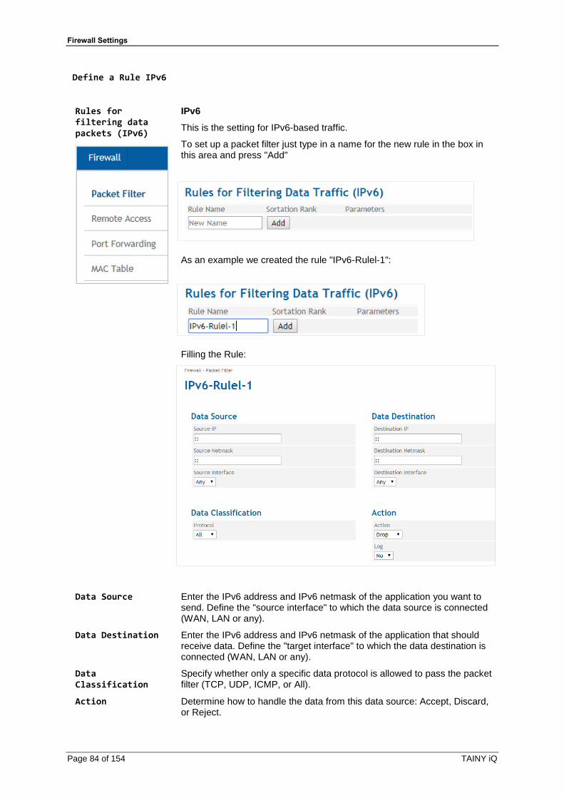
Firewall Settings
Page 84 of 154 TAINY iQ
Define a Rule IPv6
Rules for filtering data packets (IPv6)
IPv6
This is the setting for IPv6-based traffic.
To set up a packet filter just type in a name for the new rule in the box in this area and press "Add"
As an example we created the rule "IPv6-Rulel-1":
Filling the Rule:
Data Source Enter the IPv6 address and IPv6 netmask of the application you want to send. Define the "source interface" to which the data source is connected (WAN, LAN or any).
Data Destination Enter the IPv6 address and IPv6 netmask of the application that should receive data. Define the "target interface" to which the data destination is connected (WAN, LAN or any).
Data Classification
Specify whether only a specific data protocol is allowed to pass the packet filter (TCP, UDP, ICMP, or All).
Action
Determine how to handle the data from this data source: Accept, Discard, or Reject.

Firewall Settings
TAINY iQ Page 85 of 154
If you set this to "Yes", an entry is made in the firewall log each time the conditions of this rule are met. These entries can be retrieved via snapshot (see chapter 14.6).
To log each action, select “Yes”.
Rule Sortation Rank
Designates the sort level of the firewall rules. Firewall rules are processed sequentially in descending order until a matching rule is found. The following rules will no longer apply. The order of the rules is influenced by the sorting level. Level 1 is processed first, then level 2, etc.
Application Examples IPv6 firewall rules
For "Allow everything" the entry :: Data source and data destination is sufficient
Whole netzt the access permit:
Data Source:
Source IP:
2a01: 0598: 990E: 66bf: 0000: 0000: 0000: 0000
Source Network Mask:
ffff: ffff: ffff: ffff: 0000: 0000: 0000: 0000
Data destination: (allowed to all computers in the local network)
Destination IP:
0000: 0000: 0000: 0000: 0000: 0000: 0000: 0000
Destination network mask:
0000: 0000: 0000: 0000: 0000: 0000: 0000: 0000
Or destination IP ::, destination network mask ::
Allow IPv6 traffic only to a computer in the LAN:
Destination IP:
2a01: 598: 990E: 66bf: DCAD: beff: feef: aaaa
Destination network mask:
ffff: ffff: ffff: ffff: ffff: ffff: ffff: ffff
From the prefix (network ID) 2a01: 598: 990e: 66bf all computers allow access
Destination IP:
2a01: 598: 990E: 66bf: ffff: ffff: ffff: ffff
Destination network mask:
ffff: ffff: ffff: ffff :: is like ffff: ffff: ffff: ffff: 0000: 0000: 0000: 0000
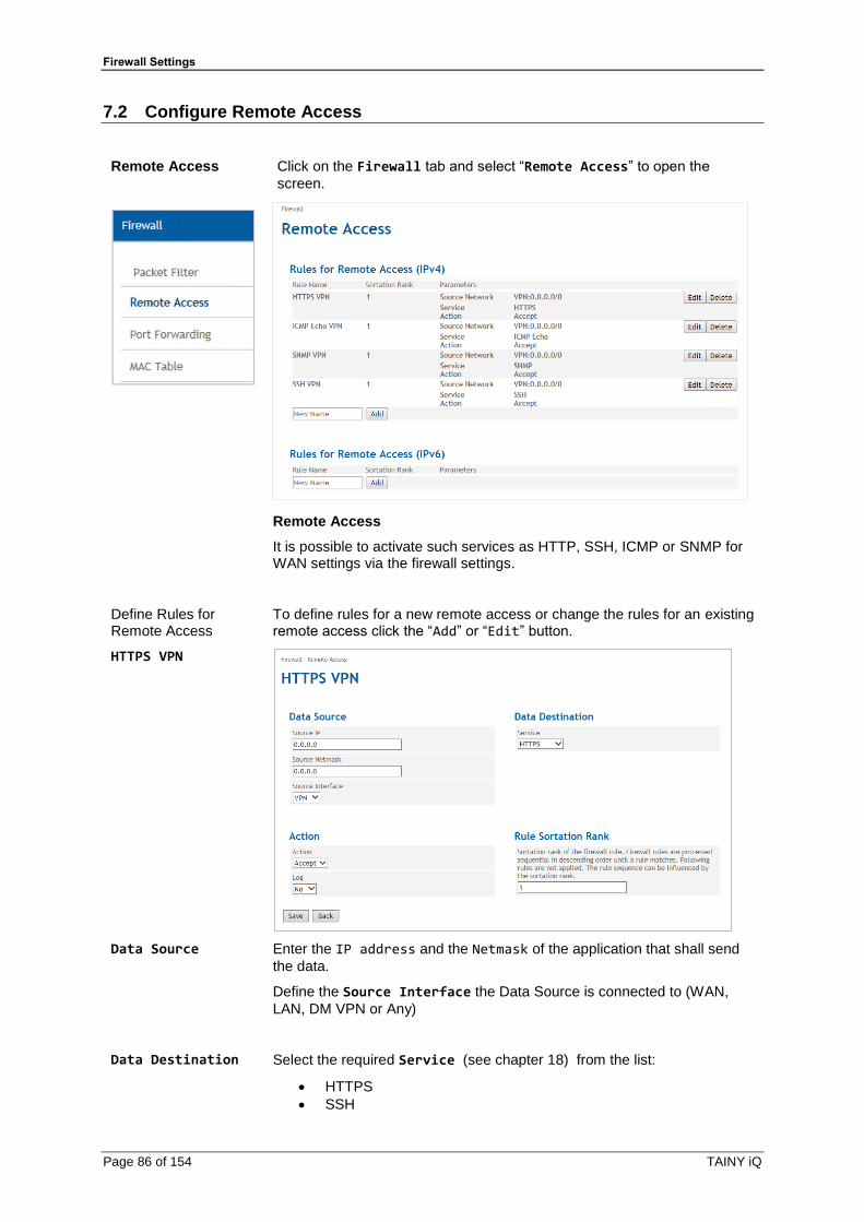
Firewall Settings
Page 86 of 154 TAINY iQ
7.2 Configure Remote Access
Remote Access
Click on the Firewall tab and select “Remote Access” to open the
screen.
Remote Access
It is possible to activate such services as HTTP, SSH, ICMP or SNMP for WAN settings via the firewall settings.
Define Rules for Remote Access
HTTPS VPN
To define rules for a new remote access or change the rules for an existing remote access click the “Add” or “Edit” button.
Data Source
Enter the IP address and the Netmask of the application that shall send
the data.
Define the Source Interface the Data Source is connected to (WAN,
LAN, DM VPN or Any)
Data Destination
Select the required Service (see chapter 18) from the list:
• HTTPS
• SSH

Firewall Settings
TAINY iQ Page 87 of 154
• ICMP
• SNMP
• RS232
• IP
Action
Action
Define whether data from this Data Source shall be Accepted, Dropped or
Rejected.
If Log is enabled (Yes) each time the conditions for the rule are fulfilled, an
entry will be made to a firewall log, retrievable via the Snapshot (see chapter 15.6)
To log all action select “Yes”.
Rule Sortation Rank
Sortation Rank of the firewall rule. Firewall rules are processed sequential in descending order until a rule matches. Following rules are not applied. The rule sequence can be influenced by the sortation rank. Rank 1 will be processed first, rank 2 second, etc.
Remote Access Rules IPv6
Create rules for the remote access of IPv6 based connections
To set up a new remote access or to change the rules for an existing remote access, press "Add" (enter the name for the new access here) or "Edit".
As an example we have created a rule called “IPv6-Remote-Access”.
Data Source
Enter the IPv6 address and the IPv6 netmask of the application that is to send data.
Data Destination Select the required service (see chapter 17) from the list:
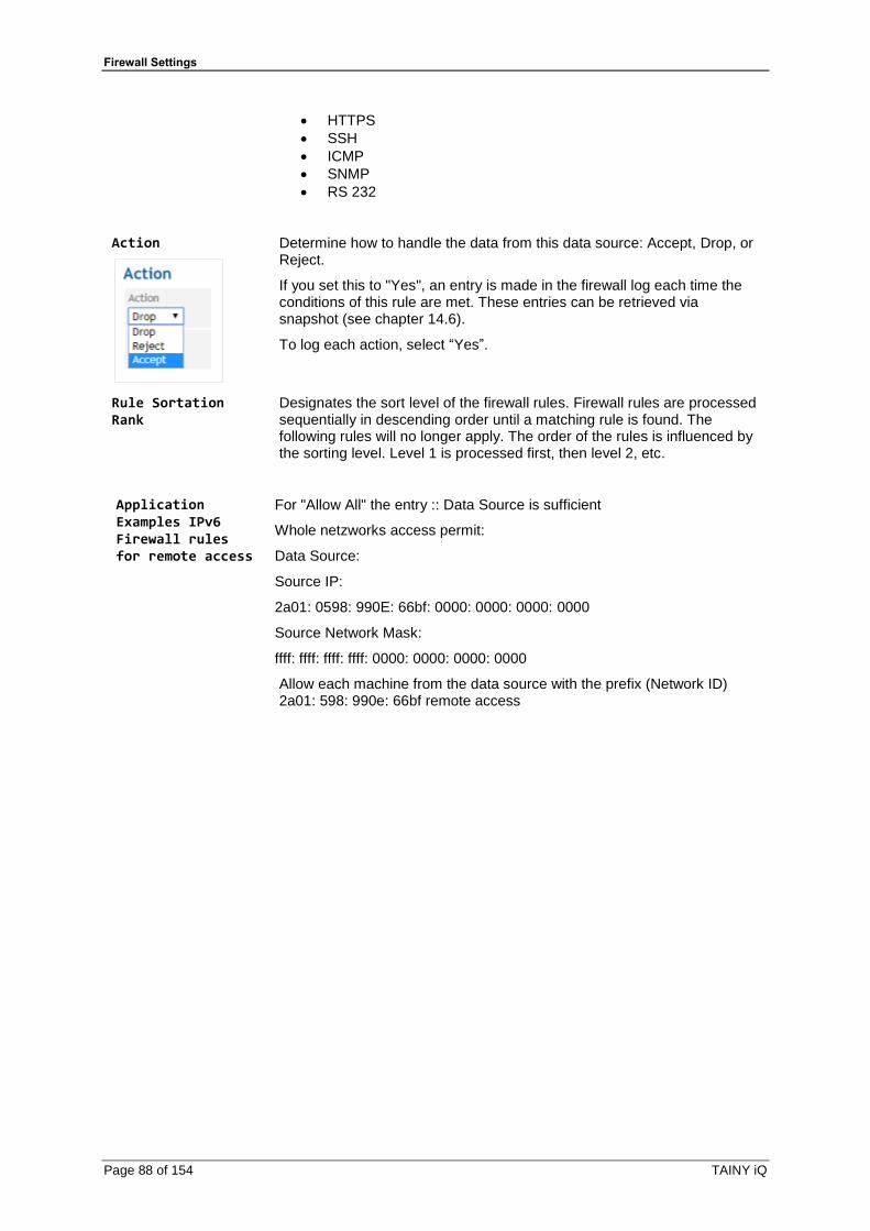
Firewall Settings
Page 88 of 154 TAINY iQ
• HTTPS
• SSH
• ICMP
• SNMP
• RS 232
Action
Determine how to handle the data from this data source: Accept, Drop, or Reject.
If you set this to "Yes", an entry is made in the firewall log each time the conditions of this rule are met. These entries can be retrieved via snapshot (see chapter 14.6).
To log each action, select “Yes”.
Rule Sortation Rank
Designates the sort level of the firewall rules. Firewall rules are processed sequentially in descending order until a matching rule is found. The following rules will no longer apply. The order of the rules is influenced by the sorting level. Level 1 is processed first, then level 2, etc.
Application Examples IPv6 Firewall rules for remote access
For "Allow All" the entry :: Data Source is sufficient
Whole netzworks access permit:
Data Source:
Source IP:
2a01: 0598: 990E: 66bf: 0000: 0000: 0000: 0000
Source Network Mask:
ffff: ffff: ffff: ffff: 0000: 0000: 0000: 0000
Allow each machine from the data source with the prefix (Network ID) 2a01: 598: 990e: 66bf remote access
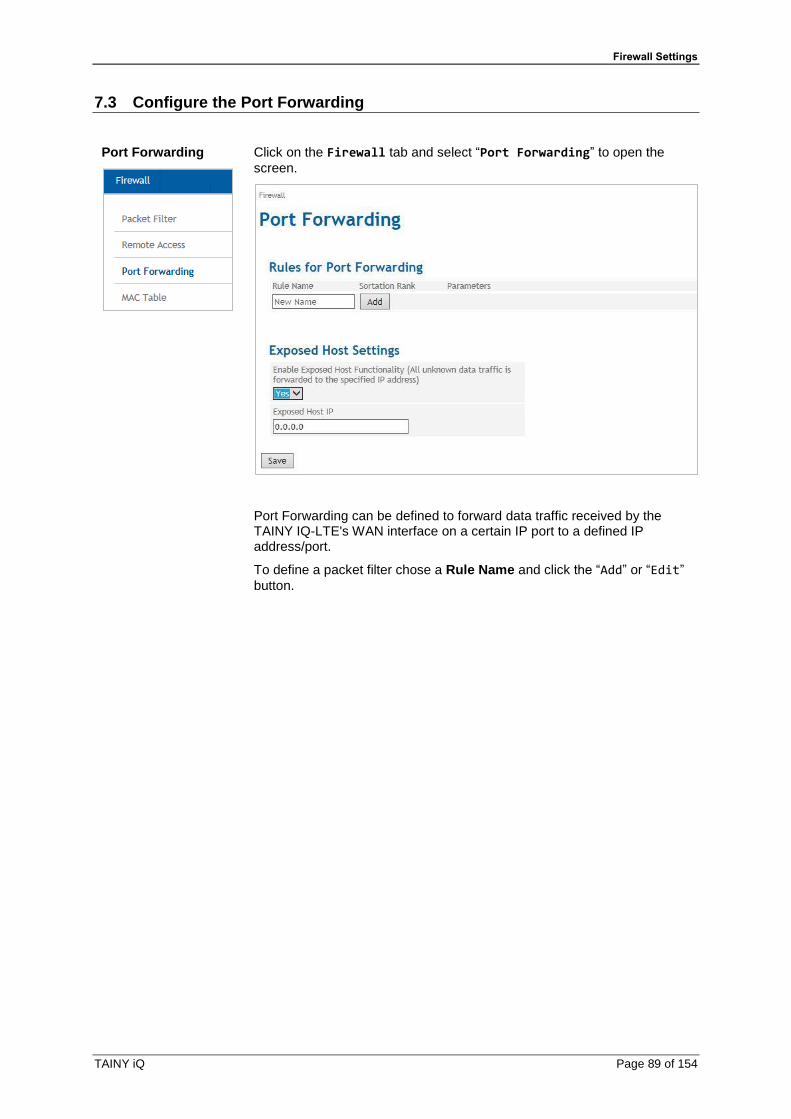
Firewall Settings
TAINY iQ Page 89 of 154
7.3 Configure the Port Forwarding
Port Forwarding
Click on the Firewall tab and select “Port Forwarding” to open the
screen.
Port Forwarding can be defined to forward data traffic received by the TAINY IQ-LTE's WAN interface on a certain IP port to a defined IP address/port.
To define a packet filter chose a Rule Name and click the “Add” or “Edit”
button.
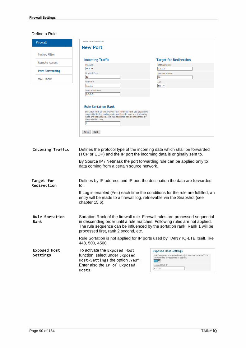
Firewall Settings
Page 90 of 154 TAINY iQ
Define a Rule
Incoming Traffic
Defines the protocol type of the incoming data which shall be forwarded (TCP or UDP) and the IP port the incoming data is originally sent to.
By Source IP / Netmask the port forwarding rule can be applied only to data coming from a certain source network.
Target for Redirection
Defines by IP address and IP port the destination the data are forwarded to.
If Log is enabled (Yes) each time the conditions for the rule are fulfilled, an
entry will be made to a firewall log, retrievable via the Snapshot (see chapter 15.6).
Rule Sortation Rank
Sortation Rank of the firewall rule. Firewall rules are processed sequential in descending order until a rule matches. Following rules are not applied. The rule sequence can be influenced by the sortation rank. Rank 1 will be processed first, rank 2 second, etc.
Rule Sortation is not applied for IP ports used by TAINY IQ-LTE itself, like 443, 500, 4500.
Exposed Host Settings
To activate the Exposed Host
function select under Exposed Host-Settings the option „Yes“.
Enter also the IP of Exposed Hosts.
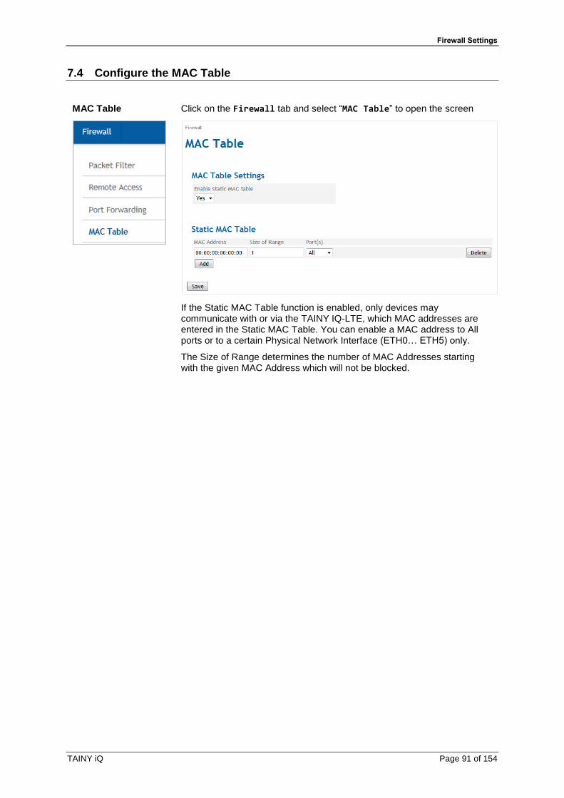
Firewall Settings
TAINY iQ Page 91 of 154
7.4 Configure the MAC Table
MAC Table
Click on the Firewall tab and select “MAC Table” to open the screen
If the Static MAC Table function is enabled, only devices may communicate with or via the TAINY IQ-LTE, which MAC addresses are entered in the Static MAC Table. You can enable a MAC address to All ports or to a certain Physical Network Interface (ETH0… ETH5) only.
The Size of Range determines the number of MAC Addresses starting with the given MAC Address which will not be blocked.
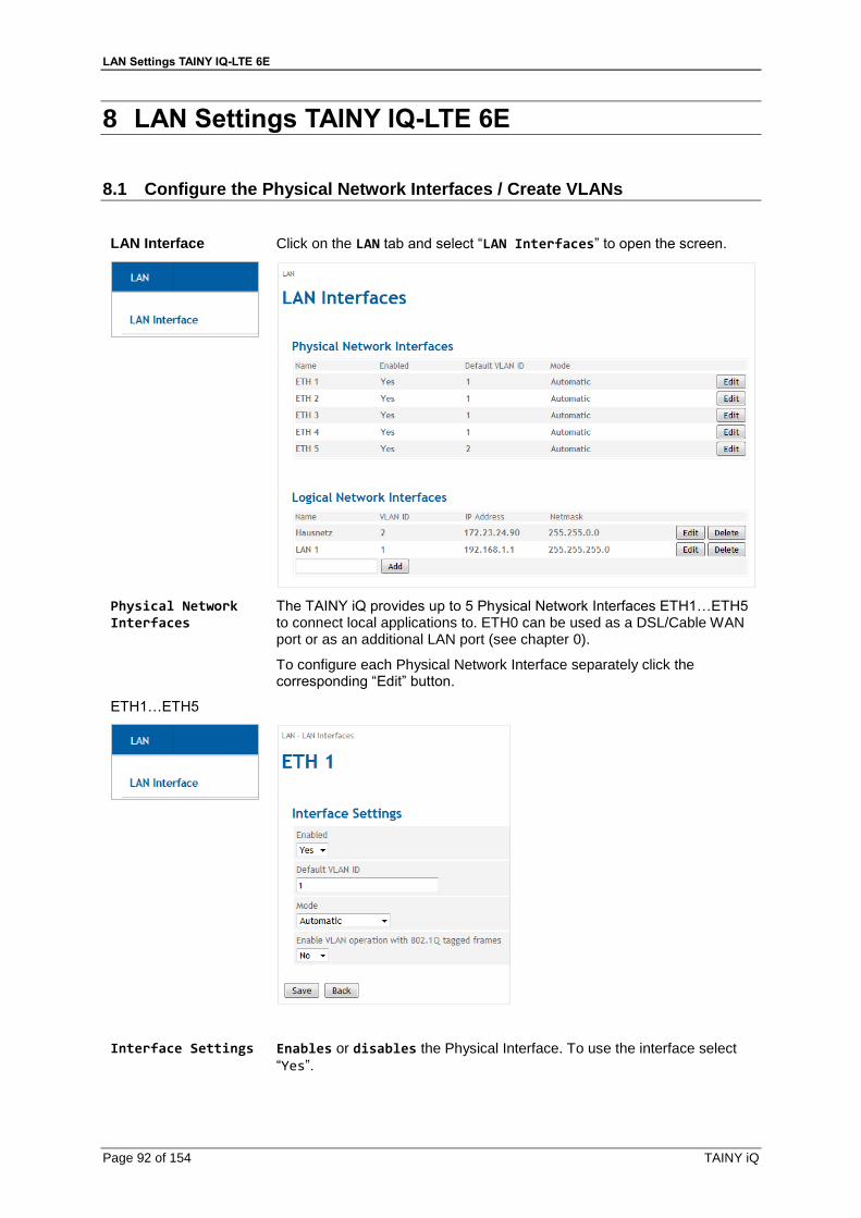
LAN Settings TAINY IQ-LTE 6E
Page 92 of 154 TAINY iQ
8 LAN Settings TAINY IQ-LTE 6E
8.1 Configure the Physical Network Interfaces / Create VLANs
LAN Interface
Click on the LAN tab and select “LAN Interfaces” to open the screen.
Physical Network Interfaces
The TAINY iQ provides up to 5 Physical Network Interfaces ETH1…ETH5 to connect local applications to. ETH0 can be used as a DSL/Cable WAN port or as an additional LAN port (see chapter 0).
To configure each Physical Network Interface separately click the corresponding “Edit” button.
ETH1…ETH5
Interface Settings
Enables or disables the Physical Interface. To use the interface select
“Yes”.

LAN Settings TAINY IQ-LTE 6E
TAINY iQ Page 93 of 154
Mode
Selects the data transmission rate (10Mbit/s or 100Mbit/s) and the transmission method (half duplex or full duplex). If the mode is set to “Automatic”, the TAINY iQ and the device connected to this Physical
Interface determines the settings automatically.
VLAN ID
This ID assigns the Physical Interface to a Virtual Local Area Network (VLAN). All Physical Interfaces which have the same VLAN ID are part of this VLAN.
See Glossary.
Enable VLAN Tags (802.1Q)
Select “Yes”, if the VLAN Tags shall be forwarded via this Physical
Interface towards the connected application. Otherwise the VLAN Tags will be removed for outbound communication.

LAN Settings TAINY IQ-LTE 6E
Page 94 of 154 TAINY iQ
8.2 Configure the Logical Network Interfaces / Address Assignment (DHCP)
LAN Interface
Click on the LAN tab and select “LAN Interfaces” to open the screen.
LAN 1
Click the “Add” button to create a new Logical Network Interface, Click the
“Edit” button to modify the settings.

LAN Settings TAINY IQ-LTE 6E
TAINY iQ Page 95 of 154
Interface Settings VLAN ID: Enter the ID of the VLAN to which this Logical Network Interface
shall relate to. A Logical Network Interface may only relate to one VLAN.
MTU: Enter the MTU (Maximum Transmission Unit) to determine the
maximum size of IP packets.
Interface Hostname
The Logical Network Interface can either be addressed by an IP address or a hostname. To address it by hostname enter the hostname in the entry field.
DNS Searchpath
Enter the Domain Name of the search path.
Hostname Assignment
Hostname, IP Address: The TAINY iQ allows assigning IP addresses of
remote stations to hostnames. Using this function, applications connected to TAINY iQ’s LAN interfaces address these remote stations by the entered hostnames. TAINY iQ functions (e.g. NTP) also use this feature. See also the Hostname Assignment related to the WAN setup, chapter 6.12.
DHCP Settings
DHCP Operation: The TAINY iQ provides a DHCP server function or a
DHCP relay function.
Note
Only the primary IP-address of the interface (e.g. Eth0) is used as DHCP-Gateway-IP.
If the DHCP server function is activated, the TAINY iQ itself assigns IP addresses to applications connected to the LAN interface. Define the range of address the assigned IP addresses shall be taken from and/or static IP leases.
If the DHCP relay function is activated, the TAINY iQ routes the DHCP requests of applications connected to the LAN interface to a remote DHCP relay server which provides the IP addresses. Enter the hostname or the IP address of the DHCP Relay Server.

LAN Settings TAINY IQ-LTE 6E
Page 96 of 154 TAINY iQ
8.3 Configure VRRP
VRRP Settings Click on the LAN tab and select “LAN Interface” to open the screen.
The TAINY iQ supports the Virtual Router Redundancy Protocol (VRRP). Enable/disable this function in the submenu the LAN tab for Logical Network Interfaces. Two TAINY iQ routers perform as one virtual router. If one TAINY iQ loses the WAN connection (or the VPN connection) the second TAINY iQ takes over/supports the connection.
If you define several virtual routers for a network, make sure to assign different IDs to them.
The VRRP Priority defines which TAINY acts as master and which as the backup. The TAINY iQ which has the highest priority acts as the master. Enter values between 1 (lowest prio) and 254 (highest prio). The VRRP priority can be adjusted automatically to a new value (Adjusted VRRP Priority) in case of an active WAN or VPN connection.
Virtual Router
Local
application
TAINY
TAINYAPN
HSPA+,
UMTS
(E-)GPRS
INTERNET
IPVRRP
IP1
IP2
The IPVRRP is the IP address of the Virtual Router. Enter/Add it to the VRRP IP Address List. Use this as the standard gateway for the local application. IP1 and IP2 are the IP addresses of TAINY iQs as being entered in the IP Address Configuration of each TAINY iQ.

LAN Settings TAINY IQ-LTE
TAINY iQ Page 97 of 154
9 LAN Settings TAINY IQ-LTE
9.1 Configure the LAN Interface/DHCP/VRRP Settings
LAN Interface
Click on the LAN tab and select “LAN Interface” to open the screen.

LAN Settings TAINY IQ-LTE
Page 98 of 154 TAINY iQ
Interfaces Settings
Enable
Select “Yes” to enable the interface.
Mode
Set the required mode to select the required data transmission rate (10Mbit/s or 100Mbit/s) and the transmission method (half duplex or full duplex).
If the mode is set to “Automatic”, the TAINY IQ-LTE and the device
connected to this LAN Interface determines the settings automatically
Enable 802.1Q VLAN
Set to “Yes” and enter the ID of the VLAN to enable the communication
with 802.1q tagged Ethernet frames.
Set to “No” to disable 802.1q tagged in this interface.
MTU
Enter the MTU (Maximum Transmission Unit) to determine the maximum size of IP packets.
Interface Hostname
The Logical Network Interface can either be addressed by an IP address or a hostname. To address it by hostname enter the hostname in the entry field.
DNS Searchpath
Enter the Domain Name Server of the search path
DHCP Settings DHCP Operation
The TAINY IQ-LTE provides a DHCP server function or a DHCP relay function
If the DHCP server function is activated, the TAINY IQ-LTE itself assigns IP addresses to applications connected to the LAN interface. Define the range of address the assigned IP addresses shall be taken from and/or static IP leases.
If the DHCP relay function is activated, the TAINY IQ-LTE routes the DHCP requests of applications connected to the LAN interface to a remote DHCP relay server which
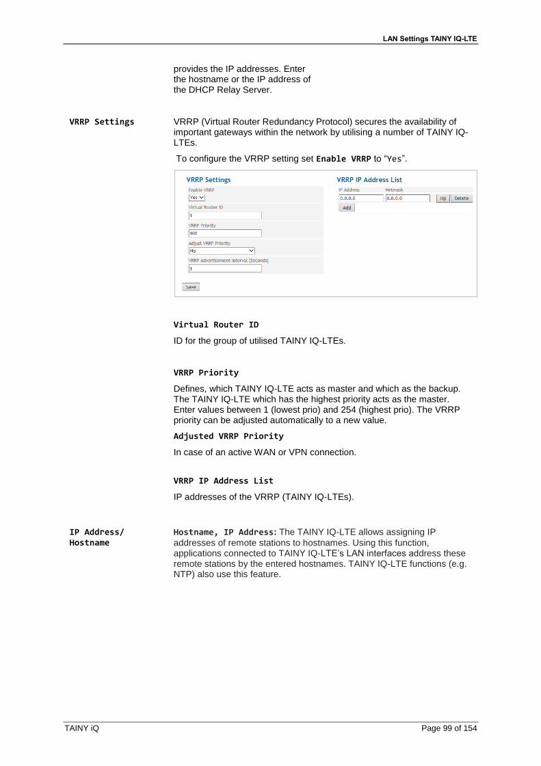
LAN Settings TAINY IQ-LTE
TAINY iQ Page 99 of 154
provides the IP addresses. Enter the hostname or the IP address of the DHCP Relay Server.
VRRP Settings VRRP (Virtual Router Redundancy Protocol) secures the availability of important gateways within the network by utilising a number of TAINY IQ-LTEs.
To configure the VRRP setting set Enable VRRP to “Yes”.
Virtual Router ID
ID for the group of utilised TAINY IQ-LTEs.
VRRP Priority
Defines, which TAINY IQ-LTE acts as master and which as the backup. The TAINY IQ-LTE which has the highest priority acts as the master. Enter values between 1 (lowest prio) and 254 (highest prio). The VRRP priority can be adjusted automatically to a new value.
Adjusted VRRP Priority
In case of an active WAN or VPN connection.
VRRP IP Address List
IP addresses of the VRRP (TAINY IQ-LTEs).
IP Address/ Hostname
Hostname, IP Address: The TAINY IQ-LTE allows assigning IP
addresses of remote stations to hostnames. Using this function, applications connected to TAINY IQ-LTE’s LAN interfaces address these remote stations by the entered hostnames. TAINY IQ-LTE functions (e.g. NTP) also use this feature.

LAN Settings TAINY IQ-LTE
Page 100 of 154 TAINY iQ
9.2 Configure VRRP
VRRP Settings Click on the LAN tab and select “LAN Interface” to open the screen.
The TAINY IQ-LTE supports the Virtual Router Redundancy Protocol (VRRP). Enable/disable this function in the submenu the LAN tab for Logical Network Interfaces. Two TAINY IQ-LTE routers perform as one virtual router. If one TAINY IQ-LTE loses the WAN connection (or the VPN connection) the second TAINY IQ-LTE takes over/supports the connection.
Virtual Router ID
ID for the group of utilised TAINY IQ-LTEs.
VRRP Priority
Defines, which TAINY IQ-LTE acts as master and which as the backup. The TAINY IQ-LTE which has the highest priority acts as the master. Enter values between 1 (lowest prio) and 254 (highest prio). The VRRP priority can be adjusted automatically to a new value.
Adjusted VRRP Priority
In case of an active WAN or VPN connection.
Virtual Router
Local
application
TAINY
TAINYAPN
HSPA+,
UMTS
(E-)GPRS
INTERNET
IPVRRP
IP1
IP2
The IPVRRP is the IP address of the Virtual Router. Enter/Add it to the VRRP IP Address List. Use this as the standard gateway for the local
application. IP1 and IP2 are the IP addresses of TAINY IQ-LTEs as being entered in the IP Address Configuration of each
TAINY IQ-LTE.

LAN Settings TAINY IQ-LTE
TAINY iQ Page 101 of 154
IP Address/ Hostname
Hostname, IP Address: The TAINY IQ-LTE allows assigning IP addresses of remote stations to hostnames. Using this function, applications connected to TAINY IQ-LTE’s LAN interfaces address these remote stations by the entered hostnames. TAINY IQ-LTE functions (e.g. NTP) also use this feature.
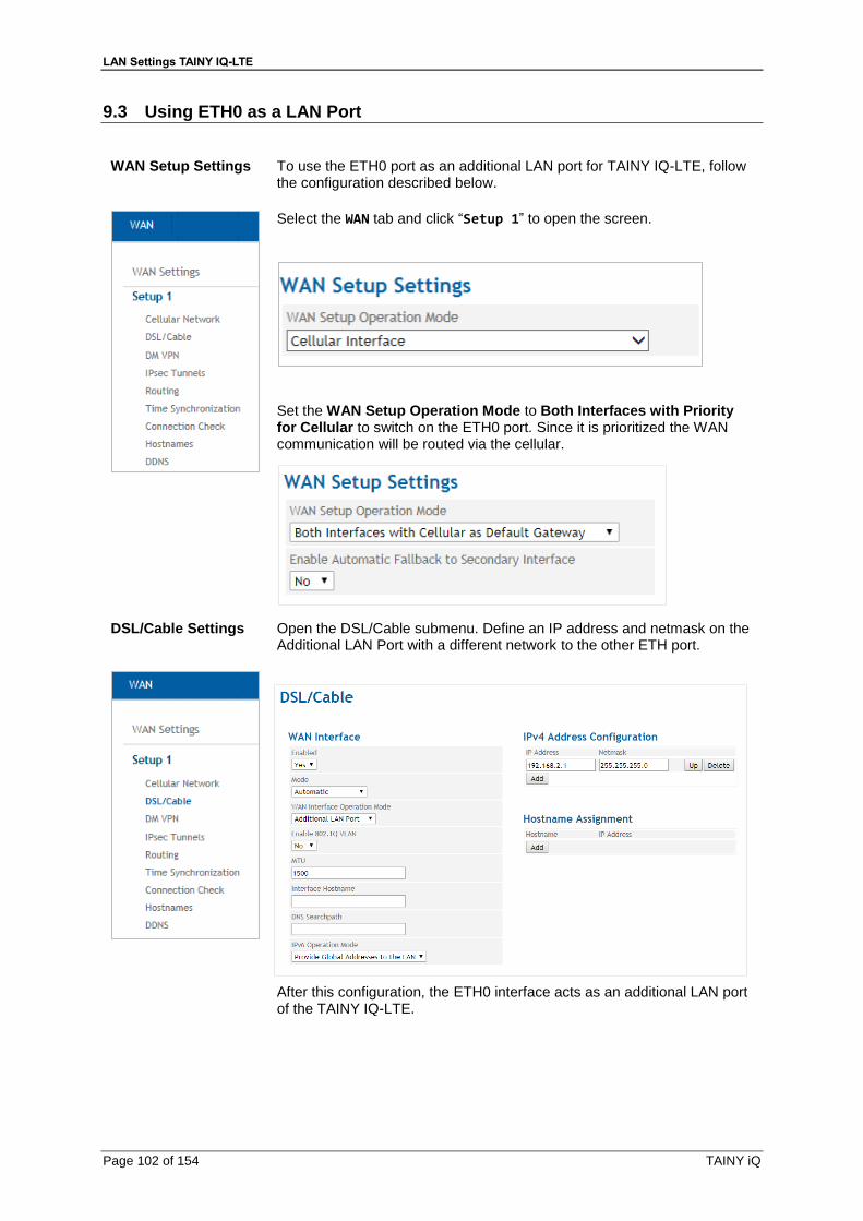
LAN Settings TAINY IQ-LTE
Page 102 of 154 TAINY iQ
9.3 Using ETH0 as a LAN Port
WAN Setup Settings
To use the ETH0 port as an additional LAN port for TAINY IQ-LTE, follow the configuration described below.
Select the WAN tab and click “Setup 1” to open the screen.
Set the WAN Setup Operation Mode to Both Interfaces with Priority for Cellular to switch on the ETH0 port. Since it is prioritized the WAN communication will be routed via the cellular.
DSL/Cable Settings
Open the DSL/Cable submenu. Define an IP address and netmask on the Additional LAN Port with a different network to the other ETH port.
After this configuration, the ETH0 interface acts as an additional LAN port of the TAINY IQ-LTE.

LAN Settings TAINY IQ-LTE
TAINY iQ Page 103 of 154
Note
Configure LAN interface
Configure 2 different networks for the ETH0 interface and for the ETH1 interface. The TAINY IQ-LTE will route data packets between these two networks.
Firewall Packet Filter
Click on the Firewall tab and select “Packet Filter” to open the
screen.
Define a Firewall package filter rule and allow traffic from LAN to LAN.
Action select “Accept”
Press “Save”
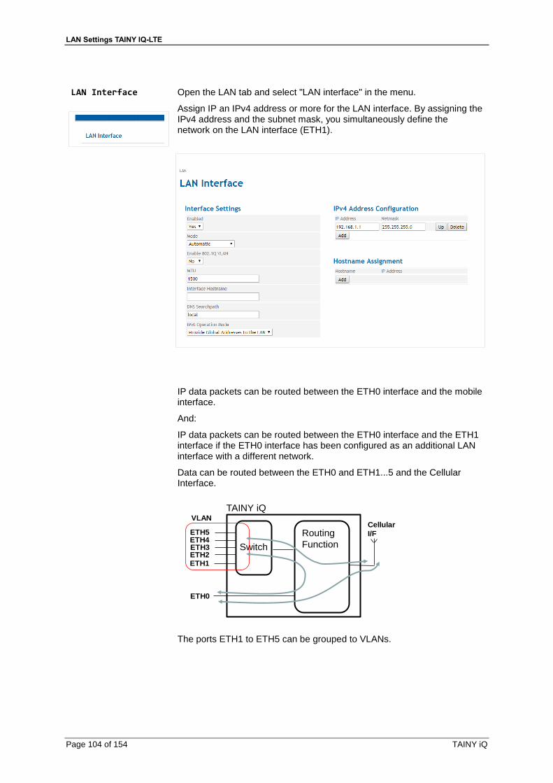
LAN Settings TAINY IQ-LTE
Page 104 of 154 TAINY iQ
LAN Interface
Open the LAN tab and select "LAN interface" in the menu.
Assign IP an IPv4 address or more for the LAN interface. By assigning the IPv4 address and the subnet mask, you simultaneously define the network on the LAN interface (ETH1).
IP data packets can be routed between the ETH0 interface and the mobile interface.
And:
IP data packets can be routed between the ETH0 interface and the ETH1 interface if the ETH0 interface has been configured as an additional LAN interface with a different network.
Data can be routed between the ETH0 and ETH1...5 and the Cellular Interface.
Switch
Routing
Function
TAINY iQ
ETH1ETH2ETH3ETH4ETH5
ETH0
Cellular
I/F
VLAN
The ports ETH1 to ETH5 can be grouped to VLANs.
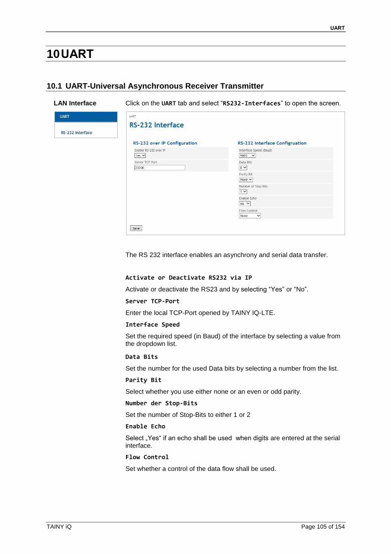
UART
TAINY iQ Page 105 of 154
10 UART
10.1 UART-Universal Asynchronous Receiver Transmitter
LAN Interface
Click on the UART tab and select “RS232-Interfaces” to open the screen.
The RS 232 interface enables an asynchrony and serial data transfer.
Activate or Deactivate RS232 via IP
Activate or deactivate the RS23 and by selecting “Yes” or “No”.
Server TCP‐Port
Enter the local TCP-Port opened by TAINY IQ-LTE.
Interface Speed
Set the required speed (in Baud) of the interface by selecting a value from the dropdown list.
Data Bits
Set the number for the used Data bits by selecting a number from the list.
Parity Bit
Select whether you use either none or an even or odd parity.
Number der Stop‐Bits
Set the number of Stop-Bits to either 1 or 2
Enable Echo
Select „Yes“ if an echo shall be used when digits are entered at the serial interface.
Flow Control
Set whether a control of the data flow shall be used.

Network Tools
Page 106 of 154 TAINY iQ
11 Network Tools
11.1 Network Tool Ping
Ping
Click on the Network Tools tab and select “Ping” to open the screen.
Use this tool to establish whether a certain host within the network is available as well as the time span for a RTT (Round trip time).
Execute Ping-command
To execute a Pin command enter he host-address oft eh host in question.
Enter the size (bytes) of the user data and click on Execute.
The result appears below Executed Ping Command.
.
11.2 Network Tools Traceroute
Ping
Traceroute
Click on the Network Tools tab and select “Traceroute” to open the
screen.
This tool shows the routers and joints within the network the IP packages pass along the way from the sender to the receiver.
Execute Traceroute command
To execute the Traceroute command enter he host-address
Select the Traceroute Mode.
Click on Execute.
The result appears below Executed Traceroute Command.
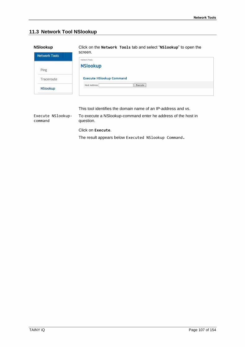
Network Tools
TAINY iQ Page 107 of 154
11.3 Network Tool NSlookup
NSlookup
Click on the Network Tools tab and select “NSlookup” to open the
screen.
This tool identifies the domain name of an IP-address and vs.
Execute NSlookup-command
To execute a NSlookup‐command enter he address of the host in question.
Click on Execute.
The result appears below Executed NSlookup Command.
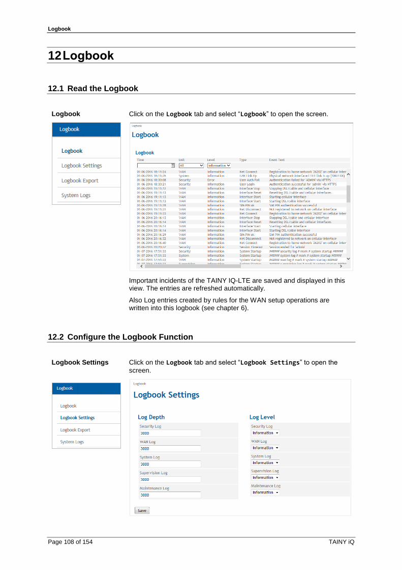
Logbook
Page 108 of 154 TAINY iQ
12 Logbook
12.1 Read the Logbook
Logbook
Click on the Logbook tab and select “Logbook” to open the screen.
Important incidents of the TAINY IQ-LTE are saved and displayed in this view. The entries are refreshed automatically.
Also Log entries created by rules for the WAN setup operations are written into this logbook (see chapter 6).
12.2 Configure the Logbook Function
Logbook Settings
Click on the Logbook tab and select “Logbook Settings” to open the
screen.
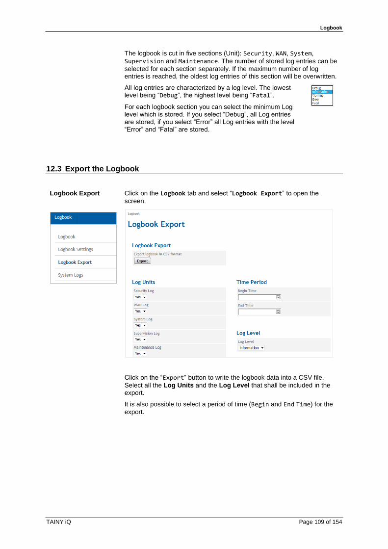
Logbook
TAINY iQ Page 109 of 154
The logbook is cut in five sections (Unit): Security, WAN, System,
Supervision and Maintenance. The number of stored log entries can be
selected for each section separately. If the maximum number of log entries is reached, the oldest log entries of this section will be overwritten.
All log entries are characterized by a log level. The lowest level being “Debug”, the highest level being “Fatal”.
For each logbook section you can select the minimum Log level which is stored. If you select “Debug”, all Log entries are stored, if you select “Error” all Log entries with the level “Error” and “Fatal” are stored.
12.3 Export the Logbook
Logbook Export
Click on the Logbook tab and select “Logbook Export” to open the
screen.
Click on the “Export” button to write the logbook data into a CSV file.
Select all the Log Units and the Log Level that shall be included in the export.
It is also possible to select a period of time (Begin and End Time) for the
export.

Logbook
Page 110 of 154 TAINY iQ
12.4 System Logs
Export System Logs
Click on the Logbook tab and select “Logbook Export” to open the
screen.
Export Firewall Log
Click “Export” button to export the firewall log file in a zip file to an
external pc.
accept log Data packages that are accepted by the firewall
drop log Data packages that are discarded by the firewall
port fw log
Data packages that are forwarded by the firewall
reject log
Data packages that are rejected by the firewall
Export IPsec Log
Click “Export” button to export the IPsec Log file in a zip file to an
external pc.

Manage Users, Enable/Disable SNMP Access
TAINY iQ Page 111 of 154
13 Manage Users, Enable/Disable SNMP Access
Current User
Click on: the Users tab and select “Current User” to open the screen.
Change Password In this screens information about the current user are displayed. Click on the “Change” button to
change the password of the current user.
User Management
Click on: the Users tab and select “User Management” to open the
screen.
Click the “Add” to define an additional user or the “Edit” button to change
the settings for an existing user.

Manage Users, Enable/Disable SNMP Access
Page 112 of 154 TAINY iQ
Add User User Group
Select the “User Group”, the new
user belongs to. The user’s access rights are defined by the User Group. An Admin has got unlimited rights, whereas the rights of Guest or Operator “User Groups” can be
limited (see Access Rights below).
If required set the complexity and length for the user’s password.
Edit User
User Settings If required change the user group of the user.
For each user you define the Required Password Complexity (numbers, letters, upper case, lower case, special characters) and the Minimum Password Length.
Apart from assigning a password you can delete the user in this screen.
SNMPv3 Settings Select “Yes” to enable the access via SNMPv3 for the current user.
Enter the Authentication and a Cryptographic Key for this access.

Manage Users, Enable/Disable SNMP Access
TAINY iQ Page 113 of 154
13.1 Configure Operator and Guests Access Rights
Access Rights
Click on the Users tab and select “Access Rights” to open the screen.
Access Rights While an Admin always has got full access rights, the access rights of the members of the Guest user group and the Operator user group are limited. Define the Access Rights for the Guest and Operator Group in
the corresponding columns of the screen.

Manage Users, Enable/Disable SNMP Access
Page 114 of 154 TAINY iQ
13.2 Configure TACACS+
TACACS+
Click on: the Users tab and select “TACACS+” to open the screen.
With the authentication method TACACS+ (Terminal Access Controller Access Control System Plus), the access data for the TAINY IQ-LTE are not saved on the device itself, but on an external server.
In the event of a registration request, the TAINY IQ-LTE forwards the registration data to the TACACS+ server. The server checks the validity of the data and reports the result back to the TAINY IQ-LTE, which then either rejects or accepts the registration.
Activate the authentication process TACACS+ in this screen by setting the parameters, the TAINY IQ-LTE needs to connect to the TACACS+ server.
As soon as the TACACS+ service is activated, the type of registration can be selected from an additional drop-down list (TACACS+ or Local) in the registration.
Primary /Secondary TACACS+ Server
A primary and a secondary (backup) TACACS+ server can be used.
At each login the router issues the message „verifying username or password“. This message will also appear if TAINY IQ-LTE cannot reach
the TACAS+.
This is all due to safety reasons, in order to not provide any information. to an attacker

Manage Users, Enable/Disable SNMP Access
TAINY iQ Page 115 of 154
Enter the Hostname (or IP address), port number, shared secret and authentication protocol to reach and access the TACACS+ server.
Access Rights
In the TACACS+ protocol the access right levels of a user are numerical coded from 1 to 15. The TAINY IQ-LTE provides three access right levels (administrator, operator and guest).
To map the levels of the TACACS+ protocol to the levels of TAINY IQ-LTE, define the minimum TACACS+ level the user shall have for TAINY IQ-LTE administrator rights and the define the minimum TACACS+ level, the user shall have for TAINY IQ-LTE operator rights. Below the operator level, the user has guests’ rights only.
13.3 Configure RADIUS
TACACS+
Click on: the Users tab and select “TACACS+” to open the screen.
With the authentication method RADIUS (Terminal Access Controller Access Control System Plus), the access data for the TAINY IQ-LTE are not saved on the device itself, but on an external server.
In the event of a registration request, the TAINY IQ-LTE forwards the registration data to the TACACS+ server. The server checks the validity of the data and reports the result back to the TAINY IQ-LTE, which then either rejects or accepts the registration.
Activate the authentication process TACACS+ in this screen by setting the parameters, the TAINY IQ-LTE needs to connect to the TACACS+ server.
As soon as the TACACS+ service is activated, the type of registration can be selected from an additional drop-down list (TACACS+ or Local) in the registration.

Manage Users, Enable/Disable SNMP Access
Page 116 of 154 TAINY iQ
Primary /Secondary TACACS+ Server
A primary and a secondary (backup) TACACS+ server can be used.
Enter the Hostname (or IP address), port number, shared secret and authentication protocol to reach and access the TACACS+ server.

Certificates
TAINY iQ Page 117 of 154
14 Certificates
14.1 Device Certificates
Device Certificates
Click on the Certificates tab and select “Device Certificates” to
open the screen.
Device Certificates are all certificates of TAINY IQ-LTE. The opposite entity certificates are the Remote Certificates as described in the next chapter. See also Glossary for further information. In this view information on the device certificates, the request templates and the currently used RSA Key Pair are displayed.
It is possible to add new certificates and request templates as well as generate a new RSA Key Pair.
List of Device Certificates
View Details/Export Certificate
Click the “Details” button to display more detailed information on the
specific certificate.
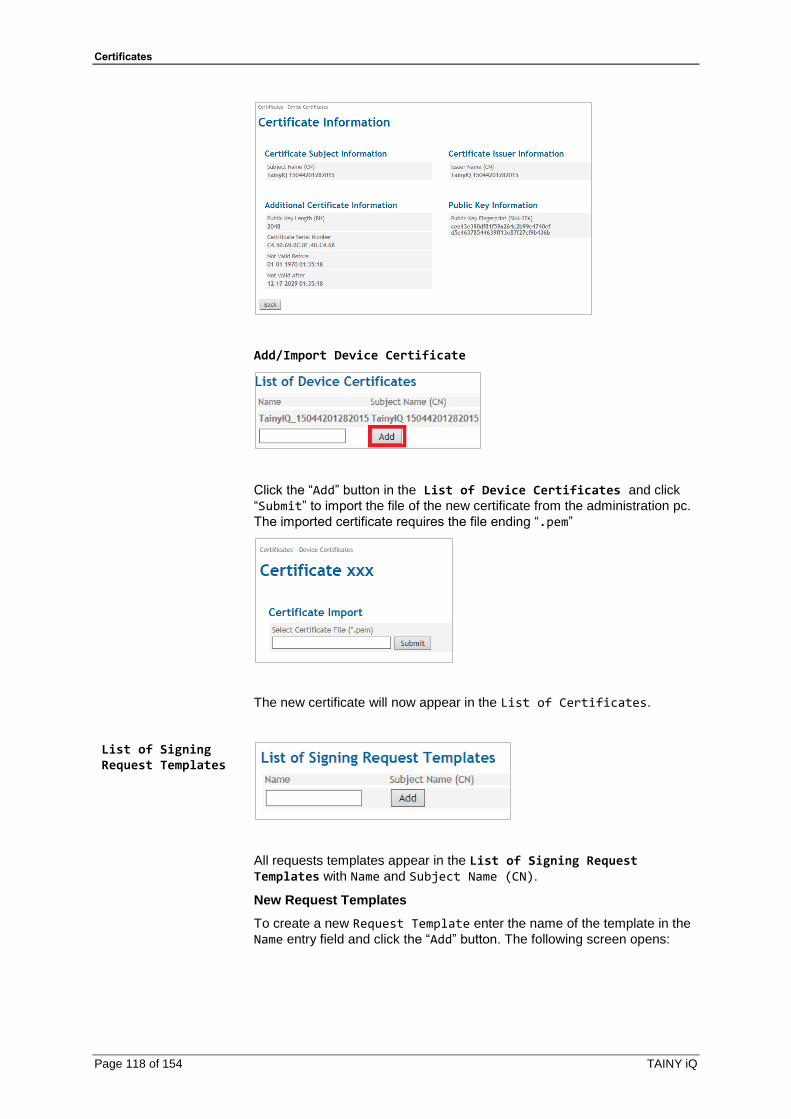
Certificates
Page 118 of 154 TAINY iQ
Add/Import Device Certificate
Click the “Add” button in the List of Device Certificates and click
“Submit” to import the file of the new certificate from the administration pc.
The imported certificate requires the file ending “.pem”
The new certificate will now appear in the List of Certificates.
List of Signing Request Templates
All requests templates appear in the List of Signing Request Templates with Name and Subject Name (CN).
New Request Templates
To create a new Request Template enter the name of the template in the
Name entry field and click the “Add” button. The following screen opens:
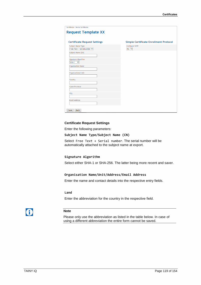
Certificates
TAINY iQ Page 119 of 154
Certificate Request Settings
Enter the following parameters:
Subject Name Type/Subject Name (CN)
Select Free Text + Serial number. The serial number will be
automatically attached to the subject name at export.
Signature Algorithm
Select either SHA-1 or SHA-256. The latter being more recent and saver.
Organisation Name/Unit/Address/Email Address
Enter the name and contact details into the respective entry fields.
Land
Enter the abbreviation for the country in the respective field.
Note
Please only use the abbreviation as listed in the table below. In case of using a different abbreviation the entire form cannot be saved.
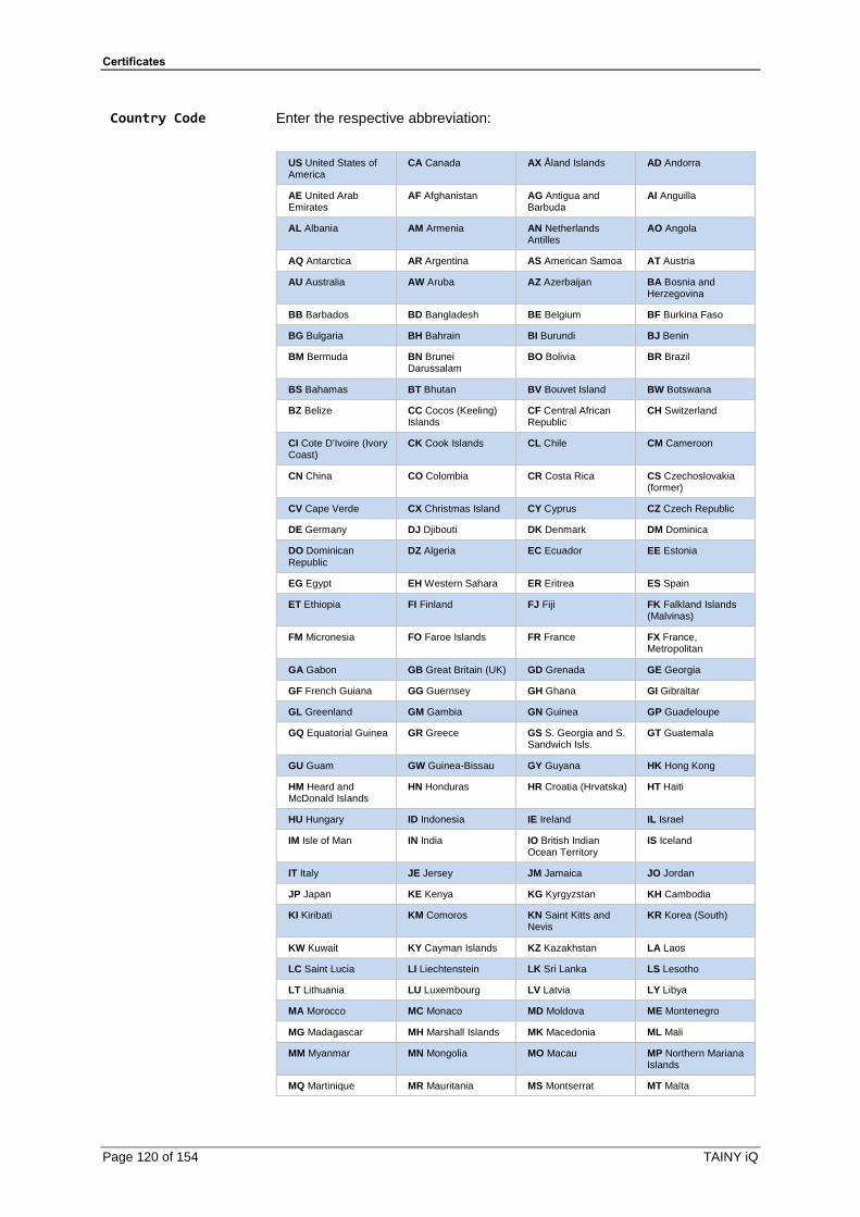
Certificates
Page 120 of 154 TAINY iQ
Country Code Enter the respective abbreviation:
US United States of America
CA Canada AX Åland Islands AD Andorra
AE United Arab Emirates
AF Afghanistan AG Antigua and Barbuda
AI Anguilla
AL Albania AM Armenia AN Netherlands Antilles
AO Angola
AQ Antarctica AR Argentina AS American Samoa AT Austria
AU Australia AW Aruba AZ Azerbaijan BA Bosnia and Herzegovina
BB Barbados BD Bangladesh BE Belgium BF Burkina Faso
BG Bulgaria BH Bahrain BI Burundi BJ Benin
BM Bermuda BN Brunei Darussalam
BO Bolivia BR Brazil
BS Bahamas BT Bhutan BV Bouvet Island BW Botswana
BZ Belize CC Cocos (Keeling) Islands
CF Central African Republic
CH Switzerland
CI Cote D'Ivoire (Ivory Coast)
CK Cook Islands CL Chile CM Cameroon
CN China CO Colombia CR Costa Rica CS Czechoslovakia (former)
CV Cape Verde CX Christmas Island CY Cyprus CZ Czech Republic
DE Germany DJ Djibouti DK Denmark DM Dominica
DO Dominican Republic
DZ Algeria EC Ecuador EE Estonia
EG Egypt EH Western Sahara ER Eritrea ES Spain
ET Ethiopia FI Finland FJ Fiji FK Falkland Islands (Malvinas)
FM Micronesia FO Faroe Islands FR France FX France, Metropolitan
GA Gabon GB Great Britain (UK) GD Grenada GE Georgia
GF French Guiana GG Guernsey GH Ghana GI Gibraltar
GL Greenland GM Gambia GN Guinea GP Guadeloupe
GQ Equatorial Guinea GR Greece GS S. Georgia and S. Sandwich Isls.
GT Guatemala
GU Guam GW Guinea-Bissau GY Guyana HK Hong Kong
HM Heard and McDonald Islands
HN Honduras HR Croatia (Hrvatska) HT Haiti
HU Hungary ID Indonesia IE Ireland IL Israel
IM Isle of Man IN India IO British Indian Ocean Territory
IS Iceland
IT Italy JE Jersey JM Jamaica JO Jordan
JP Japan KE Kenya KG Kyrgyzstan KH Cambodia
KI Kiribati KM Comoros KN Saint Kitts and Nevis
KR Korea (South)
KW Kuwait KY Cayman Islands KZ Kazakhstan LA Laos
LC Saint Lucia LI Liechtenstein LK Sri Lanka LS Lesotho
LT Lithuania LU Luxembourg LV Latvia LY Libya
MA Morocco MC Monaco MD Moldova ME Montenegro
MG Madagascar MH Marshall Islands MK Macedonia ML Mali
MM Myanmar MN Mongolia MO Macau MP Northern Mariana Islands
MQ Martinique MR Mauritania MS Montserrat MT Malta

Certificates
TAINY iQ Page 121 of 154
MU Mauritius MV Maldives MW Malawi MX Mexico
MY Malaysia MZ Mozambique NA Namibia NC New Caledonia
NE Niger NF Norfolk Island NG Nigeria NI Nicaragua
NL Netherlands NO Norway NP Nepal NR Nauru
NT Neutral Zone NU Niue NZ New Zealand (Aotearoa)
OM Oman
PA Panama PE Peru PF French Polynesia PG Papua New Guinea
PH Philippines PK Pakistan PL Poland PM St. Pierre and Miquelon
PN Pitcairn PR Puerto Rico PS Palestinian Territory
PT Portugal
PW Palau PY Paraguay QA Qatar RE Reunion
RO Romania RS Serbia RU Russian Federation
RW Rwanda
SA Saudi Arabia SB Solomon Islands SC Seychelles SE Sweden
SG Singapore SH St. Helena SI Slovenia SJ Svalbard and Jan Mayen Islands
SK Slovak Republic SL Sierra Leone SM San Marino SN Senegal
SR Suriname ST Sao Tome and Principe
SU USSR (former) SV El Salvador
SZ Swaziland TC Turks and Caicos Islands
TD Chad TF French Southern Territories
TG Togo TH Thailand TJ Tajikistan TK Tokelau
TM Turkmenistan TN Tunisia TO Tonga TP East Timor
TR Turkey TT Trinidad and Tobago
TV Tuvalu TW Taiwan
TZ Tanzania UA Ukraine UG Uganda UM US Minor Outlying Islands
UY Uruguay UZ Uzbekistan VA Vatican City State (Holy See)
VC Saint Vincent and the Grenadines
VE Venezuela VG Virgin Islands (British)
VI Virgin Islands (U.S.)
VN Viet Nam
VU Vanuatu WF Wallis and Futuna Islands
WS Samoa YE Yemen
YT Mayotte ZA South Africa ZM Zambia COM US Commercial
EDU US Educational GOV US Government INT International MIL US Military
NET Network ORG Non-Profit Organization
ARPA Old style Arpanet
State/Region
Enter the name of the state or region.
City
Enter the name of the city
Email-address
Enter the email-address.
Simple Certificate Enrolment Protocol
Set to “Yes” to obtain a device certificate of server that has to be
configured.
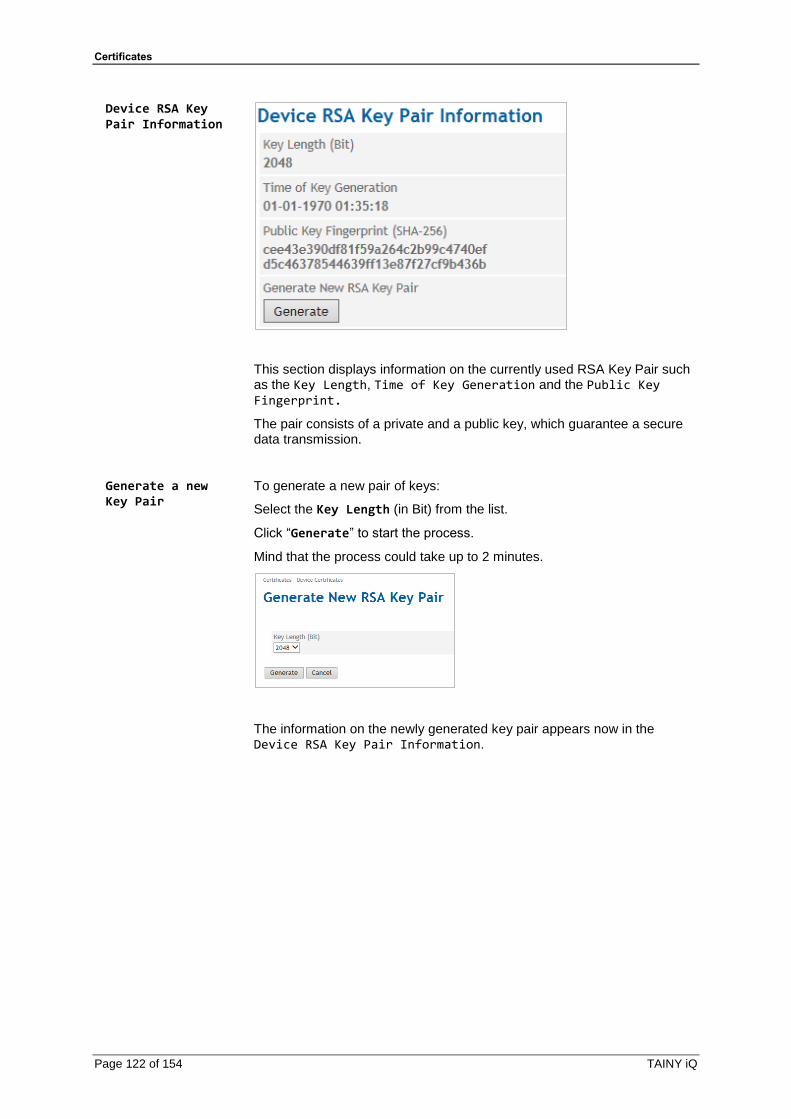
Certificates
Page 122 of 154 TAINY iQ
Device RSA Key Pair Information
This section displays information on the currently used RSA Key Pair such as the Key Length, Time of Key Generation and the Public Key Fingerprint.
The pair consists of a private and a public key, which guarantee a secure data transmission.
Generate a new Key Pair
To generate a new pair of keys:
Select the Key Length (in Bit) from the list.
Click “Generate” to start the process.
Mind that the process could take up to 2 minutes.
The information on the newly generated key pair appears now in the Device RSA Key Pair Information.

Certificates
TAINY iQ Page 123 of 154
14.2 Remote Certificates
Remote Certificates
Click on the Certificates tab and select “Device Certificates” to
open the screen.
Remote certificates are all certificates that are used to authenticate the opposite entities.
The List of CA certificates contains the certificates of the accepted Certificate Authorities
List of Remote Certificates
Add Remote Certificate
To upload a certificate from the opposite entity:
Enter a name in the Name entry field.
Click the “Add” button in the List of Remote Certificates.

Certificates
Page 124 of 154 TAINY iQ
The following screen opens:
Click on “Submit” to upload the file of the additional remote certificate
from the administration pc.
The new certificate will appear in the List of Remote Certificates.
List of CA Certificates
d CA Certificate/Add Remote Certificate
To upload a certificate from CA:
Enter a name in the Name entry field.
Click the “Add” button in the List of CA Certificates.
The following screen opens:
Click on “Submit” to upload the file of the additional CA certificate from
the administration pc.
The new certificate will appear in the List of CA Certificates.

System
TAINY iQ Page 125 of 154
15 System
15.1 Select the System Language
Web Interface
Click on the System tab and select “Web Interface” to open the screen.
Language Select the “Language” of the Web Interface in the General Web Settings.
Web Server Port Enter in the section general Web Settings the for the connection web interface required TCP-port.
Mind that after the modification of the port a new login is required
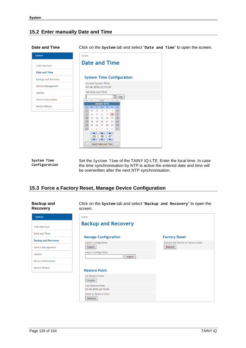
System
Page 126 of 154 TAINY iQ
15.2 Enter manually Date and Time
Date and Time
Click on the System tab and select “Date and Time” to open the screen.
System Time Configuration
Set the System Time of the TAINY IQ-LTE. Enter the local time. In case
the time synchronisation by NTP is active the entered date and time will be overwritten after the next NTP synchronisation.
15.3 Force a Factory Reset, Manage Device Configuration
Backup and Recovery
Click on the System tab and select “Backup and Recovery” to open the
screen.

System
TAINY iQ Page 127 of 154
Click the “Export” button to write the current configuration of the TAINY
IQ-LTE into a configuration file.
Select a valid configuration file and click the “Import” button to load a
new configuration from a file.
Chose if the new configuration shall be kept without further confirmation or if the TAINY IQ-LTE should fall back to the configuration used before, in case the new configuration has not been confirmed within 15 minutes.
To create a new configuration, export the current configuration and edit it in a text editor.
Mind that neither the local user and their passwords nor the log level are saved.

System
Page 128 of 154 TAINY iQ
15.4 Device Management
Device Management
Click on the System tab and select “Update” to open the screen.
Email Settings
Configure an Email account
Set the function to “Yes” to be able to send emails from this device.
SMTP Server Address/ SMTP TCP Port
Enter the SMTP Server Address and the SMTP TC Port
Username/ Password
Enter a username and password for this email account.
Sender Name
Enter the name you intend to appear in the sender’s field of the email.
Enable STARTTLS/ Enable TLS
Set to “Yes” to enable the configuration of the encryption via TLS
(Transport Layer Security)
SNMPv3 Settings Enable
To enable the SNMPv3 interface, select “Yes”.
Port
Add the port number at which the SNMPv3 service should be accessible.

System
TAINY iQ Page 129 of 154
SSH Settings Enable SSH Access
Set to “Yes”.
Set SSH Password
Enter a valid password for authentication.
For further information on how to configure conditions and rules on when to send emails see chapter 6.3
15.5 Perform Software Updates
Update
Software Update
Click on the System tab and select “Update” to open the screen.
Click the “Submit” button to select and upload the required update file
from the administration pc.
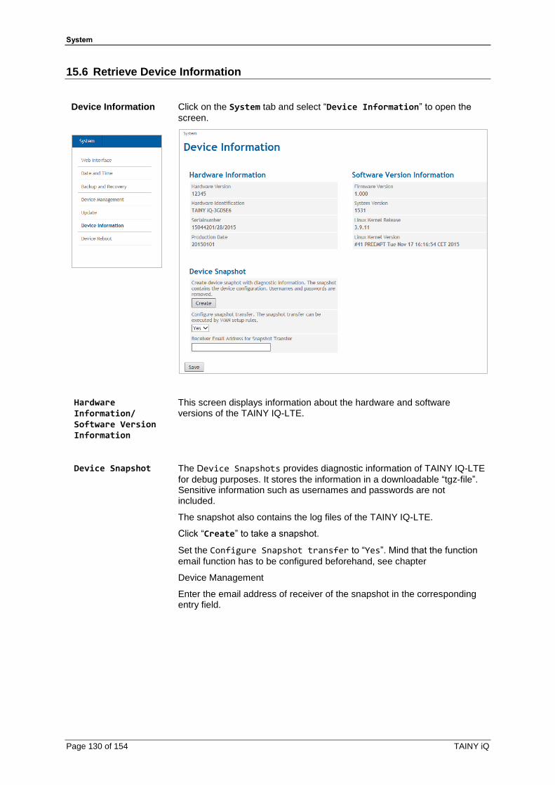
System
Page 130 of 154 TAINY iQ
15.6 Retrieve Device Information
Device Information
Click on the System tab and select “Device Information” to open the
screen.
Hardware Information/ Software Version Information
This screen displays information about the hardware and software versions of the TAINY IQ-LTE.
Device Snapshot
The Device Snapshots provides diagnostic information of TAINY IQ-LTE
for debug purposes. It stores the information in a downloadable “tgz-file”. Sensitive information such as usernames and passwords are not included.
The snapshot also contains the log files of the TAINY IQ-LTE.
Click “Create” to take a snapshot.
Set the Configure Snapshot transfer to “Yes”. Mind that the function
email function has to be configured beforehand, see chapter
Device Management
Enter the email address of receiver of the snapshot in the corresponding entry field.
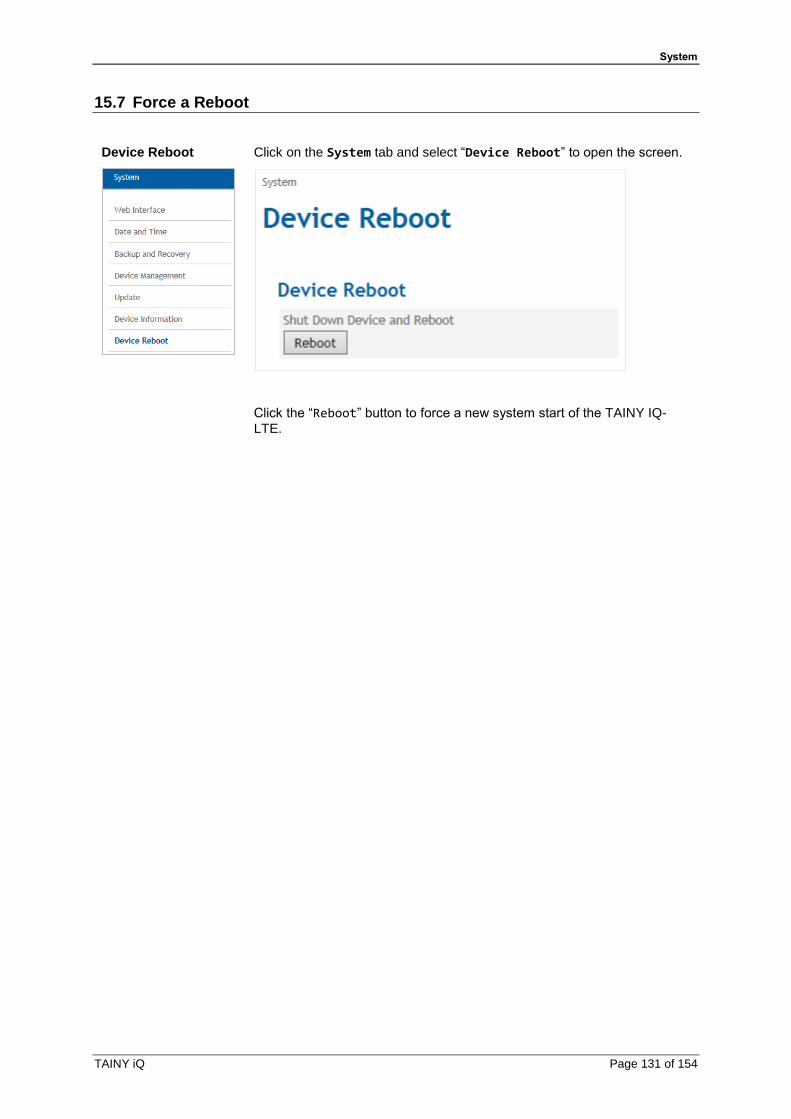
System
TAINY iQ Page 131 of 154
15.7 Force a Reboot
Device Reboot
Click on the System tab and select “Device Reboot” to open the screen.
Click the “Reboot” button to force a new system start of the TAINY IQ-
LTE.

Maintenance
Page 132 of 154 TAINY iQ
16 Maintenance
16.1 Maintenance
TAINY IQ-LTE is maintenance free.
16.2 Troubleshooting
In case you encounter any problems please refer to the table below for advice:
Problem Cause Solution
Control lamps are off
Power supply is cut off Check the connection to the power supply
Device does not log in
Wrong PIN or APN Check PIN or APN
SIM card is not activated or in PUK status
Check activation and status
SIM card is not activated for the selected service (UMTS, LTE)
Check activation and selected service
Poor reception Check positioning of antenna
No data-connection from local network to WAN possible
Default gateway configured wrongly in application
Check the gateway settings on the WAN tab
GRE Tunnel set as default gateway yet no route set (this is also important for DNS, NTP, SNMP and Ping checks)
Check the GRE settings and gateway settings on the WAN tab
Firewall is not open Check the Firewall settings
No access from the local network to TAINY
Wrong VLAN parameters set Check VLAN parameters on WAN and LAN tab
Logged out by MAC filter Check the filter settings for MAC
Logged out by firewall Check the filter settings for the firewall and if required a reset back to factory settings
IPsec Tunnel does not configure
Incorrect certificates and keys Check the certificates and keys (Certificate tab)
The encryption and hash methods do not match
Check the selected methods on the WAN tab
The networks are not consistently (crisscross)
Check the networks
Not all network devices and routers between the entities are configured correctly
Check the configuration of all devices and routers again
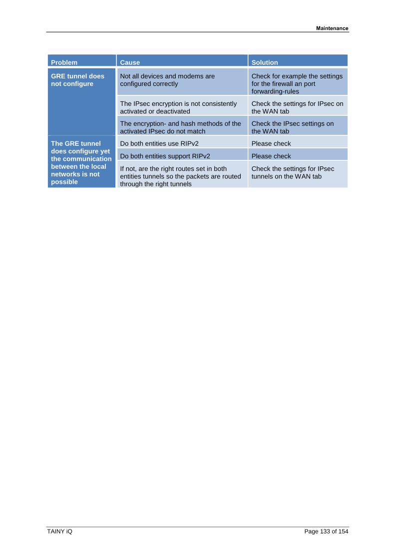
Maintenance
TAINY iQ Page 133 of 154
Problem Cause Solution
GRE tunnel does not configure
Not all devices and modems are configured correctly
Check for example the settings for the firewall an port forwarding-rules
The IPsec encryption is not consistently activated or deactivated
Check the settings for IPsec on the WAN tab
The encryption- and hash methods of the activated IPsec do not match
Check the IPsec settings on the WAN tab
The GRE tunnel does configure yet the communication between the local networks is not possible
Do both entities use RIPv2 Please check
Do both entities support RIPv2 Please check
If not, are the right routes set in both entities tunnels so the packets are routed through the right tunnels
Check the settings for IPsec tunnels on the WAN tab

Transport, Storage and Disposal
Page 134 of 154 TAINY iQ
17 Transport, Storage and Disposal
17.1 Transport
The TAINY IQ-LTE will be delivered in an individual box. Keep the packing for later transport purposes.
The TAINY IQ-LTE can be carried by public transportation:
Transportation by air, by road on all qualities of road surface, by ship and by train and where some care has been taken with respect to low temperatures.
Temperature range (transport) :
-40°C … +85°C
Relative Humidity (transport) : max. 95%
The TAINY IQ-LTE must be carried either in its individual box or mounted on a top rail inside a cabinet.
When carried mounted on a top rail it must be ensured, that the TAINY IQ-LTE cannot slip along the top rail. The cabinet must be packed inside a layer of material (e.g. Styrofoam), which absorbs shocks and vibrations. The layer of material shall be appropriate to the mass of the cabinet.
17.2 Storage
Please always cut off the power supply before removal and storage. Disconnect all cables. Store the TAINY IQ-LTE in weather-protected, not temperature-controlled storage locations:
Temperature range (storage) :
-40°C … +85°C
Relative Humidity (transport) : max. 95%
The TAINY IQ-LTE must be stored either in its individual box or mounted on a top rail inside a cabinet. The cabinet must be packed inside a layer of material (e.g. Styrofoam), which absorbs shocks and vibrations. The layer of material shall be appropriate to the mass of the cabinet.
17.3 Disposal
Environmental Information for Customers in the European Union European Directive 2002/96/EC requires that the equipment bearing this symbol on the product and/or its packaging must not be disposed of with unsorted municipal waste. The symbol indicates that this product should be disposed of separately from regular household waste streams. It is your responsibility to dispose of this and other electric and electronic equipment via designated collection facilities appointed by the government or local authorities. Correct disposal and recycling will help prevent potential negative consequences to the environment and human health. For more detailed information about the disposal of your old equipment, please contact your local authorities, waste disposal service, or the manufacturer where you purchased the product.
WEEE-Registry number 31323053

Glossary
TAINY iQ Page 135 of 154
18 Glossary
1-to-1 NAT With 1-to-1 NAT, a network component (e.g. router) maps the address range of one network to the address range of another network.
Example Network 1:
Address range: 123.123.123.xyz
Target address: 123.123.123.101
Network 1 1-to-1-NAT
Function
Example Network 2:
Address range: 234.234.234.xyz
Target address: 234.234.234.101
Network 2
A component in Network 1 addresses a component in Network 2 through a target address from the address range of Network 1. The 1-to-1 NAT function maps the target address in the address range of Network 2. In turn, responses from Network 2 are received by a sender address from Network 1.
AES
Advanced Encryption Standard.
The NIST (National Institute of Standards and Technology) has developed the AES encryption standard in collaboration with industrial corporations for years. This → symmetric encryption should replace the previous DES standard. The AES standard specified three different key sizes with 128, 192 and 256 bit. In 1997 the NIST started an initiative for AES and revealed its conditions for the algorithm. From the proposed encryption algorithms the NIST narrowed the selection down to five algorithms: MARS, RC6, Rijndael, Serpent and Twofish. In October 2000 Rijndael was chosen as the encryption algorithm.
APN (Access Point Name)
Trans-network connections, e.g. from a wireless network (HSPA+, UMTS, EGPRS or GPRS) to the Internet, are created in the wireless network via so-called APNs.
Public
INTERNET
TAINYLocal
application
Private
INTRANET
APN(public)
APN(private)
LTE, HSDPA,
UMTS
(E-)GPRS
An end device that wants/tries to establish a connection via the GPRS network specifies an APN to indicate which network it wants to be connected to: the Internet or a private company network that is connected via a dedicated line.
The APN designates the transfer point to the other network. It is communicated to the user by the network operator.
Glossary
Page 136 of 154 TAINY iQ
Asymmetric encryption
With asymmetric encryption, data is encrypted with a key and encrypted again with a second key. Both keys are suitable for encryption and decryption. One of the keys is kept secret by its owner (private key) and the other is given to the public (public key), potential communication partners.
A message encrypted with the public key can only be decrypted and read by a recipient who has the corresponding private key. A message encrypted with the private key can only be decrypted and read by any recipient who has the corresponding public key. Encryption with the private key shows that the message actually originated from the owner of the corresponding public key. For that reason, the term “digital signature” is used.
However, asymmetric encryption processes such as RSA are slow and susceptible to certain types of attacks, therefore they are often combined with a symmetric process (→ symmetric encryption). Furthermore concepts which eliminate the elaborate administrative efforts for symmetric keys are also possible.
Cell ID Unique identifier of a cellular network cell.
CIDR
Classless Inter-Domain Routing
IP netmasks and CIDR are notations for grouping a number of IP addresses into an address space. Thus a range of contiguous addresses is treated as a network.
The CIDR method reduces, for example the routing tables stored in routers by means of a postfix in the IP address. This postfix can be used to designate a network together with its subnetworks. This method is described in RFC 1518.
In order to specify a range of IP addresses to the TAINY IQ-LTE, or when configuring the firewall, it may be necessary to specify the address space in the CIDR notation. The following table shows the IP netmask on the left-hand side and to the far right the corresponding CIDR notation.
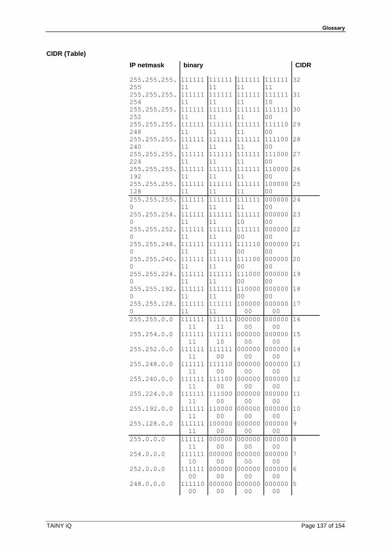
Glossary
TAINY iQ Page 137 of 154
CIDR (Table)
IP netmask binary CIDR
255.255.255.
255
111111
11
111111
11
111111
11
111111
11
32
255.255.255.
254
111111
11
111111
11
111111
11
111111
10
31
255.255.255.
252
111111
11
111111
11
111111
11
111111
00
30
255.255.255.
248
111111
11
111111
11
111111
11
111110
00
29
255.255.255.
240
111111
11
111111
11
111111
11
111100
00
28
255.255.255.
224
111111
11
111111
11
111111
11
111000
00
27
255.255.255.
192
111111
11
111111
11
111111
11
110000
00
26
255.255.255.
128
111111
11
111111
11
111111
11
100000
00
25
255.255.255.
0
111111
11
111111
11
111111
11
000000
00
24
255.255.254.
0
111111
11
111111
11
111111
10
000000
00
23
255.255.252.
0
111111
11
111111
11
111111
00
000000
00
22
255.255.248.
0
111111
11
111111
11
111110
00
000000
00
21
255.255.240.
0
111111
11
111111
11
111100
00
000000
00
20
255.255.224.
0
111111
11
111111
11
111000
00
000000
00
19
255.255.192.
0
111111
11
111111
11
110000
00
000000
00
18
255.255.128.
0
111111
11
111111
11
100000
00
000000
00
17
255.255.0.0 111111
11
111111
11
000000
00
000000
00
16
255.254.0.0 111111
11
111111
10
000000
00
000000
00
15
255.252.0.0 111111
11
111111
00
000000
00
000000
00
14
255.248.0.0 111111
11
111110
00
000000
00
000000
00
13
255.240.0.0 111111
11
111100
00
000000
00
000000
00
12
255.224.0.0 111111
11
111000
00
000000
00
000000
00
11
255.192.0.0 111111
11
110000
00
000000
00
000000
00
10
255.128.0.0 111111
11
100000
00
000000
00
000000
00
9
255.0.0.0 111111
11
000000
00
000000
00
000000
00
8
254.0.0.0 111111
10
000000
00
000000
00
000000
00
7
252.0.0.0 111111
00
000000
00
000000
00
000000
00
6
248.0.0.0 111110
00
000000
00
000000
00
000000
00
5

Glossary
Page 138 of 154 TAINY iQ
240.0.0.0 111100
00
000000
00
000000
00
000000
00
4
224.0.0.0 111000
00
000000
00
000000
00
000000
00
3
192.0.0.0 110000
00
000000
00
000000
00
000000
00
2
128.0.0.0 100000
00
000000
00
000000
00
000000
00
1
0.0.0.0 000000
00 000000
00 000000
00 000000
00 0
Example: 192.168.1.0 / 255.255.255.0 corresponds to CIDR: 192.168.1.0/24
Client / Server In a client-server environment a server is a program or computer that receives and answers queries from the client program or client computer.
With data communication the computer is also referred to as a client that establishes a connection to a server (or host). This means the client is the calling computer; the server (or host) is the caller.
CSQ / RSSI The CSQ value is a value defined in the GSM standard to indicate the signal quality. CSQ values correspond to the received field strength RSSI (= Received Signal Strength Indication):
RSSI
< 6 < -101 dBm
6..10 -101 dBm.. - 93 dBm
11..18 - 91 dBm.. -77 dBm
> 18 > -75 dBm
99 Unknown/Not detected
Datagram With the transfer protocol TCP/IP, data is sent as data packages, so-called IP datagrams. An IP datagram has the following structure:
1. IP header
2. TCP/UDP header
3. Data (payload)
The IP address contains:
• the IP address of the sender (source IP address)
• the IP address of the recipient (destination IP address)
• the protocol number of the protocol of the next higher protocol layer (according to the OSI layer model)
• the IP header check sum (checksum) for verifying the integrity of the header on receipt.
The TCP/UDP header contains the following information:
• Port of the sender (source port)
• Port of the recipient (destination port)
• a check sum over the TCP header and some information from the IP header (including source and destination IP address)
Glossary
TAINY iQ Page 139 of 154
DES / 3DES The symmetric encryption algorithm (→ symmetric encryption) DES, originating from IBM and tested by the NSA, was established in 1977 by the American National Bureau of Standards, the predecessor of today's National Institute of Standards and Technology (NIST) as a standard for American governmental institutions. Since it was the first standardised encryption algorithm, it was also quickly adopted in industrial applications in the US and beyond.
DES works with a key length of 56bit, which can no longer be considered to be secure due to the increase in computing capability of the computer since 1977.
3DES is a variant of DES. It works with keys three times the size, they are 168 bits long. It is still considered to be secure and is also a part of the IPsec standard, among other things.
DHCP Dynamic Host Configuration Protocol (DHCP) assumes the automatic dynamic assignment of IP addresses and additional parameters in a network. The Dynamic Host Configuration Protocol uses UDP. It was defined in RFC 2131 and assigned with the UDP ports 67 and 68. DHCP works in the client – server method, wherein the client is assigned the IP address by the server.
DNS The addressing in IP networks takes place over IP address as a basic rule. However, addressing in the form of a domain address is generally preferred (in the form www.abc.xyz.de). The addressing takes place over the domain address. First the sender sends the domain address to a Domain Name Server (DNS) and receives the corresponding IP address. Only afterwards does the sender address its data to this address.
DPD The Dead Peer Detection (DPD) identifies whether the IPsec connection between two networks is still valid or if the connection has to be re-established. This function presumes though that it is supported on both sides. Without DPD depending on the configuration the connection has to be manually re-established or the lifetime of the SA has to elapse. To control if the IPsec connection is still valid the DPD sends a DPD-request to the opposite party. If no answer is received the IPsec connection will be interrupted after a number of failed attempts.

Glossary
Page 140 of 154 TAINY iQ
DynDNS provider Also Dynamic DNS provider. Every computer that is connected to the internet has an IP address (IP = Internet Protocol). An IP address consists of up to 4 four three-digit numbers, with dots separating each of the numbers. If the computer is online via the telephone line via modem, ISDN or ADSL, then the internet service provider dynamically assigns it an IP address, i.e. the address changes from session to session. Even if the computer is online for more than 24 hours without interruption (e.g. in the case of a flat rate), the IP address is changed periodically.
For a local computer to be accessible via the internet, its address must be known to the external remote station. This is necessary for it to establish a connection to the local computer. This is not possible, however, if the address of the local computer constantly changes. It is possible, however, if the user of the local computer has an account with a DynamicDNS provider (DNS = Domain Name Server).
Then he can specify a host name, under which the computer can be accessed in the future, e.g.: www.xyz.abc.de. Moreover, the DynamicDNS provider makes a small program available that has to be installed and executed on the computer concerned. In each internet session of the local computer this tool reports to the DynamicDNS provider which IP address the computer obtains at the moment. Its domain name server registers the current host name - IP address assignment and reports it to other domain name servers on the internet.
If now an external computer tries to establish a connection with a local computer which is registered with the DynamicDNS provider, the external computer uses the host name of the local computer as the address. This way a connection is established with the responsible DNS (Domain Name Server) to look up the IP address which is currently assigned to this host name. The IP address is transmitted back to the external computer, and then used by it as the destination address. It now leads precisely to the desired local computer.
As a rule, all internet addresses are based on the following method: First a connection is established to a DNS to determine the IP addresses assigned to this host name. Once that has been accomplished, the IP address that was sought after is used to establish the connection to the desired remote station, which could be any Web site.
EDGE EDGE (= Enhanced Data Rates for GSM Evolution) refers to a method by which the available data rates in GSM mobile phone networks are increased by introducing an additional modulation process. EDGE, GPRS is expanded to become EGPRS (Enhanced GPRS), and HSCSD is expanded to become ECSD.
EGPRS EGPRS stands for "Enhanced General Packet Radio Service", describes a packet-oriented data service based on GPRS, which is accelerated by EDGE technology.
GPRS GPRS is the abbreviation for "General Packet Radio Service" and a data transfer system of GSM2+ mobile radio systems. GPRS systems use the base station of the GSM network for the radio technology and an internal infrastructure for the networking and coupling to other IP networks, such as the internet. In the process, data is communicated packet-oriented, wherein the internet protocol (IP) is used. GPRS provides data rates of up to 115.2 KBit/s.

Glossary
TAINY iQ Page 141 of 154
GRE Via the TAINY IQ-LTE independent (sub-) networks can be connected. For that purpose the TAINY IQ-LTE uses the GRE (=Generic Routing Encapsulation) protocol (RFC 1701; RFC 1702; RFC 2784).
GRE-VPN
TAINY iQ
TAINY iQ
TAINY iQ
Router
Sub-
Net
Sub-
Net
Sub-
Net
Sub-
Net
GRE-IP
NHRP spoke
GRE-IP
NHRP spoke
GRE-IP
NHRP spoke
GRE-IP
WAN-IP
NHRP hub
The (sub-) networks require a GRE-capable router (e.g. the TAINY IQ-LTE), to create a DM VPN among themselves.
From one (sub-) network an address of another (Sub-) network can be directly addressed provided a corresponding route is configured.
As the GRE protocol establishes 1:1 tunnels between endpoints only, the DM VPN is organized like a NBMA (=Nonbroadcast Multiple Access) network. Inside this virtual network, data are transmitted directly from endpoint to endpoint or across a switching device.
By using the NHRP (=Next Hop Resolution Protocol) the addresses of the endpoints (NHRP spokes) are collected at one endpoint acting as a NHRP hub, which shares this information on request.
In a DM VPN one GRE endpoint (e.g. the router of the central site) must operate in hub mode, while other GRE endpoints (e.g. TAINY IQ-LTE) operates in spoke mode.
All spokes in the DM VPN must know the WAN IP address as well as the DM VPN IP address of the hub.
If the hub receives data, which is not addressed to its own directly connected (sub-) network, it either forwards the data to the addressed endpoint in the DM VPN or the hub informs the sender, how to contact the addressed endpoint directly.
The GRE protocol does cover neither authentication nor encryption. This can be done by an additional IPsec layer.
GSM GSM (= Global System for Mobile Communication) is a worldwide standard for digital mobile radio networks. In addition to the voice service for telephony, GSM supports various data services, such as fax, SMS, CSD and GPRS. Depending on legal regulations in various countries, the frequency bands 900 MHz, 1800 MHz or 850 MHz and 1900 MHz are used.
HSPDA, HSUPA
(HSPA+)
HSDPA (=High Speed Downlink Packet Access) and HSUPA (=High Speed Upload Packet Access) are extensions of the UMTS network, which provides higher data rates from the base station to the mobile station (HSDPA) or from the mobile station to the base station (HSUPA).
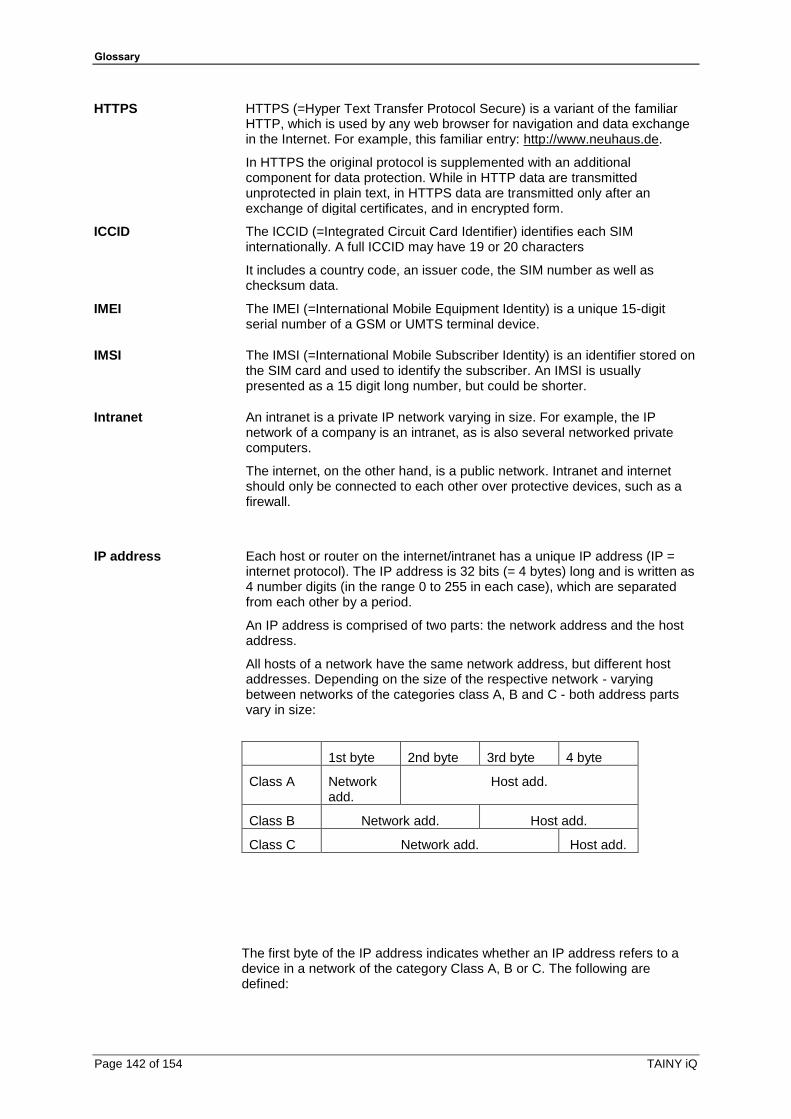
Glossary
Page 142 of 154 TAINY iQ
HTTPS HTTPS (=Hyper Text Transfer Protocol Secure) is a variant of the familiar HTTP, which is used by any web browser for navigation and data exchange in the Internet. For example, this familiar entry: http://www.neuhaus.de.
In HTTPS the original protocol is supplemented with an additional component for data protection. While in HTTP data are transmitted unprotected in plain text, in HTTPS data are transmitted only after an exchange of digital certificates, and in encrypted form.
ICCID The ICCID (=Integrated Circuit Card Identifier) identifies each SIM internationally. A full ICCID may have 19 or 20 characters
It includes a country code, an issuer code, the SIM number as well as checksum data.
IMEI The IMEI (=International Mobile Equipment Identity) is a unique 15-digit serial number of a GSM or UMTS terminal device.
IMSI The IMSI (=International Mobile Subscriber Identity) is an identifier stored on the SIM card and used to identify the subscriber. An IMSI is usually presented as a 15 digit long number, but could be shorter.
Intranet An intranet is a private IP network varying in size. For example, the IP network of a company is an intranet, as is also several networked private computers.
The internet, on the other hand, is a public network. Intranet and internet should only be connected to each other over protective devices, such as a firewall.
IP address Each host or router on the internet/intranet has a unique IP address (IP = internet protocol). The IP address is 32 bits (= 4 bytes) long and is written as 4 number digits (in the range 0 to 255 in each case), which are separated from each other by a period.
An IP address is comprised of two parts: the network address and the host address.
All hosts of a network have the same network address, but different host addresses. Depending on the size of the respective network - varying between networks of the categories class A, B and C - both address parts vary in size:
1st byte 2nd byte 3rd byte 4 byte
Class A Network add.
Host add.
Class B Network add. Host add.
Class C Network add. Host add.
The first byte of the IP address indicates whether an IP address refers to a device in a network of the category Class A, B or C. The following are defined:

Glossary
TAINY iQ Page 143 of 154
Value of the 1st byte
Bytes for the network address
Bytes for the host address
Class A 1-126 1 3
Class B 128-191 2 2
Class C 192-223 3 1
In terms of figures, there can only be a maximum of 126 Class A networks in the world; each of these networks can comprise a maximum of 256 x 256 x 256 hosts (address space 3 bytes). There can be a maximum of 64 x 256 Class B networks and each can contain up to 65,536 hosts (address space 2 bytes: 256 x 256). There can be a maximum of 32 x 256 x 256 Class B networks and each can contain up to 256 hosts (address space 1 byte).
IPv6 IP version 6 (IPv6) includes 128-bit addressing.
Note: The allocation of an IPv6 address depends on whether the Internet provider used supports the assignment of IPv6 addresses in the mobile data network. Accessibility with IPv6 from the Internet depends on the mobile operator and the contract with the operator. Mobile operators may require private access point name (APN) for the use of outgoing and incoming IPv6 connections.
IP packet See Datagram
IPsec
IP security (IPsec) is a standard which uses IP datagrams to ensure the authenticity of the sender as well as the confidentiality and the integrity of the data through encryption. The components of IPsec are the authentication header (AH), the encapsulating security payload (ESP), the security association (SA), the security parameter index (SPI) and the internet key exchanges (IKE).
At the beginning of the communication, the computers participating in the communication clarify the process used as well as its implications, such as transport mode or tunnel mode.
In transport mode, an IPsec header is used between the IP header and TCP or UDP header in each IP datagram. Since the IP header remains unchanged in the process, this mode is only suitable for a host-to-host connection.
In tunnel mode, an IPsec header and a new IP header precede the entire IP datagram. That means the original datagram is encrypted in the payload of the new datagram.
The tunnel mode is used with the VPN: The devices at the tunnel ends encrypt and decrypt the datagrams along the stretch of the tunnel; in a nutshell, the actual datagrams are fully protected along the transport route through the public network.
Location Area Code (LAC),
A location area is a group of adjacent GSM base stations connected to each other in order to facilitate the finding and call signalling for a GSM end device, i.e. the CM-E1P01-GPRS module. The group can comprise between 10 and 100 GSM base stations. Each of these groups has a unique worldwide identifier (Location Area Code = LAC)

Glossary
Page 144 of 154 TAINY iQ
Long Term Evolution (LTE)
LTE is the 4th generation of mobile radio network, which allows a significant higher data transmission rate, than the 3nd generation UMTS. It is possible to download up to 300 MB per second. The frequency range used by LTE- providers is solely on UHF-frequency band. Multiple frequencies are used varying regionally between the middle and upper section of the UHF-range from 700 to 2600 MHz
MCC/MNC The MCC (Mobile Country Code) and the MNC (Mobile Network Code) are unique worldwide identifiers for a mobile radio network.
The MCC is three-digit and the MNC are two- or three-digit long.
There are many websites on the internet with the MCC/MNC of various countries and network operators.
MIB See SNMP
NAT (Network Address Translation)
With network address translation (NAT), often called IP masquerading, an entire network is "hidden" behind a single device, known as the NAT router. The internal computers of the local network remain concealed with their IP addresses in the local network when they communicate outwardly through the NAT router. Only the NAT router with its own IP address is visible to outside communication partners.
However, in order for internal computers to be able to communicate directly with external computers (on the internet), the NAT router must change the IP datagrams to and from the internal computer to the outside.
If an IP datagram is sent from the internal network to the outside, the NAT router changes the IP and TCP header of the datagram. It switches the source IP address and the source port with its own official IP address and its own, previously unused port. For this purpose, it maintains a table which establishes the allocation of the original with the new values.
Upon receipt of a response datagram, the NAT router recognises that the datagram is actually intended for an internal computer on the basis of the specified target port. Using the table, the NAT router exchanges the target IP address and the target port and forwards the datagram to the internal network.
Network mask / Subnet mask
A company network with access to the internet is normally officially assigned only to a single IP address, e.g. 134.76.0.0. In this example address it can be seen from the 1st byte that this company network is a Class B network, i.e. the last 2 bytes can be used freely for host addressing. Arithmetically that represents an address space of 65,536 possible hosts (256 x 256).
Such a huge network is not very practical. In this case it is necessary to form subnetworks. This is accomplished by using a subnet mask. Like an IP address, this is a 4 bytes long field. The value 255 is assigned to each of the bytes that represent the network address. The main purpose is to "hide" a part of the host address range in order to use it for the addressing of subnetworks. For example, in a Class B network (2 bytes for the network address, 2 bytes for the host address), by means of the subnet mask 255.255.255.0 it is possible to take the 3rd byte, which was actually intended for host addressing, and use it now for subnet addressing. Arithmetically that means that 256 subnets with 256 hosts each could be created.
Glossary
TAINY iQ Page 145 of 154
Packet Filter Packet filtering is a method of a stateful inspection firewall. Packet filters only let IP packets pass through if this has been defined previously by firewall rules. The following are defined in the firewall rules:
which protocol (TCP, UDP, ICMP) can go through,
the permitted source of the IP packets (From IP / From port)
the permitted destination of the IP packets (To IP / To port)
It is likewise defined here how IP packets are handled that are not allowed to pass through (discard, reject).
For a simple packet filter it is always necessary to create two firewall rules for a connection:
one rule for the query direction from the source to the destination, and
a second rule for the query direction from the destination to the source.
It is different for stateful inspection firewall. In this case a firewall rule is only created for the query direction from the source to the destination. The firewall rule for the response direction from the destination to the source results from analysis of the data previously sent. The firewall rule for the responses is closed again after the responses are received or after a short time period has elapsed. Thus responses can only pass through if there was a previous query. This means that the response rule cannot be used for unauthorised access. What is more, special procedures make it possible for UDP and ICMP data to also go through, even though these data were not requested before.
Port Forwarding If a firewall rule has been created for port forwarding, then data packets received at a defined IP port of the firewall device from the external network will be forwarded. The incoming data packets are then forwarded to a specified IP address and port number in the local network. The port forwarding can be configured for TCP or UDP.
In port forwarding the following occurs: The header of incoming data packets from the external network that are addressed to the external IP address of the firewall device and to a specific port are adapted so that they are forwarded to the internal network to a specific computer and to a specific port of that computer. This means that the IP address and port number in the header of incoming data packets are modified.
This process is also called Destination NAT or Port Forwarding.
Port number The port number field is a field of 2-bytes in UDP and TCP headers. The assignment of port numbers serves for identification of the various data streams, which the UDP/TCP process simultaneously. The entire data exchange between UDP/TCP and the application processes takes place over these port numbers. The assignment of port numbers to the application processes take place dynamically and randomly. For specific, frequently used application processes, fixed port numbers are assigned. They are referred to as Assigned Numbers.
PPPoE Acronym for Point-to-Point Protocol over Ethernet. It is based on the standards PPP and Ethernet. PPPoE is a specification for connecting users to the internet via Ethernet using a jointly used broadband medium such as DSL, Wireless LAN or cable modem.
PPTP Acronym for Point-to-Point Tunnelling Protocol. This protocol was developed by Microsoft, U.S. Robotics and others in order to transmit data securely between two VPN nodes (→ VPN) over a public network.
Glossary
Page 146 of 154 TAINY iQ
Private key, public key; certification (X.509)
Two keys are used with asymmetric encryption algorithms: one private (private key) and one public (public key). The public key is used for the encryption of data and the private key is used for the decryption.
The public key is provided by the future recipient of data to those who encrypt and send data to the recipient. Only the recipient has the private key. It is used for the decryption of the data received.
Certification:
The possibility of certification exists. Therefore the user of the public key (used for encryption) can be certain that the public key really originated from the party who was intended to receive the data to be sent: a certification authority (CA) checks the authenticity of the public key and the associated linking of the sender’s identity with its key. This is conducted according to the CA’s rules, which may require the sender to appear in person. After a successful check, the CA signs the public key of the sender with its (digital) signature. A certificate is created.
X.509 certificate establishes a link between an identity in the form of an "X.500 distinguished name" (DN) and an official key, which is certified with the digital signature of an X.509 certification authority (CA). The signature (an encryption with the signature key) can be checked by the public key which the CA issues to the certificate holder.
Protocol, transfer protocol
Devices that communicate with each other must use the same set of rules for this purpose. They must "speak the same language". Such rules and standards are referred to as protocol or transfer protocol. Protocols which are often used include IP, TCP, PPP, HTTP or SMTP. TCP/IP is an umbrella term for all protocols building on IP.
RADIUS The abbreviation RADIUS means Remote Authentication Dial-In User Service. This Client-Server-Protocol controls the secure user-access to the network. The user password is verified against a central server. The authentication of the user is established on user basis. This kind authentication enables an enterprise to secure their network against potential attackers and also manage the user centrally and indivdually.
Furthermore due to the central server statistics and accountings could be issued.
RIPv2 The RIP (Routing Information Protocol) is a routing protocol which is used to generate automatically routing tables of routers. Routers with activated RIPv2-Protocol transmit periodically their routing tables to configured RIP neighbours. A router knows at start only the directly connected networks. Therefore a new router asks all RIP neighbours for their complete routing tables. The answers are used to generate first entries in the own routing table. Afterwards the generated routing table is transmitted to all RIP neighbours.
Service provider Supplier, company or institutions that offer users access to the internet or to an online service.
SNMP SNMP (Simple Network Management Protocol) is a widespread mechanism for to control network components such as servers, routers, switches, printers, computers etc. centralized
SNMP defines the communication process and structure of the data packages. UDP via IP is used for transport.
SNMP does not define the values which can be read or changed.
This is done in an MIB (Management Information Base). The MIB is a description file in which the individual values are listed in a table. The MIB is for specific network components or for a class of components, such as switches.
Glossary
TAINY iQ Page 147 of 154
SNMP Trap SNMP trap is a message which is sent unprompted by the SNMP agent (Simple Network Management Protocol) from a network component.
Spoofing, Anti-Spoofing
In internet terminology, spoofing means to specify a forged address. The forged Internet address is used to pose as an authorised user.
Anti-spoofing means mechanisms to reveal or prevent spoofing.
SSH SSH (Secure SHell) is a protocol that enables secure, encrypted data exchange between computers. Secure SHell is used for remote access to the input console from LINUX-based machines.
Symmetric encryption With symmetric encryption, data is encrypted and decrypted with the same key. DES and AES are two examples of symmetric encryption algorithms. They are fast, but time-consuming to administer as the number of users increases.
TACACS+ TACACS+ (Terminal Access Controller Access Control System Plus) is a standardised protocol, which is used for communication between clients and servers within a network in the areas authentication, authorization and accounting (billing). Like the TAINY IQ-LTE, a TACACS+ server can be set up, for example, which manages the access data for all end devices in the network centrally and carries out the authorization for the relevant interested party on behalf of the end devices when registration requests are received. The end device forwards the received registration data to the TACACS+ server, which carries out the necessary checks for the authorization and reports the result of the checks back to the end device.
TCP/IP (Transmission Control Protocol/Internet Protocol)
Network protocols that are used for the connection of two computers over the internet.
IP is the base protocol.
UDP builds on IP and sends individual packages. These could arrive at the recipient in a different sequence than they were sent, or they could even be lost.
TCP serves for securing the connection and ensures, for example, that data packages are forwarded in the correct sequence.
UDP and TCP additionally provide port numbers between 1 and 65535 for the IP address, through which the various services can be differentiated.
A series of additional protocols build on UDP and TCP, such as HTTP (Hyper Text Transfer Protocol), HTTPS (Secure Hyper Text Transfer Protocol), SMTP (Simple Mail Transfer Protocol), POP3 (Post Office Protocol, Version 3) and DNS (Domain Name Service).
ICMP builds on IP and contains control messages.
SMTP is an email protocol based on TCP.
IKE is an IPsec protocol based on UDP.
ESP is an IPsec protocol based on IP.
On a Windows PC, WINSOCK.DLL (or WSOCK32.DLL) assumes the development of the two protocols.
(see also datagram)
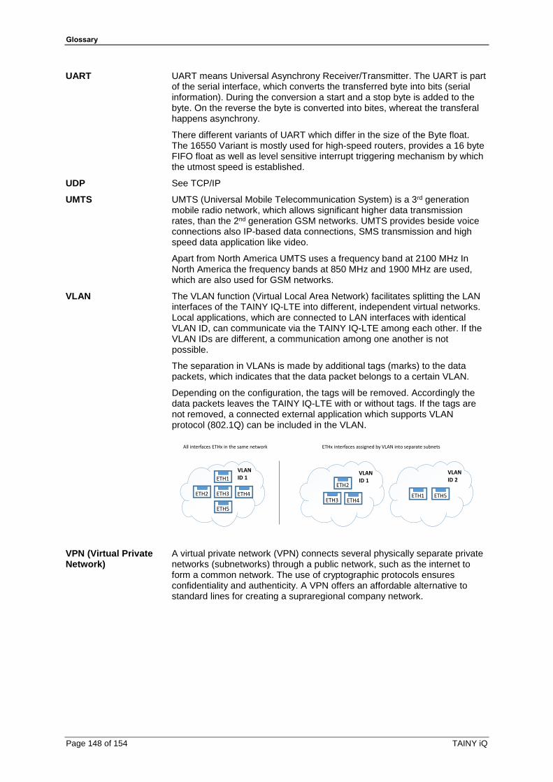
Glossary
Page 148 of 154 TAINY iQ
UART UART means Universal Asynchrony Receiver/Transmitter. The UART is part of the serial interface, which converts the transferred byte into bits (serial information). During the conversion a start and a stop byte is added to the byte. On the reverse the byte is converted into bites, whereat the transferal happens asynchrony.
There different variants of UART which differ in the size of the Byte float. The 16550 Variant is mostly used for high-speed routers, provides a 16 byte FIFO float as well as level sensitive interrupt triggering mechanism by which the utmost speed is established.
UDP See TCP/IP
UMTS
UMTS (Universal Mobile Telecommunication System) is a 3rd generation mobile radio network, which allows significant higher data transmission rates, than the 2nd generation GSM networks. UMTS provides beside voice connections also IP-based data connections, SMS transmission and high speed data application like video.
Apart from North America UMTS uses a frequency band at 2100 MHz In North America the frequency bands at 850 MHz and 1900 MHz are used, which are also used for GSM networks.
VLAN The VLAN function (Virtual Local Area Network) facilitates splitting the LAN interfaces of the TAINY IQ-LTE into different, independent virtual networks. Local applications, which are connected to LAN interfaces with identical VLAN ID, can communicate via the TAINY IQ-LTE among each other. If the VLAN IDs are different, a communication among one another is not possible.
The separation in VLANs is made by additional tags (marks) to the data packets, which indicates that the data packet belongs to a certain VLAN.
Depending on the configuration, the tags will be removed. Accordingly the data packets leaves the TAINY IQ-LTE with or without tags. If the tags are not removed, a connected external application which supports VLAN protocol (802.1Q) can be included in the VLAN.
ETH1
ETH2 ETH3 ETH4
ETH5
ETH2
ETH3 ETH4ETH1 ETH5
VLAN ID 1
VLAN ID 1
VLAN ID 2
All interfaces ETHx in the same network ETHx interfaces assigned by VLAN into separate subnets
VPN (Virtual Private Network)
A virtual private network (VPN) connects several physically separate private networks (subnetworks) through a public network, such as the internet to form a common network. The use of cryptographic protocols ensures confidentiality and authenticity. A VPN offers an affordable alternative to standard lines for creating a supraregional company network.

Glossary
TAINY iQ Page 149 of 154
X.509 certificate A type of "seal" which verifies the authenticity of the public key (→ asymmetric encryption) and corresponding data.
The possibility of certification exists so that the user of the public key (used for encryption) can be certain that the public key really originates from its actual originator and thus from the party who was intended to receive the data to be sent. A certification authority (CA) checks the authenticity of the public key and the associated linking of the originator’s identity with its key. This takes place according to the CA’s rules, which may require the originator of the public key to appear in person. After a successful check, the CA signs the public key with its (digital) signature. A certificate is created.
X.509 (v3) certificate thus contains a public key, information about the owner of the key (specified by distinguished name [DN]), allowed purposes of use, etc. and the signature of the CA.
The signature is created as follows: The CA creates an individual bit sequence up to 160 bits long known as the HASH value from the public key’s bit sequence, the data on its owner and from additional data. The CA encrypts this with its private key and adds the certificate. Encryption with the CA’s private key verifies authenticity, meaning that the encrypted HASH character sequence is the CA’s digital signature. If the data of the certificate appears to have been manipulated, this HASH value will no longer be correct and the certificate will be worthless.
The HASH value is also referred to as a fingerprint. Since it is encrypted with the CA’s private key, anyone who has the appropriate public key can encrypt the bit sequence and thus check the authenticity of this fingerprint or this signature.
By using the services of authentication authorities, it is possible that one key owner need not know the other, only the authentication authority. The additional information for the key also simplifies the administrative efforts for the key.
X.509 certificates are used for email encryption, etc. using S/MIME or IPsec.
Additional Internal Routes
The following sketch shows how the IP addresses could be distributed in a local network with subnetworks as well as the kind of network addresses resulting from this, and how the specification for an additional internal route could look like.
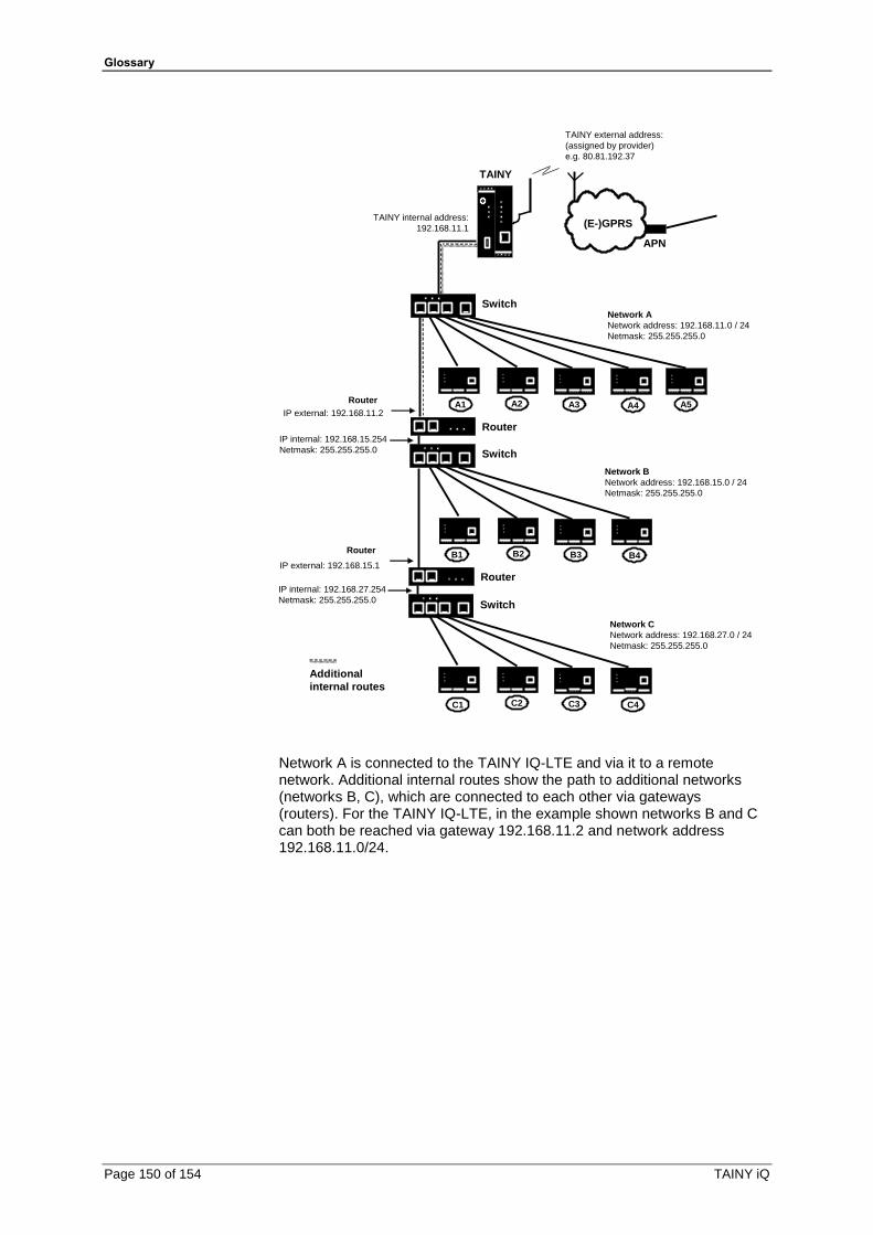
Glossary
Page 150 of 154 TAINY iQ
APN
(E-)GPRS
TAINY
Switch
Switch
Router
Router
Switch
A1 A2 A3 A4 A5
B1 B2 B3 B4
C1 C2 C3 C4
Router
IP external: 192.168.11.2
IP internal: 192.168.15.254
Netmask: 255.255.255.0
Router
IP external: 192.168.15.1
IP internal: 192.168.27.254
Netmask: 255.255.255.0
Network A
Network address: 192.168.11.0 / 24
Netmask: 255.255.255.0
Network B
Network address: 192.168.15.0 / 24
Netmask: 255.255.255.0
Network C
Network address: 192.168.27.0 / 24
Netmask: 255.255.255.0
TAINY internal address:
192.168.11.1
TAINY external address:
(assigned by provider)
e.g. 80.81.192.37
Additional
internal routes
Network A is connected to the TAINY IQ-LTE and via it to a remote network. Additional internal routes show the path to additional networks (networks B, C), which are connected to each other via gateways (routers). For the TAINY IQ-LTE, in the example shown networks B and C can both be reached via gateway 192.168.11.2 and network address 192.168.11.0/24.

Technical data
TAINY iQ Page 151 of 154
19 Technical data
Wired Interfaces Ethernet (LAN) 2 x 10/100 Base-T (RJ45 plug), Ethernet IEEE802, 10/100 Mbit/s, cross-over or one-to-one, auto-negotiation
Ethernet (LAN/WAN)
5 x 10/100 Base-T (RJ45 plug), Ethernet IEEE802, 10/100 Mbit/s, cross-over or one-to-one, auto-negotiation
RS232 TX,RX,RTS,CTS,GND
Wireless connection
Frequency bands GSM/GPRS/
EDGE
900 MHz, 1800 MHz
UMTS/
HSPA+
900 MHz (BdVIII), 1800 MHz (BdIII)*
2100 MHz (BdI)
LTE 800 MHz (Bd20), 900 MHz (Bd8)
1800 MHz (Bd3), 2100 MHz (Bd1)
2600 MHz (Bd7),
GSM/GPRS/
EDGE
850 MHz*, 900 MHz,
1800 MHz, 1900 MHz*
UMTS/
HSPA+
800 MHz (BdVI)*, 850 MHz (BdV)*,
900 MHz (BdVIII), 1900 MHz (BdII)*,
2100 MHz (BdI) * Not for use in the EU.
Bands LTE (20,8,3,7,1)
3G (8,3,1)
2G Dual Band
Max. Transmit Power
Class 4 (+33dBm ±2dB) für EGSM900
Class 1 (+30dBm ±2dB) für GSM1800
Class E2 (+27dBm ± 3dB) für GSM 900 8-PSK
Class E2 (+26dBm +3 /-4dB) für GSM 1800 8-PSK
Class 3 (+24dBm +1/-3dB) für UMTS 2100, FDD BdI
Class 3 (+24dBm +1/-3dB) für UMTS 1800, FDD BdIII*
Class 3 (+24dBm +1/-3dB) für UMTS 900, FDD BdVIII
Class 3 (+23dBm +-2dB) für LTE 2600, LTE FDD Bd7
Class 3 (+23dBm +-2dB) für LTE 2100, LTE FDD Bd1
Class 3 (+23dBm +-2dB) für LTE 1800, LTE FDD Bd3
Class 3 (+23dBm +-2dB) für LTE 900, LTE FDD Bd8
Class 3 (+23dBm +-2dB) für LTE 800, LTE FDD Bd20 * Not for use in the EU.
TAINY IQ-LTE
Class 4 (+33dBm ±2dB) for EGSM850

Technical data
Page 152 of 154 TAINY iQ
Class 4 (+33dBm ±2dB) for EGSM900
Class 1 (+30dBm ±2dB) for GSM1800
Class 1 (+30dBm ±2dB) for GSM1900
Class E2 (+27dBm ± 3dB) for GSM 850 8-PSK
Class E2 (+27dBm ± 3dB) for GSM 900 8-PSK
Class E2 (+26dBm +3 /-4dB) for GSM 1800 8-PSK
Class E2 (+26dBm +3 /-4dB) for GSM 1900 8-PSK
Class 3 (+24dBm +1/-3dB) for UMTS 2100, FDD BdI
Class 3 (+24dBm +1/-3dB) for UMTS 1900, FDD BdII*
Class 3 (+24dBm +1/-3dB) for UMTS 900, FDD BdVIII
Class 3 (+24dBm +1/-3dB) for UMTS 850, FDD BdV*
Class 3 (+24dBm +1/-3dB) for UMTS 800, FDD BdVI* * Not for use in the EU.
HSPA+ HSDPA Cat. 10 / HSUPA Cat.6 data rates DL: max. 14.4 Mbps, UL: max. 5.76 Mbps
EDGE (EGPRS) EDGE class 12 data rates: DL: max. 237 kbps, UL: max. 237 kbps
GPRS GPRS class 12 data rates DL: max. 85.6 kbps, UL: max. 85.6 kbps
Antenna connection
SMA jack;
nominal impedance: 50 ohms
Security functions
VPN Dynamic Multipoint VPN
IPsec
Firewall Stateful inspection firewall Anti-spoofing Port forwarding MAC Table
Additional functions
VLAN, PPPoE, DNS cache, DHCP server, NTP, Connection check, TACACS+, Spanning Tree,
Management Web-based administration user interface SNMPv3, Logbook, Snapshot
Ambient conditions
Temperature range Operation: -25 °C to +70 °C *) Storage: -40 °C to +85 °C
*) Automatic shut-down of the radio module in case of reaching a critical temperature.
Air humidity 0-95 y%, non-condensing
Power Supply I (nominal) Irms: 570-165 mA; Imax: 650 mA
U (nominal) 12–60 VDC
Housing Design Top-hat rail housing
Material Plastic
Protection class IP20
Dimensions 114,5 mm x 45 mm x 99 mm (d x w xh)
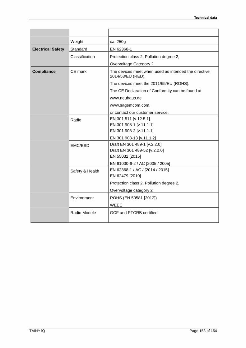
Technical data
TAINY iQ Page 153 of 154
Weight ca. 250g
Electrical Safety Standard EN 62368-1
Classification Protection class 2, Pollution degree 2,
Overvoltage Category 2
Compliance CE mark The devices meet when used as intended the directive 2014/53/EU (RED).
The devices meet the 2011/65/EU (ROHS).
The CE Declaration of Conformity can be found at
www.neuhaus.de
www.sagemcom.com,
or contact our customer service.
Radio EN 301 511 [v.12.5.1]
EN 301 908-1 [v.11.1.1]
EN 301 908-2 [v.11.1.1]
EN 301 908-13 [v.11.1.2]
EMC/ESD Draft EN 301 489-1 [v.2.2.0]
Draft EN 301 489-52 [v.2.2.0]
EN 55032 [2015]
EN 61000-6-2 / AC [2005 / 2005]
Safety & Health EN 62368-1 / AC / [2014 / 2015]
EN 62479 [2010]
Protection class 2, Pollution degree 2,
Overvoltage category 2
Environment ROHS (EN 50581 [2012])
WEEE
Radio Module GCF and PTCRB certified

Simplified EU Declaration of Conformity
Page 154 of 154 TAINY iQ
20 Simplified EU Declaration of Conformity
Simplified EU Declaration of Conformity
Hereby, Sagemcom Dr. Neuhaus GmbH, that the radio systems type TAINY IQ-LTE and TAINY IQ-LTE 6E comply with Directive 2014/53 /EU. The full text of the EU Declaration of Conformity is available at the following Internet addresses:
www.neuhaus.de or www.sagemcom.com
Frequency bands
GSM/GPRS/EDGE: 900/1800MHz
UMTS/HSPA+: 900/1800/2100MHz
LTE: 800/900/1800/2100/2600MHz
Max. Sendeleistung
Class 4 (2W) for EGSM900
Class 1 (1W) for GSM1800
Class E2 (0,5W) for GSM900 8-PSK
Class E2 (0,4W) for GSM1800 8-PSK
Class 3 (0,25W) for UMTS/HSPA+
Class 3 (0,20W) for LTE
GPRS/EGPRS
Multi-slot Class 12