MELSEC iQ-R SeriesiQ Platform-compatible PAC
96
Bridging the next generation of automation MELSEC iQ-R Series iQ Platform-compatible PAC
-
Upload
khangminh22 -
Category
Documents
-
view
0 -
download
0
Transcript of MELSEC iQ-R SeriesiQ Platform-compatible PAC
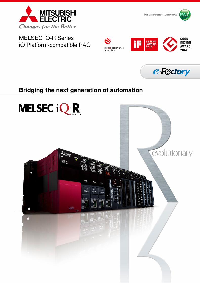
Bridging the next generation of automation
MELSEC iQ-R SeriesiQ Platform-compatible PAC

IntegratedEngineering
IntegratedNetwork
AutomationController
MES
ERP
Further reduce TCO while securing your manufacturing assets Automation ControllerImprove productivity and product quality
1. High-speed system bus realizing improved system performance
2. On-screen multi-touch control enabling smooth GOT (HMI) operations
Integrated NetworkBest-in-class integrated network optimizing production capabilities
1. CC-Link IE supporting 1 Gbps high-speed communication
2. Seamless connectivity within all levels of manufacturing with SLMP
Centralized EngineeringIntegrated engineering environment with system level features
1. Automatic generation of system configuration
2. Share parameters across multiple engineering software via MELSOFT Navigator
3. Changes to system labels are reflected between PAC and HMI
iQ Platform for maximum return on investmentMinimize TCO, Seamless integration, Maximize productivity, Transparent communications: these are common items that highlight the benefits of the iQ Platform and e-F@ctory. The iQ Platform minimizes TCO at all phases of the automation life cycle by improving development times, enhancing productivity, reducing maintenance costs, and making information more easily accessible across the plant. Together with e-F@ctory, offering various best-in-class solutions through its e-F@ctory alliance program, the capabilities of the manufacturing enterprise is enhanced even further realizing the next level for future intelligent manufacturing plants.
ERP (Enterprise resource planning)
MES (Manufacturing execution system)
PAC & HMIIntegration of automation controller and HMI
EngineeringCentralized engineering environment
NetworkIntegrated network through seamless connectivity
iQ PlatformGlobal Player
GLOBAL IMPACT OFMITSUBISHI ELECTRIC
We bring together the best minds to create the best technologies. At Mitsubishi Electric, we understand that technology is the driving force of change in our lives. By bringing great-er comfort to daily life, maximizing the efficiency of businesses and keeping things running across society, we integrate technology and innovation to bring changes for the better.
Mitsubishi Electric is involved in many areas including the following
Energy and Electric SystemsA wide range of power and electrical products from generators to large-scale displays.
Electronic DevicesA wide portfolio of cutting-edge semiconductor devices for systems and products.
Home ApplianceDependable consumer products like air conditioners and home entertain-ment systems.
Information and Communication SystemsCommercial and consumer-centric equipment, products and systems.
Industrial Automation SystemsMaximizing productivity and efficiency with cutting-edge automation technology.
Through Mitsubishi Electric’s vision, “Changes for the Better“ are possible for a brighter future.
01

IntegratedEngineering
IntegratedNetwork
AutomationController
MES
ERP
Further reduce TCO while securing your manufacturing assets Automation ControllerImprove productivity and product quality
1. High-speed system bus realizing improved system performance
2. On-screen multi-touch control enabling smooth GOT (HMI) operations
Integrated NetworkBest-in-class integrated network optimizing production capabilities
1. CC-Link IE supporting 1 Gbps high-speed communication
2. Seamless connectivity within all levels of manufacturing with SLMP
Centralized EngineeringIntegrated engineering environment with system level features
1. Automatic generation of system configuration
2. Share parameters across multiple engineering software via MELSOFT Navigator
3. Changes to system labels are reflected between PAC and HMI
iQ Platform for maximum return on investmentMinimize TCO, Seamless integration, Maximize productivity, Transparent communications: these are common items that highlight the benefits of the iQ Platform and e-F@ctory. The iQ Platform minimizes TCO at all phases of the automation life cycle by improving development times, enhancing productivity, reducing maintenance costs, and making information more easily accessible across the plant. Together with e-F@ctory, offering various best-in-class solutions through its e-F@ctory alliance program, the capabilities of the manufacturing enterprise is enhanced even further realizing the next level for future intelligent manufacturing plants.
ERP (Enterprise resource planning)
MES (Manufacturing execution system)
PAC & HMIIntegration of automation controller and HMI
EngineeringCentralized engineering environment
NetworkIntegrated network through seamless connectivity
iQ Platform
02

Revolutionary, next-generation controllers building a new era in automation
As the core for next-generation automation environment, realizing an automation controller with added value while reducing TCO*To succeed in highly competitive markets, it’s important to build automation systems that ensure high productivity
and consistent product quality. The MELSEC iQ-R Series has been developed from the ground up based on common
problems faced by customers and rationalizing them into seven key areas: Productivity, Engineering, Maintenance,
Quality, Connectivity, Security and Compatibility. Mitsubishi Electric is taking a three-point approach to solving these
problems: Reducing TCO*, increasing Reliability and Reusability of existing assets.
As a bridge to the next generation in automation, the MELSEC iQ-R Series is a driving force behind
revolutionary progress in the future of manufacturing.
*TCO: Total cost of ownership
EngineeringReducing development costs through intuitive engineering
• Intuitive engineering environment covering the product development cycle
• Simple point-and-click programming architecture• Understanding globalization by multiple language
support
QualityReliable and trusted MELSEC product quality
• Robust design ideal for harsh industrial environments• Improve and maintain actual manufacturing quality• Conforms to main international standards
ProductivityImprove productivity throughadvanced performance/functionality
• New high-speed system bus realizing shorter production cycle
• Super-high-accuracy motion control utilizing advanced multiple CPU features
• Inter-modular synchronization resulting in increased processing accuracy
MaintenanceReduce maintenance costs and downtime utilizing easier maintenance features
• Visualize entire plant data in real-time• Extensive preventative maintenance functions embedded
into modules
SafetySystem design flexibility with integrated safety control
• Integrated generic and safety control • Consolidated network topology• Complies with international safety standards
ProcessHigh availability process control in a scalable automation solution
• Extensive visualization and data acquisition• High availability across multiple levels• Integrated process control software simplifies engineering
03
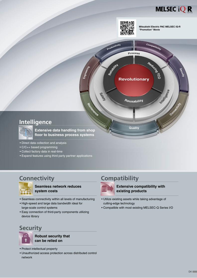
SecurityRobust security that can be relied on
• Protect intellectual property• Unauthorized access protection across distributed control
network
ConnectivitySeamless network reduces system costs
• Seamless connectivity within all levels of manufacturing• High-speed and large data bandwidth ideal for
large-scale control systems• Easy connection of third-party components utilizing
device library
CompatibilityExtensive compatibility with existing products
• Utilize existing assets while taking advantage of cutting-edge technology
• Compatible with most existing MELSEC-Q Series I/O
Mitsubishi Electric PAC MELSEC iQ-R "Promotion" Movie
Intelligence
i Extensive data handling from shop floor to business process systems
• Direct data collection and analysis• C/C++ based programming• Collect factory data in real-time• Expand features using third party partner applications
04
Ethernet
Tracking cableControl systemStandby system
Remotestation 2
Remotestation 1
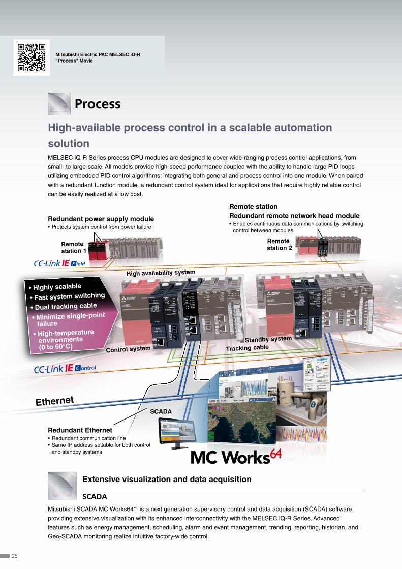
• Highly scalable
• Fast system switching
• Dual tracking cable
• Minimize single-pointfailure
SCADA
Extension base unit• Supports Q Series modules (RQ extension base)
Extension cableProcess control system
High availability system
• High-temperatureenvironments(0 to 60°C)
One Software, Many Possibilities
Process
High-available process control in a scalable automation
solutionMELSEC iQ-R Series process CPU modules are designed to cover wide-ranging process control applications, from
small- to large-scale. All models provide high-speed performance coupled with the ability to handle large PID loops
utilizing embedded PID control algorithms; integrating both general and process control into one module. When paired
with a redundant function module, a redundant control system ideal for applications that require highly reliable control
can be easily realized at a low cost.
Extensive visualization and data acquisition
SCADA
Mitsubishi SCADA MC Works64*1 is a next generation supervisory control and data acquisition (SCADA) software
providing extensive visualization with its enhanced interconnectivity with the MELSEC iQ-R Series. Advanced
features such as energy management, scheduling, alarm and event management, trending, reporting, historian, and
Geo-SCADA monitoring realize intuitive factory-wide control.
Redundant power supply module • Protects system control from power failure
Redundant Ethernet • Redundant communication line • Same IP address settable for both control and standby systems
Remote station Redundant remote network head module • Enables continuous data communications by switching control between modules
Mitsubishi Electric PAC MELSEC iQ-R "Process" Movie
05

Ethernet
Tracking cableControl systemStandby system
Remotestation 2
Remotestation 1
• Highly scalable
• Fast system switching
• Dual tracking cable
• Minimize single-pointfailure
SCADA
Extension base unit• Supports Q Series modules (RQ extension base)
Extension cableProcess control system
High availability system
• High-temperatureenvironments(0 to 60°C)
One Software, Many Possibilities
Multi-level redundancy ensuring continuous control
High availability
Highly reliable control systems can be easily realized
minimizing the possibility of single-point failure at the
visualization (SCADA), control, and network levels,
thereby avoiding system downtime and ensuring
continuous control and operation of critical systems.
*1: Redundant Ethernet connection for MX OPC server will be supported in the future.
One package process controlsoftware
Integrated engineering
GX Works3, the standard integrated engineering
software for the MELSEC iQ-R Series, makes
programming redundant process control systems
relatively easy. The program editor uses function block
diagram (FBD) language for process control and
simplifies system configuration with its intuitive features
such as process tag label (variables) sharing, simple
program structure, and easy project upload/download to
the process CPU.
Embedded PID algorithms
PID control
The process CPU includes dedicated
algorithms such as two-degree-of-freedom PID,
sample PI, and auto-tuning support advanced
process control.
Process CPU • Register up to 480 tags (execute up to 300 PID loops)
• Fast process program execution cycle (50 ms)
• I/O module supports disconnection detection • Multi-channel analog module
CPU-embedded ECC memory • Reliability improved by detection/ correction of data corruption (within 1 bit)
06
IT systemdatabase server
Ethernet Generic remote I/O
Safety remote I/O
C Controller Module
Safety CPU
High-speed Data Logger Module
C Intelligent Function ModuleMES Interface
Module
File server
Fail
PassInspection data in the CCPU
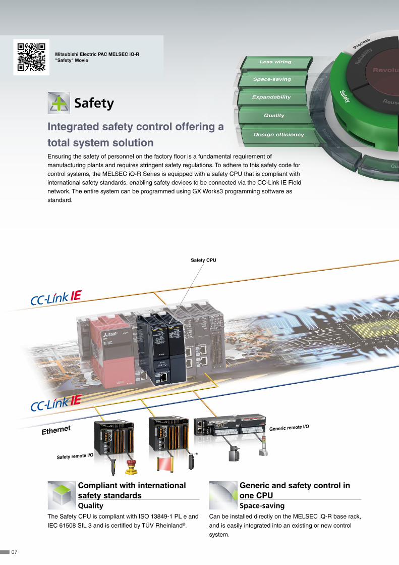
Safety
Integrated safety control offering a
total system solutionEnsuring the safety of personnel on the factory floor is a fundamental requirement of manufacturing plants and requires stringent safety regulations. To adhere to this safety code for control systems, the MELSEC iQ-R Series is equipped with a safety CPU that is compliant with international safety standards, enabling safety devices to be connected via the CC-Link IE Field network. The entire system can be programmed using GX Works3 programming software as standard.
Generic and safety control in one CPUSpace-saving
Can be installed directly on the MELSEC iQ-R base rack,
and is easily integrated into an existing or new control
system.
Compliant with international safety standardsQuality
The Safety CPU is compliant with ISO 13849-1 PL e and
IEC 61508 SIL 3 and is certified by TÜV Rheinland®.
Mitsubishi Electric PAC MELSEC iQ-R "Safety" Movie
07

IT systemdatabase server
Ethernet Generic remote I/O
Safety remote I/O
C Controller Module
Safety CPU
High-speed Data Logger Module
C Intelligent Function ModuleMES Interface
Module
File server
Fail
PassInspection data in the CCPU
i Intelligence
Extensive data handling from shop
floor to business process systemsWith ever-changing manufacturing trends, production data management, analysis, and
planning are more mainstream helping to realize leaner operations, improve yield, and
create a more efficient supply chain. The MELSEC iQ-R Series includes the MES Interface,
C Controller and C Intelligent function, and High-speed data logger modules as part of the
“Intelligence” lineup of interconnected advanced information products.
C/C++ based programming
FlexibilityBased on the ARM® dual-core Cortex A9 processor,
the real-time OS VxWorks® C Controller CPU is ideal
for high-end analytical requirements where raw data
has to be processed, such as for in-line manufacturing
quality testing. The C Intelligent Function Module, based
on the same processor, is a versatile programmable
module that can be used for installing industry-specific
communications protocols; for example, plant-wide
monitoring of wind power generation farms, building
automation and industrial open fieldbus networks.
High-speed production data collectionData logging
Enables high-speed data logging that can be synchronized
with the controller scan time, as an alternative to a dedicated
logging client computer. Includes features such as triggering
and reporting that improve troubleshooting of the manufacturing
process.
Direct access to IT system database serversInformation connection
Improve production management and recipe data handling via
real-time direct access to IT system database servers such
as Oracle® and Microsoft® (SQL Server®, Access®). Overall
system cost is also reduced as additional programming, which
can increase engineering time, and gateway computers are no
longer required.
Mitsubishi Electric PAC MELSEC iQ-R "Intelligence" Movie
08
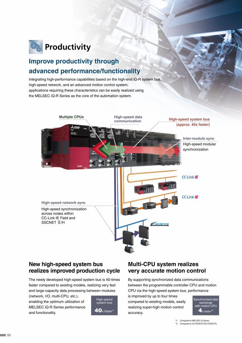
Productivity
Improve productivity through
advanced performance/functionalityIntegrating high-performance capabilities based on the high-end iQ-R system bus,
high-speed network, and an advanced motion control system;
applications requiring these characteristics can be easily realized using
the MELSEC iQ-R Series as the core of the automation system.
*1: Compared to MELSEC-Q Series.
*2: Compared to Q173DSCPU/Q172DSCPU.
Multiple CPUsHigh-speed system bus
(approx. 40x faster)
High-speed modular synchronization
High-speed synchronization across nodes within CC-Link IE Field and SSCNET 3/H
High-speed data communication
Inter-module sync
High-speed network sync
New high-speed system bus realizes improved production cycleThe newly developed high-speed system bus is 40-times
faster compared to existing models, realizing very fast
and large-capacity data processing between modules
(network, I/O, multi-CPU, etc.),
enabling the optimum utilization of
MELSEC iQ-R Series performance
and functionality.
High-speedsystem bus
40x faster*1
Multi-CPU system realizes very accurate motion controlBy supporting synchronized data communications
between the programmable controller CPU and motion
CPU via the high-speed system bus, performance
is improved by up to four times
compared to existing models, easily
realizing super-high motion control
accuracy.
Synchronized dataexchange
with motion CPU
4x faster*2
09
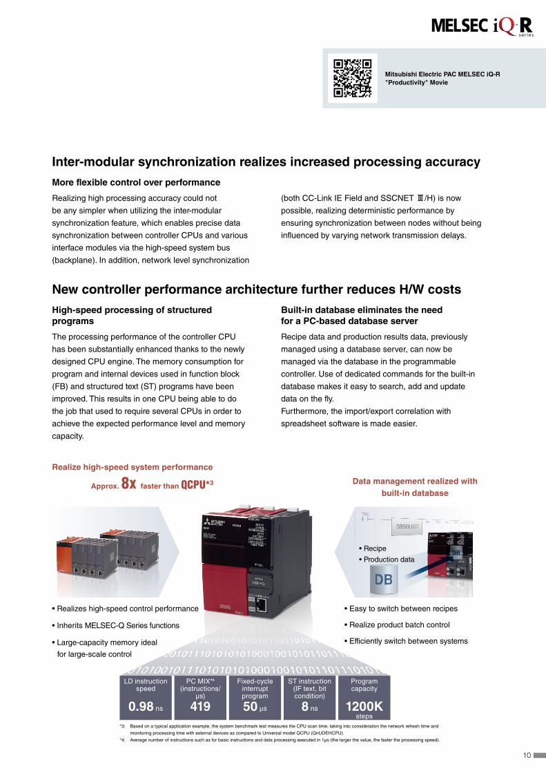
New controller performance architecture further reduces H/W costs
High-speed processing of structured programs
The processing performance of the controller CPU
has been substantially enhanced thanks to the newly
designed CPU engine. The memory consumption for
program and internal devices used in function block
(FB) and structured text (ST) programs have been
improved. This results in one CPU being able to do
the job that used to require several CPUs in order to
achieve the expected performance level and memory
capacity.
Built-in database eliminates the need for a PC-based database server
Recipe data and production results data, previously
managed using a database server, can now be
managed via the database in the programmable
controller. Use of dedicated commands for the built-in
database makes it easy to search, add and update
data on the fly.
Furthermore, the import/export correlation with
spreadsheet software is made easier.
Realize high-speed system performance
Approx. 8x faster than QCPU*3
*3: Based on a typical application example, the system benchmark test measures the CPU scan time, taking into consideration the network refresh time and
monitoring processing time with external devices as compared to Universal model QCPU (QnUDEHCPU).
*4: Average number of instructions such as for basic instructions and data processing executed in 1μs (the larger the value, the faster the processing speed).
Inter-modular synchronization realizes increased processing accuracy
More flexible control over performance
Realizing high processing accuracy could not
be any simpler when utilizing the inter-modular
synchronization feature, which enables precise data
synchronization between controller CPUs and various
interface modules via the high-speed system bus
(backplane). In addition, network level synchronization
(both CC-Link IE Field and SSCNET #/H) is now
possible, realizing deterministic performance by
ensuring synchronization between nodes without being
influenced by varying network transmission delays.
Data management realized with built-in database
• Easy to switch between recipes
• Realize product batch control
• Efficiently switch between systems
• Realizes high-speed control performance
• Inherits MELSEC-Q Series functions
• Large-capacity memory ideal
for large-scale control
LD instruction speed
0.98 ns
PC MIX*4
(instructions/µs)
419
Fixed-cycle interrupt program
50 µs
ST instruction(IF text, bit condition)
8 ns
Programcapacity
1200Ksteps
• Recipe
• Production data
Mitsubishi Electric PAC MELSEC iQ-R "Productivity" Movie
10

Engineering
Reducing development costs
through intuitive engineeringThe engineering software is sometimes considered a fundamental part of the control system in addition to the
hardware components. The core of the system, it includes various steps of the product life cycle, from the design stage
all the way to commissioning and maintenance of the control system. Today, intuitive, easy-to-use software suites are
expected as a standard for modern manufacturing needs. GX Works3 is the latest generation of programming and
maintenance software offered by Mitsubishi Electric specifically designed for the MELSEC iQ-R Series control system.
It includes many new features and technologies to ensure a trouble-free engineering environment solution.
Intuitive engineering software covering the product development cycle
Graphic-based configuration realizing easier programming
Various intuitive features such as
graphic-based system configuration
and an extensive module library
(module label/FB) provided as
standard.
Integrated motion-control system configuration
From setting simple motion module
parameters and positioning
data setup to servo amplifier
configuration, everything is
packaged into an easy-to-use
engineering environment.
Conforms to IEC 61131-3
GX Works3 realizes structured
programming such as ladder and
ST, making project standardization
across multiple users even easier.
System design Programming Debug/maintenance
Straightforward graphic based system configuration design
• Simply drag and drop from the module list to easily create system configuration • Directly setup parameters for each module • Automatically reflect changes in the layout to the module parameters
System design Programming Debug/maintenance
MELSOFT library enables efficient programming through “Module Label/FB”
• Assign convenient label names to internal devices, rather than manually entering a device name every time
• Simply drag & drop module FBs from the MELSOFT Library directly into the ladder program, making programming even easier
System design Programming Debug/maintenance
Extensive version control features
• Flexibly register program change (historical) save points • Easily visualize and confirm program changes
Simple point and click programming architecture
Tab view multiple editorsConveniently work on multiple editors without having to switch between software screens.
Module configuration Easily parameterize each module directly from the configuration editor.
Module list
Simply drag & drop modules directly into the module configuration.
Simple motion setting toolEasily configure the simple motion module with this convenient integrated tool.
Navigation windowEasily access project components Organize program file list.
11

Module label/FB
Automatically generate module function blocks simply by selecting one and placing it directly into the ladder editor.
Reduce engineering time by 60%*1
Global realization by multi-language supportTo adhere to today’s global production needs,
GX Works3 supports multi-language features at
various levels, from the multiple language software
menu system to device comment language
switching features.
*1 Based on new project test benchmarks between GX Works2 and GX Works3.
One Software, Many Possibilities
Mitsubishi Electric PAC MELSEC iQ-R "Engineering" Movie
12

Powertrain
Machining
Interior
Andon
Exterior
Engine
installation
Paint Shop
Assembly
Curing
EthernetE-Coat (electrodeposition)
Painting
Engine assembly
Press Shop
Body Shop
Control Room
Maintenance
Reduce maintenance costs and downtime
utilizing easier maintenance features A manufacturing plant is seldom stopped or taken offline and continuously produces
the desired product or component. However, the control system occasionally
requires maintenance; for example, at the time of a faulty product or system upgrade
for manufacturing a new or updated component. At that time, thanks to the extensive
maintenance functions embedded in the hardware and software, the user can trust
the control system to handle transition into/out of the maintenance period for both
preventive and post maintenance.
Preventive
maintenance CPU module
Visualize manufacturing data in real-time
• Monitor live manufacturing process data across the plant
• Very easy setup using the dedicated GX LogViewer monitoring tool
Real-time monitor
Preventive
maintenance Output module
Prevent system downtime with relay monitoring
• Monitors relay switching amount
• Check relay condition from GOT (HMI)
• Plan module maintenance prior to malfunction of relay
Preventive
maintenance MES interface module
Direct access to enterprise level
• Registers device values directly into database
• Visible shop floor data enables actions before event occurs Equipment/Machine
operating status, etc.
IT system
Corrective
maintenance CPU module
Memory dump enables confirmation of operation problems
• Saves block of device data when error occurs
• Root cause analysis by confirming data on device monitor screen and offline via program editing window
Memory dump results(Program editor)
13

Powertrain
Machining
Interior
Andon
Exterior
Engine
installation
Paint Shop
Assembly
Curing
EthernetE-Coat (electrodeposition)
Painting
Engine assembly
Press Shop
Body Shop
Control Room
The MELSEC iQ-R Series is a unique control system
equipped with innumerable functions. It works to ensure
that the “down-time” of the system is kept to a minimum,
which improves productivity and helps to maintain the
efficiency of the overall plant.
Corrective
maintenance CPU module
Efficient diagnostics with extensive event logging
• Logging of program change events, errors and when the power is turned off
• Event logging displayed in list form
• Quickly detect problems due to operating mistakes by multiple users Event log list
Corrective
maintenance GX Works3
Quickly find network errors
• Visualize error location from network system image
• Easy network error corrective measures
CC-Link IE Field diagnosis window
Corrective
maintenance GX Works3
Multi-language software improves global support
• Comment/label names can be registered in multiple languages
• Easy to switch between languages
• No need for multiple programs to satisfy regional requirements
Switch between device commentlanguages
Japanese English
Corrective
maintenance GX Works3
Simple troubleshooting, even for novice users
• Start diagnostics screen on GX Works3 just by connecting via USB
• Display detailed error information and corrective procedures
Automatically start diagnostics
USB
Mitsubishi Electric PAC MELSEC iQ-R "Maintenance" Movie
14

Electromagnetic compatibility (EMC) testing room
(simulated test)
2 32
5
1
1. Conforms to stringent quality evaluations
and tests that are based on robust
industrial environments including EMC, LSI,
temperature, vibration and HALT tests.
2. High manufacturing quality control through
QR code based quality management
system.
3. The front face has a wide and open design
with an easy-to-use front cover.
4. High-quality CPU module manufacturing
with in-line high-low temperature testing.
5. The base rack design includes a dedicated
earth rail to prevent noise interference in
low power supply conditions and a robust
structure that enables easy installation
without extensive damage to bus
connectors.
Classification according to IEC 60721-3-3 Class 3C2
For protection against aggressive
atmosphere and gases, products
with a conformal coating
(IEC 60721-3-3 Class 3C2) are
available on request*1
*1: Please contact your local Mitsubishi Electric office or
representative for further details.
Quality
Reliable and trusted
MELSEC product qualityThe MELSEC iQ-R Series is based on two fundamental aspects of quality.
“Quality of product”
“Quality for application”
These two characteristics are part of the main principle behind the MELSEC iQ-R Series. This new
control system includes various features designed-in to provide a solution that not only improves the
overall manufacturing productivity, but also maintains a high level of industrial quality that is ideal for
the harsh and rugged environments that it is subjected to on a daily basis.
Robust design ideal for harsh industrial environmentsSynonymous with the Mitsubishi
Electric name, the MELSEC
iQ-R Series is designed with
high quality and reliability, which
is a prerequisite for industrial
applications. In addition, the overall
aesthetics and usability enable
easier maintenance that customers
routinely expect.
Earth rail
4
15
6. Graph showing the signal synchronization
between several modules.
7. Data required for traceability is collected on
the SD memory card.
8. Collected data is analyzed using a
dedicated viewer.
Synchronized processing
Interruptprogram
Network transmissioncycle (link scan)
Output module
Positioningmodule
6
8
7
Maintains product quality during manufacturing
With inter-module synchronization, it is now possible to precisely synchronize
interrupt programs with the network communications cycle (link scan).
Any variations in data transmission response time (network transmission
delay time) between the controller and other devices on the network are eliminated, realizing high integrity between
manufacturing processes that are dependent on each other, ensuring high performance and processing.
Realizes traceability through data logging
Simple settings enable the collection of production data needed for traceability. Furthermore, collected data can be
analyzed easily using a dedicated viewer. Analyzing various data on production processes provides an indicator for
quality improvements and manufacturing cost reductions, thereby supporting optimization of the production system.
Improve and maintain actual manufacturing quality
• Parts inventory
• Production data
• Operations log
• Inspection record
• Quality data
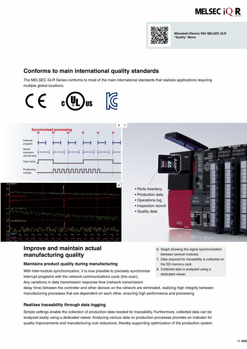
Conforms to main international quality standardsThe MELSEC iQ-R Series conforms to most of the main international standards that realizes applications requiring
multiple global locations.
Mitsubishi Electric PAC MELSEC iQ-R "Quality" Movie
16

Space saving
Real-time
Less wiring
Ethernet
Gigabit
Synchronize
Ring
Star
Seamless
General Motion
Safety
Line
Integrate motion control into one networkThe CC-Link IE Field Network compatible Simple
Motion module can be used as a master station*3 on
the network. System configuration cost can be reduced
as only one module is required for both Motion control
and network connectivity.
Cost-saving integrated network CPU moduleThe MELSEC iQ-R Series includes a lineup of CPUs
with embedded industrial network connection ports
(CC-Link IE and Ethernet). System costs can be
further reduced by approximately 50% using the
embedded network CPU module, which realizes the
same features as a generic network
interface module.System
hardware costs
Reduced
50% *2
*1: Seamless Message Protocol (SLMP): A simple client-server common protocol that enables
communication between Ethernet products and CC-Link IE-compatible machines.
*2: Cost comparison of using the MELSEC iQ-R Series R04CPU + RJ71EN71 modules.
*3: The sub-master and safety communication functions are not supported.
CC-Link IE
embedded CPU
CC-Link IE Field Network compatible
Simple Motion module
Connectivity
Seamless network reduces
system costsThe MELSEC iQ-R Series is part of a family of products
all interconnected across various levels of automation.
Based on the seamless message protocol (SLMP*1),
data flows transparently between the sensor level and
the management level across multiple industry-standard
automation networks. CC-Link IE, Asia’s No. 1 industrial
network, realizes fast gigabit data transmission speeds,
further optimizing the manufacturing cycle. In addition, the
SSCNET #/H high-speed motion control network further
enhance the factory-wide connectivity solution.
17

Space saving
Real-time
Less wiring
Ethernet
Gigabit
Synchronize
Ring
Star
Seamless
General Motion
Safety
Line
High-speed and large bandwidth ideal for large-scale control systemsThe Ethernet-based open network CC-Link IE is an
industry-leading 1 Gbps high-speed, large-capacity
network. The division of 1 Gbps broadband into uses
for distributed control and field data communications
secures the reliability of control communications and
realizes real-time data collection, which can be difficult
with standard Ethernet.
Supporting Ethernet protocol stack realizing highly-flexible systemCC-Link IE Field Network Basic protocol is software-based (not
requiring ASIC), operating on standard Ethernet protocol stack,
which can be used together with TCP/IP communications. This
allows CC-Link IE Field Network Basic compatible products
and Ethernet compatible products to be connected on the same
Ethernet communications line, enabling a highly-flexible and
low cost system. MELSEC programmable controller CPUs with
an embedded Ethernet port can be used as a master station,
eliminating the need for an additional network module.
Mitsubishi Electric PAC MELSEC iQ-R "Connectivity" Movie
USB
PULL
MODERUNERR
USERBAT
BOOT
IT system
MELSEC iQ-RSeriesMES interface
GOT(HMI)
GOT(HMI)
GOT(HMI) Robot Robot
Industrialweighing
scale
Inverter
Bar-codereader
Remote I/Omodule
Label printer
Safetyremote
I/O module
Photoelectricsensor(diffuse
reflection type)
Proximitysensor
Photointerrupter Safety
switchLight
curtainServo
amplifierServo
amplifier
Servoamplifier
Inverter Remote I/Omodule
Remote I/Omodule
Remote I/Omodule
MELSEC-LSeries
CC-Link IEField−AnyWireASLINKBridgemodule
MELSEC iQ-RSeriesSafety CPU
MELSEC iQ-RSeries
MELSEC-QSeries
MELSEC iQ-RSeries
MELSEC iQ-RSeries
FA Integrated Engineering SoftwareiQ Works
SCADAsoftware
LAN(Ethernet)
Ethernet
Enterpriselevel
Controllevel
Fieldlevel
Sensorlevel
Seamless datacoordination Production cell A Production cell B Production cell C Production cell D
18

Security key authentication protecting project data
The security key authentication prevents programs from
being opened on personal computers where the security
key has not been registered. Furthermore, because
programs cannot be executed by CPU modules where
the security key has not been registered, the integrity of
customer technologies and other intellectual property is not
compromised. The security key can also be registered on
an extended SRAM cassette. Therefore, when replacing the
CPU module, there is no need to re-register the security key,
making replacement very simple.
The IP filter can be used to register the IP addresses
of devices permitted to access the CPU module. As
a result, access from non-registered devices can be
blocked, thereby lowering the risk of program hacking
and unauthorized access by a third party.
Another feature is a remote password function for
password-based security. Passwords of up to 32
characters can be set to prevent unauthorized access
to the CPU module via networks such as Ethernet.
Security
Robust security that can be relied onAs technology becomes more complex and the distribution of manufacturing systems more
global, the protection of intellectual property is even more significant. When shipping a
finished product overseas, the last thing an OEM needs to consider is unauthorized copying
or changing of the original project data. In addition to this, unauthorized access to the control
system can have very serious implications to the control system and the end user, which can
compromise the overall safety of the plant.
The MELSEC iQ-R Series has a number of embedded features that
help to maintain these requirements, such as hardware and software
keys to protect intellectual property, and multi-level user access
password hierarchy to protect the project at the design stage.
Powerful security features protecting intellectual property
Extended SRAM cassette
with registered
security key
Prevent unauthorized access across the network
Mitsubishi Electric PAC MELSEC iQ-R "Security" Movie
Device with registered IP address
(access permitted)
Device without registered IP address
(access denied)
Ethernet
19

Variety of compatible modules
By utilizing the dedicated extension base, most
MELSEC-Q Series modules*2 can be re-used. This
makes it possible to introduce the high-performance
MELSEC iQ-R Series while controlling the cost of
supplementary equipment.*2: For further details, please refer to the "MELSEC iQ-R Module Configuration Manual".
Possible to divert external device wiring
The MELSEC iQ-R Series I/O module, analog module,
and counter module pin layouts and connectors are the
same as those of the MELSEC-Q Series. Accordingly,
existing external device wiring (connectors, terminal
blocks) can be diverted without changes and wiring
costs can be reduced.
Compatibility
Extensive compatibility
with existing productsWhenever introducing a new system or technology into an existing manufacturing
plant or control system, utilization of existing assets as much as feasibly possible is a
mandatory requirement with today’s manufacturing needs. The MELSEC iQ-R Series
addresses these subtle but substantial needs with various system hardware support
and engineering project compatibility to achieve an easy path to higher
technology and improved performance capabilities.
Current programs can be fully utilized
A simply conversion process*1 is all it takes to enable
the use of MELSEC-Q Series programs with the
MELSEC iQ-R Series. Customers can effectively use
the program assets they have accumulated, thereby
reducing the overall engineering time. *1: For detailed information about converting to GX Works3 programs,
please refer to the "GX Works3 Operating Manual".
Utilize existing MELSEC-Q Series assets
Mitsubishi Electric PAC MELSEC iQ-R "Compatibility" Movie
20

LineupPower supply P.23 R61P .................................................AC input
R62P ...............AC input (inc. 24 V DC output)
R64P ....................... AC input (large capacity)
R63P ................................................ DC input
R63RP NEW .................DC input (Redundant)
R64RP .........................AC input (Redundant)
Base P.23 Main base
R35B ......................................................5-slot
R38B ......................................................8-slot
R310RB ..........................10-slot (Redundant)
R312B ..................................................12-slot
Extended temperature range main base
R310B-HT ............................................10-slot
R38RB-HT ........................8-slot (Redundant)
Extension base
R65B ......................................................5-slot
R68B ......................................................8-slot
R610RB ..........................10-slot (Redundant)
R612B ..................................................12-slot
Extended temperature range extension base
R610B-HT ............................................10-slot
R68RB-HT ........................8-slot (Redundant)
RQ extension base (MELSEC-Q Series)
RQ65B ...................................................5-slot
RQ68B ...................................................8-slot
RQ612B ...............................................12-slot
Extension cable
RC06B .................................................. 0.6 m
RC12B ................................................... 1.2 m
RC30B ..................................................... 3 m
RC50B ..................................................... 5 m
RC100B ..................................................10 m
CPU P.26 Programmable controller CPU
R04(EN)CPU ..................................40K steps
R08(EN)CPU ..................................80K steps
R16(EN)CPU ................................160K steps
R32(EN)CPU ................................320K steps
R120(EN)CPU ............................1200K steps
R◻ENCPU is equipped with CC-Link IE Control/CC-Link IE Field
network ports.
Motion CPU
R16MTCPU ........................................ 16-axis
R32MTCPU ........................................32-axis
R64MTCPU ........................................64-axis
Safety CPU
R08SFCPU-SET .............................80K steps
R16SFCPU-SET ...........................160K steps
R32SFCPU-SET ...........................320K steps
R120SFCPU-SET .......................1200K steps
Process CPU
R08PCPU .......................................80K steps
R16PCPU .....................................160K steps
R32PCPU .....................................320K steps
R120PCPU .................................1200K steps
Redundant function module
R6RFM ........................... Redundant function
C Controller
R12CCPU-V ..........Memory capacity 256 MB
I/O P.43 AC input
RX28 NEW .......................................... 8-point
RX10 ..................................................16-point
DC input
RX40C7 .............................................16-point
RX41C4 ............................................ 32-point
RX42C4 ............................................ 64-point
DC high-speed input
RX40PC6H ...........Positive common, 16-point
RX40NC6H .........Negative common, 16-point
RX41C6HS ... Positive/negative common, 32-point
RX61C6HS ... Positive/negative common, 32-point
DC (with diagnostic functions) input
RX40NC6B ........................................16-point
Relay output
RY18R2A NEW .................................... 8-point
RY10R2 .............................................16-point
Triac output
RY20S6 NEW .....................................16-point
Transistor (sink) output
RY40NT5P .........................................16-point
RY41NT2P ........................................ 32-point
RY42NT2P ........................................ 64-point
High-speed transistor (sink) output
RY41NT2H ....................................... 32-point
Transistor (source) output
RY40PT5P .........................................16-point
RY41PT1P ........................................ 32-point
RY42PT1P ........................................ 64-point
High-speed transistor (source) output
RY41PT2H ........................................ 32-point
Transistor (with diagnostic functions) output
RY40PT5B .........................................16-point
I/O combined module
DC Input, transistor (sink) output
RH42C4NT2P ..................... 32-point/32-point
21

NEW
Motion, Positioning, Flexible high-speed I/O, High-speed counter P.57
Simple motion
(Compatible with CC-Link IE Field network)
RD77GF4 .............................................4-axis
RD77GF8 .............................................8-axis
RD77GF16 .......................................... 16-axis
RD77GF32 NEW .................................32-axis
(Compatible with SSCNET 3/H)
RD77MS2 .............................................2-axis
RD77MS4 .............................................4-axis
RD77MS8 .............................................8-axis
RD77MS16 ......................................... 16-axis
Positioning
Transistor output
RD75P2 ................................................2-axis
RD75P4 ................................................4-axis
Differential driver output
RD75D2 ................................................2-axis
RD75D4 ................................................4-axis
Flexible high-speed I/O
RD40PD01 NEW .... I/P:12-point, O/P:14-point
High-speed counter
DC input/Transistor (sink) output
RD62P2 ..........................................2-channel
DC input/Transistor (source) output
RD62P2E ........................................2-channel
Differential input/Transistor (sink) output
RD62D2 ..........................................2-channel
Network P.64 Ethernet
RJ71EN71 ...................... 1 G/100 M/10 Mbps
Multiple network type
(Ethernet/CC-Link IE)
CC-Link IE Control network
RJ71GP21-SX ....................... Control/Normal
station optical cable
CC-Link IE Field network
RJ71GF11-T2 ................. Master/Local station
RJ72GF15-T2 ........................ Remote station
CC-Link
RJ61BT11 ...................... Master/Local station
CC-Link Ver.2
AnyWireASLINK
RJ51AW12AL ..........................Master station
BACnet®
RJ71BAC96 ............... Controller/Workstation
Serial communication
RJ71C24 ....................... RS-232, RS-422/485
RJ71C24-R2 ..............................RS-232 x2ch
RJ71C24-R4 .......................RS-422/485 x2ch
Advanced information modules P.72
MES Interface
RD81MES96 .................Database connection
High-speed data logger
RD81DL96 ..............................Data collection
C Intelligent function module
RD55UP06-V .........C/C++ program execution
Analog P.48 Analog input
R60AD4 .......... 4-channel (voltage or current)
R60ADV8 .........................8-channel (voltage)
R60ADI8 .......................... 8-channel (current)
High-speed analog input
R60ADH4 ....... 4-channel (voltage or current)
Analog input (channel isolated)
R60AD8-G ...... 8-channel (voltage or current)
R60AD16-G ...16-channel (voltage or current)
Temperature input
R60TD8-G ............ 8-channel (thermocouple)
R60RD8-G ........................... 8-channel (RTD)
Temperature control
R60TCTRT2TT2 .......... 2-channel multi-input,
2-channel thermocouple input
R60TCRT4 .....................4-channel RTD input
R60TCTRT2TT2BW .... 2-channel multi-input,
2-channel thermocouple input
R60TCRT4BW ...............4-channel RTD input
Analog output
R60DA4 .......... 4-channel (voltage or current)
R60DAV8 .........................8-channel (voltage)
R60DAI8 .......................... 8-channel (current)
High-speed analog output
R60DAH4 ....... 4-channel (voltage or current)
Analog output (channel isolated)
R60DA8-G ...... 8-channel (voltage or current)
R60DA16-G ...16-channel (voltage or current)
NEW
NEW
22
Max. 7extension bases
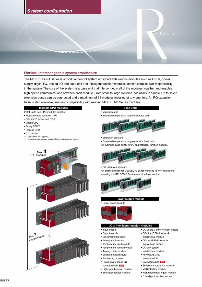
Multiple CPU modulesInstall up to four CPU modules together
• Programmable controller CPU
• CC-Link IE embedded CPU*1
• Motion CPU
• Safety CPU*2
• Process CPU
• C Controller*1: Multi-CPU is not supported.
*2: Product package includes a safety CPU and safety function module.
Base units • Main base unit
• Extended temperature range main base unit
• Extension base unit
• Extended temperature range extension base unit
An extension base strictly for I/O and intelligent function modules.
• RQ extension base unit
An extension base for MELSEC-Q Series modules (further extensions
requiring the MELSEC-Q Series extension base version).
Power supply module • Power supply module
I/O & Intelligent function modules • Input module
• Output module
• I/O combined module
• Analog input module
• Temperature input module
• Temperature control module
• Analog output module
• Simple motion module
• Positioning module
• Flexible high-speed I/O
control module NEW
• High-speed counter module
• Ethernet interface module
• CC-Link IE Control Network module
• CC-Link IE Field Network
master/local module
• CC-Link IE Field Network
remote head module
• CC-Link system
master/local module
• AnyWireASLINK
master module
• BACnet module NEW
• Serial communication module
• MES interface module
• High-speed data logger module
• C intelligent function module
Flexible, interchangeable system architecture
The MELSEC iQ-R Series is a modular control system equipped with various modules such as CPUs, power
supply, digital I/O, analog I/O and base unit and intelligent function modules, each having its own responsibility
in the system. The core of the system is a base unit that interconnects all of the modules together and enables
high-speed communications between each module. From small to large systems, scalability is simple. Up to seven
extension bases can be connected and a maximum of 64 modules installed at any one time. An RQ extension
base is also available, ensuring compatibility with existing MELSEC-Q Series modules.
Max. 4 CPU modules
2323
System configuration

Integrated safety control
The MELSEC iQ-R Series safety control system consists of a safety CPU that is compliant with international
safety standards, ISO 13849-1 PL e and IEC 61508 SIL 3, and can execute both safety and general logic in the
same CPU. The CPU module can be installed on a standard base unit and when paired with the safety function
module enables control of safety I/O, realizing easy integration into an existing or new control system. Safety I/O
such as an emergency stop switch or light curtain is controlled via CC-Link IE Field network, which is connected to
the safety remote I/O module.
CPU Safety remote I/O • Safety CPU
MELSEC iQ-R Series
(Safety CPU)
Generic
remote I/O
Safety
remote I/O
Safety
remote I/O
• Safety remote I/O module
Safety I/O Generic I/O
Enabling switch Switch
Emergency stop switch
Indicator light
Light curtain
Door switch
Highly scalable redundant control
The MELSEC iQ-R Series redundant control system is based on a dual-system architecture where all modules on
a primary (control) system are duplicated onto a secondary (standby) system with a tracking cable connecting the
systems together. Both systems are equipped with a process CPU module and redundant function module, with
the former being able to execute standard logic and process control. Remote I/Os are controlled via the CC-Link
IE Field network, and dedicated base units for supporting redundant power-supply modules are available in either
standard or extended temperature models.
CPU, redundant function module Power supply modules, base units* • Process CPU
• Redundant function module
Primary system
Standby system
Tracking cable
Remote station
• Redundant power supply module NEW
• Redundant power supply main base unit
• Extended temperature range redundant power supply main
base unit
• Redundant power supply extension base unit
• Extended temperature range redundant power supply
extension base unit
* Only these base units support redundant power supply modules.
Can utilize standard MELSEC iQ-R Series modules.
24
System
co
nfig
uratio
nC
PU
I/OA
nalog
Motion, P
ositioning,F
lexible high-speed I/OH
igh-speed counterN
etwork
Advanced
information
Softw
are

Highly accurate synchronization
The MELSEC iQ-R Series system provides highly accurate synchronization between modules on the control
system, which is realized through inter-modular synchronization. Additionally, use of the CC-Link IE Field Network
realizes network-level synchronization, providing node-level synchronization that ensures deterministic data flow
void of any influence from data transmission delays. This is ideal for applications such as "cutting and folding"
inside an offset printer, which requires synchronization between the printing quality sensor, high-speed rotary
cutter, folding roller and conveyor.
Printing quality sensor
Cutter
Paper feed Printing
Drying/cooling
Cutting/folding
Folder
Feeder
Crank folder
Reject mechanism
Positioning module
Output moduleCC-Link IE Field Network module
High-speed counter moduleHigh-speed counter moduleInput moduleCC-Link IE Field Network module
Power supply moduleItem R61P R62P R63P R64P R63RP R64RP
Input power supply voltage100...240 V AC
(85...264 V AC)
100...240 V AC
(85...264 V AC)
24 V DC
(15.6...31.2 A DC)
100...240 V AC
(85...264 V AC)
24 V DC
(19.2...31.2 A DC)
100...240 V AC
(85...264 V AC)
Input frequency 50/60 Hz ±5% 50/60 Hz ±5% - 50/60 Hz ±5% - 50/60 Hz ±5%
Max. input apparent power (VA) 130 120 - 160 - 160
Max. input power (W) - - 50 - 50 -
Rated output current (5 V DC) 6.5 A 3.5 6.5 A 9 6.5 A 9
Rated output current (24 V DC) - 0.6 - - - -
Redundant power supply - - - - ● ●
Main base unit (Standard, Extended temperature range)
ItemMain base unit (Standard) Extended temp. range main base unit*1
R35B R38B R310RB R312B R310B-HT R38RB-HT
Number of I/O modules installed 5 8 10 12 10 8
DIN rail mounting adapter type R6DIN1 R6DIN1 R6DIN1 R6DIN1 R6DIN1 R6DIN1
External dimensions (H x W x D, mm) 101 x 245 x 32.5 101 x 328 x 32.5 101 x 439 x 32.5 101 x 439 x 32.5 101 x 439 x 32.5 101 x 439 x 32.5
Extension base unit (Standard, Extended temperature range)
ItemExtension base unit (Standard) Extended temp. range extension base unit*1
R65B R68B R610RB R612B R610B-HT R68RB-HT
Number of I/O modules installed 5 8 10 12 10 8
Applicable module MELSEC iQ-R Series module
DIN rail mounting adapter type R6DIN1 R6DIN1 R6DIN1 R6DIN1 R6DIN1 R6DIN1
External dimensions (H x W x D, mm) 101 x 245 x 32.5 101 x 328 x 32.5 101 x 439 x 32.5 101 x 439 x 32.5 101 x 439 x 32.5 101 x 439 x 32.5
RQ extension base unit
ItemRQ extension base unit
RQ65B RQ68B RQ612B
Number of I/O modules installed 5 8 12
Applicable module MELSEC-Q Series module
DIN rail mounting adapter type Q6DIN2 Q6DIN1 Q6DIN1
External dimensions (H x W x D, mm) 98 x 245 x 44.1 98 x 328 x 44.1 98 x 439 x 44.1
Extension cableItem RC06B RC12B RC30B RC50B RC100B
Cable length*2 (m) 0.6 1.2 3.0 5.0 10.0
*1: Enables standard MELSEC iQ-R Series modules to support extended operating ambient temperature of 0 to 60°C.
*2: Overall cable distance 20 m. 13.2 m with the RQ extension base.25

Focus points
PC MIX*2
419 instructio
ns/µsSystem
benchmark*1
Process control
scan time
x8
x2
x6
x7
x3
Improved performance
Controller performance has been improved, resulting in increased
processing power and the ability to handle larger amounts of data.
The multi-CPU architecture has been further improved, enabling
faster data exchange across the backplane. The core instruction
processing speed has also been improved tenfold, helping to
reduce the production cycle time. High-speed and large process
control systems can be realized, supporting up to 500 loops.
Finely balanced control
Balancing of various different control needs can be done effectively
utilizing the multi-CPU feature of the MELSEC iQ-R Series. Up to
192 servo axes can be controlled by incorporating three separate
motion CPUs on the base unit, with a spare CPU slot required for
controlling the general aspects of the system. *1: Based on a typical application example, the system benchmark test measures the CPU scan time taking into consideration the
network refresh time and processing time using external devices, (compared to universal model QCPU, QnUDEHCPU).
*2: Average number of instructions, such as basic instructions and data processing, executed in 1 μs (the larger the value, the faster the processing speed).
The MELSEC iQ-R Series includes a wide range of programmable automation controllers capable of catering to
diversified automation control needs, redesigned around the new MELSEC iQ-R high-speed system bus to ensure
high performance and intelligent processing power. The lineup includes a high-performance, general-purpose
controller (with an embedded CC-Link IE network model available) capable of variable memory capacities and a
high-precision motion controller with variable controllable axes. In addition, application-specific CPUs are available;
the Safety CPU (supporting functional safety standards), Process CPU (supporting high-speed PID control and
hot-swap of I/O modules and when paired with a redundant function module realizes a high available control
system), and the C Controller CPU, which provides C language programming ideal for converting from personal
computer or micro-controller based systems.
ffProgram capacity of up to 1200K steps
ff Improved multi-CPU controller architecture
ffEmbedded gigabit network ports CPU
ff Internal DB for simple batch recipe control
ffSecurity embedded in hardware SRAM cassette
ffVarious motion control possible (position, speed, torque, advanced sync, etc.)
ff International standard (ISO 13849-1 PL e, IEC 61508 SIL 3) safety CPU
ffHigh-speed PID control, module replacement while online (hot-swap), supports highly reliable redundant system process CPU
ffC/C++ programming ideal for PC/micro-controller based systems
CPU
RnCPU
RnPCPU
QnUDVCPU
QnUDEHCPU
QnPH/ QnPRHCPU
26
System
configuration
CP
UI/O
Analog
Motion, P
ositioning,F
lexible high-speed I/OH
igh-speed counterN
etwork
Advanced
information
Softw
are

SRAM cassette connector
SD memory card slot
Ethernet port100BASE-TX/10BASE-T
CC-Link IE connection port1000BASE-T/100BASE-TX/10BASE-T
USB portHigh-speed USB2.0 (miniB)
Extended SRAM cassette
At the core of the MELSEC iQ-R Series is a programmable controller CPU. This CPU is the heart of the control
system and includes various features for different applications. The most common CPU is the programmable
controller CPU, into which various features are embedded, enabling it to perform a wide range of control tasks.
The different CPUs are highly scalable with five types available, based on program capacity needs (40K to 1200K
steps). In addition, a CC-Link IE embedded CPU is available, further reducing hardware costs as a separate
network module is not required.
Built-in hardware features
Programmable controller CPUs are equipped with a built-in USB port (high-speed Ver. 2.0 Mini-B) and an Ethernet
port (up to 100 Mbps) as standard, enabling connection to a general LAN network*1 or MELSOFT software.
Two memory options are included as well, an external SRAM cassette that enables device/label memory to be
increased and doubling up as a hardware security key, and an SD memory card which can be used for logging
data, troubleshooting device values or as a memory database for recipe storage. *1: General LAN connection supported by the Ethernet port only.
Programmable Controller CPU ModulesR04CPUProgram capacity 40K steps
R08CPUProgram capacity 80K steps
R16CPUProgram capacity 160K steps
R32CPU Program capacity 320K steps
R120CPUProgram capacity 1200K steps
R04ENCPUProgram capacity 40K steps, CC-Link IE embedded
R08ENCPUProgram capacity 80K steps, CC-Link IE embedded
R16ENCPUProgram capacity 160K steps, CC-Link IE embedded
R32ENCPUProgram capacity 320K steps, CC-Link IE embedded
R120ENCPUProgram capacity 1200K steps, CC-Link IE embedded
27
CPU

Flexible, large-capacity data storage
The MELSEC iQ-R Series programmable controller CPU is designed to allow an external SRAM cassette to
be installed directly into the CPU module. This option makes it possible to increase internal device memory to
an impressive 5786K words, expanding device/label memory even further. An SD memory card can be used
at the same time, expanding data logging memory and the capacity of the internal database, which is ideal for
large-scale systems. In general, management of programmable controller internal data is quite flexible, making
programming even easier by allowing various data area allocations to be changed within the CPU memory and
SRAM cassette.
File register area
Label area
Device area
Internal memory(max. 1690K word*1)
Extended SRAM cassette(max. 4096K word*2)
Flexible memory allocation
Continuous access
SD memory card(Max. 32 GB)
• Boot data • Comment data• Logging data• Database
*1: Based on R120CPU.
*2: Based on NZ2MC-8MBS (8 MB).
Data management utilizing internal database (DB)
The CPU includes an internal database that can be installed into the SD memory card. This feature allows, for
example, a selection of database commands that can add/delete/change records to be utilized for simple recipe
functions. It is also much easier to import/export Unicode files for use in spreadsheets. This is a very useful
feature, especially for the food and beverage industry where multiple product variations are produced using the
same machine process.
TBL1 FIELD CON OUTN OUTDATA FLAG
TBL1 FIELD CON OUTN OUTDATA FLAG
TBL1 FIELD CON OUTN OUTDATA FLAG
TBL1 FIELD CON OUTN OUTDATA FLAG
Unicode text file import
Export from DB Actual production data added to DB
Recipe data retrieved from DB
DBSELECTDBIMPORT
DBEXPORT DBINSERT
ID Mix A Mix B Mix C
0001H 20% 60% 20%
0002H 50% 30% 20%
Database (recipe table)
ID NameMix A (%)
Mix B (%)
Mix C (%)
0001H Red 20 60 20
0002H Blue 50 30 20
Database (reporting tool)Serial no. ID Date/time Amount
00001234H 0001HDD/MM/20YY
15 : 40 : 3081
00001235H 0002HDD/MM/20YY
15 : 41 : 1579
28
System
configuration
CP
UI/O
Analog
Motion, P
ositioning,F
lexible high-speed I/OH
igh-speed counterN
etwork
Advanced
information
Softw
are

High-speed, event driven programs
Further improvements to CPU performance have resulted in the interval time between event driven programs
(interrupt programs) reduced to 50 us. This has been realized by having multiple event driven programs able
to be nested within other event driven programs and being triggered from already executing programs. This
kind of performance is available with a standard input module and programmable controller CPU, without
requiring a dedicated interrupt type input module, which helps to further reduce hardware costs while realizing a
high-precision control system.
I49Interruptprogram
I48Interruptprogram
High
Priority
Low
I31Interruptprogram
Scanexecutionprogram
Constant cycle
Execute
Constant cycle
Execute
Constant cycle
Execute Execute
I/P (detect) O/P (process)
I/P module + ABS encoder accurately detect variable high-speed I/P signals.
END
CPU program management data
Operation and system historical events are automatically recorded in the CPU module, allowing quick root cause
analysis of system errors or management of program changes. Actual changes to the program, parameters
and system errors are viewable using GX Works3 or can be exported as a CSV file for use by other third-party
software.
View operations and system events with corresponding event/error codes, data can be sorted according to various attributes.
Corresponding explanatory text
29
CPU
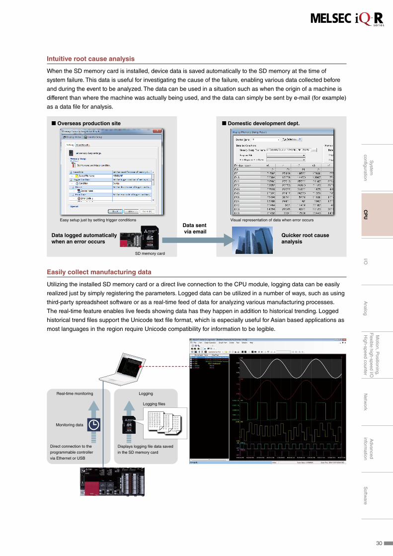
Intuitive root cause analysis
When the SD memory card is installed, device data is saved automatically to the SD memory at the time of
system failure. This data is useful for investigating the cause of the failure, enabling various data collected before
and during the event to be analyzed. The data can be used in a situation such as when the origin of a machine is
different than where the machine was actually being used, and the data can simply be sent by e-mail (for example)
as a data file for analysis.
Easy setup just by setting trigger conditions Visual representation of data when error occurs
� Overseas production site � Domestic development dept.
Data logged automatically when an error occurs
Quicker root cause analysis
Data sent via email
SD memory card
Easily collect manufacturing data
Utilizing the installed SD memory card or a direct live connection to the CPU module, logging data can be easily
realized just by simply registering the parameters. Logged data can be utilized in a number of ways, such as using
third-party spreadsheet software or as a real-time feed of data for analyzing various manufacturing processes.
The real-time feature enables live feeds showing data has they happen in addition to historical trending. Logged
historical trend files support the Unicode text file format, which is especially useful for Asian based applications as
most languages in the region require Unicode compatibility for information to be legible.
Real-time monitoring Logging
Monitoring data
Logging files
Direct connection to the
programmable controller
via Ethernet or USB
Displays logging file data saved
in the SD memory card
30
System
configuration
CP
UI/O
Analog
Motion, P
ositioning,F
lexible high-speed I/OH
igh-speed counterN
etwork
Advanced
information
Softw
are
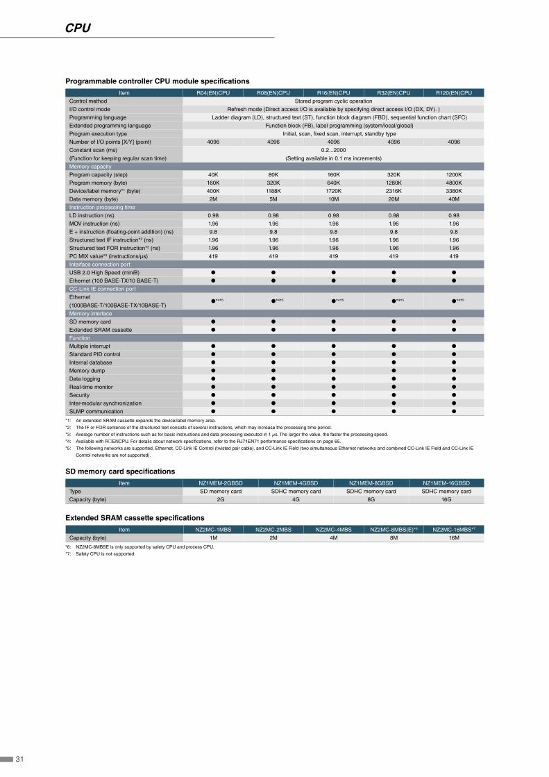
Programmable controller CPU module specifications
Item R04(EN)CPU R08(EN)CPU R16(EN)CPU R32(EN)CPU R120(EN)CPU
Control method Stored program cyclic operation
I/O control mode Refresh mode (Direct access I/O is available by specifying direct access I/O (DX, DY). )
Programming language Ladder diagram (LD), structured text (ST), function block diagram (FBD), sequential function chart (SFC)
Extended programming language Function block (FB), label programming (system/local/global)
Program execution type Initial, scan, fixed scan, interrupt, standby type
Number of I/O points [X/Y] (point) 4096 4096 4096 4096 4096
Constant scan (ms)
(Function for keeping regular scan time)
0.2...2000
(Setting available in 0.1 ms increments)
Memory capacity
Program capacity (step) 40K 80K 160K 320K 1200K
Program memory (byte) 160K 320K 640K 1280K 4800K
Device/label memory*1 (byte) 400K 1188K 1720K 2316K 3380K
Data memory (byte) 2M 5M 10M 20M 40M
Instruction processing time
LD instruction (ns) 0.98 0.98 0.98 0.98 0.98
MOV instruction (ns) 1.96 1.96 1.96 1.96 1.96
E + instruction (floating-point addition) (ns) 9.8 9.8 9.8 9.8 9.8
Structured text IF instruction*2 (ns) 1.96 1.96 1.96 1.96 1.96
Structured text FOR instruction*2 (ns) 1.96 1.96 1.96 1.96 1.96
PC MIX value*3 (instructions/µs) 419 419 419 419 419
Interface connection port
USB 2.0 High Speed (miniB) ● ● ● ● ●
Ethernet (100 BASE-TX/10 BASE-T) ● ● ● ● ●
CC-Link IE connection port
Ethernet
(1000BASE-T/100BASE-TX/10BASE-T)●*4*5 ●*4*5 ●*4*5 ●*4*5 ●*4*5
Memory interface
SD memory card ● ● ● ● ●
Extended SRAM cassette ● ● ● ● ●
Function
Multiple interrupt ● ● ● ● ●
Standard PID control ● ● ● ● ●
Internal database ● ● ● ● ●
Memory dump ● ● ● ● ●
Data logging ● ● ● ● ●
Real-time monitor ● ● ● ● ●
Security ● ● ● ● ●
Inter-modular synchronization ● ● ● ● ●
SLMP communication ● ● ● ● ●
*1: An extended SRAM cassette expands the device/label memory area.
*2: The IF or FOR sentence of the structured text consists of several instructions, which may increase the processing time period.
*3: Average number of instructions such as for basic instructions and data processing executed in 1 µs. The larger the value, the faster the processing speed.
*4: Available with R◻ENCPU. For details about network specifications, refer to the RJ71EN71 performance specifications on page 65.
*5: The following networks are supported, Ethernet, CC-Link IE Control (twisted pair cable), and CC-Link IE Field (two simultaneous Ethernet networks and combined CC-Link IE Field and CC-Link IE
Control networks are not supported).
SD memory card specifications
Item NZ1MEM-2GBSD NZ1MEM-4GBSD NZ1MEM-8GBSD NZ1MEM-16GBSD
Type SD memory card SDHC memory card SDHC memory card SDHC memory card
Capacity (byte) 2G 4G 8G 16G
Extended SRAM cassette specifications
Item NZ2MC-1MBS NZ2MC-2MBS NZ2MC-4MBS NZ2MC-8MBS(E)*6 NZ2MC-16MBS*7
Capacity (byte) 1M 2M 4M 8M 16M
*6: NZ2MC-8MBSE is only supported by safety CPU and process CPU.
*7: Safety CPU is not supported.
31
CPU
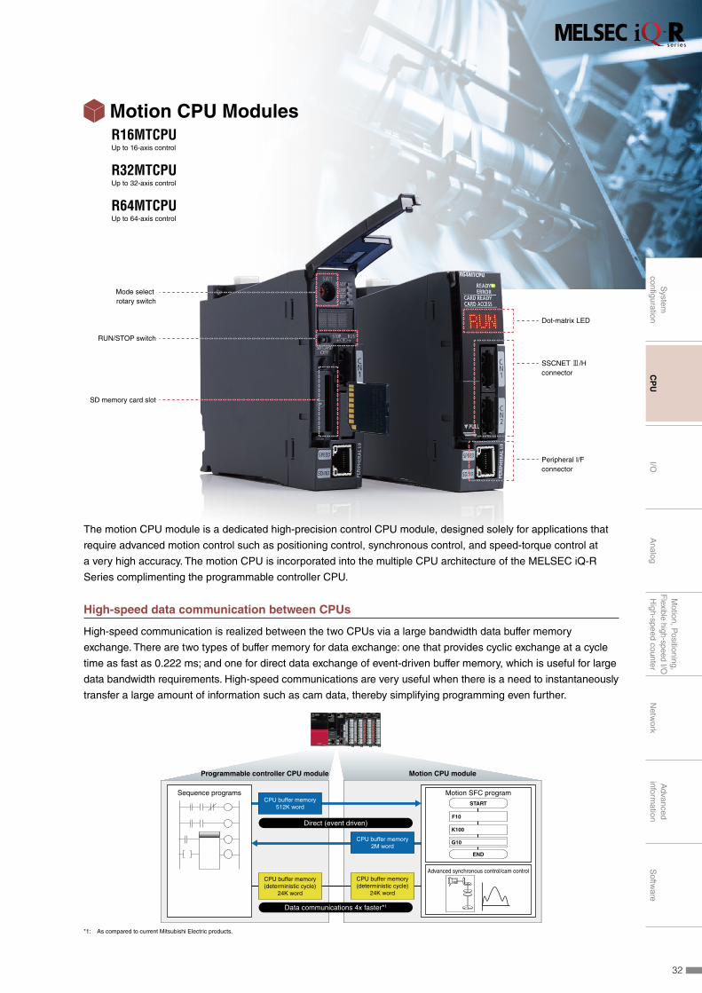
SD memory card slot
Mode select rotary switch
RUN/STOP switch
Peripheral I/Fconnector
SSCNET 3/Hconnector
Dot-matrix LED
Motion CPU ModulesR16MTCPUUp to 16-axis control
R32MTCPUUp to 32-axis control
R64MTCPU Up to 64-axis control
The motion CPU module is a dedicated high-precision control CPU module, designed solely for applications that
require advanced motion control such as positioning control, synchronous control, and speed-torque control at
a very high accuracy. The motion CPU is incorporated into the multiple CPU architecture of the MELSEC iQ-R
Series complimenting the programmable controller CPU.
High-speed data communication between CPUs
High-speed communication is realized between the two CPUs via a large bandwidth data buffer memory
exchange. There are two types of buffer memory for data exchange: one that provides cyclic exchange at a cycle
time as fast as 0.222 ms; and one for direct data exchange of event-driven buffer memory, which is useful for large
data bandwidth requirements. High-speed communications are very useful when there is a need to instantaneously
transfer a large amount of information such as cam data, thereby simplifying programming even further.
Programmable controller CPU module Motion CPU module
CPU buffer memory2M word
CPU buffer memory512K word
START
F10
K100
END
G10
Motion SFC programSequence programs
Advanced synchronous control/cam control
Data communications 4x faster*1
Direct (event driven)
CPU buffer memory(deterministic cycle)
24K word
CPU buffer memory(deterministic cycle)
24K word
*1: As compared to current Mitsubishi Electric products.
32
System
configuration
CP
UI/O
Analog
Motion, P
ositioning,F
lexible high-speed I/OH
igh-speed counterN
etwork
Advanced
information
Softw
are
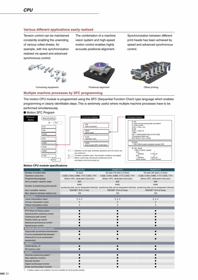
Various different applications easily realized
Tension control can be maintained
constantly enabling the unwinding
of various rolled sheets, for
example, with line synchronization
realized via speed and advanced
synchronous control.
Converting equipment
The combination of a machine
vision system and high-speed
motion control enables highly
accurate positional alignment.
Positional alignment
Synchronization between different
print heads has been achieved by
speed and advanced synchronous
control.
Offset printing
Multiple machine processes by SFC programming
The motion CPU module is programmed using the SFC (Sequential Function Chart) type language which enables
programming in clearly identifiable steps. This is extremely useful where multiple machine processes have to be
performed simultaneously.
■ Motion SFC Program
Operation control step: Arithmetic operations and I/O control, etc., are carried out. Transition (condition wait): The transition conditions are judged. Motion control step: Servomotor positioning control and speed control are carried out.
Comment display
K100Operation start
G200Work ready
F30Data calculation
G300Start accept OFF confirmation
F
G
K
Seal processing
F10
F20
G100
F150
P10
P10
Reduced display
[F 30]//1 axis real processing data calculationIF #100==#102#100 = #102 + 20ELSE#100 = #102+10I END#0L = LONG((SIN(#100)+#110F)*300)//Processing status setSET M100 = X12 + M120
[G 200] PX0 //Work ready completion sensor ON?
[K 100 : Real] 1 ABS-2 (Vector speed) Axis 1 Address # 100 µm Axis 2 Address # 200 µm Vector speed # 300 mm/min
F30
G200
K100
G300
Enlarged display
Motion CPU module specifications
Item R16MTCPU R32MTCPU R64MTCPU
Number of control axes 16 axes 32 axes (16 axes x 2 lines) 64 axes (32 axes x 2 lines)
Operation cycle (ms) 0.222, 0.444, 0.888, 1.777, 3.555, 7.111 0.222, 0.444, 0.888, 1.777, 3.555, 7.111 0.222, 0.444, 0.888, 1.777, 3.555, 7.111
Programming language Motion SFC, dedicated instruction Motion SFC, dedicated instruction Motion SFC, dedicated instruction
Servo program capacity (step) 32K 32K 32K
Number of positioning points (point)6400
(positioning data can be designated indirectly)
6400 (positioning data can be designated indirectly)
6400 (positioning data can be designated indirectly)
Servo amplifier network SSCNET 3/H (1 line) SSCNET 3/H (2 lines) SSCNET 3/H (2 lines)
Max. distance between stations (m) 100 100 100
Interpolation
Linear interpolation (axis) 2, 3, 4 2, 3, 4 2, 3, 4
Circular interpolation (axis) 2 2 2
Helical interpolation (axis) 3 3 3
Control mode
PTP (Point To Point) control ● ● ●
Speed-position switching control ● ● ●
Continuous path control ● ● ●
Position follow-up control ● ● ●
Advanced synchronous control ● ● ●
Speed-torque control ● ● ●
Acceleration/deceleration control
Trapezoidal acceleration/deceleration ● ● ●
S-curve acceleration/deceleration ● ● ●
Advanced S-curve acceleration/
deceleration● ● ●
Interface
PERIPHERAL I/F ● ● ●
SD memory card ● ● ●
Function
Absolute positioning system*1 ● ● ●
Mark detection function ● ● ●
Security function ● ● ●
Digital oscilloscope function ● ● ●
Driver communication function ● ● ●
*1: A battery needs to be installed in the servo amplifier for home position backup.
33
CPU
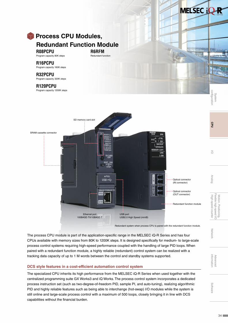
SRAM cassette connector
SD memory card slot
Ethernet port100BASE-TX/10BASE-T
Optical connector(IN connector)
Optical connector(OUT connector)
Redundant function module
USB portUSB2.0 High Speed (miniB)
Redundant system when process CPU is paired with the redundant function module.
The process CPU module is part of the application-specific range in the MELSEC iQ-R Series and has four
CPUs available with memory sizes from 80K to 1200K steps. It is designed specifically for medium- to large-scale
process control systems requiring high-speed performance coupled with the handling of large PID loops. When
paired with a redundant function module, a highly reliable (redundant) control system can be realized with a
tracking data capacity of up to 1 M words between the control and standby systems supported.
DCS style features in a cost-efficient automation control system
The specialized CPU inherits its high performance from the MELSEC iQ-R Series when used together with the
centralized programming suite GX Works3 and iQ Works. The process control system incorporates a dedicated
process instruction set (such as two-degree-of-freedom PID, sample PI, and auto-tuning), realizing algorithmic
PID and highly reliable features such as being able to interchange (hot-swap) I/O modules while the system is
still online and large-scale process control with a maximum of 500 loops, closely bringing it in line with DCS
capabilities without the financial burden.
Process CPU Modules, Redundant Function ModuleR08PCPUProgram capacity 80K steps
R16PCPUProgram capacity 160K steps
R32PCPUProgram capacity 320K steps
R120PCPUProgram capacity 1200K steps
R6RFMRedundant function
34
System
configuration
CP
UI/O
Analog
Motion, P
ositioning,F
lexible high-speed I/OH
igh-speed counterN
etwork
Advanced
information
Softw
are

Redundant system remote location and high-speed switching
Optical-fiber tracking cables enable the standby system to be installed in a remote location up to 550 m from the
control (primary) system. The tracking cables are immune to noise interference and support fast data transfer rates.
System switching speed has also been improved to speeds of 10 ms or less, enabling high-speed switching of the
control system to standby system further improving reliability.
Control panel A Control panel B
Control system System switching time
10 ms or less
Tracking cable
Extendable to 550 m
* I/O hold time is less than 100 ms, when using dual tracking cables
Standby system
Improve reliability with reduced single-point failure
A multi-level redundant system can be realized by installing dual control systems consisting of the control (primary)
and standby CPUs combined with a dual cable topology for the network cabling of the CC-Link IE Field networks,
and dual remote stations minimizing the risk of singe-point failure. The Ethernet module is equipped with two
communications ports, enabling continuous information level communications with SCADA software even if an
error occurs with one of the ports. Only one module is required per control and standby system, reducing overall
hardware cost. Online replacement of modules (hot-swapping) is possible without stopping the operating control
system.
Ethernet
Control system Standby system
Tracking cable
Operation continues even at the time of module failure or system change
RUN LED status
RUN LED on the remote head module is operating intermediately showing that a module is being replaced
Remote station
Redundant tracking cable, network cable, and communications module ensure continuous operation in the event of an error
The module is replaced without using a computer
No computer required for on-line change
Redundant communication line realized with one Ethernet module
35
CPU

Efficient engineering through extensive compatibility between software
An efficient and highly-scalable engineering environment can be realized by the extensive compatibility between
GX Works3 together with SCADA software (MC Works64), monitoring software GT SoftGOT and GT Works3 [GOT
(HMI)].
◼ Highly scalable process control visualization
Process tag labels (variables) can be shared between GX Works3, Mitsubishi SCADA MC Works64, GT SoftGOT
and GOT (HMI), realizing an efficient engineering environment that makes screen creation easier. In addition, a
scalable SCADA control system can be realized combining these products.
Small
Suitable for rugged environments
Computer-based GOT (HMI) screen monitoring
Web-based monitoring of server/client configuration
Medium Large-scale
Shop floor monitoring
◼ Generation of GOT (HMI) screens*1 Easily create process control monitoring screens (GOT2000/GOT1000)
Computer-based monitoring
◼ Linkage with GT SoftGOT Monitor tool and GT SoftGOT compatibility enable screens to be called between each software
Integrated monitoring
◼ Generating Mitsubishi SCADA MC Works64 screens Easily create screens using the process linkage tool
▶System size
*1: When using GOT (HMI) screen generation, temporary tag setting data by PX Developer is required.
Screen generation using GX Works3 setting data will be supported in the future.
◼ Integrated engineering software realizing easy programming and maintenance
GX Works3 is a centralized programming environment supporting various programming, debug and maintenance
features, thereby enabling efficient engineering. Multiple programming languages can be used within the same
GX Works3 project, including function block diagram (process control programming), ladder, structured text and
sequential function chart.
One Software, Many Possibilities
B
A
C
Tag FB setting
Faceplate
Process control function block
A Tag FB settings◼ Up to 50 dedicated process control
functions blocks available
C Tag FB monitoring and online tuning◼ Debugging improved utilizing tag FB monitoring and online tuning
Simply drag & drop
Click
Dedicated process setting toolbar
B Programming and parameter registration
◼ Integrated as part of the GX Works3 project◼ Multiple programming languages supported:
・ Ladder ・ Function block diagram (process control programming) ・ Sequential function chart*2 ・ Structured text
*2: SFC programming language is not supported when the Process CPU is being used in redundant mode (future support planned).
36
System
configuration
CP
UI/O
Analog
Motion, P
ositioning,F
lexible high-speed I/OH
igh-speed counterN
etwork
Advanced
information
Softw
are
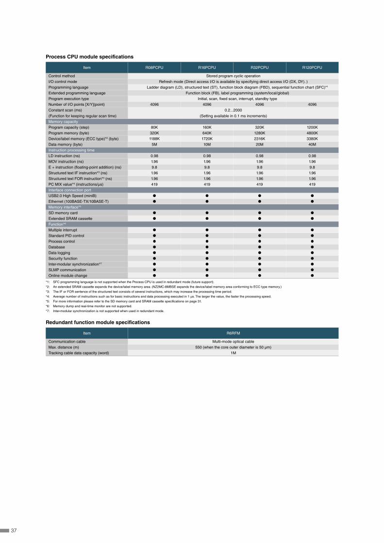
Process CPU module specifications
Item R08PCPU R16PCPU R32PCPU R120PCPU
Control method Stored program cyclic operation
I/O control mode Refresh mode (Direct access I/O is available by specifying direct access I/O (DX, DY). )
Programming language Ladder diagram (LD), structured text (ST), function block diagram (FBD), sequential function chart (SFC)*1
Extended programming language Function block (FB), label programming (system/local/global)
Program execution type Initial, scan, fixed scan, interrupt, standby type
Number of I/O points [X/Y](point) 4096 4096 4096 4096
Constant scan (ms)
(Function for keeping regular scan time)
0.2...2000
(Setting available in 0.1 ms increments)
Memory capacity
Program capacity (step) 80K 160K 320K 1200K
Program memory (byte) 320K 640K 1280K 4800K
Device/label memory (ECC type)*2 (byte) 1188K 1720K 2316K 3380K
Data memory (byte) 5M 10M 20M 40M
Instruction processing time
LD instruction (ns) 0.98 0.98 0.98 0.98
MOV instruction (ns) 1.96 1.96 1.96 1.96
E + instruction (floating-point addition) (ns) 9.8 9.8 9.8 9.8
Structured text IF instruction*3 (ns) 1.96 1.96 1.96 1.96
Structured text FOR instruction*3 (ns) 1.96 1.96 1.96 1.96
PC MIX value*4 (instructions/μs) 419 419 419 419
Interface connection port
USB2.0 High Speed (miniB) ● ● ● ●
Ethernet (100BASE-TX/10BASE-T) ● ● ● ●
Memory interface*5
SD memory card ● ● ● ●
Extended SRAM cassette ● ● ● ●
Function*6
Multiple interrupt ● ● ● ●
Standard PID control ● ● ● ●
Process control ● ● ● ●
Database ● ● ● ●
Data logging ● ● ● ●
Security function ● ● ● ●
Inter-modular synchronization*7 ● ● ● ●
SLMP communication ● ● ● ●
Online module change ● ● ● ●
*1: SFC programming language is not supported when the Process CPU is used in redundant mode (future support).
*2: An extended SRAM cassette expands the device/label memory area. (NZ2MC-8MBSE expands the device/label memory area conforming to ECC type memory.)
*3: The IF or FOR sentence of the structured text consists of several instructions, which may increase the processing time period.
*4: Average number of instructions such as for basic instructions and data processing executed in 1 μs. The larger the value, the faster the processing speed.
*5: For more information please refer to the SD memory card and SRAM cassette specifications on page 31.
*6: Memory dump and real-time monitor are not supported.
*7: Inter-modular synchronization is not supported when used in redundant mode.
Redundant function module specifications
Item R6RFM
Communication cable Multi-mode optical cable
Max. distance (m) 550 (when the core outer diameter is 50 μm)
Tracking cable data capacity (word) 1M
37

USB portUSB2.0 High Speed (miniB)
Ethernet port100BASE-TX/10BASE-T
R◻SFCPU-SET includes both modules as shown above
SD memory card slot
RUN/STOP switch
Safety function module
The safety CPU module enables control of both generic and safety programs in the same module and is easily
programmed utilizing the intuitive features of GX Works3. Compliant with internationally recognized safety
standards, the safety CPU enables safety devices such as safety light curtains, emergency switches, and door
switches to be connected via the CC-Link IE Field network without requiring a separate dedicated network line.
The safety CPU is easily programmed using GX Works3, and utilizes its intuitive features.
Generic and safety control in one CPU
The safety CPU can be installed directly on the MELSEC iQ-R Series base rack, and is easily integrated into an
existing or new control system. Safety devices are connectable using the CC-Link IE Field network with safety
communication integrated into the network protocol over a widely-available industrial Ethernet topology. The safety
CPU is compliant with ISO 13849-1 PL e and IEC 61508 SIL 3 and is certified by TÜV Rheinland®.
Safety CPUR08SFCPU-SETProgram capacity 80K steps
R16SFCPU-SETProgram capacity 160K steps
R32SFCPU-SETProgram capacity 320K steps
R120SFCPU-SETProgram capacity 1200K steps
38
System
configuration
CP
UI/O
Analog
Motion, P
ositioning,F
lexible high-speed I/OH
igh-speed counterN
etwork
Advanced
information
Softw
are
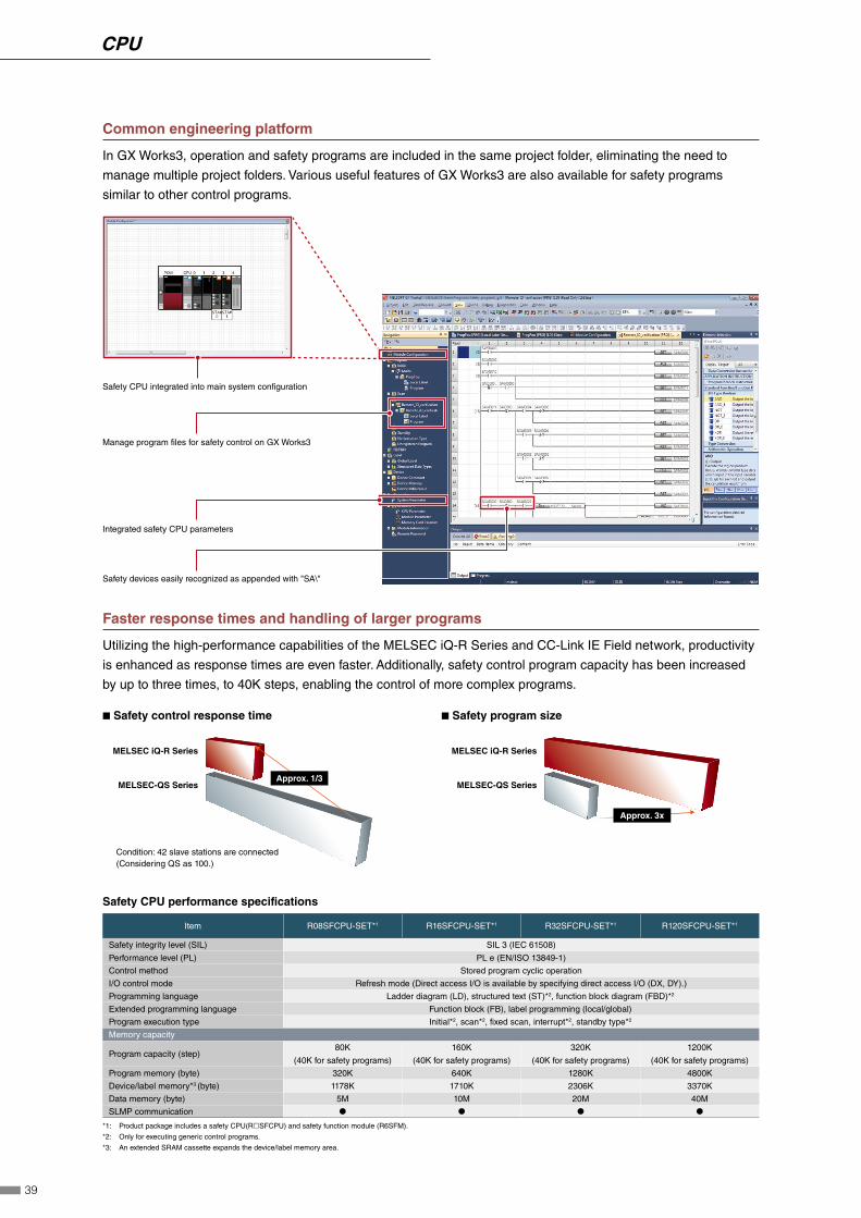
Common engineering platform
In GX Works3, operation and safety programs are included in the same project folder, eliminating the need to
manage multiple project folders. Various useful features of GX Works3 are also available for safety programs
similar to other control programs.
Safety CPU integrated into main system configuration
Manage program files for safety control on GX Works3
Integrated safety CPU parameters
Safety devices easily recognized as appended with "SA\"
Faster response times and handling of larger programs
Utilizing the high-performance capabilities of the MELSEC iQ-R Series and CC-Link IE Field network, productivity
is enhanced as response times are even faster. Additionally, safety control program capacity has been increased
by up to three times, to 40K steps, enabling the control of more complex programs.
◾ Safety control response time
MELSEC-QS Series
MELSEC iQ-R Series
Condition: 42 slave stations are connected (Considering QS as 100.)
◾ Safety program size
MELSEC-QS Series
MELSEC iQ-R Series
Approx. 1/3
Approx. 3x
Safety CPU performance specifications
Item R08SFCPU-SET*1 R16SFCPU-SET*1 R32SFCPU-SET*1 R120SFCPU-SET*1
Safety integrity level (SIL) SIL 3 (IEC 61508)
Performance level (PL) PL e (EN/ISO 13849-1)
Control method Stored program cyclic operation
I/O control mode Refresh mode (Direct access I/O is available by specifying direct access I/O (DX, DY).)
Programming language Ladder diagram (LD), structured text (ST)*2, function block diagram (FBD)*2
Extended programming language Function block (FB), label programming (local/global)
Program execution type Initial*2, scan*2, fixed scan, interrupt*2, standby type*2
Memory capacity
Program capacity (step) 80K
(40K for safety programs)
160K
(40K for safety programs)
320K
(40K for safety programs)
1200K
(40K for safety programs)
Program memory (byte) 320K 640K 1280K 4800K
Device/label memory*3 (byte) 1178K 1710K 2306K 3370K
Data memory (byte) 5M 10M 20M 40M
SLMP communication ● ● ● ●
*1: Product package includes a safety CPU(R◻SFCPU) and safety function module (R6SFM).
*2: Only for executing generic control programs.
*3: An extended SRAM cassette expands the device/label memory area.
39
CPU
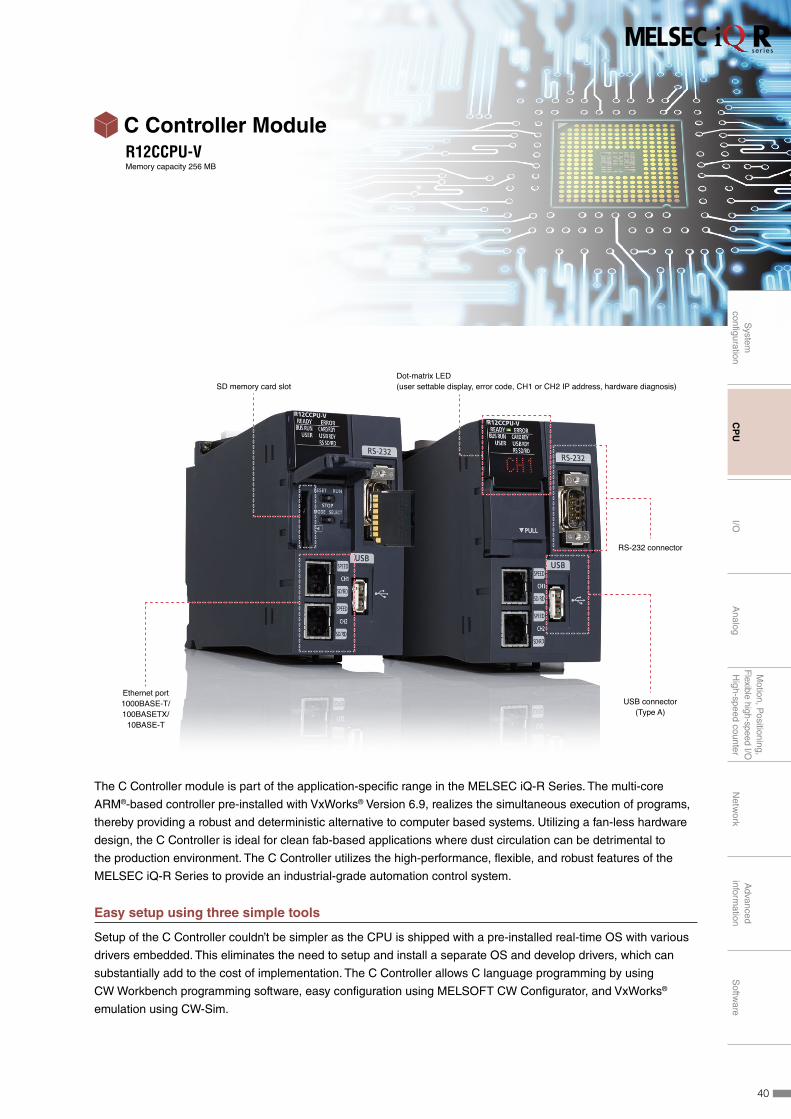
C Controller ModuleR12CCPU-VMemory capacity 256 MB
SD memory card slotDot-matrix LED(user settable display, error code, CH1 or CH2 IP address, hardware diagnosis)
Ethernet port1000BASE-T/100BASETX/
10BASE-T
RS-232 connector
USB connector(Type A)
The C Controller module is part of the application-specific range in the MELSEC iQ-R Series. The multi-core
ARM®-based controller pre-installed with VxWorks® Version 6.9, realizes the simultaneous execution of programs,
thereby providing a robust and deterministic alternative to computer based systems. Utilizing a fan-less hardware
design, the C Controller is ideal for clean fab-based applications where dust circulation can be detrimental to
the production environment. The C Controller utilizes the high-performance, flexible, and robust features of the
MELSEC iQ-R Series to provide an industrial-grade automation control system.
Easy setup using three simple tools
Setup of the C Controller couldn’t be simpler as the CPU is shipped with a pre-installed real-time OS with various
drivers embedded. This eliminates the need to setup and install a separate OS and develop drivers, which can
substantially add to the cost of implementation. The C Controller allows C language programming by using
CW Workbench programming software, easy configuration using MELSOFT CW Configurator, and VxWorks®
emulation using CW-Sim.
40
System
configuration
CP
UI/O
Analog
Motion, P
ositioning,F
lexible high-speed I/OH
igh-speed counterN
etwork
Advanced
information
Softw
are
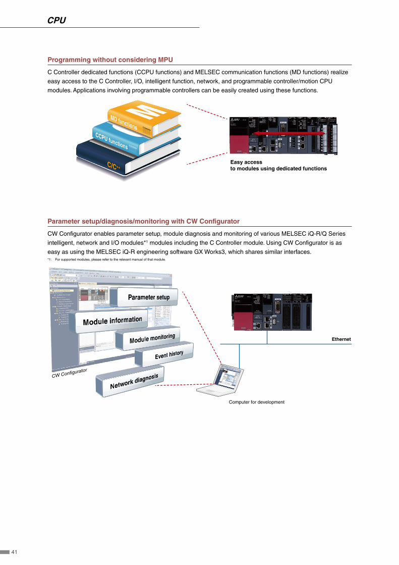
Programming without considering MPU
C Controller dedicated functions (CCPU functions) and MELSEC communication functions (MD functions) realize
easy access to the C Controller, I/O, intelligent function, network, and programmable controller/motion CPU
modules. Applications involving programmable controllers can be easily created using these functions.
Easy access to modules using dedicated functions
CCPU functions
C/C++
MD functions C Controller
C Controller
Parameter setup/diagnosis/monitoring with CW Configurator
CW Configurator enables parameter setup, module diagnosis and monitoring of various MELSEC iQ-R/Q Series
intelligent, network and I/O modules*1 modules including the C Controller module. Using CW Configurator is as
easy as using the MELSEC iQ-R engineering software GX Works3, which shares similar interfaces. *1: For supported modules, please refer to the relevant manual of that module.
CW Configurator
Computer for development
Ethernet
41
CPU
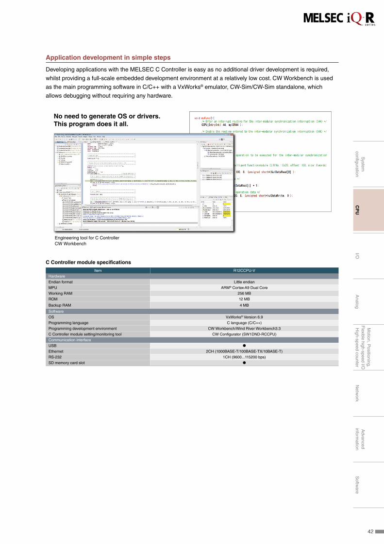
Application development in simple steps
Developing applications with the MELSEC C Controller is easy as no additional driver development is required,
whilst providing a full-scale embedded development environment at a relatively low cost. CW Workbench is used
as the main programming software in C/C++ with a VxWorks® emulator, CW-Sim/CW-Sim standalone, which
allows debugging without requiring any hardware.
No need to generate OS or drivers. This program does it all.
Engineering tool for C ControllerCW Workbench
C Controller module specifications
Item R12CCPU-V
Hardware
Endian format Little endian
MPU ARM® Cortex-A9 Dual Core
Working RAM 256 MB
ROM 12 MB
Backup RAM 4 MB
Software
OS VxWorks® Version 6.9
Programming language C language (C/C++)
Programming development environment CW Workbench/Wind River Workbench3.3
C Controller module setting/monitoring tool CW Configurator (SW1DND-RCCPU)
Communication interface
USB ●
Ethernet 2CH (1000BASE-T/100BASE-TX/10BASE-T)
RS-232 1CH (9600...115200 bps)
SD memory card slot ●
42
System
configuration
CP
UI/O
Analog
Motion, P
ositioning,F
lexible high-speed I/OH
igh-speed counterN
etwork
Advanced
information
Softw
are

Focus points
Input/output combined
Input
16 points
32 points
64 points
Serial no. on the module front surface
Output
Rating information
Easy-to-use aesthetic design
Cable tie hookff Input/output rating is printed at the front, reducing incorrect wiring
ffEasy-to-use cable tie hook for tidy wiring*1
ffExisting 16-point terminal blocks are reusable, eliminating rewiring
ffSimple confirmation by product serial no. printed on the front
ffAlternating toggle switch used to display between 32-point LED signals*2
ffTerminal signals are clearly labeled and color-coded*1
ffUp to 32 LED signals clearly visible
Digital I/O modules are the senses of the automation system and provide an interface of various processes to the
controller. Devices such as switches, indicator lamps, and sensors can be easily connected to the control system.
The high-density terminal connections (up to 64 points) results in space-saving designs within the control cabinet
further reducing installation costs. In addition, input interrupt functions and output relay health diagnosis are
additional features embedded in this intelligent, yet small, compact module.
*1: Related to 16-point type modules
*2: Related to 64-point type modules
Clear and easily legible
White and red labels clearly differentiate the input and output modules from each other, further improving safety
awareness. The LED signal displays also labeled with clearly visible and easy to read I/O signal numbers printed
on the cover. The wiring terminals of the 16-point modules are labeled with signal names, further reducing the
possibility of wiring mistakes. Up to 32 LED signals can be displayed at one time, and a toggle switch enables
alternation between the first- and second-half signal displays for the high-density 64-point modules. The input and
output ratings are also clearly printed on the front and the serial number is at the bottom, making it easy to confirm
product model and version.
Simple wiring and high-density I/O
I/O modules are available in a wide range of densities (16-, 32- and 64-points) depending on the I/O requirements
and minimum use of space in the control cabinet. A module with a 40-pin connector is available for high-density
I/O wiring. The terminal block and spring clamp terminal block are interchangeable with MELSEC-Q Series I/O
terminals and can save on the cost of upgrading from existing control systems.
I/O
43

Focus points
Input/output combined
Input
16 points
32 points
64 points
Serial no. on the module front surface
Output
Rating information
Easy-to-use aesthetic design
Cable tie hook
Digital input modules like the 24 V direct-current (DC) power supply are among the most used input signals in the
control industry. The robust design of the various modules in this diversified lineup makes them ideal for industrial use.
Multiple features integrated
A single MELSEC iQ-R input module can handle input response devices as fast as 0.1 ms, interrupt input devices
and can be wired using either positive or negative (sink or source) common terminals. Since multiple modules are
no longer required, a substantial reduction in overall footprint of up to 20% and a reduction in total system costs of
up to 60% can be realized.
Normal I/P (sink)Normal I/P (source)High-speed I/P (sink)High-speed I/P (source)Interrupt I/P
RX42C4
Sensor (sink)
Switch (sink)
Sensor (source)
Switch (source)
Sensor (interrupt, sink)
Sink wiring
Sensor Sensor
Switch Switch
Sensor (high-speed)
Sensor (Interrupt)
Sensor (high-speed)
Source wiring
Sensor (high-speed, source)
Sensor (high-speed, sink)
5 modules in one!
All features integrated into one module!
MELSEC-Q Series MELSEC iQ-R Series
The RX42C4 module can be configured to use both sink and source wiring*1
Occupied I/O slots
reduced to 20%*2
Hardware costs
reduced by 60%*2
*1: The RX42C4 module can be configured to use both sink and source wiring (between the left and right sides of 32 point terminal).
*2: Based on a comparison with the MELSEC-Q Series
Input ModulesAC input
RX28 NEW
8 points 100 to 240 V AC (50/60 Hz)
RX1016 points 100 to 120 V AC (50/60 Hz)
DC input
RX40C716 points 24 V DC, 7.0 mA
RX41C4 32 points 24 V DC, 4.0 mA
RX42C4 64 points 24 V DC, 4.0 mA
DC high-speed input
RX40PC6H16 points 24 V DC, 6.0 mA Positive common type
RX40NC6H16 points 24 V DC, 6.0 mA Negative common type
RX41C6HS32 points 24 V DC, 6.0 mA Positive/negative common shared
RX61C6HS32 points 5 V DC, 6.0 mA Positive/negative common shared
DC input (with diagnostic functions)
RX40NC6B16 points 24 V DC, 6.0 mA Negative common type
44
System
configuration
CP
UI/O
Analog
Motion, P
ositioning,F
lexible high-speed I/OH
igh-speed counterN
etwork
Advanced
information
Softw
are

Reduce downtime with disconnection detection
Similar to analog modules, the MELSEC iQ-R Series input module (with diagnostic functions) includes input
disconnection detection which enables detection of inputs directly on the I/O module. When an error occurs, the
control system can quickly highlight the fault via a monitoring system or on GX Works3 programming software,
reducing system downtime and loss of production.
Input module specifications
ItemAC input DC input
RX28 RX10 RX40C7 RX41C4 RX42C4
Number of input points 8 16 16 32 64
Rated input voltage,
frequency100...240 V AC, 50/60 Hz 100...120 V AC, 50/60 Hz 24 V DC 24 V DC 24 V DC
Rated input current (mA)
16.4 (200 V AC, 60 Hz)
13.7 (200 V AC, 50 Hz)
8.2 (100 V AC, 60 Hz)
6.8 (100 V AC, 50 Hz)
8.2 (100 V AC, 60 Hz)
6.8 (100 V AC, 50 Hz)7.0 TYP. 4.0 TYP. 4.0 TYP.
Response time ≤ 20 ms ≤ 20 ms 0.1...70 ms 0.1...70 ms 0.1...70 ms
Common terminal
arrangement
(points/common)
8 16 16 32 32
Interrupt function ● ● ● ● ●
External interface*1
18-point screw terminal block ● ● ● - -
40-pin connector - - - ● ● (2x)
ItemDC high-speed input
DC input
(with diagnostic functions)
RX40PC6H RX40NC6H RX41C6HS RX61C6HS RX40NC6B
Number of input points 16 16 32 32 16
Rated input voltage,
frequency24 V DC 24 V DC 24 V DC 5 V DC 24 V DC
Rated input current (mA) 6.0 6.0 6.0 6.0 6.0
Response time 5 μs...70 ms 5 μs...70 ms 1 μs...70 ms 1 μs...70 ms 1 ms...70 ms
Common terminal
arrangement
(points/common)
8
(positive common)
8
(negative common)
32
(positive/negative common)
32
(positive/negative common)
16
(negative common)
Interrupt function ● ● ● ● ●
Diagnostic function*2
Disconnection detection - - - - ●
External interface*1
18-point screw terminal block ● ● - - ●
40-pin connector - - ● ● -
*1: For more information about external interface (for applicable options, please refer to the relevant product manual), please refer to the options list on page 93.
*2: For more information about diagnostic functions, please refer to the relevant product manual.
45
I/O

Output ModulesRelay output
RY18R2A NEW
8 points 24 V DC, 240 V AC
RY10R216 points 24 V DC, 240 V AC
Triac output
RY20S6 NEW
16 points 100 to 240 V AC
Transistor (sink) output
RY40NT5P16 points 12 to 24 V DC, 0.5 A
RY41NT2P32 points 12 to 24 V DC, 0.2 A
RY42NT2P64 points 12 to 24 V DC, 0.2 A
Transistor (source) output
RY40PT5P16 points 12 to 24 V DC, 0.5 A
RY41PT1P32 points 12 to 24 V DC, 0.1 A
RY42PT1P64 points 12 to 24 V DC, 0.1 A
High-speed transistor (sink) output
RY41NT2H32 points 5 to 24 V DC, 0.2 A
High-speed transistor (source) output
RY41PT2H32 points 5 to 24 V DC, 0.2 A
Transistor-with diagnostic functions (source) output
RY40PT5B16 points 24 V DC, 0.5 A
A variety of digital output modules are available including relay, transistor sink (wired as positive common) and
transistor source (wired as negative common). Load voltages include 240 V AC and 12 V to 24 V DC, with various
current ratings.
Relay health diagnostics for preventive maintenance
Output modules (relay output and transistor-with diagnostic functions modules) keep track of how many times
they're turned on and off. Utilizing this data, such as from embedded relay contacts in the relay output module
or from relays connected externally to the transistor output module (with diagnostic functions), preventive
maintenance can be carried out based on the known service of the relay.
Output module specifications
ItemRelay output Triac output Transistor (sink) output
RY18R2A RY10R2 RY20S6 RY40NT5P RY41NT2P RY42NT2P RY41NT2H
Number of input points (point) 8 16 16 16 32 64 32
Rated switching voltage, current24 V DC/2 A
240 V AC/2 A
24 V DC/2 A
240 V AC/2 A
100...240 V AC
/0.6 A- - - -
Rated load voltage (V DC) - - - 12...24 12...24 12...24 5...24
Max. load current (A/point) - - - 0.5 0.2 0.2 0.2
Response time ≤ 12 ms ≤ 12 ms ≤ 1 ms+0.5 cycle ≤ 1 ms ≤ 1 ms ≤ 1 ms ≤ 2 μs
Common terminal arrangement
(points/common)- 16 16 16 32 32 32
Protection function
(overload, overheat)- - - ● ● ● -
External interface*1
18-point screw terminal block ● ● ● ● - - -
40-pin connector - - - - ● ● (2x) ●
ItemTransistor (source) output
Transistor-with diagnostic
functions (source) output
RY40PT5P RY41PT1P RY42PT1P RY41PT2H RY40PT5B
Number of input points (point) 16 32 64 32 16
Rated load voltage (V DC) 12...24 12...24 12...24 5...24 24
Max. load current (A/point) 0.5 0.1 0.1 0.2 0.5
Response time ≤ 1 ms ≤ 1 ms ≤ 1 ms ≤ 2 μs ≤ 1.5 ms
Common terminal arrangement
(points/common)16 32 32 32 16
Protection function
(overload, overheat)● ● ● - ●
Diagnostic function*2
Output disconnection detection - - - - ●
Output short-circuit detection - - - - ●
External interface*1
18-point screw terminal block ● - - - ●
40-pin connector - ● ● (2x) ● -
*1: For more information about external interface (for applicable options, please refer to the relevant product manual), please refer to the options list on page 93.
*2: For more information about diagnostic functions, please refer to the relevant product manual.
46
System
configuration
CP
UI/O
Analog
Motion, P
ositioning,F
lexible high-speed I/OH
igh-speed counterN
etwork
Advanced
information
Softw
are

I/O Combined ModuleDC input, transistor (sink) output
RH42C4NT2P32 points (input) 24 V DC, 4.0 mA 32 points (output) 12 to 24 V DC, 0.2 A
In addition to dedicated digital input and output modules, if only a few I/O points are required, a combined I/O
module is available. This is an excellent alternative for cost-sensitive applications.
I/O combined module specifications
Item RH42C4NT2P
DC input
Number of input points (point) 32
Rated input voltage (V DC) 24
Rated input current (mA) 4.0 TYP.
Response time (ms) 0.1...70
Common terminal arrangement
(points/common)32
Interrupt function ●
Transistor (sink) output
Number of output points (point) 32
Rated load voltage (V DC) 12...24
Max. load current (A/point) 0.2
Response time (ms) ≤ 1
Common terminal arrangement
(points/common)32
Protection function (overload, overheat) ●
External interface*1
40-pin connector ● (2x)
*1: For more information about external interface (for applicable options, please refer to the relevant product manual), refer to the options list on page 93.
47
I/O
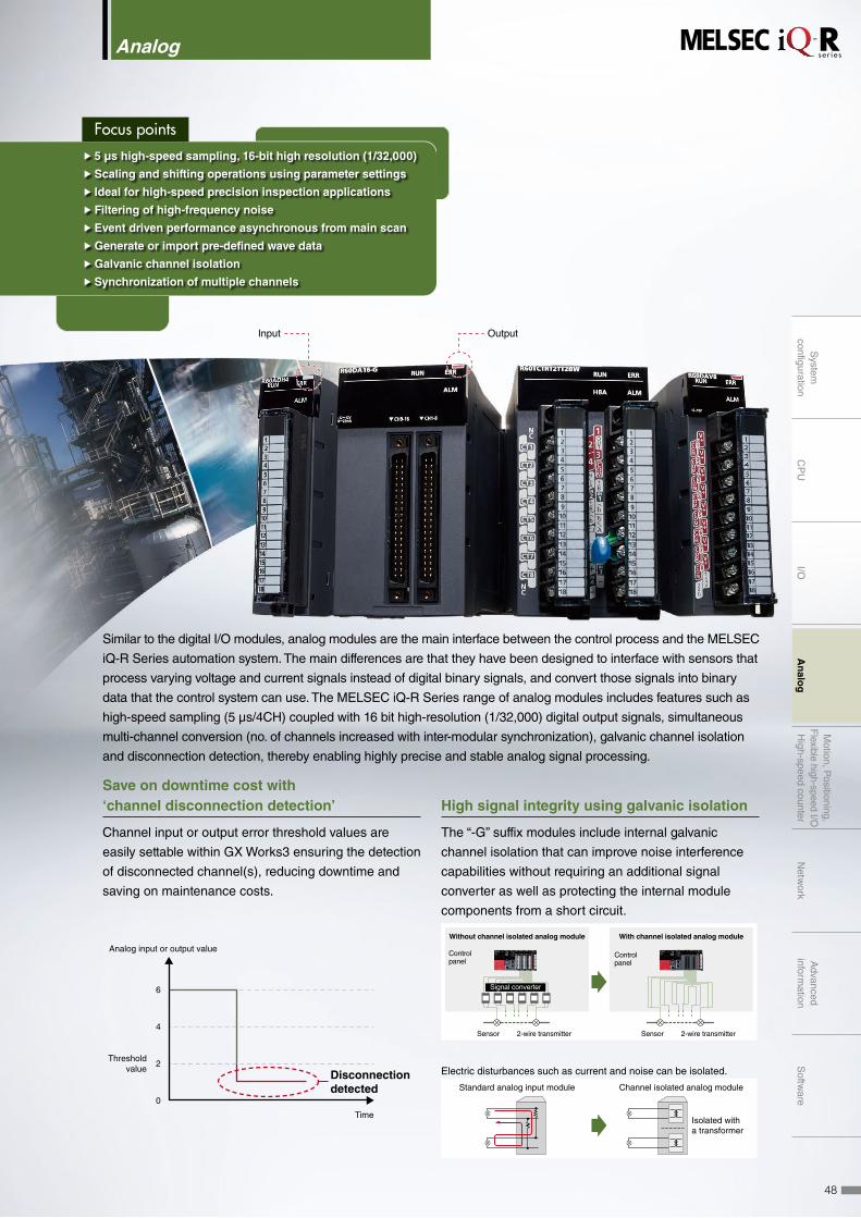
Focus points
OutputInput
ff 5 μs high-speed sampling, 16-bit high resolution (1/32,000)
ffScaling and shifting operations using parameter settings
ff Ideal for high-speed precision inspection applications
ffFiltering of high-frequency noise
ffEvent driven performance asynchronous from main scan
ffGenerate or import pre-defined wave data
ffGalvanic channel isolation
ffSynchronization of multiple channels
Similar to the digital I/O modules, analog modules are the main interface between the control process and the MELSEC
iQ-R Series automation system. The main differences are that they have been designed to interface with sensors that
process varying voltage and current signals instead of digital binary signals, and convert those signals into binary
data that the control system can use. The MELSEC iQ-R Series range of analog modules includes features such as
high-speed sampling (5 μs/4CH) coupled with 16 bit high-resolution (1/32,000) digital output signals, simultaneous
multi-channel conversion (no. of channels increased with inter-modular synchronization), galvanic channel isolation
and disconnection detection, thereby enabling highly precise and stable analog signal processing.
Save on downtime cost with ‘channel disconnection detection’
Channel input or output error threshold values are
easily settable within GX Works3 ensuring the detection
of disconnected channel(s), reducing downtime and
saving on maintenance costs.
Analog input or output value
Disconnection detected
Time
Thresholdvalue
6
4
2
0
High signal integrity using galvanic isolation
The “-G” suffix modules include internal galvanic
channel isolation that can improve noise interference
capabilities without requiring an additional signal
converter as well as protecting the internal module
components from a short circuit.
Electric disturbances such as current and noise can be isolated.
Standard analog input module Channel isolated analog module
Isolated with a transformer
Control panel
Signal converter
Sensor 2-wire transmitter
Without channel isolated analog module With channel isolated analog module
Control panel
Sensor 2-wire transmitter
Analog
48
System
configuration
CP
UI/O
An
alog
Motion, P
ositioning,F
lexible high-speed I/OH
igh-speed counterN
etwork
Advanced
information
Softw
are
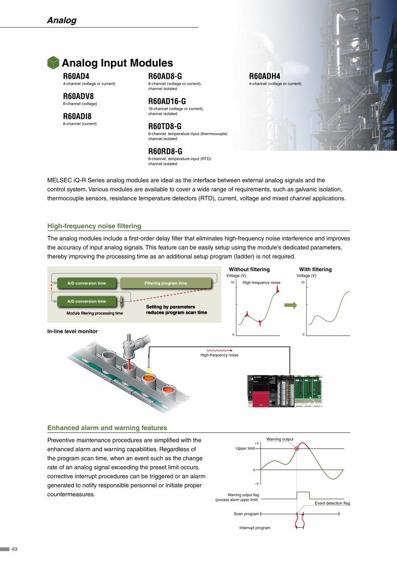
High-frequency noise filtering
The analog modules include a first-order delay filter that eliminates high-frequency noise interference and improves
the accuracy of input analog signals. This feature can be easily setup using the module's dedicated parameters,
thereby improving the processing time as an additional setup program (ladder) is not required.
00
10 10
Voltage (V)Voltage (V)Without filtering
In-line level monitor
With filtering
High-frequency noise
High-frequency noise
Setting by parameters reduces program scan timeSetting by parameters reduces program scan timeModule filtering processing timeModule filtering processing time
A/D conversion time Filtering program time
A/D conversion time
Enhanced alarm and warning features
Preventive maintenance procedures are simplified with the
enhanced alarm and warning capabilities. Regardless of
the program scan time, when an event such as the change
rate of an analog signal exceeding the preset limit occurs,
corrective interrupt procedures can be triggered or an alarm
generated to notify responsible personnel or initiate proper
countermeasures.
Analog Input ModulesR60AD44-channel (voltage or current)
R60ADV88-channel (voltage)
R60ADI88-channel (current)
R60AD8-G8-channel (voltage or current), channel isolated
R60AD16-G16-channel (voltage or current), channel isolated
R60TD8-G8-channel, temperature input (thermocouple) channel isolated
R60RD8-G8-channel, temperature input (RTD) channel isolated
R60ADH44-channel (voltage or current)
Warning output+V
Upper limit
0
−V
Warning output flag (process alarm upper limit)
Scan program
Interrupt program
Event detection flag
MELSEC iQ-R Series analog modules are ideal as the interface between external analog signals and the
control system. Various modules are available to cover a wide range of requirements, such as galvanic isolation,
thermocouple sensors, resistance temperature detectors (RTD), current, voltage and mixed channel applications.
49
Analog
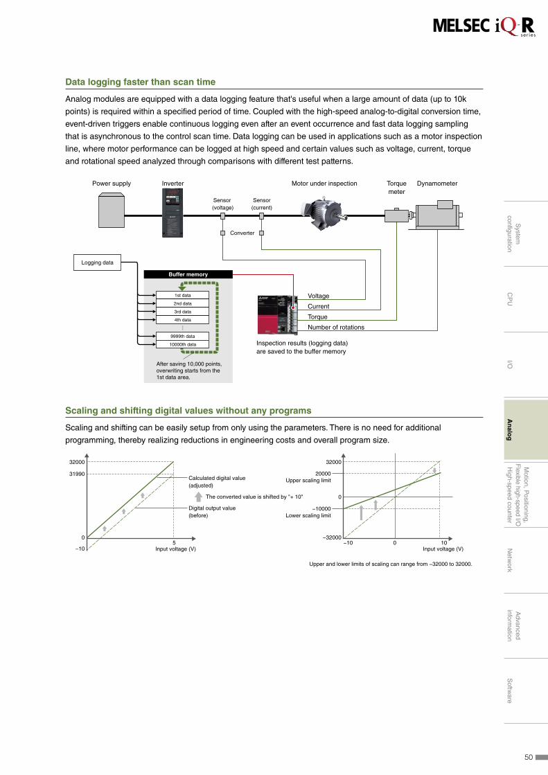
Data logging faster than scan time
Analog modules are equipped with a data logging feature that's useful when a large amount of data (up to 10k
points) is required within a specified period of time. Coupled with the high-speed analog-to-digital conversion time,
event-driven triggers enable continuous logging even after an event occurrence and fast data logging sampling
that is asynchronous to the control scan time. Data logging can be used in applications such as a motor inspection
line, where motor performance can be logged at high speed and certain values such as voltage, current, torque
and rotational speed analyzed through comparisons with different test patterns.
Sensor (voltage)
Converter
Sensor(current)
Power supply Inverter Motor under inspection Torquemeter
Voltage
Current
Torque
Number of rotations
Dynamometer
Inspection results (logging data) are saved to the buffer memory
After saving 10,000 points, overwriting starts from the 1st data area.
1st data
2nd data
3rd data
4th data
9999th data
10000th data
Buffer memory
Logging data
Scaling and shifting digital values without any programs
Scaling and shifting can be easily setup from only using the parameters. There is no need for additional
programming, thereby realizing reductions in engineering costs and overall program size.
32000
31990
−105
0
Calculated digital value(adjusted)
The converted value is shifted by "+ 10"
Input voltage (V)
Digital output value(before)
32000
20000
−10000
−32000
Upper scaling limit
Lower scaling limit
−10 0 10
0
Input voltage (V)
Upper and lower limits of scaling can range from −32000 to 32000.
50
System
configuration
CP
UI/O
An
alog
Motion, P
ositioning,F
lexible high-speed I/OH
igh-speed counterN
etwork
Advanced
information
Softw
are
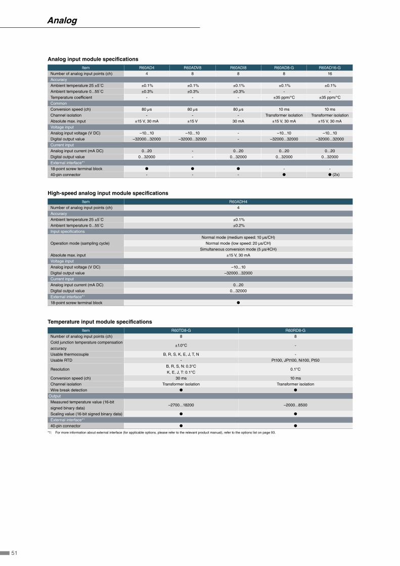
Analog input module specifications
Item R60AD4 R60ADV8 R60ADI8 R60AD8-G R60AD16-G
Number of analog input points (ch) 4 8 8 8 16
Accuracy
Ambient temperature 25 ±5˚C ±0.1% ±0.1% ±0.1% ±0.1% ±0.1%
Ambient temperature 0...55˚C ±0.3% ±0.3% ±0.3% - -
Temperature coefficient - - - ±35 ppm/°C ±35 ppm/°C
Common
Conversion speed (ch) 80 µs 80 µs 80 µs 10 ms 10 ms
Channel isolation - - - Transformer isolation Transformer isolation
Absolute max. input ±15 V, 30 mA ±15 V 30 mA ±15 V, 30 mA ±15 V, 30 mA
Voltage input
Analog input voltage (V DC) –10...10 –10...10 - –10...10 –10...10
Digital output value –32000...32000 –32000...32000 - –32000...32000 –32000...32000
Current input
Analog input current (mA DC) 0...20 - 0...20 0...20 0...20
Digital output value 0...32000 - 0...32000 0...32000 0...32000
External interface*1
18-point screw terminal block ● ● ● - -
40-pin connector - - - ● ● (2x)
High-speed analog input module specifications
Item R60ADH4
Number of analog input points (ch) 4
Accuracy
Ambient temperature 25 ±5˚C ±0.1%
Ambient temperature 0...55˚C ±0.2%
Input specifications
Operation mode (sampling cycle)
Normal mode (medium speed: 10 μs/CH)
Normal mode (low speed: 20 μs/CH)
Simultaneous conversion mode (5 μs/4CH)
Absolute max. input ±15 V, 30 mA
Voltage input
Analog input voltage (V DC) –10...10
Digital output value –32000...32000
Current input
Analog input current (mA DC) 0...20
Digital output value 0...32000
External interface*1
18-point screw terminal block ●
Temperature input module specifications
Item R60TD8-G R60RD8-G
Number of analog input points (ch) 8 8
Cold junction temperature compensation
accuracy±1.0°C -
Usable thermocouple B, R, S, K, E, J, T, N -
Usable RTD - Pt100, JPt100, Ni100, Pt50
ResolutionB, R, S, N: 0.3°C
K, E, J, T: 0.1°C0.1°C
Conversion speed (ch) 30 ms 10 ms
Channel isolation Transformer isolation Transformer isolation
Wire break detection ● ●
Output
Measured temperature value (16-bit
signed binary data)–2700...18200 –2000...8500
Scaling value (16-bit signed binary data) ● ●
External interface*1
40-pin connector ● ●
*1: For more information about external interface (for applicable options, please refer to the relevant product manual), refer to the options list on page 93.
51
Analog

Faster, smoother predefined wave signal output
The analog output module enables pre-registration of waveforms easily using MELSOFT GX Works3, realizing a
smoother continuous output that closely matches the precision required for the application, such as torque control
for a press or injection molding machine. Registering the waveform in the module is simple and easy, and does
not require a dedicated analog output program, such as for continuous line control, further reducing programming
time.
GX Works3 wave output data setup
Mold
Heater
Heating cylinderScrew
Hopper
Pressure control of injection molding
Analog output
Shift operation and scaling without programs
Shift operation and scaling can be used without creating programs; they can be simply set on parameters. This
simple setting minimizes program development cost as well as the program size.
Analog Output ModulesR60DA44-channel (voltage or current)
R60DAV88-channel (voltage)
R60DAI88-channel (current)
R60DA8-G8-channel (voltage or current), channel isolated
R60DA16-G16-channel (voltage or current), channel isolated
R60DAH4 NEW
4-channel (voltage or current)
MELSEC iQ-R Series analog output modules reliably deliver accurate analog values to points where
high-resolution digital inputs are required. A variety of modules (voltage, current, or mixed) are available to cover a
wide range of application requirements, such as high-speed drive control or variable-speed control of the pressure
applied to materials being fed into some kind of forming mechanism.
52
System
configuration
CP
UI/O
An
alog
Motion, P
ositioning,F
lexible high-speed I/OH
igh-speed counterN
etwork
Advanced
information
Softw
are
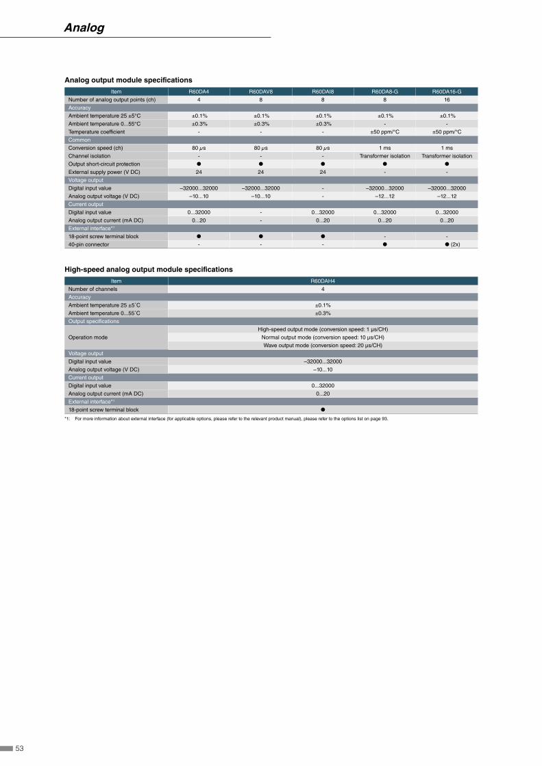
Analog output module specifications
Item R60DA4 R60DAV8 R60DAI8 R60DA8-G R60DA16-G
Number of analog output points (ch) 4 8 8 8 16
Accuracy
Ambient temperature 25 ±5°C ±0.1% ±0.1% ±0.1% ±0.1% ±0.1%
Ambient temperature 0...55°C ±0.3% ±0.3% ±0.3% - -
Temperature coefficient - - - ±50 ppm/°C ±50 ppm/°C
Common
Conversion speed (ch) 80 µs 80 µs 80 µs 1 ms 1 ms
Channel isolation - - - Transformer isolation Transformer isolation
Output short-circuit protection ● ● ● ● ●
External supply power (V DC) 24 24 24 - -
Voltage output
Digital input value –32000...32000 –32000...32000 - –32000...32000 –32000...32000
Analog output voltage (V DC) –10...10 –10...10 - –12...12 –12...12
Current output
Digital input value 0...32000 - 0...32000 0...32000 0...32000
Analog output current (mA DC) 0...20 - 0...20 0...20 0...20
External interface*1
18-point screw terminal block ● ● ● - -
40-pin connector - - - ● ● (2x)
High-speed analog output module specifications
Item R60DAH4
Number of channels 4
Accuracy
Ambient temperature 25 ±5˚C ±0.1%
Ambient temperature 0...55˚C ±0.3%
Output specifications
Operation mode
High-speed output mode (conversion speed: 1 μs/CH)
Normal output mode (conversion speed: 10 μs/CH)
Wave output mode (conversion speed: 20 μs/CH)
Voltage output
Digital input value –32000...32000
Analog output voltage (V DC) –10...10
Current output
Digital input value 0...32000
Analog output current (mA DC) 0...20
External interface*1
18-point screw terminal block ●
*1: For more information about external interface (for applicable options, please refer to the relevant product manual), please refer to the options list on page 93.
53
Analog

MELSEC iQ-R Series temperature control modules are ideal for applications requiring highly stable and responsive
temperature control. The series comes with thermocouple and RTD input module types and are available with or
without heater disconnection detection.
Controlled heating minimizes distortion in heating profile
Temperature fluctuations are attenuated at high speed through the external disturbance suppression function.
This enables the preset temperature value to be maintained, ensuring a uniform heating profile not influenced
by heating variations in the work. Due to its high-speed response capabilities, this function can be used in
applications such as packaging machine sealing, injection molding, and for wafer plates in semiconductor
manufacturing machines.
Set value
Minimize overshoot after suppressing temperature drop
Without external disturbance suppression
With external disturbance suppression
Reduce temperature drop
External disturbance
Ex.Temperature
at sealing failure
■ External disturbance suppression
Measured value:
Temperature Control ModulesR60TCTRT2TT22-channel (multiple input) + 2-channel (thermocouple input)
R60TCRT44-channel (RTD input)
R60TCTRT2TT2BW2-channel (multiple input) + 2-channel (thermocouple input) With heater disconnection detection
R60TCRT4BW4-channel (RTD input) With heater disconnection detection
54
System
configuration
CP
UI/O
An
alog
Motion, P
ositioning,F
lexible high-speed I/OH
igh-speed counterN
etwork
Advanced
information
Softw
are
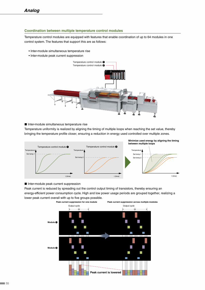
Coordination between multiple temperature control modules
Temperature control modules are equipped with features that enable coordination of up to 64 modules in one
control system. The features that support this are as follows:
• Inter-module simultaneous temperature rise
• Inter-module peak current suppression
Temperature control module �Temperature control module �
◼ Inter-module simultaneous temperature rise
Temperature uniformity is realized by aligning the timing of multiple loops when reaching the set value, thereby
bringing the temperature profile closer, ensuring a reduction in energy used controlled over multiple zones.
Minimize used energy by aligning the timing between multiple loops
Temperature
Set temp.1
t (time)
Set temp.2
Temperature control module � Temperature control module �
t (time)
Set temp.2
t (time)
Temperature Temperature
Set temp.1
◼ Inter-module peak current suppression
Peak current is reduced by spreading out the control output timing of transistors, thereby ensuring an
energy-efficient power consumption cycle. High and low power usage periods are grouped together, realizing a
lower peak current overall with up to five groups possible.
Module �
Module �
CH4
CH3
CH2
CH1
CH4
CH3
CH2
CH1
Output cycle
CH4
CH3
CH2
CH1
CH4
CH3
CH2
CH1
Output cycle
Peak current is lowered
Peak current suppression for one module Peak current suppression across multiple modules
55
Analog

Temperature trace realizing real-time temperature waveform monitoring
Setting parameters has been simplified when using the temperature trace feature of GX Works3. This
simple-to-use feature enables tracing of various temperature values in real-time, helping to visualize the control
performance while adjusting the parameters. Temperature values can also be exported as a CSV file.
Temperature waveform monitored in real-time
Adjust parameters against tem-perature waveform
.CSV
Temperature data can be saved as a CSV file
Temperature trace window
Temperature control module performance specifications
Item R60TCTRT2TT2 R60TCRT4 R60TCTRT2TT2BW R60TCRT4BW
Number of analog input channels (ch) 4 4 4 4
Usable thermocoupleB, R, S, K, E, J, T, N, U, L,
PL@, W5Re/W26Re-
B, R, S, K, E, J, T, N, U, L,
PL@, W5Re/W26Re-
Usable RTD Pt100, JPt100 Pt100, JPt100 Pt100, JPt100 Pt100, JPt100
Sampling cycle (4 ch, ms) 250/500 250/500 250/500 250/500
Control output cycle (s) 0.5...100.0 0.5...100.0 0.5...100.0 0.5...100.0
Input impedance (MΩ) 1 1 1 1
Input filter (0: Input filter OFF) 0...100 s 0...100 s 0...100 s 0...100 s
Sensor correction value setting (-(full scale of input range)) to full scale of input range
Operation at a sensor input
disconnectionUpscale processing
Temperature control method PID ON/OFF pulse or two-position control
Heater disconnection detection - - ● ●
Indication accuracy*1
Ambient temperature 25±5°C ≤ ±0.3% ≤ ±0.3% ≤ ±0.3% ≤ ±0.3%
Ambient temperature 0...55°C ≤ ±0.7% ≤ ±0.7% ≤ ±0.7% ≤ ±0.7%
PID constants range
PID constants setting Setting by auto tuning is available.
Proportional band (P)• When the input range unit is °C or °F: 0 (0.0)...full scale of input range (depending on the decimal point position)
• When the input range is another analog input unit: 0.0...1000.0%
Integral time (I) 0...3600 s (Set 0 for P control and PD control.)
Derivative time (D) 0...3600 s (Set 0 for P control and PI control.)
Transistor output
Output signal ON/OFF pulse ON/OFF pulse ON/OFF pulse ON/OFF pulse
Rated load voltage (V DC) 10...30 10...30 10...30 10...30
Maximum load current (A) 0.1/point, 0.4/common 0.1/point, 0.4/common 0.1/point, 0.4/common 0.1/point, 0.4/common
Maximum inrush current 0.4 A, 10 ms 0.4 A, 10 ms 0.4 A, 10 ms 0.4 A, 10 ms
External interface*2
18-point screw terminal block ● ● ● (2x) ● (2x)
*1: The accuracy is calculated in the following method. For details, please refer to the manual. (Only when it is not affected by noise.)
Accuracy (°C) = (full-scale) × (indication accuracy) + cold junction temperature compensation accuracy
*2: For more information about external interface (for applicable options, please refer to the relevant product manual), refer to the options list on page 93.
56
System
configuration
CP
UI/O
An
alog
Motion, P
ositioning,F
lexible high-speed I/OH
igh-speed counterN
etwork
Advanced
information
Softw
are
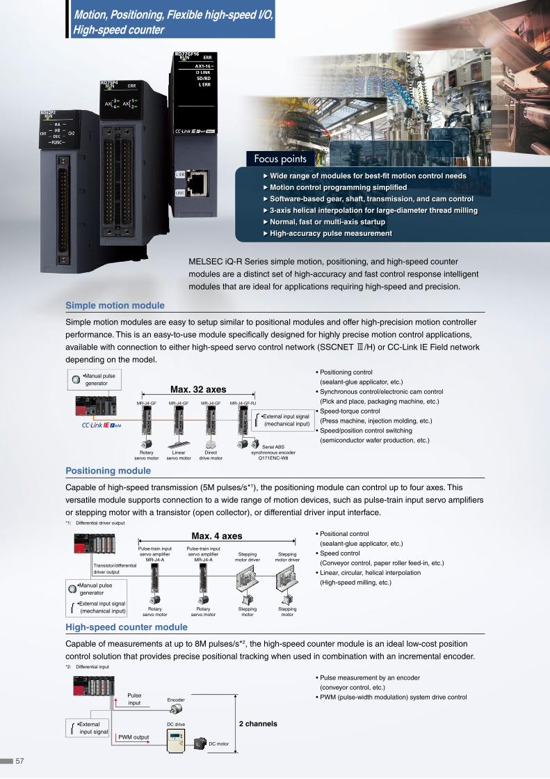
Focus points
ffWide range of modules for best-fit motion control needs
ffMotion control programming simplified
ffSoftware-based gear, shaft, transmission, and cam control
ff 3-axis helical interpolation for large-diameter thread milling
ffNormal, fast or multi-axis startup
ffHigh-accuracy pulse measurement
MELSEC iQ-R Series simple motion, positioning, and high-speed counter
modules are a distinct set of high-accuracy and fast control response intelligent
modules that are ideal for applications requiring high-speed and precision.
Simple motion module
Simple motion modules are easy to setup similar to positional modules and offer high-precision motion controller
performance. This is an easy-to-use module specifically designed for highly precise motion control applications,
available with connection to either high-speed servo control network (SSCNET 3/H) or CC-Link IE Field network
depending on the model.
•Manual pulse generator
Max. 32 axesMR-J4-GF MR-J4-GF MR-J4-GF MR-J4-GF-RJ
Rotaryservo motor
Linearservo motor
Directdrive motor
Serial ABSsynchronous encoder
Q171ENC-W8
•External input signal (mechanical input)
• Positioning control
(sealant-glue applicator, etc.)
• Synchronous control/electronic cam control
(Pick and place, packaging machine, etc.)
• Speed-torque control
(Press machine, injection molding, etc.)
• Speed/position control switching
(semiconductor wafer production, etc.)
Positioning module
Capable of high-speed transmission (5M pulses/s*1), the positioning module can control up to four axes. This
versatile module supports connection to a wide range of motion devices, such as pulse-train input servo amplifiers
or stepping motor with a transistor (open collector), or differential driver input interface.*1: Differential driver output
Transistor/differential driver output
Pulse-train inputservo amplifier
MR-J4-A
Rotaryservo motor
Steppingmotor driver
Steppingmotor
Steppingmotor driver
Steppingmotor
Pulse-train inputservo amplifier
MR-J4-A
Rotaryservo motor
•External input signal (mechanical input)
Max. 4 axes
•Manual pulse generator
• Positional control
(sealant-glue applicator, etc.)
• Speed control
(Conveyor control, paper roller feed-in, etc.)
• Linear, circular, helical interpolation
(High-speed milling, etc.)
High-speed counter module
Capable of measurements at up to 8M pulses/s*2, the high-speed counter module is an ideal low-cost position
control solution that provides precise positional tracking when used in combination with an incremental encoder. *2: Differential input
SET
LOW HIGH
MODE
2 channels
EncoderPulseinput
PWM outputDC motor
DC drive•External input signal
• Pulse measurement by an encoder
(conveyor control, etc.)
• PWM (pulse-width modulation) system drive control
Motion, Positioning, Flexible high-speed I/O, High-speed counter
57

Focus points
Simple Motion ModulesCompatible with CC-Link IE Field network
RD77GF4Up to 4-axis control
RD77GF8Up to 8-axis control
RD77GF16Up to 16-axis control
RD77GF32 NEW
Up to 32-axis control
Compatible with SSCNET 3/H
RD77MS2Up to 2-axis control
RD77MS4Up to 4-axis control
RD77MS8Up to 8-axis control
RD77MS16Up to 16-axis control
Similar to positioning modules, simple motion modules are capable of a wide range of high-precision control such
as positional control, advanced synchronous control, cam control, and speed-torque control. The module line-up
includes 2-, 4-, 8-, 16-, and 32-axis models, with setup being done easily by parameters and programming.
Advanced synchronous control
Software-based synchronous control can be used as an alternative to mechanical control, such as gear, shaft,
transmission and cam. In addition, cam control is even easier with cam auto-generation. Synchronous control can
be simply operated (start/stop) for each axis, allowing synchronous and positional control axes within the same
program.
■ Synchronous control
All axes are synchronized using a synchronous encoder or servo input axes. Up to 32 control axes can be
synchronized when using the synchronous encoder, such as that used for packaging machines, for example.
Synchronous encoder axis
■ Cam auto-generation
Cam data for a rotary cutter can be generated automatically simply by registering the sheet length, synchronization
width, rotary cutter axis dimensions, etc.
Sheet synchronizing width
User-made GOT (Mitsubishi HMI) screen
Synchronized axis length(synchronized axis circumference)
Sheet length
Sheetsynchronizing
width
Sheet feeding
Cam axis(synchronized axis)
speed
Sheet feeding speed
Stroke ratio
58
System
configuration
CP
UI/O
Analog
Motion, Positioning,
Flexible high-speed I/OH
igh-speed counterN
etwork
Advanced
information
Softw
are

Mark detection
The actual position of the servo motor can be obtained based on the registration mark printed on the high-speed
moving film. Compensation of the cutter axis position, based on the registration marks, keeps the constant cutting
position.
Corner mark
Mark sensor
Speed-torque control (press-fit control)
The motor can be switched to torque control (press-fit mode) without stopping it during positioning. The current
position is controlled during the speed/torque control. Therefore the positioning can be done smoothly even after
switching back to position control.
Switch to torque control Cap tightening withconstant torque
Position return after tightening complete
Position the cap
Cap
Bottle
Current positional control during torque control
Positional control Torque control, press-fit control Positional control
Simple motion module specifications
Item RD77GF4 RD77GF8 RD77GF16 RD77GF32 RD77MS2 RD77MS4 RD77MS8 RD77MS16
Number of control axes (axis) 4 8 16 32 2 4 8 16
Operation cycle (ms)0.5, 1.0, 2.0,
4.0
0.5, 1.0, 2.0,
4.0
0.5, 1.0, 2.0,
4.0
0.5, 1.0, 2.0,
4.0
0.444, 0.888,
1.777, 3.555
0.444, 0.888,
1.777, 3.555
0.444, 0.888,
1.777, 3.555
0.444, 0.888,
1.777, 3.555
Control unitmm, inch,
degree, pulse
mm, inch,
degree, pulse
mm, inch,
degree, pulse
mm, inch,
degree, pulse
mm, inch,
degree, pulse
mm, inch,
degree, pulse
mm, inch,
degree, pulse
mm, inch,
degree, pulse
Positioning data (data/axis) 600 600 600 600 600 600 600 600
Servo amplifier MR-J4-GF MR-J4-GF MR-J4-GF MR-J4-GF MR-J4-B MR-J4-B MR-J4-B MR-J4-B
Max. distance between stations (m) 100 100 100 100 100 100 100 100
Servo amplifier connection system
CC-Link IE Field ● ● ● ● - - - -
SSCNET 3/H - - - - ● ● ● ●
External interface*1
40-pin connector - - - - ● ● (2x) ● (2x) ● (2x)
Interpolation function
Linear interpolation (axis) 2, 3, 4 2, 3, 4 2, 3, 4 2, 3, 4 2 2, 3, 4 2, 3, 4 2, 3, 4
Circular interpolation (axis) 2 2 2 2 2 2 2 2
Control system
PTP (Point To Point) control ● ● ● ● ● ● ● ●
Trajectory control (linear, arc) ● ● ● ● ● ● ● ●
Speed control ● ● ● ● ● ● ● ●
Speed-position switching control ● ● ● ● ● ● ● ●
Speed-torque control ● ● ● ● ● ● ● ●
Pressure control - - - - ● ● ● ●
Advanced synchronous control ● ● ● ● ● ● ● ●
Acceleration/deceleration process
Trapezoidal acceleration/deceleration ● ● ● ● ● ● ● ●
S-curve acceleration/deceleration ● ● ● ● ● ● ● ●
Function
Absolute positioning system*2 ● ● ● ● ● ● ● ●
Mark detection function ● ● ● ● ● ● ● ●
*1: For more information about external interface (for applicable options, please refer to the relevant product manual), refer to the options list on page 93.
*2: A battery needs to be installed in the servo amplifier for home position backup.
59
Motion, Positioning, Flexible high-speed I/O, High-speed Counter
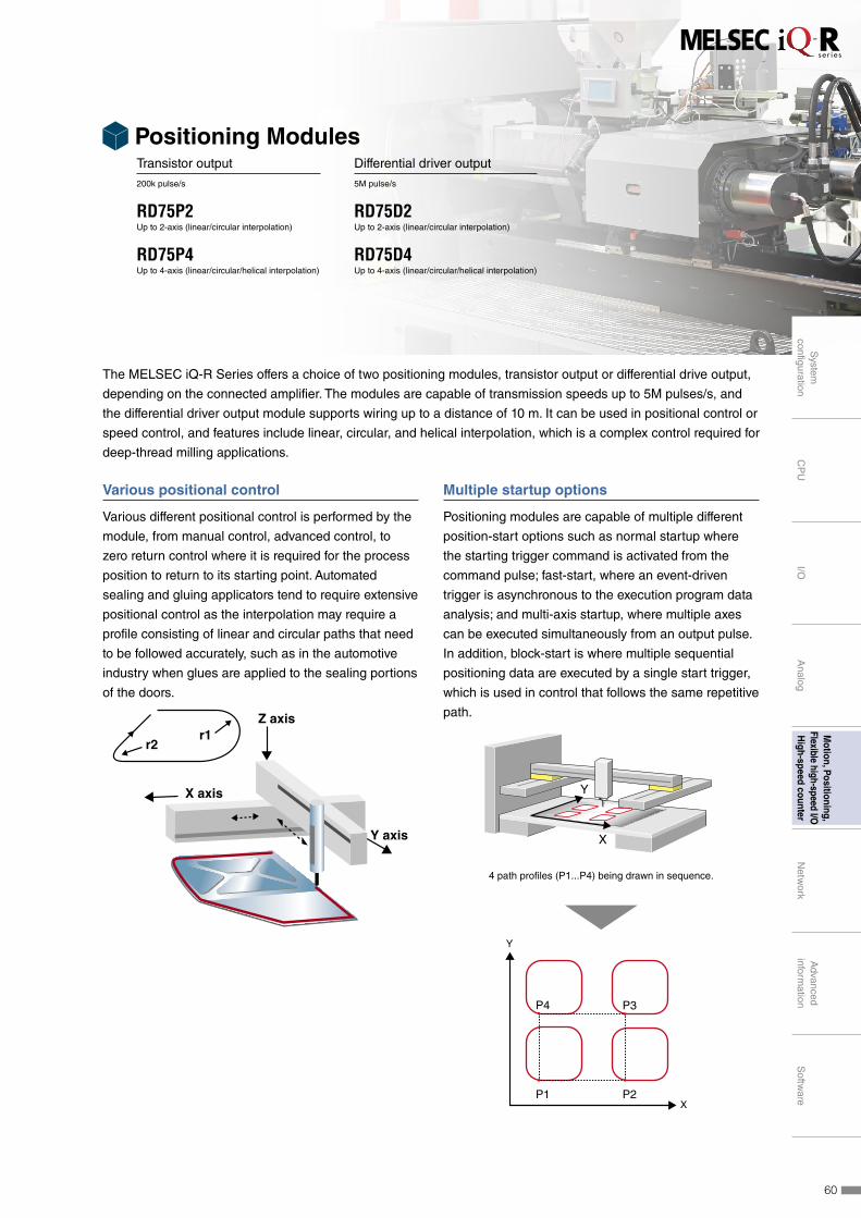
Positioning ModulesTransistor output
200k pulse/s
RD75P2Up to 2-axis (linear/circular interpolation)
RD75P4Up to 4-axis (linear/circular/helical interpolation)
Differential driver output
5M pulse/s
RD75D2Up to 2-axis (linear/circular interpolation)
RD75D4Up to 4-axis (linear/circular/helical interpolation)
The MELSEC iQ-R Series offers a choice of two positioning modules, transistor output or differential drive output,
depending on the connected amplifier. The modules are capable of transmission speeds up to 5M pulses/s, and
the differential driver output module supports wiring up to a distance of 10 m. It can be used in positional control or
speed control, and features include linear, circular, and helical interpolation, which is a complex control required for
deep-thread milling applications.
Various positional control
Various different positional control is performed by the
module, from manual control, advanced control, to
zero return control where it is required for the process
position to return to its starting point. Automated
sealing and gluing applicators tend to require extensive
positional control as the interpolation may require a
profile consisting of linear and circular paths that need
to be followed accurately, such as in the automotive
industry when glues are applied to the sealing portions
of the doors.
r2r1
X axis
Y axis
Z axis
Multiple startup options
Positioning modules are capable of multiple different
position-start options such as normal startup where
the starting trigger command is activated from the
command pulse; fast-start, where an event-driven
trigger is asynchronous to the execution program data
analysis; and multi-axis startup, where multiple axes
can be executed simultaneously from an output pulse.
In addition, block-start is where multiple sequential
positioning data are executed by a single start trigger,
which is used in control that follows the same repetitive
path.
X
Y
X
Y
P1 P2
P3P4
4 path profiles (P1...P4) being drawn in sequence.
60
System
configuration
CP
UI/O
Analog
Motion, Positioning,
Flexible high-speed I/OH
igh-speed counterN
etwork
Advanced
information
Softw
are

Realize helical interpolation
For applications that require the boring of deep, large holes, usually multiple interpolation control of three axes (X,
Y and Z) or more must be taken into consideration. In such cases, the actual milling is done in a circle, with the
X and Y axes synchronized to achieve the pre-set size. The depth of the hole is simultaneously controlled along
the Z axis, ensuring minimal deviation in the cutting bit position. This type of positioning is usually quite difficult as
the interpolation of the three axes can introduce some deviation when not utilizing a full-scale numerical control
system.
X, Y
Z
Positioning module specifications
ItemTransistor output Differential driver output
RD75P2 RD75P4 RD75D2 RD75D4
Number of control axes (axis) 2 4 2 4
Control unit mm, inch, degree, pulse mm, inch, degree, pulse mm, inch, degree, pulse mm, inch, degree, pulse
Positioning data (data/axis) 600 600 600 600
Module backup function Positioning data, and block start data can be saved on flash ROM (battery-less backup)
Starting time (1 axis linear control) (ms) 0.3 0.3 0.3 0.3
Max. output pulse (pulse/s) 200,000 200,000 5,000,000 5,000,000
Max. connection distance
between servos (m)2 2 10 10
Interpolation
Linear interpolation (axis) 2 2, 3, 4 2 2, 3, 4
Circular interpolation (axis) 2 2 2 2
Helical interpolation (axis) - 3 - 3
Control system
PTP (Point To Point) control ● ● ● ●
Path control (linear, arc, helical) ● ● ● ●
Speed control ● ● ● ●
Speed-position switching control ● ● ● ●
Position-speed switching control ● ● ● ●
Acceleration/deceleration process
Trapezoidal acceleration/deceleration ● ● ● ●
S-curve acceleration/deceleration ● ● ● ●
Fast-start function
Positioning start signal (µs) 8 8 8 8
External command signal (µs) 20 20 20 20
External interface*1
40-pin connector ● ● (2x) ● (2x) ● (2x)
*1: For more information about external interface (for applicable options, please refer to the relevant product manual), refer to the option lists on page 93.
61
Motion, Positioning, Flexible high-speed I/O, High-speed Counter

High-speed, stable I/O response
The flexible high-speed I/O control module provides highly accurate control of I/O timing owing to the
asynchronous execution of internal control logic to the CPU and control bus. Variation in processing time is
reduced to nanoseconds, thereby enabling sensors such as proximity lasers to trigger vision cameras accurately,
which is required in product testing equipment in order to capture products moving at high-speed.
Trigger input timing is adjustable to a minimum of 25 ns resolution.
FPGA logic design enables more freedom in customization
Equipped with a FPGA, control logic can be programmed easily using GX Works3. This low-cost alternative to
HDL programming, logic synthesis and timing analysis reduces the design process, which is a common feature of
general FPGA logic design.
Drag & drop selected parts
Connectable terminalsshare the same color
Click on terminalsto connect
Input
Output
SensorEncoder
ActuatorVision camera(trigger)
Buscommunication
RUN/STOP/Parameters
Status/Interrupt
One Software, Many Possibilities
• Overall system control• Module parameter registration• Interrupt program management
• Hardware logic-driven control• Trigger interrupt programs in CPU• Data communication with CPU buffer
memory
Flexible high-speed I/O controlmodule configuration software
Flexible high-speed I/O control module specifications
ItemRD40PD01
DC Differential
Number of input points (point) 12 (5/24 V DC/differential)
Number of output points (point) 8 (5...24 V DC, 0.1 A/point) 6
Number of interrupts 8
Input response time ≤ 1 μs
Output response time ≤ 1 μs
Max. pulse input speed (pulse/s) 200 k (200 kHz) 8 M (2 MHz)
Max. pulse output speed (pulse/s) 200 k (200 kHz) 8 M (2 MHz)
Main functions executable using main
block combinations
Pulse count, coincidence detection, cam switch, highly-accurate pulse output, PWM output, ratio setting,
pulse measurement, electrical interface conversion
Main hardware logic processing time Logic operation: Min. 87.5 ns, coincidence output: Min. 137.5 ns, cam switch: Min. 262.5 ns
External interface*1
40-pin connector ● (2x)
*1: For more information about external interface (for applicable options, please refer to the relevant product manual), refer to the option lists on page 93.
Flexible High-speed I/O Control ModuleDifferential input, DC input differential output, DC output
RD40PD01 NEW
Input:12 points, output:14 points
The flexible high-speed I/O control module includes features such as the ability to program control logic and
microsecond-fast asynchronous I/O response times to the programmable controller CPU and control bus, realizing
stable machine performance minimizing processing speed fluctuation. Equipped with a field programmable gate
array (FPGA), easy hardware logic design using the dedicated tool reduces development cost.
62
System
configuration
CP
UI/O
Analog
Motion, Positioning,
Flexible high-speed I/OH
igh-speed counterN
etwork
Advanced
information
Softw
are

High-Speed Counter ModulesDC input, transistor (sink) output
RD62P22-channel
DC input, transistor (source) output
RD62P2E2-channel
Differential input, transistor (sink) output
RD62D22-channel
The MELSEC iQ-R Series counter modules are capable of 200k pulse/s for the DC input type, and 8M pulse/s for
differential input. When used with a high-accuracy incremental encoder, positional tracking can also be realized. It
also features a PWM output, which is ideal for applications requiring a measurement of pulse cycles.
Pulse measurement
The pulse measurement feature enables measuring of the pulse cycle, which is ideal for various applications such
as in the food and beverage industry where proximity sensors are used to control flask position on the conveyor, or
the renewable energy industry where the wind vane angle is controlled on a wind turbine.
Measurement resolution100 ns
Accurate detection of products on the conveyor
Pulse input
Pulse width measurement
High-speed PWM output
The PWM output frequency can support up to 200 kHz with a minimum 100 ns pulse width (proportion to 'on' time)
during the required duty cycle. The set values can be changed during operation without having to stop the system,
such as in industrial-scale fan control.
High-speed counter module specifications
Item RD62P2 RD62P2E RD62D2
Number of channels (ch) 2 2 2
Count input signal
1-phase input (1 multiple/2 multiples) ● ● ●
2-phase input (1 multiple/2 multiples/4
multiples)● ● ●
CW/CCW input ● ● ●
Signal level (ϕA, ϕB) 2...5 mA at 5/12/24 V DC 2...5 mA at 5/12/24 V DCEIA Standard RS-422-A
Differential line driver level
Counter
Counting speed (pulse/s) 10k...200k 10k...200k 10k...8M
Counting range (32-bit signed binary) –2147483648...2147483647 –2147483648...2147483647 –2147483648...2147483647
External input
Preset, function start 7...10 mA at 5/12/24 V DC 7...10 mA at 5/12/24 V DC 7...10 mA at 5/12/24 V DC
Digital filter (ms) 0, 0.1, 1, 10 0, 0.1, 1, 10 0, 0.1, 1, 10
Pulse measurement
Resolution*1 (ns) 100 100 100
Number of points per channel 1 1 1
External output
Coincidence output (2 points/channel)Transistor (sink type) output,
12/24 V DC, 0.5 A/point
Transistor (source type) output,
12/24 V DC, 0.1 A/point
Transistor (sink type) output,
12/24 V DC, 0.5 A/point
PWM output
Output frequency range (kHz) 0...200 0...200 0...200
Duty ratio Multiples of 0.1 µs Multiples of 0.1 µs Multiples of 0.1 µs
Number of output points per channel 2 2 2
Setting change during operation ● ● ●
External interface*2
40-pin connector ● ● ●
*1: Pulse measurement can be performed in the range of 2000 to 2147483647 (0.2 ms to approx. 214 s).
*2: For more information about external interface (for applicable options, please refer to the relevant product manual), refer to the option lists on page 93.
63
Motion, Positioning, Flexible high-speed I/O, High-speed Counter

Focus points
ffVarious network-specific modules available
ff 1 Gbps high-speed, large bandwidth of 128K word for CC-Link IE
ffConnect to two separate networks using a single module
ffSeamless networking (SLMP)
ffLoop-back function ensures continuous communications
ffAuto-return when faulty station is replaced
ffSupports standard interfaces such as RS-232 and RS-422/485
The network and interface modules of the MELSEC iQ-R Series ensure a vast selection of interconnectivity
possibilities with various protocols and network topologies providing the best-fit solution for various applications. At
the core of the Series is the CC-Link IE network family which is a high-speed 1 Gbps control level and field level
Ethernet topology industrial open network.
Seamless message protocol (SLMP*1) network communications
With SLMP, it is possible to seamlessly access production management systems, programmable controllers and
other devices using the same method, eliminating concerns about network hierarchies and boundaries. Tasks
such as machine monitoring, data collection and maintenance can be performed from virtually anywhere on the
network. Used together with the Ethernet module, SLMP-ready Ethernet devices such as a machine vision sensor
or RFID controller can be interfaced to the CC-Link IE Field Network without further adding another network.
(CC-Link IE Control network)
(CC-Link IE Field network)
Ethernet
IT system
Production quality data,
energy consumption,
equipment operating data, etc.
Enterprise level(production
management/data system)
Control level(control system)
Field level(device system)
HUB
Personalcomputer
Visionsensor
Touchpanel
RFIDreader
Ethernetadapter
Distributed control
Ethernet devices
Remote I/Omodule
L Seriesremote station
iQ-R Seriesremote station
Inverter
I/O control
*1: SLMP (Seamless Message Protocol): Is a client/server protocol that enables communications between Ethernet-ready and CC-Link IE compatible devices.
Network
64
System
configuration
CP
UI/O
Analog
Motion, P
ositioning,F
lexible high-speed I/OH
igh-speed counterN
etwo
rkA
dvanced inform
ationS
oftware

Dual gigabit Ethernet ports
The number of connectable ports on the Ethernet module has been doubled and the number of connections
per channel increased. By increasing the number of ports the module can be used effectively as a gateway,
simultaneously connecting a generic Ethernet network to one port and using the second port for the CC-Link IE
Field or Control network. Additionally, the number of connections per channel has been increased from 64 to 128,
doubling the bandwidth for even more connectable devices.
CC-Link IEControl network
CC-Link IEField network
Two ports can be connected to two different networks*1.
EthernetEnterprise system
Select network combination from within GX Works3.
1Gbps
Ethernet interface module specifications
Item RJ71EN71*2
Transmission specifications
Data transmission speed 1 Gbps/100 Mbps/10 Mbps
Interface RJ45 connector (Auto MDI/MDI-X)
Max. frame size (byte) 1518/9022 (when jumbo frames are used)
IP version Compatible with IPv4
Sending/receiving data storage memory
Number of simultaneous open connections 128
Fixed buffer 5K words x 16
Socket communications• 5K words x 48 (when only P1 is used)
• 5K words x 112 (when only P1/P2 is used)
Random access buffer 6K words x 1
CC-Link IE Field/Control cable specifications
Communication cable Ethernet cable (Category 5e or higher, double shielded/STP)
*2: The specifications differ for the Q Series compatible Ethernet mode.
The MELSEC iQ-R Series Ethernet module is equipped with two
ports that can be used as either a generic Ethernet, CC-Link IE
Field or Control Network module. The module design incorporates
an easy-to-read display and a dot-matrix LED providing a quick way
to assess network conditions using the module.
Ethernet Interface ModuleRJ71EN711 Gbps, 100/10 Mbps multiple network type
Ethernet port (P1)
Ethernet port (P2)
■ Network combination*1
P1
P2
C
C
F
F
E
C
E
F
E
EC : CC-Link IE Control Network
F : CC-Link IE Field Network
E : Ethernet*1: The CC-Link IE Field and CC-Link IE Control networks cannot be
used together.
65
Network

Continuous communications even when cable or stations are faulty
Utilizing a high-speed, noise resistant
fiber-optic topology, the CC-Link IE
Control Network supports a loop-back
function that guarantees continuous
communications even when a cable
is disconnected or a station falls into
a fault status. The dual-loop topology
of the cable ensures that the data will
find another route along the network
without affecting overall network
communications.
Extensive real-time network monitoring
The network status can be easily monitored directly from GX Works3
software enabling intuitive troubleshooting of network errors or viewing
the operation of the network while in communications. This makes
it possible to see the actual fault occurring in the network, thereby
helping to reduce the overall downtime. In addition, error messages
related to the faulty network module station can be viewed for further
network diagnosis. All stations within the network can be monitored
regardless of which station the software is connected too.
CC-Link IE Control Network module specifications
Item RJ71GP21-SX
Communication speed 1 Gbps
Transmission path Duplex loop
Communication cable Optical fiber cable which satisfies 1000 BASE-SX standard: Multi-mode optical fiber (GI)
Max. station-to-station distance (m)550 (when the core outer diameter is 50 µm)
275 (when the core outer diameter is 62.5 µm)
Overall cable distance (m)66,000 (when 120 stations are connected and the core outer diameter is 50 µm)
33,000 (when 120 stations are connected and the core outer diameter is 62.5 µm)
Max. number of connectable stations 120 (control station: 1, normal station: 119)
Max. number of link points per network
Link relay (LB) 32K points (32768 points, 4K bytes)
Link register (LW) 128K points (131072 points, 256K bytes)
Link input (LX), link output (LY) 8K points (8192 points, 1K bytes)
CC-Link IE Control is a high-reliability distributed control network
designed to handle very large data communications (128K word)
over a high-speed (1 Gbps) dual-loop optical cable topology.
CC-Link IE Control Network ModuleRJ71GP21-SX1 Gbps optical cable, control/normal station
Continuous communicationwith loop-back function
Total extension distance:max. 66 km
Station-to-station distance:max. 550 m
1Gbps
128Kwords
Cable disconnection
CC-Link IE Control monitoring window
Optical connector
(IN connector)
Optical connector
(OUT connector)
66
System
configuration
CP
UI/O
Analog
Motion, P
ositioning,F
lexible high-speed I/OH
igh-speed counterN
etwo
rkA
dvanced inform
ationS
oftware

Multiple topology variations
■ Star topology
Devices are connected via a switching
hub allowing local stations to be added
easily.
■ Line topology
Continuous connection of devices along
the Ethernet line.
■ Ring topology
Connection is done in a continuous loop,
which guarantees communications by
isolating the faulty network station.
Synchronized network communications
The control cycle of local stations on the network can be synchronized with the master station.
� � � � � � � � � � � �
L ER
LINK
O/G
O/G
12 4
4611 5
510 69 8
0 01 192283
37
7
TEST
V I CH1 2 3 4 OFFSET
SEL
GAIN
1 3
2 4
5 7
6 8
9 11
10 12
13 15 17
1814 16
P1
L ER
LINK
P2
(FG)
+24V
24G
RUNPW MODE ERR. ALM
X10 X1 STATION NO.
D LINK
SETL ER
LINK
O/G
12 4
4611 5
510 69 8
0 01 192283
37
7
TEST
X0 1 2 3 X4 5 6 7 X8 9 A B XC D E F
1 3
2 4
5 7
6 8
9 11
10 12
13 15 17
1814 16
P1
L ER
LINK
P2
(FG)
+24V
24G
RUNPW MODE ERR.
X10 X1 STATION NO.
D LINK
L ER
LINK
O/G
12 4
4611 5
510 69 8
0 01 192283
37
7
TEST
1 3
2 4
5 7
6 8
9 11
10 12
13 15 17
1814 16
P1
L ER
LINK
P2
(FG)
+24V
24G
RUNPW MODE ERR.
X10 X1 STATION NO.
D LINK Y0 1 2 3 Y4 5 6 7 Y8 9 A B YC D I/O PWE F
Master station
Station sync cycle
Local station 1
Local station 2
Local station 3
Inter-modular sync interrupt
programs from the CPU module
Local station 1 Local station 2 Local station 3
With synccommunication
Without synccommunication
Inter-module sync cycle � Input refresh
� Event-driven program
� Output refresh
Not synchronized
Synchronized
With synccommunication
CC-Link IE Field Network module specifications
Item RJ71GF11-T2
Transmission speed 1 Gbps
Network topology Line topology, star topology (both types can be on the same line), and ring topology
Communication cable Ethernet cable (Category 5e or higher, double shielded/STP)
Max. station-to-station distance (m) 100
Overall cable distance (m)
Line topology: 12,000 (when 121 stations are connected)
Star topology: Depends on the system configuration
Ring topology: 12,100 (when 121 stations are connected)
Max. number of connectable stations 121 (master station: 1, slave station: 120)
Max. number of link points per network
Remote input (RX), remote output (RY) 16K points (16384 points, 2K bytes)
Remote register (RWw, RWr) 8K points (8192 points, 16K bytes)
CC-Link IE Field is a versatile gigabit Ethernet-based network
integrating controller, I/O control, safety control, and motion
control in a flexible wiring topology supporting star, ring, and line
configurations.
CC-Link IE Field Network ModuleRJ71GF11-T21 Gbps, master/local station
1Gbps[Star connection]
[Line connection]
[Ring connection]
Ethernet port (P1)
Ethernet port (P2)
67
Network
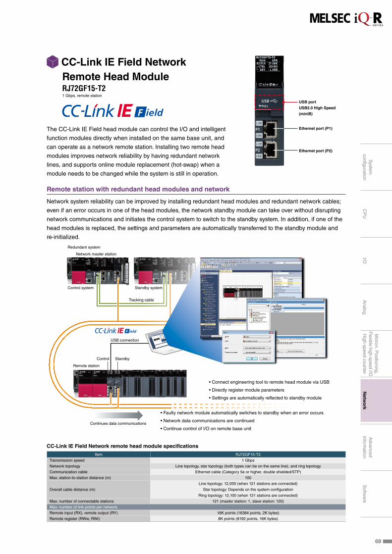
Remote station with redundant head modules and network
Network system reliability can be improved by installing redundant head modules and redundant network cables;
even if an error occurs in one of the head modules, the network standby module can take over without disrupting
network communications and initiates the control system to switch to the standby system. In addition, if one of the
head modules is replaced, the settings and parameters are automatically transferred to the standby module and
re-initialized.
• Connect engineering tool to remote head module via USB
• Directly register module parameters
• Settings are automatically reflected to standby module
• Faulty network module automatically switches to standby when an error occurs
• Network data communications are continued
• Continue control of I/O on remote base unitContinues data communications
Control Standby
USB connection
Network master station
Tracking cable
Redundant system
Control system
Remote station
Standby system
CC-Link IE Field Network remote head module specifications
Item RJ72GF15-T2
Transmission speed 1 Gbps
Network topology Line topology, star topology (both types can be on the same line), and ring topology
Communication cable Ethernet cable (Category 5e or higher, double shielded/STP)
Max. station-to-station distance (m) 100
Overall cable distance (m)
Line topology: 12,000 (when 121 stations are connected)
Star topology: Depends on the system configuration
Ring topology: 12,100 (when 121 stations are connected)
Max. number of connectable stations 121 (master station: 1, slave station: 120)
Max. number of link points per network
Remote input (RX), remote output (RY) 16K points (16384 points, 2K bytes)
Remote register (RWw, RWr) 8K points (8192 points, 16K bytes)
The CC-Link IE Field head module can control the I/O and intelligent
function modules directly when installed on the same base unit, and
can operate as a network remote station. Installing two remote head
modules improves network reliability by having redundant network
lines, and supports online module replacement (hot-swap) when a
module needs to be changed while the system is still in operation.
CC-Link IE Field Network Remote Head ModuleRJ72GF15-T21 Gbps, remote station
Ethernet port (P1)
USB port
USB2.0 High Speed
(miniB)
Ethernet port (P2)
68
System
configuration
CP
UI/O
Analog
Motion, P
ositioning,F
lexible high-speed I/OH
igh-speed counterN
etwo
rkA
dvanced inform
ationS
oftware
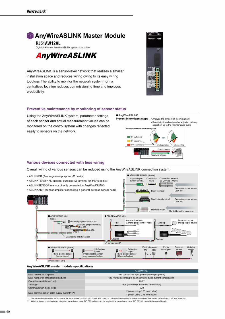
Relay terminal
Small block terminal
■ ASLINKER (2-wire)Cable
Input
Output
Mixed
■ ASLINKTERMINAL (4-wire)
Input compact8-point terminal
General-purpose sensor, LED, etc.
General-purpose sensor, LED, etc.
General-purpose sensor, etc.
General-purpose sensor, LED, etc.
LED, etc.
Manifold electric valve, etc.
Connection terminal (e-CON/JST/Molex)
Connectioncable
■ ASLINKSENSOR (2-wire)
■ ASLINKAMP (2-wire)
* Connecting only two wires
LP connector (4P)
Coupled
Fiber AnalogAnywire fiber headGeneral-purpose fiber head
General-purposeanalog output device
Cylindersensor
PressuresensorM30
Proximity sensor
LP connector (2P)
Photo electric sensor(transmission)
Photo electric sensor(regression reflection)
Photo electric sensor(diffuse reflection)
PhotointerrupterReflective
objectReflectionplate
Coupled
Manifold driver
M8
Preventive maintenance by monitoring of sensor status
Using the AnyWireASLINK system, parameter settings
of each sensor and actual measurement values can be
monitored on the control system with changes reflected
easily to sensors on the network.
■ AnyWireASLINK
ON (sufficient)
ON (caution)
OFF (insufficient) Initial operation After a while
Change in amount of incoming light
Status monitor
Parameter change
Prevent intermittent stops • Analyze the amount of incoming light
• Sensitivity threshold can be adjusted to keep operation up to the maintenance cycle
Various devices connected with less wiring
Overall wiring of various sensors can be reduced using the AnyWireASLINK connection system.
• ASLINKER (2-wire general-purpose I/O device)
• ASLINKTERMINAL (general-purpose I/O terminal for 4/8/16 points)
• ASLINKSENSOR (sensor directly connected to AnyWireASLINK)
• ASLINKAMP (sensor amplifier connecting a general-purpose sensor head)
AnyWireASLINK master module specifications
Item RJ51AW12AL
Max. number of I/O points 512 points (256 input points/256 output points)
Max. number of connectable modules 128 (varies according to each slave module’s current consumption)
Overall cable distance*1 (m) 200*2
Topology Bus (multi-drop, T-branch, tree branch)
Communication clock (kHz) 27.0
Max. communication cable supply current*1 (A)2 (when using 1.25 mm2 cable)
1 (when using 0.75 mm2 cable)
*1: The allowable value varies depending on the transmission cable supply current, total distance, or transmission cable (DP, DN) wire diameter. For details, please refer to the user's manual.
*2: With the slave module having an integrated transmission cable (DP, DN) and module, the length of the transmission cable (DP, DN) is included in the overall length.
AnyWireASLINK is a sensor-level network that realizes a smaller
installation space and reduces wiring owing to its easy wiring
topology. The ability to monitor the network system from a
centralized location reduces commissioning time and improves
productivity.
AnyWireASLINK Master ModuleRJ51AW12ALDigitalLinkSensor AnyWireASLINK system compatible
69
Network
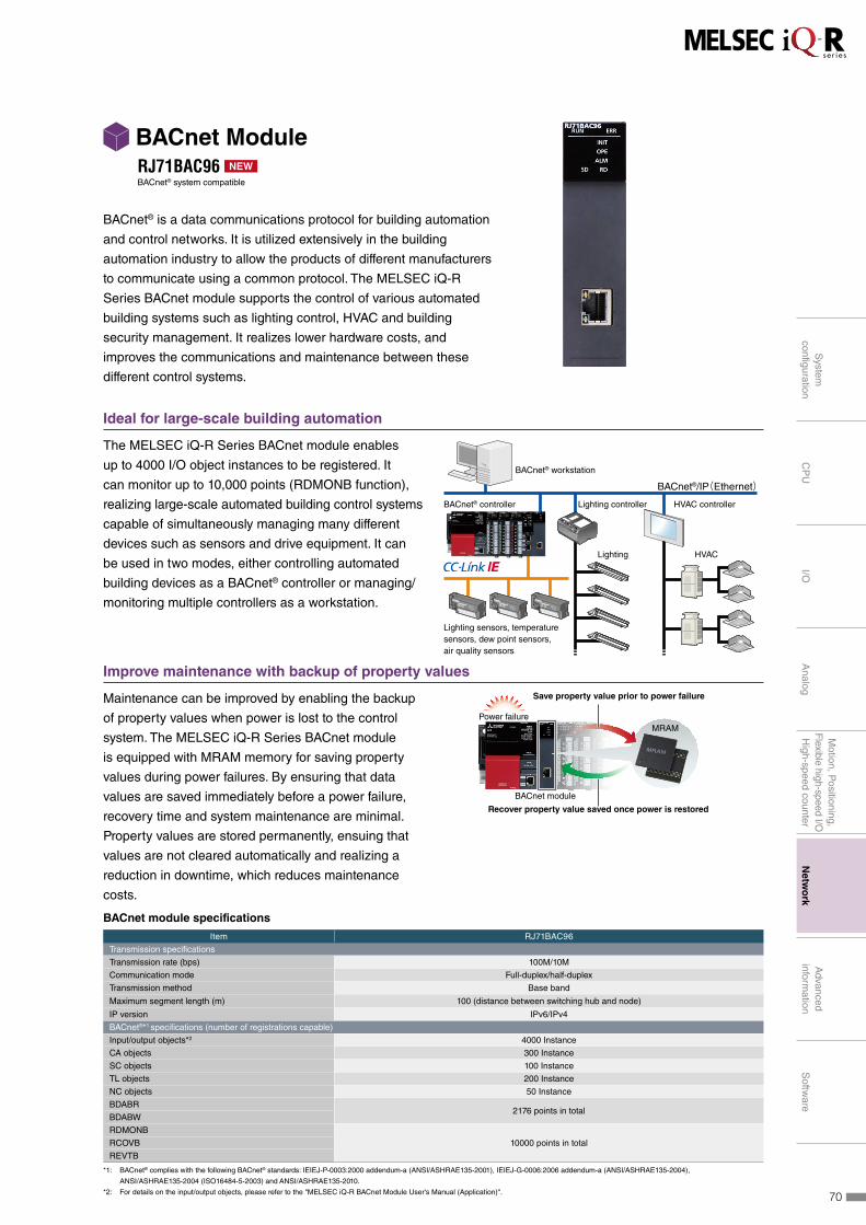
Ideal for large-scale building automation
The MELSEC iQ-R Series BACnet module enables
up to 4000 I/O object instances to be registered. It
can monitor up to 10,000 points (RDMONB function),
realizing large-scale automated building control systems
capable of simultaneously managing many different
devices such as sensors and drive equipment. It can
be used in two modes, either controlling automated
building devices as a BACnet® controller or managing/
monitoring multiple controllers as a workstation.
BACnet® workstation
BACnet® controller Lighting controller
Lighting HVAC
HVAC controller
Lighting sensors, temperature sensors, dew point sensors, air quality sensors
BACnet®/IP(Ethernet)
Improve maintenance with backup of property values
Maintenance can be improved by enabling the backup
of property values when power is lost to the control
system. The MELSEC iQ-R Series BACnet module
is equipped with MRAM memory for saving property
values during power failures. By ensuring that data
values are saved immediately before a power failure,
recovery time and system maintenance are minimal.
Property values are stored permanently, ensuing that
values are not cleared automatically and realizing a
reduction in downtime, which reduces maintenance
costs.
Power failureMRAM
Save property value prior to power failure
Recover property value saved once power is restored
BACnet module
BACnet module specifications
Item RJ71BAC96
Transmission specifications
Transmission rate (bps) 100M/10M
Communication mode Full-duplex/half-duplex
Transmission method Base band
Maximum segment length (m) 100 (distance between switching hub and node)
IP version IPv6/IPv4
BACnet®*1 specifications (number of registrations capable)
Input/output objects*2 4000 Instance
CA objects 300 Instance
SC objects 100 Instance
TL objects 200 Instance
NC objects 50 Instance
BDABR2176 points in total
BDABW
RDMONB
10000 points in totalRCOVB
REVTB
*1: BACnet® complies with the following BACnet® standards: IEIEJ-P-0003:2000 addendum-a (ANSI/ASHRAE135-2001), IEIEJ-G-0006:2006 addendum-a (ANSI/ASHRAE135-2004),
ANSI/ASHRAE135-2004 (ISO16484-5-2003) and ANSI/ASHRAE135-2010.
*2: For details on the input/output objects, please refer to the "MELSEC iQ-R BACnet Module User's Manual (Application)".
BACnet® is a data communications protocol for building automation
and control networks. It is utilized extensively in the building
automation industry to allow the products of different manufacturers
to communicate using a common protocol. The MELSEC iQ-R
Series BACnet module supports the control of various automated
building systems such as lighting control, HVAC and building
security management. It realizes lower hardware costs, and
improves the communications and maintenance between these
different control systems.
BACnet ModuleRJ71BAC96 NEW
BACnet® system compatible
70
System
configuration
CP
UI/O
Analog
Motion, P
ositioning,F
lexible high-speed I/OH
igh-speed counterN
etwo
rkA
dvanced inform
ationS
oftware

Master station
Local station Remote I/O Intelligent device
Max. 26stations*1
Max. 64stations
Max. 64stations*2
Max. 26stations*1
MAX.
10Mbps
Remote device
Max. 64 controlled stations
CC-Link is a high-speed and highly reliable deterministic I/O control
network that realizes reduced wiring while offering multi-vendor
compatible products.
The serial communication module enables serial
devices with up to 230.4 kbps transmission speeds to
be connected per channel. Communications protocols
such as MODBUS® are supported via the pre-defined
protocol feature.
Multiple connectivity of field devices
CC-Link incorporates many different field devices that
can be configured into a wire-saving communications
network. Using the remote device net mode, it is possible
to connect up to 64 remote devices, such as analog I/O
modules.
CC-Link System ModuleRJ61BT11Max. 10 Mbps, master/local station (CC-Link Ver.2)
Serial Communication ModulesRJ71C24Max. 230.4 kbps, RS-232 (1 channel), RS-422/485 (1 channel)
RJ71C24-R2Max. 230.4 kbps, RS-232 (2 channels)
RJ71C24-R4Max. 230.4 kbps, RS-422/485 (2 channels)
External connection device
230.4 kbps
230.4 kbps
RJ71C24 RJ71C24-R4RJ71C24-R2
CH2
CH1
*1: Remote network mode
*2: Remote device net mode
Item RJ61BT11
Transmission speed (bps) 156k/625k/2.5M/5M/10M
Network topology Bus (RS-485)
Communication cable Ver.1.10-compatible CC-Link dedicated cable
Overall distance (m) 100 (10 Mbps)...1200 (156 kbps)
Max. number of connected modules 65 stations (master station: 1, slave station: 64)
Max. number of link points per system (CC-Link Ver.2)
Remote I/O (RX, RY) 8192 points
Remote register (RWw, RWr) 2048 points
Item RJ71C24 RJ71C24-R2 RJ71C24-R4
Transmission speed (bps) 1.2k/2.4k/4.8k/9.6k/14.4k/19.2k/28.8k/38.4k/57.6k/115.2k/230.4k
Interface
CH1 RS-232 RS-232 RS-422/485
CH2 RS-422/485 RS-232 RS-422/485
Overall transmission distance
RS-232 (m) 15 15 -
RS-422/485 (m) 1,200 - 1,200
71
Network

e-F@ctory is a solution from Mitsubishi Electric helping to optimize production systems through its direct
connectivity between an IT system and the shop floor reducing cost over the entire product life cycle. Production
data management, analysis and planning utilizing IoT* can be realized, improving productivity through preventive
maintenance, operations management, traceability, and energy management. The MELSEC iQ-R Series includes
a range of products that fulfill these various needs as part of the “Intelligence” lineup of interconnected e-F@ctory
advanced information products.* Internet of Things
ffDirect access to IT system database
ffC/C++ based programming
ff Installation of various communications protocols
ffHigh-speed collection of shop floor data in real-time
ffUtilize third-party partner applications
Advanced information modules
Direct access to IT system database
Realize improved production management and reduce
overall system costs through real-time direct access to
IT system database servers without requiring additional
programming and gateway computers.
C/C++ based programming
Provides a robust and cost-efficient alternative from
computer-based analytical and testing systems,
enabling custom applications to be executed directly on
the control system. In addition, various communications
protocols can be installed directly.
High-speed data logging simplifies troubleshooting
Managing production line data, accurate identification
of failures and keeping daily/monthly records can be
realized at a low cost.Note: For information about the C Controller, please refer to page 40
Quality SafetyProductivity SecuritySustainability
MES interfaceC Controller
ProgrammableController
Sensor Energy-savingDrive Mechatronics
FA-ITInformation
Interface
since2003
Sales and distribution
Operation andmaintenance
Productdesign
Processdesign
ProcurementProduction
Supply chain
Engineeringchain
MES
SCADA
SCM
Simulator
ERP
CAD/CAMIT system
Edge-computing
Shop floor
Data handlingData primary processing/analysis
72
System
configuration
CP
UI/O
Analog
Motion, P
ositioning,F
lexible high-speed I/OH
igh-speed counterN
etwork
Ad
vanced
in
form
ation
Softw
are

System configuration costs reduced by 65%*2
MES Interface modules enable direct connectivity between IT database servers and programmable controllers on
the shop floor, eliminating the need for gateway computers or specified programs. Being much more reliable than
computers, the MES Interface saves on maintenance costs typical of computers.*2: Assumption based on a typical control architecture.
• Shop floor data acquisition in real-time
• Direct access to database without programming or gateway computers
• High reliability • Reduce system costs by 65%
IT system database server
Research and development
System development
Commissioning and testingHardware cost
Gateway computer • Requires dedicated
applications program
MES Interface System
Conventional System
Conventional System
MES Interface System
Reduce system costs
by 65%
Direct access to database without requiring additional
programming or gateway computers
MES Interface module specifications
Item RD81MES96
Database connection
Supported database*3 Oracle® Database, Microsoft® SQL Server, Microsoft® Access
SQL text SELECT, INSERT, UPDATE, DELETE, Multi-SELECT, STORED PROCEDURE
Database communication action field 65,536
Accessible CPU module*3 iQ-R Series (Direct, Remote), Q Series (Remote), L Series (Remote)
Data sampling interval
High speed data sampling (ms) Sequence scan time synchronization, 1...900
General data sampling (s) 0.1...0.9, 1...3600
Function
DB record read/write Reads/writes data in the database of the host information system
Device memory read/write Reads/writes device memory data of the CPU module
Trigger condition monitoringMonitors values of the time or device tag components etc., and starts jobs when a trigger condition changes from
false to true (the condition is satisfied)
Data operation and processing Performs four arithmetic operations, obtains remainder, performs character string operation, etc.
Program execution Executes a program on the server through a MES Interface module
DB bufferingBuffers the data sent to the database, and resend it after recovery, when the data cannot be linked due to the
disconnection of the network between MES Interface module and the database or failure of the database etc.
*3: For details, please refer to the relevant manual.
Along with ever-changing manufacturing trends, improving machine
productivity and maintaining manufacturing quality through meticulous
traceability have become a fundamental part of manufacturing. MES
Interface modules address these requirements by providing direct
database connectivity for IT systems and facilitating automatic SQL*1
text generation using intuitive configuration setup software. Modules
allow production data from the shop floor to be inserted into database
records directly; for example, providing real-time production status that
enables quicker response to production-related problems.*1: Structured Query Language is a programming language designed for managing data in a relational database.
MES Interface ModuleRD81MES96Database connection
Ethernet port (CH2)
Ethernet port (CH1)
73
Advanced information

Data logging synchronized with control system scan time
Acquired data can be synchronized with the
control system scan time and achieve sampling
rates up to 0.5 ms, realizing a higher resolution
that enables changes in control data to be
captured.
0 200 400100 300
High-speed data sampling function: 0.5 ms (max.)
These areas are not captured with slower sampling rates
Normal range
Time (ms)
High-speed data logger module
Computer
Easier root cause analysis
Event-driven data can be acquired right before
and after the trigger occurrence, improving the
recovery time of the control system.
Data(machine status)
Only this range is saved as logging data
Only the data required for analysis is saved, enabling faster troubleshooting
Uses minimum storage capacity
Time
Trigger occurs
Utilize data for various analysis and maintenance processes
Various data, such as the frequency and duration of a specific operation that has been satisfied, can be utilized for
preventative maintenance and machine operation/trend analysis.
High-speed data logger module specifications
Item RD81DL96
Accessible CPU modules iQ-R Series (Direct, Remote), Q Series (Remote), L Series (Remote)
Data sampling interval
High-speed data sampling (ms)
• Sequence scan time synchronization
• 0.5...0.9, 1...32767 (for trigger logging)
• 2...32767 (for continuous logging)
General data sampling (s)• 0.1...0.9, 1...32767
• Time interval specification (specify hour/minute/second)
Amount of sampled data
High-speed data sampling• Overall amount of data: 32768 (per setting: 1024)
• Overall number of device points: 32768 (per setting: 4096)
General data sampling• Overall amount of data: 65536 (per setting: 1024)
• Overall amount of data: 262144 (per setting: 4096)
Function
Data logging Logs CPU module device values at specified data sampling intervals.
Event logging Monitors sampled device values from the CPU module, and logs events that occur.
Report Outputs the data sampled by the high speed data logger module as an Excel® file.
Recipe
Executes the following operations using recipe files stored in the SD memory card:
• Transfer device values written on the recipe files to devices in the CPU module.
• Transfer device values in the CPU module to the recipe files.
The production process data acquisition feature of this high-speed
data logger module contributes to improving production quality
and efficiency, thereby realizing optimal production processes. The
module enables logging of various data such as Unicode, CSV, and
BIN text formats, which can be utilized for spreadsheet reporting
owing to the automatic report generation feature: BIN text format
data can be ported directly to Microsoft® Windows® Excel®. Logging
files can also be automatically sent to a FTP server or directly into a
Microsoft® Windows® share folder.
High-speed Data Logger ModuleRD81DL96Data collection
Ethernet port
74
System
configuration
CP
UI/O
Analog
Motion, P
ositioning,F
lexible high-speed I/OH
igh-speed counterN
etwork
Ad
vanced
in
form
ation
Softw
are

Realize complex arithmetic equations in C/C++
The C Intelligent Function module enables the execution of C/C++ programs when paired with a standard
MELSEC iQ-R Series Programmable Controller CPU, emulating the same features as a standalone C Controller.
Representing complex arithmetic and string equations in C/C++ programs is much easier than implementing in
ladder form, thereby reducing overall development time and program size. Additionally, Intellectual property is
simplified as the result of separating it from the ladder program.
I/O control I/O control
C/C++ program call operation
Arithmetic, string processingComplex processing executed directly in C/C++ program
Call execution command
C/C++ program
Processing result
Programmable Controller CPU moduleC Controller or Programmable Controller CPU plus C Intelligent Function module
Application development in simple steps
CW Workbench*1 is used as the main programming software in C/C++ with a VxWorks® emulator, CW-Sim/
CW-Sim standalone, which allows debugging without requiring any hardware.*1: For more information, please refer to page 42.
C intelligent function module specifications
Item RD55UP06-V
Hardware
Endian format Little endian
MPU ARM® Cortex-A9 Dual Core
Working RAM 128 MB
ROM 12 MB
Software
OS VxWorks® Version 6.9
Programming language C/C++
Programming development environment CW Workbench/Wind River Workbench3.3
Setting/monitoring tool GX Works3 (SW1DND-GXW3-E)*2
Communication interface
Ethernet (1000BASE-T/100BASE-TX/10BASE-T) 1CH
SD memory card slot ●
*2. Setting and monitoring of the module is integrated within the GX Works3 engineering software.
The C Intelligent function module is available with a multi-core
ARM®-based controller pre-installed with VxWorks® Version 6.9,
which realizes simultaneous execution of programs, thereby providing
a robust and deterministic alternative to computer-based systems.
Utilizing a fan-less hardware design, the C Intelligent function module
is ideal for clean fab-based environments, where dust circulation can
be detrimental to the production environment, and can be used for
applications such as in-line production quality testing or as a gateway
for various industry-specific communications protocols.
C Intelligent Function ModuleRD55UP06-VC/C++ program execution
Ethernet port
75
Advanced information

FA Integrated Engineering Software MELSOFT iQ WorksMELSOFT iQ Works is an integrated software suite consisting of GX Works3, MT Works2, GT Works3,
RT ToolBox2 mini and FR Configurator2, which are programming software for each respective product. Integration
is further enhanced with MELSOFT Navigator as the central system configuration incorporating an easy-to-use,
graphical user interface with additional project-sharing features such as system labels and parameters. The
advantages of this powerful integrated software suite are that system design is made much easier with a
substantial reduction in repetitious tasks, cutting down on errors while helping to reduce the overall TCO.
System management software
MELSOFT NavigatorSystem level graphic-based configuration tool that simplifies the system
design by providing a visual representation of the system. System
management features such as system-wide parameterization, labels
and block reading of project data are also included.
Programmable controller engineering software
MELSOFT GX Works3GX Works3 is the latest generation of programming and maintenance
software offered by Mitsubishi Electric specifically designed for the
MELSEC iQ-R Series control system. It includes many new features
such as graphic-based system configuration, integrated motion control
setup, multiple language support, providing an intuitive engineering
environment solution.
HMI/GOT screen design software
MELSOFT GT Works3This graphic operation terminal (GOT) screen creation software is
designed with three main features—simplicity, graphics design and
operation ease—that help to create graphic screens in fewer steps.
Motion controller engineering software
MELSOFT MT Works2This motion control design and maintenance software includes intuitive
graphic-based programming together with a digital oscilloscope
simulator.
Robot engineering software
MELSOFT RT ToolBox2 miniThis robot setup software supports various steps from programming,
to commissioning, evaluation, and maintenance. In addition, improved
preventative maintenance is realized through the use of an integrated
3D robot simulator.
Inverter setup software
MELSOFT FR Configurator2This software simplifies the setup and maintenance of AC Inverters.
Parameters can be registered easily and distributed to multiple inverters
when replacing, and activation of the PLC function all from one setup
screen.
76
System
configuration
CP
UI/O
Analog
Motion, P
ositioning,F
lexible high-speed I/OH
igh-speed counterN
etwork
Advanced
information
So
ftware
Software

Total system centralized configuration
The correlation between the system configuration feature of MELSOFT Navigator and GX Works3, MT Works2
has been further improved. The system design console works in a bidirectional method, enabling the system
configuration to be shared across all three software including network level integration without having to re-design
the configuration from within the product level programming software(s).
MT Works2
GX Works3
Product level projects(GX Works3, MT Works2)
• iQ-R modules• CC-Link IE (Control/Field)
Reflect changes to main system configuration
Navigator
Generate system diagram from physical hardware configuration
Effective parameter registration
Registration of module parameters within the system has been further enhanced with parameters being shared
bidirectionally between MELSOFT Navigator and GX Works3, MT Works2. Upward registration of parameters to
MELSOFT Navigator is also possible as changes are reflected from within the system configuration.
Reflect to system level Reflect to system level
RegisterRegisterGX Works3 MT Works2
Unified system label database
The unified label database allows centralized management of global labels across both GX Works3 and
GT Works3. The dynamic labeling structure enables system label sharing, which ensures that labels can be
used without being conscious of the device associated with that label. The structure is also responsive to system
configuration changes without having to modify the labels within the product programming tools.
Register
Register
GT Works3
System label databaseSystem label editor
Register
MELSOFT Navigator
System label editor
Global label editor
GX Works3/MT Works2
77
Software

GX Works3 consists of various different components that help to simplify project creation and maintenance tasks.
A system design console that enables projects to be created at the system overview stage has been added.
Additionally, the main programming languages are supported and their labels (variables) are shared, further
simplifying programming. Various debug and maintenance features are also included.
Project lifecycle engineering
Various features have been consolidated into an integrated engineering environment that enables easier project
creation throughout the engineering process, ensuring consistency through every step.
◼ System-wide design
• Easy system configuration with parts library
• Direct module parameter registration
• Integrated simple motion module setup
◼ Multiple programming languages
• Conforms to IEC 61131-3
• Supports main programming languages
• Consistency between different programming tabs
◼ Simple to debug
• Various online monitoring
• Hardware simulator (emulator)
• Data logging
◼ Straightforward maintenance
• System monitoring
• Module and network diagnostics
• Multi-language commenting
MELSOFT
GX Works3
Main
tenance System
Design
Program
min
g
Debug
One Software, Many Possibilities
Mitsubishi Electric MELSOFT GX Works3 Promotion Movie
78
System
configuration
CP
UI/O
Analog
Motion, P
ositioning,F
lexible high-speed I/OH
igh-speed counterN
etwork
Advanced
information
So
ftware
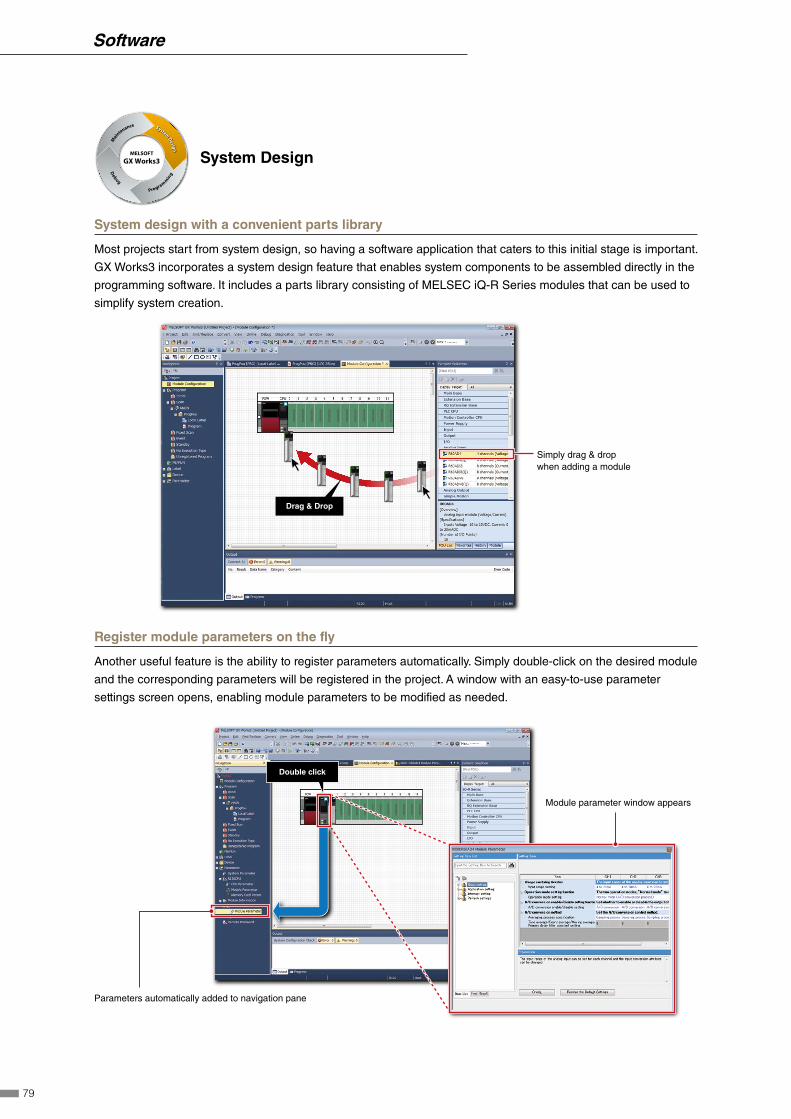
MELSOFT
GX Works3
Main
tenance System
Design
Program
min
g
Debug
System Design
System design with a convenient parts library
Most projects start from system design, so having a software application that caters to this initial stage is important.
GX Works3 incorporates a system design feature that enables system components to be assembled directly in the
programming software. It includes a parts library consisting of MELSEC iQ-R Series modules that can be used to
simplify system creation.
Drag & Drop
Simply drag & drop when adding a module
Register module parameters on the fly
Another useful feature is the ability to register parameters automatically. Simply double-click on the desired module
and the corresponding parameters will be registered in the project. A window with an easy-to-use parameter
settings screen opens, enabling module parameters to be modified as needed.
Parameters automatically added to navigation pane
Double click
Module parameter window appears
79
Software
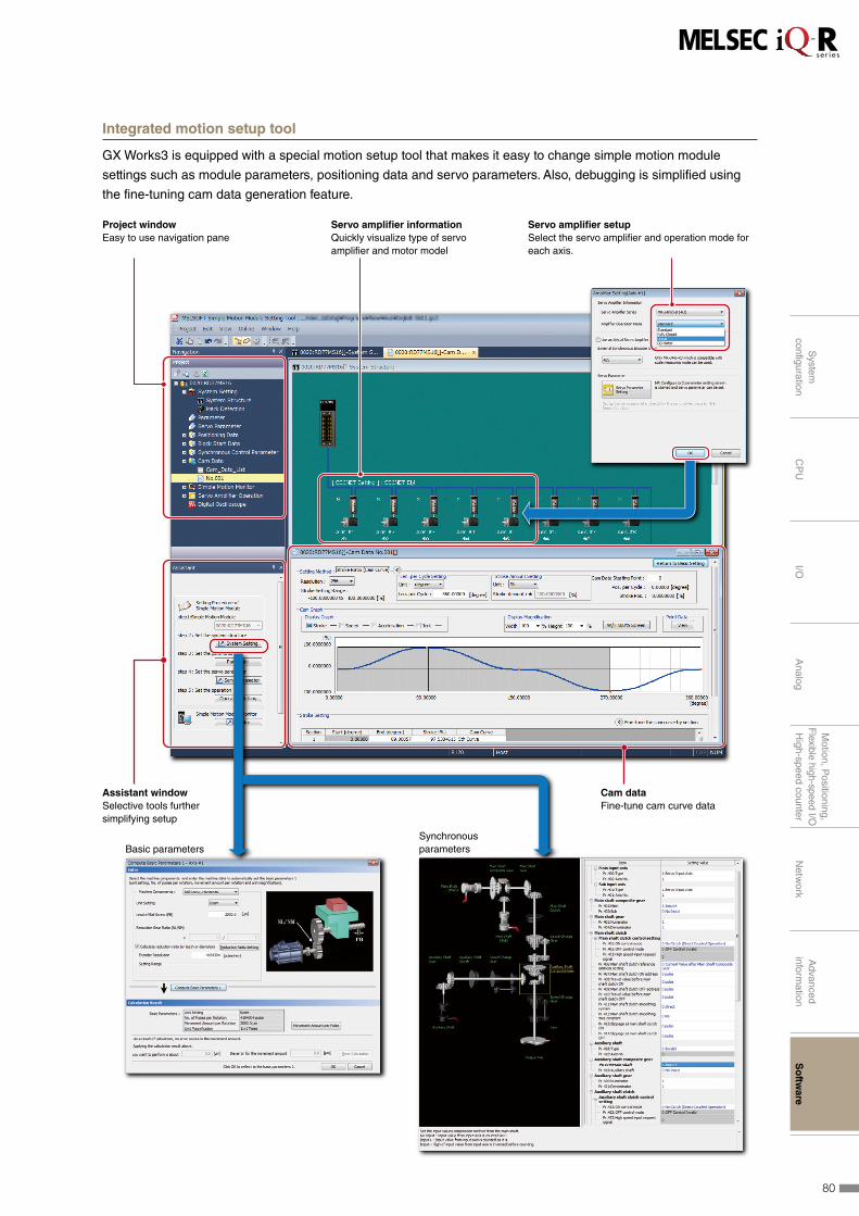
Integrated motion setup tool
GX Works3 is equipped with a special motion setup tool that makes it easy to change simple motion module
settings such as module parameters, positioning data and servo parameters. Also, debugging is simplified using
the fine-tuning cam data generation feature.
Project windowEasy to use navigation pane
Servo amplifier informationQuickly visualize type of servo amplifier and motor model
Servo amplifier setupSelect the servo amplifier and operation mode for each axis.
Assistant windowSelective tools further simplifying setup
Cam dataFine-tune cam curve data
Basic parametersSynchronous parameters
80
System
configuration
CP
UI/O
Analog
Motion, P
ositioning,F
lexible high-speed I/OH
igh-speed counterN
etwork
Advanced
information
So
ftware

MELSOFT
GX Works3
Main
tenance System
Design
Program
min
g
Debug
Programming
Central parts library
GX Works3 comes with an updated object library pre-installed in the software consisting of a module library with
current modules at time of software release although this can be added to as newer modules become available.
A variety of other objects are available such as third-party partner function blocks. The library can be fully shared
across multiple projects.
FBFB FB
Just "select" to create a program
� 3rd party partner FBs
Laser displacement sensorVision sensor RFID
� Module FBs (Mitsubishi Electric products)
Reduce repetitive program tasks
Global and local variables (labels) are supported providing an easy way to share device names across multiple
projects, other MELSOFT software and third party SCADA. The variables can be registered into either the current
program, function block as a local variable or within the project as a global variable to share across multiple
programs within the same project. Variables specific to a particular module are also available, and can be used
immediately, further reducing engineering time and cost.
Local label editor
Module label
Global label editor
81
Software

Main programming languages supported
The main IEC languages are supported by GX Works3. Various different programming languages can be used
within the same project simultaneously and can be viewed easily via the menu tab. The variables and devices
used in each program can be shared across multiple platforms, with user defined function blocks supported.
82
System
configuration
CP
UI/O
Analog
Motion, P
ositioning,F
lexible high-speed I/OH
igh-speed counterN
etwork
Advanced
information
So
ftware

MELSOFT
GX Works3
Maintenance System
Design
Programmin
g
Debug
Debug
Easy version management
Being able to visually see and manage different versions of the same project can help to reduce debugging
processes. Even with a number of engineers are working on the same project, changes made are easily
recognized directly from the program or as an automatically generated verification results list. This feature is
available for locally stored projects on the computer, and between the program stored in the programmable
controller CPU.Online data operation Verification results
Graphical representation of differences
: Source Only : Dest. Only: Unmatched Line
Hardware simulation
GX Works3 features an integrated simulator which helps to visualize the operation of the program during the
debugging process. Motion control CPU hardware can be simulated as well.
Directly debugging on the computer
Offline debugging without a control CPU required
83
Software
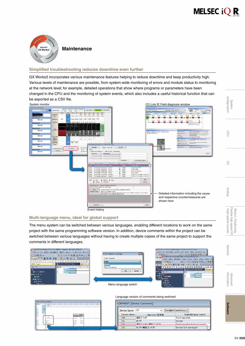
MELSOFT
GX Works3
Main
tenance System
Design
Program
min
g
Debug
Maintenance
Simplified troubleshooting reduces downtime even further
GX Works3 incorporates various maintenance features helping to reduce downtime and keep productivity high.
Various levels of maintenance are possible, from system-wide monitoring of errors and module status to monitoring
at the network level; for example, detailed operations that show where programs or parameters have been
changed in the CPU and the monitoring of system events, which also includes a useful historical function that can
be exported as a CSV file. CC-Link IE Field diagnosis windowSystem monitor
Detailed information including the cause and respective countermeasures are shown here
Event history
Multi-language menu, ideal for global support
The menu system can be switched between various languages, enabling different locations to work on the same
project with the same programming software version. In addition, device comments within the project can be
switched between various languages without having to create multiple copies of the same project to support the
comments in different languages.
Menu language switch
Language version of comments being switched
84
System
configuration
CP
UI/O
Analog
Motion, P
ositioning,F
lexible high-speed I/OH
igh-speed counterN
etwork
Advanced
information
So
ftware

MITSUBISHI ELECTRICCORPORATIONNagoya Works
w
@4
@3@1@2@0
@5e
!7
!9
!8u
!6 !3
i
o
r
y
t
q
!0
!1
!2
!4!5
Extensive global support coverage providing expert help whenever needed■ Global FA centers
China
q Shanghai FA CenterMITSUBISHI ELECTRIC AUTOMATION (CHINA) LTD. Shanghai FA CenterMitsubishi Electric Automation Center, No.1386 Hongqiao Road, Shanghai, ChinaTel: +86-21-2322-3030 / Fax: +86-21-2322-3000
w Beijing FA CenterMITSUBISHI ELECTRIC AUTOMATION (CHINA) LTD. Beijin FA CenterUnit 901, Office Tower 1, Henderson Centre, 18 Jianguomennei Avenue, Dongcheng District, Beijing, ChinaTel: +86-10-6518-8830 / Fax: +86-10-6518-2938
e Tianjin FA CenterMITSUBISHI ELECTRIC AUTOMATION (CHINA) LTD. Tianjin FA CenterRoom 2003 City Tower, No.35, Youyi Road, Hexi District, Tianjin, ChinaTel: +86-22-2813-1015 / Fax: +86-22-2813-1017
r Guangzhou FA CenterMITSUBISHI ELECTRIC AUTOMATION (CHINA) LTD. Guangzhou FA CenterRoom 1609, North Tower, The Hub Center, No.1068, Xingang East Road, Haizhu District, Guangzhou, ChinaTel: +86-20-8923-6730 / Fax: +86-20-8923-6715
Taiwan
t Taipei FA CenterSETSUYO ENTERPRISE CO., LTD. 3F, No.105, Wugong 3rd Road, Wugu District,New Taipei City 24889, TaiwanTel: +886-2-2299-9917 / Fax: +886-2-2299-9963
Korea
y Korea FA CenterMITSUBISHI ELECTRIC AUTOMATION KOREA CO., LTD.7F~9F, Gangseo Hangang Xi-tower A, 401, Yangcheon-ro, Gangseo-Gu, Seoul 07528, KoreaTel: +82-2-3660-9632 / Fax: +82-2-3664-0475
Thailand
u Thailand FA CenterMITSUBISHI ELECTRIC FACTORY AUTOMATION (THAILAND) CO., LTD.12th Floor, SV.City Building, Office Tower 1, No. 896/19 and 20 Rama 3 Road, Kwaeng Bangpongpang, Knet Yannawa, Bangkok 10120, ThailandTel: +66-2682-6522~31 / Fax: +66-2682-6020
ASEAN
i ASEAN FA CenterMITSUBISHI ELECTRIC ASIA PTE. LTD.307 Alexandra Road, Mitsubishi Electric Building, Singapore 159943Tel: +65-6470-2480 / Fax: +65-6476-7439
Indonesia
o Indonesia FA CenterPT. MITSUBISHI ELECTRIC INDONESIA Cikarang OfficeJl. Kenari Raya Blok G2-07A Delta Silicon 5, Lippo Cikarang - Bekasi 17550, IndonesiaTel: +62-21-2961-7797 / Fax: +62-21-2961-7794
Vietnam
!0 Hanoi FA CenterMITSUBISHI ELECTRIC VIETNAM COMPANY LIMITED Hanoi Branch Office6th Floor, Detech Tower, 8 Ton That Thuyet Street, My Dinh2 Ward, Nam Tu Liem District, Hanoi, VietnamTel: +84-4-3937-8075 / Fax: +84-4-3937-8076
!1 Ho Chi Minh FA CenterMITSUBISHI ELECTRIC VIETNAM COMPANY LIMITEDUnit 01-04, 10th Floor, Vincom Center, 72 Le Thanh Ton Street, District 1, Ho Chi Minh City, VietnamTel: +84-8-3910-5945 / Fax: +84-8-3910-5947
India
!2 India Pune FA CenterMITSUBISHI ELECTRIC INDIA PVT. LTD. Pune BranchEmerald House, EL-3, J Block, M.I.D.C., Bhosari, Pune - 411026, Maharashtra, IndiaTel: +91-20-2710-2000 / Fax: +91-20-2710-2100
!3 India Gurgaon FA CenterMITSUBISHI ELECTRIC INDIA PVT. LTD. Gurgaon Head Office2nd Floor, Tower A & B, Cyber Greens, DLF Cyber City, DLF Phase-3, Gurgaon-122002, Haryana, IndiaTel: +91-124-463-0300 / Fax: +91-124-463-0399
!4 India Bangalore FA CenterMITSUBISHI ELECTRIC INDIA PVT. LTD. Bangalore BranchPrestige Emerald, 6th Floor, Municipal No.2, Madras Bank Road, Bangalore - 560001, Karnataka, IndiaTel: +91-80-4020-1600 / Fax: +91-80-4020-1699
!5 India Chennai FA CenterMITSUBISHI ELECTRIC INDIA PVT. LTD. Chennai BranchCitilights Corporate Centre No. 1, Vivekananda Road, Srinivasa Nagar, Chetpet, Chennai - 600031, Tamil Nadu, IndiaTel: +91-4445548772 / Fax: +91-4445548773
!6 India Ahmedabad FA CenterMITSUBISHI ELECTRIC INDIA PVT. LTD. Ahmedabad BranchB/4, 3rd Floor, SAFAL Profitaire, Corporate Road, Prahaladnagar, Satellite, Ahmedabad - 380015, Gujarat, IndiaTel: +91-7965120063
America
!7 North America FA CenterMITSUBISHI ELECTRIC AUTOMATION, INC.500 Corporate Woods Parkway, Vernon Hills, IL 60061, U.S.A.Tel: +1-847-478-2469 / Fax: +1-847-478-2253
Mexico
!8 Mexico FA CenterMITSUBISHI ELECTRIC AUTOMATION, INC. Mexico BranchMariano Escobedo #69, Col.Zona Industrial, Tlalnepantla Edo. Mexico, C.P.54030Tel: +52-55-3067-7511
Brazil
!9 Brazil FA CenterMITSUBISHI ELECTRIC DO BRASIL COMÉRCIO E SERVIÇOS LTDA.Avenida Adelino Cardana, 293, 21 andar, Bethaville, Barueri SP, BrazilTel: +55-11-4689-3000 / Fax: +55-11-4689-3016
Europe
@0 Europe FA CenterMITSUBISHI ELECTRIC EUROPE B.V. Polish Branchul. Krakowska 50, 32-083 Balice, PolandTel: +48-12-347-65-81 / Fax: +48-12-630-47-01
@1 Germany FA CenterMITSUBISHI ELECTRIC EUROPE B.V. German Branch Mitsubishi-Electric-Platz 1, 40882 Ratingen, GermanyTel: +49-2102-486-0 / Fax: +49-2102-486-1120
@2 UK FA CenterMITSUBISHI ELECTRIC EUROPE B.V. UK BranchTravellers Lane, Hatfield, Hertfordshire, AL10 8XB, U.K.Tel: +44-1707-27-8780 / Fax: +44-1707-27-8695
@3 Czech Republic FA CenterMITSUBISHI ELECTRIC EUROPE B.V. Czech BranchAvenir Business Park, Radlicka 751/113e, 158 00 Praha 5, Czech RepublicTel: +420-251-551-470 / Fax: +420-251-551-471
@4 Russia FA CenterMITSUBISHI ELECTRIC (RUSSIA) LLC ST. Petersburg BranchPiskarevsky pr. 2, bld 2, lit "Sch", BC "Benua", office 720; 195027, St. Petersburg, RussiaTel: +7-812-633-3497 / Fax: +7-812-633-3499
@5 Turkey FA CenterMITSUBISHI ELECTRIC TURKEY A.Ş Ümraniye BranchSerifali Mahallesi Nutuk Sokak No:5, TR-34775 Umraniye / Istanbul, TurkeyTel: +90-216-526-3990 / Fax: +90-216-526-3995
85

MITSUBISHI ELECTRICCORPORATIONNagoya Works
w
@4
@3@1@2@0
@5e
!7
!9
!8u
!6 !3
i
o
r
y
t
q
!0
!1
!2
!4!5
Extensive global support coverage providing expert help whenever needed■ Global FA centers
China
q Shanghai FA CenterMITSUBISHI ELECTRIC AUTOMATION (CHINA) LTD. Shanghai FA CenterMitsubishi Electric Automation Center, No.1386 Hongqiao Road, Shanghai, ChinaTel: +86-21-2322-3030 / Fax: +86-21-2322-3000
w Beijing FA CenterMITSUBISHI ELECTRIC AUTOMATION (CHINA) LTD. Beijin FA CenterUnit 901, Office Tower 1, Henderson Centre, 18 Jianguomennei Avenue, Dongcheng District, Beijing, ChinaTel: +86-10-6518-8830 / Fax: +86-10-6518-2938
e Tianjin FA CenterMITSUBISHI ELECTRIC AUTOMATION (CHINA) LTD. Tianjin FA CenterRoom 2003 City Tower, No.35, Youyi Road, Hexi District, Tianjin, ChinaTel: +86-22-2813-1015 / Fax: +86-22-2813-1017
r Guangzhou FA CenterMITSUBISHI ELECTRIC AUTOMATION (CHINA) LTD. Guangzhou FA CenterRoom 1609, North Tower, The Hub Center, No.1068, Xingang East Road, Haizhu District, Guangzhou, ChinaTel: +86-20-8923-6730 / Fax: +86-20-8923-6715
Taiwan
t Taipei FA CenterSETSUYO ENTERPRISE CO., LTD. 3F, No.105, Wugong 3rd Road, Wugu District,New Taipei City 24889, TaiwanTel: +886-2-2299-9917 / Fax: +886-2-2299-9963
Korea
y Korea FA CenterMITSUBISHI ELECTRIC AUTOMATION KOREA CO., LTD.7F~9F, Gangseo Hangang Xi-tower A, 401, Yangcheon-ro, Gangseo-Gu, Seoul 07528, KoreaTel: +82-2-3660-9632 / Fax: +82-2-3664-0475
Thailand
u Thailand FA CenterMITSUBISHI ELECTRIC FACTORY AUTOMATION (THAILAND) CO., LTD.12th Floor, SV.City Building, Office Tower 1, No. 896/19 and 20 Rama 3 Road, Kwaeng Bangpongpang, Knet Yannawa, Bangkok 10120, ThailandTel: +66-2682-6522~31 / Fax: +66-2682-6020
ASEAN
i ASEAN FA CenterMITSUBISHI ELECTRIC ASIA PTE. LTD.307 Alexandra Road, Mitsubishi Electric Building, Singapore 159943Tel: +65-6470-2480 / Fax: +65-6476-7439
Indonesia
o Indonesia FA CenterPT. MITSUBISHI ELECTRIC INDONESIA Cikarang OfficeJl. Kenari Raya Blok G2-07A Delta Silicon 5, Lippo Cikarang - Bekasi 17550, IndonesiaTel: +62-21-2961-7797 / Fax: +62-21-2961-7794
Vietnam
!0 Hanoi FA CenterMITSUBISHI ELECTRIC VIETNAM COMPANY LIMITED Hanoi Branch Office6th Floor, Detech Tower, 8 Ton That Thuyet Street, My Dinh2 Ward, Nam Tu Liem District, Hanoi, VietnamTel: +84-4-3937-8075 / Fax: +84-4-3937-8076
!1 Ho Chi Minh FA CenterMITSUBISHI ELECTRIC VIETNAM COMPANY LIMITEDUnit 01-04, 10th Floor, Vincom Center, 72 Le Thanh Ton Street, District 1, Ho Chi Minh City, VietnamTel: +84-8-3910-5945 / Fax: +84-8-3910-5947
India
!2 India Pune FA CenterMITSUBISHI ELECTRIC INDIA PVT. LTD. Pune BranchEmerald House, EL-3, J Block, M.I.D.C., Bhosari, Pune - 411026, Maharashtra, IndiaTel: +91-20-2710-2000 / Fax: +91-20-2710-2100
!3 India Gurgaon FA CenterMITSUBISHI ELECTRIC INDIA PVT. LTD. Gurgaon Head Office2nd Floor, Tower A & B, Cyber Greens, DLF Cyber City, DLF Phase-3, Gurgaon-122002, Haryana, IndiaTel: +91-124-463-0300 / Fax: +91-124-463-0399
!4 India Bangalore FA CenterMITSUBISHI ELECTRIC INDIA PVT. LTD. Bangalore BranchPrestige Emerald, 6th Floor, Municipal No.2, Madras Bank Road, Bangalore - 560001, Karnataka, IndiaTel: +91-80-4020-1600 / Fax: +91-80-4020-1699
!5 India Chennai FA CenterMITSUBISHI ELECTRIC INDIA PVT. LTD. Chennai BranchCitilights Corporate Centre No. 1, Vivekananda Road, Srinivasa Nagar, Chetpet, Chennai - 600031, Tamil Nadu, IndiaTel: +91-4445548772 / Fax: +91-4445548773
!6 India Ahmedabad FA CenterMITSUBISHI ELECTRIC INDIA PVT. LTD. Ahmedabad BranchB/4, 3rd Floor, SAFAL Profitaire, Corporate Road, Prahaladnagar, Satellite, Ahmedabad - 380015, Gujarat, IndiaTel: +91-7965120063
America
!7 North America FA CenterMITSUBISHI ELECTRIC AUTOMATION, INC.500 Corporate Woods Parkway, Vernon Hills, IL 60061, U.S.A.Tel: +1-847-478-2469 / Fax: +1-847-478-2253
Mexico
!8 Mexico FA CenterMITSUBISHI ELECTRIC AUTOMATION, INC. Mexico BranchMariano Escobedo #69, Col.Zona Industrial, Tlalnepantla Edo. Mexico, C.P.54030Tel: +52-55-3067-7511
Brazil
!9 Brazil FA CenterMITSUBISHI ELECTRIC DO BRASIL COMÉRCIO E SERVIÇOS LTDA.Avenida Adelino Cardana, 293, 21 andar, Bethaville, Barueri SP, BrazilTel: +55-11-4689-3000 / Fax: +55-11-4689-3016
Europe
@0 Europe FA CenterMITSUBISHI ELECTRIC EUROPE B.V. Polish Branchul. Krakowska 50, 32-083 Balice, PolandTel: +48-12-347-65-81 / Fax: +48-12-630-47-01
@1 Germany FA CenterMITSUBISHI ELECTRIC EUROPE B.V. German Branch Mitsubishi-Electric-Platz 1, 40882 Ratingen, GermanyTel: +49-2102-486-0 / Fax: +49-2102-486-1120
@2 UK FA CenterMITSUBISHI ELECTRIC EUROPE B.V. UK BranchTravellers Lane, Hatfield, Hertfordshire, AL10 8XB, U.K.Tel: +44-1707-27-8780 / Fax: +44-1707-27-8695
@3 Czech Republic FA CenterMITSUBISHI ELECTRIC EUROPE B.V. Czech BranchAvenir Business Park, Radlicka 751/113e, 158 00 Praha 5, Czech RepublicTel: +420-251-551-470 / Fax: +420-251-551-471
@4 Russia FA CenterMITSUBISHI ELECTRIC (RUSSIA) LLC ST. Petersburg BranchPiskarevsky pr. 2, bld 2, lit "Sch", BC "Benua", office 720; 195027, St. Petersburg, RussiaTel: +7-812-633-3497 / Fax: +7-812-633-3499
@5 Turkey FA CenterMITSUBISHI ELECTRIC TURKEY A.Ş Ümraniye BranchSerifali Mahallesi Nutuk Sokak No:5, TR-34775 Umraniye / Istanbul, TurkeyTel: +90-216-526-3990 / Fax: +90-216-526-3995
Factory Automation Global websiteMitsubishi Electric Factory Automation provides a mix of services to support its customers worldwide. A
consolidated global website is the main portal, offering a selection of support tools and a window to its local
Mitsubishi Electric sales and support network.
Online e-learning
■ Beginner levelDesigned for newcomers to Mitsubishi Electric Factory Automation products gaining a background of the fundamentals and an overview of various products related to the course.
■ Basic to Advanced levelsThese courses are designed to provide education at all levels. Various different features are explained with application examples providing an easy and informative resource for in-house company training.
An extensive library of e-learning courses covering the factory automation product range has been prepared.
Courses from beginner to advanced levels of difficulty are available in various languages.
■ From here you can find:
• Overview of available factory automation products• Library of downloadable literature• Support tools such as online e-learning courses,
terminology dictionary, etc.• Global sales and service network portal• Latest news related to Mitsubishi Electric factory
automation
Mitsubishi Electric Factory AutomationGlobal website:
www.MitsubishiElectric.com/fa
86

CLPA-India(Gurgaon)
CLPA-Turkey(Istanbul)
CC-Link Promotion Center ASEAN(Singapore)
CLPA-Americas(Mexico office)(Tlalnepantla)
CC-Link Promotion Center Thailand(Bangkok)
NEW
NEW
CC-Link Partner Association (CLPA) - Activelypromoting worldwide adoption of CC-Link networks
Proactively supporting CC-Link, from promotion to specification development
CC-Link is supported globally by CLPA. With offices throughout the world, support for partner companies can be found locally.
Each regional CLPA office undertakes various support and promotional activities to further the influence of CC-Link/CC-Link IE in
that part of the world. For companies looking to increase their presence in their local area, CLPA is well placed to assist these
efforts through offices in all major regions.
Global influence of CC-Link continues to spread
The CC-Link Partner Association (CLPA) was established to promote the worldwide adoption of the CC-Link open-field network. By
conducting promotional activities such as organizing trade shows and seminars, conducting conformance tests, and providing catalogs,
brochures and website information, CLPA activities are successfully increasing the number of CC-Link partner manufacturers and
CC-Link-compatible products. As such, CLPA is playing a major role in the globalization of CC-Link.
Visit the CLPA website for the latest CC-Link information.
URL:www.cc-link.org
Seminar Conformance testing labTrade show
CLPA-North America(Vernon Hills, Illinois, USA)CLPA Headquarters
(Nagoya, Japan)
CLPA-Korea(Seoul)
CC-Link-Europe(Germany)
CLPA-China(Shanghai)
CLPA-Taiwan(Taipei)
CT
:Conformance Testing LabCT
CT
CT
CT
CT
CC-Link Partner Association
6F Ozone Front Bldg. 3-15-58 Ozone Kita-ku, Nagoya 462-0825, JAPANTEL: +81-52-919-1588 FAX: +81-52-916-8655E-mail:[email protected]
Innovative next-generation, e-ManualThe e-Manual viewer is a next-generation digital manual offered by Mitsubishi Electric that consolidates all
manuals into an easy-to-use package with various useful features integrated into the viewer. The e-Manual is
modeled around a centralized database allowing multiple manuals to be cross-searched at once, further reducing
the time for reading individual product manuals when setting up a control system.
■ Key features include
• One-stop database containing all required manuals, with local file cache
• Included with GX Works3 engineering software
• Also available in tablet version
• Easily download manuals all at once
• Automatic update of manual versions
• Search information across multiple manuals
• Visual navigation from hardware diagram showing various specifications
• Customizable by adding user notes and bookmarks
• Directly port sample programs within manuals to GX Works3
■ MITSUBISHI ELECTRIC FA e-Manual (tablet version)
The e-Manual application is available on iOS and Android™ tablets.
e-Manual files are provided as in-app downloads.
iOSVersion 8.1 or later
Android™Version 4.3/4.4/5.0
◼ Supported versionsOS OS version Model
iOS iOS 8.1 or laterApple iPad 2, iPad (3rd generation), iPad (4th generation), iPad Air, iPad Air 2,
iPad mini, iPad mini 2, iPad mini 3
Android™ Android™ 4.3/4.4/5.0 ASUS Nexus7™ (2013)*1
*1: When using a tablet not listed above, 7-inch (resolution of 1920×1200 dots (WUXGA)) or better is recommended.
87

CLPA-India(Gurgaon)
CLPA-Turkey(Istanbul)
CC-Link Promotion Center ASEAN(Singapore)
CLPA-Americas(Mexico office)(Tlalnepantla)
CC-Link Promotion Center Thailand(Bangkok)
NEW
NEW
CC-Link Partner Association (CLPA) - Activelypromoting worldwide adoption of CC-Link networks
Proactively supporting CC-Link, from promotion to specification development
CC-Link is supported globally by CLPA. With offices throughout the world, support for partner companies can be found locally.
Each regional CLPA office undertakes various support and promotional activities to further the influence of CC-Link/CC-Link IE in
that part of the world. For companies looking to increase their presence in their local area, CLPA is well placed to assist these
efforts through offices in all major regions.
Global influence of CC-Link continues to spread
The CC-Link Partner Association (CLPA) was established to promote the worldwide adoption of the CC-Link open-field network. By
conducting promotional activities such as organizing trade shows and seminars, conducting conformance tests, and providing catalogs,
brochures and website information, CLPA activities are successfully increasing the number of CC-Link partner manufacturers and
CC-Link-compatible products. As such, CLPA is playing a major role in the globalization of CC-Link.
Visit the CLPA website for the latest CC-Link information.
URL:www.cc-link.org
Seminar Conformance testing labTrade show
CLPA-North America(Vernon Hills, Illinois, USA)CLPA Headquarters
(Nagoya, Japan)
CLPA-Korea(Seoul)
CC-Link-Europe(Germany)
CLPA-China(Shanghai)
CLPA-Taiwan(Taipei)
CT
:Conformance Testing LabCT
CT
CT
CT
CT
CC-Link Partner Association
6F Ozone Front Bldg. 3-15-58 Ozone Kita-ku, Nagoya 462-0825, JAPANTEL: +81-52-919-1588 FAX: +81-52-916-8655E-mail:[email protected]
88

◼ General specificationsItem Specification
Operating ambient temperature0...55°C (when a base unit other than an extended temperature range base unit is used)
0...60°C (when an extended temperature range base unit is used)*1
Storage ambient temperature –25...75°C
Operating ambient humidity 5...95% RH, non-condensing
Storage ambient humidity 5...95% RH, non-condensing
Vibration resistance
Compliant with
JIS B 3502 and
IEC 61131-2
- Frequency Constant acceleration Half amplitude Sweep count
Under intermittent
vibration
5...8.4 Hz - 3.5 mm 10 times each in
X, Y, Z directions8.4...150 Hz 9.8 m/s2 -
Under continuous
vibration
5...8.4 Hz - 1.75 mm-
8.4...150 Hz 4.9 m/s2 -
Shock resistance Compliant with JIS B 3502 and IEC 61131-2 (147 m/s2, 3 times each in directions X, Y, Z)
Operating atmosphere No corrosive gases*5, no flammable gases, no excessive conductive dust
Operating altitude*2 0...2000 m*6
Installation location Inside a control panel
Overvoltage category*3 ≤ 2Pollution degree*4 ≤ 2
Equipment class Class 2*7
*1: Enables standard MELSEC iQ-R Series modules to support extended operating ambient temperature of 0 to 60°C, ensuring the same performance as the standard operating ambient temperature (0 to 55°C). When
requiring to use in an ambient temperature environment higher than 60°C, please consult your local Mitsubishi Electric representative.
*2: Do not use or store the programmable controller under pressure higher than the atmospheric pressure of altitude 0 m. Doing so may cause malfunction.
When using the programmable controller under pressure, please consult your local Mitsubishi Electric representative.
*3: This indicates the section of the power supply to which the equipment is assumed to be connected between the public electrical power distribution network and the machinery within premises.
Category 2 applies to equipment for which electrical power is supplied from fixed facilities. The surge voltage withstand level for up to the rated voltage of 300 V is 2500 V.
*4: This index indicates the degree to which conductive material is generated in terms of the environment in which the equipment is used.
Pollution level 2 is when only non-conductive pollution occurs. A temporary conductivity caused by condensing must be expected occasionally.
*5: The special coated product, which meets the regulation (JIS C 60721-3-3/IEC 60721-3-3 3C2) related to corrosive gas, is available for the use in a corrosive gas environment.
For more details on the special coated product, please consult your local Mitsubishi Electric representative.
*6: When used at an altitude higher than 2000 m, the upper limits of the permissible voltage and the operating ambient temperature become lower. Please consult your local Mitsubishi Electric representative.
*7: Class 1 when the RQ extension base unit is used.
◼ Software operating environment*8
ItemMELSOFT GX Works3,
CW ConfiguratorMELSOFT MX MESInterface-R*9
CW Workbench, CW-Sim,
CW-Sim Standalone
Personal computer Windows® supported personal computer
CPU Intel® Core™ 2 Duo Processor 2 GHz or more
Available hard disk capacity 5 GB 512 MB 4 GB or more
Display resolution 1024 x 768 pixels or higher
Required memory
64-bit edition 2 GB or more recommended 2 GB or more recommended 2 GB or more
32-bit edition 2 GB or more recommended 1 GB or more recommended1 GB or more
(2 GB or more recommended)
OS (English version)
Microsoft® Windows® 8.1 Operating System ● ● ●*10
Microsoft® Windows® 8.1 Pro Operating System ● ● ●*10
Microsoft® Windows® 8.1 Enterprise Operating System ● ● ●*10
Microsoft® Windows® 8 Operating System ● ● ●*10
Microsoft® Windows® 8 Pro Operating System ● ● ●*10
Microsoft® Windows® 8 Enterprise Operating System ● ● ●*10
Microsoft® Windows® 7 Starter Operating System ● - -
Microsoft® Windows® 7 Home Premium Operating System ● ● -
Microsoft® Windows® 7 Professional Operating System ● ● ●*11
Microsoft® Windows® 7 Ultimate Operating System ● ● ●*11
Microsoft® Windows® 7 Enterprise Operating System ● ● ●*11
Microsoft® Windows Vista® Home Basic Operating System ●*12 - -
Microsoft® Windows Vista® Home Premium Operating System ●*12 - -
Microsoft® Windows Vista® Business Operating System ●*12 - -
Microsoft® Windows Vista® Ultimate Operating System ●*12 - -
Microsoft® Windows Vista® Enterprise Operating System ●*12 - -
Microsoft® Windows® XP Professional Operating System SP3 ●*12 - ●*12
Microsoft® Windows® XP Home Edition Operating System SP3 ●*12 - -
*8. For information about software operating environment, refer to PX Developer Version 1 Operating Manual (Monitor Tool).
*9. Software operating environment when installing the MES Interface function configuration tool.
*10: Windows Touch is not supported.
*11: Windows® XP Mode is not supported.
*12: The 64-bit edition is not supported.
◼ MELSOFT GX Works3, MX MESInterface-R*13
-supported CPU modulesItem Model
Programmable controller
CPU
R04(EN)CPU
R08(EN)CPU
R16(EN)CPU
R32(EN)CPU
R120(EN)CPU
Safety CPU R08SFCPU
R16SFCPU
R32SFCPU
R120SFCPU
Process CPU R08PCPU
R16PCPU
R32PCPU
R120PCPU
*13. MX MESInterface-R does not support R◻ENCPU and safety CPU.
◼ CW Workbench, CW-Sim, CW-Sim Standalone,
MELSOFT CW Configurator-supported CPU modulesItem Model
C Controller R12CCPU-V
◼ PX Developer monitor tool-supported CPU modulesItem Model
Process CPU R08PCPU
R16PCPU
R32PCPU
R120PCPU
89
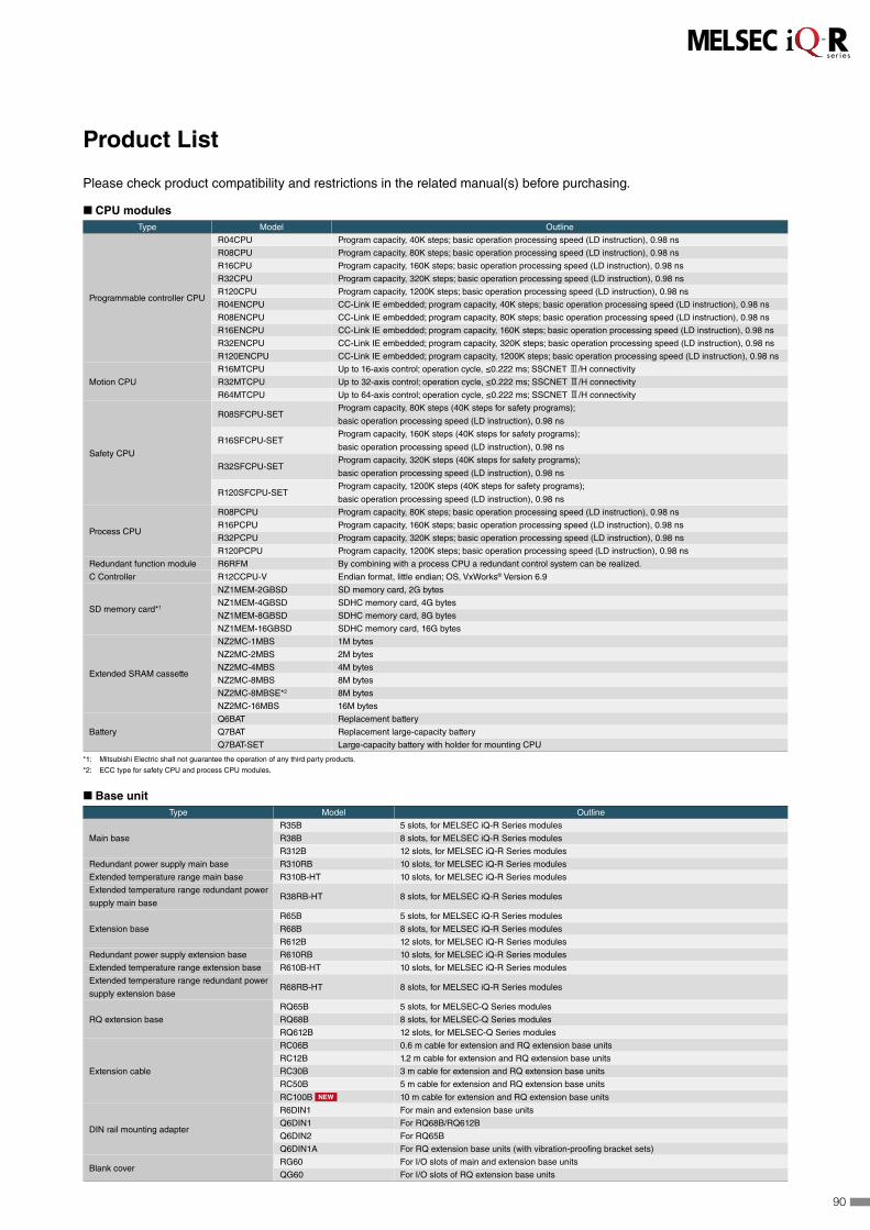
Please check product compatibility and restrictions in the related manual(s) before purchasing.
◼ CPU modulesType Model Outline
Programmable controller CPU
R04CPU Program capacity, 40K steps; basic operation processing speed (LD instruction), 0.98 ns
R08CPU Program capacity, 80K steps; basic operation processing speed (LD instruction), 0.98 ns
R16CPU Program capacity, 160K steps; basic operation processing speed (LD instruction), 0.98 ns
R32CPU Program capacity, 320K steps; basic operation processing speed (LD instruction), 0.98 ns
R120CPU Program capacity, 1200K steps; basic operation processing speed (LD instruction), 0.98 ns
R04ENCPU CC-Link IE embedded; program capacity, 40K steps; basic operation processing speed (LD instruction), 0.98 ns
R08ENCPU CC-Link IE embedded; program capacity, 80K steps; basic operation processing speed (LD instruction), 0.98 ns
R16ENCPU CC-Link IE embedded; program capacity, 160K steps; basic operation processing speed (LD instruction), 0.98 ns
R32ENCPU CC-Link IE embedded; program capacity, 320K steps; basic operation processing speed (LD instruction), 0.98 ns
R120ENCPU CC-Link IE embedded; program capacity, 1200K steps; basic operation processing speed (LD instruction), 0.98 ns
Motion CPU
R16MTCPU Up to 16-axis control; operation cycle, ≤0.222 ms; SSCNET 3/H connectivity
R32MTCPU Up to 32-axis control; operation cycle, ≤0.222 ms; SSCNET 3/H connectivity
R64MTCPU Up to 64-axis control; operation cycle, ≤0.222 ms; SSCNET 3/H connectivity
Safety CPU
R08SFCPU-SETProgram capacity, 80K steps (40K steps for safety programs);
basic operation processing speed (LD instruction), 0.98 ns
R16SFCPU-SETProgram capacity, 160K steps (40K steps for safety programs);
basic operation processing speed (LD instruction), 0.98 ns
R32SFCPU-SETProgram capacity, 320K steps (40K steps for safety programs);
basic operation processing speed (LD instruction), 0.98 ns
R120SFCPU-SETProgram capacity, 1200K steps (40K steps for safety programs);
basic operation processing speed (LD instruction), 0.98 ns
Process CPU
R08PCPU Program capacity, 80K steps; basic operation processing speed (LD instruction), 0.98 ns
R16PCPU Program capacity, 160K steps; basic operation processing speed (LD instruction), 0.98 ns
R32PCPU Program capacity, 320K steps; basic operation processing speed (LD instruction), 0.98 ns
R120PCPU Program capacity, 1200K steps; basic operation processing speed (LD instruction), 0.98 ns
Redundant function module R6RFM By combining with a process CPU a redundant control system can be realized.
C Controller R12CCPU-V Endian format, little endian; OS, VxWorks® Version 6.9
SD memory card*1
NZ1MEM-2GBSD SD memory card, 2G bytes
NZ1MEM-4GBSD SDHC memory card, 4G bytes
NZ1MEM-8GBSD SDHC memory card, 8G bytes
NZ1MEM-16GBSD SDHC memory card, 16G bytes
Extended SRAM cassette
NZ2MC-1MBS 1M bytes
NZ2MC-2MBS 2M bytes
NZ2MC-4MBS 4M bytes
NZ2MC-8MBS 8M bytes
NZ2MC-8MBSE*2 8M bytes
NZ2MC-16MBS 16M bytes
Battery
Q6BAT Replacement battery
Q7BAT Replacement large-capacity battery
Q7BAT-SET Large-capacity battery with holder for mounting CPU
*1: Mitsubishi Electric shall not guarantee the operation of any third party products.
*2: ECC type for safety CPU and process CPU modules.
◼ Base unitType Model Outline
Main base
R35B 5 slots, for MELSEC iQ-R Series modules
R38B 8 slots, for MELSEC iQ-R Series modules
R312B 12 slots, for MELSEC iQ-R Series modules
Redundant power supply main base R310RB 10 slots, for MELSEC iQ-R Series modules
Extended temperature range main base R310B-HT 10 slots, for MELSEC iQ-R Series modules
Extended temperature range redundant power
supply main baseR38RB-HT 8 slots, for MELSEC iQ-R Series modules
Extension base
R65B 5 slots, for MELSEC iQ-R Series modules
R68B 8 slots, for MELSEC iQ-R Series modules
R612B 12 slots, for MELSEC iQ-R Series modules
Redundant power supply extension base R610RB 10 slots, for MELSEC iQ-R Series modules
Extended temperature range extension base R610B-HT 10 slots, for MELSEC iQ-R Series modules
Extended temperature range redundant power
supply extension baseR68RB-HT 8 slots, for MELSEC iQ-R Series modules
RQ extension base
RQ65B 5 slots, for MELSEC-Q Series modules
RQ68B 8 slots, for MELSEC-Q Series modules
RQ612B 12 slots, for MELSEC-Q Series modules
Extension cable
RC06B 0.6 m cable for extension and RQ extension base units
RC12B 1.2 m cable for extension and RQ extension base units
RC30B 3 m cable for extension and RQ extension base units
RC50B 5 m cable for extension and RQ extension base units
RC100B NEW 10 m cable for extension and RQ extension base units
DIN rail mounting adapter
R6DIN1 For main and extension base units
Q6DIN1 For RQ68B/RQ612B
Q6DIN2 For RQ65B
Q6DIN1A For RQ extension base units (with vibration-proofing bracket sets)
Blank coverRG60 For I/O slots of main and extension base units
QG60 For I/O slots of RQ extension base units
Product List
90
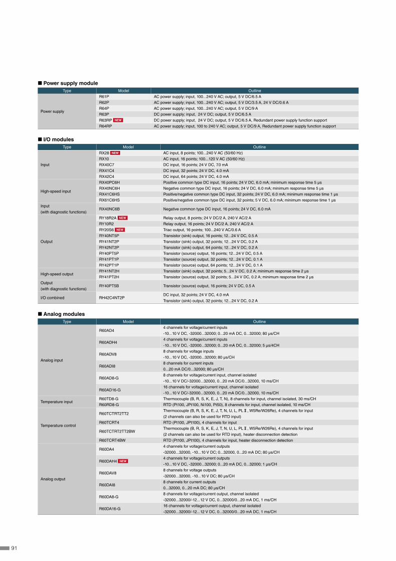
◼ Power supply moduleType Model Outline
Power supply
R61P AC power supply; input, 100...240 V AC; output, 5 V DC/6.5 A
R62P AC power supply; input, 100...240 V AC; output, 5 V DC/3.5 A, 24 V DC/0.6 A
R64P AC power supply; input, 100...240 V AC; output, 5 V DC/9 A
R63P DC power supply; input, 24 V DC; output, 5 V DC/6.5 A
R63RP NEW DC power supply; input, 24 V DC; output, 5 V DC/6.5 A, Redundant power supply function support
R64RP AC power supply; input, 100 to 240 V AC; output, 5 V DC/9 A, Redundant power supply function support
◼ I/O modulesType Model Outline
Input
RX28 NEW AC input, 8 points; 100...240 V AC (50/60 Hz)
RX10 AC input, 16 points; 100...120 V AC (50/60 Hz)
RX40C7 DC input, 16 points; 24 V DC, 7.0 mA
RX41C4 DC input, 32 points; 24 V DC, 4.0 mA
RX42C4 DC input, 64 points; 24 V DC, 4.0 mA
High-speed input
RX40PC6H Positive common type DC input, 16 points; 24 V DC, 6.0 mA; minimum response time 5 μs
RX40NC6H Negative common type DC input, 16 points; 24 V DC, 6.0 mA; minimum response time 5 μs
RX41C6HS Positive/negative common type DC input, 32 points; 24 V DC, 6.0 mA; minimum response time 1 μs
RX61C6HS Positive/negative common type DC input, 32 points; 5 V DC, 6.0 mA; minimum response time 1 μs
Input
(with diagnostic functions)RX40NC6B Negative common type DC input, 16 points; 24 V DC, 6.0 mA
Output
RY18R2A NEW Relay output, 8 points; 24 V DC/2 A, 240 V AC/2 A
RY10R2 Relay output, 16 points; 24 V DC/2 A, 240 V AC/2 A
RY20S6 NEW Triac output, 16 points; 100...240 V AC/0.6 A
RY40NT5P Transistor (sink) output, 16 points; 12...24 V DC, 0.5 A
RY41NT2P Transistor (sink) output, 32 points; 12...24 V DC, 0.2 A
RY42NT2P Transistor (sink) output, 64 points; 12...24 V DC, 0.2 A
RY40PT5P Transistor (source) output, 16 points; 12...24 V DC, 0.5 A
RY41PT1P Transistor (source) output, 32 points; 12...24 V DC, 0.1 A
RY42PT1P Transistor (source) output, 64 points; 12...24 V DC, 0.1 A
High-speed outputRY41NT2H Transistor (sink) output, 32 points; 5...24 V DC, 0.2 A; minimum response time 2 μs
RY41PT2H Transistor (source) output, 32 points; 5...24 V DC, 0.2 A; minimum response time 2 μs
Output
(with diagnostic functions)RY40PT5B Transistor (source) output, 16 points; 24 V DC, 0.5 A
I/O combined RH42C4NT2PDC input, 32 points; 24 V DC, 4.0 mA
Transistor (sink) output, 32 points; 12...24 V DC, 0.2 A
◼ Analog modulesType Model Outline
Analog input
R60AD44 channels for voltage/current inputs
-10...10 V DC, -32000...32000; 0...20 mA DC, 0...32000; 80 μs/CH
R60ADH44 channels for voltage/current inputs
-10...10 V DC, -32000...32000; 0...20 mA DC, 0...32000; 5 μs/4CH
R60ADV88 channels for voltage inputs
-10...10 V DC, -32000...32000; 80 μs/CH
R60ADI88 channels for current inputs
0...20 mA DC/0...32000; 80 µs/CH
R60AD8-G8 channels for voltage/current input, channel isolated
-10...10 V DC/-32000...32000, 0...20 mA DC/0...32000, 10 ms/CH
R60AD16-G16 channels for voltage/current input, channel isolated
-10...10 V DC/-32000...32000, 0...20 mA DC/0...32000, 10 ms/CH
Temperature inputR60TD8-G Thermocouple (B, R, S, K, E, J, T, N), 8 channels for input, channel isolated, 30 ms/CH
R60RD8-G RTD (Pt100, JPt100, Ni100, Pt50), 8 channels for input, channel isolated, 10 ms/CH
Temperature control
R60TCTRT2TT2Thermocouple (B, R, S, K, E, J, T, N, U, L, PL@, W5Re/W26Re), 4 channels for input
(2 channels can also be used for RTD input)
R60TCRT4 RTD (Pt100, JPt100), 4 channels for input
R60TCTRT2TT2BWThermocouple (B, R, S, K, E, J, T, N, U, L, PL@, W5Re/W26Re), 4 channels for input
(2 channels can also be used for RTD input), heater disconnection detection
R60TCRT4BW RTD (Pt100, JPt100), 4 channels for input, heater disconnection detection
Analog output
R60DA44 channels for voltage/current outputs
-32000...32000, -10...10 V DC; 0...32000, 0...20 mA DC; 80 µs/CH
R60DAH4 NEW4 channels for voltage/current outputs
-10...10 V DC, -32000...32000; 0...20 mA DC, 0...32000; 1 μs/CH
R60DAV88 channels for voltage outputs
-32000...32000, -10...10 V DC; 80 µs/CH
R60DAI88 channels for current outputs
0...32000, 0...20 mA DC; 80 µs/CH
R60DA8-G8 channels for voltage/current output, channel isolated
-32000...32000/-12...12 V DC, 0...32000/0...20 mA DC, 1 ms/CH
R60DA16-G16 channels for voltage/current output, channel isolated
-32000...32000/-12...12 V DC, 0...32000/0...20 mA DC, 1 ms/CH
91

◼ Motion/Positioning/Flexible high-speed I/O/High-speed counter modulesType Model Outline
Simple motion
RD77GF4 4 axes, linear/circular interpolation, advanced synchronous control, CC-Link IE Field network compatible
RD77GF8 8 axes, linear/circular interpolation, advanced synchronous control, CC-Link IE Field network compatible
RD77GF16 16 axes, linear/circular interpolation, advanced synchronous control, CC-Link IE Field network compatible
RD77GF32 NEW 32 axes, linear/circular interpolation, advanced synchronous control, CC-Link IE Field network compatible
RD77MS2 2 axes, linear/circular interpolation, advanced synchronous control, SSCNET3/H compatible
RD77MS4 4 axes, linear/circular interpolation, advanced synchronous control, SSCNET3/H compatible
RD77MS8 8 axes, linear/circular interpolation, advanced synchronous control, SSCNET3/H compatible
RD77MS16 16 axes, linear/circular interpolation, advanced synchronous control, SSCNET3/H compatible
Positioning
RD75P2 Transistor output, 2 axes; max. output, 200k pulse/s; linear/circular interpolation
RD75P4 Transistor output, 4 axes; max. output, 200k pulse/s; linear/circular/helical interpolation
RD75D2 Differential driver output, 2 axes; max. output, 5M pulse/s; linear/circular interpolation
RD75D4 Differential driver output, 4 axes; max. output, 5M pulse/s; linear/circular/helical interpolation
Flexible high-speed I/O RD40PD01 NEWInput, 12 points (5/24 V DC/differential); max counting speed, 8M pulse/s (differential)
Output, 14 points (5...24 V DC: 8 points, differential:6 points); max. output, 8M pulse/s (differential)
High-speed counter
RD62P2 5/12/24 V DC input, 2 channels; max. counting speed, 200k pulse/s; external output, transistor (sink type)
RD62P2E 5/12/24 V DC input, 2 channels; max. counting speed, 200k pulse/s; external output, transistor (source type)
RD62D2 Differential input, 2 channels; max. counting speed, 8M pulse/s; external output, transistor (sink type)
◼ Network modules DB : Co-branded product*1
Type Model Outline
Ethernet (built-in CC-Link IE) RJ71EN711 Gbps/100 Mbps/10 Mbps, 2 ports
Multi-network connectivity (Ethernet/CC-Link IE)
CC-Link IE Control RJ71GP21-SX 1 Gbps, fiber-optic cable, control/normal station
CC-Link IE Field RJ71GF11-T2 1 Gbps, master/local station
CC-Link IE Field Network
remote headRJ72GF15-T2 1 Gbps, remote station
CC-Link RJ61BT11 Max. 10 Mbps, master/local station, CC-Link Ver.2 supported
AnyWireASLINK RJ51AW12AL DB DigitalLinkSensor AnyWireASLINK system compatible, master station
BACnet® RJ71BAC96 NEW DB BACnet® system compatible, controller/workstation
Serial communication
RJ71C24 Max. 230.4 kbps; RS-232, 1 channel; RS-422/485, 1 channel
RJ71C24-R2 Max. 230.4 kbps; RS-232, 2 channels
RJ71C24-R4 Max. 230.4 kbps; RS-422/485, 2 channels
*1: General specifications and product guarantee conditions for co-branded products may vary from those of general MELSEC products. For more information, please refer to the relevant product manuals or contact
your local Mitsubishi Electric sales office/representative.
◼ Advanced information modulesType Model Outline
MES Interface RD81MES96 Database connection (MX MESInterface-R is required)
High-speed data logger RD81DL96 Data collection (High-speed data logger module tool "SW1DNN-RDLUTL-E" is required)*2
C intelligent function module RD55UP06-V C/C++ program execution (Setting and monitoring tool is integrated within GX Works3)
*2: For information on how to obtain the software, please contact your local Mitsubishi Electric sales office or representative.
◼ Software Type Model Outline
MELSOFT iQ WorksSW2DND-IQWK-E
(DVD-ROM edition)
FA engineering software*3
• System Management Software: MELSOFT Navigator • Controller Programming Software: MELSOFT GX Works3*4, GX Works2, GX Developer • Motion Programming Software: MELSOFT MT Works2 • HMI Programming Software: MELSOFT GT Works3 • Robot Programing Software: MELSOFT RT ToolBox2 mini • Inverter Setup Software: MELSOFT FR Configurator2 • C Controller setting and monitoring tool: MELSOFT CW Configurator • MITSUBISHI ELECTRIC FA Library
MELSOFT GX Works3SW1DND-GXW3-E
(DVD-ROM edition) • Controller Programming Software: MELSOFT GX Works3*4, GX Works2, GX Developer, PX Developer*5
• MITSUBISHI ELECTRIC FA Library
*3: For detailed information about supported modules, refer to the manuals of the relevant software package.
*4: The MELSOFT GX Works3 menu is switchable between Japanese, English, and simplified Chinese.
*5: Includes both programming tool and monitor tool for process control.
Type Model Outline
CW Workbench
SW1DND-CWWR-E Engineering tool for C Controller module
SW1DND-CWWR-EZ Additional license for R12CCPU-V, RD55UP06-V
SW1DND-CWWR-EVZ Update license for R12CCPU-V, RD55UP06-V
CW-Sim
CW-Sim Standalone
SW1DND-CWSIMR-EZ VxWorks® simulation environment for CW Workbench, additional license
SW1DNC-CWSIMSAR-E VxWorks® simulation environment for CW Workbench, standalone type
MELSOFT CW Configurator SW1DND-RCCPU-E Setting and monitoring tool for C Controller
MX MESInterface-R SW1DND-RMESIF-E MES Interface function configuration tool
PX Developer monitor tool SW1DNC-FBDQMON-E Monitoring tool for process control
92

◼ OptionType Model Outline
Connector
A6CON1 32-point connector soldering type (40-pin connector)
A6CON2 32-point connector crimp-contact type (40-pin connector)
A6CON3 32-point connector pressure-displacement (flat cable) type (40-pin connector)
A6CON4 32-point connector soldering type (40-pin connector, cable connectable in bidirectional)
Spring clamp terminal block Q6TE-18SN For 16-point I/O modules, 0.3…1.5 mm² (22…16 AWG)
Connector/terminal block
conversion module
A6TBXY36 For positive common input modules and sink output modules (standard type)
A6TBXY54 For positive common input modules and sink output modules (2-wire type)
A6TBX70 For positive common input modules (3-wire type)
Connector/terminal block
conversion module cable
AC05TB For A6TBXY36, A6TBXY54, and A6TBX70 (positive common/sink type), 0.5 m
AC10TB For A6TBXY36, A6TBXY54, and A6TBX70 (positive common/sink type), 1 m
AC20TB For A6TBXY36, A6TBXY54, and A6TBX70 (positive common/sink type), 2 m
AC30TB For A6TBXY36, A6TBXY54, and A6TBX70 (positive common/sink type), 3 m
AC50TB For A6TBXY36, A6TBXY54, and A6TBX70 (positive common/sink type), 5 m
AC80TB For A6TBXY36, A6TBXY54, and A6TBX70 (positive common/sink type), 8 m*
AC100TB For A6TBXY36, A6TBXY54, and A6TBX70 (positive common/sink type), 10 m*
Relay terminal module A6TE2-16SRN For 40-pin connector 24 V DC transistor output modules (sink type)
Relay terminal module cable
AC06TE For A6TE2-16SRN, 0.6 m
AC10TE For A6TE2-16SRN, 1 m
AC30TE For A6TE2-16SRN, 3 m
AC50TE For A6TE2-16SRN, 5 m
AC100TE For A6TE2-16SRN, 10 m
* Common current 0.5 A or lower
Precautions before use
This publication explains the typical features and functions of the products herein
and does not provide restrictions or other information related to usage and module
combinations. Before using the products, always read the product user manuals.
Mitsubishi Electric will not be held liable for damage caused by factors found not to
be the cause of Mitsubishi Electric; opportunity loss or lost profits caused by faults in
Mitsubishi Electric products; damage, secondary damage, or accident compensation,
whether foreseeable or not, caused by special factors; damage to products other than
Mitsubishi Electric products; or any other duties.
For safe use
• To use the products given in this publication properly, always read the relevant manuals before beginning operation.
• The products have been manufactured as general-purpose parts for general industries, and are not designed or manufactured to be incorporated in a device or system used in purposes related to human life.
• Before using the products for special purposes such as nuclear power, electric power, aerospace, medicine or passenger-carrying vehicles, consult with Mitsubishi Electric.
• The products have been manufactured under strict quality control. However, when installing the products where major accidents or losses could occur if the products fail, install appropriate backup or fail-safe functions in the system.
Microsoft, Windows, Excel, and Access are registered trademarks of Microsoft Corporation in the United States and other countries.Oracle and Java are registered trademarks of Oracle Corporation and/or its affiliates.Ethernet is a trademark of Xerox Corporation.SD/SDHC logo is a trademark of SD-3C, LLC.MODBUS is a registered trademark of Schneider Electric USA, Inc.ARM is a registered trademark of ARM Limited (or its subsidiaries) in the EU and/or elsewhere. QR Code is a trademark or a registered trademark of DENSO WAVE INCORPORATED in JAPAN, the United States and/or other countries.TÜV is the registered trademark of TÜV Rheinland.IOS is a trademark or registered trademark of Cisco in the U.S. and other countries and is used under license.Apple, iPad, iPad Air, iPad mini are trademarks of Apple Inc., registered in the U.S. and other countries.Android and Google Play are trademarks of Google Inc.BACnet is a registered trademark of the American Society of Heating, Refrigerating and Air-Conditioning Engineers, Inc.All other company names and product names used in this document are trademarks or registered trademarks of their respective companies.
93

YOUR SOLUTION PARTNER
Automation solutions
Mitsubishi Electric offers a wide range of automation equipment from PLCs and HMIs to
CNC and EDM machines.
A NAME TO TRUSTSince its beginnings in 1870, some 45 companies use the Mitsubishi name, covering a spectrum of finance, commerce and industry.
The Mitsubishi brand name is recognized around the world as a symbol of premium quality.
Mitsubishi Electric Corporation is active in space development, transportation, semi-conductors, energy systems, communications and information processing, audio visual equipment and home electronics, building and energy management and automation systems, and has 237 factories and laboratories worldwide in over 121 countries.
This is why you can rely on Mitsubishi Electric automation solution - because we know first hand about the need for reliable, efficient, easy-to-use automation and control in our own factories.
As one of the world’s leading companies with a global turnover of over 4 trillion Yen (over $40 billion), employing over 100,000 people, Mitsubishi Electric has the resource and the commitment to deliver the ultimate in service and support as well as the best products.
Medium voltage: VCB, VCC
Power monitoring, energy management
Compact and Modular Controllers
Inverters, Servos and Motors
Visualisation: HMIs
Numerical Control (NC)
Robots: SCARA, Articulated arm
Processing machines: EDM, Lasers, IDS
Transformers, Air conditioning, Photovoltaic systems
Low voltage: MCCB, MCB, ACB
* Not all products are available in all countries.
94

Mitsubishi Electric Corporation Nagoya Works is a factory certified for ISO 14001 (standards for environmental management systems) and ISO 9001 (standards for quality assurance management systems).
Country/Region Sales office Tel/FaxUSA MITSUBISHI ELECTRIC AUTOMATION, INC.
500 Corporate Woods Parkway, Vernon Hills, IL 60061, U.S.A.Tel : +1-847-478-2100Fax : +1-847-478-2253
Mexico MITSUBISHI ELECTRIC AUTOMATION, INC. Mexico BranchMariano Escobedo #69, Col. Zona Industrial, Tlalnepantla Edo. Mexico, C.P.54030
Tel : +52-55-3067-7500
Brazil MITSUBISHI ELECTRIC DO BRASIL COMÉRCIO E SERVIÇOS LTDA.Avenida Adelino Cardana, 293, 21 andar, Bethaville, Barueri SP, Brazil
Tel : +55-11-4689-3000Fax : +55-11-4689-3016
Germany MITSUBISHI ELECTRIC EUROPE B.V. German BranchMitsubishi-Electric-Platz 1, 40882 Ratingen, Germany
Tel : +49-2102-486-0Fax : +49-2102-486-1120
UK MITSUBISHI ELECTRIC EUROPE B.V. UK BranchTravellers Lane, Hatfield, Hertfordshire, AL10 8XB, U.K.
Tel : +44-1707-28-8780Fax : +44-1707-27-8695
Ireland MITSUBISHI ELECTRIC EUROPE B.V. Irish BranchWestgate Business Park, Ballymount, Dublin 24, Ireland
Tel : +353-1-4198800Fax : +353-1-4198890
Italy MITSUBISHI ELECTRIC EUROPE B.V. Italian BranchCentro Direzionale Colleoni - Palazzo Sirio, Viale Colleoni 7, 20864 Agrate Brianza (MB), Italy
Tel : +39-039-60531Fax : +39-039-6053-312
Spain MITSUBISHI ELECTRIC EUROPE, B.V. Spanish BranchCarretera de Rubí, 76-80-Apdo. 420, 08190 Sant Cugat del Vallés (Barcelona), Spain
Tel : +34-935-65-3131Fax : +34-935-89-1579
France MITSUBISHI ELECTRIC EUROPE B.V. French Branch25, Boulevard des Bouvets, 92741 Nanterre Cedex, France
Tel : +33-1-55-68-55-68Fax : +33-1-55-68-57-57
Czech Republic MITSUBISHI ELECTRIC EUROPE B.V. Czech BranchAvenir Business Park, Radlicka 751/113e, 158 00 Praha 5, Czech Republic
Tel : +420-251-551-470Fax : +420-251-551-471
Poland MITSUBISHI ELECTRIC EUROPE B.V. Polish Branchul. Krakowska 50, 32-083 Balice, Poland
Tel : +48-12-347-65-00Fax : +48-12-630-47-01
Sweden MITSUBISHI ELECTRIC EUROPE B.V. (Scandinavia)Fjelievägen 8, SE-22736 Lund, Sweden
Tel : +46-8-625-10-00Fax : +46-46-39-70-18
Russia MITSUBISHI ELECTRIC (RUSSIA) LLC St. Petersburg BranchPiskarevsky pr. 2, bld 2, lit “Sch”, BC “Benua”, office 720; 195027 St. Petersburg, Russia
Tel : +7-812-633-3497Fax : +7-812-633-3499
Turkey MITSUBISHI ELECTRIC TURKEY A.Ş Ümraniye BranchSerifali Mahallesi Nutuk Sokak No:5, TR-34775 Umraniye/Istanbul, Turkey
Tel : +90-216-526-3990Fax : +90-216-526-3995
UAE MITSUBISHI ELECTRIC EUROPE B.V. Dubai BranchDubai Silicon Oasis, P.O.BOX 341241, Dubai, U.A.E.
Tel : +971-4-3724716Fax : +971-4-3724721
South Africa ADROIT TECHNOLOGIES 20 Waterford Office Park, 189 Witkoppen Road, Fourways, South Africa
Tel : +27-11-658-8100Fax : +27-11-658-8101
China MITSUBISHI ELECTRIC AUTOMATION (CHINA) LTD.Mitsubishi Electric Automation Center, No.1386 Hongqiao Road, Shanghai, China
Tel : +86-21-2322-3030Fax : +86-21-2322-3000
Taiwan SETSUYO ENTERPRISE CO., LTD.6F, No.105, Wugong 3rd Road, Wugu District, New Taipei City 24889, Taiwan
Tel : +886-2-2299-2499Fax : +886-2-2299-2509
Korea MITSUBISHI ELECTRIC AUTOMATION KOREA CO., LTD.7F-9F, Gangseo Hangang Xi-tower A, 401, Yangcheon-ro, Gangseo-Gu, Seoul 07528, Korea
Tel : +82-2-3660-9530Fax : +82-2-3664-8372
Singapore MITSUBISHI ELECTRIC ASIA PTE. LTD.307 Alexandra Road, Mitsubishi Electric Building, Singapore 159943
Tel : +65-6473-2308Fax : +65-6476-7439
Thailand MITSUBISHI ELECTRIC FACTORY AUTOMATION (THAILAND) CO., LTD.12th Floor, SV.City Building, Office Tower 1, No. 896/19 and 20 Rama 3 Road, Kwaeng Bangpongpang, Khet Yannawa, Bangkok 10120, Thailand
Tel : +66-2682-6522Fax : +66-2682-6020
Vietnam MITSUBISHI ELECTRIC VIETNAM COMPANY LIMITED Hanoi Branch6th Floor, Detech Tower, 8 Ton That Thuyet Street, My Dinh 2 Ward, Nam Tu Liem District, Hanoi, Vietnam
Tel : +84-4-3937-8075Fax : +84-4-3937-8076
Indonesia PT. MITSUBISHI ELECTRIC INDONESIAGedung Jaya 11th Floor, JL. MH. Thamrin No.12, Jakarta Pusat 10340, Indonesia
Tel : +62-21-3192-6461Fax : +62-21-3192-3942
India MITSUBISHI ELECTRIC INDIA PVT. LTD. Pune BranchEmerald House, EL-3, J Block, M.I.D.C., Bhosari, Pune-411026, Maharashtra, India
Tel : +91-20-2710-2000Fax : +91-20-2710-2100
Australia MITSUBISHI ELECTRIC AUSTRALIA PTY. LTD.348 Victoria Road, P.O. Box 11, Rydalmere, N.S.W 2116, Australia
Tel : +61-2-9684-7777Fax : +61-2-9684-7245
HEAD OFFICE: TOKYO BLDG., 2-7-3, MARUNOUCHI, CHIYODA-KU, TOKYO 100-8310, JAPAN
www.MitsubishiElectric.com
L(NA)08298ENG-G 1703[IP]New publication, effective Mar. 2017.
Specifications are subject to change without notice.